51508 Catalog
81228-Catalog 81228-Catalog 81228-Catalog 785007 Batch1 unilog cesco-content
236499-Attachment 236499-Attachment 236499-Attachment 785007 Batch1 unilog cesco-content
66198-Catalog 66198-Catalog 66198-Catalog 785007 Batch10 unilog cesco-content
74934-Catalog 74934-Catalog 74934-Catalog 785007 Batch10 unilog cesco-content
56545-Catalog 56545-Catalog 56545-Catalog 785007 Batch10 unilog cesco-content
2016-09-04
: Pdf 51508-Catalog 51508-Catalog B4 unilog
Open the PDF directly: View PDF ![]() .
.
Page Count: 815 [warning: Documents this large are best viewed by clicking the View PDF Link!]
catalog
2011 / 2012
ELECTRICAL WIRING DEVICES
& ACCESSORIES
designed to be better.
How this new catalog works
for you.
Before we wrote a word or snapped a photo — we did the same thing we always do when designing
new products: We listened to the folks who use them. The result is a document that works for you,
whether you’re a purchasing agent, distributor salesperson, electrician, or specifying engineer.
Portions of this document are reprinted with permission from NFPA 70-1999, the National Electrical Code®, Copyright© 2010, National Fire Protection Association, Quincy, MA
02269. This reprinted material is not the complete and official position of the National Fire Protection Association, on the referenced subject which is represented only by the
standard in its entirety. National Electrical Code® and NEC® are registered trademarks of the National Fire Protection Association, Inc., Quincy, MA 02269.
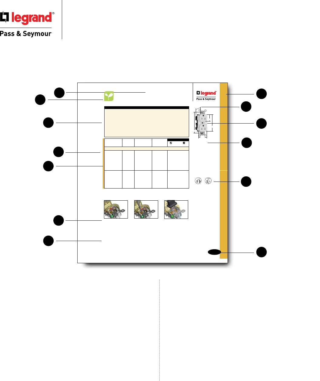
1. Clear, sans-serif typefaces remain legible after faxing and
photocopying.
2. Color-coded section pages help you find products fast. Plus,
product and section headings on every page.
3. Energy-saving products that reduce environmental impact
and help control energy costs.
4.
Product Features tell how our products work for you — fast!
5. Dimensions overlay photos and line art. No need to look in
three different spots to get a “full picture” of the product.
6. Key information at a glance:
- Features/Specs. - Catalog numbers
- Canadian models - 3rd Party listings
- NEMA ratings/configurations - Amperage/Voltage
- Dimensions - Application notes
7. Chart borders and dimension lines are clear and
easy to read, even after several duplications.
8. Black & white, silhouetted product photos for ready
faxing and photocopying.
9. NEMA configurations in 3 locations! At beginning
of catalog, in appropriate sections, and on pages with
NEMA-applicable products.
10. Additional information or accessory listing for added
convenience.
11. Catalog numbers below product photos and line
drawings let you identify what you want by sight.
12. NEC® requirements called out near products help
you keep current.
13. Extra-large page numbers for faster reference,
especially during over-the-phone catalog searches.
To make your job easier, Legrand/Pass & Seymour has gone to great lengths to ensure the accuracy of this catalog’s data and graphics. Should you discover errors,
please report them to us; we will gladly correct future editions.
The data and dimensions listed in the following pages are accurate as of the publishing date. Legrand/Pass & Seymour reserves the right to change the design,
dimensions, materials, and manufacturing techniques of the products listed without notice. Therefore, you are encouraged to verify these characteristics before
specifying, ordering, or installing these products.
© 2010, Legrand/Pass & Seymour Printed in USA
B-25
Straight Blade Receptacles
All devices listed on this page conform to NEMA WD-1 and WD-6.
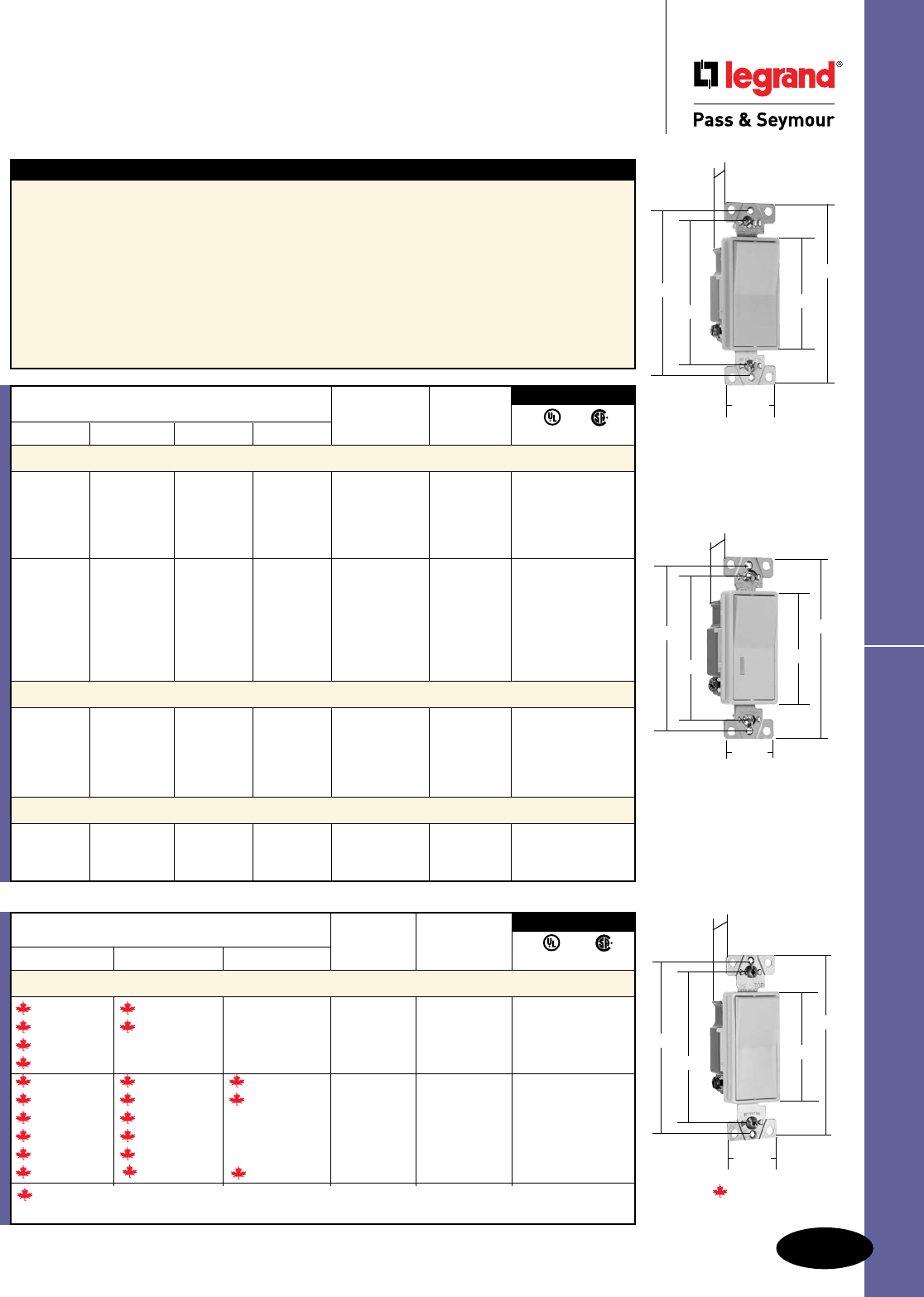
Tamper-Resistant Spec Grade Receptacles
Straight Blade Receptacles
Tamper-Resistant
Specification Grade Receptacles
15 & 20A, 125V
TR62I
Features
n Thermoplastic dual mechanism shutter system to
help prevent insertion of foreign objects.
n Exclusive patented feature, circuit label on face
allows permanent circuit identification.
n Extra heavy-duty brass, one-piece mounting strap
with integral ground.
n One-piece, brass, triple-wipe power contacts for
lasting retention.
n Strap tabs wrap around and lock down on face
to prevent strap from separating from face and
back body.
n Impact-resistant nylon face and back body.
n Easily accessed break-off, line-contact
connecting tab for fast, easy split-circuit
wiring.
n Two drive screws anchor strap to back
body and face.
n Exclusive patented feature, external screw-
pressure-plate back wire clamp on ground
terminal for faster, easier installation.
n External screw-pressure-plate back wire
clamps with #10 brass terminal screws for
visual assurance of a good connection.
n Auto-ground clip assures positive ground.
NEC
®
section 517.18(C) Pediatric Locations.
Receptacles located within the rooms, bathrooms, playrooms, activity rooms, and patient care areas
of pediatric wards shall be listed under tamper resistant or employ a listed tamper resistant cover.
Thermoplastic shutter in
closed position covers
access to contacts.
Insertion of object in any
one side does not open
shutter.
Two-bladed plug or ground-
ing plug compresses spring
and simultaneously opens
both shutters.
The Mechanical Shutter System
Rating NEMA
Catalog Number A. V. Color Cong. No.
Duplex Receptacles Back & Side Wire
TR62I 15 125 Ivory 5-15R • • •
TR62W 15 125 White 5-15R • • •
TR62 15 125 Brown 5-15R • • •
TR62GRY 15 125 Gray 5-15R • • •
TR62BK 15 125 Black 5-15R • • •
TR62RED 15 125 Red 5-15R • • •
TR62LA 15 125 Light Almond 5-15R • • •
TR62BL 15 125 Blue 5-15R • • •
TR63I 20 125 Ivory 5-20R • • •
TR63W 20 125 White 5-20R • • •
TR63 20 125 Brown 5-20R • • •
TR63GRY 20 125 Gray 5-20R • • •
TR63BK 20 125 Black 5-20R • • •
TR63RED 20 125 Red 5-20R • • •
TR63LA 20 125 Light Almond 5-20R • • •
3rd Party Compliance
FSUL
UL498 WC596 C22.2 No. 42
This tamper-resistant receptacle, like all others, can be defeated by actions such
as inserting foreign objects in both sides of the slots simultaneously.
For PlugTail™ Tamper-Resistant Receptacles, see Pages B-3.
.900"
3.281"
1.625"
1.104"
2.750"
NEMA
5-15R
NEMA
5-20R
2 Pole, 3 Wire
For Bulk Packaging Solutions consult factory.
4
6
10
12
7
12
5
9
8
11
13
3

Switches .....................................................
Straight Blade Receptacles .............................
GFCIs ........................................................
Decorator Devices ........................................
Hospital Grade Devices .................................
Surge Protective & Isolated Ground Devices ......
Straight Blade Plugs & Connectors ...................
Industrial Spec Grade Turnlok® Locking Devices....
Cam-Type Devices ........................................
IEC 309 Industrial Products ............................
Flexcor® Wire Mesh Grips ................................
Occupancy & Vacancy Sensors & Timers ............
Dimmers & Fan Speed Controls .......................
Slater® Plastic Boxes .......................................
Reiker Ceiling Fan & Fixture Support Products ......
Weatherproof Boxes & Covers .........................
Wall Plates & Specialties ...............................
Electrical Accessories ....................................
Technical Specifications .................................
Glossary of Terms ........................................
Index ........................................................
Table of Contents
T
U
S
N
O
P
Q
R
E
D
F
G
H
J
I
L
M
K
A
B
C
Devices & Wall Plates Color Selection Chart available on Pages A-29, B-78 and Q-61.
Innovative solutions that
offer you more.
The most
complete line
of GFCIs
See Section C.
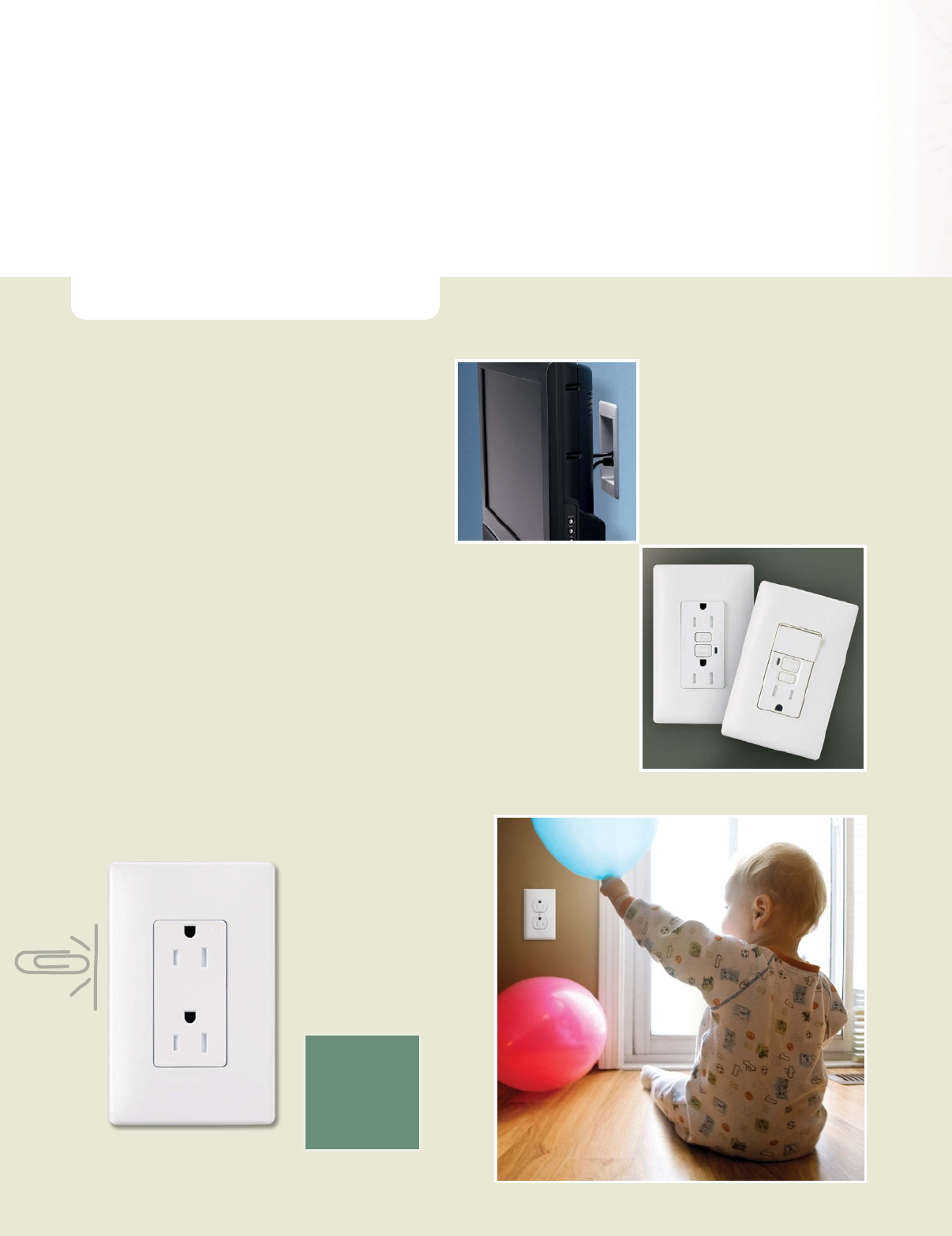
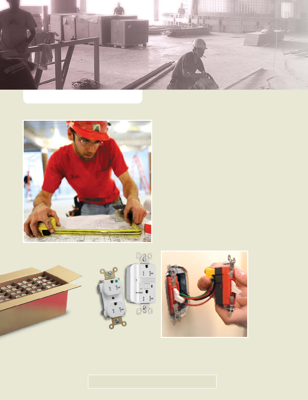
P&S Tamper-Resistant
Receptacles feature
an automatic shutter
system to prevent kids
from inserting objects.
Our complete line
covers all applications.
See Section B.
Recessed Television
Wall Boxes
See Section N.
Today’s homeowners demand more — and our
complete residential line delivers. With new
style that has any room or area looking good.
Energy-saving solutions to help counter high
utility rates. And fresh ideas to enhance safety.
Check out our pace-setting residential solutions
and you’ll find everything you’re looking for!
■Decorator-Style Wiring Devices and Wall Plates
■Screwless Wall Plates
■ P&S Harmony™ Dimmers and Decorator
Rotary Dimmers
■Digital Timers
■Vacancy and Occupancy Sensors
■Nightlight and Switch Combination Devices
■Tamper-Resistant Receptacles
■GFCIs with SafeLock™ Protection
■Home Locator Switches
■Weatherproof Receptacles and While-In-Use Covers
■Recessed Television Wall Boxes
■Surge Protective Receptacles
MEETS
NATIONAL
ELECTRICAL CODE
®
REQUIREMENTS
R E S I D E N T I A L S O L U T I O N S
Learn more at www.legrand.us/passandseymour
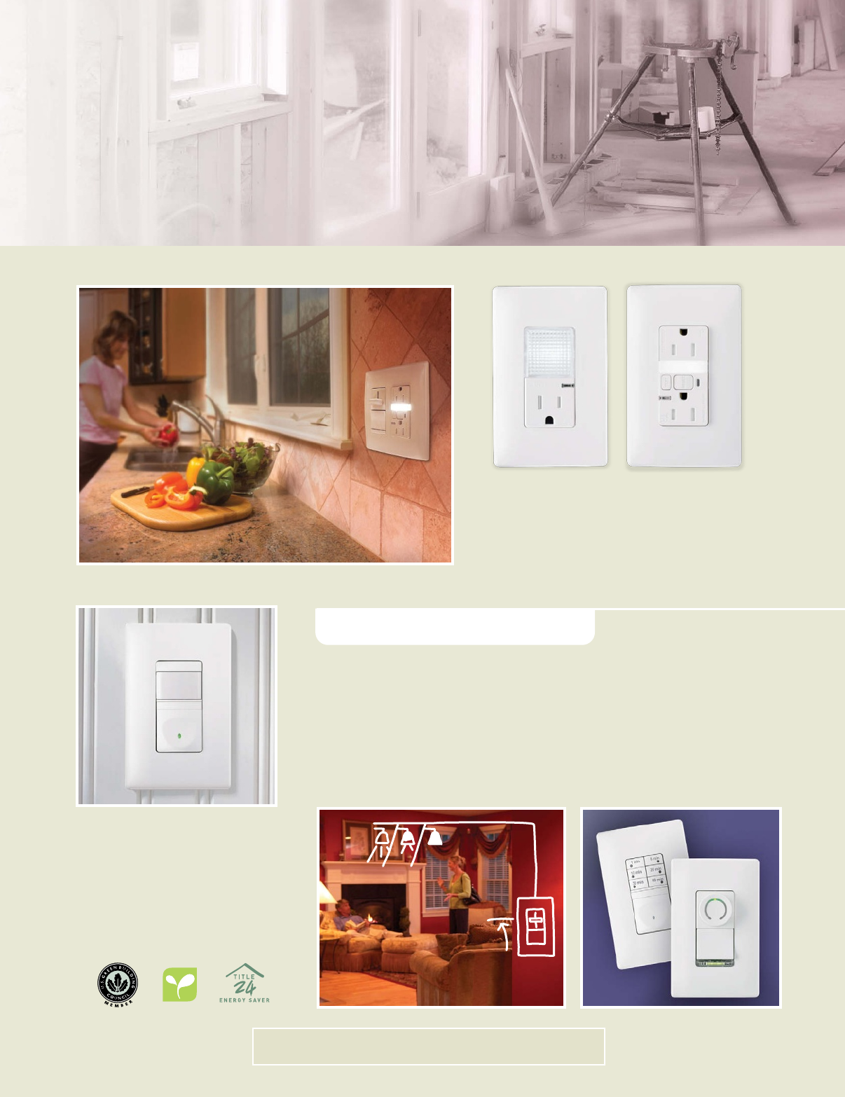
When you’re looking for quality energy-saving solutions, you’ll find them in
the broad line of P&S Lighting Controls. That includes many stylish dimmer
and fan-speed control choices, vacancy and occupancy sensors, and timers.
See Sections L, M.
P&S Occupancy and Vacancy
Sensors add safety, convenience
and energy savings.
See Section L.
P&S Tamper-Resistant Nightlight
Combinations include either a
standard or GFCI receptacle.
Add both safety and convenience!
See Sections B, C, D.
LIGHTING CONTROLS
COMMERCIAL PRODUCTS
Learn more at www.legrand.us/passandseymour
Subtract waste and
add productivity with
P&S bulk packaging
solutions.
Consult factory.
P&S PlugTail Wiring Devices — the
fastest, most reliable wiring device
installation for any commercial job.
See Sections A, B.
The full range of P&S Commercial devices is built
with a quality look and feel. Built to be easy to install.
And built to stand up to constant use. We engineer
them to satisfy virtually every need. And every user.
■Specification Grade Receptacles
■P&S PlugTail™ Devices
■Specification Grade Switches
■GFCIs with SafeLock™ Protection
■Occupancy and Vacancy Sensors
■Surge Protecting and Isolated Ground Devices
■Hospital Grade Devices
■Straight Blade Plugs & Connectors
■Clamp-Lock™ Plugs & Connectors
■P&S Titan® Dimmers
■Fan Speed Controls
■Wall Plates
INDUSTRIAL DEVICES
When we offered the first fusible mechanical
interlock with visible blown-fuse indication,
we helped plants avoid downtime. That’s
typical of the feature-rich P&S Industrial
line. These rugged, reliable workhorses
can take all the wear and tear industrial
facilities can dish out.
■ Straight Blade Plugs, Connectors
and Receptacles
■ Turnlok® Plugs, Connectors,
Receptacles, Flanged Inlets and Outlets
■Flexcor® Wire Mesh Grips
■IEC Pin and Sleeve Devices
■Surge Protecting and
Isolated Ground Devices
■Industrial Grade Switches
■Manual Controllers
■Mechanical Interlocks
■Safety Switches
■ Ground Continuity Monitoring
(GCM) Plugs and Connectors
Ground Continuity Monitoring Plugs
and Connectors add job site safety.
See Sections G, H.
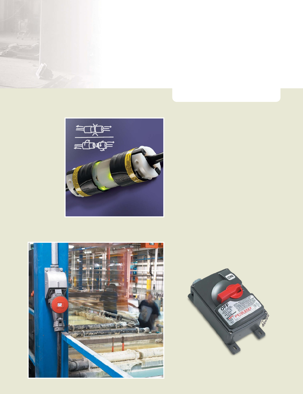
IEC 309 Industrial
Products for maximum durability
and minimum downtime.
See Section J.
Working for you — to increase
productivity, reduce risk, and increase
customer profitability and satisfaction.

… less environmental impact, less wasted energy.
Every day, in your professional life, installation after installation,
you will have the power to contribute to energy saving while
installing our solutions marked with this symbol .
Hence, you are able to help your customer save energy and
reduce their environmental impact. Energy saving is the matter
of everyone. Together, let’s make our best for 1+1+1…=less.
installing our solutions marked with this symbol .
installing our solutions marked with this symbol .
installing our solutions marked with this symbol .
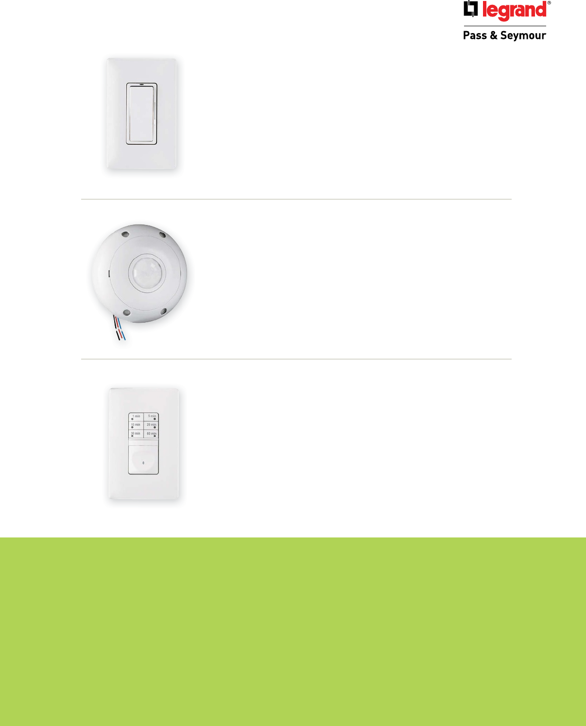
HARMONY™ DIMMERS & FAN SPEED CONTROLS
Cut energy use in bathrooms and
bedrooms by 40 to 50%
Comfort benefi t:
P&S Harmony™ Dimmers combine P&S Decorator style and easy,
ergonomic operation. They also offer the added convenience of
separate ON/OFF control and a sliding lighting-level control —
so you can turn lights on directly to any selected dimming level.
COMMERCIAL CEILING OCCUPANCY SENSOR
Reduce light usage 20 to 40%
Comfort benefi t:
P&S commercial Ceiling Mount Occupancy Sensors monitor room
occupancy and control the lights, saving energy and extending the
lamp life. All models offer manually selected time intervals so it’s
easy to optimize operation to minimize electrical consumption.
7-BUTTON DIGITAL TIMER
Make energy savings automatic
Comfort benefi t:
The P&S RT1 Timer provides maximum control, ease and convenience
with push button time-to-OFF selection and a time-to-OFF interval of
up to 60 minutes.

SWITCHES
Index
Device Rating Page Number
Horsepower Rating Chart A-1
PlugTail™ Spec Grade Switches 15 & 20A, 120/277VAC A-2, A-3
Industrial Extra Heavy-Duty Spec Grade Switches 15, 20 & 30A, 120, 277 & 120/277VAC A-4, A-5
Lock Switch Replacement Keys A-5
Extra Heavy-Duty Spec Grade & Security Switches 15 & 20A, 347VAC; 20A, 120/277VAC A-6
Hard Use & Commercial Spec Grade Switches 15 & 20A, 120/277VAC A-7
Manual Controllers 30 & 40A, 1ø & 3ø; 15, 20 & 30A,
120/277VAC; 60A NEMA 3R; 20 & 30A, 1ø A-8 – A-12
PlugTail™ Spec Grade Decorator Switches 15 & 20A, 120/277VAC A-13, A-14
TradeMaster® Grounding Toggle Switches 15A, 120VAC A-15, A-16
Combination Switches 15 & 20A, 120/277VAC; 15A, 120/125VAC;
20A, 120VAC A-17, A-18
Specification Grade Decorator Switches 15 & 20A, 120/277 & 347VAC; 20A, 120VAC A-19
TradeMaster® Decorator Switches 15A, 120 & 120/277VAC A-20, A-21
Momentary & Maintained Contact Switches 15A, 120 & 120/277VAC A-22
Spec Grade Decorator Combination Switches 20A, 277VAC A-23
Shim-Lock A-23
TradeMaster® Decorator Combination Switches 15A, 120 & 120/125VAC A-24 – A-26
Decorator Combination Tamper-Resistant Switch/GFCI 15A, 125VAC A-27
Canopy Switches & Locator Switches 15A, 120 & 250VAC; 15A, 120VAC A-28
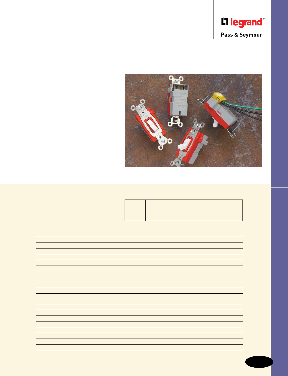
Readily installed in the plant or
at the office — you can rely on
all of our switches for years of
quiet, trouble-free operation.
15 Amp 1/2 Horsepower at 120VAC; 2 Horsepower at 240VAC
20 Amp 1 Horsepower at 120VAC; 2 Horsepower at 240VAC
30 Amp 2 Horsepower at 120VAC; 2 Horsepower at 240VAC
HP Conversion Table – Switches
A-1
Switches
Switches
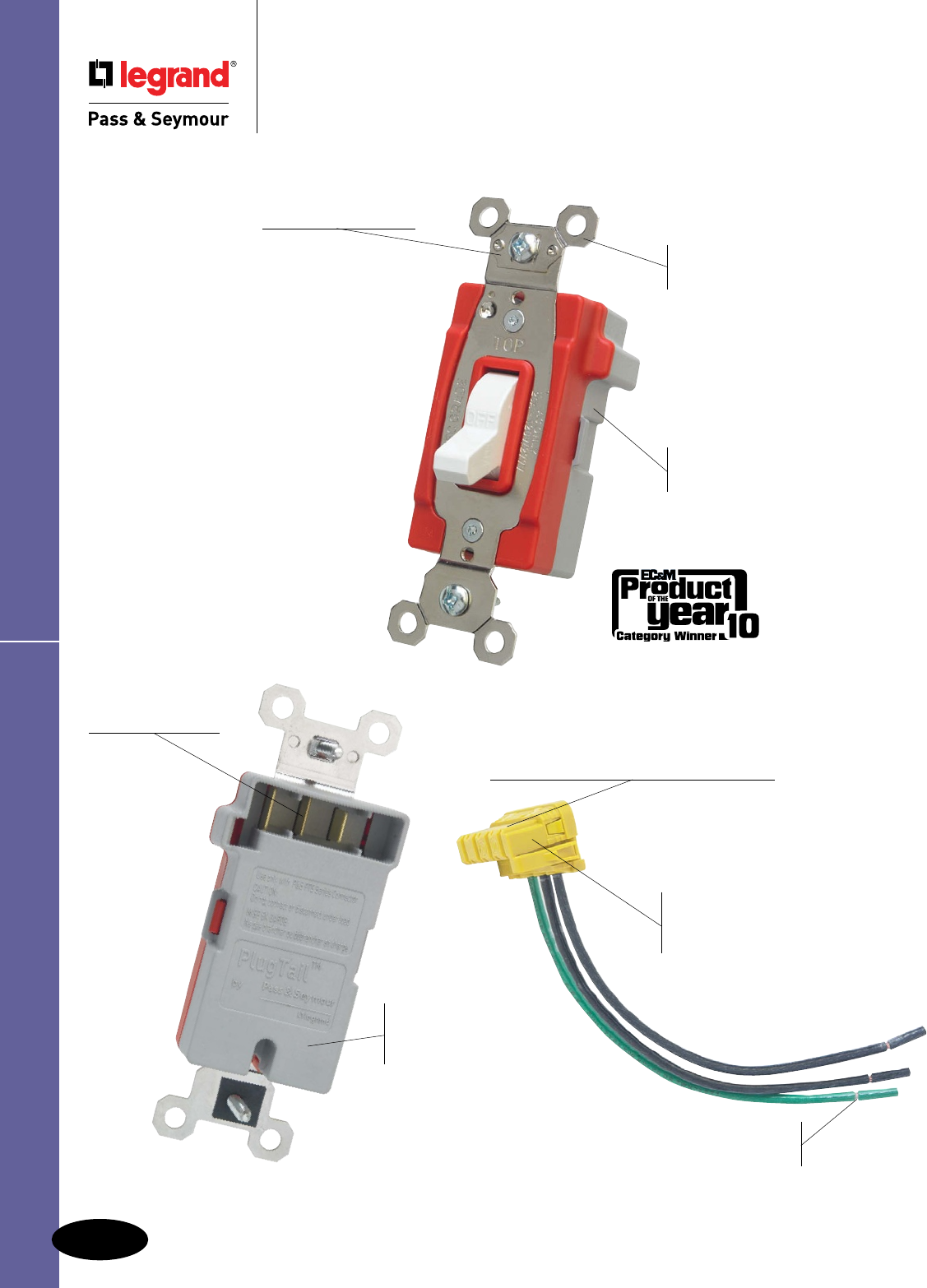
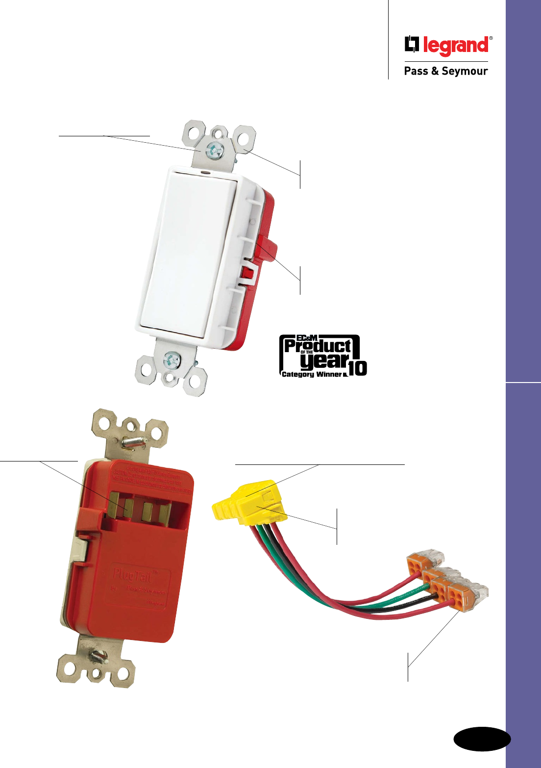
Factory-terminated devices and
connectors mean that device
installation is the same regardless
of skill level of the installer. The
UL-Listed connectors are keyed to
ensure proper wiring installation into
each device. The connector simply
snaps into the back of the device –
no fussing with wires, stripping, or
tightening screws. PlugTail devices
are finger safe with no exposed
terminals, so taping is not required.
Now device installation is a snap!
PlugTail™. The fastest, most consistent and reliable
wiring devices – ever.
Devices & Wall Plates Color Selection Chart available on Page A-29, B-78 and Q-61.
A-2
SwitchesPlugTail™ Specification Grade Switches
Switches
PlugTail™ Specification Grade Switches
PT20AC1W
Large brass contacts snugly terminate on
device blade terminals. Audible snapping
latch assures connection, allows release.
Pre-stripped connector
leads fasten to conductors,
easier than standard pigtails.
Polycarbonate connector
housing secures terminations
and conductors in a UL Listed,
finger-safe housing.
Built-in connector
features large brass
terminal blades to
ensure consistent,
reliable electrical
connections.
Glass-reinforced
nylon back body
for durability and
strength.
Shallow design
for easier installation.
Heavy-duty bumpers
for quiet, smooth operation.
Auto-ground clip
assures positive ground.
One-piece nickel-plated
mounting strap for
superior corrosion resistance.
No exposed terminals create
a finger-safe application before,
during, and after installation.
A-3
Switches
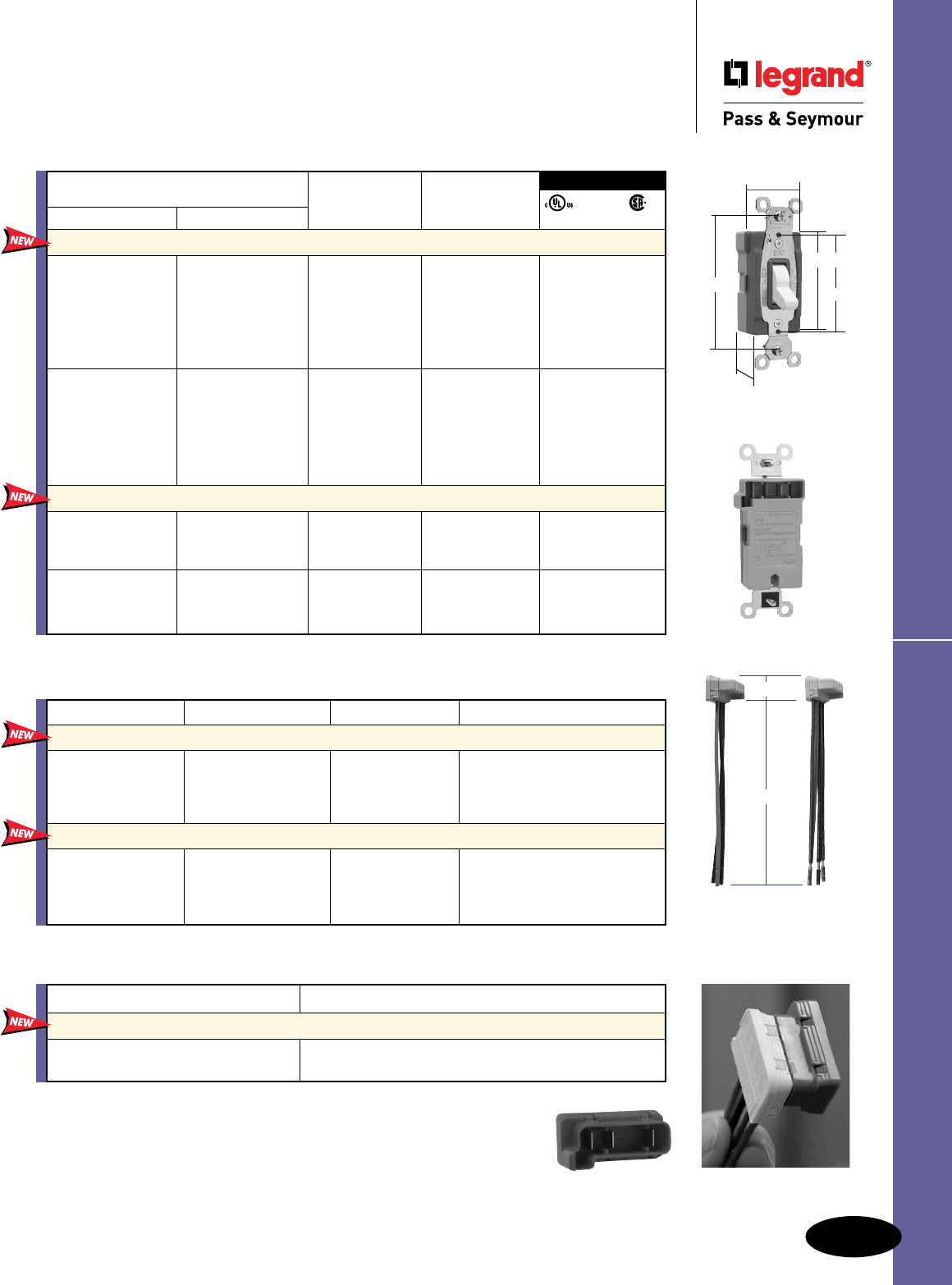
All devices listed on this page conform to NEMA WD-1 and WD-6.
3rd Party Compliance
Catalog Number Rating FSUL
Single Pole Three-Way A. VAC Color cULus WS896 C22.2 111
Toggle Switches
PT15AC1I PT15AC3I 15 120/277 Ivory • • •
PT15AC1W PT15AC3W 15 120/277 White • • •
PT15AC1 PT15AC3 15 120/277 Brown • • •
PT15AC1GRY PT15AC3GRY 15 120/277 Gray • • •
PT15AC1RED PT15AC3RED 15 120/277 Red • • •
PT15AC1LA PT15AC3LA 15 120/277 Light Almond • • •
PT20AC1I PT20AC3I 20 120/277 Ivory • • •
PT20AC1W PT20AC3W 20 120/277 White • • •
PT20AC1 PT20AC3 20 120/277 Brown • • •
PT20AC1GRY PT20AC3GRY 20 120/277 Gray • • •
PT20AC1RED PT20AC3RED 20 120/277 Red • • •
PT20AC1LA PT20AC3LA 20 120/277 Light Almond • • •
Illuminated Toggle Switches
PT15AC1CSL PT15AC3CSL 15 120/277 Clear • • •
PT15AC1ISL PT15AC3ISL 15 120/277 Ivory • • •
PT15AC1WSL PT15AC3WSL 15 120/277 White • • •
PT20AC1CSL PT20AC3CSL 20 120/277 Clear • • •
PT20AC1ISL PT20AC3ISL 20 120/277 Ivory • • •
PT20AC1WSL PT20AC3WSL 20 120/277 White • • •
PlugTail™ Specification Grade Switches
Switches
PlugTail™ Specification Grade Switches
15 & 20A, 120/277VAC
PT20AC1W
Catalog Number Wire Type Wire Length Wire Colors
PlugTail Connectors for Single Pole Switches
120/277VAC
PTS6STR3 3 Wire Stranded 6" Green, Black, Black
PTS6SOL3 3 Wire Solid 6" Green, Black, Black
PTS6STR3277 3 Wire Stranded 6" Green, Brown, Brown
PTS6SOL3277 3 Wire Solid 6" Green, Brown, Brown
PlugTail Connectors for Three-Way Switches 120/277VAC
PTS6STR4 4 Wire Stranded 6" Green, Red, Red, Black
PTS6SOL4 4 Wire Solid 6" Green, Red, Red, Black
PTS6STR4277 4 Wire Stranded 6" Green, Brown, Yellow, Yellow
PTS6SOL4277 4 Wire Solid 6" Green, Brown, Yellow, Yellow
1.320"
3.281"
1.073"
2.195"
2.375"
Available in 347VAC Canadian Catalog Numbers, add 347 to the end of the Catalog Number.
Example: PT15AC1W347. All Canadian Products have Combination Slotted/Robertson Head Brass Screws.
PTS6STR3 PTS6STR4
1.125"
6.375"
PTJ
Catalog Number Description
PlugTail Jumper
PTJ PlugTail Cover for Rough In
PTJ5 PlugTail Cover for Rough In, 5-pack
All PTS connectors are also available with WAGO connectors – add BP to the end of the catalog number.
Example: PTS6STR3BP. See Page A-14.
Industrial EHD Specification Grade Switches
Switches
Industrial Extra Heavy-Duty
Specification Grade Switches
Switches
A-4
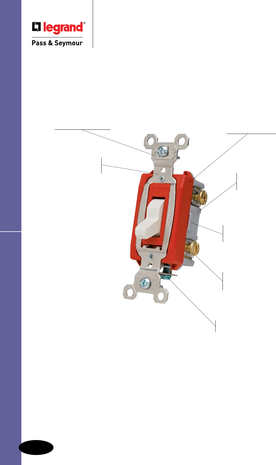
Heavy-duty bumpers
for quiet, smooth operation.
Oversized silver alloy
contacts for long life and
better heat dissipation.
Heavy-duty, brass alloy,
one-piece contact arm virtually
eliminates contact bounce. Grounding terminal is standard
with screw-pressure-plate back wire.
Side and external screw-pressure-
plate back wire with #14 – #10 AWG
copper or copper-clad wire.
Shallow design for
easier installation.
Locking support provides
resistance to face and back
body separation.
Glass-reinforced nylon
back body for superior
durability and strength.
One-piece nickel-
plated steel strap
with integral ground.
Auto-ground clip
assures positive ground.
Cam control and spring actuator
for positive “makes and breaks.”
PS20AC1LA
A-5
Switches Industrial EHD Specification Grade Switches
15 & 20 Amp Lighted
& Pilot Lighted*
15 & 20 Amp*
1.320"
3.281"
2.375"
1.073"
2.196"
Locking*
*30AC series is 1.437" wide
1.320"
3.281"
2.375"
1.073"
2.196"
1.320"
3.281"
2.375"
1.073"
2.196"
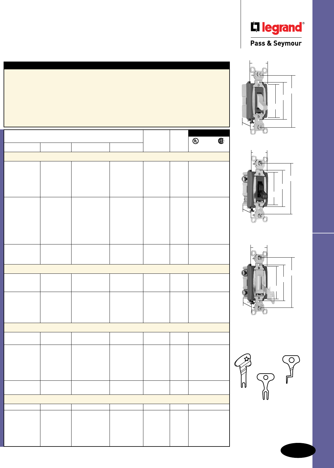
All devices listed on this
page conform to NEMA
WD-1 and WD-6.
Switches
Industrial Extra Heavy-Duty
Specification Grade Switches
15, 20 & 30A, 120, 277 & 120/277VAC
Features
n Heavy-gauge one-piece copper alloy contact
arm virtually eliminates contact bounce.
n Cam controls fast “make” and positive “break”
to minimize arcing.
n Heavy-duty bumper pads for quiet operation.
n High strength thermoplastic polycarbonate toggle.
n Back body made of glass-reinforced nylon.
n Locking support provides resistance to face and back body separation.
n Oversized silver alloy contacts for long life and better heat dissipation.
n Grounding terminal is standard.
n Shallow design for ease of installation.
n Strap nickel-plated steel with integral ground.
n Auto-ground clip assures positive ground.
500K
Fits new
Switches 1498
Fits Switches
manufactured before 1976
1498-NT
Fits Switches
manufactured
1976-present
Lock Switch
Replacement Keys
(One key furnished with each switch)
Catalog Number Rating FSUL
Single Pole Double Pole Three-Way Four-Way A. VAC Color
UL20 WS896 C22.2 111
Toggle Switches Back & Side Wire
PS15AC1I PS15AC2I PS15AC3I PS15AC4I 15 120/277 Ivory
• • •
PS15AC1W PS15AC2W PS15AC3W PS15AC4W 15 120/277 White
• • •
PS15AC1 PS15AC2 PS15AC3 PS15AC4 15 120/277 Brown
• • •
PS15AC1GRY
PS15AC2GRY
PS15AC3GRY PS15AC4GRY 15 120/277 Gray
• • •
PS15AC1LA PS15AC2LA PS15AC3LA PS15AC4LA 15 120/277 Light
• • •
Almond
PS20AC1I PS20AC2I PS20AC3I PS20AC4I 20 120/277 Ivory
• • •
PS20AC1W PS20AC2W PS20AC3W PS20AC4W 20 120/277 White
• • •
PS20AC1 PS20AC2 PS20AC3 PS20AC4 20 120/277 Brown
• • •
PS20AC1GRY PS20AC2GRY PS20AC3GRY PS20AC4GRY 20 120/277 Gray
• • •
PS20AC1BK PS20AC2BK PS20AC3BK PS20AC4BK 20 120/277 Black
• • •
PS20AC1RED PS20AC2RED PS20AC3RED PS20AC4RED 20 120/277 Red
• • •
PS20AC1LA PS20AC2LA PS20AC3LA PS20AC4LA 20 120/277 Light
• • •
Almond
PS30AC1I PS30AC2I PS30AC3I 30 120/277 Ivory
• • •
PS30AC1W PS30AC2W 30 120/277 White
• • •
PS30AC1 PS30AC2 PS30AC3 30 120/277 Brown
• • •
Lighted Toggle Switches (Lighted when OFF) Back & Side Wire
PS15AC1CSL PS15AC3CSL 15 120/277 Clear
• • •
PS15AC1ISL PS15AC3ISL 15 120/277 Ivory
• • •
PS15AC1WSL PS15AC3WSL 15 120/277 White
• • •
PS20AC1CSL PS20AC3CSL 20 120/277 Clear
• • •
PS20AC1ISL PS20AC3ISL 20 120/277 Ivory
• • •
PS20AC1WSL PS20AC3WSL 20 120/277 White
• • •
PS20AC1LASL PS20AC3LASL 20 120/277 Light
• • •
Almond
Pilot Lighted Switches (Lighted when ON) Back & Side Wire
PS15AC1CPL PS15AC3CPL 15 120 Clear
• • •
PS15AC1RPL PS15AC3RPL 15 120 Red
• • •
PS20AC1CPL PS20AC3CPL 20 120 Clear
• • •
PS20AC1CPL7 20 277 Clear
• • •
PS20AC1RPL PS20AC3RPL 20 120 Red
• • •
PS20AC1RPL7 PS20AC3RPL7 20 277 Red
• • •
PS20AC2CPL 20 120/277 Clear
• • •
PS20AC2RPL 20 120/277 Red
• • •
PS30AC1RPL PS30AC3RPL 30 120 Red
• • •
PS30AC2RPL 30 120/277 Red
• • •
Lock Switches (Key can be removed in both positions) Back & Side Wire
PS15AC1L PS15AC3L 15 120/277 Gray
• • •
PS20AC1IL PS20AC2IL PS20AC3IL PS20AC4IL 20 120/277 Ivory
• • •
PS20AC1WL PS20AC2WL PS20AC3WL PS20AC4WL 20 120/277 White
• • •
PS20AC1L PS20AC2L PS20AC3L 20 120/277 Gray
• • •
PS20AC1REDL
PS20AC3REDL
PS20AC4REDL
20 120/277 Red
• • •
PS20AC1LAL PS20AC2LAL PS20AC3LAL PS20AC4LAL 20 120/277 Light
• • •
Almond
3rd Party Compliance
For Bulk Packaging Solutions consult factory.
All devices listed on this page conform to NEMA WD-1 and WD-6.
Switches
Extra Heavy-Duty
Specification Grade & Security Switches
15 & 20A, 347VAC; 20A, 120/277VAC
Stainless Steel Plate for PS20ACKL Switches Single Gang – SS717, Double Gang – SS727.
For custom combinations specify opening Style No. 302.
Catalog Number 4609 Security Switch Replacement Keys for PS20ACKL Switches (2 keys furnished with
each switch).
Features
n External screw-pressure-plate back and side wired.
Accepts #14 – #10 AWG copper or copper-clad
conductors.
n Heavy-gauge one-piece copper alloy contact arm
virtually eliminates contact bounce.
n Cam controls fast “make” and positive “break”
to minimize arcing.
n Heavy-duty bumper pads for quiet operation.
n High strength thermoplastic polycarbonate toggle.
n Back body made of glass-reinforced nylon.
n Locking support provides resistance to face
and back body separation.
n Oversized silver alloy contacts for long life
and better heat dissipation.
n Grounding terminal is standard.
n Shallow design for ease of installation.
n Strap nickel-plated steel with integral ground.
n Auto-ground clip assures positive ground.
Features
n Back and side wired. Accepts #14 – #10 AWG.
n Operated by cam lock for maximum security in
critical areas.
n Recommended for tamper-proof installation in schools,
public housing, trailer parks, freight yards, etc.
n Uses same key as Cat.# 4600 cast
enclosure.
n Key can be removed in both positions.
Security Switch
1.475"
4.071"
2.261"
.610"
15 & 20 Amp
Canadian 347VAC
1.320"
3.531"
2.375"
1.073"
2.196"
3rd Party
Compliance
Catalog Number Rating
Single Pole Three-Way A. VAC Color
C22.2 111
347VAC Toggle Switches Back & Side Wire
PS371510I PS371530I 15 347 Ivory •
PS371510W PS371530W 15 347 White •
PS371510 PS371530 15 347 Brown •
PS371510GRY PS371530GRY 15 347 Gray •
PS371510BK PS371530BK 15 347 Black •
PS371510RED PS371530RED 15 347 Red •
PS372010I PS372030I 20 347 Ivory •
PS372010W PS372030W 20 347 White •
PS372010 PS372030 20 347 Brown •
PS372010GRY PS372030GRY 20 347 Gray •
PS372010BK PS372030BK 20 347 Black •
PS372010RED PS372030RED 20 347 Red •
PS372010LA PS372030LA 20 347 Light Almond •
PS372010L PS372030L 20 347 Gray, Locking •
Denotes Canadian catalog number. All Canadian products have Combination Slotted/Robertson Head
Brass Screws.
3rd Party Compliance
FSUL
Catalog Number Rating
Single Pole Double Pole Three-Way Four-Way A. VAC UL20 WS896 C22.2 55
Security Switches Back & Side Wire
PS20AC1KL
PS20AC2KL
PS20AC3KL
PS20AC4KL 20 120/277 • • •
PS372010KL 20 347
• •
Denotes Canadian catalog number. All Canadian products have Combination Slotted/Robertson Head
Brass Screws.
EHD Specification Grade & Security Switches
Switches
A-6
A-7
Switches
All devices listed on this page conform to NEMA WD-1 and WD-6.
Hard Use & Commercial Spec Grade Switches
Switches
Hard Use & Commercial
Specification Grade Switches
15 & 20A, 120/277VAC
Features
n One-piece brass alloy contact arm for reliable
electrical performance.
n One-piece steel strap with integral ground is
plated for corrosion resistance.
n High strength thermoplastic polycarbonate toggle
resists breaking and chipping under heavy abuse.
n Heavy-duty toggle bumpers for smooth and
quiet operation.
n Back body made of glass-reinforced nylon.
n Locking support provides resistance to face
and back body separation.
n Available with side wire or external screw-
pressure-plate back and side wire models
capable of accepting #14 – #10 AWG copper
or copper-clad wire.
n Cam designed for fast make with positive
break action to minimize arcing and prolong
switch life.
n Oversized silver alloy contacts for longer
dependable switch life.
n Tri-drive terminal and mounting screws.
15 & 20 Amp
1.320"
3.281"
2.375"
1.073"
2.196"
3rd Party Compliance
Catalog Number Rating FSUL
Single Pole Three-Way A. VAC Color UL20 WS896 C22.2 111
Commercial Specification Grade Side Wire
CS15AC1I CS15AC3I
15 120/277 Ivory • • •
CS15AC1W CS15AC3W
15 120/277 White • • •
CS15AC1 CS15AC3
15 120/277 Brown • • •
CS15AC1GRY CS15AC3GRY
15 120/277 Gray • • •
CS15AC1BK CS15AC3BK
15 120/277 Black • • •
CS15AC1LA CS15AC3LA
15 120/277 Light • • •
Almond
CS20AC1I CS20AC3I
20 120/277 Ivory • • •
CS20AC1W CS20AC3W
20 120/277 White • • •
CS20AC1 CS20AC3
20 120/277 Brown • • •
CS20AC1GRY CS20AC3GRY
20 120/277 Gray • • •
CS20AC1LA CS20AC3LA
20 120/277 Light • • •
Almond
3rd Party Compliance
Catalog Number Rating FSUL
Single Pole Double Pole Three-Way Four-Way A. VAC Color UL20 WS896 C22.2 111
Hard Use Specification Grade Back & Side Wire
CSB15AC1I CSB15AC2I CSB15AC3I CSB15AC4I 15 120/277 Ivory • • •
CSB15AC1W CSB15AC2W CSB15AC3W CSB15AC4W 15 120/277 White • • •
CSB15AC1 CSB15AC2 CSB15AC3 CSB15AC4 15 120/277 Brown • • •
CSB15AC1GRY CSB15AC2GRY CSB15AC3GRY CSB15AC4GRY 15 120/277 Gray • • •
CSB15AC1LA CSB15AC2LA CSB15AC3LA CSB15AC4LA 15 120/277 Light • • •
Almond
CSB20AC1I CSB20AC2I CSB20AC3I CSB20AC4I 20 120/277 Ivory • • •
CSB20AC1W CSB20AC2W CSB20AC3W CSB20AC4W 20 120/277 White • • •
CSB20AC1 CSB20AC2 CSB20AC3 CSB20AC4 20 120/277 Brown • • •
CSB20AC1BK CSB20AC3BK 20 120/277 Black • • •
CSB20AC1GRY CSB20AC2GRY CSB20AC3GRY CSB20AC4GRY 20 120/277 Gray • • •
CSB20AC1LA CSB20AC2LA CSB20AC3LA CSB20AC4LA 20 120/277 Light • • •
Almond
For Bulk Packaging Solutions consult factory.
Switches
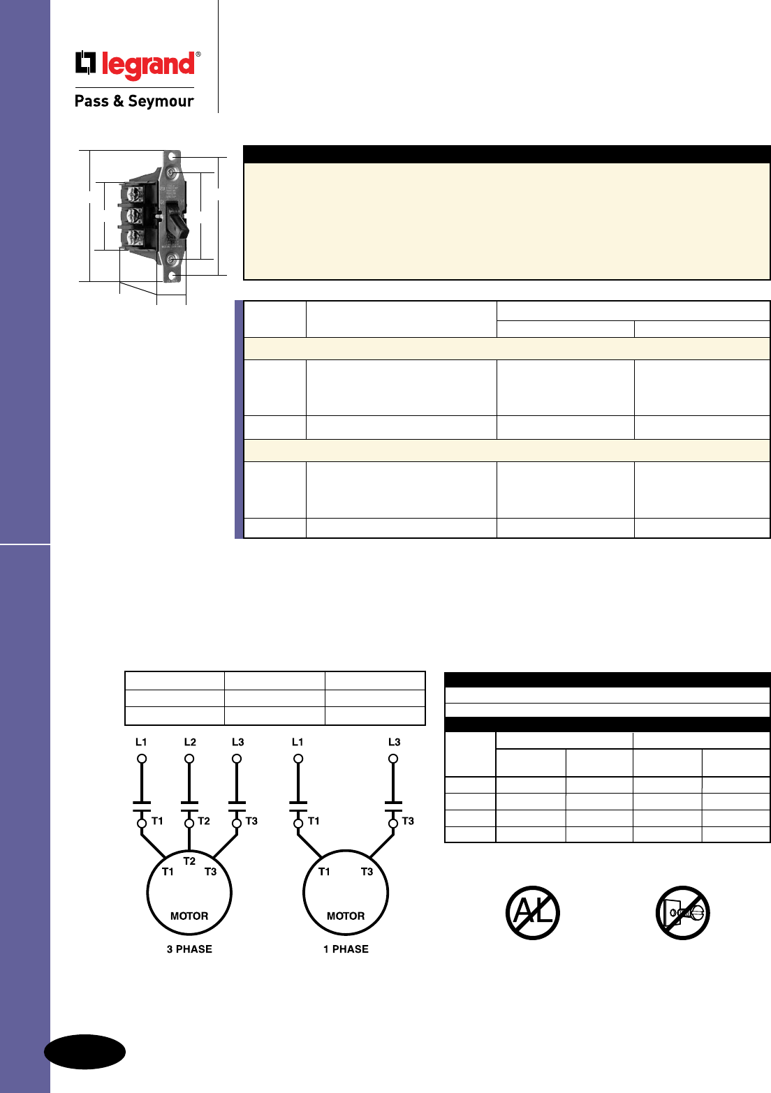
Manual Controllers
NEMA Type 1 Enclosures – Intended for indoor use primarily
to provide a degree of protection against limited amounts of falling dirt
in locations where unusual service conditions do not exist.
NEMA Type 7 Enclosures – Intended for indoor use in locations
classified as Class 1, Group A, B, C, or D, as defined in the National
Electrical Code. They shall be capable of withstanding the pressures
resulting from an internal explosion of specified gases, and contain
such an explosion sufficient that an explosive gas-air mixture existing in
the atmosphere surrounding the enclosure will not be ignited. Enclosed
heat generating devices shall not cause external surfaces to reach
temperatures capable of igniting explosive gas-air mixtures in the
surrounding atmosphere. Enclosures shall meet explosion, hydrostatic,
and temperature design tests.
NEMA Type 3R Enclosures – Intended for outdoor use primarily
to provide a degree of protection against rain and sleet; and to be
undamaged by the formation of ice on the enclosure. They are not
intended to provide protection against conditions such as internal
condensation, or internal icing.
NEMA Type 9 Enclosures – Intended for indoor use in locations
classified as Class II, Groups E, F, or G, as defined in the National
Electrical Code. They shall be capable of preventing the entrance of
dust. Enclosed heat generating devices shall not cause external surfaces
to reach temperatures capable of igniting or discoloring dust on the
enclosure or igniting dust-air mixtures in the surrounding atmosphere.
Enclosures shall meet dust penetration and temperature design tests,
and aging of gaskets (if used).
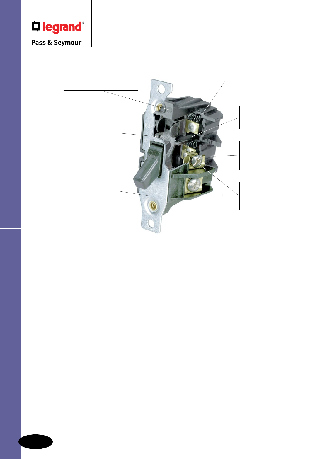
NEMA Type Enclosures
Two-point contact arm design
reduces overall unit size; provides
more enclosure space.
One-piece contact carrier
constructed of glass-reinforced
thermoplastic ensures long-lasting
“make and break” performance.
Two oversized silver alloy
contacts withstand years of
use; improve heat dissipation
by distributing arc energy.
Exclusive, ready-to-wire
external screw-pressure-
plate back and side wire
capability for easy installation
with solid or stranded wire.
Oversized #10 terminal
screws increase contact
with wire and increase torque
limit. Angled screw heads
for easier access.
Thermoplastic housing resists
tracking; withstands impacts.
Heavy-duty, zinc-plated strap
resists corrosion; two rolled-brass
rivets secure the strap to the
housing to avoid field tampering.
7803
SwitchesManual Controllers
A-8
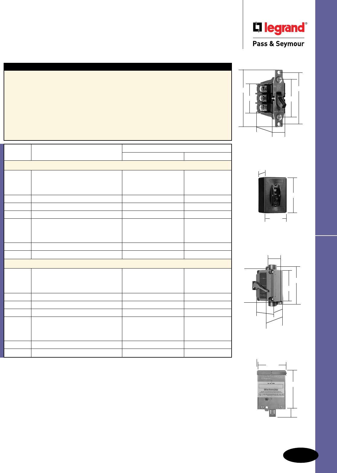
A-9
Switches Manual Controllers
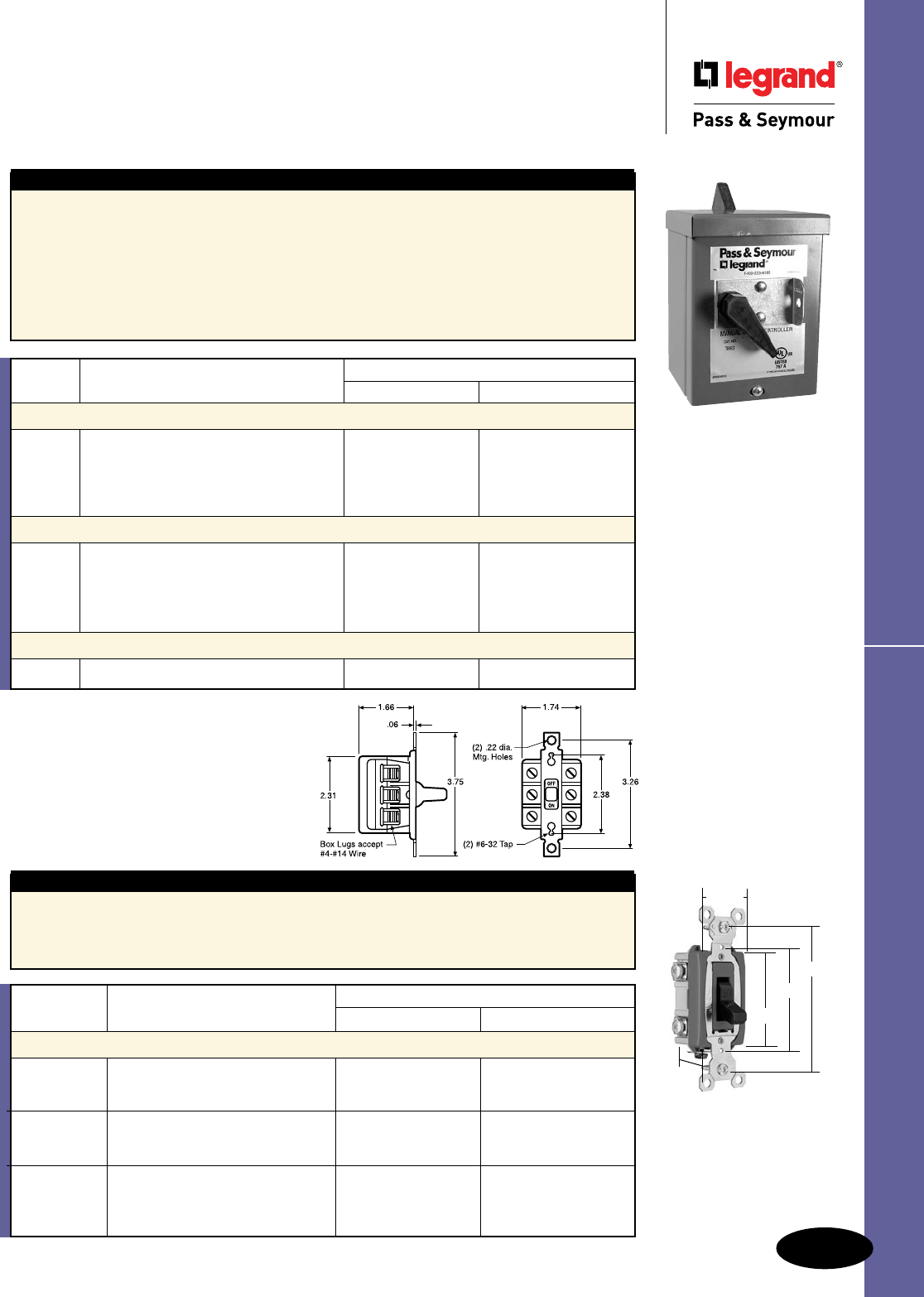
Switches
Manual Controllers
30A, 1ø & 3ø
7802
7803
2.375"
2.155"
3.280"
1.825"
3.67"
1.753"
7812EX
7813EX
2.250"
5.250"
5.875"
4.625"
4.250"
3.375"
3.000"
7806P NEMA 1 Black Nylon Enclosure with 1/2" and 3/4" knockouts at each end.
7801P Handle Locking Guard has opening for padlock to secure control in either ON or OFF position.
7830 NEMA 3R Aluminum Enclosure.
All Industrial Control Equipment is suitable for use in a circuit capable of deliverable not more than 5,000 rms
amperes at 600VAC maximum or equivalent.
Footnote:
1. Suitable as Motor Disconnect – 10KA @ 600VAC, 30A max. Class J Fuse.
7812P
7813P
3.910"
2.825"
2.80"
UL Listed. CSA Certied. All devices listed on this page conform to NEMA WD-1 and WD-6.
7832
7833
5.75"
1.80"
4.50"
3.25"
Features — 7802 & 7803
n High horsepower rating of 20HP.
n Compact design.
n Gull-wing shaped brass terminal pressure clamps.
n Constructed of glass-reinforced thermoplastic.
n Two-point contact arms.
n One-piece contact carrier.
n UL508 and cULus Listing of individual device and
assembled device within enclosure.
n Heavy-duty zinc-plated steel strap.
n Two brass rivets secure strap to housing.
n External screw-pressure-plate back and side
wire terminal screws unstaked for use with
ring terminals.
n Oversized silver alloy contacts.
n 2-3/4" hubs (7812EX and 7813EX).
n 2-1/2" knockouts on back and 2-1/2"–3/4"
knockouts on top and bottom (7812P,
7813P, 7806P).
n 2-1/2" knockouts on bottom and back
(7832 and 7833).
Catalog Rating
Number Description A. VAC HP VAC
Double Pole, Single Phase
7802 Double Pole, Single Phase AC General Use 2 120
Manual Motor Controller 30 600 max. 3 240
(No overload protection) 7.5 480
10 600
7802MD 7802, See Footnote 1 Same as 7802
7812P 7802 in a NEMA 1 Enclosure Same as 7802
7812PMD 7812P, See Footnote 1 Same as 7802
7812EX 7802 in a NEMA 7 and 9 Same as 7802
Enclosure for Hazardous Locations
Class I – Groups C, D;
Class II – Groups E, F, G
7832 7802 in a NEMA 3R Enclosure Same as 7802
7832MD 7832, See Footnote 1 Same as 7802
Three Pole, Three Phase
7803 Three Pole, Three Phase AC General Use 3 120
Manual Motor Controller 30 600 max. 7.5 240
(No overload protection) 10 480
20 600
7803MD 7803, See Footnote 1 Same as 7803
7813P 7803 in a NEMA 1 Enclosure Same as 7803
7813PMD 7813-P, See Footnote 1 Same as 7803
7813EX 7803 in a NEMA 7 & 9 Same as 7803
Enclosure for Hazardous Locations
Class I – Groups C, D;
Class II – Groups E, F, G
7833 7803 in a NEMA 3R Enclosure Same as 7803
7833MD 7833, See Footnote 1 Same as 7803
UL Listed. CSA Certied. All devices listed on this page conform to NEMA WD-1 and WD-6.
Switches
Manual Controllers
40A, 1ø & 3ø
7842
7843
2.375"
2.155"
3.280"
1.825"
3.67"
1.753"
CATALOG NO. PHASE POLE
7802 or 7842 1 2
7803 or 7843 3 3
USE 60 / 75°C WIRING
TORQUE TERMINAL SCREWS
TO 16 IN. LBS.
NO ALUMINUM DO NOT
REMOVE SCREWS
FROM 30A DEVICES
RATINGS
Features — 7842 & 7843
n High horsepower rating of 20HP.
n Compact design.
n Gull-wing shaped brass terminal pressure clamps.
n Constructed of glass-reinforced thermoplastic.
n Two-point contact arms.
n One-piece contact carrier.
n Heavy-duty yellow chromate plated steel strap.
n Two brass rivets secure strap to housing.
n External screw-pressure-plate back and side
wire terminal screws unstaked for use with
ring terminals.
n Oversized silver alloy contacts.
n UL508 and cULus Listing of individual device
and assembled device within enclosure.
Catalog Rating
Number Description A. VAC HP VAC
Double Pole, Single Phase
7842 Double Pole, Single Phase AC 40 600 max. 2 120
Manual Motor Controller 5 240
(No overload protection) 10 480
15 600
7842MD 7842, See Footnote 2 same as 7842
Three Pole, Three Phase
7843 Three Pole, Three Phase AC 40 600 max. 3 120
Manual Motor Controller 7.5 240
(No overload protection) 15 480
20 600
7843MD 7843, See Footnote 2 same as 7843
All Industrial Control Equipment is suitable for use in a circuit capable of deliverable not more than 5,000 rms
amperes at 600VAC maximum or equivalent.
Footnote:
2. Suitable as Motor Disconnect – 10KA @ 600VAC, 60A max. Class J Fuse or
100A max. Ferraz Shawmut HSJ Fuse.
RESISTANCE
7802 / 7803 30 AMP 600 VAC MAX.
7842 / 7843 40 AMP 600 VAC MAX.
MANUAL MOTOR CONTROLLER
30A 40A
VAC 1 PHASE 3 PHASE 1 PHASE 3 PHASE
HP HP HP HP
120 2 3 2 3
240 3 7.5 5 7.5
480 7.5 10 10 15
600 10 20 15 20
A-10
Manual Controllers Switches
A-11
Switches Manual Controllers
Switches
Manual Controllers
60A NEMA 3R Manual Controller
20 & 30A 1ø
Features
n High horsepower rating, up to 3 HP for heavy
duty applications.
n Compact design provides ease of installation.
n Box lug terminals.
n Single piece moveable and stationary contact arms
with oversized silver cadmium buttons provides
excellent continuity and long life.
n Made in USA.
n Wire pockets and thick wall arc barriers.
n Cold-rolled steel NEMA 3R enclosure with
polyester urethane nish conforms to OSHA
lockout requirements.
n Type 3R enclosure has 2-1/2”, 3/4” and 1”
concentric knockouts on bottom.
n Accepts #4 AWG.
n cULus listed.
7863R
Catalog Rating
Number Description A. VAC HP VAC
Double Pole Manual Motor Controller
7862R Double Pole AC Manual Motor Controller 60 600 max. 3 120
in a NEMA 3R Enclosure 5 240
15 480
15 600
7862 Double Pole AC Manual Motor Controller 60 600 max. Same as 7862R
Three Pole Manual Motor Controller
7863R Three Pole AC Manual Motor Controller 60 600 max. 5 120
in a NEMA 3R Enclosure 10 240
20 480
30 600
7863 Three Pole AC Manual Motor Controller 60 600 max. Same as 7863R
NEMA 3R Enclosure
7860 NEMA 3R Enclosure for 7862 & 7863
Catalog Rating
Number Description A. VAC HP VAC
Double Pole, Single Phase
PS20AC2HP Double Pole, Single Phase AC 20 120/277 1 120
Manual Motor Starting Switch 2 240
(No overload protection)
PS30AC2HP Double Pole, Single Phase AC 30 120/277 1 120
Manual Motor Starting Switch 2 240
(No overload protection)
HP30EX PS30AC2HP in a NEMA 7 & 9 Same as
Enclosure for Hazardous Locations PS30AC2HP
Class I – Groups C, D;
Class II – Groups E, F, G
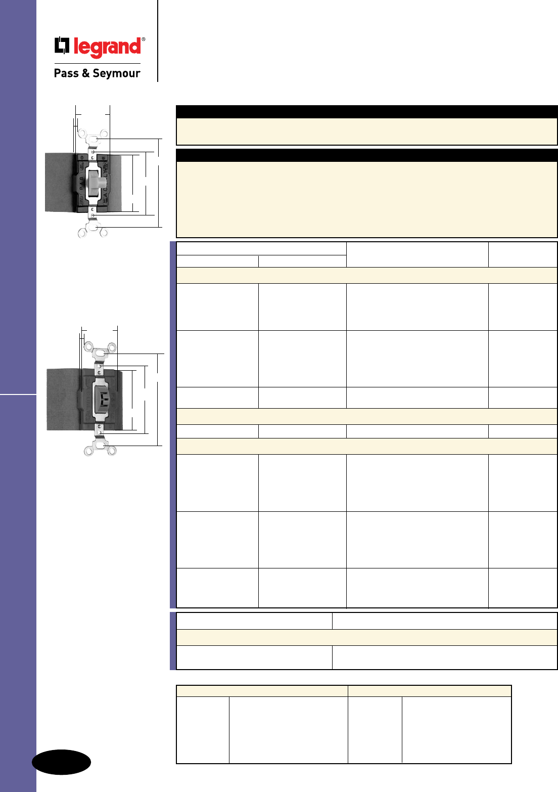
PS20AC2HP
PS30AC2HP
Features
n Oversize silver contacts for long life and better
heat dissipation.
n Single phase switches are side wired with
#14 – #10 AWG copper or copper-clad conductors.
n Shallow design for ease of installation.
n 2-3/4” hubs (HP30EX).
1.320”
3.281”
2.375”
1.073”
2.196”
All devices listed on this
page conform to NEMA
WD-1 and WD-6.
Switches
Switches
Manual Controllers
15, 20 & 30A, 120/277VAC – Maintained Contact
15, 20 & 30A, 120/277VAC – Momentary Contact
Manual Controllers Switches
Catalog Number Rating
S.P.D.T. D.P.D.T. A. VAC Color
Maintained Contact Three Position – Two Circuit, Center Off
1221I 1222I 15 120/277 Ivory
1221W 1222W 15 120/277 White
1221 1222 15 120/277 Brown
1221LA 15 120/277 Light Almond
1221L 1222L 15 120/277 Locking
1225I 1226I 20 120/277 Ivory
1225W 1226W 20 120/277 White
1225 1226 20 120/277 Brown
1225GRY 20 120/277 Gray
1225LA 20 120/277 Light Almond
1225L 1226L 20 120/277 Locking
1227I 1228I 30 120/277 Ivory
1227 1228 30 120/277 Brown
Maintained Contact Either Direction Two Position, No Center Off
1275 1276 30 120/277 Brown
Momentary Contact Either Direction Three Position, Center Off
1250I 15 120/277 Ivory
1250W 15 120/277 White
1250 15 120/277 Brown
1250GRY 15 120/277 Gray
1250RED 15 120/277 Red
1250L 15 120/277 Locking
1251I 20 120/277 Ivory
1251W 20 120/277 White
1251 20 120/277 Brown
1251GRY 20 120/277 Gray
1251LA 20 120/277 Light Almond
1251L 20 120/277 Locking
1256I 30 120/277 Ivory
1256W 30 120/277 White
1255 1256 30 120/277 Brown
1255L 1256L 30 120/277 Locking
Applications
For ON-OFF control of motors on small machine tools, pumps, fans and air conditioning equipment that
require heavy-duty AC Double Throw Center OFF controls.
HP Conversion Table
1221 Series
15 Amp 1/2 Horsepower at 120VAC
2 Horsepower at 240VAC
20 Amp 1 Horsepower at 120VAC
2 Horsepower at 240VAC
30 Amp 2 Horsepower at 120VAC
2 Horsepower at 240VAC
1250 Series
15 Amp 1/2 Horsepower at 120VAC
2 Horsepower at 240VAC
20 Amp 1 Horsepower at 120VAC
2 Horsepower at 240VAC
30 Amp 2 Horsepower at 120VAC
2 Horsepower at 240VAC
Catalog Number Description
Lock Switch Replacement Keys
1498 Fits switches manufactured before 1976.
1498NT Fits switches manufactured between 1976-present.
UL Listed.
CSA Certied.
All devices listed on this
page conform to NEMA
WD-1 and WD-6.
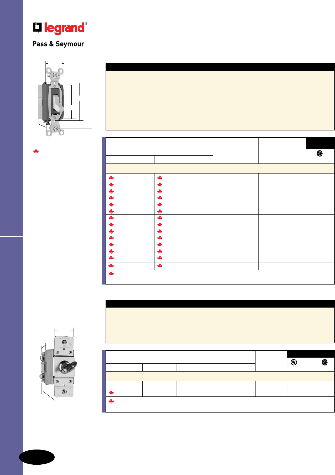
Maintained and
Momentary Contact
1.469"
Fiber
Insulator
1.500"
2.375”
3.281"
2.187"
Locking
1.469"
Fiber
Insulator
1.500"
2.375"
3.281"
2.187"
Features
n Oversized silver alloy contacts for long life and
better heat dissipation.
n Side wired terminals accept #14 – #10 AWG
copper or copper-clad conductors.
n Fiber terminal insulation barriers standard.
n Can be mounted in standard device boxes or in
NEMA 1 sheet steel enclosures.
n Bodies, covers and toggles molded of
durable nylon.
n Single Pole-Double Throw and Double
Pole-Double Throw.
n Locking Switches supplied with one
1498 NT key.
n Normally open.
A-12
A-13
PlugTail™ Spec Grade Decorator SwitchesSwitches
Switches
PlugTail™ Specification Grade
Decorator Switches
PT2626W
Large brass contacts snugly terminate on
device blade terminals. Audible snapping
latch assures connection, allows release.
WAGO push-in connectors
are available to further speed
up installation.
Polycarbonate connector
housing secures terminations
and conductors in a UL Listed,
finger-safe housing.
Built-in connector
features large brass
terminal blades to
ensure consistent,
reliable electrical
connections.
Shallow design
for easier installation.
Auto-ground clip
assures positive ground.
Heavy-gauge
steel strap for
superior strength.
No exposed terminals create
a finger-safe application before,
during, and after installation.
A-14
Switches
All devices listed on this page conform to NEMA WD-1 and WD-6.
PlugTail™ Spec Grade Decorator Switches
Switches
PlugTail™ Specification Grade
Decorator Switches
15 & 20A, 120/277VAC
PT2626W
Catalog Number Wire Type Wire Length Wire Colors
PlugTail Connectors for Single Pole Switches
PTS6STR3 3 Wire Stranded 6" Green, Black, Black
PTS6SOL3 3 Wire Solid 6" Green, Black, Black
PTS6STR3277 3 Wire Stranded 6" Green, Brown, Brown
PTS6SOL3277 3 Wire Solid 6" Green, Brown, Brown
PlugTail Connectors for Three-Way Switches
PTS6STR4 4 Wire Stranded 6" Green, Red, Red, Black
PTS6SOL4 4 Wire Solid 6" Green, Red, Red, Black
PTS6STR4277 4 Wire Stranded 6" Green, Brown, Yellow, Yellow
PTS6SOL4277 4 Wire Solid 6" Green, Brown, Yellow, Yellow
PlugTail Connectors for Single Pole Switches With WAGO Connectors
PTS6STR3BP 3 Wire Stranded 6" Green, Black, Black
PTS6SOL3BP 3 Wire Solid 6" Green, Black, Black
PTS6STR3277BP 3 Wire Stranded 6" Green, Brown, Brown
PTS6SOL3277BP 3 Wire Solid 6" Green, Brown, Brown
PlugTail Connectors for Three-Way Switches With WAGO Connectors
PTS6STR4BP 4 Wire Stranded 6" Green, Red, Red, Black
PTS6SOL4BP 4 Wire Solid 6" Green, Red, Red, Black
PTS6STR4277BP 4 Wire Stranded 6" Green, Brown, Yellow, Yellow
PTS6SOL4277BP 4 Wire Solid 6" Green, Brown, Yellow, Yellow
1.6"
3.281"
1.2"
2.6"
PTS6STR3 PTS6STR4
1.125"
6.375"
PTJ
3rd Party Compliance
Catalog Number Rating FSUL
Single Pole Three-Way A. VAC Color UL20 WS896 C22.2 111
Decorator Switches
PT2601I PT2603I 15 120/277 Ivory • • •
PT2601W PT2603W 15 120/277 White • • •
PT2601 PT2603 15 120/277 Brown • • •
PT2601GRY PT2603GRY 15 120/277 Gray • • •
PT2601RED PT2603RED 15 120/277 Red • • •
PT2601BK PT2603BK 15 120/277 Black • • •
PT2601LA PT2603LA 15 120/277 Light Almond • • •
PT2621I PT2623I 20 120/277 Ivory • • •
PT2621W PT2623W 20 120/277 White • • •
PT2621 PT2623 20 120/277 Brown • • •
PT2621GRY PT2623GRY 20 120/277 Gray • • •
PT2621RED PT2623RED 20 120/277 Red • • •
PT2621BK PT2623BK 20 120/277 Black • • •
PT2621LA PT2623LA 20 120/277 Light Almond • • •
Illuminated Decorator Switches
PT2625I PT2626I 20 120/277 Ivory • • •
PT2625W PT2626W 20 120/277 White • • •
PT2625BK PT2626BK 20 120/277 Black • • •
PT2625LA PT2626LA 20 120/277 Light Almond • • •
Catalog Number Description
PlugTail Jumper
PTJ PlugTail Cover for Rough In
PTJ5 PlugTail Cover for Rough In, 5-pack
Available in 347VAC Canadian Catalog Numbers, add 347 to the end of the Catalog Number.
Example: PT2601W347. All Canadian Products have Combination Slotted/Robertson Head Brass Screws.
PTS6STR3BP PTS6STR4BP
1.125"
6.375"
All PTS Connectors are 120/277VAC
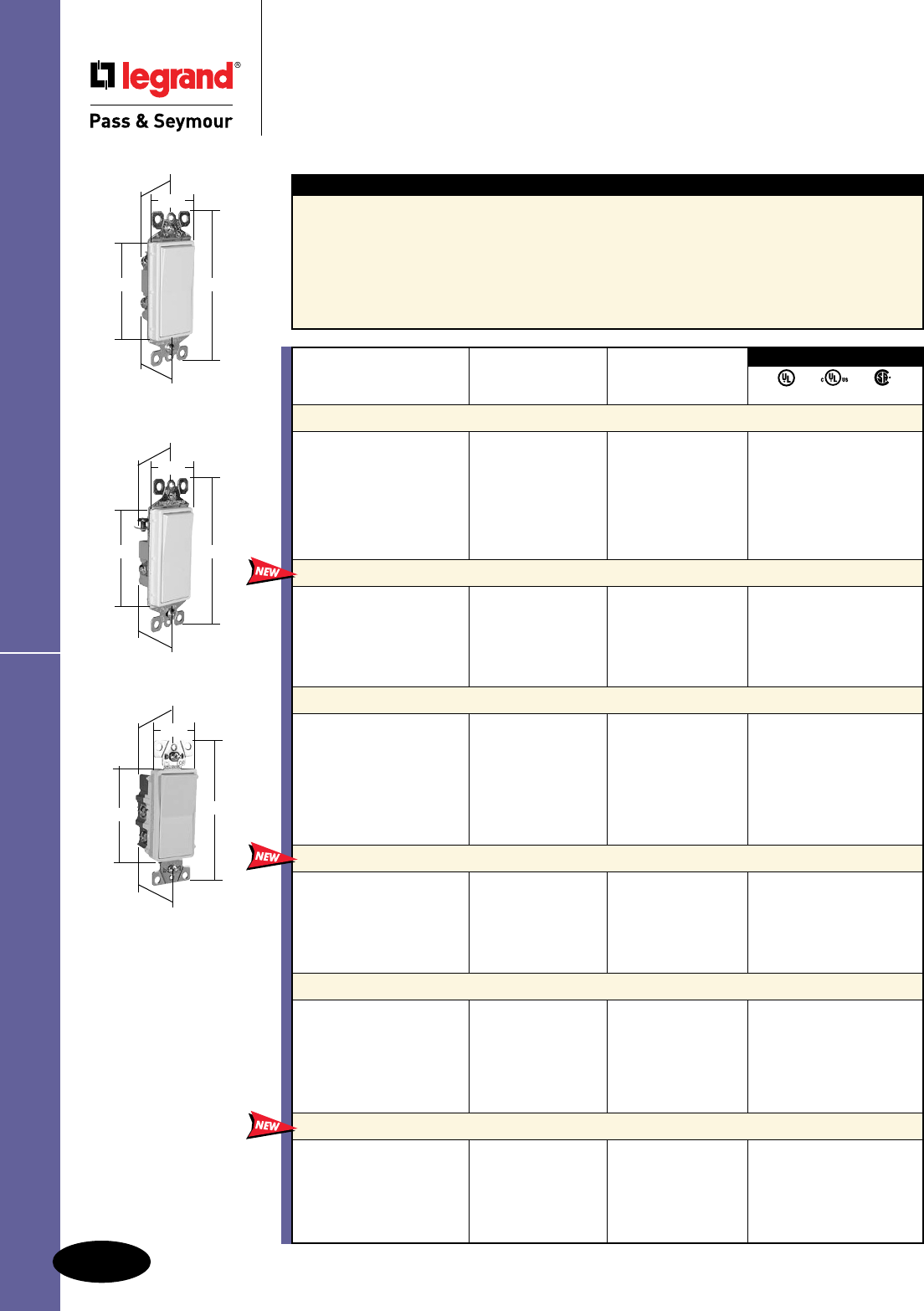
A-15
Switches
3rd Party Compliance
Rating
Catalog Number A. VAC Color
Single Pole Toggle Switches Grounding
660IG* 15 120 Ivory • •
660WG* 15 120 White • •
660G* 15 120 Brown • •
660BKG 15 120 Black • •
660LAG* 15 120 Light Almond • •
Single Pole Toggle Switches Grounding (Without Ears)
660IGMH 15 120 Ivory • •
660WGMH 15 120 White • •
660GMH 15 120 Brown • •
NAFTA-Compliant Single Pole Toggle Switches
Grounding
660NAIG 15 120 Ivory •
660NAWG 15 120 White •
660NAG 15 120 Brown •
660NABKG 15 120 Black •
660NALAG 15 120 Light Almond •
Three-Way Toggle Switches Grounding
663IG** 15 120 Ivory • •
663WG** 15 120 White • •
663G** 15 120 Brown • •
663BKG 15 120 Black • •
663LAG** 15 120 Light Almond • •
NAFTA-Compliant Three-Way Toggle Switches
Grounding
663IG 15 120 Ivory •
663WG 15 120 White •
663G 15 120 Brown •
663BKG 15 120 Black •
663LAG 15 120 Light Almond •
Four-Way Toggle Switches Grounding
664IG 15 120 Ivory • •
664WG 15 120 White • •
664G 15 120 Brown • •
664BKG 15 120 Black • •
664LAG 15 120 Light Almond • •
664ICN 15 120 Ivory • •
664WCN 15 120 White • •
Denotes Canadian catalog number. All Canadian products have Combination Slotted/Robertson
Head Brass Screws.
NAFTA-Compliant Four-Way Toggle Switches
Grounding
664IG 15 120 Ivory •
664WG 15 120 White •
664G 15 120 Brown •
664BKG 15 120 Black •
664LAG 15 120 Light Almond •
UL20 C22.2 111
All devices listed on this
page conform to NEMA
WD-1 and WD-6.
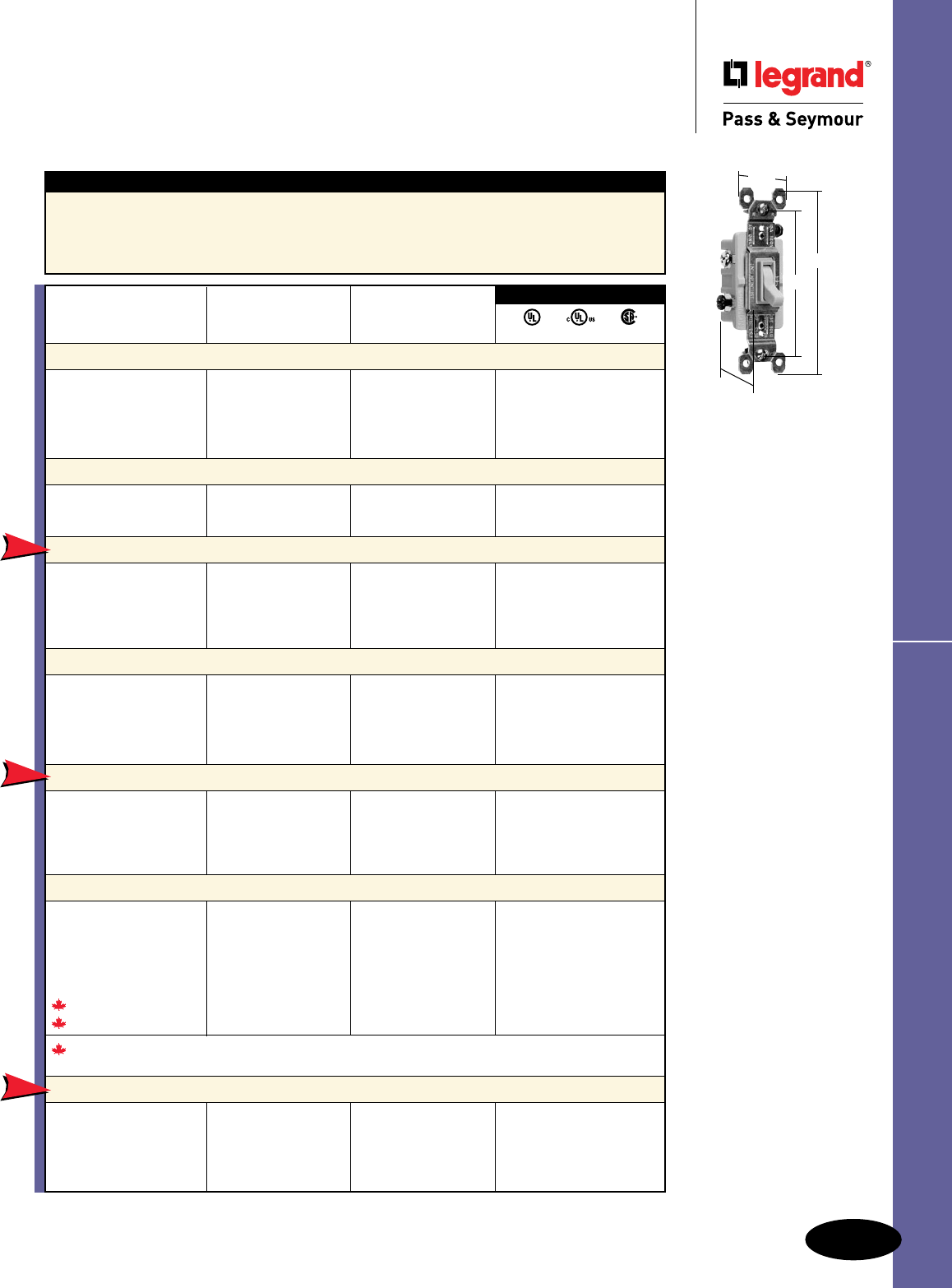
TradeMaster® Grounding Toggle Switches
Switches
TradeMaster® Grounding Toggle
Switches
15A, 120VAC
663IG
1.090"
3.281"
4.195"
1.25"
Features
n Thermoplastic toggle and frame.
n Extra-long strap.
n High-impact resistant construction.
n Side wire #12 and #14 AWG; push wire #14 AWG.
n Tri-drive ground, terminal and mounting
screws.
n Easy-access green hex head ground screw.
n Smooth, quiet toggle action.
*Available in bulk packs of 120. Add “U” to end of Catalog Number. Example: 660WGU.
**Available in bulk packs of 90. Add “U” to end of Catalog Number. Example: 663WGU.
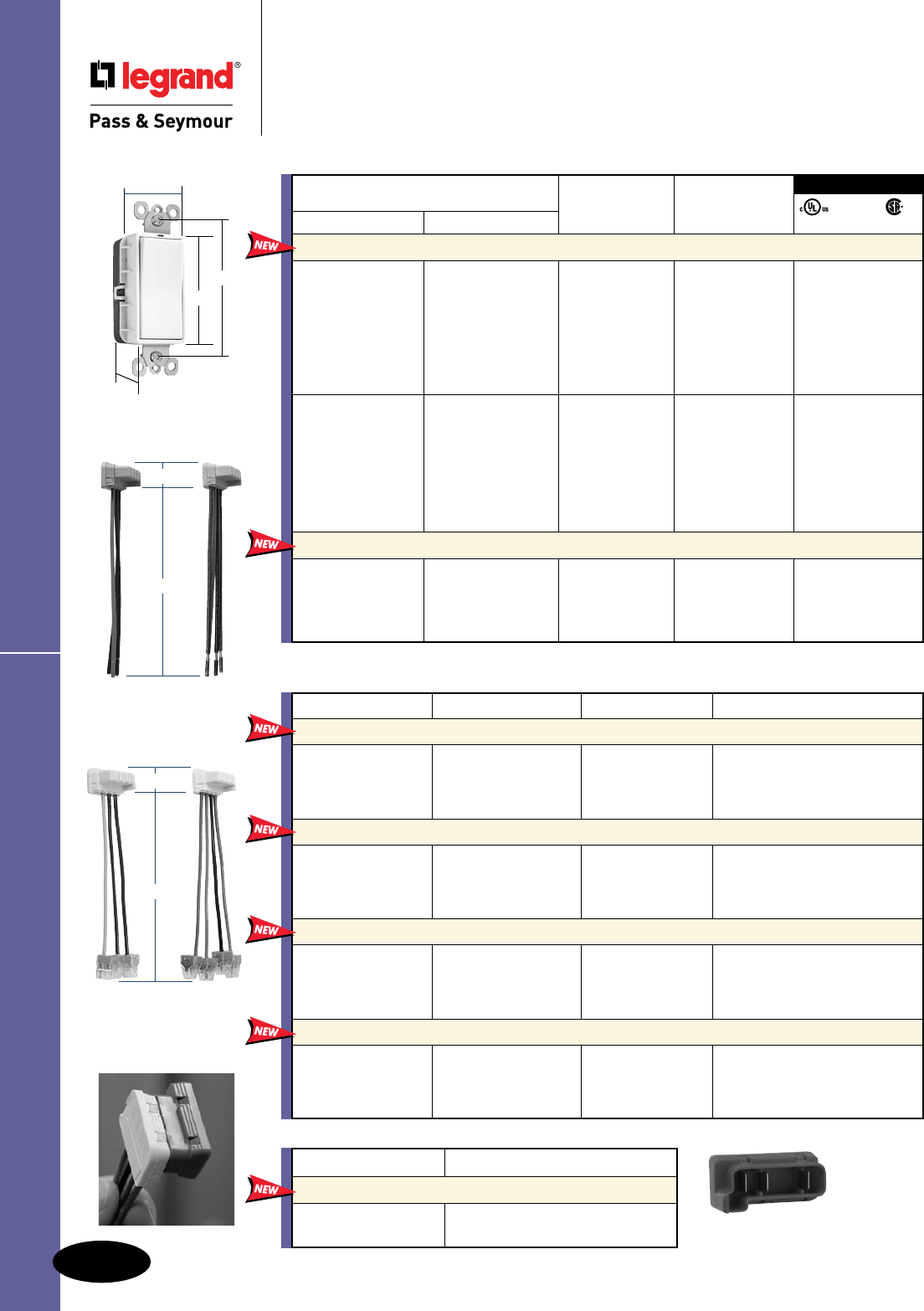
NEW
NEW
NEW
NAFTA-Compliant
Switches are ideal for
use on projects subject
to the provisions of the
Buy American Act.
TradeMaster® Grounding Toggle Switches
A-16
Switches
All devices listed on this page conform to NEMA WD-1 and WD-6.
Switches
TradeMaster® Grounding Illuminated &
Self-Grounding Toggle Switches
15A, 120VAC
Features
n Thermoplastic toggle and frame.
n Extra-long strap.
n High-impact resistant construction.
n Side wire #12 and #14 AWG.
n Push wire #14 AWG.
n Tri-drive ground, terminal and mounting
screws.
n Easy-access green hex head ground screw.
n Smooth, quiet toggle action.
n Self-grounding models provide automatic
ground clip.
3rd Party Compliance
UL20 C22.2 111
Rating
Catalog Number A. VAC Color
Single Pole Illuminated Toggle Switches Grounding (Lighted when OFF)
660ISLG 15 120 Ivory • •
660WSLG 15 120 White • •
660LASLG 15 120 Light Almond • •
Self-Grounding Single Pole Toggle Switches
660SIG 15 120 Ivory • •
660SWG 15 120 White • •
660SG 15 120 Brown • •
660SLAG 15 120 Light Almond • •
Three-Way Illuminated Toggle Switches Grounding (Lighted when OFF)
663ISLG 15 120 Ivory • •
663WSLG 15 120 White • •
663LASLG 15 120 Light Almond • •
Self-Grounding Three-Way Toggle Switches
663SIG 15 120 Ivory • •
663SWG 15 120 White • •
663SG 15 120 Brown • •
663SLAG 15 120 Light Almond • •
Self-Grounding Four-Way Toggle Switches
664SIG 15 120 Ivory • •
664SWG 15 120 White • •
664SG 15 120 Brown • •
664SLAG 15 120 Light Almond • •
663SIG
1.090"
3.281"
4.195"
1.25"
660ISLG
1.090"
3.281"
4.195"
1.25"

A-17
Switches
All devices listed on this page conform to NEMA WD-1 and WD-6.
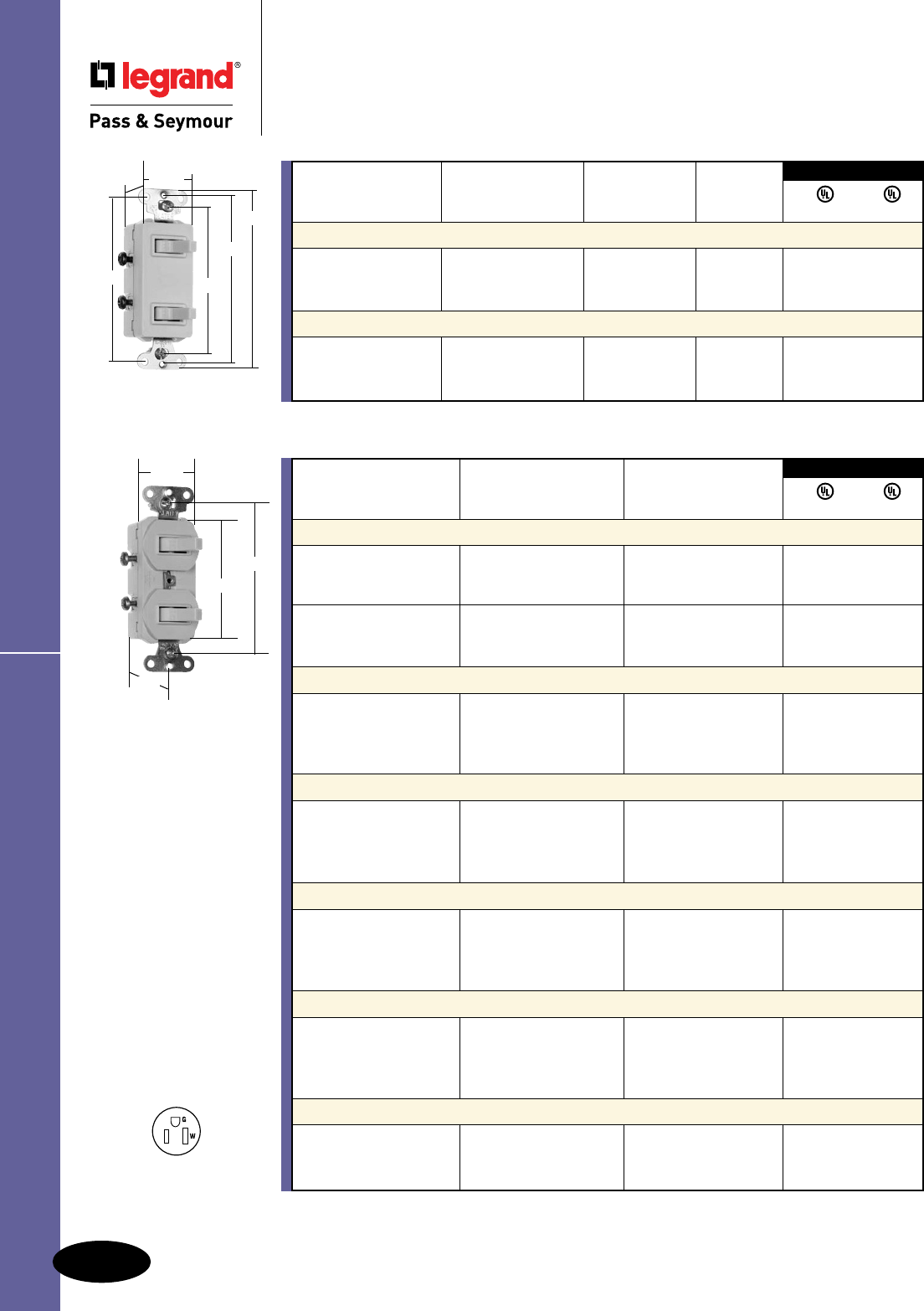
Combination
Switches
3.28"
.94"
2.64"
1.32"
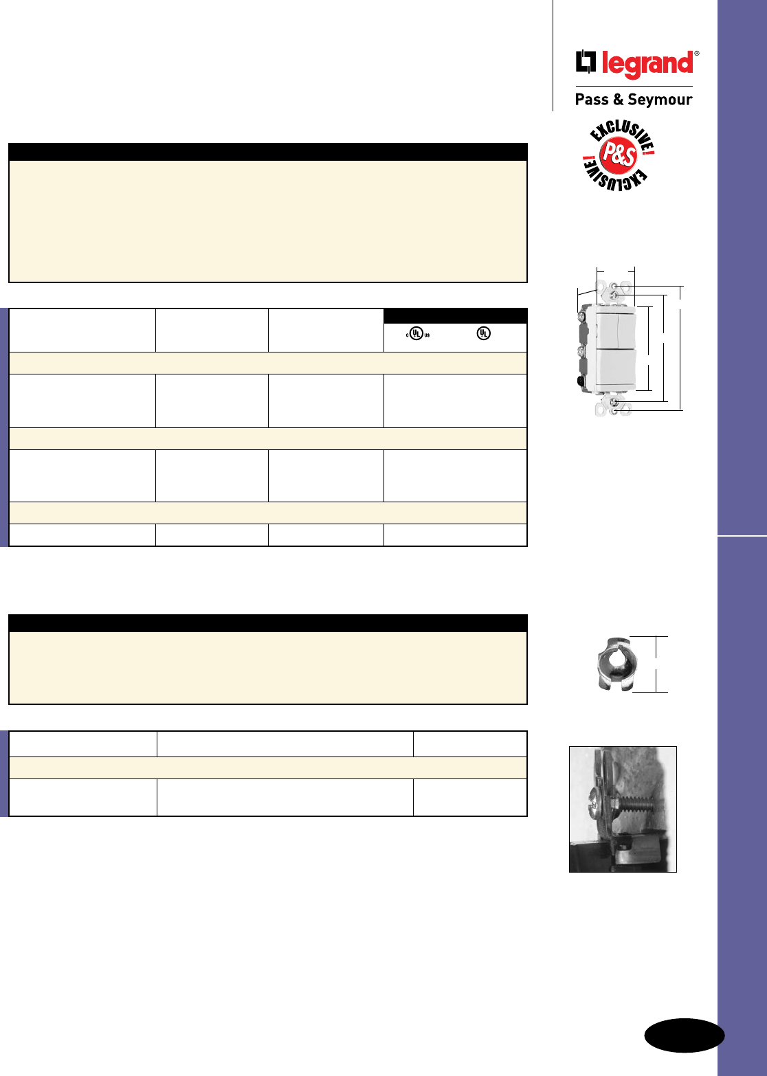
Combination Switches
Switches
Combination Switches
15 & 20A, 120/277VAC; 15 & 20A, 120/125VAC; 15A, 120VAC
Combination
Switch & Pilot Light
3.81"
4.06"
1.15"
3.28"
3.69"
1.32"
NEMA
5-20R
NEMA
5-15R
Features
n Easily accessible break-off for separate or
common feed.
n Long-life red neon lamp in pilot light rated
1/25 Watt, 125V.
n Side wire #12 and #14 AWG.
n Two devices t into the space of one.
n Grounding combination devices meet NEC
Requirements.
n Tamper-resistant version features dual
mechanical shutter system to help prevent
insertion of foreign objects.
Combination Switch
& Tamper-Resistant
Receptacle
3.81
4.06"
1.15"
3.28"
3.69"
1.32"
Rating NEMA
Catalog Number A. VAC Color Cong. No.
Single Pole Switch & Tamper-Resistant Single Receptacle
Side Wire, Grounding
691TRI 15 120/125 Ivory 5-15R • •
691TRW 15 120/125 White 5-15R • •
691TR 15 120/125 Brown 5-15R • •
691TRLA 15 120/125 Light Almond 5-15R • •
671TRI 20 120/125 Ivory 5-20R • •
671TRW 20 120/125 White 5-20R • •
671TR 20 120/125 Brown 5-20R • •
671TRLA 20 120/125 Light Almond 5-20R • •
Two Single Pole Switches Side Wire, Grounding
690IG 15 120/277 Ivory •
690WG 15 120/277 White •
690G 15 120/277 Brown •
690LAG 15 120/277 Light Almond •
670IG 20 120/277 Ivory •
670WG 20 120/277 White •
670G 20 120/277 Brown •
670LAG 20 120/277 Light Almond •
Single Pole & Three-Way Switch Side Wire, Grounding
696IG 15 120/277 Ivory •
696WG 15 120/277 White •
696G 15 120/277 Brown •
696LAG 15 120/277 Light Almond •
Two Three-Way Switches Side Wire, Grounding
693IG 15 120/277 Ivory •
693WG 15 120/277 White •
693G 15 120/277 Brown •
693LAG 15 120/277 Light Almond •
Single Pole Switch & Single Receptacle Side Wire, Grounding
691I 15 120/125 Ivory 5-15R • •
691W 15 120/125 White 5-15R • •
691 15 120/125 Brown 5-15R • •
691LA 15 120/125 Light Almond 5-15R • •
671I 20 120/125 Ivory 5-20R • •
671W 20 120/125 White 5-20R • •
671 20 120/125 Brown 5-20R • •
671LA 20 120/125 Light Almond 5-20R • •
Single Pole Switch & Pilot Light Side Wire, Grounding
692IG 15 120 Ivory •
692WG 15 120 White •
692G 15 120 Brown •
692LAG 15 120 Light Almond •
Three-Way Switch & Pilot Light Side Wire, Grounding
695IG 15 120 Ivory •
695WG 15 120 White •
695G 15 120 Brown •
695LAG 15 120 Light Almond •
3rd Party Compliance
UL20 UL498
A-18
Switches
All devices listed on this page conform to NEMA WD-1 and WD-6.
Combination Switches
Switches
Combination Switches
15 & 20A, 120/277VAC; 15A, 120/125VAC; 15A, 120VAC
Combination
Switches
3.28"
.94"
2.64"
1.32"
Decorator
Combination
3.812"
4.121"
1.20"
3.268"
3.688"
1.313"
Rating
Catalog Number A. VAC Color
Two Single Pole Switches Side Wire, Non-Grounding
690I 15 120/277 Ivory •
690W 15 120/277 White •
690 15 120/277 Brown •
670I 20 120/277 Ivory •
670W 20 120/277 White •
670 20 120/277 Brown •
Single Pole & Three-Way Switch Side Wire, Non-Grounding
696I 15 120/277 Ivory •
696W 15 120/277 White •
696 15 120/277 Brown •
696LA 15 120/277 Light Almond •
Two Three-Way Switches Side Wire, Non-Grounding
693I 15 120/277 Ivory •
693W 15 120/277 White •
693 15 120/277 Brown •
693LA 15 120/277 Light Almond •
Single Pole Switch & Pilot Light Side Wire, Non-Grounding
692I 15 120 Ivory • •
692W 15 120 White • •
692 15 120 Brown • •
692LA 15 120 Light Almond • •
Three-Way Switch & Pilot Light Side Wire, Non-Grounding
695I 15 120 Ivory •
695W 15 120 White •
695 15 120 Brown •
695LA 15 120 Light Almond •
Decorator Two Single Pole Switches Side Wire, Non-Grounding
680I 15 120/277 Ivory •
680W 15 120/277 White •
680LA 15 120/277 Light Almond •
3rd Party Compliance
UL20 UL498
See our full range of Decorator Combination Devices on Pages D-9 – D-12, D-20, D-24,
D-33, and D-39.
NEMA
5-15R
Rating NEMA
Catalog Number A. VAC Color Cong. No.
Decorator Two Single Pole Switches Side Wire, Grounding
680IG 15 120/277 Ivory •
680WG 15 120/277 White •
680LAG 15 120/277 Light Almond •
Decorator Single Pole Switch & Single Receptacle Side Wire, Grounding
681I 15 120/125 Ivory 5-15R • •
681W 15 120/125 White 5-15R • •
681LA 15 120/125 Light Almond 5-15R • •
3rd Party Compliance
UL20 UL498
Non-Grounding
A-19
Switches
All devices listed on this page conform to NEMA WD-1 and WD-6.
3rd Party Compliance
Catalog Number Rating
Single Pole Three-Way Four-Way A. VAC Color UL20 C22.2 111
Specification Grade Decorator Switches Back & Side Wire
2601347I 2603347I 15 347 Ivory • •
2601347W 2603347W 15 347 White • •
2601347GRY 15 347 Gray • •
2601347LA 15 347 Light Almond • •
2621347I 2623347I 2624347I 20 347 Ivory • •
2621347W 2623347W 2624347W 20 347 White • •
2621347GRY 2623347GRY 20 347 Gray • •
2621347BK 2623347BK 20 347 Black • •
2621347RED 2623347RED 20 347 Red • •
2621347LA 2623347LA 2624347LA 20 347 Light Almond • •
Denotes Canadian catalog number. All Canadian products have Combination Slotted/Robertson Head
Brass Screws.
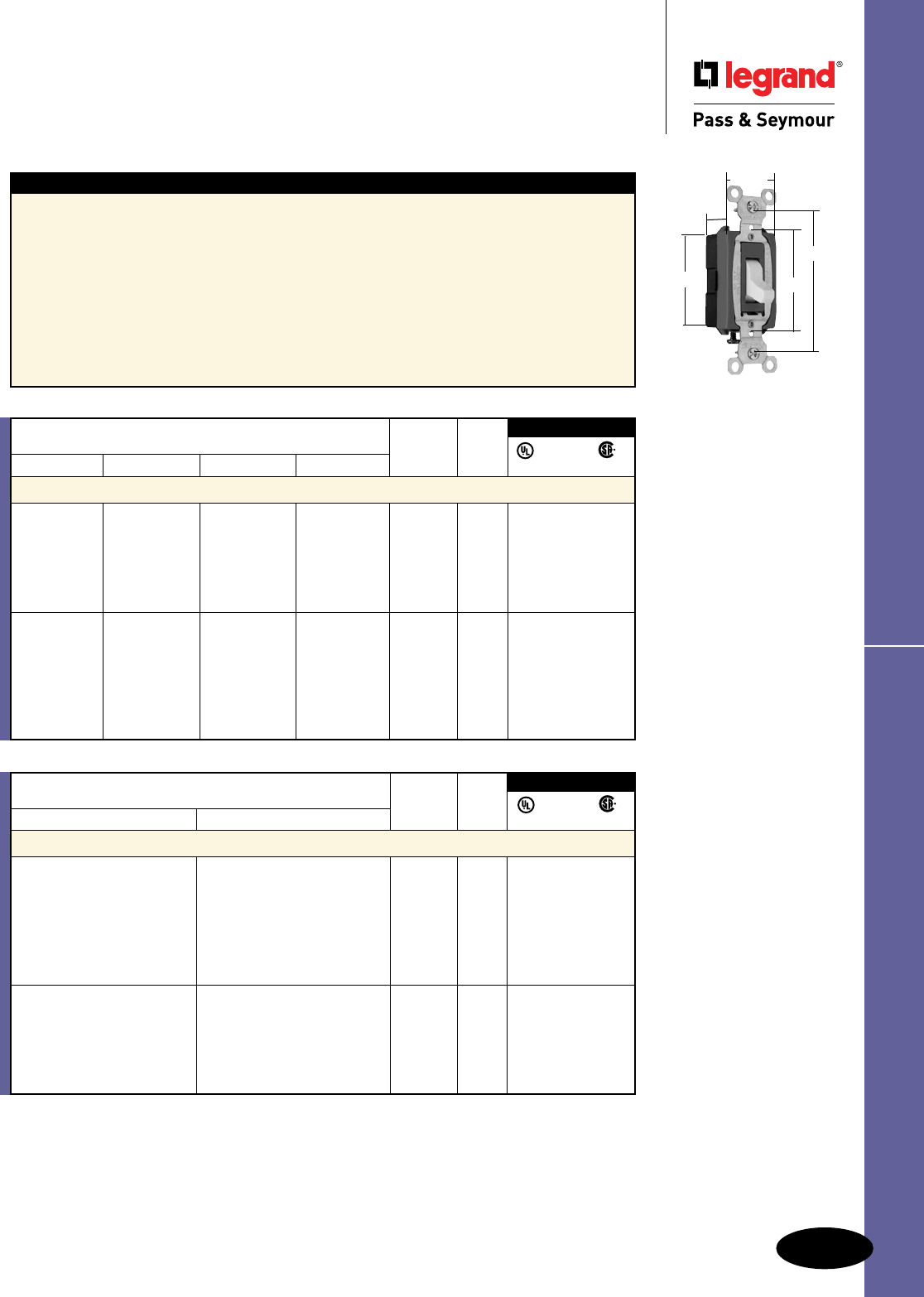
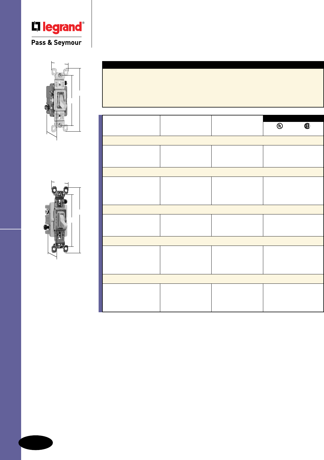
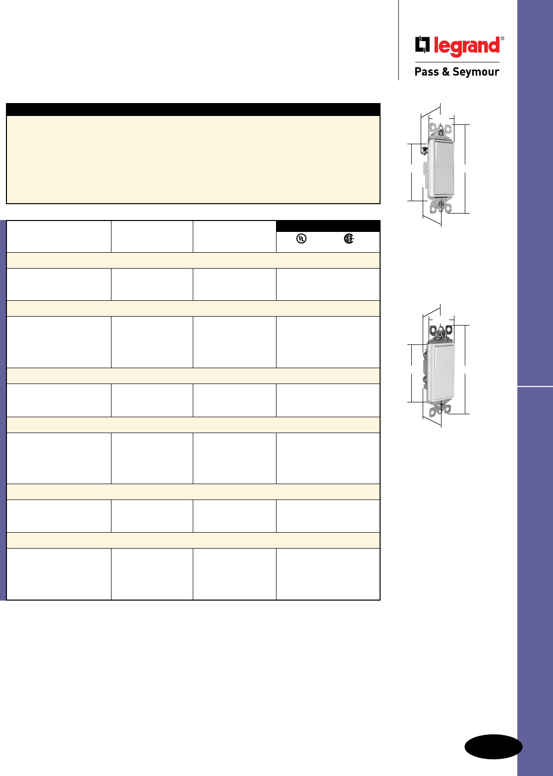
Specification Grade Decorator Switches
2601347
2.620"
4.200"
1.060"
3.531"
4.063"
1.300"
Switches
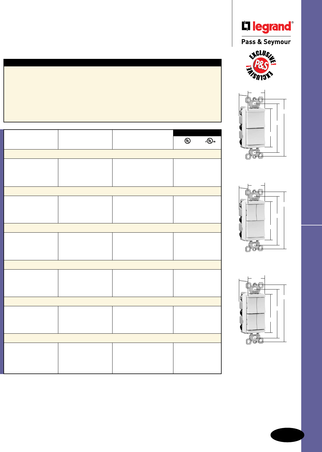
Specification Grade Decorator Switches
15 & 20A, 120/277 & 347VAC; 20A, 120VAC
2601
2.620"
4.200"
1.060"
3.281"
3.812"
1.300"
2625, 2626, 2629
2.620"
4.200"
1.060"
3.281"
3.812"
1.300"
Features
n Impact-resistant polycarb back body and frame.
n Cushioned thermoplastic paddle assures smooth,
quiet, long term operation.
n Unique single rocking buttery contact provides
long term consistent performance with signicantly
fewer moving parts.
n Internal screw-pressure-plate back and side wire
capability for easy installation with #14 – #10 stranded
or solid copper/copper clad wire. Terminals made of
high conductivity brass and serrated for maximum
wire gripping.
n Silver alloy contacts integrally formed
to the buttery actuator assures reliable
performance.
n Integral auto-ground clip for positive ground
to metal boxes.
n Tri-drive ground, terminal and mounting
screws. All terminal screws backed out,
ready-to-install.
3rd Party Compliance
Catalog Number Rating
Single Pole Double Pole Three-Way Four-Way A. VAC Color
UL20 C22.2 111
Specification Grade Decorator Switches Back & Side Wire
2601I 2603I 2604I 15 120/277 Ivory • •
2601W 2603W 2604W 15 120/277 White • •
2601GRY 2603GRY 15 120/277 Gray • •
2601BK 2603BK 15 120/277 Black • •
2601LA 2603LA 2604LA 15 120/277 Light Almond • •
2621I 2622I 2623I 2624I 20 120/277 Ivory • •
2621W 2622W 2623W 2624W 20 120/277 White • •
2621 2622 2623 2624 20 120/277 Brown • •
2621GRY 2622GRY 2623GRY 2624GRY 20 120/277 Gray • •
2621BK 2622BK 2623BK 2624BK 20 120/277 Black • •
2621RED 2623RED 2624RED 20 120/277 Red • •
2621LA 2622LA 2623LA 2624LA 20 120/277 Light Almond • •
Illuminated Decorator Switches (Lighted when OFF) Back & Side Wire
2625I 2626I 2628I 20 120 Ivory • •
2625W 2626W 2628W 20 120 White • •
2625 20 120 Brown • •
2625RED 20 120 Red • •
2625LA 2626LA 2628LA 20 120 Light Almond • •
Pilot Lighted Decorator Switches (Lighted when ON) Back & Side Wire
2629I 20 120 Ivory • •
2629W 20 120 White • •
2629LA 20 120 Light Almond • •
For Bulk Packaging Solutions consult factory.
A-20
Switches
All devices listed on this page conform to NEMA WD-1 and WD-6.
TradeMaster® Decorator Switches
Switches
TradeMaster® Decorator Switches
15A, 120/277VAC
Features
n Designer-style satin-nish rocker.
n High-impact resistant thermoplastic construction.
n External screw-pressure-plate back and side wired.
Accepts #12 and #14 AWG.
n Push wire #14 AWG.
n Narrow back body leaves more room for wires
in the box.
n Extra-long, through-body strap eliminates
oating installations and imperfect applications.
n Smooth, quiet paddle action.
n Easy-access green hex head ground screw.
n Tri-drive ground, terminal and mounting screws.
n ON-OFF switches conform to NEC 430-104
requirements for kitchen disposal units.
TM870LA
2.620"
1.43"
.99"
1.27"
4.19"
TM873LA
2.620"
1.43"
.99"
1.27"
4.19"
TM874LA
2.620"
1.43"
.99"
1.27"
4.19"
NAFTA-Compliant
Switches are ideal for
use on projects subject
to the provisions of the
Buy American Act.
Rating
Catalog Number A. VAC Color
Single Pole Decorator Switches Grounding
TM870I 15 120/277 Ivory • •
TM870W 15 120/277 White • •
TM870 15 120/277 Brown • •
TM870GRY 15 120/277 Gray • •
TM870BK 15 120/277 Black • •
TM870LA 15 120/277 Light Almond • •
TM870BNCC10 15 120/277 Brushed Nickel • •
TM870TI 15 120/277 Titanium • •
NAFTA-Compliant Single Pole Decorator Switches
Grounding
TM870NAI 15 120 Ivory •
TM870NAW 15 120 White •
TM870NA 15 120 Brown •
TM870NAGRY 15 120 Gray •
TM870NABK 15 120 Black •
TM870NALA 15 120 Light Almond •
Three-Way Decorator Switches Grounding
TM873I 15 120/277 Ivory • •
TM873W 15 120/277 White • •
TM873 15 120/277 Brown • •
TM873GRY 15 120/277 Gray • •
TM873BK 15 120/277 Black • •
TM873LA 15 120/277 Light Almond • •
TM873BNCC10 15 120/277 Brushed Nickel • •
TM873TI 15 120/277 Titanium • •
NAFTA-Compliant Three-Way Decorator Switches
Grounding
TM873NAI 15 120 Ivory •
TM873NAW 15 120 White •
TM873NA 15 120 Brown •
TM873NAGRY 15 120 Gray •
TM873NABK 15 120 Black •
TM873NALA 15 120 Light Almond •
Four-Way Decorator Switches Grounding
TM874I 15 120/277 Ivory • •
TM874W 15 120/277 White • •
TM874 15 120/277 Brown • •
TM874BK 15 120/277 Black • •
TM874LA 15 120/277 Light Almond • •
TM874BNCC6 15 120/277 Brushed Nickel • •
TM874TI 15 120/277 Titanium • •
NAFTA-Compliant Four-Way Decorator Switches
Grounding
TM874I 15 120 Ivory •
TM874W 15 120 White •
TM874 15 120 Brown •
TM874GRY 15 120 Gray •
TM874BK 15 120 Black •
TM874LA 15 120 Light Almond •
3rd Party Compliance
UL20 C 22.2 111
A-21
Switches
All devices listed on this page conform to NEMA WD-1 and WD-6.
TradeMaster® Decorator Switches
Switches
TradeMaster® Decorator Illuminated &
Self-Grounding Switches
15A, 120 & 120/277VAC
3rd Party Compliance
UL20 C22.2 111
Rating
Catalog Number A. VAC Color
Single Pole Illuminated Decorator Switches Grounding (Lighted when OFF)
TM870ISL 15 120 Ivory • •
TM870WSL 15 120 White • •
TM870LASL 15 120 Light Almond • •
Self-Grounding Single Pole Decorator Switches
TM870SI 15 120/277 Ivory • •
TM870SW 15 120/277 White • •
TM870S 15 120/277 Brown • •
TM870SBK 15 120/277 Black • •
TM870SLA 15 120/277 Light Almond • •
Three-Way Illuminated Decorator Switches Grounding (Lighted when OFF)
TM873ISL 15 120 Ivory • •
TM873WSL 15 120 White • •
TM873LASL 15 120 Light Almond • •
Self-Grounding Three-Way Decorator Switches
TM873SI 15 120/277 Ivory • •
TM873SW 15 120/277 White • •
TM873S 15 120/277 Brown • •
TM873SBK 15 120/277 Black • •
TM873SLA 15 120/277 Light Almond • •
Four-Way Illuminated Decorator Switches Grounding (Lighted when OFF)
TM874ISL 15 120 Ivory • •
TM874WSL 15 120 White • •
TM874LASL 15 120 Light Almond • •
Self-Grounding Four-Way Decorator Switches
TM874SI 15 120/277 Ivory • •
TM874SW 15 120/277 White • •
TM874S 15 120/277 Brown • •
TM874SBK 15 120/277 Black • •
TM874SLA 15 120/277 Light Almond • •
TM870SLA
2.620"
1.43"
.99"
1.27"
4.19"
TM870LASL
2.620"
1.43"
.99"
1.27"
4.19"
Features
n Designer-style satin-nish rocker.
n High-impact resistant thermoplastic construction.
n External screw-pressure-plate back and side
wired. Accepts #12 and #14 AWG.
n Push wire #14 AWG.
n Narrow back body leaves more room for wires
in the box.
n Extra-long, through-body strap eliminates
oating installations and imperfect applications.
n Smooth, quiet paddle action.
n Easy-access green hex head ground screw.
n Tri-drive ground, terminal and mounting
screws.
n Self-grounding models provide automatic
ground clip.
A-22
Switches
All devices listed on this page conform to NEMA WD-1 and WD-6.
Decorator & Spec Grade Switches
Switches
Decorator & Specification Grade
Momentary & Maintained
Contact Switches
15A, 120 & 120/277VAC
Rating
Catalog Number A. VAC Color
Single Pole Decorator Momentary Contact Switches
TM870STMWCC10 15 120/277 White • •
TM870STMBKCC10 15 120/277 Black • •
TM870STMLACC10 15 120/277 Light Almond • •
3rd Party Compliance
UL20 C22.2 111
Momentary
Contact
Maintained
Contact
TM870STMLACC10
2.620"
1.43"
.99"
1.27"
4.19"
Features
n Designer-style satin-nish rocker.
n High-impact resistant thermoplastic construction.
n External screw-pressure-plate back and side wired.
Accepts #12 and #14 AWG.
n Push wire #14 AWG.
n Narrow back body leaves more room for wires
in the box.
n Extra-long, through-body strap eliminates
oating installations and imperfect applications.
n Smooth, quiet paddle action.
n Easy-access green hex head ground screw.
n Tri-drive ground, terminal and mounting screws.
Rating
Catalog Number A. VAC Color
Specification Grade Double Throw Momentary Contact Switches
TM811DTMOI 15 120 Ivory • •
TM811DTMOW 15 120 White • •
TM811DTMOBK 15 120 Black • •
TM811DTMOLA 15 120 Light Almond • •
Specification Grade Double Throw Maintained Contact Switches
TM811DTMAI 15 120 Ivory • •
TM811DTMAW 15 120 White • •
TM811DTMABK 15 120 Black • •
TM811DTMALA 15 120 Light Almond • •
3rd Party Compliance
cULus UL20 UL508
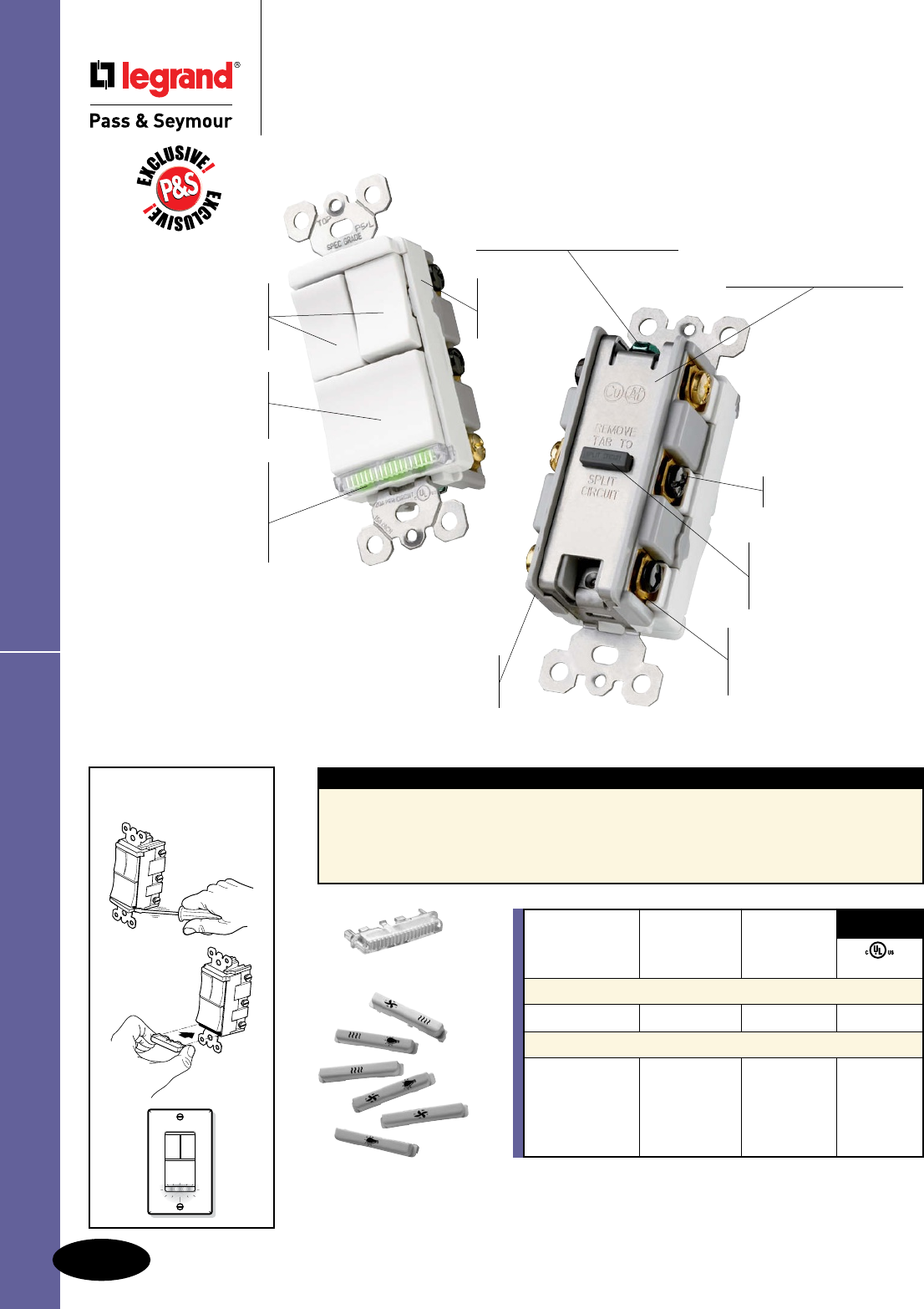
Features
n Unique “Up/Down” switches match the look and
feel of standard decorator switches.
n Impact-resistant face and body.
n Side and external screw-pressure-plate back wire
accepts #12 and #14 AWG.
n All screws are tri-drive.
n Full wraparound heavy-gauge steel strap is
plated for corrosion resistance and features
lock-in tabs.
n Patent-pending split circuit tab — easily
accessible, and can be reinstalled without
a tool.
1.29"
1.59"
2.60"
3.281"
3.812"
1.29"
1.59"
2.60"
3.281"
3.812"
A-23
Switches
All devices listed on this page conform to NEMA WD-1 and WD-6.
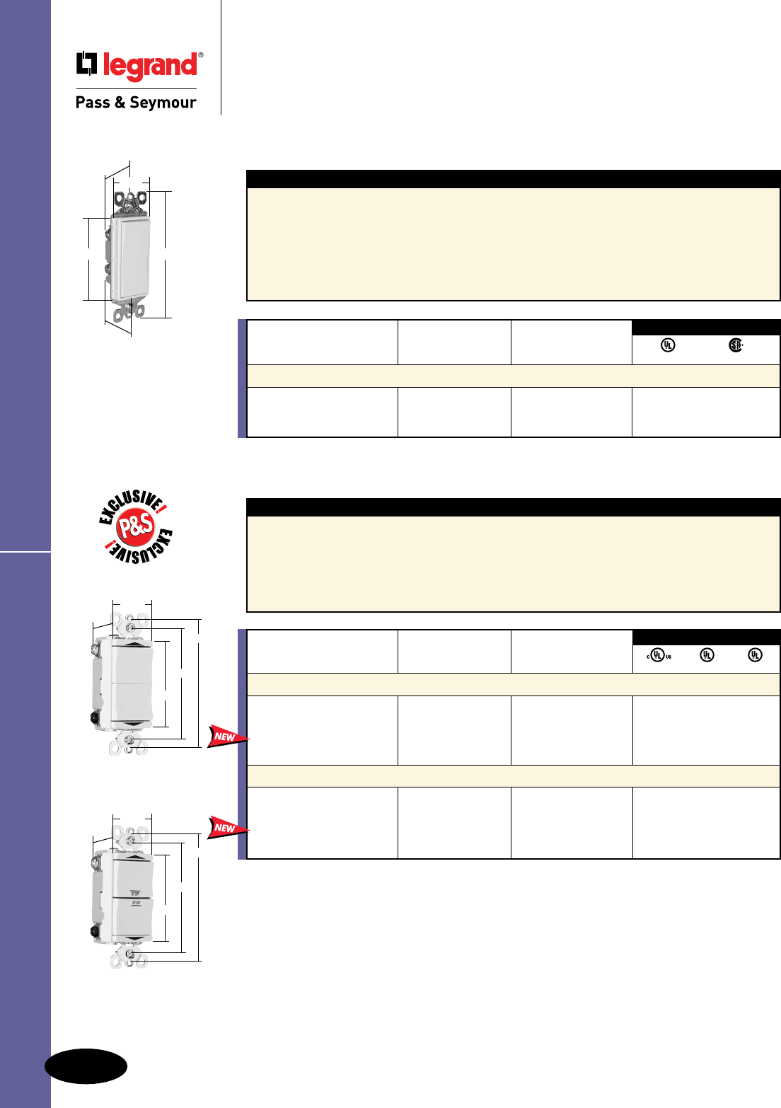
Spec Grade Decorator Combination Switches
Switches
Specification Grade Decorator
Combination Switches & Shim-Lock
20A, 277VAC
Features
n Unique “Up/Down” switches match the look and
feel of standard decorator switches.
n Impact-resistant face and body.
n Side and external screw-pressure-plate back wire
accepts #12 and #14 AWG.
n All screws are tri-drive.
n Full wraparound heavy-gauge steel strap is plated
for corrosion resistance and features lock-in tabs.
n Patent-pending split circuit tab — easily
accessible, and can be reinstalled without a tool.
n Patent-pending snap-in light module (sold
separately) transforms a combination switch
into an illuminated switch.
n Identication modules (sold separately)
identies each switch — light, fan, heat lamp.
See Page A-24 for details.
*For use with PS81120 and PS811120 only.
Rating
Catalog Number A. VAC Color
Two Single Pole Switches
PS81120I 20 277 Ivory • •
PS81120W 20 277 White • •
PS81120LA 20 277 Light Almond • •
Three Single Pole Switches
PS811120I 20 277 Ivory • •
PS811120W 20 277 White • •
PS811120LA 20 277 Light Almond • •
Snap-In Light Module*
PS8LM — — Clear
3rd Party Compliance
cULus UL20
Features
n One Shim-Lock provides a device adjustment
depth range between 1/8" and 3/4".
n An inexpensive and quick x for oating
installations.
n Provides a perfect ush mount every time,
regardless of the wallboard, tile or panel
condition.
n Made of steel and nished with clear zinc
chromate plating.
Catalog Number Dimensions Qty. Per Package
Shim-Lock
SHL20 Length: .310", Screw Opening: #6 20
SHL100 Length: .310", Screw Opening: #6 100
15 & 20 Amp
1.29"
1.59"
2.60"
3.281"
3.812"
Shim-Lock
.310"
A-24
Switches
All devices listed on this page conform to NEMA WD-1 and WD-6.
TradeMaster® Decorator Combination Switches
Switches
TradeMaster® Decorator
Combination Switches
Adding a Snap-In
Light Module
Impact-
resistant
face and
body.
Unique “Up/Down”
switches match the look
and feel of standard
Decorator switches.
Patented Snap-In
Light Module
(sold separately)
transforms a combination
switch into an illuminated
switch in seconds. Patented split circuit
tab – easily accessible,
and can be reinstalled
without a tool.
External screw-pressure-
plate back and side
wired. Accepts #12 and
#14 AWG.
Ground screw position
under the end of the strap
minimizes the risk of contact.
Fully rounded back body
protects wires from being
damaged by sharp edges.
Full wraparound metal
strap, commercial grade
with lock-in tabs.
Easy-to-use
oversized
main switch
for primary load.
TM8113WCC
Shown with Snap-In
Light Module TM8LMCC.
All screws
are tri-drive.
Identification modules
(sold separately) identifies
each switch — light, fan,
heat lamp.
Features
n Module simply snaps-in for easy installation.
n Can be installed with the following devices: TM811,
TM813, TM833, TM818, TM838, TM8111, TM8113,
TM81111, TM8118 and the LS Series of Dimmers &
Fan Speed Controls (see Pages M-13 through M-15).
Snap-In Light Module:
n Lights when OFF.
n Uses energy-efficient 1/4 watt LED light.
n LED light will not generate heat and will
last on average 47 years.
TM8IDWCC
TM8LMCC
For Decorator Hallway Lights and Combination Devices,
see Page D-24.
Rating
Catalog Number A. VAC Color cULus
Snap-In Light Module
TM8LMCC 15 120/125 Clear •
Identification Modules
TM8IDICC — — Ivory
TM8IDWCC — — White
TM8IDCC — — Brown
TM8IDBKCC — — Black
TM8IDLACC — — Light Almond
3rd Party
Compliance
A-25
Switches
All devices listed on this page conform to NEMA WD-1 and WD-6.
TradeMaster® Decorator Combination Switches
Switches
TradeMaster® Decorator
Combination Switches
15A, 120VAC
Features
n Impact-resistant face and body.
n Fully rounded back body protects wires from
being damaged by sharp edges.
n Clear identication of circuits.
n External screw-pressure-plate back and side
wired. Accepts #12 and #14 AWG.
n Ground screw position under the end of the
strap minimizes the risk of contact.
n Full wraparound metal strap with lock-in tabs.
n Patented split circuit tab – easily accessible,
and can be reinstalled without a tool.
n Unique “Up/Down” switches match the look
and feel of standard Decorator switches.
n Largest breadth of 15 amp offering.
n All screws are tri-drive.
n Tamper-resistant version features dual
mechanical shutter system to help prevent
insertion of foreign objects (see Page A-26).
Rating
Catalog Number A. VAC Color UL20 cULus
Two Single Pole Switches
TM811ICC 15 120 Ivory • •
TM811WCC 15 120 White • •
TM811CC 15 120 Brown • •
TM811BKCC 15 120 Black • •
TM811LACC 15 120 Light Almond • •
Single Pole Switch & Three-Way Switch
TM813ICC 15 120 Ivory • •
TM813WCC 15 120 White • •
TM813CC 15 120 Brown • •
TM813BKCC 15 120 Black • •
TM813LACC 15 120 Light Almond • •
Two Three-Way Switches
TM833ICC 15 120 Ivory • •
TM833WCC 15 120 White • •
TM833CC 15 120 Brown • •
TM833BKCC 15 120 Black • •
TM833LACC 15 120 Light Almond • •
Three Single Pole Switches
TM8111ICC 15 120 Ivory • •
TM8111WCC 15 120 White • •
TM8111CC 15 120 Brown • •
TM8111BKCC 15 120 Black • •
TM8111LACC 15 120 Light Almond • •
Two Single Pole Switches & Three-Way Switch
TM8113ICC 15 120 Ivory • •
TM8113WCC 15 120 White • •
TM8113CC 15 120 Brown • •
TM8113BKCC 15 120 Black • •
TM8113LACC 15 120 Light Almond • •
Four Single Pole Switches
TM81111ICC 15 120 Ivory • •
TM81111WCC 15 120 White • •
TM81111CC 15 120 Brown • •
TM81111BKCC 15 120 Black • •
TM81111LACC 15 120 Light Almond • •
3rd Party Compliance
TM811WCC
TM8111WCC
TM81111WCC
3.28"
3.81"
2.60"
1.29"
1.59"
3.28"
3.81"
2.60"
1.29"
1.59"
3.28"
3.81"
2.60"
1.29"
1.59"
A-26
Switches
All devices listed on this page conform to NEMA WD-1 and WD-6.
TradeMaster
®
TR Decorator Combination Switches
Switches
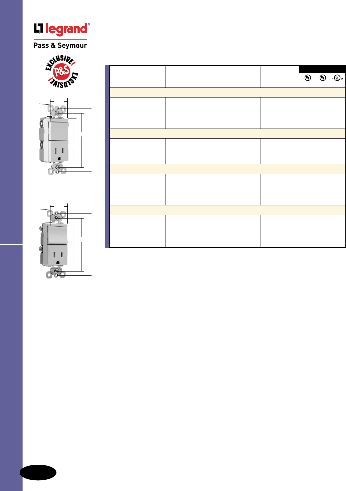
TradeMaster
®
Tamper-Resistant
Decorator Combination Switches
15A, 120/125VAC
TM838TRLACC
TM818TRWCC
3.28"
3.81"
2.60"
1.29"
1.59"
3.28"
3.81"
2.60"
1.29"
1.59"
3rd Party Compliance
Rating NEMA
Catalog Number A. VAC Color Cong. No. UL20 UL498 cULus
Tamper-Resistant Single Pole Switch & Single Receptacle
TM818TRICC 15 120/125 Ivory 5-15R • • •
TM818TRWCC 15 120/125 White 5-15R • • •
TM818TRCC 15 120/125 Brown 5-15R • • •
TM818TRBKCC 15 120/125 Black 5-15R • • •
TM818TRLACC 15 120/125 Light Almond 5-15R • • •
Tamper-Resistant Single Pole Switch & Single Receptacle with Pilot Light
TM818TRPLICC 15 120/125 Ivory 5-15R • • •
TM818TRPLWCC 15 120/125 White 5-15R • • •
TM818TRPLBKCC 15 120/125 Black 5-15R • • •
TM818TRPLLACC 15 120/125 Light Almond 5-15R • • •
Tamper-Resistant Three-Way Switch & Single Receptacle
TM838TRICC 15 120/125 Ivory 5-15R • • •
TM838TRWCC 15 120/125 White 5-15R • • •
TM838TRCC 15 120/125 Brown 5-15R • • •
TM838TRBKCC 15 120/125 Black 5-15R • • •
TM838TRLACC 15 120/125 Light Almond 5-15R • • •
Tamper-Resistant Two Single Pole Switches & Single Receptacle
TM8118TRICC 15 120/125 Ivory 5-15R • • •
TM8118TRWCC 15 120/125 White 5-15R • • •
TM8118TRCC 15 120/125 Brown 5-15R • • •
TM8118TRBKCC 15 120/125 Black 5-15R • • •
TM8118TRLACC 15 120/125 Light Almond 5-15R • • •
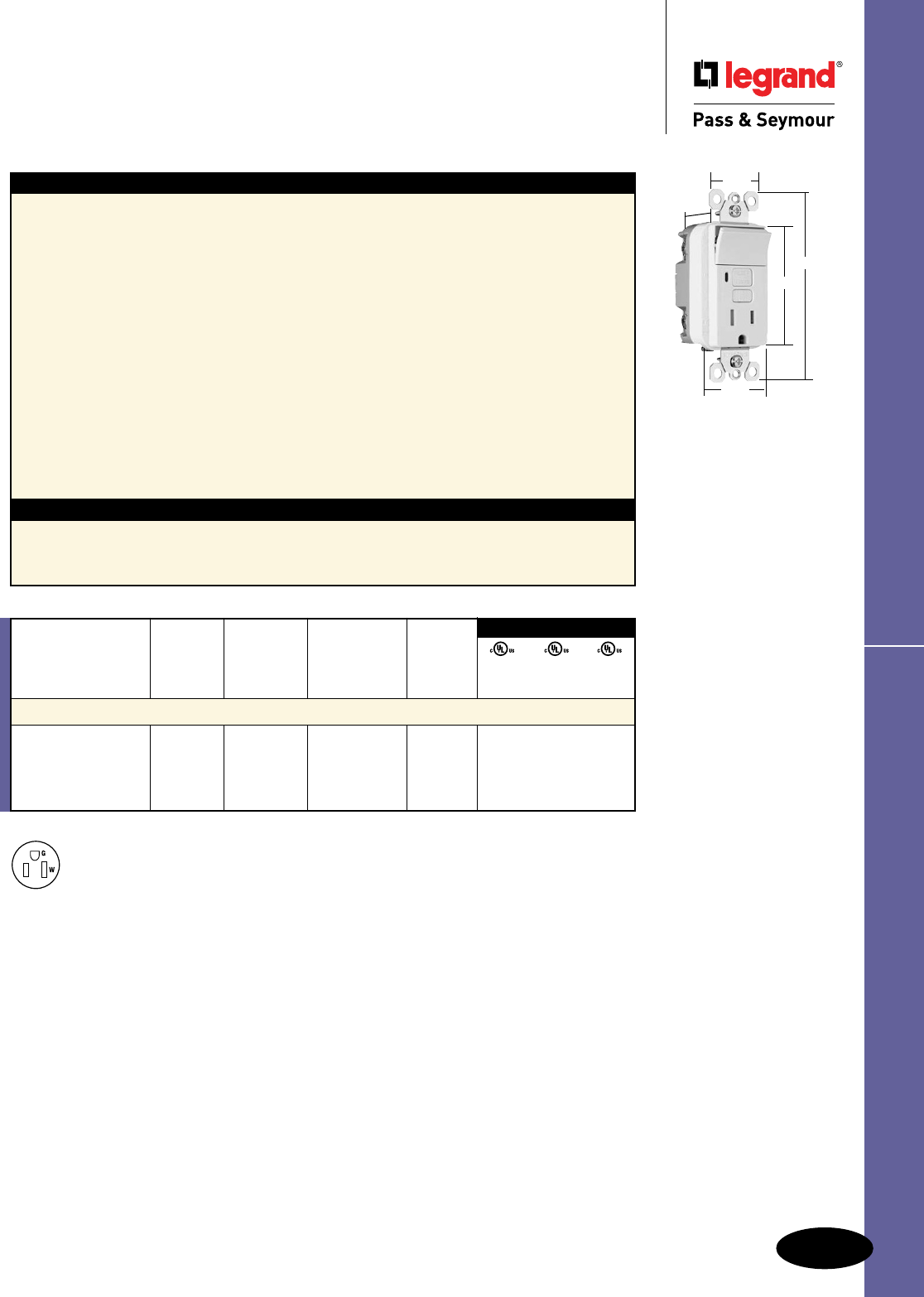
A-27
Switches Decorator Combination Switch/GFCI
All devices listed on this page conform to NEMA WD-1 and WD-6.
Switches
Decorator Combination Tamper-Resistant
Switch/GFCI Receptacles
15A, 125VAC
1595SWTTRWCC4
NEMA
5-15R
1.13"
1.25"
4.20"
2.62"
1.72"
Switch Receptacle NEMA
Catalog Rating Rating Cong.
Number A. VAC A. VAC Color No.
Combination Tamper-Resistant Single Pole Switch/GFCI
1595SWTTRICC4 15 120 15 125 Ivory 5-15R • • •
1595SWTTRWCC4 15 120 15 125 White 5-15R • • •
1595SWTTRBKCC4 15 120 15 125 Black 5-15R • • •
1595SWTTRLACC4 15 120 15 125 Light Almond 5-15R • • •
3rd Party Compliance
UL943 UL498 UL20
C22.2 C22.2 C22.2
No. 144 No. 42 No. 111
Features
n Protects children: patented shutter system helps
prevent improper insertion of foreign objects.
n Meets National Electrical Code®
Tamper-Resistant requirements.
n SafeLockTM Protection: if critical components are
damaged and ground fault protection is lost, power
to receptacle is disconnected.
n Up-down switching.
n 15 Amp single pole switch rated for 1/2 HP motor
loads – perfect for bath or kitchen vents and
garbage disposals.
n Prevents line-load reversal miswire: no power to the
face or downstream receptacles if wired incorrectly.
n Exceeds UL943 voltage surge requirements;
survives 100x the required UL 3kA/6kV voltage
surge test cycles.
n Trip indicator light (red LED).
n Two back wire holes per terminal.
Specications
n Supply Voltage: 125VAC, 60 Hz
n Supply Voltage Range: 102-132 VAC
n Trip Threshold: 5± 1mA
n Trip Time: 0.025 sec., nominal per UL
Standard
n 20 Amp feed-thru capacity
n Side or internal screw-pressure-plate back
wire with #10 – #14 AWG solid or stranded
copper wire.
n Ground screw has a back wire clamp for easy
installation.
n 1/4" thinner than competitors’ GFCIs; leaves
more room for wires in the box.
n Mounting screws are shipped captive in the
device and wall plate for easier installation.
n High-impact-resistant thermoplastic
construction.
n Extra-long strap.
n Button colors match the device face.
n Dual-direction test and reset buttons.
n Class A rated GFCI.
n Supplied with matching TP26 nylon wall plate.
n Tri-drive screws.
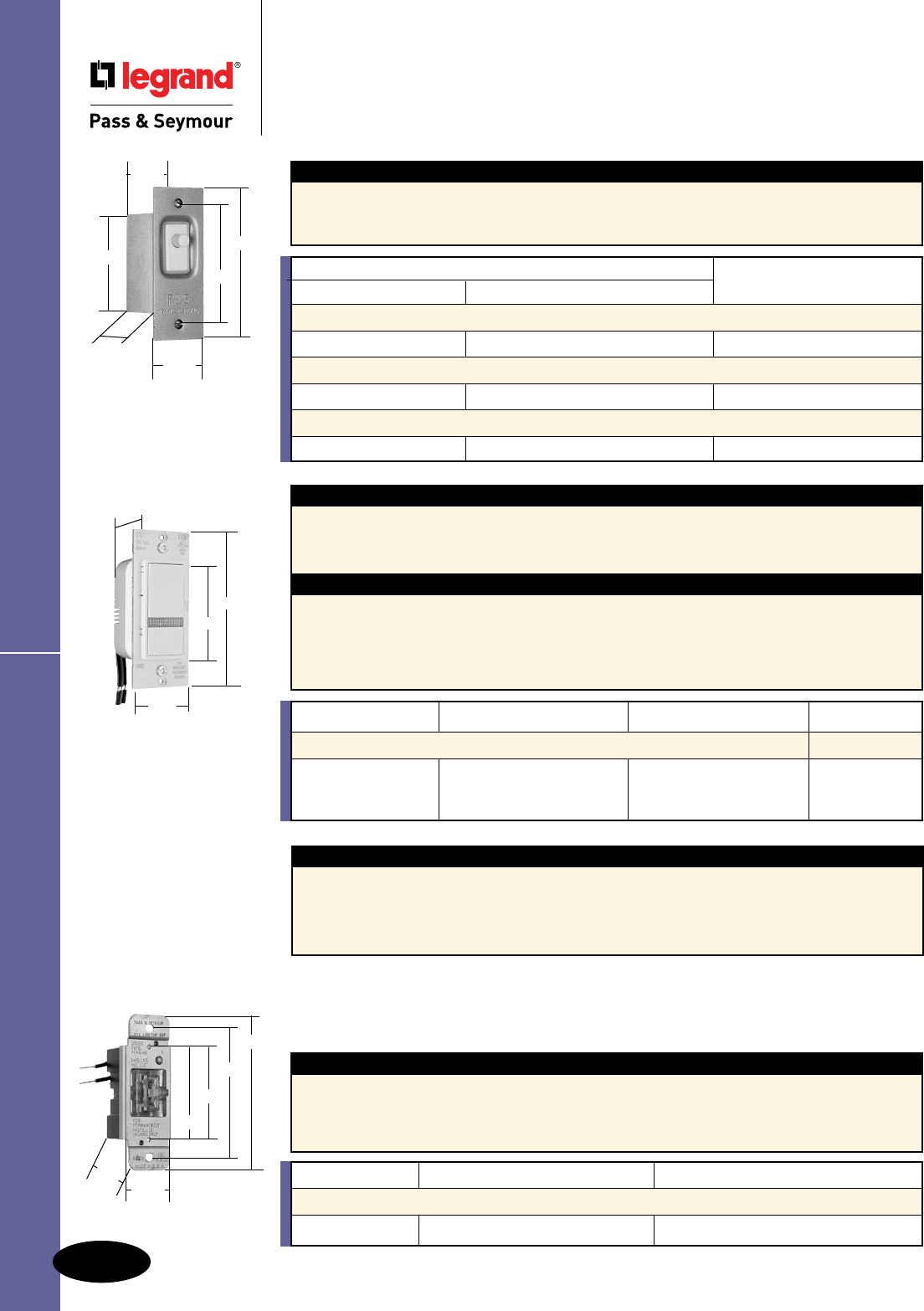
A-28
Switches
All devices listed on this page conform to NEMA WD-1 and WD-6.
Switches
Canopy Switches & Locator Switches
15A, 120 & 250VAC; 15A, 120VAC
Canopy Switches & Locator Switches
911LOCATOR
2.375"
2.406"
3.313"
4.000"
1.219"
1.453"
Catalog Number Rating AC
Light On Door Open Light On Door Closed 120VAC 250VAC
Pressure Sensitive Door & Canopy Switches
1200 1201 15A 15A
Interiors Only, with Leads & Plunger
1205 1206 15A 15A
Interiors Only, with Leads, Plunger & Face Plate
1205A 1206A 15A 15A
Features
n Equipped with wire leads.
n 1200 and 1201 complete with metal box and plate.
n Only 14 oz. pressure actuates switch.
n Back box cold rolled steel.
n Plate is steel with a bronze coating.
Helps Emergency Personnel Locate Address
Used in conjunction with your call for assistance, the 911 Locator solves the problem of night time house
identication for emergency personnel. After you have placed your call for help, simply ick the switch toggle
to the “911” position and your outdoor light will ash on and off continuously, cutting response time to insure
effective action.
Catalog Number Description Rating
Single Pole, Double Throw
911LOCATOR Emergency Flasher Switch 600 Watts, 120VAC
Features
n Functions as a standard ON/OFF switch.
n Installs in minutes. Replaces any standard
single-pole switch.
n 5" pre-stripped wire leads.
n All wire nuts and mounting hardware included.
n Transparent wall plate sticker included.
n UL20 Listed.
Application
The 911 Locator should be used in place of a standard
single-pole switch to turn outdoor house or porch lights
ON and OFF. In the 911 “ashing” position, the light
becomes a house locator for police, medical personnel,
emergency utility service, foul weather deliveries, etc.
n Illuminated toggle when switch is off.
n Toggle and attached load ashes when
toggle in center position (in 911 mode).
1200
1201
4.031"
3.188"
1.516"
2.656"
1.344"
1.547"
Application
In an emergency, seconds can make all the difference. Easily make a home instantly identiable with
a P&S Decorator Home Locator Switch. Just a single touch on its lower push button ashes the front
outside lights continuously. The switch’s LED ashes red to indicate the locator is in operation. When
the locator asher isn’t in use, the switch’s LED glows green for easy location in the dark.
Features
n ON/OFF switch with normal paddle operation.
n Locator function ashes the outdoor light ON and OFF
signaling SOS in Morse Code.
n Green LED illuminates and differentiates switch for
easy location in emergency.
n Red LED indicates the emergency
function is enabled.
n Wires the same as a single pole switch.
n cULus Listed.
TM8LOCATORLA
1.13"
4.20"
2.62"
1.72"
Catalog Number Description Rating Color
Decorator Home Locator Switches
TM8LOCATORI Emergency Decorator Ivory
TM8LOCATORW Home Locator 500 Watts, 15A, 120VAC White
TM8LOCATORLA Light Almond
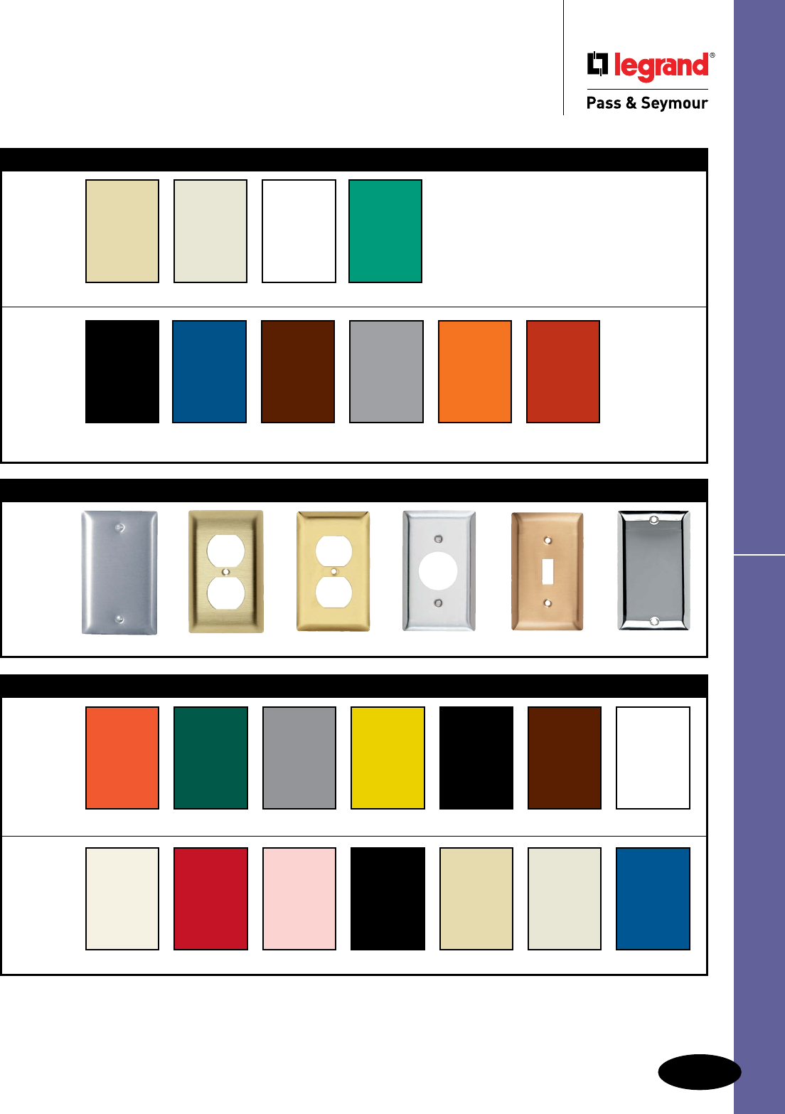
A-29
Devices & Wall Plates Color Selection Chart
Devices & Wall Plates
Color Selection Chart
Devices & Plastic Wall Plate Colors
Ivory Light Almond White Green
Black Blue Brown Gray Orange Red
See specific device and wall plate catalog charts for particular color availabilities.
To order custom metal wall plates, see Pages Q-43 – Q-45.
For additional colors consult factory.
Custom Metal Wall Plates Paint Finish Colors
Custom Metal Wall Plates Paint Finish Colors
Paint Color Orange Green Gray Yellow Glossy Black Brown White
Paint Color Primer Red Pink Flat Black Ivory Light Almond Blue
Metal Wall Plates
Metal Finish Aluminum Brass (Brushed) Polished Brass Stainless Steel Brushed Bronze Chrome

STRAIGHT BLADE RECEPTACLES
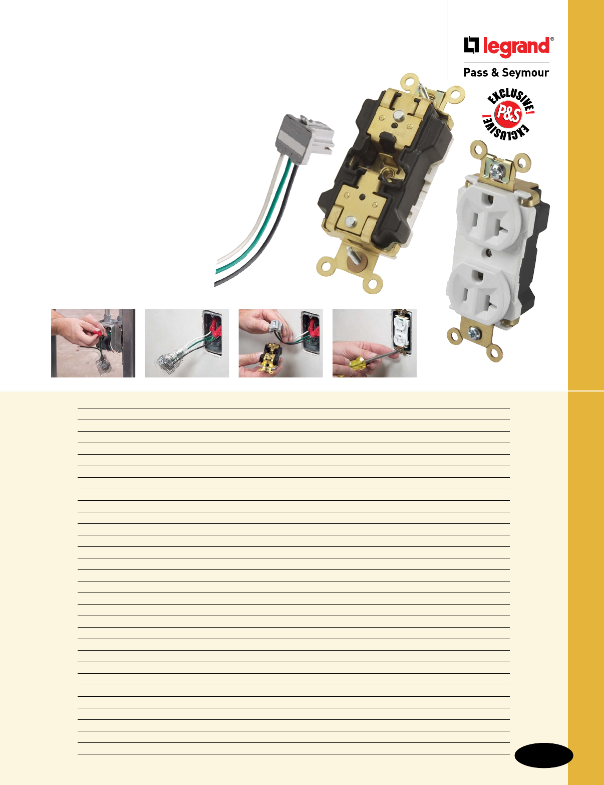
Device Rating Page Number
PlugTail™ Extra Heavy-Duty Specification Grade Receptacles 15 & 20A, 125V B-2 – B-5
Extra Heavy-Duty Hospital Grade Receptacles 15 & 20A, 125V; 20A, 250V B-6, B-7
Industrial Extra Heavy-Duty Specification Grade Receptacles 15 & 20A, 125 & 250V B-8, B-9
Heavy-Duty Specification Grade Receptacles 15 & 20A, 125 & 250V B-10
Heavy-Duty Hospital Grade Receptacles 15 & 20A, 125V; 20A, 250V B-11, B-12
PlugTail™ Specification Grade Receptacles 15 & 20A, 125V B-13 – B-16
PlugTail™ Power Pre-Fab Wiring Systems & Metal Box Kits B-17, B-18
Hard Use Specification Grade Receptacles 15 & 20A, 125, 125/250V B-19
Construction Specification Grade Receptacles 15 & 20A, 125V B-20
Commercial Specification Grade Receptacles 15A, 125V; 20A, 125 & 250V B-21
Hospital & Specification Grade Single Receptacles 15 & 20A, 125 & 250V B-22 – B-24
Tamper-Resistant Receptacles 15 & 20A, 125V B-25 – B-28
Weather-Resistant Receptacles 15 & 20A, 125 & 250V B-29
Isolated Ground Receptacles 15 & 20A, 125V; 20A, 250V B-30, B-31
PlugTail™ Decorator Receptacles 15 & 20A, 125V B-32
Hospital & Specification Grade Decorator Receptacles 15 & 20A, 120/125, 125 & 250V B-33 – B-37
TradeMaster® Tamper-Resistant Receptacles 15A, 125V B-38, B-39
Weather-Resistant Receptacles 15A, 125V B-40
TradeMaster® Receptacles, Hallway Lights & Combinations 15A, 125V & 15A, 120/125VAC B-41 – B-43
Recessed TV Boxes B-44
Specification & Hospital Grade GFCI Receptacles 15 & 20A, 125VAC B-45 – B-51
Weather-Resistant & DuraShield™ GFCI Receptacles 15 & 20A, 125VAC B-52, B-53
PlugTail™ GFCI Receptacles 15 & 20A, 125VAC B-54 – B-57
NAFTA-Compliant & RoHS-Compliant GFCI Receptacles 15 & 20A, 125VAC B-58 – B-61
Surge Protective Spec Grade Hospital Receptacles & PlugTail 15 & 20A, 125VAC B-62, B-68
Quad Receptacles & Specifications & Accessories 15 & 20A, 125V B-69, B-70
Dust & Moisture Resistant & Clock Hanger Receptacles 15 & 20A, 125V B-71
Power Outlet Receptacles & Plugs 20, 30, 50 & 60A B-72 – B-74
Miscellaneous Configurations B-75
Power & Surge Protection Strips & Specifications B-76, B-77
B-1
Straight Blade Receptacles
Straight Blade Receptacles
PlugTail™. The fastest, most consistent and
reliable wiring devices – ever! Factory-terminated
devices and connectors mean that device installation
is the same regardless of skill level of the installer.
The UL-Listed connectors are keyed to ensure proper
wiring installation into each receptacle. The connector
simply snaps into the back of the device — no
preparing, stripping or looping conductors, no
exposed terminals to tighten or tape, and no
mistakes mean no costly callbacks! Now device
installation is a snap!
Devices & Wall Plates Color Selection Chart available on Pages A-29, B-78 and Q-61.
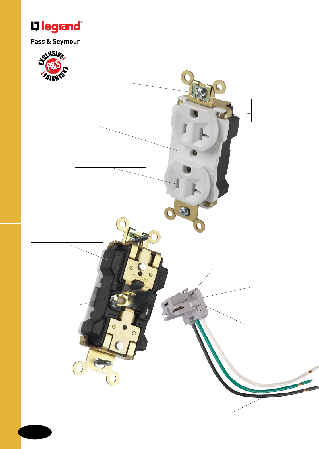
B-2
Straight Blade Receptacles
Straight Blade Receptacles
PlugTail™ Extra Heavy-Duty
Specification Grade Receptacles
PT5362AW
Strap tabs wrap around
and lock down on face to
prevent strap from separating
from face and back body.
Built-in connector
features large brass
terminal blades to
ensure consistent,
reliable electrical
connections.
Auto-ground clip
assures positive ground.
Exclusive patented feature,
circuit label on face allows
permanent circuit identification.
.036 inch thick, brass,
triple-wipe power contacts
for lasting retention.
No exposed terminals create
a finger-safe application before,
during, and after installation.
Two drive screws anchor
strap to back body and face.
Large crimped and
welded brass contacts
snugly terminate on
device blade terminals.
Pre-stripped
connector leads
fasten to conductors,
easier than standard
pigtails.
PlugTail™ EHD Specification Grade Receptacles
Tamper-resistant version
features dual mechanical shutter
system to help prevent insertion
of foreign objects.
Ultrasonically welded
polycarbonate connector
housing secures terminations
and conductors in a UL Listed,
finger safe housing. Audible
snapping latch assures
connection, allows release.
Exclusive patented feature,
circuit label on back allows
permanent circuit identification.
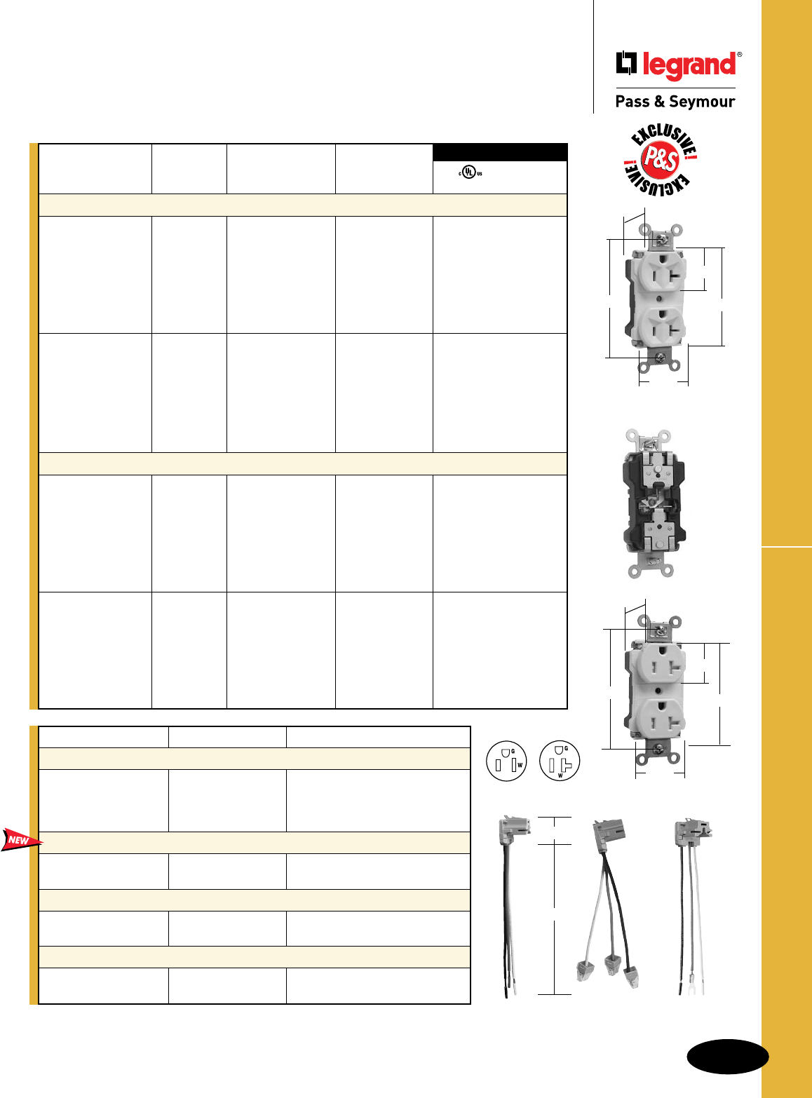
B-3
PlugTail™ EHD Specification Grade Receptacles
Straight Blade Receptacles
Straight Blade Receptacles
PlugTail™ Extra Heavy-Duty
Specification Grade Receptacles
15 & 20A, 125V
PT5362AW
.866"
3.281"
1.625"
1.104"
2.750"
Rating NEMA
Catalog Number A. V. Color Cong. No.
Duplex Receptacles
PT5262AI 15 125 Ivory 5-15R ••
PT5262AW 15 125 White 5-15R ••
PT5262A 15 125 Brown 5-15R ••
PT5262AGRY 15 125 Gray 5-15R ••
PT5262ABK 15 125 Black 5-15R ••
PT5262ARED 15 125 Red 5-15R ••
PT5262ALA 15 125 LightAlmond 5-15R ••
PT5262ABL 15 125 Blue 5-15R ••
PT5362AI 20 125 Ivory 5-20R ••
PT5362AW 20 125 White 5-20R ••
PT5362A 20 125 Brown 5-20R ••
PT5362AGRY 20 125 Gray 5-20R ••
PT5362ABK 20 125 Black 5-20R ••
PT5362ARED 20 125 Red 5-20R ••
PT5362ALA 20 125 LightAlmond 5-20R ••
PT5362ABL 20 125 Blue 5-20R ••
Tamper-Resistant Duplex Receptacles
PTTR62I 15 125 Ivory 5-15R ••
PTTR62W 15 125 White 5-15R ••
PTTR62 15 125 Brown 5-15R ••
PTTR62GRY 15 125 Gray 5-15R ••
PTTR62BK 15 125 Black 5-15R ••
PTTR62RED 15 125 Red 5-15R ••
PTTR62LA 15 125 LightAlmond 5-15R ••
PTTR62BL 15 125 Blue 5-15R ••
PTTR63I 20 125 Ivory 5-20R ••
PTTR63W 20 125 White 5-20R ••
PTTR63 20 125 Brown 5-20R ••
PTTR63GRY 20 125 Gray 5-20R ••
PTTR63BK 20 125 Black 5-20R ••
PTTR63RED 20 125 Red 5-20R ••
PTTR63LA 20 125 LightAlmond 5-20R ••
PTTR63BL 20 125 Blue 5-20R ••
3rd Party Compliance
FSUL
UL498 WC596
PTTR63W
.866"
3.281"
1.625"
1.104"
2.750"
AlldeviceslistedonthispageconformtoNEMAWD-1andWD-6.
For Bulk Packaging Solutions consult factory.
NEMA
5-15R
NEMA
5-20R
2Pole,3Wire
Catalog Number Wire Type Wire Length
PlugTail Connectors – Right Angle
PTRA6SOL Solid 6"
PTRA6STR Stranded 6"
PTRA6SOLB25 Solid 25"
PTRA6STRB25 Stranded 25"
NAFTA-Compliant PlugTail Connectors – Right Angle
PTRA6SOLNA Solid 6"
PTRA6STRNA Stranded 6"
PlugTail Connectors – Right Angle with WAGO Connectors
PTRA6SOLBP Solid 6"
PTRA6STRBP Stranded 6"
PlugTail Connectors – Right Angle with Ground Screw
PTRA6SOLG Solid 6"
PTRA6STRG Stranded 6"
1.125"
6.375"
PTRA6STR PTRA6STRBP PTRA6STRG
NAFTA-Compliant PlugTail Connectors are ideal for use on projects subject to the provisions of the Buy American Act.
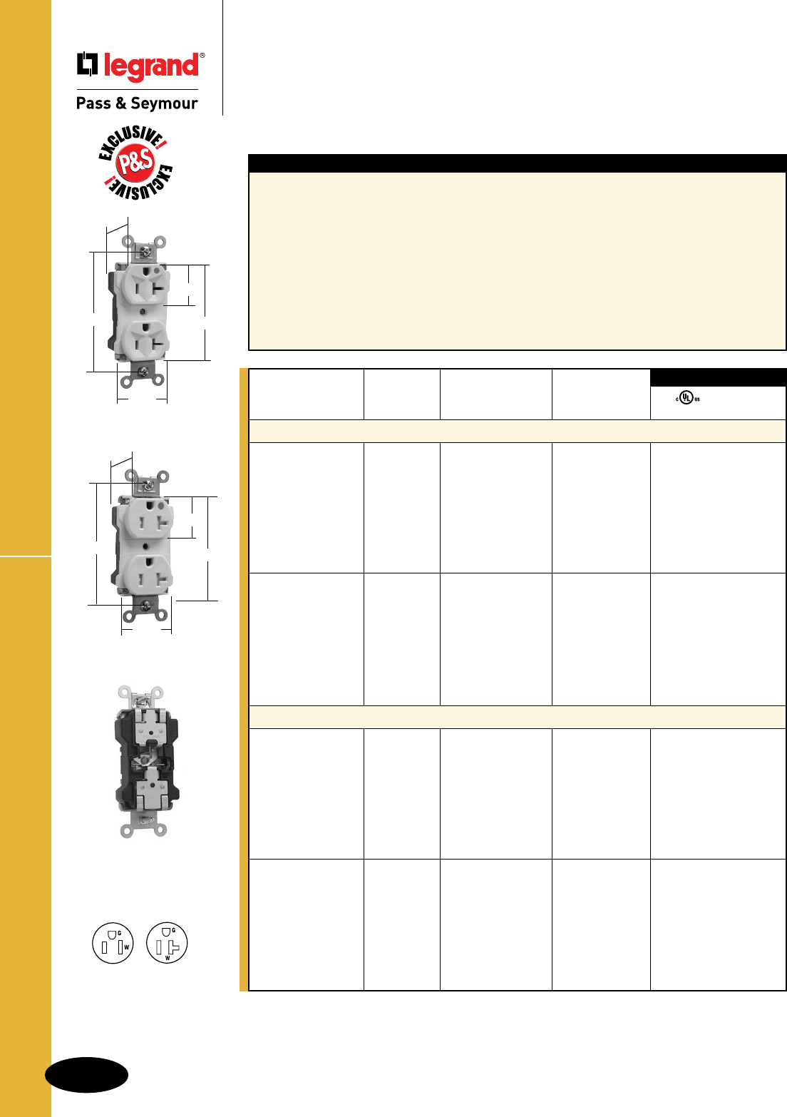
For PlugTail Connectors, see Page B-3.
For Bulk Packaging Solutions consult factory.
PlugTail™ EHD Hospital Grade Receptacles
B-4
Straight Blade Receptacles
AlldeviceslistedonthispageconformtoNEMAWD-1andWD-6.
Straight Blade Receptacles
PlugTail™ Extra Heavy-Duty
Hospital Grade Receptacles
15 & 20A, 125V
Features
nExclusivepatentedfeature,circuitlabelonface
allowspermanentcircuitidentification.
n.036inchthick,brass,triple-wipepowercontactsfor
lastingretention.
nStraptabswraparoundandlockdownonfaceto
preventstrapfromseparatingfromfaceandbackbody.
nNoexposedterminalscreateafingersafeapplication
before,during,andafterinstallation.
nBuilt-inconnectorfeatureslargebrassterminalblades
toensureconsistent,reliableelectricalconnections.
nCrimpedandweldedcontacts.
nUltrasonicallyweldedpolycarbonate
connectorhousingsecuresterminations
andconductorsinaULListed,fingersafe
housing.
nLargebrasscontactssnuglyterminateon
devicebladeterminals.
nPre-strippedconnectorleadsfastento
conductors,easierthanstandardpigtails.
nAuto-groundclipassurespositiveground.
n
Tamper-resistantversionfeaturesdual
mechanicalshuttersystemtohelpprevent
insertionofforeignobjects.
PTTR63HW
.866"
3.281"
1.625"
1.104"
2.750"
PT8300W
.866"
3.281"
1.625"
1.104"
2.750"
Rating NEMA
Catalog Number A. V. Color Cong. No.
Duplex Receptacles
PT8200I 15 125 Ivory 5-15R ••
PT8200W 15 125 White 5-15R ••
PT8200 15 125 Brown 5-15R ••
PT8200GRY 15 125 Gray 5-15R ••
PT8200BK 15 125 Black 5-15R ••
PT8200RED 15 125 Red 5-15R ••
PT8200LA 15 125 LightAlmond 5-15R ••
PT8200BL 15 125 Blue 5-15R ••
PT8300I 20 125 Ivory 5-20R ••
PT8300W 20 125 White 5-20R ••
PT8300 20 125 Brown 5-20R ••
PT8300GRY 20 125 Gray 5-20R ••
PT8300BK 20 125 Black 5-20R ••
PT8300RED 20 125 Red 5-20R ••
PT8300LA 20 125 LightAlmond 5-20R ••
PT8300BL 20 125 Blue 5-20R ••
Tamper-Resistant Duplex Receptacles
PTTR62HI 15 125 Ivory 5-15R ••
PTTR62HW 15 125 White 5-15R ••
PTTR62H 15 125 Brown 5-15R ••
PTTR62HGRY 15 125 Gray 5-15R ••
PTTR62HBK 15 125 Black 5-15R ••
PTTR62HRED 15 125 Red 5-15R ••
PTTR62HLA 15 125 LightAlmond 5-15R ••
PTTR62HBL 15 125 Blue 5-15R ••
PTTR63HI 20 125 Ivory 5-20R ••
PTTR63HW 20 125 White 5-20R ••
PTTR63H 20 125 Brown 5-20R ••
PTTR63HGRY 20 125 Gray 5-20R ••
PTTR63HBK 20 125 Black 5-20R ••
PTTR63HRED 20 125 Red 5-20R ••
PTTR63HLA 20 125 LightAlmond 5-20R ••
PTTR63HBL 20 125 Blue 5-20R ••
3rd Party Compliance
FSUL
UL498 WC596
NEMA
5-15R
NEMA
5-20R
2Pole,3Wire
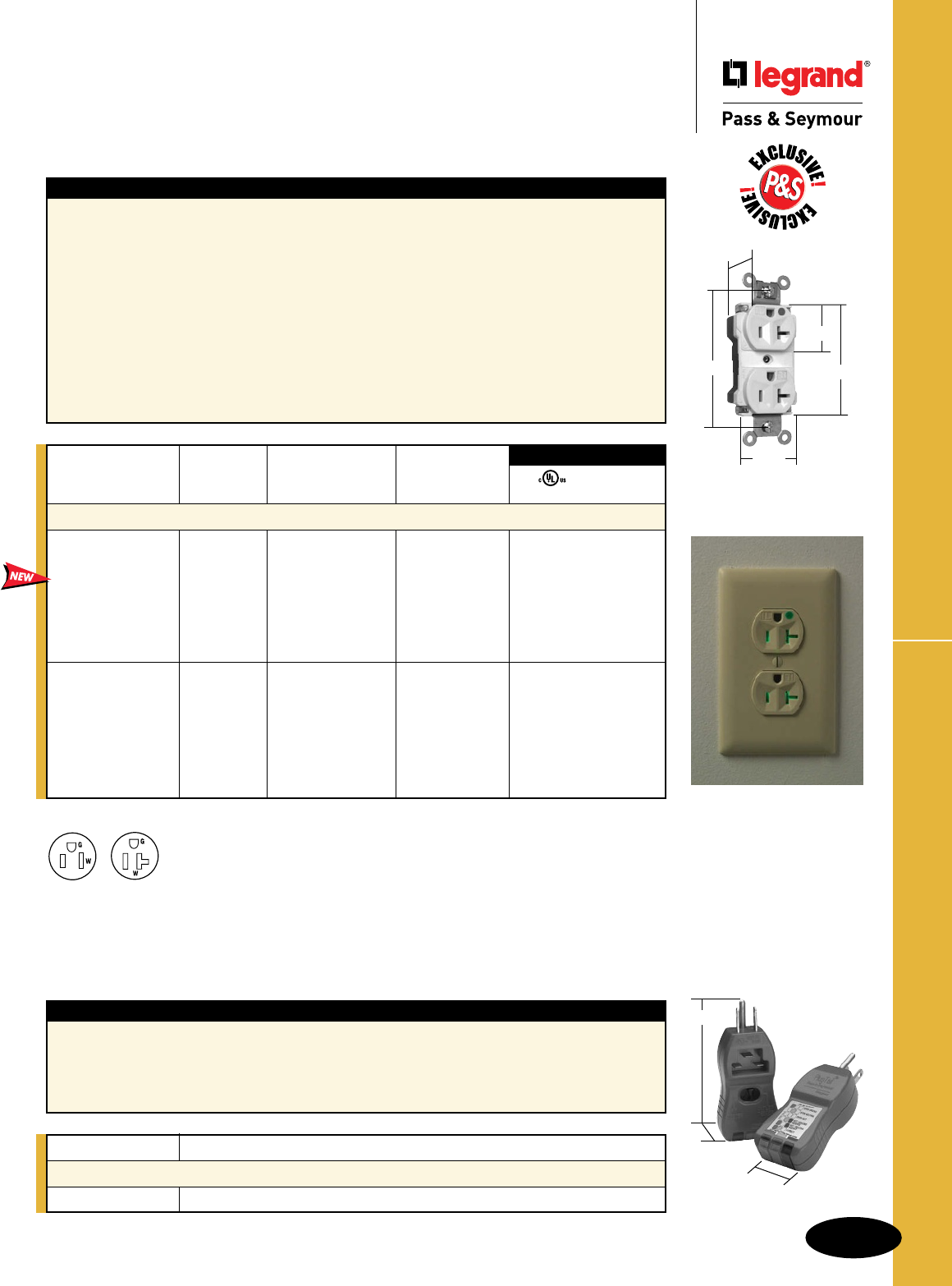
B-5
Straight Blade Receptacles
AlldeviceslistedonthispageconformtoNEMAWD-1andWD-6.
Straight Blade Receptacles
PlugTail™ Extra Heavy-Duty
Hospital Grade Illuminated Receptacles
15 & 20A, 125V
PlugTail™ EHD Hospital Grade Receptacles
Features
nMolded-in“IL”markingsonfaceofproduct.
nIlluminatedfaceindicatespowertoreceptacleand
makesiteasytoidentifyreceptacleindarkapplications.
nExclusivepatentedfeature,circuitlabelonface
allowspermanentcircuitidentification.
n.036inchthick,brass,triple-wipepowercontactsfor
lastingretention.
nStraptabswraparoundandlockdownonfaceto
preventstrapfromseparatingfromfaceandbackbody.
nNoexposedterminalscreateafingersafeapplication
before,during,andafterinstallation.
nBuilt-inconnectorfeatureslargebrassterminalblades
toensureconsistent,reliableelectricalconnections.
nCrimpedandweldedcontacts.
nUltrasonicallyweldedpolycarbonate
connectorhousingsecuresterminations
andconductorsinaULListed,fingersafe
housing.
nLargebrasscontactssnuglyterminateon
devicebladeterminals.
nPre-strippedconnectorleadsfastento
conductors,easierthanstandardpigtails.
nAuto-groundclipassurespositiveground.
Rating NEMA
Catalog Number A. V. Color Cong. No.
Illuminated Duplex Receptacles
PT8200ILI 15 125 Ivory 5-15R ••
PT8200ILW 15 125 White 5-15R ••
PT8200IL 15 125 Brown 5-15R ••
PT8200ILGRY 15 125 Gray 5-15R ••
PT8200ILBK 15 125 Black 5-15R ••
PT8200ILRED 15 125 Red 5-15R ••
PT8200ILLA 15 125 LightAlmond 5-15R ••
PT8300ILI 20 125 Ivory 5-20R ••
PT8300ILW 20 125 White 5-20R ••
PT8300IL 20 125 Brown 5-20R ••
PT8300ILGRY 20 125 Gray 5-20R ••
PT8300ILBK 20 125 Black 5-20R ••
PT8300ILRED 20 125 Red 5-20R ••
PT8300ILLA 20 125 LightAlmond 5-20R ••
3rd Party Compliance
FSUL
UL498 WC596
For PlugTail Connectors, see Page B-3.
For Bulk Packaging Solutions consult factory.
Features
nEnsuresproperconnectionsandpowerpresenceat
bothrough-inanddevice-outstagesduringP&S
PlugTailDeviceinstallation.
nFast,easyidentificationofcircuitconnections.
nEasy-to-seeindicatorlights.
nSturdyconstructionforlong-term
dependability.
nHelpspreventcallbacks.
nEnsuresproperwiring.
Catalog Number Description
P&S PlugTail™ Tester
PTTESTER RedPlugTailTesterforReceptaclesandTails
PT8300ILLA
.866"
3.281"
1.625"
1.104"
2.750"
NEMA
5-15R
NEMA
5-20R
2Pole,3Wire
3.93"
1.06"
1.68"
PTTESTER
Illuminatedfaceindicates
powertoreceptacleand
makesiteasytoidentify
receptacleindark
applications.
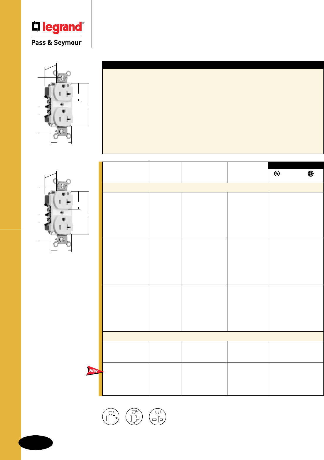
B-6
Straight Blade Receptacles
AlldeviceslistedonthispageconformtoNEMAWD-1andWD-6.
Extra Heavy-Duty Hospital Grade Receptacles
Straight Blade Receptacles
Extra Heavy-Duty
Hospital Grade Receptacles
15 & 20A, 125V; 20A, 250V
NEMA
5-15R
NEMA
5-20R
NEMA
6-20R
Rating NEMA
Catalog Number A. V. Color Cong. No.
Duplex Receptacles Back & Side Wire
8200I 15 125 Ivory 5-15R •••
8200W 15 125 White 5-15R •••
8200 15 125 Brown 5-15R •••
8200GRY 15 125 Gray 5-15R •••
8200BK 15 125 Black 5-15R •••
8200RED 15 125 Red 5-15R •••
8200LA 15 125 LightAlmond 5-15R •••
8300I 20 125 Ivory 5-20R •• •
8300W 20 125 White 5-20R •• •
8300 20 125 Brown 5-20R •• •
8300GRY 20 125 Gray 5-20R •• •
8300BK 20 125 Black 5-20R •• •
8300RED 20 125 Red 5-20R •• •
8300LA 20 125 LightAlmond 5-20R •• •
8800I 20 250 Ivory 6-20R •• •
8800W 20 250 White 6-20R •• •
8800 20 250 Brown 6-20R •• •
8800GRY 20 250 Gray 6-20R •• •
8800BK 20 250 Black 6-20R •• •
8800LA 20 250 LightAlmond 6-20R •• •
8800RED 20 250 Red 6-20R •• •
LED Illuminated Face Duplex Receptacles Back & Side Wire
8200ILI 15 125 Ivory 5-15R •••
8200ILW 15 125 White 5-15R •••
8200ILRED 15 125 Red 5-15R •••
8300ILI 20 125 Ivory 5-20R •• •
8300ILW 20 125 White 5-20R •• •
8300ILGRY 20 125 Gray 5-20R •• •
8300ILRED 20 125 Red 5-20R •• •
8300ILLA 20 125 LightAlmond 5-20R •• •
3rd Party Compliance
FSUL
UL498 WC596 C22.2 No. 42
8300I
.900"
3.281"
1.625"
1.104"
2.750"
Features
nOne-piecenickel-platedbrassmountingstrapwith
integralground.
nStraptabswraparoundandlockdownonfaceto
preventstrapfromseparatingfromfaceandbackbody.
nTwodrivescrewsanchorstraptobackbodyandface.
nExclusivepatentedfeature,circuitlabelonface
allowspermanentcircuitidentification.
n.040inchthick,nickel-platedbrass,triple-wipepower
contactsforlastingretention.
nEasilyaccessedbreak-off,line-contactconnecting
tabforfast,easysplit-circuitwiring.
nImpact-resistantnylonfaceandbackbody.
nOversized#10deeptri-driveheadbrassterminaland
groundscrews.
nExclusivepatentedfeature,externalscrew-
pressure-platebackwireclamponground
terminalforfaster,easierinstallation.
nExternalnickel-platedscrew-pressure-plate
backwireclampswith#10brassterminal
screwsforvisualassuranceofagood
connection.
nLineterminalsaccept#14–#10AWG
strandedorsolidcoppercladconductors.
nAuto-groundclipassurespositiveground.
n
Illuminatedversionfeaturesexclusive
LEDlampwithsolderconnectionforlong
durablelife(10-12years).
8300ILI
.900"
3.281"
1.625"
1.104"
2.750"
For Bulk Packaging Solutions consult factory.
2Pole,3Wire
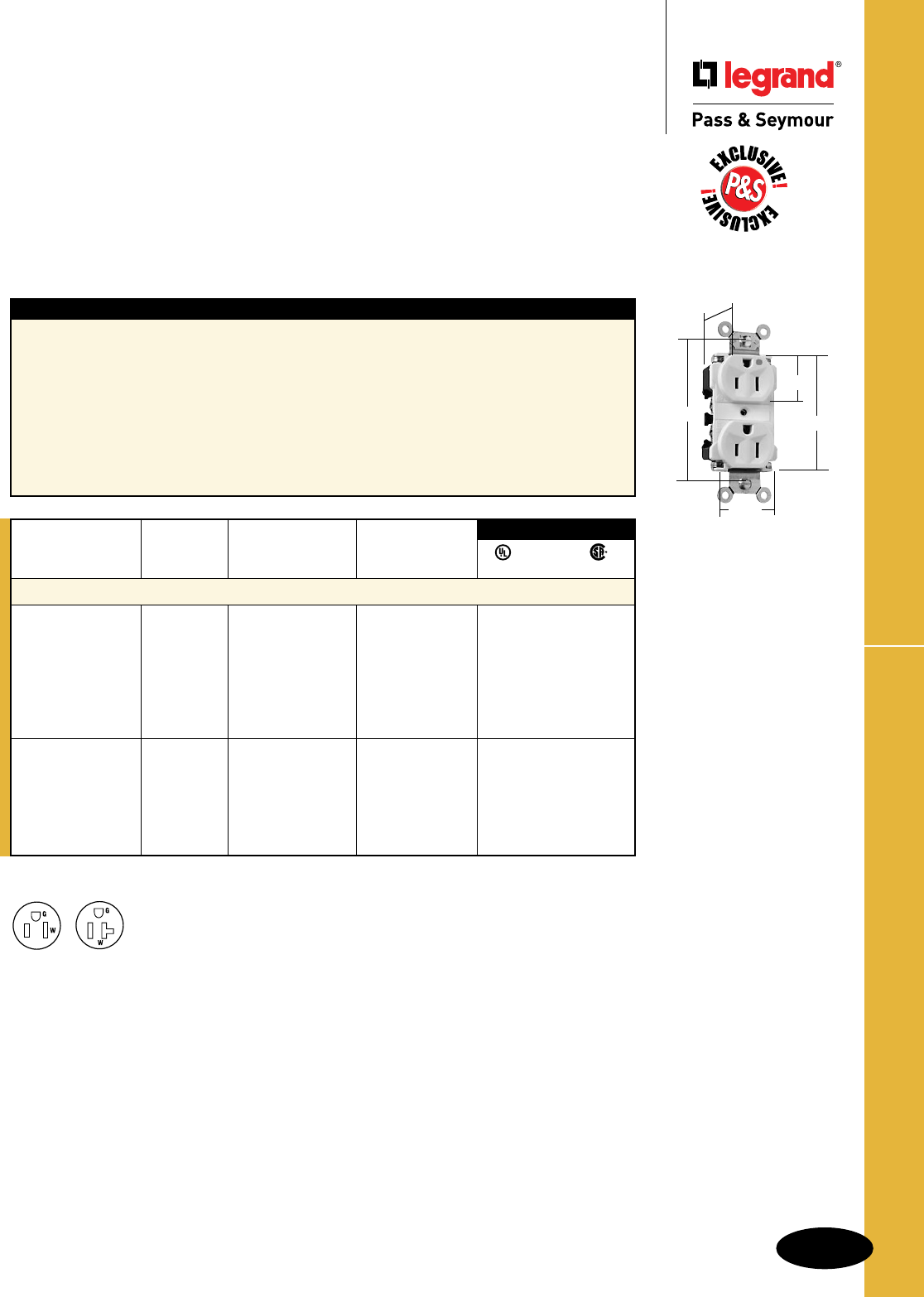
B-7
Straight Blade Receptacles
AlldeviceslistedonthispageconformtoNEMAWD-1andWD-6.
EHD Hospital Grade MRI Receptacles
Straight Blade Receptacles
Extra Heavy-Duty Hospital Grade
MRI Receptacles
15 & 20A, 125V
Rating NEMA
Catalog Number A. V. Color Cong. No.
Hospital Grade Duplex Receptacles Back & Side Wire
8200IMRI 15 125 Ivory 5-15R •••
8200WMRI 15 125 White 5-15R •••
8200MRI 15 125 Brown 5-15R •••
8200GRYMRI 15 125 Gray 5-15R •••
8200BKMRI 15 125 Black 5-15R •••
8200REDMRI 15 125 Red 5-15R •••
8200LAMRI 15 125 LightAlmond 5-15R •••
8300IMRI 20 125 Ivory 5-20R •••
8300WMRI 20 125 White 5-20R •••
8300GRYMRI 20 125 Gray 5-20R •••
8300BKMRI 20 125 Black 5-20R •••
8300REDMRI 20 125 Red 5-20R •••
8300LAMRI 20 125 LightAlmond 5-20R •••
3rd Party Compliance
FSUL
UL498 WC596 C22.2 No. 42
Features
nExclusivepatentedfeature,circuitlabelonface
allowspermanentcircuitidentification.
nExtraheavy-duty,one-piecenickel-platedbrass
mountingstrapwithintegralgroundforsuperior
structuralintegrityandlong-termperformance.
n.036inchthick,brass,triple-wipepowercontacts
forlastingretention.
nStraptabswraparoundandlockdownonface
topreventstrapfromseparatingfromfaceand
backbody.
nEasilyaccessedbreak-off,line-contact
connectingtabforfast,easysplit-circuit
wiring.
nExclusivepatentedfeature,externalscrew-
pressure-platebackwireclamponground
terminalforfaster,easierinstallation.
nExternalscrew-pressure-platebackwire
clampswith#10brassterminalscrewsfor
visualassuranceofagoodconnection.
nAuto-groundclipassurespositiveground.
8200LAMRI
.900"
3.281"
1.625"
1.104"
2.750"
Receptacles designed expressly for MRI applications –
We build these
exclusive P&S receptacles with no ferrous metal, so they are perfect for high-magnetic-field
environments such as magnetic-resonance imaging (MRI) suites. With the same basic design
as our standard Extra Heavy-Duty Receptacles, they are extremely durable.
NEMA
5-15R
NEMA
5-20R
2Pole,3Wire
For Bulk Packaging Solutions consult factory.
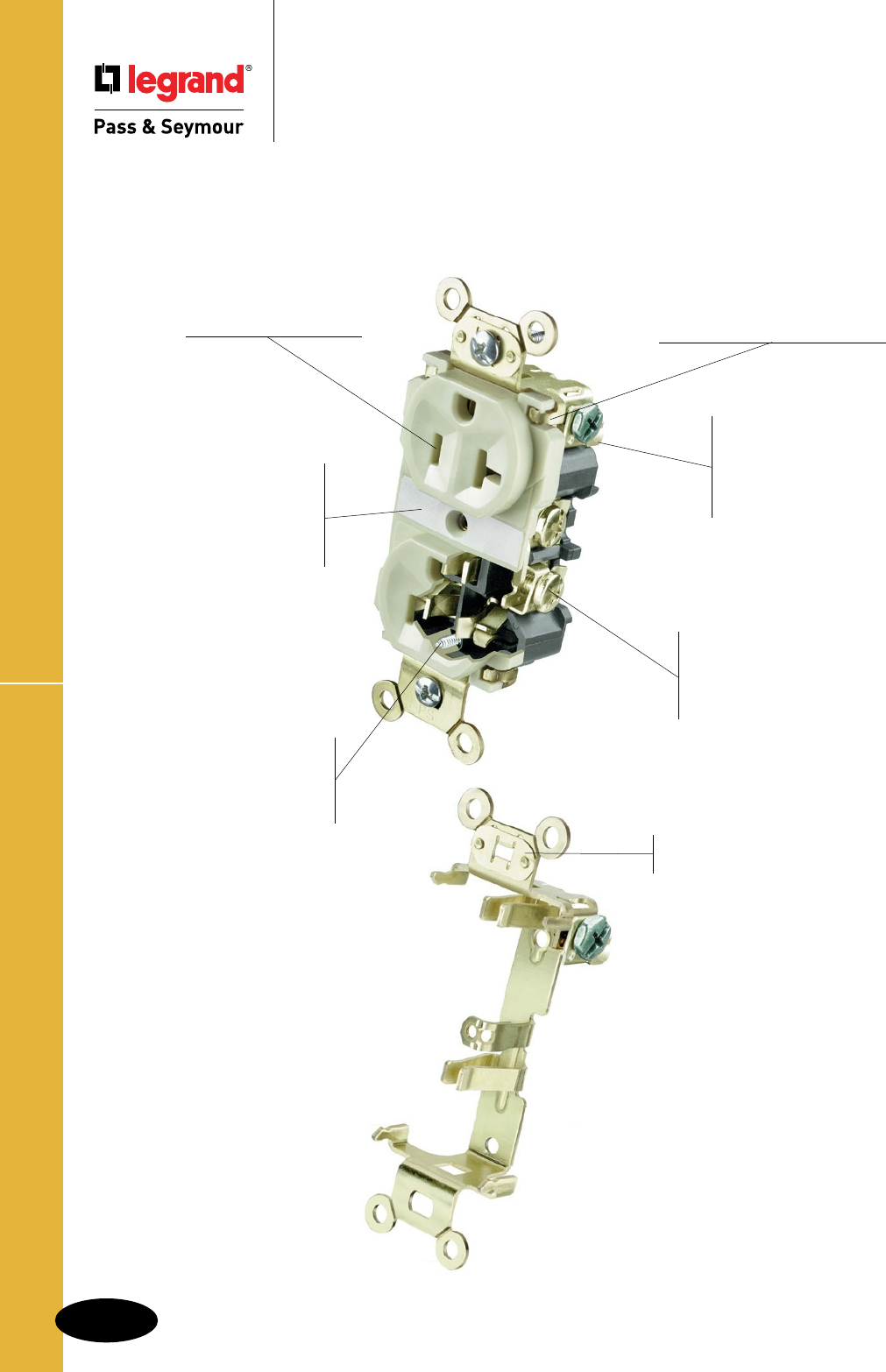
B-8
Straight Blade ReceptaclesIndustrial EHD Spec Grade Receptacles
Straight Blade Receptacles
Industrial Extra Heavy-Duty
Specification Grade Receptacles
External screw-pressure-
plate back wire clamps
with #10 brass terminal
screws for visual assurance
of a good connection.
Exclusive, patented
feature, external
screw-pressure-plate
back wire clamp on
ground terminal for
faster, easier installation.
Two drive screws
anchor strap to
back body and face
where abrupt removal
torque is strongest.
Strap tabs wrap around and
lock down on face to prevent
strap from separating from face
and back body.
Exclusive
patented feature,
circuit label
on face allows
permanent circuit
identification.
.036 inch thick, brass,
triple-wipe power
contacts for lasting
retention.
Heavy-duty, one-piece
brass strap and integral
ground for added strength
and safety.
5362AI
Auto-ground clip
assures positive ground.
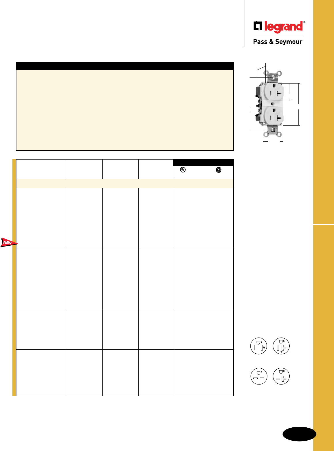
B-9
Straight Blade Receptacles
AlldeviceslistedonthispageconformtoNEMAWD-1andWD-6.
B-9
Industrial EHD Spec Grade ReceptaclesStraight Blade Receptacles
Straight Blade Receptacles
Industrial
Extra Heavy-Duty
Specification Grade Receptacles
15 & 20A, 125 & 250V
5362AI
.900"
3.281"
1.625"
1.104"
2.750"
Features
nOne-piecebrassmountingstrapwithintegralground.
nStraptabswraparoundandlockdownonfaceto
preventstrapfromseparatingfromfaceandbackbody.
nTwodrivescrewsanchorstraptobackbodyandface.
nExclusivepatentedfeature,circuitlabelonface
allowspermanentcircuitidentification.
n.036inchthick,brass,triple-wipepowercontacts
forlastingretention.
nEasilyaccessedbreak-off,line-contactconnecting
tabforfast,easysplit-circuitwiring.
nImpact-resistantnylonfaceandbackbody.
nOversized#10deeptri-driveheadbrassterminal
andgroundscrews.
nExclusivepatentedfeature,externalscrew-
pressure-platebackwireclamponground
terminalforfaster,easierinstallation.
nExternalscrew-pressure-platebackwire
clampswith#10brassterminalscrewsfor
visualassuranceofagoodconnection.
nLineterminalsaccept#14–#10AWG
strandedorsolidcoppercladconductors.
nAuto-groundclipassurespositiveground.
n
Corrosion-resistantmodelshavenickel-
platedstrapsandcontacts.
Rating NEMA
Catalog Number A. V. Color Cong. No.
Duplex Receptacles Back & Side Wire
5262AI 15 125 Ivory 5-15R •••
5262AW 15 125 White 5-15R •••
5262A 15 125 Brown 5-15R •••
5262AGRY 15 125 Gray 5-15R •••
5262ABK 15 125 Black 5-15R •••
5262ARED 15 125 Red 5-15R •••
5262ALA 15 125 LightAlmond 5-15R •••
CR6200* 15 125 Yellow 5-15R •••
CR6200GRY* 15 125 Gray 5-15R •••
5362AI 20 125 Ivory 5-20R •••
5362AW 20 125 White 5-20R •••
5362A 20 125 Brown 5-20R •••
5362AGRY 20 125 Gray 5-20R •••
5362ABK 20 125 Black 5-20R •••
5362ARED 20 125 Red 5-20R •••
5362ALA 20 125 LightAlmond 5-20R •••
5362ABL 20 125 Blue 5-20R •••
CR6300BR* 20 125 Brown 5-20R •••
CR6300* 20 125 Yellow 5-20R •••
5662AI 15 250 Ivory 6-15R •••
5662AW 15 250 White 6-15R •••
5662A 15 250 Brown 6-15R •••
5662AGRY 15 250 Gray 6-15R •••
5662ABK 15 250 Black 6-15R •••
5662ARED 15 250 Red 6-15R •••
5862AI 20 250 Ivory 6-20R •••
5862AW 20 250 White 6-20R •••
5862A 20 250 Brown 6-20R •••
5862AGRY 20 250 Gray 6-20R •••
5862ABK 20 250 Black 6-20R •••
5862ARED 20 250 Red 6-20R •••
5862ALA 20 250 LightAlmond 6-20R •••
3rd Party Compliance
FSUL
UL498 WC596 C22.2 No. 42
*Corrosion-Resistant.
For Bulk Packaging Solutions consult factory.
NEMA
5-15R
NEMA
5-20R
NEMA
6-15R
NEMA
6-20R
2Pole,3Wire
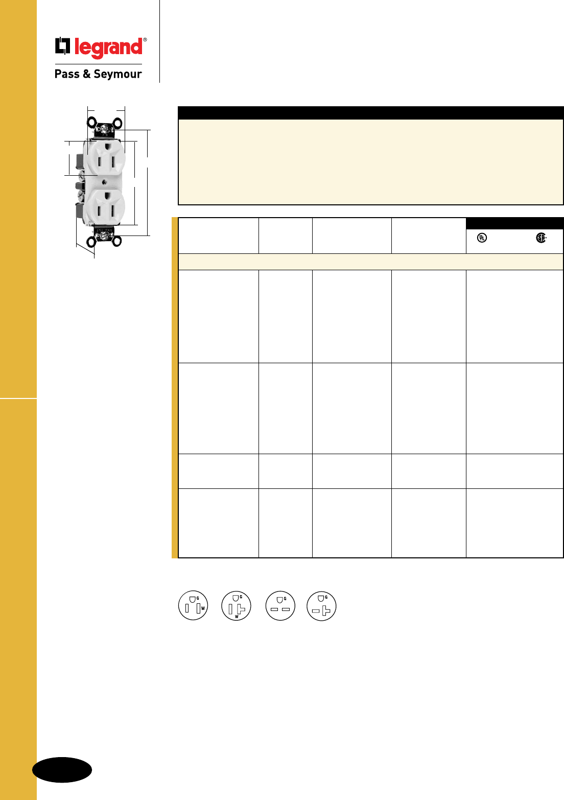
Heavy-Duty Specification Grade Receptacles
B-10
Straight Blade Receptacles
AlldeviceslistedonthispageconformtoNEMAWD-1andWD-6.
Straight Blade Receptacles
Heavy-Duty Specification Grade Receptacles
15 & 20A, 125 & 250V
NEMA
5-15R
NEMA
6-15R
NEMA
5-20R
NEMA
6-20R
Features
nHeavy-duty,brassstrapforaddedstrengthand
groundconductivity.
n.032inchthick,brass,triple-wipepowercontacts
forlastingretention.
nStraptabswraparoundfacetopreventstrapfrom
separatingfromfaceandbackbody.
nEasilyaccessedbreak-off,line-contactconnecting
tabforfast,easysplit-circuitwiring.
nHighstrengthnylonface.
nInternalscrew-pressure-platebackandside
wiredtoaccept#14and#10AWGstranded
orsolidcopperorcopper-cladconductors.
Eightbackwireholes.
nAuto-groundclipassurespositiveground.
Rating NEMA
Catalog Number A. V. Color Cong. No.
Duplex Receptacles Back & Side Wire
PS5262I 15 125 Ivory 5-15R • • •
PS5262W 15 125 White 5-15R • • •
PS5262 15 125 Brown 5-15R • • •
PS5262GRY 15 125 Gray 5-15R • • •
PS5262BK 15 125 Black 5-15R • • •
PS5262RED 15 125 Red 5-15R • • •
PS5262LA 15 125 LightAlmond 5-15R • • •
PS5262BL 15 125 Blue 5-15R • • •
PS5362I 20 125 Ivory 5-20R • • •
PS5362W 20 125 White 5-20R • • •
PS5362 20 125 Brown 5-20R • • •
PS5362GRY 20 125 Gray 5-20R • • •
PS5362BK 20 125 Black 5-20R • • •
PS5362RED 20 125 Red 5-20R • • •
PS5362LA 20 125 LightAlmond 5-20R • • •
PS5362BL 20 125 Blue 5-20R • • •
5662I 15 250 Ivory 6-15R • • •
5662W 15 250 White 6-15R • • •
5662 15 250 Brown 6-15R • • •
5862I 20 250 Ivory 6-20R • • •
5862W 20 250 White 6-20R • • •
5862 20 250 Brown 6-20R • • •
5862GRY 20 250 Gray 6-20R • • •
5862BK 20 250 Black 6-20R • • •
5862RED 20 250 Red 6-20R • • •
3rd Party Compliance
FSUL
UL498 WC596 C22.2 No. 42
PS5262I
.780"
2.635"
3.281"
1.322"
1.104"
2Pole,3Wire
For Bulk Packaging Solutions consult factory.
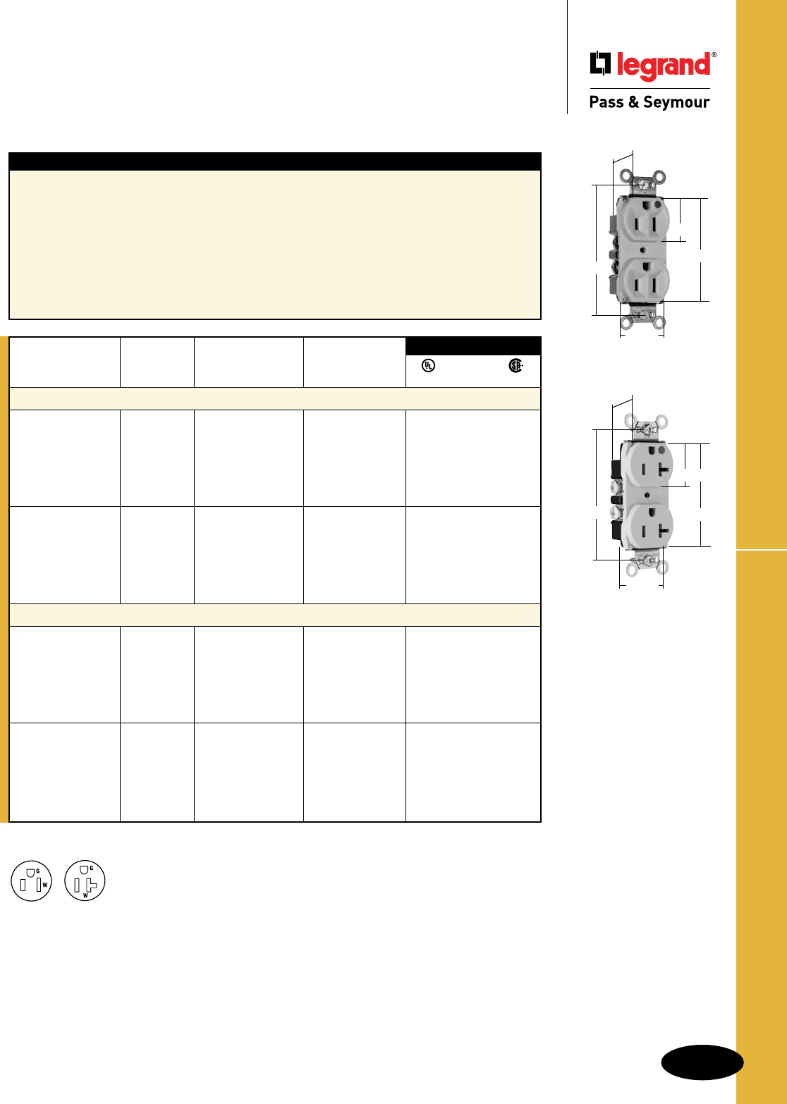
B-11
Straight Blade Receptacles
AlldeviceslistedonthispageconformtoNEMAWD-1andWD-6.
Heavy-Duty Hospital Grade Receptacles
Straight Blade Receptacles
Heavy-Duty Hospital Grade Receptacles
15 & 20A, 125V
PS8200HI
.780"
3.281"
1.322"
1.104"
2.635"
PS8300HSLA
.780"
3.281"
1.322"
1.104"
2.635"
Features
nHeavy-duty,brassstrapforaddedstrengthand
groundconductivity.
n.032inchthick,brass,triple-wipepowercontacts
forlastingretention.
nStraptabswraparoundfacetopreventstrap
fromseparatingfromfaceandbackbody.
nEasilyaccessedbreak-off,line-contactconnecting
tabforfast,easysplit-circuitwiring.
nTwodrivescrewsanchorstraptoback
bodyandface.
nTri-drivebrassterminalscrews.Internal
screw-pressure-platebackandsidewire
capability.Twobackwireholesformore
wiringflexibility.
nAuto-groundclipassurespositiveground.
n
Smoothfaceversionfeaturesanimpact-
resistantnylonfaceforeaseofcleaning
andlessdirtbuild-up.
Rating NEMA
Catalog Number A. V. Color Cong. No.
Duplex Receptacles Back & Side Wire
PS8200HI 15 125 Ivory 5-15R •••
PS8200HW 15 125 White 5-15R •••
PS8200H 15 125 Brown 5-15R •••
PS8200HGRY 15 125 Gray 5-15R •••
PS8200HRED 15 125 Red 5-15R •••
PS8200HLA 15 125 LightAlmond 5-15R •••
PS8300HI 20 125 Ivory 5-20R •••
PS8300HW 20 125 White 5-20R •••
PS8300H 20 125 Brown 5-20R •••
PS8300HGRY 20 125 Gray 5-20R •••
PS8300HRED 20 125 Red 5-20R •••
PS8300HLA 20 125 LightAlmond 5-20R •••
Duplex Receptacles – Smooth Face Back & Side Wire
PS8200HSI 15 125 Ivory 5-15R •••
PS8200HSW 15 125 White 5-15R •••
PS8200HS 15 125 Brown 5-15R •••
PS8200HSGRY 15 125 Gray 5-15R •••
PS8200HSRED 15 125 Red 5-15R •••
PS8200HSLA 15 125 LightAlmond 5-15R •••
PS8300HSI 20 125 Ivory 5-20R •••
PS8300HSW 20 125 White 5-20R •••
PS8300HS 20 125 Brown 5-20R •••
PS8300HSGRY 20 125 Gray 5-20R •••
PS8300HSRED 20 125 Red 5-20R •••
PS8300HSLA 20 125 LightAlmond 5-20R •••
3rd Party Compliance
FSUL
UL498 WC596 C22.2 No. 42
For Bulk Packaging Solutions consult factory.
NEMA
5-15R
NEMA
5-20R
2Pole,3Wire
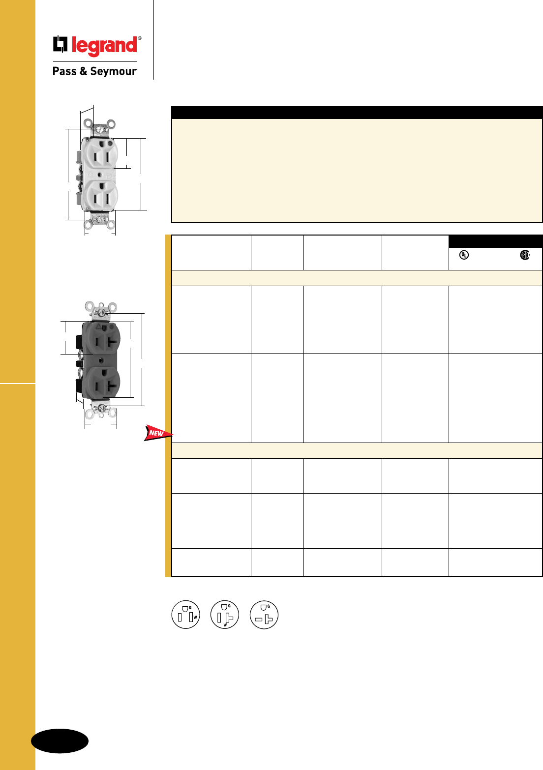
AlldeviceslistedonthispageconformtoNEMAWD-1andWD-6.
Straight Blade Receptacles
Heavy-Duty Hospital Grade
Compact Design Receptacles
15 & 20A, 125V; 20A, 250V
Features
nImpact-resistantnylonface.
nOne-pieceheat-treatedtriple-wipebrass
powercontacts.
nEasilyaccessiblebreak-offlinecontactconnecting
tabforsplitcircuitwiring.
nTerminalcompartmentsisolatedfromeach
otherforpositiveconductorcontainment.
nCorrosion-resistant,zinc-platedsteelstrap
islockedin.
nInternalscrew-pressure-platebackwireand
sidewirelineterminalsaccept#14–#10
AWGcopperorcopper-cladconductors.
nHighstrengththermoplasticbackbody.
nBackwireholesallowentryofconductor
insulationpartiallyintobodybutnotinto
wiringcompartment.
nAuto-groundclipassurespositiveground.
nCompactdesignforeasyinstallation.
nTri-driveterminalandmountingscrews.
Rating NEMA
Catalog Number A. V. Color Cong. No.
Duplex Receptacles – Compact Design Back & Side Wire
8200HI 15 125 Ivory 5-15R •••
8200HW 15 125 White 5-15R •••
8200H 15 125 Brown 5-15R •••
8200HGRY 15 125 Gray 5-15R •••
8200HRED 15 125 Red 5-15R •••
8200HLA 15 125 LightAlmond 5-15R •••
8300HI 20 125 Ivory 5-20R •••
8300HW 20 125 White 5-20R •••
8300H 20 125 Brown 5-20R •••
8300HGRY 20 125 Gray 5-20R •••
8300HBK 20 125 Black 5-20R •••
8300HRED 20 125 Red 5-20R •••
8300HLA 20 125 LightAlmond 5-20R •••
8300HBL 20 125 Blue 5-20R •••
Isolated Ground Duplex Receptacles Back & Side Wire
IG8200I 15 125 Ivory 5-15R •••
IG8200 15 125 Orange 5-15R •••
IG8200RED 15 125 Red 5-15R •••
IG8300I 20 125 Ivory 5-20R •••
IG8300W 20 125 White 5-20R •••
IG8300 20 125 Orange 5-20R •••
IG8300RED 20 125 Red 5-20R •••
IG8300LA 20 125 LightAlmond 5-20R •••
IG8800 20 250 Orange 6-20R •••
IG8800LA 20 250 LightAlmond 6-20R •••
3rd Party Compliance
FSUL
UL498 WC596 C22.2 No. 42
NEMA
5-15R
NEMA
5-20R
NEMA
6-20R
2Pole,3Wire
IG8300
1.322"
1.104" 2.635"
3.281"
.922"
8200HI
.780"
3.281"
1.322"
1.104"
2.635"
Straight Blade ReceptaclesHeavy-Duty Hospital Grade Receptacles
B-12
For Bulk Packaging Solutions consult factory.
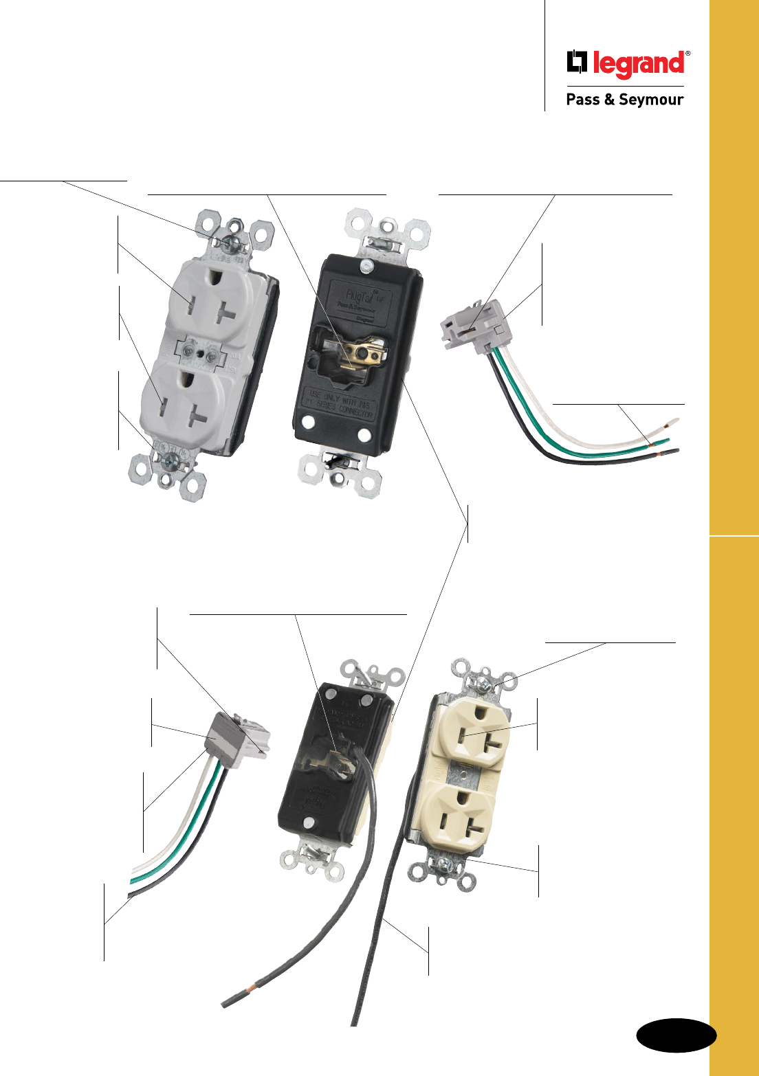
B-13
Straight Blade Receptacles
Auto-ground clip
assures positive ground.
Built-in connector features large brass
terminal blades to ensure consistent, reliable
electrical connections.
.036 inch thick,
brass, triple-wipe
power contacts for
lasting retention.
Dual mechanical
shutter system to
help prevent insertion
of foreign objects.
Plated steel
wrap strap
design for
maximum durability
and corrosion
resistance.
No exposed terminals create a
finger safe application before,during,
and after installation.
Pre-stripped
connector leads fasten
to conductors, easier
than standard pigtails.
Ultrasonically welded
polycarbonate
connector housing
secures terminations and
conductors in a UL Listed,
finger safe housing.
Large brass contacts snugly terminate on
device blade terminals. Audible snapping
latch assures connection, allows release.
PlugTail™ Specification Grade Receptacles
Straight Blade Receptacles
PlugTail™ Specification Grade Receptacles
PTTR5362W
Three drive
screws anchor
strap to back
body and face.
Built-in connector features large brass
terminal blades to ensure consistent,
reliable electrical connections.
Large brass contacts
snugly terminate on device
blade terminals. Audible
snapping latch assures
connection, allows release.
Ultrasonically welded
polycarbonate
connector housing
secures terminations and
conductors in a UL Listed,
finger safe housing.
Pre-stripped
connector
leads fasten to
conductors, easier
than standard
pigtails.
Pre-wired with one welded
pre-stripped wire lead to
facilitate switched receptacle
circuit applications.
Plated steel wrap
strap design for
maximum durability and
corrosion resistance.
.036 inch thick,
brass, triple-wipe
power contacts
for lasting retention.
Auto-ground clip
assures positive ground.
PT5362SCI
Exclusive patented
feature, circuit label on
back allows permanent
circuit identification
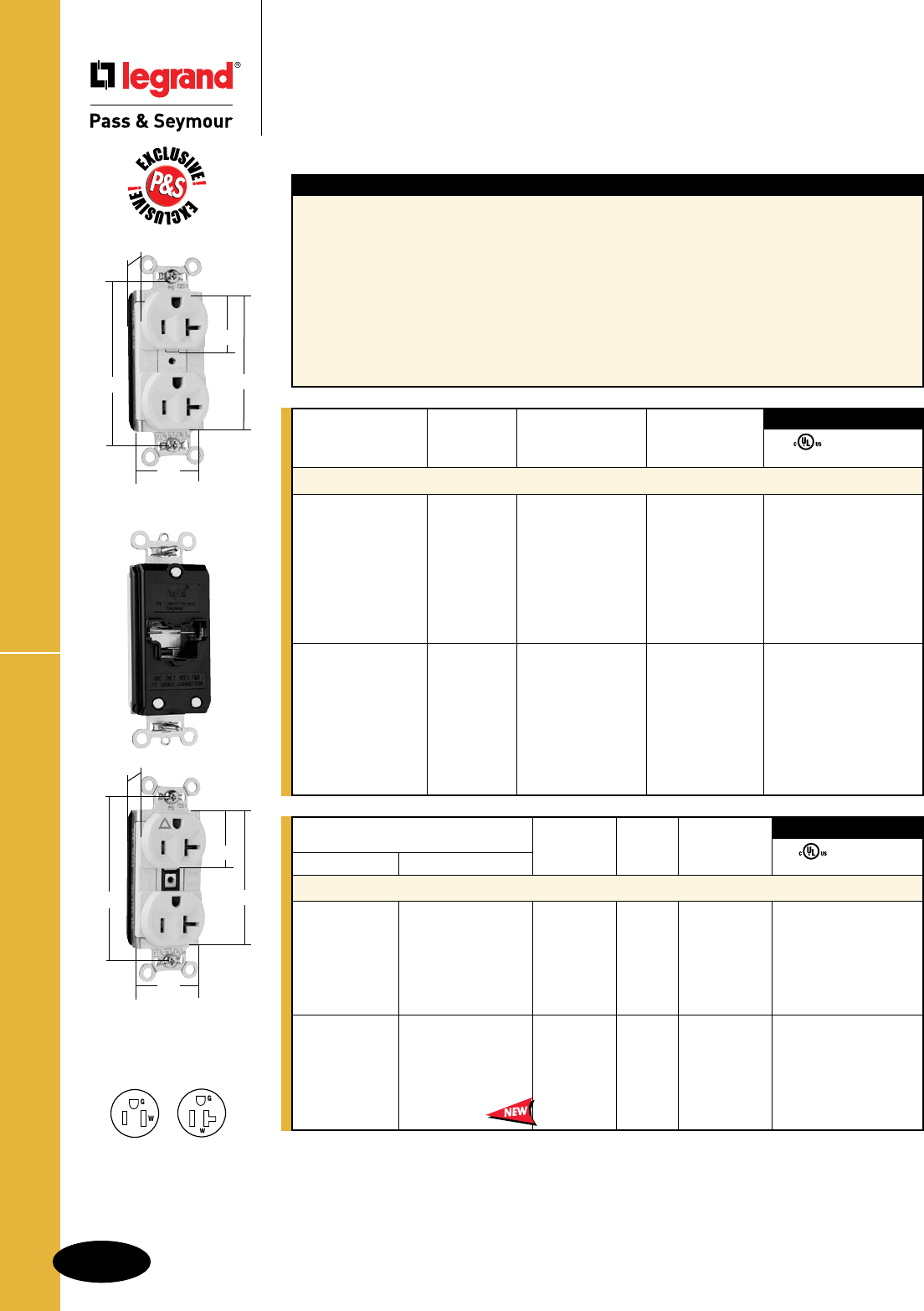
AlldeviceslistedonthispageconformtoNEMAWD-1andWD-6.
FSUL
UL498 WC596
NEMA
Catalog Number Rating Cong.
Spec Grade Hospital Grade A. V. No. Color
Isolated Ground Duplex Receptacles
PTIG5262I PTIG8200I 15 125 5-15R Ivory ••
PTIG5262W 15 125 5-15R White ••
PTIG5262PTIG8200 15 125 5-15R Orange ••
PTIG5262GRY 15 125 5-15R Gray ••
PTIG5262REDPTIG8200RED 15 125 5-15R Red ••
PTIG5262LA 15 125 5-15R LightAlmond ••
PTIG5362IPTIG8300I 20 125 5-20R Ivory ••
PTIG5362W 20 125 5-20R White ••
PTIG5362PTIG8300 20 125 5-20R Orange ••
PTIG5362GRY 20 125 5-20R Gray ••
PTIG5362REDPTIG8300RED 20 125 5-20R Red ••
PTIG5362LAPTIG8300LA 20 125 5-20R LightAlmond ••
3rd Party Compliance
Straight Blade Receptacles
PlugTail™ Specification Grade Receptacles
15 & 20A, 125V
Features
n.036inchthick,brass,triple-wipepowercontactsfor
lastingretention.
nPlatedsteelwrapstrapdesignformaximumdurability
andcorrosionresistance.
nNoexposedterminalscreateafingersafeapplication
before,during,andafterinstallation.
nBuilt-inconnectorfeatureslargebrassterminalblades
toensureconsistent,reliableelectricalconnections.
nUltrasonicallyweldedpolycarbonateconnectorhousing
securesterminationsandconductorsinaULListed,
fingersafehousing.
nCrimpedandweldedcontacts.
nLargebrasscontactssnuglyterminateon
devicebladeterminals.
nPre-strippedconnectorleadsfastento
conductors,easierthanstandardpigtails.
nAuto-groundclipassurespositiveground.
nIsolatedgroundversionfeaturesaplastic
barrierthatisolatesgroundingterminalfrom
mountingstrapandmetalboxes.
PTIG5362LA
2.750"
3.281"
.625"
1.5"
1.104"
PT5362LA
2.750"
3.281"
.625"
1.5"
1.104"
Rating NEMA
Catalog Number A. V. Color Cong. No.
Duplex Receptacles
PT5262I 15 125 Ivory 5-15R ••
PT5262W 15 125 White 5-15R ••
PT5262 15 125 Brown 5-15R ••
PT5262GRY 15 125 Gray 5-15R ••
PT5262BK 15 125 Black 5-15R ••
PT5262RED 15 125 Red 5-15R ••
PT5262LA 15 125 LightAlmond 5-15R ••
PT5262BL 15 125 Blue 5-15R ••
PT5362I 20 125 Ivory 5-20R ••
PT5362W 20 125 White 5-20R ••
PT5362 20 125 Brown 5-20R ••
PT5362GRY 20 125 Gray 5-20R ••
PT5362BK 20 125 Black 5-20R ••
PT5362RED 20 125 Red 5-20R ••
PT5362LA 20 125 LightAlmond 5-20R ••
PT5362BL 20 125 Blue 5-20R ••
3rd Party Compliance
FSUL
UL498 WC596
For PlugTail Connectors, see Page B-3.
For Bulk Packaging Solutions consult factory.
NEMA
5-15R
NEMA
5-20R
2Pole,3Wire
PlugTail™ Specification Grade Receptacles
Straight Blade Receptacles
B-14
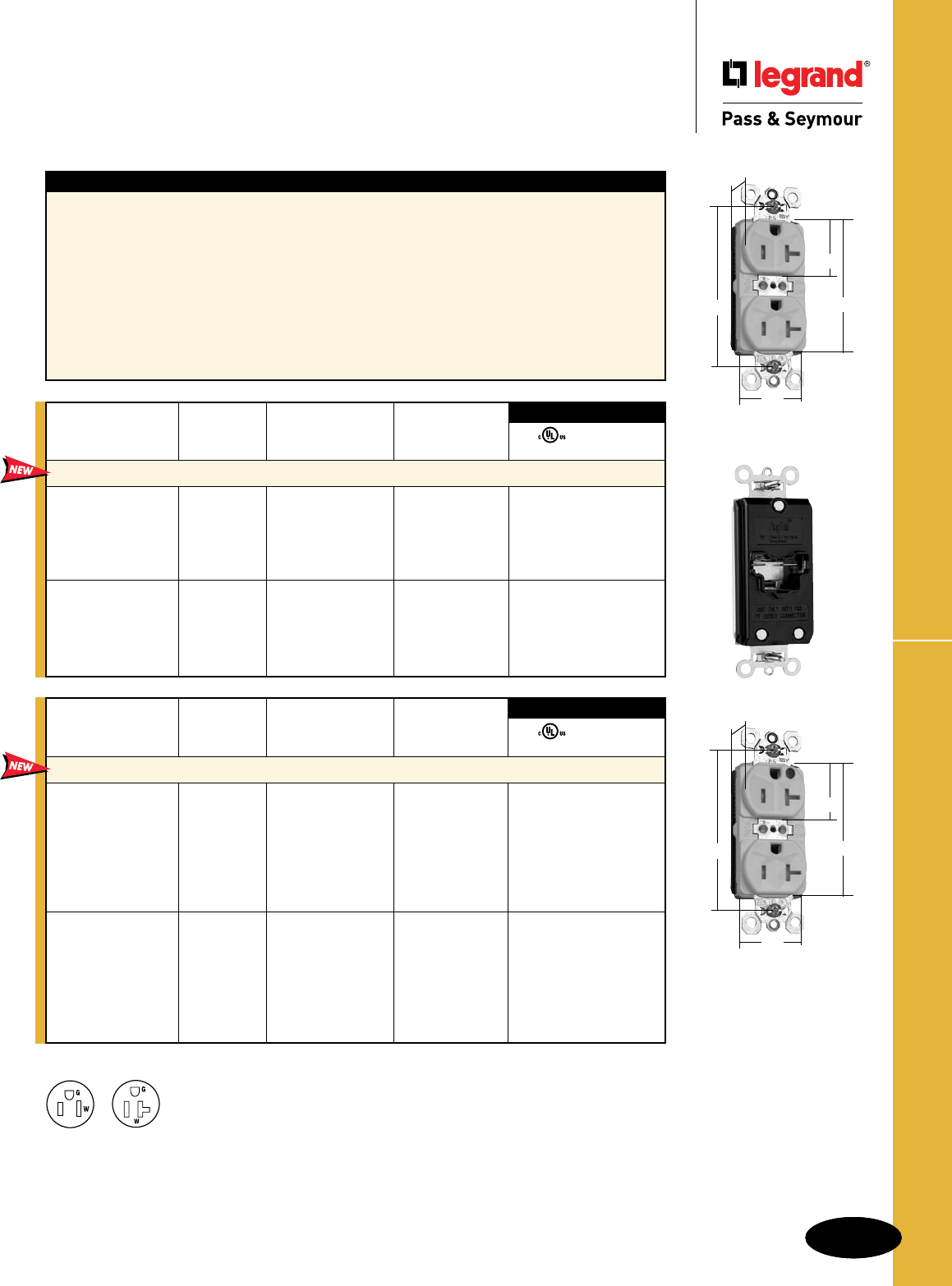
B-15
Straight Blade Receptacles
AlldeviceslistedonthispageconformtoNEMAWD-1andWD-6.
PlugTail™ TR Spec & HG Grade Receptacles
Straight Blade Receptacles
PlugTail™ Tamper-Resistant
Specification & Hospital Grade Receptacles
15 & 20A, 125V
B-15
For Bulk Packaging Solutions consult factory.
Features
n
Dualmechanicalshuttersystemtohelpprevent
insertionofforeignobjects.
n.036inchthick,brass,triple-wipepowercontactsfor
lastingretention.
nPlatedsteelwrapstrapdesignformaximumdurability
andcorrosionresistance.
nNoexposedterminalscreateafingersafeapplication
before,during,andafterinstallation.
nBuilt-inconnectorfeatureslargebrassterminalblades
toensureconsistent,reliableelectricalconnections.
nCrimpedandweldedcontacts.
nUltrasonicallyweldedpolycarbonate
connectorhousingsecuresterminations
andconductorsinaULListed,fingersafe
housing.
nLargebrasscontactssnuglyterminateon
devicebladeterminals.
nPre-strippedconnectorleadsfastento
conductors,easierthanstandardpigtails.
nAuto-groundclipassurespositiveground.
Rating NEMA
Catalog Number A. V. Color Cong. No.
Duplex Receptacles
PTTR5262I 15 125 Ivory 5-15R ••
PTTR5262W 15 125 White 5-15R ••
PTTR5262 15 125 Brown 5-15R ••
PTTR5262BK 15 125 Black 5-15R ••
PTTR5262LA 15 125 LightAlmond 5-15R ••
PTTR5362I 20 125 Ivory 5-20R ••
PTTR5362W 20 125 White 5-20R ••
PTTR5362 20 125 Brown 5-20R ••
PTTR5362BK 20 125 Black 5-20R ••
PTTR5362LA 20 125 LightAlmond 5-20R ••
3rd Party Compliance
FSUL
UL498 WC596
Rating NEMA
Catalog Number A. V. Color Cong. No.
Hospital Grade Duplex Receptacles
PTTR8200I 15 125 Ivory 5-15R ••
PTTR8200W 15 125 White 5-15R ••
PTTR8200 15 125 Brown 5-15R ••
PTTR8200GRY 15 125 Gray 5-15R ••
PTTR8200BK 15 125 Black 5-15R ••
PTTR8200RED 15 125 Red 5-15R ••
PTTR8200LA 15 125 LightAlmond 5-15R ••
PTTR8300I 20 125 Ivory 5-20R ••
PTTR8300W 20 125 White 5-20R ••
PTTR8300 20 125 Brown 5-20R ••
PTTR8300GRY 20 125 Gray 5-20R ••
PTTR8300BK 20 125 Black 5-20R ••
PTTR8300RED 20 125 Red 5-20R ••
PTTR8300LA 20 125 LightAlmond 5-20R ••
3rd Party Compliance
FSUL
UL498 WC596
NEMA
5-15R
NEMA
5-20R
2Pole,3Wire
PTTR5362W
2.750"
3.281"
.625"
1.5"
1.104"
PTTR8300W
2.750"
3.281"
.625"
1.5"
1.104"
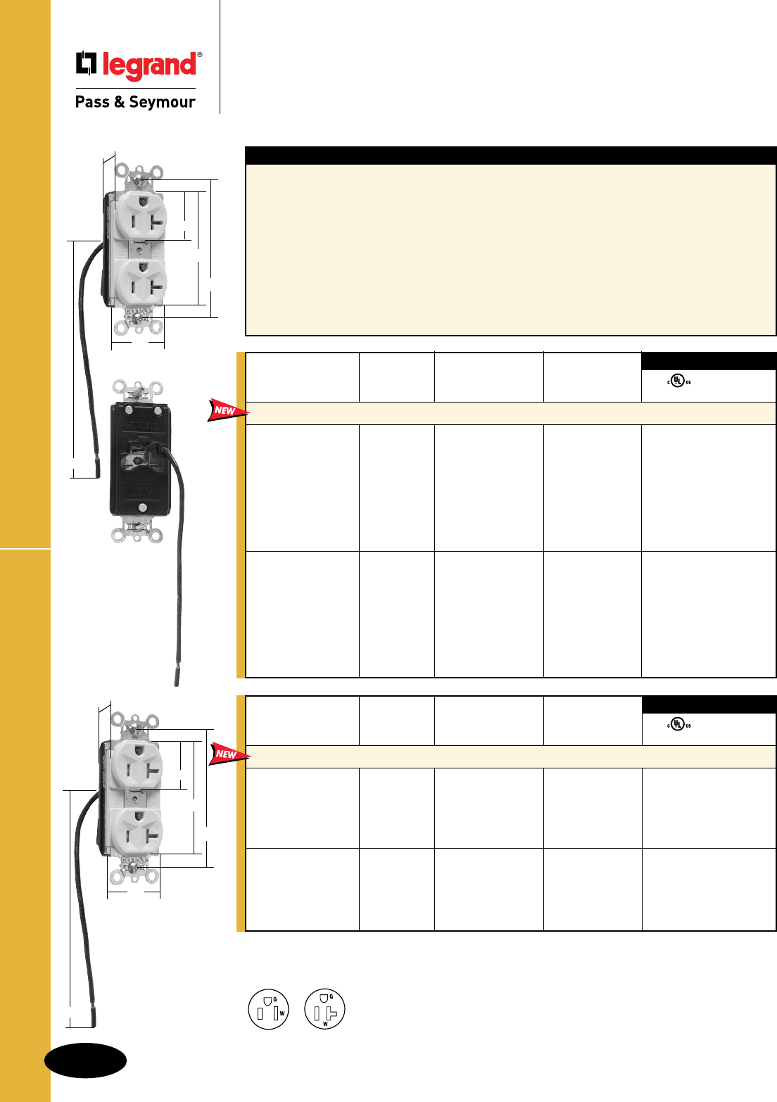
B-16
Straight Blade Receptacles
AlldeviceslistedonthispageconformtoNEMAWD-1andWD-6.
PlugTail™ Spec Grade Split Circuit Receptacles
Straight Blade Receptacles
PlugTail™ Specification Grade Receptacles
Split Circuit
15 & 20A, 125V
For Bulk Packaging Solutions consult factory.
Features
nPre-wiredwithoneweldedpre-strippedwirelead
tofacilitateswitchedreceptaclecircuitapplications.
n.036inchthick,brass,triple-wipepowercontactsfor
lastingretention.
nPlatedsteelwrapstrapdesignformaximumdurability
andcorrosionresistance.
nNoexposedterminalscreateafingersafeapplication
before,during,andafterinstallation.
nBuilt-inconnectorfeatureslargebrassterminalblades
toensureconsistent,reliableelectricalconnections.
nCrimpedandweldedcontacts.
nUltrasonicallyweldedpolycarbonate
connectorhousingsecuresterminations
andconductorsinaULListed,fingersafe
housing.
nLargebrasscontactssnuglyterminateon
devicebladeterminals.
nPre-strippedconnectorleadsfastento
conductors,easierthanstandardpigtails.
nAuto-groundclipassurespositiveground.
n
Tamper-resistantversionfeaturesdual
mechanicalshuttersystemtohelpprevent
insertionofforeignobjects.
Rating NEMA
Catalog Number A. V. Color Cong. No.
Tamper-Resistant Split Circuit Duplex Receptacles with 6" Lead
PTTR5262SCI 15 125 Ivory 5-15R ••
PTTR5262SCW 15 125 White 5-15R ••
PTTR5262SC 15 125 Brown 5-15R ••
PTTR5262SCBK 15 125 Black 5-15R ••
PTTR5262SCLA 15 125 LightAlmond 5-15R ••
PTTR5362SCI 20 125 Ivory 5-20R ••
PTTR5362SCW 20 125 White 5-20R ••
PTTR5362SC 20 125 Brown 5-20R ••
PTTR5362SCBK 20 125 Black 5-20R ••
PTTR5362SCLA 20 125 LightAlmond 5-20R ••
3rd Party Compliance
FSUL
UL498 WC596
NEMA
5-15R
NEMA
5-20R
2Pole,3Wire
Rating NEMA
Catalog Number A. V. Color Cong. No.
Split Circuit Duplex Receptacles with 6" Lead
PT5262SCI 15 125 Ivory 5-15R ••
PT5262SCW 15 125 White 5-15R ••
PT5262SC 15 125 Brown 5-15R ••
PT5262SCGRY 15 125 Gray 5-15R ••
PT5262SCBK 15 125 Black 5-15R ••
PT5262SCRED 15 125 Red 5-15R ••
PT5262SCLA 15 125 LightAlmond 5-15R ••
PT5262SCBL 15 125 Blue 5-15R ••
PT5362SCI 20 125 Ivory 5-20R ••
PT5362SCW 20 125 White 5-20R ••
PT5362SC 20 125 Brown 5-20R ••
PT5362SCGRY 20 125 Gray 5-20R ••
PT5362SCBK 20 125 Black 5-20R ••
PT5362SCRED 20 125 Red 5-20R ••
PT5362SCLA 20 125 LightAlmond 5-20R ••
PT5362SCBL 20 125 Blue 5-20R ••
3rd Party Compliance
FSUL
UL498 WC596
PT5362SCI
2.750"
3.281"
.625"
1.5"
1.104"
6.0"
PTTR5362SCI
2.750"
3.281"
.625"
1.5"
1.104"
6.0"
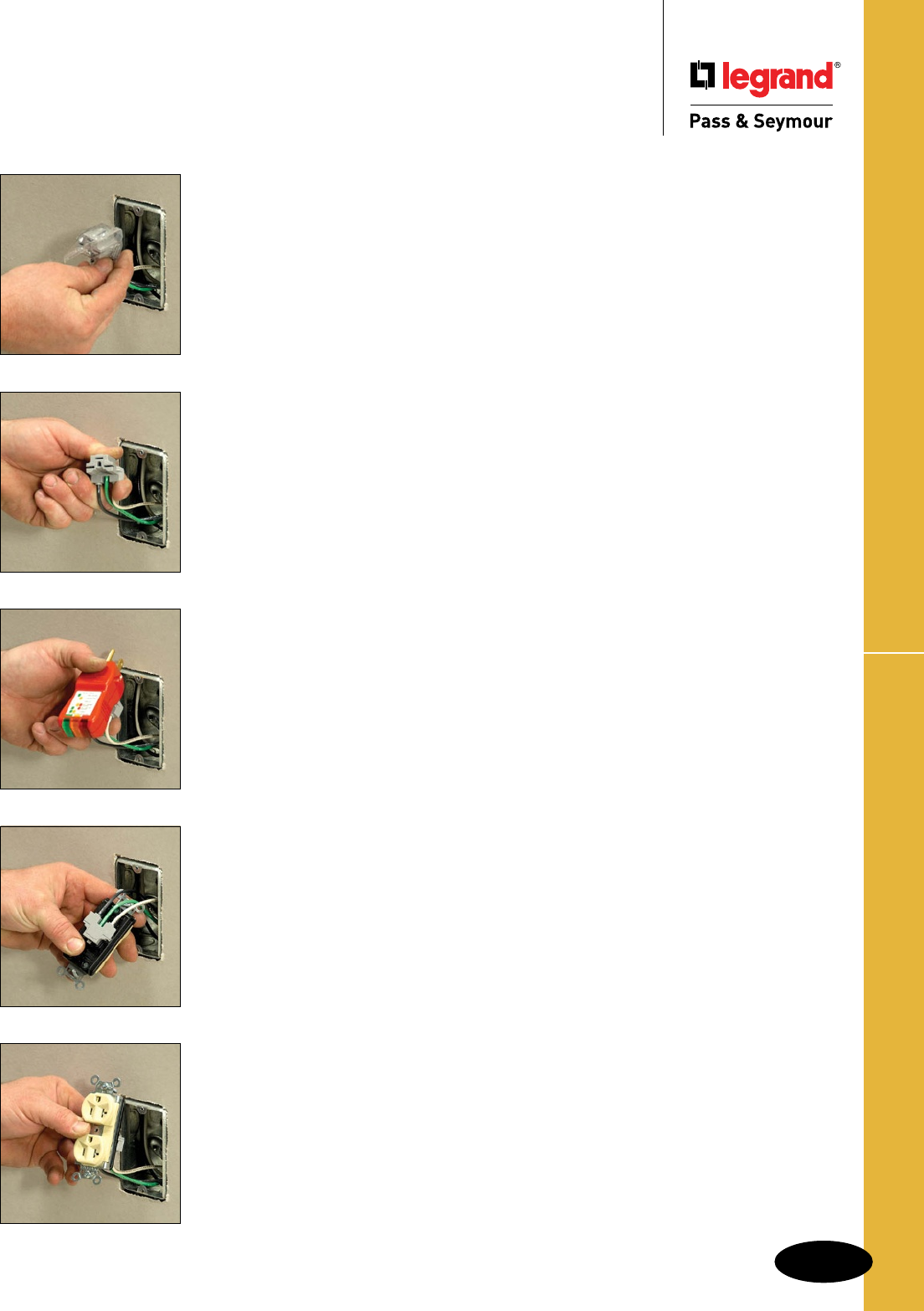
B-17
Straight Blade Receptacles
PlugTail™ Power Pre-Fabricated Wiring Systems
Straight Blade Receptacles
PlugTail™ Power
Pre-Fabricated Wiring Systems
Constructing a condominium complex, office building or hotel and the
wiring project is substantial or repetitive? Look to PlugTail Power
Products from Legrand/Pass & Seymour. With PlugTail Power, much
of the electrical assembly is completed in advance, dramatically cutting
project completion times.
Rough-in is fast and easy. PlugTail Power floor brackets slide under the sill plate so
no vertical measuring is necessary. Wall brackets that attach to the stud are also
available. Everything is pre-wired for fast rough in – P&S PlugTail Connector is
pre-wired to the ground screw.
And all PlugTail Power Products are pre-packaged and shipped to the requirements of
the contractor for fast job starts.
Each PlugTail Power assembly includes:
n Floor or wall bracket with one or two gang openings
n Pre-installed boxes
n Pre-installed rings available in 5/8" or 3/4" rise
n Far side support arms
n PlugTail devices pre-wired to ground screw
PlugTail Power can benefit you in many ways:
n PlugTail Power assemblies are packaged per contractor
n Simple installation – no vertical measuring necessary for mounting boxes
n Pre-mounted and grounded boxes cut install times
n Available in 2-1/2" and 3-1/2" depth, depending on wall thickness
n Pre-wired PlugTail Connector allows you to make device choices at finish
Floor Bracket Wired Assemblies – One and Two Gang
The P&S Floor Bracket Assembly consists of a floor bracket, 4-inch ring, back side support
arm, 4-11/16 x 2-1/8 inch metal boxes, and PlugTail Right Angle Connectors with push-in
connectors. The PlugTail Connectors are sealed in plastic to keep them finish-ready. The boxes
are mounted independent of the rings to allow full box access when wiring. Multiple wire
openings in the push-in wire connectors allow connection of in-line, end-of-line, or multi-wire
branch circuits. A large selection of PlugTail Receptacles and GFCIs is available to complete the
installation.
Installation: The Floor Bracket is installed by kicking the lower flange under the wall base.
Two holes are provided for attachment screws, if required.
Wall Bracket Wired Assemblies – One and Two Gang
The P&S Wall Bracket Wire Assembly consists of a 9-1/2 x 5 inch wall bracket, 4-inch mud
rings, back side support arm, 4-11/16 x 2-1/8 inch metal boxes, and PlugTail Right Angle
Connectors with push-in wire connectors. The PlugTail Connectors are sealed in plastic to keep
them finish-ready. The boxes are mounted independent of the rings to allow full box access
when wiring. Multiple wire openings in the push-in wire connectors allow connection of in-line,
end-of-line, or multi-wire branch circuits.
Installation: The Wall Bracket Assembly is quickly installed with screws using the holes
provided in the bracket.
A large selection of PlugTail Receptacles and GFCIs is available to complete the installation.
For more information, see Section B and Section C.

MRC2 & MRC1
Straight Blade Receptacles
PlugTail™ Power Pre-Fabricated
Wiring Systems & Metal-Box Kits
B-18
Straight Blade ReceptaclesPlugTail™ Metal Box Kits
MBD4S1PTSTR
Features
nGroundwirepre-mountedtothebox.
nMudringfactoryinstalled.
n4"squarex1-1/2"or2-1/8"metalboxes.
nUnitonlyshipsinquantitiesof24.
nPlugTailRightAngleConnectorswith
12AWGcopperpigtails.
nAllDoubleGangKitscontaintworight
anglePlugTailconnectors.
Features
nFour-inchmudring.
nBacksidesupportarm.
n18-inchboxmountingheight.
n4-11/16"x2-1/8"metalboxes.
nPush-inpushwireconnectors.
nPlugTailRightAngleConnectorswith12AWGcopperpigtails.
nFloorbracketsare16-gaugegalvanizedsteel.
nWallbracketsare18-gaugegalvanizedsteel.
PlugTailReceptaclesandGFCIssoldseparately.
PSF1185825
Catalog Number
Single Gang Double Gang
Single PlugTail™ Double PlugTail™ Description
Floor Bracket Wired Assemblies with Stranded Copper Pigtails
PSF1185825PSF2185825 5/8"ringrise,2-1/2"walldepth
PSF1185835PSF2185835 5/8"ringrise,3-1/2"walldepth
PSF1187525PSF2187525 3/4"ringrise,2-1/2"walldepth
PSF1187535PSF2187535 3/4"ringrise,3-1/2"walldepth
Floor Bracket Wired Assemblies with Solid Copper Pigtails
PSFS1185825PSFS2185825 5/8"ringrise,2-1/2"walldepth
PSFS1185835PSFS2185835 5/8"ringrise,3-1/2"walldepth
PSFS1187525PSFS2187525 3/4"ringrise,2-1/2"walldepth
PSFS1187535PSFS2187535 3/4"ringrise,3-1/2"walldepth
Wall Bracket Wired Assemblies with Stranded Copper Pigtails
PSW15825PSW25825 5/8"ringrise,2-1/2"walldepth
PSW15835PSW25835 5/8"ringrise,3-1/2"walldepth
PSW17525PSW27525 3/4"ringrise,2-1/2"walldepth
PSW17535PSW27535 3/4"ringrise,3-1/2"walldepth
Wall Bracket Wired Assemblies with Solid Copper Pigtails
PSWS15825PSWS25825 5/8"ringrise,2-1/2"walldepth
PSWS15835PSWS25835 5/8"ringrise,3-1/2"walldepth
PSWS17525PSWS27525 3/4"ringrise,2-1/2"walldepth
PSWS17535PSWS27535 3/4"ringrise,3-1/2"walldepth
PSW15825
Catalog Number
Single Gang Double Gang Description
Metal-Box Kits with Stranded Copper Pigtails
MB4S1PTSTRMB4S2PTSTR 4Sq.1-1/2"MetalBox,5/8MR,PTRA6STR
MBD4S1PTSTRMBD4S2PTSTR 4Sq.2-1/8"MetalBox,5/8MR,PTRA6STR
MB4S1SPTSTR MB4S2SPTSTR 4Sq.1-1/2"MetalBox,3/4MR,PTRA6STR
MBD4S1SPTSTR MBD4S2SPTSTR 4Sq.2-1/8"MetalBox,3/4MR,PTRA6STR
Metal-Box Kits with Solid Copper Pigtails
MB4S1PTSOLMB4S2PTSOL 4Sq.1-1/2"MetalBox,5/8MR,PTRA6SOL
MBD4S1PTSOL MBD4S2PTSOL 4Sq.2-1/8"MetalBox,5/8MR,PTRA6SOL
MB4S1SPTSOL MB4S2SPTSOL 4Sq.1-1/2"MetalBox,3/4MR,PTRA6SOL
MBD4S1SPTSOLMBD4S2SPTSOL 4Sq.2-1/8"MetalBox,3/4MR,PTRA6SOL
MBD4S1SPTSTR
Catalog Number Description Size
P&S Mud Ring Covers
MRC1 MudRingCover 1-Gang
MRC2 MudRingCover 2-Gang
Features
nProtectselectricalboxopeningfrom
dust,debrisandothercontaminants.
nRemoveseasilyuponinstallationof
thedevice.
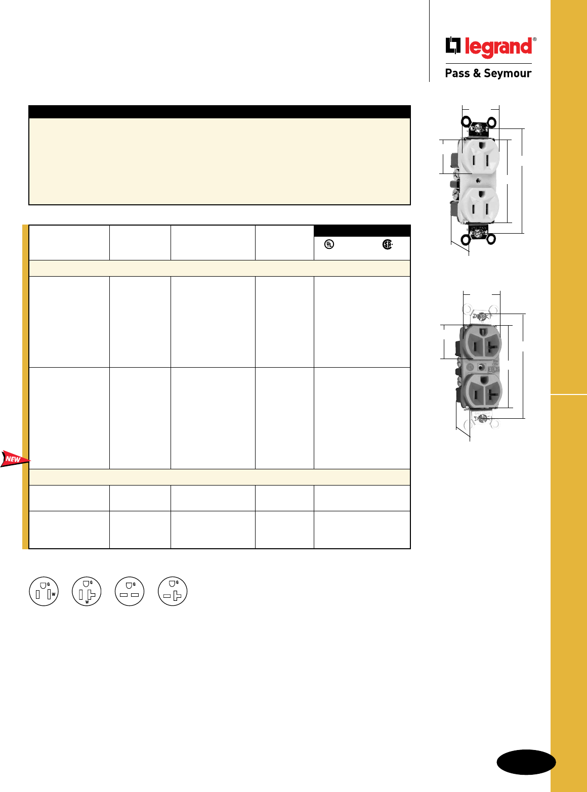
B-19
Straight Blade Receptacles
AlldeviceslistedonthispageconformtoNEMAWD-1andWD-6.
Hard Use Specification Grade Receptacles
2Pole,3Wire
5262I
1.104"
.780"
2.635"
3.281"
1.322"
Features
nCorrosion-resistant,platedandtabbedsteelstrapis
lockedintofaceandbackbodytoresistpullingaway
fromface/bodyassembly.
n.032inchthick,brass,triple-wipepowercontacts
forlastingretention.
nEasilyaccessedbreak-off,line-contactconnecting
tabforfast,easysplit-circuitwiring.
nImpact-resistantnylonface.
n8holeinternalscrew-pressure-plateback
wireterminalsaccept#10–14AWGsolidor
strandedcopperorcopper-cladconductors.
nTerminalcompartmentsisolatedfromeach
otherforpositiveconductorcontainment.
nTri-driveterminalandmountingscrews.
nAuto-groundclipassurespositiveground.
Straight Blade Receptacles
Hard Use Specification Grade Receptacles
15A & 20A, 125 & 125/250V
For Bulk Packaging Solutions consult factory.
3rd Party Compliance
FSUL
UL498 WC596 C22.2 No. 42
Rating NEMA
Catalog Number A. V. Color Cong. No.
Duplex Receptacles Back & Side Wire
5262I 15 125 Ivory 5-15R • • •
5262W 15 125 White 5-15R • • •
5262 15 125 Brown 5-15R • • •
5262GRY 15 125 Gray 5-15R • • •
5262BK 15 125 Black 5-15R • • •
5262RED 15 125 Red 5-15R • • •
5262LA 15 125 LightAlmond 5-15R • • •
5262BL 15 125 Blue 5-15R • • •
5362I 20 125 Ivory 5-20R • • •
5362W 20 125 White 5-20R • • •
5362 20 125 Brown 5-20R • • •
5362GRY 20 125 Gray 5-20R • • •
5362BK 20 125 Black 5-20R • • •
5362RED 20 125 Red 5-20R • • •
5362LA 20 125 LightAlmond 5-20R • • •
5362BL 20 125 Blue 5-20R • • •
5362GN 20 125 Green 5-20R • • •
Combination Duplex Receptacles Side Wire
5290I 15 125/250 Ivory 5/6-15R • • •
5290 15 125/250 Brown 5/6-15R • • •
5890I 20 125/250 Ivory 5/6-20R • •
5890W 20 125/250 White 5/6-20R • •
5890 20 125/250 Brown 5/6-20R • •
NEMA
5-15R
NEMA
6-15R
NEMA
5-20R
NEMA
6-20R
5362GN
1.104"
.780"
2.635"
3.281"
1.322"
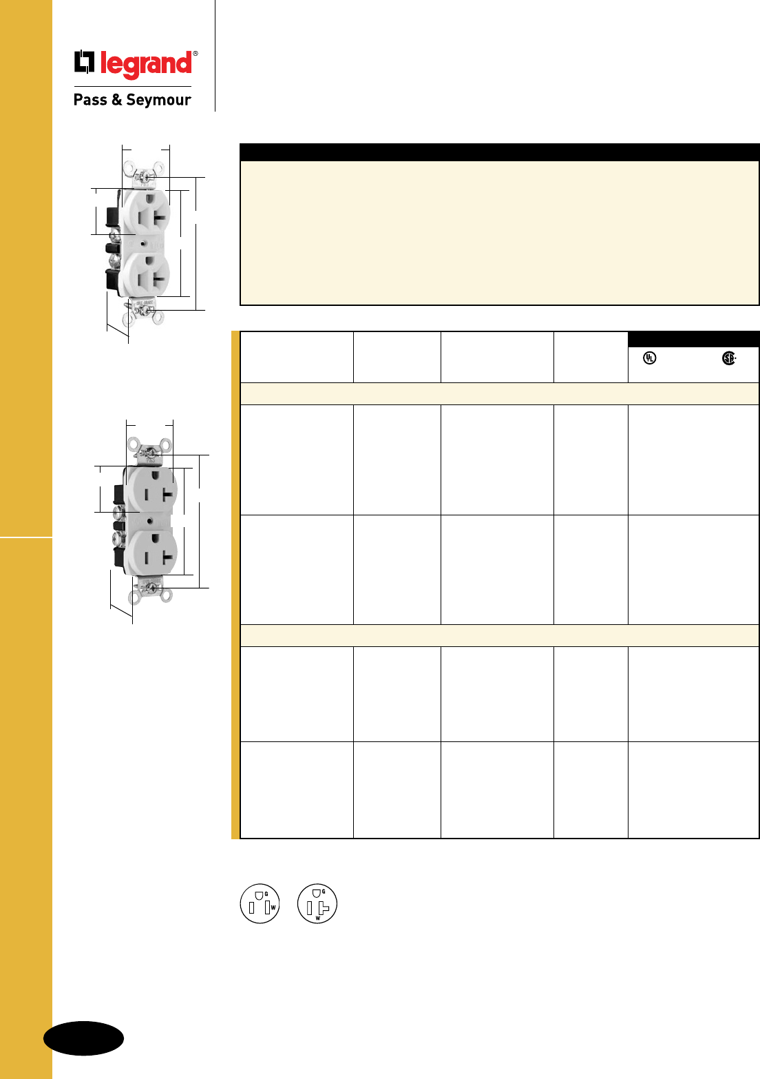
AlldeviceslistedonthispageconformtoNEMAWD-1andWD-6.
For Bulk Packaging Solutions consult factory.
NEMA
5-15R
NEMA
5-20R
2Pole,3Wire
Features
nCorrosion-resistant,platedsteelstraplockedin
tofaceandbackbodytoresistpullingawayfrom
face/bodyassembly.
n.032inchthick,brass,triple-wipepowercontacts
forlastingretention.
nEasilyaccessedbreak-off,line-contactconnecting
tabforfast,easysplit-circuitwiring.
nImpact-resistantnylonfaceandthermoplastic
backbody.
n8holeinternalscrew-pressure-plateback
wireterminalsaccept#10–14AWGsolidor
strandedcopperorcopper-cladconductors.
nTerminalcompartmentsisolatedfromeach
otherforpositiveconductorcontainment.
nTri-driveterminalandmountingscrews.
nAuto-groundclipassurespositiveground.
n
Smoothfaceversionfeaturesanimpact-
resistantnylonfaceforeaseofcleaning
andlessdirtbuild-up.
3rd Party Compliance
FSUL
UL498 WC596 C22.2 No. 42
Rating NEMA
Catalog Number A. V. Color Cong. No.
Duplex Receptacles Back & Side Wire
CRB5262I 15 125 Ivory 5-15R • • •
CRB5262W 15 125 White 5-15R • • •
CRB5262 15 125 Brown 5-15R • • •
CRB5262GRY 15 125 Gray 5-15R • • •
CRB5262BK 15 125 Black 5-15R • • •
CRB5262RED 15 125 Red 5-15R • • •
CRB5262LA 15 125 LightAlmond 5-15R • • •
CRB5362I 20 125 Ivory 5-20R • • •
CRB5362W 20 125 White 5-20R • • •
CRB5362 20 125 Brown 5-20R • • •
CRB5362GRY 20 125 Gray 5-20R • • •
CRB5362BK 20 125 Black 5-20R • • •
CRB5362RED 20 125 Red 5-20R • • •
CRB5362LA 20 125 LightAlmond 5-20R • • •
Duplex Receptacles – Smooth Face Back & Side Wire
CRB5262SI 15 125 Ivory 5-15R • • •
CRB5262SW 15 125 White 5-15R • • •
CRB5262S 15 125 Brown 5-15R • • •
CRB5262SGRY 15 125 Gray 5-15R • • •
CRB5262SRED 15 125 Red 5-15R • • •
CRB5262SLA 15 125 LightAlmond 5-15R • • •
CRB5362SI 20 125 Ivory 5-20R • • •
CRB5362SW 20 125 White 5-20R • • •
CRB5362S 20 125 Brown 5-20R • • •
CRB5362SGRY 20 125 Gray 5-20R • • •
CRB5362SRED 20 125 Red 5-20R • • •
CRB5362SLA 20 125 LightAlmond 5-20R • • •
Straight Blade Receptacles
Construction Specification Grade
Receptacles
15 & 20A, 125V
CRB5362I
1.104"
.780"
2.635"
3.281"
1.322"
CRB5362SLA
1.104"
.780"
2.635"
3.281"
1.322"
B-20
Straight Blade Receptacles
Construction Specification Grade Receptacles
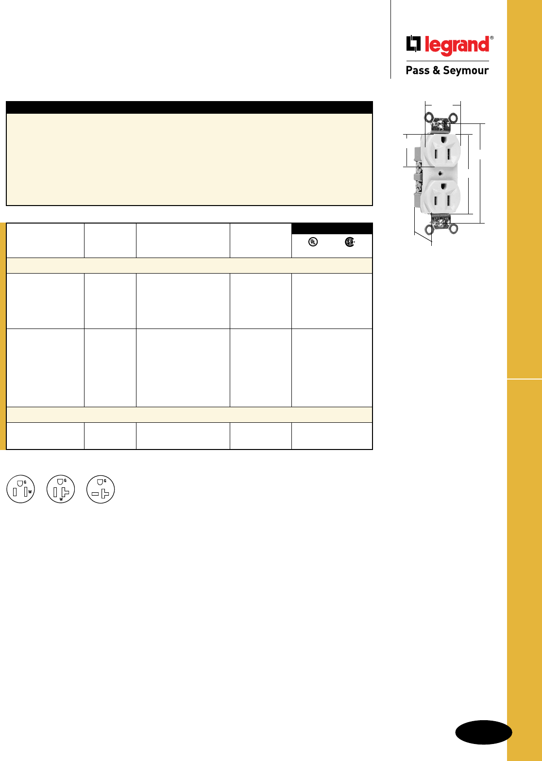
B-21
Straight Blade Receptacles
AlldeviceslistedonthispageconformtoNEMAWD-1andWD-6.
Straight Blade Receptacles
Commercial Specification Grade
Receptacles
15A, 125V; 20A, 125 & 250V
Commercial Specification Grade Receptacles
Features
nCorrosion-resistant,platedsteelstraplockedin
tofaceandbackbodytoresistpullingawayfrom
face/bodyassembly.
n.032inchthick,brass,triple-wipepowercontacts
forlastingretention.
nEasilyaccessedbreak-off,line-contactconnecting
tabforfast,easysplit-circuitwiring.
nImpact-resistantnylonfaceandthermoplastic
backbody.
nAccepts#14–#10AWGsolidorstranded
copperorcopper-cladwire.
nTerminalcompartmentsisolatedfromeach
otherforpositiveconductorcontainment.
nTri-driveterminalandmountingscrews.
nAuto-groundclipassurespositiveground.
CR15I
1.104"
.780"
2.635"
3.281"
1.322"
For Bulk Packaging Solutions consult factory.
3rd Party Compliance
UL498 C22.2 No. 42
Rating NEMA
Catalog Number A. V. Color Cong. No.
Duplex Receptacles Side Wire
CR15I 15 125 Ivory 5-15R • •
CR15W 15 125 White 5-15R • •
CR15 15 125 Brown 5-15R • •
CR15GRY 15 125 Gray 5-15R • •
CR15LA 15 125 LightAlmond 5-15R • •
CR20I 20 125 Ivory 5-20R • •
CR20W 20 125 White 5-20R • •
CR20 20 125 Brown 5-20R • •
CR20GRY 20 125 Gray 5-20R • •
CR20BK 20 125 Black 5-20R • •
CR20RED 20 125 Red 5-20R • •
CR20LA 20 125 LightAlmond 5-20R • •
Duplex Receptacles Side Wire
5850I 20 250 Ivory 6-20R • •
5850W 20 250 White 6-20R • •
2Pole,3Wire
NEMA
5-15R
NEMA
5-20R
NEMA
6-20R
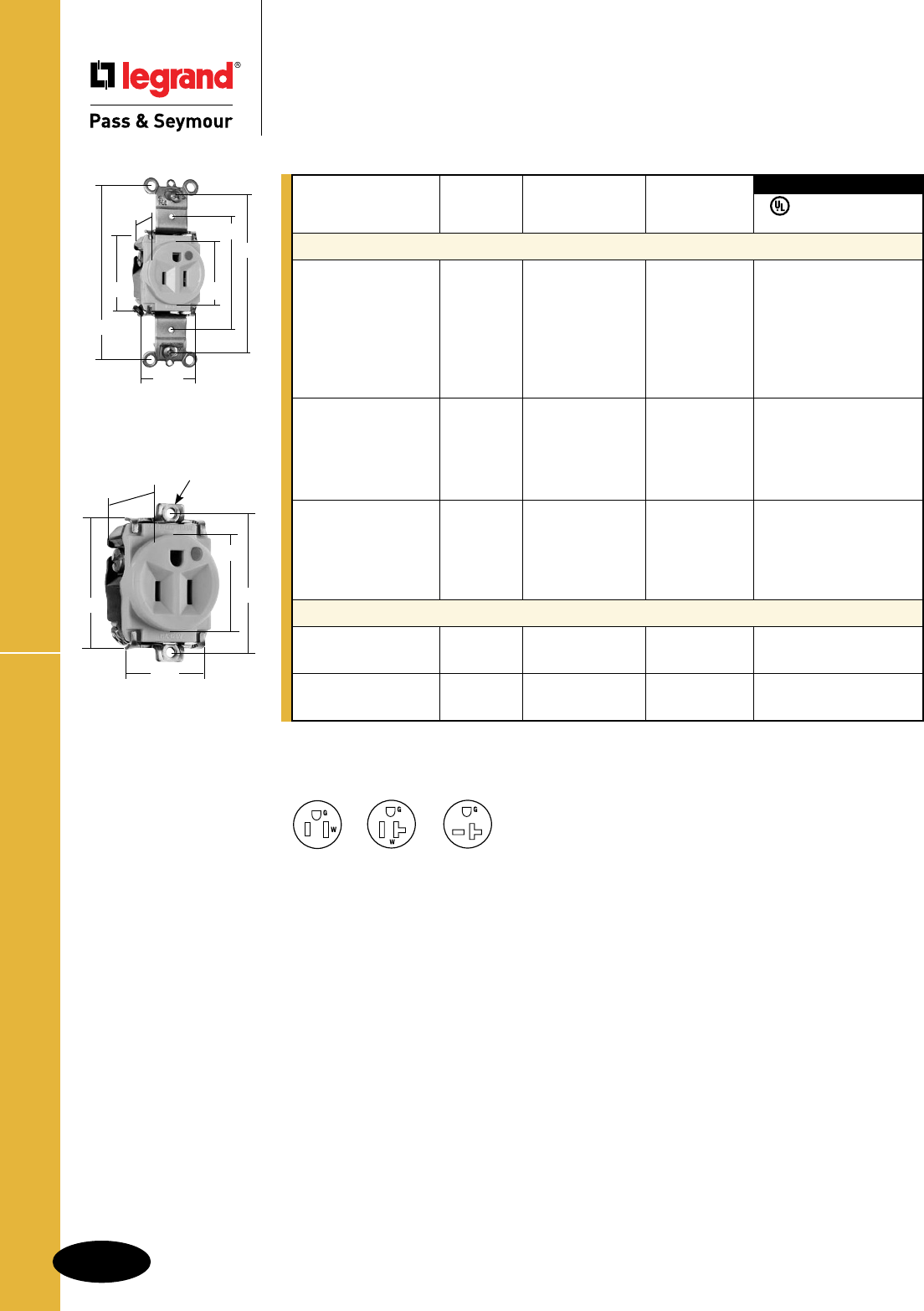
B-22
Straight Blade Receptacles
AlldeviceslistedonthispageconformtoNEMAWD-1andWD-6.
Straight Blade Receptacles
Hospital Grade Single Receptacles
15 & 20A, 125V; 20A, 250V
Hospital Grade Single Receptacles
NEMA
5-15R
NEMA
5-20R
NEMA
6-20R
8201I
1.093"
1.38"
2.37"
3.28"
3.68"
1.68"
1.32"
8284I
1.018"
8-32Thd.
1.937"
1.38"
1.68"
1.32"
2Pole,3Wire
ForHospitalUsePowerInterruptingDeviceconsultTurnlok®SectionH.
Rating NEMA
Catalog Number A. V. Color Cong. No.
Single Receptacles Back & Side Wire
8201I 15 125 Ivory 5-15R •••
8201W 15 125 White 5-15R •••
8201 15 125 Brown 5-15R •••
8201GRY 15 125 Gray 5-15R •••
8201BK 15 125 Black 5-15R •••
8201RED 15 125 Red 5-15R •••
8201LA 15 125 LightAlmond 5-15R •••
8301I 20 125 Ivory 5-20R •••
8301W 20 125 White 5-20R •••
8301 20 125 Brown 5-20R •••
8301GRY 20 125 Gray 5-20R •••
8301RED 20 125 Red 5-20R •••
8801I 20 250 Ivory 6-20R •••
8801W 20 250 White 6-20R •••
8801 20 250 Brown 6-20R •••
8801GRY 20 250 Gray 6-20R •••
8801RED 20 250 Red 6-20R •••
Short Strap Single Receptacles 1.937" Screw Spacing, Back & Side Wire
8284I 15 125 Ivory 5-15R •••
8284 15 125 Brown 5-15R •••
8384I 20 125 Ivory 5-20R ••
8384 20 125 Brown 5-20R ••
3rd Party Compliance
FSUL
UL498 WC596 cUL/CSA
For Bulk Packaging Solutions consult factory.
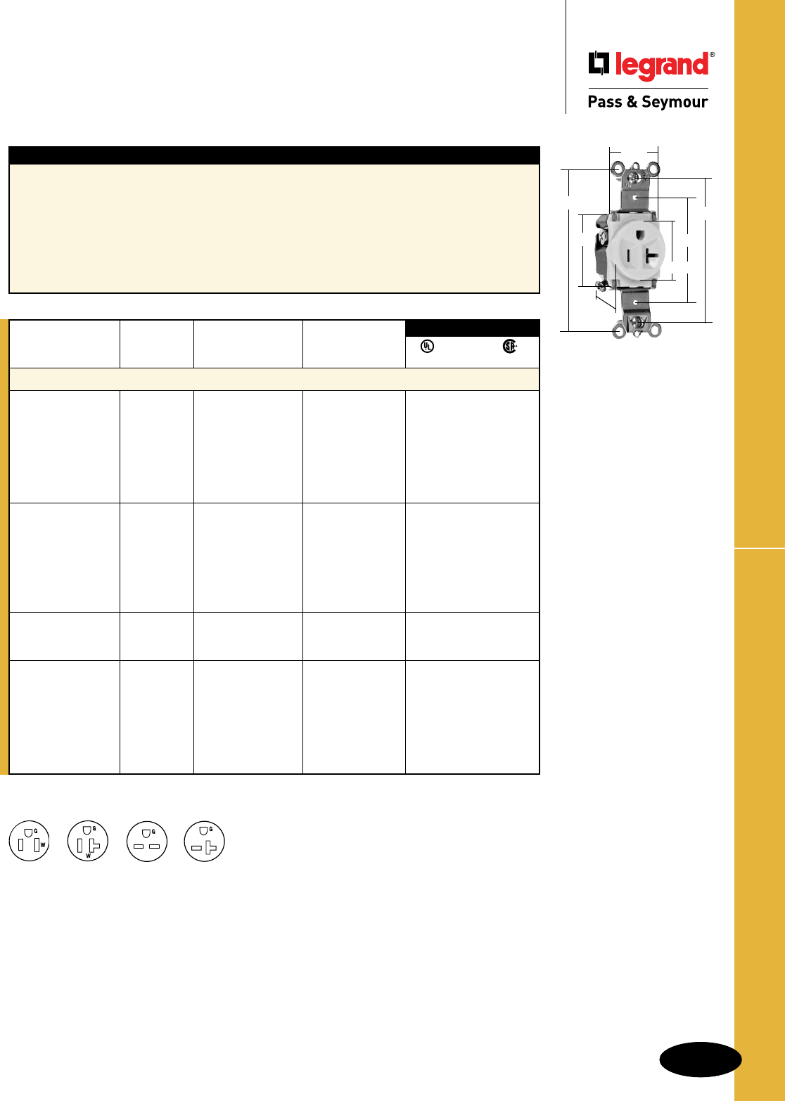
B-23
Straight Blade Receptacles
AlldeviceslistedonthispageconformtoNEMAWD-1andWD-6.
Heavy-Duty Spec Grade Single Receptacles
Straight Blade Receptacles
Heavy-Duty Specification Grade
Single Receptacles
15 & 20A, 125 & 250V
NEMA
5-15R
NEMA
6-15R
NEMA
5-20R
NEMA
6-20R
2Pole,3Wire
5361I
1.68"
1.093"
2.37"
3.28"
1.32"
3.68"
1.38"
Features
nCorrosion-resistant,platedsteelstraplockedin
tofaceandbackbodytoresistpullingawayfrom
face/bodyassembly.
nOne-piecebrass,triple-wipepowercontacts
forlastingretention.
nEasilyaccessedbreak-off,line-contactconnecting
tabforfast,easysplit-circuitwiring.
nImpact-resistantnylonfaceandthermoplastic
backbody.
nInternalscrew-pressure-platebackwire
capableofaccepting#14–#10AWGsolid
orstrandedcopperorcopper-cladwire.
nTerminalcompartmentsisolatedfromeach
otherforpositiveconductorcontainment.
nTri-driveterminalandmountingscrews.
nAuto-groundclipassurespositiveground.
Rating NEMA
Catalog Number A. V. Color Cong. No.
Single Receptacles Back & Side Wire
5261I 15 125 Ivory 5-15R • • •
5261W 15 125 White 5-15R • • •
5261 15 125 Brown 5-15R • • •
5261GRY 15 125 Gray 5-15R • • •
5261BK 15 125 Black 5-15R • • •
5261RED 15 125 Red 5-15R • • •
5261LA 15 125 LightAlmond 5-15R • • •
5361I 20 125 Ivory 5-20R • • •
5361W 20 125 White 5-20R • • •
5361 20 125 Brown 5-20R • • •
5361GRY 20 125 Gray 5-20R • • •
5361BK 20 125 Black 5-20R • • •
5361RED 20 125 Red 5-20R • • •
5361LA 20 125 LightAlmond 5-20R • • •
5671I 15 250 Ivory 6-15R • • •
5671 15 250 Brown 6-15R • • •
5671LA 15 250 LightAlmond 6-15R • • •
5871I 20 250 Ivory 6-20R • • •
5871W 20 250 White 6-20R • • •
5871 20 250 Brown 6-20R • • •
5871GRY 20 250 Gray 6-20R • • •
5871BK 20 250 Black 6-20R • • •
5871RED 20 250 Red 6-20R • • •
5871LA 20 250 LightAlmond 6-20R • • •
3rd Party Compliance
FSUL
UL498 WC596 C22.2 No. 42
For Bulk Packaging Solutions consult factory.
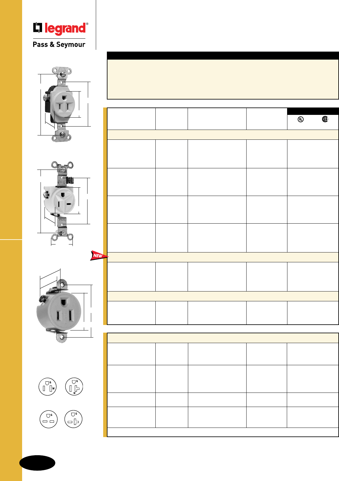
B-24
Straight Blade Receptacles
AlldeviceslistedonthispageconformtoNEMAWD-1andWD-6.
Features
nAuto-groundclipassurespositiveground.
nTwodrivescrewsanchorstraptobackbodyand
facewhereabruptremovaltorqueisgreatest.
nHeavy-duty,corrosion-resistantzinc-platedsteel
strapforaddedstrength.
nBacked-outtri-drivesteelterminalscrews.
Internalscrew-pressure-platebackandside
wirecapability.Twobackwireholesfor
increasedwiringflexibility.
nOne-piecebrasstriple-wipepowercontacts
forlastingretention.
Specification Grade Single Receptacles
Straight Blade Receptacles
Specification Grade Single Receptacles
15 & 20A, 125 & 250V
5258I
.762"
1.00"
1.49"
1.75"
5251I
1.08"
3.280"
1.380"
2.370"
5371I
.950"
3.280"
1.380"
2.370"
1.320"
Short Strap Single Receptacles Screw Spacing 1.750"
5258I 15 125 Ivory 5-15R • •
5258W 15 125 White 5-15R • •
5258 15 125 Brown 5-15R • •
5358I 20 125 Ivory 5-20R • •
5358W 20 125 White 5-20R • •
5358 20 125 Brown 5-20R • •
5358BK 20 125 Black 5-20R • •
5658I 15 250 Ivory 6-15R • •
5658 15 250 Brown 6-15R • •
5858I 20 250 Ivory 6-20R • •
5858W 20 250 White 6-20R • •
5858 20 250 Brown 6-20R • •
Suppliedwithmountingscrews.
NEMA
5-15R
NEMA
5-20R
NEMA
6-15R
NEMA
6-20R
2Pole,3Wire
For Bulk Packaging Solutions consult factory.
3rd Party Compliance
UL498 C22.2 No. 42
Rating NEMA
Catalog Number A. V. Color Cong. No.
Single Receptacles Back & Side Wire
5251I 15 125 Ivory 5-15R • •
5251W 15 125 White 5-15R • •
5251 15 125 Brown 5-15R • •
5251LA 15 125 LightAlmond 5-15R • •
5351I 20 125 Ivory 5-20R • •
5351W 20 125 White 5-20R • •
5351 20 125 Brown 5-20R • •
5351LA 20 125 LightAlmond 5-20R • •
5651I 15 250 Ivory 6-15R • •
5651W 15 250 White 6-15R • •
5651 15 250 Brown 6-15R • •
5651LA 15 250 LightAlmond 6-15R • •
5851I 20 250 Ivory 6-20R • •
5851W 20 250 White 6-20R • •
5851 20 250 Brown 6-20R • •
5851LA 20 250 LightAlmond 6-20R • •
Short Strap Single Receptacles Screw Spacing 2.370"
5251SSBKI 15 125 Ivory 5-15R ••
5251SSBKW 15 125 White 5-15R ••
5251SSBKBK 15 125 Black 5-15R ••
5251SSBKLA 15 125 LightAlmond 5-15R ••
Single Receptacles Side Wire Right Angle Slots
5371I 20 125 Ivory Non-NEMA ••
5371W 20 125 White Non-NEMA ••
5371 20 125 Brown Non-NEMA • •
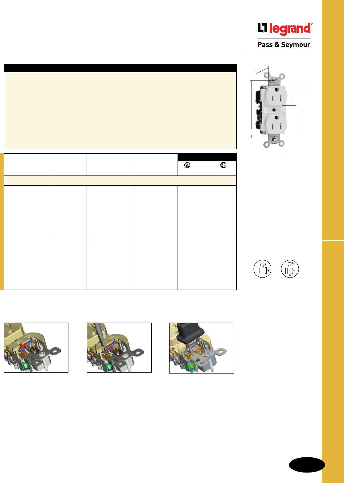
B-25
Straight Blade Receptacles
AlldeviceslistedonthispageconformtoNEMAWD-1andWD-6.
Tamper-Resistant Spec Grade Receptacles
Straight Blade Receptacles
Tamper-Resistant
Specification Grade Receptacles
15 & 20A, 125V
TR62I
Features
nThermoplasticdualmechanismshuttersystemto
helppreventinsertionofforeignobjects.
nExclusivepatentedfeature,circuitlabelonface
allowspermanentcircuitidentification.
nExtraheavy-dutybrass,one-piecemountingstrap
withintegralground.
nOne-piece,brass,triple-wipepowercontactsfor
lastingretention.
nStraptabswraparoundandlockdownonface
topreventstrapfromseparatingfromfaceand
backbody.
nImpact-resistantnylonfaceandbackbody.
nEasilyaccessedbreak-off,line-contact
connectingtabforfast,easysplit-circuit
wiring.
nTwodrivescrewsanchorstraptoback
bodyandface.
nExclusivepatentedfeature,externalscrew-
pressure-platebackwireclamponground
terminalforfaster,easierinstallation.
nExternalscrew-pressure-platebackwire
clampswith#10brassterminalscrewsfor
visualassuranceofagoodconnection.
nAuto-groundclipassurespositiveground.
NEC® section 517.18(C) Pediatric Locations.
Receptacleslocatedwithintherooms,bathrooms,playrooms,activityrooms,andpatientcareareas
ofpediatricwardsshallbelistedundertamperresistantoremployalistedtamperresistantcover.
Thermoplastic shutter in
closed position covers
access to contacts.
Insertion of object in any
one side does not open
shutter.
Two-bladed plug or ground-
ing plug compresses spring
and simultaneously opens
both shutters.
The Mechanical Shutter System
Rating NEMA
Catalog Number A. V. Color Cong. No.
Duplex Receptacles Back & Side Wire
TR62I 15 125 Ivory 5-15R •••
TR62W 15 125 White 5-15R •••
TR62 15 125 Brown 5-15R •••
TR62GRY 15 125 Gray 5-15R •••
TR62BK 15 125 Black 5-15R •••
TR62RED 15 125 Red 5-15R •••
TR62LA 15 125 LightAlmond 5-15R •••
TR62BL 15 125 Blue 5-15R •••
TR63I 20 125 Ivory 5-20R •••
TR63W 20 125 White 5-20R •••
TR63 20 125 Brown 5-20R •••
TR63GRY 20 125 Gray 5-20R •••
TR63BK 20 125 Black 5-20R •••
TR63RED 20 125 Red 5-20R •••
TR63LA 20 125 LightAlmond 5-20R •••
3rd Party Compliance
FSUL
UL498 WC596 C22.2 No. 42
This tamper-resistant receptacle, like all others, can be defeated by actions such
as inserting foreign objects in both sides of the slots simultaneously.
For PlugTail™ Tamper-Resistant Receptacles, see Pages B-3.
.900"
3.281"
1.625"
1.104"
2.750"
NEMA
5-15R
NEMA
5-20R
2Pole,3Wire
For Bulk Packaging Solutions consult factory.
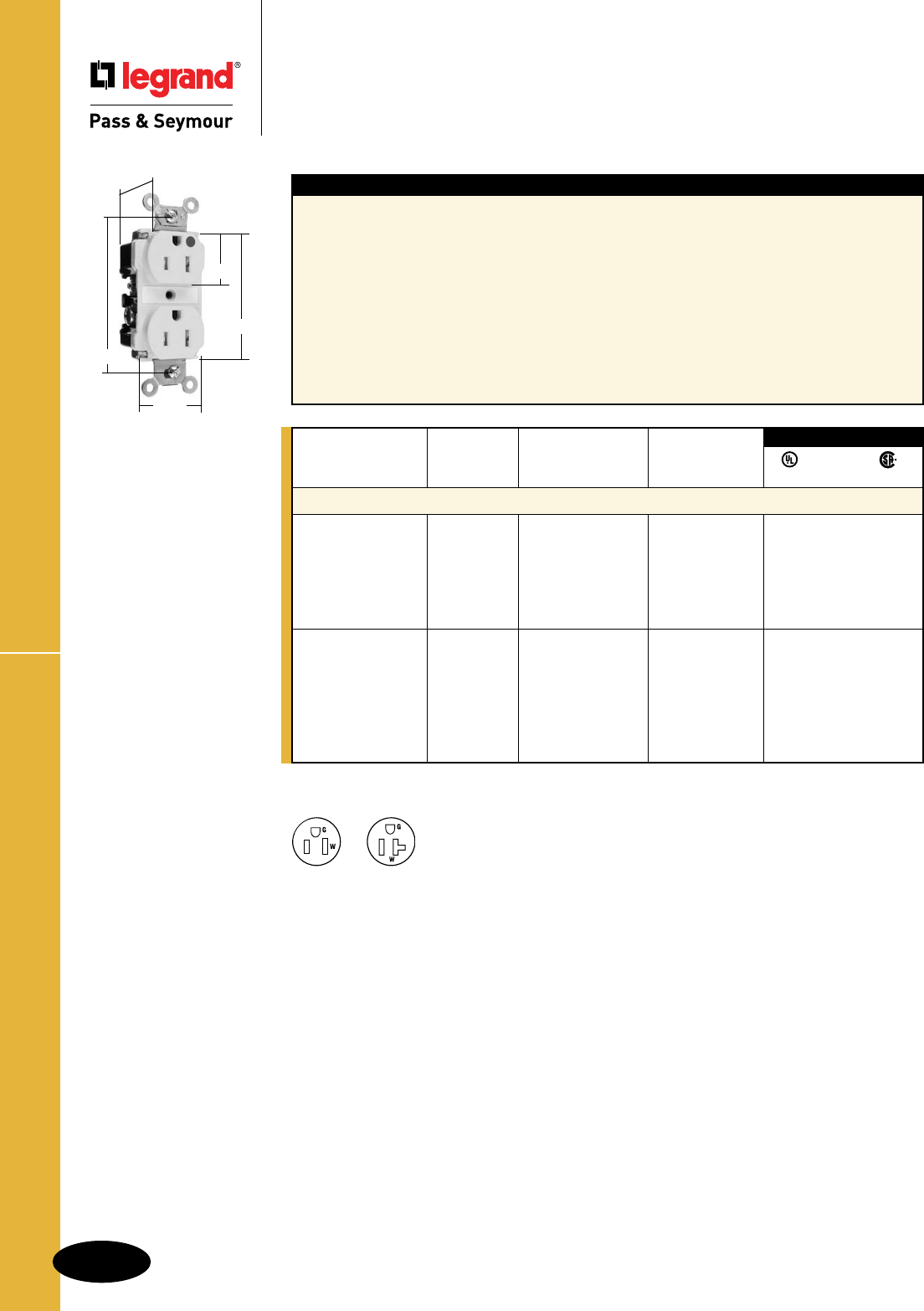
B-26
Straight Blade Receptacles
AlldeviceslistedonthispageconformtoNEMAWD-1andWD-6.
Tamper-Resistant Hospital Grade Recept.
Straight Blade Receptacles
Tamper-Resistant
Hospital Grade Receptacles
15 & 20A, 125V
NEMA
5-15R
NEMA
5-20R
Features
nThermoplasticdualmechanismshuttersystemto
helppreventinsertionofforeignobjects.
nExclusivepatentedfeature,circuitlabelonface
allowspermanentcircuitidentification.
nExtraheavy-dutybrass,one-piecemountingstrap
withintegralground.
nOne-piece,nickel-platedbrass,triple-wipepower
contactsforlastingretention.
nStraptabswraparoundandlockdownonface
topreventstrapfromseparatingfromfaceand
backbody.
nImpact-resistantnylonfaceandbackbody.
nEasilyaccessedbreak-off,line-contact
connectingtabforfast,easysplit-circuit
wiring.
nTwodrivescrewsanchorstraptoback
bodyandface.
nExclusivepatentedfeature,externalscrew-
pressure-platebackwireclamponground
terminalforfaster,easierinstallation.
nExternalscrew-pressure-platebackwire
clampswith#10brassterminalscrewsfor
visualassuranceofagoodconnection.
nAuto-groundclipassurespositiveground.
Rating NEMA
Catalog Number A. V. Color Cong. No.
Hospital Grade Duplex Receptacles Back & Side Wire
TR62HI 15 125 Ivory 5-15R •••
TR62HW 15 125 White 5-15R •••
TR62H 15 125 Brown 5-15R •••
TR62HGRY 15 125 Gray 5-15R •••
TR62HRED 15 125 Red 5-15R •••
TR62HLA 15 125 LightAlmond 5-15R •••
TR63HI 20 125 Ivory 5-20R •••
TR63HW 20 125 White 5-20R •••
TR63H 20 125 Brown 5-20R •••
TR63HGRY 20 125 Gray 5-20R •••
TR63HRED 20 125 Red 5-20R •••
TR63HLA 20 125 LightAlmond 5-20R •••
TR63HBL 20 125 Blue 5-20R •••
3rd Party Compliance
FSUL
UL498 WC596 C22.2 No. 42
For PlugTail™ Tamper-Resistant Receptacles, see Pages B-4 and B-5.
TR62HI
.900"
1.625"
1.104"
2.750"
3.281"
2Pole,3Wire
For Bulk Packaging Solutions consult factory.
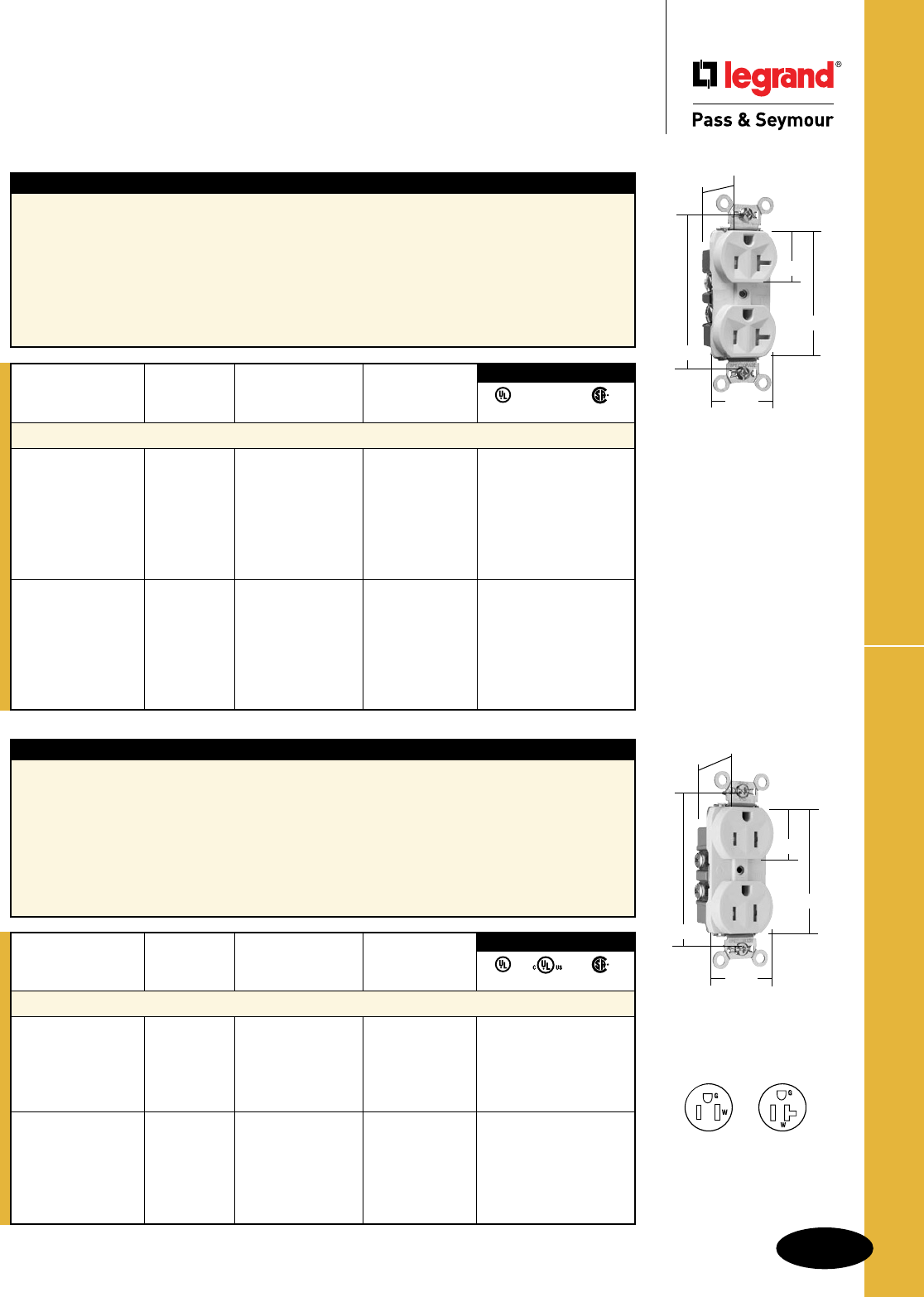
B-27
Straight Blade Receptacles
AlldeviceslistedonthispageconformtoNEMAWD-1andWD-6.
TR Hard Use & Commercial Grade Recept.
Straight Blade Receptacles
Tamper-Resistant Hard Use &
Commercial Grade Receptacles
15 & 20A, 125V
NEMA
5-15R
NEMA
5-20R
Features
nDualmechanicalshuttersystemtohelpprevent
insertionofforeignobjects.
nAuto-groundclipassurespositiveground.
nEasilyaccessedbreak-offline-contactconnectingtab
forfastandeasysplit-circuitwiring.
nBacked-outtri-drivebrassterminalscrewsforfaster
installation.Internalscrew-pressure-platebackand
sidewirecapability.Twobackwireholesforadditional
wiringflexibility.
nCorrosion-resistantplatedsteelstrapis
lockedintofaceandbackbodytoresist
pullingawayfromtheface/bodyassembly.
n.032inchthickbrasstriple-wipepower
contacts.
nTwodrivescrewsanchorsteelstraptoback
bodyandfacewhereabruptremovaltorque
isgreatest.
Rating NEMA
Catalog Number A. V. Color Cong. No.
Tamper-Resistant Duplex Receptacles Back & Side Wire
TR5262I 15 125 Ivory 5-15R •••
TR5262W 15 125 White 5-15R •••
TR5262 15 125 Brown 5-15R •••
TR5262GRY 15 125 Gray 5-15R •••
TR5262BK 15 125 Black 5-15R •••
TR5262RED 15 125 Red 5-15R •••
TR5262LA 15 125 LightAlmond 5-15R •••
TR5362I 20 125 Ivory 5-20R •••
TR5362W 20 125 White 5-20R •••
TR5362 20 125 Brown 5-20R •••
TR5362GRY 20 125 Gray 5-20R •••
TR5362BK 20 125 Black 5-20R •••
TR5362RED 20 125 Red 5-20R •••
TR5362LA 20 125 LightAlmond 5-20R •••
3rd Party Compliance
FSUL
UL498 WC596 C22.2 No. 42
TR5362LA
1.130"
1.322"
1.104"
2.635"
3.281"
Features
nDualmechanicalshuttersystemtohelpprevent
insertionsofforeignobjects.
nTwodrivescrewsanchorstraptobackbodyandface
whereabruptremovaltorqueisgreatest.
n.032inchthickbrasstriple-wipepowercontactsfor
lastingretention.
nCorrosion-resistantplatedsteelstrapislockedinto
thefaceandbackbodytoresistpullingawayfrom
theface/bodyassembly.
nAuto-groundclipassurespositiveground.
nEasilyaccessedbreak-offline-contact
connectingtabforfastandeasysplit-circuit
wiring.
nBacked-outtri-drivesteelterminalscrews.
Sidewirecapability.
Rating NEMA
Catalog Number A. V. Color Cong. No.
Tamper-Resistant Duplex Receptacles Side Wire
TR15I 15 125 Ivory 5-15R •••
TR15W 15 125 White 5-15R •••
TR15 15 125 Brown 5-15R •••
TR15GRY 15 125 Gray 5-15R •••
TR15LA 15 125 LightAlmond 5-15R •••
TR20I 20 125 Ivory 5-20R •••
TR20W 20 125 White 5-20R •••
TR20 20 125 Brown 5-20R •••
TR20GRY 20 125 Gray 5-20R •••
TR20BK 20 125 Black 5-20R •••
TR20LA 20 125 LightAlmond 5-20R •••
3rd Party Compliance
UL498 cULus C22.2 No. 42
TR15LA
1.130"
1.322"
1.104"
2.635"
3.281"
For Bulk Packaging
Solutions consult factory.
2Pole,3Wire
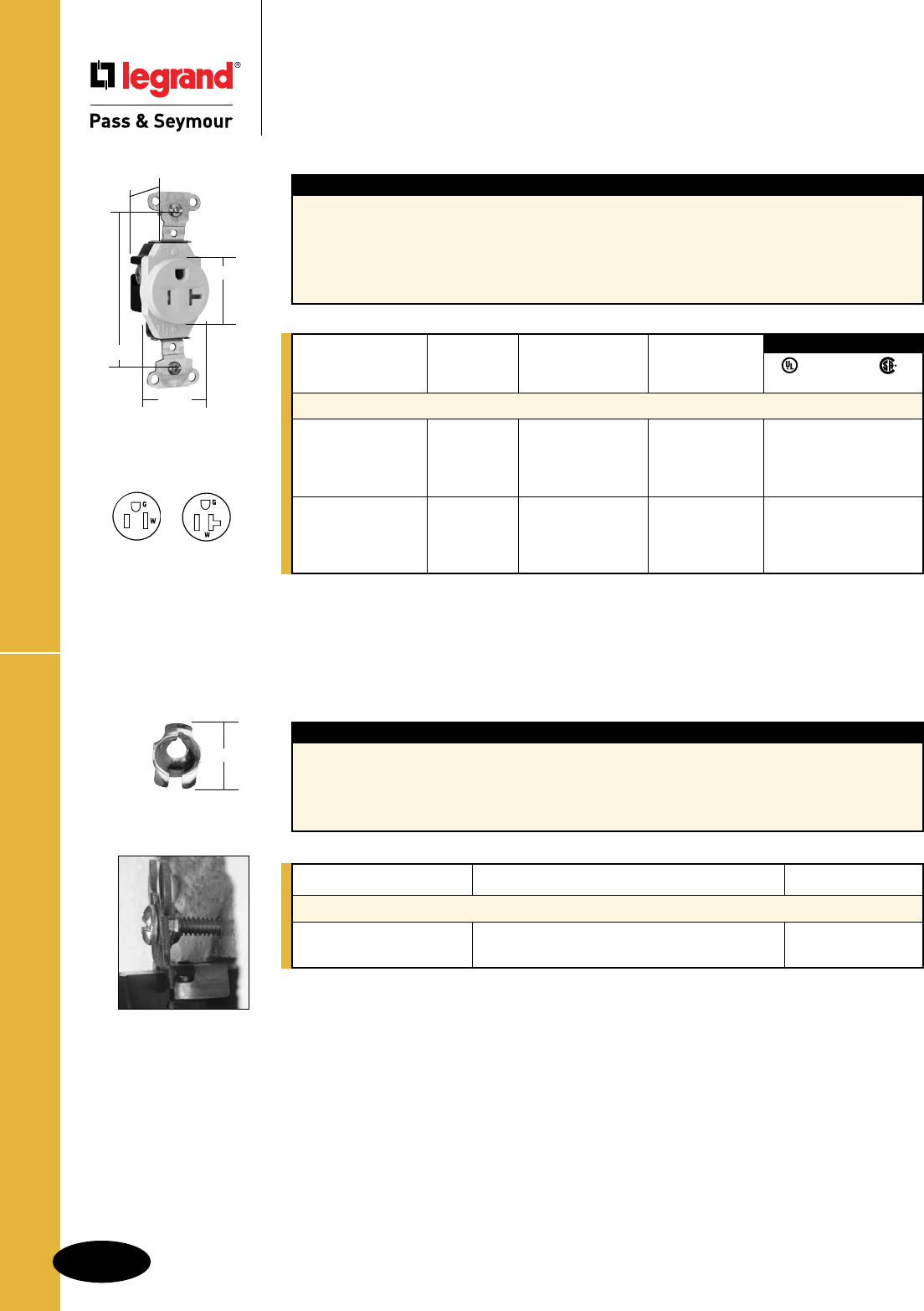
B-28
Straight Blade Receptacles
AlldeviceslistedonthispageconformtoNEMAWD-1andWD-6.
Straight Blade Receptacles
Tamper-Resistant Construction Grade
Receptacles & Shim-Lock
15 & 20A, 125V
TR Construction Grade Receptacles
NEMA
5-15R
NEMA
5-20R
Features
nDualmechanicalshuttersystemtohelpprevent
insertionsofforeignobjects.
nTwodrivescrewsanchorstraptobackbodyand
facewhereabruptremovaltorqueisgreatest.
nHeavy-duty,corrosion-resistantzinc-platedsteel
strapforaddedstrength.
nBacked-outtri-drivesteelterminalscrews.
Internalscrew-pressure-platebackandside
wirecapability.Twobackwireholesfor
increasedwiringflexibility.
nOne-piecebrasstriple-wipepowercontacts
forlastingretention.
Rating NEMA
Catalog Number A. V. Color Cong. No.
Tamper-Resistant Single Receptacles Back & Side Wire
TR5251I 15 125 Ivory 5-15R •••
TR5251W 15 125 White 5-15R •••
TR5251 15 125 Brown 5-15R •••
TR5251LA 15 125 LightAlmond 5-15R •••
TR5351I 20 125 Ivory 5-20R •••
TR5351W 20 125 White 5-20R •••
TR5351 20 125 Brown 5-20R •••
TR5351LA 20 125 LightAlmond 5-20R •••
3rd Party Compliance
FSUL
UL498 WC596 C22.2 No. 42
TR5351LA
1.190"
1.296"
1.38"
3.28"
Features
nOneShim-Lockprovidesadeviceadjustment
depthrangebetween1/8"and3/4".
nAninexpensiveandquickfixforfloating
installations.
nProvidesaperfectflushmounteverytime,
regardlessofthewallboard,tileorpanel
condition.
nMadeofsteelandfinishedwithclearzinc
chromateplating.
Catalog Number Dimensions Qty. Per Package
Shim-Lock
SHL20 Length:.310",ScrewOpening:#6 20
SHL100 Length:.310",ScrewOpening:#6 100
Shim-Lock
.310"
For Bulk Packaging Solutions consult factory.
2Pole,3Wire
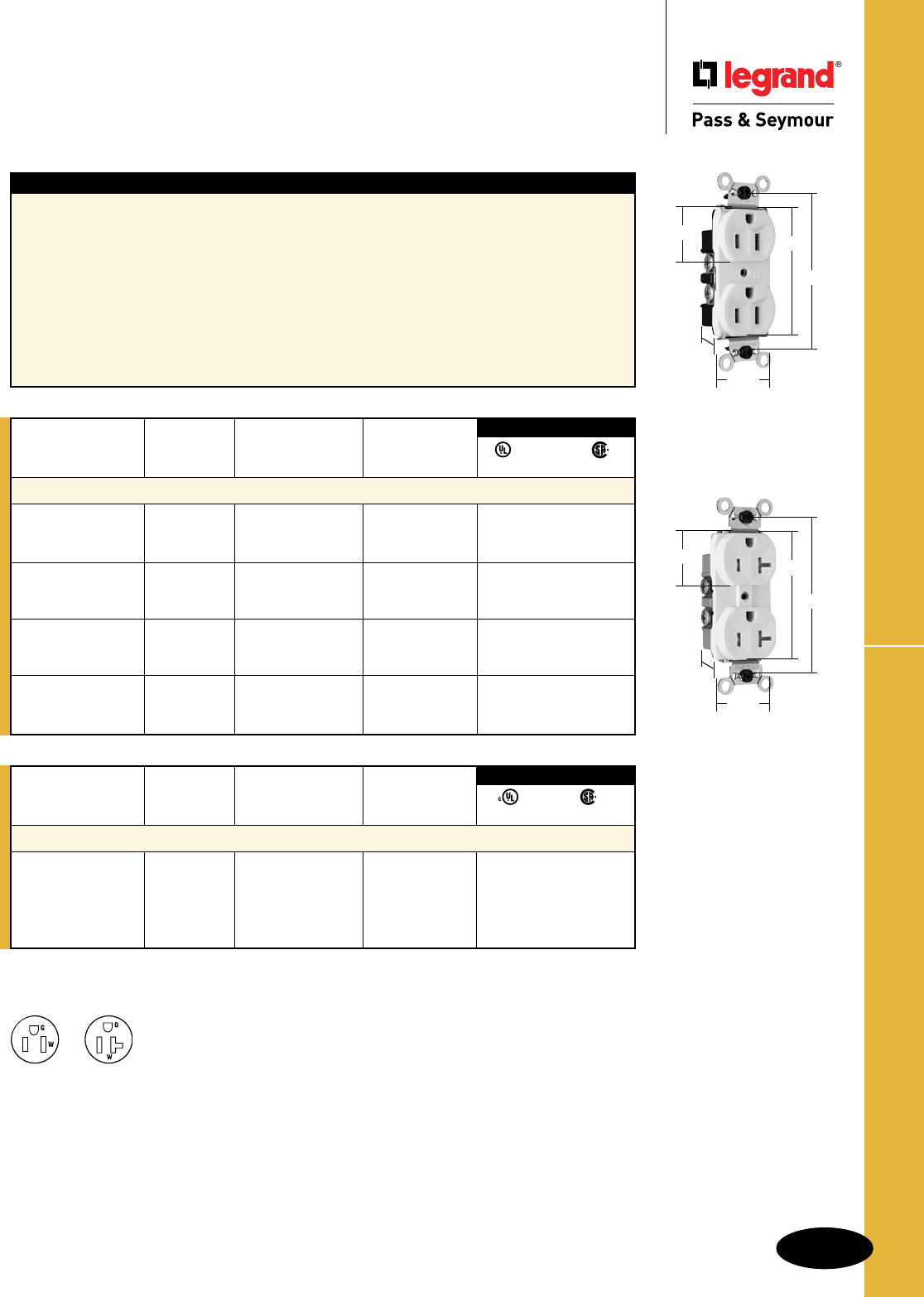
B-29
Straight Blade Receptacles
AlldeviceslistedonthispageconformtoNEMAWD-1andWD-6.
Weather-Resistant Receptacles
Straight Blade Receptacles
Weather-Resistant Heavy-Duty &
Commercial Grade Receptacles
15 & 20A, 125 & 250V
NEMA
5-15R
NEMA
5-20R
Features
nAuto-groundclipassurespositiveground.
nWRmarkingonfaceasrequiredbyULStandard.
nZinc-platedsteelmountingscrewsforgreaterease
ofinstallationandremovalinwetordamplocations.
nStraptabswraparoundfacetopreventstrapfrom
separatingfromfaceandbackbody.
nTri-drivebrassterminalscrews.Internalscrew-
pressure-platebackandsidewirecapability.
Twobackwireholesformorewiringflexibility.
nHeavy-duty,brassstrapforaddedstrengthand
groundconductivity.
nUV-resistantnylonfaceforlongerlifeunder
adverseenvironmentalconditions.
nTwodrivescrewsanchorstraptoback
bodyandfacewhereabruptremovaltorque
isstrongest.
nEasilyaccessedbreak-off,line-contact
connectingtabforfast,easysplit-circuit
wiring.
n.032inchthickbrasstriple-wipepower
contactsforlastingretention.
Rating NEMA
Catalog Number A. V. Color Cong. No.
Weather-Resistant Duplex Receptacles Back & Side Wire
WR5262I 15 125 Ivory 5-15R •••
WR5262W 15 125 White 5-15R •••
WR5262GRY 15 125 Gray 5-15R •••
WR5362I 20 125 Ivory 5-20R •••
WR5362W 20 125 White 5-20R •••
WR5362GRY 20 125 Gray 5-20R •••
WR5662I 15 250 Ivory 6-15R •••
WR5662W 15 250 White 6-15R •••
WR5662GRY 15 250 Gray 6-15R •••
WR5862I 20 250 Ivory 6-20R •••
WR5862W 20 250 White 6-20R •••
WR5862GRY 20 250 Gray 6-20R •••
3rd Party Compliance
FSUL
UL498 WC596 C22.2 No. 42
2Pole,3Wire
Rating NEMA
Catalog Number A. V. Color Cong. No.
Weather-Resistant Duplex Receptacles Side Wire
WR20TRI 20 125 Ivory 5-20R ••
WR20TRW 20 125 White 5-20R ••
WR20TR 20 125 Brown 5-20R ••
WR20TRGRY 20 125 Gray 5-20R ••
WR20TRLA 20 125 LightAlmond 5-20R ••
3rd Party Compliance
UL498 C22.2 No. 42
WR5262W
1.322"
1.104" 2.635"
3.281"
.780"
WR20TRW
1.322"
1.104"
2.635"
3.281"
1.130"
National Electrical Code® Section 406.8 Receptacles in Wet or Damp Locations.
Requiresthatall15-and20-amp,125-and250-voltnon-lockingreceptaclesinstalledinwetordamplocationsshallbe
weather-resistantreceptacles.
WR20TRmodelsareTamper-Resistant.
For Bulk Packaging Solutions consult factory.
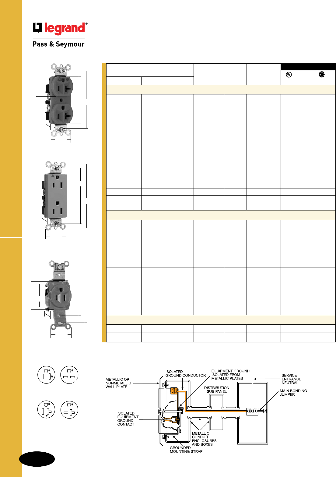
B-30
Straight Blade Receptacles
AlldeviceslistedonthispageconformtoNEMAWD-1andWD-6.
Isolated Ground Receptacles
NEMA
5-15R
NEMA
6-15R
NEMA
6-20R
NEMA
5-20R
For Wall Plates for Isolated Ground Systems, consult Wall Plates Section Q.
For Bulk Packaging Solutions consult factory.
Straight Blade Receptacles
Isolated Ground Receptacles
2 Pole, 3 Wire Grounding 15 & 20A, 125V & 250V
IG26262GRY
.833"
1.322"
3.281"
2.635"
3.813"
IG8300
1.322"
1.104" 2.635"
3.281"
.922"
1.093"
1.32"
3.28"
2.37"
3.68"
1.38"
1.68"
IG5261
NEMA
Catalog Number Rating Cong.
Spec Grade Hospital Grade A. V. No. Color
Duplex Receptacles Back & Side Wire
IG5262IIG8200I 15 125 5-15R Ivory •••
IG5262W 15 125 5-15R White •••
IG5262 IG8200 15 125 5-15R Orange •• •
IG5262GRY 15 125 5-15R Gray •••
IG5262RED IG8200RED 15 125 5-15R Red •• •
IG5262LA 15 125 5-15R LightAlmond •• •
IG5362IIG8300I 20 125 5-20R Ivory •• •
IG5362WIG8300W 20 125 5-20R White •• •
IG5362IG8300 20 125 5-20R Orange •• •
IG5362GRY 20 125 5-20R Gray •• •
IG5362BK 20 125 5-20R Black •• •
IG5362RED IG8300RED 20 125 5-20R Red • •
IG5362LAIG8300LA 20 125 5-20R LightAlmond •• •
IG5362BL 20 125 5-20R Blue •• •
IG5662 15 250 6-15R Orange •• •
IG5862IG8800 20 250 6-20R Orange •• •
IG8800LA 20 250 6-20R LightAlmond •• •
Decorator Duplex Receptacles Back & Side Wire
IG26262I 15 125 5-15R Ivory •• •
IG26262WIG26262HGW 15 125 5-15R White •• •
IG26262 IG26262HG 15 125 5-15R Orange •• •
IG26262GRY 15 125 5-15R Gray •• •
IG26262BK 15 125 5-15R Black •• •
IG26262REDIG26262HGRED 15 125 5-15R Red •• •
IG26262LA 15 125 5-15R LightAlmond •• •
IG26362I 20 125 5-20R Ivory •• •
IG26362W IG26362HGW 20 125 5-20R White •• •
IG26362 IG26362HG 20 125 5-20R Orange •••
IG26362GRY 20 125 5-20R Gray •• •
IG26362BKIG26362HGBK 20 125 5-20R Black •• •
IG26362REDIG26362HGRED 20 125 5-20R Red •• •
IG26362LA 20 125 5-20R LightAlmond •• •
Single Receptacles Back & Side Wire
IG5261 15 125 5-15R Orange •••
IG5361 IG8301 20 125 5-20R Orange •••
3rd Party Compliance
FSUL
UL498 WC596 C22.2 No. 42
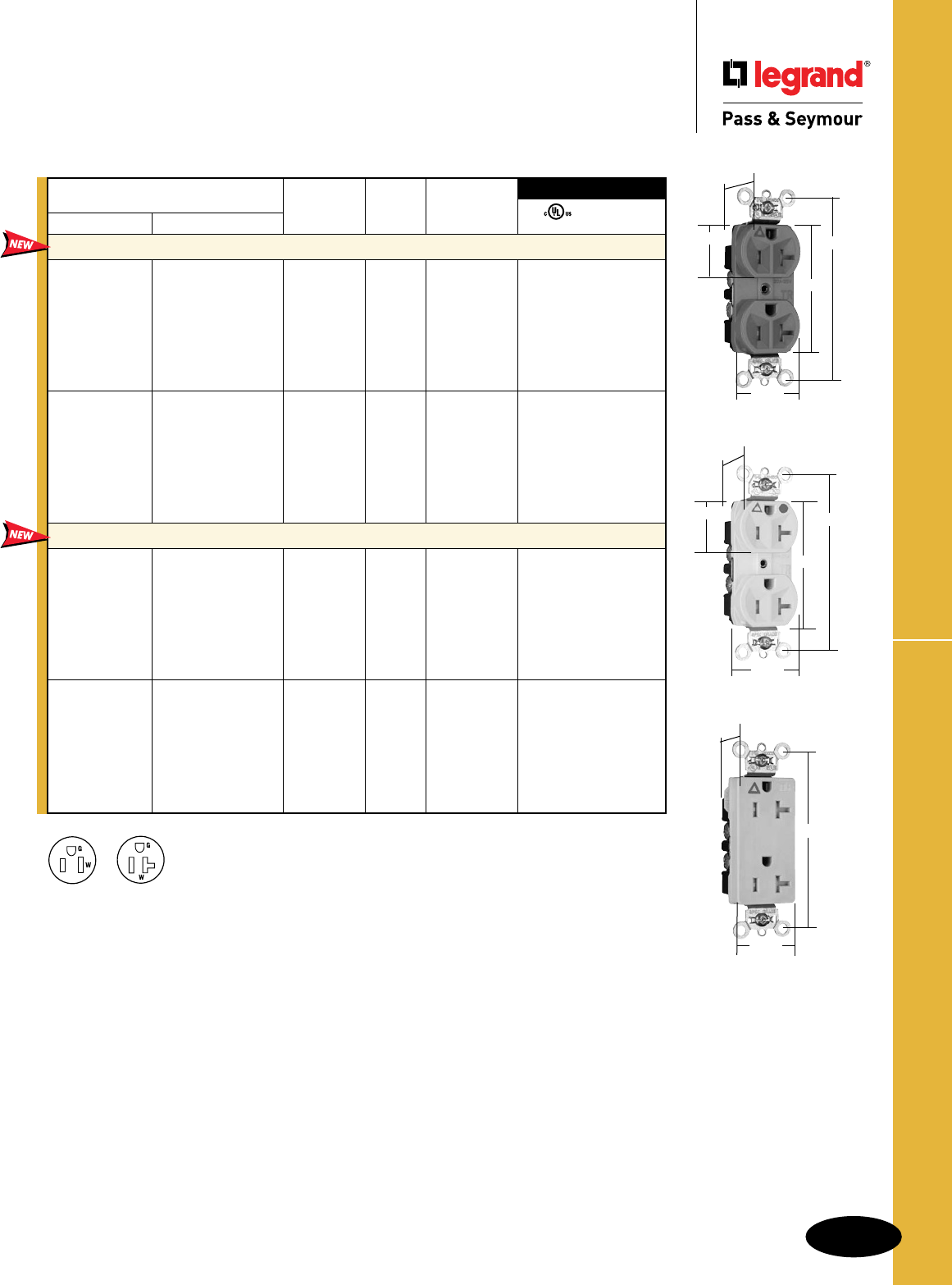
B-31
Straight Blade Receptacles
AlldeviceslistedonthispageconformtoNEMAWD-1andWD-6.
Straight Blade Receptacles
Tamper-Resistant Isolated Ground
Receptacles
2 Pole, 3 Wire Grounding 15 & 20A, 125V
Tamper-Resistant Isolated Ground Receptacles
1.187"
1.25"
1.125"
2.625"
3.625"
TRIG5362
TRIG8300W
1.187"
1.25"
1.125"
2.625"
3.625"
TRIG26362
1.187"
1.25"
3.625"
For Bulk Packaging Solutions consult factory.
NEMA
5-20R
NEMA
5-15R
FSUL
UL498 WC596
3rd Party Compliance
NEMA
Catalog Number Rating Cong.
Spec Grade Hospital Grade A. V. No. Color
Tamper-Resistant Duplex Receptacles Back & Side Wire
TRIG5262I TRIG8200I 15 125 5-15R Ivory ••
TRIG5262W TRIG8200W 15 125 5-15R White ••
TRIG5262 TRIG8200 15 125 5-15R Orange ••
TRIG5262BKTRIG8200BK 15 125 5-15R Black ••
TRIG5262GRYTRIG8200GRY 15 125 5-15R Gray ••
TRIG5262RED TRIG8200RED 15 125 5-15R Red ••
TRIG5262LA TRIG8200LA 15 125 5-15R LightAlmond ••
TRIG5362I TRIG8300I 20 125 5-20R Ivory ••
TRIG5362W TRIG8300W 20 125 5-20R White ••
TRIG5362 TRIG8300 20 125 5-20R Orange ••
TRIG5362BKTRIG8300BK 20 125 5-20R Black ••
TRIG5362GRYTRIG8300GRY 20 125 5-20R Gray ••
TRIG5362RED TRIG8300RED 20 125 5-20R Red ••
TRIG5362LA TRIG8300LA 20 125 5-20R LightAlmond ••
Tamper-Resistant Decorator Receptacles Back & Side Wire
TRIG26262I TRIG26262HGI 15 125 5-15R Ivory ••
TRIG26262W TRIG26262HGW 15 125 5-15R White ••
TRIG26262 TRIG26262HG 15 125 5-15R Orange ••
TRIG26262BKTRIG26262HGBK 15 125 5-15R Black ••
TRIG26262GRYTRIG26262HGGRY 15 125 5-15R Gray ••
TRIG26262RED TRIG26262HGRED 15 125 5-15R Red ••
TRIG26262LA TRIG26262HGLA 15 125 5-15R LightAlmond ••
TRIG26362I TRIG26362HGI 20 125 5-20R Ivory ••
TRIG26362W TRIG26362HGW 20 125 5-20R White ••
TRIG26362 TRIG26362HG 20 125 5-20R Orange ••
TRIG26362BKTRIG26362HGBK 20 125 5-20R Black ••
TRIG26362GRYTRIG26362HGGRY 20 125 5-20R Gray ••
TRIG26362RED TRIG26362HGRED 20 125 5-20R Red ••
TRIG26362LA TRIG26362HGLA 20 125 5-20R LightAlmond ••
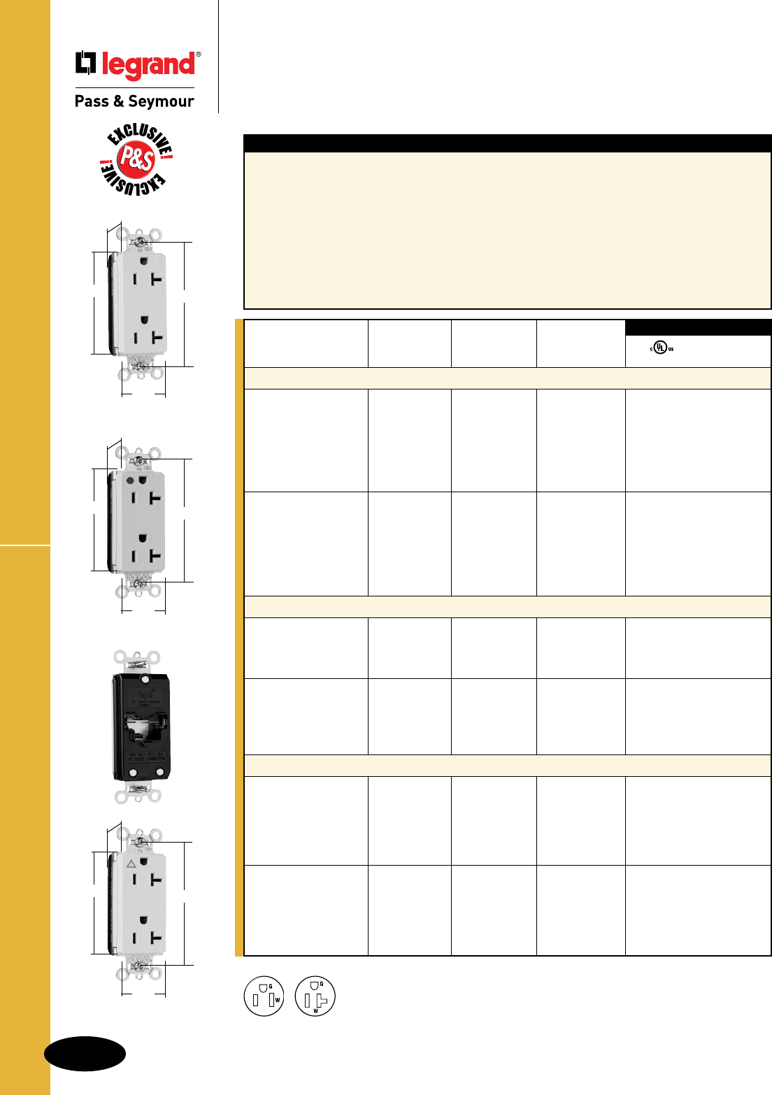
B-32
Straight Blade Receptacles
AlldeviceslistedonthispageconformtoNEMAWD-1andWD-6.
Straight Blade Receptacles
PlugTail™ Decorator Receptacles
15 & 20A, 125V
PlugTail™ Decorator Receptacles
3rd Party Compliance
FSUL
UL498 WC596
Rating NEMA
Catalog Number A. V. Color Cong. No.
Duplex Receptacles
PT26252I 15 125 Ivory 5-15R • •
PT26252W 15 125 White 5-15R • •
PT26252 15 125 Brown 5-15R • •
PT26252GRY 15 125 Gray 5-15R • •
PT26252BK 15 125 Black 5-15R • •
PT26252RED 15 125 Red 5-15R • •
PT26252LA 15 125 LightAlmond 5-15R • •
PT26352I 20 125 Ivory 5-20R • •
PT26352W 20 125 White 5-20R • •
PT26352 20 125 Brown 5-20R • •
PT26352GRY 20 125 Gray 5-20R • •
PT26352BK 20 125 Black 5-20R • •
PT26352RED 20 125 Red 5-20R • •
PT26352LA 20 125 LightAlmond 5-20R • •
Hospital Grade Duplex Receptacles
PT26262HGI 15 125 Ivory 5-15R ••
PT26262HGW 15 125 White 5-15R ••
PT26262HGGRY 15 125 Gray 5-15R ••
PT26262HGRED 15 125 Red 5-15R ••
PT26362HGI 20 125 Ivory 5-20R ••
PT26362HGW 20 125 White 5-20R ••
PT26362HGGRY 20 125 Gray 5-20R ••
PT26362HGRED 20 125 Red 5-20R ••
PT26362HGLA 20 125 LightAlmond 5-20R ••
Isolated Ground Duplex Receptacles
PTIG26262I 15 125 Ivory 5-15R ••
PTIG26262W 15 125 White 5-15R ••
PTIG26262 15 125 Orange 5-15R ••
PTIG26262GRY 15 125 Gray 5-15R ••
PTIG26262RED 15 125 Red 5-15R ••
PTIG26262LA 15 125 LightAlmond 5-15R ••
PTIG26362I 20 125 Ivory 5-20R ••
PTIG26362W 20 125 White 5-20R ••
PTIG26362 20 125 Orange 5-20R ••
PTIG26362GRY 20 125 Gray 5-20R ••
PTIG26362RED 20 125 Red 5-20R ••
PTIG26362LA 20 125 LightAlmond 5-20R ••
PT26362HGI
2.75" 3.281"
.625"
1.5"
Features
n.036inchthick,brass,triple-wipepowercontactsfor
lastingretention.
nPlatedsteelwrapstrapdesignformaximumdurability
andcorrosionresistance.
nNoexposedterminalscreateafingersafeapplication
before,during,andafterinstallation.
nBuilt-inconnectorfeatureslargebrassterminalblades
toensureconsistent,reliableelectricalconnections.
nCrimpedandweldedcontacts.
nUltrasonicallyweldedpolycarbonateconnector
housingsecuresterminationsandconductors
inaULListed,fingersafehousing.
nLargebrasscontactssnuglyterminateon
devicebladeterminals.
nPre-strippedconnectorleadsfastento
conductors,easierthanstandardpigtails.
nAuto-groundclipassurespositiveground.
nIsolatedgroundversionfeaturesnylon
isolatorplateforisolatinggroundfromstrap
andboxsystem.
PT26352LA
2.75" 3.281"
.625"
1.5"
PTIG26362LA
2.75" 3.281"
.625"
1.5"
NEMA
5-15R
NEMA
5-20R
2Pole,3Wire
For PlugTail Connectors, see Page B-3.
For Bulk Packaging Solutions consult factory.
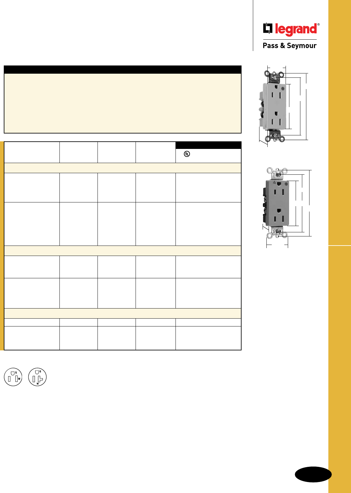
B-33
Straight Blade Receptacles
AlldeviceslistedonthispageconformtoNEMAWD-1andWD-6.
HD Hospital Grade Decorator Receptacles
Straight Blade Receptacles
Heavy-Duty Hospital Grade
Decorator Receptacles
15 & 20A, 125V
Features
nCorrosion-resistant,platedsteelstraplockedinto
assemblytoprohibitstrapfrombending
awayfrombody.
nOne-piece,brass,triple-wipepowercontacts
forlastingretention.
nHeavy-dutycompactdesignforeasierinstallation
andlonglastingperformance.
nEasilyaccessedbreak-off,line-contactconnecting
tabforfast,easysplit-circuitwiring.
nImpact-resistantnylonface.
nTerminalcompartmentsisolatedfromeach
otherforpositiveconductorcontainment.
nSideandinternalscrew-pressure-plate
backwireaccepts#14–#10AWGsolid
orstrandedwire.
nAlldevicesfitstandard#26openingwallplate.
nTri-driveterminalandmountingscrews.
nAuto-groundclipassurespositiveground.
3rd Party Compliance
FSUL
UL498 WC596 cUL/CSA
Rating NEMA
Catalog Number A. V. Color Cong. No.
Hospital Grade Duplex Receptacles Back & Side Wire
26262HGI 15 125 Ivory 5-15R •• •
26262HGW 15 125 White 5-15R •• •
26262HGGRY 15 125 Gray 5-15R •• •
26262HGRED 15 125 Red 5-15R •• •
26362HGI 20 125 Ivory 5-20R •• •
26362HGW 20 125 White 5-20R •• •
26362HG 20 125 Brown 5-20R •• •
26362HGGRY 20 125 Gray 5-20R •• •
26362HGRED 20 125 Red 5-20R •• •
26362HGLA 20 125 LightAlmond 5-20R •• •
Hospital Grade Isolated Ground Duplex Receptacles Back & Side Wire
IG26262HGW 15 125 White 5-15R • •
IG26262HG 15 125 Orange 5-15R • •
IG26262HGRED 15 125 Red 5-15R • •
IG26362HGW 20 125 White 5-20R • •
IG26362HG 20 125 Orange 5-20R • •
IG26362HGBK 20 125 Black 5-20R • •
IG26362HGRED 20 125 Red 5-20R • •
Hospital Grade Illuminated Duplex Receptacles Back & Side Wire
26222HGI 15 125 Ivory 5-15R • •
26322HGI 20 125 Ivory 5-20R • •
26322HGW 20 125 White 5-20R • •
26322HGRED 20 125 Red 5-20R • •
For Bulk Packaging Solutions consult factory.
26262HGI
2.635"
3.281"
1.322"
3.813"
.833"
NEMA
5-15R
NEMA
5-20R
2Pole,3Wire
IG26262HG
.833"
1.322"
3.281"
2.635"
3.813"
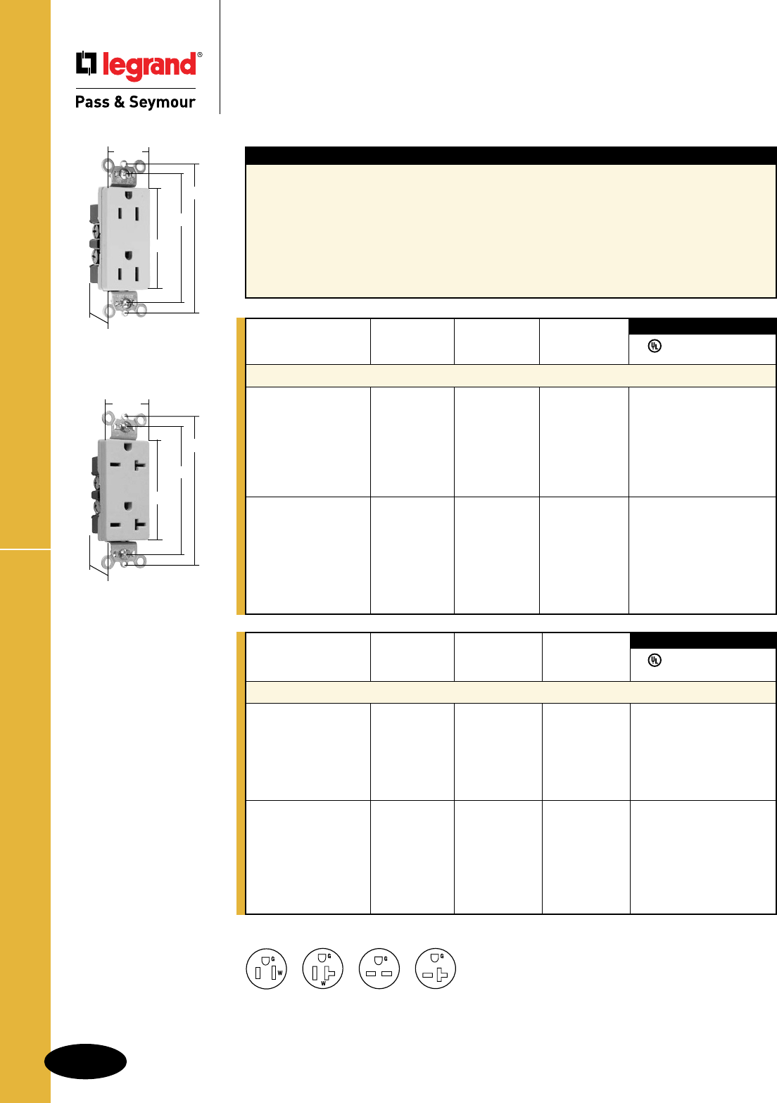
B-34
Straight Blade Receptacles
AlldeviceslistedonthispageconformtoNEMAWD-1andWD-6.
Specification Grade Decorator Receptacles
Straight Blade Receptacles
Specification Grade
Decorator Receptacles
15 & 20A, 125 & 250V
Rating NEMA
Catalog Number A. V. Color Cong. No.
Duplex Receptacles Back & Side Wire
26652I 15 250 Ivory 6-15R • • •
26652W 15 250 White 6-15R • • •
26652 15 250 Brown 6-15R • • •
26652GRY 15 250 Gray 6-15R • • •
26652BK 15 250 Black 6-15R • • •
26652RED 15 250 Red 6-15R • • •
26852I 20 250 Ivory 6-20R • • •
26852W 20 250 White 6-20R • • •
26852 20 250 Brown 6-20R •• •
26852GRY 20 250 Gray 6-20R •• •
26852BK 20 250 Black 6-20R •• •
26852RED 20 250 Red 6-20R •• •
26852LA 20 250 LightAlmond 6-20R •• •
3rd Party Compliance
FSUL
UL498 WC596 cUL/CSA
Features
nCorrosion-resistant,platedsteelstraplockedinto
assemblytoprohibitstrapfrombendingaway
frombody.
nOne-piece,brass,triple-wipepowercontacts
forlastingretention.
nHeavy-dutycompactdesignforeasierinstallation
andlonglastingperformance.
nEasilyaccessedbreak-off,line-contactconnecting
tabforfast,easysplit-circuitwiring.
nImpact-resistantnylonface.
nTerminalcompartmentsisolatedfromeach
otherforpositiveconductorcontainment.
nSideandinternalscrew-pressure-plate
backwireaccepts#14–#10AWGsolid
orstrandedwire.
nAlldevicesfitstandard#26openingwallplate.
nTri-driveterminalandmountingscrews.
nAuto-groundclipassurespositiveground.
For Bulk Packaging Solutions consult factory.
2Pole,3Wire
NEMA
5-15R
NEMA
5-20R
NEMA
6-15R
NEMA
6-20R
26252I
2.635"
3.281"
1.322"
3.81"
.833"
Rating NEMA
Catalog Number A. V. Color Cong. No.
Specification Grade Duplex Receptacles Back & Side Wire
26252I 15 125 Ivory 5-15R • • •
26252W 15 125 White 5-15R • • •
26252 15 125 Brown 5-15R • • •
26252GRY 15 125 Gray 5-15R • • •
26252BK 15 125 Black 5-15R • • •
26252RED 15 125 Red 5-15R • • •
26252LA 15 125 LightAlmond 5-15R • • •
26352I 20 125 Ivory 5-20R •• •
26352W 20 125 White 5-20R • • •
26352 20 125 Brown 5-20R • • •
26352GRY 20 125 Gray 5-20R • • •
26352BK 20 125 Black 5-20R • • •
26352RED 20 125 Red 5-20R • • •
26352LA 20 125 LightAlmond 5-20R • • •
3rd Party Compliance
FSUL
UL498 WC596 cUL/CSA
26852I
2.635"
3.281"
1.322"
3.81"
.833"
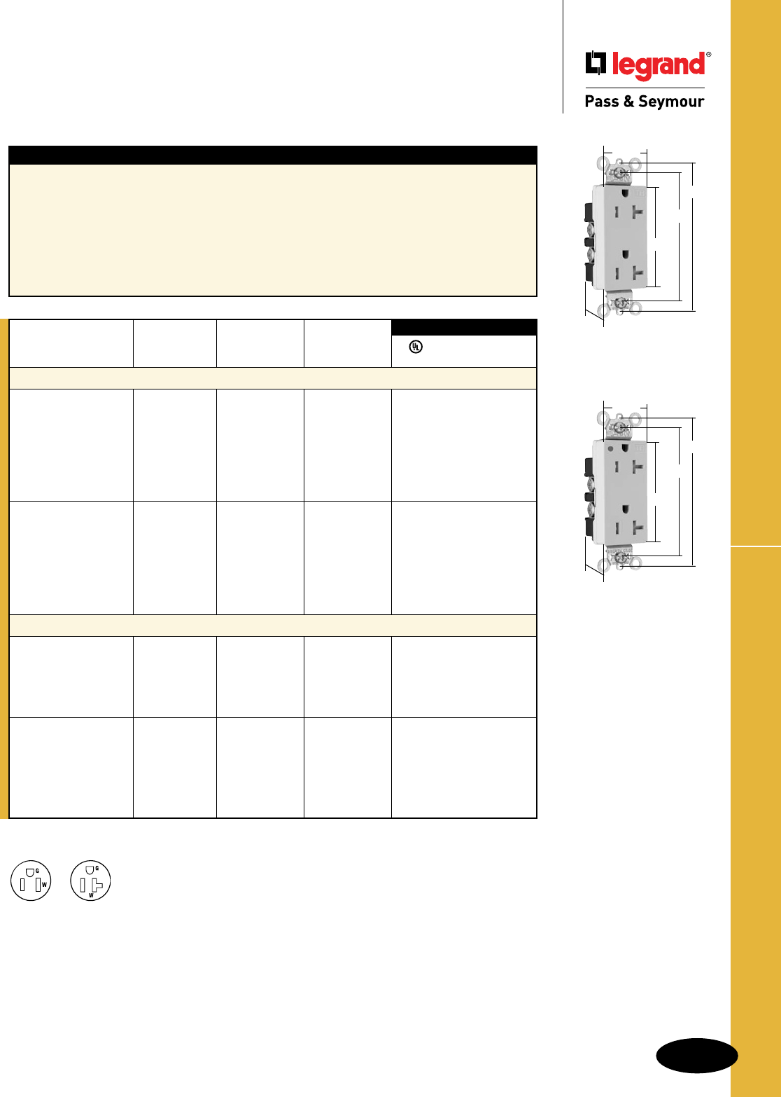
B-35
Straight Blade Receptacles
AlldeviceslistedonthispageconformtoNEMAWD-1andWD-6.
Heavy-Duty TR Decorator Receptacles
Straight Blade Receptacles
Heavy-Duty Tamper-Resistant
Decorator Receptacles
15 & 20A, 125V
Features
nAuto-groundclipassurespositiveground.
nDualmechanicalshuttersystemtohelpprevent
insertionofforeignobjects.
nOne-piecebrasstriple-wipepowercontactsfor
reliableplugretention.
nTwodrivescrewsanchorstraptobackbodyand
facewhereabruptremovaltorqueisstrongest.
nPatentedexternalscrew-pressure-platebackwire
clampongroundterminalforfaster,easierinstallation.
nEasilyaccessedbreak-off,line-contact
connectingtabforfast,easysplit-circuitwiring.
nExternalscrew-pressure-platebackwire
clampswith#10brassterminalscrewsfor
visualassuranceofagoodconnection.
nOne-pieceplatedsteelmountingstrap
withintegralgroundforsuperiorlong-term
performance.
TR26362I
2.635"
3.281"
1.322"
3.81"
.833"
Rating NEMA
Catalog Number A. V. Color Cong. No.
Tamper-Resistant Decorator Duplex Receptacles Back & Side Wire
TR26262I 15 125 Ivory 5-15R • • •
TR26262W 15 125 White 5-15R • • •
TR26262 15 125 Brown 5-15R • • •
TR26262GRY 15 125 Gray 5-15R • • •
TR26262BK 15 125 Black 5-15R • • •
TR26262RED 15 125 Red 5-15R • • •
TR26262LA 15 125 LightAlmond 5-15R • • •
TR26362I 20 125 Ivory 5-20R • • •
TR26362W 20 125 White 5-20R • • •
TR26362 20 125 Brown 5-20R •• •
TR26362GRY 20 125 Gray 5-20R •• •
TR26362BK 20 125 Black 5-20R •• •
TR26362RED 20 125 Red 5-20R •• •
TR26362LA 20 125 LightAlmond 5-20R •• •
Tamper-Resistant Hospital Grade Duplex Receptacles Back & Side Wire
TR26262HGI 15 125 Ivory 5-15R • ••
TR26262HGW 15 125 White 5-15R • ••
TR26262HGGRY 15 125 Gray 5-15R • ••
TR26262HGRED 15 125 Red 5-15R • ••
TR26262HGLA 15 125 LightAlmond 5-15R • • •
TR26362HGI 20 125 Ivory 5-20R • • •
TR26362HGW 20 125 White 5-20R •• •
TR26362HGGRY 20 125 Gray 5-20R •• •
TR26362HGBK 20 125 Black 5-20R •• •
TR26362HGRED 20 125 Red 5-20R • • •
TR26362HGLA 20 125 LightAlmond 5-20R •• •
3rd Party Compliance
FSUL
UL498 WC596 cUL/CSA
TR26362HGI
2.635"
3.281"
1.322"
3.81"
.833"
For Bulk Packaging Solutions consult factory.
NEMA
5-20R
NEMA
5-15R
2Pole,3Wire
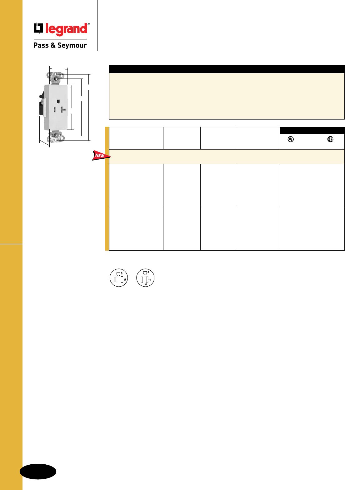
B-36
Straight Blade Receptacles
AlldeviceslistedonthispageconformtoNEMAWD-1andWD-6.
HD TR Decorator Single Receptacles
Straight Blade Receptacles
Heavy-Duty Tamper-Resistant
Decorator Single Receptacles
15 & 20A, 125V
Features
nAuto-groundclipassurespositiveground.
nBacked-outtri-drivebrassterminalscrewsfor
fasterinstallation.Internalscrew-pressure-plate
backandsidewirecapability.Twobackwire
holesforadditionalwiringflexibility.
nHeavy-dutycorrosion-resistantzinc-plated
strapforaddedstrength.
nOne-piecebrasstriple-wipepowercontactfor
lastingretention.
nTwodrivescrewsanchorsteelstraptoback
bodyandfacewhereabruptremovaltorqueis
greatest.
nDualmechanicalshuttersystemtohelpprevent
insertionofforeignobjects.
NEMA
5-20R
NEMA
5-15R
2Pole,3Wire
For Bulk Packaging Solutions consult factory.
TR26361LA
2.635"
3.281"
1.322"
3.813"
1.188"
Rating NEMA
Catalog Number A. V. Color Cong. No.
Heavy-Duty Tamper-Resistant Decorator Single Receptacles
Back & Side Wire
TR26261I 15 125 Ivory 5-15R • • •
TR26261W 15 125 White 5-15R • • •
TR26261 15 125 Brown 5-15R • • •
TR26261GRY 15 125 Gray 5-15R • • •
TR26261BK 15 125 Black 5-15R • • •
TR26261LA 15 125 LightAlmond 5-15R • • •
TR26361I 20 125 Ivory 5-20R • • •
TR26361W 20 125 White 5-20R • • •
TR26361 20 125 Brown 5-20R • • •
TR26361GRY 20 125 Gray 5-20R • • •
TR26361BK 20 125 Black 5-20R • • •
TR26361LA 20 125 LightAlmond 5-20R • • •
3rd Party Compliance
FSUL
UL498 WC596 22.2 No. 42
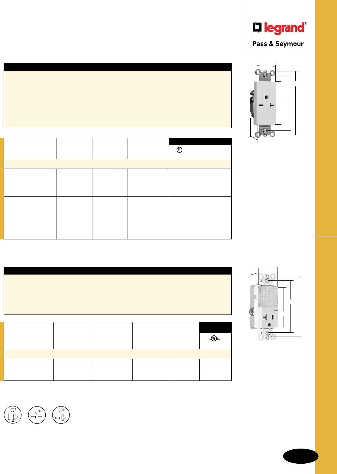
B-37
Straight Blade Receptacles
AlldeviceslistedonthispageconformtoNEMAWD-1andWD-6.
Features
nImpact-resistantfaceandbody.
nGELexan™highimpact-resistantlens.
nExternalscrew-pressure-platebackandside
wired.Accepts#12and#14AWG.
nGroundscrewpositionundertheendofthe
strapminimizestheriskofcontact.
nEnergy-efficientLEDhasaverage20-yearlife
expectancy:eliminatesbulbreplacement.
nSensorautomaticallyturnslightONinthedark.
nIncreasedlightoutputforbetterillumination.
nLightsensorforenhancedsensitivity.
Straight Blade Receptacles
Specification Grade Decorator &
Combination Receptacles
15 & 20A, 125 & 250V; 20A, 120/125VAC
Spec Grade Decorator & Combo Receptacles
26861LA
2.635"
3.281"
1.322"
3.813"
.833"
Catalog Rating Light Output NEMA
Number A. VAC In 1' FCD* Color Cong. No. UL498
Specification Grade Decorator Hallway Light & Single Receptacle
PS8HWLI 20 120/125 0.2561 Ivory 5-20R •
PS8HWLW 20 120/125 0.2561 White 5-20R •
PS8HWLLA 20 120/125 0.2561 LightAlmond 5-20R •
3rd Party
Compliance
PS8HWLLA
3.281"
3.812"
2.60"
1.29"
1.59"
*FCD = Foot Candle Distance. 1 Lumen = 1 FCD. See Page S-56 for more information.
Features
nCorrosion-resistant,platedwraparoundsteelstrap
lockedintoassemblytoprohibitstrapfrombending
awayfrombody.
nOne-piece,brass,triple-wipepowercontacts
forlastingretention.
nHeavy-dutycompactdesignforeasierinstallation
andlonglastingperformance.
nEasilyaccessedbreak-off,line-contactconnecting
tabforfast,easysplit-circuitwiring.
nImpact-resistantnylonface.
nTerminalcompartmentsisolatedfromeach
otherforpositiveconductorcontainment.
nSideandinternalscrew-pressure-plate
backwireaccepts#14–#10AWGsolid
orstrandedwire.
nAlldevicesfitstandard#26openingwallplate.
nTri-driveterminalandmountingscrews.
nAuto-groundclipassurespositiveground.
NEMA
5-20R
NEMA
6-15R
NEMA
6-20R
2Pole,3Wire
3rd Party Compliance
FSUL
UL498 WC596 cUL/CSA
Rating NEMA
Catalog Number A. V. Color Cong. No.
Heavy-Duty Specification Grade Single Receptacles Back & Side Wire
26661I 15 250 Ivory 6-15R • • •
26661W 15 250 White 6-15R • • •
26661GRY 15 250 Gray 6-15R • • •
26661BK 15 250 Black 6-15R • • •
26861I 20 250 Ivory 6-20R • •
26861W 20 250 White 6-20R • •
26861 20 250 Brown 6-20R • •
26861GRY 20 250 Gray 6-20R • •
26861BK 20 250 Black 6-20R • •
26861LA 20 250 LightAlmond 6-20R • •
For Bulk Packaging Solutions consult factory.
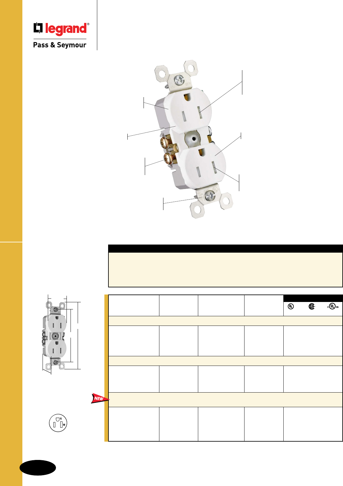
B-38
Straight Blade Receptacles
Features
nExtra-longstrap.
nQuickloopwireloopingaid.
nLong-termbladeretention.
nLongertri-drivescrewsforeasier12AWGlooping.
nExtra-largecircuitbreak-offtabs.
nSide-accesspushwirerelease.
nUltrasonicweldingoffacetobackbody.
nTraditionalcontouredface(3232models).
nSelf-groundingmodelsprovideautomatic
groundclip.
TradeMaster
®
Tamper-Resistant Receptacles
Straight Blade Receptacles
TradeMaster® Tamper-Resistant
Receptacles
National Electrical Code® Section 406.11 Tamper-Resistant Receptacles in Dwelling Units.
Inallareasspecifiedin210.52all125-volt,15-and20-ampreceptaclesshallbelistedtamper-resistantreceptacles.
Meets National Electrical Code®
Tamper-Resistant requirements.
3232TRW
“TR” markings on strap per UL
Tamper-Resistant requirements.
Patented internal shutter system
lets plugs in, but keeps keys and
other objects out with automatic
shutters that block access.
Side wire accepts #12 – #14
AWG solid wire. Push wire
accepts #14 AWG solid only.
Traditional contoured face.
High-impact resistant
thermoplastic construction.
Low profile face.
Safer and more effective than
traditional plastic outlet caps or
protection plates.
3232TRW
3.31"
4.20"
1.320"
1.0"
AlldeviceslistedonthispageconformtoNEMAWD-1andWD-6.
3rd Party Compliance
UL498 C22.2 No. 42 cULus
Rating NEMA
Catalog Number A. V. Color Cong. No.
Tamper-Resistant Duplex Receptacles – Grounding
3232TRI 15 125 Ivory 5-15R •• •
3232TRW 15 125 White 5-15R • • •
3232TR 15 125 Brown 5-15R • • •
3232TRBK 15 125 Black 5-15R • • •
3232TRLA 15 125 LightAlmond 5-15R • • •
Self-Grounding Tamper-Resistant Duplex Receptacles
3232TRSI 15 125 Ivory 5-15R • • •
3232TRSW 15 125 White 5-15R • • •
3232TRS 15 125 Brown 5-15R • • •
3232TRSLA 15 125 LightAlmond 5-15R • • •
NAFTA-Compliant TradeMaster
®
Tamper-Resistant 15 Amp
Duplex Receptacles
3232TRNAI 15 125 Ivory 5-15R •• •
3232TRNAW 15 125 White 5-15R •• •
3232TRNA 15 125 Brown 5-15R •• •
3232TRNABK 15 125 Black 5-15R •• •
3232TRNALA 15 125 LightAlmond 5-15R •• •
NAFTA-Compliant Receptacles are ideal for use on projects subject to the provisions of the
Buy American Act.
NEMA
5-15R
2Pole,3Wire

B-39
Straight Blade Receptacles
885TRNAW
3.812"
2.60"
4.20"
1.290"
1.0"
AlldeviceslistedonthispageconformtoNEMAWD-1andWD-6.
Features
nMeetsNationalElectricalCode®
Tamper-Resistantrequirements.
nProtectschildren:patentedshuttersystemhelps
preventimproperinsertionofforeignobjects.
nHigh-impactresistantthermoplasticconstruction.
nExtra-longstrap.
nQuickloopwireloopingaid.
nLong-termbladeretention.
nLongertri-drivescrewsforeasier12AWGlooping.
nExtra-largecircuitbreak-offtabs.
nSide-accesspushwirerelease.
nUltrasonicweldingoffacetobackbody.
nSidewireaccepts#12–#14AWGsolidwire.
nPushwireaccepts#14AWGsolidonly.
nSuperiorprotectionthantraditionaloutlet
“caps”or“protectionplates.”
nLowprofileface.
nTraditionalcontouredface(3232models).
nSelf-groundingmodelsprovideautomatic
groundclip.
NEMA
5-15R
2Pole,3Wire
Straight Blade Receptacles
TradeMaster® Tamper-Resistant
Receptacles
15A, 125V
TradeMaster
®
Tamper-Resistant Receptacles
885TRSLA
3.812"
2.60"
4.20"
1.290"
1.0"
3rd Party Compliance
UL498 C22.2 No. 42 cULus
Rating NEMA
Catalog Number A. V. Color Cong. No.
Decorator Tamper-Resistant Receptacles
885TRI 15 125 Ivory 5-15R • • •
885TRW 15 125 White 5-15R • • •
885TR 15 125 Brown 5-15R • • •
885TRGRY 15 125 Gray 5-15R • • •
885TRBK 15 125 Black 5-15R • • •
885TRLA 15 125 LightAlmond 5-15R • • •
885TRTI 15 125 Titanium 5-15R • • •
885TRBNCC12 15 125 BrushedNickel 5-15R • • •
Self-Grounding Decorator Tamper-Resistant Receptacles
885TRSI 15 125 Ivory 5-15R • • •
885TRSW 15 125 White 5-15R • • •
885TRSLA 15 125 LightAlmond 5-15R • • •
NAFTA-Compliant TradeMaster
®
Tamper-Resistant 15 Amp
Decorator Receptacle
885TRNAI 15 125 Ivory 5-15R • • •
885TRNAW 15 125 White 5-15R • • •
885TR 15 125 Brown 5-15R • • •
885TRNAGRY 15 125 Gray 5-15R • • •
885TRBK 15 125 Black 5-15R • • •
885TRNALA 15 125 LightAlmond 5-15R • • •
3rd Party Compliance
UL498 C22.2 No. 42
Rating NEMA
Catalog Number A. V. Color Cong. No.
Tamper-Resistant 8 Hole Push Wire Without Terminal Screws
880TRI 15 125 Ivory 5-15R • •
880TRW 15 125 White 5-15R • •
880TRWMH* 15 125 White 5-15R • •
880TR 15 125 Brown 5-15R • •
880TRW
2.635"
3.28"
1.322"
1.104"
1.018"
NEW
NAFTA-Compliant Receptacles are ideal for use on projects subject
to the provisions of the Buy American Act.
*Withoutears.

B-40
Straight Blade ReceptaclesWeather-Resistant Receptacles
Straight Blade Receptacles
Weather-Resistant Receptacles
National Electrical Code® Section 406.8 Receptacles in Wet or
Damp Locations.
Requiresthatall15-and20-amp,125-and250-voltnon-lockingreceptaclesinstalledin
wetordamplocationsshallbeweather-resistantreceptacles.
NEMA
5-15R
2Pole,3Wire
885TRWRW
3.812"
2.60"
4.20"
1.290"
1.0"
3232TRWRW
3.31"
4.20"
1.320"
1.0"
Rating NEMA
Catalog Number A. V. Color Cong. No.
Weather-Resistant Duplex Receptacles
3232TRWRI 15 125 Ivory 5-15R • • •
3232TRWRW 15 125 White 5-15R • • •
3232TRWR 15 125 Brown 5-15R • • •
3232TRWRGRY 15 125 Gray 5-15R • • •
3232TRWRLA 15 125 LightAlmond 5-15R • • •
Decorator Weather-Resistant Duplex Receptacles
885TRWRI 15 125 Ivory 5-15R • • •
885TRWRW 15 125 White 5-15R • • •
885TRWR 15 125 Brown 5-15R • • •
885TRWRLA 15 125 LightAlmond 5-15R • • •
3rd Party Compliance
UL498 C22.2 No. 42 cULus
AlldeviceslistedonthispageconformtoNEMAWD-1andWD-6.
Features
nSpecificallydesignedforincreasedprotection
ofchildreninthehome.
nExtra-longstrap.
nQuickloopwireloopingaid.
nLong-termbladeretention.
Residential Weather-Resistant Receptacles
are Tamper-Resistant as required by
National Electrical Code®
Listed to the Weather-Resistant supplement of
UL498, meeting demanding UL requirements
including:
n
Ultraviolet light exposure test
n
Cold impact test
n
Accelerated aging test
n
Stringent material requirements for current-carrying
parts, wire binding screws and mounting straps to
ensure superior corrosion resistance.
“WR” markings on face per UL
Weather-Resistant requirements.
Patented internal shutter system
lets plugs in, but keeps keys and
other objects out with automatic
shutters that block access.
3232TRWRW
Side wire accepts #12 – #14
AWG solid wire. Push wire
accepts #14 AWG solid only.
Low profile face.
Traditional contoured face.
High-impact resistant
thermoplastic construction.
Safer and more effective than
plastic outlet caps.
“TR” markings identify devices
as Tamper-Resistant.
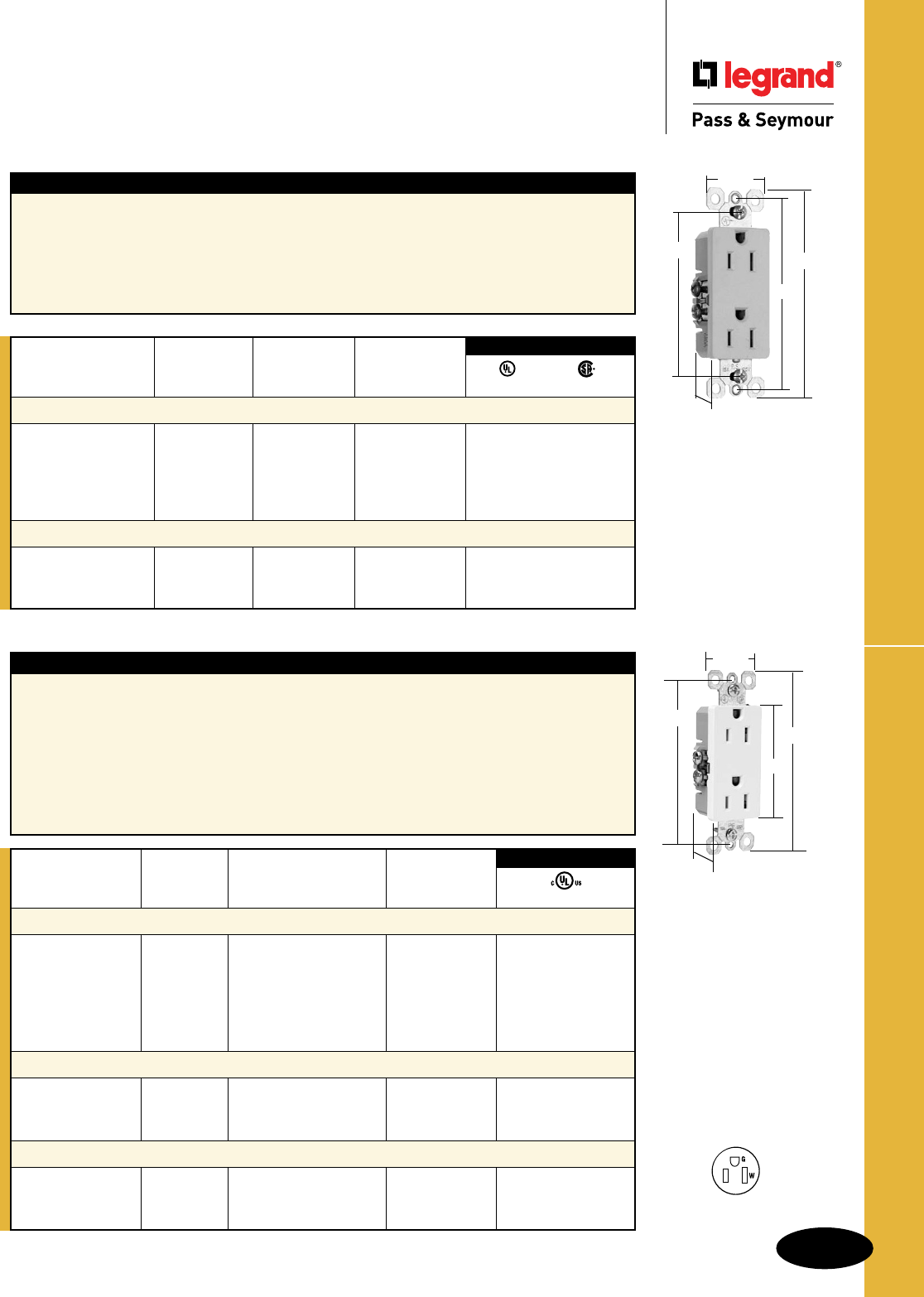
B-41
Straight Blade Receptacles
AlldeviceslistedonthispageconformtoNEMAWD-1andWD-6.
TradeMaster® Receptacles
Straight Blade Receptacles
TradeMaster® Decorator Receptacles
15A, 125V
885I
Features
nHighimpact-resistantthermoplasticconstruction.
nExtra-longstrap.
nQuickloopwireloopingaid.
nLong-termbladeretention.
nTri-drivescrews.
nExtra-largecircuitbreak-offtabs.
nSide-accesspushwirerelease.
nUltrasonicweldingoffacetobackbody.
nSidewireaccepts#12–#14AWGsolid.
nPushwireaccepts#14AWGsolidonly.
nSelf-groundingmodelsprovideautomatic
groundclip.
3.812"
1.0"
2.60"
4.20"
1.290"
For Bulk Packaging Solutions consult factory.
Rating NEMA
Catalog Number A. V. Color Cong. No.
Decorator Duplex Receptacles
885I 15 125 Ivory 5-15R • •
885W 15 125 White 5-15R • •
885 15 125 Brown 5-15R • •
885BK 15 125 Black 5-15R • •
885LA 15 125 LightAlmond 5-15R • •
Self-Grounding Decorator Duplex Receptacles
885SI 15 125 Ivory 5-15R • •
885SW 15 125 White 5-15R • •
885SLA 15 125 LightAlmond 5-15R • •
3rd Party Compliance
UL498 C22.2 42
NEMA
5-15R
2Pole,3Wire
Rating NEMA
Catalog Number A. V. Color Cong. No.
Decorator Duplex Receptacles with Pressure Plates
TM885I 15 125 Ivory 5-15R •
TM885W 15 125 White 5-15R •
TM885 15 125 Brown 5-15R •
TM885GRY 15 125 Gray 5-15R •
TM885BK 15 125 Black 5-15R •
TM885LA 15 125 LightAlmond 5-15R •
Decorator Duplex Receptacles with Pressure Plates Self-Grounding
TM885SI 15 125 Ivory 5-15R •
TM885SW 15 125 White 5-15R •
TM885SLA 15 125 LightAlmond 5-15R •
Decorator Duplex Receptacles with Pressure Plates Bulk Pack of 150
TM885I150 15 125 Ivory 5-15R •
TM885W150 15 125 White 5-15R •
TM885LA150 15 125 LightAlmond 5-15R •
3rd Party Compliance
UL498 TM885W
3.812"
2.60"
4.20"
1.290"
1.0"
Features
nLongersteelstrapsthancompetitivedevices,
stillfitsunderastandardwallplate.
nHigh-impactthermoplasticfaceandbackbody
eliminatecracks,breaksandcallbacks.
nUltrasonicweldingoffacetobackbody.
nPatenteddesignprovidesbetterplugretention.
nExternalscrew-pressure-platebackwireonall
fourterminalscrewsandgroundscreweliminates
wrapping.
nAccepts#12and#14strandedandsolidwire.
nBreak-offtabsthatarebigenoughtograb
holdof–evenifthecontactscrewsare
backed-out.Scoreddeeper,forfast,clean
breakseverytime.
nAllfourcontactscrewsandthegroundscrew
arebacked-out.
nAllscrewsaretri-drive.
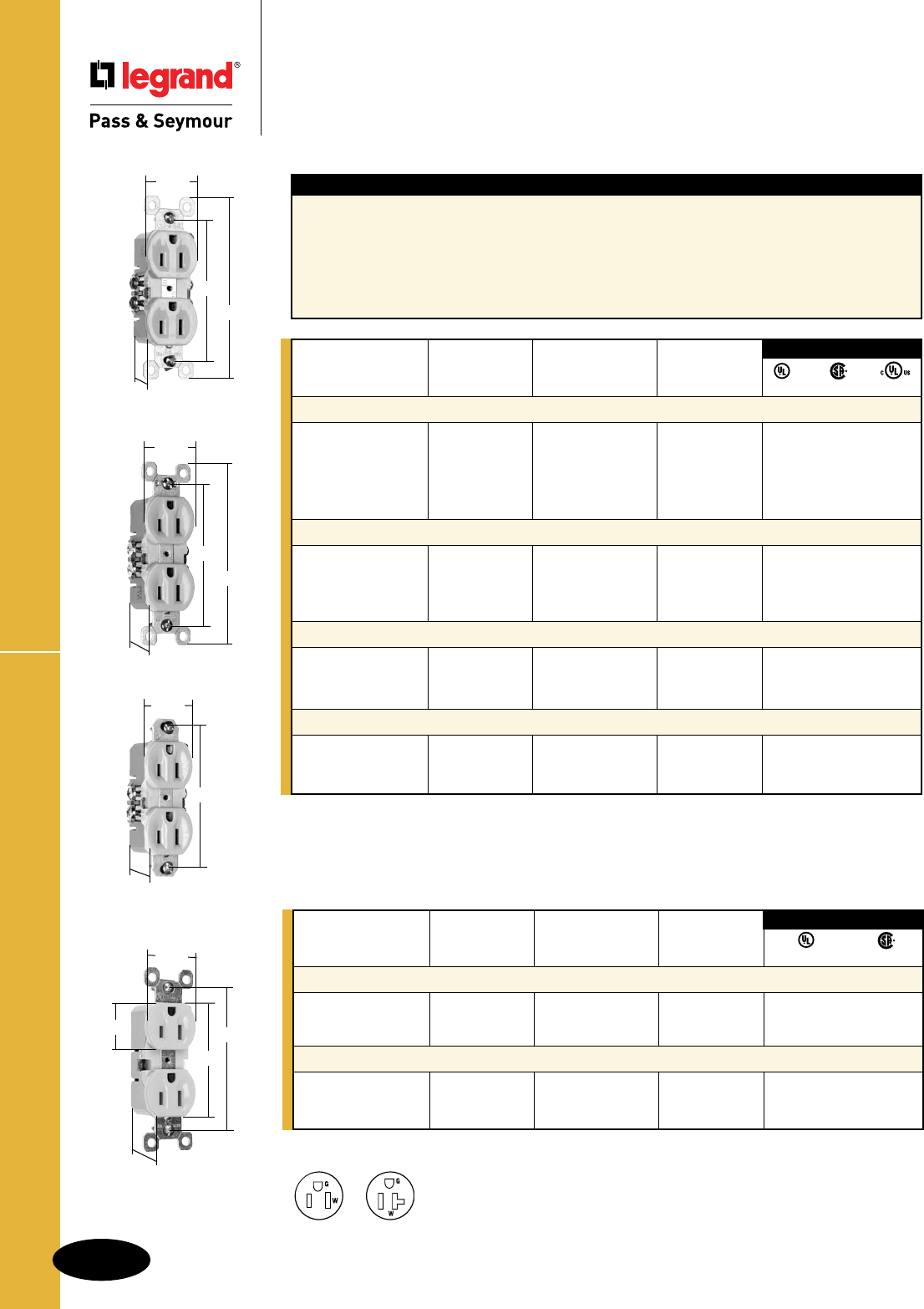
B-42
Straight Blade Receptacles
AlldeviceslistedonthispageconformtoNEMAWD-1andWD-6.
Features
nHigh-impactresistantthermoplasticconstruction.
nExtra-longstrap.
nQuickloopwireloopingaid.
nLong-termbladeretention.
nLongertri-drivescrewsforeasier12AWGlooping.
nExtra-largecircuitbreak-offtabs.
nSide-accesspushwirerelease.
nUltrasonicweldingoffacetobackbody.
nSidewireaccepts#12–#14AWGsolidwire.
nPushwireaccepts#14AWGsolidonly.
nLowprofileface.
nTraditionalcontouredface.(3232models.)
nSelf-groundingmodelsprovideautomatic
groundclip.
TradeMaster® Receptacles
Straight Blade Receptacles
TradeMaster® Receptacles
15A, 125V
3rd Party Compliance
UL498 C22.2 No. 42
Rating NEMA
Catalog Number A. V. Color Cong. No.
8 Hole Push Wire Without Terminal Screws
880I 15 125 Ivory 5-15R • •
880W 15 125 White 5-15R • •
880 15 125 Brown 5-15R • •
8 Hole Push Wire – Without Ears Without Terminal Screws
880IMH 15 125 Ivory 5-15R • •
880WMH 15 125 White 5-15R • •
880MH 15 125 Brown 5-15R • •
3232I
3.31"
4.20"
1.320"
.960"
880I
2.635"
3.28"
1.322"
1.104"
1.018"
*Availableinbulkpacksof150.Add“U"toendofCatalogNumber.Example:3232LAU.
3rd Party Compliance
UL498 C22.2 No. 42 cULus
Rating NEMA
Catalog Number A. V. Color Cong. No.
Duplex Receptacles – Grounding
3232I* 15 125 Ivory 5-15R ••
3232W* 15 125 White 5-15R • •
3232* 15 125 Brown 5-15R • •
3232BK 15 125 Black 5-15R • •
3232LA* 15 125 LightAlmond 5-15R • •
Self-Grounding Duplex Receptacles
3232SI 15 125 Ivory 5-15R • •
3232SW 15 125 White 5-15R • •
3232S 15 125 Brown 5-15R • •
3232SLA 15 125 LightAlmond 5-15R • •
4 Terminal, Screws In
3232I4 15 125 Ivory 5-15R • •
3232W4 15 125 White 5-15R • •
32324 15 125 Brown 5-15R • •
Duplex Receptacles – Without Ears
3232IMH 15 125 Ivory 5-15R • •
3232WMH 15 125 White 5-15R • •
3232MH 15 125 Brown 5-15R • •
3232IMH
3.31"
1.320"
.960"
3232SI
3.31"
4.20"
1.320"
.960"
NEMA
5-20R
NEMA
5-15R
2Pole,3Wire
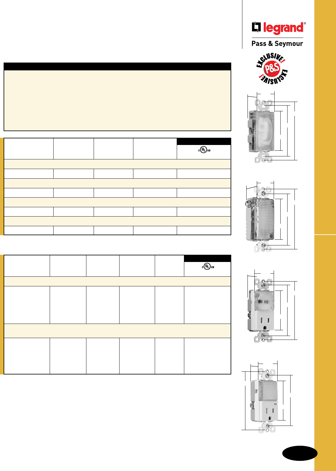
B-43
Straight Blade Receptacles
AlldeviceslistedonthispageconformtoNEMAWD-1andWD-6.
Hallway Lights & Combination Devices
Straight Blade Receptacles
TradeMaster® Decorator Hallway Lights &
Combination Devices
TM8HWLTRLACC
3.281"
3.812"
2.60"
1.29"
1.28"
Features
nImpact-resistantfaceandbody.
nGELexan™highimpact-resistantlens.
nExternalscrew-pressure-platebackandside
wired.Accepts#12and#14AWG.
nGroundscrewpositionundertheendofthe
strapminimizestheriskofcontact.
nEnergy-efficientLEDhasaverage20-yearlife
expectancy:eliminatesbulbreplacement.
nSensorautomaticallyturnslightONinthedark.
nIncreasedlightoutputforbetterillumination.
nLightsensorforenhancedsensitivity.
Tamper-Resistant Combination Version:
nULtestedshuttermechanismforprotection
againstimproperobjectinsertionperUL478.
nSpeciallydesignedforincreasedprotectionof
childrenintheirhomes.
nSuperiorprotectionthantraditionaloutlet“caps”
or“protectionplates.”
Catalog Rating Light Output
Number A. VAC In 1' FCD* Color UL1598
TradeMaster® Decorator Full Hallway Light with Light Sensor
TMHWLCC — 120 0.1328 Clear •
Enhanced Decorator Full Hallway Light with Light Sensor
TMHWLECC — 120 1.079 Clear •
Enhanced Decorator Full Hallway Light without Light Sensor
TMHWLENSCC — 120 1.113 Clear •
Full Hallway Decorator Light for use with P&S Metal Louver Plates**
TMHWLLOUVCC — 120 0.0843 Clear •
3rd Party Compliance
Catalog Rating Light Output NEMA
Number A. VAC In 1' FCD* Color Cong. No. UL498
TradeMaster® Decorator Hallway Light & Single Receptacle
TM8HWLICC 15 120/125 0.1442 Ivory 5-15R •
TM8HWLWCC 15 120/125 0.1442 White 5-15R •
TM8HWLCC 15 120/125 0.1442 Brown 5-15R •
TM8HWLBKCC 15 120/125 0.1442 Black 5-15R •
TM8HWLLACC 15 120/125 0.1442 LightAlmond 5-15R •
Decorator Hallway Light with High Output Light & Tamper-Resistant
Single Receptacle
TM8HWLTRICC 15 125 0.2561 Ivory 5-15R •
TM8HWLTRWCC 15 125 0.2561 White 5-15R •
TM8HWLTRCC 15 125 0.2561 Brown 5-15R •
TM8HWLTRBKCC 15 125 0.2561 Black 5-15R •
TM8HWLTRLACC 15 125 0.2561 LightAlmond 5-15R •
3rd Party Compliance
For complete line of Decorator Combination Devices, see Pages D-9 – D-12, D-20, D-24,
D-33 and D-39.
TM8HWLWCC
3.281"
3.812"
2.60"
1.29"
1.59"
TMHWLCC
3.281"
3.812"
2.60"
1.29"
1.59"
TMHWLECC
3.281"
3.812"
2.60"
1.29"
1.59"
*FCD=FootCandleDistance,1Lumen=1FCD.SeepageS-56formoreinformation.
**ForLouverPlates,seePageQ-21.
*FCD=FootCandleDistance.1Lumen=1FCD.SeepageS-56formoreinformation.
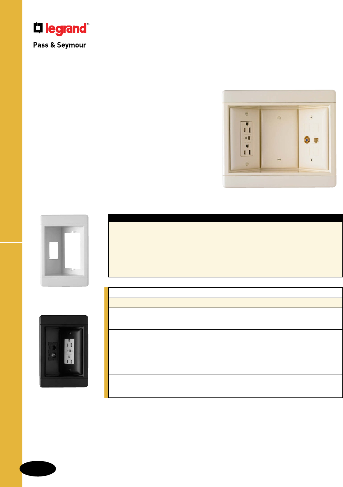
B-44
Straight Blade Receptacles
AlldeviceslistedonthispageconformtoNEMAWD-1andWD-6.
Ideal for flat-screen TVs, home office, kitchen counter tops, and behind furniture
to allow snug-to-wall placement.
Today’s homeowners have more multimedia choices
than ever — including flat panel, wall-mounted televisions.
P&S Recessed TV Boxes offer a clean installation with the
versatility to handle up to 12 multimedia connections, while
providing surge protected power.
Their recessed design saves space and simplifies connections
to cable or satellite boxes, DVRs, DVD players, surround-sound
systems and more.
And they’re available with or without surge protective
receptacles to protect costly electronics from potentially
damaging surges.
Recessed TV Boxes
Straight Blade Receptacles
Recessed TV Boxes
Features
nClean,flush-mountappearance—snap-on
endcapshidemountingscrews.
nFlexible—positioneitherlinevoltageor
low-voltageinallthreeopenings.
nLow-voltageconnectorsofferbothterminated
andpull-throughcapability.
nPlugsandmultimediaconnectionsstay
recessedbehindthewallsurface.
nMolded-intemplateandrectangularcut-out.
nAcceptsstandardTPwallplates.
nMetalswingbracketsensureasolidmounting.
nUsesold-work-styleboxesforlinevoltage.
nAcceptsallP&Skeystonelow-voltage
connectors,includingCat5eandF-connectors
(bothsuppliedwithSurgeProtectivekit),aswell
asRCAandaudiobindingposts.
Catalog Number Description Color
Recessed TV Boxes
TV1WW White
TV1WBK SingleGangRecessedTVBox—FrameOnly. Black
TV1WLA LightAlmond
TV1WTVSSW SingleGangRecessedTVBoxwithSurgeProtective& White
TV1WTVSSBK Low-VoltageKit.IncludesSurgeProtectiveDuplex Black
TV1WTVSSLA Receptacle,Cat5eJack,F-Connector,Blanks,&WallPlates. LightAlmond
TV3WW White
TV3WBK ThreeGangRecessedTVBox—FrameOnly. Black
TV3WLA LightAlmond
TV3WTVSSW ThreeGangRecessedTVBoxwithSurgeProtective& White
TV3WTVSSBK Low-VoltageKit.IncludesSurgeProtectiveDuplex Black
TV3WTVSSLA Receptacle,Cat5eJack,F-Connector,Blanks,&WallPlates. LightAlmond
Single gang dimensions: 7.25"Lx4.875"Wx2.25"D
Three gang dimensions: 8.5"Lx4.875"Wx2.25"D
TV1WTVSSBK
TV1WW
TV3WTVSSLA
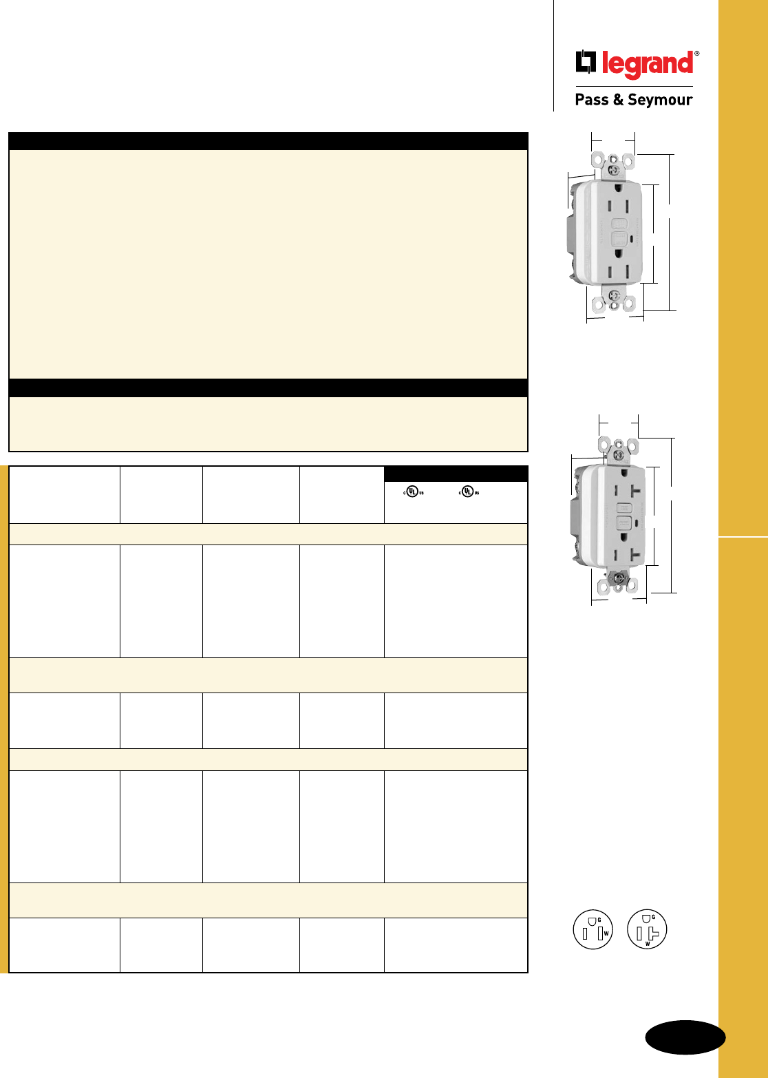
B-45
Straight Blade Receptacles
AlldeviceslistedonthispageconformtoNEMAWD-1andWD-6.
Tamper-Resistant GFCI Receptacles
Straight Blade Receptacles
Tamper-Resistant GFCI Receptacles
2 Pole, 3 Wire Grounding 15 & 20A, 125VAC
Features
nProtectschildren:patentedshuttersystemhelps
preventimproperinsertionofforeignobjects.
nMeetsNationalElectricalCode®
Tamper-Resistantrequirements.
nSafeLockTMProtection:ifcriticalcomponentsare
damagedandgroundfaultprotectionislost,power
toreceptacleisdisconnected.
nPreventsline-loadreversalmiswire:nopowertothe
faceordownstreamreceptaclesifwiredincorrectly.
nExceedsUL943voltagesurgerequirements;
survives100xtherequiredUL3kA/6kVvoltage
surgetestcycles.
nFSULListed(FederalSpecificationWC596).
nTripindicatorlight(redLED).
nSideorinternalscrew-pressure-platebackwirewith
#10–#14AWGsolidorstrandedcopperwire.
Specications
nSupplyVoltage:125VAC,60Hz
nSupplyVoltageRange:102-132VAC
nTripThreshold:5±1mA
nTripTime:0.025sec.,nominalper
ULStandard
n20Ampfeed-thrucapacity
nTwobackwireholesperterminal.
nGroundscrewhasabackwireclampforeasy
installation.
n1/4"thinnerthancompetitors’GFCIs;leaves
moreroomforwiresinthebox.
nMountingscrewsareshippedcaptiveinthe
deviceandwallplateforeasierinstallation.
nHigh-impact-resistantthermoplastic
construction.
nExtra-longstrap.
nButtoncolorsmatchthedeviceface.
nDual-directiontestandresetbuttons.
nClassAratedGFCI.
nSuppliedwithmatchingTP26nylonwallplate.
nTri-drivescrews.
Catalog Rating NEMA
Number A. VAC Color Cong. No.
TradeMaster®/Spec Grade Tamper-Resistant 15 Amp Duplex GFCI
1595TRI 15 125 Ivory 5-15R • • •
1595TRW 15 125 White 5-15R • • •
1595TR 15 125 Brown 5-15R • • •
1595TRBK 15 125 Black 5-15R • • •
1595TRLA 15 125 LightAlmond 5-15R • • •
1595TRBNCC4 15 125 BrushedNickel 5-15R • • •
1595TRTI 15 125 Titanium 5-15R • • •
TradeMaster®/Spec Grade Tamper-Resistant 15 Amp Duplex GFCI
with Auto-Ground
1595TRSI 15 125 Ivory 5-15R • • •
1595TRSW 15 125 White 5-15R • • •
1595TRSLA 15 125 LightAlmond 5-15R • • •
Specification Grade Tamper-Resistant 20 Amp Duplex GFCI
2095TRI 20 125 Ivory 5-20R • • •
2095TRW 20 125 White 5-20R • • •
2095TR 20 125 Brown 5-20R • • •
2095TRGRY 20 125 Gray 5-20R • • •
2095TRBK 20 125 Black 5-20R • • •
2095TRRED 20 125 Red 5-20R • • •
2095TRLA 20 125 LightAlmond 5-20R • • •
Specification Grade Tamper-Resistant 20 Amp Duplex GFCI
with Auto-Ground
2095TRSI 20 125 Ivory 5-20R • • •
2095TRSW 20 125 White 5-20R • • •
2095TRSLA 20 125 LightAlmond 5-20R • • •
UL943 UL498 FSUL
C22.2 No. 144 C22.2 No. 42 WC596
3rd Party Compliance
1595TRW
1.13"
1.72"
1.25"
2.62"
4.20"
NEMA
5-15R
NEMA
5-20R
2095TRSW
1.13"
1.72"
1.25"
2.62"
4.20"
National Electrical Code® Section 406.11 Tamper-Resistant Receptacles in Dwelling
Units.
Inallareasspecifiedin210.52all125-volt,15-and20-ampreceptaclesshallbelistedtamper-resistantreceptacles.
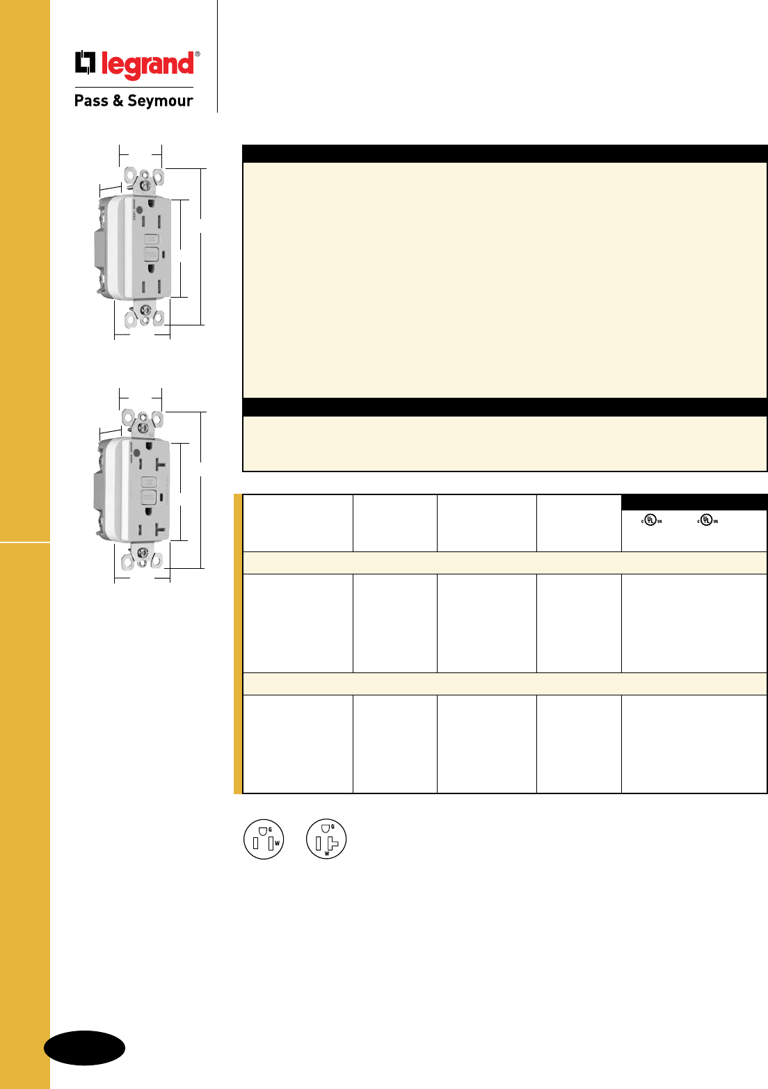
B-46
Straight Blade Receptacles
AlldeviceslistedonthispageconformtoNEMAWD-1andWD-6.
HG Tamper-Resistant GFCI Receptacles
Straight Blade Receptacles
Hospital Grade Tamper-Resistant
GFCI Receptacles
2 Pole, 3 Wire Grounding 15 & 20A, 125VAC
Features
nProtectschildren:patentedshuttersystemhelps
preventimproperinsertionofforeignobjects.
nMeetsNationalElectricalCode®
Tamper-Resistantrequirements.
nSafeLockTMProtection:ifcriticalcomponentsare
damagedandgroundfaultprotectionislost,power
toreceptacleisdisconnected.
nPreventsline-loadreversalmiswire:nopowertothe
faceordownstreamreceptaclesifwiredincorrectly.
nExceedsUL943voltagesurgerequirements;
survives100xtherequiredUL3kA/6kVvoltage
surgetestcycles.
nFSULListed(FederalSpecificationWC596).
nTripindicatorlight(redLED).
nSideorinternalscrew-pressure-platebackwirewith
#10–#14AWGsolidorstrandedcopperwire.
Specications
nSupplyVoltage:125VAC,60Hz
nSupplyVoltageRange:102-132VAC
nTripThreshold:5±1mA
nTripTime:0.025sec.,nominalper
ULStandard
n20Ampfeed-thrucapacity
nTwobackwireholesperterminal.
nGroundscrewhasabackwireclampforeasy
installation.
n1/4"thinnerthancompetitors’GFCIs;leaves
moreroomforwiresinthebox.
nMountingscrewsareshippedcaptiveinthe
deviceandwallplateforeasierinstallation.
nHigh-impact-resistantthermoplastic
construction.
nExtra-longstrap.
nButtoncolorsmatchthedeviceface.
nDual-directiontestandresetbuttons.
nClassAratedGFCI.
nSuppliedwithmatchingTP26nylonwallplate.
nTri-drivescrews.
Catalog Rating NEMA
Number A. VAC Color Cong. No.
Hospital Grade Tamper-Resistant 15 Amp Duplex GFCI
1595HGTRI 15 125 Ivory 5-15R • • •
1595HGTRW 15 125 White 5-15R • • •
1595HGTR 15 125 Brown 5-15R • • •
1595HGTRGRY 15 125 Gray 5-15R • • •
1595HGTRRED 15 125 Red 5-15R • • •
1595HGTRLA 15 125 LightAlmond 5-15R • • •
Hospital Grade Tamper-Resistant 20 Amp Duplex GFCI
2095HGTRI 20 125 Ivory 5-20R • • •
2095HGTRW 20 125 White 5-20R • • •
2095HGTR 20 125 Brown 5-20R • • •
2095HGTRGRY 20 125 Gray 5-20R • • •
2095HGTRRED 20 125 Red 5-20R • • •
2095HGTRLA 20 125 LightAlmond 5-20R • • •
UL943 UL498 FSUL
C22.2 No. 144 C22.2 No. 42 WC596
3rd Party Compliance
NEMA
5-15R
NEMA
5-20R
2095HGTRW
1.13"
1.72"
1.25"
2.62"
4.20"
1595HGTRW
1.13"
1.72"
1.25"
2.62"
4.20"
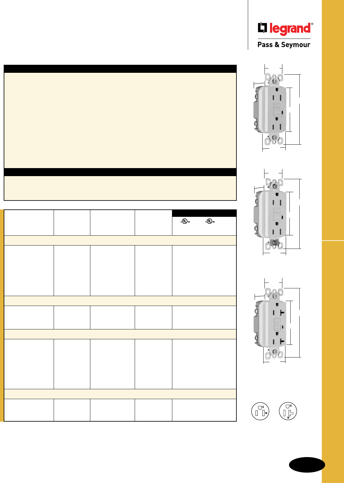
B-47
Straight Blade Receptacles
AlldeviceslistedonthispageconformtoNEMAWD-1andWD-6.
TradeMaster® & Spec Grade GFCI Receptacles
Straight Blade Receptacles
TradeMaster® & Specification Grade
GFCI Receptacles
2 Pole, 3 Wire Grounding 15 & 20A, 125VAC
1595W
1.72"
1.25"
2.62"
4.20"
.98"
2095W
.98"
1.72"
1.25"
2.62"
4.20"
NEMA
5-15R
NEMA
5-20R
Features
nSafeLockTMProtection:ifcriticalcomponentsare
damagedandgroundfaultprotectionislost,power
toreceptacleisdisconnected.
nPreventsline-loadreversalmiswire:nopowertothe
faceordownstreamreceptaclesifwiredincorrectly.
nExceedsUL943voltagesurgerequirements;
survives100xtherequiredUL3kA/6kVvoltage
surgetestcycles.
nFSULListed(FederalSpecificationWC596).
nTripindicatorlight(redLED).
nSideorinternalscrew-pressure-platebackwire
with#10–#14AWGsolidorstrandedcopperwire.
nTwobackwireholesperterminal.
nGroundscrewhasabackwireclampfor
easyinstallation.
Specications
nSupplyVoltage:125VAC,60Hz
nSupplyVoltageRange:102-132VAC
nTripThreshold:5±1mA
nTripTime:0.025sec.,nominalperULStandard
n20Ampfeed-thrucapacity
n1/4"thinnerthancompetitors’GFCIs;leaves
moreroomforwiresinthebox.
nMountingscrewsareshippedcaptiveinthe
deviceandwallplateforeasierinstallation.
nHigh-impact-resistantthermoplastic
construction.
nExtra-longstrap.
nButtoncolorsmatchthedeviceface.
nDual-directiontestandresetbuttons.
nClassAratedGFCI.
nSuppliedwithmatchingTP26nylonwallplate.
nTri-drivescrews.
nGFCIswithAuto-Groundassureapositive
groundtometalbox.
Catalog Rating NEMA
Number A. VAC Color Cong. No.
TradeMaster®/Spec Grade 15 Amp Duplex GFCI
1595I 15 125 Ivory 5-15R •••
1595W 15 125 White 5-15R •••
1595 15 125 Brown 5-15R •••
1595GRY 15 125 Gray 5-15R •••
1595BK 15 125 Black 5-15R •••
1595RED 15 125 Red 5-15R •••
1595LA 15 125 LightAlmond 5-15R •••
TradeMaster®/Spec Grade 15 Amp Duplex GFCI with Auto-Ground
1595SI 15 125 Ivory 5-15R •••
1595SW 15 125 White 5-15R •••
1595SLA 15 125 LightAlmond 5-15R •••
Specification Grade 20 Amp Duplex GFCI
2095I 20 125 Ivory 5-20R •• •
2095W 20 125 White 5-20R •• •
2095 20 125 Brown 5-20R •• •
2095GRY 20 125 Gray 5-20R •• •
2095BK 20 125 Black 5-20R •• •
2095RED 20 125 Red 5-20R •• •
2095LA 20 125 LightAlmond 5-20R •• •
Specification Grade 20 Amp Duplex GFCI with Auto-Ground
2095SI 20 125 Ivory 5-20R •• •
2095SW 20 125 White 5-20R •• •
2095SLA 20 125 LightAlmond 5-20R •• •
UL943 UL498 FSUL
C22.2 No. 144 C22.2 No. 42 WC596
3rd Party Compliance
1595SW
.98"
1.72"
1.25"
2.62"
4.20"
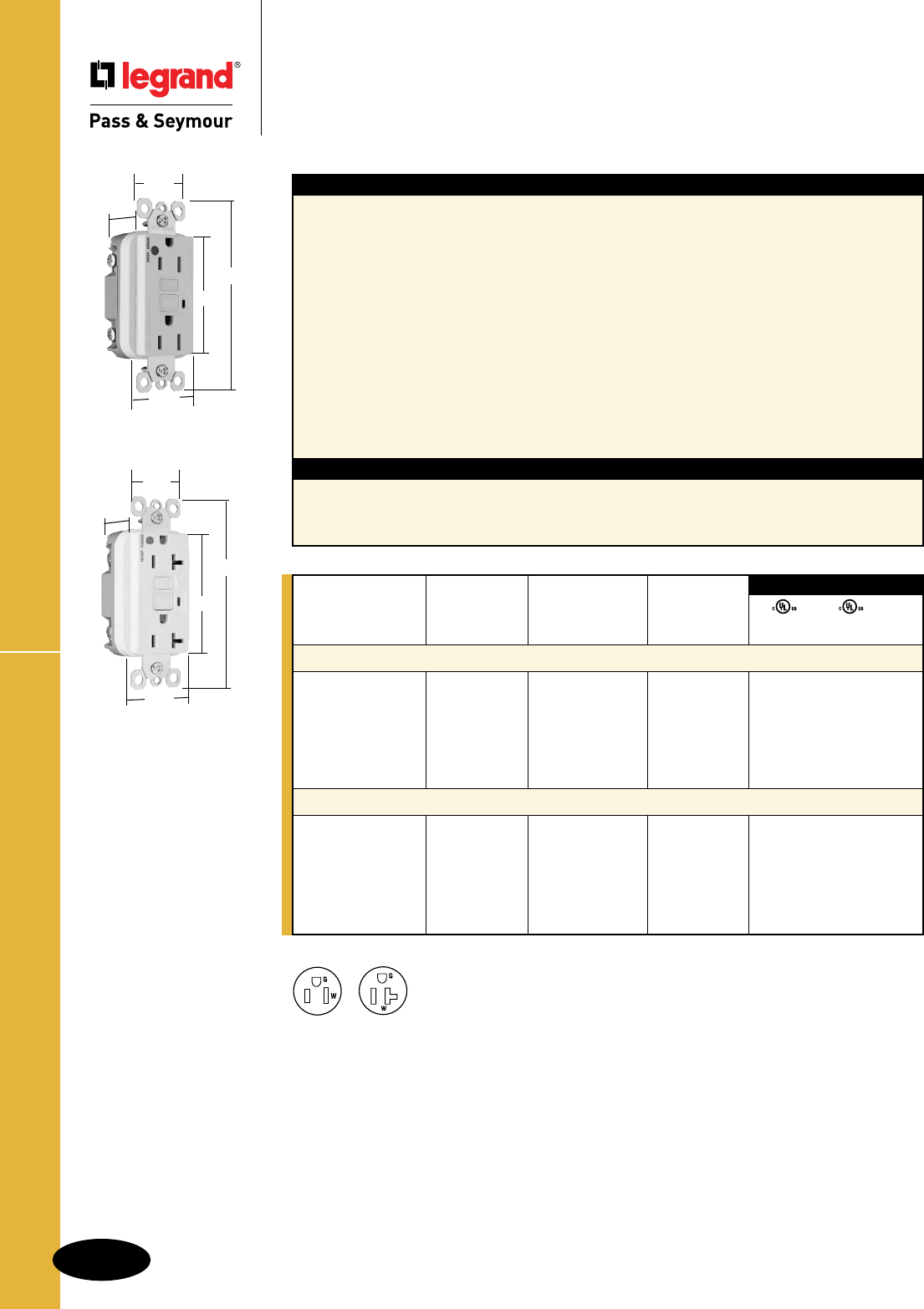
B-48
Straight Blade Receptacles
AlldeviceslistedonthispageconformtoNEMAWD-1andWD-6.
Hospital Grade GFCI Receptacles
Straight Blade Receptacles
Hospital Grade GFCI Receptacles
2 Pole, 3 Wire Grounding 15 & 20A, 125VAC
NEMA
5-15R
NEMA
5-20R
1595HGW
1.72"
1.25"
2.62"
4.20"
.98"
2095HGW
.98"
1.72"
1.25"
2.62"
4.20"
Features
nSafeLockTMProtection:ifcriticalcomponentsare
damagedandgroundfaultprotectionislost,power
toreceptacleisdisconnected.
nPreventsline-loadreversalmiswire:nopowertothe
faceordownstreamreceptaclesifwiredincorrectly.
nExceedsUL943voltagesurgerequirements;
survives100xtherequiredUL3kA/6kVvoltage
surgetestcycles.
nFSULListed(FederalSpecificationWC596).
nTripindicatorlight(redLED).
nSideorinternalscrew-pressure-platebackwirewith
#10–#14AWGsolidorstrandedcopperwire.
nTwobackwireholesperterminal.
nGroundscrewhasabackwireclampfor
easyinstallation.
n1/4"thinnerthancompetitors’GFCIs;leaves
moreroomforwiresinthebox.
nMountingscrewsareshippedcaptiveinthe
deviceandwallplateforeasierinstallation.
nHigh-impact-resistantthermoplastic
construction.
nExtra-longstrap.
nButtoncolorsmatchthedeviceface.
nDual-directiontestandresetbuttons.
nClassAratedGFCI.
nSuppliedwithmatchingTP26nylonwallplate.
nTri-drivescrews.
Specications
nSupplyVoltage:125VAC,60Hz
nSupplyVoltageRange:102-132VAC
nTripThreshold: 5±1mA
nTripTime: 0.025sec.,nominalperULStandard
n20Ampfeed-thrucapacity
Catalog Rating NEMA
Number A. VAC Color Cong. No.
Hospital Grade 15 Amp Duplex GFCI
1595HGI 15 125 Ivory 5-15R •••
1595HGW 15 125 White 5-15R • • •
1595HG 15 125 Brown 5-15R • • •
1595HGGRY 15 125 Gray 5-15R • • •
1595HGRED 15 125 Red 5-15R • • •
1595HGLA 15 125 LightAlmond 5-15R • • •
Hospital Grade 20 Amp Duplex GFCI
2095HGI 20 125 Ivory 5-20R • • •
2095HGW 20 125 White 5-20R • • •
2095HG 20 125 Brown 5-20R • • •
2095HGGRY 20 125 Gray 5-20R • • •
2095HGRED 20 125 Red 5-20R • • •
2095HGLA 20 125 LightAlmond 5-20R • • •
UL943 UL498 FSUL
C22.2 No. 144 C22.2 No. 42 WC596
3rd Party Compliance

B-49
Straight Blade Receptacles
AlldeviceslistedonthispageconformtoNEMAWD-1andWD-6.
Illuminated GFCI Receptacles
Straight Blade Receptacles
Illuminated GFCI Receptacles
2 Pole, 3 Wire Grounding 20A, 125VAC
2095HGWL
.98"
1.72"
1.25"
2.62"
4.20"
Features
nGreenindicatorlight(LED)isONwhenpoweris
available.Helpsidentifyemergencypowerbranch
circuits.
nSafeLockTMProtection:ifcriticalcomponentsare
damagedandgroundfaultprotectionislost,power
toreceptacleisdisconnected.
nPreventsline-loadreversalmiswire:nopowertothe
faceordownstreamreceptaclesifwiredincorrectly.
nExceedsUL943voltagesurgerequirements;
survives100xtherequiredUL3kA/6kVvoltage
surgetestcycles.
nFSULListed(FederalSpecificationWC596).
nSideorinternalscrew-pressure-platebackwirewith
#10–#14AWGsolidorstrandedcopperwire.
nTwobackwireholesperterminal.
Specications
nSupplyVoltage:125VAC,60Hz
nSupplyVoltageRange:102-132VAC
nTripThreshold:5±1mA
nTripTime:0.025sec.,nominalper
ULStandard
n20Ampfeed-thrucapacity
nGroundscrewhasabackwireclampforeasy
installation.
n1/4"thinnerthancompetitors’GFCIs;leaves
moreroomforwiresinthebox.
nMountingscrewsareshippedcaptiveinthe
deviceandwallplateforeasierinstallation.
nHigh-impact-resistantthermoplastic
construction.
nExtra-longstrap.
nButtoncolorsmatchthedeviceface.
nDual-directiontestandresetbuttons.
nClassAratedGFCI.
nSuppliedwithmatchingTP26nylonwallplate.
nTri-drivescrews.
Catalog Rating NEMA
Number A. VAC Color Cong. No.
Specification Grade Illuminated 20 Amp Duplex GFCI
2095IL 20 125 Ivory 5-20R • • •
2095WL 20 125 White 5-20R • • •
2095LAL 20 125 LightAlmond 5-20R • • •
Hospital Grade Illuminated 20 Amp Duplex GFCI
2095HGIL 20 125 Ivory 5-20R • • •
2095HGWL 20 125 White 5-20R • • •
2095HGREDL 20 125 Red 5-20R • • •
UL943 UL498 FSUL
C22.2 No. 144 C22.2 No. 42 WC596
3rd Party Compliance
NEMA
5-20R
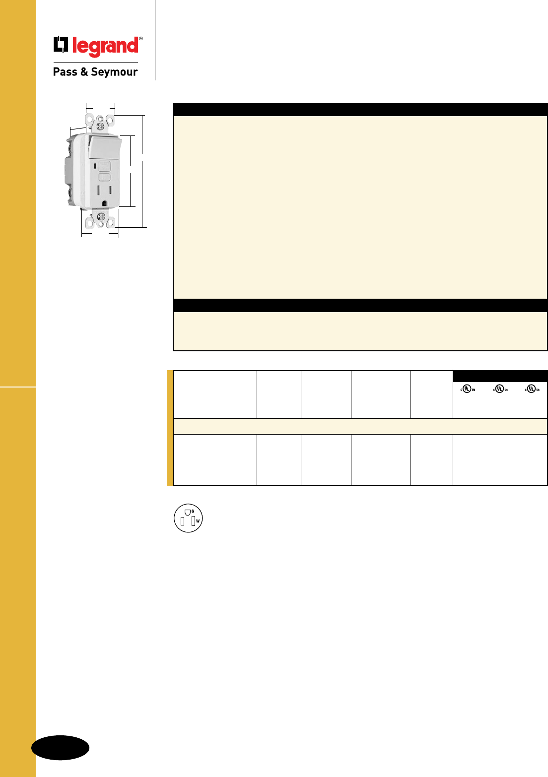
B-50
Straight Blade Receptacles
AlldeviceslistedonthispageconformtoNEMAWD-1andWD-6.
Decorator Combination GFCI Receptacles
Straight Blade Receptacles
Decorator Combination Tamper-Resistant
Switch/GFCI Receptacles
15A, 125VAC
1595SWTTRWCC4
NEMA
5-15R
1.13"
1.25"
4.20"
2.62"
1.72"
SwitchReceptacle NEMA
Catalog Rating Rating Cong.
Number A. VAC A. VAC Color No.
Combination Tamper-Resistant Single Pole Switch/GFCI
1595SWTTRICC4 15 120 15 125 Ivory 5-15R • • •
1595SWTTRWCC4 15 120 15 125 White 5-15R • • •
1595SWTTRBKCC4 15 120 15 125 Black 5-15R • • •
1595SWTTRLACC4 15 120 15 125 LightAlmond 5-15R • • •
3rd Party Compliance
UL943 UL498 UL20
C22.2 C22.2 C22.2
No. 144 No. 42 No. 111
Features
nProtectschildren:patentedshuttersystemhelps
preventimproperinsertionofforeignobjects.
nMeetsNationalElectricalCode®
Tamper-Resistantrequirements.
nSafeLockTMProtection:ifcriticalcomponentsare
damagedandgroundfaultprotectionislost,power
toreceptacleisdisconnected.
nUp-downswitching.
n15Ampsinglepoleswitchratedfor1/2HPmotor
loads–perfectforbathorkitchenventsand
garbagedisposals.
nPreventsline-loadreversalmiswire:nopowertothe
faceordownstreamreceptaclesifwiredincorrectly.
nExceedsUL943voltagesurgerequirements;
survives100xtherequiredUL3kA/6kVvoltage
surgetestcycles.
nTripindicatorlight(redLED).
nTwobackwireholesperterminal.
Specications
nSupplyVoltage:125VAC,60Hz
nSupplyVoltageRange:102-132VAC
nTripThreshold:5±1mA
nTripTime:0.025sec.,nominalperUL
Standard
n20Ampfeed-thrucapacity
nSideorinternalscrew-pressure-plateback
wirewith#10–#14AWGsolidorstranded
copperwire.
nGroundscrewhasabackwireclampforeasy
installation.
n1/4"thinnerthancompetitors’GFCIs;leaves
moreroomforwiresinthebox.
nMountingscrewsareshippedcaptiveinthe
deviceandwallplateforeasierinstallation.
nHigh-impact-resistantthermoplastic
construction.
nExtra-longstrap.
nButtoncolorsmatchthedeviceface.
nDual-directiontestandresetbuttons.
nClassAratedGFCI.
nSuppliedwithmatchingTP26nylonwallplate.
nTri-drivescrews.
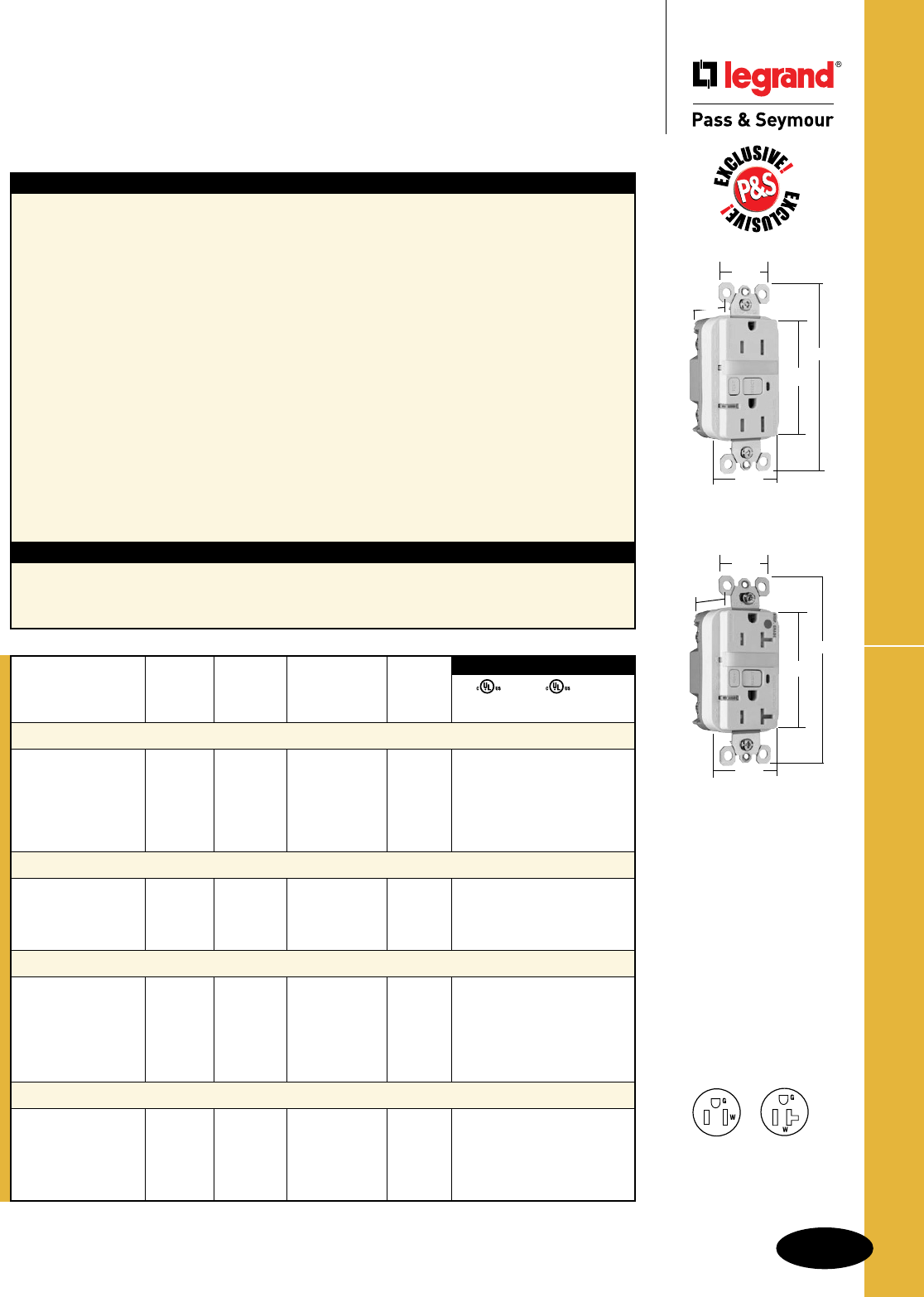
B-51
Straight Blade Receptacles
AlldeviceslistedonthispageconformtoNEMAWD-1andWD-6.
Decorator Combination GFCI Receptacles
Straight Blade Receptacles
Decorator Combination Tamper-Resistant
Nightlight/GFCI Receptacles
2 Pole, 3 Wire Grounding15 & 20A, 125VAC
1595NTLTRWCC4
1.25"
1.13"
4.20"
2.62"
1.72"
2095HGNTLTRW
1.25"
1.13"
4.20"
2.62"
1.72"
NEMA
5-15R
NEMA
5-20R
Features
nProtectschildren:patentedshuttersystemhelps
preventimproperinsertionofforeignobjects.
nMeetsNationalElectricalCode®
Tamper-Resistantrequirements.
nSafeLockTMProtection:ifcriticalcomponentsare
damagedandgroundfaultprotectionislost,power
toreceptacleisdisconnected.
nSealednightlightwithhighimpact-resistantLexan®
lenspreventstampering.
nNightlightusescoolerLEDillumination.
nEnergy-efficientLEDhasaverage20-yearlife
expectancy,eliminatingbulbreplacement.
nTworeceptacles.
nPhotocellturnsnightlightONindark,OFFindaylight.
nPreventsline-loadreversalmiswire:nopowertothe
faceordownstreamreceptaclesifwiredincorrectly.
nExceedsUL943voltagesurgerequirements;
survives100xtherequiredUL3kA/6kVvoltage
surgetestcycles.
nFSULListed(FederalSpecificationWC596).
Specications
nSupplyVoltage:125VAC,60Hz
nSupplyVoltageRange:102-132VAC
nTripThreshold:5±1mA
nTripTime:0.025sec.,nominalperUL
Standard
n20Ampfeed-thrucapacity
nTripindicatorlight(redLED).
nSideorinternalscrew-pressure-plateback
wirewith#10–#14AWGsolidorstranded
copperwire.
nTwobackwireholesperterminal.
nGroundscrewhasabackwireclampfor
easyinstallation.
n1/4"thinnerthancompetitors’GFCIs;leaves
moreroomforwiresinthebox.
nMountingscrewsareshippedcaptiveinthe
deviceandwallplateforeasierinstallation.
nHigh-impact-resistantthermoplastic
construction.
nExtra-longstrap.
nButtoncolorsmatchthedeviceface.
nDual-directiontestandresetbuttons.
nClassAratedGFCI.
nSuppliedwithmatchingTP26nylon
wallplate.
nTri-drivescrews.
*FCD=FootCandleDistance,1Lumen=1FCD.SeePageS-56formoreinformation.
UL943 UL498 FSUL
C22.2 No. 144 C22.2 No. 42 WC596
3rd Party Compliance
Light NEMA
Catalog Rating Output in Cong.
Number A. VAC 1' FCD* Color No.
Combination Tamper-Resistant 15 Amp Nightlight/GFCI
1595NTLTRICC4 15 125 0.180 Ivory 5-15R • • •
1595NTLTRWCC4 15 125 0.180 White 5-15R • • •
1595NTLTRBKCC4 15 125 0.180 Black 5-15R • • •
1595NTLTRLACC4 15 125 0.180 LightAlmond 5-15R • • •
1595NTLTRBNCC4 15 125 0.180 BrushedNickel 5-15R • • •
1595NTLTRTICC4 15 125 0.180 Titanium 5-15R • • •
Combination Tamper-Resistant 20 Amp Nightlight/GFCI
2095NTLTRI 20 125 0.180 Ivory 5-20R • • •
2095NTLTRW 20 125 0.180 White 5-20R • • •
2095NTLTRGRY 20 125 0.180 Gray 5-20R • • •
2095NTLTRLA 20 125 0.180 LightAlmond 5-20R • • •
Hospital Grade Combination Tamper-Resistant 15 Amp Nightlight/GFCI
1595HGNTLTRI 15 125 0.180 Ivory 5-15R • • •
1595HGNTLTRW 15 125 0.180 White 5-15R • • •
1595HGNTLTR 15 125 0.180 Brown 5-15R • • •
1595HGNTLTRGRY 15 125 0.180 Gray 5-15R • • •
1595HGNTLTRRED 15 125 0.180 Red 5-15R • • •
1595HGNTLTRLA 15 125 0.180 LightAlmond 5-15R • • •
Hospital Grade Combination Tamper-Resistant 20 Amp Nightlight/GFCI
2095HGNTLTRI 20 125 0.180 Ivory 5-20R • • •
2095HGNTLTRW 20 125 0.180 White 5-20R • • •
2095HGNTLTRGRY 20 125 0.180 Gray 5-20R • • •
2095HGNTLTRRED 20 125 0.180 Red 5-20R • • •
2095HGNTLTRLA 20 125 0.180 LightAlmond 5-20R • • •
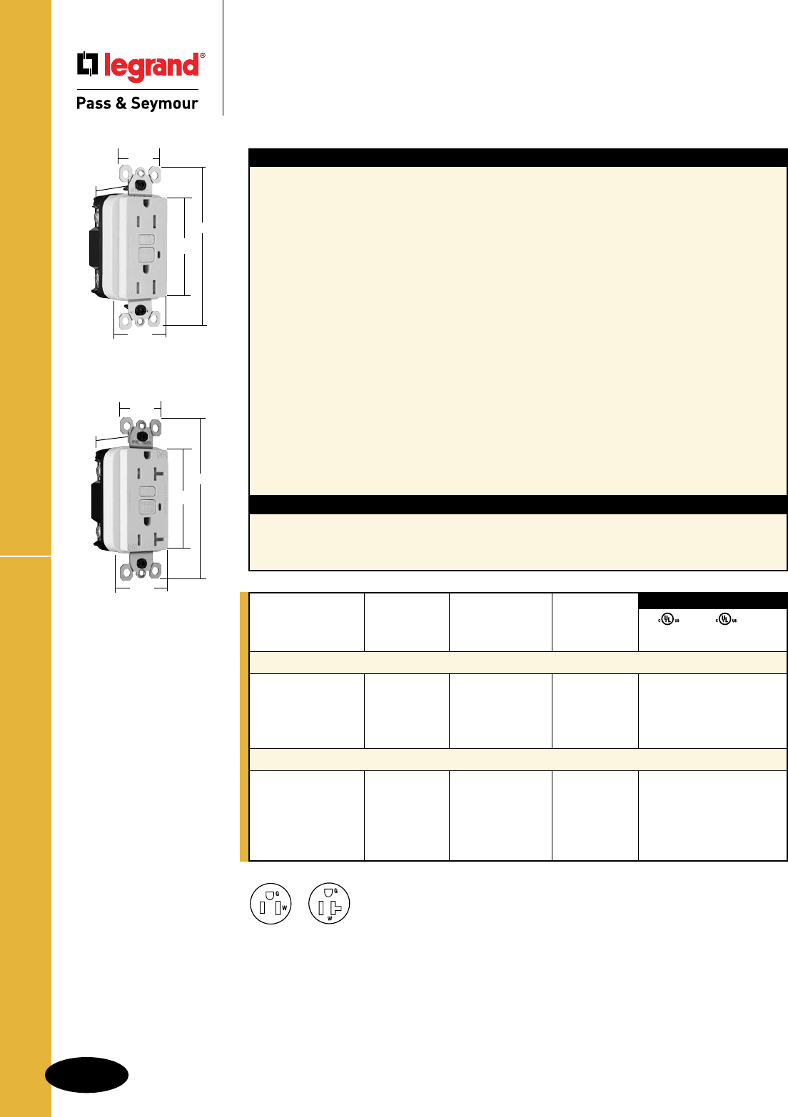
B-52
Straight Blade Receptacles
AlldeviceslistedonthispageconformtoNEMAWD-1andWD-6.
Weather-Resistant GFCI Receptacles
Straight Blade Receptacles
Weather-Resistant GFCI Receptacles
2 Pole, 3 Wire Grounding 15 & 20A, 125VAC
Features
nWeather-Resistant:MeetsNationalElectrical
Code®Weather-Resistantrequirements.
nTamper-Resistant:MeetsNationalElectrical
Code®Tamper-Resistantrequirements.
nProtectschildren:patentedshuttersystemhelps
preventimproperinsertionofforeignobjects.
nListedtotheWeather-ResistantsupplementofUL498,
meetingdemandingULrequirementsincluding:
- Ultravioletlightexposuretest
- Coldimpacttest
- Acceleratedagingtest
- Stringentmaterialrequirementsforcurrent-
carryingparts,wirebindingscrewsandmounting
strapstoensuresuperiorcorrosionresistance.
nSafeLockTMProtection:ifcriticalcomponentsare
damagedandgroundfaultprotectionislost,power
toreceptacleisdisconnected.
nPreventsline-loadreversalmiswire:nopowertothe
faceordownstreamreceptaclesifwiredincorrectly.
nExceedsUL943voltagesurgerequirements;
survives100xtherequiredUL3kA/6kVvoltage
surgetestcycles.
Specications
nSupplyVoltage:125VAC,60Hz
nSupplyVoltageRange:102-132VAC
nTripThreshold:5±1mA
nTripTime:0.025sec.,nominalper
ULStandard
n20Ampfeed-thrucapacity
nFSULListed(FederalSpecificationWC596).
nTripindicatorlight(redLED).
nSideorinternalscrew-pressure-plateback
wirewith#10–#14AWGsolidorstranded
copperwire.
nTwobackwireholesperterminal.
nGroundscrewhasabackwireclampfor
easyinstallation.
n1/4"thinnerthancompetitors’GFCIs;
leavesmoreroomforwiresinthebox.
nMountingscrewsareshippedcaptiveinthe
deviceandwallplateforeasierinstallation.
nHigh-impact-resistantthermoplastic
construction.
nExtra-longnickelpost-platedsteel
mountingstrap.
nButtoncolorsmatchthedeviceface.
nDual-directiontestandresetbuttons.
nClassAratedGFCI.
nSuppliedwithmatchingTP26nylon
wallplate.
nTri-drivescrews.
NEMA
5-15R
NEMA
5-20R
National Electrical Code® Section 406.8 Receptacles in Wet or Damp Locations.
Requiresthatall15-and20-amp,125-and250-voltnon-lockingreceptaclesinstalledinwetordamplocationsshallbe
weather-resistantreceptacles.
UL943 UL498 FSUL
C22.2 No. 144 C22.2 No. 42 WC596
3rd Party Compliance
Catalog Rating NEMA
Number A. VAC Color Cong. No.
TradeMaster®/Spec Grade Weather-Resistant 15 Amp Duplex GFCI
1595TRWRI 15 125 Ivory 5-15R • • •
1595TRWRW 15 125 White 5-15R • • •
1595TRWR 15 125 Brown 5-15R • • •
1595TRWRLA 15 125 LightAlmond 5-15R • • •
Specification Grade Weather-Resistant 20 Amp Duplex GFCI
2095TRWRI 20 125 Ivory 5-20R • • •
2095TRWRW 20 125 White 5-20R • • •
2095TRWR 20 125 Brown 5-20R • • •
2095TRWRGRY 20 125 Gray 5-20R • • •
2095TRWRLA 20 125 LightAlmond 5-20R • • •
1595TRWRW
1.25"
1.13"
4.20"
2.62"
1.72"
2095TRWRW
1.25"
1.13"
4.20"
2.62"
1.72"
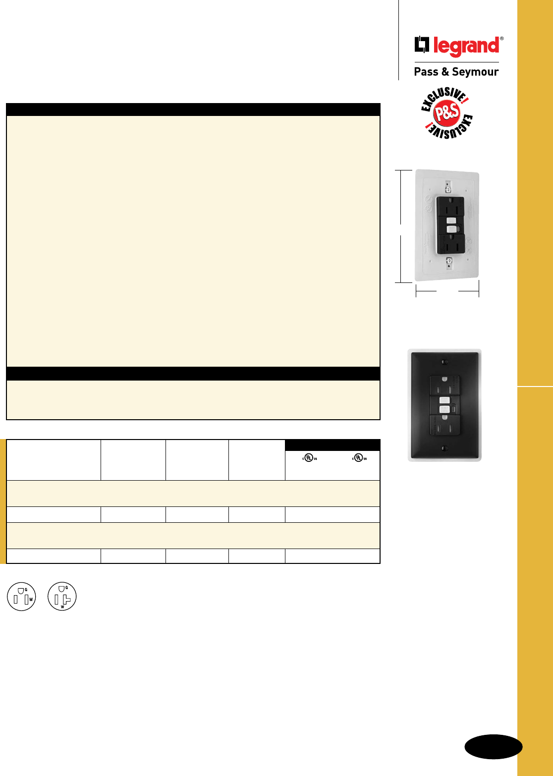
B-53
Straight Blade Receptacles
AlldeviceslistedonthispageconformtoNEMAWD-1andWD-6.
1595DSWRBKCC4
5.125"
3.313"
Weather-Resistant DuraShield™ GFCIs
Straight Blade Receptacles
Weather-Resistant DuraShieldTM
GFCI Receptacles
2 Pole, 3 Wire Grounding 15 & 20A, 125VAC
Features
nDesignedforextradurabilityandalongservicelife
wheninstalledinharshenvironments:outdoor,
garages,workshops,washdownareas,commercial
kitchens,andlabs.
nWeather-Resistant:MeetsNationalElectrical
Code®Weather-Resistantrequirements.
nListedtotheWeather-Resistantsupplementof
UL498,meetingdemandingULrequirements
including:
- Ultravioletlightexposuretest
- Coldimpacttest
- Acceleratedagingtest
- Stringentmaterialrequirementsforcurrent-
carryingparts,wirebindingscrewsandmounting
strapstoensuresuperiorcorrosionresistance.
nDust-andinsect-resistant.
nRubbercurtainsletplugbladesin;keepdust,
waterandinsectsout.
nIntegralgasketsealsreceptacle,protectingcritical
electroniccomponents.
nExceedsULcorrosionrequirements–survives
4Xtherequiredcorrosiontestcycles.
nSafeLockTMProtection:ifcriticalcomponentsare
damagedandgroundfaultprotectionislost,
powertoreceptacleisdisconnected.
Specications
nSupplyVoltage:125VAC,60Hz
nSupplyVoltageRange:102-132VAC
nTripThreshold:5±1mA
nTripTime:0.025sec.,nominalper
ULStandard
n20Ampfeed-thrucapacity
nPreventsline-loadreversalmiswire:nopower
tothefaceordownstreamreceptaclesifwired
incorrectly.
nExceedsUL943voltagesurgerequirements;
survives100xtherequiredUL3kA/6kV
voltagesurgetestcycles.
nTripindicatorlight(redLED).
nSideorinternalscrew-pressure-plateback
wirewith#10–#14AWGsolidorstranded
copperwire.
nTwobackwireholesperterminal.
nGroundscrewhasabackwireclampforeasy
installation.
nMountingscrewsareshippedcaptiveinthe
deviceandwallplateforeasierinstallation.
nHigh-impact-resistantthermoplastic
construction.
nExtra-longnickelpost-platedsteelmounting
strap.
nDual-directiontestandresetbuttons.
nClassAratedGFCI.
nSuppliedwithmatchingTP26nylonwallplate.
nTri-drivescrews.
NEMA
5-15R
NEMA
5-20R
National Electrical Code® Section 406.8 Receptacles in Wet or Damp Locations.
Requiresthatall15-and20-amp,125-and250-voltnon-lockingreceptaclesinstalledinwetordamplocationsshallbe
weather-resistantreceptacles.
UL943 UL498
C22.2 No. 144 C22.2 No. 42
3rd Party Compliance
Catalog Rating NEMA
Number A. VAC Color Cong. No.
Specification Grade Weather-Resistant DuraShield™
15 Amp Duplex GFCI
1595DSWRBKCC4 15 125 Black 5-15R • •
Specification Grade Weather-Resistant DuraShield™
20 Amp Duplex GFCI
2095DSWRBK 20 125 Black 5-20R • •
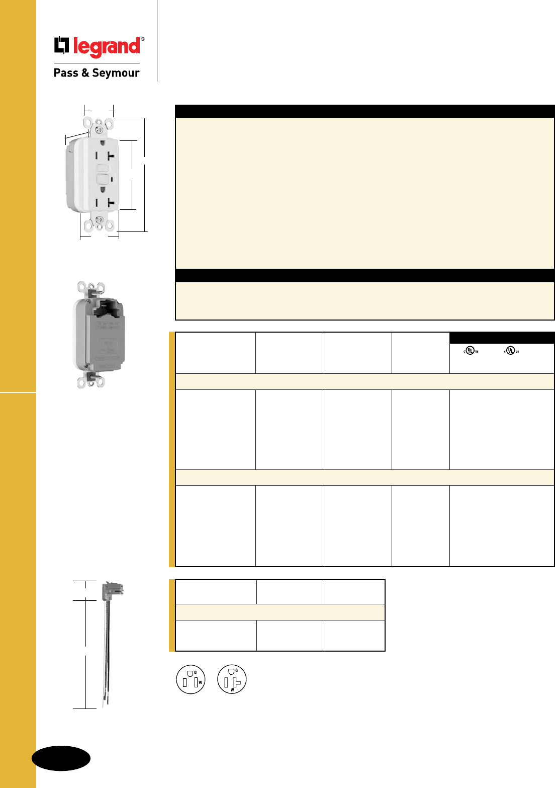
B-54
Straight Blade Receptacles
AlldeviceslistedonthispageconformtoNEMAWD-1andWD-6.
PlugTailTM Spec Grade GFCIs
Straight Blade Receptacles
PlugTailTM Specification Grade
GFCI Receptacles
2 Pole, 3 Wire Grounding 15 & 20A, 125VAC
Catalog
Number Wire Type Wire Length
PlugTail Connectors – Right Angle
PTRA6STR Stranded 6"
PTRA6SOL Solid 6"
For additional PlugTail Connectors,
see Page B-3.
All PlugTail Connectors are available
in any wire length up to 25 inches,
consult factory to order.
Features
nFaster,morereliableinstallation.
nNoexposedterminalscreateafingersafe
applicationbefore,during,andafterinstallation.
nBuilt-inconnectorfeatureslargebrassterminal
bladestoensureconsistent,reliableelectrical
connectionstoPlugTailConnector.
nGFCIworkswiththeexisting3wirePlugTail
Connectorscreatinganon-feed-thruapplicationfor
facilityowners.Atrough-injustinstallthesameright
angleconnectorforGFCIandreceptacleopenings.
nSafeLockTMProtection:ifcriticalcomponentsare
damagedandgroundfaultprotectionislost,power
toreceptacleisdisconnected.
nFSULListed(FederalSpecificationWC596).
Specications
nSupplyVoltage:125VAC,60Hz
nSupplyVoltageRange:102-132VAC
nTripThreshold:5±1mA
nTripTime:0.025sec.,nominalper
ULStandard
n20Ampfeed-thrucapacity
nExceedsUL943voltagesurgerequirements;
survives100xtherequiredUL3kA/6kV
voltagesurgetestcycles.
nTripindicatorlight(redLED).
nMountingscrewsareshippedcaptiveinthe
deviceandwallplateforeasierinstallation.
nHigh-impact-resistantthermoplastic
construction.
nZinc-platedsteelmountingstrap.
nButtoncolorsmatchthedeviceface.
nDual-directiontestandresetbuttons.
nClassAratedGFCI.
nSuppliedwithmatchingTP26nylonwallplate.
nTri-drivescrews.
NEMA
5-15R
NEMA
5-20R
UL943 UL498 FSUL
C22.2 No. 144 C22.2 No. 42 WC596
3rd Party Compliance
Catalog Rating NEMA
Number A. VAC Color Cong. No.
Specification Grade 15 Amp Duplex GFCI
PT1595I 15 125 Ivory 5-15R • • •
PT1595W 15 125 White 5-15R • • •
PT1595 15 125 Brown 5-15R • • •
PT1595GRY 15 125 Gray 5-15R • • •
PT1595BK 15 125 Black 5-15R • • •
PT1595RED 15 125 Red 5-15R • • •
PT1595LA 15 125 LightAlmond 5-15R • • •
Specification Grade 20 Amp Duplex GFCI
PT2095I 20 125 Ivory 5-20R • • •
PT2095W 20 125 White 5-20R • • •
PT2095 20 125 Brown 5-20R • • •
PT2095GRY 20 125 Gray 5-20R • • •
PT2095BK 20 125 Black 5-20R • • •
PT2095RED 20 125 Red 5-20R • • •
PT2095LA 20 125 LightAlmond 5-20R • • •
PT2095W
1.25"
1.20"
4.20"
2.62"
1.72"
PTRA6STR
1.125"
6.375"
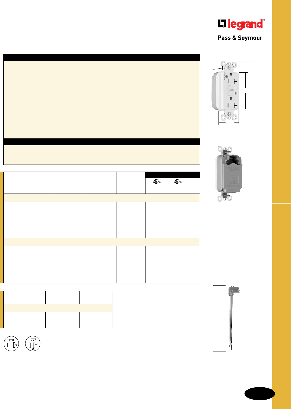
B-55
Straight Blade Receptacles
AlldeviceslistedonthispageconformtoNEMAWD-1andWD-6.
PlugTailTM Hospital Grade GFCIs
Straight Blade Receptacles
PlugTailTM Hospital Grade
GFCI Receptacles
2 Pole, 3 Wire Grounding 15 & 20A, 125VAC
PT2095HGW
1.25"
1.20"
4.20"
2.62"
1.72"
Catalog
Number Wire Type Wire Length
PlugTail Connectors – Right Angle
PTRA6STR Stranded 6"
PTRA6SOL Solid 6"
For additional PlugTail Connectors,
see Page B-3.
All PlugTail Connectors are available
in any wire length up to 25 inches,
consult factory to order.
NEMA
5-15R
NEMA
5-20R
UL943 UL498 FSUL
C22.2 No. 144 C22.2 No. 42 WC596
3rd Party Compliance
Catalog Rating NEMA
Number A. VAC Color Cong. No.
Hospital Grade 15 Amp Duplex GFCI
PT1595HGI 15 125 Ivory 5-15R • • •
PT1595HGW 15 125 White 5-15R • • •
PT1595HG 15 125 Brown 5-15R • • •
PT1595HGGRY 15 125 Gray 5-15R • • •
PT1595HGRED 15 125 Red 5-15R • • •
PT1595HGLA 15 125 LightAlmond 5-15R • • •
Hospital Grade 20 Amp Duplex GFCI
PT2095HGI 20 125 Ivory 5-20R • • •
PT2095HGW 20 125 White 5-20R • • •
PT2095HG 20 125 Brown 5-20R • • •
PT2095HGGRY 20 125 Gray 5-20R • • •
PT2095HGRED 20 125 Red 5-20R • • •
PT2095HGLA 20 125 LightAlmond 5-20R • • •
Features
nFaster,morereliableinstallation.
nNoexposedterminalscreateafingersafe
applicationbefore,during,andafterinstallation.
nBuilt-inconnectorfeatureslargebrassterminal
bladestoensureconsistent,reliableelectrical
connectionstoPlugTailConnector.
nGFCIworkswiththeexisting3wirePlugTail
Connectorscreatinganon-feed-thruapplicationfor
facilityowners.Atrough-injustinstallthesameright
angleconnectorforGFCIandreceptacleopenings.
nSafeLockTMProtection:ifcriticalcomponentsare
damagedandgroundfaultprotectionislost,power
toreceptacleisdisconnected.
nFSULListed(FederalSpecificationWC596).
Specications
nSupplyVoltage:125VAC,60Hz
nSupplyVoltageRange:102-132VAC
nTripThreshold:5±1mA
nTripTime:0.025sec.,nominalper
ULStandard
n20Ampfeed-thrucapacity
nExceedsUL943voltagesurgerequirements;
survives100xtherequiredUL3kA/6kV
voltagesurgetestcycles.
nTripindicatorlight(redLED).
nMountingscrewsareshippedcaptiveinthe
deviceandwallplateforeasierinstallation.
nHigh-impact-resistantthermoplastic
construction.
nZinc-platedsteelmountingstrap.
nButtoncolorsmatchthedeviceface.
nDual-directiontestandresetbuttons.
nClassAratedGFCI.
nSuppliedwithmatchingTP26nylonwallplate.
nTri-drivescrews.
PTRA6STR
1.125"
6.375"
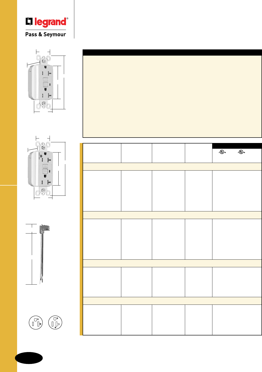
B-56
Straight Blade Receptacles
AlldeviceslistedonthispageconformtoNEMAWD-1andWD-6.
PlugTailTM Tamper-Resistant GFCIs
Straight Blade Receptacles
PlugTailTM Specification & Hospital Grade
Tamper-Resistant GFCI Receptacles
2 Pole, 3 Wire Grounding 15 & 20A, 125VAC
PTRA6STR
1.125"
6.375"
Features
nProtectschildren:patentedshuttersystemhelps
preventimproperinsertionofforeignobjects.
nMeetsNationalElectricalCode®
Tamper-Resistantrequirements.
nFaster,morereliableinstallation.
nNoexposedterminalscreateafingersafe
applicationbefore,during,andafterinstallation.
nBuilt-inconnectorfeatureslargebrassterminal
bladestoensureconsistent,reliableelectrical
connectionstoPlugTailConnector.
nGFCIworkswiththeexisting3wirePlugTail
Connectorscreatinganon-feed-thruapplicationfor
facilityowners.Atrough-injustinstallthesameright
angleconnectorforGFCIandreceptacleopenings.
nSafeLockTMProtection:ifcriticalcomponentsare
damagedandgroundfaultprotectionislost,power
toreceptacleisdisconnected.
nFSULListed(FederalSpecificationWC596).
nExceedsUL943voltagesurgerequirements;
survives100xtherequiredUL3kA/6kV
voltagesurgetestcycles.
nTripindicatorlight(redLED).
nMountingscrewsareshippedcaptiveinthe
deviceandwallplateforeasierinstallation.
nHigh-impact-resistantthermoplastic
construction.
nZinc-platedsteelmountingstrap.
nButtoncolorsmatchthedeviceface.
nDual-directiontestandresetbuttons.
nClassAratedGFCI.
nSuppliedwithmatchingTP26nylonwallplate.
nTri-drivescrews.
UL943 UL498 FSUL
C22.2 No. 144 C22.2 No. 42 WC596
3rd Party Compliance
Catalog Rating NEMA
Number A. VAC Color Cong. No.
Specification Grade Tamper-Resistant 15 Amp Duplex GFCI
PT1595TRI 15 125 Ivory 5-15R • • •
PT1595TRW 15 125 White 5-15R • • •
PT1595TR 15 125 Brown 5-15R • • •
PT1595TRGRY 15 125 Gray 5-15R • • •
PT1595TRBK 15 125 Black 5-15R • • •
PT1595TRRED 15 125 Red 5-15R • • •
PT1595TRLA 15 125 LightAlmond 5-15R • • •
Specification Grade Tamper-Resistant 20 Amp Duplex GFCI
PT2095TRI 20 125 Ivory 5-20R • • •
PT2095TRW 20 125 White 5-20R • • •
PT2095TR 20 125 Brown 5-20R • • •
PT2095TRGRY 20 125 Gray 5-20R • • •
PT2095TRBK 20 125 Black 5-20R • • •
PT2095TRRED 20 125 Red 5-20R • • •
PT2095TRLA 20 125 LightAlmond 5-20R • • •
Hospital Grade Tamper-Resistant 15 Amp Duplex GFCI
PT1595HGTRI 15 125 Ivory 5-15R • • •
PT1595HGTRW 15 125 White 5-15R • • •
PT1595HGTRGRY 15 125 Gray 5-15R • • •
PT1595HGTRRED 15 125 Red 5-15R • • •
PT1595HGTRLA 15 125 LightAlmond 5-15R • • •
Hospital Grade Tamper-Resistant 20 Amp Duplex GFCI
PT2095HGTRI 20 125 Ivory 5-20R • • •
PT2095HGTRW 20 125 White 5-20R • • •
PT2095HGTRGRY 20 125 Gray 5-20R • • •
PT2095HGTRRED 20 125 Red 5-20R • • •
PT2095HGTRLA 20 125 LightAlmond 5-20R • • •
For PlugTail Connector catalog numbers, see Page B-54 or B-55.
PT2095TRW
1.20"
1.25"
4.20"
2.62"
1.72"
NEMA
5-15R
NEMA
5-20R
PT2095HGTRW
1.25"
1.2"
4.20"
2.62"
1.72"

B-57
Straight Blade Receptacles
AlldeviceslistedonthispageconformtoNEMAWD-1andWD-6.
PlugTail™ TR Nightlight/GFCIs
Straight Blade Receptacles
PlugTail
TM
Specification & Hospital Grade
Tamper-Resistant Nightlight/GFCI Receptacles
2 Pole, 3 Wire Grounding 15 & 20A, 125VAC
For PlugTail Connector catalog numbers, see Page B-54 or B-55.
NEMA
5-15R
NEMA
5-20R
Specications
nSupplyVoltage:125VAC,60Hz
nSupplyVoltageRange:102-132VAC
nTripThreshold:5±1mA
nTripTime:0.025sec.,nominalper
ULStandard
n20Ampfeed-thrucapacity
Features
nProtectschildren:patentedshuttersystemhelps
preventimproperinsertionofforeignobjects.
nMeetsNationalElectricalCode®
Tamper-Resistantrequirements.
nSealednightlightwithhighimpact-resistantLexan®
lenspreventstampering.
nNightlightusescoolerLEDillumination.
nEnergy-efficientLEDhasaverage20-yearlife
expectancy,eliminatingbulbreplacement.
nPhotocellturnsnightlightONindark,OFFindaylight.
nFaster,morereliableinstallation.
nNoexposedterminalscreateafingersafe
applicationbefore,during,andafterinstallation.
nBuilt-inconnectorfeatureslargebrassterminal
bladestoensureconsistent,reliableelectrical
connectionstoPlugTailConnector.
nGFCIworkswiththeexisting3wirePlugTail
Connectorscreatinganon-feed-thruapplicationfor
facilityowners.Atrough-injustinstallthesameright
angleconnectorforGFCIandreceptacleopenings.
nSafeLockTMProtection:ifcriticalcomponents
aredamagedandgroundfaultprotectionis
lost,powertoreceptacleisdisconnected.
nExceedsUL943voltagesurgerequirements;
survives100xtherequiredUL3kA/6kV
voltagesurgetestcycles.
nFSULListed(FederalSpecificationWC596).
nTripindicatorlight(redLED).
nMountingscrewsareshippedcaptiveinthe
deviceandwallplateforeasierinstallation.
nHigh-impact-resistantthermoplastic
construction.
nZinc-platedsteelmountingstrap.
nButtoncolorsmatchthedeviceface.
nDual-directiontestandresetbuttons.
nClassAratedGFCI.
nSuppliedwithmatchingTP26nylonwallplate.
nTri-drivescrews.
1.25"
1.20"
4.20"
2.62"
1.72"
PT1595NTLTRI
UL943 UL498 FSUL
C22.2 No. 144 C22.2 No. 42 WC596
3rd Party Compliance
Catalog Rating NEMA
Number A. VAC Color Cong. No.
Specification Grade Tamper-Resistant 15 Amp Combination Nightlight/GFCI
PT1595NTLTRI 15 125 Ivory 5-15R • • •
Specification Grade Tamper-Resistant 20 Amp Combination Nightlight/GFCI
PT2095NTLTRI 20 125 Ivory 5-20R • • •
PT2095NTLTRW 20 125 White 5-20R • • •
Hospital Grade Tamper-Resistant 15 Amp Combination Nightlight/GFCI
PT1595HGNTLTRI 15 125 Ivory 5-15R • • •
PT1595HGNTLTRW 15 125 White 5-15R • • •
PT1595HGNTLTRRED 15 125 Red 5-15R • • •
Hospital Grade Tamper-Resistant 20 Amp Combination Nightlight/GFCI
PT2095HGNTLTRI 20 125 Ivory 5-20R • • •
PT2095HGNTLTRW 20 125 White 5-20R • • •
PT2095HGNTLTRLA 20 125 LightAlmond 5-20R • • •
NEW
NEW
NEW
NEW
PT1595HGNTLTRI
1.25"
1.20"
4.20"
2.62"
1.72"
PTRA6STR
1.125"
6.375"
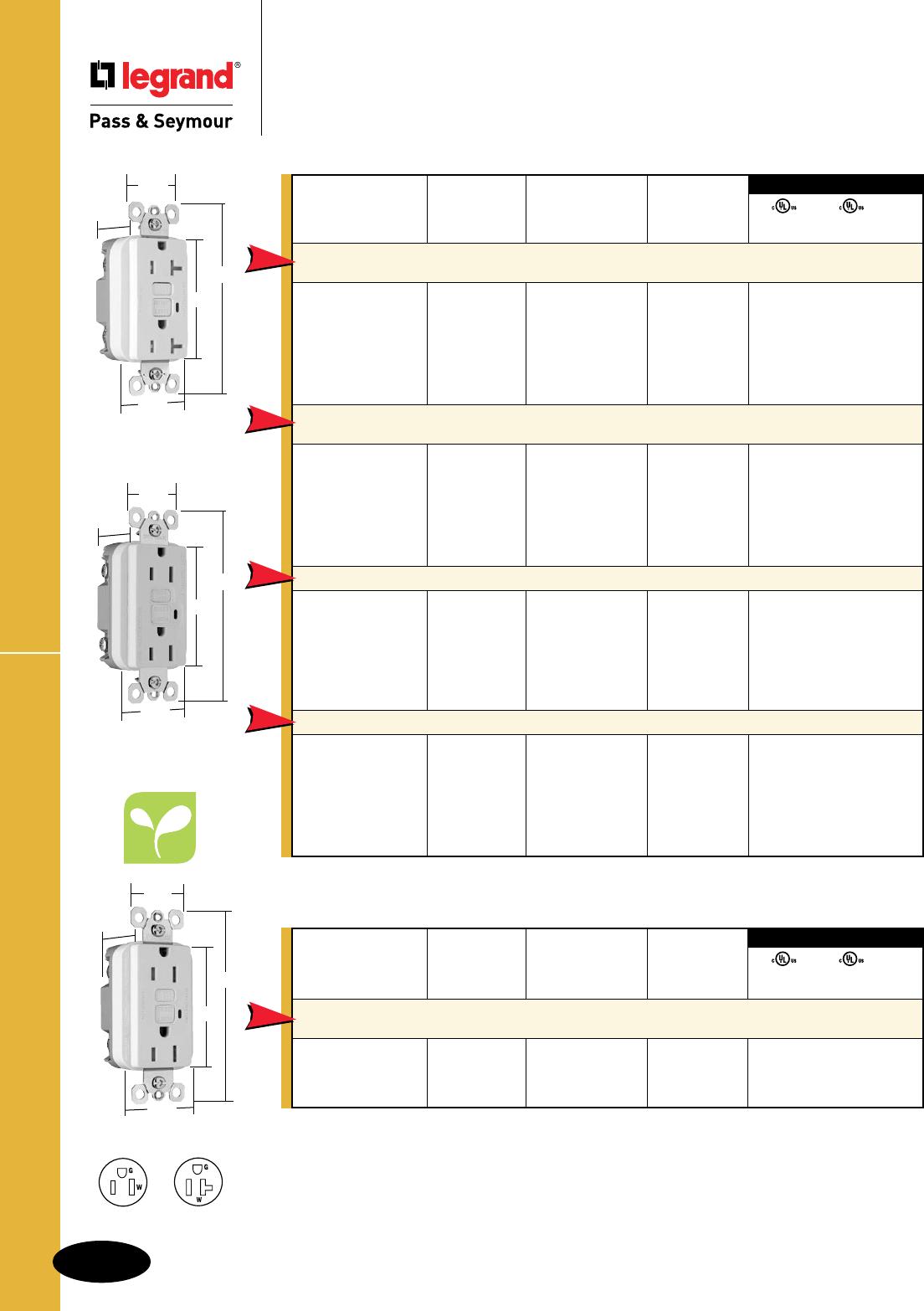
B-58
Straight Blade Receptacles
AlldeviceslistedonthispageconformtoNEMAWD-1andWD-6.
NAFTA-Compliant & RoHS-Compliant GFCIs
Straight Blade Receptacles
NAFTA-Compliant & RoHS-Compliant
GFCI Receptacles
2 Pole, 3 Wire Grounding 15 & 20A, 125VAC
NAFTA-Compliant GFCI Receptacles are ideal for use on projects subject to the provisions of the
Buy American Act.
Catalog Rating NEMA
Number A. VAC Color Cong. No.
NAFTA-Compliant TradeMaster
®
/Spec Grade Tamper-Resistant
15 Amp Duplex GFCI
1595TRNAI 15 125 Ivory 5-15R •••
1595TRNAW 15 125 White 5-15R •••
1595TRNA 15 125 Brown 5-15R •••
1595TRNAGRY 15 125 Gray 5-15R •••
1595TRNABK 15 125 Black 5-15R •••
1595TRNALA 15 125 LightAlmond 5-15R •••
NAFTA-Compliant TradeMaster
®
/Spec Grade Tamper-Resistant
20 Amp Duplex GFCI
2095TRNAI 20 125 Ivory 5-20R •••
2095TRNAW 20 125 White 5-20R •••
2095TRNA 20 125 Brown 5-20R •••
2095TRNAGRY 20 125 Gray 5-20R •••
2095TRNABK 20 125 Black 5-20R •••
2095TRNALA 20 125 LightAlmond 5-20R •••
NAFTA-Compliant TradeMaster®/Spec Grade 15 Amp Duplex GFCI
1595NAI 15 125 Ivory 5-15R •••
1595NAW 15 125 White 5-15R •••
1595NA 15 125 Brown 5-15R •••
1595NAGRY 15 125 Gray 5-15R •••
1595NABK 15 125 Black 5-15R •••
1595NALA 15 125 LightAlmond 5-15R •••
NAFTA-Compliant Spec Grade 20 Amp Duplex GFCI
2095NAI 20 125 Ivory 5-20R •••
2095NAW 20 125 White 5-20R •••
2095NA 20 125 Brown 5-20R •••
2095NAGRY 20 125 Gray 5-20R •••
2095NABK 20 125 Black 5-20R •••
2095NALA 20 125 LightAlmond 5-20R •••
UL943 UL498 FSUL
C22.2 No. 144 C22.2 No. 42 WC596
3rd Party Compliance
NEW
NEW
NEW
NEW
UL943 UL498 FSUL
C22.2 No. 144 C22.2 No. 42 WC596
3rd Party Compliance
Catalog Rating NEMA
Number A. VAC Color Cong. No.
RoHS-Compliant
TradeMaster
®
/Spec Grade Tamper-Resistant
15 Amp Duplex GFCI
1595RI 15 125 Ivory 5-15R • • •
1595RW 15 125 White 5-15R • • •
1595RLA 15 125 LightAlmond 5-15R • • •
NEW
RoHS-Compliant GFCI Receptacles meet the requirements of Restriction of Hazardous Substances
directives and regulations.
2095TRNAW
1.72"
1.25"
2.62"
4.20"
.98"
1.72"
1.25"
2.62"
4.20"
.98"
NEMA
5-15R
NEMA
5-20R
1595NAW
1595RW
1.13"
1.72"
1.25"
2.62"
4.20"

B-59
Straight Blade Receptacles
AlldeviceslistedonthispageconformtoNEMAWD-1andWD-6.
NAFTA-Compliant Hospital Grade GFCIs
Straight Blade Receptacles
NAFTA-Compliant Hospital Grade
GFCI Receptacles
2 Pole, 3 Wire Grounding 15 & 20A, 125VAC
NEMA
5-15R
NEMA
5-20R
NAFTA-Compliant GFCI Receptacles are ideal for use on projects subject to the provisions of the
Buy American Act.
Catalog Rating NEMA
Number A. VAC Color Cong. No.
NAFTA-Compliant Hospital Grade Tamper-Resistant 20 Amp Duplex GFCI
2095HGTRNAI 20 125 Ivory 5-20R •••
2095HGTRNAW 20 125 White 5-20R •••
2095HGTRNAGRY 20 125 Gray 5-20R •••
2095HGTRNARED 20 125 Red 5-20R •••
2095HGTRNALA 20 125 LightAlmond 5-20R •••
NAFTA-Compliant Hospital Grade 15 Amp Duplex GFCI
1595HGNAI 15 125 Ivory 5-15R •••
1595HGNAW 15 125 White 5-15R •••
1595HGNARED 15 125 Red 5-15R •••
NAFTA-Compliant Hospital Grade 20 Amp Duplex GFCI
2095HGNAI 20 125 Ivory 5-20R •••
2095HGNAW 20 125 White 5-20R •••
2095HGNA 20 125 Brown 5-20R •••
2095HGNAGRY 20 125 Gray 5-20R •••
2095HGNARED 20 125 Red 5-20R •••
2095HGNALA 20 125 LightAlmond 5-20R •••
UL943 UL498 FSUL
C22.2 No. 144 C22.2 No. 42 WC596
3rd Party Compliance
NEW
NEW
NEW
1.72"
1.25"
2.62"
4.20"
.98"
2095HGTRNAW
1595HGNAW
1.72"
1.25"
2.62"
4.20"
.98"

B-60
Straight Blade Receptacles
AlldeviceslistedonthispageconformtoNEMAWD-1andWD-6.
NAFTA-Compliant PlugTail™ GFCI Receptacles
Straight Blade Receptacles
NAFTA-Compliant
PlugTail™ GFCI Receptacles
2 Pole, 3 Wire Grounding 15 & 20A, 125VAC
PT1595NAW
1.72"
1.25"
2.62"
4.20"
.98"
NEMA
5-15R
NEMA
5-20R
Specications
nSupplyVoltage:125VAC,60Hz
nSupplyVoltageRange:102-132VAC
nTripThreshold:5±1mA
nTripTime:0.025sec.,nominalper
ULStandard
n20Ampfeed-thrucapacity
Features
nFaster,morereliableinstallation.
nNoexposedterminalscreateafingersafe
applicationbefore,during,andafterinstallation.
nBuilt-inconnectorfeatureslargebrassterminal
bladestoensureconsistent,reliableelectrical
connectionstoPlugTailConnector.
nGFCIworkswiththeexisting3wirePlugTail
Connectorscreatinganon-feed-thruapplicationfor
facilityowners.Atrough-injustinstallthesameright
angleconnectorforGFCIandreceptacleopenings.
nSafeLockTMProtection:ifcriticalcomponentsare
damagedandgroundfaultprotectionislost,power
toreceptacleisdisconnected.
nFSULListed(FederalSpecificationWC596).
nExceedsUL943voltagesurgerequirements;
survives100xtherequiredUL3kA/6kV
voltagesurgetestcycles.
nTripindicatorlight(redLED).
nMountingscrewsareshippedcaptiveinthe
deviceandwallplateforeasierinstallation.
nHigh-impact-resistantthermoplastic
construction.
nZinc-platedsteelmountingstrap.
nButtoncolorsmatchthedeviceface.
nDual-directiontestandresetbuttons.
nClassAratedGFCI.
nSuppliedwithmatchingTP26nylonwallplate.
nTri-drivescrews.
Catalog Rating NEMA
Number A. VAC Color Cong. No.
NAFTA-Compliant Spec Grade 15 Amp Duplex GFCI
PT1595NAI 15 125 Ivory 5-15R •••
PT1595NAW 15 125 White 5-15R •••
PT1595NAGRY 15 125 Gray 5-15R •••
PT1595NALA 15 125 LightAlmond 5-15R •••
NAFTA-Compliant Spec Grade 20 Amp Duplex GFCI
PT2095NAI 20 125 Ivory 5-20R •••
PT2095NAW 20 125 White 5-20R •••
PT2095NAGRY 20 125 Gray 5-20R •••
PT2095NABK 20 125 Black 5-20R •••
PT2095NALA 20 125 LightAlmond 5-20R •••
NAFTA-Compliant Spec Grade Tamper-Resistant 20 Amp Duplex GFCI
PT2095TRNAI 20 125 Ivory 5-20R •••
PT2095TRNAW 20 125 White 5-20R •••
PT2095TRNAGRY 20 125 Gray 5-20R •••
PT2095TRNALA 20 125 LightAlmond 5-20R • • •
NAFTA-Compliant Spec Grade Tamper-Resistant 15 Amp
Combination Nightlight/GFCI
PT1595NTLTRNAI 15 125 Ivory 5-15R •••
PT1595NTLTRNAW 15 125 White 5-15R •••
NAFTA-Compliant Spec Grade Tamper-Resistant 20 Amp
Combination Nightlight/GFCI
PT2095NTLTRNAI 20 125 Ivory 5-20R •••
PT2095NTLTRNAW 20 125 White 5-20R •••
UL943 UL498 FSUL
C22.2 No. 144 C22.2 No. 42 WC596
3rd Party Compliance
NEW
NEW
NEW
NEW
NEW
NAFTA-Compliant GFCI Receptacles are ideal for use on projects subject to the provisions of the
Buy American Act.
1.72"
1.25"
2.62"
4.20"
.98"
PT2095TRNAW
For PlugTail Connector catalog numbers, see Page B-61.
PT2095NTLTRNAW
1.72"
1.25"
2.62"
4.20"
1.13"
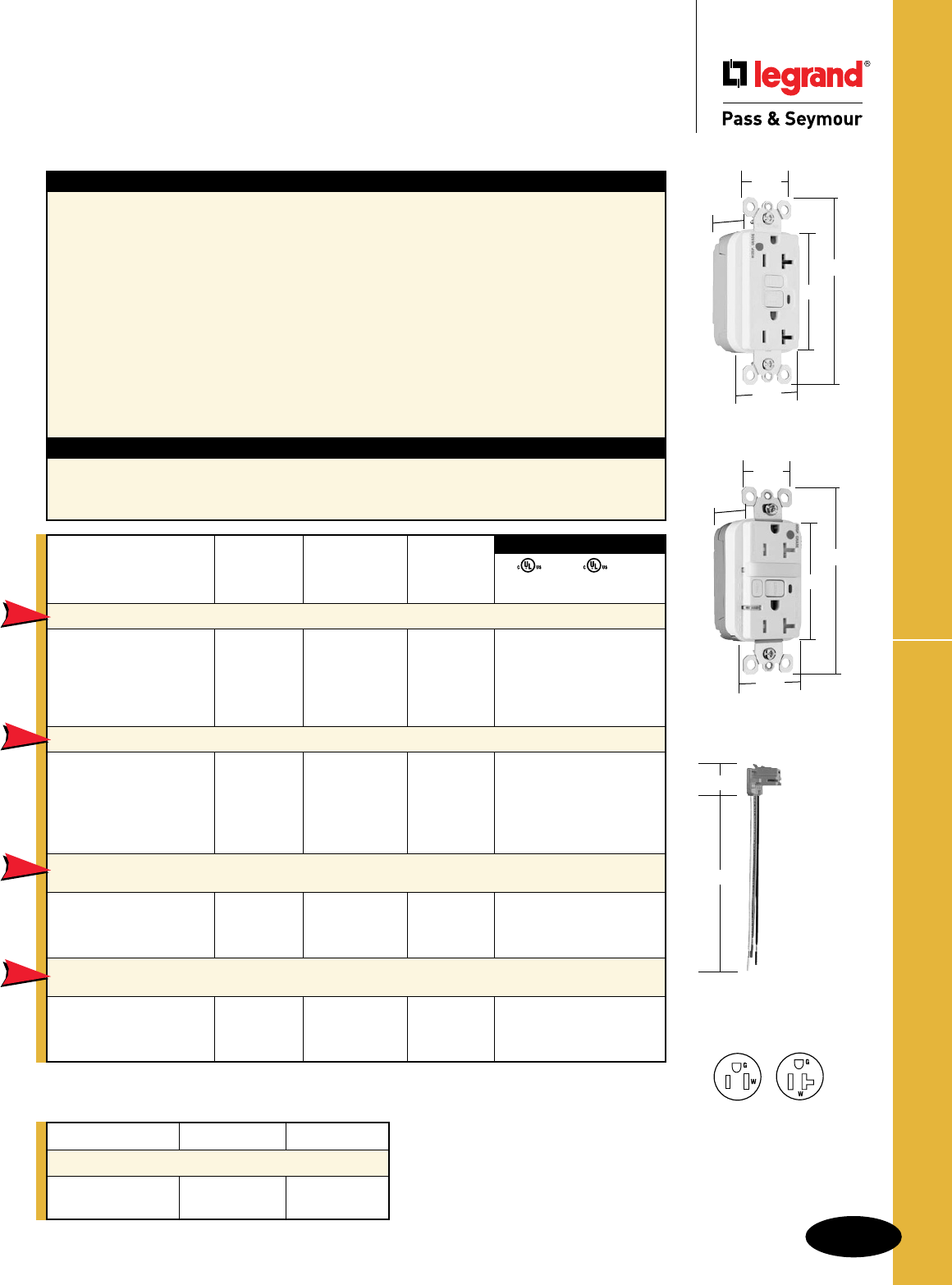
B-61
Straight Blade Receptacles
AlldeviceslistedonthispageconformtoNEMAWD-1andWD-6.
NAFTA-Compliant PlugTail™ HG GFCIs
Straight Blade Receptacles
NAFTA-Compliant PlugTail™
Hospital Grade GFCI Receptacles
2 Pole, 3 Wire Grounding 15 & 20A, 125VAC
For additional PlugTail Connectors, see
Page B-3.
All PlugTail Connectors are available in
any wire length up to 25 inches, consult
factory to order.
Specications
nSupplyVoltage:125VAC,60Hz
nSupplyVoltageRange:102-132VAC
nTripThreshold:5±1mA
nTripTime:0.025sec.,nominalper
ULStandard
n20Ampfeed-thrucapacity
Features
nFaster,morereliableinstallation.
nNoexposedterminalscreateafingersafe
applicationbefore,during,andafterinstallation.
nBuilt-inconnectorfeatureslargebrassterminal
bladestoensureconsistent,reliableelectrical
connectionstoPlugTailConnector.
nGFCIworkswiththeexisting3wirePlugTail
Connectorscreatinganon-feed-thruapplicationfor
facilityowners.Atrough-injustinstallthesameright
angleconnectorforGFCIandreceptacleopenings.
nSafeLockTMProtection:ifcriticalcomponentsare
damagedandgroundfaultprotectionislost,power
toreceptacleisdisconnected.
nFSULListed(FederalSpecificationWC596).
nExceedsUL943voltagesurgerequirements;
survives100xtherequiredUL3kA/6kV
voltagesurgetestcycles.
nTripindicatorlight(redLED).
nMountingscrewsareshippedcaptiveinthe
deviceandwallplateforeasierinstallation.
nHigh-impact-resistantthermoplastic
construction.
nZinc-platedsteelmountingstrap.
nButtoncolorsmatchthedeviceface.
nDual-directiontestandresetbuttons.
nClassAratedGFCI.
nSuppliedwithmatchingTP26nylonwallplate.
nTri-drivescrews.
Catalog Rating NEMA
Number A. VAC Color Cong. No.
NAFTA-Compliant Hospital Grade 20 Amp Duplex GFCI
PT2095HGNAI 20 125 Ivory 5-20R •••
PT2095HGNAW 20 125 White 5-20R •••
PT2095HGNAGRY 20 125 Gray 5-20R •••
PT2095HGNARED 20 125 Red 5-20R •••
PT2095HGNALA 20 125 LightAlmond 5-20R • • •
NAFTA-Compliant Hospital Grade Tamper-Resistant 20 Amp Duplex GFCI
PT2095HGTRNAI 20 125 Ivory 5-20R •••
PT2095HGTRNAW 20 125 White 5-20R •••
PT2095HGTRNAGRY 20 125 Gray 5-20R •••
PT2095HGTRNARED 20 125 Red 5-20R •••
PT2095HGTRNALA 20 125 LightAlmond 5-20R • • •
NAFTA-Compliant Hospital Grade
Tamper-Resistant
15 Amp
Combination Nightlight/GFCI
PT1595HGNTLTRNAI 15 125 Ivory 5-15R •••
PT1595HGNTLTRNAW 15 125 White 5-15R •••
PT1595HGNTLTRNARED 15 125 Red 5-15R •••
NAFTA-Compliant Hospital Grade
Tamper-Resistant
20 Amp
Combination Nightlight/GFCI
PT2095HGNTLTRNAI 20 125 Ivory 5-20R •••
PT2095HGNTLTRNAW 20 125 White 5-20R •••
PT2095HGNTLTRNARED 20 125 Red 5-20R •••
UL943 UL498 FSUL
C22.2 No. 144 C22.2 No. 42 WC596
3rd Party Compliance
NEW
NEW
NEW
NEW
NAFTA-Compliant GFCI Receptacles are ideal for use on projects subject to the provisions of the
Buy American Act.
PT2095HGNAW
1.72"
1.25"
2.62"
4.20"
.98"
PT2095HGNTLTRNAW
1.72"
1.25"
2.62"
4.20"
1.13"
Catalog Number Wire Type Wire Length
PlugTail Connectors – Right Angle
PTRA6STR Stranded 6"
PTRA6SOL Solid 6"
PTRA6STR
1.125"
6.375"
NEMA
5-20R
NEMA
5-15R
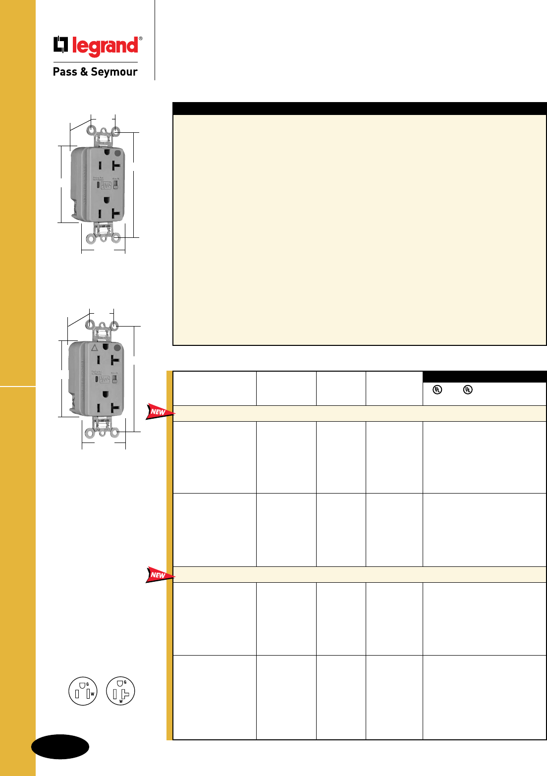
B-62
Straight Blade ReceptaclesHG Surge Protective Receptacles
Straight Blade Receptacles
Hospital Grade Surge Protective
Receptacles
2 Pole, 3 Wire Grounding 15 & 20A, 125VAC
Specications
nUL1449(3rdEdition).(1.2x50µs
6000V,8x20µs3000A).
n24,000ampscurrenthandlingcapabilityin
eachof3modes:linetoneutral,line
toground,neutraltoground.
nLEDindication:Steadygreen=protected;
Flashingred=notprotected
OFF=nopowertounit
nResponsetimelessthan1nanosecondfor
unmountedMOV.
nOvercurrentprotectioninall3modes.
nPrintedcircuitboardconformallycoatedto
protectagainstcondensinghumidityand
airborneparticulates.
nThermalprotectioninall3modes.
nLeakagecurrent:0.5mAat25°C/120VAC.
nCommonmodenoiseattenuation:500KHz
to30MHz;upto20dB(50ohmsource
impedance)
nVaristorvoltage:130VRMS.
nBackandsidewirecapabilityincluding
groundterminal.
nOperatingtemperature:-40°Cto85°C
(-40°Fto185°F)
5262/5362, IG5262/5362, 8200/8300, IG8200/8300,
TR5262/5362, TRIG5262/5362, TR8200/8300,
TRIG8200/8300
n340joulesofenergyabsorptionineachofthe3modes.
Energy(measuredforan8x20µSduration)=340J.
nNominallet-through(suppressed)voltageinall
3modes,500V.
n Audiblealarmabletobeturnedon/off.
n317mmdualpackMOVstosuppresstransientsinall
modes–equally.
nIsolatedGroundversioncomplieswithNEC410-56(C)
and250-146.
5252/5352, TR5252/5352, All PlugTail™
n340joulesofenergyabsorptioninline-to-neutraland
line-to-groundmodes.680joulesofenergyabsorption
inneutral-to-groundmode.Energy(measuredforan
8x20µSduration)=340J;680JforN-Gmode.
n217mmdualpackMOVstosuppress
transientsinallmodes–equally.
nNominallet-through(suppressed)voltage:
Line-to-neutralandline-to-groundmodes=500V;
neutral-to-ground=1000V.
nPlugTailversions–factory-terminateddevicesand
connectors.
NEMA
5-20R
NEMA
5-15R
8300GRYSP
3.75"
1.70"
.875"
1.25"
BehindStrap
2.75"
IG8300GRYSP
3.75"
1.70"
.875"
1.25"
BehindStrap
2.75"
FSUL
UL1449 UL498 WC596 cUL/CSA
Rating NEMA
Catalog Number A. VAC Cong. No. Color
Duplex Receptacles Back & Side Wire
8200ISP 15 125 5-15R Ivory ••••
8200WSP 15 125 5-15R White ••••
8200SP 15 125 5-15R Brown ••••
8200GRYSP 15 125 5-15R Gray ••••
8200REDSP 15 125 5-15R Red ••••
8200LASP 15 125 5-15R LightAlmond • • • •
8200BLSP 15 125 5-15R Blue ••••
8300ISP 20 125 5-20R Ivory • •••
8300WSP 20 125 5-20R White • •••
8300SP 20 125 5-20R Brown • •••
8300GRYSP 20 125 5-20R Gray • •••
8300REDSP 20 125 5-20R Red • •••
8300LASP 20 125 5-20R LightAlmond • •••
8300BLSP 20 125 5-20R Blue • •••
Isolated Ground Duplex Receptacles Back & Side Wire
IG8200ISP 15 125 5-15R Ivory • •••
IG8200WSP 15 125 5-15R White • •••
IG8200GRYSP 15 125 5-15R Gray • •••
IG8200REDSP 15 125 5-15R Red • •••
IG8200LASP 15 125 5-15R LightAlmond • •••
IG8200BLSP 15 125 5-15R Blue • •••
IG8200OSP 15 125 5-15R Orange • •••
IG8300ISP 20 125 5-20R Ivory • •••
IG8300WSP 20 125 5-20R White • •••
IG8300SP 20 125 5-20R Brown • •••
IG8300GRYSP 20 125 5-20R Gray • •••
IG8300REDSP 20 125 5-20R Red • •••
IG8300LASP 20 125 5-20R LightAlmond • •••
IG8300BLSP 20 125 5-20R Blue • •••
IG8300OSP 20 125 5-20R Orange • •••
3rd Party Compliance
Audible Alarm with LED Indicator
Alldeviceslistedonthispage
conformtoNEMAWD-1and
WD-6.Conformstothelatest
revisionANSI/IEEEC62.41
(formerlyIEEE587),ANSI/IEEE
C62.45.
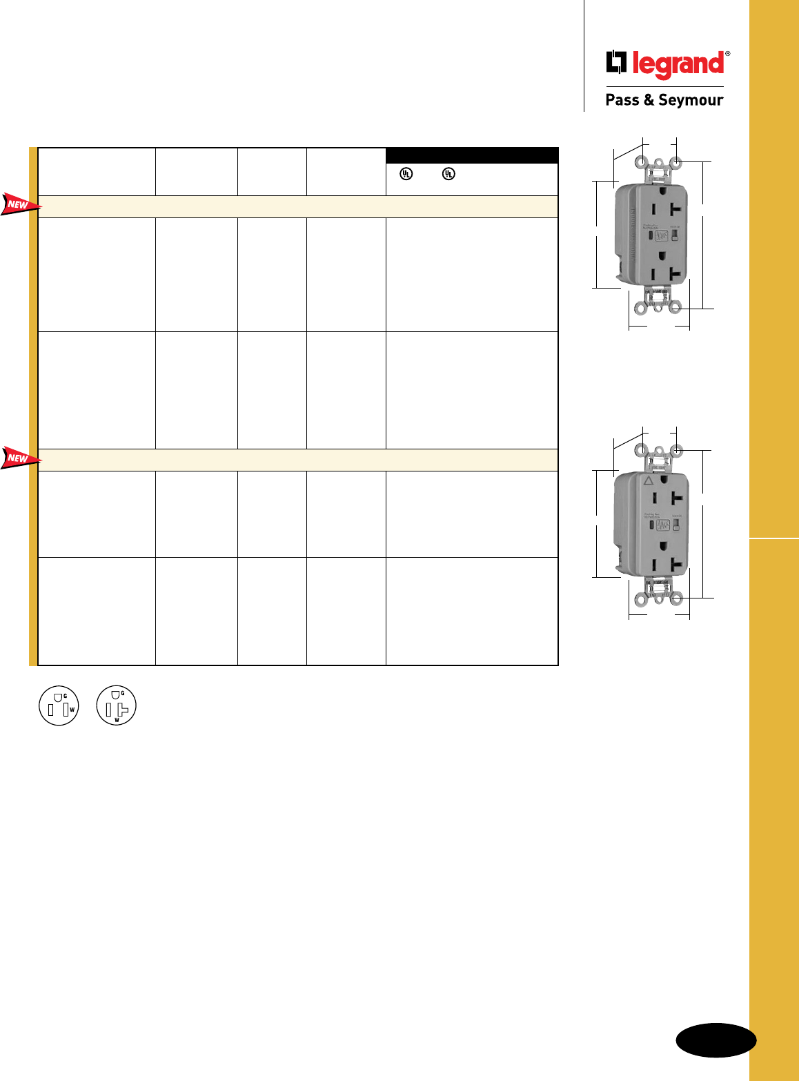
B-63
Straight Blade Receptacles Surge Protective Receptacles
Straight Blade Receptacles
Surge Protective
Receptacles
2 Pole, 3 Wire Grounding 15 & 20A, 125VAC
AlldeviceslistedonthispageconformtoNEMAWD-1andWD-6.
ConformstothelatestrevisionANSI/IEEEC62.41(formerlyIEEE587),ANSI/IEEEC62.45.
NEMA
5-20R
NEMA
5-15R
5362GRYSP
3.75"
1.70"
.875"
1.25"
BehindStrap
2.75"
Audible Alarm with LED Indicator
FSUL
UL1449 UL498 WC596 cUL/CSA
3rd Party Compliance
Rating NEMA
Catalog Number A. VAC Cong. No. Color
Extra Heavy-Duty Duplex Receptacles Back & Side Wire
5262ISP 15 125 5-15R Ivory ••••
5262WSP 15 125 5-15R White ••••
5262SP 15 125 5-15R Brown ••••
5262GRYSP 15 125 5-15R Gray ••••
5262BKSP 15 125 5-15R Black ••••
5262REDSP 15 125 5-15R Red ••••
5262LASP 15 125 5-15R LightAlmond ••••
5262BLSP 15 125 5-15R Blue ••••
5362ISP 20 125 5-20R Ivory • •••
5362WSP 20 125 5-20R White • •••
5362SP 20 125 5-20R Brown • •••
5362GRYSP 20 125 5-20R Gray • •••
5362BKSP 20 125 5-20R Black • •••
5362REDSP 20 125 5-20R Red • •••
5362LASP 20 125 5-20R LightAlmond • •••
5362BLSP 20 125 5-20R Blue • •••
Isolated Ground Duplex Receptacles
Back & Side Wire
IG5262ISP 15 125 5-15R Ivory ••••
IG5262WSP 15 125 5-15R White ••••
IG5262GRYSP 15 125 5-15R Gray ••••
IG5262LASP 15 125 5-15R LightAlmond ••••
IG5262BLSP 15 125 5-15R Blue ••••
IG5262OSP 15 125 5-15R Orange ••••
IG5362ISP 20 125 5-20R Ivory ••••
IG5362WSP 20 125 5-20R White • •••
IG5362SP 20 125 5-20R Brown ••••
IG5362GRYSP 20 125 5-20R Gray • •••
IG5362LASP 20 125 5-20R LightAlmond • •••
IG5362BLSP 20 125 5-20R Blue • •••
IG5362OSP 20 125 5-20R Orange • •••IG5362GRYSP
3.75"
1.70"
.875"
1.25"
BehindStrap
2.75"
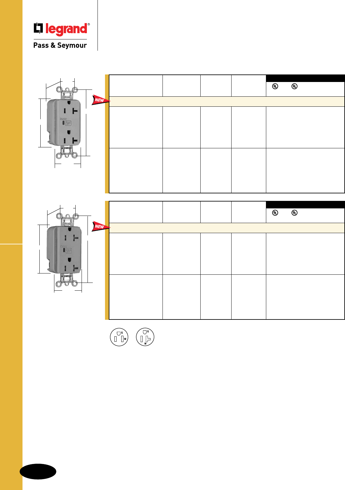
B-64
Straight Blade ReceptaclesSurge Protective Receptacles
Straight Blade Receptacles
Surge Protective Receptacles
2 Pole, 3 Wire Grounding 15 & 20A, 125VAC
AlldeviceslistedonthispageconformtoNEMAWD-1andWD-6.
ConformstothelatestrevisionANSI/IEEEC62.41(formerlyIEEE587),ANSI/IEEEC62.45.
5352GRYSP
3.75"
1.70"
.875"
1.29"
BehindStrap
2.75"
3rd Party Compliance
3rd Party Compliance
FSUL
UL1449 UL498 WC596 cUL/CSA
Rating NEMA
Catalog Number A. VAC Cong. No. Color
Duplex Receptacles Back & Side Wire
5252ISP 15 125 5-15R Ivory • • • •
5252WSP 15 125 5-15R White • • • •
5252GRYSP 15 125 5-15R Gray • • • •
5252BKSP 15 125 5-15R Black • • • •
5252LASP 15 125 5-15R LightAlmond • • • •
5252BLSP 15 125 5-15R Blue • • • •
5352ISP 20 125 5-20R Ivory • • • •
5352WSP 20 125 5-20R White • • • •
5352GRYSP 20 125 5-20R Gray • • • •
5352BKSP 20 125 5-20R Black • • • •
5352LASP 20 125 5-20R LightAlmond • • • •
5352BLSP 20 125 5-20R Blue • • • •
LED Indicator Only
3rd Party Compliance
3rd Party Compliance
FSUL
UL1449 UL498 WC596 cUL/CSA
Rating NEMA
Catalog Number A. VAC Cong. No. Color
Tamper-Resistant Duplex Receptacles Back & Side Wire*
TR5252ISP 15 125 5-15R Ivory • • • •
TR5252WSP 15 125 5-15R White • • • •
TR5252GRYSP 15 125 5-15R Gray • • • •
TR5252BKSP 15 125 5-15R Black • • • •
TR5252LASP 15 125 5-15R LightAlmond • • • •
TR5252BLSP 15 125 5-15R Blue • • • •
TR5352ISP 20 125 5-20R Ivory • • • •
TR5352WSP 20 125 5-20R White • • • •
TR5352GRYSP 20 125 5-20R Gray • • • •
TR5352BKSP 20 125 5-20R Black • • • •
TR5352LASP 20 125 5-20R LightAlmond • • • •
TR5352BLSP 20 125 5-20R Blue • • • •
*Available Spring 2011
NEMA
5-20R
NEMA
5-15R
TR5352GRYSP
3.75"
1.70"
.875"
1.40"
BehindStrap
2.75"
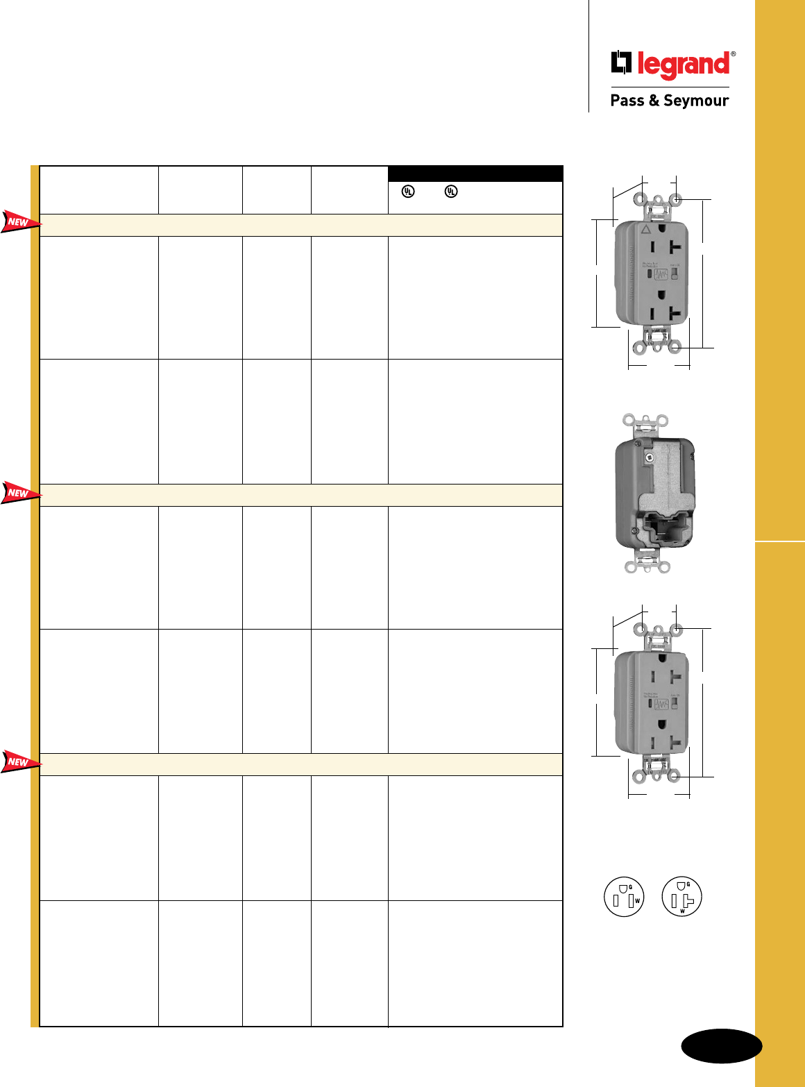
B-65
Straight Blade Receptacles PlugTail™ Surge Protective Receptacles
Straight Blade Receptacles
PlugTail™ Surge Protective Receptacles
2 Pole, 3 Wire Grounding, 15 & 20A, 125VAC
3rd Party Compliance
3rd Party Compliance
FSUL
UL1449 UL498 WC596 cUL/CSA
Rating NEMA
Catalog Number A. VAC Cong. No. Color
Extra Heavy-Duty Duplex Receptacles
PT5262ISP 15 125 5-15R Ivory • • • •
PT5262WSP 15 125 5-15R White • • • •
PT5262SP 15 125 5-15R Brown • • • •
PT5262GRYSP 15 125 5-15R Gray • • • •
PT5262BKSP 15 125 5-15R Black • • • •
PT5262REDSP 15 125 5-15R Red • • • •
PT5262LASP 15 125 5-15R LightAlmond • • • •
PT5262BLSP 15 125 5-15R Blue • • • •
PT5362ISP 20 125 5-20R Ivory • • • •
PT5362WSP 20 125 5-20R White • • • •
PT5362SP 20 125 5-20R Brown • • • •
PT5362GRYSP 20 125 5-20R Gray • • • •
PT5362BKSP 20 125 5-20R Black • • • •
PT5362REDSP 20 125 5-20R Red • • • •
PT5362LASP 20 125 5-20R LightAlmond • • • •
PT5362BLSP 20 125 5-20R Blue • • • •
Isolated Ground Duplex Receptacles
PTIG5262ISP 15 125 5-15R Ivory • • • •
PTIG5262WSP 15 125 5-15R White • • • •
PTIG5262GRYSP 15 125 5-15R Gray • • • •
PTIG5262BKSP 15 125 5-15R Black • • • •
PTIG5262REDSP 15 125 5-15R Red • • • •
PTIG5262LASP 15 125 5-15R LightAlmond • • • •
PTIG5262OSP 15 125 5-15R Orange • • • •
PTIG5262BLSP 15 125 5-15R Blue • • • •
PTIG5362ISP 20 125 5-20R Ivory • • • •
PTIG5362WSP 20 125 5-20R White • • • •
PTIG5362GRYSP 20 125 5-20R Gray • • • •
PTIG5362BKSP 20 125 5-20R Black • • • •
PTIG5362REDSP 20 125 5-20R Red • • • •
PTIG5362LASP 20 125 5-20R LightAlmond • • • •
PTIG5362OSP 20 125 5-20R Orange • • • •
PTIG5362BLSP 20 125 5-20R Blue • • • •
Tamper-Resistant Duplex Receptacles
PTTR5262ISP 15 125 5-15R Ivory • • • •
PTTR5262WSP 15 125 5-15R White • • • •
PTTR5262SP 15 125 5-15R Brown • • • •
PTTR5262GRYSP 15 125 5-15R Gray • • • •
PTTR5262BKSP 15 125 5-15R Black • • • •
PTTR5262REDSP 15 125 5-15R Red • • • •
PTTR5262LASP 15 125 5-15R LightAlmond • • • •
PTTR5262BLSP 15 125 5-15R Blue • • • •
PTTR5362ISP 20 125 5-20R Ivory • • • •
PTTR5362WSP 20 125 5-20R White • • • •
PTTR5362SP 20 125 5-20R Brown • • • •
PTTR5362GRYSP 20 125 5-20R Gray • • • •
PTTR5362BKSP 20 125 5-20R Black • • • •
PTTR5362REDSP 20 125 5-20R Red • • • •
PTTR5362LASP 20 125 5-20R LightAlmond • • • •
PTTR5362BLSP 20 125 5-20R Blue • • • •
Audible Alarm with LED Indicator
NEMA
5-20R
NEMA
5-15R
PTIG5362GRYSP
3.75"
1.70"
.875"
1.20"
BehindStrap
2.75"
PTTR5362GRYSP
3.75"
1.70"
.875"
1.40"
BehindStrap
2.75"
Alldeviceslistedonthispage
conformtoNEMAWD-1,WD-6.
Conformstothelatestrevision
ANSI/IEEEC62.41(formerly
IEEE587),ANSI/IEEEC62.45.
For PlugTail Connectors,
see Page B-3.
Available Spring 2011
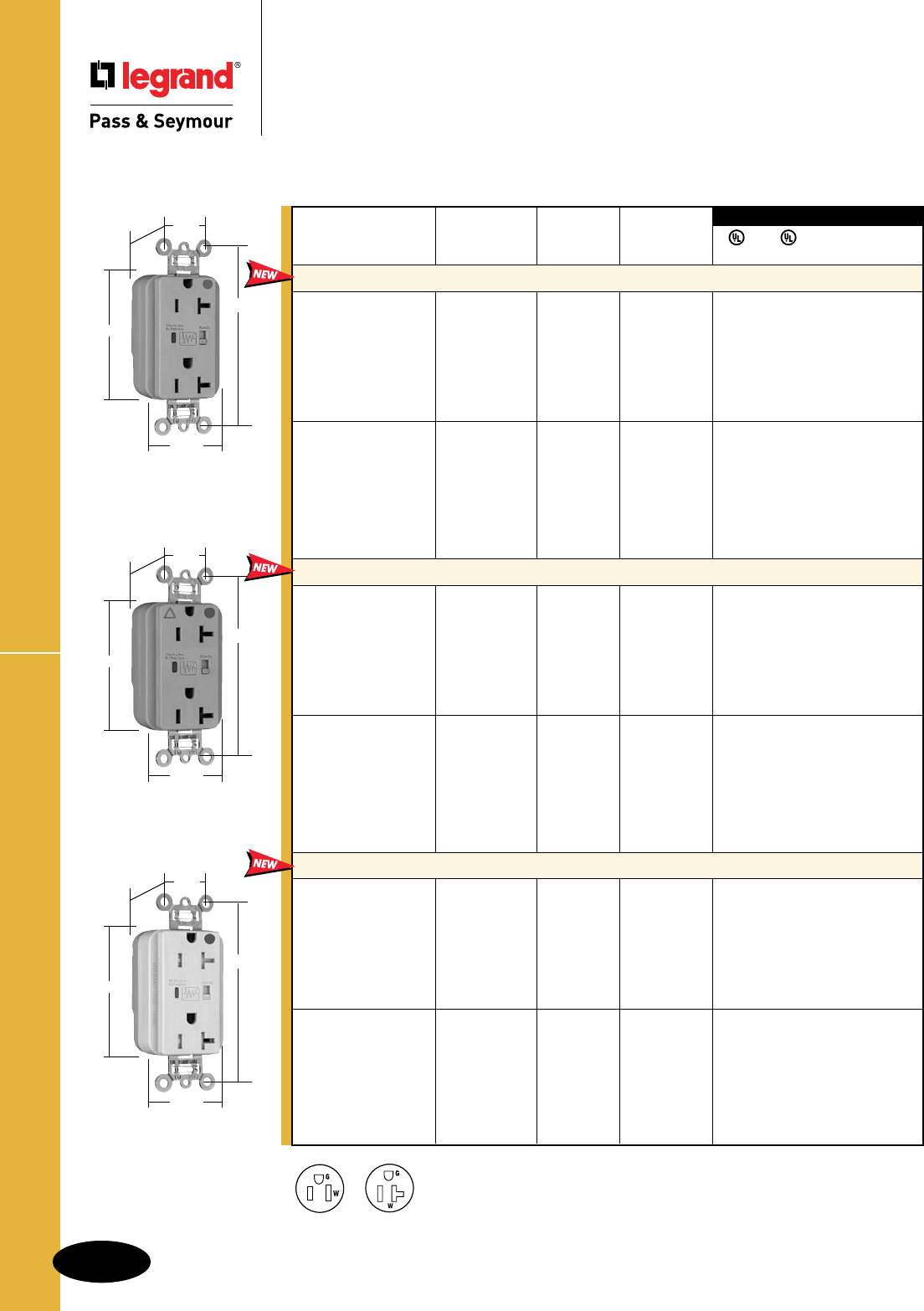
B-66
Straight Blade Receptacles
PlugTail™ HG Surge Protective Receptacles
Straight Blade Receptacles
PlugTail™ Hospital Grade
Surge Protective Receptacles
2 Pole, 3 Wire Grounding, 15 & 20A, 125VAC
AlldeviceslistedonthispageconformtoNEMAWD-1andWD-6.
ConformstothelatestrevisionANSI/IEEEC62.41(formerlyIEEE587),ANSI/IEEEC62.45.
Available Spring 2011
NEMA
5-20R
NEMA
5-15R
3rd Party Compliance
3rd Party Compliance
FSUL
UL1449 UL498 WC596 cUL/CSA
Rating NEMA
Catalog Number A. VAC Cong. No. Color
Extra Heavy-Duty Duplex Receptacles
PT8200ISP 15 125 5-15R Ivory • • • •
PT8200WSP 15 125 5-15R White • • • •
PT8200SP 15 125 5-15R Brown • • • •
PT8200GRYSP 15 125 5-15R Gray • • • •
PT8200REDSP 15 125 5-15R Red • • • •
PT8200LASP 15 125 5-15R LightAlmond • • • •
PT8200BLSP 15 125 5-15R Blue • • • •
PT8300ISP 20 125 5-20R Ivory • • • •
PT8300WSP 20 125 5-20R White • • • •
PT8300SP 20 125 5-20R Brown • • • •
PT8300GRYSP 20 125 5-20R Gray • • • •
PT8300REDSP 20 125 5-20R Red • • • •
PT8300LASP 20 125 5-20R LightAlmond • • • •
PT8300BLSP 20 125 5-20R Blue • • • •
Isolated Ground Duplex Receptacles
PTIG8200ISP 15 125 5-15R Ivory • • • •
PTIG8200WSP 15 125 5-15R White • • • •
PTIG8200GRYSP 15 125 5-15R Gray • • • •
PTIG8200REDSP 15 125 5-15R Red • • • •
PTIG8200LASP 15 125 5-15R LightAlmond • • • •
PTIG8200BLSP 15 125 5-15R Blue • • • •
PTIG8200OSP 15 125 5-15R Orange • • • •
PTIG8300ISP 20 125 5-20R Ivory • • • •
PTIG8300WSP 20 125 5-20R White • • • •
PTIG8300GRYSP 20 125 5-20R Gray • • • •
PTIG8300REDSP 20 125 5-20R Red • • • •
PTIG8300LASP 20 125 5-20R LightAlmond • • • •
PTIG8300BLSP 20 125 5-20R Blue • • • •
PTIG8300OSP 20 125 5-20R Orange • • • •
Tamper-Resistant Duplex Receptacles
PTTR8200ISP 15 125 5-15R Ivory • • • •
PTTR8200WSP 15 125 5-15R White • • • •
PTTR8200SP 15 125 5-15R Brown • • • •
PTTR8200GRYSP 15 125 5-15R Gray • • • •
PTTR8200REDSP 15 125 5-15R Red • • • •
PTTR8200LASP 15 125 5-15R LightAlmond • • • •
PTTR8200BLSP 15 125 5-15R Blue • • • •
PTTR8300ISP 20 125 5-20R Ivory • • • •
PTTR8300WSP 20 125 5-20R White • • • •
PTTR8300SP 20 125 5-20R Brown • • • •
PTTR8300GRYSP 20 125 5-20R Gray • • • •
PTTR8300REDSP 20 125 5-20R Red • • • •
PTTR8300LASP 20 125 5-20R LightAlmond • • • •
PTTR8300BLSP 20 125 5-20R Blue • • • •
Audible Alarm with LED Indicator
PT8300GRYSP
3.75"
1.70"
.875"
1.20"
BehindStrap
2.75"
PTIG8300GRYSP
3.75"
1.70"
.875"
1.20"
BehindStrap
2.75"
PTTR8300ISP
3.75"
1.70"
.875"
1.40"
BehindStrap
2.75"
For PlugTail Connectors,
see Page B-3.
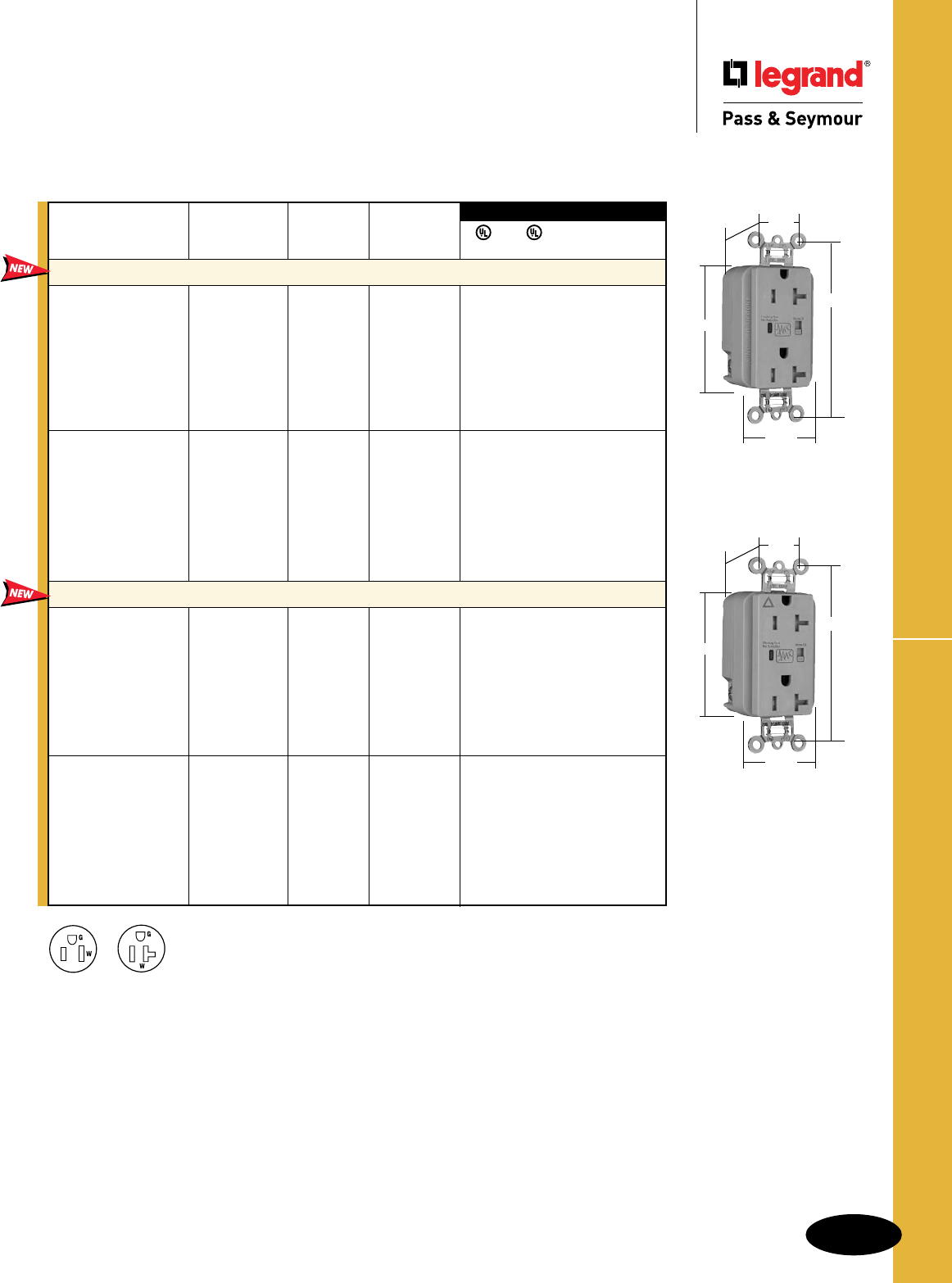
B-67
Straight Blade Receptacles TR Surge Protective Receptacles
Straight Blade Receptacles
Tamper-Resistant
Surge Protective Receptacles
2 Pole, 3 Wire Grounding, 15 & 20A, 125VAC
AlldeviceslistedonthispageconformtoNEMAWD-1andWD-6.
ConformstothelatestrevisionANSI/IEEEC62.41(formerlyIEEE587),ANSI/IEEEC62.45.
3rd Party Compliance
3rd Party Compliance
FSUL
UL1449 UL498 WC596 cUL/CSA
Rating NEMA
Catalog Number A. VAC Cong. No. Color
Extra Heavy-Duty Duplex Receptacles Back & Side Wire
TR5262ISP 15 125 5-15R Ivory • • • •
TR5262WSP 15 125 5-15R White • • • •
TR5262SP 15 125 5-15R Brown • • • •
TR5262GRYSP 15 125 5-15R Gray • • • •
TR5262BKSP 15 125 5-15R Black • • • •
TR5262REDSP 15 125 5-15R Red • • • •
TR5262LASP 15 125 5-15R LightAlmond • • • •
TR5262BLSP 15 125 5-15R Blue • • • •
TR5362ISP 20 125 5-20R Ivory • • • •
TR5362WSP 20 125 5-20R White • • • •
TR5362SP 20 125 5-20R Brown • • • •
TR5362GRYSP 20 125 5-20R Gray • • • •
TR5362BKSP 20 125 5-20R Black • • • •
TR5362REDSP 20 125 5-20R Red • • • •
TR5362LASP 20 125 5-20R LightAlmond • • • •
TR5362BLSP 20 125 5-20R Blue • • • •
Isolated Ground Duplex Receptacles Back & Side Wire
TRIG5262ISP 15 125 5-15R Ivory • • • •
TRIG5262WSP 15 125 5-15R White • • • •
TRIG5262GRYSP 15 125 5-15R Gray • • • •
TRIG5262BKSP 15 125 5-15R Black • • • •
TRIG5262REDSP 15 125 5-15R Red • • • •
TRIG5262LASP 15 125 5-15R LightAlmond • • • •
TRIG5262BLSP 15 125 5-15R Blue • • • •
TRIG5262OSP 15 125 5-15R Orange • • • •
TRIG5362ISP 20 125 5-20R Ivory • • • •
TRIG5362WSP 20 125 5-20R White • • • •
TRIG5362GRYSP 20 125 5-20R Gray • • • •
TRIG5362BKSP 20 125 5-20R Black • • • •
TRIG5362REDSP 20 125 5-20R Red • • • •
TRIG5362LASP 20 125 5-20R LightAlmond • • • •
TRIG5362BLSP 20 125 5-20R Blue • • • •
TRIG5362OSP 20 125 5-20R Orange • • • •
Audible Alarm with LED Indicator
Available Spring 2011
NEMA
5-20R
NEMA
5-15R
TR5362GRYSP
TRIG5362GRYSP
3.75"
1.70"
.875"
2.75"
1.40"
BehindStrap
3.75"
1.70"
.875"
2.75"
1.40"
BehindStrap
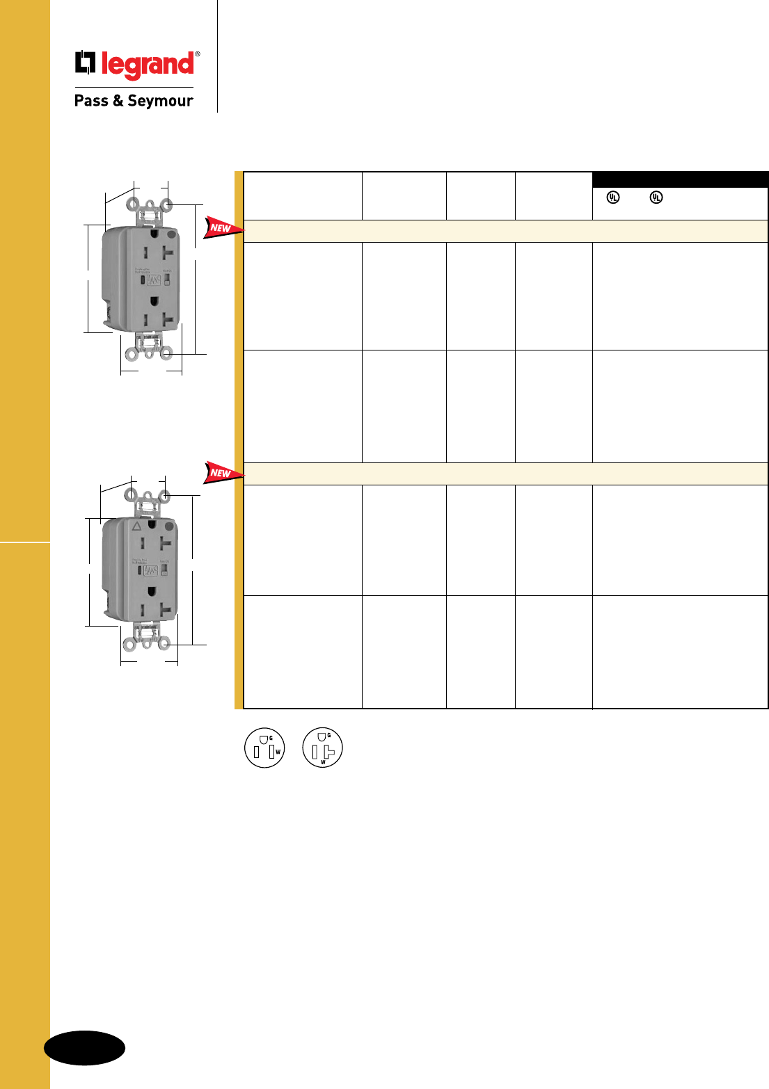
B-68
Straight Blade Receptacles
Straight Blade Receptacles
Tamper-Resistant Hospital Grade
Surge Protective Receptacles
2 Pole, 3 Wire Grounding, 15 & 20A, 125VAC
TR HG Surge Protective Receptacles
TR8300GRYSP
3.75"
1.70"
.875"
1.40"
BehindStrap
2.75"
TRIG8300GRYSP
3.75"
1.70"
.875"
1.40"
BehindStrap
2.75"
3rd Party Compliance
3rd Party Compliance
FSUL
UL1449 UL498 WC596 cUL/CSA
Rating NEMA
Catalog Number A. VAC Cong. No. Color
Extra Heavy-Duty Duplex Receptacles Back & Side Wire
TR8200ISP 15 125 5-15R Ivory • • • •
TR8200WSP 15 125 5-15R White • • • •
TR8200SP 15 125 5-15R Brown • • • •
TR8200GRYSP 15 125 5-15R Gray • • • •
TR8200REDSP 15 125 5-15R Red • • • •
TR8200LASP 15 125 5-15R LightAlmond • • • •
TR8200BLSP 15 125 5-15R Blue • • • •
TR8300ISP 20 125 5-20R Ivory • • • •
TR8300WSP 20 125 5-20R White • • • •
TR8300SP 20 125 5-20R Brown • • • •
TR8300GRYSP 20 125 5-20R Gray • • • •
TR8300REDSP 20 125 5-20R Red • • • •
TR8300LASP 20 125 5-20R LightAlmond • • • •
TR8300BLSP 20 125 5-20R Blue • • • •
Isolated Ground Duplex Receptacles Back & Side Wire
TRIG8200ISP 15 125 5-15R Ivory • • • •
TRIG8200WSP 15 125 5-15R White • • • •
TRIG8200GRYSP 15 125 5-15R Gray • • • •
TRIG8200REDSP 15 125 5-15R Red • • • •
TRIG8200LASP 15 125 5-15R LightAlmond • • • •
TRIG8200BLSP 15 125 5-15R Blue • • • •
TRIG8200OSP 15 125 5-15R Orange • • • •
TRIG8300ISP 20 125 5-20R Ivory • • • •
TRIG8300WSP 20 125 5-20R White • • • •
TRIG8300GRYSP 20 125 5-20R Gray • • • •
TRIG8300REDSP 20 125 5-20R Red • • • •
TRIG8300LASP 20 125 5-20R LightAlmond • • • •
TRIG8300BLSP 20 125 5-20R Blue • • • •
TRIG8300OSP 20 125 5-20R Orange • • • •
Audible Alarm with LED Indicator
Available Spring 2011
NEMA
5-20R
NEMA
5-15R
AlldeviceslistedonthispageconformtoNEMAWD-1andWD-6.
ConformstothelatestrevisionANSI/IEEEC62.41(formerlyIEEE587),ANSI/IEEEC62.45.
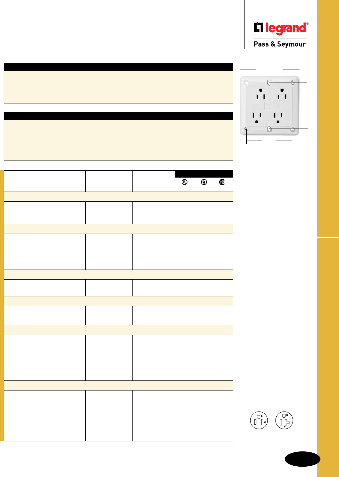
B-69
Straight Blade Receptacles
AlldeviceslistedonthispageconformtoNEMAWD-1andWD-6.
Quad Receptacles & Accessories
Straight Blade Receptacles
Quad Receptacles & Accessories
15 & 20A, 125V
Rating NEMA
Catalog Number A. V. Color Cong. No.
Hospital Grade Isolated Ground Surge Protective Quads
IG420HISP 20 125 Ivory 5-20R ••
IG420HGRYSP 20 125 Gray 5-20R ••
IG420HBLSP 20 125 Blue 5-20R ••
Hospital Grade Quads
420HI 20 125 Ivory 5-20R • •
420HW 20 125 White 5-20R • •
420H 20 125 Brown 5-20R • •
420HGRY 20 125 Gray 5-20R • •
420HRED 20 125 Red 5-20R • •
Specification Grade Surge Protective Quads
420ISP 20 125 Ivory 5-20R ••
420BLSP 20 125 Blue 5-20R ••
Specification Isolated Grade Quads
IG415 15 125 Orange 5-15R • •
IG420 20 125 Orange 5-20R • •
Specification Grade Quads
415I 15 125 Ivory 5-15R • •
415W 15 125 White 5-15R • •
415GRY 15 125 Gray 5-15R • •
420I 20 125 Ivory 5-20R • •
420W 20 125 White 5-20R • •
420GRY 20 125 Gray 5-20R • •
Quad Adapter Plates
4API Ivory ••
4APW White ••
4AP Brown ••
4APGRY Gray ••
4APRED Red ••
4APBL Blue ••
4APORG Orange ••
3rd Party Compliance
UL498 UL1449 CSA
Application
Legrand/Pass&Seymour’squadreceptaclesaredesignedfordense,multiple-outletapplications
suchaspersonalcomputersandperipherals,officeequipment,andhomeentertainmentcenters.The
bidirectionaloutletconfigurationallowsuseofuptofouroversizedplugs,incloseproximity.Theclean,
contemporarydesignofthequadreceptacleallowsforsurfacemountingwithminimalprotrusionfrom
thewall.Nowallplateisrequired.
Features
nRuggednylonfaceandbodywithstandsimpacts
andharduse.
nBuilt-inwirestrippinggauge.
nOutward-facinggroundterminalsmakehandling
uptofourstraightorangledplugseasyand
convenient.
nHeavy-duty,phosphorbronzecontacts.
nShieldingwallsguardagainstlive-circuit-to-
groundshorts.
nSplitcircuitbreak-offtabs.
nULandCSAlisted. Quad Receptacle
3.38"
4.50"square
3.38"
NEMA
5-15R
NEMA
5-20R
2Pole,3Wire
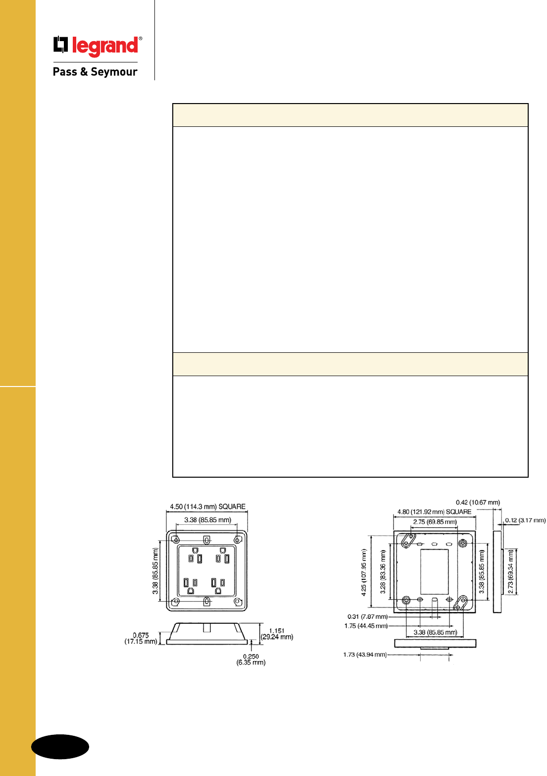
B-70
Straight Blade Receptacles
AlldeviceslistedonthispageconformtoNEMAWD-1andWD-6.
Quad Receptacles Specifications
Straight Blade Receptacles
Quad Receptacles Specifications
Quad Receptacle Adapter Plate
Hard Use Spec Grade & Hard Use Surge Protective Spec Grade
Quads
•IsolatedgroundcompliedwithNEC®410-56(c)and250-74exception4
•ConformstoNEMAWD-1,WD-6.
Electrical
Frequency 60Hz
Voltage 125V
Mechanical
TerminalIdentification Brass=Hot,Nickel=Neutral,Green=Ground
TerminalAccommodation #14–12AWGcopperandcopper-clad
ProductIdentification Ratingsarepermanentpartofdevice
Weight 10.75oz.
Environmental
Flammability UL94V2
OperatingTemperature -40°Cto65°C(-40°Fto150°F)continuouswithoutimpact
Materials
Face Nylon
Body Nylon
LineTerminals .035"T-typeTriple-WipePhosphorBronze
TerminalScrews Brass#8-32
HexHeadGroundingScrew Steel(Green)
MountingScrews Zinc-platedsteel
Additional Specifications for Hard Use Surge Protective Spec
Grade Quads
•ANSI/IEEEC62.41(formerlyIEEE587),ANSI/IEEEC62.45
•InstallationCategories“A
”
(ringwave)and“B
”
(unidirectionalimpulse)
Electrical
MOVRating 18mm
UL1449SuppressedVoltageRating 500V(L-N,L-G,N-G)
NoiseAttenuation -35dbNoiseFilteringat5kHz-50MHz
ThermalProtection Fused
GreenLEDIndicator ONwhenprotectionisactive,
OFFwhenprotectionisinactive
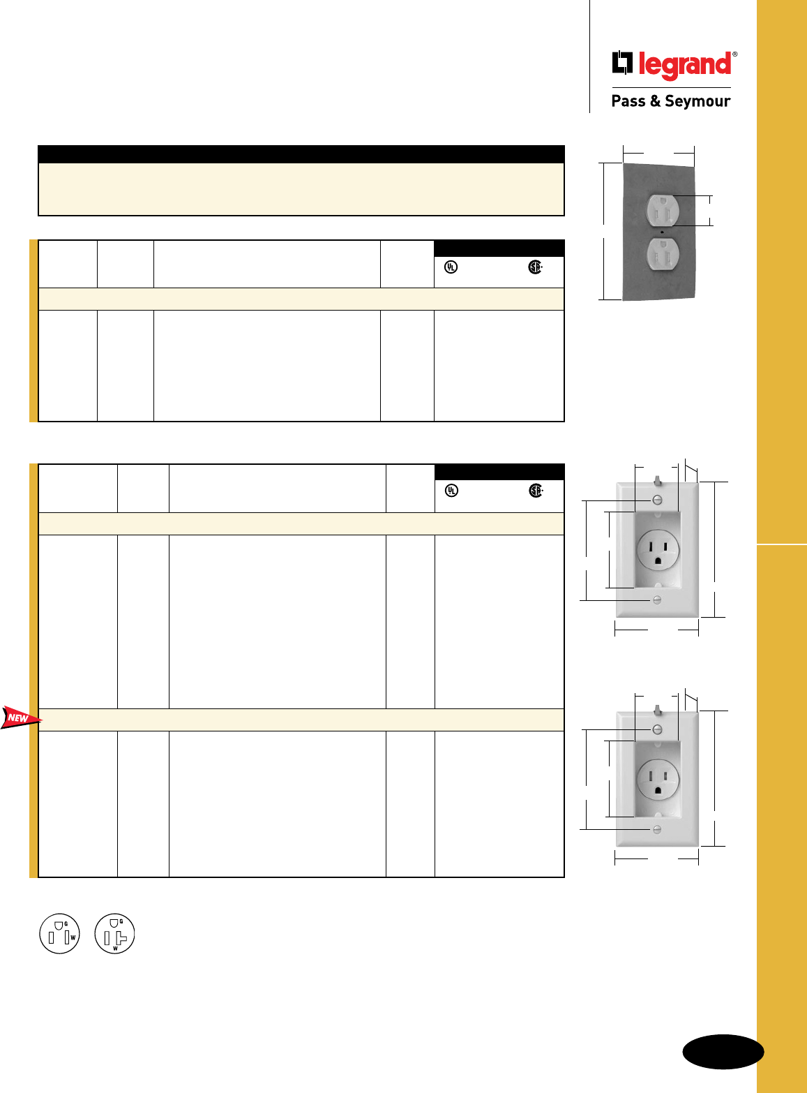
B-71
Straight Blade Receptacles
AlldeviceslistedonthispageconformtoNEMAWD-1andWD-6.
Dust & Moisture Resistant & Clock Hanger
Straight Blade Receptacles
Dust & Moisture Resistant &
Clock Hanger Receptacles
15 & 20A, 125V
3rd Party Compliance
FSUL
UL498 WC596 C22.2 No. 42
NEMA
Catalog Rating Cong.
Number A. V. Description No.
Dust & Moisture Resistant
6207 15 125 Duplex,DustandMoistureResistant,Gray 5-15R •••
CR6207 15 125 Duplex,Corrosion,DustandMoisture 5-15R •••
Resistant,Yellow
6307 20 125 Duplex,DustandMoistureResistant,Gray 5-20R ••
6307RED 20 125 Duplex,DustandMoistureResistant,Red 5-20R ••
CR6307 20 125 Duplex,Corrosion,DustandMoisture 5-20R ••
Resistant,Yellow
S3713I
1.471"
4.478"
2.473"
3.256"
2.740"
1.878"
Behind
6207
shown with neoprene
sealing mat
1.104"
4.865"
2.985"
Features – Dust & Moisture Resistant
nDuplexreceptaclehasfacebackedbyneoprene
gasketwhichisslittoprovidewipingactiononplug
bladesandtoprovidepositiveclosurewhennotinuse.
nCellularneoprenesealingmatfitsunder
wallplate.
NEMA
5-15R
NEMA
5-20R
2Pole,3Wire
3rd Party Compliance
FSUL
UL498 WC596 C22.2 No. 42
NEMA
Catalog Rating Cong.
Number A. V. Description No.
Clock Hangers
S3713I 15 125 RecessedReceptaclewithIvory 5-15R• • •
SmoothWallPlate
S3713W 15 125 RecessedReceptaclewithWhite 5-15R• • •
SmoothWallPlate
S3713BK 15 125 RecessedReceptaclewithBlack 5-15R• • •
SmoothWallPlate
S3713LA 15 125 RecessedReceptaclewithLightAlmond 5-15R• • •
SmoothWallPlate
S3733SS 15 125 RecessedReceptaclewithStainlessSteel 5-15R• • •
WallPlate
S3733 15 125 RecessedReceptaclewithBrass
WallPlate 5-15R • • •
Tamper-Resistant Clock Hangers Back & Side Wire
S3713TRI 15 125 RecessedReceptaclewithIvory 5-15R• • •
SmoothWallPlate
S3713TRW 15 125 RecessedReceptaclewithWhite 5-15R• • •
SmoothWallPlate
S3713TRGRY 15 125 RecessedReceptaclewithGray 5-15R• • •
SmoothWallPlate
S3713TRBK 15 125 RecessedReceptaclewithBlack 5-15R• • •
SmoothWallPlate
S3713TRLA 15 125 RecessedReceptaclewithLightAlmond 5-15R• • •
SmoothWallPlate
S3713TRI
1.471"
4.478"
2.473"
3.256"
2.740"
1.878"
Behind
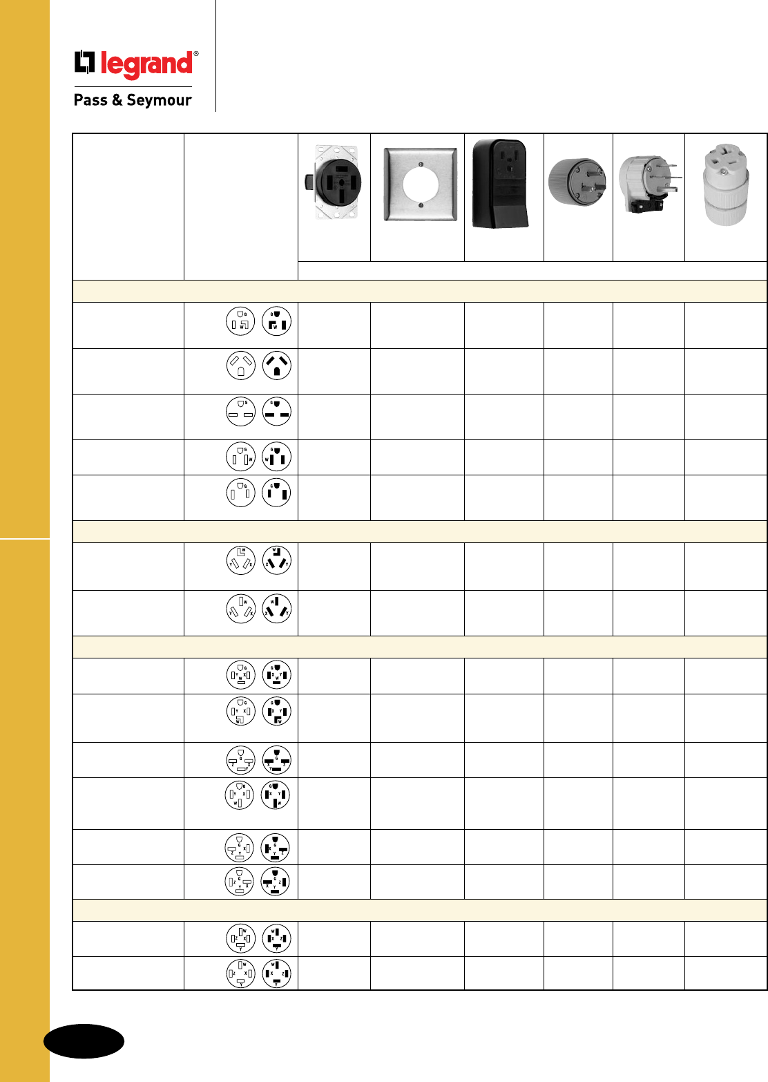
B-72
Straight Blade Receptacles
AlldeviceslistedonthispageconformtoNEMAWD-1andWD-6.
Power Outlet Receptacles & Plugs
Straight Blade Receptacles
Power Outlet Receptacles & Plugs
20, 30, 50, & 60A
‡ In bulk pack of 40 with plastic snap-in wire clamp. §Upto#3AWGaluminumconductors. #Upto#4AWGaluminumconductors.
ForfurtherinformationconsultWallPlateSectionQ(forStainlessSteelversionsofTP724andTP703,refertoPagesQ-13andQ-14).
†NAFTA-Compliant Receptacles are ideal for use on projects subject to the provisions of the Buy American Act.
Receptacle/Plug Flush Wall Plate Surface Plug Angle Plug Connector
Rating Conguration Receptacle
*For2screwmounting
Receptacle
A. V. & NEMA No.
**For4screwmounting
Catalog Nos.
2 Pole, 3 Wire Grounding
30 125 5-30 3802§ 1-Gang:TP724* D0531 D0533
AL/CU 2-Gang:SS702* .57"-1.26" .57"-1.26"
2-Gang:TP703**
30 125 NEMA 3830 1-Gang:TP724*
TT30 AL/CU 2-Gang:SS702*
Forrecreationalvehicles. 2-Gang:TP703**
30 250 6-30 3801 1-Gang:TP724* D0631 D0633
AL/CU 2-Gang:SS702* .57"-1.26" 3869 .57"-1.26"
2-Gang:TP703**
50 125 5-50 D0551 D0553
.57"-1.26" .57"-1.26"
50 250 6-50 3804§ 1-Gang:TP724*3852#D06513869 D0653
AL/CU 2-Gang:SS702* AL/CU .57"-1.26" .57"-1.26"
2-Gang:TP703**
3 Pole, 3 Wire Non-Grounding
30 125/250 10-30 3860 1-Gang:TP724*38810313861
Dryer AL/CU 2-Gang:SS702* AL/CU
2-Gang:TP703**
50 125/250 10-50 3890§ 1-Gang:TP724*38510513861 1053
Range AL/CU 2-Gang:SS702* AL/CU .57"-1.26" .32"-.91"
2-Gang:TP703**
3 Pole, 4 Wire Grounding
20 125/250 14-20 3820 1-Gang:SS7*
30 125/250 14-30 3864 2-Gang:SS702*3884#/388440‡14315746AN
Dryer AL/CU 2-Gang:TP703** AL/CU .57"-1.26" 3867
3864NA† 3884NA†
30 3ø,250 15-30 5740 2-Gang:SS702* 5741AN
AL/CU 2-Gang:TP703**
50 125/250 14-50 3894§ 2-Gang:SS702*3854#/385440‡14515745AN
Range AL/CU 2-Gang:TP703** AL/CU .57"-1.26" 3867
3894NA† 3854NA†
50 3ø,250 15-50 5750 2-Gang:SS702* 5751AN
AL/CU 2-Gang:TP703**
60 3ø,250 15-60 5760 2-Gang:SS702* 5761AN
AL/CU 2-Gang:TP703**
4 Pole, 4 Wire Non-Grounding
20 3øY,120/208 18-20 3822 1-Gang:SS7* 7251DF
.35"-1.05"
60 3øY,120/208 18-60 3870§ 2-Gang:SS701** D18618302AN
AL/CU .57"-1.26"
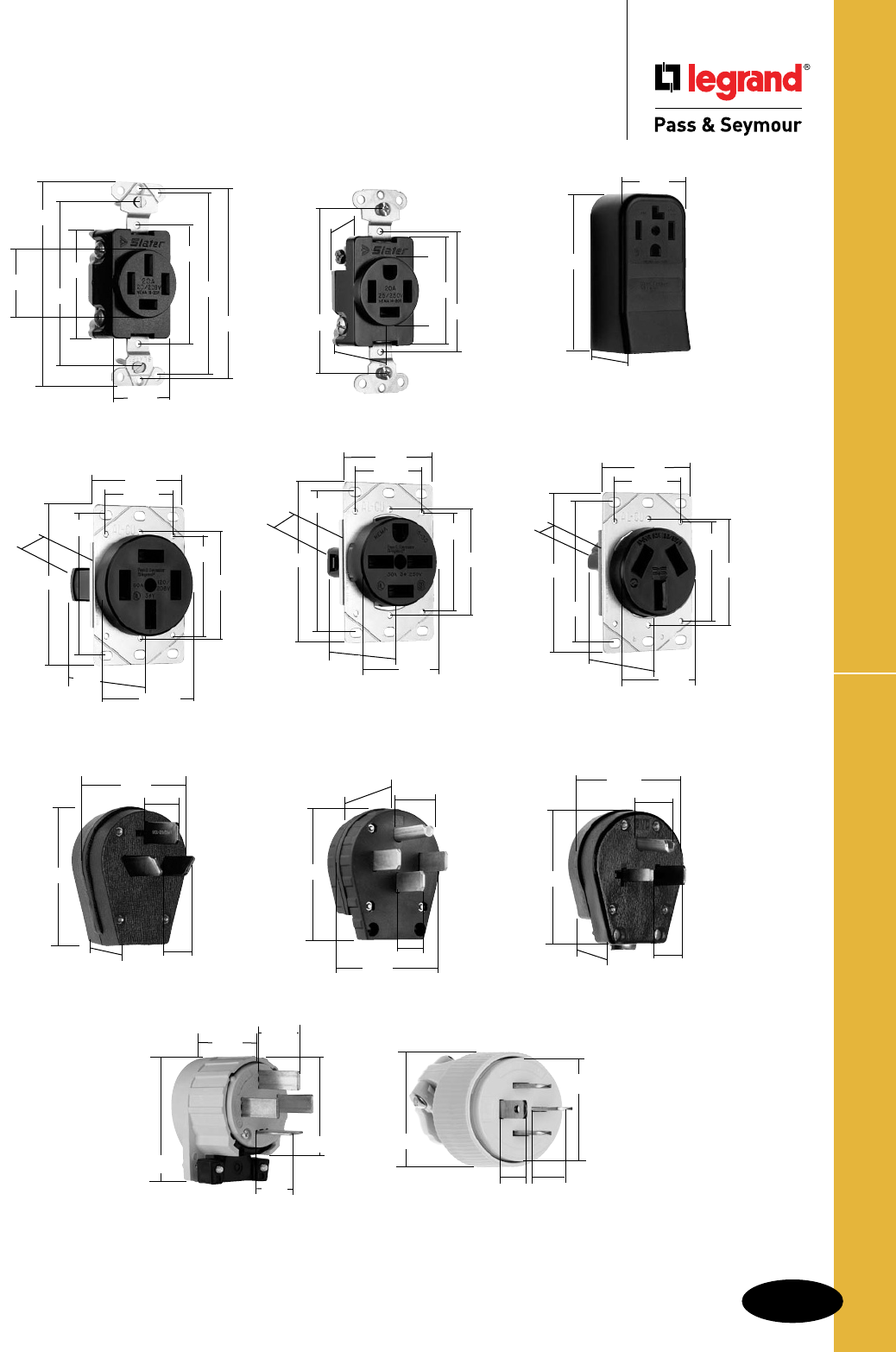
B-73
Straight Blade Receptacles
AlldeviceslistedonthispageconformtoNEMAWD-1andWD-6.
Power Outlet Receptacles & Plugs
Straight Blade Receptacles
Power Outlet Receptacles & Plugs
20, 30, 50, & 60A
2.80"
5.65"
385 3854
388 3884
3852
2.41"
3820
1.018"
2.20"
1.23"
3.281"
1.380"
2.37"
5741AN 5751AN
5745AN 5761AN
5746AN 8302AN
3861
2.77"
1.30"
1.36"
3.3"
1.22"
3869
2.86"
1.40"
3.43"
1.30"
1.22"
3822
3.28"
4.06"
2.37"
3.685"
3.812"
1.40"
2.2"
1.38"
3870
2.20"
1.81"
2.49"
2.50"
3.75"
3.29"
2.375"
2.37"
1.70"
2.20"
1.81"
2.49"
2.50"
3.75"
3.29"
2.10"
2.37"
1.70"
3801 3802
3804 3864
3894 5740
5750 5760
1.90"
1.81"
2.49"
2.50"
3.75"
2.10"
2.37"
1.30"
3830
3860
3890
3.29"
7251DF
.875"
Max.
.687"
Min.
1.77"
2.03"
3867
2.77"
1.388"
1.36"
3.43"
1.22"
1.22"
2.12"
2.62"
3.43"
1.388"
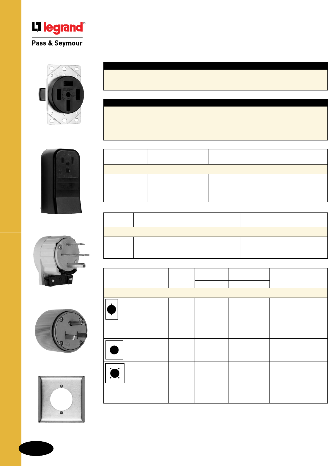
B-74
Straight Blade Receptacles
AlldeviceslistedonthispageconformtoNEMAWD-1andWD-6.
Power Outlet Receptacles & Plugs
Straight Blade Receptacles
Power Outlet Receptacles & Plugs
20, 30, 50 & 60A
Angle Plug
Application
Powerdevicesareforuseinindustrial,institutional,commercial,andcertainresidentialapplicationsto
providehigheramperagepowertoequipmentsuchasairconditioners,copiers,smallwelders,ranges,
anddryers.
Ampere With Non-Metallic With Conduit
Rating Sheathed Cable
Recommended Box Sizes for Flush Receptacles
30A 4"sq.x2-1/8"deep 4-11/16"sq.x2-1/8"deep
50A 4-11/16"sq.x2-1/8"deep 2-gdeepbox(4"sq.x2-1/2"deep)
60A 4-11/16"sq.x2-1/8"deepwith1/2"raisedring 2-gdeepbox(4"sq.x2-1/2"deep)
Flush Receptacle
Surface Receptacle
Plug
Wall Plate
New Installations require 4 wire range and dryer outlets.
Ref:2002NEC250-134,250-138
Existing Installations permitted to use 3 wire range and dryer outlets.
Ref:2002NEC250-140
Receptacle AWG Size Material
Amp. Rating
Conductor Size & Material for Power Outlet Receptacles
20A #14–#10 Copper/Copper-clad
30A #10–#6 Copper/Copper-clad/Aluminum
50A #10–#6 Copper/Copper-clad/Aluminum
60A #8–#4 Copper/Copper-clad/Aluminum
Features
n
Flushreceptaclebodiesaremoldedof
arc-resistantplastic.
nAlldevicesareofdeadfrontdesign.
n
Receptacleshavedouble-wipecontactsofhigh
performancecopper-basedalloy.
n
Recommendedstainlesssteelwallplates
arelistedwitheachflushreceptacle.
nULListedforusewithaluminumwiring.
Wall Plates Recommended
Nylon Metal
for the Following Flush
Description Color TradeMaster® Material
Receptacles
Accessories – Flush Receptacle Wall Plates
•2.156"holefor Ivory TP724I
2Pole,3WireGrounded
2.125"dia.device White TP724W
3801 3804
•2mtg.holes Brown TP724 ChromeS384C
3802 3830
Gray TP724GRY
Black TP724BK
Light
Almond TP724LA 302S/S SS724
•2-5/32"holefor
3Pole,3WireUngrounded
2-1/8"dia.device 302S/SSS702
3860
•2mtg.holes
3860
•2.1563"holefor Ivory TP703I
3Pole,4WireUngrounded
2.125"dia.device White TP703W Chrome S3862C 3864 5740
•4mtg.holes Brown TP703302S/SSS703 3894 5750
Gray TP703GRY 5760
Black TP703BK
Light
Almond TP703LA
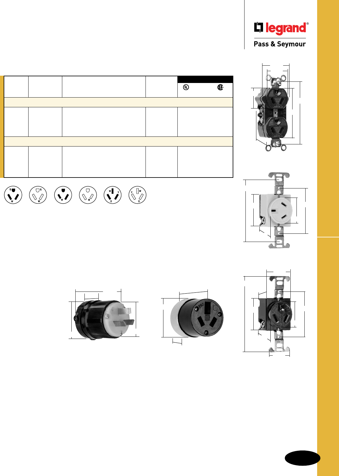
B-75
Straight Blade Receptacles
AlldeviceslistedonthispageconformtoNEMAWD-1andWD-6.
Miscellaneous Configurations
Straight Blade Receptacles
Miscellaneous Configurations
NEMA
10-20R
NEMA
7-15R
NEMA
7-20R
NEMA
7-15P
NEMA
10-20P
NEMA
7-20P
7088
1.859"
1.953"
.676"
5762
1.104"
.813"
2.635"
3.281"
1.656"
1.322"
6810I
1.750" 2.370"
3.280"
1.380"
1.150"
Straight Blade Receptacles, 3 Wire, Specification Grade
NEMA
Catalog Rating Cong.
Number A. V. Description No.
2 Pole, 3 Wire Grounding
5762 15 277 DuplexReceptacle,Self-Grounding 7-15R •
PS5766X 15 277 Plug,Yellow 7-15P • •
7621 20 277 SingleReceptacle 7-20R •
PS5866X 20 277 Plug,Yellow 7-20P
3 Pole, 3 Wire Non-Grounding
6810I 20 125/250 Receptacle,Ivory 10-20R •
6810 20 125/250 Receptacle,Black 10-20R •
9977 20 125/250 Plug,Nylon 10-20P
7088 20 125/250 Connector,Armored 10-20R
3rd Party Compliance
FSUL
UL498 WC596 C22.2 No. 42
7621
1.740" 2.375"
4.031"
1.375"
1.144"
1.437"
.866"
1.555"
9977
1.781"
.531"
2.063"
2.156"
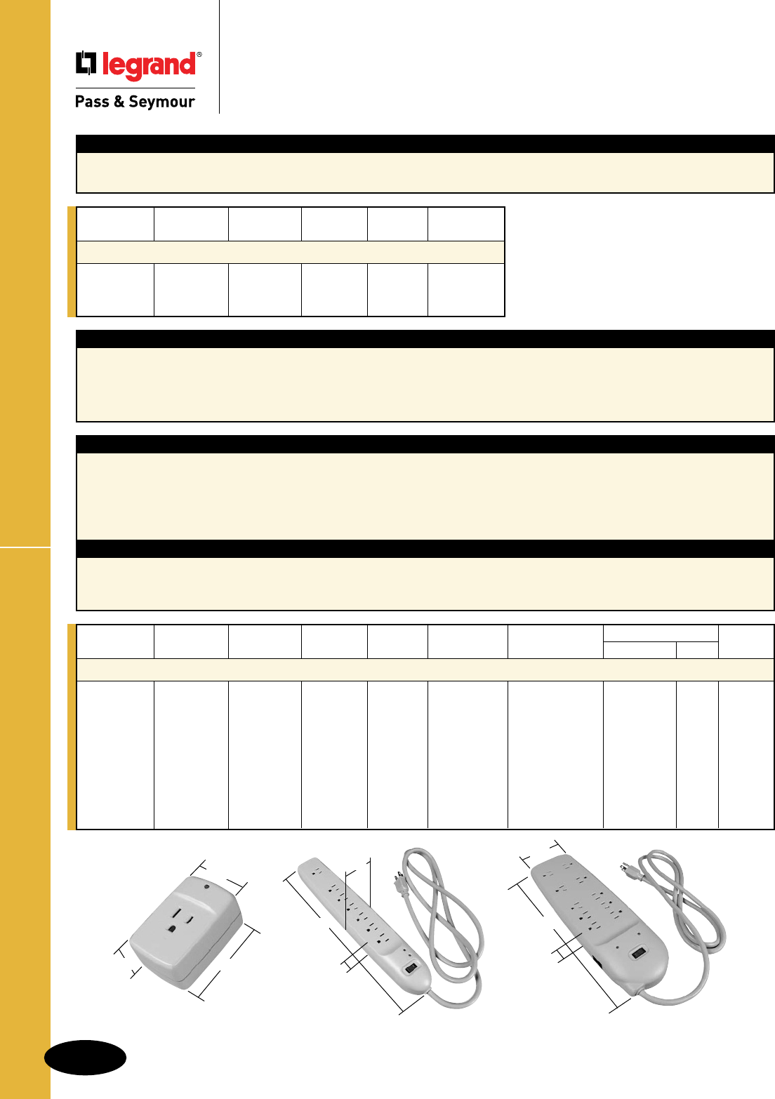
B-76
Straight Blade Receptacles
AlldeviceslistedonthispageconformtoNEMAWD-1andWD-6.
Power & Surge Protection Strips
Straight Blade Receptacles
Power & Surge Protection Strips
TAP – PS1
1.9375"
2.875"
1.25"
STRIP – PNS7L
1.25"
14.0"
2.3125"
BLOCK – PS10PC
13.9"
1.4"
4.2"
Application
Thereareanaverageofover250powerdisturbancesperyearineachhomeorofficeintheUnitedStates.Over8%datalossisadirect
resultfromlightningandthevalueofequipmentanddataissometimesmuchgreaterthanthatofequipment.
Surgesandspikescancomethroughpowerlinesaswellasphoneandcoaxlines.Sochooseaprotectorwhichincludesphoneand/or
coaxprotection.
Features
n400Vclampingvoltage.
nUL1449listed.
nHeavy-dutycordfrom3'to15',dependingondevice.
nMultiplefunctionprotectionavailableforpower,phone,fax,
modem,coaxordata.
nExtremelylonglifewithdependableprotection.
nSurgeprotectionindicatoronsurgedevices.
nCircuitbreakerswitch.
nHeavy-dutyhigh-energyMOVs.
nGroundcontinuityindicator.
Protection Specications
nLineprotectionmodes:L-N,L-G,N-G.
nSpikeprotectionforsudden,dramaticsurges,over400V.
nSurgeprotectionlastsfor1/120ofasecond,formoderateshort
termovervoltage.
nEMI/RFInoiseattenuation.
Features
nUL1449listed.
nHeavy-dutycordfrom3'to15',dependingondevice.
nCircuitbreakerswitch.
Catalog Rating Type of # of Cord
Number A. V. Housing Outlets Length Color
Power Strips without Surge Protection
PNS6 15 125 Strip 6 3' Black
PNS7L 15 125 Strip 7 8' Black
PNS10 15 125 Block 10 15' Black
Catalog Rating Type of # of Cord Joule Rating Max. Spike Type of Protection
Number A. V. Housing Outlets Length Range Current (Amps) Phone/Fax Coax Color
Power Strips with Surge Protection
PS1 15 125 Tap 1 740J 48K PCGray
PS1P 15 125 Tap 1 740J 48K X PCGray
PS6 15 125 Strip 6 3' 555J 36K PCGray
PS7 15 125 Strip 7 6' 740J 48K PCGray
PS7P 15 125 Strip 7 6' 740J 48K X PCGray
PS7L 15 125 Strip 7 15' 740J 48K PCGray
PS8C 15 125 Block 8 8' 1100J 72K X PCGray
PS8P 15 125 Block 8 8' 1100J 72K X PCGray
PS10PC 15 125 Block 10 8' 1100J 72K X X PCGray
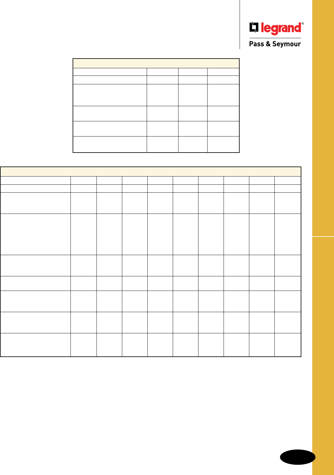
B-77
Straight Blade Receptacles
AlldeviceslistedonthispageconformtoNEMAWD-1andWD-6.
Power & Surge Protection Strips Specs
Straight Blade Receptacles
Power & Surge Protection Strips
Specifications
Power Devices – Ratings
CatalogNumber PNS6 PNS7L PNS10
TypeofHousing Strip Strip Strip
TotalOutlets 6 7 10
StandardGroundedOutlets 6 6 6
TransformerReadyOutlets 0 1 4
PowerIndicator X
CircuitBreakerSwitch Unlighted Lighted Lighted
CordLength(exposed)ft. 3' 8' 15'
Plug Straight Straight Straight
MoldedAdd-OnSafetyCovers 0 0 5
MoldedHousingColor Black Black Black
Power & Surge Protection Devices – Ratings
CatalogNumber PS1 PS1P PS6 PS7 PS7P PS7L PS8C PS8P PS10PC
TypeofHousing Tap Tap Strip Strip Strip Strip Block Block Block
NumberofOutlets 1 1 6 7 7 7 8 8 10
StandardGroundedOutlets 1 1 6 6 6 6 0 0 6
TransformerReadyOutlets 1 1 0 1 1 1 8 8 4
JouleRatingRange 740J 740J 555J 740J 740J 740J 1100J 1100J 1100J
MOVConfiguration 4-20mm 4-20mm 3-20mm 4-20mm 4-20mm 4-20mm 6-20mm 6-20mm 6-20mm
ClampingVoltage 400V 400V 400V 400V 400V 400V 400V 400V 400V
Max.SpikeCurrent(Amps) 48K 48K 36K 48K 48K 48K 72K 72K 72K
EMIFilterCapacitors X X X X X X X X
Protection(L-N,L-G,N-G) X X X X X X X X X
SurgeProtectionIndicator X X X X X X X X X
Ground/WiringIndicator X X X X X X
CircuitBreakerSwitch Unlighted Lighted Lighted Lighted Lighted Lighted Lighted
CordLength(exposed)ft. 3' 6' 6' 15' 8' 8' 8'
Plug Straight Straight Straight Straight Rt.Angle Rt.Angle Rt.Angle
Phone/FaxProtection X X X X
PhoneLine(s)Configuration 1in/1out 1in/2out 1in/1out
PhoneJackSpec RJ-11 RJ-11 RJ-45 RJ-45
Nickel-CoaxialJackProtection X X
6'PhoneCable(6P2C) X X X X
6'CoaxCable(NickelPlated) X X
MoldedAdd-OnSafetyCovers 0 0 0 2 2 2 4 4 5
MoldedHousingColor PCGray PCGray PCGray PCGray PCGray PCGray PCGray PCGray PCGray
UL14492ndEdition X X X X X X X X X
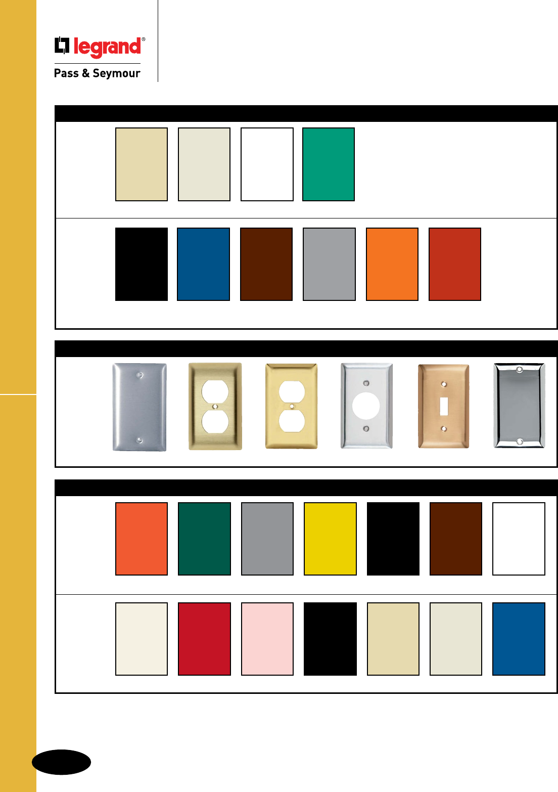
B-78
Devices & Wall PlatesColor Selection Chart
Devices & Wall Plates
Color Selection Chart
Devices & Plastic Wall Plate Colors
Ivory Light Almond White Green
Black Blue Brown Gray Orange Red
See specific device and wall plate catalog charts for particular color availabilities.
To order custom metal wall plates, see Pages Q-43 – Q-45.
For additional colors consult factory.
Custom Metal Wall Plates Paint Finish Colors
Custom Metal Wall Plates Paint Finish Colors
Paint Color Orange Green Gray Yellow Glossy Black Brown White
Paint Color Primer Red Pink Flat Black Ivory Light Almond Blue
Metal Wall Plates
Metal Finish Aluminum Brass (Brushed) Polished Brass Stainless Steel Brushed Bronze Chrome

B-79
Notes
Notes
B-79

GFCIs

C-1
GFCIs
GFCIs
Index
Device Rating Page Number
TradeMaster® & Specification Grade GFCI Receptacles 15 & 20A, 125VAC C-2, C-5
Tamper-Resistant GFCI Receptacles 15 & 20A, 125VAC C-3
Hospital Grade Tamper-Resistant GFCI Receptacles 15 & 20A, 125VAC C-4
Hospital Grade GFCI Receptacles 15 & 20A, 125VAC C-6
Illuminated GFCI Receptacles 20A, 125VAC C-7
Specification Grade Dead Front GFCIs 20A, 125VAC C-8
Decorator Combination Tamper-Resistant Switch/GFCI Receptacles 15A, 125VAC C-9
Decorator Combination Tamper-Resistant Nightlight/GFCI Receptacles 15 & 20A, 125VAC C-10
Weather-Resistant GFCI Receptacles 15 & 20A, 125VAC C-11
Weather-Resistant DuraShieldTM GFCI Receptacles 15 & 20A, 125VAC C-12
PlugTail™ Specification Grade GFCI Receptacles 15 & 20A, 125VAC C-13
PlugTail™ Hospital Grade GFCI Receptacles 15 & 20A, 125VAC C-14
PlugTail™ Tamper-Resistant GFCI Receptacles 15 & 20A, 125VAC C-15
PlugTail™ Tamper-Resistant Nightlight/GFCI Receptacles 15 & 20A, 125VAC C-16
NAFTA-Compliant & RoHS-Compliant GFCI Receptacles 15 & 20A, 125VAC C-17, C-18
NAFTA-Compliant PlugTail™ GFCI Receptacles 15 & 20A, 125VAC C-19, C-20
GFCI Portables C-21 – C-23
A full range of intelligently engineered,
highly durable, and reliable GFCIs
— whether you require receptacle,
combination, portable, or in-line
ground fault protection.
In 1971, we introduced the first GFCI receptacle. Soon, our
invention was preventing injuries and saving lives throughout
North America.
That spirit of innovation and commitment to safety continues.
P&S GFCI receptacles now have SafeLock™ Protection –
and made it standard in all our GFCI receptacles. It goes
beyond UL® standards to provide our best GFCI safety
ever. With SafeLock Protection, if critical components are
damaged and ground fault protection is lost, power to the
receptacle is disconnected.
Today, you’ll find P&S innovation and safety throughout
a broad range of GFCI products – products that offer new
versatility, save installation time, and solve problems. And
products that continue a proud safety tradition that we
began more than 30 years ago.
P&S innovations – from the first GFCI receptacle
to SafeLock™ Protection.
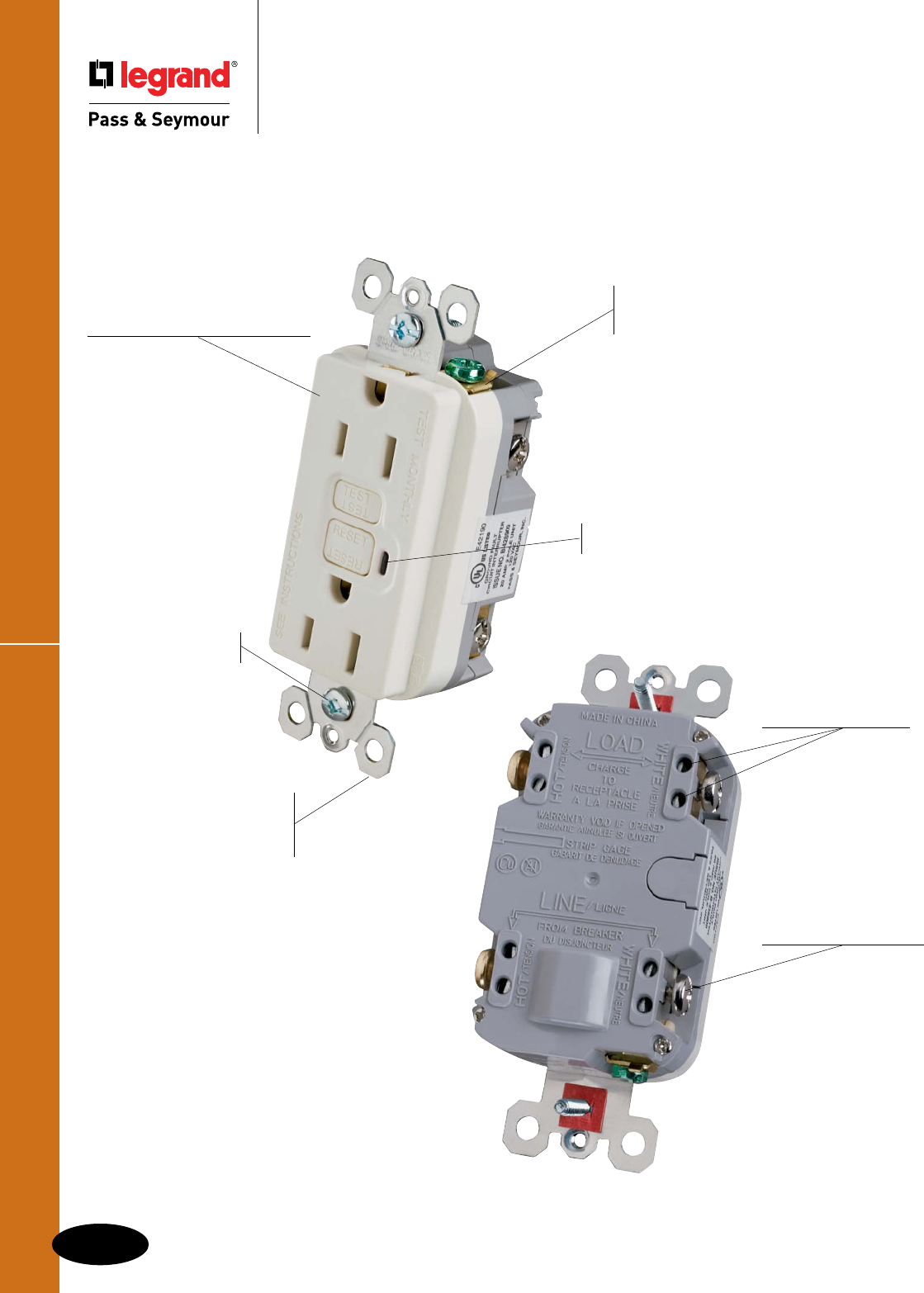
TradeMaster® & Spec Grade GFCI Receptacles
C-2
GFCIs
GFCIs
TradeMaster® & Specification Grade
GFCI Receptacles
1/4" thinner than competitors’ GFCIs;
leaves more room for wires in the box.
Two back wire holes
per termination
add wiring flexibility,
eliminate pigtailing,
and save box space.
Extra-long strap for better
sheet rock contact
eliminates “floaters” yet takes
standard wall plate.
Back wire clamp allows
for fast installation of
ground wires.
Side or internal
screw-pressure-
plate back wire
termination takes
#10–#14 AWG stranded
or solid, copper or
copper-clad conductors.
The most durable GFCI available. Exceeds
UL943 voltage surge requirements; survives 100x the
required UL 3kA/6kV voltage surge test cycles.
Captive screws make
for easier installation.
Prevents line-load
reversal miswire:
No power to the face or
downstream receptacles
if wired incorrectly.
1595LA
GFCIs with patented SafeLock™ Protection
If critical components are damaged and ground fault
protection is lost, power to receptacle is disconnected.
High-impact-resistant,
thermoplastic construction
for superior strength and durability.
FSUL Listed (Federal Specification WC596).
Trip indicator light (LED) makes it easy
to identify tripped condition.
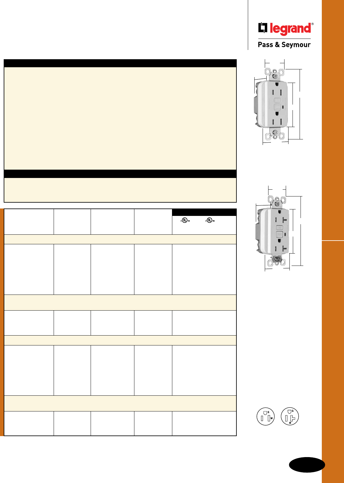
C-3
GFCIs
All devices listed on this page conform to NEMA WD-1 and WD-6.
Tamper-Resistant GFCI Receptacles
GFCIs
Tamper-Resistant GFCI Receptacles
2 Pole, 3 Wire Grounding 15 & 20A, 125VAC
Features
n Protects children: patented shutter system helps
prevent improper insertion of foreign objects.
n Meets National Electrical Code®
Tamper-Resistant requirements.
n SafeLockTM Protection: if critical components are
damaged and ground fault protection is lost, power
to receptacle is disconnected.
n Prevents line-load reversal miswire: no power to the
face or downstream receptacles if wired incorrectly.
n Exceeds UL943 voltage surge requirements;
survives 100x the required UL 3kA/6kV voltage
surge test cycles.
n FSUL Listed (Federal Specification WC596).
n Trip indicator light (red LED).
n Side or internal screw-pressure-plate back wire with
#10 – #14 AWG solid or stranded copper wire.
Specications
n Supply Voltage: 125VAC, 60 Hz
n Supply Voltage Range: 102-132 VAC
n Trip Threshold: 5± 1mA
n Trip Time: 0.025 sec., nominal per
UL Standard
n 20 Amp feed-thru capacity
n Two back wire holes per terminal.
n Ground screw has a back wire clamp for easy
installation.
n 1/4" thinner than competitors’ GFCIs; leaves
more room for wires in the box.
n Mounting screws are shipped captive in the
device and wall plate for easier installation.
n High-impact-resistant thermoplastic
construction.
n Extra-long strap.
n Button colors match the device face.
n Dual-direction test and reset buttons.
n Class A rated GFCI.
n Supplied with matching TP26 nylon wall plate.
n Tri-drive screws.
Catalog Rating NEMA
Number A. VAC Color Cong. No.
TradeMaster®/Spec Grade Tamper-Resistant 15 Amp Duplex GFCI
1595TRI 15 125 Ivory 5-15R • • •
1595TRW 15 125 White 5-15R • • •
1595TR 15 125 Brown 5-15R • • •
1595TRBK 15 125 Black 5-15R • • •
1595TRLA 15 125 Light Almond 5-15R • • •
1595TRBNCC4 15 125 Brushed Nickel 5-15R • • •
1595TRTI 15 125 Titanium 5-15R • • •
TradeMaster®/Spec Grade Tamper-Resistant 15 Amp Duplex GFCI
with Auto-Ground
1595TRSI 15 125 Ivory 5-15R • • •
1595TRSW 15 125 White 5-15R • • •
1595TRSLA 15 125 Light Almond 5-15R • • •
Specification Grade Tamper-Resistant 20 Amp Duplex GFCI
2095TRI 20 125 Ivory 5-20R • • •
2095TRW 20 125 White 5-20R • • •
2095TR 20 125 Brown 5-20R • • •
2095TRGRY 20 125 Gray 5-20R • • •
2095TRBK 20 125 Black 5-20R • • •
2095TRRED 20 125 Red 5-20R • • •
2095TRLA 20 125 Light Almond 5-20R • • •
Specification Grade Tamper-Resistant 20 Amp Duplex GFCI
with Auto-Ground
2095TRSI 20 125 Ivory 5-20R • • •
2095TRSW 20 125 White 5-20R • • •
2095TRSLA 20 125 Light Almond 5-20R • • •
UL943 UL498 FSUL
C22.2 No. 144 C22.2 No. 42 WC596
3rd Party Compliance
1595TRW
1.13"
1.72"
1.25"
2.62"
4.20"
NEMA
5-15R
NEMA
5-20R
2095TRSW
1.13"
1.72"
1.25"
2.62"
4.20"
National Electrical Code® Section 406.11 Tamper-Resistant Receptacles in Dwelling
Units.
In all areas specified in 210.52 all 125-volt, 15- and 20-amp receptacles shall be listed tamper-resistant receptacles.
C-4
GFCIs
All devices listed on this page conform to NEMA WD-1 and WD-6.
GFCIs
Hospital Grade Tamper-Resistant
GFCI Receptacles
2 Pole, 3 Wire Grounding 15 & 20A, 125VAC
HG Tamper-Resistant GFCI Receptacles
Features
n Protects children: patented shutter system helps
prevent improper insertion of foreign objects.
n Meets National Electrical Code®
Tamper-Resistant requirements.
n SafeLockTM Protection: if critical components are
damaged and ground fault protection is lost, power
to receptacle is disconnected.
n Prevents line-load reversal miswire: no power to the
face or downstream receptacles if wired incorrectly.
n Exceeds UL943 voltage surge requirements;
survives 100x the required UL 3kA/6kV voltage
surge test cycles.
n FSUL Listed (Federal Specification WC596).
n Trip indicator light (red LED).
n Side or internal screw-pressure-plate back wire with
#10 – #14 AWG solid or stranded copper wire.
Specications
n Supply Voltage: 125VAC, 60 Hz
n Supply Voltage Range: 102-132 VAC
n Trip Threshold: 5± 1mA
n Trip Time: 0.025 sec., nominal per
UL Standard
n 20 Amp feed-thru capacity
n Two back wire holes per terminal.
n Ground screw has a back wire clamp for easy
installation.
n 1/4" thinner than competitors’ GFCIs; leaves
more room for wires in the box.
n Mounting screws are shipped captive in the
device and wall plate for easier installation.
n High-impact-resistant thermoplastic
construction.
n Extra-long strap.
n Button colors match the device face.
n Dual-direction test and reset buttons.
n Class A rated GFCI.
n Supplied with matching TP26 nylon wall plate.
n Tri-drive screws.
Catalog Rating NEMA
Number A. VAC Color Cong. No.
Hospital Grade Tamper-Resistant 15 Amp Duplex GFCI
1595HGTRI 15 125 Ivory 5-15R • • •
1595HGTRW 15 125 White 5-15R • • •
1595HGTR 15 125 Brown 5-15R • • •
1595HGTRGRY 15 125 Gray 5-15R • • •
1595HGTRRED 15 125 Red 5-15R • • •
1595HGTRLA 15 125 Light Almond 5-15R • • •
Hospital Grade Tamper-Resistant 20 Amp Duplex GFCI
2095HGTRI 20 125 Ivory 5-20R • • •
2095HGTRW 20 125 White 5-20R • • •
2095HGTR 20 125 Brown 5-20R • • •
2095HGTRGRY 20 125 Gray 5-20R • • •
2095HGTRRED 20 125 Red 5-20R • • •
2095HGTRLA 20 125 Light Almond 5-20R • • •
UL943 UL498 FSUL
C22.2 No. 144 C22.2 No. 42 WC596
3rd Party Compliance
NEMA
5-15R
NEMA
5-20R
2095HGTRW
1.13"
1.72"
1.25"
2.62"
4.20"
1595HGTRW
1.13"
1.72"
1.25"
2.62"
4.20"
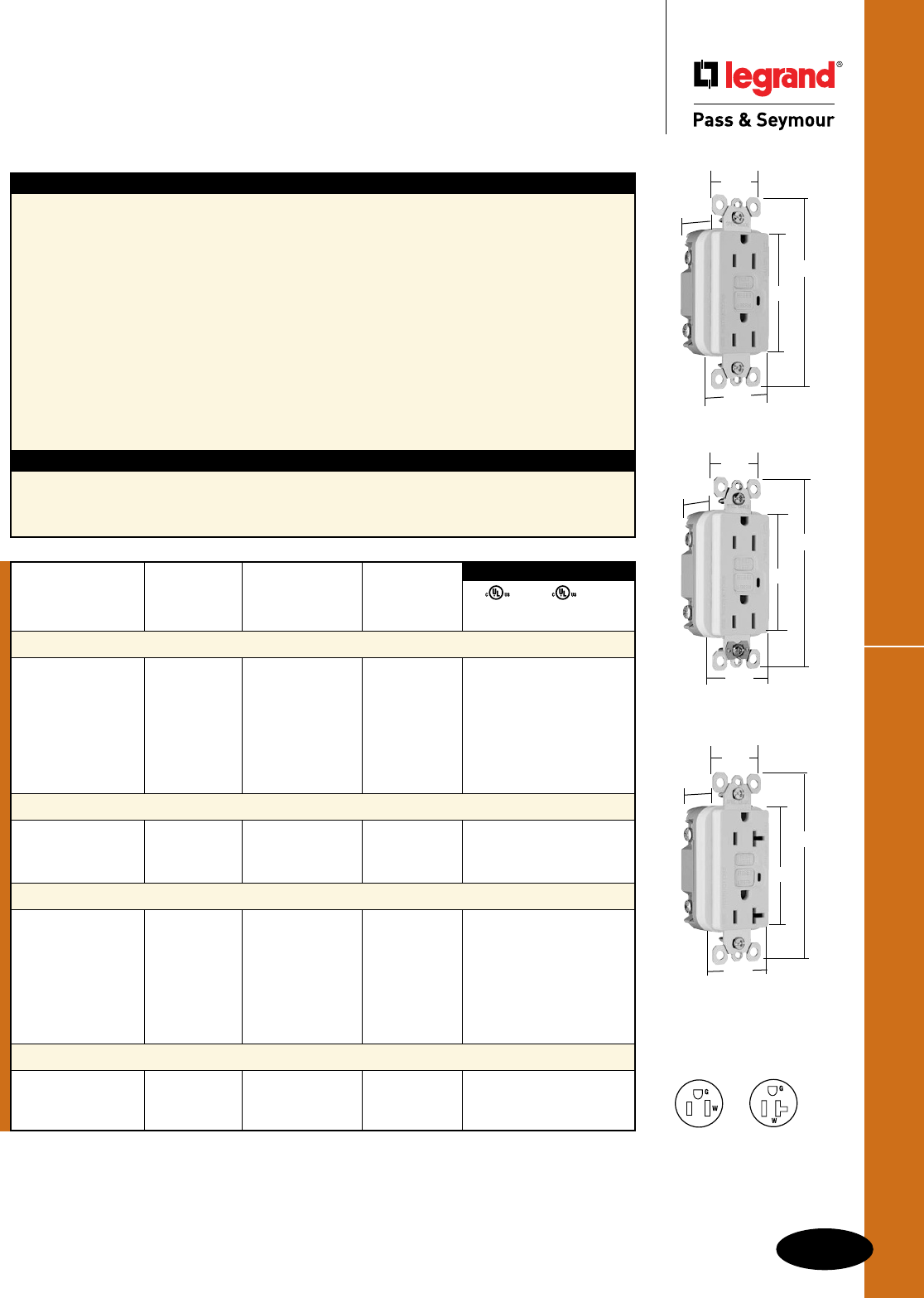
C-5
GFCIs
All devices listed on this page conform to NEMA WD-1 and WD-6.
TradeMaster® & Spec Grade GFCI Receptacles
GFCIs
TradeMaster® & Specification Grade
GFCI Receptacles
2 Pole, 3 Wire Grounding 15 & 20A, 125VAC
1595W
1.72"
1.25"
2.62"
4.20"
.98"
2095W
.98"
1.72"
1.25"
2.62"
4.20"
NEMA
5-15R
NEMA
5-20R
Features
n SafeLockTM Protection: if critical components are
damaged and ground fault protection is lost, power
to receptacle is disconnected.
n Prevents line-load reversal miswire: no power to the
face or downstream receptacles if wired incorrectly.
n Exceeds UL943 voltage surge requirements;
survives 100x the required UL 3kA/6kV voltage
surge test cycles.
n FSUL Listed (Federal Specification WC596).
n Trip indicator light (red LED).
n Side or internal screw-pressure-plate back wire
with #10 – #14 AWG solid or stranded copper wire.
n Two back wire holes per terminal.
n Ground screw has a back wire clamp for
easy installation.
Specications
n Supply Voltage: 125VAC, 60 Hz
n Supply Voltage Range: 102-132 VAC
n Trip Threshold: 5± 1mA
n Trip Time: 0.025 sec., nominal per UL Standard
n 20 Amp feed-thru capacity
n 1/4" thinner than competitors’ GFCIs; leaves
more room for wires in the box.
n Mounting screws are shipped captive in the
device and wall plate for easier installation.
n High-impact-resistant thermoplastic
construction.
n Extra-long strap.
n Button colors match the device face.
n Dual-direction test and reset buttons.
n Class A rated GFCI.
n Supplied with matching TP26 nylon wall plate.
n Tri-drive screws.
n GFCIs with Auto-Ground assure a positive
ground to metal box.
Catalog Rating NEMA
Number A. VAC Color Cong. No.
TradeMaster®/Spec Grade 15 Amp Duplex GFCI
1595I 15 125 Ivory 5-15R • • •
1595W 15 125 White 5-15R • • •
1595 15 125 Brown 5-15R • • •
1595GRY 15 125 Gray 5-15R • • •
1595BK 15 125 Black 5-15R • • •
1595RED 15 125 Red 5-15R • • •
1595LA 15 125 Light Almond 5-15R • • •
TradeMaster®/Spec Grade 15 Amp Duplex GFCI with Auto-Ground
1595SI 15 125 Ivory 5-15R • • •
1595SW 15 125 White 5-15R • • •
1595SLA 15 125 Light Almond 5-15R • • •
Specification Grade 20 Amp Duplex GFCI
2095I 20 125 Ivory 5-20R • • •
2095W 20 125 White 5-20R • • •
2095 20 125 Brown 5-20R • • •
2095GRY 20 125 Gray 5-20R • • •
2095BK 20 125 Black 5-20R • • •
2095RED 20 125 Red 5-20R • • •
2095LA 20 125 Light Almond 5-20R • • •
Specification Grade 20 Amp Duplex GFCI with Auto-Ground
2095SI 20 125 Ivory 5-20R • • •
2095SW 20 125 White 5-20R • • •
2095SLA 20 125 Light Almond 5-20R • • •
UL943 UL498 FSUL
C22.2 No. 144 C22.2 No. 42 WC596
3rd Party Compliance
1595SW
.98"
1.72"
1.25"
2.62"
4.20"
C-6
GFCIs
All devices listed on this page conform to NEMA WD-1 and WD-6.
Hospital Grade GFCI Receptacles
GFCIs
Hospital Grade GFCI Receptacles
2 Pole, 3 Wire Grounding 15 & 20A, 125VAC
NEMA
5-15R
NEMA
5-20R
1595HGW
1.72"
1.25"
2.62"
4.20"
.98"
2095HGW
.98"
1.72"
1.25"
2.62"
4.20"
Features
n SafeLockTM Protection: if critical components are
damaged and ground fault protection is lost, power
to receptacle is disconnected.
n Prevents line-load reversal miswire: no power to the
face or downstream receptacles if wired incorrectly.
n Exceeds UL943 voltage surge requirements;
survives 100x the required UL 3kA/6kV voltage
surge test cycles.
n FSUL Listed (Federal Specification WC596).
n Trip indicator light (red LED).
n Side or internal screw-pressure-plate back wire with
#10 – #14 AWG solid or stranded copper wire.
n Two back wire holes per terminal.
n Ground screw has a back wire clamp for
easy installation.
n 1/4" thinner than competitors’ GFCIs; leaves
more room for wires in the box.
n Mounting screws are shipped captive in the
device and wall plate for easier installation.
n High-impact-resistant thermoplastic
construction.
n Extra-long strap.
n Button colors match the device face.
n Dual-direction test and reset buttons.
n Class A rated GFCI.
n Supplied with matching TP26 nylon wall plate.
n Tri-drive screws.
Specications
n Supply Voltage: 125VAC, 60 Hz
n Supply Voltage Range: 102-132VAC
n Trip Threshold: 5± 1mA
n Trip Time: 0.025 sec., nominal per UL Standard
n 20 Amp feed-thru capacity
Catalog Rating NEMA
Number A. VAC Color Cong. No.
Hospital Grade 15 Amp Duplex GFCI
1595HGI 15 125 Ivory 5-15R • • •
1595HGW 15 125 White 5-15R • • •
1595HG 15 125 Brown 5-15R • • •
1595HGGRY 15 125 Gray 5-15R • • •
1595HGRED 15 125 Red 5-15R • • •
1595HGLA 15 125 Light Almond 5-15R • • •
Hospital Grade 20 Amp Duplex GFCI
2095HGI 20 125 Ivory 5-20R • • •
2095HGW 20 125 White 5-20R • • •
2095HG 20 125 Brown 5-20R • • •
2095HGGRY 20 125 Gray 5-20R • • •
2095HGRED 20 125 Red 5-20R • • •
2095HGLA 20 125 Light Almond 5-20R • • •
UL943 UL498 FSUL
C22.2 No. 144 C22.2 No. 42 WC596
3rd Party Compliance
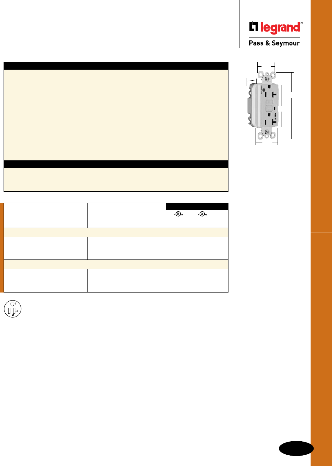
C-7
GFCIs
All devices listed on this page conform to NEMA WD-1 and WD-6.
GFCIs
Illuminated GFCI Receptacles
2 Pole, 3 Wire Grounding 20A, 125VAC
Illuminated GFCI Receptacles
2095HGWL
.98"
1.72"
1.25"
2.62"
4.20"
Features
n Green indicator light (LED) is ON when power is
available. Helps identify emergency power branch
circuits.
n SafeLockTM Protection: if critical components are
damaged and ground fault protection is lost, power
to receptacle is disconnected.
n Prevents line-load reversal miswire: no power to the
face or downstream receptacles if wired incorrectly.
n Exceeds UL943 voltage surge requirements;
survives 100x the required UL 3kA/6kV voltage
surge test cycles.
n FSUL Listed (Federal Specification WC596).
n Side or internal screw-pressure-plate back wire with
#10 – #14 AWG solid or stranded copper wire.
n Two back wire holes per terminal.
Specications
n Supply Voltage: 125VAC, 60 Hz
n Supply Voltage Range: 102-132 VAC
n Trip Threshold: 5± 1mA
n Trip Time: 0.025 sec., nominal per
UL Standard
n 20 Amp feed-thru capacity
n Ground screw has a back wire clamp for easy
installation.
n 1/4" thinner than competitors’ GFCIs; leaves
more room for wires in the box.
n Mounting screws are shipped captive in the
device and wall plate for easier installation.
n High-impact-resistant thermoplastic
construction.
n Extra-long strap.
n Button colors match the device face.
n Dual-direction test and reset buttons.
n Class A rated GFCI.
n Supplied with matching TP26 nylon wall plate.
n Tri-drive screws.
Catalog Rating NEMA
Number A. VAC Color Cong. No.
Specification Grade Illuminated 20 Amp Duplex GFCI
2095IL 20 125 Ivory 5-20R • • •
2095WL 20 125 White 5-20R • • •
2095LAL 20 125 Light Almond 5-20R • • •
Hospital Grade Illuminated 20 Amp Duplex GFCI
2095HGIL 20 125 Ivory 5-20R • • •
2095HGWL 20 125 White 5-20R • • •
2095HGREDL 20 125 Red 5-20R • • •
UL943 UL498 FSUL
C22.2 No. 144 C22.2 No. 42 WC596
3rd Party Compliance
NEMA
5-20R
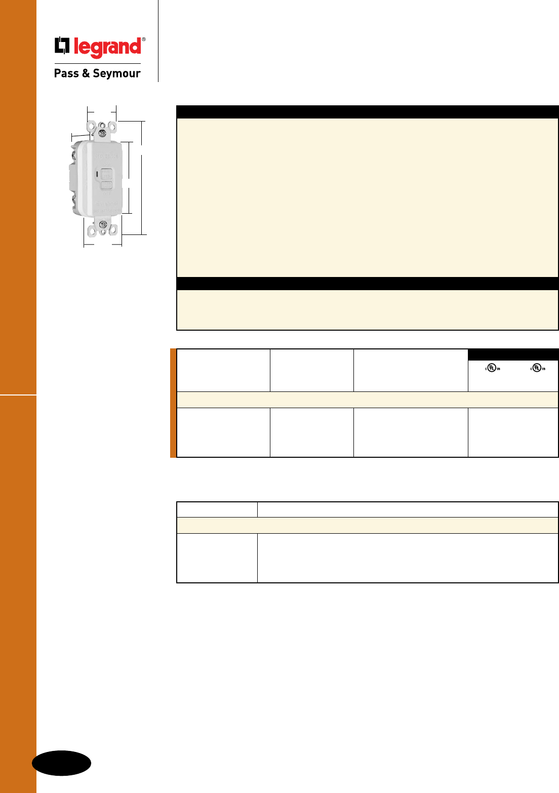
All devices listed on this page conform to NEMA WD-1 and WD-6.
GFCIs
Specification Grade Dead Front GFCI
20A, 125VAC
Features
n Rated as a 11⁄2 HP motor control switch.
n SafeLockTM Protection: if critical components are
damaged and ground fault protection is lost, power
to the load is disconnected.
n Prevents line-load reversal miswire: no power to the
load or downstream receptacles if wired incorrectly.
n Exceeds UL943 voltage surge requirements;
survives 100x the required UL 3kA/6kV voltage
surge test cycles.
n Trip indicator light (red LED).
n Side or internal screw-pressure-plate back wire with
#10 – #14 AWG solid or stranded copper wire.
n Two back wire holes per terminal.
n Ground screw has a back wire clamp for
easy installation.
Specications
n Supply Voltage: 125VAC, 60 Hz.
n Supply Voltage Range: 102-132 VAC.
n Trip Threshold: 5± 1mA.
n Trip Time: 0.025 sec., nominal per
UL Standard.
n 20 Amp feed-thru capacity.
n 1/4" thinner than competitors’ GFCIs; leaves
more room for wires in the box.
n Mounting screws are shipped captive in the
device and wall plate for easier installation.
n High-impact-resistant thermoplastic
construction.
n Extra-long strap.
n Button colors match the device face.
n Dual-direction test and reset buttons.
n Class A rated GFCI.
n Supplied with matching TP26 nylon wall plate.
n Tri-drive screws.
Rating
Catalog Number A. VAC Color
Specification Grade Dead Front GFCI – 11⁄2 HP Motor Control Rating
2085I 20 125 Ivory • •
2085W 20 125 White • •
2085BK 20 125 Black • •
2085LA 20 125 Light Almond • •
3rd Party Compliance
UL943 UL508
C22.2 No. 144 C22.2 No. 14
Catalog Number Description
Accessories – GFCIs
1594TPAI 7.0 cu. in. Extension Ring, Ivory
1594TPAW 7.0 cu. in. Extension Ring, White
1594TPA 7.0 cu. in. Extension Ring, Brown
1594TPALA 7.0 cu. in. Extension Ring, Light Almond
2085W
.98"
1.72"
1.25"
2.62"
4.20"
Specification Grade Dead Front GFCI
C-8
GFCIs
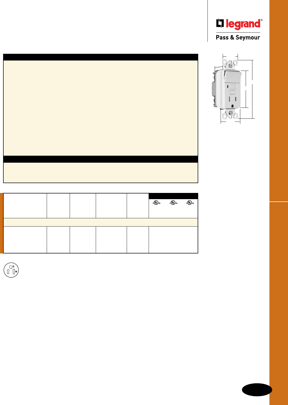
C-9
GFCIs
All devices listed on this page conform to NEMA WD-1 and WD-6.
Decorator Combination GFCI Receptacles
GFCIs
Decorator Combination Tamper-Resistant
Switch/GFCI Receptacles
15A, 125VAC
1595SWTTRWCC4
NEMA
5-15R
1.13"
1.25"
4.20"
2.62"
1.72"
Switch Receptacle NEMA
Catalog Rating Rating Cong.
Number A. VAC A. VAC Color No.
Combination Tamper-Resistant Single Pole Switch/GFCI
1595SWTTRICC4 15 120 15 125 Ivory 5-15R • • •
1595SWTTRWCC4 15 120 15 125 White 5-15R • • •
1595SWTTRBKCC4 15 120 15 125 Black 5-15R • • •
1595SWTTRLACC4 15 120 15 125 Light Almond 5-15R • • •
3rd Party Compliance
UL943 UL498 UL20
C22.2 C22.2 C22.2
No. 144 No. 42 No. 111
Features
n Protects children: patented shutter system helps
prevent improper insertion of foreign objects.
n Meets National Electrical Code®
Tamper-Resistant requirements.
n SafeLockTM Protection: if critical components are
damaged and ground fault protection is lost, power
to receptacle is disconnected.
n Up-down switching.
n 15 Amp single pole switch rated for 1/2 HP motor
loads – perfect for bath or kitchen vents and
garbage disposals.
n Prevents line-load reversal miswire: no power to the
face or downstream receptacles if wired incorrectly.
n Exceeds UL943 voltage surge requirements;
survives 100x the required UL 3kA/6kV voltage
surge test cycles.
n Trip indicator light (red LED).
n Two back wire holes per terminal.
Specications
n Supply Voltage: 125VAC, 60 Hz
n Supply Voltage Range: 102-132 VAC
n Trip Threshold: 5± 1mA
n Trip Time: 0.025 sec., nominal per UL
Standard
n 20 Amp feed-thru capacity
n Side or internal screw-pressure-plate back
wire with #10 – #14 AWG solid or stranded
copper wire.
n Ground screw has a back wire clamp for easy
installation.
n 1/4" thinner than competitors’ GFCIs; leaves
more room for wires in the box.
n Mounting screws are shipped captive in the
device and wall plate for easier installation.
n High-impact-resistant thermoplastic
construction.
n Extra-long strap.
n Button colors match the device face.
n Dual-direction test and reset buttons.
n Class A rated GFCI.
n Supplied with matching TP26 nylon wall plate.
n Tri-drive screws.
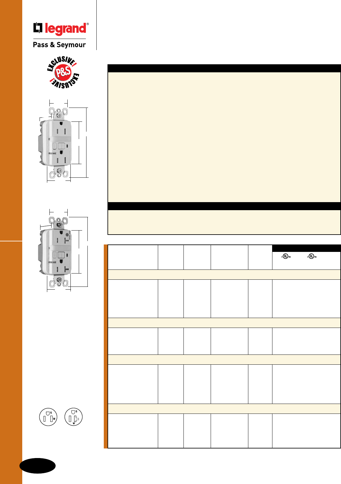
C-10
GFCIs
All devices listed on this page conform to NEMA WD-1 and WD-6.
Decorator Combination GFCI Receptacles
GFCIs
Decorator Combination Tamper-Resistant
Nightlight/GFCI Receptacles
2 Pole, 3 Wire Grounding 15 & 20A, 125VAC
Features
n Protects children: patented shutter system helps
prevent improper insertion of foreign objects.
n Meets National Electrical Code®
Tamper-Resistant requirements.
n SafeLockTM Protection: if critical components are
damaged and ground fault protection is lost, power
to receptacle is disconnected.
n Sealed nightlight with high impact-resistant Lexan®
lens prevents tampering.
n Nightlight uses cooler LED illumination.
n Energy-efficient LED has average 20-year life
expectancy, eliminating bulb replacement.
n Two receptacles.
n Photocell turns nightlight ON in dark, OFF in daylight.
n Prevents line-load reversal miswire: no power to the
face or downstream receptacles if wired incorrectly.
n Exceeds UL943 voltage surge requirements;
survives 100x the required UL 3kA/6kV voltage
surge test cycles.
n FSUL Listed (Federal Specification WC596).
Specications
n Supply Voltage: 125VAC, 60 Hz
n Supply Voltage Range: 102-132 VAC
n Trip Threshold: 5± 1mA
n Trip Time: 0.025 sec., nominal per UL
Standard
n 20 Amp feed-thru capacity
n Trip indicator light (red LED).
n Side or internal screw-pressure-plate back
wire with #10 – #14 AWG solid or stranded
copper wire.
n Two back wire holes per terminal.
n Ground screw has a back wire clamp for
easy installation.
n 1/4" thinner than competitors’ GFCIs; leaves
more room for wires in the box.
n Mounting screws are shipped captive in the
device and wall plate for easier installation.
n High-impact-resistant thermoplastic
construction.
n Extra-long strap.
n Button colors match the device face.
n Dual-direction test and reset buttons.
n Class A rated GFCI.
n Supplied with matching TP26 nylon
wall plate.
n Tri-drive screws.
*FCD = Foot Candle Distance, 1 Lumen = 1 FCD. See Page S-56 for more information.
1595NTLTRWCC4
1.25"
1.13"
4.20"
2.62"
1.72"
2095HGNTLTRW
1.25"
1.13"
4.20"
2.62"
1.72"
NEMA
5-15R
NEMA
5-20R
UL943 UL498 FSUL
C22.2 No. 144 C22.2 No. 42 WC596
3rd Party Compliance
Light NEMA
Catalog Rating Output in Cong.
Number A. VAC 1' FCD* Color No.
Combination Tamper-Resistant 15 Amp Nightlight/GFCI
1595NTLTRICC4 15 125 0.180 Ivory 5-15R • • •
1595NTLTRWCC4 15 125 0.180 White 5-15R • • •
1595NTLTRBKCC4 15 125 0.180 Black 5-15R • • •
1595NTLTRLACC4 15 125 0.180 Light Almond 5-15R • • •
1595NTLTRBNCC4 15 125 0.180 Brushed Nickel 5-15R • • •
1595NTLTRTICC4 15 125 0.180 Titanium 5-15R • • •
Combination Tamper-Resistant 20 Amp Nightlight/GFCI
2095NTLTRI 20 125 0.180 Ivory 5-20R • • •
2095NTLTRW 20 125 0.180 White 5-20R • • •
2095NTLTRGRY 20 125 0.180 Gray 5-20R • • •
2095NTLTRLA 20 125 0.180 Light Almond 5-20R • • •
Hospital Grade Combination Tamper-Resistant 15 Amp Nightlight/GFCI
1595HGNTLTRI 15 125 0.180 Ivory 5-15R • • •
1595HGNTLTRW 15 125 0.180 White 5-15R • • •
1595HGNTLTR 15 125 0.180 Brown 5-15R • • •
1595HGNTLTRGRY 15 125 0.180 Gray 5-15R • • •
1595HGNTLTRRED 15 125 0.180 Red 5-15R • • •
1595HGNTLTRLA 15 125 0.180 Light Almond 5-15R • • •
Hospital Grade Combination Tamper-Resistant 20 Amp Nightlight/GFCI
2095HGNTLTRI 20 125 0.180 Ivory 5-20R • • •
2095HGNTLTRW 20 125 0.180 White 5-20R • • •
2095HGNTLTRGRY 20 125 0.180 Gray 5-20R • • •
2095HGNTLTRRED 20 125 0.180 Red 5-20R • • •
2095HGNTLTRLA 20 125 0.180 Light Almond 5-20R • • •

C-11
GFCIs
All devices listed on this page conform to NEMA WD-1 and WD-6.
Weather-Resistant GFCI Receptacles
GFCIs
Weather-Resistant GFCI Receptacles
2 Pole, 3 Wire Grounding 15 & 20A, 125VAC
Features
n Weather-Resistant: Meets National Electrical
Code® Weather-Resistant requirements.
n Tamper-Resistant: Meets National Electrical
Code® Tamper-Resistant requirements.
n Protects children: patented shutter system helps
prevent improper insertion of foreign objects.
n Listed to the Weather-Resistant supplement of UL498,
meeting demanding UL requirements including:
- Ultraviolet light exposure test
- Cold impact test
- Accelerated aging test
- Stringent material requirements for current-
carrying parts, wire binding screws and mounting
straps to ensure superior corrosion resistance.
n SafeLockTM Protection: if critical components are
damaged and ground fault protection is lost, power
to receptacle is disconnected.
n Prevents line-load reversal miswire: no power to the
face or downstream receptacles if wired incorrectly.
n Exceeds UL943 voltage surge requirements;
survives 100x the required UL 3kA/6kV voltage
surge test cycles.
Specications
n Supply Voltage: 125VAC, 60 Hz
n Supply Voltage Range: 102-132 VAC
n Trip Threshold: 5± 1mA
n Trip Time: 0.025 sec., nominal per
UL Standard
n 20 Amp feed-thru capacity
n FSUL Listed (Federal Specification WC596).
n Trip indicator light (red LED).
n Side or internal screw-pressure-plate back
wire with #10 – #14 AWG solid or stranded
copper wire.
n Two back wire holes per terminal.
n Ground screw has a back wire clamp for
easy installation.
n 1/4" thinner than competitors’ GFCIs;
leaves more room for wires in the box.
n Mounting screws are shipped captive in the
device and wall plate for easier installation.
n High-impact-resistant thermoplastic
construction.
n Extra-long nickel post-plated steel
mounting strap.
n Button colors match the device face.
n Dual-direction test and reset buttons.
n Class A rated GFCI.
n Supplied with matching TP26 nylon
wall plate.
n Tri-drive screws.
NEMA
5-15R
NEMA
5-20R
National Electrical Code® Section 406.8 Receptacles in Wet or Damp Locations.
Requires that all 15- and 20-amp, 125- and 250-volt non-locking receptacles installed in wet or damp locations shall be
weather-resistant receptacles.
UL943 UL498 FSUL
C22.2 No. 144 C22.2 No. 42 WC596
3rd Party Compliance
Catalog Rating NEMA
Number A. VAC Color Cong. No.
TradeMaster®/Spec Grade Weather-Resistant 15 Amp Duplex GFCI
1595TRWRI 15 125 Ivory 5-15R • • •
1595TRWRW 15 125 White 5-15R • • •
1595TRWR 15 125 Brown 5-15R • • •
1595TRWRLA 15 125 Light Almond 5-15R • • •
Specification Grade Weather-Resistant 20 Amp Duplex GFCI
2095TRWRI 20 125 Ivory 5-20R • • •
2095TRWRW 20 125 White 5-20R • • •
2095TRWR 20 125 Brown 5-20R • • •
2095TRWRGRY 20 125 Gray 5-20R • • •
2095TRWRLA 20 125 Light Almond 5-20R • • •
1595TRWRW
1.25"
1.13"
4.20"
2.62"
1.72"
2095TRWRW
1.25"
1.13"
4.20"
2.62"
1.72"
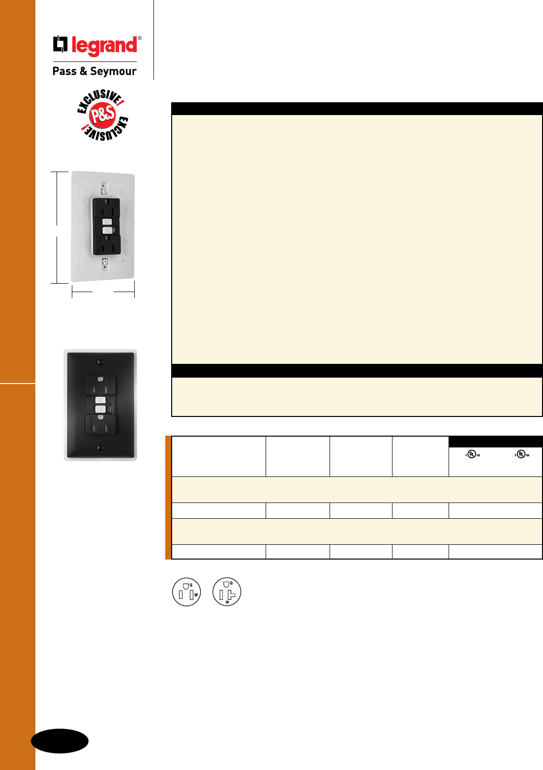
C-12
GFCIs
All devices listed on this page conform to NEMA WD-1 and WD-6.
Weather-Resistant DuraShieldTM GFCIs
GFCIs
Weather-Resistant DuraShieldTM
GFCI Receptacles
2 Pole, 3 Wire Grounding 15 & 20A, 125VAC
Features
n Designed for extra durability and a long service life
when installed in harsh environments: outdoor,
garages, workshops, wash down areas, commercial
kitchens, and labs.
n Weather-Resistant: Meets National Electrical
Code® Weather-Resistant requirements.
n Listed to the Weather-Resistant supplement of
UL498, meeting demanding UL requirements
including:
- Ultraviolet light exposure test
- Cold impact test
- Accelerated aging test
- Stringent material requirements for current-
carrying parts, wire binding screws and mounting
straps to ensure superior corrosion resistance.
n Dust- and insect-resistant.
n Rubber curtains let plug blades in; keep dust,
water and insects out.
n Integral gasket seals receptacle, protecting critical
electronic components.
n Exceeds UL corrosion requirements – survives
4X the required corrosion test cycles.
n SafeLockTM Protection: if critical components are
damaged and ground fault protection is lost,
power to receptacle is disconnected.
Specications
n Supply Voltage: 125VAC, 60 Hz
n Supply Voltage Range: 102-132 VAC
n Trip Threshold: 5± 1mA
n Trip Time: 0.025 sec., nominal per
UL Standard
n 20 Amp feed-thru capacity
n Prevents line-load reversal miswire: no power
to the face or downstream receptacles if wired
incorrectly.
n Exceeds UL943 voltage surge requirements;
survives 100x the required UL 3kA/6kV
voltage surge test cycles.
n Trip indicator light (red LED).
n Side or internal screw-pressure-plate back
wire with #10 – #14 AWG solid or stranded
copper wire.
n Two back wire holes per terminal.
n Ground screw has a back wire clamp for easy
installation.
n Mounting screws are shipped captive in the
device and wall plate for easier installation.
n High-impact-resistant thermoplastic
construction.
n Extra-long nickel post-plated steel mounting
strap.
n Dual-direction test and reset buttons.
n Class A rated GFCI.
n Supplied with matching TP26 nylon wall plate.
n Tri-drive screws.
NEMA
5-15R
NEMA
5-20R
National Electrical Code® Section 406.8 Receptacles in Wet or Damp Locations.
Requires that all 15- and 20-amp, 125- and 250-volt non-locking receptacles installed in wet or damp locations shall be
weather-resistant receptacles.
1595DSWRBKCC4
UL943 UL498
C22.2 No. 144 C22.2 No. 42
3rd Party Compliance
Catalog Rating NEMA
Number A. VAC Color Cong. No.
Specification Grade Weather-Resistant DuraShield™
15 Amp Duplex GFCI
1595DSWRBKCC4 15 125 Black 5-15R • •
Specification Grade Weather-Resistant DuraShield™
20 Amp Duplex GFCI
2095DSWRBK 20 125 Black 5-20R • •
5.125"
3.313"
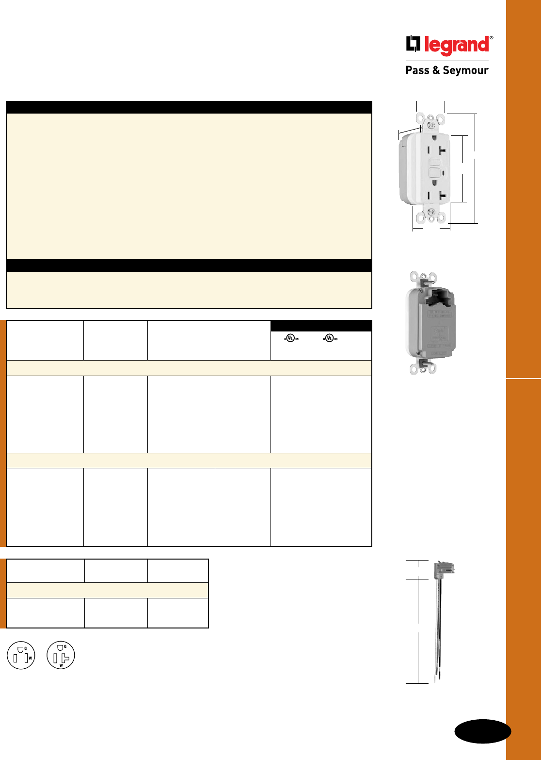
C-13
GFCIs
All devices listed on this page conform to NEMA WD-1 and WD-6.
PlugTailTM Spec Grade GFCIs
GFCIs
PlugTailTM Specification Grade
GFCI Receptacles
2 Pole, 3 Wire Grounding 15 & 20A, 125VAC
Catalog
Number Wire Type Wire Length
PlugTail Connectors – Right Angle
PTRA6STR Stranded 6"
PTRA6SOL Solid 6"
For additional PlugTail Connectors,
see Page B-3.
All PlugTail Connectors are available
in any wire length up to 25 inches,
consult factory to order.
Features
n Faster, more reliable installation.
n No exposed terminals create a finger safe
application before, during, and after installation.
n Built-in connector features large brass terminal
blades to ensure consistent, reliable electrical
connections to PlugTail Connector.
n GFCI works with the existing 3 wire PlugTail
Connectors creating a non-feed-thru application for
facility owners. At rough-in just install the same right
angle connector for GFCI and receptacle openings.
n SafeLockTM Protection: if critical components are
damaged and ground fault protection is lost, power
to receptacle is disconnected.
n FSUL Listed (Federal Specification WC596).
Specications
n Supply Voltage: 125VAC, 60 Hz
n Supply Voltage Range: 102-132 VAC
n Trip Threshold: 5± 1mA
n Trip Time: 0.025 sec., nominal per
UL Standard
n 20 Amp feed-thru capacity
n Exceeds UL943 voltage surge requirements;
survives 100x the required UL 3kA/6kV
voltage surge test cycles.
n Trip indicator light (red LED).
n Mounting screws are shipped captive in the
device and wall plate for easier installation.
n High-impact-resistant thermoplastic
construction.
n Zinc-plated steel mounting strap.
n Button colors match the device face.
n Dual-direction test and reset buttons.
n Class A rated GFCI.
n Supplied with matching TP26 nylon wall plate.
n Tri-drive screws.
NEMA
5-15R
NEMA
5-20R
UL943 UL498 FSUL
C22.2 No. 144 C22.2 No. 42 WC596
3rd Party Compliance
Catalog Rating NEMA
Number A. VAC Color Cong. No.
Specification Grade 15 Amp Duplex GFCI
PT1595I 15 125 Ivory 5-15R • • •
PT1595W 15 125 White 5-15R • • •
PT1595 15 125 Brown 5-15R • • •
PT1595GRY 15 125 Gray 5-15R • • •
PT1595BK 15 125 Black 5-15R • • •
PT1595RED 15 125 Red 5-15R • • •
PT1595LA 15 125 Light Almond 5-15R • • •
Specification Grade 20 Amp Duplex GFCI
PT2095I 20 125 Ivory 5-20R • • •
PT2095W 20 125 White 5-20R • • •
PT2095 20 125 Brown 5-20R • • •
PT2095GRY 20 125 Gray 5-20R • • •
PT2095BK 20 125 Black 5-20R • • •
PT2095RED 20 125 Red 5-20R • • •
PT2095LA 20 125 Light Almond 5-20R • • •
PT2095W
1.25"
1.20"
4.20"
2.62"
1.72"
PTRA6STR
1.125"
6.375"
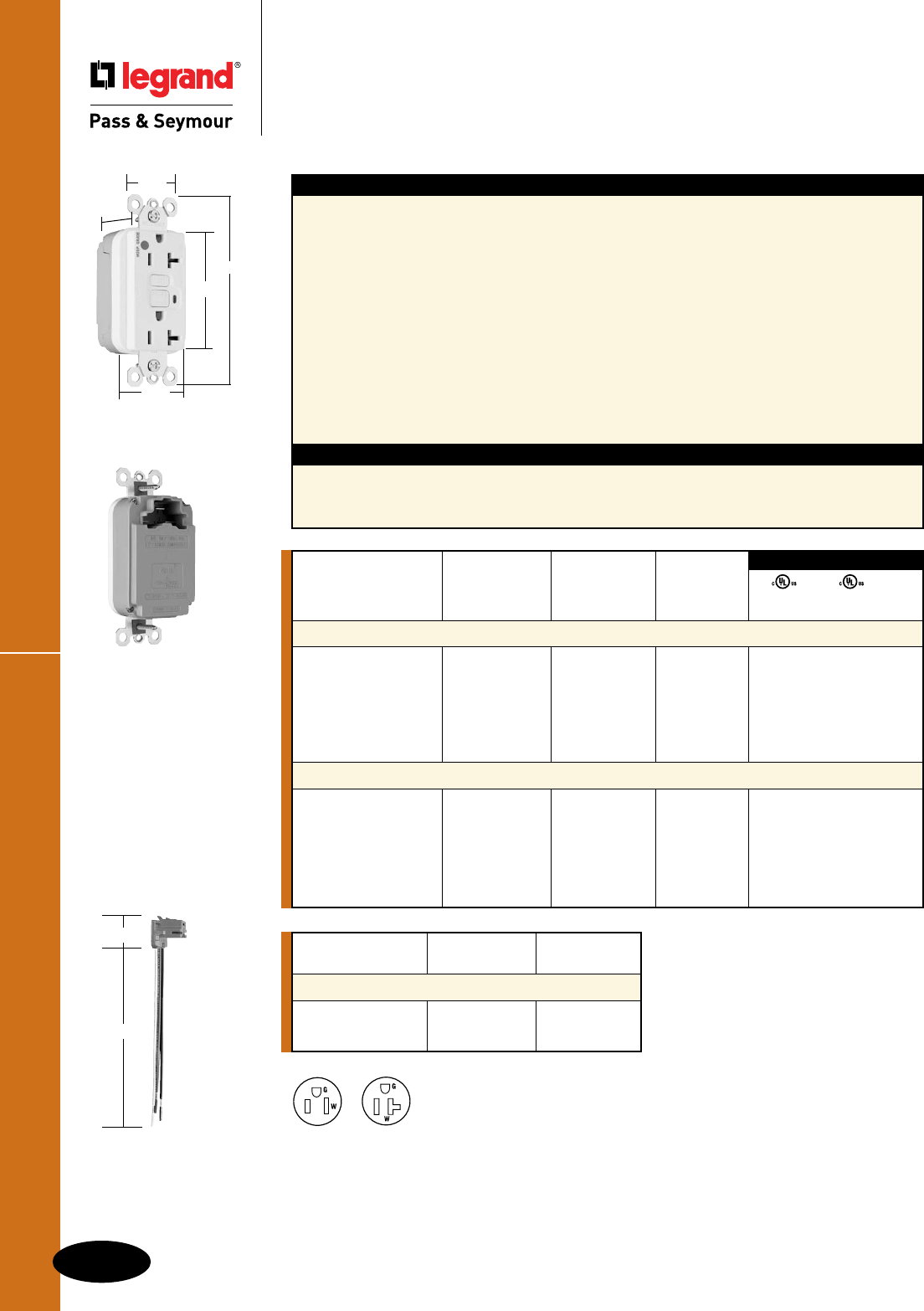
C-14
GFCIs
All devices listed on this page conform to NEMA WD-1 and WD-6.
PlugTailTM Hospital Grade GFCIs
GFCIs
PlugTailTM Hospital Grade
GFCI Receptacles
2 Pole, 3 Wire Grounding 15 & 20A, 125VAC
PT2095HGW
1.25"
1.20"
4.20"
2.62"
1.72"
Catalog
Number Wire Type Wire Length
PlugTail Connectors – Right Angle
PTRA6STR Stranded 6"
PTRA6SOL Solid 6"
For additional PlugTail Connectors,
see Page B-3.
All PlugTail Connectors are available
in any wire length up to 25 inches,
consult factory to order.
NEMA
5-15R
NEMA
5-20R
UL943 UL498 FSUL
C22.2 No. 144 C22.2 No. 42 WC596
3rd Party Compliance
Catalog Rating NEMA
Number A. VAC Color Cong. No.
Hospital Grade 15 Amp Duplex GFCI
PT1595HGI 15 125 Ivory 5-15R • • •
PT1595HGW 15 125 White 5-15R • • •
PT1595HG 15 125 Brown 5-15R • • •
PT1595HGGRY 15 125 Gray 5-15R • • •
PT1595HGRED 15 125 Red 5-15R • • •
PT1595HGLA 15 125 Light Almond 5-15R • • •
Hospital Grade 20 Amp Duplex GFCI
PT2095HGI 20 125 Ivory 5-20R • • •
PT2095HGW 20 125 White 5-20R • • •
PT2095HG 20 125 Brown 5-20R • • •
PT2095HGGRY 20 125 Gray 5-20R • • •
PT2095HGRED 20 125 Red 5-20R • • •
PT2095HGLA 20 125 Light Almond 5-20R • • •
Features
n Faster, more reliable installation.
n No exposed terminals create a finger safe
application before, during, and after installation.
n Built-in connector features large brass terminal
blades to ensure consistent, reliable electrical
connections to PlugTail Connector.
n GFCI works with the existing 3 wire PlugTail
Connectors creating a non-feed-thru application for
facility owners. At rough-in just install the same right
angle connector for GFCI and receptacle openings.
n SafeLockTM Protection: if critical components are
damaged and ground fault protection is lost, power
to receptacle is disconnected.
n FSUL Listed (Federal Specification WC596).
Specications
n Supply Voltage: 125VAC, 60 Hz
n Supply Voltage Range: 102-132 VAC
n Trip Threshold: 5± 1mA
n Trip Time: 0.025 sec., nominal per
UL Standard
n 20 Amp feed-thru capacity
n Exceeds UL943 voltage surge requirements;
survives 100x the required UL 3kA/6kV
voltage surge test cycles.
n Trip indicator light (red LED).
n Mounting screws are shipped captive in the
device and wall plate for easier installation.
n High-impact-resistant thermoplastic
construction.
n Zinc-plated steel mounting strap.
n Button colors match the device face.
n Dual-direction test and reset buttons.
n Class A rated GFCI.
n Supplied with matching TP26 nylon wall plate.
n Tri-drive screws.
PTRA6STR
1.125"
6.375"
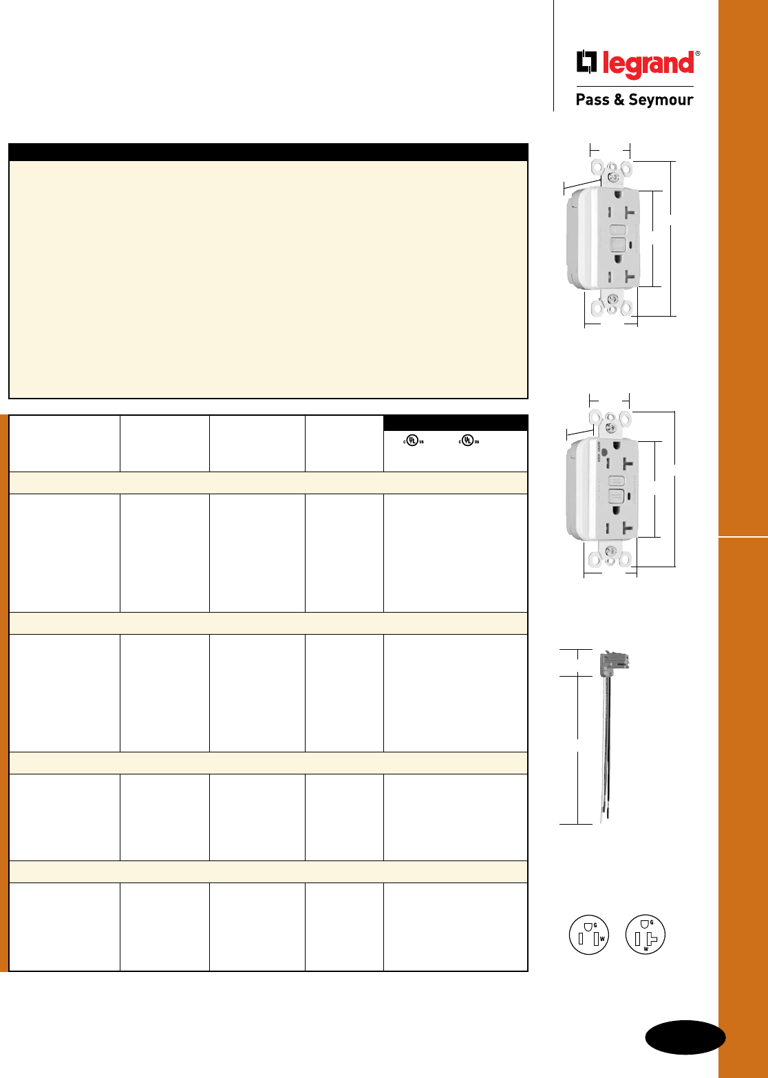
C-15
GFCIs
All devices listed on this page conform to NEMA WD-1 and WD-6.
PTRA6STR
1.125"
6.375"
PlugTailTM Tamper-Resistant GFCIs
GFCIs
PlugTailTM Specification & Hospital Grade
Tamper-Resistant GFCI Receptacles
2 Pole, 3 Wire Grounding 15 & 20A, 125VAC
Features
n Protects children: patented shutter system helps
prevent improper insertion of foreign objects.
n Meets National Electrical Code®
Tamper-Resistant requirements.
n Faster, more reliable installation.
n No exposed terminals create a finger safe
application before, during, and after installation.
n Built-in connector features large brass terminal
blades to ensure consistent, reliable electrical
connections to PlugTail Connector.
n GFCI works with the existing 3 wire PlugTail
Connectors creating a non-feed-thru application for
facility owners. At rough-in just install the same right
angle connector for GFCI and receptacle openings.
n SafeLockTM Protection: if critical components are
damaged and ground fault protection is lost, power
to receptacle is disconnected.
n FSUL Listed (Federal Specification WC596).
n Exceeds UL943 voltage surge requirements;
survives 100x the required UL 3kA/6kV
voltage surge test cycles.
n Trip indicator light (red LED).
n Mounting screws are shipped captive in the
device and wall plate for easier installation.
n High-impact-resistant thermoplastic
construction.
n Zinc-plated steel mounting strap.
n Button colors match the device face.
n Dual-direction test and reset buttons.
n Class A rated GFCI.
n Supplied with matching TP26 nylon wall plate.
n Tri-drive screws.
UL943 UL498 FSUL
C22.2 No. 144 C22.2 No. 42 WC596
3rd Party Compliance
Catalog Rating NEMA
Number A. VAC Color Cong. No.
Specification Grade Tamper-Resistant 15 Amp Duplex GFCI
PT1595TRI 15 125 Ivory 5-15R • • •
PT1595TRW 15 125 White 5-15R • • •
PT1595TR 15 125 Brown 5-15R • • •
PT1595TRGRY 15 125 Gray 5-15R • • •
PT1595TRBK 15 125 Black 5-15R • • •
PT1595TRRED 15 125 Red 5-15R • • •
PT1595TRLA 15 125 Light Almond 5-15R • • •
Specification Grade Tamper-Resistant 20 Amp Duplex GFCI
PT2095TRI 20 125 Ivory 5-20R • • •
PT2095TRW 20 125 White 5-20R • • •
PT2095TR 20 125 Brown 5-20R • • •
PT2095TRGRY 20 125 Gray 5-20R • • •
PT2095TRBK 20 125 Black 5-20R • • •
PT2095TRRED 20 125 Red 5-20R • • •
PT2095TRLA 20 125 Light Almond 5-20R • • •
Hospital Grade Tamper-Resistant 15 Amp Duplex GFCI
PT1595HGTRI 15 125 Ivory 5-15R • • •
PT1595HGTRW 15 125 White 5-15R • • •
PT1595HGTRGRY 15 125 Gray 5-15R • • •
PT1595HGTRRED 15 125 Red 5-15R • • •
PT1595HGTRLA 15 125 Light Almond 5-15R • • •
Hospital Grade Tamper-Resistant 20 Amp Duplex GFCI
PT2095HGTRI 20 125 Ivory 5-20R • • •
PT2095HGTRW 20 125 White 5-20R • • •
PT2095HGTRGRY 20 125 Gray 5-20R • • •
PT2095HGTRRED 20 125 Red 5-20R • • •
PT2095HGTRLA 20 125 Light Almond 5-20R • • •
For PlugTail Connector catalog numbers, see Page C-13 or C-14.
PT2095TRW
1.20"
1.25"
4.20"
2.62"
1.72"
NEMA
5-15R
NEMA
5-20R
PT2095HGTRW
1.25"
1.2"
4.20"
2.62"
1.72"
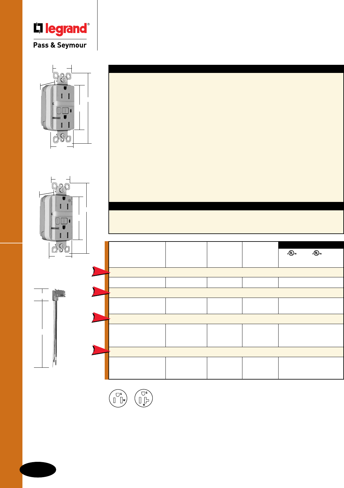
C-16
GFCIs
All devices listed on this page conform to NEMA WD-1 and WD-6.
PlugTailTM TR Nightlight/GFCIs
GFCIs
PlugTailTM Specification & Hospital Grade
Tamper-Resistant Nightlight/GFCI Receptacles
2 Pole, 3 Wire Grounding 15 & 20A, 125VAC
For PlugTail Connector catalog numbers, see Page C-13 or C-14.
NEMA
5-15R
NEMA
5-20R
Specications
n Supply Voltage: 125VAC, 60 Hz
n Supply Voltage Range: 102-132 VAC
n Trip Threshold: 5± 1mA
n Trip Time: 0.025 sec., nominal per
UL Standard
n 20 Amp feed-thru capacity
Features
n Protects children: patented shutter system helps
prevent improper insertion of foreign objects.
n Meets National Electrical Code®
Tamper-Resistant requirements.
n Sealed nightlight with high impact-resistant Lexan®
lens prevents tampering.
n Nightlight uses cooler LED illumination.
n Energy-efficient LED has average 20-year life
expectancy, eliminating bulb replacement.
n Photocell turns nightlight ON in dark, OFF in daylight.
n Faster, more reliable installation.
n No exposed terminals create a finger safe
application before, during, and after installation.
n Built-in connector features large brass terminal
blades to ensure consistent, reliable electrical
connections to PlugTail Connector.
n GFCI works with the existing 3 wire PlugTail
Connectors creating a non-feed-thru application for
facility owners. At rough-in just install the same right
angle connector for GFCI and receptacle openings.
n SafeLockTM Protection: if critical components
are damaged and ground fault protection is
lost, power to receptacle is disconnected.
n Exceeds UL943 voltage surge requirements;
survives 100x the required UL 3kA/6kV
voltage surge test cycles.
n FSUL Listed (Federal Specification WC596).
n Trip indicator light (red LED).
n Mounting screws are shipped captive in the
device and wall plate for easier installation.
n High-impact-resistant thermoplastic
construction.
n Zinc-plated steel mounting strap.
n Button colors match the device face.
n Dual-direction test and reset buttons.
n Class A rated GFCI.
n Supplied with matching TP26 nylon wall plate.
n Tri-drive screws.
1.25"
1.20"
4.20"
2.62"
1.72"
PT1595NTLTRI
UL943 UL498 FSUL
C22.2 No. 144 C22.2 No. 42 WC596
3rd Party Compliance
Catalog Rating NEMA
Number A. VAC Color Cong. No.
Specification Grade Tamper-Resistant 15 Amp Combination Nightlight/GFCI
PT1595NTLTRI 15 125 Ivory 5-15R • • •
Specification Grade Tamper-Resistant 20 Amp Combination Nightlight/GFCI
PT2095NTLTRI 20 125 Ivory 5-20R • • •
PT2095NTLTRW 20 125 White 5-20R • • •
Hospital Grade Tamper-Resistant 15 Amp Combination Nightlight/GFCI
PT1595HGNTLTRI 15 125 Ivory 5-15R • • •
PT1595HGNTLTRW 15 125 White 5-15R • • •
PT1595HGNTLTRRED 15 125 Red 5-15R • • •
Hospital Grade Tamper-Resistant 20 Amp Combination Nightlight/GFCI
PT2095HGNTLTRI 20 125 Ivory 5-20R • • •
PT2095HGNTLTRW 20 125 White 5-20R • • •
PT2095HGNTLTRLA 20 125 Light Almond 5-20R • • •
NEW
NEW
NEW
NEW
PT1595HGNTLTRI
1.25"
1.20"
4.20"
2.62"
1.72"
PTRA6STR
1.125"
6.375"
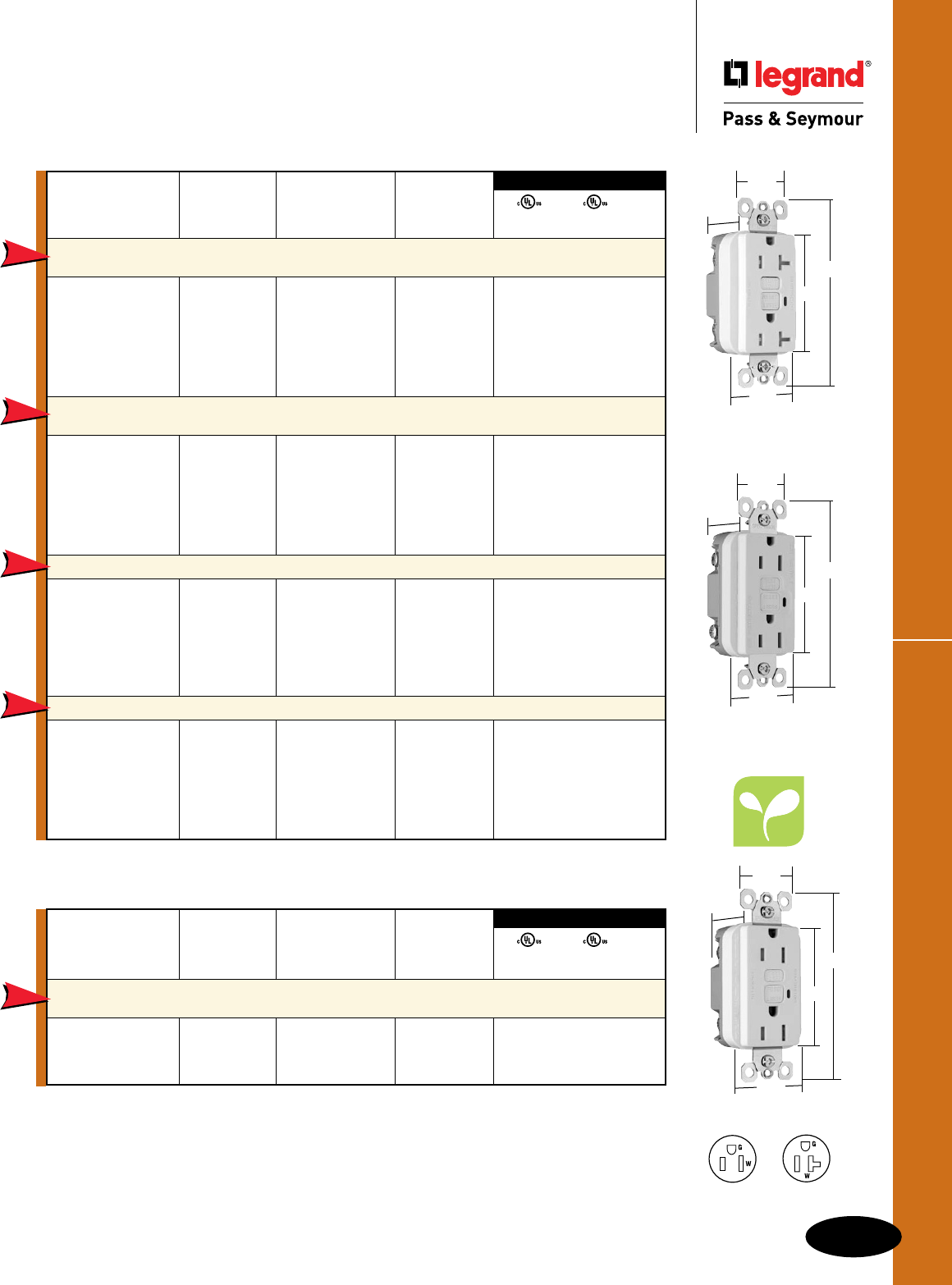
C-17
GFCIs
All devices listed on this page conform to NEMA WD-1 and WD-6.
NAFTA-Compliant & RoHS-Compliant GFCIs
GFCIs
NAFTA-Compliant & RoHS-Compliant
GFCI Receptacles
2 Pole, 3 Wire Grounding 15 & 20A, 125VAC
2095TRNAW
1.72"
1.25"
2.62"
4.20"
.98"
1.72"
1.25"
2.62"
4.20"
.98"
NEMA
5-15R
NEMA
5-20R
NAFTA-Compliant GFCI Receptacles are ideal for use on projects subject to the provisions of the
Buy American Act.
1595NAW
Catalog Rating NEMA
Number A. VAC Color Cong. No.
NAFTA-Compliant TradeMaster
®
/Spec Grade Tamper-Resistant
15 Amp Duplex GFCI
1595TRNAI 15 125 Ivory 5-15R • • •
1595TRNAW 15 125 White 5-15R • • •
1595TRNA 15 125 Brown 5-15R • • •
1595TRNAGRY 15 125 Gray 5-15R • • •
1595TRNABK 15 125 Black 5-15R • • •
1595TRNALA 15 125 Light Almond 5-15R • • •
NAFTA-Compliant TradeMaster
®
/Spec Grade Tamper-Resistant
20 Amp Duplex GFCI
2095TRNAI 20 125 Ivory 5-20R • • •
2095TRNAW 20 125 White 5-20R • • •
2095TRNA 20 125 Brown 5-20R • • •
2095TRNAGRY 20 125 Gray 5-20R • • •
2095TRNABK 20 125 Black 5-20R • • •
2095TRNALA 20 125 Light Almond 5-20R • • •
NAFTA-Compliant TradeMaster®/Spec Grade 15 Amp Duplex GFCI
1595NAI 15 125 Ivory 5-15R • • •
1595NAW 15 125 White 5-15R • • •
1595NA 15 125 Brown 5-15R • • •
1595NAGRY 15 125 Gray 5-15R • • •
1595NABK 15 125 Black 5-15R • • •
1595NALA 15 125 Light Almond 5-15R • • •
NAFTA-Compliant Spec Grade 20 Amp Duplex GFCI
2095NAI 20 125 Ivory 5-20R • • •
2095NAW 20 125 White 5-20R • • •
2095NA 20 125 Brown 5-20R • • •
2095NAGRY 20 125 Gray 5-20R • • •
2095NABK 20 125 Black 5-20R • • •
2095NALA 20 125 Light Almond 5-20R • • •
UL943 UL498 FSUL
C22.2 No. 144 C22.2 No. 42 WC596
3rd Party Compliance
NEW
NEW
NEW
NEW
UL943 UL498 FSUL
C22.2 No. 144 C22.2 No. 42 WC596
3rd Party Compliance
Catalog Rating NEMA
Number A. VAC Color Cong. No.
RoHS-Compliant
TradeMaster
®
/Spec Grade Tamper-Resistant
15 Amp Duplex GFCI
1595RI 15 125 Ivory 5-15R • • •
1595RW 15 125 White 5-15R • • •
1595RLA 15 125 Light Almond 5-15R • • •
NEW
RoHS-Compliant GFCI Receptacles meet the requirements of Restriction of Hazardous Substances
directives and regulations.
1595RW
1.13"
1.72"
1.25"
2.62"
4.20"
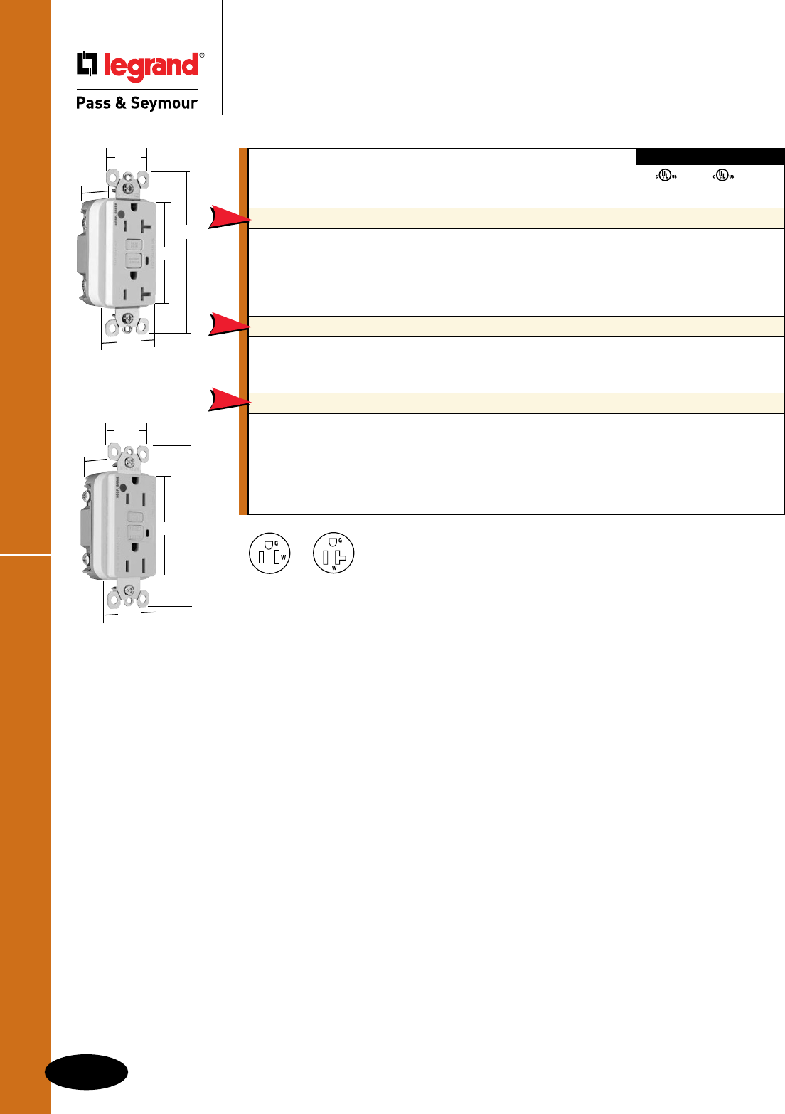
C-18
GFCIs
All devices listed on this page conform to NEMA WD-1 and WD-6.
NAFTA-Compliant Hospital Grade GFCIs
GFCIs
NAFTA-Compliant Hospital Grade
GFCI Receptacles
2 Pole, 3 Wire Grounding 15 & 20A, 125VAC
NEMA
5-15R
NEMA
5-20R
NAFTA-Compliant GFCI Receptacles are ideal for use on projects subject to the provisions of the
Buy American Act.
Catalog Rating NEMA
Number A. VAC Color Cong. No.
NAFTA-Compliant Hospital Grade Tamper-Resistant 20 Amp Duplex GFCI
2095HGTRNAI 20 125 Ivory 5-20R • • •
2095HGTRNAW 20 125 White 5-20R • • •
2095HGTRNAGRY 20 125 Gray 5-20R • • •
2095HGTRNARED 20 125 Red 5-20R • • •
2095HGTRNALA 20 125 Light Almond 5-20R • • •
NAFTA-Compliant Hospital Grade 15 Amp Duplex GFCI
1595HGNAI 15 125 Ivory 5-15R • • •
1595HGNAW 15 125 White 5-15R • • •
1595HGNARED 15 125 Red 5-15R • • •
NAFTA-Compliant Hospital Grade 20 Amp Duplex GFCI
2095HGNAI 20 125 Ivory 5-20R • • •
2095HGNAW 20 125 White 5-20R • • •
2095HGNA 20 125 Brown 5-20R • • •
2095HGNAGRY 20 125 Gray 5-20R • • •
2095HGNARED 20 125 Red 5-20R • • •
2095HGNALA 20 125 Light Almond 5-20R • • •
UL943 UL498 FSUL
C22.2 No. 144 C22.2 No. 42 WC596
3rd Party Compliance
NEW
NEW
NEW
1.72"
1.25"
2.62"
4.20"
.98"
2095HGTRNAW
1595HGNAW
1.72"
1.25"
2.62"
4.20"
.98"
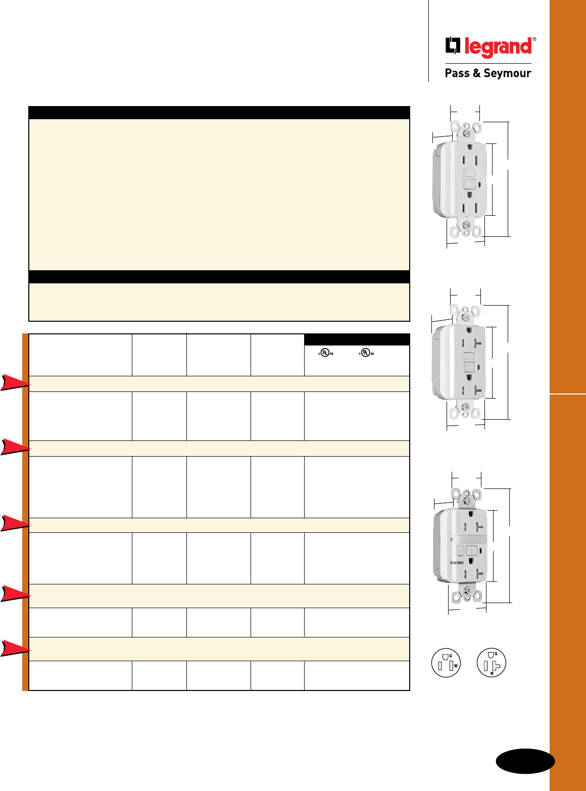
C-19
GFCIs
All devices listed on this page conform to NEMA WD-1 and WD-6.
NAFTA-Compliant PlugTail™ GFCI Receptacles
GFCIs
NAFTA-Compliant
PlugTail™ GFCI Receptacles
2 Pole, 3 Wire Grounding 15 & 20A, 125VAC
PT1595NAW
1.72"
1.25"
2.62"
4.20"
.98"
NEMA
5-15R
NEMA
5-20R
Specications
n Supply Voltage: 125VAC, 60 Hz
n Supply Voltage Range: 102-132 VAC
n Trip Threshold: 5± 1mA
n Trip Time: 0.025 sec., nominal per
UL Standard
n 20 Amp feed-thru capacity
Features
n Faster, more reliable installation.
n No exposed terminals create a finger safe
application before, during, and after installation.
n Built-in connector features large brass terminal
blades to ensure consistent, reliable electrical
connections to PlugTail Connector.
n GFCI works with the existing 3 wire PlugTail
Connectors creating a non-feed-thru application for
facility owners. At rough-in just install the same right
angle connector for GFCI and receptacle openings.
n SafeLockTM Protection: if critical components are
damaged and ground fault protection is lost, power
to receptacle is disconnected.
n FSUL Listed (Federal Specification WC596).
n Exceeds UL943 voltage surge requirements;
survives 100x the required UL 3kA/6kV
voltage surge test cycles.
n Trip indicator light (red LED).
n Mounting screws are shipped captive in the
device and wall plate for easier installation.
n High-impact-resistant thermoplastic
construction.
n Zinc-plated steel mounting strap.
n Button colors match the device face.
n Dual-direction test and reset buttons.
n Class A rated GFCI.
n Supplied with matching TP26 nylon wall plate.
n Tri-drive screws.
Catalog Rating NEMA
Number A. VAC Color Cong. No.
NAFTA-Compliant Spec Grade 15 Amp Duplex GFCI
PT1595NAI 15 125 Ivory 5-15R • • •
PT1595NAW 15 125 White 5-15R • • •
PT1595NAGRY 15 125 Gray 5-15R • • •
PT1595NALA 15 125 Light Almond 5-15R • • •
NAFTA-Compliant Spec Grade 20 Amp Duplex GFCI
PT2095NAI 20 125 Ivory 5-20R • • •
PT2095NAW 20 125 White 5-20R • • •
PT2095NAGRY 20 125 Gray 5-20R • • •
PT2095NABK 20 125 Black 5-20R • • •
PT2095NALA 20 125 Light Almond 5-20R • • •
NAFTA-Compliant Spec Grade Tamper-Resistant 20 Amp Duplex GFCI
PT2095TRNAI 20 125 Ivory 5-20R • • •
PT2095TRNAW 20 125 White 5-20R • • •
PT2095TRNAGRY 20 125 Gray 5-20R • • •
PT2095TRNALA 20 125 Light Almond 5-20R • • •
NAFTA-Compliant Spec Grade Tamper-Resistant 15 Amp
Combination Nightlight/GFCI
PT1595NTLTRNAI 15 125 Ivory 5-15R • • •
PT1595NTLTRNAW 15 125 White 5-15R • • •
NAFTA-Compliant Spec Grade Tamper-Resistant 20 Amp
Combination Nightlight/GFCI
PT2095NTLTRNAI 20 125 Ivory 5-20R • • •
PT2095NTLTRNAW 20 125 White 5-20R • • •
UL943 UL498 FSUL
C22.2 No. 144 C22.2 No. 42 WC596
3rd Party Compliance
NEW
NEW
NEW
NEW
NEW
NAFTA-Compliant GFCI Receptacles are ideal for use on projects subject to the provisions of the
Buy American Act.
1.72"
1.25"
2.62"
4.20"
.98"
PT2095TRNAW
For PlugTail Connector catalog numbers, see Page C-20.
PT2095NTLTRNAW
1.72"
1.25"
2.62"
4.20"
1.13"
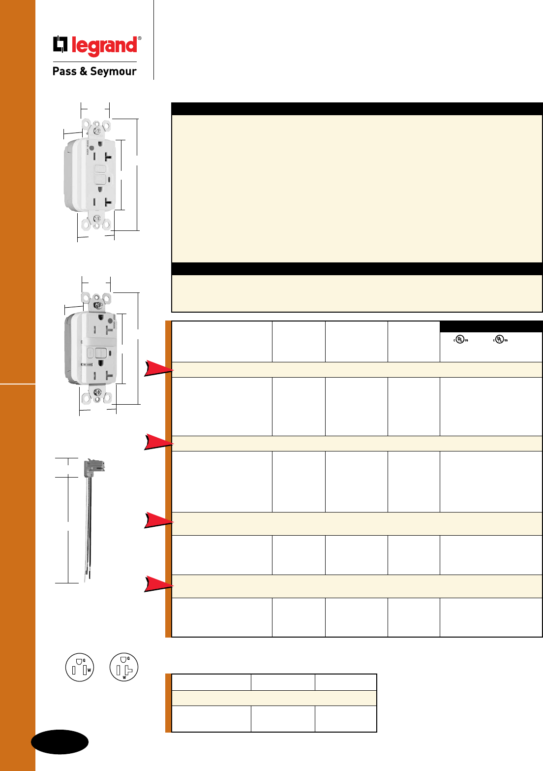
C-20
GFCIs
All devices listed on this page conform to NEMA WD-1 and WD-6.
NAFTA-Compliant PlugTail™ Hospital Grade GFCIs
GFCIs
NAFTA-Compliant PlugTail™
Hospital Grade GFCI Receptacles
2 Pole, 3 Wire Grounding 15 & 20A, 125VAC
Specications
n Supply Voltage: 125VAC, 60 Hz
n Supply Voltage Range: 102-132 VAC
n Trip Threshold: 5± 1mA
n Trip Time: 0.025 sec., nominal per
UL Standard
n 20 Amp feed-thru capacity
Features
n Faster, more reliable installation.
n No exposed terminals create a finger safe
application before, during, and after installation.
n Built-in connector features large brass terminal
blades to ensure consistent, reliable electrical
connections to PlugTail Connector.
n GFCI works with the existing 3 wire PlugTail
Connectors creating a non-feed-thru application for
facility owners. At rough-in just install the same right
angle connector for GFCI and receptacle openings.
n SafeLockTM Protection: if critical components are
damaged and ground fault protection is lost, power
to receptacle is disconnected.
n FSUL Listed (Federal Specification WC596).
n Exceeds UL943 voltage surge requirements;
survives 100x the required UL 3kA/6kV
voltage surge test cycles.
n Trip indicator light (red LED).
n Mounting screws are shipped captive in the
device and wall plate for easier installation.
n High-impact-resistant thermoplastic
construction.
n Zinc-plated steel mounting strap.
n Button colors match the device face.
n Dual-direction test and reset buttons.
n Class A rated GFCI.
n Supplied with matching TP26 nylon wall plate.
n Tri-drive screws.
Catalog Rating NEMA
Number A. VAC Color Cong. No.
NAFTA-Compliant Hospital Grade 20 Amp Duplex GFCI
PT2095HGNAI 20 125 Ivory 5-20R • • •
PT2095HGNAW 20 125 White 5-20R • • •
PT2095HGNAGRY 20 125 Gray 5-20R • • •
PT2095HGNARED 20 125 Red 5-20R • • •
PT2095HGNALA 20 125 Light Almond 5-20R • • •
NAFTA-Compliant Hospital Grade Tamper-Resistant 20 Amp Duplex GFCI
PT2095HGTRNAI 20 125 Ivory 5-20R • • •
PT2095HGTRNAW 20 125 White 5-20R • • •
PT2095HGTRNAGRY 20 125 Gray 5-20R • • •
PT2095HGTRNARED 20 125 Red 5-20R • • •
PT2095HGTRNALA 20 125 Light Almond 5-20R • • •
NAFTA-Compliant Hospital Grade
Tamper-Resistant
15 Amp
Combination Nightlight/GFCI
PT1595HGNTLTRNAI 15 125 Ivory 5-15R • • •
PT1595HGNTLTRNAW 15 125 White 5-15R • • •
PT1595HGNTLTRNARED 15 125 Red 5-15R • • •
NAFTA-Compliant Hospital Grade
Tamper-Resistant
20 Amp
Combination Nightlight/GFCI
PT2095HGNTLTRNAI 20 125 Ivory 5-20R • • •
PT2095HGNTLTRNAW 20 125 White 5-20R • • •
PT2095HGNTLTRNARED 20 125 Red 5-20R • • •
UL943 UL498 FSUL
C22.2 No. 144 C22.2 No. 42 WC596
3rd Party Compliance
NEW
NEW
NEW
NEW
NAFTA-Compliant GFCI Receptacles are ideal for use on projects subject to the provisions of the
Buy American Act.
PT2095HGNAW
1.72"
1.25"
2.62"
4.20"
.98"
PT2095HGNTLTRNAW
1.72"
1.25"
2.62"
4.20"
1.13"
Catalog Number Wire Type Wire Length
PlugTail Connectors – Right Angle
PTRA6STR Stranded 6"
PTRA6SOL Solid 6"
For additional PlugTail Connectors,
see Page B-3.
All PlugTail Connectors are available in
any wire length up to 25 inches, consult
factory to order.
PTRA6STR
1.125"
6.375"
NEMA
5-15R
NEMA
5-20R
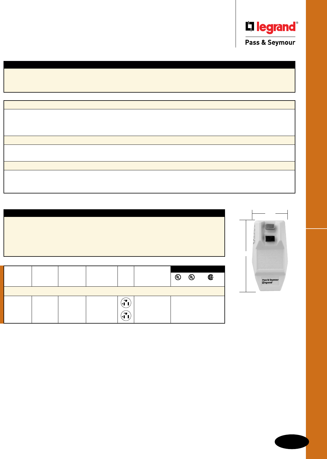
C-21
GFCIs
All devices listed on this page conform to NEMA WD-1 and WD-6.
1594CMM
2.00"
4.00"
Portables
GFCIs
Portables
Features & Specications
n Durable polycarbonate case withstands hard use.
n Open neutral protection.
n Supply Voltage: 125VAC, 60 Hz
n Supply Voltage Range: 102-132VAC
n Operating Temperature: -35°C (-30°F) to
+66°C (150°F)
n Trip Time: .025 sec., nominal per UL Standard
n Trip Threshold: 5 ±1mA
n Cord Grip Range: .30"-.46"
n RoHS-Compliant.
Catalog Rating NEMA Right Angle
Number Reset A. VAC Cong. No. GFCI Plug
Right Angle Plug – Portable GFCI
1594CMM Manual 15 125 5-15P User attachable • • •
1594CMA Automatic 15 125 5-15P User attachable • • •
UL943 UL498 C22.2 No. 144
3rd Party Compliance
Open Neutral Protection
All Legrand/Pass & Seymour portable GFCIs have an open neutral relay that automatically cuts off power to the line (hot) conductor
of the device in the event that the neutral wire preceding the GFCI becomes severed. For example, if your portable GFCI were plugged
into an extension cord that was supplying the power and the neutral conductor on that extension cord was accidentally cut (as can
happen on a job site), the open neutral relay would shut off power to the hot conductor. This provides an additional level of safety from
possible ground faults.
Manual Reset GFCI
Requires the GFCI to be manually set for use by pressing the reset button upon plug in and after loss of primary power (power failure or
unplugging the device). Must be manually reset after a ground fault condition. Ideal for applications where operator injury might occur if
equipment were to restart after a power failure. Typical equipment includes power drills, saws, lathes, and grinders.
Automatic Reset GFCI
Automatically energizes or sets the GFCI for use upon plug in and after the loss of primary power (power failure or unplugging the device).
After a ground fault condition, must be reset by pushing the reset button. This feature eliminates the need for unit to be reset each time it
is plugged in or powered up. Ideal for equipment intended for continuous use where a temporary power failure is likely and undesirable.
Examples are pumps, pressure washers, portable signs, or lighting and engine heaters.
Applications
All Legrand/Pass & Seymour Portable GFCIs meet OSHA and NEC requirements to provide ground fault protection for personnel utilizing
temporary power during construction, remodeling, maintenance, repair and demolition. Can be used with power tools, high-pressure power
washers, wet vacuums, and grounds keeping equipment. Also used on spas, hot tubs, vending machines, and portable signs to provide
ground fault protection.
RoHS-Compliant Portable GFCIs meet the requirements of Restriction of Hazardous Substances
directives and regulations.
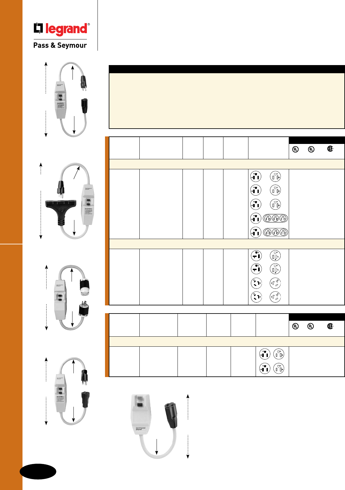
C-22
GFCIs
All devices listed on this page conform to NEMA WD-1 and WD-6.
Portables
GFCIs
Portables
NEMA
Catalog Rating Cong.
Number Description Reset A. VAC No. Plug Conn.
Cord Set – Portable GFCI
1594CS1M 1' cord Manual 15 125 5-15P/R • • •
with connector
1594CS1A 1' cord Automatic 15 125 5-15P/R • • •
with connector
UL943 UL498 C22.2 No. 144
3rd Party Compliance
Features & Specications
n Durable polycarbonate case withstands hard use.
n In-line has power indicator light that is on when
power is available.
n Open neutral protection.
n Optional Turnlok® plugs and connectors prevent
accidental disconnection.
n Optional tri-cord connector handles up to
three loads.
n Supply Voltage: 125VAC, 60 Hz
n Supply Voltage Range: 102-132VAC
n Operating Temperature: -35°C (-30°F)
to +66°C (150°F)
n Trip Time: .025 sec., nominal per UL Standard
n Trip Threshold: 5 ±1mA
n RoHS-Compliant.
NEMA
Catalog Rating Cong.
Number Description Reset A. VAC No. Plug Conn.
15 Amp In-Line – Portable GFCI
1594PC6M 6' cord, Manual 15 125 5-15P/R • • •
straight blade
1594PC2M 2' cord, Manual 15 125 5-15P/R • • •
straight blade
1594PC2A 2' cord, Auto. 15 125 5-15P/R • • •
straight blade
1594TC2M 2' cord with Manual 15 125 5-15P/R • • •
tri-cord connector
1594TC2A 2' cord with Auto. 15 125 5-15P/R • • •
tri-cord connector
20 Amp In-Line Portable GFCI
2094PC2A 2' cord, Auto. 20 125 5-20P/R • • •
straight blade
2094PC2M 2' cord, Manual 20 125 5-20P/R • • •
straight blade
2094TL2A 2' cord, Turnlok® Auto. 20 125 L5-20P/R • • •
2094TL2M 2' cord, Turnlok® Manual 20 125 L5-20P/R • • •
UL943 UL498 C22.2 No. 144
3rd Party Compliance
1594PC2A
9.6"
11.75"
Total
Length
27.75"
1594TC2A
10.25"
10.10"
Total
Length
26.75"
1594CS1M
1594CS1A
9.8"
Total
Length
13.60"
Total
Length
26.00"
2094TL2M
7.6"
12.00"
2094PC2A
Total
Length
24.90"
8.75"
9.75"
RoHS-Compliant Portable GFCIs meet the requirements
of Restriction of Hazardous Substances directives and
regulations.
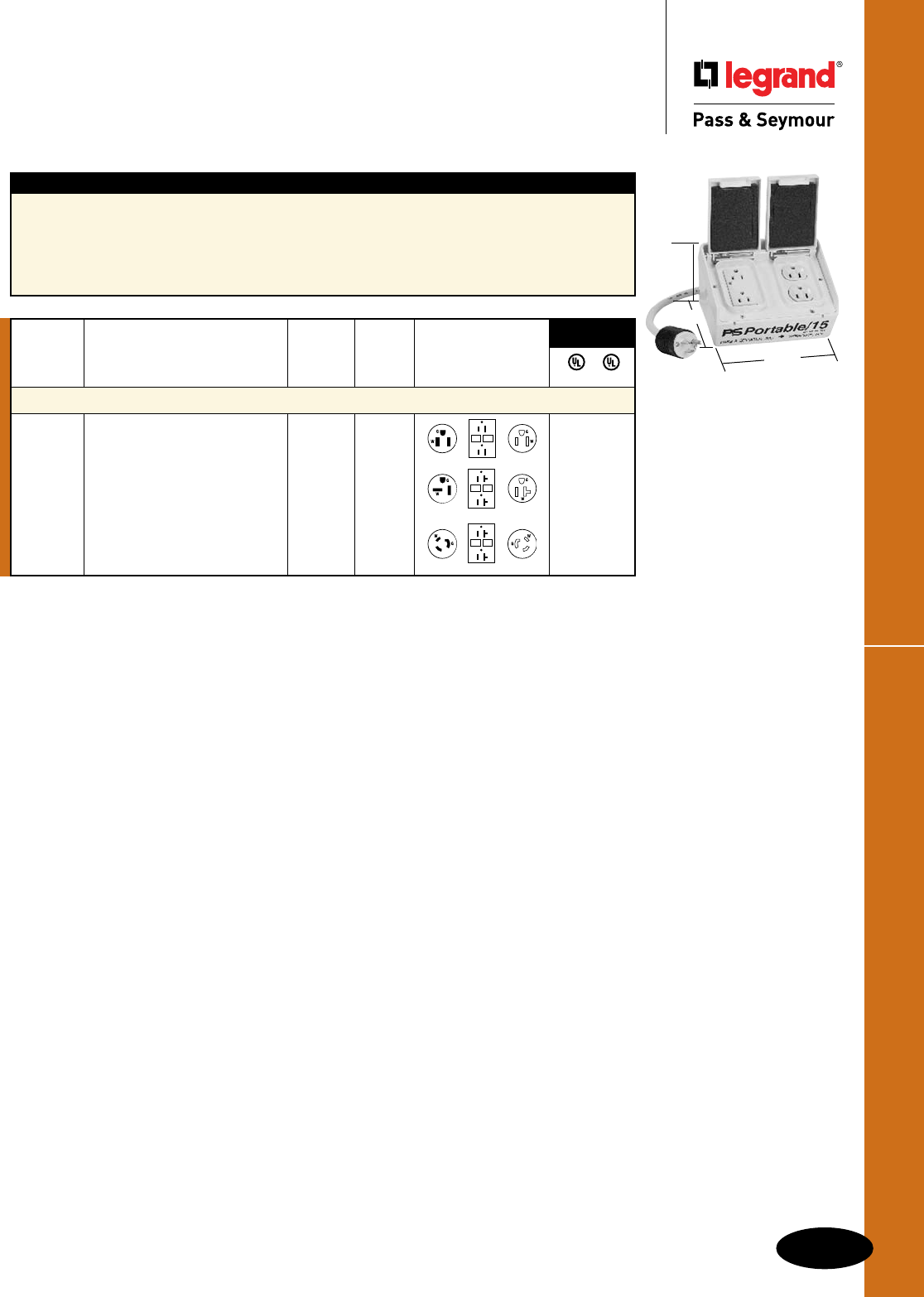
C-23
GFCIs
All devices listed on this page conform to NEMA WD-1 and WD-6.
Portables
GFCIs
Portables
NEMA
Catalog Rating Cong.
Number Description A. VAC No. Plug Receptacle
Auto Reset Boxes – Portable GFCI
PS154S Four 15A, 125V straight blade 15 125 5-15P • •
outlets. Cord has 15A, 125V plug 5-15R
PS204S Four 20A, 125V straight blade 20 125 5-20P • •
outlets. Cord has 20A, 125V plug 5-20R
PL204L Two 20A, 125V straight blade 20 125 L5-20P • •
outlets and one 20A 125V locking L5-20R
outlet has 20A, 125V locking plug 5-20R
3rd Party
Compliance
UL943 UL498
Features & Specications
n Handles up to four loads.
n Open neutral protection.
n High-impact-resistant thermoplastic housing.
n Optional Turnlok® plugs and connectors prevent
accidental disconnection.
n Supply Voltage: 125VAC, 60 Hz
n Supply Voltage Range: 102-132VAC
n Trip Threshold: 5 ±1mA
n Trip Time: .025 sec., nominal per UL Standard
n Case Material: Yellow Thermoplastic
PS154S
5.287"
6.666"
Height
at rear
3.950"
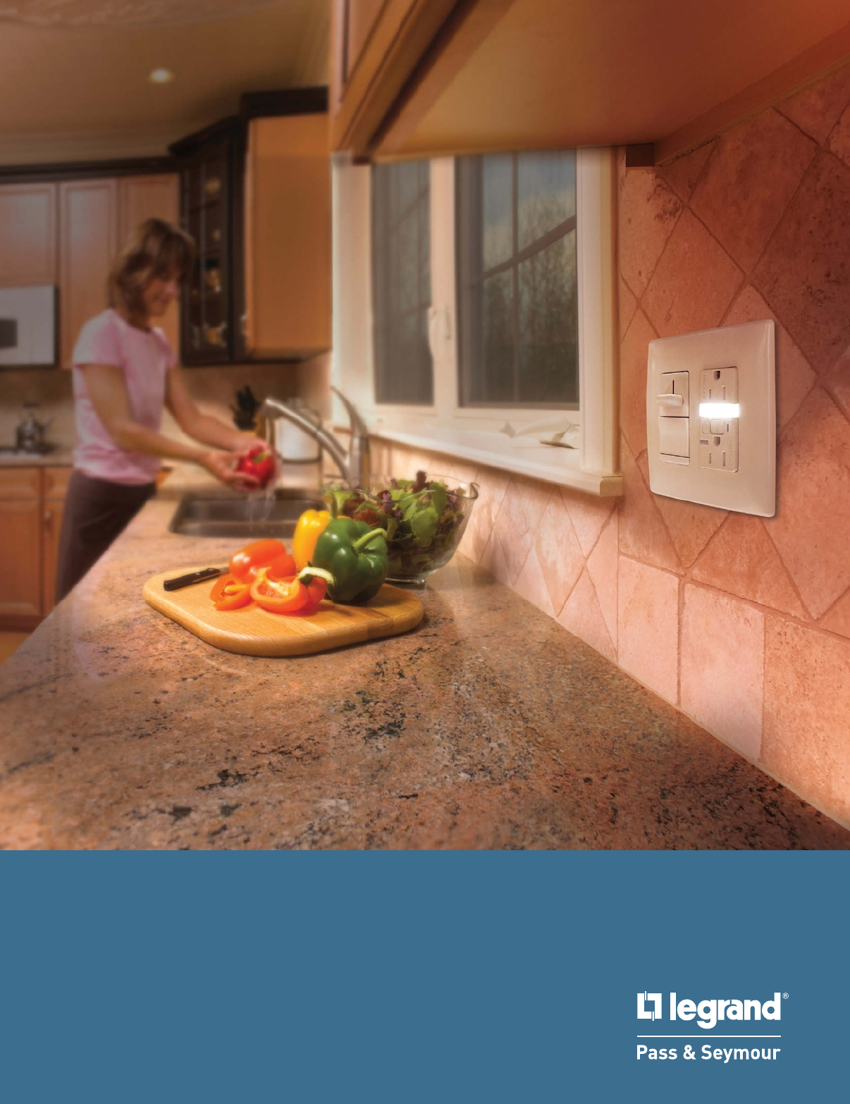
DECORATOR DEVICES
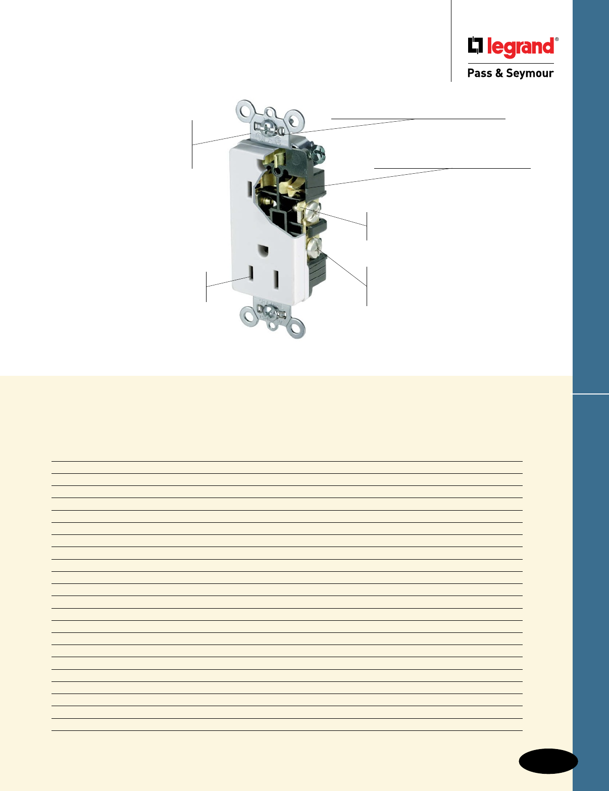
Decorator Devices
D-1
Decorator Devices
Device Page Number
PlugTail™ Specification Grade Decorator Switches D-2, D-3
Specification Grade Decorator & Combination & Contact Switches D-4, D-8, D-9, D-20
TradeMaster® Decorator & Combinations D-5 – D-8, D-10 – D-12
Home Locator Switches D-13
PlugTail™ Decorator Receptacles D-14
Hospital & Specification Grade & Isolated Ground Decorator Receptacles D-15 – D-17
Heavy-Duty Tamper-Resistant Decorator Receptacles & Single Receptacles D-18 – D-20
TradeMaster® Decorator Receptacles & Hallway Lights & Combinations D-21, D-23, D-24
Weather-Resistant Receptacles D-22
Recessed TV Boxes D-25
TradeMaster®, Specification & Hospital Grade GFCI & Combination Receptacles D-26 – D-35, D-40, D-41
PlugTail™ GFCI Receptacles D-36 – D-39, D-42, D-43
Surge Protective Receptacles D-44 – D-50
Vacancy & Occupancy Sensors & Timers D-51 – D-61
RF Lighting Control System D-62, D-63
Scene Director & Leandro® D-64 – D-66
Harmony™ TradeMaster® Dimmers & Fan Speed Controls D-67, D-68
LS TradeMaster® Series D-69 – D-71
DR TradeMaster® Series D-72
Wide Slide TradeMaster® Series D-73
Titan™ Series D-74 – D-81
Decorator Wall Plates D-82 – D-86
Our complete line of Decorator devices combine today’s
design aesthetics — with ease of installation, reliability,
and performance that never goes out of style.
26252W
Triple-wipe contacts interface with
plug blades at three points for better
contact, lasting blade retention.
Totally isolated terminal
compartments for positive
conductor containment.
Side and internal screw-
pressure-plate back wire
capability. Accepts #14 – #10
AWG solid or stranded wire.
Chromate-plated steel
strap ensures structural
integrity. A high-strength,
nylon face withstands impacts.
Easily accessed break-off,
line-contact connecting tab
for fast, easy split-circuit wiring.
Auto-ground clip assures positive ground.
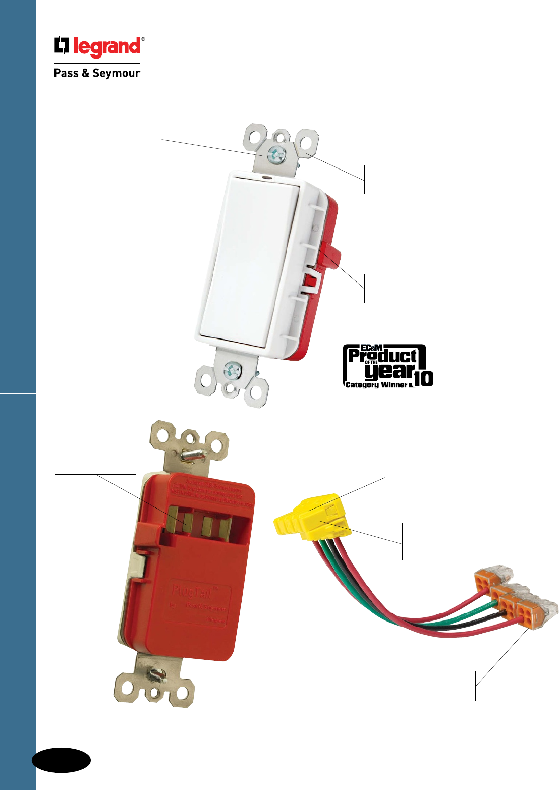
D-2
Decorator Devices
Decorator Devices
PlugTail™ Specification Grade
Decorator Switches
PlugTail™ Spec Grade Decorator Switches
PT2626W
Large brass contacts snugly terminate on
device blade terminals. Audible snapping
latch assures connection, allows release.
WAGO push-in connectors
are available to further speed
up installation.
Polycarbonate connector
housing secures terminations
and conductors in a UL Listed,
finger-safe housing.
Built-in connector
features large brass
terminal blades to
ensure consistent,
reliable electrical
connections.
Shallow design
for easier installation.
Auto-ground clip
assures positive ground.
Heavy-gauge
steel strap for
superior strength.
No exposed terminals create
a finger-safe application before,
during, and after installation.
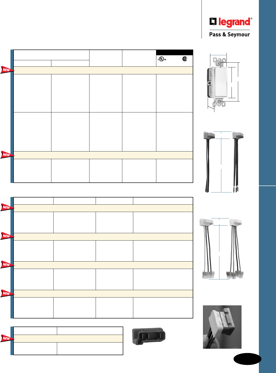
D-3
Decorator Devices
All devices listed on this page conform to NEMA WD-1 and WD-6.
PlugTail™ Spec Grade Decorator Switches
Decorator Devices
PlugTail™ Specification Grade
Decorator Switches
15 & 20A, 120/277VAC
PT2626W
1.6"
3.281"
1.2"
2.6"
PTS6STR3 PTS6STR4
1.125"
6.375"
PTS6STR3BP PTS6STR4BP
1.125"
6.375"
Catalog Number Wire Type Wire Length Wire Colors
PlugTail Connectors for Single Pole Switches
PTS6STR3 3 Wire Stranded 6" Green, Black, Black
PTS6SOL3 3 Wire Solid 6" Green, Black, Black
PTS6STR3277 3 Wire Stranded 6" Green, Brown, Brown
PTS6SOL3277 3 Wire Solid 6" Green, Brown, Brown
PlugTail Connectors for Three-Way Switches
PTS6STR4 4 Wire Stranded 6" Green, Red, Red, Black
PTS6SOL4 4 Wire Solid 6" Green, Red, Red, Black
PTS6STR4277 4 Wire Stranded 6" Green, Brown, Yellow, Yellow
PTS6SOL4277 4 Wire Solid 6" Green, Brown, Yellow, Yellow
PlugTail Connectors for Single Pole Switches With WAGO Connectors
PTS6STR3BP 3 Wire Stranded 6" Green, Black, Black
PTS6SOL3BP 3 Wire Solid 6" Green, Black, Black
PTS6STR3277BP 3 Wire Stranded 6" Green, Brown, Brown
PTS6SOL3277BP 3 Wire Solid 6" Green, Brown, Brown
PlugTail Connectors for Three-Way Switches With WAGO Connectors
PTS6STR4BP 4 Wire Stranded 6" Green, Red, Red, Black
PTS6SOL4BP 4 Wire Solid 6" Green, Red, Red, Black
PTS6STR4277BP 4 Wire Stranded 6" Green, Brown, Yellow, Yellow
PTS6SOL4277BP 4 Wire Solid 6" Green, Brown, Yellow, Yellow
PTJ
3rd Party Compliance
Catalog Number Rating FSUL
Single Pole Three-Way A. VAC Color UL20 WS896 C22.2 111
Decorator Switches
PT2601I PT2603I 15 120/277 Ivory • • •
PT2601W PT2603W 15 120/277 White • • •
PT2601 PT2603 15 120/277 Brown • • •
PT2601GRY PT2603GRY 15 120/277 Gray • • •
PT2601RED PT2603RED 15 120/277 Red • • •
PT2601BK PT2603BK 15 120/277 Black • • •
PT2601LA PT2603LA 15 120/277 Light Almond • • •
PT2621I PT2623I 20 120/277 Ivory • • •
PT2621W PT2623W 20 120/277 White • • •
PT2621 PT2623 20 120/277 Brown • • •
PT2621GRY PT2623GRY 20 120/277 Gray • • •
PT2621RED PT2623RED 20 120/277 Red • • •
PT2621BK PT2623BK 20 120/277 Black • • •
PT2621LA PT2623LA 20 120/277 Light Almond • • •
Illuminated Decorator Switches
PT2625I PT2626I 20 120/277 Ivory • • •
PT2625W PT2626W 20 120/277 White • • •
PT2625BK PT2626BK 20 120/277 Black • • •
PT2625LA PT2626LA 20 120/277 Light Almond • • •
Catalog Number Description
PlugTail Jumper
PTJ PlugTail Cover for Rough In
PTJ5 PlugTail Cover for Rough In, 5-pack
Available in 347VAC Canadian Catalog Numbers, add 347 to the end of the Catalog Number.
Example: PT2601W347. All Canadian Products have Combination Slotted/Robertson Head Brass Screws.
All PTS Connectors are 120/277VAC
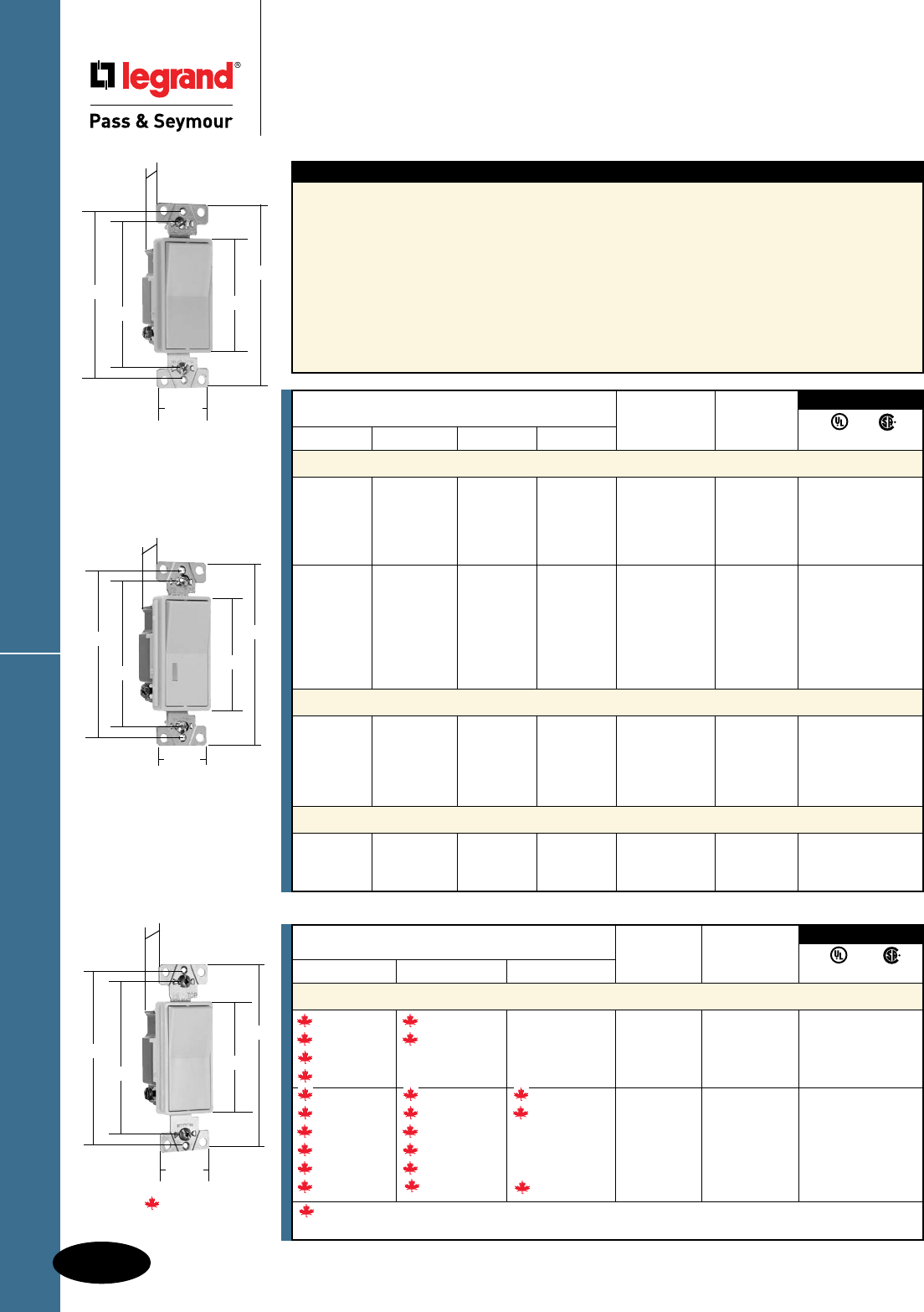
3rd Party Compliance
Catalog Number Rating
Single Pole Three-Way Four-Way A. VAC Color UL20 C22.2 111
Specification Grade Decorator Switches Back & Side Wire
2601347I 2603347I 15 347 Ivory • •
2601347W 2603347W 15 347 White • •
2601347GRY 15 347 Gray • •
2601347LA 15 347 Light Almond • •
2621347I 2623347I 2624347I 20 347 Ivory • •
2621347W 2623347W 2624347W 20 347 White • •
2621347GRY 2623347GRY 20 347 Gray • •
2621347BK 2623347BK 20 347 Black • •
2621347RED 2623347RED 20 347 Red • •
2621347LA 2623347LA 2624347LA 20 347 Light Almond • •
Denotes Canadian catalog number. All Canadian products have Combination Slotted/Robertson Head
Brass Screws.
Specification Grade Decorator Switches
D-4
Decorator Devices
All devices listed on this page conform to NEMA WD-1 and WD-6.
Decorator Devices
Specification Grade Decorator Switches
15 & 20A, 120/277 & 347VAC; 20A, 120VAC
Features
n Impact-resistant polycarb back body and frame.
n Cushioned thermoplastic paddle assures smooth,
quiet, long term operation.
n Unique single rocking butterfly contact provides
long term consistent performance with significantly
fewer moving parts.
n Internal screw-pressure-plate back and side wire
capability for easy installation with #14 – #10 stranded
or solid copper/copper clad wire. Terminals made of
high conductivity brass and serrated for maximum
wire gripping.
n Silver alloy contacts integrally formed
to the butterfly actuator assures reliable
performance.
n Integral auto-ground clip for positive ground
to metal boxes.
n Tri-drive ground, terminal and mounting
screws. All terminal screws backed out,
ready-to-install.
3rd Party Compliance
Catalog Number Rating
Single Pole Double Pole Three-Way Four-Way A. VAC Color
UL20 C22.2 111
Specification Grade Decorator Switches Back & Side Wire
2601I 2603I 2604I 15 120/277 Ivory • •
2601W 2603W 2604W 15 120/277 White • •
2601GRY 2603GRY 15 120/277 Gray • •
2601BK 2603BK 15 120/277 Black • •
2601LA 2603LA 2604LA 15 120/277 Light Almond • •
2621I 2622I 2623I 2624I 20 120/277 Ivory • •
2621W 2622W 2623W 2624W 20 120/277 White • •
2621 2622 2623 2624 20 120/277 Brown • •
2621GRY 2622GRY 2623GRY 2624GRY 20 120/277 Gray • •
2621BK 2622BK 2623BK 2624BK 20 120/277 Black • •
2621RED 2623RED 2624RED 20 120/277 Red • •
2621LA 2622LA 2623LA 2624LA 20 120/277 Light Almond • •
Illuminated Decorator Switches (Lighted when OFF) Back & Side Wire
2625I 2626I 2628I 20 120 Ivory • •
2625W 2626W 2628W 20 120 White • •
2625 20 120 Brown • •
2625RED 20 120 Red • •
2625LA 2626LA 2628LA 20 120 Light Almond • •
Pilot Lighted Decorator Switches (Lighted when ON) Back & Side Wire
2629I 20 120 Ivory • •
2629W 20 120 White • •
2629LA 20 120 Light Almond • •
For Bulk Packaging Solutions consult factory.
2601347
2.620"
4.200"
1.060"
3.531"
4.063"
1.300"
2601
2.620"
4.200"
1.060"
3.281"
3.812"
1.300"
2625, 2626, 2629
2.620"
4.200"
1.060"
3.281"
3.812"
1.300"
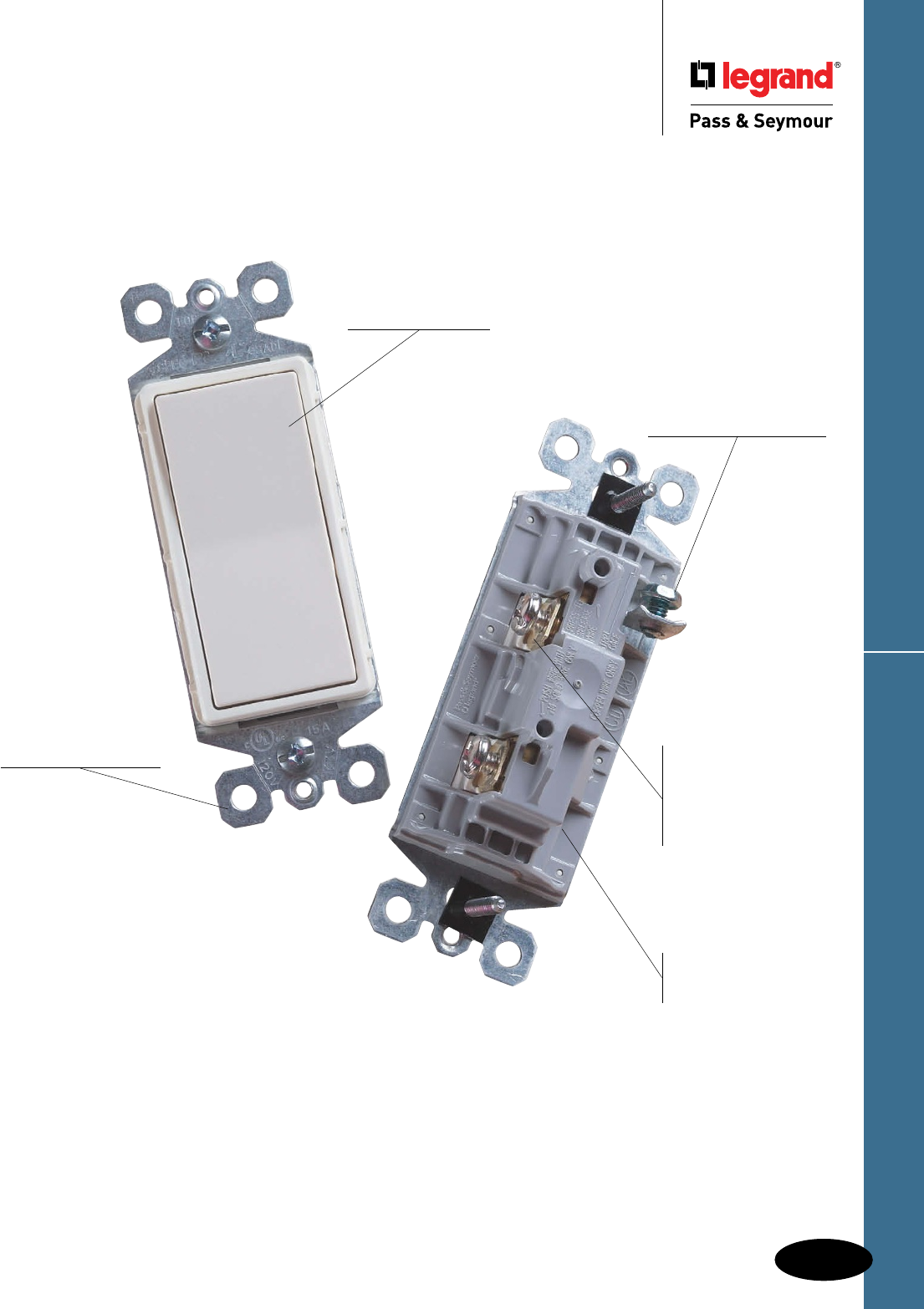
D-5
Decorator Devices
Decorator Devices
TradeMaster® Decorator Switches
Ground screw location
maximizes distance from
terminal screw on adjacent
device to eliminate risk of
dead shorts.
External screw-
pressure-plate
back wire eliminates
wrapping. Accepts
#12 and #14 stranded
and solid wire.
Narrow back body
leaves more room for
wires in the box.
Low profile paddle
offers the quality look
and feel builders and
homeowners love.
Extra-long, through-
body strap eliminates
floating installations and
imperfect applications.
TM870LA
TradeMaster® Decorator Switches
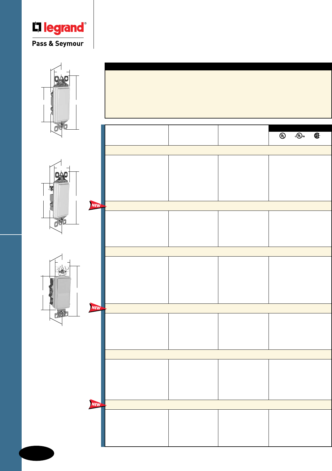
D-6
Decorator Devices
Decorator Devices
TradeMaster® Decorator Switches
15A, 120/277VAC
TradeMaster® Decorator Switches
All devices listed on this page conform to NEMA WD-1 and WD-6.
Features
n Designer-style satin-finish rocker.
n High-impact resistant thermoplastic construction.
n External screw-pressure-plate back and side wired.
Accepts #12 and #14 AWG.
n Push wire #14 AWG.
n Narrow back body leaves more room for wires
in the box.
n Extra-long, through-body strap eliminates
floating installations and imperfect applications.
n Smooth, quiet paddle action.
n Easy-access green hex head ground screw.
n Tri-drive ground, terminal and mounting screws.
n ON-OFF switches conform to NEC 430-104
requirements for kitchen disposal units.
TM870LA
2.620"
1.43"
.99"
1.27"
4.19"
TM873LA
2.620"
1.43"
.99"
1.27"
4.19"
TM874LA
2.620"
1.43"
.99"
1.27"
4.19"
NAFTA-Compliant
Switches are ideal for
use on projects subject
to the provisions of the
Buy American Act.
Rating
Catalog Number A. VAC Color
Single Pole Decorator Switches Grounding
TM870I 15 120/277 Ivory • •
TM870W 15 120/277 White • •
TM870 15 120/277 Brown • •
TM870GRY 15 120/277 Gray • •
TM870BK 15 120/277 Black • •
TM870LA 15 120/277 Light Almond • •
TM870BNCC10 15 120/277 Brushed Nickel • •
TM870TI 15 120/277 Titanium • •
NAFTA-Compliant Single Pole Decorator Switches
Grounding
TM870NAI 15 120 Ivory •
TM870NAW 15 120 White •
TM870NA 15 120 Brown •
TM870NAGRY 15 120 Gray •
TM870NABK 15 120 Black •
TM870NALA 15 120 Light Almond •
Three-Way Decorator Switches Grounding
TM873I 15 120/277 Ivory • •
TM873W 15 120/277 White • •
TM873 15 120/277 Brown • •
TM873GRY 15 120/277 Gray • •
TM873BK 15 120/277 Black • •
TM873LA 15 120/277 Light Almond • •
TM873BNCC10 15 120/277 Brushed Nickel • •
TM873TI 15 120/277 Titanium • •
NAFTA-Compliant Three-Way Decorator Switches
Grounding
TM873NAI 15 120 Ivory •
TM873NAW 15 120 White •
TM873NA 15 120 Brown •
TM873NAGRY 15 120 Gray •
TM873NABK 15 120 Black •
TM873NALA 15 120 Light Almond •
Four-Way Decorator Switches Grounding
TM874I 15 120/277 Ivory • •
TM874W 15 120/277 White • •
TM874 15 120/277 Brown • •
TM874BK 15 120/277 Black • •
TM874LA 15 120/277 Light Almond • •
TM874BNCC6 15 120/277 Brushed Nickel • •
TM874TI 15 120/277 Titanium • •
NAFTA-Compliant Four-Way Decorator Switches
Grounding
TM874I 15 120 Ivory •
TM874W 15 120 White •
TM874 15 120 Brown •
TM874GRY 15 120 Gray •
TM874BK 15 120 Black •
TM874LA 15 120 Light Almond •
3rd Party Compliance
UL20 C 22.2 111

D-7
Decorator Devices
Decorator Devices
TradeMaster® Decorator Illuminated &
Self-Grounding Switches
15A, 120 & 120/277VAC
TradeMaster® Decorator Switches
All devices listed on this page conform to NEMA WD-1 and WD-6.
3rd Party Compliance
UL20 C22.2 111
Rating
Catalog Number A. VAC Color
Single Pole Illuminated Decorator Switches Grounding (Lighted when OFF)
TM870ISL 15 120 Ivory • •
TM870WSL 15 120 White • •
TM870LASL 15 120 Light Almond • •
Self-Grounding Single Pole Decorator Switches
TM870SI 15 120/277 Ivory • •
TM870SW 15 120/277 White • •
TM870S 15 120/277 Brown • •
TM870SBK 15 120/277 Black • •
TM870SLA 15 120/277 Light Almond • •
Three-Way Illuminated Decorator Switches Grounding (Lighted when OFF)
TM873ISL 15 120 Ivory • •
TM873WSL 15 120 White • •
TM873LASL 15 120 Light Almond • •
Self-Grounding Three-Way Decorator Switches
TM873SI 15 120/277 Ivory • •
TM873SW 15 120/277 White • •
TM873S 15 120/277 Brown • •
TM873SBK 15 120/277 Black • •
TM873SLA 15 120/277 Light Almond • •
Four-Way Illuminated Decorator Switches Grounding (Lighted when OFF)
TM874ISL 15 120 Ivory • •
TM874WSL 15 120 White • •
TM874LASL 15 120 Light Almond • •
Self-Grounding Four-Way Decorator Switches
TM874SI 15 120/277 Ivory • •
TM874SW 15 120/277 White • •
TM874S 15 120/277 Brown • •
TM874SBK 15 120/277 Black • •
TM874SLA 15 120/277 Light Almond • •
TM870SLA
2.620"
1.43"
.99"
1.27"
4.19"
TM870LASL
2.620"
1.43"
.99"
1.27"
4.19"
Features
n Designer-style satin-finish rocker.
n High-impact resistant thermoplastic construction.
n External screw-pressure-plate back and side
wired. Accepts #12 and #14 AWG.
n Push wire #14 AWG.
n Narrow back body leaves more room for wires
in the box.
n Extra-long, through-body strap eliminates
floating installations and imperfect applications.
n Smooth, quiet paddle action.
n Easy-access green hex head ground screw.
n Tri-drive ground, terminal and mounting
screws.
n Self-grounding models provide automatic
ground clip.
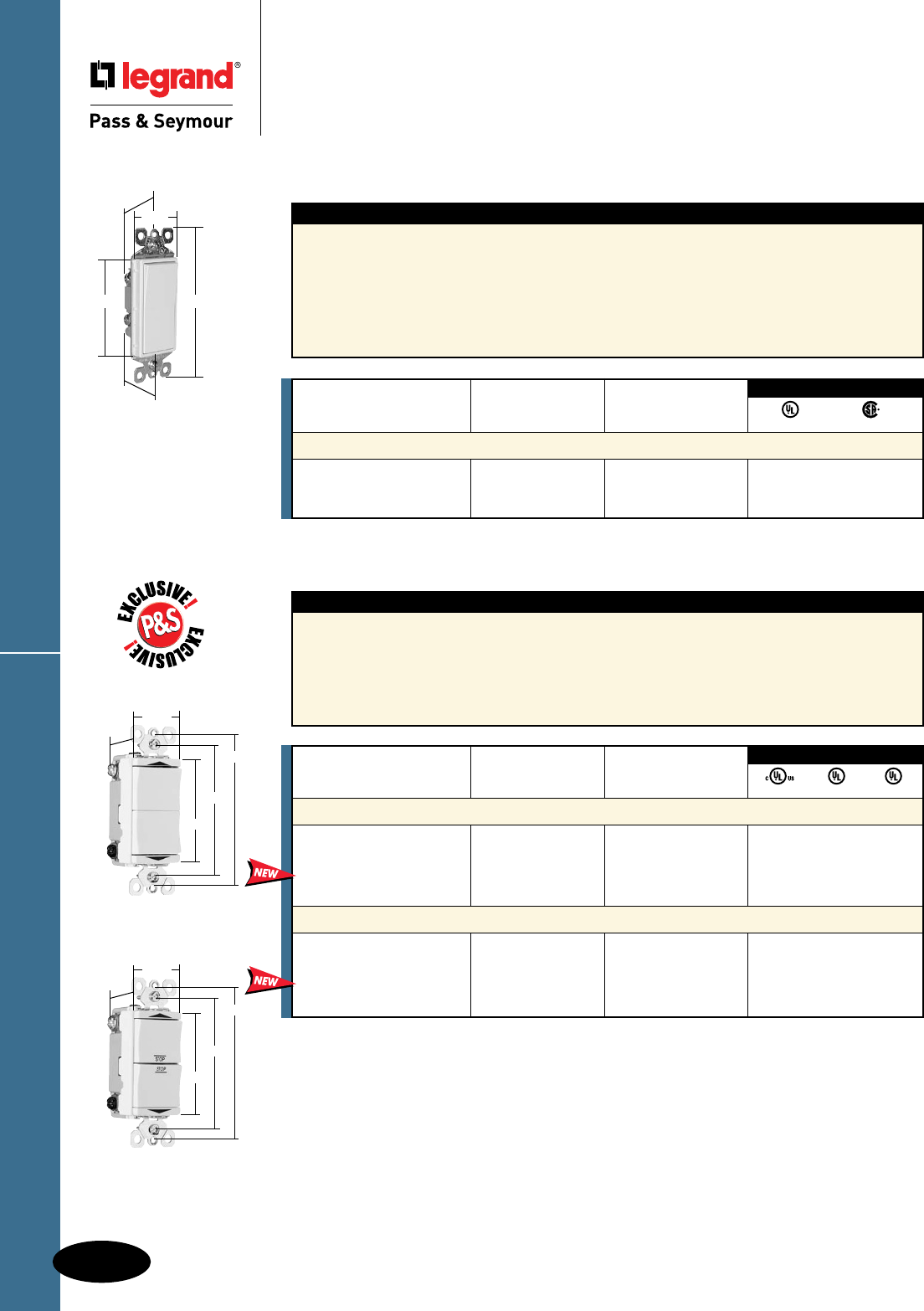
Rating
Catalog Number A. VAC Color
Single Pole Decorator Momentary Contact Switches
TM870STMWCC10 15 120/277 White • •
TM870STMBKCC10 15 120/277 Black • •
TM870STMLACC10 15 120/277 Light Almond • •
3rd Party Compliance
UL20 C22.2 111
Rating
Catalog Number A. VAC Color
Specification Grade Double Throw Momentary Contact Switches
TM811DTMOI 15 120 Ivory • •
TM811DTMOW 15 120 White • •
TM811DTMOBK 15 120 Black • •
TM811DTMOLA 15 120 Light Almond • •
Specification Grade Double Throw Maintained Contact Switches
TM811DTMAI 15 120 Ivory • •
TM811DTMAW 15 120 White • •
TM811DTMABK 15 120 Black • •
TM811DTMALA 15 120 Light Almond • •
3rd Party Compliance
cULus UL20 UL508
D-8
Decorator Devices
Decorator Devices
Decorator & Specification Grade
Momentary & Maintained
Contact Switches
15A, 120 & 120/277VAC
Decorator & Spec Grade Switches
Momentary
Contact
Maintained
Contact
TM870STMLACC10
2.620"
1.43"
.99"
1.27"
4.19"
Features
n Designer-style satin-nish rocker.
n High-impact resistant thermoplastic construction.
n External screw-pressure-plate back and side wired.
Accepts #12 and #14 AWG.
n Push wire #14 AWG.
n Narrow back body leaves more room for wires
in the box.
n Extra-long, through-body strap eliminates
oating installations and imperfect applications.
n Smooth, quiet paddle action.
n Easy-access green hex head ground screw.
n Tri-drive ground, terminal and mounting screws.
Features
n Unique “Up/Down” switches match the look and
feel of standard decorator switches.
n Impact-resistant face and body.
n Side and external screw-pressure-plate back wire
accepts #12 and #14 AWG.
n All screws are tri-drive.
n Full wraparound heavy-gauge steel strap is
plated for corrosion resistance and features
lock-in tabs.
n Patent-pending split circuit tab — easily
accessible, and can be reinstalled without
a tool.
1.29"
1.59"
2.60"
3.281"
3.812"
1.29"
1.59"
2.60"
3.281"
3.812"
All devices listed on this page conform to NEMA WD-1 and WD-6.
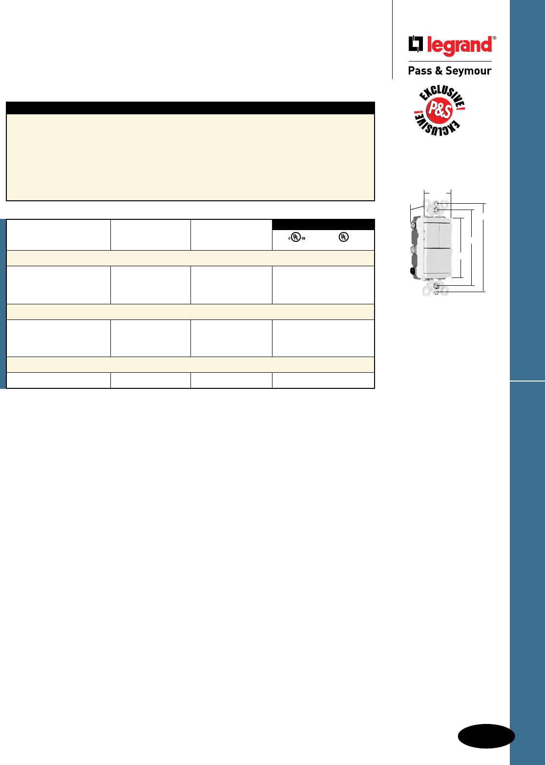
D-9
Decorator Devices
Decorator Devices
Specification Grade Decorator
Combination Switches
20A, 277VAC
Spec Grade Decorator Combination Switches
All devices listed on this page conform to NEMA WD-1 and WD-6.
Features
n Unique “Up/Down” switches match the look and
feel of standard decorator switches.
n Impact-resistant face and body.
n Side and external screw-pressure-plate back wire
accepts #12 and #14 AWG.
n All screws are tri-drive.
n Full wraparound heavy-gauge steel strap is plated
for corrosion resistance and features lock-in tabs.
n Patent-pending split circuit tab — easily
accessible, and can be reinstalled without a tool.
n Patent-pending snap-in light module (sold
separately) transforms a combination switch
into an illuminated switch.
n Identication modules (sold separately)
identies each switch — light, fan, heat lamp.
See Page A-24 for details.
15 & 20 Amp
1.29"
1.59"
2.60"
3.281"
3.812"
*For use with PS81120 and PS811120 only.
Rating
Catalog Number A. VAC Color
Two Single Pole Switches
PS81120I 20 277 Ivory • •
PS81120W 20 277 White • •
PS81120LA 20 277 Light Almond • •
Three Single Pole Switches
PS811120I 20 277 Ivory • •
PS811120W 20 277 White • •
PS811120LA 20 277 Light Almond • •
Snap-In Light Module*
PS8LM — — Clear
3rd Party Compliance
cULus UL20
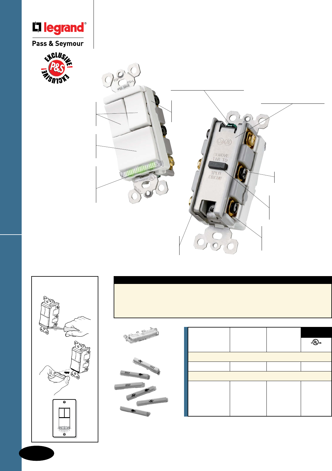
D-10
Decorator Devices
Decorator Devices
TradeMaster® Decorator
Combination Switches
TradeMaster® Decorator Combination Switches
Adding a Snap-In
Light Module
Impact-
resistant
face and
body.
Unique “Up/Down”
switches match the look
and feel of standard
Decorator switches.
Patented Snap-In
Light Module
(sold separately)
transforms a combination
switch into an illuminated
switch in seconds. Patented split circuit
tab – easily accessible,
and can be reinstalled
without a tool.
External screw-pressure-
plate back and side
wired. Accepts #12 and
#14 AWG.
Ground screw position
under the end of the strap
minimizes the risk of contact.
Fully rounded back body
protects wires from being
damaged by sharp edges.
Full wraparound metal
strap, commercial grade
with lock-in tabs.
Easy-to-use
oversized
main switch
for primary load.
TM8113WCC
Shown with Snap-In
Light Module TM8LMCC.
All screws
are tri-drive.
Identification modules
(sold separately) identifies
each switch — light, fan,
heat lamp.
Features
n Module simply snaps-in for easy installation.
n Can be installed with the following devices: TM811,
TM813, TM833, TM818, TM838, TM8111, TM8113,
TM81111, TM8118 and the LS Series of Dimmers &
Fan Speed Controls (see Pages M-13 through M-15).
Snap-In Light Module:
n Lights when OFF.
n Uses energy-efficient 1/4 watt LED light.
n LED light will not generate heat and will
last on average 47 years.
TM8IDWCC
TM8LMCC
For Decorator Hallway Lights and Combination Devices,
see Pages D-24.
Rating
Catalog Number A. VAC Color cULus
Snap-In Light Module
TM8LMCC 15 120/125 Clear •
Identification Modules
TM8IDICC — — Ivory
TM8IDWCC — — White
TM8IDCC — — Brown
TM8IDBKCC — — Black
TM8IDLACC — — Light Almond
3rd Party
Compliance
All devices listed on this page conform to NEMA WD-1 and WD-6.
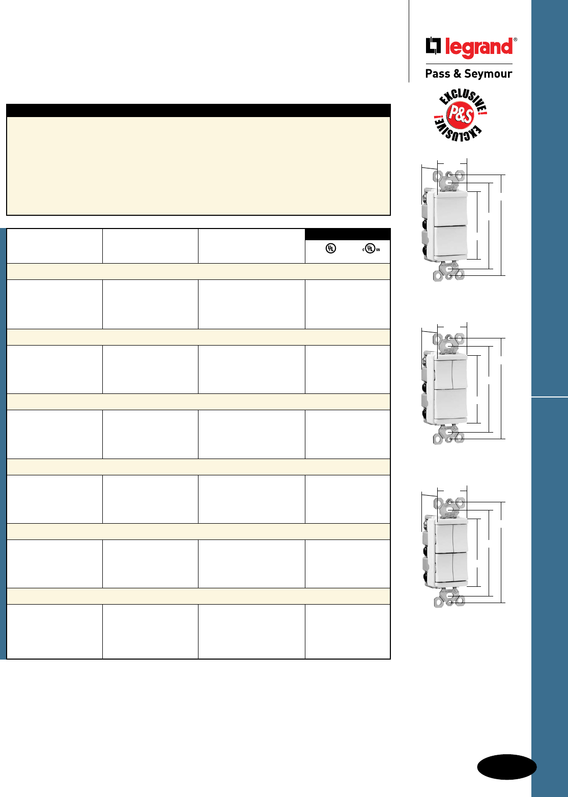
D-11
Decorator Devices
Decorator Devices
TradeMaster® Decorator
Combination Switches
15A, 120VAC
All devices listed on this page conform to NEMA WD-1 and WD-6.
TradeMaster® Decorator Combination Switches
Features
n Impact-resistant face and body.
n Fully rounded back body protects wires from
being damaged by sharp edges.
n Clear identication of circuits.
n External screw-pressure-plate back and side
wired. Accepts #12 and #14 AWG.
n Ground screw position under the end of the
strap minimizes the risk of contact.
n Full wraparound metal strap with lock-in tabs.
n Patented split circuit tab – easily accessible,
and can be reinstalled without a tool.
n Unique “Up/Down” switches match the look
and feel of standard Decorator switches.
n Largest breadth of 15 amp offering.
n All screws are tri-drive.
n Tamper-resistant version features dual
mechanical shutter system to help prevent
insertion of foreign objects (see Page D-12).
TM811WCC
TM8111WCC
TM81111WCC
3.28"
3.81"
2.60"
1.29"
1.59"
3.28"
3.81"
2.60"
1.29"
1.59"
3.28"
3.81"
2.60"
1.29"
1.59"
Rating
Catalog Number A. VAC Color UL20 cULus
Two Single Pole Switches
TM811ICC 15 120 Ivory • •
TM811WCC 15 120 White • •
TM811CC 15 120 Brown • •
TM811BKCC 15 120 Black • •
TM811LACC 15 120 Light Almond • •
Single Pole Switch & Three-Way Switch
TM813ICC 15 120 Ivory • •
TM813WCC 15 120 White • •
TM813CC 15 120 Brown • •
TM813BKCC 15 120 Black • •
TM813LACC 15 120 Light Almond • •
Two Three-Way Switches
TM833ICC 15 120 Ivory • •
TM833WCC 15 120 White • •
TM833CC 15 120 Brown • •
TM833BKCC 15 120 Black • •
TM833LACC 15 120 Light Almond • •
Three Single Pole Switches
TM8111ICC 15 120 Ivory • •
TM8111WCC 15 120 White • •
TM8111CC 15 120 Brown • •
TM8111BKCC 15 120 Black • •
TM8111LACC 15 120 Light Almond • •
Two Single Pole Switches & Three-Way Switch
TM8113ICC 15 120 Ivory • •
TM8113WCC 15 120 White • •
TM8113CC 15 120 Brown • •
TM8113BKCC 15 120 Black • •
TM8113LACC 15 120 Light Almond • •
Four Single Pole Switches
TM81111ICC 15 120 Ivory • •
TM81111WCC 15 120 White • •
TM81111CC 15 120 Brown • •
TM81111BKCC 15 120 Black • •
TM81111LACC 15 120 Light Almond • •
3rd Party Compliance
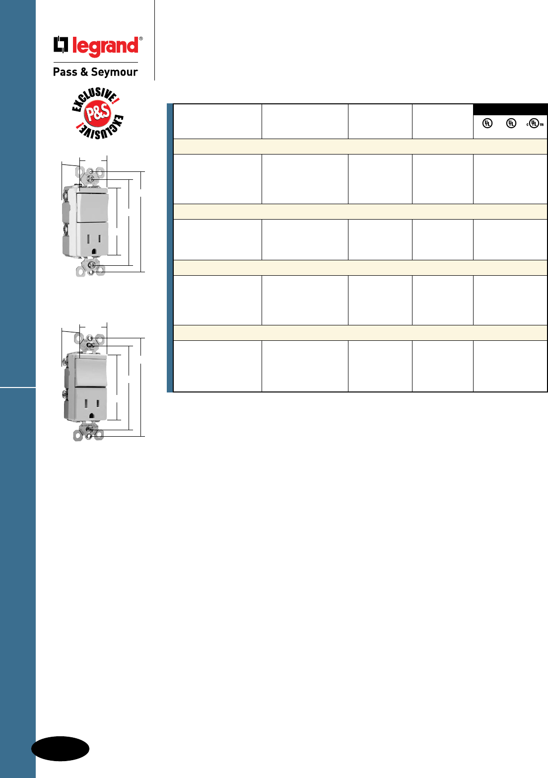
D-12
Decorator Devices
Decorator Devices
TradeMaster
®
Tamper-Resistant
Decorator Combination Switches
15A, 120/125VAC
All devices listed on this page conform to NEMA WD-1 and WD-6.
TradeMaster
®
TR Decorator Combination Switches
TM838TRLACC
TM818TRWCC
3.28"
3.81"
2.60"
1.29"
1.59"
3.28"
3.81"
2.60"
1.29"
1.59"
3rd Party Compliance
Rating NEMA
Catalog Number A. VAC Color Cong. No. UL20 UL498 cULus
Tamper-Resistant Single Pole Switch & Single Receptacle
TM818TRICC 15 120/125 Ivory 5-15R • • •
TM818TRWCC 15 120/125 White 5-15R • • •
TM818TRCC 15 120/125 Brown 5-15R • • •
TM818TRBKCC 15 120/125 Black 5-15R • • •
TM818TRLACC 15 120/125 Light Almond 5-15R • • •
Tamper-Resistant Single Pole Switch & Single Receptacle with Pilot Light
TM818TRPLICC 15 120/125 Ivory 5-15R • • •
TM818TRPLWCC 15 120/125 White 5-15R • • •
TM818TRPLBKCC 15 120/125 Black 5-15R • • •
TM818TRPLLACC 15 120/125 Light Almond 5-15R • • •
Tamper-Resistant Three-Way Switch & Single Receptacle
TM838TRICC 15 120/125 Ivory 5-15R • • •
TM838TRWCC 15 120/125 White 5-15R • • •
TM838TRCC 15 120/125 Brown 5-15R • • •
TM838TRBKCC 15 120/125 Black 5-15R • • •
TM838TRLACC 15 120/125 Light Almond 5-15R • • •
Tamper-Resistant Two Single Pole Switches & Single Receptacle
TM8118TRICC 15 120/125 Ivory 5-15R • • •
TM8118TRWCC 15 120/125 White 5-15R • • •
TM8118TRCC 15 120/125 Brown 5-15R • • •
TM8118TRBKCC 15 120/125 Black 5-15R • • •
TM8118TRLACC 15 120/125 Light Almond 5-15R • • •
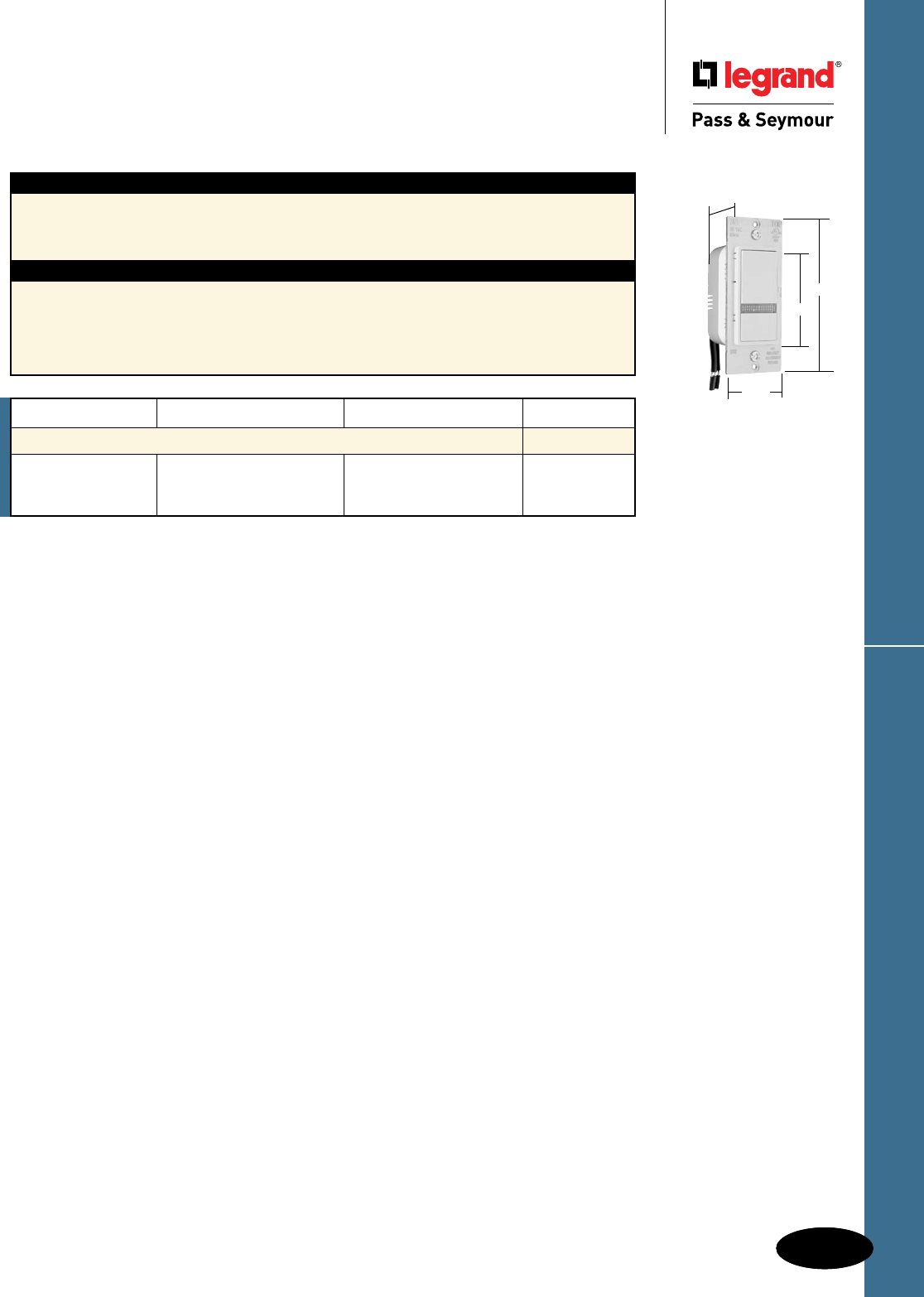
D-13
Decorator Devices
Decorator Devices
Locator Switches
15A, 120VAC
D-13
All devices listed on this page conform to NEMA WD-1 and WD-6.
Locator Switches
Application
In an emergency, seconds can make all the difference. Easily make a home instantly identiable with
a P&S Decorator Home Locator Switch. Just a single touch on its lower push button ashes the front
outside lights continuously. The switch’s LED ashes red to indicate the locator is in operation. When
the locator asher isn’t in use, the switch’s LED glows green for easy location in the dark.
Features
n ON/OFF switch with normal paddle operation.
n Locator function ashes the outdoor light ON and OFF
signaling SOS in Morse Code.
n Green LED illuminates and differentiates switch for
easy location in emergency.
n Red LED indicates the emergency
function is enabled.
n Wires the same as a single pole switch.
n cULus Listed.
TM8LOCATORLA
1.13"
4.20"
2.62"
1.72"
Catalog Number Description Rating Color
Decorator Home Locator Switches
TM8LOCATORI Emergency Decorator Ivory
TM8LOCATORW Home Locator 500 Watts, 15A, 120VAC White
TM8LOCATORLA Light Almond
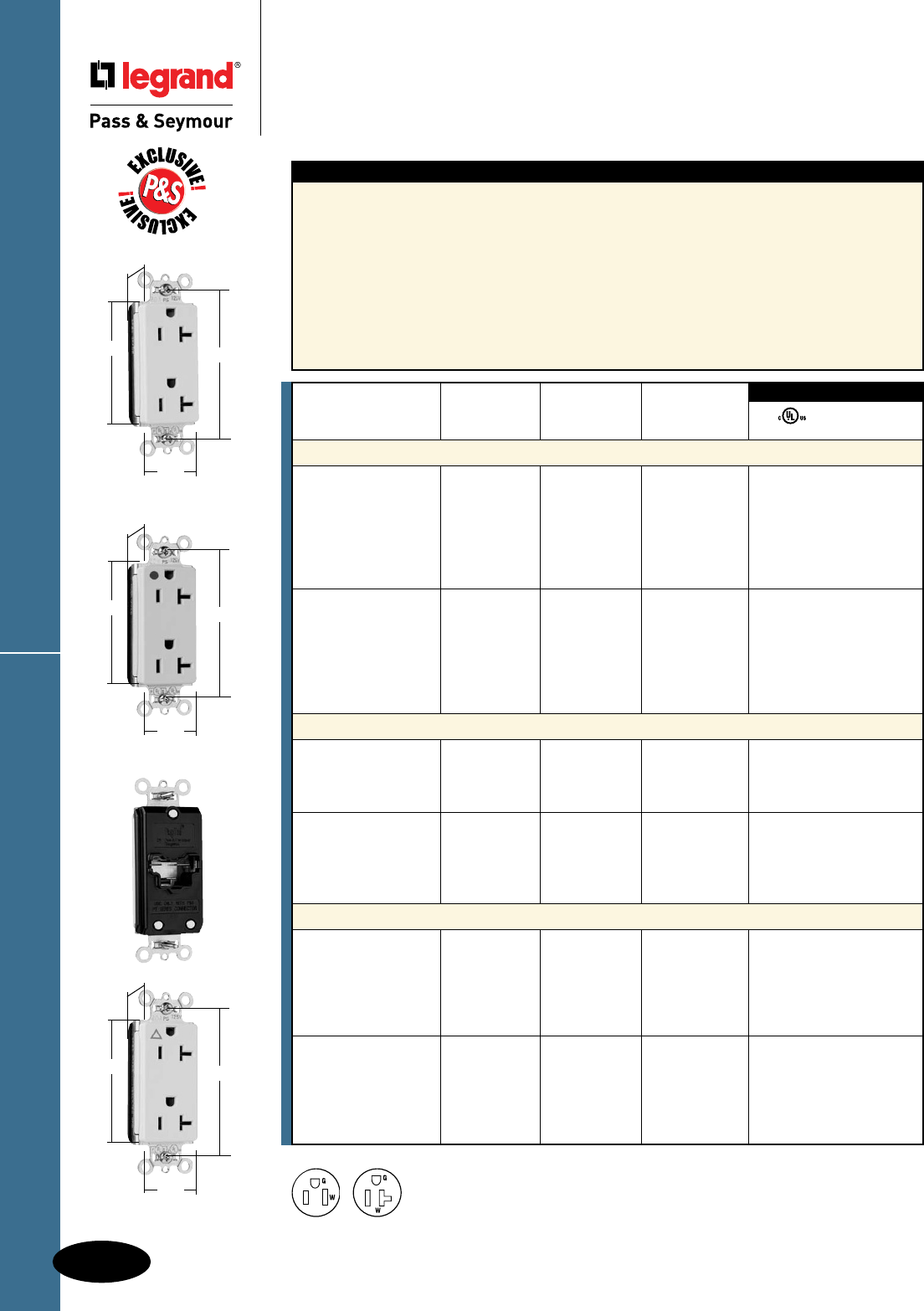
D-14
Decorator Devices
Decorator Devices
PlugTail™ Decorator Receptacles
15 & 20A, 125V
All devices listed on this page conform to NEMA WD-1 and WD-6.
PlugTail™ Decorator Receptacles
3rd Party Compliance
FSUL
UL498 WC596
Rating NEMA
Catalog Number A. V. Color Cong. No.
Duplex Receptacles
PT26252I 15 125 Ivory 5-15R • •
PT26252W 15 125 White 5-15R • •
PT26252 15 125 Brown 5-15R • •
PT26252GRY 15 125 Gray 5-15R • •
PT26252BK 15 125 Black 5-15R • •
PT26252RED 15 125 Red 5-15R • •
PT26252LA 15 125 Light Almond 5-15R • •
PT26352I 20 125 Ivory 5-20R • •
PT26352W 20 125 White 5-20R • •
PT26352 20 125 Brown 5-20R • •
PT26352GRY 20 125 Gray 5-20R • •
PT26352BK 20 125 Black 5-20R • •
PT26352RED 20 125 Red 5-20R • •
PT26352LA 20 125 Light Almond 5-20R • •
Hospital Grade Duplex Receptacles
PT26262HGI 15 125 Ivory 5-15R • •
PT26262HGW 15 125 White 5-15R • •
PT26262HGGRY 15 125 Gray 5-15R • •
PT26262HGRED 15 125 Red 5-15R • •
PT26362HGI 20 125 Ivory 5-20R • •
PT26362HGW 20 125 White 5-20R • •
PT26362HGGRY 20 125 Gray 5-20R • •
PT26362HGRED 20 125 Red 5-20R • •
PT26362HGLA 20 125 Light Almond 5-20R • •
Isolated Ground Duplex Receptacles
PTIG26262I 15 125 Ivory 5-15R • •
PTIG26262W 15 125 White 5-15R • •
PTIG26262 15 125 Orange 5-15R • •
PTIG26262GRY 15 125 Gray 5-15R • •
PTIG26262RED 15 125 Red 5-15R • •
PTIG26262LA 15 125 Light Almond 5-15R • •
PTIG26362I 20 125 Ivory 5-20R • •
PTIG26362W 20 125 White 5-20R • •
PTIG26362 20 125 Orange 5-20R • •
PTIG26362GRY 20 125 Gray 5-20R • •
PTIG26362RED 20 125 Red 5-20R • •
PTIG26362LA 20 125 Light Almond 5-20R • •
PT26362HGI
2.75" 3.281"
.625"
1.5"
Features
n .036 inch thick, brass, triple-wipe power contacts for
lasting retention.
n Plated steel wrap strap design for maximum durability
and corrosion resistance.
n No exposed terminals create a finger safe application
before, during, and after installation.
n Built-in connector features large brass terminal blades
to ensure consistent, reliable electrical connections.
n Crimped and welded contacts.
n Ultrasonically welded polycarbonate connector
housing secures terminations and conductors
in a UL Listed, finger safe housing.
n Large brass contacts snugly terminate on
device blade terminals.
n Pre-stripped connector leads fasten to
conductors, easier than standard pigtails.
n Auto-ground clip assures positive ground.
n Isolated ground version features nylon
isolator plate for isolating ground from strap
and box system.
PT26352LA
2.75" 3.281"
.625"
1.5"
PTIG26362LA
2.75" 3.281"
.625"
1.5"
NEMA
5-15R
NEMA
5-20R
2 Pole, 3 Wire
For PlugTail Connectors, see Page D-36.
For Bulk Packaging Solutions consult factory.
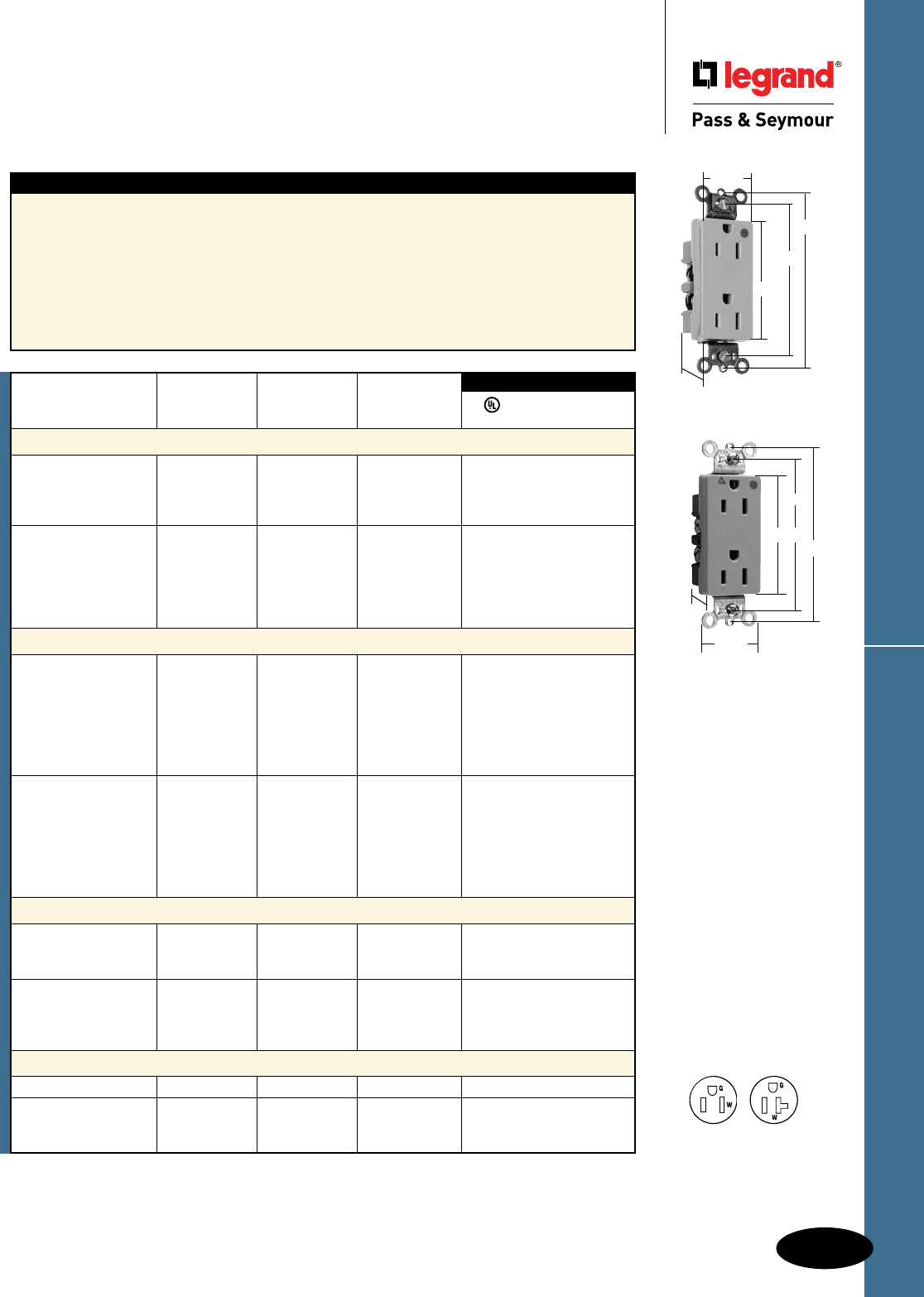
D-15
Decorator Isolated Ground & HG Receptacles
Decorator Devices
Decorator Devices
Decorator Isolated Ground &
Hospital Grade Receptacles
15 & 20A, 125V
All devices listed on this page conform to NEMA WD-1 and WD-6.
Features
n Corrosion-resistant, plated steel strap locked into
assembly to prohibit strap from bending
away from body.
n One-piece, brass, triple-wipe power contacts
for lasting retention.
n Heavy-duty compact design for easier installation
and long lasting performance.
n Easily accessed break-off, line-contact connecting
tab for fast, easy split-circuit wiring.
n Impact-resistant nylon face.
n Terminal compartments isolated from each
other for positive conductor containment.
n Side and internal screw-pressure-plate
back wire accepts #14 – #10 AWG solid
or stranded wire.
n All devices fit standard #26 opening wall plate.
n Tri-drive terminal and mounting screws.
n Auto-ground clip assures positive ground.
3rd Party Compliance
FSUL
UL498 WC596 cUL/CSA
Rating NEMA
Catalog Number A. V. Color Cong. No.
Hospital Grade Duplex Receptacles Back & Side Wire
26262HGI 15 125 Ivory 5-15R • • •
26262HGW 15 125 White 5-15R • • •
26262HGGRY 15 125 Gray 5-15R • • •
26262HGRED 15 125 Red 5-15R • • •
26362HGI 20 125 Ivory 5-20R • • •
26362HGW 20 125 White 5-20R • • •
26362HG 20 125 Brown 5-20R • • •
26362HGGRY 20 125 Gray 5-20R • • •
26362HGRED 20 125 Red 5-20R • • •
26362HGLA 20 125 Light Almond 5-20R • • •
Isolated Ground Duplex Receptacles Back & Side Wire
IG26262I 15 125 Ivory 5-15R • • •
IG26262W 15 125 White 5-15R • • •
IG26262 15 125 Orange 5-15R • • •
IG26262GRY 15 125 Gray 5-15R • • •
IG26262BK 15 125 Black 5-15R • • •
IG26262RED 15 125 Red 5-15R • • •
IG26262LA 15 125 Light Almond 5-15R • • •
IG26362I 20 125 Ivory 5-20R • • •
IG26362W 20 125 White 5-20R • • •
IG26362 20 125 Orange 5-20R • • •
IG26362GRY 20 125 Gray 5-20R • • •
IG26362BK 20 125 Black 5-20R • • •
IG26362RED 20 125 Red 5-20R • • •
IG26362LA 20 125 Light Almond 5-20R • • •
Hospital Grade Isolated Ground Duplex Receptacles Back & Side Wire
IG26262HGW 15 125 White 5-15R • •
IG26262HG 15 125 Orange 5-15R • •
IG26262HGRED 15 125 Red 5-15R • •
IG26362HGW 20 125 White 5-20R • •
IG26362HG 20 125 Orange 5-20R • •
IG26362HGBK 20 125 Black 5-20R • •
IG26362HGRED 20 125 Red 5-20R • •
Hospital Grade Illuminated Duplex Receptacles Back & Side Wire
26222HGI 15 125 Ivory 5-15R • •
26322HGI 20 125 Ivory 5-20R • •
26322HGW 20 125 White 5-20R • •
26322HGRED 20 125 Red 5-20R • •
For Bulk Packaging Solutions consult factory.
26262HGI
2.635"
3.281"
1.322"
3.813"
.833"
IG26262HG
.833"
1.322"
3.281"
2.635"
3.813"
NEMA
5-15R
NEMA
5-20R
2 Pole, 3 Wire
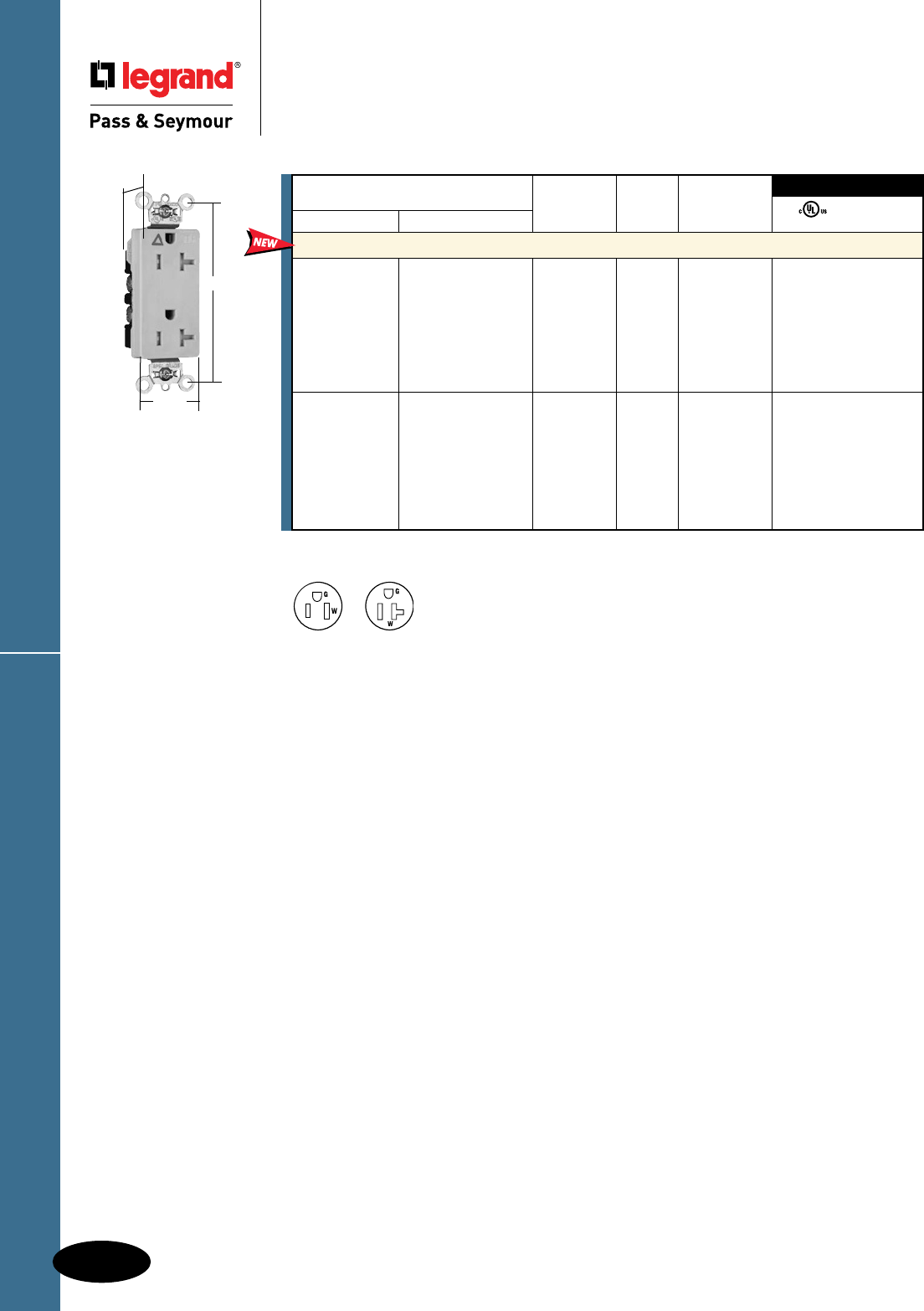
TR Decorator Isolated Ground Receptacles
D-16
Decorator Devices
Decorator Devices
Tamper-Resistant Decorator
Isolated Ground Receptacles
15 & 20A, 125V
TRIG26362
1.187"
1.25"
3.625"
For Bulk Packaging Solutions consult factory.
FSUL
UL498 WC596
3rd Party Compliance
NEMA
Catalog Number Rating Cong.
Spec Grade Hospital Grade A. V. No. Color
Tamper-Resistant Decorator Receptacles Back & Side Wire
TRIG26262I TRIG26262HGI 15 125 5-15R Ivory • •
TRIG26262W TRIG26262HGW 15 125 5-15R White • •
TRIG26262 TRIG26262HG 15 125 5-15R Orange • •
TRIG26262BK TRIG26262HGBK 15 125 5-15R Black • •
TRIG26262GRY TRIG26262HGGRY 15 125 5-15R Gray • •
TRIG26262RED TRIG26262HGRED 15 125 5-15R Red • •
TRIG26262LA TRIG26262HGLA 15 125 5-15R Light Almond • •
TRIG26362I TRIG26362HGI 20 125 5-20R Ivory • •
TRIG26362W TRIG26362HGW 20 125 5-20R White • •
TRIG26362 TRIG26362HG 20 125 5-20R Orange • •
TRIG26362BK TRIG26362HGBK 20 125 5-20R Black • •
TRIG26362GRY TRIG26362HGGRY 20 125 5-20R Gray • •
TRIG26362RED TRIG26362HGRED 20 125 5-20R Red • •
TRIG26362LA TRIG26362HGLA 20 125 5-20R Light Almond • •
NEMA
5-20R
NEMA
5-15R
2 Pole, 3 Wire
All devices listed on this page conform to NEMA WD-1 and WD-6.
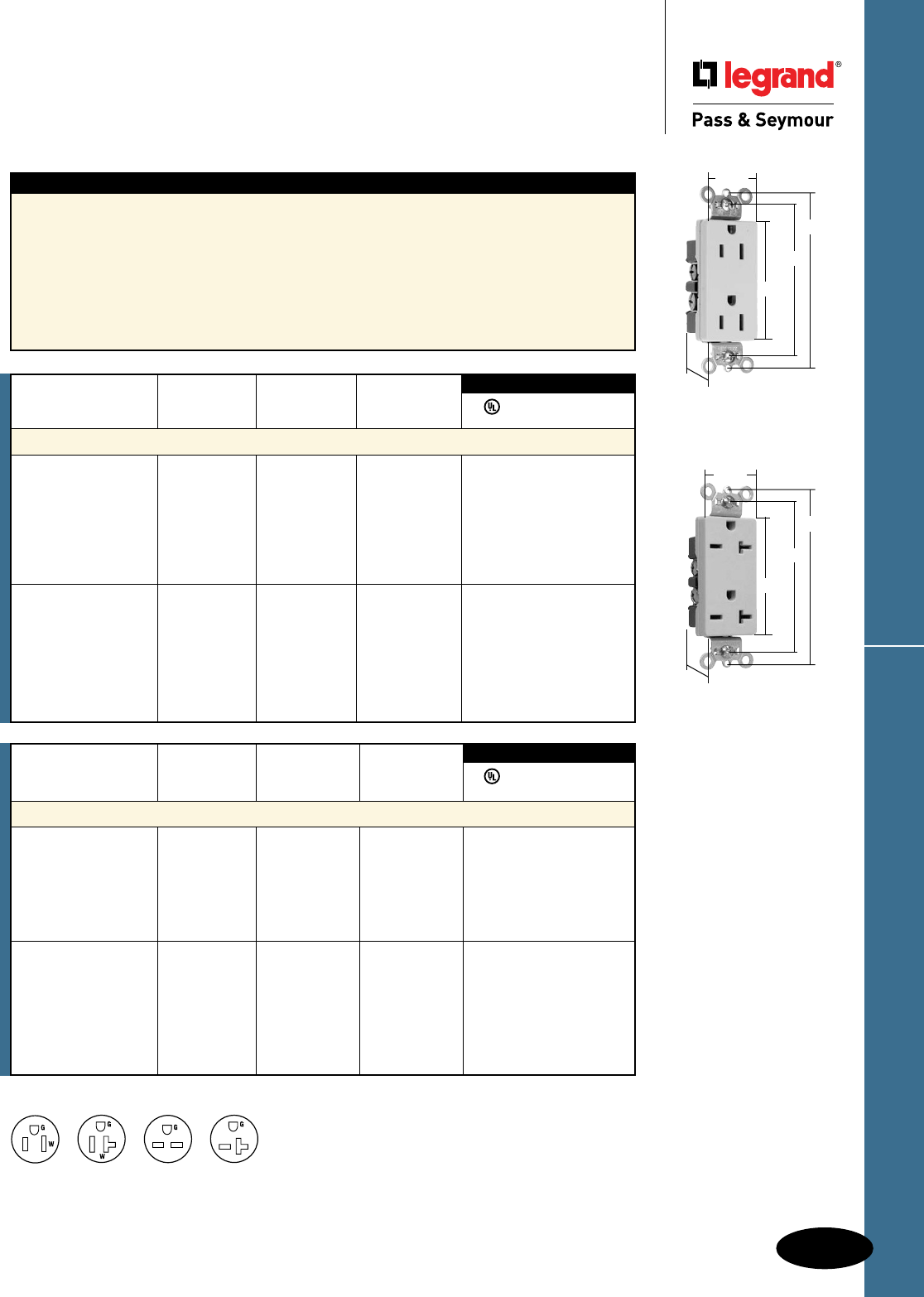
D-17
Specification Grade Decorator ReceptaclesDecorator Devices
Decorator Devices
Specification Grade
Decorator Receptacles
15 & 20A, 125 & 250V
All devices listed on this page conform to NEMA WD-1 and WD-6.
Rating NEMA
Catalog Number A. V. Color Cong. No.
Duplex Receptacles Back & Side Wire
26652I 15 250 Ivory 6-15R • • •
26652W 15 250 White 6-15R • • •
26652 15 250 Brown 6-15R • • •
26652GRY 15 250 Gray 6-15R • • •
26652BK 15 250 Black 6-15R • • •
26652RED 15 250 Red 6-15R • • •
26852I 20 250 Ivory 6-20R • • •
26852W 20 250 White 6-20R • • •
26852 20 250 Brown 6-20R • • •
26852GRY 20 250 Gray 6-20R • • •
26852BK 20 250 Black 6-20R • • •
26852RED 20 250 Red 6-20R • • •
26852LA 20 250 Light Almond 6-20R • • •
3rd Party Compliance
FSUL
UL498 WC596 cUL/CSA
Features
n Corrosion-resistant, plated steel strap locked into
assembly to prohibit strap from bending away
from body.
n One-piece, brass, triple-wipe power contacts
for lasting retention.
n Heavy-duty compact design for easier installation
and long lasting performance.
n Easily accessed break-off, line-contact connecting
tab for fast, easy split-circuit wiring.
n Impact-resistant nylon face.
n Terminal compartments isolated from each
other for positive conductor containment.
n Side and internal screw-pressure-plate
back wire accepts #14 – #10 AWG solid
or stranded wire.
n All devices fit standard #26 opening wall plate.
n Tri-drive terminal and mounting screws.
n Auto-ground clip assures positive ground.
For Bulk Packaging Solutions consult factory.
2 Pole, 3 Wire
NEMA
5-15R
NEMA
5-20R
NEMA
6-15R
NEMA
6-20R
Rating NEMA
Catalog Number A. V. Color Cong. No.
Specification Grade Duplex Receptacles Back & Side Wire
26252I 15 125 Ivory 5-15R • • •
26252W 15 125 White 5-15R • • •
26252 15 125 Brown 5-15R • • •
26252GRY 15 125 Gray 5-15R • • •
26252BK 15 125 Black 5-15R • • •
26252RED 15 125 Red 5-15R • • •
26252LA 15 125 Light Almond 5-15R • • •
26352I 20 125 Ivory 5-20R • • •
26352W 20 125 White 5-20R • • •
26352 20 125 Brown 5-20R • • •
26352GRY 20 125 Gray 5-20R • • •
26352BK 20 125 Black 5-20R • • •
26352RED 20 125 Red 5-20R • • •
26352LA 20 125 Light Almond 5-20R • • •
3rd Party Compliance
FSUL
UL498 WC596 cUL/CSA
26252I
2.635"
3.281"
1.322"
3.81"
.833"
26852I
2.635"
3.281"
1.322"
3.81"
.833"
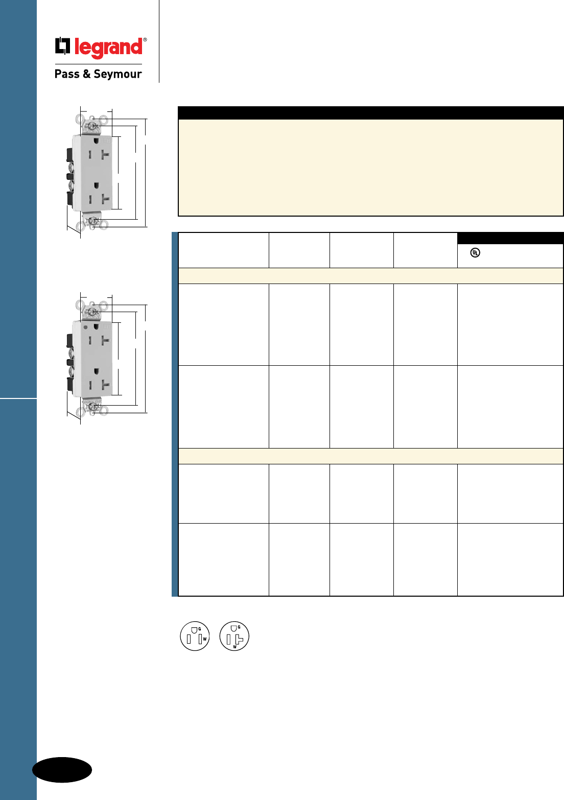
Heavy-Duty TR Decorator Receptacles
D-18
Decorator Devices
Decorator Devices
Heavy-Duty Tamper-Resistant
Decorator Receptacles
15 & 20A, 125V
Features
n Auto-ground clip assures positive ground.
n Dual mechanical shutter system to help prevent
insertion of foreign objects.
n One-piece brass triple-wipe power contacts for
reliable plug retention.
n Two drive screws anchor strap to back body and
face where abrupt removal torque is strongest.
n Patented external screw-pressure-plate back wire
clamp on ground terminal for faster, easier installation.
n Easily accessed break-off, line-contact
connecting tab for fast, easy split-circuit wiring.
n External screw-pressure-plate back wire
clamps with #10 brass terminal screws for
visual assurance of a good connection.
n One-piece plated steel mounting strap
with integral ground for superior long-term
performance.
Rating NEMA
Catalog Number A. V. Color Cong. No.
Tamper-Resistant Decorator Duplex Receptacles Back & Side Wire
TR26262I 15 125 Ivory 5-15R • • •
TR26262W 15 125 White 5-15R • • •
TR26262 15 125 Brown 5-15R • • •
TR26262GRY 15 125 Gray 5-15R • • •
TR26262BK 15 125 Black 5-15R • • •
TR26262RED 15 125 Red 5-15R • • •
TR26262LA 15 125 Light Almond 5-15R • • •
TR26362I 20 125 Ivory 5-20R • • •
TR26362W 20 125 White 5-20R • • •
TR26362 20 125 Brown 5-20R • • •
TR26362GRY 20 125 Gray 5-20R • • •
TR26362BK 20 125 Black 5-20R • • •
TR26362RED 20 125 Red 5-20R • • •
TR26362LA 20 125 Light Almond 5-20R • • •
Tamper-Resistant Hospital Grade Duplex Receptacles Back & Side Wire
TR26262HGI 15 125 Ivory 5-15R • • •
TR26262HGW 15 125 White 5-15R • • •
TR26262HGGRY 15 125 Gray 5-15R • • •
TR26262HGRED 15 125 Red 5-15R • • •
TR26262HGLA 15 125 Light Almond 5-15R • • •
TR26362HGI 20 125 Ivory 5-20R • • •
TR26362HGW 20 125 White 5-20R • • •
TR26362HGGRY 20 125 Gray 5-20R • • •
TR26362HGBK 20 125 Black 5-20R • • •
TR26362HGRED 20 125 Red 5-20R • • •
TR26362HGLA 20 125 Light Almond 5-20R • • •
3rd Party Compliance
FSUL
UL498 WC596 cUL/CSA
For Bulk Packaging Solutions consult factory.
TR26362I
2.635"
3.281"
1.322"
3.81"
.833"
TR26362HGI
2.635"
3.281"
1.322"
3.81"
.833"
All devices listed on this page conform to NEMA WD-1 and WD-6.
NEMA
5-15R
NEMA
5-20R
2 Pole, 3 Wire
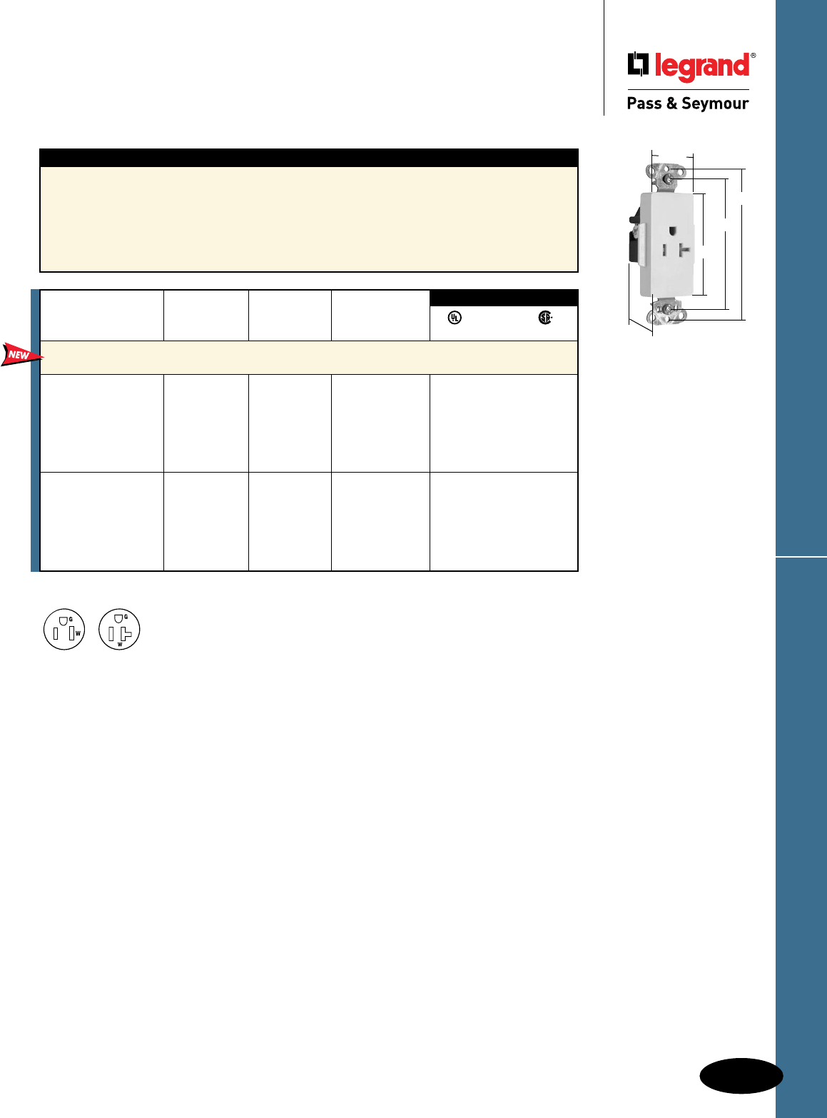
D-19
HD TR Decorator Single ReceptaclesDecorator Devices
Decorator Devices
Heavy-Duty Tamper-Resistant
Decorator Single Receptacles
15 & 20A, 125V
All devices listed on this page conform to NEMA WD-1 and WD-6.
TR26361LA
2.635"
3.281"
1.322"
3.813"
1.188"
Features
n Auto-ground clip assures positive ground.
n Backed-out tri-drive brass terminal screws for
faster installation. Internal screw-pressure-plate
back and side wire capability. Two back wire
holes for additional wiring flexibility.
n Heavy-duty corrosion-resistant zinc-plated
strap for added strength.
n One-piece brass triple-wipe power contact for
lasting retention.
n Two drive screws anchor steel strap to back
body and face where abrupt removal torque is
greatest.
n Dual mechanical shutter system to help prevent
insertion of foreign objects.
Rating NEMA
Catalog Number A. V. Color Cong. No.
Heavy-Duty Tamper-Resistant Decorator Single Receptacles
Back & Side Wire
TR26261I 15 125 Ivory 5-15R • • •
TR26261W 15 125 White 5-15R • • •
TR26261 15 125 Brown 5-15R • • •
TR26261GRY 15 125 Gray 5-15R • • •
TR26261BK 15 125 Black 5-15R • • •
TR26261LA 15 125 Light Almond 5-15R • • •
TR26361I 20 125 Ivory 5-20R • • •
TR26361W 20 125 White 5-20R • • •
TR26361 20 125 Brown 5-20R • • •
TR26361GRY 20 125 Gray 5-20R • • •
TR26361BK 20 125 Black 5-20R • • •
TR26361LA 20 125 Light Almond 5-20R • • •
3rd Party Compliance
FSUL
UL498 WC596 22.2 No. 42
For Bulk Packaging Solutions consult factory.
NEMA
5-15R
NEMA
5-20R
2 Pole, 3 Wire
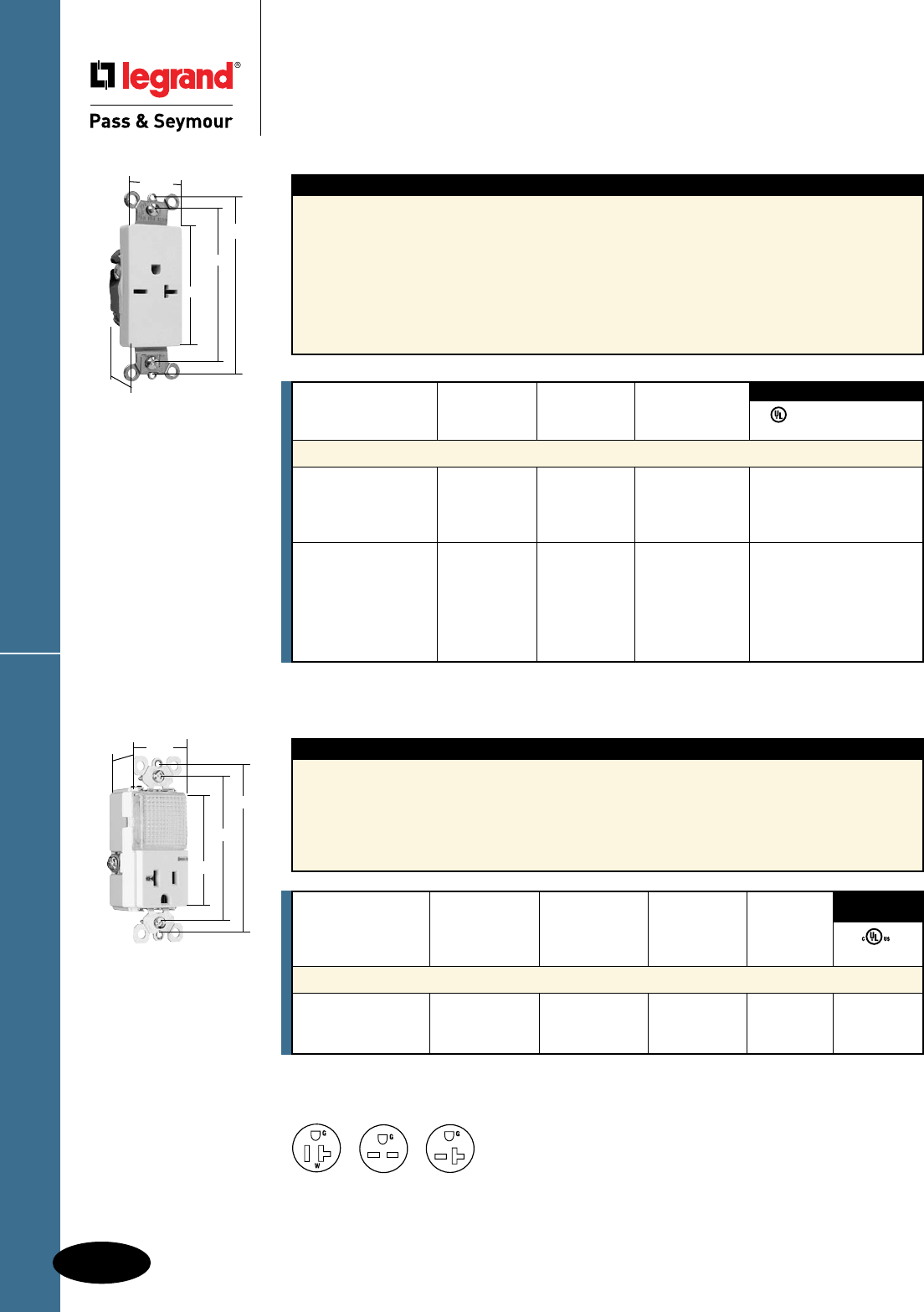
Spec Grade Decorator & Combo Receptacles
D-20
Decorator Devices
Decorator Devices
Specification Grade Decorator &
Combination Receptacles
15 & 20A, 125 & 250V; 20A, 120/125VAC
All devices listed on this page conform to NEMA WD-1 and WD-6.
Features
n Impact-resistant face and body.
n GE Lexan™ high impact-resistant lens.
n External screw-pressure-plate back and side
wired. Accepts #12 and #14 AWG.
n Ground screw position under the end of the
strap minimizes the risk of contact.
n Energy-efficient LED has average 20-year life
expectancy: eliminates bulb replacement.
n Sensor automatically turns light ON in the dark.
n Increased light output for better illumination.
n Light sensor for enhanced sensitivity.
Catalog Rating Light Output NEMA
Number A. VAC In 1' FCD* Color Cong. No. UL498
Specification Grade Decorator Hallway Light & Single Receptacle
PS8HWLI 20 120/125 0.2561 Ivory 5-20R •
PS8HWLW 20 120/125 0.2561 White 5-20R •
PS8HWLLA 20 120/125 0.2561 Light Almond 5-20R •
3rd Party
Compliance
*FCD = Foot Candle Distance. 1 Lumen = 1 FCD. See Page S-56 for more information.
Features
n Corrosion-resistant, plated wraparound steel strap
locked into assembly to prohibit strap from bending
away from body.
n One-piece, brass, triple-wipe power contacts
for lasting retention.
n Heavy-duty compact design for easier installation
and long lasting performance.
n Easily accessed break-off, line-contact connecting
tab for fast, easy split-circuit wiring.
n Impact-resistant nylon face.
n Terminal compartments isolated from each
other for positive conductor containment.
n Side and internal screw-pressure-plate
back wire accepts #14 – #10 AWG solid
or stranded wire.
n All devices fit standard #26 opening wall plate.
n Tri-drive terminal and mounting screws.
n Auto-ground clip assures positive ground.
NEMA
5-20R
NEMA
6-15R
NEMA
6-20R
2 Pole, 3 Wire
3rd Party Compliance
FSUL
UL498 WC596 cUL/CSA
Rating NEMA
Catalog Number A. V. Color Cong. No.
Heavy-Duty Specification Grade Single Receptacles Back & Side Wire
26661I 15 250 Ivory 6-15R • • •
26661W 15 250 White 6-15R • • •
26661GRY 15 250 Gray 6-15R • • •
26661BK 15 250 Black 6-15R • • •
26861I 20 250 Ivory 6-20R • •
26861W 20 250 White 6-20R • •
26861 20 250 Brown 6-20R • •
26861GRY 20 250 Gray 6-20R • •
26861BK 20 250 Black 6-20R • •
26861LA 20 250 Light Almond 6-20R • •
For Bulk Packaging Solutions consult factory.
26861LA
2.635"
3.281"
1.322"
3.813"
.833"
PS8HWLLA
3.281"
3.812"
2.60"
1.29"
1.59"
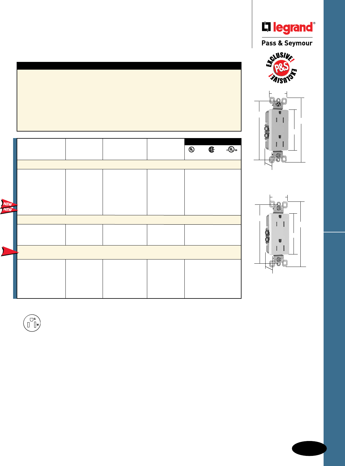
D-21
TradeMaster
®
Tamper-Resistant Receptacles
Decorator Devices
Decorator Devices
TradeMaster® Tamper-Resistant
Receptacles
15A, 125V
All devices listed on this page conform to NEMA WD-1 and WD-6.
885TRNAW
3.812"
2.60"
4.20"
1.290"
1.0"
Features
n Meets National Electrical Code®
Tamper-Resistant requirements.
n Protects children: patented shutter system helps
prevent improper insertion of foreign objects.
n High-impact resistant thermoplastic construction.
n Extra-long strap.
n Quickloop wire looping aid.
n Long-term blade retention.
n Longer tri-drive screws for easier 12 AWG looping.
n Extra-large circuit break-off tabs.
n Side-access push wire release.
n Ultrasonic welding of face to back body.
n Side wire accepts #12 – #14 AWG solid wire.
n Push wire accepts #14 AWG solid only.
n Superior protection than traditional outlet
“caps” or “protection plates.”
n Low profile face.
n Traditional contoured face (3232 models).
n Self-grounding models provide automatic
ground clip.
NEMA
5-15R
2 Pole, 3 Wire
885TRSLA
3.812"
2.60"
4.20"
1.290"
1.0"
3rd Party Compliance
UL498 C22.2 No. 42 cULus
Rating NEMA
Catalog Number A. V. Color Cong. No.
Decorator Tamper-Resistant Receptacles
885TRI 15 125 Ivory 5-15R • • •
885TRW 15 125 White 5-15R • • •
885TR 15 125 Brown 5-15R • • •
885TRGRY 15 125 Gray 5-15R • • •
885TRBK 15 125 Black 5-15R • • •
885TRLA 15 125 Light Almond 5-15R • • •
885TRTI 15 125 Titanium 5-15R • • •
885TRBNCC12 15 125 Brushed Nickel 5-15R • • •
Self-Grounding Decorator Tamper-Resistant Receptacles
885TRSI 15 125 Ivory 5-15R • • •
885TRSW 15 125 White 5-15R • • •
885TRSLA 15 125 Light Almond 5-15R • • •
NAFTA-Compliant TradeMaster
®
Tamper-Resistant 15 Amp
Decorator Receptacle
885TRNAI 15 125 Ivory 5-15R • • •
885TRNAW 15 125 White 5-15R • • •
885TR 15 125 Brown 5-15R • • •
885TRNAGRY 15 125 Gray 5-15R • • •
885TRBK 15 125 Black 5-15R • • •
885TRNALA 15 125 Light Almond 5-15R • • •
NEW
NAFTA-Compliant Receptacles are ideal for use on projects subject to the provisions of the
Buy American Act.
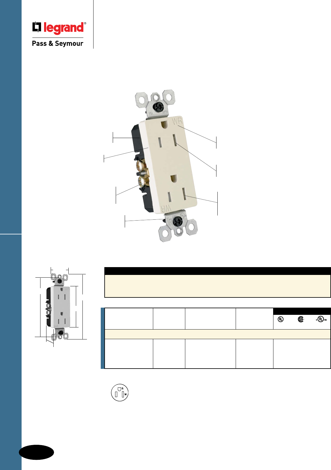
Weather-Resistant Receptacles
D-22
Decorator Devices
Decorator Devices
Weather-Resistant Receptacles
Residential Weather-Resistant Receptacles
are Tamper-Resistant as required by
National Electrical Code®
Listed to the Weather-Resistant supplement of
UL498, meeting demanding UL requirements
including:
n
Ultraviolet light exposure test
n
Cold impact test
n
Accelerated aging test
n
Stringent material requirements for current-carrying
parts, wire binding screws and mounting straps to
ensure superior corrosion resistance.
“WR” markings on face per UL
Weather-Resistant requirements.
Patented internal shutter system
lets plugs in, but keeps keys and
other objects out with automatic
shutters that block access.
885TRWRLA
Side wire accepts #12 – #14
AWG solid wire. Push wire
accepts #14 AWG solid only.
Low profile face.
High-impact resistant
thermoplastic construction.
Safer and more effective than
plastic outlet caps.
“TR” markings identify devices
as Tamper-Resistant.
All devices listed on this page conform to NEMA WD-1 and WD-6.
National Electrical Code® Section 406.8 Receptacles in Wet or Damp Locations.
Requires that all 15- and 20-amp, 125- and 250-volt non-locking receptacles installed in wet or damp locations shall be
weather-resistant receptacles.
NEMA
5-15R
2 Pole, 3 Wire
885TRWRW
3.812"
2.60"
4.20"
1.290"
1.0"
Rating NEMA
Catalog Number A. V. Color Cong. No.
Decorator Weather-Resistant Duplex Receptacles
885TRWRI 15 125 Ivory 5-15R • • •
885TRWRW 15 125 White 5-15R • • •
885TRWR 15 125 Brown 5-15R • • •
885TRWRLA 15 125 Light Almond 5-15R • • •
3rd Party Compliance
UL498 C22.2 No. 42 cULus
Features
n Specifically designed for increased protection
of children in the home.
n Extra-long strap.
n Quickloop wire looping aid.
n Long-term blade retention.
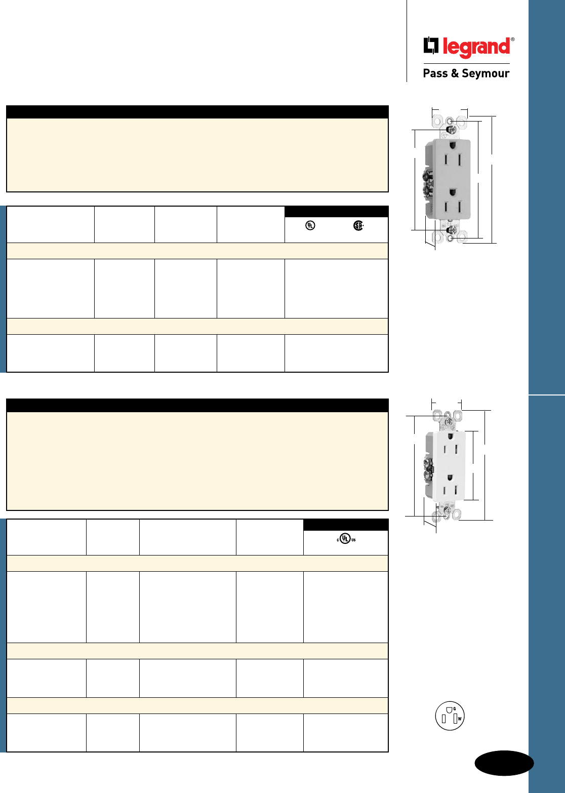
D-23
TradeMaster® ReceptaclesDecorator Devices
Decorator Devices
TradeMaster® Decorator Receptacles
15A, 125V
All devices listed on this page conform to NEMA WD-1 and WD-6.
885I
Features
n High impact-resistant thermoplastic construction.
n Extra-long strap.
n Quickloop wire looping aid.
n Long-term blade retention.
n Tri-drive screws.
n Extra-large circuit break-off tabs.
n Side-access push wire release.
n Ultrasonic welding of face to back body.
n Side wire accepts #12 – #14 AWG solid.
n Push wire accepts #14 AWG solid only.
n Self-grounding models provide automatic
ground clip.
3.812"
1.0"
2.60"
4.20"
1.290"
For Bulk Packaging Solutions consult factory.
Rating NEMA
Catalog Number A. V. Color Cong. No.
Decorator Duplex Receptacles
885I 15 125 Ivory 5-15R • •
885W 15 125 White 5-15R • •
885 15 125 Brown 5-15R • •
885BK 15 125 Black 5-15R • •
885LA 15 125 Light Almond 5-15R • •
Self-Grounding Decorator Duplex Receptacles
885SI 15 125 Ivory 5-15R • •
885SW 15 125 White 5-15R • •
885SLA 15 125 Light Almond 5-15R • •
3rd Party Compliance
UL498 C22.2 42
NEMA
5-15R
2 Pole, 3 Wire
Rating NEMA
Catalog Number A. V. Color Cong. No.
Decorator Duplex Receptacles with Pressure Plates
TM885I 15 125 Ivory 5-15R •
TM885W 15 125 White 5-15R •
TM885 15 125 Brown 5-15R •
TM885GRY 15 125 Gray 5-15R •
TM885BK 15 125 Black 5-15R •
TM885LA 15 125 Light Almond 5-15R •
Decorator Duplex Receptacles with Pressure Plates Self-Grounding
TM885SI 15 125 Ivory 5-15R •
TM885SW 15 125 White 5-15R •
TM885SLA 15 125 Light Almond 5-15R •
Decorator Duplex Receptacles with Pressure Plates Bulk Pack of 150
TM885I150 15 125 Ivory 5-15R •
TM885W150 15 125 White 5-15R •
TM885LA150 15 125 Light Almond 5-15R •
3rd Party Compliance
UL498 TM885W
3.812"
2.60"
4.20"
1.290"
1.0"
Features
n Longer steel straps than competitive devices,
still fits under a standard wall plate.
n High-impact thermoplastic face and back body
eliminate cracks, breaks and callbacks.
n Ultrasonic welding of face to back body.
n Patented design provides better plug retention.
n External screw-pressure-plate back wire on all
four terminal screws and ground screw eliminates
wrapping.
n Accepts #12 and #14 stranded and solid wire.
n Break-off tabs that are big enough to grab
hold of – even if the contact screws are
backed-out. Scored deeper, for fast, clean
breaks every time.
n All four contact screws and the ground screw
are backed-out.
n All screws are tri-drive.
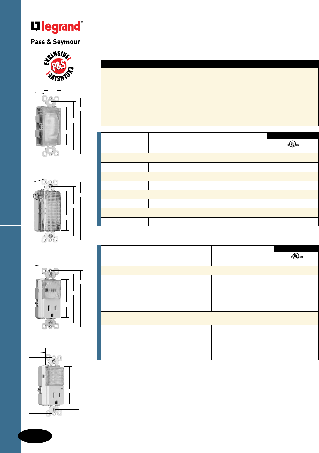
Hallway Lights & Combination Devices
D-24
Decorator Devices
Decorator Devices
TradeMaster® Decorator Hallway Lights &
Combination Devices
TM8HWLTRLACC
3.281"
3.812"
2.60"
1.29"
1.28"
TM8HWLWCC
3.281"
3.812"
2.60"
1.29"
1.59"
TMHWLCC
3.281"
3.812"
2.60"
1.29"
1.59"
TMHWLECC
3.281"
3.812"
2.60"
1.29"
1.59"
Features
n Impact-resistant face and body.
n GE Lexan™ high impact-resistant lens.
n External screw-pressure-plate back and side
wired. Accepts #12 and #14 AWG.
n Ground screw position under the end of the
strap minimizes the risk of contact.
n Energy-efficient LED has average 20-year life
expectancy: eliminates bulb replacement.
n Sensor automatically turns light ON in the dark.
n Increased light output for better illumination.
n Light sensor for enhanced sensitivity.
Tamper-Resistant Combination Version:
n UL tested shutter mechanism for protection
against improper object insertion per UL478.
n Specially designed for increased protection of
children in their homes.
n Superior protection than traditional outlet “caps”
or “protection plates.”
Catalog Rating Light Output
Number A. VAC In 1' FCD* Color UL1598
TradeMaster® Decorator Full Hallway Light with Light Sensor
TMHWLCC — 120 0.1328 Clear •
Enhanced Decorator Full Hallway Light with Light Sensor
TMHWLECC — 120 1.079 Clear •
Enhanced Decorator Full Hallway Light without Light Sensor
TMHWLENSCC — 120 1.113 Clear •
Full Hallway Decorator Light for use with P&S Metal Louver Plates**
TMHWLLOUVCC — 120 0.0843 Clear •
3rd Party Compliance
Catalog Rating Light Output NEMA
Number A. VAC In 1' FCD* Color Cong. No. UL498
TradeMaster® Decorator Hallway Light & Single Receptacle
TM8HWLICC 15 120/125 0.1442 Ivory 5-15R •
TM8HWLWCC 15 120/125 0.1442 White 5-15R •
TM8HWLCC 15 120/125 0.1442 Brown 5-15R •
TM8HWLBKCC 15 120/125 0.1442 Black 5-15R •
TM8HWLLACC 15 120/125 0.1442 Light Almond 5-15R •
Decorator Hallway Light with High Output Light & Tamper-Resistant
Single Receptacle
TM8HWLTRICC 15 125 0.2561 Ivory 5-15R •
TM8HWLTRWCC 15 125 0.2561 White 5-15R •
TM8HWLTRCC 15 125 0.2561 Brown 5-15R •
TM8HWLTRBKCC 15 125 0.2561 Black 5-15R •
TM8HWLTRLACC 15 125 0.2561 Light Almond 5-15R •
3rd Party Compliance
For complete line of Decorator Combination Devices, see Pages D-9 – D-12, D-20, D-24,
D-33, and D-39.
*FCD = Foot Candle Distance, 1 Lumen = 1 FCD. See page S-56 for more information.
**For Louver Plates, see Page Q-21.
*FCD = Foot Candle Distance. 1 Lumen = 1 FCD. See page S-56 for more information.
All devices listed on this page conform to NEMA WD-1 and WD-6.
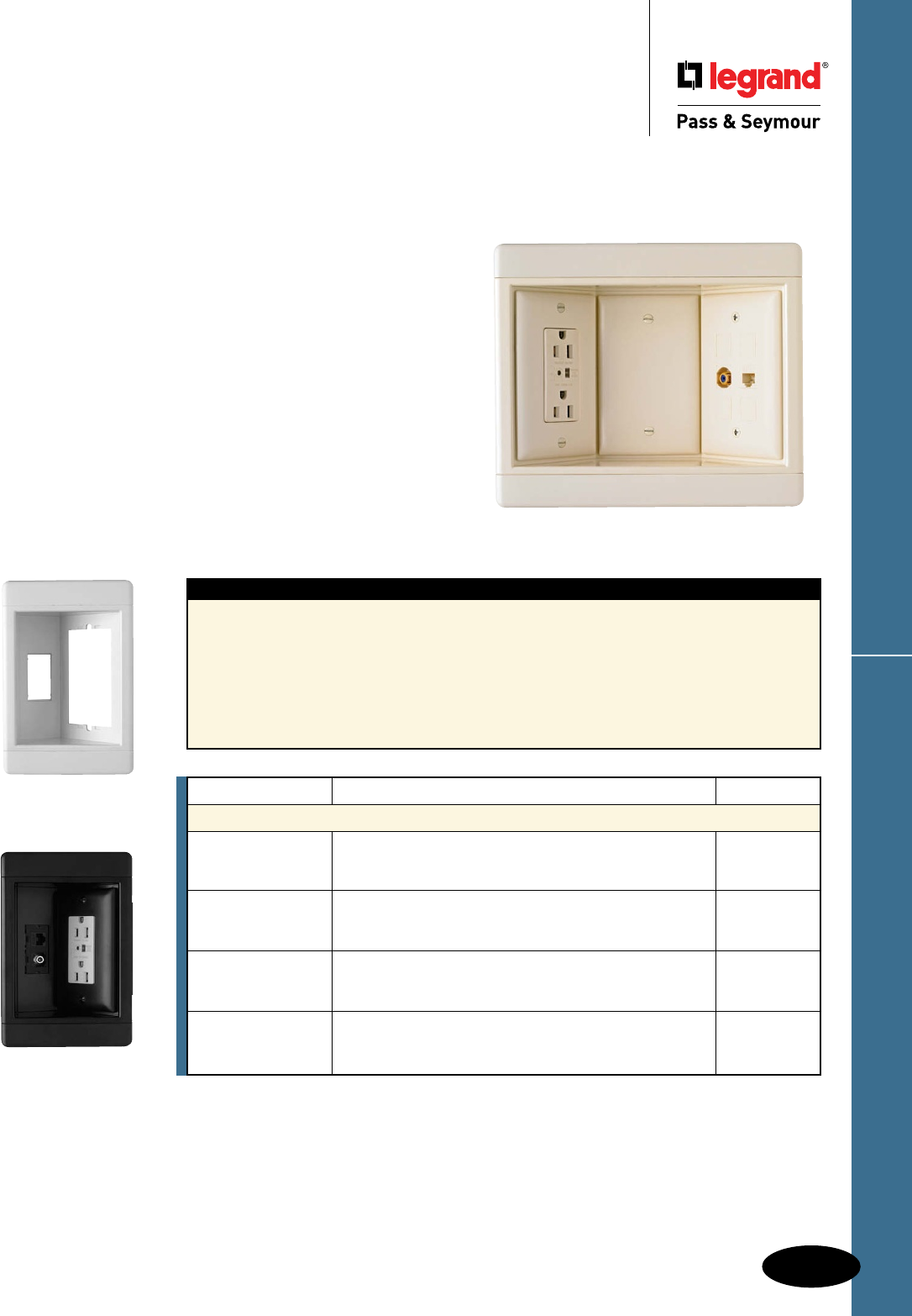
D-25
Recessed TV BoxesDecorator Devices
Decorator Devices
Recessed TV Boxes
All devices listed on this page conform to NEMA WD-1 and WD-6.
Ideal for flat-screen TVs, home office, kitchen counter tops, and behind furniture
to allow snug-to-wall placement.
Today’s homeowners have more multimedia choices
than ever — including flat panel, wall-mounted televisions.
P&S Recessed TV Boxes offer a clean installation with the
versatility to handle up to 12 multimedia connections, while
providing surge protected power.
Their recessed design saves space and simplifies connections
to cable or satellite boxes, DVRs, DVD players, surround-sound
systems and more.
And they’re available with or without surge protective
receptacles to protect costly electronics from potentially
damaging surges.
Features
n Clean, flush-mount appearance — snap-on
end caps hide mounting screws.
n Flexible — position either line voltage or
low-voltage in all three openings.
n Low-voltage connectors offer both terminated
and pull-through capability.
n Plugs and multimedia connections stay
recessed behind the wall surface.
n Molded-in template and rectangular cut-out.
n Accepts standard TP wall plates.
n Metal swing brackets ensure a solid mounting.
n Uses old-work-style boxes for line voltage.
n Accepts all P&S keystone low-voltage
connectors, including Cat 5e and F-connectors
(both supplied with Surge Protective kit), as well
as RCA and audio binding posts.
Catalog Number Description Color
Recessed TV Boxes
TV1WW White
TV1WBK Single Gang Recessed TV Box — Frame Only. Black
TV1WLA Light Almond
TV1WTVSSW Single Gang Recessed TV Box with Surge Protective & White
TV1WTVSSBK Low-Voltage Kit. Includes Surge Protective Duplex Black
TV1WTVSSLA Receptacle, Cat 5e Jack, F-Connector, Blanks, & Wall Plates. Light Almond
TV3WW White
TV3WBK Three Gang Recessed TV Box — Frame Only. Black
TV3WLA Light Almond
TV3WTVSSW Three Gang Recessed TV Box with Surge Protective & White
TV3WTVSSBK Low-Voltage Kit. Includes Surge Protective Duplex Black
TV3WTVSSLA Receptacle, Cat 5e Jack, F-Connector, Blanks, & Wall Plates. Light Almond
Single gang dimensions: 7.25" L x 4.875" W x 2.25" D
Three gang dimensions: 8.5" L x 4.875" W x 2.25" D
TV1WTVSSBK
TV1WW
TV3WTVSSLA
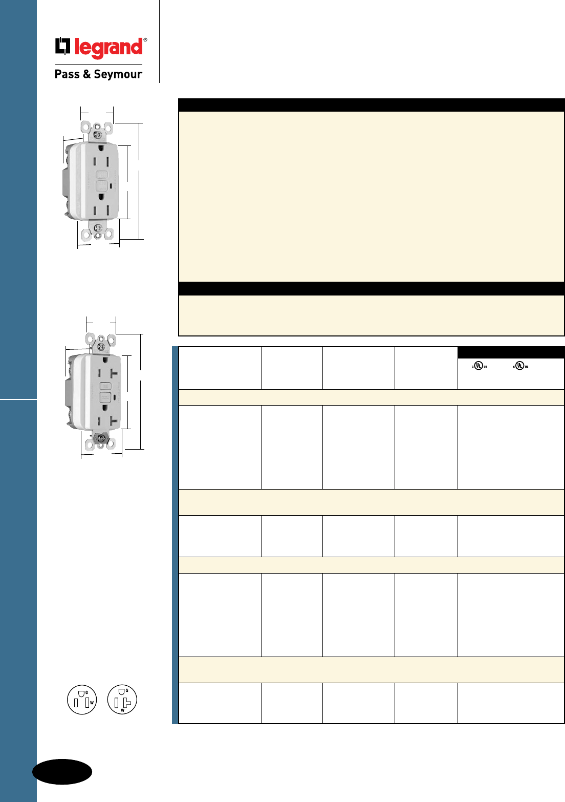
Tamper-Resistant GFCI Receptacles
D-26
Decorator Devices
Decorator Devices
Tamper-Resistant GFCI Receptacles
2 Pole, 3 Wire Grounding 15 & 20A, 125VAC
All devices listed on this page conform to NEMA WD-1 and WD-6.
1595TRW
1.13"
1.72"
1.25"
2.62"
4.20"
NEMA
5-15R
NEMA
5-20R
2095TRSW
1.13"
1.72"
1.25"
2.62"
4.20"
Features
n Protects children: patented shutter system helps
prevent improper insertion of foreign objects.
n Meets National Electrical Code®
Tamper-Resistant requirements.
n SafeLockTM Protection: if critical components are
damaged and ground fault protection is lost, power
to receptacle is disconnected.
n Prevents line-load reversal miswire: no power to the
face or downstream receptacles if wired incorrectly.
n Exceeds UL943 voltage surge requirements;
survives 100x the required UL 3kA/6kV voltage
surge test cycles.
n FSUL Listed (Federal Specification WC596).
n Trip indicator light (red LED).
n Side or internal screw-pressure-plate back wire with
#10 – #14 AWG solid or stranded copper wire.
Specications
n Supply Voltage: 125VAC, 60 Hz
n Supply Voltage Range: 102-132 VAC
n Trip Threshold: 5± 1mA
n Trip Time: 0.025 sec., nominal per
UL Standard
n 20 Amp feed-thru capacity
n Two back wire holes per terminal.
n Ground screw has a back wire clamp for easy
installation.
n 1/4" thinner than competitors’ GFCIs; leaves
more room for wires in the box.
n Mounting screws are shipped captive in the
device and wall plate for easier installation.
n High-impact-resistant thermoplastic
construction.
n Extra-long strap.
n Button colors match the device face.
n Dual-direction test and reset buttons.
n Class A rated GFCI.
n Supplied with matching TP26 nylon wall plate.
n Tri-drive screws.
Catalog Rating NEMA
Number A. VAC Color Cong. No.
TradeMaster®/Spec Grade Tamper-Resistant 15 Amp Duplex GFCI
1595TRI 15 125 Ivory 5-15R • • •
1595TRW 15 125 White 5-15R • • •
1595TR 15 125 Brown 5-15R • • •
1595TRBK 15 125 Black 5-15R • • •
1595TRLA 15 125 Light Almond 5-15R • • •
1595TRBNCC4 15 125 Brushed Nickel 5-15R • • •
1595TRTI 15 125 Titanium 5-15R • • •
TradeMaster®/Spec Grade Tamper-Resistant 15 Amp Duplex GFCI
with Auto-Ground
1595TRSI 15 125 Ivory 5-15R • • •
1595TRSW 15 125 White 5-15R • • •
1595TRSLA 15 125 Light Almond 5-15R • • •
Specification Grade Tamper-Resistant 20 Amp Duplex GFCI
2095TRI 20 125 Ivory 5-20R • • •
2095TRW 20 125 White 5-20R • • •
2095TR 20 125 Brown 5-20R • • •
2095TRGRY 20 125 Gray 5-20R • • •
2095TRBK 20 125 Black 5-20R • • •
2095TRRED 20 125 Red 5-20R • • •
2095TRLA 20 125 Light Almond 5-20R • • •
Specification Grade Tamper-Resistant 20 Amp Duplex GFCI
with Auto-Ground
2095TRSI 20 125 Ivory 5-20R • • •
2095TRSW 20 125 White 5-20R • • •
2095TRSLA 20 125 Light Almond 5-20R • • •
UL943 UL498 FSUL
C22.2 No. 144 C22.2 No. 42 WC596
3rd Party Compliance
National Electrical Code® Section 406.11 Tamper-Resistant Receptacles in Dwelling
Units.
In all areas specified in 210.52 all 125-volt, 15- and 20-amp receptacles shall be listed tamper-resistant receptacles.
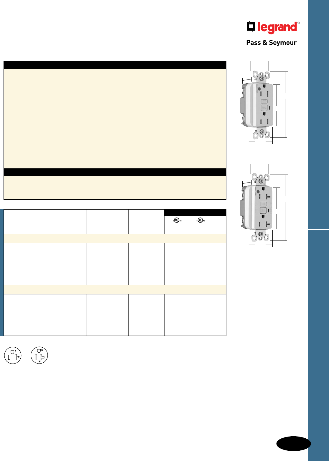
D-27
HG Tamper-Resistant GFCI ReceptaclesDecorator Devices
Decorator Devices
Hospital Grade Tamper-Resistant
GFCI Receptacles
2 Pole, 3 Wire Grounding 15 & 20A, 125VAC
Features
n Protects children: patented shutter system helps
prevent improper insertion of foreign objects.
n Meets National Electrical Code®
Tamper-Resistant requirements.
n SafeLockTM Protection: if critical components are
damaged and ground fault protection is lost, power
to receptacle is disconnected.
n Prevents line-load reversal miswire: no power to the
face or downstream receptacles if wired incorrectly.
n Exceeds UL943 voltage surge requirements;
survives 100x the required UL 3kA/6kV voltage
surge test cycles.
n FSUL Listed (Federal Specification WC596).
n Trip indicator light (red LED).
n Side or internal screw-pressure-plate back wire with
#10 – #14 AWG solid or stranded copper wire.
Specications
n Supply Voltage: 125VAC, 60 Hz
n Supply Voltage Range: 102-132 VAC
n Trip Threshold: 5± 1mA
n Trip Time: 0.025 sec., nominal per
UL Standard
n 20 Amp feed-thru capacity
n Two back wire holes per terminal.
n Ground screw has a back wire clamp for easy
installation.
n 1/4" thinner than competitors’ GFCIs; leaves
more room for wires in the box.
n Mounting screws are shipped captive in the
device and wall plate for easier installation.
n High-impact-resistant thermoplastic
construction.
n Extra-long strap.
n Button colors match the device face.
n Dual-direction test and reset buttons.
n Class A rated GFCI.
n Supplied with matching TP26 nylon wall plate.
n Tri-drive screws.
Catalog Rating NEMA
Number A. VAC Color Cong. No.
Hospital Grade Tamper-Resistant 15 Amp Duplex GFCI
1595HGTRI 15 125 Ivory 5-15R • • •
1595HGTRW 15 125 White 5-15R • • •
1595HGTR 15 125 Brown 5-15R • • •
1595HGTRGRY 15 125 Gray 5-15R • • •
1595HGTRRED 15 125 Red 5-15R • • •
1595HGTRLA 15 125 Light Almond 5-15R • • •
Hospital Grade Tamper-Resistant 20 Amp Duplex GFCI
2095HGTRI 20 125 Ivory 5-20R • • •
2095HGTRW 20 125 White 5-20R • • •
2095HGTR 20 125 Brown 5-20R • • •
2095HGTRGRY 20 125 Gray 5-20R • • •
2095HGTRRED 20 125 Red 5-20R • • •
2095HGTRLA 20 125 Light Almond 5-20R • • •
UL943 UL498 FSUL
C22.2 No. 144 C22.2 No. 42 WC596
3rd Party Compliance
NEMA
5-15R
NEMA
5-20R
2095HGTRW
1.13"
1.72"
1.25"
2.62"
4.20"
1595HGTRW
1.13"
1.72"
1.25"
2.62"
4.20"
All devices listed on this page conform to NEMA WD-1 and WD-6.

TradeMaster® & Spec Grade GFCI Receptacles
D-28
Decorator Devices
Decorator Devices
TradeMaster® & Specification Grade
GFCI Receptacles
2 Pole, 3 Wire Grounding 15 & 20A, 125VAC
Features
n SafeLockTM Protection: if critical components are
damaged and ground fault protection is lost, power
to receptacle is disconnected.
n Prevents line-load reversal miswire: no power to the
face or downstream receptacles if wired incorrectly.
n Exceeds UL943 voltage surge requirements;
survives 100x the required UL 3kA/6kV voltage
surge test cycles.
n FSUL Listed (Federal Specification WC596).
n Trip indicator light (red LED).
n Side or internal screw-pressure-plate back wire
with #10 – #14 AWG solid or stranded copper wire.
n Two back wire holes per terminal.
n Ground screw has a back wire clamp for
easy installation.
Specications
n Supply Voltage: 125VAC, 60 Hz
n Supply Voltage Range: 102-132 VAC
n Trip Threshold: 5± 1mA
n Trip Time: 0.025 sec., nominal per UL Standard
n 20 Amp feed-thru capacity
n 1/4" thinner than competitors’ GFCIs; leaves
more room for wires in the box.
n Mounting screws are shipped captive in the
device and wall plate for easier installation.
n High-impact-resistant thermoplastic
construction.
n Extra-long strap.
n Button colors match the device face.
n Dual-direction test and reset buttons.
n Class A rated GFCI.
n Supplied with matching TP26 nylon wall plate.
n Tri-drive screws.
n GFCIs with Auto-Ground assure a positive
ground to metal box.
Catalog Rating NEMA
Number A. VAC Color Cong. No.
TradeMaster®/Spec Grade 15 Amp Duplex GFCI
1595I 15 125 Ivory 5-15R • • •
1595W 15 125 White 5-15R • • •
1595 15 125 Brown 5-15R • • •
1595GRY 15 125 Gray 5-15R • • •
1595BK 15 125 Black 5-15R • • •
1595RED 15 125 Red 5-15R • • •
1595LA 15 125 Light Almond 5-15R • • •
TradeMaster®/Spec Grade 15 Amp Duplex GFCI with Auto-Ground
1595SI 15 125 Ivory 5-15R • • •
1595SW 15 125 White 5-15R • • •
1595SLA 15 125 Light Almond 5-15R • • •
Specification Grade 20 Amp Duplex GFCI
2095I 20 125 Ivory 5-20R • • •
2095W 20 125 White 5-20R • • •
2095 20 125 Brown 5-20R • • •
2095GRY 20 125 Gray 5-20R • • •
2095BK 20 125 Black 5-20R • • •
2095RED 20 125 Red 5-20R • • •
2095LA 20 125 Light Almond 5-20R • • •
Specification Grade 20 Amp Duplex GFCI with Auto-Ground
2095SI 20 125 Ivory 5-20R • • •
2095SW 20 125 White 5-20R • • •
2095SLA 20 125 Light Almond 5-20R • • •
UL943 UL498 FSUL
C22.2 No. 144 C22.2 No. 42 WC596
3rd Party Compliance
1595W
1.72"
1.25"
2.62"
4.20"
.98"
2095W
.98"
1.72"
1.25"
2.62"
4.20"
NEMA
5-15R
NEMA
5-20R
1595SW
.98"
1.72"
1.25"
2.62"
4.20"
All devices listed on this page conform to NEMA WD-1 and WD-6.
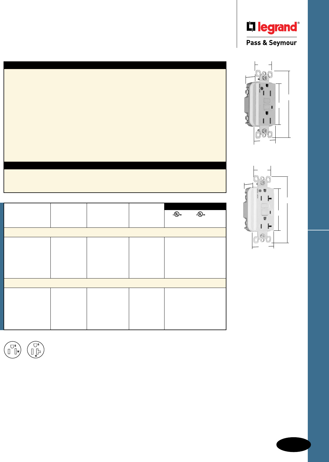
D-29
Decorator Devices
Decorator Devices
Hospital Grade GFCI Receptacles
2 Pole, 3 Wire Grounding 15 & 20A, 125VAC
Hospital Grade GFCI Receptacles
All devices listed on this page conform to NEMA WD-1 and WD-6.
NEMA
5-15R
NEMA
5-20R
Features
n SafeLockTM Protection: if critical components are
damaged and ground fault protection is lost, power
to receptacle is disconnected.
n Prevents line-load reversal miswire: no power to the
face or downstream receptacles if wired incorrectly.
n Exceeds UL943 voltage surge requirements;
survives 100x the required UL 3kA/6kV voltage
surge test cycles.
n FSUL Listed (Federal Specification WC596).
n Trip indicator light (red LED).
n Side or internal screw-pressure-plate back wire with
#10 – #14 AWG solid or stranded copper wire.
n Two back wire holes per terminal.
n Ground screw has a back wire clamp for
easy installation.
n 1/4" thinner than competitors’ GFCIs; leaves
more room for wires in the box.
n Mounting screws are shipped captive in the
device and wall plate for easier installation.
n High-impact-resistant thermoplastic
construction.
n Extra-long strap.
n Button colors match the device face.
n Dual-direction test and reset buttons.
n Class A rated GFCI.
n Supplied with matching TP26 nylon wall plate.
n Tri-drive screws.
Specications
n Supply Voltage: 125VAC, 60 Hz
n Supply Voltage Range: 102-132VAC
n Trip Threshold: 5± 1mA
n Trip Time: 0.025 sec., nominal per UL Standard
n 20 Amp feed-thru capacity
Catalog Rating NEMA
Number A. VAC Color Cong. No.
Hospital Grade 15 Amp Duplex GFCI
1595HGI 15 125 Ivory 5-15R • • •
1595HGW 15 125 White 5-15R • • •
1595HG 15 125 Brown 5-15R • • •
1595HGGRY 15 125 Gray 5-15R • • •
1595HGRED 15 125 Red 5-15R • • •
1595HGLA 15 125 Light Almond 5-15R • • •
Hospital Grade 20 Amp Duplex GFCI
2095HGI 20 125 Ivory 5-20R • • •
2095HGW 20 125 White 5-20R • • •
2095HG 20 125 Brown 5-20R • • •
2095HGGRY 20 125 Gray 5-20R • • •
2095HGRED 20 125 Red 5-20R • • •
2095HGLA 20 125 Light Almond 5-20R • • •
UL943 UL498 FSUL
C22.2 No. 144 C22.2 No. 42 WC596
3rd Party Compliance
1595HGW
1.72"
1.25"
2.62"
4.20"
.98"
2095HGW
.98"
1.72"
1.25"
2.62"
4.20"
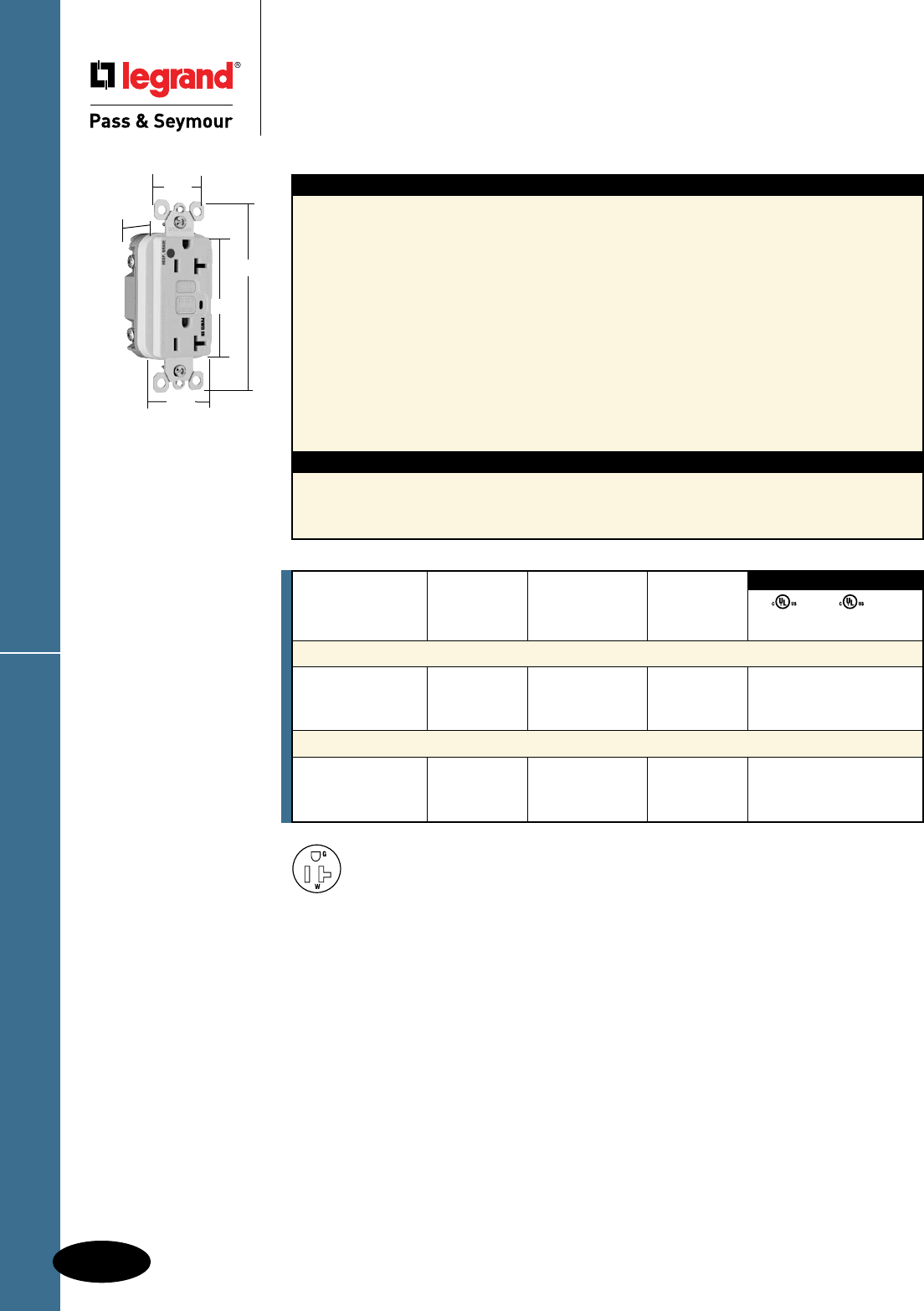
D-30
Decorator Devices
Decorator Devices
Illuminated GFCI Receptacles
2 Pole, 3 Wire Grounding 20A, 125VAC
Illuminated GFCI Receptacles
All devices listed on this page conform to NEMA WD-1 and WD-6.
Features
n Green indicator light (LED) is ON when power is
available. Helps identify emergency power branch
circuits.
n SafeLockTM Protection: if critical components are
damaged and ground fault protection is lost, power
to receptacle is disconnected.
n Prevents line-load reversal miswire: no power to the
face or downstream receptacles if wired incorrectly.
n Exceeds UL943 voltage surge requirements;
survives 100x the required UL 3kA/6kV voltage
surge test cycles.
n FSUL Listed (Federal Specification WC596).
n Side or internal screw-pressure-plate back wire with
#10 – #14 AWG solid or stranded copper wire.
n Two back wire holes per terminal.
Specications
n Supply Voltage: 125VAC, 60 Hz
n Supply Voltage Range: 102-132 VAC
n Trip Threshold: 5± 1mA
n Trip Time: 0.025 sec., nominal per
UL Standard
n 20 Amp feed-thru capacity
n Ground screw has a back wire clamp for easy
installation.
n 1/4" thinner than competitors’ GFCIs; leaves
more room for wires in the box.
n Mounting screws are shipped captive in the
device and wall plate for easier installation.
n High-impact-resistant thermoplastic
construction.
n Extra-long strap.
n Button colors match the device face.
n Dual-direction test and reset buttons.
n Class A rated GFCI.
n Supplied with matching TP26 nylon wall plate.
n Tri-drive screws.
Catalog Rating NEMA
Number A. VAC Color Cong. No.
Specification Grade Illuminated 20 Amp Duplex GFCI
2095IL 20 125 Ivory 5-20R • • •
2095WL 20 125 White 5-20R • • •
2095LAL 20 125 Light Almond 5-20R • • •
Hospital Grade Illuminated 20 Amp Duplex GFCI
2095HGIL 20 125 Ivory 5-20R • • •
2095HGWL 20 125 White 5-20R • • •
2095HGREDL 20 125 Red 5-20R • • •
UL943 UL498 FSUL
C22.2 No. 144 C22.2 No. 42 WC596
3rd Party Compliance
NEMA
5-20R
2095HGWL
.98"
1.72"
1.25"
2.62"
4.20"
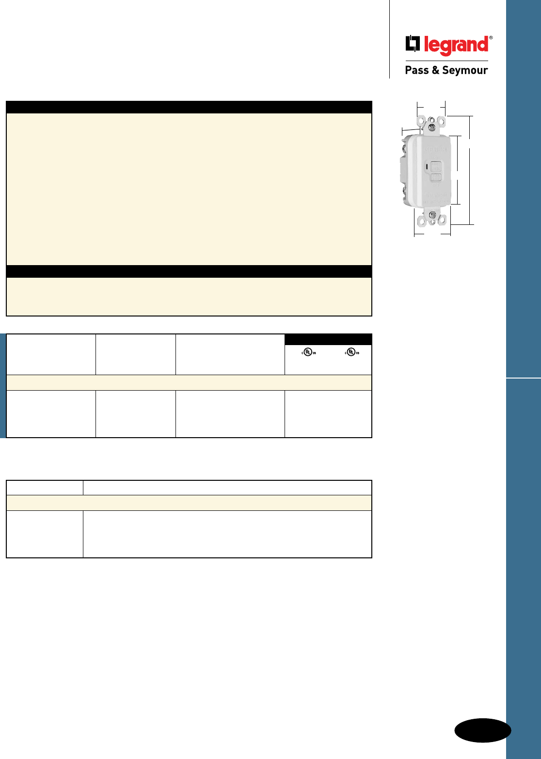
D-31
Decorator Devices
Decorator Devices
Specification Grade Dead Front GFCI
20A, 125VAC
Specification Grade Dead Front GFCI
All devices listed on this page conform to NEMA WD-1 and WD-6.
Features
n Rated as a 11⁄2 HP motor control switch.
n SafeLockTM Protection: if critical components are
damaged and ground fault protection is lost, power
to the load is disconnected.
n Prevents line-load reversal miswire: no power to the
load or downstream receptacles if wired incorrectly.
n Exceeds UL943 voltage surge requirements;
survives 100x the required UL 3kA/6kV voltage
surge test cycles.
n Trip indicator light (red LED).
n Side or internal screw-pressure-plate back wire with
#10 – #14 AWG solid or stranded copper wire.
n Two back wire holes per terminal.
n Ground screw has a back wire clamp for
easy installation.
Specications
n Supply Voltage: 125VAC, 60 Hz.
n Supply Voltage Range: 102-132 VAC.
n Trip Threshold: 5± 1mA.
n Trip Time: 0.025 sec., nominal per
UL Standard.
n 20 Amp feed-thru capacity.
n 1/4" thinner than competitors’ GFCIs; leaves
more room for wires in the box.
n Mounting screws are shipped captive in the
device and wall plate for easier installation.
n High-impact-resistant thermoplastic
construction.
n Extra-long strap.
n Button colors match the device face.
n Dual-direction test and reset buttons.
n Class A rated GFCI.
n Supplied with matching TP26 nylon wall plate.
n Tri-drive screws.
Rating
Catalog Number A. VAC Color
Specification Grade Dead Front GFCI – 11⁄2 HP Motor Control Rating
2085I 20 125 Ivory • •
2085W 20 125 White • •
2085BK 20 125 Black • •
2085LA 20 125 Light Almond • •
3rd Party Compliance
UL943 UL508
C22.2 No. 144 C22.2 No. 14
Catalog Number Description
Accessories – GFCIs
1594TPAI 7.0 cu. in. Extension Ring, Ivory
1594TPAW 7.0 cu. in. Extension Ring, White
1594TPA 7.0 cu. in. Extension Ring, Brown
1594TPALA 7.0 cu. in. Extension Ring, Light Almond
2085W
.98"
1.72"
1.25"
2.62"
4.20"
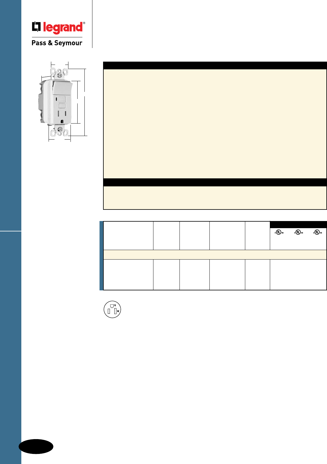
D-32
Decorator Devices
Decorator Devices
Decorator Combination Tamper-Resistant
Switch/GFCI Receptacles
15A, 125VAC
Decorator Combination GFCI Receptacles
All devices listed on this page conform to NEMA WD-1 and WD-6.
1595SWTTRWCC4
1.13"
1.25"
4.20"
2.62"
1.72"
NEMA
5-15R
Switch Receptacle NEMA
Catalog Rating Rating Cong.
Number A. VAC A. VAC Color No.
Combination Tamper-Resistant Single Pole Switch/GFCI
1595SWTTRICC4 15 120 15 125 Ivory 5-15R • • •
1595SWTTRWCC4 15 120 15 125 White 5-15R • • •
1595SWTTRBKCC4 15 120 15 125 Black 5-15R • • •
1595SWTTRLACC4 15 120 15 125 Light Almond 5-15R • • •
3rd Party Compliance
UL943 UL498 UL20
C22.2 C22.2 C22.2
No. 144 No. 42 No. 111
Features
n Protects children: patented shutter system helps
prevent improper insertion of foreign objects.
n Meets National Electrical Code®
Tamper-Resistant requirements.
n SafeLockTM Protection: if critical components are
damaged and ground fault protection is lost, power
to receptacle is disconnected.
n Up-down switching.
n 15 Amp single pole switch rated for 1/2 HP motor
loads – perfect for bath or kitchen vents and
garbage disposals.
n Prevents line-load reversal miswire: no power to the
face or downstream receptacles if wired incorrectly.
n Exceeds UL943 voltage surge requirements;
survives 100x the required UL 3kA/6kV voltage
surge test cycles.
n Trip indicator light (red LED).
n Two back wire holes per terminal.
Specications
n Supply Voltage: 125VAC, 60 Hz
n Supply Voltage Range: 102-132 VAC
n Trip Threshold: 5± 1mA
n Trip Time: 0.025 sec., nominal per UL
Standard
n 20 Amp feed-thru capacity
n Side or internal screw-pressure-plate back
wire with #10 – #14 AWG solid or stranded
copper wire.
n Ground screw has a back wire clamp for easy
installation.
n 1/4" thinner than competitors’ GFCIs; leaves
more room for wires in the box.
n Mounting screws are shipped captive in the
device and wall plate for easier installation.
n High-impact-resistant thermoplastic
construction.
n Extra-long strap.
n Button colors match the device face.
n Dual-direction test and reset buttons.
n Class A rated GFCI.
n Supplied with matching TP26 nylon wall plate.
n Tri-drive screws.
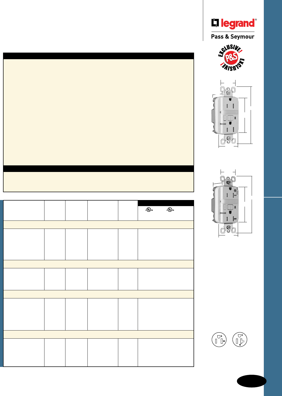
D-33
Decorator Devices
Decorator Devices
Decorator Combination Tamper-Resistant
Nightlight/GFCI Receptacles
2 Pole, 3 Wire Grounding 15 & 20A, 125VAC
Decorator Combination GFCI Receptacles
All devices listed on this page conform to NEMA WD-1 and WD-6.
1595NTLTRWCC4
1.25"
1.13"
4.20"
2.62"
1.72"
2095HGNTLTRW
1.25"
1.13"
4.20"
2.62"
1.72"
NEMA
5-15R
NEMA
5-20R
Features
n Protects children: patented shutter system helps
prevent improper insertion of foreign objects.
n Meets National Electrical Code®
Tamper-Resistant requirements.
n SafeLockTM Protection: if critical components are
damaged and ground fault protection is lost, power
to receptacle is disconnected.
n Sealed nightlight with high impact-resistant Lexan®
lens prevents tampering.
n Nightlight uses cooler LED illumination.
n Energy-efficient LED has average 20-year life
expectancy, eliminating bulb replacement.
n Two receptacles.
n Photocell turns nightlight ON in dark, OFF in daylight.
n Prevents line-load reversal miswire: no power to the
face or downstream receptacles if wired incorrectly.
n Exceeds UL943 voltage surge requirements;
survives 100x the required UL 3kA/6kV voltage
surge test cycles.
n FSUL Listed (Federal Specification WC596).
Specications
n Supply Voltage: 125VAC, 60 Hz
n Supply Voltage Range: 102-132 VAC
n Trip Threshold: 5± 1mA
n Trip Time: 0.025 sec., nominal per UL
Standard
n 20 Amp feed-thru capacity
n Trip indicator light (red LED).
n Side or internal screw-pressure-plate back
wire with #10 – #14 AWG solid or stranded
copper wire.
n Two back wire holes per terminal.
n Ground screw has a back wire clamp for
easy installation.
n 1/4" thinner than competitors’ GFCIs; leaves
more room for wires in the box.
n Mounting screws are shipped captive in the
device and wall plate for easier installation.
n High-impact-resistant thermoplastic
construction.
n Extra-long strap.
n Button colors match the device face.
n Dual-direction test and reset buttons.
n Class A rated GFCI.
n Supplied with matching TP26 nylon
wall plate.
n Tri-drive screws.
*FCD = Foot Candle Distance, 1 Lumen = 1 FCD. See Page S-56 for more information.
UL943 UL498 FSUL
C22.2 No. 144 C22.2 No. 42 WC596
3rd Party Compliance
Light NEMA
Catalog Rating Output in Cong.
Number A. VAC 1' FCD* Color No.
Combination Tamper-Resistant 15 Amp Nightlight/GFCI
1595NTLTRICC4 15 125 0.180 Ivory 5-15R • • •
1595NTLTRWCC4 15 125 0.180 White 5-15R • • •
1595NTLTRBKCC4 15 125 0.180 Black 5-15R • • •
1595NTLTRLACC4 15 125 0.180 Light Almond 5-15R • • •
1595NTLTRBNCC4 15 125 0.180 Brushed Nickel 5-15R • • •
1595NTLTRTICC4 15 125 0.180 Titanium 5-15R • • •
Combination Tamper-Resistant 20 Amp Nightlight/GFCI
2095NTLTRI 20 125 0.180 Ivory 5-20R • • •
2095NTLTRW 20 125 0.180 White 5-20R • • •
2095NTLTRGRY 20 125 0.180 Gray 5-20R • • •
2095NTLTRLA 20 125 0.180 Light Almond 5-20R • • •
Hospital Grade Combination Tamper-Resistant 15 Amp Nightlight/GFCI
1595HGNTLTRI 15 125 0.180 Ivory 5-15R • • •
1595HGNTLTRW 15 125 0.180 White 5-15R • • •
1595HGNTLTR 15 125 0.180 Brown 5-15R • • •
1595HGNTLTRGRY 15 125 0.180 Gray 5-15R • • •
1595HGNTLTRRED 15 125 0.180 Red 5-15R • • •
1595HGNTLTRLA 15 125 0.180 Light Almond 5-15R • • •
Hospital Grade Combination Tamper-Resistant 20 Amp Nightlight/GFCI
2095HGNTLTRI 20 125 0.180 Ivory 5-20R • • •
2095HGNTLTRW 20 125 0.180 White 5-20R • • •
2095HGNTLTRGRY 20 125 0.180 Gray 5-20R • • •
2095HGNTLTRRED 20 125 0.180 Red 5-20R • • •
2095HGNTLTRLA 20 125 0.180 Light Almond 5-20R • • •
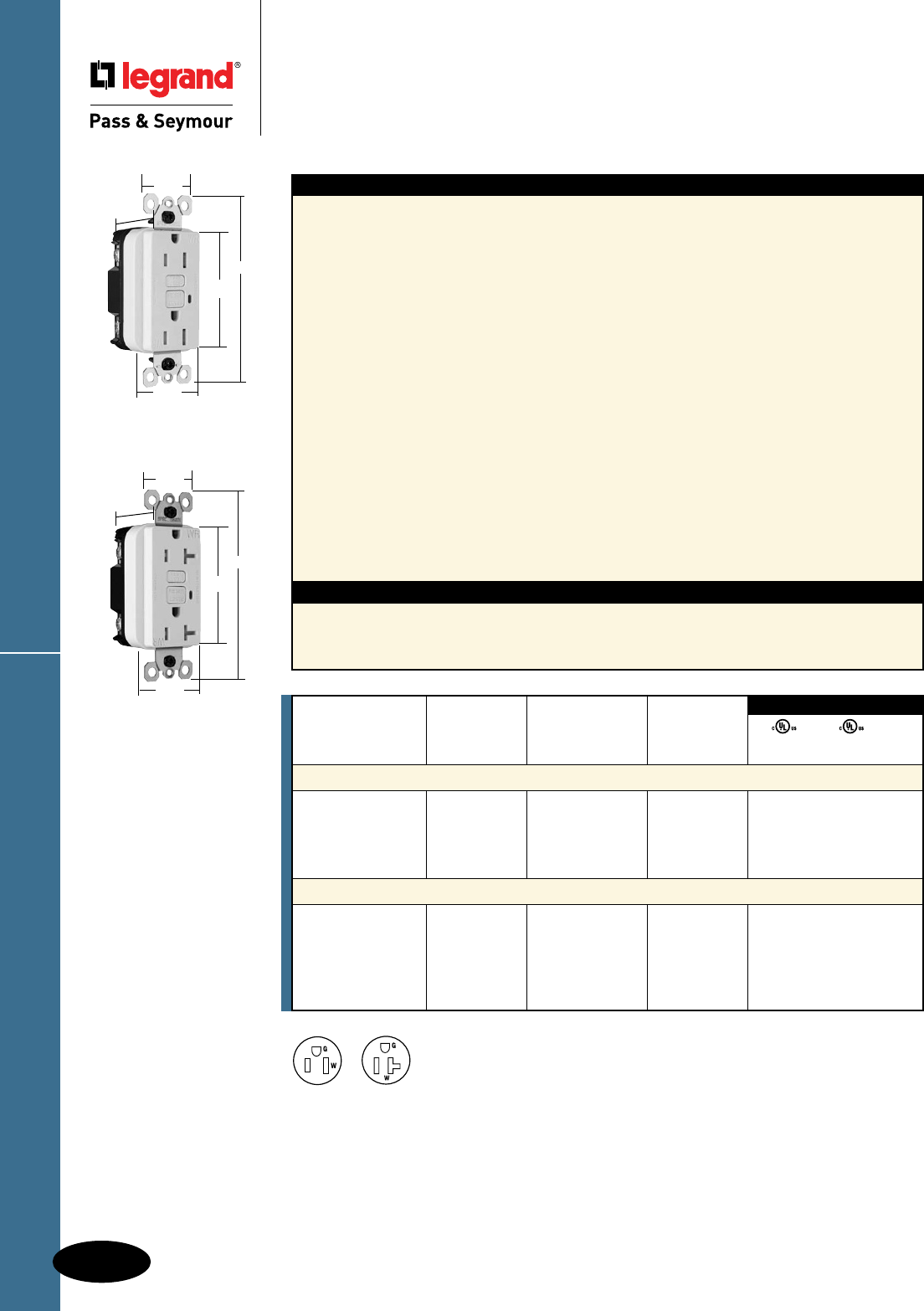
D-34
Decorator Devices
Decorator Devices
Weather-Resistant GFCI Receptacles
2 Pole, 3 Wire Grounding 15 & 20A, 125VAC
Weather-Resistant GFCI Receptacles
All devices listed on this page conform to NEMA WD-1 and WD-6.
Features
n Weather-Resistant: Meets National Electrical
Code® Weather-Resistant requirements.
n Tamper-Resistant: Meets National Electrical
Code® Tamper-Resistant requirements.
n Protects children: patented shutter system helps
prevent improper insertion of foreign objects.
n Listed to the Weather-Resistant supplement of UL498,
meeting demanding UL requirements including:
- Ultraviolet light exposure test
- Cold impact test
- Accelerated aging test
- Stringent material requirements for current-
carrying parts, wire binding screws and mounting
straps to ensure superior corrosion resistance.
n SafeLockTM Protection: if critical components are
damaged and ground fault protection is lost, power
to receptacle is disconnected.
n Prevents line-load reversal miswire: no power to the
face or downstream receptacles if wired incorrectly.
n Exceeds UL943 voltage surge requirements;
survives 100x the required UL 3kA/6kV voltage
surge test cycles.
Specications
n Supply Voltage: 125VAC, 60 Hz
n Supply Voltage Range: 102-132 VAC
n Trip Threshold: 5± 1mA
n Trip Time: 0.025 sec., nominal per
UL Standard
n 20 Amp feed-thru capacity
n FSUL Listed (Federal Specification WC596).
n Trip indicator light (red LED).
n Side or internal screw-pressure-plate back
wire with #10 – #14 AWG solid or stranded
copper wire.
n Two back wire holes per terminal.
n Ground screw has a back wire clamp for
easy installation.
n 1/4" thinner than competitors’ GFCIs;
leaves more room for wires in the box.
n Mounting screws are shipped captive in the
device and wall plate for easier installation.
n High-impact-resistant thermoplastic
construction.
n Extra-long nickel post-plated steel
mounting strap.
n Button colors match the device face.
n Dual-direction test and reset buttons.
n Class A rated GFCI.
n Supplied with matching TP26 nylon
wall plate.
n Tri-drive screws.
NEMA
5-15R
NEMA
5-20R
National Electrical Code® Section 406.8 Receptacles in Wet or Damp Locations.
Requires that all 15- and 20-amp, 125- and 250-volt non-locking receptacles installed in wet or damp locations shall be
weather-resistant receptacles.
UL943 UL498 FSUL
C22.2 No. 144 C22.2 No. 42 WC596
3rd Party Compliance
Catalog Rating NEMA
Number A. VAC Color Cong. No.
TradeMaster®/Spec Grade Weather-Resistant 15 Amp Duplex GFCI
1595TRWRI 15 125 Ivory 5-15R • • •
1595TRWRW 15 125 White 5-15R • • •
1595TRWR 15 125 Brown 5-15R • • •
1595TRWRLA 15 125 Light Almond 5-15R • • •
Specification Grade Weather-Resistant 20 Amp Duplex GFCI
2095TRWRI 20 125 Ivory 5-20R • • •
2095TRWRW 20 125 White 5-20R • • •
2095TRWR 20 125 Brown 5-20R • • •
2095TRWRGRY 20 125 Gray 5-20R • • •
2095TRWRLA 20 125 Light Almond 5-20R • • •
1595TRWRW
1.25"
1.13"
4.20"
2.62"
1.72"
2095TRWRW
1.25"
1.13"
4.20"
2.62"
1.72"
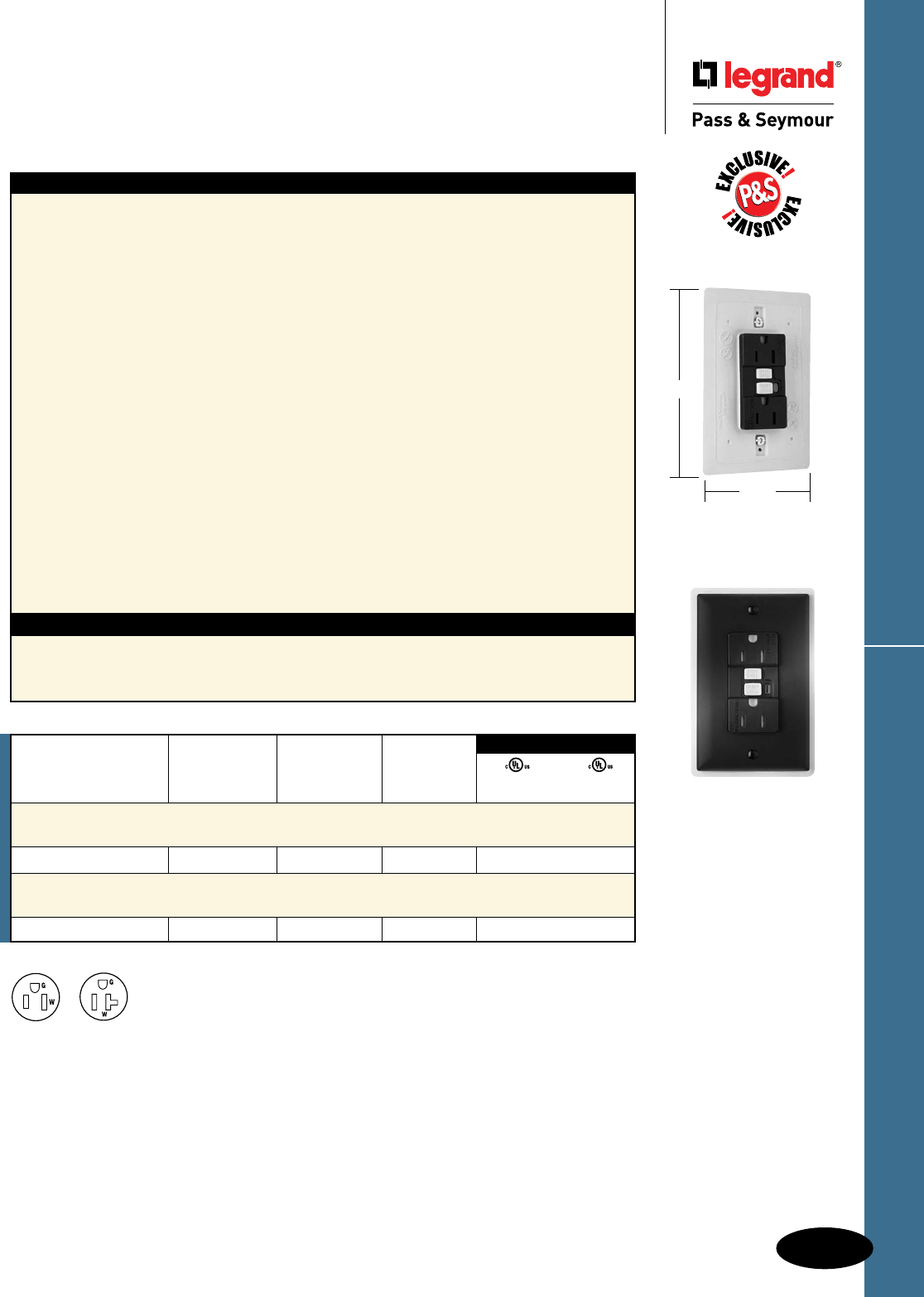
D-35
Decorator Devices
Decorator Devices
Weather-Resistant DuraShieldTM
GFCI Receptacles
2 Pole, 3 Wire Grounding 15 & 20A, 125VAC
Weather-Resistant DuraShieldTM GFCIs
All devices listed on this page conform to NEMA WD-1 and WD-6.
Features
n Designed for extra durability and a long service life
when installed in harsh environments: outdoor,
garages, workshops, wash down areas, commercial
kitchens, and labs.
n Weather-Resistant: Meets National Electrical
Code® Weather-Resistant requirements.
n Listed to the Weather-Resistant supplement of
UL498, meeting demanding UL requirements
including:
- Ultraviolet light exposure test
- Cold impact test
- Accelerated aging test
- Stringent material requirements for current-
carrying parts, wire binding screws and mounting
straps to ensure superior corrosion resistance.
n Dust- and insect-resistant.
n Rubber curtains let plug blades in; keep dust,
water and insects out.
n Integral gasket seals receptacle, protecting critical
electronic components.
n Exceeds UL corrosion requirements – survives
4X the required corrosion test cycles.
n SafeLockTM Protection: if critical components are
damaged and ground fault protection is lost,
power to receptacle is disconnected.
Specications
n Supply Voltage: 125VAC, 60 Hz
n Supply Voltage Range: 102-132 VAC
n Trip Threshold: 5± 1mA
n Trip Time: 0.025 sec., nominal per
UL Standard
n 20 Amp feed-thru capacity
n Prevents line-load reversal miswire: no power
to the face or downstream receptacles if wired
incorrectly.
n Exceeds UL943 voltage surge requirements;
survives 100x the required UL 3kA/6kV
voltage surge test cycles.
n Trip indicator light (red LED).
n Side or internal screw-pressure-plate back
wire with #10 – #14 AWG solid or stranded
copper wire.
n Two back wire holes per terminal.
n Ground screw has a back wire clamp for easy
installation.
n Mounting screws are shipped captive in the
device and wall plate for easier installation.
n High-impact-resistant thermoplastic
construction.
n Extra-long nickel post-plated steel mounting
strap.
n Dual-direction test and reset buttons.
n Class A rated GFCI.
n Supplied with matching TP26 nylon wall plate.
n Tri-drive screws.
NEMA
5-15R
NEMA
5-20R
National Electrical Code® Section 406.8 Receptacles in Wet or Damp Locations.
Requires that all 15- and 20-amp, 125- and 250-volt non-locking receptacles installed in wet or damp locations shall be
weather-resistant receptacles.
UL943 UL498
C22.2 No. 144 C22.2 No. 42
3rd Party Compliance
Catalog Rating NEMA
Number A. VAC Color Cong. No.
Specification Grade Weather-Resistant DuraShield™
15 Amp Duplex GFCI
1595DSWRBKCC4 15 125 Black 5-15R • •
Specification Grade Weather-Resistant DuraShield™
20 Amp Duplex GFCI
2095DSWRBK 20 125 Black 5-20R • •
1595DSWRBKCC4
5.125"
3.313"
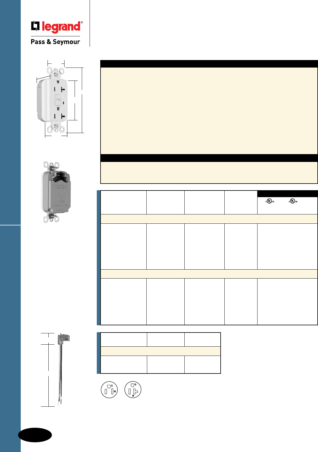
D-36
Decorator Devices
Decorator Devices
PlugTailTM Specification Grade
GFCI Receptacles
2 Pole, 3 Wire Grounding 15 & 20A, 125VAC
PlugTailTM Spec Grade GFCIs
All devices listed on this page conform to NEMA WD-1 and WD-6. UL Listed and CSA Certified.
Catalog
Number Wire Type Wire Length
PlugTail Connectors – Right Angle
PTRA6STR Stranded 6"
PTRA6SOL Solid 6"
For additional PlugTail Connectors,
see Page B-3.
All PlugTail Connectors are available
in any wire length up to 25 inches,
consult factory to order.
Features
n Faster, more reliable installation.
n No exposed terminals create a finger safe
application before, during, and after installation.
n Built-in connector features large brass terminal
blades to ensure consistent, reliable electrical
connections to PlugTail Connector.
n GFCI works with the existing 3 wire PlugTail
Connectors creating a non-feed-thru application for
facility owners. At rough-in just install the same right
angle connector for GFCI and receptacle openings.
n SafeLockTM Protection: if critical components are
damaged and ground fault protection is lost, power
to receptacle is disconnected.
n FSUL Listed (Federal Specification WC596).
Specications
n Supply Voltage: 125VAC, 60 Hz
n Supply Voltage Range: 102-132 VAC
n Trip Threshold: 5± 1mA
n Trip Time: 0.025 sec., nominal per
UL Standard
n 20 Amp feed-thru capacity
n Exceeds UL943 voltage surge requirements;
survives 100x the required UL 3kA/6kV
voltage surge test cycles.
n Trip indicator light (red LED).
n Mounting screws are shipped captive in the
device and wall plate for easier installation.
n High-impact-resistant thermoplastic
construction.
n Zinc-plated steel mounting strap.
n Button colors match the device face.
n Dual-direction test and reset buttons.
n Class A rated GFCI.
n Supplied with matching TP26 nylon wall plate.
n Tri-drive screws.
NEMA
5-15R
NEMA
5-20R
UL943 UL498 FSUL
C22.2 No. 144 C22.2 No. 42 WC596
3rd Party Compliance
Catalog Rating NEMA
Number A. VAC Color Cong. No.
Specification Grade 15 Amp Duplex GFCI
PT1595I 15 125 Ivory 5-15R • • •
PT1595W 15 125 White 5-15R • • •
PT1595 15 125 Brown 5-15R • • •
PT1595GRY 15 125 Gray 5-15R • • •
PT1595BK 15 125 Black 5-15R • • •
PT1595RED 15 125 Red 5-15R • • •
PT1595LA 15 125 Light Almond 5-15R • • •
Specification Grade 20 Amp Duplex GFCI
PT2095I 20 125 Ivory 5-20R • • •
PT2095W 20 125 White 5-20R • • •
PT2095 20 125 Brown 5-20R • • •
PT2095GRY 20 125 Gray 5-20R • • •
PT2095BK 20 125 Black 5-20R • • •
PT2095RED 20 125 Red 5-20R • • •
PT2095LA 20 125 Light Almond 5-20R • • •
PT2095W
1.25"
1.20"
4.20"
2.62"
1.72"
PTRA6STR
1.125"
6.375"
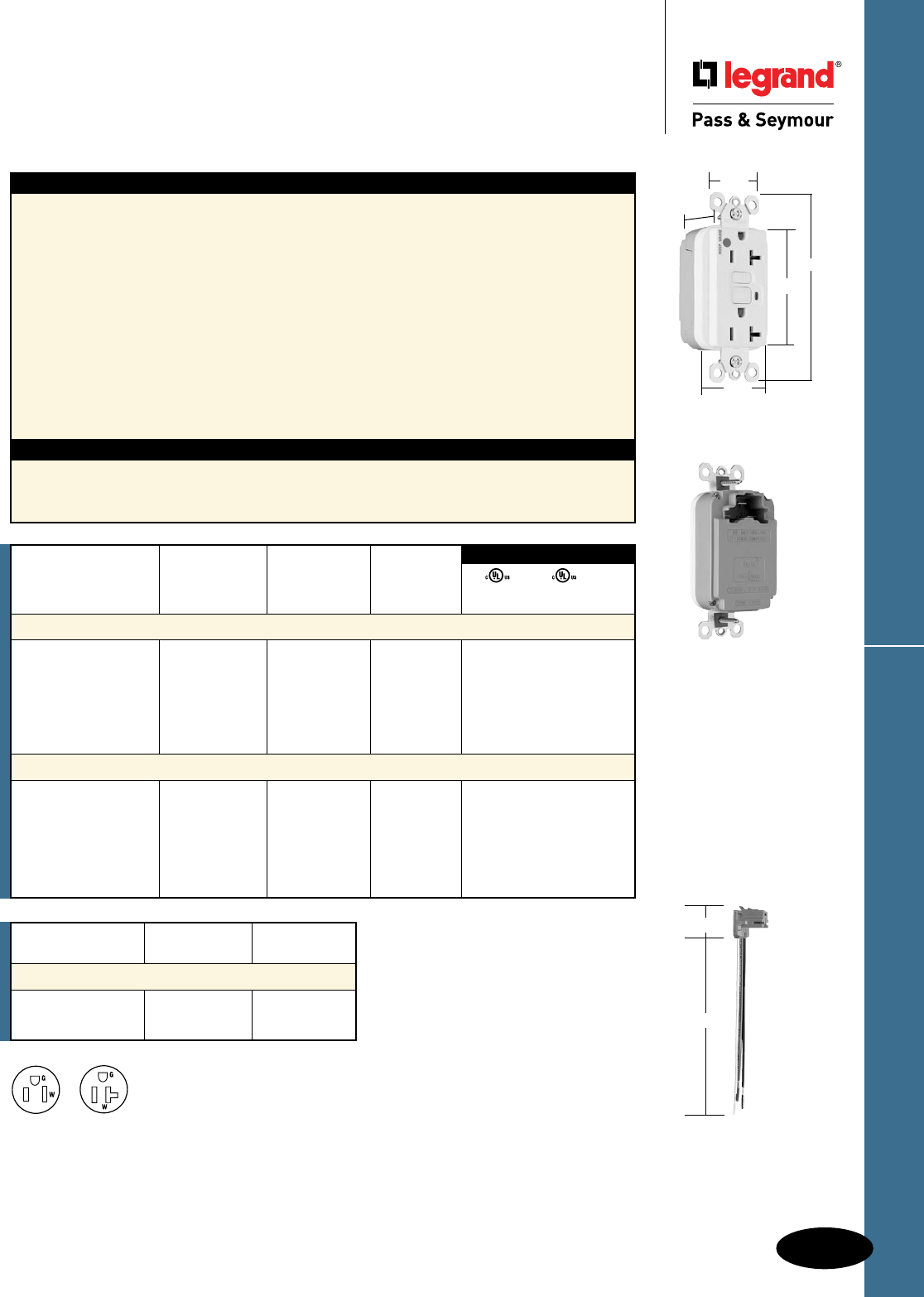
D-37
PlugTailTM Hospital Grade GFCIsDecorator Devices
Decorator Devices
PlugTailTM Hospital Grade
GFCI Receptacles
2 Pole, 3 Wire Grounding 15 & 20A, 125VAC
All devices listed on this page conform to NEMA WD-1 and WD-6.
Catalog
Number Wire Type Wire Length
PlugTail Connectors – Right Angle
PTRA6STR Stranded 6"
PTRA6SOL Solid 6"
For additional PlugTail Connectors,
see Page B-3.
All PlugTail Connectors are available
in any wire length up to 25 inches,
consult factory to order.
NEMA
5-15R
NEMA
5-20R
UL943 UL498 FSUL
C22.2 No. 144 C22.2 No. 42 WC596
3rd Party Compliance
Catalog Rating NEMA
Number A. VAC Color Cong. No.
Hospital Grade 15 Amp Duplex GFCI
PT1595HGI 15 125 Ivory 5-15R • • •
PT1595HGW 15 125 White 5-15R • • •
PT1595HG 15 125 Brown 5-15R • • •
PT1595HGGRY 15 125 Gray 5-15R • • •
PT1595HGRED 15 125 Red 5-15R • • •
PT1595HGLA 15 125 Light Almond 5-15R • • •
Hospital Grade 20 Amp Duplex GFCI
PT2095HGI 20 125 Ivory 5-20R • • •
PT2095HGW 20 125 White 5-20R • • •
PT2095HG 20 125 Brown 5-20R • • •
PT2095HGGRY 20 125 Gray 5-20R • • •
PT2095HGRED 20 125 Red 5-20R • • •
PT2095HGLA 20 125 Light Almond 5-20R • • •
Features
n Faster, more reliable installation.
n No exposed terminals create a finger safe
application before, during, and after installation.
n Built-in connector features large brass terminal
blades to ensure consistent, reliable electrical
connections to PlugTail Connector.
n GFCI works with the existing 3 wire PlugTail
Connectors creating a non-feed-thru application for
facility owners. At rough-in just install the same right
angle connector for GFCI and receptacle openings.
n SafeLockTM Protection: if critical components are
damaged and ground fault protection is lost, power
to receptacle is disconnected.
n FSUL Listed (Federal Specification WC596).
Specications
n Supply Voltage: 125VAC, 60 Hz
n Supply Voltage Range: 102-132 VAC
n Trip Threshold: 5± 1mA
n Trip Time: 0.025 sec., nominal per
UL Standard
n 20 Amp feed-thru capacity
n Exceeds UL943 voltage surge requirements;
survives 100x the required UL 3kA/6kV
voltage surge test cycles.
n Trip indicator light (red LED).
n Mounting screws are shipped captive in the
device and wall plate for easier installation.
n High-impact-resistant thermoplastic
construction.
n Zinc-plated steel mounting strap.
n Button colors match the device face.
n Dual-direction test and reset buttons.
n Class A rated GFCI.
n Supplied with matching TP26 nylon wall plate.
n Tri-drive screws.
PT2095HGW
1.25"
1.20"
4.20"
2.62"
1.72"
PTRA6STR
1.125"
6.375"
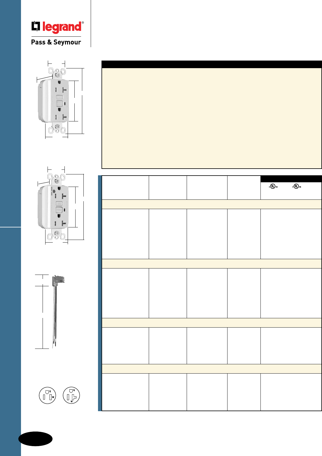
PlugTailTM Tamper-Resistant GFCIs
D-38
Decorator Devices
Decorator Devices
PlugTailTM Specification & Hospital Grade
Tamper-Resistant GFCI Receptacles
2 Pole, 3 Wire Grounding 15 & 20A, 125VAC
All devices listed on this page conform to NEMA WD-1 and WD-6.
Features
n Protects children: patented shutter system helps
prevent improper insertion of foreign objects.
n Meets National Electrical Code®
Tamper-Resistant requirements.
n Faster, more reliable installation.
n No exposed terminals create a finger safe
application before, during, and after installation.
n Built-in connector features large brass terminal
blades to ensure consistent, reliable electrical
connections to PlugTail Connector.
n GFCI works with the existing 3 wire PlugTail
Connectors creating a non-feed-thru application for
facility owners. At rough-in just install the same right
angle connector for GFCI and receptacle openings.
n SafeLockTM Protection: if critical components are
damaged and ground fault protection is lost, power
to receptacle is disconnected.
n FSUL Listed (Federal Specification WC596).
n Exceeds UL943 voltage surge requirements;
survives 100x the required UL 3kA/6kV
voltage surge test cycles.
n Trip indicator light (red LED).
n Mounting screws are shipped captive in the
device and wall plate for easier installation.
n High-impact-resistant thermoplastic
construction.
n Zinc-plated steel mounting strap.
n Button colors match the device face.
n Dual-direction test and reset buttons.
n Class A rated GFCI.
n Supplied with matching TP26 nylon wall plate.
n Tri-drive screws.
UL943 UL498 FSUL
C22.2 No. 144 C22.2 No. 42 WC596
3rd Party Compliance
Catalog Rating NEMA
Number A. VAC Color Cong. No.
Specification Grade Tamper-Resistant 15 Amp Duplex GFCI
PT1595TRI 15 125 Ivory 5-15R • • •
PT1595TRW 15 125 White 5-15R • • •
PT1595TR 15 125 Brown 5-15R • • •
PT1595TRGRY 15 125 Gray 5-15R • • •
PT1595TRBK 15 125 Black 5-15R • • •
PT1595TRRED 15 125 Red 5-15R • • •
PT1595TRLA 15 125 Light Almond 5-15R • • •
Specification Grade Tamper-Resistant 20 Amp Duplex GFCI
PT2095TRI 20 125 Ivory 5-20R • • •
PT2095TRW 20 125 White 5-20R • • •
PT2095TR 20 125 Brown 5-20R • • •
PT2095TRGRY 20 125 Gray 5-20R • • •
PT2095TRBK 20 125 Black 5-20R • • •
PT2095TRRED 20 125 Red 5-20R • • •
PT2095TRLA 20 125 Light Almond 5-20R • • •
Hospital Grade Tamper-Resistant 15 Amp Duplex GFCI
PT1595HGTRI 15 125 Ivory 5-15R • • •
PT1595HGTRW 15 125 White 5-15R • • •
PT1595HGTRGRY 15 125 Gray 5-15R • • •
PT1595HGTRRED 15 125 Red 5-15R • • •
PT1595HGTRLA 15 125 Light Almond 5-15R • • •
Hospital Grade Tamper-Resistant 20 Amp Duplex GFCI
PT2095HGTRI 20 125 Ivory 5-20R • • •
PT2095HGTRW 20 125 White 5-20R • • •
PT2095HGTRGRY 20 125 Gray 5-20R • • •
PT2095HGTRRED 20 125 Red 5-20R • • •
PT2095HGTRLA 20 125 Light Almond 5-20R • • •
For PlugTail Connector catalog numbers, see Page D-36.
PTRA6STR
1.125"
6.375"
PT2095TRW
1.20"
1.25"
4.20"
2.62"
1.72"
NEMA
5-15R
NEMA
5-20R
PT2095HGTRW
1.25"
1.2"
4.20"
2.62"
1.72"
D-39
PlugTailTM TR Nightlight/GFCIsDecorator Devices
Decorator Devices
PlugTailTM Specification & Hospital Grade
Tamper-Resistant Nightlight/GFCI Receptacles
2 Pole, 3 Wire Grounding 15 & 20A, 125VAC
All devices listed on this page conform to NEMA WD-1 and WD-6.
For PlugTail Connector catalog numbers, see Page D-36.
NEMA
5-15R
NEMA
5-20R
Specications
n Supply Voltage: 125VAC, 60 Hz
n Supply Voltage Range: 102-132 VAC
n Trip Threshold: 5± 1mA
n Trip Time: 0.025 sec., nominal per
UL Standard
n 20 Amp feed-thru capacity
Features
n Protects children: patented shutter system helps
prevent improper insertion of foreign objects.
n Meets National Electrical Code®
Tamper-Resistant requirements.
n Sealed nightlight with high impact-resistant Lexan®
lens prevents tampering.
n Nightlight uses cooler LED illumination.
n Energy-efficient LED has average 20-year life
expectancy, eliminating bulb replacement.
n Photocell turns nightlight ON in dark, OFF in daylight.
n Faster, more reliable installation.
n No exposed terminals create a finger safe
application before, during, and after installation.
n Built-in connector features large brass terminal
blades to ensure consistent, reliable electrical
connections to PlugTail Connector.
n GFCI works with the existing 3 wire PlugTail
Connectors creating a non-feed-thru application for
facility owners. At rough-in just install the same right
angle connector for GFCI and receptacle openings.
n SafeLockTM Protection: if critical components
are damaged and ground fault protection is
lost, power to receptacle is disconnected.
n Exceeds UL943 voltage surge requirements;
survives 100x the required UL 3kA/6kV
voltage surge test cycles.
n FSUL Listed (Federal Specification WC596).
n Trip indicator light (red LED).
n Mounting screws are shipped captive in the
device and wall plate for easier installation.
n High-impact-resistant thermoplastic
construction.
n Zinc-plated steel mounting strap.
n Button colors match the device face.
n Dual-direction test and reset buttons.
n Class A rated GFCI.
n Supplied with matching TP26 nylon wall plate.
n Tri-drive screws.
UL943 UL498 FSUL
C22.2 No. 144 C22.2 No. 42 WC596
3rd Party Compliance
Catalog Rating NEMA
Number A. VAC Color Cong. No.
Specification Grade Tamper-Resistant 15 Amp Combination Nightlight/GFCI
PT1595NTLTRI 15 125 Ivory 5-15R • • •
Specification Grade Tamper-Resistant 20 Amp Combination Nightlight/GFCI
PT2095NTLTRI 20 125 Ivory 5-20R • • •
PT2095NTLTRW 20 125 White 5-20R • • •
Hospital Grade Tamper-Resistant 15 Amp Combination Nightlight/GFCI
PT1595HGNTLTRI 15 125 Ivory 5-15R • • •
PT1595HGNTLTRW 15 125 White 5-15R • • •
PT1595HGNTLTRRED 15 125 Red 5-15R • • •
Hospital Grade Tamper-Resistant 20 Amp Combination Nightlight/GFCI
PT2095HGNTLTRI 20 125 Ivory 5-20R • • •
PT2095HGNTLTRW 20 125 White 5-20R • • •
PT2095HGNTLTRLA 20 125 Light Almond 5-20R • • •
NEW
NEW
NEW
NEW
1.25"
1.20"
4.20"
2.62"
1.72"
PT1595NTLTRI
PT1595HGNTLTRI
1.25"
1.20"
4.20"
2.62"
1.72"
PTRA6STR
1.125"
6.375"
D-40
Decorator Devices
Decorator Devices
NAFTA-Compliant & RoHS-Compliant
GFCI Receptacles
2 Pole, 3 Wire Grounding 15 & 20A, 125VAC
NAFTA-Compliant & RoHS-Compliant GFCIs
All devices listed on this page conform to NEMA WD-1 and WD-6.
NAFTA-Compliant GFCI Receptacles are ideal for use on projects subject to the provisions of the
Buy American Act.
Catalog Rating NEMA
Number A. VAC Color Cong. No.
NAFTA-Compliant TradeMaster
®
/Spec Grade Tamper-Resistant
15 Amp Duplex GFCI
1595TRNAI 15 125 Ivory 5-15R • • •
1595TRNAW 15 125 White 5-15R • • •
1595TRNA 15 125 Brown 5-15R • • •
1595TRNAGRY 15 125 Gray 5-15R • • •
1595TRNABK 15 125 Black 5-15R • • •
1595TRNALA 15 125 Light Almond 5-15R • • •
NAFTA-Compliant TradeMaster
®
/Spec Grade Tamper-Resistant
20 Amp Duplex GFCI
2095TRNAI 20 125 Ivory 5-20R • • •
2095TRNAW 20 125 White 5-20R • • •
2095TRNA 20 125 Brown 5-20R • • •
2095TRNAGRY 20 125 Gray 5-20R • • •
2095TRNABK 20 125 Black 5-20R • • •
2095TRNALA 20 125 Light Almond 5-20R • • •
NAFTA-Compliant TradeMaster®/Spec Grade 15 Amp Duplex GFCI
1595NAI 15 125 Ivory 5-15R • • •
1595NAW 15 125 White 5-15R • • •
1595NA 15 125 Brown 5-15R • • •
1595NAGRY 15 125 Gray 5-15R • • •
1595NABK 15 125 Black 5-15R • • •
1595NALA 15 125 Light Almond 5-15R • • •
NAFTA-Compliant Spec Grade 20 Amp Duplex GFCI
2095NAI 20 125 Ivory 5-20R • • •
2095NAW 20 125 White 5-20R • • •
2095NA 20 125 Brown 5-20R • • •
2095NAGRY 20 125 Gray 5-20R • • •
2095NABK 20 125 Black 5-20R • • •
2095NALA 20 125 Light Almond 5-20R • • •
UL943 UL498 FSUL
C22.2 No. 144 C22.2 No. 42 WC596
3rd Party Compliance
NEW
NEW
NEW
NEW
UL943 UL498 FSUL
C22.2 No. 144 C22.2 No. 42 WC596
3rd Party Compliance
Catalog Rating NEMA
Number A. VAC Color Cong. No.
RoHS-Compliant
TradeMaster
®
/Spec Grade Tamper-Resistant
15 Amp Duplex GFCI
1595RI 15 125 Ivory 5-15R • • •
1595RW 15 125 White 5-15R • • •
1595RLA 15 125 Light Almond 5-15R • • •
NEW
RoHS-Compliant GFCI Receptacles meet the requirements of Restriction of Hazardous Substances
directives and regulations.
2095TRNAW
1.72"
1.25"
2.62"
4.20"
.98"
1.72"
1.25"
2.62"
4.20"
.98"
NEMA
5-15R
NEMA
5-20R
1595NAW
1595RW
1.13"
1.72"
1.25"
2.62"
4.20"

D-41
Decorator Devices
Decorator Devices
NAFTA-Compliant Hospital Grade
GFCI Receptacles
2 Pole, 3 Wire Grounding 15 & 20A, 125VAC
NAFTA-Compliant Hospital Grade GFCIs
All devices listed on this page conform to NEMA WD-1 and WD-6.
NEMA
5-15R
NEMA
5-20R
NAFTA-Compliant GFCI Receptacles are ideal for use on projects subject to the provisions of the
Buy American Act.
Catalog Rating NEMA
Number A. VAC Color Cong. No.
NAFTA-Compliant Hospital Grade Tamper-Resistant 20 Amp Duplex GFCI
2095HGTRNAI 20 125 Ivory 5-20R • • •
2095HGTRNAW 20 125 White 5-20R • • •
2095HGTRNAGRY 20 125 Gray 5-20R • • •
2095HGTRNARED 20 125 Red 5-20R • • •
2095HGTRNALA 20 125 Light Almond 5-20R • • •
NAFTA-Compliant Hospital Grade 15 Amp Duplex GFCI
1595HGNAI 15 125 Ivory 5-15R • • •
1595HGNAW 15 125 White 5-15R • • •
1595HGNARED 15 125 Red 5-15R • • •
NAFTA-Compliant Hospital Grade 20 Amp Duplex GFCI
2095HGNAI 20 125 Ivory 5-20R • • •
2095HGNAW 20 125 White 5-20R • • •
2095HGNA 20 125 Brown 5-20R • • •
2095HGNAGRY 20 125 Gray 5-20R • • •
2095HGNARED 20 125 Red 5-20R • • •
2095HGNALA 20 125 Light Almond 5-20R • • •
UL943 UL498 FSUL
C22.2 No. 144 C22.2 No. 42 WC596
3rd Party Compliance
NEW
NEW
NEW
1.72"
1.25"
2.62"
4.20"
.98"
2095HGTRNAW
1595HGNAW
1.72"
1.25"
2.62"
4.20"
.98"
NAFTA-Compliant PlugTail™ GFCI Receptacles
D-42
Decorator Devices
Decorator Devices
NAFTA-Compliant
PlugTail™ GFCI Receptacles
2 Pole, 3 Wire Grounding 15 & 20A, 125VAC
All devices listed on this page conform to NEMA WD-1 and WD-6.
PT1595NAW
1.72"
1.25"
2.62"
4.20"
.98"
NEMA
5-15R
NEMA
5-20R
Specications
n Supply Voltage: 125VAC, 60 Hz
n Supply Voltage Range: 102-132 VAC
n Trip Threshold: 5± 1mA
n Trip Time: 0.025 sec., nominal per
UL Standard
n 20 Amp feed-thru capacity
Features
n Faster, more reliable installation.
n No exposed terminals create a finger safe
application before, during, and after installation.
n Built-in connector features large brass terminal
blades to ensure consistent, reliable electrical
connections to PlugTail Connector.
n GFCI works with the existing 3 wire PlugTail
Connectors creating a non-feed-thru application for
facility owners. At rough-in just install the same right
angle connector for GFCI and receptacle openings.
n SafeLockTM Protection: if critical components are
damaged and ground fault protection is lost, power
to receptacle is disconnected.
n FSUL Listed (Federal Specification WC596).
n Exceeds UL943 voltage surge requirements;
survives 100x the required UL 3kA/6kV
voltage surge test cycles.
n Trip indicator light (red LED).
n Mounting screws are shipped captive in the
device and wall plate for easier installation.
n High-impact-resistant thermoplastic
construction.
n Zinc-plated steel mounting strap.
n Button colors match the device face.
n Dual-direction test and reset buttons.
n Class A rated GFCI.
n Supplied with matching TP26 nylon wall plate.
n Tri-drive screws.
Catalog Rating NEMA
Number A. VAC Color Cong. No.
NAFTA-Compliant Spec Grade 15 Amp Duplex GFCI
PT1595NAI 15 125 Ivory 5-15R • • •
PT1595NAW 15 125 White 5-15R • • •
PT1595NAGRY 15 125 Gray 5-15R • • •
PT1595NALA 15 125 Light Almond 5-15R • • •
NAFTA-Compliant Spec Grade 20 Amp Duplex GFCI
PT2095NAI 20 125 Ivory 5-20R • • •
PT2095NAW 20 125 White 5-20R • • •
PT2095NAGRY 20 125 Gray 5-20R • • •
PT2095NABK 20 125 Black 5-20R • • •
PT2095NALA 20 125 Light Almond 5-20R • • •
NAFTA-Compliant Spec Grade Tamper-Resistant 20 Amp Duplex GFCI
PT2095TRNAI 20 125 Ivory 5-20R • • •
PT2095TRNAW 20 125 White 5-20R • • •
PT2095TRNAGRY 20 125 Gray 5-20R • • •
PT2095TRNALA 20 125 Light Almond 5-20R • • •
NAFTA-Compliant Spec Grade Tamper-Resistant 15 Amp
Combination Nightlight/GFCI
PT1595NTLTRNAI 15 125 Ivory 5-15R • • •
PT1595NTLTRNAW 15 125 White 5-15R • • •
NAFTA-Compliant Spec Grade Tamper-Resistant 20 Amp
Combination Nightlight/GFCI
PT2095NTLTRNAI 20 125 Ivory 5-20R • • •
PT2095NTLTRNAW 20 125 White 5-20R • • •
UL943 UL498 FSUL
C22.2 No. 144 C22.2 No. 42 WC596
3rd Party Compliance
NEW
NEW
NEW
NEW
NEW
NAFTA-Compliant GFCI Receptacles are ideal for use on projects subject to the provisions of the
Buy American Act.
1.72"
1.25"
2.62"
4.20"
.98"
PT2095TRNAW
For PlugTail Connector catalog numbers, see Page D-36.
PT2095NTLTRNAW
1.72"
1.25"
2.62"
4.20"
1.13"
D-43
NAFTA-Compliant PlugTail™ Hospital Grade GFCIs
Decorator Devices
Decorator Devices
NAFTA-Compliant PlugTail™
Hospital Grade GFCI Receptacles
2 Pole, 3 Wire Grounding 15 & 20A, 125VAC
All devices listed on this page conform to NEMA WD-1 and WD-6.
For additional PlugTail Connectors, see
Page B-3.
All PlugTail Connectors are available in
any wire length up to 25 inches, consult
factory to order.
Specications
n Supply Voltage: 125VAC, 60 Hz
n Supply Voltage Range: 102-132 VAC
n Trip Threshold: 5± 1mA
n Trip Time: 0.025 sec., nominal per
UL Standard
n 20 Amp feed-thru capacity
Features
n Faster, more reliable installation.
n No exposed terminals create a finger safe
application before, during, and after installation.
n Built-in connector features large brass terminal
blades to ensure consistent, reliable electrical
connections to PlugTail Connector.
n GFCI works with the existing 3 wire PlugTail
Connectors creating a non-feed-thru application for
facility owners. At rough-in just install the same right
angle connector for GFCI and receptacle openings.
n SafeLockTM Protection: if critical components are
damaged and ground fault protection is lost, power
to receptacle is disconnected.
n FSUL Listed (Federal Specification WC596).
n Exceeds UL943 voltage surge requirements;
survives 100x the required UL 3kA/6kV
voltage surge test cycles.
n Trip indicator light (red LED).
n Mounting screws are shipped captive in the
device and wall plate for easier installation.
n High-impact-resistant thermoplastic
construction.
n Zinc-plated steel mounting strap.
n Button colors match the device face.
n Dual-direction test and reset buttons.
n Class A rated GFCI.
n Supplied with matching TP26 nylon wall plate.
n Tri-drive screws.
Catalog Rating NEMA
Number A. VAC Color Cong. No.
NAFTA-Compliant Hospital Grade 20 Amp Duplex GFCI
PT2095HGNAI 20 125 Ivory 5-20R • • •
PT2095HGNAW 20 125 White 5-20R • • •
PT2095HGNAGRY 20 125 Gray 5-20R • • •
PT2095HGNARED 20 125 Red 5-20R • • •
PT2095HGNALA 20 125 Light Almond 5-20R • • •
NAFTA-Compliant Hospital Grade Tamper-Resistant 20 Amp Duplex GFCI
PT2095HGTRNAI 20 125 Ivory 5-20R • • •
PT2095HGTRNAW 20 125 White 5-20R • • •
PT2095HGTRNAGRY 20 125 Gray 5-20R • • •
PT2095HGTRNARED 20 125 Red 5-20R • • •
PT2095HGTRNALA 20 125 Light Almond 5-20R • • •
NAFTA-Compliant Hospital Grade
Tamper-Resistant
15 Amp
Combination Nightlight/GFCI
PT1595HGNTLTRNAI 15 125 Ivory 5-15R • • •
PT1595HGNTLTRNAW 15 125 White 5-15R • • •
PT1595HGNTLTRNARED 15 125 Red 5-15R • • •
NAFTA-Compliant Hospital Grade
Tamper-Resistant
20 Amp
Combination Nightlight/GFCI
PT2095HGNTLTRNAI 20 125 Ivory 5-20R • • •
PT2095HGNTLTRNAW 20 125 White 5-20R • • •
PT2095HGNTLTRNARED 20 125 Red 5-20R • • •
UL943 UL498 FSUL
C22.2 No. 144 C22.2 No. 42 WC596
3rd Party Compliance
NEW
NEW
NEW
NEW
NAFTA-Compliant GFCI Receptacles are ideal for use on projects subject to the provisions of the
Buy American Act.
PT2095HGNAW
1.72"
1.25"
2.62"
4.20"
.98"
PT2095HGNTLTRNAW
1.72"
1.25"
2.62"
4.20"
1.13"
Catalog Number Wire Type Wire Length
PlugTail Connectors – Right Angle
PTRA6STR Stranded 6"
PTRA6SOL Solid 6"
PTRA6STR
1.125"
6.375"
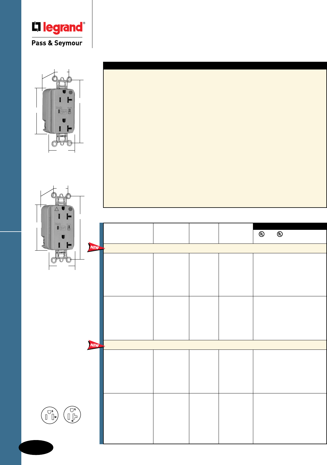
HG Surge Protective Receptacles
D-44
Decorator Devices
Decorator Devices
Hospital Grade Surge Protective
Receptacles
2 Pole, 3 Wire Grounding 15 & 20A, 125VAC
Specications
n UL1449 (3rd Edition). (1.2 x 50µs
6000V, 8 x 20µs 3000A).
n 24,000 amps current handling capability in
each of 3 modes: line to neutral, line
to ground, neutral to ground.
n LED indication: Steady green = protected;
Flashing red = not protected
OFF = no power to unit
n Response time less than 1 nanosecond for
unmounted MOV.
n Overcurrent protection in all 3 modes.
n Printed circuit board conformally coated to
protect against condensing humidity and
airborne particulates.
n Thermal protection in all 3 modes.
n Leakage current: 0.5 mA at 25°C/120VAC.
n Common mode noise attenuation: 500 KHz
to 30 MHz; up to 20 dB (50 ohm source
impedance)
n Varistor voltage: 130V RMS.
n Back and side wire capability including
ground terminal.
n Operating temperature: -40°C to 85°C
(-40°F to 185°F)
5262/5362, IG5262/5362, 8200/8300, IG8200/8300,
TR5262/5362, TRIG5262/5362, TR8200/8300,
TRIG8200/8300
n 340 joules of energy absorption in each of the 3 modes.
Energy (measured for an 8x20µS duration) = 340J.
n Nominal let-through (suppressed) voltage in all
3 modes, 500V.
n Audible alarm able to be turned on/off.
n 3 17mm dual pack MOVs to suppress transients in all
modes – equally.
n Isolated Ground version complies with NEC 410-56 (C)
and 250-146.
5252/5352, TR5252/5352, All PlugTail™
n 340 joules of energy absorption in line-to-neutral and
line-to-ground modes. 680 joules of energy absorption
in neutral-to-ground mode. Energy (measured for an
8x20µS duration) = 340J; 680J for N-G mode.
n 2 17mm dual pack MOVs to suppress
transients in all modes – equally.
n Nominal let-through (suppressed) voltage:
Line-to-neutral and line-to-ground modes = 500V;
neutral-to-ground = 1000V.
n PlugTail versions – factory-terminated devices and
connectors.
NEMA
5-20R
NEMA
5-15R
8300GRYSP
3.75"
1.70"
.875"
1.25"
Behind Strap
2.75"
IG8300GRYSP
3.75"
1.70"
.875"
1.25"
Behind Strap
2.75"
FSUL
UL1449 UL498 WC596 cUL/CSA
Rating NEMA
Catalog Number A. VAC Cong. No. Color
Duplex Receptacles Back & Side Wire
8200ISP 15 125 5-15R Ivory • • • •
8200WSP 15 125 5-15R White • • • •
8200SP 15 125 5-15R Brown • • • •
8200GRYSP 15 125 5-15R Gray • • • •
8200REDSP 15 125 5-15R Red • • • •
8200LASP 15 125 5-15R Light Almond • • • •
8200BLSP 15 125 5-15R Blue • • • •
8300ISP 20 125 5-20R Ivory • • • •
8300WSP 20 125 5-20R White • • • •
8300SP 20 125 5-20R Brown • • • •
8300GRYSP 20 125 5-20R Gray • • • •
8300REDSP 20 125 5-20R Red • • • •
8300LASP 20 125 5-20R Light Almond • • • •
8300BLSP 20 125 5-20R Blue • • • •
Isolated Ground Duplex Receptacles Back & Side Wire
IG8200ISP 15 125 5-15R Ivory • • • •
IG8200WSP 15 125 5-15R White • • • •
IG8200GRYSP 15 125 5-15R Gray • • • •
IG8200REDSP 15 125 5-15R Red • • • •
IG8200LASP 15 125 5-15R Light Almond • • • •
IG8200BLSP 15 125 5-15R Blue • • • •
IG8200OSP 15 125 5-15R Orange • • • •
IG8300ISP 20 125 5-20R Ivory • • • •
IG8300WSP 20 125 5-20R White • • • •
IG8300SP 20 125 5-20R Brown • • • •
IG8300GRYSP 20 125 5-20R Gray • • • •
IG8300REDSP 20 125 5-20R Red • • • •
IG8300LASP 20 125 5-20R Light Almond • • • •
IG8300BLSP 20 125 5-20R Blue • • • •
IG8300OSP 20 125 5-20R Orange • • • •
3rd Party Compliance
Audible Alarm with LED Indicator
All devices listed on this page
conform to NEMA WD-1 and
WD-6. Conforms to the latest
revision ANSI/IEEE C62.41
(formerly IEEE587), ANSI/IEEE
C62.45.
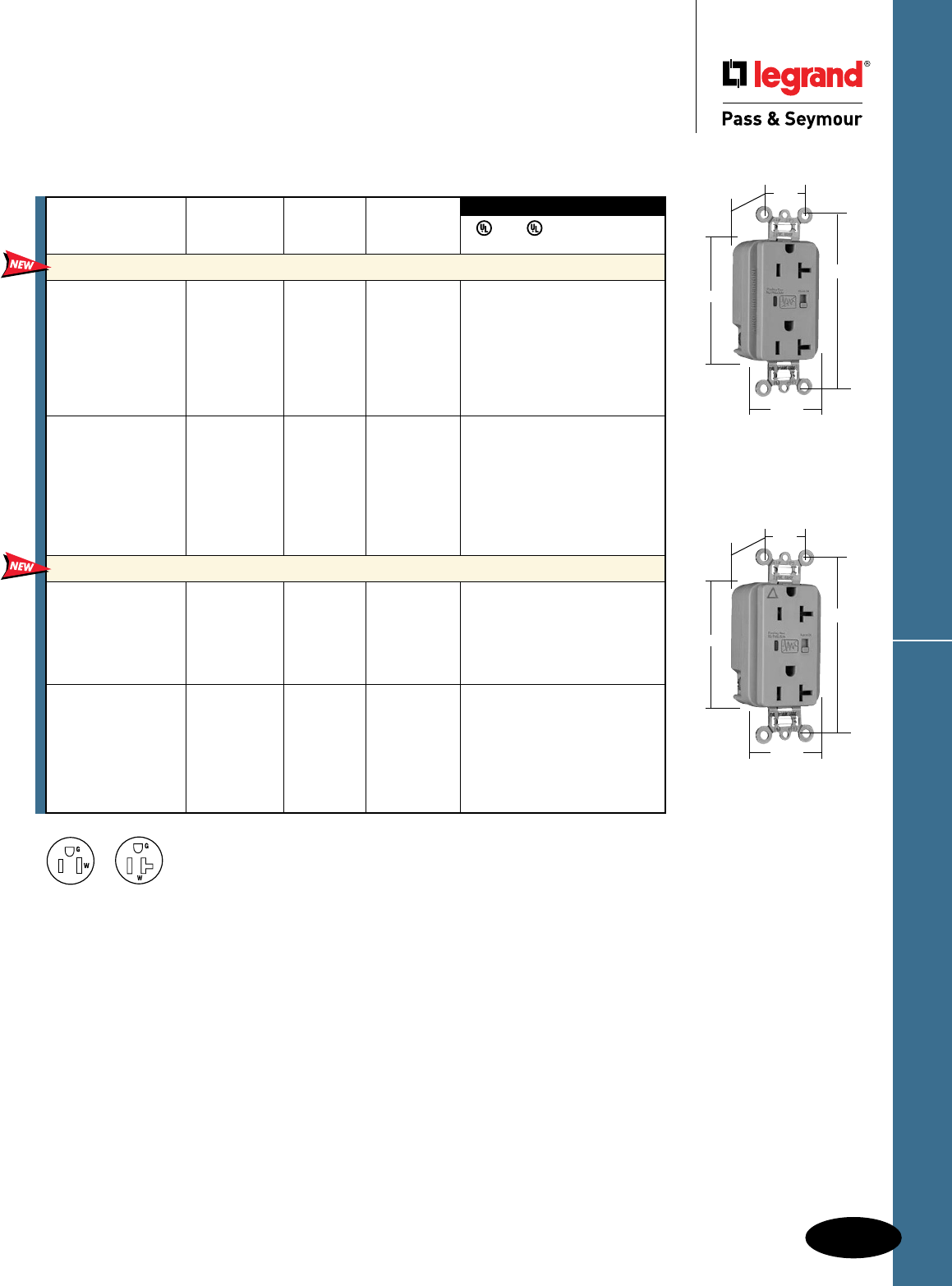
D-45
Decorator Devices Surge Protective Receptacles
Decorator Devices
Surge Protective Receptacles
2 Pole, 3 Wire Grounding 15 & 20A, 125VAC
NEMA
5-20R
NEMA
5-15R
5362GRYSP
3.75"
1.70"
.875"
1.25"
Behind Strap
2.75"
Audible Alarm with LED Indicator
FSUL
UL1449 UL498 WC596 cUL/CSA
3rd Party Compliance
Rating NEMA
Catalog Number A. VAC Cong. No. Color
Extra Heavy-Duty Duplex Receptacles Back & Side Wire
5262ISP 15 125 5-15R Ivory • • • •
5262WSP 15 125 5-15R White • • • •
5262SP 15 125 5-15R Brown • • • •
5262GRYSP 15 125 5-15R Gray • • • •
5262BKSP 15 125 5-15R Black • • • •
5262REDSP 15 125 5-15R Red • • • •
5262LASP 15 125 5-15R Light Almond • • • •
5262BLSP 15 125 5-15R Blue • • • •
5362ISP 20 125 5-20R Ivory • • • •
5362WSP 20 125 5-20R White • • • •
5362SP 20 125 5-20R Brown • • • •
5362GRYSP 20 125 5-20R Gray • • • •
5362BKSP 20 125 5-20R Black • • • •
5362REDSP 20 125 5-20R Red • • • •
5362LASP 20 125 5-20R Light Almond • • • •
5362BLSP 20 125 5-20R Blue • • • •
Isolated Ground Duplex Receptacles
Back & Side Wire
IG5262ISP 15 125 5-15R Ivory • • • •
IG5262WSP 15 125 5-15R White • • • •
IG5262GRYSP 15 125 5-15R Gray • • • •
IG5262LASP 15 125 5-15R Light Almond • • • •
IG5262BLSP 15 125 5-15R Blue • • • •
IG5262OSP 15 125 5-15R Orange • • • •
IG5362ISP 20 125 5-20R Ivory • • • •
IG5362WSP 20 125 5-20R White • • • •
IG5362SP 20 125 5-20R Brown • • • •
IG5362GRYSP 20 125 5-20R Gray • • • •
IG5362LASP 20 125 5-20R Light Almond • • • •
IG5362BLSP 20 125 5-20R Blue • • • •
IG5362OSP 20 125 5-20R Orange • • • •IG5362GRYSP
3.75"
1.70"
.875"
1.25"
Behind Strap
2.75"
All devices listed on this page conform to NEMA WD-1 and WD-6.
Conforms to the latest revision ANSI/IEEE C62.41 (formerly IEEE587), ANSI/IEEE C62.45.
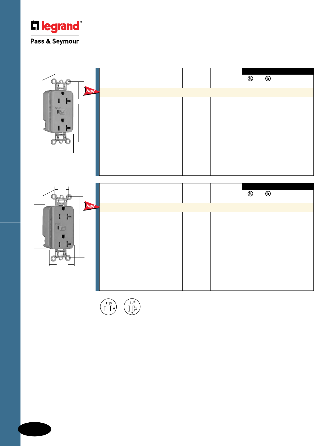
D-46
Decorator DevicesSurge Protective Receptacles
Decorator Devices
Surge Protective Receptacles
2 Pole, 3 Wire Grounding 15 & 20A, 125VAC
5352GRYSP
3.75"
1.70"
.875"
1.29"
Behind Strap
2.75"
3rd Party Compliance
3rd Party Compliance
FSUL
UL1449 UL498 WC596 cUL/CSA
Rating NEMA
Catalog Number A. VAC Cong. No. Color
Duplex Receptacles Back & Side Wire
5252ISP 15 125 5-15R Ivory • • • •
5252WSP 15 125 5-15R White • • • •
5252GRYSP 15 125 5-15R Gray • • • •
5252BKSP 15 125 5-15R Black • • • •
5252LASP 15 125 5-15R Light Almond • • • •
5252BLSP 15 125 5-15R Blue • • • •
5352ISP 20 125 5-20R Ivory • • • •
5352WSP 20 125 5-20R White • • • •
5352GRYSP 20 125 5-20R Gray • • • •
5352BKSP 20 125 5-20R Black • • • •
5352LASP 20 125 5-20R Light Almond • • • •
5352BLSP 20 125 5-20R Blue • • • •
LED Indicator Only
3rd Party Compliance
3rd Party Compliance
FSUL
UL1449 UL498 WC596 cUL/CSA
Rating NEMA
Catalog Number A. VAC Cong. No. Color
Tamper-Resistant Duplex Receptacles Back & Side Wire*
TR5252ISP 15 125 5-15R Ivory • • • •
TR5252WSP 15 125 5-15R White • • • •
TR5252GRYSP 15 125 5-15R Gray • • • •
TR5252BKSP 15 125 5-15R Black • • • •
TR5252LASP 15 125 5-15R Light Almond • • • •
TR5252BLSP 15 125 5-15R Blue • • • •
TR5352ISP 20 125 5-20R Ivory • • • •
TR5352WSP 20 125 5-20R White • • • •
TR5352GRYSP 20 125 5-20R Gray • • • •
TR5352BKSP 20 125 5-20R Black • • • •
TR5352LASP 20 125 5-20R Light Almond • • • •
TR5352BLSP 20 125 5-20R Blue • • • •
*Available Spring 2011
NEMA
5-20R
NEMA
5-15R
TR5352GRYSP
3.75"
1.70"
.875"
1.40"
Behind Strap
2.75"
All devices listed on this page conform to NEMA WD-1 and WD-6.
Conforms to the latest revision ANSI/IEEE C62.41 (formerly IEEE587), ANSI/IEEE C62.45.
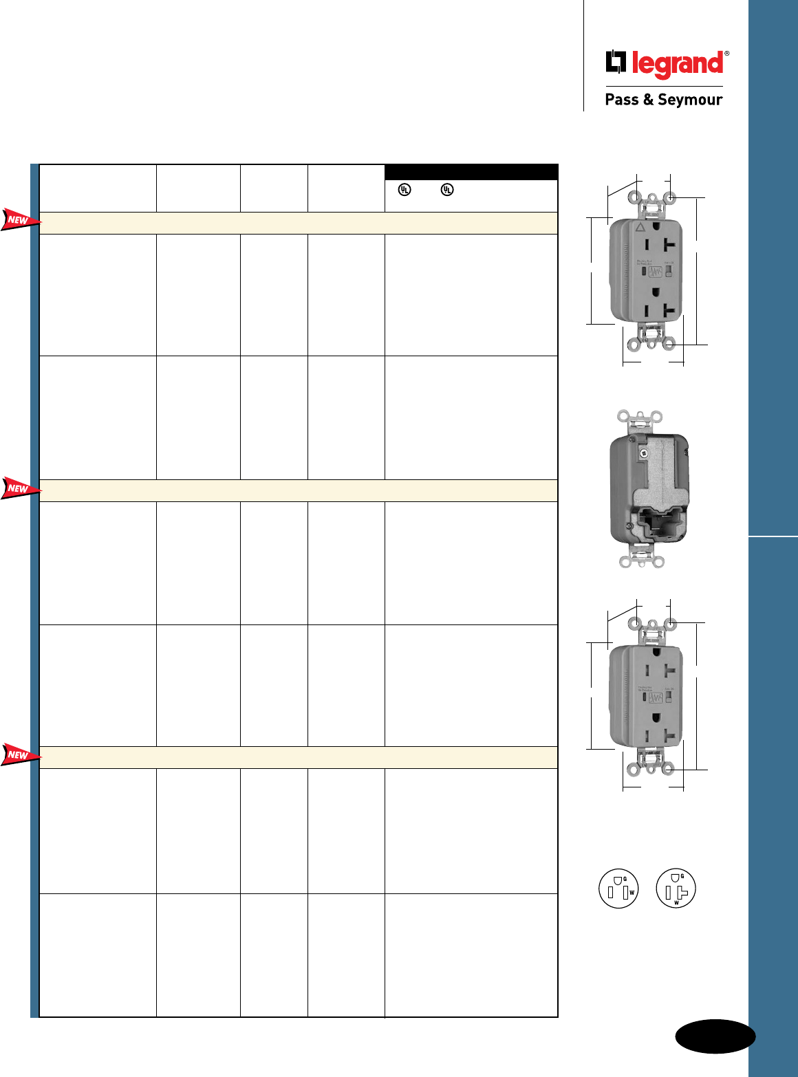
D-47
Decorator Devices PlugTail™ Surge Protective Receptacles
Decorator Devices
PlugTail™ Surge Protective Receptacles
2 Pole, 3 Wire Grounding, 15 & 20A, 125VAC
3rd Party Compliance
3rd Party Compliance
FSUL
UL1449 UL498 WC596 cUL/CSA
Rating NEMA
Catalog Number A. VAC Cong. No. Color
Extra Heavy-Duty Duplex Receptacles
PT5262ISP 15 125 5-15R Ivory • • • •
PT5262WSP 15 125 5-15R White • • • •
PT5262SP 15 125 5-15R Brown • • • •
PT5262GRYSP 15 125 5-15R Gray • • • •
PT5262BKSP 15 125 5-15R Black • • • •
PT5262REDSP 15 125 5-15R Red • • • •
PT5262LASP 15 125 5-15R Light Almond • • • •
PT5262BLSP 15 125 5-15R Blue • • • •
PT5362ISP 20 125 5-20R Ivory • • • •
PT5362WSP 20 125 5-20R White • • • •
PT5362SP 20 125 5-20R Brown • • • •
PT5362GRYSP 20 125 5-20R Gray • • • •
PT5362BKSP 20 125 5-20R Black • • • •
PT5362REDSP 20 125 5-20R Red • • • •
PT5362LASP 20 125 5-20R Light Almond • • • •
PT5362BLSP 20 125 5-20R Blue • • • •
Isolated Ground Duplex Receptacles
PTIG5262ISP 15 125 5-15R Ivory • • • •
PTIG5262WSP 15 125 5-15R White • • • •
PTIG5262GRYSP 15 125 5-15R Gray • • • •
PTIG5262BKSP 15 125 5-15R Black • • • •
PTIG5262REDSP 15 125 5-15R Red • • • •
PTIG5262LASP 15 125 5-15R Light Almond • • • •
PTIG5262OSP 15 125 5-15R Orange • • • •
PTIG5262BLSP 15 125 5-15R Blue • • • •
PTIG5362ISP 20 125 5-20R Ivory • • • •
PTIG5362WSP 20 125 5-20R White • • • •
PTIG5362GRYSP 20 125 5-20R Gray • • • •
PTIG5362BKSP 20 125 5-20R Black • • • •
PTIG5362REDSP 20 125 5-20R Red • • • •
PTIG5362LASP 20 125 5-20R Light Almond • • • •
PTIG5362OSP 20 125 5-20R Orange • • • •
PTIG5362BLSP 20 125 5-20R Blue • • • •
Tamper-Resistant Duplex Receptacles
PTTR5262ISP 15 125 5-15R Ivory • • • •
PTTR5262WSP 15 125 5-15R White • • • •
PTTR5262SP 15 125 5-15R Brown • • • •
PTTR5262GRYSP 15 125 5-15R Gray • • • •
PTTR5262BKSP 15 125 5-15R Black • • • •
PTTR5262REDSP 15 125 5-15R Red • • • •
PTTR5262LASP 15 125 5-15R Light Almond • • • •
PTTR5262BLSP 15 125 5-15R Blue • • • •
PTTR5362ISP 20 125 5-20R Ivory • • • •
PTTR5362WSP 20 125 5-20R White • • • •
PTTR5362SP 20 125 5-20R Brown • • • •
PTTR5362GRYSP 20 125 5-20R Gray • • • •
PTTR5362BKSP 20 125 5-20R Black • • • •
PTTR5362REDSP 20 125 5-20R Red • • • •
PTTR5362LASP 20 125 5-20R Light Almond • • • •
PTTR5362BLSP 20 125 5-20R Blue • • • •
Audible Alarm with LED Indicator
Available Spring 2011
NEMA
5-20R
NEMA
5-15R
PTIG5362GRYSP
3.75"
1.70"
.875"
1.20"
Behind Strap
2.75"
PTTR5362GRYSP
3.75"
1.70"
.875"
1.40"
Behind Strap
2.75"
All devices listed on this page
conform to NEMA WD-1, WD-6.
Conforms to the latest revision
ANSI/IEEE C62.41 (formerly
IEEE587), ANSI/IEEE C62.45.
For PlugTail Connectors,
see Page B-3.
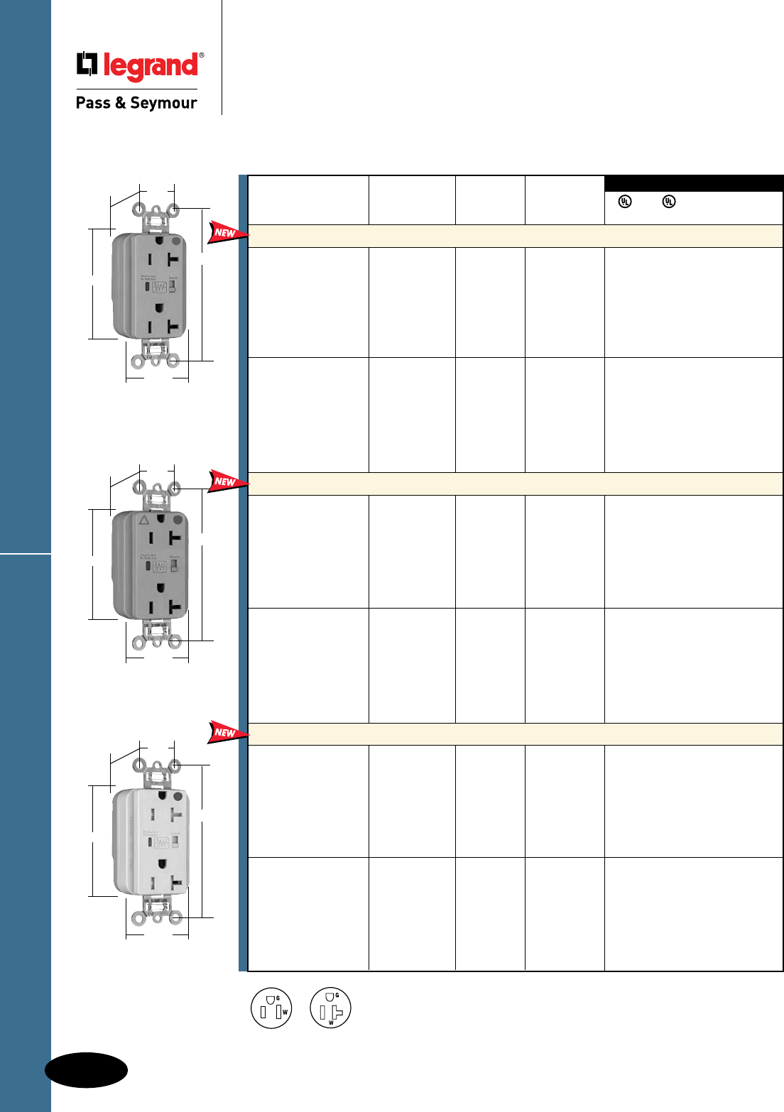
D-48
Decorator Devices
PlugTail™ HG Surge Protective Receptacles
Decorator Devices
PlugTail™ Hospital Grade
Surge Protective Receptacles
2 Pole, 3 Wire Grounding, 15 & 20A, 125VAC
Available Spring 2011
NEMA
5-20R
NEMA
5-15R
3rd Party Compliance
3rd Party Compliance
FSUL
UL1449 UL498 WC596 cUL/CSA
Rating NEMA
Catalog Number A. VAC Cong. No. Color
Extra Heavy-Duty Duplex Receptacles
PT8200ISP 15 125 5-15R Ivory • • • •
PT8200WSP 15 125 5-15R White • • • •
PT8200SP 15 125 5-15R Brown • • • •
PT8200GRYSP 15 125 5-15R Gray • • • •
PT8200REDSP 15 125 5-15R Red • • • •
PT8200LASP 15 125 5-15R Light Almond • • • •
PT8200BLSP 15 125 5-15R Blue • • • •
PT8300ISP 20 125 5-20R Ivory • • • •
PT8300WSP 20 125 5-20R White • • • •
PT8300SP 20 125 5-20R Brown • • • •
PT8300GRYSP 20 125 5-20R Gray • • • •
PT8300REDSP 20 125 5-20R Red • • • •
PT8300LASP 20 125 5-20R Light Almond • • • •
PT8300BLSP 20 125 5-20R Blue • • • •
Isolated Ground Duplex Receptacles
PTIG8200ISP 15 125 5-15R Ivory • • • •
PTIG8200WSP 15 125 5-15R White • • • •
PTIG8200GRYSP 15 125 5-15R Gray • • • •
PTIG8200REDSP 15 125 5-15R Red • • • •
PTIG8200LASP 15 125 5-15R Light Almond • • • •
PTIG8200BLSP 15 125 5-15R Blue • • • •
PTIG8200OSP 15 125 5-15R Orange • • • •
PTIG8300ISP 20 125 5-20R Ivory • • • •
PTIG8300WSP 20 125 5-20R White • • • •
PTIG8300GRYSP 20 125 5-20R Gray • • • •
PTIG8300REDSP 20 125 5-20R Red • • • •
PTIG8300LASP 20 125 5-20R Light Almond • • • •
PTIG8300BLSP 20 125 5-20R Blue • • • •
PTIG8300OSP 20 125 5-20R Orange • • • •
Tamper-Resistant Duplex Receptacles
PTTR8200ISP 15 125 5-15R Ivory • • • •
PTTR8200WSP 15 125 5-15R White • • • •
PTTR8200SP 15 125 5-15R Brown • • • •
PTTR8200GRYSP 15 125 5-15R Gray • • • •
PTTR8200REDSP 15 125 5-15R Red • • • •
PTTR8200LASP 15 125 5-15R Light Almond • • • •
PTTR8200BLSP 15 125 5-15R Blue • • • •
PTTR8300ISP 20 125 5-20R Ivory • • • •
PTTR8300WSP 20 125 5-20R White • • • •
PTTR8300SP 20 125 5-20R Brown • • • •
PTTR8300GRYSP 20 125 5-20R Gray • • • •
PTTR8300REDSP 20 125 5-20R Red • • • •
PTTR8300LASP 20 125 5-20R Light Almond • • • •
PTTR8300BLSP 20 125 5-20R Blue • • • •
Audible Alarm with LED Indicator
PT8300GRYSP
3.75"
1.70"
.875"
1.20"
Behind Strap
2.75"
PTIG8300GRYSP
3.75"
1.70"
.875"
1.20"
Behind Strap
2.75"
PTTR8300ISP
3.75"
1.70"
.875"
1.40"
Behind Strap
2.75"
All devices listed on this page conform to NEMA WD-1 and WD-6.
Conforms to the latest revision ANSI/IEEE C62.41 (formerly IEEE587), ANSI/IEEE C62.45.
For PlugTail Connectors,
see Page B-3.
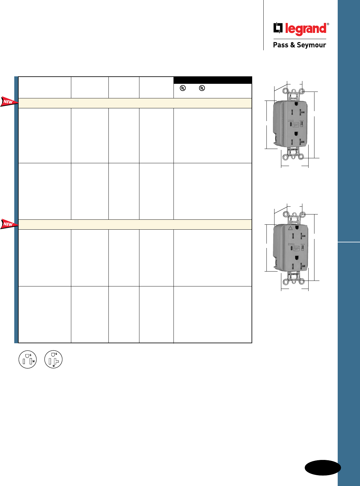
D-49
Decorator Devices
Tamper-Resistant Surge Protective Receptacles
Decorator Devices
Tamper-Resistant
Surge Protective Receptacles
2 Pole, 3 Wire Grounding, 15 & 20A, 125VAC
3rd Party Compliance
3rd Party Compliance
FSUL
UL1449 UL498 WC596 cUL/CSA
Rating NEMA
Catalog Number A. VAC Cong. No. Color
Extra Heavy-Duty Duplex Receptacles Back & Side Wire
TR5262ISP 15 125 5-15R Ivory • • • •
TR5262WSP 15 125 5-15R White • • • •
TR5262SP 15 125 5-15R Brown • • • •
TR5262GRYSP 15 125 5-15R Gray • • • •
TR5262BKSP 15 125 5-15R Black • • • •
TR5262REDSP 15 125 5-15R Red • • • •
TR5262LASP 15 125 5-15R Light Almond • • • •
TR5262BLSP 15 125 5-15R Blue • • • •
TR5362ISP 20 125 5-20R Ivory • • • •
TR5362WSP 20 125 5-20R White • • • •
TR5362SP 20 125 5-20R Brown • • • •
TR5362GRYSP 20 125 5-20R Gray • • • •
TR5362BKSP 20 125 5-20R Black • • • •
TR5362REDSP 20 125 5-20R Red • • • •
TR5362LASP 20 125 5-20R Light Almond • • • •
TR5362BLSP 20 125 5-20R Blue • • • •
Isolated Ground Duplex Receptacles Back & Side Wire
TRIG5262ISP 15 125 5-15R Ivory • • • •
TRIG5262WSP 15 125 5-15R White • • • •
TRIG5262GRYSP 15 125 5-15R Gray • • • •
TRIG5262BKSP 15 125 5-15R Black • • • •
TRIG5262REDSP 15 125 5-15R Red • • • •
TRIG5262LASP 15 125 5-15R Light Almond • • • •
TRIG5262BLSP 15 125 5-15R Blue • • • •
TRIG5262OSP 15 125 5-15R Orange • • • •
TRIG5362ISP 20 125 5-20R Ivory • • • •
TRIG5362WSP 20 125 5-20R White • • • •
TRIG5362GRYSP 20 125 5-20R Gray • • • •
TRIG5362BKSP 20 125 5-20R Black • • • •
TRIG5362REDSP 20 125 5-20R Red • • • •
TRIG5362LASP 20 125 5-20R Light Almond • • • •
TRIG5362BLSP 20 125 5-20R Blue • • • •
TRIG5362OSP 20 125 5-20R Orange • • • •
Audible Alarm with LED Indicator
Available Spring 2011
NEMA
5-20R
NEMA
5-15R
TR5362GRYSP
TRIG5362GRYSP
3.75"
1.70"
.875"
2.75"
1.40"
Behind Strap
3.75"
1.70"
.875"
2.75"
1.40"
Behind Strap
All devices listed on this page conform to NEMA WD-1 and WD-6.
Conforms to the latest revision ANSI/IEEE C62.41 (formerly IEEE587), ANSI/IEEE C62.45.
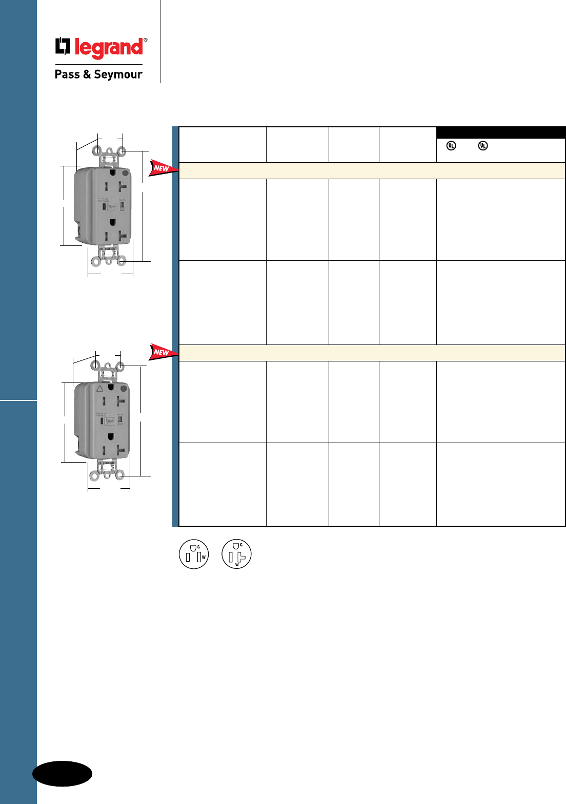
D-50
Decorator DevicesTR HG Surge Protective Receptacles
Decorator Devices
Tamper-Resistant Hospital Grade
Surge Protective Receptacles
2 Pole, 3 Wire Grounding, 15 & 20A, 125VAC
TR8300GRYSP
3.75"
1.70"
.875"
1.40"
Behind Strap
2.75"
TRIG8300GRYSP
3.75"
1.70"
.875"
1.40"
Behind Strap
2.75"
3rd Party Compliance
3rd Party Compliance
FSUL
UL1449 UL498 WC596 cUL/CSA
Rating NEMA
Catalog Number A. VAC Cong. No. Color
Extra Heavy-Duty Duplex Receptacles Back & Side Wire
TR8200ISP 15 125 5-15R Ivory • • • •
TR8200WSP 15 125 5-15R White • • • •
TR8200SP 15 125 5-15R Brown • • • •
TR8200GRYSP 15 125 5-15R Gray • • • •
TR8200REDSP 15 125 5-15R Red • • • •
TR8200LASP 15 125 5-15R Light Almond • • • •
TR8200BLSP 15 125 5-15R Blue • • • •
TR8300ISP 20 125 5-20R Ivory • • • •
TR8300WSP 20 125 5-20R White • • • •
TR8300SP 20 125 5-20R Brown • • • •
TR8300GRYSP 20 125 5-20R Gray • • • •
TR8300REDSP 20 125 5-20R Red • • • •
TR8300LASP 20 125 5-20R Light Almond • • • •
TR8300BLSP 20 125 5-20R Blue • • • •
Isolated Ground Duplex Receptacles Back & Side Wire
TRIG8200ISP 15 125 5-15R Ivory • • • •
TRIG8200WSP 15 125 5-15R White • • • •
TRIG8200GRYSP 15 125 5-15R Gray • • • •
TRIG8200REDSP 15 125 5-15R Red • • • •
TRIG8200LASP 15 125 5-15R Light Almond • • • •
TRIG8200BLSP 15 125 5-15R Blue • • • •
TRIG8200OSP 15 125 5-15R Orange • • • •
TRIG8300ISP 20 125 5-20R Ivory • • • •
TRIG8300WSP 20 125 5-20R White • • • •
TRIG8300GRYSP 20 125 5-20R Gray • • • •
TRIG8300REDSP 20 125 5-20R Red • • • •
TRIG8300LASP 20 125 5-20R Light Almond • • • •
TRIG8300BLSP 20 125 5-20R Blue • • • •
TRIG8300OSP 20 125 5-20R Orange • • • •
Audible Alarm with LED Indicator
Available Spring 2011
NEMA
5-20R
NEMA
5-15R
All devices listed on this page conform to NEMA WD-1 and WD-6.
Conforms to the latest revision ANSI/IEEE C62.41 (formerly IEEE587), ANSI/IEEE C62.45.
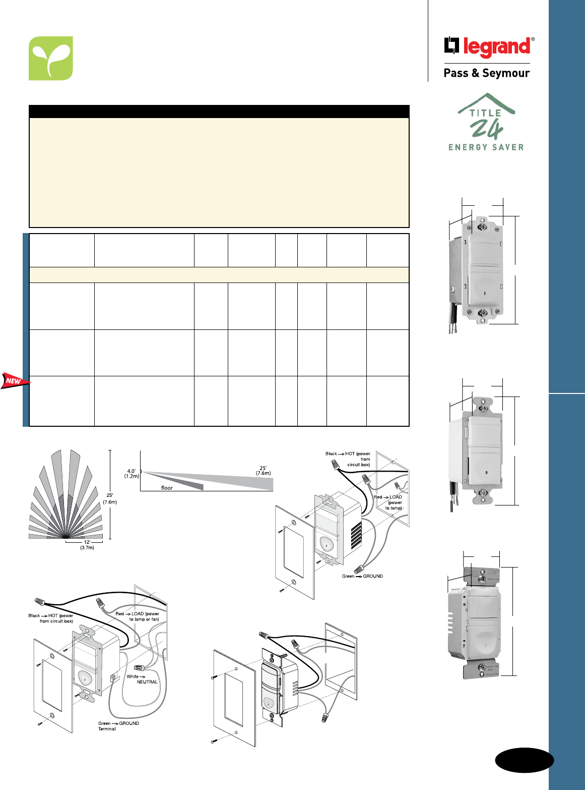
D-51
Decorator Devices Residential Vacancy Sensors
Decorator Devices
Residential Vacancy Sensors
Passive Infrared (PIR)
All devices listed on this page conform to NEMA WD-1 and WD-6.
RW500BLACC4
1.69"
2.63"
1.88"
1.69"
2.63"
1.88"
RWU600BLACC4
RW600BTC
1.69"
2.63"
1.88"
Features
n California Title 24 compliant.
n Replaces a standard light or fan single pole switch.
n Lighted switch for visibility in darkened rooms.
n Manual-ON operation.
n Fixed 30-minute time delay, no adjustment
necessary.
n Low-profile styling with uniform color-matched
lens and device.
n Coverage: 180°, max. 600 ft.2 (56m2).
n cULus listed.
n 5-year warranty.
RW500B only
n Incandescent.
RWU600B only
n Load: Incandescent, fluorescent, compact
fluorescent (CFL), magnetic low-voltage (MLV)
and electronic low-voltage (ELV), 1/6 hp.
RW600BTC only
n Interchangeable face – Three colors in one
box (Ivory, White, Light Almond).
RW500B Wiring
Wiring for RW500B does
not require a neutral.
RWU600B Wiring
Wiring for RWU600B requires a neutral.
Coverage
Selectable
Catalog Auto Manual Auto/Man.
Number Description Voltage Load ON ON ON Color
Single Pole Vacancy Sensors
RW500BICC4 No Yes No Ivory
RW500BWCC4 No neutral required, 120VAC 25-500W No Yes No White
RW500BBKCC4 ideal for bedrooms 60 Hz Incandescent No Yes No Black
RW500BLACC4 and baths No Yes No Lt. Almond
RWU600BICC4 No Yes No Ivory
RWU600BWCC4 Neutral required, 120VAC 0-600W No Yes No White
RWU600BBKCC4 ideal for bedrooms 60 Hz All No Yes No Black
RWU600BLACC4 and baths No Yes No Lt. Almond
RW600BTC No neutral required, ideal No Yes No Ivory/
for bedrooms and baths 120VAC 0-600W White/
Comes with three 60 Hz All Lt. Almond
interchangeable face colors.
RW600B Wiring
Wiring for RW600B does not require a neutral.
Green -> GROUND
Black -> HOT (power
from circuit box)
Time
Delay
Motion Blink
OFF
30sec.
30min.
5min.
10min.
20min.
11543r1
Red -> LOAD (power
to lamp or fan)
OPEN
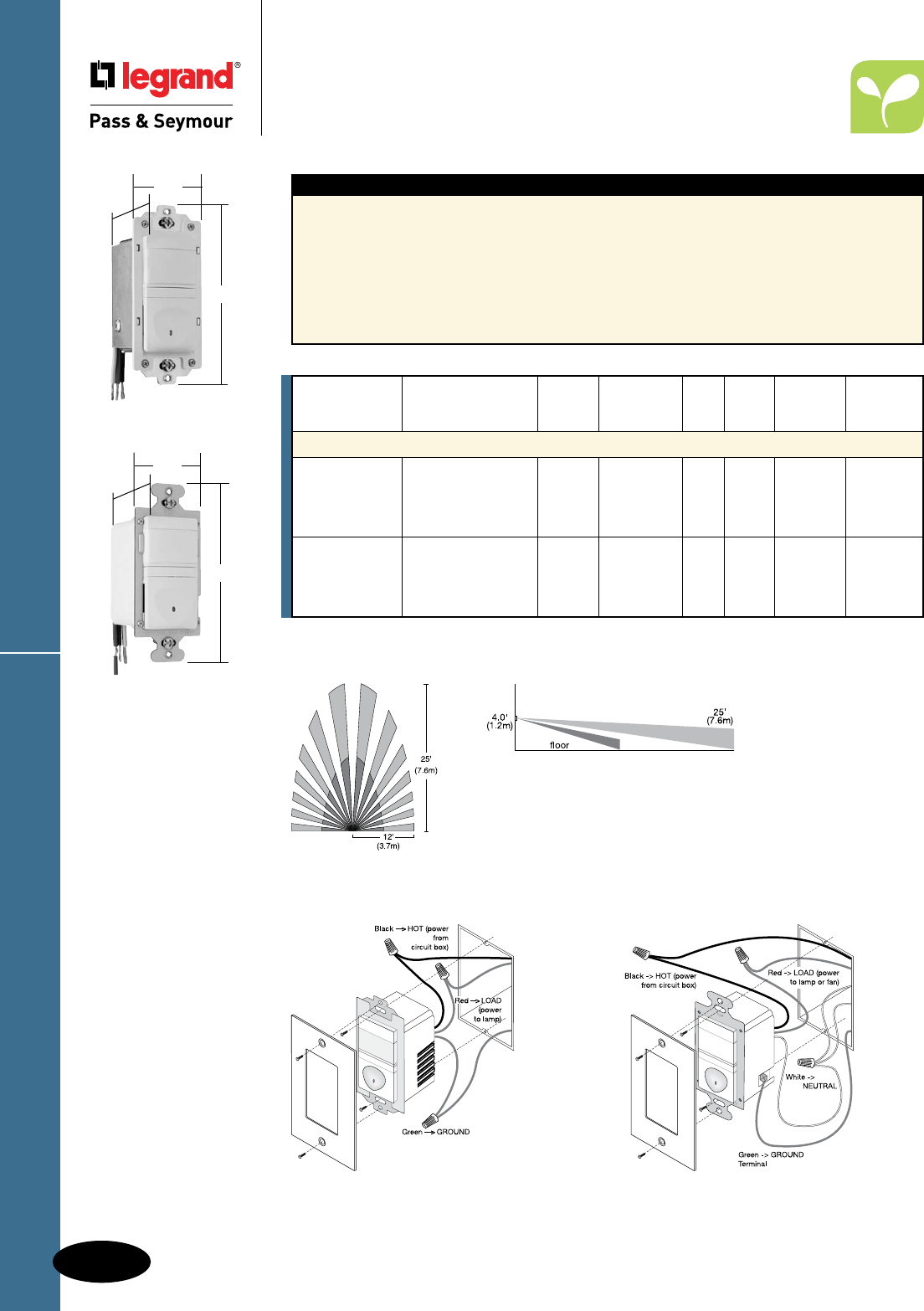
D-52
Decorator DevicesResidential Occupancy Sensors
Decorator Devices
Residential Occupancy Sensors
Passive Infrared (PIR)
All devices listed on this page conform to NEMA WD-1 and WD-6.
Coverage
Features
n Replaces a standard light or fan single pole switch.
n Lighted switch for visibility in darkened rooms.
n Automatic-ON operation.
n Fixed five-minute time delay.
n Low-profile styling with uniform color-matched
lens and device.
n Coverage: 180°, max. 600 ft.2 (56m2)
n cULus listed.
n 5-year warranty.
n Works with most common residential
lighting types
RWU600U only
n Load: Incandescent, fluorescent, compact
fluorescent (CFL), magnetic low-voltage (MLV)
and electronic low-voltage (ELV), 1/6 hp
RW500U Wiring
Wiring for RW500U does not require a neutral.
RWU600U Wiring
Wiring for RWU600U requires a neutral.
Selectable
Catalog Auto Manual Auto/Man.
Number Description Voltage Load ON ON ON Color
Single Pole Occupancy Sensors
RW500UICC4 Yes No No Ivory
RW500UWCC4 No neutral required, 120VAC 25-500W Yes No No White
RW500UBKCC4 ideal for storage 60 Hz Incandescent Yes No No Black
RW500ULACC4 and utility rooms Yes No No Lt. Almond
RWU600UICC4 Neutral required, Yes No No Ivory
RWU600UWCC4 controls most types 120VAC 0-600W Yes No No White
RWU600UBKCC4 of lighting, ideal for 60 Hz All Yes No No Black
RWU600ULACC4 storage & utility rooms Yes No No Lt. Almond
RW500ULACC4
1.69"
2.63"
1.88"
1.69"
2.63"
1.88"
RWU600ULACC4
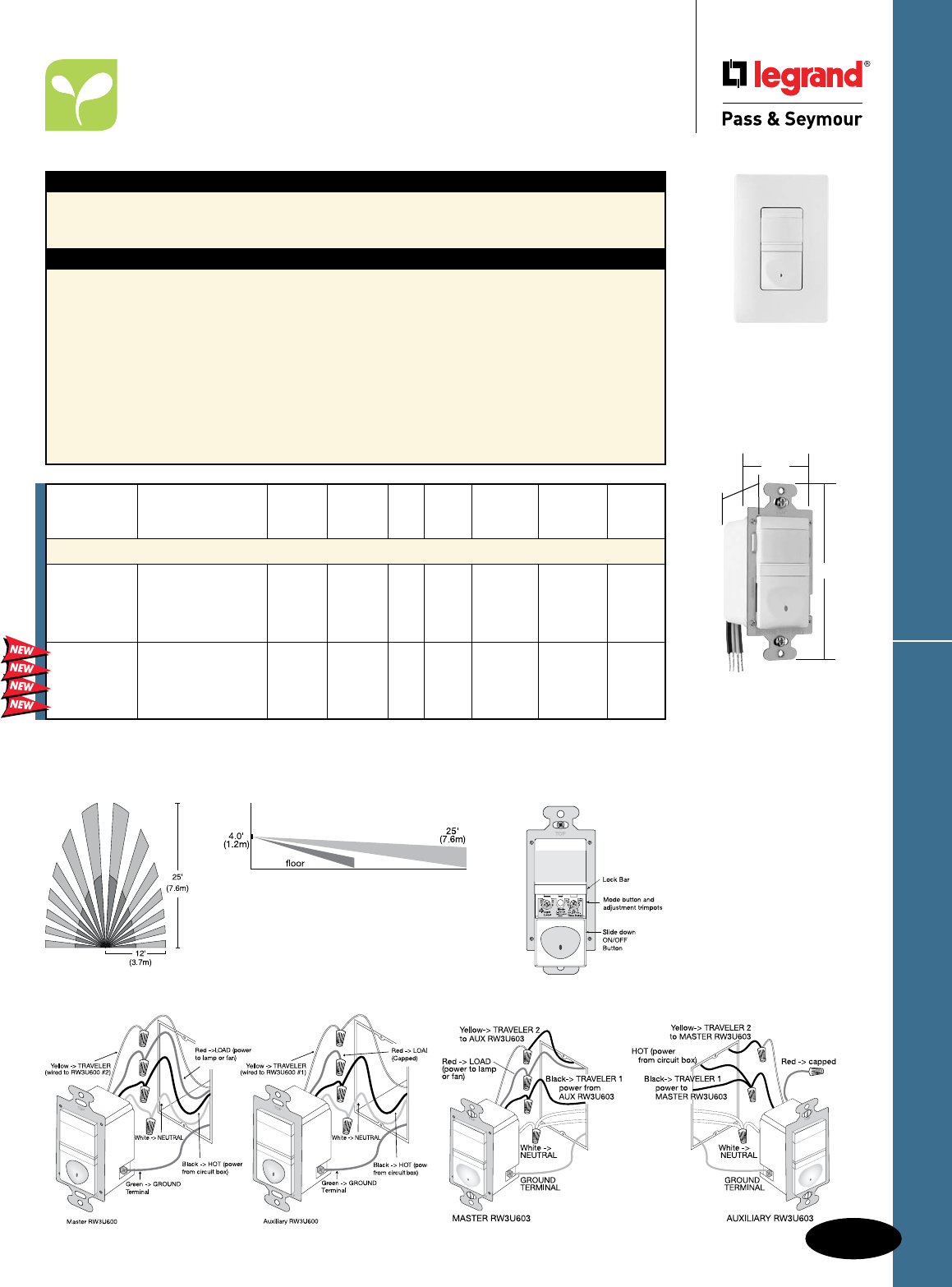
D-53
Decorator Devices Residential Occupancy/Vacancy Sensors
Decorator Devices
Residential Occupancy/
Vacancy Sensors
3-Way Passive Infrared (PIR)
All devices listed on this page conform to NEMA WD-1 and WD-6.
RW3U600W
shown with
SWP26W
2.8"
4.8"
1.5"
RW3U600W
RW3U603W
Dimensions for
RW3U603W:
2.67" (L) x
1.73" (W) x 1.77" (D)
Coverage
Applications
The RW3U600 has the flexibility to work in a variety of applications including hallways, stairways,
bathrooms, living and dining rooms, and other areas with multiple entries. The RW3U600 vacancy
sensor allows true multi-way operation with automatic ON/OFF control.
Features
n Occupancy-based control plus multi-way operation.
n Two or more RW3U600s connected together will
allow enhanced coverage of the controlled space.
n Works with most common residential lighting types.
n Adjustable time delay of 15 seconds to 30 minutes.
n Light level sensing prevents automatic ON of lights
when adequate daylight exists.
n Replaces three-way or four-way switches when used
with other RW3U600s.
n Lighted switch for visibility in darkened rooms.
n Manual- or automatic-ON operation.
n Adjustable light level setting of 10 to 150 fc
(100 to 1500 lux).
n Coverage: 180°, max. 600 ft.2 (56m2).
n cULus listed.
n 5-year warranty.
n Load: Incandescent, fluorescent, compact
fluorescent (CFL), magnetic low-voltage (MLV)
and electronic low-voltage (ELV), 1/6 hp
RW3U603 only
n California Title 24 compliant.
n Time delay 15 seconds, 5, 15, 30 minutes.
Product Controls
RW3U600
Selectable Light
Catalog Auto Manual Auto/Man. Level
Number Description Voltage Load ON ON ON Color Sensing
Single Pole/3-Way Occupancy/Vacancy Sensors
RW3U600I* Light-level sensing for Yes Yes Yes Ivory Yes
RW3U600W* optimum operation – 120VAC 0-600W Yes Yes Yes White Yes
RW3U600BK* ideal for rooms with 60Hz All Yes Yes Yes Black Yes
RW3U600LA* multiple entrances Yes Yes Yes Lt. Almond Yes
RW3U603I** No Yes No Ivory No
RW3U603W** Ideal for rooms with 120VAC 0-600W No Yes No White No
RW3U603BK** multiple entrances 60Hz All No Yes No Black No
RW3U603LA** No Yes No Lt. Almond No
*RW3U600 requires an additional RW3U600 in multi-way circuits.
** RW3U603 can be used with either a momentary contact switch or an additional RW3U603 unit for multi-way applications.
Momentary contact switches on Page A-22.
RW3U600 Wiring for 3-Way Operation
RW3U603 Wiring for 3-Way Operation
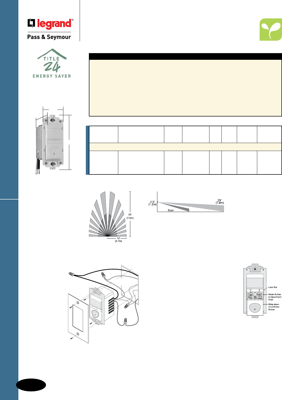
D-54
Decorator DevicesResidential Occupancy/Vacancy Sensors
Decorator Devices
Residential Occupancy/
Vacancy Sensors
Passive Infrared (PIR) with Dimmer
All devices listed on this page conform to NEMA WD-1 and WD-6.
Features
n California Title 24 compliant.
n Replaces standard single pole switch or
incandescent dimmer.
n Low-profile styling with uniform color-matched
lens and device.
n Lighted pushbutton for visibility in darkened rooms.
n Manual- or automatic-ON operation.
n Adjustable time delay from 15 seconds
to 30 minutes.
n Soft start technology to prolong lamp life.
n Air gap isolation switch for safe relamping.
n If enabled, light level sensing prevents
automatic-ON when adequate daylight exists.
n Adjustable light level setting from 10-150 fc
(100-1500 lux) for daylight sensing.
n Operating conditions: 32°-104°F (0°-40°C),
95% RH, noncondensing.
n Coverage: 180°, max. 600 ft2 (56 m2).
n cULus listed.
n 5-year warranty.
Selectable
Catalog Auto Manual Auto/Man.
Number Description Voltage Load ON ON ON Color
Occupancy/Vacancy Sensors with Preset Dimmers
RWDU500I Neutral required, ideal Yes Yes Yes Ivory
RWDU500W for living, dining and 120VAC 25-500 Yes Yes Yes White
RWDU500BK family rooms, master 60Hz Incandescent Yes Yes Yes Black
RWDU500LA bathrooms and bedrooms Yes Yes Yes Lt. Almond
RWDU500 Wiring
Green
->
GROUND
Black
->
HOT (power
from circuit box)
White
->
NEUTRAL
Red
->
LOAD (power
to dimmable lamp)
De-rating
When more that one dimmer is installed
in a multi-gang box, it is necessary
to reduce the maximum load on each
dimmer.
• For an RWDU500 in either end
position of a multi-gang box, reduce
the maximum load by 50W.
• For an RWDU500 in a central position
of a multi-gang box, reduce its
maximum load by 100W. Mounting in
a deep electrical box is recommended.
Coverage
Product Controls
RWDU500
1.73"
2.67"
1.77"
RWDU500W
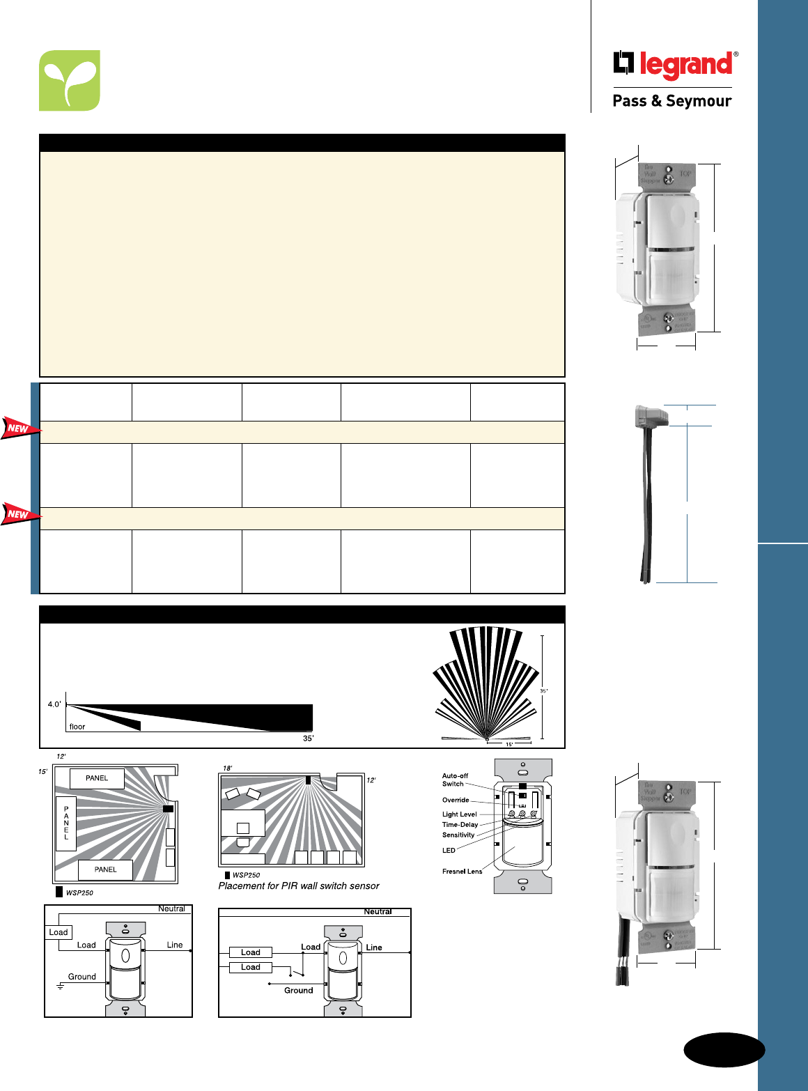
D-55
Decorator Devices Commercial Occupancy Sensors
Decorator Devices
Commercial Occupancy Sensors
Wall Box Passive Infrared (PIR)
All devices listed on this page conform to NEMA WD-1 and WD-6.
PTWSP250W
1.55"
2.6"
1.7"
WSP250W
1.55"
2.6"
1.7"
PTS6STR3
1.125"
6.375"
PlugTail™ Wall Switch
Sensors use PTS
Single Pole PlugTail™
Connectors. See Page
A-14.
Single Level Lighting WSP250 Manual Bi-level Lighting WSP250
Catalog
Number Description Voltage Load Color
PlugTail™ Automatic Wall Switches – 3 Wire Technology
PTWSP250I Ivory
PTWSP250W PIR 120/277VAC; 800W Max. at 120V White
PTWSP250GRY Occupancy Sensor 60 Hz 1200W Max. at 277V Gray
PTWSP250LA Light Almond
Automatic Wall Switches – 3 Wire Technology
WSP250I Ivory
WSP250W PIR 120/277VAC; 800W Max. at 120V White
WSP250GRY Occupancy Sensor 60 Hz 1200W Max. at 277V Gray
WSP250LA Light Almond
Features
n Detection Signature Analysis provides high
immunity to RFI and EMI.
n Compact, decorator design replaces existing
wall switch.
n Shallow back body (1")
n Integrated light level sensor works from
10 to 150 footcandles.
n Compatible with all electronic and magnetic
ballasts, PL lamp ballasts, compact fluorescent.
n Adjustable time delay of 30 seconds to 30 minutes.
n Dual 120/277VAC operation.
n 30% to 60% energy savings.
n Positive detection indicator.
n No minimum load requirement.
n Adjustable sensitivity from 20% to 100%.
n Patented voltage drop protection.
n Patented Zero Crossing Circuitry.
n 180° coverage of up to 900 sq. ft.
n cULus listed.
n 5-year warranty.
PlugTail™ PTWSP250 Only
n No exposed terminals create a finger-
safe application before, during, and after
installation.
n Built-in connector features large brass
terminal blades to ensure consistent,
reliable electrical connections.
WSP250 Only
n 6" flying leads
Planning a Layout
The WSP250’s 2-level lens provides superior coverage at desktop level by allowing the sensor
to detect vertical as well as horizontal motion. Coverage shown is for walking motion. Under
optimum conditions with a high level of activity and with no barriers or obstacles, coverage can
reach a maximum of 900 square feet. Under a typical, desktop level of activity, when mounted
at 4 feet, coverage is 300 square feet.
WSP250
Factory settings: 30 min. time
delay, maximum light level and
sensitivity
Technical
Specifications on
Page S-139.

D-56
Decorator DevicesCommercial Occupancy Sensors
Decorator Devices
Commercial Occupancy Sensors
Dual Technology Wall Box
All devices listed on this page conform to NEMA WD-1 and WD-6.
Features
n Adjusts time delays automatically based on actual
usage patterns
n Assigns short delays (as low as 7 minutes) when
the space is typically vacant, and longer delays
(up to 30 minutes) for busier times
n Differentiates electrical noise from human motion
n Fixed mode – 5, 15, or 30 minutes.
n Walk-through mode – turns lights off 3 minutes after
the room is initially occupied if no motion is detected
after 30 seconds.
n Test mode – allows quick and easy adjustments.
n Sensitivity adjustment.
n Color-matched lenses and low profile for
appealing design.
n Choice of auto-ON or manual-ON operation.
n Fast, easy installation/switch-out.
n Zero-crossing for long relay life.
n High sensitivity and dense coverage for
exceptional performance.
n cULus listed.
n 5-year warranty.
n WDT200 offers bi-level control of two
loads independently from the same box.
- Built-in sensor holds secondary lights
off until daylight levels drop
- Each relay can be set for automatic or
manual ON
- Dual ON/OFF buttons can control each
of the loads manually as well
WDT100W
Coverage
Catalog
Number Description Voltage Load Coverage Color
Dual Technology Wall Switch Sensors
WDT100I Ivory
WDT100W White
WDT100BK Black
WDT100GRY Gray
WDT100LA Light Almond
WDT200I Ivory
WDT200W White
WDT200BK Black
WDT200GRY Gray
WDT200LA Light Almond
Dual Technology
Wall Switch
Sensor
Bi-Level
Dual Technology
Wall Switch
Sensor
120/230/277VAC,
50/60Hz
120VAC, 0-800W
ballast or tungsten,
1/6HP 230/277VAC,
0-1200 ballast
1050
sq. ft.
120/230/277VAC,
50/60Hz
120VAC, 0-800W
ballast or tungsten,
1/6HP 230/277VAC,
0-1200 ballast
1050
sq. ft.
1.76"
2.73"
1.83"
PIR Coverage
7.5’
(2.2m)
15’
(4.5m)
20’
(6.1m)
35’
(10.6m)
Major motion
Minor motion
Ultrasonic
Coverage
10'
(3.0m)
7.5’
(2.2m)
20’
(6.1m)
15’
(4.5m)
Major motion
Minor motion
Technical Specifications on Page S-140.

D-57
Decorator Devices Commercial Occupancy/Vacancy Sensors
Decorator Devices
Commercial Occupancy/
Vacancy Sensors
Wall Box Passive Infrared (PIR)
All devices listed on this page conform to NEMA WD-1 and WD-6.
OS300SW
1.76"
2.73"
1.83"
Features
n Detection signature processing eliminates false
triggers and provides immunity to RFI and EMI.
n Zero-crossing for long relay life.
n Vandal-resistant lens combines precise
coverage with durability.
n Choice of Auto-ON or Manual-ON operation.
n Auto adjustable time delays: automatic, fixed
(5, 10, 15, 20, 25 or 30 minutes), walk-through,
test-mode.
n Selectable time delay automatically adjusts
for maximum savings.
n Walk-through mode turns lights off 3 minutes
after the area is initially occupied – ideal for
brief visits such as mail delivery.
n Selectable test mode allows quick and
easy adjustments.
n Selectable audible alert for impending shutoff.
n In AUTO-ON mode, if the sensor is manually
turned OFF, AUTO-ON will not enable until no
motion is detected for 5 minutes. This prevents the
light from turning ON when it was intended they
remain OFF. Ideal for presentations.
n LED indicates occupancy detection.
n Built-in light level sensing with simple,
one-step setup.
n Override mode allows sensor to operate as a
service switch in the unlikely event of a failure.
n NEMA WD 7 guideline utilized for coverage testing.
n Sensitivity adjustment: PIR (high/low).
n Coverage: 180°, up to 1050 sq. ft.;
major motion 35' x 30'; minor motion 20' x 15'.
n cULus listed.
n 5-year warranty.
n Load: Incandescent, fluorescent, compact
fluorescent (CFL), magnetic low-voltage (MLV)
and electronic low-voltage (ELV), 1/6 hp
For best performance, Legrand/Pass & Seymour
recommends using this sensor in spaces no
larger than 15' x 20'.
Occupant Selectable
Catalog Warning Auto/Man.
Number Description Rating Load Before OFF ON Color
Single-Pole Occupancy/Vacancy Sensors
OS300SI Self-adaptive 120/230/277VAC; 50/60 Hz. Yes Yes Ivory
OS300SW design remembers @ 120VAC, 0-800 W ballast All Yes Yes White
OS300SGRY ON/OFF cycles or tungsten, 1/6 hp. Yes Yes Gray
OS300SLA @ 230/277VAC, 0-1200 W ballast. Yes Yes Lt. Almond
DIP Switch Settings
Technical Specifications on
Page S-139.
Coverage
Product Controls
OS300S
ON/OFF Button
DIP Switches
Detection LED
PIR Lens
5
$XWR2Q
0DQXDO2Q
ON Mode
6PDUW6HW7HVW
PLQXWHV
PLQXWHV
PLQXWHV
PLQXWHV
PLQXWHV
RYHUULGH
PLQXWHV
123
Time Delay
',36ZLWFKV
21 2))
6
+LJK
/RZ
Sensitivity
4
'LVDEOHG
(QDEOHG
Walk Through
7LPH'HOD\
)$&725<
35(6(76
:DON7KURXJK
21
2Q0RGH
6HQVLWLYLW\
$XGLEOH$OHUWV
9LVLEOH$OHUWV
)DFWRU\6HWWLQJV
7
'LVDEOHG
(QDEOHG
Audible Alerts
',36ZLWFK
',36ZLWFK
8
'LVDEOHG
(QDEOHG
Visible Alerts
',36ZLWFK
',36ZLWFK
',36ZLWFK
%\SDVVRFFXSDQF\OLJKWOHYHOIXQFWLRQV
/RDGLVPDQXDOO\FRQWUROOHGZLWK:6EXWWRQ

D-58
Decorator DevicesCommercial Occupancy/Vacancy Sensors
Decorator Devices
Commercial Occupancy/
Vacancy Sensors
Bi-Level Wall Box Passive Infrared (PIR)
All devices listed on this page conform to NEMA WD-1 and WD-6.
OSR300SW
1.76"
2.73"
1.83"
For best performance, Legrand/Pass & Seymour recommends
using this sensor in spaces no larger than 15' x 20'.
Features
n Detection signature processing eliminates false
triggers and provides immunity to RFI and EMI.
n Zero-crossing for long relay life.
n Vandal-resistant lens combines precise
coverage with durability.
n Choice of Auto-ON or Manual-ON operation,
selectable for each relay.
n Auto adjustable time delays: automatic,
fixed (5, 10, 15, 20, 25 or 30 minutes),
walk-through, test-mode.
n Selectable time delay automatically adjusts
for maximum savings.
n Selectable walk-through mode turns lights off
three minutes after the room is initially occupied
if no motion is detected after the first 30 seconds.
n Selectable test mode allows quick and
easy adjustments.
n Selectable audible alert for impending shutoff.
n In AUTO-ON mode, if the sensor is manually
turned OFF, AUTO-ON will not enable until no
motion is detected for 5 minutes. This prevents
the light from turning ON when it was intended
they remain OFF. Ideal for presentations.
n LED indicates occupancy detection.
n Built-in light level sensing with simple,
one-step setup.
n Override mode allows sensor to operate as a
service switch in the unlikely event of a failure.
n NEMA WD 7 guideline utilized for coverage testing.
n Sensitivity adjustment: PIR (high/low).
n Coverage: 180°, up to 1050 sq. ft.;
major motion 35' x 30'; minor motion 20' x 15'.
n cULus listed.
n 5-year warranty.
n Load: Incandescent, fluorescent, compact
fluorescent (CFL), magnetic low-voltage (MLV)
and electronic low-voltage (ELV), 1/6 hp.
Coverage
Occupant Selectable
Catalog Warning Auto/Man.
Number Description Rating Load Before OFF ON Color
Single-Pole Dual-Relay Occupancy/Vacancy Sensors
OSR300SI Operates both 120/230/277VAC; 50/60 Hz. Yes Yes Ivory
OSR300SW circuits of a bi-level @ 120VAC, 0-800 W ballast All Yes Yes White
OSR300SGRY lighting system or tungsten, 1/6 hp. Yes Yes Gray
OSR300SLA @ 230/277VAC, 0-1200 W ballast. Yes Yes Lt. Almond
OSR300S Bi-Level Wiring OSR300S Two Circuit Level Wiring
DIP Switch Settings
Technical Specifications on Page S-139.
Product Controls
OSR300S
ON/OFF Button
DIP Switches
Detection LED
PIR Lens
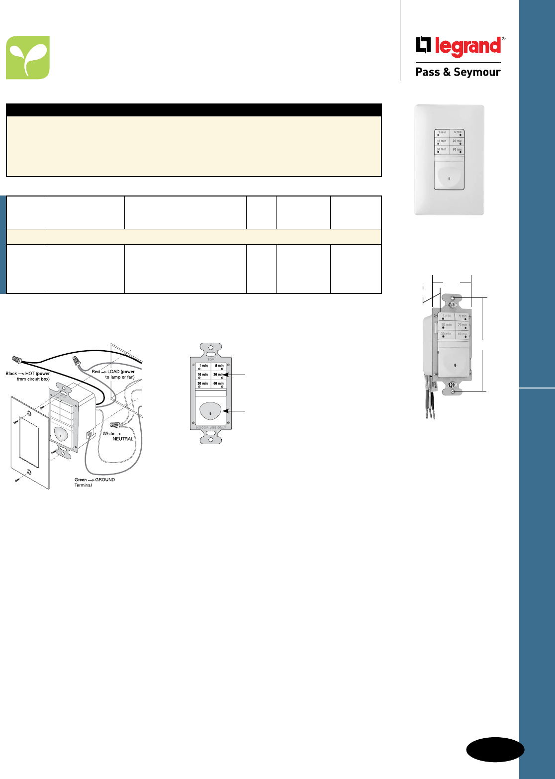
D-59
Decorator Devices Timers
Decorator Devices
Timers
All devices listed on this page conform to NEMA WD-1 and WD-6.
RT1LA
shown with
SWP26LA
1.69"
3.281"
1.88"
RT1LA
Time-
Catalog Running-Out
Number Description Rating Load Warning Color
Digital Timers
RT1I No Ivory
RT1W 7-Button Digital Timer, 0-600W, 1/6 hp @ 120VAC 60 Hz All No White
RT1BK Neutral required No Black
RT1LA No Light Almond
RT1 Wiring
Features
n Seven-button preset time switch.
n Manual ON/OFF.
n Adjustable time delay: 1, 5, 10, 20, 30, 60 minutes.
n Lighted switch for visibility in darkened rooms.
n Controls most types of lighting.
n cULus listed.
n 5-year warranty.
n Load: Incandescent, fluorescent, compact
fluorescent (CFL), magnetic low-voltage (MLV)
and electronic low-voltage (ELV), 1/6 hp
Product Controls
RT1
Six time selection
buttons with activation
indicator lights
ON/OFF Button
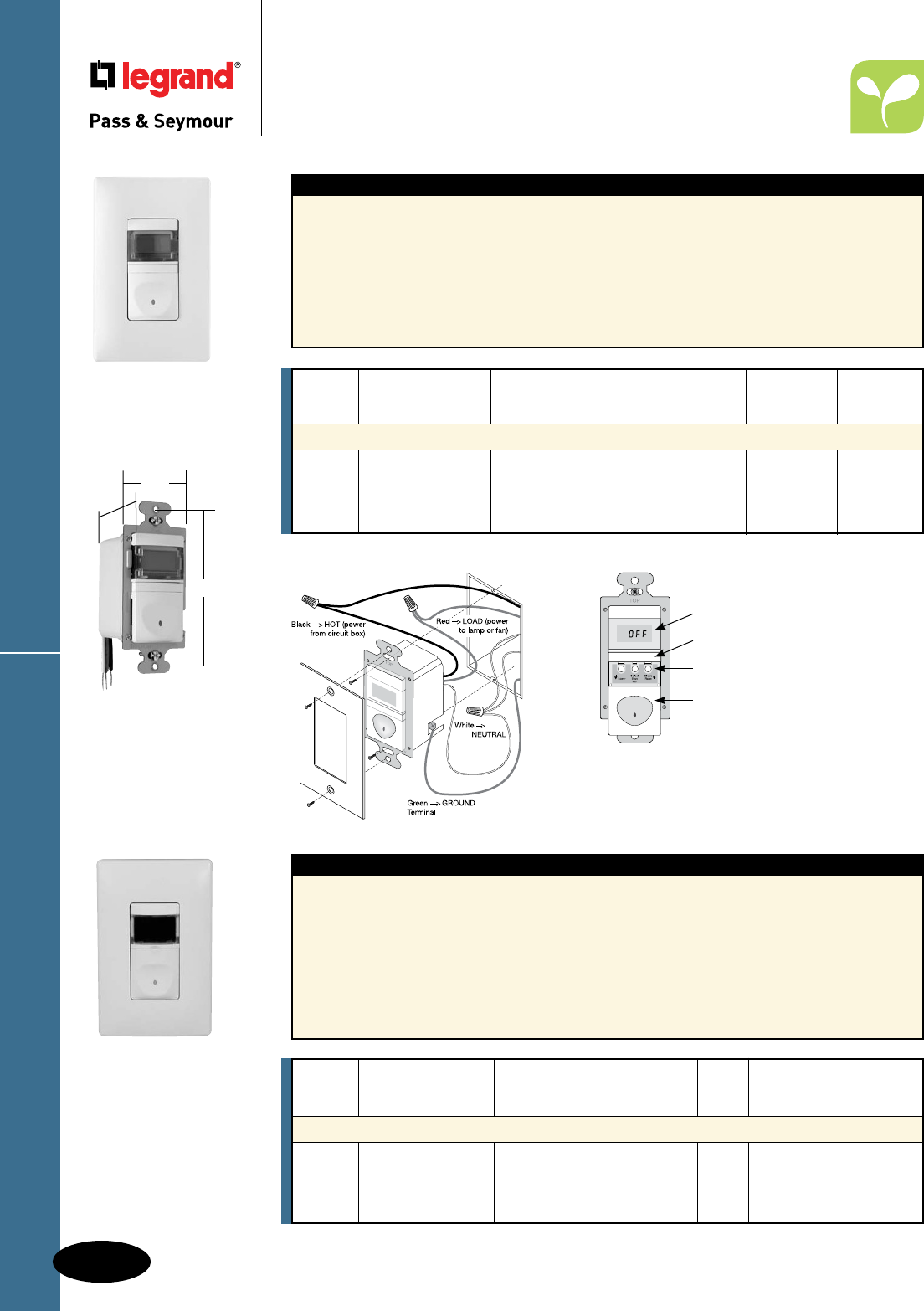
D-60
Decorator DevicesTimers
Decorator Devices
Timers
All devices listed on this page conform to NEMA WD-1 and WD-6.
RT12W
shown with
SWP26W
1.69"
3.281"
1.88"
RT12LA
RT24W
shown with
SWP26W
RT12 Wiring
Features
n Programmable countdown time switch
n Manual ON/OFF.
n Digital countdown display.
n Adjustable time delay from 5-55 minutes
(five-minute increments) to 1-12 hours
(15-minute increments).
n Audible beep and visible light flash warnings
before automatic-OFF.
n Lighted switch for visibility in darkened rooms.
n Works with most common lighting types.
n cULus listed.
n 5-year warranty.
n Load: Incandescent, fluorescent, compact
fluorescent (CFL), magnetic low-voltage (MLV)
and electronic low-voltage (ELV), 1/6 hp
Time-
Catalog Running-Out
Number Description Rating Load Warning Color
Digital Timers
RT12I Yes Ivory
RT12W 12-Hour Digital Timer, 0-600W, 1/6 hp @ 120VAC 60 Hz All Yes White
RT12BK Neutral required Yes Black
RT12LA Yes Light Almond
Product Controls
Features
n Manual or programmed ON/OFF switching.
n Real time clock with day/date calendar.
n Easy to read LED display.
n Programming buttons accessible without removing
wall plate.
n Eight programs can be assigned to any day or
combination of days of the week.
n Automatically calculates sunrise and sunset times
based on latitude and longitude.
n Audible or visual occupant warning
before OFF.
n Power failure memory.
n Zero crossing circuitry.
n cULus listed.
n 5-year warranty.
n Load: Incandescent, fluorescent, compact
fluorescent (CFL), magnetic low-voltage (MLV)
and electronic low-voltage (ELV), 1/6 hp
RT12
LCD Display
Lock Bar
Programming Buttons
Slide Down:
ON/OFF Button
Time-
Catalog Running-Out
Number Description Rating Load Warning Color
Astronomic Programmable Timers
RT24I 0-800W @ 120V Yes Ivory
RT24W 24-Hour 0-1200W @ 277V All Yes White
RT24BK Programmable Timer 1/6 hp @ 120/277V Yes Black
RT24LA Yes Light Almond
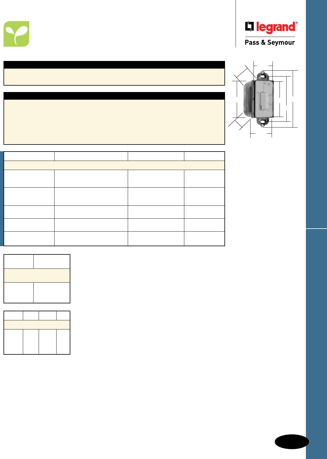
D-61
Decorator Devices Timers
Decorator Devices
Wall Box Timers
125, 125-T, 250 & 277VAC, 60 Hz
All devices listed on this page conform to NEMA WD-1 and WD-6.
97015I
2.62"
1.80"
4.20"
3.281"
1.30"
2.76"
1.85"
1.80"
Catalog Number Description Time Range Color
Specification Grade Decorator Rotary Timers
97015I Ivory
97015W Timeout, No Hold 15 Minutes White
97015LA Light Almond
97030I Ivory
97030W Timeout, No Hold 30 Minutes White
97030LA Light Almond
97060I Timeout, No Hold 60 Minutes Ivory
97060W White
97115I Timeout, With Hold 15 Minutes Ivory
97115W White
97160I Timeout, With Hold 60 Minutes Ivory
97160W White
VAC Hz Amp HP
Ratings
125 60 20 1
125T 60 7
250 60 10 1
277 60 10
Catalog
Number Color
Replacement Knobs
(without plate)
PS55A1 White
PS55B1 Ivory
PS55G1 Light Almond
Applications
n Lighting
n Exhaust fans
n Whirlpools and spas
n Saunas
n Heating and heat lamps
n Ventilating and air conditioning
Features
n Units with “Hold” feature may be turned counter-clockwise to
hold the load on without timing function.
n Turning clockwise causes unit to time load off after desired
time delay.
n Quiet operation.
n Time range from 5 minutes to 12 hours.
n Available with or without hold.
n Decorator styling.
n Easily installed.
n Large head screw terminals.
n Accurate to ± 5 percent.
n Motor rated.
n Energy saving.
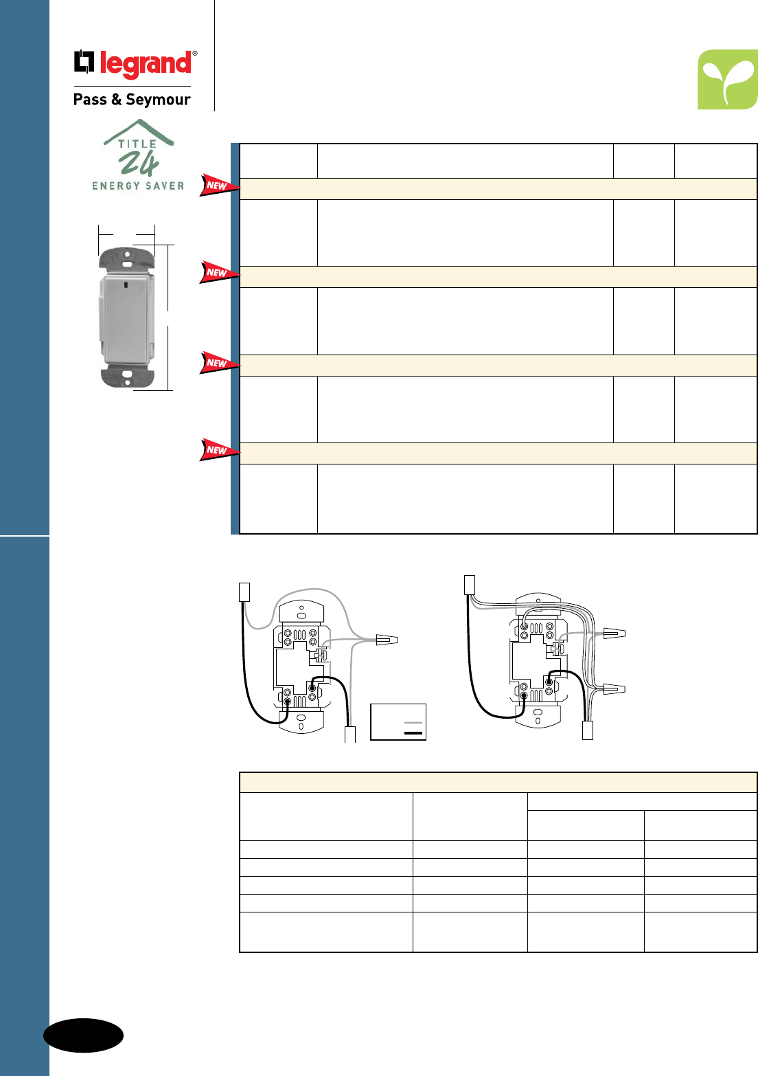
D-62
Decorator Devices
Catalog
Number Description Ratings Color
In-Wall Universal Dimmers
DRD4I Ivory
DRD4W 600W White
DRD4B Black
DRD4A Light Almond
In-Wall Incandescent Dimmers
DRD2I Ivory
DRD2W 600W White
DRD2B Black
DRD2A Light Almond
In-Wall 3-Way Switches
DRD8IV2 Ivory
DRD8WV2 N/A White
DRD8BV2 Black
DRD8AV2 Light Almond
In-Wall Switches
DRD3IV2 Ivory
DRD3WV2 800W White
DRD3BV2 Black
DRD3AV2 Light Almond
The In-Wall Universal Dimmer operates most dimmable
lighting types, including neon and compact fluorescent.
Includes a CFL setting to alleviate flickering and
premature bulb burn-out.
Easily dim traditional incandescent bulbs, without the
requirement of a neutral connection.
Provides convenient control from multiple access points
when used in conjunction with any wireless switch or
dimmer.
Perfect for controlling lights that don’t need dimming, the
In-Wall Switch can be included in scene programming for
use with Room and Whole-House Scene Controllers.
RF Lighting Control System
Decorator Devices
RF Lighting Control System
Dimmers & Switches
LOAD LINE
GND
Wire Legend
Ground
Line
DRD2 Wiring Diagram
NEUTRAL
LOAD LINE
GND
DRD4 Wiring Diagram
Mounting in deep
electrical boxes is
recommended.
DRD4A
DRD2A
DRD8AV2
1.69"
4.25"
De-rate Dimmers as follows:
Maximum Capacity
Single Dimmer Dimmer at End Dimmer in Middle
of a Multi-Gang of a Multi-Gang
Incandescent/Quartz Halogen 600W 500W 400W
Magnetic Low Voltage 500W 400W 300W
Electronic Low Voltage 500W 400W 300W
Cold Cathode/Neon 500W 400W 300W
Fluorescent:
2-Wire 500W 400W 300W
Compact Fluorescent 500W 400W 300W
All devices listed on this page conform to NEMA WD-1 and WD-6. UL Listed and CSA Certified.
For complete RF Lighting Control System, see Pages M-4 – M-7.
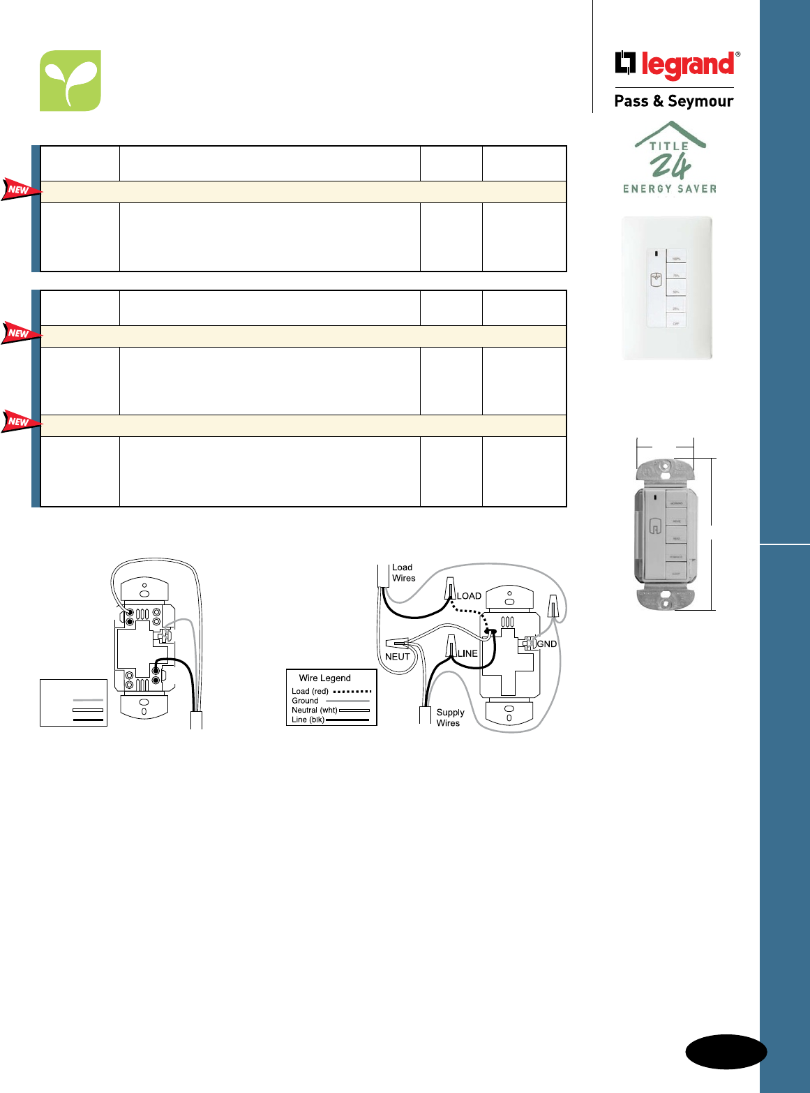
D-63
Decorator Devices RF Lighting Control System
Decorator Devices
RF Lighting Control System
Fan Speed & Master Controls
All devices listed on this page conform to NEMA WD-1 and WD-6. UL Listed and CSA Certified.
1.69"
4.25"
DRD5AV2
DRD9W
Shown with
SWP26W
DRD5/DRD6 Wiring Diagram
LINE
GND
Supply
Wires
NEUTRAL
Wire Legend
Ground
Line
Neutral
Catalog
Number Description Ratings Color
In-Wall Whole House Scene Controllers
DRD5IV2 Ivory
DRD5WV2 N/A White
DRD5BV2 Black
DRD5AV2 Light Almond
In-Wall Room Scene Controllers
DRD6IV2 Ivory
DRD6WV2 N/A White
DRD6BV2 Black
DRD6AV2 Light Almond
This product allows lighting control for the entire home
from any location.
Program up to five room scenes with this in-wall
controller.
Catalog
Number Description Ratings Color
In-Wall Fan Speed Controllers
DRD9I Ivory
DRD9W 1.5 A White
DRD9B Black
DRD9A Light Almond
This controller gives you four options for ceiling fan
speed and includes a built-in de-hummer to reduce
fan noise.
DRD9 Wiring Diagram
Mounting controls in
deep electrical boxes
is recommended.
For complete RF Lighting Control System, see Pages M-4 – M-7.

D-64
Decorator DevicesScene Director
Decorator Devices
Scene Director
For everything people do at home, there’s a combination of
light sources and levels that will work best. P&S Scene Director
Controls let homeowners capture these combinations (or scenes)
— and recall them whenever they want at the touch of a button.
Red LED glows
when dimmer is OFF.
Green LEDs indicate light
level selected and preset level.
Sleek, ergonomic P&S
Decorator style matches
other Decorator devices.
Can be operated individually.
P&S Scene Director Dimmer
Constant memory returns
lights to previously selected
level after power failure.
Works in conjunction with a
P&S Scene Director Master.
Touch pad raises or lowers individual
light levels without affecting preset.
Unobtrusive set button for simple
programming of preset scenes.
SC600LAV
Raises or lowers all lights
in any scene simultaneously.
Controls up to 30 dimmers per
Master, providing the ability to control
even complex, multiroom scenes.
Programmable fade rates
enable users to easily select the
speed of fade-up and fade-down.
Buttons glow when selected —
glow levels are adjustable, too.
Available infrared remote (SCIR)
provides mobile control flexibility.
P&S Scene Director Master
Provides powerful control
via conventional wall-box
wiring. Wires like a 3-way switch.
Communication among devices
requires just one additional conductor.
One-touch selection for up
to five lighting environments
(scenes) — plus full Off.
Constant memory returns lights
to previously selected level after
power failure. No need to reset.
Easy to install, program, and
operate for sophisticated scene
control dimming.
No tools or plate removal
necessary for programming
with our exclusive, patent-
pending system. Set light levels
with product fully installed.
SCMC5WV
Matching Fan Speed Control available.

D-65
Decorator Devices Scene Director
Decorator Devices
Scene Director
Wiring Diagram
* Use with Advance Mark X® dimmable fluorescent ballasts.
** Feature specially designed capacitive circuitry to virtually eliminate fan motor “hum.”
Note: All Dimmers on this page may be ganged without de-rating.
Catalog Number Description Ratings Color
600W Incandescent Scene Director Control Dimmers
SC600IV Ivory
SC600WV Preset, Controls 1 Load in a Scene 120V, 600 Watt White
SC600LAV Light Almond
300VA Electronic Low-Voltage Scene Director Control Dimmers
SCELV300IV Ivory
SCELV300WV Preset, Controls 1 Load in a Scene 120V, 300VA White
SCELV300LAV Light Almond
600VA Fluorescent Ballast Scene Director Control Dimmers*
SCFB600IV Ivory
SCFB600WV Preset, Controls 1 Load in a Scene 120V, 600VA White
SCFB600LAV Light Almond
5 Scene Director Master Controllers
SCMC5IV Ivory
SCMC5WV 5-Button Preset Scene Controller 120V White
SCMC5LAV Light Almond
Remote Location Control
SCRIV Ivory
SCRWV For Full Dimming or Fan Speed Control 120V White
SCRLAV of 1 Load from Two or More Locations Light Almond
Accessories
SCIR Infrared Hand-Held Remote
SCMCK Preprinted Inserts for Master Controller
1.5A De-Hummer** Fan Speed Controllers
SCDH15IV Ivory
SCDH15WV Preset, Controls 1 Fan Load in a Scene 120V, 1.5A White
SCDH15LAV Light Almond
SCDH15LAV
4.25"
1.68"
1.37"
All devices listed on this page conform to NEMA WD-1 and WD-6. UL Listed and CSA Certified.
SC600LAV
SCELV300LAV
SCFB600LAV
4.25"
1.68"
1.37"
SCMC5WV
4.0"
1.68"
1.37"
SCRLAV
4.25"
1.68"
1.37"
SCIR
3.313"
0.25"
2.125"
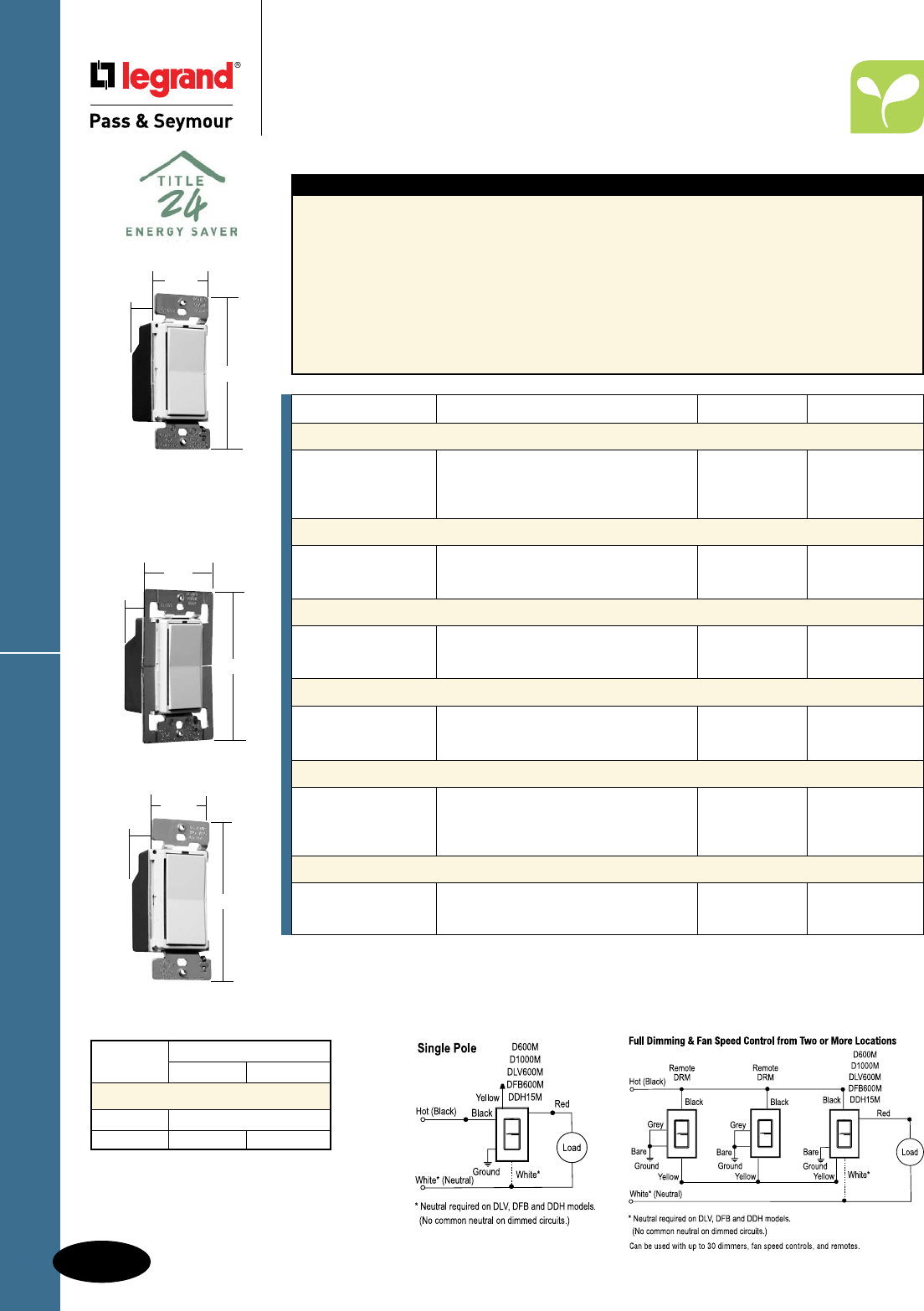
D-66
Decorator DevicesLeandro®
Decorator Devices
Leandro®
Features
n Enables full dimming control from up to
30 locations using the matching remote dimmers.
n Constant memory returns lights to previous
level after power failure.
n LED indicators keep you informed. Green LEDs
indicate preset level and current light level.
Red LED night light glows when load is OFF.
n Easy operation — Tap up once for preset, twice
for full ON. Tap down once for full OFF. Hold paddle
up to raise lights, down to lower.
n Sleek, ergonomic P&S Decorator style
matches other Decorator devices.
n Unobtrusive preset selection button helps
prevent accidental setting changes.
n Elegant fade ON and OFF extends bulb life.
Easy on the eyes, too.
n Installs easily using the same wiring as
conventional 3-way switches.
n Change light level without affecting preset.
All devices listed on this page conform
to NEMA WD-1 and WD-6.
UL Listed and CSA Certified.
* Use with MR16s with magnetic transformers, neon, cold cathode, general inductive loads.
** Use with Advance Mark X® dimmable fluorescent ballasts.
† All dimmers and fan controls can be dimmed from more than one location when used with DRM remotes.
Uses standard 3-way wiring. See wiring diagram.
†† Feature specially designed capacitive circuitry to virtually eliminate fan motor “hum.”
Wiring Diagrams
D600MLAV
DFB600MLAV
DLV600MLAV
DRMLAV
4.25"
1.68"
1.37"
D1000MLAV
4.25"
2.50"
1.37"
Max. Load Fins Removed
Rating One Side Two Side
De-Rating Chart
600W/VA No De-Rating Required
1000W 800W 600W
DDH15MLAV
4.25"
1.68"
1.37"
Catalog Number Description Ratings Color
600W Incandescent Preset Dimmers†
D600MIV Ivory
D600MWV Preset, Single Pole and 3-Way 120V White
D600MBKV 600 Watt Black
D600MLAV Light Almond
1000W Incandescent Preset Dimmers†
D1000MIV 120V Ivory
D1000MWV Preset, Single Pole and 3-Way 1000 Watt White
D1000MLAV Light Almond
600VA Low-Voltage Preset Dimmers*†
DLV600MIV 120V Ivory
DLV600MWV Preset, Single Pole and 3-Way 600VA White
DLV600MLAV Light Almond
600VA Fluorescent Ballast Preset Dimmers**†
DFB600MIV 120V Ivory
DFB600MWV Preset, Single Pole and 3-Way 600VA White
DFB600MLAV Light Almond
Remote Dimmers†
DRMIV Ivory
DRMWV Full Dimming or Fan Speed Control 120V White
DRMBKV from Two or More Locations Black
DRMLAV Light Almond
1.5A De-Hummer†† Fan Controls
DDH15MIV 120V Ivory
DDH15MWV Preset, Single Pole, 3-Speed 1.5A White
DDH15MLAV Light Almond
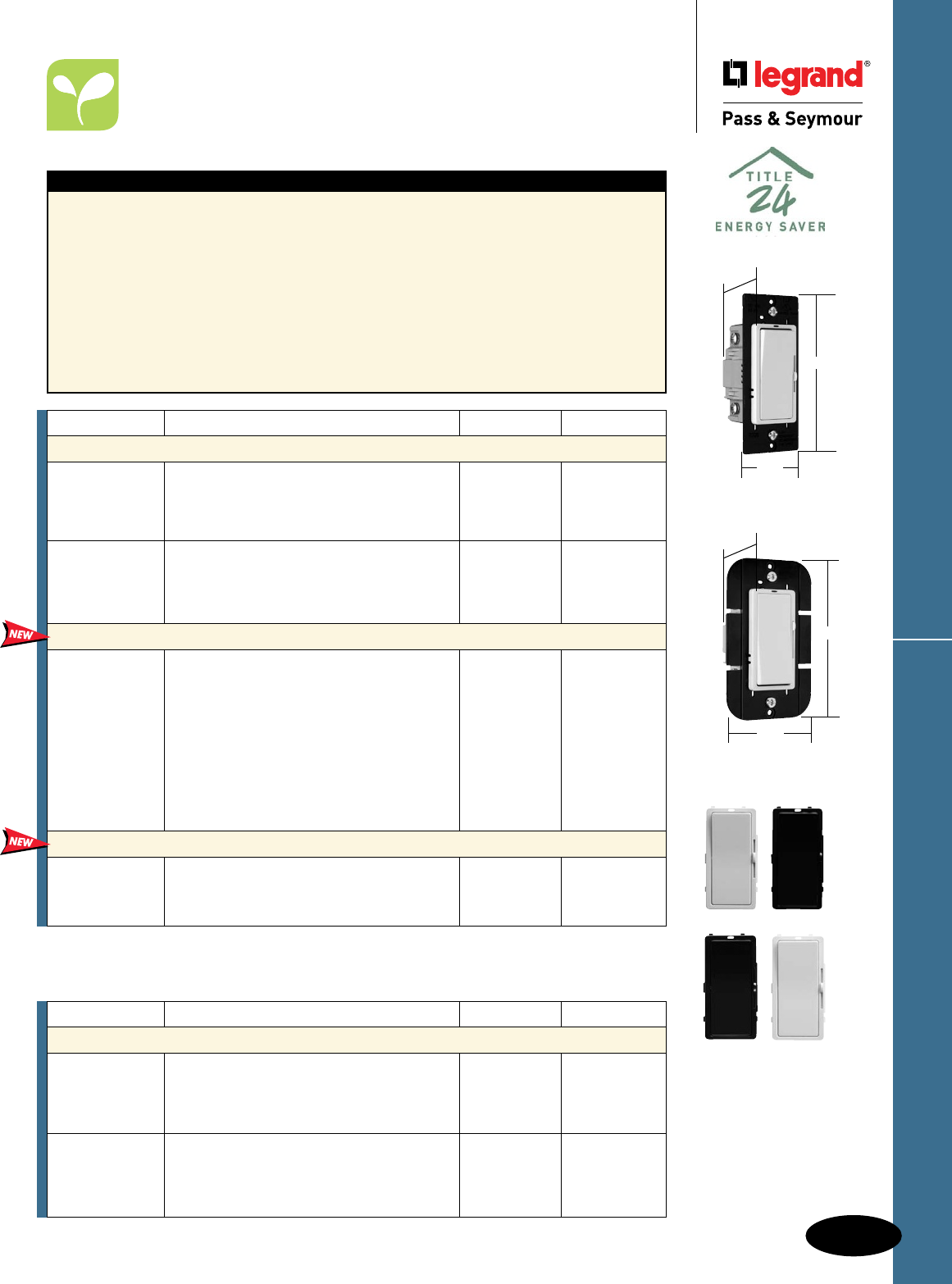
D-67
Decorator Devices Harmony™ Dimmers
Decorator Devices
Harmony™ TradeMaster® Dimmers
Catalog Number Description Ratings Color
Magnetic Low-Voltage Single Pole/3-Way Dimmers
DLV703PI Ivory
DLV703PW White
DLV703P Magnetic Low-Voltage Single Pole and 3-Way 120V, 700VA Brown
DLV703PBK Black
DLV703PLA Light Almond
DLV1103PI Ivory
DLV1103PW White
DLV1103P Magnetic Low-Voltage Single Pole and 3-Way 120V, 1100VA Brown
DLV1103PBK Black
DLV1103PLA Light Almond
All devices listed on this page conform to NEMA WD-1 and WD-6. UL Listed and CSA Certified.
Features
n Convenient operation – combines ON/OFF Decorator
switch with separate slider for dimming control.
n Green LED glows when OFF to make dimmer easy
to find in the dark.
n Constant memory returns lights to previous level
after a power failure.
n Sleek, ergonomic P&S Decorator style matches
other Decorator devices.
n Higher ratings.
n Single pole and 3-way operation.
n Works with standard 3-way switches and wiring.
n Screw-pressure-plate back wire terminals
save time, space and money.
D703P, DLV703P
n No de-rating.
n No fins to break.
Interchangeable Face Versions
n Package comes with three face colors –
Ivory, White, Light Almond (TC).
n White only option also available (WC).
n Interchangeable faces available in four
colors (sold separately, see below).
Catalog Number Description Ratings Color
Incandescent Single Pole/3-Way Dimmers*
D703PI Ivory
D703PW White
D703P Incandescent Single Pole and 3-Way 120V, 700W Brown
D703PBK Black
D703PLA Light Almond
D1103PI Ivory
D1103PW White
D1103P Incandescent Single Pole and 3-Way 120V, 1100W Brown
D1103PBK Black
D1103PLA Light Almond
Interchangeable Face Incandescent Single Pole/3-Way Dimmers
D703PTC** Incandescent Single Pole and 3-Way 120V, 700W Ivory/
Three Interchangeable Face Colors White/
Light Almond
D703PWC Incandescent Single Pole and 3-Way 120V, 700W White
White Interchangeable Face Only
D1103PTC** Incandescent Single Pole and 3-Way 120V, 1100W Ivory/
Three Interchangeable Face Colors White/
Light Almond
D1103PWC Incandescent Single Pole and 3-Way 120V, 1100W White
White Interchangeable Face Only
Interchangeable Face Covers†
DKITI Harmony™ Interchangeable Face, Ivory Ivory
DKIT Harmony™ Interchangeable Face, Brown Brown
DKITBK Harmony™ Interchangeable Face, Black Black
DKITLA Harmony™ Interchangeable Face, Light Almond Light Almond
D703PW
4.25"
1.75"
1.25"
D1103PLA
4.25"
2.50"
1.25"
For de-rating,
see Page D-68.
*Available in VisionPak™ packaging, add “V” to Catalog Number. Example: D703PLAV.
**Available in VisionPak™ packaging, add “CCV6” to Catalog Number. Example: D703PTCCCV6.
†Available in VisionPak™ packaging, add “BPCCV6” to Catalog Number. Example: DKITIBPCCV6.
DKITI DKITBK
DKIT DKITLA
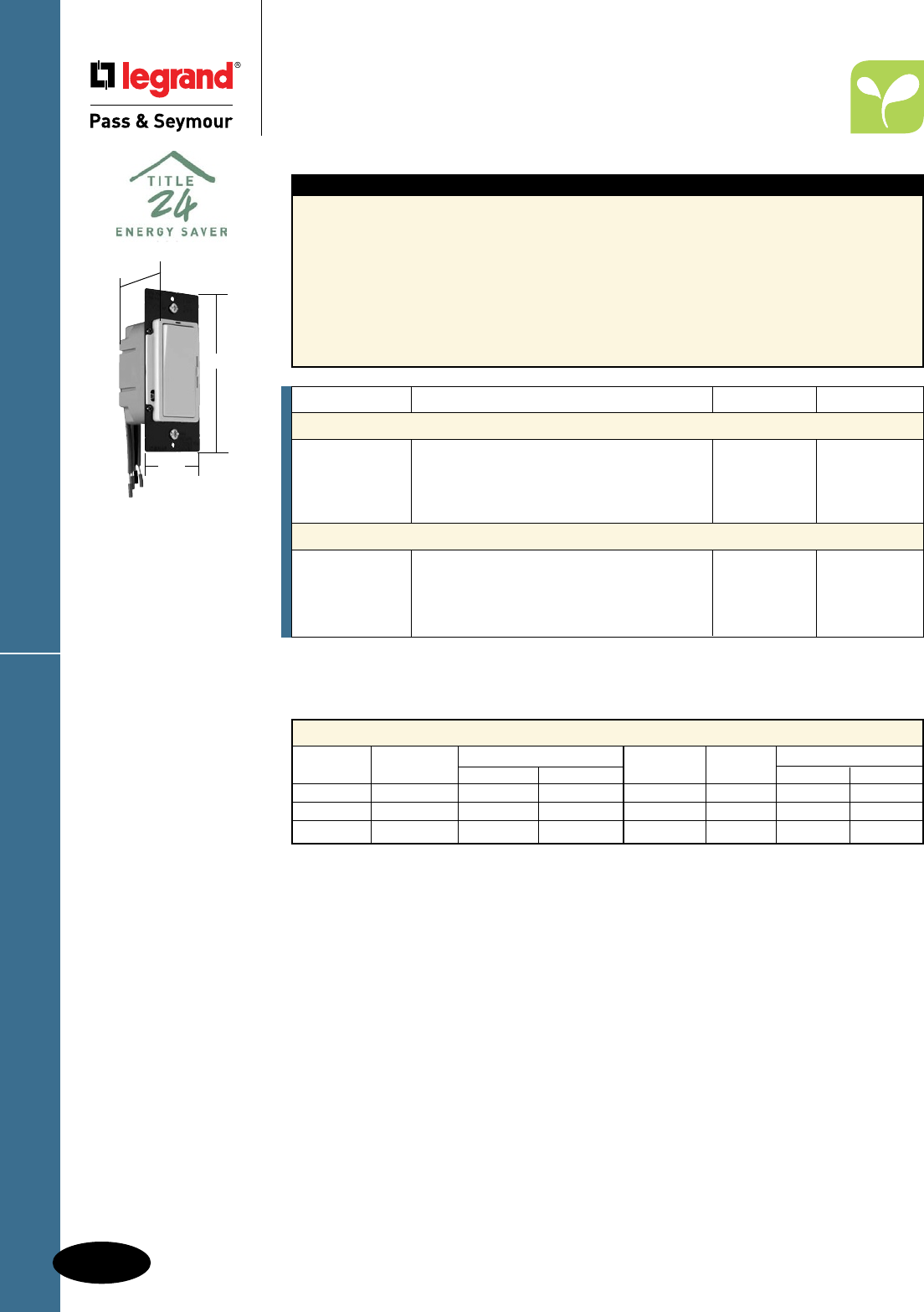
D-68
Decorator DevicesHarmony™ Dimmers & Fan Speed Controls
Decorator Devices
Harmony™ TradeMaster® Dimmers
& Fan Speed Controls
All devices listed on this page conform to NEMA WD-1 and WD-6. UL Listed and CSA Certified.
Features
n Convenient operation – combines ON/OFF Decorator
switch with separate slider for dimming control.
n Green LED glows when OFF to make dimmer easy
to find in the dark.
n Constant memory returns lights to previous level
after a power failure.
n Sleek, ergonomic P&S Decorator style matches
other Decorator devices.
n Higher ratings.
n Single pole and 3-way operation.
n Works with standard 3-way switches and
wiring.
n Screw-pressure-plate backwire terminals
save time, space and money.
DDH16P
n No de-rating.
n No fins to break.
Catalog Number Description Ratings Color
Fluorescent Single Pole/3-Way Dimmers*
DFB8PI Ivory
DFB8PW White
DFB8P Two Wire Fluorescent Single Pole and 3-Way 120V, 8A Brown
DFB8PBK Black
DFB8PLA Light Almond
De-Hummer** Fan Speed Controls
DDH16PI Ivory
DDH16PW White
DDH16P De-Hummer Fan Speed Control 120V, 1.6A Brown
DDH16PBK Black
DDH16PLA Light Almond
De-Rating Chart for Harmony Dimmers
Catalog Maximum Multi-Gang De-Rating Catalog Maximum Multi-Gang De-Rating
Number Load 2 Gang 3 Gang Number Load 2 Gang 3 Gang
D703P 700W 700W 700W DLV1103P 1100VA 950VA 700VA
D1103P 1100W 1100W 800W DFB8P 8A 8A 6.5A
DLV703P 700VA 700VA 650VA DDH16 1.6A 1.6A 1.6A
* For use with Advance MK10 dimming ballasts. See instruction sheet for complete list of compatible ballasts.
** Feature specially designed capacitive circuitry to virtually eliminate fan motor “hum.”
DDH16PLA
4.25"
1.75"
1.25"
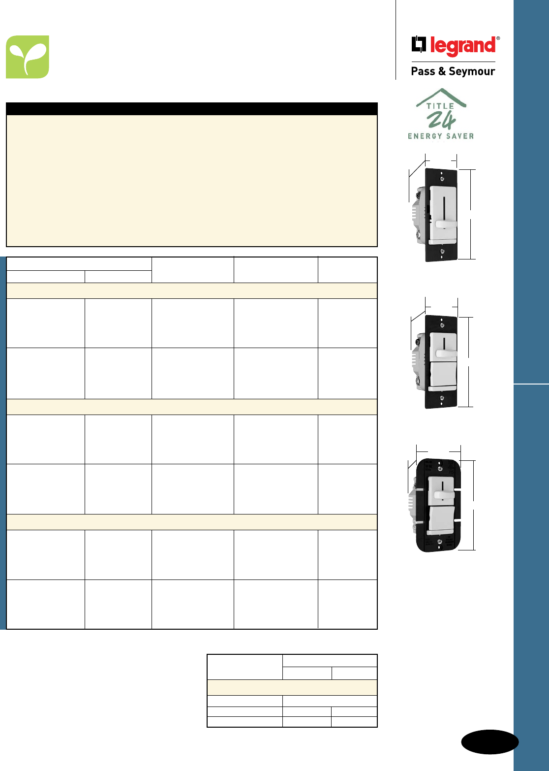
D-69
Decorator Devices LS Series Dimmers
Decorator Devices
LS TradeMaster® Series Dimmers
All devices listed on this page conform to NEMA WD-1 and WD-6. UL Listed and CSA Certified.
LS600LA
1.74"
4.19"
1.28"
LS600PLA
1.74"
4.19"
1.28"
LS1000PLA
2.50"
4.19"
1.28"
Max. Load Rating Fins Removed
One Side Two Side
De-Rating Chart
LS600, LS603 No De-Rating Required
LS1000P, LS1003P 900W 750W
LS1000 850W 700W
For wiring diagrams, see Page S-20.
Features
n Ergonomic design and solid, quality feel combine
for smooth, easy operation and precise control.
n Electromagnetic and radio-frequency interference
protection built in.
n Sleek, sculpted contemporary design. No dirt-
catching crevices.
n Tough, impact-resistant thermoplastic housing
makes it a perfect choice for new home
construction. Matching, unbreakable TradeMaster®
wall plate available for all models.
n Preset ON/OFF switch automatically returns
controlled lights to preset level without readjusting
dimmer setting.
n Exclusive, screw-pressure-plate back wire
terminals save time, space and money.
Designed for 12 and 14 gauge wire, stranded
or solid. No-wire-lead design eliminates wire
nuts.
n Superior heat management.
n No de-rating on 600W units.
n Patented Snap-In Light Module (sold
separately) transforms the dimmer into an
illuminated dimmer. See Page D-70 for
information.
* Available in VisionPak™ packaging, add “V” to Catalog Number. Example: LS600IV.
**Available in boxed packaging only.
Catalog Number
Single Pole Three-Way Description Ratings Color
600W Incandescent Slide Dimmers*
LS600I Ivory
LS600W White
LS600 Non-Preset 120V, 600W max. Brown
LS600BK Black
LS600LA Light Almond
LS600PI LS603PI Ivory
LS600PW LS603PW White
LS600P LS603P Preset 120V, 600W max. Brown
LS600PBK LS603PBK Black
LS600PLA LS603PLA Light Almond
1000W Incandescent Slide Dimmers*
LS1000I Ivory
LS1000W White
LS1000 Non-Preset 120V, 1000W max. Brown
LS1000BK Black
LS1000LA Light Almond
LS1000PI LS1003PI Ivory
LS1000PW LS1003PW White
LS1000P LS1003P Preset 120V, 1000W max. Brown
LS1000PBK LS1003PBK Black
LS1000PLA LS1003PLA Light Almond
600VA Magnetic Low-Voltage Slide Dimmers**
LSLV600I Ivory
LSLV600W White
LSLV600 Non-Preset 120V, 600VA max. Brown
LSLV600BK Black
LSLV600LA Light Almond
LSLV600PI LSLV603PI Ivory
LSLV600PW LSLV603PW White
LSLV600P LSLV603P Preset 120V, 600VA max. Brown
LSLV600PBK LSLV603PBK Black
LSLV600PLA LSLV603PLA Light Almond
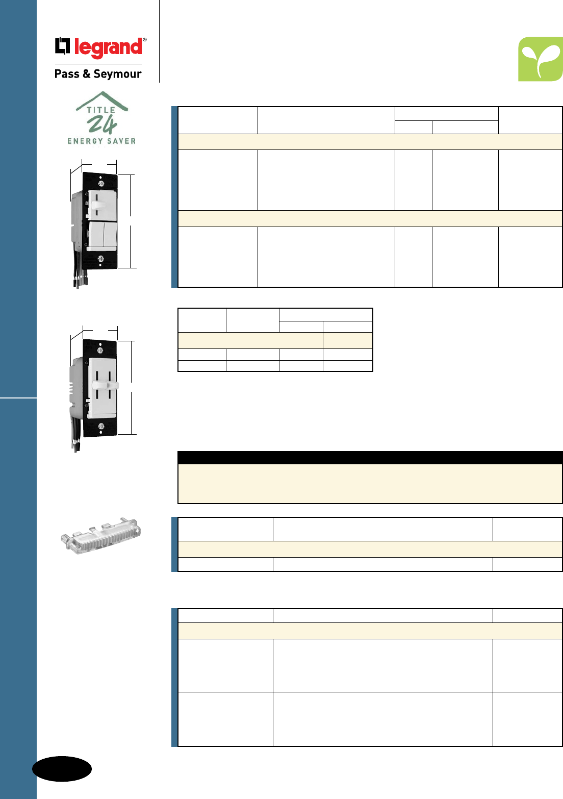
D-70
Decorator Devices
Decorator Devices
LS TradeMaster® Series Dimmers
LS Series Dimmers
All devices listed on this page conform to NEMA WD-1 and WD-6. UL Listed and CSA Certified.
Catalog Number Description Color
Accessories for LS Series
LRKIV Ivory
LRKWV White
LRKV Replacement Knobs for Decorator Dual Slides Brown
LRKBKV Black
LRKLAV Light Almond
LLRKIV Ivory
LLRKWV White
LLRKV Large Replacement Knobs for Decorator Single Slides Brown
LLRKBKV Black
LLRKLAV Light Almond
Catalog Maximum Multi-Gang De-Rating
Number Load 2 Gang 3 Gang
De-Rating Chart
LSDS300 300W 300W 300W
LSDD300 300W 300W 300W
Ratings
Catalog Number Description Dimmer Switch Color
Single Pole/3-Way Preset Dimmers & Switches
LSDS300PI 7A general Ivory
LSDS300PW Single Pole/3-Way Preset Dimmer 120V purpose White
LSDS300P and Independent Single Pole/ 300W resistive and Brown
LSDS300PBK 3-Way Switch ballast, 1/4 hp Black
LSDS300PLA 900W tungsten Light Almond
Dual Slide to OFF Single Pole Dimmers
LSDD300I Ivory
LSDD300W Dual Slide to OFF 120V White
LSDD300 Single Pole Dimmers 300W — Brown
LSDD300BK Black
LSDD300LA Light Almond
For wiring diagrams, see Page S-20.
TM8LMCC
Features
n No tool needed, module snaps-in.
n Lights when OFF.
n Uses energy-efficient 1/4 watt LED light.
n LED light will not generate heat and will last
on average 47 years.
Rating
Catalog Number A. VAC Color
Snap-In Light Module
TM8LMCC 15 120/125 Clear
LSDS300PW
1.74"
4.19"
1.28"
LSDD300W
1.74"
4.19"
1.28"

D-71
Decorator Devices LS Series Fan Speed Controls
Decorator Devices
LS TradeMaster® Series
Fan Speed Controls
All devices listed on this page conform to NEMA WD-1 and WD-6. UL Listed and CSA Certified.
Features
n Tough impact-resistant thermoplastic housing.
n Power-failure memory.
n Superior heat management: no time wasting break off tabs.
n Exclusive, screw-pressure-plate back wire terminals eliminates wire nuts.
n Can be used with patented Snap-In Light Module (sold separately).
LSDC16LAV
1.74"
4.185"
1.28"
LSDC163PLAV
1.74"
4.185"
1.28"
For wiring diagrams, see Page S-20.
Catalog Number Description Ratings Color
Decorator Slide Fan Speed Controls*
LSSC5I Ivory
LSSC5W White
LSSC5 Non-Preset, Single Pole, Adjustable Trim 5A Brown
LSSC5BK Black
LSSC5LA Light Almond
LSSC5PI Ivory
LSSC5PW White
LSSC5P Preset, Single Pole, Adjustable Trim 5A Brown
LSSC5PBK Black
LSSC5PLA Light Almond
Decorator Slide De-Hummer Controls**
LSDH16IV Ivory
LSDH16WV White
LSDH16V Non-Preset, 4-Speed Fan Control 1.6A Brown
LSDH16BKV Black
LSDH16LAV Light Almond
Dual Control Decorator Slides**
LSDC16IV Ivory
LSDC16WV White
LSDC16V Non-Preset, 3-Speed De-Hummer Fan Control 1.6A/300W Brown
LSDC16BKV with Single Pole Dimmer Black
LSDC16LAV Light Almond
LSDC163PIV Ivory
LSDC163PWV White
LSDC163PV Preset, Single Pole/3-Way 3-Speed De-Hummer 1.6A/300W Brown
LSDC163PBKV Fan Control with Single Pole/3-Way Dimmer Black
LSDC163PLAV Light Almond
LSDV25IV Ivory
LSDV25WV White
LSDV25V Non-Preset, Variable Speed Fan Control 2.5A/300W Brown
LSDV25BKV With Single Pole Dimmer Black
LSDV25LAV Light Almond
* Available in VisionPak™ packaging, add “V” to Catalog Number. Example: LSSC5IV.
**Available in VisionPak™ only.
Feature specially designed capacitive circuitry to virtually eliminate fan motor “hum.”
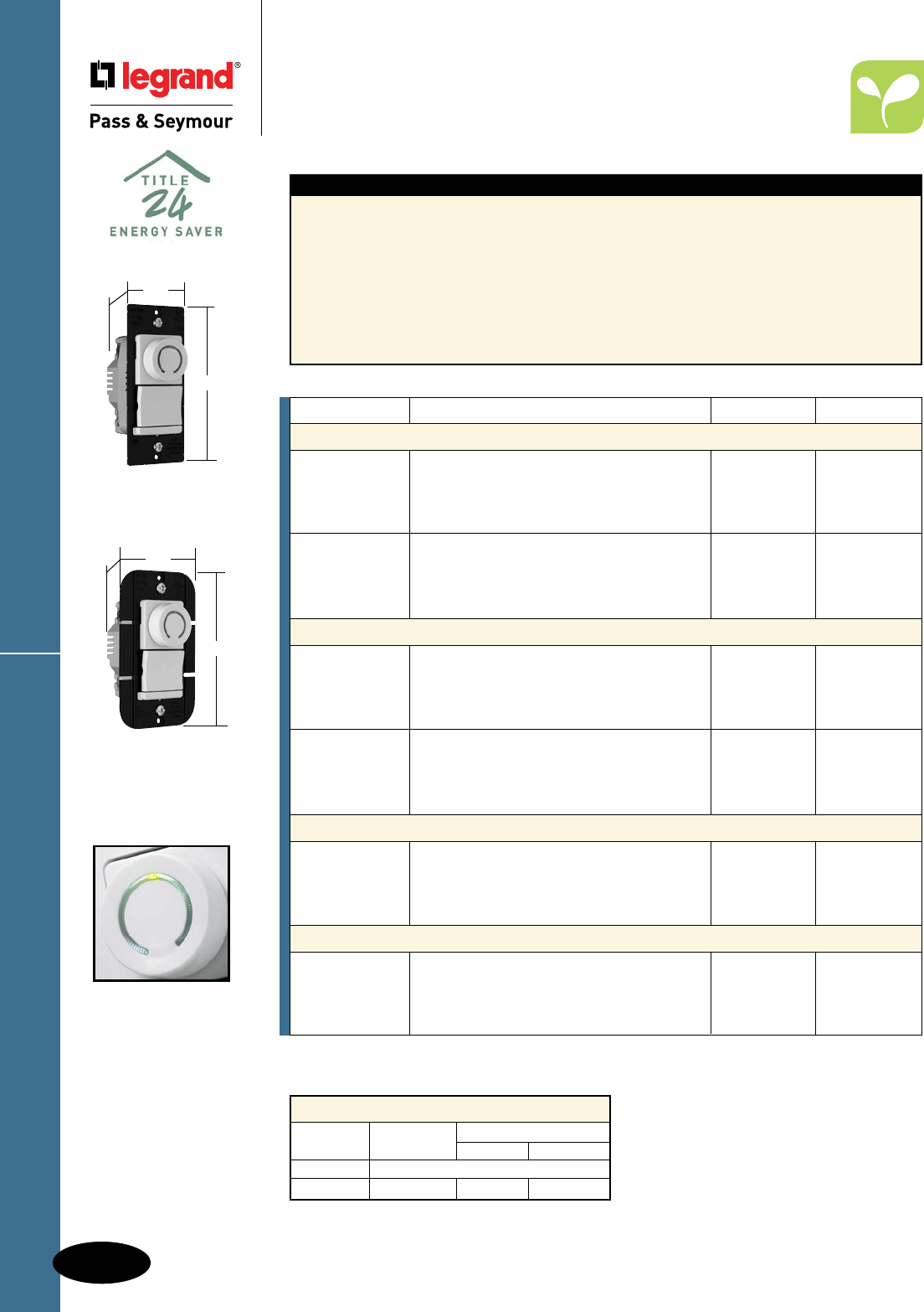
D-72
Decorator DevicesDecorator Rotary DR Series
Decorator Devices
Decorator Rotary DR
TradeMaster® Series
All devices listed on this page conform to NEMA WD-1 and WD-6. UL Listed and CSA Certified.
Features
n A new style that matches P&S Decorator
Combination devices.
n Accepts Snap-In Light Module (sold separately)
to convert decorator rotary devices into
illuminated-type in moments; makes devices
easy to find in the dark. See Page M-14.
n Screw-pressure-plate backwiring speeds installation
and ensures solid, high-quality electrical connections.
Also supports traditional, wire-loop side wiring.
n Heavy-gauge black anodized aluminum
strap provides superior heat management
and structural strength for mounting against
wall surfaces.
n Slim design leaves more room in the box
and makes installation faster and easier.
n Higher ratings of 700 and 1100 watts.
n No de-rating of 700 watt devices.
n Single pole and 3-way in same device.
Catalog Number Description Ratings Color
Incandescent Preset Dimmers
DR703PIV Ivory
DR703PWV White
DR703PV Single Pole/3-Way Dimmer with Pilot Light 120V, 700W Brown
DR703PBKV Black
DR703PLAV Light Almond
DR1103PIV Ivory
DR1103PWV White
DR1103PV Single Pole/3-Way Dimmer with Pilot Light 120V, 1100W Brown
DR1103PBKV Black
DR1103PLAV Light Almond
Magnetic Low-Voltage Dimmers
DRLV703PIV Ivory
DRLV703PWV White
DRLV703PV Single Pole/3-Way Dimmer with Pilot Light 120V, 700VA Brown
DRLV703PBKV Black
DRLV703PLAV Light Almond
DRLV1103PIV Ivory
DRLV1103PWV White
DRLV1103PV Single Pole/3-Way Dimmer with Pilot Light 120V, 1100VA Brown
DRLV1103PBKV Black
DRLV1103PLAV Light Almond
Continuously Variable Preset Fan Speed Controls
DRSC53PIV Ivory
DRSC53PWV White
DRSC53PV Single Pole/3-Way Fan Speed Control 120V, 5A Brown
DRSC53PBKV Black
DRSC53PLAV Light Almond
3-Speed De-Hummer* Preset Fan Speed Controls
DRDH163PIV Ivory
DRDH163PWV Single Pole/3-Way Fan Speed Control White
DRDH163PV with back-lit speed indication 120V, 1.6A Brown
DRDH163PBKV Black
DRDH163PLAV Light Almond
De-Rating Chart for DR Series
Catalog Maximum Multi-Gang De-Rating
Number Load 2 Gang 3 Gang
DR703 No De-Rating Required
DR1103 1100W 900W 750W
Available in VisionPak™ only.
* Feature specially designed capacitive circuitry to virtually eliminate fan motor “hum.”
DR703PLAV
1.74"
4.185"
1.28"
Illuminated knob
indicates light level.
DR1103PWV
2.50"
4.185"
1.28"

D-73
Decorator Devices
All devices listed on this page conform to NEMA WD-1 and WD-6. UL Listed and CSA Certified.
Wide Slide Series
Decorator Devices
Wide Slide TradeMaster® Series
Features
n Convenient operation – combines ON/OFF Decorator-
style switch with separate slider for dimming control.
n Constant memory returns lights to previous level
after a power failure.
n Sleek, ergonomic P&S Decorator-style matches
other Decorator devices.
n Higher ratings.
n Single pole and 3-way operation.
n Screw-pressure-plate back wire terminals
save time, space and money.
n 700W maximum rated dimmers can be
ganged without de-rating.
n Package comes with three face colors –
Ivory, White, Light Almond (TC).
n White only option also available (W).
n Interchangeable faces available in four colors
(sold separately, see below).
Max. Fins Removed
Load One Two
Rating Side Side
De-Rating Chart
1000W 800W 700W
1000VA 800VA 700VA
Note: Each side removed reduces
plate size by 3/8".
Preset Models
4.25"
1.75"
1.25"
Catalog Number Description Rating Color
Interchangeable Face Incandescent Dimmers
WS700TC* Single Pole, Slide to OFF, 3 Face Colors 120V, 700W Ivory/White/Lt. Almond
WS700W White Face Only 120V, 700W White
WS703PTC* Preset, Single Pole/3-Way, 3 Face Colors 120V, 700W Ivory/White/Lt. Almond
WS703PW White Face Only 120V, 700W White
WS1100TC* Preset, Single Pole/3-Way, 3 Face Colors 120V, 1100W Ivory/White/Lt. Almond
WS1100W White Face Only 120V, 1100W White
WS1103PTC* Preset, Single Pole/3-Way, 3 Face Colors 120V, 1100W Ivory/White/Lt. Almond
WS1103PW White Face Only 120V, 1100W White
Interchangeable Face Magnetic Low-Voltage Dimmers
WSLV700TC* Single Pole, 3 Face Colors 120V, 700VA Ivory/White/Lt. Almond
WSLV700W White Face Only 120V, 700VA White
WSLV703PTC* Preset, Single Pole/3-Way, 3 Face Colors 120V, 700VA Ivory/White/Lt. Almond
WSLV703PW White Face Only 120V, 700VA White
Interchangeable Face Fan Speed Controls
WSSC53PTC* Preset, Variable Speed, 3 Face Colors 120V, 5A Ivory/White/Lt. Almond
WSSC53PW White Face Only 120V, 5A White
Interchangeable Face Covers**
WSKITI Wide Slide Interchangeable Face, Ivory Ivory
WSKIT Wide Slide Interchangeable Face, White Brown
WSKITBK Wide Slide Interchangeable Face, Black Black
WSKITLA Wide Slide Interchangeable Face, Light Almond Light Almond
WSKITPI Present Wide Slide Interchangeable Face, Ivory Ivory
WSKITP Present Wide Slide Interchangeable Face, Brown Brown
WSKITPBK Present Wide Slide Interchangeable Face, Black Black
WSKITPLA Present Wide Slide Interchangeable Face, Light Almond Light Almond
94084
4.25"
1.688"
1.469"
No-Noise De-Hummers
Since the development of variable fan speed controls, many fans have made an annoying humming noise
when their speed was reduced. Through the use of specially designed capacitive circuitry, these units can
control fans at 3 or 4-speed levels in slide, rotary, and dual styles with virtually no fan motor noise.
Catalog Number Description Ratings Color
1.5A Max. No-Noise De-Hummer Specification Grade
Fan Speed Controls – RFI Protected
94084I* Ivory
94084W* 3-Speed, Single Pole 120V White
94084GRY 1.5A max. Gray
94084LA* Light Almond
* Available in VisionPak™ packaging, add “V” to Catalog Number. Example: 94084LAV.
WS700TC
WSLV700TC
Shown with the Three
Interchangeable Faces
4.25"
1.75"
1.25"
*Available in VisionPak™ packaging, add “CCV6” to Catalog Number. Example: WS700TCCCV6.
**Available in VisionPak™ packaging, add “BPCC6” to Catalog Number. Example: WSKITIBPCC6.
All 1100W versions
are 2.50" W

D-74
Decorator Devices
Decorator Devices
Titan™ Series
Titan™ Series
A complete solution for easy, economical
multi-gang installations.
The P&S Titan™ Series have key features designed to
increase installer productivity. Each comes with all the
screwless wall plate components necessary for single gang
or multi-gang installations. No need to order any additional
components such as long-lead time custom wall plates to
finish the job. Complete the installation with everything right
out of the box, increasing productivity by finishing up in one
visit instead of several.
Exclusive adjustable limit control
in incandescent dimmers saves
energy and extends bulb life —
reduces maximum output by up to
10 percent.
Power-failure memory retains
presets through power outages.
High-reliability design
with built-in surge and static
protection plus oversize output
devices to stand up to abuse.
Improved heat management
enables superior load ratings.
Enclosed slider helps prevent
dust and dirt contamination.
Air-gap switch
Included screwless wall plate
components make it easy to assemble
a custom multi-gang wall plate in any
configuration — saving money and time.
Preset models feature large
ON/OFF button and single
pole/three-way functionality.
Widest choice of amperage
ratings with minimal or no
de-rating for faster job planning.
Exclusive labeling
system has a built-in
label holder enabling
instant circuit identification;
looks clean and professional.
Adaptor kit enables matching installation
of standard P&S Decorator Devices – outlets,
switches, GFCIs and more.
CDADAPTORKITW
CD703PW
Included end-caps and
spacers screw directly
to heat sinks; center plate
snaps easily on and off.

D-75
Decorator Devices Titan™ Series Incandescent Dimmers
Decorator Devices
Titan™ Series
Incandescent Dimmers
All devices listed on this page conform to NEMA WD-1 and WD-6. cULus Listed.
CD1100W
Narrow
2.85"
4.87"
1.44"
CD703PW
Narrow
2.85"
4.87"
1.44"
CD1603PW
Wide
4.65"
4.87"
1.44"
CD2003PW
Wide
4.65"
4.87"
1.44"
Features
n Field configurable wall plate system.
n Labeling system.
n Adjustable top end output voltage.
n Shipped with protective film.
n Rugged construction.
n Superior ratings with a minimum of de-rating
when ganged.
n Simple to plan the rough-in.
n Available in single pole slide-to-OFF and
single pole/3-way preset models.
n Attractive European styling.
n Eye-catching packaging.
n Exclusive adaptor kit to install other Decorator
opening devices under the Titan™ wall plate
system. (See Page D-76.)
n Blank center plate included.
Catalog Narrow
Number Description Ratings or Wide Color
Incandescent
CD700I Ivory
CD700W White
CD700 Single Pole, Slide-to-OFF 120V, 700W Narrow Brown
CD700GRY Gray
CD700BK Black
CD700LA Light Almond
CD703PI Ivory
CD703PW White
CD703P Single Pole/3-Way, Preset 120V, 700W Narrow Brown
CD703PGRY Gray
CD703PBK Black
CD703PLA Light Almond
CD1100I Ivory
CD1100W White
CD1100 Single Pole, Slide-to-OFF 120V, 1100W Narrow Brown
CD1100GRY Gray
CD1100BK Black
CD1100LA Light Almond
CD1103PI Ivory
CD1103PW White
CD1103P Single Pole/3-Way, Preset 120V, 1100W Narrow Brown
CD1103PGRY Gray
CD1103PBK Black
CD1103PLA Light Almond
CD1600I Ivory
CD1600W White
CD1600 Single Pole, Slide-to-OFF 120V, 1600W Wide Brown
CD1600GRY Gray
CD1600BK Black
CD1600LA Light Almond
CD1603PI Ivory
CD1603PW White
CD1603P Single Pole/3-Way, Preset 120V, 1600W Wide Brown
CD1603PGRY Gray
CD1603PBK Black
CD1603PLA Light Almond
CD2000I Ivory
CD2000W White
CD2000 Single Pole, Slide-to-OFF 120V, 2000W Wide Brown
CD2000GRY Gray
CD2000BK Black
CD2000LA Light Almond
CD2003PI Ivory
CD2003PW White
CD2003P Single Pole/3-Way, Preset 120V, 2000W Wide Brown
CD2003PGRY Gray
CD2003PBK Black
CD2003PLA Light Almond
For technical specifications, de-rating, and rough-in box charts, see Pages S-147 and S-148.

D-76
Decorator DevicesTitan™ Series Magnetic Low-Voltage
Decorator Devices
Titan™ Series Magnetic
Low-Voltage Dimmers &
Adaptor Kit
All devices listed on this page conform to NEMA WD-1 and WD-6. cULus Listed.
Catalog Narrow
Number Description Ratings or Wide Color
Magnetic Low-Voltage
CDLV700I Ivory
CDLV700W White
CDLV700 Single Pole, Slide-to-OFF 120V, 700W Narrow Brown
CDLV700GRY Gray
CDLV700BK Black
CDLV700LA Light Almond
CDLV703PI Ivory
CDLV703PW White
CDLV703P Single Pole/3-Way, Preset 120V, 700W Narrow Brown
CDLV703PGRY Gray
CDLV703PBK Black
CDLV703PLA Light Almond
CDLV1100I Ivory
CDLV1100W White
CDLV1100 Single Pole, Slide-to-OFF 120V, 1100W Narrow Brown
CDLV1100GRY Gray
CDLV1100BK Black
CDLV1100LA Light Almond
CDLV1103PI Ivory
CDLV1103PW White
CDLV1103P Single Pole/3-Way, Preset 120V, 1100W Narrow Brown
CDLV1103PGRY Gray
CDLV1103PBK Black
CDLV1103PLA Light Almond
CDLV1600I Ivory
CDLV1600W White
CDLV1600 Single Pole, Slide-to-OFF 120V, 1600W Wide Brown
CDLV1600GRY Gray
CDLV1600BK Black
CDLV1600LA Light Almond
CDLV1603PI Ivory
CDLV1603PW White
CDLV1603P Single Pole/3-Way, Preset 120V, 1600W Wide Brown
CDLV1603PGRY Gray
CDLV1603PBK Black
CDLV1603PLA Light Almond
Adaptor Kit
CDADAPTORKITI Ivory
CDADAPTORKITW White
CDADAPTORKIT Decorator Device Adaptor Kit Narrow Brown
CDADAPTORKITGRY Gray
CDADAPTORKITBK Black
CDADAPTORKITLA Light Almond
For technical specifications, de-rating, and rough-in box charts, see Pages S-147 and S-148.
Features
n Field configurable wall plate system.
n Labeling system.
n Adjustable low end output voltage.
n Shipped with protective film.
n Rugged construction.
n Superior ratings with a minimum of de-rating
when ganged.
n Simple to plan the rough-in.
n Available in single pole slide-to-OFF and
single pole/3-way preset models.
n Attractive European styling.
n Eye-catching packaging.
n Exclusive adaptor kit to install other Decorator
opening devices under the Titan™ wall plate
system.
n Blank center plate included.
4.65"
4.87"
1.44"
CDLV1103PW
Wide
CDLV700W
Narrow
2.85"
4.87"
1.44"
Adaptor kit enables
matching installation of
standard P&S Decorator
Devices – outlets, switches,
GFCIs and more.
See Page D-74.
CDADAPTORKITW

D-77
Decorator Devices Titan™ Series Fluorescent
Decorator Devices
Titan™ Series Fluorescent
2 Wire Dimmers
All devices listed on this page conform to NEMA WD-1 and WD-6. cULus Listed.
CDFB5W
Narrow
2.85"
4.87"
1.44"
For technical specifications, de-rating, rough-in box charts, and complete list of compatible
ballasts, see Pages S-149 and S-151.
Features
n For use with 2 wire 120V and 277V fluorescent
dimming ballasts.
n Field configurable wall plate system.
n Labeling system.
n Adjustable low end output voltage.
n Shipped with protective film.
n Rugged construction.
n Superior ratings with a minimum of de rating
when ganged.
n Simple to plan the rough-in.
n Available in single pole slide-to-OFF and
single pole/3-way preset models.
n Attractive European styling.
n Eye-catching packaging.
n Exclusive adaptor kit to install other Decorator
opening devices under the Titan™ wall plate
system. (See Page D-76.)
n Blank center plate included.
Catalog Narrow
Number Description Ratings or Wide Color
Fluorescent
CDFB5I Ivory
CDFB5W White
CDFB5 2 Wire, Electronic, 5A, 120V Narrow Brown
CDFB5GRY Single Pole, Slide-to-OFF Gray
CDFB5BK Black
CDFB5LA Light Almond
CDFB8I Ivory
CDFB8W White
CDFB8 2 Wire, Electronic, 8A, 120V Narrow Brown
CDFB8GRY Single Pole, Slide-to-OFF Gray
CDFB8BK Black
CDFB8LA Light Almond
CDFB10I Ivory
CDFB10W White
CDFB10 2 Wire, Electronic, 10A, 120V Wide Brown
CDFB10GRY Single Pole, Slide-to-OFF Gray
CDFB10BK Black
CDFB10LA Light Almond
CDFB16I Ivory
CDFB16W White
CDFB16 2 Wire, Electronic, 16A, 120V Wide Brown
CDFB16GRY Single Pole, Slide-to-OFF Gray
CDFB16BK Black
CDFB16LA Light Almond
CDFB7277I Ivory
CDFB7277W White
CDFB7277 2 Wire, Electronic, 7A, 277V Wide Brown
CDFB7277GRY Single Pole, Slide-to-OFF Gray
CDFB7277BK Black
CDFB7277LA Light Almond
CDFB10277I Ivory
CDFB10277W White
CDFB10277 2 Wire, Electronic, 10A, 277V Wide Brown
CDFB10277GRY Single Pole, Slide-to-OFF Gray
CDFB10277BK Black
CDFB10277LA Light Almond
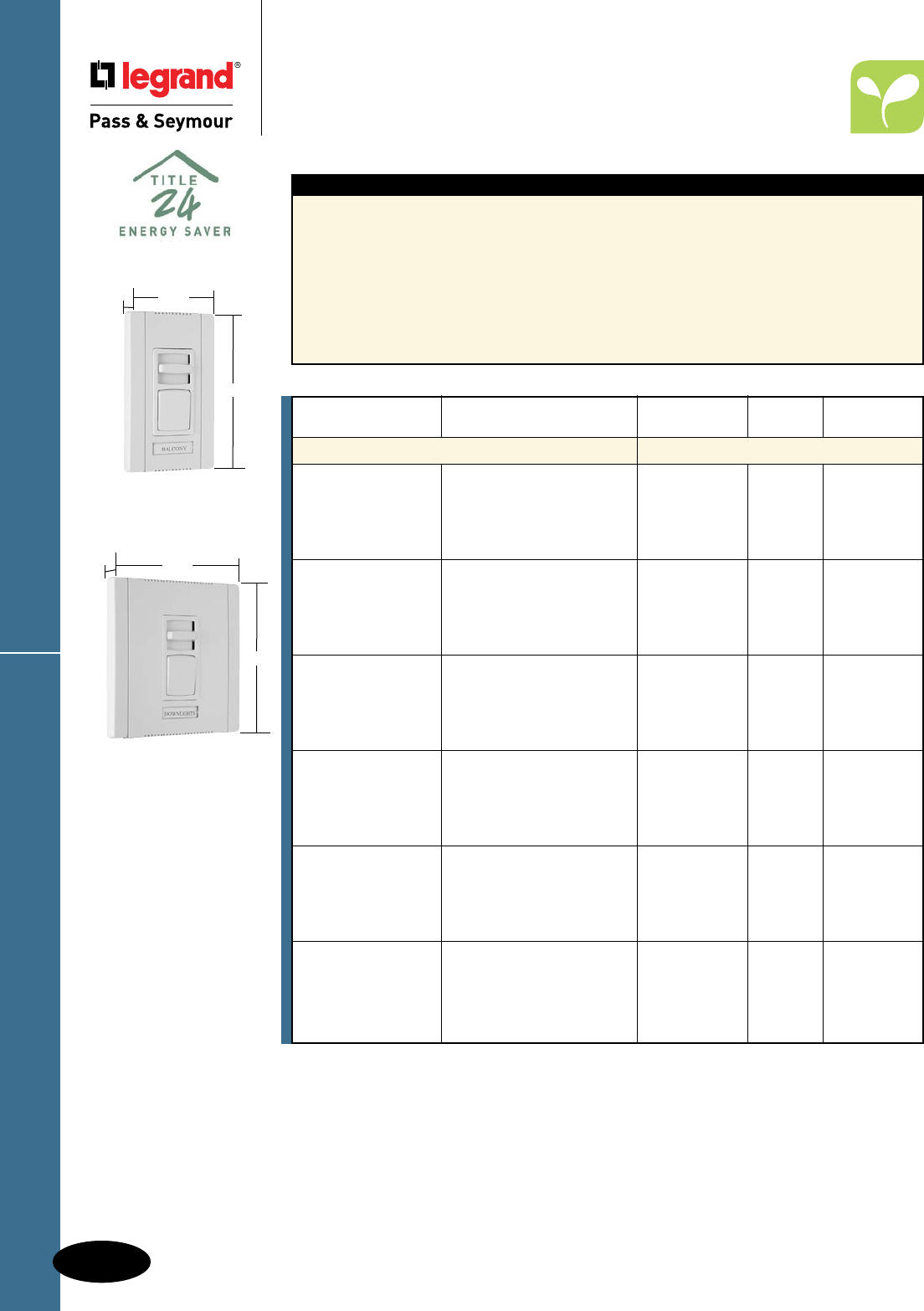
D-78
Decorator DevicesTitan™ Series Fluorescent
Decorator Devices
Titan™ Series Fluorescent
2 Wire Dimmers
All devices listed on this page conform to NEMA WD-1 and WD-6. cULus Listed.
CDFB53PW
Narrow
2.85"
4.87"
1.44"
4.65"
4.87"
1.44"
CDFB103PW
Wide
Features
n For use with 2 wire 120V and 277V fluorescent
dimming ballasts.
n Field configurable wall plate system.
n Labeling system.
n Adjustable low end output voltage.
n Shipped with protective film.
n Rugged construction.
n Superior ratings with a minimum of de-rating
when ganged.
n Simple to plan the rough-in.
n Available in single pole slide-to-OFF and
single pole/3-way preset models.
n Attractive European styling.
n Eye-catching packaging.
n Exclusive adaptor kit to install other Decorator
opening devices under the Titan™ wall plate
system. (See Page D-76.)
n Blank center plate included.
For technical specifications, de-rating, rough-in box charts, and complete list of compatible
ballasts, see Pages S-149 and S-151.
Catalog Narrow
Number Description Ratings or Wide Color
Fluorescent
CDFB53PI Ivory
CDFB53PW White
CDFB53P 2 Wire, Electronic, 5A, 120V Narrow Brown
CDFB53PGRY Single Pole/3-Way, Preset Gray
CDFB53PBK Black
CDFB53PLA Light Almond
CDFB83PI Ivory
CDFB83PW White
CDFB83P 2 Wire, Electronic, 8A, 120V Narrow Brown
CDFB83PGRY Single Pole/3-Way, Preset Gray
CDFB83PBK Black
CDFB83PLA Light Almond
CDFB103PI Ivory
CDFB103PW White
CDFB103P 2 Wire, Electronic, 10A, 120V Wide Brown
CDFB103PGRY Single Pole/3-Way, Preset Gray
CDFB103PBK Black
CDFB103PLA Light Almond
CDFB163PI Ivory
CDFB163PW White
CDFB163P 2 Wire, Electronic, 16A, 120V Wide Brown
CDFB163PGRY Single Pole/3-Way, Preset Gray
CDFB163PBK Black
CDFB163PLA Light Almond
CDFB73P277I Ivory
CDFB73P277W White
CDFB73P277 2 Wire, Electronic, 7A, 277V Wide Brown
CDFB73P277GRY Single Pole/3-Way, Preset Gray
CDFB73P277BK Black
CDFB73P277LA Light Almond
CDFB103P277I Ivory
CDFB103P277W White
CDFB103P277 2 Wire, Electronic, 10A, 277V Wide Brown
CDFB103P277GRY Single Pole/3-Way, Preset Gray
CDFB103P277BK Black
CDFB103P277LA Light Almond

D-79
Decorator Devices Titan™ Series Fluorescent
Decorator Devices
Titan™ Series Fluorescent
3 Wire Dimmers
All devices listed on this page conform to NEMA WD-1 and WD-6. cULus Listed.
Features
n For use with 3 wire 120V and 277V fluorescent
dimming ballasts.
n Field configurable wall plate system.
n Labeling system.
n Adjustable low end output voltage.
n Shipped with protective film.
n Rugged construction.
n Superior ratings with a minimum of de-rating
when ganged.
n Simple to plan the rough-in.
n Available in single pole slide-to-OFF and
single pole/3-way preset models.
n Attractive European styling.
n Eye-catching packaging.
n Exclusive adaptor kit to install other Decorator
opening devices under the Titan™ wall plate
system. (See Page D-76.)
n Blank center plate included.
Catalog Narrow
Number Description Ratings or Wide Color
Fluorescent
CD3FB16I Ivory
CD3FB16W White
CD3FB16 3 Wire Electronic, 120V, 16A Narrow Brown
CD3FB16GRY Single Pole, Slide-to-OFF Gray
CD3FB16BK Black
CD3FB16LA Light Almond
CD3FB163PI Ivory
CD3FB163PW White
CD3FB163P 3 Wire Electronic, 120V, 16A Narrow Brown
CD3FB163PGRY Single Pole/3-Way, Preset Gray
CD3FB163PBK Black
CD3FB163PLA Light Almond
CD3FB10277I Ivory
CD3FB10277W White
CD3FB10277 3 Wire Electronic, 277V, 10A Narrow Brown
CD3FB10277GRY Single Pole, Slide-to-OFF Gray
CD3FB10277BK Black
CD3FB10277LA Light Almond
CD3FB103P277I Ivory
CD3FB103P277W White
CD3FB103P277 3 Wire Electronic, 277V, 10A Narrow Brown
CD3FB103P277GRY Single Pole/3-Way, Preset Gray
CD3FB103P277BK Black
CD3FB103P277LA Light Almond
CD3FB163PW
Narrow
2.85"
4.87"
1.44"
For technical specifications, de-rating, rough-in box charts, and complete list of compatible
ballasts, see Pages S-149 – S-151.
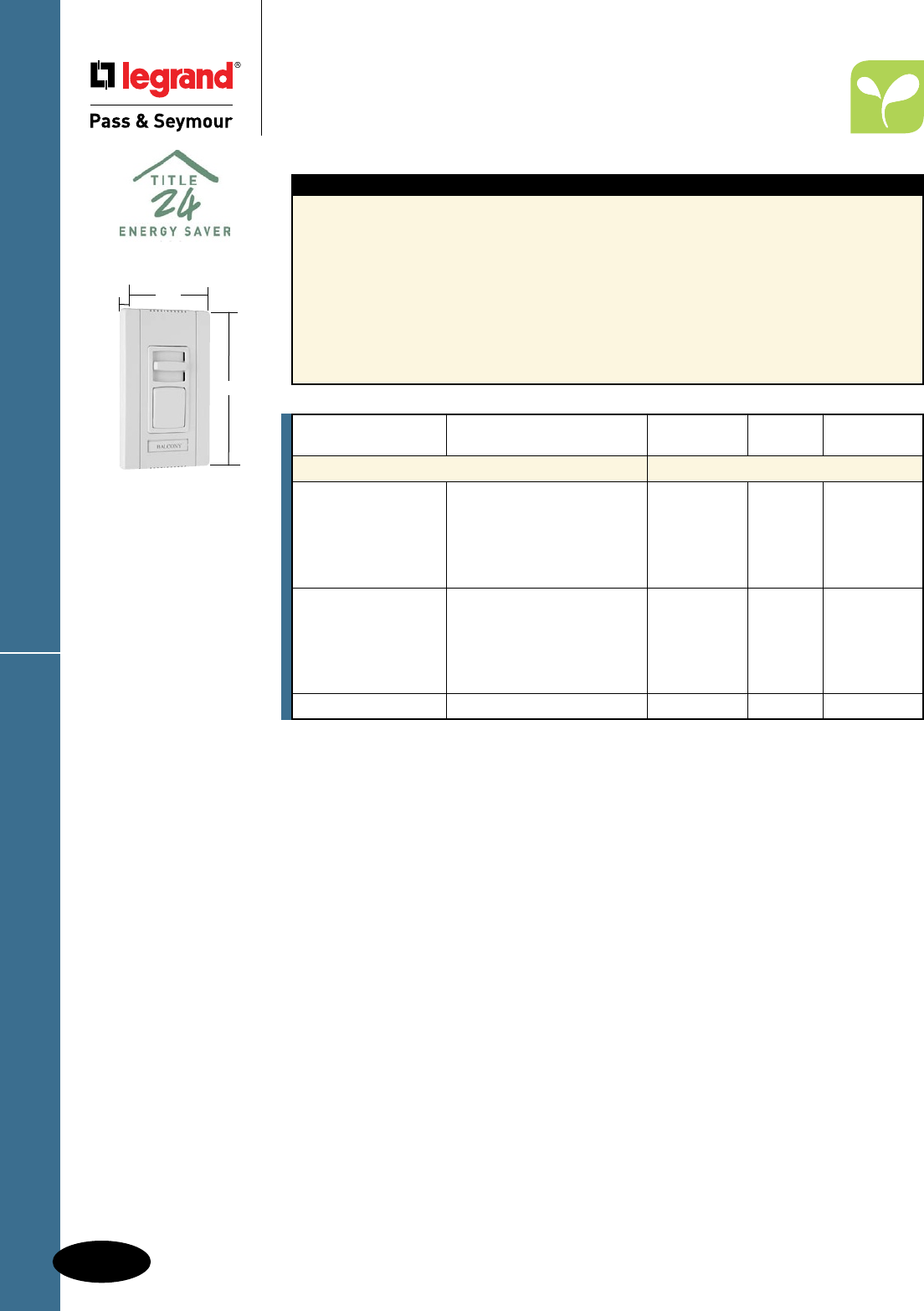
D-80
Decorator Devices
Decorator Devices
Titan™ Series Fluorescent
4 Wire Dimmers
Titan™ Series Fluorescent
All devices listed on this page conform to NEMA WD-1 and WD-6. cULus Listed.
Features
n For use with 0-10V, 4 wire, 120V and 277V
fluorescent dimming ballasts.
n Field configurable wall plate system.
n Labeling system.
n Adjustable low end output voltage.
n Shipped with protective film.
n Rugged construction.
n Superior ratings with a minimum of de-rating
when ganged.
n Must be used with power pack.
n Simple to plan the rough-in.
n Available in single pole slide-to-OFF and
single pole/3-way preset models.
n Attractive European styling.
n Eye-catching packaging.
n Exclusive adaptor kit to install other Decorator
opening devices under the Titan™ wall plate
system. (See Page D-76.)
n Blank center plate included.
Red available made to order.
CD4FB3PW
Narrow
2.85"
4.87"
1.4375"
Catalog Narrow
Number Description Ratings or Wide Color
Fluorescent
CD4FBI Ivory
CD4FBW White
CD4FB 24VDC Narrow Brown
CD4FBGRY Single Pole, Slide-to-OFF Gray
CD4FBBK Black
CD4FBLA Light Almond
CD4FB3PI Ivory
CD4FB3PW White
CD4FB3P Single Pole/3-Way, Preset 24VDC Narrow Brown
CD4FB3PGRY Gray
CD4FB3PBK Black
CD4FB3PLA Light Almond
PWP120277 Power pack for switching load 24VDC —
For technical specifications, de-rating, rough-in box charts, and complete list of compatible
ballasts, see Pages S-149 – S-151.
Power Pack technical specifications, see Page S-146.
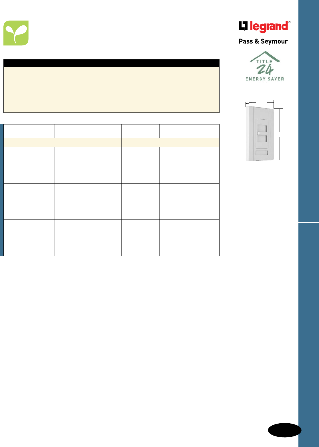
D-81
Decorator Devices Titan™ Series Fan Speed Controls
Decorator Devices
Titan™ Series Fan Speed Controls
All devices listed on this page conform to NEMA WD-1 and WD-6. cULus Listed.
Features
n Field configurable wall plate system.
n Labeling system.
n Shipped with protective film.
n Rugged construction.
n Simple to plan the rough-in.
n Available in single pole slide-to-OFF models.
n Attractive European styling.
n Eye-catching packaging.
n Exclusive adaptor kit to install other Decorator
opening devices under the Titan™ wall plate
system. (See Page D-76.)
n Available in both continuously variable and
de-hummer styles.
n Blank center plate included.
CDSC6W
Narrow
2.85"
4.87"
1.4375"
Catalog Narrow
Number Description Ratings or Wide Color
Fan Speed Controls
CDSC6I Ivory
CDSC6W White
CDSC6 Continuously Variable Speed 120V, 6A Narrow Brown
CDSC6GRY Fan Speed Control Gray
CDSC6BK Black
CDSC6LA Light Almond
CDSC12I Ivory
CDSC12W White
CDSC12 Continuously Variable Speed 120V, 12A Wide Brown
CDSC12GRY Fan Speed Control Gray
CDSC12BK Black
CDSC12LA Light Almond
CDDH16I Ivory
CDDH16W De-Hummer, 4 Speed White
CDDH16 Low/Low-Mid/High-Mid/High 120V, 1.6A Narrow Brown
CDDH16GRY Fan Speed Control Gray
CDDH16BK Black
CDDH16LA Light Almond
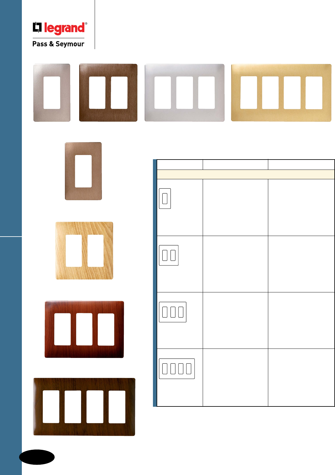
D-82
Decorator DevicesDecorative Finish Screwless Wall Plates
Decorator Devices
Decorative Finish Screwless Wall Plates
Polycarbonate
Four Gang
Walnut
For Screwless Wall Plate, and Plastic Subplate dimensions, see Page D-83.
Description Color Decorator Openings
Screwless Decorator Openings Plastic Subplate included
One Gang Brushed Nickel SWP26BN
Brushed Copper SWP26BC
Stainless Steel SWP26SS
Brass SWP26BR
Brushed Bronze SWP26BB
Maple SWP26MA
Mahogany SWP26MH
Walnut SWP26WA
Two Gang Brushed Nickel SWP262BN
Brushed Copper SWP262BC
Stainless Steel SWP262SS
Brass SWP262BR
Brushed Bronze SWP262BB
Maple SWP262MA
Mahogany SWP262MH
Walnut SWP262WA
Three Gang Brushed Nickel SWP263BN
Brushed Copper SWP263BC
Stainless Steel SWP263SS
Brass SWP263BR
Brushed Bronze SWP263BB
Maple SWP263MA
Mahogany SWP263MH
Walnut SWP263WA
Four Gang Brushed Nickel SWP264BN
Brushed Copper SWP264BC
Stainless Steel SWP264SS
Brass SWP264BR
Brushed Bronze SWP264BB
Maple SWP264MA
Mahogany SWP264MH
Walnut SWP264WA
One Gang
Brushed Nickel
Four Gang
Brass
Three Gang
Mahogany
Three Gang
Stainless Steel
Two Gang
Brushed Copper
Two Gang
Maple
One Gang
Brushed Bronze
These products listed to UL514, Cover Plates for Flush-Mounted Wiring Devices, CSA Certified.
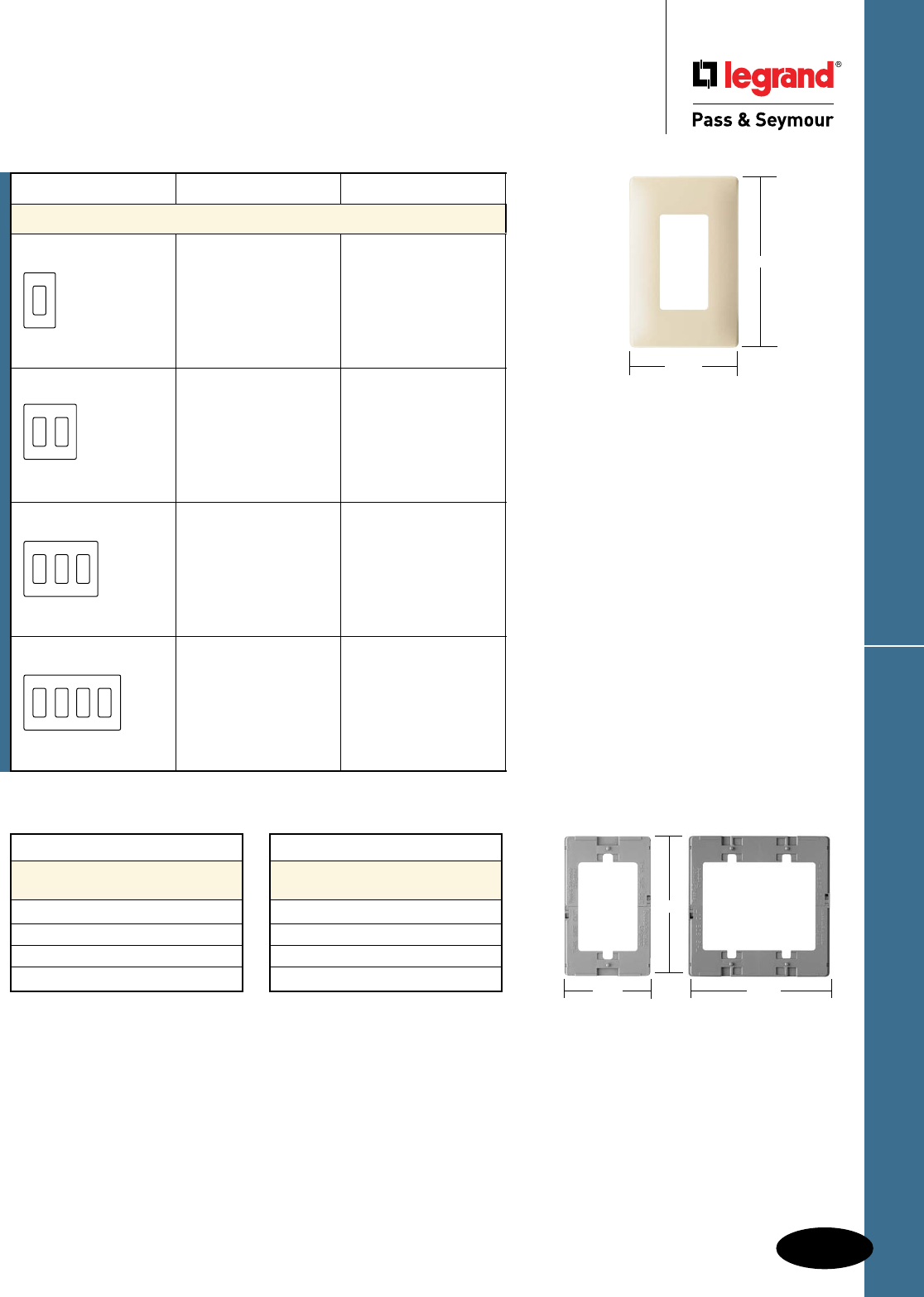
D-83
Decorator Devices Screwless Wall Plates
Decorator Devices
Screwless Wall Plates
Polycarbonate
These products listed to UL514, Cover Plates for Flush-Mounted Wiring Devices, CSA Certified.
Description Height Width
Screwless Wall Plate
Dimensions
One Gang 4.87" 3.10"
Two Gang 4.87" 4.912"
Three Gang 4.87" 6.724"
Four Gang 4.87" 8.536"
Description Height Width
Screwless Plastic
Subplate Dimensions
One Gang 4.62" 2.85"
Two Gang 4.62" 4.662"
Three Gang 4.62" 6.474"
Four Gang 4.62" 8.286"
Number of Gangs Color Decorator Openings
Screwless Wall Plates Plastic Subplate included
One Gang Ivory
White
Brown
Gray
Black
Light Almond
SWP26I
SWP26W
SWP26
SWP26GRY
SWP26BK
SWP26LA
Two Gang Ivory
White
Brown
Gray
Black
Light Almond
SWP262I
SWP262W
SWP262
SWP262GRY
SWP262BK
SWP262LA
Three Gang Ivory
White
Brown
Gray
Black
Light Almond
SWP263I
SWP263W
SWP263
SWP263GRY
SWP263BK
SWP263LA
Four Gang Ivory
White
Brown
Gray
Black
Light Almond
SWP264I
SWP264W
SWP264
SWP264GRY
SWP264BK
SWP264LA
One Gang
3.10"
4.87"
2.85"
4.62"
One Gang
Plastic Subplate
4.662"
Two Gang
Plastic Subplate
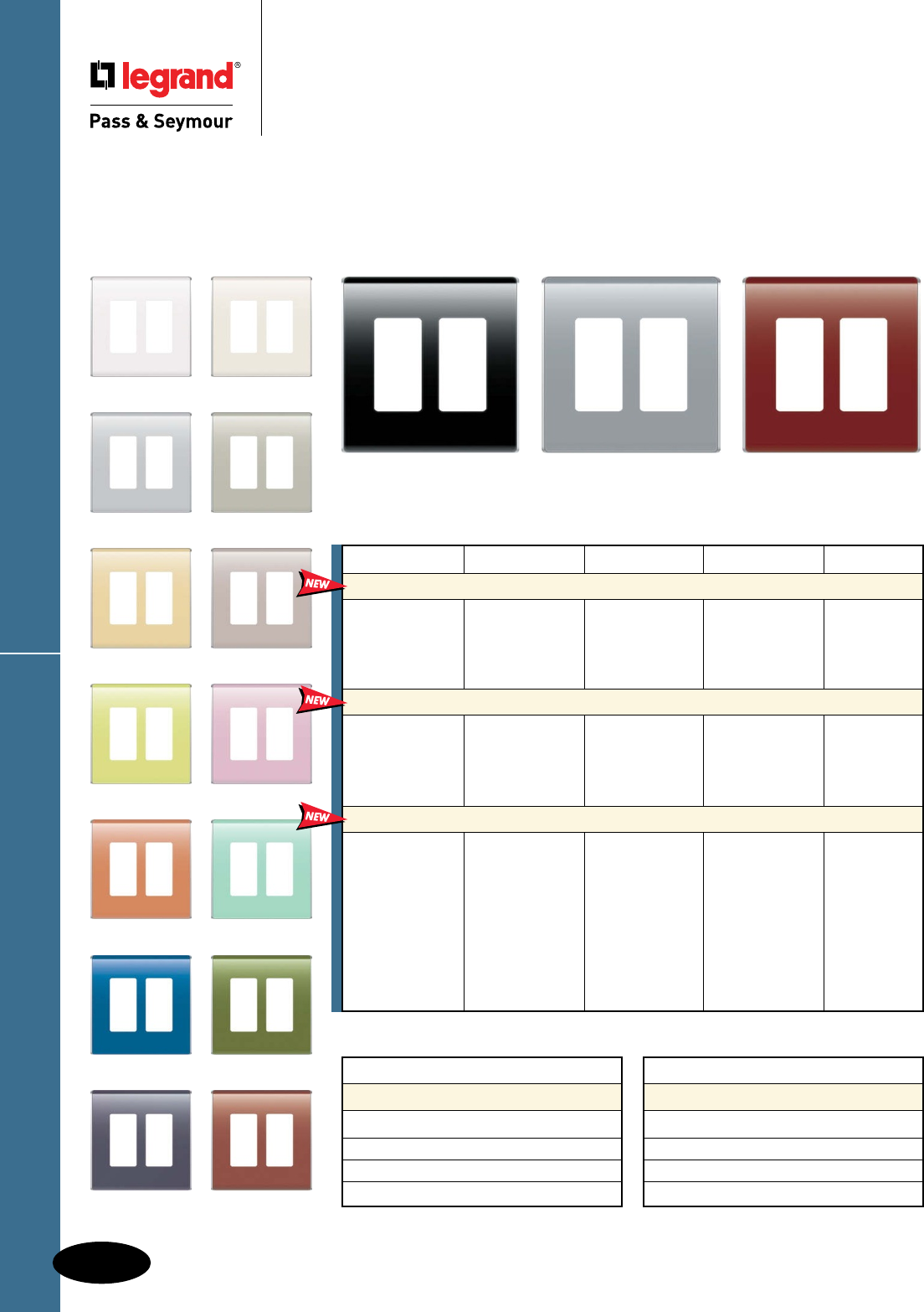
D-84
Decorator Devices
WP5002NV WP5002SP
WP5002WH WP5002LA
WP5002TI WP5002KK
WP5002SD WP5002TP
WP5002AE WP5002CP
WP5002CR WP5002CZ
WP5002CY WP5002MS
Studio Wall Plates
Decorator Devices
Studio Wall Plates
Polycarbonate
These products listed to UL514, Cover Plates for Flush-Mounted Wiring Devices, CSA Certified.
WP5002GB WP5002CM
Color One Gang Two Gang Three Gang Four Gang
Basic Color – Screwless Decorator Opening Back Plate included
White WP5001WH WP5002WH WP5003WH WP5004WH
Light Almond WP5001LA WP5002LA WP5003LA WP5004LA
Titanium WP5001TI WP5002TI WP5003TI WP5004TI
Gloss Black WP5001GB WP5002GB WP5003GB WP5004GB
Neutrals – Screwless Decorator Opening Back Plate included
Cement WP5001CM WP5002CM WP5003CM WP5004CM
Khaki WP5001KK WP5002KK WP5003KK WP5004KK
Sand WP5001SD WP5002SD WP5003SD WP5004SD
Taupe WP5001TP WP5002TP WP5003TP WP5004TP
Hues – Screwless Decorator Opening Back Plate included
Aloe WP5001AE WP5002AE WP5003AE WP5004AE
Bordeaux WP5001BD WP5002BD WP5003BD WP5004BD
Cameo Pink WP5001CP WP5002CP WP5003CP WP5004CP
Citrus WP5001CR WP5002CR WP5003CR WP5004CR
Cozumel WP5001CZ WP5002CZ WP5003CZ WP5004CZ
Cyan WP5001CY WP5002CY WP5003CY WP5004CY
Moss WP5001MS WP5002MS WP5003MS WP5004MS
Nirvana WP5001NV WP5002NV WP5003NV WP5004NV
Spanish Red WP5001SP WP5002SP WP5003SP WP5004SP
Revolutionize the look of technology in the home with Studio Wall Plates.
Available in one, two, three, and four gang sizes — and in 17 contemporary color options, these decorator-style wall plates feature
a design and form-factor never before available to homeowners. The design, a sculptural flow of curves with titanium edging and a
screwless finish, offers a new way to integrate home system products with personal style and taste throughout the entire home.
WP5002BD
Description Height Width
Studio Wall Plate Dimensions
One Gang 4.901" 2.988"
Two Gang 4.901" 4.80"
Three Gang 4.901" 6.613"
Four Gang 4.901" 8.425"
Description Height Width
Studio Back Plate Dimensions
One Gang 4.97" 3.158"
Two Gang 4.97" 4.97"
Three Gang 4.97" 6.783"
Four Gang 4.97" 8.595"
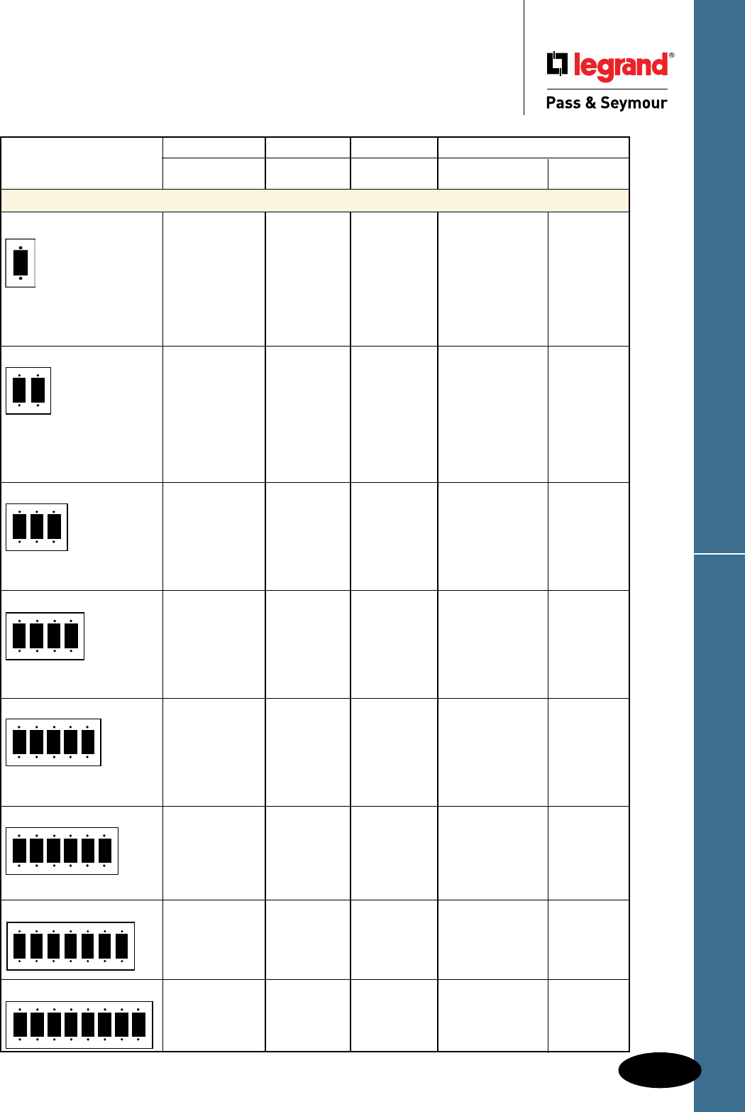
D-85
Decorator Devices Decorator Openings
Decorator Devices
Decorator Openings
Standard Size Plastic & Metal
These products listed to UL514, Cover Plates for Flush-Mounted Wiring Devices, CSA Certified.
Nylon Thermoset Metal
TradeMaster®
Description Color Plates Smooth Material Smooth
Decorator Openings
One Gang Ivory TP26I SP26I
White TP26W SP26W Aluminum SA26
Brown TP26 SP26 Brass SB26
Gray TP26GRY SP26GRY Polished Brass SB26PB
Black TP26BK SP26BK 430S/S SL26
Red TP26RED 302S/S SS26
Light Almond TP26LA SP26LA Brushed Bronze SB26BZ
Blue TP26BL Chrome SB26CH
Orange TP26OR
Two Gang Ivory TP262I SP262I
White TP262W SP262W Aluminum SA262
Brown TP262 SP262 Brass SB262
Gray TP262GRY SP262GRY Polished Brass SB262PB
Black TP262BK SP262BK 430S/S SL262
Red TP262RED 302S/S SS262
Light Almond TP262LA SP262LA
Blue TP262BL
Orange TP262OR
Three Gang Ivory TP263I SP263I
White TP263W SP263W Brass SB263
Brown TP263 Polished Brass SB263PB
Gray TP263GRY SP263GRY
Black TP263BK SP263BK 302S/S SS263
Red TP263RED
Light Almond TP263LA SP263LA
Four Gang Ivory TP264I SP264I
White TP264W SP264W Brass SB264
Brown TP264 SP264 Polished Brass SB264PB
Gray TP264GRY SP264GRY
Black TP264BK SP264BK 302S/S SS264
Red TP264RED
Light Almond TP264LA SP264LA
Five Gang Ivory TP265I SP265I
White TP265W SP265W
Brown TP265 302S/S SS265
Gray TP265GRY SP265GRY
Black TP265BK SP265BK
Red SP265RED
Light Almond TP265LA SP265LA
Six Gang Ivory TP266I SP266I
White TP266W SP266W
Brown TP266 SP266 302S/S SS266
Gray TP266GRY SP266GRY
Black TP266BK SP266BK
Light Almond TP266LA SP266LA
Seven Gang 302S/S SS267
302S/S Painted Ivory SS267I
302S/S Painted White SS267W
Eight Gang 302S/S SS268
302S/S Painted Ivory SS268I
302S/S Painted White SS268W
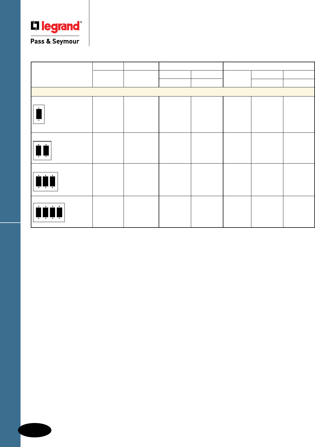
D-86
Decorator Devices
Decorator Devices
Decorator Openings
Junior-Jumbo & Jumbo Plastic & Metal
Decorator Openings
These products listed to UL514, Cover Plates for Flush-Mounted Wiring Devices, CSA Certified.
Nylon Thermoset Metal
TradeMaster® Junior-Jumbo Jumbo Junior-Jumbo Jumbo
Description Color Jumbo Smooth Smooth Material Smooth Smooth
Decorator Openings
One Gang Ivory TPJ26I SPJ26I SPO26I
White TPJ26W SPJ26W SPO26W Brass SBJ26 SBO26
Brown TPJ26 SPJ26 SPO26 302S/S SSJ26 SSO26
Gray TPJ26GRY
Red TPJ26RED
Light Almond TPJ26LA SPJ26LA SPO26LA
Two Gang Ivory TPJ262I SPJ262I SPO262I
White TPJ262W SPJ262W SPO262W 302S/S SSJ262 SSO262
Brown TPJ262 SPJ262 SPO262
Gray TPJ262GRY
Light Almond TPJ262LA SPJ262LA
Three Gang Ivory TPJ263I SPJ263I
White TPJ263W SPJ263W 302S/S SSJ263
Brown TPJ263 SPJ263
Gray TPJ263GRY
Light Almond TPJ263LA SPJ263LA
Four Gang Ivory TPJ264I SPJ264I
White TPJ264W SPJ264W
Brown TPJ264 SPJ264
Gray TPJ264GRY
Light Almond TPJ264LA SPJ264LA

D-87
Notes
Notes

HOSPITAL GRADE DEVICES
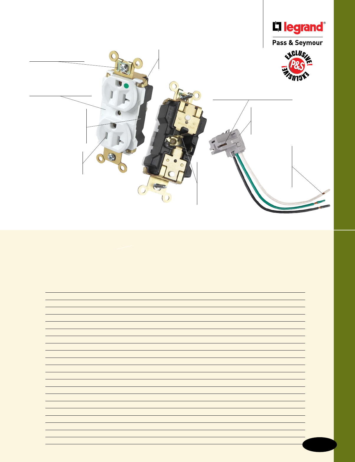
E-1
Hospital Grade Devices
Hospital Grade Devices
Device Rating Page Number
Receptacle Test Requirements E-2
PlugTail™ Extra Heavy-Duty & Tamper-Resistant Receptacles 15 & 20A, 125V E-3, E-4
Extra Heavy-Duty Receptacles 15 & 20A, 125V; 20A, 250V E-5
Extra Heavy-Duty MRI Receptacles 15 & 20A, 125V E-6
Heavy-Duty Receptacles 15 & 20A, 125V; 20A, 250V E-7, E-8
PlugTail™ Specification Grade Receptacles 15 & 20A, 125V E-9
Single Receptacles 15 & 20A, 125V; 20A, 250V E-10
Tamper-Resistant Receptacles 15 & 20A, 125V E-11
Isolated Ground Receptacles 15 & 20A, 125V; 20A, 250V E-12
Tamper-Resistant Isolated Ground Receptacles 15 & 20A, 125V E-13
PlugTail™ Decorator Receptacles 15 & 20A, 125V E-14
Heavy-Duty Decorator Receptacles 15 & 20A, 125V E-15, E-16
GFCI Receptacles 15 & 20A, 125VAC E-17, E-23
Illuminated GFCI Receptacles 20A, 125VAC E-18
Decorator TR Combination Nightlight/GFCI Receptacles 15 & 20A, 125VAC E-19
PlugTail™ GFCI Receptacles 15 & 20A, 125VAC E-20, E-21, E-24
PlugTail™ Tamper-Resistant Nightlight/GFCI Receptacles 15 & 20A, 125VAC E-22
Surge Protective Receptacles 15 & 20A, 125VAC E-25, E-27
PlugTail™ Surge Protective Receptacles 15 & 20A, 125VAC E-26
Straight Blade Plugs & Connectors 15 & 20A, 125 & 250V E-28
Quad Receptacles 20A, 125V E-29
All of our Hospital Grade devices
are designed for optimum durability,
performance, and reliability — to help
make today’s facility maintenance
operations more productive and consistent.
PT8300W
Ultrasonically welded
polycarbonate connector
housing
secures terminations
and conductors in a UL
Listed, finger safe housing.
Large brass contacts
snugly terminate on device blade
terminals. Audible snapping latch
assures connection, allows release.
Strap tabs wrap around and lock
down on face
to prevent strap from
separating from face and back body.
Built-in
connector
features large
brass terminal
blades to ensure
consistent, reliable
electrical connections.
Pre-stripped
connector
leads
fasten
to conductors,
easier than
standard
pigtails.
Auto-ground clip
assures positive ground.
Exclusive patented
feature, circuit label
on face
allows permanent
circuit identification.
.036 inch thick,
brass, triple-wipe
power contacts
for
lasting retention.
No exposed
terminals
create
a finger safe
application before,
during, and after
installation.
Two drive screws
anchor strap
to
back body and face.
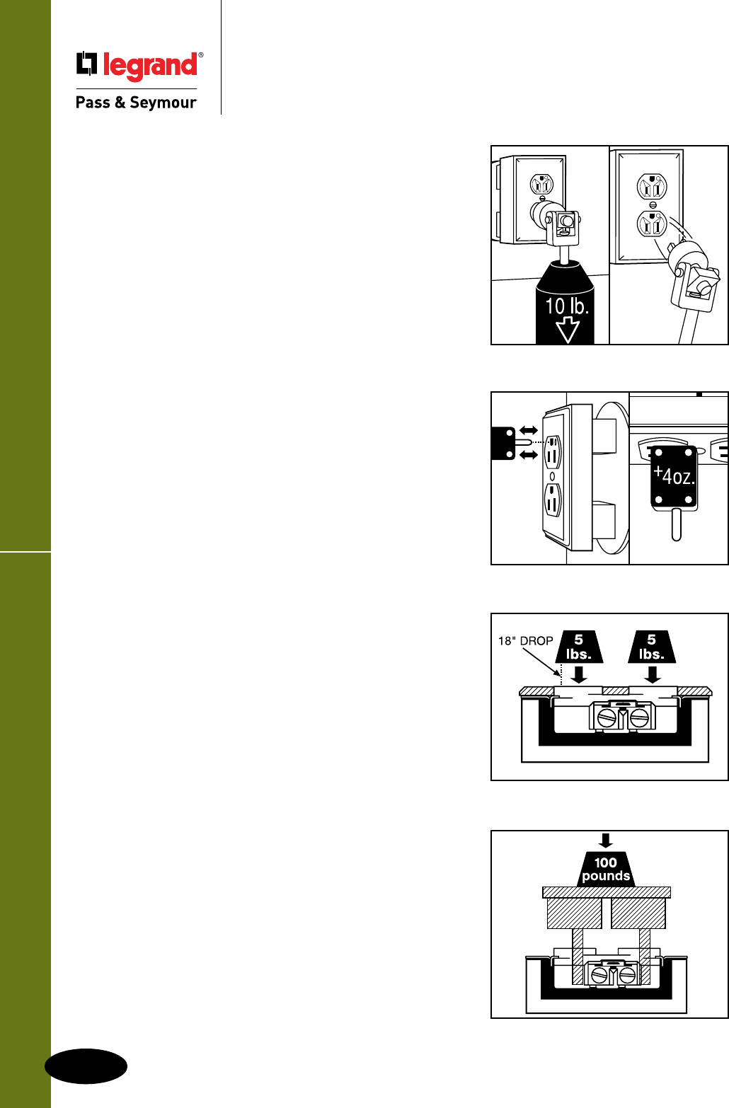
Receptacle Test Requirements
E-2
Hospital Grade Devices
Hospital Grade Devices
Receptacle Test Requirements
All straight blade receptacles must pass a sequence
of tests established in UL498. To earn the “Hospital
Grade” rating a device must pass an additional
series of abuse and performance tests.
Abrupt Plug Removal Test
After ten conditioning insertion and withdrawal cycles
of an attachment plug of matching configuration
and ground pin, each outlet is to hold without any
displace ment a fully inserted test pin for at least one
minute from a face down horizontal position. Then
each receptacle is mounted to represent a typical
installation and go through a series of abrupt removal
tests – the full insertion of a test plug that is removed
by dropping an attached 10-pound weight two feet,
thus exerting excessive force on the receptacle face
and contacts. Each outlet must go through eight cycles
of this test, two in the initial position, then rotated
180 degrees for the next four cycles, then back to
the original position for the final two cycles. Duplex
receptacles are tested by having one outlet with the
ground pin in the 12 o’clock and 6 o’clock positions,
the other in the 3 o’clock and 9 o’clock positions.
After testing, each outlet, while in the face down
horizontal position must hold without displacement
a .184" diameter 4-ounce ground pin for one minute.
The outlet must have no breakage that would interfere
with its function and integrity.
Ground Contact Overstress Test
The receptacle ground contact is conditioned with
twenty cycles of full insertion and withdrawal of a
.204" oversized test pin. Then, with the receptacle
in a horizontal face down position, the same contact
must retain a .184" diameter 4-ounce test pin for at
least one minute without any displacement.
Impact Test
Receptacles mounted in a cast metal box are placed
on a steel plate facing upward. A 5-pound weight
is dropped from 18" above the device impacting at
the center of the outlet. The device must withstand
the impact without having any breakage that hinders
its function.
Assembly Security Test
A device, supported at its mounting screws, must
with stand 100 pounds through the slots in the
receptacle face without cracking the device back
body or deforming the yoke.
Abrupt Plug Removal Test
Ground Contact Overstress Test
Impact Test
Assembly Security Test
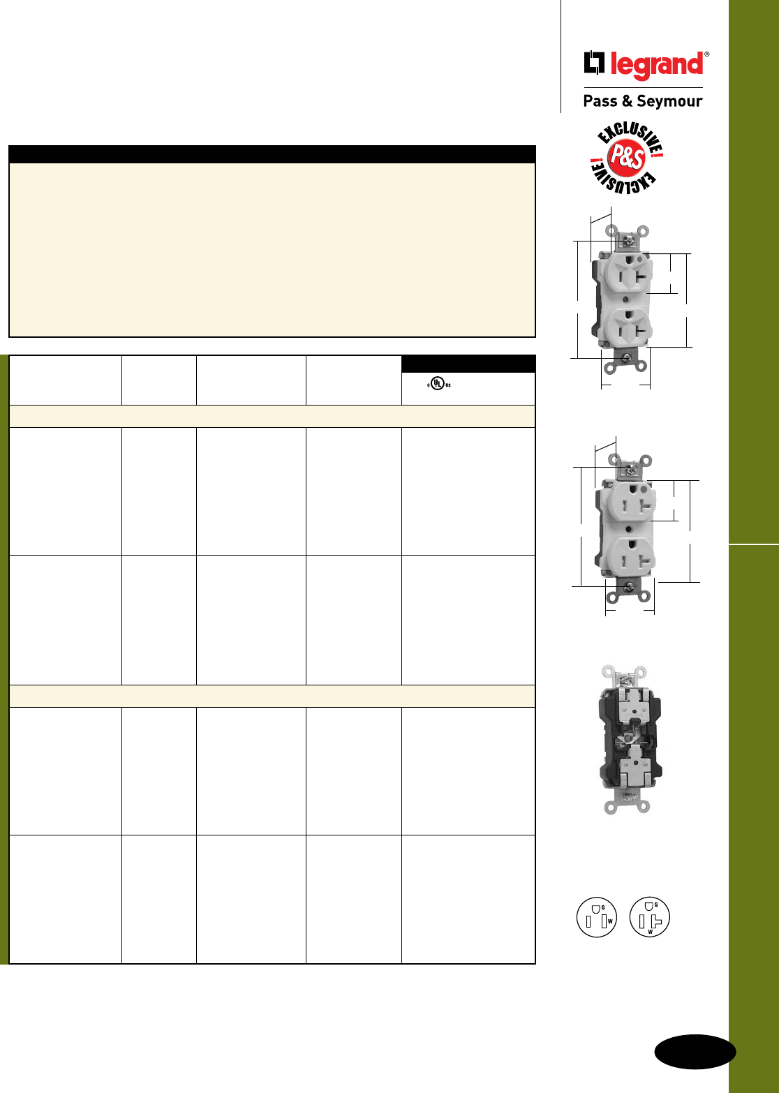
E-3
PlugTail™ Extra Heavy-Duty ReceptaclesHospital Grade Devices
Hospital Grade Devices
PlugTail™ Extra Heavy-Duty Receptacles
& Tamper-Resistant Receptacles
15 & 20A, 125V
All devices listed on this page conform to NEMA WD-1 and WD-6.
For PlugTail Connectors, see Page E-14.
For Bulk Packaging Solutions consult factory.
Features
n Exclusive patented feature, circuit label on face
allows permanent circuit identification.
n .036 inch thick, brass, triple-wipe power contacts for
lasting retention.
n Strap tabs wrap around and lock down on face to
prevent strap from separating from face and back body.
n No exposed terminals create a finger safe application
before, during, and after installation.
n Built-in connector features large brass terminal blades
to ensure consistent, reliable electrical connections.
n Crimped and welded contacts.
n Ultrasonically welded polycarbonate
connector housing secures terminations
and conductors in a UL Listed, finger safe
housing.
n Large brass contacts snugly terminate on
device blade terminals.
n Pre-stripped connector leads fasten to
conductors, easier than standard pigtails.
n Auto-ground clip assures positive ground.
n
Tamper-resistant version features dual
mechanical shutter system to help prevent
insertion of foreign objects.
PTTR63HW
.866"
3.281"
1.625"
1.104"
2.750"
PT8300W
.866"
3.281"
1.625"
1.104"
2.750"
Rating NEMA
Catalog Number A. V. Color Cong. No.
Duplex Receptacles
PT8200I 15 125 Ivory 5-15R • •
PT8200W 15 125 White 5-15R • •
PT8200 15 125 Brown 5-15R • •
PT8200GRY 15 125 Gray 5-15R • •
PT8200BK 15 125 Black 5-15R • •
PT8200RED 15 125 Red 5-15R • •
PT8200LA 15 125 Light Almond 5-15R • •
PT8200BL 15 125 Blue 5-15R • •
PT8300I 20 125 Ivory 5-20R • •
PT8300W 20 125 White 5-20R • •
PT8300 20 125 Brown 5-20R • •
PT8300GRY 20 125 Gray 5-20R • •
PT8300BK 20 125 Black 5-20R • •
PT8300RED 20 125 Red 5-20R • •
PT8300LA 20 125 Light Almond 5-20R • •
PT8300BL 20 125 Blue 5-20R • •
Tamper-Resistant Duplex Receptacles
PTTR62HI 15 125 Ivory 5-15R • •
PTTR62HW 15 125 White 5-15R • •
PTTR62H 15 125 Brown 5-15R • •
PTTR62HGRY 15 125 Gray 5-15R • •
PTTR62HBK 15 125 Black 5-15R • •
PTTR62HRED 15 125 Red 5-15R • •
PTTR62HLA 15 125 Light Almond 5-15R • •
PTTR62HBL 15 125 Blue 5-15R • •
PTTR63HI 20 125 Ivory 5-20R • •
PTTR63HW 20 125 White 5-20R • •
PTTR63H 20 125 Brown 5-20R • •
PTTR63HGRY 20 125 Gray 5-20R • •
PTTR63HBK 20 125 Black 5-20R • •
PTTR63HRED 20 125 Red 5-20R • •
PTTR63HLA 20 125 Light Almond 5-20R • •
PTTR63HBL 20 125 Blue 5-20R • •
3rd Party Compliance
FSUL
UL498 WC596
NEMA
5-15R
NEMA
5-20R
2 Pole, 3 Wire
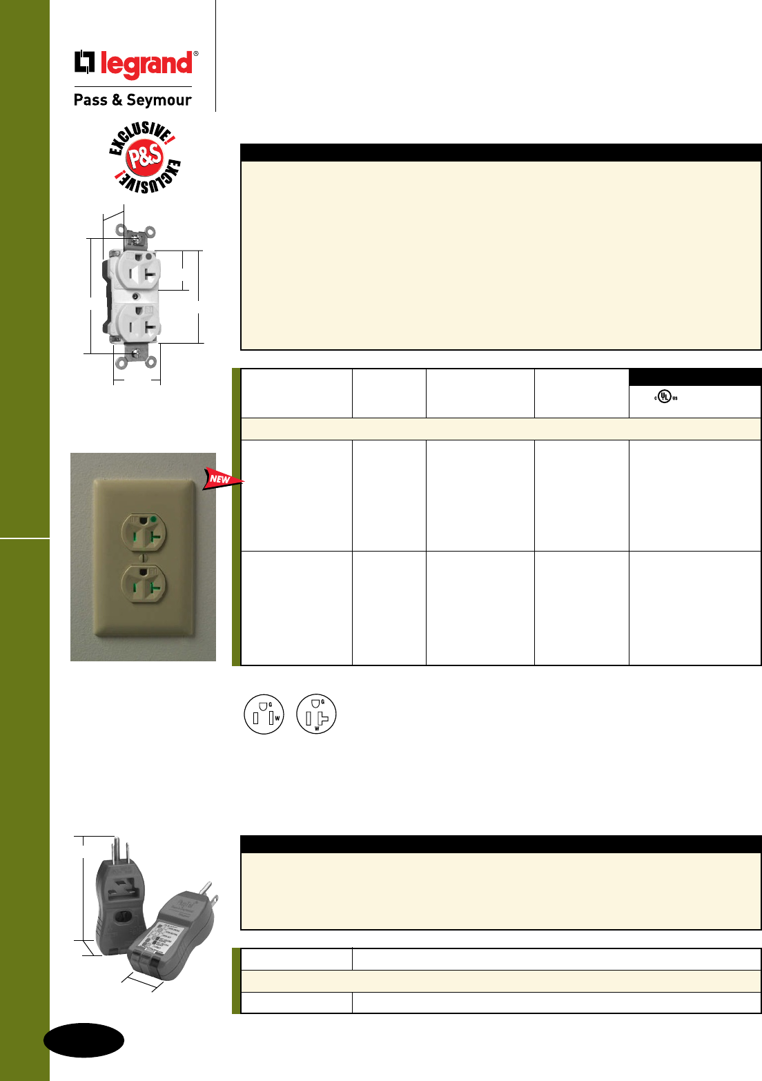
PlugTail™ Extra Heavy-Duty Receptacles
E-4
Hospital Grade Devices
All devices listed on this page conform to NEMA WD-1 and WD-6.
Hospital Grade Devices
PlugTail™ Extra Heavy-Duty
Illuminated Receptacles
15 & 20A, 125V
3.93"
1.06"
1.68"
PTTESTER
Illuminated face indicates
power to receptacle and
makes it easy to identify
receptacle in dark
applications.
For PlugTail Connectors, see Page E-14.
For Bulk Packaging Solutions consult factory.
Features
n Molded-in “IL” markings on face of product.
n Illuminated face indicates power to receptacle and
makes it easy to identify receptacle in dark applications.
n Exclusive patented feature, circuit label on face
allows permanent circuit identification.
n .036 inch thick, brass, triple-wipe power contacts for
lasting retention.
n Strap tabs wrap around and lock down on face to
prevent strap from separating from face and back body.
n No exposed terminals create a finger safe application
before, during, and after installation.
n Built-in connector features large brass terminal blades
to ensure consistent, reliable electrical connections.
n Crimped and welded contacts.
n Ultrasonically welded polycarbonate
connector housing secures terminations
and conductors in a UL Listed, finger safe
housing.
n Large brass contacts snugly terminate on
device blade terminals.
n Pre-stripped connector leads fasten to
conductors, easier than standard pigtails.
n Auto-ground clip assures positive ground.
Rating NEMA
Catalog Number A. V. Color Cong. No.
Illuminated Duplex Receptacles
PT8200ILI 15 125 Ivory 5-15R • •
PT8200ILW 15 125 White 5-15R • •
PT8200IL 15 125 Brown 5-15R • •
PT8200ILGRY 15 125 Gray 5-15R • •
PT8200ILBK 15 125 Black 5-15R • •
PT8200ILRED 15 125 Red 5-15R • •
PT8200ILLA 15 125 Light Almond 5-15R • •
PT8300ILI 20 125 Ivory 5-20R • •
PT8300ILW 20 125 White 5-20R • •
PT8300IL 20 125 Brown 5-20R • •
PT8300ILGRY 20 125 Gray 5-20R • •
PT8300ILBK 20 125 Black 5-20R • •
PT8300ILRED 20 125 Red 5-20R • •
PT8300ILLA 20 125 Light Almond 5-20R • •
3rd Party Compliance
FSUL
UL498 WC596
Features
n Ensures proper connections and power presence at
both rough-in and device-out stages during P&S
PlugTail Device installation.
n Fast, easy identification of circuit connections.
n Easy-to-see indicator lights.
n Sturdy construction for long-term
dependability.
n Helps prevent call backs.
n Ensures proper wiring.
Catalog Number Description
P&S PlugTail™ Tester
PTTESTER Red PlugTail Tester for Receptacles and Tails
PT8300ILLA
.866"
3.281"
1.625"
1.104"
2.750"
NEMA
5-15R
NEMA
5-20R
2 Pole, 3 Wire
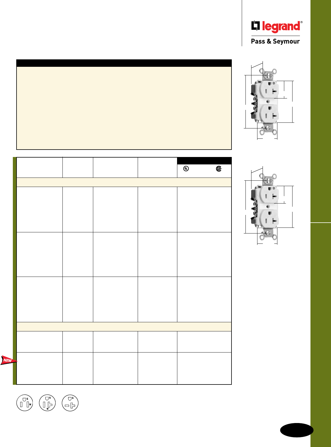
E-5
Extra Heavy-Duty ReceptaclesHospital Grade Devices
All devices listed on this page conform to NEMA WD-1 and WD-6.
Hospital Grade Devices
Extra Heavy-Duty Receptacles
15 & 20A, 125V; 20A, 250V
NEMA
5-15R
NEMA
5-20R
NEMA
6-20R For Bulk Packaging Solutions consult factory.
2 Pole, 3 Wire
Rating NEMA
Catalog Number A. V. Color Cong. No.
Duplex Receptacles Back & Side Wire
8200I 15 125 Ivory 5-15R • • •
8200W 15 125 White 5-15R • • •
8200 15 125 Brown 5-15R • • •
8200GRY 15 125 Gray 5-15R • • •
8200BK 15 125 Black 5-15R • • •
8200RED 15 125 Red 5-15R • • •
8200LA 15 125 Light Almond 5-15R • • •
8300I 20 125 Ivory 5-20R • • •
8300W 20 125 White 5-20R • • •
8300 20 125 Brown 5-20R • • •
8300GRY 20 125 Gray 5-20R • • •
8300BK 20 125 Black 5-20R • • •
8300RED 20 125 Red 5-20R • • •
8300LA 20 125 Light Almond 5-20R • • •
8800I 20 250 Ivory 6-20R • • •
8800W 20 250 White 6-20R • • •
8800 20 250 Brown 6-20R • • •
8800GRY 20 250 Gray 6-20R • • •
8800BK 20 250 Black 6-20R • • •
8800LA 20 250 Light Almond 6-20R • • •
8800RED 20 250 Red 6-20R • • •
LED Illuminated Face Duplex Receptacles Back & Side Wire
8200ILI 15 125 Ivory 5-15R • • •
8200ILW 15 125 White 5-15R • • •
8200ILRED 15 125 Red 5-15R • • •
8300ILI 20 125 Ivory 5-20R • • •
8300ILW 20 125 White 5-20R • • •
8300ILGRY 20 125 Gray 5-20R • • •
8300ILRED 20 125 Red 5-20R • • •
8300ILLA 20 125 Light Almond 5-20R • • •
3rd Party Compliance
FSUL
UL498 WC596 C22.2 No. 42
Features
n One-piece nickel-plated brass mounting strap with
integral ground.
n Strap tabs wrap around and lock down on face to
prevent strap from separating from face and back body.
n Two drive screws anchor strap to back body and face.
n Exclusive patented feature, circuit label on face
allows permanent circuit identification.
n .040 inch thick, nickel-plated brass, triple-wipe power
contacts for lasting retention.
n Easily accessed break-off, line-contact connecting
tab for fast, easy split-circuit wiring.
n Impact-resistant nylon face and back body.
n Oversized #10 deep tri-drive head brass terminal and
ground screws.
n Exclusive patented feature, external screw-
pressure-plate back wire clamp on ground
terminal for faster, easier installation.
n External nickel-plated screw-pressure-plate
back wire clamps with #10 brass terminal
screws for visual assurance of a good
connection.
n Line terminals accept #14 – #10 AWG
stranded or solid copper clad conductors.
n Auto-ground clip assures positive ground.
n
Illuminated version features exclusive
LED lamp with solder connection for long
durable life (10-12 years).
8300I
.900"
3.281"
1.625"
1.104"
2.750"
8300ILI
.900"
3.281"
1.625"
1.104"
2.750"
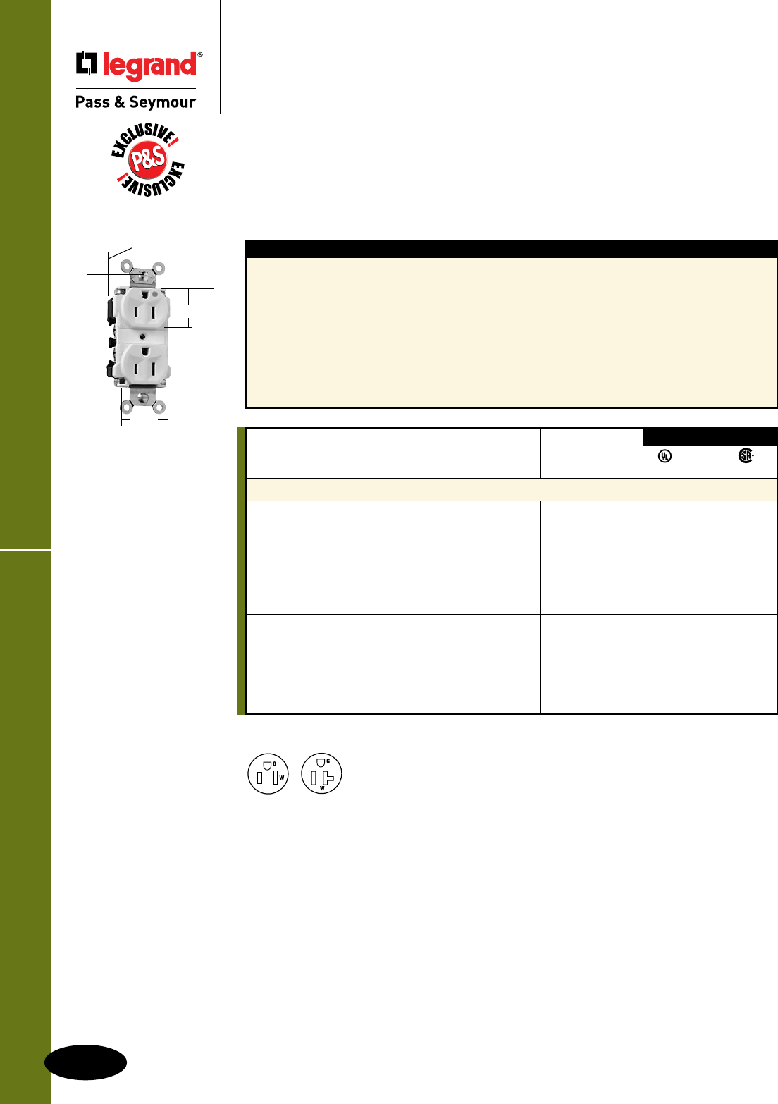
Extra Heavy-Duty MRI Receptacles
E-6
Hospital Grade Devices
All devices listed on this page conform to NEMA WD-1 and WD-6.
Hospital Grade Devices
Extra Heavy-Duty MRI Receptacles
15 & 20A, 125V
Rating NEMA
Catalog Number A. V. Color Cong. No.
Duplex Receptacles Back & Side Wire
8200IMRI 15 125 Ivory 5-15R • • •
8200WMRI 15 125 White 5-15R • • •
8200MRI 15 125 Brown 5-15R • • •
8200GRYMRI 15 125 Gray 5-15R • • •
8200BKMRI 15 125 Black 5-15R • • •
8200REDMRI 15 125 Red 5-15R • • •
8200LAMRI 15 125 Light Almond 5-15R • • •
8300IMRI 20 125 Ivory 5-20R • • •
8300WMRI 20 125 White 5-20R • • •
8300GRYMRI 20 125 Gray 5-20R • • •
8300BKMRI 20 125 Black 5-20R • • •
8300REDMRI 20 125 Red 5-20R • • •
8300LAMRI 20 125 Light Almond 5-20R • • •
3rd Party Compliance
FSUL
UL498 WC596 C22.2 No. 42
Features
n Exclusive patented feature, circuit label on face
allows permanent circuit identification.
n Extra heavy-duty, one-piece nickel-plated brass
mounting strap with integral ground for superior
structural integrity and long-term performance.
n .036 inch thick, brass, triple-wipe power contacts
for lasting retention.
n Strap tabs wrap around and lock down on face
to prevent strap from separating from face and
back body.
n Easily accessed break-off, line-contact
connecting tab for fast, easy split-circuit
wiring.
n Exclusive patented feature, external screw-
pressure-plate back wire clamp on ground
terminal for faster, easier installation.
n External screw-pressure-plate back wire
clamps with #10 brass terminal screws for
visual assurance of a good connection.
n Auto-ground clip assures positive ground.
8200LAMRI
.900"
3.281"
1.625"
1.104"
2.750"
Receptacles designed expressly for MRI applications –
We build these
exclusive P&S receptacles with no ferrous metal, so they are perfect for high-magnetic-field
environments such as magnetic-resonance imaging (MRI) suites. With the same basic design
as our standard Extra Heavy-Duty Receptacles, they are extremely durable.
NEMA
5-15R
NEMA
5-20R
2 Pole, 3 Wire
For Bulk Packaging Solutions consult factory.

E-7
Heavy-Duty Receptacles Hospital Grade Devices
All devices listed on this page conform to NEMA WD-1 and WD-6.
Hospital Grade Devices
Heavy-Duty Receptacles
15 & 20A, 125V
PS8200HI
.780"
3.281"
1.322"
1.104"
2.635"
PS8300HSLA
.780"
3.281"
1.322"
1.104"
2.635"
Features
n Heavy-duty, brass strap for added strength and
ground conductivity.
n .032 inch thick, brass, triple-wipe power contacts
for lasting retention.
n Strap tabs wrap around face to prevent strap
from separating from face and back body.
n Easily accessed break-off, line-contact connecting
tab for fast, easy split-circuit wiring.
n Two drive screws anchor strap to back
body and face.
n Tri-drive brass terminal screws. Internal
screw-pressure-plate back and side wire
capability. Two back wire holes for more
wiring flexibility.
n Auto-ground clip assures positive ground.
n
Smooth face version features an impact-
resistant nylon face for ease of cleaning
and less dirt build-up.
Rating NEMA
Catalog Number A. V. Color Cong. No.
Duplex Receptacles Back & Side Wire
PS8200HI 15 125 Ivory 5-15R • • •
PS8200HW 15 125 White 5-15R • • •
PS8200H 15 125 Brown 5-15R • • •
PS8200HGRY 15 125 Gray 5-15R • • •
PS8200HRED 15 125 Red 5-15R • • •
PS8200HLA 15 125 Light Almond 5-15R • • •
PS8300HI 20 125 Ivory 5-20R • • •
PS8300HW 20 125 White 5-20R • • •
PS8300H 20 125 Brown 5-20R • • •
PS8300HGRY 20 125 Gray 5-20R • • •
PS8300HRED 20 125 Red 5-20R • • •
PS8300HLA 20 125 Light Almond 5-20R • • •
Duplex Receptacles – Smooth Face Back & Side Wire
PS8200HSI 15 125 Ivory 5-15R • • •
PS8200HSW 15 125 White 5-15R • • •
PS8200HS 15 125 Brown 5-15R • • •
PS8200HSGRY 15 125 Gray 5-15R • • •
PS8200HSRED 15 125 Red 5-15R • • •
PS8200HSLA 15 125 Light Almond 5-15R • • •
PS8300HSI 20 125 Ivory 5-20R • • •
PS8300HSW 20 125 White 5-20R • • •
PS8300HS 20 125 Brown 5-20R • • •
PS8300HSGRY 20 125 Gray 5-20R • • •
PS8300HSRED 20 125 Red 5-20R • • •
PS8300HSLA 20 125 Light Almond 5-20R • • •
3rd Party Compliance
FSUL
UL498 WC596 C22.2 No. 42
For Bulk Packaging Solutions consult factory.
NEMA
5-15R
NEMA
5-20R
2 Pole, 3 Wire
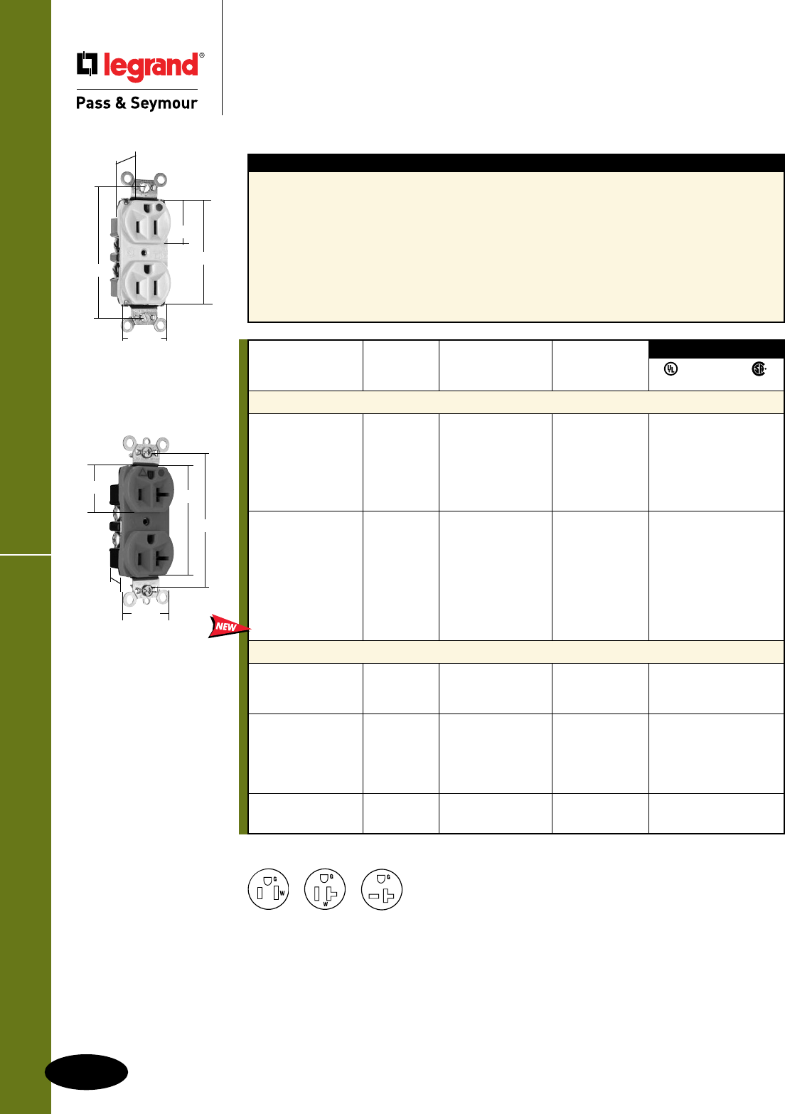
Heavy-Duty Receptacles
E-8
Hospital Grade Devices
All devices listed on this page conform to NEMA WD-1 and WD-6.
Hospital Grade Devices
Heavy-Duty Compact Design Receptacles
15 & 20A, 125V; 20A, 250V
Features
n Impact-resistant nylon face.
n One-piece heat-treated triple-wipe brass
power contacts.
n Easily accessible break-off line contact connecting
tab for split circuit wiring.
n Terminal compartments isolated from each
other for positive conductor containment.
n Corrosion-resistant, zinc-plated steel strap
is locked in.
n Internal screw-pressure-plate back wire and
side wire line terminals accept #14 – #10
AWG copper or copper-clad conductors.
n High strength thermoplastic back body.
n Back wire holes allow entry of conductor
insulation partially into body but not into
wiring compartment.
n Auto-ground clip assures positive ground.
n Compact design for easy installation.
n Tri-drive terminal and mounting screws.
Rating NEMA
Catalog Number A. V. Color Cong. No.
Duplex Receptacles – Compact Design Back & Side Wire
8200HI 15 125 Ivory 5-15R • • •
8200HW 15 125 White 5-15R • • •
8200H 15 125 Brown 5-15R • • •
8200HGRY 15 125 Gray 5-15R • • •
8200HRED 15 125 Red 5-15R • • •
8200HLA 15 125 Light Almond 5-15R • • •
8300HI 20 125 Ivory 5-20R • • •
8300HW 20 125 White 5-20R • • •
8300H 20 125 Brown 5-20R • • •
8300HGRY 20 125 Gray 5-20R • • •
8300HBK 20 125 Black 5-20R • • •
8300HRED 20 125 Red 5-20R • • •
8300HLA 20 125 Light Almond 5-20R • • •
8300HBL 20 125 Blue 5-20R • • •
Isolated Ground Duplex Receptacles Back & Side Wire
IG8200I 15 125 Ivory 5-15R • • •
IG8200 15 125 Orange 5-15R • • •
IG8200RED 15 125 Red 5-15R • • •
IG8300I 20 125 Ivory 5-20R • • •
IG8300W 20 125 White 5-20R • • •
IG8300 20 125 Orange 5-20R • • •
IG8300RED 20 125 Red 5-20R • • •
IG8300LA 20 125 Light Almond 5-20R • • •
IG8800 20 250 Orange 6-20R • • •
IG8800LA 20 250 Light Almond 6-20R • • •
3rd Party Compliance
FSUL
UL498 WC596 C22.2 No. 42
NEMA
5-15R
NEMA
5-20R
NEMA
6-20R
2 Pole, 3 Wire
IG8300
1.322"
1.104" 2.635"
3.281"
.922"
8200HI
.780"
3.281"
1.322"
1.104"
2.635"
For Bulk Packaging Solutions consult factory.
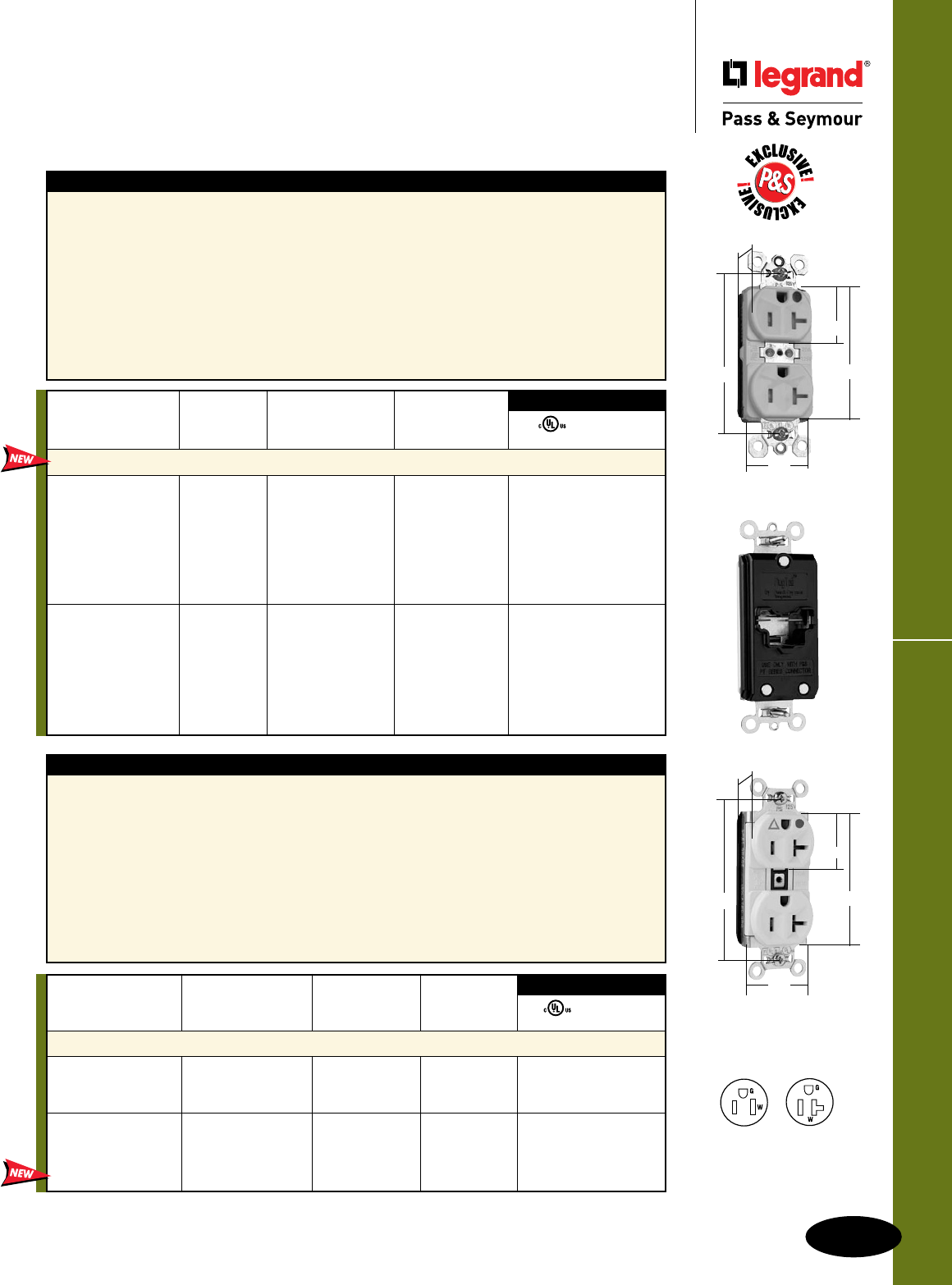
E-9
Hospital Grade Devices
All devices listed on this page conform to NEMA WD-1 and WD-6.
2.750"
3.281"
.625"
1.5"
1.104"
PlugTail™ Specification Grade Receptacles
Hospital Grade Devices
PlugTail™ Specification Grade Receptacles
15 & 20A, 125V
PTIG8300LA
NEMA
5-15R
NEMA
5-20R
2 Pole, 3 Wire
FSUL
UL498 WC596
NEMA
Rating Cong.
Catalog Number A. V. Color No.
Isolated Ground Duplex Receptacles
PTIG8200I 15 125 Ivory 5-15R • •
PTIG8200 15 125 Orange 5-15R • •
PTIG8200RED 15 125 R ed 5-15R • •
PTIG8300I 20 125 Ivory 5-20R • •
PTIG8300 20 125 Orange 5-20R • •
PTIG8300RED 20 125 Red 5-20R • •
PTIG8300LA 20 125 Light Almond 5-20R • •
3rd Party Compliance
Features
n .036 inch thick, brass, triple-wipe power contacts for
lasting retention.
n Plated steel wrap strap design for maximum durability
and corrosion resistance.
n No exposed terminals create a finger safe application
before, during, and after installation.
n Built-in connector features large brass terminal blades
to ensure consistent, reliable electrical connections.
n Ultrasonically welded polycarbonate connector housing
secures terminations and conductors in a UL Listed,
finger safe housing.
n Crimped and welded contacts.
n Large brass contacts snugly terminate on
device blade terminals.
n Pre-stripped connector leads fasten to
conductors, easier than standard pigtails.
n Auto-ground clip assures positive ground.
n Features a plastic barrier that isolates
grounding terminal from mounting strap
and metal boxes.
For PlugTail Connectors,
see Page E-14.
Features
n
Dual mechanical shutter system to help prevent
insertion of foreign objects.
n .036 inch thick, brass, triple-wipe power contacts for
lasting retention.
n Plated steel wrap strap design for maximum durability
and corrosion resistance.
n No exposed terminals create a finger safe application
before, during, and after installation.
n Built-in connector features large brass terminal blades
to ensure consistent, reliable electrical connections.
n Crimped and welded contacts.
n Ultrasonically welded polycarbonate
connector housing secures terminations
and conductors in a UL Listed, finger safe
housing.
n Large brass contacts snugly terminate on
device blade terminals.
n Pre-stripped connector leads fasten to
conductors, easier than standard pigtails.
n Auto-ground clip assures positive ground.
Rating NEMA
Catalog Number A. V. Color Cong. No.
Tamper-Resistant Duplex Receptacles
PTTR8200I 15 125 Ivory 5-15R • •
PTTR8200W 15 125 White 5-15R • •
PTTR8200 15 125 Brown 5-15R • •
PTTR8200GRY 15 125 Gray 5-15R • •
PTTR8200BK 15 125 Black 5-15R • •
PTTR8200RED 15 125 Red 5-15R • •
PTTR8200LA 15 125 Light Almond 5-15R • •
PTTR8300I 20 125 Ivory 5-20R • •
PTTR8300W 20 125 White 5-20R • •
PTTR8300 20 125 Brown 5-20R • •
PTTR8300GRY 20 125 Gray 5-20R • •
PTTR8300BK 20 125 Black 5-20R • •
PTTR8300RED 20 125 Red 5-20R • •
PTTR8300LA 20 125 Light Almond 5-20R • •
3rd Party Compliance
FSUL
UL498 WC596
PTTR8300W
2.750"
3.281"
.625"
1.5"
1.104"
For Bulk Packaging Solutions consult factory.
PTTR8300W
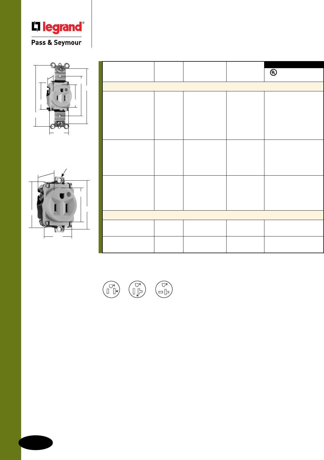
All devices listed on this page conform to NEMA WD-1 and WD-6.
Hospital Grade Devices
Single Receptacles
15 & 20A, 125V; 20A, 250V
Single Receptacles Hospital Grade Devices
E-10
NEMA
5-15R
NEMA
5-20R
NEMA
6-20R
8201I
1.093"
1.38"
2.37"
3.28"
3.68"
1.68"
1.32"
8284I
1.018"
8-32 Thd.
1.937"
1.38"
1.68"
1.32"
2 Pole, 3 Wire
For Hospital Use Power Interrupting Device consult Turnlok® Section H.
Rating NEMA
Catalog Number A. V. Color Cong. No.
Single Receptacles Back & Side Wire
8201I 15 125 Ivory 5-15R • • •
8201W 15 125 White 5-15R • • •
8201 15 125 Brown 5-15R • • •
8201GRY 15 125 Gray 5-15R • • •
8201BK 15 125 Black 5-15R • • •
8201RED 15 125 Red 5-15R • • •
8201LA 15 125 Light Almond 5-15R • • •
8301I 20 125 Ivory 5-20R • • •
8301W 20 125 White 5-20R • • •
8301 20 125 Brown 5-20R • • •
8301GRY 20 125 Gray 5-20R • • •
8301RED 20 125 Red 5-20R • • •
8801I 20 250 Ivory 6-20R • • •
8801W 20 250 White 6-20R • • •
8801 20 250 Brown 6-20R • • •
8801GRY 20 250 Gray 6-20R • • •
8801RED 20 250 Red 6-20R • • •
Short Strap Single Receptacles 1.937" Screw Spacing, Back & Side Wire
8284I 15 125 Ivory 5-15R • • •
8284 15 125 Brown 5-15R • • •
8384I 20 125 Ivory 5-20R • •
8384 20 125 Brown 5-20R • •
3rd Party Compliance
FSUL
UL498 WC596 cUL/CSA
For Bulk Packaging Solutions consult factory.
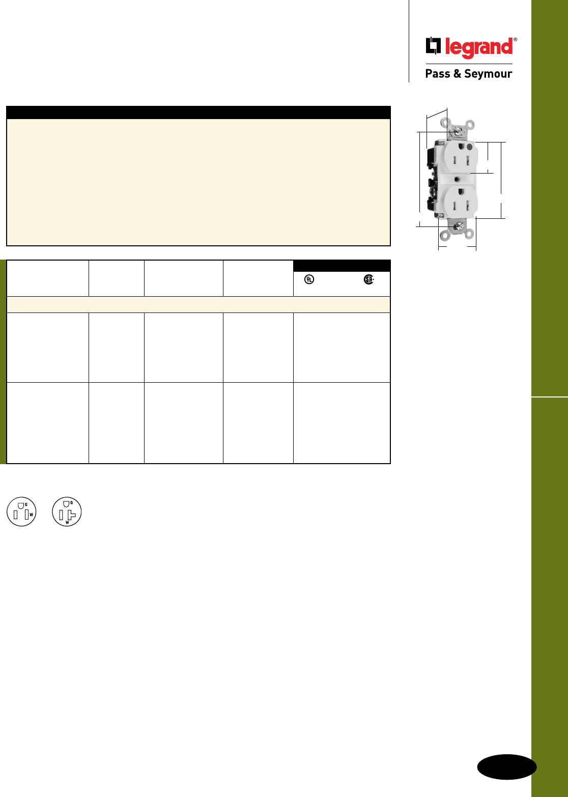
E-11
Tamper-Resistant ReceptaclesHospital Grade Devices
All devices listed on this page conform to NEMA WD-1 and WD-6.
Hospital Grade Devices
Tamper-Resistant Receptacles
15 & 20A, 125V
TR62HI
.900"
1.625"
1.104"
2.750"
3.281"
NEMA
5-15R
NEMA
5-20R
Features
n Thermoplastic dual mechanism shutter system to
help prevent insertion of foreign objects.
n Exclusive patented feature, circuit label on face
allows permanent circuit identification.
n Extra heavy-duty brass, one-piece mounting strap
with integral ground.
n One-piece, nickel-plated brass, triple-wipe power
contacts for lasting retention.
n Strap tabs wrap around and lock down on face
to prevent strap from separating from face and
back body.
n Impact-resistant nylon face and back body.
n Easily accessed break-off, line-contact
connecting tab for fast, easy split-circuit
wiring.
n Two drive screws anchor strap to back
body and face.
n Exclusive patented feature, external screw-
pressure-plate back wire clamp on ground
terminal for faster, easier installation.
n External screw-pressure-plate back wire
clamps with #10 brass terminal screws for
visual assurance of a good connection.
n Auto-ground clip assures positive ground.
Rating NEMA
Catalog Number A. V. Color Cong. No.
Duplex Receptacles Back & Side Wire
TR62HI 15 125 Ivory 5-15R • • •
TR62HW 15 125 White 5-15R • • •
TR62H 15 125 Brown 5-15R • • •
TR62HGRY 15 125 Gray 5-15R • • •
TR62HRED 15 125 Red 5-15R • • •
TR62HLA 15 125 Light Almond 5-15R • • •
TR63HI 20 125 Ivory 5-20R • • •
TR63HW 20 125 White 5-20R • • •
TR63H 20 125 Brown 5-20R • • •
TR63HGRY 20 125 Gray 5-20R • • •
TR63HRED 20 125 Red 5-20R • • •
TR63HLA 20 125 Light Almond 5-20R • • •
TR63HBL 20 125 Blue 5-20R • • •
3rd Party Compliance
FSUL
UL498 WC596 C22.2 No. 42
For PlugTail™ Tamper-Resistant Receptacles, see Page E-3.
2 Pole, 3 Wire
For Bulk Packaging Solutions consult factory.
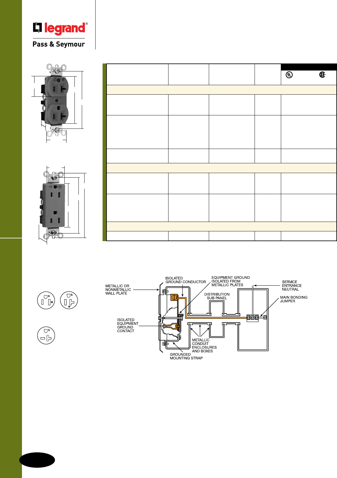
E-12
Hospital Grade Devices
All devices listed on this page conform to NEMA WD-1 and WD-6.
Isolated Ground Receptacles
Hospital Grade Devices
Isolated Ground Receptacles
15 & 20A, 125; 20A, 250V
IG8300
1.322"
1.104" 2.635"
3.281"
.922"
For Wall Plates for Isolated Ground Systems, consult Wall Plates Section Q.
For Bulk Packaging Solutions consult factory.
NEMA
Rating Cong.
Catalog Number A. V. Color No.
Duplex Receptacles Back & Side Wire
IG8200I 15 125 Ivory 5-15R • • •
IG8200 15 125 Orange 5-15R • • •
IG8200RED 15 125 Red 5-15R • • •
IG8300I 20 125 Ivory 5-20R • • •
IG8300W 20 125 White 5-20R • • •
IG8300 20 125 Orange 5-20R • • •
IG8300RED 20 125 Red 5-20R • •
IG8300LA 20 125 Light Almond 5-20R • • •
IG8800 20 250 Orange 6-20R • • •
IG8800LA 20 250 Light Almond 6-20R • • •
Decorator Duplex Receptacles Back & Side Wire
IG26262HGW 15 125 White 5-15R • • •
IG26262HG 15 125 Orange 5-15R • • •
IG26262HGRED 15 125 Red 5-15R • • •
IG26362HGW 20 125 White 5-20R • • •
IG26362HG 20 125 Orange 5-20R • • •
IG26362HGBK 20 125 Black 5-20R • • •
IG26362HGRED 20 125 Red 5-20R • • •
Single Receptacles Back & Side Wire
IG8301 20 125 Orange 5-20R • • •
FSUL
UL498 WC596 C22.2 No. 42
3rd Party Compliance
NEMA
5-15R
NEMA
6-20R
NEMA
5-20R
2 Pole, 3 Wire
IG26262HG
2.635"
3.281"
1.322"
3.813"
.833"
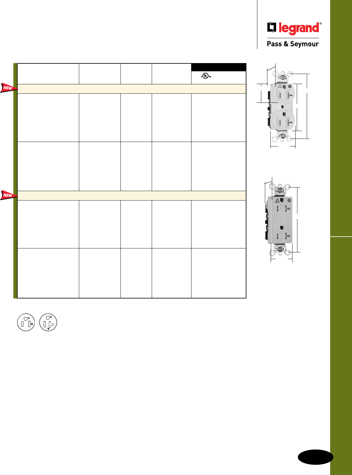
E-13
Hospital Grade Devices
All devices listed on this page conform to NEMA WD-1 and WD-6.
Tamper-Resistant Isolated Ground Receptacles
Hospital Grade Devices
Tamper-Resistant Isolated Ground
Receptacles
15 & 20A, 125V
TRIG8300W
1.187"
1.25"
1.125"
2.625"
3.625"
For Bulk Packaging Solutions consult factory.
FSUL
UL498 WC596
3rd Party Compliance
NEMA
Rating Cong.
Catalog Number A. V. No. Color
Tamper-Resistant Duplex Receptacles Back & Side Wire
TRIG8200I 15 125 5-15R Ivory • •
TRIG8200W 15 125 5-15R White • •
TRIG8200 15 125 5-15R Orange • •
TRIG8200BK 15 125 5-15R Black • •
TRIG8200GRY 15 125 5-15R Gray • •
TRIG8200RED 15 125 5-15R Red • •
TRIG8200LA 15 125 5-15R Light Almond • •
TRIG8300I 20 125 5-20R Ivory • •
TRIG8300W 20 125 5-20R White • •
TRIG8300 20 125 5-20R Orange • •
TRIG8300BK 20 125 5-20R Black • •
TRIG8300GRY 20 125 5-20R Gray • •
TRIG8300RED 20 125 5-20R Red • •
TRIG8300LA 20 125 5-20R Light Almond • •
Tamper-Resistant Decorator Receptacles Back & Side Wire
TRIG26262HGI 15 125 5-15R Ivory • •
TRIG26262HGW 15 125 5-15R White • •
TRIG26262HG 15 125 5-15R Orange • •
TRIG26262HGBK 15 125 5-15R Black • •
TRIG26262HGGRY 15 125 5-15R Gray • •
TRIG26262HGRED 15 125 5-15R Red • •
TRIG26262HGLA 15 125 5-15R Light Almond • •
TRIG26362HGI 20 125 5-20R Ivory • •
TRIG26362HGW 20 125 5-20R White • •
TRIG26362HG 20 125 5-20R Orange • •
TRIG26362HGBK 20 125 5-20R Black • •
TRIG26362HGGRY 20 125 5-20R Gray • •
TRIG26362HGRED 20 125 5-20R Red • •
TRIG26362HGLA 20 125 5-20R Light Almond • •
NEMA
5-15R
NEMA
5-20R
2 Pole, 3 Wire
TRIG26362HG
1.187"
1.25"
3.625"

PlugTail™ Decorator Receptacles
E-14
Hospital Grade Devices
All devices listed on this page conform to NEMA WD-1 and WD-6.
Hospital Grade Devices
PlugTail™ Decorator Receptacles
15 & 20A, 125V
Features
n .036 inch thick, brass, triple-wipe power contacts for
lasting retention.
n Plated steel wrap strap design for maximum durability
and corrosion resistance.
n No exposed terminals create a finger safe application
before, during, and after installation.
n Built-in connector features large brass terminal blades
to ensure consistent, reliable electrical connections.
n Crimped and welded contacts.
n Ultrasonically welded polycarbonate connector
housing secures terminations and conductors
in a UL Listed, finger safe housing.
n Large brass contacts snugly terminate on
device blade terminals.
n Pre-stripped connector leads fasten to
conductors, easier than standard pigtails.
n Auto-ground clip assures positive ground.
PT26362HGI
2.75" 3.281"
.625"
1.5"
3rd Party Compliance
FSUL
UL498 WC596
Rating NEMA
Catalog Number A. V. Color Cong. No.
Duplex Receptacles
PT26262HGI 15 125 Ivory 5-15R • •
PT26262HGW 15 125 White 5-15R • •
PT26262HGGRY 15 125 Gray 5-15R • •
PT26262HGRED 15 125 Red 5-15R • •
PT26362HGI 20 125 Ivory 5-20R • •
PT26362HGW 20 125 White 5-20R • •
PT26362HGGRY 20 125 Gray 5-20R • •
PT26362HGRED 20 125 Red 5-20R • •
PT26362HGLA 20 125 Light Almond 5-20R • •
NEMA
5-15R
NEMA
5-20R
2 Pole, 3 Wire For Bulk Packaging Solutions consult factory.
NAFTA-Compliant PlugTail Connectors are ideal for use on projects subject to the
provisions of the Buy American Act.
Catalog Number Wire Type Wire Length
PlugTail Connectors – Right Angle
PTRA6SOL Solid 6"
PTRA6STR Stranded 6"
PTRA6SOLB25 Solid 25"
PTRA6STRB25 Stranded 25"
NAFTA-Compliant PlugTail Connectors – Right Angle
PTRA6SOLNA Solid 6"
PTRA6STRNA Stranded 6"
PlugTail Connectors – Right Angle with WAGO Connectors
PTRA6SOLBP Solid 6"
PTRA6STRBP Stranded 6"
PlugTail Connectors – Right Angle with Ground Screw
PTRA6SOLG Solid 6"
PTRA6STRG Stranded 6"
1.125"
6.375"
PTRA6STR PTRA6STRBP PTRA6STRG
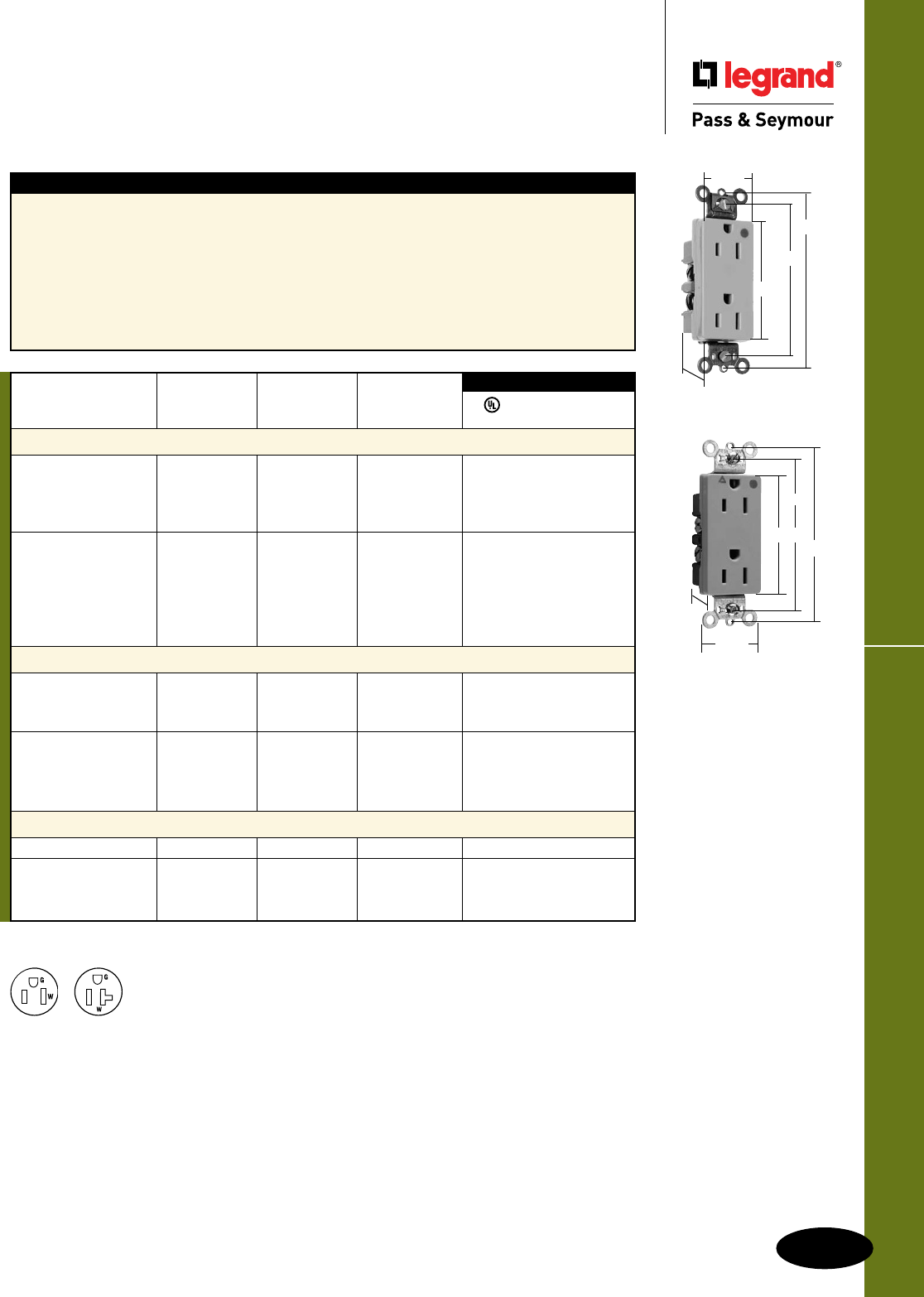
E-15
Heavy-Duty Decorator ReceptaclesHospital Grade Devices
All devices listed on this page conform to NEMA WD-1 and WD-6.
Hospital Grade Devices
Heavy-Duty Decorator Receptacles
15 & 20A, 125V
Features
n Corrosion-resistant, plated steel strap locked into
assembly to prohibit strap from bending
away from body.
n One-piece, brass, triple-wipe power contacts
for lasting retention.
n Heavy-duty compact design for easier installation
and long lasting performance.
n Easily accessed break-off, line-contact connecting
tab for fast, easy split-circuit wiring.
n Impact-resistant nylon face.
n Terminal compartments isolated from each
other for positive conductor containment.
n Side and internal screw-pressure-plate
back wire accepts #14 – #10 AWG solid
or stranded wire.
n All devices fit standard #26 opening wall plate.
n Tri-drive terminal and mounting screws.
n Auto-ground clip assures positive ground.
3rd Party Compliance
FSUL
UL498 WC596 cUL/CSA
Rating NEMA
Catalog Number A. V. Color Cong. No.
Duplex Receptacles Back & Side Wire
26262HGI 15 125 Ivory 5-15R • • •
26262HGW 15 125 White 5-15R • • •
26262HGGRY 15 125 Gray 5-15R • • •
26262HGRED 15 125 Red 5-15R • • •
26362HGI 20 125 Ivory 5-20R • • •
26362HGW 20 125 White 5-20R • • •
26362HG 20 125 Brown 5-20R • • •
26362HGGRY 20 125 Gray 5-20R • • •
26362HGRED 20 125 Red 5-20R • • •
26362HGLA 20 125 Light Almond 5-20R • • •
Isolated Ground Duplex Receptacles Back & Side Wire
IG26262HGW 15 125 White 5-15R • •
IG26262HG 15 125 Orange 5-15R • •
IG26262HGRED 15 125 Red 5-15R • •
IG26362HGW 20 125 White 5-20R • •
IG26362HG 20 125 Orange 5-20R • •
IG26362HGBK 20 125 Black 5-20R • •
IG26362HGRED 20 125 Red 5-20R • •
Illuminated Duplex Receptacles Back & Side Wire
26222HGI 15 125 Ivory 5-15R • •
26322HGI 20 125 Ivory 5-20R • •
26322HGW 20 125 White 5-20R • •
26322HGRED 20 125 Red 5-20R • •
For Bulk Packaging Solutions consult factory.
26262HGI
2.635"
3.281"
1.322"
3.813"
.833"
NEMA
5-15R
NEMA
5-20R
2 Pole, 3 Wire
IG26262HG
.833"
1.322"
3.281"
2.635"
3.813"
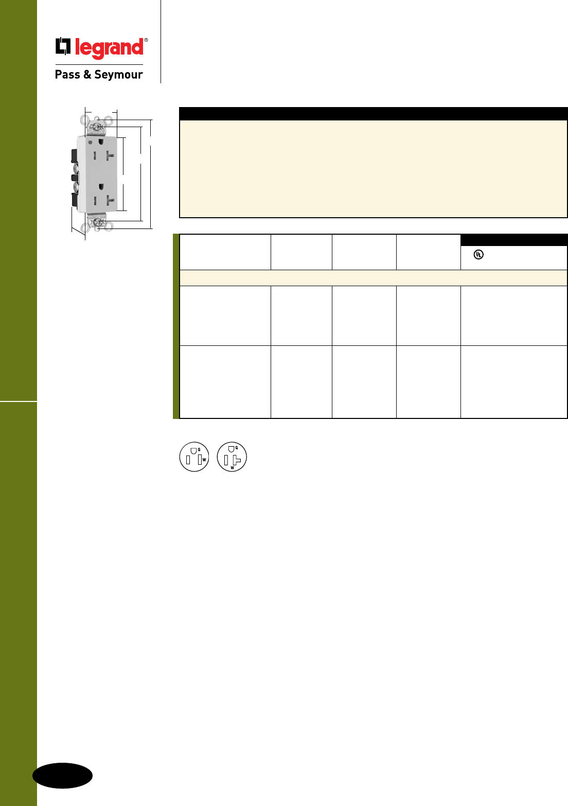
Heavy-Duty TR Decorator Receptacles
E-16
Hospital Grade Devices
All devices listed on this page conform to NEMA WD-1 and WD-6.
Hospital Grade Devices
Heavy-Duty Tamper-Resistant
Decorator Receptacles
15 & 20A, 125V
TR26362HGI
2.635"
3.281"
1.322"
3.81"
.833"
Features
n Auto-ground clip assures positive ground.
n Dual mechanical shutter system to help prevent
insertion of foreign objects.
n One-piece brass triple-wipe power contacts for
reliable plug retention.
n Two drive screws anchor strap to back body and
face where abrupt removal torque is strongest.
n Patented external screw-pressure-plate back wire
clamp on ground terminal for faster, easier installation.
n Easily accessed break-off, line-contact
connecting tab for fast, easy split-circuit wiring.
n External screw-pressure-plate back wire
clamps with #10 brass terminal screws for
visual assurance of a good connection.
n One-piece plated steel mounting strap
with integral ground for superior long-term
performance.
Rating NEMA
Catalog Number A. V. Color Cong. No.
Tamper-Resistant Duplex Receptacles Back & Side Wire
TR26262HGI 15 125 Ivory 5-15R • • •
TR26262HGW 15 125 White 5-15R • • •
TR26262HGGRY 15 125 Gray 5-15R • • •
TR26262HGRED 15 125 Red 5-15R • • •
TR26262HGLA 15 125 Light Almond 5-15R • • •
TR26362HGI 20 125 Ivory 5-20R • • •
TR26362HGW 20 125 White 5-20R • • •
TR26362HGGRY 20 125 Gray 5-20R • • •
TR26362HGBK 20 125 Black 5-20R • • •
TR26362HGRED 20 125 Red 5-20R • • •
TR26362HGLA 20 125 Light Almond 5-20R • • •
3rd Party Compliance
FSUL
UL498 WC596 cUL/CSA
For Bulk Packaging Solutions consult factory.
NEMA
5-15R
NEMA
5-20R
2 Pole, 3 Wire
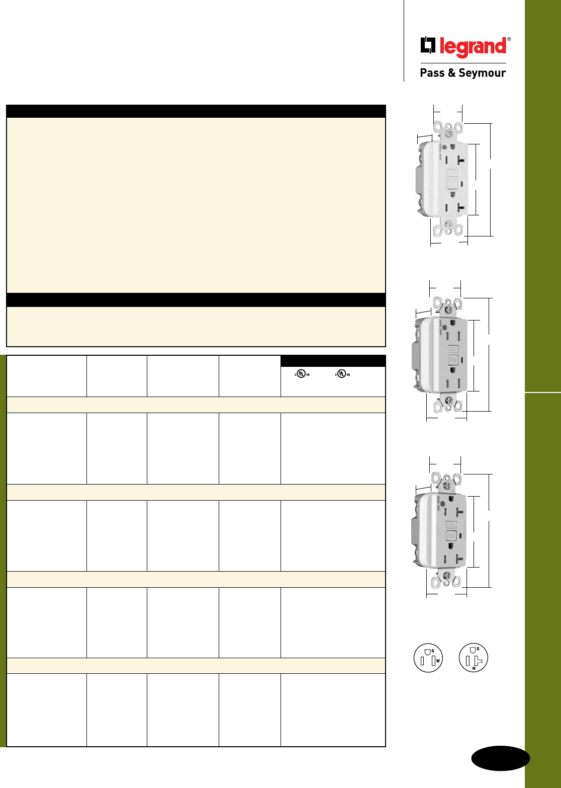
E-17
GFCI ReceptaclesHospital Grade Devices
All devices listed on this page conform to NEMA WD-1 and WD-6.
Hospital Grade Devices
GFCI Receptacles
2 Pole, 3 Wire Grounding 15 & 20A, 125VAC
Specications
n Supply Voltage: 125VAC, 60 Hz
n Supply Voltage Range: 102-132 VAC
n Trip Threshold: 5± 1mA
n Trip Time: 0.025 sec., nominal per
UL Standard
n 20 Amp feed-thru capacity
Features
n SafeLockTM Protection: if critical components are
damaged and ground fault protection is lost, power
to receptacle is disconnected.
n Prevents line-load reversal miswire: no power to the
face or downstream receptacles if wired incorrectly.
n Exceeds UL943 voltage surge requirements;
survives 100x the required UL 3kA/6kV voltage
surge test cycles.
n FSUL Listed (Federal Specification WC596).
n Trip indicator light (red LED).
n Side or internal screw-pressure-plate back wire
with #10 – #14 AWG solid or stranded copper wire.
n Two back wire holes per terminal.
n Ground screw has a back wire clamp for easy
installation.
n 1/4” thinner than competitors’ GFCIs; leaves
more room for wires in the box.
n Mounting screws are shipped captive in the
device and wall plate for easier installation.
n High-impact-resistant thermoplastic
construction.
n Extra-long strap.
n Button colors match the device face.
n Dual-direction test and reset buttons.
n Class A rated GFCI.
n Supplied with matching TP26 nylon wall plate.
n Tri-drive screws.
Tamper-Resistant Models
n Protects children: patented shutter system
helps prevent improper insertion of foreign
objects.
n Meets National Electrical Code®
Tamper-Resistant requirements.
UL943 UL498 FSUL
C22.2 No. 144 C22.2 No. 42 WC596
3rd Party Compliance
Catalog Rating NEMA
Number A. VAC Color Cong. No.
Tamper-Resistant 15 Amp Duplex GFCI
1595HGTRI 15 125 Ivory 5-15R • • •
1595HGTRW 15 125 White 5-15R • • •
1595HGTR 15 125 Brown 5-15R • • •
1595HGTRGRY 15 125 Gray 5-15R • • •
1595HGTRRED 15 125 Red 5-15R • • •
1595HGTRLA 15 125 Light Almond 5-15R • • •
Tamper-Resistant 20 Amp Duplex GFCI
2095HGTRI 20 125 Ivory 5-20R • • •
2095HGTRW 20 125 White 5-20R • • •
2095HGTR 20 125 Brown 5-20R • • •
2095HGTRGRY 20 125 Gray 5-20R • • •
2095HGTRRED 20 125 Red 5-20R • • •
2095HGTRLA 20 125 Light Almond 5-20R • • •
15 Amp Duplex GFCI
1595HGI 15 125 Ivory 5-15R • • •
1595HGW 15 125 White 5-15R • • •
1595HG 15 125 Brown 5-15R • • •
1595HGGRY 15 125 Gray 5-15R • • •
1595HGRED 15 125 Red 5-15R • • •
1595HGLA 15 125 Light Almond 5-15R • • •
20 Amp Duplex GFCI
2095HGI 20 125 Ivory 5-20R • • •
2095HGW 20 125 White 5-20R • • •
2095HG 20 125 Brown 5-20R • • •
2095HGGRY 20 125 Gray 5-20R • • •
2095HGRED 20 125 Red 5-20R • • •
2095HGLA 20 125 Light Almond 5-20R • • •
NEMA
5-15R
NEMA
5-20R
2095HGTRW
1.13"
1.72"
1.25"
2.62"
4.20"
1595HGTRW
1.13"
1.72"
1.25"
2.62"
4.20"
2095HGW
.98"
1.72"
1.25"
2.62"
4.20"
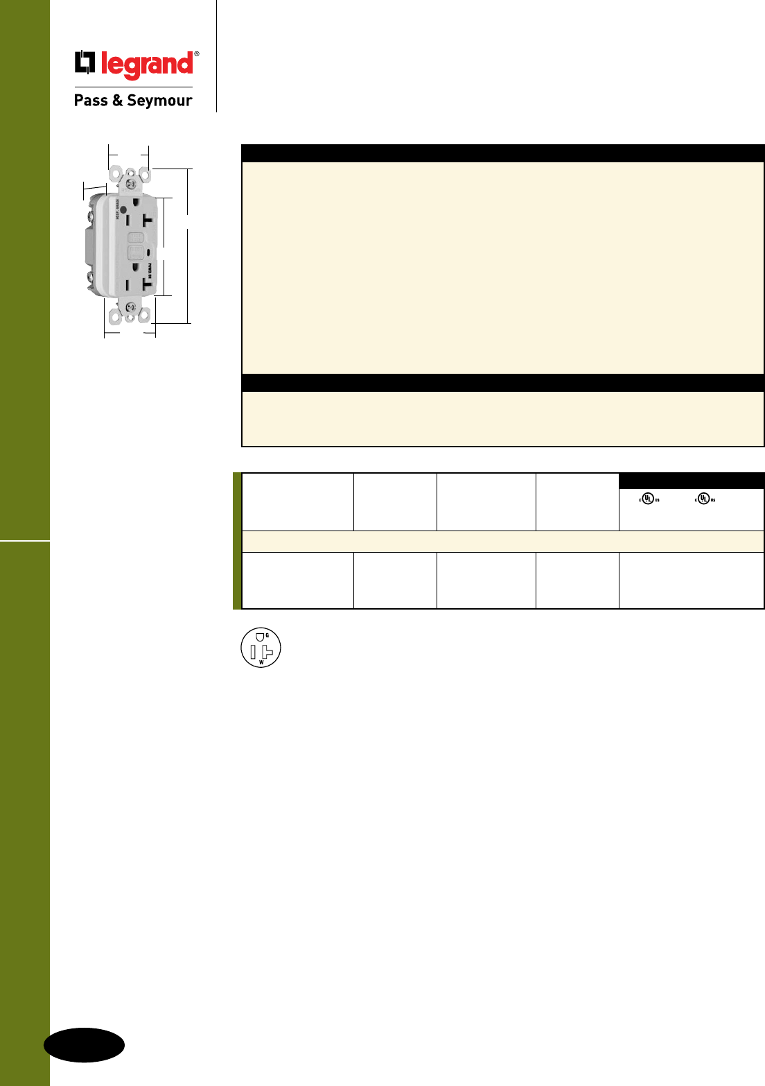
Illuminated GFCI Receptacless
E-18
Hospital Grade Devices
All devices listed on this page conform to NEMA WD-1 and WD-6.
Hospital Grade Devices
Illuminated GFCI Receptacles
2 Pole, 3 Wire Grounding 20A, 125VAC
2095HGWL
.98"
1.72"
1.25"
2.62"
4.20"
NEMA
5-20R
Features
n Green indicator light (LED) is ON when power is
available. Helps identify emergency power branch
circuits.
n SafeLockTM Protection: if critical components are
damaged and ground fault protection is lost, power
to receptacle is disconnected.
n Prevents line-load reversal miswire: no power to the
face or downstream receptacles if wired incorrectly.
n Exceeds UL943 voltage surge requirements;
survives 100x the required UL 3kA/6kV voltage
surge test cycles.
n FSUL Listed (Federal Specification WC596).
n Side or internal screw-pressure-plate back wire with
#10 – #14 AWG solid or stranded copper wire.
n Two back wire holes per terminal.
Specications
n Supply Voltage: 125VAC, 60 Hz
n Supply Voltage Range: 102-132 VAC
n Trip Threshold: 5± 1mA
n Trip Time: 0.025 sec., nominal per
UL Standard
n 20 Amp feed-thru capacity
n Ground screw has a back wire clamp for easy
installation.
n 1/4" thinner than competitors’ GFCIs; leaves
more room for wires in the box.
n Mounting screws are shipped captive in the
device and wall plate for easier installation.
n High-impact-resistant thermoplastic
construction.
n Extra-long strap.
n Button colors match the device face.
n Dual-direction test and reset buttons.
n Class A rated GFCI.
n Supplied with matching TP26 nylon wall plate.
n Tri-drive screws.
Catalog Rating NEMA
Number A. VAC Color Cong. No.
Illuminated 20 Amp Duplex GFCI
2095HGIL 20 125 Ivory 5-20R • • •
2095HGWL 20 125 White 5-20R • • •
2095HGREDL 20 125 Red 5-20R • • •
UL943 UL498 FSUL
C22.2 No. 144 C22.2 No. 42 WC596
3rd Party Compliance
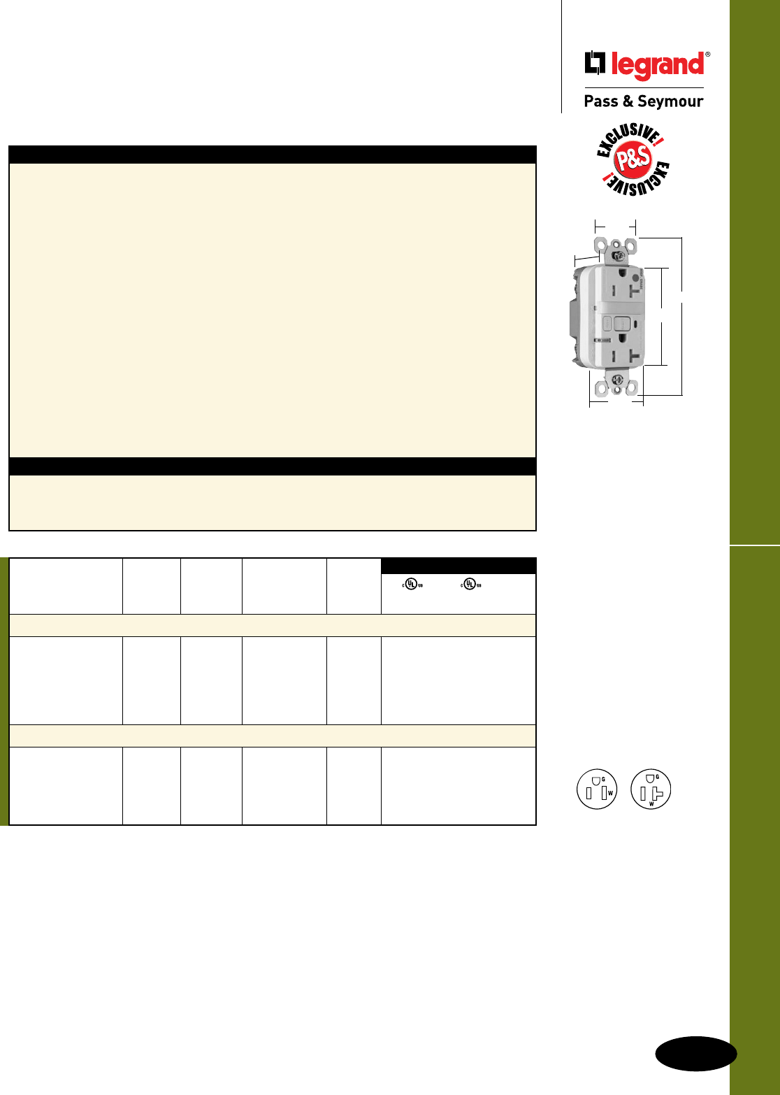
E-19
Hospital Grade Devices
Hospital Grade Devices
Decorator Combination Tamper-Resistant
Nightlight/GFCI Receptacles
2 Pole, 3 Wire Grounding 15 & 20A, 125VAC
Decorator Combination TR GFCI Receptacles
All devices listed on this page conform to NEMA WD-1 and WD-6.
*FCD = Foot Candle Distance, 1 Lumen = 1 FCD. See Page S-56 for more information.
Features
n Protects children: patented shutter system helps
prevent improper insertion of foreign objects.
n Meets National Electrical Code®
Tamper-Resistant requirements.
n SafeLockTM Protection: if critical components are
damaged and ground fault protection is lost, power
to receptacle is disconnected.
n Sealed nightlight with high impact-resistant Lexan®
lens prevents tampering.
n Nightlight uses cooler LED illumination.
n Energy-efficient LED has average 20-year life
expectancy, eliminating bulb replacement.
n Two receptacles.
n Photocell turns nightlight ON in dark, OFF in daylight.
n Prevents line-load reversal miswire: no power to the
face or downstream receptacles if wired incorrectly.
n Exceeds UL943 voltage surge requirements;
survives 100x the required UL 3kA/6kV voltage
surge test cycles.
n FSUL Listed (Federal Specification WC596).
Specications
n Supply Voltage: 125VAC, 60 Hz
n Supply Voltage Range: 102-132 VAC
n Trip Threshold: 5± 1mA
n Trip Time: 0.025 sec., nominal per UL
Standard
n 20 Amp feed-thru capacity
n Trip indicator light (red LED).
n Side or internal screw-pressure-plate back
wire with #10 – #14 AWG solid or stranded
copper wire.
n Two back wire holes per terminal.
n Ground screw has a back wire clamp for
easy installation.
n 1/4” thinner than competitors’ GFCIs; leaves
more room for wires in the box.
n Mounting screws are shipped captive in the
device and wall plate for easier installation.
n High-impact-resistant thermoplastic
construction.
n Extra-long strap.
n Button colors match the device face.
n Dual-direction test and reset buttons.
n Class A rated GFCI.
n Supplied with matching TP26 nylon
wall plate.
n Tri-drive screws.
2095HGNTLTRW
1.25"
1.13"
4.20"
2.62"
1.72"
UL943 UL498 FSUL
C22.2 No. 144 C22.2 No. 42 WC596
3rd Party Compliance
Light NEMA
Catalog Rating Output in Cong.
Number A. VAC 1' FCD* Color No.
Combination Tamper-Resistant 15 Amp Nightlight/GFCI
1595HGNTLTRI 15 125 0.180 Ivory 5-15R • • •
1595HGNTLTRW 15 125 0.180 White 5-15R • • •
1595HGNTLTR 15 125 0.180 Brown 5-15R • • •
1595HGNTLTRGRY 15 125 0.180 Gray 5-15R • • •
1595HGNTLTRRED 15 125 0.180 Red 5-15R • • •
1595HGNTLTRLA 15 125 0.180 Light Almond 5-15R • • •
Combination Tamper-Resistant 20 Amp Nightlight/GFCI
2095HGNTLTRI 20 125 0.180 Ivory 5-20R • • •
2095HGNTLTRW 20 125 0.180 White 5-20R • • •
2095HGNTLTRGRY 20 125 0.180 Gray 5-20R • • •
2095HGNTLTRRED 20 125 0.180 Red 5-20R • • •
2095HGNTLTRLA 20 125 0.180 Light Almond 5-20R • • • NEMA
5-15R
NEMA
5-20R
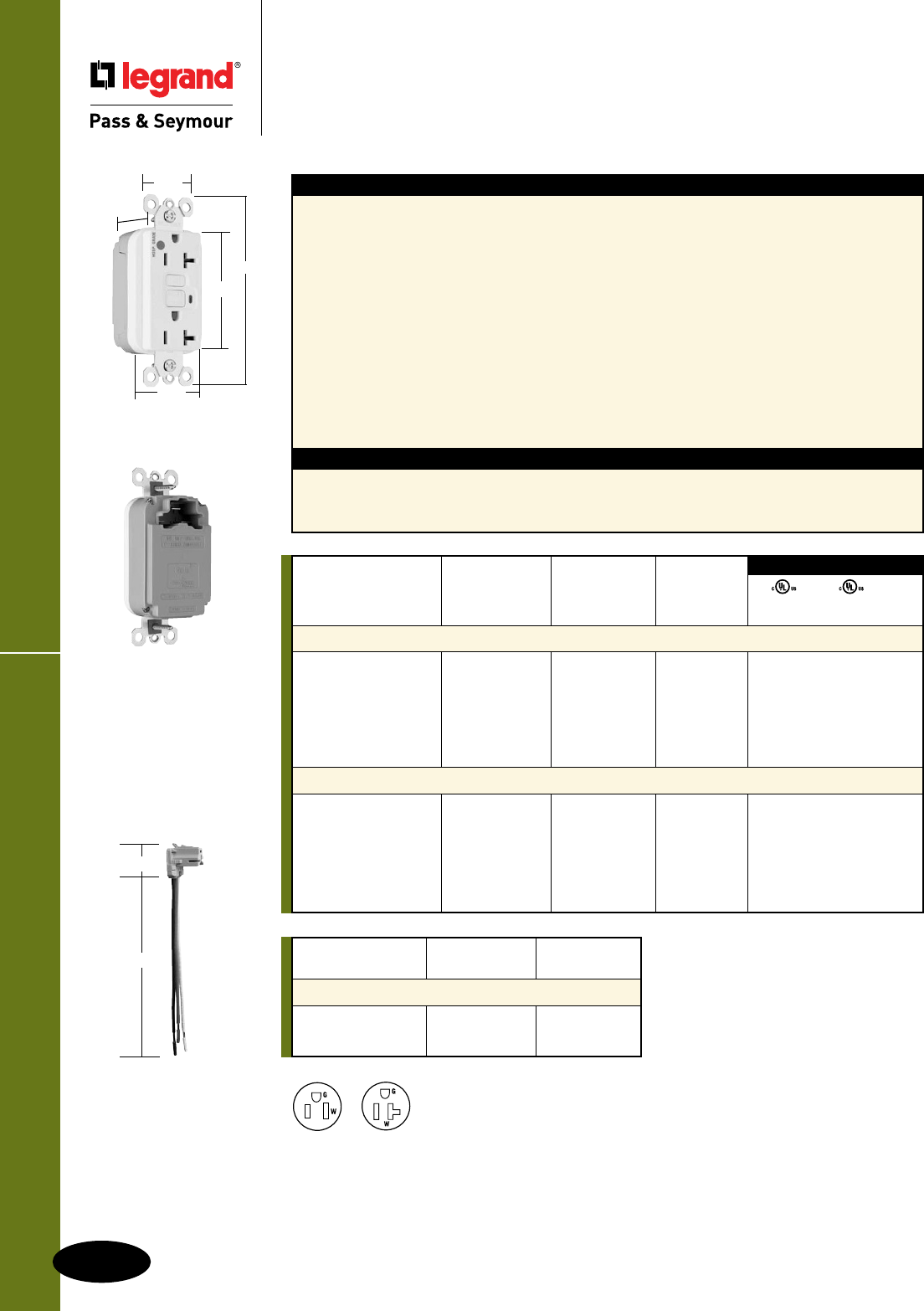
PTRA6STR
1.125"
6.375"
PlugTailTM GFCIs
E-20
Hospital Grade Devices
All devices listed on this page conform to NEMA WD-1 and WD-6.
Hospital Grade Devices
PlugTailTM GFCI Receptacles
2 Pole, 3 Wire Grounding 15 & 20A, 125VAC
PT2095HGW
1.25"
1.20"
4.20"
2.62"
1.72"
Catalog
Number Wire Type Wire Length
PlugTail Connectors – Right Angle
PTRA6STR Stranded 6"
PTRA6SOL Solid 6"
For additional PlugTail Connectors,
see Page E-14.
All PlugTail Connectors are available
in any wire length up to 25 inches,
consult factory to order.
NEMA
5-15R
NEMA
5-20R
UL943 UL498 FSUL
C22.2 No. 144 C22.2 No. 42 WC596
3rd Party Compliance
Catalog Rating NEMA
Number A. VAC Color Cong. No.
15 Amp Duplex GFCI
PT1595HGI 15 125 Ivory 5-15R • • •
PT1595HGW 15 125 White 5-15R • • •
PT1595HG 15 125 Brown 5-15R • • •
PT1595HGGRY 15 125 Gray 5-15R • • •
PT1595HGRED 15 125 Red 5-15R • • •
PT1595HGLA 15 125 Light Almond 5-15R • • •
20 Amp Duplex GFCI
PT2095HGI 20 125 Ivory 5-20R • • •
PT2095HGW 20 125 White 5-20R • • •
PT2095HG 20 125 Brown 5-20R • • •
PT2095HGGRY 20 125 Gray 5-20R • • •
PT2095HGRED 20 125 Red 5-20R • • •
PT2095HGLA 20 125 Light Almond 5-20R • • •
Features
n Faster, more reliable installation.
n No exposed terminals create a finger safe
application before, during, and after installation.
n Built-in connector features large brass terminal
blades to ensure consistent, reliable electrical
connections to PlugTail Connector.
n GFCI works with the existing 3 wire PlugTail
Connectors creating a non-feed-thru application for
facility owners. At rough-in just install the same right
angle connector for GFCI and receptacle openings.
n SafeLockTM Protection: if critical components are
damaged and ground fault protection is lost, power
to receptacle is disconnected.
n FSUL Listed (Federal Specification WC596).
Specications
n Supply Voltage: 125VAC, 60 Hz
n Supply Voltage Range: 102-132 VAC
n Trip Threshold: 5± 1mA
n Trip Time: 0.025 sec., nominal per
UL Standard
n 20 Amp feed-thru capacity
n Exceeds UL943 voltage surge requirements;
survives 100x the required UL 3kA/6kV
voltage surge test cycles.
n Trip indicator light (red LED).
n Mounting screws are shipped captive in the
device and wall plate for easier installation.
n High-impact-resistant thermoplastic
construction.
n Zinc-plated steel mounting strap.
n Button colors match the device face.
n Dual-direction test and reset buttons.
n Class A rated GFCI.
n Supplied with matching TP26 nylon wall plate.
n Tri-drive screws.
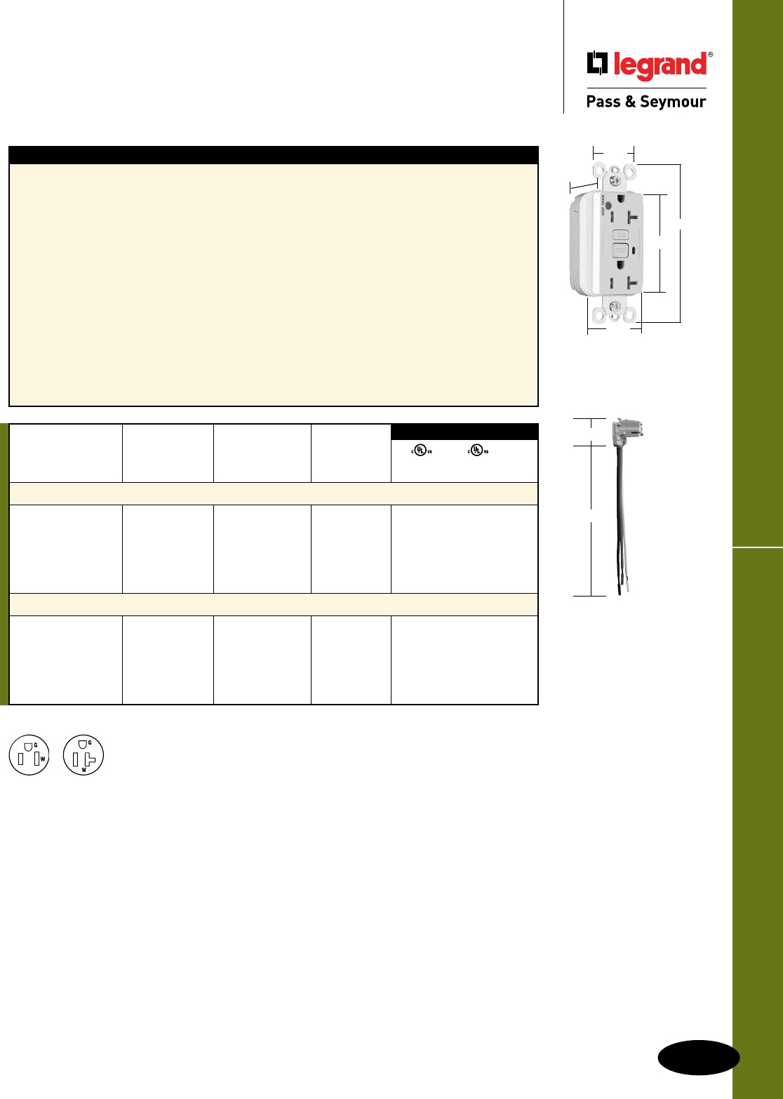
E-21
Hospital Grade Devices
All devices listed on this page conform to NEMA WD-1 and WD-6.
1.25"
1.2"
4.20"
2.62"
1.72"
Hospital Grade Devices
PlugTailTM Tamper-Resistant
GFCI Receptacles
2 Pole, 3 Wire Grounding 15 & 20A, 125VAC
PlugTailTM Tamper-Resistant GFCIs
NEMA
5-15R
NEMA
5-20R
Features
n Protects children: patented shutter system helps
prevent improper insertion of foreign objects.
n Meets National Electrical Code®
Tamper-Resistant requirements.
n Faster, more reliable installation.
n No exposed terminals create a finger safe
application before, during, and after installation.
n Built-in connector features large brass terminal
blades to ensure consistent, reliable electrical
connections to PlugTail Connector.
n GFCI works with the existing 3 wire PlugTail
Connectors creating a non-feed-thru application for
facility owners. At rough-in just install the same right
angle connector for GFCI and receptacle openings.
n SafeLockTM Protection: if critical components are
damaged and ground fault protection is lost, power
to receptacle is disconnected.
n FSUL Listed (Federal Specification WC596).
n Exceeds UL943 voltage surge requirements;
survives 100x the required UL 3kA/6kV
voltage surge test cycles.
n Trip indicator light (red LED).
n Mounting screws are shipped captive in the
device and wall plate for easier installation.
n High-impact-resistant thermoplastic
construction.
n Zinc-plated steel mounting strap.
n Button colors match the device face.
n Dual-direction test and reset buttons.
n Class A rated GFCI.
n Supplied with matching TP26 nylon wall plate.
n Tri-drive screws.
PT2095HGTRW
UL943 UL498 FSUL
C22.2 No. 144 C22.2 No. 42 WC596
3rd Party Compliance
Catalog Rating NEMA
Number A. VAC Color Cong. No.
Tamper-Resistant 15 Amp Duplex GFCI
PT1595HGTRI 15 125 Ivory 5-15R • • •
PT1595HGTRW 15 125 White 5-15R • • •
PT1595HGTRGRY 15 125 Gray 5-15R • • •
PT1595HGTRRED 15 125 Red 5-15R • • •
PT1595HGTRLA 15 125 Light Almond 5-15R • • •
Tamper-Resistant 20 Amp Duplex GFCI
PT2095HGTRI 20 125 Ivory 5-20R • • •
PT2095HGTRW 20 125 White 5-20R • • •
PT2095HGTRGRY 20 125 Gray 5-20R • • •
PT2095HGTRRED 20 125 Red 5-20R • • •
PT2095HGTRLA 20 125 Light Almond 5-20R • • •
For PlugTail Connector catalog numbers, see Page E-14.
PTRA6STR
1.125"
6.375"
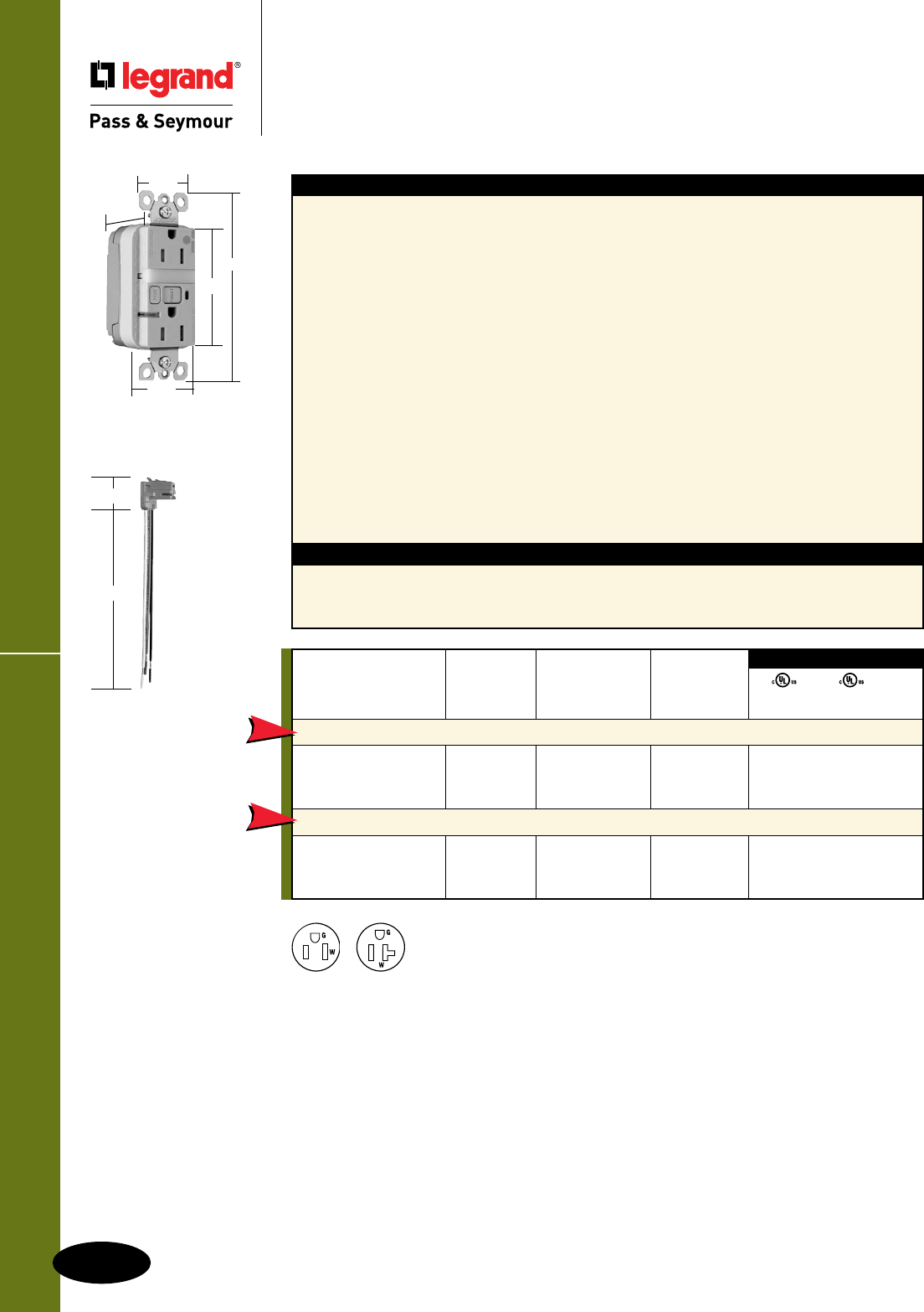
E-22
Hospital Grade Devices
All devices listed on this page conform to NEMA WD-1 and WD-6.
Hospital Grade Devices
PlugTailTM Tamper-Resistant Nightlight/
GFCI Receptacles
2 Pole, 3 Wire Grounding 15 & 20A, 125VAC
PlugTailTM TR Nightlight/GFCIs
NEMA
5-15R
NEMA
5-20R
For PlugTail Connector catalog numbers, see Page E-14.
UL943 UL498 FSUL
C22.2 No. 144 C22.2 No. 42 WC596
3rd Party Compliance
Catalog Rating NEMA
Number A. VAC Color Cong. No.
Tamper-Resistant 15 Amp Combination Nightlight/GFCI
PT1595HGNTLTRI 15 125 Ivory 5-15R • • •
PT1595HGNTLTRW 15 125 White 5-15R • • •
PT1595HGNTLTRRED 15 125 Red 5-15R • • •
Tamper-Resistant 20 Amp Combination Nightlight/GFCI
PT2095HGNTLTRI 20 125 Ivory 5-20R • • •
PT2095HGNTLTRW 20 125 White 5-20R • • •
PT2095HGNTLTRLA 20 125 Light Almond 5-20R • • •
NEW
NEW
PT1595HGNTLTRI
1.25"
1.20"
4.20"
2.62"
1.72"
PTRA6STR
1.125"
6.375"
Specications
n Supply Voltage: 125VAC, 60 Hz
n Supply Voltage Range: 102-132 VAC
n Trip Threshold: 5± 1mA
n Trip Time: 0.025 sec., nominal per
UL Standard
n 20 Amp feed-thru capacity
Features
n Protects children: patented shutter system helps
prevent improper insertion of foreign objects.
n Meets National Electrical Code®
Tamper-Resistant requirements.
n Sealed nightlight with high impact-resistant Lexan®
lens prevents tampering.
n Nightlight uses cooler LED illumination.
n Energy-efficient LED has average 20-year life
expectancy, eliminating bulb replacement.
n Photocell turns nightlight ON in dark, OFF in daylight.
n Faster, more reliable installation.
n No exposed terminals create a finger safe
application before, during, and after installation.
n Built-in connector features large brass terminal
blades to ensure consistent, reliable electrical
connections to PlugTail Connector.
n GFCI works with the existing 3 wire PlugTail
Connectors creating a non-feed-thru application for
facility owners. At rough-in just install the same right
angle connector for GFCI and receptacle openings.
n SafeLockTM Protection: if critical components
are damaged and ground fault protection is
lost, power to receptacle is disconnected.
n Exceeds UL943 voltage surge requirements;
survives 100x the required UL 3kA/6kV
voltage surge test cycles.
n FSUL Listed (Federal Specification WC596).
n Trip indicator light (red LED).
n Mounting screws are shipped captive in the
device and wall plate for easier installation.
n High-impact-resistant thermoplastic
construction.
n Zinc-plated steel mounting strap.
n Button colors match the device face.
n Dual-direction test and reset buttons.
n Class A rated GFCI.
n Supplied with matching TP26 nylon wall plate.
n Tri-drive screws.
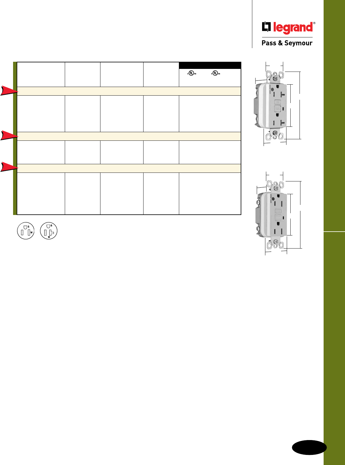
E-23
Hospital Grade Devices
All devices listed on this page conform to NEMA WD-1 and WD-6.
NAFTA-Compliant GFCIs
Hospital Grade Devices
NAFTA-Compliant GFCI Receptacles
2 Pole, 3 Wire Grounding 15 & 20A, 125VAC
NAFTA-Compliant GFCI Receptacles are ideal for use on projects subject to the provisions of the
Buy American Act.
Catalog Rating NEMA
Number A. VAC Color Cong. No.
NAFTA-Compliant Tamper-Resistant 20 Amp Duplex GFCI
2095HGTRNAI 20 125 Ivory 5-20R • • •
2095HGTRNAW 20 125 White 5-20R • • •
2095HGTRNAGRY 20 125 Gray 5-20R • • •
2095HGTRNARED 20 125 Red 5-20R • • •
2095HGTRNALA 20 125 Light Almond 5-20R • • •
NAFTA-Compliant 15 Amp Duplex GFCI
1595HGNAI 15 125 Ivory 5-15R • • •
1595HGNAW 15 125 White 5-15R • • •
1595HGNARED 15 125 Red 5-15R • • •
NAFTA-Compliant 20 Amp Duplex GFCI
2095HGNAI 20 125 Ivory 5-20R • • •
2095HGNAW 20 125 White 5-20R • • •
2095HGNA 20 125 Brown 5-20R • • •
2095HGNAGRY 20 125 Gray 5-20R • • •
2095HGNARED 20 125 Red 5-20R • • •
2095HGNALA 20 125 Light Almond 5-20R • • •
UL943 UL498 FSUL
C22.2 No. 144 C22.2 No. 42 WC596
3rd Party Compliance
NEW
NEW
NEW
1.72"
1.25"
2.62"
4.20"
.98"
2095HGTRNAW
1595HGNAW
1.72"
1.25"
2.62"
4.20"
.98"
NEMA
5-15R
NEMA
5-20R
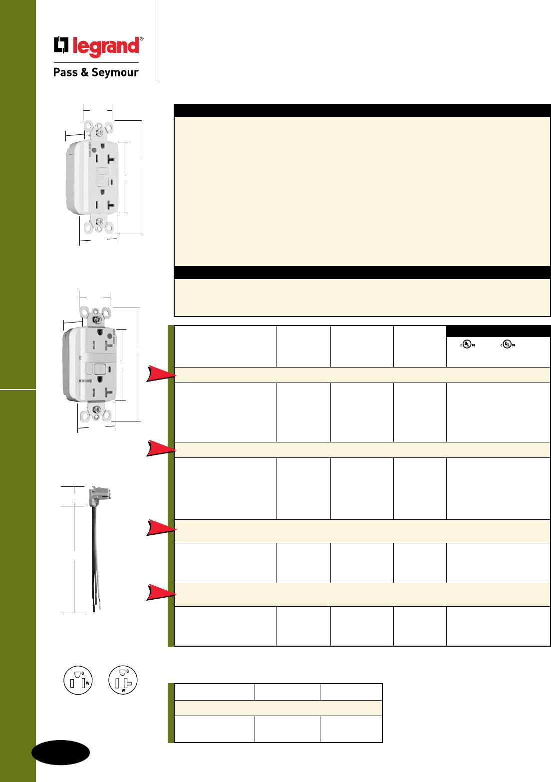
E-24
Hospital Grade Devices
All devices listed on this page conform to NEMA WD-1 and WD-6.
Hospital Grade Devices
NAFTA-Compliant PlugTail™
GFCI Receptacles
2 Pole, 3 Wire Grounding 15 & 20A, 125VAC
NAFTA-Compliant PlugTail™ GFCIs
PT2095HGNAW
1.72"
1.25"
2.62"
4.20"
.98"
PT2095HGNTLTRNAW
1.72"
1.25"
2.62"
4.20"
1.13"
PTRA6STR
1.125"
6.375"
Specications
n Supply Voltage: 125VAC, 60 Hz
n Supply Voltage Range: 102-132 VAC
n Trip Threshold: 5± 1mA
n Trip Time: 0.025 sec., nominal per
UL Standard
n 20 Amp feed-thru capacity
Features
n Faster, more reliable installation.
n No exposed terminals create a finger safe
application before, during, and after installation.
n Built-in connector features large brass terminal
blades to ensure consistent, reliable electrical
connections to PlugTail Connector.
n GFCI works with the existing 3 wire PlugTail
Connectors creating a non-feed-thru application for
facility owners. At rough-in just install the same right
angle connector for GFCI and receptacle openings.
n SafeLockTM Protection: if critical components are
damaged and ground fault protection is lost, power
to receptacle is disconnected.
n FSUL Listed (Federal Specification WC596).
n Exceeds UL943 voltage surge requirements;
survives 100x the required UL 3kA/6kV
voltage surge test cycles.
n Trip indicator light (red LED).
n Mounting screws are shipped captive in the
device and wall plate for easier installation.
n High-impact-resistant thermoplastic
construction.
n Zinc-plated steel mounting strap.
n Button colors match the device face.
n Dual-direction test and reset buttons.
n Class A rated GFCI.
n Supplied with matching TP26 nylon wall plate.
n Tri-drive screws.
Catalog Rating NEMA
Number A. VAC Color Cong. No.
NAFTA-Compliant 20 Amp Duplex GFCI
PT2095HGNAI 20 125 Ivory 5-20R • • •
PT2095HGNAW 20 125 White 5-20R • • •
PT2095HGNAGRY 20 125 Gray 5-20R • • •
PT2095HGNARED 20 125 Red 5-20R • • •
PT2095HGNALA 20 125 Light Almond 5-20R • • •
NAFTA-Compliant Tamper-Resistant 20 Amp Duplex GFCI
PT2095HGTRNAI 20 125 Ivory 5-20R • • •
PT2095HGTRNAW 20 125 White 5-20R • • •
PT2095HGTRNAGRY 20 125 Gray 5-20R • • •
PT2095HGTRNARED 20 125 Red 5-20R • • •
PT2095HGTRNALA 20 125 Light Almond 5-20R • • •
NAFTA-Compliant Tamper-Resistant 15 Amp
Combination Nightlight/GFCI
PT1595HGNTLTRNAI 15 125 Ivory 5-15R • • •
PT1595HGNTLTRNAW 15 125 White 5-15R • • •
PT1595HGNTLTRNARED 15 125 Red 5-15R • • •
NAFTA-Compliant Tamper-Resistant 20 Amp
Combination Nightlight/GFCI
PT2095HGNTLTRNAI 20 125 Ivory 5-20R • • •
PT2095HGNTLTRNAW 20 125 White 5-20R • • •
PT2095HGNTLTRNARED 20 125 Red 5-20R • • •
UL943 UL498 FSUL
C22.2 No. 144 C22.2 No. 42 WC596
3rd Party Compliance
NEW
NEW
NEW
NEW
NAFTA-Compliant GFCI Receptacles are ideal for use on projects subject to the provisions of the
Buy American Act.
Catalog Number Wire Type Wire Length
PlugTail Connectors – Right Angle
PTRA6STR Stranded 6"
PTRA6SOL Solid 6"
For additional PlugTail Connectors, see
Page E-14.
All PlugTail Connectors are available in
any wire length up to 25 inches, consult
factory to order.
NEMA
5-15R
NEMA
5-20R
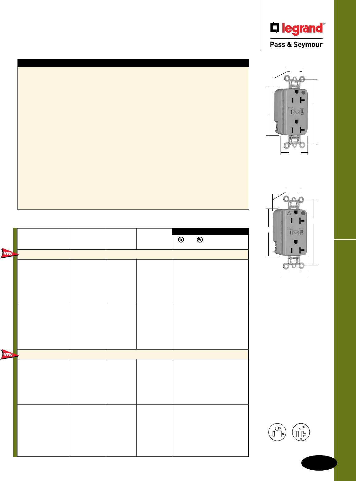
E-25
Hospital Grade Devices
Hospital Grade Devices
Surge Protective Receptacles
2 Pole, 3 Wire Grounding 15 & 20A, 125VAC
Surge Protective Receptacles
NEMA
5-15R
NEMA
5-20R
Specications
n UL1449 (3rd Edition). (1.2 x 50µs
6000V, 8 x 20µs 3000A).
n 24,000 amps current handling capability in
each of 3 modes: line to neutral, line
to ground, neutral to ground.
n LED indication: Steady green = protected;
Flashing red = not protected
OFF = no power to unit
n Response time less than 1 nanosecond for
unmounted MOV.
n Overcurrent protection in all 3 modes.
n Printed circuit board conformally coated to
protect against condensing humidity and
airborne particulates.
n Thermal protection in all 3 modes.
n Leakage current: 0.5 mA at 25°C/120VAC.
n Common mode noise attenuation: 500 KHz
to 30 MHz; up to 20 dB (50 ohm source
impedance)
n Varistor voltage: 130V RMS.
n Back and side wire capability including
ground terminal.
n Operating temperature: -40°C to 85°C
(-40°F to 185°F)
5262/5362, IG5262/5362, 8200/8300, IG8200/8300,
TR5262/5362, TRIG5262/5362, TR8200/8300,
TRIG8200/8300
n 340 joules of energy absorption in each of the 3 modes.
Energy (measured for an 8x20µS duration) = 340J.
n Nominal let-through (suppressed) voltage in all
3 modes, 500V.
n Audible alarm able to be turned on/off.
n 3 17mm dual pack MOVs to suppress transients in all
modes – equally.
n Isolated Ground version complies with NEC 410-56 (C)
and 250-146.
5252/5352, TR5252/5352, All PlugTail™
n 340 joules of energy absorption in line-to-neutral and
line-to-ground modes. 680 joules of energy absorption
in neutral-to-ground mode. Energy (measured for an
8x20µS duration) = 340J; 680J for N-G mode.
n 2 17mm dual pack MOVs to suppress
transients in all modes – equally.
n Nominal let-through (suppressed) voltage:
Line-to-neutral and line-to-ground modes = 500V;
neutral-to-ground = 1000V.
n PlugTail versions – factory-terminated devices and
connectors.
8300GRYSP
3.75"
1.70"
.875"
1.25"
Behind Strap
2.75"
IG8300GRYSP
3.75"
1.70"
.875"
1.25"
Behind Strap
2.75"
FSUL
UL1449 UL498 WC596 cUL/CSA
Rating NEMA
Catalog Number A. VAC Cong. No. Color
Duplex Receptacles Back & Side Wire
8200ISP 15 125 5-15R Ivory • • • •
8200WSP 15 125 5-15R White • • • •
8200SP 15 125 5-15R Brown • • • •
8200GRYSP 15 125 5-15R Gray • • • •
8200REDSP 15 125 5-15R Red • • • •
8200LASP 15 125 5-15R Light Almond • • • •
8200BLSP 15 125 5-15R Blue • • • •
8300ISP 20 125 5-20R Ivory • • • •
8300WSP 20 125 5-20R White • • • •
8300SP 20 125 5-20R Brown • • • •
8300GRYSP 20 125 5-20R Gray • • • •
8300REDSP 20 125 5-20R Red • • • •
8300LASP 20 125 5-20R Light Almond • • • •
8300BLSP 20 125 5-20R Blue • • • •
Isolated Ground Duplex Receptacles Back & Side Wire
IG8200ISP 15 125 5-15R Ivory • • • •
IG8200WSP 15 125 5-15R White • • • •
IG8200GRYSP 15 125 5-15R Gray • • • •
IG8200REDSP 15 125 5-15R Red • • • •
IG8200LASP 15 125 5-15R Light Almond • • • •
IG8200BLSP 15 125 5-15R Blue • • • •
IG8200OSP 15 125 5-15R Orange • • • •
IG8300ISP 20 125 5-20R Ivory • • • •
IG8300WSP 20 125 5-20R White • • • •
IG8300SP 20 125 5-20R Brown • • • •
IG8300GRYSP 20 125 5-20R Gray • • • •
IG8300REDSP 20 125 5-20R Red • • • •
IG8300LASP 20 125 5-20R Light Almond • • • •
IG8300BLSP 20 125 5-20R Blue • • • •
IG8300OSP 20 125 5-20R Orange • • • •
3rd Party Compliance
Audible Alarm with LED Indicator
All devices listed on this
page conform to NEMA
WD-1 and WD-6.
Conforms to the latest
revision ANSI/IEEE C62.41
(formerly IEEE587), ANSI/
IEEE C62.45.
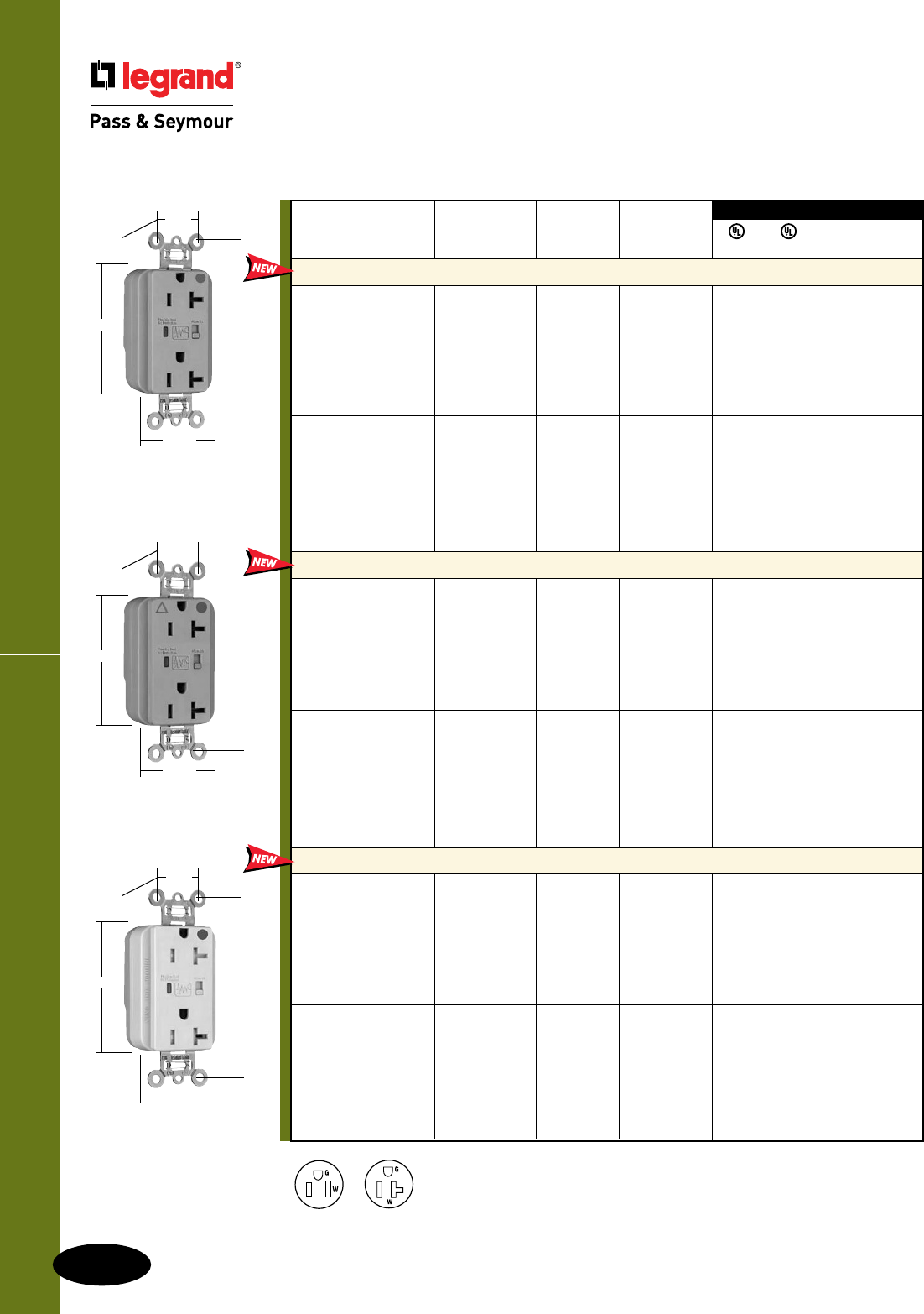
E-26
Hospital Grade Devices
All devices listed on this page conform to NEMA WD-1 and WD-6.
Conforms to the latest revision ANSI/IEEE C62.41 (formerly IEEE587), ANSI/IEEE C62.45.
PlugTail™ Surge Protective Receptacles
Hospital Grade Devices
PlugTail™ Surge Protective Receptacles
2 Pole, 3 Wire Grounding, 15 & 20A, 125VAC
Available Spring 2011
NEMA
5-20R
NEMA
5-15R
3rd Party Compliance
3rd Party Compliance
FSUL
UL1449 UL498 WC596 cUL/CSA
Rating NEMA
Catalog Number A. VAC Cong. No. Color
Extra Heavy-Duty Duplex Receptacles
PT8200ISP 15 125 5-15R Ivory • • • •
PT8200WSP 15 125 5-15R White • • • •
PT8200SP 15 125 5-15R Brown • • • •
PT8200GRYSP 15 125 5-15R Gray • • • •
PT8200REDSP 15 125 5-15R Red • • • •
PT8200LASP 15 125 5-15R Light Almond • • • •
PT8200BLSP 15 125 5-15R Blue • • • •
PT8300ISP 20 125 5-20R Ivory • • • •
PT8300WSP 20 125 5-20R White • • • •
PT8300SP 20 125 5-20R Brown • • • •
PT8300GRYSP 20 125 5-20R Gray • • • •
PT8300REDSP 20 125 5-20R Red • • • •
PT8300LASP 20 125 5-20R Light Almond • • • •
PT8300BLSP 20 125 5-20R Blue • • • •
Isolated Ground Duplex Receptacles
PTIG8200ISP 15 125 5-15R Ivory • • • •
PTIG8200WSP 15 125 5-15R White • • • •
PTIG8200GRYSP 15 125 5-15R Gray • • • •
PTIG8200REDSP 15 125 5-15R Red • • • •
PTIG8200LASP 15 125 5-15R Light Almond • • • •
PTIG8200BLSP 15 125 5-15R Blue • • • •
PTIG8200OSP 15 125 5-15R Orange • • • •
PTIG8300ISP 20 125 5-20R Ivory • • • •
PTIG8300WSP 20 125 5-20R White • • • •
PTIG8300GRYSP 20 125 5-20R Gray • • • •
PTIG8300REDSP 20 125 5-20R Red • • • •
PTIG8300LASP 20 125 5-20R Light Almond • • • •
PTIG8300BLSP 20 125 5-20R Blue • • • •
PTIG8300OSP 20 125 5-20R Orange • • • •
Tamper-Resistant Duplex Receptacles
PTTR8200ISP 15 125 5-15R Ivory • • • •
PTTR8200WSP 15 125 5-15R White • • • •
PTTR8200SP 15 125 5-15R Brown • • • •
PTTR8200GRYSP 15 125 5-15R Gray • • • •
PTTR8200REDSP 15 125 5-15R Red • • • •
PTTR8200LASP 15 125 5-15R Light Almond • • • •
PTTR8200BLSP 15 125 5-15R Blue • • • •
PTTR8300ISP 20 125 5-20R Ivory • • • •
PTTR8300WSP 20 125 5-20R White • • • •
PTTR8300SP 20 125 5-20R Brown • • • •
PTTR8300GRYSP 20 125 5-20R Gray • • • •
PTTR8300REDSP 20 125 5-20R Red • • • •
PTTR8300LASP 20 125 5-20R Light Almond • • • •
PTTR8300BLSP 20 125 5-20R Blue • • • •
Audible Alarm with LED Indicator
PT8300GRYSP
3.75"
1.70"
.875"
1.20"
Behind Strap
2.75"
PTIG8300GRYSP
3.75"
1.70"
.875"
1.20"
Behind Strap
2.75"
PTTR8300ISP
3.75"
1.70"
.875"
1.40"
Behind Strap
2.75"
For PlugTail Connectors,
see Page E-14.
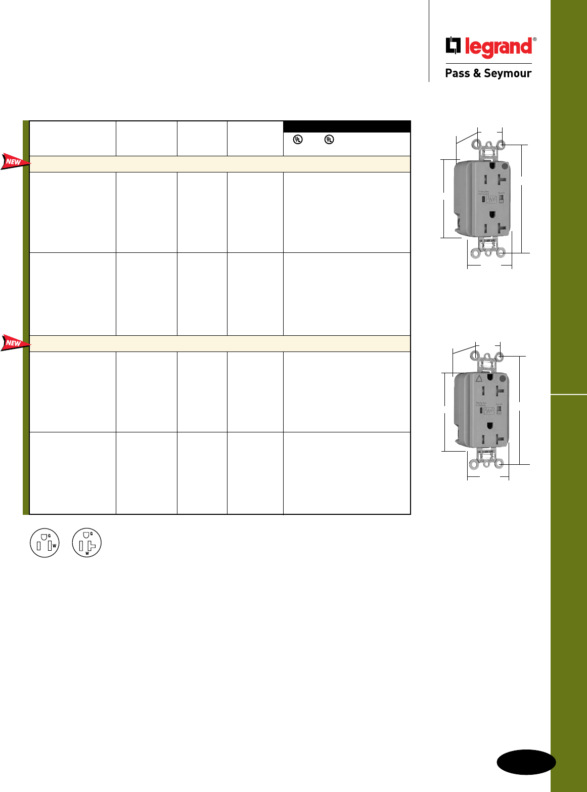
E-27
Hospital Grade Devices
Hospital Grade Devices
Tamper-Resistant
Surge Protective Receptacles
2 Pole, 3 Wire Grounding, 15 & 20A, 125VAC
TR Surge Protective Receptacles
3rd Party Compliance
3rd Party Compliance
FSUL
UL1449 UL498 WC596 cUL/CSA
Rating NEMA
Catalog Number A. VAC Cong. No. Color
Extra Heavy-Duty Duplex Receptacles Back & Side Wire
TR8200ISP 15 125 5-15R Ivory • • • •
TR8200WSP 15 125 5-15R White • • • •
TR8200SP 15 125 5-15R Brown • • • •
TR8200GRYSP 15 125 5-15R Gray • • • •
TR8200REDSP 15 125 5-15R Red • • • •
TR8200LASP 15 125 5-15R Light Almond • • • •
TR8200BLSP 15 125 5-15R Blue • • • •
TR8300ISP 20 125 5-20R Ivory • • • •
TR8300WSP 20 125 5-20R White • • • •
TR8300SP 20 125 5-20R Brown • • • •
TR8300GRYSP 20 125 5-20R Gray • • • •
TR8300REDSP 20 125 5-20R Red • • • •
TR8300LASP 20 125 5-20R Light Almond • • • •
TR8300BLSP 20 125 5-20R Blue • • • •
Isolated Ground Duplex Receptacles Back & Side Wire
TRIG8200ISP 15 125 5-15R Ivory • • • •
TRIG8200WSP 15 125 5-15R White • • • •
TRIG8200GRYSP 15 125 5-15R Gray • • • •
TRIG8200REDSP 15 125 5-15R Red • • • •
TRIG8200LASP 15 125 5-15R Light Almond • • • •
TRIG8200BLSP 15 125 5-15R Blue • • • •
TRIG8200OSP 15 125 5-15R Orange • • • •
TRIG8300ISP 20 125 5-20R Ivory • • • •
TRIG8300WSP 20 125 5-20R White • • • •
TRIG8300GRYSP 20 125 5-20R Gray • • • •
TRIG8300REDSP 20 125 5-20R Red • • • •
TRIG8300LASP 20 125 5-20R Light Almond • • • •
TRIG8300BLSP 20 125 5-20R Blue • • • •
TRIG8300OSP 20 125 5-20R Orange • • • •
Audible Alarm with LED Indicator
Available Spring 2011
NEMA
5-20R
NEMA
5-15R
TR8300GRYSP
3.75"
1.70"
.875"
1.40"
Behind Strap
2.75"
TRIG8300GRYSP
3.75"
1.70"
.875"
1.40"
Behind Strap
2.75"
All devices listed on this page conform to NEMA WD-1 and WD-6.
Conforms to the latest revision ANSI/IEEE C62.41 (formerly IEEE587), ANSI/IEEE C62.45.
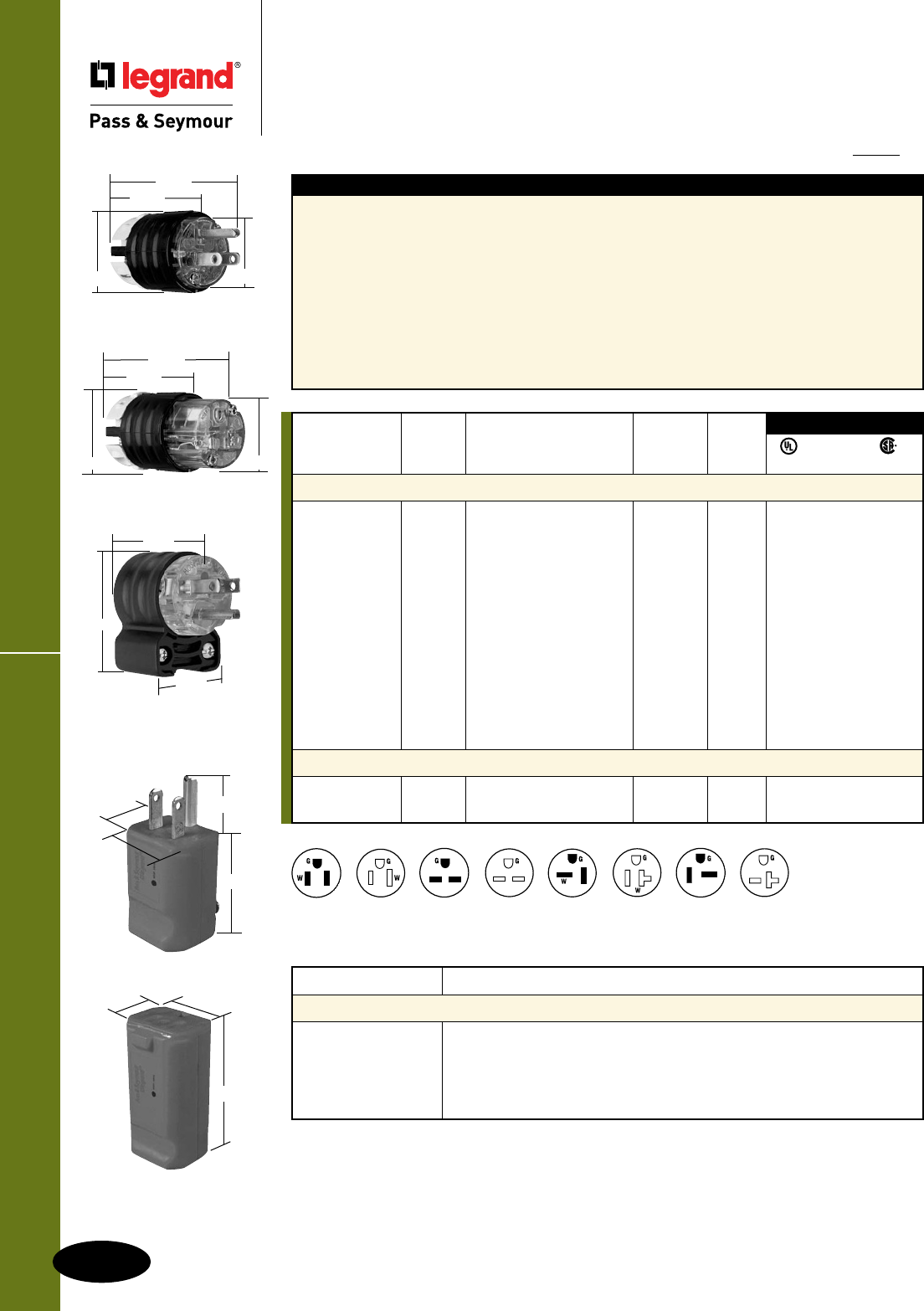
E-28
Hospital Grade Devices
All devices listed on this page conform to NEMA WD-1 and WD-6.
Hospital Grade Devices
Straight Blade Plugs & Connectors
2 Pole, 3 Wire Grounding 15 & 20A, 125 & 250V
Straight Blade Plugs & Connectors
IP20
Suitability
PS5266XHG
1.752"
2.791"
1.516" 1.358"
1.34"
1.21"
1.83"
PS8119
1.34"
1.21"
1.83"
PS8115
.77"
PS5269XHG
2.638"
1.516" 1.358"
1.752"
PS5266HGAN
2.130"
1.350"
1.530"
NEMA
6-20R
NEMA
5-15P
NEMA
6-15P
NEMA
6-15R
NEMA
6-20P
NEMA
5-15R
NEMA
5-20P
NEMA
5-20R
Catalog Number Description
Accessories
EHU15AN 15 & 20A EHU Straight Blade, Right Angle Adapter
FC22GL EHU-Strain Relief Grip*
FC30GL EHU-Strain Relief Grip*
FC40GL EHU-Strain Relief Grip*
FC52GL EHU-Strain Relief Grip*
Features – Extra-Hard Use (EHU)
n Unit arrives completely ready-to-wire, cuts
installation time significantly.
n Nylon housing provides impact and
chemical resistance.
n Rugged two-piece cord grip provides more
uniform cord retention.
n Internal dust shield keeps terminals free
of contaminants.
n Tri-drive assembly screws are standard on
Hospital Grade plugs and connectors
(angle plugs not included).
n All 3-wire terminals located on the same
plane, allows for quick wire termination from
any angle.
n Heavy-duty brass alloy blades and contacts,
resist heat rise, provide excellent conductivity.
n Cord-grip screws recessed to protect installer
against screwdriver head slippage.
*For further information consult the Flexcor® Section K.
NEMA
Catalog Rating Cord Cong.
Number A. V. Description Diameter No.
Extra-Hard Use (EHU)
PS5266XHG 15 125 Plug, Black & Clear .230"-.720" 5-15P • • •
PS5266HGAN 15 125 Angle Plug, Black & Clear .320"-.655" 5-15P • • •
PS5269XHG 15 125 Connector, Black & Clear .230"-.720" 5-15R • • •
PS5366XHG 20 125 Plug, Black & Clear .230"-.720" 5-20P • • •
PS5366HGAN 20 125 Angle Plug, Black & Clear .320"-.655" 5-20P • • •
PS5369XHG 20 125 Connector, Black & Clear .230"-.720" 5-20R • • •
PS5666XHG 15 250 Plug, Black & Clear .230"-.720" 6-15P • • •
PS5666HGAN 15 250 Angle Plug, Black & Clear .320"-.655" 6-15P • • •
PS5669XHG 15 250 Connector, Black & Clear .230"-.720" 6-15R • • •
PS5466XHG 20 250 Plug, Black & Clear .230"-.720" 6-20P • • •
PS5466HGAN 20 250 Angle Plug, Black & Clear .320"-.655" 6-20P • • •
PS5469XHG 20 250 Connector, Black & Clear .230"-.720" 6-20R • • •
MaxGrip® M3
PS8115 15 125 Plug, Gray .230"-.720" 5-15P • • •
PS8119 15 125 Connector, Gray .230"-.720" 5-15R • • •
FSUL
UL498 WC596 C22.2 No. 42
3rd Party Compliance
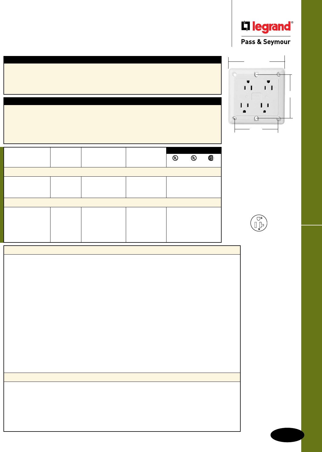
E-29
Hospital Grade Devices Quad Receptacles
All devices listed on
this page conform to
NEMA WD-1
and WD-6.
Hospital Grade Devices
Quad Receptacles
20A, 125V
Rating NEMA
Catalog Number A. V. Color Cong. No.
Isolated Ground Surge Protective Quads
IG420HISP 20 125 Ivory 5-20R • •
IG420HGRYSP 20 125 Gray 5-20R • •
IG420HBLSP 20 125 Blue 5-20R • •
Quads
420HI 20 125 Ivory 5-20R • •
420HW 20 125 White 5-20R • •
420H 20 125 Brown 5-20R • •
420HGRY 20 125 Gray 5-20R • •
420HRED 20 125 Red 5-20R • •
3rd Party Compliance
UL498 UL1449 CSA
Application
Legrand/Pass & Seymour’s quad receptacles are designed for dense, multiple-outlet applications
such as personal computers and peripherals, office equipment, and home entertainment centers. The
bidirectional outlet configuration allows use of up to four oversized plugs, in close proximity. The clean,
contemporary design of the quad receptacle allows for surface mounting with minimal protrusion from
the wall. No wall plate is required.
Features
n Rugged nylon face and body withstands impacts
and hard use.
n Built-in wire stripping gauge.
n Outward-facing ground terminals make handling
up to four straight or angled plugs easy and
convenient.
n Heavy-duty, phosphor bronze contacts.
n Shielding walls guard against live-circuit-to-
ground shorts.
n Split circuit break-off tabs.
n UL and CSA listed. Quad Receptacle
3.38"
4.50" square
3.38"
NEMA
5-20R
2 Pole, 3 Wire
Hard Use Spec Grade & Hard Use Surge Protective Spec Grade Quads
• Isolated ground complied with NEC® 410-56(c) and 250-74 exception 4
• Conforms to NEMA WD-1, WD-6.
Electrical
Frequency 60Hz
Voltage 125V
Mechanical
Terminal Identification Brass = Hot, Nickel = Neutral, Green = Ground
Terminal Accommodation #14 –12 AWG copper and copper-clad
Product Identification Ratings are permanent part of device
Weight 10.75 oz.
Environmental
Flammability UL94 V2
Operating Temperature -40°C to 65°C (-40°F to 150°F) continuous without impact
Materials
Face Nylon
Body Nylon
Line Terminals .035" T-type Triple-Wipe Phosphor Bronze
Terminal Screws Brass #8-32
Hex Head Grounding Screw Steel (Green)
Mounting Screws Zinc-plated steel
Additional Specifications for Hard Use Surge Protective Spec Grade Quads
• ANSI /IEEE C62.41 (formerly IEEE 587), ANSI/IEEE C62.45
• Installation Categories “A
”
(ring wave) and “B
”
(unidirectional impulse)
Electrical
MOV Rating 18mm
UL1449 Suppressed Voltage Rating 500V (L-N, L-G, N-G)
Noise Attenuation -35db Noise Filtering at 5kHz-50MHz
Thermal Protection Fused
Green LED Indicator ON when protection is active, OFF when protection is inactive
SURGE PROTECTIVE & ISOLATED GROUND DEVICES
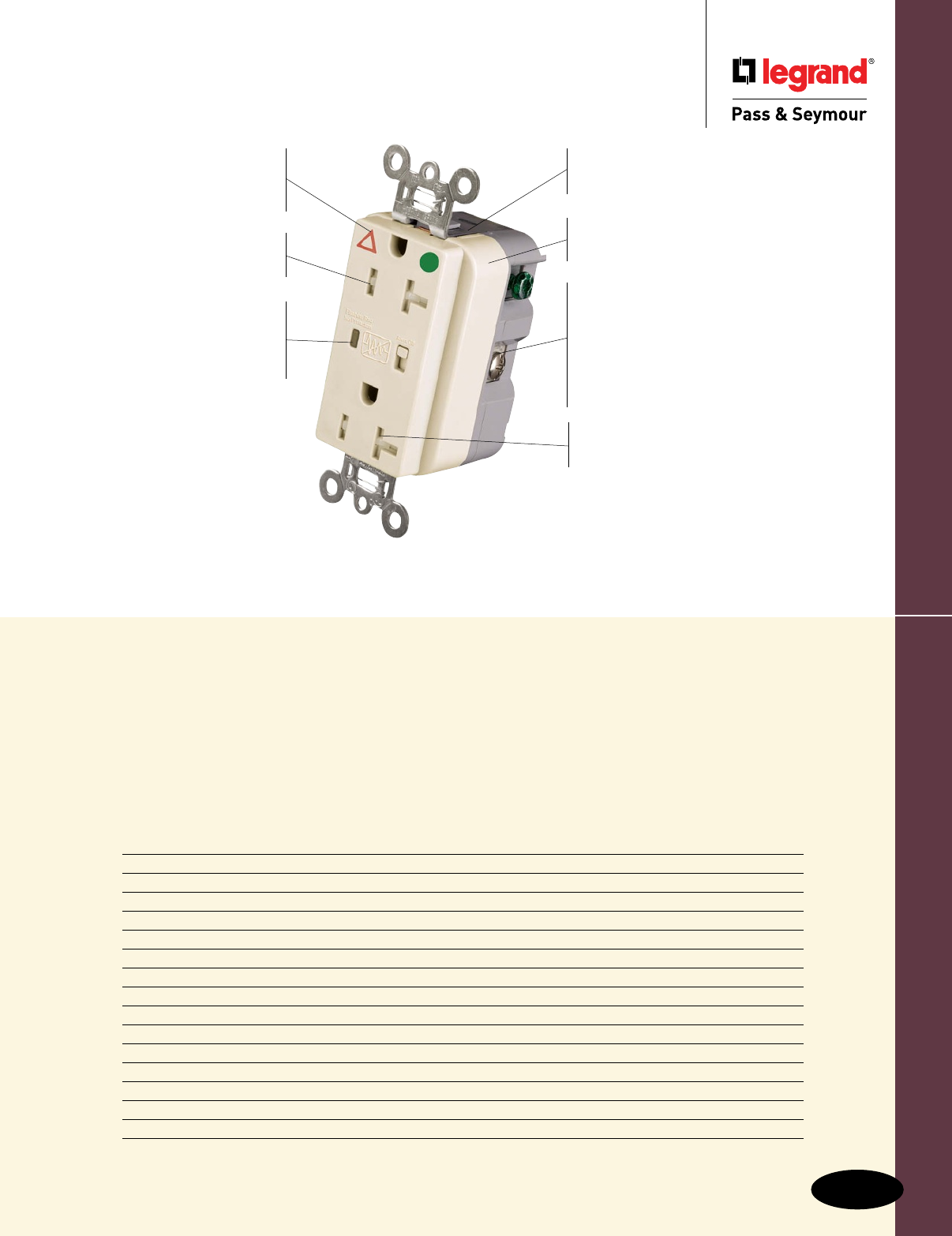
Surge Protective & Isolated Ground Devices
Surge Protective &
Isolated Ground Devices
F-1
Index
Device Rating Page Number
Surge Protective Devices Product Description F-2
Product Specifications F-3
Hospital Grade Surge Protective Receptacles 15 & 20A, 125VAC F-4
Surge Protective Receptacles 15 & 20A, 125VAC F-5, F-6
PlugTail™ Surge Protective Receptacles 15 & 20A, 125V F-7
PlugTail™ Hospital Grade Surge Protective Receptacles 15 & 20A, 125V F-8
Tamper-Resistant Surge Protective Receptacles 15 & 20A, 125V F-9
Tamper-Resistant Hospital Grade Surge Protective Receptacles 15 & 20A, 125V F-10
Surge Protection Panels Heavy-, Medium- & Light-Duty F-11 – F-13
Isolated Ground Product Description F-14
PlugTail™ Isolated Ground Receptacles 15 & 20A, 125V F-16
Isolated Ground Receptacles 15 & 20A, 125 & 250V F-17
Tamper-Resistant Isolated Ground Receptacles 15 & 20A, 125 F-18
Turnlok® Isolated Ground Receptacles 15, 20 & 30A F-19
Power & Surge Protection Strips & Specifications F-20, F-21
Surge protective device offering with
increased transient protection, reliability
and protection notification — for
industrial, commercial, and residential
applications in the electronics age.
Thermal protection in 3 modes. 3 17mm
dual pack MOVs absorb up to 340 Joules
of excess energy in each leg (L-N, L-G, N-G)
with 24,000 amp current handling capability
for full, equal and symmetrical protection.
Protection response time in less than one
nanosecond.
LED indication:
Steady green = protected
Flashing red = not protected
OFF = no power to unit
Audible alarm alert of
MOV damage. Alarm able
to be turned On/Off.
Solid-state LED monitor
has 25-year minimum life
expectancy. A high visibility,
wide-angle lens indicates
protection is in place.
Wrap-around steel strap for structural
integrity. Auto-ground is standard, for
easier installation.
Dual mechanical shutter
system to help prevent
insertion of foreign objects.
Triple-wipe, copper-alloy
contacts for superior, more
dependable connection.
TRIG8300LASP
External screw-pressure-plate back
and side wire terminals including
ground with external back wire
clamps (exclusive) accept #14 – #10
AWG copper or copper-clad, solid or
stranded conductors. External pressure
plate feature allows two conductors to
be terminated by a single screw.
Plastic barrier isolates
grounding terminal from
mounting strap and metal boxes.
IG symbol and Isolated
Ground markings on strap
make for easy identification
and circuit delineation.
Impact-resistant
thermoplastic exterior
resists impacts and scrapes.
Product Description – Surge Protective Devices
Surge Protective & Isolated Ground Devices
Surge Protective & Isolated Ground Devices
Product Description –
Surge Protective Devices
F-2
Surge Protective Devices
Office buildings, schools and campuses, hospitals and medical facilities, and your own
home; the use of microprocessor-based equipment has become prevalent in all day-to-
day environments. Commercial and industrial facilities have computer, IT, and telephone
systems; and control and automation equipment. Retail locations have sophisticated
cash registers, electronic scanning, and security systems. At home, we have desktop
and laptop computers, smart telephones, high-definition TVs, audio and home theater
equipment, gaming systems, and control systems (thermostats, garage door openers,
etc.). In today’s world we are dependent on (and take for granted) the performance of
all this sophisticated yet sensitive equipment.
All microprocessor-based equipment is extremely sensitive to momentary spikes
and surges that occur daily over AC circuits. Sources for these transient spikes and
surges range from lightning and utility switching to inductive load switching such as
air conditioners, power tools, vacuum cleaners, and copy machines. Externally or
internally induced, high energy spikes and surges are capable of causing catastrophic
instantaneous damage or cumulative transients that continue to erode the effectiveness
of the equipment, hindering performance until it prematurely fails.
The best line of defense for any location is a coordination of protection at the service
entrance, branch service locations, and at the point of use. Legrand®/Pass & Seymour’s
Surge Protection products offer single and multi-phase panel-mounted units for installation
at the main service entrance and branch distribution locations and a full line of receptacles
and portable/plug-in units with multiple outlets, phone, and data protection. This full
package allows you to cost effectively provide the right protection for your specific
application.
Product Specifications
Surge Protective & Isolated Ground Devices
Surge Protective & Isolated Ground Devices
Product Specifications
F-3
Specications – 5262/5362, IG5262/5362, 8200/8300, IG8200/8300,
TR5262/5362, TRIG5262/5362, TR8200/8300, TRIG8200/8300
n UL1449 (3rd Edition). (1.2 x 50µs
6000V, 8 x 20µs 3000A).
n 340 joules of energy absorption in each of the
3 modes.
Energy (measured for an 8x20µS duration) = 340J.
n 24,000 amps current handling capability in each
of 3 modes: line to neutral, line to ground,
neutral to ground.
n Nominal let-through (suppressed) voltage in
all 3 modes, 500V.
n Audible alarm able to be turned on/off.
n LED indication:
Steady green = protected
Flashing red = not protected
OFF = no power to unit
n Response time less than 1 nanosecond for
unmounted MOV.
n Overcurrent protection in all 3 modes.
n Printed circuit board conformally coated to
protect against condensing humidity and
airborne particulates.
n Thermal protection in all 3 modes.
n Leakage current: 0.5 mA at 25°C/120VAC.
n 3 17mm dual pack MOVs to suppress
transients in all modes – equally.
n Common mode noise attenuation:
500 KHz to 30 MHz; up to 20 dB
(50 ohm source impedance)
n Varistor voltage: 130V RMS.
n Back and side wire capability including
ground terminal.
n Operating temperature: -40°C to 85°C
(-40°F to 185°F)
n Isolated Ground version complies with NEC
410-56 (C) and 250-146.
n Conforms to the latest revision ANSI/IEEE
C62.41 (formerly IEEE 587), ANSI/IEEE
C62.45.
Specications – 5252/5352, TR5252/5352, All PlugTail™ Receptacles
n UL1449 (3rd Edition). (1.2 x 50µs 6000V,
8 x 20µs 3000A).
n 340 joules of energy absorption in line-to-neutral
and line-to-ground modes.
680 joules of energy absorption in neutral-to-ground
mode.
Energy (measured for an 8x20µS duration) = 340J
(680J for N-G mode).
n 24,000 amps current handling capability in each
of 3 modes; line to neutral, line to ground,
neutral to ground.
n Nominal let-through (suppressed) voltage:
Line-to-neutral and line-to-ground modes = 500V;
neutral-to-ground mode = 1000V.
n LED indication:
Steady green = protected
Flashing red = not protected
OFF = no power to unit
n Response time less than 1 nanosecond for
unmounted MOV.
n Overcurrent protection in all 3 modes.
n Printed circuit board conformally coated to
protect against condensing humidity and
airborne particulates.
n Thermal protection in all 3 modes.
n Leakage current: 0.5 mA at 25°C/120VAC.
n 2 17mm dual pack MOVs to suppress
transients in all modes – equally.
n Common mode noise attenuation:
500 KHz to 30 MHz; up to 20 dB
(50 ohm source impedance)
n Varistor voltage: 130V RMS.
n Back and side wire capability including
ground terminal.
n PlugTail versions – factory-terminated
devices and connectors.
n Operating temperature: -40°C to 85°C
(-40°F to 185°F)
n Conforms to the latest revision ANSI/IEEE
C62.41 (formerly IEEE 587), ANSI/IEEE
C62.45.
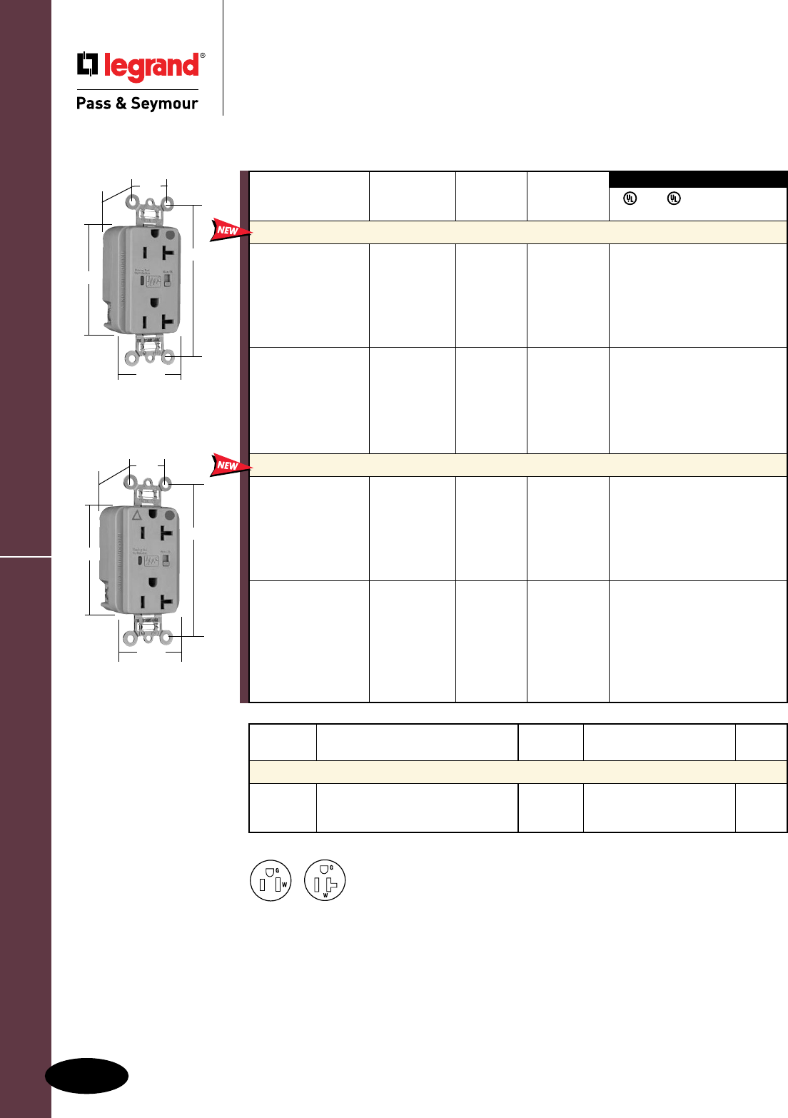
Catalog Catalog
Number Description Number Description Color
Wall Plates for Surge Protective Duplex Receptacles
SS26 Stainless Steel Decorator TP26IG* Thermoplastic Decorator Orange
SS26IG* Stainless Steel Decorator TP26BL Thermoplastic Decorator Blue
SB26 Brass Decorator *For Isolated Ground
HG Surge Protective Receptacles
F-4
Surge Protective & Isolated Ground Devices
Surge Protective & Isolated Ground Devices
Hospital Grade Surge Protective
Receptacles
2 Pole, 3 Wire Grounding 15 & 20A, 125VAC
NEMA
5-20R
NEMA
5-15R
8300GRYSP
3.75"
1.70"
.875"
1.25"
Behind Strap
2.75"
IG8300GRYSP
3.75"
1.70"
.875"
1.25"
Behind Strap
2.75"
All devices listed on this page conform to NEMA WD-1 and WD-6.
Conforms to the latest revision ANSI/IEEE C62.41 (formerly IEEE587), ANSI/IEEE C62.45.
FSUL
UL1449 UL498 WC596 cUL/CSA
Rating NEMA
Catalog Number A. VAC Cong. No. Color
Duplex Receptacles Back & Side Wire
8200ISP 15 125 5-15R Ivory • • • •
8200WSP 15 125 5-15R White • • • •
8200SP 15 125 5-15R Brown • • • •
8200GRYSP 15 125 5-15R Gray • • • •
8200REDSP 15 125 5-15R Red • • • •
8200LASP 15 125 5-15R Light Almond • • • •
8200BLSP 15 125 5-15R Blue • • • •
8300ISP 20 125 5-20R Ivory • • • •
8300WSP 20 125 5-20R White • • • •
8300SP 20 125 5-20R Brown • • • •
8300GRYSP 20 125 5-20R Gray • • • •
8300REDSP 20 125 5-20R Red • • • •
8300LASP 20 125 5-20R Light Almond • • • •
8300BLSP 20 125 5-20R Blue • • • •
Isolated Ground Duplex Receptacles Back & Side Wire
IG8200ISP 15 125 5-15R Ivory • • • •
IG8200WSP 15 125 5-15R White • • • •
IG8200GRYSP 15 125 5-15R Gray • • • •
IG8200REDSP 15 125 5-15R Red • • • •
IG8200LASP 15 125 5-15R Light Almond • • • •
IG8200BLSP 15 125 5-15R Blue • • • •
IG8200OSP 15 125 5-15R Orange • • • •
IG8300ISP 20 125 5-20R Ivory • • • •
IG8300WSP 20 125 5-20R White • • • •
IG8300SP 20 125 5-20R Brown • • • •
IG8300GRYSP 20 125 5-20R Gray • • • •
IG8300REDSP 20 125 5-20R Red • • • •
IG8300LASP 20 125 5-20R Light Almond • • • •
IG8300BLSP 20 125 5-20R Blue • • • •
IG8300OSP 20 125 5-20R Orange • • • •
3rd Party Compliance
Audible Alarm with LED Indicator
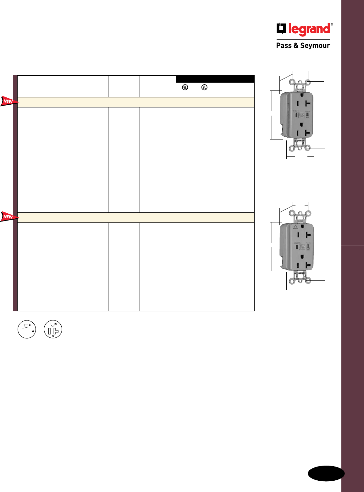
Surge Protective Receptacles
Surge Protective & Isolated Ground Devices
All devices listed on this page conform to NEMA WD-1 and WD-6.
Conforms to the latest revision ANSI/IEEE C62.41 (formerly IEEE587), ANSI/IEEE C62.45.
Surge Protective & Isolated Ground Devices
Surge Protective Receptacles
2 Pole, 3 Wire Grounding 15 & 20A, 125VAC
F-5
NEMA
5-20R
NEMA
5-15R
5362GRYSP
3.75"
1.70"
.875"
1.25"
Behind Strap
2.75"
Audible Alarm with LED Indicator
FSUL
UL1449 UL498 WC596 cUL/CSA
3rd Party Compliance
Rating NEMA
Catalog Number A. VAC Cong. No. Color
Extra Heavy-Duty Duplex Receptacles Back & Side Wire
5262ISP 15 125 5-15R Ivory • • • •
5262WSP 15 125 5-15R White • • • •
5262SP 15 125 5-15R Brown • • • •
5262GRYSP 15 125 5-15R Gray • • • •
5262BKSP 15 125 5-15R Black • • • •
5262REDSP 15 125 5-15R Red • • • •
5262LASP 15 125 5-15R Light Almond • • • •
5262BLSP 15 125 5-15R Blue • • • •
5362ISP 20 125 5-20R Ivory • • • •
5362WSP 20 125 5-20R White • • • •
5362SP 20 125 5-20R Brown • • • •
5362GRYSP 20 125 5-20R Gray • • • •
5362BKSP 20 125 5-20R Black • • • •
5362REDSP 20 125 5-20R Red • • • •
5362LASP 20 125 5-20R Light Almond • • • •
5362BLSP 20 125 5-20R Blue • • • •
Isolated Ground Duplex Receptacles
Back & Side Wire
IG5262ISP 15 125 5-15R Ivory • • • •
IG5262WSP 15 125 5-15R White • • • •
IG5262GRYSP 15 125 5-15R Gray • • • •
IG5262LASP 15 125 5-15R Light Almond • • • •
IG5262BLSP 15 125 5-15R Blue • • • •
IG5262OSP 15 125 5-15R Orange • • • •
IG5362ISP 20 125 5-20R Ivory • • • •
IG5362WSP 20 125 5-20R White • • • •
IG5362SP 20 125 5-20R Brown • • • •
IG5362GRYSP 20 125 5-20R Gray • • • •
IG5362LASP 20 125 5-20R Light Almond • • • •
IG5362BLSP 20 125 5-20R Blue • • • •
IG5362OSP 20 125 5-20R Orange • • • •IG5362GRYSP
3.75"
1.70"
.875"
1.25"
Behind Strap
2.75"
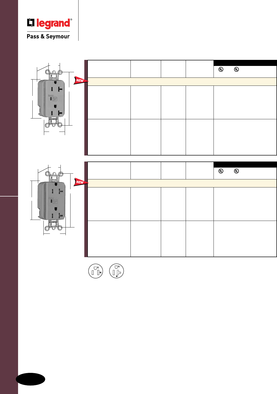
Surge Protective & Isolated Ground Devices
F-6
All devices listed on this page conform to NEMA WD-1 and WD-6.
Conforms to the latest revision ANSI/IEEE C62.41 (formerly IEEE587), ANSI/IEEE C62.45.
Surge Protective Receptacles
Surge Protective & Isolated Ground Devices
Surge Protective Receptacles
2 Pole, 3 Wire Grounding 15 & 20A, 125VAC
5352GRYSP
3.75"
1.70"
.875"
1.29"
Behind Strap
2.75"
3rd Party Compliance
3rd Party Compliance
FSUL
UL1449 UL498 WC596 cUL/CSA
Rating NEMA
Catalog Number A. VAC Cong. No. Color
Duplex Receptacles Back & Side Wire
5252ISP 15 125 5-15R Ivory • • • •
5252WSP 15 125 5-15R White • • • •
5252GRYSP 15 125 5-15R Gray • • • •
5252BKSP 15 125 5-15R Black • • • •
5252LASP 15 125 5-15R Light Almond • • • •
5252BLSP 15 125 5-15R Blue • • • •
5352ISP 20 125 5-20R Ivory • • • •
5352WSP 20 125 5-20R White • • • •
5352GRYSP 20 125 5-20R Gray • • • •
5352BKSP 20 125 5-20R Black • • • •
5352LASP 20 125 5-20R Light Almond • • • •
5352BLSP 20 125 5-20R Blue • • • •
LED Indicator Only
3rd Party Compliance
3rd Party Compliance
FSUL
UL1449 UL498 WC596 cUL/CSA
Rating NEMA
Catalog Number A. VAC Cong. No. Color
Tamper-Resistant Duplex Receptacles Back & Side Wire*
TR5252ISP 15 125 5-15R Ivory • • • •
TR5252WSP 15 125 5-15R White • • • •
TR5252GRYSP 15 125 5-15R Gray • • • •
TR5252BKSP 15 125 5-15R Black • • • •
TR5252LASP 15 125 5-15R Light Almond • • • •
TR5252BLSP 15 125 5-15R Blue • • • •
TR5352ISP 20 125 5-20R Ivory • • • •
TR5352WSP 20 125 5-20R White • • • •
TR5352GRYSP 20 125 5-20R Gray • • • •
TR5352BKSP 20 125 5-20R Black • • • •
TR5352LASP 20 125 5-20R Light Almond • • • •
TR5352BLSP 20 125 5-20R Blue • • • •
*Available Spring 2011
NEMA
5-20R
NEMA
5-15R
TR5352GRYSP
3.75"
1.70"
.875"
1.40"
Behind Strap
2.75"
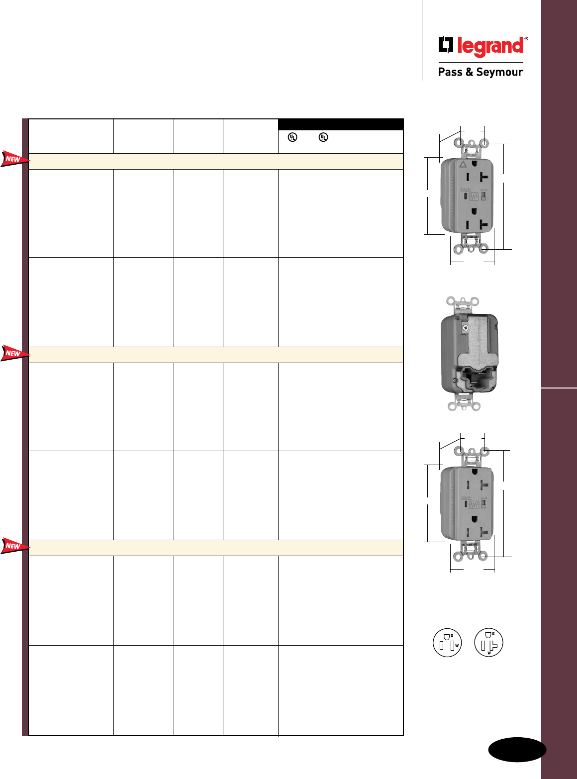
Surge Protective & Isolated Ground Devices
F-7
PlugTail™ Surge Protective Receptacles
Surge Protective & Isolated Ground Devices
PlugTail™ Surge Protective Receptacles
2 Pole, 3 Wire Grounding, 15 & 20A, 125VAC
3rd Party Compliance
3rd Party Compliance
FSUL
UL1449 UL498 WC596 cUL/CSA
Rating NEMA
Catalog Number A. VAC Cong. No. Color
Extra Heavy-Duty Duplex Receptacles
PT5262ISP 15 125 5-15R Ivory • • • •
PT5262WSP 15 125 5-15R White • • • •
PT5262SP 15 125 5-15R Brown • • • •
PT5262GRYSP 15 125 5-15R Gray • • • •
PT5262BKSP 15 125 5-15R Black • • • •
PT5262REDSP 15 125 5-15R Red • • • •
PT5262LASP 15 125 5-15R Light Almond • • • •
PT5262BLSP 15 125 5-15R Blue • • • •
PT5362ISP 20 125 5-20R Ivory • • • •
PT5362WSP 20 125 5-20R White • • • •
PT5362SP 20 125 5-20R Brown • • • •
PT5362GRYSP 20 125 5-20R Gray • • • •
PT5362BKSP 20 125 5-20R Black • • • •
PT5362REDSP 20 125 5-20R Red • • • •
PT5362LASP 20 125 5-20R Light Almond • • • •
PT5362BLSP 20 125 5-20R Blue • • • •
Isolated Ground Duplex Receptacles
PTIG5262ISP 15 125 5-15R Ivory • • • •
PTIG5262WSP 15 125 5-15R White • • • •
PTIG5262GRYSP 15 125 5-15R Gray • • • •
PTIG5262BKSP 15 125 5-15R Black • • • •
PTIG5262REDSP 15 125 5-15R Red • • • •
PTIG5262LASP 15 125 5-15R Light Almond • • • •
PTIG5262OSP 15 125 5-15R Orange • • • •
PTIG5262BLSP 15 125 5-15R Blue • • • •
PTIG5362ISP 20 125 5-20R Ivory • • • •
PTIG5362WSP 20 125 5-20R White • • • •
PTIG5362GRYSP 20 125 5-20R Gray • • • •
PTIG5362BKSP 20 125 5-20R Black • • • •
PTIG5362REDSP 20 125 5-20R Red • • • •
PTIG5362LASP 20 125 5-20R Light Almond • • • •
PTIG5362OSP 20 125 5-20R Orange • • • •
PTIG5362BLSP 20 125 5-20R Blue • • • •
Tamper-Resistant Duplex Receptacles
PTTR5262ISP 15 125 5-15R Ivory • • • •
PTTR5262WSP 15 125 5-15R White • • • •
PTTR5262SP 15 125 5-15R Brown • • • •
PTTR5262GRYSP 15 125 5-15R Gray • • • •
PTTR5262BKSP 15 125 5-15R Black • • • •
PTTR5262REDSP 15 125 5-15R Red • • • •
PTTR5262LASP 15 125 5-15R Light Almond • • • •
PTTR5262BLSP 15 125 5-15R Blue • • • •
PTTR5362ISP 20 125 5-20R Ivory • • • •
PTTR5362WSP 20 125 5-20R White • • • •
PTTR5362SP 20 125 5-20R Brown • • • •
PTTR5362GRYSP 20 125 5-20R Gray • • • •
PTTR5362BKSP 20 125 5-20R Black • • • •
PTTR5362REDSP 20 125 5-20R Red • • • •
PTTR5362LASP 20 125 5-20R Light Almond • • • •
PTTR5362BLSP 20 125 5-20R Blue • • • •
Audible Alarm with LED Indicator
Available Spring 2011
NEMA
5-20R
NEMA
5-15R
PTIG5362GRYSP
3.75"
1.70"
.875"
1.20"
Behind Strap
2.75"
PTTR5362GRYSP
3.75"
1.70"
.875"
1.40"
Behind Strap
2.75"
All devices listed on this page
conform to NEMA WD-1, WD-6.
Conforms to the latest revision
ANSI/IEEE C62.41 (formerly
IEEE587), ANSI/IEEE C62.45.
For PlugTail Connectors,
see Page B-3.
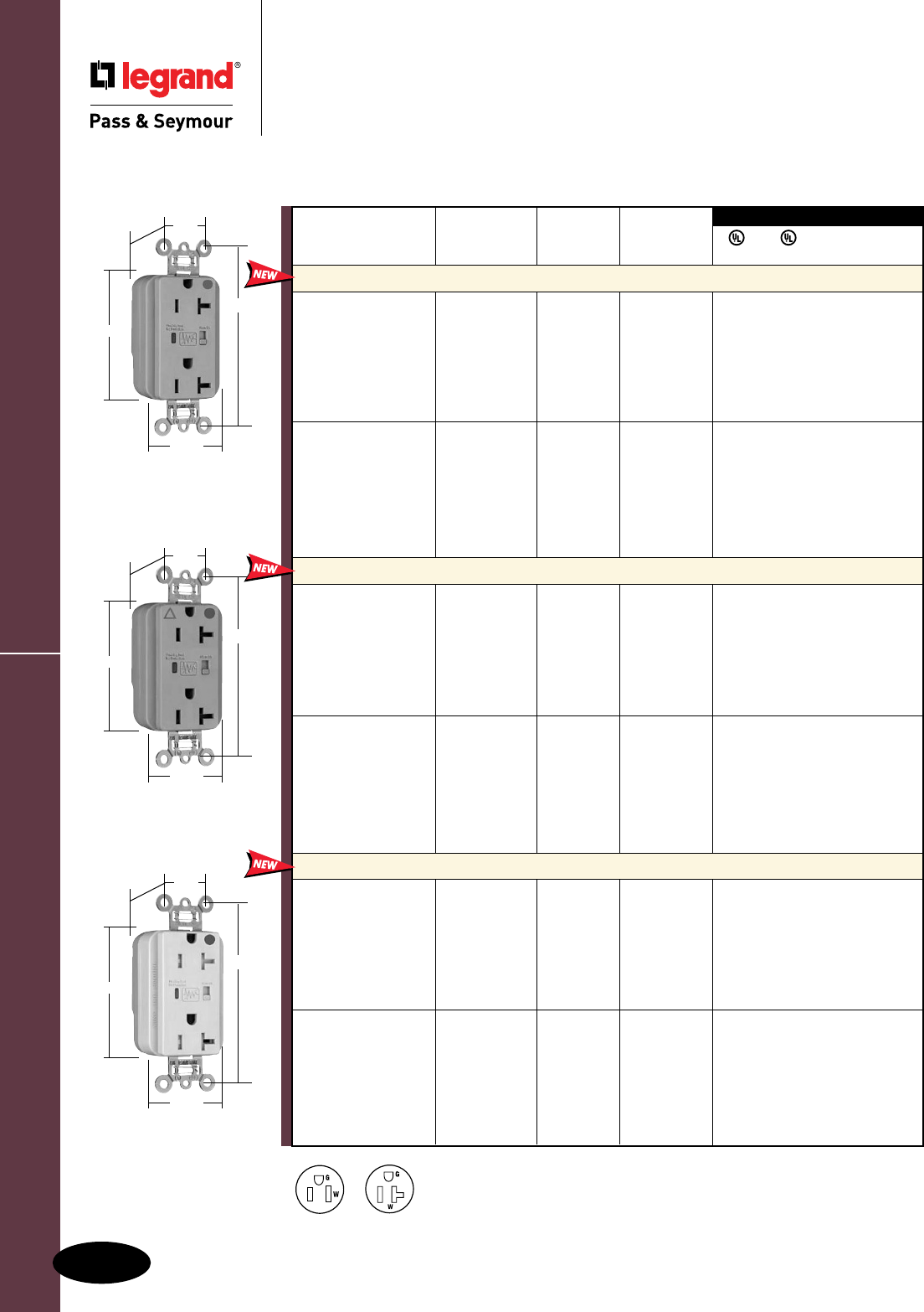
Surge Protective & Isolated Ground Devices
F-8
Available Spring 2011
NEMA
5-20R
NEMA
5-15R
PlugTail™ HG Surge Protective Receptacles
Surge Protective & Isolated Ground Devices
PlugTail™ Hospital Grade
Surge Protective Receptacles
2 Pole, 3 Wire Grounding, 15 & 20A, 125VAC
3rd Party Compliance
3rd Party Compliance
FSUL
UL1449 UL498 WC596 cUL/CSA
Rating NEMA
Catalog Number A. VAC Cong. No. Color
Extra Heavy-Duty Duplex Receptacles
PT8200ISP 15 125 5-15R Ivory • • • •
PT8200WSP 15 125 5-15R White • • • •
PT8200SP 15 125 5-15R Brown • • • •
PT8200GRYSP 15 125 5-15R Gray • • • •
PT8200REDSP 15 125 5-15R Red • • • •
PT8200LASP 15 125 5-15R Light Almond • • • •
PT8200BLSP 15 125 5-15R Blue • • • •
PT8300ISP 20 125 5-20R Ivory • • • •
PT8300WSP 20 125 5-20R White • • • •
PT8300SP 20 125 5-20R Brown • • • •
PT8300GRYSP 20 125 5-20R Gray • • • •
PT8300REDSP 20 125 5-20R Red • • • •
PT8300LASP 20 125 5-20R Light Almond • • • •
PT8300BLSP 20 125 5-20R Blue • • • •
Isolated Ground Duplex Receptacles
PTIG8200ISP 15 125 5-15R Ivory • • • •
PTIG8200WSP 15 125 5-15R White • • • •
PTIG8200GRYSP 15 125 5-15R Gray • • • •
PTIG8200REDSP 15 125 5-15R Red • • • •
PTIG8200LASP 15 125 5-15R Light Almond • • • •
PTIG8200BLSP 15 125 5-15R Blue • • • •
PTIG8200OSP 15 125 5-15R Orange • • • •
PTIG8300ISP 20 125 5-20R Ivory • • • •
PTIG8300WSP 20 125 5-20R White • • • •
PTIG8300GRYSP 20 125 5-20R Gray • • • •
PTIG8300REDSP 20 125 5-20R Red • • • •
PTIG8300LASP 20 125 5-20R Light Almond • • • •
PTIG8300BLSP 20 125 5-20R Blue • • • •
PTIG8300OSP 20 125 5-20R Orange • • • •
Tamper-Resistant Duplex Receptacles
PTTR8200ISP 15 125 5-15R Ivory • • • •
PTTR8200WSP 15 125 5-15R White • • • •
PTTR8200SP 15 125 5-15R Brown • • • •
PTTR8200GRYSP 15 125 5-15R Gray • • • •
PTTR8200REDSP 15 125 5-15R Red • • • •
PTTR8200LASP 15 125 5-15R Light Almond • • • •
PTTR8200BLSP 15 125 5-15R Blue • • • •
PTTR8300ISP 20 125 5-20R Ivory • • • •
PTTR8300WSP 20 125 5-20R White • • • •
PTTR8300SP 20 125 5-20R Brown • • • •
PTTR8300GRYSP 20 125 5-20R Gray • • • •
PTTR8300REDSP 20 125 5-20R Red • • • •
PTTR8300LASP 20 125 5-20R Light Almond • • • •
PTTR8300BLSP 20 125 5-20R Blue • • • •
Audible Alarm with LED Indicator
PT8300GRYSP
3.75"
1.70"
.875"
1.20"
Behind Strap
2.75"
PTIG8300GRYSP
3.75"
1.70"
.875"
1.20"
Behind Strap
2.75"
PTTR8300ISP
3.75"
1.70"
.875"
1.40"
Behind Strap
2.75"
All devices listed on this page conform to NEMA WD-1 and WD-6.
Conforms to the latest revision ANSI/IEEE C62.41 (formerly IEEE587), ANSI/IEEE C62.45.
For PlugTail Connectors,
see Page B-3.
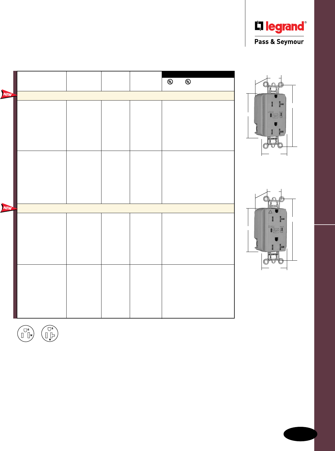
Surge Protective & Isolated Ground Devices
F-9
TR Surge Protective Receptacles
Surge Protective & Isolated Ground Devices
Tamper-Resistant
Surge Protective Receptacles
2 Pole, 3 Wire Grounding, 15 & 20A, 125VAC
3rd Party Compliance
3rd Party Compliance
FSUL
UL1449 UL498 WC596 cUL/CSA
Rating NEMA
Catalog Number A. VAC Cong. No. Color
Extra Heavy-Duty Duplex Receptacles Back & Side Wire
TR5262ISP 15 125 5-15R Ivory • • • •
TR5262WSP 15 125 5-15R White • • • •
TR5262SP 15 125 5-15R Brown • • • •
TR5262GRYSP 15 125 5-15R Gray • • • •
TR5262BKSP 15 125 5-15R Black • • • •
TR5262REDSP 15 125 5-15R Red • • • •
TR5262LASP 15 125 5-15R Light Almond • • • •
TR5262BLSP 15 125 5-15R Blue • • • •
TR5362ISP 20 125 5-20R Ivory • • • •
TR5362WSP 20 125 5-20R White • • • •
TR5362SP 20 125 5-20R Brown • • • •
TR5362GRYSP 20 125 5-20R Gray • • • •
TR5362BKSP 20 125 5-20R Black • • • •
TR5362REDSP 20 125 5-20R Red • • • •
TR5362LASP 20 125 5-20R Light Almond • • • •
TR5362BLSP 20 125 5-20R Blue • • • •
Isolated Ground Duplex Receptacles Back & Side Wire
TRIG5262ISP 15 125 5-15R Ivory • • • •
TRIG5262WSP 15 125 5-15R White • • • •
TRIG5262GRYSP 15 125 5-15R Gray • • • •
TRIG5262BKSP 15 125 5-15R Black • • • •
TRIG5262REDSP 15 125 5-15R Red • • • •
TRIG5262LASP 15 125 5-15R Light Almond • • • •
TRIG5262BLSP 15 125 5-15R Blue • • • •
TRIG5262OSP 15 125 5-15R Orange • • • •
TRIG5362ISP 20 125 5-20R Ivory • • • •
TRIG5362WSP 20 125 5-20R White • • • •
TRIG5362GRYSP 20 125 5-20R Gray • • • •
TRIG5362BKSP 20 125 5-20R Black • • • •
TRIG5362REDSP 20 125 5-20R Red • • • •
TRIG5362LASP 20 125 5-20R Light Almond • • • •
TRIG5362BLSP 20 125 5-20R Blue • • • •
TRIG5362OSP 20 125 5-20R Orange • • • •
Audible Alarm with LED Indicator
Available Spring 2011
NEMA
5-20R
NEMA
5-15R
TR5362GRYSP
TRIG5362GRYSP
3.75"
1.70"
.875"
2.75"
1.40"
Behind Strap
3.75"
1.70"
.875"
2.75"
1.40"
Behind Strap
All devices listed on this page conform to NEMA WD-1 and WD-6.
Conforms to the latest revision ANSI/IEEE C62.41 (formerly IEEE587), ANSI/IEEE C62.45.
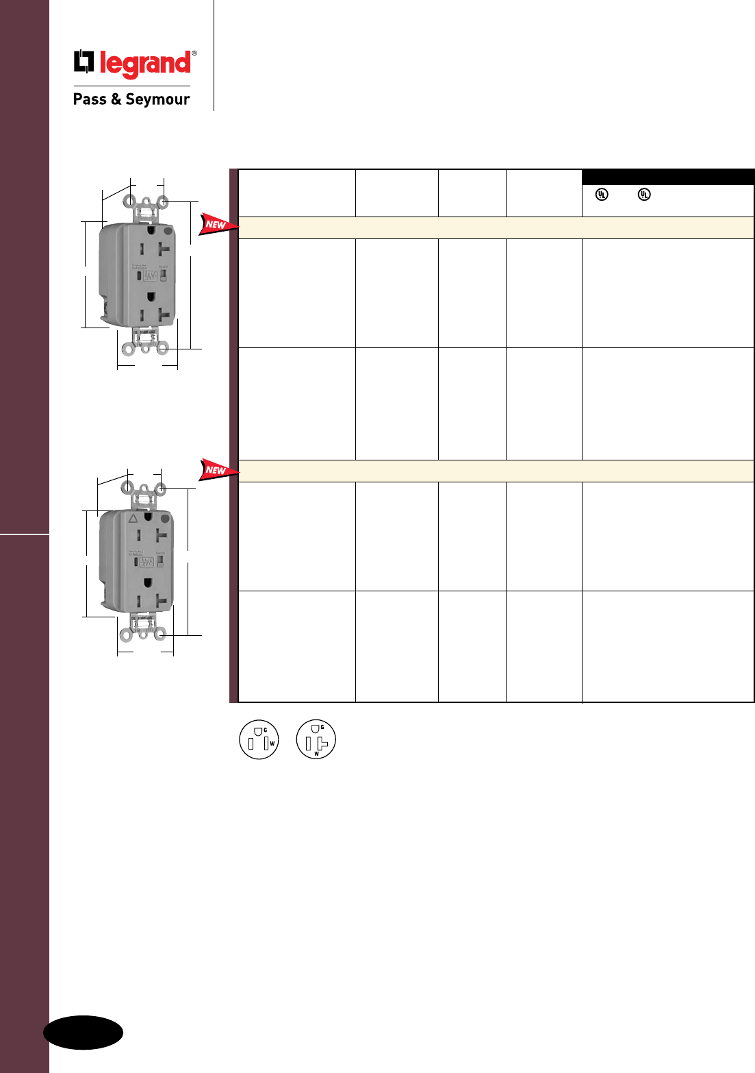
Surge Protective & Isolated Ground Devices
F-10
TR8300GRYSP
3.75"
1.70"
.875"
1.40"
Behind Strap
2.75"
TRIG8300GRYSP
3.75"
1.70"
.875"
1.40"
Behind Strap
2.75"
Surge Protective & Isolated Ground Devices
Tamper-Resistant Hospital Grade
Surge Protective Receptacles
2 Pole, 3 Wire Grounding, 15 & 20A, 125VAC
TR HG Surge Protective Receptacles
3rd Party Compliance
3rd Party Compliance
FSUL
UL1449 UL498 WC596 cUL/CSA
Rating NEMA
Catalog Number A. VAC Cong. No. Color
Extra Heavy-Duty Duplex Receptacles Back & Side Wire
TR8200ISP 15 125 5-15R Ivory • • • •
TR8200WSP 15 125 5-15R White • • • •
TR8200SP 15 125 5-15R Brown • • • •
TR8200GRYSP 15 125 5-15R Gray • • • •
TR8200REDSP 15 125 5-15R Red • • • •
TR8200LASP 15 125 5-15R Light Almond • • • •
TR8200BLSP 15 125 5-15R Blue • • • •
TR8300ISP 20 125 5-20R Ivory • • • •
TR8300WSP 20 125 5-20R White • • • •
TR8300SP 20 125 5-20R Brown • • • •
TR8300GRYSP 20 125 5-20R Gray • • • •
TR8300REDSP 20 125 5-20R Red • • • •
TR8300LASP 20 125 5-20R Light Almond • • • •
TR8300BLSP 20 125 5-20R Blue • • • •
Isolated Ground Duplex Receptacles Back & Side Wire
TRIG8200ISP 15 125 5-15R Ivory • • • •
TRIG8200WSP 15 125 5-15R White • • • •
TRIG8200GRYSP 15 125 5-15R Gray • • • •
TRIG8200REDSP 15 125 5-15R Red • • • •
TRIG8200LASP 15 125 5-15R Light Almond • • • •
TRIG8200BLSP 15 125 5-15R Blue • • • •
TRIG8200OSP 15 125 5-15R Orange • • • •
TRIG8300ISP 20 125 5-20R Ivory • • • •
TRIG8300WSP 20 125 5-20R White • • • •
TRIG8300GRYSP 20 125 5-20R Gray • • • •
TRIG8300REDSP 20 125 5-20R Red • • • •
TRIG8300LASP 20 125 5-20R Light Almond • • • •
TRIG8300BLSP 20 125 5-20R Blue • • • •
TRIG8300OSP 20 125 5-20R Orange • • • •
Audible Alarm with LED Indicator
Available Spring 2011
NEMA
5-20R
NEMA
5-15R
All devices listed on this page conform to NEMA WD-1 and WD-6.
Conforms to the latest revision ANSI/IEEE C62.41 (formerly IEEE587), ANSI/IEEE C62.45.
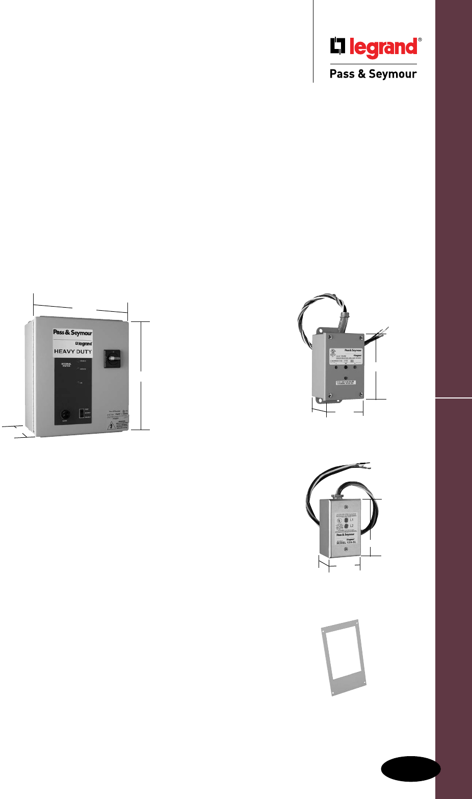
Surge Protective & Isolated Ground Devices
F-11
All devices listed on this page are UL & CSA Listed and conform to NEMA LS-1.
Surge Protection Panels
Surge Protective & Isolated Ground Devices
Surge Protection Panels
Heavy-, Medium- & Light-Duty
Heavy-Duty
14.00"
8.00" Medium-Duty
6.00"
4.00"
3.00"
Light-Duty
2.8" 2.2"
MFKIT
Stronger Protection That’s Needed — And Required.
Our most rugged line of Surge Protection Panels deliver premise-wide
protection from electrical surges caused by lightning, utility grid switching,
and initial startup of electrical equipment such as motors, arc furnaces,
and welders.
When surges hit, few business owners can count on insurance to cover
full replacement value — and downtime can be devastating to businesses.
UL Standard for Safety for Surge Protective Devices, UL1449 3rd Edition
requires a higher degree of protection from panel Surge Protection units.
P&S Surge Protection Panels meet the new standard, bringing greater
protection to any residential, commercial, or industrial application where
equipment surge protection is needed.
n NEMA 12 enclosure made of epoxy painted steel with gasketing,
provides for indoor use protection against dust, dirt and non-corrosive
liquids.
n Audible alarm — visible on the enclosure coverprovides supplementary
indication of failed surge suppression components.
n LED visual indicators provide a method for determining the status of
the surge suppression components. Green LED is illuminated at all times
while unit is functioning with no faults. A red LED will come on if any
phase/mode has a fault.
n Flanged mounting feet are standard with the NEMA 12 enclosure.
n Lockable rotary disconnect switch allows for removal of electrical
power in the event that servicing is required. Lockable only in the off
position for increased safety.
n Three-position test switch allows for operational testing of indicator
lights and the audible alarm. Functions are: enable/switch/test.
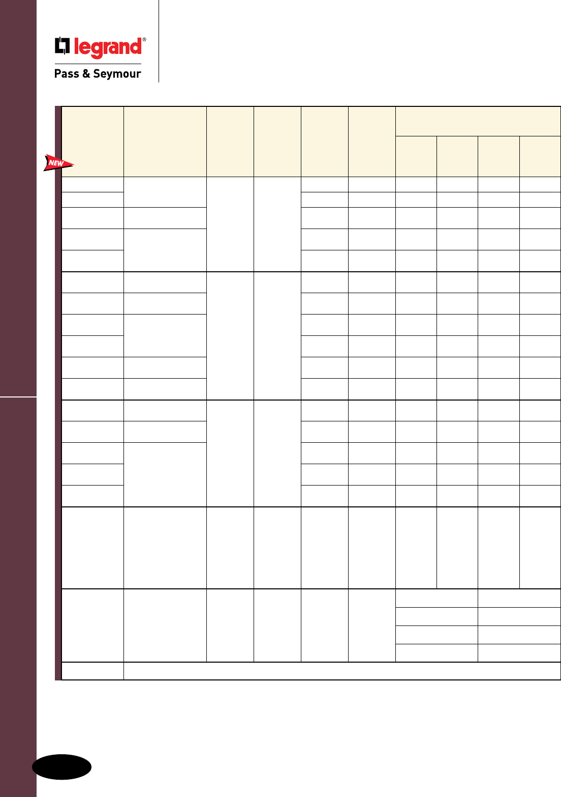
Surge Protection Panels
Surge Protective & Isolated Ground Devices
Surge Protective & Isolated Ground Devices
Surge Protection Panels
Heavy-, Medium- & Light-Duty
F-12
All devices listed on this page are UL & CSA Listed and conform to NEMA LS-1.
Catalog
Number Description Nominal
Voltage
System
Application
Max
Surge
Capability
Available
Interrupt
Current
UL 1449 Voltage Protection Ratings (Vpk)
Line
to Neutral
Line
to
Ground
Line
to
Line
Neutral to
Ground
1224SL Light-Duty Surge
Protection Panel
120/240
VAC
Single
Phase,
3W plus
Ground
40KA 42kAIC 600 N/A 1200 N/A
1224SLI 50KA 22kAIC 600 700 1000 700
1224SM Medium-Duty Surge
Protection Panel 100KA 65kAIC 600 1000 1200 600
1224SH Heavy-Duty Surge
Protection Panel
200KA 200kAIC 800 900 1200 700
1224SHB 200KA 200kAIC 800 900 1200 700
1220TWLI Light-Duty Surge
Protection Panel
120/208
VAC
Three
Phase,
Wye,
4W plus
Ground
100KA 22kAIC 600 700 1000 700
1220TWM Medium-Duty Surge
Protection Panel 100KA 65kAIC 600 1000 1200 600
1220TWH Heavy-Duty Surge
Protection Panel
200KA 200kAIC 800 900 1200 700
1220TWHB 200KA 200kAIC 800 900 1200 700
1220TWES Surge Protection
Panel Extension 200KA 200kAIC 800 800 1000 700
1220TWH4B Heavy-Duty Surge
Protection Panel 400KA 200kAIC 800 900 1200 700
2748TWLI Light-Duty Surge
Protection Panel
277/480
VAC
Three
Phase,
Wye,
4W plus
Ground
100KA 22kAIC 1200 1200 2000 1200
2748TWM Medium-Duty Surge
Protection Panel 100KA 65kAIC 1000 1800 2000 1000
2748TWH
Heavy-Duty Surge
Protection Panel
200KA 200kAIC 1200 1200 2000 1000
2748TWHB 200KA 200kAIC 1200 1200 2000 1000
2748TWH4B 400KA 200kAIC 1200 1200 2000 1000
480TDH Heavy-Duty Surge
Protection Panel
480
VAC
Three
Phase,
Delta,
3W plus
Ground
200KA 200kAIC N/A 1800 3000 N/A
240TDM Medium-Duty Surge
Protection Panel
120/240
VAC
Three
Phase,
Delta,
High Leg,
4W plus
Ground
100KA 65kAIC
A-N,C-N: 600 B-N: 1200
A-G,C-G: 1000 B-G: 1500
N-G: 600 A-B: 1500
A-C: 1200 B-C: 1500
MFKIT Allows for flush mounting of Catalog Numbers 1224SM, 1220TWM, 2748TWM, 240TDM.
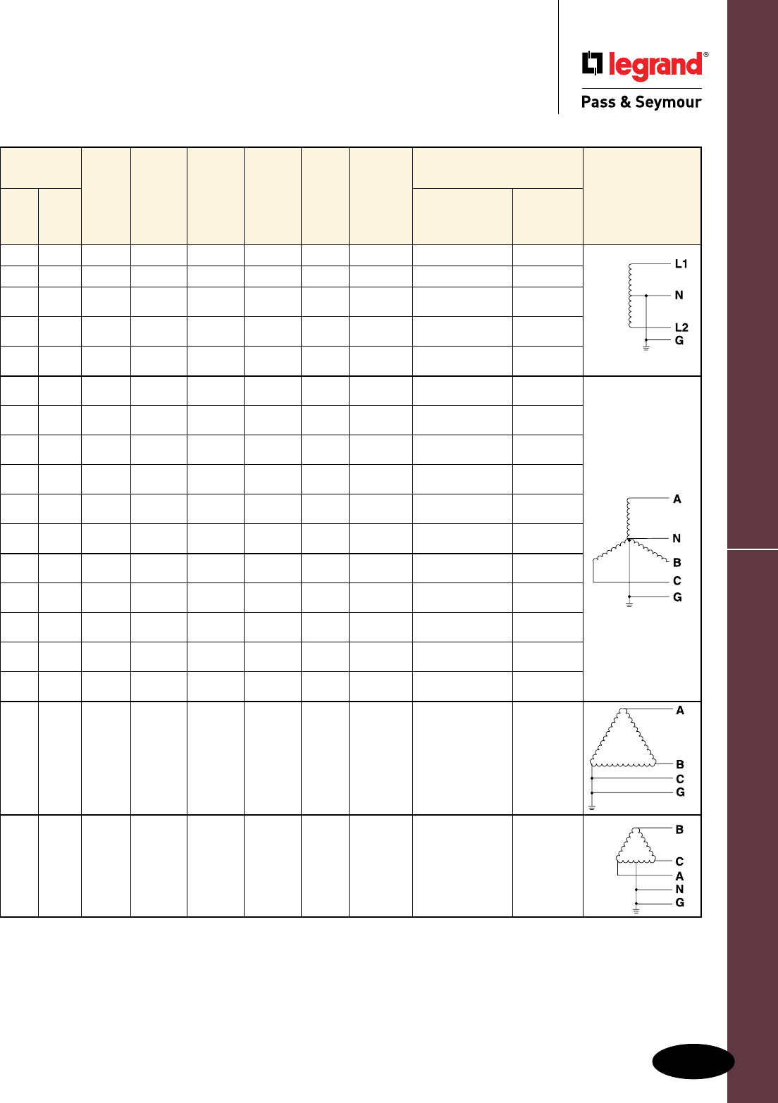
Surge Protection Panels
Surge Protective & Isolated Ground Devices
Surge Protective & Isolated Ground Devices
Surge Protection Panels
Heavy-, Medium- & Light-Duty
F-13
Visual
Indicators
Audio
Alarm
Alarm
Disable
Switch
Test
Switch
Form C
Contract
EMI/RFI
Filtering
Rotary
Disconnect
Connection Means
Transformer
Configurations
Red Green Type Gauge
0 2 Wire #10
0 1 X Wire #12
1 2 X X Wire #12
1 1 X X X X X X Screw Terminal #4 – #8
1 1 X X X X X Screw Terminal #10 – #4
1 1 X Wire #12
1 3 X X Wire #12
1 1 X X X X X X Screw Terminal #4 – #8
1 1 X X X X X Screw Terminal #10 – #4
1 1 X X X X Terminal Block #4 – #10
1 1 X X X X X Screw Terminal #10 – #4
0 1 X Wire #12
1 3 X X Wire #12
1 1 X X X X X X Screw Terminal #4 – #8
1 1 X X X X X Screw Terminal #10 – #4
1 1 X X X X X Screw Terminal #10 – #4
1 1 X X X X X X Screw Terminal #1/0 – #8
1 3 X X Wire #12
All devices listed on this page are UL & CSA Listed and conform to NEMA LS-1.
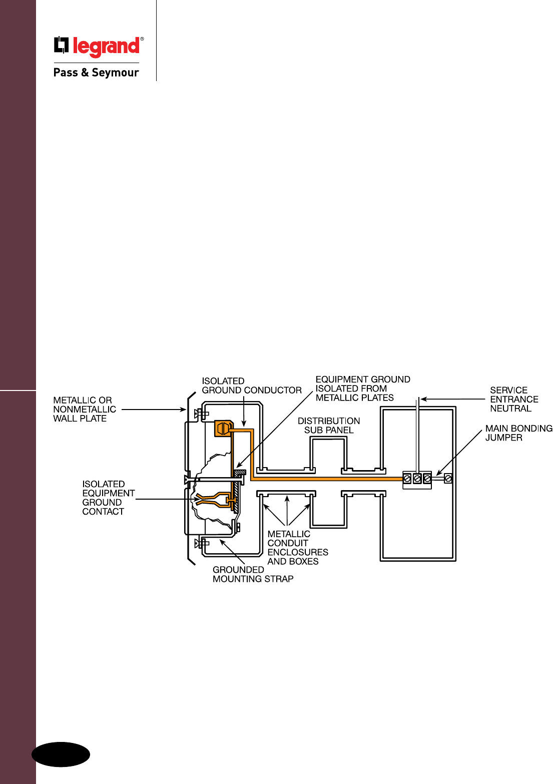
Product Description – Isolated Ground
Surge Protective & Isolated Ground Devices
Surge Protective & Isolated Ground Devices
Product Description – Isolated Ground
Straight Blade & Turnlok®
F-14F-14
The Problem of Electromagnetic Interference
Reduction of electromagnetic interference (EMI) in the electrical grounding system is
essential for proper operation of many types of electronic equipment. In conventional
grounding circuits, the conduit system is used as the grounding path. The conduit system
is grounded at the service entrance and connected to intervening sub-panels, structural
steel, and other grounded equipment. Although this will provide personnel and equipment
protection, the entire conduit system becomes a large antenna which collects EMI (i.e.,
electrical noise) and transmits it throughout the grounding system. Whenever that occurs,
the signals may adversely affect the performance of personal and small business computers,
electronic testing and calibration equipment, and solid-state cash registers.
The Legrand®
/
Pass & Seymour Solution
By running an insulated equipment grounding conductor directly to the neutral at the
service entrance, and installing P&S Isolated Ground Receptacles, you effectively isolate
the grounding circuit from the conduit grounding system. This significantly reduces the
size of the antenna and limits the amount of EMI that can be picked up in the isolated
grounding system. This provides a relatively noise-free grounding path and improves the
operation of electronic equipment.
2011 National Electrical Code® Section 250.146(D) Isolated Receptacles.
Where installed for the reduction of electrical noise (electromagnetic interference) on the grounding circuit, a receptacle
in which the grounding terminal is purposely insulated from the receptacle mounting means shall be permitted. The
receptacle grounding terminal shall be connected to an insulated equipment grounding conductor run with the circuit
conductors. This equipment grounding conductor shall be permitted to pass through one or more panelboards without a
connection to the panelboard grounding terminal bar as permitted in Section 408.40, Exception, so as to terminate within
the same building or structure directly at an equipment grounding conductor terminal of the applicable derived system or
service. Where installed in accordance with the provisions of this section, this equipment grounding conductor shall also
be permitted to pass through boxes, wireways, or other enclosures without being connected to such enclosures.
2011 National Electrical Code® Section 406.3
(D)
Isolated Ground Receptacles.
Receptacles incorporating an isolated grounding conductor connection intended for the reduction of electrical noise
(electromagnetic interference) as permitted in Section 250.146(D), shall be identified by an orange triangle located on
the face of the receptacle.
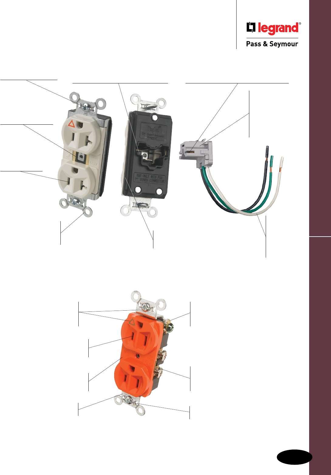
Isolated Ground Receptacles
Surge Protective & Isolated Ground Devices
Surge Protective & Isolated Ground Devices
Isolated Ground Receptacles
F-15
IG5262
IG symbol and Isolated
Ground markings for
easy identification and
circuit delineation.
Patented feature, external
screw-pressure-plate back wire
clamp on ground terminal for
faster, easier installation.
Triple-wipe brass contacts
ensure lasting, positive contact
with plug blades.
Plastic barrier isolates
grounding terminal from
mounting strap and metal boxes.
High-impact resistant
nylon face resists impacts
and scrapes.
Corrosion-resistant
plated steel strap.
Side and internal screw-pressureplate
back wire capability with #14 – #10
AWG copper or copper-clad, solid or
stranded wire.
Auto-ground clip
assures positive ground.
Plastic barrier
isolates grounding
terminal from
mounting strap and
metal boxes.
.036 inch thick,
brass, triple-
wipe power
contacts for
lasting retention.
Auto-ground clip
assures positive ground.
Three drive screws
anchor strap to back
body and face.
Plated steel wrap
strap design for
maximum durability and
corrosion resistance.
PTIG5362LA No exposed terminals create
a finger safe application before,
during, and after installation.
Built-in connector features large brass
terminal blades to ensure consistent,
reliable electrical connections.
Large brass contacts snugly terminate on
device blade terminals. Audible snapping
latch assures connection, allows release.
Pre-stripped
connector
leads fasten
to conductors,
easier than
standard
pigtails.
Ultrasonically
welded
polycarbonate
connector housing
secures terminations
and conductors in a
UL Listed, finger safe
housing.
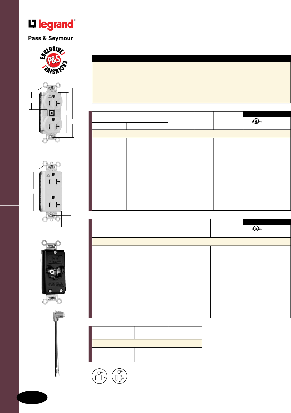
PTIG5362LA
1.104"
2.750"
3.281"
.625"
PTIG26362LA
1.5"
3.281"
2.750"
.625"
PlugTail™ Isolated Ground Receptacles
Surge Protective & Isolated Ground Devices
All devices listed on this page conform to NEMA WD-1 and WD-6.
Surge Protective & Isolated Ground Devices
PlugTail™ Isolated Ground Receptacles
2 Pole, 3 Wire Grounding, 15 & 20A, 125V
F-16
Features
n .036 inch thick brass triple wire contacts for
lasting retention.
n Impact-resistant nylon face.
n Corrosion-resistant plated steel straight strap
for increased rigidity and strength.
n Auto-ground clip assures positive ground.
n No exposed terminals for a finger safe application.
n Ultrasonically welded polycarbonate
connector housing secures terminations
in a UL Listed finger safe housing.
n Pre-stripped connector leads.
n Nylon isolator plate for isolating ground from
strap and box system.
n Crimped and welded contacts.
NEMA
5-15R
NEMA
5-20R
PTRA6STR
1.125"
6.375"
For Bulk Packaging Solutions consult factory.
Catalog
Number Wire Type Wire Length
PlugTail Connectors – Right Angle
PTRA6STR Stranded 6"
PTRA6SOL Solid 6"
For additional PlugTail Connectors,
see Page B-3.
All PlugTail Connectors are available
in any wire length up to 25 inches,
consult factory to order.
3rd Party Compliance
FSUL
cULus WC596
Catalog Rating NEMA
Number A. V. Cong. No. Color
Decorator Duplex Receptacles
PTIG26262I 15 125 5-15R Ivory • •
PTIG26262W 15 125 5-15R White • •
PTIG26262 15 125 5-15R Orange • •
PTIG26262GRY 15 125 5-15R Gray • •
PTIG26262RED 15 125 5-15R Red • •
PTIG26262LA 15 125 5-15R Light Almond • •
PTIG26362I 20 125 5-20R Ivory • •
PTIG26362W 20 125 5-20R White • •
PTIG26362 20 125 5-20R Orange • •
PTIG26362GRY 20 125 5-20R Gray • •
PTIG26362RED 20 125 5-20R Red • •
PTIG26362LA 20 125 5-20R Light Almond • •
NEMA
Catalog Number Rating Cong.
Spec Grade Hospital Grade A. V. No. Color
Duplex Receptacles
PTIG5262I PTIG8200I 15 125 5-15R Ivory • •
PTIG5262W 15 125 5-15R White • •
PTIG5262 PTIG8200 15 125 5-15R Orange • •
PTIG5262GRY 15 125 5-15R Gray • •
PTIG5262RED PTIG8200RED 15 125 5-15R Red • •
PTIG5262LA 15 125 5-15R Light Almond • •
PTIG5362I PTIG8300I 20 125 5-20R Ivory • •
PTIG5362W 20 125 5-20R White • •
PTIG5362 PTIG8300 20 125 5-20R Orange • •
PTIG5362GRY 20 125 5-20R Gray • •
PTIG5362RED PTIG8300RED 20 125 5-20R Red • •
PTIG5362LA PTIG8300LA 20 125 5-20R Light Almond • •
3rd Party Compliance
FSUL
cULus WC596
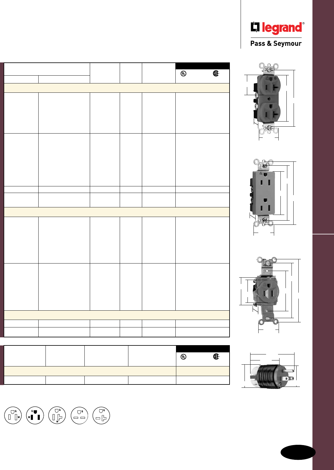
Isolated Ground Receptacles
Surge Protective & Isolated Ground Devices
All devices listed on this page conform to NEMA WD-1 and WD-6.
Surge Protective & Isolated Ground Devices
Isolated Ground Receptacles
2 Pole, 3 Wire Grounding 15 & 20A, 125 & 250V
F-17
IG26262GRY
.833"
1.322"
3.281"
2.635"
3.813"
IG8300
1.322"
1.104" 2.635"
3.281"
.922"
NEMA
5-15R
NEMA
5-15P
NEMA
6-20R
PSIG5266X
1.752"
1.516" 1.358"
2.791"
Consult Straight Blade Section G for complete line of Straight Blade Plugs & Connectors.
Catalog Rating NEMA Cord
Number A. V. Cong. No. Diameter
Straight Blade Plugs, Orange
PSIG5266X 15 125 5-15P .230" – .720" • • •
3rd Party Compliance
FSUL
UL498 WC596 C22.2 No. 42
NEMA
5-20R
1.093"
1.32"
3.28"
2.37"
3.68"
1.38"
1.68"
IG5261
For Wall Plates for Isolated Ground Systems,
consult Wall Plates Section Q.
For Bulk Packaging Solutions consult factory.
NEMA
Catalog Number Rating Cong.
Spec Grade Hospital Grade A. V. No. Color
Duplex Receptacles Back & Side Wire
IG5262I IG8200I 15 125 5-15R Ivory • • •
IG5262W 15 125 5-15R White • • •
IG5262 IG8200 15 125 5-15R Orange • • •
IG5262GRY 15 125 5-15R Gray • • •
IG5262RED IG8200RED 15 125 5-15R Red • • •
IG5262LA 15 125 5-15R Light Almond • • •
IG5362I IG8300I 20 125 5-20R Ivory • • •
IG5362W IG8300W 20 125 5-20R White • • •
IG5362 IG8300 20 125 5-20R Orange • • •
IG5362GRY 20 125 5-20R Gray • • •
IG5362BK 20 125 5-20R Black • • •
IG5362RED IG8300RED 20 125 5-20R Red • •
IG5362LA IG8300LA 20 125 5-20R Light Almond • • •
IG5362BL 20 125 5-20R Blue • • •
IG5662 15 250 6-15R Orange • • •
IG8800LA 20 250 6-20R Light Almond • • •
IG5862 IG8800 20 250 6-20R Orange • • •
Decorator Duplex Receptacles Back & Side Wire
IG26262I 15 125 5-15R Ivory • • •
IG26262W IG26262HGW 15 125 5-15R White • • •
IG26262 IG26262HG 15 125 5-15R Orange • • •
IG26262GRY 15 125 5-15R Gray • • •
IG26262BK 15 125 5-15R Black • • •
IG26262RED IG26262HGRED 15 125 5-15R Red • • •
IG26262LA 15 125 5-15R Light Almond • • •
IG26362I 20 125 5-20R Ivory • • •
IG26362W IG26362HGW 20 125 5-20R White • • •
IG26362 IG26362HG 20 125 5-20R Orange • • •
IG26362GRY 20 125 5-20R Gray • • •
IG26362BK IG26362HGBK 20 125 5-20R Black • • •
IG26362RED IG26362HGRED 20 125 5-20R Red • • •
IG26362LA 20 125 5-20R Light Almond • • •
Single Receptacles Back & Side Wire
IG5261 15 125 5-15R Orange • • •
IG5361 IG8301 20 125 5-20R Orange • • •
3rd Party Compliance
FSUL
UL498 WC596 C22.2 No. 42
NEMA
6-15R
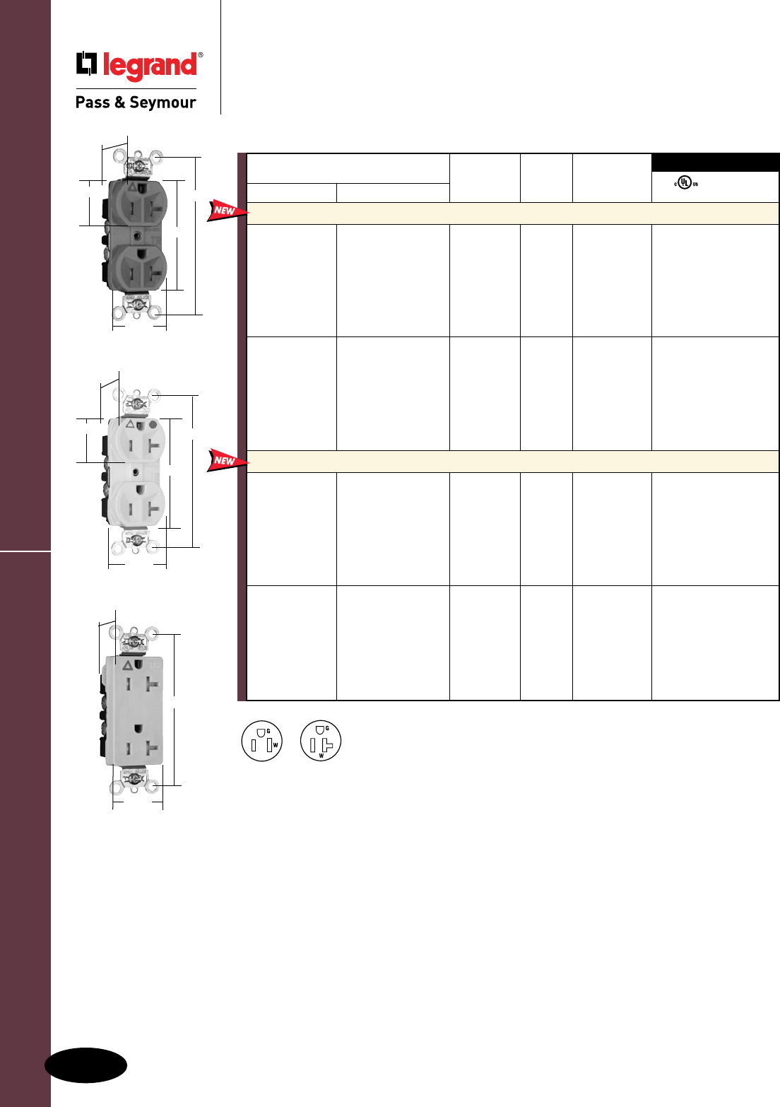
Surge Protective & Isolated Ground Devices
All devices listed on this page conform to NEMA WD-1 and WD-6.
F-18
Tamper-Resistant Isolated Ground Receptacles
Surge Protective & Isolated Ground Devices
Tamper-Resistant Isolated Ground
Receptacles
2 Pole, 3 Wire Grounding, 15 & 20A, 125V
For Bulk Packaging Solutions consult factory.
NEMA
5-20R
NEMA
5-15R
FSUL
UL498 WC596
3rd Party Compliance
NEMA
Catalog Number Rating Cong.
Spec Grade Hospital Grade A. V. No. Color
Tamper-Resistant Duplex Receptacles Back & Side Wire
TRIG5262I TRIG8200I 15 125 5-15R Ivory • •
TRIG5262W TRIG8200W 15 125 5-15R White • •
TRIG5262 TRIG8200 15 125 5-15R Orange • •
TRIG5262GRY TRIG8200GRY 15 125 5-15R Gray • •
TRIG5262BK TRIG8200BK 15 125 5-15R Black • •
TRIG5262RED TRIG8200RED 15 125 5-15R Red • •
TRIG5262LA TRIG8200LA 15 125 5-15R Light Almond • •
TRIG5362I TRIG8300I 20 125 5-20R Ivory • •
TRIG5362W TRIG8300W 20 125 5-20R White • •
TRIG5362 TRIG8300 20 125 5-20R Orange • •
TRIG5362GRY TRIG8300GRY 20 125 5-20R Gray • •
TRIG5362BK TRIG8300BK 20 125 5-20R Black • •
TRIG5362RED TRIG8300RED 20 125 5-20R Red • •
TRIG5362LA TRIG8300LA 20 125 5-20R Light Almond • •
Tamper-Resistant Decorator Receptacles Back & Side Wire
TRIG26262I TRIG26262HGI 15 125 5-15R Ivory • •
TRIG26262W TRIG26262HGW 15 125 5-15R White • •
TRIG26262 TRIG26262HG 15 125 5-15R Orange • •
TRIG26262GRY TRIG26262HGGRY 15 125 5-15R Gray • •
TRIG26262BK TRIG26262HGBK 15 125 5-15R Black • •
TRIG26262RED TRIG26262HGRED 15 125 5-15R Red • •
TRIG26262LA TRIG26262HGLA 15 125 5-15R Light Almond • •
TRIG26362I TRIG26362HGI 20 125 5-20R Ivory • •
TRIG26362W TRIG26362HGW 20 125 5-20R White • •
TRIG26362 TRIG26362HG 20 125 5-20R Orange • •
TRIG26362GRY TRIG26362HGGRY 20 125 5-20R Gray • •
TRIG26362BK TRIG26362HGBK 20 125 5-20R Black • •
TRIG26362RED TRIG26362HGRED 20 125 5-20R Red • •
TRIG26362LA TRIG26362HGLA 20 125 5-20R Light Almond • •
1.187"
1.25"
1.125"
2.625"
3.625"
TRIG5362
TRIG8300W
1.187"
1.125"
2.625"
3.625"
TRIG26362
1.187"
1.25"
3.625"
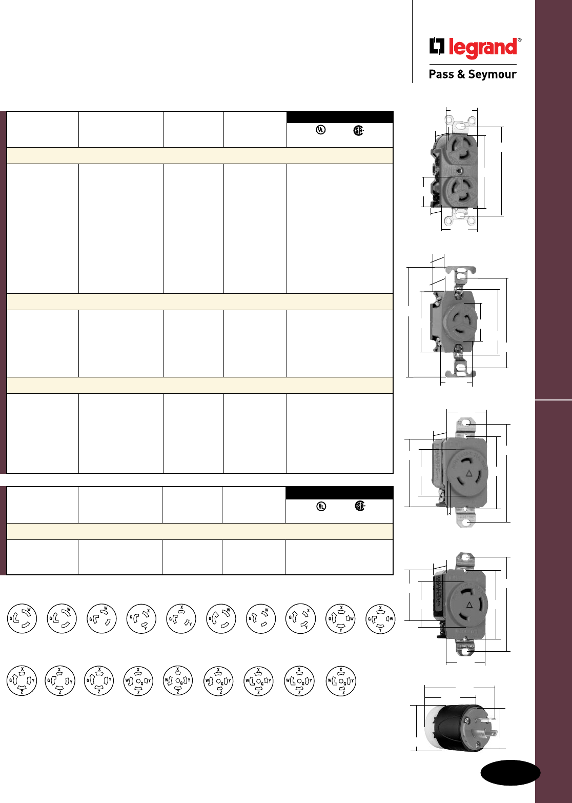
Surge Protective & Isolated Ground Devices
All devices listed on this page conform to NEMA WD-1 and WD-6.
F-19
Surge Protective & Isolated Ground Devices
Turnlok® Isolated Ground Receptacles
2 Pole, 3 Wire 15, 20 & 30A
Turnlok® Isolated Ground Receptacles
Consult Turnlok Section H for complete line of Turnlok Locking Devices.
3rd Party Compliance
Rating NEMA
Catalog Number A. V. Cong. No. Color UL498 C22.2 No. 42
2 Pole, 3 Wire Grounding, Orange Back Wire
IG4700RED 15 125 L5-15R Red • •
IG4700 15 125 L5-15R Orange • •
IG4710 15 125 L5-15R Orange • •
IG4760 15 277 L7-15R Orange • •
IGL520R 20 125 L5-20R Orange • •
IGL620R 20 250 L6-20R Orange • •
IGL720R 20 277 L7-20R Orange • •
IGL820R 20 480 L8-20R Orange • •
IGL530R 30 125 L5-30R Orange • •
IGL630R 30 250 L6-30R Orange • •
3 Pole, 4 Wire Grounding, Orange Back Wire
IGL1420R 20 125/250 L14-20R Orange • •
IGL1520R 20 3ø, 250 L15-20R Orange • •
IGL1620R 20 3ø, 480 L16-20R Orange • •
IGL1430R 30 125/250 L14-30R Orange • •
IGL1530R 30 3ø, 250 L15-30R Orange • •
4 Pole, 5 Wire Grounding, Orange Back Wire
IGL2120R 20 3øY, 120/208 L21-20R Orange • •
IGL2220R 20 3øY, 277/480 L22-20R Orange • •
IGL2320R 20 3øY, 347/600 L23-20R Orange • •
IGL2130R 30 3øY, 120/208 L21-30R Orange • •
IGL2230R 30 3øY, 277/480 L22-30R Orange • •
IGL2330R 30 3øY, 347/600 L23-30R Orange • •
Catalog Rating NEMA Cord
Number A. V. Cong. No. Diameter UL498 C22.2 No. 42
Turnlok® Plugs, Orange
IGL520P 20 125 L5-20P .385" – 1.150" • •
IGL630P 30 250 L6-30P .385" – 1.150" • •
3rd Party Compliance
NEMA
L6-20R
NEMA
L6-30R
NEMA
L14-30R
NEMA
L23-20R
NEMA
L5-15R
NEMA
L14-20R
NEMA
L15-30R
NEMA
L21-30R
NEMA
L7-20R
NEMA
L7-15R
NEMA
L8-20R
NEMA
L15-20R
NEMA
L21-20R
NEMA
L22-30R
NEMA
L5-20R
NEMA
L16-20R
NEMA
L22-20R
NEMA
L23-30R
NEMA
L5-30R
IGL620P
2.57"
2.20" 1.358"
3.75"
30 Amp Receptacle
1.28"
1.61"
3.28"
2.37"
2.42"
1.545"
IG4700
1.199"
.938"
1.50"
3.281"
2.635"
1.104"
1.322"
IG4710
1.437"
1.375"
2.375"
2.25"
1.203"
1.0"
4.031"
3.281"
20 Amp Receptacle
1.19"
.14"
1.61"
3.28"
2.37"
2.29"
1.545"
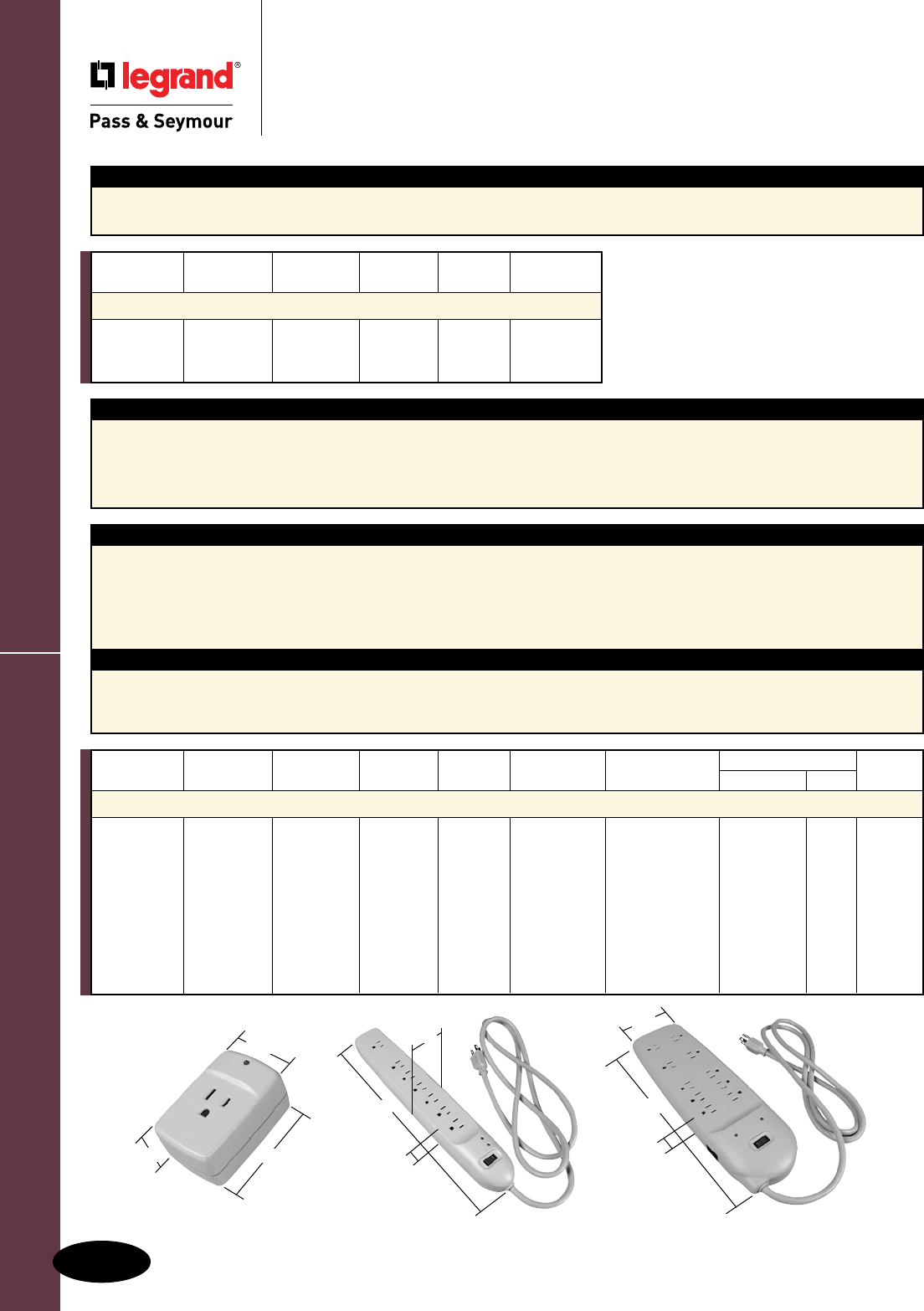
Surge Protective & Isolated Ground Devices
All devices listed on this page conform to NEMA WD-1 and WD-6.
F-20
Power & Surge Protection Strips
Surge Protective & Isolated Ground Devices
Power & Surge Protection Strips
TAP – PS1
1.9375"
2.875"
1.25"
STRIP – PNS7L
1.25"
14.0"
2.3125"
BLOCK – PS10PC
13.9"
1.4"
4.2"
Application
There are an average of over 250 power disturbances per year in each home or office in the United States. Over 8% data loss is a direct
result from lightning and the value of equipment and data is sometimes much greater than that of equipment.
Surges and spikes can come through power lines as well as phone and coax lines. So choose a protector which includes phone and/or
coax protection.
Features
n 400V clamping voltage.
n UL1449 listed.
n Heavy-duty cord from 3' to 15', depending on device.
n Multiple function protection available for power, phone, fax,
modem, coax or data.
n Extremely long life with dependable protection.
n Surge protection indicator on surge devices.
n Circuit breaker switch.
n Heavy-duty high-energy MOVs.
n Ground continuity indicator.
Protection Specications
n Line protection modes: L-N, L-G, N-G.
n Spike protection for sudden, dramatic surges, over 400V.
n Surge protection lasts for 1/120 of a second, for moderate short
term overvoltage.
n EMI/RFI noise attenuation.
Features
n UL1449 listed.
n Heavy-duty cord from 3' to 15', depending on device.
n Circuit breaker switch.
Catalog Rating Type of # of Cord
Number A. V. Housing Outlets Length Color
Power Strips without Surge Protection
PNS6 15 125 Strip 6 3' Black
PNS7L 15 125 Strip 7 8' Black
PNS10 15 125 Block 10 15' Black
Catalog Rating Type of # of Cord Joule Rating Max. Spike Type of Protection
Number A. V. Housing Outlets Length Range Current (Amps) Phone/Fax Coax Color
Power Strips with Surge Protection
PS1 15 125 Tap 1 740J 48K PC Gray
PS1P 15 125 Tap 1 740J 48K X PC Gray
PS6 15 125 Strip 6 3' 555J 36K PC Gray
PS7 15 125 Strip 7 6' 740J 48K PC Gray
PS7P 15 125 Strip 7 6' 740J 48K X PC Gray
PS7L 15 125 Strip 7 15' 740J 48K PC Gray
PS8C 15 125 Block 8 8' 1100J 72K X PC Gray
PS8P 15 125 Block 8 8' 1100J 72K X PC Gray
PS10PC 15 125 Block 10 8' 1100J 72K X X PC Gray
Surge Protective & Isolated Ground Devices
All devices listed on this page conform to NEMA WD-1 and WD-6.
F-21
Power & Surge Protection Strips Specs
Surge Protective & Isolated Ground Devices
Power & Surge Protection
Strips Specifications
Power Devices – Ratings
Catalog Number PNS6 PNS7L PNS10
Type of Housing Strip Strip Strip
Total Outlets 6 7 10
Standard Grounded Outlets 6 6 6
Transformer Ready Outlets 0 1 4
Power Indicator X
Circuit Breaker Switch Unlighted Lighted Lighted
Cord Length (exposed) ft. 3' 8' 15'
Plug Straight Straight Straight
Molded Add-On Safety Covers 0 0 5
Molded Housing Color Black Black Black
Power & Surge Protection Devices – Ratings
Catalog Number PS1 PS1P PS6 PS7 PS7P PS7L PS8C PS8P PS10PC
Type of Housing Tap Tap Strip Strip Strip Strip Block Block Block
Number of Outlets 1 1 6 7 7 7 8 8 10
Standard Grounded Outlets 1 1 6 6 6 6 0 0 6
Transformer Ready Outlets 1 1 0 1 1 1 8 8 4
Joule Rating Range 740J 740J 555J 740J 740J 740J 1100J 1100J 1100J
MOV Configuration 4-20mm 4-20mm 3-20mm 4-20mm 4-20mm 4-20mm 6-20mm 6-20mm 6-20mm
Clamping Voltage 400V 400V 400V 400V 400V 400V 400V 400V 400V
Max. Spike Current (Amps) 48K 48K 36K 48K 48K 48K 72K 72K 72K
EMI Filter Capacitors X X X X X X X X
Protection (L-N, L-G, N-G) X X X X X X X X X
Surge Protection Indicator X X X X X X X X X
Ground/Wiring Indicator X X X X X X
Circuit Breaker Switch Unlighted Lighted Lighted Lighted Lighted Lighted Lighted
Cord Length (exposed) ft. 3' 6' 6' 15' 8' 8' 8'
Plug Straight Straight Straight Straight Rt. Angle Rt. Angle Rt. Angle
Phone/Fax Protection X X X X
Phone Line(s) Configuration 1 in/1 out 1 in/2 out 1 in/1 out
Phone Jack Spec RJ-11 RJ-11 RJ-45 RJ-45
Nickel-Coaxial Jack Protection X X
6' Phone Cable (6P2C) X X X X
6' Coax Cable (Nickel Plated) X X
Molded Add-On Safety Covers 0 0 0 2 2 2 4 4 5
Molded Housing Color PC Gray PC Gray PC Gray PC Gray PC Gray PC Gray PC Gray PC Gray PC Gray
UL1449 2nd Edition X X X X X X X X X
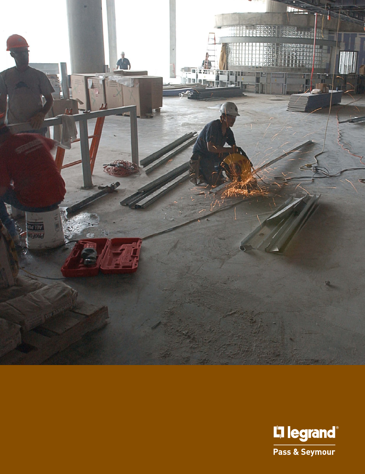
STRAIGHT BLADE PLUGS & CONNECTORS

Straight Blade Plugs & Connectors
G-1
Index
Device Rating Page Number
NEMA Configurations G-2
Hospital Grade 15 & 20A, 125 & 250V G-3
Extra-Hard Use Specification Grade 15 & 20A, 125, 250 & 277V G-4
Extra-Hard Use Angled Devices 15 & 20A, 125 & 250V G-5
Extra-Hard Use Ground Continuity Monitoring 15 & 20A, 125 & 250V G-6
MaxGrip® M3 15 & 20A, 125 & 250V G-7
Rubber Housing 15 & 20A, 125 & 250V G-8
Watertight 15 & 20A, 125 & 250V G-9
Medium-Duty Devices 15 & 20A, 125 & 250V G-10
Flanged Inlets & Outlets 15 & 20A, 125 & 250V G-11
Miscellaneous Configurations G-12
Gator Grip Devices 30, 50 & 60A, 125, 250, 277 & 125/250V,
3øY 120/208V G-13
Clamp-Lock™ Devices 15A, 125 & 250V; 20A, 125V G-14
Product Specifications & Performance G-15 – G-17
Ready-to-wire and ready-to-perform under
adverse plant conditions — our Straight
Blade Plug & Connector line is an
industrial-strength, on-the-job asset.
Straight Blade Plugs & Connectors
Quick-thread assembly
screws and cord-grip screws
come backed-out, ready-to-wire.
Housing is keyed
for fast alignment with
terminal section.
Color-coded terminal screws
are positioned on same plane and
backed-out for fast installation.
Tapered wire wells guide
conductors into captivated,
staked clamping nuts.
Industrial-strength, brass alloy plug
blades and connector contacts resist heat rise,
provide excellent conductivity; ground pin is
reinforced for added strength and safety.
Double-wipe, firm-grip ground
contact and triple-wipe power
contacts guarantee a superior connection.
Recessed cord-grip screw reduces
screwdriver slippage, improves safety.
PS5266X and PS5269X
Chemical- and impact-
resistant nylon housing
features horizontal, easy-grip
ribs on back body.
See-through, thermoplastic
terminal chamber for clear
view of terminals and wire
connections.
Rugged external
two-piece cord
grip provides uniform
pressure for superior
retention of conductors.
Internal dust shield
keeps terminals free of
contaminants.
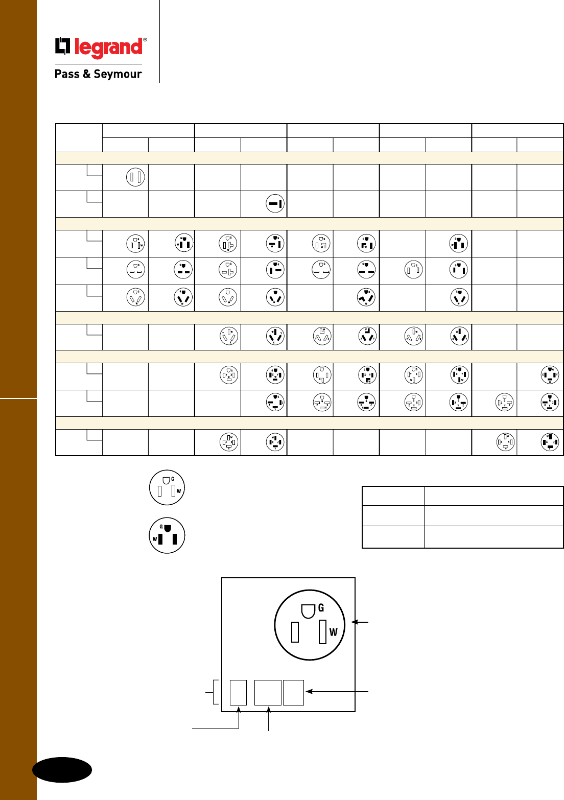
NEMA Configurations
G-2
Straight Blade Plugs & Connectors
Straight Blade Plugs & Connectors
NEMA Configurations
Labels and Their Meanings
X, Y, Z Hot Lead
W Neutral Lead
G Grounding Lead
Open Slots
Indicate receptacle
configurations (female).
Closed Slots
Indicate plug blade
configurations (male).
Blade
Conguration
R = Female
(receptacle, connector,
anged outlet)
P = Male
(plug, anged inlet)
NEMA
Conguration
Line #
(refers to voltage) Amperage
5-15R
Straight Blade Plugs & Receptacles
15 Ampere 20 Ampere 30 Ampere 50 Ampere 60 Ampere
Receptacle Plug Receptacle Plug Receptacle Plug Receptacle Plug Receptacle Plug
2 Pole, 2 Wire Non-Grounding
1
125V
1-15R
2
250V
2-20P
2 Pole, 3 Wire Grounding
5
125V
5-15R 5-15P 5-20R 5-20P 5-30R 5-30P 5-50P
6
250V
6-15R 6-15P 6-20R 6-20P 6-30R 6-30P 6-50R 6-50P
7
277VAC
7-15R 7-15P 7-20R 7-20P 7-30P 7-50P
3 Pole, 3 Wire Non-Grounding
10
125/250V
10-20R 10-20P 10-30R 10-30P 10-50R 10-50P
3 Pole, 4 Wire Grounding
14
125/250V
14-20R
14-20P 14-30R 14-30P 14-50R 14-50P 14-60P
15
3ø250V
15-20P 15-30R 15-30P 15-50R 15-50P 15-60R 15-60P
4 Pole, 4 Wire Non-Grounding
18
3øY
120/208V
18-20R 18-20P 18-60R 18-60P
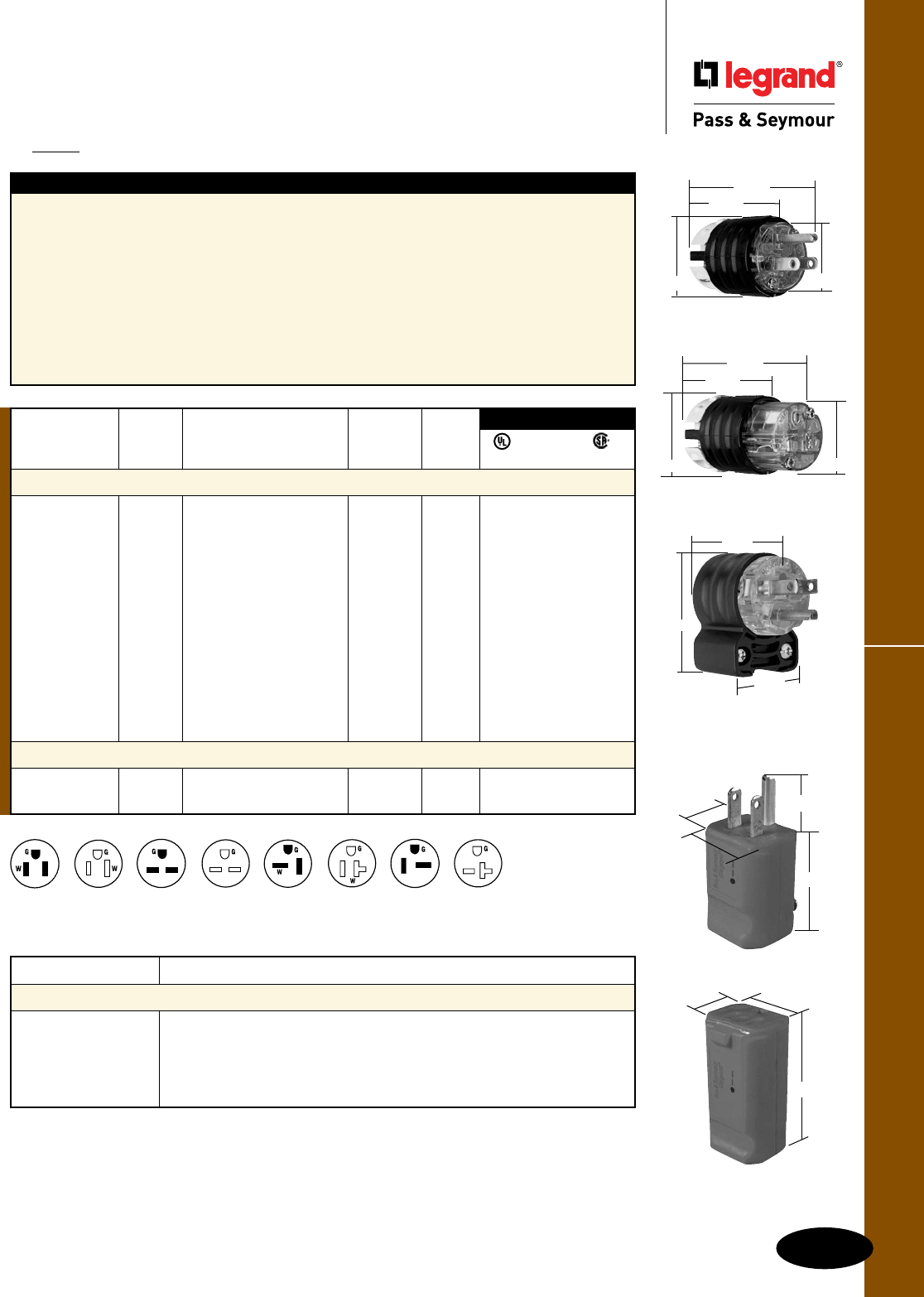
G-3
Hospital Grade Plugs & ConnectorsStraight Blade Plugs & Connectors
All devices listed on this page conform to NEMA WD-1 and WD-6.
Straight Blade Plugs & Connectors
Hospital Grade Plugs & Connectors
2 Pole, 3 Wire Grounding 15 & 20A, 125 & 250V
PS5266XHG
1.752"
2.791"
1.516" 1.358"
NEMA
6-20R
NEMA
5-15P
NEMA
6-15P
NEMA
6-15R
NEMA
6-20P
NEMA
5-15R
NEMA
5-20P
NEMA
5-20R
Catalog Number Description
Accessories
EHU15AN 15 & 20A EHU Straight Blade, Right Angle Adapter
FC22GL EHU-Strain Relief Grip*
FC30GL EHU-Strain Relief Grip*
FC40GL EHU-Strain Relief Grip*
FC52GL EHU-Strain Relief Grip*
IP20
Suitability
Features – Extra-Hard Use (EHU)
n Unit arrives completely ready-to-wire, cuts
installation time significantly.
n Nylon housing provides impact and
chemical resistance.
n Rugged two-piece cord grip provides more
uniform cord retention.
n Internal dust shield keeps terminals free
of contaminants.
n Tri-drive assembly screws are standard on
Hospital Grade plugs and connectors
(angle plugs not included).
n All 3-wire terminals located on the same
plane, allows for quick wire termination from
any angle.
n Heavy-duty brass alloy blades and contacts,
resist heat rise, provide excellent conductivity.
n Cord-grip screws recessed to protect installer
against screwdriver head slippage.
*For further information consult the Flexcor® Section K.
1.34"
1.21"
1.83"
PS8119
NEMA
Catalog Rating Cord Cong.
Number A. V. Description Diameter No.
Hospital Grade – Extra-Hard Use (EHU)
PS5266XHG 15 125 Plug, Black & Clear .230"-.720" 5-15P • • •
PS5266HGAN 15 125 Angle Plug, Black & Clear .320"-.655" 5-15P • • •
PS5269XHG 15 125 Connector, Black & Clear .230"-.720" 5-15R • • •
PS5366XHG 20 125 Plug, Black & Clear .230"-.720" 5-20P • • •
PS5366HGAN 20 125 Angle Plug, Black & Clear .320"-.655" 5-20P • • •
PS5369XHG 20 125 Connector, Black & Clear .230"-.720" 5-20R • • •
PS5666XHG 15 250 Plug, Black & Clear .230"-.720" 6-15P • • •
PS5666HGAN 15 250 Angle Plug, Black & Clear .320"-.655" 6-15P • • •
PS5669XHG 15 250 Connector, Black & Clear .230"-.720" 6-15R • • •
PS5466XHG 20 250 Plug, Black & Clear .230"-.720" 6-20P • • •
PS5466HGAN 20 250 Angle Plug, Black & Clear .320"-.655" 6-20P • • •
PS5469XHG 20 250 Connector, Black & Clear .230"-.720" 6-20R • • •
Hospital Grade MaxGrip® M3
PS8115 15 125 Plug, Gray .230"-.720" 5-15P • • •
PS8119 15 125 Connector, Gray .230"-.720" 5-15R • • •
FSUL
UL498 WC596 C22.2 No. 42
3rd Party Compliance
1.34"
1.21"
1.83"
PS8115
.77"
PS5269XHG
2.638"
1.516" 1.358"
1.752"
PS5266HGAN
2.130"
1.350"
1.530"
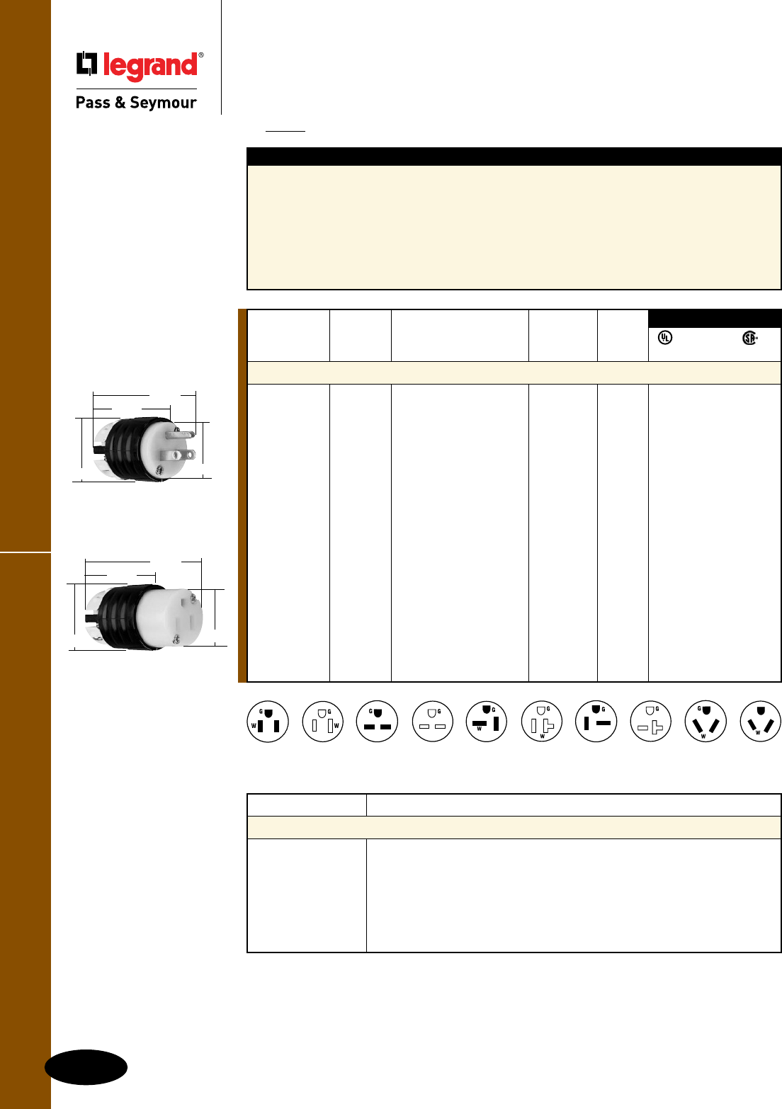
G-4
Straight Blade Plugs & Connectors
All devices listed on this page conform to NEMA WD-1 and WD-6.
Straight Blade Plugs & Connectors
Extra-Hard Use (EHU) Specification Grade
2 Pole, 3 Wire Grounding 15 & 20A, 125, 250 & 277V
IP20
Suitability
Catalog Number Description
Accessories
EHU15AN 15 & 20A EHU Straight Blade, Right Angle Adapter
L15RBC Weatherproof Boot-Connector**
L15RBP Weatherproof Boot-Plug**
FC22GL EHU-Strain Relief Grip=
FC30GL EHU-Strain Relief Grip=
FC40GL EHU-Strain Relief Grip=
FC52GL EHU-Strain Relief Grip=
Extra-Hard Use (EHU) Specification Grade
Features – Extra-Hard Use (EHU)
n Unit arrives completely ready-to-wire, cuts
installation time significantly.
n Nylon housing provides impact and
chemical resistance.
n Rugged two-piece cord grip provides more
uniform cord retention.
n Internal dust shield keeps terminals free
of contaminants.
n Tri-drive assembly screws are standard on all
Specification Grade plugs and connectors.
n All 3-wire terminals located on the same plane,
allows for quick wire termination from any angle.
n Heavy-duty brass alloy blades and contacts,
resist heat rise, provide excellent conductivity.
n Cord-grip screws recessed to protect installer
against screwdriver head slippage.
*PS5866X requires L20303AN right angle adapter.
**For further information consult the Turnlok® Section H.
=For further information consult the Flexcor® Section K.
NEMA
Catalog Rating Cord Cong.
Number A. V. Description Diameter No.
EHU – Specification Grade
PS5266X 15 125 Plug, Black & White .230"-.720" 5-15P • •
PS5266XGRY 15 125 Plug, Black & Gray .230"-.720" 5-15P • •
PS5266XBK 15 125 Plug, Black .230"-.720" 5-15P • •
CR5266X 15 125 Plug, Corrosion- .230"-.720" 5-15P • •
Resistant, Yellow & White
PS5269X 15 125 Connector, Black & White .230"-.720" 5-15R • •
PS5269XGRY 15 125 Connector, Black & Gray .230"-.720" 5-15R • •
PS5269XBK 15 125 Connector, Black .230"-.720" 5-15R • •
CR5269X 15 125 Connector, Corrosion- .230"-.720" 5-15R • •
Resistant, Yellow & White
PS5366X 20 125 Plug, Black & White .230"-.720" 5-20P • • •
PS5369X 20 125 Connector, Black & White .230"-.720" 5-20R • •
PS5666X 15 250 Plug, Black & White .230"-.720" 6-15P • • •
PS5669X 15 250 Connector, Black & White .230"-.720" 6-15R • • •
PS5466X 20 250 Plug, Black & White .230"-.720" 6-20P • • •
PS5469X 20 250 Connector, Black & White .230"-.720" 6-20R • •
PS5766X 15 277 Plug, Black & White .230"-.720" 7-15P • •
PS5866X* 20 277 Plug, Black & White .385"-1.150" 7-20P • •
FSUL
UL498 WC596 C22.2 No. 42
3rd Party Compliance
PS5269X
1.516" 1.358"
1.752"
2.638"
PS5266X
1.516" 1.358"
2.791"
1.752"
NEMA
7-20P
NEMA
7-15P
NEMA
6-20R
NEMA
5-15P
NEMA
6-15P
NEMA
6-15R
NEMA
6-20P
NEMA
5-15R
NEMA
5-20P
NEMA
5-20R
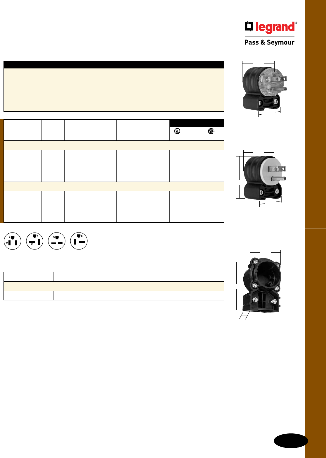
G-5
Extra-Hard Use (EHU) Angled DevicesStraight Blade Plugs & Connectors
All devices listed on this page conform to NEMA WD-1 and WD-6.
Straight Blade Plugs & Connectors
Extra-Hard Use (EHU) Angled Devices
2 Pole, 3 Wire Grounding 15 & 20A, 125 & 250V
NEMA
6-15P
NEMA
6-20P
NEMA
5-15P
NEMA
5-20P
Catalog Number Description
Accessories
EHU15AN 15 & 20A EHU Straight Blade, Right Angle Adapter
IP20
Suitability
Features – Extra-Hard Use (EHU)
n Angle plugs and adapters both allow for 4-position
face rotation.
n Tri-drive assembly and cord-grip screws are
standard on all angle adapters.
n Angle adapter (sold separately as catalog
number EHU15AN) will accommodate all
Pass & Seymour EHU-style Straight Blade
plugs and connectors on a retrofit basis.
Simply remove the straight handle body
from the plug or connector face assembly,
and replace with the angle adapter.
EHU15AN
2.97"
1.94"
1.37"
NEMA
Catalog Rating Cord Cong.
Number A. V. Description Diameter No.
EHU – Hospital Grade
PS5266HGAN 15 125 Plug, Black & Clear .320"-.655" 5-15P • • •
PS5366HGAN 20 125 Plug, Black & Clear .320"-.655" 5-20P • • •
PS5666HGAN 15 250 Plug, Black & Clear .320"-.655" 6-15P • • •
PS5466HGAN 20 250 Plug, Black & Clear .320"-.655" 6-20P • • •
EHU – Specification Grade
PS5266SSAN 15 125 Plug, Black & White .320"-.655" 5-15P • • •
PS5366SSAN 20 125 Plug, Black & White .320"-.655" 5-20P • • •
PS5666SSAN 15 250 Plug, Black & White .320"-.655" 6-15P • • •
PS5466SSAN 20 250 Plug, Black & White .320"-.655" 6-20P • • •
3rd Party Compliance
FSUL
UL498 WC596 C22.2 No. 42
PS5266HGAN
PS5266SSAN
2.130"
1.350"
1.530"
2.130"
1.350"
1.530"
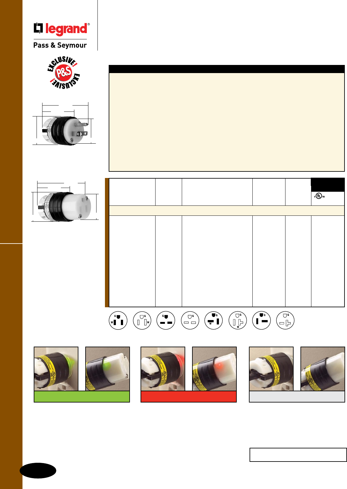
G-6
Ground Continuity Monitoring Straight Blade Plugs & Connectors
All devices listed on this page conform to NEMA WD-1 and WD-6.
Straight Blade Plugs & Connectors
Extra-Hard Use Ground Continuity
Monitoring (GCM) Plugs & Connectors
2 Pole, 3 Wire Grounding 15 & 20A, 125 & 250V
Features – Extra-Hard Use (EHU) Straight Blade GCM
n Integral indication of ground continuity and
power status. Continuous monitoring enhances
personnel safety and adds convenience.
n Dual, bright LED indicators with 360° visibility.
Green LEDs indicate proper ground continuity
and power status. Red LEDs indicate ground
continuity loss or reversed polarity. No LED
indicates open hot, open neutral, or hot to
ground cross. For 250V configurations: Hot to
ground cross will be indicated by a green and
red LED.
n Chemical- and impact-resistant nylon housing
features horizontal, easy-grip ribs on back body.
n Exclusive two-piece cord grip accepts a wide
range of cord widths. Provides more consistent
pressure for superior conductor retention.
n Internal dust shield keeps terminals free
of contaminants.
n Recessed cord-grip screw reduces screwdriver
slippage, improves safety. Quick-thread tri-drive
assembly and cord-grip screws come backed-out
and ready-to-wire.
n Color-coded terminal screws are positioned
on the same plane and backed-out for fast
installation.
n Industrial-strength, brass alloy plug blades and
connector contacts resist heat rise, provide
excellent conductivity.
NEMA
Catalog Rating Cord Cong.
Number A. V. Description Diameter No.
EHU – GCM
PS5266XGCM 15 125 Plug, Black & White .230"-.720" 5-15P • •
PS5266XGCMAN 15 125 Angled Plug, Black & White .320"-.655" 5-15P • •
PS5269XGCM 15 125 Connector, Black & White .230"-.720" 5-15R • •
PS5366XGCM 20 125 Plug, Black & White .230"-.720" 5-20P • •
PS5366XGCMAN 20 125 Angled Plug, Black & White .320"-.655" 5-20P • •
PS5369XGCM 20 125 Connector, Black & White .230"-.720" 5-20R • •
PS5666XGCM 15 250 Plug, Black & White .230"-.720" 6-15P • •
PS5666XGCMAN 15 250 Angled Plug, Black & White .320"-.655" 6-15P • •
PS5669XGCM 15 250 Connector, Black & White .230"-.720" 6-15R • •
PS5466XGCM 20 250 Plug, Black & White .230"-.720" 6-20P • •
PS5466XGCMAN 20 250 Angled Plug, Black & White .320"-.655" 6-20P • •
PS5469XGCM 20 250 Connector, Black & White .230"-.720" 6-20R • •
FSUL
cULus WC596
3rd Party
Compliance
PS5266XGCM
1.516" 1.358"
1.752"
2.791"
PS5269XGCM
1.516" 1.358"
1.752"
2.638"
250V products will show red and green
when hot and ground are reversed.
No LED
Plug – Power loss, open hot or neutral
conductor, or hot/ground reversal.
Connector – Assuming power is
present at the outlet, there’s an open
hot or open neutral conductor in the
cordset, or a hot/ground reversal.
Red LED
Plug – Power’s present, but there’s
a ground continuity fault or miswire
between the receptacle and the panel.
Connector – Power’s present, but there’s
a ground continuity fault or mis wire in the
cordset (or, if there’s a red indication in
the plug as well, between the receptacle
and the panel). It’s also possible there
could be a problem in both.
Green LED
Plug – There’s proper ground
continuity from the panel to the outlet
and power’s present.
Connector – Power’s present and
there’s proper ground continuity
through out the cordset and back to
the panel.
NEMA
6-20R
NEMA
5-15P
NEMA
6-15P
NEMA
6-15R
NEMA
6-20P
NEMA
5-15R
NEMA
5-20P
NEMA
5-20R
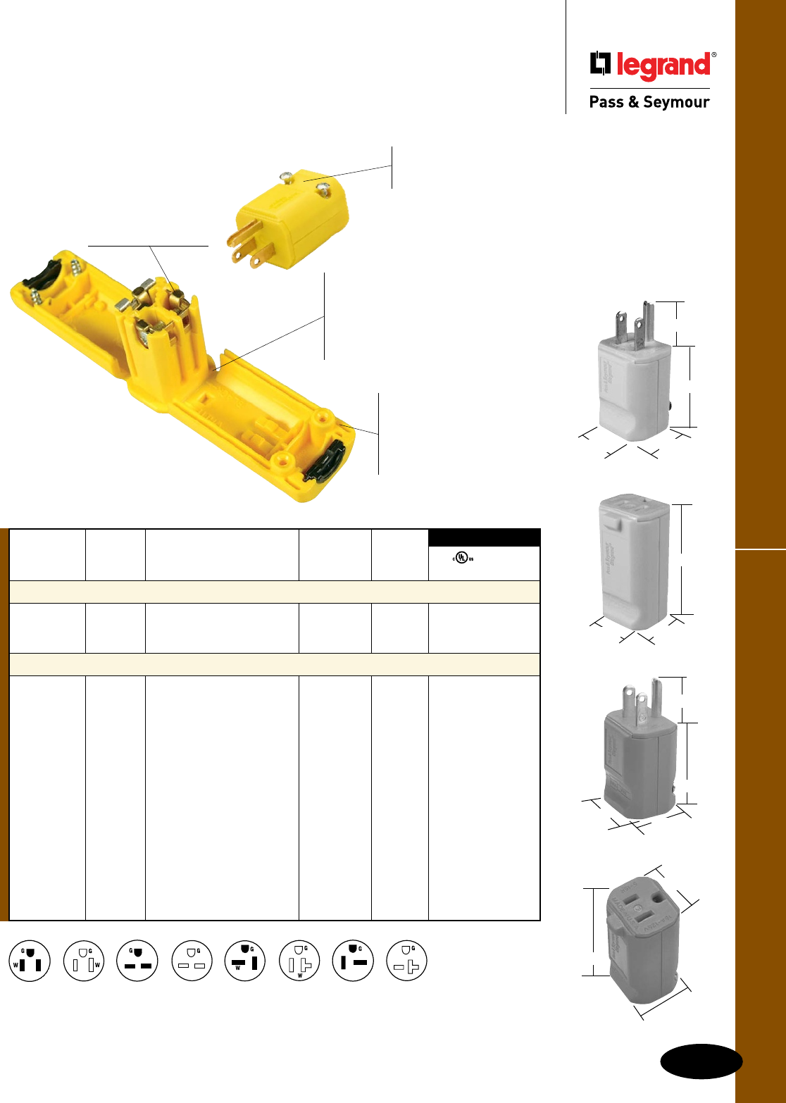
NEMA
Catalog Rating Cord Cong.
Number A. V. Description Diameter No.
Hospital Grade MaxGrip® M3
PS8115 15 125 Hospital Grade Plug, Gray .230"-.720" 5-15P • •
PS8119 15 125 Hospital Grade Connector,
Gray .230"-.720" 5-15R • •
MaxGrip M3
PS5965Y 15 125 Plug, Yellow .230"-.720" 5-15P •
PS5965GRY 15 125 Plug, Gray .230"-.720" 5-15P •
PS5965O 15 125 Plug, Orange .230"-.720" 5-15P •
PS5969Y 15 125 Connector, Yellow .230"-.720" 5-15R •
PS5969GRY 15 125 Connector, Gray .230"-.720" 5-15R •
PS5969O 15 125 Connector, Orange .230"-.720" 5-15R •
PS5364Y 20 125 Plug, Yellow .230"-.720" 5-20P • •
PS5364GRY 20 125 Plug, Gray .230"-.720" 5-20P • •
PS5369Y 20 125 Connector, Yellow .230"-.720" 5-20R • •
PS5369GRY 20 125 Connector, Gray .230"-.720" 5-20R • •
PS5666Y 15 250 Plug, Yellow .230"-.720" 6-15P • •
PS5669Y 15 250 Connector, Yellow .230"-.720" 6-15R • •
PS5464Y 20 250 Plug, Yellow .230"-.720" 6-20P • •
PS5469Y 20 250 Connector, Yellow .230"-.720" 6-20R • •
3rd Party Compliance
FSUL
cULus WC596
G-7
MaxGrip® M3
Straight Blade Plugs & Connectors
All devices listed on this page conform to NEMA WD-1 and WD-6.
PS5965Y
.77"
1.83"
1.34" 1.21"
PS5969Y
1.83"
1.21"
1.34"
PS5965O
1.83"
1.21"
1.34"
.77"
PS5969O
1.34"
1.83"
1.21"
Straight Blade Plugs & Connectors
MaxGrip® M3
2 Pole, 3 Wire Grounding 15 & 20A, 125 & 250V
High-visibility yellow
and orange, or gray.
Hospital Grade version
displays the Hospital Grade
green dot.
Enclosed terminals
provide solid,
internally-clamped
connections.
Molded finger grips
promote safe, sure
handing.
PS5965Y and PS5969Y
Self-hinge swings wide open to
make quick, easy work of tight,
clean connections. Insert conductors
into terminals and tighten terminal
screws; close hinge housing around
cord and tighten housing screws.
Tough nylon construction
with crush/impact resistance
that exceeds hospital grade
and Fed Spec requirements;
arc resistance exceeds UL
requirements.
NEMA
6-20R
NEMA
5-15P
NEMA
6-15P
NEMA
6-15R
NEMA
6-20P
NEMA
5-15R
NEMA
5-20P
NEMA
5-20R

A
1447
C
D
B
1547
A
C
E
D
B
(Inch) A B C D E
Rubber Straight Blade Plug
15A 2.27" 1.44" 1.53" 1.53"
20A 2.59" 1.76" 1.93" 1.60"
Rubber Straight Blade Connector
15A 2.99" 2.16" 1.53" 1.66" 1.53"
20A 3.74" 2.19" 1.93" 2.07" 1.60"
Cord Grip Range: .335"-.640"
G-8
Straight Blade Plugs & Connectors
All devices listed on this page conform to NEMA WD-1 and WD-6.
Rubber Housing
Straight Blade Plugs & Connectors
Rubber Housing
2 Pole, 3 Wire Grounding 15 & 20A, 125 & 250V
UL498 C22.2 No. 42M
3rd Party Compliance
NEMA
Catalog Rating Cong.
Number A. V. Description No.
Rubber Housing Plugs & Connectors
1447 15 125 Plug, Yellow 5-15P • •
1547 15 125 Connector, Yellow 5-15R • •
1433P 20 125 Plug, Yellow 5-20P • •
1533 20 125 Connector, Yellow 5-20R • •
1449 15 250 Plug, Yellow 6-15P • •
1549 15 250 Connector, Yellow 6-15R • •
1448 20 250 Plug, Yellow 6-20P • •
1548 20 250 Connector, Yellow 6-20R • •
Nickel-plated blades and contacts
for long-lasting, superior corrosion
resistance.
Terminal screws
backed-out, ready-
to-wire, saving time
and money.
Floating blades allow
self-alignment with contacts for a
firm, even electrical connection.
Self-centering
cord clamps
provide superior
strain relief.
Quick-drive assembly screws
allow for fast installation, saving
time and money.
Rubber body construction
stands up to impacts, oils,
chemicals, heat, and weather.
1447 and 1547
NEMA
6-20R
NEMA
5-15P
NEMA
6-15P
NEMA
6-15R
NEMA
6-20P
NEMA
5-15R
NEMA
5-20P
NEMA
5-20R

15W47
A
B
Straight Blade Plugs & Connectors
Watertight
2 Pole, 3 Wire Grounding 15 & 20A, 125 & 250V
G-9
Watertight
All devices listed on this page conform to NEMA WD-1 and WD-6.
IP67
Suitability
(Inch) A B
Watertight Plug
15A 2.62" 1.85"
20A 2.62" 1.85"
Watertight Connector
15A 4.03" 1.85"
20A 4.03" 1.85"
Cord Grip Range: .062"-.625"
Straight Blade Plugs & Connectors
UL498 C22.2 No. 42M
3rd Party Compliance
NEMA
Catalog Rating Cong.
Number A. V. Description No.
Rubber Housing Plugs & Connectors – Watertight
14W47 15 125 Plug, Yellow, NEMA 4X 5-15P • •
15W47 15 125 Connector, Yellow, NEMA 4X 5-15R • •
14W33 20 125 Plug, Yellow, NEMA 4X 5-20P • •
15W33 20 125 Connector, Yellow, NEMA 4X 5-20R • •
14W49 15 250 Plug, Yellow, NEMA 4X 6-15P • •
15W49 15 250 Connector, Yellow, NEMA 4X 6-15R • •
14W48 20 250 Plug, Yellow, NEMA 4X 6-20P • •
15W48 20 250 Connector, Yellow, NEMA 4X 6-20R • •
Floating blades allow self-alignment
with contacts for a firm, even electrical
connection.
Nickel-plated blades and
contacts for long-lasting, superior
corrosion resistance.
Terminal screws backed-out, ready-
to-wire, saving time and money.
Compression-type cord grip
provides watertight seal and
205 lb. pull out strength.
Rubber body construction
stands up to impacts, oils,
chemicals, heat, and weather.
Multiple ring seals between plug
and connector ensures protection
from water and contaminants.
NEMA 4, 4X, Watertight. IP65, 66, 67. Rated
watertight for 1,000 psi high-pressure hose-down.
Quick-drive assembly screws
allow for fast installation, saving
time and money. 15W47 and 14W47
NEMA
6-15P
NEMA
6-20P
NEMA
5-15P
NEMA
5-20P
NEMA
6-15R
NEMA
6-20R
NEMA
5-15R
NEMA
5-20R
3rd Party Compliance
UL498 C22.2 42M
NEMA
Catalog Cong.
Number Description No.
Caps – Watertight Only
14WPS Male Cap All • •
50W50PS Female Replacement Cap All • •
14WPS
50W50PS
B
14W47
A
14W47 shown with 14WPS cap.
Cap sold separately.
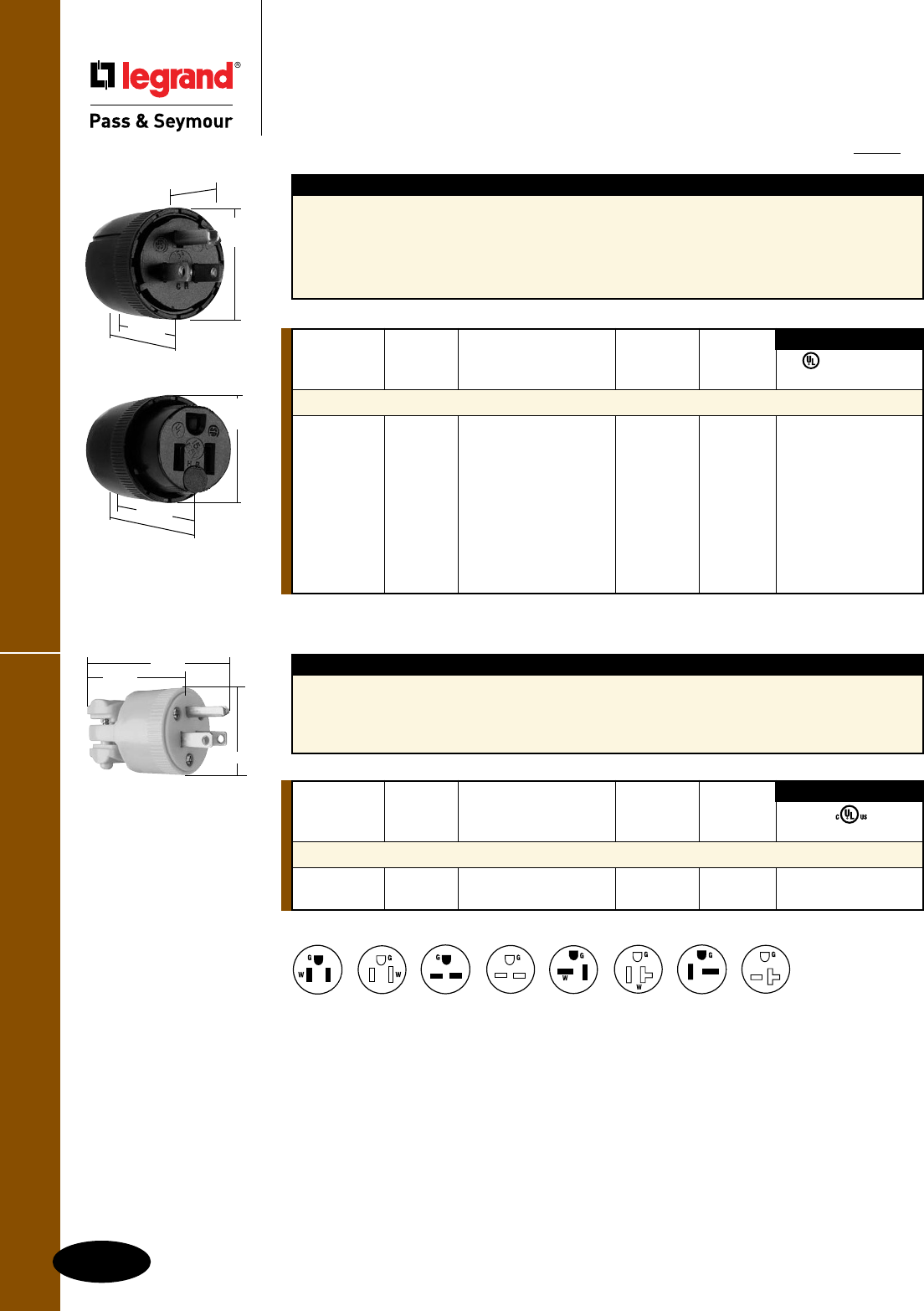
Medium-Duty Devices
G-10
Straight Blade Plugs & Connectors
All devices listed on this page conform to NEMA WD-1 and WD-6.
Straight Blade Plugs & Connectors
Medium-Duty Devices
2 Pole, 3 Wire Grounding 15 & 20A, 125 & 250V
IP20
Suitability
5276BK
1.640"
.843" Max
1.530"
Dia.
1.840"
Features
n All nylon construction, provides excellent impact
and chemical resistance.
n Simple turn and twist assembly for quick
installation.
n Ready-to-wire from factory, saves time and money.
n All black, perfect for stage and entertainment
applications.
n Internal finger grips automatically adjust to
securely grip the cord jacket.
5296BK
2.140"
2.340"
1.530"
Dia.
NEMA
Catalog Rating Cord Cong.
Number A. V. Description Diameter No.
Dead Front Plugs & Connectors
5276BK 15 125 Plug, Black .230"-.655" 5-15P • •
5296BK 15 125 Connector, Black .230"-.655" 5-15R • •
5765BK 20 125 Plug, Black .230"-.655" 5-20P • •
5374BK 20 125 Connector, Black .230"-.655" 5-20R •
5666BK 15 250 Plug, Black .230"-.655" 6-15P • •
5669BK 15 250 Connector, Black .230"-.655" 6-15R • •
5864BK 20 250 Plug, Black .230"-.655" 6-20P • •
5866BK 20 250 Connector, Black .230"-.655" 6-20R • •
3rd Party Compliance
FSUL
UL498 WC596
NEMA
Catalog Rating Cord Cong.
Number A. V. Description Diameter No.
Medium-Duty Plugs & Connectors
4867Y 15 125 Plug, Yellow .250-.600" 5-15P •
4887Y 15 125 Connector, Yellow .250-.600" 5-15R •
3rd Party Compliance
cULus
4867Y
2.500"
1.688"
1.563"
Features
n All nylon construction.
n Termination saddle clamps securely capture
stranded wires.
n All yellow, perfect for high-visibility cords.
n External cord grips are one-size-fits-all,
no inserts or flipping the clamps to fit the
proper cord OD.
NEMA
6-20R
NEMA
5-15P
NEMA
6-15P
NEMA
6-15R
NEMA
6-20P
NEMA
5-15R
NEMA
5-20P
NEMA
5-20R
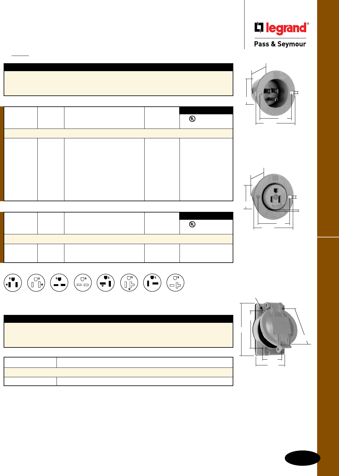
G-11
Flanged Inlets & OutletsStraight Blade Plugs & Connectors
Catalog Number Description
Weatherproof Cover for Flanged Devices
WPG1 Weatherproof Cover for Flanged Inlets and Outlets
For further information consult the Weatherproof Section P.
5278SS
2.0"
.156"
2.562"
1.655"
1.725"
5279SS
2.0"
.156"
2.562"
1.374"
1.660" .143"
Features
n All thermoplastic construction, provides excellent
impact and chemical resistance.
n Available in Gray or Black.
n NEMA configuration molded on flange, easy
field identification.
Features
n Glass-filled polycarbonate, impact- and
corrosion-resistant.
n Stainless steel hardware.
n Molded-in flat surface label area.
n OSHA lock-out/tag-out provision molded-in.
n Accepts competitor inlets and outlets.
IP20
Suitability
Straight Blade Plugs & Connectors
Flanged Inlets & Outlets
2 Pole, 3 Wire Grounding 15 & 20A, 125 & 250V
WPG1
4.57"
3.25"
.19"
(4 HOLES)
2.85"
1.88"
3.57"
3rd Party Compliance
FSUL
UL498 WC596
NEMA
Catalog Rating Cong.
Number A. V. Description No.
Flanged Inlets & Outlets – Black
5278SSBK 15 125 Inlet, Black 5-15P • •
5279SSBK 15 125 Outlet, Black 5-15R • •
3rd Party Compliance
FSUL
UL498 WC596
NEMA
Catalog Rating Cong.
Number A. V. Description No.
Flanged Inlets & Outlets – Gray
5278SS 15 125 Inlet, Gray 5-15P • •
5279SS 15 125 Outlet, Gray 5-15R • •
5378SS 20 125 Inlet, Gray 5-20P • •
5379SS 20 125 Outlet, Gray 5-20R • •
5678SS 15 250 Inlet, Gray 6-15P • •
5679SS 15 250 Outlet, Gray 6-15R • •
5478SS 20 250 Inlet, Gray 6-20P • •
5479SS 20 250 Outlet, Gray 6-20R • •
All devices listed on this page conform to NEMA WD-1 and WD-6.
NEMA
6-20R
NEMA
5-15P
NEMA
6-15P
NEMA
6-15R
NEMA
6-20P
NEMA
5-15R
NEMA
5-20P
NEMA
5-20R
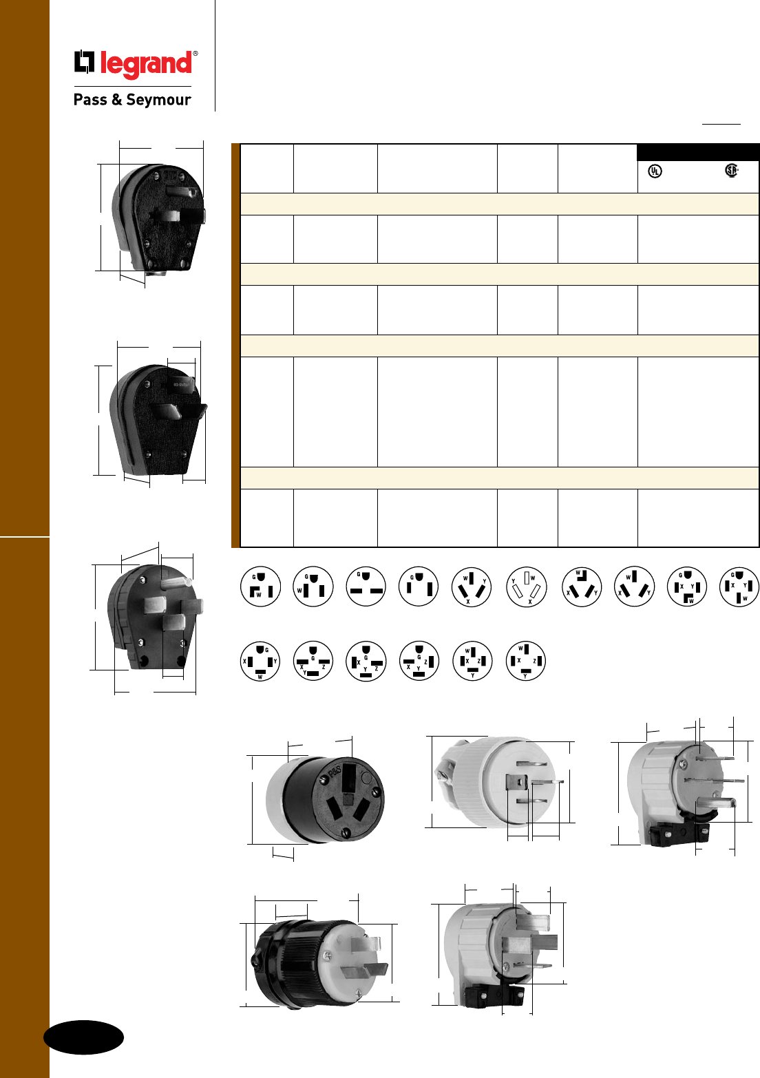
Miscellaneous Configurations
G-12
Straight Blade Plugs & Connectors
Straight Blade Plugs & Connectors
Miscellaneous Configurations
All devices listed on this
page conform to NEMA
WD-1 and WD-6.
IP20
Suitability
3861
2.77"
1.388"
1.36"
3.3"
1.22"
3869
2.86"
1.40"
3.43"
7088
1.859"
.676"
1.953"
NEMA
6-30P
NEMA
5-30P
NEMA
6-50P
NEMA
10-50P
NEMA
10-30P
NEMA
10-20P
NEMA
10-20R
NEMA
14-30P
NEMA
15-30P
NEMA
5-50P
NEMA
14-50P
NEMA
14-60P
NEMA
15-50P
NEMA
15-60P
NEMA
18-20P
NEMA
18-60P
3867
2.77"
1.388"
1.36"
3.43"
1.22"
7251DF
.875"
Max.
.687"
Min.
1.77"
2.03"
8302AN
1.22"
1.362"
2.12"
2.62"
3.43"
NEMA
Catalog Rating Cord Cong.
Number A. V. Description Diameter No.
2 Pole, 3 Wire Grounding
43379 30 125 Angled Plug, Yellow 5-30P
43399 50 125 Angled Plug, Yellow 5-50P
3869 30/50 250 Angled Plug, Black .56"-1.1" 6-30P/6-50P •
3 Pole, 3 Wire Non-Grounding
3861 30/50 125/250 Angled Plug, Black .56"-1.1" 10-30P/10-50P •
9977 20 125/250 Plug, Nylon 10-20P •
7088 20 125/250 Connector, Armored 10-20R
3 Pole, 4 Wire Grounding
5746AN 30 125/250 Angled Plug, Yellow 14-30P •
5741AN 30 3ø, 250 Angled Plug, Yellow 15-30P • •
5745AN 50 125/250 Angled Plug, Yellow 14-50P •
14629 60 125/250 Angled Plug, Yellow 14-60P
5751AN 50 3ø, 250 Angled Plug, Yellow 15-50P • •
5761AN 60 3ø, 250 Angled Plug, Yellow 15-60P • •
3867 30/50 125/250 Angled Plug, Black .56"-1.1" 14-30P/14-50P • •
4 Pole, 4 Wire Non-Grounding
7251DF 20 3øY, Plug, Yellow .365"-.775" 18-20P • •
120/208
8302AN 60 3øY, Angled Plug, Yellow 18-60P •
120/208
3rd Party Compliance
FSUL
UL498 WC596 C22.2 No. 42
5741AN
1.22"
2.12"
2.62"
3.43"
1.388"
9977
1.781"
.531"
2.063"
2.156"
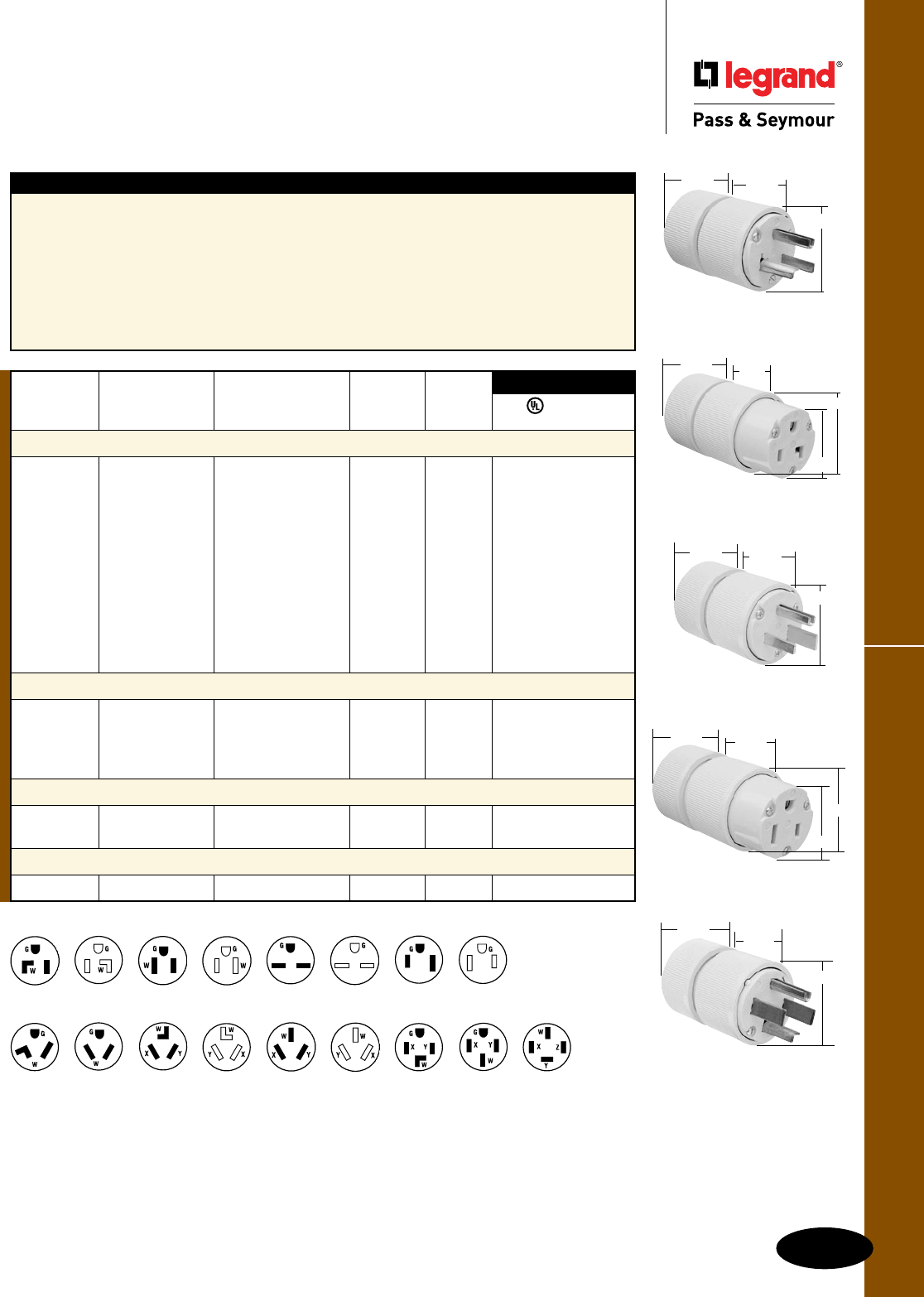
G-13
Gator Grip DevicesStraight Blade Plugs & Connectors
All devices listed on this page conform to NEMA WD-1 and WD-6.
Straight Blade Plugs & Connectors
Gator Grip Devices
Features – Gator Grip Devices
n Gator Grip Jaws grab cord tighter as you
hand turn the housing.
n Nylon jaws grip securely, but won’t damage
insulation.
n Self-locking Dardelet Thread holds securely and
assures firm clamping.
n Fast wiring — simply insert stranded conductors
into individual wiring chambers and tighten
oversized terminal screws.
n Transparent wiring chamber cover allows visual
inspection of wiring chambers to assure proper
connections.
n Sloped shoulders won’t catch or snap.
n Automatic cord centering.
n Brilliant high-visibility yellow.
n Neoprene Dust Seal helps keep out dirt & debris.
n Dead front construction.
NEMA
10-50P
NEMA
10-30P
NEMA
6-30P
NEMA
6-50P
NEMA
5-30P
NEMA
5-50P
NEMA
6-30R
NEMA
6-50R
NEMA
7-50P
NEMA
7-30P
NEMA
5-30R
NEMA
5-50R
NEMA
10-50R
NEMA
10-30R NEMA
14-30P
NEMA
14-50P
NEMA
18-60P
D0531
1.85" 1.72"
2.63"
D0651
1.85" 1.72"
2.63"
D0653
1.85" 1.72"
2.22"
2.63"
NEMA
Catalog Rating Cord Cong.
Number A. V. Description Diameter No.
2 Pole, 3 Wire Grounding 30 & 50A, 125, 250 & 277V
D0531 30 125 Plug, Yellow .57"-1.26" 5-30P • •
D0533 30 125 Connector, Yellow .57"-1.26" 5-30R • •
D0551 50 125 Plug, Yellow .57"-1.26" 5-50P • •
D0553 50 125 Connector, Yellow .57"-1.26" 5-50R • •
D0631 30 250 Plug, Yellow .57"-1.26" 6-30P • •
D0633 30 250 Connector, Yellow .57"-1.26" 6-30R
D0651 50 250 Plug, Yellow .57"-1.26" 6-50P • •
D0653 50 250 Connector, Yellow .57"-1.26" 6-50R • •
D0731 50 277 Plug, Yellow .57"-1.26" 7-30P • •
D0751 50 277 Plug, Yellow .57"-1.26" 7-50P • •
3 Pole, 3 Wire 30 & 50A, 125/250V
1031 30 125/250 Plug, Yellow .57"-1.26" 10-30P • •
1033 30 125/250 Connector, Yellow .57"-1.26" 10-30R
1051 50 125/250 Plug, Yellow .57"-1.26" 10-50P • •
1053 50 125/250 Connector, Yellow .57"-1.26" 10-50R • •
3 Pole, 4 Wire 30 & 50A, 125/250V
1431 30 125/250 Plug, Yellow .57"-1.26" 14-30P • •
1451 50 125/250 Plug, Yellow .57"-1.26" 14-50P • •
4 Pole, 4 Wire 60A, 3øY 120/208V
D1861 60 3øY 120/208 Plug, Yellow .57"-1.26" 18-60P • •
FSUL
UL498 WC596
3rd Party Compliance
D0533
1.85" 1.72"
2.63"
2.22"
1.85"
1.72"
2.63"
1431
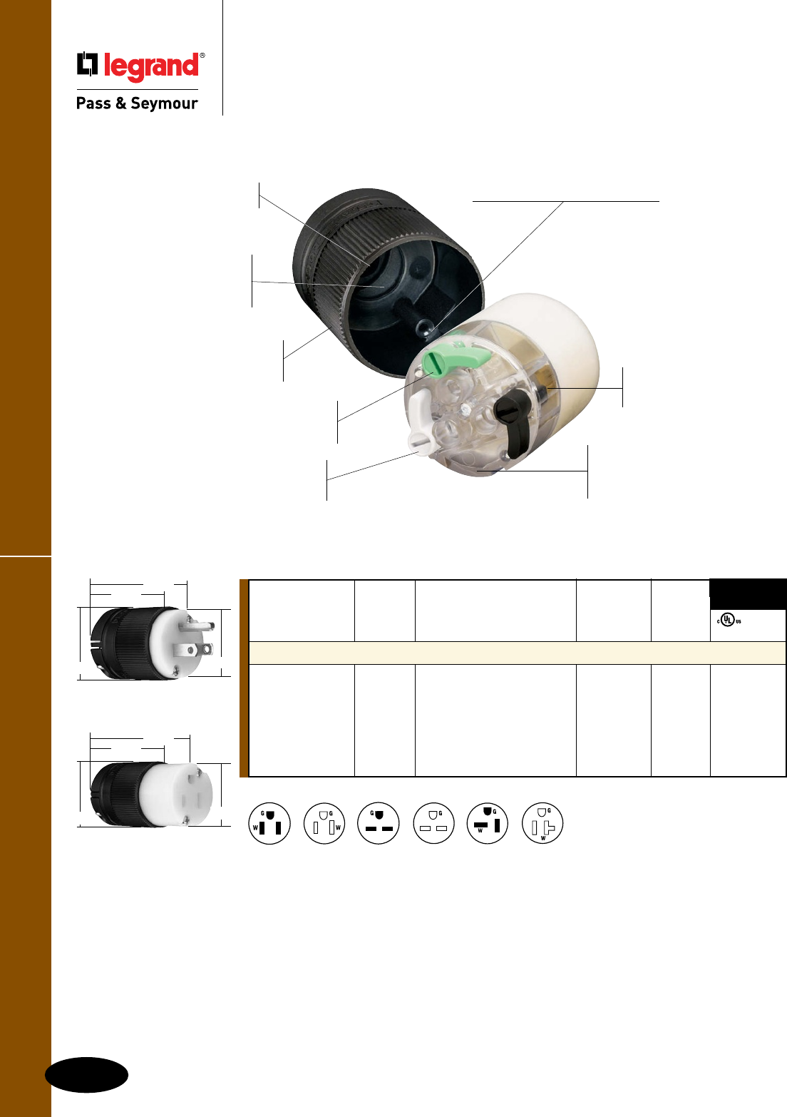
All devices listed on this page conform to NEMA WD-1 and WD-6.
U-drive combination slot/
crosshead screws ensure
easy assembly.
Long, deep channels
guide conductors and
prevent over-insertion.
PS515CCLB
Molded-in guide shows correct
wire stripping length.
Solid brass blades
and contacts provide
excellent conductivity.
Transparent polycarbonate
terminal cover makes terminals
visible for visual termination
verification.
Self-centering cord grip
helps speed assembly.
Color-coded levers enable terminal
identification at a glance and reduce the
chance of wiring errors.
Removable inserts
accom modate the
widest possible range
of cable diameters.
Rugged nylon housing and
backbody withstand chemicals,
heat, wear and impact.
Speedy, patented cam-lever
termination provides solid,
dependable connections.
G-14
Straight Blade Plugs & Connectors
Clamp-Lock™ Devices
2 Pole, 3 Wire Grounding 15A, 125 & 250V; 20A, 125V
Clamp-Lock™ Devices Straight Blade Plugs & Connectors
NEMA
Catalog Rating Cord Cong.
Number A. V. Description Diameter No.
P&S Clamp-Lock™ Straight Blade Plugs & Connectors
PS515PCLB 15 125 Plug, Black & White .20"-.470" 5-15P • •
PS515CCLB 15 125 Connector, Black & White .20"-.470" 5-15R • •
PS520PCLB 20 125 Plug, Black & White .20"-.470" 5-20P • •
PS520CCLB 20 125 Connector, Black & White .20"-.470" 5-20R • •
PS615PCLB 15 250 Plug, Black & White .20"-.470" 6-15P • •
PS615CCLB 15 250 Connector, Black & White .20"-.470" 6-15R • •
FSUL
cULus WC596
3rd Party
Compliance
NEMA
5-15P
NEMA
6-15P
NEMA
6-15R
NEMA
5-15R
NEMA
5-20P
NEMA
5-20R
PS515PCLB
1.55" 1.40"
1.85"
2.10"
PS515CCLB
1.55"
1.85"
2.80"
1.40"
G-15
Straight Blade Plugs & Connectors Product Specifications & Performance
Straight Blade Plugs & Connectors
Product Specifications & Performance
EHU Ground Continuity Monitoring
(GCM) Plugs & Connectors
15 & 20A Straight Blade
Plugs
Back Body Nylon
Front Body Nylon
Terminal Chamber Polycarbonate
Cord Clamp Nylon
Insert Nylon
Blades Brass
Terminal Clamp Zinc-Plated Steel
Terminal Screws Nickel- or Brass-Plated Steel
Ground Screws Nickel-Plated Steel
Cord Clamp Screws Nickel-Plated Steel #8
Assembly Screws Nickel-Plated Steel
Connectors
Back Body Nylon
Front Body Nylon
Terminal Chamber Polycarbonate
Cord Clamp Nylon
Insert Nylon
Contacts Brass
Terminal Clamp Zinc-Plated Steel
Terminal Screws Nickel- or Brass-Plated Steel
Ground Screws Nickel-Plated Steel
Cord Clamp Screws Nickel-Plated Steel #8
Assembly Screws Nickel-Plated Steel
Performance
Electrical
Dielectric Withstand Voltage 1500V minimum
Maximum Working Voltage 250V
Current Interrupting Certified for current interrupting
at full-rated current
Temperature Rise 30°C maximum after 50 cycles
at 150% rated current
Mechanical
Cord Accommodation Round portable service cords
of diameters in accordance with
the device rating as defined in
UL62
Cord Grip Accommodation .230"–.720" diameter
Terminal Identification Green = Ground,
White = Neutral, Brass = Hot
Terminal Accommodation #18 AWG min.– #10 AWG max.
Product Identification Amperage, Voltage,
3rd Party Compliance,
NEMA Configuration
Environmental
Flammability UL94 V2
Operating Temperature Maximum continuous: +75°C
Minimum: -40°C without impact
EHU & Corrosion-Resistant
Plugs & Connectors
15 & 20A Straight Blade
Plugs
Back Body Nylon
Front Body Nylon
Terminal Chamber Polycarbonate
Cord Clamp Nylon
Insert Nylon
Blades * Brass
Terminal Clamp * Zinc-Plated Steel
Terminal Screws Nickel- or Brass-Plated Steel
Ground Screws Nickel-Plated Steel
Cord Clamp Screws Nickel-Plated Steel #8
Assembly Screws Nickel-Plated Steel
Connectors
Back Body Nylon
Front Body Nylon
Terminal Chamber Polycarbonate
Cord Clamp Nylon
Insert Nylon
Contacts * Brass
Terminal Clamp * Zinc-Plated Steel
Terminal Screws Nickel- or Brass-Plated Steel
Ground Screws Nickel-Plated Steel
Cord Clamp Screws Nickel-Plated Steel #8
Assembly Screws Nickel-Plated Steel
Performance
Electrical
Dielectric Withstand Voltage 1500V minimum
Maximum Working Voltage 250V
Current Interrupting Certified for current interrupting
at full-rated current
Temperature Rise 30°C maximum after 50 cycles
at 150% rated current
Mechanical
Cord Accommodation Round portable service cords
of diameters in accordance with
the device rating as defined in
UL62
Cord Grip Accommodation .230"–.720" diameter
Terminal Identification Green = Ground,
White = Neutral, Brass = Hot
Terminal Accommodation #18 AWG min.– #10 AWG max.
Product Identification Amperage, Voltage,
3rd Party Compliance,
NEMA configuration
Environmental
Flammability UL94 V2
Operating Temperature Maximum continuous: +75°C
Minimum: -40°C without impact
* Nickel-Plated for Corrosion-Resistant Product.
G-16
Straight Blade Plugs & ConnectorsProduct Specifications & Performance
Straight Blade Plugs & Connectors
Product Specifications & Performance
MaxGrip® M3 Plugs & Connectors
Plug
Part Material
Body/Housing Nylon
Cord Grip Insert Nylon
Terminal Clamp Brass
Terminal Screws Zinc- or Brass-Plated Steel
Ground Screws Zinc-Plated Steel
Blades Brass
Cord Clamp Assembly Screws Zinc-Plated Steel
Connector
Part Material
Body/Housing Nylon
Cord Grip Insert Nylon
Terminal Clamp Brass
Terminal Screws Zinc- or Brass-Plated Steel
Ground Screws Zinc-Plated Steel
Contacts Brass
Cord Clamp Assembly Screws Zinc-Plated Steel
Performance
Electrical
Dielectric Withstand Voltage 1500V
Maximum Working Voltage 250V
Current Interrupting Certified for current interrupting
at full-rated current
Temperature Rise 30°C maximum after 50 cycles
at 150% rated current
Mechanical
Cord Accommodation Round portable service cords
of diameters in accordance
with the device rating as
defined in UL62
Cord Grip Accommodation .230"–.720" diameter cord
Terminal Identification Green = Ground,
Silver = Neutral, Brass = Hot
Terminal Accommodation #18 AWG min.– #12 AWG max.
Product Identification Amperage, Voltage,
3rd Party Compliance,
NEMA Configuration
Environmental
Flammability UL94 HB
Operating Temperature Maximum continuous: +75°C;
Minimum: -40°C without impact
Gator Grip Devices
Plugs & Connectors
30, 50 & 60A Straight Blade
Plugs
Back Body Glass-Filled Polypropylene
Front Body Glass-Filled Polypropylene
Terminal Chamber Polycarbonate
Cord Clamp Glass-Filled Nylon
Insert Nylon
Blades Brass
Terminal Clamp Zinc-Plated Steel
Terminal Screws Tin- or Brass-Plated Steel
Ground Screws Zinc-Plated Steel
Cord Clamp Screws N/A
Assembly Screws Zinc-Plated Steel
Connectors
Back Body Glass-Filled Polypropylene
Front Body Glass-Filled Polypropylene
Terminal Chamber Polycarbonate
Cord Clamp Glass-Filled Polypropylene
Insert Nylon
Contacts Brass
Terminal Clamp Zinc-Plated Steel
Terminal Screws Tin- or Brass-Plated Steel
Ground Screws Zinc-Plated Steel
Cord Clamp Screws N/A
Assembly Screws Zinc-Plated Steel
Performance
Electrical
Dielectric Withstand Voltage 1500V
Maximum Working Voltage Up to 277V
Current Interrupting Certified for current interrupting
at full-rated current
Temperature Rise 30°C maximum after 50 cycles
at 150% rated current
Mechanical
Cord Accommodation Round portable service cords
of diameters in accordance with
the device rating as defined in
UL62
Cord Grip Accommodation .570"–1.260" diameter
Terminal Identification Green = Ground,
White = Neutral, Brass = Hot
Terminal Accommodation #10 AWG min.– #4 AWG max.
Product Identification Amperage, Voltage,
3rd Party Compliance,
NEMA Configuration
Environmental
Flammability UL94 V0
Operating Temperature Maximum continuous: +75°C
Minimum: -40°C without impact
G-17
Straight Blade Plugs & Connectors
Straight Blade Plugs & Connectors
Product Specifications & Performance
Product Specifications & Performance
*Suitable for 208V motor applications at the HP rating specified.
NEMA Conguration AC HP Rating
Straight Blade Horsepower Rating for
NEMA Configuration Attachment
Plugs & Receptacles
5-15 1⁄2
6-15 11⁄2*
7-15 2
5-20 1
6-20 2*
7-20 2
10-20 2 Line to Line*
1 Line to Neutral
Clamp-Lock™ Plugs & Connectors
Plug
Part Material
Body/Housing Nylon
Cord Grip Insert Nylon
Terminal Clamp Brass
Terminal Screws Zinc- or Brass-Plated Steel
Ground Screws Zinc-Plated Steel
Blades Brass
Cord Clamp Assembly Screws Zinc-Plated Steel
Connector
Part Material
Body/Housing Nylon
Cord Grip Insert Nylon
Terminal Clamp Brass
Terminal Screws Zinc- or Brass-Plated Steel
Ground Screws Zinc-Plated Steel
Contacts Brass
Cord Clamp Assembly Screws Zinc-Plated Steel
Performance
Electrical
Dielectric Withstand Voltage 1500V
Maximum Working Voltage 250V
Current Interrupting Certified for current interrupting
at full-rated current
Temperature Rise 30°C maximum after 50 cycles
at 150% rated current
Mechanical
Cord Accommodation Round portable service cords
of diameters in accordance
with the device rating as
defined in UL62
Cord Grip Accommodation .20"–.470" diameter cord
Terminal Identification Green = Ground,
Silver = Neutral, Brass = Hot
Terminal Accommodation #18 AWG min.– #12 AWG max.
Product Identification Amperage, Voltage,
3rd Party Compliance,
NEMA Configuration
Environmental
Flammability UL94 HB
Operating Temperature Maximum continuous: +75°C;
Minimum: -40°C without impact

INDUSTRIAL SPEC GRADE TURNLOK
® LOCKING DEVICES
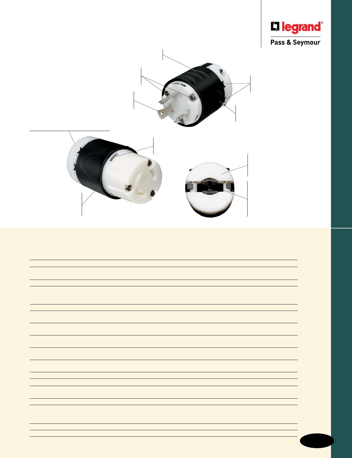
Index
Description Rating Page Number
NEMA Configurations H-3
Ground Continuity Monitoring Devices 15A, 125 & 250V, 277VAC H-4
20 & 30A, 125, 250 & 347V, & 277VAC; 20 & 30A, 125/250V H-5
2 Pole, 2 Wire Non-Grounding 15A, 125V; 20A, 250V H-6
2 Pole, 3 Wire 15A, 125 & 250V, 277VAC H-7, H-8
20A, 125, 250, 347, 480 & 600V, 277VAC H-9 – H-11
30A, 125, 250, 480 & 600V, 277VAC H-12 – H-14
3 Wire Grounding & Non-Grounding 10 & 15A, 125 & 250V; 20 & 30A, 125/250 & 250V H-15
3 Pole, 3 Wire Non-Grounding 20A, 125/250V; 3ø, 250 & 480V H-16
30A, 125/250V; 3ø, 250, 480 & 600V H-17
3 Pole, 4 Wire 20A, 125/250V; 3ø, 250 & 480V H-18
30A, 125/250V; 3ø, 250, 480 & 600V H-19, H-20
3 Pole, 4 Wire; 4 Pole, 4 Wire 20A, 3øY, 250V; 10A, 600V; 20A, 3øY, 120/208V H-21
30A, 3øY, 250V; 10A, 600V; 30A, 3øY, 120/208V H-22
4 Pole, 4 Wire Non-Grounding 20A, 3øY, 120/208, 277/480 & 347/600V H-23
30A, 3øY, 120/208, 277/480 & 347/600V H-24
4 Pole, 5 Wire 20A, 3øY, 120/208, 277/480 & 347/600V H-25
30A, 3øY, 120/208, 277/480 & 347/600V H-26
Angle Plugs & Adapters 15A, 125 & 250V, 277VAC; 15, 20 & 30A Adapters H-27
Rubber & Watertight 15, 20 & 30A, 125V; 15A, 277VAC H-28
California Standard & Corrosion-Resistant 50A, 125, 250 & 480V; 250VDC, 600VAC H-29
50A, 125/250V; 3ø, 250 & 480V; 250VDC, 600VAC H-30
Midget Connectors, Plugs, Inlets, Outlets 15A, 125V, 125/250V H-31
Power Interrupting Devices, 2 Pole, 3 Wire 20A, 125V Hospital Use; 20A, 125V; 20A, 125V; 10A, 250VDC, 480VAC H-32
3 Pole, 4 Wire 30A, 480V; 30A, 600VAC; 20A, 250VDC; 60A, 600V H-33
4 Pole, 5 Wire 30A, 600VAC; 20A 250VDC; 60A, 600V H-34
Accessories H-35, H-36
Product Specifications & Performance, Horsepower Ratings H-37 – H-43
H-1
Turnlok® Locking Devices
Industrial Spec Grade
Turnlok® Locking Devices
New-design external
cord grips provide visible
assurance of safe and proper
cord retention.
Integral flexible rubber
cord grommet conforms to
and seals around SO cord to
provide protection from oils,
water, or chips entering wiring
chamber.
L630C & L630P
Impact- and
corrosion-resistant
durable nylon 6/6
shell material.
Rounded back contour reduces
snags and hang-ups on the job site.
Visible stamped
NEMA configuration
and device rating.
Industrial-strength, brass alloy plug
blades and connector contacts resist heat
rise, provide excellent conductivity.
Raised ribs provide non-slip gripping profile
for turning to lock and unlock.
Quick-thread assembly
screws and cord-grip screws
come backed-out, ready-to-wire. Double dovetail design
provides superior protection
against cord pull-out forces.
Scallop shell design provides
non-slip gripping surface for
insertion and withdrawal.
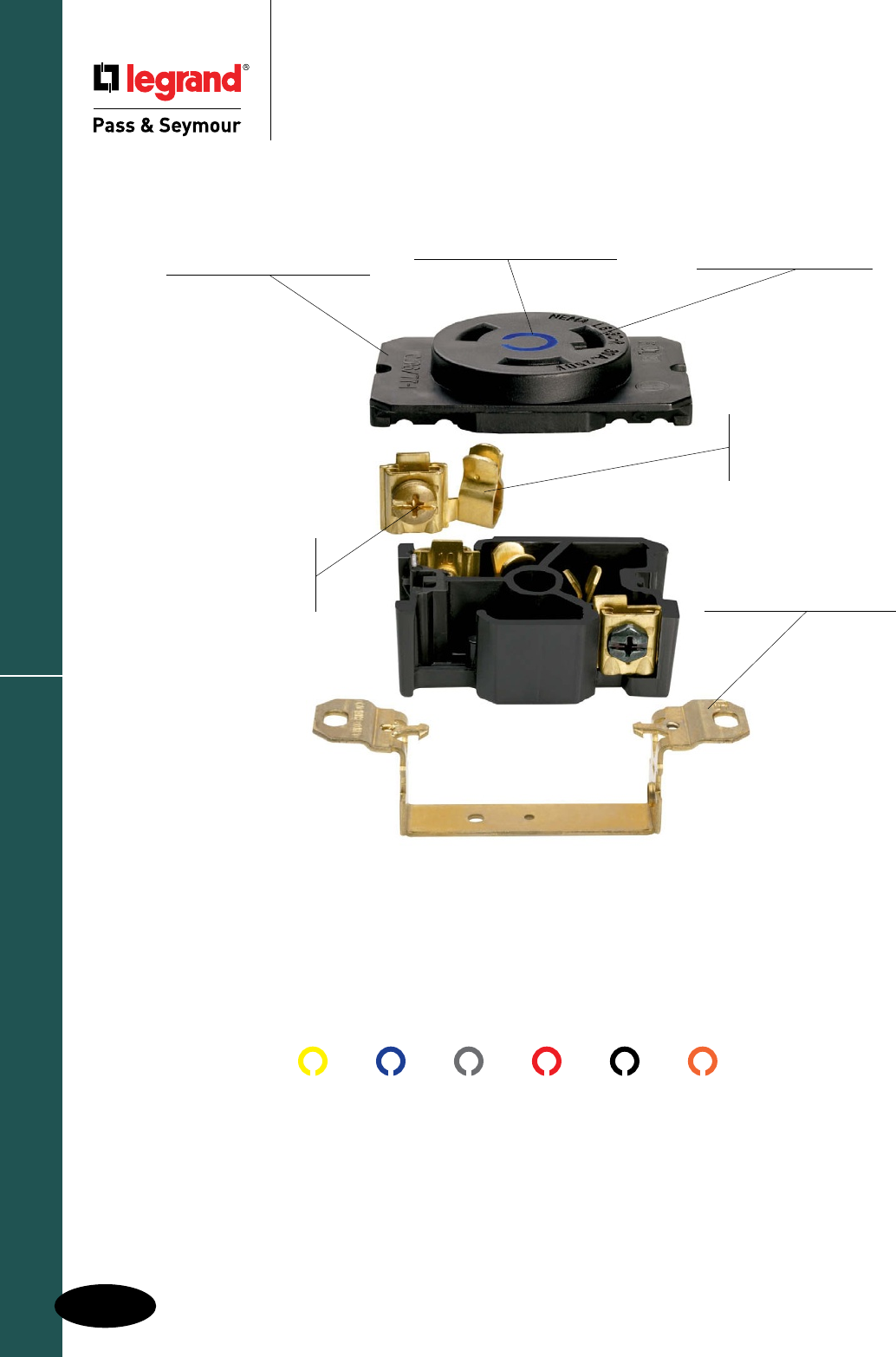
Turnlok® Locking Devices
Industrial Spec Grade
Turnlok® Locking Devices
Turnlok® Locking Devices
H-2
P&S Turnlok Receptacles. Voltage color coding on the outside.
Proven designs and quality materials on the inside. Any way you look
at them, they're the standard of the industry.
125V 250V 277VAC 480VAC 600VAC 125/250V
Compact, impact-resistant
nylon face and body are
ultrasonically welded together
for unrivaled strength.
Single-piece, solid brass
mounting strap is free of
easily loosened rivets found
on other brands.
L630R
One-piece, high-grade
brass contacts offer
excellent conductivity and
heat-rise resistance.
Clearly marked NEMA
configuration, rating,
and third party listing
on each unit’s face.
Side and external
screw-pressure-plate
back wire capability.
Accepts #14 - #10 AWG.
Face color coding by
voltage facilitates locating
and mating of proper devices.
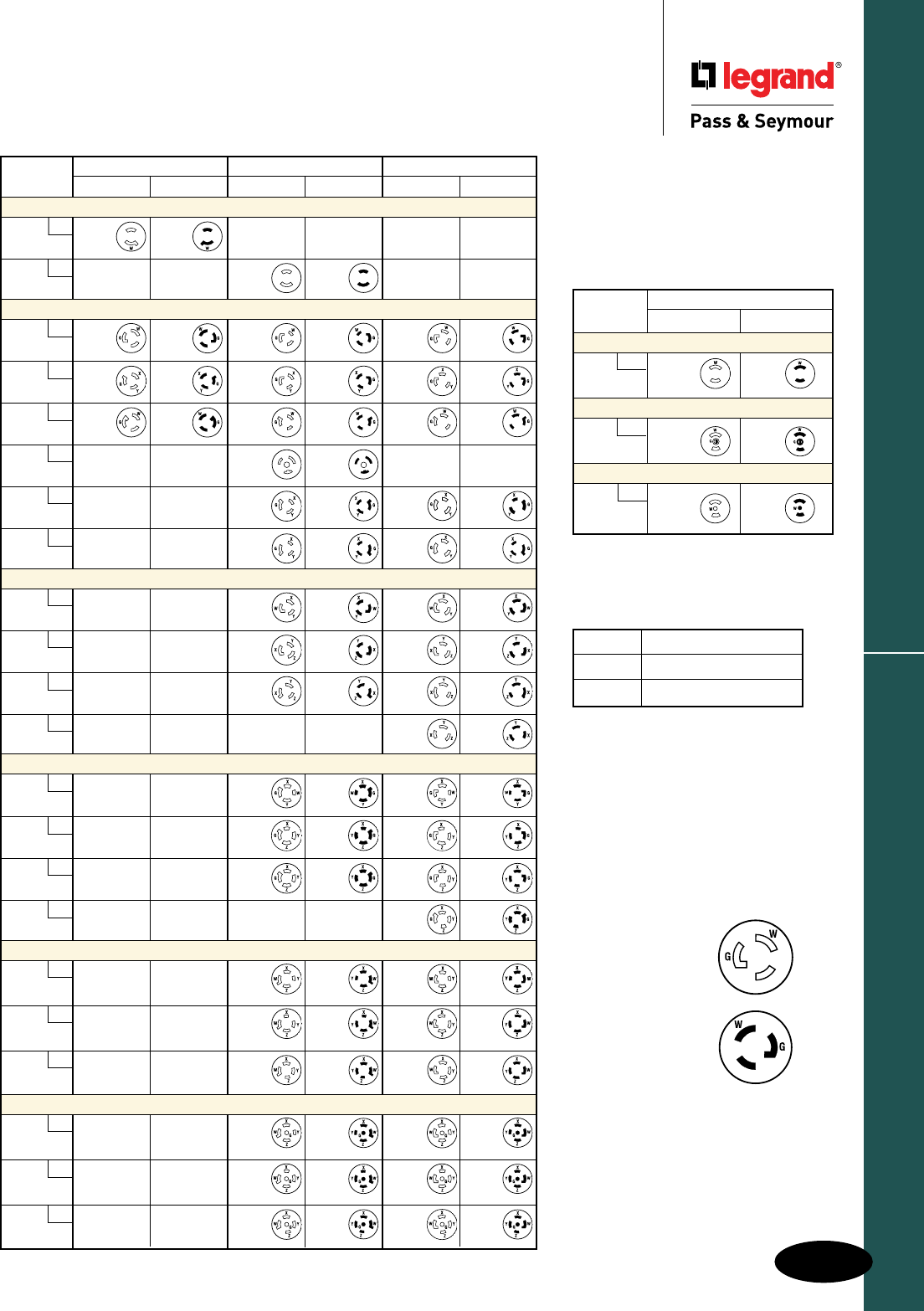
H-3
Turnlok® Locking Devices
Industrial Spec Grade Turnlok® Locking Devices
NEMA Configurations
Midget – Locking
15 AMPERE
RECEPTACLE PLUG
2 Pole, 2 Wire Non-Grounding
ML1
125V
ML-1R ML-1P
2 Pole, 3 Wire Grounding
ML2
125V
ML-2R ML-2P
3 Pole, 3 Wire Non-Grounding
ML3
125/250V
ML-3R ML-3P
Open Slots
Indicatereceptacle
configurations(female).
Closed Slots
Indicateplugblade
configurations(male).
X, Y, Z HotLead
W NeutralLead
G GroundingLead
Labels & Their Meaning
15 AMPERE 20 AMPERE 30 AMPERE
RECEPTACLE PLUG RECEPTACLE PLUG RECEPTACLE PLUG
2 Pole, 2 Wire Non-Grounding
L1
125V
L1-15R L1-15P
L2
250V
L2-20R L2-20P
2 Pole, 3 Wire Grounding
L5
125V
L5-15R L5-15P L5-20R L5-20P L5-30R L5-30P
L6
250V
L6-15R L6-15P L6-20R L6-20P L6-30R L6-30P
L7
277VAC
L7-15R L7-15P L7-20R L7-20P L7-30R L7-30P
L24
347VAC
L24-20R L24-20P
L8
480VAC
L8-20R L8-20P L8-30R L8-30P
L9
600VAC
L9-20R L9-20P L9-30R L9-30P
3 Pole, 3 Wire Non-Grounding
L10
125/250V
L10-20R L10-20P L10-30R L10-30P
L11
3ø250V
L11-20R L11-20P L11-30R L11-30P
L12
3ø480V
L12-20R L12-20P L12-30R L12-30P
L13
3ø600V
L13-30R L13-30P
3 Pole, 4 Wire Grounding
L14
125/250V
L14-20R L14-20P L14-30R L14-30P
L15
3ø250V
L15-20R L15-20P L15-30R L15-30P
L16
3ø480V
L16-20R L16-20P L16-30R L16-30P
L17
3ø600V
L17-30R L17-30P
4 Pole, 4 Wire Non-Grounding
L18
3øY
120/208V
L18-20R L18-20P L18-30R L18-30P
L19
3øY
277/480V
L19-20R L19-20P L19-30R L19-30P
L20
3øY
347/600V
L20-20R L20-20P L20-30R L20-30P
4 Pole, 5 Wire Grounding
L21
3øY
120/208V
L21-20R L21-20P L21-30R L21-30P
L22
3øY
277/480V
L22-20R L22-20P L22-30R L22-30P
L23
3øY
347/600V
L23-20R L23-20P L23-30R L23-30P
Locking Plugs & Receptacles
NEMA Configurations
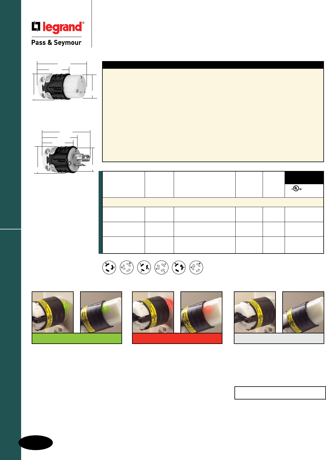
Industrial Spec Grade Turnlok® Locking Devices
Heavy-Duty Ground Continuity
Monitoring (GCM) Plugs & Connectors
2 Pole, 3 Wire 15A, 125 & 250V & 277VAC
H-4
Turnlok® Locking DevicesGround Continuity Monitoring
Features – Heavy-Duty Turnlok GCM
nIntegralindicationofgroundcontinuityand
powerstatus.Continuousmonitoringenhances
personnelsafetyandaddsconvenience.
nDual,brightLEDindicatorswith360°visibility.
GreenLEDsindicatepropergroundcontinuity
andpowerstatus.RedLEDsindicateground
continuitylossorreversedpolarity.NoLED
indicatesopenhot,openneutral,orhotto
groundcross.For250Vconfigurations:Hotto
groundcrosswillbeindicatedbyagreenand
redLED.
nNEMAconfigurationsalwaysvisibleforfast
identificationwithoutdisconnecting.
nExclusiveneoprenedustshieldondevices
sealscableentry.Optionalweatherproof
boots(soldseparately).
nChemical-andimpact-resistantnylonhousing
featureshorizontal,easy-gripribsonbackbody.
nExclusive,ruggedtwo-piececordgrip(15Amp
only)acceptsawiderangeofcordwidths.
Providesuniformpressureforsuperiorretention
ofconductors.
nRecessedcord-gripscrewreducesscrewdriver
slippage,improvessafety.Quick-threadtri-drive
assemblyandcord-gripscrewscomebacked-out
andready-to-wire.
nColor-codedterminalscrewsarebacked-outfor
fastinstallation.
nIndustrial-strength,brassalloyplugbladesand
connectorcontactsresistheatrise,provide
excellentconductivity.
NEMA
L6-15P
NEMA
L6-15R
NEMA
L5-15R
NEMA
L5-15P
NEMA
L7-15P
NEMA
L7-15R
NEMA
Catalog Rating Cord Cong.
Number A. V. Description Diameter No.
2 Pole, 3 Wire Grounding
PSL515CGCM 15 125 Connector,Black&White .230"-.720" L5-15R • •
PSL515PGCM 15 125 Plug,Black&White .230"-.720" L5-15P • •
PSL615CGCM 15 250 Connector,Black&White .230"-.720" L6-15R • •
PSL615PGCM 15 250 Plug,Black&White .230"-.720" L6-15P • •
PSL715CGCM 15 277 Connector,Black&White .230"-.720" L7-15R • •
PSL715PGCM 15 277 Plug,Black&White .230"-.720" L7-15P • •
FSUL
cULus WC596
3rd Party
Compliance
250V products will show red and green
when hot and ground are reversed.
No LED
Plug – Power loss, open hot or neutral
conductor, or hot/ground reversal.
Connector – Assuming power is
present at the outlet, there’s an open
hot or open neutral conductor in the
cordset, or a hot/ground reversal.
Green LED
Plug – There’s proper ground
continuity from the panel to the outlet
and power’s present.
Connector – Power’s present and
there’s proper ground continuity
through out the cordset and back to
the panel.
Red LED
Plug – Power’s present, but there’s
a ground continuity fault or miswire
between the receptacle and the panel.
Connector – Power’s present, but there’s
a ground continuity fault or mis wire in the
cordset (or, if there’s a red indication in
the plug as well, between the receptacle
and the panel). It’s also possible there
could be a problem in both.
PSL515PGCM
1.358"
1.516"
1.752"
1.844"
2.617"
1.516"
PSL515CGCM
1.358"
1.752"
2.598"
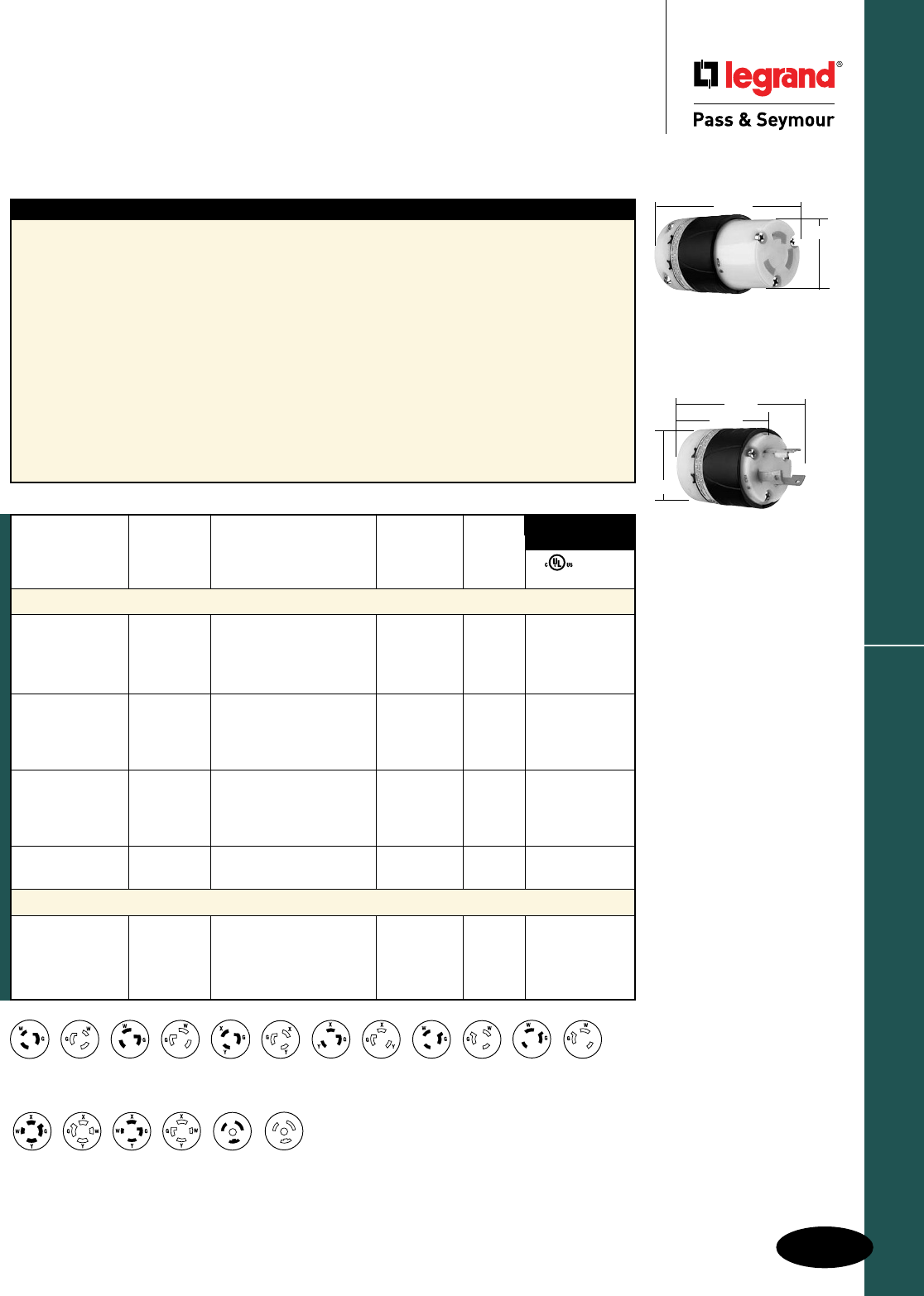
H-5
Turnlok® Locking Devices
AlldeviceslistedonthispageconformtoNEMAWD-1andWD-6.
Ground Continuity Monitoring
Industrial Spec Grade Turnlok® Locking Devices
Heavy-Duty Ground Continuity
Monitoring (GCM) Plugs & Connectors
2 Pole, 3 Wire 20 & 30A; 125, 250, 277 & 347V
3 Pole, 4 Wire 20 & 30A, 125/250V
NEMA
L5-30P
NEMA
L5-30R
NEMA
L6-20P
NEMA
L6-30P
NEMA
L6-20R
NEMA
L6-30R
NEMA
L5-20R
NEMA
L5-20P
NEMA
L7-20P
NEMA
L7-20R
NEMA
L7-30R
NEMA
L7-30P
NEMA
L14-20P
NEMA
L14-20R
NEMA
L14-30R
NEMA
L14-30P
NEMA
L24-20R
NEMA
L24-20P
NEMA
Catalog Rating Cord Cong.
Number A. V. Description Diameter No.
2 Pole, 3 Wire Grounding
L520CGCM 20 125 Connector,Black&White .225"-.750" L5-20R • •
L520PGCM 20 125 Plug,Black&White .225"-.750" L5-20P • •
L530CGCM 30 125 Connector,Black&White .225"-.750" L5-30R • •
L530PGCM 30 125 Plug,Black&White .225"-.750" L5-30P • •
L620CGCM 20 250 Connector,Black&White .225"-.750" L6-20R • •
L620PGCM 20 250 Plug,Black&White .225"-.750" L6-20P • •
L630CGCM 30 250 Connector,Black&White .225"-.750" L6-30R • •
L630PGCM 30 250 Plug,Black&White .225"-.750" L6-30P • •
L720CGCM 20 277 Connector,Black&White .225"-.750" L7-20R • •
L720PGCM 20 277 Plug,Black&White .225"-.750" L7-20P • •
L730CGCM 30 277 Connector,Black&White .225"-.750" L7-30R • •
L730PGCM 30 277 Plug,Black&White .225"-.750" L7-30P • •
L3720CGCM 20 347 Connector,Black&White .225"-.750" L24-20R • •
L3720PGCM 20 347 Plug,Black&White .225"-.750" L24-20P • •
3 Pole, 4 Wire Grounding
L1420CGCM 20 125/250 Connector,Black&White .225"-1.150" L14-20R • •
L1420PGCM 20 125/250 Plug,Black&White .225"-1.150" L14-20P • •
L1430CGCM 30 125/250 Connector,Black&White .225"-1.150" L14-30R • •
L1430PGCM 30 125/250 Plug,Black&White .225"-1.150" L14-30P • •
FSUL
cULus WC596
3rd Party
Compliance
Features – Heavy-Duty Turnlok GCM
nIntegralindicationofgroundcontinuityand
powerstatus.Continuousmonitoringenhances
personnelsafetyandaddsconvenience.
nDual,brightLEDindicatorswith360°visibility.
GreenLEDsindicatepropergroundcontinuity
andpowerstatus.RedLEDsindicateground
continuitylossorreversedpolarity.NoLED
indicatesopenhot,openneutral,orhotto
groundcross.For250Vconfigurations:Hotto
groundcrosswillbeindicatedbyagreenand
redLED.
nNEMAconfigurationsalwaysvisibleforfast
identificationwithoutdisconnecting.
nExclusiveneoprenedustshieldondevices
sealscableentry.Optionalweatherproof
boots(soldseparately).
nChemical-andimpact-resistantnylonhousing
featureshorizontal,easy-gripribsonbackbody.
nExclusive,ruggedtwo-piececordgrip(15Amp
only)acceptsawiderangeofcordwidths.
Providesuniformpressureforsuperiorretention
ofconductors.
nRecessedcord-gripscrewreducesscrewdriver
slippage,improvessafety.Quick-threadtri-drive
assemblyandcord-gripscrewscomebacked-out
andready-to-wire.
nColor-codedterminalscrewsarebacked-outfor
fastinstallation.
nIndustrial-strength,brassalloyplugbladesand
connectorcontactsresistheatrise,provide
excellentconductivity.
2.20"
2.57"
3.75"
L630PGCM
2.20"
3.33"
L630CGCM
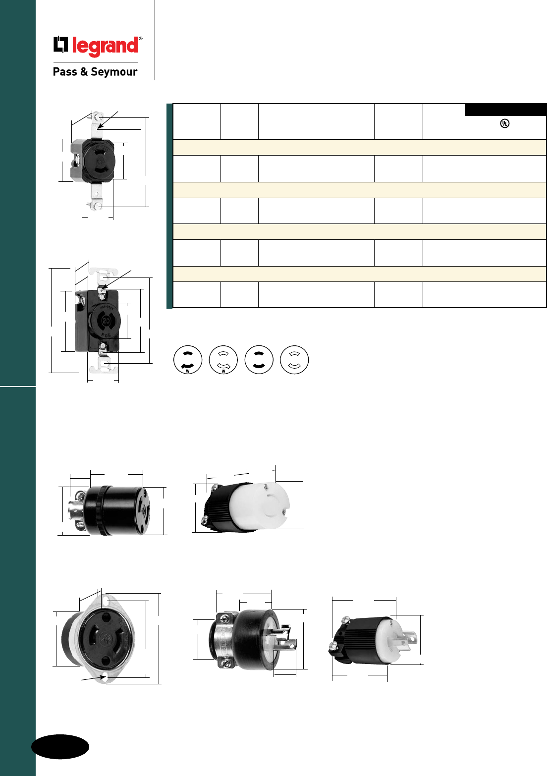
H-6
Turnlok® Locking Devices
AlldeviceslistedonthispageconformtoNEMAWD-1andWD-6.
Industrial Spec Grade Turnlok® Locking Devices
15 & 20 Amp NEMA L115 & L220
2 Pole, 2 Wire Non-Grounding 15A, 125V & 20A, 250V
15 & 20 Amp NEMA L115 & L220
3rd Party Compliance
NEMA
Catalog Rating Cord Cong.
Number A. V. Description/Color Diameter No.
Receptacles
7535 15 125 SingleReceptacle L1-15R •
7210 20 250 SingleReceptacle L2-20R •
Connectors
7506* 15 125 Black .296"-.562" L1-15R •
7101* 20 250 BlackBack,WhiteFrontBody .296"-.562" L2-20R
Plugs
7547DF 15 125 Black .296"-.625" L1-15P •
7102* 20 250 BlackBack,WhiteFrontBody .296"-.562" L2-20P
Flanged Inlets & Outlets
L0115 15 125 Inlet L1-15P •
7526 15 125 Outlet L1-15R •
UL498
NEMA
L1-15R
NEMA
L1-15P
NEMA
L2-20P
NEMA
L2-20R
*Forreplacementuseonly.
ReferencePagesH-35andH-36forAccessories.
7101
1.140"
1.865"
1.368"
1.500"
7506
1.562"
.546"
1.312"
1.375"
7102
2.085"
1.510"
1.865"
.860"
1.560"
1.000"
.640"
1.560"
7547DF
7526
1.625"
TO
1.750"
1.375"
.146"
(2HOLES)
2.031"
.093"
.985"
7535
.922"
1.750"
3.281"
1.562"
1.375"
2.375"
#6-32TAP
7210
1.234"
2.375"
3.281"
1.437"
1.375"
2.375"
4.031"
#6-32TAP
1.015"

H-7
Turnlok® Locking Devices
AlldeviceslistedonthispageconformtoNEMAWD-1andWD-6.
Industrial Spec Grade Turnlok® Locking Devices
15 Amp NEMA L515
2 Pole, 3 Wire 15A, 125V
15 Amp NEMA L515
4716SS
2.0"
.156"
2.562"
1.655"
1.725"
4715SS
2.0"
.156"
2.562"
1.374"
1.660"
NEMA
Catalog Rating Cord Cong.
Number A. V. Description/Color Diameter No.
Receptacles
4710 15 125 SingleReceptacle L5-15R • •
IG4710 15 125 SingleReceptacle,Orange, L5-15R • •
IsolatedGround
4700 15 125 DuplexReceptacle L5-15R • •
IG4700 15 125 DuplexReceptacle,Orange, L5-15R • •
IsolatedGround
4792 15 125 CombinationStraightBlade 5-15Rand •
andLocking L5-15R
Connectors IP20 Suitability
PSL515C 15 125 BlackBack,WhiteFrontBody .230"-.720" L5-15R • • •
CRL515C 15 125 YellowBack,WhiteFrontBody,.230"-.720" L5-15R • • •
Corrosion-Resistant
Plugs IP20 Suitability
PSL515P 15 125 BlackBack,WhiteFrontBody .230"-.720" L5-15P • • •
CRL515P 15 125 YellowBack,WhiteFrontBody,.230"-.720" L5-15P • • •
Corrosion-Resistant
Flanged Inlets & Outlets
4716SS 15 125 GrayInlet L5-15P • •
4715SS 15 125 GrayOutlet L5-15R • •
Straight Blade/Locking Adapters
44859 15 125 High-VisibilityYellow 5-15R/L5-15P
3rd Party Compliance
FSUL
UL498 WC596 CSA
ReferencePagesH-35andH-36forAccessories.
4710
1.203"
2.25"
1.0"
3.281"
1.437"
1.375"
2.375"
4.031"
4700
1.322"
1.104"
.0625"
3.281"
2.635"
1.50"
1.199"
.9375"
4792
3.28"
1.50"
1.199"
NEMA
L5-15P
NEMA
5-15R
NEMA
L5-15R
15A Connector
1.358"
1.516"
2.598"
1.752"
15A Plug
1.516" 1.358"
2.617"
1.752"
1.844"
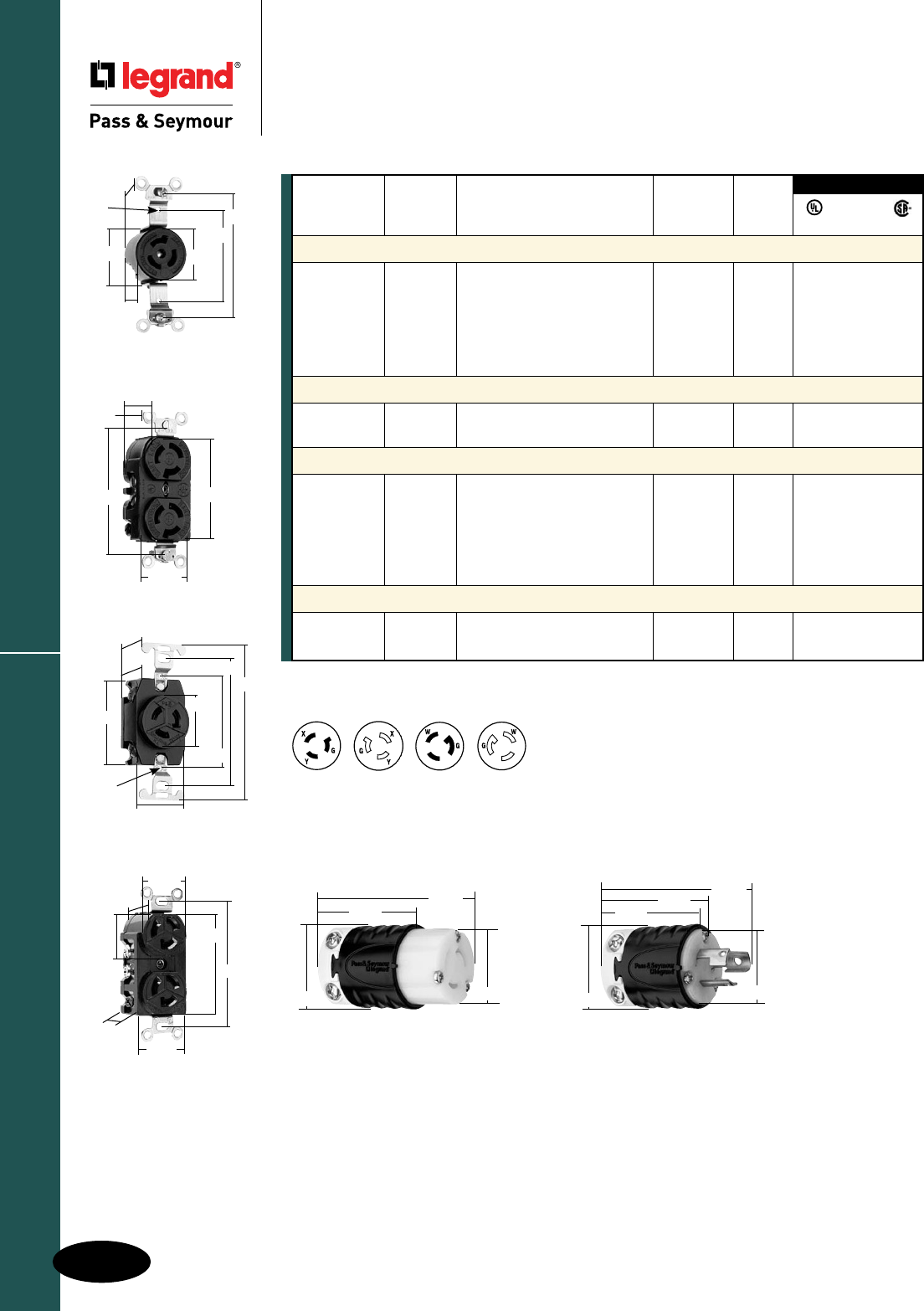
H-8
Turnlok® Locking Devices
AlldeviceslistedonthispageconformtoNEMAWD-1andWD-6.
15 Amp NEMA L615 & L715
Industrial Spec Grade Turnlok® Locking Devices
15 Amp NEMA L615 & L715
2 Pole, 3 Wire 15A, 250 & 277V
3rd Party Compliance
NEMA
Catalog Rating Cord Cong
Number A. V. Description/Color Diameter No.
Receptacles
4560 15 250 SingleReceptacle L6-15R •
4550† 15 250 DuplexReceptacle L6-15R •
4760 15 277 SingleReceptacle L7-15R • •
IG4760 15 277 SingleReceptacle,Orange, L7-15R • •
IsolatedGround
4750 15 277 DuplexReceptacle L7-15R • •
Connectors IP20 Suitability
PSL615C 15 250 BlackBack,WhiteFrontBody .230"-.720" L6-15R • • •
PSL715C 15 277 BlackBack,WhiteFrontBody .230"-.720" L7-15R • • •
Plugs IP20 Suitability
PSL615P 15 250 BlackBack,WhiteFrontBody .230"-.720" L6-15P • • •
PSL615PAN 15 250 AngledPlug,BlackBack, .320"-.655" L6-15P •
WhiteFrontBody
PSL715P 15 277 BlackBack,WhiteFrontBody .230"-.720" L7-15P • • •
PSL715PAN 15 277 AngledPlug,BlackBack, .320"-.655" L7-15P •
WhiteFrontBody
Flanged Outlets
614 15 250 GrayOutlet L6-15R
L0714 15 277 GrayOutlet L7-15R
FSUL
UL498 WC596 CSA
†Notdesignedforsplitcircuits.
ReferencePagesH-35andH-36forAccessories.
NEMA
L6-15R
NEMA
L6-15P
NEMA
L7-15R
NEMA
L7-15P
15A Connector
1.358"
1.516"
2.598"
1.752"
15A Plug
1.516" 1.358"
2.617"
1.844"
1.752"
4550
1.150"
.940"
3.281"
1.500"
2.270"
4560
2.375"
1.375"
1.500"
#6-32
TAP
.922"
1.125"
3.281"
4760
2.375"
2.250"
1.203"
1.000"
1.375"
3.281"
4.031"
1.437"
#6-32
TAP
4750
1.104"
3.281"
2.635"
.938"
1.199"
1.322"
1.50"

H-9
Turnlok® Locking Devices
AlldeviceslistedonthispageconformtoNEMAWD-1andWD-6.
20 Amp NEMA L520
Industrial Spec Grade Turnlok® Locking Devices
20 Amp NEMA L520
2 Pole, 3 Wire 20A, 125V
NEMA
L5-20R
NEMA
L5-20P
3rd Party Compliance
NEMA
Catalog Rating Cord Cong.
Number A. V. Description/Color Diameter No.
Receptacles
L520R 20 125 SingleReceptacle L5-20R • • •
IGL520R 20 125 SingleReceptacle,Orange, L5-20R • •
IsolatedGround
CRL520R 20 125 SingleReceptacle,Yellow, L5-20R • • •
Corrosion-Resistant
Connectors IP20 Suitability
L520C 20 125 BlackBack,WhiteFrontBody .225"-.750" L5-20R • • •
L520CBK 20 125 BlackBack,BlackFrontBody .225"-.750" L5-20R • • •
CRL520C 20 125 YellowBack,WhiteFrontBody, .225"-.750" L5-20R • • •
Corrosion-Resistant
Plugs IP20 Suitability
L520P 20 125 BlackBack,WhiteFrontBody .225"-.750" L5-20P • • •
L520PBK 20 125 BlackBack,BlackFrontBody .225"-.750" L5-20P • • •
CRL520P 20 125 YellowBack,WhiteFrontBody, .225"-.750" L5-20P • • •
Corrosion-Resistant
Flanged Inlets & Outlets
L520FI 20 125 GrayInlet L5-20P • •
L520FO 20 125 GrayOutlet L5-20R • •
FSUL
UL498 WC596 CSA
ReferencePagesH-35andH-36forAccessories.
Catalog Number Description Color
Weatherproof Cover
WPG2 Coverfor20and30ATurnlokFlangedInletsandOutlets Gray
Stainless Steel Wall Plate
SS720 WallPlateforLockingReceptacles 302S/S
2.09"
ø.187"
1.65"
2.87"
2.09"
1.34"
ø.187"
2.87"
3HOLESONø2.50"C/L@120°
20A Flanged Inlet & Outlet
WPG2
4.57"
3.25"
.19"
(4HOLES)
2.85"
1.88"
3.57"
2.29"
1.19"
1.61"
2.37"
3.28"
1.545"
.14"
20A Receptacle
2.20"
3.33"
20A Connector
3.75"
2.57"
2.20"
20A Plug
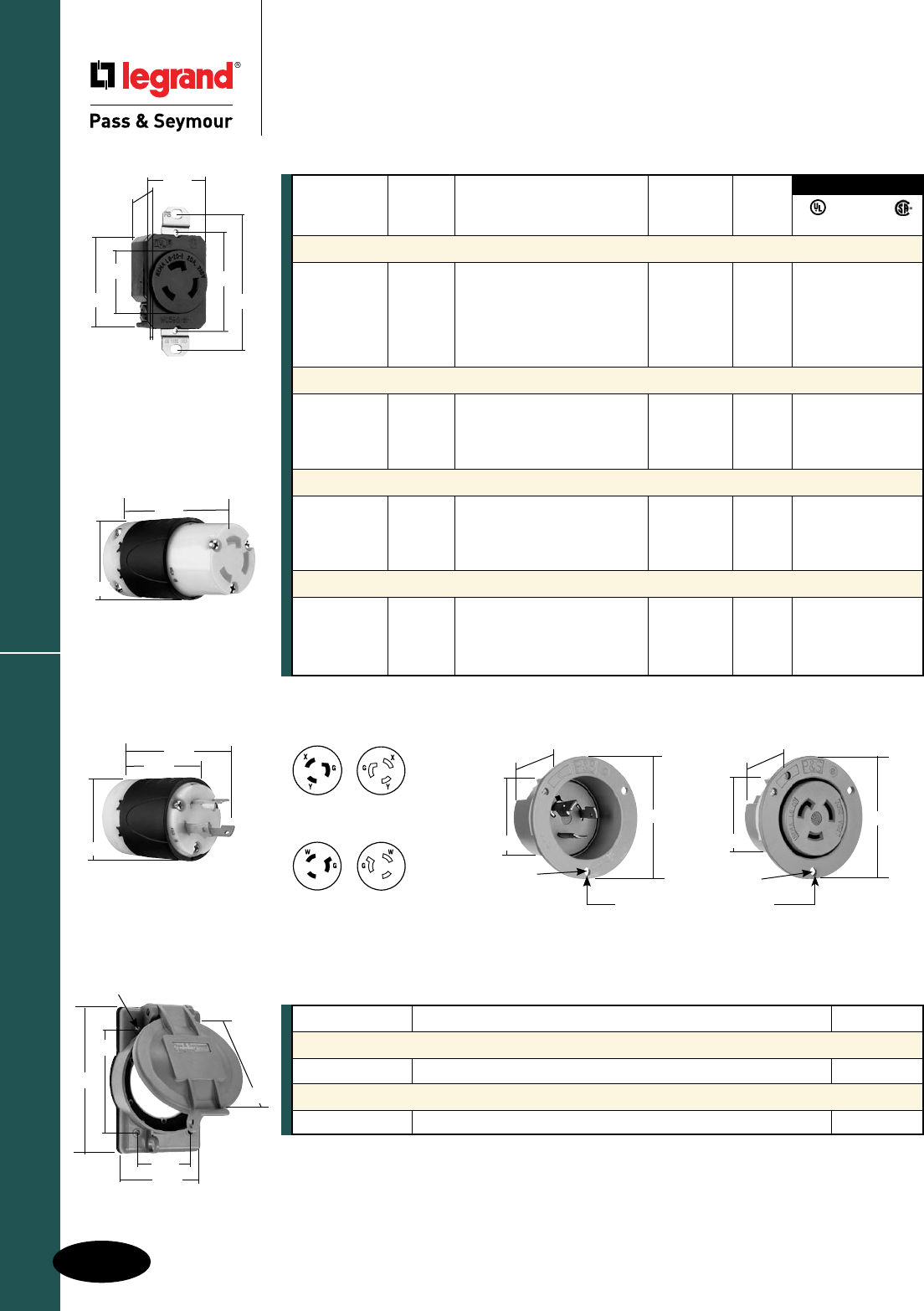
Turnlok® Locking Devices
20A NEMA L620 & L720
Industrial Spec Grade Turnlok® Locking Devices
20 Amp NEMA L620 & L720
2 Pole, 3 Wire 20A, 250 & 277V
AlldeviceslistedonthispageconformtoNEMAWD-1andWD-6.
ReferencePagesH-35andH-36forAccessories.
NEMA
Catalog Rating Cord Cong.
Number A. V. Description/Color Diameter No.
Receptacles
L620R 20 250 SingleReceptacle L6-20R • • •
IGL620R 20 250 SingleReceptacle,Orange, L6-20R • •
IsolatedGround
L720R 20 277 SingleReceptacle L7-20R • • •
IGL720R 20 277 SingleReceptacle,Orange, L7-20R • •
IsolatedGround
Connectors IP20 Suitability
L620C 20 250 BlackBack,WhiteFrontBody .225"-.750" L6-20R • • •
CRL620C 20 250 YellowBack,WhiteFrontBody, .225"-.750" L6-20R • • •
Corrosion-Resistant
L720C 20 277 BlackBack,WhiteFrontBody .225"-.750" L7-20R • • •
Plugs IP20 Suitability
L620P 20 250 BlackBack,WhiteFrontBody .225"-.750" L6-20P • • •
CRL620P 20 250 YellowBack,WhiteFrontBody, .225"-.750" L6-20P • • •
Corrosion-Resistant
L720P 20 277 BlackBack,WhiteFrontBody .225"-.750" L7-20P • • •
Flanged Inlets & Outlets
L620FI 20 250 GrayInlet L6-20P • •
L620FO 20 250 GrayOutlet L6-20R • •
L720FI 20 277 GrayInlet L7-20P • •
L720FO 20 277 GrayOutlet L7-20R • •
FSUL
UL498 WC596 CSA
3rd Party Compliance
NEMA
L6-20R
NEMA
L6-20P
NEMA
L7-20R
NEMA
L7-20P
2.09"
ø.187"
1.65"
2.87"
2.09"
1.34"
ø.187"
2.87"
3HOLESONø2.50"C/L@120°
20A Flanged Inlet & Outlet
Catalog Number Description Color
Weatherproof Cover
WPG2 Coverfor20and30ATurnlokFlangedInletsandOutlets Gray
Stainless Steel Wall Plate
SS720 WallPlateforLockingReceptacles 302S/S
2.29"
1.19"
1.61"
2.37"
3.28"
1.545"
.14"
20A Receptacle
2.20"
3.33"
20A Connector
3.75"
2.57"
2.20"
20A Plug
WPG2
4.57"
3.25"
.19"
(4HOLES)
2.85"
1.88"
3.57"
H-10
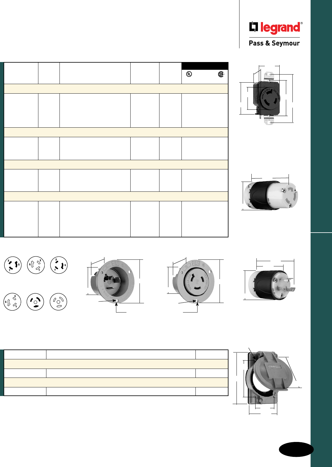
H-11
Turnlok® Locking Devices
AlldeviceslistedonthispageconformtoNEMAWD-1andWD-6.
20 Amp NEMA L820, L920 & L2420
Industrial Spec Grade Turnlok® Locking Devices
20 Amp NEMA L820, L920 & L2420
2 Pole, 3 Wire 20A, 347, 480 & 600V
NEMA
L8-20R
NEMA
L8-20P
NEMA
L9-20P
NEMA
L9-20R
NEMA
L24-20R
NEMA
L24-20P
ReferencePagesH-35andH-36forAccessories.
3rd Party Compliance
FSUL
UL498 WC596 CSA
NEMA
Catalog Rating Cord Cong.
Number A. V. Description/Color Diameter No.
Receptacles
L820R 20 480 SingleReceptacle L8-20R • •
IGL820R 20 480 SingleReceptacle,Orange, L8-20R • •
IsolatedGround
L920R 20 600 SingleReceptacle L9-20R • •
L3720R 20 347 SingleReceptacle L24-20R •
Connectors IP20 Suitability
L820C 20 480 BlackBack,WhiteFrontBody .225"-.750" L8-20R • •
L920C 20 600 BlackBack,WhiteFrontBody .225"-.750" L9-20R • •
L3720C 20 347 BlackBack,WhiteFrontBody .225"-.750" L24-20R •
Plugs IP20 Suitability
L820P 20 480 BlackBack,WhiteFrontBody .225"-.750" L8-20P • •
L920P 20 600 BlackBack,WhiteFrontBody .225"-.750" L9-20P • •
L3720P 20 347 BlackBack,WhiteFrontBody .225"-.750" L24-20P • • •
Flanged Inlets & Outlets
L820FI 20 480 GrayInlet L8-20P • •
L820FO 20 480 GrayOutlet L8-20R • •
L920FI 20 600 GrayInlet L9-20P • •
L920FO 20 600 GrayOutlet L9-20R • •
L3720FO 20 347 GrayOutlet L24-20R •
2.09"
ø.187"
1.65"
2.87"
2.09"
1.34"
ø.187"
2.87"
3HOLESONø2.50"C/L @120°
20A Flanged Inlet & Outlet
Catalog Number Description Color
Weatherproof Cover
WPG2 Coverfor20and30ATurnlokFlangedInletsandOutlets Gray
Stainless Steel Wall Plate
SS720 WallPlateforLockingReceptacles 302S/S
2.29"
1.19"
1.61"
2.37"
3.28"
1.545"
.14"
20A Receptacle
2.20"
3.33"
20A Connector
3.75"
2.57"
2.20"
20A Plug
WPG2
4.57"
3.25"
.19"
(4HOLES)
2.85"
1.88"
3.57"
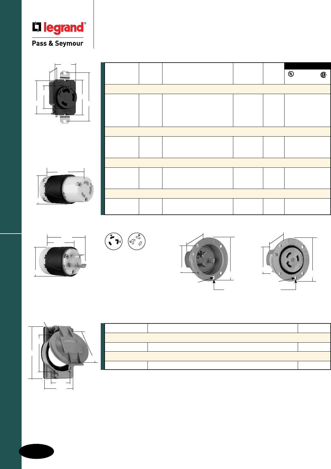
H-12
Turnlok® Locking Devices
AlldeviceslistedonthispageconformtoNEMAWD-1andWD-6.
30 Amp NEMA L530
Industrial Spec Grade Turnlok® Locking Devices
30 Amp NEMA L530
2 Pole, 3 Wire 30A, 125V
3rd Party Compliance
FSUL
UL498 WC596 CSA
NEMA
Catalog Rating Cord Cong.
Number A. V. Description/Color Diameter No.
Receptacles
L530R 30 125 SingleReceptacle L5-30R • • •
IGL530R 30 125 SingleReceptacle,Orange, L5-30R • •
IsolatedGround
CRL530R 30 125 SingleReceptacle,Yellow, L5-30R • • •
Corrosion-Resistant
Connectors IP20 Suitability
L530C 30 125 BlackBack,WhiteFrontBody .225"-.750" L5-30R • • •
CRL530C 30 125 YellowBack,WhiteFrontBody, .225"-.750" L5-30R • • •
Corrosion-Resistant
Plugs IP20 Suitability
L530P 30 125 BlackBack,WhiteFrontBody .225"-.750" L5-30P • • •
CRL530P 30 125 YellowBack,WhiteFrontBody, .225"-.750" L5-30P • • •
Corrosion-Resistant
Flanged Inlets & Outlets
L530FI 30 125 GrayInlet L5-30P • •
L530FO 30 125 GrayOutlet L5-30R • •
ReferencePagesH-35andH-36forAccessories.
NEMA
L5-30R
NEMA
L5-30P
2.26"
3.12"
ø.187"
1.765"
2.26"
3.12"
1.750"
ø.187"
3HOLESONø2.72"C/L @120°
30A Flanged Inlet & Outlet
Catalog Number Description Color
Weatherproof Cover
WPG2 Coverfor20and30ATurnlokFlangedInletsandOutlets Gray
Stainless Steel Wall Plate
SS720 WallPlateforLockingReceptacles 302S/S
2.42"
1.28"
1.61"
2.37"
3.28"
1.545"
.23"
30A Receptacle
2.20"
3.33"
30A Connector
3.75"
2.57"
2.20"
30A Plug
WPG2
4.57"
3.25"
.19"
(4HOLES)
2.85"
1.88"
3.57"
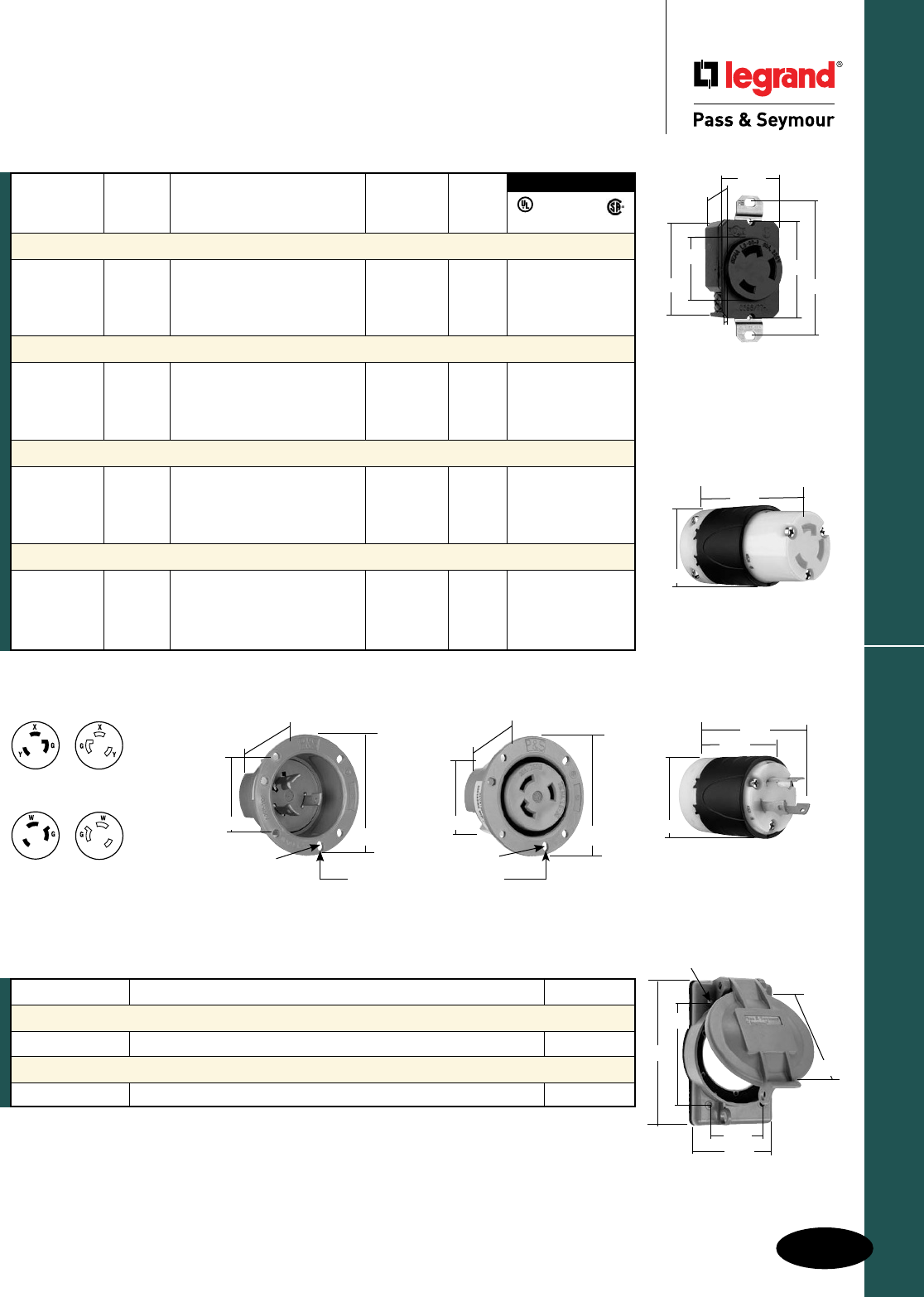
H-13
Turnlok® Locking Devices
AlldeviceslistedonthispageconformtoNEMAWD-1andWD-6.
Industrial Spec Grade Turnlok® Locking Devices
30 Amp NEMA L630 & L730
2 Pole, 3 Wire 30A, 250 & 277V
30 Amp NEMA L630 & L730
ReferencePagesH-35andH-36forAccessories.
NEMA
L6-30R
NEMA
L6-30P
3rd Party Compliance
FSUL
UL498 WC596 CSA
NEMA
Catalog Rating Cord Cong.
Number A. V. Description/Color Diameter No.
Receptacles
L630R 30 250 SingleReceptacle L6-30R • • •
IGL630R 30 250 SingleReceptacle,Orange, L6-30R • •
IsolatedGround
L730R 30 277 SingleReceptacle L7-30R • • •
Connectors IP20 Suitability
L630C 30 250 BlackBack,WhiteFrontBody .225"-.750" L6-30R • • •
CRL630C 30 250 YellowBack,WhiteFrontBody, .225"-.750" L6-30R • • •
Corrosion-Resistant
L730C 30 277 BlackBack,WhiteFrontBody .225"-.750" L7-30R • • •
Plugs IP20 Suitability
L630P 30 250 BlackBack,WhiteFrontBody .225"-.750" L6-30P • • •
CRL630P 30 250 YellowBack,WhiteFrontBody, .225"-.750" L6-30P • • •
Corrosion-Resistant
L730P 30 277 BlackBack,WhiteFrontBody .225"-.750" L7-30P • • •
Flanged Inlets & Outlets
L630FI 30 250 GrayInlet L6-30P • •
L630FO 30 250 GrayOutlet L6-30R • •
L730FI 30 277 GrayInlet L7-30P • •
L730FO 30 277 GrayOutlet L7-30R • •
Catalog Number Description Color
Weatherproof Cover
WPG2 Coverfor20and30ATurnlokFlangedInletsandOutlets Gray
Stainless Steel Wall Plate
SS720 WallPlateforLockingReceptacles 302S/S
NEMA
L7-30R
NEMA
L7-30P
2.26"
3.12"
ø.187"
1.765"
2.26"
3.12"
1.750"
ø.187"
3HOLESONø2.72"C/L @120°
30A Flanged Inlet & Outlet
3.75"
2.57"
2.20"
2.20"
3.33"
30A Connector
30A Plug
WPG2
4.57"
3.25"
.19"
(4HOLES)
2.85"
1.88"
3.57"
2.42"
1.28"
1.61"
2.37"
3.28"
1.545"
.23"
30A Receptacle
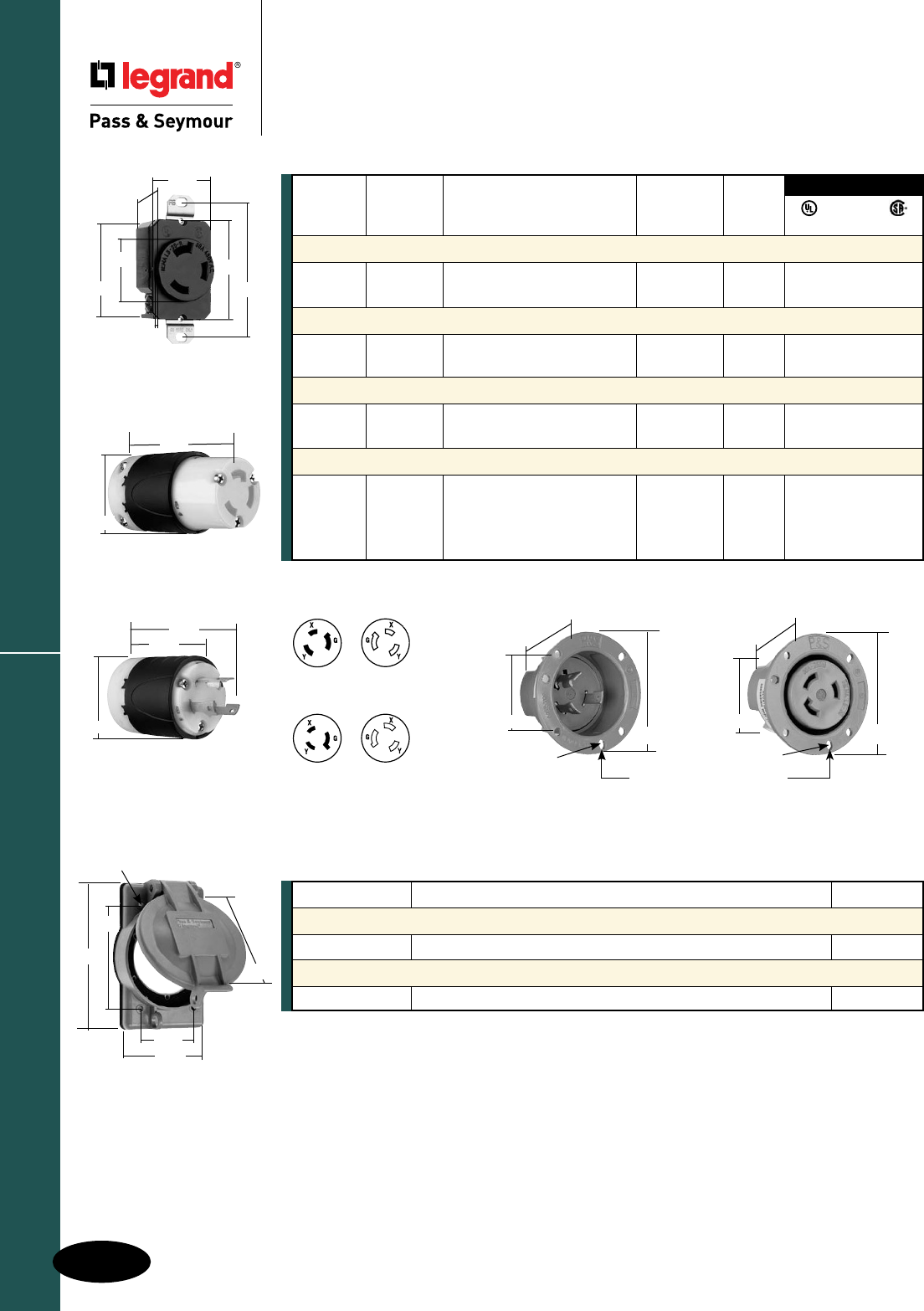
H-14
Turnlok® Locking Devices
AlldeviceslistedonthispageconformtoNEMAWD-1andWD-6.
Industrial Spec Grade Turnlok® Locking Devices
30 Amp NEMA L830 & L930
2 Pole, 3 Wire 30A, 480 & 600V
30 Amp NEMA L830 & L930
NEMA
L8-30R
NEMA
L8-30P
NEMA
L9-30R
NEMA
L9-30P
3rd Party Compliance
FSUL
UL498 WC596 CSA
ReferencePagesH-35andH-36forAccessories.
NEMA
Catalog Rating Cord Cong.
Number A. V. Description/Color Diameter No.
Receptacles
L830R 30 480 SingleReceptacle L8-30R • • •
L930R 30 600 SingleReceptacle L9-30R • • •
Connectors IP20 Suitability
L830C 30 480 BlackBack,WhiteFrontBody .225"-.750" L8-30R • • •
L930C 30 600 BlackBack,WhiteFrontBody .225"-.750" L9-30R • • •
Plugs IP20 Suitability
L830P 30 480 BlackBack,WhiteFrontBody, .225"-.750" L8-30P • • •
L930P 30 600 BlackBack,WhiteFrontBody .225"-.750" L9-30P • • •
Flanged Inlets & Outlets
L830FI 30 480 GrayInlet L8-30P • •
L830FO 30 480 GrayOutlet L8-30R • •
L930FI 30 600 GrayInlet L9-30P • •
L930FO 30 600 GrayOutlet L9-30R • •
Catalog Number Description Color
Weatherproof Cover
WPG2 Coverfor20and30ATurnlokFlangedInletsandOutlets Gray
Stainless Steel Wall Plate
SS720 WallPlateforLockingReceptacles 302S/S
2.26"
3.12"
ø.187"
1.765"
2.26"
3.12"
1.750"
ø.187"
3HOLESONø2.72"C/L @120°
30A Flanged Inlet & Outlet
3.75"
2.57"
2.20"
2.42"
1.28"
1.61"
2.37"
3.28"
1.545"
.23"
30A Receptacle
2.20"
3.33"
30A Connector
30A Plug
WPG2
4.57"
3.25"
.19"
(4HOLES)
2.85"
1.88"
3.57"
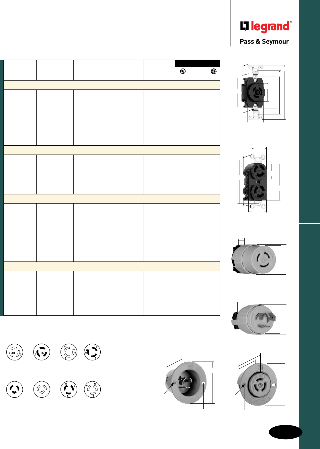
H-15
Turnlok® Locking Devices
AlldeviceslistedonthispageconformtoNEMAWD-1andWD-6.
Industrial Spec Grade Turnlok® Locking Devices
Non-NEMA
3 Wire Grounding & Non-Grounding
10 & 15A, 125 & 250V; 20 & 30A, 125/250 & 250V
Non-NEMA
*Forreplacementuseonly.
ReferencePagesH-35andH-36forAccessories.
Catalog Rating Cord
Number A. V. Description/Color Diameter
Receptacles
7582* 15 125 SingleReceptacle
10 250
7580 15 125 DuplexReceptacle
10 250
7580G 15 125 DuplexReceptacle,Grounding
10 250
7310* 20 125/250 SingleReceptacle
3330 30 125/250 SingleReceptacle
3330G 30 125/250 SingleReceptacle,Grounding
Connectors IP20 Suitability
7555SS* 15 125 Yellow .296"-.625"
10 250
7555G 15 125 Yellow .280"-.710"
7313SS 20 125/250 BlackBack,WhiteFrontBody .225"-.750" •• •
7313SSBK 20 125/250 BlackBack,BlackFrontBody .225"-.750" •• •
3333SS 30 125/250 BlackBack,WhiteFrontBody .225"-.750" • •
Plugs IP20 Suitability
S2348DF 14 125-480 BlackBack,WhiteFrontBody
7554SS* 15 125 Yellow .296"-.625"
10 250
7572G 15 125 Yellow,Grounding .280"-.710"
7311SS 20 125/250 BlackBack,WhiteFrontBody .225"-.750" •• •
7311SSBK 20 125/250 BlackBack,BlackFrontBody .225"-.750" •• •
7311G 20 250 Yellow,Grounding .410"-1.060"
3331SS 30 125/250 BlackBack,WhiteFrontBody .225"-.750" •• •
3331G 30 250 Yellow,Grounding .410"-1.060"
Flanged Inlets & Outlets
S2347 14 125-480 Outlet
7556SS* 15 125 GrayInlet
10 250
7557SS* 15 125 GrayOutlet
10 250
3334SS 30 125/250 GrayInlet •
3335SS 30 125/250 GrayOutlet •
FSUL
UL498 WC596 CSA
3rd Party Compliance
Non-NEMA
7580, 7580G
7582, 7555SS
7557SS
Non-NEMA
7554SS
7556SS
7572G
Non-NEMA
7310
7313SS
Non-NEMA
7311SS
7311G
Non-NEMA
3330, 3330G
3333SS
3335SS
Non-NEMA
S2348DF
Non-NEMA
S2347
Non-NEMA
3331SS
3334SS
3331G 7556SS
2.10"
2.56"
.25x.15
(2holes)
1.72"
7557SS
2.10"
.25x.15
(2holes)
2.57"
1.40" 2.56"
7582
2.375"
2.250"
#6-32TAP
(2HOLES)
1.208"
.970"
1.375"
3.281"
4.031"
1.437"
7580G
1.199"
.938"
3.281"
1.500"
1.322"
2.635"
1.104"
7555SS
1.406"
1.531"
1.812"
.812"
7554SS
1.406"
1.531"
1.105"
.812"
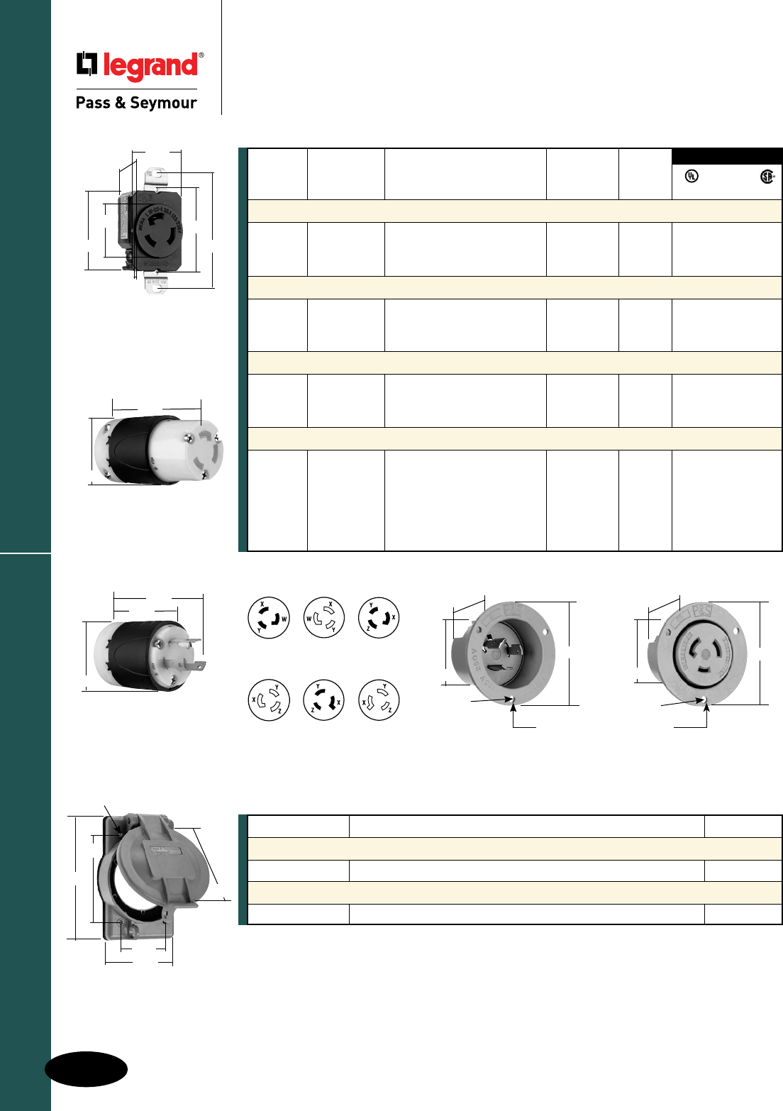
H-16
Turnlok® Locking Devices
AlldeviceslistedonthispageconformtoNEMAWD-1andWD-6.
20 Amp NEMA L1020, L1120 & L1220
Industrial Spec Grade Turnlok® Locking Devices
20 Amp NEMA L1020, L1120 & L1220
3 Pole, 3 Wire Non-Grounding, 20A, 125/250V; 3ø, 250 & 480V
WPG2
4.57"
3.25"
.19"
(4HOLES)
2.85"
1.88"
3.57"
Catalog Number Description Color
Weatherproof Cover
WPG2 Coverfor20and30ATurnlokFlangedInletsandOutlets Gray
Stainless Steel Wall Plate
SS720 WallPlateforLockingReceptacles 302S/S
3.75"
2.57"
2.20"
NEMA
L10-20R
NEMA
L10-20P
NEMA
L11-20P
NEMA
L11-20R
NEMA
L12-20R
NEMA
L12-20P
3rd Party Compliance
NEMA
Catalog Rating Cord Cong.
Number A. V. Description/Color Diameter No.
Receptacles
L1020R 20 125/250 SingleReceptacle L10-20R • •
L1120R 20 3ø,250 SingleReceptacle L11-20R • •
L1220R 20 3ø,480 SingleReceptacle L12-20R • •
Connectors IP20 Suitability
L1020C 20 125/250 BlackBack,WhiteFrontBody .225"-.750"" L10-20R • • •
L1120C 20 3ø,250 BlackBack,WhiteFrontBody .225"-.750" L11-20R • • •
L1220C 20 3ø,480 BlackBack,WhiteFrontBody .225"-.750" L12-20R • • •
Plugs IP20 Suitability
L1020P 20 125/250 BlackBack,WhiteFrontBody .225"-.750" L10-20P • • •
L1120P 20 3ø,250 BlackBack,WhiteFrontBody .225"-.750" L11-20P • • •
L1220P 20 3ø,480 BlackBack,WhiteFrontBody .225"-.750" L12-20P • • •
Flanged Inlets & Outlets
L1020FI 20 125/250 GrayInlet L10-20P • •
L1020FO 20 125/250 GrayOutlet L10-20R •
L1120FI 20 3ø,250 GrayInlet L11-20P • •
L1120FO 20 3ø,250 GrayOutlet L11-20R •
L1220FI 20 3ø,480 GrayInlet L12-20P • •
L1220FO 20 3ø,480 GrayOutlet L12-20R •
FSUL
UL498 WC596 CSA
ReferencePagesH-35andH-36forAccessories.
2.09"
ø.187"
1.65"
2.87"
2.09"
1.34"
ø.187"
2.87"
3HOLESONø2.50"C/L @120°
20A Flanged Inlet & Outlet
2.29"
1.19"
1.61"
2.37"
3.28"
1.545"
.14"
20A Receptacle
2.20"
3.33"
20A Connector
20A Plug
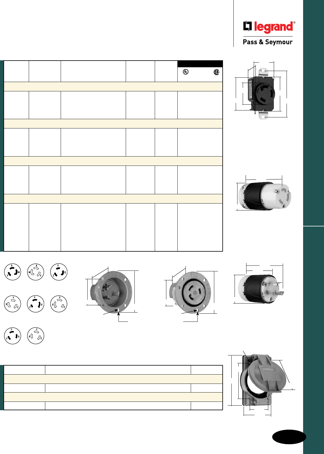
H-17
Turnlok® Locking Devices
AlldeviceslistedonthispageconformtoNEMAWD-1andWD-6.
30 Amp NEMA L1030, L1130, L1230 & L1330
Industrial Spec Grade Turnlok® Locking Devices
30 Amp NEMA L1030, L1130, L1230 & L1330
3 Pole, 3 Wire Non-Grounding 30A, 125/250V; 3ø, 250, 480 & 600V
3rd Party Compliance
NEMA
Catalog Rating Cord Cong.
Number A. V. Description/Color Diameter No.
Receptacles
L1030R 30 125/250 SingleReceptacle L10-30R • •
L1130R 30 3ø,250 SingleReceptacle L11-30R • •
L1230R 30 3ø,480 SingleReceptacle L12-30R • •
L1330R 30 3ø,600 SingleReceptacle L13-30R • •
Connectors IP20 Suitability
L1030C 30 125/250 BlackBack,WhiteFrontBody .225"-.750" L10-30R • •
L1130C 30 3ø,250 BlackBack,WhiteFrontBody .225"-.750" L11-30R • • •
L1230C 30 3ø,480 BlackBack,WhiteFrontBody .225"-.750" L12-30R • • •
L1330C 30 3ø,600 BlackBack,WhiteFrontBody .225"-.750" L13-30R • • •
Plugs IP20 Suitability
L1030P 30 125/250 BlackBack,WhiteFrontBody .225"-.750" L10-30P • •
L1130P 30 3ø,250 BlackBack,WhiteFrontBody .225"-.750" L11-30P • • •
L1230P 30 3ø,480 BlackBack,WhiteFrontBody .225"-.750" L12-30P • • •
L1330P 30 3ø,600 BlackBack,WhiteFrontBody .225"-.750" L13-30P • • •
Flanged Inlets and Outlets
L1030FI 30 125/250 GrayInlet L10-30P •
L1030FO 30 125/250 GrayOutlet L10-30R • •
L1130FI 30 3ø,250 GrayInlet L11-30P • •
L1130FO 30 3ø,250 GrayOutlet L11-30R • •
L1230FI 30 3ø,480 GrayInlet L12-30P • •
L1230FO 30 3ø,480 GrayOutlet L12-30R • •
L1330FO 30 3ø,600 GrayOutlet L13-30R • •
FSUL
UL498 WC596 CSA
NEMA
L10-30R
NEMA
L10-30P
NEMA
L11-30P
NEMA
L11-30R
NEMA
L12-30R
NEMA
L12-30P
NEMA
L13-30R
NEMA
L13-30P
ReferencePagesH-35andH-36forAccessories.
Catalog Number Description Color
Weatherproof Cover
WPG2 Coverfor20and30ATurnlokFlangedInletsandOutlets Gray
Stainless Steel Wall Plate
SS720 WallPlateforLockingReceptacles 302S/S
2.26"
3.12"
ø.187"
1.765"
2.26"
3.12"
1.750"
ø.187"
3HOLESONø2.72"C/L @120°
30A Flanged Inlet & Outlet
3.75"
2.57"
2.20"
2.42"
1.28"
1.61"
2.37"
3.28"
1.545"
.23"
30A Receptacle
2.20"
3.33"
30A Connector
30A Plug
WPG2
4.57"
3.25"
.19"
(4HOLES)
2.85"
1.88"
3.57"
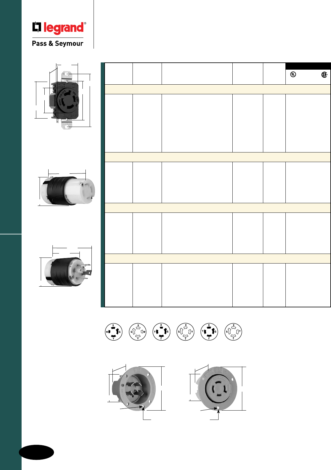
H-18
Turnlok® Locking Devices
AlldeviceslistedonthispageconformtoNEMAWD-1andWD-6.
Industrial Spec Grade Turnlok® Locking Devices
20 Amp NEMA L1420, L1520 & L1620
3 Pole, 4 Wire 20A, 125/250V; 3ø, 250 & 480V
20 Amp NEMA L1420, L1520 & L1620
NEMA
Catalog Rating Cord Cong.
Number A. V. Description/Color Diameter No.
Receptacles
L1420R 20125/250 SingleReceptacle L14-20R • • •
IGL1420R 20 125/250 SingleReceptacle,Orange, L14-20R • •
IsolatedGround
L1520R 203ø,250 SingleReceptacle L15-20R • • •
IGL1520R 20 3ø,250 SingleReceptacle,Orange, L15-20R • •
IsolatedGround
L1620R 203ø,480 SingleReceptacle L16-20R • • •
IGL1620R 20 3ø,480 SingleReceptacle,Orange, L16-20R • •
IsolatedGround
Connectors IP20 Suitability
L1420C 20125/250 BlackBack,WhiteFrontBody .225"-1.150" L14-20R • • •
CRL1420C 20125/250 YellowBack,WhiteFrontBody, .225"-1.150" L14-20R • • •
Corrosion-Resistant
L1520C 203ø,250 BlackBack,WhiteFrontBody .225"-1.150" L15-20R • • •
L1520CBK 203ø,250 BlackBack,BlackFrontBody .225"-1.150" L15-20R • • •
L1620C 203ø,480 BlackBack,WhiteFrontBody .225"-1.150" L16-20R • • •
Plugs IP20 Suitability
L1420P 20125/250 BlackBack,WhiteFrontBody, .225"-1.150" L14-20P • • •
CRL1420P 20125/250 YellowBack,WhiteFrontBody, .225"-1.150" L14-20P • • •
Corrosion-Resistant
L1520P 203ø,250 BlackBack,WhiteFrontBody .225"-1.150" L15-20P • • •
L1520PBK 203ø,250 BlackBack,BlackFrontBody .225"-1.150" L15-20P • • •
L1620P 203ø,480 BlackBack,WhiteFrontBody .225"-1.150" L16-20P • • •
Flanged Inlets & Outlets
L1420FI 20125/250 GrayInlet L14-20P • •
L1420FO 20125/250 GrayOutlet L14-20R • •
L1520FI 203ø,250 GrayInlet L15-20P • •
L1520FO 203ø,250 GrayOutlet L15-20R • •
L1620FI 203ø,480 GrayInlet L16-20P • •
L1620FO 203ø,480 GrayOutlet L16-20R • •
3rd Party Compliance
FSUL
UL498 WC596 CSA
ReferencePagesH-35andH-36forAccessories.
2.29"
1.19" 1.61"
..14"
2.37"
3.28"
1.545"
20A Receptacle
2.20"
3.33"
20A Connector
3.75"
2.57"
2.20"
20A Plug
NEMA
L14-20R
NEMA
L14-20P
NEMA
L15-20R
NEMA
L15-20P
NEMA
L16-20R
NEMA
L16-20P
2.09"
ø.187"
1.65"
2.87"
2.09"
1.34"
ø.187"
2.87"
3HOLESONø2.50"C/L @120°
20A Flanged Inlet & Outlet

H-19
Turnlok® Locking Devices
AlldeviceslistedonthispageconformtoNEMAWD-1andWD-6.
30 Amp NEMA L1430 & L1530
Industrial Spec Grade Turnlok® Locking Devices
30 Amp NEMA L1430 & L1530
3 Pole, 4 Wire 30A, 125/250V; 3ø, 250V
ReferencePagesH-35andH-36forAccessories.
NEMA
Catalog Rating Cord Cong.
Number A. V. Description/Color Diameter No.
Receptacles
L1430R 30 125/250 SingleReceptacle L14-30R • • •
IGL1430R 30125/250 SingleReceptacle,Orange, L14-30R • •
IsolatedGround
L1530R 30 3ø,250 SingleReceptacle L15-30R • • •
IGL1530R 303ø,250 SingleReceptacle,Orange, L15-30R • •
IsolatedGround
Connectors IP20 Suitability
L1430C 30 125/250 BlackBack,WhiteFrontBody .225"-1.150" L14-30R • • •
CRL1430C 30125/250 YellowBack,WhiteFrontBody,.225"-1.150" L14-30R • • •
Corrosion-Resistant
L1530C 30 3ø,250 BlackBack,WhiteFrontBody .225"-1.150" L15-30R • • •
Plugs IP20 Suitability
L1430P 30 125/250 BlackBack,WhiteFrontBody .225"-1.150" L14-30P • • •
CRL1430P 30125/250 YellowBack,WhiteFrontBody,.225"-1.150" L14-30P • • •
Corrosion-Resistant
L1530P 30 3ø,250 BlackBack,WhiteFrontBody .225"-1.150" L15-30P • • •
Flanged Inlets & Outlets
L1430FI 30125/250 GrayInlet L14-30P • •
L1430FO 30125/250 GrayOutlet L14-30R • •
L1530FI 303ø,250 GrayInlet L15-30P • •
L1530FIBK 303ø,250 BlackInlet L15-30P • •
L1530FO 303ø,250 GrayOutlet L15-30R • •
L1530FOBK 30 3ø,250 BlackOutlet L15-30R • •
3rd Party Compliance
FSUL
UL498 WC596 CSA
Catalog Number Description Color
Weatherproof Cover
WPG2 Coverfor20and30ATurnlokFlangedInletsandOutlets Gray
Stainless Steel Wall Plate
SS720 WallPlateforLockingReceptacles 302S/S
NEMA
L14-30R
NEMA
L14-30P
NEMA
L15-30R
NEMA
L15-30P
Catalog Number Description
Weatherproof Locking Inlet Kit for
Generator Applications
L1430FIKIT Kitincludes30ALockingGrayFlangedInlet
L1430FI,WeatherproofCoverWPG2,and
WeatherproofBoxWPB23
2.42"
1.28" 1.61"
..23"
2.37"
3.28"
1.545"
30A Receptacle
2.20"
3.33"
30A Connector
3.75"
2.57"
2.20"
30A Plug
2.26"
3.12"
.187"
1.765"
2.26"
3.12"
1.750"
.187"
3HOLESONø2.72"C/L @120°
30A Flanged Inlet & Outlet
WPG2
4.57"
3.25"
.19"
(4HOLES)
2.85"
1.88"
3.57"
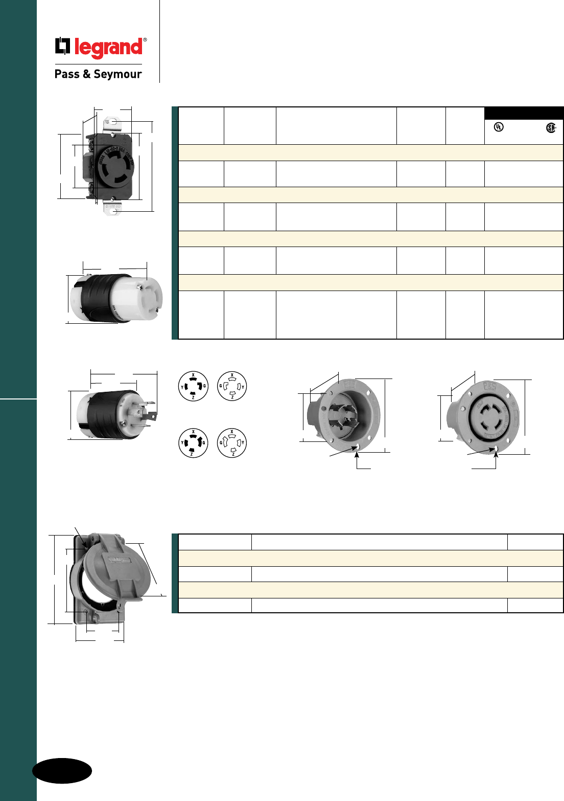
H-20
Turnlok® Locking Devices
AlldeviceslistedonthispageconformtoNEMAWD-1andWD-6.
30 Amp NEMA L1630 & L1730
Industrial Spec Grade Turnlok® Locking Devices
30 Amp NEMA L1630 & L1730
3 Pole, 4 Wire 30A; 3ø, 480 & 600V
2.26"
3.12"
.187"
1.765"
2.26"
3.12"
1.750"
.187"
3HOLESONø2.72"C/L @120°
30A Flanged Inlet & Outlet
2.42"
1.28" 1.61"
..23"
2.37"
3.28"
1.545"
30A Receptacle
3.75"
2.57"
2.20"
NEMA
L17-30R
NEMA
L17-30P
NEMA
L16-30R
NEMA
L16-30P
ReferencePagesH-35andH-36forAccessories.
3rd Party Compliance
NEMA
Catalog Rating Cord Cong.
Number A. V. Description/Color Diameter No.
Receptacles
L1630R 30 3ø,480 SingleReceptacle L16-30R • • •
L1730R 30 3ø,600 SingleReceptacle L17-30R • • •
Connectors IP20 Suitability
L1630C 30 3ø,480 BlackBack,WhiteFrontBody .225"-1.150" L16-30R • • •
L1730C 30 3ø,600 BlackBack,WhiteFrontBody .225"-1.150" L17-30R • • •
Plugs IP20 Suitability
L1630P 30 3ø,480 BlackBack,WhiteFrontBody .225"-1.150" L16-30P • • •
L1730P 30 3ø,600 BlackBack,WhiteFrontBody .225"-1.150" L17-30P • • •
Flanged Inlets & Outlets
L1630FI 30 3ø,480 GrayInlet L16-30P • •
L1630FO 30 3ø,480 GrayOutlet L16-30R • •
L1730FI 30 3ø,600 GrayInlet L17-30P • •
L1730FO 30 3ø,600 GrayOutlet L17-30R • •
FSUL
UL498 WC596 CSA
2.20"
3.33"
30A Connector
30A Plug
WPG2
4.57"
3.25"
.19"
(4HOLES)
2.85"
1.88"
3.57"
Catalog Number Description Color
Weatherproof Cover
WPG2 Coverfor20and30ATurnlokFlangedInletsandOutlets Gray
Stainless Steel Wall Plate
SS720 WallPlateforLockingReceptacles 302S/S
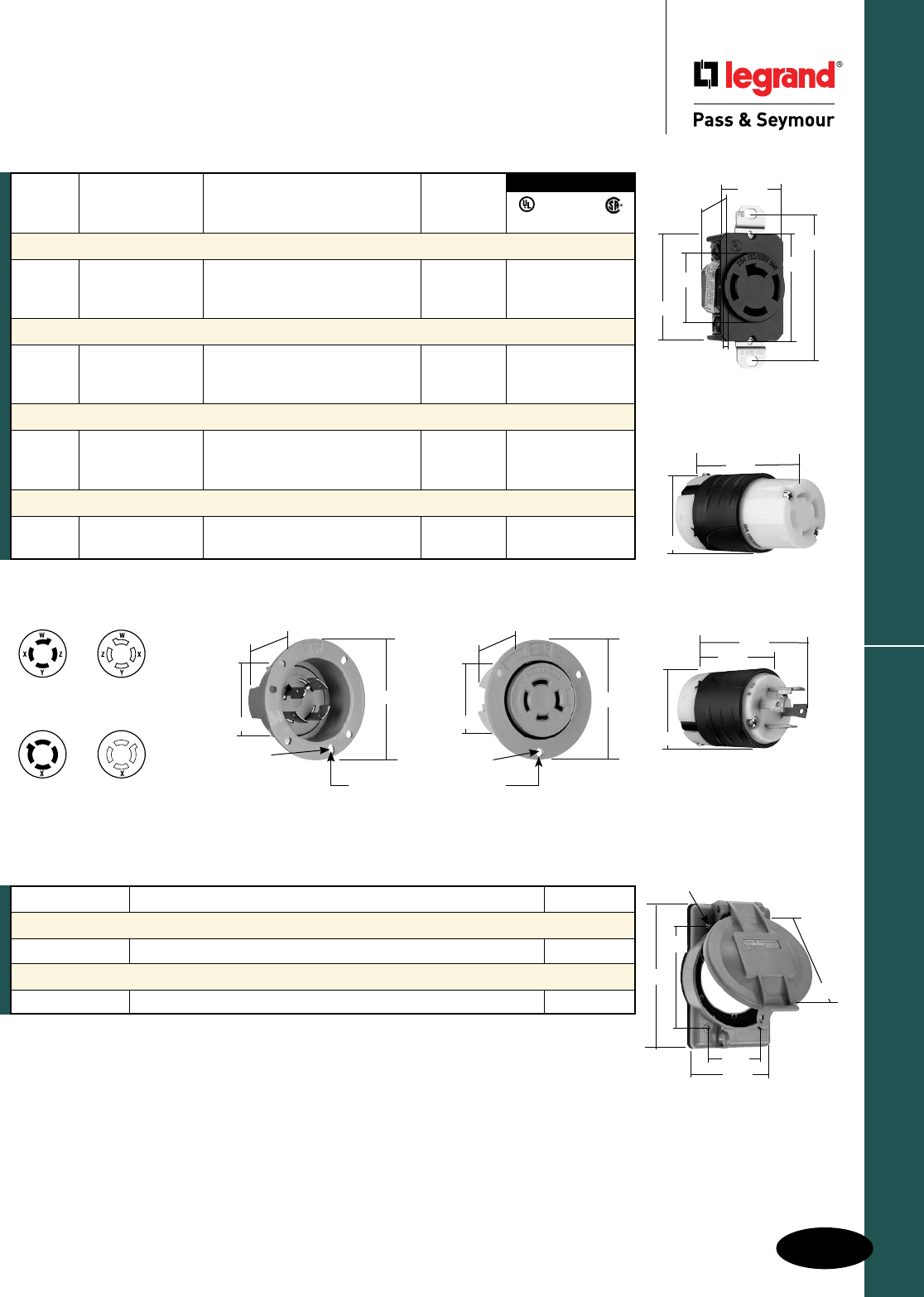
H-21
Turnlok® Locking Devices
AlldeviceslistedonthispageconformtoNEMAWD-1andWD-6.
20 Amp Non-NEMA
Industrial Spec Grade Turnlok® Locking Devices
20 Amp Non-NEMA
3 Pole, 4 Wire 20A, 3øY, 250V; 10A, 600V
4 Pole, 4 Wire 20A, 3øY, 120/208V
NON-NEMA
7409SS, 7410
7413SS
NON-NEMA
7410G
7413G
NON-NEMA
7408SS
7411SS
NON-NEMA
7411G
*Forreplacementuseonly.
ReferencePagesH-35andH-36forAccessories.
Catalog Rating Cord
Number A. V. Description/Color Diameter
Receptacles
7410G* 20 3øY,250 SingleReceptacle,Grounded •
10 600
7410 20 3øY,120/208 SingleReceptacle • •
Connectors IP20 Suitability
7413G* 20 3øY,250 Yellow .333"-1.060"
10 600
7413SS 20 3øY,120/208 BlackBack,WhiteFrontBody .225"-1.150" • •
Plugs IP20 Suitability
7411G* 20 3øY,250 Yellow .333"-1.060"
10 600
7411SS 20 3øY,120/208 BlackBack,WhiteFrontBody .225"-1.150" • •
Flanged Inlets & Outlets
7408SS 20 3øY,120/208 GrayInlet •
7409SS 20 3øY,120/208 GrayOutlet •
FSUL
UL498 WC596 CSA
3rd Party Compliance
2.09"
ø.187"
1.65"
2.87"
2.09"
1.34"
ø.187"
2.87"
3HOLESONø2.50"C/L@120°
20A Flanged Inlet & Outlet
Catalog Number Description Color
Weatherproof Cover
WPG2 Coverfor20and30ATurnlokFlangedInletsandOutlets Gray
Stainless Steel Wall Plate
SS720 WallPlateforLockingReceptacles 302S/S
3.75"
2.57"
2.20"
2.29"
1.19" 1.61"
..14"
2.37"
3.28"
1.545"
20A Receptacle
2.20"
3.33"
20A Connector
20A Plug
WPG2
4.57"
3.25"
.19"
(4HOLES)
2.85"
1.88"
3.57"
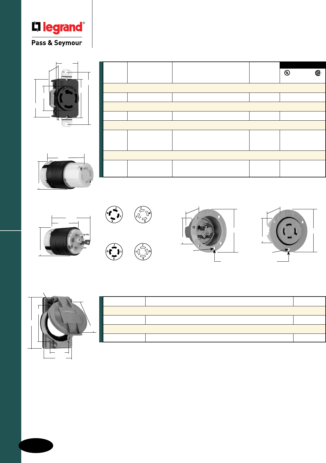
H-22
Turnlok® Locking Devices
AlldeviceslistedonthispageconformtoNEMAWD-1andWD-6.
30 Amp Non-NEMA
Industrial Spec Grade Turnlok® Locking Devices
30 Amp Non-NEMA
3 Pole, 4 Wire 30A, 3øY 250V; 10A, 600V
4 Pole, 4 Wire 30A, 3øY, 120/208V
NON-NEMA
3431SS
3434SS
NON-NEMA
3431G
3.75"
2.57"
2.20"
2.42"
1.28" 1.61"
..23"
2.37"
3.28"
1.545"
NON-NEMA
3430, 3433SS
3435SS
NON-NEMA
3430G
3433G
Catalog Rating Cord
Number A. V. Description/Color Diameter
Receptacles
3430 30 3øY,120/208 SingleReceptacle • •
Connectors IP20 Suitability
3433SS 30 3øY,120/208 BlackBack,WhiteFrontBody .225"-1.150" • •
Plugs IP20 Suitability
3431G* 30 30øY,250 Yellow .333"-1.060"
10 600
3431SS 30 3øY,120/208 BlackBack,WhiteFrontBody .225"-1.150" • •
Flanged Inlets & Outlets
3434SS 30 3øY,120/208 GrayInlet •
3435SS 30 3øY,120/208 GrayOutlet •
FSUL
UL498 WC596 CSA
3rd Party Compliance
*Forreplacementuseonly.
ReferencePagesH-35andH-36forAccessories.
30A Receptacle
2.20"
3.33"
30A Connector
30A Plug
WPG2
4.57"
3.25"
.19"
(4HOLES)
2.85"
1.88"
3.57"
Catalog Number Description Color
Weatherproof Cover
WPG2 Coverfor20and30ATurnlokFlangedInletsandOutlets Gray
Stainless Steel Wall Plate
SS720 WallPlateforLockingReceptacles 302S/S
2.09"
ø.187"
1.65"
2.87"
2.09"
1.34"
ø.187"
2.87"
3HOLESONø2.50"C/L@120°
20A Flanged Inlet & Outlet
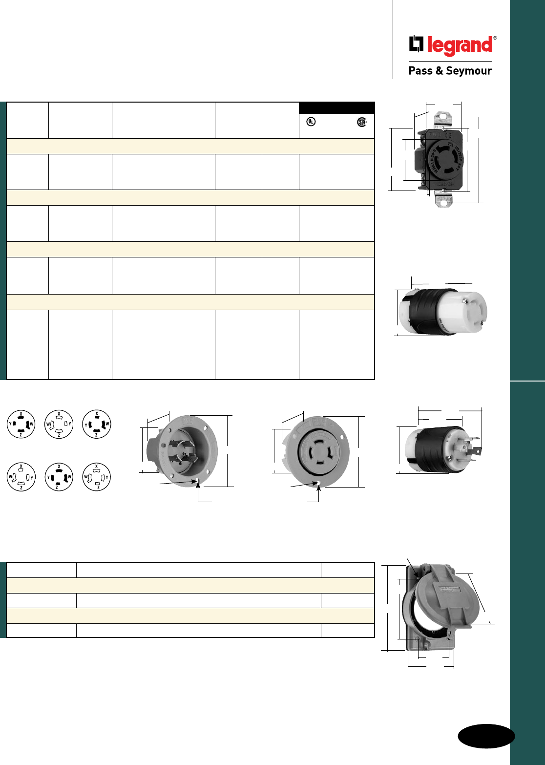
H-23
Turnlok® Locking Devices
AlldeviceslistedonthispageconformtoNEMAWD-1andWD-6.
20 Amp NEMA L1820, L1920 & L2020
Industrial Spec Grade Turnlok® Locking Devices
20 Amp NEMA L1820, L1920 & L2020
4 Pole, 4 Wire Non-Grounding 20A, 3øY, 120/208,
277/480 & 347/600V
NEMA
L18-20R
NEMA
L18-20P
NEMA
L19-20P
NEMA
L19-20R
NEMA
L20-20R
NEMA
L20-20P
NEMA
Catalog Rating Cord Cong.
Number A. V. Description/Color Diameter No.
Receptacles
L1820R 20 3øY,120/208 SingleReceptacle L18-20R • •
L1920R 20 3øY,277/480 SingleReceptacle L19-20R • •
L2020R 20 3øY,347/600 SingleReceptacle L20-20R • •
Connectors IP20 Suitability
L1820C 20 3øY,120/208 BlackBack,WhiteFrontBody .225"-1.150" L18-20R • • •
L1920C 20 3øY,277/480 BlackBack,WhiteFrontBody .225"-1.150" L19-20R • • •
L2020C 20 3øY,347/600 BlackBack,WhiteFrontBody .225"-1.150" L20-20R • • •
Plugs IP20 Suitability
L1820P 20 3øY,120/208 BlackBack,WhiteFrontBody .225"-1.150" L18-20P • • •
L1920P 20 3øY,277/480 BlackBack,WhiteFrontBody .225"-1.150" L19-20P • • •
L2020P 20 3øY,347/600 BlackBack,WhiteFrontBody .225"-1.150" L20-20P • • •
Flanged Inlets & Outlets
L1820FI 20 3øY,120/208 GrayInlet L18-20P • •
L1820FO 20 3øY,120/208 GrayOutlet L18-20R • •
L1920FI 20 3øY,277/480 GrayInlet L19-20P • •
L1920FO 20 3øY,277/480 GrayOutlet L19-20R • •
L2020FI 20 3øY,347/600 GrayInlet L20-20P • •
L2020FO 20 3øY,347/600 GrayOutlet L20-20R • •
ReferencePagesH-35andH-36forAccessories.
3rd Party Compliance
FSUL
UL498 WC596 CSA
2.09"
ø.187"
1.65"
2.87"
2.09"
1.34"
ø.187"
2.87"
3HOLESONø2.50"C/L @120°
20A Flanged Inlet & Outlet
Catalog Number Description Color
Weatherproof Cover
WPG2 Coverfor20and30ATurnlokFlangedInletsandOutlets Gray
Stainless Steel Wall Plate
SS720 WallPlateforLockingReceptacles 302S/S
3.75"
2.57"
2.20"
2.29"
1.19" 1.61"
..14"
2.37"
3.28"
1.545"
20A Receptacle
2.20"
3.33"
20A Connector
20A Plug
WPG2
4.57"
3.25"
.19"
(4HOLES)
2.85"
1.88"
3.57"
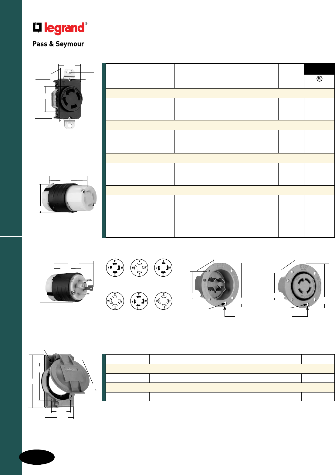
H-24
Turnlok® Locking Devices
AlldeviceslistedonthispageconformtoNEMAWD-1andWD-6.
Industrial Spec Grade Turnlok® Locking Devices
30 Amp NEMA L1830, L1930 & L2030
4 Pole, 4 Wire Non-Grounding
30A, 3øY, 120/208, 277/480 & 347/600V
30 Amp NEMA L1830, L1930 & L2030
3.75"
2.57"
2.20"
NEMA
L18-30P
NEMA
L19-30P
NEMA
L18-30R
NEMA
L20-30P
NEMA
L19-30R
NEMA
L20-30R
ReferencePagesH-35andH-36forAccessories.
2.42"
1.28"
1.61"
..23"
2.37"
3.28"
1.545"
30A Receptacle
2.20"
3.33"
30A Connector
30A Plug
WPG2
4.57"
3.25"
.19"
(4HOLES)
2.85"
1.88"
3.57"
Catalog Number Description Color
Weatherproof Cover
WPG2 Coverfor20and30ATurnlokFlangedInletsandOutlets Gray
Stainless Steel Wall Plate
SS720 WallPlateforLockingReceptacles 302S/S
3rd Party
Compliance
UL498
NEMA
Catalog Rating Cord Cong.
Number A. V. Description/Color Diameter No.
Receptacles
L1830R 30 3øY,120/208 SingleReceptacle L18-30R •
L1930R 30 3øY,277/480 SingleReceptacle L19-30R •
L2030R 30 3øY,347/600 SingleReceptacle L20-30R •
Connectors IP20 Suitability
L1830C 30 3øY,120/208 BlackBack,WhiteFrontBody .225"-1.150" L18-30R •
L1930C 30 3øY,277/480 BlackBack,WhiteFrontBody .225"-1.150" L19-30R •
L2030C 30 3øY,347/600 BlackBack,WhiteFrontBody .225"-1.150" L20-30R •
Plugs IP20 Suitability
L1830P 30 3øY,120/208 BlackBack,WhiteFrontBody .225"-1.150" L18-30P •
L1930P 30 3øY,277/480 BlackBack,WhiteFrontBody .225"-1.150" L19-30P •
L2030P 30 3øY,347/600 BlackBack,WhiteFrontBody .225"-1.150" L20-30P •
Flanged Inlets & Outlets
L1830FI 30 3øY,120/208 GrayInlet L18-30P •
L1830FO 30 3øY,120/208 GrayOutlet L18-30R •
L1930FI 30 3øY,277/480 GrayInlet L19-30P •
L1930FO 30 3øY,277/480 GrayOutlet L19-30R •
L2030FI 30 3øY,347/600 GrayInlet L20-30P •
L2030FO 30 3øY,347/600 GrayOutlet L20-30R •
2.26"
3.12"
ø.187"
1.765"
2.26"
3.12"
1.750"
ø.187"
3HOLESONø2.72"C/L @120°
30A Flanged Inlet & Outlet
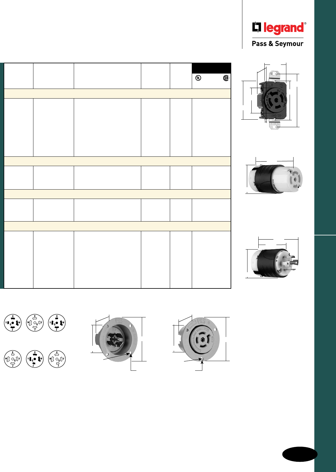
H-25
Turnlok® Locking Devices
AlldeviceslistedonthispageconformtoNEMAWD-1andWD-6.
20 Amp NEMA L2120, L2220 & L2320
Industrial Spec Grade Turnlok® Locking Devices
20 Amp NEMA L2120, L2220 & L2320
4 Pole, 5 Wire 20A, 3øY, 120/208, 277/480 & 347/600V
NEMA
L21-20P
NEMA
L22-20P
NEMA
L21-20R
NEMA
L23-20P
NEMA
L22-20R
NEMA
L23-20R
ReferencePagesH-35andH-36forAccessories.
3rd Party
Compliance
FSUL
UL498 WC596 CSA
NEMA
Catalog Rating Cord Cong.
Number A. V. Description/Color Diameter No.
Receptacles
L2120R 20 3øY,120/208 SingleReceptacle L21-20R • • •
IGL2120R 20 3øY,120/208 SingleReceptacle,Orange, L21-20R • •
IsolatedGround
L2220R 20 3øY,277/480 SingleReceptacle L22-20R • • •
IGL2220R 20 3øY,277/480 SingleReceptacle,Orange, L22-20R • •
IsolatedGround
L2320R 20 3øY,347/600 SingleReceptacle L23-20R • • •
IGL2320R 20 3øY,347/600 SingleReceptacle,Orange, L23-20R • •
IsolatedGround
Connectors IP20 Suitability
L2120C 20 3øY,120/208 BlackBack,WhiteFrontBody .225"-1.150" L21-20R • • •
L2220C 20 3øY,277/480 BlackBack,WhiteFrontBody .225"-1.150" L22-20R • • •
L2320C 20 3øY,347/600 BlackBack,WhiteFrontBody .225"-1.150" L23-20R • • •
Plugs IP20 Suitability
L2120P 20 3øY,120/208 BlackBack,WhiteFrontBody .225"-1.150" L21-20P • • •
L2220P 20 3øY,277/480 BlackBack,WhiteFrontBody .225"-1.150" L22-20P • • •
L2320P 20 3øY,347/600 BlackBack,WhiteFrontBody .225"-1.150" L23-20P • • •
Flanged Inlets & Outlets
L2120FI 20 3øY,120/208 GrayInlet L21-20P • •
L2120FO 20 3øY,120/208 GrayOutlet L21-20R • •
L2220FI 20 3øY,277/480 GrayInlet L22-20P • •
L2220FIBK 20 3øY,277/480 BlackInlet L22-20P • •
L2220FO 20 3øY,277/480 GrayOutlet L22-20R • •
L2220FOBK 20 3øY,277/480 BlackOutlet L22-20R • •
L2320FI 20 3øY,347/600 GrayInlet L23-20P • •
L2320FO 20 3øY,347/600 GrayOutlet L23-20R • •.
2.09"
ø.187"
1.65"
2.87"
2.09"
1.34"
ø.187"
2.87"
3HOLESONø2.50"C/L @120°
20A Flanged Inlet & Outlet
2.29"
1.19" 1.61"
..14"
2.37"
3.28"
1.545"
20A Receptacle
2.20"
3.33"
20A Connector
3.75"
2.57"
2.20"
20A Plug
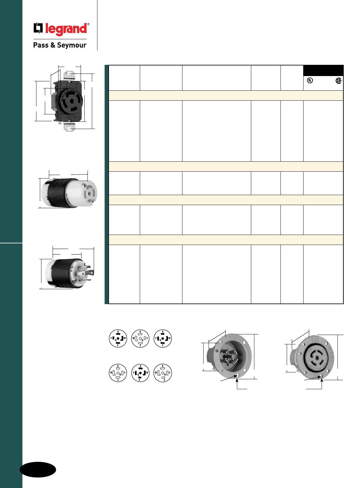
H-26
Turnlok® Locking Devices
AlldeviceslistedonthispageconformtoNEMAWD-1andWD-6.
30 Amp L2130, L2230 & L2330
Industrial Spec Grade Turnlok® Locking Devices
30 Amp L2130, L2230 & L2330
4 Pole, 5 Wire 30A, 3øY, 120/208, 277/480 & 347/600V
NEMA
L21-30P
NEMA
L22-30P
NEMA
L21-30R
NEMA
L23-30P
NEMA
L22-30R
NEMA
L23-30R
2.42"
1.28" 1.61"
..23"
2.37"
3.28"
1.545"
30A Receptacle
2.20"
3.33"
30A Connector
3.75"
2.57"
2.20"
30A Plug
2.26"
3.12"
ø.187"
1.765"
2.26"
3.12"
1.750"
ø.187"
3HOLESONø2.72"C/L @120°
30A Flanged Inlet & Outlet
ReferencePagesH-35andH-36forAccessories.
NEMA
Catalog Rating Cord Cong.
Number A. V. Description/Color Diameter No.
Receptacles
L2130R 30 3øY,120/208 SingleReceptacle L21-30R • • •
IGL2130R 30 3øY,120/208 SingleReceptacle,Orange, L21-30R • •
IsolatedGround
L2230R 30 3øY,277/480 SingleReceptacle L22-30R • • •
IGL2230R 30 3øY,277/480 SingleReceptacle,Orange, L22-30R • •
IsolatedGround
L2330R 30 3øY,347/600 SingleReceptacle L23-30R • • •
IGL2330R 30 3øY,347/600 SingleReceptacle,Orange, L23-30R • •
IsolatedGround
Connectors IP20 Suitability
L2130C 30 3øY,120/208 BlackBack,WhiteFrontBody .225"-1.150" L21-30R • • •
L2230C 30 3øY,277/480 BlackBack,WhiteFrontBody .225"-1.150" L22-30R • • •
L2330C 30 3øY,347/600 BlackBack,WhiteFrontBody .225"-1.150" L23-30R • • •
Plugs IP20 Suitability
L2130P 30 3øY,120/208 BlackBack,WhiteFrontBody .225"-1.150" L21-30P • • •
L2230P 30 3øY,277/480 BlackBack,WhiteFrontBody .225"-1.150" L22-30P • • •
L2230PBK 30 3øY,277/480 BlackBack,BlackFrontBody .225"-1.150" L22-30P • • •
L2330P 30 3øY,347/600 BlackBack,WhiteFrontBody .225"-1.150" L23-30P • • •
Flanged Inlets & Outlets
L2130FI 30 3øY,120/208 GrayInlet L21-30P • •
L2130FO 30 3øY,120/208 GrayOutlet L21-30R • •
L2230FI 30 3øY,277/480 GrayInlet L22-30P • •
L2230FIBK 30 3øY,277/480 BlackInlet L22-30P • •
L2230FO 30 3øY,277/480 GrayOutlet L22-30R • •
L2230FOBK 30 3øY,277/480 BlackOutlet L22-30R • •
L2330FI 30 3øY,347/600 GrayInlet L23-30P • •
L2330FO 30 3øY,347/600 GrayOutlet L23-30R • •
3rd Party
Compliance
FSUL
UL498 WC596 CSA
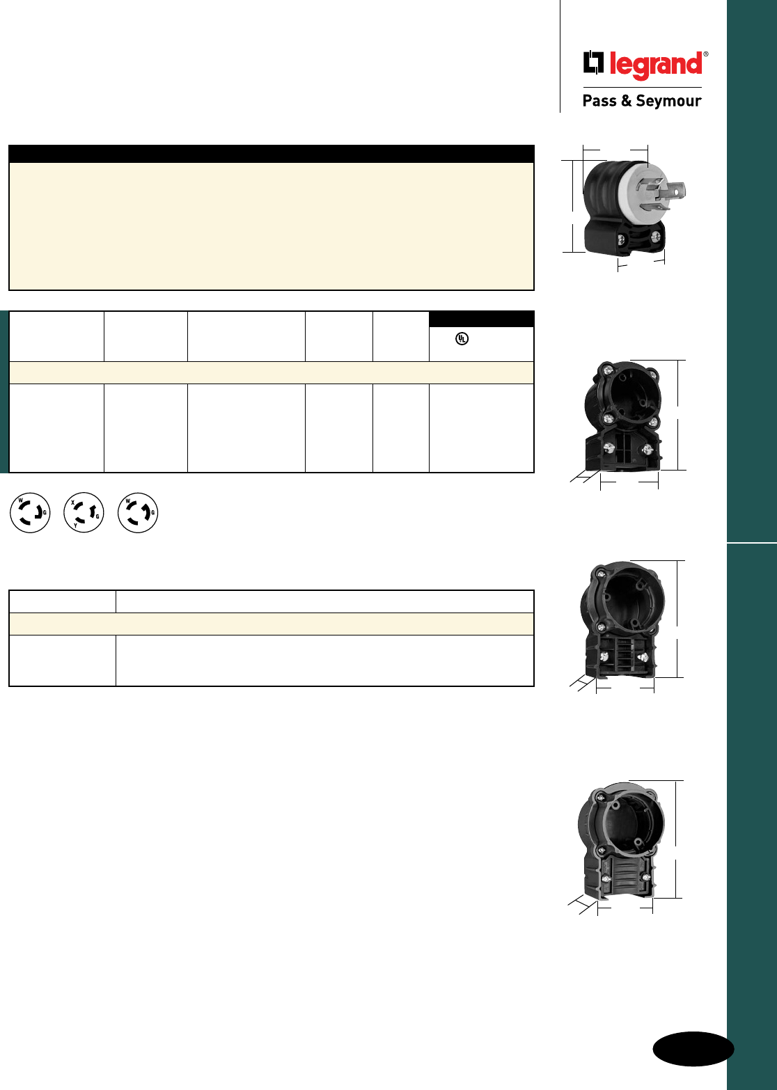
H-27
Turnlok® Locking Devices
AlldeviceslistedonthispageconformtoNEMAWD-1andWD-6.
Angle Plugs & Adapters
Industrial Spec Grade Turnlok® Locking Devices
Angle Plugs & Adapters
2 Pole, 3 Wire 15A, 125, 250 & 277V
3, 4 & 5 Wire 15, 20 & 30A Adapters
Features
nAngleplugsandadaptersbothallowfor
4-positionfacerotation.20/30A3WireTurnlok®
RightAngleAdaptersareadjustableupto
8positions.
nAngleadapters(soldseparately)willaccommodate
allP&STurnlokstyleplugsandconnectorsona
retrofitbasis.Simplyremovethestraighthandle
bodyfromtheplugorconnectorfaceassembly,
andreplacewiththeangleadapter.
nTri-driveassemblyandcord-gripscrewsare
standardonallangleplugsandadapters.
nAngleplugsandadaptershavethesamewide
corddiameterrange(.230"-1.150")thatis
presentonallTurnlokplugsandconnectors.
Catalog Number Description
Accessories
L15AN 15ATurnlokRightAngleAdapter
L20303AN 20/30A3WireTurnlokRightAngleAdapter
L203045AN 20/30A4and5WireTurnlokRightAngleAdapter
NEMA
L5-15P
NEMA
L6-15P
NEMA
L7-15P
3rd Party Compliance
NEMA
Catalog Rating Cord Cong.
Number A. V. Description/Color Diameter No.
Plugs
PS4720SSAN 15 125 BlackBackBody, .230"-.655" L5-15P
• •
WhiteFrontBody
PSL615PAN 15 250 BlackBackBody, .230"-.690" L6-15P
• •
WhiteFrontBody
PSL715PAN 15 277 BlackBackBody, .230"-.690" L7-15P
• •
WhiteFrontBody
FSUL
UL498 WC596
15 Amp
Angle Plug
L203045AN
3.868"
2.675"
1.65"
L15AN
2.97"
1.94"
1.37"
L20303AN
3.868"
2.675"
1.65"
2.130"
1.350"
1.530"
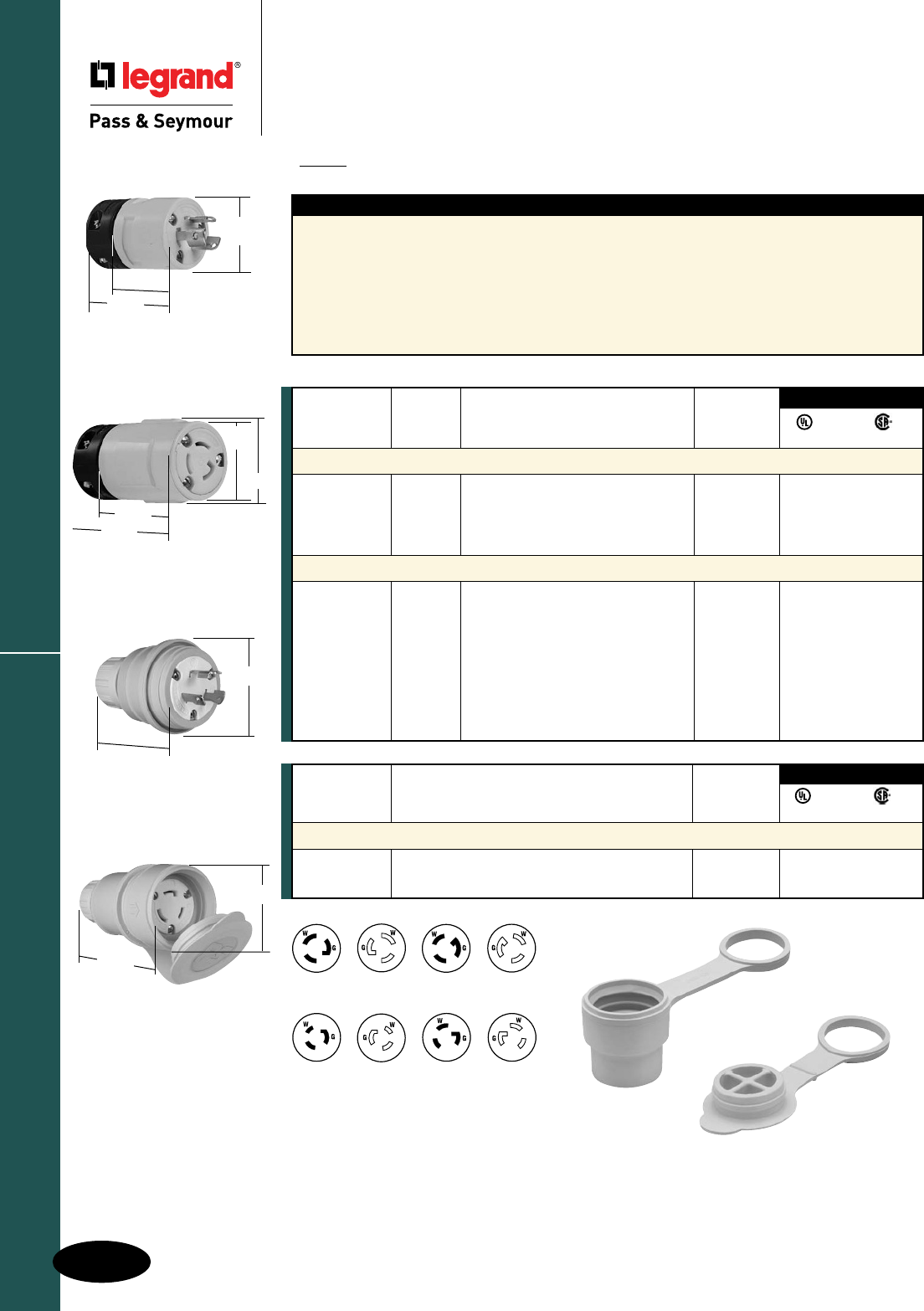
H-28
Turnlok® Locking Devices
AlldeviceslistedonthispageconformtoNEMAWD-1andWD-6.
Rubber & Watertight Plugs & Connectors
Industrial Spec Grade Turnlok® Locking Devices
Rubber & Watertight Plugs & Connectors
2 Pole, 3 Wire 15, 20 & 30A, 125V; 15A, 277V
PS26W47
2.620"
1.850"
2.270"
1.440"
2447
1.530"
Dia.
IP20
Suitability
Features
nRubberbodyconstructionstandsuptoimpacts,
oil,chemicals,heat,andweather.
nFloatingbladesallowself-alignmentwithcontacts
andreducestressonbladesandcontacts.
nNeoprenegrommetkeepsoutcontaminants
atcordentrance.
nTerminalscrewscomebacked-out–ready-to-wire.
nNickel-platedbladesandconnectorsprovidean
extrameasureofcorrosionresistance.
nClosurecaponwatertightmodelformsaseal
tokeepoutcontaminantswhenconnectoris
notinuse.
nMultiplesealsbetweenplugandconnectoron
watertightversionprotectselectricalconnection
fromcontaminants.
2547
1.530"
Dia.
2.990"
1.660"
2.16"
PS27W47
4.030"
1.850"
50W50PS
14WPS
UL498 C22.2 42M
3rd Party Compliance
NEMA
Catalog Rating Cong.
Number A. V. Description No.
Rubber
2447 15 125 RubberLockingPlug L5-15P ••
2547 15 125 RubberLockingConnector L5-15R ••
2434 15 277 RubberLockingPlug L7-15P ••
2534 15 277 RubberLockingConnector L7-15R ••
NEMA 4X – Watertight Devices
24W47 15 125 NEMA4XLockingPlug L5-15P ••
25W47 15 125 NEMA4XLockingConnector L5-15R ••
PS26W4720 125 NEMA4XLockingPlug L5-20P ••
PS27W4720 125 NEMA4XLockingConnector L5-20R ••
PS28W4730 125 NEMA4XLockingPlug L5-30P ••
PS29W4730 125 NEMA4XLockingConnector L5-30R ••
24W34 15 277 NEMA4XLockingPlug L7-15P ••
25W34 15 277 NEMA4XLockingConnector L7-15R ••
NEMA
L5-15P
NEMA
L5-15R
NEMA
L7-15P
NEMA
L7-15R
NEMA
L5-30P
NEMA
L5-30R
NEMA
L5-20R
NEMA
L5-20P
UL498 C22.2 42M
3rd Party Compliance
NEMA
Catalog Cong.
Number Description No.
Caps – Watertight Only
14WPS MaleCap All • •
50W50PS FemaleReplacementCap All • •
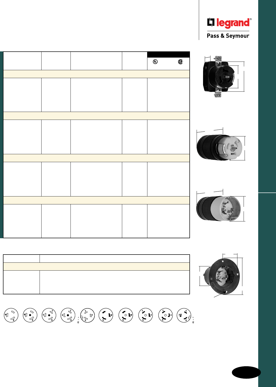
H-29
Turnlok® Locking Devices
AlldeviceslistedonthispageconformtoNEMAWD-1andWD-6.
California Standard & Corrosion-Resistant
Industrial Spec Grade Turnlok® Locking Devices
California Standard & Corrosion-Resistant
3 Wire Grounding 50A, 125, 250 & 480V; 250VDC, 600VAC
Catalog Number Description
Accessories
7770 WeatherproofCoverfor50ALockingReceptacles,Thermoplastic
Note:7770coversnottobeusedwithflangeddevices.
CR7716N WeatherproofBoot,50ALockingConnector
CR7717N WeatherproofBoot,50ALockingPlug
Non-NEMA
CR6370
CR6360
Non-NEMA
3763
3777
Non-NEMA
CS6370
CS6360
Non-NEMA
CS8269
CS8264
Non-NEMA
CS8469
CS8464
Non-NEMA
3771
3762
Non-NEMA
CR6361
CR6377
Non-NEMA
CS6361
CS6377
Non-NEMA
CS8265
CS8275
Non-NEMA
CS8465
CS8475
ReferencePagesH-35andH-36forAccessories.
Catalog Rating Cord
Number A. V. Description Diameter
Receptacles
CR6370 50 125 Corrosion-Resistant • •
CS6370 50 125 CaliforniaStandard • •
CS8269 50 250 CaliforniaStandard • •
CS8469 50 480 CaliforniaStandard • •
3771 50 250VDC, Corrosion-Resistant • •
600VAC
Connectors
CR6360 50 125 Corrosion-Resistant .680"-1.125" • •
CS6360 50 125 CaliforniaStandard .680"-1.125" • •
CS8264 50 250 CaliforniaStandard .680"-1.125" • •
CS8464 50 480 CaliforniaStandard .680"-1.125" • •
3762 50 250VDC, Corrosion-Resistant .680"-1.125" • •
600VAC
Plugs
CR6361 50 125 Corrosion-Resistant .680"-1.125" • •
CS6361 50 125 CaliforniaStandard .680"-1.125" • •
CS8265 50 250 CaliforniaStandard .680"-1.125" • •
CS8465 50 480 CaliforniaStandard .680"-1.125" • •
3763M 50 250VDC, Corrosion-Resistant .680"-1.125" • •
600VAC
Flanged Inlets
CR6377 50 125 Corrosion-Resistant • •
CS6377 50 125 CaliforniaStandard • •
CS8275 50 250 CaliforniaStandard • •
CS8475 50 480 CaliforniaStandard • •
3777 50 250VDC, Corrosion-Resistant • •
600VAC
FSUL
UL498 WC596 CSA
3rd Party Compliance
California Standard
Connector
2.26"
3.90"
California Standard
Plug
2.29"
4.38"
California Standard
Receptacle
1.98"
3.28"
1.08"
California Standard
Flanged Inlet
3.50"
2.10"
2.25"
.185"DIA.
(4HOLES)
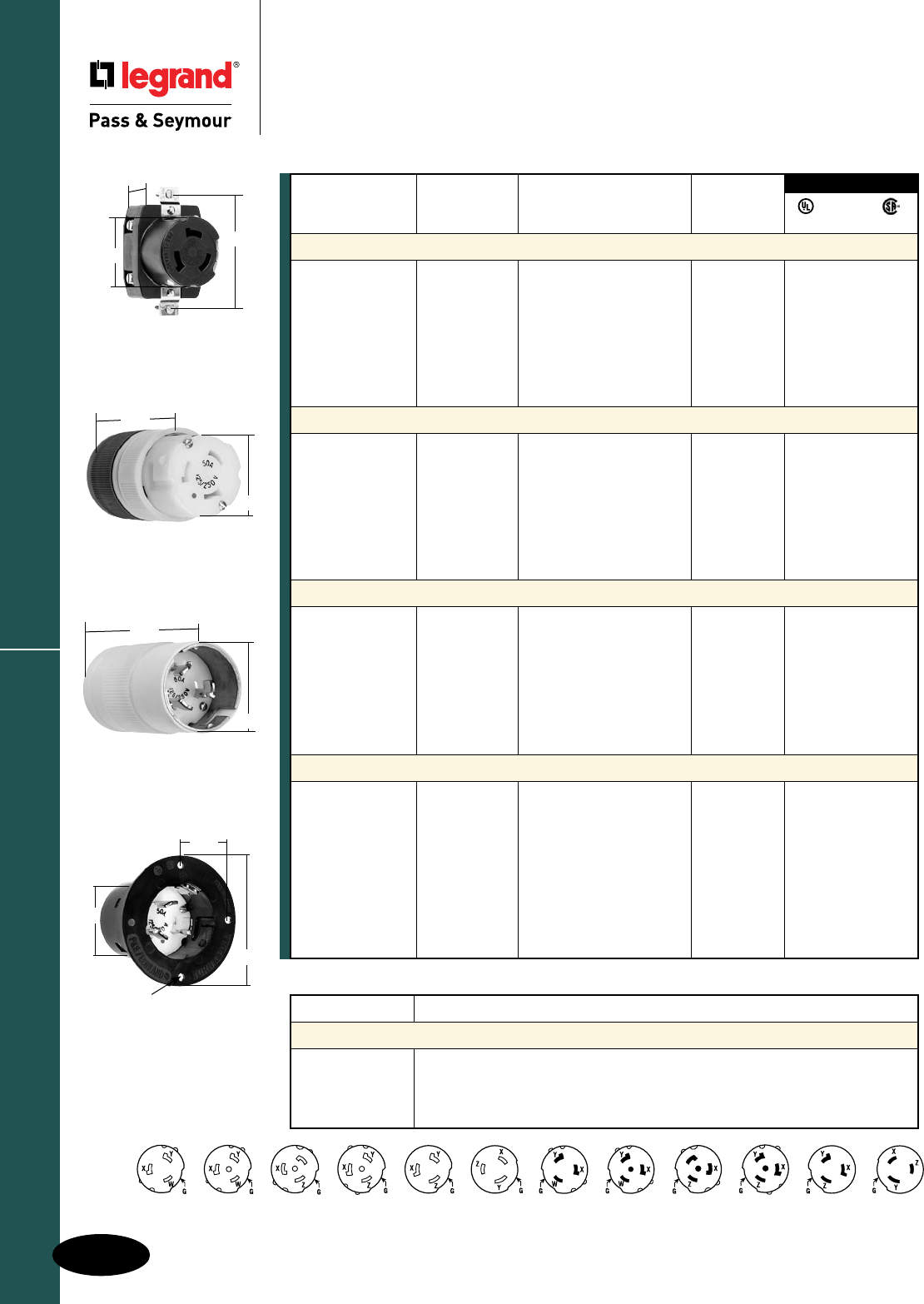
H-30
Turnlok® Locking DevicesCalifornia Standard & Corrosion-Resistant
Industrial Spec Grade Turnlok® Locking Devices
California Standard & Corrosion-Resistant
4 Wire Grounding 50A, 125/250V; 3ø, 250 & 480V; 250VDC, 600VAC
Non-NEMA
CR6364
CR6369
Non-NEMA
CS8365
CS8375
Non-NEMA
CS8165
CS8175
Non-NEMA
CS6365
CS6375
Non-NEMA
CR6365
CR6375
Non-NEMA
CS6364
CS6369
Non-NEMA
CS8364
CS8369
Non-NEMA
CS8164
CS8169
Non-NEMA
3764
3769
Non-NEMA
7379
7764
Non-NEMA
3765
3775
Non-NEMA
7765
7958
Alldeviceslistedon
thispageconformto
NEMAWD-1andWD-6.
Corrosion-Resistant
Flanged Inlet
3.50"
2.10"
2.25"
.185"DIA.
(4HOLES) Catalog Number Description
Accessories
7770 WeatherproofCoverfor50ALockingReceptacles,Thermoplastic
Note:7770coversnottobeusedwithflangeddevices.
CR7716N WeatherproofBoot,50ALockingConnector
CR7717N WeatherproofBoot,50ALockingPlug
*Devicesforreplacementuseonlyinexistinginstallations.ReferencePagesH-35andH-36forAccessories.
3rd Party Compliance
FSUL
UL498 WC596 CSA
Catalog Rating Cord
Number A. V. Description Diameter
Receptacles
CR6369 50 125/250 Corrosion-Resistant • •
CS6369 50 125/250 CaliforniaStandard • •
CS8369 50 3ø,250 CaliforniaStandard • •
CS8169 50 3ø,480 CaliforniaStandard • •
3769 50 250VDC, Corrosion-Resistant • •
600VAC
7379* 50 250VDC, Corrosion-Resistant • •
600VAC
Connectors
CR6364 50 125/250 Corrosion-Resistant .680
"
-1.125
"
• •
CS6364 50 125/250 CaliforniaStandard .680
"
-1.125
"
• •
CS8364 50 3ø,250 CaliforniaStandard .680
"
-1.125
"
• •
CS8164 50 3ø,480 CaliforniaStandard .680
"
-1.125
"
• •
3764 50 250VDC, Corrosion-Resistant .680
"
-1.125
"
• •
600VAC
7764* 50 250VDC, Corrosion-Resistant .680
"
-1.125
"
• •
600VAC
Plugs
CR6365 50 125/250 Corrosion-Resistant .680
"
-1.125
"
• •
CS6365 50 125/250 CaliforniaStandard .680
"
-1.125
"
• •
CS8365 50 3ø,250 CaliforniaStandard .680
"
-1.125
"
• •
CS8165 50 3ø,480 CaliforniaStandard .680
"
-1.125
"
• •
3765 50 250VDC, Corrosion-Resistant .680
"
-1.125
"
• •
600VAC
7765* 50 250VDC, Corrosion-Resistant .680
"
-1.125
"
• •
600VAC
Flanged Inlets
CR6375 50 125/250 Corrosion-Resistant • •
CS6375 50 125/250 CaliforniaStandard • •
CS8375 50 3ø,250 CaliforniaStandard • •
CS8175 50 3ø,480 CaliforniaStandard • •
CS8177 50 3ø,480 CaliforniaStandard • •
withFlipLid
3775 50 250VDC, Corrosion-Resistant • •
600VAC
7958P* 50 250VDC, Corrosion-Resistant • •
600VAC
Corrosion-Resistant
Receptacle
1.98"
3.28"
1.08"
Corrosion-Resistant
Plug
2.29"
4.38"
Corrosion-Resistant
Connector
3.90"
2.26"
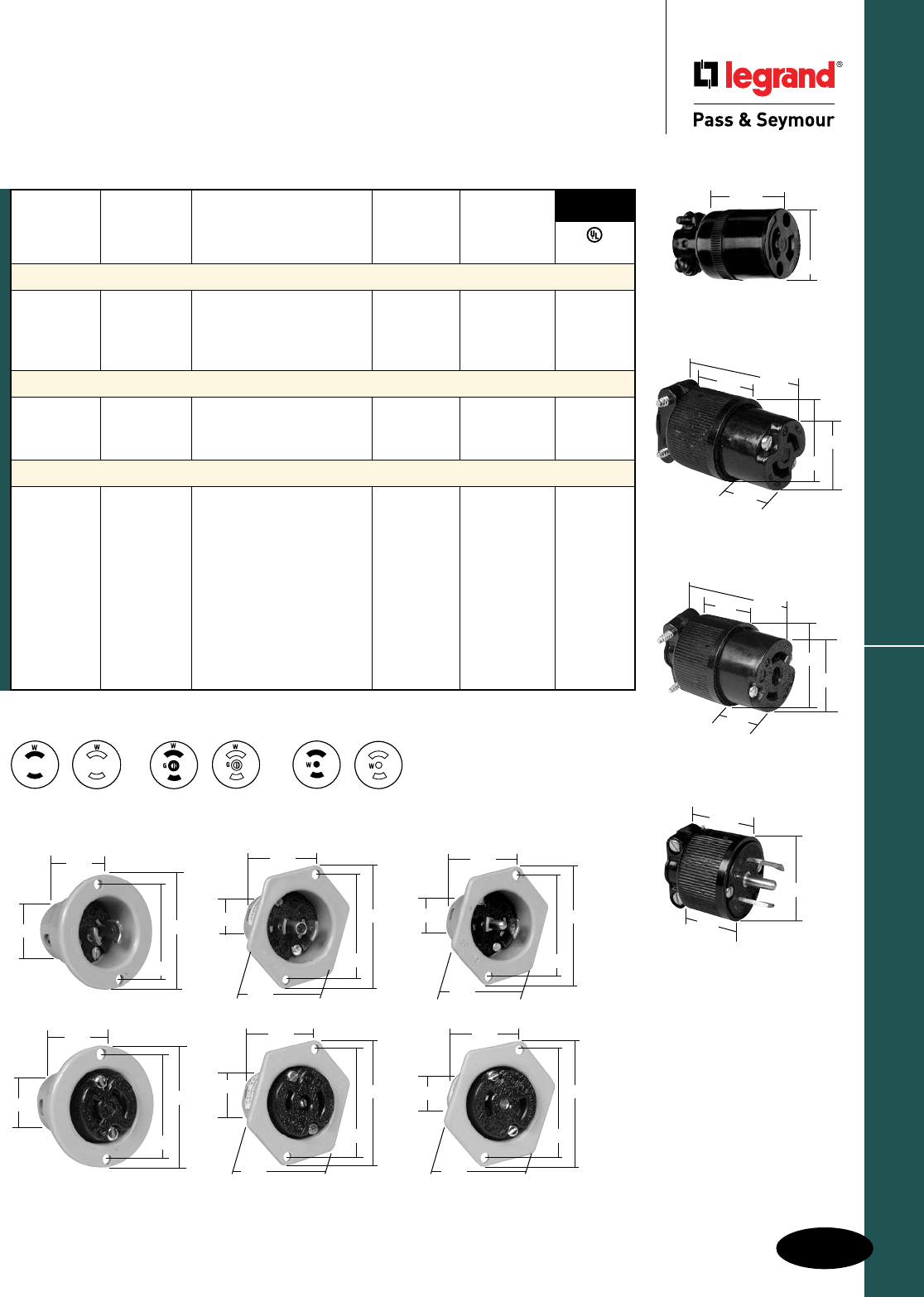
H-31
Turnlok® Locking Devices Midget Connectors, Plugs, Inlets, Outlets
Industrial Spec Grade Turnlok® Locking Devices
Midget Connectors, Plugs, Inlets, Outlets
2 Pole, 2 Wire Non-Grounding 15A, 125V
2 Pole, 3 Wire Grounding 15A, 125V
3 Pole, 3 Wire Non-Grounding 15A, 125/250V
NEMA
ML-2P
NEMA
ML-3P
NEMA
ML-1P
NEMA
ML-1R
NEMA
ML-2R
NEMA
ML-3R
2Pole,2Wire 2Pole,3Wire 3Pole,3Wire
Catalog Rating Cord NEMA
Number A. V. Description Diameter Cong. No.
Connectors
7427 15 125 Black .312"-.50" ML1-15R •
ML1133 15 125 Black .10"-.35" ML1-15R •
ML2133 15 125 Black .18"-.52" ML2-15R •
ML3133 15 125/250 Black .18"-.52" ML3-15R •
Plugs
ML1113 15 125 Black .10"-.35" ML1-15P •
ML2113 15 125 Black .18"-.52" ML2-15P •
ML3113 15 125/250 Black .18"-.52" ML3-15P •
Flanged Inlets & Outlets
ML115 15 125 Inlet,BlackFace, ML1-15P •
GrayFlange
ML114 15 125 Outlet,BlackFace, ML1-15R •
GrayFlange
ML215 15 125 Inlet,BlackFace, ML2-15P •
GrayFlange
ML214 15 125 Outlet,BlackFace, ML2-15R •
GrayFlange
ML315 15 125/250 Inlet,BlackFace, ML3-15P •
GrayFlange
ML314 15 125/250 Outlet,BlackFace, ML3-15R •
GrayFlange
UL498
3rd Party
Compliance
ML115
1.62"
1.38"
1.04"
1.13"
ML114
1.62"
1.38"
1.04"
1.13"
ML214
2.06"
1.75"
1.26"
1.29"
1.62"
ML314
2.06"
1.75"
1.26"
1.29"
1.62"
ML315
2.06"
1.75"
1.13"
1.29"
1.62"
ML215
2.06"
1.75"
1.13"
1.29"
1.62"
7427
1.0"
1.187"
ML1133
ML2133
1.23"
1.08"
1.81"
.80"
.66"
ML3113
1.18"
.80"
1.23"
1.81"
.80"
.66"
1.23"
1.08"
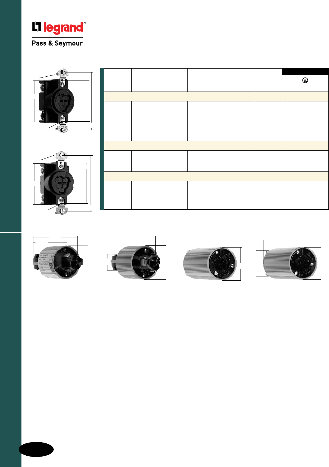
H-32
Turnlok® Locking Devices
AlldeviceslistedonthispageconformtoNEMAWD-1andWD-6.
Industrial Spec Grade Turnlok® Locking Devices
Power Interrupting Devices
2 Pole, 3 Wire 20A, 125V Hospital Use
2 Pole, 3 Wire 20A, 125V
2 Pole, 3 Wire 20A, 125V; 10A, 250VDC, 480VAC
Power Interrupting Devices
Catalog Rating Cord
Number A. V. Description Diameter
Receptacles
23000HG 20 125 HospitalUse,Non-Metallic •
23050 20 125 HospitalUse,BlackBakelite •
23000G 20 125;
10 250VDC,480VAC Grounding,Non-Metallic •
23000 20 125;
10 250VDC,480VAC Non-Grounding,Non-Metallic •
Connectors
23054N 20 125 HospitalUse,Non-Metallic .250"-.656" •
23002N 20 125;
10 250VDC,480VAC Non-Metallic .250"-.656" •
Plugs
23056N 20 125 HospitalUse,Non-Metallic .250"-.656" •
23035N 20 125 Non-Metallic .250"-.656" •
23005N 20 125;
10 250VDC,480VAC Non-Metallic .250"-.656" •
3rd Party Compliance
UL498
23000HG
23000
1.656"
3.281"
2.375"
1.387"
2.50"
#6-32TAP
(2HOLES)
1.656"
3.281"
2.375"
1.387"
2.50"
#6-32TAP
(2HOLES)
23002N
23005N 23056N
23035N 23054N
1.50"
2.625"
3.25"
1.688"
3.625"
1.50"
1.50"
1.688"
2.313"
3.25"
1.50"
3.625"
H-33
Turnlok® Locking Devices Power Interrupting Devices
H-33
AlldeviceslistedonthispageconformtoNEMAWD-1andWD-6.
Industrial Spec Grade Turnlok® Locking Devices
Power Interrupting Devices
3 Pole, 4 Wire 30A, 480V
3 Pole, 4 Wire 30A, 600VAC; 20A, 250VDC
3 Pole, 4 Wire 60A, 600V
Catalog Number Description
Accessories
WPG1 WeatherproofCoverfor20403N
26400 BoxandPlatefor26420
26401 Boxonlyfor26404AngleAdapter
26402 MountingPlateonlyfor26401Box
26404 45°AngleAdapter
20446N RedNylonCoverandGasketfor20443N
20416N NylonCoverandGasketfor20403N
20417N AluminumCover(NoGasket)for20403N
20445N, 20415N
2.56"
Dia.
2.38"
Dia.
4.18"
26415A
3.406"
2.25" 1.078"
3.75"
2.859"
.188"
20444N, 20414N
2.56"
Dia. 2.38"
Dia.
5.55"
26427
2.938"
3.688"
Catalog Rating Cord
Number A. V. Description Diameter
Receptacles
20443N 30 480 Non-Metallic
20403N 30,600VAC;20,250VDC Non-Metallic •
21420 30,600VAC;20,250VDC Angled,3/4"TapforConduit, •
Die-Cast
26420 60 600 Die-CastwithLiftLidEnclosure •
Connectors
20444N 30 480 Non-Metallic .400"-1.062"
20414 30,600VAC;20,250VDC Metallic .562"-1.000"
20414N 30,600VAC;20,250VDC Non-Metallic .400"-1.062" •
21414 30,600VAC;20,250VDC MetallicwithRubberCordGrip .360"-0.484"
26414 60 600 Metallic .750"-1.250"
26427 60 600 Metallic .750"-1.250" •
Plugs
20445N 30 480 Non-Metallic .400"-1.062"
20415 30,600VAC;20,250VDC Metallic .562"-1.000"
20415N 30,600VAC;20,250VDC Non-Metallic .400"-1.062"
21415 30,600VAC;20,250VDC MetallicwithRubberCordGrip .360"-0.484"
21426 30,600VAC;20,250VDC MetallicwithRubberCordGrip .484"-0.750"
21426S 30,600VAC;20,250VDC MetallicwithTabwithRubber .484"-0.750"
CordGrip
26415 60 600 Metallic .750"-1.250"
26426 60 600 Metallic .750"-1.250" •
Flanged Inlets & Outlets
20418 30,600VAC;20,250VDC Inlet,Die-CastforFSandFDBox •
26415A 60 600 Inlet,Die-Cast
UL498
3rd Party
Compliance
2.688"
4.188"
26426
20418
2.87"
1.87"
.187"Dia.
(4HOLES)
3.25"
4.59"
26414
2.938"
3.813"
26420
3.50"
2.875"
4.063"
20443N
1.813"
3.281"
2.688"
1.438"
1.938"
26415
2.688"
3.375"
Power Interrupting Devices
H-34
Turnlok® Locking Devices
Industrial Spec Grade Turnlok® Locking Devices
Power Interrupting Devices
4 Pole, 5 Wire 30A, 600VAC; 20A 250VDC
4 Pole, 5 Wire 60A, 600V
Catalog Rating Cord
Number A. V. Description Diameter
Receptacles
25250 30 600VAC; Die-CastwithLiftLidEnclosure
20 250VDC
26520 60 600 Die-CastwithLiftLidEnclosure •
Connectors
25414N 30 600VAC; Non-Metallic .625
"
-1.000
"
20 250VDC .725
"
-1.250
"
25414 30 600VAC; Metallic .625
"
-1.000
"
20 250VDC
26514 60 600 Metallic .750
"
-1.250
"
•
26527 60 600 MetallicwithRubberCordGrip .750
"
-1.250
"
•
Plugs
25415N 30 600VAC; Non-Metallic .625
"
-1.000
"
20 250VDC .725
"
-1.250
"
25415 30 600VAC; Metallic .625
"
-1.000
"
20 250VDC
26515 60 600 Metallic .750
"
-1.250
"
•
26526 60 600 MetallicwithRubberCordGrip .750
"
-1.250
"
•
Flanged Inlets & Outlets
26515A 60 600 Inlet,Die-Cast •
26514A 60 600 Outlet,Die-Cast •
3rd Party Compliance
UL498
Catalog
Number Description
Accessories
26400 BoxandPlatefor26520
26401 Boxonlyfor26404AngleAdapter
Catalog
Number Description
26402 MountingPlateonlyfor26401Box
26404 45°AngleAdapter
25250
4.563"
3.250"
(4)No.6-32
Screws 2.844"
25414N
2.94"
Dia.
3.95"
26520
3.50"
2.875"
4.063"
26527
2.938"
4.563"
.875"
26526
2.688"
4.188"
.875"
26514A
2.859" 3.344"
3.750"
2.578" 1.156"
3.813"
.844"
26515A
2.703"
3.750"
1.078"
.844"
3.344"
3.406"
2.25"
26402
4.50"
3.87"
2.87"
3.25"
diameter
26401
2.72" 1.5"
pipethread
3.87"
4.50"
26404
3.50"
2.875"
3.875"
45°
angle
4.50"
AlldeviceslistedonthispageconformtoNEMAWD-1andWD-6.
H-35
AccessoriesTurnlok® Locking Devices
Industrial Spec Grade Turnlok® Locking Devices
Accessories
AlldeviceslistedonthispageconformtoNEMAWD-1andWD-6.
DC1
Catalog Number Description Color
Weatherproof Boots
L15RBC Bootfor15ALockingConnector Black
L15RBP Bootfor15ALockingPlug Black
L2030RBC Bootfor20/30ALockingConnector Black
L2030RBP Bootfor20/30ALockingPlug Black
Corrosion-Resistant Boots
CRL2030RBC Bootfor20/30ALockingConnector Yellow
CRL2030RBP Bootfor20/30ALockingPlug Yellow
CR7716N Bootfor50ALockingConnector Yellow
CR7717N Bootfor50ALockingPlug Yellow
Dust Covers
DC1 ReplacementCover,tobeusedwith“old-style”20and30A Black
TurnlokPlugsandConnectorsonly. L15RBP
1.420"
.210"
.250"
Dia.
3.090"
L2030RBC
CRL2030RBC
2.81"
5.55"
L2030RBP
CRL2030RBP
2.61"
5.04"
CR7717N
3.031"
4.703"
.609"
.625"
.625"
CR7716N
3.0"
4.703"
.953"
.609"
3.031"
L15RBC
1.420"
.240"
.250"
Dia.
3.520"
Accessories
H-36
Turnlok® Locking Devices
Industrial Spec Grade Turnlok® Locking Devices
Accessories
Catalog Number Description Color
Weatherproof Covers
WPG1 Coverfor15ATurnlokFlangedInletsandOutlets Gray
WPG2 Coverfor20and30ATurnlokFlangedInletsandOutlets Gray
7770 Coverfor50ALockingReceptacle,Thermoplastic Yellow
3720FS ClearCoverforSingleReceptacle,Thermoplastic Gray
3710FS ClearCoverforDuplexReceptacle,Thermoplastic Gray
3722FS ClearCoverforPowerOutlet,Thermoplastic Gray
3760 CoverforSingleReceptacle Gray
Stainless Steel Plates
SS7 PlateforSingleReceptacle S/S
SS8 PlateforDuplexReceptacle S/S
SS720 PlateforLockingReceptacle S/S
WP7 DustproofCoverforSingleReceptacle S/S
WP8 DustproofCoverforDuplexReceptacle S/S
Strain Relief Grips
FC22GL StrainReliefGrip–.220"-.320"
FC30GL StrainReliefGrip–.300"-.430"
FC40GL StrainReliefGrip–.400"-.560"
FC52GL StrainReliefGrip–.520"-.730"
FC70GL StrainReliefGrip–.700"-.940"
FC94GL StrainReliefGrip–.940"-1.250"
Turnlok Right Angle Adapter
L15AN 15ATurnlokRightAngleAdapter Black
L20303AN 20and30A3WireTurnlokRightAngleAdapter Black
L203045AN 20and30A4and5WireTurnlokRightAngleAdapter Black
L15AN
2.97"
1.94"
1.37"
L20303AN
3.868"
2.675"
1.65"
L203045AN
3.868"
2.675"
1.65"
7770
3.00"
3.281"
4.60"
2.35"
4.57"
3.25"
.19"
(4HOLES)
2.85"
1.88"
3.57"
WPG1
WPG2
4.57"
3.25"
.19"
(4HOLES)
2.85"
1.88"
3.57"
H-37
Product Specifications & PerformanceTurnlok® Locking Devices
Industrial Spec Grade Turnlok® Locking Devices
Ground Continuity Monitoring
Plugs & Connectors
Product Specifications & Performance
Plugs
BackBody SuperToughNylon
FrontBody Nylon
TerminalChamber Polycarbonate
CordClamp Nylon
Insert Nylon
DustShield* Neoprene
Blades Brass
TerminalClamp 15A=Zinc-PlatedSteel,20A=Nickel-PlatedSteel,30A=Brass
TerminalScrews 15A=Nickel-orBrass-PlatedSteel,20&30A=Brass
GroundScrews 15A=Nickel-PlatedSteel,20&30A=Brass
CordClampScrews Nickel-PlatedSteel
AssemblyScrews Nickel-PlatedSteel
Connectors
BackBody SuperToughNylon
FrontBody Nylon
TerminalChamber Polycarbonate
CordClamp Nylon
Insert Nylon
DustShield* Neoprene
Contacts Brass
TerminalClamp 15A=Zinc-PlatedSteel,20A=Nickel-PlatedSteel,30A=Brass
TerminalScrews 15A=Nickel-orBrass-PlatedSteel,20&30A=Brass
GroundScrews 15A=Nickel-PlatedSteel,20&30A=Brass
CordClampScrews Nickel-PlatedSteel
AssemblyScrews Nickel-PlatedSteel
Performance
Electrical
DielectricWithstandVoltage 15A=1600Vminimum,20&30A=2200Vminimum
MaximumWorkingVoltage 15A=277VAC,20&30A=600VAC
CurrentInterrupting Certifiedforcurrentinterruptingatfull-ratedcurrent
TemperatureRise 30°Cmaximumafter50cyclesat150%ratedcurrent
Mechanical
CordAccommodations Roundportableservicecordsofdiametersinaccordancewith
thedeviceratingasdefinedinUL62
CordGripAccommodations 15A=.230"–.720"diameter,20&30A3Wire=.225"–.750"diameter
20&30A4&5Wire=.225"–1.150"diameter
TerminalIdentification 15A=Green=Ground,White=Neutral,Brass=Hot
20&30A=“GR”andGreenColor=Ground,
“WH”andWhiteColor=Neutral,“X”,“Y”,“Z”=Hot
TerminalAccommodation 15A=#18AWGmin.–#10AWGmax.
20A=#18AWGmin.–#8AWGmax.
30A=#18AWGmin.–#6AWGmax.
ProductIdentification Amperage,Voltage,3rdPartyCompliance,
NEMAConfigurationhotstampedontodevice
Environmental
Flammability UL94V2
OperatingTemperature Maximumcontinuous:+75°C
Minimum:-40°Cwithoutimpact
15, 20 & 30 Amp Turnlok GCM Plugs & Connectors
*DustShieldfor20&30AmpPlugs&Connectors.
Product Specifications & Performance
H-38
Turnlok® Locking Devices
Industrial Spec Grade Turnlok® Locking Devices
Plugs & Connectors
Product Specifications & Performance
Standard Product Corrosion-Resistant
Plugs
BackBody Nylon Nylon
FrontBody Nylon Nylon
TerminalChamber Polycarbonate Polycarbonate
CordClamp Nylon Nylon
Insert Nylon Nylon
Blades Brass Nickel-PlatedBrass
TerminalClamp Zinc-PlatedSteel Nickel-PlatedSteel
TerminalScrews Nickel-orBrass-PlatedSteel Nickel-PlatedSteel
GroundScrews Nickel-PlatedSteel Nickel-PlatedSteel
CordClampScrews Nickel-PlatedSteel Nickel-PlatedSteel
AssemblyScrews Nickel-PlatedSteel Nickel-PlatedSteel
Connectors
BackBody Nylon Nylon
FrontBody Nylon Nylon
TerminalChamber Polycarbonate Polycarbonate
CordClamp Nylon Nylon
Insert Nylon Nylon
Contacts Brass Nickel-PlatedBrass
TerminalClamp Zinc-PlatedSteel Nickel-PlatedSteel
TerminalScrews Nickel-orBrass-PlatedSteel Nickel-PlatedSteel
GroundScrews Nickel-PlatedSteel Nickel-PlatedSteel
CordClampScrews Nickel-PlatedSteel Nickel-PlatedSteel
AssemblyScrews Nickel-PlatedSteel Nickel-PlatedSteel
Performance
Electrical
DielectricWithstandVoltage 1600Vminimum
MaximumWorkingVoltage 277VAC
CurrentInterrupting Certifiedforcurrentinterruptingatfull-ratedcurrent
TemperatureRise 30°Cmaximumafter50cyclesat150%ratedcurrent
Mechanical
CordAccommodations Roundportableservicecordsofdiametersinaccordancewith
thedeviceratingasdefinedinUL62
CordGripAccommodations .230"–.720"diameter
TerminalIdentification Green=Ground,White=Neutral,Brass=Hot
TerminalAccommodation #18AWGmin.–#10AWGmax.
ProductIdentification Amperage,Voltage,3rdPartyCompliance,NEMAConfiguration
Environmental
Flammability UL94V2
OperatingTemperature Maximumcontinuous:+75°C
Minimum:-40°Cwithoutimpact
15 Amp Turnlok Plugs & Connectors
H-39
Product Specifications & PerformanceTurnlok® Locking Devices
Industrial Spec Grade Turnlok® Locking Devices
Receptacles
Product Specifications & Performance
Standard Corrosion-Resistant
Receptacles
FrontBody Nylon Nylon
BackBody Nylon Nylon
MountingStrap 15A=Steel;20&30A=Brass Nickel-PlatedBrass
PressurePlate Brass Nickel-PlatedBrass
Contacts Brass Nickel-PlatedBrass
TerminalClamps Brass Nickel-PlatedBrass
TerminalScrews Brass Brass
MountingScrews Zinc-PlatedSteel StainlessSteel
Performance
Electrical
DielectricWithstandVoltage 2000Vminimum
MaximumWorkingVoltage 600VAC
CurrentInterrupting Certifiedforcurrentinterruptingatfull-ratedcurrent
TemperatureRise 30°Cmaximumafter50cyclesat150%ratedcurrent
Mechanical
TerminalAccommodation 15A=#18AWGmin.–#10AWGmax.
20&30A=#14AWGmin.–#10AWGmax.
ProductIdentification Amperage,Voltage,NEMAConfigurationmoldedintoface
Environmental
Flammability UL94V2
OperatingTemperature Maximumcontinuous:+75°C
Minimum:-40°Cwithoutimpact
15, 20 & 30 Amp Turnlok Receptacles
50 Amp Turnlok Receptacles
Corrosion-Resistant California Standard
Receptacles
FrontBody Glass-FilledNylon Glass-FilledNylon
BackBody Glass-FilledNylon Glass-FilledNylon
MountingStrap Nickel-PlatedBrass Nickel-PlatedBrass
Contacts Nickel-PlatedBrass Brass
TerminalClamps Brass Brass
GroundShunt Brass Brass
MountingScrews StainlessSteel Zinc-PlatedSteel
Performance
Electrical
DielectricWithstandVoltage 3000Vminimum
MaximumWorkingVoltage 600VAC
CurrentInterrupting Certifiedforcurrentinterruptingatfull-ratedcurrent
TemperatureRise 30°Cmaximumafter50cyclesat150%ratedcurrent
Mechanical
TerminalAccommodation #10AWGmin.–#6AWGmax.
ProductIdentification Amperage,Voltagemoldedintoface
Environmental
Flammability UL94V0
OperatingTemperature Maximumcontinuous:+115°C
Minimum:-40°Cwithoutimpact
Product Specifications & Performance
H-40
Turnlok® Locking Devices
Industrial Spec Grade Turnlok® Locking Devices
Plugs & Connectors
Product Specifications & Performance
Standard Corrosion-Resistant
Plugs
BackBody SuperToughNylon SuperToughNylon
FrontBody Nylon Nylon
TerminalChamber Polycarbonate Polycarbonate
CordClamp Nylon Nylon
Insert Nylon Nylon
DustShield Neoprene Neoprene
Blades Brass 20A=Nickel-PlatedBrass
30A=Tin-PlatedBrass
TerminalClamp 20A=Nickel-PlatedSteel 20A=Nickel-PlatedSteel
30A=Brass 30A=Nickel-PlatedBrass
TerminalScrews Brass Nickel-PlatedBrass
GroundScrews Brass Nickel-PlatedBrass
CordClampScrews Nickel-PlatedSteel Nickel-PlatedSteel
AssemblyScrews Nickel-PlatedSteel Nickel-PlatedSteel
Connectors
BackBody SuperToughNylon SuperToughNylon
FrontBody Nylon Nylon
TerminalChamber Polycarbonate Polycarbonate
CordClamp Nylon Nylon
Insert Nylon Nylon
DustShield Neoprene Neoprene
Contacts Brass 20A=Nickel-PlatedBrass
30A=Tin-PlatedBrass
TerminalClamp 20A=Nickel-PlatedSteel 20A=Nickel-PlatedSteel
30A=Brass 30A=Nickel-PlatedBrass
TerminalScrews Brass Nickel-PlatedBrass
GroundScrews Brass Nickel-PlatedBrass
CordClampScrews Nickel-PlatedSteel Nickel-PlatedSteel
AssemblyScrews Nickel-PlatedSteel Nickel-PlatedSteel
Performance
Electrical
DielectricWithstandVoltage 2200Vminimum
MaximumWorkingVoltage 600VAC
CurrentInterrupting Certifiedforcurrentinterruptingatfull-ratedcurrent
TemperatureRise 30°Cmaximumafter50cyclesat150%ratedcurrent
Mechanical
CordAccommodations Roundportableservicecordsofdiametersinaccordancewiththe
deviceratingasdefinedinUL62
CordGripAccommodations 20&30A3Wire=.225"–.750"diameter
20&30A4&5Wire=.225"–1.150"diameter
TerminalIdentification “GR”andGreenColor=Ground,“WH”andWhiteColor=Neutral,
“X”,“Y”,“Z”=Hot
TerminalAccommodation #18AWGmin.– #8AWGmax.
ProductIdentification Amperage,Voltage,3rdPartyCompliance,
NEMAConfigurationhotstampedontodevice
Environmental
Flammability UL94V2
OperatingTemperature Maximumcontinuous:+75°C
Minimum:-40°Cwithoutimpact
20 & 30 Amp Turnlok Plugs & Connectors
H-41
Product Specifications & PerformanceTurnlok® Locking Devices
Industrial Spec Grade Turnlok® Locking Devices
Plugs & Connectors
Product Specifications & Performance
Corrosion-Resistant California Standard
Plugs
PlugShroud ZytelSuperToughNylon ZytelSuperToughNylon
BackBody Nylon Nylon
FrontBody Nylon Nylon
TerminalChamber Nylon Nylon
CordClamp Nylon Nylon
Blades Nickel-PlatedBrass Brass
TerminalClamp Nickel-PlatedBrass Brass
TerminalScrews Nickel-PlatedBrass Brass
GroundScrew Nickel-PlatedBrass Brass
AssemblyScrews StainlessSteel StainlessSteel
Connectors
BackBody Nylon Nylon
FrontBody Nylon Nylon
TerminalChamber Nylon Nylon
CordClamp Nylon Nylon
Contacts Nickel-PlatedBrass Brass
TerminalClamp Nickel-PlatedBrass Brass
TerminalScrews Nickel-PlatedBrass Brass
GroundScrew Nickel-PlatedBrass Brass
AssemblyScrews StainlessSteel StainlessSteel
Performance
Electrical
DielectricWithstandVoltage 3000Vminimum
MaximumWorkingVoltage 600VAC
CurrentInterrupting Certifiedforcurrentinterruptingatfull-ratedcurrent
TemperatureRise 30°Cmaximumafter50cyclesat150%ratedcurrent
Mechanical
CordAccommodations Roundportableservicecordsofdiametersinaccordancewiththe
deviceratingasdefinedinUL62
CordGripAccommodations .680"–1.125"diameter
TerminalIdentification ColorCodedTerminalScrews
TerminalAccommodation #10AWGmin.–#4AWGmax.
ProductIdentification Amperage,Voltagehotstampedondevice
Environmental
Flammability UL94HBorbetter
OperatingTemperature Maximumcontinuous:+75°C
Minimum:-40°Cwithoutimpact
50 Amp Turnlok Plugs & Connectors
Product Specifications & Performance
H-42
Turnlok® Locking Devices
Industrial Spec Grade Turnlok® Locking Devices
Inlets & Outlets
Product Specifications & Performance
15 Amp 20 Amp 30 Amp
Flanged Inlets
FlangedCasing Polycarbonate Polycarbonate Polycarbonate
BladeHolder Polycarbonate Polycarbonate Nylon
Blades Nickel-PlatedBrass Brass Tin-PlatedStresscon
TerminalClamp Zinc-PlatedSteel Zinc-PlatedSteel Brass
TerminalScrews Zinc-orBrass- Zinc-orBrass- Brass
PlatedSteel PlatedSteel
GroundScrews Zinc-PlatedSteel Zinc-PlatedSteel Brass
AssemblyScrews Zinc-PlatedSteel Zinc-PlatedSteel Zinc-PlatedSteel
Flanged Outlets
FlangedCasing Polycarbonate Polycarbonate Polycarbonate
ContactCarrier Polycarbonate Polycarbonate Nylon
Contacts Brass Brass Tin-PlatedBrass
TerminalClamp Zinc-PlatedSteel Zinc-PlatedSteel Brass-orNickel-
PlatedSteel
TerminalScrews Zinc-orBrass- Zinc-orBrass- Brass-orNickel-
PlatedSteel PlatedSteel PlatedSteel
GroundScrews Zinc-PlatedSteel Zinc-PlatedSteel Nickel-PlatedBrass
AssemblyScrews Zinc-PlatedSteel Zinc-PlatedSteel Zinc-PlatedSteel
Performance
Electrical
DielectricWithstandVoltage 15A=2000Vminimum,20&30A=3000Vminimum
MaximumWorkingVoltage 15A=277VAC,20&30A=600VAC
CurrentInterrupting Certifiedforcurrentinterruptingatfull-ratedcurrent
TemperatureRise 30°Cmaximumafter50cyclesat150%ratedcurrent
Mechanical
TerminalIdentification Green=Ground,White=Neutral,Brass=Hot
TerminalAccommodation 15A=#18AWGmin.– #10AWGmax.,
20&30A=#12AWGmin.–#8AWGmax.
ProductIdentification Amperage,Voltage,3rdPartyCompliance,NEMAConfiguration
Environmental
Flammability UL94V2
OperatingTemperature Maximumcontinuous:15&20A=+115°C,30A=+75°C
Minimum:-40°Cwithoutimpact
15, 20 & 30 Amp Turnlok
Inlets & Outlets
H-43
Product Specifications & PerformanceTurnlok® Locking Devices
Industrial Spec Grade Turnlok® Locking Devices
Inlets Product Specifications &
Performance & Horsepower Rating Chart
Inlets
FlangedCasing Nylon
ContactCarrier Nylon
Blades Brass
TerminalClamps Brass
TerminalScrews Brass
AssemblyScrews Nickel-PlatedSteel
Performance
Electrical
DielectricWithstandVoltage 3000Vminimum
MaximumWorkingVoltage 600VAC
CurrentInterrupting Certifiedforcurrentinterruptingatfull-ratedcurrent
TemperatureRise 30oCmaximumafter50cyclesat150%ratedcurrent
Mechanical
TerminalAccommodation #10AWGmin.–#4AWGmax.
ProductIdentification Amperage,Voltagehotstampedontoface
Environmental
Flammability UL94V0
OperatingTemperature Maximumcontinuous:+75oC
Minimum:-40oCwithoutimpact
50 Amp Inlet
*Suitablefor208VmotorapplicationsattheHPratingspecified.
NEMA Conguration AC HP Rating
L1-15 1/2
L5-15 1/2
L6-15 11/2*
L7-15 2
L2-20 2*
L5-20 1
L6-20 2*
L7-20 2
L8-20 3
L10-20 2LinetoLine*
1LinetoNeutral
L11-20 3
L12-20 5
L14-20 2LinetoLine*
L15-20 3
L16-20 5
L18-20 2
L19-20 5
NEMA Conguration AC HP Rating
L21-20 2
L22-20 5
L5-30 2
L6-30 2*
L7-30 3
L8-30 5
L10-30 2LinetoLine*
2LinetoNeutral
L11-30 3
L12-30 10
L14-30 2LinetoLine*
L15-30 3
L16-30 10
L18-30 3
L19-30 10
L21-30 3
L22-30 10
Turnlok Horsepower Rating for NEMA Configuration
Attachment Plugs & Receptacles

CAM-TYPE DEVICES
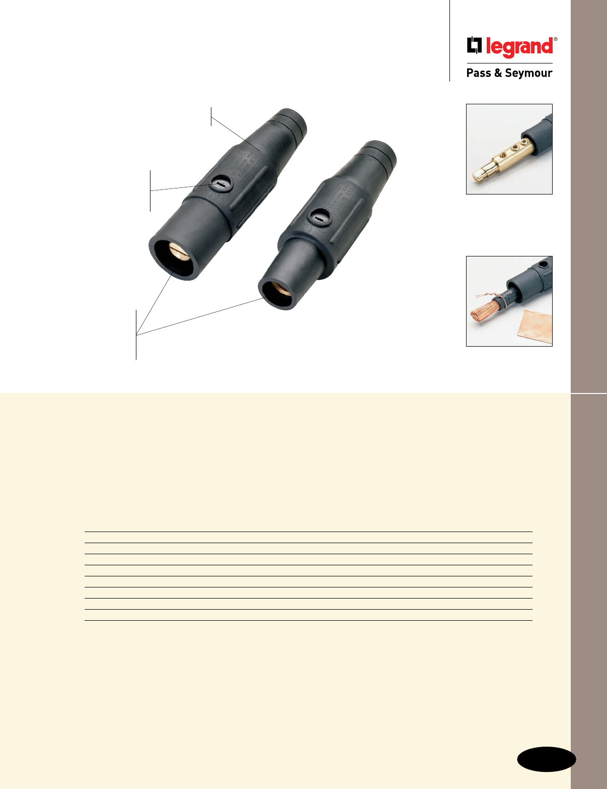
Index
Devices Page Number
Series 16 In-Line Connectors I-2
Series 16 Panel Mounts I-3
Series 16 Protective Caps & Adapters I-4
Series 16 Flip Lid Covers I-5
Series 16 Accessories I-6
Series 15 In-Line Connectors, Protective Caps & Adapters I-7
Series 15 Panel Mounts & Accessories I-8
Series 18 In-Line Connectors I-9
I-1
Cam-Type Devices
Cam-Type Devices
Heavy-duty
brass contacts
provide superior
and consistent
conductivity.
Non-conductive
retaining screw
insures stability of the
fully assembled product. Heavy-duty hex
set screws allow
greater termination
torque.
Thermoplastic elastomer housing
is chemical- and impact-resistant.
PS40MBBK
PS40FBBK
P&S Cam-Type Devices are built with
top-quality materials for enhanced
durability and service life, with
increased insulation protection for safety.
Copper shim
bundles wire
strands to reduce
“splaying.”
Copper wire
provides superior
strain relief.

Series 16 In-Line Connectors
I-2
Cam-Type Devices
Cam-Type Devices
Series 16 In-Line Connectors
Rating*
Catalog Number A. V. Cable Size Color
Series 16 In-Line Connectors – Male
PS20MBBK 400 600 #2-2/0 Black • •
PS20MBW 400 600 #2-2/0 White • •
PS20MBR 400 600 #2-2/0 Red • •
PS20MBBL 400 600 #2-2/0 Blue • •
PS20MBG 400 600 #2-2/0 Green • •
PS20MBBR 400 600 #2-2/0 Brown • •
PS20MBO 400 600 #2-2/0 Orange • •
PS20MBY 400 600 #2-2/0 Yellow • •
PS40MBBK 400 600 2/0-4/0 Black • •
PS40MBW 400 600 2/0-4/0 White • •
PS40MBR 400 600 2/0-4/0 Red • •
PS40MBBL 400 600 2/0-4/0 Blue • •
PS40MBG 400 600 2/0-4/0 Green • •
PS40MBBR 400 600 2/0-4/0 Brown • •
PS40MBO 400 600 2/0-4/0 Orange • •
PS40MBY 400 600 2/0-4/0 Yellow • •
Series 16 In-Line Connectors – Female
PS20FBBK 400 600 #2-2/0 Black • •
PS20FBW 400 600 #2-2/0 White • •
PS20FBR 400 600 #2-2/0 Red • •
PS20FBBL 400 600 #2-2/0 Blue • •
PS20FBG 400 600 #2-2/0 Green • •
PS20FBBR 400 600 #2-2/0 Brown • •
PS20FBO 400 600 #2-2/0 Orange • •
PS20FBY 400 600 #2-2/0 Yellow • •
PS40FBBK 400 600 2/0-4/0 Black • •
PS40FBW 400 600 2/0-4/0 White • •
PS40FBR 400 600 2/0-4/0 Red • •
PS40FBBL 400 600 2/0-4/0 Blue • •
PS40FBG 400 600 2/0-4/0 Green • •
PS40FBBR 400 600 2/0-4/0 Brown • •
PS40FBO 400 600 2/0-4/0 Orange • •
PS40FBY 400 600 2/0-4/0 Yellow • •
3rd Party Compliance
UL cCSAus
PS40MBR
(unassembled)
PS40MBBK
PS40FBBK
6.875"
6.800"
Features
nThermoplasticelastomerhousingforoutstanding
impactandchemicalresistance,aswellasan
exceptionalsealformaintainingNEMAType3R
and4integrity.
nNon-conductiveretainingscrewhelpstoinsure
nocontactwithliveparts,alongwithproviding
stabilitytothefullyassembledproduct.
nHeavy-dutybrassmaleandfemalecontacts
provideasuperiorandconsistentmeans
ofconductivity.
nHeavy-dutyhexsetscrewsallowgreater
terminationtorque.
nCopperwireprovidesqualitystrainrelief.
nCoppershimbundleswirestrandstoreduce
“splaying.”
*AllratingsbothAC/DC.
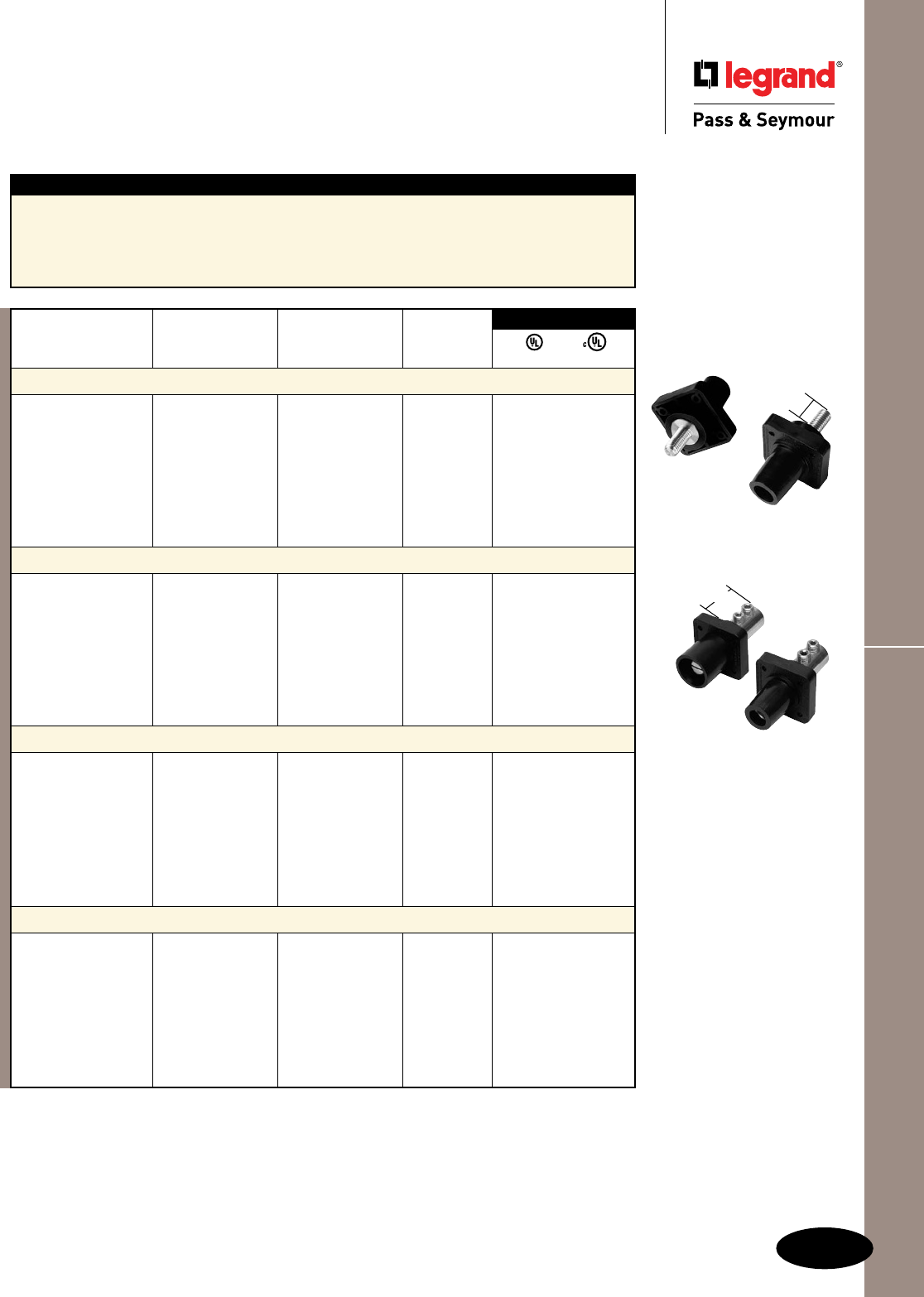
I-3
Series 16 Panel MountsCam-Type Devices
Cam-Type Devices
Series 16 Panel Mounts
Rating*
Catalog Number A. V. Cable Size Color
Series 16 Threaded Stud Panel Mounts – Male
PS40MRSBBK 400 600 #2-4/0 Black • •
PS40MRSBW 400 600 #2-4/0 White • •
PS40MRSBR 400 600 #2-4/0 Red • •
PS40MRSBBL 400 600 #2-4/0 Blue • •
PS40MRSBG 400 600 #2-4/0 Green • •
PS40MRSBBR 400 600 #2-4/0 Brown • •
PS40MRSBO 400 600 #2-4/0 Orange • •
PS40MRSBY 400 600 #2-4/0 Yellow • •
Series 16 Threaded Stud Panel Mounts – Female
PS40FRSBBK 400 600 #2-4/0 Black • •
PS40FRSBW 400 600 #2-4/0 White • •
PS40FRSBR 400 600 #2-4/0 Red • •
PS40FRSBBL 400 600 #2-4/0 Blue • •
PS40FRSBG 400 600 #2-4/0 Green • •
PS40FRSBBR 400 600 #2-4/0 Brown • •
PS40FRSBO 400 600 #2-4/0 Orange • •
PS40FRSBY 400 600 #2-4/0 Yellow • •
Series 16 Double Set Screw Panel Mounts – Male
PS40MRBBK 400 600 2/0-4/0 Black • •
PS40MRBW 400 600 2/0-4/0 White • •
PS40MRBR 400 600 2/0-4/0 Red • •
PS40MRBBL 400 600 2/0-4/0 Blue • •
PS40MRBG 400 600 2/0-4/0 Green • •
PS40MRBBR 400 600 2/0-4/0 Brown • •
PS40MRBO 400 600 2/0-4/0 Orange • •
PS40MRBY 400 600 2/0-4/0 Yellow • •
Series 16 Double Set Screw Panel Mounts – Female
PS40FRBBK 400 600 2/0-4/0 Black • •
PS40FRBW 400 600 2/0-4/0 White • •
PS40FRBR 400 600 2/0-4/0 Red • •
PS40FRBBL 400 600 2/0-4/0 Blue • •
PS40FRBG 400 600 2/0-4/0 Green • •
PS40FRBBR 400 600 2/0-4/0 Brown • •
PS40FRBO 400 600 2/0-4/0 Orange • •
PS40FRBY 400 600 2/0-4/0 Yellow • •
UL cUL
3rd Party Compliance
PS40MRSBBK
PS40FRSBBK
1.25"**
Features
nNylonhousingprovidesoutstandingimpactand
chemicalresistance.
nHeavy-dutybrassmaleandfemalecontacts
provideasuperiorandconsistentmeans
ofconductivity.
nHeavy-dutyhexsetscrews(availableon
doublesetscrewversiononly)allowgreater
terminationtorque.
*AllratingsbothAC/DC.
PS40MRBBK
PS40FRBBK
2.150"**
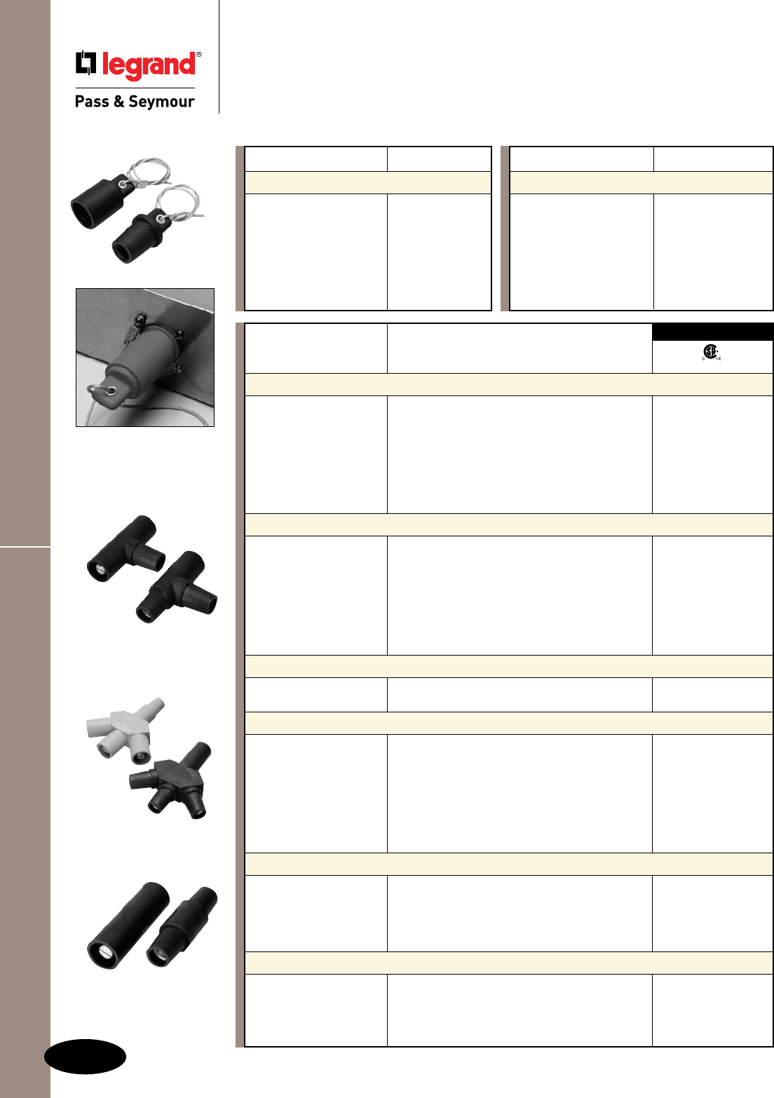
Series 16 Protective Caps & Adapters
I-4
Cam-Type Devices
Cam-Type Devices
Series 16 Protective Caps & Adapters
Catalog Number Color
Series 16 Protective Caps – Male
PS40MCBK Black
PS40MCW White
PS40MCR Red
PS40MCBL Blue
PS40MCG Green
PS40MCBR Brown
PS40MCO Orange
PS40MCY Yellow
PSPTBK
PSTTBK
Catalog Number Color
Series 16 Tapping “T” Adapters
PSTTBK Black •
PSTTW White •
PSTTR Red •
PSTTBL Blue •
PSTTG Green •
PSTTBR Brown •
PSTTO Orange •
PSTTY Yellow •
Series 16 Paralleling “T” Adapters
PSPTBK Black •
PSPTW White •
PSPTR Red •
PSPTBL Blue •
PSPTG Green •
PSPTBR Brown •
PSPTO Orange •
PSPTY Yellow •
Series 16 F-M-M-M 3fer Adapters
PS3MW White
PS3MG Green
Series 16 M-F-F-F 3fer Adapters
PS3FBK Black •
PS3FW White •
PS3FR Red •
PS3FBL Blue •
PS3FG Green •
PS3FBR Brown •
PS3FO Orange •
PS3FY Yellow •
Series 16 Male-to-Male Coupler
PSMMBK Black •
PSMMW White •
PSMMR Red •
PSMMBL Blue •
PSMMG Green •
Series 16 Female-to-Female Coupler
PSFFCBK Black •
PSFFCW White •
PSFFCR Red •
PSFFCBL Blue •
PSFFCG Green •
cCSAus
3rd Party Compliance
PS40MCBK
PS40FCBK
PS3MG
PS3FBK
PSMMBK
PSFFCBK
Catalog Number Color
Series 16 Protective Caps – Female
PS40FCBK Black
PS40FCW White
PS40FCR Red
PS40FCBL Blue
PS40FCG Green
PS40FCBR Brown
PS40FCO Orange
PS40FCY Yellow
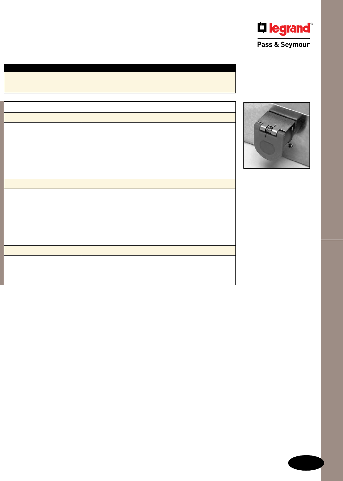
Description
Manufactured in UV-resistant polycarbonate, all snap back plastic covers are made with stainless steel
offset, spring and pin. Designed for surface mount or internal mount, the new snap back plastic covers
are fully gasketed and NEMA 3R rated for weathertight protection.
Catalog Number Color
Plastic Flip Lid, Through-Mount for .070–.090 Wall Thickness
PS40WTCLBK Blackcover
PS40WTCLW White
PS40WTCLR Red
PS40WTCLBL Blue
PS40WTCLG Green
PS40WTCLBR Brown
PS40WTCLO Orange
PS40WTCLY Yellow
Plastic Flip Lid, Through-Mount for .370–.400 Wall Thickness
PS40WTCSBK Blackcover
PS40WTCSW White
PS40WTCSR Red
PS40WTCSBL Blue
PS40WTCSG Green
PS40WTCSBR Brown
PS40WTCSO Orange
PS40WTCSY Yellow
Metal Flip Lid
PS40WTCMBK Blackcover
PS40WTCMW White
PS40WTCMBL Blue
PS40WTCMG Green
I-5
Series 16 Flip Lid CoversCam-Type Devices
Cam-Type Devices
Series 16 Flip Lid Covers
PS40WTCL
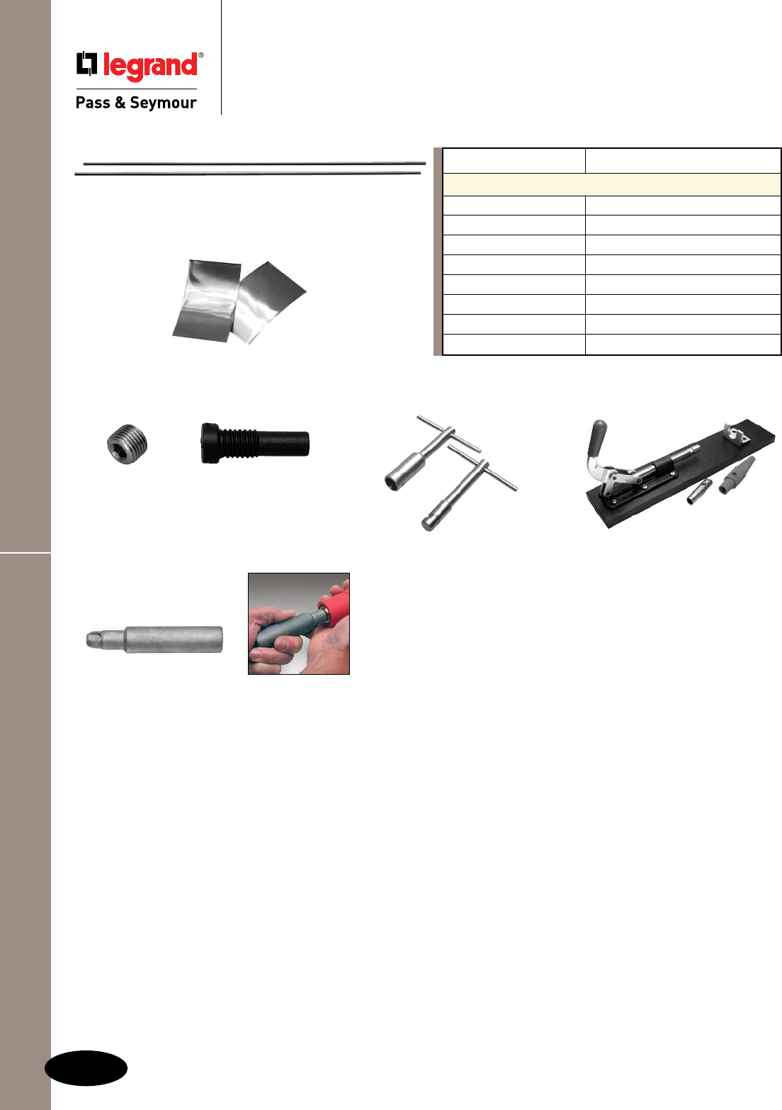
I-6
Cam-Type Devices
Cam-Type Devices
Series 16 Accessories
Series 16 Accessories
Catalog Number Description
Series 16 Accessories
PS430245 Series16StrainReliefWire
PS430244 CopperShim
PS520710 Series16RetainingScrew
PS500017PLT Series16SetScrew
PS16CLM MaleConnectorExtractor
PS16CLF FemaleConnectorExtractor
PSCLSPRESS Come-AlongTool
PS500072 FemaleReformingTool
PS430245
PS430244
Restores damaged
female cam-type
contacts.
PS500072
PS500017PLT
PSCLSPRESS
PS520710
PS16CLM
PS16CLF
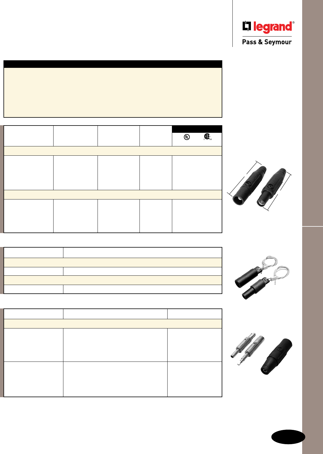
I-7
Cam-Type Devices
Series 15 In-Line Connectors, Caps & Adapters
Cam-Type Devices
Series 15 In-Line Connectors,
Protective Caps & Adapters
Rating
Catalog Number A. V. Cable Size Color
Series 15 In-Line Connectors – Male
PSM2MBK 150 600 #8–#2 Black • •
PSM2MW 150 600 #8–#2 White • •
PSM2MR 150 600 #8–#2 Red • •
PSM2MBL 150 600 #8–#2 Blue • •
PSM2MG 150 600 #8–#2 Green • •
Series 15 In-Line Connectors – Female
PSM2FBK 150 600 #8–#2 Black • •
PSM2FW 150 600 #8–#2 White • •
PSM2FR 150 600 #8–#2 Red • •
PSM2FBL 150 600 #8–#2 Blue • •
PSM2FG 150 600 #8–#2 Green • •
UL cCSAus
3rd Party Compliance
PSM2MBK
PSM2FBK
4.300"
4.300"
Features
nThermoplasticelastomerhousingforoutstanding
impactandchemicalresistance,aswellasan
exceptionalsealformaintainingNEMAType3R
and4integrity.
nNon-conductiveretainingscrewhelpstoinsure
nocontactwithliveparts,alongwithproviding
stabilitytothefullyassembledproduct.
nHeavy-dutybrassmaleandfemalecontacts
provideasuperiorandconsistentmeansof
conductivity.
nHeavy-dutyhexsetscrewsallowgreater
terminationtorque.
nCopperwireprovidesqualitystrainrelief.
nCoppershimbundleswirestrandstoreduce
“splaying.”
Catalog Number Rating Color
Series 15 Adapters – Cam Reducers
PSMADMFBK 400AM–150AF Black
PSMADMFW 400AM–150AF White
PSMADMFR 400AM–150AF Red
PSMADMFBL 400AM–150AF Blue
PSMADMFG 400AM–150AF Green
PSMADFMBK 400AF–150AM Black
PSMADFMW 400AF–150AM White
PSMADFMR 400AF–150AM Red
PSMADFMBL 400AF–150AM Blue
PSMADFMG 400AF–150AM Green
Catalog Number Color
Series 15 Protective Caps – Male
PSMMCBK Black
Series 15 Protective Caps – Female
PSMFCBK Black
PSMFCBK
PSMMCBK
PSMADMF
PSMADFM
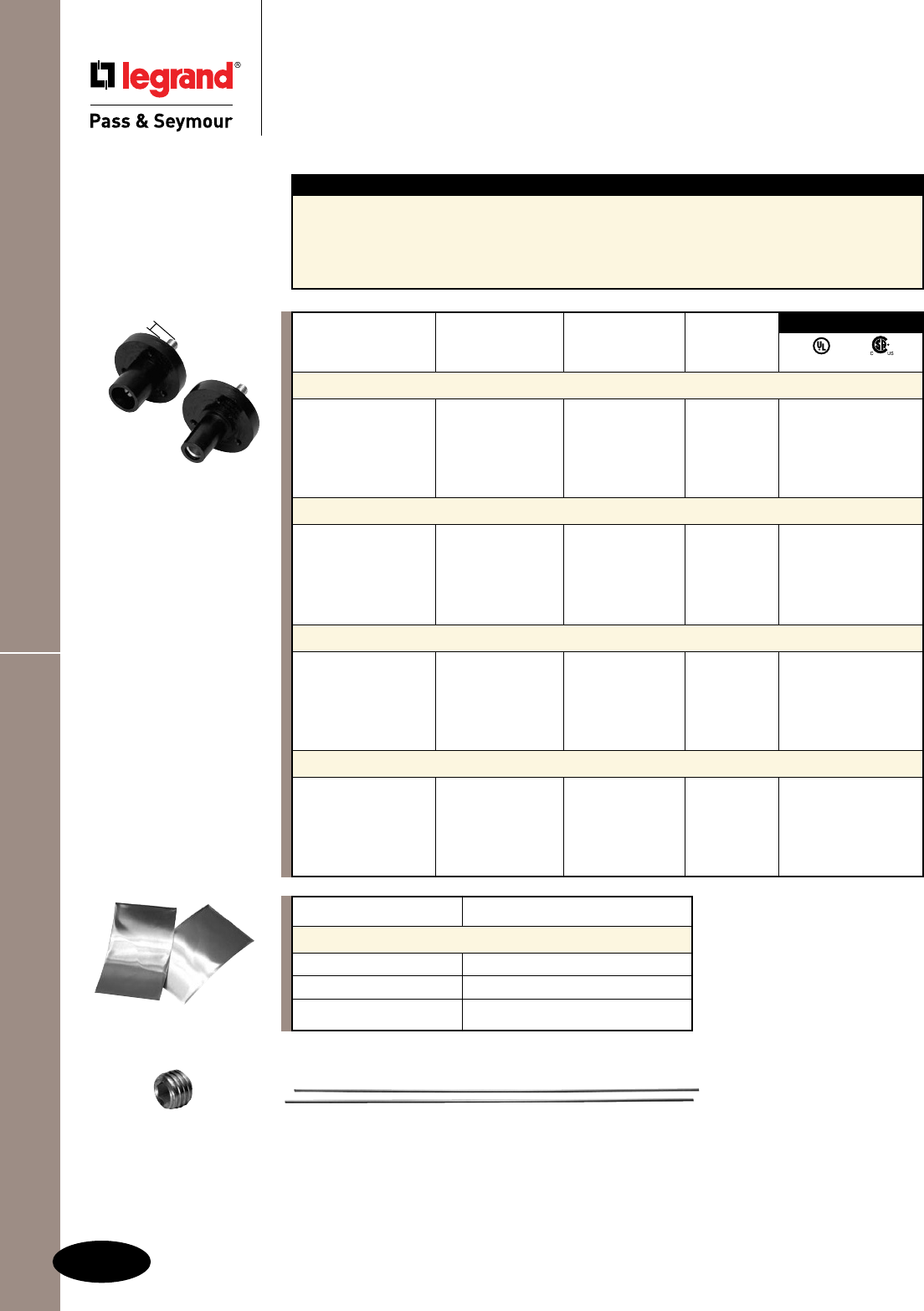
Series 15 Panel Mounts & Accessories Cam-Type Devices
Cam-Type Devices
Series 15 Panel Mounts & Accessories
Rating
Catalog Number A. V. Cable Size Color
Series 15 Threaded Stud Panel Mounts – Male
PSMMRSBK 150 600 #8–#2 Black • •
PSMMRSW 150 600 #8–#2 White • •
PSMMRSR 150 600 #8–#2 Red • •
PSMMRSBL 150 600 #8–#2 Blue • •
PSMMRSG 150 600 #8–#2 Green • •
Series 15 Threaded Stud Panel Mounts – Female
PSMFRSBK 150 600 #8–#2 Black • •
PSMFRSW 150 600 #8–#2 White • •
PSMFRSR 150 600 #8–#2 Red • •
PSMFRSBL 150 600 #8–#2 Blue • •
PSMFRSG 150 600 #8–#2 Green • •
Series 15 Double Set Screw Panel Mounts – Male
PSMMRBK 150 600 #8–#2 Black • •
PSMMRW 150 600 #8–#2 White • •
PSMMRR 150 600 #8–#2 Red • •
PSMMRBL 150 600 #8–#2 Blue • •
PSMMRG 150 600 #8–#2 Green • •
Series 15 Double Set Screw Panel Mounts – Female
PSMFRBK 150 600 #8–#2 Black • •
PSMFRW 150 600 #8–#2 White • •
PSMFRR 150 600 #8–#2 Red • •
PSMFRBL 150 600 #8–#2 Blue • •
PSMFRG 150 600 #8–#2 Green • •
UL cCSAus
3rd Party Compliance
PSMMRSBK
PSMFRSBK
.500"*
*Fordoublesetscrew,
dimensionis1.000".
Features
nNylonhousingprovidesoutstandingimpact
andchemicalresistance.
nHeavy-dutybrassmaleandfemalecontacts
provideasuperiorandconsistentmeans
ofconductivity.
nHeavy-dutyhexsetscrews(availableon
doublesetscrewversiononly)allowgreater
terminationtorque.
Catalog Number Description
Series 15 Accessories
PS430246 Series15StrainReliefWire
PS430244 CopperShim
PS430171 Series15SetScrew
PS430171
PS430244
I-8
PS430246
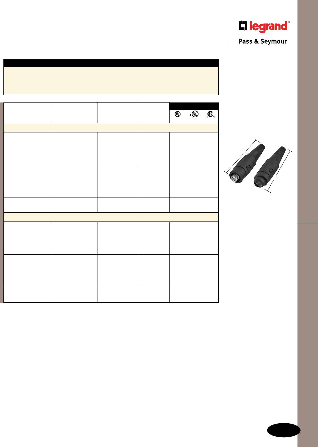
I-9
Cam-Type Devices Series 18 In-Line Connectors
Cam-Type Devices
Series 18 In-Line Connectors
Weatherproof
Features
nInterchangeablewithCanadianCAMdevices
fromothermanufacturers.
nBallnosedesignachievesNEMA3R,4rating.
nDesignedspecificallyforSeaWaycable.
n Accepts#6through4/0sizewire.
nDoublesetscrewsforpremiumwireretention.
nLockingscrewpreventscontactfromrotating
insidehousing.
PLS182MBK
PLS182FBK
6.875"
6.800"
3rd Party Compliance
Rating*
Catalog Number A. V. Cable Size Color
Series 18 In-Line Connectors – Male
PLS182MBK 400 600 #6–#2 Black • • •
PLS182MW 400 600 #6–#2 White • • •
PLS182MR 400 600 #6–#2 Red • • •
PLS182MBL 400 600 #6–#2 Blue • • •
PLS182MG 400 600 #6–#2 Green • • •
PLS1820MBK 400 600 #2–2/0 Black • • •
PLS1820MW 400 600 #2–2/0 White • • •
PLS1820MR 400 600 #2–2/0 Red • • •
PLS1820MBL 400 600 #2–2/0 Blue • • •
PLS1820MG 400 600 #2–2/0 Green • • •
PLS1840MBK 400 600 4/0 Black • • •
PLS1840MBL 400 600 4/0 Blue • • •
Series 18 In-Line Connectors – Female
PLS182FBK 400 600 #6–#2 Black • • •
PLS182FW 400 600 #6–#2 White • • •
PLS182FR 400 600 #6–#2 Red • • •
PLS182FBL 400 600 #6–#2 Blue • • •
PLS182FG 400 600 #6–#2 Green • • •
PLS1820FBK 400 600 #2–2/0 Black • • •
PLS1820FW 400 600 #2–2/0 White • • •
PLS1820FR 400 600 #2–2/0 Red • • •
PLS1820FBL 400 600 #2–2/0 Blue • • •
PLS1820FG 400 600 #2–2/0 Green • • •
PLS1840FBK 400 600 4/0 Black • • •
PLS1840FBL 400 600 4/0 Blue • • •
*AllratingsbothAC/DC.
UL cUL cCSAus

IEC 309 IndustrIal ProduCts
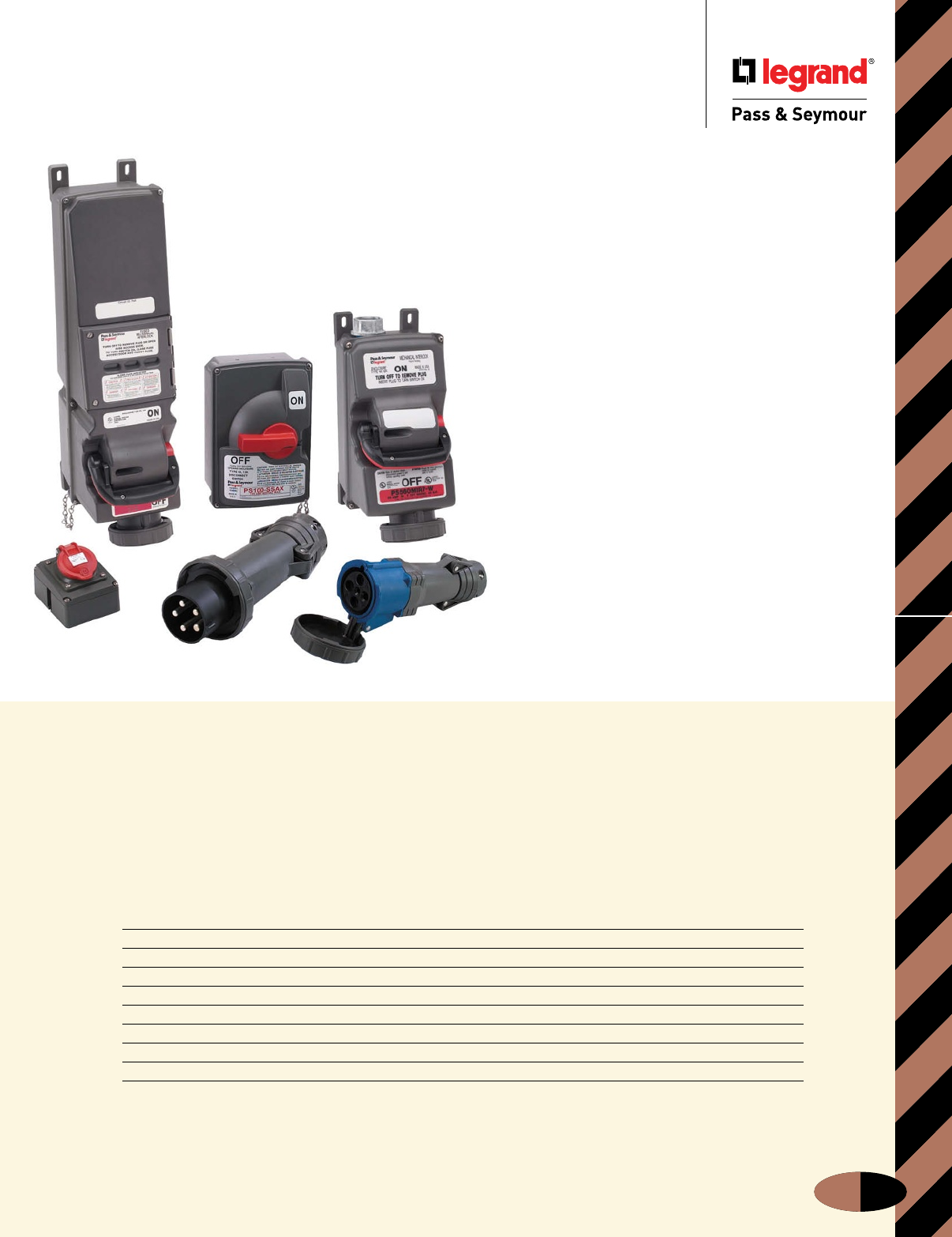
IEC 309 Industrial Products
J-1
Contents
Device Page Number
Configuration & Clocking System J-2
Fusible Mechanical Interlock J-3 – J-7
Non-Fusible Mechanical Interlock J-8 – J-13
Fusible Safety Switches J-14 – J-19
Non-Fusible Safety Switches J-20 – J-24
Pin & Sleeve Devices J-25 – J-31
Pin & Sleeve Devices Dimensional Information & Technical Specifications J-32 – J-38
Product Selection Guide J-39 – J-41
Our durable, high-performance
IEC 309 Industrial Products solutions
have a unifying principle: Just because
a device has to endure difficult
conditions doesn’t mean it has to be
difficult to wire and use.
IEC 309 Industrial Products
We took a close look at your IEC industrial product needs —
and responded with unique solutions.
Installers asked for quick, no-guesswork wiring… Plant
and MRO staff asked for maximum durability and minimum
downtime… And everyone wanted better selection to meet
today’s demanding requirements without compromise. Now
take a close look at our answers: Fusible Mechanical Interlocks
that cut downtime, thanks to the first-ever visible blown-fuse
indication. Fusible Safety Switches with the same innovative
blown-fuse-indicating LEDs. And capacities in P&S Non-Fusible
Interlocks and Safety Switches.
Add proven feature-rich P&S Pin & Sleeve devices, and the
result is a problem-solving IEC 309-1 and -2 product family.
It’s ready to work for you anywhere — because P&S IEC 309
products are guaranteed to be inter change able with all IEC
309-1 and -2 devices, and because more than 50 countries
are IEC participants, including all the world’s major trading
nations. As a result, manufacturers can easily standardize
their electrical component specifications worldwide, simplifying
purchasing, training and application to reduce costs.
P&S IEC products work for you, helping you multiply those
savings — thanks to uncompromising materials and construction
that deliver long-term dependability.
Take a closer look at the complete P&S IEC 309 industrial
family. Compare construction, features, and specifications. Add
the support of a global company, ready to help you succeed no
matter where you do business. And see why this is the selection
that works for you.
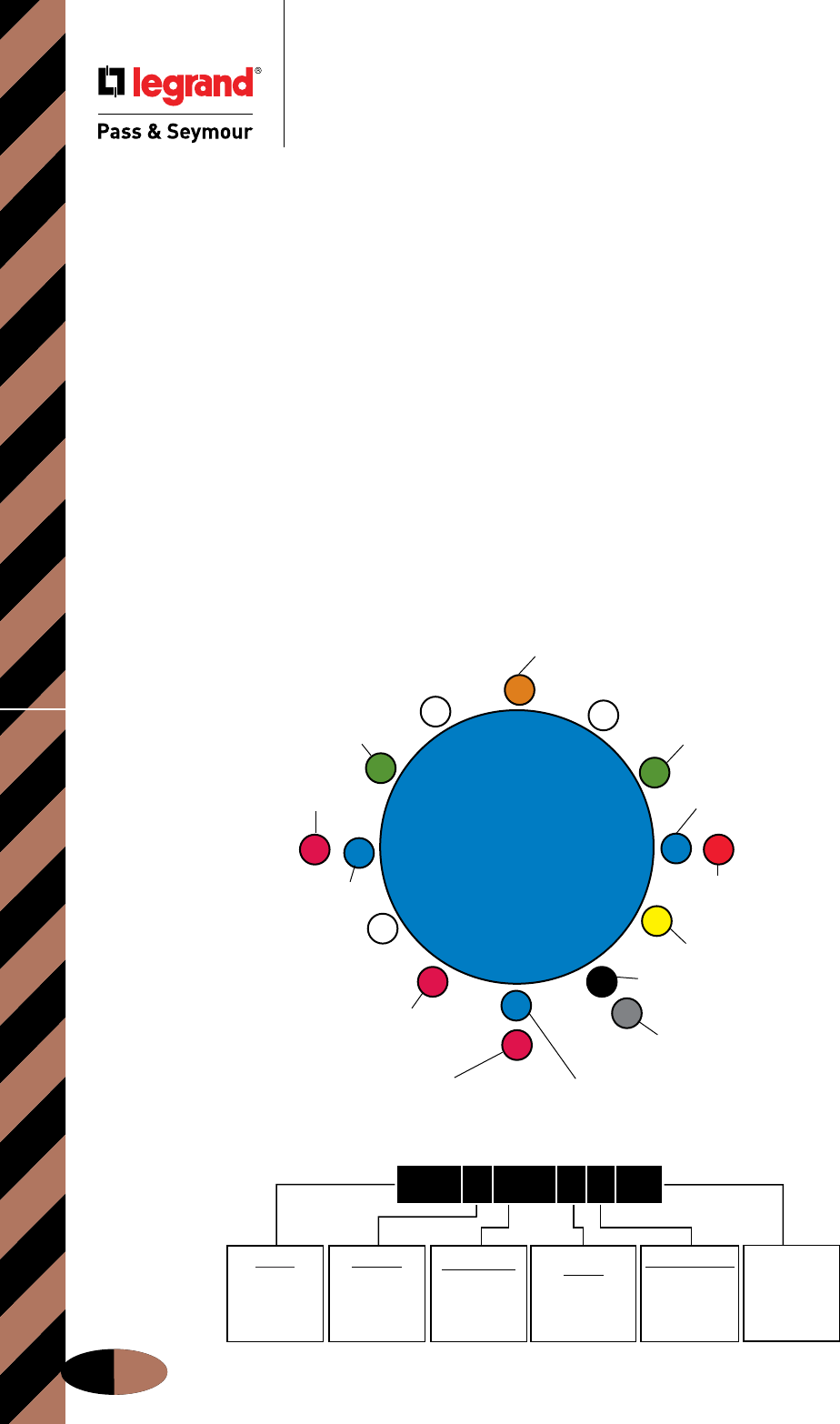
250VDC
2 POLE, 3 WIRE
IEC 309 Industrial Products
IEC 309 Industrial Products
Configuration & Clocking System
J-2
Adapting To Worldwide Configuration
Standards
Application
Legrand/Pass & Seymour’s Pin & Sleeve products are designed
to meet IEC 309-1, 309-2 specifications. These specifications
are recognized around the world and are intended to prevent
the mating of plugs and receptacles of different voltage and
current ratings (see Section 406.3(F) of the National Electrical
Code® relating to this noninterchangeability feature).
Global Product Offering
Legrand/Pass & Seymour provides IEC 309-1, 309-2 Pin &
Sleeve products in both Series I (International) and Series II
(North American) current ratings:
Series I (International) 16, 32, 63, 125 Amps
Series II (North American) 20, 30, 60, 100 Amps
North American Catalog Numbering System
Catalog numbers within the North American product offering
are structured to communicate the following: manufacturer,
number of conductors, amperage rating, device type, clocking
position of the ground sleeve, and environmental rating. This
applies to all receptacles, inlets, plugs, and connectors in
the Legrand/Pass & Seymour North American Pin & Sleeve
product line (see sample below).
Here’s How It Works
The amperage rating is determined by the size of the device.
Voltage rating is determined by the location of the ground
sleeve on the receptacle and/or connector along with the
number of conductors.
Ground sleeve position for all connectors and receptacles
is based on a clock face with the keyway always being at
6 o’clock. The ground sleeve is positioned at a specific hour
point, depending on the device’s voltage rating.
The clocking position for plugs and inlets is a mirror image
of the mating device, allowing for interconnection.
In addition, voltage ratings for all Pin & Sleeve products are
color coded for visual identification.
12
3
9
6
1
2
11
10
8
75
4
125/250VAC 3 POLE, 4 WIRE
277VAC 2 POLE, 3 WIRE
250VAC 2 POLE, 3 WIRE
380-415VAC 3 POLE, 4 WIRE
220/380-240/415VAC 4 POLE, 5 WIRE
480VAC 2 POLE, 3 WIRE
3ø 480VAC 3 POLE, 4 WIRE
3øY 277VAC 4 POLE, 5 WIRE
3ø 250VAC
3 POLE, 4 WIRE
3øY 120/208VAC
4 POLE, 5 WIRE
380-415VAC
2 POLE, 3 WIRE
50-500VAC
300-500 Hz
2 POLE, 3 WIRE
3 POLE, 4 WIRE
4 POLE, 5 WIRE
50-500VAC
100-300 Hz
3 POLE, 4 WIRE
380/440VAC
3 POLE, 4 WIRE
(REFRIGERANT
CONTAINERS)
125VAC 2 POLE, 3 WIRE
600VAC 3 POLE, 4 WIRE
600VAC 4 POLE, 5 WIRE
PREFIX
PS
=
PASS &
SEYMOUR
1ST DIGIT
3 = 3 WIRE
4 = 4 WIRE
5 = 5 WIRE
2ND-4TH DIGIT
20 = 20 AMP
30 = 30 AMP
60 = 60 AMP
100 = 100 AMP
LETTER
R = RECEPTACLE
P = PLUG
C = CONNECTOR
B = INLET
CLOCK POSITION
POSITION OF
GROUNDING
SLEEVE
WATERTIGHT
OR
SPLASHPROOF
W = WATERTIGHT
S = SPLASH-
PROOF
P S 4 6 0 R 7 W
North American Catalog Numbering System
IEC 309 Clocking System
s
Application
Specific
Configuration & Clocking System
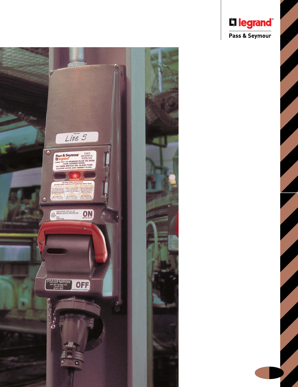
IEC Fusible Mechanical Interlock
J-3
See everything
you’re looking
for in a Fusible
Mechanical
Interlock.
Even if it’s
a blown fuse.
Introducing the first interlocks to include
visible blown-fuse indication, a hinged,
easy-access fuse door, and integral fuse
pullers. At last, you can easily locate
and replace a blown fuse in less than
a minute.
Of course, saving time isn’t your only
challenge. You face dirt and dust.
Corrosive liquids or vapors. Water or
high humidity. Heat. Vibration. And
impacts. No wonder ensuring safe,
dependable, locally fused power to
portable industrial equipment can
be tough! But now, these unique P&S
Fusible Mechanical Interlocks bring you
a better solution.
Here’s the extra-rugged construction
to stand up to the toughest plant
environments. Complete IEC 309
interchangeability. And an easy-
installing design that fits into most
I-beams. Choose these 20 to 100 amp
NEMA 4X and 12 watertight-rated
Fusible Mechanical Interlocks for your
most demanding applications — and
see how Legrand/Pass & Seymour is
“The one that works for you.”
Fusible Mechanical Interlock

IEC Fusible Mechanical Interlock
J-4
Fusible Mechanical Interlock
Valox® is a registered trademark of the General Electric Co.
Time-saving LED indicators
identify blown fuses at a glance.
Hinged access door with
windows allows clear viewing
of blown-fuse LED indicators
and provides fast, easy access
to fuse pullers.
Captive, quick-release,
stainless steel screws
speed fuse removal, ensure
a watertight access door
seal, and won’t fall out.
Compact design fits in most I-beams
to provide mounting versatility, easy
access, and reduced possibility of
impact damage.
Corrosion-resistant,
stainless steel captive
screws speed installation,
minimize risk of lost parts,
and withstand abuse.
Heavy-duty, steel-geared
switch mechanism provides
enhanced durability and extra-
long service life.
Fusible Mechanical
Interlock Operating
Sequence
1. When there is no plug in
the device, the lock tab is
in the “off” position and
prevents the lock gear
from turning. The handle
cannot be moved to the
“on” position.
2. Upon inserting a plug,
the lock tab moves
from the “off” position,
freeing the lock gear.
3. The handle can then
be moved to the “on”
position. This rotates the
lock gear and engages the
key on the plug to prevent
it from being removed. At
the same time, the rack is
actuated and rotates the
switch gear, turning on
the switch and inducing
power.
4. Returning the handle to
the “off” position frees the
lock gear, disengaging
the plug key from the
switch and allowing the
plug to be removed.
Patent-pending integral
fuse pullers with easy-grip
ergonomics make removing
and replacing blown fuses
simple, comfortable, and quick.
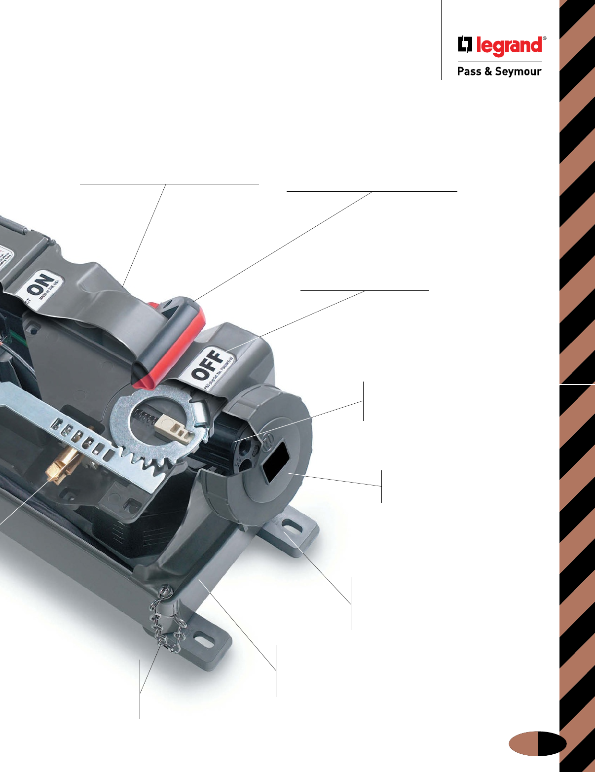
IEC Fusible Mechanical Interlock
J-5
Fusible Mechanical Interlock
Durable, stainless
steel cover-
retaining chain
makes installation
and maintenance
more convenient.
Heavy-duty, ergonomic switch
handle meets OSHA Lockout/Tagout
requirements and provides plenty of grip
for sure, easy operation. Black/red color
coding and high-visibility ON/OFF markings
clearly indicate status from a distance and at
any visual angle.
Durable brass/nickel-plated
contacts ensure reliable, long-lasting
electrical performance and corrosion
resistance.
Color-coded label clearly
identifies voltage rating of mating
IEC plug for fast identification.
Completely interchangeable with
all manufacturers’ IEC 309-1 and 309-2
plugs for economy and versatility.
Nonconductive, watertight, corrosion-
and impact-resistant Valox® enclosure
ensures NEMA 4X and 12 ratings. Withstands
the harshest industrial environments.
Easy to drill for bottom wiring
access, top wiring access — or
both. Only one catalog number per
amp rating — simplifies ordering and
provides maximum application flexibility.
Adjustable mounting feet can
be moved to center of unit for instant
strut- or pole-mounting without special
brackets or harnesses. Oversized foot
design eliminates the need for washers.
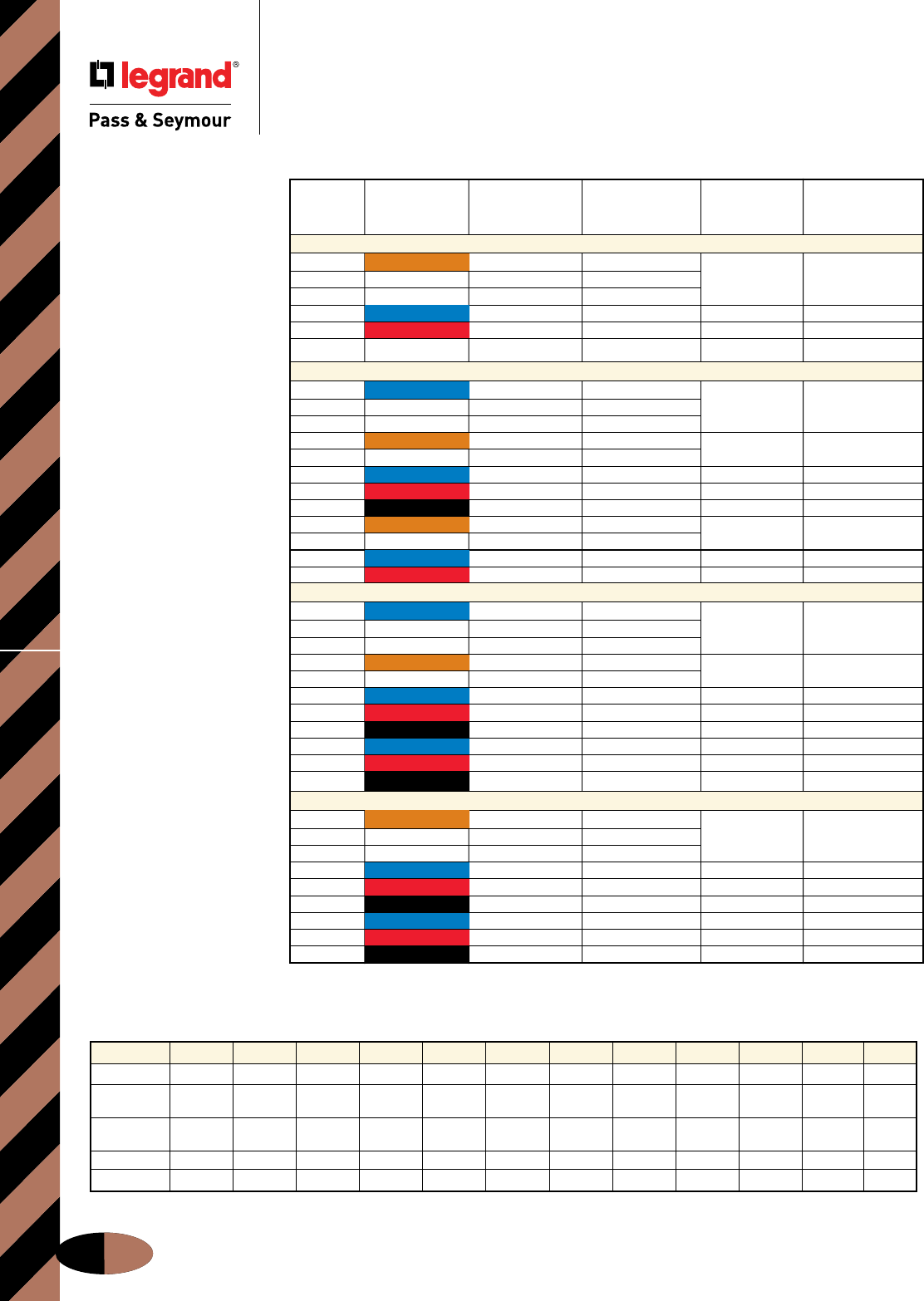
IEC Fusible Mechanical InterlockOrdering Information & Dimensions
J-6
Fusible Mechanical Interlock
Ordering Information & Dimensions
(HP Ratings subject to change.)
Standard Maximum Interlock
Horsepower Horsepower Receptacle Pin & Sleeve
Poles/Wires Voltage Rating Rating Catalog # Plug Catalog #
20 Amps
3P4W 120/240VAC 1/4 HP @ 120VAC 1 HP @ 120VAC
1/2 HP @ 208VAC 2 HP @ 208VAC PS420FMIR12W PS420P12W
1/2 HP @ 240VAC 2 HP @ 240VAC
3P4W 3ø 240VAC 11/2 HP 5 HP PS420FMIR9W PS420P9W
3P4W 3ø 480VAC 3 HP 10 HP PS420FMIR7W PS420P7W
3P4W 3ø 600VAC 5 HP 15 HP PS420FMIR5W PS420P5W
30 Amps
2P3W 240VAC 1 HP @ 208VAC 3 HP @ 208VAC
11/2 HP @ 240VAC 3 HP @ 240VAC PS330FMIR6W PS330P6W
1/2 HP @ 120VAC 2 HP @ 120VAC
3P4W 120/240VAC 1 HP @ 208VAC 3 HP @ 208VAC PS430FMIR12W PS430P12W
11/2 HP @ 240VAC 3 HP @ 240VAC
3P4W 3ø 240VA C 3 HP 71/2 HP PS430FMIR9W PS430P9W
3P4W 3ø 480VAC 5 HP 15 HP PS430FMIR7W PS430P7W
3P4W 3ø 600VAC 71/2 HP 15 HP PS430FMIR5W PS430P5W
3P4W 380/440VAC 5 HP @ 380VAC 15 HP @ 380VAC PS430FMIR3W PS430P3W
5 HP @ 440VAC 15 HP @ 440VAC
4P5W 3øY 120/208VAC 2 HP 5 HP PS530FMIR9W PS530P9W
4P5W 3øY 277/480VAC 5 HP 15 HP PS530FMIR7W PS530P7W
60 Amps
2P3W 240VAC 3 HP @ 208VAC 71/2 HP @ 208VAC
3 HP @ 240VAC 71/2 HP @ 240VAC PS360FMIR6W PS360P6W
11/2 HP @ 120VAC 3 HP @ 120VAC
3P4W 120/240VAC 3 HP @ 208VAC 71/2 HP @ 208VAC PS460FMIR12W PS460P12W
3 HP @ 240VAC 10 HP @ 240VAC
3P4W 3ø 240VAC 5 HP 15 HP PS460FMIR9W PS460P9W
3P4W 3ø 480VAC 10 HP 30 HP PS460FMIR7W PS460P7W
3P4W 3ø 600VAC 15 HP 40 HP PS460FMIR5W PS460P5W
4P5W 3øY 120/208VAC 5 HP 15 HP PS560FMIR9W PS560P9W
4P5W 3øY 277/480VAC 10 HP 30 HP PS560FMIR7W PS560P7W
4P5W 3øY 347/600VAC 15 HP 40 HP PS560FMIR5W PS560P5W
100 Amps
3P4W 120/240VAC 2 HP @ 120VAC 5 HP @ 120VAC
5 HP @ 208VAC 10 HP @ 208VAC PS4100FMIR12W PS4100P12W
5 HP @ 240VAC 15 HP @ 240VAC
3P4W 3ø 240VAC 10 HP 25 HP PS4100FMIR9W PS4100P9W
3P4W 3ø 480VAC 20 HP 50 HP PS4100FMIR7W PS4100P7W
3P4W 3ø 600VAC 30 HP 50 HP PS4100FMIR5W PS4100P5W
4P5W 3øY 120/208VAC 10 HP 20 HP PS5100FMIR9W PS5100P9W
4P5W 3øY 277/480VAC 20 HP 50 HP PS5100FMIR7W PS5100P7W
4P5W 3øY 347/600VAC 30 HP 50 HP PS5100FMIR5W PS5100P5W
Fusible Mechanical Interlock Dimensions
All measurements shown in inches.
Amps A B C D E F G H I J K L
20 9.13 1.19 10.09 23.34 24.50 1.97 4.75 6.88 7.75 20.13 22.25 23.13
3 & 4 Wire
30 9.13 1.19 9.53 23.69 24.50 1.97 4.75 6.88 7.75 20.13 22.25 23.13
5 Wire
30 9.13 1.19 9.53 23.78 24.50 1.97 4.75 6.88 7.75 20.13 22.25 23.13
60 9.13 1.19 9.94 24.59 24.50 2.25 4.75 6.88 7.75 20.13 22.25 23.13
100 11.13 1.75 11.06 27.94 28.31 2.41 6.75 8.88 9.75 23.94 26.06 26.94
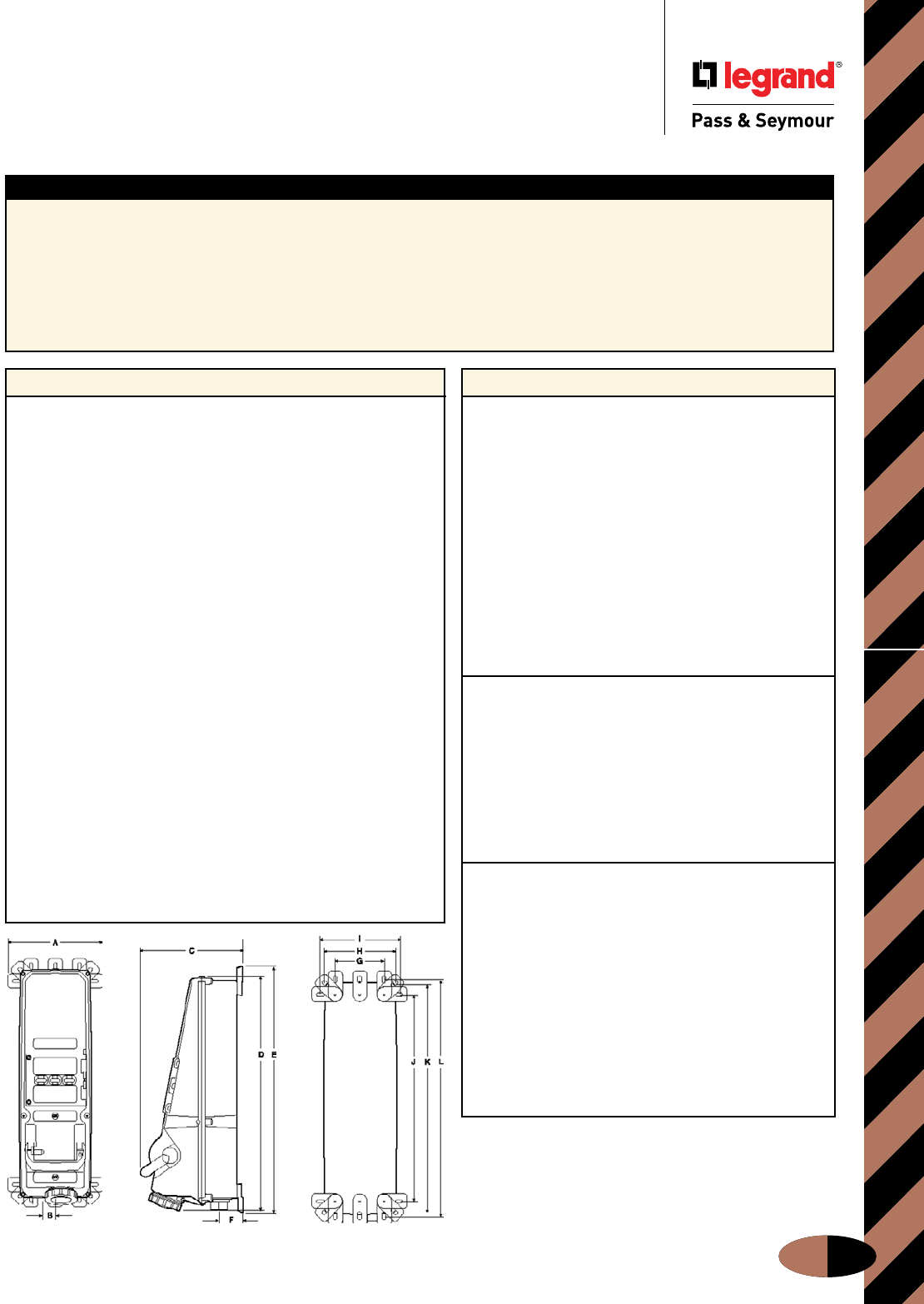
IEC Fusible Mechanical Interlock
Materials of Manufacture
J-7
Fusible Mechanical Interlock
Materials of Manufacture
Typical/Sample Spec
Front Side Back
Manufacturer’s Identification: Legrand/Pass & Seymour PS560FMIR5W
Description: Fusible Pin & Sleeve Mechanical Interlock
Electrical Type: 3 Pole + Neutral + Earth
Rating: 60A 3ø 600VAC 15 HP standard, 50 HP maximum
Configuration: IEC clock position 5
Enclosure Type: NEMA 4X (watertight, hosedown), 12K (dusttight, falling dirt), IP67 suitability
Conduit Location: Top or bottom feed. Unit shipped with no holes drilled; a top and bottom feed spot drill is provided for locating hole saw
or knockout. End user decides at installation whether top or bottom feed is appropriate. No closure plug kits required.
Typical Specications
Performance
Electrical:
Fuse Type Class “J”
Dielectric Voltage Withstand 3000V minimum
Maximum Working Voltage 600V RMS
Current Interrupting Listed for current
interrupting at full-rated
current and voltage
Short Circuit
Withstand Rating For use on circuit capable
of delivering not more
than 10,000 RMS amps at
receptacle voltage rating
Operations Mechanical: 15,000 cycles
Electrical: 10,000 cycles
Auxiliary Contacts 10A @ 600VAC
1 N.O. & 1 N.C.
Mechanical:
Impact Resistance Per UL746C
Terminal Identification Per UL, CSA, and IEC
specifications
Product Identification Identification and rating on
external and internal labels
Mounting External adjustable feet
with five (5) positions
Can be mounted directly to
channel or strut
(no washers required)
Environmental:
Moisture Resistance Per UL50, section 35,
NEMA Enclosure Type 4X
(watertight, hosedown)
Per UL50, section 35,
NEMA Enclosure Type 12K
(dusttight, falling dirt)
IP67 suitability
Flammability UL94 5VA and VO
Classification
Operating Temperature Maximum continuous: +60°C
Minimum continuous: -50°C
without impact
UV Resistance All enclosure materials are
UV stable
Hub shown at bottom of unit for reference only; may be
field-installed for top or bottom entry.
Materials
Enclosure Cover Valox 357®
Enclosure Base Valox 357®
Enclosure Door Valox 357®
Enclosure Gasket Neoprene
Door Hinge 316 Stainless Steel
Switch Handle Valox 357®
Switch Handle Seal Neoprene
Shaft Brass
Gear Mechanism 1/8" Zinc-Plated Steel
Locktab 10% Glass-Filled Nylon
Switch Key 10% Glass-Filled Nylon
Mounting Feet Valox 357®
Mounting Feet Screws 300 Series Stainless Steel
Enclosure Assembly Screws 300 Series Stainless Steel
Enclosure Assembly Inserts Brass
Receptacle Lid Valox 357®
Receptacle Gasketing Neoprene
Receptacle Lid Hinge Spring 300 Series Stainless Steel
Receptacle Contact Carrier Polyamide 6
Receptacle Sleeves 20-60 amp Brass/Nickel Plate
100 amp Brass/Silver Plate
Receptacle Terminal Screws Zinc-Plated Steel
Grounding Plate Zinc-Plated Steel
Cover Chain 300 Series Stainless Steel
Conduit Hub Aluminum/Zinc
20/30 amp shipped with one (1) 1"
60 amp shipped with one (1) 11/4"
100 amp shipped with one (1) 11/2"
(will also fit a 2" hub, not provided)
Viewing Slots in 1/8" thick glass lens
Fuse-Access Door
(See dimensions on Page J-6.)
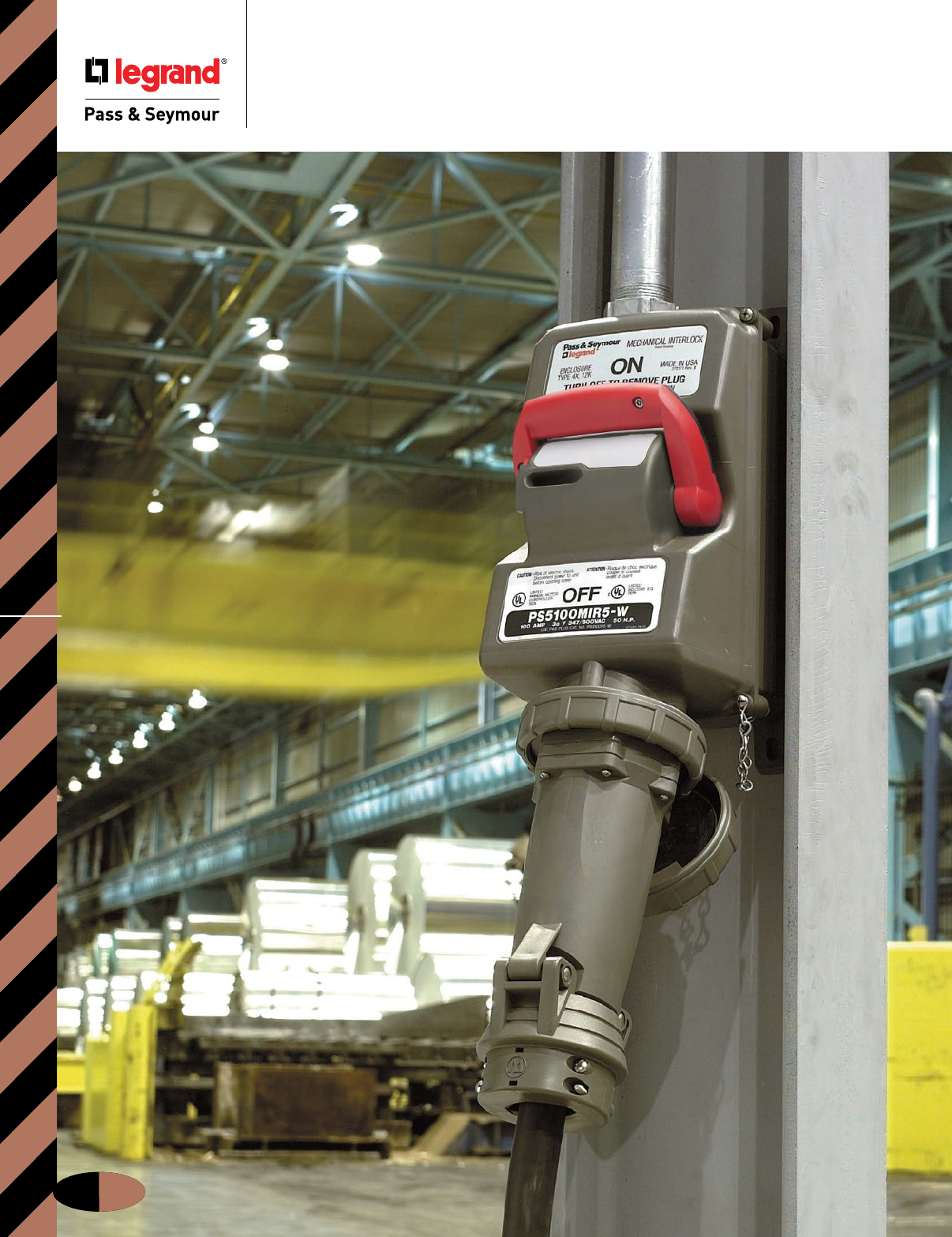
IEC Non-Fusible Mechanical Interlock
J-8
Non-Fusible Mechanical Interlock
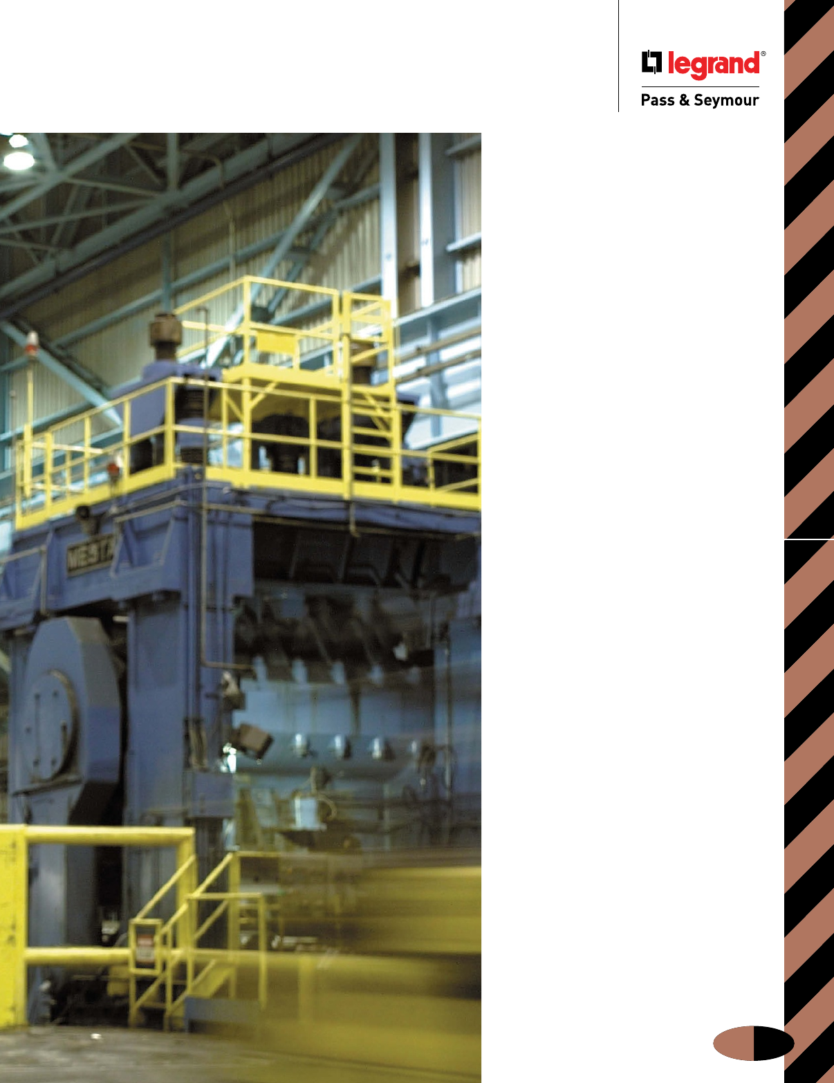
IEC Non-Fusible Mechanical Interlock
J-9
Performance
and quality
you can see
at a distance.
Now take a
closer look.
P&S Non-Fusible Interlocks are easy
to apply, thanks to their versatile,
adjustable mounting feet, compact
dimensions, and flexible wiring via
either top or bottom feed. And once
installed, they’ll with stand tough
conditions — including water in wash-
down areas, contamina tion from
shavings, dirt, and dust; accidental
impacts, heat from furnaces, welding or
other processes; and vibration from any
type of equipment.
Here’s the safety that goes beyond
ordinary requirements. These Interlocks
feature a patent-pending, tamper-
resistant activating assembly and cover-
integral switch mechanism that protect
against unauthorized overrides. And
high-visibility ON/OFF designations
plus a hefty black/red handle make
status easy to read at a glance.
Take a close look at our 20 to 100
amp Non-Fusible Interlocks — and see
the design and construction that works
for you.
Non-Fusible Mechanical Interlock
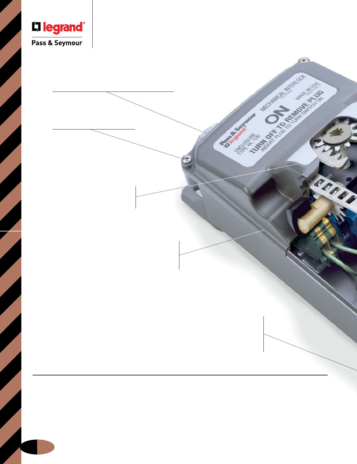
IEC Non-Fusible Mechanical Interlock
Non-Fusible Mechanical Interlock
J-10
Top- or bottom-feed models offer installation
flexibility and eliminate the need for time-consuming
modifications like drilling and plugging that may
nullify the NEMA 4X enclosure rating. Off-center
cable entry directs condensation away from internal
circuitry — reducing the risk of shorts and corrosion.
Compact design doesn’t protrude,
avoids unnecessary knocks, allows
for versatile mounting, and fits into
standard I-beams and channels.
Stainless steel captive screws
speed up installation, minimize risk
of lost parts, and resist corrosion.
Exclusive circuit ID pad for fast
identification of the motor circuit.
Accepts preprinted labels or
handwritten data.
Nonconductive, watertight,
corrosion- and impact-resistant
Valox® enclosure ensures NEMA
4X and 12 ratings, withstands the
harshest industrial environments.
Non-Fusible Mechanical
Interlock Operating
Sequence
1. When there is no plug in
the device, the lock tab is
in the “off” position and
prevents the lock gear
from turning. The handle
cannot be moved to the
“on” position.
2. Upon inserting a plug,
the lock tab moves
from the “off” position,
freeing the lock gear.
3. The handle can then
be moved to the “on”
position. This rotates the
lock gear and engages the
key on the plug to prevent
it from being removed. At
the same time, the rack is
actuated and rotates the
switch gear, turning on
the switch and inducing
power.
4. Returning the handle to
the “off” position frees the
lock gear, disengaging
the plug key from the
switch and allowing the
plug to be removed.
Adjustable mounting feet provide optimum
flexibility when mounting to equipment and
walls. Feet can also be moved to center of unit,
for instant strut- or pole-mounting without special
brackets or harnesses. And our oversized foot
design eliminates the need for washers.
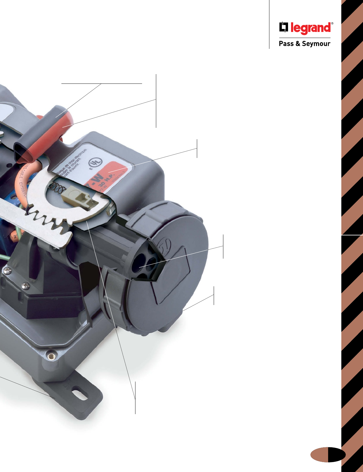
IEC Non-Fusible Mechanical Interlock
J-11
Non-Fusible Mechanical Interlock
Valox® is a registered trademark of the General Electric Co.
Stainless steel cover
retaining chain allows
for easy installation and
maintenance.
Top mount auxiliary
contacts are standard
to simplify ordering,
purchasing, inventory, and
installation requirements.
Completely interchangeable
with all manufacturers’
IEC 309-1 and 309-2 plugs.
Patent-pending, tamper-resistant
activating assembly and
cover-integral switch mechanism
protect against unauthorized overrides,
ensuring operator safety.
Handle meets OSHA Lockout/
Tagout requirements.
Label is color coded to correspond
with the voltage ratings of all mating IEC
plugs for easy visual identification.
Durable brass/nickel-plated
contacts ensure reliable,
long-lasting electrical performance
and corrosion resistance.
Heavy-duty, lever-style switch handle
ensures a firm grip — even with wet, greasy
hands. Black/red color-coded handle and high-
visibility ON/OFF markings clearly indicate
power supply status from a distance and
from all angles. Handle enters enclosure from
one side to minimize damage due to frontal
impacts; entry is offset and sealed to prevent
moisture contamination during washdowns.
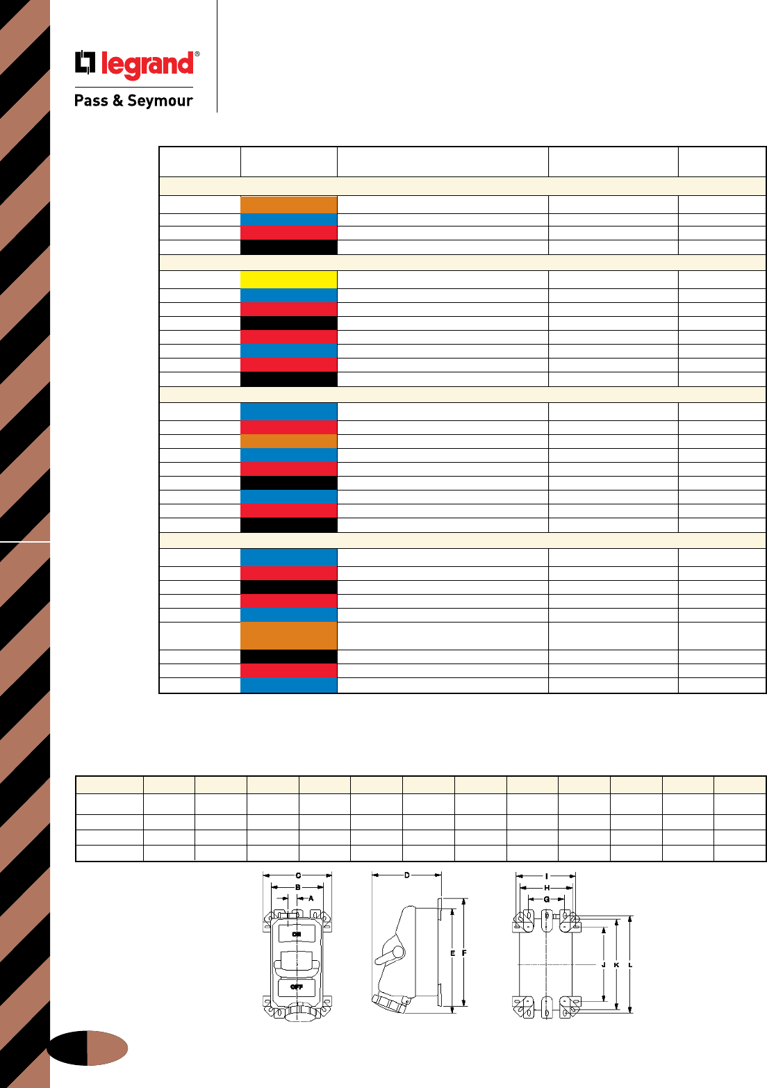
IEC Non-Fusible Mechanical InterlockOrdering Information & Dimensions
J-12
Non-Fusible Mechanical Interlock
Ordering Information & Dimensions
All products are top or bottom feed.
Unit shipped with no holes drilled; a top and bottom feed spot drill is provided for locking hole saw or knockout.
End user decides whether top or bottom feed is appropriate.
No closure plug kits required. HP ratings subject to change.
Horsepower Receptacle Pin & Sleeve
Poles/Wires Voltage Rating Catalog # Plug Catalog #
20 Amps
3P4W 120/240VAC 1 HP (120VAC); 2 HP (208-240VAC L-L) PS420MIR12W PS420P12W
3P4W 3ø 240VAC 5 HP PS420MIR9W PS420P9W
3P4W 3ø 480VAC 10 HP PS420MIR7W PS420P7W
3P4W 3ø 600VAC 15 HP PS420MIR5W PS420P5W
30 Amps
2P3W 120VAC 2 HP PS330MIR4W PS330P4W
3P4W 3ø 240VAC 71/2 HP PS430MIR9W PS430P9W
3P4W 3ø 480VAC 15 HP PS430MIR7W PS430P7W
3P4W 3ø 600VAC 20 HP PS430MIR5W PS430P5W
3P4W 380/440VAC 15 HP PS430MIR3W PS430P3W
4P5W 3øY 120/208VAC 5 HP PS530MIR9W PS530P9W
4P5W 3øY 277/480VAC 15 HP PS530MIR7W PS530P7W
4P5W 3øY 347/600VAC 20 HP PS530MIR5W PS530P5W
60 Amps
2P3W 240VAC 71/2 HP (208-240VAC) PS360MIR6W PS360P6W
2P3W 480VAC 10 HP PS360MIR7W PS360P7W
3P4W 120/240VAC 3 HP (120VAC); 71/2 HP (208-240VAC L-L) PS460MIR12W PS460P12W
3P4W 3ø 240VAC 15 HP PS460MIR9W PS460P9W
3P4W 3ø 480VAC 30 HP PS460MIR7W PS460P7W
3P4W 3ø 600VAC 40 HP PS460MIR5W PS460P5W
4P5W 3øY 120/208VAC 15 HP PS560MIR9W PS560P9W
4P5W 3øY 277/480VAC 30 HP PS560MIR7W PS560P7W
4P5W 3øY 347/600VAC 40 HP PS560MIR5W PS560P5W
100 Amps
2P3W 240VAC 10 HP (208VAC); 15 HP (240VAC) PS3100MIR6W PS3100P6W
2P3W 480VAC 30 HP PS3100MIR7W PS3100P7W
3P4W 3ø 600VAC 50 HP PS4100MIR5W PS4100P5W
3P4W 3ø 480VAC 50 HP PS4100MIR7W PS4100P7W
3P4W 3ø 240VAC 25 HP PS4100MIR9W PS4100P9W
3P4W 120/240VAC 5 HP (120VAC); 10 HP (208VAC L-L); PS4100MIR12W PS4100P12W
15 HP (240VAC L-L)
4P5W 3øY 347/600VAC 50 HP PS5100MIR5W PS5100P5W
4P5W 3øY 277/480VAC 50 HP PS5100MIR7W PS5100P7W
4P5W 3øY 120/208VAC 20 HP PS5100MIR9W PS5100P9W
Front Side Back
All measurements shown in inches.
(See dimensions above.)
Non-Fusible Mechanical Interlock Dimensions
Amps A B C D E F G H I J K L
20 1.38 6.88 9.13 8.00 12.38 11.06 4.75 6.88 7.75 8.00 10.13 11.00
30 1.38 6.88 9.13 8.25 12.38 11.50 4.75 6.88 7.75 8.00 10.13 11.00
60 1.19 6.88 9.13 9.00 13.63 14.13 4.75 6.88 7.75 9.75 11.88 12.75
100 1.19 6.88 9.13 9.50 14.13 14.13 4.75 6.88 7.75 9.75 11.88 12.75
IEC Non-Fusible Mechanical Interlock
Non-Fusible Mechanical Interlock
Materials of Manufacture
Typical/Sample Spec
Materials of Manufacture
J-13
Manufacturer’s Identification: Legrand/Pass & Seymour PS560MIR5W
Description: Non-Fusible Pin & Sleeve Mechanical Interlock
Electrical Type: 3 Pole + Neutral + Earth
Rating: 60A 3ø 600VAC 15 HP standard, 40 HP maximum
Configuration: IEC clock position 5
Enclosure Type: NEMA 4X (watertight, hosedown), 12K (dusttight, falling dirt), IP67 suitability
Conduit Location: Top or bottom feed. Unit shipped with no holes drilled; a top and bottom feed spot drill is provided for locating hole saw
or knockout. End user decides at installation whether top or bottom feed is appropriate. No closure plug kits required.
Typical Specications
Materials
Enclosure Cover Valox 357®
Enclosure Base Valox 357®
Enclosure Gasket Neoprene
Switch Handle Valox 357®
Switch Handle Seal Neoprene
Shaft Brass
Gear Mechanism 1/8" Zinc-Plated Steel
Locktab 10% Glass-Filled Nylon
Switch Key 10% Glass-Filled Nylon
Mounting Feet Valox 357®
Mounting Feet Screws 300 Series Stainless Steel
Enclosure Assembly Screws 300 Series Stainless Steel
Enclosure Assembly Inserts Brass
Receptacle Lid Valox 357®
Receptacle Gasketing Neoprene
Receptacle Lid Hinge Spring 300 Series Stainless Steel
Receptacle Contact Carrier Polyamide 6
Receptacle Sleeves Brass/Nickel Plate
Receptacle Terminal Screws Zinc-Plated Steel
Grounding Plate Zinc-Plated Steel
Cover Chain 300 Series Stainless Steel
Conduit Hub Aluminum/Zinc
20/30 amp shipped with one (1) 1"
60 amp shipped with one (1) 11/4"
100 amp shipped with one (1) 11/2"
(will also fit a 2" hub, not provided)
Performance
Electrical:
Dielectric Voltage Withstand 3000V minimum
Maximum Working Voltage 600V RMS
Current Interrupting Listed for current
interrupting at full-rated
current and voltage
Short Circuit
Withstand Rating For use on circuit capable
of delivering not more
than 10,000 RMS amps at
receptacle voltage rating
Operations Mechanical: 15,000 cycles
Electrical: 10,000 cycles
Auxiliary Contacts 10A @ 600VAC
1 N.O. & 1 N.C.
Mechanical:
Impact Resistance Per UL746C
Terminal Identification Per UL, CSA, and IEC
specifications
Product Identification Identification and rating on
external and internal labels
Mounting External adjustable feet
with five (5) positions
Can be mounted directly to
channel or strut
(no washers required)
Environmental:
Moisture Resistance Per UL50, section 35,
NEMA Enclosure Type 4X
(watertight, hosedown)
Per UL50, section 35,
NEMA Enclosure Type 12K
(dusttight, falling dirt)
IP67 suitability
Flammability UL94 5VA and VO
Classification
Operating Temperature Maximum continuous: +60°C
Minimum continuous: -50°C
without impact
UV Resistance All enclosure materials are
UV stable
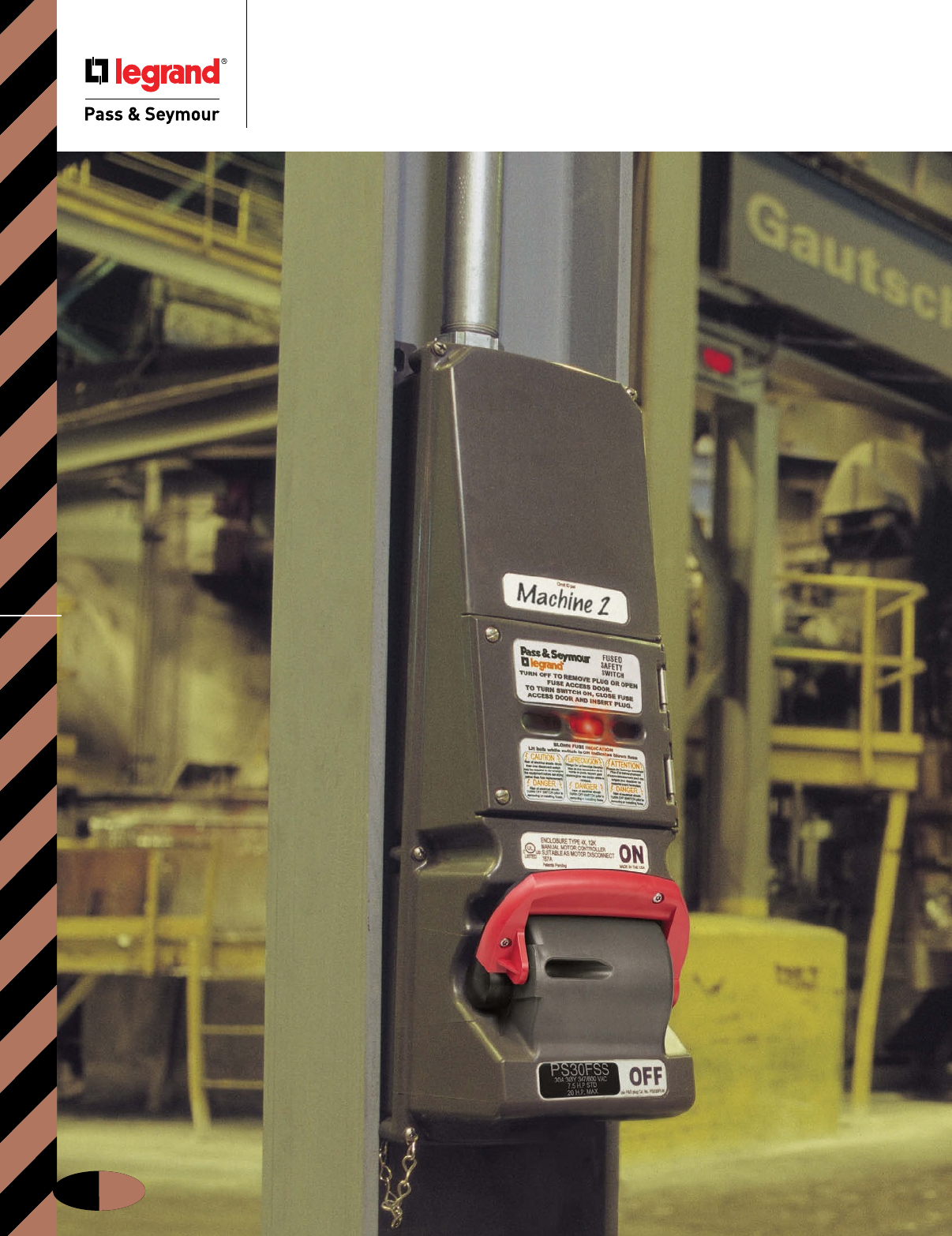
IEC Fusible Safety Switches
J-14
Fusible Safety Switches
IEC Fusible Safety Switches
J-15
Fusible Safety Switches
See blown fuses
at a glance in
these Fusible
Safety Switches.
Looking for safety switches that cut
downtime? Take a close look at these
innovative P&S Fusible Safety Switches.
Here’s the same first-ever blown-fuse
indication system that’s in our pace-
setting Fusible Mechanical Interlocks
— with individual LED indicators for
each line, patent-pending integral fuse
pullers, and a hinged fuse-access door.
That means no time lost to locating a
blown fuse — and no time wasted in
fuse replacement.
P&S Fusible Safety Switches deliver the
same ultra-heavy-duty construction as
our Fusible Mechanical Interlocks, too.
So they provide maximum protection
against water, dirt, heat, and vibration
— and just about any other harsh
condition you’ll encounter. You get the
same installation flexibility, too. With
capacities available from 30 to 100
amps, there’s a P&S Fusible Safety
Switch that’s ready to work for you
in any industrial environment.
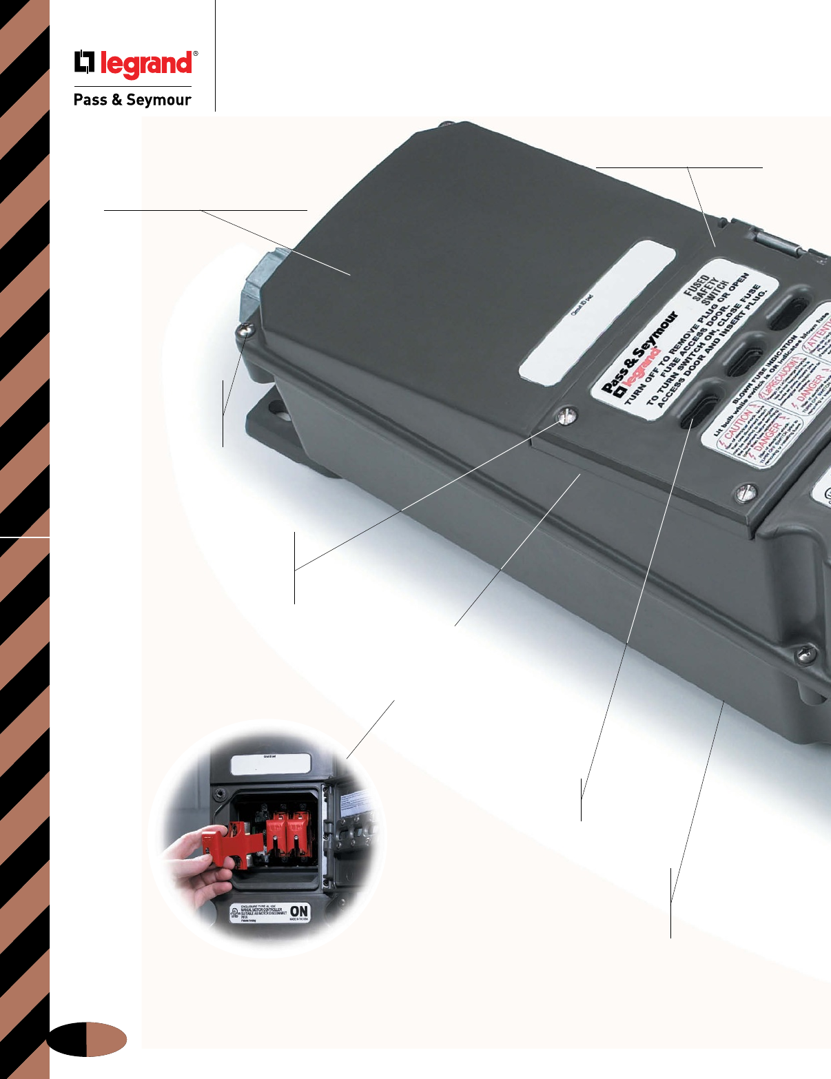
IEC Fusible Safety Switches
J-16
Fusible Safety Switches
Time-saving LED
indicators identify blown
fuses at a glance.
Hinged access door with
windows allows clear viewing
of blown-fuse LED indicators
and provides fast, easy access
to fuse pullers.
Captive, quick-release,
stainless steel screws
speed fuse removal, ensure
a watertight access door
seal, and won’t fall out.
Compact design fits in most I-beams
to provide mounting versatility, easy
access, and reduced possibility of
impact damage.
Corrosion-resistant,
stainless steel captive
screws speed installation,
minimize risk of lost parts,
and withstand abuse.
Nonconductive, watertight,
corrosion- and impact-resistant
Valox® enclosure ensures NEMA
4X and 12 ratings. Withstands the
harshest industrial environments.
Valox® is a registered trademark of the General Electric Co.
Patent-pending integral fuse
pullers with easy-grip ergonomics
make removing and replacing
blown fuses simple, comfortable,
and quick.
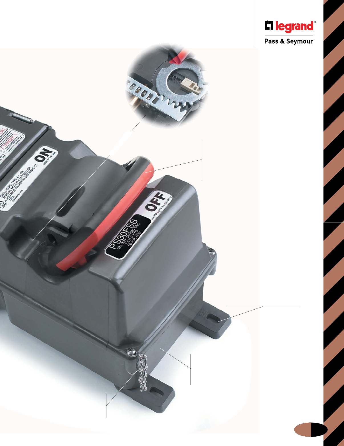
IEC Fusible Safety Switches
J-17
Fusible Safety Switches
Durable, stainless steel
cover-retaining chain makes
installation and maintenance
more convenient.
Heavy-duty, ergonomic switch
handle meets OSHA Lockout/Tagout
requirements and provides plenty of
grip for sure, easy operation. Black/red
color coding and high-visibility ON/OFF
markings clearly indicate status from a
distance and at any visual angle.
Easy to drill for bottom wiring access,
top wiring access — or both. Only
one catalog number per amp rating —
simplifies ordering and provides maximum
application flexibility.
Adjustable mounting feet
can be moved to center of unit
for instant strut- or pole-mounting
without special brackets or
harnesses. Oversized foot design
eliminates the need for washers.
Heavy-duty, steel-geared
switch mechanism provides
enhanced durability and extra-
long service life.
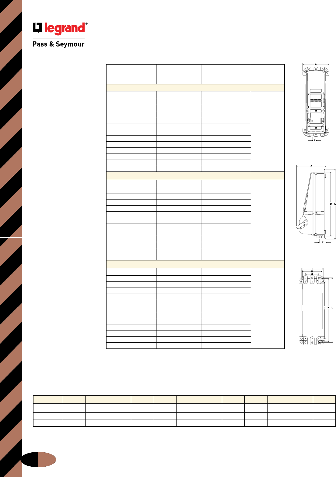
IEC Fusible Safety SwitchesOrdering Information & Dimensions
Fusible Safety Switches
Ordering Information & Dimensions
J-18
Front
Side
Back
Hub shown at bottom of unit for reference only;
may be field-installed for top or bottom entry.
(HP Ratings subject to change.)
Standard Maximum Fusible
Horsepower Horsepower Safety Switch
Voltage Rating Rating Catalog #
30 Amps 600VAC
120VAC 1/2 HP 2 HP
208VAC 1 HP 5 HP
240VAC 11/2 HP 5 HP
277VAC 11/2 HP 5 HP
480VAC 3 HP 10 HP
120/240VAC 1/2 HP @ 120VAC 2 HP @ 120VAC
11/2 HP @ 240VAC 5 HP @ 240VAC PS30FSS
3ø 240VAC 3 HP 10 HP
3ø 480VAC 5 HP 20 HP
3ø 600VAC 71/2 HP 20 HP
3øY 120/208VAC 2 HP 71/2 HP
3øY 277/480VAC 5 HP 20 HP
3øY 347/600VAC 71/2 HP 20 HP
60 Amps 600VAC
120VAC 11/2 HP 3 HP
208VAC 3 HP 71/2 HP
240VAC 3 HP 10 HP
277VAC 3 HP 10 HP
480VAC 5 HP 20 HP
120/240VAC 11/2 HP @ 120VAC 3 HP @ 120VAC
3 HP @ 240VAC 10 HP @ 240VAC PS60FSS
3ø 240VAC 5 HP 20 HP
3ø 480VAC 10 HP 40 HP
3ø 600VAC 15 HP 50 HP
3øY 120/208VAC 5 HP 20 HP
3øY 277/480VAC 10 HP 40 HP
3øY 347/600VAC 15 HP 50 HP
100 Amps 600VAC
120VAC 2 HP 5 HP
208VAC 5 HP 10 HP
240VAC 5 HP 15 HP
277VAC 71/2 HP 15 HP
480VAC 10 HP 30 HP
120/240VAC 2 HP @ 120VAC 5 HP @ 120VAC
5 HP @ 240VAC 15 HP @ 240VAC PS100FSS
3ø 240VAC 10 HP 25 HP
3ø 480VAC 20 HP 50 HP
3ø 600VAC 30 HP 50 HP
3øY 120/208VAC 10 HP 20 HP
3øY 277/480VAC 20 HP 50 HP
3øY 347/600VAC 30 HP 50 HP
(See dimensions below.)
Fusible Safety Switches Dimensions
All measurements shown in inches.
Amps A B C D E F G H I J K L
30 9.13 1.19 10.09 22.59 22.59 1.97 4.75 6.88 7.75 20.13 22.25 23.13
60 9.13 1.19 10.09 22.59 22.59 2.25 4.75 6.88 7.75 20.13 22.25 23.13
100 11.13 1.75 11.06 26.59 28.31 2.41 6.75 8.88 9.75 23.94 26.06 26.94
IEC Fusible Safety Switches
Materials of Manufacture
Fusible Safety Switches
Materials of Manufacture
Typical/Sample Spec
Manufacturer’s Identifications: Legrand/Pass & Seymour PS60FSS
Description: Fusible Safety Switch
Rating: 60A, 600VAC maximum
Enclosure Type: NEMA 4X (watertight, hosedown), 12K (dusttight, falling dirt), IP67 suitability
Conduit Location: Top or bottom feed. Unit shipped with no holes drilled; a top and bottom feed spot drill is provided for locating hole saw
or knockout. End user decides at installation whether top or bottom feed is appropriate. No closure plug kits required.
Typical Specications
Performance
Electrical:
Fuse Type Class “J”
Dielectric Voltage Withstand 3000V minimum
Maximum Working Voltage 600V RMS
Current Interrupting Listed for current interrupting at full-rated current and voltage
Short Circuit Withstand Rating For use on circuit capable of delivering not more than 10,000 RMS amps at
receptacle voltage rating
Operations Mechanical: 15,000 cycles
Electrical: 10,000 cycles
Auxiliary Contacts 10A @ 600VAC
1 N.O. & 1 N.C.
Mechanical:
Impact Resistance Per UL746C
Terminal Identification Per UL and CSA
Product Identification Identification and rating on external and internal labels
Mounting External adjustable feet with five (5) positions
Can be mounted directly to channel or strut (no washers required)
Environmental:
Moisture Resistance Per UL50, section 35, NEMA Enclosure Type 4X (watertight, hosedown)
Per UL50, section 35, NEMA Enclosure Type 12K (dusttight, falling dirt)
IP67 suitability
Flammability UL94 5VA and VO Classification
Operating Temperature Maximum continuous: +60°C
Minimum continuous: -50°C without impact
UV Resistance All enclosure materials are UV stable
J-19
Materials
Enclosure Cover Valox 357®
Enclosure Base Valox 357®
Enclosure Door Valox 357®
Enclosure Gasket Neoprene
Door Hinge 316 Stainless Steel
Switch Handle Valox 357®
Switch Handle Seal Neoprene
Shaft Brass
Gear Mechanism 1/8" Zinc-Plated Steel
Switch Key 10% Glass-Filled Nylon
Mounting Feet Valox 357®
Mounting Feet Screws 300 Series Stainless Steel
Enclosure Assembly Screws 300 Series Stainless Steel
Enclosure Assembly Inserts Brass
Grounding Plate Zinc-Plated Steel
Cover Chain 300 Series Stainless Steel
Conduit Hub Aluminum/Zinc
30 amp shipped with one (1) 1"
60 amp shipped with one (1) 11/4"
100 amp shipped with one (1) 11/2" (will also fit a 2" hub, not provided)
Viewing Slots in 1/8" thick glass lens
Fuse-Access Door
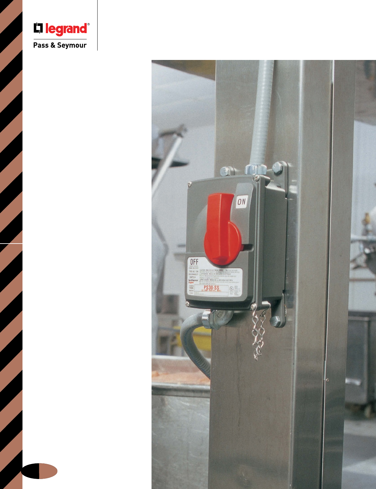
IEC Non-Fusible Safety Switches
J-20
Non-Fusible
Safety Switches
UL Listed
as “Suitable
as Motor
Disconnect.”
Here’s the first non-metallic NEMA 4X
Non-Fusible Safety Switch line UL Listed
as “Suitable as Motor Disconnect” —
per NEC® Article 430.109(A)(6).
P&S Non-Fusible Safety Switches
feature extra-tough components,
including an impact-resistant
Valox® NEMA 4X enclosure. And
an innovative design that delivers
safe, sure operation under the worst
conditions. These rugged performers
are available in capacities from
30 to 100 amps.
And when you take a closer look, you’ll
see even more to like. For example,
the fits-anywhere compact design.
The adjustable mounting feet that
speed installation. Or the no-confusion,
at-a-glance ON/OFF status indication.
See how P&S Non-Fusible Safety
Switches work better for you.
Non-Fusible Safety Switches
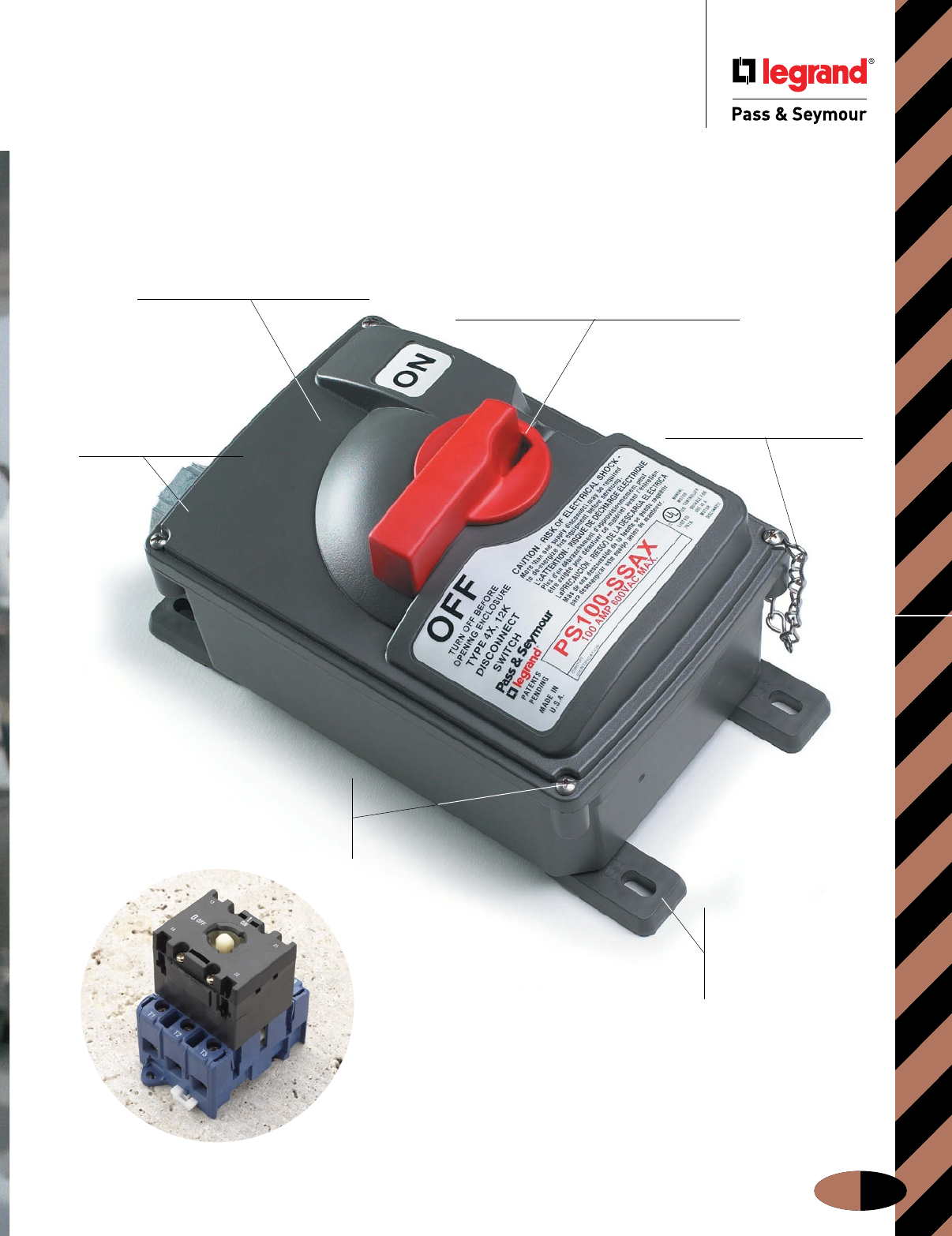
Adjustable mounting
feet can be moved to
center of unit for instant
strut- or pole-mounting
without special brackets
or harnesses.
Durable, stainless steel
cover-retaining chain makes
installation and maintenance
more convenient.
Heavy-duty, ergonomic switch handle
meets OSHA Lockout/Tagout provisions
and provides plenty of grip for sure, easy
operation. Black/red color coding and high-
visibility ON/OFF markings clearly indicate
status from a distance and at any visual angle.
Switch entry into the enclosure is offset to
the side and sealed to provide enhanced
water resistance.
Nonconductive,
watertight, corrosion-,
heat-, and impact-
resistant thermoplastic
enclosure ensures
NEMA 4X and 12 ratings.
Withstands the harshest
industrial environments.
Corrosion-resistant,
stainless steel captive
screws speed installation,
minimize risk of lost parts,
and withstand abuse.
Compact design fits in most I-beams
to provide mounting versatility, easy
access, and reduced possibility of
impact damage.
IEC Non-Fusible Safety Switches
J-21
Non-Fusible Safety Switches
Bottom and top wiring access
options. No unnecessary openings
to compromise water resistance.
Top mount auxiliary contact
enables additional control
functions or signal lights.
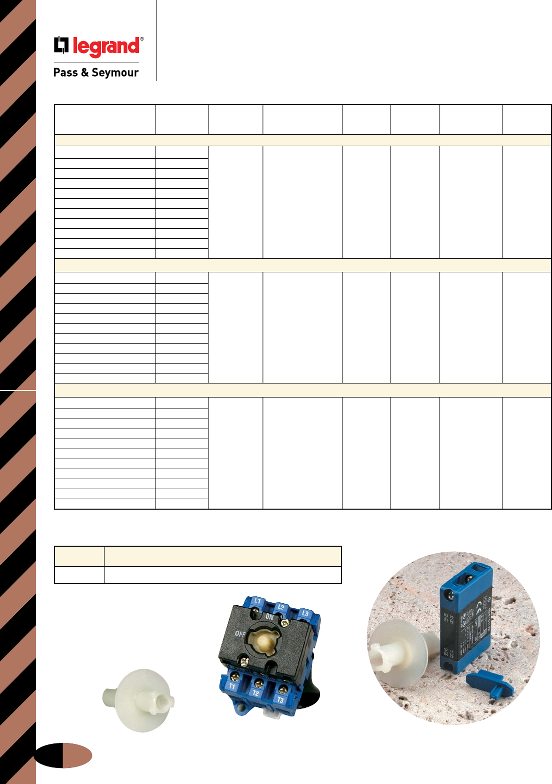
Catalog
Number Description
SSMF Mounting Feet Replacement Kit for PS30SS and PS30SSAX
Mounting Feet Replacement Kit
IEC Non-Fusible Safety SwitchesOrdering Information
J-22
Non-Fusible Safety Switches
Ordering Information
RS30 AX30
Maximum Non-Fusible Non-Fusible Safety Replacement
Horsepower Safety Switch Switch with Auxiliary Auxiliary Replacement Switch with Replacement
Voltage Rating Catalog # Contact Catalog # Contact Kit* Switch Auxiliary Contact Cover
30 Amps 600VAC
120VAC 1 HP
208VAC 2 HP
240VAC 3 HP
277VAC 3 HP
480VAC 5 HP
3ø 240VAC 5 HP PS30SS PS30SSAX AX30 RS30 PS30RSAX PS30SSRC
3ø 480VAC 10 HP
3ø 600VAC 10 HP
3øY 120/208VAC 5 HP
3øY 277/480VAC 10 HP
3øY 347/600VAC 10 HP
60 Amps 600VAC
120VAC 3 HP
208VAC 10 HP
240VAC 10 HP
277VAC 15 HP
480VAC 20 HP
3ø 240VAC 20 HP PS60SS PS60SSAX AX60 RS60 N/A PS60SSRC
3ø 480VAC 40 HP
3ø 600VAC 50 HP
3øY 120/208VAC 20 HP
3øY 277/480VAC 40 HP
3øY 347/600VAC 50 HP
100 Amps 600VAC
120VAC 5 HP
208VAC 10 HP
240VAC 15 HP
277VAC 15 HP
480VAC 30 HP
3ø 240VAC 25 HP PS100SS PS100SSAX AX60 N/A N/A PS100SSRC
3ø 480VAC 50 HP
3ø 600VAC 50 HP
3øY 120/208VAC 20 HP
3øY 277/480VAC 50 HP
3øY 347/600VAC 50 HP
*For replacement of side mount auxiliary contact on previous design.
IEC Non-Fusible Safety Switches
Materials of Manufacture
J-23
Non-Fusible Safety Switches
Materials of Manufacture
Typical/Sample Spec
Manufacturer’s Identification PS60SS
Description: Non-Fusible Safety Switch
Rating: 60A, 600VAC maximum
Enclosure Type: NEMA 4X (watertight, hosedown), 12K (dusttight, falling dirt), IP67 suitability
Conduit Location: Top, bottom, or back feed. Units are shipped without holes for conduit. Spot drills for locating hole saw or knockouts are
provided for top, bottom, or back feed. End user decides at installation whether top, bottom, or back feed is appropriate.
No closure plug kits required. Units are not provided with conduit hubs.
Typical Specications
Materials
Enclosure Cover Valox 357®
Enclosure Base Valox 357®
Enclosure Gasket Neoprene
Switch Handle Valox 357®
Switch Handle Seal Neoprene
Switch Key 10% Glass-Filled Nylon
Mounting Feet Valox 357®
Mounting Feet Screws 300 Series Stainless Steel
Enclosure Assembly Screws 300 Series Stainless Steel
Enclosure Assembly Inserts Brass (60 and 100 amp units only)
Grounding Plate Galvanized Steel
Cover Chain 300 Series Stainless Steel
Mechanical:
Impact Resistance Per UL746C
Terminal Identification Per UL and CSA
Product Identification Identification and rating on external and internal labels
Mounting External adjustable feet with five (5) positions
Can be mounted directly to channel or strut (no washers required)
Environmental:
Moisture Resistance Per UL50, section 35, NEMA Enclosure Type 4X (watertight, hosedown)
Per UL50, section 35, NEMA Enclosure Type 12K (dusttight, falling dirt) • IP67 suitability
Flammability UL94 5VA and VO Classification
Operating Temperature Maximum continuous: +60°C • Minimum continuous: -50°C without impact
UV Resistance All enclosure materials are UV stable
Performance
Electrical:
Dielectric Voltage Withstand 3000V minimum
Maximum Working Voltage 600V RMS
Current Interrupting Listed for current interrupting at full-rated current and voltage
Short Circuit Withstand Rating For use on circuit capable of delivering not more than (see chart below) RMS amps at 600VAC
Operations Mechanical: 15,000 cycles
Electrical: 10,000 cycles
Auxiliary Contacts (optional) 10A @ 600VAC
1 N.O. & 1 N.C.
Manual Motor Motor
Catalog Number Controller Disconnect
PS30SS (AX) 10,000 AMP 10,000 AMP
PS60SS (AX) 10,000 AMP 5,000 AMP
PS100SS (AX)
Interrupting Ratings — RMS Symmetrical Amperes
Suitable for use on circuits capable of delivering not more than (see chart below for cat. no. and application)
RMS symmetrical amperes, 600VAC maximum.
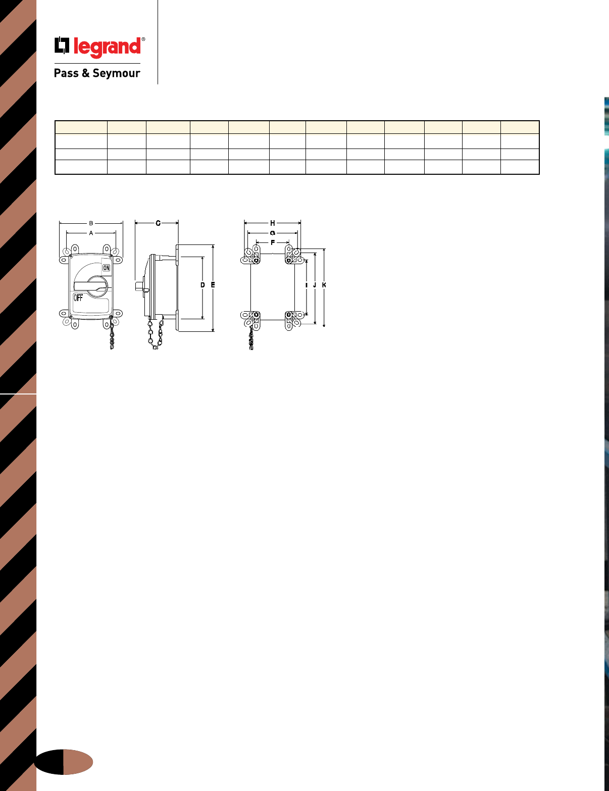
IEC Non-Fusible Safety Switches
Dimensions
Non-Fusible Safety Switches
Dimensions
J-24
Front Side Back
Non-Fusible Safety Switches Dimensions
All measurements shown in inches.
Amps A B C D E F G H I J K
30 5.75 7.38 4.88 7.19 9.69 3.75 5.75 6.56 6.13 8.06 8.88
60 7.19 9.13 6.31 9.63 12.38 4.75 7.19 8.13 8.00 10.38 11.38
100 7.19 9.13 6.31 9.63 12.38 4.75 7.19 8.13 8.00 10.38 11.38
(See dimensions above.)
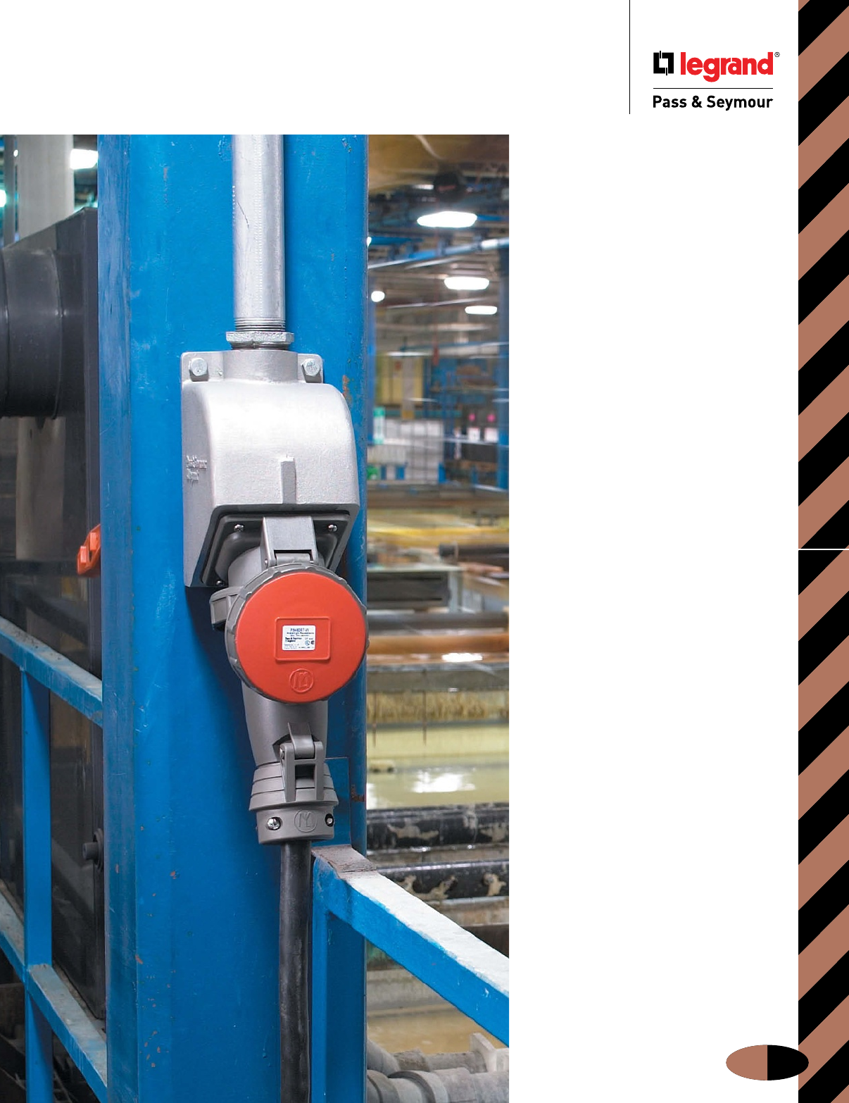
IEC Pin & Sleeve Devices
J-25
Pin & Sleeve Devices
Take a closer
look at
fast-installing
Pin & Sleeve
products that
work for you.
There’s no better protection against
moisture and industrial contaminants
than P&S IEC Pin & Sleeve products.
With spring-loaded covers, locking
rings, and neoprene gaskets,
everything from water to dirt is
completely shut out of the electrical
system — even if the connection is
accidentally submerged!
All P&S Watertight Pin & Sleeve plugs,
connectors, receptacles, and inlets
bring you the features to enhance
versatility, reliability, and safety. For
example, North American products
come completely ready to wire, for
quick, simple installation. And all
feature impact- and chemical-resistant
thermoplastic construction. Shrouded,
nickel-plated, solid-brass pins provide
corrosion protection and excellent
conductivity. And an exclusive, hinged
cord grip eliminates loose parts that
get lost.
With a complete range of choices
rated from 20 to 100 amps, you’ll find
a Legrand/Pass & Seymour works-for-
you solution for every Pin & Sleeve
application in and around your plant.
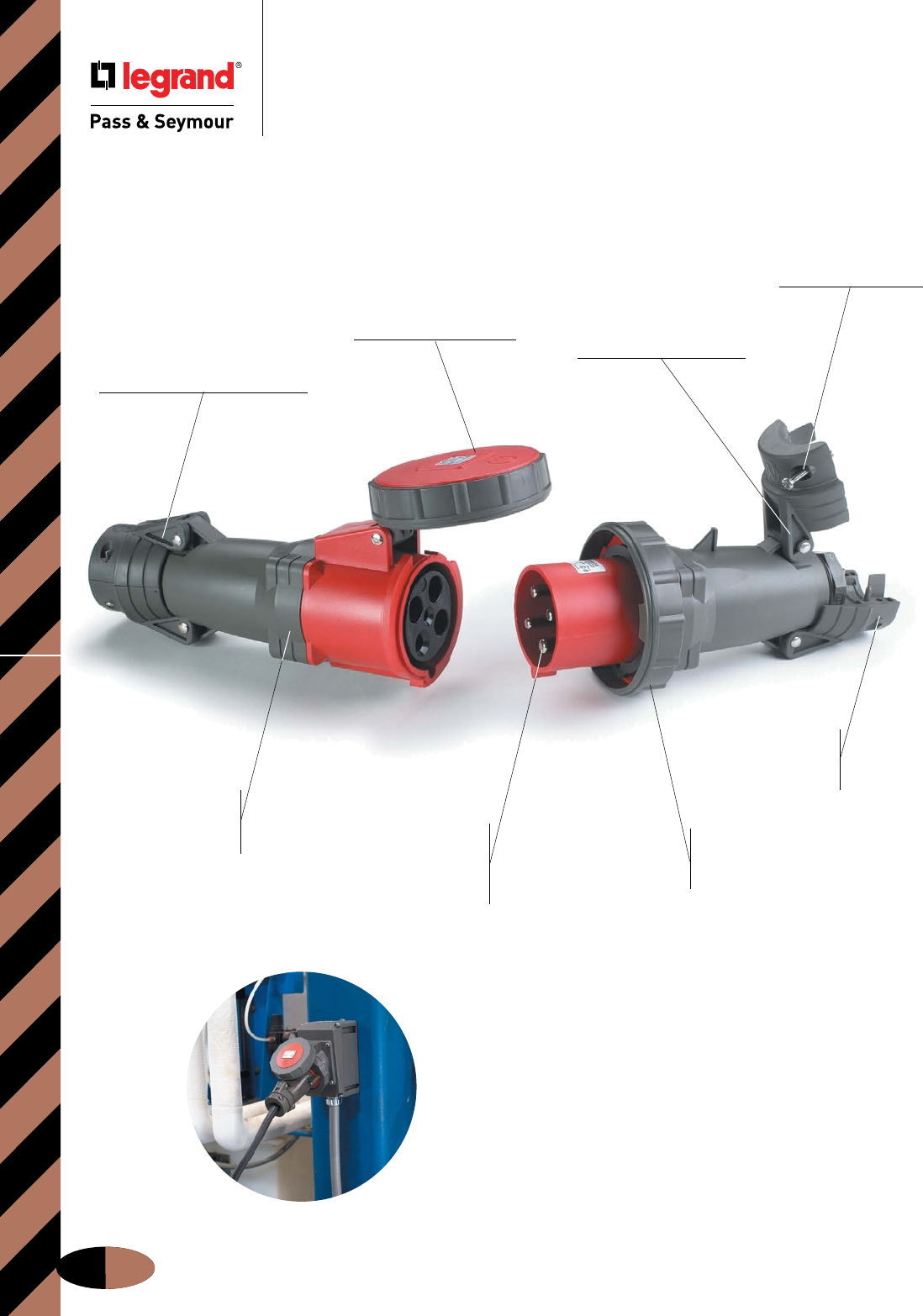
IEC Pin & Sleeve Devices
J-26
Pin & Sleeve Devices
P&S Pin & Sleeve products
provide installation ease,
enduring performance in harsh
conditions, and guaranteed IEC
309 compatibility.
Cover with integral
neoprene gasket
provides watertight seal.
Revolutionary, hinged
cord grip for durable
performance and ease
of installation.
Arrives ready to wire, with
cord grip open and cable-
ready; terminal screws come
backed out and ready to wire;
front and back body require no
disassembly prior to assembly.
Combination-head
screws for added
convenience and
quick installation.
Natural-rubber
grommets provide
watertight protection
at cable entry.
Nylon construction
for high-impact
and corrosion
resistance. Locking ring with an integral
neoprene gasket provides
watertight seal when plug and
connector/receptacle are mated.
Nickel-plated brass
pins provide extra
corrosion resistance
without sacrificing
electrical conductivity.
Ratings, compliances visible
on strap for fast, long-lasting I.D.
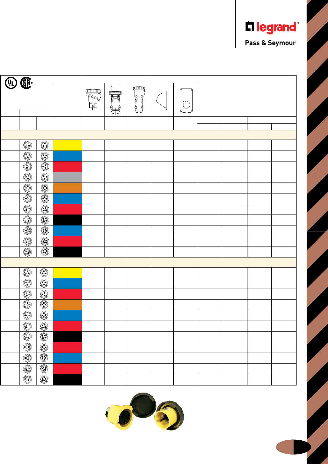
IEC Pin & Sleeve Watertight Devices
Pin & Sleeve Devices
North American Watertight Devices
Ordering Information
Ordering Information
J-27
North American Product Offering
PS330C4WR PS330P4WR
*Application specific, reference Page J-2.
IP67
Suitability
Watertight Back Boxes
Conguration Replacement Parts
Poles & Recep./ Plug/ Voltage/ Metallic
Non-Metallic
Bodies Caps
Wires Conn. Inlet Color Coding Receptacle Plug Connector Back Box Back Box Plug Connector Receptacle Connector
20 Amps
2P3W 125 PS320R4W PS320P4W PS320C4W PSBB201W PSBBN201W PS320P4WR PS320C4WR PS320R4WL
2P3W 250 PS320R6W PS320P6W PS320C6W PSBB201W PSBBN201W PS320P6WR PS320C6WR PS320R6WL
2P3W 480 PS320R7W PS320P7W PS320C7W PSBB201W PSBBN201W PS320P7WR PS320C7WR PS320R7WL
2P3W 277 PS320R5W PS320P5W PS320C5W PSBB201W PSBBN201W PS320P5WR PS320C5WR PS320R5WL
3P4W 125/250 PS420R12W PS420P12W PS420C12W PSBB202W PSBBN202W PS420P12WR PS420C12WR PS420R12WL
3P4W 3
ø
250 PS420R9W PS420P9W PS420C9W PSBB202W PSBBN202W PS420P9WR PS420C9WR PS420R9WL
3P4W 3
ø
480 PS420R7W PS420P7W PS420C7W PSBB202W PSBBN202W PS420P7WR PS420C7WR
3P4W 3
ø
600 PS420R5W PS420P5W PS420C5W PSBB202W PSBBN202W PS420P5WR PS420C5WR
4P5W 3
ø
Y 120/208 PS520R9W PS520P9W PS520C9W PSBB202W PSBBN202W PS520P9WR PS520C9WR
4P5W 3
ø
Y 277/480 PS520R7W PS520P7W PS520C7W PSBB202W PSBBN202W PS520P7WR PS520C7WR
4P5W 3
ø
Y 347/600 PS520R5W PS520P5W PS520C5W PSBB202W PSBBN202W PS520P5WR PS520C5WR
30 Amps
2P3W 125 PS330R4W PS330P4W PS330C4W PSBB301W PSBBN301W PS330R4WL PS330C4WL
2P3W 250 PS330R6W PS330P6W PS330C6W PSBB301W PSBBN301W PS330P6WR PS330C6WR PS330R6WL PS330C6WL
2P3W 480 PS330R7W PS330P7W PS330C7W PSBB301W PSBBN301W PS330P7WR PS330C7WR PS330R7WL PS330C7WL
3P4W 125/250 PS430R12W PS430P12W PS430C12W PSBB301W PSBBN301W PS430P12WR PS430C12WR PS430R12WL PS430C12WL
3P4W 3
ø
250 PS430R9W PS430P9W PS430C9W PSBB301W PSBBN301W PS430P9WR PS430C9WR PS430R9WL PS430C9WL
3P4W 3
ø
480 PS430R7W PS430P7W PS430C7W PSBB301W PSBBN301W PS430P7WR PS430C7WR PS430R7WL
3P4W 3
ø
600 PS430R5W PS430P5W PS430C5W PSBB301W PSBBN301W PS430R5WL PS430C5WL
3P4W* 380/440 PS430R3W PS430P3W PS430C3W PSBB301W PSBBN301W PS430P3WR PS430C3WR PS430R3WL PS430C3WL
4P5W 3
ø
Y 120/208 PS530R9W PS530P9W PS530C9W PSBB301W PSBBN301W PS530P9WR PS530C9WR PS530R9WL PS530C9WL
4P5W 3
ø
Y 277/480 PS530R7W PS530P7W PS530C7W PSBB301W PSBBN301W PS530P7WR PS530C7WR PS530R7WL PS530C7WL
4P5W 3
ø
Y 347/600 PS530R5W PS530P5W PS530C5W PSBB301W PSBBN301W PS530P5WR PS530C5WR PS530R5WL PS530C5WL
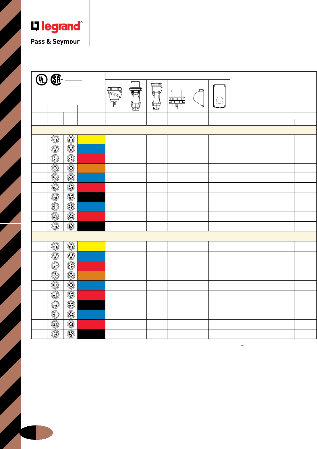
IEC Pin & Sleeve Watertight DevicesOrdering Information
Pin & Sleeve Devices
North American Watertight Devices
Ordering Information
J-28
† Note: For straight 60 and 100 amp watertight receptacles, add "S" to catalog number after the R, example: PS4100RS5W.
IP67
Suitability
North American Product Offering
Watertight Back Boxes
Conguration Replacement Parts
Poles & Recep./ Plug/ Voltage/ Metallic
Non-Metallic
Bodies Caps
Wires Conn. Inlet Color Coding Receptacle† Plug Connector Inlet Back Box Back Box Plug Connector Receptacle Connector
60 Amps
2P3W 125 PS360R4W PS360P4W PS360C4W PS360B4W PSBB601W PSBBN601W PS360P4WR PS360C4WR PS360R4WL PS360C4WL
2P3W 250 PS360R6W PS360P6W PS360C6W PS360B6W PSBB601W PSBBN601W PS360P6WR PS360C6WR PS360C6WL
2P3W 480 PS360R7W PS360P7W PS360C7W PS360B7W PSBB601W PSBBN601W PS360P7WR PS360C7WR PS360R7WL PS360C7WL
3P4W 125/250 PS460R12W PS460P12W PS460C12W PS460B12W PSBB601W PSBBN601W PS460P12WR PS460C12WR PS460R12WL PS460C12WL
3P4W 3
ø
250 PS460R9W PS460P9W PS460C9W PS460B9W PSBB601W PSBBN601W PS460C9WR
3P4W 3
ø
480 PS460R7W PS460P7W PS460C7W PS460B7W PSBB601W PSBBN601W
3P4W 3
ø
600 PS460R5W PS460P5W PS460C5W PS460B5W PSBB601W PSBBN601W PS460R5WL
4P5W 3
ø
Y 120/208 PS560R9W PS560P9W PS560C9W PS560B9W PSBB601W PSBBN601W PS560P9WR
4P5W 3
ø
Y 277/480 PS560R7W PS560P7W PS560C7W PS560B7W PSBB601W PSBBN601W PS560P7WR PS560C7WR PS560R7WL PS560C7WL
4P5W 3
ø
Y 347/600 PS560R5W PS560P5W PS560C5W PS560B5W PSBB601W PSBBN601W PS560P5WR PS560C5WR PS560R5WL PS560C5WL
100 Amps
2P3W 125 PS3100R4W PS3100P4W PS3100C4W PSBB1001W PS3100P4WR PS3100C4WR PS3100R4WL PS3100C4WL
2P3W 250 PS3100R6W PS3100P6W PS3100C6W PS3100B6W PSBB1001W PS3100C6WR PS3100R6WL PS3100C6WL
2P3W 480 PS3100R7W PS3100P7W PS3100C7W PS3100B7W PSBB1001W PS3100P7WR PS3100C7WR PS3100R7WL PS3100C7WL
3P4W 125/250
PS4100R12W PS4100P12W PS4100C12W PS4100B12W
PSBB1001W
PS4100C12WR PS4100R12WL PS4100C12WL
3P4W 3
ø
250 PS4100R9W PS4100P9W PS4100C9W PS4100B9W PSBB1001W PS4100C9WR PS4100R9WL PS4100C9WL
3P4W 3
ø
480 PS4100R7W PS4100P7W PS4100C7W PS4100B7W PSBB1001W PS4100R7WL PS4100C7WL
3P4W 3
ø
600 PS4100R5W PS4100P5W PS4100C5W PS4100B5W PSBB1001W PS4100C5WR PS4100R5WL PS4100C5WL
4P5W 3
ø
Y 120/208 PS5100R9W PS5100P9W PS5100C9W PS5100B9W PSBB1001W PS5100P9WR PS5100C9WR PS5100R9WL PS5100C9WL
4P5W 3
ø
Y 277/480 PS5100R7W PS5100P7W PS5100C7W PS5100B7W PSBB1001W PS5100P7WR PS5100R7WL PS5100C7WL
4P5W 3
ø
Y 347/600 PS5100R5W PS5100P5W PS5100C5W PS5100B5W PSBB1001W PS5100P5WR PS5100C5WR PS5100R5WL PS5100C5WL
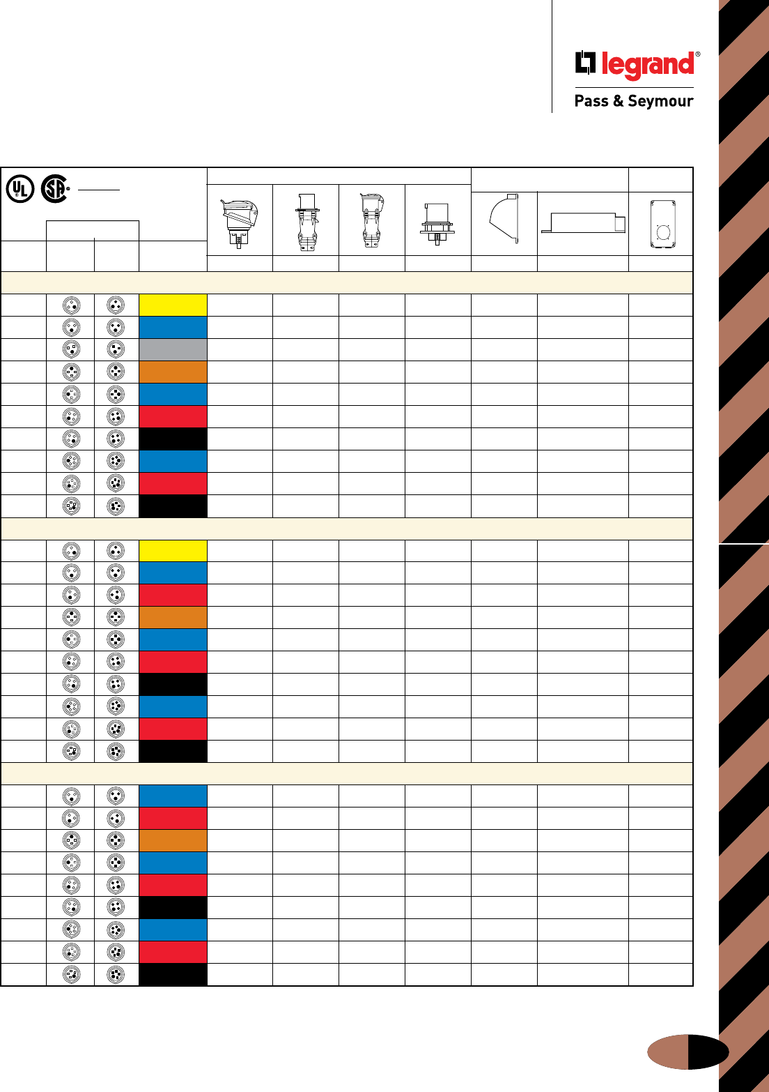
IEC Pin & Sleeve Splashproof Devices
Pin & Sleeve Devices
North American Splashproof Devices
Ordering Information
Ordering Information
J-29
North American Product Offering
* Line art for 60 amp only. 20 and 30 amp inlets are angled.
** Line art for 20 and 30 amp only. 60 amp back box is angled.
IP44
Suitability
***
Splashproof Non-Metallic
Back Boxes Back Box
Conguration
Poles & Recep./ Plug/ Voltage/ Angled Box
Wires Conn. Inlet Color Coding Receptacle Plug Connector Inlet Receptacle Inlet Receptacle
20 Amps
2P3W 125 PS320R4S PS320P4S PS320C4S PSBB201W PSBB201SP PSBBN201W
2P3W 250 PS320R6S PS320P6S PS320C6S PS320B6S PSBB201W PSBB201SP PSBBN201W
2P3W 277 PS320R5S PS320P5S PSBB201W PSBB201SP PSBBN201W
3P4W 125/250 PS420R12S PS420P12S PS420C12S PSBB202W PSBB201SP PSBBN202W
3P4W 3
ø
250 PS420R9S PS420P9S PS420C9S PS420B9S PSBB202W PSBB201SP PSBBN202W
3P4W 3
ø
480 PS420R7S PS420P7S PS420C7S PS420B7S PSBB202W PSBB201SP PSBBN202W
3P4W 3
ø
600 PS420R5S PS420B5S PSBB202W PSBB201SP PSBBN202W
4P5W 3
ø
Y 120/208 PS520R9S PS520C9S PS520B9S PSBB202W PSBB201SP PSBBN202W
4P5W 3
ø
Y 277/480 PS520C7S PS520B7S PSBB202W PSBB201SP PSBBN202W
4P5W 3
ø
Y 347/600 PS520R5S PS520C5S PS520B5S PSBB202W PSBB201SP PSBBN202W
30 Amps
2P3W 125 PS330R4S PS330P4S PS330C4S PS330B4S PSBB301W PSBB301SP PSBBN301W
2P3W 250 PS330R6S PS330P6S PS330C6S PS330B6S PSBB301W PSBB301SP PSBBN301W
2P3W 480 PS330P7S PS330C7S PS330B7S PSBB301W PSBB301SP PSBBN301W
3P4W 125/250 PS430R12S PS430C12S PS430B12S PSBB301W PSBB301SP PSBBN301W
3P4W 3
ø
250 PS430R9S PS430P9S PS430C9S PS430B9S PSBB301W PSBB301SP PSBBN301W
3P4W 3
ø
480 PS430R7S PS430P7S PS430C7S PS430B7S PSBB301W PSBB301SP PSBBN301W
3P4W 3
ø
600 PS430R5S PS430P5S PS430C5S PS430B5S PSBB301W PSBB301SP PSBBN301W
4P5W 3
ø
Y 120/208 PS530R9S PS530P9S PS530C9S PS530B9S PSBB301W PSBB301SP PSBBN301W
4P5W 3
ø
Y 277/480 PS530P7S PS530B7S PSBB301W PSBB301SP PSBBN301W
4P5W 3
ø
Y 347/600 PS530R5S PS530P5S PS530C5S PS530B5S PSBB301W PSBB301SP PSBBN301W
60 Amps
2P3W 250 PS360R6S PS360P6S PS360C6S PS360B6S PSBB601W PSBB601W PSBBN601W
2P3W 480 PS360R7S PS360P7S PS360C7S PS360B7S PSBB601W PSBB601W PSBBN601W
3P4W 125/250 PS460R12S PS460P12S PS460C12S PS460B12S PSBB601W PSBB601W PSBBN601W
3P4W 3
ø
250 PS460R9S PS460P9S PS460C9S PS460B9S PSBB601W PSBB601W PSBBN601W
3P4W 3
ø
480 PS460R7S PS460P7S PS460C7S PS460B7S PSBB601W PSBB601W PSBBN601W
3P4W 3
ø
600 PS460R5S PS460P5S PS460C5S PS460B5S PSBB601W PSBB601W PSBBN601W
4P5W 3
ø
Y 120/208 PS560R9S PS560P9S PS560C9S PS560B9S PSBB601W PSBB601W PSBBN601W
4P5W 3
ø
Y 277/480 PS560R7S PS560P7S PS560C7S PS560B7S PSBB601W PSBB601W PSBBN601W
4P5W 3
ø
Y 347/600 PS560R5S PS560P5S PS560C5S PS560B5S PSBB601W PSBB601W PSBBN601W
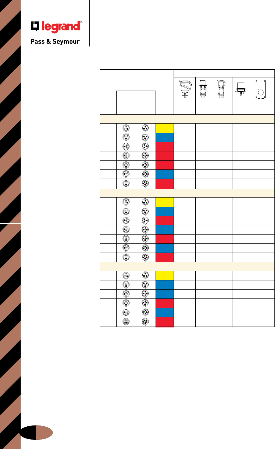
IEC Pin & Sleeve International DevicesOrdering Information
Pin & Sleeve Devices
International Splashproof Devices
Ordering Information
J-30
*Use with Back Box listed for surface mounting. Refer to chart on Page J-31.
Additional international configuration available — consult Factory Export Department.
International Product Offering
Splashproof (IP44
Suitability
)
Conguration
Voltage/
Poles & Recep./ Plug/ Color Non-Metallic
Wires Conn. Inlet Coding
Receptacle
Plug
Connector
Inlet Back Box
16 Amps
2P3W 110/120 51920 51940 51980 51970* 52029
2P3W 220/240 52022 52042 52082 52172* 52029
2P3W 380/415 52222 52242 52282 52272* 52029
3P4W 220/240 52023 52043 52083 52073* 52229
3P4W 380/415 52223 52243 52283 52173* 52229
4P5W 220/240 52044 52084 52074* 52229
4P5W 220/380
240/415 52224 52244 52284 52174 52229
32 Amps
2P3W 110/120 51972*
2P3W 220/240 52718 52742 52782 52872*
2P3W 380/415 52942 52982 52972*
3P4W 220/240 52743 52783 52773*
3P4W 380/415 52943 52983 52873*
4P5W 220/240 52744 52774*
4P5W 220/380
240/415 52944 52984
63 Amps
2P3W 110/120 53542 53582 53889
2P3W 220/240 53622 53642 53682 53772* 53889
3P4W 220/240 53623 53643 53683 53889
3P4W 380/415 53823 53843 53883 53773* 53889
4P5W 220/240 53644 53684 53889
4P5W 220/380
240/415 53824 53844 53884 53774* 53889
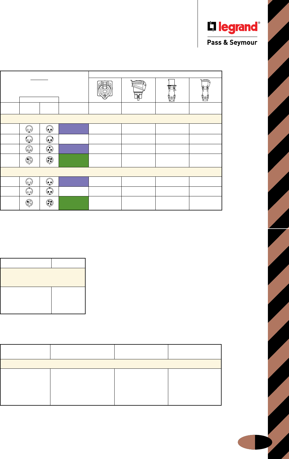
IEC Pin & Sleeve Devices Special Voltages & Frequencies
J-31
Pin & Sleeve Devices
Special Voltages & Frequencies
Special Voltages and Frequencies
Size
Back Box for IP44
Non-Metallic Inlets
and Receptacles
16A: 2P3W 52079
16A: 3P4W, 4P5W 52279
63A: All 53879
IP44
Suitability
* Use with Back Box listed below for surface mounting.
Splashproof
Conguration
Poles & Recep./ Plug/ Voltage/ Surface
Wires Conn. Inlet Color-Coding Receptacle Receptacle Plug Connector
16 Amps
2P 24V 52421
2P 42VDC
3P 24V 52402* 52402
3P4W 50-500V
100/300Hz
32 Amps
2P 24V
2P 42V
3P4W 50-500V
100/300Hz 52371
Adapter Plate Leviton, Adapter Plate
Device Type Crouse Hinds/Appleton Device Type Hubbell
Competitor Back Box Adapter Plate
20A 3 Wire PSAP320CA 20A 3 Wire PSAP320HBL
20A 4, 5 Wire PSAP4520CA 20A 4 Wire PSAP420HBL
All 30A PSAP30CA 20A 5 Wire & All 30A PSAP52030HBL
All 60A All 60A PSAP60HB
Additional international configuration available—consult Factory Export Department.
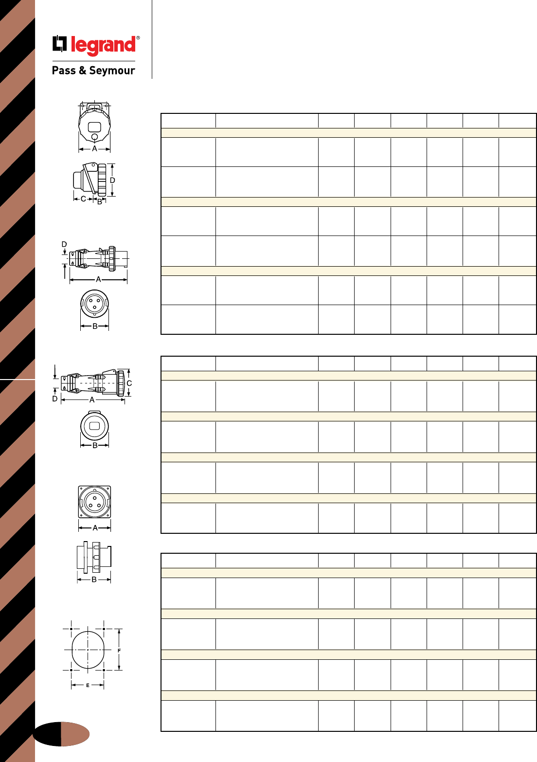
IEC Pin & Sleeve DevicesWatertight Dimensional Information
Pin & Sleeve Devices
Watertight Dimensional Information
J-32
Receptacles
Plugs
Connectors
Inlets
Receptacle/Inlet
Drilling Pattern
16/20 & 30/32 Amp Watertight Devices/Dimensional Information
Amps Wire Configurations A B C D E F
Watertight Receptacles
2 Pole, 3 Wire 2.85 1.80 1.60 3.40 2.05 2.36
16/20 3 Pole, 4 Wire 3.20 1.90 1.60 3.80 2.36 2.75
4 Pole, 5 Wire 3.40 2.00 1.70 3.80 2.36 2.75
2 Pole, 3 Wire 3.72 2.60 1.80 4.30 2.75 3.15
30/32 3 Pole, 4 Wire 3.72 2.60 1.90 4.30 2.75 3.15
4 Pole, 5 Wire 3.98 2.70 1.95 4.30 2.75 3.15
Watertight Plugs
2 Pole, 3 Wire 5.30 2.85 .31-.59
16/20 3 Pole, 4 Wire 5.50 3.20 .31-.59
4 Pole, 5 Wire 6.00 3.40 .39-.71
2 Pole, 3 Wire 6.50 3.70 .39-.71
30/32 3 Pole, 4 Wire 6.50 3.70 .47-.87
4 Pole, 5 Wire 6.70 3.98 .47-.87
Watertight Connectors
2 Pole, 3 Wire 5.90 2.85 3.00 .31-.59
16/20 3 Pole, 4 Wire 6.00 3.20 3.40 .31-.59
4 Pole, 5 Wire 6.70 3.40 3.50 .39-.71
2 Pole, 3 Wire 7.00 3.70 3.90 .39-.71
30/32 3 Pole, 4 Wire 7.00 3.70 3.90 .47-.87
4 Pole, 5 Wire 7.30 3.98 4.10 .47-.87
60/63 Amp Watertight Devices/Dimensional Information
Amps Wire Configurations A B C D E F
Watertight Receptacles
2 Pole, 3 Wire 4.20 3.10 3.50 5.00 3.03 3.35
60/63 3 Pole, 4 Wire 4.20 3.10 3.50 5.00 3.03 3.35
4 Pole, 5 Wire 4.20 3.10 3.50 5.00 3.03 3.35
Watertight Plugs
2 Pole, 3 Wire 10.00 4.50 .63-1.04
60/63 3 Pole, 4 Wire 10.00 4.50 .73-1.14
4 Pole, 5 Wire 10.00 4.50 .80-1.26
Watertight Connectors
2 Pole, 3 Wire 10.90 4.50 4.70 .63-1.04
60/63 3 Pole, 4 Wire 10.90 4.50 4.70 .73-1.14
4 Pole, 5 Wire 10.90 4.50 4.70 .80-1.26
Watertight Inlets
2 Pole, 3 Wire 4.50 4.25 3.03 3.35
60/63 3 Pole, 4 Wire 4.50 4.25 3.03 3.35
4 Pole, 5 Wire 4.50 4.25 3.03 3.35
100/125 Amp Watertight Devices/Dimensional Information
Amps Wire Configurations A B C D E F
Watertight Receptacles
2 Pole, 3 Wire 5.20 2.20 4.40 5.60 4.88 4.88
100/125 3 Pole, 4 Wire 5.20 2.20 4.40 5.60 4.88 4.88
4 Pole, 5 Wire 5.20 2.20 4.40 5.60 4.88 4.88
Watertight Plugs
2 Pole, 3 Wire 13.40 5.20 .59-1.97
100/125 3 Pole, 4 Wire 13.40 5.20 .59-1.97
4 Pole, 5 Wire 13.40 5.20 .59-1.97
Watertight Connectors
2 Pole, 3 Wire 14.30 5.20 5.30 .59-1.97
100/125 3 Pole, 4 Wire 14.30 5.20 5.30 .59-1.97
4 Pole, 5 Wire 14.30 5.20 5.30 .59-1.97
Watertight Inlets
2 Pole, 3 Wire 5.75 5.71 4.88 4.88
100/125 3 Pole, 4 Wire 5.75 5.71 4.88 4.88
4 Pole, 5 Wire 5.75 5.71 4.88 4.88
All measurements shown in inches.
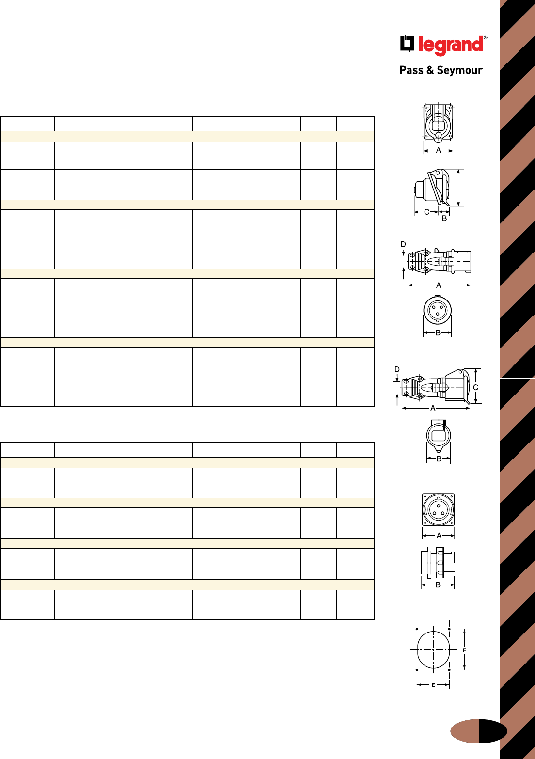
Connectors
IEC Pin & Sleeve Devices
Pin & Sleeve Devices
Splashproof Dimensional Information
Splashproof Dimensional Information
J-33
60/63 Amp Splashproof Devices/Dimensional Information
All measurements shown in inches.
Inlets
Receptacle/Inlet
Drilling Pattern
16/20 & 30/32 Amp Splashproof Devices/Dimensional Information
Amps Wire Configurations A B C D E F
Splashproof Receptacles
2 Pole, 3 Wire 2.50 1.57 1.60 3.10 2.05 2.36
16/20 3 Pole, 4 Wire 2.90 1.57 1.73 3.46 2.36 2.75
4 Pole, 5 Wire 2.90 1.73 1.73 3.66 2.36 2.75
2 Pole, 3 Wire 3.30 2.10 1.97 4.06 2.75 3.15
30/32 3 Pole, 4 Wire 3.30 2.10 1.97 4.06 2.75 3.15
4 Pole, 5 Wire 3.30 2.20 2.05 4.20 2.75 3.15
Splashproof Plugs
2 Pole, 3 Wire 5.30 2.17 .31-.59
16/20 3 Pole, 4 Wire 5.50 2.36 .31-.59
4 Pole, 5 Wire 6.00 2.60 .39-.71
2 Pole, 3 Wire 6.50 2.78 .39-.71
30/32 3 Pole, 4 Wire 6.50 2.78 .47-.87
4 Pole, 5 Wire 6.70 3.03 .47-.87
Splashproof Connectors
2 Pole, 3 Wire 5.79 2.15 2.91 .31-.59
16/20 3 Pole, 4 Wire 5.94 2.42 3.19 .31-.59
4 Pole, 5 Wire 6.77 2.73 3.54 .39-.71
2 Pole, 3 Wire 6.97 2.80 3.66 .39-.71
30/32 3 Pole, 4 Wire 6.97 2.80 3.66 .47-.87
4 Pole, 5 Wire 7.20 3.05 3.94 .47-.87
Splashproof Inlets
2 Pole, 3 Wire 2.83 3.07 2.44 3.70
16/20 3 Pole, 4 Wire 3.70 3.39 3.27 4.29
4 Pole, 5 Wire 3.70 3.39 3.27 4.29
2 Pole, 3 Wire 3.98 4.37 3.54 5.86
30/32 3 Pole, 4 Wire 3.98 4.37 3.54 5.86
4 Pole, 5 Wire 3.98 4.25 3.54 5.86
Amps Wire Configurations A B C D E F
Splashproof Receptacles
2 Pole, 3 Wire 4.20 3.50 2.76 5.08 3.03 3.35
60/63 3 Pole, 4 Wire 4.20 3.50 2.76 5.08 3.03 3.35
4 Pole, 5 Wire 4.20 3.50 2.76 5.08 3.03 3.35
Splashproof Plugs
2 Pole, 3 Wire 10.00 4.02 .63-1.04
60/63 3 Pole, 4 Wire 10.00 4.02 .73-1.14
4 Pole, 5 Wire 10.00 4.02 .80-1.26
Splashproof Connectors
2 Pole, 3 Wire 10.75 3.78 4.67 .63-1.04
60/63 3 Pole, 4 Wire 10.75 3.78 4.67 .73-1.14
4 Pole, 5 Wire 10.75 3.78 4.67 .80-1.26
Splashproof Inlets
2 Pole, 3 Wire 4.50 4.25 3.03 3.35
60/63 3 Pole, 4 Wire 4.50 4.25 3.03 3.35
4 Pole, 5 Wire 4.50 4.25 3.03 3.35
Receptacles
D
Plugs
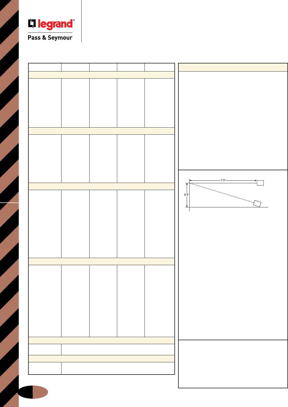
IEC Pin & Sleeve DevicesWatertight & Splashproof Material
J-34
Pin & Sleeve Devices
Watertight & Splashproof
Material & Performance
† Does not apply to splashproof.
* 16/20A and 30/32A sleeves and pins on splashproof products are brass
only. Splashproof inlets and plugs do not have locking rings.
Consult factory for additional details.
Performance
Electrical:
Dielectric Voltage Withstand 3000V maximum
Maximum Working Voltage 600 RMS
Current Interrupting Certified for current
interrupting at full-rated
current
Temperature Rise Maximum 30˚C temperature
rise at full-rated current after
50 cycles of 150% overload
(at 0.75 to 0.80 power
factor)
Endurance 20 amp: 5000 cycles with
full-rated current and
voltage
30, 60, 100 amp: 2000
cycles with full-rated current
and voltage applied on
every other cycle
Mechanical:
Impact Resistance Device dropped 8 times
from a height of 2.5 feet with
7.5 feet of cord attached (per
CSA 182.1)
Cord Grip Retention
Force, Lbs.** Torque, Ft.lbs.**
20A 30 0.4
30A 75 0.5
60A 150 1.0
100A 150 1.0
** Applied to minimum recommended cable size.
Cord Accommodation Round portable service cords
Diameters commensurate with
the device rating as defined
in UL62, CSA C22.2, No. 49,
and the harmonized (HAR)
European Standard
Terminal Identification Identified in accordance with
North American convention,
UL1682, and IEC 309-1,
309-2
Product Identification Identification and ratings are
labeled on the device housing
Environmental:
Moisture Resistance Per IEC 309-1
Flammability Contact with live parts:
V2 or V0 Enclosure: HB or
better per UL94
Operating Temperature +80˚C maximum continuous;
-50˚C minimum without impact
Specimen
Pin & Sleeve Product Specifications
16/20 Amp 30/32 Amp 60/63 Amp 100/125 Amp
Receptacles
Housing Polyamide 6 Polyamide 6 Valox Valox
Cover Polyamide 66 Polyamide 66 Valox Valox
Cover Spring Stainless Steel Stainless Steel Stainless Steel Stainless Steel
Sealing Gasket† Neoprene Neoprene Neoprene Neoprene
Mounting Gasket Neoprene Neoprene Neoprene Neoprene
Contact Carrier Polyamide 6 Polyamide 6 Polyamide 6 Polyamide 6
Sleeves Brass w/Nickel Brass w/Nickel Brass w/Nickel Brass w/Nickel
Plate*† Plate*† Plate Plate
Terminal Screws Zinc-Plated Zinc-Plated Zinc-Plated Zinc-Plated
Steel Steel Steel Steel
Inlets
Housing Polyamide 6 Polyamide 6 Valox Valox
Mounting Flange Polyamide 6 Polyamide 6 Valox Valox
Locking Ring*† Polyamide 66 Polyamide 66 Valox Valox
Sealing Gasket† Neoprene Neoprene Neoprene Neoprene
Mounting Gasket Neoprene Neoprene Neoprene Neoprene
Contact Carrier Polyamide 6 Polyamide 6 Polyamide 6 Polyamide 6
Pins Brass w/Nickel Brass w/Nickel Brass w/Nickel Brass w/Nickel
Plate*† Plate*† Plate Plate
Terminal Screws Zinc-Plated Zinc-Plated Zinc-Plated Zinc-Plated
Steel Steel Steel Steel
Plugs
Housing Polyamide 6 Polyamide 6 Valox Valox
Locking Ring*† Polyamide 66 Polyamide 66 Valox Valox
Sealing Gasket† Neoprene Neoprene Neoprene Neoprene
Housing Gasket Neoprene Neoprene Neoprene Neoprene
Back Body Polyamide 6 Polyamide 6 Valox Valox
Contact Carrier Polyamide 6 Polyamide 6 Polyamide 6 Polyamide 6
Pins Brass w/Nickel Brass w/Nickel Brass w/Nickel Brass w/Nickel
Plate*† Plate*† Plate Plate
Terminal Screws Zinc-Plated Zinc-Plated Zinc-Plated Zinc-Plated
Steel Steel Steel Steel
Cord Grip Polyamide 6 Polyamide 6 Polyamide 66 Polyamide 66
Grommet Natural Rubber Natural Rubber Natural Rubber Natural Rubber
Cord Grip Screws Stainless Steel Stainless Steel Stainless Steel Stainless Steel
Assembly Screws Stainless Steel Stainless Steel Stainless Steel Stainless Steel
Connectors
Housing Polyamide 6 Polyamide 6 Valox Valox
Cover Polyamide 66 Polyamide 66 Valox Valox
Cover Spring Stainless Steel Stainless Steel Stainless Steel Stainless Steel
Sealing Gasket† Neoprene Neoprene Neoprene Neoprene
Housing Gasket Neoprene Neoprene Neoprene Neoprene
Back Body Polyamide 6 Polyamide 6 Valox Valox
Contact Carrier Polyamide 6 Polyamide 6 Polyamide 6 Polyamide 6
Sleeves Brass w/Nickel Brass w/Nickel Brass w/Nickel Brass w/Nickel
Plate*† Plate*† Plate Plate
Terminal Screws Zinc-Plated Zinc-Plated Zinc-Plated Zinc-Plated
Steel Steel Steel Steel
Cord Grip Polyamide 6 Polyamide 6 Polyamide 66 Polyamide 66
Grommet Natural Rubber Natural Rubber Natural Rubber Natural Rubber
Cord Grip Screws Stainless Steel Stainless Steel Stainless Steel Stainless Steel
Assembly Screws Stainless Steel Stainless Steel Stainless Steel Stainless Steel
Metallic Back Box
Housing Cast Aluminum
Hub Cast Iron
Non-Metallic Back Box
Housing Polyamide 6
Hub

IEC Pin & Sleeve Devices
Pin & Sleeve Devices
Accessories/Dimensional Information
Accessories/Dimensional Information
J-35
Watertight: Inlets and
Receptacles
Splashproof: 20, 30 & 60A
Receptacles
60A Inlets
Splashproof: 20 & 30A
Inlets
In both non-metallic (left) and metallic (right) Back Boxes,
you’ll find easy installation and no-compromises durability.
PSBBN201W
Non-Metallic Back Boxes Dimensions
PSBBN202W PSBBN301W PSBBN601W
All measurements shown in inches.
Metallic Back Boxes Dimensions
Catalog
Number A B C D E F G H J DIA K L
PSBB201W 5.60 5.00 3.17 5.00 2.05 2.36 8-32UNC 2.04 .20 DIA 1/2" NPT 2.75
PSBB202W 6.82 6.12 4.11 6.07 2.36 2.76 8-32UNC 2.55 .20 DIA 3/4" NPT 3.61
PSBB201SP 7.00 5.98 2.00 6.00 3.27 4.29 8-32UNC 3.00 .20 DIA 3/4" NPT 3.96
PSBB301W 6.82 6.12 4.11 6.07 2.76 3.15 8-32UNC 2.55 .20 DIA 3/4" NPT 3.61
PSBB301SP 8.60 7.58 2.00 7.60 3.54 5.87 8-32UNC 3.00 .20 DIA 3/4" NPT 4.22
PSBB601W 8.63 7.75 4.92 7.70 3.03 3.35 10-24UNC 3.87 .28 DIA 11/2" NPT 4.75
PSBB1001W 12.50 11.00 6.25 11.00 4.88 4.88 1/4-20UNC 4.75 .28 DIA 11/2" NPT 6.25
PSBB1002W 12.50 11.00 6.25 11.00 4.88 4.88 1/4-20UNC 4.75 .28 DIA 2" NPT 6.25
Catalog A B C D E Hub
Number Size
PSBBN201W 2.50 2.31 4.16 2.28 0.78 3/4" NPT
PSBBN202W 3.34 3.78 4.81 2.38 0.63 3/4" NPT
PSBBN301W 3.53 4.03 6.38 3.53 1.03 1" NPT
PSBBN601W 6.00 6.69 11.81 5.91 1.56 11/2" NPT

Device Back Hub Protective Plug &
Type Box Size Inlet Cover
20A 3 Wire PSBB201W 1/2" PSCP320
20A 4 Wire PSBB202W 3/4" PSCP420
20A 5 Wire PSBB202W 3/4" PSCP520
20A 3, 4,
5 Wire (Inlet) PSBB201SP 3/4"
30A 3, 4 Wire PSBB301W 3/4" PSCP3430
30A 5 Wire PSBB301W 3/4" PSCP530
30A 3, 4,
5 Wire (Inlet) PSBB301SP 3/4"
All 60A PSBB601W* 11/2" PSCP60
All 100A PSBB1001W 11/2" PSCP100
All 100A PSBB1002W 2"
IEC Pin & Sleeve DevicesAccessories/Dimensional Information
Pin & Sleeve Devices
Accessories/Dimensional Information
J-36
Choose from a full range of P&S Strain Relief Adapters,
all built extra-tough for no-worries dependability.
PSCP320 PSCP60
*11/4" Reducer Supplied
Back Box & Protective Covers
Device Fitting Catalog
Type Size Number
20A 3, 4 Wire 1/2" NPT PSAD2050
20A 3, 4 Wire 3/4" NPT PSAD2034
20A 5W, All 30A 1/2" NPT PSAD3050
30A 3, 4 Wire 3/4" NPT PSAD3034
30A 3, 4 Wire 1" NPT PSAD301
All 60A 1" NPT PSAD601
All 60A 11/4" NPT PSAD60125
All 60A 11/2" NPT PSAD60150
All 100A 11/4" NPT PSAD100125
All 100A 11/2" NPT PSAD100150
All 100A 2" NPT PSAD1002
Strain Relief Adapter Fittings
Pin & Sleeve Strain Relief Adapters
Catalog A B C D E F G H
Number (Metric Thread)
PSAD2050 1/2" NPT 1.38 1.13 .54 .25 .47 .75 M25X1.5
PSAD2034 3/4" NPT 1.50 1.50 .56 .25 .47 .75 M25X1.5
PSAD3050 1/2" NPT 1.38 1.13 .54 .25 .47 .88 M32X1.5
PSAD3034 3/4" NPT 1.50 1.50 .56 .25 .47 .88 M32X1.5
PSAD301 1" NPT 1.75 1.75 .70 .25 .47 .88 M32X1.5
PSAD601 1" NPT 2.00 1.75 .70 .38 1.00 1.38 M45X2
PSAD60125 11/4" NPT 2.00 2.00 .70 .38 1.00 1.38 M45X2
PSAD60150 11/2" NPT 2.38 2.38 .70 .38 1.00 1.38 M45X2
PSAD100125 11/4" NPT 2.50 2.38 .70 .38 1.10 2.00 M60X2
PSAD100150 11/2" NPT 2.50 2.38 .70 .38 1.10 2.00 M60X2
PSAD1002 2" NPT 2.75 2.70 .75 .38 1.10 2.00 M60X2
All measurements shown in inches.

IEC Pin & Sleeve Devices Technical Specifications
J-37
Pin & Sleeve Devices
Technical Specifications
Splashproof Pin & Sleeve Connectors
20, 30 & 60A
Manufacturer’s Identification: Legrand/Pass & Seymour PS460C7S
Description: Connector, Power Supply
Type: 3 Pole, 4 Wire Grounding
Rating: 60A, 3 Phase 480VAC
Configuration: IEC 309-2, Clock Position 7, Splashproof (IP44)
3rd Party Compliance: UL Listed to UL Standard 1682; CSA Certified to CSA 22.2 No. 182.2; UL Classified to IEC 309-1 and IEC 309-2
Typical Specications
Splashproof Pin & Sleeve Plugs
20, 30 & 60A
Manufacturer’s Identification: Legrand/Pass & Seymour PS460P7S
Description: Plug, Power Supply
Type: 3 Pole, 4 Wire Grounding
Rating: 60A, 3 Phase 480VAC
Configuration: IEC 309-2, Clock Position 7, Splashproof (IP44)
3rd Party Compliance: UL Listed to UL Standard 1682; CSA Certified to CSA 22.2 No. 182.2; UL Classified to IEC 309-1 and IEC 309-2
Typical Specications
Manufacturer’s Identification: Legrand/Pass & Seymour PS460C7W
Description: Connector, Power Supply
Type: 3 Pole, 4 Wire Grounding
Rating: 60A, 3 Phase 480VAC
Configuration: IEC 309-2, Clock Position 7, Watertight (IP67)
3rd Party Compliance: UL Listed to UL Standard 1682; CSA Certified to CSA 22.2 No. 182.2; UL Classified to IEC 309-1 and IEC 309-2
Watertight Pin & Sleeve Connectors
20, 30, 60 & 100A
Typical Specications
Watertight Pin & Sleeve Plugs
20, 30, 60 & 100A
Manufacturer’s Identification: Legrand/Pass & Seymour PS460P7W
Description: Plug, Power Supply
Type: 3 Pole, 4 Wire Grounding
Rating: 60A, 3 Phase 480VAC
Configuration: IEC 309-2, Clock Position 7, Watertight (IP67)
3rd Party Compliance: UL Listed to UL Standard 1682; CSA Certified to CSA 22.2 No. 182.2; UL Classified to IEC 309-1 and IEC 309-2
Typical Specications
IEC Pin & Sleeve DevicesTechnical Specifications
J-38
Pin & Sleeve Devices
Technical Specifications
IP Suitability Rating
IP Suitability Ratings are an international system for classifying the degree of protection provided
by enclosures of electrical equipment. The higher the number, the greater the degree of protec-
tion; they apply ONLY to properly installed equipment. The numerals stand for the following:
1. First Number: Degree of protection for persons against access to hazardous parts inside the
enclosure and/or against solid bodies.
2. Second Number: Degree of protection of equipment inside enclosures against damage from
the ingress of water.
IP44
Suitability
Example: IP44=Ingress Protection; Solid bodies >=1.0 mm; Splashing
Note: >= denotes greater than or equal to. Dimensions in millimeters (mm).
IEC Enclosure Classification Designation
Code Letters First Number Second Number
Ingress Protection Against Ingress of Against Ingress of Water
Solid Bodies with Harmful Effects
IP 0 - Nonprotected 0 - Nonprotected
1 - >=50 mm diameter 1 - Vertically dripping
2 - >=12.5 mm diameter 2 - Dripping (15° Tilted)
3 - >=2.5 mm diameter 3 - Spraying
4 - >=1.0 mm 4 - Splashing
5 - Dust-protected 5 - Jetting
6 - Dusttight 6 - Power jetting
7 - Temporary immersion
8 - Continuous immersion
Inches Inches Inches Inches
Fraction Decimal mm Fraction Decimal mm Fraction Decimal mm Fraction Decimal mm
1/64 0.0156 0.3969 17/64 0.2656 6.7469 33/64 0.5156 13.0969 49/64 0.7656 19.4469
1/32 0.0312 0.7938 9/32 0.2812 7.1438 17/32 0.5312 13.4938 25/32 0.7812 19.8437
3/64 0.0468 1.1906 19/64 0.2968 7.5406 35/64 0.5468 13.8906 51/64 0.7968 20.2406
1/16 0.0625 1.5875 5/16 0.3125 7.9375 9/16 0.5625 14.2875 13/16 0.8125 20.6375
5/64 0.0781 1.9844 21/64 0.3281 8.3344 37/64 0.5781 14.6844 53/64 0.8281 21.0344
3/32 0.0937 2.3812 11/32 0.3437 8.7312 19/32 0.5937 15.0812 27/32 0.8437 21.4312
7/64 0.1093 2.7781 23/64 0.3593 9.1281 39/64 0.6093 15.4781 55/64 0.8593 21.8281
1/8 0.1250 3.1750 3/8 0.3750 9.5250 5/8 0.6250 15.8750 7/8 0.8750 22.2250
9/64 0.1406 3.5719 25/64 0.3906 9.9219 41/64 0.6406 16.2719 57/64 0.8906 22.6219
5/32 0.1562 3.9688 13/32 0.4062 10.3188 21/32 0.6562 16.6688 29/32 0.9062 23.0188
11/64 0.1718 4.3656 27/64 0.4218 10.7156 43/64 0.6718 17.0656 59/64 0.9218 23.4156
3/16 0.1875 4.7625 7/16 0.4375 11.1125 11/16 0.6875 17.4625 15/16 0.9375 23.8125
13/64 0.2031 5.1594 29/64 0.4531 11.5094 45/64 0.7031 17.8594 61/ 64 0.9531 24.2094
7/32 0.2187 5.5562 15/32 0.4687 11.9062 23/32 0.7187 18.2562 31/32 0.9687 24.6062
15/64 0.2343 5.9531 31/64 0.4843 12.3031 47/64 0.7343 18.6531 63/64 0.9843 25.0031
1/4 0.2500 6.3500 1/2 0.5000 12.7000 3/4 0.7500 19.0500 1 1.0000 25.4000
Conversion Chart
Fractions to Decimals to Millimeters
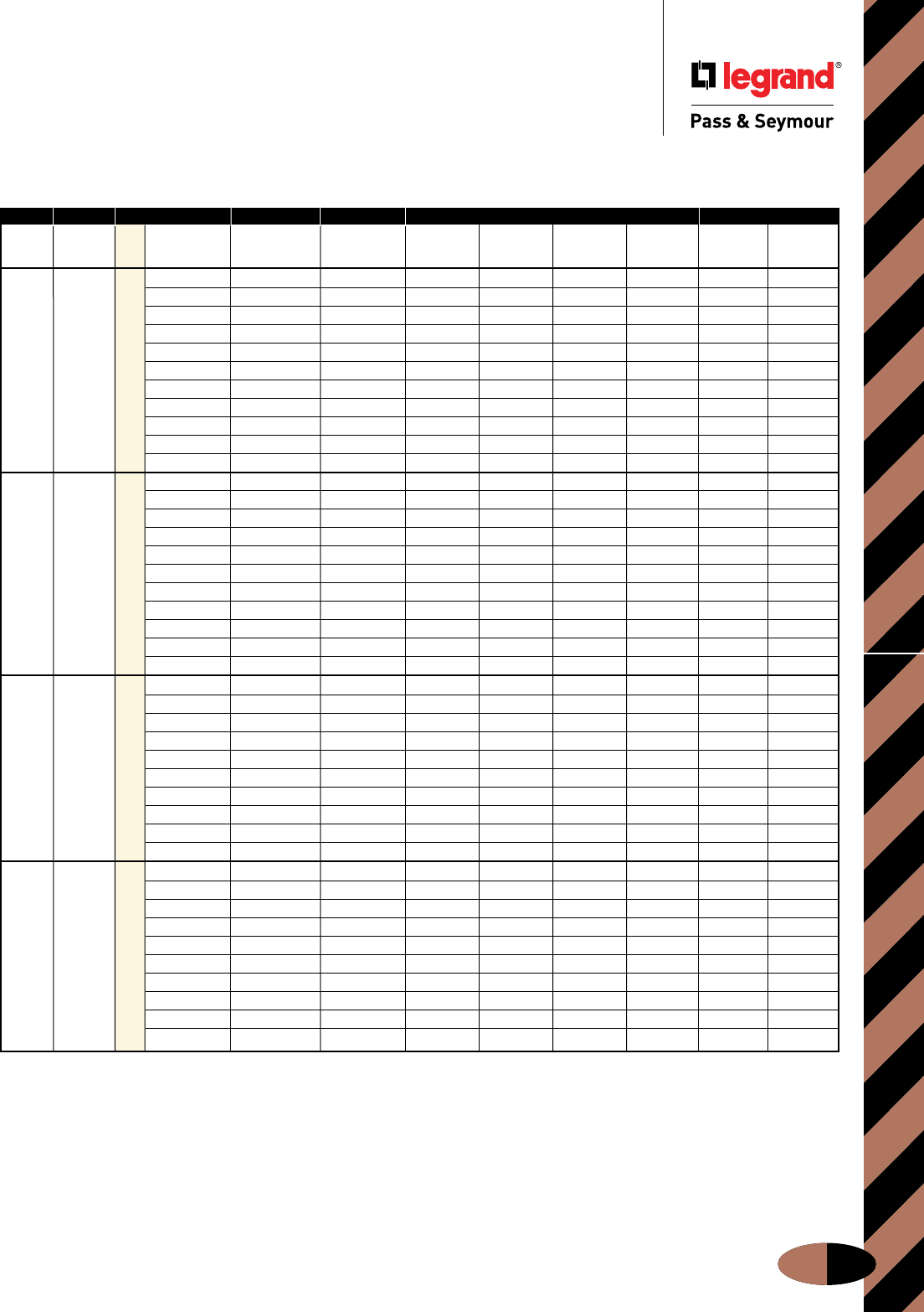
Product Selection Guide
J-39
Product Selection Guide
North American Watertight
Pg. J-14-19
Pg. J-20-24 Pg. J-3-7 Pg. J-8-13 Pg. J-25-28 Pg. J-35
Fusible Non-Fusible
Safety Safety Fusible Mec. Non-Fusible Metallic Non-Metallic
Switches Switches Amps Volts Interlock Mec. Interlock Plug Receptacle Connector Inlet Back Box Back Box
120VAC PS320P4W PS320R4W PS320C4W PSBB201W PSBBN201W
240VAC PS320P6W PS320R6W PS320C6W PSBB201W PSBBN201W
480VAC PS320P7W PS320R7W PS320C7W PSBB201W PSBBN201W
277VAC PS320P5W PS320R5W PS320C5W PSBB201W PSBBN201W
120/240VAC PS420FMIR12W PS420MIR12W PS420P12W PS420R12W PS420C12W PSBB202W PSBBN202W
N/A N/A 20 3ø 240VAC PS420FMIR9W PS420MIR9W PS420P9W PS420R9W PS420C9W PSBB202W PSBBN202W
3ø 480VAC PS420FMIR7W PS420MIR7W PS420P7W PS420R7W PS420C7W PSBB202W PSBBN202W
3ø 600VAC PS420FMIR5W PS420MIR5W PS420P5W PS420R5W PS420C5W PSBB202W PSBBN202W
3øY 120/208VAC PS520P9W PS520R9W PS520C9W PSBB202W PSBBN202W
3øY 277/480VAC PS520P7W PS520R7W PS520C7W PSBB202W PSBBN202W
3øY 347/600VAC PS520P5W PS520R5W PS520C5W PSBB202W PSBBN202W
120VAC PS330MIR4W PS330P4W PS330R4W PS330C4W PSBB301W PSBBN301W
240VAC PS330FMIR6W PS330P6W PS330R6W PS330C6W PSBB301W PSBBN301W
480VAC PS330P7W PS330R7W PS330C7W PSBB301W PSBBN301W
120/240VAC PS430FMIR12W PS430R12W PS430C12W PSBB301W PSBBN301W
3ø 240VAC PS430FMIR9W PS430MIR9W PS430P9W PS430R9W PS430C9W PSBB301W PSBBN301W
PS30FSS PS30SS 30 3ø 480VAC PS430FMIR7W PS430MIR7W PS430P7W PS430R7W PS430C7W PSBB301W PSBBN301W
3ø 600VAC PS430FMIR5W PS430MIR5W PS430P5W PS430R5W PS430C5W PSBB301W PSBBN301W
380/440 VAC PS430FMIR3W PS430MIR3W PS430P3W PS430R3W PS430C3W PSBB301W PSBBN301W
3øY 120/208VAC PS530FMIR9W PS530MIR9W PS530P9W PS530R9W PS530C9W PSBB301W PSBBN301W
3øY 277/480VAC PS530FMIR7W PS530MIR7W PS530P7W PS530R7W PS530C7W PSBB301W PSBBN301W
3øY 347/600VAC PS530MIR5W PS530R5W PS530C5W PSBB301W PSBBN301W
120VAC PS360P4W PS360R4W PS360C4W PS360B4W PSBB601W PSBBN601W
240VAC PS360FMIR6W PS360MIR6W PS360P6W PS360R6W PS360C6W PS360B6W PSBB601W PSBBN601W
480VAC PS360MIR7W PS360P7W PS360R7W PS360C7W PS360B7W PSBB601W PSBBN601W
120/240VAC PS460FMIR12W PS460MIR12W PS460P12W PS460R12W PS460C12W PS460B12W PSBB601W PSBBN601W
PS60FSS PS60SS 60 3ø 240VAC PS460FMIR9W PS460MIR9W PS460P9W PS460R9W PS460C9W PS460B9W PSBB601W PSBBN601W
3ø 480VAC PS460FMIR7W PS460MIR7W PS460P7W PS460R7W PS460C7W PS460B7W PSBB601W PSBBN601W
3ø 600VAC PS460FMIR5W PS460MIR5W PS460P5W PS460R5W PS460C5W PS460B5W PSBB601W PSBBN601W
3øY 120/208VAC PS560FMIR9W PS560MIR9W PS560P9W PS560R9W PS560C9W PS560B9W PSBB601W PSBBN601W
3øY 277/480VAC PS560FMIR7W PS560MIR7W PS560P7W PS560R7W PS560C7W PS560B7W PSBB601W PSBBN601W
3øY 347/600VAC PS560FMIR5W PS560MIR5W PS560P5W PS560R5W PS560C5W PS560B5W PSBB601W PSBBN601W
120VAC PS3100P4W PS3100R4W PS3100C4W PSBB1001W
240VAC PS3100MIR6W PS3100P6W PS3100R6W PS3100C6W PS3100B6W PSBB1001W
480VAC PS3100MIR7W PS3100P7W PS3100R7W PS3100C7W PS3100B7W PSBB1001W
120/240VAC PS4100FMIR12W PS4100MIR12W PS4100P12W PS4100R12W PS4100C12W PS4100B12W PSBB1001W
PS100FSS PS100SS 100 3ø 240VAC PS4100FMIR9W PS4100MIR9W PS4100P9W PS4100R9W PS4100C9W PS4100B9W PSBB1001W
3ø 480VAC PS4100FMIR7W PS4100MIR7W PS4100P7W PS4100R7W PS4100C7W PS4100B7W PSBB1001W
3ø 600VAC PS4100FMIR5W PS4100MIR5W PS4100P5W PS4100R5W PS4100C5W PS4100B5W PSBB1001W
3øY 120/208VAC PS5100FMIR9W PS5100MIR9W PS5100P9W PS5100R9W PS5100C9W PS5100B9W PSBB1001W
3øY 277/480VAC PS5100FMIR7W PS5100MIR7W PS5100P7W PS5100R7W PS5100C7W PS5100B7W PSBB1001W
3øY 347/600VAC PS5100FMIR5W PS5100MIR5W PS5100P5W PS5100R5W PS5100C5W PS5100B5W PSBB1001W
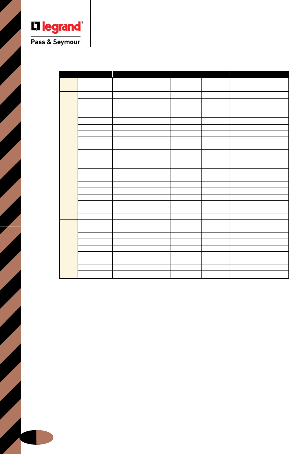
Product Selection Guide
J-40
Product Selection Guide
Pg. J-29 Pg. J-35
Metallic Non-Metallic
Amps Volts Plug Receptacle Connector Inlet Back Box Back Box
120VAC PS320P4S PS320R4S PS320C4S PSBB201W PSBBN201W
240VAC PS320P6S PS320R6S PS320C6S PS320B6S PSBB201W PSBBN201W
277VAC PS320P5S PS320R5S PSBB201W PSBBN201W
120/240VAC PS420P12S PS420R12S PS420C12S PSBB202W PSBBN202W
20 3ø 240VAC PS420P9S PS420R9S PS420C9S PS420B9S PSBB202W PSBBN202W
3ø 480VAC PS420P7S PS420R7S PS420C7S PS420B7S PSBB202W PSBBN202W
3ø 600VAC PS420R5S PS420B5S PSBB202W PSBBN202W
3øY 120/208VAC PS520R9S PS520C9S PS520B9S PSBB202W PSBBN202W
3øY 277/480VAC PS520C7S PS520B7S PSBB202W PSBBN202W
3øY 347/600VAC PS520R5S PS520C5S PS520B5S PSBB202W PSBBN202W
120VAC PS330P4S PS330R4S PS330C4S PS330B4S PSBB301W PSBBN301W
240VAC PS330P6S PS330R6S PS330C6S PS330B6S PSBB301W PSBBN301W
480VAC PS330P7S PS330C7S PS330B7S PSBB301W PSBBN301W
120/240VAC PS430R12S PS430C12S PS430B12S PSBB301W PSBBN301W
3ø 240VAC PS430P9S PS430R9S PS430C9S PS430B9S PSBB301W PSBBN301W
30 3ø 480VAC PS430P7S PS430R7S PS430C7S PS430B7S PSBB301W PSBBN301W
3ø 600VAC PS430P5S PS430R5S PS430C5S PS430B5S PSBB301W PSBBN301W
3øY 120/208VAC PS530P9S PS530R9S PS530C9S PS530B9S PSBB301W PSBBN301W
3øY 277/480VAC PS530P7S PS530B7S PSBB301W PSBBN301W
3øY 347/600VAC PS530P5S PS530R5S PS530C5S PS530B5S PSBB301W PSBBN301W
240VAC PS360P6S PS360R6S PS360C6S PS360B6S PSBB601W PSBBN601W
480VAC PS360P7S PS360R7S PS360C7S PS360B7S PSBB601W PSBBN601W
120/240VAC PS460P12S PS460R12S PS460C12S PS460B12S PSBB601W PSBBN601W
60 3ø 240VAC PS460P9S PS460R9S PS460C9S PS460B9S PSBB601W PSBBN601W
3ø 480VAC PS460P7S PS460R7S PS460C7S PS460B7S PSBB601W PSBBN601W
3ø 600VAC PS460P5S PS460R5S PS460C5S PS460B5S PSBB601W PSBBN601W
3øY 120/208VAC PS560P9S PS560R9S PS560C9S PS560B9S PSBB601W PSBBN601W
3øY 277/480VAC PS560P7S PS560R7S PS560C7S PS560B7S PSBB601W PSBBN601W
3øY 347/600VAC PS560P5S PS560R5S PS560C5S PS560B5S PSBB601W PSBBN601W
North American Splashproof
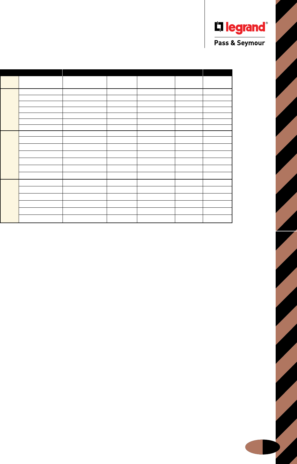
Product Selection Guide
J-41
Product Selection Guide
International Splashproof
Non-Metallic
Amps Volts Receptacle Plug Connector Inlet Back Box
110/120 51920 51940 51980 51970 52029
220/240 52022 52042 52082 52172 52029
380/415 52222 52242 52282 52272 52029
16 220/240 52023 52043 52083 52073 52229
380/415 52223 52243 52283 52173 52229
220/240 52044 52084 52074 52229
220/380; 240/415 52224 52244 52284 52174 52229
110/120 51972
220/240 52718 52742 52782 52872
380/415 52942 52982 52972
32 220/240 52743 52783 52773
380/415 52943 52983 52873
220/240 52744 52774
220/380; 240/415 52944 52984
110/120 53542 53582 53889
220/240 53622 53642 53682 53772 53889
220/240 53623 53643 53683 53889
63
380/415 53823 53843 53883 53773 53889
220/240 53644 53684 53889
220/380; 240/415 53824 53844 53884 53774 53889
Pg. J-30 Pg. J-30

FLEXCOR® WIRE MESH GRIPS
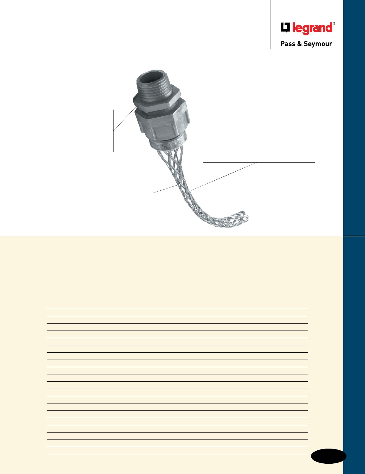
Flexcor® Wire Mesh Grips
Flexcor® Wire Mesh Grips
K-1
Index
Device Page Number
Applications K-2, K-3
Product Description K-4
Split Support Grip Lace & Rod Mesh Termination K-5
Strain Relief Deluxe Cord Grips K-6
Strain Relief Grips K-7
Strain Relief Liquid-Tight Grips K-8
Support Grips Standard-Duty, Closed Mesh K-9
Support Grips Standard-Duty, Split Lace K-10
Support Grips Standard-Duty, Split Rod K-11
Support Grips Heavy-Duty K-12
Support Grips Service & Bus Drop K-13
Support Grips Fiber Optic K-14
Pulling Grips Junior- & Light-Duty K-15
Pulling Grips Medium-Duty K-16
Pulling Grips Heavy-Duty K-17
Pulling Grips Multi-Weave K-18
Pulling Grips High Strength & Fiber Optic K-19
Pulling Grips Slack K-20
Selecting Properly Sized Pulling & Support Grips K-21, K-22
Pulling & Support Grips Strength Information K-23
Rugged, easy-to-install and available
in a wide range of sizes — our Flexcor®
Wire Mesh Strain Relief, Cable-Pulling,
and Cable-Support Grips are engineered
to take some of the strain off of you.
Corrosion-resistant, die
cast aluminum fitting with
watertight seal (Deluxe Cord
Connector Strain Relief)
protects connections
from cable stress in
damp applications.
Non-corrosive, double-weave stainless
steel mesh (Deluxe Cord Grip) supports
the cable, absorbs stress caused by flexure and
vibration, as well as controls arc of cable.
Fittings available in male straight,
female straight, 45° and 90° designs
for fast installation in all
kinds of applications.
No special installation tools required.
Mesh readily expands for a wide
range of cord diameters.
CG610
Male Straight, Deluxe Cord
Connectors Strain Relief
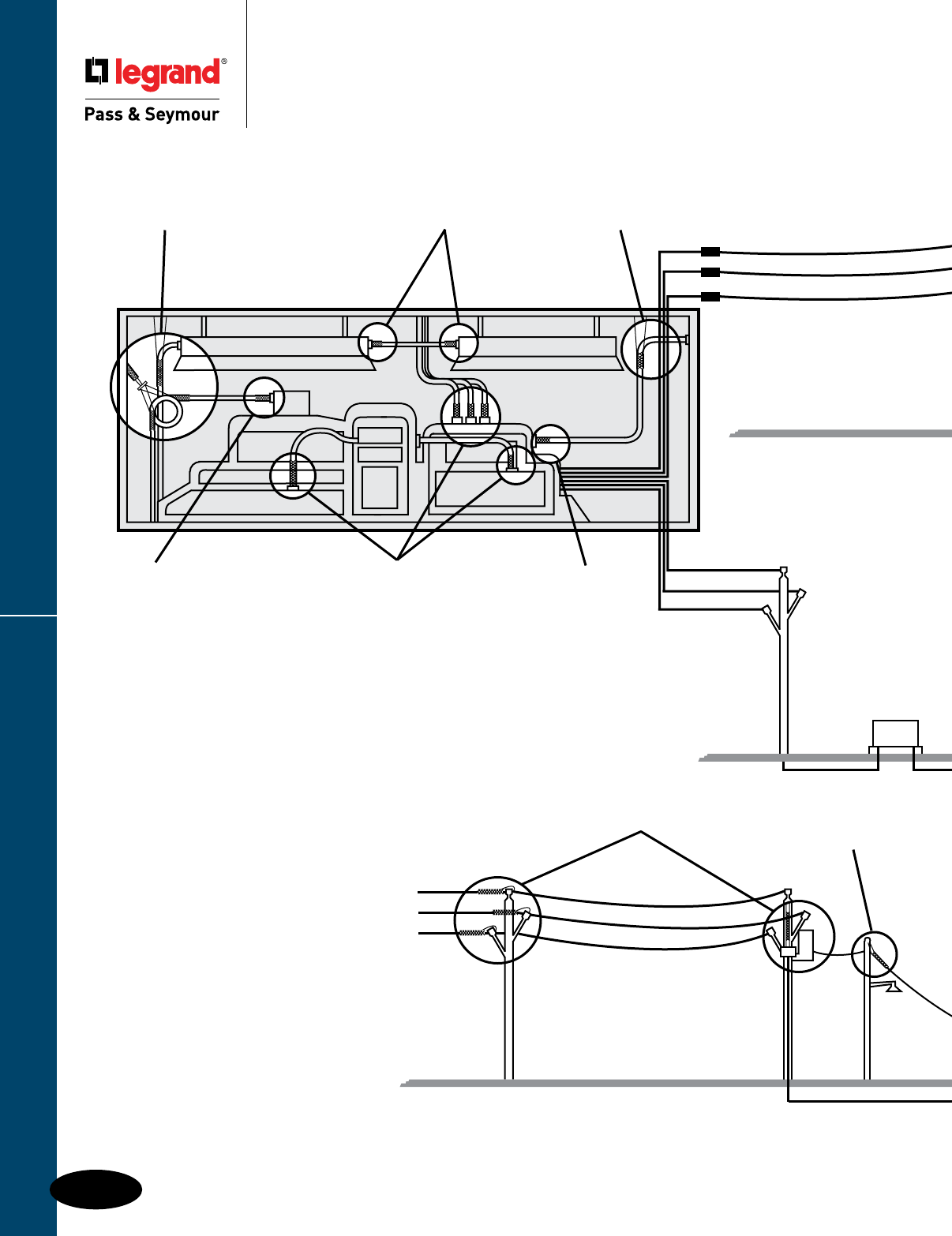
Flexcor® Wire Mesh Grips
Most Flexcor products have UL and/or CSA Approvals. Please contact factory for approval information.
K-2
Flexcor® Wire Mesh Grips
Applications
Applications
AIR
Liquid-Tight
Conduit Grip
Strain Relief
(page K-8)
Bus/Service Drop
Support Grip
(page K-13)
Liquid-Tight
Conduit Grip
Strain Relief
(page K-8)
Deluxe Cord Grip
Strain Relief
(page K-6)
Deluxe Cord Grip
Strain Relief
(page K-6)
Medium/Heavy-Duty
Support Grip
(pages K-16, K-17)
Bus/Service Drop
Support Grip
(page K-13)
Service Drop
Support Grip
(page K-13)
For assistance in selecting
Flexcor® Wire Mesh Grips,
see pages K-21 – K-23.
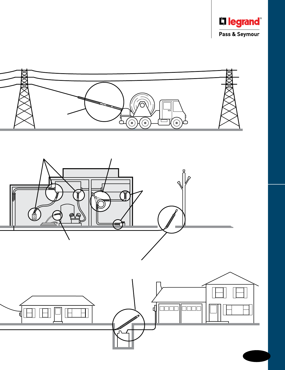
Flexcor® Wire Mesh Grips
Most Flexcor products have UL and/or CSA Approvals. Please contact factory for approval information.
K-3
Flexcor® Wire Mesh Grips
Applications
Applications
AIR
Deluxe Cord Grip
Strain Relief
(page K-6)
Bus Drop
Support Grip
(page K-13)
Deluxe Cord
Grip Strain
Relief
(page K-6)
High
Strength
Pulling Grip
(page K-19)
Deluxe Cord Grip
Strain Relief
(page K-6)
Heavy-Duty
Underground
Pulling Grip
(page K-17
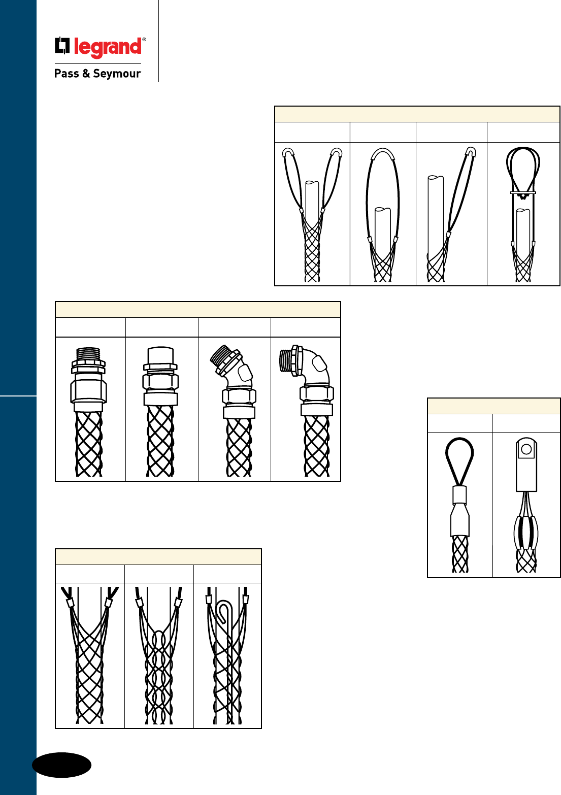
Flexcor® Wire Mesh Grips
K-4
Product Description
Flexcor® Wire Mesh Grips
Product Description
Strain Relief Grip Fittings
Male Straight Female Straight Male 45˚ Male 90˚
Pulling Grips
Flexible Eye Rotating Eye
Support Grip Attachments
Double Eye Single Eye Offset Eye Locking Bail Eye
Available in four
different attachments.
Load is distributed over
entire length of grip and
will not injure cable.
Support Grip Mesh Types
Closed Mesh Split Lace Mesh Split Rod Mesh
Prevents pull-out or
damage to cable due
to constant motion or
flexing. Also for Liquid-Tight,
hose and box connections.
Assortment of rugged
pulling grips available
individually or in kits to
make wire pulling easier.
Available in three
types and depends on
availability of wire end.
Application
Flexcor® Wire Mesh Grips are used to
support cable or conductor after it has been
installed, pull electrical cable or conductor
into place, provide strain relief at the point
of wiring connections. Flexcor® devices
protect cables, relieve stress, and prevent
cable pull-out from fittings and terminations.
Most Flexcor products have UL and/or CSA Approvals. Please contact factory for approval information.

Flexcor® Wire Mesh Grips
K-5
Most Flexcor products have UL and/or CSA Approvals. Please contact factory for approval information.
1 2
Split Support Grip Mesh Termination
Flexcor® Wire Mesh Grips
Split Support Grip
Lace & Rod Mesh Termination
Split Lace/Split Rod Attachments
(for use where end of cable is not
accessible)
Split Rod Support Grip
Mesh Termination
For Split Rod mesh termination, a
weaving rod is supplied with each grip.
The open mesh passes around the rod
and matches up with the open mesh
from the opposite direction. Split Rod
support grips are quick and easy to
use and reusable.
1. Wrap split mesh grip around cable. Thread
rod through the open loops in a weaving
motion, using end of the rod to engage loops.
2. A steady push and twist motion is required.
Use other hand to bring mesh loops together
so as to weave through them.
3. To remove, pull rod out.
34
1
3
2
Split Lace Support Grip
Mesh Termination
For Split Lace mesh termination, Flexcor®
single weave Split Lace grips are provided
with an additional single lace, two laces
are provided with each double weave
Split Lace grip. Lace strands should be
same material as the grip.
1. Wrap split mesh grip around cable. Start lacing
at top or bottom end of mesh. Thread lace
through first two loops of split mesh and pull
through until the lace is centered
at this point. Lace as you would your shoe,
crossing laces before lacing the next two
loops.
2. Leave a space between adjoining loops
approximately equal to the width of one
diamond of the mesh.
3. Twist ends of lace strands together at end
of grip or tie in a knot.
4. Wrap ends of lace tightly around grip.
Excess lace may be cut off.
Flexcor® Wire Mesh Grips
K-6
Straight Female
Connector
45º Male
Connector
90º Male
Connector
Most Flexcor products have UL and/or CSA Approvals. Please contact factory for approval information.
Strain Relief Deluxe Cord Grips Flexcor® Wire Mesh Grips
Flexcor® Wire Mesh Grips
Strain Relief
Deluxe Cord Grips
Description
Deluxe cord grips are woven of stainless steel mesh with an aluminum body for corrosion resistance.
They are offered in single/double weave construction to help absorb direct pull, to resist flexing and
binding, and to eliminate strain. They are recommended for indoor or outdoor use where subjected to
moisture in the wiring of pendant stations, processing equipment, hand tools, and extension cord sets.
Deluxe grips are suitable for use in hazardous locations per Class I, Div. 2; Class II, Div. 1 & 2; and
Class III, Div. 1 & 2. NOTE: Stainless steel mesh is not suitable for marine use.
Straight Male 90° Male 45° Male Straight Female Cable
Catalog Number Catalog Number Catalog Number Catalog Number Diameter Range
1/2" NPT Deluxe Cord Grips
CG405 CG40590 CG40545 — 0.250"-0.300"
CG406 CG40690 CG40645 — 0.310"-0.375"
CG407 CG40790 — — 0.375"-0.430"
CG408 CG40890 — — 0.440"-0.500"
CG409 CG40990 CG40945 — 0.500"-0.550"
CG410 CG41090 — CG410F 0.560"-0.625"
CG411 — — — 0.625"-0.750"
CG412 — — — 0.750"-0.875"
3/4" NPT Deluxe Cord Grips
CG606 — — — 0.250"-0.375"
CG607 — — — 0.375"-0.440"
CG608 CG60890 CG60845 — 0.440"-0.500"
CG609 CG60990 CG60945 — 0.500"-0.550"
CG610 CG61090 — — 0.560"-0.625"
CG611 CG61190 — — 0.625"-0.670"
CG612 CG61290 CG61245 — 0.670"-0.750"
1" NPT Deluxe Cord Grips
CG809 — — — 0.437"-0.562"
CG811 — — — 0.562"-0.687"
CG812 CG81290 CG81245 CG812F 0.625"-0.750"
CG814 CG81490 CG81445 — 0.750"-0.875"
CG816 CG81690 CG81645 CG816F 0.875"-1.000"
Straight Male Cable
Catalog Number Diameter Range
2-1/2" NPT Deluxe
Cord Grips
CG1630 1.687"-1.812"
CG1634 1.812"-1.937"
CG1636 1.937"-2.062"
CG1638 2.062"-2.187"
CG1640 2.187"-2.312"
CG1642 2.312"-2.437"
3" NPT Deluxe Cord Grips
CG1830 1.688"-1.812"
CG1834 1.812"-1.937"
CG1836 1.937"-2.062"
CG1838 2.062"-2.187"
CG1840 2.187"-2.312"
CG1842 2.312"-2.437"
CG1844 2.437"-2.625"
CG1846 2.625"-2.812"
CG1848 2.812"-3.000"
CG1850 3.000"-3.250"
Straight Male
Connector
Straight Male 90° Male 45° Male Cable
Catalog Number Catalog Number Catalog Number Diameter Range
1-1/4" NPT Deluxe Cord Grips
CG1016 CG101690 0.875"-1.000"
CG1018 CG101890 1.000"-1.125"
CG1020 — 1.125"-1.250"
CG1022 — CG102245 1.250"-1.375"
1-1/2" NPT Deluxe Cord Grips
CG1218 — 1.000"-1.125"
CG1220 CG122090 1.125"-1.250"
CG1222 CG122290 CG122245 1.250"-1.375"
2" NPT Deluxe Cord Grips
CG1422 CG142290 1.250"-1.375"
CG1424 CG142490 1.312"-1.437"
CG1426 CG142690 1.437"-1.562"
CG1428 CG142890 1.562"-1.687"
CG1430 CG143090 1.687"-1.812"
CG1432 CG143290 1.750"-1.875"
CG1434 — 1.812"-1.937"
CG1436 — 1.937"-2.062"
CG1438 — 2.062"-2.187"
CG1440 — 2.187"-2.312"
CG1442 — 2.312"-2.437"

Flexcor® Wire Mesh Grips
Most Flexcor products have UL and/or CSA Approvals. Please contact factory for approval information.
K-7
Flexcor® Wire Mesh Grips
Strain Relief
Grips
Strain Relief Grips
Description
Wide range grips are recommended for use in wiring of enclosures, power boxes, machine tools, and
power centers. Includes insulated bushing.
Wide Range, Straight Male, Dust Tight
Description
Wire mesh grips for Turnlok and EHU straight blade plugs and connectors provide additional strain-relief
for wiring device plugs and connectors used on portable equipment in commercial and institutional
applications, and industrial plant and construction site areas, which incur abnormally high abuse.
Turnlok/EHU
Strain Relief Grips
Catalog NPT Cable
Number Size Diameter Range
Wide Range, Straight Male, Dust Tight Grips
BOX22 1/2" 0.220"-0.320"
BOX30 1/2" 0.300"-0.430"
BOX40 1/2" 0.400"-0.540"
BOX52 3/4" 0.520"-0.730"
BOX70 1" 0.700"-1.000"
BOX94 1-1/4" 0.940"-1.250"
BOX120 1-1/2" 1.200"-1.500"
BOX140 2" 1.400"-1.750"
Cable
Catalog Number Diameter Range Mesh Length
Turnlok/EHU Strain Relief Grips
FC22GL 0.220"-0.320" 4.00"
FC30GL 0.300"-0.430" 5.00"
FC40GL 0.400"-0.560" 5.00"
FC52GL 0.520"-0.730" 9.00"
FC70GL 0.700"-0.940" 7.50"
FC94GL 0.940"-1.250" 11.50"
Flexcor® Wire Mesh Grips
Most Flexcor products have UL and/or CSA Approvals. Please contact factory for approval information.
K-8
Non-Metallic
Straight Male Connector
Straight Male
Connector
90º Male
Connector
45º Male
Connector
Straight Female
Connector
Strain Relief Liquid-Tight Grips
Flexcor® Wire Mesh Grips
Strain Relief
Liquid-Tight Grips
Description
Liquid-Tight grips are woven of stainless steel mesh with zinc plated steel or malleable iron bodies
and nuts for corrosion resistance. They are used to connect liquid-tight flexible conduit to electrical
enclosures to prevent conduit pullout. Each fitting is supplied with an insulated throat to provide
conductor insulation and protect against damage by flexing, heat expansion and contraction.
Liquid-Tight grips are recommended in the wiring of motors and any electrical enclosure where liquid-
tight conduit is subject to motion or strain. NOTE: Stainless steel mesh is not suitable for marine use.
Straight Male 90° Male 45° Male NPT Mesh
Catalog Number Catalog Number Catalog Number Size Length
Liquid-Tight for Metallic Flexible Conduit
STB38SF — STB4538SF 3/8" 2.625"
STB50SF STB9050SF STB4550SF 1/2" 3.875"
STB75SF STB9075SF STB4575SF 3/4" 4.375"
STB100SF STB90100SF STB45100SF 1" 5.25"
STB125SF STB90125SF STB45125SF 1-1/4" 5.625"
STB150SF STB90150SF — 1-1/2" 5.75"
STB200SF STB90200SF STB45200SF 2" 7.5"
STB250SF — STB45250SF 2-1/2" 9.625"
STB300SF STB90300SF STB45300SF 3" 10.625"
Straight Male NPT Mesh
Catalog Number Size Length
Liquid-Tight Grips for Non-Metallic
Type “A” Flexible Conduit
STBN38SF 3/8" 9"
STBN50SF 1/2" 10"
STBN75SF 3/4" 10.5"
STBN100SF 1" 12"
STBN125SF 1-1/4" 17"
STBN150SF 1-1/2" 21.5"
STBN200SF 2" 24"
Most Flexcor products have UL and/or CSA Approvals. Please contact factory for approval information.
K-9
Offset Eye Grips
Single Eye Grips
Double Eye Grips
Locking Bale Grips
(Universal Eye)
Support Grips Standard-Duty, Closed Mesh
Flexcor® Wire Mesh Grips
Support Grips
Standard-Duty, Closed Mesh
Description
Standard closed mesh support grips are designed for loads up to 600 lbs. and vertical runs of no more
than 100 ft. They are available in a variety of eye styles and cable ranges for supporting electrical and
fiber optic cable, metal rods, and tubing. Closed mesh support grips are used when the end of the
cable is accessible. Support grips are woven of corrosion-resistant tinned-bronze wire.
* For stainless steel support grips, add “SS” suffix to the catalog no.; For example, FC050UU becomes FC050UUSS.
Consult factory for price, availability and application. Stainless steel mesh is not suitable for marine use.
**To determine workload safety factor, divide approximate break strength by 10. See Page K-23 for strength information.
Cable Diameter Bale Mesh Approximate
Catalog Number* Range Length Length Break Strength**
Standard-Duty, Closed Mesh, Single Eye Grips
FC050U 0.500"-0.610" 7" 11" 770 lbs.
FC062U 0.620"-0.740" 8" 11" 960 lbs.
FC075U 0.750"-0.990" 8" 14" 1,300 lbs.
FC100U 1.000"-1.240" 9" 15" 1,680 lbs.
FC125U 1.250"-1.490" 10" 16" 1,680 lbs.
FC150U 1.500"-1.740" 12" 18" 1,680 lbs.
FC175U 1.750"-1.990" 14" 20" 2,640 lbs.
FC200U 2.000"-2.490" 16" 22" 3,760 lbs.
FC250U 2.500"-2.990" 18" 24" 3,760 lbs.
FC300U 3.000"-3.490" 21" 26" 5,040 lbs.
Standard-Duty, Closed Mesh, Double Eye Grips
FC050UU 0.500"-0.610" 4" 11" 770 lbs.
FC062UU 0.620"-0.740" 4" 11" 1,150 lbs.
FC075UU 0.750"-0.990" 4" 14" 1,320 lbs.
FC100UU 1.000"-1.240" 5" 15" 1,920 lbs.
FC125UU 1.250"-1.490" 5" 16" 1,920 lbs.
FC150UU 1.500"-1.740" 6" 18" 1,920 lbs.
FC175UU 1.750"-1.990" 6" 20" 3,150 lbs.
FC200UU 2.000"-2.490" 6" 22" 3,360 lbs.
FC250UU 2.500"-2.990" 6" 24" 3,360 lbs.
Standard-Duty, Closed Mesh, Offset Eye Grips
FC050OF 0.500"-0.610" 4" 11" 770 lbs.
FC062OF 0.620"-0.740" 4" 11" 960 lbs.
FC075OF 0.750"-0.990" 4" 14" 960 lbs.
FC100OF 1.000"-1.240" 5" 15" 1,680 lbs.
FC125OF 1.250"-1.490" 5" 16" 1,680 lbs.
FC150OF 1.500"-1.740" 5" 18" 1,680 lbs.
FC175OF 1.750"-1.990" 6" 20" 2,640 lbs.
FC200OF 2.000"-2.490" 6" 22" 3,760 lbs.
FC250OF 2.500"-2.990" 8" 24" 3,760 lbs.
FC300OF 3.000"-3.490" 9" 26" 5,040 lbs.
FC350OF 3.500"-3.990" 9" 28" 5,040 lbs.
Standard-Duty, Closed Mesh, Locking Bale Grips (Universal Eye)
FC050LB 0.500"-0.610" 18" 11" 770 lbs.
FC062LB 0.620"-0.740" 18" 11" 1,150 lbs.
FC075LB 0.750"-0.990" 18" 14" 1,320 lbs.
FC100LB 1.000"-1.240" 18" 15" 1,920 lbs.
FC125LB 1.250"-1.490" 18" 16" 1,920 lbs.
FC150LB 1.500"-1.740" 18" 18" 1,920 lbs.
FC175LB 1.750"-1.990" 18" 20" 3,150 lbs.
FC200LB 2.000"-2.490" 18" 22" 3,360 lbs.
FC250LB 2.500"-2.990" 18" 24" 3,360 lbs.
FC300LB 3.000"-3.490" 18" 26" 5,280 lbs.
FC350LB 3.500"-3.990" 18" 28" 5,280 lbs.
Flexcor® Wire Mesh Grips
K-9
Flexcor® Wire Mesh Grips
Most Flexcor products have UL and/or CSA Approvals. Please contact factory for approval information.
K-10
Support Grips Standard-Duty, Split Lace
Flexcor® Wire Mesh Grips
Support Grips
Standard-Duty, Split Lace
Split Lace, Single Eye
Split Lace, Double Eye
*For stainless steel support grips, add “SS” suffix to the catalog no.; For example, FS050OF becomes FS050OFSS.
Consult factory for price, availability and application. Stainless steel mesh is not suitable for marine use.
**To determine workload safety factor, divide approximate break strength by 10. See Page K-23 for strength information.
Split Lace, Offset Eye
Split Lace, Locking Bale
(Universal Eye)
Description
Split lace support grips are designed for loads up to 600 lbs. and vertical runs of no more than 100 ft.
They are available in a variety of eye styles and cable ranges for supporting electrical and fiber optic
cable, metal rods, and tubing. Split lace support grips are used when the end of the cable cannot easily
be accessed and the support grip is intended for permanent installation. Support grips are woven of
corrosion-resistant tinned-bronze wire.
Cable Diameter Bale Mesh Approximate
Catalog Number* Range Length Length Break Strength**
Standard-Duty, Split Lace, Single Eye
FS050U 0.500"-0.610" 7" 11" 770 lbs.
FS062U 0.620"-0.740" 8" 11" 960 lbs.
FS075U 0.750"-0.990" 8" 14" 1,320 lbs.
FS100U 1.000"-1.240" 9" 15" 1,680 lbs.
FS125U 1.250"-1.490" 10" 16" 1,680 lbs.
FS150U 1.500"-1.740" 12" 18" 1,680 lbs.
FS175U 1.750"-1.990" 14" 20" 2,640 lbs.
FS200U 2.000"-2.490" 16" 22" 3,760 lbs.
FS250U 2.500"-2.990" 18" 24" 3,760 lbs.
FS300U 3.000"-3.490" 21" 26" 5,040 lbs.
FS350U 3.500"-3.990" 24" 28" 5,040 lbs.
Standard-Duty, Split Lace, Double Eye
FS050UU 0.500"-0.610" 4" 11" 770 lbs.
FS062UU 0.620"-0.740" 4" 11" 1,150 lbs.
FS100UU 1.000"-1.240" 5" 15" 1,920 lbs.
FS125UU 1.250"-1.490" 5" 16" 1,920 lbs.
FS150UU 1.500"-1.740" 5" 18" 1,920 lbs.
FS175UU 1.750"-1.990" 6" 20" 3,150 lbs.
FS200UU 2.000"-2.490" 6" 22" 3,360 lbs.
FS250UU 2.500"-2.990" 6" 24" 3,360 lbs.
FS300UU 3.000"-3.490" 8" 26" 5,280 lbs.
FS350UU 3.500"-3.990" 8" 28" 5,280 lbs.
Standard-Duty, Split Lace, Offset Eye
FS050OF 0.500"-0.610" 4" 11" 770 lbs.
FS062OF 0.620"-0.740" 4" 11" 960 lbs.
FS075OF 0.750"-0.990" 4" 14" 960 lbs.
FS100OF 1.000"-1.240" 5" 15" 1,680 lbs.
FS125OF 1.250"-1.490" 5" 16" 1,680 lbs.
FS150OF 1.500"-1.740" 5" 18" 1,680 lbs.
FS175OF 1.750"-1.990" 8" 20" 2,640 lbs.
FS200OF 2.000"-2.490" 8" 22" 3,760 lbs.
FS250OF 2.500"-2.990" 8" 24" 3,760 lbs.
FS300OF 3.000"-3.490" 9" 26" 5,040 lbs.
FS350OF 3.500"-3.990" 9" 28" 5,040 lbs.
Standard-Duty, Split Lace, Locking Bale (Universal Eye)
FS050LB 0.500"-0.610" 18" 11" 770 lbs.
FS062LB 0.620"-0.740" 18" 11" 1,150 lbs.
FS100LB 1.000"-1.240" 18" 15" 1,920 lbs.
FS125LB 1.250"-1.490" 18" 16" 1,920 lbs.
FS150LB 1.500"-1.740" 18" 18" 1,920 lbs.
FS175LB 1.750"-1.990" 18" 20" 3,150 lbs.
FS200LB 2.000"-2.490" 18" 22" 3,360 lbs.
FS250LB 2.500"-2.990" 18" 24" 3,360 lbs.
FS300LB 3.000"-3.490" 18" 26" 5,280 lbs.
FS350LB 3.500"-3.990" 18" 28" 5,280 lbs.

Flexcor® Wire Mesh Grips
Most Flexcor products have UL and/or CSA Approvals. Please contact factory for approval information.
K-11
Support Grips Standard-Duty, Split Rod
Flexcor® Wire Mesh Grips
Support Grips
Standard-Duty, Split Rod
Split Rod, Single Eye
Split Rod, Double Eye
Description
Split rod support grips are designed for loads up to 600 lbs. and vertical runs of no more than 100 ft.
They are available in a variety of eye styles and cable ranges for supporting electrical and fiber optic
cable, metal rods, and tubing. Split rod support grips are used when the end of the cable cannot
be easily accessed and the installation is temporary. Support grips are woven of corrosion-resistant
tinned-bronze wire.
Split Rod, Offset Eye
Split Rod, Locking Bale
(Universal Eye)
Cable Diameter Bale Mesh Approximate
Catalog Number* Range Length Length Break Strength**
Standard-Duty, Split Rod, Single Eye
FR050U 0.500"-0.610" 7" 11" 770 lbs.
FR062U 0.620"-0.740" 8" 11" 960 lbs.
FR075U 0.750"-0.990" 8" 14" 1,320 lbs.
FR100U 1.000"-1.240" 9" 15" 1,680 lbs.
FR125U 1.250"-1.490" 10" 16" 1,680 lbs.
FR150U 1.500"-1.740" 12" 18" 1,680 lbs.
FR175U 1.750"-1.990" 14" 20" 2,640 lbs.
FR200U 2.000"-2.490" 16" 22" 3,760 lbs.
Standard-Duty, Split Rod, Double Eye
FR050UU 0.500"-0.610" 4" 11" 770 lbs.
FR062UU 0.620"-0.740" 4" 11" 1,150 lbs.
FR075UU 0.750"-0.990" 4" 14" 1,320 lbs.
FR100UU 1.000"-1.240" 5" 15" 1,920 lbs.
FR125UU 1.250"-1.490" 5" 16" 1,920 lbs.
FR150UU 1.500"-1.740" 5" 18" 1,920 lbs.
FR175UU 1.750"-1.990" 6" 20" 3,150 lbs.
FR200UU 2.000"-2.490" 6" 22" 3,360 lbs.
Standard-Duty, Split Rod, Offset Eye
FR050OF 0.500"-0.610" 4" 11" 770 lbs.
FR062OF 0.620"-0.740" 4" 11" 960 lbs.
FR075OF 0.750"-0.990" 4" 14" 960 lbs.
FR100OF 1.000"-1.240" 5" 15" 1,680 lbs.
FR125OF 1.250"-1.490" 5" 16" 1,680 lbs.
FR150OF 1.500"-1.740" 5" 18" 1,680 lbs.
FR175OF 1.750"-1.990" 6" 20" 2,640 lbs.
FR200OF 2.000"-2.490" 6" 22" 3,760 lbs.
Standard-Duty, Split Rod, Locking Bale (Universal Eye)
FR050LB 0.500"-0.610" 10" 9" 770 lbs.
FR062LB 0.620"-0.740" 10" 9" 1,150 lbs.
FR075LB 0.750"-0.990" 10" 11" 1,320 lbs.
FR100LB 1.000"-1.240" 14" 13" 1,920 lbs.
FR125LB 1.250"-1.490" 14" 15" 1,920 lbs.
FR150LB 1.500"-1.740" 14" 16" 1,920 lbs.
FR175LB 1.750"-1.990" 14" 17" 3,150 lbs.
FR200LB 2.000"-2.490" 18" 20" 3,360 lbs..
* For stainless steel support grips, add “SS” suffix to the catalog no.; For example, FR050LB becomes FR050LBSS.
Consult factory for price, availability and application. Stainless steel mesh is not suitable for marine use.
**To determine workload safety factor, divide approximate break strength by 10. See Page K-23 for strength information.
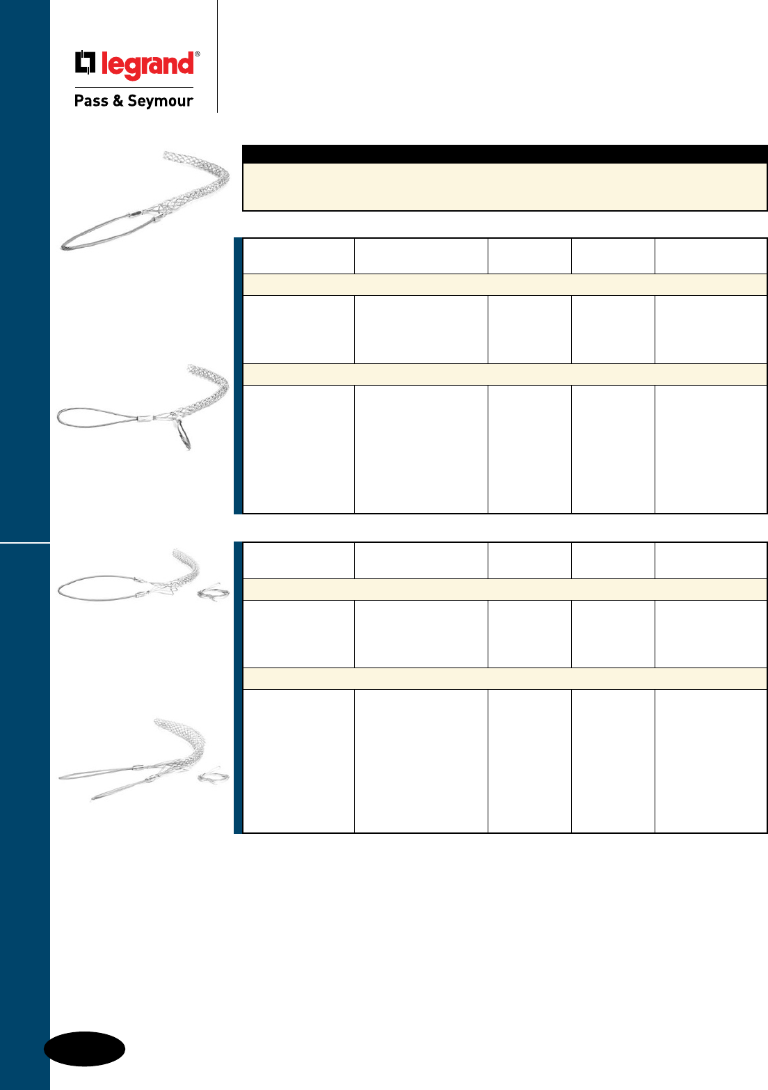
Flexcor® Wire Mesh Grips
Most Flexcor products have UL and/or CSA Approvals. Please contact factory for approval information.
K-12
Support Grips Heavy-Duty
Flexcor® Wire Mesh Grips
Support Grips
Heavy-Duty
Closed Mesh,
Single Eye
Split Lace,
Single Eye
* For stainless steel support grips, add “SS” suffix to the catalog no.; For example, FSHL075U becomes FSHL075USS.
Consult factory for price, availability and application. Stainless steel mesh is not suitable for marine use.
**To determine workload safety factor, divide approximate break strength by 10. See Page K-23 for strength information.
Description
Heavy-duty support grips feature a double weave mesh and are available in a variety of eye styles and
cable ranges for supporting electrical and fiber optic cable, metal rods, and tubing. Support grips are
woven of corrosion-resistant tinned-bronze wire.
Closed Mesh,
Double Eye
Split Lace,
Double Eye
Cable Diameter Bale Mesh Approximate
Catalog Number* Range Length Length Break Strength**
Heavy-Duty, Closed Mesh, Single Eye
FCHL075U 0.750"-0.990" 10" 26" 2,700 lbs.
FCHL100U 1.000"-1.240" 10" 29" 4,720 lbs.
FCHL125U 1.250"-1.490" 10" 31" 4,720 lbs.
FCHL150U 1.500"-1.990" 10" 35" 4,720 lbs.
Heavy-Duty, Closed Mesh, Double Eye
FCHL075UU 0.750"-0.990" 10" 26" 2,700 lbs.
FCHL100UU 1.000"-1.240" 10" 29" 4,720 lbs.
FCHL125UU 1.250"-1.490" 10" 31" 4,720 lbs.
FCHL150UU 1.500"-1.990" 10" 35" 4,720 lbs.
FCHL200UU 2.000"-2.490" 10" 37" 10,080 lbs.
FCHL250UU 2.500"-2.990" 10" 39" 10,080 lbs.
FCHL300UU 3.000"-3.490" 10" 41" 10,080 lbs.
FCHL350UU 3.500"-3.990" 10" 45" 13,120 lbs.
Cable Diameter Bale Mesh Approximate
Catalog Number* Range Length Length Break Strength**
Heavy-Duty, Split Lace, Single Eye
FSHL075U 0.750"-0.990" 10" 26" 2,700 lbs.
FSHL100U 1.000"-1.240" 10" 29" 4,720 lbs.
FSHL125U 1.250"-1.490" 10" 31" 4,720 lbs.
FSHL150U 1.500"-1.990" 10" 35" 4,720 lbs.
Heavy-Duty, Split Lace, Double Eye
FSHL075UU 0.750"-0.990" 10" 26" 2,700 lbs.
FSHL100UU 1.000"-1.240" 10" 29" 4,720 lbs.
FSHL125UU 1.250"-1.490" 10" 31" 4,720 lbs.
FSHL150UU 1.500"-1.990" 10" 35" 4,720 lbs.
FSHL200UU 2.000"-2.490" 10" 37" 10,080 lbs.
FSHL250UU 2.500"-2.990" 10" 39" 10,080 lbs.
FSHL300UU 3.000"-3.490" 10" 41" 10,080 lbs.
FSHL350UU 3.500"-3.990" 10" 45" 13,120 lbs.
FSHL400UU 4.000"-4.490" 10" 47" 13,120 lbs.
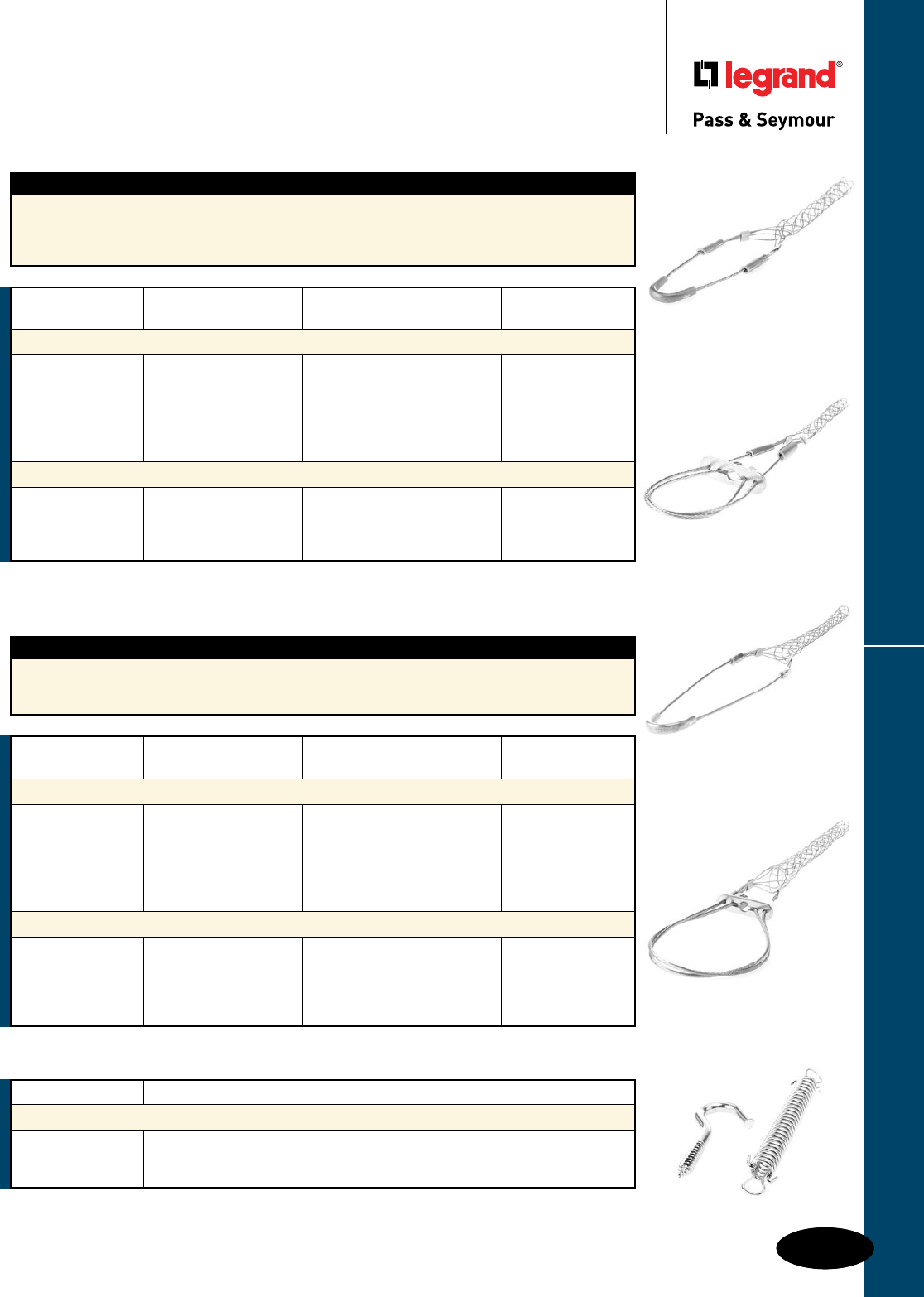
Most Flexcor products have UL and/or CSA Approvals. Please contact factory for approval information.
K-13
Service Drop
Closed Mesh
Locking Bale
Flexcor® Wire Mesh Grips Support Grips Service & Bus Drop
Flexcor® Wire Mesh Grips
Support Grips
Service & Bus Drop
Description
Service drop grips provide support for utility distribution lines from service pole to building or from pole
to pole. They can also be used for cable TV and fiber optic cable support. They are woven from tinned
bronze wire to provide superior corrosion resistance, and are available in single eye and locking bale
configurations.
Service Drop
Closed Mesh
Single Eye
Catalog Number Description
Bus Drop Accessories
S40 Safety Spring, 40 Lb. Load
S80 Safety Spring, 80 Lb. Load
GH5 Support Hook
Description
Bus drop grips are used as cable support. They relieve any direct tension from the critical connection
and absorb vibration and flexing. Bus drop grips are woven of galvanized steel wire. They are offered
with either the single eye or locking bale attachment.
Bus Drop
Closed Mesh
Single Eye
Bus Drop
Closed Mesh
Locking Bale
Bus Drop Accessories
*To determine workload safety factor, divide approximate break strength by 10. See Page K-23 for strength information.
Cable Diameter Bale Mesh Approximate
Catalog Number Range Length Length Break Strength*
Bus Drop, Closed Mesh, Single Eye
FC22 0.220"-0.320" 9" 3.5" 1,100 lbs.
FC30 0.300"-0.430" 9" 4.5" 1,100 lbs.
FC40 0.410"-0.560" 9" 5.0" 1,100 lbs.
FC52 0.530"-0.730" 9" 6.5" 1,100 lbs.
FC70 0.700"-0.850" 9" 8.5" 1,900 lbs.
FC94 0.940"-1.250" 9" 11.0" 1,900 lbs.
Bus Drop, Closed Mesh, Locking Bale
FC30LB 0.300"-0.430" 12" 4.5" 1,100 lbs.
FC40LB 0.410"-0.560" 12" 5.0" 1,100 lbs.
FC52LB 0.530"-0.730" 15" 6.5" 1,100 lbs.
FC70LB 0.700"-0.850" 16" 8.5" 1,900 lbs.
FC94LB 0.940"-1.250" 17" 11.0" 1,900 lbs.
Cable Diameter Bale Mesh Approximate
Catalog Number Range Length Length Break Strength*
Service Drop, Closed Mesh, Single Eye
FCSD22 0.220"-0.320" 4" 4" 290 lbs.
FCSD30 0.300"-0.430" 5" 5" 500 lbs.
FCSD40 0.410"-0.560" 6" 5" 500 lbs.
FCSD52 0.530"-0.730" 8" 8" 790 lbs.
FCSD70 0.700"-0.970" 8" 9" 1,020 lbs.
FCSD94 0.940"-1.250" 10" 11" 1,020 lbs.
Service Drop, Closed Mesh, Locking Bale
FCSD30LB 0.300"-0.430" 11" 5" 500 lbs.
FCSD52LB 0.530"-0.730" 14" 8" 790 lbs.
FCSD70LB 0.700"-0.970" 14" 9" 1,020 lbs.
FCSD94LB 0.940"-1.250" 16" 11" 1,020 lbs.
*To determine workload safety factor, divide approximate break strength by 10. See Page K-23 for strength information.
K-13
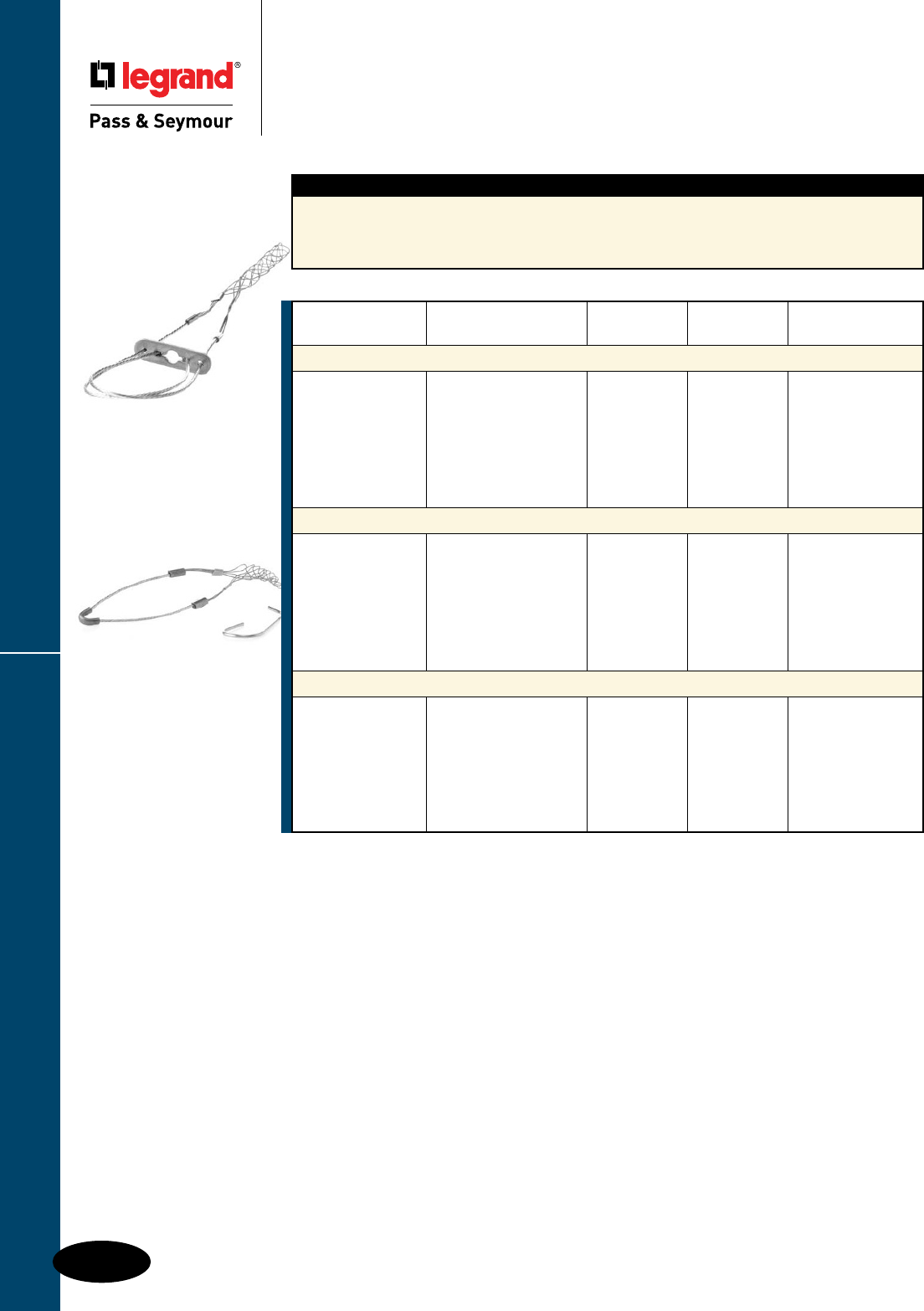
Flexcor® Wire Mesh Grips
Most Flexcor products have UL and/or CSA Approvals. Please contact factory for approval information.
K-14
Fiber Optic, Split Rod,
Single Eye
Fiber Optic,
Closed Mesh,
Locking Bale
Support Grips Fiber Optic
Flexcor® Wire Mesh Grips
Support Grips
Fiber Optic
Description
Fiber optic support grips are designed to reduce stress on fragile cables in vertical or sloping runs.
They are woven of nonmagnetic tinned bronze wire, and are available in both single eye and locking
bale configurations. A split rod version is offered for use on existing runs of cable or where specific
placement of the grip along the cable is desired.
Cable Diameter Bale Mesh Approximate
Catalog Number Range Length Length Break Strength*
Fiber Optic, Closed Mesh, Single Eye
FFO18U 0.180"-0.250" 3" 1.7" 300 lbs.
FFO24U 0.230"-0.320" 3" 2.5" 300 lbs.
FFO30U 0.300"-0.390" 4" 2.5" 300 lbs.
FFO38U 0.370"-0.480" 5" 4.0" 300 lbs.
FFO46U 0.460"-0.580" 6" 4.0" 400 lbs.
FFO56U 0.560"-0.710" 7" 5.5" 600 lbs.
FFO70U 0.690"-0.880" 8" 6.0" 800 lbs.
Fiber Optic, Closed Mesh, Locking Bale
FFO18LB 0.180"-0.250" 9" 2.5" 300 lbs.
FFO24LB 0.230"-0.320" 9" 2.0" 300 lbs.
FFO30LB 0.300"-0.390" 9" 2.5" 300 lbs.
FFO38LB 0.370"-0.480" 10" 4.0" 300 lbs.
FFO46LB 0.460"-0.580" 10" 4.0" 400 lbs.
FFO56LB 0.560"-0.710" 10" 5.5" 600 lbs.
FFO70LB 0.690"-0.880" 10" 6.0" 800 lbs.
Fiber Optic, Split Rod, Single Eye
FFRO18U 0.180"-0.250" 3" 2.5" 300 lbs.
FFRO24U 0.230"-0.320" 3" 2.5" 300 lbs.
FFRO30U 0.300"-0.390" 4" 2.5" 300 lbs.
FFRO38U 0.370"-0.480" 5" 4.0" 300 lbs.
FFRO46U 0.460"-0.580" 6" 5.0" 400 lbs.
FFRO56U 0.560"-0.710" 7" 5.0" 600 lbs.
FFRO70U 0.690"-0.880" 8" 6.0" 800 lbs.
*To determine workload safety factor, divide approximate break strength by 10. See Page K-23 for strength information.
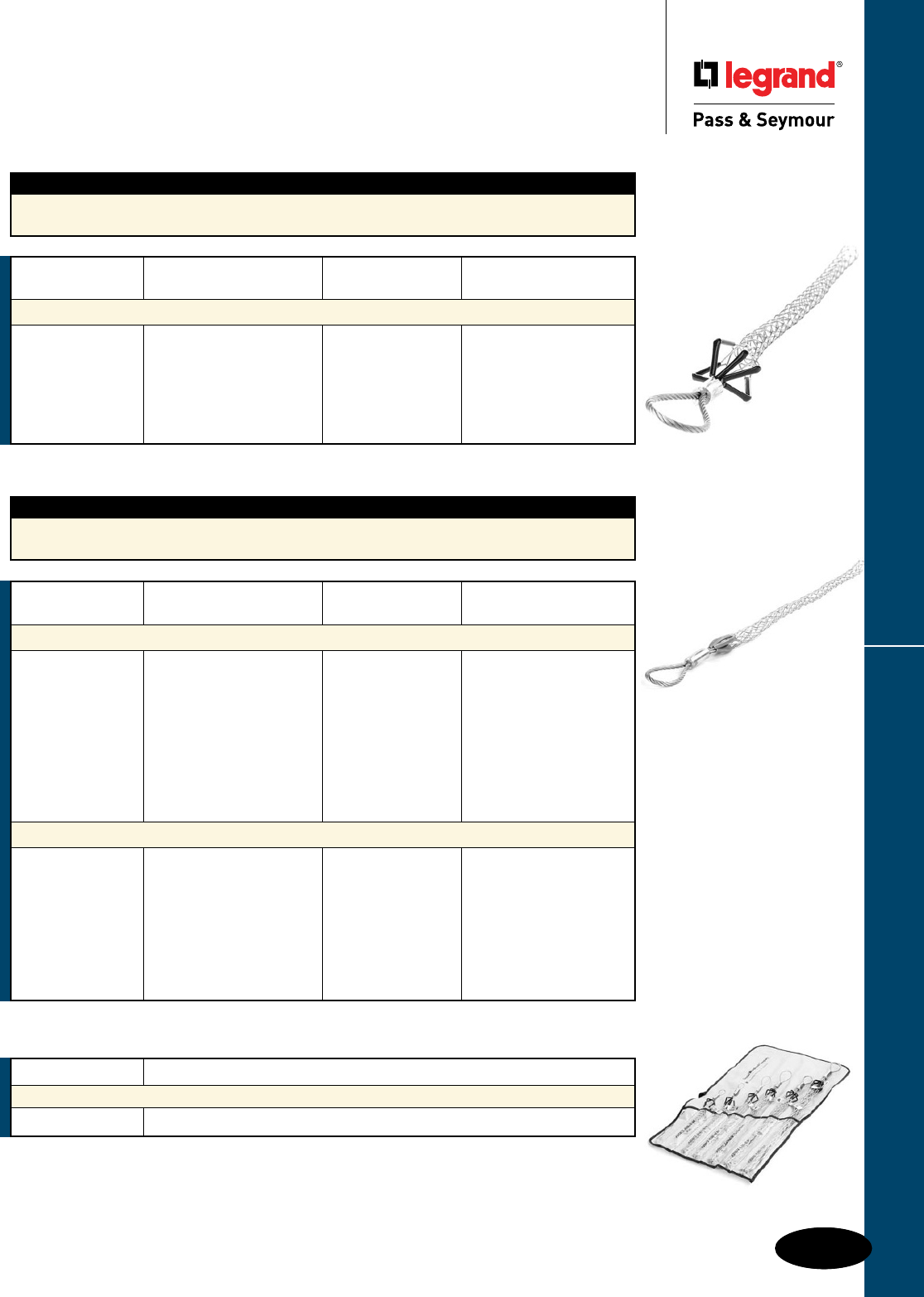
Most Flexcor products have UL and/or CSA Approvals. Please contact factory for approval information.
K-15
Light-Duty
Short Length
Flexible Eye
Flexcor® Wire Mesh Grips Pulling Grips Junior-Duty & Light-Duty
Flexcor® Wire Mesh Grips
Pulling Grips
Junior-Duty & Light-Duty
Description
Junior-duty series grips are indispensable tools for electricians with small job requirements. They are
used to connect insulated wire bundles to pulling tape or to pull wire or rope through conduit.
Cable Diameter Mesh Approximate
Catalog Number Range Length Break Strength*
Junior-Duty, Flexible Eye
PJ25 0.250"-0.360" 5" 1,700 lbs.
PJ37 0.370"-0.490" 7" 1,700 lbs.
PJ50 0.500"-0.610" 8" 1,700 lbs.
PJ62 0.620"-0.740" 10" 2,800 lbs.
PJ75 0.750"-0.990" 10" 4,100 lbs.
PJ100 1.000"-1.240" 12" 4,100 lbs.
Junior-Duty
Flexible Eye
Description
Light-Duty grips are the most economical pulling grips for many applications, such as industrial plant
wiring, and rewiring, and underground electrical pulls.
*To determine workload safety factor, divide approximate break strength by 5. See Page K-23 for strength information.
PJ1KIT
Cable Diameter Mesh Approximate
Catalog Number Range Length Break Strength*
Light-Duty, Short Length, Flexible Eye
PL0501 0.500"-0.610" 11" 3,400 lbs.
PL0621 0.620"-0.740" 11" 4,100 lbs.
PL0751 0.750"-0.990" 13" 4,100 lbs.
PL1001 1.000"-1.240" 14" 5,800 lbs.
PL1251 1.250"-1.490" 15" 5,800 lbs.
PL1501 1.500"-1.740" 16" 7,500 lbs.
PL1751 1.750"-1.990" 18" 10,000 lbs.
PL2001 2.000"-2.490" 19" 10,000 lbs.
PL2501 2.500"-2.990" 19" 13,000 lbs.
Light-Duty, Standard Length, Flexible Eye
PL0622 0.620"-0.740" 16" 4,100 lbs.
PL0752 0.750"-0.990" 20" 4,100 lbs.
PL1002 1.000"-1.240" 20" 7,500 lbs.
PL1252 1.250"-1.490" 22" 7,500 lbs.
PL1502 1.500"-1.990" 25" 7,500 lbs.
PL2002 2.000"-2.490" 26" 10,000 lbs.
PL2502 2.500"-2.990" 28" 13,000 lbs.
PL3002 3.000"-3.490" 30" 16,200 lbs..
Catalog Number Description
Junior-Duty, Flexible Eye Kit
PJ1KIT Kit contains 1 each of PJ25, PJ37, PJ50, PJ62, PJ75, PJ100
*To determine workload safety factor, divide approximate break strength by 5. See Page K-23 for strength information.
K-15
Flexcor® Wire Mesh Grips
Most Flexcor products have UL and/or CSA Approvals. Please contact factory for approval information.
K-16
Pulling Grips Medium-Duty
Flexcor® Wire Mesh Grips
Pulling Grips
Medium-Duty
Catalog Number Description
Medium-Duty, Flexible Eye Kit
PM1KIT Kit contains 1 each of PM037, PM050, PM075, PM100, PM125, PM150
Description
Medium-duty pulling grips are ideal for overhead and underground pulling applications that require
additional durability at an economical price. Medium-duty pulling grips are hand crafted with single
weave strands that graduate to a double weave design for added strength and durability.
Medium-Duty
Flexible Eye
Cable Diameter Mesh Approximate
Catalog Number Range Length Break Strength*
Medium-Duty, Flexible Eye
PM037 0.370"-0.490" 13" 2,600 lbs.
PM050 0.500"-0.740" 17" 3,400 lbs.
PM075 0.750"-0.990" 20" 5,500 lbs.
PM100 1.000"-1.240" 28" 8,100 lbs.
PM125 1.250"-1.490" 33" 8,100 lbs.
PM150 1.500"-1.740" 36" 8,100 lbs.
Medium-Duty, Long Length, Flexible Eye
PM0753 0.750"-0.990" 48" 8,100 lbs.
PM1003 1.000"-1.490" 48" 11,600 lbs.
PM1503 1.500"-1.990" 48" 19,400 lbs.
PM2003 2.000"-2.490" 48" 19,400 lbs.
PM2503 2.500"-2.990" 48" 25,900 lbs.
PM3003 3.000"-3.490" 48" 25,900 lbs.
PM3503 3.500"-3.990" 48" 32,400 lbs.
Short Length,
Flexible Eye, T-Type
*To determine workload safety factor, divide approximate break strength by 5. See Page K-23 for strength information.
Cable Diameter Mesh Eye Approximate
Catalog Number Range Length Diameter Break Strength*
Medium-Duty, Short Length, Flexible Eye, T-Type
PM0501 0.500"-0.610" 21" 7/32" 4,500 lbs.
PM0751 0.750"-0.990" 24" 1/4" 6,800 lbs.
PM1001 1.000"-1.490" 24" 5/16" 9,600 lbs.
PM1501 1.500"-1.990" 24" 7/16" 16,400 lbs.
PM2001 2.000"-2.490" 24" 7/16" 18,500 lbs.
PM2501 2.500"-2.990" 24" 1/2" 24,500 lbs.
PM3001 3.000"-3.490" 24" 1/2" 24,500 lbs.
PM3501 3.500"-3.990" 26" 5/8" 31,000 lbs.
Medium-Duty, Standard Length, Flexible Eye, T-Type
PM0752 0.750"-0.990" 36" 1/4" 6,800 lbs.
PM1002 1.000"-1.490" 36" 5/16" 9,600 lbs.
PM1502 1.500"-1.990" 36" 7/16" 16,400 lbs.
PM2002 2.000"-2.490" 36" 7/16" 18,500 lbs.
PM2502 2.500"-2.990" 36" 1/2" 24,500 lbs.
PM3002 3.000"-3.490" 36" 1/2" 24,500 lbs.
PM3502 3.500"-3.990" 40" 5/8" 31,000 lbs.
*To determine workload safety factor, divide approximate break strength by 5. See Page K-23 for strength information.
Flexcor® Wire Mesh Grips
Most Flexcor products have UL and/or CSA Approvals. Please contact factory for approval information.
K-17
Pulling Grips Heavy-Duty
Flexcor® Wire Mesh Grips
Pulling Grips
Heavy-Duty
Description
K-type pulling grips feature a double weave of galvanized steel for greater strength and added
mesh contact with the cable as well as a forged steel compact rotating eye, which can be attached
to a swivel. They are designed to handle longer or heavier pulling jobs such as an installation of
underground cables, communication lines and service lines.
*To determine workload safety factor, divide approximate break strength by 5. See Page K-23 for strength information.
Short Length,
Rotating Eye,
K-Type
Cable Diameter Mesh Eye Approximate
Catalog Number Range Length Diameter Break Strength*
Heavy-Duty, Short Length, Rotating Eye, K-Type
PS0501 0.500"-0.610" 11" 7/8" 5,600 lbs.
PS0751 0.750"-0.990" 20" 1" 9,600 lbs.
PS1001 1.000"-1.240" 20" 1-3/8" 16,400 lbs.
PS1251 1.250"-1.490" 21" 1-3/8" 16,400 lbs.
PS1501 1.500"-1.990" 25" 1-5/8" 27,200 lbs.
PS2001 2.000"-2.490" 26" 1-7/8" 33,000 lbs.
PS2501 2.500"-2.990" 28" 1-7/8" 41,000 lbs.
PS3001 3.000"-3.490" 30" 1-7/8" 48,000 lbs.
PS3501 3.500"-3.990" 32" 1-7/8" 48,000 lbs.
PS4001 4.000"-4.490" 33" 1-7/8" 48,000 lbs
Heavy-Duty, Standard Length, Rotating Eye, K-Type
PS0502 0.500"-0.610" 16" 7/8" 5,600 lbs.
PS0622 0.620"-0.740" 16" 7/8" 6,800 lbs.
PS0752 0.750"-0.990" 32" 1" 9,600 lbs.
PS1002 1.000"-1.490" 33" 1-3/8" 16,400 lbs.
PS1502 1.500"-1.990" 34" 1-3/8" 16,400 lbs.
PS2002 2.000"-2.490" 36" 1-5/8" 27,200 lbs.
PS2502 2.500"-2.990" 38" 1-7/8" 33,000 lbs.
PS3002 3.000"-3.490" 39" 1-7/8" 41,000 lbs.
PS3502 3.500"-3.990" 41" 1-7/8" 48,000 lbs.
PS4002 4.000"-4.490" 42" 1-7/8" 48,000 lbs.
PS4502 4.500"-4.990" 58" 1-7/8" 48,000 lbs.
Flexcor® Wire Mesh Grips
Most Flexcor products have UL and/or CSA Approvals. Please contact factory for approval information.
K-18
Pulling Grips Multi-Weave
Flexcor® Wire Mesh Grips
Pulling Grips
Multi-Weave
Description — Multi-Weave
Multi-weave pulling grips are constructed of high strength galvanized steel and are designed for
pulling aluminum or copper bare conductor, wire rope and insulated cables. These grips are used in
applications such as distribution line stringing and overhead transmission. Multi-weave pulling grips are
available with a flexible and rotating eye, which can be attached to a swivel.
Description — Rotating Eye
The forged steel rotating eye will thread through sheaves and blocks without binding, but is not a
swivel and will not turn under tension. The rotating eye can turn to relieve pulling torque when tension
is relaxed.
Note: it is recommended that a swivel be used for release of torque during a pull. Use a connecting link
when a swivel is not needed. Do not run grips or swivels over bullwheels while under tension. Do not
use multi-weave for pulling rope. When higher loads are required, use Legrand/Pass & Seymour’s high
strength-style pulling grips. See installation instructions supplied with grip for recommended swivels,
links and clamps or accessories listing.
Multi-Weave
Flexible Eye
*To determine workload safety factor, divide approximate break strength by 5. See Page K-23 for strength information.
Cable Diameter Mesh Eye Approximate Color
Catalog Number Range Length Diameter Break Strength* Code
Multi-Weave, Rotating Eye
P0501 0.500"-0.740" 32" 1" 10,000 lbs. Brown
P0751 0.750"-0.990" 41" 1" 14,400 lbs. Lt Blue
P1001 1.000"-1.240" 52" 1-3/8" 24,600 lbs. Gold
P1501 1.500"-1.740" 60" 1-7/8" 30,600 lbs. Red
P2001 2.000"-2.490" 50" 1-7/8" 48,000 lbs. Yellow
P2501 2.500"-2.990" 52" 1-7/8" 48,000 lbs. Orange
P3001 3.000"-3.490" 54" 1-7/8" 48,000 lbs. Aluminum
P3501 3.500"-3.990" 56" 1-7/8" 48,000 lbs. Lt Green
Multi-Weave, Flexible Eye
P0752 0.750"-0.990" 41" 3/8" 14,400 lbs. Lt Blue
P1002 1.000"-1.240" 52" 1/2" 24,600 lbs. Gold
P1502 1.500"-1.740" 60" 1/2" 30,600 lbs. Red
P2002 2.000"-2.490" 50" 5/8" 48,000 lbs. Yellow
P2502 2.500"-2.990" 52" 5/8" 48,000 lbs. Orange
P3002 3.000"-3.490" 54" 5/8" 48,000 lbs. Aluminum
P3502 3.500"-3.990" 56" 5/8" 48,000 lbs. Lt Green
Most Flexcor products have UL and/or CSA Approvals. Please contact factory for approval information.
K-19
Closed Mesh,
Rotating Eye
Flexcor® Wire Mesh Grips Pulling Grips High Strength & Fiber Optic
Flexcor® Wire Mesh Grips
Pulling Grips
High Strength & Fiber Optic
Description
High strength pulling grips are designed for situations where loads and safety considerations require
an extra high strength grip. They are most commonly used for attaching pulling lines to conductors,
conductors to running boards and conductor-to-conductor connections. These grips can be used for
pulling bare or insulated conductor, wire rope or synthetic rope.
*For rope, select smallest size grip which meets required workload.
**To determine workload safety factor, divide approximate break strength by 5. See Page K-23 for strength information.
High Strength
Flexible Eye
Rope Assembly Using High Strength Feed Tube
A feed tube is recommended when assembling synthetic rope into the High Strength Pulling Grip and is
required on the two largest grip sizes.
1. Insert feed tube into high strength pulling grip.
2. Insert rope end fully into feed tube.
3. Hold rope in feed tube by pinning rope to the ground with end of tube. Pull mesh down onto feed
so feed tube nose is protruding through shoulder protectors.
4. Push mesh to end of feed tube and pull feed tube through mesh. When pulled, the mesh gripping
action will hold rope in place.
5. Position rope so that its end is inside the shoulder protectors. Remove slack by smoothing mesh
tight to rope.
6. Apply clamps to mesh end as necessary.
Description
Fiber optic pulling grips are used for installation of fiber optic communication lines. Easily installed on
cables and reusable. Applications include underground, overhead, through conduit and/or enclosure-
type pulls.
*To determine workload safety factor, divide approximate break strength by 5. See Page K-23 for strength information.
Cable Diameter Mesh Eye Nose Approximate
Catalog Number Range Length Diameter Diameter Break Strength*
Fiber Optic, Closed Mesh, Rotating Eye
PF100 0.100"-0.200" 9" 4.75" 0.8" 1,000 lbs.
PF210 0.210"-0.350" 14" 4.75" 0.8" 1,500 lbs.
PF350 0.350"-0.480" 18" 5.00" 0.9" 2,200 lbs.
PF420 0.420"-0.610" 21" 5.00" 0.9" 2,800 lbs.
PF540 0.530"-0.740" 24" 5.00" 1.2" 3,300 lbs.
PF640 0.640"-0.870" 27" 5.00" 1.2" 4,700 lbs.
K-19
Approx.
Catalog Cable Diameter Mesh Break
Number Range* Length Strength**
With Flexible Eye Single-Double-Triple Weave
MSP025 0.250"-.0490" 26" 6,800 lbs.
MSP050 0.500"-0.740" 32" 10,000 lbs.
MSP075 0.750"-0.990" 41" 14,400 lbs.
MSP100 1.000"-1.240" 52" 24,600 lbs.
MSP125 1.250"-1.490" 56" 30,600 lbs.
MSP150 1.500"-1.740" 60" 30,600 lbs.
MSP175 1.750"-2.240" 70" 48,000 lbs.
MSP200 2.000"-2.490" 50" 48,000 lbs.
MSP250 2.500"-2.990" 52" 48,000 lbs.
Approx.
Catalog Cable Diameter Mesh Break
Number Range* Length Strength**
With Swivel Eye Single-Double-Triple Weave
MSPS025 0.250"-0.490" 26" 6,800 lbs.
MSPS050 0.500"-0.740" 32" 10,000 lbs.
MSPS075 0.750"-0.990" 41" 14,400 lbs.
MSPS100 1.000"-1.240" 52" 24,600 lbs.
MSPS125 1.250"-1.490" 56" 30,600 lbs.
MSPS150 1.500"-1.740" 60" 30,600 lbs.
MSPS175 1.750"-2.240" 70" 48,000 lbs.
MSPS200 2.000"-2.490" 50" 48,000 lbs.
MSPS250 2.500"-2.990" 52" 48,000 lbs.
MSPS300 3.000"-3.490" 54" 48,000 lbs.
Flexcor® Wire Mesh Grips
Most Flexcor products have UL and/or CSA Approvals. Please contact factory for approval information.
K-20
Pulling Grips Slack
Flexcor® Wire Mesh Grips
Pulling Grips
Slack
Description
Slack grips are reusable grips used for pulling slack in underground cable preparatory to final
placement. They may also be used for cable removal. Slack grips feature an offset eye for easy
attachment to the pulling line.
*To determine workload safety factor, divide approximate break strength by 5. See Page K-23 for strength information.
Single Weave,
Standard Length,
Split Rod, Offset Eye
Cable Diameter Mesh Approximate
Catalog Number Range Length Break Strength*
Double Weave, Standard Length, Closed Mesh, Offset Eye
SCK0751 0.750"-0.990" 13" 3,000 lbs.
SCK1001 1.000"-1.240" 16" 4,200 lbs.
SCK1251 1.250"-1.490" 17" 5,500 lbs.
SCK1501 1.500"-1.740" 18" 7,400 lbs.
SCK1751 1.750"-1.990" 19" 11,000 lbs.
SCK2501 2.500"-2.990" 21" 11,000 lbs.
SCK3001 3.000"-3.490" 22" 16,000 lbs.
SCK3501 3.500"-3.990" 23" 16,000 lbs.
Double Weave, Long Length, Closed Mesh, Offset Eye
SCK1502 1.500"-1.740" 26" 7,400 lbs.
SCK2002 2.000"-2.490" 27" 11,000 lbs.
SCK2502 2.500"-2.990" 30" 11,000 lbs.
SCK3002 3.000"-3.490" 33" 16,000 lbs.
Double Weave, Standard Length, Split Lace, Offset Eye
SSK0751 0.750"-0.990" 13" 3,000 lbs.
SSK1251 1.250"-1.490" 17" 4,100 lbs.
SSK1501 1.500"-1.740" 18" 5,500 lbs.
SSK1751 1.750"-1.990" 19" 7,300 lbs.
SSK2001 2.000"-2.490" 20" 7,300 lbs.
SSK3001 3.000"-3.490" 22" 9,200 lbs.
SSK3501 3.500"-3.990" 23" 11,000 lbs.
Double Weave, Long Length, Split Lace, Offset Eye
SSK1002 1.000"-1.240" 21" 4,100 lbs.
SSK1252 1.250"-1.490" 24" 4,100 lbs.
SSK1502 1.500"-1.740" 25" 5,500 lbs.
SSK2002 2.000"-2.490" 27" 7,300 lbs.
SSK2502 2.500"-2.990" 30" 7,300 lbs.
SSK3002 3.000"-3.490" 33" 9,200 lbs.
Single Weave, Standard Length, Split Rod, Offset Eye
SRK050OF 0.500"-0.610" 7" 1,800 lbs.
SRK062OF 0.620"-0.740" 9" 1,900 lbs.
SRK075OF 0.750"-0.990" 11" 3,000 lbs.
SRK100OF 1.000"-1.240" 12" 4,100 lbs.
SRK125OF 1.250"-1.490" 14" 5,700 lbs.
SRK150OF 1.500"-1.740" 16" 5,800 lbs.
SRK175OF 1.750"-1.990" 17" 7,700 lbs.
SRK200OF 2.000"-2.490" 20" 9,300 lbs.
SRK250OF 2.500"-2.990" 21" 11,300 lbs.
SRK300OF 3.000"-3.490" 22" 15,100 lbs.
SRK350OF 3.500"-3.990" 25" 15,100 lbs.
Double Weave,
Standard Length,
Closed Mesh,
Offset Eye
Double Weave,
Standard Length,
Split Lace, Offset Eye
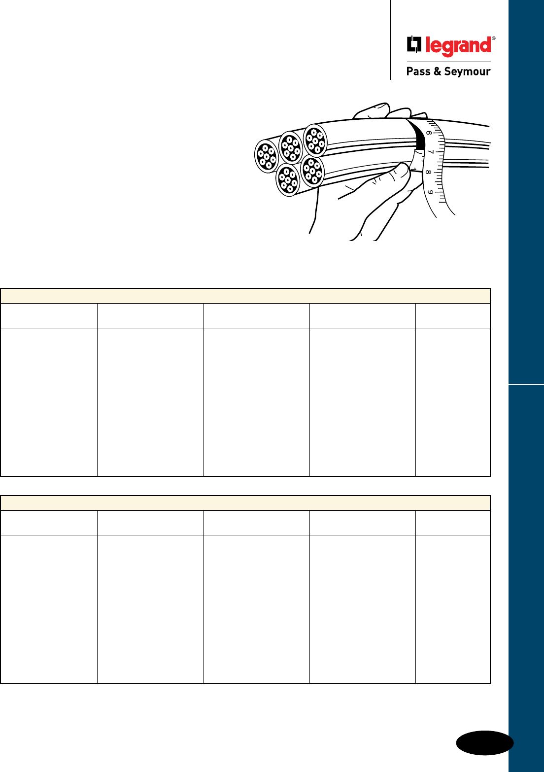
Flexcor® Wire Mesh Grips
K-21
Decimal & Fractional Inch Cable Diameters – For One or More Cables of Equal Diameter
5 6 & 7 8 9 Grip Diameter
Cable Cables Cables Cables Range
0.11-0.14 = 7⁄64 - 9⁄64 0.10-0.11 = 3⁄32 - 7⁄64 0.09-0.10 = 3⁄32 - 7⁄64 0.06-0.09 = 1⁄16 - 3⁄32 0.25"-0.375"
0.14-0.21 = 9⁄64 - ¼ 0.11-0.25 = 7⁄64 - ¼ 0.10-0.20 = 7⁄64 - 13⁄64 0.09-0.19 = 3⁄32 - 3⁄16 0.375"-0.50"
0.21-0.25 = 7⁄32 - ¼ 0.19-0.22 = 3⁄16 - 7⁄32 0.17-0.20 = 11⁄64 - 13⁄64 0.15-0.19 = 5⁄32 - 3⁄16 0.50"-0.62"
0.25-0.29 = ¼ - 19⁄64 0.22-0.26 = 7⁄32 - 17⁄64 0.20-0.23 = 13⁄64 - 15⁄64 0.19-0.22 = 3⁄16 - 7⁄32 0.62"-0.75"
0.29-0.38 = 19⁄64 - 3⁄8 0.26-0.34 = 17⁄64 - 11⁄32 0.23-0.31 = 15⁄64 - 5⁄16 0.22-0.31 = 7⁄32 - 5⁄16 0.75"-1.00"
0.38-0.48 = 3⁄8 - 31⁄64 0.34-0.43 = 11⁄32 - 7⁄16 0.31-0.39 = 5⁄16 - 25⁄64 0.29-0.36 = 19⁄64 - 23⁄64 1.00"-1.25"
0.48-0.58 = 31⁄64 - 41⁄64 0.43-0.52 = 7⁄16 - 33⁄64 0.39-0.46 = 25⁄64 - 15⁄32 0.36-0.43 = 23⁄64 - 7⁄16 1.25"-1.50"
0.58-0.67 = 37⁄64 - 43⁄64 0.52-0.60 = 33⁄64 - 39⁄64 0.46-0.54 = 15⁄32 - 35⁄64 0.43-0.49 = 7⁄16 - 31⁄64 1.50"-1.75"
0.67-0.77 = 43⁄64 - 49⁄64 0.60-0.69 = 39⁄64 - 11⁄16 0.54-0.62 = 35⁄64 - 5⁄8 0.49-0.57 = 31⁄64 - 37⁄64 1.75"-2.00"
0.77-0.96 = 49⁄64 - 31⁄32 0.69-0.86 = 11⁄16 - 55⁄64 0.62-0.77 = 5⁄8 - 49⁄64 0.57-0.72 = 37⁄64 - 23⁄32 2.00"-2.50"
0.96-1.16 = 31⁄32 - 15⁄32 0.86-1.03 = 55⁄64 - 11⁄32 0.77-0.93 = 49⁄64 - 15⁄16 0.72-0.86 = 23⁄32 - 55⁄64 2.50"-3.00"
1.16-1.35 = 15⁄32 - 123⁄64 1.03-1.20 = 11⁄32 - 113⁄64 0.93-1.08 = 15⁄16 - 15⁄64 0.86-1.00 = 55⁄64 - 1 3.00"-3.50"
1.35-1.54 = 123⁄64 - 135⁄64 1.20-1.37 = 113⁄64 - 13⁄8 1.08-1.24 = 15⁄64 - 115⁄64 1.00-1.14 = 1 - 19⁄64 3.50"-4.00"
Selecting Pulling & Support Grips
Flexcor® Wire Mesh Grips
Selecting Properly Sized
Pulling & Support Grips
Select grip size based upon the outside diameter or circumference
of the cable(s). See the following reference tables for convenience in
determining cable diameters.
Use the following grip selection tables to determine the grip
diameter range for your application.
Grip selection for one or more cables of
equal diameter
1. Read across top line for number of cables in one grip.
2. Read down for diameter of each cable.
3. Read across to the right to grip diameter range column.
Example: For five cables together with diameter of 0.42" each
1. Locate “5 cables” column.
2. Read down column to range (0.38"-0.48").
3. Read across line to grip diameter range (1.00"-1.25").
Decimal & Fractional Inch Cable Diameters – For One or More Cables of Equal Diameter
1 2 3 4 Grip Diameter
Cable Cables Cables Cables Range
0.25-0.37 = ¼ - 3⁄8 0.16-0.25 = 1⁄64 - ¼ 0.15-0.22 = 5⁄32 - 7⁄32 0.12-0.20 = 1⁄8 - 13⁄64 0.25"-0.375"
0.37-0.50 = 3⁄8 - ½ 0.25-0.36 = ¼ - 23⁄64 0.22-0.33 = 7⁄32 - 21⁄64 0.20-0.28 = 13⁄64 - 9⁄32 0.375"-0.50"
0.50-0. 62 = ½ - 5⁄8 0.27-0.36 = 17⁄64 - 23⁄64 0.26-0.33 = 17⁄64 - 21⁄64 0.24-0.28 = 15⁄64 - 9⁄32 0.50"-0.62"
0.62-0.75 = 5⁄8 - ¾ 0.36-0.45 = 23⁄64 - 29⁄64 0.33-0.36 = 21⁄64 - 23⁄64 0.28-0.31 = 9⁄32 - 5⁄16 0.62"-0.75"
0.75-1.00 = ¾ - 1 0.45-0.60 = 29⁄64 - 39⁄64 0.36-0.49 = 23⁄64 - 31⁄64 0.31-0.42 = 5⁄16 - 27⁄64 0.75"-1.00"
1.00-1.25 = 1 - 1¼ 0.60-0.76 = 39⁄64 - 49⁄64 0.49-0.63 = 31⁄64 - 5⁄8 0.42-0.54 = 27⁄64 - 35⁄64 1.00"-1.25"
1.25-1.50 = 1¼ - 1½ 0.76-0.91 = 49⁄64 - 29⁄32 0.63-0.75 = 5⁄8 - 49⁄64 0.54-0.65 = 35⁄64 - 21⁄32 1.25"-1.50"
1.50-1.75 = 1½ - 1¾ 0.91-1.23 = 29⁄32 - 115⁄64 0.76-0.89 = 49⁄64 - 57⁄64 0.65-0.77 = 21⁄32 - 49⁄64 1.50"-1.75"
1.75-2.00 = 1¾ - 2 1.23-1.54 = 115⁄64 - 135⁄64 0.89-1.02 = 57⁄64 - 11⁄64 0.77-0.88 = 49⁄64 - 7⁄8 1.75"-2.00"
2.00-2.50 = 2 - 2½ 1.54-1.84 = 135⁄64 - 127⁄32 1.02-1.28 = 11⁄64 - 19⁄32 0.88-1.00 = 7⁄8 - 1 2.00"-2.50"
2.50-3.00 = 2½ - 3 1.84-2.15 = 127⁄32 - 25⁄32 1.28-1.53 = 19⁄32 - 117⁄32 1.10-1.32 = 13⁄32 - 121⁄64 2.50"-3.00"
3.00-3.50 = 3 - 3½ 2.15-2.45 = 25⁄32 - 229⁄64 1.53-1.79 = 117⁄32 - 151⁄64 1.32-1.54 = 121⁄64 - 135⁄64 3.00"-3.50"
3.50-4.00 = 3½ - 4 1.79-2.05 = 151⁄64 - 23⁄64 1.54-1.76 = 135⁄64 - 149⁄64 3.50"-4.00"
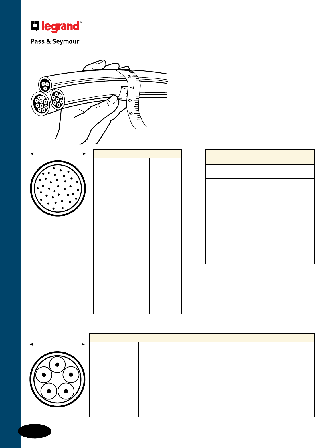
Flexcor® Wire Mesh Grips
K-22
Selecting Pulling & Support Grips
Flexcor® Wire Mesh Grips
Selecting Properly Sized
Pulling & Support Grips
Grip circumference range refers to
circumference of all cables held together.
1. Determine grip circumference range by measuring
circumference of bundle of cables to be held (as shown in
illustration).
2. Read down to locate correct range.
3. Read across to grip diameter column.
Example: For three cables together with combined
circumference of 6.35"
1. Read down “inches (decimal)” column for 6.35" (6.29"-7.86").
2. Read across line to grip diameter range (2.00"-2.50").
Grip Circumference Range –
For Cables of Different Diameters
Inches Inches Grip Diameter
(Fractional) (Decimal) Range
25⁄32 - 111⁄64 " 0.78"-1.17" 0.25"-.375"
111⁄64 - 137⁄64" 1.17"-1.57" 0.375"-0.50"
137⁄64 - 23⁄8" 1.57"-2.37" 0.50"-0.75"
115⁄16 - 23⁄8" 1.94"-2.37" 0.625"-0.75"
23⁄8 - 35⁄32" 2.37"-3.15" 0.75"-1.00"
35⁄32 - 315⁄16" 3.15"-3.94" 1.00"-1.25"
315⁄16 - 4" 3.94"-4.72" 1.25"-1.50"
423⁄32 - 533⁄64" 4.72"-5.51" 1.50"-1.75"
533⁄64 - 619⁄64" 5.51"-6.29" 1.75"-2.00"
619⁄64 - 755⁄64" 6.29"-7.86" 2.00"-2.50"
755⁄64 - 97⁄16" 7.86"-9.43" 2.50"-3.00"
97⁄16 - 111⁄64" 9.43"-11.01" 3.00"-3.50"
111⁄64 - 1237⁄64" 11.01"-12.58" 3.50"-4.00"
Reference Table: Cord Diameters
Average Wire Size
And Type 2 Conductors 3 Conductors 4 Conductors 5 Conductors
18 SO, STO 0.36" 0.38" 0.41" 0.49"
18 SJO, SJTO 0.30" 0.32" 0.35" —
16 SO, STO 0.39" 0.41" 0.44" 0.52"
16 SJO, SJTO 0.32" 0.34" 0.37" —
14 SO, STO 0.52" 0.55" 0.59" 0.67"
12 SO, STO 0.60" 0.62" 0.68" 0.74"
10 SO, STO 0.65" 0.69" 0.74" 0.80"
8 SO, STO 0.83" 0.88" 0.99" 1.08"
6 SO, STO 0.99" 1.04" 1.12" 1.25"
Diameter
This table to be used as a guide only.
Sizes may vary by manufacturer.
AWG or MCM Wire Sizes
AWG or Approx. Dia. Approx. Dia.
MCM THHM THW
14 0.105" 0.162"
12 0.122" 0.179"
10 0.153" 0.199"
8 0.201" 0.259"
6 0.257" 0.323"
4 0.328" 0.372"
3 0.356" 0.401"
2 0.388" 0.433"
1 0.450" 0.508"
1/0 0.491" 0.549"
2/0 0.537" 0.595"
3/0 0.588" 0.647"
4/0 0.646" 0.705"
250 0.716" 0.788"
300 0.771" 0.843"
350 0.822" 0.895"
400 0.869" 0.942"
500 0.955" 1.03"
600 1.06" 1.14"
700 1.13" 1.21"
750 1.16" 1.25"
1000 1.32" 1.40"
Diameter
Nominal overall diameters (in inches) for flexible cord.
Flexcor® Wire Mesh Grips
K-23
Pulling & Support Grips Strength Info
Flexcor® Wire Mesh Grips
Pulling & Support Grips
Strength Information
Strength Information
The approximate breaking strength of any Legrand/Pass & Seymour wire mesh cable grip is based on
working load information established by Legrand/Pass & Seymour engineering laboratories. In making
these determinations, it is not possible to cover all applications and operating conditions. Variables such
as diameters, gripping surfaces, number of items gripped, tension, movement, attachment, abrasion,
corrosion, prior use, or abuse must be assessed by the user. Greater safety factors should be utilized
when the conditions of application are vague or unknown.
For specific applications where strength and holding power are important, consult the manufacturer.
To determine the recommended working load safety factor for listed cable grips, divide the approximate
breaking strength by 5 for pulling grips and 10 for support grips. Legrand/Pass & Seymour maintains
a 6 sigma safety factor for pulling grips and a 5 sigma safety factor for support grips for these
recommended working loads (using average break strengths obtained on new grips under lab test
conditions).
Example: For pulling grips – 33,000÷5=6,600 lbs. which is the workload factor.
Example: For support grips – 10,080÷10=1,008 lbs. which is the workload factor.
All warranties concerning product quality or performance are based on wire mesh grips that are properly
stored and handled by the user, and grips that are maintained and inspected at a proper frequency in
keeping with their use and condition.
Grip Cable Range Conversion
Inches (Fractional) Inches (Decimal) Metric (mm)
¼ - 23⁄64" 0.25"-0.36" 6.35 mm-9.13 mm
3⁄8 - 31⁄64" 0.37"-0.49" 9.52 mm-12.30 mm
½ - 39⁄64" 0.50"-0.61" 12.70 mm-15.48 mm
5⁄8 - 47⁄64" 0.62"-0.74" 15.88 mm-18.65 mm
¾ - 63⁄64" 0.75"-0.99" 19.05 mm-25.00 mm
1 - 115⁄64" 1.00"-1.24" 25.40 mm-31.35 mm
1¼ - 131⁄64" 1.25"-1.49" 31.75 mm-37.70 mm
1½ - 163⁄64" 1.50"-1.99" 38.10 mm-50.40 mm
2 - 231⁄64" 2.00"-2.49" 50.80 mm-63.10 mm
2½ - 263⁄64" 2.50"-2.99" 63.50 mm-75.80 mm
3 - 331⁄64" 3.00"-3.49" 76.20 mm-88.50 mm
3½ - 363⁄64" 3.50"-3.99" 88.90 mm-101.20 mm

OCCUPANCY & VACANCY SENSORS & TIMERS
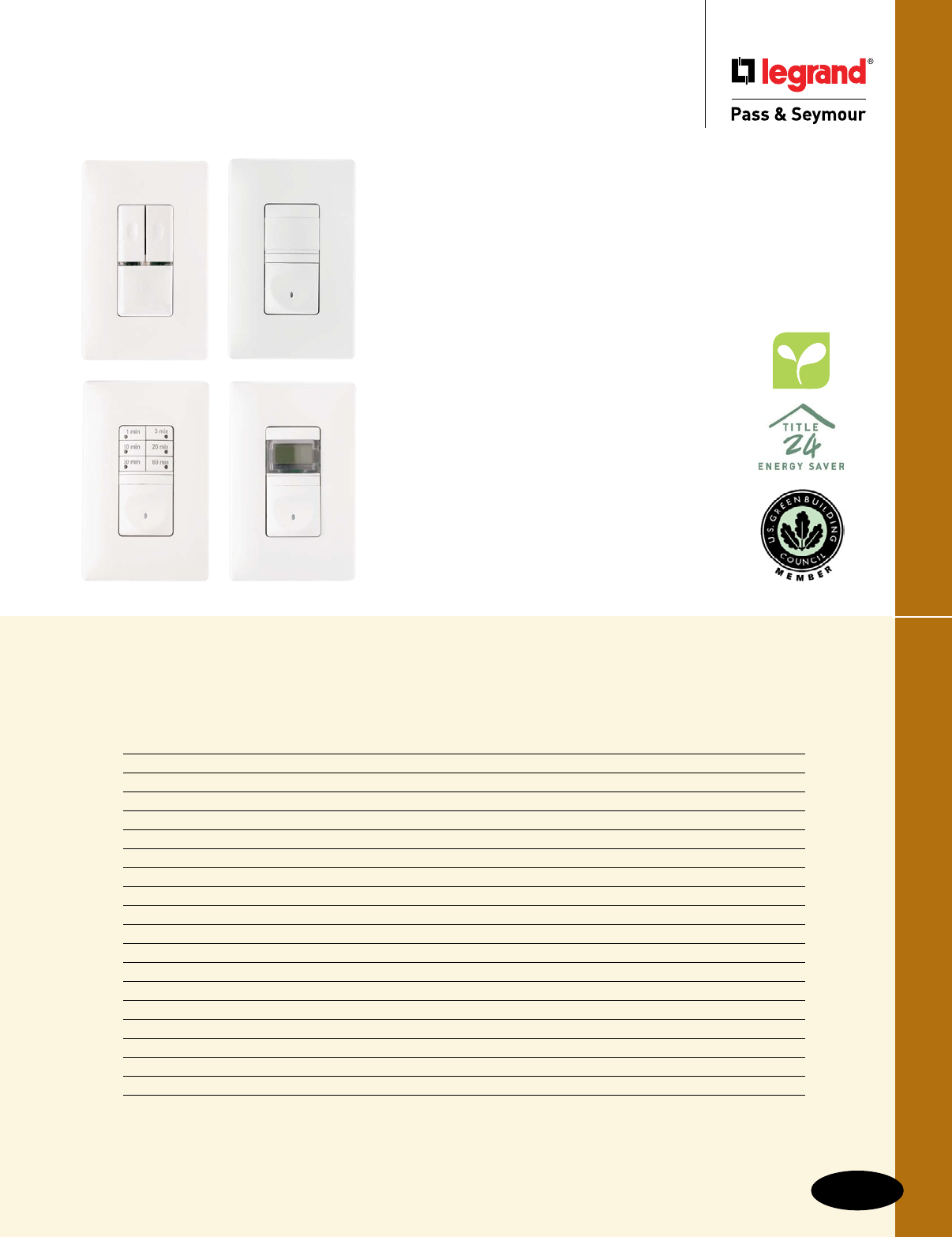
Occupancy & Vacancy Sensors & Timers
Index
Device Page Number
Technology L-2
Applications L-3
Residential Vacancy Sensors L-4
Residential Occupancy Sensors L-5
Residential Occupancy/Vacancy Sensors L-6, L-7
Commercial Occupancy Sensors
PlugTail™ Wall Box L-8
Wall Box L-8
Dual Technology Wall Box L-9
Wall or Ceiling Mount L-12
Ceiling Mount L-13
Ultrasonic Ceiling Mount L-14
Dual Technology Ceiling Mount L-15
Commercial Occupancy/Vacancy Wall Box Sensors L-10, L-11
Power Packs & Add-A-Relay L-16
Useful Calculations L-17
Timers L-18, L-19
Wall Box Timers L-20
L-1
Occupancy & Vacancy Sensors & Timers
Occupancy & Vacancy Sensors & Timers
make saving energy and saving money easy.
n Occupancy sensors turn lights on when you enter a room and save
energy by automatically turning them off when room is unoccupied.
n Vacancy sensors save more energy by requiring anyone entering the
room to manually turn on the lights. When the room is unoccupied,
the lights will turn off.
n Using occupancy and vacancy sensors may contribute to LEED
certification and help make buildings sustainable.
P&S Sensors and Timers help meet energy codes.
They are convenient, easy-to-install, and compatible
with all standard types of lighting.
Sensors add to the comfort, safety and security
of the people who occupy the building.
Timers turn loads off when no longer needed.

Technology
L-2
Occupancy & Vacancy Sensors & Timers
Occupancy & Vacancy Sensors & Timers
Technology
Passive Infrared Sensors (PIR)
Using a patented fresnel lens which minimizes optical aberrations, each Legrand/Pass &
Seymour PIR sensor breaks its coverage area into zones. Upon detecting an infrared energy
change within a zone, one of the elements in the dual-element pyroelectric sensing device of an
occupancy sensor generates a positive pulse. Within milliseconds, the other element produces
a negative pulse and the lights are turned on. Vacancy sensors turn lights off when the room is
vacant for a period of time, or when there is no infrared energy detected within a zone.
Passive infrared sensors are unable to detect occupancy around barriers, and are more
effective when sensing movement across their field of sight rather than towards or away
from it.
All Legrand/Pass & Seymour PIR occupancy sensors feature:
n Patented fresnel lenses with multi-segment design
n Dual-element pyroelectric sensors
n Low-profile design
n Daylight filter systems
n Adjustable settings for time and sensitivity
n Custom Detection Signature Analysis for high immunity to RFI and EMI, and reliability
n Self-adaptive technology is available on some models
Ultrasonic Sensors
Ultrasonic sensors use a multi-directional transmitter/receiver system to broadcast ultrasonic
sound waves generated by a quartz crystal oscillator, and then measure the amount of time it
takes the waves to return. Movement within the area results in the sound waves returning to
the sensor at a slower or faster rate, and thus occupancy is detected.
Ultrasonic sensors broadcast in three dimensions, and are therefore able to detect smaller
movements than PIR sensors. Proper placement of the sensors is essential as sound waves
can escape through open doorways, resulting in false triggering.
While Legrand/Pass & Seymour ultrasonic sensors use special circuitry to filter out air-flow
movement caused by HVAC equipment or fans, sensors should be kept away from breezy
areas. Also, heavy carpeting and other sound-absorbing materials used in the construction of
a room will reduce coverage.
Legrand/Pass & Seymour ultrasonic occupancy sensor features:
n Temperature- and humidity-resistant tuned receivers
n Signal Processing Circuitry
n Solid-state, crystal-controlled transmitter
n Adjustable controls for time and sensitivity
Dual Technology
Dual Technology sensors combine PIR and Ultrasonic sensing in one device. This minimizes
false ONs and nuisance OFFs. Sensitivity adjustments and user selectable operational
characteristics make dual technology sensors the most versatile, even in the most difficult
installations.
Use dual technology sensors for the most demanding sensor applications. Odd shaped rooms,
lots of partitions, and changing floor plans can be handled best by dual technology sensors.
Catalog
P&S Model Page # Best Suited For:
Residential Occupancy Sensors
RW500U L-5 Storage rooms, walk-in closets, pantries, garage where no neutral is available
RWU600U L-5 Storage rooms, walk-in closets, pantries, garage where a neutral is available
Residential Vacancy Sensors (T24 Compliant)
RW500B L-4 Bedrooms, basements bathrooms, laundry rooms, where no neutral is available
RWU600B L-4 Bedrooms, basements bathrooms, laundry rooms, where a neutral is available
RW600BTC L-4 Bedrooms, basements bathrooms, laundry rooms, where no neutral is available
3-Way Residential Occupancy/Vacancy Sensor
RW3U600 L-6 Any room/hall with multiple entrances — allows manual ON/OFF control from both
locations. Can be switched between occupancy and vacancy.
RW3U603 L-6 T24 Compliant. Any room/hall with multiple entrances — allows manual ON/OFF control
from both locations. Can be switched between occupancy and vacancy.
Residential Occupancy/Vacancy Sensor with Dimmer
RWDU500 L-7 Any room where adjustable light level is desired
Commercial Passive Infrared (PIR) Wall Box Sensors
PTWSP250 L-8 Small offices, closets, utility rooms with no partitions or obstructions
WSP250 L-8 Small offices, closets, utility rooms with no partitions or obstructions
OS300S L10 Small offices, closets, small conference rooms with no partitions or obstructions
OSR300S L-11 Small rooms with two individually-controlled loads or bi-level lighting with
no partitions or obstructions
Commercial Passive Infrared (PIR) and Ultrasonic Wall Sensors
WDT100 L-9 Small offices, executive suites, conference rooms, break rooms.
WDT200 L-9
Commercial Passive Infrared (PIR) Ceiling Sensors
CS500 L-13 Open offices, lunch, utility, storage, and computer rooms with no partitions or obstructions
CS1200 L-13 Larger rooms, up to 1200 sq. ft., with open floor plans, no partitions or obstructions
Commercial Passive Infrared (PIR) Wall or Ceiling Mount Sensors
HS1001 L-12 Hallways, or aisles
WA1001 L-12 Entrances, vestibules, classrooms, for wide-angle applications
Commercial Ultrasonic Ceiling Mount Sensors
CSU600 L-14 Offices, computer, meeting, copy, and restrooms
CSU1100 L-14 Offices, lunch, break and classrooms, restrooms, and conference rooms
CSU2200 L-14 Offices, lunch, break and classrooms, restrooms, conference rooms, halls, storage areas
Commercial Dual Technology Sensors
CSD1000 L-15 Meeting, conference and classrooms, restrooms, dressing rooms, libraries,
interview rooms, testing areas, lunch and break rooms
Timers
RT1 L-18 Closets, bathroom fans, exhaust fans, heat lamps, bedrooms
RT12 L-19 Garages, basements, laundry rooms, fans, motors, landscape lights
RT24 L-19 Exterior lights, landscape lighting, security lighting, holiday lighting
97015, 30, 60 L-20 Bathroom fans, heat lamps, guest rooms
97115, 30, 60 L-20 Bathroom fans, heat lamps, guest rooms where a hold function is desired
97352 L-20 Dual control for bathroom light and fan
L-3
ApplicationsOccupancy & Vacancy Sensors & Timers
Occupancy & Vacancy Sensors & Timers
Applications
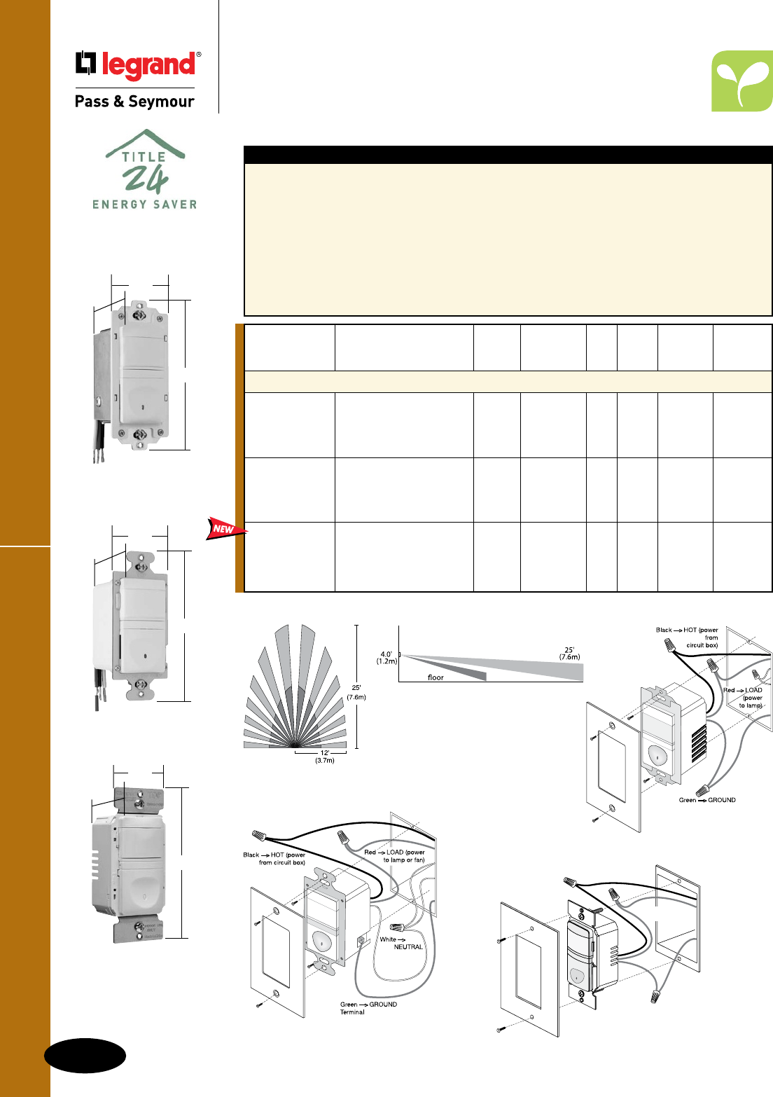
Residential Vacancy Sensors
L-4
Occupancy & Vacancy Sensors & Timers
Occupancy & Vacancy Sensors & Timers
Residential Vacancy Sensors
Passive Infrared (PIR)
Features
n California Title 24 compliant.
n Replaces a standard light or fan single pole switch.
n Lighted switch for visibility in darkened rooms.
n Manual-ON operation.
n Fixed 30-minute time delay, no adjustment
necessary.
n Low-profile styling with uniform color-matched
lens and device.
n Coverage: 180°, max. 600 ft.2 (56m2).
n cULus listed.
n 5-year warranty.
RW500B only
n Incandescent.
RWU600B only
n Load: Incandescent, fluorescent, compact
fluorescent (CFL), magnetic low-voltage (MLV)
and electronic low-voltage (ELV), 1/6 hp.
RW600BTC only
n Interchangeable face – Three colors in one
box (Ivory, White, Light Almond).
RW500BLACC4
1.69"
2.63"
1.88"
1.69"
2.63"
1.88"
RWU600BLACC4
RW500B Wiring
Wiring for RW500B does
not require a neutral.
RWU600B Wiring
Wiring for RWU600B requires a neutral.
Coverage
All devices listed on this page conform to NEMA WD-1 and WD-6.
Selectable
Catalog Auto Manual Auto/Man.
Number Description Voltage Load ON ON ON Color
Single Pole Vacancy Sensors
RW500BICC4 No Yes No Ivory
RW500BWCC4 No neutral required, 120VAC 25-500W No Yes No White
RW500BBKCC4 ideal for bedrooms 60 Hz Incandescent No Yes No Black
RW500BLACC4 and baths No Yes No Lt. Almond
RWU600BICC4 No Yes No Ivory
RWU600BWCC4 Neutral required, 120VAC 0-600W No Yes No White
RWU600BBKCC4 ideal for bedrooms 60 Hz All No Yes No Black
RWU600BLACC4 and baths No Yes No Lt. Almond
RW600BTC No neutral required, ideal No Yes No Ivory/
for bedrooms and baths 120VAC 0-600W White/
Comes with three 60 Hz All Lt. Almond
interchangeable face colors.
RW600BTC
1.69"
2.63"
1.88"
RW600B Wiring
Wiring for RW600B does not require a neutral.
Green -> GROUND
Black -> HOT (power
from circuit box)
Time
Delay
Motion Blink
OFF
30sec.
30min.
5min.
10min.
20min.
11543r1
Red -> LOAD (power
to lamp or fan)
OPEN
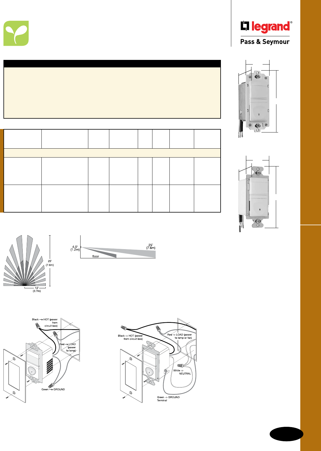
Coverage
L-5
Residential Occupancy SensorsOccupancy & Vacancy Sensors & Timers
All devices listed on this page conform to NEMA WD-1 and WD-6.
Occupancy & Vacancy Sensors & Timers
Residential Occupancy Sensors
Passive Infrared (PIR)
Features
n Replaces a standard light or fan single pole switch.
n Lighted switch for visibility in darkened rooms.
n Automatic-ON operation.
n Fixed five-minute time delay.
n Low-profile styling with uniform color-matched
lens and device.
n Coverage: 180°, max. 600 ft.2 (56m2)
n cULus listed.
n 5-year warranty.
n Works with most common residential
lighting types
RWU600U only
n Load: Incandescent, fluorescent, compact
fluorescent (CFL), magnetic low-voltage (MLV)
and electronic low-voltage (ELV), 1/6 hp
RW500ULACC4
1.69"
2.63"
1.88"
1.69"
2.63"
1.88"
RWU600ULACC4
RW500U Wiring
Wiring for RW500U does not require a neutral.
RWU600U Wiring
Wiring for RWU600U requires a neutral.
Selectable
Catalog Auto Manual Auto/Man.
Number Description Voltage Load ON ON ON Color
Single Pole Occupancy Sensors
RW500UICC4 Yes No No Ivory
RW500UWCC4 No neutral required, 120VAC 25-500W Yes No No White
RW500UBKCC4 ideal for storage 60 Hz Incandescent Yes No No Black
RW500ULACC4 and utility rooms Yes No No Lt. Almond
RWU600UICC4 Neutral required, Yes No No Ivory
RWU600UWCC4 controls most types 120VAC 0-600W Yes No No White
RWU600UBKCC4 of lighting, ideal for 60 Hz All Yes No No Black
RWU600ULACC4 storage & utility rooms Yes No No Lt. Almond

L-6
Occupancy & Vacancy Sensors & Timers
All devices listed on this page conform to NEMA WD-1 and WD-6.
Coverage
RW3U600 Wiring for 3-Way Operation
Residential Occupancy/Vacancy Sensors
Occupancy & Vacancy Sensors & Timers
Residential Occupancy/
Vacancy Sensors
3-Way Passive Infrared (PIR)
Applications
The RW3U600 has the flexibility to work in a variety of applications including hallways, stairways,
bathrooms, living and dining rooms, and other areas with multiple entries. The RW3U600 vacancy
sensor allows true multi-way operation with automatic ON/OFF control.
Features
n Occupancy-based control plus multi-way operation.
n Two or more RW3U600s connected together will
allow enhanced coverage of the controlled space.
n Works with most common residential lighting types.
n Adjustable time delay of 15 seconds to 30 minutes.
n Light level sensing prevents automatic ON of lights
when adequate daylight exists.
n Replaces three-way or four-way switches when used
with other RW3U600s.
n Lighted switch for visibility in darkened rooms.
n Manual- or automatic-ON operation.
n Adjustable light level setting of 10 to 150 fc
(100 to 1500 lux).
n Coverage: 180°, max. 600 ft.2 (56m2).
n cULus listed.
n 5-year warranty.
n Load: Incandescent, fluorescent, compact
fluorescent (CFL), magnetic low-voltage (MLV)
and electronic low-voltage (ELV), 1/6 hp
RW3U603 only
n California Title 24 compliant.
n Time delay 15 seconds, 5, 15, 30 minutes.
RW3U600W
shown with
SWP26W
2.8"
4.8"
1.5"
RW3U600W
RW3U603W
Dimensions for
RW3U603W:
2.67" (L) x
1.73" (W) x 1.77" (D)
Product Controls
RW3U600
Selectable Light
Catalog Auto Manual Auto/Man. Level
Number Description Voltage Load ON ON ON Color Sensing
Single Pole/3-Way Occupancy/Vacancy Sensors
RW3U600I* Light-level sensing for Yes Yes Yes Ivory Yes
RW3U600W* optimum operation – 120VAC 0-600W Yes Yes Yes White Yes
RW3U600BK* ideal for rooms with 60Hz All Yes Yes Yes Black Yes
RW3U600LA* multiple entrances Yes Yes Yes Lt. Almond Yes
RW3U603I** No Yes No Ivory No
RW3U603W** Ideal for rooms with 120VAC 0-600W No Yes No White No
RW3U603BK** multiple entrances 60Hz All No Yes No Black No
RW3U603LA** No Yes No Lt. Almond No
*RW3U600 requires an additional RW3U600 in multi-way circuits.
** RW3U603 can be used with either a momentary contact switch or an additional RW3U603 unit for multi-way applications.
Momentary contact switches on Page A-22.
RW3U603 Wiring for 3-Way Operation
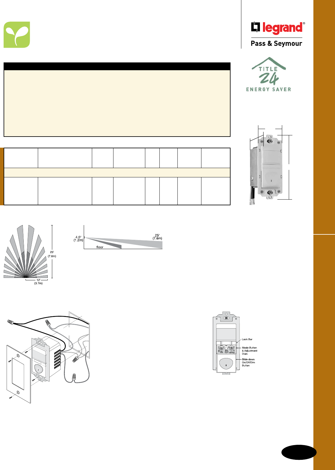
L-7
Occupancy & Vacancy Sensors & Timers
All devices listed on this page conform to NEMA WD-1 and WD-6.
Residential Occupancy/Vacancy Sensors
Occupancy & Vacancy Sensors & Timers
Residential Occupancy/
Vacancy Sensors
Passive Infrared (PIR) with Dimmer
1.73"
2.67"
1.77"
RWDU500W
Features
n California Title 24 compliant.
n Replaces standard single pole switch or
incandescent dimmer.
n Low-profile styling with uniform color-matched
lens and device.
n Lighted pushbutton for visibility in darkened rooms.
n Manual- or automatic-ON operation.
n Adjustable time delay from 15 seconds
to 30 minutes.
n Soft start technology to prolong lamp life.
n Air gap isolation switch for safe relamping.
n If enabled, light level sensing prevents
automatic-ON when adequate daylight exists.
n Adjustable light level setting from 10-150 fc
(100-1500 lux) for daylight sensing.
n Operating conditions: 32°-104°F (0°-40°C),
95% RH, noncondensing.
n Coverage: 180°, max. 600 ft2 (56 m2).
n cULus listed.
n 5-year warranty.
Selectable
Catalog Auto Manual Auto/Man.
Number Description Voltage Load ON ON ON Color
Occupancy/Vacancy Sensors with Preset Dimmers
RWDU500I Neutral required, ideal Yes Yes Yes Ivory
RWDU500W for living, dining and 120VAC 25-500 Yes Yes Yes White
RWDU500BK family rooms, master 60Hz Incandescent Yes Yes Yes Black
RWDU500LA bathrooms and bedrooms Yes Yes Yes Lt. Almond
RWDU500 Wiring
Green
->
GROUND
Black
->
HOT (power
from circuit box)
White
->
NEUTRAL
Red
->
LOAD (power
to dimmable lamp)
De-rating
When more that one dimmer is installed
in a multi-gang box, it is necessary
to reduce the maximum load on each
dimmer.
• For an RWDU500 in either end
position of a multi-gang box, reduce
the maximum load by 50W.
• For an RWDU500 in a central position
of a multi-gang box, reduce its
maximum load by 100W. Mounting in
a deep electrical box is recommended.
Coverage
Product Controls
RWDU500

Commercial Occupancy Sensors
L-8
Occupancy & Vacancy Sensors & Timers
All devices listed on this page conform to NEMA WD-1 and WD-6.
Occupancy & Vacancy Sensors & Timers
Commercial Occupancy Sensors
Wall Box Passive Infrared (PIR)
Single Level Lighting WSP250 Manual Bi-level Lighting WSP250
Catalog
Number Description Voltage Load Color
PlugTail™ Automatic Wall Switches – 3 Wire Technology
PTWSP250I Ivory
PTWSP250W PIR 120/277VAC; 800W Max. at 120V White
PTWSP250GRY Occupancy Sensor 60 Hz 1200W Max. at 277V Gray
PTWSP250LA Light Almond
Automatic Wall Switches – 3 Wire Technology
WSP250I Ivory
WSP250W PIR 120/277VAC; 800W Max. at 120V White
WSP250GRY Occupancy Sensor 60 Hz 1200W Max. at 277V Gray
WSP250LA Light Almond
Features
n Detection Signature Analysis provides high
immunity to RFI and EMI.
n Compact, decorator design replaces existing
wall switch.
n Shallow back body (1")
n Integrated light level sensor works from
10 to 150 footcandles.
n Compatible with all electronic and magnetic
ballasts, PL lamp ballasts, compact fluorescent.
n Adjustable time delay of 30 seconds to 30 minutes.
n Dual 120/277VAC operation.
n 30% to 60% energy savings.
n Positive detection indicator.
n No minimum load requirement.
n Adjustable sensitivity from 20% to 100%.
n Patented voltage drop protection.
n Patented Zero Crossing Circuitry.
n 180° coverage of up to 900 sq. ft.
n cULus listed.
n 5-year warranty.
PlugTail™ PTWSP250 Only
n No exposed terminals create a finger-
safe application before, during, and after
installation.
n Built-in connector features large brass
terminal blades to ensure consistent,
reliable electrical connections.
WSP250 Only
n 6" flying leads
Planning a Layout
The WSP250’s 2-level lens provides superior coverage at desktop level by allowing the sensor
to detect vertical as well as horizontal motion. Coverage shown is for walking motion. Under
optimum conditions with a high level of activity and with no barriers or obstacles, coverage can
reach a maximum of 900 square feet. Under a typical, desktop level of activity, when mounted
at 4 feet, coverage is 300 square feet.
WSP250
Factory settings: 30 min. time
delay, maximum light level and
sensitivity
PTWSP250W
1.55"
2.6"
1.7"
WSP250W
1.55"
2.6"
1.7"
PTS6STR3
1.125"
6.375"
Technical
Specifications on
Page S-139.
PlugTail™ Wall Switch
Sensors use PTS
Single Pole PlugTail™
Connectors. See Page
A-14.
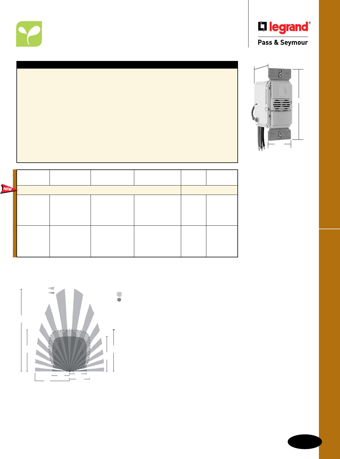
L-9
Occupancy & Vacancy Sensors & Timers
All devices listed on this page conform to NEMA WD-1 and WD-6.
Commercial Occupancy Sensors
Occupancy & Vacancy Sensors & Timers
Commercial Occupancy Sensors
Dual Technology Wall Box
Features
n Adjusts time delays automatically based on actual
usage patterns
n Assigns short delays (as low as 7 minutes) when
the space is typically vacant, and longer delays
(up to 30 minutes) for busier times
n Differentiates electrical noise from human motion
n Fixed mode – 5, 15, or 30 minutes.
n Walk-through mode – turns lights off 3 minutes after
the room is initially occupied if no motion is detected
after 30 seconds.
n Test mode – allows quick and easy adjustments.
n Sensitivity adjustment.
n Color-matched lenses and low profile for
appealing design.
n Choice of auto-ON or manual-ON operation.
n Fast, easy installation/switch-out.
n Zero-crossing for long relay life.
n High sensitivity and dense coverage for
exceptional performance.
n cULus listed.
n 5-year warranty.
n WDT200 offers bi-level control of two
loads independently from the same box.
- Built-in sensor holds secondary lights
off until daylight levels drop
- Each relay can be set for automatic or
manual ON
- Dual ON/OFF buttons can control each
of the loads manually as well WDT100W
Coverage
Catalog
Number Description Voltage Load Coverage Color
Dual Technology Wall Switch Sensors
WDT100I Ivory
WDT100W White
WDT100BK Black
WDT100GRY Gray
WDT100LA Light Almond
WDT200I Ivory
WDT200W White
WDT200BK Black
WDT200GRY Gray
WDT200LA Light Almond
Dual Technology
Wall Switch
Sensor
Bi-Level
Dual Technology
Wall Switch
Sensor
120/230/277VAC,
50/60Hz
120VAC, 0-800W
ballast or tungsten,
1/6HP 230/277VAC,
0-1200 ballast
1050
sq. ft.
120/230/277VAC,
50/60Hz
120VAC, 0-800W
ballast or tungsten,
1/6HP 230/277VAC,
0-1200 ballast
1050
sq. ft.
1.76"
2.73"
1.83"
PIR Coverage
7.5’
(2.2m)
15’
(4.5m)
20’
(6.1m)
35’
(10.6m)
Major motion
Minor motion
Ultrasonic
Coverage
10'
(3.0m)
7.5’
(2.2m)
20’
(6.1m)
15’
(4.5m)
Major motion
Minor motion
Technical Specifications on Page S-140.
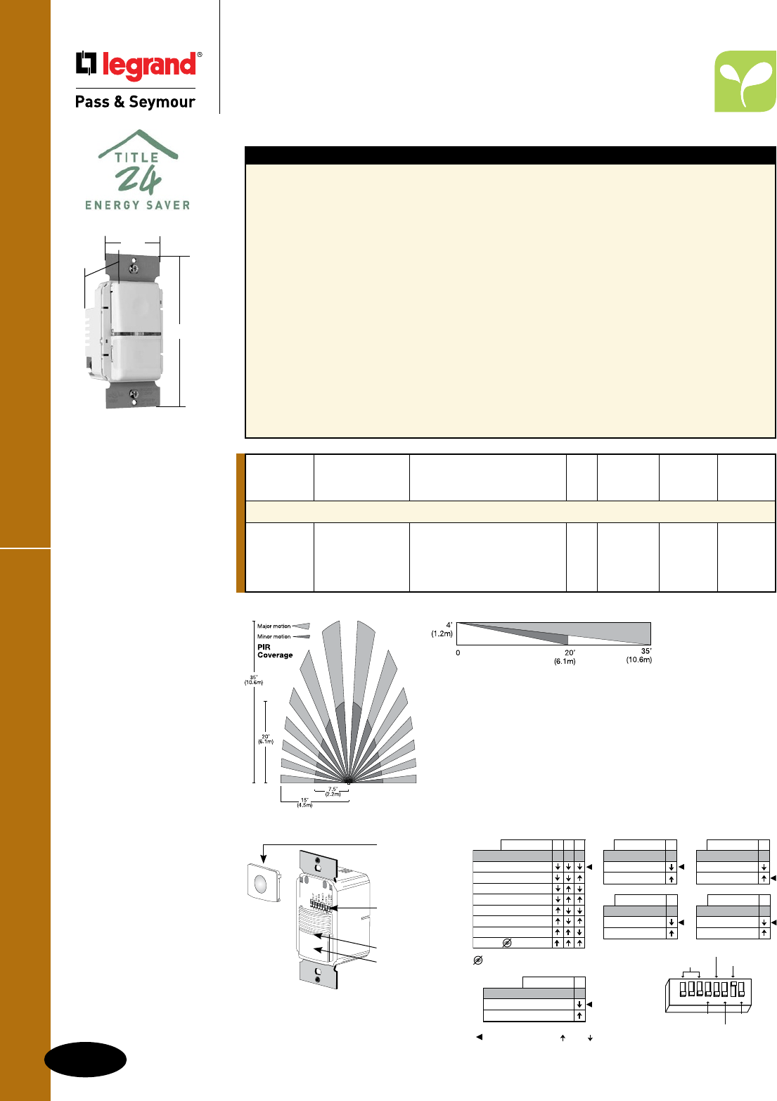
L-10
Occupancy & Vacancy Sensors & Timers
All devices listed on this page conform to NEMA WD-1 and WD-6.
Commercial Occupancy/Vacancy Sensors
Occupancy & Vacancy Sensors & Timers
Commercial Occupancy/
Vacancy Sensors
Wall Box Passive Infrared (PIR)
Features
n Detection signature processing eliminates false
triggers and provides immunity to RFI and EMI.
n Zero-crossing for long relay life.
n Vandal-resistant lens combines precise
coverage with durability.
n Choice of Auto-ON or Manual-ON operation.
n Auto adjustable time delays: automatic, fixed
(5, 10, 15, 20, 25 or 30 minutes), walk-through,
test-mode.
n Selectable time delay automatically adjusts
for maximum savings.
n Walk-through mode turns lights off 3 minutes
after the area is initially occupied – ideal for
brief visits such as mail delivery.
n Selectable test mode allows quick and
easy adjustments.
n Selectable audible alert for impending shutoff.
n In AUTO-ON mode, if the sensor is manually
turned OFF, AUTO-ON will not enable until no
motion is detected for 5 minutes. This prevents the
light from turning ON when it was intended they
remain OFF. Ideal for presentations.
n LED indicates occupancy detection.
n Built-in light level sensing with simple,
one-step setup.
n Override mode allows sensor to operate as a
service switch in the unlikely event of a failure.
n NEMA WD 7 guideline utilized for coverage testing.
n Sensitivity adjustment: PIR (high/low).
n Coverage: 180°, up to 1050 sq. ft.;
major motion 35' x 30'; minor motion 20' x 15'.
n cULus listed.
n 5-year warranty.
n Load: Incandescent, fluorescent, compact
fluorescent (CFL), magnetic low-voltage (MLV)
and electronic low-voltage (ELV), 1/6 hp
For best performance, Legrand/Pass & Seymour
recommends using this sensor in spaces no
larger than 15' x 20'.
Occupant Selectable
Catalog Warning Auto/Man.
Number Description Rating Load Before OFF ON Color
Single-Pole Occupancy/Vacancy Sensors
OS300SI Self-adaptive 120/230/277VAC; 50/60 Hz. Yes Yes Ivory
OS300SW design remembers @ 120VAC, 0-800 W ballast All Yes Yes White
OS300SGRY ON/OFF cycles or tungsten, 1/6 hp. Yes Yes Gray
OS300SLA @ 230/277VAC, 0-1200 W ballast. Yes Yes Lt. Almond
OS300SW
1.76"
2.73"
1.83"
DIP Switch Settings
Technical Specifications on Page S-139.
Coverage
Product Controls
OS300S
ON/OFF Button
DIP Switches
Detection LED
PIR Lens
5
$XWR2Q
0DQXDO2Q
ON Mode
6PDUW6HW7HVW
PLQXWHV
PLQXWHV
PLQXWHV
PLQXWHV
PLQXWHV
RYHUULGH
PLQXWHV
123
Time Delay
',36ZLWFKV
21 2))
6
+LJK
/RZ
Sensitivity
4
'LVDEOHG
(QDEOHG
Walk Through
7LPH'HOD\
)$&725<
35(6(76
:DON7KURXJK
21
2Q0RGH
6HQVLWLYLW\
$XGLEOH$OHUWV
9LVLEOH$OHUWV
)DFWRU\6HWWLQJV
7
'LVDEOHG
(QDEOHG
Audible Alerts
',36ZLWFK
',36ZLWFK
8
'LVDEOHG
(QDEOHG
Visible Alerts
',36ZLWFK
',36ZLWFK
',36ZLWFK
%\SDVVRFFXSDQF\OLJKWOHYHOIXQFWLRQV
/RDGLVPDQXDOO\FRQWUROOHGZLWK:6EXWWRQ
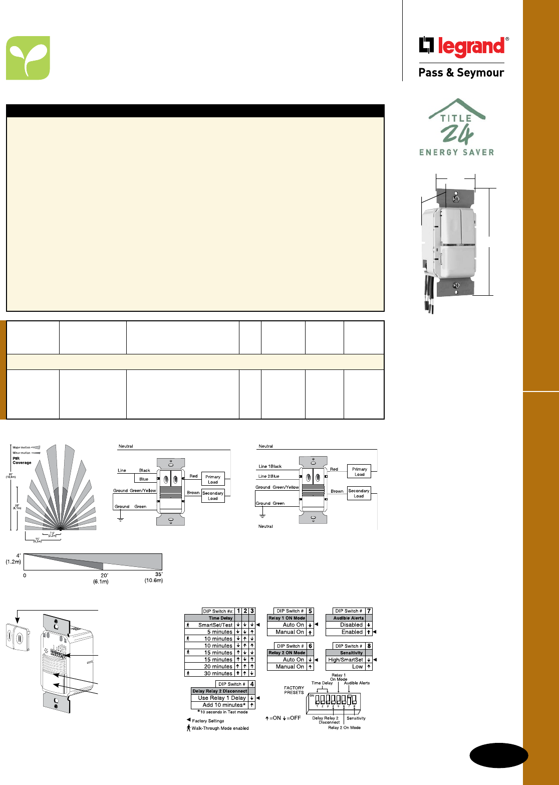
L-11
Occupancy & Vacancy Sensors & Timers
All devices listed on this page conform to NEMA WD-1 and WD-6.
Commercial Occupancy/Vacancy Sensors
Occupancy & Vacancy Sensors & Timers
Commercial Occupancy/
Vacancy Sensors
Bi-Level Wall Box Passive Infrared (PIR)
For best performance, Legrand/Pass & Seymour recommends
using this sensor in spaces no larger than 15' x 20'.
Features
n Detection signature processing eliminates false
triggers and provides immunity to RFI and EMI.
n Zero-crossing for long relay life.
n Vandal-resistant lens combines precise
coverage with durability.
n Choice of Auto-ON or Manual-ON operation,
selectable for each relay.
n Auto adjustable time delays: automatic,
fixed (5, 10, 15, 20, 25 or 30 minutes),
walk-through, test-mode.
n Selectable time delay automatically adjusts
for maximum savings.
n Selectable walk-through mode turns lights off
three minutes after the room is initially occupied
if no motion is detected after the first 30 seconds.
n Selectable test mode allows quick and
easy adjustments.
n Selectable audible alert for impending shutoff.
n In AUTO-ON mode, if the sensor is manually
turned OFF, AUTO-ON will not enable until no
motion is detected for 5 minutes. This prevents
the light from turning ON when it was intended
they remain OFF. Ideal for presentations.
n LED indicates occupancy detection.
n Built-in light level sensing with simple,
one-step setup.
n Override mode allows sensor to operate as a
service switch in the unlikely event of a failure.
n NEMA WD 7 guideline utilized for coverage testing.
n Sensitivity adjustment: PIR (high/low).
n Coverage: 180°, up to 1050 sq. ft.;
major motion 35' x 30'; minor motion 20' x 15'.
n cULus listed.
n 5-year warranty.
n Load: Incandescent, fluorescent, compact
fluorescent (CFL), magnetic low-voltage (MLV)
and electronic low-voltage (ELV), 1/6 hp.
Coverage
Occupant Selectable
Catalog Warning Auto/Man.
Number Description Rating Load Before OFF ON Color
Single-Pole Dual-Relay Occupancy/Vacancy Sensors
OSR300SI Operates both 120/230/277VAC; 50/60 Hz. Yes Yes Ivory
OSR300SW circuits of a bi-level @ 120VAC, 0-800 W ballast All Yes Yes White
OSR300SGRY lighting system or tungsten, 1/6 hp. Yes Yes Gray
OSR300SLA @ 230/277VAC, 0-1200 W ballast. Yes Yes Lt. Almond
OSR300S Bi-Level Wiring OSR300S Two Circuit Level Wiring
DIP Switch Settings
Technical Specifications on Page S-139.
OSR300SW
1.76"
2.73"
1.83"
Product Controls
OSR300S
ON/OFF Button
DIP Switches
Detection LED
PIR Lens

Occupancy & Vacancy Sensors & Timers
Commercial Occupancy Sensors
Wall or Ceiling Mount Passive Infrared (PIR)
All devices listed on this page conform to NEMA WD-1 and WD-6.
Features – WA1001 and HS1001
n Detection Signature Analysis provides high immunity
to RFI and EMI.
n 2 coverage patterns to choose from.
n Wall mount or ceiling mount.
n Adjustable sensitivity settings.
n Digital time delay from 15 seconds to 30 minutes.
n Dual-element, temperature-compensated
pyroelectric sensor.
n LED occupancy detection indicator.
n Compatible with 120VAC or 277VAC, 60 Hz
lighting systems.
n Class 2 low-voltage device.
n Positive detection indicator.
n cULus listed.
n 5-year warranty.
WA1001
HS1001
For best results, the bracket should
be used in every installation to allow
for greatest exibility of adjustment.
Brackets are included with each unit.
2.034"
3.335"
3.367"
HS1001WA1001
Catalog Current
Number Description Voltage Draw Coverage Color
Wall/Ceiling Mount Sensors
WA1001 Wide Angle PIR 24VDC 8mA Up to 1200 sq. ft. White
Occupancy Sensor
HS1001 Long Range PIR 24VDC 8mA Up to 50 linear ft. White
Occupancy Sensor
Reference Page L-16 for Power Packs.
Wiring Diagram
Occupancy & Vacancy Sensors & TimersCommercial Occupancy Sensors
Detection of motion toward the sensor
begins at a max. of 50'. Reliable
detection occurs at 35' to 40'.
L-12
Technical Specifications on
Pages S-141 and S-142.
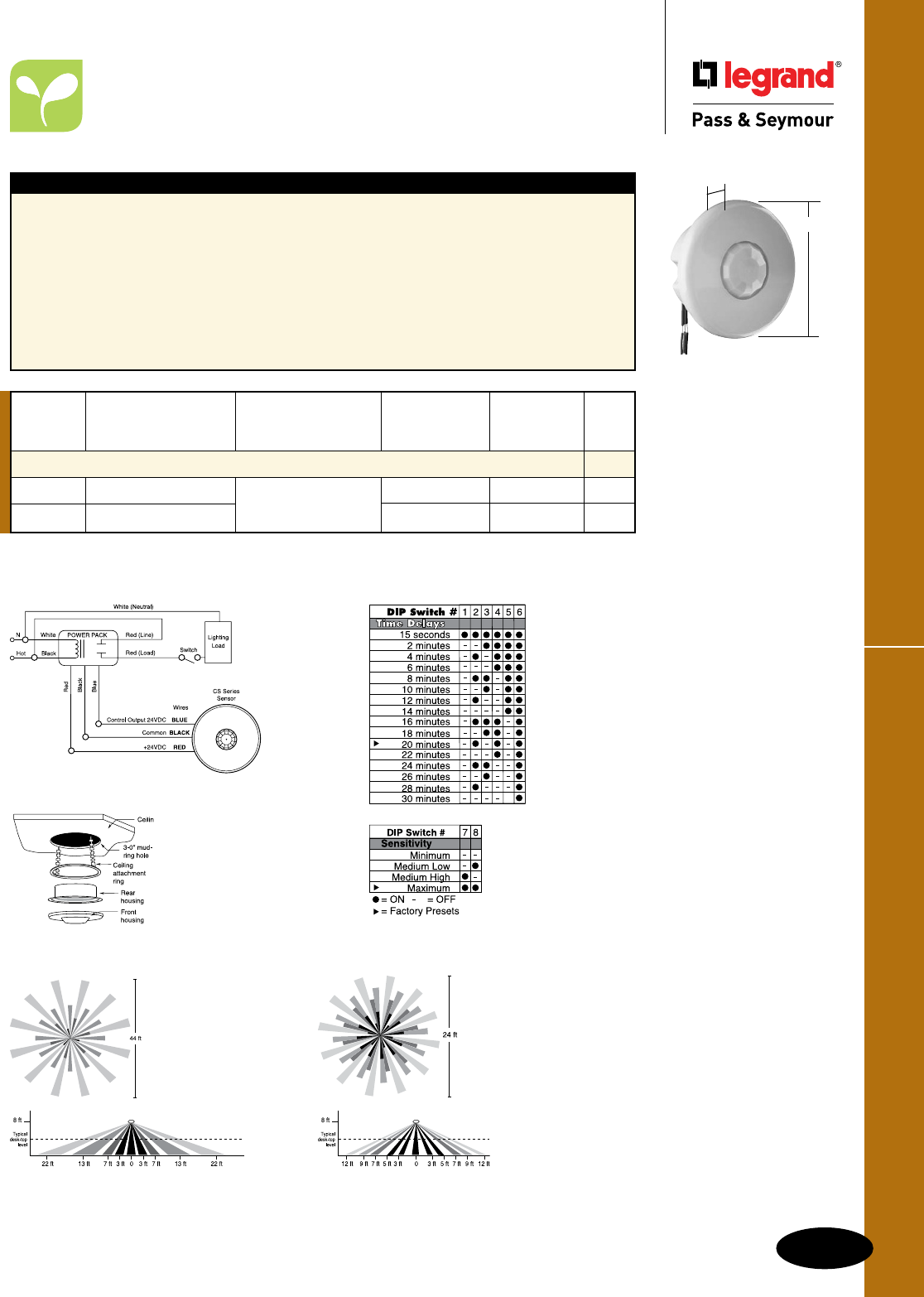
L-13
Commercial Occupancy SensorsOccupancy & Vacancy Sensors & Timers
Occupancy & Vacancy Sensors & Timers
Commercial Occupancy Sensors
Ceiling Mount Passive Infrared (PIR)
CS500
CS1200
2.2"
3.3"
Features
n ASIC technology reduces components and
enhances reliability.
n Pulse count processing eliminates false offs
without reducing sensitivity.
n Detection signature analysis eliminates false
triggers and proves immunity to RFI and EMI.
n Low-profile design ensures a clean and
uncluttered ceiling appearance.
n User-adjustable time delay from 15 seconds to
30 minutes by two minute increments.
n Sensitivity is programmed through a DIP switch
and has four settings from minimum to
maximum.
n Dual-element, temperature compensated pyro-
electric sensor.
n Mounting options: ceiling tile or 3.0 inch round
mudring.
n Units per power pack: up to 13.
n cULus listed.
n 5-year warranty.
Reference Page L-16 for Power Packs.
Mounting – CS1200
Override and
Catalog Output
Number Description Rating Coverage Disable Color
Low-Profile Ceiling Mount Sensors
CS500 PIR Occupancy Sensor 24VDC Input, requires 360°, 500 sq. ft. No White
CS1200 PIR Occupancy Sensor Power Pack 11mA 360°, 1200 sq. ft. No White
DIP Switch Settings
CS500/CS1200 Wiring
Technical Specifications on Page S-143.
Extended Range Lens
(Standard)
CS1200
Coverage
High Density Lens
CS500
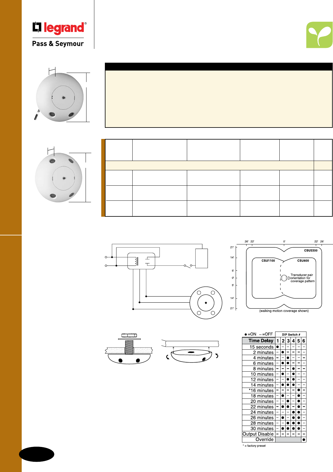
Commercial Occupancy Sensors
L-14
Occupancy & Vacancy Sensors & Timers
All devices listed on this page conform to NEMA WD-1 and WD-6.
Occupancy & Vacancy Sensors & Timers
Commercial Occupancy Sensors
Ultrasonic Ceiling Mount
CSU1100
CSU2200
1.5"
4.8"
Features
n Advanced signal processing circuitry helps to
eliminate false ONs.
n Utilizes advanced, omni-directional (360°), Doppler
technology for reliable occupancy detection.
n Angled transmitter and receiver pairs help
optimize sensitivity while eliminating unwanted
detection from ceiling air movement.
n Digital DIP switch time delay (15 seconds to
30 minutes).
n LED indicates occupancy detection.
n Reliable solid-state construction.
n Temperature and humidity resistant 32 kHz
receivers.
n Mounts to ceiling tiles or box.
n Units per power pack: up to 4.
n cULus listed.
n 5-year warranty.
Reference Page L-16 for Power Packs.
Override and
Catalog Output
Number Description Rating Coverage Disable Color
Ultrasonic Ceiling Mount Sensors
CSU600 Ultrasonic 24VDC Input, requires 360°, 500 sq. ft. Yes White
Occupancy Sensor Power Pack 27mA One-sided
CSU1100 Ultrasonic 24VDC Input, requires 360°, 1100 sq. ft. Yes White
Occupancy Sensor Power Pack 30mA Two-sided
CSU2200 Ultrasonic 24VDC Input, requires 360°, 2200 sq. ft. Yes White
Occupancy Sensor Power Pack 30mA Two-sided
Control Output 24VDC
Common
+24VDC
Lighting
Load
White (Neutral)
Red (Load)
Red (Line)
White
BlackHot
NPOWER PACK
Red
Black
Blue
Optional
Switch
(BLU)
(RED)
(BLK)
CSU600/CSU1100/CSU2200 Wiring Coverage
Mounting
Attached to a vibration-free surface. Mount the
sensors with the receivers facing the area of coverage.
Note: Place 4' away from supply ducts, 6' from
horizontal discharge ducts, and 6" from power packs.
Technical Specifications on Page S-144.
CSU600
1.5"
4.8"
DIP Switch Settings
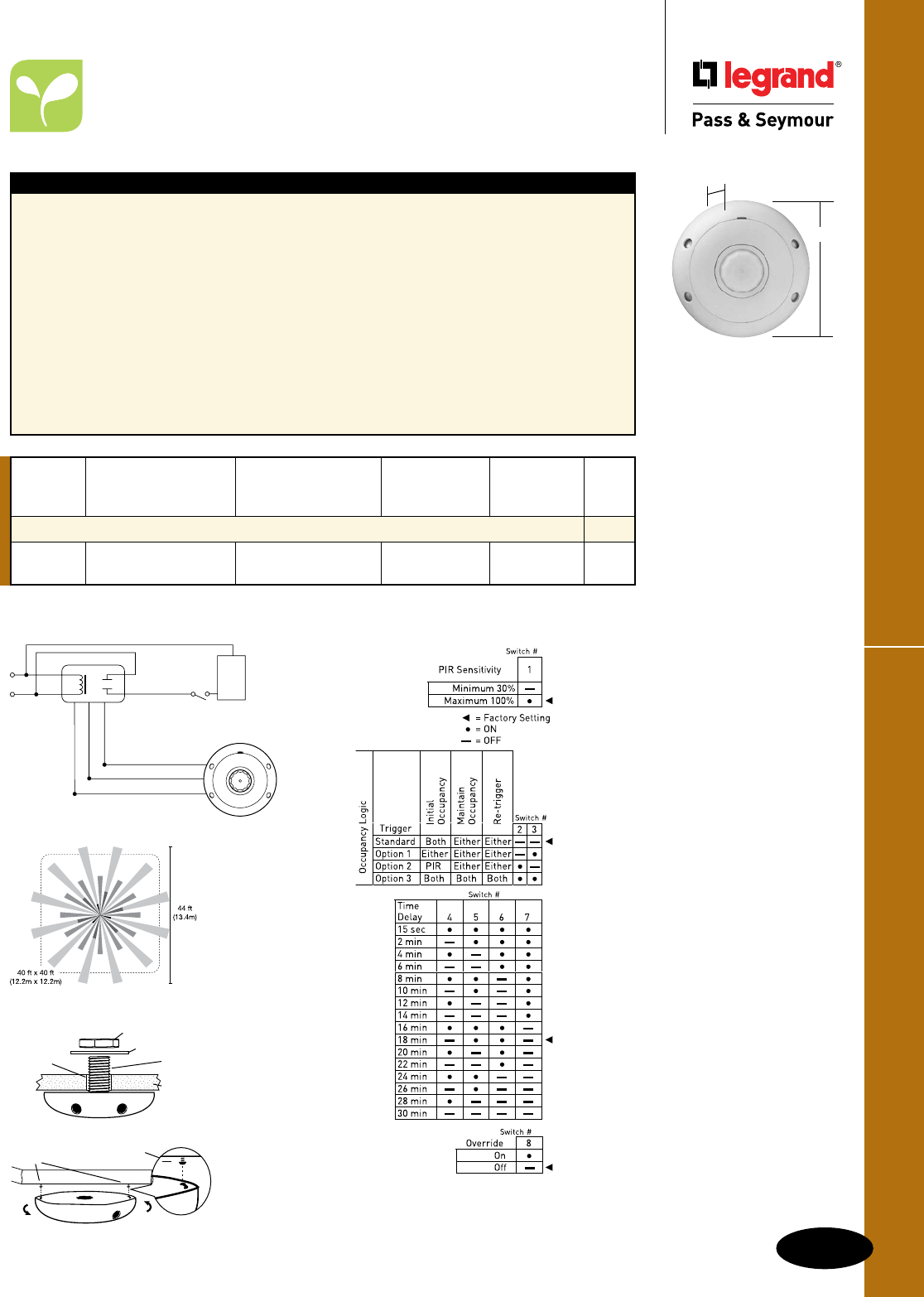
L-15
Commercial Occupancy SensorsOccupancy & Vacancy Sensors & Timers
All devices listed on this page conform to NEMA WD-1 and WD-6.
Occupancy & Vacancy Sensors & Timers
Commercial Occupancy Sensors
Dual Technology Ceiling Mount
Technical Specifications on Page S-145.
CSD1000
1.02"
4.5"
Features
n Advanced control logic based on RISC
microcontroller provides:
- Detection signature processing eliminates false
triggers and provides immunity to RFI and EMI.
n Walk-through mode turns lights off three minutes
after the area is initially occupied – ideal for brief
visits such as mail delivery.
n Simple, one-step setup.
n Ultrasonic diffusion technology spreads coverage
to a wider area (patented).
n LEDs indicate occupancy detection.
n Four occupancy logic options give users the ability
to customize control to meet application needs.
n Ultrasonic frequency of 40 kHz.
n Time delays: automatic, fixed (5, 10, 15, 20, or
30 minutes), walk-through, test-mode.
n Sensitivity adjustment: reduce sensitivity (for
PIR sensitivity); ultrasonic sensitivity is variable
with trimpot
n Multi-level, 360° Fresnel lens for superior
occupancy detection.
n Mounting options: ceiling tile; 4 square junction
box with double gang mudring.
n Units per power pack: up to 4.
n cULus listed.
n 5-year warranty.
Reference Page L-16 for Power Packs.
Override and
Catalog Output
Number Description Rating Coverage Disable Color
Low-Profile Ceiling Mount Sensors
CSD1000 Dual Technology 24VDC Input, requires 360°, 1000 sq. ft. Yes White
Occupancy Sensor Power Pack 35mA Two-sided
Control Output 24VDC
Common
+24VDC
Lighting
Load
White (Neutral)
Red (Load)
Red (Line)
White
BlackHot
NPOWER PACK
Red
Black
Blue
Optional
Switch
(BLU)
(RED)
(BLK)
CSD1000 Wiring
Coverage
Mounting
Nut
Washer
7/8" (22mm)
hole Threaded
Insert
Ceiling
Tile
Rotate
clockwise
Ceiling
Screws:
103mm (4.1") apart
Space:
3mm/(1/8")
DIP Switch Settings
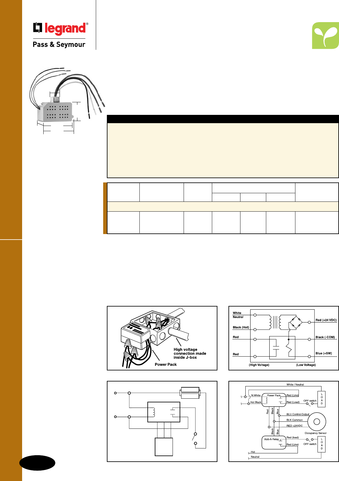
All devices listed on this
page conform to NEMA
WD-1 and WD-6.
Power Packs & Add-A-Relay
Occupancy & Vacancy Sensors & Timers
Power Packs & Add-A-Relay
Occupancy & Vacancy Sensors & Timers
L-16
A cost-effective way to power Legrand/Pass & Seymour®
occupancy sensors.
Legrand/Pass & Seymour universal voltage power packs consist of a transformer and high-current relay in
one small unit. In addition to a primary high input, power packs have a secondary output of 24VDC, 114mA
which provides operating power to sensors. Upon sensing motion or insufficient light, sensors electrically
close an internal circuit and send 24VDC back to the power packs or Add-A-Relays that control lighting
systems. Unlike power packs, Add-A-Relay does not have transformer power supply, only an isolated relay.
Power packs can switch a maximum 20 Amps of fluorescent lighting. Both power packs and Add-A-Relay
are available for 120 and 277 Volt systems.
Catalog Input Load Ratings
Number Description Voltage Ballast (A) Incan. (A) Motor (HP) Output
Power Packs & Add-A-Relay
PWP120277 Universal Voltage 120/230/ 20 20 1* 24VDC; 225mA**
Power Pack 277
AR120/277 Add-A-Relay 120/277 20 13 1 0†
Constructed with environmentally friendly materials and is RoHS-compliant.
*1HP rated at 120/250VAC.
**Output is 225mA with relay connected.
†Add-A-Relay has a current consumption of 36mA.
Installation
Power packs should be installed in accordance with state, local, and national electrical codes. They are
designed to attach to electrical enclosures with 1/2 inch knockouts. In plenum ceilings, power packs should
be installed in approved electrical enclosures. Most applications require UL listed, 18-22 AWG, 3-conductor,
class 2 cable for low-voltage wiring. For plenum rated ceilings use UL listed plenum-approved cables.
Power Pack SchematicsJ-Box Installation
Sensor Schematic with Add-A-RelayCeiling Sensor with Power Pack
Neutral
Red
White
BlackHot
Power
Pack
Red
Blue
Switch
Black
Red
Load
Load
24VDC
Sensor
Technical Specifications
on Page S-146.
For additional Wiring
Diagrams, see
Pages S-18 and S-19.
2.805"
2.916"
1.634"
.842"
1.673"
PWP120277
AR120/277
Features
n Efficient switching power supply provides optimized
current output based on number of sensors.
n Essential to ceiling mount sensor systems.
n Self-contained power supply relay system.
n UL 2043 plenum rated for cost-effective installation.
n UL-rated 94 V0 plastic enclosure.
n 1/2" snap-in nipple attaches to standard electrical
enclosures through 1/2" knockouts.
n LED indicates status of relay or
low-voltage overcurrent.
n Secondary voltage: 24VDC;
Secondary output: 225mA.
n Easy-to-install.
n cULus listed.
n 5-year warranty.
L-17
Occupancy & Vacancy Sensors & Timers
Occupancy & Vacancy Sensors & Timers
Useful Calculations
Useful Calculations
Multi-Sensor Installation
For applications requiring more than one sensor, the load per power pack should not
exceed 225mA. Use the following table to calculate the maximum number of sensors per
power pack.
Examples:
2 x CSU1100 (30mA) = 60mA 4
This is an acceptable load because it is less than 150mA.
4 x CSU1100 (30mA) + 1 x AR120/277(36mA) = 156mA 7
This is not an acceptable load because it is greater than 150mA.
Examples of savings and payback
EXAMPLE 1
Large office using a WA1001 Passive Infrared Sensor
Six 88-watt, 3-lamp fixtures = 0.528 kW x $0.086/kWh* = $0.04541/hr
Savings = 35 hours per week
Total hours saved = 1,820 hrs/yr
Annual Savings = $82.65; 5 Year Savings = $413.23
Total estimated cost including power pack: (Product and Labor) = $140.00
Payback = 20.33 months
ROI = $82.65 ÷ $140.00 = 59.03%
Individual office using a CS500 PIR Ceiling Sensor
Three 88-watt, 3-lamp fixtures = 0.264 kW x $0.086/kWh* = $0.02270/hr
Savings = 50 hours per week
Total hours saved = 2,600 hrs/yr
Annual Savings = $59.02; 5 Year Savings = $295.10
Total estimated cost: (Product and Labor) = $54.00
Payback = 10.98 months
ROI = $59.02 ÷ $54.00 = 109.30%
EXAMPLE 2
Restroom using a CSU1100 Ultrasonic Occupancy Sensor
Four 88-watt, 3-lamp fixtures = 0.352 kW x $0.086/kWh* = $0.03027/hr
Savings = 75 hours per week
Total hours saved = 3,900 hrs/yr
Annual Savings = $118.05; 5 Year Savings = $590.27
Total estimated cost: (Product and Labor) = $160.00
Payback = 16.26 months
ROI = $118.05 ÷ $160.00 = 73.78%
EXAMPLE 3
*Based on 2004 US Government National average cost.
WA1001 CS500/1200 HS1001 CSU600 CSU1100/2200 AR120/277 CSD1000
8mA 11mA 8mA 27mA 30mA 36mA 35mA

L-18
Occupancy & Vacancy Sensors & TimersTimers
Occupancy & Vacancy Sensors & Timers
Timers
Time-
Catalog Running-Out
Number Description Rating Load Warning Color
Digital Timers
RT1I No Ivory
RT1W 7-Button Digital Timer, 0-600W, 1/6 hp @ 120VAC 60 Hz All No White
RT1BK Neutral required No Black
RT1LA No Light Almond
RT1 Wiring
Features
n Seven-button preset time switch.
n Manual ON/OFF.
n Adjustable time delay: 1, 5, 10, 20, 30, 60 minutes.
n Lighted switch for visibility in darkened rooms.
n Controls most types of lighting.
n cULus listed.
n 5-year warranty.
n Load: Incandescent, fluorescent, compact
fluorescent (CFL), magnetic low-voltage (MLV)
and electronic low-voltage (ELV), 1/6 hp
RT1LA
shown with
SWP26LA
1.69"
3.281"
1.88"
RT1LA
Product Controls
RT1
Six time selection
buttons with activation
indicator lights
ON/OFF Button
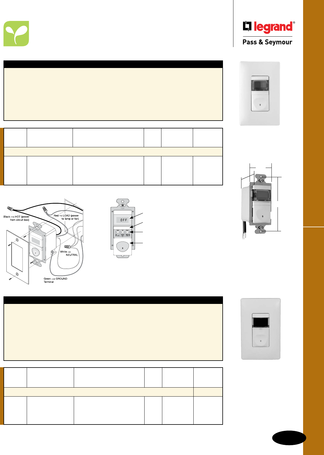
L-19
Occupancy & Vacancy Sensors & Timers
All devices listed on this page conform to NEMA WD-1 and WD-6.
Timers
Occupancy & Vacancy Sensors & Timers
Timers
RT12 Wiring
Features
n Programmable countdown time switch
n Manual ON/OFF.
n Digital countdown display.
n Adjustable time delay from 5-55 minutes
(five-minute increments) to 1-12 hours
(15-minute increments).
n Audible beep and visible light flash warnings
before automatic-OFF.
n Lighted switch for visibility in darkened rooms.
n Works with most common lighting types.
n cULus listed.
n 5-year warranty.
n Load: Incandescent, fluorescent, compact
fluorescent (CFL), magnetic low-voltage (MLV)
and electronic low-voltage (ELV), 1/6 hp
RT12W
shown with
SWP26W
1.69"
3.281"
1.88"
RT12LA
Time-
Catalog Running-Out
Number Description Rating Load Warning Color
Digital Timers
RT12I Yes Ivory
RT12W 12-Hour Digital Timer, 0-600W, 1/6 hp @ 120VAC 60 Hz All Yes White
RT12BK Neutral required Yes Black
RT12LA Yes Light Almond
Product Controls
Features
n Manual or programmed ON/OFF switching.
n Real time clock with day/date calendar.
n Easy to read LED display.
n Programming buttons accessible without removing
wall plate.
n Eight programs can be assigned to any day or
combination of days of the week.
n Automatically calculates sunrise and sunset times
based on latitude and longitude.
n Audible or visual occupant warning
before OFF.
n Power failure memory.
n Zero crossing circuitry.
n cULus listed.
n 5-year warranty.
n Load: Incandescent, fluorescent, compact
fluorescent (CFL), magnetic low-voltage (MLV)
and electronic low-voltage (ELV), 1/6 hp
RT12
LCD Display
Lock Bar
Programming Buttons
Slide Down:
ON/OFF Button
Time-
Catalog Running-Out
Number Description Rating Load Warning Color
Astronomic Programmable Timers
RT24I 0-800W @ 120V Yes Ivory
RT24W 24-Hour 0-1200W @ 277V All Yes White
RT24BK Programmable Timer 1/6 hp @ 120/277V Yes Black
RT24LA Yes Light Almond
RT24W
shown with
SWP26W
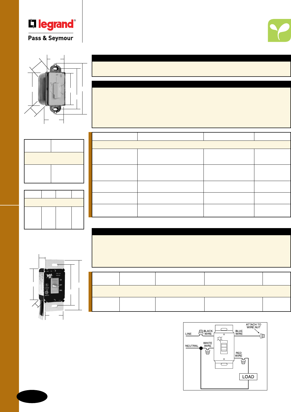
L-20
Occupancy & Vacancy Sensors & TimersWall Box Timers
All devices listed on this page conform to NEMA WD-1 and WD-6.
97015I
2.62"
1.80"
4.20"
3.281"
1.30"
2.76"
1.85"
1.80"
Catalog Number Description Time Range Color
Specification Grade Decorator Rotary Timers
97015I Ivory
97015W Timeout, No Hold 15 Minutes White
97015LA Light Almond
97030I Ivory
97030W Timeout, No Hold 30 Minutes White
97030LA Light Almond
97060I Timeout, No Hold 60 Minutes Ivory
97060W White
97115I Timeout, With Hold 15 Minutes Ivory
97115W White
97160I Timeout, With Hold 60 Minutes Ivory
97160W White
VAC Hz Amp HP
Ratings
125 60 20 1
125T 60 7
250 60 10 1
277 60 10
Catalog
Number Color
Replacement Knobs
(without plate)
PS55A1 White
PS55B1 Ivory
PS55G1 Light Almond
Applications
n Lighting
n Exhaust fans
n Whirlpools and spas
n Saunas
n Heating and heat lamps
n Ventilating and air conditioning
Features
n Units with “Hold” feature may be turned counter-clockwise to
hold the load on without timing function.
n Turning clockwise causes unit to time load off after desired
time delay.
n Quiet operation.
n Time range from 5 minutes to 12 hours.
n Available with or without hold.
n Decorator styling.
n Easily installed.
n Large head screw terminals.
n Accurate to ± 5 percent.
n Motor rated.
n Energy saving.
Operation:
Catalog Number 97352
n When toggle is up, one or two loads
remain on.
n When toggle is down, load “A” is off, load
“B” times-off at preset time. In the center
position, both loads are off.
Wiring Diagram: Single Timed Load Application
Catalog
Number Description Time Range Rating Color
Specification Grade Toggle Time Delay Switches
Center Off
97352I Double Pole, 1-60 Minutes, Adjustable 500W, 1/3 HP, 120VAC, 60 Hz Ivory
97352W Double Throw White
Features
n Eliminates the need for two switches.
n Fits standard toggle opening for easy ganging.
n Time range adjustable from 1-60 minutes.
n Easily installed.
n May control one or two loads simultaneously.
n Motor rated.
n Silent operation.
n Reliable solid-state construction.
n Energy saving.
97352I
4.15"
1.80"
3.281"
2.70"
1.70"
1.50"
Occupancy & Vacancy Sensors & Timers
Wall Box Timers
125, 125-T, 250 & 277VAC, 60 Hz

L-21
Notes
Notes

DIMMERS & FAN SPEED CONTROLS
M-1
Dimmers & Fan Speed Controls
Dimmers & Fan Speed Controls
Index
Device Page Number
Product Selection Guide M-2
Catalog Numbering System M-3
Residential Dimmers & Fan Speed Controls
RF Lighting Control System M-4 – M-7
Scene Director M-8, M-9, M-34
Leandro® M-10, M-34
Harmony™ TradeMaster® M-11, M-12, M-34
TradeMaster® Toggle M-18, M-19, M-20, M-36
Rotary R TradeMaster® Series M-21
Residential & Light Commercial Dimmers & Fan Speed Controls
LS TradeMaster® Series M-13 – M-15, M-35
DR TradeMaster® Series M-16, M-34
Wide Slide TradeMaster® Series M-17, M-36
Rotary TradeMaster® Series M-22, M-23, M-37
Commercial Dimmers & Fan Speed Controls
Titan™ Series M-24 – M-31, M-38
Rotary Dimmers M-32
Rotary Fan Speed Controls M-33, M-39
Today’s home and business owners want optimum control of
their electrical systems. P&S Dimmers & Fan Speed Controls
provide that control — along with aesthetics, durability,
trouble-free installation, and innovative technologies.
Benefits of Using Legrand/Pass & Seymour Dimming
Save Energy – Dimming reduces the amount of energy consumed by the
lamps which reduces energy costs.
Add ambience – Change the lighting to set the mood or highlight the décor.
Add comfort – Use only the light you need for the task.
Add flexibility – Change the look of the room and then change it back.
Quickly and easily.
Add convenience – Presets and scene controls make it easy to set up your
home the way you like with accuracy and repeatability.
Increase safety and security – Never drive up to a dark house again.
Lower maintenance costs – Dimming increases the life of incandescent
lamps.
Add value – A home with lighting controls is worth more.
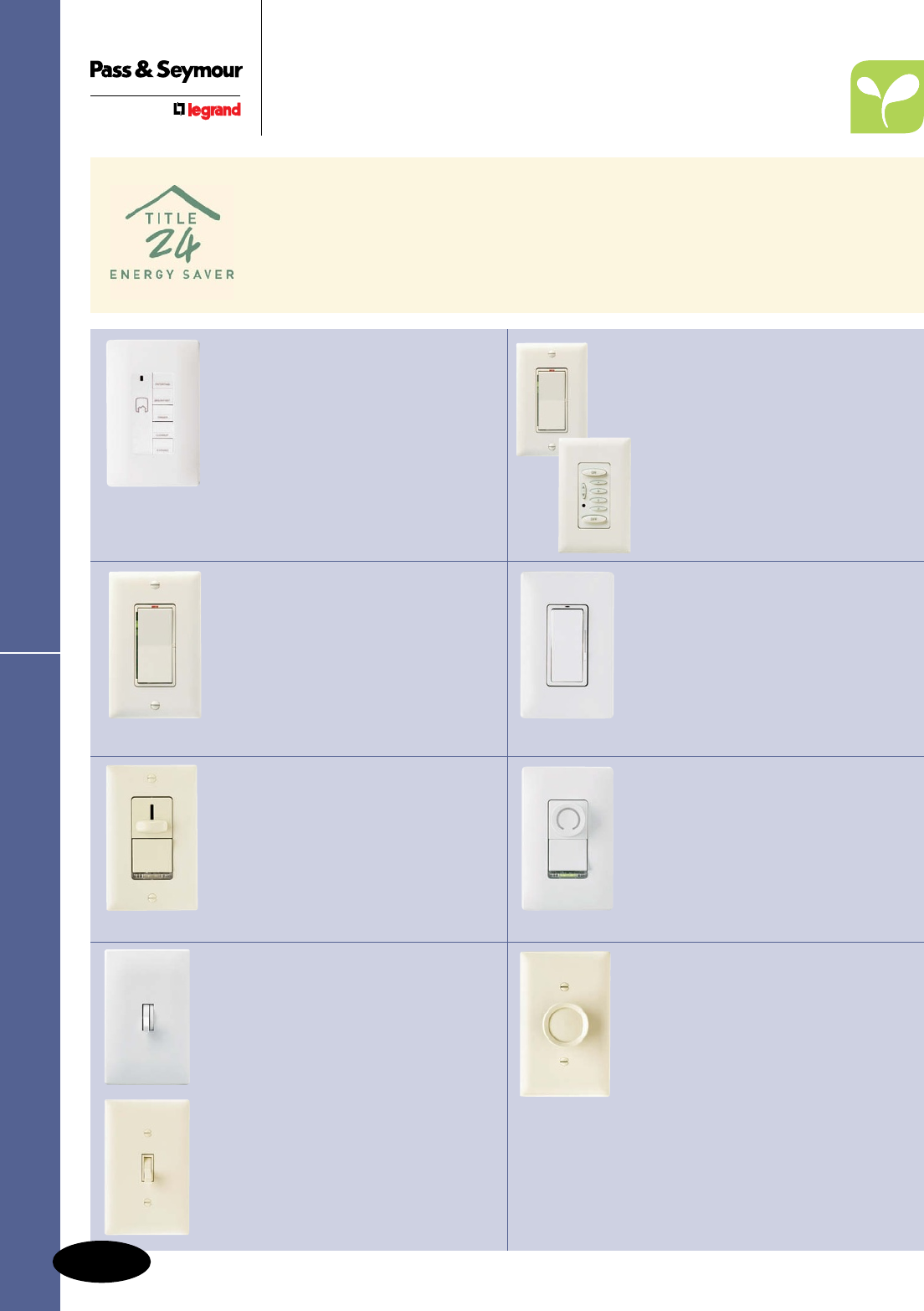
LS Series Decorator Slide
Dimmers
n Smooth,ergonomicoperation.
n Snap-inLEDlightmodulesmake
dimmerseasytofindatnight.
n Availableinbothpresetand
non-presetmodels.
PAGES M-13 – M-15
Leandro® Decorator Dimmers
n Multi-locationdimming.
n Lightlevelsfadeelegantlyup/down.
n GreenLEDsindicatepresetlevel;
redLEDmakesdimmerseasyto
findinthedark.
PAGE M-10
Rotary Dimmers
n Modelsforincandescentand
low-voltagelights;presetand
illuminatedfeaturesavailable.
n Simpletooperate.
n Availableinbothpresetand
non-presetmodels.
PAGE M-21
RF Lighting Control System
n Wholehouseandroomscene
controlsallowhomeownerstochange
theirenvironmentatthepushofa
button.
n Frequency-agileRadioFrequency
(RF)wirelesscommunications
technology.
n Simple,intuitiveprogrammingwithout
theuseofacomputerorcontroller.
PAGES M-4 – M-7
Harmony™ Decorator Dimmers
n MatchesP&SDecoratordevices.
n CombinesON/OFFDecorator
switchwithseparatesliderfor
dimmingcontrol.
n Nolostsettingsduringpower
outages.
PAGE M-11, M-12
DR Series Decorator Rotary
Dimmers
n Illuminatedknobshowslightlevel.
n Snap-inLEDlightmodulesmake
dimmerseasytofindatnight.
n Availableforincandescentand
low-voltagelighting.
PAGE M-16
Scene Director Control
n Selectanylightingsceneatthe
touchofabutton.
n Optionalinfraredremoteenables
controlfromanywhereintheroom.
n Mastercancontrolupto30
dimmers.
n Easytoprogram–andwon’tlose
programmingduringpoweroutage.
PAGES M-8, M-9
n Matchappearanceoftoggle
switches.
n Nolossofsettingsduringpower
outages.
n Illuminatedversionsavailable.
PAGE M-20
Toggle Dimmers
n Convenientpresetdimmingcontrol.
n CombinesON/OFFtogglewith
separatepresetfordimmingcontrol.
n Matchesappearanceoftoggle
switches.
PAGE M-18, M-19
Product Selection Guide Dimmers & Fan Speed Controls
Dimmers & Fan Speed Controls
Product Selection Guide
Energyconcernshavecreateddirectivesinsomestatesforlightingcontrolsinnewresidential
constructionandmajorrenovations.Inanefforttoreduceelectricalpowerconsumption,
Californiahasmandatedoneofthemoststringentenergycodesinthecountry.California
Title24requireshighefficacyluminaires,vacancysensors(SectionL),ordimmerstobe
placedincertainareasofthehome.ThestandardbecameeffectiveonOctober1,2005.
Otherstatesareconsideringadoptingsimilarmandatestoanswertheirownenergyconcerns.
Legrand/Pass&Seymourhasanextensiveselectionofvacancysensoranddimmersolutions
toaddressthisgrowingindustrytrend.
M-2
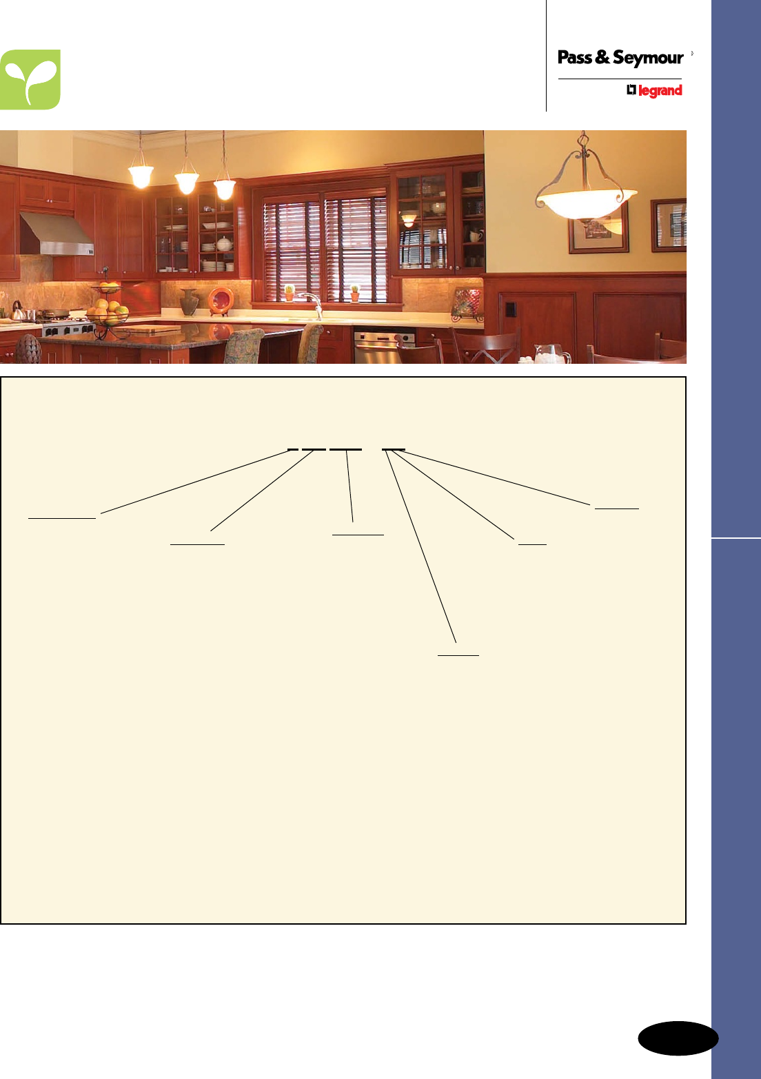
M-3
Catalog Numbering SystemDimmers & Fan Speed Controls
Dimmers & Fan Speed Controls
Catalog Numbering System
ManyP&SDimmers&FanSpeedControlsareavailableboxedorVisionPak™clam-shellpackagingforhigh-impactmerchandising.
PleaseseetheCatalogNumberingSystemaboveorspecificchartsfororderinginformation.
See Pages M-4 – M-7 to order RF Lighting Control System products.
Package
Blank=Box
V=VisionPak™
TK=TripleKnob
All P&S Dimmers and Fan Speed Controls use an easy-to-understand
catalog numbering system:
T LV 600 - *
Examples:
D600MLAV =DecoratorDimmer,Incandescent,600W,Multilocation,LightAlmond,inaVisionPak
LS600LA=DecoratorSlideDimmer,Incandescent,600W,LightAlmond,inaBox
SSSC5-WV =ShortSlide,FanSpeedControl,5Amp,White,inaVisionPak
Control Type
D=Decorator
LS=LongSlide
SC=SceneDirector
T=Toggle
R=Rotary
DR=Decorator
Rotary
Load Size
300=300Watt
600=600Watt/VA
603=600Watt/VA,3-Way
700=700Watt
703=700Watt3-Way
1000=1000Watt/VA
1003=1000Watt/VA,3-Way
1100=1100Watt
1103=1100Watt3-Way
1600=1600Watt
1603=1600Watt3-Way
2000=2000Watt
2003=2000Watt3-Way
3=3Amps
5=5Amps
7=7Amps
8=8Amps
10=10Amps
15=1.5Amps
16=1.6Ampsor16Amps
25=2.5Amps
Options
E=Electronic
Preset
L=Lighted
M=Multilocation
P=Preset
Color
BK=Black
(Blank)=Brown
CL=Clear
GRY=Gray
I=Ivory
LA=LightAlmond
LC=LightedClear
W=White
Load Type
Blank=Incandescent
FB=FluorescentBallast
IR=InfraredRemote
LV=MagneticLow-Voltage
ELV=ElectronicLow-Voltage
MC=MasterController
DC=DualDimmer/De-Hummer
SpeedControl
DV=Dimmer/VariableSpeed
Control
DH=De-Hummer
FanSpeedControl
SC=FanSpeedControl
Package
Blank=Box
V=VisionPak™
TK=TripleKnob
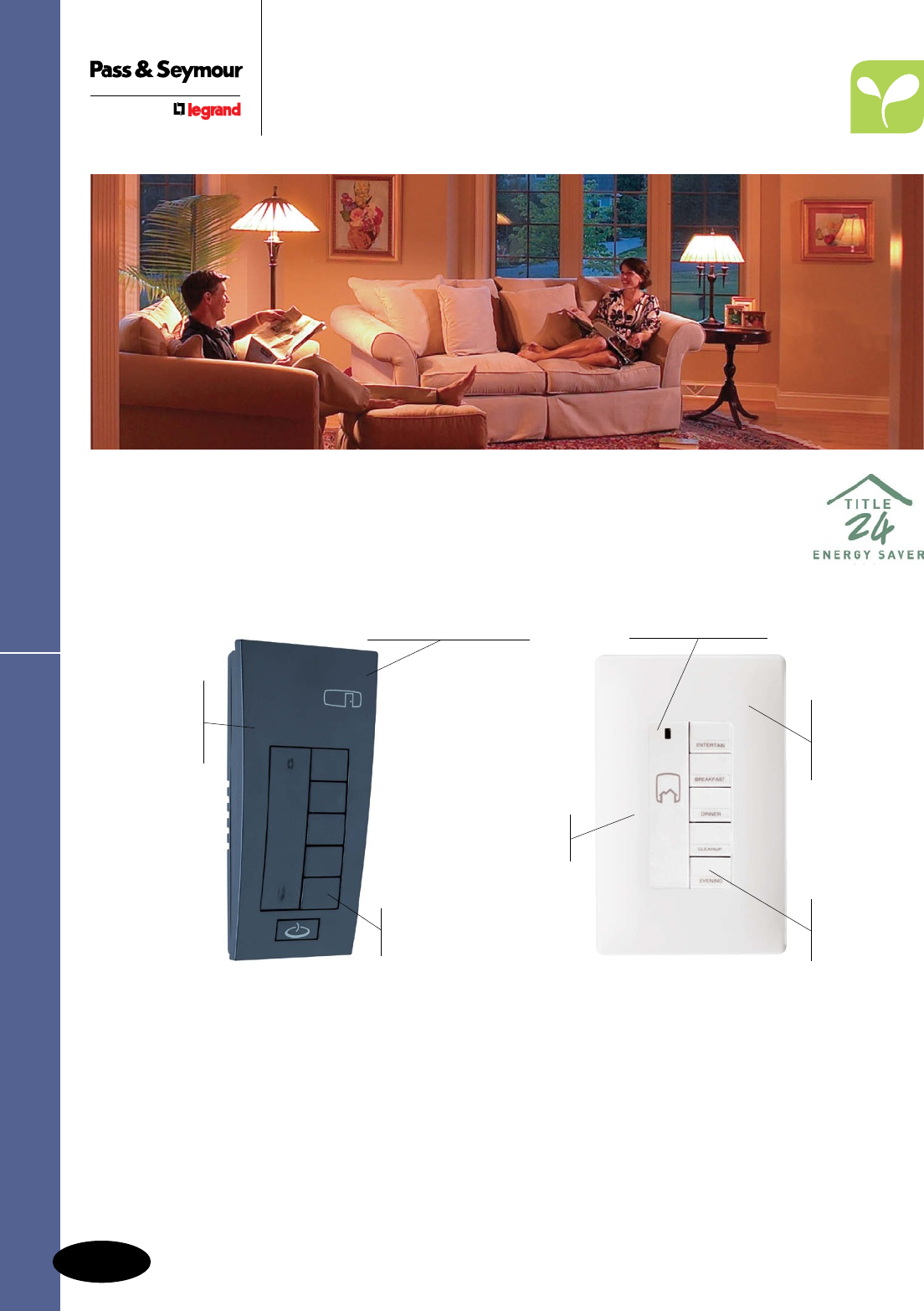
RF Lighting Control System
M-4
Dimmers & Fan Speed Controls
Residential Dimmers & Fan Speed Controls
RF Lighting Control System
The RF Lighting Control System allows homeowners to control lights, ceiling
fans and small appliances from anywhere in the home, without the need for special
wiring or expensive master controllers. The system can handle up to 127 rooms and
1,023 devices – making it the perfect lighting control system for any size home.
System Features & Benefits
n Whole house and room scene controls allow
homeowners to change their environment at the
push of a button.
n Frequency-agile Radio Frequency (RF) wireless
communications technology.
n Simple, intuitive programming without the use of a
computer or controller.
n Increase control with RS232 and IR to RF interfaces.
n Plug-in modules allow control of small appliances
and table or floor lamps, giving homeowners the
full control of not only their lights, but also their
energy bills.
Hand-held
device includes
wall-mounted
holster for easy
storage.
Whole house and
room scene control.
Program up
to 15 scenes
per room.
Whole house
and room
scene control.
Program
up to 10
whole-house
scenes.
One-touch whole
house ON/OFF.
Decorator
style device
mounts in
standard
one-gang box.
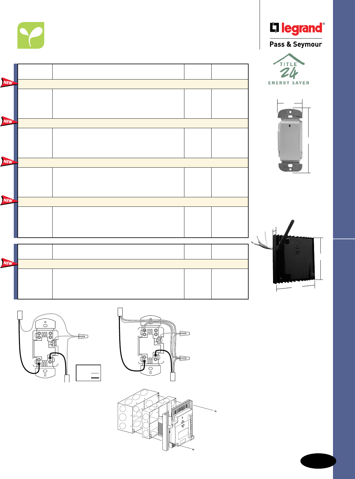
M-5
Dimmers & Fan Speed Controls
AlldeviceslistedonthispageconformtoNEMAWD-1andWD-6.ULListedandCSACertified.
RF Lighting Control System
Residential Dimmers & Fan Speed Controls
RF Lighting Control System
Dimmers & Switches
Catalog
Number Description Ratings Color
In-Wall Universal Dimmers
DRD4I Ivory
DRD4W 600W White
DRD4B Black
DRD4A Light Almond
In-Wall Incandescent Dimmers
DRD2I Ivory
DRD2W 600W White
DRD2B Black
DRD2A Light Almond
In-Wall 3-Way Switches
DRD8IV2 Ivory
DRD8WV2 N/A White
DRD8BV2 Black
DRD8AV2 Light Almond
In-Wall 2000W Box Dimmers
MR2000 2000W Black
The In-Wall Universal Dimmer operates most dimmable
lighting types, including neon and compact uorescent.
Includes a CFL setting to alleviate ickering and
premature bulb burn-out.
Easily dim traditional incandescent bulbs, without the
requirement of a neutral connection.
Provides convenient control from multiple access points
when used in conjunction with any wireless switch or
dimmer.
The box dimmer operates as a remove mounted
dimmer for operating large lighting loads, and works in
conjunction with multi-location controllers to provide true
multi-way lighting.
Catalog
Number Description Ratings Color
In-Wall Switches
DRD3IV2 Ivory
DRD3WV2 800W White
DRD3BV2 Black
DRD3AV2 Light Almond
Perfect for controlling lights that don't need dimming, the
In-Wall Switch can be included in scene programming for
use with Room and Whole-House Scene Controllers.
1.69"
4.25"
DRD4A
DRD2A
DRD3AV2
DRD8AV2
MR2000
4.92"
4.92"
3.78"
LOAD LINE
GND
Wire Legend
Ground
Line
DRD2 Wiring Diagram
NEUTRAL
LOAD LINE
GND
DRD3 & DRD4 Wiring Diagram
Mountingindeep
electricalboxesis
recommended.
MR2000 Mounting Diagram
MounttheMR2000dimmerverticallyand
provide6"clearanceaboveandbelowthe
dimmerforairflow.Requires100BTW/
hourventilation.Backbox(4"x2-1/8")may
besurfaceorrecessmounted.Extension
(1-1/2")mustextendoutfromthewall.
For de-rating chart, see Page M-7.
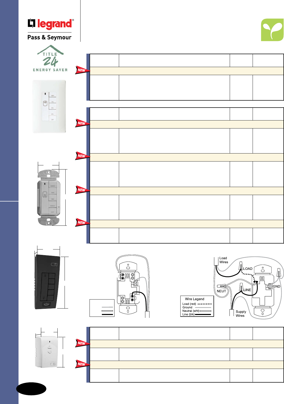
M-6
Dimmers & Fan Speed Controls
AlldeviceslistedonthispageconformtoNEMAWD-1andWD-6.ULListedandCSACertified.
RF Lighting Control System
Residential Dimmers & Fan Speed Controls
RF Lighting Control System
Fan Speed & Master Controls &
Plug-In Modules
DRD5/DRD6 Wiring Diagram
LINE
GND
Supply
Wires
NEUTRAL
Wire Legend
Ground
Line
Neutral
Catalog
Number Description Ratings Color
In-Wall Whole House Scene Controllers
DRD5IV2 Ivory
DRD5WV2 N/A White
DRD5BV2 Black
DRD5AV2 Light Almond
In-Wall Room Scene Controllers
DRD6IV2 Ivory
DRD6WV2 N/A White
DRD6BV2 Black
DRD6AV2 Light Almond
Hand-Held Whole House Scene Controllers
MRH5G N/A Black
Hand-Held Room Scene Controllers
MRH6G N/A Black
This product allows lighting control for the entire home
from any location.
Program up to ve room scenes with this in-wall
controller.
This remote whole house controller can be programmed
for up to ve house scenes. It also includes a panic
button that when pushed, turns the lights on or ashes
them in a pre-determined scene.
The hand-held room controller enables ve room and
individual load control.
2.625"
5.125"
.75"
MRH6G
1.69"
4.25"
DRD6AV2
Catalog
Number Description Ratings Color
Plug-In Lamp Module
MRP6W 300W White
Plug-In Small Appliance Module
MRP7W 800W White
Control table and oor lamps up to 300W with this
plug-in module.
Control small appliances, including coffee machines,
radios, TVs and more with this plug-in module.
MRP6W
2.30"
3.56"
1.59"
Catalog
Number Description Ratings Color
In-Wall Fan Speed Controllers
DRD9I Ivory
DRD9W 1.5 A White
DRD9B Black
DRD9A Light Almond
This controller gives you four options for ceiling fan
speed and includes a built-in de-hummer to reduce
fan noise.
DRD9W
Shown with
SWP26W
DRD9 Wiring Diagram
Mountingcontrolsin
deepelectricalboxes
isrecommended.
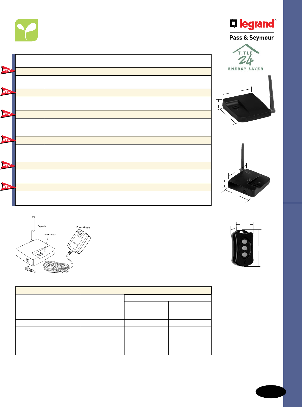
M-7
Dimmers & Fan Speed Controls
AlldeviceslistedonthispageconformtoNEMAWD-1andWD-6.cULusListed.
RF Lighting Control System
Residential Dimmers & Fan Speed Controls
RF Lighting Control System
Interfaces
Catalog
Number Description
RS232 to RF Interface
MR232G Incorporate RS232-compliant home theater systems, computers and other devices by
using this interface.
IR to RF Interface
MRIR1 Use this interface to program universal remotes to control lighting as well as audio/video
components.
Room Scene Interface
MRRC3G The Room Scene Interface is used to connect the RFLC system with external devices
at a room level. Common applications include interfacing with security systems and
occupancy or vacancy sensors.
House Scene Interface
MRHC3G The House Scene Interface is used to connect the RFLC system with external devices
on a whole house level. Common applications include interfacing with security systems
and occupancy or vacancy sensors.
Repeater & Away Emulator
MRR2G Record the normal usage of lights throughout the home and play them back while
homeowners are away with the Repeater & Away Emulator.
Wireless Key Fob
MKFOB The Wireless Key Fob allows the lights to be turned on from a remote location,
like the driveway. Visor Clip included.
MKFOB
1.375"
2.375"
.625"
3.70"
.97"
3.20"
3.70"
.97"
3.20"
MRR2G
MRR2G Product Controls
Thewirelessrepeatereasilyplugs
intoanystandardoutlet.Itisbest
installedinacentrallocation.
De-rate Dimmers as follows:
Maximum Capacity
Single Dimmer Dimmer at End Dimmer in Middle
of a Multi-Gang of a Multi-Gang
Incandescent/QuartzHalogen 600W 500W 400W
MagneticLowVoltage 500W 400W 300W
ElectronicLowVoltage 500W 400W 300W
ColdCathode/Neon 500W 400W 300W
Fluorescent:
2-Wire 500W 400W 300W
CompactFluorescent 500W 400W 300W
MR232G
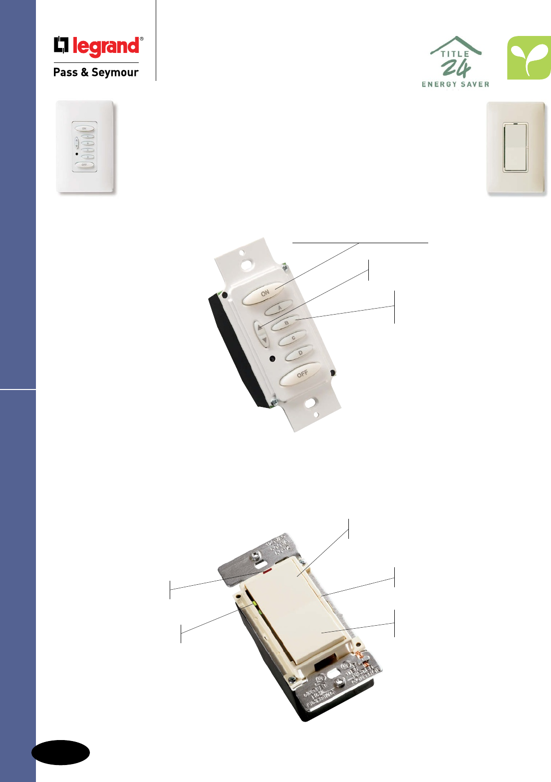
M-8
Dimmers & Fan Speed ControlsScene Director
Residential Dimmers &
Fan Speed Controls
Scene Director
For everything people do at home, there’s a combination of
light sources and levels that will work best. P&S Scene Director
Controls let homeowners capture these combinations (or scenes)
— and recall them whenever they want at the touch of a button.
Red LED glows
when dimmer is OFF.
Green LEDs indicate light
level selected and preset level.
Sleek, ergonomic P&S
Decorator style matches
other Decorator devices.
Can be operated individually.
P&S Scene Director Dimmer
Constant memory returns
lights to previously selected
level after power failure.
Works in conjunction with a
P&S Scene Director Master.
Touch pad raises or lowers individual
light levels without affecting preset.
Unobtrusive set button for simple
programming of preset scenes.
SC600LAV
Raises or lowers all lights
in any scene simultaneously.
Controls up to 30 dimmers per
Master, providing the ability to control
even complex, multiroom scenes.
Programmable fade rates
enable users to easily select the
speed of fade-up and fade-down.
Buttons glow when selected —
glow levels are adjustable, too.
Available infrared remote (SCIR)
provides mobile control flexibility.
P&S Scene Director Master
Provides powerful control
via conventional wall-box
wiring. Wires like a 3-way switch.
Communication among devices
requires just one additional conductor.
One-touch selection for up
to five lighting environments
(scenes) — plus full Off.
Constant memory returns lights
to previously selected level after
power failure. No need to reset.
Easy to install, program, and
operate for sophisticated scene
control dimming.
No tools or plate removal
necessary for programming
with our exclusive, patent-
pending system. Set light levels
with product fully installed.
SCMC5WV
Matching Fan Speed Control available.
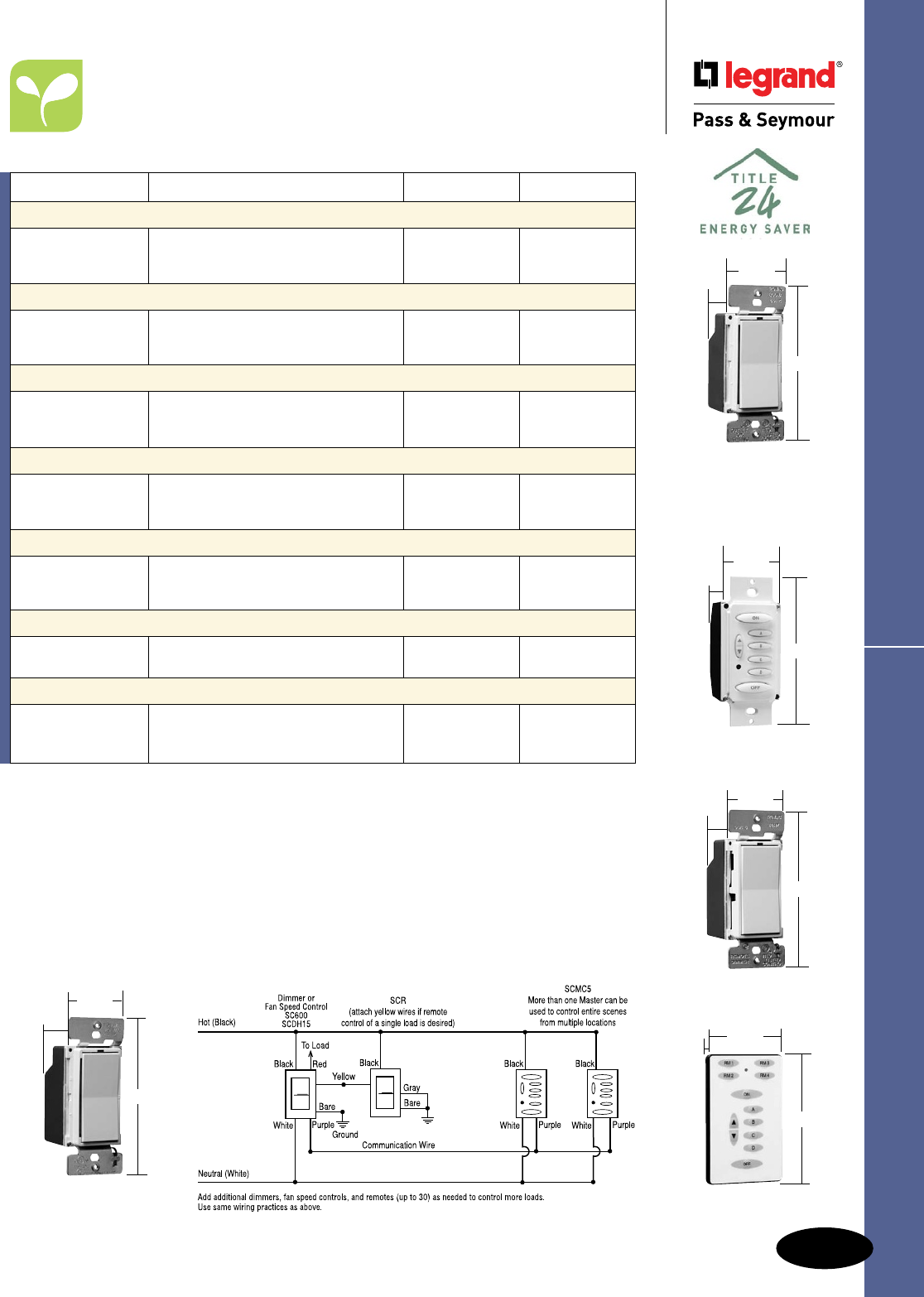
M-9
Dimmers & Fan Speed Controls Scene Director
Residential Dimmers & Fan Speed Controls
Scene Director
Wiring Diagram
*UsewithAdvanceMarkX®dimmablefluorescentballasts.
**Featurespeciallydesignedcapacitivecircuitrytovirtuallyeliminatefanmotor“hum.”
Note:AllDimmersonthispagemaybegangedwithoutde-rating.
Catalog Number Description Ratings Color
600W Incandescent Scene Director Control Dimmers
SC600IV Ivory
SC600WV Preset, Controls 1 Load in a Scene 120V, 600 Watt White
SC600LAV Light Almond
300VA Electronic Low-Voltage Scene Director Control Dimmers
SCELV300IV Ivory
SCELV300WV Preset, Controls 1 Load in a Scene 120V, 300VA White
SCELV300LAV Light Almond
600VA Fluorescent Ballast Scene Director Control Dimmers*
SCFB600IV Ivory
SCFB600WV Preset, Controls 1 Load in a Scene 120V, 600VA White
SCFB600LAV Light Almond
5 Scene Director Master Controllers
SCMC5IV Ivory
SCMC5WV 5-Button Preset Scene Controller 120V White
SCMC5LAV Light Almond
Remote Location Control
SCRIV Ivory
SCRWV For Full Dimming or Fan Speed Control 120V White
SCRLAV of 1 Load from Two or More Locations Light Almond
Accessories
SCIR Infrared Hand-Held Remote
SCMCK Preprinted Inserts for Master Controller
1.5A De-Hummer** Fan Speed Controllers
SCDH15IV Ivory
SCDH15WV Preset, Controls 1 Fan Load in a Scene 120V, 1.5A White
SCDH15LAV Light Almond
SCDH15LAV
4.25"
1.68"
1.37"
AlldeviceslistedonthispageconformtoNEMAWD-1andWD-6.ULListedandCSACertified.
SC600LAV
SCELV300LAV
SCFB600LAV
4.25"
1.68"
1.37"
SCMC5WV
4.0"
1.68"
1.37"
SCRLAV
4.25"
1.68"
1.37"
SCIR
3.313"
0.25"
2.125"

M-10
Dimmers & Fan Speed ControlsLeandro®
Residential Dimmers & Fan Speed Controls
Leandro®
Features
nEnablesfulldimmingcontrolfromupto
30locationsusingthematchingremotedimmers.
nConstantmemoryreturnslightstoprevious
levelafterpowerfailure.
nLEDindicatorskeepyouinformed.GreenLEDs
indicatepresetlevelandcurrentlightlevel.
RedLEDnightlightglowswhenloadisOFF.
nEasyoperation—Tapuponceforpreset,twice
forfullON.TapdownonceforfullOFF.Holdpaddle
uptoraiselights,downtolower.
nSleek,ergonomicP&SDecoratorstyle
matchesotherDecoratordevices.
nUnobtrusivepresetselectionbuttonhelps
preventaccidentalsettingchanges.
nElegantfadeONandOFF extendsbulblife.
Easyontheeyes,too.
nInstallseasilyusingthesamewiringas
conventional3-wayswitches.
nChangelightlevel withoutaffectingpreset.
Alldeviceslistedonthispageconform
toNEMAWD-1andWD-6.
ULListedandCSACertified.
* UsewithMR16swithmagnetictransformers,neon,coldcathode,generalinductiveloads.
** UsewithAdvanceMarkX®dimmablefluorescentballasts.
† AlldimmersandfancontrolscanbedimmedfrommorethanonelocationwhenusedwithDRMremotes.
Usesstandard3-waywiring.Seewiringdiagram.
††Featurespeciallydesignedcapacitivecircuitrytovirtuallyeliminatefanmotor“hum.”
Wiring Diagrams
D600MLAV
DFB600MLAV
DLV600MLAV
DRMLAV
4.25"
1.68"
1.37"
D1000MLAV
4.25"
2.50"
1.37"
Max. Load Fins Removed
Rating One Side Two Side
De-Rating Chart
600W/VA NoDe-RatingRequired
1000W 800W 600W
DDH15MLAV
4.25"
1.68"
1.37"
Catalog Number Description Ratings Color
600W Incandescent Preset Dimmers†
D600MIV Ivory
D600MWV Preset, Single Pole and 3-Way 120V White
D600MBKV 600 Watt Black
D600MLAV Light Almond
1000W Incandescent Preset Dimmers†
D1000MIV 120V Ivory
D1000MWV Preset,SinglePoleand3-Way 1000Watt White
D1000MLAV LightAlmond
600VA Low-Voltage Preset Dimmers*†
DLV600MIV 120V Ivory
DLV600MWV Preset,SinglePoleand3-Way 600VA White
DLV600MLAV LightAlmond
600VA Fluorescent Ballast Preset Dimmers**†
DFB600MIV 120V Ivory
DFB600MWV Preset,SinglePoleand3-Way 600VA White
DFB600MLAV LightAlmond
Remote Dimmers†
DRMIV Ivory
DRMWV FullDimmingorFanSpeedControl 120V White
DRMBKV fromTwoorMoreLocations Black
DRMLAV LightAlmond
1.5A De-Hummer†† Fan Controls
DDH15MIV 120V Ivory
DDH15MWV Preset,SinglePole,3-Speed 1.5A White
DDH15MLAV LightAlmond

M-11
Dimmers & Fan Speed Controls
Catalog Number Description Ratings Color
Magnetic Low-Voltage Single Pole/3-Way Dimmers
DLV703PI Ivory
DLV703PW White
DLV703P Magnetic Low-Voltage Single Pole and 3-Way 120V, 700VA Brown
DLV703PBK Black
DLV703PLA Light Almond
DLV1103PI Ivory
DLV1103PW White
DLV1103P Magnetic Low-Voltage Single Pole and 3-Way 120V, 1100VA Brown
DLV1103PBK Black
DLV1103PLA Light Almond
AlldeviceslistedonthispageconformtoNEMAWD-1andWD-6.ULListedandCSACertified.
Harmony™ Dimmers
Residential Dimmers & Fan Speed Controls
Harmony™ TradeMaster® Dimmers
Features
nConvenientoperation–combinesON/OFFDecorator
switchwithseparatesliderfordimmingcontrol.
nGreenLEDglowswhenOFFtomakedimmereasy
tofindinthedark.
nConstantmemoryreturnslightstopreviouslevel
afterapowerfailure.
nSleek,ergonomicP&SDecoratorstylematches
otherDecoratordevices.
nHigherratings.
nSinglepoleand3-wayoperation.
nWorkswithstandard3-wayswitchesandwiring.
nScrew-pressure-platebackwireterminals
savetime,spaceandmoney.
D703P, DLV703P
nNode-rating.
nNofinstobreak.
Interchangeable Face Versions
nPackagecomeswiththreefacecolors–
Ivory,White,LightAlmond(TC).
nWhiteonlyoptionalsoavailable(WC).
nInterchangeablefacesavailableinfour
colors(soldseparately,seebelow).
Catalog Number Description Ratings Color
Incandescent Single Pole/3-Way Dimmers*
D703PI Ivory
D703PW White
D703P Incandescent Single Pole and 3-Way 120V, 700W Brown
D703PBK Black
D703PLA Light Almond
D1103PI Ivory
D1103PW White
D1103P Incandescent Single Pole and 3-Way 120V, 1100W Brown
D1103PBK Black
D1103PLA Light Almond
Interchangeable Face Incandescent Single Pole/3-Way Dimmers
D703PTC** Incandescent Single Pole and 3-Way 120V, 700W Ivory/
Three Interchangeable Face Colors White/
Light Almond
D703PWC Incandescent Single Pole and 3-Way 120V, 700W White
White Interchangeable Face Only
D1103PTC** Incandescent Single Pole and 3-Way 120V, 1100W Ivory/
Three Interchangeable Face Colors White/
Light Almond
D1103PWC Incandescent Single Pole and 3-Way 120V, 1100W White
White Interchangeable Face Only
Interchangeable Face Covers†
DKITI Harmony™ Interchangeable Face, Ivory Ivory
DKIT Harmony™ Interchangeable Face, Brown Brown
DKITBK Harmony™ Interchangeable Face, Black Black
DKITLA Harmony™ Interchangeable Face, Light Almond Light Almond
D703PW
4.25"
1.75"
1.25"
D1103PLA
4.25"
2.50"
1.25"
For de-rating,
see Page M-12.
*AvailableinVisionPak™packaging,add“V”toCatalogNumber.Example:D703PLAV.
**AvailableinVisionPak™packaging,add“CCV6”toCatalogNumber.Example:D703PTCCCV6.
†AvailableinVisionPak™packaging,add“BPCCV6”toCatalogNumber.Example:DKITIBPCCV6.
DKITI DKITBK
DKIT DKITLA

M-12
Dimmers & Fan Speed Controls
AlldeviceslistedonthispageconformtoNEMAWD-1andWD-6.ULListedandCSACertified.
Features
nConvenientoperation–combinesON/OFFDecorator
switchwithseparatesliderfordimmingcontrol.
nGreenLEDglowswhenOFFtomakedimmereasy
tofindinthedark.
nConstantmemoryreturnslightstopreviouslevel
afterapowerfailure.
nSleek,ergonomicP&SDecoratorstylematches
otherDecoratordevices.
nHigherratings.
nSinglepoleand3-wayoperation.
nWorkswithstandard3-wayswitchesand
wiring.
nScrew-pressure-platebackwireterminals
savetime,spaceandmoney.
DDH16P
nNode-rating.
nNofinstobreak.
Catalog Number Description Ratings Color
Fluorescent Single Pole/3-Way Dimmers*
DFB8PI Ivory
DFB8PW White
DFB8P Two Wire Fluorescent Single Pole and 3-Way 120V, 8A Brown
DFB8PBK Black
DFB8PLA Light Almond
De-Hummer** Fan Speed Controls
DDH16PI Ivory
DDH16PW White
DDH16P De-Hummer Fan Speed Control 120V, 1.6A Brown
DDH16PBK Black
DDH16PLA Light Almond
De-Rating Chart for Harmony Dimmers
Catalog Maximum Multi-Gang De-Rating Catalog Maximum Multi-Gang De-Rating
Number Load 2 Gang 3 Gang Number Load 2 Gang 3 Gang
D703P 700W 700W 700W DLV1103P 1100VA 950VA 700VA
D1103P 1100W 1100W 800W DFB8P 8A 8A 6.5A
DLV703P 700VA 700VA 650VA DDH16 1.6A 1.6A 1.6A
* ForusewithAdvanceMK10dimmingballasts.Seeinstructionsheetforcompletelistofcompatibleballasts.
** Featurespeciallydesignedcapacitivecircuitrytovirtuallyeliminatefanmotor“hum.”
Harmony™ Dimmers & Fan Speed Controls
Residential Dimmers & Fan Speed Controls
Harmony™ TradeMaster® Dimmers
& Fan Speed Controls
DDH16PLA
4.25"
1.75"
1.25"
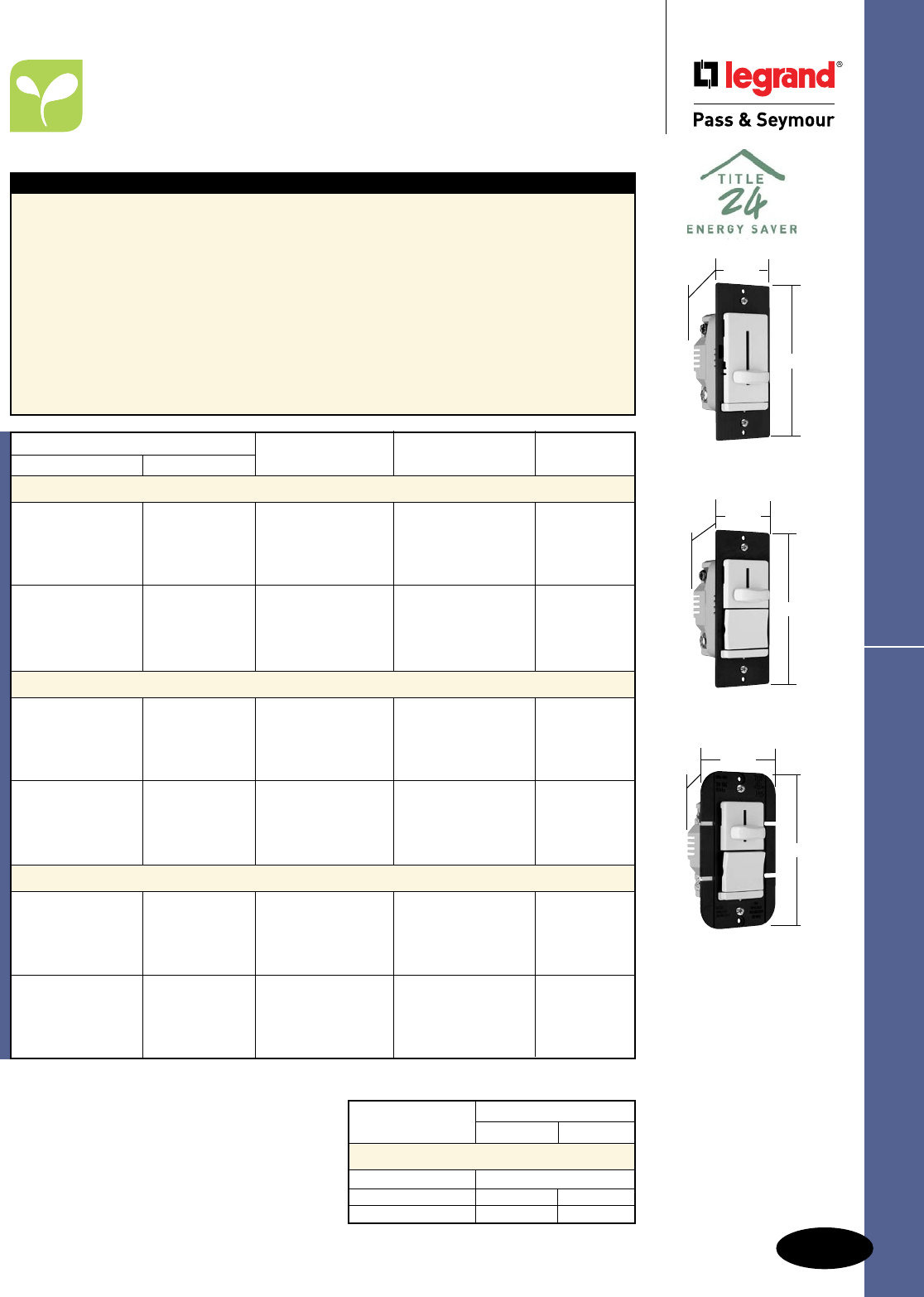
M-13
Dimmers & Fan Speed Controls
AlldeviceslistedonthispageconformtoNEMAWD-1andWD-6.ULListedandCSACertified.
LS Series Dimmers
Residential & Light Commercial
Dimmers & Fan Speed Controls
LS TradeMaster® Series Dimmers
LS600LA
1.74"
4.19"
1.28"
LS600PLA
1.74"
4.19"
1.28"
LS1000PLA
2.50"
4.19"
1.28"
Max. Load Rating Fins Removed
One Side Two Side
De-Rating Chart
LS600,LS603 NoDe-RatingRequired
LS1000P,LS1003P 900W 750W
LS1000 850W 700W
For wiring diagrams, see Page S-20.
Features
nErgonomicdesignandsolid,qualityfeelcombine
forsmooth,easyoperationandprecisecontrol.
nElectromagneticandradio-frequencyinterference
protectionbuiltin.
nSleek,sculptedcontemporarydesign.Nodirt-
catchingcrevices.
nTough,impact-resistantthermoplastichousing
makesitaperfectchoicefornewhome
construction.Matching,unbreakableTradeMaster®
wallplateavailableforallmodels.
nPresetON/OFFswitchautomaticallyreturns
controlledlightstopresetlevelwithoutreadjusting
dimmersetting.
nExclusive,screw-pressure-platebackwire
terminalssavetime,spaceandmoney.
Designedfor12and14gaugewire,stranded
orsolid.No-wire-leaddesigneliminateswire
nuts.
nSuperiorheatmanagement.
nNode-ratingon600Wunits.
nPatentedSnap-InLightModule(sold
separately)transformsthedimmerintoan
illuminateddimmer.SeePageM-14for
information.
*AvailableinVisionPak™packaging,add“V”toCatalogNumber.Example:LS600IV.
**Availableinboxedpackagingonly.
Catalog Number
Single Pole Three-Way Description Ratings Color
600W Incandescent Slide Dimmers*
LS600I Ivory
LS600W White
LS600 Non-Preset 120V,600Wmax. Brown
LS600BK Black
LS600LA LightAlmond
LS600PILS603PI Ivory
LS600PWLS603PW White
LS600PLS603P Preset 120V,600Wmax. Brown
LS600PBKLS603PBK Black
LS600PLALS603PLA LightAlmond
1000W Incandescent Slide Dimmers*
LS1000I Ivory
LS1000W White
LS1000 Non-Preset 120V,1000Wmax. Brown
LS1000BK Black
LS1000LA LightAlmond
LS1000PILS1003PI Ivory
LS1000PWLS1003PW White
LS1000PLS1003P Preset 120V,1000Wmax. Brown
LS1000PBKLS1003PBK Black
LS1000PLALS1003PLA LightAlmond
600VA Magnetic Low-Voltage Slide Dimmers**
LSLV600I Ivory
LSLV600W White
LSLV600 Non-Preset 120V,600VAmax. Brown
LSLV600BK Black
LSLV600LA LightAlmond
LSLV600PILSLV603PI Ivory
LSLV600PWLSLV603PW White
LSLV600PLSLV603P Preset 120V,600VAmax. Brown
LSLV600PBKLSLV603PBK Black
LSLV600PLALSLV603PLA LightAlmond
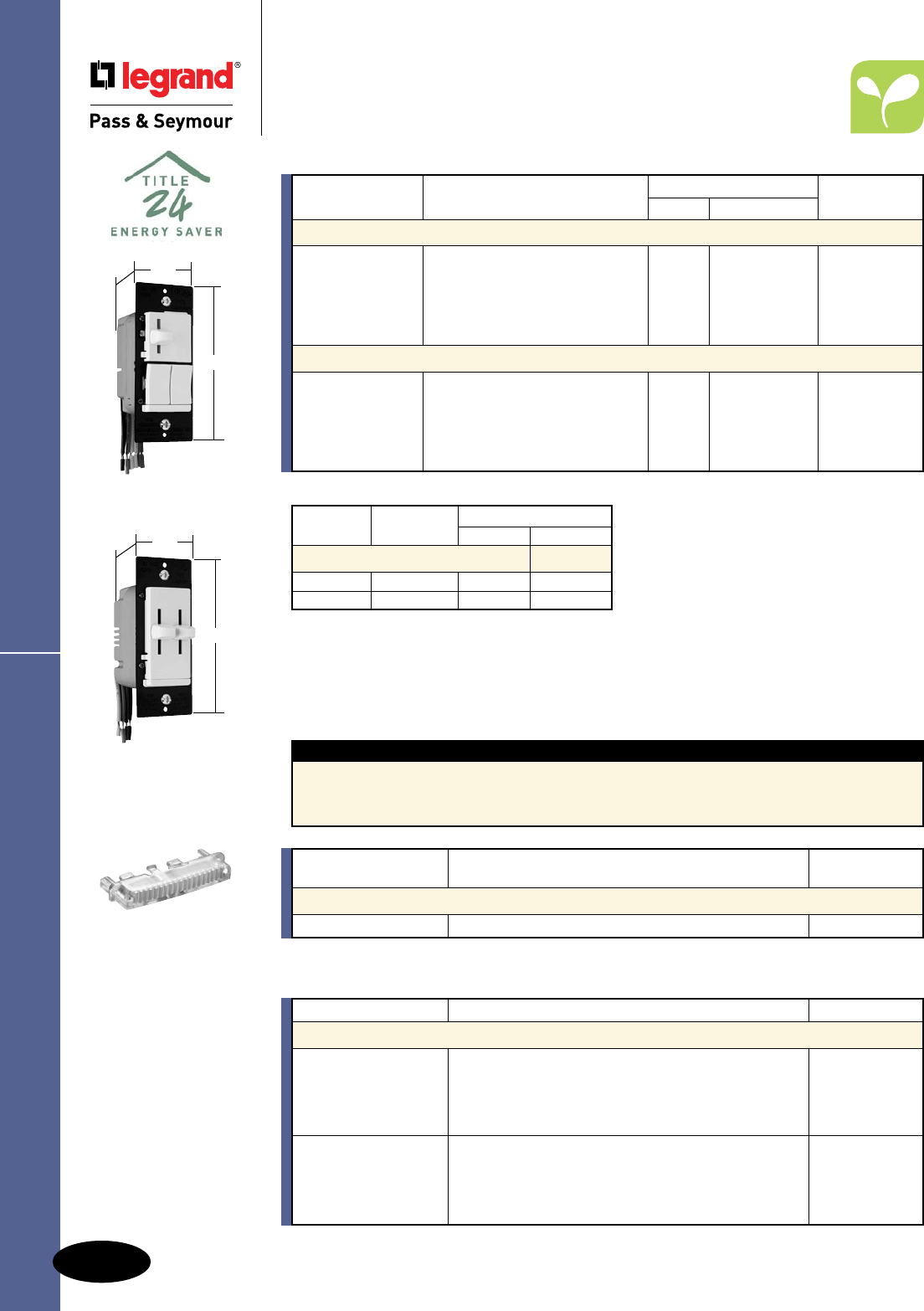
M-14
Dimmers & Fan Speed Controls
AlldeviceslistedonthispageconformtoNEMAWD-1andWD-6.ULListedandCSACertified.
LS Series Dimmers
Residential & Light Commercial
Dimmers & Fan Speed Controls
LS TradeMaster® Series Dimmers
Catalog Number Description Color
Accessories for LS Series
LRKIV Ivory
LRKWV White
LRKV ReplacementKnobsforDecoratorDualSlides Brown
LRKBKV Black
LRKLAV LightAlmond
LLRKIV Ivory
LLRKWV White
LLRKV LargeReplacementKnobsforDecoratorSingleSlides Brown
LLRKBKV Black
LLRKLAV LightAlmond
Catalog Maximum Multi-Gang De-Rating
Number Load 2 Gang 3 Gang
De-Rating Chart
LSDS300 300W 300W 300W
LSDD300 300W 300W 300W
Ratings
Catalog Number Description Dimmer Switch Color
Single Pole/3-Way Preset Dimmers & Switches
LSDS300PI 7Ageneral Ivory
LSDS300PW SinglePole/3-WayPresetDimmer 120V purpose White
LSDS300P andIndependentSinglePole/ 300W resistiveand Brown
LSDS300PBK 3-WaySwitch ballast,1/4hp Black
LSDS300PLA 900Wtungsten LightAlmond
Dual Slide to OFF Single Pole Dimmers
LSDD300I Ivory
LSDD300WDualSlidetoOFF120V White
LSDD300SinglePoleDimmers300W — Brown
LSDD300BK Black
LSDD300LA LightAlmond
For wiring diagrams, see Page S-20.
TM8LMCC
Features
nNotoolneeded,modulesnaps-in.
nLightswhenOFF.
nUsesenergy-efficient1/4wattLEDlight.
nLEDlightwillnotgenerateheatandwilllast
onaverage47years.
Rating
Catalog Number A. VAC Color
Snap-In Light Module
TM8LMCC 15 120/125 Clear
LSDS300PW
1.74"
4.19"
1.28"
LSDD300W
1.74"
4.19"
1.28"
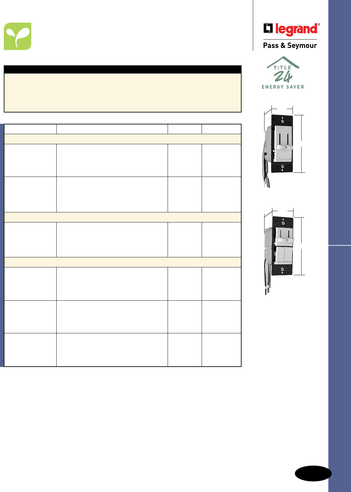
M-15
Dimmers & Fan Speed Controls
AlldeviceslistedonthispageconformtoNEMAWD-1andWD-6.ULListedandCSACertified.
LS Series Fan Speed Controls
Residential & Light Commercial
Dimmers & Fan Speed Controls
LS TradeMaster® Series
Fan Speed Controls
Features
nToughimpact-resistantthermoplastichousing.
nPower-failurememory.
nSuperiorheatmanagement:notimewastingbreakofftabs.
nExclusive,screw-pressure-platebackwireterminalseliminateswirenuts.
nCanbeusedwithpatentedSnap-InLightModule(soldseparately).
LSDC16LAV
1.74"
4.185"
1.28"
LSDC163PLAV
1.74"
4.185"
1.28"
For wiring diagrams, see Page S-20.
Catalog Number Description Ratings Color
Decorator Slide Fan Speed Controls*
LSSC5I Ivory
LSSC5W White
LSSC5 Non-Preset,SinglePole,AdjustableTrim 5A Brown
LSSC5BK Black
LSSC5LA LightAlmond
LSSC5PI Ivory
LSSC5PW White
LSSC5P Preset,SinglePole,AdjustableTrim 5A Brown
LSSC5PBK Black
LSSC5PLA LightAlmond
Decorator Slide De-Hummer Controls**
LSDH16IV Ivory
LSDH16WV White
LSDH16V Non-Preset,4-SpeedFanControl 1.6A Brown
LSDH16BKV Black
LSDH16LAV LightAlmond
Dual Control Decorator Slides**
LSDC16IV Ivory
LSDC16WV White
LSDC16VNon-Preset,3-SpeedDe-HummerFanControl 1.6A/300W Brown
LSDC16BKVwithSinglePoleDimmer Black
LSDC16LAV LightAlmond
LSDC163PIV Ivory
LSDC163PWV White
LSDC163PVPreset,SinglePole/3-Way3-SpeedDe-Hummer 1.6A/300W Brown
LSDC163PBKVFanControlwithSinglePole/3-WayDimmer Black
LSDC163PLAV LightAlmond
LSDV25IV Ivory
LSDV25WV White
LSDV25VNon-Preset,VariableSpeedFanControl 2.5A/300W Brown
LSDV25BKVWithSinglePoleDimmer Black
LSDV25LAV LightAlmond
*AvailableinVisionPak™packaging,add“V”toCatalogNumber.Example:LSSC5IV.
**AvailableinVisionPak™only.
Featurespeciallydesignedcapacitivecircuitrytovirtuallyeliminatefanmotor“hum.”
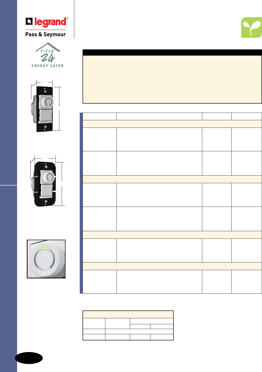
M-16
Dimmers & Fan Speed Controls
AlldeviceslistedonthispageconformtoNEMAWD-1andWD-6.ULListedandCSACertified.
Decorator Rotary DR Series
Residential & Light Commercial
Dimmers & Fan Speed Controls
Decorator Rotary DR
TradeMaster® Series
Features
nAnewstylethatmatchesP&SDecorator
Combinationdevices.
nAcceptsSnap-InLightModule(soldseparately)
toconvertdecoratorrotarydevicesinto
illuminated-typeinmoments;makesdevices
easytofindinthedark.SeePageM-14.
nScrew-pressure-platebackwiringspeedsinstallation
andensuressolid,high-qualityelectricalconnections.
Alsosupportstraditional,wire-loopsidewiring.
nHeavy-gaugeblackanodizedaluminum
strapprovidessuperiorheatmanagement
andstructuralstrengthformountingagainst
wallsurfaces.
nSlimdesignleavesmoreroominthebox
andmakesinstallationfasterandeasier.
nHigherratingsof700and1100watts.
nNode-ratingof700wattdevices.
nSinglepoleand3-wayinsamedevice.
Catalog Number Description Ratings Color
Incandescent Preset Dimmers
DR703PIV Ivory
DR703PWV White
DR703PV Single Pole/3-Way Dimmer with Pilot Light 120V, 700W Brown
DR703PBKV Black
DR703PLAV Light Almond
DR1103PIV Ivory
DR1103PWV White
DR1103PV Single Pole/3-Way Dimmer with Pilot Light 120V, 1100W Brown
DR1103PBKV Black
DR1103PLAV Light Almond
Magnetic Low-Voltage Dimmers
DRLV703PIV Ivory
DRLV703PWV White
DRLV703PV Single Pole/3-Way Dimmer with Pilot Light 120V, 700VA Brown
DRLV703PBKV Black
DRLV703PLAV Light Almond
DRLV1103PIV Ivory
DRLV1103PWV White
DRLV1103PV Single Pole/3-Way Dimmer with Pilot Light 120V, 1100VA Brown
DRLV1103PBKV Black
DRLV1103PLAV Light Almond
Continuously Variable Preset Fan Speed Controls
DRSC53PIV Ivory
DRSC53PWV White
DRSC53PV Single Pole/3-Way Fan Speed Control 120V, 5A Brown
DRSC53PBKV Black
DRSC53PLAV Light Almond
3-Speed De-Hummer* Preset Fan Speed Controls
DRDH163PIV Ivory
DRDH163PWV Single Pole/3-Way Fan Speed Control White
DRDH163PV with back-lit speed indication 120V, 1.6A Brown
DRDH163PBKV Black
DRDH163PLAV Light Almond
De-Rating Chart for DR Series
Catalog Maximum Multi-Gang De-Rating
Number Load 2 Gang 3 Gang
DR703 NoDe-RatingRequired
DR1103 1100W 900W 750W
AvailableinVisionPak™only.
*Featurespeciallydesignedcapacitivecircuitrytovirtuallyeliminatefanmotor“hum.”
DR703PLAV
1.74"
4.185"
1.28"
Illuminatedknob
indicateslightlevel.
DR1103PWV
2.50"
4.185"
1.28"
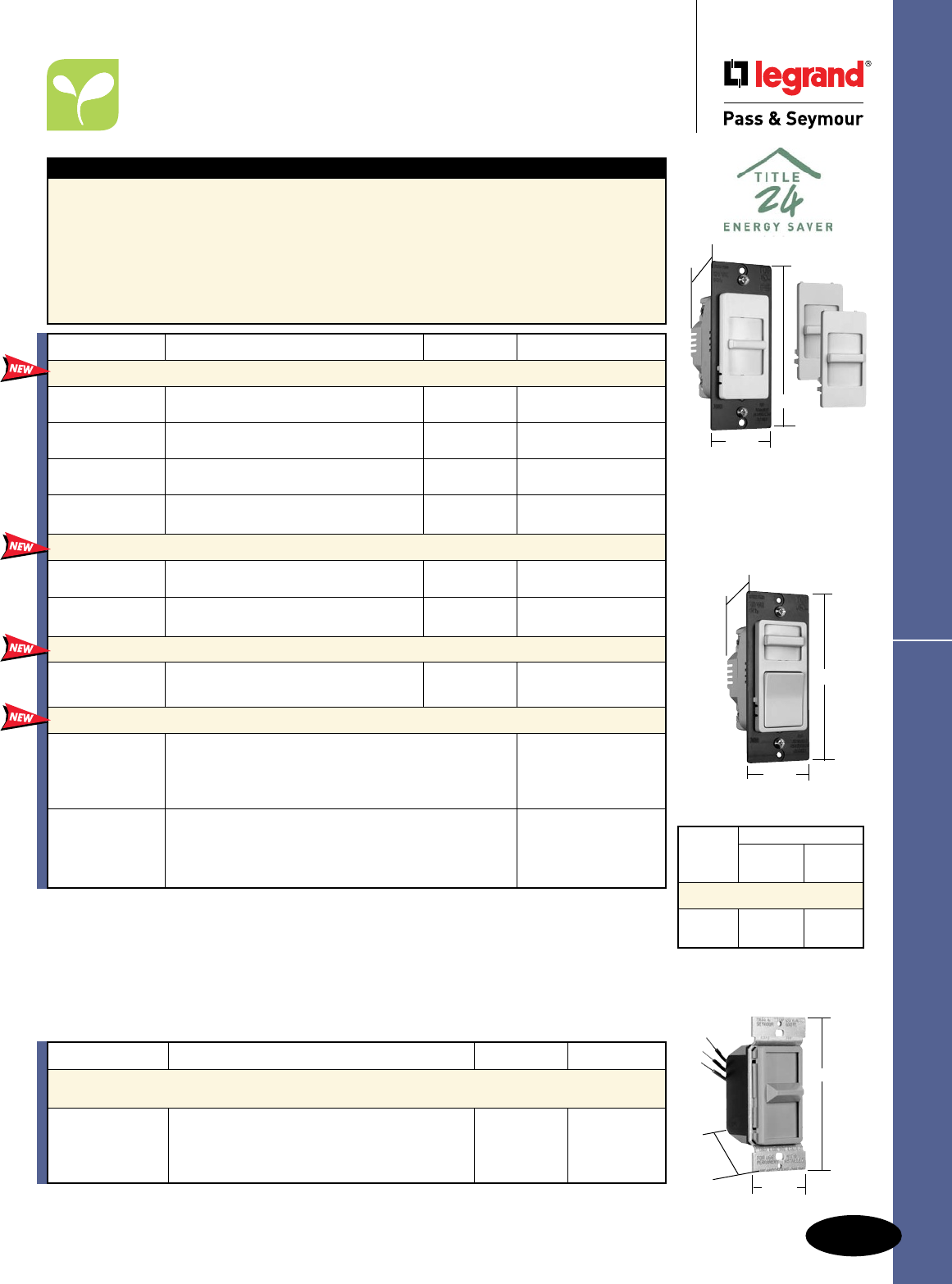
M-17
Dimmers & Fan Speed Controls
AlldeviceslistedonthispageconformtoNEMAWD-1andWD-6.ULListedandCSACertified.
Wide Slide Series
Residential & Light Commercial
Dimmers & Fan Speed Controls
Wide Slide TradeMaster® Series
Features
nConvenientoperation–combinesON/OFFDecorator-
styleswitchwithseparatesliderfordimmingcontrol.
nConstantmemoryreturnslightstopreviouslevel
afterapowerfailure.
nSleek,ergonomicP&SDecorator-stylematches
otherDecoratordevices.
nHigherratings.
nSinglepoleand3-wayoperation.
nScrew-pressure-platebackwireterminals
savetime,spaceandmoney.
n700Wmaximumrateddimmerscanbe
gangedwithoutde-rating.
nPackagecomeswiththreefacecolors–
Ivory,White,LightAlmond(TC).
nWhiteonlyoptionalsoavailable(W).
nInterchangeablefacesavailableinfourcolors
(soldseparately,seebelow).
Max. Fins Removed
Load One Two
Rating Side Side
De-Rating Chart
1000W 800W 700W
1000VA 800VA 700VA
Note:Eachsideremovedreduces
platesizeby3/8".
Preset Models
4.25"
1.75"
1.25"
Catalog Number Description Rating Color
Interchangeable Face Incandescent Dimmers
WS700TC* SinglePole,SlidetoOFF,3FaceColors 120V,700W Ivory/White/Lt.Almond
WS700W WhiteFaceOnly 120V,700W White
WS703PTC* Preset,SinglePole/3-Way,3FaceColors 120V,700W Ivory/White/Lt.Almond
WS703PW WhiteFaceOnly 120V,700W White
WS1100TC* Preset,SinglePole/3-Way,3FaceColors 120V,1100W Ivory/White/Lt.Almond
WS1100W WhiteFaceOnly 120V,1100W White
WS1103PTC* Preset,SinglePole/3-Way,3FaceColors 120V,1100W Ivory/White/Lt.Almond
WS1103PW WhiteFaceOnly 120V,1100W White
Interchangeable Face Magnetic Low-Voltage Dimmers
WSLV700TC* SinglePole,3FaceColors 120V,700VA Ivory/White/Lt.Almond
WSLV700W WhiteFaceOnly 120V,700VA White
WSLV703PTC* Preset,SinglePole/3-Way,3FaceColors 120V,700VA Ivory/White/Lt.Almond
WSLV703PW WhiteFaceOnly 120V,700VA White
Interchangeable Face Fan Speed Controls
WSSC53PTC* Preset,VariableSpeed,3FaceColors 120V,5A Ivory/White/Lt.Almond
WSSC53PW WhiteFaceOnly 120V,5A White
Interchangeable Face Covers**
WSKITI WideSlideInterchangeableFace,Ivory Ivory
WSKIT WideSlideInterchangeableFace,White Brown
WSKITBK WideSlideInterchangeableFace,Black Black
WSKITLA WideSlideInterchangeableFace,LightAlmond LightAlmond
WSKITPI PresentWideSlideInterchangeableFace,Ivory Ivory
WSKITP PresentWideSlideInterchangeableFace,Brown Brown
WSKITPBK PresentWideSlideInterchangeableFace,Black Black
WSKITPLA PresentWideSlideInterchangeableFace,LightAlmond LightAlmond
94084
4.25"
1.688"
1.469"
No-Noise De-Hummers
Sincethedevelopmentofvariablefanspeedcontrols,manyfanshavemadeanannoyinghummingnoise
whentheirspeedwasreduced.Throughtheuseofspeciallydesignedcapacitivecircuitry,theseunitscan
controlfansat3or4-speedlevelsinslide,rotary,anddualstyleswithvirtuallynofanmotornoise.
Catalog Number Description Ratings Color
1.5A Max. No-Noise De-Hummer Specification Grade
Fan Speed Controls – RFI Protected
94084I* Ivory
94084W*3-Speed,SinglePole 120V White
94084GRY 1.5Amax. Gray
94084LA* LightAlmond
*AvailableinVisionPak™packaging,add“V”toCatalogNumber.Example:94084LAV.
WS700TC
WSLV700TC
Shown with the Three
Interchangeable Faces
4.25"
1.75"
1.25"
*AvailableinVisionPak™packaging,add“CCV6”toCatalogNumber.Example:WS700TCCCV6.
**AvailableinVisionPak™packaging,add“BPCC6”toCatalogNumber.Example:WSKITIBPCC6.
All 1100W versions
are 2.50" W
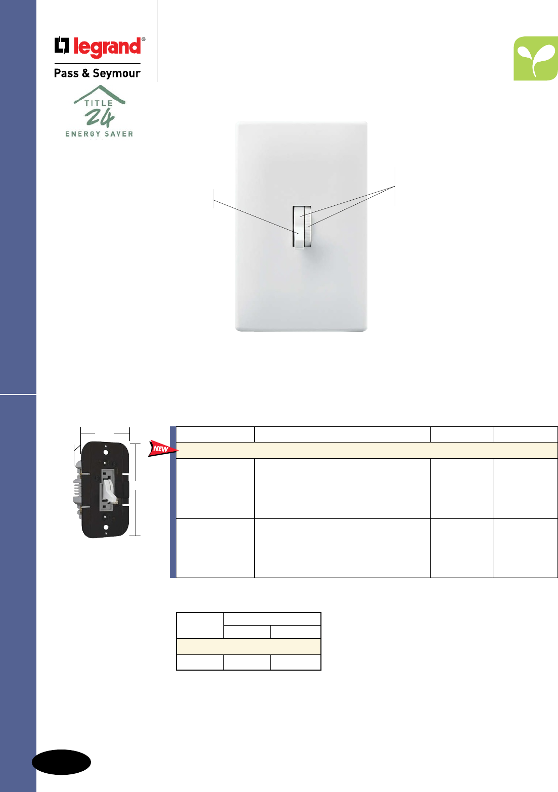
M-18
Dimmers & Fan Speed Controls
AlldeviceslistedonthispageconformtoNEMAWD-1andWD-6.ULListedandCSACertified.
Toggle Dimmers
Residential Dimmers & Fan Speed Controls
TradeMaster
®
Toggle Dimmers
*AvailableinVisionPak™packaging,add“CCV6”toCatalogNumber.Example:TD703PICCV6.
TD1103PW
700W versions
are 1.75" W
4.25"
2.50"
1.25"
Uses conventional 3-way
wiring when used in conjunction
with a 3-way switch.
Matches appearance of
standard P&S toggle switch.
Returns lights to previous
level after power failure.
Screwless Toggle Wall Plates,
see Page Q-6.
More versatile than standard
toggle dimmers. Provides easy
ON/OFF. Separate preset allows
convenient dimming control.
TD703PW
Shown with SWP1W
Catalog Number Description Ratings Color
Incandescent Single Pole/3-Way Dimmers
TD703PI* Ivory
TD703PW* White
TD703P Preset, Single Pole/3-Way 120V, 700W Brown
TD703PBK Black
TD703PLA* Light Almond
TD1103PI* Ivory
TD1103PW* White
TD1103P Preset, Single Pole/3-Way 120V, 1100W Brown
TD1103PBK Black
TD1103PLA* Light Almond
No de-rating required in
multi-gang applications (700W).
Note:Eachsideremovedreducesplatesize
by3/8".
For wiring diagrams, see Page M-19.
Max. Load Fins Removed
Rating One Side Two Side
De-Rating Chart
1000W 800W 700W
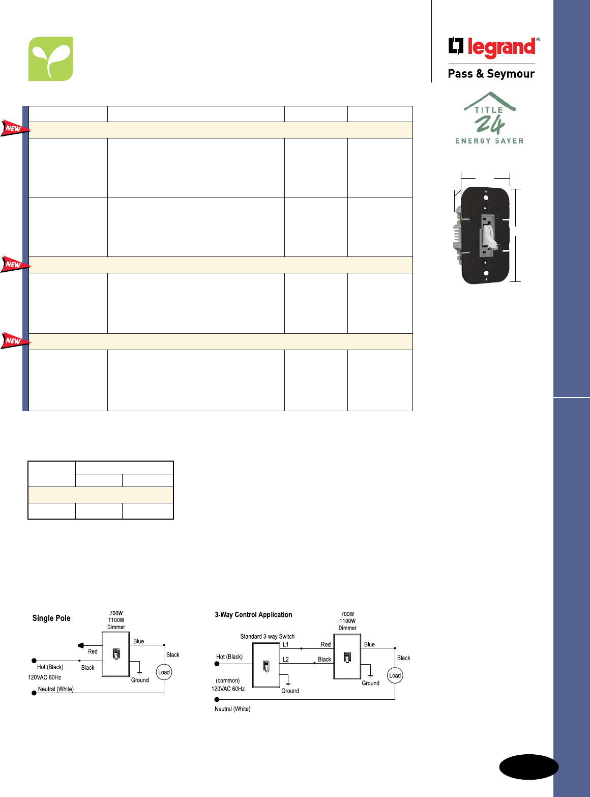
M-19
Dimmers & Fan Speed Controls
AlldeviceslistedonthispageconformtoNEMAWD-1andWD-6.ULListedandCSACertified.
Note:Eachsideremovedreducesplatesize
by3/8".
Max. Load Fins Removed
Rating One Side Two Side
De-Rating Chart
1000VA 800VA 700VA
Toggle Dimmers & Fan Speed Controls
Residential Dimmers & Fan Speed Controls
TradeMaster
®
Toggle Dimmers &
Fan Speed Controls
Wiring Diagrams
*ForusewithAdvanceMK10dimmingballasts.Seeinstructionsheetforcompletelistofcompatibleballasts.
**Featurespeciallydesignedcapacitivecircuitrytovirtuallyeliminatefanmotor“hum.”
Catalog Number Description Ratings Color
Magnetic Low-Voltage Single Pole/3-Way Dimmers
TDLV703PI Ivory
TDLV703PW White
TDLV703P Preset, Single Pole/3-Way 120V, 700VA Brown
TDLV703PBK Black
TDLV703PLA Light Almond
TDLV1103PI Ivory
TDLV1103PW White
TDLV1103P Preset, Single Pole/3-Way 120V, 1100VA Brown
TDLV1103PBK Black
TDLV1103PLA Light Almond
Fluorescent Single Pole/3-Way Dimmers*
TDFB83PI Ivory
TDFB83PW White
TDFB83P Two Wire Fluorescent Single Pole/3-Way 120V, 8A Brown
TDFB83PBK Black
TDFB83PLA Light Almond
De-Hummer** Fan Speed Controls
TDDH163PI Ivory
TDDH163PW White
TDDH163P De-Hummer Fan Speed Control 120V, 1.6A Brown
TDDH163PBK Black
TDDH163PLA Light Almond
TDLV1103PW
700VA versions are
1.75" W
4.25"
2.50"
1.25"
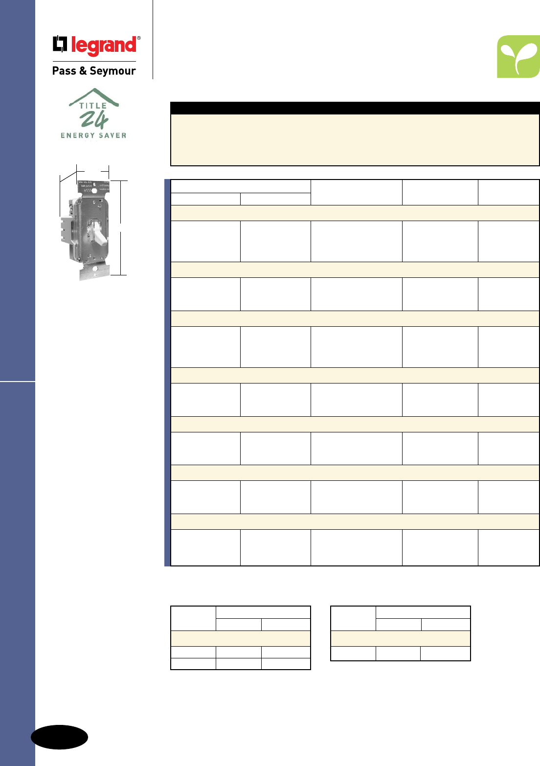
M-20
Dimmers & Fan Speed Controls
AlldeviceslistedonthispageconformtoNEMAWD-1andWD-6.ULListedandCSACertified.
TradeMaster® Toggles
Residential Dimmers & Fan Speed Controls
TradeMaster® Toggles
T600I
TSC5I
1.60"
4.130"
1.450"
Features
nToughimpact-resistantthermoplastichousing.
nPower-failurememory.
nSuperiorheatmanagement:notimewastingbreakofftabs.
nExclusive,screw-pressure-platebackwireterminalseliminateswirenuts.
*AvailableinVisionPak™packaging,add“V”toCatalogNumber.Example:T600LAV.
**Availableinboxedpackagingonly.
Max. Load Gang Reduction
Rating 2 Dimmers 3+ Dimmers
De-Rating Chart
600W 500W 400W
1000W 700W 650W
Max. Load Gang Reduction
Rating 2 Controls 3+ Controls
De-Rating Chart
5A 4A 3A
Catalog Number
Single Pole Three-Way Description Ratings Color
600W Incandescent Toggle Dimmers
T600I*T603I** Ivory
T600W*T603W**Non-Preset 120V White
T600*T603** 600W Brown
T600LA*T603LA** LightAlmond
600W Incandescent – Lighted Toggle Dimmers*
T600LIT603LI 120V Ivory
T600LWT603LW Non-Preset 600W White
T600LLAT603LLA LightAlmond
1000W Incandescent Toggle Dimmers
T1000I*T1003I** Ivory
T1000W*T1003W**Non-Preset 120V White
T1000*T1003** 1000W Brown
T1000LA*T1003LA** LightAlmond
1000W Incandescent – Lighted Toggle Dimmers**
T1000LIT1003LI 120V Ivory
T1000LWT1003LW Non-Preset 1000W White
T1000LLAT1003LLA LightAlmond
600VA Low-Voltage Magnetic Toggle Dimmers*
TLV600ITLV603I 120V Ivory
TLV600WTLV603W Non-Preset 600VA White
TLV600LATLV603LA LightAlmond
1000VA Low-Voltage Magnetic Toggle Dimmers**
TLV1000ITLV1003I 120V Ivory
TLV1000WTLV1003W Non-Preset 1000VA White
TLV1000LATLV1003LA LightAlmond
Toggle Fan Speed Controls*
TSC5I Non-Preset,120V Ivory
TSC5W — AdjustableTrim5A White
TSC5LA LightAlmond

M-21
Dimmers & Fan Speed Controls
AlldeviceslistedonthispageconformtoNEMAWD-1andWD-6.ULListedandCSACertified.
Rotary R Series
Residential Dimmers & Fan Speed Controls
Rotary R TradeMaster® Series
R600PWV
1.74"
4.19"
1.28"
R1000WV
2.50"
4.19"
1.28"
Features
nSlimmerdesign–thetrimmestrotarydimmers,
1/4"lessdepththantheleadingcompetitor'smodels.
nEasy-to-gripknobwithsoft,contemporary
curvesgoeswithanydécor.Interchangeable
witholder-styleknobs.
nExcellentRFI/EMIfilteringperformance–won't
impactsensitiveelectronicdevices.
nPre-strippedleadsspeedtermination.
nNode-ratingof600wattmodelsinmulti-
gangapplications.
nLeavesmoreroomintheboxforfaster,
easierinstallation.
nMakessmalladjustmentsinlightinglevels
easier.
nIlluminatedmodelsareeasytofindinthe
dark.
Catalog Number Description Color
Rotary Replacement Knobs
RRKIV Ivory
RRKWV PlainReplacementKnob White
RRKLAV LightAlmond
RRKCLGV Clear
RRKIGVDeluxeReplacementKnob Ivory
RRKWGV White
RRKLAGV LightAlmond
Catalog Number
Single Pole Three-Way Description Ratings Color
600W Incandescent RFI Rotary Dimmers
R600IV 120V Ivory
R600WV Non-Preset 600W White
R600LAV LightAlmond
R600PIV R603PIV 120V Ivory
R600PWV R603PWV Preset 600W White
R600PLAV R603PLAV LightAlmond
1000W Incandescent RFI Rotary Dimmers
R1000IV 120V Ivory
R1000WV Non-Preset 1000W White
R1000LAV LightAlmond
R1000PIV R1003PIV 120V Ivory
R1000PWV R1003PWV Preset 1000W White
R1000PLAV R1003PLAV LightAlmond
AvailableinVisionPak™only.
De-Rating Chart for R Series
Catalog Maximum Multi-Gang De-Rating
Number Load 2 Gang 3 Gang
R600,R600P 600W NoDe-RatingRequired
R1000 1000W 750W 700W
R1000P 1000W 900W 800W
R1003P 1000W 900W 800W
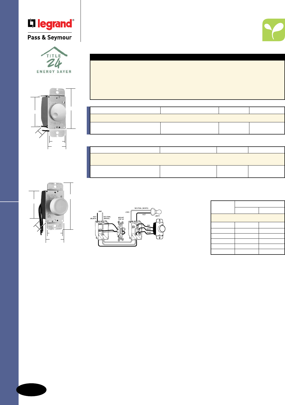
M-22
Dimmers & Fan Speed Controls
AlldeviceslistedonthispageconformtoNEMAWD-1andWD-6.ULListedandCSACertified.
Forusewithmagnetictransformerincandescentlow-voltagelighting.
Catalog Number Description Ratings Color
Magnetic Low-Voltage Specification Grade Rotary Dimmers
Single Pole
95600IPreset,PushOn/Off 120V Ivory
95600W 600VAmax. White
Rotary Series
Residential Dimmers & Fan Speed Controls
Rotary TradeMaster®
Series
Rotary Dimmer 3-Way Wiring Diagram
90621
4"
1.672"
2.672"
1.453"
1.438"
Features
nFullrangerotarydimming.
nLow-voltageandfluorescentmodelshavefield
adjustabletrimsthatmaybesettocontrol
minimumlightlevel.
nGroundleadprovidedonallmodels.
nVoltagecompensationcircuitryinfluorescentand
magneticlow-voltagemodelreduceslightingfluctuations.
nAllmodelsfitstandardtogglewallplate.
nAlldimmersonthispagemaybeganged
withoutde-rating.
nRFIprotected.
Catalog Number Description Ratings Color
600W Max. Incandescent Specification Grade Rotary Dimmers
90621IV SinglePole120V Ivory
90621WV LowProfile,DialOn/Off 600Wmax. White
AvailableinVisionPak™only.
4"
1.672"
2.672"
1.438" 1.453"
95600
Max. Load Fins Removed
Rating One Side Two Side
De-Rating Chart
600W 500W 400W
600VA 450VA 400VA
1000VA 800VA 700VA
1000W 800W 700W
1500W 1400W 1300W
2000W 1800W 1600W
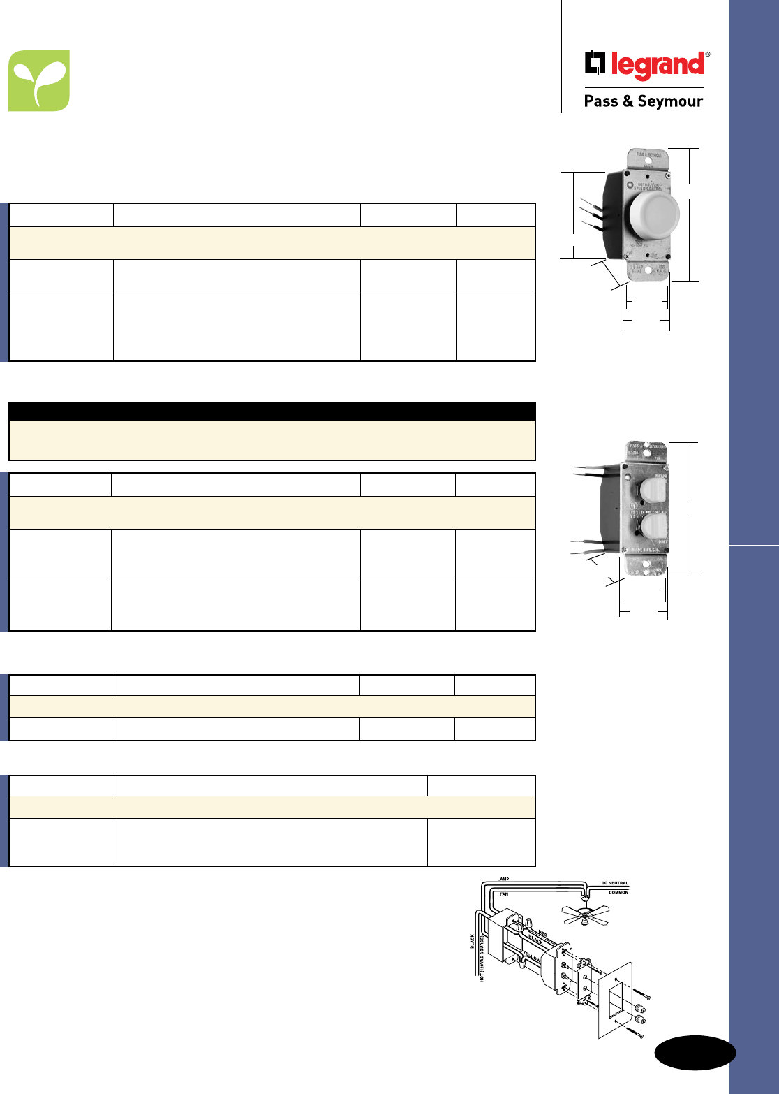
M-23
Dimmers & Fan Speed Controls
AlldeviceslistedonthispageconformtoNEMAWD-1andWD-6.ULListedandCSACertified.
Rotary Fan Speed Controls
Residential Dimmers & Fan Speed Controls
Rotary TradeMaster®
Fan Speed Controls
Dual Control Connection Diagram
1.672"
1.438"
1.453"
4.156"
94215
94315
94331
542433
94004
94003
1.672"
2.672"
1.453"
4"
1.438"
No-Noise De-Hummers
Sincethedevelopmentofvariablefanspeedcontrols,manyfanshavemadeanannoyinghummingnoise
whentheirspeedwasreduced.Throughtheuseofspeciallydesignedcapacitivecircuitry,theseunitscan
controlfansat3or4-speedlevelsinslide,rotaryanddualstyleswithvirtuallynofanmotornoise.
Requires3wireinstallation.
*AvailableinVisionPak™packaging,add“V”toCatalogNumber.Example:94315LAV.
Catalog Number Description Ratings Color
1.5A/300W Max. Specification Grade Dual Controls –
No-Noise De-Hummers*
94315I 120V Ivory
94315W3-SpeedFanControland1.5A/300Wmax. White
94315LA2-LevelHi/LowDimmer LightAlmond
94215I 120V Ivory
94215W4-SpeedFanControland1.5A/300Wmax. White
94215LA2-LevelHi/LowDimmer LightAlmond
Catalog Number Description Ratings Color
3A/300W Max. Specification Grade Dual Controls*
94331I DialSpeedControlandDimmer 120V Ivory
*AvailableinVisionPak™packaging,add“V”toCatalogNumber.Example:94331IV.
Catalog Number Description Ratings Color
1.5A Max. Specification Grade Rotary Fan Speed Controls –
No-Noise De-Hummers, RFI Protected*
94003I 120V Ivory
94003W3-Speed,Low-Medium-High 1.5Amax. White
94004CL Clear
94004I4-Speed,Low-High 120V Ivory
94004W 1.5Amax. White
94004LA LightAlmond
*AvailableinVisionPak™packaging,add“V”toCatalogNumber.Example:94003LAV.
Note:Allcontrolsonthispagemaybegangedwithoutde-rating.
Dual Control Features
nFitsonegangbox.
nControlsbothfanspeedandlightlevel.
nDecoratorstyling.
Catalog Number Description Color
Accessories for Dual Controls
109019V Ivory
109020V AdapterKitforDualFan/LightControls White
109018V LightAlmond
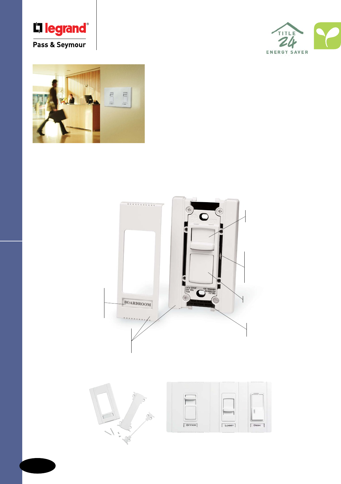
M-24
Dimmers & Fan Speed ControlsTitan™ Series
Commercial Dimmers &
Fan Speed Controls
Titan™ Series
A complete solution for easy, economical
multi-gang installations.
The P&S Titan™ Series have key features designed to
increase installer productivity. Each comes with all the
screwless wall plate components necessary for single gang
or multi-gang installations. No need to order any additional
components such as long-lead time custom wall plates to
finish the job. Complete the installation with everything right
out of the box, increasing productivity by finishing up in one
visit instead of several.
Exclusive adjustable limit control
in incandescent dimmers saves
energy and extends bulb life —
reduces maximum output by up to
10 percent.
Power-failure memory retains
presets through power outages.
High-reliability design
with built-in surge and static
protection plus oversize output
devices to stand up to abuse.
Improved heat management
enables superior load ratings.
Enclosed slider helps prevent
dust and dirt contamination.
Air-gap switch
Included screwless wall plate
components make it easy to assemble
a custom multi-gang wall plate in any
configuration — saving money and time.
Preset models feature large
ON/OFF button and single
pole/three-way functionality.
Widest choice of amperage
ratings with minimal or no
de-rating for faster job planning.
Exclusive labeling
system has a built-in
label holder enabling
instant circuit identification;
looks clean and professional.
Adaptor kit enables matching installation
of standard P&S Decorator Devices – outlets,
switches, GFCIs and more.
CDADAPTORKITW
CD703PW
Included end-caps and
spacers screw directly
to heat sinks; center plate
snaps easily on and off.
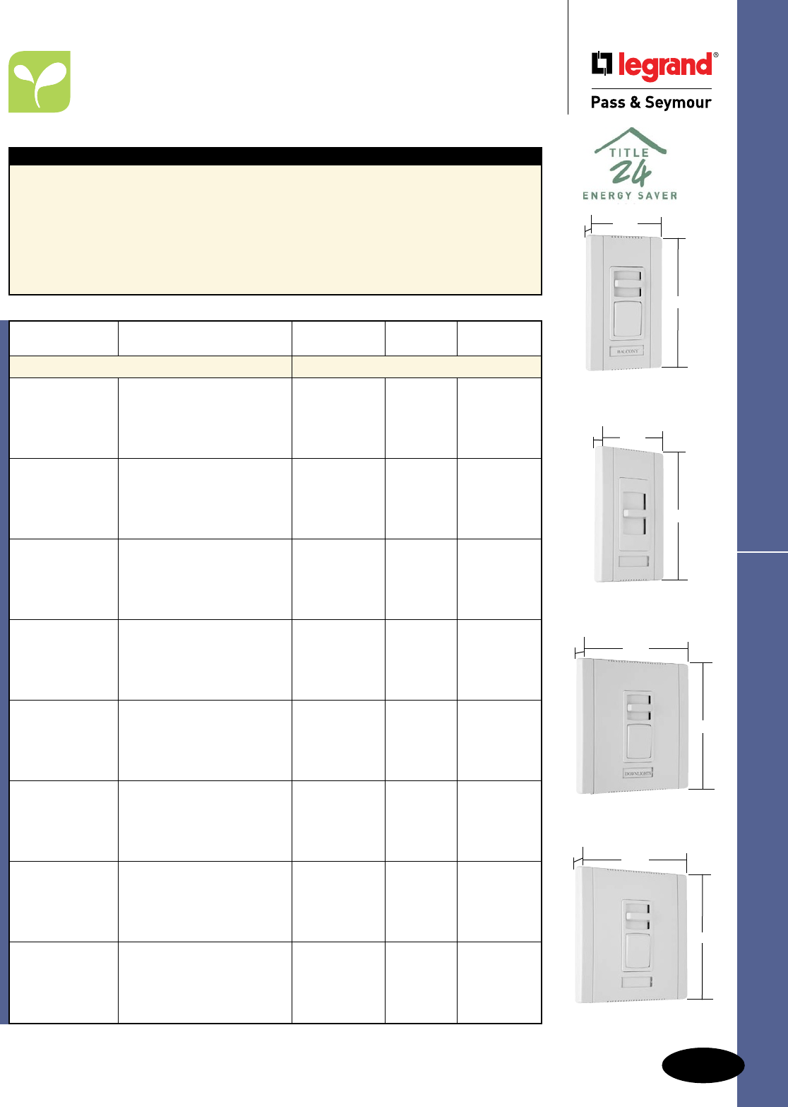
M-25
Dimmers & Fan Speed Controls Titan™ Series Incandescent Dimmers
Commercial Dimmers & Fan Speed Controls
Titan™ Series Incandescent Dimmers
CD1100W
Narrow
2.85"
4.87"
1.44"
CD703PW
Narrow
2.85"
4.87"
1.44"
CD1603PW
Wide
4.65"
4.87"
1.44"
CD2003PW
Wide
4.65"
4.87"
1.44"
Features
nFieldconfigurablewallplatesystem.
nLabelingsystem.
nAdjustabletopendoutputvoltage.
nShippedwithprotectivefilm.
nRuggedconstruction.
nSuperiorratingswithaminimumofde-rating
whenganged.
nSimpletoplantherough-in.
nAvailableinsinglepoleslide-to-OFFand
singlepole/3-waypresetmodels.
nAttractiveEuropeanstyling.
nEye-catchingpackaging.
nExclusiveadaptorkittoinstallotherDecorator
openingdevicesundertheTitan™wallplate
system.(SeePageM-26.)
nBlankcenterplateincluded.
Catalog Narrow
Number Description Ratings or Wide Color
Incandescent
CD700I Ivory
CD700W White
CD700SinglePole,Slide-to-OFF 120V,700W Narrow Brown
CD700GRY Gray
CD700BK Black
CD700LA LightAlmond
CD703PI Ivory
CD703PW White
CD703PSinglePole/3-Way,Preset 120V,700W Narrow Brown
CD703PGRY Gray
CD703PBK Black
CD703PLA LightAlmond
CD1100I Ivory
CD1100W White
CD1100SinglePole,Slide-to-OFF 120V,1100W Narrow Brown
CD1100GRY Gray
CD1100BK Black
CD1100LA LightAlmond
CD1103PI Ivory
CD1103PW White
CD1103PSinglePole/3-Way,Preset 120V,1100W Narrow Brown
CD1103PGRY Gray
CD1103PBK Black
CD1103PLA LightAlmond
CD1600I Ivory
CD1600W White
CD1600SinglePole,Slide-to-OFF 120V,1600W Wide Brown
CD1600GRY Gray
CD1600BK Black
CD1600LA LightAlmond
CD1603PI Ivory
CD1603PW White
CD1603PSinglePole/3-Way,Preset 120V,1600W Wide Brown
CD1603PGRY Gray
CD1603PBK Black
CD1603PLA LightAlmond
CD2000I Ivory
CD2000W White
CD2000SinglePole,Slide-to-OFF 120V,2000W Wide Brown
CD2000GRY Gray
CD2000BK Black
CD2000LA LightAlmond
CD2003PI Ivory
CD2003PW White
CD2003PSinglePole/3-Way,Preset 120V,2000W Wide Brown
CD2003PGRY Gray
CD2003PBK Black
CD2003PLA LightAlmond
For technical specifications, de-rating, and rough-in box charts, see Pages S-147 and S-148.
AlldeviceslistedonthispageconformtoNEMAWD-1andWD-6.cULusListed.
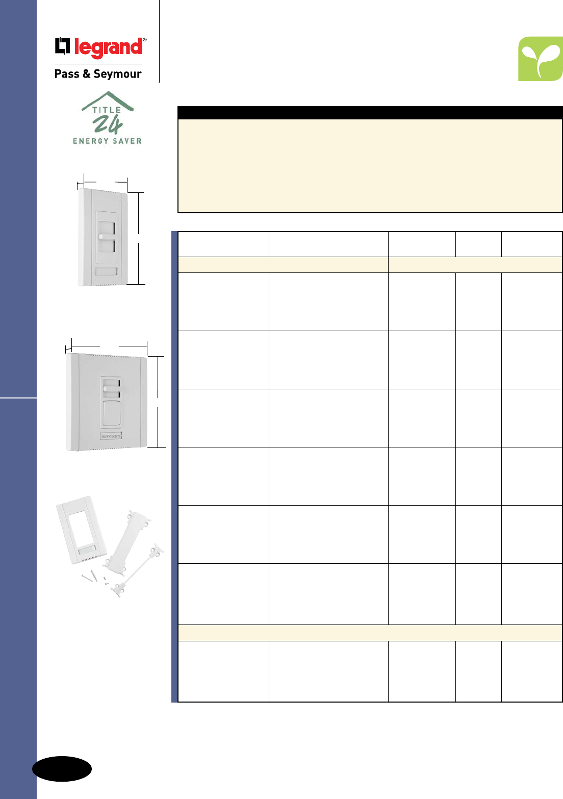
M-26
Dimmers & Fan Speed Controls
AlldeviceslistedonthispageconformtoNEMAWD-1andWD-6.cULusListed.
Titan™ Series Magnetic Low-Voltage
Commercial Dimmers & Fan Speed Controls
Titan™ Series Magnetic
Low-Voltage Dimmers &
Adaptor Kit
Catalog Narrow
Number Description Ratings or Wide Color
Magnetic Low-Voltage
CDLV700I Ivory
CDLV700W White
CDLV700SinglePole,Slide-to-OFF 120V,700W Narrow Brown
CDLV700GRY Gray
CDLV700BK Black
CDLV700LA LightAlmond
CDLV703PI Ivory
CDLV703PW White
CDLV703PSinglePole/3-Way,Preset 120V,700W Narrow Brown
CDLV703PGRY Gray
CDLV703PBK Black
CDLV703PLA LightAlmond
CDLV1100I Ivory
CDLV1100W White
CDLV1100SinglePole,Slide-to-OFF 120V,1100W Narrow Brown
CDLV1100GRY Gray
CDLV1100BK Black
CDLV1100LA LightAlmond
CDLV1103PI Ivory
CDLV1103PW White
CDLV1103PSinglePole/3-Way,Preset 120V,1100W Narrow Brown
CDLV1103PGRY Gray
CDLV1103PBK Black
CDLV1103PLA LightAlmond
CDLV1600I Ivory
CDLV1600W White
CDLV1600SinglePole,Slide-to-OFF 120V,1600W Wide Brown
CDLV1600GRY Gray
CDLV1600BK Black
CDLV1600LA LightAlmond
CDLV1603PI Ivory
CDLV1603PW White
CDLV1603PSinglePole/3-Way,Preset 120V,1600W Wide Brown
CDLV1603PGRY Gray
CDLV1603PBK Black
CDLV1603PLA LightAlmond
Adaptor Kit
CDADAPTORKITI Ivory
CDADAPTORKITW White
CDADAPTORKIT DecoratorDeviceAdaptorKit Narrow Brown
CDADAPTORKITGRY Gray
CDADAPTORKITBK Black
CDADAPTORKITLA LightAlmond
For technical specifications, de-rating, and rough-in box charts, see Pages S-147 and S-148.
Features
nFieldconfigurablewallplatesystem.
nLabelingsystem.
nAdjustablelowendoutputvoltage.
nShippedwithprotectivefilm.
nRuggedconstruction.
nSuperiorratingswithaminimumofde-rating
whenganged.
nSimpletoplantherough-in.
nAvailableinsinglepoleslide-to-OFFand
singlepole/3-waypresetmodels.
nAttractiveEuropeanstyling.
nEye-catchingpackaging.
nExclusiveadaptorkittoinstallotherDecorator
openingdevicesundertheTitan™wallplate
system.
nBlankcenterplateincluded.
4.65"
4.87"
1.44"
CDLV1103PW
Wide
CDLV700W
Narrow
2.85"
4.87"
1.44"
Adaptor kit enables
matching installation of
standard P&S Decorator
Devices – outlets, switches,
GFCIs and more.
See Page M-24.
CDADAPTORKITW
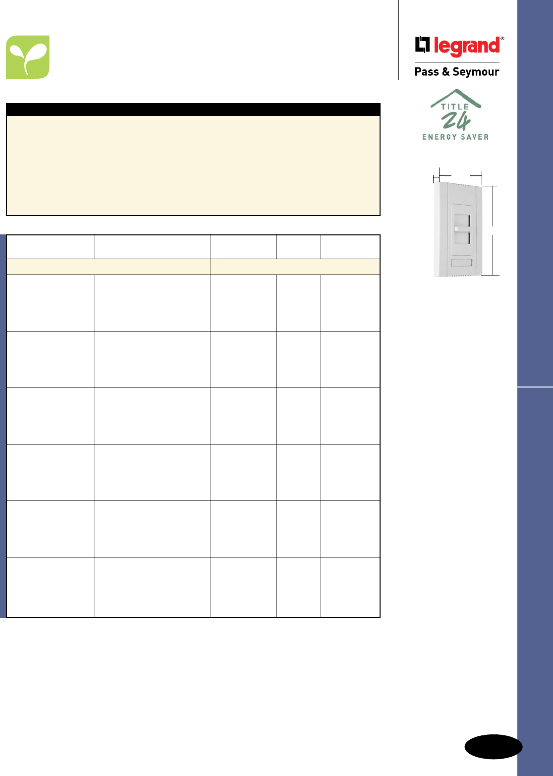
M-27
Dimmers & Fan Speed Controls Titan™ Series Fluorescent
AlldeviceslistedonthispageconformtoNEMAWD-1andWD-6.cULusListed.
Commercial Dimmers & Fan Speed Controls
Titan™ Series Fluorescent
2 Wire Dimmers
CDFB5W
Narrow
2.85"
4.87"
1.44"
For technical specifications, de-rating, rough-in box charts, and complete list of compatible
ballasts, see Pages S-149 – S-151.
Features
nForusewith2wire120Vand277Vfluorescent
dimmingballasts.
nFieldconfigurablewallplatesystem.
nLabelingsystem.
nAdjustablelowendoutputvoltage.
nShippedwithprotectivefilm.
nRuggedconstruction.
nSuperiorratingswithaminimumofderating
whenganged.
nSimpletoplantherough-in.
nAvailableinsinglepoleslide-to-OFFand
singlepole/3-waypresetmodels.
nAttractiveEuropeanstyling.
nEye-catchingpackaging.
nExclusiveadaptorkittoinstallotherDecorator
openingdevicesundertheTitan™wallplate
system.(SeePageM-26.)
nBlankcenterplateincluded.
Catalog Narrow
Number Description Ratings or Wide Color
Fluorescent
CDFB5I Ivory
CDFB5W White
CDFB5 2Wire,Electronic, 5A,120V Narrow Brown
CDFB5GRY SinglePole,Slide-to-OFF Gray
CDFB5BK Black
CDFB5LA LightAlmond
CDFB8I Ivory
CDFB8W White
CDFB8 2Wire,Electronic, 8A,120V Narrow Brown
CDFB8GRY SinglePole,Slide-to-OFF Gray
CDFB8BK Black
CDFB8LA LightAlmond
CDFB10I Ivory
CDFB10W White
CDFB10 2Wire,Electronic, 10A,120V Wide Brown
CDFB10GRY SinglePole,Slide-to-OFF Gray
CDFB10BK Black
CDFB10LA LightAlmond
CDFB16I Ivory
CDFB16W White
CDFB16 2Wire,Electronic, 16A,120V Wide Brown
CDFB16GRY SinglePole,Slide-to-OFF Gray
CDFB16BK Black
CDFB16LA LightAlmond
CDFB7277I Ivory
CDFB7277W White
CDFB7277 2Wire,Electronic, 7A,277V Wide Brown
CDFB7277GRY SinglePole,Slide-to-OFF Gray
CDFB7277BK Black
CDFB7277LA LightAlmond
CDFB10277I Ivory
CDFB10277W White
CDFB10277 2Wire,Electronic, 10A,277V Wide Brown
CDFB10277GRY SinglePole,Slide-to-OFF Gray
CDFB10277BK Black
CDFB10277LA LightAlmond

M-28
Dimmers & Fan Speed Controls
AlldeviceslistedonthispageconformtoNEMAWD-1andWD-6.cULusListed.
Titan™ Series Fluorescent
Commercial Dimmers & Fan Speed Controls
Titan™ Series Fluorescent
2 Wire Dimmers
CDFB53PW
Narrow
2.85"
4.87"
1.44"
4.65"
4.87"
1.44"
CDFB103PW
Wide
Features
nForusewith2wire120Vand277Vfluorescent
dimmingballasts.
nFieldconfigurablewallplatesystem.
nLabelingsystem.
nAdjustablelowendoutputvoltage.
nShippedwithprotectivefilm.
nRuggedconstruction.
nSuperiorratingswithaminimumofde-rating
whenganged.
nSimpletoplantherough-in.
nAvailableinsinglepoleslide-to-OFFand
singlepole/3-waypresetmodels.
nAttractiveEuropeanstyling.
nEye-catchingpackaging.
nExclusiveadaptorkittoinstallotherDecorator
openingdevicesundertheTitan™wallplate
system.(SeePageM-26.)
nBlankcenterplateincluded.
For technical specifications, de-rating, rough-in box charts, and complete list of compatible
ballasts, see Pages S-149 – S-151.
Catalog Narrow
Number Description Ratings or Wide Color
Fluorescent
CDFB53PI Ivory
CDFB53PW White
CDFB53P 2Wire,Electronic, 5A,120V Narrow Brown
CDFB53PGRY SinglePole/3-Way,Preset Gray
CDFB53PBK Black
CDFB53PLA LightAlmond
CDFB83PI Ivory
CDFB83PW White
CDFB83P 2Wire,Electronic, 8A,120V Narrow Brown
CDFB83PGRY SinglePole/3-Way,Preset Gray
CDFB83PBK Black
CDFB83PLA LightAlmond
CDFB103PI Ivory
CDFB103PW White
CDFB103P 2Wire,Electronic, 10A,120V Wide Brown
CDFB103PGRY SinglePole/3-Way,Preset Gray
CDFB103PBK Black
CDFB103PLA LightAlmond
CDFB163PI Ivory
CDFB163PW White
CDFB163P 2Wire,Electronic, 16A,120V Wide Brown
CDFB163PGRY SinglePole/3-Way,Preset Gray
CDFB163PBK Black
CDFB163PLA LightAlmond
CDFB73P277I Ivory
CDFB73P277W White
CDFB73P277 2Wire,Electronic, 7A,277V Wide Brown
CDFB73P277GRY SinglePole/3-Way,Preset Gray
CDFB73P277BK Black
CDFB73P277LA LightAlmond
CDFB103P277I Ivory
CDFB103P277W White
CDFB103P277 2Wire,Electronic, 10A,277V Wide Brown
CDFB103P277GRY SinglePole/3-Way,Preset Gray
CDFB103P277BK Black
CDFB103P277LA LightAlmond
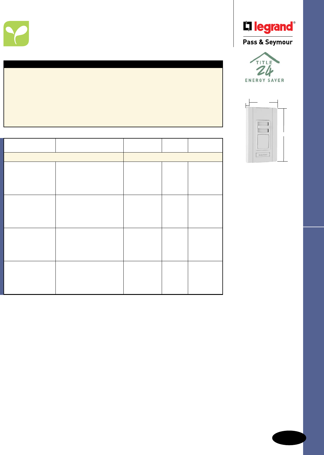
M-29
Dimmers & Fan Speed Controls
AlldeviceslistedonthispageconformtoNEMAWD-1andWD-6.cULusListed.
Titan™ Series Fluorescent
Commercial Dimmers & Fan Speed Controls
Titan™ Series Fluorescent
3 Wire Dimmers
Features
nForusewith3wire120Vand277Vfluorescent
dimmingballasts.
nFieldconfigurablewallplatesystem.
nLabelingsystem.
nAdjustablelowendoutputvoltage.
nShippedwithprotectivefilm.
nRuggedconstruction.
nSuperiorratingswithaminimumofde-rating
whenganged.
nSimpletoplantherough-in.
nAvailableinsinglepoleslide-to-OFFand
singlepole/3-waypresetmodels.
nAttractiveEuropeanstyling.
nEye-catchingpackaging.
nExclusiveadaptorkittoinstallotherDecorator
openingdevicesundertheTitan™wallplate
system.(SeePageM-26.)
nBlankcenterplateincluded.
Catalog Narrow
Number Description Ratings or Wide Color
Fluorescent
CD3FB16I Ivory
CD3FB16W White
CD3FB16 3WireElectronic, 120V,16A Narrow Brown
CD3FB16GRY SinglePole,Slide-to-OFF Gray
CD3FB16BK Black
CD3FB16LA LightAlmond
CD3FB163PI Ivory
CD3FB163PW White
CD3FB163P 3WireElectronic, 120V,16A Narrow Brown
CD3FB163PGRY SinglePole/3-Way,Preset Gray
CD3FB163PBK Black
CD3FB163PLA LightAlmond
CD3FB10277I Ivory
CD3FB10277W White
CD3FB10277 3WireElectronic, 277V,10A Narrow Brown
CD3FB10277GRY SinglePole,Slide-to-OFF Gray
CD3FB10277BK Black
CD3FB10277LA LightAlmond
CD3FB103P277I Ivory
CD3FB103P277W White
CD3FB103P277 3WireElectronic, 277V,10A Narrow Brown
CD3FB103P277GRY SinglePole/3-Way,Preset Gray
CD3FB103P277BK Black
CD3FB103P277LA LightAlmond
CD3FB163PW
Narrow
2.85"
4.87"
1.44"
For technical specifications, de-rating, rough-in box charts, and complete list of compatible
ballasts, see Pages S-149 – S-151.
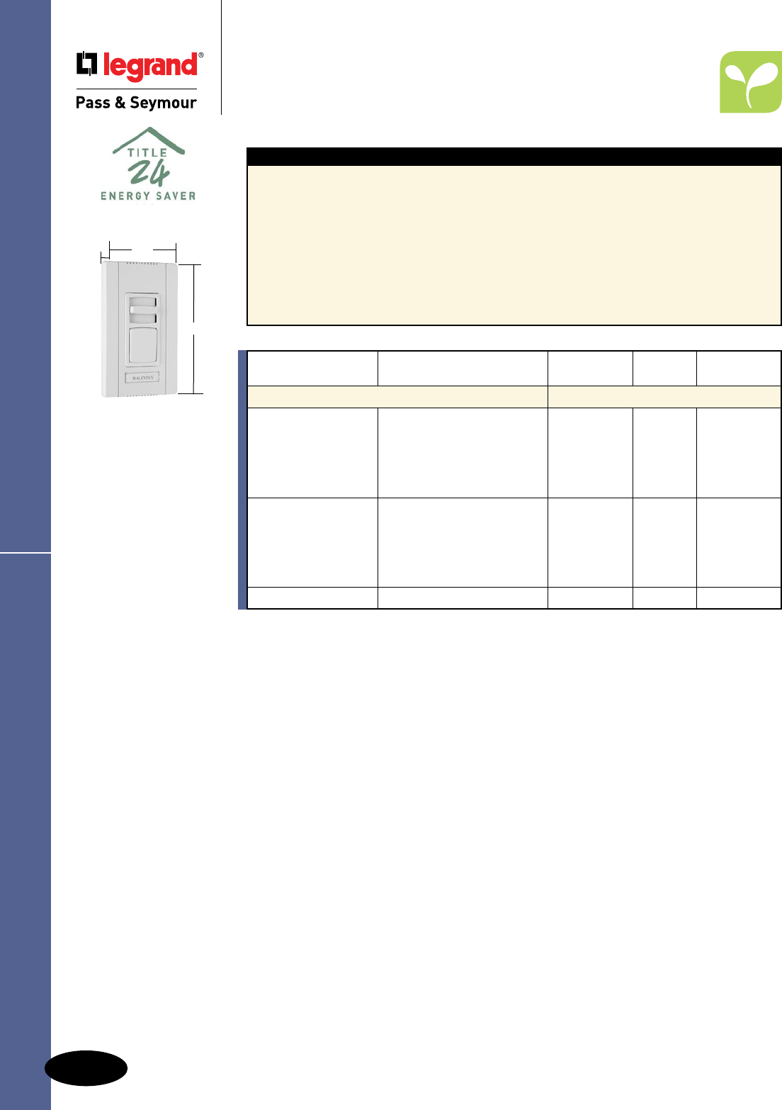
M-30
Dimmers & Fan Speed Controls
AlldeviceslistedonthispageconformtoNEMAWD-1andWD-6.cULusListed.
Titan™ Series Fluorescent
Commercial Dimmers & Fan Speed Controls
Titan™ Series Fluorescent
4 Wire Dimmers
Features
nForusewith0-10V,4wire,120Vand277V
fluorescentdimmingballasts.
nFieldconfigurablewallplatesystem.
nLabelingsystem.
nAdjustablelowendoutputvoltage.
nShippedwithprotectivefilm.
nRuggedconstruction.
nSuperiorratingswithaminimumofde-rating
whenganged.
nMustbeusedwithpowerpack.
nSimpletoplantherough-in.
nAvailableinsinglepoleslide-to-OFFand
singlepole/3-waypresetmodels.
nAttractiveEuropeanstyling.
nEye-catchingpackaging.
nExclusiveadaptorkittoinstallotherDecorator
openingdevicesundertheTitan™wallplate
system.(SeePageM-26.)
nBlankcenterplateincluded.
Red available made to order.
CD4FB3PW
Narrow
2.85"
4.87"
1.4375"
Catalog Narrow
Number Description Ratings or Wide Color
Fluorescent
CD4FBI Ivory
CD4FBW White
CD4FB 24VDC Narrow Brown
CD4FBGRYSinglePole,Slide-to-OFF Gray
CD4FBBK Black
CD4FBLA LightAlmond
CD4FB3PI Ivory
CD4FB3PW White
CD4FB3P SinglePole/3-Way,Preset 24VDC Narrow Brown
CD4FB3PGRY Gray
CD4FB3PBK Black
CD4FB3PLA LightAlmond
PWP120277 Powerpackforswitchingload 24VDC —
For technical specifications, de-rating, rough-in box charts, and complete list of compatible
ballasts, see Pages S-149 – S-151.
Power Pack technical specifications, see Page S-146.

M-31
Dimmers & Fan Speed Controls
AlldeviceslistedonthispageconformtoNEMAWD-1andWD-6.cULusListed.
Titan™ Series Fan Speed Controls
Commercial Dimmers & Fan Speed Controls
Titan™ Series Fan Speed Controls
Features
nFieldconfigurablewallplatesystem.
nLabelingsystem.
nShippedwithprotectivefilm.
nRuggedconstruction.
nSimpletoplantherough-in.
nAvailableinsinglepoleslide-to-OFFmodels.
nAttractiveEuropeanstyling.
nEye-catchingpackaging.
nExclusiveadaptorkittoinstallotherDecorator
openingdevicesundertheTitan™wallplate
system.(SeePageM-26.)
nAvailableinbothcontinuouslyvariableand
de-hummerstyles.
nBlankcenterplateincluded.
CDSC6W
Narrow
2.85"
4.87"
1.4375"
Catalog Narrow
Number Description Ratings or Wide Color
Fan Speed Controls
CDSC6I Ivory
CDSC6W White
CDSC6 ContinuouslyVariableSpeed 120V,6A Narrow Brown
CDSC6GRY FanSpeedControl Gray
CDSC6BK Black
CDSC6LA LightAlmond
CDSC12I Ivory
CDSC12W White
CDSC12 ContinuouslyVariableSpeed 120V,12A Wide Brown
CDSC12GRY FanSpeedControl Gray
CDSC12BK Black
CDSC12LA LightAlmond
CDDH16I Ivory
CDDH16WDe-Hummer,4Speed White
CDDH16Low/Low-Mid/High-Mid/High 120V,1.6A Narrow Brown
CDDH16GRYFanSpeedControl Gray
CDDH16BK Black
CDDH16LA LightAlmond
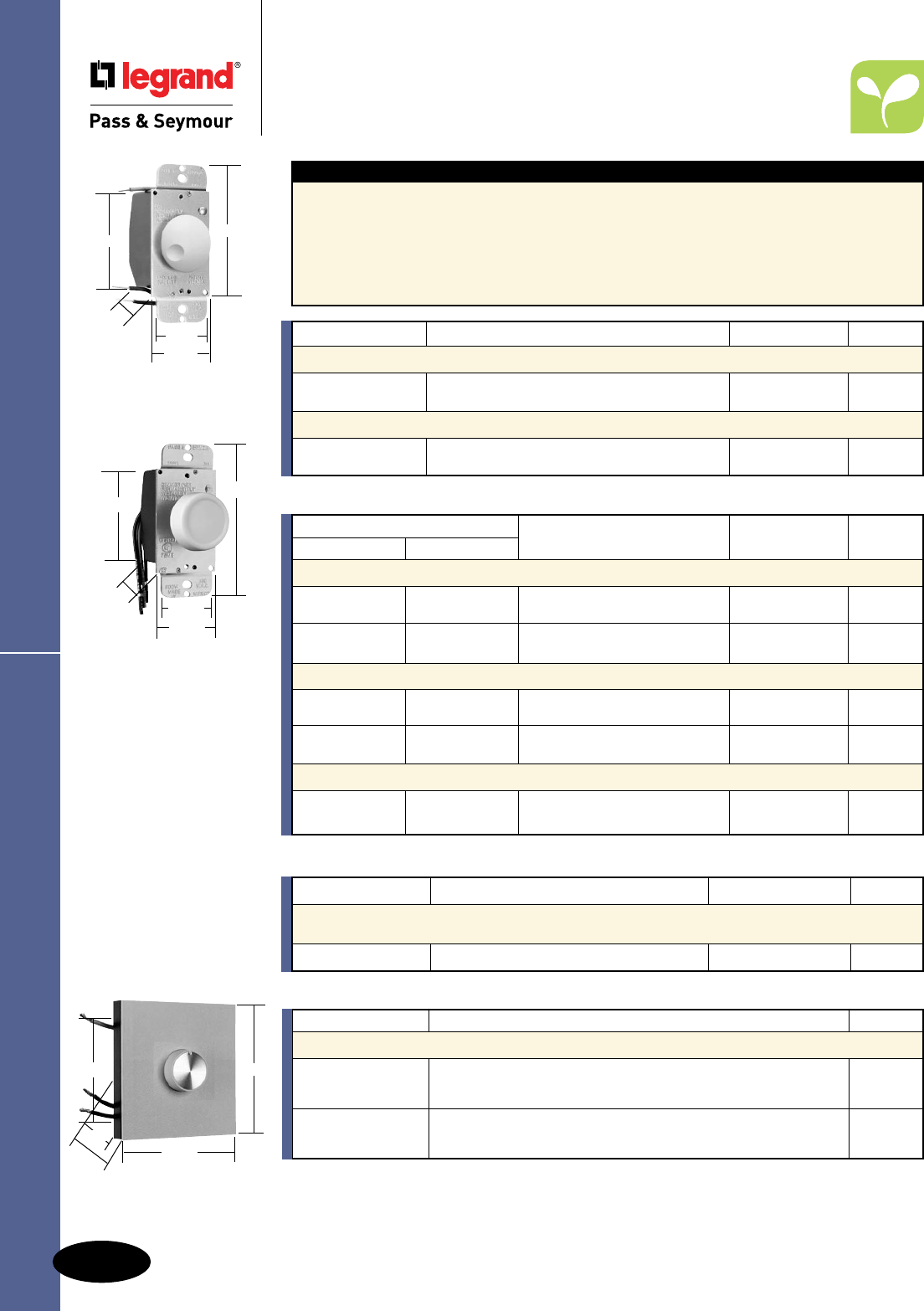
M-32
Dimmers & Fan Speed Controls
4"
1.672"
2.672"
1.438" 1.453"
95600
AlldeviceslistedonthispageconformtoNEMAWD-1andWD-6.cULusListed.
Commercial Dimmers & Fan Speed Controls
Rotary Dimmers
Rotary Dimmers
Catalog Number Description Color
Accessories for Rotary Heat Sink Dimmers & Fan Speed Controls
DAPK1I Ivory
DAPK1W 1-GangWallPlate–PlateandKnobKit White
DAPK1 Brown
DAPK2I Ivory
DAPK2W 2-GangWallPlate–PlateandKnobKit White
DAPK2 Brown
91500
91501
91503
92001
4.516"
4.453"
2.672"
1.313"
1.906"
Features
nFullrangerotarydimming.
nLow-voltageandfluorescentmodelshavefield
adjustabletrimsthatmaybesettocontrol
minimumlightlevel.
nGroundleadprovidedonallmodels.
nNewattractiveknobdesign.
nVoltagecompensationcircuitryinfluorescent
andmagneticlow-voltagemodelreduceslighting
fluctuations.
nAllmodelsfitstandardtogglewallplate.
nAlldimmersonthispagemaybeganged
withoutde-rating.
nRFIprotected.
90621
4"
1.672"
2.672"
1.453"
1.438"
*Forusewithmagnetictransformerincandescentlow-voltagelighting.
Catalog Number Description Ratings Color
Incandescent Specification Grade Rotary Dimmers — Single Pole
90621IV LowProfile,DialON/OFF 120V,600Wmax. Ivory
90621WV White
Magnetic Low-Voltage Specification Grade Rotary Dimmers — Single Pole*
95600IPreset,PushON/OFF120V,600Wmax. Ivory
95600W White
*Fitsinstandardtogglewallplateopening.
Catalog Number
Single Pole Three-Way Description Ratings Color
1000W Max. Incandescent Rotary Dimmers with Architectural Heat Sink
91000I 91003IPreset,PushON/OFF 120V Ivory
91000W 91003W 1000Wmax. White
91001I Dial,ON/OFF 120V Ivory
91001W 1000Wmax. White
1500W Max. Incandescent Rotary Dimmers with Architectural Heat Sink
91500I 91503IPreset,PushON/OFF 120V Ivory
91503W 1500Wmax. White
91501I Dial,ON/OFF120V Ivory
91501W 1500Wmax. White
2000W Max. Incandescent Rotary Dimmers with Architectural Heat Sink
92001I Dial,ON/OFF120V Ivory
92001W 2000Wmax. White
Catalog Number Description Ratings Color
1000VA Max. Magnetic Low-Voltage Specification Grade Single Pole
Rotary Dimmer* with Architectural Heat Sink
95100I Dial,ON/OFF 120V,1000VAmax. Ivory
*Forusewithmagnetictransformerincandescentlow-voltagelighting.
For wiring diagrams, see Page S-20. For de-rating chart, see Page M-22.
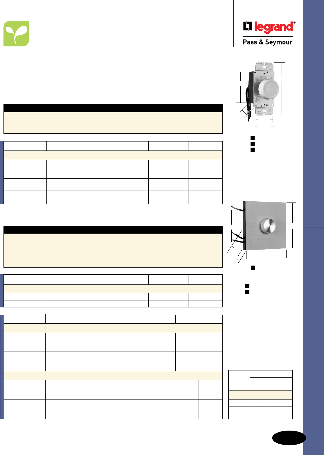
M-33
Dimmers & Fan Speed Controls
AlldeviceslistedonthispageconformtoNEMAWD-1andWD-6.ULListedandCSACertified.
Rotary Fan Speed Controls
Commercial Dimmers & Fan Speed Controls
Rotary Fan Speed Controls
94301
94503
94601
P
N
N
4"
1.672"
2.672"
1.438" 1.453"
=Preset
=Non-Preset
P
N
N94121
4.516"
4.453"
2.672"
1.313"
1.906"
Max. Gang Reduction
Load One Two
Rating Side Side
De-Rating Chart
5Amp 4Amp 3Amp
8Amp 7Amp 6Amp
12Amp 11Amp 10Amp
Features
nFullrangevariablelowtohighspeedcontrol.
nEasilygangedbyremovingscoredheatsinkfins.
nHeavy-dutytoroidchokeforRFIsuppression.
nBlackanodizedheatsinkforgreaterheat
dispersionandenhancedappearance.
n100%testedforsymmetryforextendedfanlife.
nGroundleadprovided.
nFerritebarcoilchokeforexcellent
RFIsuppression.
Field Adjustable Trim
Thisfeatureallowstheusertosettheminimumspeedleveldesiredandhelpspreventdamagetomotor
duetostalling.Modelswithoutfieldadjustabletrimsfeaturefactorysettingsforminimumanti-stalllevels.
Full-On Bypass
Whencontrolisplacedinthefull-Onposition,speedcontrolcircuitryisbypassedbylatchingcontacts.
Thisfeatureallowsfor100%motoroutputandextendsspeedcontrol’slifebyeliminatingheatbuild-up.
Features
nFullrangespeedcontrol.
nUtilizesstandardtogglewallplates.
n100%testedforsymmetryforextendedfanlife.
nGroundleadprovided.
nFerritebarcoilchokeforexcellent
RFIsuppression.
*AvailableinVisionPak™packaging,add“V”toCatalogNumber.Example:94301LAV.
**AvailableinVisionPak™only.
Catalog Number Description Ratings Color
3, 5 & 6A Max. Rotary Fan Speed Controls
94301I* 120V Ivory
94301WV**Dial(Non-RFI),3Amax. White
94301LA*MayBeGangedWithoutDe-Rating LightAlmond
94503I* Preset,PushOn/Off,AdjustableTrim,3-Way 120V Ivory
MayBeGangedWithoutDe-Rating 5Amax.
94601I* Dial,AdjustableTrim,120V Ivory
94601WV** MayBeGangedWithoutDe-Rating 6Amax. White
Catalog Number Description Ratings Color
8 & 12A Max. Rotary Fan Speed Controls with Architectural Heat Sink
94801I Dial,AdjustableTrim,1GangHeatSink 120V,8Amax. Ivory
94121I Dial,AdjustableTrim,2GangHeatSink 120V,12Amax. Ivory
Catalog Number Description Color
Accessories for Rotary Dimmers & Fan Speed Controls
RRKCLGV Clear/GoldInsert
RRKIGV KnobReplacementforRotaryDimmers/FanControls Ivory/GoldInsert
RRKWGV White/GoldInsert
RRKIV Ivory
RRKLAV KnobReplacementforRotaryDimmers/FanControls LightAlmond
RRKWV White
Accessories for Rotary Heat Sink Dimmers & Fan Speed Controls
DAPK1I Ivory
DAPK1W 1-GangWallPlate–PlateandKnobKitforRotaryHeatSinkDevices White
DAPK1 Brown
DAPK2I Ivory
DAPK2W 2-GangWallPlate–PlateandKnobKitforRotaryHeatSinkDevices White
DAPK2 Brown
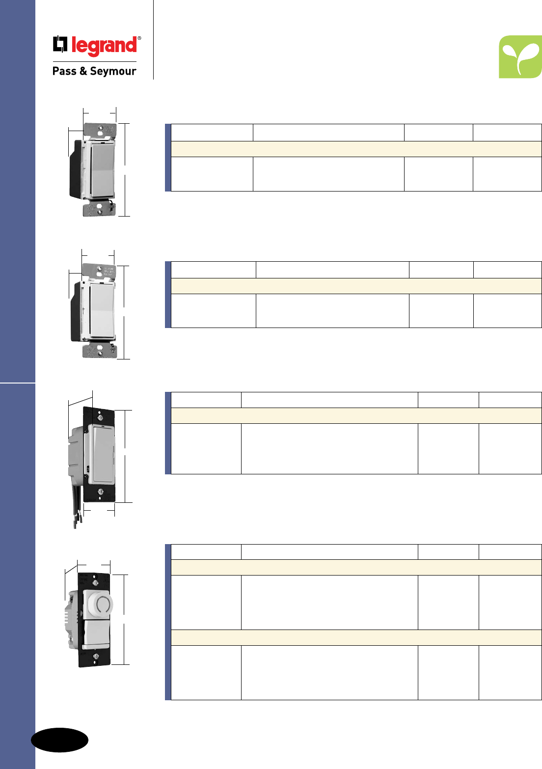
M-34
Dimmers & Fan Speed Controls
Residential Fan Speed Controls
Scene Director,
Leandro®
,
Harmony™ TradeMaster® &
Rotary DR TradeMaster® Series
Fan Speed Controls
AlldeviceslistedonthispageconformtoNEMAWD-1andWD-6.ULListedandCSACertified.
Fan Speed Controls
*Featurespeciallydesignedcapacitivecircuitrytovirtuallyeliminatefanmotor“hum.”
Catalog Number Description Ratings Color
Scene Director 1.5A De-Hummer* Fan Speed Controllers
SCDH15IV Ivory
SCDH15WV Preset, Controls 1 Fan Load in a Scene 120V, 1.5A White
SCDH15LAV Light Almond
SCDH15LAV
4.25"
1.68"
1.37"
DDH15MLAV
4.25"
1.68"
1.37"
DDH16PLA
4.25"
1.75"
1.25"
For additional Scene Director products including remotes, masters, and wiring diagrams, see
Pages M-8 and M-9.
Catalog Number Description Ratings Color
Harmony™ 1.6A De-Hummer* Fan Speed Controls
DDH16PW White
DDH16PI Ivory
DDH16PLA De-Hummer Fan Speed Control 120V, 1.6A Light Almond
DDH16P Brown
DDH16PBK Black
*Featurespeciallydesignedcapacitivecircuitrytovirtuallyeliminatefanmotor“hum.”
For additional Harmony™ products and information, see Page M-11 and M-12.
Catalog Number Description Ratings Color
Leandro® 1.5A De-Hummer* Fan Controls
DDH15MIV Ivory
DDH15MWV Preset,SinglePole,3-Speed 120V,1.5A White
DDH15MLAV LightAlmond
For additional Leandro® products including remotes, masters, and wiring diagrams, see Page M-10.
*Featurespeciallydesignedcapacitivecircuitrytovirtuallyeliminatefanmotor“hum.”
Catalog Number Description Ratings Color
DR Series 5A Continuously Variable Preset Fan Speed Controls
DRSC53PIV Ivory
DRSC53PWV White
DRSC53PV Single Pole/3-Way Fan Speed Control 120V, 5A Brown
DRSC53PBKV Black
DRSC53PLAV Light Almond
DR Series 1.6A 3-Speed De-Hummer* Preset Fan Speed Controls
DRDH163PIV Ivory
DRDH163PWV Single Pole/3-Way Fan Speed Control White
DRDH163PV with back-lit speed indication 120V, 1.6A Brown
DRDH163PBKV Black
DRDH163PLAV Light Almond
*Featurespeciallydesignedcapacitivecircuitrytovirtuallyeliminatefanmotor“hum.”
DRSC53PWV
1.74"
4.185"
1.28"
For additional Decorator Rotary DR Series products and information, see Page M-16.
Residential & Light Commercial Fan Speed Controls
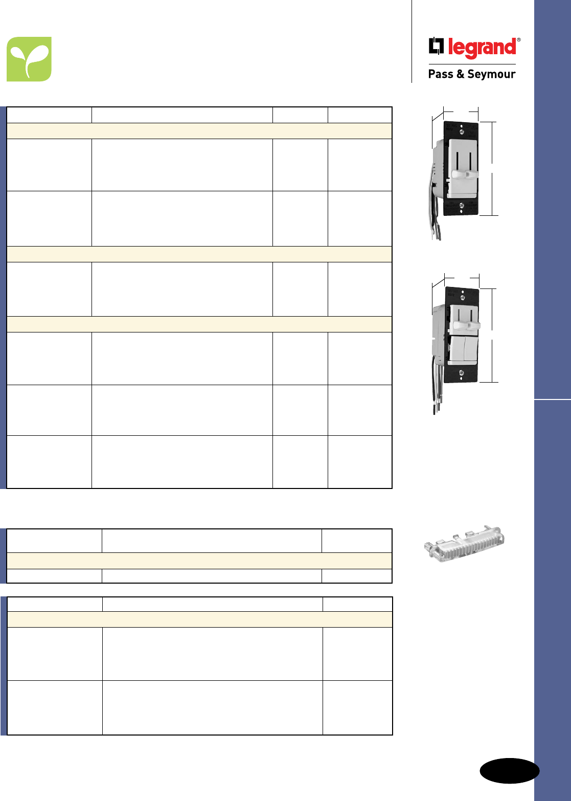
M-35
Dimmers & Fan Speed Controls
Residential & Light Commercial
Fan Speed Controls
LS TradeMaster® Series
Fan Speed Controls
Rating
Catalog Number A. VAC Color
Snap-In Light Module
TM8LMCC 15 120/125 Clear
AlldeviceslistedonthispageconformtoNEMAWD-1andWD-6.ULListedandCSACertified.
LS Series Fan Speed Controls
Catalog Number Description Color
Accessories for LS Series
LRKIV Ivory
LRKWV White
LRKV ReplacementKnobsforDecoratorDualSlides Brown
LRKBKV Black
LRKLAV LightAlmond
LLRKIV Ivory
LLRKWV White
LLRKV LargeReplacementKnobsforDecoratorSingleSlides Brown
LLRKBKV Black
LLRKLAV LightAlmond
LSDC16LAV
1.74"
4.185"
1.28"
LSDC163PLAV
1.74"
4.185"
1.55"
*AvailableinVisionPak™packaging,add“V”toCatalogNumber.Example:LSSC5IV.
**AvailableinVisionPak™only.
Featurespeciallydesignedcapacitivecircuitrytovirtuallyeliminatefanmotor“hum.”
TM8LMCC
Catalog Number Description Ratings Color
Decorator Slide Fan Speed Controls*
LSSC5I Ivory
LSSC5W 120V White
LSSC5 Non-Preset,SinglePole,AdjustableTrim 5A Brown
LSSC5BK Black
LSSC5LA LightAlmond
LSSC5PI Ivory
LSSC5PW 120V White
LSSC5P Preset,SinglePole,AdjustableTrim 5A Brown
LSSC5PBK Black
LSSC5PLA LightAlmond
Decorator Slide De-Hummer Controls**
LSDH16IV Ivory
LSDH16WV 120V White
LSDH16V Non-Preset,4-SpeedFanControl 1.6A Brown
LSDH16BKV Black
LSDH16LAV LightAlmond
Dual Control Decorator Slides**
LSDC16IV Ivory
LSDC16WV 120V White
LSDC16VNon-Preset,3-SpeedDe-HummerFanControl1.6A/300W Brown
LSDC16BKVWithSinglePoleDimmer Black
LSDC16LAV LightAlmond
LSDC163PIV Ivory
LSDC163PWV 120V White
LSDC163PVPreset,3-SpeedDe-HummerFanControl1.6A/300W Brown
LSDC163PBKVWithSinglePole3-WayDimmer Black
LSDC163PLAV LightAlmond
LSDV25IV Ivory
LSDV25WV 120V White
LSDV25VNon-Preset,VariableSpeedFanControl2.5A/300W Brown
LSDV25BKVWithSinglePoleDimmer Black
LSDV25LAV LightAlmond
For additional LS Series products and information, see Pages M-13 – M-15.
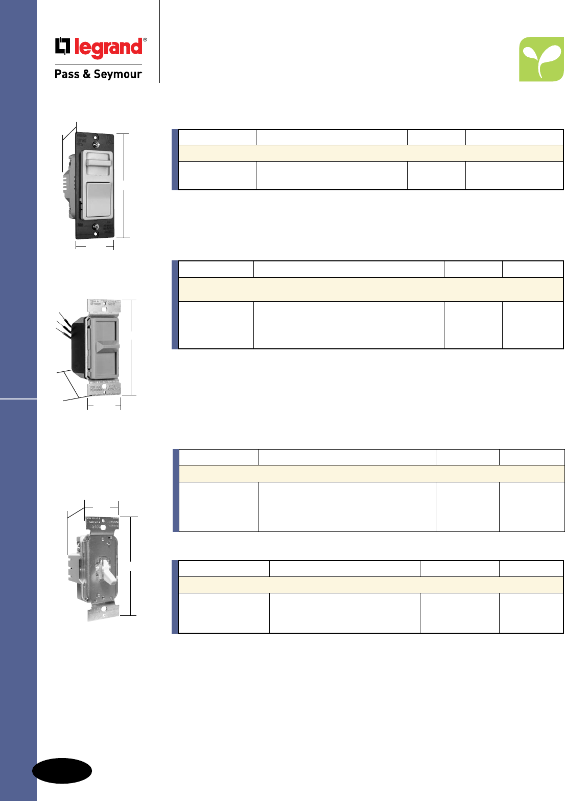
M-36
Dimmers & Fan Speed Controls
AlldeviceslistedonthispageconformtoNEMAWD-1andWD-6.ULListedandCSACertified.
Catalog Number Description Ratings Color
Wide Slide TradeMaster® Interchangeable Face Fan Speed Controls
WSSC53PTC* Preset,VariableSpeed,3FaceColors 120V,5A Ivory/White/Lt.Almond
WSSC53PW WhiteFaceOnly 120V,5A White
Wide Slide & Toggle
Residential & Light Commercial
Fan Speed Controls
Wide Slide TradeMaster®
&
TradeMaster®
Toggle
Fan Speed Controls
94084
4.25"
1.688"
1.469"
No-Noise De-Hummers
Sincethedevelopmentofvariablefanspeedcontrols,manyfanshavemadeanannoyinghummingnoise
whentheirspeedwasreduced.Throughtheuseofspeciallydesignedcapacitivecircuitry,theseunitscan
controlfansat3or4-speedlevelsinslide,rotary,anddualstyleswithvirtuallynofanmotornoise.
Catalog Number Description Ratings Color
1.5A Max. No-Noise De-Hummer Specification Grade Wide Slide
TradeMaster® Fan Speed Controls – RFI Protected
94084I* Ivory
94084W*3-Speed,SinglePole 120V White
94084GRY 1.5Amax. Gray
94084LA* LightAlmond
*AvailableinVisionPak™packaging,add“V”toCatalogNumber.Example:94084LAV.
TSC5I
1.60"
4.130"
1.450"
Catalog Number Description Ratings Color
TradeMaster® Toggle Fan Speed Controls*
TSC5I Ivory
TSC5W Non-Preset,AdjustableTrim 120V White
TSC5LA 5A LightAlmond
* AvailableinVisionPak™packaging,add“V”toCatalogNumber.Example:SS600LAV.
For additional TradeMaster® Toggle products and information, see Page M-18 and M-19.
*Featurespeciallydesignedcapacitivecircuitrytovirtuallyeliminatefanmotor“hum.”
Catalog Number Description Ratings Color
TradeMaster® Toggle De-Hummer* Fan Speed Controls
TDDH163PI Ivory
TDDH163PW White
TDDH163P De-Hummer Fan Speed Control 120V, 1.6A Brown
TDDH163PBK Black
TDDH163PLA Light Almond
For additional Wide Slide TradeMaster® products and information, see Page M-17.
Preset Models
4.25"
1.75"
1.25"
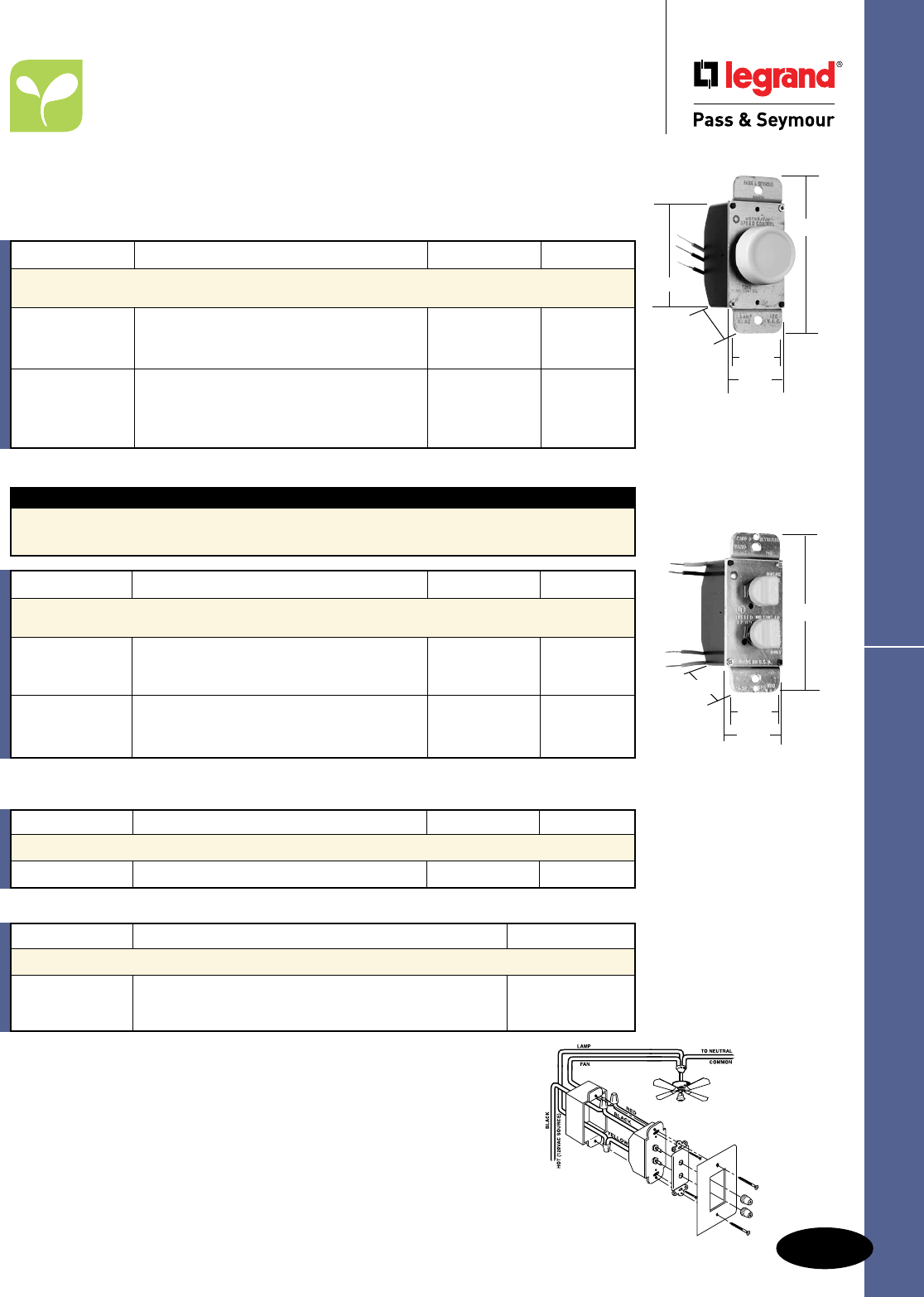
M-37
Dimmers & Fan Speed Controls
AlldeviceslistedonthispageconformtoNEMAWD-1andWD-6.ULListedandCSACertified.
Rotary Fan Speed Controls
Residential Fan Speed Controls
Rotary TradeMaster®
Fan Speed Controls
No-Noise De-Hummers
Sincethedevelopmentofvariablefanspeedcontrols,manyfanshavemadeanannoyinghummingnoise
whentheirspeedwasreduced.Throughtheuseofspeciallydesignedcapacitivecircuitry,theseunitscan
controlfansat3or4-speedlevelsinslide,rotaryanddualstyleswithvirtuallynofanmotornoise.
Requires3wireinstallation.
*AvailableinVisionPak™packaging,add“V”toCatalogNumber.Example:94315LAV.
Catalog Number Description Ratings Color
1.5A/300W Max. Specification Grade Dual Controls –
No-Noise De-Hummers*
94315I Ivory
94315W3-SpeedFanControland120V White
94315LA2-LevelHi/LowDimmer1.5A/300Wmax. LightAlmond
94215I Ivory
94215W4-SpeedFanControland120V White
94215LA2-LevelHi/LowDimmer1.5A/300Wmax. LightAlmond
Catalog Number Description Ratings Color
3A/300W Max. Specification Grade Dual Controls*
94331I DialSpeedControlandDimmer 120V Ivory
*AvailableinVisionPak™packaging,add“V”toCatalogNumber.Example:94331IV.
Catalog Number Description Ratings Color
1.5A Max. Specification Grade Rotary Fan Speed Controls –
No-Noise De-Hummers, RFI Protected*
94003I 120V Ivory
94003W 3-Speed,Low-Medium-High 1.5Amax. White
94003LA LightAlmond
94004CL Clear
94004I4-Speed,Low-High 120V Ivory
94004W 1.5Amax. White
94004LA LightAlmond
*AvailableinVisionPak™packaging,add“V”toCatalogNumber.Example:94003LAV.
Note:Allcontrolsonthispagemaybegangedwithoutde-rating.
Dual Control Connection Diagram
1.672"
1.438"
1.453"
4.156"
94215
94315
94331
94004
94003
1.672"
2.672"
1.453"
4"
1.438"
Dual Control Features
nFitsonegangbox.
nControlsbothfanspeedandlightlevel.
nDecoratorstyling.
Catalog Number Description Color
Accessories for Dual Controls
109019V Ivory
109020V AdapterKitforDualFan/LightControls White
109018V LightAlmond
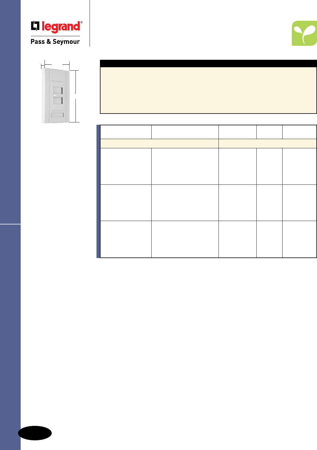
M-38
Dimmers & Fan Speed Controls
AlldeviceslistedonthispageconformtoNEMAWD-1andWD-6.ULListedandCSACertified.
Commercial Fan Speed Controls
Titan™ Series Fan Speed Controls
Titan™ Series Fan Speed Controls
Features
nFieldconfigurablewallplatesystem.
nLabelingsystem.
nShippedwithprotectivefilm.
nRuggedconstruction.
nSimpletoplantherough-in.
nAvailableinsinglepoleslide-to-OFFmodels.
nAttractiveEuropeanstyling.
nEye-catchingpackaging.
nExclusiveadaptorkittoinstallotherDecorator
openingdevicesundertheTitan™wallplate
system.(SeePageM-26.)
nAvailableinbothcontinuouslyvariableand
de-hummerstyles.
nBlankcenterplateincluded.
CDSC6W
Narrow
2.85"
4.87"
1.4375"
Catalog Narrow
Number Description Ratings or Wide Color
Fan Speed Controls
CDSC6I Ivory
CDSC6W White
CDSC6 ContinuouslyVariableSpeed 120V,6A Narrow Brown
CDSC6GRY FanSpeedControl Gray
CDSC6BK Black
CDSC6LA LightAlmond
CDSC12I Ivory
CDSC12W White
CDSC12 ContinuouslyVariableSpeed 120V,12A Wide Brown
CDSC12GRY FanSpeedControl Gray
CDSC12BK Black
CDSC12LA LightAlmond
CDDH16I Ivory
CDDH16WDe-Hummer*,4Speed White
CDDH16Low/Low-Mid/High-Mid/High 120V,1.6A Narrow Brown
CDDH16GRYFanSpeedControl Gray
CDDH16BK Black
CDDH16LA LightAlmond
For additional Titan™ Series products and information, see Pages M-24 – M-31.
*Featurespeciallydesignedcapacitivecircuitrytovirtuallyeliminatefanmotor“hum.”
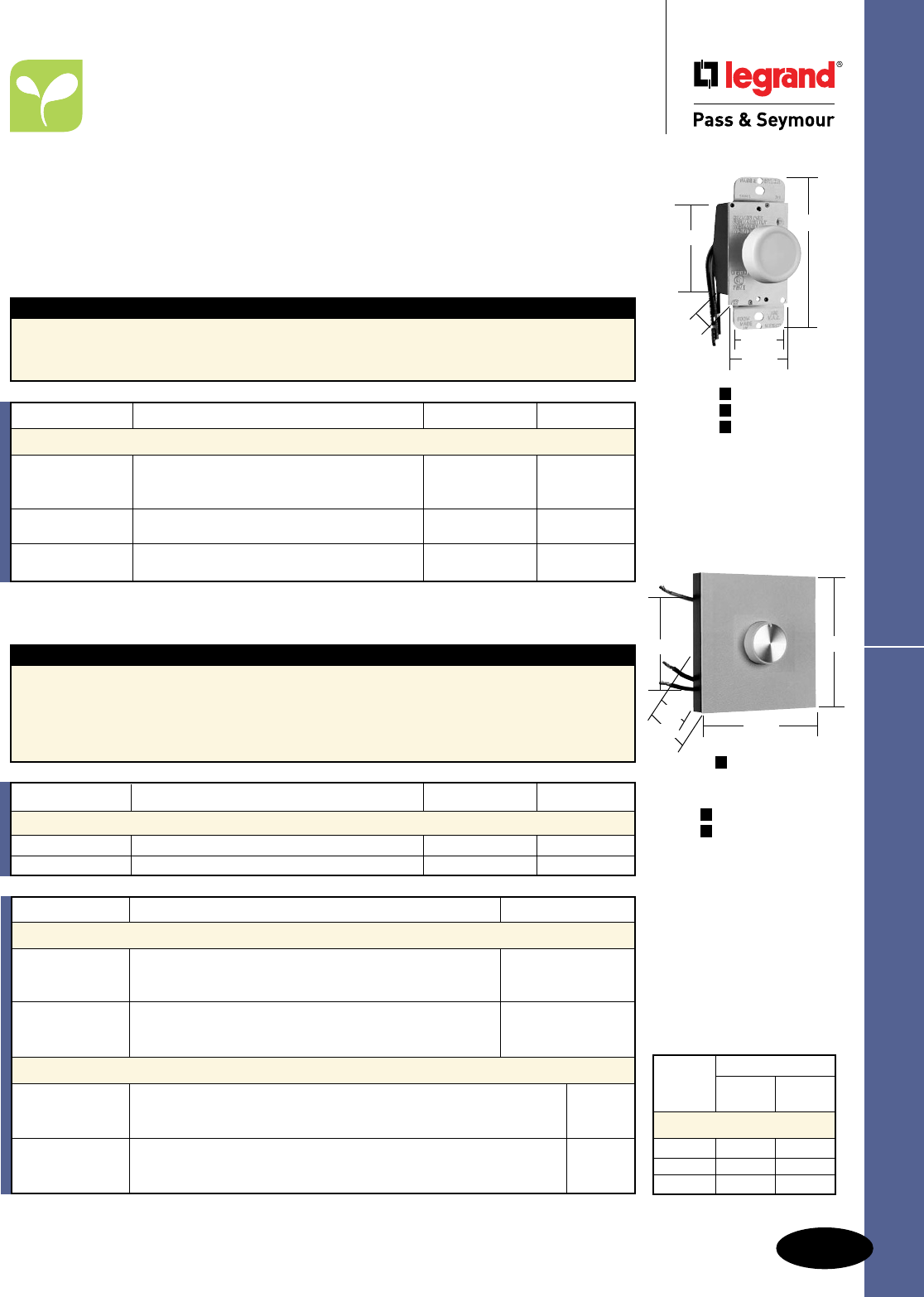
M-39
Dimmers & Fan Speed Controls
AlldeviceslistedonthispageconformtoNEMAWD-1andWD-6.ULListedandCSACertified.
Rotary Fan Speed Controls
Features
nFullrangevariablelowtohighspeedcontrol.
nEasilygangedbyremovingscoredheatsinkfins.
nHeavy-dutytoroidchokeforRFIsuppression.
nBlackanodizedheatsinkforgreaterheat
dispersionandenhancedappearance.
n100%testedforsymmetryforextendedfanlife.
nGroundleadprovided.
nFerritebarcoilchokeforexcellent
RFIsuppression.
Commercial Fan Speed Controls
Rotary Fan Speed Controls
Field Adjustable Trim
Thisfeatureallowstheusertosettheminimumspeedleveldesiredandhelpspreventdamagetomotor
duetostalling.Modelswithoutfieldadjustabletrimsfeaturefactorysettingsforminimumanti-stalllevels.
Full-On Bypass
Whencontrolisplacedinthefull-Onposition,speedcontrolcircuitryisbypassedbylatchingcontacts.
Thisfeatureallowsfor100%motoroutputandextendsspeedcontrol’slifebyeliminatingheatbuild-up.
Features
nFullrangespeedcontrol.
nUtilizesstandardtogglewallplates.
n100%testedforsymmetryforextendedfanlife.
nGroundleadprovided.
nFerritebarcoilchokeforexcellent
RFIsuppression.
*AvailableinVisionPak™packaging,add“V”toCatalogNumber.Example:94301LAV.
**AvailableinVisionPak™only.
Catalog Number Description Ratings Color
3, 5 & 6A Max. Rotary Fan Speed Controls
94301I* 120V Ivory
94301WV**Dial(Non-RFI),3Amax. White
94301LA*MayBeGangedWithoutDe-Rating LightAlmond
94503I* Preset,PushOn/Off,AdjustableTrim,3-Way 120V Ivory
MayBeGangedWithoutDe-Rating 5Amax.
94601I* Dial,AdjustableTrim,120V Ivory
94601WV** MayBeGangedWithoutDe-Rating 6Amax. White
Catalog Number Description Ratings Color
8 & 12A Max. Rotary Fan Speed Controls with Architectural Heat Sink
94801I Dial,AdjustableTrim,1GangHeatSink 120V,8Amax. Ivory
94121I Dial,AdjustableTrim,2GangHeatSink 120V,w12Amax. Ivory
Catalog Number Description Color
Accessories for Rotary Dimmers & Fan Speed Controls
RRKCLGV Clear/GoldInsert
RRKIGV KnobReplacementforRotaryDimmers/FanControls Ivory/GoldInsert
RRKWGV White/GoldInsert
RRKIV Ivory
RRKLAV KnobReplacementforRotaryDimmers/FanControls LightAlmond
RRKWV White
Accessories for Rotary Heat Sink Dimmers & Fan Speed Controls
DAPK1I Ivory
DAPK1W 1-GangWallPlate–PlateandKnobKitforRotaryHeatSinkDevices White
DAPK1 Brown
DAPK2I Ivory
DAPK2W 2-GangWallPlate–PlateandKnobKitforRotaryHeatSinkDevices White
DAPK2 Brown
94301
94503
94601
P
N
N
4"
1.672"
2.672"
1.438" 1.453"
=Preset
=Non-Preset
P
N
N94121
4.516"
4.453"
2.672"
1.313"
1.906"
Max. Gang Reduction
Load One Two
Rating Side Side
De-Rating Chart
5Amp 4Amp 3Amp
8Amp 7Amp 6Amp
12Amp 11Amp 10Amp
SLATER
® PLASTIC BOXES
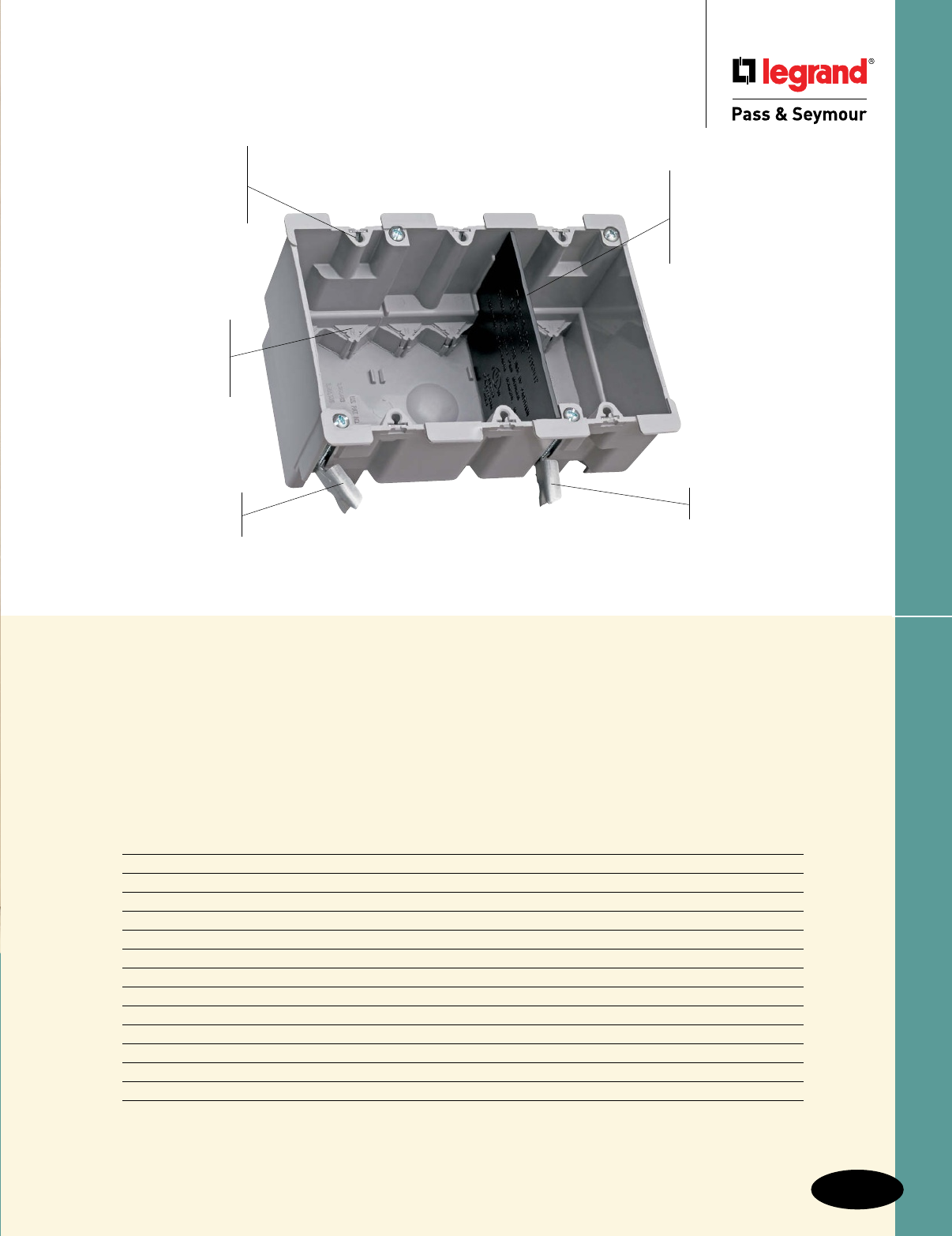
4 Auto/Clamps® on
each end eliminate
the need for separate
cable clamps. See
Page N-19 for details.
N-1
Slater® Plastic Boxes
Slater® Plastic Boxes
Durable, impact-resistant
thermoplastic boxes in a full
range of sizes — complemented
by innovative extras that cut
installation time.
Easy installation,
rectangular cutout.
S352W
3 Gang Old Work Box shown with
Divider Plate, LVDIV1
Metal swing bracket
for quick mounting in
existing walls.
Quick/Click® feature
secures devices quickly
and easily. Does not
strip when over-torqued.
See Page N-19 for details.
Big 52 cubic inch capacity.
Index
Device Page Number
Switch & Outlet Boxes N-2, N-3
Old Work Boxes & Shallow Boxes N-4
Low-Voltage Brackets N-5
Wood & Steel Stud Bracket Boxes N-6
Screw Mount Steel Stud Boxes N-7
4" Square Boxes & Covers N-8
4" Round Ceiling Boxes N-9 – N-11
Round Ceiling Boxes N-12
Tamper-Resistant Floor Box Assemblies N-13, N-14, N-17
Tamper-Resistant Round Floor Box Assemblies N-15, N-16
Round Floor Box Covers N-16
Recessed TV Boxes N-18
Applications & Product Features N-19 – N-21
Divider plate (LVDIV1,
sold separately) used when
installing line and low-voltage
devices or multiple 277 volt
devices in same box.
See Page N-5 for details.
Swing bracket
adjusts from 11⁄4" to 1⁄8".
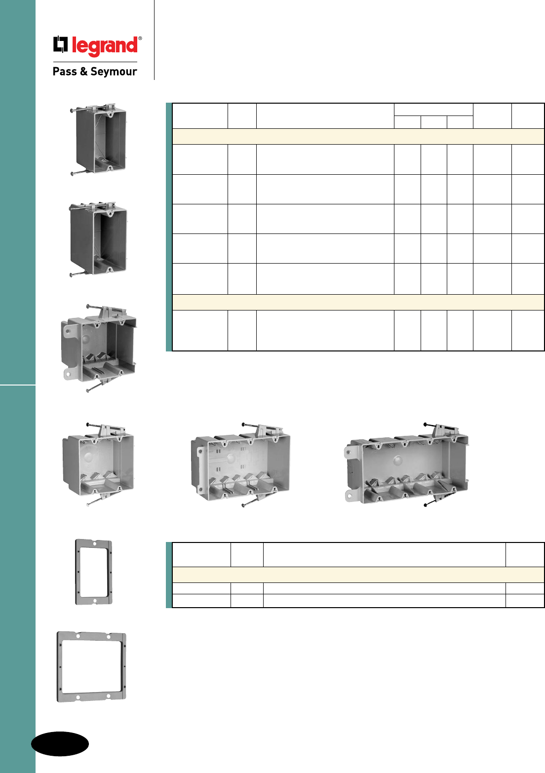
EXT2
EXT1
Switch & Outlet Boxes
N-2
Slater® Plastic Boxes
All devices listed on this page conform to NEMA OS2.
Slater® Plastic Boxes
Switch & Outlet Boxes
With Captive Mounting Nails on Each End with Quick/Click®
S354RAC S468RAC
S118R
Catalog Cu. In. Dimensions (inches) Wire Fill Qty. Per
Number Vol. Description L W D (AWG) Carton
Switch & Outlet Boxes with Quick/Click
®
S118R 18.0 Single gang. 33⁄4 21⁄4 223⁄32 9 No. 14 100
2 Quick/Entries® each end. 8 No. 12
7 No. 10
S235RAC 35.0 Two gang. 331⁄32 331⁄32 33⁄8 17 No. 14 50
4 Auto/Clamps® each end. 15 No. 12
14 No. 10
S235RACMH 35.0 Two gang. 4 Auto/Clamps® 33⁄4 41⁄16 3 17 No. 14 100
each end. 3" depth for 15 No. 12
manufactured housing walls. 14 No. 10
S354RAC
54.0 Three gang. 331⁄32 525⁄32 3 27 No. 14 50
6 Auto/Clamps® each end. 24 No. 12
21 No. 10
S468RAC 68.0 Four gang. Rear stabilizing bar 313⁄16 713⁄16 3 34 No. 14 25
virtually eliminates inward movement. 30 No. 12
6 Auto/Clamps® each end. 27 No. 10
Deep Switch & Outlet Boxes with Quick/Click
®
S122R 22.5 Single gang deep. 2 Quick/Entries® 33⁄4 21⁄4 33⁄8 11 No. 14 100
each end. Extra deep for dimmers, 10 No. 12
GFCIs and thermostats, yet 9 No. 10
suitable for 2 x 4 construction.
Catalog Cu. In. Qty. Per
Number Vol. Description Carton
Wall Box Extension Rings
EXT1 1.0 Single gang. 1/4" thick. Stackable. 10
EXT2 2 .0 Two gang. 1/4" thick. Stackable. 10
All boxes are UL Listed.
UL Classified for 2 Hour Fire Resistance. (Does not apply to S468RAC.)
S235RAC
S122R
S235RACMH
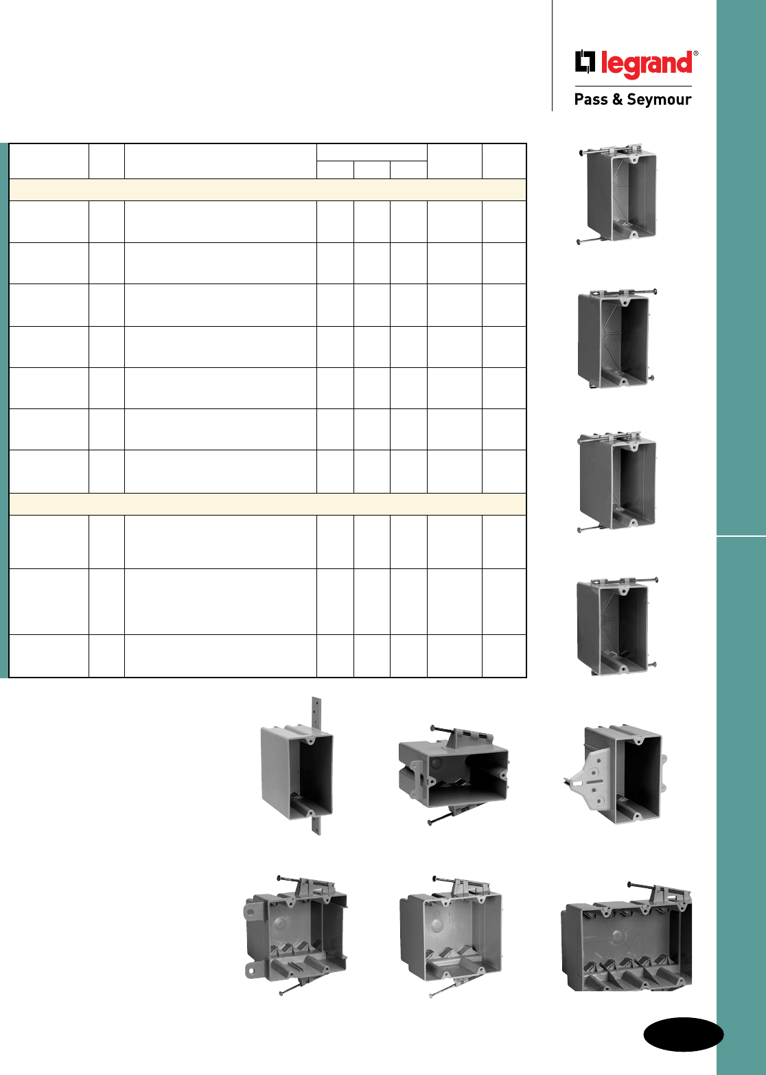
N-3
Switch & Outlet BoxesSlater® Plastic Boxes
All devices listed on this page conform to NEMA OS2.
Slater® Plastic Boxes
Switch & Outlet Boxes
With Captive Mounting Nails on Each End
P122RN
P354RACMH
P118R
Catalog Cu. In. Dimensions (inches) Wire Fill Qty. Per
Number Vol. Description L W D (AWG) Carton
Switch & Outlet Boxes with Threaded Mounting Holes
P118R 18.0 Single gang. 2 Quick/Entries® 33⁄4 21⁄4 223⁄32 9 No. 14 100
each end. 8 No. 12
7 No. 10
P118RN 18.0 Single gang. Reverse angled captive 33⁄4 21⁄4 223⁄32 9 No. 14 100
mounting nail. 2 Quick/Entries® each 8 No. 12
end. Used for manufactured housing. 7 No. 10
P122C 22.0
Single gang. With EZ Grip – 33⁄4 21⁄4 4 11 No. 14 100
a temporary hold feature. 10 No. 12
9 No. 10
PH122R 22.0 Single gang. Horizontal. Captive 33⁄4 21⁄4 37⁄8 11 No. 14 100
mounting nail each side. 10 No. 12
9 No. 10
P235RAC 35.0 Two gang. 4 Auto/Clamps® each end. 331⁄32 331⁄32 33⁄8 17 No. 14 100
15 No. 12
14 No. 10
P235RACMH 35.0 Two gang. 4 Auto/Clamps® each end. 331⁄32 331⁄32 3 17 No. 14 100
3" depth for manufactured housing 15 No. 12
walls. 14 No. 10
P354RACMH 54.0 Three gang. 6 Auto/Clamps® each 313⁄16 515⁄16 31⁄16 27 No. 14 50
end. 31⁄16" depth for manufactured 24 No. 12
housing walls. 21 No. 10
Deep Switch & Outlet Boxes with Threaded Mounting Holes
P122R 22.5 Single gang deep. 2 Quick/Entries® 33⁄4 21⁄4 33⁄8 11 No. 14 100
each end. Extra deep for dimmers, 10 No. 12
GFCIs and thermostats, yet 9 No. 10
suitable for 2 x 4 construction.
P122RN 22.5 Single gang deep. Reverse angled 33⁄4 21⁄4 33⁄8 11 No. 14 100
captive mounting nail. 2 Quick/Entries® 10 No. 12
each end. Extra deep for dimmers, 9 No. 10
GFCIs and thermostats, yet suitable
for 2 x 4 construction.
P122N 22.5 Single gang deep. Vertical 33⁄4 21⁄4 33⁄8 11 No. 14 100
bracket mount. 10 No. 12
9 No. 10
P1-18-RN
P1-22-R
PH1-22-R P1-22-C
P2-35-RAC P2-35-RACMH
All boxes are UL Listed.
UL Classified for 2 Hour Fire Resistance (Does not apply
to P122N.)
P1-22-N
All boxes are UL listed.
UL Classified for 2 Hour Fire Resistance. (Does not apply to S352W, P108W, and P108N.)
Old Work & Shallow Boxes
N-4
Slater® Plastic Boxes
All devices listed on this page conform to NEMA OS2.
Slater® Plastic Boxes
Old Work Boxes & Shallow Boxes
S118W
S232W S352W
S122W
P108WP108N
Catalog Cu. In. Dimensions (inches) Wire Fill Qty. Per
Number Vol. Description L W D (AWG) Carton
Old Work Switch & Outlet Boxes with Quick/Click®
S116W 16.0 Single gang. Swing-bracket for mounting 33⁄4 21⁄4 23⁄4 8 No. 14 100
adjusts from 11⁄4" down to 1⁄8". 7 No. 12
2 Auto/Clamps® each end. 6 No. 10
S118W 18.0 Single gang. Swing-bracket for mounting 33⁄4 21⁄4 31⁄32 9 No. 14 100
adjusts from 11⁄4" down to 1⁄8". 8 No. 12
2 Auto/Clamps® each end. 7 No. 10
S232W 32.0 Two gang. Swing-bracket for mounting 33⁄4 41⁄16 31⁄32 16 No. 14 50
adjusts from 11⁄4" down to 1⁄8". 14 No. 12
4 Auto/Clamps® each end. 12 No. 10
S352W 52.0 Three gang. Swing-bracket for mounting 33⁄4 57⁄8 31⁄32 26 No. 14 10
adjusts from 11⁄4" down to 1⁄8". 23 No. 12
6 Auto/Clamps® each end. 20 No. 10
Deep Old Work Switch & Outlet Boxes with Quick/Click®
S122W 22.0 Single gang deep. Swing-bracket for 33⁄4 25⁄16 31⁄2 – 50
mounting adjusts from 11⁄4" down to 1⁄8".
2 Auto/Clamps® each end.
Old Work Switch & Outlet Boxes with Threaded Mounting Holes
P116W 16.0 Single gang. Swing-bracket for mounting 33⁄4 21⁄4 23⁄4 8 No. 14 100
adjusts from 11⁄4" down to 1⁄8". 7 No. 12
2 Auto/Clamps® each end. 6 No. 10
Shallow Switch & Outlet Boxes for use in limited depth applications
P108W 8.0 Single gang. Old work flange box for 33⁄4 25⁄16 11⁄8 – 20
retrofit applications.
P108N 8.0 Single gang. With vertical side bracket 33⁄4 25⁄16 11⁄8 – 20
for new construction applications.
SLV2B
SLV3W
N-5
Low-Voltage BracketsSlater® Plastic Boxes
All devices listed on this page conform to NEMA OS2.
Slater® Plastic Boxes
Low-Voltage Brackets
PLVIR
PLV1W
LVDIV1
All boxes are UL listed.
Catalog Cu. In. Dimensions (inches) Wire Fill Qty. Per
Number Vol. Description L W D (AWG) Carton
Low-Voltage Brackets with Quick/Click® for class 2 low-voltage applications
SDV2B 22.5 Two gang. For dual-voltage. 33⁄4 4 33⁄4 11 No. 14 12
Face mount box and bracket for 10 No. 12
new construction. 9 No. 10
SLV1R – Single gang. 33⁄4 21⁄4 – – 12
Nail on for new construction.
SLV1S – Single gang. 33⁄4 21⁄4 – – 12
Screw on for new construction.
SLV1B – Single gang. 33⁄4 21⁄4 – – 12
Face mount bracket for new construction.
SLV2B – Two gang. 33⁄4 4 – – 12
Face mount bracket for new construction.
SLV1W – Single gang. 33⁄4 21⁄4 – – 12
Swing bracket mount for old work.
SLV2W – Two gang. 33⁄4 4 – – 12
Swing bracket mount for old work.
SLV3W – Three gang. 33⁄4 6 – – 12
Swing bracket mount for old work.
Low-Voltage Brackets for class 2 low-voltage applications
P100WD 8.0 Single Gang. Gangable. 33⁄4 2 – – 15
Swing bracket for mounting, adjusts
from 11⁄4" down to 1⁄8", for old work, stand
alone applications.
P100ND 8.0 Single gang. With vertical side bracket 33⁄4 23⁄8 11⁄4 – 15
for new construction, with wire retaining
fingers.
PDV2B 22.5 Two gang. For dual-voltage. 33⁄4 4 33⁄4 11 No. 14 12
Face mount box and bracket for 10 No. 12
new construction. 9 No. 10
PLV1R – Single gang. 33⁄4 21⁄4 – – 12
Nail on for new construction.
PLV1S – Single gang. 33⁄4 21⁄4 – – 12
Screw on for new construction.
PLV1B – Single gang. 33⁄4 21⁄4 – – 12
Face mount bracket for new construction.
PLV2B – Two gang. 33⁄4 4 – – 12
Face mount bracket for new construction.
PLV1W – Single gang. 33⁄4 21⁄4 – – 12
Swing bracket mount for old work.
PLV2W – Two gang. 33⁄4 4 – – 12
Swing bracket mount for old work.
PLV3W – Three gang. 33⁄4 6 – – 12
Swing bracket mount for old work.
Divider Plate
LVDIV1 -.5 Suitable for low-voltage or multiple 277V – – – – 12
devices. For use with S235RAC,
S235RACS, P235RAC, S235S50AC,
S354RAC and S352W.
Wood & Steel Stud Bracket Boxes
N-6
Slater® Plastic Boxes
All devices listed on this page conform to NEMA OS2.
Slater® Plastic Boxes
Wood & Steel Stud Bracket Boxes
With Offset Bracket for Wood and/or Steel Mounting
S468S50AC
All boxes are UL Listed.
UL Classified for 2 Hour Fire Resistance. (Does not apply to S468S50AC.)
Catalog Cu. In. Dimensions (inches) Wire Fill Qty. Per
Number Vol. Description L W D (AWG) Carton
Wood & Steel Stud Bracket Boxes with Quick/Click®
S118S50 18.0 Single gang. 3⁄8" offset for wood and 33⁄4 21⁄4 223⁄32 9 No. 14 100
steel stud mounting. 2 Quick/Entries® 8 No. 12
each end. For use with 3⁄8" to 5⁄8" 7 No. 10
wallboard.
S118B50 18.0 Single gang. 1⁄2" offset for wood and 33⁄4 21⁄4 23⁄4 9 No. 14 100
steel stud mounting. Rear stabilizing 8 No. 12
bar virtually eliminates inward 7 No. 10
movement. 2 Quick/Entries® each end.
For use with 3⁄8" to 5⁄8" wallboard.
S235S50AC
35.0 Two gang. 3⁄8" offset for wood and steel 331⁄32 331⁄32 33⁄8 17 No. 14 50
stud mounting. 4 Auto/Clamps® each 15 No. 12
end. For use with 3⁄8" to 5⁄8" wallboard. 14 No. 10
S354S50AC
54.0 Three gang. 3⁄8" offset for wood and steel 33⁄4 525⁄32 3 27 No. 14 25
stud mounting. 6 Auto/Clamps® each end. 24 No. 12
For use with 3⁄8" to 5⁄8" wallboard. 21 No. 10
S468S50AC 68.0 Four gang. 3⁄8" offset for wood and steel 33⁄4 713⁄16 3 34 No. 14 25
stud mounting. Rear stabilizing bar 30 No. 12
virtually eliminates inward movement. 27 No. 10
6 Auto/Clamps® each end. For use with
3⁄8" to 5⁄8" wallboard.
Deep Wood & Steel Stud Bracket Boxes with Quick/Click®
S122S50 22.5 Single gang deep. 3⁄8" offset for wood 33⁄4 21⁄4 33⁄8 11 No. 14 100
and steel stud mounting. 2 Quick/ 10 No. 12
Entries® each end. For use with 3⁄8" to 9 No. 10
5⁄8" wallboard.
S118B50
S122S50
S235S50AC
S354S50AC
S118S50
PH122BP122B
All boxes are UL Listed.
UL Classified for 2 Hour Fire Resistance.
Catalog Cu. In. Dimensions (inches) Wire Fill Qty. Per
Number Vol. Description L W D (AWG) Carton
Steel Stud Bracket Boxes with Quick/Click®
S122B 22.0 Single gang. 1⁄2" offset for steel stud 33⁄4 21⁄4 41⁄4 11 No. 14 100
mount only. 2 stabilizer legs. 10 No. 12
9 No. 10
SH122B 22.0 Single gang. Horizontal. 1⁄2" offset 33⁄4 21⁄4 37⁄8 11 No. 14 100
for wood or steel stud mount. 10 No. 12
2 stabilizer legs. 9 No. 10
Steel Stud Bracket Boxes
P122B 22.0 Single gang. 1⁄2" offset for steel stud 33⁄4 21⁄4 41⁄4 11 No. 14 100
mount only. 2 stabilizer legs. 10 No. 12
9 No. 10
PH122B 22.0 Single gang. Horizontal. 1⁄2" offset 33⁄4 21⁄4 37⁄8 11 No. 14 100
for wood or steel stud mount. 10 No. 12
2 stabilizer legs. 9 No. 10
All boxes are UL Listed.
UL Classied for 2 Hour Fire Resistance. (Does not apply to S468RACS.)
Note: 3¼" self-tapping, drill-point screws. Nails are 3¼".
Catalog Cu. In. Dimensions (inches) Wire Fill Qty. Per
Number Vol. Description L W D (AWG) Carton
Screw Mount, Steel Stud Boxes with Quick/Click®
S118RS 18.0 Single gang. 2 Quick/Entries® 33⁄4 21/4 223⁄32 9 No. 14 100
each end. 8 No. 12
7 No. 10
S235RACS 35.0 Two gang. 4 Auto/Clamps® each end. 331⁄32 331⁄32 33⁄8 17 No. 14 50
15 No. 12
14 No. 10
S235RACSMH
35.0 Two gang. 4 Auto/Clamps® each end. 33⁄4 41⁄16 3 17 No. 14 100
3" depth for manufactured housing 15 No. 12
walls. 14 No. 10
S354RACS 54.0 Three gang. 6 Auto/Clamps® 331⁄32 525⁄32 3 27 No. 14 50
each end.
24 No. 12
21 No. 10
S468RACS 68.0 Four gang. 6 Auto/Clamps® each end. 313⁄16 713⁄16 3 34 No. 14 25
Rear stabilizing bar virtually 30 No. 12
eliminates inward movement. 27 No. 10
Deep Screw Mount, Steel Stud Boxes with Quick/Click®
S122RS 22.5 Single gang deep. 2 Quick/Entries® 33⁄4 2 1/4 33⁄8 11 No. 14 100
each end. Extra deep for dimmers, 10 No. 12
GFCIs and thermostats, yet suitable 9 No. 10
for 2 x 4 construction.
Catalog Qty. Per
Number Description Carton
Crimping Tool for Attaching Steel Stud Boxes
CT1 Crimping tool for attaching boxes to steel studs. Comes equipped 1
with long and short anvils to meet most installation requirements.
N-7
Screw Mount Steel Stud BoxesSlater® Plastic Boxes
All devices listed on this page conform to NEMA OS2.
Slater® Plastic Boxes
Screw Mount Steel Stud Boxes
With Captive Combo Head Self Tapping Mounting Screws on Each End
CT1
S118RS
S122RS
S354RACS
S235RACSMH
S468RACS
S235RACS
Catalog Cu. In. Dimensions (inches) Wire Fill Qty. Per
Number Vol. Description L W D (AWG) Carton
Range & Dryer Boxes
P242SRD 42.0 1/2" offset for wood or steel stud 33⁄4 4 4 16 No. 10 12
mount with metal cable clamp. 14 No. 8
Captive mounting screw each end. 8 No. 6
P242RRD 42.0 1/2" offset for wood or steel stud 33⁄4 4 4 16 No. 10 12
mount with metal cable clamp. 14 No. 8
Captive mounting nail each end. 8 No. 6
All boxes are UL Listed.
UL Classied for 2 Hour Fire Resistance. (Does not apply to 4SBC and 4SBCW.)
S4435RAC
S4421SAC S4435SAC
Catalog Cu. In. Dimensions (inches) Wire Fill Qty. Per
Number Vol. Description L W D (AWG) Carton
Covers for 4" Square Boxes
4SBC – 4" square at blank cover - gray 41⁄4 41⁄4 N/A – 50
4SBCW – 4" square at blank cover - white 41⁄4 41⁄4 N/A – 50
RC1 3.2 Single gang device cover, raised 3⁄8" 41⁄4 41⁄4 3⁄8 – 100
RC2 5.3 Two gang device cover, raised 3⁄8" 41⁄4 41⁄4 3⁄8 – 100
4" Square Boxes with Threaded Mounting Holes
S4418BAC 17.0 Shallow 4" square. Captive mounting 41⁄4 41/4 11⁄4 9 No. 14 50
nail each end. 2 Auto/Clamps® each end. 8 No. 12
2 #8 mounting screws factory installed. 7 No. 10
S4421RAC 21.0 4" square. Captive mounting nail each 41⁄4 41⁄4 11⁄2 10 No. 14 100
end. 3 Auto/Clamps® each end, 2 on 9 No. 12
side opposite to nails. 2 #8 mounting 8 No. 10
screws factory installed.
S4421SAC 21.0 4" square. For wood and steel stud 41⁄4 41⁄4 11⁄2 10 No. 14 50
mounting. 3 Auto/Clamps each end, 9 No. 12
2 on side opposite bracket. 8 No. 10
2 #8 mounting screws factory installed.
S4435RAC 35.0 4" square. Captive mounting nail each 41⁄4 41⁄4 23⁄8 17 No. 14 50
end. 3 Auto/Clamps® each end, 2 on 15 No. 12
side adjacent to nails. 2 #8 mounting 14 No. 10
screws factory installed.
S4435SAC 35.0 4" square. For wood and steel stud 41⁄4 41⁄4 23⁄8 17 No. 14 50
mounting. 3 Auto/Clamps® each end, 15 No. 12
2 on side opposite bracket. 14 No. 10
2 #8 mounting screws factory installed.
All boxes are UL Listed.
UL Classified for 2 Hour Fire Resistance (pending).
4" Square Boxes & Covers
N-8
Slater® Plastic Boxes
All devices listed on this page conform to NEMA OS2.
Slater® Plastic Boxes
4" Square Boxes & Covers
RC2
S4421RAC
RC1
4SBC
S4418BAC
P242SRD
P242RRD
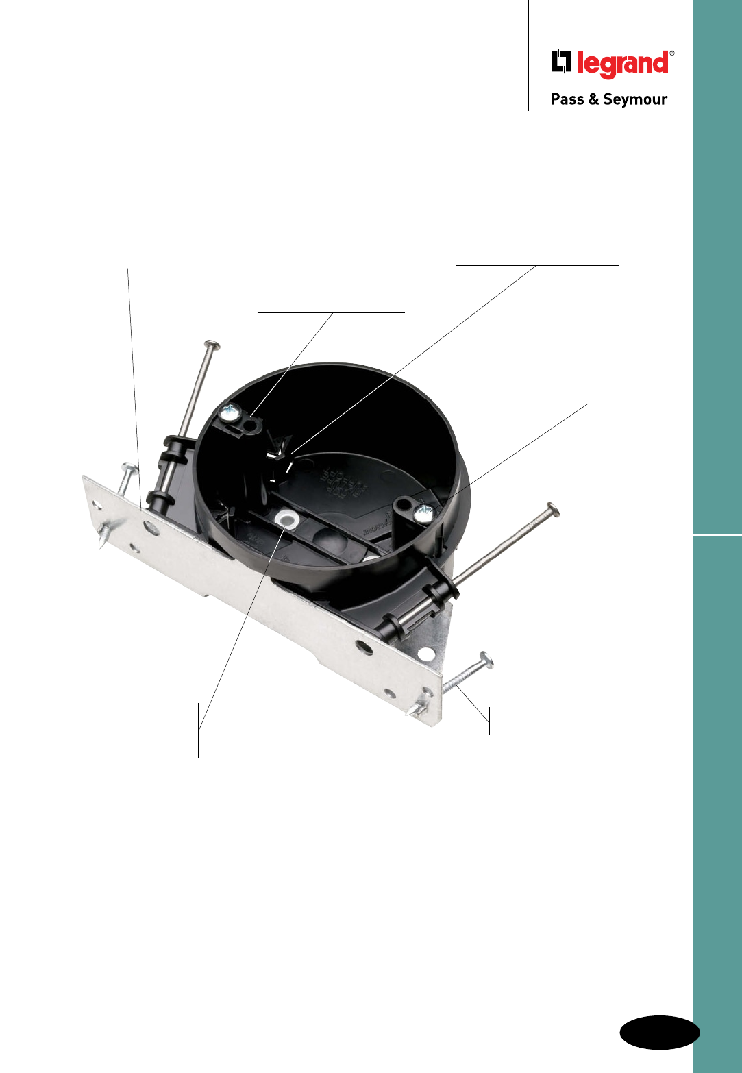
N-9
4" Round Ceiling BoxesSlater® Plastic Boxes
All devices listed on this page conform to NEMA OS2.
Slater® Plastic Boxes
4" Round Ceiling Boxes
UL Listed for fan
and fixture support.
Constructed of impact-resistant
Noryl® thermoplastic, making it virtually
unbreakable and non-conductive.
Depth-mounting gauge
at bottom of bracket helps you
align the box at the proper
depth relative to the ceiling.
Large, 20.25 cubic inch
capacity for extra wiring
space.
S120JFAN
Fan mounts
directly to
bracket through
box with #10-32
screws (provided).
Angled, rugged, metal
mounting bracket safely and
securely fastens fans or fixtures
to the building structure.
Auto Clamp® cable clamps
molded in — hold wire
securely in box.
Phillips-head screws
(#10-32 x 3") mount the
fan or fixture directly to
the metal bracket.
Ringed nails for
tighter grip.
Dual mounting accepts
fans or fixtures with 2.75"
or 3.5" straps.
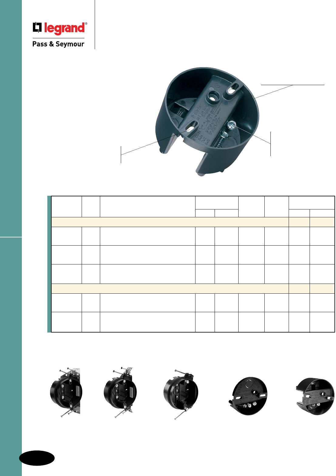
All boxes are UL listed.
UL Classified for 2 Hour Fire Resistance.
Dual mounting accommodates both 2.75" and 3.5" fixtures.
S116FAN
N-10
Slater® Plastic Boxes
All devices listed on this page conform to NEMA OS2.
Slater® Plastic Boxes
4" Round Ceiling Boxes
With Dual Threaded Mounting Holes
S120JFAN S120BFAN S120RFAN S109FAN
Impact-resistant Noryl®
means no ground wiring
as with metal boxes.
Easy installation. One #10 x 11⁄4"
screw holds the box at rough in. Two
factory-supplied #10 x 2" screws secure
the fan or fixture through the box, directly
to the joist.
UL Listed for fan and
fixture support.
Mounts directly under
a joist or on a joist
cross member.
Screw lock holds screws
in box until needed. No
lost hardware and no
broken spiral saw bits.
S116FAN
4" Round Ceiling Boxes
UL Listed
Catalog Cu. In. Dimensions (in.) Wires Qty. Per Max. Weight Rating
Number Vol. Description Dia. Depth (AWG) Carton Fan Fixture
Fan Boxes – Fan & Fixture Rated
S120JFAN 20.25 Ceiling Fan Box – Premium Grade 4 23⁄16 10 No. 14 12 70 lbs. 150 lbs.
with integral fan mounting bracket and 9 No. 12
4 Auto/Clamps®. 8 No. 10
S120BFAN 20.25 Ceiling Fan Box – Construction Grade 4 23⁄16 10 No. 14 30 70 lbs. 70 lbs.
with 4 Auto/Clamps®. 9 No. 12
8 No. 10
S120RFAN 20.25 Ceiling Fan Box – Standard Grade 4 23⁄16 10 No. 14 30 35 lbs. 50 lbs.
4 Auto/Clamps® with 2 captive mounting
nails.
4" Round Direct Mount Ceiling Fan Boxes – Fan & Fixture Rated
S116FAN 16 Ceiling Fan Box – with Direct Mount. 4 23⁄4 8 No. 14 24 70 lbs. 210 lbs.
7 No. 12
6 No. 10
S109FAN 9 Ceiling Fan Box – with Direct Mount. 4 23⁄4 4 No. 14 24 70 lbs. 210 lbs.
Suitable for single or double joist. 4 No. 12
3 No. 10

N-11
4" Round Ceiling BoxesSlater® Plastic Boxes
Slater® Plastic Boxes
4" Round Ceiling Boxes
With Dual Threaded Mounting Holes
Catalog Qty. Per
Number Description Carton
Covers for 4" Round Boxes
4RBC 4" round at blank cover – gray 50
4RBCW 4" round at blank cover – white 50 4RBC
All devices listed on this page conform to NEMA OS2.
S120RAC
S120JAC
S120RGAC
S120JGAC
All boxes are UL listed.
UL Classified for 2 Hour Fire Resistance.
Dual mounting accommodates both 2.75" and 3.5" fixtures.
UL Listed
Dimensions Qty. Max. Weight
Catalog Cu. In. (inches) Wires Per Rating
Number Vol. Description Dia. Depth (AWG) Carton Fixture
Ceiling Boxes
S120RAC 20.25 4" round. 2 captive mounting 4 23⁄16 10 No. 14 50 50 lbs.
nails. 4 Auto/Clamps. 9 No. 12
8 No. 10
S120RGAC 20.25 4" round with ground lug. 4 23⁄16 10 No. 14 50 50 lbs.
2 captive mounting nails. 9 No. 12
4 Auto/Clamps. 8 No. 10
S120JAC 20.25 4" round. J-bracket with 4 23⁄16 10 No. 14 50 50 lbs.
2 captive mounting nails. 9 No. 12
4 Auto/Clamps. 8 No. 10
S120JGAC 20.25 4" round with ground lug. 4 23⁄16 10 No. 14 50 50 lbs.
J-bracket with 2 captive 9 No. 12
mounting nails. 4 Auto/Clamps. 8 No. 10
S120HAC 20.25 4" round. Bar-hanger adjusts 4 23⁄16 10 No. 14 50 50 lbs.
to 16" or 24" joist spacing. 9 No. 12
4 Auto/Clamps. 8 No. 10
S120HGAC 20.25 4" round with ground lug. 4 23⁄16 10 No. 14 50 50 lbs.
Bar-hanger adjusts to 16" or 24" 9 No. 12
joist spacing. 4 Auto/Clamps. 8 No. 10
S120RACS 20.25 4" round. 2 captive mounting 4 23⁄16 10 No. 14 50 50 lbs.
screws. 4 Auto/Clamps. 9 No. 12
8 No. 10
S120HAC S120RACS
S120HGAC
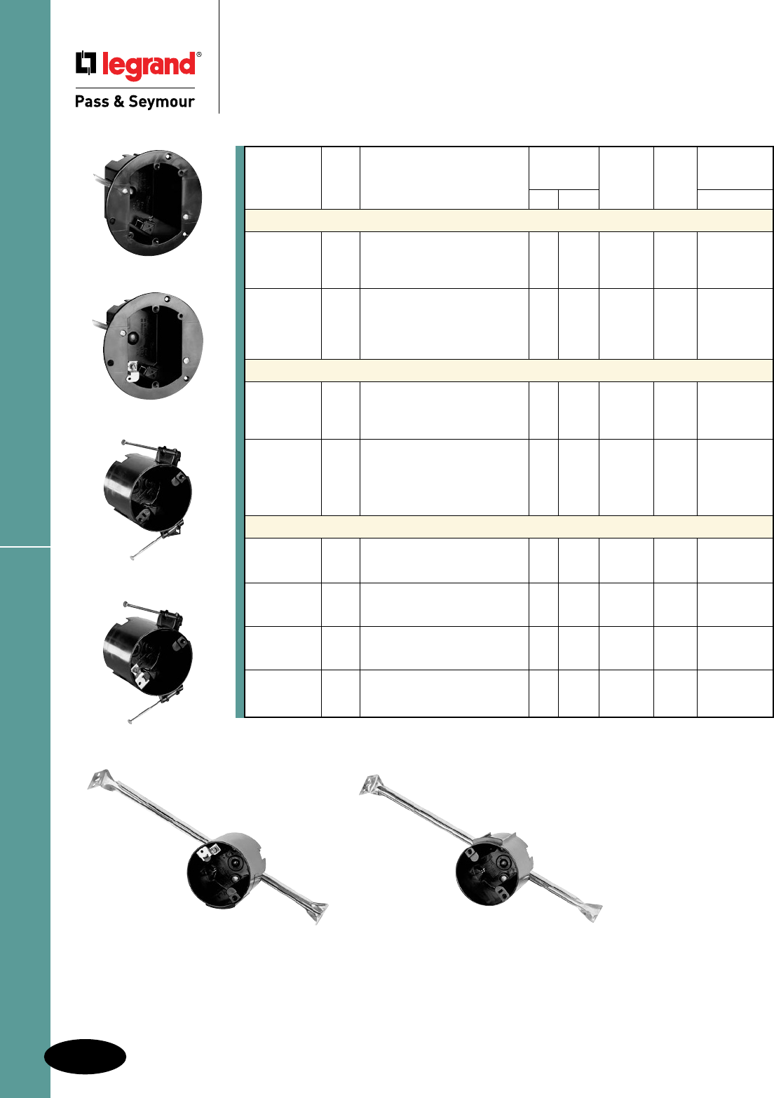
Round Ceiling Boxes
N-12
Slater® Plastic Boxes
All devices listed on this page conform to NEMA OS2.
Slater® Plastic Boxes
Round Ceiling Boxes
C118WAC
C118WGAC
C118RAC
C118RGAC
C118HAC
C118HGAC
UL Classified for 2 Hour Fire Resistance.
UL Listed
Dimensions Qty. Max. Weight
Catalog Cu. In. (inches) Wires Per Rating
Number Vol. Description Dia. Depth (AWG) Carton Fixture
33⁄4" Round Old Work Ceiling Boxes
C118WAC 18.0 33⁄4" round. Swing brackets for 33⁄4 211⁄16 9 No. 14 50 20 lbs.
mounting adjust from 11⁄4" down 8 No. 12
to 1⁄8". 4 Auto/Clamps®. Includes 7 No. 10
device mounting holes.
C118WGAC 18.0 33⁄4" round. With grounding lug. 33⁄4 211⁄16 9 No. 14 50 20 lbs.
Swing brackets for mounting 8 No. 12
adjust from 11⁄4" down to 1⁄8". 7 No. 10
4 Auto/Clamps®. Includes device
mounting holes.
33⁄4" Round Old Work Ceiling Boxes
C118WACX 18.0 33⁄4" round. Same as C118WAC, 33⁄4 211⁄16 9 No. 14 50 8 lbs.
except without swing brackets, 8 No. 12
for screw mounting into OSB or 7 No. 10
plywood. 4 Auto/Clamps®.
C118WGACX 18.0 33⁄4" round. Same as 33⁄4 211⁄16 9 No. 14 50 8 lbs.
C118WGAC, except without 8 No. 12
swing brackets, for screw 7 No. 10
mounting into OSB or plywood.
4 Auto/Clamps®.
31⁄4" Round Ceiling Boxes
C118RAC 18.0 31⁄4" round. 2 captive mounting 31⁄4 35⁄32 9 No. 14 50 50 lbs.
nails. 4 Auto/Clamps. 8 No. 12
7 No. 10
C118RGAC 18.0 31⁄4" round with ground lug. 31⁄4 35⁄32 9 No. 14 50 50 lbs.
2 captive mounting nails. 8 No. 12
4 Auto/Clamps®. 7 No.10
C118HAC 18.0 31⁄4" round. Bar-hanger adjusts 31⁄4 35⁄32 9 No. 14 50 50 lbs.
to 16" or 24" joist spacing. 8 No. 12
4 Auto/Clamps®. 7 No. 10
C118HGAC 18.0 31⁄4" round with ground lug. 31⁄4 35⁄32 9 No. 14 50 50 lbs.
Bar-hanger adjusts to 16" or 24" 8 No. 12
joist spacing. 4 Auto/Clamps®. 7 No. 10
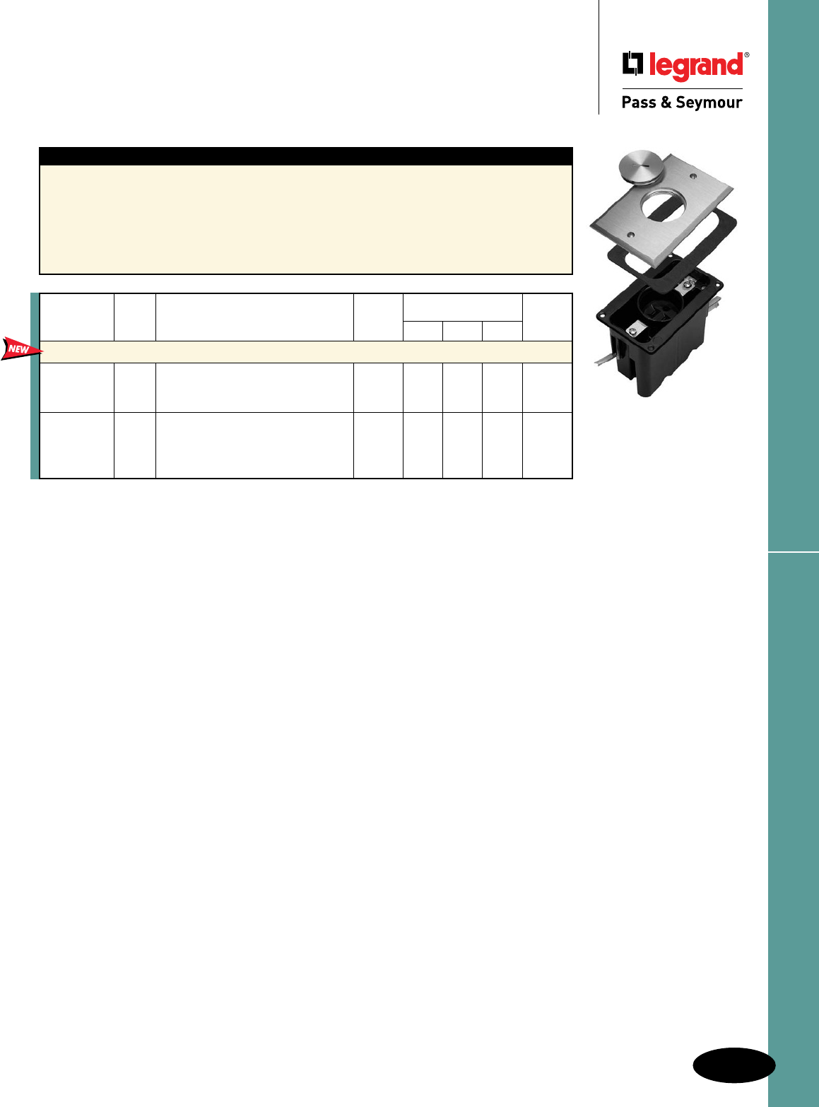
N-13
Tamper-Resistant Floor Box AssembliesSlater® Plastic Boxes
All devices listed on this page conform to NEMA OS2.
Slater® Plastic Boxes
Tamper-Resistant Floor Box Assemblies
For Wood Sub-Floors
Features – FB Series
n Tamper-resistant receptacles feature dual
mechanical shutter system to help prevent insertion
of foreign objects.
n Meets NEC 406.11 requirements.
n Rugged diecast cover plates.
n Meets UL514(c) and NEC 314.27(c).
n Scrub water compliant.
n With durable nickel or brass cover plates.
n Swing brackets mounting option eliminates
drilling tile flooring for mounting screws.
n Wood sub-floors only.
n Wire Fill (AWG):
10 No. 14, 9 No. 12, 8 No. 10.
FB1TRSRB
Cover
Catalog Cu. In. Plate Dimensions (inches) Qty. Per
Number Vol. Description Finish L W D Carton
Floor Box Assemblies — One Gang for Wood Sub-Floors
FB1TRSRB 20.5 Single threaded screw plug. Brass 43⁄4 31⁄4 4 1
FB1TRSRN Includes 15A, 125V single Nickel
tamper-resistant receptacle.
FB1TRDRB 20.5 #8 duplex opening, 2 threaded Brass 43⁄4 31⁄4 4 1
FB1TRDRN screw plugs. Includes 3232 Nickel
tamper-resistant 15A, 125V
duplex receptacle.
National Electrical Code® Section 406.11 Tamper-Resistant Receptacles in Dwelling Units.
In all areas specified in 210.52 all 125-volt, 15- and 20-amp receptacles shall be listed tamper-resistant receptacles.
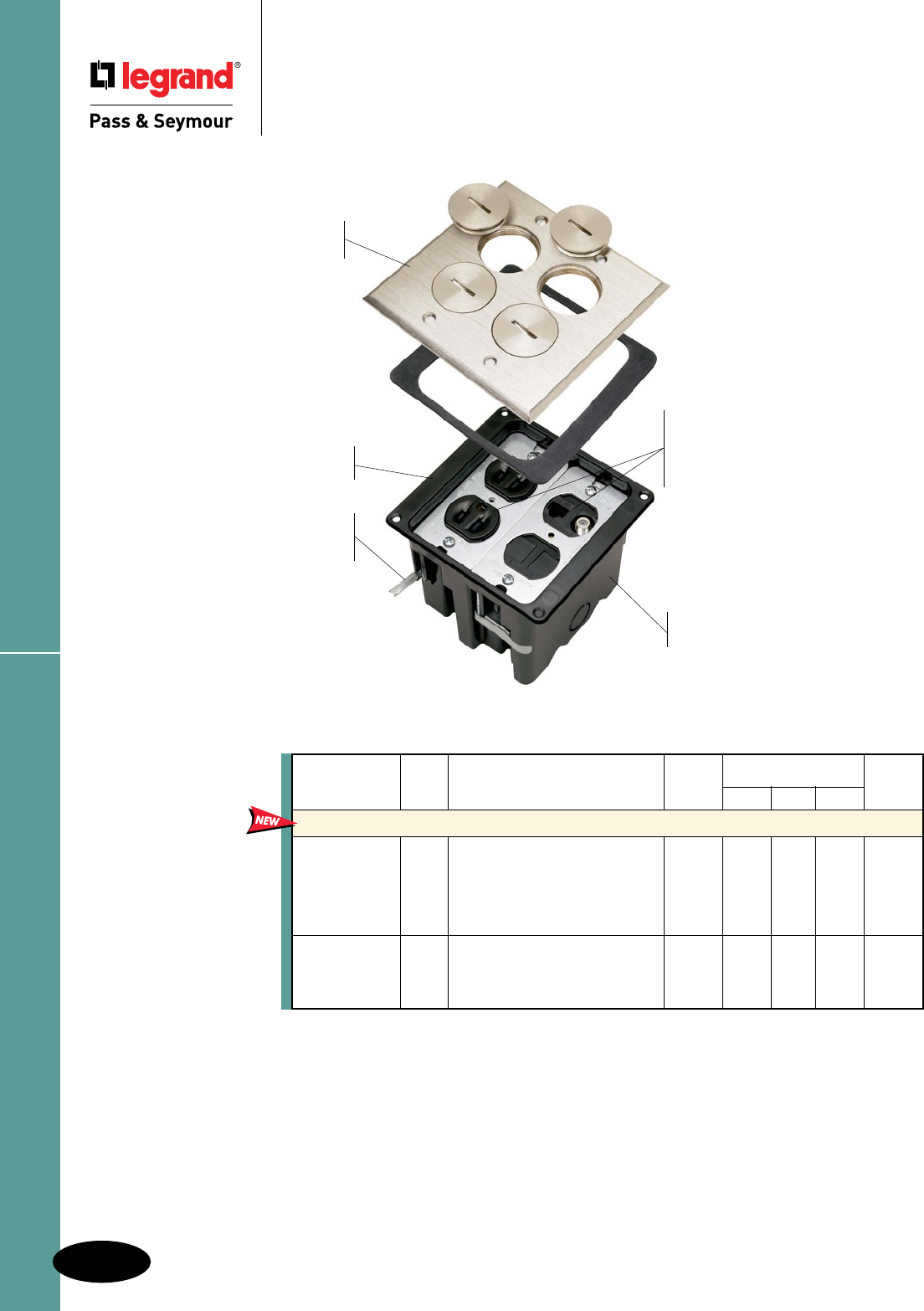
N-14
Slater® Plastic Boxes
All devices listed on this page conform to NEMA OS2.
Tamper-Resistant Floor Box Assemblies
Slater® Plastic Boxes
Tamper-Resistant Floor Box Assemblies
For Wood Sub-Floors
FB2TRDRKS4N
Scrub water compliant
without caulking, supplied
with foam gasket and O-ring-
equipped plugs.
Dual-voltage models available.
Includes 15 Amp, 125 Volt
tamper-resistant duplex receptacle,
low-voltage divider, Cat 5e jack,
F-connector, and blanks.
Extra-deep design leaves
plenty of wiring room.
Large box flange rests on finished
floor — no adjustments needed.
Swing-bracket mounting,
great for tile floors — eliminates
drilling for mounting screws.
Meet UL514C and NEC314.27c
requirements including scrub
water for tile floors.
Rugged, die-cast cover plate
with durable nickel or brass finish.
Cover
Catalog Cu. In. Plate Dimensions (inches) Qty. Per
Number Vol. Description Finish L W D Carton
Floor Box Assemblies — Two Gang for Wood Sub-Floors
FB2TRDR2B 42.5 Dual-voltage. Two #8 duplex Brass 43⁄4 61⁄2 4 1
FB2TRDR2N openings, 4 threaded screw plugs. Nickel
Includes 3232 tamper-resistant
15A, 125V duplex receptacle,
Cat 5e jack, F-connector,
10 blanks & low-voltage divider.
FB2TRDRKS4B 42.5 Two #8 duplex openings, Brass 43⁄4 61⁄2 4 1
FB2TRDRKS4N 4 threaded screw plugs. Includes Nickel
two 3232 tamper-resistant 15A,
125V duplex receptacles.
Wire File (AWG): 21 No. 14, 18 No. 12, 17 No. 10.
Meets NEC Section 406.11
Tamper-Resistant requirements.
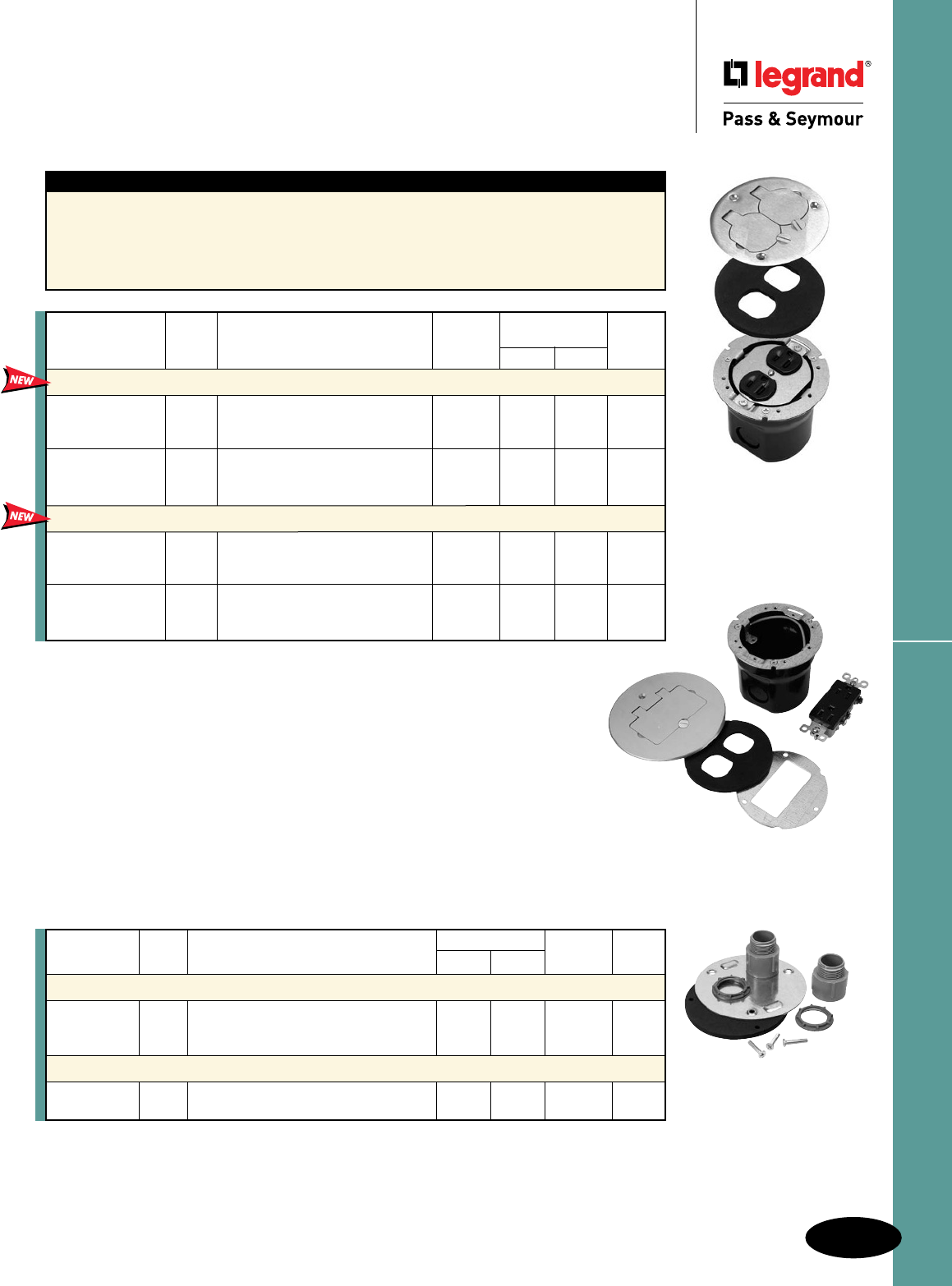
N-15
Slater® Plastic Boxes
All devices listed on this page conform to NEMA OS2.
Tamper-Resistant Round Floor Box Assemblies
Slater® Plastic Boxes
Tamper-Resistant
Round Floor Box Assemblies
For Wood or Concrete Sub-Floors
Features
n Tamper-resistant receptacles feature dual
mechanical shutter system to help prevent
insertion of foreign objects.
n Meets NEC 406.11 requirements.
n Rugged diecast cover plates.
n Brass or aluminum.
n Smooth, nearly flush installation.
n PS862 Series wood or concrete sub-floors only.
n Wire Fill (AWG):
11 No. 14, 9 No. 12, 8 No. 10.
Cover
Catalog Cu. In. Plate Dimensions (in.) Qty. Per
Number Vol. Description Finish Dia. D Carton
Round Floor Box Assemblies for Hardwood or Tile Finished Floors
PS862TRT 22.0 #8 duplex opening, 2 flip lids. Brass 41⁄4 31⁄4 1
PS862TRTAL Includes 3232 tamper-resistant Aluminum
15A, 125V duplex receptacle.
PS862TRTGFI 22.0 #26 opening, flip lid. Includes Brass 41⁄4 31⁄4 1
PS862TRTGFIAL 885 tamper-resistant 15A, Aluminum
125V duplex Decorator receptacle.
Round Floor Box Assemblies for Carpeted Finished Floors
PS862TRC 22.0 #8 duplex opening, 2 flip lids. Brass 51⁄2 31⁄4 1
PS862TRCAL Includes 3232 tamper-resistant Aluminum
15A, 125V duplex receptacle.
PS862TRTGFIC 22.0 #26 opening, flip lid. Brass 51⁄2 31⁄4 1
PS862TRTGFICAL Includes 885 tamper-resistant 15A, Aluminum
125V duplex Decorator receptacle.
PS862TRT
PS862KIT
Catalog Cu. In. Dimensions (in.) Wire Fill Qty. Per
Number Vol. Description Dia. Depth (AWG) Carton
Round Floor Box for Hardwood, Tile or Carpeted Finish Floors
PS862 22.0 Box only. 33⁄4 211⁄16 11 No. 14 1
9 No. 12
8 No. 10
Concrete Kit
PS862KIT – Mud Cap, Gasket. Two 3/4" male PVC – – – 5
conduit fittings.
PS862TRGFICAL
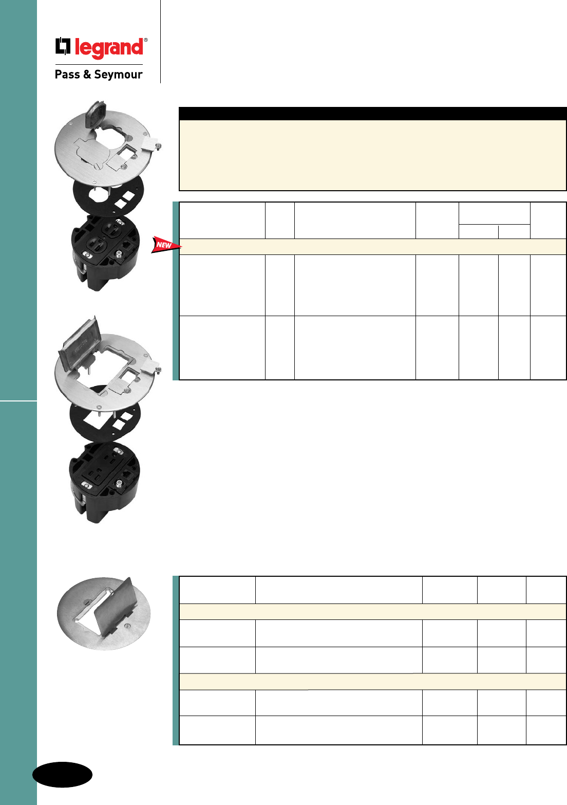
N-16
Slater® Plastic Boxes
All devices listed on this page conform to NEMA OS2.
PS863TRGFIC
PS895GFIC
PS863TRC
TR Round Floor Box Assemblies & Covers
Slater® Plastic Boxes
Tamper-Resistant
Round Floor Box Assemblies & Covers
For Wood Sub-Floors
Features
n Tamper-resistant receptacles feature dual
mechanical shutter system to help prevent
insertion of foreign objects.
n Meets NEC 406.11 requirements.
n Rugged diecast cover plates.
n Brass or aluminum.
n Dual-voltage.
n Smooth, nearly flush installation.
n PS863 series wood sub-floors only.
n Includes Cat 5e & F-Connector.
n Wire Fill (AWG):
11 No. 14, 10 No. 12, 9 No. 10.
Cover
Catalog Cu. In. Plate Dimensions (in.) Qty. Per
Number Vol. Description Finish Dia. D Carton
Round Floor Box Assemblies
PS863TRC 23.5 Dual-voltage. #8 duplex Brass 53⁄4 31⁄2 1
PS863TRCAL opening, 2 flip lids and Aluminum
2 low-voltage openings.
Includes 3232 tamper-resistant
15A, 125V duplex receptacle,
Cat 5e jack and F-connector.
PS863TRGFIC 23.5 Dual-voltage. #26 opening, Brass 53⁄4 31⁄2 1
PS863TRGFICAL flip lid and 2 low-voltage Aluminum
openings. Includes 885
tamper-resistant 15A, 125V
duplex Decorator receptacle,
Cat 5e jack & F-connector.
Catalog Cover Plate Qty. Per
Number Description Finish Diameter Carton
Round Floor Box Covers for Hardwood or Tile Finished Floors
PS895T #8 duplex opening, 2 flip lids. Cover only. Brass 41⁄4 8
PS895TAL Aluminum
PS895TGFI #26 Decorator opening, flip lid. Cover only. Brass 41⁄4 8
PS895TGFIAL Aluminum
Round Floor Box Covers for Carpeted Finished Floors
PS895C #8 duplex opening, 2 flip lids. Cover only. Brass 51⁄2 8
PS895CAL Aluminum
PS895GFIC #26 Decorator opening, flip lid. Cover only. Brass 51⁄2 8
PS895GFICAL Aluminum
Round Floor Box Covers
For Wood or Concrete Sub-Floors
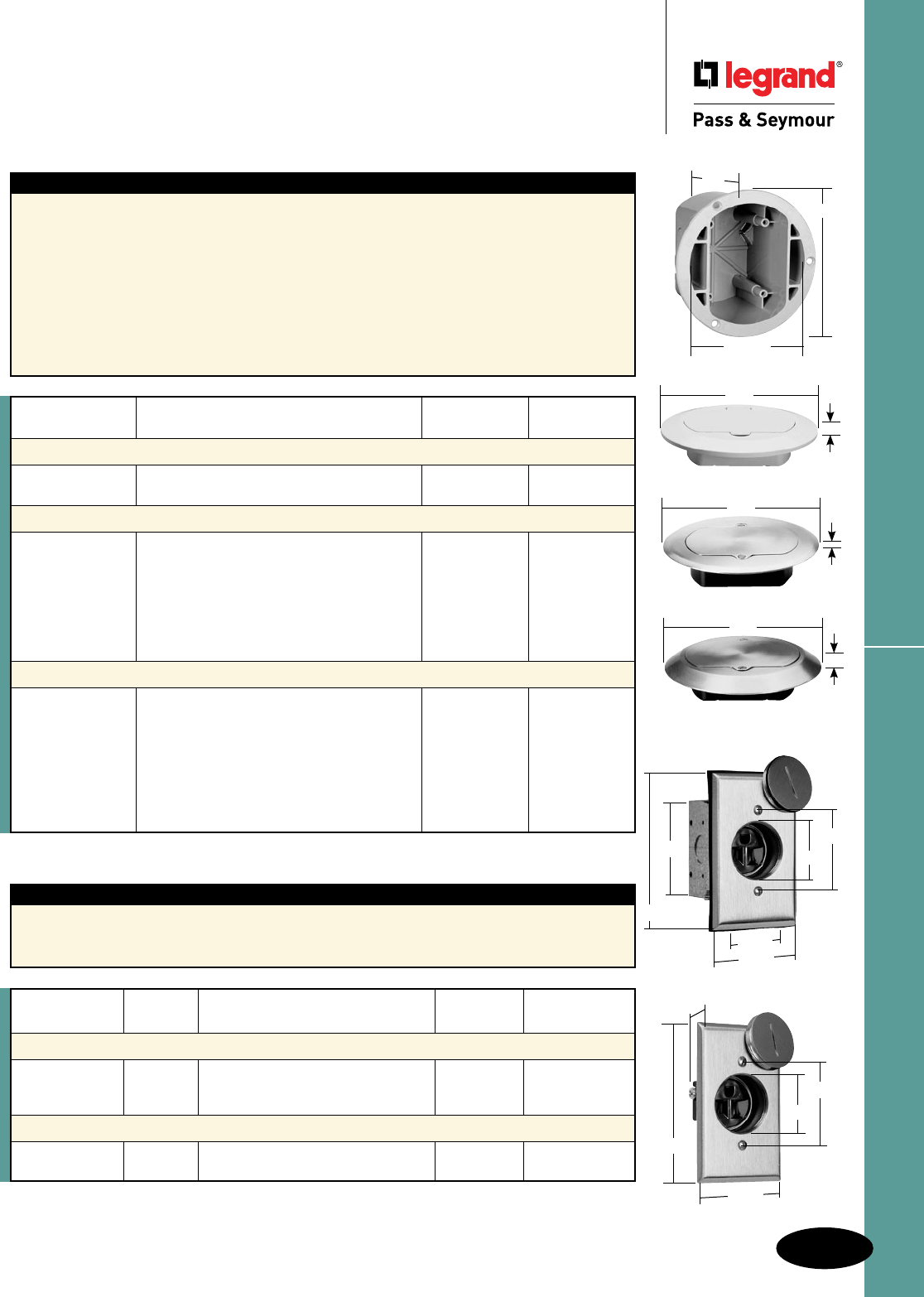
N-17
Slater® Plastic Boxes
All devices listed on this page conform to NEMA OS2.
Tamper-Resistant Floor Box Assemblies
Plastic Boxes
Tamper-Resistant Floor Box Assemblies
2 Pole, 3 Wire Grounding 15A, 125V
UL listed in accordance with 314.27(e).
Features
n Solid brass covered plate with matching
flush fitting brass cap.
n 15A, 125V single receptacle made of durable thermoplastic.
n UL and FSUL listed.
Features
n Tamper-resistant receptacles feature dual
mechanical shutter system to help prevent
insertion of foreign objects.
n Meets NEC 406.11 requirements.
n Hinged door is removable and easily replaceable.
n Durable construction, impact and scratch resistant
PVC construction.
n Standard Decorator opening that accepts GFCI,
TVSS, DataCom or other Decorator devices.
n Auto/Clamps® and knockouts on both sides of box.
n Meets UL514(c) scrub water exclusion test.
n Threaded device mounting holes.
n Simple mounting box, fits into a 4-3/4" hole
and mounts with 3 screws included.
n Ready for low-voltage wiring, drill guides on
underside of cover.
n UL and cUL Listed.
n Captive screws on TM1542 series – screws
will not be lost – new.
n Made in USA.
1542TRFBA
3.015"
4.500"
1.675"
2.375"
2.750"
1.950"
1542TRDR
4.500"
1.675"
2.375"
2.750"
1.825"
*UL listed in accordance with 314.27(e).
**Conforms to NEMA OS2.
Rating NEMA
Catalog Number A. V. Description Color Cong. No.
Floor Box Assembly**
1542TRFBA 15 125 Tamper-resistant receptacle, brass Brown 5-15R
plate, 1.01" recessed plug, gasket,
O-ring, and metal 18 cu. in. box
Display Receptacle*
1542TRDR 15 125 Tamper-resistant receptacle, Brown 5-15R
brass plate and 1.01" recessed plug
TM1542BOX
5.5"
4.0"
4.71875"
TM1542TRLA*
6.5"
.4375"
TM1542TRFM
6.5"
.125"
TM1542TRCF
*See available colors at right.
6.5"
.5"
NEMA
Catalog Number Description Color Cong. No.
Floor Box
TM1542BOX 38 cu. in., with knockouts and Auto/Clamps®, Gray 5-15R
3 screws for mounting to floor.
Thermoplastic Covers
TM1542TRW White 5-15R
TM1542TRBR Brown 5-15R
TM1542TRGRY Paintable Gray 5-15R
TM1542TRLA Light Almond 5-15R
Brass Covers
TM1542TRFM Low-profile cover requires minimum 3/8" Brass 5-15R
hardwood floor thickness.
TM1542TRCF High-profile cover fits any floor finish – Brass 5-15R
including carpeting, linoleum, tile, etc.
Both covers include an 885 tamper-resistant
15A, 125V Decorator duplex receptacle and
will accept any Decorator device. Covers
include captive screws to prevent loss.
Includes 15A, 125V tamper-resistant
Decorator receptacle, matching detachable
and replaceable hinged door; threaded
device-mounting holes; drill guides for
low-voltage poke-through holes; accepts
any Decorator device; mounts on carpeting,
hardwood, linoleum, tile floors; 4 mounting/
leveling screws.
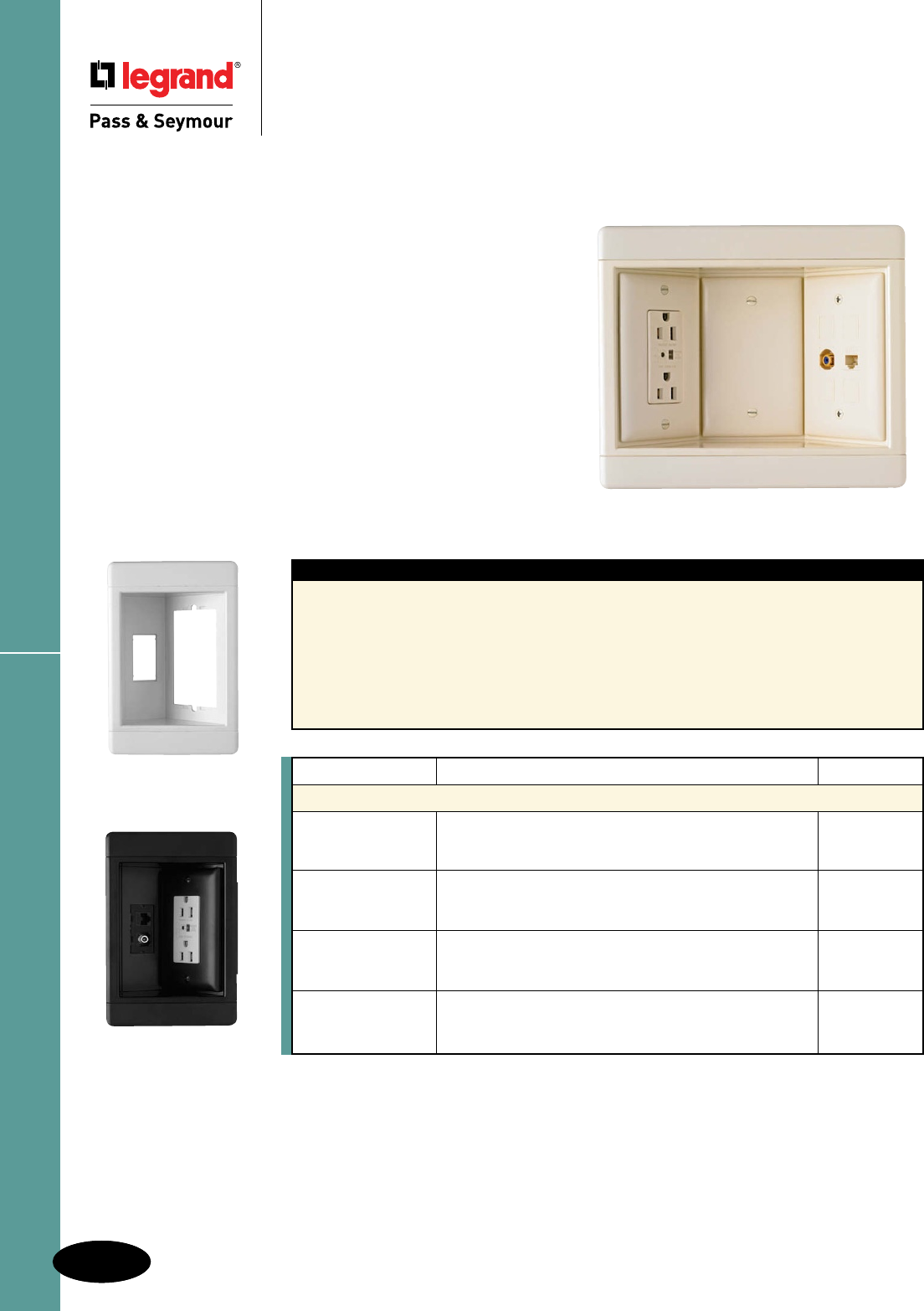
N-18
Recessed TV Boxes
N-18
Plastic Boxes
Recessed TV Boxes
Slater® Plastic Boxes
Ideal for flat-screen TVs, home office, kitchen counter tops, and behind furniture
to allow snug-to-wall placement.
Today’s homeowners have more multimedia choices
than ever — including flat panel, wall-mounted televisions.
P&S Recessed TV Boxes offer a clean installation with the
versatility to handle up to 12 multimedia connections, while
providing surge protected power.
Their recessed design saves space and simplifies connections
to cable or satellite boxes, DVRs, DVD players, surround-sound
systems and more.
And they’re available with or without surge protective
receptacles to protect costly electronics from potentially
damaging surges.
TV3WTVSSLA
All devices listed on this page conform to NEMA WD-1 and WD-6.
Features
n Clean, flush-mount appearance — snap-on
end caps hide mounting screws.
n Flexible — position either line voltage or
low-voltage in all three openings.
n Low-voltage connectors offer both terminated
and pull-through capability.
n Plugs and multimedia connections stay
recessed behind the wall surface.
n Molded-in template and rectangular cut-out.
n Accepts standard TP wall plates.
n Metal swing brackets ensure a solid mounting.
n Uses old-work-style boxes for line voltage.
n Accepts all P&S keystone low-voltage
connectors, including Cat 5e and F-connectors
(both supplied with Surge Protective kit), as well
as RCA and audio binding posts.
Catalog Number Description Color
Recessed TV Boxes
TV1WW White
TV1WBK Single Gang Recessed TV Box — Frame Only. Black
TV1WLA Light Almond
TV1WTVSSW Single Gang Recessed TV Box with Surge Protective & White
TV1WTVSSBK Low-Voltage Kit. Includes Surge Protective Duplex Black
TV1WTVSSLA Receptacle, Cat 5e Jack, F-Connector, Blanks, & Wall Plates. Light Almond
TV3WW White
TV3WBK Three Gang Recessed TV Box — Frame Only. Black
TV3WLA Light Almond
TV3WTVSSW Three Gang Recessed TV Box with Surge Protective & White
TV3WTVSSBK Low-Voltage Kit. Includes Surge Protective Duplex Black
TV3WTVSSLA Receptacle, Cat 5e Jack, F-Connector, Blanks, & Wall Plates. Light Almond
Single gang dimensions: 7.25" L x 4.875" W x 2.25" D
Three gang dimensions: 8.5" L x 4.875" W x 2.25" D
TV1WTVSSBK
TV1WW
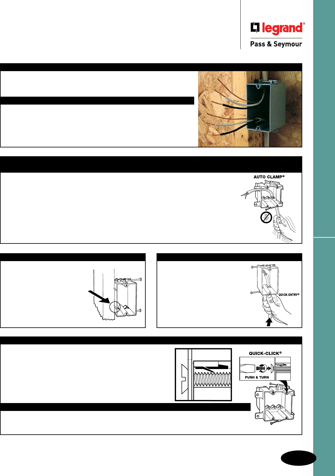
N-19
Applications & Product FeaturesSlater® Plastic Boxes
Slater® Plastic Boxes
Applications & Product Features
Quick/Click®
Fast, easy, and secure installations.
The unique, labor-saving Quick/Click® design secures the wiring device
quickly and easily. Simply push in the mounting screws with a screwdriver
and turn the screw one turn.
With Quick/Click® you cannot cross-thread or strip a device mounting
screw.
Wall boxes are tested for a minimum 100 lb. total device pull-out
resistance.
How Quick/Click® Works
The spring steel insert for quick mounting of switches and receptacles is a unique patented feature.
(Refer to illustration.) Note how the spring acts as a locking ratchet and allows the screw to be pushed in
and then tightened. The screw can only be released by unscrewing it in the conventional fashion.
Application
Slater Plastic Boxes, the Contractor’s Choice designed with unique labor-saving
features, include a complete range of wall, ceiling, and old work boxes for commercial
and residential construction applications.
UL Classied
All Slater Plastic Boxes are Underwriters Laboratories Listed. Slater Plastic Boxes
shown that are UL Classified for Fire Resistance meet the requirements of UL263
and have a two hour fire resistance rating. These boxes may be used in fire resistant
walls and ceilings. Installation information for Slater Plastic Boxes Classified for Fire
Resistance may be found in the UL Fire Resistance Directory under category CEYY
for Legrand/Pass & Seymour.
Product Features
Exclusive Auto/Clamp®
Eliminates the need for separate cable clamps as well as the tools usually needed for installation.
Auto/Clamp® is available on all multigang boxes, old work boxes, 4" square boxes, and 3-1/4" and 4" round
ceiling boxes. A major installation advantage with Auto/Clamp® is that the clamp is molded as an integral
part of the box (there are no separate clamps and screws to install, adjust or tighten). Each cable opening
contains an Auto/Clamp®, therefore, the non-metallic sheathed cable may be inserted where needed or
where most convenient. Auto/Clamp® does not take up as much room as conventional clamps, allow ing
more room for wire and devices – another important feature.
To install the cable, insert stripped or unstripped non-metallic wire into the Auto/Clamp® opening and
pull through to the desired length. The cable is automatically secured and the installation is complete.
There are no other operations for the electrician to perform. Contractors can look forward to saving
time and money with every Auto/Clamp® plastic box installation.
Location Ribs
Location Ribs enable the installer
to quickly and accurately maintain
a 1/2" offset. Dual ribs also make
it easy to keep the face of the box
parallel to the stud. The ribs are
.450" long to reduce the chance of
the box protruding beyond the 1/2"
sheet rock.They project .080" to span
the rounded edges of wood studs but
will not cause excessive canting of the
box when used with thinner wallboard.
Quick/Entry®
Speeds installation by eliminating
need for tools
Another time-saving idea is Quick/
Entry®, a method that allows you to
push stripped or unstripped non-metallic
cable into a single gang plastic box
without removing knock-outs. Jagged
edges usually formed in other boxes are
eliminated. Staple wire to stud within
8" of the box [per NEC 314.17(c)] to
complete installation.
Note: no additional
cubic inch volume
deduction required.
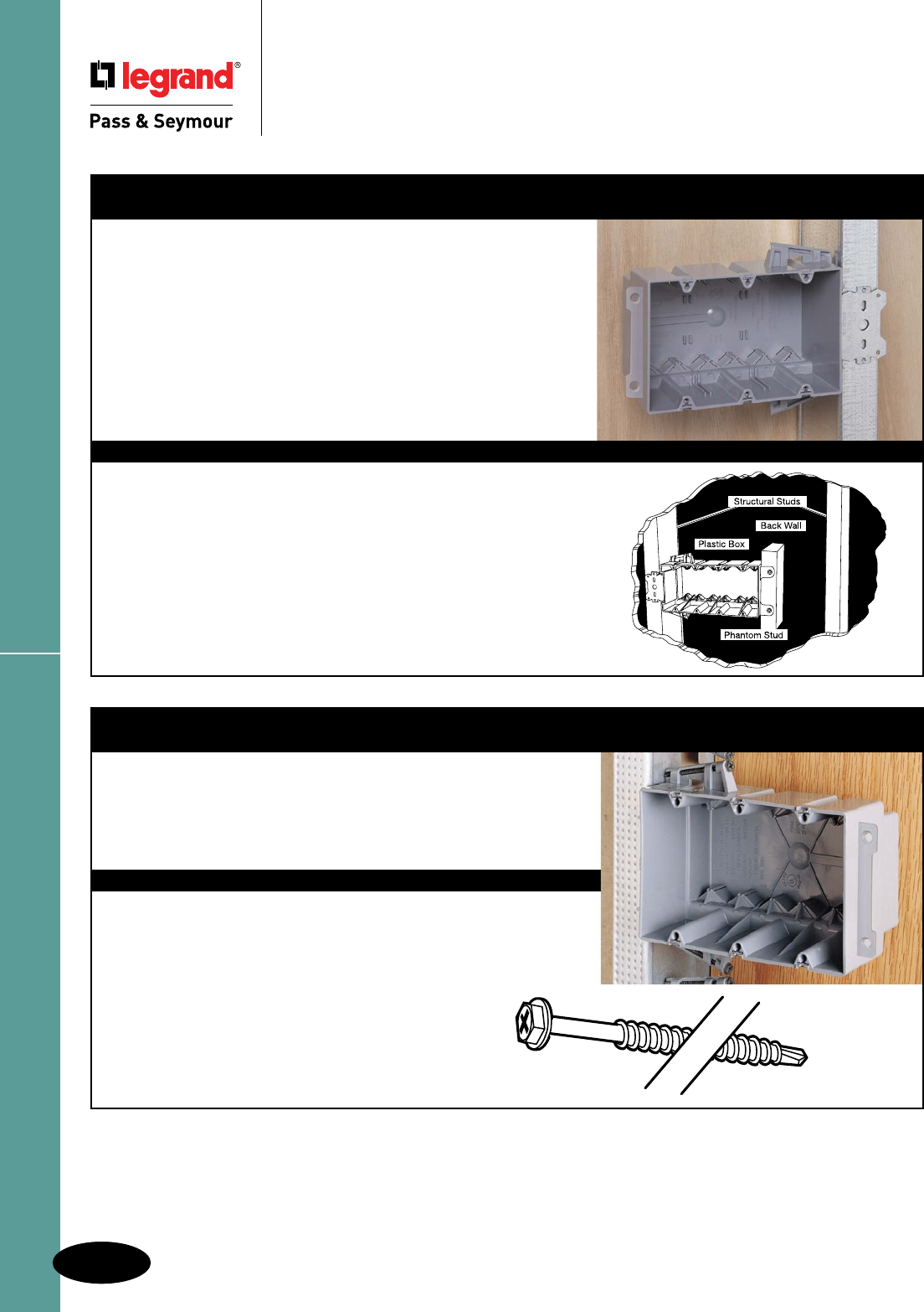
Applications & Product Features
N-20
Slater® Plastic Boxes
Slater® Plastic Boxes
Applications & Product Features
Wood & Steel Stud Bracket Boxes
Application
Single, two, three, four gang and 4" square wood and steel stud boxes
feature Quick/Click®, the labor-saving device that assures quick and
dependable installation of switches and receptacles. These high-impact
thermoplastic boxes can be mounted quickly to steel or aluminum studs
using the CT-1 Crimping Tool. They can also be mounted to wooden studs
with common nails or screws.
On the single, two, three and four gang steel stud boxes, a steel mounting
bracket is provided for mounting to the structural stud. The non-mounting side
of the two and four gang box has provisions for attachment to a short section of
stud (phantom stud), as shown in the illustration below, to give additional rigidity
to the installation. This assembly may also be used without the phantom stud
as a positioning tab to automatically realign the box to the wallboard surface.
The brackets are 3/8" offset to accommodate 3/8" to 5/8" thick wallboard.
Features
n Available in single, two, three, four gang and 4" square boxes. Two, three and
four gang boxes and 4" square include exclusive Auto/Clamp® feature.
n Single gang include Quick/Entry® feature.
n Quick/Click® feature offers fast and dependable installation of devices (single,
two, three and four gang).
n Unique offset tab assures proper alignment to wall face. Available with 3/8" offsets.
n Can be used for steel, aluminum, or wooden studs. Can be installed on
steel studs with most standard crimping tools in addition to CT-1 Crimping Tool.
n Molded of high-impact thermoplastic.
Screw Mount: Steel Stud Boxes
Application
Single, deep single, two, three, four gang, and 4" round ceiling boxes come
with combination Hex/Phillips washer head screws. They are designed to save
labor and speed installation in steel stud construction. These innovative boxes
are an alternative to bracket boxes, and can also be used on wood studs. The
specially designed drill point on the screw rapidly penetrates medium gauge
steel studs to securely fasten the box. Locator ribs 0.450" long help align the
box on the stud and insure correct mounting depth.
Features
• Available in single, single deep, two, three and four gang, and 4" round
ceiling boxes.
• All multi-gang and ceiling boxes include exclusive Auto/Clamp® feature.
• Single gang include Quick/Entry® feature.
• Specially designed drill point rapidly penetrates medium gauge steel studs.
• Screws have combination Hex/Phillips washer heads.
• Quick/Click® feature on wall boxes offers fast and dependable
installation of devices.
• Can be used for steel, aluminum, or wood studs.
• Molded of high-impact thermoplastic.
• Locator ribs ensure proper alignment on stud and proper offset depth.
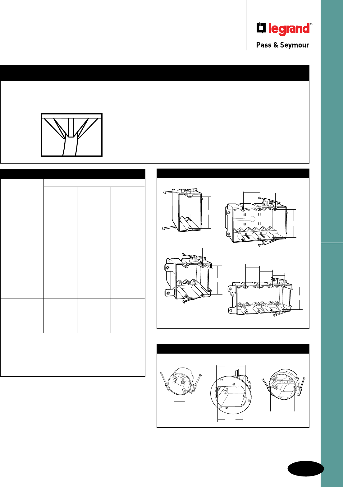
N-21
Applications & Product FeaturesSlater® Plastic Boxes
Slater® Plastic Boxes
Applications & Product Features
Standard Mounting Dimensions for Boxes
Box Volume Required
Total Conductor Cubic Inches Required For
Fill Count #14 Wire #12 Wire #10 Wire
1 2.0 2.25 2.50
2 4.0 4.50 5.00
3 6.0 6.75 7.50
4 8.0 9.00 10.00
5 10.0 11.25 12.50
6 12.0 13.50 15.00
7 14.0 15.75 17.50
8 16.0 18.00 20.00
9 18.0 20.25 22.50
10 20.0 22.50 25.00
11 22.0 24.75 27.50
12 24.0 27.00 30.00
13 26.0 29.25 32.50
14 28.0 31.50 35.00
15 30.0 33.75 37.50
16 32.0 36.00 40.00
17 34.0 38.25 42.50
18 36.0 40.50 45.00
19 38.0 42.75 47.50
20 40.0 45.00 50.00
In addition to counting 1 conductor fill allowance for each
conductor, 1 additional allowance must be counted for all cable
clamps, and 1 additional allowance for all ground conductors.
2 additional fill allowances must be counted for each device
strap. See NEC Section 314.16(b). The table above defines
box volume required for resulting total conductor fill count,
depending on AWG used.
Old Work Boxes
Application Features
Old Work Boxes provide fast, easy installation of an electrical
device in a finished (dry walled) area where no box existed
before. Old Work Boxes include the Auto/Clamp® and Quick/Click®
features for convenient, labor-saving installations.
n Box designed so mounting strap of the device, with plaster
ears removed, fits flush, allowing use of standard depth wall
plate without unsightly gap between plate and wall surface.
n Swing out wing brackets permit installation of box in wall with
1-1/4" thick wallboard down to 1/8" thick paneling.
n New longer swing brackets have greater reach to clamp onto
oversized cutouts.
n Made of high impact thermoplastic.
n Combination slotted/Phillips head swing bracket screws.
n Include exclusive Auto/Clamp® feature.
n Wall boxes include exclusive Quick/Click® feature.
n Available in ceiling box versions.
Standard Mounting Dimensions Round
Boxes
3.281"
31⁄4" Round 33⁄4" Round 4" Round
2.75"
3.5"
3.5"
3.281"
3.281"
1.8125"
3.281"
1.8125"
1.8125"
3.281"
1.8125"
1.8125"
1.8125"

REIKER CEILING FAN & FIXTURE SUPPORT PRODUCTS
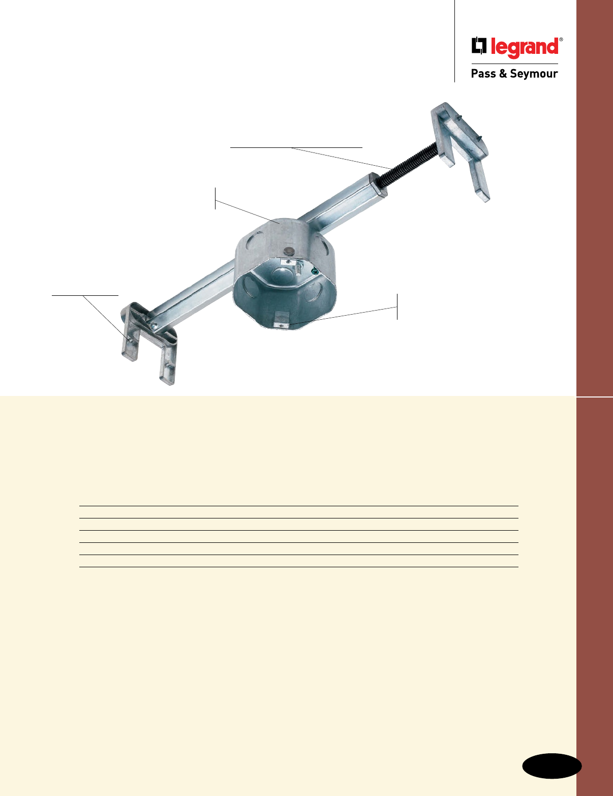
O-1
Reiker Ceiling Fan & Fixture Support Products
Reiker Ceiling Fan & Fixture
Support Products
Index
Device Page Number
Retrofit Braces O-2
New Construction Slides O-3
Side, Direct & Shallow Boxes O-4
Specialty Boxes & Concrete Fan Support Boxes O-5
Specifications O-6, O-7
22200
Rotating dual supports accept
both fan (#10-32 screws) and
fixture (#8-32 screws) mounting.
25 cu. in. metal box
included.
Cast zinc self-
leveling feet
ease installation.
Heavy-duty hexagon brace
expands from 16"–24", perfect
for existing ceiling applications.
Supports fans up to
70 lbs. and fixtures
up to 150 lbs.
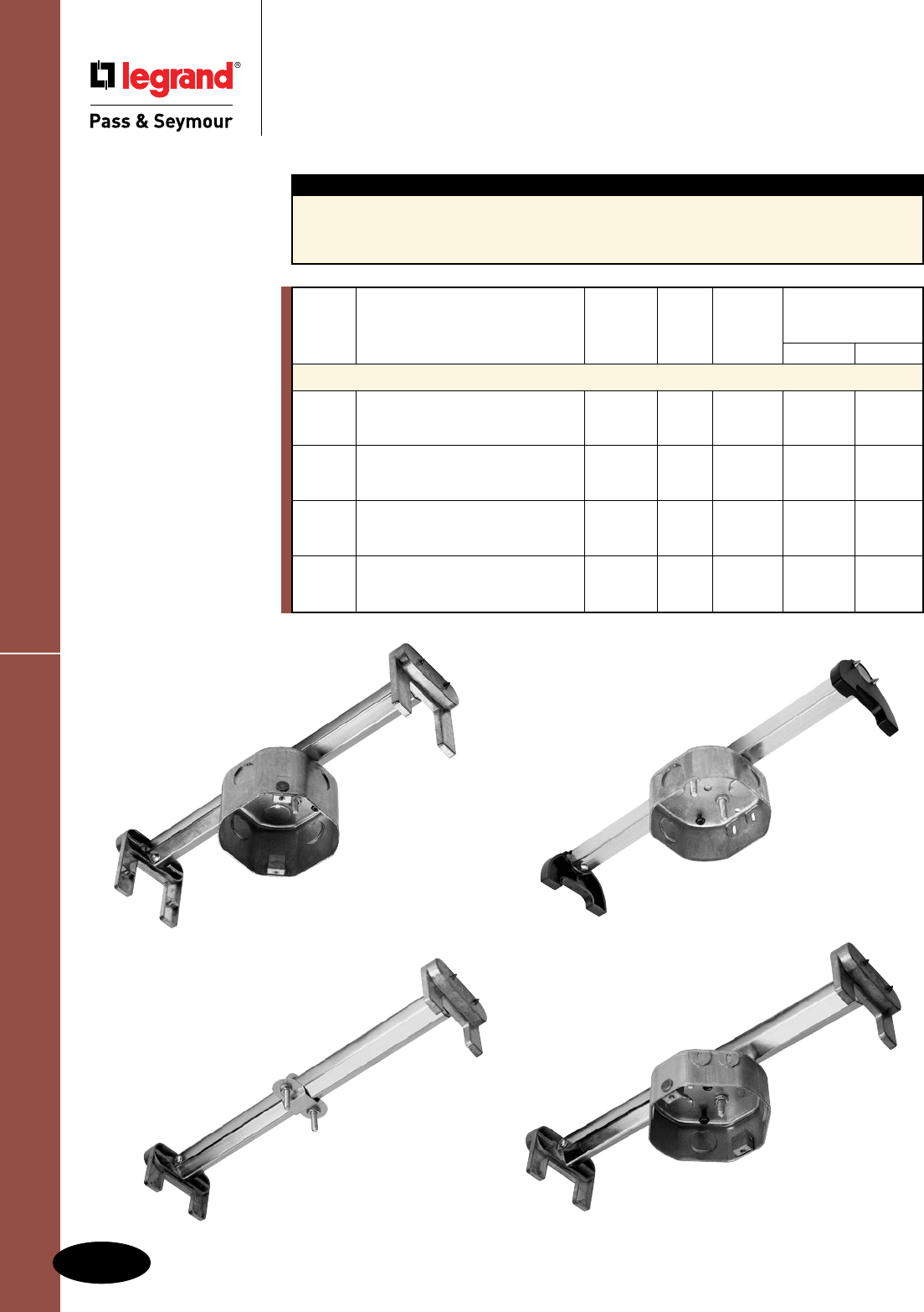
83300
22200
Retrofit Braces
O-2
Reiker Ceiling Fan & Fixture Support Products
Reiker Ceiling Fan & Fixture Support Products
Retrofit Braces
Features
nForspansfrom16to24inches.
nULlistedforfanandfixturesupport.
nSelf-levelingfeet.
nMaximumweightratingshownfor16"spans.
nGroundscrewpre-installed.
n Boxesincludetopknockouts.
33300
33310
AlldeviceslistedonthispageconformtoNEMAOS1.
UL Listed
Quantity Max. Weight Rating
Catalog Volume Box Per at 16" Span
Number Description Cu. In. Depth Carton Fan Fixture
Retrofit Braces
22200 FanBrace–premiumgradewith 25cu.in. 2.5" 12 70lbs. 150lbs.
deepbox,rotatingdualsupport
for16-24"spans
33310 FanBrace–standardgradewith 16cu.in. 1.5" 12 70lbs. 150lbs.
standardbox,single#10support
for16-24"spans
33300 FanBraceOnly–usewithstandard N/A N/A 12 70lbs. 150lbs.
octagonelectricalbox(33303),
single#10supportfor16-24"spans
83300 FanBrace—premiumgradewith 16cu.in. 1.5" 12 70lbs. 150lbs.
standardbox,rotatingdualsupport
for16-24"spans
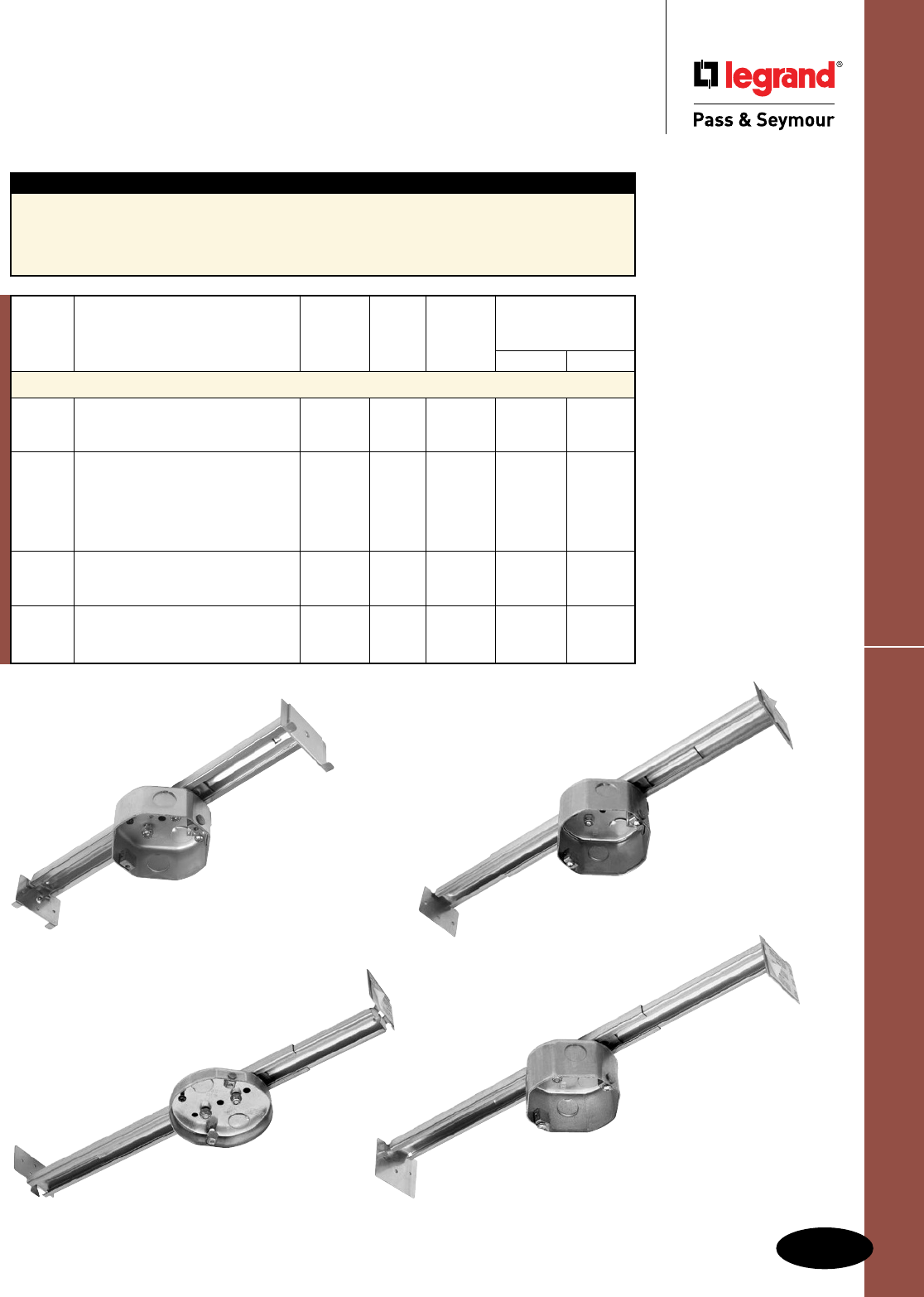
85502
O-3
New Construction Slides
Reiker Ceiling Fan & Fixture Support Products
Reiker Ceiling Fan & Fixture Support Products
New Construction Slides
55501 65521
Features
nForspansfrom16to24inches.
nULlistedforfanandfixturesupport.
nPeel-offtapefor“hands-free”installation.
nMaximumweightratingshownfor16"spans.
nBroadestlineavailable,fromshallowto
deepboxes.
nPre-assembledwithgroundscrewinstalled.
nBoxesincludetopknockouts.
77702
AlldeviceslistedonthispageconformtoNEMAOS1.
*Availablein12Pack.UseCatalogNumber5550112.
UL Listed
Quantity Max. Weight Rating
Catalog Volume Box Per at 16" Span
Number Description Cu. In. Depth Carton Fan Fixture
New Construction
55501* SlideFanSupport–heavy-duty 16cu.in. 1.5" 24 70lbs. 110lbs.
slidewithstandardbox,rotating
dualsupportfor16-24"spans
65521 SlideFanSupport–sameheavy- 21cu.in. 2.0" 25 70lbs. 110lbs.
dutyslideas55501,butwith2.0"
deepbox,toaccommodateupto
1"firewallorsoundproofedceilings,
withrotatingdualsupportfor16-24"
spans,bulkpacked
85502 SlideFanSupport–heavy-duty 21cu.in. 2.0" 24 70lbs. 110lbs.
slidewithdeepbox,rotatingdual
supportfor16-24"spans
77702 SlideFanSupport–heavy-duty 8cu.in. 5/8" 24 70lbs. 110lbs.
slidewithshallowbox,rotatingdual
supportfor16-24"spans
55505
55025
Side, Direct & Shallow Boxes
O-4
Reiker Ceiling Fan & Fixture Support Products
Reiker Ceiling Fan & Fixture Support Products
Side, Direct & Shallow Boxes
77705
Features
nDirectmounttojoist.
nULlistedforfanandfixturesupport.
nPeel-offtapefor“hands-free”installation.
nBroadestlineavailable,fromshallowtodeepboxes.
nGroundscrewpre-installed.
nSuppliedwithhardware.
nBoxesincludetopknockouts.
UL Listed
Quantity Max. Weight Rating
Catalog Volume Box Per at 16" Span
Number Description Cu. In. Depth Carton Fan Fixture
Side Mount Boxes
55015 SideMountBox–withrotating 16cu.in. 1.5" 24 70lbs. 150lbs.
dualsupport
55020* SideMountDeepBox–with 21cu.in. 2.0" 24 70lbs. 150lbs.
rotatingdualsupport
55025 SideMountDeepBox–sameas 21cu.in. 2.0" 24 70lbs. 150lbs.
55020with5topknockoutsand
rotatingdualsupport
Direct Mount Boxes
33303 StandardElectricalBox–foruse 16cu.in. 1.5" 36 N/A N/A
with33300Brace
44400 DirectMountDeepBox—with 25cu.in. 2.5" 24 70lbs. 150lbs.
rotatingdualsupport
55505* DirectMountBox–withrotating 16cu.in. 1.5" 48 70lbs. 150lbs.
dualsupport
55528 DirectMountDeepBox–with 21cu.in. 2.0" 24 70lbs. 150lbs.
rotatingdualsupport
Shallow Boxes
77700* DirectMountShallowBox—with 8cu.in. 5/8" 24 70lbs. 150lbs.
rotatingdualsupport
77705 DirectMountShallowBox—with 6.5cu.in. 1/2" 24 70lbs. 150lbs.
rotatingdualsupport
*Availablein12Packs.UseCatalogNumbers55020012,55505012and77700012.
AlldeviceslistedonthispageconformtoNEMAOS1.
O-5
Specialty Boxes & Concrete Fan Support BoxReiker Ceiling Fan & Fixture Support Products
Reiker Ceiling Fan & Fixture Support Products
Specialty Boxes, Concrete Fan Support
Box & Contractor Packs
77706
15010
Features
nDirectmounttojoist.
nULlistedforfanandfixturesupport.
nPeel-offtapefor“hands-free”installation.
nMaximumweightratings(slidesandbraces)
shownfor16"spans.
nBroadestlineavailable,fromshallowtodeepboxes.
nGroundscrewpre-installed.
nSuppliedwithhardware.
nBoxesincludetopknockouts.
AlldeviceslistedonthispageconformtoNEMAOS1.
15040
UL Listed
Quantity Max. Weight Rating
Catalog Volume Box Per Base at 16" Span
Number Description Cu. In. Depth Carton Item Fan Fixture
Bulk – Contractor Pack
65501 SlideFanSupport–heavy-duty 16cu.in. 1.5" 25 55501 70lbs. 110lbs.
slidewithstandardbox,rotating
dualsupportfor16-24"spans
77708 SlideFanSupport–heavy-duty 8cu.in. 5/8" 24 77702 70lbs. 110lbs.
slidewithshallowbox,rotating
dualsupportfor16-24"spans
55500 DirectMountBox–withrotating 16cu.in. 1.5" 24 55505 70lbs. 150lbs.
dualsupport
65505 DirectMountBox–withrotating 16cu.in. 1.5" 50 55505 70lbs. 150lbs.
dualsupport
67705 DirectMountShallowBox– with 6.5cu.in. 1/2" 50 77705 70lbs. 150lbs.
rotatingdualsupport
UL Listed
Quantity Max. Weight Rating
Catalog Volume Box Per at 16" Span
Number Description Cu. In. Depth Carton Fan Fixture
Specialty Boxes
77706 ShallowBox–withwingsforthick/ 8cu.in. 5/8" 24 70lbs. 150lbs.
firewallceilings,rotatingdual
support
15010* DropCeilingSupport–single#10 16cu.in. 1.5" 6 70lbs. 150lbs.
supportfor24-36"spans,38"drop
Concrete Fan Support Box
15040 ConcreteBox–single#10support 47.5 4.0" 12 35lbs. 50lbs.
cu.in.
*ULListedFan/Fixtureat24"Span.
Specifications
O-6
Reiker Ceiling Fan & Fixture Support Products
Reiker Ceiling Fan & Fixture Support Products
Specifications
Materials of Construction
HexTube 16GaugeExtrudedSteelwithChromePlating
SquareTube 16GaugeExtrudedSteelwithChromePlating
DieCastFeet DieCastZinc
PlasticFeet InjectionMoldedPlastic
Compliances
CompliantwithUL514A
CompliantwithNECSection422.18andSection314.27
Extensionratingfrom16to24inches
CompliantwithNEMAStandardOS1
Retrofit Braces
Materials of Construction
SlideParts 16GaugeStampedSteel
InnerSlide 14GaugeStampedSteel
New Construction Slides
Compliances
CompliantwithUL514A
CompliantwithNECSection422.18and
Section314.27
Extensionratingfrom16to24inches
CompliantwithNEMAStandardOS1
Weight Rating (lbs.)
Catalog Box Included 16" Spans >16-24" Spans
Number Description Type Depth Cu. In. Fan Fixture Fan Fixture
22200 PremiumBracewithdeepbox B 2.5 25 70 150 35 50
33300 PremiumBraceonly None 70 150 35 50
33310 StandardBracewithstandardbox A 1.5 16 70 150 35 50
83300 PremiumBracewithstandardbox A 1.5 16 70 150 35 50
Weight Rating (lbs.)
Catalog Box Included 16" Spans >16-24" Spans
Number Description Type Depth Cu. In. Fan Fixture Fan Fixture
55501 Heavy-DutySlidew/standardbox A 1.5 16 70 110 35 50
65501 Heavy-DutySlidew/standardbox A 1.5 16 70 110 35 50
65521 Heavy-DutySlidew/deepbox D 2.0 21 70 110 35 50
77702 Heavy-DutySlidewithshallowbox C 0.625 8 70 110 35 50
77708 Heavy-DutySlidewithshallowbox C 0.625 8 70 110 35 50
85502 Heavy-DutySlidewithdeepbox D 2.0 21 70 110 35 50
A
1.5"
4.0"
B
4.0"
2.5"
C
4.0"
.625"
D
4.0"
2.0"
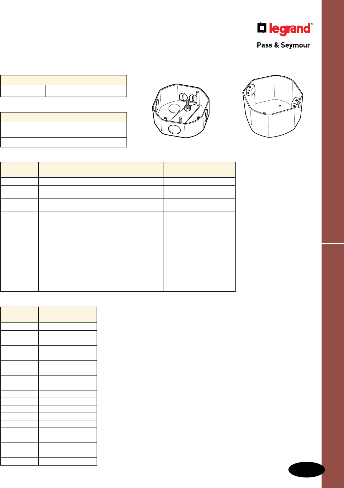
O-7
Specifications
Reiker Ceiling Fan & Fixture Support Products
Reiker Ceiling Fan & Fixture Support Products
Specifications
Side, Direct, Shallow & Specialty Boxes
Materials of Construction
BoxSteel 16GaugeStampedSteel
Compliances
CompliantwithUL514A
CompliantwithNECSections422.18and314.27
CompliantwithNEMAStandardOS1
Catalog Box
Number Description Capacity Weight Rating
33303 ElectricalBoxOnly 16cu.in. N/A
44400 DirectMountwithRotating 25cu.in. Upto70#Fan/150#Fixture
DualSupport
55015 SideMountwithRotating 16cu.in. Upto70#Fan/150#Fixture
DualSupport
55020 SideMountwithRotating 21cu.in. Upto70#Fan/150#Fixture
55025 DualSupport
55505 DirectMountwithRotating 16cu.in. Upto70#Fan/150#Fixture
DualSupport
55528 DirectMountwithRotating 21cu.in. Upto70#Fan/150#Fixture
DualSupport
77700 DirectMountShallowBox 8cu.in. Upto70#Fan/150#Fixture
withRotatingDualSupport
77705 DirectMountShallowBox 6.5cu.in. Upto70#Fan/150#Fixture
withRotatingDualSupport
77706 DirectMountwithU-Bracketfor 8cu.in. Upto70#Fan/150#Fixture
FirewallswithRotatingDualSupport
Catalog
Number Wire Clamp Type
15010 Metal
15040 Plastic
22200 Plastic
33303 Metal
33310 Plastic
44400 Plastic
55015 Metal
55020 Plastic
55025 Plastic
55501 Metal
55505 Metal
55528 Plastic
65501 Metal
65521 Metal
77700 Plastic
77702 Plastic
77705 Plastic
77706 Plastic
83300 Plastic
Single #10 Support Rotating Dual Support

WEATHERPROOF BOXES & COVERS
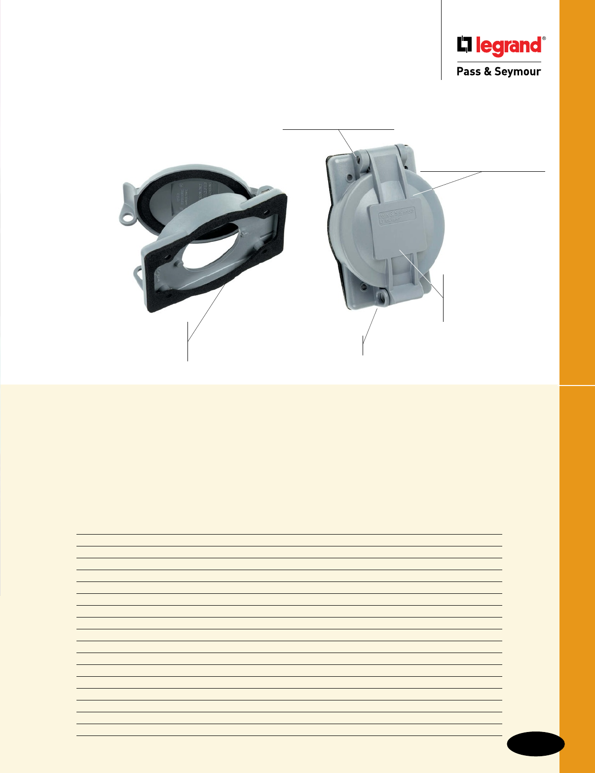
Weatherproof Boxes & Covers
Index
Device Page Number
While-In-Use Covers 2, P-3
Flush Mount While-In-Use Covers P-4
Cast While-In-Use Covers P-5
Cast Weatherproof Covers P-6 – P-8
Thermoplastic Covers P-9 – P-12
Heavy Cast Aluminum Covers P-12, P-13
Weatherproof Stainless Steel Covers P-14
Single Gang Boxes P-16
Weatherproof Locking Inlet Kit for Generator Applications P-16
Two Gang Boxes P-17
Three Gang Boxes & Deep Boxes P-18
Round Boxes & Weatherproof Kits P-19
Cluster & Blank Covers P-20
Lighting Accessories & Swimming Pool Junction Box P-21
Vapor Proof Lighting P-22
Gaskets & Accessories P-23
NEC Compliance P-24, P-25
We offer a complete line of durable,
easy-to-install, and environment-resistant
weatherproof products — for first-rate
performance in worst-case applications.
Unbreakable glass-filled
polycarbonate construction
withstands years of job site
abuse and harsh environmental
exposure. Stainless steel
mounting screws resist corrosion.
Molded-in label
area for pre-printed
or handwritten labels
identifying circuits,
ratings, and other data.
Lockable “bullnose” for OSHA
Lockout/Tagout compliance.
Two sizes: 1.96" and 2.32" diameters
to cover 15A/20A Straight Blade and
15A/20A/30A Turnlok® devices. Covers
fit all competitive flanged inlets and outlets.
Pre-attached gaskets for easy
installation and tight seal to panel
or weatherproof box — with no
misaligned or collapsed gaskets.
Tamper-proof hinge
features permanent, locked-in
pins for added security.
Stainless steel
mounting screws
resist corrosion.
WPG1 and WPG2
Weatherproof Boxes & Covers
P-1
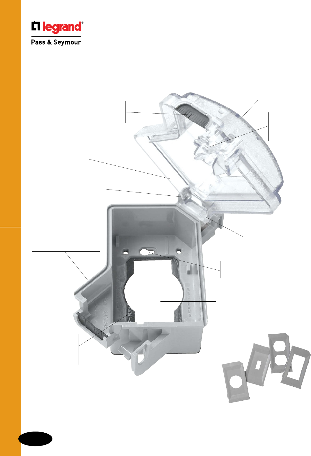
While-In-Use Covers
P-2
Weatherproof Boxes & Covers
Weatherproof Boxes & Covers
While-In-Use Covers
The NEC Section 406.8(B)(1) requires
that all 15 and 20 Amp,
125 and 250 Volt outdoor receptacles in wet locations have a cover that is
weatherproof — even when a plug is inserted into the receptacle.
Sturdy polycarbonate
construction resists
impacts and harsh weather.
Sturdy, molded-in
hinge withstands
hard use.
Patented corner hinge and
cord opening allow vertical
or horizontal installation.
Roomy interior provides space
for plugs and cord bends.
Preapplied
gasket easier to
install, saves time,
won’t get lost or
damaged.
Exclusive WaterShed™
Channel keeps water moving
outside while cord flap keeps
the inside dry.
Installs without removing
electrical device, thanks to
patented, keyed mounting holes.
Exclusive cord flap
gasket inhibits water
splash from driving
rain or sprinklers.
Shallow profile models have
1" shorter top lid than prior
models.
Paintable, textured
finish hides scratches.
Patented trigger
latch opens easily
with one finger,
yet is lockable to
prevent tampering.
Snap-in device plates
require no tools to install
and won’t fall out. See
chart for plates provided
with each catalog number.
WIUC10SC
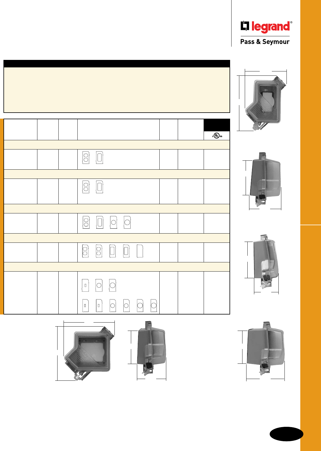
P-3
While-In-Use CoversWeatherproof Boxes & Covers
Weatherproof Boxes & Covers
While-In-Use Covers
Features
nComplywithNECSection406.8(B)(1)forwet
locationcovers,andconformtoNEMA3R.
nCoversareself-closingasrequiredbyUL514C42.3.
nCoversmountverticallyorhorizontally.
nBody,cover,andplatesmadeofpolycarbonate.
nGasketmadeofclosedcellfoam,neopreneblend
regulardensity,ULRatedHBF.
nMountingscrewsmadeof302stainlesssteel.
nSinglereceptacleplateavailablein1.405"
and1.595"openings.
nDeepmodelavailablefor20Alockingplugs.
nShallowcoversaccommodateupto14/3AWG
extensioncords.
nNewtriggerlatchopenseasilywithonefinger.
SINGLE GANG COVERS
SINGLE GANG
SINGLE GANG
SHALLOW
SINGLE GANG
DEEP
TWO GANG COVER
Catalog Bottom Top Plate Package
Number Color Color Device Plates Provided Width Quantity
Single Gang
WIUC10GL Gray Gray
WIUC10CL Clear Clear 23⁄8" 12 •
WIUC10WL White White
Single Gang Shallow
WIUC10SG Gray Gray
WIUC10SC Gray Clear 23⁄8" 14 •
WIUC10SW White White
WIUC10SB White Clear
Single Gang Deep
WIUC10DGL Gray Gray
WIUC10DCL Gray Clear 23⁄8" 9 •
WIUC10DWL White White
Two Gang
WIUC20GL Gray Gray
WIUC20CL Gray Clear 2" 8 •
WIUC20WL White White
Extra Plate Kits
WIU10PK Gray SingleGangPlateKit 23⁄8" •
WIU10PKW White
WIU20PK Gray TwoGangPlateKit 2" •
WIU20PKW White
3rd Party
Compliance
5.34"
7.40"
3.00"
4.00"
3.00"
3.00"
3.00"
5.00"
4.47"
4.00"
7.08"
7.71"
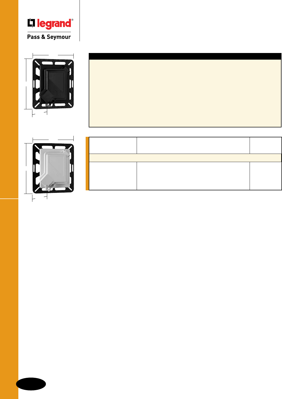
Flush Mount While-In-Use Covers
P-4
Weatherproof Boxes & Covers
Weatherproof Boxes & Covers
Flush Mount While-In-Use Covers
Features
nOne-pieceboxandcoverdesignprovidesfast,
easyinstallation.
nBoxservesasatemplateforarectangular
wallcut-out.
n28cubic-inchboxprovidesamplespaceforGFCIs;
makeswiringeasy.
nAcceptsstandardTPwallplatesanddevicesfor
virtuallyanyapplication.
nOnecatalogstyleinstallseasilyinmostexterior
walltypes.
nMountingflangefeatureslargeopenareas,
cross-hatching,andtaperededgestoenhance
stuccoadherenceandmounting.
nCornerhingeforeitherverticalorhorizontal
mountingwithoutfieldmodifications.
nEasy-opening,one-fingerlatch.
nFactoryinstalledcord-openinggaskettokeep
waterandinsectsout.
nAutoclampsandstandardknock-outssimplify
installation.
nNocaulkingorgasketassemblyrequired.
nReplaceablecoverandframeassemblydoes
notrequiredisruptionofsidingmaterials.
6.25"
8.0"
5.25"
WIUFC10S
6.25"
8.0"
5.25"
WIUFC10W
Catalog Number Description Color
Single Gang
WIUFC10S While-in-usecoverandboxassembly Smoke
WIUFC10SQC While-in-usecoverandboxassemblywithQuick/Click® Smoke
WIUFC10W While-in-usecoverandboxassembly White
WIUFC10WQC While-in-usecoverandboxassemblywithQuick/Click® White
FordescriptionofQuick/Click®feature,seePageN-19.
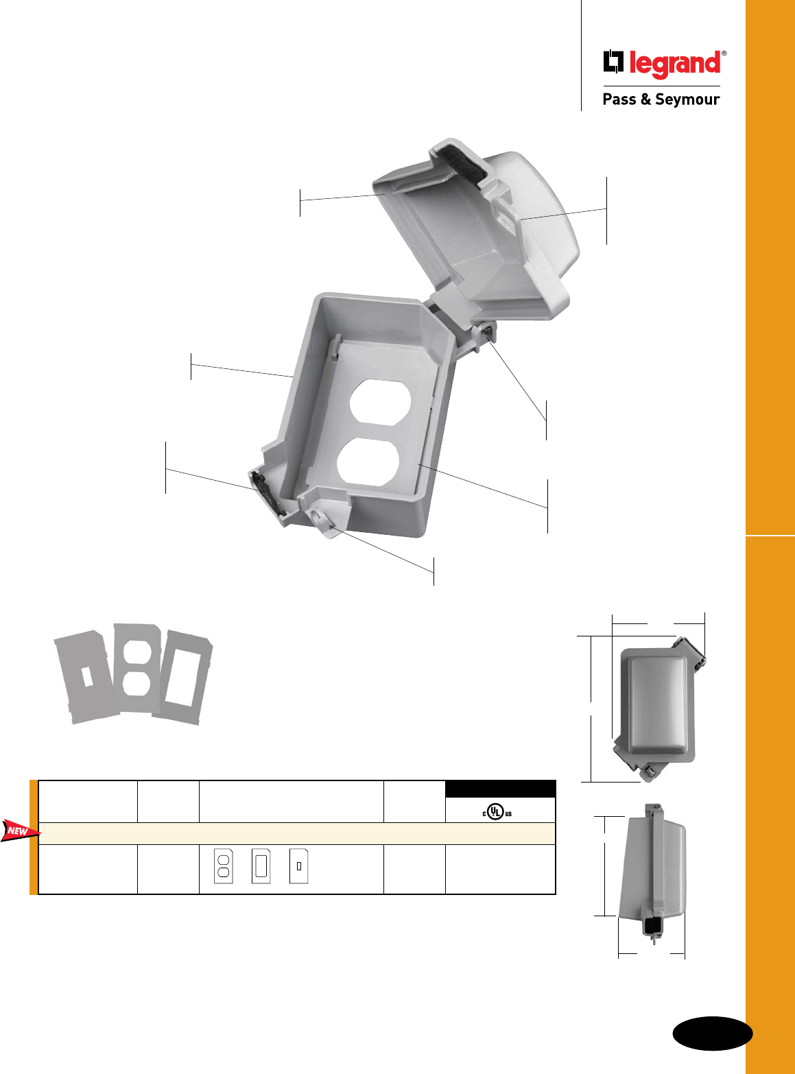
P-5
Cast While-In-Use CoversWeatherproof Boxes & Covers
Weatherproof Boxes & Covers
Cast While-In-Use Covers
WIUCAST1
4.875"
3.1875"
Stainless steel screws, and
three metal mounting plates
are supplied.
3rd Party Compliance
Catalog Package
Number Color Device Plates Provided Quantity
Single Gang
WIUCAST1 Gray 12 •
WIUCAST1
All components baked-on electrostatic,
polyester, powder paint coated prior to
assembly for superior corrosion resistance.
Stainless steel springs
resist corrosion.
Accepts a standard
sized padlock.
Meets NEC Section 406.8(B)(1)
suitable for wet locations.
Self-closing lids as
required by UL514C42.3.
Exclusive cord flap
gasket inhibits water
splash from driving
rain or sprinklers. Preapplied gasket
easier to install, saves
time, won’t get lost or
damaged.
Patented trigger
latch opens easily
with one finger,
yet is lockable to
prevent tampering.
Heavy-duty
die-cast zinc.
Patented corner hinge and
cord opening allow vertical
or horizontal installation.
7.5"
4.625"
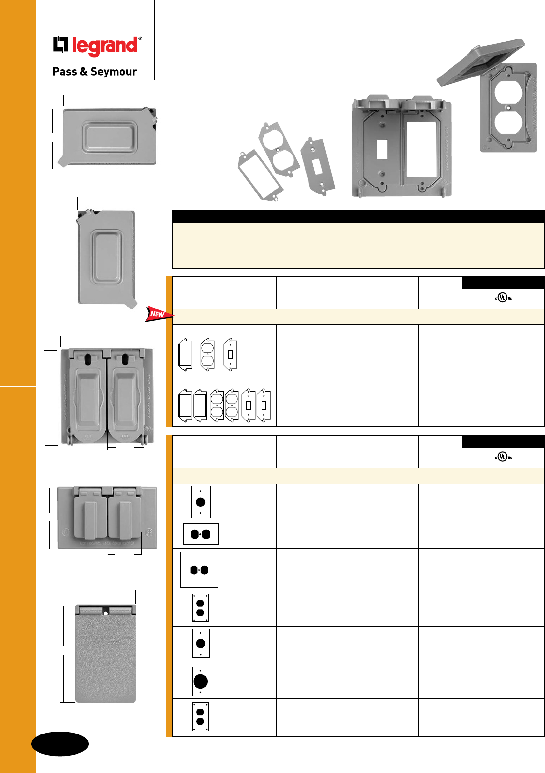
P-6
Weatherproof Boxes & CoversCast Weatherproof Covers
Weatherproof Boxes & Covers
Cast Weatherproof Covers
Horizontal
2 Self-Closing Lids
1.50"
4.57"
2.90"
Vertical
1 Self-Closing Lid
2.81"
4.56"
Features
nFeaturingoneandtwoganguniversalcovers.
nBroadlineofonegangcoversforreceptacles
andpoweroutlets.
nHeavy-dutydie-castzinc.Stainlesssteelsprings.
nBaked-onelectrostatic,polyester,powderpaint
forsuperiorscratchandcorrosionresistance.
nCoverscomplywithNECSection406.8(A)and
406.8(B)(2).
Catalog Number Description Color
One Gang
CA7GV SingleReceptacle Gray
Vertical–1Self-ClosingLid
CA8GH DuplexReceptacle Gray •
CA8WH Horizontal–2Self-ClosingLids White
CA8GJ OversizedDuplexReceptacle Gray •
Horizontal–2Self-ClosingLids
Dimensions:H-4.52",L-4.58"
CA8GVFS DuplexReceptacle Gray
CA8WV Vertical–1Self-ClosingLid White
5ScrewMounting
CA721G PowerOutlet–1.625Diameter Gray •
Vertical–1Self-ClosingLid
CA723G PowerOutlet–2.125Diameter Gray
Vertical–1Self-ClosingLid
CA8WVFS DuplexReceptacle
Vertical–1Self-ClosingLid White •
4ScrewMounting
3rd Party Compliance
CA1U2681G
Horizontal
4.50"
2.75"
CA2U2681G
1.75"
4.60"
4.60"
Catalog Number Description Color
Universal Cast Weatherproof Covers
CA1U2681G OneGangCoverwithMetalDevice Gray •
Platesfor#26,#8and#1Openings
(OneEach)
CA2U2681G TwoGangCoverwithMetalDevice Gray •
Platesfor#26,#8and#1Openings
(TwoEach)
3rd Party Compliance
2.75"
4.50"
CA1U2681G
Vertical
Universal Cast Weatherproof Covers
can serve six applications with
a combination of inserts and
one gang horizontal or vertical
mounting.
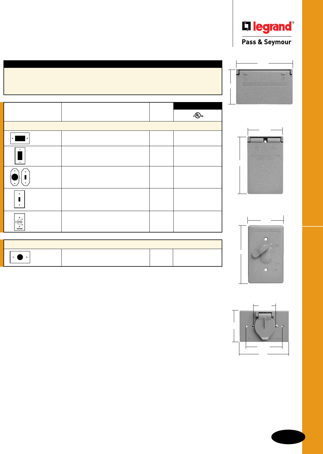
P-7
Cast Weatherproof CoversWeatherproof Boxes & Covers
Weatherproof Boxes & Covers
Cast Weatherproof Covers
Self-Closing Cover – Motor Base – Horizontal
3778 Singlewith15A125V Gray •
RecessedFlangedInlet.
Vertical
1 Self-Closing Lid
4.56"
2.81"
Horizontal
1 Self-Closing Lid
2.80"
4.56"
3778
4.5"
3.247"
1.850"
2.750"
CA1GL
2.80"
4.5"
Features
nBroadlineofsinglegangcoversforswitches
andGFCIs.
nBaked-onelectrostatic,polyester,powderpaint
forsuperiorscratchandcorrosionresistance.
nHeavy-dutydie-castzinc.
nStainlesssteelsprings.
nCoverscomplywithNECSection406.8(A)
and406.8(B)(2).
Catalog Number Description Color
One Gang
CA26GH DecoratororGFCI Gray •
CA26WH Horizontal–1Self-ClosingLid White
CA26GV DecoratororGFCI Gray •
CA26WV Vertical–1Self-ClosingLid White
CA1G Vertical–1Self-ClosingLidwithInserts Gray •
AccommodatesToggleSwitch+
1.750PowerOutlet
CA1GS Togglewith15A120VAC Gray •
SinglePoleToggleSwitch(Cat.#660)
IncludedVertical–1Self-ClosingLid
CA1GL ToggleSwitchCover–withActuating Gray •
Lever– MountsDirectlyOverSwitch
3rd Party Compliance
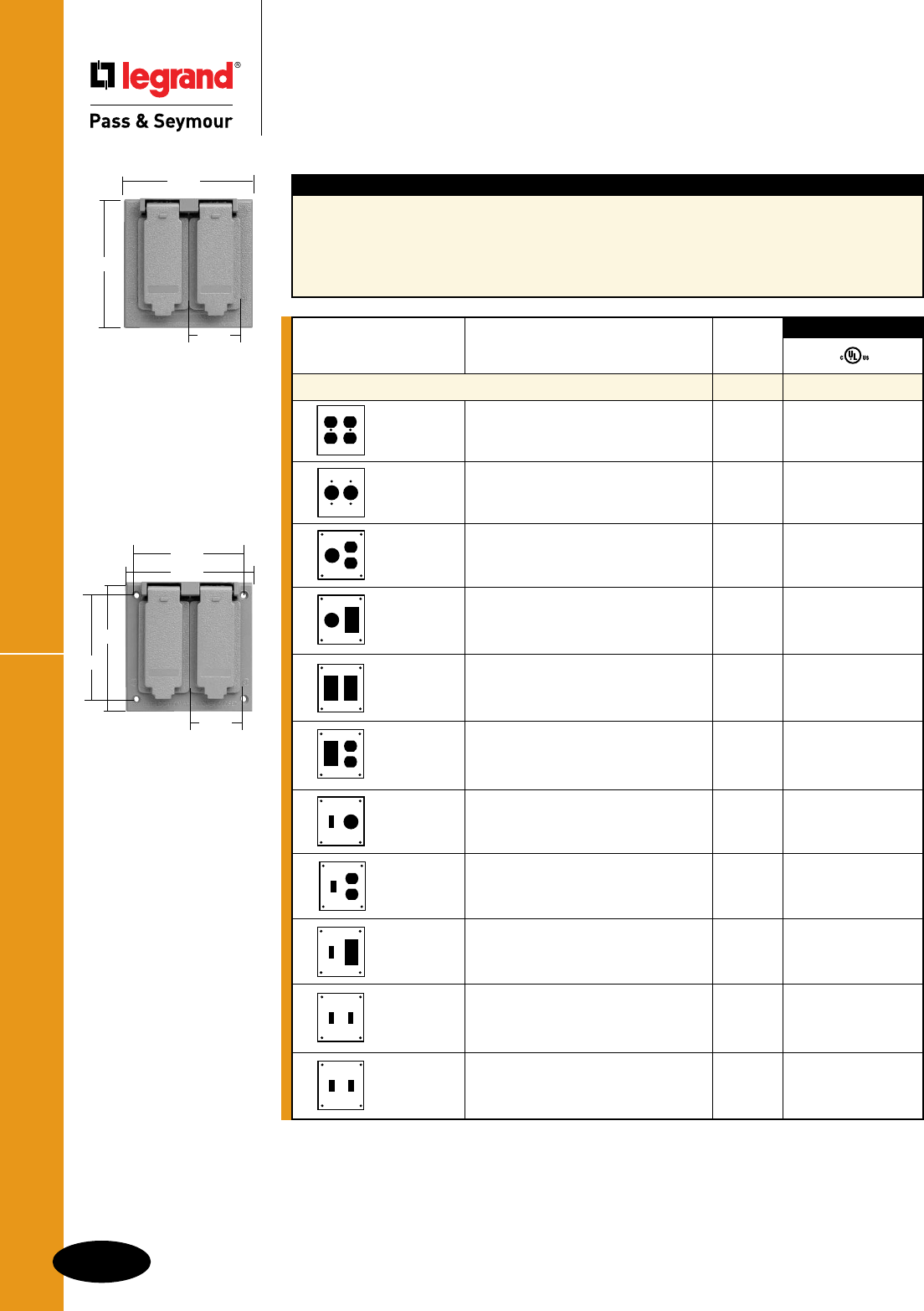
Cast Weatherproof Covers
P-8
Weatherproof Boxes & Covers
Weatherproof Boxes & Covers
Cast Weatherproof Covers
Two Gang Cover
1.78"
4.58"
4.52"
Two Gang Cover
4 Screw Mounting
1.78"
4.58"
3.75"
4.52"
3.25"
Features
nBroadlineoftwogangcoversforswitches,
receptacles,GFCIs,andpoweroutlets.
nBaked-onelectrostatic,polyester,powderpaint
forsuperiorscratchandcorrosionresistance.
nHeavy-dutydie-castzinc.
nStainlesssteelsprings.
nAllcovershave2self-closinglids.
nCoverscomplywithNECSection406.8(A)
and406.8(B)(2).
Catalog Number Description Color
Two Gang
CA82G 2DuplexReceptacles Gray •
CA82W White
CA72G 2SingleReceptacles Gray •
CA78G 1Single/1Duplex Gray •
4ScrewMounting
CA726G 1Single/1Decorator Gray •
4ScrewMounting
CA262G 2Decorator Gray •
4ScrewMounting
CA268G 1Decorator/1Duplex Gray •
4ScrewMounting
CA17G 1Toggle/1Single Gray •
4ScrewMounting
CA18G 1Toggle/1Duplex Gray •
4ScrewMounting
CA126GRY 1Toggle/1Decorator Gray •
4ScrewMounting
CA2G 2Toggles Gray •
CA2W 4ScrewMounting White
CA2GS 2Toggleswith215A120VAC Gray
SinglePoleToggleSwitches(Cat.#660) •
Included4ScrewMounting
3rd Party Compliance
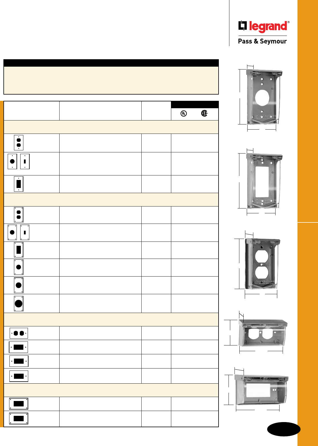
Thermoplastic CoversWeatherproof Boxes & Covers
Weatherproof Boxes & Covers
Thermoplastic Covers
3720FS
3"
4.938"
1.125"
3723FS
3"
4.938"
1.125"
3700
4.75"
2.813"
1.686"
3710
3"
4.938"
1.125"
3703
4.750"
2.813"
1.688"
Features
nBroadlineofsinglegangcoversforswitches,
receptacles,GFCIsandpoweroutlets.
nClearpolycarbonatelidwithreinforced
thermoplasticbase.
nCoverscomplywithNECSection406.8(A)
and406.8(B)(2).
P-9
3rd Party Compliance
Gasket
Catalog Number Description Thickness
Self-Closing Covers – Clear Polycarbonate Lid
Vertical Two Screw Mounting – Padlockable
3710 DuplexRVuse 3/8" ••
GrayBase/ClearCover
3710WH WhiteBase/WhiteCover
3720 SingleReceptacle1.40"Diameteror 3/8" ••
ToggleSwitch(ToggleSwitchInsert
Included),GrayBase/ClearCover
3720WH WhiteBase/WhiteCover
3723 DecoratorRVuse 3/8" ••
GrayBase/ClearCover
3723WH WhiteBase/WhiteCover
Self-Closing Covers – Clear Polycarbonate Lid
Vertical Four Screw Mounting – Padlockable
3710FS DuplexReceptacle 3/32" ••
GrayBase
3720FS SingleReceptacle1.40"Diameteror 3/32" ••
ToggleSwitch(ToggleSwitchInsert
Included),GrayBase
3723FS DecoratororGFCI 3/32" ••
GrayBase
3722FS PowerOutlet,1.60"Diameter 3/32" ••
GrayBase
3724FS PowerOutlet,1.73"Diameter 3/32" ••
GrayBase
3795 PowerOutlet,2.13"Diameter 3/8" ••
GrayBase
Self-Closing Covers – Clear Polycarbonate Lid
Horizontal Two Screw Mounting
3700 DuplexReceptacle 3/32" ••
GrayBase
3703 Decorator 3/32" ••
GrayBase
3703T DecoratorRVUse 3/8" ••
GrayBase
3703TCW DecoratorRVUse 3/8" ••
ColonialWhiteBase
Self-Closing Covers – Clear Polycarbonate Lid
Horizontal Four Screw Mounting
3700FS DuplexReceptacle 3/32" ••
GrayBase
3703FS DecoratorReceptacle 3/32" ••
GrayBase
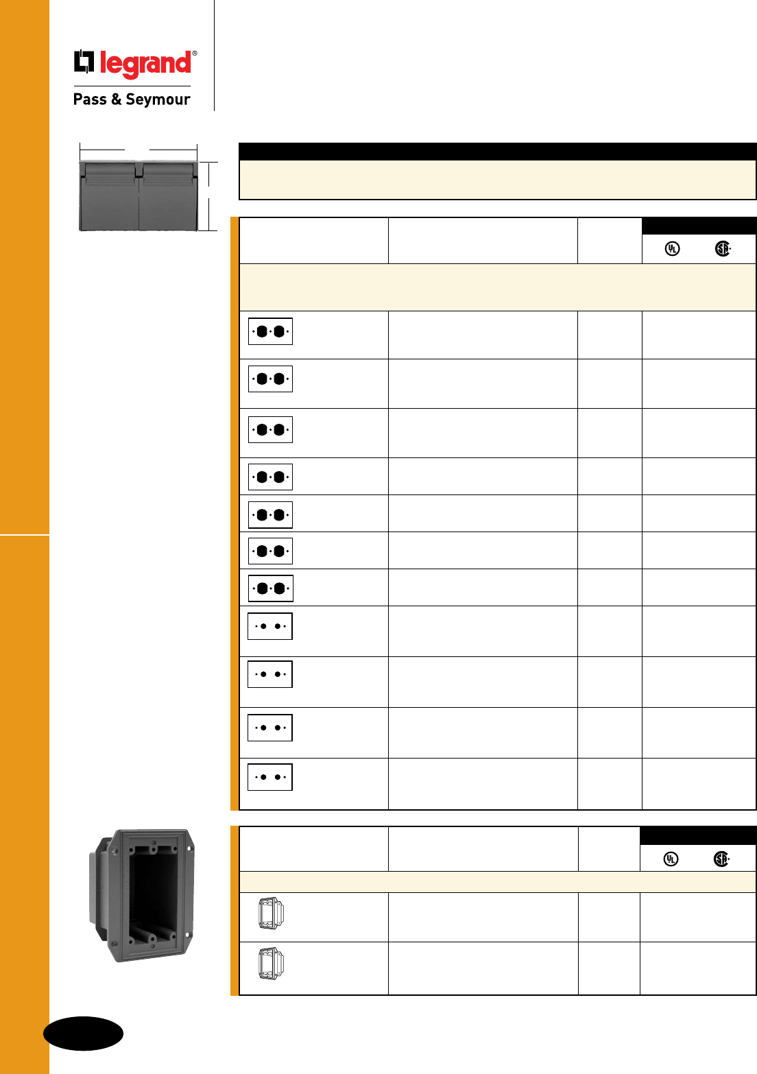
Thermoplastic Covers
P-10
Weatherproof Boxes & Covers
Weatherproof Boxes & Covers
Thermoplastic Covers
FBOX1
3780 Series
4.68"
2.8"
Gasket
Catalog Number Description Thickness
Outdoor Assemblies and Special Covers For Mobile Homes,
Manufactured and Modular Housing, and RV Use –
Horizontal Installation with Two Self-Closing Flip Lids
3780SCFBX 3232DuplexReceptacle, 1/8" •
GasketandFlangedBox,
GraywithBlackGasket
3780SCFBXCW 3232DuplexReceptacle, 1/8" •
GasketandFlangedBox,
ColonialWhitewithBlackGasket
3780SCFBXWH 3232DuplexReceptacle, 1/8" •
GasketandFlangedBox,
WhitewithBlackGasket
3780SCMH 3232DuplexReceptacle&Gasket, 3/8" •
GraywithBlackGasket
3780SCMHCW 3232DuplexReceptacle&Gasket, 3/8" •
ColonialWhitewithBlackGasket
3780SCMHBG 3232DuplexReceptacle&Gasket, 3/8" •
BeigewithBlackGasket
3780SCMHWH 3232DuplexReceptacle&Gasket, 3/8" •
WhitewithBlackGasket
3780SCLV 3/8"RoundOpeningsfor 1/8" ••
2CoaxialConnections,
GraywithBlackGasket
3780SCLVBG 3/8"RoundOpeningsfor 1/8" ••
2CoaxialConnections,
BeigewithBlackGasket
3780SCLVCW 3/8"RoundOpeningsfor 1/8" ••
2CoaxialConnections,
ColonialWhitewithBlackGasket
3780SCLVWH 3/8"RoundOpeningsfor 1/8" ••
2CoaxialConnections,
WhitewithBlackGasket
3rd Party Compliance
Features
nBroadestlineintheindustry.
n Allcoversareself-closingwithtwofliplids.
nCoverscomplywithNECSection406.8(A)
and406.8(B)(2).
Catalog Number Description Color
Flanged Boxes for Horizontal or Vertical Installation
FBOX1 FlangedBox–18.5CubicInch Gray •
MinimumOpeningSize2.5"x4.1"
Depth3.0"
FBOX1WH FlangedBox–18.5CubicInch White •
MinimumOpeningSize2.5"x4.1"
Depth3.0"
3rd Party Compliance
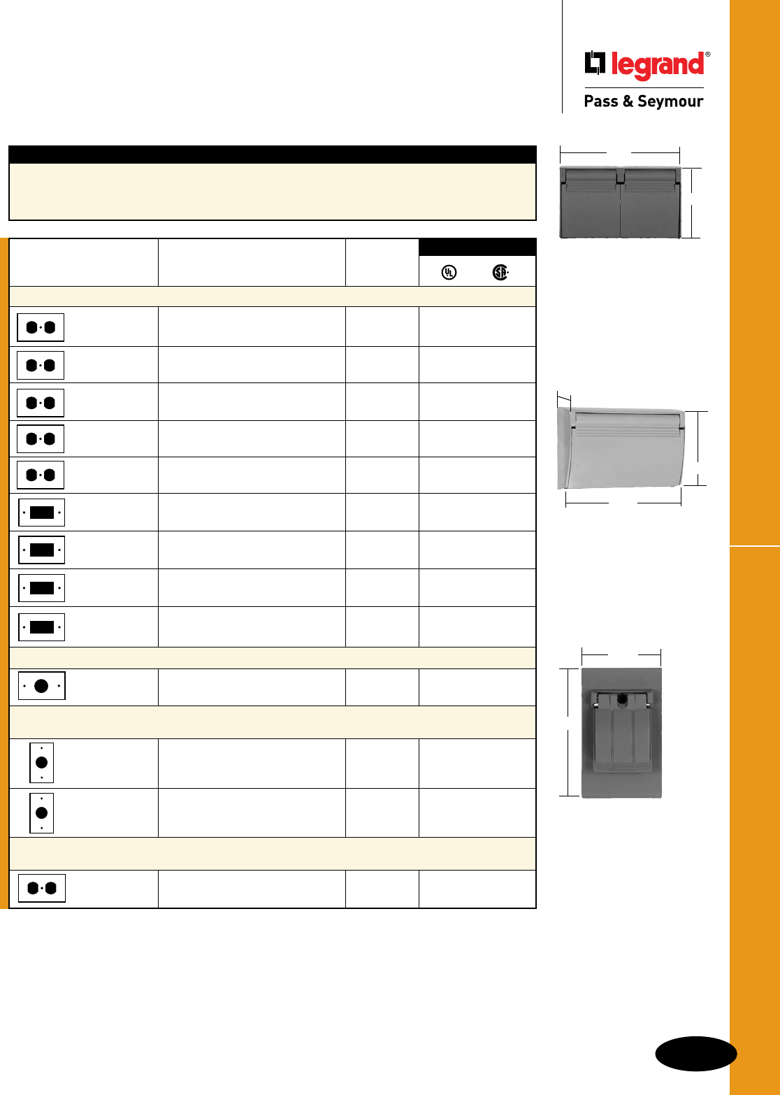
P-11
Thermoplastic Covers
Weatherproof Boxes & Covers
Weatherproof Boxes & Covers
Thermoplastic Covers
3780 Series
4.68"
2.8"
3726 Series
2.875"
4.688"
.945"
3760
2.785"
4.5"
Features
nBroadestlineintheindustry.
nCoverscomplywithNECSection406.8(A)
and406.8(B)(2).
n3780serieshavetwofliplids.
n3726serieshaveasinglefliplid.
Gasket
Catalog Number Description Thickness
Horizontal Self-Closing Flip Lids
3780SC Duplex,GraywithBlackGasket 1/8" ••
3780SCCW Duplex,ColonialWhitewith 1/8" ••
BlackGasket
3780SCWH Duplex,WhitewithBlackGasket 1/8" ••
3780SCBG Duplex,BeigewithBlackGasket 1/8" ••
3780SCCWT Duplex,ColonialWhitewith 3/8" ••
BlackGasket
3726SC DecoratororGFCI,Graywith 3/32" ••
BlackGasket
3726SCBG DecoratororGFCI,Beigewith 3/32" ••
BlackGasket
3726SCCW DecoratororGFCI,ColonialWhite 3/32" ••
withBlackGasket
3726SCWH DecoratororGFCI,White 3/32" ••
withBlackGasket
Horizontal Single Cover Self-Closing Flip-Lid
3770SC SingleReceptacle1.405"Diameter, 3/32" ••
Gray
Vertical Single Cover Three Position Flip-Lid
(Closed, Opened 90° or Opened 180°)
3760 SingleReceptacle 3/32" ••
1.563"Diameter,Gray
3763 Coverwith5251-ISingle 3/32" •
Receptacle,15A-125V,Gray
Horizontal Reinforced Thermoplastic Two Position Flip-Lids,
(Closed or Opened 90°)
3780 Duplex,GraywithBlackGasket, 1/8" ••
2FlipLids
3rd Party Compliance
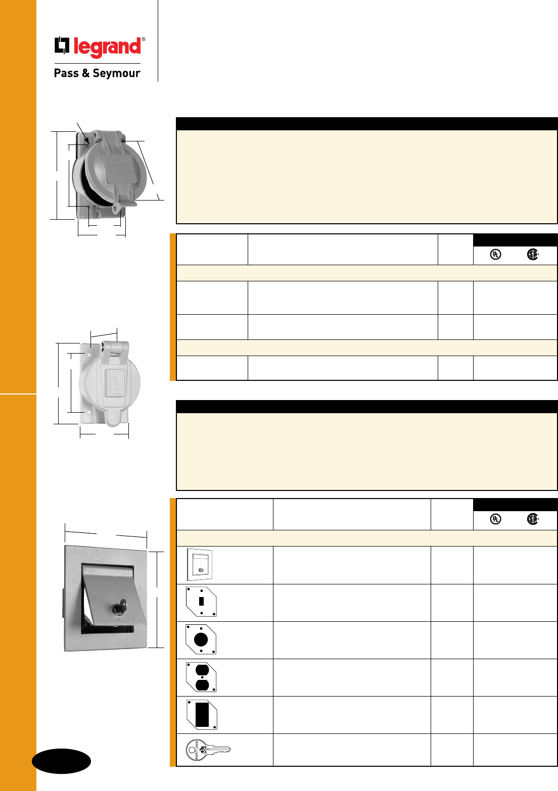
Thermoplastic/Heavy Cast Aluminum Covers
P-12
Weatherproof Boxes & Covers
Weatherproof Boxes & Covers
Thermoplastic/
Heavy Cast Aluminum Covers
Specification Grade
Industrial Grade Weatherproof Covers
WPG1
4.57"
3.25"
.19"
(4HOLES)
2.85"
1.88"
3.57"
4600
7.19"
6.59"
Features
nUnbreakableglass-filledpolycarbonate
constructiontowithstandyearsofjobsiteabuse
andharshenvironmentalexposure.Stainlesssteel
mountingscrewsalsoresistcorrosion.
nCoverscomplywithNECSection406.8(A)
and406.8(B)(2).
nMolded-inlabelarea(2.8sq.in.)forpre-printed
orhandwrittenlabelsforidentificationofcircuits,
ratings,andotherapplicationdata.
nWPG1andWPG2havelockable“bullnose”
forOSHAlocktag/tagoutcompliance.
nCoversfitallcompetitiveinletsandoutlets.
nPre-attachedgasketsforeasyinstallation
andtightsealtopanelorweatherproofbox–
withnomisalignedorcollapsedgaskets.
nTamper-proofhingefeaturespermanent,
locked-inpinsforaddedsecurity.
Features
nAdapter,frame,andcoverareheavy
castaluminum.
nNo.8-32screwsholdassemblyfirmlyinplace.
nCoverscomplywithNECSection406.8(A)
and406.8(B)(2).
nMortarkeysprovidepositiveholdingmeans
withinwall.
nNeoprenegasketsealscovertoframe.
Moistureanddustcannotenterenclosure.
nTwokeysprovidedforlock.
nPurchaseenclosureandmountingplate
separately
nMountson4"or4-11/16"box.
7770
3.00"
3.281"
4.60"
2.35"
Catalog Number Description Color
Thermoplastic Weatherproof Covers for Flanged Inlet/Outlet
WPG1 1.96"DiameterOpeningtoAccommodate Gray ••
15/20AStraightBlade,15ATurnlok,20403
PowerInterrupter
WPG2 2.32"DiameterOpeningtoAccommodate Gray ••
20ATurnlok,30ATurnlok
Thermoplastic Weatherproof Cover for Single Receptacles
7770 2.38"DiameterOpeningtoAccommodate Yellow •
50ATurnlok(non-lockout)
3rd Party Compliance
Heavy Cast Aluminum Covers – Flush Enclosures
Catalog Number Description Color
Mortared-in Applications
4600 EnclosureOnly,withoutMountingPlate Gray ••
46001P MountingPlateforToggleSwitch Gray ••
46007P MountingPlateforSingleReceptacle Gray ••
Diameter:2.156"
46008P MountingPlateforDuplexReceptacle Gray ••
460026P MountingPlateforDecorator/GFCI Gray ••
4609 ReplacementKeyforEnclosure ••
3rd Party Compliance
Note: All locks
keyed the same.
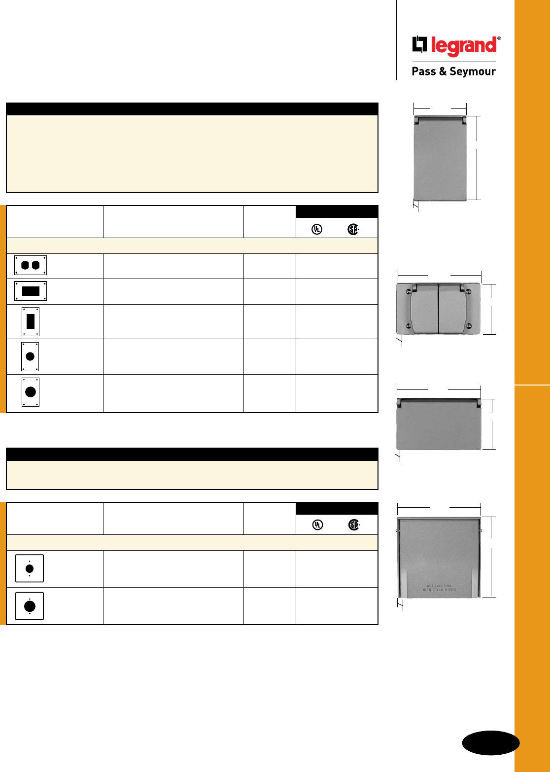
P-13
Heavy Cast Aluminum CoversWeatherproof Boxes & Covers
Weatherproof Boxes & Covers
Heavy Cast Aluminum Covers
Specification Grade
Features
nExtremelydurableforhard-useinstitutional
applications.
nSpring-loadedcoverscloseautomaticallywhen
plugsareremoved.
nDie-castcopper-freealuminumconstruction.
nStainlesssteelsprings.
nScrewsandspringcoversarechrome-platedbrass.
nBaked-onlacquerfinish.
nHeavyrubbergasketsprovidepositiveseal.
nAllcoversbelowarefor4screwmountingonly.
nComplywithNECSection406.8(A)and
406.8(B)(2).
4512
7420
3393
2.813"
4.563"
.75"
4510
4.563"
2.813"
.75"
4511
4.56"
2.81"
.75"
3796
3797
4.56"
4.5"
1.20"
Catalog Number
Description
Color
Heavy Cast Aluminum Covers – One Gang
4510 DuplexReceptacle,2Doors Gray ••
Horizontal
4511 Decorator/GFCI Gray ••
Horizontal
4512 Decorator/GFCI Gray ••
Vertical
7420 1GangPowerOutlet Gray ••
1.593"max.Diameter
Vertical
3393 1GangPowerOutlet Gray ••
1.750"max.Diameter
Vertical
3rd Party Compliance
Catalog Number Description Color
Multigang Covers – Outdoor
3796 2GangPowerOutlet Gray ••
(2.156"DiameterOpening)
3797 2GangPowerOutlet Gray ••
(2.656"DiameterOpening)
3rd Party Compliance
Features
nHeavy-dutydiecastaluminumcoversandplate.
n3/32"gasketincluded.
nStainlesssteelmountingscrews.

Weatherproof Stainless Steel Covers
P-14
Weatherproof Boxes & Covers
Weatherproof Boxes & Covers
Weatherproof Stainless Steel Covers
Specification Grade
WP13
4.633" 3.281"
2.875" Features
nCoverscomplywithNECSection406.8(A)
and406.8(B)(2).
nPlateisType302StainlessSteelforcorrosionresistance.
nIdealforhard-useandcorrosive
applications.
nAestheticallypleasing.
Catalog Number Description
Stainless Steel Covers
WP13 1GangBlank(BoxMounted) ••
Gasketed
WP13FS For4ScrewMounting ••
WP23 2GangBlank(BoxMounted) ••
Gasketed
3rd Party Compliance
Features
nCoverscomplywithNECSection406.8(A)
and406.8(B)(2).
nPlateisType302StainlessSteelforcorrosionresistance.
nTransparentsiliconerubbermatsealsplateandopening
fromcontamination.
nSwitcheasilyactuatedthroughflexiblesiliconebubble.
nSiliconematmaintainspliabilityfrom
-100°Fto+250°F.
nMatisresistanttogrease,water,
steam,detergents,aging,andozone.
Mat
Catalog Catalog
Number
Number
Description
Stainless Steel Covers
45154515GAS Roundmat,mountstoStandardSwitchBox • •
4515FS4515FSGAS Roundmat,4ScrewBoxmounting ••
4516 Rectangularmat,mountstoStandardSwitchBox ••
4516GAS* (includes#348strapforDespardswitches)
4517 Rectangularmat,4ScrewBoxmounting ••
3rd Party Compliance
*Forusewithboth4516and4517.
4515
4.50"
2.75"
2.375"
1.375"
4515FS
4.50"
3.255"
2.750"
1.867"
4516
4.50"
3.812"
2.750"
1.375"
4517
4.50"
2.750"
1.872"
3.255"
For Dustproof Stainless Steel Covers, see Page Q-28.
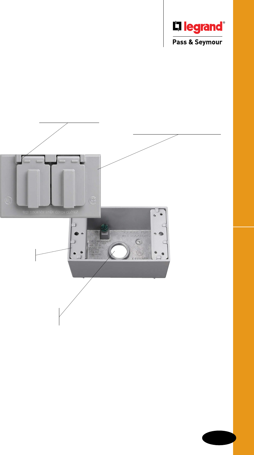
P-15
Weatherproof Boxes & Covers
Cast Weatherproof Boxes & Covers
Product assembled after
painting for complete
corrosion resistance.
No rough edges.
Boxes available in 1, 2 & 3 gang.
Available in
standard and deep
configurations.
Available in gray, white
and bronze.
Available in 1/2" and
3/4" hub sizes, from 3 to 6
hole configurations.
UL Listed, for wet
and/or damp locations
with appropriate cover.
Stainless steel springs. Baked-on electrostatic, polyester,
powder paint, for superior scratch-
and corrosion-resistant finish.
CA8GH
WPB23
Covers available in
1 & 2 gang in a variety
of configurations.
Heavy die-cast
aluminum.

Weatherproof Boxes
P-16
Weatherproof Boxes & Covers
Weatherproof Boxes & Covers
Weatherproof Boxes
Single Gang Box
4.63"
2.09" 2.86" Features
nWiderangeofsizes,depths,andgangs.
nBaked-onelectrostatic,polyester,powderpaint
forsuperiorscratchandcorrosionresistance.
n2closureplugsandmountinglugsfurnished
withallboxes.
nULListedforwetand/ordamplocationswith
appropriatecover.
nDesignedforbothinteriorandexterior
applications.
nWillacceptstandard4screwmountingcovers
andsinglegangweatherproofcovers.
nSimplystrikedesiredknockoutstudswitha
sharphammerblowforcleanmountingholes.
nHeavydie-castaluminum.
Catalog Number Description Color
Single Gang Boxes
WPB23 3Hole1/2",18.5Cu.In. Gray ••
WPB23W (1HoleEachEnd,1HoleinBack) White
WPB33 3Hole3/4",18.5Cu.In. Gray ••
WPB33W (1HoleEachEnd,1HoleinBack) White
WPB24 4Hole1/2",18.0Cu.In. Gray ••
WPB24W (2HolesOneEnd,1HoleOtherEnd, White
WPB34 4Hole3/4",18.0Cu.In. Gray ••
WPB34W (2HolesOneEnd,1HoleOtherEnd, White
WPB25 5Hole1/2",17.0Cu.In. Gray ••
WPB25W (2HolesEachEnd,1HoleinBack) White
WPB35 5Hole3/4",17.0Cu.In. Gray ••
(2HolesEachEnd,1HoleinBack)
WPB26 5Hole1/2",17.0Cu.In. Gray ••
WPB26W (1HoleEachEnd,1HoleEachSide, White
WPB36 5Hole3/4",16.8Cu.In. Gray ••
(1HoleEachEnd,1HoleEachSide,
1HoleinBack)
3rd Party Compliance
Catalog Number Description
Weatherproof Locking Inlet Kit for Generator Applications
L1430FIKIT Kitincludes30ALockingGrayFlangedInletL1430FI,WeatherproofCoverWPG2,
andWeatherproofBoxWPB33with3/4"knockoutholes.
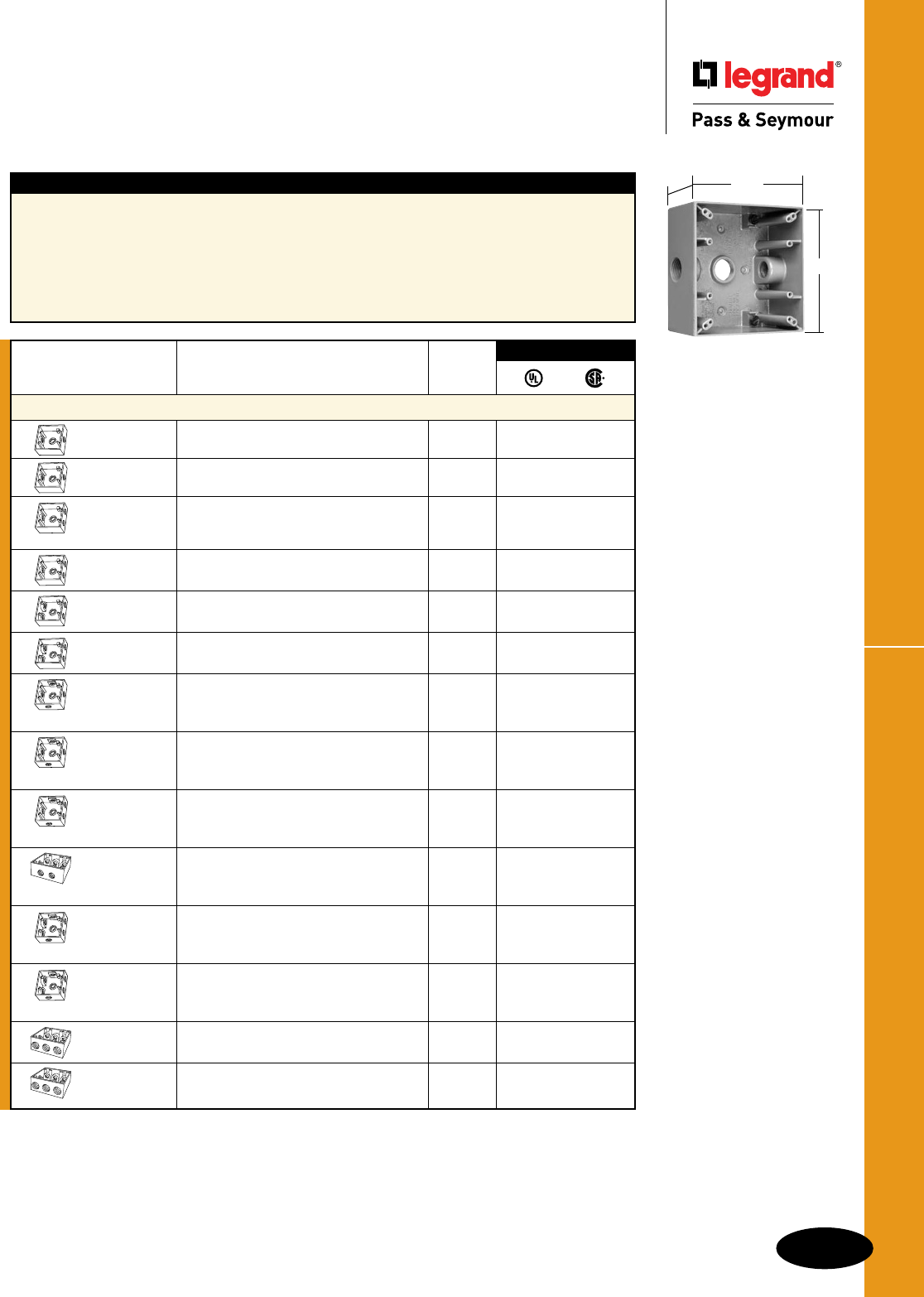
P-17
Weatherproof BoxesWeatherproof Boxes & Covers
Weatherproof Boxes & Covers
Weatherproof Boxes
Two Gang Box
4.50"
2.24" 4.50"
Features
nWiderangeofsizes,depths,andgangs.
nBaked-onelectrostatic,polyester,powderpaint
forsuperiorscratchandcorrosionresistance.
n2closureplugsandmountinglugsfurnished
withallboxes.
nULListedforwetand/ordamplocations
withappropriatecover.
nDesignedforbothinteriorandexteriorapplications.
nWillacceptstandardtwogangweatherproofcovers.
nSimplystrikedesiredknockoutstudswitha
sharphammerblowforcleanmountingholes.
nHeavydie-castaluminum.
Catalog Number Description Color
Two Gang Boxes
WPB232 2Gang–3Hole1/2",30.5Cu.In. Gray ••
WPB232W (1HoleEachEnd,1HoleinBack) White
WPB332 2Gang–3Hole3/4",30.5Cu.In. Gray ••
(1HoleEachEnd,1HoleinBack)
WPB242 2Gang–4Hole1/2",30.5Cu.In. Gray ••
(2HolesOneEnd,1HoleOtherEnd,
1HoleinBack)
WPB342 2Gang–4Hole3/4",30.5Cu.In. Gray ••
WPB342W (2HolesOneEnd,1HoleOtherEnd, White
WPB252 2Gang–5Hole1/2",30.5Cu.In. Gray ••
(2HolesEachEnd,1HoleinBack)
WPB352 2Gang–5Hole3/4",30.5Cu.In. Gray ••
(2HolesEachEnd,1HoleinBack)
WPB262 2Gang–5Hole1/2",30.5Cu.In. Gray ••
(1HoleEachEnd,1HoleEachSide,
1HoleinBack)
WPB362 2Gang–5Hole3/4",30.5Cu.In. Gray ••
(1HoleEachEnd,1HoleEachSide,
1HoleinBack)
WPB272 2Gang–6Hole1/2",30.5Cu.In. Gray ••
(2HolesOneEnd,1HoleOtherEnd,
1HoleEachSide,1HoleinBack)
WPB276 2Gang–6Hole1/2",30.5Cu.In. Gray ••
(3HolesOneSide,2HolesOtherSide,
1HoleinBack)
WPB282 2Gang–7Hole1/2",30.5Cu.In. Gray ••
(2HolesEachEnd,1HoleEachSide,
1HoleinBack)
WPB382 2Gang–7Hole3/4",30.5Cu.In. Gray ••
(2HolesEachEnd,1HoleEachSide,
1HoleinBack)
WPB287 2Gang–7Hole1/2",30.5Cu.In. Gray ••
(3HolesEachSide,1HoleinBack)
WPB387 2Gang–7Hole3/4",30.5Cu.In. Gray ••
(3HolesinEachSide,1HoleinBack)
3rd Party Compliance

Weatherproof Boxes
P-18
Weatherproof Boxes & Covers
Weatherproof Boxes & Covers
Weatherproof Boxes
Three Gang Box
4.59"
6.438"
2.75"
1 Gang Deep Box
4.59"
2.82"
2.75"
1 Gang Deep Boxes
WPBD23 1GangDeep–3Hole1/2",23Cu.In. Gray ••
WPBD23BR withThreadedHoles Bronze
WPBD23W (1HoleEachSide,1HoleinBack) White
WPBD33 1GangDeep–3Hole3/4",23Cu.In. Gray ••
withThreadedHoles
(1HoleEachSide,1HoleinBack)
WPBD43 1GangDeep–3Hole1",23Cu.In. Gray••
withThreadedHoles
(1HoleEachSide,1HoleinBack)
2 Gang Deep Boxes
WPBD252 2GangDeep– 5Hole1/2",37Cu.In. Gray••
withThreadedHoles
(2HolesEachEnd,1HoleinBack)
WPBD352 2GangDeep–5Hole3/4",37Cu.In. Gray••
withThreadedHoles
(2HolesEachEnd,1HoleinBack)
WPBD452 2GangDeep–5Hole1",37Cu.In. Gray••
withThreadedHoles
(2HolesEachEnd,1HoleinBack)
Features
nWiderangeofsizes,depths,andgangs.
nBaked-onelectrostatic,polyester,powderpaint
forsuperiorscratchandcorrosionresistance.
n2closureplugsandmountinglugsfurnished
withallboxes.
nULListedforwetand/ordamplocationswith
appropriatecover.
nDesignedforbothinteriorandexterior
applications.
nSimplystrikedesiredknockoutstudswitha
sharphammerblowforcleanmountingholes.
nHeavydie-castaluminum.
Features
nBaked-onelectrostatic,polyester,powderpaint
forsuperiorscratchandcorrosionresistance.
n4closureplugsandmountinglugsfurnished
withallboxes.
nULListedforwetand/ordamplocationswith
appropriatecover.
nDesignedforbothinteriorandexteriorapplications.
nWillacceptstandardthree-gangweatherproof
covers.
nSimplystrikedesiredknockoutstudswitha
sharphammerblowforcleanmountingholes.
nHeavydie-castaluminum.
2 Gang Deep Box
4.5"
4.5"
2.72"
Catalog Number Description Color
Three Gang Box
WPB373 3Gang–7Hole3/4",59.8Cu.In. Gray ••
(3HolesEachSide,1HoleinBack)
3rd Party Compliance

P-19
Weatherproof Round Boxes & KitsWeatherproof Boxes & Covers
Weatherproof Boxes & Covers
Weatherproof Round Boxes &
Weatherproof Kits
WPRB25
Catalog Number Description Color
4" Round Die-Cast Aluminum Boxes
WPRB25 RoundCastBox–5Hole1/2", Gray ••
16.1Cu.In.,4PlugsFurnished
WPRB35 RoundCastBox–5Hole3/4" Gray ••
WPRB35W 16.1Cu.In.,4PlugsFurnished White
3rd Party Compliance
Features – 4" Round Die-Cast Aluminum Boxes
nBaked-onelectrostatic,polyester,powderpaint
forsuperiorscratchandcorrosionresistance.
n4closureplugsandmountinglugsfurnished
withallboxes.
nULListedforwetand/ordamplocationswith
appropriatecover.
nDesignedforbothinteriorandexterior
applications.
nHeavydie-castaluminum.
Catalog
Number Color Description Components
Weatherproof Kits
WPWIUKITC Clear WeatherproofWhile-in-Use 1595GRY,WPB23, •
SafetyOutlet(GFCI)Kitincludes WIUC10CL
WPWIUKITW White GFCI,box,andWhile-In-Usecover 1595W,WPB23W, •
WIUC10WL
WPWIUKITSC Clear WeatherproofShallowWhile-in-Use 1595GRY,WPB23, •
SafetyOutlet(GFCI)Kitincludes WIUC10SC
WPWIUKITSW White GFCI,box,andshallow 1595W,WPB23W, •
While-In-Usecover WIUC10SW
WPGFIKIT Gray WeatherproofSafetyOutlet 1595GRY,WPB23,
(GFCI)KitincludesGFCI, CA26GH •
WPGFIKITW White 1595W,WPB23W, •
CA26WH
WPOUTKIT Gray WeatherproofOutletKitincludes 3232I,WPB23,CA8GH •
WPOUTKITW White 3232W,WPB23W, •
CA8WH
WPFLDKIT Gray WeatherproofDualFloodlightKit WPRB25,(2)PAR1, •
includesbox,cover,and WPRB12
WPFLDKITW White WPRB25W,(2)PAR1W, •
WPRB12W
3rd Party
Compliance
WPWIUKITC
WPGFIKIT
WPOUTKIT
WPFLDKIT
Features
nEasy-to-install,self-containedkitsinclude
everythingneededforinstallation–gaskets,
plugs,andhardware.
nClam-shellpackagingdesignedforhanging
displays.
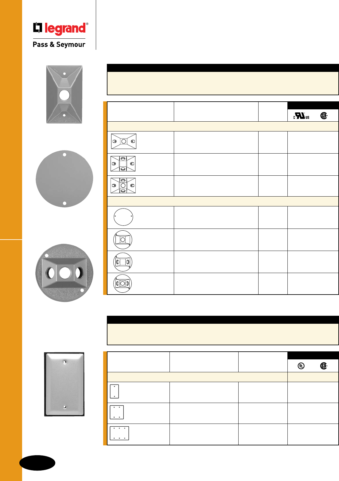
Cluster & Blank Covers
P-20
Weatherproof Boxes & Covers
Weatherproof Boxes & Covers
Cluster & Blank Covers
WPB11
WPRB1
WPRB13
Features
nWiderangeofrectangularandroundcovers.
nBaked-onelectrostatic,polyester,powderpaint
forsuperiorscratchandcorrosionresistance.
Catalog Number Description Color
Blank Covers
WPB1 1GangBlank BrushedAluminum ••
WPB1G AluminumCover Gray
WPB1W withGasketandScrews White
WPB2 2GangBlank BrushedAluminum ••
WPB2G AluminumCover Gray
WPB2W withGasketandScrews White
WPB3 3GangBlank BrushedAluminum ••
AluminumCover
withGasketandScrews
3rd Party Compliance
nKitsavailablecombiningfixtures,lampcovers,
andaccessories.
Catalog Number Description Color
Outdoor Lamp Cluster Covers for Single Gang Boxes
WPB11 RectangularSingleGangCover Gray ••
WPB11W 1Hole1/2" White
WPB12 RectangularSingleGangCover Gray ••
WPB12W 2Hole1/2",1PlugFurnished White
WPB13 RectangularSingleGangCover Gray ••
WPB13W 3Hole1/2",2PlugsFurnished White
4" Round Outdoor Cluster Covers
WPRB1 RoundBlankCover Gray •
WPRB1W withGasketandScrews White
WPRB11 RoundCover–1Hole1/2" Gray ••
WPRB11W withGasketandScrews White
WPRB12 RoundCover–2Hole1/2" Gray ••
WPRB12W withGasketandScrews White
1PlugFurnished
WPRB13 RoundCover–3Hole1/2" Gray ••
WPRB13W withGasketandScrews White
2PlugsFurnished
3rd Party Compliance
Features
nDesignedforbothinteriorandexteriorapplications.
nUniversalaluminummountingplates.
nGray,bronzeandwhitemodelshavebaked-
onelectrostatic,polyester,powderpaintfor
superiorscratchandcorrosionresistance.
WPB1
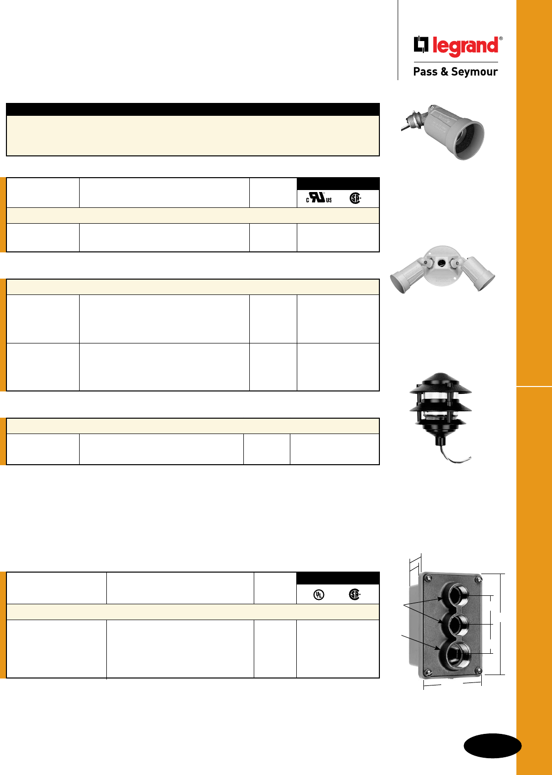
P-21
Lighting AccessoriesWeatherproof Boxes & Covers
Weatherproof Boxes & Covers
Lighting Accessories &
Swimming Pool Junction Box
PAR1
WPLKIT2
GARD3BK
Outdoor Lampholder Kits
WPLKIT1 Kitincludes(1)WPRB13and Gray •
(2)PAR1Lampholders
WPLKIT2 Kitincludes(1)WPRB13Wand White •
(2)PAR1WLampholders
WPLKIT3 Kitincludes(1)WPB13and Gray •
(2)PAR1Lampholders
WPLKIT4 Kitincludes(1)WPB13Wand White •
(2)PAR1WLampholders
Outdoor Garden Lamps & Accessories
GARD3GR 3TierGardenLamp Green ••
GARD3BK 3TierGardenLamp Black ••
Features
nMediumbaseheatresistant.
nFits1/2"threadedoutlet.
nSealgasketincluded.
nAdjustablethrough180°.
nCompleterangeoflampcoversingrayandwhite.
nCorrosion-resistantfinish.
Catalog Number Description Color
Die-Cast Outdoor Lampholder
PAR1 OutdoorLampholder Gray •
PAR1W OutdoorLampholder White •
3rd Party Compliance
WPBJ22
5.438"
3.625"
2.563"
3.250"
1.5"
1.5"
.75"
NPT
1"
NPT
Catalog Number Description Color
Swimming Pool Junction Box
WPBJ22 22cu.in.ThermoplasticBase, Gray ••
BrassCover.MeetsNEC®Article680.
Two3/4"Hubs,one1"Hub.
FourGroundPosts,Gasket,and
MountingScrewsIncluded.
3rd Party Compliance
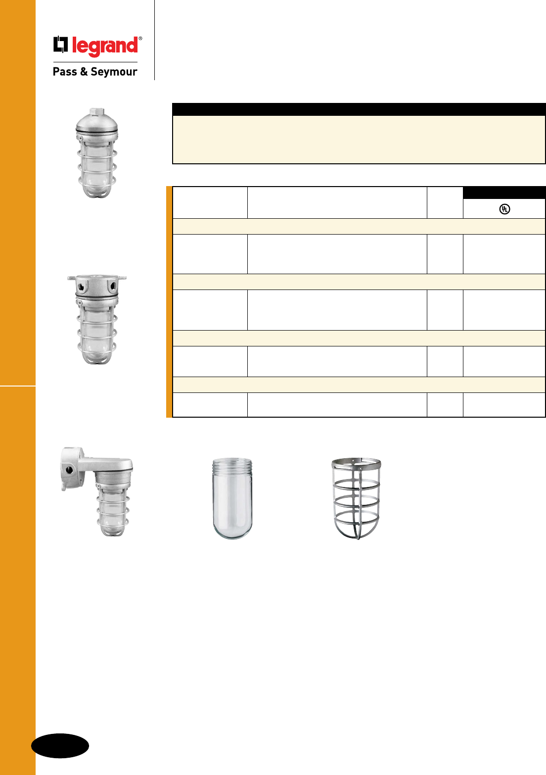
Vapor Proof Lighting
P-22
Weatherproof Boxes & Covers
Weatherproof Boxes & Covers
Vapor Proof Lighting
VPP100G
VPP200G
VPC100G
VPC200G
VPW100G
VPW200G
VPG100
VPG200
VG100
VG200
Features
nCastmetalguardsforgreaterimpactresistance.
nEasy-to-installwithtimesavingfeatures.
nLightsincluderoundcastbox,lampholder,
glassglobe,guard,andhardware.
nHigh-qualitycastingseliminatesharpedges.
nDualrubbergasketsprovidecompletevapor
proofseal.
n4plugsfurnishedwithwallandceilingmounts.
Catalog Number Description Color
100 Watt
VPW100G WallMount,5Hole1/2" Gray •
VPP100G PendantMount,1/2"NPTTopHub Gray •
VPC100G CeilingMount,5Hole1/2" Gray •
200 Watt
VPW200G WallMount,5Hole1/2" Gray •
VPP200G PendantMount,1/2"NPTTopHub Gray •
VPC200G CeilingMount,5Hole1/2" Gray •
Globes
VPG100 ClearGlobe–100Watt Clear
VPG200 ClearGlobe–200Watt Clear
Cast Guard
VG100 CastGuard–100Watt Gray
VG200 CastGuard–200Watt Gray
3rd Party Compliance
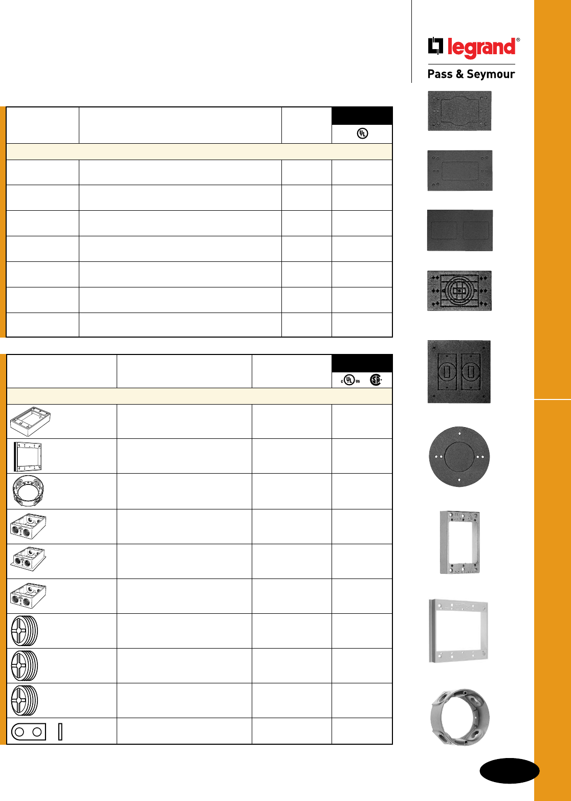
P-23
Weatherproof Boxes & Covers Gaskets & Accessories
Weatherproof Boxes & Covers
Gaskets & Accessories
Catalog Number Description Color
Gaskets
GASKET2 1/8"Thick,1Gang,MultiuseGasket, Black •
ClosedCellPolyethylene
GASKET38 3/8"Thick,Weatherproof,1Gang, Black
GASKET38W MultiuseGasket,ClosedCellPolyethylene White
GASKET3726 3/32"Thick,Weatherproof,1Gang,Decorator Gray •
MultiuseGasket,ClosedCellPolyethylene
GASKET3780 3/32"Thick,Weatherproof,1Gang,Duplex Gray •
MultiuseGasket,ClosedCellPolyethylene
WPGAS100 1/8"Thick,Weatherproof,1Gang,MultiuseGasket, Black
ClosedCellPolyethylene
WPGAS101 1/8"Thick,Weatherproof,2Gang,MultiuseGasket, Black
ClosedCellPolyethylene
WPGASR101 1/8"Thick,Weatherproof,Round,MultiuseGasket, Black
ClosedCellPolyethylene
3rd Party
Compliance
WPEX1
WPEX3
WPEX2
WPGAS100
GASKET3726
GASKET3780
WPGAS101
GASKET38
WPGASR101
Catalog Number Description Color
Accessories
WPEX1 1GangExtensionRing, Gray •
9.5Cu.In.
2.75"x4.5"x1"
WPEX2 2GangExtensionRing, Gray •
16.3Cu.In.
4.5"x4.5"x1"
WPEX3 RoundDeviceBoxExtension Gray •
4-1/2"Hubs
WPEX4 1GangExtensionRingwith Gray •
4-1/2"Hubs,2-1/2"Plugs
Supplied,9.5Cu.In.
WPEX5 1GangFlangedExtensionRing Gray •
with4-1/2"Hubs,2-1/2"Plugs
Supplied,9.5Cu.In.
WPEX6 1GangExtensionRing Gray •
with4-3/4"Hubs,2-3/4"Plugs
Supplied,9.5Cu.In.
WPBP50 ClosurePlug–1/2" Metallic,Qty.100 • •
WPBP50CC Gray,Qty.3 • •
WPBP50WCC White,Qty.3 • •
WPBP75 ClosurePlug–3/4" Metallic,Qty.100 • •
WPBP75CC Gray,Qty.3 • •
WPBP75WCC White,Qty.3 • •
WPBP100CC ClosurePlug–1" Metallic,Qty.100 • •
WPBL100 AluminumLugs(2) Gray
andSelf-TappingScrews
3rd Party
Compliance
P-24
Weatherproof Boxes & CoversNEC® Compliance
Weatherproof Boxes & Covers
NEC® Compliance
Choose the cover according to the location
in which it is to be used.
Other Wet Locations
NEC 406.8(B)(2)
(a)Areceptacleinstalledinawetlocation,wheretheproductintendedtobepluggedintoitisnotattendedwhilein
use,shallhaveanenclosurethatisweatherproofwiththeattachmentplugcapinsertedorremoved.
(b)Areceptacleinstalledinawetlocationwheretheproductintendedtobepluggedintoitwillbeattendedwhileinuse
(e.g.,portabletools)shallhaveanenclosurethatisweatherproofwhentheattachmentplugisremoved.
CA1G
CA1GL
CA1GS
CA126GRY
CA17G
CA18G
CA2G
CA2GS
CA2W
CA26GH
CA26GV
CA26WH
CA26WV
CA262G
CA268G
CA7GV
CA72G
CA721G
CA723G
CA726G
CA78G
CA8GH
CA8GJ
CA8GVFS
CA8WH
CA8WV
CA8WVFS
CA82G
CA82W
WP13
WP13FS
WP23
WPBJ22
WPFLDKIT
WPFLDKITW
WPGFIKIT
WPGFIKITW
WPG1
WPG2
WPOUTKIT
WPOUTKITW
WPWIUKITC
WPWIUKITSC
WPWIUKITSW
WPWIUKITW
3393
3700
3700FS
3703
3703FS
3703T
3703TCW
3710
3710FS
3710WH
3720
3720FS
3720WH
3722FS
3723
3723FS
3723WH
3724FS
3726SC
3726SCBG
3726SCCW
3726SCWH
3770SC
3778
3780SC
3780SCBG
3780SCCW
3780SCCWT
3780SCFBX
3780SCFBXCW
3780SCFBXWH
3780SCLV
3780SCLVBG
3780SCLVCW
3780SCLVWH
3780SCMH
3780SCMHBG
3780SCMHCW
3780SCMHWH
3780SCWH
3795
3796
3797
4510
4511
4512
4515
4515FS
4516
4517
4600
7420
7700
Outdoor Wet Locations
NEC 406.8(B)(1)
Wetlocationsaredefinedasthosesubjectedtosaturationwithwaterorotherliquids,suchasvehiclewashingareas,
unprotectedlocationsexposedtoweather,orininstallationsundergroundorinconcreteslabsormasonryindirect
contactwiththeearth.
NECArticle406.8(B)(1)requiresthatall15and20amp,125&250voltreceptaclesinstalledinwetlocationsmusthave
anenclosurethatisweatherproof,whetherornotaplugisinserted.Thesereceptaclesmustuseawhile-in-usecover,
suchasthoseshownbelow:
WIUC10GL
WIUC10CL
WIUC10WL
WIUC10SG
WIUC10SC
WIUC10SW
WIUC10SB
WIUC10DGL
WIUC10DCL
WIUC10DWL
WIUC20GL
WIUC20CL
WIUC20WL
WIUCAST1
WIUFC10S
WIUFC10SQC
WIUFC10W
WIUFC10WQC
P-25
NEC® ComplianceWeatherproof Boxes & Covers
Weatherproof Boxes & Covers
NEC® Compliance
Damp Locations
NEC 406.8(A)
Damplocationsaredefinedasthoseprotectedfromweatherandnotsubjecttosaturationwithwaterorotherliquids,
butsubjecttomoderatedegreesofmoisture.Examplesofsuchlocationsincludepartiallyprotectedlocationsunder
canopies,marquees,androofedopenporchesnotsubjectedtoabeatingrainorwaterrunoff,aswellasinterior
locationssuchassomebasements,barns,andcold-storagewarehouses.
NECArticle406.8(A)requiresthatreceptaclesinstalledindamplocationsmusthaveanenclosurethatisweatherproof
whenthereceptacleiscovered(attachmentplugisnotinsertedandreceptaclecoverisclosed).
Aninstallationsuitableforwetlocationsshallalsobeconsideredsuitablefordamplocations.Therefore,allcatalog
numbersshownabovearealsosuitableforuseindamplocations.Thecoversbelowaresuitablefordamplocations
only,becausethelidcanbeproppedinthefullopenposition.
3760 3763 3780
Weather-Resistant Receptacles in Damp and Wet Locations
NEC 406.8(A) and 406.8(B)
Anadditionalrequirementhasbeenaddedwhichstatesthatalistedweather-resistantreceptaclemustbeusedwhere
15-and20-amp,125-and250-voltstraightbladereceptacleconfigurationsareinstalledindamporwetlocations.
Thegoalofthechangeistoensurethatreceptaclesofsufficientlyrobustdesignareemployedundertheseconditions.
Listedweather-resistantreceptacleshaveimprovedresistancetosunlightexposure,corrosionandimpact.
Switches in Damp or Wet Locations
NEC 404.4
Surface-mountedswitchesandcircuitbreakersindamporwetlocationsarerequiredtobeenclosedinaweatherproof
enclosureandflush-mountedswitchesandcircuitbreakersindamporwetlocationstobeprovidedwithweatherproof
covers.Thischangerecognizesthatexposuretoadverseweatherconditionsrequirescomparableprotectionfor
switchesandreceptaclesusedindamporwetlocations.
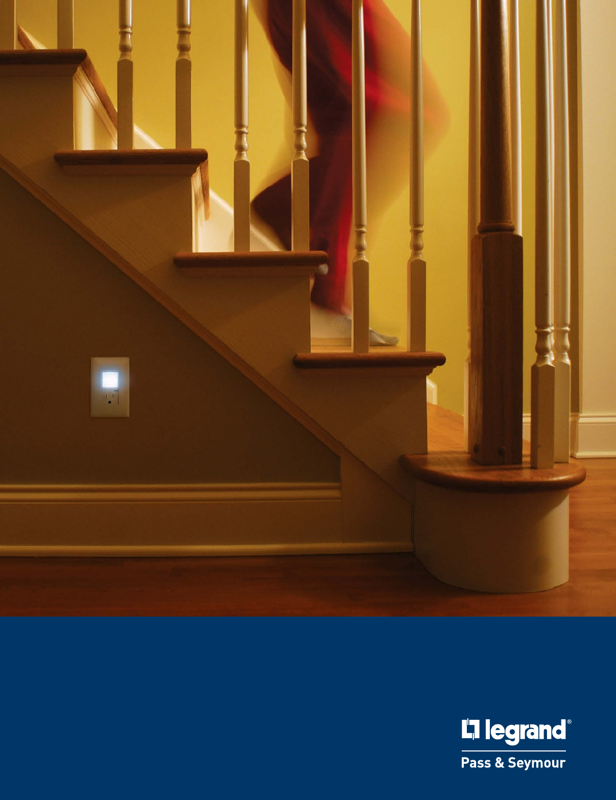
WALL PLATES & SPECIALTIES
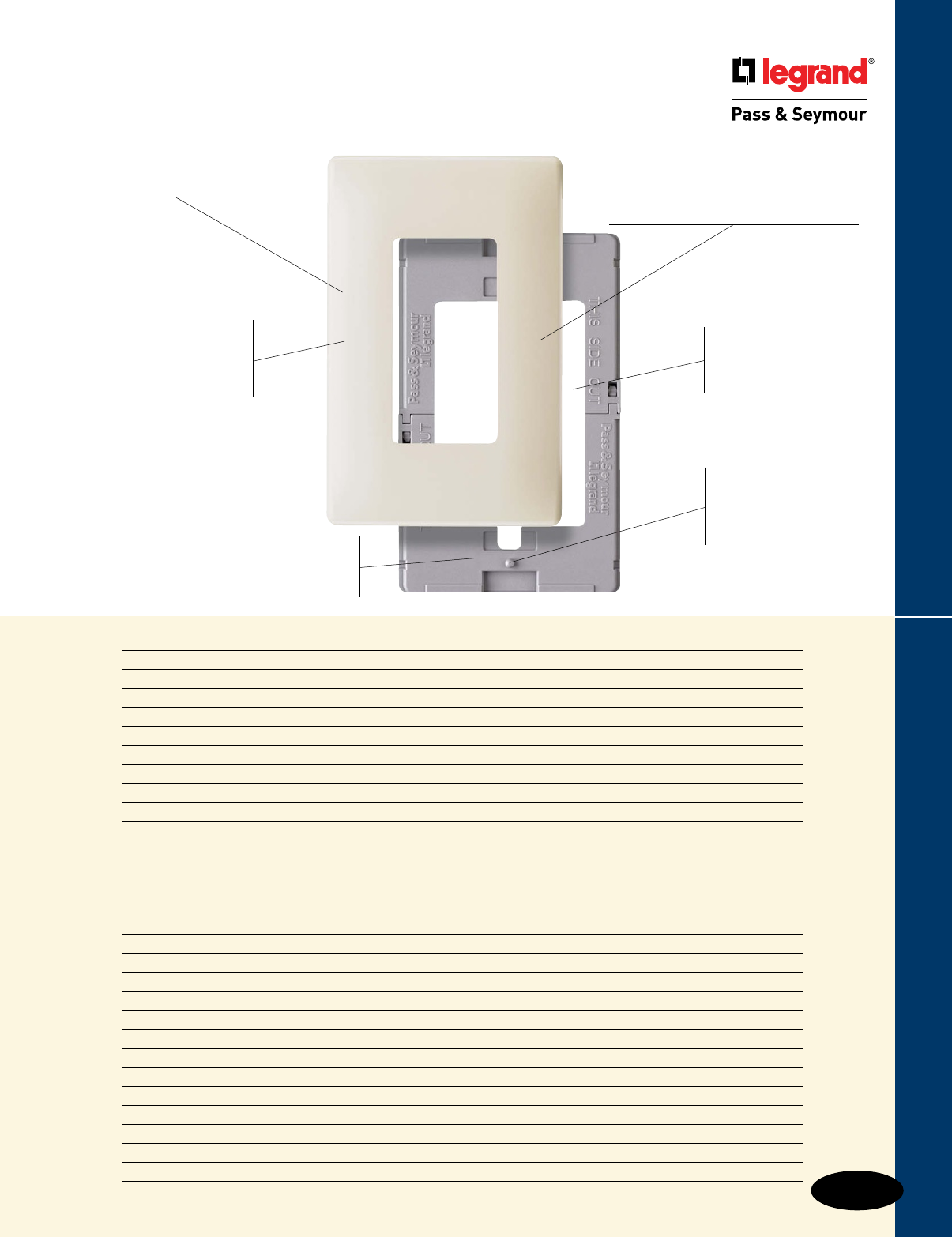
Q-1
Wall Plates & Specialties
Wall Plates & Specialties
Style Page Number
Specifications & Dimensions Q-2 – Q-4
Screwless Wall Plates Q-5, Q-6
Studio Wall Plates Q-7
Toggle Switch Openings Q-8
Duplex Receptacle Openings & Decorator Openings Q-9
Decorator Openings Q-10
Blank Plates Q-11, Q-12
Single Receptacle Openings & Power Outlet Openings Q-13, Q-14
Combination Openings Q-15 – Q-18
Despard® Openings Q-19
Two Gang with Center Opening & Locking Switch Plates Q-20
Louver & Biplex/Triplex Openings Q-21
Junior-Jumbo & Jumbo Toggle, Duplex, Single Receptacle, Decorator, Blank & Combination Openings Q-22 – Q-24
Sectional Wall Plates Q-25
Tandem & Handy Box Plates Q-26
Narrow Metal Q-27
Dustproof Stainless Steel Covers Q-28
Communication Devices & Plates Q-29 – Q-34
Mounting Straps, Yokes & Jewels Q-35
Decorator Hallway Lights & Combination Devices Q-36
Decorator Combination Tamper-Resistant Nightlight/GFCI Receptacles Q-37
PlugTail™ Nightlight/GFCI Receptacles Q-38
Incandescent Lampholders, Neon Pilot Lights & Panelites Q-39
Screws & Screwdrivers Q-40
Engraved & Pad Printed Q-41, Q-42
Custom Metal Wall Plates Q-43 – Q-45
Custom Panel Plates Q-46, Q-47
Style Selector Guide Q-48 – Q-60
SWP26W Automatic alignment
pins ensure that devices
are properly positioned
so that wall plates fit
perfectly.
Molded of rugged .065"
thick polycarbonate.
Seamless, sleek, super
smooth construction
provides no dirt-catching
channel around plate’s
perimeter.
Two-piece plastic subplate
bridges recessed boxes and uneven
sheet rock. Fixes floating installations.
An extra 1/8" width and height
than standard size wall plates for
more tolerance in covering ragged sheet
rock openings.
Oversized opening
to accommodate all
NEMA 26 decorator-
style openings.
Devices & Wall Plates Color Selection Chart available on Pages A-29, B-78 and Q-61.
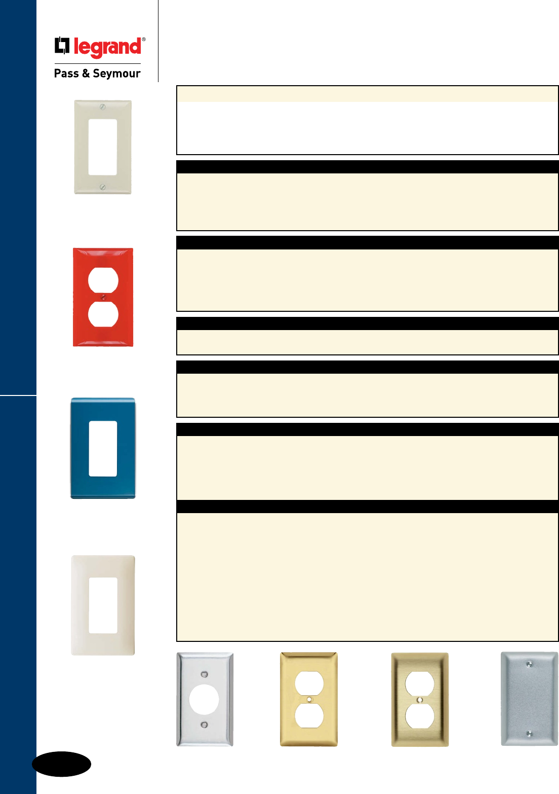
Q-2
Wall Plates & Specialties
Wall Plates
Specifications
Specifications
Application
Legrand/Pass & Seymour’s broad line of Standard Size Plastic and Metal Wall Plates features the most
complete range of types, sizes, colors, and finishes available. Choose from more than 1,900 standard
plates in non-combustible thermoset plastic material, self-extinguishing nylon material, screwless
polycarbonate material, or attractively finished metal, for residential, commercial, institutional, and
industrial applications. All plastic wall plates color match to Legrand/Pass & Seymour devices.
TradeMaster® Thermoplastic Wall Plates
n Molded of rugged, practically indestructible
self-extinguishing nylon. (“TP” series only.)
n Available in “TP” series, extra 3/16" width and
height than Standard size plates; and “TPJ” series,
extra 3/16" width and height than Junior-Jumbo
size plates.
n Available in Ivory, White, Brown, Gray, Black,
Blue, Orange, Red, and Light Almond.
n Preferred for hospital, industrial, institutional,
and other high-abuse applications.
n Nominal thickness, .070"
Thermoset Plastic Wall Plates
n Molded of non-combustible mar-proof material.
n Available in “SP” series in Standard, Junior-Jumbo,
and Jumbo sizes.
n Seven standard colors available – Ivory, White,
Brown, Gray, Black, Red, and Light Almond.
n Individually wrapped with color-matching screws.
n Resistant to discoloration, grease, oil,
solvent and moisture.
n Nominal thickness, .070"
Thermoset
SP Series
Nylon
TP Series
Screwless
Polycarbonate
SWP Series
Polished Brass Brushed Brass Aluminum
302
Stainless Steel
Metal Wall Plates
Materials
n Constructed of corrosion-resistant stainless steel,
brass, aluminum, chrome, brushed bronze or
galvanized steel.
n Standard, Jumbo, and Tandem size plates
available, as well as special Panel size plates up
to 5-gangs high and 10-gangs wide.
n Packaged in protective film, with finish-matching
screws.
n Variety of special plated finishes. Paintable to
match plastic plates.
n Can be silk-screened or engraved, and custom
punched with over 300 opening styles.
n Type 302 Stainless Steel, non-magnetic, .032"
nominal thickness, brushed finish. This alloy
contains 18% chromium and 8% nickel for
superior resistance to corrosion. Recommended
for use in food processing plants, dairies,
chemical plants, and other industrial, institutional,
and commercial applications where corrosive
atmospheres exist.
n Type 430 Stainless Steel, magnetic, .032"
nominal thickness, brushed finish. Less corrosion-
resistant than Type 302, but ideal for general
service in high abuse applications in industrial
plants, commercial, and institutional buildings.
n Chrome, Brushed and Polished Brass, .040"
thick. 70% copper, 30% zinc alloy gives warm,
appealing finish to modern decor as well as
retrofit applications. Lacquered to prevent
corrosion.
n Aluminum, .040" thick. Lustrous satin finish.
Lacquered to prevent corrosion.
n Galvanized Steel. Used only for Handy Box
Plates.
n Brushed Bronze, .040" thick. 90% copper,
10% zinc. Lacquered to prevent corrosion.
Screwless Polycarbonate Wall Plates
n Molded of .065" thick polycarbonate, matte finish.
n 2-piece plastic subplate made of polycarbonate.
n Extra 1/8" width and height than Standard size
plates.
n Available in Ivory, White, Brown, Gray, Black,
and Light Almond; and five metallic and three
wood finishes.
Studio Polycarbonate Wall Plates
n Wall plate and back plate made of polycarbonate
Lexan 241R opaque.
n Wall plate thickness: 0.210
Back plate thickness: 0.28
Studio
Polycarbonate
WP Series
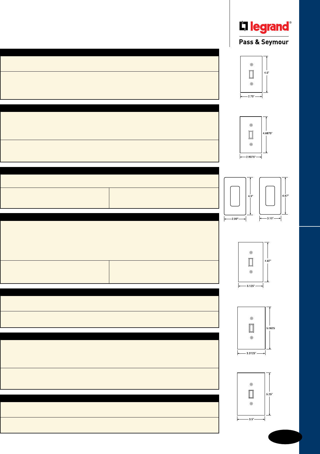
Q-3
Wall Plates & Specialties
Wall Plates
Dimensions
Dimensions
STANDARD
TRADEMASTER STANDARD
TRADEMASTER JUMBO
JUMBO
JUNIOR-JUMBO
TradeMaster® Wall Plates
n Extra 3/16" width and height than Standard size wall plates.
n Provide better sheet rock coverage with standard size appearance.
n Available in unbreakable nylon 6 construction only.
n Screws pre-installed in the duplex, toggle, and decorator single gang plates.
Dimensions
1 gang 2.9375" x 4.6875"
2 gang 4.75" x 4.6875"
3 gang 6.563" x 4.6875"
4 gang 8.375" x 4.6875"
5 gang 10.188" x 4.6875"
6 gang 12" x 4.6875"
TradeMaster Jumbo Wall Plates
n Extra 3/16" width and height than Junior-Jumbo size wall plates.
n Provide additional coverage for sheet rock gaps, matching the appearance of the TradeMaster Plates.
n Available in unbreakable nylon 6 construction only.
n Screws pre-installed in the duplex, toggle, and decorator single gang plates.
Dimensions
1 gang 3.3125" x 5.0625"
2 gang 5.125" x 5.0625"
3 gang 6.9375" x 5.0625"
4 gang 8.75" x 5.0625"
Standard Size Wall Plates
n Standard size wall plates for all applications.
n Best fit for surface mount boxes.
Dimensions
1 gang 2.75" x 4.5"
2 gang 4.56" x 4.5"
3 gang 6.375" x 4.5"
4 gang 8.125" x 4.5"
5 gang 10" x 4.5"
6 gang 11.812" x 4.5"
7 gang 13.62" x 4.5"
8 gang 15.44" x 4.5"
n Available in plastic and metal only.
Jumbo Wall Plates
n Extra 3/4" width and height than Standard size wall plates.
n Largest size wall plates to cover larger wall damage.
Dimensions
1 gang 3.5" x 5.25" 2 gang 5.31" x 5.25" 3 gang 7.12" x 5.25" 4 gang 8.93" x 5.25"
n Available in plastic and metal only.
STUDIO
Junior-Jumbo Wall Plates
n Extra 3/8" width and height than Standard size wall plates.
n Additional coverage for sheet rock gaps.
Dimensions
1 gang 3.125" x 4.87" 2 gang 4.93" x 4.87" 3 gang 6.75" x 4.87" 4 gang 8.56" x 4.87"
n Available in plastic and metal only.
Screwless Polycarbonate Wall Plates
n Available in decorator, toggle, and duplex openings.
n Extra 1/8" width and height than Standard size wall plates.
n Provide better sheet rock coverage with standard size appearance.
n Molded of .065" thick polycarbonate.
n 2-piece plastic subplate made of polycarbonate.
n Available in five metallic and three wood finishes; and six standard colors.
Wall Plate Dimensions
1 gang 3.10" x 4.87"
2 gang 4.912" x 4.87"
3 gang 6.724" x 4.87"
4 gang 8.536" x 4.87"
Subplate Dimensions
1 gang 2.85" x 4.62"
2 gang 4.662" x 4.62"
3 gang 6.474" x 4.62"
4 gang 8.286" x 4.62"
Studio Polycarbonate Wall Plates
n Wall plate and back plate made of polycarbonate
Lexan 241R opaque.
n Wall plate thickness: 0.210
Back plate thickness: 0.28
Wall Plate Dimensions
1 gang 2.988" x 4.901"
2 gang 4.80" x 4.901"
3 gang 6.613" x 4.901"
4 gang 8.425" x 4.901"
Back Plate Dimensions
1 gang 3.158" x 4.97"
2 gang 4.97" x 4.97"
3 gang 6.783" x 4.97"
4 gang 8.595" x 4.97"
SCREWLESS
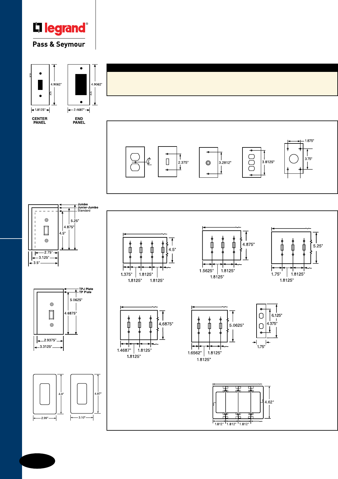
Dimensions
Q-4
Wall Plates & Specialties
Wall Plates
Dimensions
Sectional Wall Plates
n End and center panels with each of five most-used configurations make it possible to improvise
custom wall plates on the job. Panels lock securely together on installation. Blank sections furnished
with mounting strap.
Wall Plate Sizes
Illustrated are the five standard methods of plate mounting. There are many other non-standard
methods which depend upon the special device used. Exact mounting hole specifications for every
device appear in the Selector Guide.
Center Strap Box Decorator and FS (4 Screw)
Interchangeable
Wall Plate Mountings
Standard Size
Available in plastic and metal
Jumbo
Metal only. Plate
mounting dimensions
are non-standard.
Refer to Page Q-26
for details and
devices that can
be used.
For Screwless
(SWP) Wall Plate
dimensions refer
to Page Q-3.
Junior-Jumbo
TradeMaster® Size
Available in nylon only
TradeMaster Jumbo
Available in nylon only
Tandem Wall Plates
SP Plates
TP Plates
Screwless Wall Plate Plastic Subplate
WP Plates SWP Plates
For Studio (WP) Wall
Plate & Back Plate
dimensions refer to
Page Q-3.
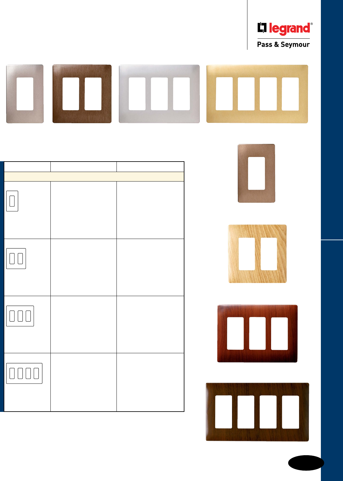
Q-5
Wall Plates & Specialties
These products listed to UL514, Cover Plates for Flush-Mounted Wiring Devices, CSA Certified.
Decorative Finish Screwless Wall Plates
Wall Plates
Decorative Finish Screwless Wall Plates
Polycarbonate
Four Gang
Walnut
For Screwless Wall Plate, and Plastic Subplate dimensions, see Page Q-6.
Description Color Decorator Openings
Screwless Decorator Openings Plastic Subplate included
One Gang Brushed Nickel SWP26BN
Brushed Copper SWP26BC
Stainless Steel SWP26SS
Brass SWP26BR
Brushed Bronze SWP26BB
Maple SWP26MA
Mahogany SWP26MH
Walnut SWP26WA
Two Gang Brushed Nickel SWP262BN
Brushed Copper SWP262BC
Stainless Steel SWP262SS
Brass SWP262BR
Brushed Bronze SWP262BB
Maple SWP262MA
Mahogany SWP262MH
Walnut SWP262WA
Three Gang Brushed Nickel SWP263BN
Brushed Copper SWP263BC
Stainless Steel SWP263SS
Brass SWP263BR
Brushed Bronze SWP263BB
Maple SWP263MA
Mahogany SWP263MH
Walnut SWP263WA
Four Gang Brushed Nickel SWP264BN
Brushed Copper SWP264BC
Stainless Steel SWP264SS
Brass SWP264BR
Brushed Bronze SWP264BB
Maple SWP264MA
Mahogany SWP264MH
Walnut SWP264WA
One Gang
Brushed Nickel
Four Gang
Brass
Three Gang
Mahogany
Three Gang
Stainless Steel
Two Gang
Brushed Copper
Two Gang
Maple
One Gang
Brushed Bronze
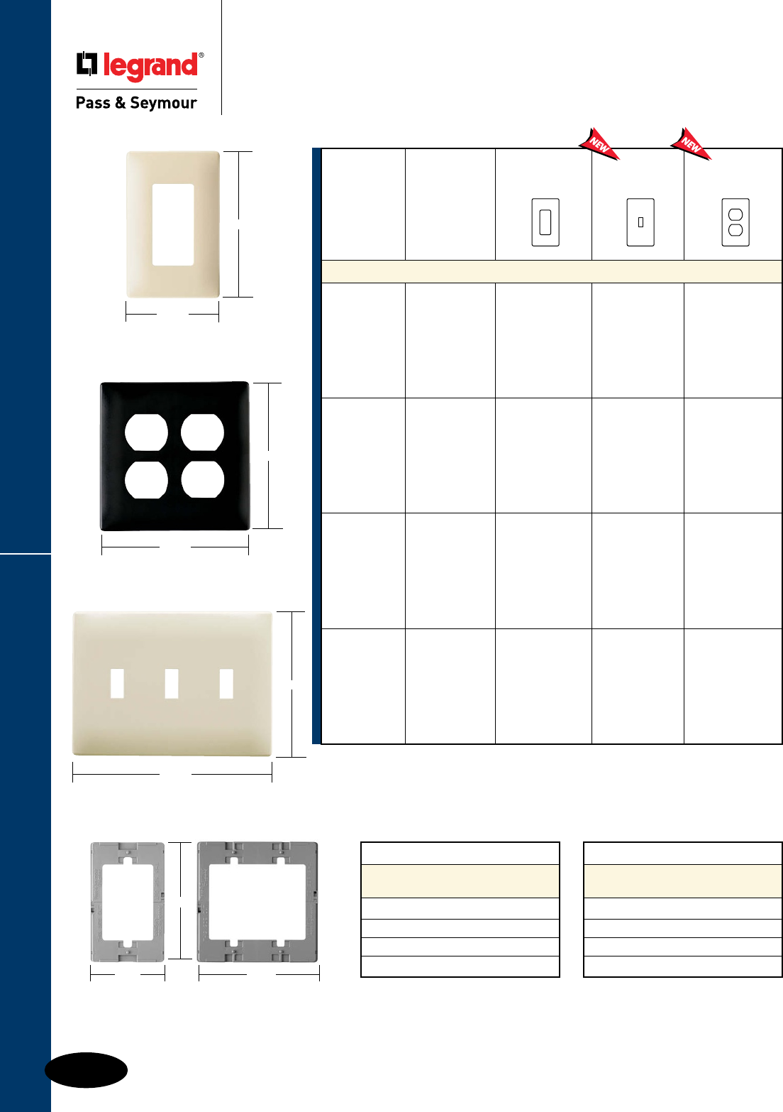
Q-6
Wall Plates & Specialties
One Gang
3.10"
4.87"
Two Gang
4.912"
4.87"
2.85"
4.62"
One Gang
Plastic Subplate
4.662"
Two Gang
Plastic Subplate
Three Gang
6.724"
4.87"
These products listed to UL514, Cover Plates for Flush-Mounted Wiring Devices, CSA Certified.
Screwless Wall Plates
Wall Plates
Screwless Wall Plates
Polycarbonate
Description Height Width
Screwless Wall Plate
Dimensions
One Gang 4.87" 3.10"
Two Gang 4.87" 4.912"
Three Gang 4.87" 6.724"
Four Gang 4.87" 8.536"
Description Height Width
Screwless Plastic
Subplate Dimensions
One Gang 4.62" 2.85"
Two Gang 4.62" 4.662"
Three Gang 4.62" 6.474"
Four Gang 4.62" 8.286"
Number of
Gangs Color
Decorator
Openings
Toggle
Switch
Openings
Duplex
Receptacle
Openings
Screwless Wall Plates Plastic Subplate included
One Gang Ivory
White
Brown
Gray
Black
Light Almond
SWP26I
SWP26W
SWP26
SWP26GRY
SWP26BK
SWP26LA
SWP1I
SWP1W
SWP1
SWP1GRY
SWP1BK
SWP1LA
SWP8I
SWP8W
SWP8
SWP8GRY
SWP8BK
SWP8LA
Two Gang Ivory
White
Brown
Gray
Black
Light Almond
SWP262I
SWP262W
SWP262
SWP262GRY
SWP262BK
SWP262LA
SWP2I
SWP2W
SWP2
SWP2GRY
SWP2BK
SWP2LA
SWP82I
SWP82W
SWP82
SWP82GRY
SWP82BK
SWP82LA
Three Gang Ivory
White
Brown
Gray
Black
Light Almond
SWP263I
SWP263W
SWP263
SWP263GRY
SWP263BK
SWP263LA
SWP3I
SWP3W
SWP3
SWP3GRY
SWP3BK
SWP3LA
Four Gang Ivory
White
Brown
Gray
Black
Light Almond
SWP264I
SWP264W
SWP264
SWP264GRY
SWP264BK
SWP264LA
SWP4I
SWP4W
SWP4
SWP4GRY
SWP4BK
SWP4LA
Q-7
Wall Plates & Specialties
These products listed to UL514, Cover Plates for Flush-Mounted Wiring Devices, CSA Certified.
Studio Wall Plates
Wall Plates
Studio Wall Plates
Polycarbonate
WP5002NV WP5002SP
WP5002WH WP5002LA
WP5002TI WP5002KK
WP5002SD WP5002TP
WP5002AE WP5002CP
WP5002CR WP5002CZ
WP5002CY WP5002MS
WP5002GB WP5002CM
Color One Gang Two Gang Three Gang Four Gang
Basic Color – Screwless Decorator Opening Back Plate included
White WP5001WH WP5002WH WP5003WH WP5004WH
Light Almond WP5001LA WP5002LA WP5003LA WP5004LA
Titanium WP5001TI WP5002TI WP5003TI WP5004TI
Gloss Black WP5001GB WP5002GB WP5003GB WP5004GB
Neutrals – Screwless Decorator Opening Back Plate included
Cement WP5001CM WP5002CM WP5003CM WP5004CM
Khaki WP5001KK WP5002KK WP5003KK WP5004KK
Sand WP5001SD WP5002SD WP5003SD WP5004SD
Taupe WP5001TP WP5002TP WP5003TP WP5004TP
Hues – Screwless Decorator Opening Back Plate included
Aloe WP5001AE WP5002AE WP5003AE WP5004AE
Bordeaux WP5001BD WP5002BD WP5003BD WP5004BD
Cameo Pink WP5001CP WP5002CP WP5003CP WP5004CP
Citrus WP5001CR WP5002CR WP5003CR WP5004CR
Cozumel WP5001CZ WP5002CZ WP5003CZ WP5004CZ
Cyan WP5001CY WP5002CY WP5003CY WP5004CY
Moss WP5001MS WP5002MS WP5003MS WP5004MS
Nirvana WP5001NV WP5002NV WP5003NV WP5004NV
Spanish Red WP5001SP WP5002SP WP5003SP WP5004SP
Revolutionize the look of technology in the home with Studio Wall Plates.
Available in one, two, three, and four gang sizes — and in 17 contemporary color options, these decorator-style wall plates feature
a design and form-factor never before available to homeowners. The design, a sculptural flow of curves with titanium edging and a
screwless finish, offers a new way to integrate home system products with personal style and taste throughout the entire home.
WP5002BD
Description Height Width
Studio Wall Plate Dimensions
One Gang 4.901" 2.988"
Two Gang 4.901" 4.80"
Three Gang 4.901" 6.613"
Four Gang 4.901" 8.425"
Description Height Width
Studio Back Plate Dimensions
One Gang 4.97" 3.158"
Two Gang 4.97" 4.97"
Three Gang 4.97" 6.783"
Four Gang 4.97" 8.595"

Q-8
Wall Plates & Specialties
These products listed to UL514, Cover Plates for Flush-Mounted Wiring Devices, CSA Certified.
Toggle Switch Openings
Wall Plates
Toggle Switch Openings
Standard Size Plastic & Metal
Nylon Thermoset Metal
TradeMaster®
Description Color Plates Smooth Material Smooth
Toggle Switch Openings
One Gang Ivory TP1I SP1I Aluminum SA1
White TP1W SP1W Brass SB1
Brown TP1 SP1 Polished Brass SB1PB
Gray TP1GRY SP1GRY 430S/S SL1
Black TP1BK 302S/S SS1
Red TP1RED Brushed Bronze SB1BZ
Light Almond TP1LA SP1LA Chrome SB1CH
Two Gang Ivory TP2I SP2I Aluminum SA2
White TP2W SP2W Brass SB2
Brown TP2 SP2 Polished Brass SB2PB
Gray TP2GRY SP2GRY 430S/S SL2
Black TP2BK 302S/S SS2
Red TP2RED Brushed Bronze SB2BZ
Light Almond TP2LA SP2LA Chrome SB2CH
Three Gang Ivory TP3I SP3I Aluminum SA3
White TP3W SP3W Brass SB3
Brown TP3 SP3 Polished Brass SB3PB
Gray TP3GRY SP3GRY 430S/S SL3
Black TP3BK 302S/S SS3
Red TP3RED Brushed Bronze SB3BZ
Light Almond TP3LA SP3LA Chrome SB3CH
Four Gang Ivory TP4I SP4I Aluminum SA4
White TP4W SP4W Brass SB4
Brown TP4 SP4 Polished Brass SB4PB
Gray TP4GRY SP4GRY 430S/S SL4
Black TP4BK 302S/S SS4
Red TP4RED
Light Almond TP4LA SP4LA
Five Gang Ivory TP5I SP5I
White TP5W SP5W Brass SB5
Brown TP5 SP5 Polished Brass SB5PB
Gray TP5GRY SP5GRY
Black TP5BK 302S/S SS5
Light Almond TP5LA SP5LA
Six Gang Ivory TP6I SP6I
White TP6W SP6W Polished Brass SB6PB
Brown TP6
Gray TP6GRY SP6GRY 302S/S SS6
Black TP6BK
Light Almond TP6LA SP6LA
Seven Gang 302S/S SS601
302S/S Painted Ivory SS601I
302S/S Painted White SS601W
Eight Gang 302S/S SS602
302S/S Painted Ivory SS602I
302S/S Painted White SS602W
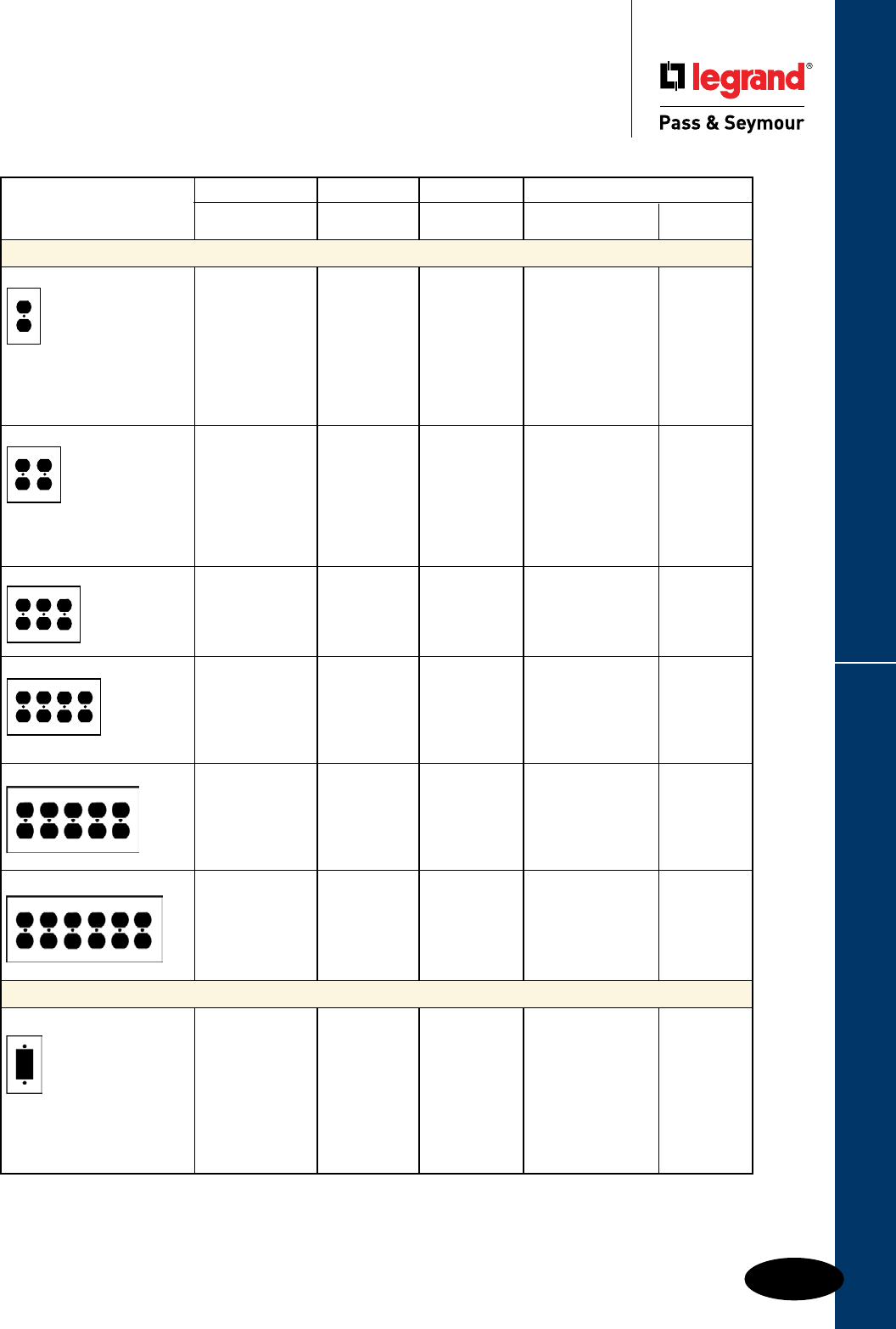
Q-9
Wall Plates & Specialties
These products listed to UL514, Cover Plates for Flush-Mounted Wiring Devices, CSA Certified.
Duplex Receptacle & Decorator Openings
Wall Plates
Duplex Receptacle & Decorator Openings
Standard Size Plastic & Metal
Nylon Thermoset Metal
TradeMaster®
Description Color Plates Smooth Material Smooth
Duplex Receptacle Openings
One Gang Ivory TP8I SP8I
White TP8W SP8W Aluminum SA8
Brown TP8 SP8 Brass SB8
Gray TP8GRY SP8GRY Polished Brass SB8PB
Black TP8BK 430S/S SL8
Red TP8RED 302S/S SS8
Light Almond TP8LA SP8LA Brushed Bronze SB8BZ
Blue TP8BL Chrome SB8CH
Orange TP8OR
Two Gang Ivory TP82I SP82I
White TP82W SP82W Aluminum SA82
Brown TP82 SP82 Brass SB82
Gray TP82GRY SP82GRY Polished Brass SB82PB
Black TP82BK 430S/S SL82
Red TP82RED 302S/S SS82
Light Almond TP82LA SP82LA Brushed Bronze SB82BZ
Orange TP82OR Chrome SB82CH
Three Gang Ivory SP83I
White SP83W Brass SB83
Brown SP83 Polished Brass SB83PB
Gray SP83GRY
Light Almond SP83LA 302S/S SS83
Four Gang Ivory SP84I
White SP84W Polished Brass SB84PB
Brown SP84
Gray SP84GRY 302S/S SS84
Five Gang
302S/S SS85
Six Gang
302S/S SS86
Decorator Openings
One Gang Ivory TP26I SP26I
White TP26W SP26W Aluminum SA26
Brown TP26 SP26 Brass SB26
Gray TP26GRY SP26GRY Polished Brass SB26PB
Black TP26BK SP26BK 430S/S SL26
Red TP26RED 302S/S SS26
Light Almond TP26LA SP26LA Brushed Bronze SB26BZ
Blue TP26BL Chrome SB26CH
Orange TP26OR
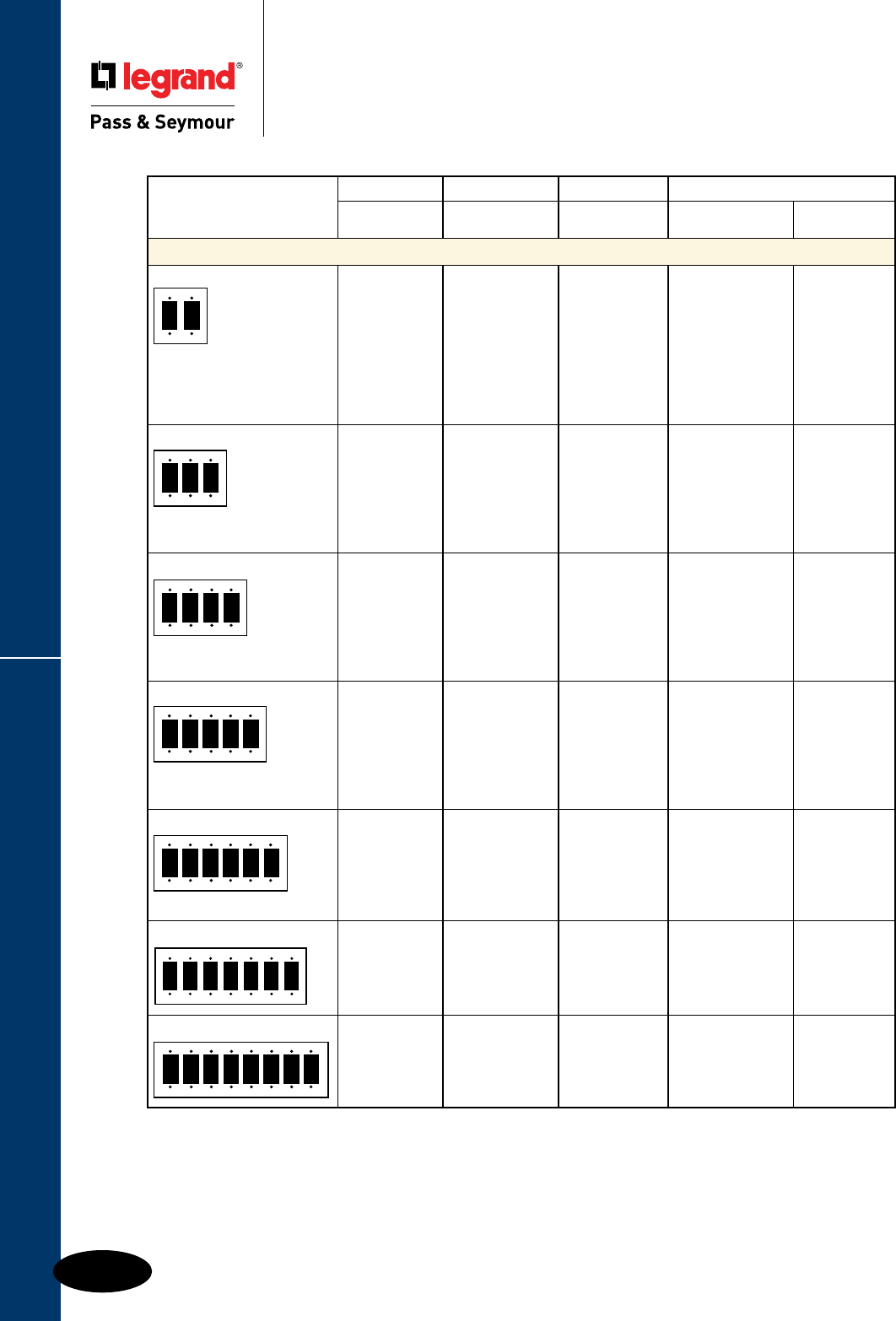
Q-10
Wall Plates & Specialties
These products listed to UL514, Cover Plates for Flush-Mounted Wiring Devices, CSA Certified.
Decorator Openings
Wall Plates
Decorator Openings
Standard Size Plastic & Metal
Nylon Thermoset Metal
TradeMaster®
Description Color Plates Smooth Material Smooth
Decorator Openings
Two Gang Ivory TP262I SP262I
White TP262W SP262W Aluminum SA262
Brown TP262 SP262 Brass SB262
Gray TP262GRY SP262GRY Polished Brass SB262PB
Black TP262BK SP262BK 430S/S SL262
Red TP262RED 302S/S SS262
Light Almond TP262LA SP262LA
Blue TP262BL
Orange TP262OR
Three Gang Ivory TP263I SP263I
White TP263W SP263W Brass SB263
Brown TP263 Polished Brass SB263PB
Gray TP263GRY SP263GRY
Black TP263BK SP263BK 302S/S SS263
Red TP263RED
Light Almond TP263LA SP263LA
Four Gang Ivory TP264I SP264I
White TP264W SP264W Brass SB264
Brown TP264 SP264 Polished Brass SB264PB
Gray TP264GRY SP264GRY
Black TP264BK SP264BK 302S/S SS264
Red TP264RED
Light Almond TP264LA SP264LA
Five Gang Ivory TP265I SP265I
White TP265W SP265W
Brown TP265 302S/S SS265
Gray TP265GRY SP265GRY
Black TP265BK SP265BK
Red SP265RED
Light Almond TP265LA SP265LA
Six Gang Ivory TP266I SP266I
White TP266W SP266W
Brown TP266 SP266 302S/S SS266
Gray TP266GRY SP266GRY
Black TP266BK SP266BK
Light Almond TP266LA SP266LA
Seven Gang 302S/S SS267
302S/S Painted Ivory SS267I
302S/S Painted White SS267W
Eight Gang 302S/S SS268
302S/S Painted Ivory SS268I
302S/S Painted White SS268W
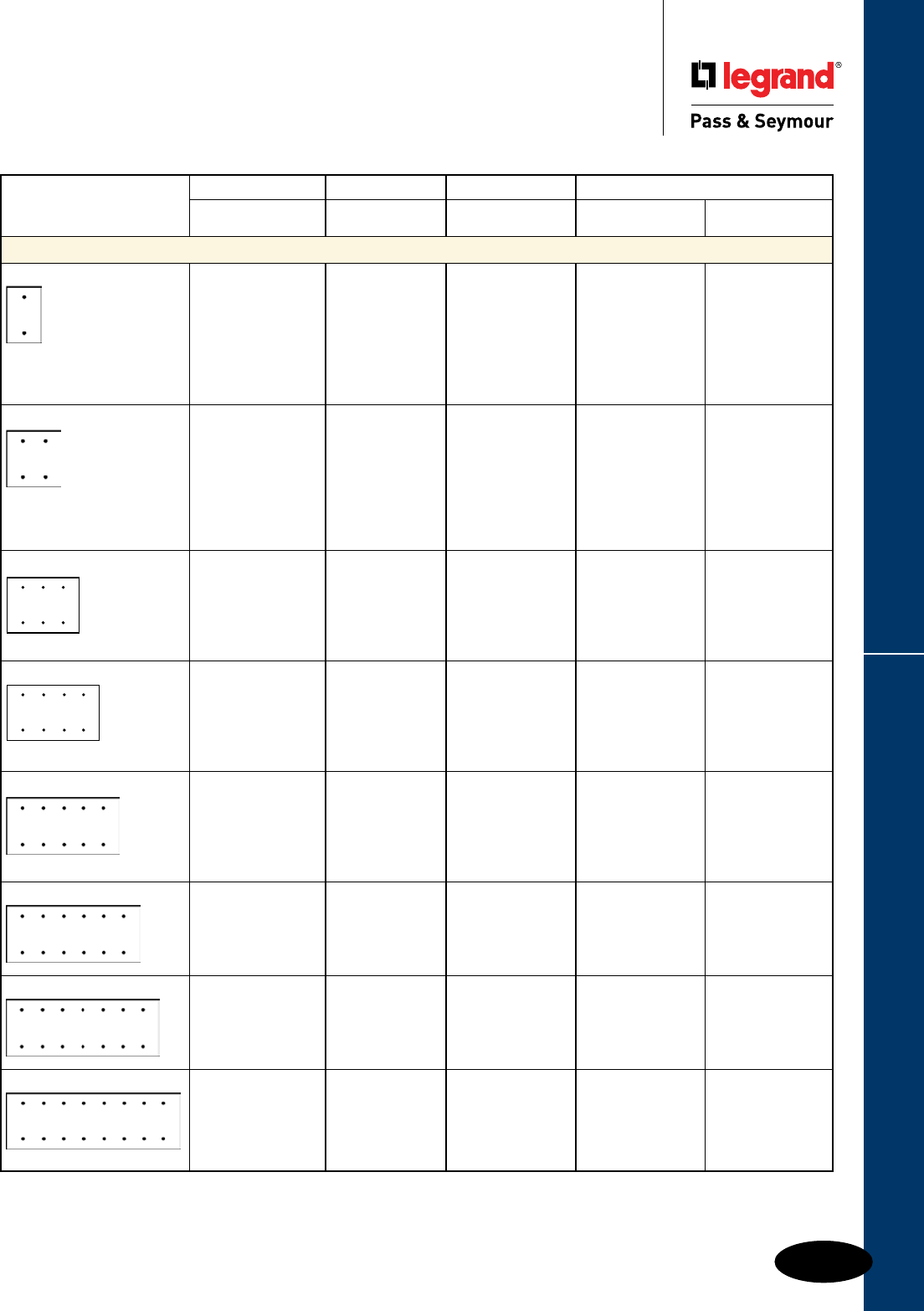
Q-11
Wall Plates & Specialties
These products listed to UL514, Cover Plates for Flush-Mounted Wiring Devices, CSA Certified.
Blank Plates – Box Mounted
Wall Plates
Blank Plates – Box Mounted
Standard Size Plastic & Metal
Nylon Thermoset Metal
TradeMaster®
Description Color Plates Smooth Material Smooth
Blank Plates – Box Mounted
One Gang Blank – Box Mtd. Ivory TP13I SP13I Aluminum SA13
White TP13W SP13W Brass SB13
Brown TP13 SP13 Polished Brass SB13PB
Gray TP13GRY SP13GRY 430S/S SL13
Black TP13BK 302S/S SS13
Red TP13RED 302S/S (1/2" Screws) SS13.5
Light Almond TP13LA SP13LA Brushed Bronze SB13BZ
Chrome SB13CH
Two Gang Blank – Box Mtd. Ivory TP23I SP23I Aluminum SA23
White TP23W SP23W Brass SB23
Brown TP23 SP23 Polished Brass SB23PB
Gray TP23GRY SP23GRY 430S/S SL23
Black TP23BK 302S/S SS23
Light Almond TP23LA SP23LA 302S/S (1/2" Screws) SS23.5
Brushed Bronze SB23BZ
Chrome SB23CH
Three Gang Blank – Box Mtd. Ivory SP33I Polished Brass SB33PB
White SP33W
Brown SP33 302S/S SS33
Gray SP33GRY 302S/S (1/2" Screws) SS33.5
Light Almond SP33LA
Four Gang Blank – Box Mtd. Ivory SP43I
White SP43W
Brown SP43 302S/S SS43
Gray SP43GRY
Five Gang Blank – Box Mtd.
302S/S SS53
Six Gang Blank – Box Mtd.
302S/S SS63
Seven Gang Blank – Box Mtd.
302S/S SS6013
Eight Gang Blank – Box Mtd.
302S/S SS6023
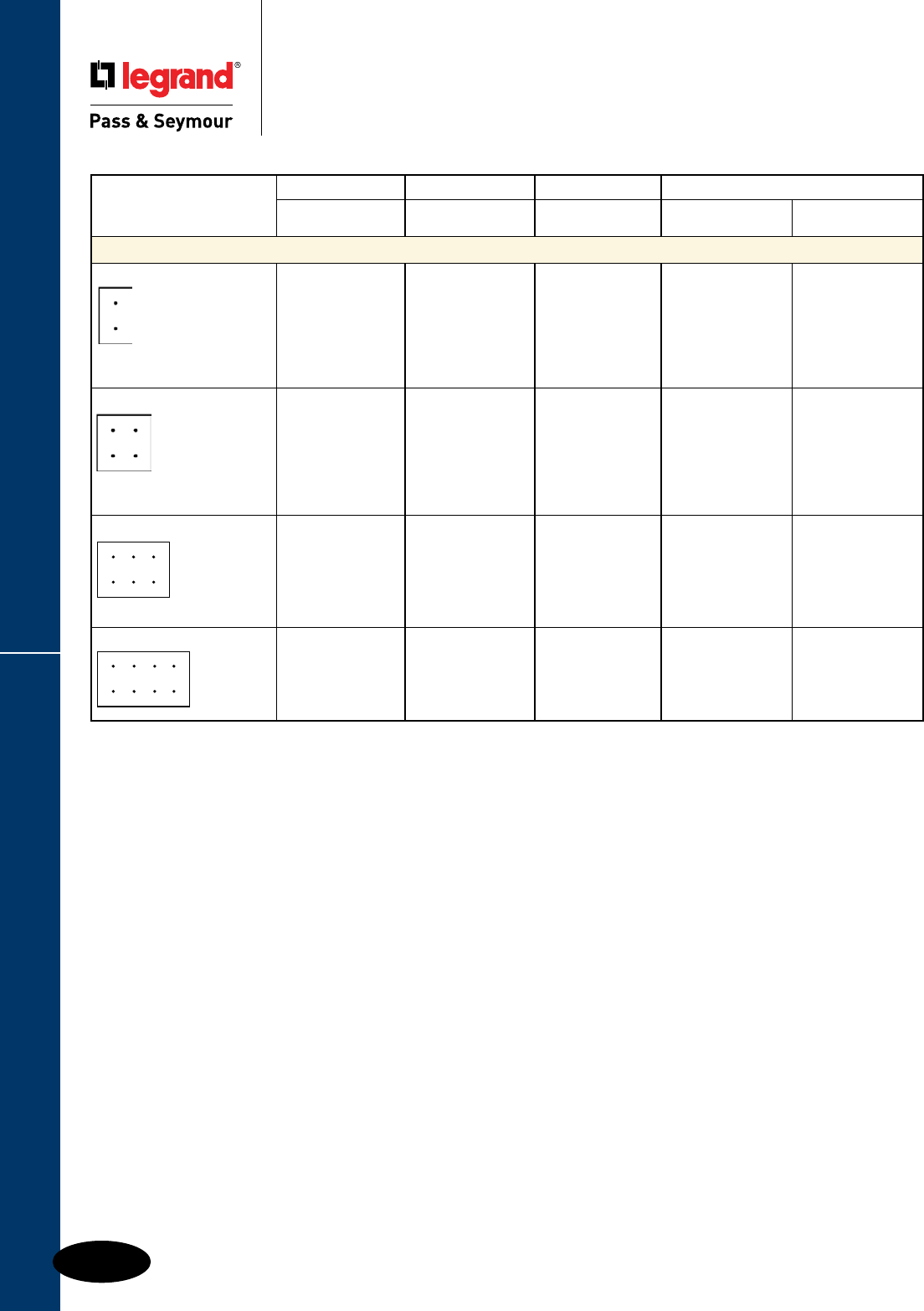
Q-12
Wall Plates & Specialties
These products listed to UL514, Cover Plates for Flush-Mounted Wiring Devices, CSA Certified.
Blank Plates – Strap Mounted
Wall Plates
Blank Plates – Strap Mounted
Standard Size Plastic & Metal
Nylon Thermoset Metal
TradeMaster®
Description Color Plates Smooth Material Smooth
Blank Plates – Strap Mounted with Adjustment Yoke
One Gang Blank – Strap Mtd. Ivory TP14I SP14I
White TP14W SP14W Aluminum SA14
Brown TP14 SP14 Brass SB14
Gray TP14GRY SP14GRY 430S/S SL14
Black TP14BK SP14BK 302S/S SS14
Red SP14RED 302S/S (1/2" Screws) SS14.5
Light Almond TP14LA SP14LA
Two Gang Blank – Strap Mtd. Ivory TP24I SP24I
White TP24W SP24W Aluminum SA24
Brown TP24 SP24 Brass SB24
Gray TP24GRY SP24GRY 430S/S SL24
Black TP24BK SP24BK 302S/S SS24
Red SP24RED 302S/S (1/2" Screws) SS24.5
Light Almond TP24LA SP24LA
Three Gang Blank – Strap Mtd. Ivory SP34I
White SP34W
Brown SP34 302S/S SS34
Gray SP34GRY
Four Gang Blank – Strap Mtd. Ivory SP44I
White SP44W
Brown SP44 302S/S SS44
Gray SP44GRY
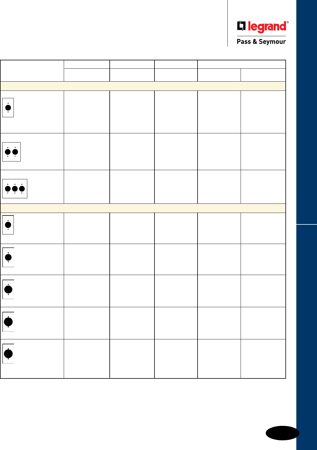
Q-13
Wall Plates & Specialties
These products listed to UL514, Cover Plates for Flush-Mounted Wiring Devices, CSA Certified.
Single Receptacle & Power Outlet Openings
Wall Plates
Single Receptacle & Power Outlet Openings
Standard Size Plastic & Metal
1.5938" hole for 1.5625"
dia. device – 2 mtg. holes
1.625" hole for 1.5938"
dia. device – 2 mtg. holes
1.75" hole for 1.7186"
dia. device-2 mtg. holes
2.125" hole for 2.094"
dia. device – 2 mtg. holes
2.156" hole for 2.125"
dia. device – 2 mtg. holes
Nylon Thermoset Metal
TradeMaster®
Description Color Plates Smooth Material Smooth
Single Receptacle Openings
One Gang Ivory TP7I SP7I
White TP7W SP7W Aluminum SA7
Brown TP7 SP7 Brass SB7
Gray TP7GRY SP7GRY Polished Brass SB7PB
Black TP7BK 430S/S SL7
Red TP7RED 302S/S SS7
Light Almond TP7LA SP7LA
Two Gang Ivory SP72I
White SP72W
Brown SP72 302S/S SS72
Three Gang 302S/S SS73
302S/S Painted Ivory SS73I
302S/S Painted White SS73W
302S/S Painted Gray SS73GRY
Power Outlet Receptacle Openings – One Gang
Ivory TP720I SP720I
White TP720W SP720W
Brown TP720 SP720 302S/S SS720
Gray TP720GRY SP720GRY
Light Almond TP720LA SP720LA
302S/S SS721
302S/S SS725
302S/S SS723
Ivory TP724I 384I
White TP724W
Brown TP724 384 Chrome S384C
Gray TP724GRY 302S/S SS724
Black TP724BK
Light Almond TP724LA

Q-14
Wall Plates & Specialties
These products listed to UL514, Cover Plates for Flush-Mounted Wiring Devices, CSA Certified.
Power Outlet Receptacle Openings
Wall Plates
Power Outlet Receptacle Openings
Standard Size Plastic & Metal
2.1563" hole for 2.125"
dia. device – 2 mtg. holes
2.4688" hole for 2.375"
dia. device – 4 mtg. holes
2.1563" hole for 2.125"
dia. device – 4 mtg. holes
2.1563" hole for 2.125"
dia. device – 4 mtg. holes
2.2813" hole for 2.125"
dia. device – 4 mtg. holes
1.5938" hole for 1.5625"
dia. device – 2 mtg. holes
Nylon Thermoset Metal
TradeMaster®
Description Color Plates Smooth Material Smooth
Power Outlet Receptacle Openings – Two Gang
Chrome S3863C
302S/S SS701
302S/S SS702
Ivory TP703I SP703I
Ivory 3862I
White TP703W Chrome S3862C
Brown TP703 SP703 302S/S SS703
Brown 3862
Gray TP703GRY
Black TP703BK
Light Almond TP703LA
Aluminum SA716
302S/S SS716
302S/S SS705
302S/S SS710
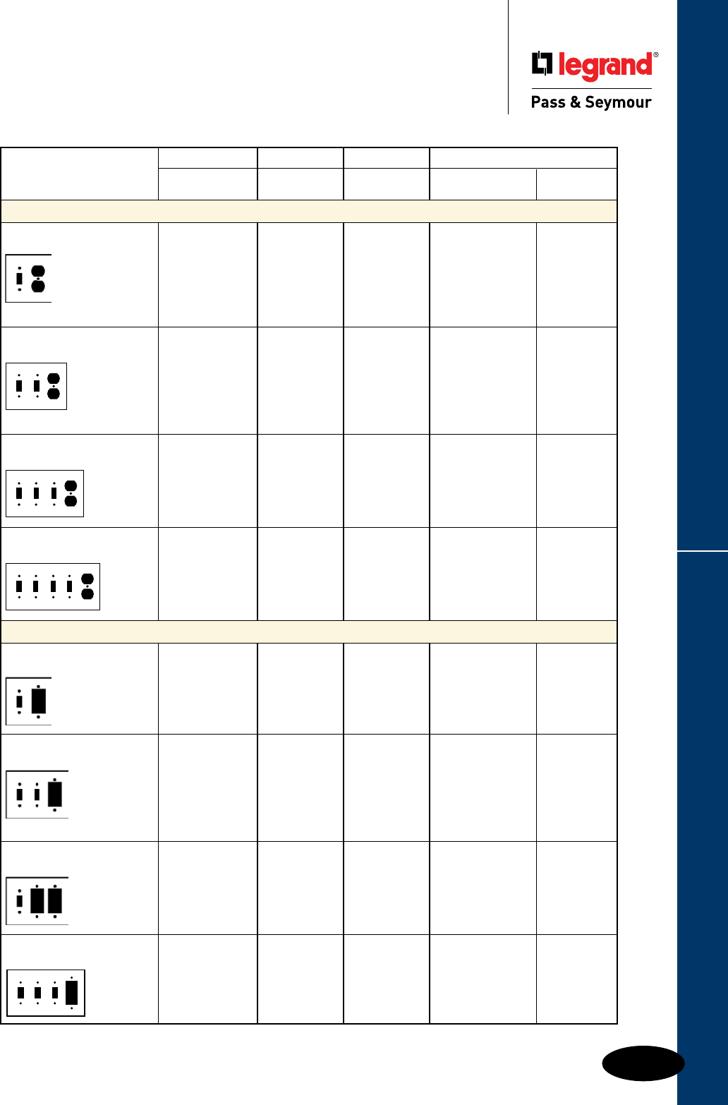
Q-15
Wall Plates & Specialties
These products listed to UL514, Cover Plates for Flush-Mounted Wiring Devices, CSA Certified.
Combination Openings
Wall Plates
Combination Openings
Standard Size Plastic & Metal
Nylon Thermoset Metal
TradeMaster®
Description Color Plates Smooth Material Smooth
Toggle Switch & Duplex Receptacle Openings
Two Gang Ivory TP18I SP18I
1 Toggle, 1 Duplex White TP18W SP18W Brass SB18
Brown TP18 SP18 Polished Brass SB18PB
Gray TP18GRY SP18GRY
Black TP18BK 302S/S SS18
Red TP18RED
Light Almond TP18LA SP18LA
Three Gang Ivory TP28I SP28I
2 Toggles, 1 Duplex White TP28W SP28W Brass SB28
Brown TP28 SP28 Polished Brass SB28PB
Gray TP28GRY SP28GRY
Black TP28BK 302S/S SS28
Red TP28RED
Light Almond TP28LA SP28LA
Four Gang Ivory SP38I Polished Brass SB38PB
3 Toggles, 1 Duplex White SP38W
Brown SP38 302S/S SS38
Gray SP38GRY
Light Almond SP38LA
Five Gang 302S/S SS48
4 Toggles, 1 Duplex 302S/S Painted Ivory SS48I
302S/S Painted White SS48W
Toggle Switch & Decorator Openings
Two Gang Ivory TP126I SP126I
1 Toggle, 1 Decorator White TP126W SP126W Aluminum SA126
Brown TP126 SP126 Brass SB126
Gray TP126GRY SP126GRY Polished Brass SB126PB
Black TP126BK SP126BK
Light Almond TP126LA SP126LA 302S/S SS126
Three Gang Ivory TP226I SP226I
2 Toggles, 1 Decorator White TP226W SP226W
Brown TP226 SP226 302S/S SS226
Gray TP226GRY SP226GRY
Light Almond TP226LA SP226LA
Black TP226BK
Three Gang Ivory SP1262I
1 Toggle, 2 Decorator White SP1262W
Brown SP1262 302S/S SS1262
Gray SP1262GRY
Black SP1262BK
Light Almond SP1262LA
Four Gang Ivory SP326I
3 Toggles, 1 Decorator White SP326W
Brown SP326 302S/S SS326
Gray SP326GRY
Light Almond SP326LA
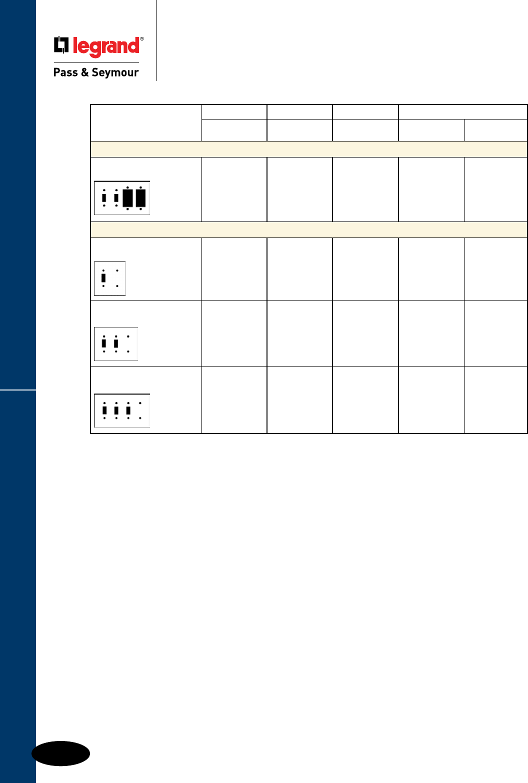
Q-16
Wall Plates & Specialties
These products listed to UL514, Cover Plates for Flush-Mounted Wiring Devices, CSA Certified.
Combination Openings
Wall Plates
Combination Openings
Standard Size Plastic & Metal
Nylon Thermoset Metal
TradeMaster®
Description Color Plates Smooth Material Smooth
Toggle Switch & Decorator Openings (cont.)
Four Gang Ivory SP2262I
2 Toggles, 2 Decorator White SP2262W
Brown SP2262
Light Almond SP2262LA
Toggle Switch & Blank Strap Mounted Openings
Two Gang
1 Toggle, 1 Blank
302S/S SS114
Three Gang
2 Toggles, 1 Blank
302S/S SS214
Four Gang
3 Toggles, 1 Blank
302S/S SS314
Q-17
Wall Plates & Specialties
These products listed to UL514, Cover Plates for Flush-Mounted Wiring Devices, CSA Certified.
Combination Openings
Wall Plates
Combination Openings
Standard Size Plastic & Metal
Nylon Thermoset Metal
TradeMaster®
Description Color Plates Smooth Material Smooth
Two Gang Combination Openings
Two Gang Ivory SP17I
1 Toggle,1 Single White SP17W
Brown SP17
Gray SP17GRY 302S/S SS17
Two Gang Ivory SP78I
Single/Duplex White SP78W
Brown SP78 Aluminum SA78
Gray SP78GRY
302S/S SS78
Two Gang Ivory TP826I SP826I
Duplex/Decorator White TP826W SP826W Polished Brass SB826PB
Brown TP826 SP826
Gray TP826GRY SP826GRY 302S/S SS826
Black
TP826BK
Red
TP826RED
Light Almond TP826LA SP826LA
Two Gang Ivory SP112I
Telephone/Toggle White SP112W
Brown SP112
Two Gang Ivory SP128I
Telephone/Duplex White SP128W
Brown SP128
Gray SP128GRY 302S/S SS128
Two Gang Ivory SP1214I
Telephone/Blank (Strap Mtd) White SP1214W
302S/S SS1214
Two Gang White SP1226W
Telephone/Decorator Brown SP1226
302S/S SS1226
Two Gang Ivory TP138I SP138I
Blank (Box Mtd)/Duplex White TP138W SP138W
Brown TP138 SP138
Gray TP138GRY SP138GRY 302S/S SS138
Black TP138BK
Red TP138RED
Light Almond TP138LA
Two Gang Ivory TP113I
Toggle/Blank (Box Mtd) White TP113W
Brown TP113
Gray TP113GRY 302S/S SS113
Black TP113BK
Light Almond TP113LA
Q-18
Wall Plates & Specialties
These products listed to UL514, Cover Plates for Flush-Mounted Wiring Devices, CSA Certified.
Combination Openings
Wall Plates
Combination Openings
Standard Size Plastic & Metal
Nylon Thermoset Metal
TradeMaster®
Description Color Plates Smooth Material Smooth
Two Gang Combination Openings (cont.)
Two Gang Ivory SP148I
Blank (Strap Mtd)/Duplex White SP148W
Brown SP148
Gray SP148GRY 302S/S SS148
Two Gang Ivory SP147I
Blank (Strap Mtd)/Single White SP147W
302S/S SS147
Two Gang Ivory SP1426I
Blank (Strap Mtd)/Decorator White SP1426W
Brown SP1426
Gray SP1426GRY 302S/S SS1426
Light Almond SP1426LA
Three & Four Gang Combination Openings
Three Gang Ivory SP182I
Toggle/Duplex/Duplex White SP182W Polished Brass SB182PB
Brown SP182
Gray SP182GRY 302S/S SS182
Light Almond SP182LA
Three Gang
Duplex/Blank (Strap Mtd)/Duplex
302S/S SS8148
Three Gang
Blank (Strap Mtd)/Toggle/Blank (Strap Mtd)
302S/S SS14114
Three Gang
Blank (Strap Mtd)/Duplex/Blank (Strap Mtd)
302S/S SS14814
Four Gang
2 Toggles, 2 Duplex
302S/S SS282
Q-19
Wall Plates & Specialties
These products listed to UL514, Cover Plates for Flush-Mounted Wiring Devices, CSA Certified.
Despard® Openings
Wall Plates
Despard® Openings
Standard Size Plastic & Metal
Despard Interchangeable Plate Supplied with Mounting Straps
See Page R-11 for Devices.
Nylon Thermoset Metal
TradeMaster®
Description Color Plates Smooth Material Smooth
One Horizontal Opening Per Gang
One Gang Ivory K1I
White K1W
Brown K1 302S/S SSK1
Two Gang
302S/S SSK12
Three Gang
302S/S SSK13
Two Horizontal Openings Per Gang
One Gang Ivory K2I
White K2W
Brown K2 302S/S SSK2
Two Gang
302S/S SSK22
Three Horizontal Openings Per Gang
One Gang Ivory K3I
White K3W
Brown K3 302S/S SSK3
Two Gang
302S/S SSK32
Three Gang
302S/S SSK33
One Vertical Opening Per Gang
One Gang Ivory K4I
White K4W
Brown K4
Q-20
Wall Plates & Specialties
These products listed to UL514, Cover Plates for Flush-Mounted Wiring Devices, CSA Certified.
Two Gang with Center Opening
Wall Plates
Two Gang with Center Opening
Standard Size Metal
Nylon Thermoset Metal
TradeMaster®
Description Color Plates Smooth Material Smooth
Two Gang with Center Opening
Toggle Switch
302S/S SS740
Blank-Box Mount
302S/S SS743
Decorator
302S/S SS746
Single Receptacle
302S/S SS747
Duplex Receptacle
302S/S SS748
.906 diameter
Reference Page A-3
for device
KL Series Locking Switch Plates
One Gang 302S/S SS717
Two Gang 302S/S SS727
.906 diameter
Reference Page A-3
for device
Q-21
Wall Plates & Specialties
These products listed to UL514, Cover Plates for Flush-Mounted Wiring Devices, CSA Certified.
Louver & Biplex/Triplex Openings
Wall Plates
Louver & Biplex/Triplex Openings
Standard Size Metal
Nylon Thermoset Metal
TradeMaster®
Description Color Plates Smooth Material Smooth
Louver Plates
One Gang Brass SB760
Horizontal 302S/S SS760
302S/S Painted Ivory SS760I
302S/S Painted White SS760W
302S/S Painted Light Almond SS760LA
One Gang Brass SB771
Vertical 302S/S SS771
302S/S Painted Ivory SS771I
302S/S Painted White SS771W
302S/S Painted Brown SS771X
302S/S Painted Gray SS771GRY
302S/S Painted Light Almond SS771LA
Two Gang
Vertical
302S/S SS772
Biplex/Triplex Receptacle
One Gang
1 Biplex/Triplex
302S/S SS9
Q-22
Wall Plates & Specialties
These products listed to UL514, Cover Plates for Flush-Mounted Wiring Devices, CSA Certified.
Toggle, Duplex & Single Recept. Openings
Wall Plates
Toggle Switch,
Duplex & Single Receptacle Openings
Junior-Jumbo & Jumbo Plastic & Metal
Nylon Thermoset Metal
TradeMaster® Junior-Jumbo Jumbo Junior-Jumbo Jumbo
Description Color Jumbo Smooth Smooth Material Smooth Smooth
Toggle Switch Openings
One Gang Ivory TPJ1I SPJ1I SPO1I
White TPJ1W SPJ1W SPO1W Brass SBJ1 SBO1
Brown TPJ1 SPJ1 SPO1 302S/S SSJ1 SSO1
Gray TPJ1GRY
Light Almond TPJ1LA SPJ1LA
Two Gang Ivory TPJ2I SPJ2I SPO2I
White TPJ2W SPJ2W SPO2W Brass SBJ2
Brown TPJ2 SPJ2 SPO2 302S/S SSJ2 SSO2
Gray TPJ2GRY
Light Almond TPJ2LA SPJ2LA
Three Gang Ivory TPJ3I SPJ3I
White TPJ3W SPJ3W 302S/S SSJ3 SSO3
Brown TPJ3 SPJ3
Gray TPJ3GRY
Light Almond TPJ3LA SPJ3LA
Four Gang Ivory TPJ4I SPJ4I
White TPJ4W SPJ4W 302S/S SSO4
Brown TPJ4 SPJ4
Gray TPJ4GRY
Light Almond TPJ4LA SPJ4LA
Duplex Receptacle Openings
One Gang Ivory TPJ8I SPJ8I SPO8I
White TPJ8W SPJ8W SPO8W Brass SBJ8 SBO8
Brown TPJ8 SPJ8 SPO8 302S/S SSJ8 SSO8
Gray TPJ8GRY
Light Almond TPJ8LA SPJ8LA SPO8LA
Two Gang Ivory TPJ82I SPJ82I SPO82I
White TPJ82W SPJ82W SPO82W 302S/S SSJ82 SSO82
Brown TPJ82 SPJ82 SPO82
Gray TPJ82GRY SPJ82GRY
Light Almond TPJ82LA SPJ82LA
Three Gang
302S/S SSO83
Single Receptacle Openings
One Gang Ivory TPJ7I SPJ7I
White TPJ7W SPJ7W 302S/S SSJ7 SSO7
Brown TPJ7 SPJ7
Gray TPJ7GRY
Light Almond TPJ7LA SPJ7LA
Q-23
Wall Plates & Specialties
These products listed to UL514, Cover Plates for Flush-Mounted Wiring Devices, CSA Certified.
Decorator Openings & Blank Plates
Wall Plates
Decorator Openings & Blank Plates
Junior-Jumbo & Jumbo Plastic & Metal
Nylon Thermoset Metal
TradeMaster® Junior-Jumbo Jumbo Junior-Jumbo Jumbo
Description Color Jumbo Smooth Smooth Material Smooth Smooth
Decorator Openings
One Gang Ivory TPJ26I SPJ26I SPO26I
White TPJ26W SPJ26W SPO26W Brass SBJ26 SBO26
Brown TPJ26 SPJ26 SPO26 302S/S SSJ26 SSO26
Gray TPJ26GRY
Red TPJ26RED
Light Almond TPJ26LA SPJ26LA SPO26LA
Two Gang Ivory TPJ262I SPJ262I SPO262I
White TPJ262W SPJ262W SPO262W 302S/S SSJ262 SSO262
Brown TPJ262 SPJ262 SPO262
Gray TPJ262GRY
Light Almond TPJ262LA SPJ262LA
Three Gang Ivory TPJ263I SPJ263I
White TPJ263W SPJ263W 302S/S SSJ263
Brown TPJ263 SPJ263
Gray TPJ263GRY
Light Almond TPJ263LA SPJ263LA
Four Gang Ivory TPJ264I SPJ264I
White TPJ264W SPJ264W
Brown TPJ264 SPJ264
Gray TPJ264GRY
Light Almond TPJ264LA SPJ264LA
Blank Plates – Box & Strap Mounted
One Gang Blank – Box Mtd. Ivory TPJ13I SPJ13I SPO13I
White TPJ13W SPJ13W SPO13W 302S/S SSJ13 SSO13
Brown TPJ13 SPJ13 SPO13
Gray TPJ13GRY
Light Almond TPJ13LA SPJ13LA
Two Gang Blank – Box Mtd. Ivory SPO23I
White SPO23W 302S/S SSO23
Brown SPO23
Three Gang Blank – Box Mtd.
302S/S SSO33
One Gang Blank – Strap Mtd.
302S/S SSO14
Two Gang Blank – Strap Mtd.
302S/S SSO24
Three Gang Blank – Strap Mtd.
302S/S SSO34
Q-24
Wall Plates & Specialties
These products listed to UL514, Cover Plates for Flush-Mounted Wiring Devices, CSA Certified.
Combination Openings
Wall Plates
Combination Openings
Junior-Jumbo & Jumbo Plastic & Metal
** strap mounted
* box mounted
Nylon Thermoset Metal
TradeMaster® Junior-Jumbo Jumbo Junior-Jumbo Jumbo
Description Color Jumbo Smooth Smooth Material Smooth Smooth
Two Gang Combination Openings
Two Gang Ivory TPJ18I SPJ18I SPO18I
Toggle/Duplex White TPJ18W SPJ18W SPO18W 302S/S SSJ18 SSO18
Brown TPJ18 SPJ18 SPO18
Gray TPJ18GRY
Light Almond TPJ18LA SPJ18LA
Two Gang Ivory TPJ126I SPJ126I
Toggle/Decorator White TPJ126W SPJ126W 302S/S SSJ126 SSO126
Brown TPJ126 SPJ126
Gray TPJ126GRY
Light Almond TPJ126LA SPJ126LA
Two Gang
Toggle/Blank (Strap Mtd) 302S/S SSO114
Supplied with 340 Yoke
Two Gang Ivory TPJ113I SPJ113I SPO113I
Toggle/Blank (Box Mtd) White TPJ113W SPJ113W
Brown TPJ113 SPJ113 SPO113
Gray TPJ113GRY
Light Almond TPJ113LA
Two Gang Ivory SPJ138I SPO138I
Blank (Box Mtd)/Duplex White SPJ138W 302S/S SSO138
Brown SPJ138 SPO138
Two Gang Ivory TPJ826I SPJ826I
Duplex/Decorator White TPJ826W SPJ826W
Brown TPJ826
Gray TPJ826GRY
Light Almond TPJ826LA SPJ826LA
Two Gang Ivory SPJ1426I** SPO1326I*
Blank/Decorator White SPJ1426W** SPO1326W*
Brown SPJ1426** SPO1326*
Three Gang
2 Toggles/Duplex 302S/S SSO28
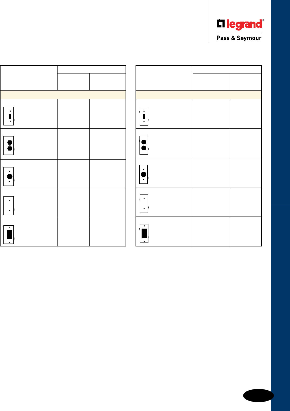
Q-25
Wall Plates & Specialties
These products listed to UL514, Cover Plates for Flush-Mounted Wiring Devices, CSA Certified.
Sectional
Wall Plates
Sectional
Thermoplastic Thermoplastic
Semi-Jumbo
Smooth
Description Color Nylon
Sectional Wall Plates – Center Sections
Toggle Switch Ivory PJSC1I
White PJSC1W
Light Almond PJSC1LA
Duplex Receptacle Ivory PJSC8I
White PJSC8W
Light Almond PJSC8LA
Single Receptacle Ivory PJSC7I
White PJSC7W
Light Almond PJSC7LA
Blank, Strap Mounted Ivory PJSC14I
supplied with #340 Yoke White PJSC14W
Light Almond PJSC14LA
Decorator Ivory PJSC26I
White PJSC26W
Light Almond PJSC26LA
Semi-Jumbo
Smooth
Description Color Nylon
Sectional Wall Plates – End Sections
Toggle Switch Ivory PJSE1I
White PJSE1W
Light Almond PJSE1LA
Duplex Receptacle Ivory PJSE8I
White PJSE8W
Light Almond PJSE8LA
Single Receptacle Ivory PJSE7I
White PJSE7W
Light Almond PJSE7LA
Blank, Strap Mounted Ivory PJSE14I
supplied with #340 Yoke White PJSE14W
Light Almond PJSE14LA
Decorator Ivory PJSE26I
White PJSE26W
Light Almond PJSE26LA
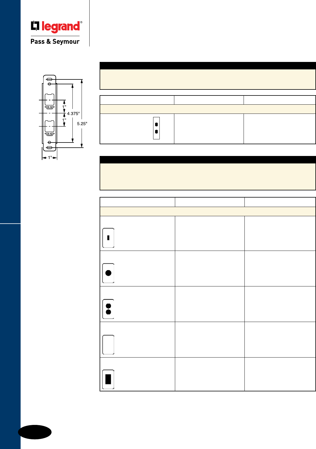
Q-26
Wall Plates & Specialties
These products listed to UL514, Cover Plates for Flush-Mounted Wiring Devices, CSA Certified.
Tandem & Handy Box Plates
Wall Plates
Tandem & Handy Box Plates
Features
n Handy Box Plates give a finished appearance
and style to surface mounted boxes.
n Available in the five most-used openings, they
have a bright corrosion-resistant zinc-plated finish.
n Plate conceals rough edge of box.
Features
n Tandem wall plates are ideal for curtain wall
and movable partitions or wherever limited
wiring exists.
n Note: Write factory for availability of other
tandem sizes, materials, and openings.
Description Material Catalog Number
Tandem Wall Plates
1-3/4" W x 6-1/8" H
2 Vertical Devices 302S/S SSTK424
Supplied with #342 Strap
342 Strap
Description Material Catalog Number
Galvanized Steel Handy Box Plates
One Gang
Toggle Switch Plated SH1
One Gang
Single Receptacle Plated SH7
One Gang
Duplex Receptacle Plated SH8
One Gang
Blank (Box Mounted) Plated SH13
One Gang
Decorator/GFCI Plated SH26
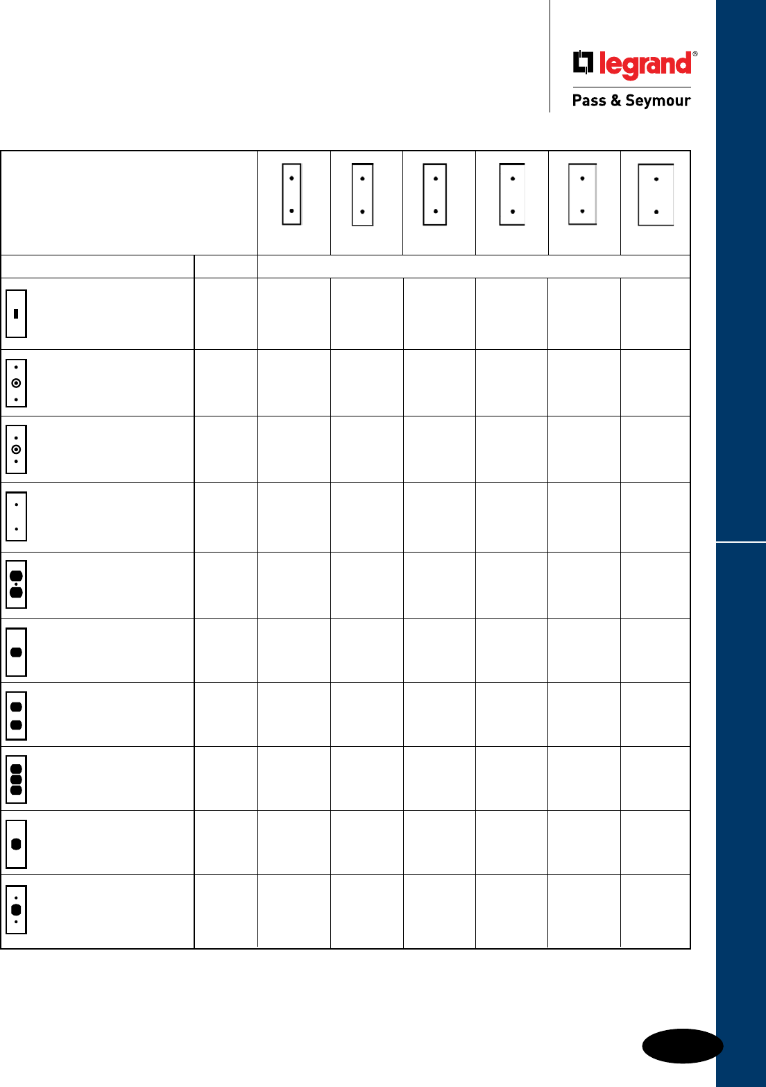
Q-27
Wall Plates & Specialties
These products listed to UL514, Cover Plates for Flush-Mounted Wiring Devices, CSA Certified.
Narrow Metal
Wall Plates
Narrow Metal
Made to Order – Consult factory for price and availability
Note: All narrow plates are 4-1/2" high.
Made to Order Wall Plates
1-3/8" 1-1/2" 1-11/16" 1-3/4" 2" 2-1/2"
Description Material Catalog Numbers
Toggle Switch Aluminum SAN11 SAN14
302S/S SSN11 SSN14 SSN15
Telephone Outlet
13/32" Hole – Box Mounted
302S/S SSN117
Telephone Outlet
13/32" Hole – Strap Mounted 302S/S SSN121
Blank
Aluminum SAN144
Strap Mounted, 1 #340 Yoke
302S/S SSN142 SSN144
Duplex Receptacle Aluminum SAN85
302S/S SSN85
1 Despard® Interchangeable Aluminum SANK14
Horizontal Opening
Supplied With #348 Mounting Strap 302S/S SSNK14
2 Despard Interchangeable Aluminum SANK24
Horizontal Openings
Supplied With #348 Mounting Strap 302S/S SSNK24
3 Despard Interchangeable
Horizontal Openings 302S/S SSNK34
Supplied With #348 Mounting Strap
1 Despard Interchangeable Aluminum SANK41 SANK43 SANK44
Vertical Opening
Supplied With #347 Mounting Strap 302S/S SSNK41 SSNK43 SSNK44
1 Despard Interchangeable
Aluminum SANK51 SANK53 SANK54
Vertical Opening
Device Mounted
Use with #347 Strap 302S/S SSNK51 SSNK53 SSNK54
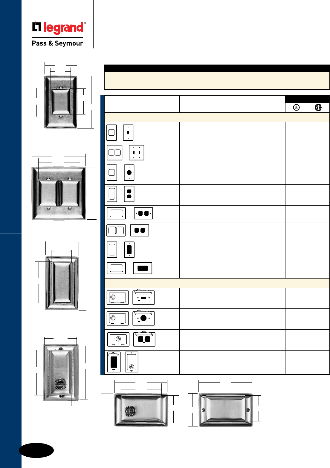
Q-28
Wall Plates & Specialties
WP2
4.5"
4.56"
3.56"
WP26L
4.50"
2.750"
1.75"
3.594"
2.75"
1.75"
3.606" 4.5"
WP8
WP26
4.5"
2.75"
2.375"
1.75"
2.297"
WP1
WP7
Dustproof Stainless Steel Covers
Wall Plates
Dustproof Stainless Steel Covers
Specification Grade
WPH8, WPH26
2.75"
4.5"
3.594"
1.75"
Catalog Number WP255K.
Replacement key for all
Dustproof Locking Covers.
(Two keys furnished with
each unit.)
Note: All locks
keyed the same.
Features
n Exclusive – Spec-grade stainless steel dust covers.
n Ideal for hard-use and corrosive applications.
n Aesthetically pleasing.
Stainless Steel Covers are dustproof only and do not meet NEC 406.8(A) or (B).
Catalog Number Description
Dustproof Stainless Steel Covers
WP1 1 Toggle Switch • •
1 Small Cover, Vertical 1 Gang Plate
Available for Four Screw Mount – add suffix -FS
WP2 2 Toggle Switches • •
2 Small Covers, Vertical 2 Gang Plate
WP7 1 Single Receptacle • •
1 Small Cover, Vertical 1 Gang Plate
Available for Four Screw Mount – add suffix -FS
WP8 1 Duplex Receptacle • •
1 Long Cover, Vertical 1 Gang Plate
WPH8 1 Duplex Receptacle • •
1 Long Cover, Horizontal 1 Gang Plate
WPD8 1 Duplex Receptacle • •
2 Small Covers, Horizontal 1 Gang Plate
WP26 1 Decorator/GFCI • •
1 Long Cover, Vertical 1 Gang Plate
WPH26 1 Decorator/GFCI • •
1 Long Cover, Horizontal 1 Gang Plate
Dustproof Locking Stainless Steel Covers
WPH1L Toggle Opening • •
Horizontal
WPH7L Single Receptacle Opening • •
Horizontal
WPH8L Duplex Receptacle Opening • •
Horizontal
WP26L Decorator/GFCI • •
Vertical
3rd Party Compliance
For Weatherproof Stainless Steel Covers, see Page P-14.
WPH1L, WPH7L
4.5"
2.75"
3.50"
2.32"
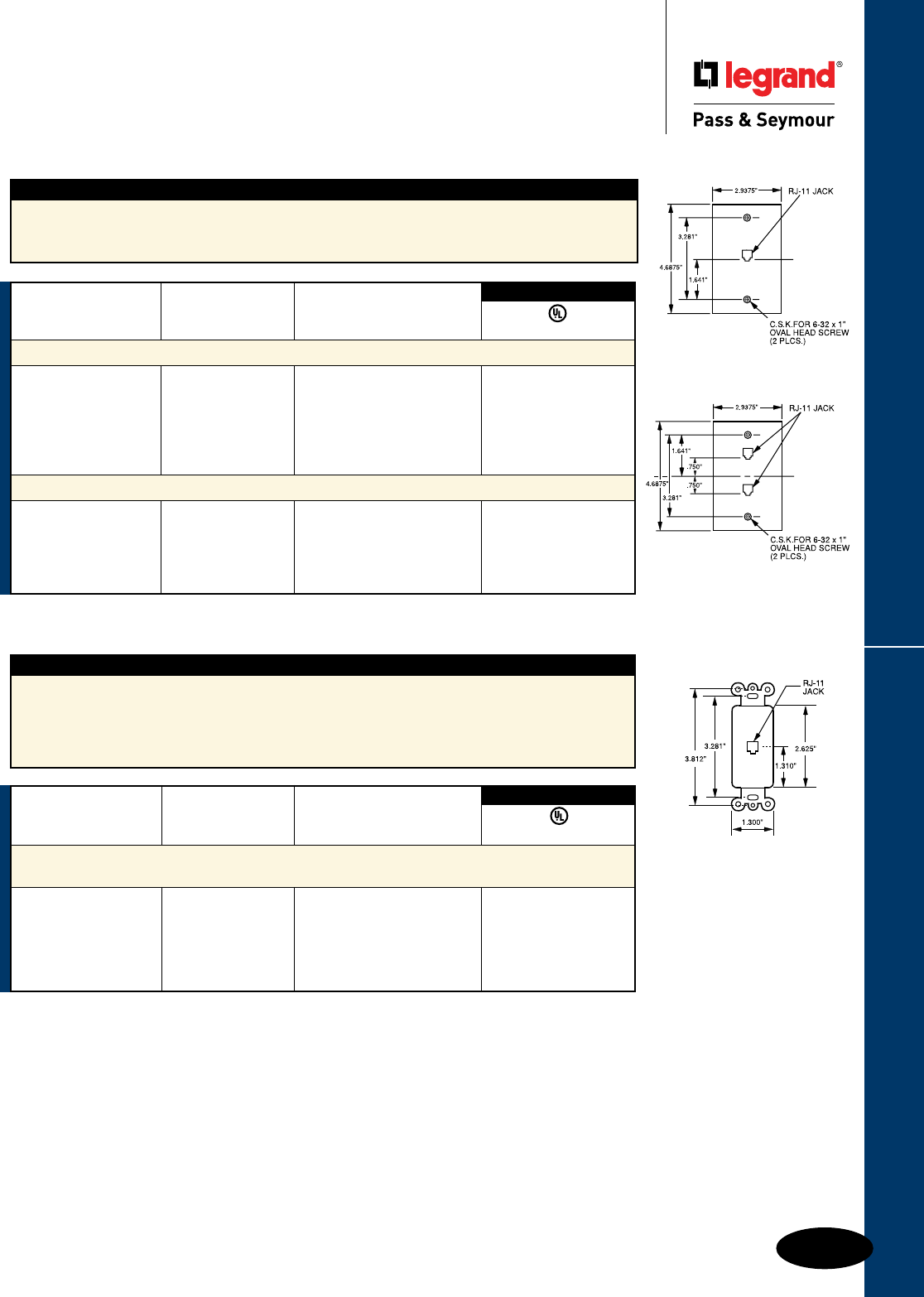
Q-29
Wall Plates & Specialties Communication Devices
Wall Plates
Communication Devices
Telephone Wiring Devices
26TE14
26TE16
TPTE1
TPTE2
3rd Party Compliance
UL1863
Catalog Number Color Conguration
Decorator Modular Jack
Single Gang, 1 Opening Modular Jack
26TE14I Ivory 4 Conductor •
26TE14W White 4 Conductor •
26TE14LA Light Almond 4 Conductor •
26TE16I Ivory 6 Conductor •
26TE16W White 6 Conductor •
Features
n RJ11 modular jack.
n Mar-resistant wall plate.
n Wall plate dimension is Standard size.
n Fits standard size single gang electrical box.
n Meets FCC Part 68 requirements.
Features
n Decorator-style rectangular design.
n RJ11 modular jack.
n Fits standard single gang electrical box.
n May be used in multigang applications.
n Face constructed of high-impact
thermoplastic.
n Brass terminals with nickel-plated steel
screws and washers.
n Meets FCC Part 68 requirements.
3rd Party Compliance
UL1863
Catalog Number Color Conguration
Single Gang Opening Modular Telephone Jack with Wall Plate
TPTE1I Ivory 4 Conductor
TPTE1W White 4 Conductor
TPTE1 Brown 4 Conductor
TPTE1GRY Gray 4 Conductor
TPTE1BK Black 4 Conductor
TPTE1LA Light Almond 4 Conductor
Single Gang, Two Modular RJ11 Telephone Jacks with Wall Plate
TPTE2I Ivory 4 Conductor
TPTE2W White 4 Conductor
TPTE2 Brown 4 Conductor
TPTE2BK Black 4 Conductor
TPTE2LA Light Almond 4 Conductor
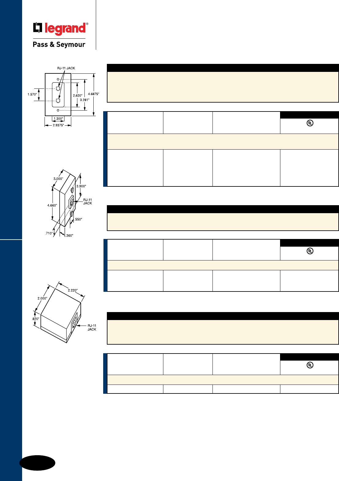
Q-30
Wall Plates & Specialties
These products listed to UL514, Cover Plates for Flush-Mounted Wiring Devices, CSA Certified.
Communication Devices
Wall Plates
Communication Devices
Telephone Wiring Devices
Features
n RJ-11 modular jack.
n High-impact thermoplastic face plate and back body.
n Nickel-plated steel screw terminals.
n Zinc-plated mounting lugs.
Features
n Nickel-plated steel screws and washers.
n Brass terminals.
n Comes with mounting screws and adhesive pad.
n Snap-on cover and base constructed of
high-impact thermoplastic.
Catalog Number Color Conguration
Decorator Duplex Modular Jack with Smooth Plate
Single Gang, 2 Openings
26TE24I Ivory 4 Conductor •
26TE24W White 4 Conductor •
26TE24LA Light Almond 4 Conductor •
26TE26I Ivory 6 Conductor •
26TE26W White 6 Conductor •
3rd Party Compliance
UL1863
Catalog Number Color Conguration
Modular Wall Mount Telephone Jack for Hanging Phones
WMTE14I Ivory 4 Conductor •
WMTE14W White 4 Conductor •
WMTE14LA Light Almond 4 Conductor •
3rd Party Compliance
UL1863
26TE24
SMTE14
WMTE14
Features
n One piece molded plate Decorator outline.
n Two RJ11 modular jacks.
n Fits standard single gang electrical box.
n Face constructed of high-impact thermoplastic.
n Brass terminals with nickel-plated steel
screws and washers.
n Wall plate dimension is standard size.
n Meets FCC Part 68 requirements.
3rd Party Compliance
UL1863
Catalog Number Color Conguration
Surface Mount Modular RJ-11 Telephone Jack
SMTE14I Ivory 4 Conductor •
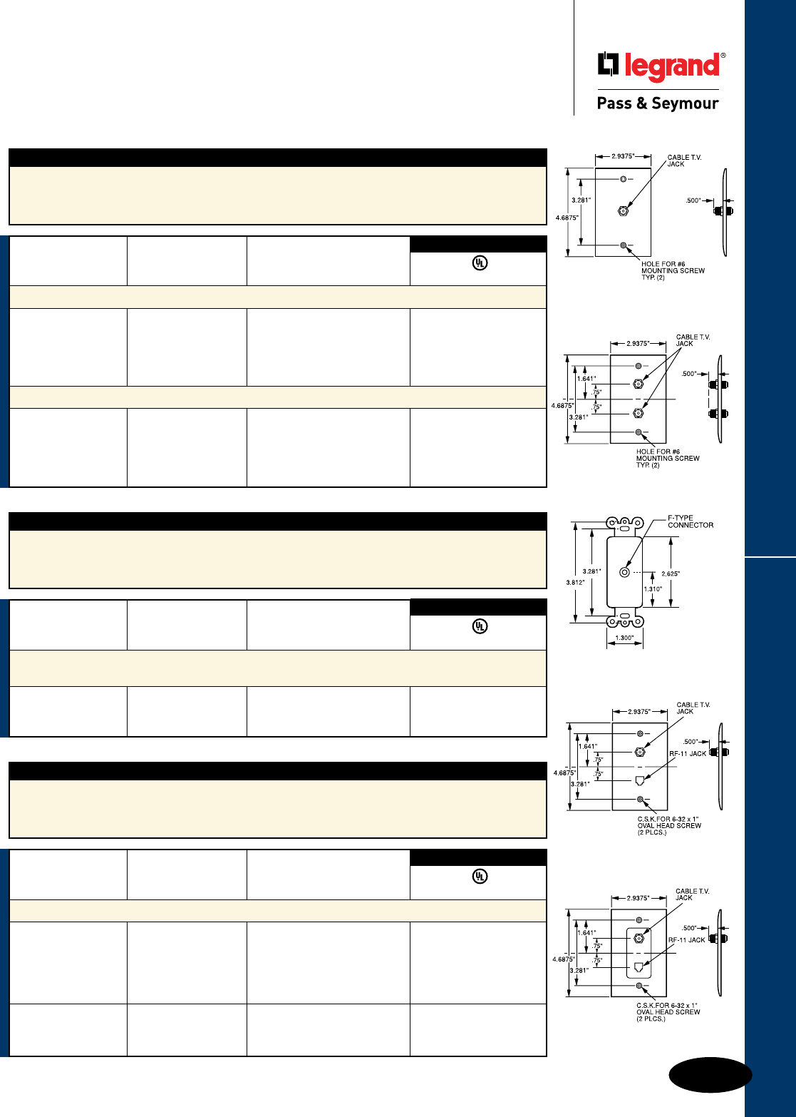
Q-31
Wall Plates & Specialties
These products listed to UL514, Cover Plates for Flush-Mounted Wiring Devices, CSA Certified.
Communication Devices
Wall Plates
Communication Devices
Telephone & CATV Wiring Devices
Features
n Mar-resistant wall plate.
n Fits standard size single gang electrical box.
n Wall plate dimension is Standard size.
n Nickel-plated steel.
n Connector is threaded at each end.
Features
n Decorator outline.
n Face constructed of high-impact thermoplastic.
n Zinc-plated steel strap.
n Nickel-plated “F” type connector.
n Threaded on each end.
Features
n Decorator outline.
n RJ11 modular jack.
n Face constructed of high-impact thermoplastic.
n Zinc-plated steel strap.
n Nickel-plated “F” type connector.
n Threaded on each end.
Catalog Number Color Conguration
“F” Type with One Coaxial Connector & Wall Plate, Single Gang
TPCATVI Ivory F-type COAX Connector •
TPCATVW White F-type COAX Connector •
TPCATV Brown F-type COAX Connector •
TPCATVBK Black F-type COAX Connector •
TPCATVLA Light Almond F-type COAX Connector •
“F” Type with Two Coaxial Connectors & Wall Plate, Single Gang
TPCATV2I Ivory 2 F-type COAX Connectors •
TPCATV2W White 2 F-type COAX Connectors •
TPCATV2 Brown 2 F-type COAX Connectors •
TPCATV2BK Black 2 F-type COAX Connectors •
TPCATV2LA Light Almond 2 F-type COAX Connectors •
3rd Party Compliance
UL1863
Catalog Number Color Conguration
Decorator “F” Type Coaxial Connector
Single Gang with 1 COAX Connector
26CATVI Ivory F-type COAX Connector •
26CATVW White F-type COAX Connector •
26CATVLA Light Almond F-type COAX Connector •
3rd Party Compliance
UL1863
Catalog Number Color Conguration
Combination Coaxial Connector & Telephone Jack
TPTELTVI Ivory •
TPTELTVW White F-type COAX Connector with •
TPTELTV Brown 4 Conductor RJ-11 jack •
TPTELTVBK Black •
TPTELTVLA Light Almond •
26TELTVICC10 Ivory Same as TPTELTV with •
26TELTVWCC10 White one-piece molded plate •
26TELTVLACC10 Light Almond Decorator outline. •
3rd Party Compliance
UL1863
TPCATV
26CATV
TPTELTV
26TELTVCC10
TPCATV2
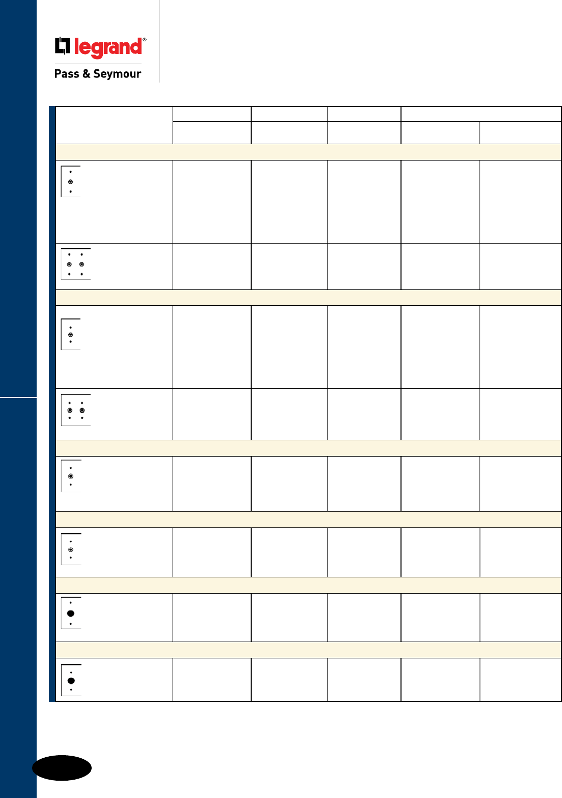
Q-32
Wall Plates & Specialties
These products listed to UL514, Cover Plates for Flush-Mounted Wiring Devices, CSA Certified.
Communication Plates
Wall Plates
Communication Plates
Standard Size Plastic & Metal
(Metal plates have
removable 13/32" I.D.
grommet in 17/32" hole.)
(Metal plates have removable
5/8" I.D. grommet in 7/8" hole.)
(Metal plates have
removable 13/32" I.D.
grommet in 17/32" hole.)
Nylon Thermoset Metal
TradeMaster®
Description Color Plates Smooth Material Smooth
Telephone or Cable Outlet 13/32" Hole, Box Mounted
One Gang Ivory TP11I SP11I Brass SB11
1 Outlet White TP11W SP11W 302S/S SS11
Brown TP11 SP11
Gray TP11GRY
Black TP11BK
Red TP11RED
Light Almond TP11LA
Two Gang Ivory SP21I
2 Outlets White SP21W
Gray SP21GRY 302S/S SS21
Telephone or Cable Outlet 13/32" Hole, Strap Mounted, With Adjustment Yoke
Ivory TP12I SP12I Brass SB12
One Gang White TP12W SP12W
1 Outlet Brown TP12 SP12 430S/S SL12
1 #340 Yoke Gray TP12GRY 302S/S SS12
Black TP12BK SP12BK
Red SP12RED
Light Almond TP12LA SP12LA
Two Gang 302S/S SS22
2 Outlets 302S/S Painted Ivory SS22I
302S/S Painted White SS22W
302S/S Painted Gray SS22GRY
Telephone or Cable Outlet 5/8" Hole, Strap Mounted
One Gang
1 Outlet 302S/S SS730
1 #340 Yoke
Telephone or Cable Outlet 13/32" Hole With Knockout, Strap Mounted
One Gang Ivory SP732I
1 Outlet Brown SP732
1 #340 Yoke Gray SP732GRY
Telephone or Cable Outlet 5/8" ID, Box Mounted
One Gang Ivory TP60I SP60I
1 Outlet White TP60W SP60W
Light Almond TP60LA SP60LA
Telephone or Cable Outlet 11/4" Hole, Strap Mounted
One Gang
1 Outlet 302S/S SS736
Supplied With #340 Yoke
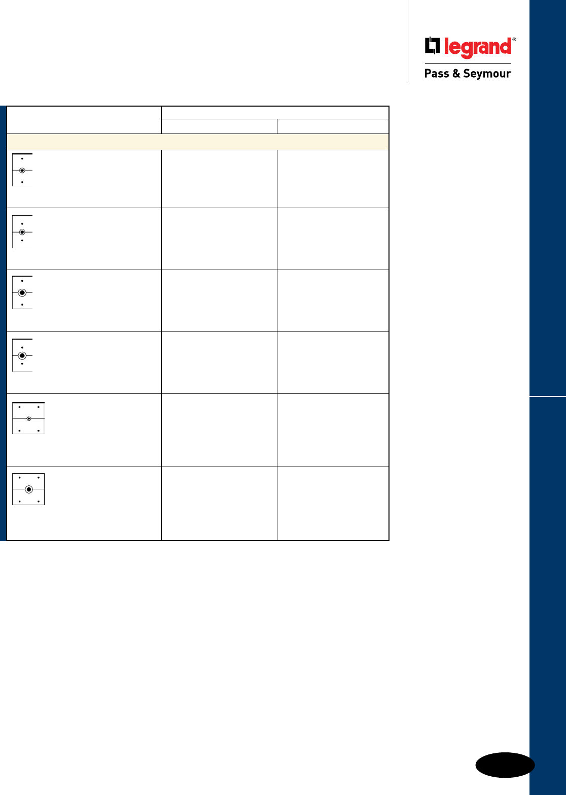
Q-33
Wall Plates & Specialties
These products listed to UL514, Cover Plates for Flush-Mounted Wiring Devices, CSA Certified.
Communication Plates
Wall Plates
Communication Plates
Communication
Plates
* For telephone, security systems, FM and cable TV antennas or wherever cable interconnections are required.
** Strap Mounted with 2 #340 Yokes.
Box Mounted. Removable 13/32" I.D.
grommet in 1/2" hole.
Strap Mounted. Removable 13/32" I.D.
grommet in 17/32" hole.
Box Mounted. Removable 5/8" I.D.
grommet in 7/8" hole.
Strap Mounted. Removable 5/8" I.D.
grommet in 7/8" hole.
(Also Furnished for Strap Mounting Cat. # SS786
with 2 #340 Yokes. Box Mounted. Removable
13/32" I.D. grommet in 17/32" hole.)
(Also Furnished for Strap Mounting Cat. # SS788
with 2 #340 Yokes. Box Mounted. Removable
5/8" I.D. grommet in 7/8" hole.)
Metal
Description Material Smooth
Horizontal-Split Wall Plates for Television or Cable Lead-In*
One Gang
1 Outlet 302S/S SS751
One Gang
1 Outlet 302S/S SS752
Supplied With #340 Yoke
One Gang
1 Outlet 302S/S SS753
One Gang 302S/S SS754
1 Outlet
Supplied With #340 Yoke
Two Gang 302S/S** SS785
1 Centered Outlet
Two Gang
1 Centered Outlet 302S/S** SS787
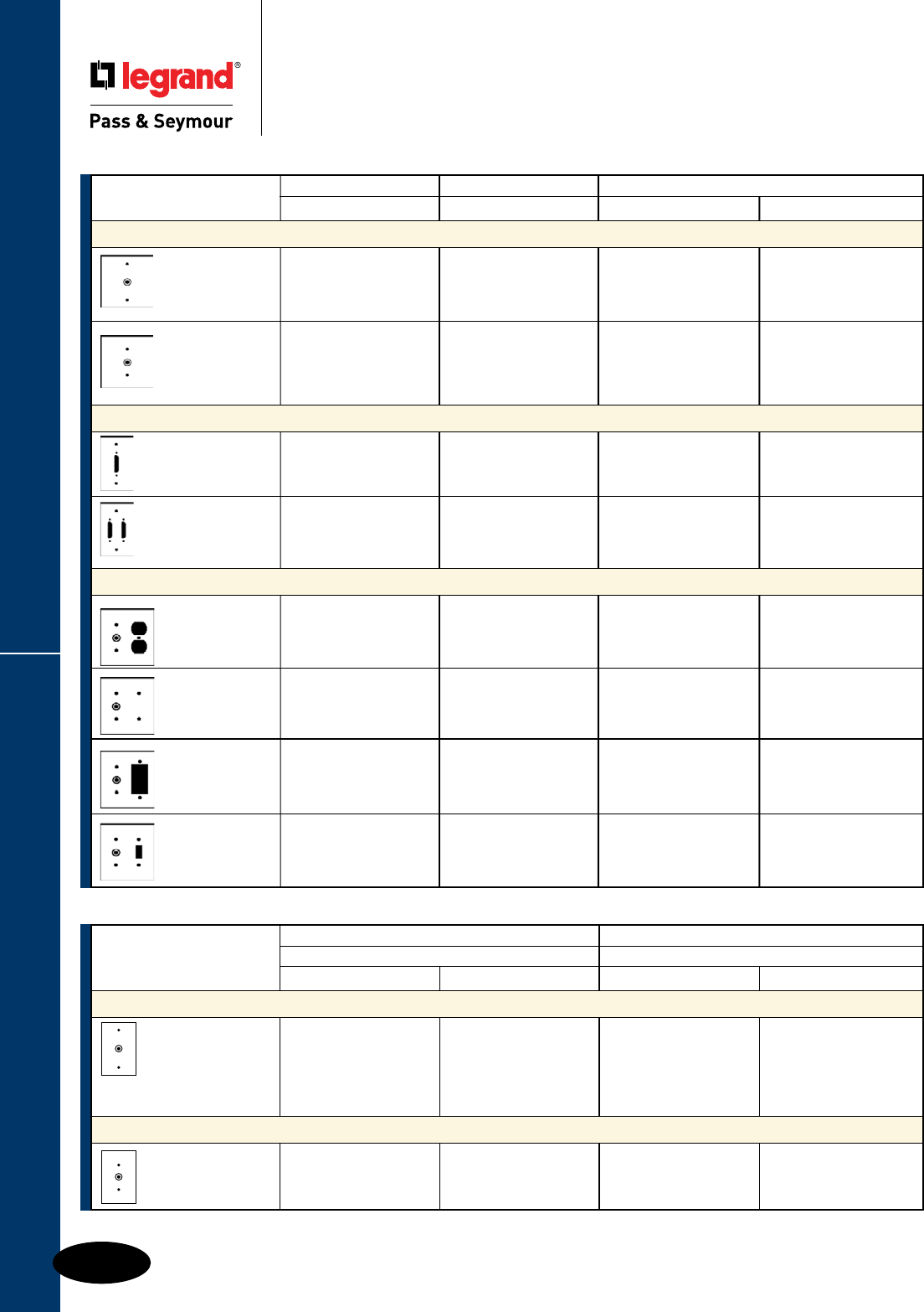
Q-34
Wall Plates & Specialties
**These products listed to UL514, Cover Plates for Flush-Mounted Wiring Devices, CSA Certified.
Communication Plates
Wall Plates
Communication Plates
*Has 13/32" and 5/8" double knockout.
Thermoset Metal
Description Color Smooth Material Smooth
Two Gang with Centered Openings
**
1 Centered Outlet 302S/S SS741
Box Mounted
1 Centered Outlet 302S/S SS742
Strap Mounted
Supplied with
#340 Yoke
Computer Jack Plates for RS-232 Connectors
**
One Gang
One Jack Opening 302S/S SS791
One Gang
Two Jack Opening 302S/S SS792
Standard Combination Two Gang*
Ivory SP128I 302S/S SS128
Two Gang White SP128W
Telephone/Duplex Brown SP128
Gray SP128GRY
Two Gang Ivory SP1214I
Telephone/Blank White SP1214W 302S/S SS1214
(Strap Mtd)
White SP1226W
Two Gang Brown SP1226 302S/S SS1226
Telephone/Decorator
Two Gang Ivory SP112I
Telephone/Toggle White SP112W
Brown SP112
(Metal plates have removable 13/32"
I.D. grommet in 17/32" hole.)
Thermoset Metal
Junior-Jumbo Jumbo
Description Color Smooth Material Smooth
Telephone/Cable Outlet**
One Gang
Ivory SPJ11I 302S/S SSO11
1 Outlet White SPJ11W
Light Almond SPJ11LA
Telephone/Cable Outlet**
One Gang 302S/S SSO12
1 Outlet
Supplied with #340 Yoke
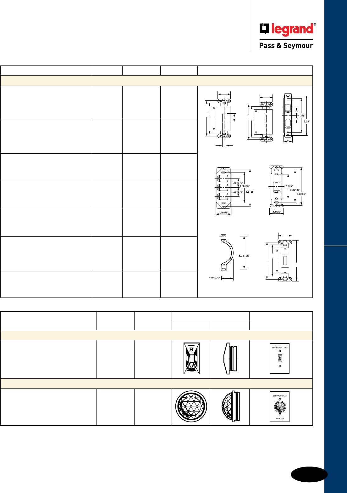
Q-35
Wall Plates & Specialties Mounting Straps, Yokes & Jewels
Specialties
Mounting Straps, Yokes & Jewels
Jewel Catalog Jewels Jewels Shown
Description Color Number Front View Side View with Wall Plates
Plastic Jewels – For Toggle Switch Openings (Style #1)
Rectangular acrylic plastic warning light Red 406RED
jewel for toggle switch plates with Green 406GN
holding ring. Red Jewel Standard. White 406W
Plastic Jewels – For Single Receptacle Openings (Style #7)
Round acrylic plastic warning light Red 405RED
jewel for single receptacle plates with Green 405GN
holding ring. Red Jewel Standard. White 405W
UL Listed.
342326
327
3.812''
3.281''
2.625''
1.300''
SLATER
80700-I340
347
348
Description Finish Color Catalog Number Dimensions
Mounting Straps & Yokes
Mounting strap for dimmer insert. Painted Ivory 327I
Box mounted. Change from decorator Steel White 327W
to toggle opening. Brown 327
Light Almond 327LA
Mounting strap for blank insert. Painted Ivory 326I
Box mounted. Changes decorator Steel White 326W
opening to blank. Brown 326
Light Almond 326LA
Tandem mounting strap with two Bright 342
vertical openings. Plate screw hole Zinc
spacing 4-3/8".
Mounting strap with three horizontal Bright 348
openings. Plate screw hole spacing Zinc
3-13/16". Box mounted.
Mounting strap with single vertical Bright 347
opening. Plate screw hole spacing Zinc
3-13/16". Box mounted.
Adjustment yoke for strap mounted Bright 340
telephone and blank wall plates. Slots Zinc
3-9/32" C to C. Plate screw holes
2-3/8" C to C. Box mounted.
Mounting strap for blank insert. Thermoset Ivory 80700I
Changes toggle opening to blank, box White 80700W
mounted. Light Almond 80700LA
4.07''
1.30''
2.37''
3.25''
3.65''

Q-36
Wall Plates & SpecialtiesHallway Lights & Combination Devices
Specialties
Decorator Hallway Lights &
Combination Devices
Features
n Impact-resistant face and body.
n GE Lexan™ high impact-resistant lens.
n External screw-pressure-plate back and side
wired. Accepts #12 and #14 AWG.
n Ground screw position under the end of the
strap minimizes the risk of contact.
n Energy-efficient LED has average 20-year life
expectancy: eliminates bulb replacement.
n Sensor automatically turns light ON in the dark.
n Increased light output for better illumination.
n Light sensor for enhanced sensitivity.
Tamper-Resistant Combination Version:
n UL tested shutter mechanism for protection
against improper object insertion per UL478.
n Specially designed for increased protection of
children in their homes.
n Superior protection than traditional outlet “caps”
or “protection plates.”
Catalog Rating Light Output
Number A. VAC In 1' FCD* Color UL1598
TradeMaster® Decorator Full Hallway Light with Light Sensor
TMHWLCC — 120 0.1328 Clear •
Enhanced Decorator Full Hallway Light with Light Sensor
TMHWLECC — 120 1.079 Clear •
Enhanced Decorator Full Hallway Light without Light Sensor
TMHWLENSCC — 120 1.113 Clear •
Full Hallway Decorator Light for use with P&S Metal Louver Plates**
TMHWLLOUVCC — 120 0.0843 Clear •
3rd Party Compliance
Catalog Rating Light Output NEMA
Number A. VAC In 1' FCD* Color Cong. No. UL498
TradeMaster® Decorator Hallway Light & Single Receptacle
TM8HWLICC 15 120/125 0.1442 Ivory 5-15R •
TM8HWLWCC 15 120/125 0.1442 White 5-15R •
TM8HWLBKCC 15 120/125 0.1442 Black 5-15R •
TM8HWLCC 15 120/125 0.1442 Brown 5-15R •
TM8HWLLACC 15 120/125 0.1442 Light Almond 5-15R •
Specification Grade Enhanced Decorator Hallway Light & Single Receptacle
PS8HWLI 20 120/125 0.2561 Ivory 5-20R •
PS8HWLW 20 120/125 0.2561 White 5-20R •
PS8HWLLA 20 120/125 0.2561 Light Almond 5-20R •
TradeMaster® Enhanced Decorator Hallway Light & Tamper-Resistant
Single Receptacle
TM8HWLTRICC 15 125 0.2561 Ivory 5-15R •
TM8HWLTRWCC 15 125 0.2561 White 5-15R •
TM8HWLTRBKCC 15 125 0.2561 Black 5-15R •
TM8HWLTRCC 15 125 0.2561 Brown 5-15R •
TM8HWLTRLACC 15 125 0.2561 Light Almond 5-15R •
3rd Party Compliance
For complete line of Decorator Combination Devices, see Pages D-9 – D-12, D-20, D-24,
D-33, and D-39.
TM8HWLWCC
3.281"
3.812"
2.60"
1.29"
1.59"
TMHWLCC
3.281"
3.812"
2.60"
1.29"
1.59"
TMHWLECC
3.281"
3.812"
2.60"
1.29"
1.59"
PS8HWLLA
3.281"
3.812"
2.60"
1.29"
1.59"
*FCD = Foot Candle Distance, 1 Lumen = 1 FCD. See page S-56 for more information.
**For Louver Plates, see Page Q-21.
*FCD = Foot Candle Distance. 1 Lumen = 1 FCD. See page S-56 for more information.
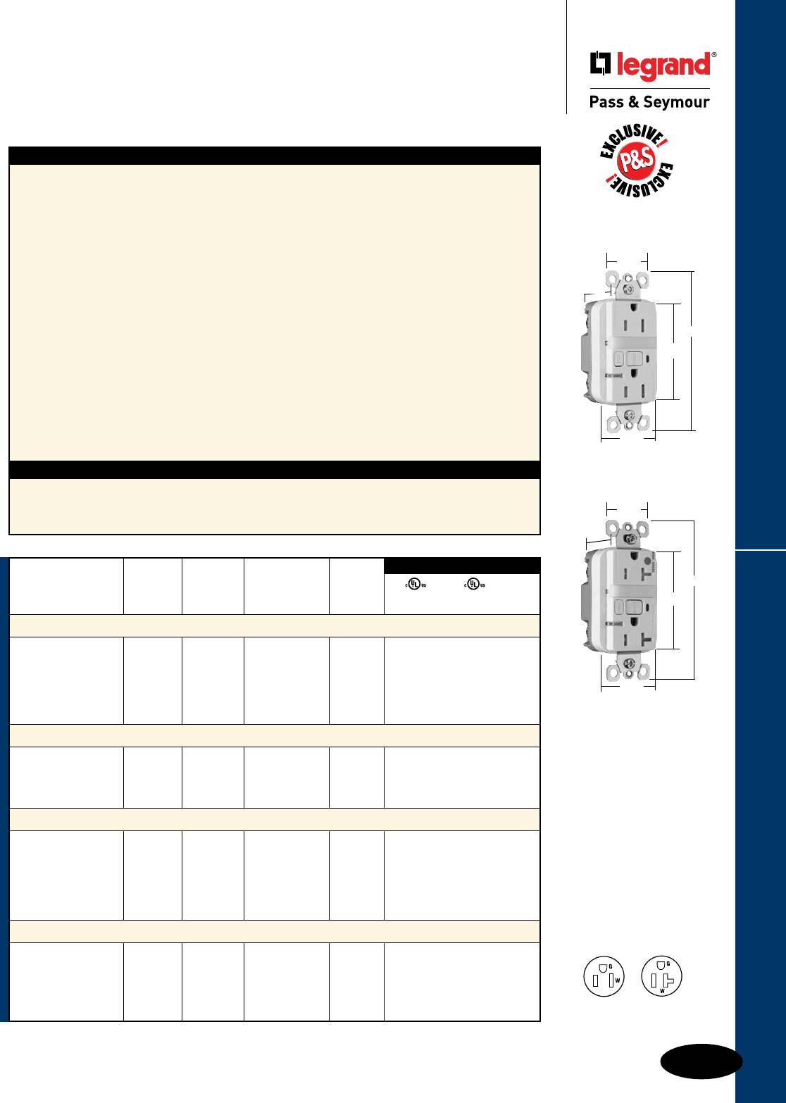
Q-37
Wall Plates & Specialties
1595NTLTRWCC4
1.25"
1.13"
4.20"
2.62"
1.72"
2095HGNTLTRW
1.25"
1.13"
4.20"
2.62"
1.72"
NEMA
5-15R
NEMA
5-20R
All devices listed on this page conform to NEMA WD-1 and WD-6.
Decorator Combination GFCI Receptacles
Specialties
Decorator Combination Tamper-Resistant
Nightlight/GFCI Receptacles
2 Pole, 3 Wire Grounding 15 & 20A, 125VAC
Features
n Protects children: patented shutter system helps
prevent improper insertion of foreign objects.
n Meets National Electrical Code®
Tamper-Resistant requirements.
n SafeLockTM Protection: if critical components are
damaged and ground fault protection is lost, power
to receptacle is disconnected.
n Sealed nightlight with high impact-resistant Lexan®
lens prevents tampering.
n Nightlight uses cooler LED illumination.
n Energy-efficient LED has average 20-year life
expectancy, eliminating bulb replacement.
n Two receptacles.
n Photocell turns nightlight ON in dark, OFF in daylight.
n Prevents line-load reversal miswire: no power to the
face or downstream receptacles if wired incorrectly.
n Exceeds UL943 voltage surge requirements;
survives 100x the required UL 3kA/6kV voltage
surge test cycles.
n FSUL Listed (Federal Specification WC596).
Specications
n Supply Voltage: 125VAC, 60 Hz
n Supply Voltage Range: 102-132 VAC
n Trip Threshold: 5± 1mA
n Trip Time: 0.025 sec., nominal per UL
Standard
n 20 Amp feed-thru capacity
n Trip indicator light (red LED).
n Side or internal screw-pressure-plate back
wire with #10 – #14 AWG solid or stranded
copper wire.
n Two back wire holes per terminal.
n Ground screw has a back wire clamp for
easy installation.
n 1/4" thinner than competitors’ GFCIs; leaves
more room for wires in the box.
n Mounting screws are shipped captive in the
device and wall plate for easier installation.
n High-impact-resistant thermoplastic
construction.
n Extra-long strap.
n Button colors match the device face.
n Dual-direction test and reset buttons.
n Class A rated GFCI.
n Supplied with matching TP26 nylon
wall plate.
n Tri-drive screws.
*FCD = Foot Candle Distance, 1 Lumen = 1 FCD. See Page S-56 for more information.
UL943 UL498 FSUL
C22.2 No. 144 C22.2 No. 42 WC596
3rd Party Compliance
Light NEMA
Catalog Rating Output in Cong.
Number A. VAC 1' FCD* Color No.
Combination Tamper-Resistant 15 Amp Nightlight/GFCI
1595NTLTRICC4 15 125 0.180 Ivory 5-15R • • •
1595NTLTRWCC4 15 125 0.180 White 5-15R • • •
1595NTLTRBKCC4 15 125 0.180 Black 5-15R • • •
1595NTLTRLACC4 15 125 0.180 Light Almond 5-15R • • •
1595NTLTRBNCC4 15 125 0.180 Brushed Nickel 5-15R • • •
1595NTLTRTICC4 15 125 0.180 Titanium 5-15R • • •
Combination Tamper-Resistant 20 Amp Nightlight/GFCI
2095NTLTRI 20 125 0.180 Ivory 5-20R • • •
2095NTLTRW 20 125 0.180 White 5-20R • • •
2095NTLTRGRY 20 125 0.180 Gray 5-20R • • •
2095NTLTRLA 20 125 0.180 Light Almond 5-20R • • •
Hospital Grade Combination Tamper-Resistant 15 Amp Nightlight/GFCI
1595HGNTLTRI 15 125 0.180 Ivory 5-15R • • •
1595HGNTLTRW 15 125 0.180 White 5-15R • • •
1595HGNTLTR 15 125 0.180 Brown 5-15R • • •
1595HGNTLTRGRY 15 125 0.180 Gray 5-15R • • •
1595HGNTLTRRED 15 125 0.180 Red 5-15R • • •
1595HGNTLTRLA 15 125 0.180 Light Almond 5-15R • • •
Hospital Grade Combination Tamper-Resistant 20 Amp Nightlight/GFCI
2095HGNTLTRI 20 125 0.180 Ivory 5-20R • • •
2095HGNTLTRW 20 125 0.180 White 5-20R • • •
2095HGNTLTRGRY 20 125 0.180 Gray 5-20R • • •
2095HGNTLTRRED 20 125 0.180 Red 5-20R • • •
2095HGNTLTRLA 20 125 0.180 Light Almond 5-20R • • •
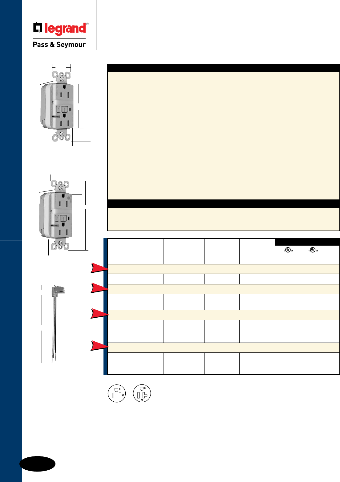
Q-38
Wall Plates & Specialties
All devices listed on this page conform to NEMA WD-1 and WD-6.
PlugTailTM Nightlight/GFCIs
Specialties
PlugTailTM Specification & Hospital Grade
Tamper-Resistant Nightlight/GFCI Receptacles
2 Pole, 3 Wire Grounding 15 & 20A, 125VAC
For PlugTail Connector catalog numbers, see Page C-13 or C-14.
NEMA
5-15R
NEMA
5-20R
Specications
n Supply Voltage: 125VAC, 60 Hz
n Supply Voltage Range: 102-132 VAC
n Trip Threshold: 5± 1mA
n Trip Time: 0.025 sec., nominal per
UL Standard
n 20 Amp feed-thru capacity
Features
n Protects children: patented shutter system helps
prevent improper insertion of foreign objects.
n Meets National Electrical Code®
Tamper-Resistant requirements.
n Sealed nightlight with high impact-resistant Lexan®
lens prevents tampering.
n Nightlight uses cooler LED illumination.
n Energy-efficient LED has average 20-year life
expectancy, eliminating bulb replacement.
n Photocell turns nightlight ON in dark, OFF in daylight.
n Faster, more reliable installation.
n No exposed terminals create a finger safe
application before, during, and after installation.
n Built-in connector features large brass terminal
blades to ensure consistent, reliable electrical
connections to PlugTail Connector.
n GFCI works with the existing 3 wire PlugTail
Connectors creating a non-feed-thru application for
facility owners. At rough-in just install the same right
angle connector for GFCI and receptacle openings.
n SafeLockTM Protection: if critical components
are damaged and ground fault protection is
lost, power to receptacle is disconnected.
n Exceeds UL943 voltage surge requirements;
survives 100x the required UL 3kA/6kV
voltage surge test cycles.
n FSUL Listed (Federal Specification WC596).
n Trip indicator light (red LED).
n Mounting screws are shipped captive in the
device and wall plate for easier installation.
n High-impact-resistant thermoplastic
construction.
n Zinc-plated steel mounting strap.
n Button colors match the device face.
n Dual-direction test and reset buttons.
n Class A rated GFCI.
n Supplied with matching TP26 nylon wall plate.
n Tri-drive screws.
1.25"
1.20"
4.20"
2.62"
1.72"
PT1595NTLTRI
UL943 UL498 FSUL
C22.2 No. 144 C22.2 No. 42 WC596
3rd Party Compliance
Catalog Rating NEMA
Number A. VAC Color Cong. No.
Specification Grade Tamper-Resistant 15 Amp Combination Nightlight/GFCI
PT1595NTLTRI 15 125 Ivory 5-15R • • •
Specification Grade Tamper-Resistant 20 Amp Combination Nightlight/GFCI
PT2095NTLTRI 20 125 Ivory 5-20R • • •
PT2095NTLTRW 20 125 White 5-20R • • •
Hospital Grade Tamper-Resistant 15 Amp Combination Nightlight/GFCI
PT1595HGNTLTRI 15 125 Ivory 5-15R • • •
PT1595HGNTLTRW 15 125 White 5-15R • • •
PT1595HGNTLTRRED 15 125 Red 5-15R • • •
Hospital Grade Tamper-Resistant 20 Amp Combination Nightlight/GFCI
PT2095HGNTLTRI 20 125 Ivory 5-20R • • •
PT2095HGNTLTRW 20 125 White 5-20R • • •
PT2095HGNTLTRLA 20 125 Light Almond 5-20R • • •
NEW
NEW
NEW
NEW
PT1595HGNTLTRI
1.25"
1.20"
4.20"
2.62"
1.72"
PTRA6STR
1.125"
6.375"
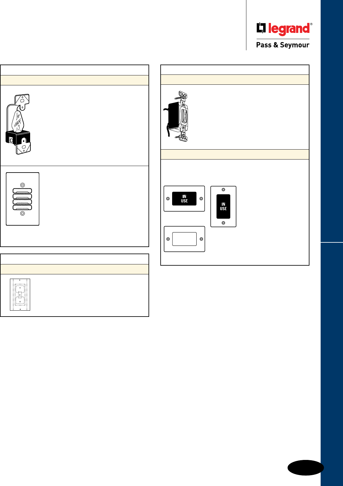
Q-39
Wall Plates & Specialties Lampholders, Neon Pilot Lights, Panelites
All devices listed on this page conform to NEMA WD-1 and WD-6.
Wall Plates & Specialties
Incandescent Lampholders,
Neon Pilot Lights & Panelites
Description Catalog Number
Energy Efficient Gasket
Gangable gasket, use for
toggle, duplex, GFCI or blank.. . . . . GASKET1
UL Listed and CSA Certified.
Description Catalog Number
Neon Pilot Lights
Long life neon bulb emits indicating light through
transparent lens to show power is on. May be
installed at the load, at switching posts or at remote
locations. We suggest the wall plate be engraved to
explain indication. Fits standard wall box and takes
standard toggle switch plate opening. Plate mount-
ing is 2-3/8". UL listed 120/277 VAC.
With green lens . . . . . . . . . . . . . . . 2151GN
With red lens. . . . . . . . . . . . . . . . 2151RED
With white lens . . . . . . . . . . . . . . . . 2151W
Panelites
Panelites are attractive wall plates that light the message
“IN USE” to protect darkrooms, private meeting areas, etc. Also
available with a clear face for user to apply his own message.
Furnished complete ready to wire. Panelites may be installed
in a feed-through wall box,
with the Panelite on one wall
and a pilot light on the other.
Panelite also may be installed
in a standard wall box with
the control switch in any
desired location. With
4 Watt Incandescent bulb.
Ivory plate.
IN USE, for Horizontal mounting . 2219PL
IN USE, for Vertical mounting. . . . 2220PL
With clear unprinted face . . . . . . . 2200PL
2220PL
2219PL
2200PL
Description Catalog Number
Incandescent Lampholders
Designed to give adequate light when installed
behind a louvre plate or indicator jewel. Mounts
in standard wall box. Plate mounting is 2-3/8"
and 3-13/16". UL listed for 120 VAC circuits.
Plate not included.
Standard lampholder, 4 Watt ........ 2152
Extra long life: Integral series resistor in
base reduces light output by about 40%,
but increases lamp life more than ten times.
Plate not included.
Extra long life, 4 Watt............... 2156
Application
Lampholders and louver plates are an ideal
combination for providing bright, shielded
light in hallways and pathways. They
increase safety in corridors, theater aisles,
porches, stairways, etc. A wide choice
of plates gives unlimited possibilities for
designing the perfect night light installation.
Available in brushed brass, custom-painted
stainless steel and stainless steel.
For the complete listing of Louver Plates,
see Page Q-21 .
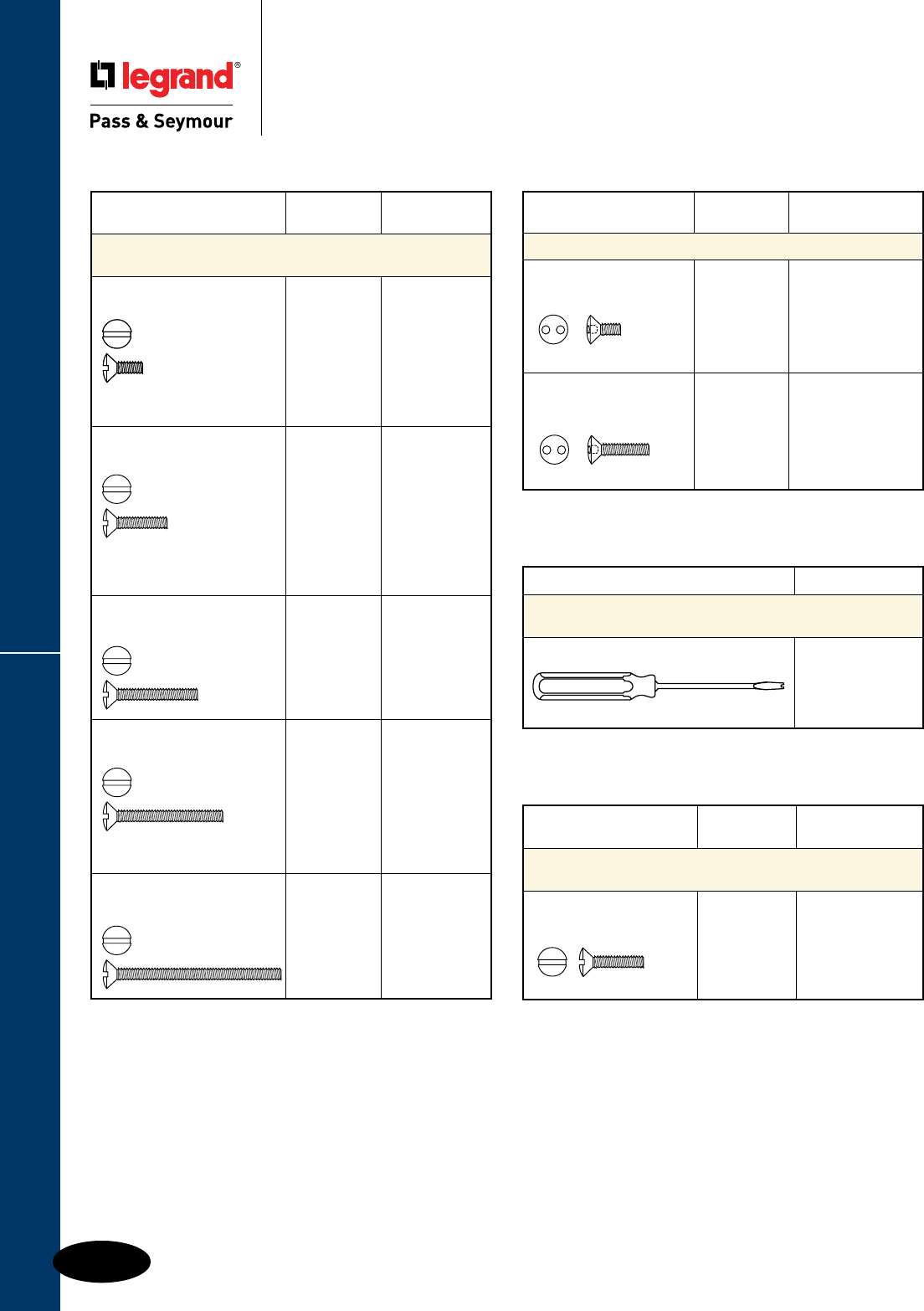
Screws & Screwdrivers
Q-40
Wall Plates & Specialties
Specialties
Screws & Screwdrivers
Notes:
n Specify screws by catalog number to designate type of screw, thread, length, color or finish required.
n Screws are available by the box only.
n Order by number of boxes…not by the quantity of screws.
n Each box contains 100 screws.
n Metal screws are available with special finishes and can be painted.
Description Catalog Number
Screwdriver for Spanner Head or
Key Slot Screws
Screwdriver for Spanner Head Screw 533D
Catalog
Description Finish Number
Tamper-Proof Spanner Head Screws
Spanner Oval Head
1/2" long, 6 x 32 Thread 430S/S 531S
Spanner Oval Head
1" long, 6 x 32 Thread 430S/S 532S
Catalog
Description Finish Number
Nylon Screws for Standard and
Interchangeable Wall Plates
Oval Head Standard Slot Ivory 528I
1/2" long, 6 x 32 Thread
Color or Catalog
Description Finish Number
Standard & Interchangeable
Wall Plate Screws
Oval Head Milled Slot Ivory 509I
5/16" long, 6 x 32 Thread White 509W
Brown 509
Gray 509GRY
Light Almond 509LA
Stainless 509S
Standard size for
Decorator Wall Plates.
Oval Head Milled Slot Ivory 510I
1/2" long, 6 x 32 Thread White 510W
Brown 510
Brass 510BR
Stainless 510S
Standard size for Duplex
Receptacles and Toggle
Switch Wall Plates.
Oval Head Milled Slot Ivory 511I
3/4" long, 6 x 32 Thread White 511W
Brown 511
Light Almond 511LA
Stainless 511S
Oval Head Milled Slot Ivory 512I
1" long, 6 x 32 Thread White 512W
Brown 512
Light Almond 512LA
Stainless 512S
Standard size for Blank
Box Mounted Wall Plates.
Oval Head Milled Slot Ivory 513I
1-1/2" long, 6 x 32 Thread White 513W
Brown 513
Light Almond 513LA
Stainless 513S
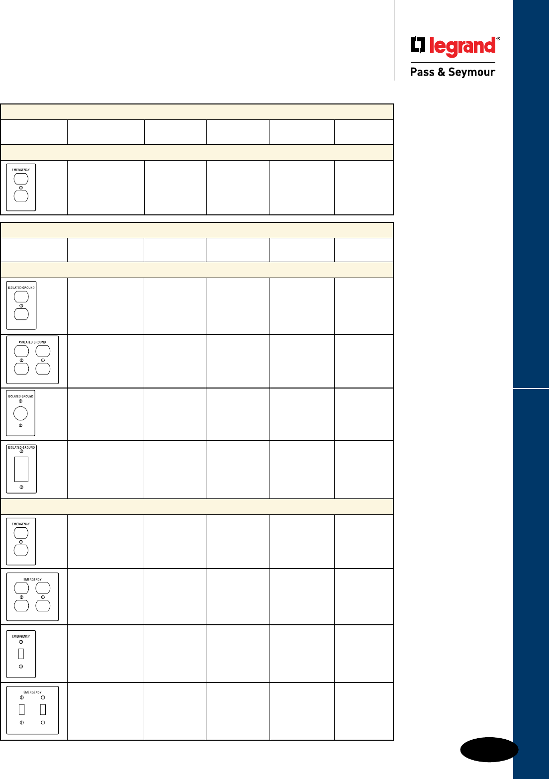
Q-41
Engraved & Pad PrintedWall Plates & Specialties
Wall Plates
Engraved & Pad Printed
Engraved (1/8" Characters)
Nylon Metal
Description Plate Color Fill Color TradeMaster® Smooth
Emergency
1 Gang Duplex 302 S/S Black SS8EE
1 Gang Duplex 302 S/S Black SS8ERED
Painted Red
Pad Printed (1/8" Characters)
Nylon Metal
Description Plate Color Fill Color TradeMaster Smooth
Isolated Ground
1 Gang Duplex Orange Black TP8IG
1 Gang Duplex 302 S/S Black SS8IG
2 Gang Duplex 302 S/S Black SS82IG
1 Gang Single Orange Black TP7IG
1 Gang Decorator Orange Black TP26IG
1 Gang Decorator 302 S/S Black SS26IG
Emergency
1 Gang Duplex Ivory Red TP8EI
1 Gang Duplex White Red TP8EW
1 Gang Duplex Red Black TP8ERED
1 Gang Duplex 302S/S Black SS8ES
2 Gang Duplex Red Black TP82ERED
1 Gang Toggle Red Black TP1ERED
2 Gang Toggle Red Black TP2ERED
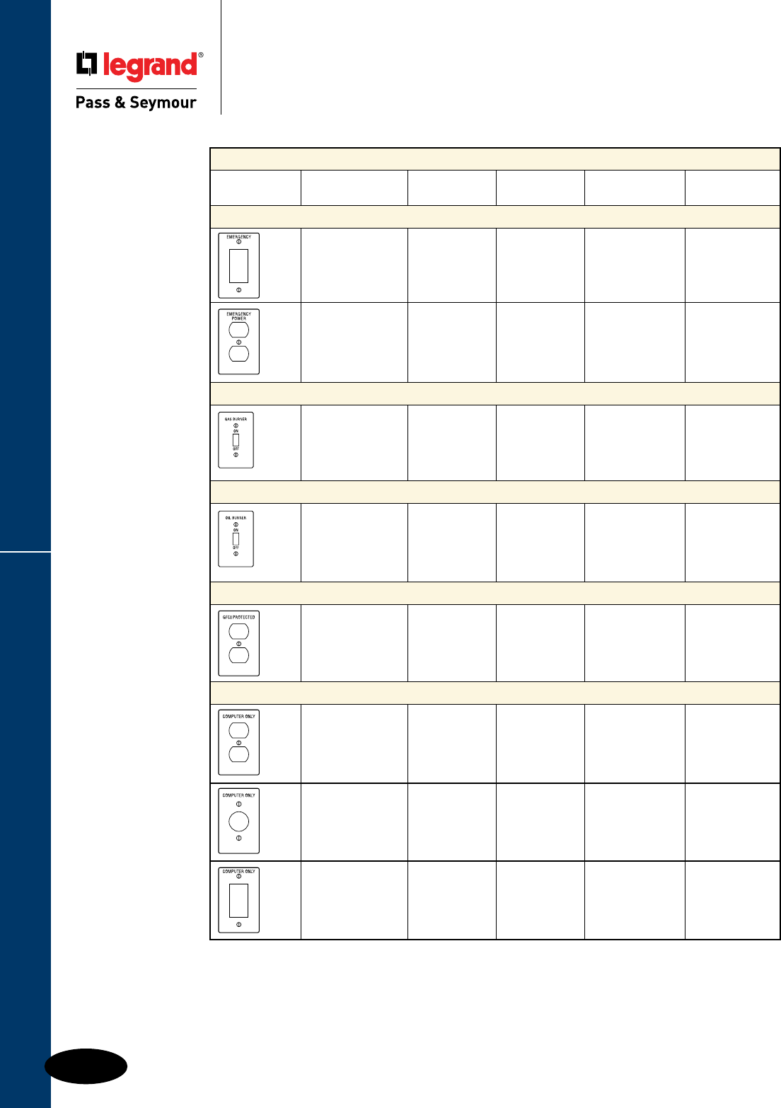
Engraved & Pad Printed
Q-42
Wall Plates & Specialties
Wall Plates
Engraved & Pad Printed
Pad Printed (1/8" Characters)
Nylon Metal
Description Plate Color Fill Color TradeMaster® Smooth
Emergency
1 Gang Decorator Red Black TP26ERED
1 Gang Duplex Red Black TP8EMPOWER
Gas Burner ON/OFF Emergency Switch
1 Gang Toggle 302 S/S Black SS1GBRED
Painted Red
Oil Burner ON/OFF Emergency Switch
1 Gang Toggle 302 S/S Black SS1OBRED
Painted Red
GFCI Protected
1 Gang Duplex Ivory Black TP8GFI
1 Gang Duplex White Black TP8GFW
Computer Only
1 Gang Duplex Ivory Black TP8CI
1 Gang Duplex Orange Black TP8CO
Single Receptacle Ivory Black TP7CI
Single Receptacle Orange Black TP7CO
1 Gang Decorator Ivory Black TP26CI
1 Gang Decorator Blue Black TP26CBL
1 Gang Decorator Orange Black TP26CO

Q-43
Custom Metal Wall PlatesWall Plates & Specialties
Wall Plates
Custom Metal Wall Plates
Ordering Instructions
Ordering Instructions:
1. Using the following charts, ll in the spaces provided to select the proper material, number of gangs, desired nish and color.
2. Review the Plate Opening Styles on pages Q-48 – Q-60. Following the sequence of your installation (left to right), label each
box below with the appropriate Opening Style Number for each gang.
3. Create the Complete Order Part Number by lling in items from previous steps in spaces below.
Space #1-Material Prefix Code (from step 1) Space #4-Metal Finish Suffix (from step 1)
Space #2-Total Number of Gangs (from step 1) Space #5-Paint Finish Suffix (from step 1)
Space #3-Style Numbers In Order (from step 2)
Catalog #_________________ G_____ Style _____ - _____ - _____ - _____ - _____ - _____ - _____ - _____ - _____ - _____ - _____ - _____
Space # 1 2 3 3 3 3 3 3 3 3 3 3 4 5
Review Your Requirements: For Example: Write Your Selection: Space #
Material Prex Code (Chart A below) SBO 1
For Jr. Jumbo Size add “J” after prefix,
if Jumbo Size, add "O" after Prefix
Total Number of Gangs Ordered 4 2
Paint Finish Suffix (Chart B – Page Q-44) BLU 4
Metal Finish Suffix (Chart C – Page Q-44) BC 5
Maximum Gangs for Custom Metal Wall Plates
Metal Plate Standard Jr. Jumbo Jumbo
Stainless (302) 20 3 20
Aluminum 8 N/A N/A
Brushed Brass 8 3 20
Material Prex Code
Chart A: Material Selection
Aluminum* SA
Brushed Brass SB
302 Stainless Steel SS
*Standard size only.
Gang: 12345678910
For help with configuring a Custom Metal Wall Plate, go to www.legrand.us/passandseymour
and select Downloads/Product Selection Guides/Custom Wall Plates.
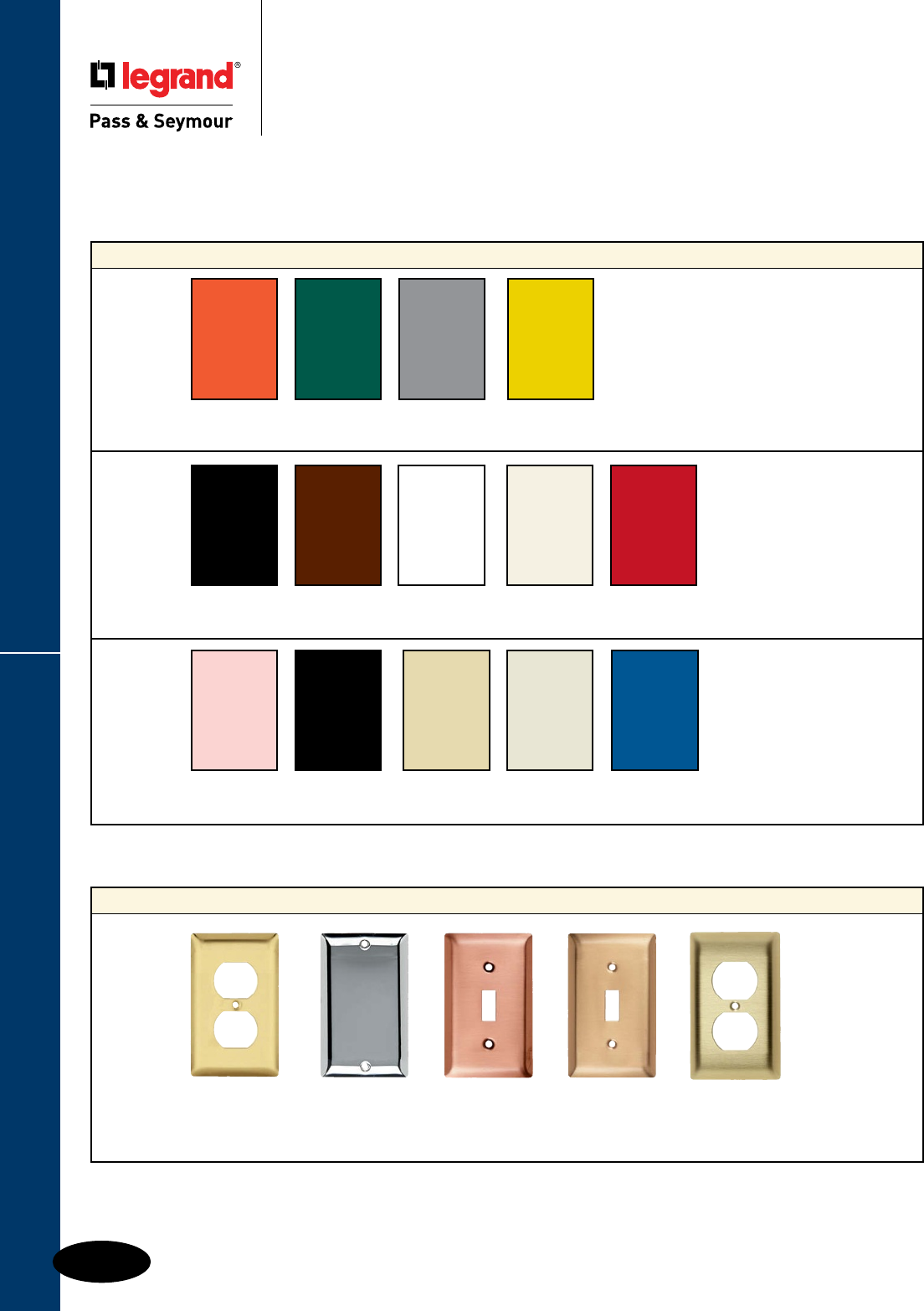
Chart B: Paint Finish Selection
Paint Color Orange Green Gray Yellow
Paint Suffix ORG GRN GRY YEL
Paint Color Glossy Black Brown White Primer Red
Paint Suffix GBK BRO WHT PRI RED
Paint Color Pink Flat Black Ivory Light Almond Blue
Paint Suffix PNK FBK IVY LTA MBL
Custom Metal Wall Plates
Q-44
Wall Plates & Specialties
Wall Plates
Custom Metal Wall Plates
Special Configurations
Only available on Stainless Steel and Aluminum Plate Material. Colors may vary slightly.
All Paint Finishes are gloss, except primer and flat black.
Chart C: Metal Finish Selection
Metal Finish Polished Brass Bright Brushed Brushed Brushed Brass
US #3 Chromium Copper
Bronze Standard Finish
US #26
US #10
Finish Suffix PB* CH BC BZ BB
*Order with Brass Plate Material Prefix Only.
For additional colors consult factory.
These charts are for Custom Metal Wall Plates ONLY.
For Devices & Wall Plates Color Selection Charts, see Pages A-29, B-78 and Q-61.
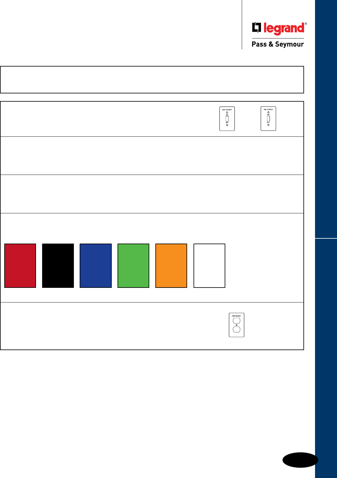
Q-45
Custom Metal Wall PlatesWall Plates & Specialties
Wall Plates
Custom Metal Wall Plates
Engraving & Pad Printing
Position
Height of Mark
Color of Filler
Plate Style
by Catalog Number
Including
Color/Finish
Position
Marking may appear anywhere on the flat surface of smooth plates.
On Decorator plates, markings are restricted to the top and bottom flat panels.
If space permits, up to three lines can be pad printed on a plate provided the lettering
fits within a 50mm circle.
Letter Height
Unless specified otherwise, designers will select size and position
of letters or markings for maximum legibility. Characters per inch:
3/8" - 2-1/2 1/4" - 4 3/16" - 6 1/8" - 9 1/16" - 14 3/8" 1/4" 3/16" 1/8" 1/16"
Letter Font
Pad printing is available in any True Type font in colors listed below, on 1 gang and 2 gang plates. Bitmap images can also be printed.
Laser engraving is available in any True Type font only in black (not color-filled) including bitmap images.
Engraving with color fill is available only in block letter font. While mixing of laser and color-filled engraving is allowed,
it is not recommended since the font types will not match.
Color
Color-filled engraving can be filled with red, orange, black, blue, or white paint.
Standard colors for pad printing are red, black, blue, green, orange or white, as shown below.
Red Black Blue Green Orange White
Ordering Instructions
Specify clearly the following information when you order.
1. Catalog number of plate(s). 4. Position and size.
2. To be engraved or pad printed. 5. Color of filler, or pad printing.
3. Letters, numbers, characters required. 6. Special layout information, if applicable.
Custom Engraving & Pad Printing
Most plates in this catalog can be engraved or pad printed. However, engraving plated finish metal plates is not recommended, since
exposed edges could oxidize over time. Refer to current price sheet to select the better process that suits your needs.
SSSSS
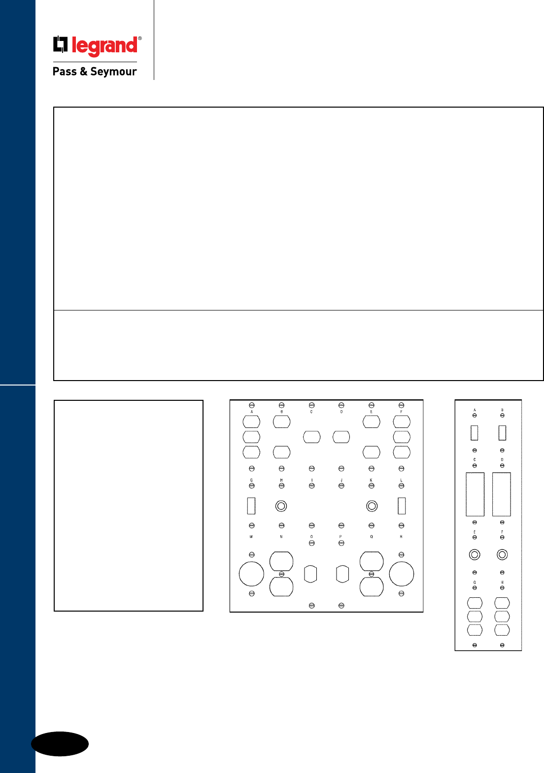
Custom Metal Wall Plates
Q-46
Wall Plates & Specialties
Wall Plates
Custom Panel Plates
Ordering Instructions
Example
SSPP-4-2
ROW #1:
Style Nos. 1 1
Engraving: ALTAR CHOIR
(Above) (Above)
ROW #2:
Style Nos. 9 9
Engraving: (None) (None)
ROW #3:
Style Nos. 12 12
Engraving: (None) TEL
(Above)
ROW #4:
Style Nos. 16 16
Engraving: (None) 120V.
(Above)
Figure 2
Figure 1 Custom Panel Plate
Blank panel plates (PP-series) up to 5-gangs high and 10-gangs wide are made from Type 302 Stainless Steel. Up to 50 openings
from the style selector guide can be custom punched to your specifications. For uniformity of design throughout the building, panel
plates have the same distinctive styling as all other plates, plastic and metal.
1. Start the catalog number with the material prefix: “SS” for Type
302 Stainless. This is a 302 Stainless plate, so the first letters
of its catalog number will be “SS.”
2. Determine the catalog number for a panel plate 4 gangs high
and 2 gangs wide from the table on page Q-47. It is PP-4-2.
Your 302 Stainless Steel catalog number is SSPP-4-2.
3. Construct a chart upon which you can indicate the opening
style number for each of the 8 gangs, starting from the top
left. Leave space to show any words or symbols that will be
engraved. Write the catalog number SSPP-4-2 at the top
of the chart. See Figure 1.
For this example, use the 4 gang high by 2 gang wide panel plate illustrated in Figure 2.
4. Refer to the Style Selector Guide and find the style numbers
for each of the desired openings. Write these numbers in their
appropriate position on your chart.
5. Indicate what, if any, engraving is required for each gang. Show
in parentheses if engraving is to be above or below the opening.
6. Send the chart with your order to the factory. You have provided
all required information. Refer to current price sheet for pricing
details.
Ordering Instructions
n Where no opening or mounting holes are required, specify
Style #149.
n Louvered openings can be placed only on the top row of a
panel plate.
n For painted or special metal finishes, refer to price sheet for
price adds per gang.
n For special openings not in Selector Guide, provide detailed
drawing.
Additional Information
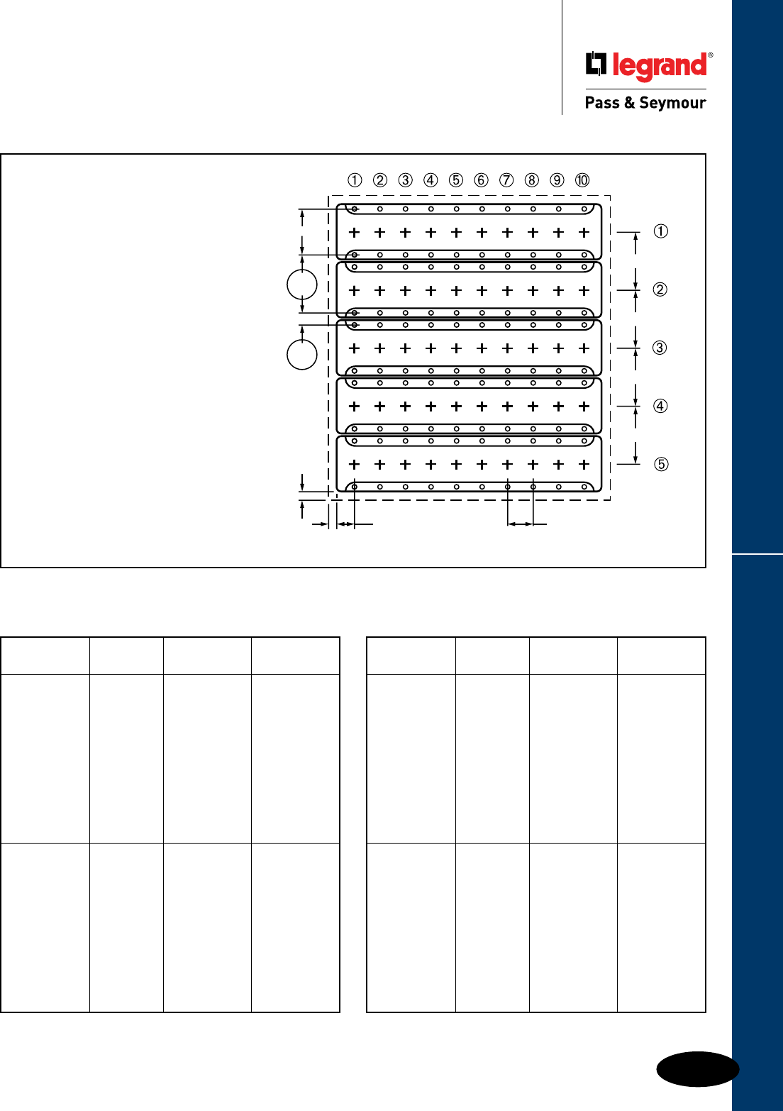
Q-47
Custom Panel PlatesWall Plates & Specialties
Wall Plates
Custom Panel Plates
Ordering Instructions
Wall Box Dimensions
Panel Plates are limited to fit the box
configuration shown.
Caution: Not all boxes are identical in overall
dimensions, but are built to exact standards
on device mounting holes. When boxes are
connected together, they should be shimmed
to ensure that the bottom hole to bottom hole
dimension between two vertically adjacent
boxes is 4-1/8" as errors are cumulative.
Critical dimensions circled.
If additional mounting holes are required in
the corners, indicate location and spacing.
41/8'' TYP.
41/8'' TYP.
41/8'' TYP.
41/8'' TYP.
113/16'' TYP.11/8'' TYP.
39/32'' TYP
.
41/8''
TYP.
27/32''
TYP.
1/4'' TYP.
1/4'' TYP.
Plate Catalog Gangs Plate
Height Number Wide Width
PP21 One 2-3/4"
PP22 Two 4-9/16"
PP23 Three 6-3/8"
PP24 Four 8-3/16"
Two Gangs PP25 Five 10"
High 8-3/4" PP26 Six 11-13/16"
PP27 Seven 13-5/8"
PP28 Eight 15-7/16"
PP29 Nine 17-1/4"
PP210 Ten 19-1/16"
PP31 One 2-3/4"
PP32 Two 4-9/16"
PP33 Three 6-3/8"
PP34 Four 8-3/16"
Three Gangs PP35 Five 10"
High 12-7/8" PP36 Six 11-13/16"
PP37 Seven 13-5/8"
PP38 Eight 15-7/16"
PP39 Nine 17-1/4"
PP310 Ten 19-1/16"
302 Stainless Steel
Plate Catalog Gangs Plate
Height Number Wide Width
PP41 One 2-3/4"
PP42 Two 4-9/16"
PP43 Three 6-3/8"
PP44 Four 8-3/16"
Four Gangs PP45 Five 10"
High 17" PP46 Six 11-13/16"
PP47 Seven 13-5/8"
PP48 Eight 15-7/16"
PP49 Nine 17-1/4"
PP410 Ten 19-1/16"
PP51 One 2-3/4"
PP52 Two 4-9/16"
PP53 Three 6-3/8"
PP54 Four 8-3/16"
Five Gangs PP55 Five 10"
High 21-1/8" PP56 Six 11-13/16"
PP57 Seven 13-5/8"
PP58 Eight 15-7/16"
PP59 Nine 17-1/4"
PP510 Ten 19-1/16"
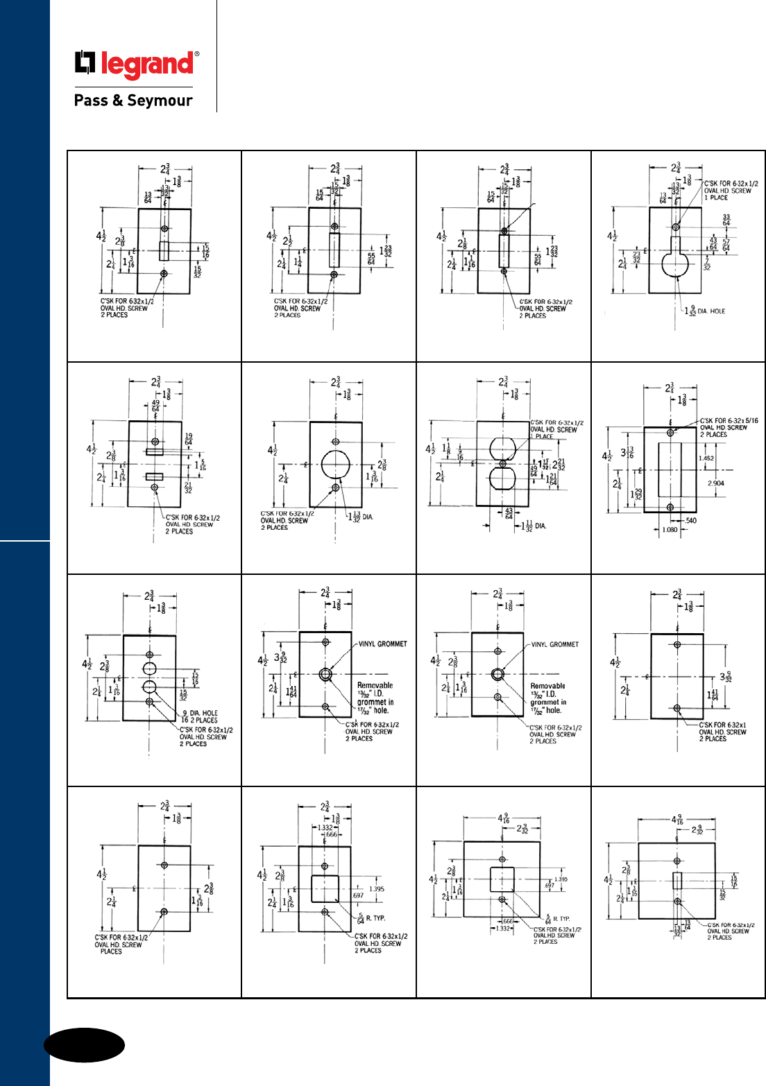
Style Selector Guide
Q-48
Wall Plates & Specialties
Wall Plates
Style Selector Guide
Custom Metal Wall Plates
STYLE
1
TOGGLE SWITCH
#1 Standard Plate page Q-8
STYLE
2
STYLE
3
STYLE
4
STYLE
5
STYLE
7
STYLE
8
STYLE
10
STYLE
11
STYLE
12
STYLE
13
STYLE
14
STYLE
16
STYLE
17
SINGLE OUTLET
#7 Standard Plate page Q-13
DUPLEX OUTLET
#8 Standard Plate page Q-9
BIPLEX/TRIPLEX
#9 Standard Plate page Q-21
PUSH BUTTON TELEPHONE, BOX MTD.
#11 Standard Plate page Q-32
TELEPHONE, STRAP MTD.
with #340 Yoke
#12 Standard Plate page Q-32
BLANK, BOX MTD.
#13 Standard Plate page Q-11
BLANK, STRAP MTD.
with #340 Yoke
#14 Standard Plate page Q-12
SINGLE OUTLET
FOR 1600 SERIES
SINGLE RECEPTACLE
FOR 1600 SERIES
CENTERED 2 GANG
TOGGLE SWITCH
CENTERED 2 GANG
#740 Standard Plate page Q-20
STYLE
18
STYLE
9
All wall plate dimensions shown above are in inches.
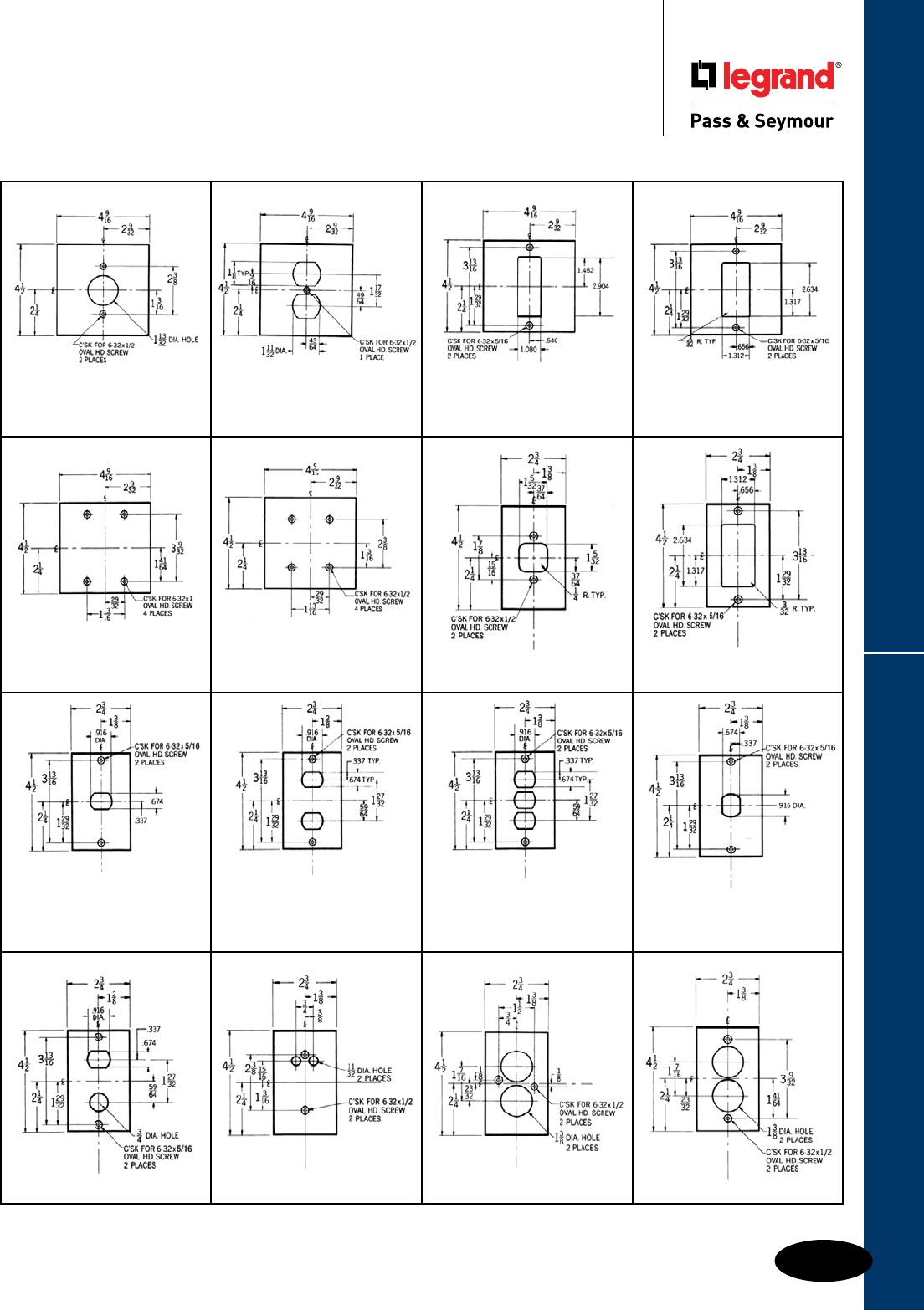
Q-49
Style Selector GuideWall Plates & Specialties
Wall Plates
Style Selector Guide
Custom Metal Wall Plates
All wall plate dimensions shown above are in inches.
SINGLE OUTLET
CENTERED 2 GANG
#747 Standard Plate page Q-20
STYLE
19
STYLE
20
STYLE
21
STYLE
22
BIPLEX/TRIPLEX
CENTERED 2 GANG
BLANK, BOX MTD.
#23 Standard Plate page Q-11
BLANK, STRAP MTD.
with 2 #340 Yokes
#24 Standard Plate page Q-12
TELEPHONE JACK OUTLET
NOTE: Special Plate Mounting
DECORATOR/GFCI
#26 Standard Plate page Q-9
ONE DESPARD®
INTERCHANGEABLE
with #348 Strap
Standard Plate page Q-19
STYLE 27A — BOX MTD.
TWO DESPARD®
INTERCHANGEABLE
with #348 Straps
Standard Plate page Q-19
STYLE 29 — BOX MTD.
THREE DESPARD®
INTERCHANGEABLE
with #348 Straps
Standard Plate page Q-19
STYLE 31 — BOX MTD.
STYLE
23
STYLE
24
STYLE
25
STYLE
26
STYLE
27
STYLE
28
STYLE
30
STYLE
32
STYLE
33
STYLE
36
STYLE
37
STYLE
38
ONE VERTICAL DESPARD®
INTERCHANGEABLE
with #347 Strap
Standard Plate page Q-19
DUPLEX OUTLET
CENTERED 2 GANG
#748 Standard Plate page Q-20
DECORATOR/GFCI
CENTERED 2 GANG
#746 Standard Plate page Q-20
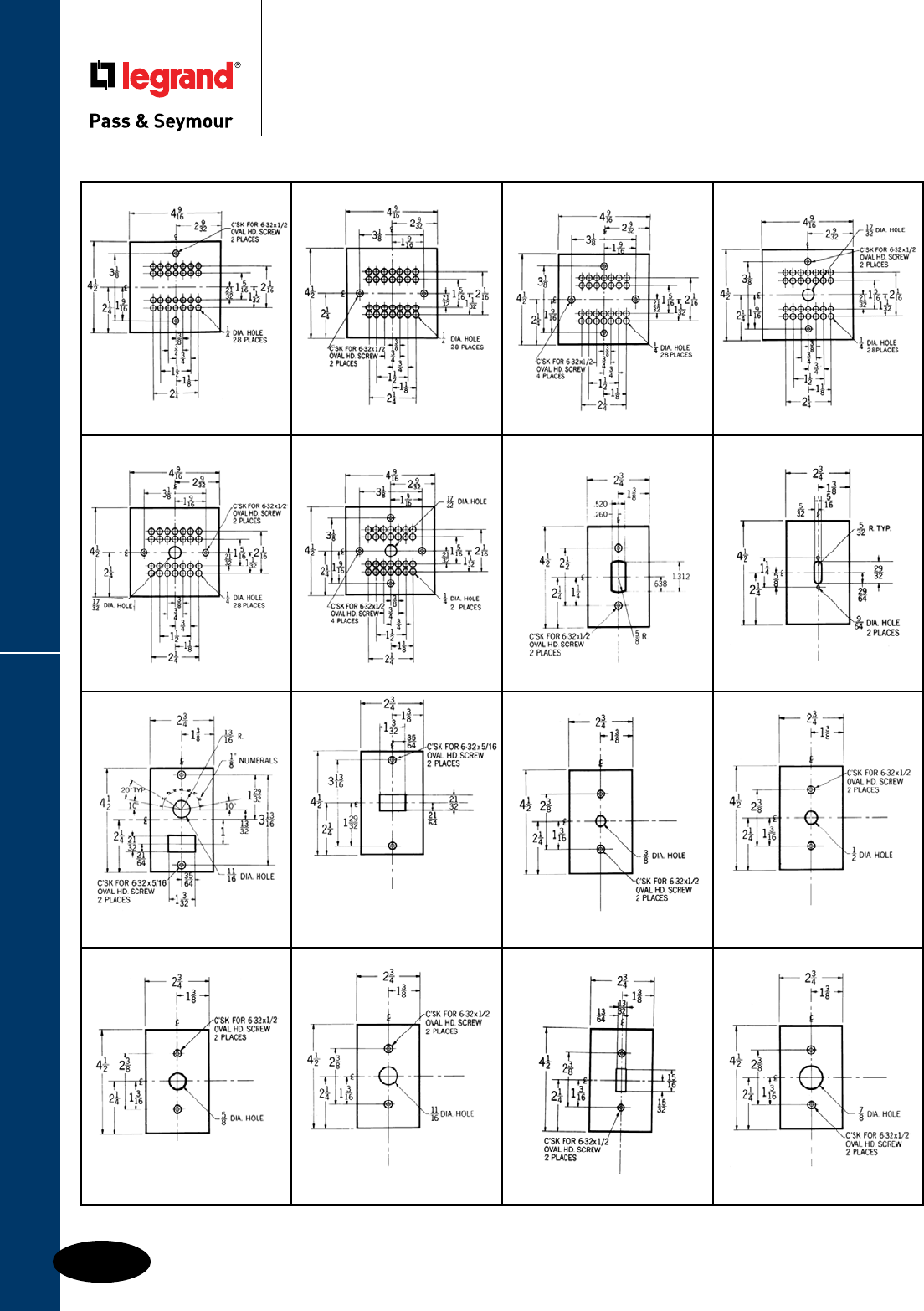
Style Selector Guide
Q-50
Wall Plates & Specialties
Wall Plates
Style Selector Guide
Custom Metal Wall Plates
STYLE
66
STYLE 67— BOX MTD.
STYLE
40
STYLE
41
STYLE
42
STYLE
43
STYLE
44
STYLE
45
STYLE
46 STYLE
47
STYLE
48
STYLE
55
NOTE: Engraving Extra at
Standard Price per Character
STYLE 49A — Vertical Opening
STYLE 50 — 2 Openings 1 Gang
STYLE 51— 3 Openings 1 Gang
STYLE 52 — 4 Openings 1 Gang
with #340 Yoke
STYLE 56 — BOX MTD.
with #340 Yoke
STYLE 58 — BOX MTD.
with #340 Yoke
STYLE 60 — BOX MTD.
STYLE 61— DESP. INTCH. MTD. STYLE 63— BOX MTD. STYLE 65 — BOX MTD.
STYLE
64
STYLE
62
STYLE
57
STYLE
59
STYLE
49
All wall plate dimensions shown above are in inches.

Q-51
Style Selector GuideWall Plates & Specialties
Wall Plates
Style Selector Guide
Custom Metal Wall Plates
All wall plate dimensions shown above are in inches.
STYLE 84 — BOX MTD.
STYLE 85 — DESP. INTCH. MTD.
STYLE 87 — BOX MTD.
STYLE 88 — DESP. INTCH. MTD.
STYLE 90 — BOX MTD.
POWER OUTLET
#720 Standard Plate page Q-13 STYLE 93 — DESP. INTCH. MTD.
STYLE
68
STYLE
71
STYLE
73
STYLE
75
STYLE
77
STYLE
80
STYLE
83
STYLE
86
STYLE
89
STYLE
91
STYLE
92
STYLE 69 — BOX MTD.
STYLE 70— DESP. INTCH. MTD. STYLE 72— BOX MTD. STYLE 74 — BOX MTD.
Clearance for 11/8" Device
STYLE 76 — BOX MTD.
STYLE 78 — BOX MTD.
STYLE 79 — DESP. INTCH. MTD.
STYLE 81 —BOX MTD.
STYLE 82 — DESP. INTCH. MTD.
STYLE 95 — BOX MTD.
STYLE 96 — DESP. INTCH. MTD.
POWER OUTLET
#723 Standard Plate page Q-13
STYLE
99
STYLE
98
STYLE
94
STYLE
97
STYLE
100
with 2 # 340 Yokes
STYLE 101 — BOX MTD.
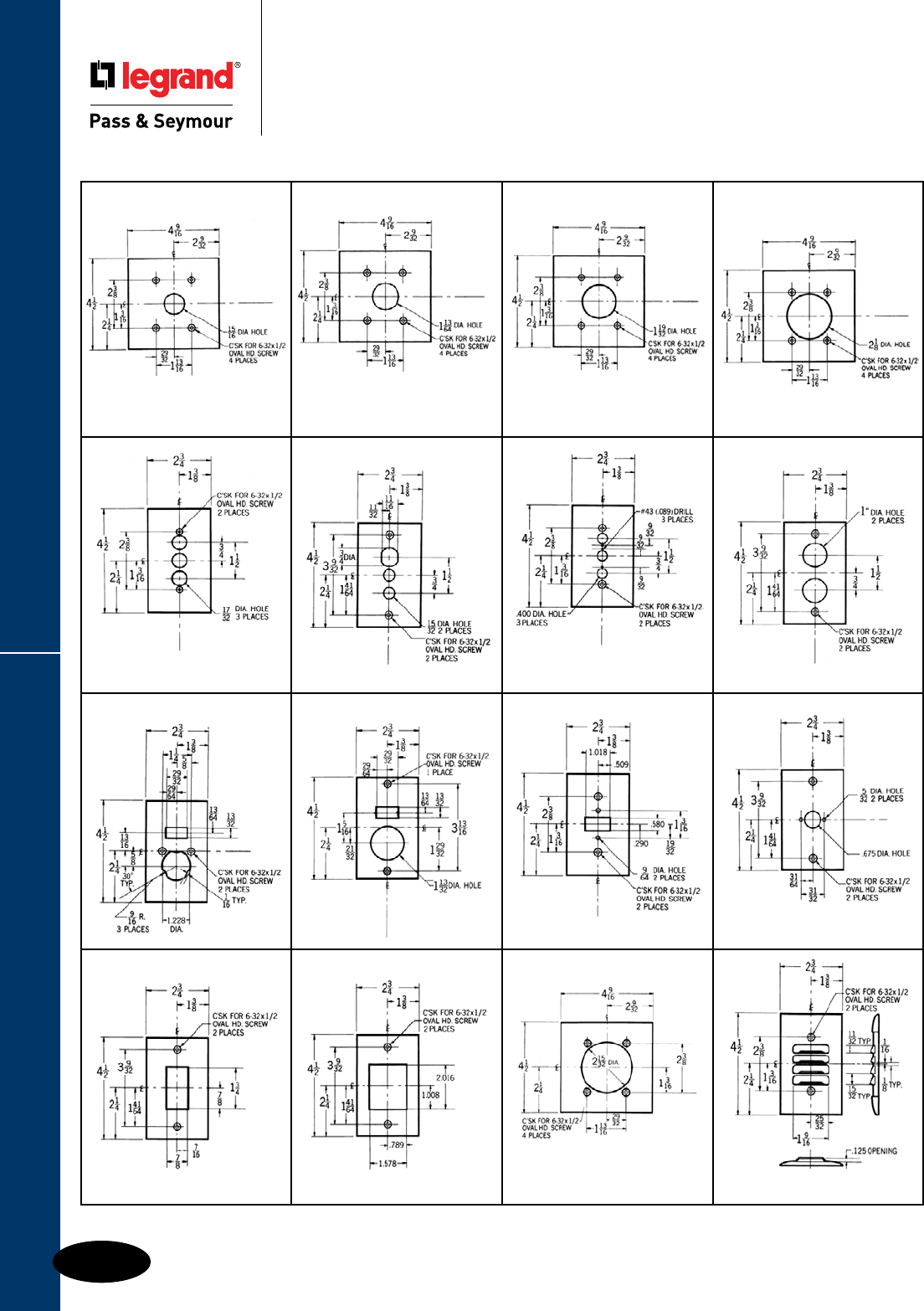
Style Selector Guide
Q-52
Wall Plates & Specialties
Wall Plates
Style Selector Guide
Custom Metal Wall Plates
All wall plate dimensions shown above are in inches.
STYLE 135A. — DESP. INTCH. MTD.
#771 Standard Plate page Q-21
STYLE
135
STYLE
104
STYLE
106
STYLE
110
STYLE
112
STYLE
115
STYLE
116STYLE
119
STYLE 103 — BOX MTD. STYLE 105 — BOX MTD. STYLE 107 — BOX MTD.
STYLE 113 — BOX MTD.
STYLE 114 — DESP. INTCH. MTD.
STYLE 117 — BOX MTD.
STYLE 118 — DESP. INTCH. MTD.
with #340 Yoke
STYLE 125 — 2 HOLES
STYLE 126 — 3 HOLES
POWER OUTLET
#701 Standard Plate page Q-14
STYLE
123
STYLE
122
STYLE
121
STYLE
134
STYLE
132
STYLE
131
STYLE
124
STYLE
102
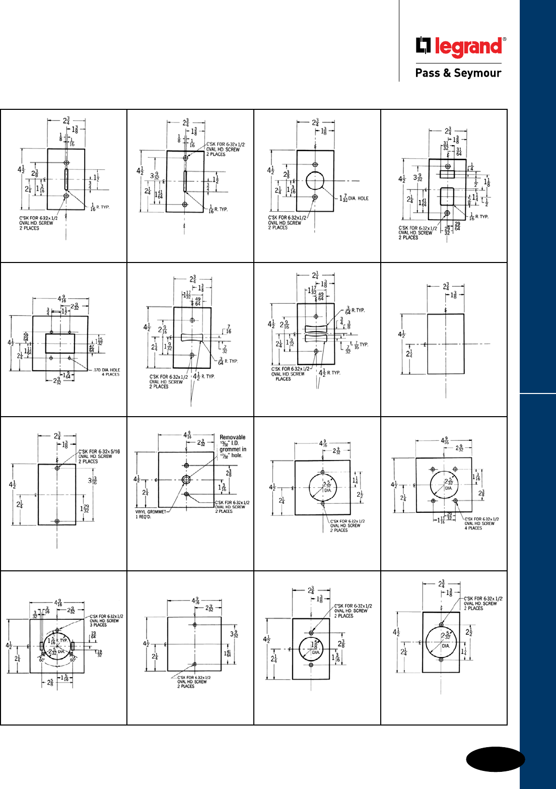
Q-53
Style Selector GuideWall Plates & Specialties
Wall Plates
Style Selector Guide
Custom Metal Wall Plates
All wall plate dimensions shown above are in inches.
STYLE 176 — STRAP MTD.
with #340 Yoke
#743 Standard Plate page Q-20
RAZOR BLADES
with #340 Yoke
RAZOR BLADES, BOX MTD.
STYLE 137B — HORIZONTAL
RAZOR BLADE, BOX MTD.
STYLE
136
STYLE
137
STYLE
138
STYLE
141
STYLE
142
STYLE
143
STYLE
163
STYLE 139 — BOX MTD.
STYLE 140 — DESP. INTCH. MTD.
STYLE 145 — 3 OPENINGS
STYLE 146 — 4 OPENINGS
STYLE 147 — MASTER CONTROL
DESP. INTCH. MTD.
TELEPHONE OUTLET
CENTERED
2 GANG, with #340 Yoke
STYLE 151 — BOX MTD.
#741, 742 Standard Plate page Q-34
POWER OUTLET
#702 Standard Plate page Q-14
POWER OUTLET
#703 Standard Plate page Q-14
STYLE
144
STYLE
152
STYLE
155
STYLE
149
STYLE
150
STYLE
162
STYLE
160
STYLE
156
POWER OUTLET
#721 Standard Plate page Q-13
STYLE
165
POWER OUTLET
#724 Standard Plate page Q-13
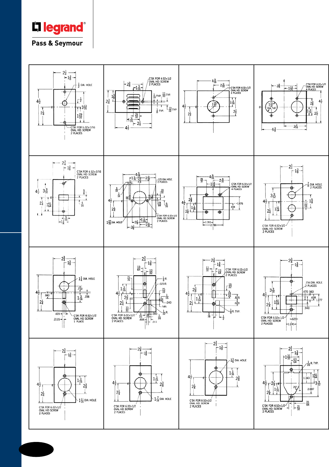
Style Selector Guide
Q-54
Wall Plates & Specialties
Wall Plates
Style Selector Guide
Custom Metal Wall Plates
STYLE
199
3 GANG PLATE
LOUVRE
#760 Standard Plate page Q-21
POWER OUTLET
#710 Standard Plate page Q-14
STYLE 178
Touch Plate 50-2, 2 Openings
STYLE 179
Touch Plate 50-3, 3 Openings Box Mtd.
STYLE 190 — BOX MTD.
STYLE 192 — BOX MTD.
STYLE 193 — DESP. INTCH. MTD.
STYLE
166
STYLE
171
STYLE
169 STYLE
172
STYLE
177
STYLE
181
STYLE
180 STYLE
182
STYLE
183
STYLE
187
STYLE
185 STYLE
188
STYLE
189
STYLE
194
STYLE
191
POWER OUTLET
#725 Standard Plate page Q-13
STYLE 195 — BOX MTD.
STYLE 196 — DESP. INTCH. MTD.
All wall plate dimensions shown above are in inches.
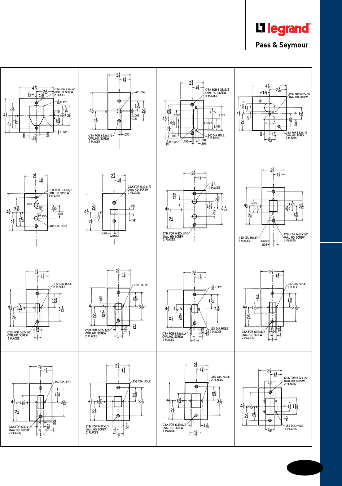
Q-55
Style Selector GuideWall Plates & Specialties
Wall Plates
Style Selector Guide
Custom Metal Wall Plates
All wall plate dimensions shown above are in inches.
with #340 Yoke
STYLE 207 — BOX MTD.
4-S Box Mtd. Plate available in any
Standard 1 Gang Opening
(Style 8 Shown)
with #340 Yoke STYLE 215A — 1 HOLE CENTERED
STYLE
200
STYLE
206
STYLE
210 STYLE
211
STYLE
213
STYLE
214
STYLE
215
STYLE
216
STYLE
217
STYLE
218
STYLE
219
STYLE
220
STYLE
221
STYLE
222
STYLE
223 STYLE
224

Style Selector Guide
Q-56
Wall Plates & Specialties
Wall Plates
Style Selector Guide
Custom Metal Wall Plates
STYLE
243
STYLE
225
STYLE
226
STYLE
227
STYLE
228
STYLE
229
STYLE
230
STYLE 233A — EXTRA CIRCLE
OF HOLES (31 HOLES)
with #340 Yoke
STYLE 238 — BOX MTD.
STYLE
232 STYLE
233
STYLE
235
STYLE
236
STYLE
237 STYLE
239
STYLE
240
STYLE
241
STYLE
242
All wall plate dimensions shown above are in inches.
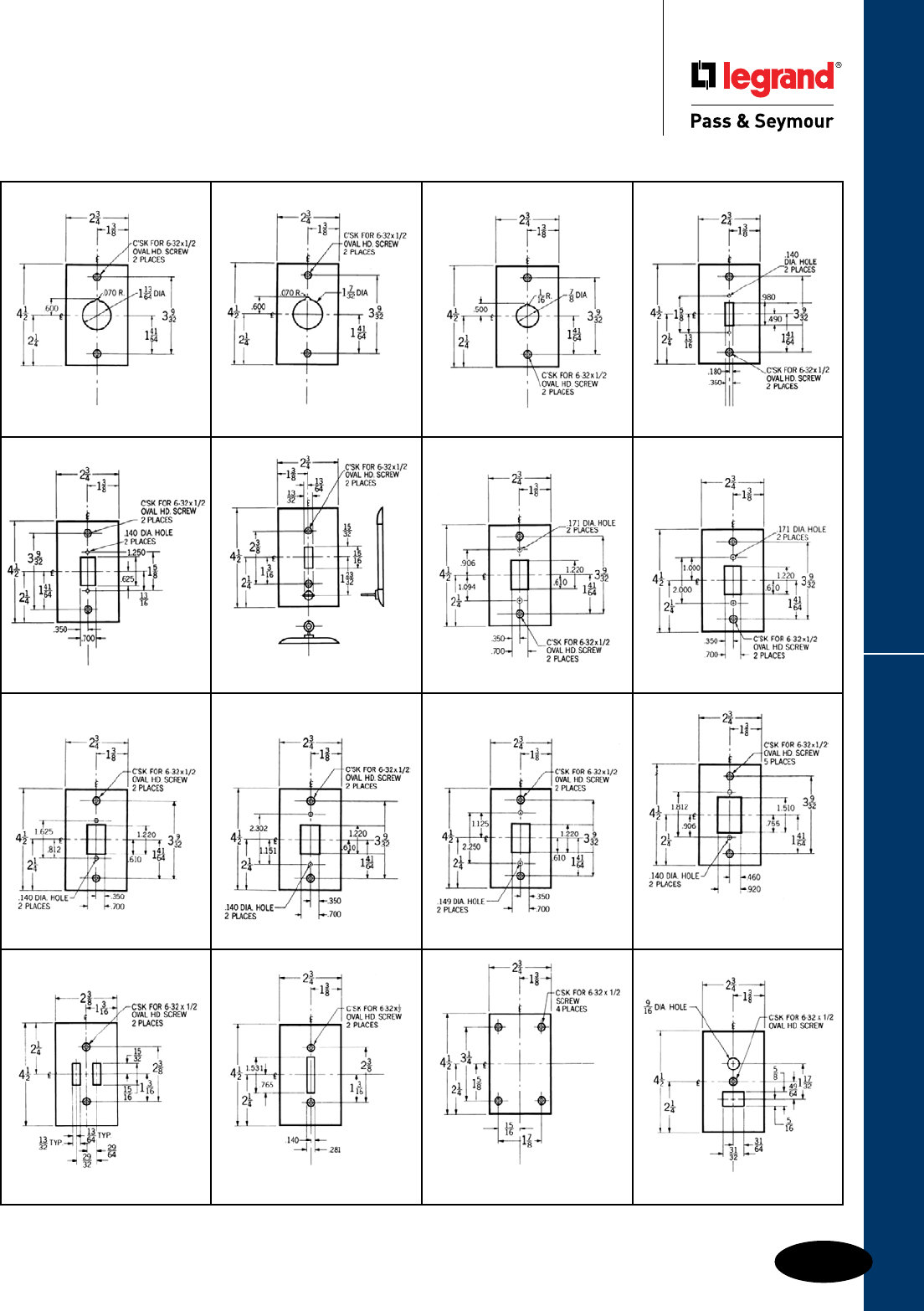
Q-57
Style Selector GuideWall Plates & Specialties
Wall Plates
Style Selector Guide
Custom Metal Wall Plates
All wall plate dimensions shown above are in inches.
F.S. BOX MTD.
with Hospital Cord Eyelet
STYLE 262A
HORIZONTAL OPENING, BOX MTD.
STYLE
244
STYLE
245
STYLE
246 STYLE
247
STYLE
248
STYLE
252
STYLE
257 STYLE
258
STYLE
259
STYLE
260
STYLE
261 STYLE
262
STYLE
267
STYLE
269
STYLE
270
STYLE
271

Style Selector Guide
Q-58
Wall Plates & Specialties
Wall Plates
Style Selector Guide
Custom Metal Wall Plates
All wall plate dimensions shown above are in inches.
STYLE
291
STYLE
272
#736 Standard Plate page Q-32
STYLE
274
STYLE
273 STYLE
275
STYLE
276
STYLE
281
STYLE
279 STYLE
282
STYLE
283
STYLE
285
STYLE
284 STYLE
286
STYLE
287
STYLE
289
STYLE
288
JUMBO 2 GANG PLATE
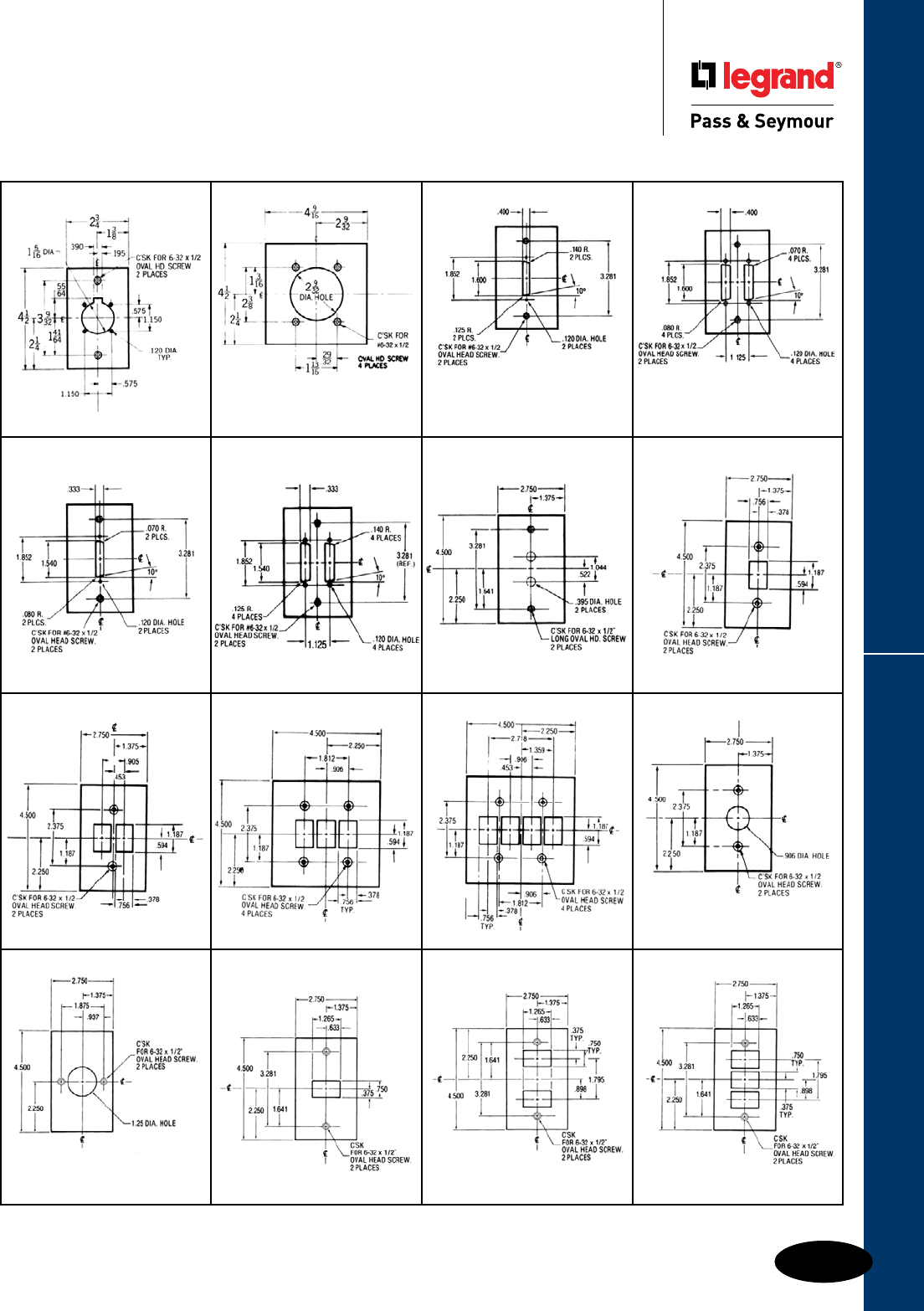
Q-59
Style Selector GuideWall Plates & Specialties
All wall plate dimensions shown above are in inches.
Wall Plates
Style Selector Guide
Custom Metal Wall Plates
SS-717 for PS20AC1KL Switch
POWER OUTLET
for 30, 50, 60A. Receptacle
#716 Standard Plate page Q-14
FOR RS-232
COMPUTER JACK
#791 Standard Plate page Q-34
FOR RS-232
COMPUTER JACKS
#792 Standard Plate page Q-34
STYLE
292
STYLE
293 STYLE
295
STYLE
295A
STYLE
296
STYLE
296A STYLE
298
STYLE
299
STYLE
300 STYLE
301
STYLE
302
STYLE
305
STYLE
303
STYLE
297
STYLE
306
STYLE
307
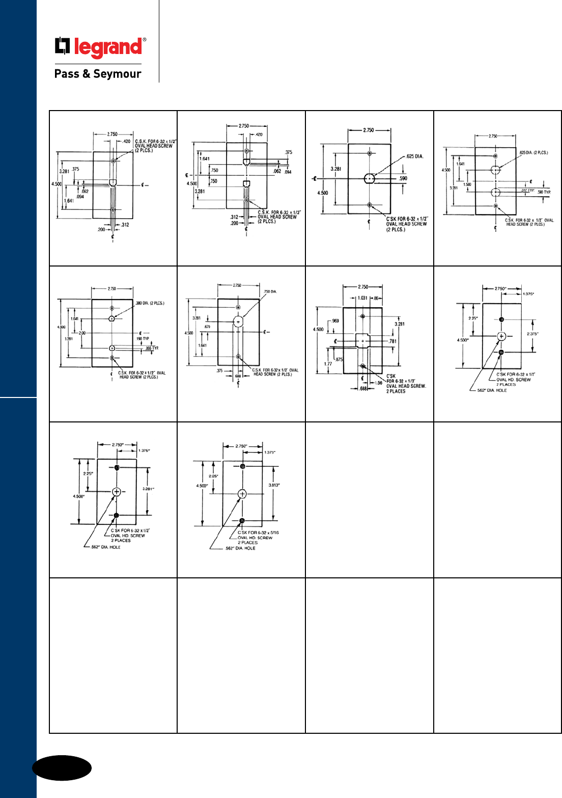
Style Selector Guide
Q-60
Wall Plates & Specialties
Wall Plates
Style Selector Guide
Custom Metal Wall Plates
TELEPHONE JACKTELEPHONE JACK AMP ELECTRONIC
CONNECTOR COAXIAL ELECTRONIC
CONNECTOR
COAXIAL ELECTRONIC
CONNECTOR COAXIAL ELECTRONIC
CONNECTOR LAN PORT
STYLE
308
STYLE
309 STYLE
310
STYLE
311
STYLE
312
STYLE
313
STYLE
314
STYLE
315
STYLE
315A
STYLE
315B
All wall plate dimensions shown above are in inches.
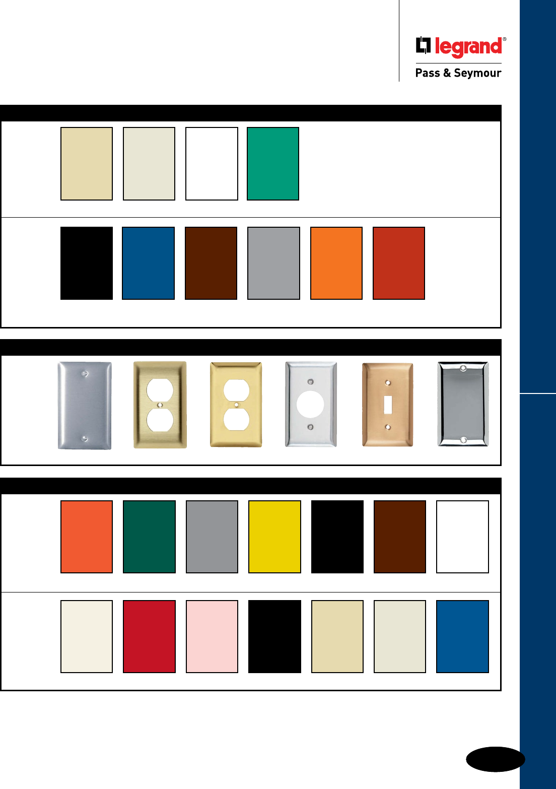
Q-61Q-61
Devices & Wall Plates Color Selection Chart
Devices & Wall Plates
Color Selection Chart
Devices & Plastic Wall Plate Colors
Ivory Light Almond White Green
Black Blue Brown Gray Orange Red
See specific device and wall plate catalog charts for particular color availabilities.
To order custom metal wall plates, see Pages Q-43 – Q-45.
For additional colors consult factory.
Custom Metal Wall Plates Paint Finish Colors
Custom Metal Wall Plates Paint Finish Colors
Paint Color Orange Green Gray Yellow Glossy Black Brown White
Paint Color Primer Red Pink Flat Black Ivory Light Almond Blue
Metal Wall Plates
Metal Finish Aluminum Brass (Brushed) Polished Brass Stainless Steel Brushed Bronze Chrome

ElEctrical accEssoriEs
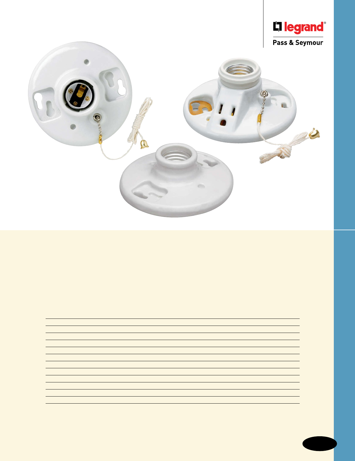
R-1
Electrical Accessories
Electrical Accessories
Index
Device Page Number
Appliance Switches R-2
Fluorescent Lampholders R-3
Incandescent Lampholders R-4 – R-6
Household Devices R-6 – R-9
Fluorescent Starters & Wall Plate Inserts R-10
Special Purpose Devices – Despard® R-11, R-12
Low-Voltage Switching Components R-13 – R-15
Network Wiring Connectivity
Keystone Products, Wall Plates & Frames R-16
Activate™ Products R-17
Frames & Wall Plates R-18
Patch Panels, 66 Block & Patch Cords R-19
Looking for the classic porcelain lampholder?
A hard-to-find household adapter? Or
a wide range of replace ment appliance
switches? You’ll find them in our accessory
line — along with quality materials,
durability, and time-tested designs.
288
282
272
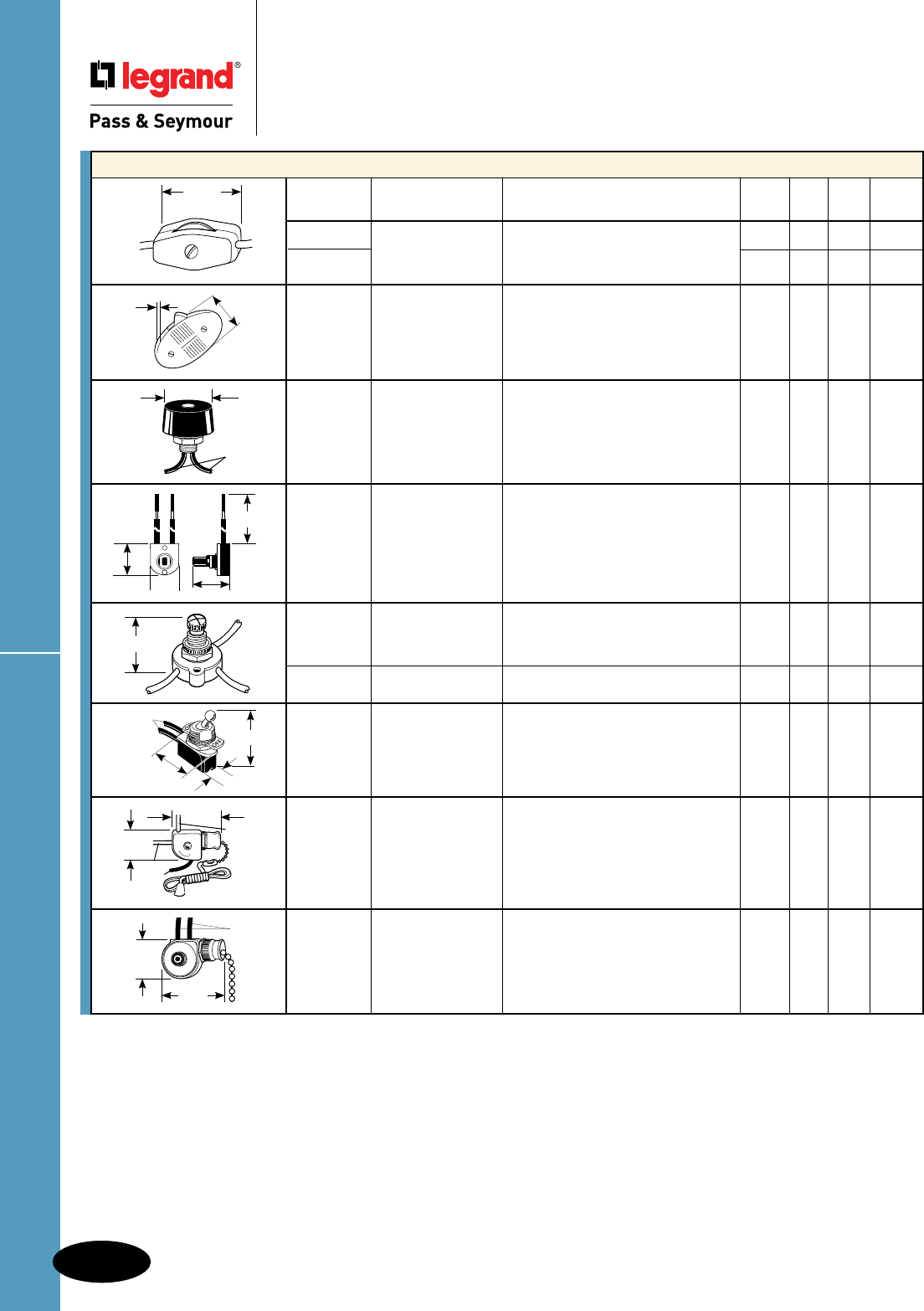
Appliance Switches
Catalog
Number Rating Description Color UL CSA cULus
423 6A 125V In-linecordswitch,light-duty. Brown ••
410WCC253A 250V
3A 125VT White •
5410CC10 10A 125V Heavy-duty,feed-thrucordswitch, Black • •
5A 250Vsinglepole,ON-OFFsequence,
markingsneartoggle.
574T 3A 125V Rotary,singlepole,non-removable Black •
1A 125VT blackphenolicstem,2blackleads.
1A 250V (18AWG)6.5"long,ON-OFF
sequence.
575 3A 250V Pushbuttoncanopyswitch,single Brown •
1A 250V pole,Bakeliteplunger,ON-OFF
sequence,RUListed.
653 6A 125VT Rotary,singlepole,twocircuit,four •
3A 250V position,heavy-duty,black,blue,red
leads,1stON,2ndON,bothON,
OFFsequence.RUListed.
90577 6A 125V Rotary,singlepole,2position
3A 250V ON-OFFsequence.
738 8A 125V Toggle,singlethrow,ON-OFF •
sequence,2blackleads.(18AWG)
6.5"long,RUListed.
168950 3A 125V-L Pullchain,twocircuit,four • •
6A 125V position,1stON,2ndON,bothON,
3A 250V OFFsequence,RUListed.
1/4HP@125/120V
220 6A 125V Heavy-dutysinglepolecanopy • •
3A 250V pullswitch.2blackleads
(18AWG) 6.5"long,RUListed.
0.97"
(ref)
0.80" 1.22"(ref)
6.00"(ref)
1.375"
1.25"
0.63"
18AWG
6.5"long
0.98"
18AWG
6.5"long 1.48"
0.64"
1.38"
Red
Blue
Black
1.13"
0.88"
1.44"
18AWG
6.5"long
.80" 1.18"
Appliance Switches
R-2
Electrical Accessories
AlldeviceslistedonthispageconformtoNEMAWD-1andWD-6.
Electrical Accessories
Appliance Switches
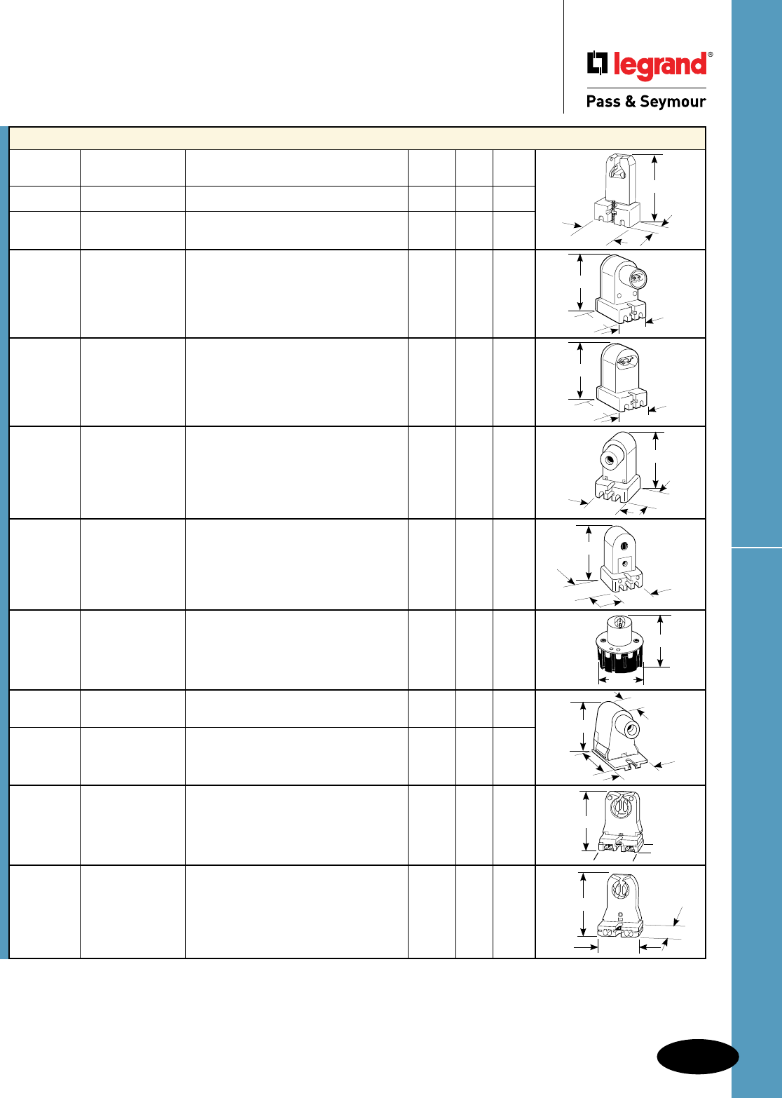
R-3
Fluorescent Lampholders
Electrical Accessories
AlldeviceslistedonthispageconformtoNEMAWD-1andWD-6.
Electrical Accessories
Fluorescent Lampholders
2.00"
1.375"
0.75"
1.4375"
2.3125"
1.625"
1.4375"
2.3125"
1.625"
1.44"
2.37"
0.75"
1.88"
2.37"
1.45"
1.630"
2.375"
1.50"
1.625"
0.75"
1.25"
1.6875"
1.13"
1.74"
1.468" 1.312"
1.375"
Fluorescent Lampholders
Catalog
Number Rating Description Color UL CSA
3901W 660W 600V Mediumbi-pin,screwterminals. White • •
3911W 660W 600V Mediumbi-pin,pressurelockterminals, White • •
includesstarterbase.
464 660W 600V Pedestaltype,recessed,contact,plunger, White • •
withfloorterminalscrewcover
(for800&1500MAT-12lamps).
465 660W 600V Pedestaltype,recessed,fixed,quickwire White • •
terminals(for800&1500MAT-12lamps).
466 660W1000V Pedestaltype,recessed,plunger,quick White •
wireterminals(forallsizesoflamps
T-12,T-8,andT-6).
467 660W600V Pedestaltype,recessed,fixed,quickwire White •
terminals(forallsizesoflampsT-12,
T-8,andT-6).
623 660W600V Snap-in,highoutputwithplunger. White • •
2536 660W1000V Slimline,forsinglepinlamps,shallow White • •
base,slideplunger,pushinterminal.
2537 660W600V Slimline,forsinglepinlamps,shallow White • •
base,slidefixed,2pushinterminals.
13053UN 660W660V Slide-on,short,formediumbi-pinlamps White •
withcaptivenut,4quickwireterminals.
13057UN 660W600V Slide-on,formediumbi-pinwithcaptive White • •
nut,4quickwireterminals.
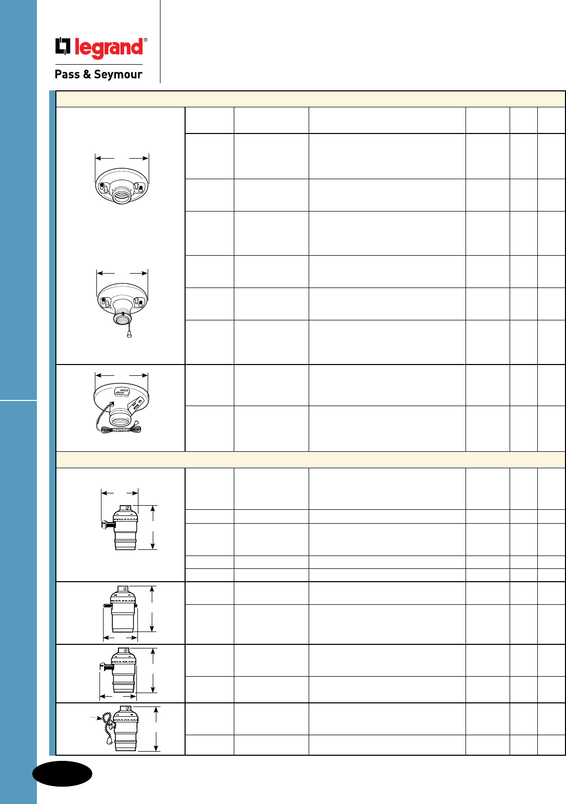
Incandescent Lampholders
Medium Base Lampholders
Catalog
Number Rating Description Color UL CSA
272 660W 250V Mediumbase,porcelain,onepiece White • •
keyless,2terminalswithtri-drivescrews,
fits3-1/4"and4"boxes,withcageneck.
272WH6 660W 250V Samewith6"leads. White • •
274 660W 250V Mediumbase,porcelain,onepiece White • •
keyless,4terminalswithtri-drivescrews,
fits3-1/4"and4"boxes.
276WH 660W 250V Mediumbase,phenolic,one-piece White • •
keyless,4terminalswithtri-drivescrews,
fits3-1/4"and4"boxes,withcageneck.
276WH6 660W 250V Samewith6"leads. White • •
282 250W 250V Mediumbase,porcelain,pullchain, White • •
2terminalswithtri-drivescrews,fits
3-1/4"and4"boxes,withcageneck.
284 250W 250V Mediumbase,porcelain,pullchain, White • •
4terminalswithtri-drivescrews,fits
3-1/4"and4"boxes,withcageneck.
280WH 250W 250V Mediumbase,phenolic,pullchain, White • •
4terminalswithtri-drivescrews,fits
3-1/4"and4"boxes,withcageneck.
280WH6 250W 250V Samewith6"leads. White • •
29816C2 250W 250V Mediumbase,porcelain,pullchain, White • •
2terminalswithtri-drivescrews,
6"leads,fits3-1/4"and4"boxes
withcageneck.
288 250W 125V Mediumbase,porcelain,pullchain, White • •
2terminalswithtri-drivescrews,
15A125Vgroundingreceptacle,
fits3-1/4"and4"boxes,withcageneck.
Metal Shell Lampholders
7070PG 250W 250V Mediumbase,metalshell,removable • •
turnknob,electrolier,2lampcontrols,
3terminals,1stON,2ndON,bothON,
OFFsequence.
7070M Interioronlyfor7070-PG. •
7090PG 250W 250V Mediumbase,metalshell,removable •
turnknob,electrolier,3-way
LO-MED-HIGH.
7090M Interioronlyfor7090-PG. •
7090MH Interioronlywithhickeyfor7090-PG. •
6098PG 660W 250V Mediumbase,pushthrough,metalshell, • •
electrolier,singlecircuit.
7080M Interioronlyfor6098-PG. •
1008316 250W 250V Mediumbase,metalshell,removable •
turnknob,singlecircuit,electrolier,
1/8"IPStappedbushingwithsetscrew.
10083M Interioronlyfor10083-16. •
19980PG 660W 250V Mediumbase,metalshell,pullchain, • •
electrolier,singlecircuit,1/8"IPS
bushingwithsetscrew.
8002M Interioronlyfor19980. •
2.0"
2.5"
7070PG
7090PG
276WH
4.5"
4.5"
280WH
4.5"
288
2.0"
2.5"
5.50"
2.5"
2.0"
2.5"
Electrical Accessories
AlldeviceslistedonthispageconformtoNEMAWD-1andWD-6.
Electrical Accessories
Incandescent Lampholders
R-4
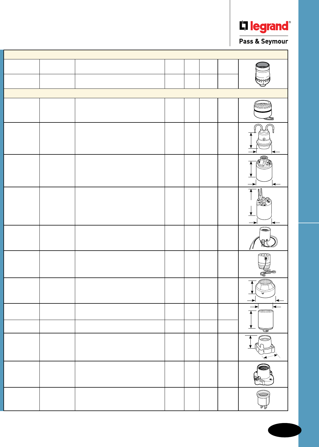
R-5
Incandescent LampholdersElectrical Accessories
AlldeviceslistedonthispageconformtoNEMAWD-1andWD-6.
Electrical Accessories
Incandescent Lampholders
1.40"
2.00"
2.00"
1.75"
1.75"
1.75"
1.38"
2.00"
1.38"
3.38"
Metal Shell Lampholders
Catalog
Number Rating Description Color UL CSA cULus
975ABDCC10 660W 250V Mediumbase,metalshell,keyless. ••
Medium Base Lampholders
8101 660W 250V Mediumbase,porcelain,keyless,single White •
circuit,2pieceringwithleads.
1-3/8"to1-1/2"hole.
201 660W 600V Mediumbase,rubber,keyless,for Black • •
temporarylighting,2wireleads6"long.
31528 660W 250V Mediumbase,porcelain,screwterminals, White • •
keyless,singlecircuit,fixturepanwith
1/8"IPShickey.
3352F 660W 250V Mediumbase,porcelain,keyless,screw White • •
terminals,shortbase.
8052CC10 660W 250V Mediumbase,porcelain,bracketmount. • •
9814 250W 250V Mediumbase,porcelain,2-piecepull White
chain,ringtype,screwterminals,
gasketfurnished.
9880 660W 250V Mediumbase,porcelain,surfacemount White • •
type,2-piece.
10045 660W 250V Mediumbase,porcelain,keyless,single White • •
circuitwithscrewterminals,aluminum
screwshellwithset.
10085 660W 250V Mediumbase,porcelain,keyless,single White • •
circuitwith2-18AWGleads6"long.
19062 660W 250V Mediumbase,porcelain,ponycleattype, White • •
terminalscrews.
S752WCC10 660W 250V Mediumbase,cleatsockets,frontwire. White •
61 660W 125V Mediumbase,outlettolampholder, Brown
2Pole,2Wire.
2.31"
1.53"
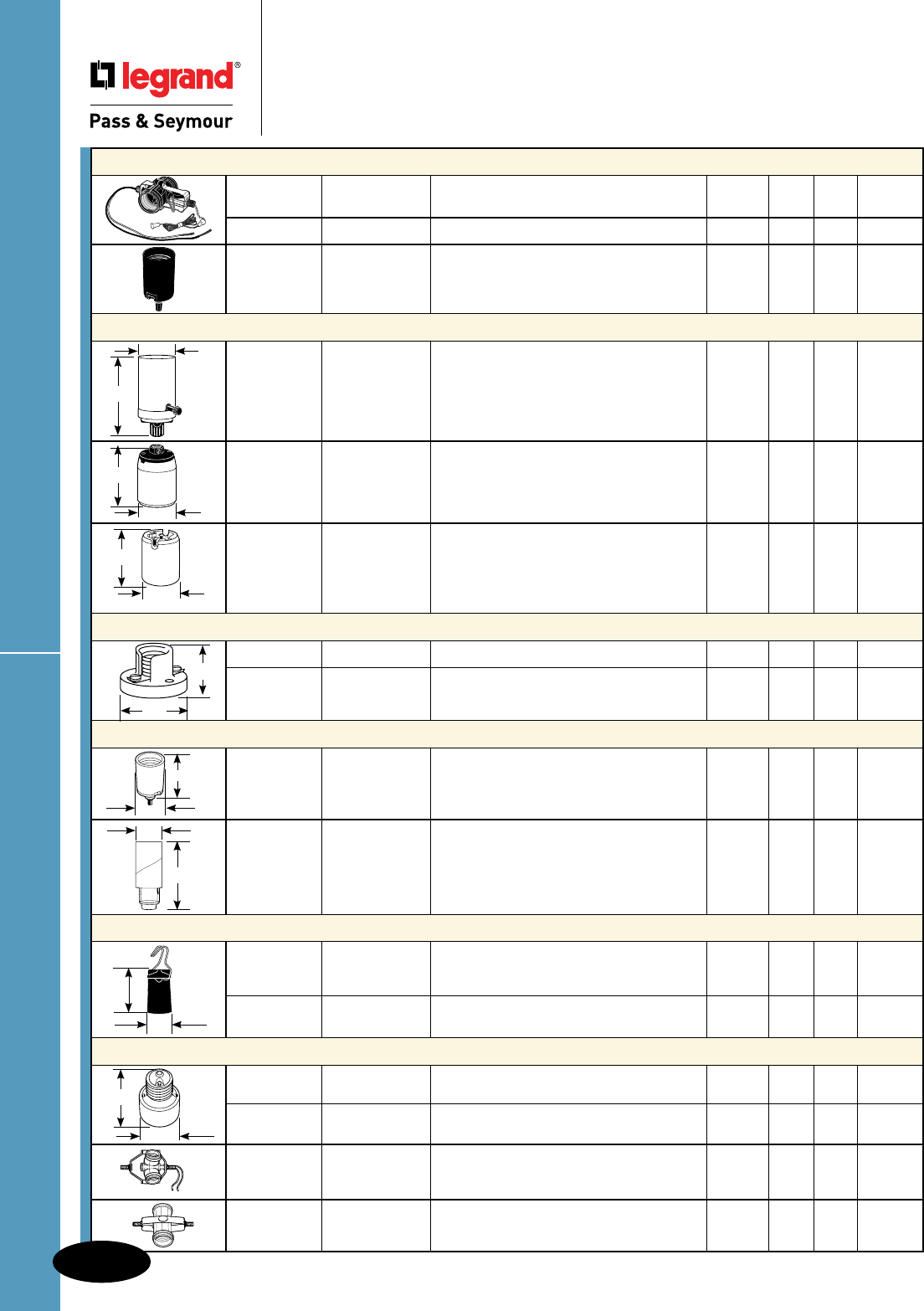
Incand. Lampholders & Household Devices
Electrical Accessories
AlldeviceslistedonthispageconformtoNEMAWD-1andWD-6.
Electrical Accessories
Incandescent Lampholders
& Household Devices
2.75"
4.375"
2.13"
2.56"
2.00"
4.25"
3.12"
3.25"
1.44"
.88"
0.75"
1.75"
1.53"
2.0"
Medium Base Lampholders
Catalog
Number Rating Description Color UL CSA cULus
4017CC10 660W 250V Mediumbase,single-to-twin. • •
4063CC10 250W 250V Mediumbase,turnknob,3way. • •
Mogul Base Lampholders
8601 750W 250V Mogulbase,porcelain,removableturn White •
knob,2circuits,hickeytapped1/4"
IPSx7/8"high.
8678 1500W 600V Mogulbase,porcelain,keyless,single White • •
circuit,1/4"IPS13/16"hexagonx
9/16"highwithscrewset.
8694 1500W 600V Mogulbase,porcelain,screwterminals, White •
keyless,singlepolewithbushings,
4KVpulserated.
Pony Cleat Type Lampholders
10020 75W 125V Ponycleattype,plastic,miniaturebase. White
10028 75W 125V Ponycleattype,plastic,candelabrabase. White
Candelabra Base Lampholders
4155 660W 250V Candlesocket,bottomturnknob,one Black •
piece,phenolicbody.
10027 75W 125V Candelabrabase,keyless,screw •
terminals,solidhickey,overallheight
1-1/2",paperboardsleeve.
Temporary Lighting Devices
267 75W 125V Keyless,candelabrabase,detachable Brown •
wirehook,twopiecepintype,for
temporaryuse.
43308 660W 250V Mediumbase,phenolic,pintypehook Black •
supplied,fortemporaryuse.
Socket Extensions/Clusters
2005 660W 250V Socketextensions,medium-to-medium, White • •
onepieceporcelain,1.25"extension.
2006 660W 250V Socketextensions,medium-to-medium, White • •
onepiecephenolic,1.1875"extension.
341DU4 660W 250V Mediumbase,multi-lampholdercluster, Black
3lights1/8"IPSmale(top&bottom),
2wireleads(18AWG)6.5"long.
4015D4F 660W 250V Mediumbase,multi-lampholdercluster, Black
2lights1/8"IPSmale(top&bottom).
1.44"
2.0"
R-6
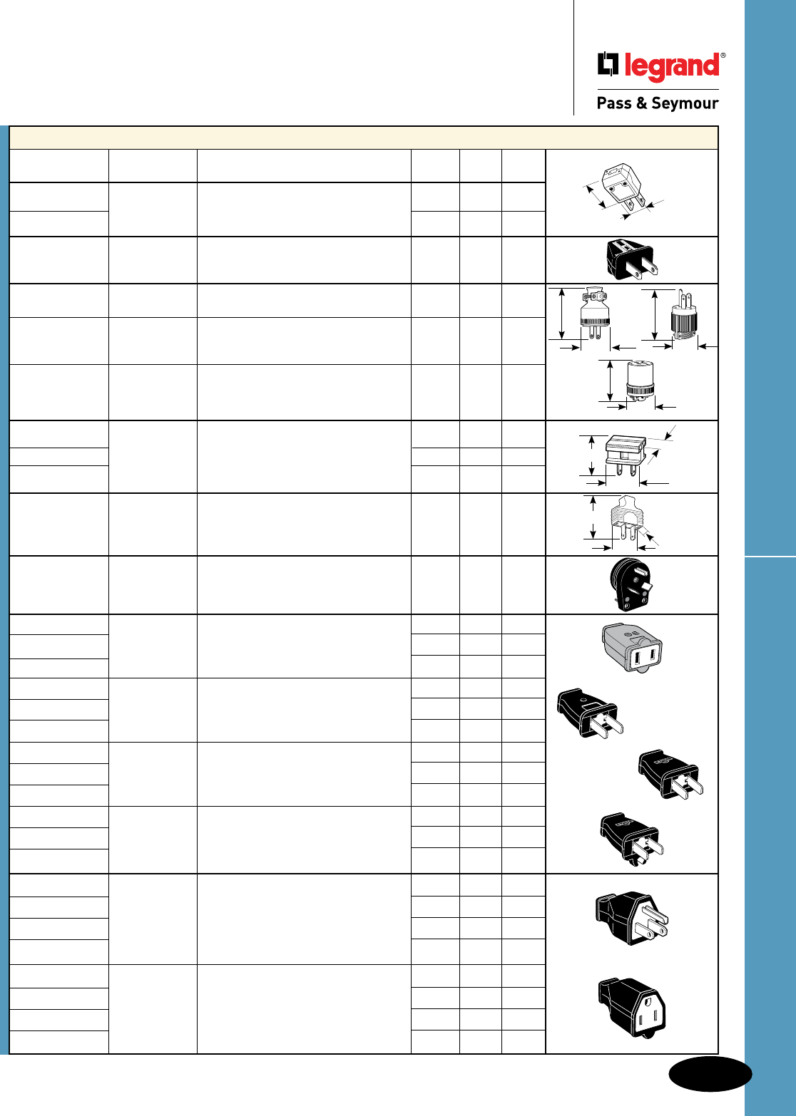
Household DevicesElectrical Accessories
AlldeviceslistedonthispageconformtoNEMAWD-1andWD-6.
Electrical Accessories
Household Devices
R-7
1.56"
2.69"
1.50"
2.69"
1.56"
2.3"
111MC 111GMC
114GMC
1.13"
1.38" 0.75"
1.63" 0.75"
2.13"
1.5" 1.13"
SA155
SA440
SA540
SA840
SA399
SA993
Plugs & Connectors
Catalog
Number Rating Description Color UL CSA
101 15A 125V Clamptiteplug,light-duty,2Pole,2Wire.Black •
101W White •
84BKCC20 15A 125V Angleplug,light-duty,2Pole,2Wire. Black ••
111MC 15A 125V Rubberplug,withvinylcordclamp, Black •
2Pole,2Wire.
111GMC 15A 125V Rubberplug,withvinylcordclamp Black •
innerassembly,2Pole,3Wire,
(mateswith114GMC).
114GMC 15A 125V Rubberconnector,withvinylcordclamp, Black •
2Pole,3Wire,(mateswith111GMC).
123P 10A 125V Easywireplug,10A125Vusewith18-2 Brown •
123PI
3A 125V SPT-1Cord,3A125Vusewith Ivory •
123PW 20-2XTCord,non-polarized.
White•
48643 15A 125V Plug,vinyl,shortflat,2Pole,2Wire. Brown •
83CC4 30A 125V Angletraveltrailerplug,2Pole,3Wire. Black ••
SA155BKCC10 15A 125V Straightbladeconnector,polarized, Black ••
SA155CC10 2Pole,2Wire. Brown ••
SA155WCC10 White ••
SA440BKCC10 15A 125V Straightbladeplug, Black ••
SA440CC10 2Pole,2Wire. Brown ••
SA440WCC10 White ••
SA540BKCC10 15A 125V Straightbladeplug,polarized, Black ••
SA540CC102Pole,2Wire. Brown ••
SA540WCC10 White ••
SA840BKCC10 15A 125V Straightbladeplug,withcordclip, Black ••
SA840CC102Pole,2Wire. Brown ••
SA840WCC10 White ••
SA399BKCC10 15A 125V Straightbladeplug,2Pole,3Wire. Black ••
SA399GRYCC10 Gray ••
SA399OCC10 Orange ••
SA399WCC10 White ••
SA993BKCC10 15A 125V Straightbladeconnector,2Pole,3Wire. Black ••
SA993GRYCC10 Gray ••
SA993OCC10 Orange ••
SA993WCC10 White ••

Household Devices
R-8
Electrical Accessories
AlldeviceslistedonthispageconformtoNEMAWD-1andWD-6.
Electrical Accessories
Household Devices
3.00"
1.06"
Quick Clamp Plugs & Connectors
Catalog
Number Rating Description Color UL CSA
123PQC 2wireQuickClampplug Brown •
123PQCW White •
123C3W 2wiretri-tapQuickClampconnector White •
Adapters
125 15A 125V Lampholdertooutlet,mediumbase. White •
660W
1403 660W 125V Mediumbaselampholder/outletadapter, Black •
keylesslampholderwith2outlets,
2Pole,2Wire.
1406 250W125V Mediumbaselampholder/outletadapter, Black •
1406I
pullchainlampholderwith2outlets,Ivory •
2Pole,2Wire.
128 15A 250V Singlelampholder-to-twinlampholder, Brown •
660W mediumbase.
8681 660W 250V Mogultomediumsocketadapter, White • •
1piece.1.66"Dia.x2.0"Deep
313CC10 75W 125V Socketreducer,mediumtocandelabra, Black • •
keyless.
1264 15,20A 125V Traveltraileradapter,2Pole,3Wire.
210G 15A 125V Adapter,parallelblades,moldedrubber, Gray •
polarized,3Wiregrounding.
1482ICC10 15A 125V Cubetap,singletotripleoutlet, Ivory ••
2Pole,3Wire.
68 15A 125V Cubetape,phenolic,singletotriple, Brown
2Pole,2Wire.
68I Ivory
63 15A 125V Plug-inadapter,singletotriple, Brown • •
polarized,2Pole,2Wire.
63I Ivory • •
69I 15A 125V Plug-inadapter,singletotriple,swivel, Ivory • •
polarized,2Pole,2Wire.
69W White • •
123PQC 123C3W
3.00" 1.08"
3.1"
1.75"
10Awith18AWG
SPT-1&2Cord,
13Awith16AWG
SPT-1Cord
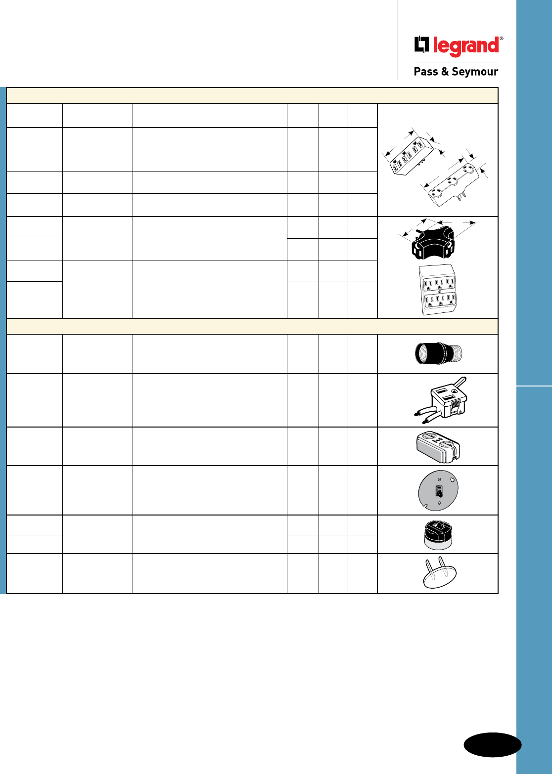
R-9
Household Devices
Electrical Accessories
AlldeviceslistedonthispageconformtoNEMAWD-1andWD-6.
Electrical Accessories
Household Devices
3.25" 1.38"
4.0"
1.38"
697
697-RI
3.2" 2.2"
Adapters
Catalog
Number Rating Description Color UL CSA
697 15A 125V Plug-inoutletadapter,singletotriple, Brown •
2Pole,3Wire.
697I Ivory •
697RI 15A 125V Plug-inoutletadapter,singletotriple, Ivory •
rubber,2Pole,3Wire.
697W 15A 125V Plug-inoutletadapter,singletotriple, White •
2Pole,3Wire.
699CC25 15A 120VPlug-inoutletadapter,singletotriple, Brown • •
2Pole,3Wire.
699GRCC25 Green • •
226PAI 15A 125V Plug-inadapter,twotosix,polarized, Ivory ••
2Pole,3Wire.
226PAW White ••
Miscellaneous Devices
941904 150W 120V Dawntoduskdimmer,automaticlight Gray • •
sensorfitsintostandardlampsocket.
Indoororoutdooruse.
13741 15A 125V Snap-inreceptacle,3Wiregrounding Black • •
outletwith6"leads,No.14AWG
105°Cplastic.
746ICC10 15A 125V Surfaceoutlet,2Pole,2Wire. Ivory ••
779CC5 15A 120/277V Cover-mountedswitch. ••
735CC10 10A 125V Surfacemountswitch Black ••
5A 250V
735ICC10 Ivory ••
5SC Outletsafetycaps. Clear •
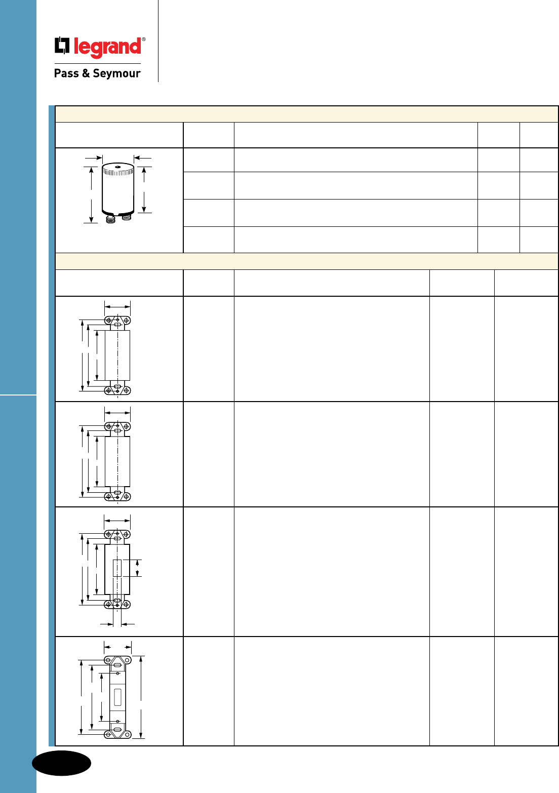
Fluorescent Starters & Wall Plate Inserts
R-10
Electrical Accessories
AlldeviceslistedonthispageconformtoNEMAWD-1andWD-6.
Electrical Accessories
Fluorescent Starters & Wall Plate Inserts
Fluorescent Starters
Catalog
Number Description UL CSA
FS2 Glowswitchstarterwithoutreset,2pins14,15&20W. • •
FS4 Glowswitchstarterwithoutreset,2pins13,30&40W. • •
FS5 Glowswitchstarterwithoutreset,2pins4,6&8W. • •
FS25 Glowswitchstarterwithoutreset,2pins22WCircline25WStd. • •
Wall Plate Inserts
Catalog
Dimensions Number Description Finish Color
325I Mountingstrapforblankinsert.Boxmounted. Polycarbonate Ivory
325W Changesdecoratoropeningtoblank. Plastic White
325 Brown
325BK Black
325LA LightAlmond
325GRY Grey
326I Mountingstrapforblankinsert.Boxmounted. Painted Ivory
326W Changesdecoratoropeningtoblank. Steel White
326 Brown
326LA LightAlmond
327I Mountingstrapfordimmerinsert.Boxmounted. Painted Ivory
327W Changefromdecoratortotoggleopening. Steel White
327 Brown
327LA LightAlmond
80700I Mountingstrapforblankinsert.Boxmounted. Thermoset Ivory
80700W Changestoggleopeningtoblank. Plastic White
80700LA LightAlmond
1.34"
1.50"
0.84"
FS2
FS4
FS5
FS25
3.812''
3.281''
2.625''
1.300''
SLATER
4.07''
1.30''
2.37''
3.25''
3.65''
3.812''
3.281''
2.625''
1.300''
SLATER
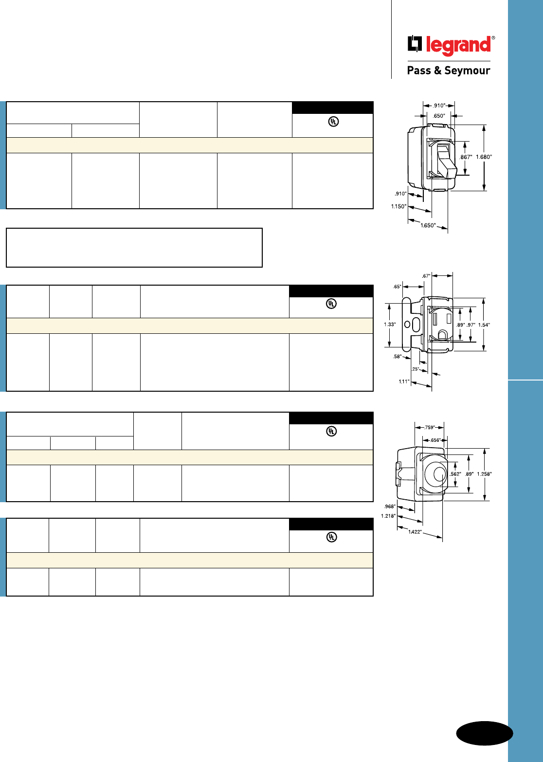
R-11
Special Purpose Devices – Despard®
Electrical Accessories
AlldeviceslistedonthispageconformtoNEMAWD-1andWD-6.
Electrical Accessories
Special Purpose Devices – Despard®
Catalog Number Rating
Ivory Brown White W. V. Description
Neon Pilot Lights
147513751575 1/25 125 FlushRedNeonPilot•
1375220 1/8 220 LightwithScrewTerminals•
1475277 1/6 277 •
3rd Party Compliance
UL542
Catalog Rating
Number Color A. V. Description
Flush Pilot Lights with Mounting Straps
1376 Brown 6 125 Single,forSingleVerticalOpeningPlate •
1377 Brown 6 125 Combination,forSwitchorOutletPlate •
3rd Party Compliance
UL542
HP Conversion Table
15Amp 1/2Horsepowerat120V 2Horsepowerat240V
20Amp 1Horsepowerat120V 2Horsepowerat240V
ACD1
1432
1475
Catalog Number Rating
Single Pole Three-Way Color A. V.
Toggle Switches Screw Terminals
ACD1I ACD3I Ivory 15 120/277 •
ACD1W ACD3W White 15 120/277 •
ACD1 ACD3 Brown 15 120/277 •
ACD201I ACD203I Ivory 20 120/277 •
ACD201 ACD203 Brown 20 120/277 •
UL20
3rd Party Compliance
Catalog Rating
Number Color A. V. Description
Receptacles Three Wire Grounding
1432 Ivory 15 125 •
1532 White 15 125 Mustbeinstalledinendopeningofstrap•
1332 Brown 15 125 •
1433 Ivory 15 125 withGroundLead •
1333 Brown 15 125 •
UL498
3rd Party Compliance
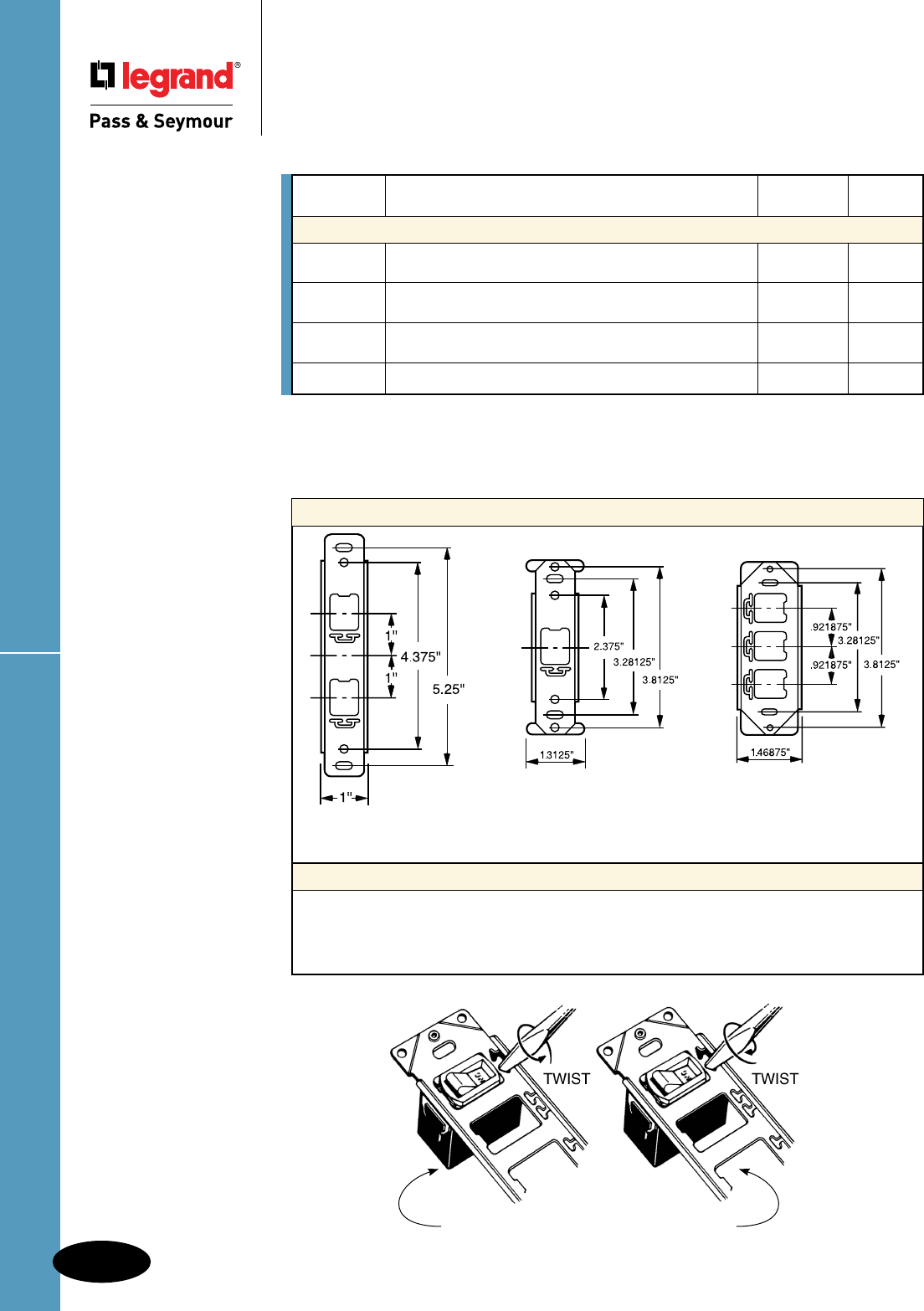
Special Purpose Devices – Despard®
R-12
Electrical Accessories
AlldeviceslistedonthispageconformtoNEMAWD-1andWD-6.
Electrical Accessories
Special Purpose Devices – Despard®
ThecorrectstyleofmountingstrapisfurnishedwitheachDespardwallplate,butstrapsmaybeordered
separately.
Consult Page Q-35 for additional mounting straps.
Catalog Screw
Number Description Spacing Finish
Mounting Straps
342 Tandemmountingstrapwithtwoverticalopenings. 4-3/8" Bright
Platescrewholespacing4-3/8". Zinc
347 Mountingstrapwithsingleverticalopening. 3-13/16" Bright
Platescrewholespacing3-13/16".Boxmounted. Zinc
348 Mountingstrapwiththreehorizontalopenings. 3-13/16" Bright
Platescrewholespacing3-13/16".Boxmounted. Zinc
1354 ApplianceStrap. 1-31/32"
To Insert To Remove
Dimensions
Installation & Removal
ToassembleDesparddevicesinstrap,inserttabonstrapintotheslotinthedevice;atwistofa
screwdriverintheslotsontheoppositesideofthestrapturnsaslimstripofmetalintothemounting
slotonthatsideofthedevicetolockthedevicesecurelyinplace.Toremovethedevice,reverse
theprocedure.
347
342
348
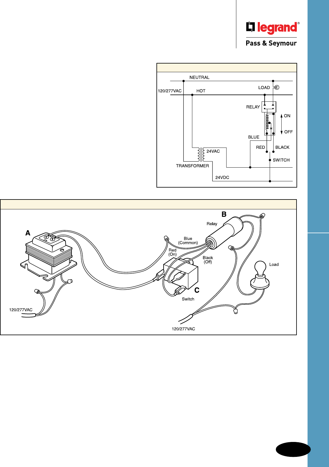
R-13
Low-Voltage Switching ComponentsElectrical Accessories
Electrical Accessories
Low-Voltage Switching Components
Application
Legrand/Pass & Seymour’s Low-Voltage Remote
Control Products consist of reliable, field-tested switching
circuitry that provide central or local control of lighting
loads throughout a building. These are best applied in
institutions, schools, commercial buildings, warehouses
and other installations where the ON-OFF switching of
lighting is widely dispersed throughout the structures.
Thelow-voltagesystemdiffersfromconventionalswitchwiringby
actuatingrelaysthroughtheuseofmomentarycontactswitches.
Thistypeofswitchingutilizesatransformertoprovidesafelow-
voltagecurrenttocontrollinevoltagecircuits.Thewiringoflights
andotherelectricalloadsisinstalledintheconventionalmanner.
Theaboveillustrationsimplifiesalow-voltagecircuitwithitsbasic
components:
A. Transformer–Convertslinevoltagetolow-voltage.Alllow-
voltagecomponentsoperateusing24voltsfurnishedbythe
step-downtransformer.Secondaryoutputis3-12A.
B. Relay–Themagneticrelayswitcheslinevoltage.Amomentary
24voltpulseenergizesthe“ON”or“OFF”coilstomakeorbreak
linevoltagecontacts.
C. Switches–Switchesaremomentarycontacttypeusedto
energizeeitherthe“ON”or“OFF”coilsofarelay.Momentary
contactswitchesarenormallyopen,singlepole,doublethrow.
Important:
Low-VoltageSwitchingComponentsarespecificallydesignedfor
switchingincandescentandfluorescentlighting(non-HID)loads.
Low-VoltageSwitchingComponentsarenottobeusedwithany
componentssuppliedbyothermanufacturers.Misapplicationor
improperusemayvoidproductwarranties.
The ABCs of Low-Voltage Wiring and Components
Basic Wiring Diagram
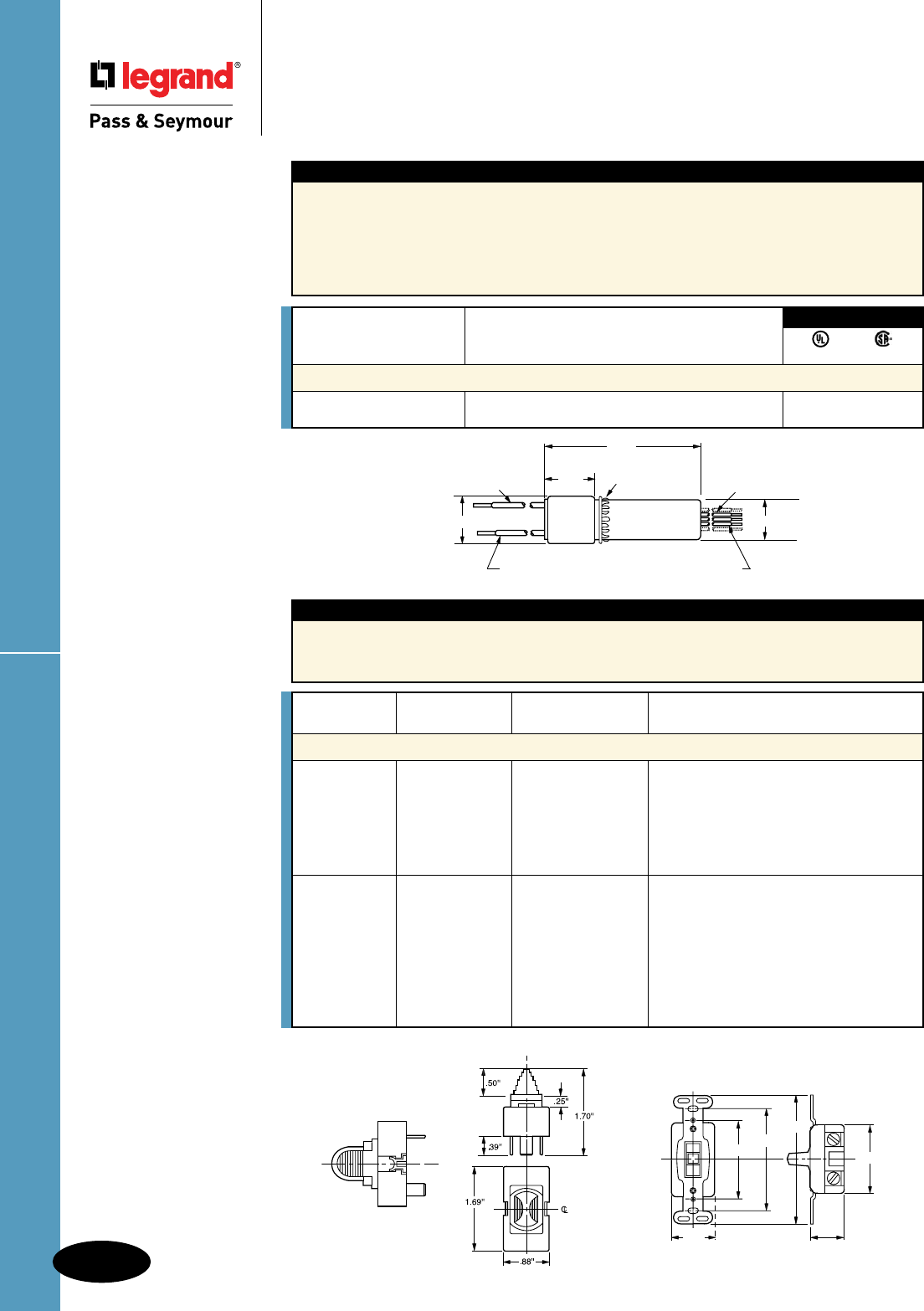
Low-Voltage Switching Components
R-14
Electrical Accessories
Electrical Accessories
Low-Voltage Switching Components
Alldeviceslistedonthis
pageconformtoNEMA
WD-1andWD-6.
1070B
Features
nMountinstandard1/2"KOthroughnoise
suppressingnylonring.
nMaximumambienttemp:140°F(60°C).
nInsulatedflameretardantnylonshell.
nPrestripped5-1/2"(140mm)#22AWG
leadsforeasywiring.
nSplitcoildesignenergizesONcoiltoclose
linecontacts,andOFFcoiltoopencontacts.
nCanbemountedinanyposition.
nOperatesonmomentaryimpulse.
nDraws.520mA.
Features
nAvailableinDespard®interchangeableand
heavy-dutytoggleversions.
nSidewiredscrewterminals.
nHeavy-dutytogglesrecommendedwhere
low-voltageswitchesmustmatchconventional
switches.
1.176''
Line Voltage Leads 1.290''
3.156''
Nylon Mounting Ring
Control Leads
.818''
#12-19 Stranded Copper Wire
(Tinned) Type T-1/32 INS
Black - 6''
Type SRIR #22 Stranded
Tinned Wire Thermoplastic
Insulation - 5-1/2'' Long
1081
2.188''
1.062''
1.312''
2.375''
3.281''
4.093''
1091
CSAlistedfor347V.
Rating
Catalog Number A. V.
Magnetic Latching Relay, 24V/24VDC Control
1070B 20 120/277V ••
20 347V
UL Listed CSA Listed
3rd Party Compliance
Catalog Rating
Number Color A. V. Description
Momentary Contact Switches
1091I Ivory 3 24AC/DC DespardInterchangeable
1091W White 3 24AC/DC DespardInterchangeable
1091 Brown 3 24AC/DC DespardInterchangeable
1091GRY Gray 3 24AC/DC DespardInterchangeable
1091KGRY Gray 3 24AC/DC DespardInterchangeable,Key-Locking
1050K KeyonlyforDespardLockingSwitch
1081I Ivory 3 24AC/DC Heavy-DutyToggle
1081W White 3 24AC/DC Heavy-DutyToggle
1081 Brown 3 24AC/DC Heavy-DutyToggle
1081GRY Gray 3 24AC/DC Heavy-DutyToggle
1081LA LightAlmond 3 24AC/DC Heavy-DutyToggle
1081RED Red 3 24AC/DC Heavy-DutyToggle
1081KGRY Gray 3 24AC/DC Heavy-DutyKey-Locking
500K KeyonlyforHeavy-DutyLockingSwitch
Note:Wheninstallinglow-voltagecontrolwiring,wiresshouldnotbebundledorruninparallelwith
linevoltagewires.
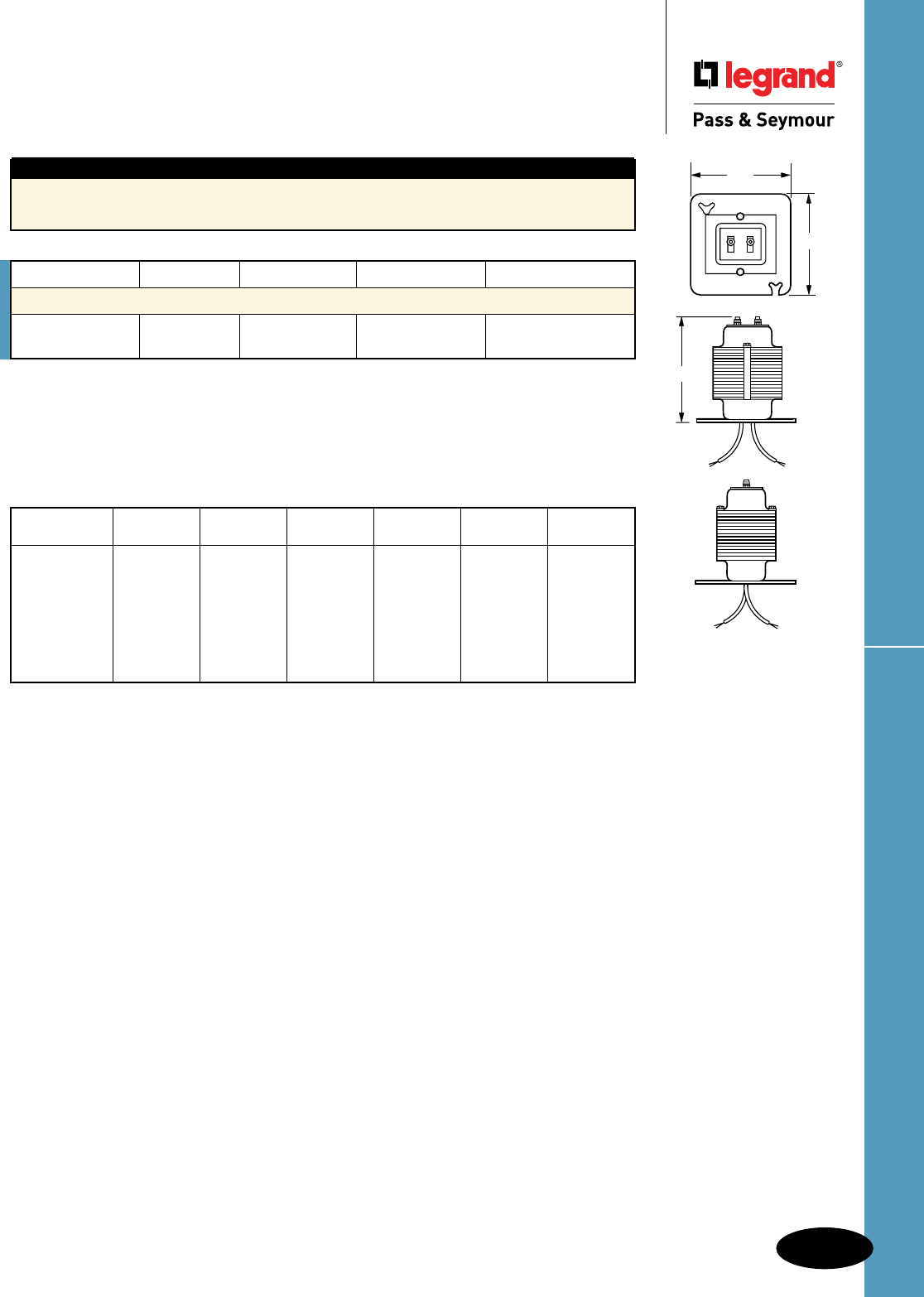
R-15
Low-Voltage Switching ComponentsElectrical Accessories
AlldeviceslistedonthispageconformtoNEMAWD-1andWD-6.
Electrical Accessories
Low-Voltage Switching Components
Catalog Number VA Rating Primary Volts Secondary Volts Secondary Output
Transformers
1038 75VA 120V 24V 3.12A
1039 75VA 277V 24V 3.12A
No. of Relays
in Parallel #12 Wire #14 Wire #16 Wire #18 Wire #20 Wire #22 Wire
1 3000' 2000' 1200' 750' 500' 300'
2 1500' 1000' 600' 375' 250' 150'
3 1000' 650' 400' 250' 160' 100'
4 750' 500' 300' 180' 125' 75'
5 600' 400' 240' 150' 100' 60'
6 500' 330' 200' 125' 80' 50'
7 420' 280' 170' 100' 70' 40'
75VA transformer
(1038 or 1039) switch leg-length of run in feet (2 wires):
A75VAtransformercandriveamaximumof7relayssimultaneously.However,thelengthofawirerun
aswellasthesizeofthewireitselfhaveaneffectonatransformer’soutputcapability.
Thefollowingtableswillbeusefulinselectingtheproperwiresizeandlengthofwireruns.
Notes:
RelaysinParallel–Relayssowiredwillallbeactivatedbyanyswitchinthecircuit.Ifmorethanone
transformerisused,theloadshouldbedividedbetweentransformers.
Features
n100%HIPOTtestedprimaryandsecondary.
nBuilt-inoverloadprotection.
nBasefits4Screwbox.
1038
4.25''
4.25'' 4.50''
4.25''
4.25'' 4.50''
4.25''
4.25'' 4.50''
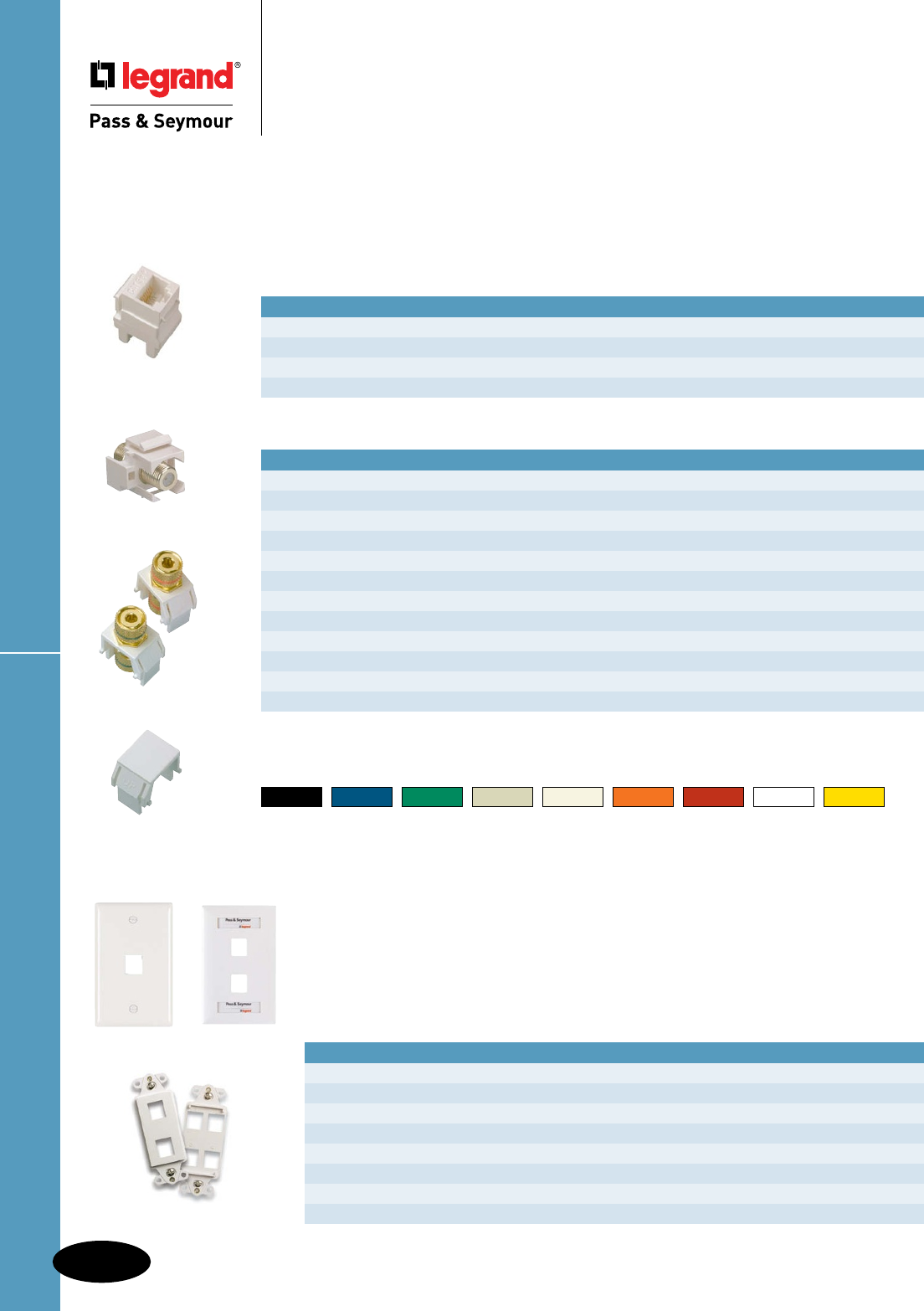
R-16
Electrical AccessoriesKeystone Products, Wall Plates & Frames
Electrical Accessories – Network Wiring Connectivity
Keystone Products, Wall Plates & Frames
Keystone Products
Enhanced Keystone product offering includes jacks and adapters that feature quick,
snap-in mounting that saves installation time. A flexible modular design allows for
fast, easy configuration. Use with TradeMaster® Keystone Wall Plates.
KS58LA
KSFFLA
KS2BPW
KSBL10W
Keystone Multimedia & Fiber Adapters
CATALOG NUMBER DESCRIPTION AVAILABLE COLORS
KSFF_ Keystone Standard F Connector I, LA, W
KSFFST_ Keystone Self-Terminating F Connector I, LA, W
KSBNC_ Keystone BNC Connector I, LA, W
KS2BP_ Pair of Keystone Binding Posts, Red/Positive, Black/Negative I, LA, W
KSSV_ Keystone S-Video, 110 Termination I, LA, W
KSRCAB_ Keystone RCA (Black Insulator) Bulkhead I, LA, W
KSRCAR_ Keystone RCA (Red Insulator) Bulkhead I, LA, W
KSRCAY_ Keystone RCA (Yellow Insulator) Bulkhead I, LA, W
KSRCAF_ Keystone RCA (Red Insulator) to F Connector I, LA, W
KSSC_ Keystone SC Multimode, Phosphor Bronze Sleeve I, LA, W
KSST_ Keystone ST Multimode, Phosphor Bronze Sleeve I, LA, W
KSBL10_ Keystone Blank Inserts (Includes 10 Blanks) BK, I, LA, W
Replace _ in Catalog Number with Keystone Color Code to designate color.
Color Codes for Keystone Products
BK** BL** G** I LA OR** RED** W Y**
Black Blue Green Ivory Light Almond Orange Red White Yellow
**Each sold as a package of 10.
Keystone Jacks
CATALOG NUMBER DESCRIPTION AVAILABLE COLORS
KS68AB_ Keystone RJ45 Category 6, T568A/B Universal Wiring BK, BL, G, I, LA, OR, RED, W, Y
KS58AB_ Keystone RJ45 Category 5e, T568A/B Universal Wiring BK, BL, G, I, LA, OR, RED, W, Y
KS6U_ Keystone RJ25C 6P/6C Category 3, USOC Wiring I, LA, W
KS88_ Keystone RJ45 Category 5e, Female to Female Connector I, LA, W
KTPD1W KTPDL1W
KS226W KS426W
Without Label Windows With Label Windows DESCRIPTION AVAILABLE COLORS
KTPD1_ KTPDL1_ 1-Port Keystone Wall Plate I, LA, W
KTPD2_ KTPDL2_ 2-Port Keystone Wall Plate I, LA, W
KTPD3_ KTPDL3_ 3-Port Keystone Wall Plate I, LA, W
KTPD4_ KTPDL4_ 4-Port Keystone Wall Plate I, LA, W
KTPD6_ KTPDL6_ 6-Port Keystone Wall Plate I, LA, W
KS226_ 2-Port Keystone Decorator Frame I, LA, W
KS326_ 3-Port Keystone Decorator Frame I, LA, W
KS426_ 4-Port Keystone Decorator Frame I, LA, W
Replace _ in Catalog Number to designate color.
TradeMaster® Keystone Wall Plates & Decorator Frames
Virtually unbreakable TradeMaster® Keystone Wall Plates provide better
coverage with an extra 3/16" width and height than standard wall plates to
reduce time-consuming drywall rework. Available with label windows to help
make identification easy.
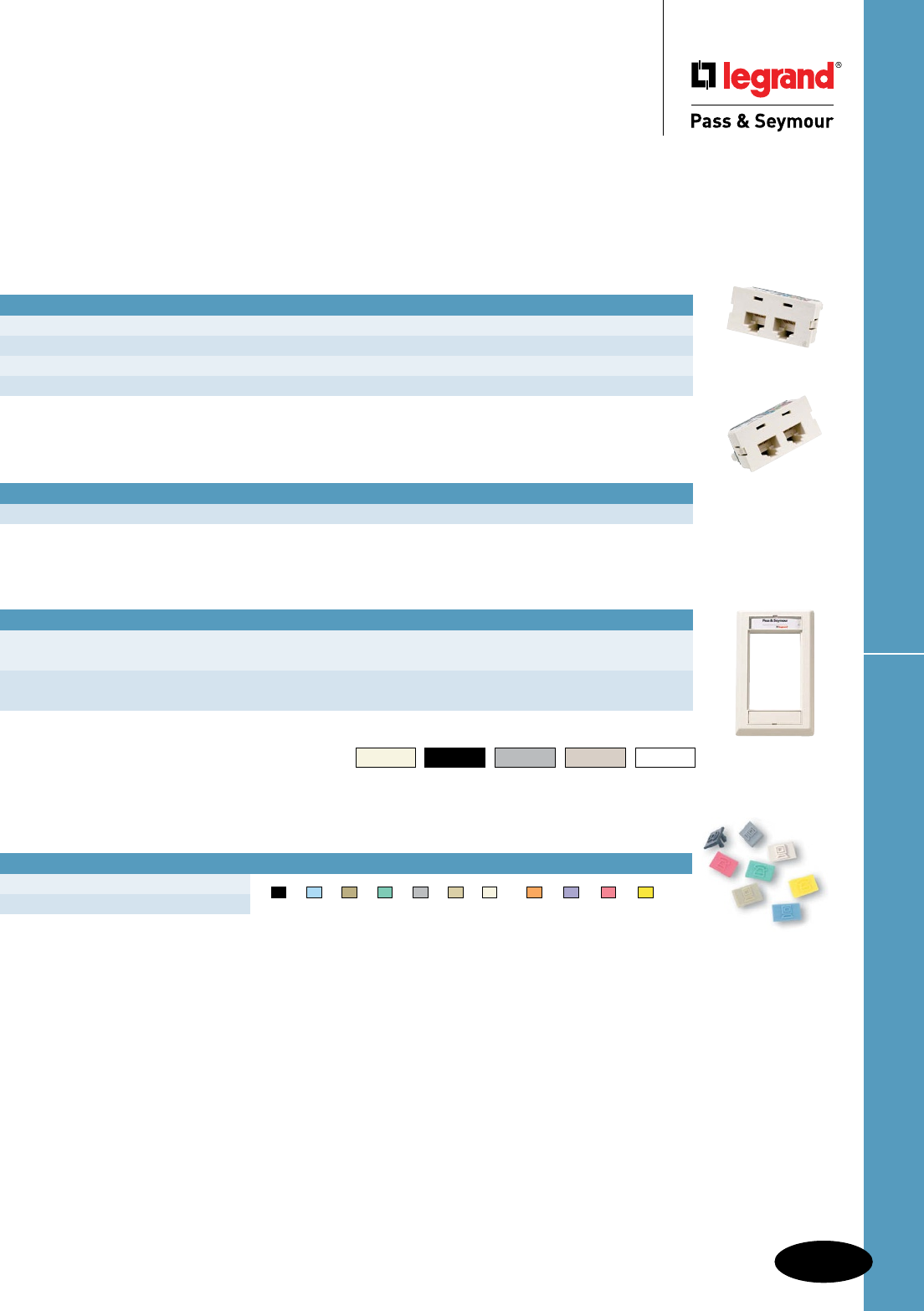
R-17
Electrical Accessories Activate™ Products
Electrical Accessories – Network Wiring Connectivity
Activate™ Products
2A245CC6
2A245C5EU
ACSFP
ActivateTM Products
Choose any combination of our Activate™ high performance modular inserts and
wall plates for complete multimedia capability at any point of use. Cut installation
time, thanks to this front-load, snap-in design.
ActivateTM Blank Inserts
CATALOG NUMBER DESCRIPTION AVAILABLE COLORS
2ABL_ Blank Insert LA†, BK, G, GY, WH
Each sold as a package of 10.
ActivateTM Category 6 & 5e Jack Inserts
CATALOG NUMBER DESCRIPTION AVAILABLE COLORS
2A145CC6_ Single Port RJ45 Category 6, T568A/B Universal Wiring LA†, BK, G
2A245CC6_ Dual Port RJ45 Category 6, T568A/B Universal Wiring LA†, BK, G, GY, WH
2A145C5EU_ Single Port RJ45 Category 5e, T568A/B Universal Wiring LA†, BK, G, GY, WH
2A245C5EU_ Dual Port RJ45 Category 5e, T568A/B Universal Wiring LA†, BK, G, GY, WH
Each sold as a package of 10.
ActivateTM Wall Plates & Modular Furniture Bezel
CATALOG NUMBER DESCRIPTION AVAILABLE COLORS
ACSFP_ Single Gang LA†, WH
ACSAP_ Single Gang Angled LA†, WH
ACSWRP_ Single Gang WallReadyTM LA†, WH
ACMFB_ Modular Furniture Bezel LA†, BK, G
Replace _ in Catalog Number with Activate™ Color Code to designate color.
† No color code designates Light Almond.
Color Codes for Activate™ Products
† BK G GY WH
Light Almond Black Gray Light Gray White
CATALOG NUMBER DESCRIPTION AVAILABLE COLORS
PSDT_ Data Icon Tabs
PSVT_ Voice Icon Tabs
Each sold as a package of 100.
Replace _ in Catalog Number with Icon Tab Color Code to designate color.
ActivateTM Icon Tabs
BK BL BR G GRY I LA OR P RED Y
Black Blue Brown Green Gray Ivory Light Almond Orange Purple Red Yellow
R-18
Electrical AccessoriesFrames & Wall Plates
Electrical Accessories – Network Wiring Connectivity
Frames & Wall Plates
C5EFLA
TPD1LA
TPD9LA
Multimedia & Decorator Frames
CATALOG NUMBER DESCRIPTION AVAILABLE COLORS
C5EF_ Category 5e Jack and F Connector I, LA, W
C25E2F_ 2 Category 5e Jacks and 2 F Connectors I, LA, W
SF326_ 3-Port Decorator Frame I, LA, W
Each sold as a package of 10.
Replace _ in Catalog Number to designate color.
TradeMaster® Datacom Wall Plates
CATALOG NUMBER DESCRIPTION AVAILABLE COLORS
TPD1_ 1-Port TradeMaster Datacom Wall Plate, Single Gang GRY, I, LA, W
TPD2_ 2-Port TradeMaster Datacom Wall Plate, Single Gang GRY, I, LA, W
TPD3_ 3-Port TradeMaster Datacom Wall Plate, Single Gang GRY, I, LA, W
TPD4_ 4-Port TradeMaster Datacom Wall Plate, Single Gang GRY, I, LA, W
TPD6_ 6-Port TradeMaster Datacom Wall Plate, Single Gang GRY, I, LA, W
TPD9_ 9-Port TradeMaster Datacom Wall Plate, Double Gang GRY, I, LA, W
WMPPSS Wall Mount Phone Plate Stainless Steel
Replace _ in Catalog Number to designate color.
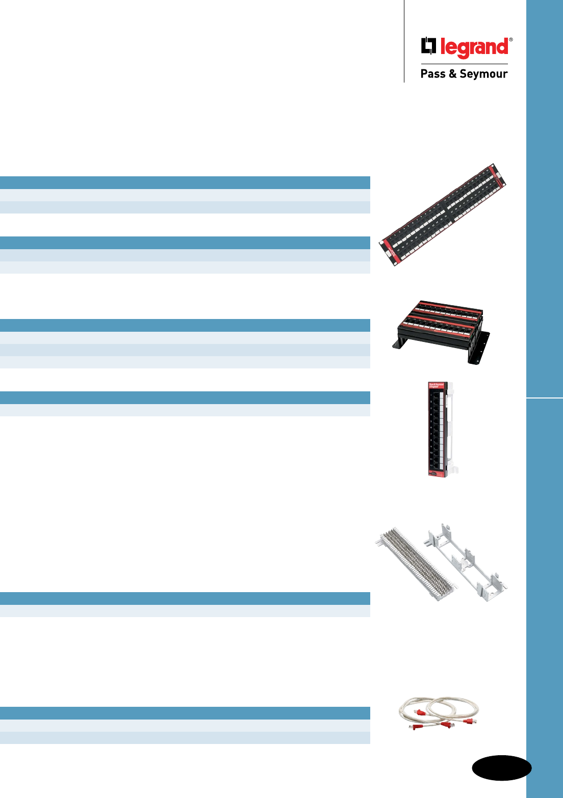
R-19
Electrical Accessories Patch Panels, 66 Block & Patch Cords
Electrical Accessories – Network Wiring Connectivity
Patch Panels, 66 Block & Patch Cords
Category 6
CATALOG NUMBER DESCRIPTION DIMENSIONS RACK UNITS
24845CC6 24-Port T568A/B Universal Wiring 19" x 1.75" 1
48845CC6 48-Port T568A/B Universal Wiring 19" x 3.50" 2
Category 5e
CATALOG NUMBER DESCRIPTION DIMENSIONS RACK UNITS
24845C5E 24-Port T568A/B Universal Wiring 19" x 1.75" 1
48845C5E 48-Port T568A/B Universal Wiring 19" x 3.50" 2
Dimensions shown are W x H.
One Rack Unit = 1.75" H.
Category 5e Modular IDC Wall-Mount Jack Panels with Stand-Off Legs
CATALOG NUMBER DESCRIPTION DIMENSIONS
JP12845C5E 12-Port T568A/ Universal Wiring 10.69" x 3.46" x 3.08"
JP24845C5E 24-Port T568A/ Universal Wiring 10.69" x 3.46" x 3.08"
JP36845C5E 36-Port T568A/ Universal Wiring 10.69" x 6.94" x 3.08"
Category 5e Wall-Mount Patch Panel with 89D Bracket
CATALOG NUMBER DESCRIPTION DIMENSIONS
12845C5E89 12-Port T568A/B Universal Wiring 2.25" x 10" x 1.625"
Dimensions shown are W x H x D.
Patch Cords
Stranded-wire, twisted-pair construction provides the flexibility to make
Cross-connections easy.
CATALOG NUMBER DESCRIPTION AVAILABLE LENGTHS
PCC6_ Category 6, Gray 3', 5', 7', 10', 15'
PSPC5B_ Category 5e Booted, White 3', 5', 7', 10', 15'
Add desired length to end of Catalog Number to order, example PCC610.
Patch Panels
High-performance panels meet the TIA/EIA-568-B.2 standard for connecting
hardware, including Addendum 1 for Cat 6 component performance.
66 Block
Provides flexibility in network interface connections. Used primarily for cross-
connections, 66 blocks provide easy connections between customer voice or
data networks and telecommunications equipment.
66 Block & Bracket
CATALOG NUMBER DESCRIPTION
PS665089V 50-Pair 66 Block, Unwired & Mounting Bracket
12845C5E89
48845CC6
PSPC5B7 PSPC5B5
JP24845C5E
PS665089V*
*Block and bracket pictured separately,
product sold together as one catalog number.

Technical Specifications
ii
Technical Specifications
Category Description Page Number
Associations, Organizations & Standards S-3, S-4
Cam-Type Devices Series 15 In-Line Connectors S-117
Series 16 In-Line Connectors S-116
Series 18 In-Line Connectors S-118
Configuration & Clocking Systems S-119
Dimmers High Wattage Rotary Dimmers S-155, S-156
Incandescent Rotary Dimmers S-154
Magnetic Low-Voltage Rotary Dimmers S-157, S-158
Titan™ Series Fluorescent 2, 3 & 4 Wire S-149 – S-151
Titan™ Series Incandescent & Magnetic Low-Voltage S-147, S-148
Wide Slide Dimmers S-152, S-153
GFCI Receptacles Hospital Grade GFCI Receptacles S-60
Hospital Grade Illuminated GFCI Receptacles S-62
Hospital Grade Tamper-Resistant GFCI Receptacles S-58
Hospital Grade Tamper-Resistant Nightlight/GFCI Receptacles S-64
Illuminated GFCI Receptacles S-61
NAFTA-Compliant & RoHS-Compliant GFCI Receptacles S-73
NAFTA-Compliant Hospital Grade GFCI Receptacles S-74
NAFTA-Compliant PlugTail™ GFCI Receptacles S-75
NAFTA-Compliant PlugTail™ Hospital Grade GFCI Receptacles S-76
PlugTail™ Hospital Grade GFCI Receptacles S-68
PlugTail™ Hospital Grade Tamper-Resistant GFCI Receptacles S-70
PlugTail™ Hospital Grade TR Nightlight/GFCI Receptacles S-72
PlugTail™ Specification Grade GFCI Receptacles S-67
PlugTail™ Specification Grade Tamper-Resistant GFCI Receptacles S-69
PlugTail™ Specification Grade TR Nightlight/GFCI Receptacles S-71
Tamper-Resistant GFCI Receptacles S-57
Tamper-Resistant Nightlight/GFCI Receptacles S-63
TradeMaster® & Specification Grade GFCI Receptacles S-59
Weather-Resistant DuraShield™ GFCI Receptacles S-66
Weather-Resistant GFCI Receptacles S-65
Hallway Lights Light Output Measurements S-56
Horsepower Ratings for NEMA S-10
International Standards S-164 – S-168
IP Codes & Their Meanings S-9
NEMA Configurations Straight Blade Devices & Turnlok® Devices S-6, S-7
Network Wiring Universal & Six-Pin Wiring Guides & UTP Cabling Installation S-160
UTP Outlet Wiring Configurations S-159
Occupancy Sensors Dual-Technology Ceiling Sensor S-145
Dual-Technology Wall Switch S-140
Occupancy Sensors S-138
Passive Infrared Sensors S-141 – S-143
Passive Infrared Wall Switch S-139
Power Pack & Add-A-Relay S-146
Ultrasonic Ceiling Sensors S-144

Technical Specifications
S-1
Technical Specifications
Category Description Page Number
Pin & Sleeve/Mechanical Interlock Watertight Pin & Sleeve Non-Fusible Mechanical Interlock S-136, S-137
Pin & Sleeve/Splashproof Splashproof Pin & Sleeve Connectors S-132, S-133
Splashproof Pin & Sleeve Inlets S-134, S-135
Splashproof Pin & Sleeve Plugs S-130, S-131
Splashproof Pin & Sleeve Receptacles S-128, S-129
Pin & Sleeve/Watertight Watertight Pin & Sleeve Connectors S-124, S-125
Watertight Pin & Sleeve Inlets S-126, S-127
Watertight Pin & Sleeve Plugs S-122, S-123
Watertight Pin & Sleeve Receptacles S-120, S-121
Receptacles Commercial Specification Grade Receptacles S-45
Construction Specification Grade Receptacles S-44
Extra Heavy-Duty Hospital Grade MRI Receptacles S-35
Extra Heavy-Duty Hospital Grade Receptacles S-34
Hard Use Specification Grade Receptacles S-43
Heavy-Duty Hospital Grade Compact Design Receptacles S-39
Heavy-Duty Hospital Grade Receptacles S-38
Heavy-Duty Specification Grade Receptacles S-37
Heavy-Duty Tamper-Resistant Decorator Receptacles S-53
Heavy-Duty Tamper-Resistant Decorator Single Receptacles S-54
Industrial Extra Heavy-Duty Specification Grade Receptacles S-36
PlugTail™ Decorator Receptacles S-52
PlugTail™ Extra Heavy-Duty Hospital Grade Illuminated Receptacles S-33
PlugTail™ Extra Heavy-Duty Hospital Grade Receptacles S-32
PlugTail™ Extra Heavy-Duty Specification Grade Receptacles S-31
PlugTail™ Specification Grade Receptacles S-40
PlugTail™ Specification Grade Receptacles Split Circuit S-42
PlugTail™ Tamper-Resistant Specification & Hospital Grade Receptacles S-41
Specification Grade Combination Receptacles S-55
Tamper-Resistant Commercial Grade Receptacles S-48
Tamper-Resistant Construction Grade Single Receptacles S-49
Tamper-Resistant Hard Use Receptacles S-47
Tamper-Resistant Specification & Hospital Grade Receptacles S-46
Weather-Resistant Commercial Grade Receptacles S-51
Weather-Resistant Heavy-Duty Receptacles S-50
Straight Blade Plugs & Connectors Clamp-Lock™ Plugs & Connectors S-100
Ground Continuity Monitoring (GCM) Connectors S-97
Ground Continuity Monitoring (GCM) Plugs S-96
MaxGrip® M3 Connectors S-99
MaxGrip® M3 Plugs S-98
Straight Blade Connectors S-95
Straight Blade Plugs S-94
Switches Commercial Specification Grade Switches S-25
Hard-Use Specification Grade Switches S-24
Industrial Extra Heavy-Duty Specification Grade Switches S-22, S-23
Manual Controller Switches S-26, S-27

Technical Specifications
S-2
Technical Specifications
Category Description Page Number
Switches (con't.) PlugTail™ Specification Grade Decorator Switches S-28
PlugTail™ Specification Grade Switches S-21
Specification Grade Combination & Contact Switches S-30
Specification Grade Decorator Switches S-29
Symbols S-5
Turnlok® Plugs, Connectors, Inlets & Outlets 15, 20 & 30A Heavy-Duty Ground Continuity Monitoring
(GCM) Connectors S-110
15, 20 & 30A Heavy-Duty Ground Continuity Monitoring (GCM) Plugs S-109
15A Turnlok® EHU Plugs & Connectors S-104
15A Turnlok® Flanged Inlets & Outlets S-111
15A Turnlok® Receptacles S-101
20A Turnlok® Connectors S-106
20A Turnlok® Flanged Inlets S-112
20A Turnlok® Flanged Outlets S-113
20A Turnlok® Plugs S-105
20A Turnlok® Receptacles S-102
30A Turnlok® Connectors S-108
30A Turnlok® Flanged Inlets S-114
30A Turnlok® Flanged Outlets S-115
30A Turnlok® Plugs S-107
30A Turnlok® Receptacles S-103
Surge Protective Extra Heavy-Duty Tamper-Resistant Hospital Grade Receptacles S-91
Extra Heavy-Duty Tamper-Resistant Receptacles S-89
Hospital Grade Isolated Ground Receptacles S-78
Hospital Grade Receptacles S-77
PlugTail™ Extra Heavy-Duty Receptacles S-83
PlugTail™ Hospital Grade Extra Heavy-Duty Receptacles S-86
PlugTail™ Hospital Grade Isolated Ground Receptacles S-87
PlugTail™ Hospital Grade Tamper-Resistant Receptacles S-88
PlugTail™ Isolated Ground Receptacles S-84
PlugTail™ Tamper-Resistant Receptacles S-85
Receptacles S-81
Specification Grade Extra Heavy-Duty Receptacles S-79
Specification Grade Isolated Ground Receptacles S-80
Surge Protection Panels S-93
Tamper-Resistant Hospital Grade Isolated Ground Receptacles S-92
Tamper-Resistant Isolated Ground Receptacles S-90
Tamper-Resistant Receptacles S-82
UL Changes, Conversions & Wire Spec Chart S-8
Wall Plates Dimensions S-163
Specifications S-161, S-162
Wiring Diagrams S-11 – S-20
Devices & Wall Plates Color Selection Chart available on Pages A-29, B-78 and Q-61.
Technical Specifications
S-3
Associations, Organizations & Standards
Technical Specifications
Associations, Organizations, & Standards
For convenience, the following listings define common acronyms for a variety of organizations.
Standards Development Organization
Organizations primarily involved in the development and/or promulgation of standards.
NFPA National Fire Protection Agency
IEC International Electrotechnical Commission
IEEE Institute of Electrical and Electronics Engineers, Inc.
ANSI American National Standards Institute
CANENA Consejo de Armonizacion de Normas Electrotecnicas de Naciones America
(Council for Harmonization of Electrotechnical Standardization of the Nations
of the Americas)
SAE Society of Automotive Engineers
ISA Instrument Society of America
SME Society of Manufacturing Engineers
ISO International Standards Organization
Industry Associations
Associations of companies or individuals for the purpose of standardization, trade and
professional development, etc.
NMDA National Marine Distributor Association
NEMA National Electrical Manufacturers Association
ABYC American Boat and Yacht Council
EIA/TIA Electronics Industry Association/Telecommunications Industry Association
NAED National Association of Electrical Distributors
NAW National Association of Wholesalers
BICSI Building Industry Consulting Services International
IBI Intelligent Building Institute
EPRI Electric Power Research Institute
NEMRA National Electrical Manufacturers Representatives Association
IAEI International Association of Electrical Inspectors
IFMA International Facilities Management Association
BOMA Building Owner Management Association
SEMI Semi-Conductor Equipment and Material International
CEMRA Canadian Electrical Manufacturers Representative Association
NMRA National Marine Representative Association
EFI Electro-Federation Incorporated
NECA National Electrical Contractors Association
IECA Independent Electrical Contractors Association
ECOC Electrical Contractors of Canada
CANAME Camara Nacional de Manufacturas Electricas
HLCA Home Lighting Control Alliance
USGBC U.S. Green Building Council
Codes & Standards
Installation codes and product safety, performance on interchangeability standards.
NEC National Electrical Code
NOM Normas Oficiales de Mexicanas (Official Mexican Standard)
NMX Normas Mexicanas
CEC Canadian Electrical Code

Technical Specifications
S-4
Associations, Organizations & Standards
Technical Specifications
Associations, Organizations, & Standards
Certication Agencies
Primarily involved in certification of products or manufacturers to standards developed by
the certification agency or by others.
UL Underwriters’ Laboratories, Inc.
cUL Tested to Canadian Safety Standards by
Underwriters’ Laboratories, Inc.
cULus Tested to U.S. and Canadian Safety Standards by
Underwriters’ Laboratories, Inc.
CSA Canadian Standards Association
ANCE National Association of Normalization and Certification
of the Electrical Sector, (Mexico)
TUV TUV Rheinland of N.A., Inc.
VDE Verband Deutscher Elektrotechniker
BSI British Standards Institute
FM Factory Mutual
NRTL Nationally Recognized Testing Laboratories
Government Agencies
OSHA Occupational Safety and Health Administration
FCC Federal Communications Commission
DSSC Defense Supply Center, Columbus
IAPA Independent Accident and Protection Association (Canada)
LEED Leadership in Energy and Environmental Design
Underwriters’ Laboratories, Inc. (UL)
1285 Walt Whitman Road
Melville, NY 11747
333 Pfingston Road
Northbrook, IL 60062
1655 Scott Boulevard
Santa Clara, CA 95050
12 Laboratory Drive
Research Triangle Park, NC 27709
2600 N.W. Lake Road
Camas, WA 98607
The Canadian Standards Association (CSA)
Standards Division
178 Rexdale Boulevard
Rexdale, Ontario
Canada M9W 1R3
The American National Standards Institute
(ANSI)
1430 Broadway
New York, NY 10018
National Electrical Manufacturers Association
(NEMA)
2101 L Street, NW, Suite 300
Washington, DC 20037
National Fire Protection Association (NFPA)
Batterymarch Park
Quincy, MA 02269
The International Electrotechnical Commission
(IEC)
Copies of IEC standards may be obtained from the
American National Standards Institute (ANSI) at
the above address.
American Boat and Yacht Council, Inc. (ABYC)
P.O. Box 806
Amityville, NY 11701
Asociacion Nacional de Normalizacion y
Certicacion del Sector Electrico A.C.
(NOM-ANCE)
Insurgentes Sur 664, 3ER Piso
Col. Del Valle
03100 Mexico D.F.
Phone: 011-525-227-1110
Fax: 011-525-227-1177
Occupational Safety and Health Administration
200 Constitution Avenue N.W.
Room 3647
Washington, DC 20210
Copies of standards referred to on the preceding pages may be purchased from the following:
Technical Specifications
S-5
Symbols
Technical Specifications
Symbols
Electrical Symbols & Abbreviations
In Accordance with American National Standards Institute
General Outlets
Outlet
Blanked Outlet
Drop Cord
Electrical Outlet: for use only when circle used
alone might be confused with columns, plumbing
symbols, etc.
Fan Outlet
Junction Box
Lamp Holder
Lamp Holder with Pull Switch
Pull Switch
Outlet for Vapor Discharge Lamp
Exit Light Outlet
Clock Outlet (Specify Voltage)
Convenience Outlets
Duplex Convenience Outlet
Convenience Outlet other than Duplex
1 = Single, 3 = Triplex, etc.
Weatherproof Convenience Outlet
Range Outlet
Switch and Convenience Outlet
Radio and Convenience Outlet
Special Purpose Outlet
Floor Outlet
Switch Outlets
S Single Pole Switch
S2 Double Pole Switch
S3 Three Way Switch
S4 Four Way Switch
SD Automatic Door Switch
SE Electrolier Switch
SK Key Operated Switch
SP Switch and Pilot Lamp
SCB Circuit Breaker
SWCB Weatherproof Circuit Breaker
SMC Momentary Contact Switch
SRC Remote Control Switch
SWP Weatherproof Switch
SF Fused Switch
SWF Weatherproof Fused Switch
Special Outlets
Any Standard Symbol as given above with the
addition of a lower case subscript letter may be used
to designate some special variation of Standard
Equipment of particular interest in a specific set
of Architectural Plans. When used they must be
listed in the Key of Symbols on each drawing and if
necessary further described in the specifications.
Panels, Circuits & Miscellaneous
Lighting Panel
Power Panel
Branch Circuit: Concealed in Ceiling or Wall
Branch Circuit: Concealed in Floor
Branch Circuit: Exposed
Home Run to Panel Board. Indicate number of Circuits by
number of arrows.
Note: Any circuit without further designation
indicates a two-wire circuit. For a greater number of
wires indicate as follows: (3 wires),
(4 wires), etc.
Feeders: Note: Use heavy lines and designate by number
corresponding to listing in Feeder Schedule.
Underfloor Duct and Junction Box. Triple System.
Note: For double or single systems eliminate one
or two lines. This symbol is equally adaptable to
auxiliary system layouts.
Generator
Motor
Instrument
Power Transformer. (Or draw to scale.)
Controller
Isolating Switch
Auxiliary Systems
Push Button
Buzzer
Bell
Annunciator
Outside Telephone
Interconnecting Telephone
Telephone Switchboard
Bell Ringing Transformer
Electric Door Opener
Fire Alarm Bell
Fire Alarm Station
City Fire Alarm Station
Fire Alarm Central Station
Automatic Fire Alarm Device
Watchman’s Station
Watchman’s Central Station
Horn
Nurse’s Signal Plug
Maid’s Signal Plug
Radio Outlet
Signal Central Station
Interconnection Box
Battery
Auxiliary System Circuits
Note: Any line without further designation indicates
System. For a greater number of wires designate
with numerals in manner similar to 12-No.
18 W-3/4" C., or designate by number
corresponding to listing in Schedule.
Special Auxiliary Outlets
Subscript letters refer to notes on plans or
detailed description in specifications.
.
T
D
F
F
FA
FS
W
W
C C
X X
V
S
L
L
J
F
V
S
L
L
J
F
E
D
B
E
B
R
S
R
WP
PS PS
[ 3
a.b.c.etc
a.b.c.etc
a.b.c.etc
S
T
I
M
G
R
M
N
H
SC
a.b.c.
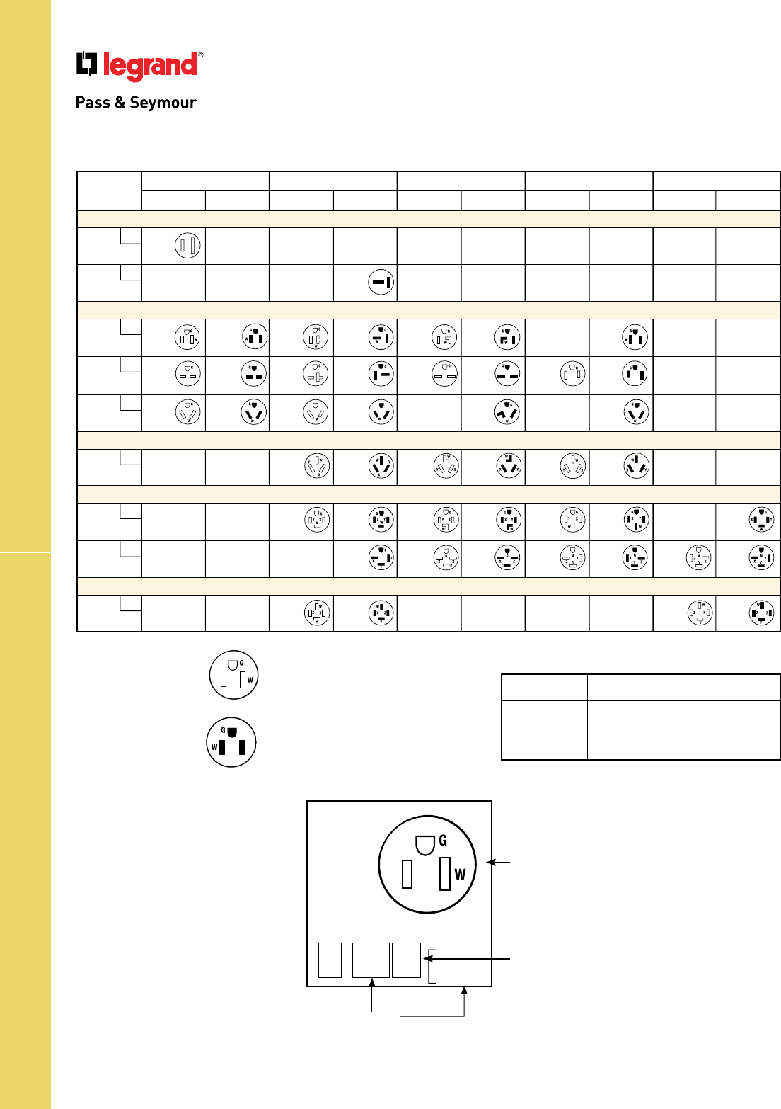
Technical Specifications
S-6
NEMA Configurations – Straight Blade Devices
Technical Specifications
NEMA Configurations –
Straight Blade Devices
Labels and Their Meanings
X, Y, Z Hot Lead
W Neutral Lead
G Grounding Lead
Open Slots
Indicate receptacle
configurations (female).
Closed Slots
Indicate plug blade
configurations (male).
Blade
Conguration
R = Female
(receptacle, connector,
anged outlet)
P = Male
(plug, anged inlet)
NEMA
Conguration
Line #
(refers to voltage) Amperage
5-15R
Straight Blade Plugs & Receptacles
15 AMPERE 20 AMPERE 30 AMPERE 50 AMPERE 60 AMPERE
RECEPTACLE PLUG RECEPTACLE PLUG RECEPTACLE PLUG RECEPTACLE PLUG RECEPTACLE PLUG
2 Pole, 2 Wire Non-Grounding
1
125V
1-15R
2
250V
2-20P
2 Pole, 3 Wire Grounding
5
125V
5-15R 5-15P 5-20R 5-20P 5-30R 5-30P 5-50P
6
250V
6-15R 6-15P 6-20R 6-20P 6-30R 6-30P 6-50R 6-50P
7
277VAC
7-15R 7-15P 7-20R 7-20P 7-30P 7-50P
3 Pole, 3 Wire Non-Grounding
10
125/250V
10-20R 10-20P 10-30R 10-30P 10-50R 10-50P
3 Pole, 4 Wire Grounding
14
125/250V
14-20R
14-20P 14-30R 14-30P 14-50R 14-50P 14-60P
15
3ø250V
15-20P 15-30R 15-30P 15-50R 15-50P 15-60R 15-60P
4 Pole, 4 Wire Non-Grounding
18
3øY
120/208V
18-20R 18-20P 18-60R 18-60P
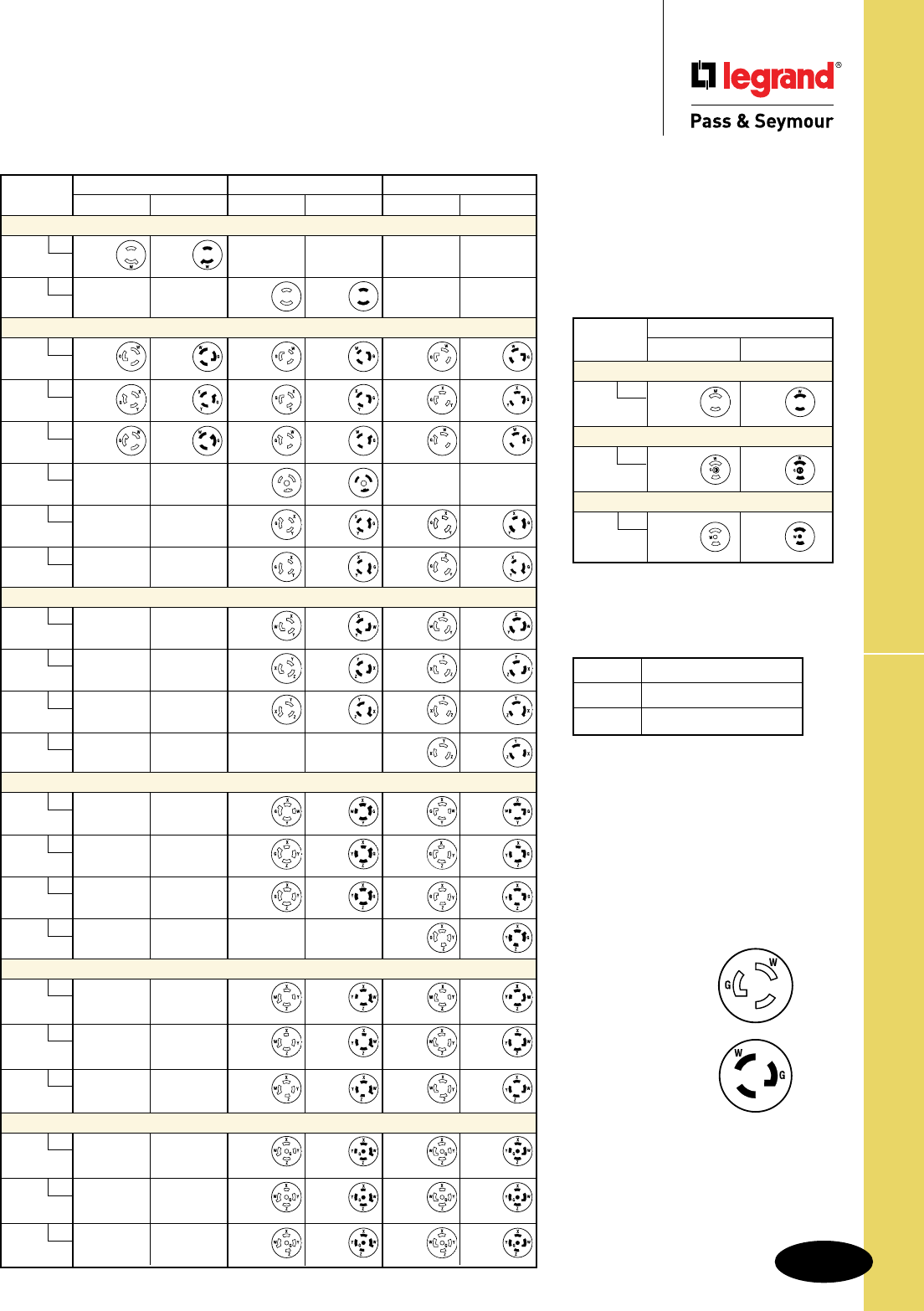
Technical Specifications
S-7
NEMA Configurations – Turnlok® Devices
Technical Specifications
NEMA Configurations – Turnlok® Devices
Midget – Locking
15 AMPERE
RECEPTACLE PLUG
2 Pole, 2 Wire Non-Grounding
ML1
125V
ML-1R ML-1P
2 Pole, 3 Wire Grounding
ML2
125V
ML-2R ML-2P
3 Pole, 3 Wire Non-Grounding
ML3
125/250V
ML-3R ML-3P
15 AMPERE 20 AMPERE 30 AMPERE
RECEPTACLE PLUG RECEPTACLE PLUG RECEPTACLE PLUG
2 Pole, 2 Wire Non-Grounding
L1
125V
L1-15R L1-15P
L2
250V
L2-20R L2-20P
2 Pole, 3 Wire Grounding
L5
125V
L5-15R L5-15P L5-20R L5-20P L5-30R L5-30P
L6
250V
L6-15R L6-15P L6-20R L6-20P L6-30R L6-30P
L7
277VAC
L7-15R L7-15P L7-20R L7-20P L7-30R L7-30P
L24
347VAC
L24-20R L24-20P
L8
480VAC
L8-20R L8-20P L8-30R L8-30P
L9
600VAC
L9-20R L9-20P L9-30R L9-30P
3 Pole, 3 Wire Non-Grounding
L10
125/250V
L10-20R L10-20P L10-30R L10-30P
L11
3ø250V
L11-20R L11-20P L11-30R L11-30P
L12
3ø480V
L12-20R L12-20P L12-30R L12-30P
L13
3ø600V
L13-30R L13-30P
3 Pole, 4 Wire Grounding
L14
125/250V
L14-20R L14-20P L14-30R L14-30P
L15
3ø250V
L15-20R L15-20P L15-30R L15-30P
L16
3ø480V
L16-20R L16-20P L16-30R L16-30P
L17
3ø600V
L17-30R L17-30P
4 Pole, 4 Wire Non-Grounding
L18
3øY
120/208V
L18-20R L18-20P L18-30R L18-30P
L19
3øY
277/480V
L19-20R L19-20P L19-30R L19-30P
L20
3øY
347/600V
L20-20R L20-20P L20-30R L20-30P
4 Pole, 5 Wire Grounding
L21
3øY
120/208V
L21-20R L21-20P L21-30R L21-30P
L22
3øY
277/480V
L22-20R L22-20P L22-30R L22-30P
L23
3øY
347/600V
L23-20R L23-20P L23-30R L23-30P
Locking Plugs & Receptacles
Open Slots
Indicate receptacle
configurations (female).
Closed Slots
Indicate plug blade
configurations (male).
X, Y, Z Hot Lead
W Neutral Lead
G Grounding Lead
Labels & Their Meaning
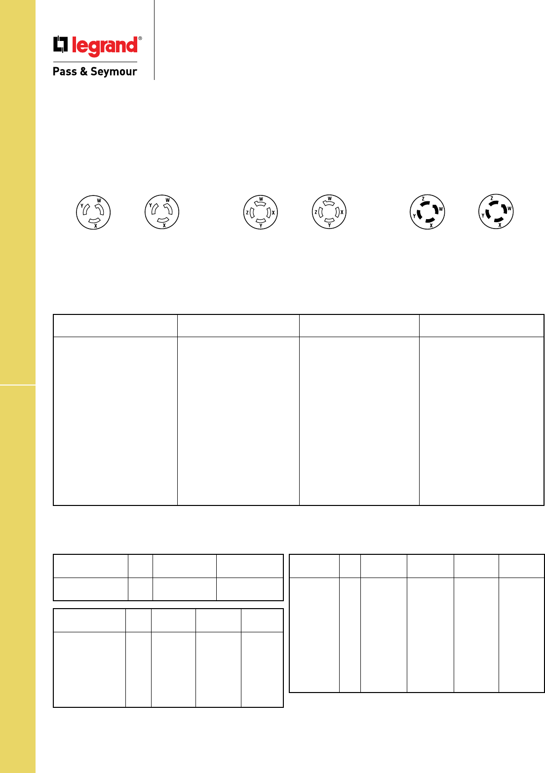
Technical Specifications
S-8
UL Changes, Conversion & Wire Spec Chart
Technical Specifications
UL Changes, Conversion & Wire Spec Chart
AWG
Type* Size 2 Cond. 3 Cond.
SV,SVO,SVT,SVTO 18 .220-.255" .230-.265"
17 .235-.270" .250-.285"
AWG
Type* Size 2 Cond. 3 Cond. 4 Cond.
SJ,SJO,SJT,SJTO 18 .280-.315" .300-.335" .325-.365"
17 .290-.325" .310-.345" .340-.380"
16 .305-.340" .325-.360" .350-.395"
15 .315-.350" .335-.375" .370-.415"
14 .335-.375" .360-.395" .390-.435"
12 .405-.455" .425-.475" .465-.520"
10 .540-.605" .565-.635" .625-.700"
AWG
Type* Size 2 Cond. 3 Cond. 4 Cond. 5 Cond.
S,SO,ST,STO 18 .340-.385
"
.360-.400" .385-.430" .460-.510"
17 .350-.390
"
.370-.415" .400-.445" .465-.520"
16 .365-.410
"
.385-.430" .410-.460" .490-.550"
15 .475-.530
"
.500-.560" .540-.610" .615-.690"
14 .495-.550
"
.520-.575" .560-.620" .630-.705"
12 .565-.625
"
.590-.655" .640-.710" .700-.770"
10 .615-.685
"
.650-.720" .700-.775" .760-.840"
8 .780-.880
"
.830-.930" .925-1.050" 1.000-1.150"
6 .920-1.050
"
.970-1.100" 1.050-1.200
"
1.180-1.330"
4 1.060-1.210
"
1.130-1.280" 1.250-1.450
"
2 1.210-1.400
"
1.300-1.500" 1.450-1.650
"
*Actual sizes will vary by cord manufacturers.
Wire Specifications
Diameter Ranges of Jacketed Cord in Accordance with Standard “UL62”
UL Rating Changes
On July 1, 1983, UL cancelled listing of 3 non-NEMA dual-rated configurations and assigned new voltage ratings to them. There is
no change in the slot/blade configurations and the catalog numbers for each series are now UL listed under their new voltage ratings.
Affected configurations are:
1. 30A, 3 Pole, 3 Wire 2. 20A, 4 Pole, 4 Wire 3. 30A , 4 Pole, 4 Wire
not grounding Turnlok® not grounding Turnlok not grounding Turnlok
No. 3330 Series No. 7410 Series No. 3430 Series
*Old Rating New Rating *Old Rating New Rating *Old Rating New Rating
30A, 250V 30A,125/250V 20A, 250V 20A, 120/208V 3øY 30A, 600V 30A, 120/208V 3øY
10A, 600V 30A, 250V
Conversion Chart
Fractions to Decimals to Millimeters
Inches Inches Inches Inches
Fraction Decimal mm Fraction Decimal mm Fraction Decimal mm Fraction Decimal mm
1/64 0.0156 0.3969 17/64 0.2656 6.7469 33/64 0.5156 13.0969 49/64 0.7656 19.4469
1/32 0.0312 0.7938 9/32 0.2812 7.1438 17/32 0.5312 13.4938 25/32 0.7812 19.8437
3/64 0.0468 1.1906 19/64 0.2968 7.5406 35/64 0.5468 13.8906 51/64 0.7968 20.2406
1/16 0.0625 1.5875 5/16 0.3125 7.9375 9/16 0.5625 14.2875 13/16 0.8125 20.6375
5/64 0.0781 1.9844 21/64 0.3281 8.3344 37/64 0.5781 14.6844 53/64 0.8281 21.0344
3/32 0.0937 2.3812 11/32 0.3437 8.7312 19/32 0.5937 15.0812 27/32 0.8437 21.4312
7/64 0.1093 2.7781 23/64 0.3593 9.1281 39/64 0.6093 15.4781 55/64 0.8593 21.8281
1/8 0.1250 3.1750 3/8 0.3750 9.5250 5/8 0.6250 15.8750 7/8 0.8750 22.2250
9/64 0.1406 3.5719 25/64 0.3906 9.9219 41/64 0.6406 16.2719 57/64 0.8906 22.6219
5/32 0.1562 3.9688 13/32 0.4062 10.3188 21/32 0.6562 16.6688 29/32 0.9062 23.0188
11/64 0.1718 4.3656 27/64 0.4218 10.7156 43/64 0.6718 17.0656 59/64 0.9218 23.4156
3/16 0.1875 4.7625 7/16 0.4375 11.1125 11/16 0.6875 17.4625 15/16 0.9375 23.8125
13/64 0.2031 5.1594 29/64 0.4531 11.5094 45/64 0.7031 17.8594 61/ 64 0.9531 24.2094
7/32 0.2187 5.5562 15/32 0.4687 11.9062 23/32 0.7187 18.2562 31/32 0.9687 24.6062
15/64 0.2343 5.9531 31/64 0.4843 12.3031 47/64 0.7343 18.6531 63/64 0.9843 25.0031
1/4 0.2500 6.3500 1/2 0.5000 12.7000 3/4 0.7500 19.0500 1 1.0000 25.4000

Technical Specifications
S-9
IP Codes & Their Meanings
Technical Specifications
IP Codes & Their Meanings
IP Suitability Rating
IP Suitability Ratings are an international system for classifying the
degree of protection provided by enclosures of electrical equipment.
The higher the number, the greater the degree of protection; they
apply ONLY to properly installed equipment. The numerals stand for
the following:
1. First Number: Degree of protection for persons against access to
hazardous parts inside the enclosure and/or against solid bodies.
2. Second Number: Degree of protection of equipment inside
enclosures against damage from the ingress of water.
IP44
Suitability
Example: IP44
=Ingress Protection; Solid bodies >=1.0mm; Splashing
Note: >= denotes greater than or equal to. Dimensions in Inches (mm)
Meaning for the Protection of Equipment
Code Letters First Number Second Number
Ingress Protection Against Ingress of Against Ingress of Water
Solid Bodies with Harmful Effects
IP 0 - Non-protected 0 – Non-protected
1 – >= 50 mm diameter 1 – Vertically dripping
2 – >=12.5 mm diameter 2 – Dripping (15° Tilted)
3 – >=2.5 mm diameter 3 – Spraying
4 – >=1.0 mm 4 – Splashing
5 – Dust-protected 5 – Jetting
6 – Dust-tight 6 – Power jetting
7 – Temporary immersion
8 – Continuous immersion

Technical Specifications
S-10
Horsepower Ratings for NEMA
Technical Specifications
Horsepower Ratings for NEMA
Configuration Receptacles & Plugs Only
Ampere AC Voltage Phases Poles Horsepower NEMA
Rating Rating Rating Designation
15 125 1 2 1/2 1-15, L1-15, 5-15, L5-15
250 1 2 1-1/2# 6-15, L6-15
277 1 2 2 7-15, L7-15
125/250 1 3 1-1/2 L-L# 14-15
1/2 L-N
250 3 3 2 11-15, L11-15, 15-15
120/208 3 4 2 18-15
20 125 1 2 1 5-20, L5-20
250 1 2 2# 2-20, L2-20, 6-20, L6-20
277 1 2 2 7-20, L7-20
480 1 2 3 L8-20
125/250 1 3 2 L-L# 10-20, L10-20, 14-20, L14-20
1 L-N
250 3 3 3 11-20, L11-20, 15-20, L15-20
480 3 3 5 L12-20, L16-20
120/208 3 4 2 18-20, L18-20, L21-20
277/480 3 4 5 L19-20, L22-20
30 125 1 2 2 5-30, L5-30
250 1 2 2# 2-30, 6-30, L6-30
277 1 2 3 7-30, L7-30
480 1 2 5 L8-30
125/250 1 3 2 L-L# 10-30, L10-30
2 L-N 14-30, L14-30
250 3 3 3 11-30, L11-30, 15-30, L15-30
480 3 3 10 L12-30, L16-30
120/208 3 4 3 18-30, L18-30, L21-30
277/480 3 4 10 L19-30, L22-30
50 125 1 2 2 5-50
250 1 2 3 6-50
277 1 2 5 7-50
125/250 1 3 3 L-L# 10-50, 14-50
2 L-N
250 3 3 7-1/2 11-50, 15-50
120/208 3 4 7-1/2 18-50
60 125/250 1 3 3 L-L# 14-60
2 L-N
250 3 3 10 15-60
120/208 3 4 7-1/2 18-60
L-L: Motor connected line-to-line.
L-N: Motor connected line-to-neutral.
#: Also suitable for 208V motor applications at the indicated horsepower rating.
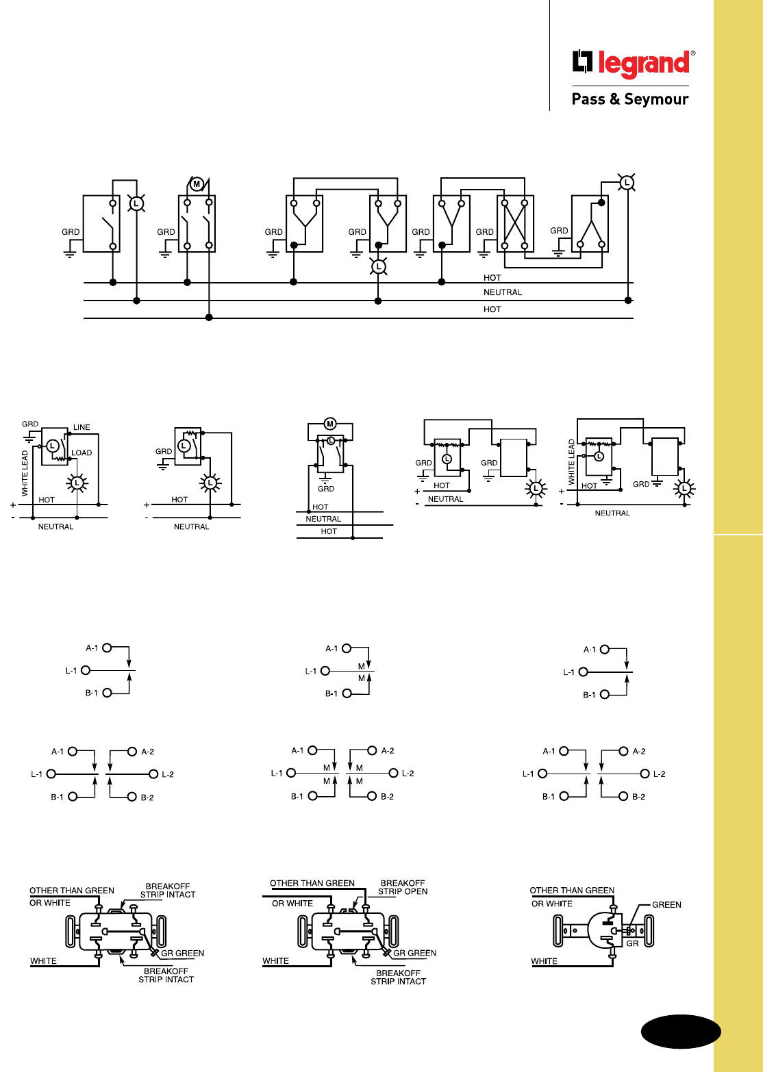
Technical Specifications
S-11
Wiring Diagrams
Switches
Single Pole Double Pole 3-Way to 3-Way 3-Way to 4-Way to 3-Way
Pilot Light Switch & Lighted Toggle Switch
Single Pole Single Pole Double Pole 3-Way 3-Way Pilot
Pilot Light Switch Lighted Toggle Switch Pilot Light Switch Lighted Toggle Lighted Toggle
Toggle Glows when Toggle Glows when Toggle Glows when Switch Switch
Light is On Switch is Off Switch is On (Two Lighted or Pilots May Be Used)
Maintained & Momentary Contact
Maintained Contact Momentary Contact Maintained Contact
3-Position, 2-Circuit Either Direction Either Direction
Center “Off” 3-Position, Center “Off” 2-Position, No Center “Off”
Single Pole Single Pole Single Pole
Double Throw Double Throw Double Throw
Double Pole Double Pole Double Pole
Double Throw Double Throw Double Throw
1222 1256 1276
Receptacles
1 Circuit Split Circuit 1 Circuit
Technical Specifications
Wiring Diagrams –
Switches & Receptacles
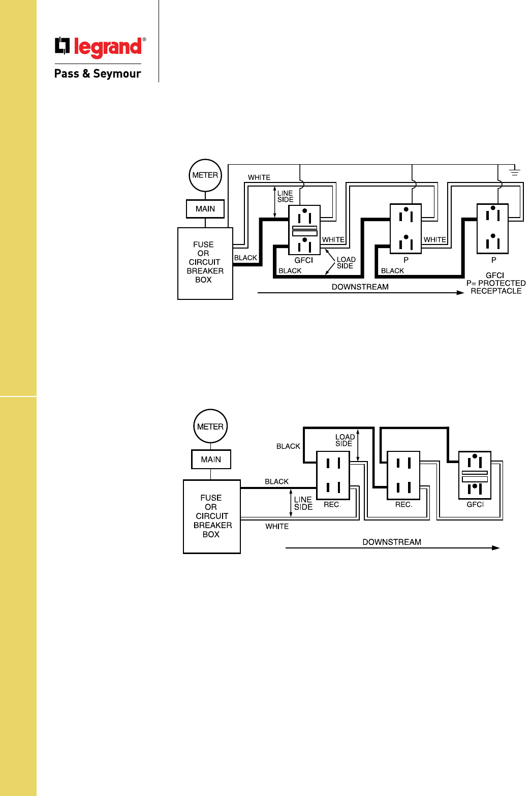
Technical Specifications
S-12
Wiring Diagrams
Technical Specifications
Wiring Diagrams – GFCIs
Wiring Diagram GFCI Receptacle, Feed-Thru Installation
To protect the entire branch circuit the GFCI must be the first receptacle from the fuse or circuit
breaker box. Receptacles on the circuit between the GFCI and the box will not be protected,
but receptacles downstream from the GFCI will have protection.
Wiring Diagram GFCI Receptacle, Non-Feed-Thru Installation
Terminal, or one-outlet-only protection can be achieved on a multi-outlet circuit by connecting
the hot and neutral line conductors to the corresponding line side terminals of the GFCI. Only
the GFCI receptacle will be protected.
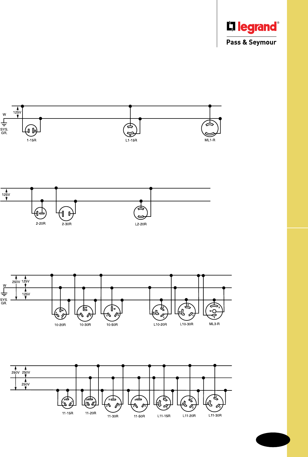
Technical Specifications
S-13
Wiring Diagrams
Technical Specifications
Wiring Diagrams –
2 Pole, 2 Wire Non-Grounding
3 Pole, 3 Wire Non-Grounding
2 Pole, 2 Wire Non-Grounding
125V
3ø250V
3 Pole, 3 Wire Non-Grounding
125V/250V
250V
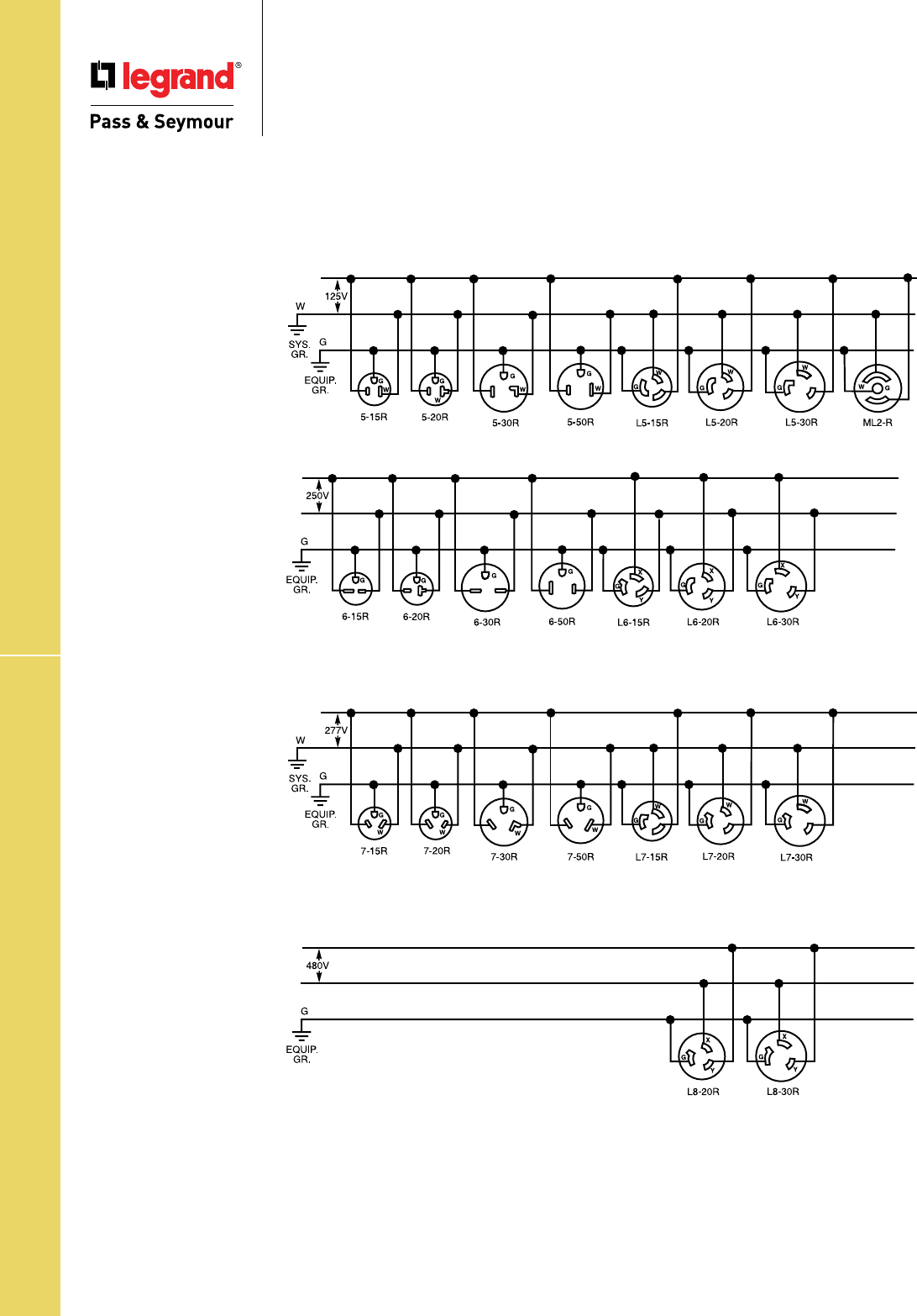
Technical Specifications
S-14
Wiring Diagrams
Technical Specifications
Wiring Diagrams –
2 Pole, 3 Wire Grounding
2 Pole, 3 Wire Grounding
125V
250V
277VAC
480VAC
G
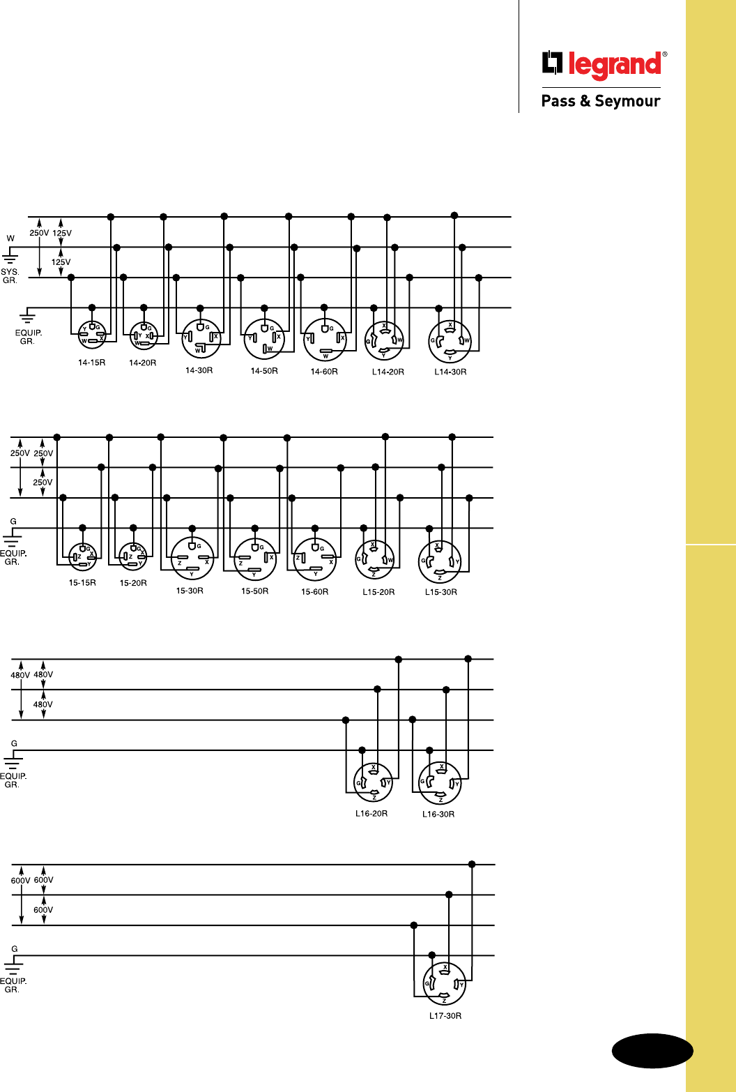
Technical Specifications
S-15
Wiring Diagrams
Technical Specifications
Wiring Diagrams –
3 Pole, 4 Wire Grounding
3 Pole, 4 Wire Grounding
125V/250V
3ø250V
3ø480V
3ø600V
G
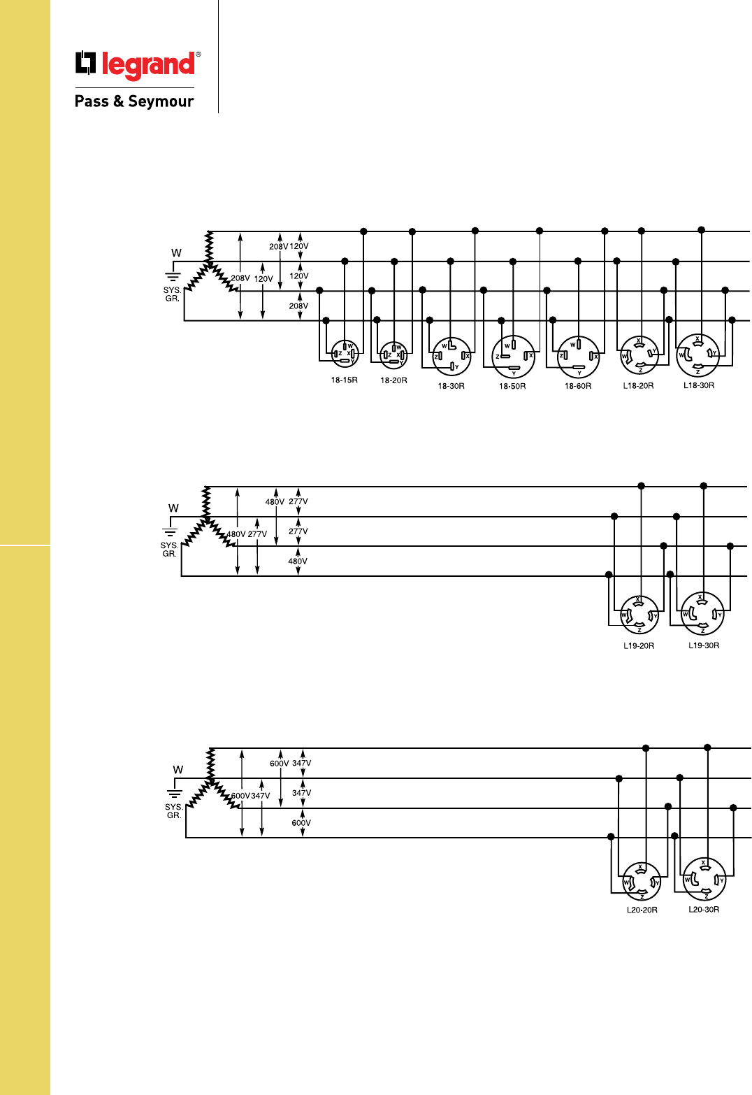
Technical Specifications
S-16
Wiring Diagrams
Technical Specifications
Wiring Diagrams –
4 Pole, 4 Wire Non-Grounding
4 Pole, 4 Wire Non-Grounding
3øY120V/208V
3øY277/480V
3ø347/600V
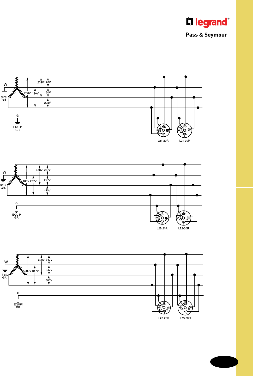
Technical Specifications
S-17
Wiring Diagrams
Technical Specifications
Wiring Diagrams –
4 Pole, 5 Wire Grounding
4 Pole, 5 Wire Grounding
3øY120V/208V
3øY277/480V
3øY347/600V
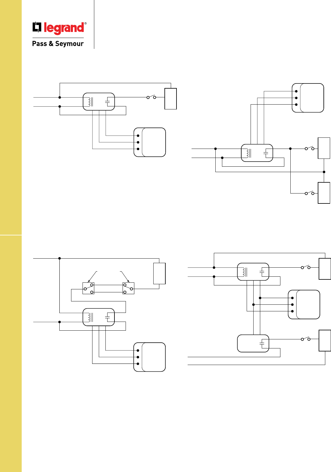
Technical Specifications
S-18
Wiring Diagrams
Technical Specifications
Wiring Diagrams –
Sensors Connected to Power Packs
Neutral
Hot
Wht
Blk
Power
Pack
Local
Off
Switch
Local
Off
Switch
Red
Red
Red
Blk
Blu
Hot Blk
Auxilliary
Relay Pack
Red
Red
Neutral
Any
24VDC
Ceiling/Wall
Sensor
Control Output
Common
+24VDC
Load
Load
Hot
Neutral
Wht
Blk
Power
Pack
Travelers
Red
Red
Red
Blk
Blu
Any
24VDC
Ceiling/Wall
Sensor
Control Output
Common
+24VDC
Load
Existing 3-Way
Switches
Neutral
Hot
Wht
Blk
Power
Pack
Local
Off
Switch
Red
Red
Red
Blk
Blu
Any
24VDC
Ceiling/Wall
Sensor
Control Output
Common
+24VDC
Load
Local
Off
Switch
Load
Neutral
Hot
Wht
Blk
Power
Pack
Local
Off
Switch
Red
Red
Red
Blk
Blu
Any
3-Wire
24VDC
Sensor
Control Output
Common
+24VDC
Load
1 Sensor, 1 Power Pack
Standard Wiring
1 Sensor, 1 Power Pack
Bi-Level Lighting
1 Sensor, 1 Power Pack
3-Way Switching
1 Sensor, 1 Power Pack
2 Lighting Loads

Technical Specifications
S-19
Wiring Diagrams
Technical Specifications
Wiring Diagrams –
Sensors Connected to Power Packs
Neutral
Hot
Wht
Blk
Power
Pack
Local
Off
Switch
Red
Red
Red
Blk
Blu
Any
24VDC
Ceiling/Wall
Sensor
Control Output
Common
+24VDC
Any
24VDC
Ceiling/Wall
Sensor
Control Output
Common
+24VDC
Any
24VDC
Ceiling/Wall
Sensor
Control Output
Common
+24VDC
Load
Red
Neutral
Hot
Wht
Blk
Power
Pack
Local
Off
Switch
Red
Red
Red
Blk
Blu
Red
Blk
Blu
Any
24VDC
Ceiling/Wall
Sensor
Control Output
Common
+24VDC
Load
Neutral
Hot
Wht
Blk
Power
Pack
Red
TO OTHER
LOADS
Red
Red
Blk
Blu
Neutral
Hot
Wht
Blk
Power
Pack
Red
TO OTHER
LOADS
Neutral
Hot
Wht
Blk
Power
Pack
Local
Off
Switch
Red
Red
Red
Blk
Blu
Neutral
Hot
Wht
Blk
Power
Pack
Local
Off
Switch
Red
Red
Neutral
Any
24VDC
Ceiling/Wall
Sensor
Control Output
Common
+24VDC
Any
24VDC
Ceiling/Wall
Sensor
Control Output
Common
+24VDC
Load
Load
1 Sensor & Up to 3 Power Packs Multiple Sensors, 1 Power Pack
Multiple Sensors, Multiple Power Packs
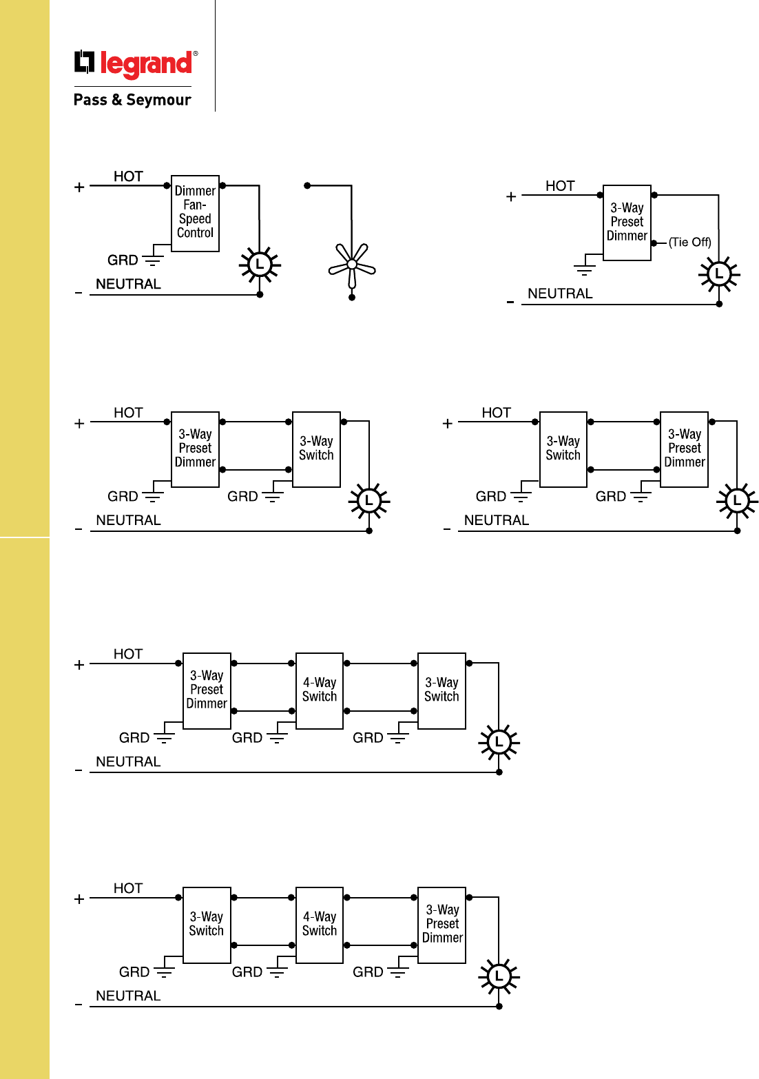
Technical Specifications
S-20
Wiring Diagrams
Technical Specifications
Wiring Diagrams –
Dimmers & Fan Speed Controls
Single-Pole Wiring Single-Pole Wiring
Using 3-Way Preset Dimmer
Control Line Side
OR
Control Load Side
3-Way Wiring
Control Line Side
Control Load Side
OR
4-Way Wiring
OR
For Scene Director
Wiring Diagrams,
see Page M-9.
For Leandro®
Wiring Diagrams,
see Page M-10.
For Dual Timer Cat.# 97352
Wiring Diagrams,
see Page L-20.
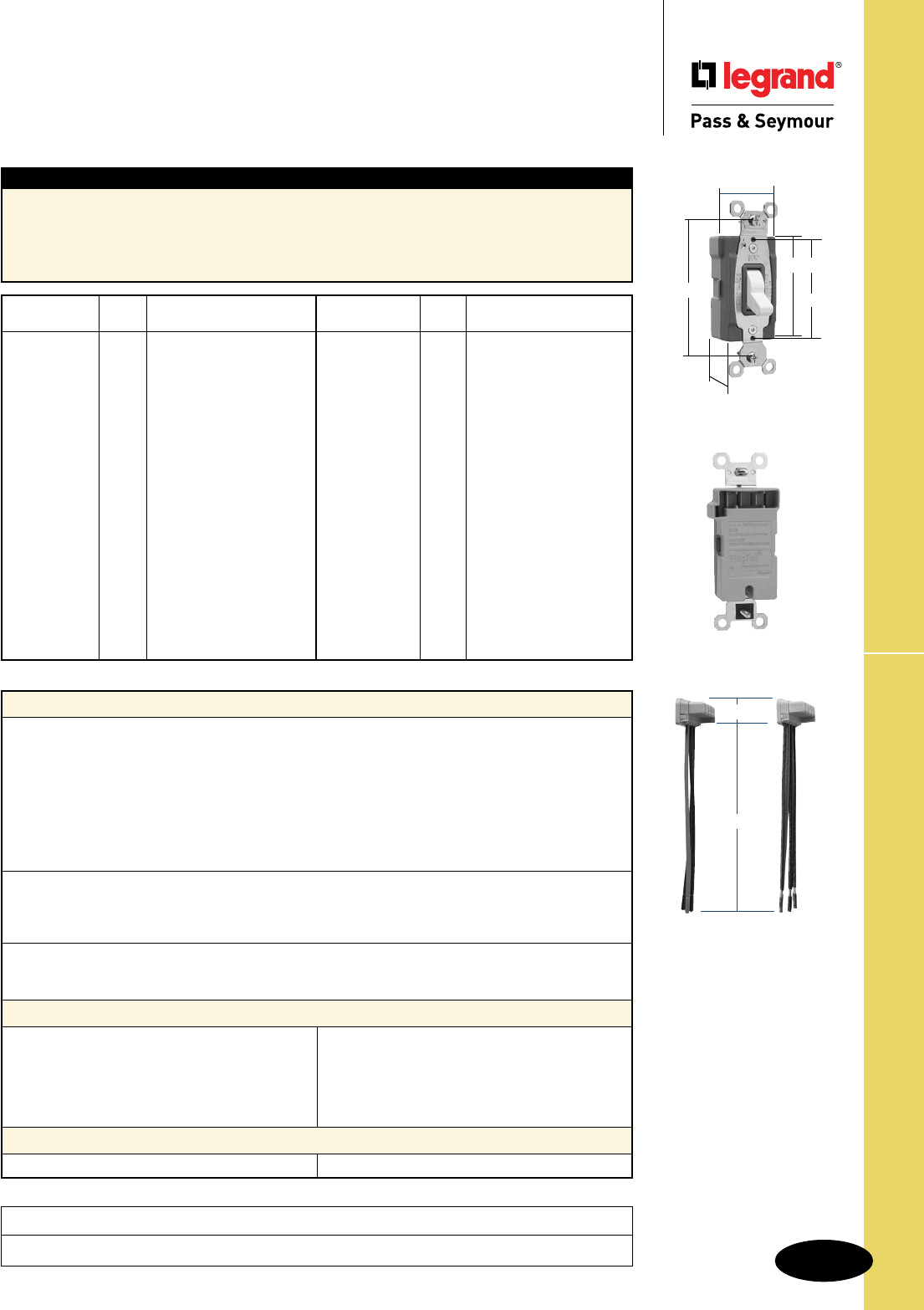
Technical Specifications
S-21
PlugTail™ Specification Grade Switches
Technical Specifications
PlugTail™ Specification Grade Switches
15 & 20A, 120/277VAC
PT20AC1W
1.320"
3.281"
1.073"
2.195"
2.375"
Typical Specications
Manufacturer’s Identification: Legrand/Pass & Seymour PT15AC1
Description: PlugTail™ Specification Grade Switches
Rating: 15 & 20A, 120/277VAC
3rd Party Compliance: cULus Listed, File Number LR17446, Standard CSA-C22.2 No. 111,
General Use Snap Switches. Federal Specification WS896. Conforms to NEMA WD-1 and WD-6.
Catalog
Number Color Description/Rating
r PT15AC1I Ivory 15A 120/277VAC, Single Pole
r PT15AC1W White 15A 120/277VAC, Single Pole
r PT15AC1 Brown 15A 120/277VAC, Single Pole
r PT15AC1GRY Gray 15A 120/277VAC, Single Pole
r PT15AC1RED Red 15A 120/277VAC, Single Pole
r PT15AC1LA Lt. Al. 15A 120/277VAC, Single Pole
r PT15AC3I Ivory 15A 120/277VAC, 3-Way
r PT15AC3W White 15A 120/277VAC, 3-Way
r PT15AC3 Brown 15A 120/277VAC, 3-Way
r PT15AC3GRY Gray 15A 120/277VAC, 3-Way
r PT15AC3RED Red 15A 120/277VAC, 3-Way
r PT15AC3LA Lt. Al. 15A 120/277VAC, 3-Way
r PT20AC1I Ivory 20A 120/277VAC, Single Pole
r PT20AC1W White 20A 120/277VAC, Single Pole
r PT20AC1 Brown 20A 120/277VAC, Single Pole
r PT20AC1GRY Gray 20A 120/277VAC, Single Pole
r PT20AC1RED Red 20A 120/277VAC, Single Pole
r PT20AC1LA Lt. Al. 20A 120/277VAC, Single Pole
Catalog
Number Color Description/Rating
r PT20AC3I Ivory 20A 120/277VAC, 3-Way
r PT20AC3W White 20A 120/277VAC, 3-Way
r PT20AC3 Brown 20A 120/277VAC, 3-Way
r PT20AC3GRY Gray 20A 120/277VAC, 3-Way
r PT20AC3RED Red 20A 120/277VAC, 3-Way
r PT20AC3LA Lt. Al. 20A 120/277VAC, 3-Way
Illuminated*
r PT15AC1CSL Clear 15A 120/277VAC, Single Pole
r PT15AC1ISL White 15A 120/277VAC, Single Pole
r PT15AC1WSL White 15A 120/277VAC, Single Pole
r PT15AC3CSL Clear 15A 120/277VAC, 3-Way
r PT15AC3ISL White 15A 120/277VAC, 3-Way
r PT15AC3WSL White 15A 120/277VAC, 3-Way
r PT20AC1CSL Clear 20A 120/277VAC, Single Pole
r PT20AC1ISL White 20A 120/277VAC, Single Pole
r PT20AC1WSL White 20A 120/277VAC, Single Pole
r PT20AC3CSL Clear 20A 120/277VAC, 3-Way
r PT20AC3ISL White 20A 120/277VAC, 3-Way
r PT20AC3WSL White 20A 120/277VAC, 3-Way
Project
Location/Type
PTS6STR3 PTS6STR4
1.125"
6.375"
Performance
Electrical
Dielectric Withstand Voltage 1500V minimum
Maximum Working Voltage 277VAC
347VAC
Overload Minimum 4.8 times rated current for 100 cycles
Temperature Rise 30°C maximum at rated current
Maximum Continuous Current 277VAC 20A
Endurance 50,000 cycles minimum, resistive, inductive, tungsten filament
lamp load (Fed Spec)
Mechanical
PlugTail Connector Identification #12 AWG, THHN, copper conductor, 6" leads, stripped,
solid or stranded, for use with PlugTail Switches only
Product Identification Ratings are a permanent part of the device
Environmental
Flammability UL94 V2
Operating Temperature Maximum continuous +60°C, minimum -40°C without impact
PlugTail Receptacle Materials
PlugTail Connector Materials
Front Body Nylon
Back Body Glass-Reinforced Nylon
Toggle Thermoplastic Polycarbonate
Contacts Brass
Mounting Strap Nickel-Plated Brass
Spring Arm Brass
Bumper Rubber
Spring Zinc-Plated Steel
Auto Ground Clip Nickel-Plated Brass
Illuminating Lamp* Neon
Housing Polycarbonate Contacts Brass
*For Illuminated versions. May not be compatible with some fluorescent lighting loads.
*For Illuminated versions. May not be compatible with some fluorescent lighting loads.
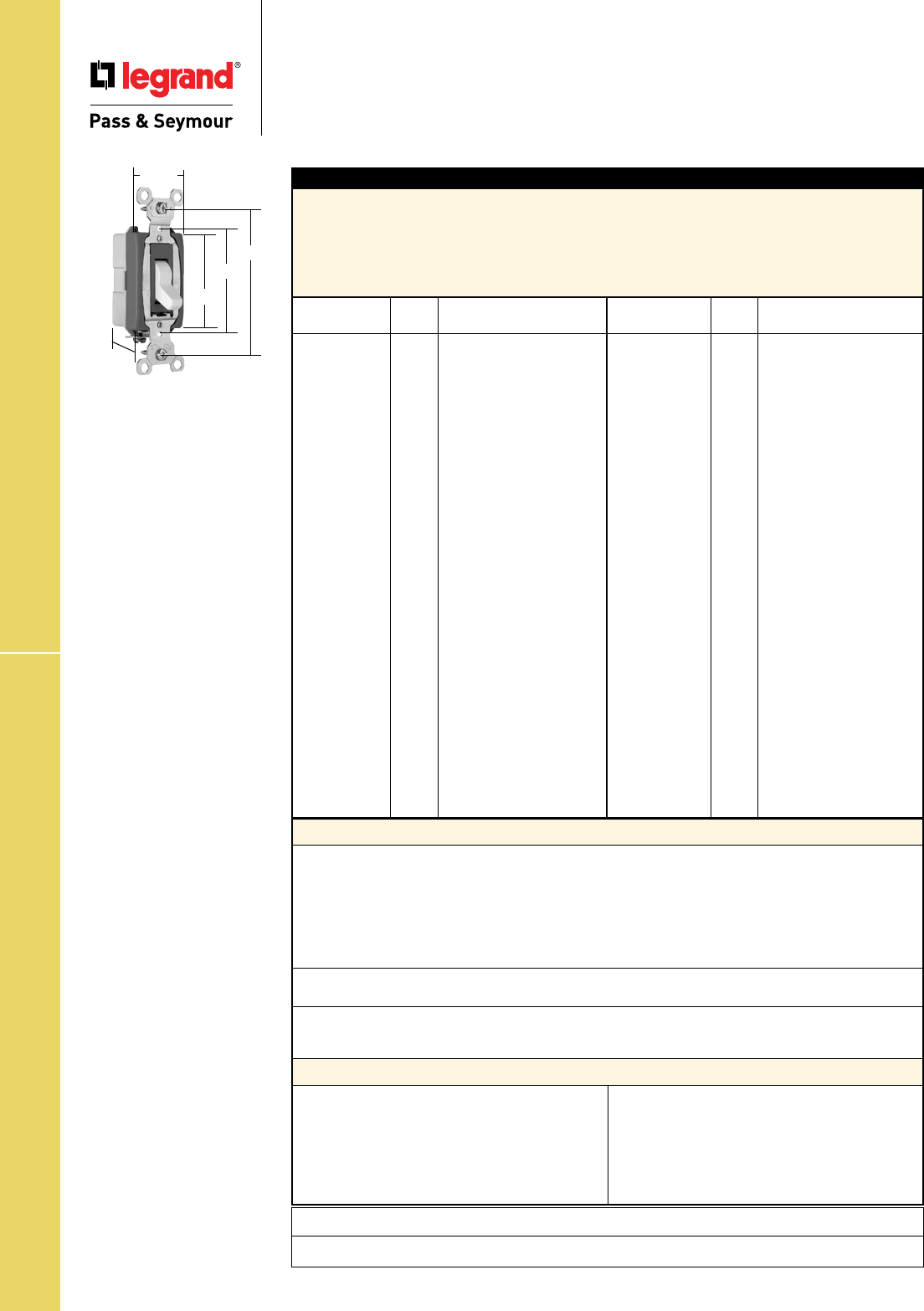
Technical Specifications
S-22
Industrial EHD Spec Grade Switches
Technical Specifications
Industrial Extra Heavy-Duty
Specification Grade Switches
Back & Side Wire 15, 20 & 30A, 120/277VAC
Performance
Electrical
Dielectric Withstand Voltage 1500V Minimum
Maximum Working Voltage 277VAC
Overload Minimum 4.8 times rated current for 100 cycles
Temperature Rise 30°C maximum at rated current
Maximum Continuous Current 277VAC
Endurance 50,000 cycles minimum, resistive, inductive, tungsten filament
lamp load (Fed Spec)
Mechanical
Terminal Accommodations #14 AWG – #10 AWG
Environmental
Flammability UL94 V2
Operating Temperature Maximum continuous +115°C, minimum -40°C
Materials
Back Body Glass-Reinforced Nylon
Front Body Nylon
Toggle Thermoplastic Polycarbonate
Terminals Brass
Terminal Screws Tri-Drive Brass
Mounting Strap Nickel-Plated Steel
Pressure Plate Brass
Contacts Silver Cadmium Oxide
Spring Arm Brass
Bumper Rubber
Spring Zinc-Plated Steel
Ground Terminal Brass
Ground Screw Tri-Drive Zinc-Plated Steel
Auto-Ground Clip Nickel-Plated Brass
Typical Specications
Manufacturer’s Identification: Legrand/Pass & Seymour PS15AC1
Description: Industrial EHD Specification Grade Switch, Back & Side Wire
Rating: 15A, 120/277VAC
3rd Party Compliance: UL Listed File Number E140597; Standard UL20, General Use Snap Switches.
Federal Specification WS896, CSA Certified, File Number LR17446, Standard CSA-C22.2 No. 111,
General Use Snap Switches. Conforms to NEMA WD-1 and WD-6.
15 & 20 Amp*
*30AC series is 1.437" wide
Catalog
Number Color Description/Rating
r PS15AC1I Ivory 15A 120/277VAC, Single Pole
r PS15AC1W White 15A 120/277VAC, Single Pole
r PS15AC1 Brown 15A 120/277VAC, Single Pole
r PS15AC1GRY Gray 15A 120/277VAC, Single Pole
r PS15AC1LA Lt. Al. 15A 120/277VAC, Single Pole
r PS15AC2I Ivory 15A 120/277VAC, Double Pole
r PS15AC2W White 15A 120/277VAC, Double Pole
r PS15AC2 Brown 15A 120/277VAC, Double Pole
r PS15AC2GRY Gray 15A 120/277VAC, Double Pole
r PS15AC2LA Lt. Al. 15A 120/277VAC, Double Pole
r PS15AC3I Ivory 15A 120/277VAC, 3-Way
r PS15AC3W White 15A 120/277VAC, 3-Way
r PS15AC3 Brown 15A 120/277VAC, 3-Way
r PS15AC3GRY Gray 15A 120/277VAC, 3-Way
r PS15AC3LA Lt. Al. 15A 120/277VAC, 3-Way
r PS15AC4I Ivory 15A 120/277VAC, 4-Way
r PS15AC4W White 15A 120/277VAC, 4-Way
r PS15AC4 Brown 15A 120/277VAC, 4-Way
r PS15AC4GRY Gray 15A 120/277VAC, 4-Way
r PS15AC4LA Lt. Al. 15A 120/277VAC, 4-Way
r PS20AC1I Ivory 20A 120/277VAC, Single Pole
r PS20AC1W White 20A 120/277VAC, Single Pole
r PS20AC1 Brown 20A 120/277VAC, Single Pole
r PS20AC1GRY Gray 20A 120/277VAC, Single Pole
r PS20AC1BK Black 20A 120/277VAC, Single Pole
r PS20AC1RED Red 20A 120/277VAC, Single Pole
r PS20AC1LA Lt. Al. 20A 120/277VAC, Single Pole
r PS20AC2I Ivory 20A 120/277VAC, Double Pole
Catalog
Number Color Description/Rating
r PS20AC2W White 20A 120/277VAC, Double Pole
r PS20AC2 Brown 20A 120/277VAC, Double Pole
r PS20AC2GRY Gray 20A 120/277VAC, Double Pole
r PS20AC2BK Black 20A 120/277VAC, Double Pole
r PS20AC2RED Red 20A 120/277VAC, Double Pole
r PS20AC2LA Lt. Al. 20A 120/277VAC, Double Pole
r PS20AC3I Ivory 20A 120/277VAC, 3-Way
r PS20AC3W White 20A 120/277VAC, 3-Way
r PS20AC3 Brown 20A 120/277VAC, 3-Way
r PS20AC3GRY Gray 20A 120/277VAC, 3-Way
r PS20AC3BK Black 20A 120/277VAC, 3-Way
r PS20AC3RED Red 20A 120/277VAC, 3-Way
r PS20AC3LA Lt. Al. 20A 120/277VAC, 3-Way
r PS20AC4I Ivory 20A 120/277VAC, 4-Way
r PS20AC4W White 20A 120/277VAC, 4-Way
r PS20AC4 Brown 20A 120/277VAC, 4-Way
r PS20AC4GRY Gray 20A 120/277VAC, 4-Way
r PS20AC4BK Black 20A 120/277VAC, 4-Way
r PS20AC4RED Red 20A 120/277VAC, 4-Way
r PS20AC4LA Lt. Al. 20A 120/277VAC, 4-Way
r PS30AC1I Ivory 30A 120/277VAC, Single Pole
r PS30AC1W White 30A 120/277VAC, Single Pole
r PS30AC1 Brown 30A 120/277VAC, Single Pole
r PS30AC2I Ivory 30A 120/277VAC, Double Pole
r PS30AC2W White 30A 120/277VAC, Double Pole
r PS30AC2 Brown 30A 120/277VAC, Double Pole
r PS30AC3I Ivory 30A 120/277VAC, 3-Way
r PS30AC3 Brown 30A 120/277VAC, 3-Way
1.320"
3.281"
2.375"
1.073"
2.196"
Project
Location/Type
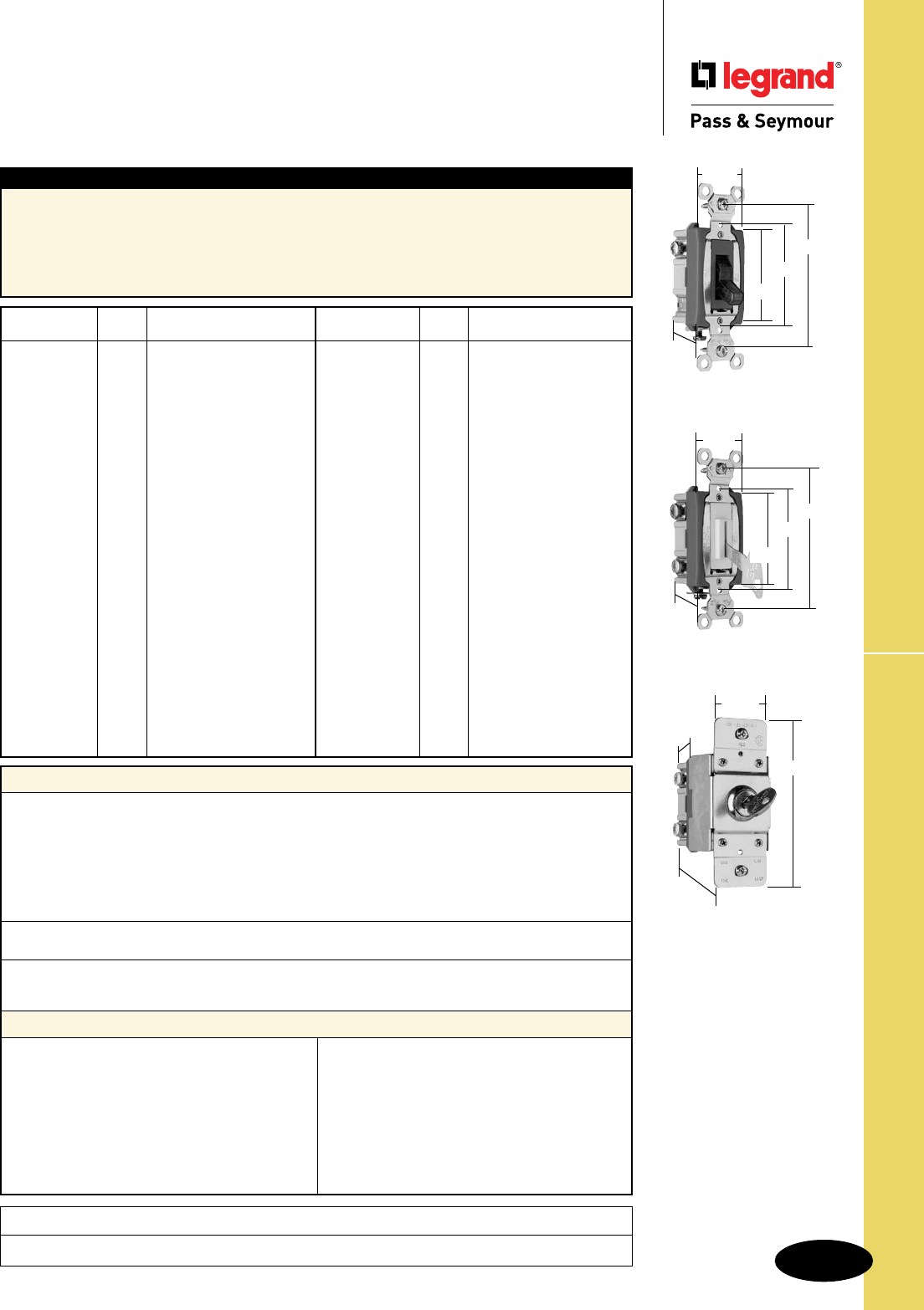
Technical Specifications
S-23
Industrial EHD & EHD Spec Grade Switches
Technical Specifications
Industrial Extra Heavy-Duty & Extra
Heavy-Duty Specification Grade Switches
15, 20 & 30A, 120, 277 & 120/277VAC
Typical Specications
Manufacturer’s Identification: Legrand/Pass & Seymour PS15AC1ISL
Description: Industrial EHD Specification Grade Switch, Back & Side Wire
Rating: 15A, 120/277VAC
3rd Party Compliance: UL Listed, File Number E140597, Standard UL20, General Use Snap Switches.
Federal Specification WS896, CSA Certified, File Number LR17446, Standard CSA-C22.2 No. 111,
General Use Snap Switches. Conforms to NEMA WD-1 and WD-6.
Catalog
Number Color Description/Rating
r PS15AC1CSL Clear 15A 120/277VAC, Single Pole
r PS15AC1ISL Ivory 15A 120/277VAC, Single Pole
r PS15AC1WSL White 15A 120/277VAC, Single Pole
r PS15AC1CPL Clear 15A 120VAC, Single Pole
r PS15AC1RPL Red 15A 120VAC, Single Pole
r PS15AC1L Gray 15A 120/277VAC, Single Pole
r PS15AC3CSL Clear 15A 120/277VAC, 3-Way
r PS15AC3ISL Ivory 15A 120/277VAC, 3-Way
r PS15AC3WSL White 15A 120/277VAC, 3-Way
r PS15AC3CPL Clear 15A 120VAC, 3-Way
r PS15AC3RPL Red 15A 120VAC, 3-Way
r PS15AC3L Gray 15A 120/277VAC, 3-Way
r PS20AC1CSL Clear 20A 120/277VAC, Single Pole
r PS20AC1ISL Ivory 20A 120/277VAC, Single Pole
r PS20AC1WSL White 20A 120/277VAC, Single Pole
r PS20AC1LASL Lt. Al. 20A 120/277VAC, Single Pole
r PS20AC1LASL Lt. Al. 20A 120/277VAC, Single Pole
r PS20AC1CPL Clear 20A 120VAC, Single Pole
r PS20AC1CPL7 Clear 20A 277VAC, Single Pole
r PS20AC1RPL Red 20A 120VAC, Single Pole
r PS20AC1RPL7 Red 20A 277VAC, Single Pole
r PS20AC1CPL Clear 20A 120VAC, Single Pole
r PS20AC1CPL7 Clear 20A 277VAC, Single Pole
r PS20AC1RPL Red 20A 120VAC, Single Pole
r PS20AC1RPL7 Red 20A 277VAC, Single Pole
r PS20AC1IL Ivory 20A 120/277VAC, Single Pole
r PS20AC1WL White 20A 120/277VAC, Single Pole
r PS20AC1L Gray 20A 120/277VAC, Single Pole
r PS20AC1LAL Lt. Al. 20A 120/277VAC, Single Pole
Catalog
Number Color Description/Rating
r PS20AC1KL — 20A 120/277VAC, Single Pole
r PS20AC2CPL Clear 20A 120/277VAC, Double Pole
r PS20AC2RPL Red 20A 120/277VAC, Double Pole
r PS20AC2CPL Clear 20A 120/277VAC, Double Pole
r PS20AC2RPL Red 20A 120/277VAC, Double Pole
r PS20AC2IL Ivory 20A 120/277VAC, Double Pole
r PS20AC2WL White 20A 120/277VAC, Double Pole
r PS20AC2L Gray 20A 120/277VAC, Double Pole
r PS20AC2LAL Lt. Al. 20A 120/277VAC, Double Pole
r PS20AC2KL — 20A 120/277VAC, Double Pole
r PS20AC3LASL Lt. Al. 20A 120/277VAC, 3-Way
r PS20AC3CPL Clear 20A 120VAC, 3-Way
r PS20AC3RPL Red 20A 120VAC, 3-Way
r PS20AC3RPL7 Red 20A 277VAC, 3-Way
r PS20AC3IL Ivory 20A 120/277VAC, 3-Way
r PS20AC3WL White 20A 120/277VAC, 3-Way
r PS20AC3L Gray 20A 120/277VAC, 3-Way
r PS20AC3REDL Red 20A 120/277VAC, 3-Way
r PS20AC3LAL Lt. Al. 20A 120/277VAC, 3-Way
r PS20AC3KL — 20A 120/277VAC, 3-Way
r PS20AC4IL Ivory 20A 120/277VAC, 4-Way
r PS20AC4WL White 20A 120/277VAC, 4-Way
r PS20AC4L Gray 20A 120/277VAC, 4-Way
r PS20AC4REDL Red 20A 120/277VAC, 4-Way
r PS20AC4LAL Lt. Al. 20A 120/277VAC, 4-Way
r PS20AC4KL — 20A 120/277VAC, 4-Way
r PS30AC1RPL Red 30A 120VAC, Single Pole
r PS30AC2RPL Red 30A 120/ 277VAC, Double Pole
r PS30AC3RPL Red 30A 120VAC, 3-Way
Project
Location/Type
Performance
Electrical
Dielectric Withstand Voltage 1500V Minimum
Maximum Working Voltage 277VAC
Overload Minimum 4.8 times rated current for 100 cycles
Temperature Rise 30°C maximum at rated current
Maximum Continuous Current 277VAC
Endurance 50,000 cycles minimum, resistive, inductive, tungsten filament
lamp load (Fed Spec)
Mechanical
Terminal Accommodations #14 AWG – #10 AWG
Environmental
Flammability UL94 V2
Operating Temperature Maximum continuous +115°C, minimum -40°C
Materials
Back Body Glass-Reinforced Nylon
Front Body Nylon
Toggle Thermoplastic Polycarbonate
Key Slot** Thermoplastic Polycarbonate
Terminals Brass
Terminal Screws Tri-Drive Brass
Strap Nickel-Plated Brass
Pressure Plate Brass
Contacts Silver Cadmium Oxide
Spring Arm Brass
Bumper Rubber
Spring Zinc-Plated Steel
Ground Terminal† Brass
Ground Screw Tri-Drive Zinc-Plated Steel
Auto-Ground Clip† Nickel-Plated Brass
Illuminating Lamp* Neon
Lock Housing† Stainless Steel
15 & 20 Amp Lighted &
Pilot Lighted
Locking
30AC series is 1.437" wide
1.320"
3.281"
2.375"
1.073"
2.196"
1.320"
3.281"
2.375"
1.073"
2.196"
Security Switch
1.475"
4.071"
2.261"
.610"
* For Lighted versions. May not be
compatible with some fluorescent
lighting loads.
**For Locking versions.
†
For Security versions Ground
Terminal is Zinc-Plated Steel.
No Auto-Ground Clip on Security
Switches.
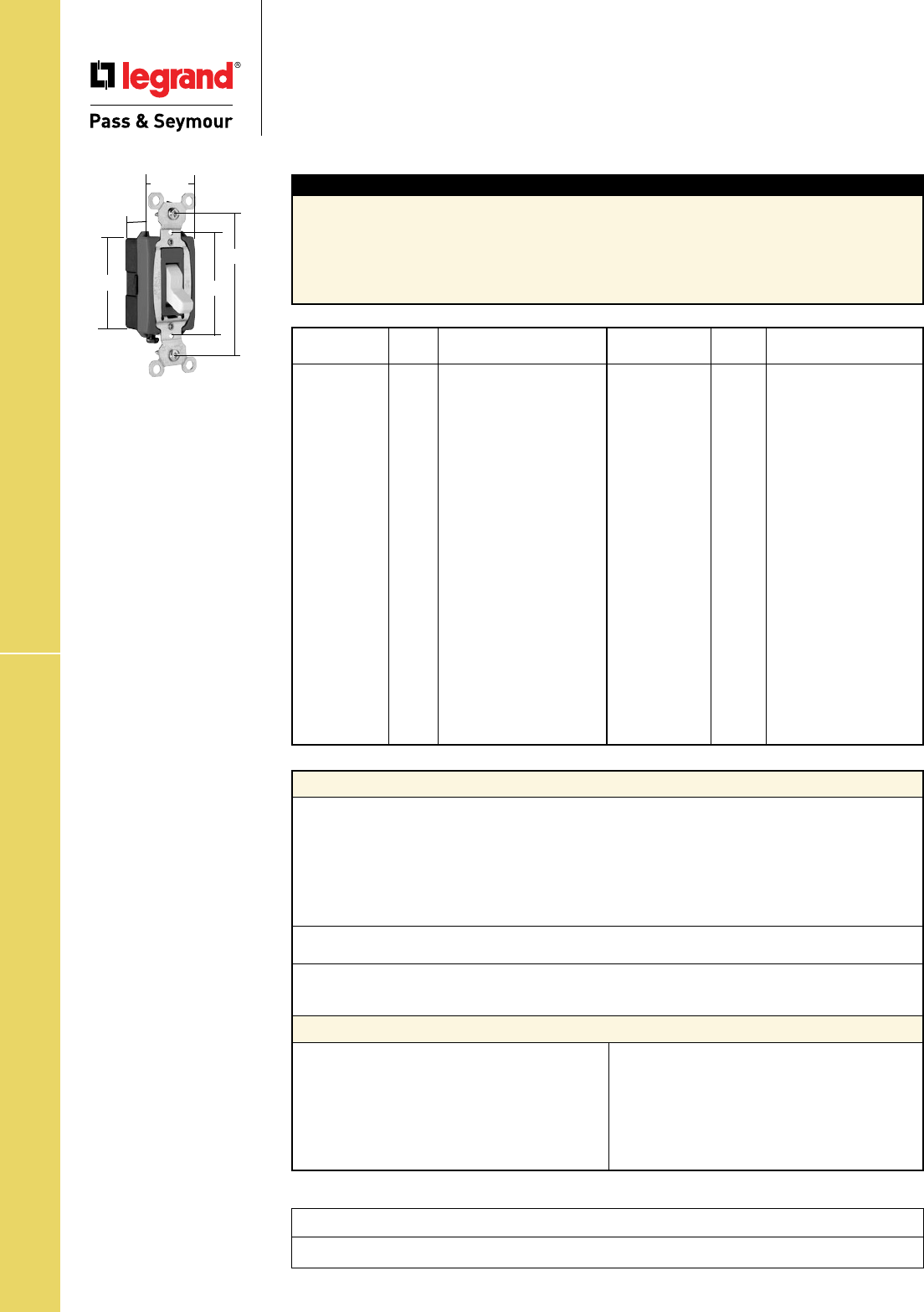
Technical Specifications
S-24
Hard Use Spec Grade Switches
Technical Specifications
Hard Use Specification Grade Switches
Back & Side Wire 15 & 20A, 120/277VAC
1.320"
3.281"
2.375"
1.073"
2.196"
Catalog
Number Color Description/Rating
r CSB15AC1I Ivory 15A 120/277VAC, Single Pole
r CSB15AC1W White 15A 120/277VAC, Single Pole
r CSB15AC1 Brown 15A 120/277VAC, Single Pole
r CSB15AC1GRY Gray 15A 120/277VAC, Single Pole
r CSB15AC1LA Lt. Al. 15A 120/277VAC, Single Pole
r CSB20AC1I Ivory 20A 120/277VAC, Single Pole
r CSB20AC1W White 20A 120/277VAC, Single Pole
r CSB20AC1 Brown 20A 120/277VAC, Single Pole
r CSB20AC1GRY Gray 20A 120/277VAC, Single Pole
r CSB20AC1BK Black 20A 120/277VAC, Single Pole
r CSB20AC1LA Lt. Al. 20A 120/277VAC, Single Pole
r CSB15AC2I Ivory 15A 120/277VAC, Double Pole
r CSB15AC2W White 15A 120/277VAC, Double Pole
r CSB15AC2 Brown 15A 120/277VAC, Double Pole
r CSB15AC2GRY Gray 15A 120/277VAC, Double Pole
r CSB15AC2LA Lt. Al. 15A 120/277VAC, Double Pole
r CSB20AC2I Ivory 20A 120/277VAC, Double Pole
r CSB20AC2W White 20A 120/277VAC, Double Pole
r CSB20AC2 Brown 20A 120/277VAC, Double Pole
r CSB20AC2GRY Gray 20A 120/277VAC, Double Pole
r CSB20AC2LA Lt. Al. 20A 120/277VAC, Double Pole
Catalog
Number Color Description/Rating
r CSB15AC3I Ivory 15A 120/277VAC, 3-Way
r CSB15AC3W White 15A 120/277VAC, 3-Way
r CSB15AC3 Brown 15A 120/277VAC, 3-Way
r CSB15AC3GRY Gray 15A 120/277VAC, 3-Way
r CSB15AC3LA Lt. Al. 15A 120/277VAC, 3-Way
r CSB20AC3I Ivory 20A 120/277VAC, 3-Way
r CSB20AC3W White 20A 120/277VAC, 3-Way
r CSB20AC3 Brown 20A 120/277VAC, 3-Way
r CSB20AC3GRY Gray 20A 120/277VAC, 3-Way
r CSB20AC3BK Black 20A 120/277VAC, 3-Way
r CSB20AC3LA Lt. Al. 20A 120/277VAC, 3-Way
r CSB15AC4I Ivory 15A 120/277VAC, 4-Way
r CSB15AC4W White 15A 120/277VAC, 4-Way
r CSB15AC4 Brown 15A 120/277VAC, 4-Way
r CSB15AC4GRY Gray 15A 120/277VAC, 4-Way
r CSB15AC4LA Lt. Al. 15A 120/277VAC, 4-Way
r CSB20AC4I Ivory 20A 120/277VAC, 4-Way
r CSB20AC4W White 20A 120/277VAC, 4-Way
r CSB20AC4 Brown 20A 120/277VAC, 4-Way
r CSB20AC4GRY Gray 20A 120/277VAC, 4-Way
r CSB20AC4LA Lt. Al. 20A 120/277VAC, 4-Way
Performance
Electrical
Dielectric Withstand Voltage 1500V Minimum
Maximum Working Voltage 277VAC
Overload Minimum 4.8 times rated current for 100 cycles
Temperature Rise 30°C maximum at rated current
Maximum Continuous Current 277VAC
Endurance 50,000 cycles minimum, resistive, inductive, tungsten filament
lamp load (Fed Spec)
Mechanical
Terminal Accommodations #14 AWG – #10 AWG
Environmental
Flammability UL94 V2
Operating Temperature Maximum continuous +115°C, minimum -40°C
Materials
Back Body Glass-Reinforced Nylon
Front Body Nylon
Toggle Thermoplastic Polycarbonate
Terminals Brass
Terminal Screws Tri-Drive Brass-Plated Steel
Mounting Strap Zinc-Plated Steel
Pressure Plate Brass
Contacts Silver Cadmium Oxide
Spring Arm Brass
Bumper Rubber
Spring Zinc-Plated Steel
Ground Terminal Brass
Ground Screw Tri-Drive Zinc-Plated Steel
Typical Specications
Manufacturer’s Identification: Legrand/Pass & Seymour CSB15AC1
Description: Hard Use Specification Grade Switch, Back & Side Wire
Rating: 15A, 120/277VAC
3rd Party Compliance: UL Listed, File Number E140597, Standard UL20, General Use Snap Switches.
Federal Specification WS896, CSA Certified, File Number LR17446, Standard CSA-C22.2 No. 111,
General Use Snap Switches. Conforms to NEMA WD-1 and WD-6.
15 & 20 Amp
Project
Location/Type
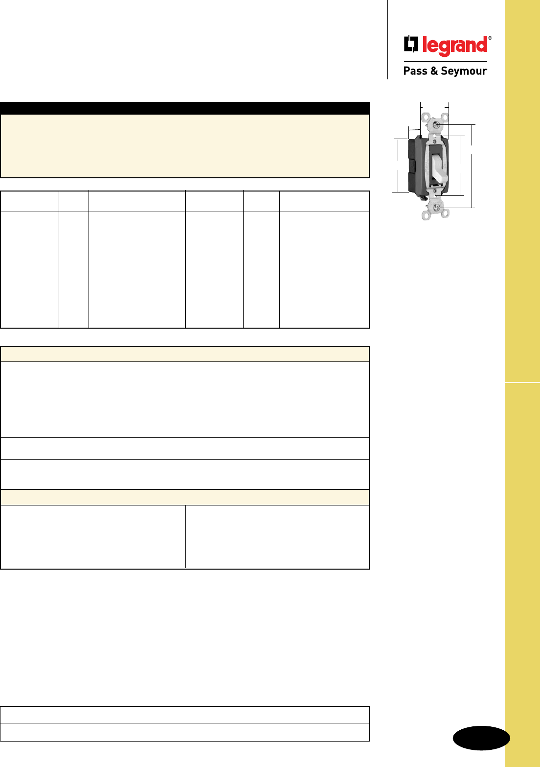
Technical Specifications
S-25
Commercial Spec Grade Switches
Technical Specifications
Commercial Specification Grade Switches
Side Wire 15 & 20A, 120/277VAC
Typical Specications
Manufacturer’s Identification: Legrand/Pass & Seymour CS15AC1
Description: Commercial Specification Grade Switch, Side Wire
Rating: 15A, 120/277VAC
3rd Party Compliance: UL Listed, File Number E140597, Standard UL20, General Use Snap Switches.
Federal Specification WS896, CSA Certified, File Number LR17446, Standard CSA-C22.2 No. 111,
General Use Snap Switches. Conforms to NEMA WD-1 and WD-6.
Catalog
Number Color Description/Rating
r CS15AC1I Ivory 15A 120/277VAC, Single Pole
r CS15AC1W White 15A 120/277VAC, Single Pole
r CS15AC1 Brown 15A 120/277VAC, Single Pole
r CS15AC1GRY Gray 15A 120/277VAC, Single Pole
r CS15AC1BK Black 15A 120/277VAC, Single Pole
r CS15AC1LA Lt. Al. 15A 120/277VAC, Single Pole
r CS20AC1I Ivory 20A 120/277VAC, Single Pole
r CS20AC1W White 20A 120/277VAC, Single Pole
r CS20AC1 Brown 20A 120/277VAC, Single Pole
r CS20AC1GRY Gray 20A 120/277VAC, Single Pole
r CS20AC1LA Lt. Al. 20A 120/277VAC, Single Pole
Catalog
Number Color Description/Rating
r CS15AC3I Ivory 15A 120/277VAC, 3-Way
r CS15AC3W White 15A 120/277VAC, 3-Way
r CS15AC3 Brown 15A 120/277VAC, 3-Way
r CS15AC3GRY Gray 15A 120/277VAC, 3-Way
r CS15AC3BK Black 15A 120/277VAC, 3-Way
r CS15AC3LA Lt. Al. 15A 120/277VAC, 3-Way
r CS20AC3I Ivory 20A 120/277VAC, 3-Way
r CS20AC3W White 20A 120/277VAC, 3-Way
r CS20AC3 Brown 20A 120/277VAC, 3-Way
r CS20AC3GRY Gray 20A 120/277VAC, 3-Way
r CS20AC3LA Lt. Al. 20A 120/277VAC, 3-Way
For double pole and 4-Way switches refer to CSB version on Page S-24.
Performance
Electrical
Dielectric Withstand Voltage 1500V minimum
Maximum Working Voltage 277VAC
Overload Minimum 4.8 times rated current for 100 cycles
Temperature Rise 30°C maximum at rated current
Maximum Continuous Current 277VAC
Endurance 50,000 cycles minimum, resistive, inductive, tungsten filament
lamp load (Fed Spec)
Mechanical
Terminal Accommodations #14 AWG – #10 AWG
Environmental
Flammability UL94 V2
Operating Temperature Maximum continuous +115°C, minimum -40°C
Materials
Back Body Glass-Reinforced Nylon
Front Body Nylon
Toggle Thermoplastic Polycarbonate
Terminals Brass
Terminal Screws Tri-Drive Brass-Plated Steel
Mounting Strap Zinc-Plated Steel
Contacts Silver Cadmium Oxide
Spring Arm Brass
Bumper Rubber
Spring Zinc-Plated Steel
Ground Terminal Brass
Ground Screw Tri-Drive Zinc-Plated Steel
Project
Location/Type
1.320"
3.281"
2.375"
1.073"
2.196"
15 & 20 Amp
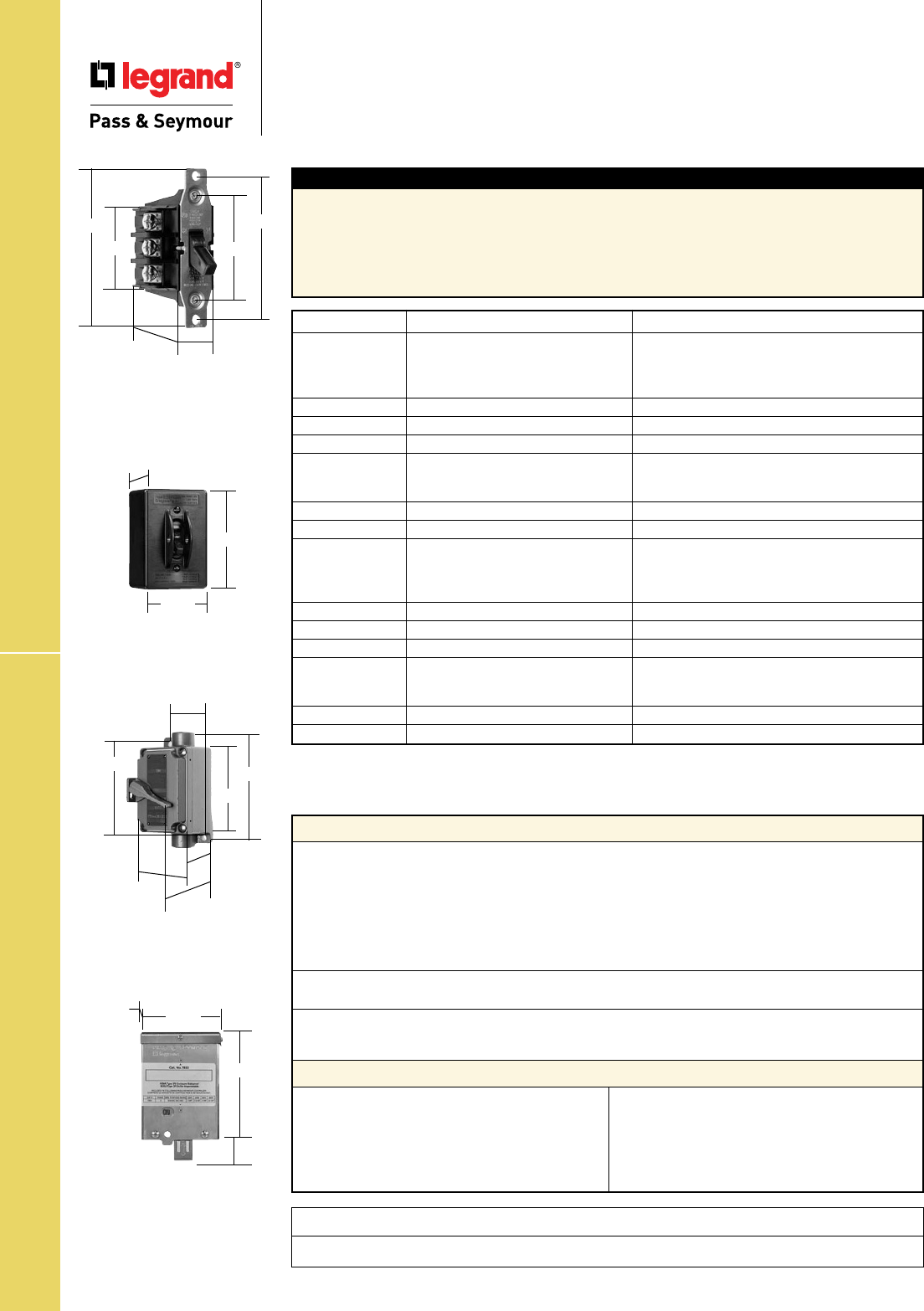
Technical Specifications
S-26
Manual Controller Switches
Technical Specifications
Manual Controller Switches
30A, 600VAC, 1ø & 3ø
Performance
Electrical
Dielectric Withstand Voltage 2000V Minimum
Maximum Working Voltage 600VAC
Overload 50 cycles, 132 Amps/600VAC .5 PF
Temperature Rise 50°C maximum
Maximum Continuous Current 30A
Endurance 1000 Cycles, 44Amp/600VAC 0.5 PF
5000 Cycles, 30Amp/600VAC 0.75 PF
Mechanical
Terminal Accommodations #14 AWG – #10 AWG copper or copper-clad wire
Environmental
Flammability UL94 V2
Operating Temperature Maximum continuous +75°C, minimum -40°C
Materials
Back Body Nylon
Front Body Nylon
Carrier Nylon
Toggle Nylon
Contact Arm Brass
Terminals Brass
Terminal Screws Brass
Leaf Springs Stainless Steel
Coil Springs Zinc-Plated Steel
Strap Zinc-Plated Steel
Rivets Brass
Contacts Silver Cadmium Oxide
7802
7803
2.375"
2.155"
3.280"
1.825"
3.67"
1.753"
7812EX
7813EX
2.250"
5.250" 5.875"
4.625"
4.250"
3.375"
3.000"
7812P
7813P
3.910"
2.825"
2.80"
Typical Specications
Manufacturer’s Identification: Legrand/Pass & Seymour 7802
Description: Manual Controller, Double Pole, Single Phase
Rating: 30A, 600VAC max.
3rd Party Compliance: UL Listed, File Number E31169, Standard UL508, Industrial Control Equipment;
CSA Certified, File Number LR17949, Standard CSA-C22.23, No. 14, Industrial Control Equipment.
Conforms to NEMA WD-1 and WD-6.
Project
Location/Type
All Industrial Control Equipment is suitable for use in a circuit capable of deliverable not more than 5,000 rms
amperes at 600VAC maximum or equivalent.
Footnote 1. Suitable as Motor Disconnect – 10KA @ 600VAC, 30A max. Class J Fuse
Catalog Number Rating Description
r
7802 General Use 2 120 Double Pole, Single Phase AC
30 600Max. 3 240 Manual Motor Starting Switch
7.5 480 (No overload protection)
10 600
r
7802MD Same as 7802 7802, See Footnote 1
r
7812P Same as 7802 7802 in a NEMA 1 Enclosure
r
7812PMD Same as 7802 7812P, See Footnote 1
r
7812EX Same as 7802 7802 in a NEMA 7 & 9 Enclosure for
Hazardous Locations Class I – Groups C, D;
Class II – Groups E, F, G
r
7832 Same as 7802 7802 in a NEMA 3R Enclosure
r
7832MD Same as 7802 7832, See Footnote 1
r
7803 General Use 3 120 Three Phase, Three Pole AC
30 600Max. 7.5 240 Manual Motor Starting Switch
10 480 (No overload protection)
20 600
r
7803MD Same as 7803 7803, See Footnote 1
r
7813P Same as 7803 7803 in a NEMA 1 Enclosure
r
7813PMD Same as 7803 7813P , See Footnote 1
r
7813EX Same as 7803 7803 in a NEMA 7 & 9 Enclosure for
Hazardous Locations Class I – Groups C, D;
Class II – Groups E, F, G
r
7833 Same as 7803 7803 in a NEMA 3R Enclosure
r
7833MD Same as 7803 7803, See Footnote 1
5.75"
1.80"
4.50"
3.25"
7832
7833
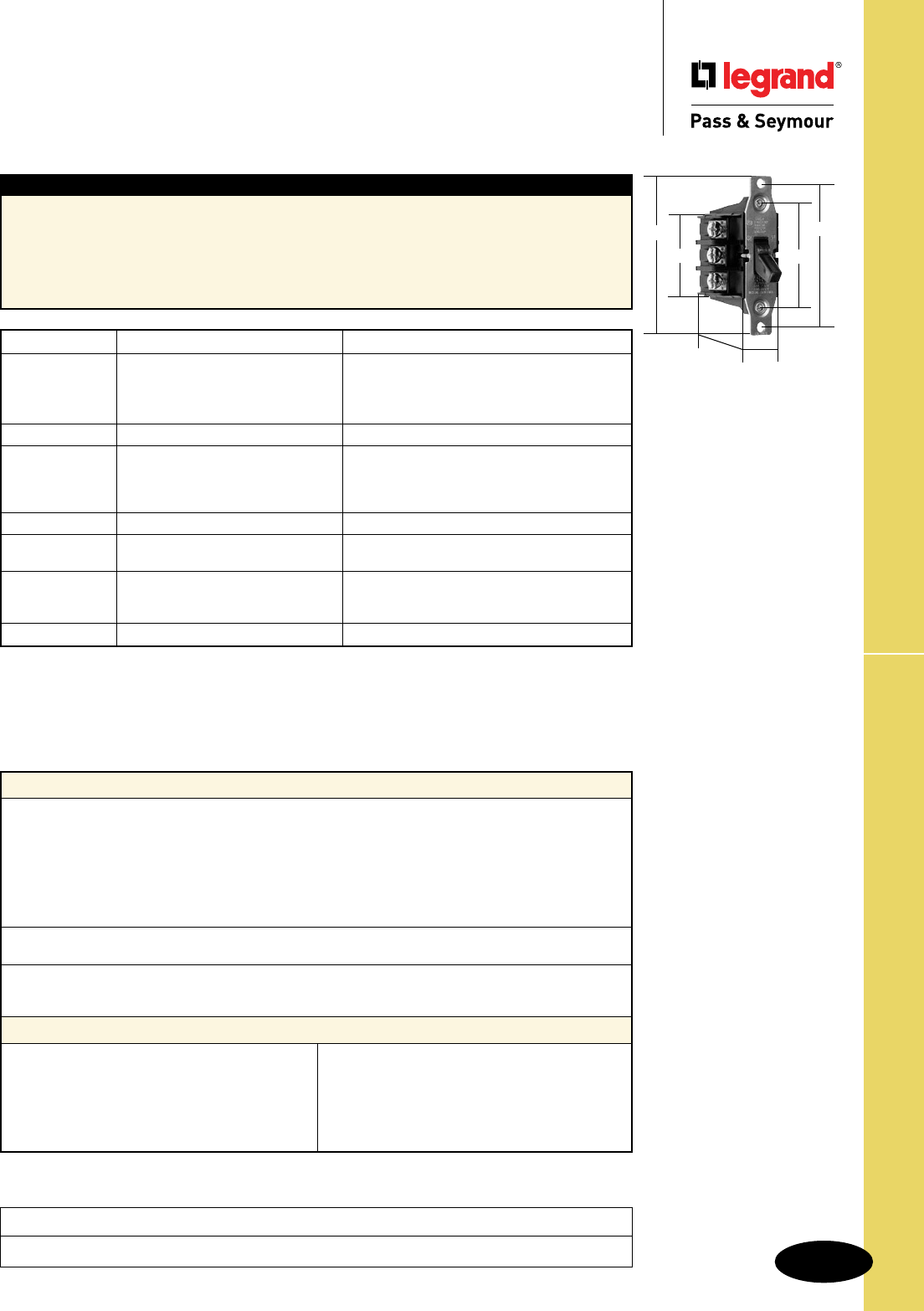
Technical Specifications
S-27
Manual Controller Switches
Technical Specifications
Manual Controller Switches
40A, 600VAC, 1ø & 3ø
Typical Specications
Manufacturer’s Identification: Legrand/Pass & Seymour 7842
Description: Manual Controller, Double Pole, Single Phase
Rating: 40A, 600VAC max.
3rd Party Compliance: UL Listed, File Number E31169, Standard UL508, Industrial Control Equipment;
CSA Certified, File Number LR17949, Standard CSA-C22.23, No. 14, Industrial Control Equipment.
Conforms to NEMA WD-1 and WD-6.
Performance
Electrical
Dielectric Withstand Voltage 2000V Minimum
Maximum Working Voltage 600VAC
Overload 50 cycles, 132 Amps/600VAC .5 PF
Temperature Rise 50°C maximum
Maximum Continuous Current 30A
Endurance 1000 Cycles, 44Amp/600VAC 0.5 PF
5000 Cycles, 30Amp/600VAC 0.75 PF
Mechanical
Terminal Accommodations #14 AWG – #10 AWG copper or copper-clad wire
Environmental
Flammability UL94 V2
Operating Temperature Maximum continuous +75°C, minimum -40°C
Materials
Back Body Nylon
Front Body Nylon
Carrier Nylon
Toggle Nylon
Contact Arm Brass
Terminals Brass
Terminal Screws Brass
Leaf Springs Stainless Steel
Coil Springs Zinc-Plated Steel
Strap Zinc-Plated Steel
Rivets Brass
Contacts Silver Cadmium Oxide
Catalog Number Rating Description
r
7842 General Use 2 120 Double Pole, Single Phase AC
40 600Max. 5 240 Manual Motor Starting Switch
10 480 (No overload protection)
15 600
r
7842MD Same as 7842 7842, See Footnote 2
r
7843 General Use 3 120 Three Phase, Three Pole AC
40 600Max. 7.5 240 Manual Motor Starting Switch
15 480 (No overload protection)
20 600
r
7843MD Same as 7843 7843, See Footnote 2
r
7801P Handle Locking Guard has opening for padlock
to secure control in either ON or OFF position.
r
7806P NEMA 1 Black Nylon Enclosure has
baked-on gray enamel finish with 1/2"
and 3/4" knockouts at each end.
r
7830 NEMA 3R Aluminum Enclosure
All Industrial Control Equipment is suitable for use in a circuit capable of deliverable not more than 5,000 rms
amperes at 600VAC maximum or equivalent.
Footnote:
2. Suitable as Motor Disconnect – 10KA @ 600VAC, 60A max. Class J Fuse or
100A max. Ferraz Shawmut HSJ Fuse
Project
Location/Type
7842
7843
2.375"
2.155"
3.280"
1.825"
3.67"
1.753"
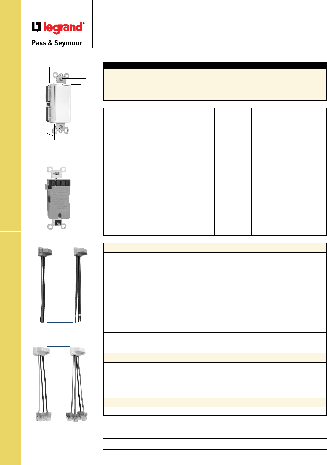
Technical Specifications
S-28
PlugTail™ Spec Grade Decorator Switches
Technical Specifications
PlugTail™ Specification Grade
Decorator Switches
15 & 20A, 120/277VAC
Typical Specications
Manufacturer’s Identification: Legrand/Pass & Seymour PT2601
Description: PlugTail™ Specification Grade Decorator Switches
Rating: 15 & 20A, 120/277VAC
3rd Party Compliance: cULus Listed, File Number E140597, Standard CSA-C22.2 No. 111, General Use
Snap Switches. Federal Specification WS896. Conforms to NEMA WD-1 and WD-6.
Catalog
Number Color Description/Rating
r PT2601I Ivory 15A 120/277VAC, Single Pole
r PT2601W White 15A 120/277VAC, Single Pole
r PT2601 Brown 15A 120/277VAC, Single Pole
r PT2601GRY Gray 15A 120/277VAC, Single Pole
r PT2601RED Red 15A 120/277VAC, Single Pole
r PT2601BK Black 15A 120/277VAC, Single Pole
r PT2601LA Lt. Al. 15A 120/277VAC, Single Pole
r PT2603I Ivory 15A 120/277VAC, 3-Way
r PT2603W White 15A 120/277VAC, 3-Way
r PT2603 Brown 15A 120/277VAC, 3-Way
r PT2603GRY Gray 15A 120/277VAC, 3-Way
r PT2603RED Red 15A 120/277VAC, 3-Way
r PT2603BK Black 15A 120/277VAC, 3-Way
r PT2603LA Lt. Al. 15A 120/277VAC, 3-Way
r PT2621I Ivory 20A 120/277VAC, Single Pole
r PT2621W White 20A 120/277VAC, Single Pole
r PT2621 Brown 20A 120/277VAC, Single Pole
r PT2621GRY Gray 20A 120/277VAC, Single Pole
Catalog
Number Color Description/Rating
r PT2621RED Red 20A 120/277VAC, Single Pole
r PT2621BK Black 20A 120/277VAC, Single Pole
r PT2621LA Lt. Al. 20A 120/277VAC, Single Pole
r PT2623I Ivory 20A 120/277VAC, 3-Way
r PT2623W White 20A 120/277VAC, 3-Way
r PT2623 Brown 20A 120/277VAC, 3-Way
r PT2623GRY Gray 20A 120/277VAC, 3-Way
r PT2623RED Red 20A 120/277VAC, 3-Way
r PT2623BK Black 20A 120/277VAC, 3-Way
r PT2623LA Lt. Al. 20A 120/277VAC, 3-Way
Illuminated*
r PT2625I Ivory 20A 120/277VAC, Single Pole
r PT2625W White 20A 120/277VAC, Single Pole
r PT2625BK Black 20A 120/277VAC, Single Pole
r PT2625LA Lt. Al. 20A 120/277VAC, Single Pole
r PT2626I Ivory 20A 120/277VAC, 3-Way
r PT2626W White 20A 120/277VAC, 3-Way
r PT2626BK Black 20A 120/277VAC, 3-Way
r PT2626LA Lt. Al. 20A 120/277VAC, 3-Way
Performance
Electrical
Dielectric Withstand Voltage 1500V minimum
Maximum Working Voltage 277VAC
347VAC
Overload Minimum 4.8 times rated current for 100 cycles
Temperature Rise 30°C maximum at rated current
Maximum Continuous Current 20A
Endurance 50,000 cycles minimum, resistive, inductive, tungsten filament
lamp load (Fed Spec)
Mechanical
PlugTail Connector Identification #12 AWG, THHN, copper conductor, 6" leads, stripped,
solid or stranded, for use with PlugTail Switches only
Product Identification Ratings are a permanent part of the device
Environmental
Flammability UL94 V2
Operating Temperature Maximum continuous +60°C, minimum -40°C without impact
PlugTail Receptacle Materials
PlugTail Connector Materials
Front Body Polycarbonate
Back Body Polycarbonate
Paddle Thermoplastic Polycarbonate
Contacts Slver Cadmiun Oxide
Mounting Strap Steel
Spring Arm Brass
Spring Zinc-Plated Steel
Auto Ground Clip Steel
Illuminating Lamp* LED
Housing Polycarbonate Contacts Brass
Project
Location/Type
*For Illuminated versions. May not be compatible with some fluorescent lighting loads.
PT2626W
1.6"
3.281"
1.2"
2.6"
PTS6STR3 PTS6STR4
1.125"
6.375"
PTS6STR3BP PTS6STR4BP
1.125"
6.375"
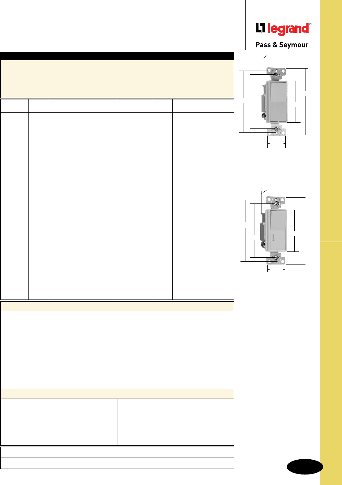
Technical Specifications
S-29
Project
Location/Type
Spec Grade Decorator Switches
Technical Specifications
Specification Grade Decorator Switches
15 & 20A, 120/277VAC; 20A, 120VAC
2601
2.620"
4.200"
1.060"
3.281"
3.812"
1.300"
2625, 2626, 2629
2.620"
4.200"
1.060"
3.281"
3.812"
1.300"
Typical Specications
Manufacturer’s Identification: Legrand/Pass & Seymour 2601
Description: Specification Grade Decorator Switch, Back & Side Wire
Rating: 15A, 120/277VAC
3rd Party Compliance: UL Listed, File Number E140597, Standard UL20, General Use Snap Switches,
CSA Certified, File Number LR17446, Standard CSA-C22.2 No. 111, General Use Snap Switches.
Conforms to NEMA WD-1 and WD-6.
Performance
Electrical
Dielectric Withstand Voltage 1500V Minimum
Maximum Working Voltage 277VAC
Overload Minimum 4.8 times rated current for 100 cycles
Temperature Rise 30°C maximum at rated current
Maximum Continuous Current 277VAC
Endurance 50,000 cycles minimum, resistive, inductive, tungsten filament
lamp load
Mechanical
Terminal Accommodation #14 AWG – #10 AWG
Environmental
Flammability UL94 V2
Operating Temperature Maximum continuous +115°C, minimum -40°C
Materials
Back Body Polycarbonate
Frame Polycarbonate
Paddle Thermoplastic
Terminals Brass
Terminal Screws Tri-Drive Brass-Plated Steel
Strap Steel
Pressure Plate Steel
Contacts Silver Cadmium Oxide
Spring Arm Brass
Bumper Rubber
Spring Zinc-Plated Steel
Ground Terminal Brass
Ground Screw Tri-Drive Zinc-Plated Steel
Illuminating Lamp* Neon
Lens* Polycarbonate *For Illuminated versions.
May not be compatible
with some fluorescent
lighting loads.
Catalog
Number Color Description/Rating
r 2601I Ivory 15A 120/277VAC, Single Pole
r 2601W White 15A 120/277VAC, Single Pole
r 2601GRY Gray 15A 120/277VAC, Single Pole
r 2601BK Black 15A 120/277VAC, Single Pole
r 2601LA Lt. Al. 15A 120/277VAC, Single Pole
r 2621I Ivory 20A 120/277VAC, Single Pole
r 2621W White 20A 120/277VAC, Single Pole
r 2621 Brown 20A 120/277VAC, Single Pole
r 2621GRY Gray 20A 120/277VAC, Single Pole
r 2621BK Black 20A 120/277VAC, Single Pole
r 2621RED Red 20A 120/277VAC, Single Pole
r 2621LA Lt. Al. 20A 120/277VAC, Single Pole
r 2622I Ivory 20A 120/277VAC, Double Pole
r 2622W White 20A 120/277VAC, Double Pole
r 2622 Brown 20A 120/277VAC, Double Pole
r 2622GRY Gray 20A 120/277VAC, Double Pole
r 2622BK Black 20A 120/277VAC, Double Pole
r 2622LA Lt. Al. 20A 120/277VAC, Double Pole
r 2603I Ivory 15A 120/277VAC, 3-Way
r 2603W White 15A 120/277VAC, 3-Way
r 2603GRY Gray 15A 120/277VAC, 3-Way
r 2603BK Black 15A 120/277VAC, 3-Way
r 2603LA Lt. Al. 15A 120/277VAC, 3-Way
r 2623I Ivory 20A 120/277VAC, 3-Way
r 2623W White 20A 120/277VAC, 3-Way
r 2623 Brown 20A 120/277VAC, 3-Way
r 2623GRY Gray 20A 120/277VAC, 3-Way
r 2623BK Black 20A 120/277VAC, 3-Way
Catalog
Number Color Description/Rating
r 2623RED Red 20A 120/277VAC, 3-Way
r 2623LA Lt. Al. 20A 120/277VAC, 3-Way
r 2604I Ivory 15A 120/277VAC, 4-Way
r 2604W White 15A 120/277VAC, 4-Way
r 2604LA Lt. Al. 15A 120/277VAC, 4-Way
r 2624I Ivory 20A 120/277VAC, 4-Way
r 2624W White 20A 120/277VAC, 4-Way
r 2624 Brown 20A 120/277VAC, 4-Way
r 2624GRY Gray 20A 120/277VAC, 4-Way
r 2624BK Black 20A 120/277VAC, 4-Way
r 2624RED Red 20A 120/277VAC, 4-Way
r 2624LA Lt. Al. 20A 120/277VAC, 4-Way
Illuminated*
r 2625I Ivory 20A 120VAC, Single Pole
r 2625W White 20A 120VAC, Single Pole
r 2625 Brown 20A 120VAC, Single Pole
r 2625LA Lt. Al. 20A 120VAC, Single Pole
r 2626I Ivory 20A 120VAC, 3-Way
r 2626W White 20A 120VAC, 3-Way
r 2626LA Lt. Al. 20A 120VAC, 3-Way
r 2628I Ivory 20A 120VAC, 4-Way
r 2628W White 20A 120VAC, 4-Way
r 2628LA Lt. Al. 20A 120VAC, 4-Way
Pilot Lighted
r 2629I Ivory 20A 120VAC, Single Pole
r 2629W White 20A 120VAC, Single Pole
r 2629LA Lt. Al. 20A 120VAC, Single Pole
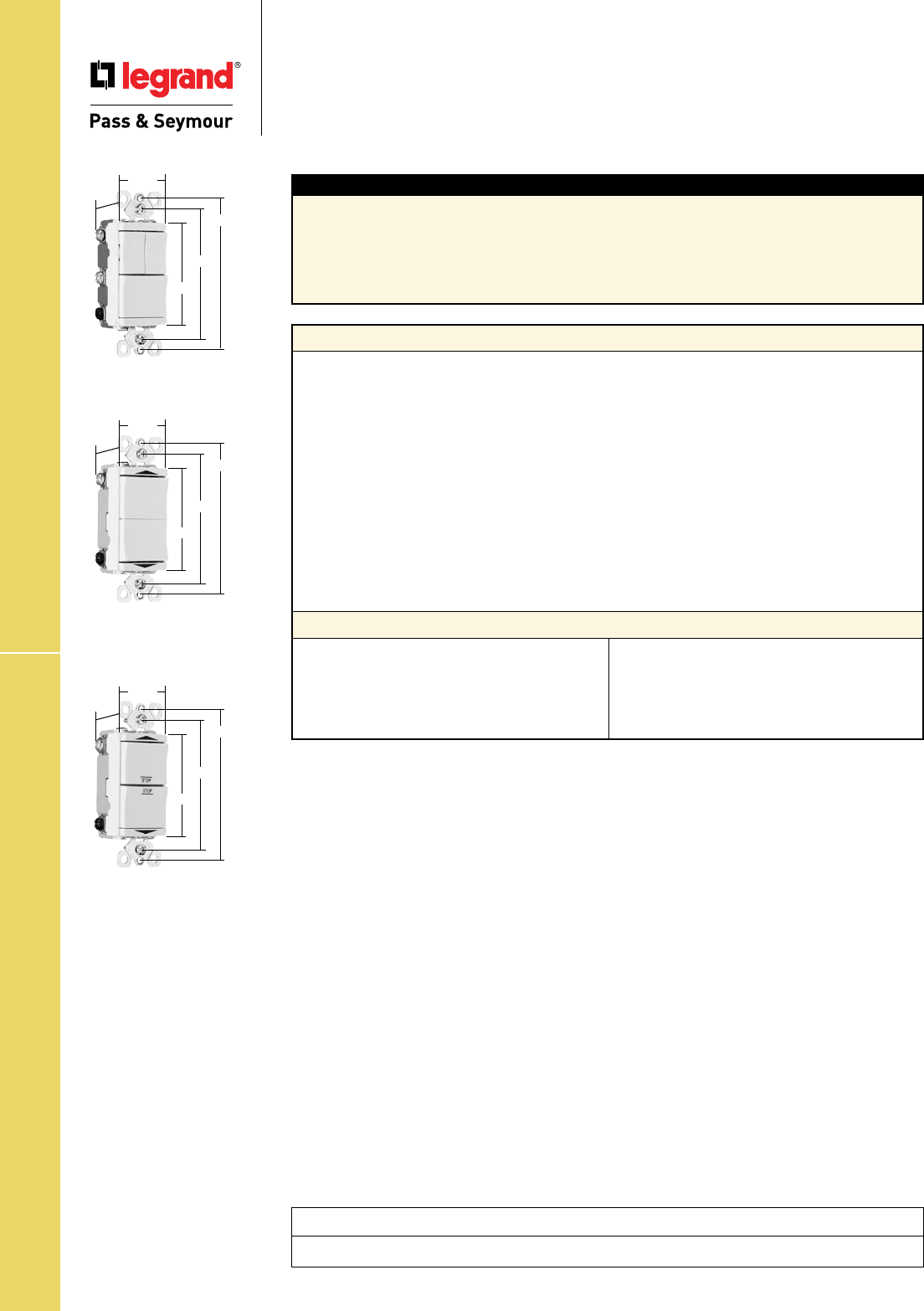
Technical Specifications
S-30
Spec Grade Combination & Contact Switches
Technical Specifications
Specification Grade Combination &
Momentary & Maintained Contact Switches
15A, 120VAC; 20A, 277VAC
Momentary
Contact
Maintained
Contact
1.29"
1.59"
2.60"
3.281"
3.812"
1.29"
1.59"
2.60"
3.281"
3.812"
15 & 20 Amp
1.29"
1.59"
2.60"
3.281"
3.812"
Typical Specications
Manufacturer's Identification: Legrand/Pass & Seymour PS81120, PS811120, TM811DTMO &
TM811DTMA
Rating: PS81120 & PS811120: 20A, 277VAC. TM811DTMO & TM811DTMA: 15A, 120VAC
3rd Party Compliance: PS81120, PS811120, TM811DTMA: cULus Listed, File Number E140597,
Standard UL20, General Use Snap Switches.TM811DTMO: cULus Listed, File Number E31169, UL508,
Industrial Control. Conforms to NEMA WD-1 and WD-6.
Performance
Electrical
Maximum Amperage per Circuit PS81120 and PS811120 = 20A
Maximum Amperage per Device PS81120 = 30A, PS811120 = 35A
Dielectric Withstand Voltage 1500V Minimum
Maximum Working Voltage PS81120 and PS811120 = 277VAC
TM811DTMO and TM811DTMA = 120VAC
Overload Minimum 4.8 times rated current for 100 cycles
Temperature Rise 30°C maximum at rated current
Maximum Continuous Current PS81120 and PS811120 = 277VAC
TM811DTMO and TM811DTMA = 120VAC
Mechanical
Terminal Accommodation #14 AWG – #10 AWG
Product Identification Amperage, Voltage, 3rd Party Compliance
Environmental
Flammability UL94 V2
Operating Temperature Maximum continuous +115°C, minimum -40°C
Materials
Back Body Polycarbonate
Frame Polycarbonate
Paddle Thermoplastic
Terminals Brass
Terminal Screws Tri-Drive Brass-Plated Steel
Strap Steel
Pressure Plate Steel
Contacts Silver Cadmium Oxide
Spring Zinc-Plated Steel
Ground Terminal Brass
Ground Screw Tri-Drive Zinc-Plated Steel
Project
Location/Type
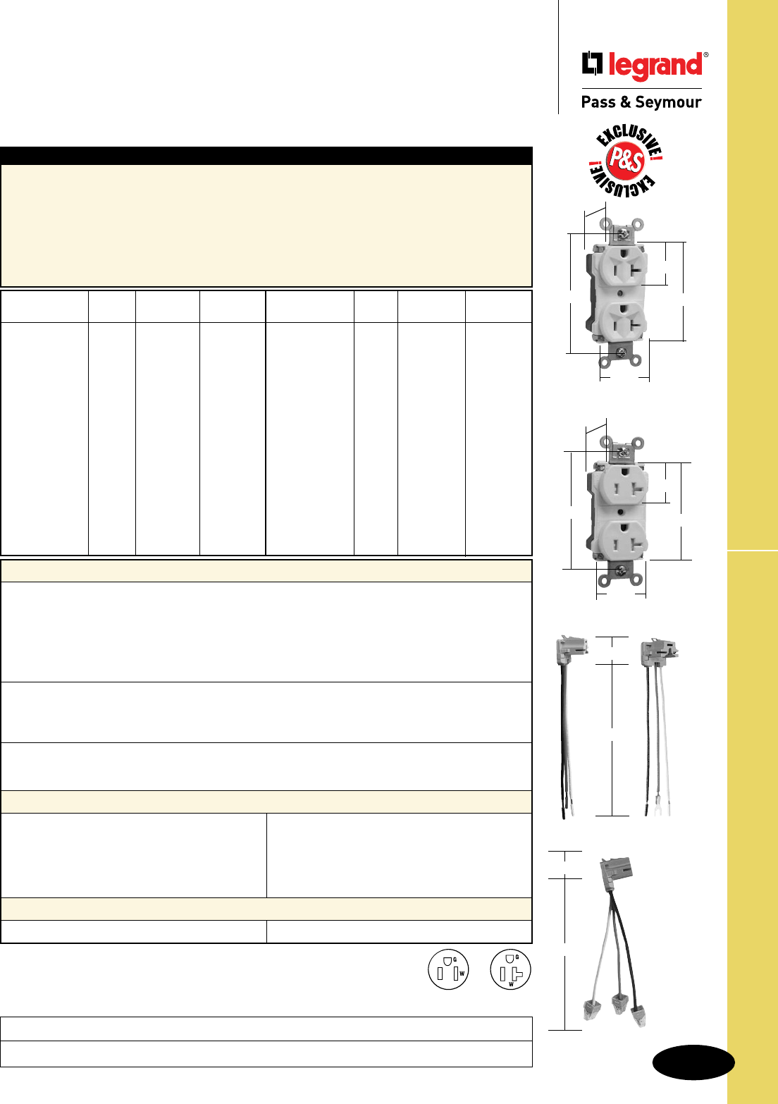
Technical Specifications
S-31
Project
Location/Type
PlugTail™ EHD Specification Grade Receptacles
Technical Specifications
PlugTail™ Extra Heavy-Duty
Specification Grade Receptacles
2 Pole, 3 Wire Grounding 15 & 20A, 125V
Typical Specications
Manufacturer’s Identification: Legrand/Pass & Seymour PT5262A & PTTR62
Description: PlugTail™ Straight Blade Duplex Receptacle & Tamper-Resistant Duplex Receptacle –
Extra Heavy-Duty
Type: 2 Pole, 3 Wire Grounding
Rating: 15A, 125V
Configuration: NEMA 5-15R
3rd Party Compliance: cULus Listed, File Number E140596, Standard UL498, Federal Specification WC596.
Conforms to NEMA WD-1 and WD-6.
*For Tamper-Resistant version.
Consult Straight Blade Section B for complete compliance listing.
Catalog NEMA
Number Color Rating Cong. No.
r
Ivory 15A 125V 5-15R
r
PT5262AW White 15A 125V 5-15R
r
PT5262A Brown 15A 125V 5-15R
r
PT5262AGRY Gray 15A 125V 5-15R
r
PT5262ABK Black 15A 125V 5-15R
r
PT5262ARED Red 15A 125V 5-15R
r
PT5262ALA Lt. Al. 15A 125V 5-15R
r
PT5262ABL Blue 15A 125V 5-15R
r
PT5362AI Ivory 20A 125V 5-20R
r
PT5362AW White 20A 125V 5-20R
r
PT5362A Brown 20A 125V 5-20R
r
PT5362AGRY Gray 20A 125V 5-20R
r
PT5362ABK Black 20A 125V 5-20R
r
PT5362ARED Red 20A 125V 5-20R
r
PT5362ALA Lt. Al. 20A 125V 5-20R
r
PT5362ABL Blue 20A 125V 5-20R
Catalog NEMA
Number Color Rating Cong. No.
r
PTTR62I Ivory 15A 125V 5-15R
r
PTTR62W White 15A 125V 5-15R
r
PTTR62 Brown 15A 125V 5-15R
r
PTTR62GRY Gray 15A 125V 5-15R
r
PTTR62BK Black 15A 125V 5-15R
r
PTTR62RED Red 15A 125V 5-15R
r
PTTR62LA Lt. Al. 15A 125V 5-15R
r
PTTR62BL Blue 15A 125V 5-15R
r
PTTR63I Ivory 20A 125V 5-20R
r
PTTR63W White 20A 125V 5-20R
r
PTTR63 Brown 20A 125V 5-20R
r
PTTR63GRY Gray 20A 125V 5-20R
r
PTTR63BK Black 20A 125V 5-20R
r
PTTR63RED Red 20A 125V 5-20R
r
PTTR63LA Lt. Al. 20A 125V 5-20R
r
PTTR63BL Blue 20A 125V 5-20R
Performance
Electrical
Dielectric Voltage Withstands 2000V minimum
Maximum Working Voltage 125V
Current Interrupting Certified for current interrupting at full-rated current
(receptacle only)
Temperature Rise Maximum 30°C temperature rise at full-rated current after 50
cycles of overload at 150% of rated current with direct current
Mechanical
PlugTail Connectors Identification #12 AWG, THHN, copper conductor, 6" leads, stripped, solid or
stranded, for use with PlugTail Receptacles only
Product Identification Ratings are a permanent part of the device
Environmental
Flammability UL94 V2
Operating Temperature Maximum continuous +60°C, minimum -40°C without impact
PlugTail Receptacle Materials
PlugTail Connector Materials
Face Nylon
Back Body Nylon
Line Contacts .036 688 Brass
Mounting Strap .050 260 Brass
Tamper Shutter* Thermoplastic
Integral Ground System .036 260 Brass
Assembly Drive Screw Zinc-Plated Steel
Auto-Ground Clip Brass
Mounting Screws Tri-Drive Steel
Housing Polycarbonate Contacts 036 688 Brass
NEMA
5-15R
NEMA
5-20R
PT5362AW
.866"
3.281"
1.625"
1.104"
2.750"
PTTR63W
.866"
3.281"
1.625"
1.104"
2.750"
1.125"
6.375"
PTRA6STR PTRA6STRG
PTRA6STRBP
1.125"
6.375"
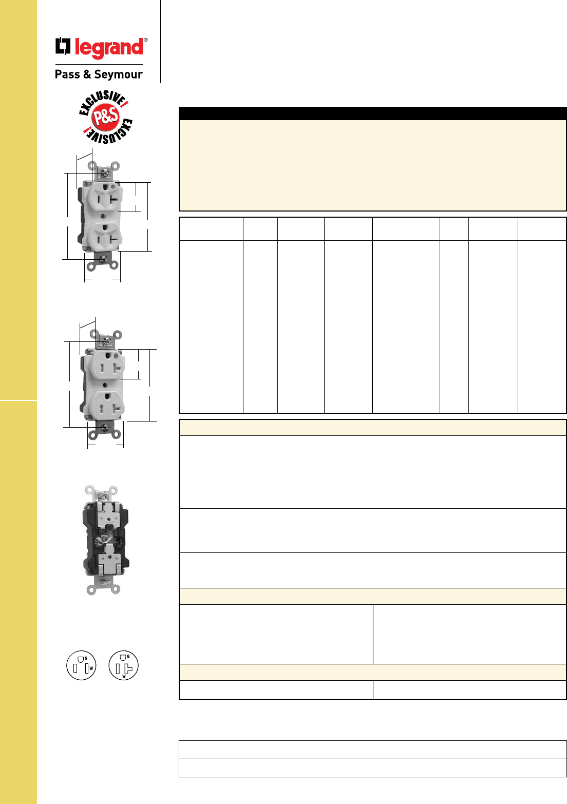
Technical Specifications
S-32
PlugTail™ EHD Hospital Grade Receptacles
Technical Specifications
PlugTail™ Extra Heavy-Duty
Hospital Grade Receptacles
2 Pole, 3 Wire Grounding 15 & 20A, 125V
Typical Specications
Manufacturer’s Identification: Legrand/Pass & Seymour PT8200 & PTTR62H
Description: PlugTail™ Straight Blade Duplex Receptacle & Tamper-Resistant Duplex Receptacle –
Extra Heavy-Duty
Type: 2 Pole, 3 Wire Grounding
Rating: 15A, 125V
Configuration: NEMA 5-15R
3rd Party Compliance: cULus Listed, File Number E140596, Standard UL498, Federal Specification
WC596, Hospital Grade. Conforms to NEMA WD-1 and WD-6.
*For Tamper-Resistant version.
Consult Straight Blade Section B and Hospital Grade Section E for complete compliance listing.
Catalog NEMA
Number Color Rating Cong. No.
r PT8200I Ivory 15A 125V 5-15R
r PT8200W White 15A 125V 5-15R
r PT8200 Brown 15A 125V 5-15R
r PT8200GRY Gray 15A 125V 5-15R
r PT8200BK Black 15A 125V 5-15R
r PT8200RED Red 15A 125V 5-15R
r PT8200LA Lt. Al. 15A 125V 5-15R
r PT8200BL Blue 15A 125V 5-15R
r PT8300I Ivory 20A 125V 5-20R
r PT8300W White 20A 125V 5-20R
r PT8300 Brown 20A 125V 5-20R
r PT8300GRY Gray 20A 125V 5-20R
r PT8300BK Black 20A 125V 5-20R
r PT8300RED Red 20A 125V 5-20R
r PT8300LA Lt. Al. 20A 125V 5-20R
r PT8300BL Blue 20A 125V 5-20R
Catalog NEMA
Number Color Rating Cong. No.
r PTTR62HI Ivory 15A 125V 5-15R
r PTTR62HW White 15A 125V 5-15R
r PTTR62H Brown 15A 125V 5-15R
r PTTR62HGRY Gray 15A 125V 5-15R
r PTTR62HBK Black 15A 125V 5-15R
r PTTR62HRED Red 15A 125V 5-15R
r PTTR62HLA Lt. Al. 15A 125V 5-15R
r PTTR62HBL Blue 15A 125V 5-15R
r PTTR63HI Ivory 20A 125V 5-20R
r PTTR63HW White 20A 125V 5-20R
r PTTR63H Brown 20A 125V 5-20R
r PTTR63HGRY Gray 20A 125V 5-20R
r PTTR63HBK Black 20A 125V 5-20R
r PTTR63HRED Red 20A 125V 5-20R
r PTTR63HLA Lt. Al. 20A 125V 5-20R
r PTTR63HBL Blue 20A 125V 5-20R
Performance
Electrical
Dielectric Voltage Withstands 2000V minimum
Maximum Working Voltage 125V
Current Interrupting Certified for current interrupting at full-rated current
(receptacle only)
Temperature Rise Maximum 30°C temperature rise at full-rated current after 50
cycles of overload at 150% of rated current with direct current
Mechanical
PlugTail Connectors Identification #12 AWG, THHN, copper conductor, 6" leads, stripped, solid or
stranded, for use with PlugTail Receptacles only
Product Identification Ratings are a permanent part of the device
Environmental
Flammability UL94 V2
Operating Temperature Maximum continuous +60°C, minimum -40°C without impact
PlugTail Receptacle Materials
PlugTail Connector Materials
Face Nylon
Back Body Nylon
Line Contacts .036 688 Brass
Mounting Strap .050 260 Brass
Tamper Shutter* Thermoplastic
Integral Ground System .036 260 Brass
Assembly Drive Screw Zinc-Plated Steel
Auto-Ground Clip Brass
Mounting Screws Tri-Drive Steel
Housing Polycarbonate Contacts .036 688 Brass
NEMA
5-15R
NEMA
5-20R
PTTR63HW
.866"
3.281"
1.625"
1.104"
2.750"
PT8300W
.866"
3.281"
1.625"
1.104"
2.750"
Project
Location/Type
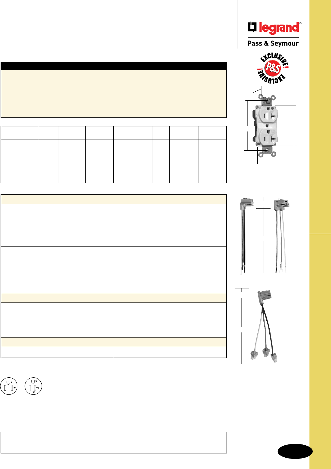
Technical Specifications
S-33
PlugTail™ EHD Hospital Grade Receptacles
Technical Specifications
PlugTail™ Extra Heavy-Duty
Hospital Grade Illuminated Receptacles
2 Pole, 3 Wire Grounding 15 & 20A, 125V
PT8300ILLA
.866"
3.281"
1.625"
1.104"
2.750"
Typical Specications
Manufacturer’s Identification: Legrand/Pass & Seymour PT8200IL
Description: PlugTail™ Straight Blade Illuminated Duplex Receptacle – Extra Heavy-Duty Hospital Grade
Type: 2 Pole, 3 Wire Grounding
Rating: 15A, 125V
Configuration: NEMA 5-15R
3rd Party Compliance: cULus Listed, File Number E140596, Standard UL498, Federal Specification
WC596, Hospital Grade. Conforms to NEMA WD-1 and WD-6.
Catalog NEMA
Number Color Rating Cong. No.
r PT8200ILI Ivory 15A 125V 5-15R
r PT8200ILW White 15A 125V 5-15R
r PT8200IL Brown 15A 125V 5-15R
r PT8200ILGRY Gray 15A 125V 5-15R
r PT8200ILBK Black 15A 125V 5-15R
r PT8200ILRED Red 15A 125V 5-15R
r PT8200ILLA Lt. Al. 15A 125V 5-15R
Catalog NEMA
Number Color Rating Cong. No.
r PT8300ILI Ivory 20A 125V 5-20R
r PT8300ILW White 20A 125V 5-20R
r PT8300IL Brown 20A 125V 5-20R
r PT8300ILGRY Gray 20A 125V 5-20R
r PT8300ILBK Black 20A 125V 5-20R
r PT8300ILRED Red 20A 125V 5-20R
r PT8300ILLA Lt. Al. 20A 125V 5-20R
Performance
Electrical
Dielectric Voltage Withstands 2000V minimum
Maximum Working Voltage 125V
Current Interrupting Certified for current interrupting at full-rated current
(receptacle only)
Temperature Rise Maximum 30°C temperature rise at full-rated current after 50
cycles of overload at 150% of rated current with direct current
Mechanical
PlugTail Connectors Identification #12 AWG, THHN, copper conductor, 6" leads, stripped, solid or
stranded, for use with PlugTail Receptacles only
Product Identification Ratings are a permanent part of the device
Environmental
Flammability UL94 V2
Operating Temperature Maximum continuous +60°C, minimum -40°C without impact
PlugTail Receptacle Materials
PlugTail Connector Materials
Face Nylon
Back Body Nylon
Line Contacts .036 688 Brass
Mounting Strap .050 260 Brass
Integral Ground System .036 260 Brass
Assembly Drive Screw Zinc-Plated Steel
Auto-Ground Clip Brass
Mounting Screws Tri-Drive Steel
LED 8-9 Years
Housing Polycarbonate Contacts .036 688 Brass
1.125"
6.375"
PTRA6STR
PTRA6STRBP
PTRA6STRG
1.125"
6.375"
NEMA
5-15R
NEMA
5-20R
Consult Straight Blade Section B and Hospital Grade Section E for complete compliance listing.
Project
Location/Type

Technical Specifications
S-34
Extra Heavy-Duty Hospital Grade Receptacles
Technical Specifications
Extra Heavy-Duty
Hospital Grade Receptacles
Back & Side Wire 2 Pole, 3 Wire Grounding 15 & 20A, 125 & 250V
Typical Specications
Manufacturer’s Identification: Legrand/Pass & Seymour 8200
Description: Straight Blade Duplex Receptacle – Extra Heavy-Duty Hospital Grade
Type: 2 Pole, 3 Wire Grounding
Rating: 15A, 125V
Configuration: NEMA 5-15R
3rd Party Compliance: UL Listed, File Number E140596, Standard UL498, Federal Specification WC596,
Hospital Grade. CSA Certified, File Number LR16063, Standard CSA-C22.2, No. 42.. Conforms to NEMA
WD-1 and WD-6.
Performance
Electrical
Dielectric Voltage Withstands 2000V minimum
Maximum Working Voltage 250V
Current Interrupting Certified for current interrupting at full-rated current
Temperature Rise Maximum 30°C temperature rise at full-rated current after 50
cycles of overload at 150% of rated current with direct current
Mechanical
Terminal Identification Terminals identified in accordance with UL498
(Brass, White, Green)
Terminal Accommodation #14 – #10 AWG copper conductor only
Product Identification Ratings are a permanent part of the device
Environmental
Flammability UL94 V2 and UL94-5 VA
Operating Temperature Maximum continuous +60°C, minimum -40°C without impact
Materials
Face Nylon
Back Body Nylon
Line Contacts .040 688 Nickel-Plated Brass
Mounting Strap .050 688 Brass
Ground Contacts Strap with Integral Ground
Pressure Plate .031 260 Nickel-Plated Brass
Terminal Screws #10 Tri-Drive Brass
(Neutral = Nickel-Plated
Steel)
Ground Screw #10 Hex Tri-Drive Brass
Assembly Drive Screw Zinc-Plated Steel
Auto-Ground Clip Brass
Mounting Screws Tri-Drive Steel
Illuminating Lamp* Neon
*For LED Illuminated Face version.
Consult Straight Blade Section B and Hospital Grade Section E for complete compliance listing.
NEMA
5-15R NEMA
5-20R
NEMA
6-20R
15 & 20 Amp
.900"
3.281"
1.625"
1.104"
2.750"
Catalog NEMA
Number Color Rating Cong. No.
r
8200I Ivory 15A 125V 5-15R
r
8200W White 15A 125V 5-15R
r
8200 Brown 15A 125V 5-15R
r
8200GRY Gray 15A 125V 5-15R
r
8200BK Black 15A 125V 5-15R
r
8200RED Red 15A 125V 5-15R
r
8200LA Lt. Al. 15A 125V 5-15R
r
8200ILI Ivory 15A 125V 5-15R
r
8200ILW White 15A 125V 5-15R
r
8200ILRED Red 15A 125V 5-15R
r
8300I Ivory 20A 125V 5-20R
r
8300W White 20A 125V 5-20R
r
8300 Brown 20A 125V 5-20R
r
8300GRY Gray 20A 125V 5-20R
Catalog NEMA
Number Color Rating Cong. No.
r
8300BK Black 20A 125V 5-20R
r
8300RED Red 20A 125V 5-20R
r
8300LA Lt. Al. 20A 125V 5-20R
r
8300ILI Ivory 20A 125V 5-20R
r
8300ILW White 20A 125V 5-20R
r
8300ILGRY Gray 20A 125V 5-20R
r
8300ILRED Red 20A 125V 5-20R
r
8300ILLA Lt. Al. 20A 125V 5-20R
r
8800I Ivory 20A 250V 6-20R
r
8800W White 20A 250V 6-20R
r
8800 Brown 20A 250V 6-20R
r
8800GRY Gray 20A 250V 6-20R
r
8800BK Black 20A 250V 6-20R
r
8800LA Lt. Al. 20A 250V 6-20R
r
8800RED Red 20A 250V 6-20R
Project
Location/Type
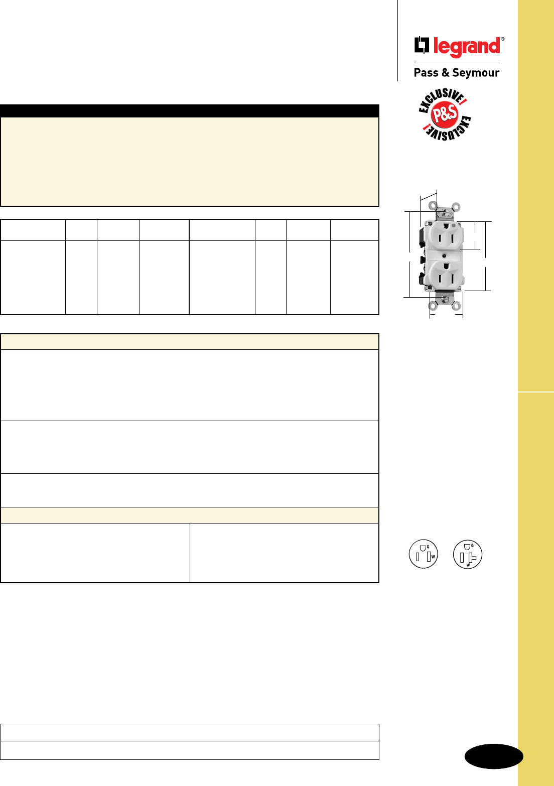
Technical Specifications
S-35
EHD Hospital Grade MRI Receptacles
Technical Specifications
Extra Heavy-Duty Hospital Grade
MRI Receptacles
Back & Side Wire 2 Pole, 3 Wire Grounding 15 & 20A, 125V
Typical Specications
Manufacturer’s Identification: Legrand/Pass & Seymour 8200MRI
Description: Straight Blade Duplex Receptacle – Extra Heavy-Duty Hospital Grade MRI
Type: 2 Pole, 3 Wire Grounding
Rating: 15A, 125V
Configuration: NEMA 5-15R
3rd Party Compliance: UL Listed, File Number E140596, Standard UL498, Federal Specification
WC596, Hospital Grade. CSA Certified, File Number LR16063, Standard CSA-C22.2 No. 42. Conforms to
NEMA WD-1 and WD-6.
Catalog NEMA
Number Color Rating Cong. No.
r
8200IMRI Ivory 15A 125V 5-15R
r
8200WMRI White 15A 125V 5-15R
r
8200MRI Brown 15A 125V 5-15R
r
8200GRYMRI Gray 15A 125V 5-15R
r
8200BKMRI Black 15A 125V 5-15R
r
8200REDMRI Red 15A 125V 5-15R
r
8200LAMRI Lt. Al. 15A 125V 5-15R
Catalog NEMA
Number Color Rating Cong. No.
r
8300IMRI Ivory 20A 125V 5-20R
r
8300WMRI White 20A 125V 5-20R
r
8300MRI Brown 20A 125V 5-20R
r
8300GRYMRI Gray 20A 125V 5-20R
r
8300BKMRI Black 20A 125V 5-20R
r
8300REDMRI Red 20A 125V 5-20R
r
8300LAMRI Lt. Al. 20A 125V 5-20R
Consult Straight Blade Section B and Hospital Grade Section E for complete compliance listing.
Performance
Electrical
Dielectric Voltage Withstands 2000V minimum
Maximum Working Voltage 250V
Current Interrupting Certified for current interrupting at full-rated current
Temperature Rise Maximum 30°C temperature rise at full-rated current
after 50 cycles of overload at 150% of rated current
with direct current
Mechanical
Terminal Identification Terminal Identification in accordance with UL498
(Brass, White, Green)
Terminal Accommodation #14 – #10 AWG copper conductor only
Product Identification Ratings are a permanent part of the device
Environmental
Flammability UL94 V2
Operating Temperature Maximum continuous +60°C, minimum -40°C without impact
Materials
Face Nylon
Back Body Nylon
Line Contacts .036 688 Brass
Mounting Strap .050 688 Brass
Ground Contacts Strap with Integral Ground
Pressure Plate .031 260 Brass
Terminal Screws #10 Tri-Drive Brass
Ground Screw #10 Hex Tri-Drive Brass
Auto-Ground Clip Brass
Mounting Screws Slotted Brass NEMA
5-15R
NEMA
5-20R
15 & 20 Amp
.900"
3.281"
1.625"
1.104"
2.750"
Project
Location/Type
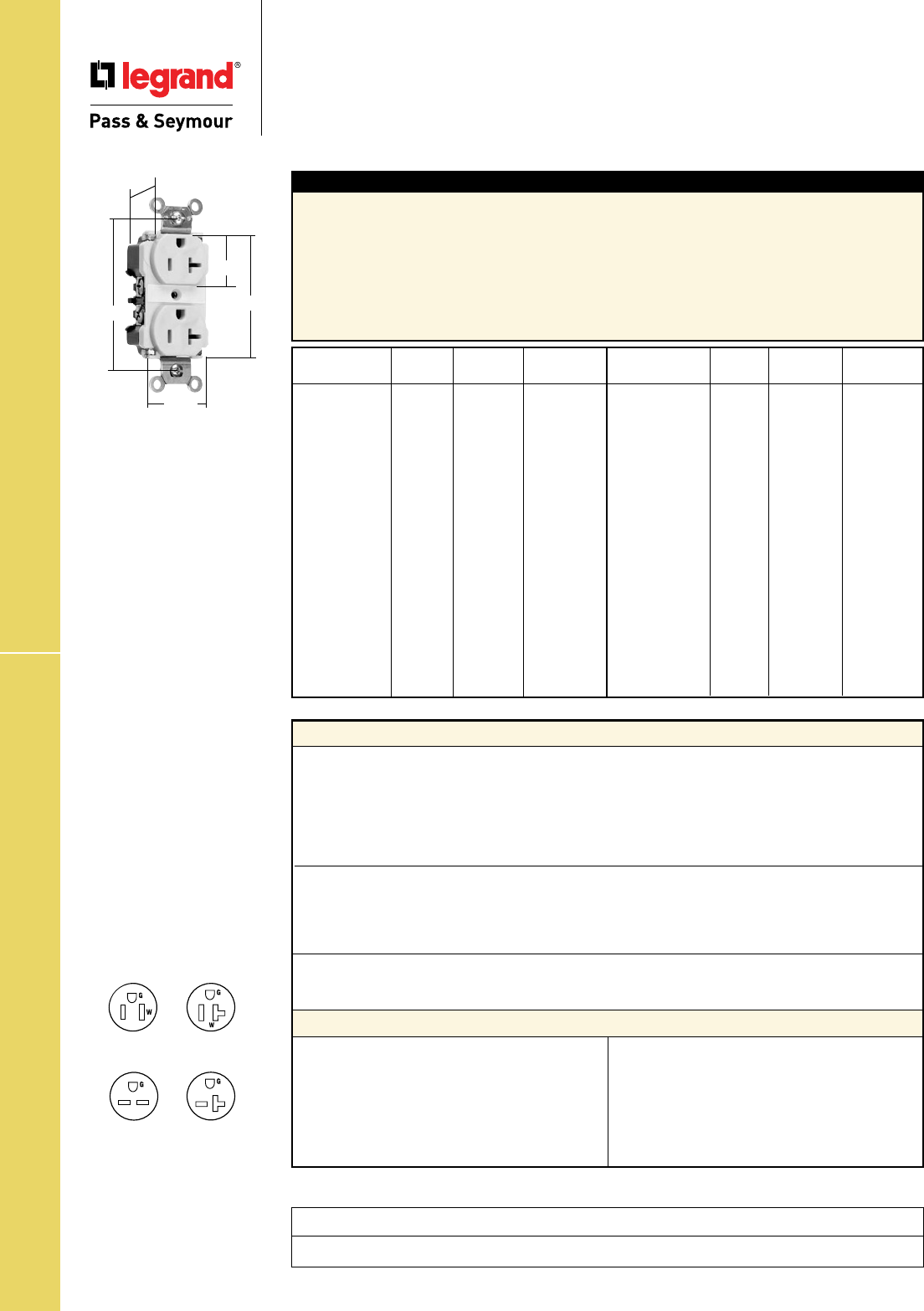
Technical Specifications
S-36
Industrial EHD Specification Grade Receptacles
Technical Specifications
Industrial Extra Heavy-Duty
Specification Grade Receptacles
Back & Side Wire 2 Pole, 3 Wire Grounding 15 & 20A, 125 & 250V
Project
Location/Type
15 & 20 Amp
.900"
3.281"
1.625"
1.104"
2.750"
Typical Specications
Manufacturer’s Identification: Legrand/Pass & Seymour 5262A
Description: Straight Blade Duplex Receptacle – Industrial Extra Heavy-Duty Specification Grade
Type: 2 Pole, 3 Wire Grounding
Rating: 15A, 125V
Configuration: NEMA 5-15R
3rd Party Compliance: UL Listed, File Number E140596, Standard UL498, Federal Specification
WC596. CSA Certified, File Number LR16063, Standard CSA-C22.2 No. 42. Conforms to NEMA WD-1
and WD-6.
*Corrosion-Resistant versions have nickel-plated straps and contacts.
Consult Straight Blade Section B for complete compliance listing.
Performance
Electrical
Dielectric Voltage Withstands 2000V minimum
Maximum Working Voltage 250V
Current Interrupting Certified for current interrupting at full-rated current
Temperature Rise Maximum 30°C temperature rise at full-rated current
after 50 cycles of overload at 150% of rated current
with direct current
Mechanical
Terminal Identification Terminal Identification in accordance with UL498
(Brass, White, Green)
Terminal Accommodation #14 – #10 AWG copper conductor only
Product Identification Ratings are a permanent part of the device
Environmental
Flammability UL94 V2
Operating Temperature Maximum continuous +60°C, minimum -40°C without impact
Materials
Face Nylon
Back Body Nylon
Line Contacts* .036 688 Brass
Mounting Strap* .050 688 Brass
Ground Contacts Strap with Integral Ground
Pressure Plate .031 260 Brass
Terminal Screws #10 Tri-Drive Brass
(Neutral = Nickel-Plated
Steel)
Ground Screw #10 Hex Tri-Drive Brass
Assembly Drive Screw Zinc-Plated Steel
Auto-Ground Clip Brass
Mounting Screws Tri-Drive Steel
NEMA
6-15R
NEMA
6-20R
NEMA
5-15R
NEMA
5-20R
Catalog NEMA
Number Color Rating Cong. No.
r 5262AI Ivory 15A 125V 5-15R
r 5262AW White 15A 125V 5-15R
r 5262A Brown 15A 125V 5-15R
r 5262AGRY Gray 15A 125V 5-15R
r 5262ABK Black 15A 125V 5-15R
r 5262ARED Red 15A 125V 5-15R
r 5262ALA Lt. Al. 15A 125V 5-15R
r CR6200* Yellow 15A 125V 5-15R
r CR6200GRY* Gray 15A 125V 5-15R
r 5662AI Ivory 15A 250V 6-15R
r 5662AW White 15A 250V 6-15R
r 5662A Brown 15A 250V 6-15R
r 5662AGRY Gray 15A 250V 6-15R
r 5662ABK Black 15A 250V 6-15R
r 5662ARED Red 15A 250V 6-15R
Catalog NEMA
Number Color Rating Cong. No.
r 5362AI Ivory 20A 125V 5-20R
r 5362AW White 20A 125V 5-20R
r 5362A Brown 20A 125V 5-20R
r 5362AGRY Gray 20A 125V 5-20R
r 5362ABK Black 20A 125V 5-20R
r 5362ARED Red 20A 125V 5-20R
r 5362ALA Lt. Al. 20A 125V 5-20R
r 5362ABL Blue 20A 125V 5-20R
r CR6300* Yellow 20A 125V 5-20R
r CR6300BR* Brown 20A 125V 5-20R
r 5862AI Ivory 20A 250V 6-20R
r 5862AW White 20A 250V 6-20R
r 5862A Brown 20A 250V 6-20R
r 5862AGRY Gray 20A 250V 6-20R
r 5862ABK Black 20A 250V 6-20R
r 5862ARED Red 20A 250V 6-20R
r 5862ALA Lt. Al. 20A 250V 6-20R
*Corrosion-Resistant

Technical Specifications
S-37
Heavy-Duty Specification Grade Receptacles
Technical Specifications
Heavy-Duty Specification Grade Receptacles
Back & Side Wire 2 Pole, 3 Wire Grounding 15 & 20A, 125 & 250V
Project
Location/Type
Typical Specications
Manufacturer’s Identification: Legrand/Pass & Seymour PS5262
Description: Straight Blade Duplex Receptacle – Heavy-Duty Specification Grade
Type: 2 Pole, 3 Wire Grounding
Rating: 15A, 125V
3rd Party Compliance: UL Listed, File Number E140596, Standard UL498, Federal Specification
WC596. CSA Certified, File Number LR16063, Standard CSA-C22.2 No. 42. Conforms to NEMA WD-1
and WD-6.
Catalog NEMA
Number Color Rating Cong. No.
r
PS5262I Ivory 15A 125V 5-15R
r
PS5262W White 15A 125V 5-15R
r
PS5262 Brown 15A 125V 5-15R
r
PS5262GRY Gray 15A 125V 5-15R
r
PS5262BK Black 15A 125V 5-15R
r
PS5262RED Red 15A 125V 5-15R
r
PS5262LA Lt. Almond 15A 125V 5-15R
r
PS5262BL Blue 15A 125V 5-15R
r
5662I Ivory 15A 250V 6-15R
r
5662W White 15A 250V 6-15R
r
5662 Brown 15A 250V 6-15R
Catalog NEMA
Number Color Rating Cong. No.
r
PS5362I Ivory 20A 125V 5-20R
r
PS5362W White 20A 125V 5-20R
r
PS5362 Brown 20A 125V 5-20R
r
PS5362GRY Gray 20A 125V 5-20R
r
PS5362BK Black 20A 125V 5-20R
r
PS5362RED Red 20A 125V 5-20R
r
PS5362LA Lt. Almond 20A 125V 5-20R
r
PS5362BL Blue 20A 125V 5-20R
r
5862I Ivory 20A 250V 6-20R
r
5862W White 20A 250V 6-20R
r
5862 Brown 20A 250V 6-20R
r
5862GRY Gray 20A 250V 6-20R
r
5862BK Black 20A 250V 6-20R
r
5862RED Red 20A 250V 6-20R
15 & 20 Amp
1.104"
.780"
2.635"
3.281"
1.322"
Consult Straight Blade Section B for complete compliance listing.
Performance
Electrical
Dielectric Voltage Withstands 2000V minimum
Maximum Working Voltage 250V
Current Interrupting Certified for current interrupting at full-rated current
Temperature Rise Max 30°C temperature rise at full-rated current after 50 cycles
of overload at 150% of rated current with direct current
Mechanical
Terminal Identification Terminal Identification in accordance with UL498
(Brass, White, Green)
Terminal Accommodation #14 – #10 AWG copper conductor only
Product Identification Ratings are a permanent part of the device
Environmental
Flammability UL94 V2
Operating Temperature Maximum continuous +60oC, minimum -40o (without impact)
Materials
Face Nylon
Back Body PVC
Line Contacts .032 688 Brass
Mounting Strap .043 688 Brass
Ground Contacts .040 688 Brass
Pressure Plate .080 Steel
Terminal Screws #8 Tri-Drive Brass
(Neutral = Nickel-Plated
Steel)
Ground Screw #8 Hex Tri-Drive Brass
Assembly Drive Screw Zinc-Plated Steel
Auto-Ground Clip Stainless Steel
Mounting Screws Tri-Drive Steel NEMA
6-15R
NEMA
6-20R
NEMA
5-15R
NEMA
5-20R
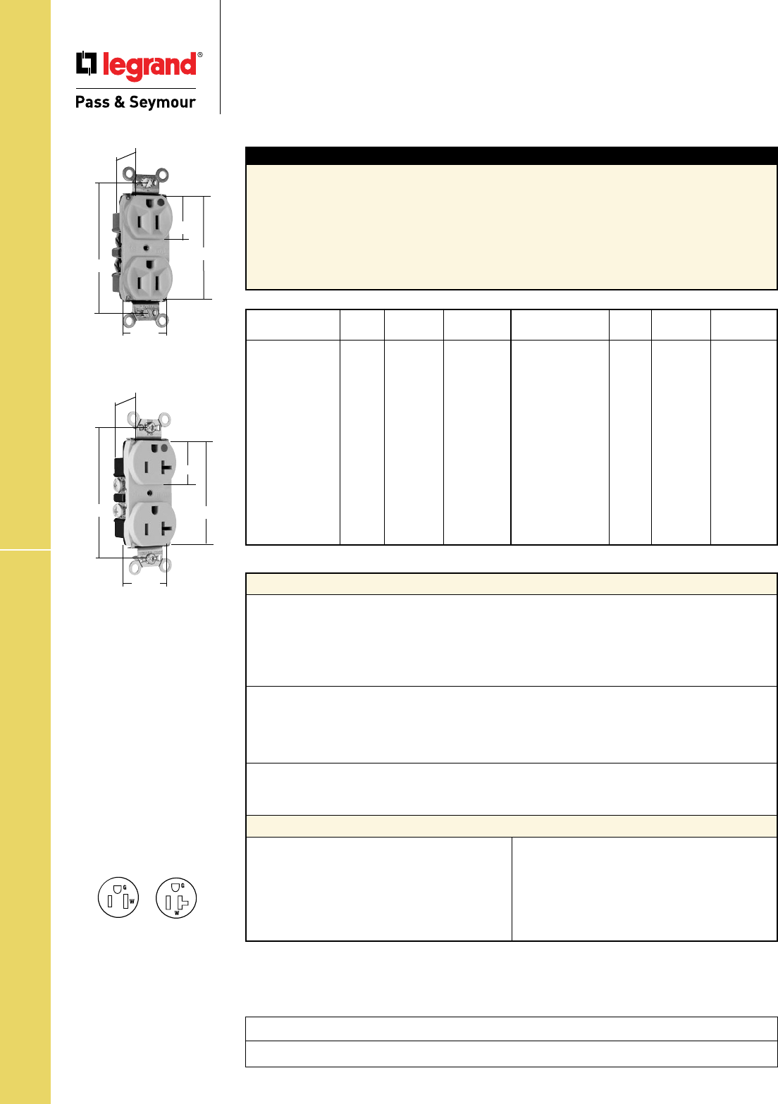
Technical Specifications
S-38
Heavy-Duty Hospital Grade Receptacles
Technical Specifications
Heavy-Duty Hospital Grade Receptacles
Back & Side Wire 2 Pole, 3 Wire Grounding 15 & 20A, 125V
Project
Location/Type
Typical Specications
Manufacturer’s Identification: Legrand/Pass & Seymour PS8200H
Description: Straight Blade Duplex Receptacle – Heavy-Duty Hospital Grade
Type: 2 Pole, 3 Wire Grounding
Rating: 15A, 125V
Configuration: NEMA 5-15R
3rd Party Compliance: UL Listed, File Number E140596, Standard UL498. Federal Specification
WC596, Hospital Grade. CSA Certified, File Number LR16063, Standard CSA C22.2 No. 42. Conforms
to NEMA WD-1 and WD-6.
Catalog NEMA
Number Color Rating Cong. No.
r PS8200HI Ivory 15A 125V 5-15R
r PS8200HW White 15A 125V 5-15R
r PS8200H Brown 15A 125V 5-15R
r PS8200HGRY Gray 15A 125V 5-15R
r PS8200HRED Red 15A 125V 5-15R
r PS8200HLA Lt. Al. 15A 125V 5-15R
r PS8300HI Ivory 20A 125V 5-20R
r PS8300HW White 20A 125V 5-20R
r PS8300H Brown 20A 125V 5-20R
r PS8300HGRY Gray 20A 125V 5-20R
r PS8300HRED Red 20A 125V 5-20R
r PS8300HLA Lt. Al. 20A 125V 5-20R
Catalog NEMA
Number Color Rating Cong. No.
r PS8200HSI Ivory 15A 125V 5-15R
r PS8200HSW White 15A 125V 5-15R
r PS8200HS Brown 15A 125V 5-15R
r PS8200HSGRY Gray 15A 125V 5-15R
r PS8200HSBK Black 15A 125V 5-15R
r PS8200HSRED Red 15A 125V 5-15R
r PS8200HSLA Lt. Al. 15A 125V 5-15R
r PS8300HSI Ivory 20A 125V 5-20R
r PS8300HSW White 20A 125V 5-20R
r PS8300HS Brown 20A 125V 5-20R
r PS8300HSGRY Gray 20A 125V 5-20R
r PS8300HSBK Black 20A 125V 5-20R
r PS8300HSRED Red 20A 125V 5-20R
r PS8300HSLA Lt. Al. 20A 125V 5-20R
PS8200HI
PS8300HSLA
.780"
3.281"
1.322"
1.104"
2.635"
.780"
3.281"
1.322"
1.104"
2.635"
Performance
Electrical
Dielectric Voltage Withstands 2000V minimum
Maximum Working Voltage 250V
Current Interrupting Certified for current interrupting at full-rated current
Temperature Rise Maximum 30°C temperature rise at full-rated current after 50
cycles of overload at 150% of rated current with direct current
Mechanical
Terminal Identification Terminal Identification in accordance with UL498
(Brass, White, Green)
Terminal Accommodation #14 AWG – #10 AWG copper conductor only
Product Identification Ratings are a permanent part of the device
Environmental
Flammability UL94 V2
Operating Temperature Maximum continuous +60°C, minimum -40°C without impact
Materials
Face Nylon
Back Body PVC
Line Contacts .032 688 Brass
Mounting Strap .043 260 Brass
Ground Contacts .040 688 Brass
Pressure Plate .080 Steel
Terminal Screws #8 Tri-Drive Brass
(Neutral = Nickel-Plated
Steel)
Ground Screw #8 Hex Tri-Drive Brass
Assembly Drive Screw Zinc-Plated Steel
Auto-Ground Clip Stainless Steel
Mounting Screws Tri-Drive Steel
Consult Straight Blade Section B and Hospital Grade Section E for complete compliance listing.
NEMA
5-15R
NEMA
5-20R

Technical Specifications
S-39
Heavy-Duty Hospital Grade Receptacles
Technical Specifications
Heavy-Duty Hospital Grade
Compact Design Receptacles
2 Pole, 3 Wire Grounding 15 & 20A, 125V; 20A, 250V
Typical Specications
Manufacturer’s Identification: Legrand/Pass & Seymour 8200H
Description: Straight Blade Duplex Receptacle – Heavy-Duty Hospital Grade
Type: 2 Pole, 3 Wire Grounding
Rating: 15A, 125V
Configuration: NEMA 5-15R
3rd Party Compliance: UL Listed, File Number E140596, Standard UL498. Federal Specification
WC596, Hospital Grade. CSA Certified, File Number LR16063, Standard CSA C22.2 No. 42. Conforms
to NEMA WD-1 and WD-6.
Catalog NEMA
Number Color Rating Cong. No.
r 8200HI Ivory 15A 125V 5-15R
r 8200HW White 15A 125V 5-15R
r 8200H Brown 15A 125V 5-15R
r 8200HGRY Gray 15A 125V 5-15R
r 8200HRED Red 15A 125V 5-15R
r 8200HLA Lt. Al. 15A 125V 5-15R
r 8300HI Ivory 20A 125V 5-20R
r 8300HW White 20A 125V 5-20R
r 8300H Brown 20A 125V 5-20R
r 8300HGRY Gray 20A 125V 5-20R
r 8300HBK Black 20A 125V 5-20R
r 8300HRED Red 20A 125V 5-20R
r 8300HLA Lt. Al. 20A 125V 5-20R
r 8300HBL Blue 20A 125V 5-20R
Catalog NEMA
Number Color Rating Cong. No.
r IG8200I Ivory 15A 125V 5-15R
r IG8200 Orange 15A 125V 5-15R
r IG8200RED Red 15A 125V 5-15R
r IG8300I Ivory 20A 125V 5-20R
r IG8300W White 20A 125V 5-20R
r IG8300RED Red 20A 125V 5-20R
r IG8300 Orange 20A 125V 5-20R
r IG8300LA Lt. Al. 20A 125V 5-20R
r IG8800 Orange 20A 250V 6-20R
r IG8800LA Lt. Al. 20A 250V 6-20R
Performance
Electrical
Dielectric Voltage Withstands 2000V minimum
Maximum Working Voltage 250V
Current Interrupting Certified for current interrupting at full-rated current
Temperature Rise Maximum 30°C temperature rise at full-rated current after 50
cycles of overload at 150% of rated current with direct current
Mechanical
Terminal Identification Terminal Identification in accordance with UL498
(Brass, White, Green)
Terminal Accommodation #14 AWG – #10 AWG copper conductor only
Product Identification Ratings are a permanent part of the device
Environmental
Flammability UL94 V2
Operating Temperature Maximum continuous +60°C, minimum -40°C without impact
Materials
Face Nylon
Back Body PVC
Line Contacts .032 688 Brass
Mounting Strap .043 260 Brass
Ground Contacts .040 688 Brass
Pressure Plate .080 Steel
Terminal Screws #8 Tri-Drive Brass
(Neutral = Nickel-Plated
Steel)
Ground Screw #8 Hex Tri-Drive Brass
Assembly Drive Screw Zinc-Plated Steel
Auto-Ground Clip Stainless Steel
Mounting Screws Tri-Drive Steel
Consult Straight Blade Section B and Hospital Grade Section E for complete compliance listing.
NEMA
5-15R
NEMA
5-20R
NEMA
6-20R
IG8300
1.322"
1.104" 2.635"
3.281"
.922"
8200HI
.780"
3.281"
1.322"
1.104"
2.635"
Project
Location/Type

Technical Specifications
S-40
Performance
Electrical
Dielectric Voltage Withstands 2000V minimum
Maximum Working Voltage 125V
Current Interrupting Certified for current interrupting at full-rated current
(receptacle only)
Temperature Rise Maximum 30°C temperature rise at full-rated current after 50
cycles of overload at 150% of rated current with direct current
Mechanical
PlugTail Connector Identification #12 AWG, THHN, copper conductor, 6" leads, stripped, solid or
stranded, for use with PlugTail Receptacles only
Product Identification Ratings are a permanent part of the device
Environmental
Flammability UL94 V2
Operating Temperature Maximum continuous +60°C, minimum -40°C without impact
PlugTail Receptacle Materials
PlugTail Connector Materials
Face Nylon
Back Body PVC
Line Contacts .036 688 Brass
Mounting Strap .042 Zinc-Plated Steel
Integral Ground System .036 260 Brass
Assembly Drive Screw Zinc-Plated Steel
Auto-Ground Clip Steel
Mounting Screws Tri-Drive Steel
Housing Polycarbonate Contacts .030 Brass
Catalog NEMA
Number Color Rating Cong. No.
r
PT5262I Ivory 15A 125V 5-15R
r
PT5262W White 15A 125V 5-15R
r
PT5262 Brown 15A 125V 5-15R
r
PT5262GRY Gray 15A 125V 5-15R
r
PT5262BK Black 15A 125V 5-15R
r
PT5262RED Red 15A 125V 5-15R
r
PT5262LA Lt. Al. 15A 125V 5-15R
r
PT5262BL Blue 15A 125V 5-15R
r
PT5362I Ivory 20A 125V 5-20R
r
PT5362W White 20A 125V 5-20R
r
PT5362 Brown 20A 125V 5-20R
r
PT5362GRY Gray 20A 125V 5-20R
r
PT5362BK Black 20A 125V 5-20R
r
PT5362RED Red 20A 125V 5-20R
r
PT5362LA Lt. Al. 20A 125V 5-20R
r
PT5362BL Blue 20A 125V 5-20R
Catalog NEMA
Number Color Rating Cong. No.
r
PTIG5262I Ivory 15A 125V 5-15R
r
PTIG5262W White 15A 125V 5-15R
r
PTIG5262 Orange 15A 125V 5-15R
r
PTIG5262GRY Gray 15A 125V 5-15R
r
PTIG5262RED Red 15A 125V 5-15R
r
PTIG5262LA Lt. Al. 15A 125V 5-15R
r
PTIG5362I Ivory 20A 125V 5-20R
r
PTIG5362W White 20A 125V 5-20R
r
PTIG5362 Orange 20A 125V 5-20R
r
PTIG5362GRY Gray 20A 125V 5-20R
r
PTIG5362RED Red 20A 125V 5-20R
r
PTIG5362LA Lt. Al. 20A 125V 5-20R
r
PTIG8200I Ivory 15A 125V 5-15R
r
PTIG8200 Orange 15A 125V 5-15R
r
PTIG8200RED Red 15A 125V 5-15R
r
PTIG8300I Ivory 15A 125V 5-15R
r
PTIG8300 Orange 15A 125V 5-15R
r
PTIG8300RED Red 15A 125V 5-15R
r
PTIG8300LA Lt. Al. 15A 125V 5-15R
PlugTail™ Spec Grade & HG Receptacles
Technical Specifications
PlugTail™ Specification &
Hospital Grade Receptacles
2 Pole, 3 Wire Grounding 15 & 20A, 125V
NEMA
5-15R
NEMA
5-20R
PTIG5362LA
PT5362LA
Typical Specications
Manufacturer’s Identification: Legrand/Pass & Seymour PT5262
Description: Plugtail™ Straight Blade Duplex Receptacle – Specification Grade
Type: 2 Pole, 3 Wire Grounding
Rating: 15A, 125V
3rd Party Compliance: cULus Listed, File Number E140596, Standard UL498. Federal Specification
WC596. Conforms to NEMA WD-1 and WD-6.
Consult Straight Blade Section B and Hospital Grade Section E for complete compliance listing.
3.281"
.625"
1.5"
2.750"
1.104"
3.281"
.625"
1.5"
1.104"
2.750"
Project
Location/Type
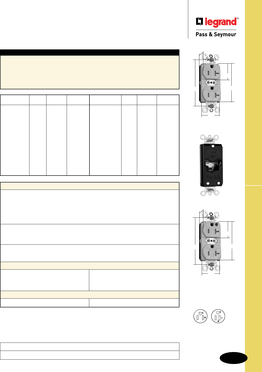
Technical Specifications
S-41
PlugTail™ TR Spec & HG Grade Receptacles
Technical Specifications
PlugTail™ Tamper-Resistant Specification
& Hospital Grade Receptacles
2 Pole, 3 Wire Grounding 15 & 20A, 125V
Project
Location/Type
Performance
Electrical
Dielectric Voltage Withstands 2000V minimum
Maximum Working Voltage 125V
Current Interrupting Certified for current interrupting at full-rated current
(receptacle only)
Temperature Rise Maximum 30°C temperature rise at full-rated current after 50
cycles of overload at 150% of rated current with direct current
Mechanical
PlugTail Connector Identification #12 AWG, THHN, copper conductor, 6" leads, stripped, solid or
stranded, for use with PlugTail Receptacles only
Product Identification Ratings are a permanent part of the device
Environmental
Flammability UL94 V2
Operating Temperature Maximum continuous +60°C, minimum -40°C without impact
PlugTail Receptacle Materials
PlugTail Connector Materials
Face Nylon
Back Body PVC
Line Contacts .036 688 Brass
Mounting Strap .042 Zinc-Plated Steel
Integral Ground System .036 260 Brass
Assembly Drive Screw Zinc-Plated Steel
Auto-Ground Clip Steel
Mounting Screws Tri-Drive Steel
Housing Polycarbonate Contacts .030 Brass
Catalog NEMA
Number Color Rating Cong. No.
r
PTTR5262I Ivory 15A 125V 5-15R
r
PTTR5262W White 15A 125V 5-15R
r
PTTR5262 Brown 15A 125V 5-15R
r
PTTR5262BK Black 15A 125V 5-15R
r
PTTR5262LA Lt. Al. 15A 125V 5-15R
r
PTTR5362I Ivory 20A 125V 5-20R
r
PTTR5362W White 20A 125V 5-20R
r
PTTR5362 Brown 20A 125V 5-20R
r
PTTR5362BK Black 20A 125V 5-20R
r
PTTR5362LA Lt. Al. 20A 125V 5-20R
Catalog NEMA
Number Color Rating Cong. No.
r
PTTR8200I Ivory 15A 125V 5-15R
r
PTTR8200W White 15A 125V 5-15R
r
PTTR8200 Brown 15A 125V 5-15R
r
PTTR8200GRY Gray 15A 125V 5-15R
r
PTTR8200BK Black 15A 125V 5-15R
r
PTTR8200RED Red 15A 125V 5-15R
r
PTTR8200LA Lt. Al. 15A 125V 5-15R
r
PTTR8300I Ivory 20A 125V 5-20R
r
PTTR8300W White 20A 125V 5-20R
r
PTTR8300 Brown 20A 125V 5-20R
r
PTTR8300GRY Gray 20A 125V 5-20R
r
PTTR8300BK Black 20A 125V 5-20R
r
PTTR8300RED Red 20A 125V 5-20R
r
PTTR8300LA Lt. Al. 20A 125V 5-20R
Typical Specications
Manufacturer’s Identification: Legrand/Pass & Seymour PTTR5262
Description: Plugtail™ Straight Blade Duplex Receptacle – Specification Grade
Type: 2 Pole, 3 Wire Grounding
Rating: 15A, 125V
3rd Party Compliance: cULus Listed, File Number E140596, Standard UL498. Federal Specification
WC596. Conforms to NEMA WD-1 and WD-6.
Consult Straight Blade Section B and Hospital Grade Section E for complete compliance listing.
PTTR5362W
2.750"
3.281"
.625"
1.5"
1.104"
PTTR8300W
NEMA
5-15R
NEMA
5-20R
2.750"
3.281"
.625"
1.5"
1.104"
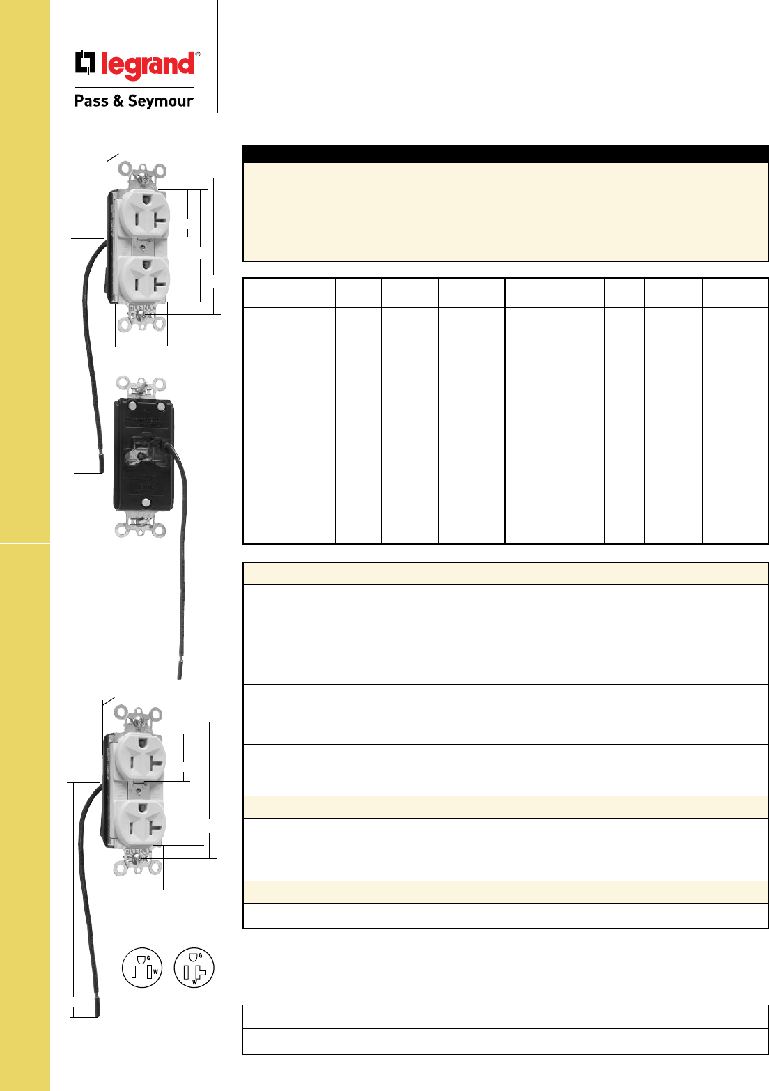
Technical Specifications
S-42
Technical Specifications
PlugTail™ Specification Grade Receptacles
Split Circuit
2 Pole, 3 Wire Grounding 15 & 20A, 125V
PlugTail™ Spec Grade Split Circuit Receptacles
Performance
Electrical
Dielectric Voltage Withstands 2000V minimum
Maximum Working Voltage 125V
Current Interrupting Certified for current interrupting at full-rated current
(receptacle only)
Temperature Rise Maximum 30°C temperature rise at full-rated current after 50
cycles of overload at 150% of rated current with direct current
Mechanical
PlugTail Connector Identification #12 AWG, THHN, copper conductor, 6" leads, stripped, solid or
stranded, for use with PlugTail Receptacles only
Product Identification Ratings are a permanent part of the device
Environmental
Flammability UL94 V2
Operating Temperature Maximum continuous +60°C, minimum -40°C without impact
PlugTail Receptacle Materials
PlugTail Connector Materials
Face Nylon
Back Body PVC
Line Contacts .036 688 Brass
Mounting Strap .042 Zinc-Plated Steel
Integral Ground System .036 260 Brass
Assembly Drive Screw Zinc-Plated Steel
Auto-Ground Clip Steel
Mounting Screws Tri-Drive Steel
Housing Polycarbonate Contacts .030 Brass
Catalog NEMA
Number Color Rating Cong. No.
r
PT5262SCI Ivory 15A 125V 5-15R
r
PT5262SCW White 15A 125V 5-15R
r
PT5262SC Brown 15A 125V 5-15R
r
PT5262SCGRY Gray 15A 125V 5-15R
r
PT5262SCBK Black 15A 125V 5-15R
r
PT5262SCRED Red 15A 125V 5-15R
r
PT5262SCLA Lt. Al. 15A 125V 5-15R
r
PT5262SCBL Blue 15A 125V 5-15R
r
PT5362SCI Ivory 20A 125V 5-20R
r
PT5362SCW White 20A 125V 5-20R
r
PT5362SC Brown 20A 125V 5-20R
r
PT5362SCGRY Gray 20A 125V 5-20R
r
PT5362SCBK Black 20A 125V 5-20R
r
PT5362SCRED Red 20A 125V 5-20R
r
PT5362SCLA Lt. Al. 20A 125V 5-20R
r
PT5362SCBL Blue 20A 125V 5-20R
Catalog NEMA
Number Color Rating Cong. No.
r
PTTR5262SCI Ivory 15A 125V 5-15R
r
PTTR5262SCW White 15A 125V 5-15R
r
PTTR5262SC Brown 15A 125V 5-15R
r
PTTR5262SCBK Black 15A 125V 5-15R
r
PTTR5262SCLA Lt. Al. 15A 125V 5-15R
r
PTTR5362SCI Ivory 20A 125V 5-20R
r
PTTR5362SCW White 20A 125V 5-20R
r
PTTR5362SC Brown 20A 125V 5-20R
r
PTTR5362SCBK Black 20A 125V 5-20R
r
PTTR5362SCLA Lt. Al. 20A 125V 5-20R
Typical Specications
Manufacturer’s Identification: Legrand/Pass & Seymour PT5262SC
Description: Plugtail™ Straight Blade Duplex Receptacle – Specification Grade
Type: 2 Pole, 3 Wire Grounding
Rating: 15A, 125V
3rd Party Compliance: cULus Listed, File Number E140596, Standard UL498. Federal Specification
WC596. Conforms to NEMA WD-1 and WD-6.
Consult Straight Blade Section B for complete compliance listing.
Project
Location/Type
PT5362SCI
2.750"
3.281"
.625"
1.5"
1.104"
6.0"
PTTR5362SCI
2.750"
3.281"
.625"
1.5"
1.104"
6.0" NEMA
5-15R
NEMA
5-20R

Technical Specifications
S-43
Hard Use Specification Grade Receptacles
Technical Specifications
Hard Use Specification Grade Receptacles
Back & Side Wire 2 Pole, 3 Wire Grounding 15 & 20A, 125 & 250V
Project
Location/Type
Typical Specications
Manufacturer’s Identification: Legrand/Pass & Seymour 5262
Description: Straight Blade Duplex Receptacle – Hard Use Specification Grade
Type: 2 Pole, 3 Wire Grounding
Rating: 15A, 125V
3rd Party Compliance: UL Listed, File Number E140596, Standard UL498, Federal Specification
WC596. CSA Certified, File Number LR16063, Standard CSA-C22.2 No. 42.27. Conforms to NEMA
WD-1 and WD-6.
Performance
Electrical
Dielectric Voltage Withstands 2000V minimum
Maximum Working Voltage 250V
Current Interrupting Certified for current interrupting at full-rated current
Temperature Rise Max 30°C temperature rise at full-rated current after 50
cycles of overload at 150% of rated current with direct current
Mechanical
Terminal Identification Terminal Identification in accordance with UL498
(Brass, White, Green)
Terminal Accommodation #14 – #10 AWG copper conductor only
Product Identification Ratings are a permanent part of the device
Environmental
Flammability UL94 V2
Operating Temperature Maximum continuous +60°C, minimum -40°C (without impact)
Materials
Face Nylon
Back Body PVC
Contacts .032" (.8) Brass
Clamping Plate .080" Steel
Mounting Strap .042" Steel
Terminal Screws Tri-Drive Brass
Hex Head
Grounding Screw Tri-Drive Zinc-Plated Steel
Assembly Rivets Steel
Auto-Ground Clip Stainless Steel
Mounting Screws Tri-Drive Steel
15 & 20 Amp
1.104"
.780"
2.635"
3.281"
1.322"
Consult Straight Blade Section B for complete compliance listing.
Catalog NEMA
Number Color Rating Cong. No.
r
5262I Ivory 15A 125V 5-15R
r
5262W White 15A 125V 5-15R
r
5262 Brown 15A 125V 5-15R
r
5262GRY Gray 15A 125V 5-15R
r
5262BK Black 15A 125V 5-15R
r
5262RED Red 15A 125V 5-15R
r
5262LA Lt. Almond 15A 125V 5-15R
r
5262BL Blue 15A 125V 5-15R
r
5362I Ivory 20A 125V 5-20R
r
5362W White 20A 125V 5-20R
r
5362 Brown 20A 125V 5-20R
r
5362GRY Gray 20A 125V 5-20R
Catalog NEMA
Number Color Rating Cong. No.
r
5362BK Black 20A 125V 5-20R
r
5362RED Red 20A 125V 5-20R
r
5362LA Lt. Almond 20A 125V 5-20R
r
5362BL Blue 20A 125V 5-20R
r
5362GN Green 20A 125V 5-20R
r
5290I* Ivory 15A 125/250V 5/6-15R
r
5290* Brown 15A 125/250V 5/6-15R
r
5890I* Ivory 20A 125/250V 5/6-20R
r
5890W* White 20A 125/250V 5/6-20R
r
5890* Brown 20A 125/250V 5/6-20R
*Side wire only.
NEMA
6-15R
NEMA
5-15R
NEMA
5-20R
NEMA
6-20R
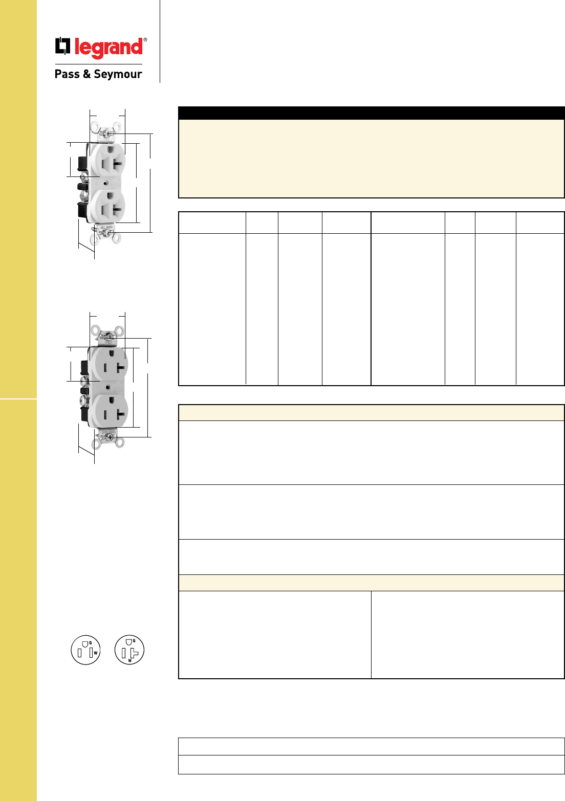
Technical Specifications
S-44
Construction Specification Grade Receptacles
Technical Specifications
Construction Specification Grade Receptacles
Back & Side Wire 2 Pole, 3 Wire Grounding 15 & 20A, 125V
Project
Location/Type
Catalog NEMA
Number Color Rating Cong. No.
r
CRB5262I Ivory 15A 125V 5-15R
r
CRB5262W White 15A 125V 5-15R
r
CRB5262 Brown 15A 125V 5-15R
r
CRB5262GRY Gray 15A 125V 5-15R
r
CRB5262BK Black 15A 125V 5-15R
r
CRB5262RED Red 15A 125V 5-15R
r
CRB5262LA Lt. Al. 15A 125V 5-15R
r
CRB5362I Ivory 20A 125V 5-20R
r
CRB5362W White 20A 125V 5-20R
r
CRB5362 Brown 20A 125V 5-20R
r
CRB5362GRY Gray 20A 125V 5-20R
r
CRB5362BK Black 20A 125V 5-20R
r
CRB5362RED Red 20A 125V 5-20R
r
CRB5362LA Lt. Al. 20A 125V 5-20R
Catalog NEMA
Number Color Rating Cong. No.
r
CRB5262SI Ivory 15A 125V 5-15R
r
CRB5262SW White 15A 125V 5-15R
r
CRB5262S Brown 15A 125V 5-15R
r
CRB5262SGRY Gray 15A 125V 5-15R
r
CRB5262SRED Red 15A 125V 5-15R
r
CRB5262SLA Lt. Al. 15A 125V 5-15R
r
CRB5362SI Ivory 20A 125V 5-20R
r
CRB5362SW White 20A 125V 5-20R
r
CRB5362S Brown 20A 125V 5-20R
r
CRB5362SGRY Gray 20A 125V 5-20R
r
CRB5362SRED Red 20A 125V 5-20R
r
CRB5362SLA Lt. Al. 20A 125V 5-20R
Performance
Electrical
Dielectric Voltage Withstands 2000V minimum
Maximum Working Voltage 250V
Current Interrupting Certified for current interrupting at full-rated current
Temperature Rise Max 30°C temperature rise at full-rated current after 50
cycles of overload at 150% of rated current with direct current
Mechanical
Terminal Identification Terminal Identification in accordance with UL498
(Brass, White, Green)
Terminal Accommodation #14 – #10 AWG copper conductor only
Product Identification Ratings are a permanent part of the device
Environmental
Flammability UL94 V2
Operating Temperature Maximum continuous +60°C, minimum -40°C (without impact)
Materials
Face Nylon
Back Body PVC
Line Contacts .032 688 Brass
Mounting Strap .042 Plated Steel
Ground Contacts .040 260 Brass
Pressure Plate .080 Steel
Terminal Screws #8 Tri-Drive Brass
(Neutral = Nickel-Plated
Steel)
Ground Screw #8 Hex Tri-Drive Steel
with Green Zinc Coating
Assembly Drive Screw Zinc-Plated Steel
Auto-Ground Clip Stainless Steel
Mounting Screws Tri-Drive Steel
Consult Straight Blade Section B for complete compliance listing.
Typical Specications
Manufacturer’s Identification: Legrand/Pass & Seymour CRB5262
Description: Straight Blade Duplex Receptacle – Construction Specification Grade
Type: 2 Pole, 3 Wire Grounding
Rating: 15A, 125V
3rd Party Compliance: UL Listed, File Number E140596, Standard UL498, Federal Specification
WC596. CSA/CUL approved, File Number LR16063, Standard CSA-C22.2 No. 42. Conforms to NEMA
WD-1 and WD-6.
15 & 20 Amp
1.104"
.780"
2.635"
3.281"
1.322"
CRB5362SLA
1.104"
.780"
2.635"
3.281"
1.322"
NEMA
5-15R
NEMA
5-20R
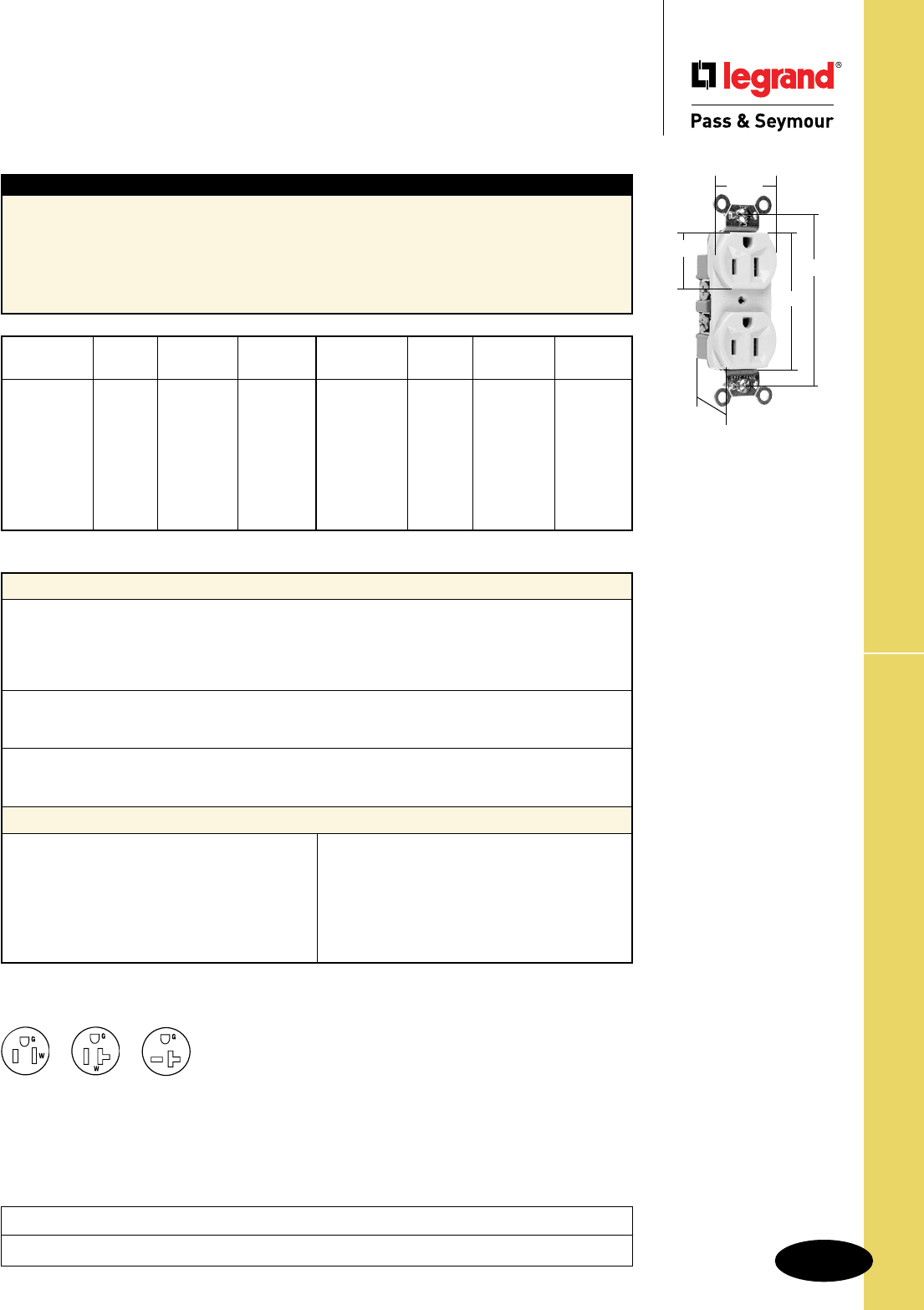
Technical Specifications
S-45
Commercial Specification Grade Receptacles
Technical Specifications
Commercial Specification Grade Receptacles
2 Pole, 3 Wire Grounding 15 & 20A, 125V; 20A, 250V
Typical Specications
Manufacturer’s Identification: Legrand/Pass & Seymour CR15
Description: Straight Blade Duplex Receptacle – Commercial Specification Grade
Type: 2 Pole, 3 Wire Grounding
Rating: 15A, 125V
3rd Party Compliance: UL Listed, File Number E140596, Standard UL498, CSA Certified, File Number
LR16063, Standard CSA-C22.2 No. 42. Conforms to NEMA WD-1 and WD-6.
Performance
Electrical
Dielectric Voltage Withstands 1500V minimum
Maximum Working Voltage 125V
Maximum Continuous Current 15A – CR15/BR15; 20A – CR20/BR20/5850
Temperature Rise Maximum 30°C after 50 cycles at 150% of rated current
Mechanical
Terminal Accommodation #14 – #10 AWG
Product Identification Amp, Voltage, 3rd Party Compliance
Environmental
Flammability UL94 V2
Operating Temperature Maximum continuous +50°C, minimum -40°C without impact
Materials
Face Nylon
Back Body PVC
Line Contacts .032 688 Brass
Mounting Strap .042 Plated Steel
Ground Contacts .040 260 Brass
Terminal Screws #8 Tri-Drive Steel (Neutral
= Nickel-Plated Steel)
Ground Screw #8 Hex Tri-Drive Steel
with Green Zinc Coating
Assembly Drive Screw Zinc-Plated Steel
Auto-Ground Clip Stainless Steel
Mounting Screws Tri-Drive Steel
Consult Straight Blade Section B for complete compliance listing.
Catalog NEMA
Number Color Rating Cong. No.
r
CR15I Ivory 15A 125V 5-15R
r
CR15W White 15A 125V 5-15R
r
CR15 Brown 15A 125V 5-15R
r
CR15GRY Gray 15A 125V 5-15R
r
CR15LA Lt. Al. 15A 125V 5-15R
Catalog NEMA
Number Color Rating Cong. No.
r
CR20I Ivory 20A 125V 5-20R
r
CR20W White 20A 125V 5-20R
r
CR20 Brown 20A 125V 5-20R
r
CR20GRY Gray 20A 125V 5-20R
r
CR20BK Black 20A 125V 5-20R
r
CR20RED Red 20A 125V 5-20R
r
CR20LA Lt. Al. 20A 125V 5-20R
r
5850I* Ivory 20A 250V 6-20R
r
5850W* White 20A 250V 6-20R
15 & 20 Amp
1.104"
1.018"
2.635"
3.281"
1.322"
Project
Location/Type
NEMA
5-15R
NEMA
5-20R NEMA
6-20R
*Side wire only
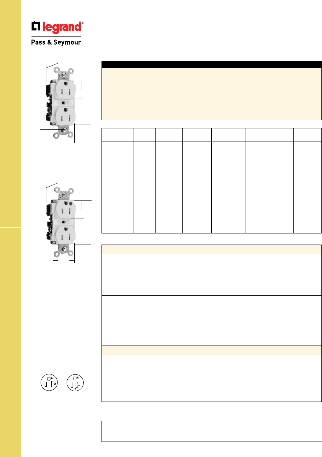
Technical Specifications
S-46
Tamper-Resistant Spec & Hospital Grade
Technical Specifications
Tamper-Resistant
Specification & Hospital Grade Receptacles
Back & Side Wire 2 Pole, 3 Wire Grounding 15 & 20A, 125
Typical Specications
Manufacturer’s Identification: Legrand/Pass & Seymour TR62
Description: Straight Blade Duplex Receptacle – Tamper-Resistant Specification & Hospital Grade
Type: 2 Pole, 3 Wire Grounding
Rating: 15A, 125V
Configuration: NEMA 5-15R
3rd Party Compliance: UL Listed, File Number E140596, Standard UL498, Federal Specification
WC596. CSA Certified, File Number LR16063, Standard CSA-C22.2 No. 42. Conforms to NEMA WD-1
and WD-6.
Catalog NEMA
Number Color Rating Cong. No.
r TR62I Ivory 15A 125V 5-15R
r TR62W White 15A 125V 5-15R
r TR62 Brown 15A 125V 5-15R
r TR62GRY Gray 15A 125V 5-15R
r TR62BK Black 15A 125V 5-15R
r TR62RED Red 15A 125V 5-15R
r TR62LA Lt. Al. 15A 125V 5-15R
r TR62BL Blue 15A 125V 5-15R
r TR63I Ivory 20A 125V 5-20R
r TR63W White 20A 125V 5-20R
r TR63 Brown 20A 125V 5-20R
r TR63GRY Gray 20A 125V 5-20R
r TR63BK Black 20A 125V 5-20R
r TR63RED Red 20A 125V 5-20R
r TR63LA Lt. Al. 20A 125V 5-20R
Catalog NEMA
Number Color Rating Cong. No.
r TR62HI Ivory 15A 125V 5-15R
r TR62HW White 15A 125V 5-15R
r TR62H Brown 15A 125V 5-15R
r TR62HGRY Gray 15A 125V 5-15R
r TR62HRED Red 15A 125V 5-15R
r TR62HLA Lt. Al. 15A 125V 5-15R
r TR63HI Ivory 20A 125V 5-20R
r TR63HW White 20A 125V 5-20R
r TR63H Brown 20A 125V 5-20R
r TR63HGRY Gray 20A 125V 5-20R
r TR63HRED Red 20A 125V 5-20R
r TR63HLA Lt. Al 20A 125V 5-20R
r TR63HBL Blue 20A 125V 5-20R
Consult Straight Blade Section B for complete compliance listing.
Performance
Electrical
Dielectric Voltage Withstands 2000V minimum
Maximum Working Voltage 250V
Current Interrupting Certified for current interrupting at full-rated current
Temperature Rise Maximum 30°C temperature rise at full-rated current
after 50 cycles of overload at 150% of rated current
with direct current
Mechanical
Terminal Identification Terminal Identification in accordance with UL498
(Brass, White, Green)
Terminal Accommodation #14 – #10 AWG copper conductor only
Product Identification Ratings are a permanent part of the device
Environmental
Flammability UL94 V2
Operating Temperature Maximum continuous +60°C, minimum -40°C without impact
Materials
Face Nylon
Back Body Nylon
Line Contacts .036 688 Brass
Mounting Strap .050 688 Brass
Ground Contacts Strap with Integral Ground
Pressure Plate .031 260 Brass
Tamper Shutter Thermoplastic
Terminal Screws #10 Tri-Drive Brass
(Neutral = Nickel-Plated
Steel)
Ground Screw #10 Hex Tri-Drive Brass
Assembly Drive Screw Zinc-Plated Steel
Auto-Ground Clip Brass
Mounting Screws Tri-Drive Steel
NEMA
5-15R
NEMA
5-20R
TR62I
.900"
3.281"
1.625"
1.104"
2.750"
TR62HI
.900"
1.625"
1.104"
2.750"
3.281"
Project
Location/Type

Technical Specifications
S-47
Tamper-Resistant Hard Use Recept.
Technical Specifications
Tamper-Resistant Hard Use Receptacles
2 Pole, 3 Wire Grounding 15 & 20A, 125V
Typical Specications
Manufacturer’s Identification: Legrand/Pass & Seymour TR5262
Description: Straight Blade Duplex Receptacle – Tamper-Resistant Hard Use
Type: 2 Pole, 3 Wire Grounding
Rating: 15A, 125V
Configuration: NEMA 5-15R
3rd Party Compliance: UL Listed, File Number E140596, Standard UL498, Federal Specification
WC596, CSA/CUL Approved, Standard CSA-C22.2 No. 42. Conforms to NEMA WD-1 and WD-6.
Catalog NEMA
Number Color Rating Cong. No.
r TR5262I Ivory 15A 125V 5-15R
r TR5262W White 15A 125V 5-15R
r TR5262 Brown 15A 125V 5-15R
r TR5262GRY Gray 15A 125V 5-15R
r TR5262BK Black 15A 125V 5-15R
r TR5262RED Red 15A 125V 5-15R
r TR5262LA Lt. Al. 15A 125V 5-15R
Catalog NEMA
Number Color Rating Cong. No.
r TR5362I Ivory 20A 125V 5-20R
r TR5362W White 20A 125V 5-20R
r TR5362 Brown 20A 125V 5-20R
r TR5362GRY Gray 20A 125V 5-20R
r TR5362BK Black 20A 125V 5-20R
r TR5362RED Red 20A 125V 5-20R
r TR5362LA Lt. Al. 20A 125V 5-20R
Performance
Electrical
Dielectric Voltage Withstands 2000V minimum
Maximum Working Voltage 125V
Maximum Continuous Current TR5262 = 15A
TR5263 = 20A
Temperature Rise Maximum 30°C temperature rise at full-rated current after 50
cycles of overload at 150% of rated current with direct current
Mechanical
Terminal Accommodation #14 – #10 AWG copper conductor only
Product Identification Amperage, Voltage, 3rd Party Compliance
Environmental
Flammability UL94 V2
Operating Temperature Maximum continuous +60°C, minimum -40°C without impact
Materials
Face Nylon
Back Body PVC
Line Contacts .036 Olin 688 Brass
Mounting Strap .042 Zinc-Plated Steel
Ground Contacts .040 Olin 688 Brass
Pressure Plate .080 Steel
Tamper-Resistant
Shutters Thermoplastic
Terminal Screws #10 Tri-Drive Brass
(Neutral = Nickel-Plated
Steel)
Ground Screw #8 Hex Tri-Drive Steel;
Zinc Coating with
Green Chromate
Assembly Drive Screw Zinc-Plated Steel
Auto-Ground Clip Stainless Steel
Mounting Screws Tri-Drive Steel
Project
Location/Type
TR5362LA
1.130"
1.322"
1.104"
2.635"
3.281"
Consult Straight Blade Section B for complete compliance listing.
NEMA
5-15R
NEMA
5-20R
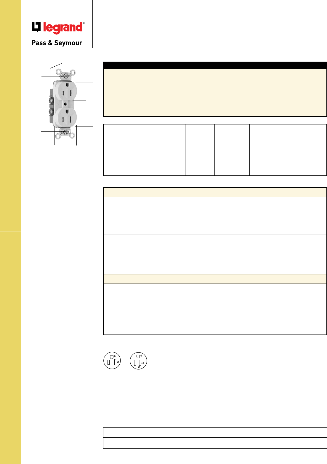
Technical Specifications
S-48
Technical Specifications
Tamper-Resistant Commercial Grade
Receptacles
2 Pole, 3 Wire Grounding 15 & 20A, 125V
TR Commercial Grade Receptacles
Typical Specications
Manufacturer’s Identification: Legrand/Pass & Seymour TR15
Description: Straight Blade Duplex Receptacle – Tamper-Resistant Commercial Grade
Type: 2 Pole, 3 Wire Grounding
Rating: 15A, 125V
Configuration: NEMA 5-15R
3rd Party Compliance: cULs Listed, File Number E140596, Standard UL498, Standard CSA-C22.2
No. 42. Conforms to NEMA WD-1 and WD-6.
Catalog NEMA
Number Color Rating Cong. No.
r TR15I Ivory 15A 125V 5-15R
r TR15W White 15A 125V 5-15R
r TR15 Brown 15A 125V 5-15R
r TR15GRY Gray 15A 125V 5-15R
r TR15LA Lt. Al. 15A 125V 5-15R
Catalog NEMA
Number Color Rating Cong. No.
r TR20I Ivory 20A 125V 5-20R
r TR20W White 20A 125V 5-20R
r TR20 Brown 20A 125V 5-20R
r TR20GRY Gray 20A 125V 5-20R
r TR20BK Black 20A 125V 5-20R
r TR20LA Lt. Al. 20A 125V 5-20R
Performance
Electrical
Dielectric Voltage Withstands 1500V minimum
Maximum Working Voltage 125V
Maximum Continuous Current 15A – TR15; 20A – TR20
Temperature Rise Maximum 30°C temperature rise at full-rated current after 50
cycles of overload at 150% of rated current with direct current
Mechanical
Terminal Accommodation #14 – #10 AWG
Product Identification Amperage, Voltage, 3rd Party Compliance
Environmental
Flammability UL94 V2
Operating Temperature Maximum continuous +50°C, minimum -40°C without impact
Materials
Face Nylon
Back Body PVC
Line Contacts .032 260 Brass
Mounting Strap .042 Zinc-Plated Steel
Ground Contacts .040 260 Brass
Tamper-Resistant
Shutters Thermoplastic
Terminal Screws #8 Tri-Drive Steel
(Neutral = Nickel-Plated Steel)
Ground Screws #8 Hex Tri-Drive Steel; Zinc
Coating with Green Chromate
Assembly
Drive Screw Zinc-Plated Steel
Auto-Ground Clip Stainless Steel
Mounting Screws Tri-Drive Steel
TR15LA
1.130"
1.322"
1.104"
2.635"
3.281"
Project
Location/Type
NEMA
5-15R
NEMA
5-20R
Consult Straight Blade Section B for complete compliance listing.
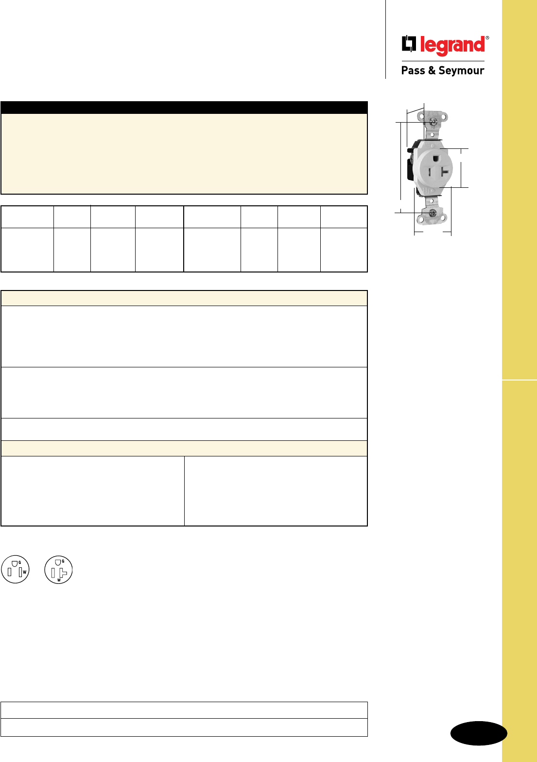
Technical Specifications
S-49
Technical Specifications
Tamper-Resistant Construction Grade
Single Receptacles
2 Pole, 3 Wire Grounding 15 & 20A, 125V
TR Construction Grade Single Receptacles
TR5351LA
1.190"
1.296"
1.38"
3.28"
Typical Specications
Manufacturer’s Identification: Legrand/Pass & Seymour TR5251
Description: Straight Blade Single Receptacle – Tamper-Resistant Construction Grade
Type: 2 Pole, 3 Wire Grounding
Rating: 15A, 125V
Configuration: NEMA 5-15R
3rd Party Compliance: UL Listed, File Number E140596, Standard UL498, Federal Specification
WC596, CSA Certified, Standard CSA-C22.2 No. 42. Conforms to NEMA WD-1 and WD-6.
Catalog NEMA
Number Color Rating Cong. No.
r TR5251I Ivory 15A 125V 5-15R
r TR5251W White 15A 125V 5-15R
r TR5251 Brown 15A 125V 5-15R
r TR5251LA Lt. Al. 15A 125V 5-15R
Catalog NEMA
Number Color Rating Cong. No.
r TR5351I Ivory 20A 125V 5-20R
r TR5351W White 20A 125V 5-20R
r TR5351 Brown 20A 125V 5-20R
r TR5351LA Lt. Al. 20A 125V 5-20R
Performance
Electrical
Dielectric Voltage Withstands 2000V minimum
Maximum Working Voltage 125V
Current Interrupting Certified for current interrupting at full-rated current
Temperature Rise Maximum 30°C temperature rise at full-rated current after 50
cycles of overload at 150% of rated current with direct current
Mechanical
Terminal Identification Terminal identification in accordance with UL498
(Brass, White, Green)
Terminal Accommodation #14 – #10 AWG copper conductor only
Product Identification Ratings are a permanent part of the device
Environmental
Flammability UL94 V2
Materials
Face Nylon
Back Body PVC
Contacts .032" (.8)Brass
Clamping Plate .080" Steel
Mounting Strap .042" Steel
Tamper-Resistant Shutters Thermoplastic
Terminal Screws Tri-Drive Brass
Hex Head
Grounding Screw Tri-Drive Zinc-Plated Steel
Assembly Rivets Steel
Mounting Screws Tri-Drive Steel
Project
Location/Type
NEMA
5-15R
NEMA
5-20R
Consult Straight Blade Section B for complete compliance listing.
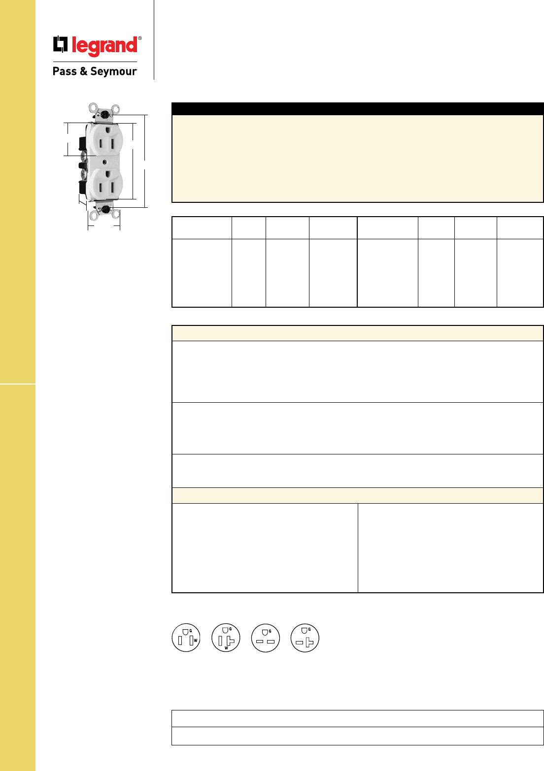
Technical Specifications
S-50
Technical Specifications
Weather-Resistant Heavy-Duty
Receptacles
2 Pole, 3 Wire Grounding 15 & 20A, 125 & 250V
Weather-Resistant Receptacles
Project
Location/Type
WR5262W
1.322"
1.104" 2.635"
3.281"
.780"
Typical Specications
Manufacturer’s Identification: Legrand/Pass & Seymour WR5262
Description: Straight Blade Duplex Receptacle – Weather-Resistant Heavy-Duty
Type: 2 Pole, 3 Wire Grounding
Rating: 15A, 125V
Configuration: NEMA 5-15R
3rd Party Compliance: UL Listed, File Number E140596, Standard UL498, Federal Specification
WC596, CSA Certified, File Number LR16063, Standard CSA-C22.2 No. 42. Conforms to NEMA WD-1
and WD-6.
Catalog NEMA
Number Color Rating Cong. No.
r WR5262I Ivory 15A 125V 5-15R
r WR5262W White 15A 125V 5-15R
r WR5262GRY Gray 15A 125V 5-15R
r WR5362I Ivory 20A 125V 5-20R
r WR5362W White 20A 125V 5-20R
r WR5362GRY Gray 20A 125V 5-20R
Catalog NEMA
Number Color Rating Cong. No.
r WR5662I Ivory 15A 250V 6-15R
r WR5662W White 15A 250V 6-15R
r WR5662GRY Gray 15A 250V 6-15R
r WR5362I Ivory 20A 250V 6-20R
r WR5362W White 20A 250V 6-20R
r WR5362GRY Gray 20A 250V 6-20R
Performance
Electrical
Dielectric Voltage Withstands 2000V minimum
Maximum Working Voltage 125V/250V
Current Interrupting Certified for current interrupting at full-rated current
Temperature Rise Maximum 30°C temperature rise at full-rated current after 50
cycles of overload at 150% of rated current with direct current
Mechanical
Terminal Identification Terminal identification in accordance with UL498
(Brass, White, Green)
Terminal Accommodation #14 – #10 AWG copper conductor only
Product Identification Ratings are a permanent part of the device
Environmental
Flammability UL94 V2
Operating Temperature Maximum continuous +60°C, minimum -40°C without impact
Materials
Face UV Resistant Nylon
Back Body PVC
Line Contacts .032 688 Brass
Mounting Strap .043 260 Brass
Ground Contact .040 688 Brass
Pressure Plate .080 Nickel-Plated Steel
Terminal Screws #8 Tri-Drive Steel
(Neutral = Nickel-Plated Steel)
Ground Screw #8 Hex Tri-Drive
Nickel-Plated Steel
Assembly Drive Screw .0004" Zinc-Plated Steel
Auto-Ground Clip Stainless Steel
Mounting Screws Tri-Drive Steel .0004"
Zinc-Plated Steel
NEMA
5-15R
NEMA
5-20R
NEMA
6-15R
NEMA
6-20R
Consult Straight Blade Section B for complete compliance listing.
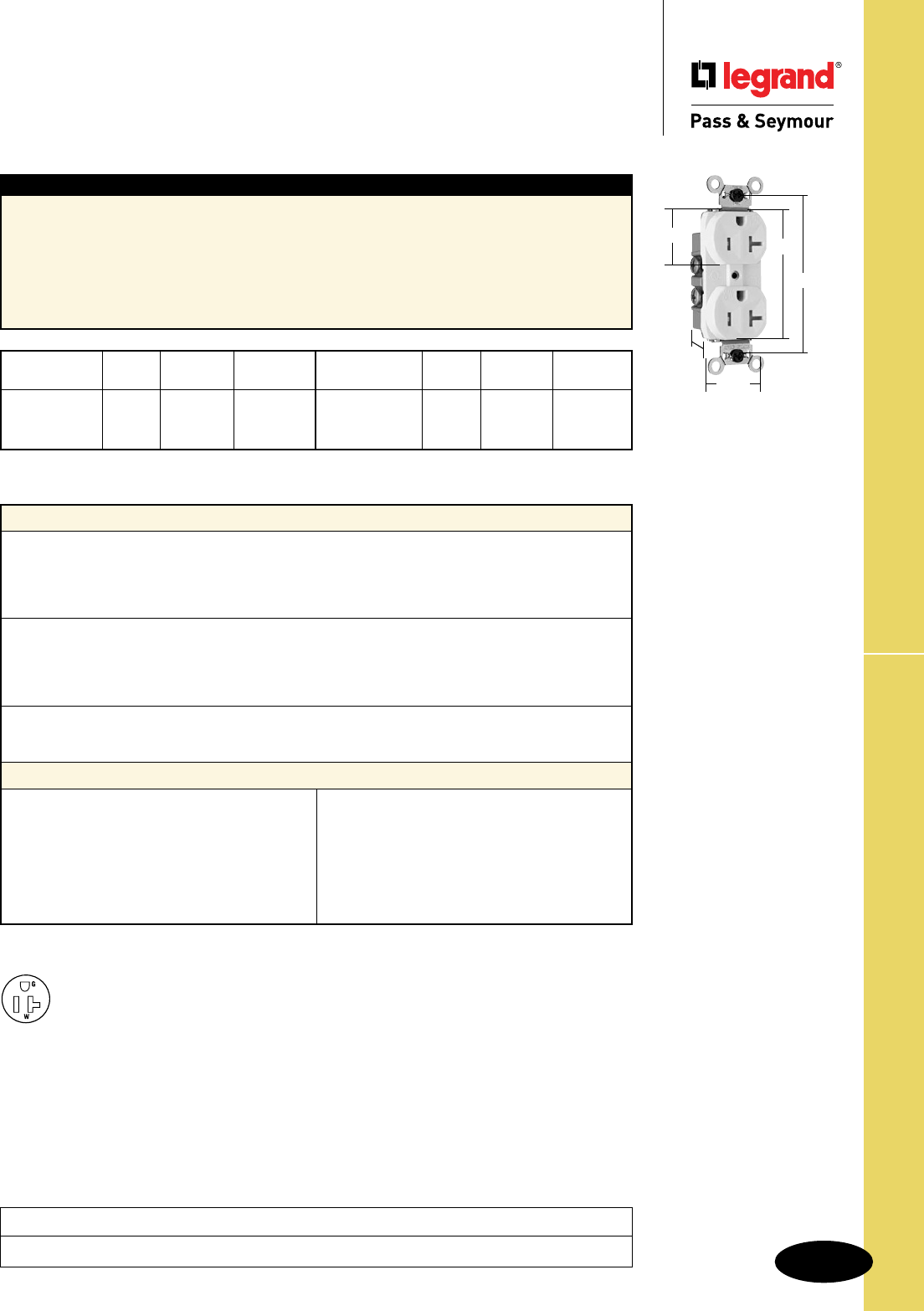
Technical Specifications
S-51
Weather-Resistant Receptacles
Technical Specifications
Weather-Resistant Commercial Grade
Receptacles
2 Pole, 3 Wire Grounding 20A, 125V
Project
Location/Type
WR20TRW
1.322"
1.104"
2.635"
3.281"
1.130"
Typical Specications
Manufacturer’s Identification: Legrand/Pass & Seymour WR20TR
Description: Straight Blade Duplex Receptacle – Weather-Resistant Commercial Grade
Type: 2 Pole, 3 Wire Grounding
Rating: 20A, 125V
Configuration: NEMA 5-20R
3rd Party Compliance: cUL Listed, File Number E140596, Standard UL498, Standard CSA-C22.2
No. 42. Conforms to NEMA WD-1 and WD-6.
Catalog NEMA
Number Color Rating Cong. No.
r WR20TRI Ivory 20A 125V 5-20R
r WR20TRW White 20A 125V 5-20R
r WR20TR Brown 20A 125V 5-20R
Catalog NEMA
Number Color Rating Cong. No.
r WR20TRGRY Gray 20A 125V 5-20R
r WR20TRLA Lt. Al. 20A 125V 5-20R
Performance
Electrical
Dielectric Voltage Withstands 1500V minimum
Maximum Working Voltage 125V
Temperature Rise Maximum 30°C temperature rise at full-rated current after 50
cycles of overload at 150% of rated current with direct current
Mechanical
Terminal Identification Terminal identification in accordance with UL498
(Brass, White, Green)
Terminal Accommodation #14 – #10 AWG copper conductor only
Product Identification Ratings are a permanent part of the device
Environmental
Flammability UL94 V2
Operating Temperature Maximum continuous +50°C, minimum -40°C without impact
Materials
Face UV Resistant Nylon
Back Body PVC
Line Contacts .032 260 Brass
Mounting Strap .042 Nickel-Plated Steel
Ground Contact .040 260 Brass
Terminal Screws #8 Tri-Drive Brass
(Neutral = Nickel-Plated Brass)
Ground Screw #8 Hex Tri-Drive
Nickel-Plated Steel
Assembly Drive Screw Zinc-Plated Steel
Auto-Ground Clip Stainless Steel
Mounting Screws Tri-Drive Steel
NEMA
5-20R
WR20TR models are Tamper-Resistant.
Consult Straight Blade Section B for complete compliance listing.
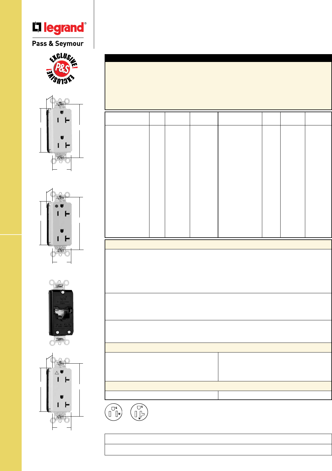
Technical Specifications
S-52
PT26352LA
2.75" 3.281"
.625"
1.5"
PTIG26362LA
2.75" 3.281"
.625"
1.5"
PT26362HGI
2.75" 3.281"
.625"
1.5"
PlugTail™ Decorator Receptacles
Technical Specifications
PlugTail™ Decorator Receptacles
2 Pole, 3 Wire Grounding 15 & 20A, 125V
Catalog NEMA
Number Color Rating Cong. No.
r
PT26252I Ivory 15A 125V 5-15R
r
PT26252W White 15A 125V 5-15R
r
PT26252 Brown 15A 125V 5-15R
r
PT26252GRY Gray 15A 125V 5-15R
r
PT26252BK Black 15A 125V 5-15R
r
PT26252RED Red 15A 125V 5-15R
r
PT26252LA Lt. Al. 15A 125V 5-15R
r
PT26352I Ivory 20A 125V 5-20R
r
PT26352W White 20A 125V 5-20R
r
PT26352 Brown 20A 125V 5-20R
r
PT26352GRY Gray 20A 125V 5-20R
r
PT26352BK Black 20A 125V 5-20R
r
PT26352RED Red 20A 125V 5-20R
r
PT26352LA Lt. Al. 20A 125V 5-20R
r PT26262HGI Ivory 15A 125V 5-15R
r PT26262HGW White 15A 125V 5-15R
r PT26262HGGRY Gray 15A 125V 5-15R
r PT26262HGRED Red 15A 125V 5-15R
Catalog NEMA
Number Color Rating Cong. No.
r PT26362HGI Ivory 20A 125V 5-20R
r PT26362HGW White 20A 125V 5-20R
r PT26362HGGRY Gray 20A 125V 5-20R
r PT26362HGRED Red 20A 125V 5-20R
r PT26362HGLA Lt. Al. 20A 125V 5-20R
r PTIG26262I Ivory 15A 125V 5-15R
r PTIG26262W White 15A 125V 5-15R
r PTIG26262 Orange 15A 125V 5-15R
r PTIG26262GRY Gray 15A 125V 5-15R
r PTIG26262RED Red 15A 125V 5-15R
r PTIG26262LA Lt. Al. 15A 125V 5-15R
r PTIG26362I Ivory 20A 125V 5-20R
r PTIG26362W White 20A 125V 5-20R
r PTIG26362 Orange 20A 125V 5-20R
r PTIG26362GRY Gray 20A 125V 5-20R
r PTIG26362RED Red 20A 125V 5-20R
r PTIG26362LA Lt. Al. 20A 125V 5-20R
Typical Specications
Manufacturer’s Identification: Legrand/Pass & Seymour PT26252
Description: PlugTail™ Straight Blade Duplex Receptacle – Decorator Specification Grade
Type: 2 Pole, 3 Wire Grounding
Rating: 15A, 125V
Configuration: NEMA 5-15R
3rd Party Compliance: cULus Listed, File Number E140596, Standard UL498. Federal Specification
WC596. Conforms to NEMA WD-1 and WD-6.
Performance
Electrical
Dielectric Voltage Withstands 2000V minimum
Maximum Working Voltage 125V
Current Interrupting Certified for current interrupting at full-rated current
(receptacle only)
Temperature Rise Maximum 30°C temperature rise at full-rated current after 50
cycles of overload at 150% of rated current with direct current
Mechanical
PlugTail Connector Identification #12 AWG, THHN, copper conductor, 6" leads, stripped, solid or
stranded, for use with PlugTail Receptacles only
Product Identification Ratings are a permanent part of the device
Environmental
Flammability UL94 V2
Operating Temperature Maximum continuous +60°C, minimum -40°C without impact
PlugTail Receptacle Materials
PlugTail Connector Materials
Face Nylon
Back Body PVC
Line Contacts .036 688 Brass
Mounting Strap .042 Plated Steel
Integral Ground System .036 260 Brass
Assembly Drive Screw Plated Steel
Auto-Ground Clip Steel
Mounting Screws Tri-Drive Steel
Housing Polycarbonate Contacts .030 Brass
Consult Straight Blade Section B for complete compliance listing.
NEMA
5-15R
NEMA
5-20R
Project
Location/Type
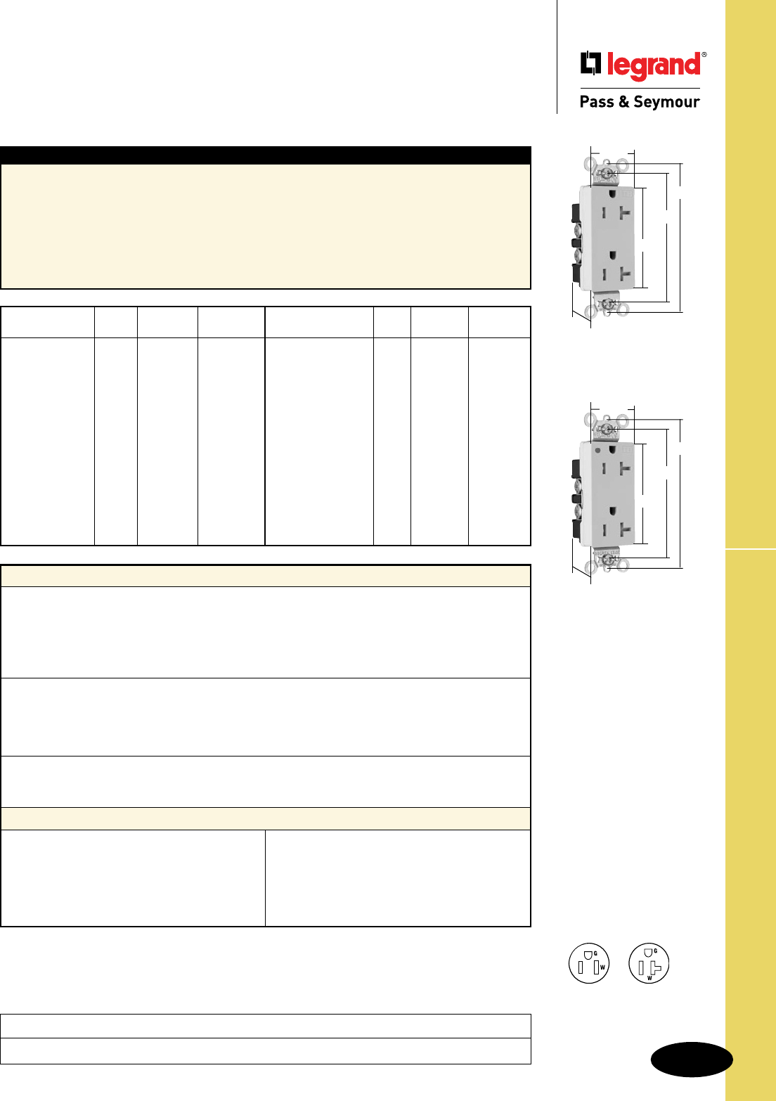
Technical Specifications
S-53
Technical Specifications
Heavy-Duty Tamper-Resistant
Decorator Receptacles
2 Pole, 3 Wire Grounding 15 & 20A, 125V
Heavy-Duty TR Decorator Receptacles
Catalog NEMA
Number Color Rating Cong. No.
r
TR26262I Ivory 15A 125V 5-15R
r
TR26262W White 15A 125V 5-15R
r
TR26262 Brown 15A 125V 5-15R
r
TR26262GRY Gray 15A 125V 5-15R
r
TR26262BK Black 15A 125V 5-15R
r
TR26262RED Red 15A 125V 5-15R
r
TR26262LA Lt. Al. 15A 125V 5-15R
r
TR26362I Ivory 20A 125V 5-20R
r
TR26362W White 20A 125V 5-20R
r
TR26362 Brown 20A 125V 5-20R
r
TR26362GRY Gray 20A 125V 5-20R
r
TR26362BK Black 20A 125V 5-20R
r
TR26362RED Red 20A 125V 5-20R
r
TR26362LA Lt. Al. 20A 125V 5-20R
Catalog NEMA
Number Color Rating Cong. No.
r
TR26262HGI Ivory 15A 125V 5-15R
r
TR26262HGW White 15A 125V 5-15R
r
TR26262HGGRY Gray 15A 125V 5-15R
r
TR26262HGRED Red 15A 125V 5-15R
r
TR26262HGLA Lt. Al. 15A 125V 5-15R
r
TR26362HGI Ivory 20A 125V 5-20R
r
TR26362HGW White 20A 125V 5-20R
r
TR26362HGGRY Gray 20A 125V 5-20R
r
TR26362HGBK Black 20A 125V 5-20R
r
TR26362HGRED Red 20A 125V 5-20R
r
TR26362HGLA Lt. Al. 20A 125V 5-20R
Typical Specications
Manufacturer’s Identification: Legrand/Pass & Seymour TR26362
Description: PlugTail™ Straight Blade Duplex Receptacle – Heavy-Duty Tamper-Resistant Decorator
Type: 2 Pole, 3 Wire Grounding
Rating: 15A, 125V
Configuration: NEMA 5-15R
3rd Party Compliance: UL Listed, File Number E140596, Standard UL498, Federal Specification
WC596, CSA Certified, File Number LR16063, Standard CSA-C22.2 No. 42. Conforms to NEMA WD-1
and WD-6.
Performance
Electrical
Dielectric Voltage Withstands 2000V minimum
Maximum Working Voltage 250V
Current Interrupting Certified for current interrupting at full-rated current
Temperature Rise Maximum 30°C temperature rise at full-rated current after 50
cycles of overload at 150% of rated current with direct current
Mechanical
Terminal Identification Terminal identification in accordance with UL498
(Brass, White, Green)
Terminal Accommodation #14 – #10 AWG copper conductor only
Product Identification Ratings are a permanent part of the device
Environmental
Flammability UL94 V2
Operating Temperature Maximum continuous +60°C, minimum -40°C without impact
Materials
Face Nylon
Back Body Nylon
Line Contacts .036 688 Brass
Mounting Strap Plated Steel
Ground Contacts Strap with Integral Ground
Pressure Plate .031 260 Brass
Tamper Shutter Thermoplastic
Terminal Screws #10 Tri-Drive Brass
(Neutral = Nickel-Plated Steel)
Ground Screw #10 Hex Tri-Drive Brass
Auto-Ground Clip Steel
Mounting Screws Tri-Drive Steel
NEMA
5-15R
NEMA
5-20R
Project
Location/Type
TR26362I
2.635"
3.281"
1.322"
3.81"
.833"
TR26362HGI
2.635"
3.281"
1.322"
3.81"
.833"
Consult Straight Blade Section B for complete compliance listing.
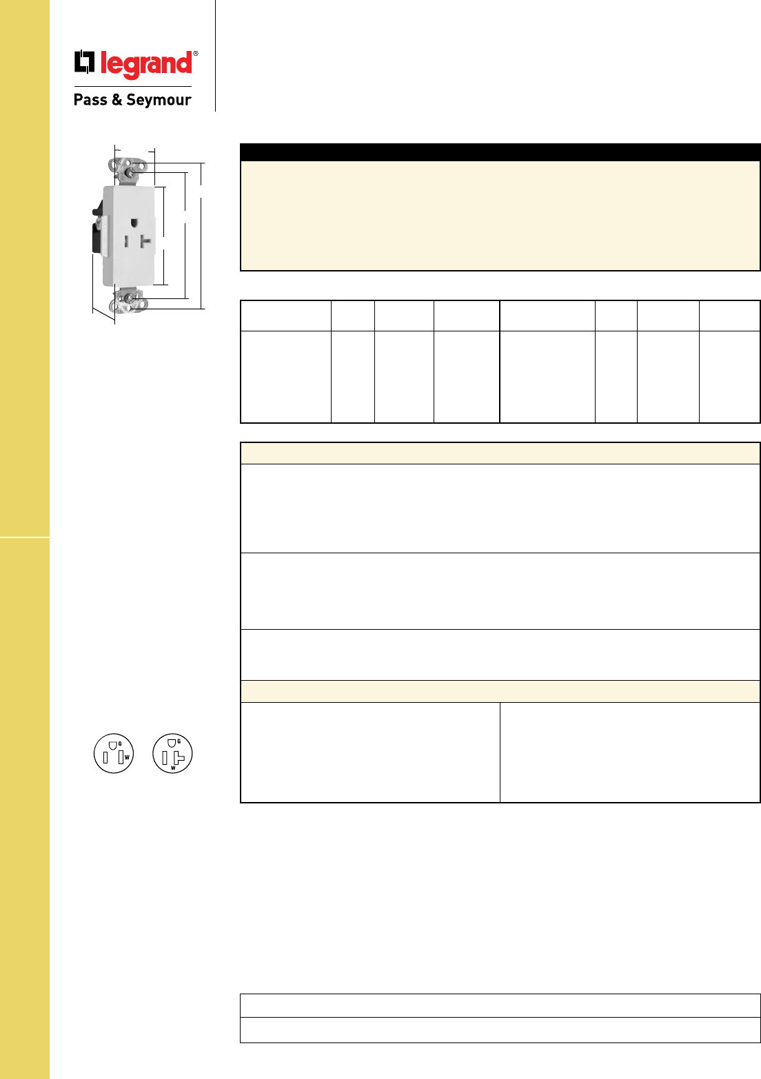
Technical Specifications
S-54
HD TR Decorator Single Receptacles
Technical Specifications
Heavy-Duty Tamper-Resistant
Decorator Single Receptacles
2 Pole, 3 Wire Grounding 15 & 20A, 125V
Catalog NEMA
Number Color Rating Cong. No.
r
TR26261I Ivory 15A 125V 5-15R
r
TR26261W White 15A 125V 5-15R
r
TR26261 Brown 15A 125V 5-15R
r
TR26261GRY Gray 15A 125V 5-15R
r
TR26261BK Black 15A 125V 5-15R
r
TR26261LA Lt. Al. 15A 125V 5-15R
Catalog NEMA
Number Color Rating Cong. No.
r
TR26361I Ivory 20A 125V 5-20R
r
TR26361W White 20A 125V 5-20R
r
TR26361 Brown 20A 125V 5-20R
r
TR26361GRY Gray 20A 125V 5-20R
r
TR26361BK Black 20A 125V 5-20R
r
TR26361LA Lt. Al. 20A 125V 5-20R
Typical Specications
Manufacturer’s Identification: Legrand/Pass & Seymour TR26261
Description: PlugTail™ Straight Blade Duplex Receptacle – Heavy-Duty Tamper-Resistant Decorator
Type: 2 Pole, 3 Wire Grounding
Rating: 15A, 125V
Configuration: NEMA 5-15R
3rd Party Compliance: UL Listed, File Number E140596, Standard UL498, Federal Specification
WC596, CSA Certified, Standard CSA-C22.2 No. 42. Conforms to NEMA WD-1 and WD-6.
Performance
Electrical
Dielectric Voltage Withstands 2000V minimum
Maximum Working Voltage 125V
Current Interrupting Certified for current interrupting at full-rated current
Temperature Rise Maximum 30°C temperature rise at full-rated current after 50
cycles of overload at 150% of rated current with direct current
Mechanical
Terminal Identification Terminal identification in accordance with UL498
(Brass, White, Green)
Terminal Accommodation #14 – #10 AWG copper conductor only
Product Identification Ratings are a permanent part of the device
Environmental
Flammability UL94 V2
Operating Temperature Maximum continuous +60°C, minimum -40°C without impact
Materials
Face Nylon
Back Body PVC
Line Contacts .032 (.8) Brass
Mounting Strap .042 Zinc-Plated Steel
Clamping Plate .080 Steel
Tamper Shutter Thermoplastic
Terminal Screws Tri-Drive Brass
Hex Head Tri-Drive Zinc-Plated
Grounding Screw Steel with Green
Chromate
Assembly Drive Screws Zinc-Plated Steel
Auto-Ground Clip StainlessSteel
Mounting Screws Tri-Drive Steel
NEMA
5-15R
NEMA
5-20R
Project
Location/Type
TR26361LA
2.635"
3.281"
1.322"
3.813"
1.188"
Consult Straight Blade Section B for complete compliance listing.
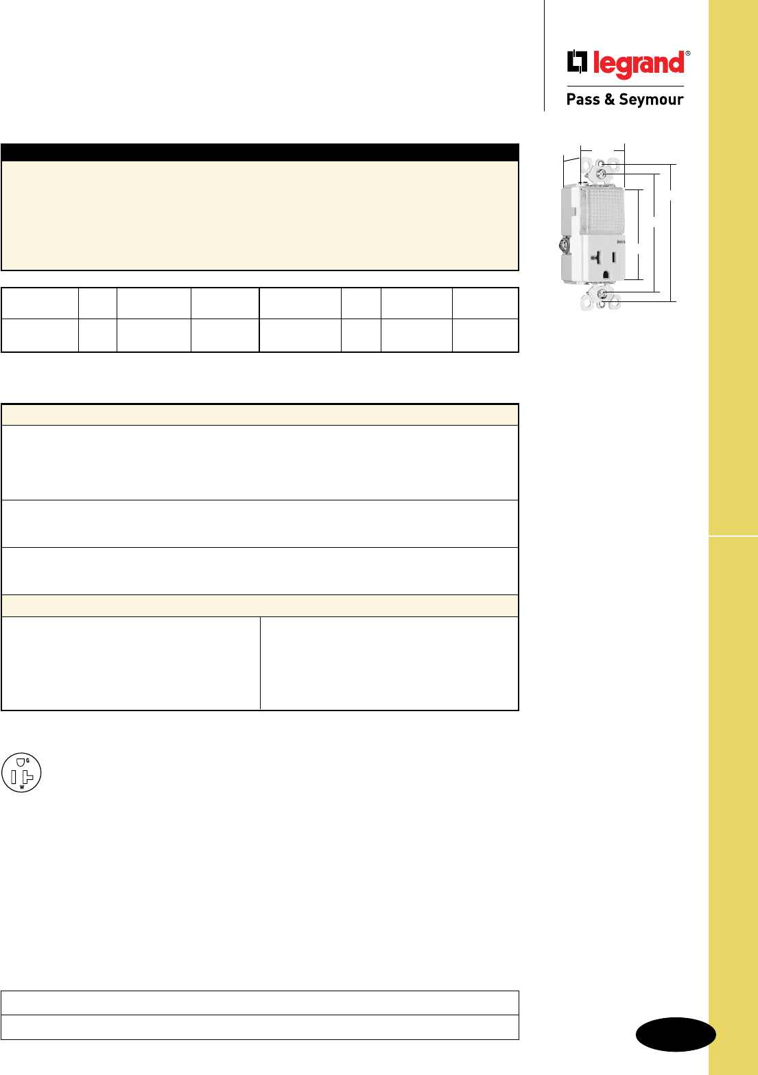
Technical Specifications
S-55
Spec Grade Combination Receptacles
Technical Specifications
Specification Grade
Combination Receptacles
2 Pole, 3 Wire Grounding 20A, 120/125VAC
PS8HWLLA
3.281"
3.812"
2.60"
1.29"
1.59"
Typical Specications
Manufacturer’s Identification: Legrand/Pass & Seymour PS8HWL
Description: Combination Straight Blade Receptacle – Specification Grade
Type: 2 Pole, 3 Wire Grounding
Rating: 20A, 120/125V
Configuration: NEMA 5-15R
3rd Party Compliance: cULus Listed, File Number E140596, Standard UL498. Conforms to NEMA
WD-1 and WD-6.
Catalog NEMA
Number Color Rating Cong. No.
r PS8HWLI Ivory 20A 120/125V 5-20R
r PS8HWLW White 20A 120/125V 5-20R
Catalog NEMA
Number Color Rating Cong. No.
r PS8HWLLA Lt. Al. 20A 120/125V 5-20R
Performance
Electrical
Dielectric Voltage Withstands 1500V minimum
Maximum Working Voltage 125V
Maximum Continuous Current 20A
Temperature Rise Maximum 30°C after 50 cycles at 150% of rated current
Mechanical
Terminal Accommodation #14 AWG – #10 AWG
Product Identification Amperage, Voltage, 3rd Party Compliance
Environmental
Flammability UL94 V2
Operating Temperature Maximum continuous +50°C, minimum -40°C (without impact)
Materials
Face Polycarbonate
Back Body Polycarbonate
Line Contacts .031 688 Brass
Mounting Strap .047 Steel
Ground Contacts .040 260 Brass
Pressure Plate .031 260 Brass
Terminal Screws #8 Tri-Drive Brass
Ground Screw #8 Hex Tri-Drive Brass
Mounting Screws Tri-Drive Steel
Lens Polycarbonate
Illuminating Lamp 2 LED
Light output in 1' FCD = 0.2561. FCD = Foot Candle Distance. 1 Lumen = 1 FCD.
See Page S-56 for more information.
Project
Location/Type
NEMA
5-20R
Consult Straight Blade Section B for complete compliance listing.
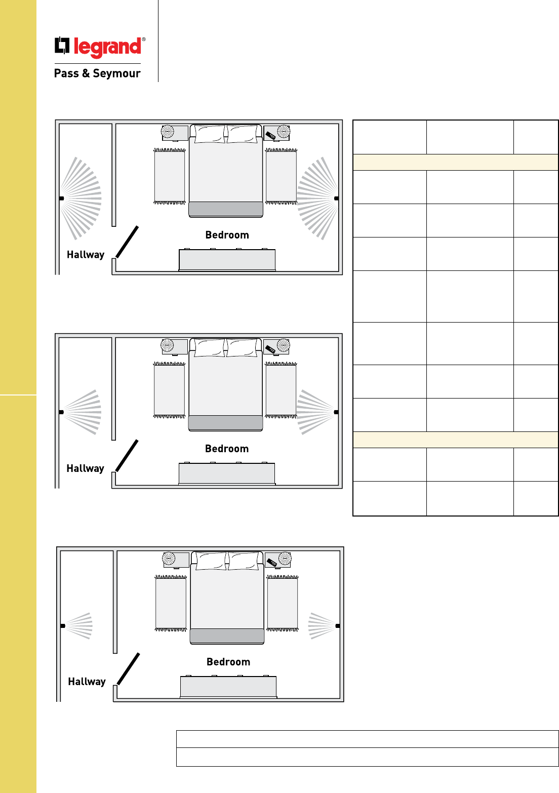
Technical Specifications
S-56
Hallway Lights – Light Output Measurements
Technical Specifications
Hallway Lights
Light Output Measurements
Standard 4 Watt Incandescent Nightlight
16 Lumens
P&S Enhanced LED Nightlight
3 Lumens
P&S LED Nightlight
1 Lumen
Light
Output
Catalog Number Description in 1' FCD*
P&S Enhanced LED Nightlights
TMHWLECC Enhanced Decorator 1.079
Full Hallway Light with
Light Sensor
TMHWLENSCC Enhanced Decorator 1.113
Full Hallway Light
without Light Sensor
TMHWLLOUVCC Full Hallway Decorator 0.0843
Light for use with P&S
Metal Louver Plates
TM8HWLTRCC Decorator Hallway 0.2561
Light with High
Output Light &
Tamper-Resistant
Single Receptacle
PS8HWL Specification Grade 0.2561
Enhanced Decorator
Hallway Light &
Single Receptacle
1595NTLTRCC4 Combination 0.180
Enhanced Nightlight/
GFCI (15 Amp)
2095NTLTR Combination 0.180
Enhanced Nightlight/
GFCI (20 Amp)
P&S LED Nightlights
TMHWLCC Decorator Full 0.1328
Hallway Light
with Light Sensor
TM8HWLCC Decorator Hallway 0.1442
Light & Single
Receptacle
*FCD = Foot Candle Distance. 1 Lumen = 1 FCD.
Project
Location/Type
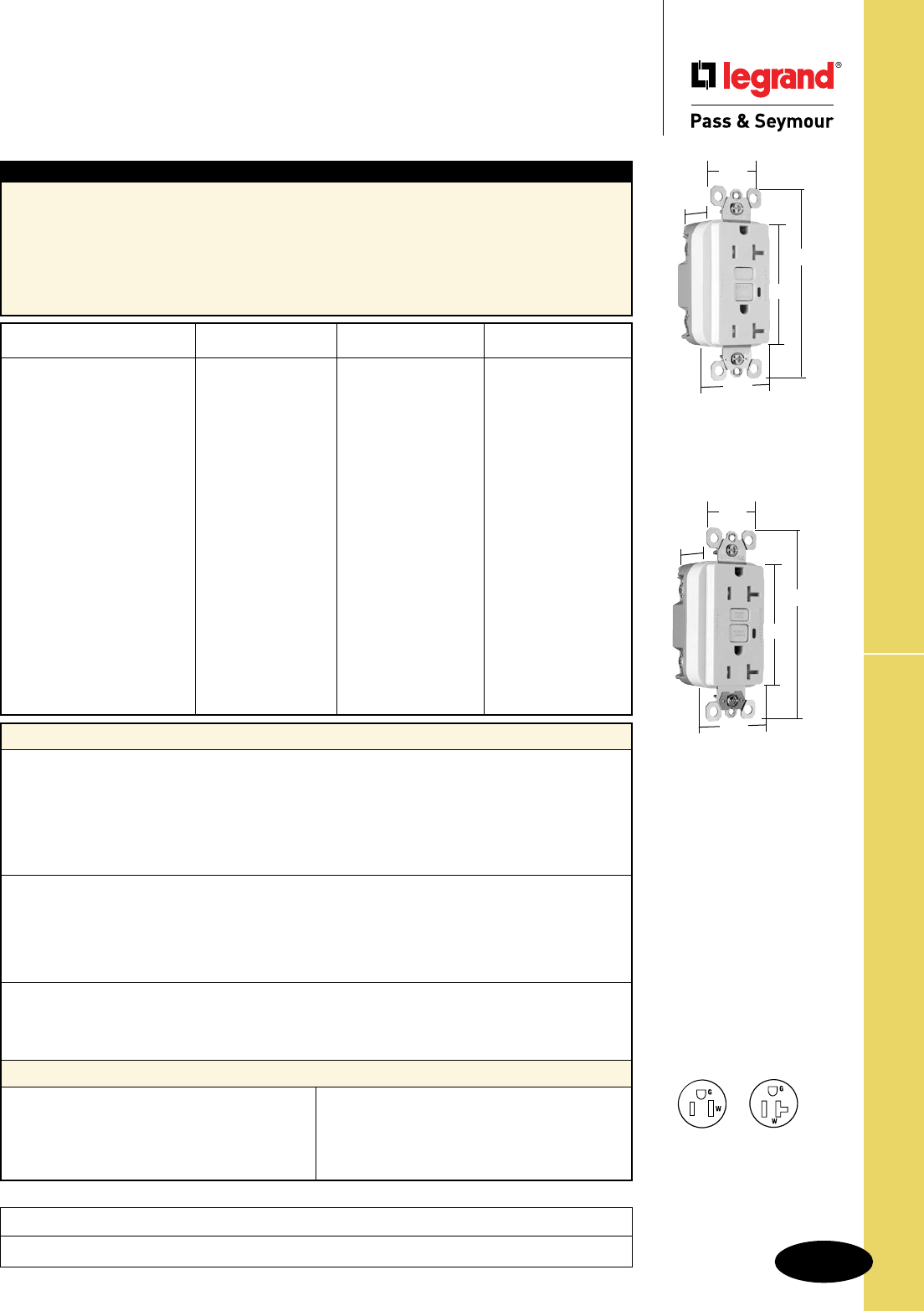
Technical Specifications
S-57
Tamper-Resistant GFCIs
Technical Specifications
Tamper-Resistant GFCI Receptacles
2 Pole, 3 Wire Grounding 15 & 20A, 125VAC
Project
Location/Type
Typical Specications
Manufacturer’s Identification: Legrand/Pass & Seymour 1595TR
Description: Straight Blade Duplex Tamper-Resistant GFCI Receptacle
Type: 2 Pole, 3 Wire Grounding
Rating: 20A, 125VAC Feed Thru; 15 or 20A, 125VAC Face
3rd Party Compliance: cULus Listed, File Number E42190; Standard UL498 Tamper-Resistant, Attachment
Plugs and Receptacles UL943 GFCIs. Federal Specification WC596. Standard CSA-C22.2 No. 42,
General Use Receptacles, CSA-C22.2 No. 144 GFCIs. Conforms to NEMA WD-1 and WD-6.
Performance
Electrical
Dielectric Withstands 1500V minimum
Trip Level 4 to 6 mA
Trip Time .025 Second Nominal
Frequency 60 Hz
Voltage 125VAC
Voltage Range 102-132VAC
Mechanical
Indicator Light (LED) Red, ON when GFCI is tripped
Terminal Identification Terminals identified in accordance with UL498
(Hot, White, Green)
Terminal Accommodation #14 – #10 AWG solid or stranded copper conductor only
Product Identification Ratings are a permanent part of device
Environmental
Operating Temperature -35°C to +66°C
Maximum Humidity 95%
Flammability UL94 V2
Materials
Face Nylon
Body Nylon
Contacts .03" Brass (.8)
Mounting Straps .05" Zinc-Plated Steel (1.3)
Terminal Screws Steel #8 - 32
Hex Head Grounding Screw Steel (Green)
Flat Head Mounting Screws Zinc-Plated Steel
Test/Reset Buttons Nylon
Tamper-Resistant Shutter Thermoplastic
Auto-Ground Clip* Brass Alloy C260
NEMA
Catalog Number Color Rating Conguration No.
r 1595TRI Ivory 15A 125VAC 5-15R
r 1595TRW White 15A 125VAC 5-15R
r 1595TR Brown 15A 125VAC 5-15R
r 1595TRBK Black 15A 125VAC 5-15R
r 1595TRLA Light Almond 15A 125VAC 5-15R
r 1595TRBNCC4 Brushed Nickel 15A 125VAC 5-15R
r 1595TRTI Titanium 15A 125VAC 5-15R
r 1595TRSI* Ivory 15A 125VAC 5-15R
r 1595TRSW* White 15A 125VAC 5-15R
r 1595TRSLA* Light Almond 15A 125VAC 5-15R
r 2095TRI Ivory 20A 125VAC 5-20R
r 2095TRW White 20A 125VAC 5-20R
r 2095TR Brown 20A 125VAC 5-20R
r 2095TRGRY Gray 20A 125VAC 5-20R
r 2095TRBK Black 20A 125VAC 5-20R
r 2095TRRED Red 20A 125VAC 5-20R
r 2095TRLA Light Almond 20A 125VAC 5-20R
r 2095TRSI* Ivory 20A 125VAC 5-20R
r 2095TRSW* White 20A 125VAC 5-20R
r 2095TRSLA* Light Almond 20A 125VAC 5-20R
*Tamper-Resistant GFCIs with Auto-Ground feature.
Dimensions for
15 & 20 Amp
1.13"
1.72"
1.25"
2.62"
4.20"
NEMA
5-15R
NEMA
5-20R
Dimensions for
15 & 20 Amp
With Auto-Ground
1.13"
1.72"
1.25"
2.62"
4.20"
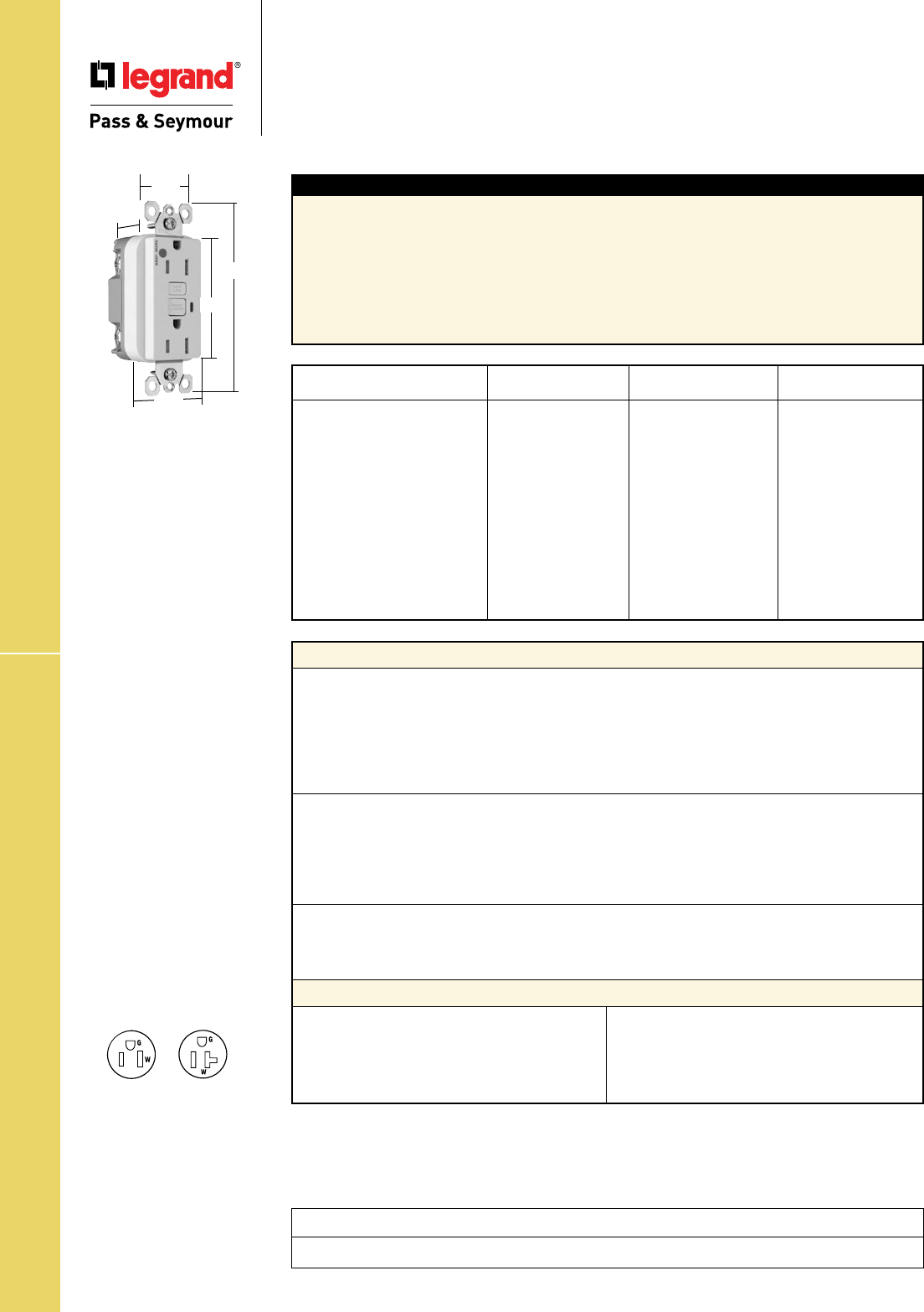
Technical Specifications
S-58
Technical Specifications
Hospital Grade Tamper-Resistant
GFCI Receptacles
2 Pole, 3 Wire Grounding 15 & 20A, 125VAC
Hospital Grade Tamper-Resistant GFCIs
Project
Location/Type
Typical Specications
Manufacturer’s Identification: Legrand/Pass & Seymour 1595HGTR
Description: Straight Blade Duplex Hospital Grade Tamper-Resistant GFCI Receptacle
Type: 2 Pole, 3 Wire Grounding
Rating: 20A, 125VAC Feed Thru; 15 or 20A, 125VAC Face
3rd Party Compliance: cULus Listed, File Number E42190, Standard UL498 Tamper-Resistant,
Attachment Plugs and Receptacles UL943 GFCIs. Federal Specification WC596 Hospital Grade.
Standard CSA-C22.2 No. 42, General Use Receptacles, CSA-C22.2 No. 144 GFCIs. Conforms to
NEMA WD-1 and WD-6.
Performance
Electrical
Dielectric Withstands 1500V minimum
Trip Level 4 to 6 mA
Trip Time .025 Second Nominal
Frequency 60 Hz
Voltage 125VAC
Voltage Range 102-132VAC
Mechanical
Indicator Light (LED) Red, ON when GFCI is tripped
Terminal Identification Terminals identified in accordance with UL498
(Hot, White, Green)
Terminal Accommodation #14 – #10 AWG solid or stranded copper conductor only
Product Identification Ratings are a permanent part of the device
Environmental
Operating Temperature -35°C to +66°C
Maximum Humidity 95%
Flammability UL94 V2
Materials
Face Nylon
Body Nylon
Contacts .03" Brass (.8)
Mounting Strap .05" Zinc-Plated Steel (1.3)
Terminal Screws Steel #8 - 32
Hex Head Grounding Screw Steel (Green)
Flat Head Mounting Screw Zinc-Plated Steel
Test/Reset Buttons Nylon
Tamper-Resistant Shutter Thermoplastic
NEMA
Catalog Number Color Rating Conguration No.
r 1595HGTRI Ivory 15A 125VAC 5-15R
r 1595HGTRW White 15A 125VAC 5-15R
r 1595HGTR Brown 15A 125VAC 5-15R
r 1595HGTRGRY Gray 15A 125VAC 5-15R
r 1595HGTRRED Red 15A 125VAC 5-15R
r 1595HGTRLA Light Almond 15A 125VAC 5-15R
r 2095HGTRI Ivory 20A 125VAC 5-20R
r 2095HGTRW White 20A 125VAC 5-20R
r 2095HGTR Brown 20A 125VAC 5-20R
r 2095HGTRGRY Gray 20A 125VAC 5-20R
r 2095HGTRRED Red 20A 125VAC 5-20R
r 2095HGTRLA Light Almond 20A 125VAC 5-20R
Dimensions for
15 & 20 Amp
1.13"
1.72"
1.25"
2.62"
4.20"
NEMA
5-15R
NEMA
5-20R
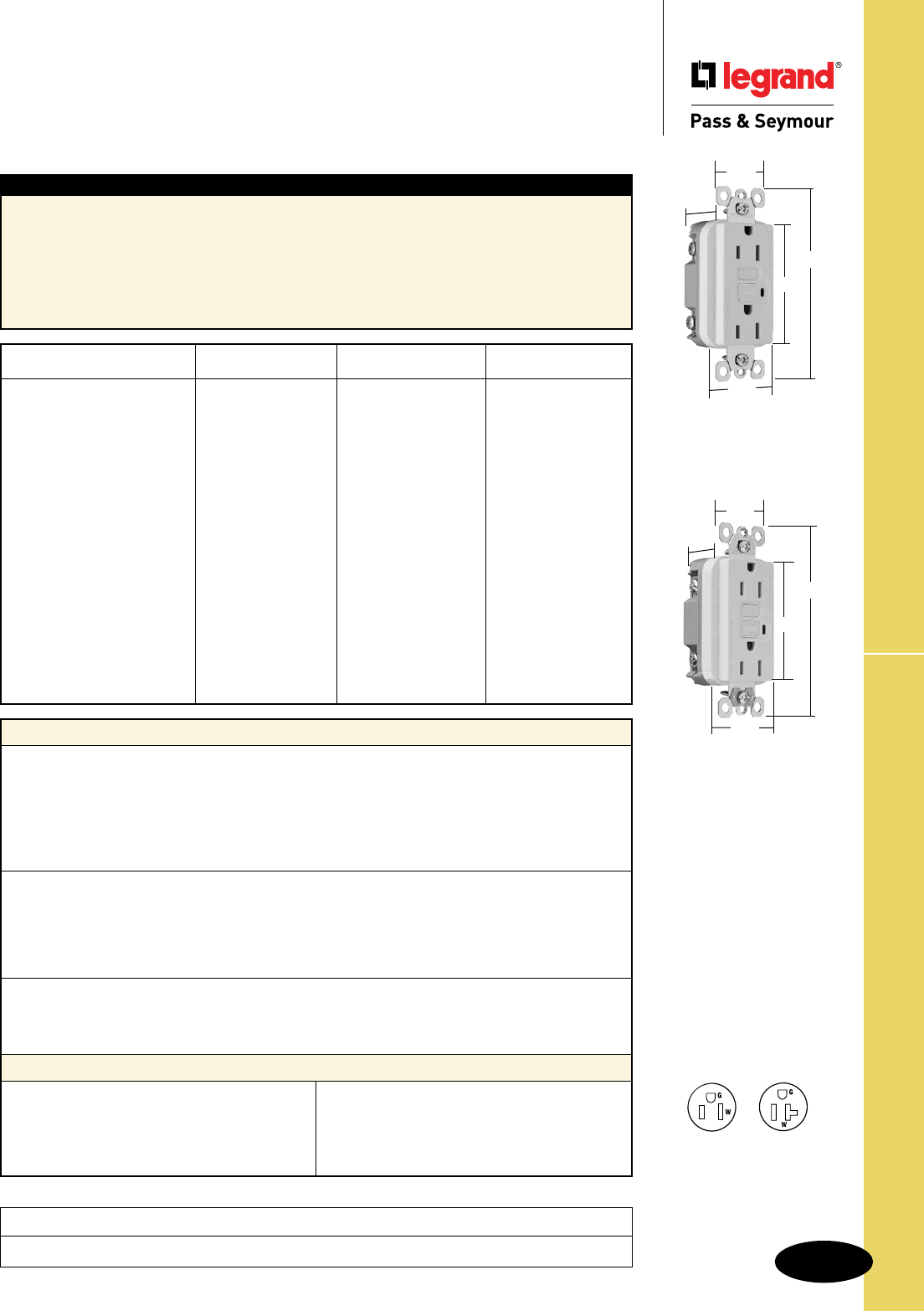
Technical Specifications
S-59
TradeMaster®
& Spec Grade GFCIs
Technical Specifications
TradeMaster® & Specification Grade
GFCI Receptacles
2 Pole, 3 Wire Grounding 15 & 20A, 125VAC
Project
Location/Type
Typical Specications
Manufacturer’s Identification: Legrand/Pass & Seymour 1595
Description: Straight Blade Duplex GFCI Receptacle
Type: 2 Pole, 3 Wire Grounding
Rating: 20A, 125VAC Feed Thru; 15 or 20A, 125VAC Face
3rd Party Compliance: cULus Listed, File Number E42190; Standard UL498, Attachment Plugs
and Receptacles UL943 GFCIs. Federal Specification WC596. Standard CSA-C22.2 No. 42,
General Use Receptacles, CSA-C22.2 No. 144 GFCIs. Conforms to NEMA WD-1 and WD-6.
Performance
Electrical
Dielectric Withstands 1500V minimum
Trip Level 4 to 6 mA
Trip Time .025 Second Nominal
Frequency 60 Hz
Voltage 125VAC
Voltage Range 102-132VAC
Mechanical
Indicator Light (LED) Red, ON when GFCI is tripped
Terminal Identification Terminals identified in accordance with UL498
(Hot, White, Green)
Terminal Accommodation #14 – #10 AWG solid or stranded copper conductor only
Product Identification Ratings are a permanent part of device
Environmental
Operating Temperature -35°C to +66°C
Maximum Humidity 95%
Flammability UL94 V2
Materials
Face Nylon
Body Nylon
Contacts .03" Brass (.8)
Mounting Straps .05" Zinc-Plated Steel (1.3)
Terminal Screws Steel #8 - 32
Hex Head Grounding Screw Steel (Green)
Flat Head Mounting Screws Zinc-Plated Steel
Test/Reset Buttons Nylon
Auto-Ground Clip* Brass Alloy C260
NEMA
Catalog Number Color Rating Conguration No.
r 1595I Ivory 15A 125VAC 5-15R
r 1595W White 15A 125VAC 5-15R
r 1595 Brown 15A 125VAC 5-15R
r 1595GRY Gray 15A 125VAC 5-15R
r 1595BK Black 15A 125VAC 5-15R
r 1595RED Red 15A 125VAC 5-15R
r 1595LA Light Almond 15A 125VAC 5-15R
r 1595SI* Ivory 15A 125VAC 5-15R
r 1595SW* White 15A 125VAC 5-15R
r 1595SLA* Light Almond 15A 125VAC 5-15R
r 2095I Ivory 20A 125VAC 5-20R
r 2095W White 20A 125VAC 5-20R
r 2095 Brown 20A 125VAC 5-20R
r 2095GRY Gray 20A 125VAC 5-20R
r 2095BK Black 20A 125VAC 5-20R
r 2095RED Red 20A 125VAC 5-20R
r 2095LA Light Almond 20A 125VAC 5-20R
r 2095SI* Ivory 20A 125VAC 5-20R
r 2095SW* White 20A 125VAC 5-20R
r 2095SLA* Light Almond 20A 125VAC 5-20R
*GFCIs with Auto-Ground feature.
Dimensions for
15 & 20 Amp
1.72"
1.25"
2.62"
4.20"
.98"
Dimensions for
15 & 20 Amp
With Auto-Ground
.98"
1.72"
1.25"
2.62"
4.20"
NEMA
5-15R
NEMA
5-20R
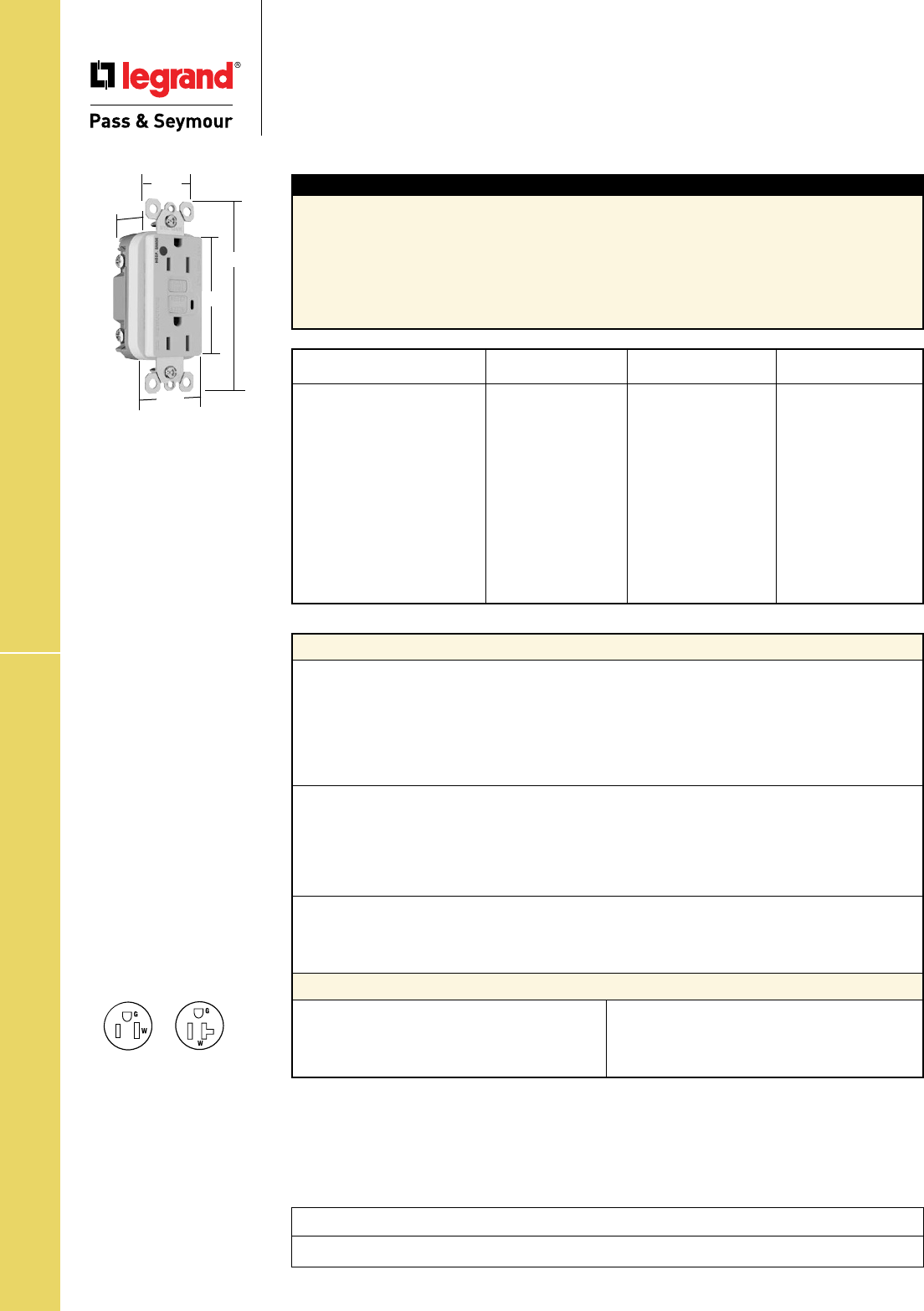
Technical Specifications
S-60
Hospital Grade GFCIs
Technical Specifications
Hospital Grade GFCI Receptacles
2 Pole, 3 Wire Grounding 15 & 20A, 125VAC
Project
Location/Type
Typical Specications
Manufacturer’s Identification: Legrand/Pass & Seymour 1595HG
Description: Straight Blade Duplex Hospital Grade GFCI Receptacle
Type: 2 Pole, 3 Wire Grounding
Rating: 20A, 125VAC Feed Thru; 15 or 20A, 125VAC Face
3rd Party Compliance: cULus Listed, File Number E42190, Standard UL498, Attachment Plugs and
Receptacles UL943 GFCIs. Federal Specification WC596 Hospital Grade. Standard CSA-C22.2 No. 42,
General Use Receptacles, CSA-C22.2 No. 144 GFCIs. Conforms to NEMA WD-1 and WD-6.
Performance
Electrical
Dielectric Withstands 1500V minimum
Trip Level 4 to 6 mA
Trip Time .025 Second Nominal
Frequency 60 Hz
Voltage 125VAC
Voltage Range 102-132VAC
Mechanical
Indicator Light (LED) Red, ON when GFCI is tripped
Terminal Identification Terminals identified in accordance with UL498
(Hot, White, Green)
Terminal Accommodation #14 – #10 AWG solid or stranded copper conductor only
Product Identification Ratings are a permanent part of the device
Environmental
Operating Temperature -35°C to +66°C
Maximum Humidity 95%
Flammability UL94 V2
Materials
Face Nylon
Body Nylon
Contacts .03" Brass (.8)
Mounting Strap .05" Zinc-Plated Steel (1.3)
Terminal Screws Steel #8 - 32
Hex Head Grounding Screw Steel (Green)
Flat Head Mounting Screw Zinc-Plated Steel
Test/Reset Buttons Nylon
NEMA
Catalog Number Color Rating Conguration No.
r 1595HGI Ivory 15A 125VAC 5-15R
r 1595HGW White 15A 125VAC 5-15R
r 1595HG Brown 15A 125VAC 5-15R
r 1595HGGRY Gray 15A 125VAC 5-15R
r 1595HGRED Red 15A 125VAC 5-15R
r 1595HGLA Light Almond 15A 125VAC 5-15R
r 2095HGI Ivory 20A 125VAC 5-20R
r 2095HGW White 20A 125VAC 5-20R
r 2095HG Brown 20A 125VAC 5-20R
r 2095HGGRY Gray 20A 125VAC 5-20R
r 2095HGRED Red 20A 125VAC 5-20R
r 2095HGLA Light Almond 20A 125VAC 5-20R
Dimensions for
15 & 20 Amp
1.72"
1.25"
2.62"
.98"
4.20"
NEMA
5-15R
NEMA
5-20R
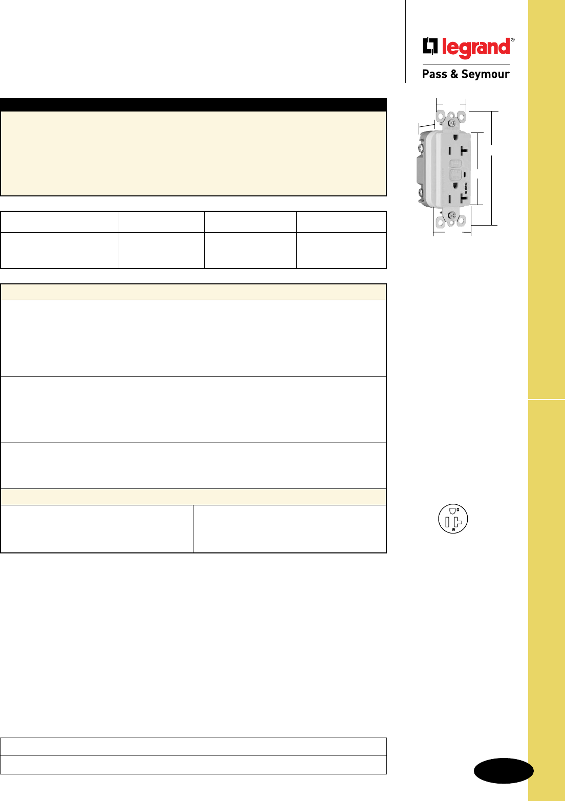
Technical Specifications
S-61
Illuminated GFCIs
Technical Specifications
Illuminated GFCI Receptacles
2 Pole, 3 Wire Grounding 20A, 125VAC
Project
Location/Type
NEMA
Catalog Number Color Rating Conguration No.
r 2095IL Ivory 20A 125VAC 5-20R
r 2095WL White 20A 125VAC 5-20R
r 2095LAL Light Almond 20A 125VAC 5-20R
Typical Specications
Manufacturer’s Identification: Legrand/Pass & Seymour 1595L
Description: Straight Blade Duplex Illuminated GFCI Receptacle
Type: 2 Pole, 3 Wire Grounding
Rating: 20A, 125VAC Feed Thru; 15 or 20A, 125VAC Face
3rd Party Compliance: cULus Listed, File Number E42190; Standard UL498, Attachment Plugs
and Receptacles UL943 GFCIs. Federal Specification WC596. Standard CSA-C22.2 No. 42, General
Use Receptacles, CSA-C22.2 No. 144 GFCIs. Conforms to NEMA WD-1 and WD-6.
Performance
Electrical
Dielectric Withstands 1500V minimum
Trip Level 4 to 6 mA
Trip Time .025 Second Nominal
Frequency 60 Hz
Voltage 125VAC
Voltage Range 102-132VAC
Mechanical
Indicator Light (LED) Green, ON when power is available
Terminal Identification Terminals identified in accordance with UL498
(Hot, White, Green)
Terminal Accommodation #14 – #10 AWG solid or stranded copper conductor only
Product Identification Ratings are a permanent part of device
Environmental
Operating Temperature -35°C to +66°C
Maximum Humidity 95%
Flammability UL94 V2
Materials
Face Nylon
Body Nylon
Contacts .03" Brass (.8)
Mounting Straps .05" Zinc-Plated Steel (1.3)
Terminal Screws Steel #8 - 32
Hex Head Grounding Screw Steel (Green)
Flat Head Mounting Screws Zinc-Plated Steel
Test/Reset Buttons Nylon
Dimensions for
15 & 20 Amp
.98"
1.72"
1.25"
2.62"
4.20"
NEMA
5-20R
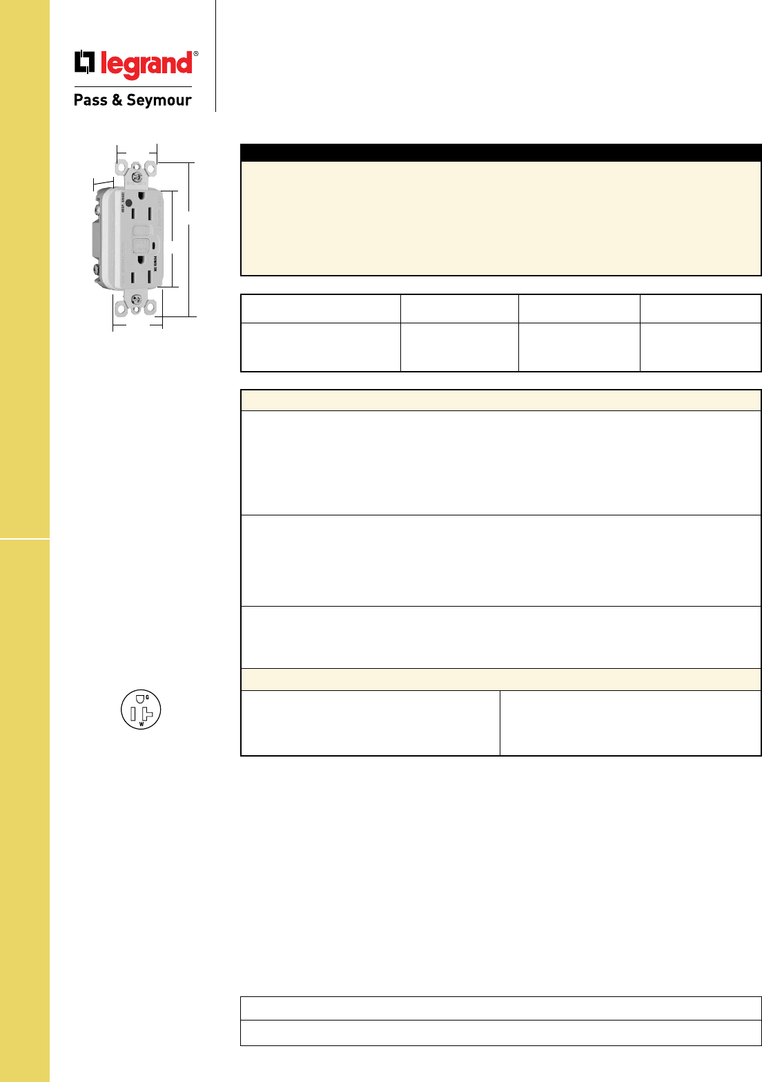
Technical Specifications
S-62
Hospital Grade Illuminated GFCIs
Technical Specifications
Hospital Grade Illuminated
GFCI Receptacles
2 Pole, 3 Wire Grounding 20A, 125VAC
Project
Location/Type
NEMA
Catalog Number Color Rating Conguration No.
r 2095HGIL Ivory 20A 125VAC 5-20R
r 2095HGWL White 20A 125VAC 5-20R
r 2095HGREDL Red 20A 125VAC 5-20R
Typical Specications
Manufacturer’s Identification: Legrand/Pass & Seymour 1595HGL
Description: Straight Blade Duplex Hospital Grade Illuminated GFCI Receptacle
Type: 2 Pole, 3 Wire Grounding
Rating: 20A, 125VAC Feed Thru; 15 or 20A, 125VAC Face
3rd Party Compliance: cULus Listed, File Number E42190, Standard UL498, Attachment Plugs and
Receptacles UL943 GFCIs. Federal Specification WC596 Hospital Grade. Standard CSA-C22.2 No. 42,
General Use Receptacles, CSA-C22.2 No. 144 GFCIs. Conforms to NEMA WD-1 and WD-6.
Performance
Electrical
Dielectric Withstands 1500V minimum
Trip Level 4 to 6 mA
Trip Time .025 Second Nominal
Frequency 60 Hz
Voltage 125VAC
Voltage Range 102-132VAC
Mechanical
Indicator Light (LED) Green, ON when power is available
Terminal Identification Terminals identified in accordance with UL498
(Hot, White, Green)
Terminal Accommodation #14 – #10 AWG solid or stranded copper conductor only
Product Identification Ratings are a permanent part of the device
Environmental
Operating Temperature -35°C to +66°C
Maximum Humidity 95%
Flammability UL94 V2
Materials
Face Nylon
Body Nylon
Contacts .03" Brass (.8)
Mounting Strap .05" Zinc-Plated Steel (1.3)
Terminal Screws Steel #8 - 32
Hex Head Grounding Screw Steel (Green)
Flat Head Mounting Screw Zinc-Plated Steel
Test/Reset Buttons Nylon
Dimensions for
15 & 20 Amp
.98"
1.72"
1.25"
2.62"
4.20"
NEMA
5-20R
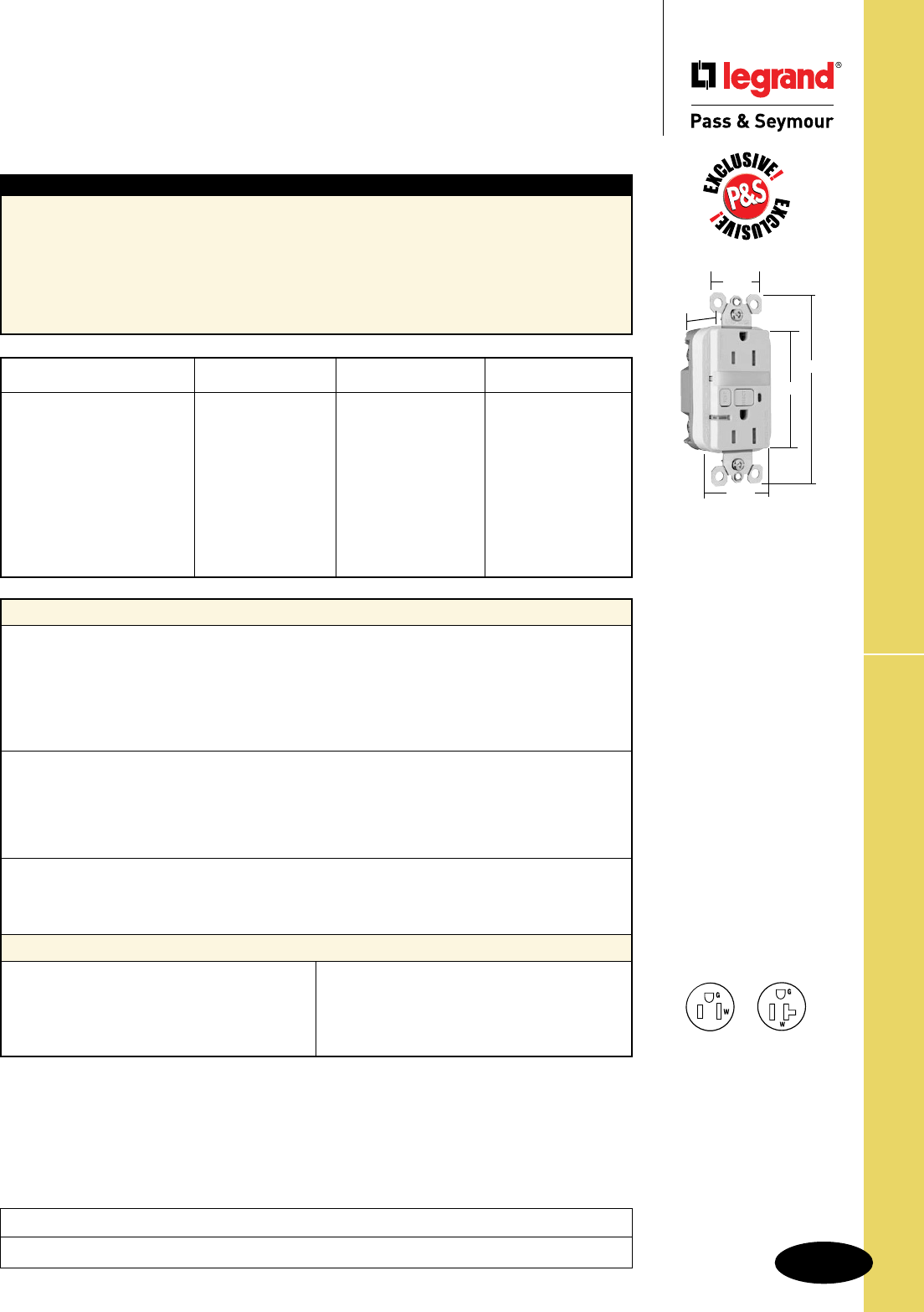
Technical Specifications
S-63
Tamper-Resistant Nightlight/GFCIs
Technical Specifications
Tamper-Resistant Nightlight/
GFCI Receptacles
2 Pole, 3 Wire Grounding 15 & 20A, 125VAC
Project
Location/Type
Typical Specications
Manufacturer’s Identification: Legrand/Pass & Seymour 1595NTLTRCC4
Description: Straight Blade Duplex Tamper-Resistant Nightlight/GFCI Receptacle
Type: 2 Pole, 3 Wire Grounding
Rating: 20A, 125VAC Feed Thru; 15 or 20A, 125VAC Face
3rd Party Compliance: cULus Listed, File Number E42190; Standard UL498 Tamper-Resistant, Attachment
Plugs and Receptacles UL943 GFCIs. Federal Specification WC596. Standard CSA-C22.2 No. 42,
General Use Receptacles, CSA-C22.2 No. 144 GFCIs. Conforms to NEMA WD-1 and WD-6.
Performance
Electrical
Dielectric Withstands 1500V minimum
Trip Level 4 to 6 mA
Trip Time .025 Second Nominal
Frequency 60 Hz
Voltage 125VAC
Voltage Range 102-132VAC
Mechanical
Indicator Light (LED) Red, ON when GFCI is tripped
Terminal Identification Terminals identified in accordance with UL498
(Hot, White, Green)
Terminal Accommodation #14 – #10 AWG solid or stranded copper conductor only
Product Identification Ratings are a permanent part of device
Environmental
Operating Temperature -35°C to +66°C
Maximum Humidity 95%
Flammability UL94 V2
Materials
Face Nylon
Body Nylon
Contacts .03" Brass (.8)
Mounting Straps .05" Zinc-Plated Steel (1.3)
Terminal Screws Steel #8 - 32
Hex Head Grounding Screw Steel (Green)
Flat Head Mounting Screws Zinc-Plated Steel
Test/Reset Buttons Nylon
Nightlight Lens Lexan®
Tamper-Resistant Shutter Thermoplastic
NEMA
Catalog Number Color Rating Conguration No.
r 1595NTLTRICC4 Ivory 15A 125VAC 5-15R
r 1595NTLTRWCC4 White 15A 125VAC 5-15R
r 1595NTLTRBKCC4 Black 15A 125VAC 5-15R
r 1595NTLTRLACC4 Light Almond 15A 125VAC 5-15R
r 1595NTLTRBNCC4 Brushed Nickel 15A 125VAC 5-15R
r 1595NTLTRTICC4 Titanium 15A 125VAC 5-15R
r 2095NTLTRI Ivory 20A 125VAC 5-20R
r 2095NTLTRW White 20A 125VAC 5-20R
r 2095NTLTRGRY Gray 20A 125VAC 5-20R
r 2095NTLTRLA Light Almond 20A 125VAC 5-20R
Dimensions for
15 & 20 Amp
1.25"
1.13"
4.20"
2.62"
1.72"
NEMA
5-15R
NEMA
5-20R
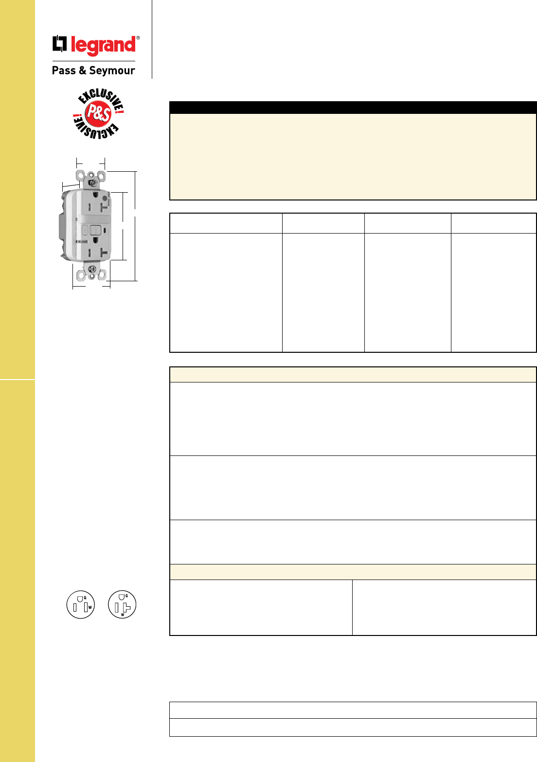
Technical Specifications
S-64
HG Tamper-Resistant Nightlight/GFCIs
Technical Specifications
Hospital Grade Tamper-Resistant
Nightlight/ GFCI Receptacles
2 Pole, 3 Wire Grounding 15 & 20A, 125VAC
Project
Location/Type
Typical Specications
Manufacturer’s Identification: Legrand/Pass & Seymour 1595HGNTLTR
Description: Straight Blade Duplex Hospital Grade Tamper-Resistant Nightlight/GFCI Receptacle
Type: 2 Pole, 3 Wire Grounding
Rating: 20A, 125VAC Feed Thru; 15 or 20A, 125VAC Face
3rd Party Compliance: cULus Listed, File Number E42190, Standard UL498 Tamper-Resistant,
Attachment Plugs and Receptacles UL943 GFCIs. Federal Specification WC596 Hospital Grade.
Standard CSA-C22.2 No. 42, General Use Receptacles, CSA-C22.2 No. 144 GFCIs. Conforms to
NEMA WD-1 and WD-6.
Performance
Electrical
Dielectric Withstands 1500V minimum
Trip Level 4 to 6 mA
Trip Time .025 Second Nominal
Frequency 60 Hz
Voltage 125VAC
Voltage Range 102-132VAC
Mechanical
Indicator Light (LED) Red, ON when GFCI is tripped
Terminal Identification Terminals identified in accordance with UL498
(Hot, White, Green)
Terminal Accommodation #14 – #10 AWG solid or stranded copper conductor only
Product Identification Ratings are a permanent part of the device
Environmental
Operating Temperature -35°C to +66°C
Maximum Humidity 95%
Flammability UL94 V2
Materials
Face Nylon
Body Nylon
Contacts .03" Brass (.8)
Mounting Strap .05" Zinc-Plated Steel (1.3)
Terminal Screws Steel #8 - 32
Hex Head Grounding Screw Steel (Green)
Flat Head Mounting Screw Zinc-Plated Steel
Test/Reset Buttons Nylon
Nightlight Lens Lexan®
Tamper-Resistant Shutter Thermoplastic
Dimensions for
15 & 20 Amp
1.25"
1.13"
4.20"
2.62"
1.72"
NEMA
5-15R
NEMA
5-20R
NEMA
Catalog Number Color Rating Conguration No.
r 1595HGNTLTRI Ivory 15A 125VAC 5-15R
r 1595HGNTLTRW White 15A 125VAC 5-15R
r 1595HGNTLTR Brown 15A 125VAC 5-15R
r 1595HGNTLTRGRY Gray 15A 125VAC 5-15R
r 1595HGNTLTRRED Red 15A 125VAC 5-15R
r 1595HGNTLTRLA Light Almond 15A 125VAC 5-15R
r 2095HGNTLTRI Ivory 20A 125VAC 5-20R
r 2095HGNTLTRW White 20A 125VAC 5-20R
r 2095HGNTLTRGRY Gray 20A 125VAC 5-20R
r 2095HGNTLTRRED Red 20A 125VAC 5-20R
r 2095HGNTLTRLA Light Almond 20A 125VAC 5-20R

Technical Specifications
S-65
Weather-Resistant GFCIs
Technical Specifications
Weather-Resistant GFCI Receptacles
2 Pole, 3 Wire Grounding 15 & 20A, 125VAC
Project
Location/Type
Typical Specications
Manufacturer’s Identification: Legrand/Pass & Seymour 1595TRWR
Description: Straight Blade Duplex Weather-Resistant GFCI Receptacle
Type: 2 Pole, 3 Wire Grounding
Rating: 20A, 125VAC Feed Thru; 15 or 20A, 125VAC Face
3rd Party Compliance: cULus Listed, File Number E42190; Standard UL498 Weather-Resistant,
Tamper-Resistant, Attachment Plugs and Receptacles; UL943 GFCIs. Federal Specification WC596.
Standard CSA-C22.2 No. 42, General Use Receptacles, CSA-C22.2 No. 144 GFCIs. Conforms to
NEMA WD-1 and WD-6.
Performance
Electrical
Dielectric Withstands 1500V minimum
Trip Level 4 to 6 mA
Trip Time .025 Second Nominal
Frequency 60 Hz
Voltage 125VAC
Voltage Range 102-132VAC
Mechanical
Indicator Light (LED) Red, ON when GFCI is tripped
Terminal Identification Terminals identified in accordance with UL498
(Hot, White, Green)
Terminal Accommodation #14 – #10 AWG solid or stranded copper conductor only
Product Identification Ratings are a permanent part of the device
Environmental
Operating Temperature -35°C to +66°C
Maximum Humidity 95%
Flammability UL94 V2
Materials
Face Nylon 66
Body Nylon
Contacts .03" Brass (.8)
Mounting Strap .05" Nickel Post-Plated
Steel (1.3)
Terminal Screws Brass #8 - 32
Hex Head Grounding Screw Steel (Green)
Flat Head Mounting Screws Zinc-Plated Steel
Test/Reset Buttons Nylon 66
Tamper-Resistant Shutter Thermoplastic
NEMA
Catalog Number Color Rating Conguration No.
r 1595TRWRI Ivory 15A 125VAC 5-15R
r 1595TRWRW White 15A 125VAC 5-15R
r 1595TRWR Brown 15A 125VAC 5-15R
r 1595TRWRLA Light Almond 15A 125VAC 5-15R
r 2095TRWRI Ivory 20A 125VAC 5-20R
r 2095TRWRW White 20A 125VAC 5-20R
r 2095TRWR Brown 20A 125VAC 5-20R
r 2095TRWRGRY Gray 20A 125VAC 5-20R
r 2095TRWRLA Light Almond 20A 125VAC 5-20R
NEMA
5-15R
NEMA
5-20R
Dimensions for
15 & 20 Amp
1.25"
1.13"
4.20"
2.62"
1.72"
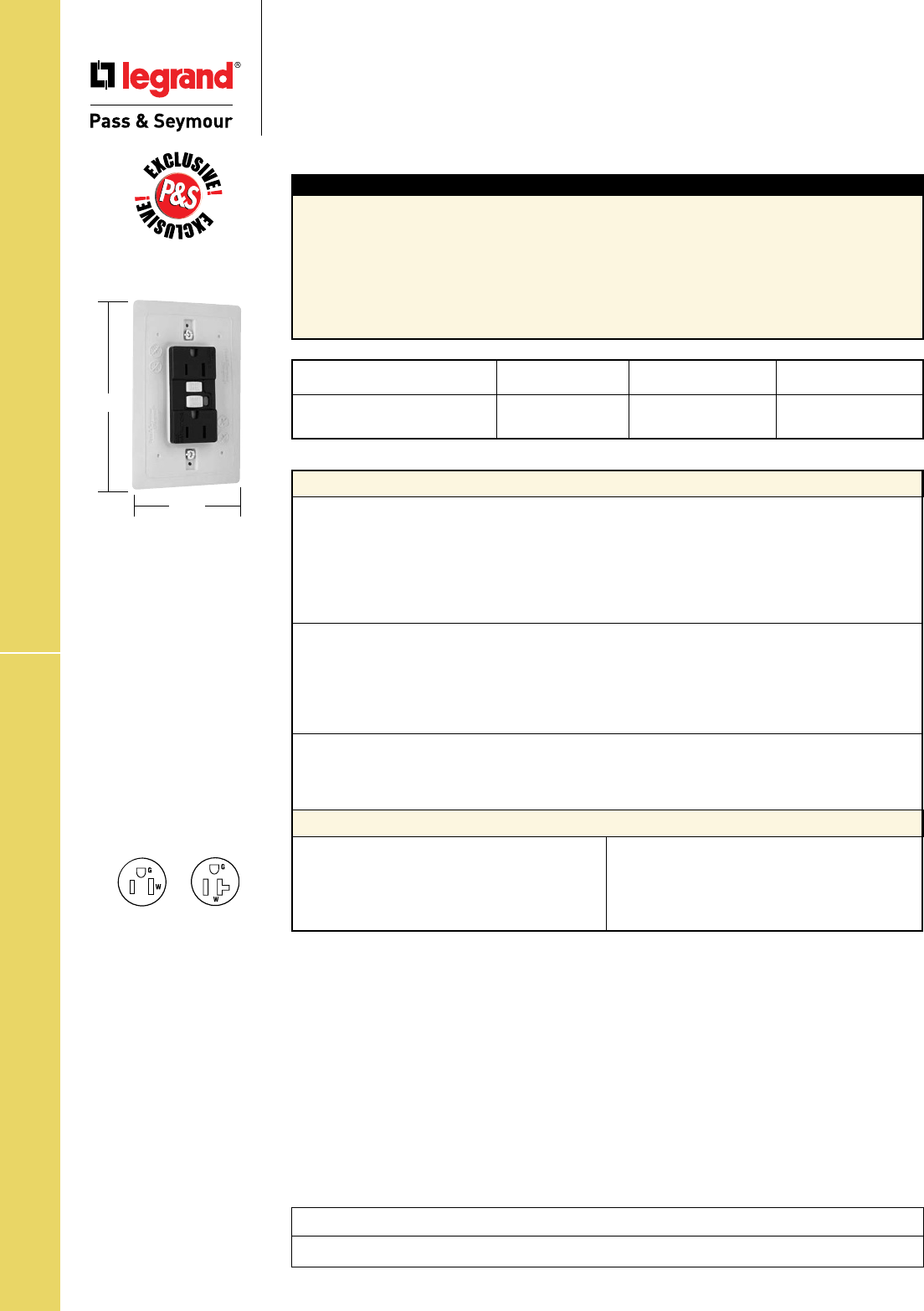
Technical Specifications
S-66
Weather-Resistant DuraShield™ GFCIs
Technical Specifications
Weather-Resistant DuraShield™
GFCI Receptacles
2 Pole, 3 Wire Grounding 15 & 20A, 125VAC
Project
Location/Type
5.125"
3.313"
Typical Specications
Manufacturer’s Identification: Legrand/Pass & Seymour 1595DSWRBKCC4
Description: Straight Blade Duplex Weather-Resistant GFCI Receptacle
Type: 2 Pole, 3 Wire Grounding
Rating: 20A, 125VAC Feed Thru; 15 or 20A, 125VAC Face
3rd Party Compliance: cULus Listed, File Number E42190; Standard UL498 Weather-Resistant,
Attachment Plugs and Receptacles; UL943 GFCIs. Standard CSA-C22.2 No. 42, General Use
Receptacles, CSA-C22.2 No. 144 GFCIs.Conforms to NEMA WD-1 and WD-6.
NEMA
Catalog Number Color Rating Conguration No.
r 1595DSWRBKCC4 Black 15A 125VAC 5-15R
r 2095DSWRBK Black 20A 125VAC 5-20R
NEMA
5-15R
NEMA
5-20R
Dimensions for
15 & 20 Amp
Performance
Electrical
Dielectric Withstands 1500V minimum
Trip Level 4 to 6 mA
Trip Time .025 Second Nominal
Frequency 60 Hz
Voltage 125VAC
Voltage Range 102-132VAC
Mechanical
Indicator Light (LED) Red, ON when GFCI is tripped
Terminal Identification Terminals identified in accordance with UL498
(Hot, White, Green)
Terminal Accommodation #14 – #10 AWG solid or stranded copper conductor only
Product Identification Ratings are a permanent part of the device
Environmental
Operating Temperature -35°C to +66°C
Maximum Humidity 95%
Flammability UL94 V2
Materials
Face Nylon 66
Body Nylon
Contacts .03" Brass (.8)
Mounting Strap .05" Nickel Post-Plated
Steel (1.3)
Terminal Screws Brass #8 - 32
Hex Head Grounding Screw Steel (Green)
Flat Head Mounting Screws Zinc-Plated Steel
Test/Reset Buttons Nylon 66
Integral Gasket Santoprene®
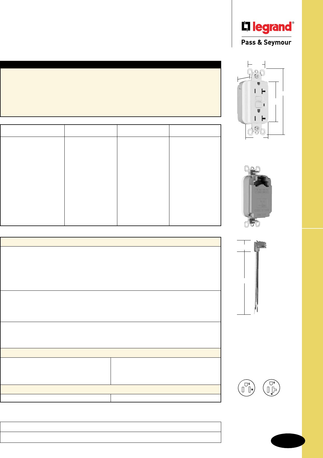
Technical Specifications
S-67
PlugTailTM Spec Grade GFCIs
Technical Specifications
PlugTailTM Specification Grade
GFCI Receptacles
2 Pole, 3 Wire Grounding 15 & 20A, 125VAC
Project
Location/Type
NEMA
5-15R
NEMA
5-20R
Dimensions for
15 & 20 Amp
1.25"
1.20"
4.20"
2.62"
1.72"
Typical Specications
Manufacturer’s Identification: Legrand/Pass & Seymour PT1595
Description: PlugTail™ Straight Blade Duplex GFCI Receptacle
Type: 2 Pole, 3 Wire Grounding
Rating: 20A, 125VAC Feed Thru; 15 or 20A, 125VAC Face
3rd Party Compliance: cULus Listed File Number E42190 and E140596, Standard UL498 Attachment
Plugs and Receptacles, UL943 GFCIs. Federal Specification WC596. Standard CSA C22.2 No. 42
General Use Receptacles, CSA C22.2 No. 144 GFCIs. Conforms to NEMA WD-1 and WD-6.
NEMA
Catalog Number Color Rating Conguration No.
❐PT1595I Ivory 15A 125VAC 5-15R
❐PT1595W White 15A 125VAC 5-15R
❐PT1595 Brown 15A 125VAC 5-15R
❐PT1595GRY Gray 15A 125VAC 5-15R
❐PT1595BK Black 15A 125VAC 5-15R
❐PT1595RED Red 15A 125VAC 5-15R
❐PT1595LA Light Almond 15A 125VAC 5-15R
❐PT2095I Ivory 20A 125VAC 5-20R
❐PT2095W White 20A 125VAC 5-20R
❐PT2095 Brown 20A 125VAC 5-20R
❐PT2095GRY Gray 20A 125VAC 5-20R
❐PT2095BK Black 20A 125VAC 5-20R
❐PT2095RED Red 20A 125VAC 5-20R
❐PT2095LA Light Almond 20A 125VAC 5-20R
Performance
Electrical
Dielectric Withstands 1500V minimum
Trip Level 4 to 6 mA
Trip Time .025 Second Nominal
Frequency 60 Hz
Voltage 125VAC
Voltage Range 102-132VAC
Mechanical
Indicator Light (LED) Red, ON when GFCI is tripped
PlugTail Connector Identification #12 AWG, THHN, copper conductor, 6" leads, stripped,
solid or stranded, for use with PlugTail Receptacles only
Product Identification Ratings are a permanent part of the device
Environmental
Operating Temperature -35°C to +66°C
Maximum Humidity 95%
Flammability UL94 V2
PlugTail™ GFCI Receptacle Materials
PlugTail Connector Materials
Face Nylon
Body Nylon
Contacts .03" Brass (.8)
Mounting Strap .05" Zinc-Plated Steel (1.3)
Flat Head
Mounting Screws Zinc-Plated Steel
Test/Reset Buttons Nylon
Housing Polycarbonate Contacts .030" Brass
PTRA6STR
1.125"
6.375"
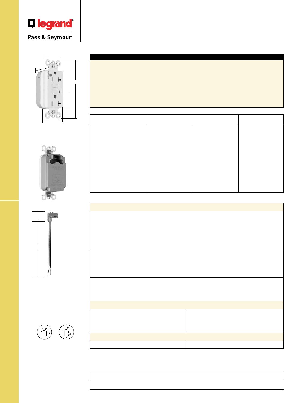
Technical Specifications
S-68
PTRA6STR
1.125"
6.375"
PlugTailTM Hospital Grade GFCIs
Technical Specifications
PlugTailTM Hospital Grade
GFCI Receptacles
2 Pole, 3 Wire Grounding 15 & 20A, 125VAC
Project
Location/Type
Typical Specications
Manufacturer’s Identification: Legrand/Pass & Seymour PT1595HG
Description: PlugTail™ Straight Blade Duplex Hospital Grade GFCI Receptacle
Type: 2 Pole, 3 Wire Grounding
Rating: 20A, 125VAC Feed Thru; 15 or 20A, 125VAC Face
3rd Party Compliance: cULus Listed File Number E42190 and E140596, Standard UL498 Attachment
Plugs and Receptacles, UL943 GFCIs. Federal Specification WC596, Hospital Grade. Standard CSA
C22.2 No. 42 General Use Receptacles, CSA C22.2 No. 144 GFCIs. Conforms to NEMA WD-1 and
WD-6.
NEMA
Catalog Number Color Rating Conguration No.
❐PT1595HGI Ivory 15A 125VAC 5-15R
❐PT1595HGW White 15A 125VAC 5-15R
❐PT1595HG Brown 15A 125VAC 5-15R
❐PT1595HGGRY Gray 15A 125VAC 5-15R
❐PT1595HGRED Red 15A 125VAC 5-15R
❐PT1595HGLA Light Almond 15A 125VAC 5-15R
❐PT2095HGI Ivory 20A 125VAC 5-20R
❐PT2095HGW White 20A 125VAC 5-20R
❐PT2095HG Brown 20A 125VAC 5-20R
❐PT2095HGGRY Gray 20A 125VAC 5-20R
❐PT2095HGRED Red 20A 125VAC 5-20R
❐PT2095HGLA Light Almond 20A 125VAC 5-20R
NEMA
5-15R
NEMA
5-20R
Dimensions for
15 & 20 Amp
1.25"
1.20"
4.20"
2.62"
1.72"
Performance
Electrical
Dielectric Withstands 1500V minimum
Trip Level 4 to 6 mA
Trip Time .025 Second Nominal
Frequency 60 Hz
Voltage 125VAC
Voltage Range 102-132VAC
Mechanical
Indicator Light (LED) Red, ON when GFCI is tripped
PlugTail Connector Identification #12 AWG, THHN, copper conductor, 6" leads, stripped,
solid or stranded, for use with PlugTail Receptacles only
Product Identification Ratings are a permanent part of the device
Environmental
Operating Temperature -35°C to +66°C
Maximum Humidity 95%
Flammability UL94 V2
PlugTail™ GFCI Receptacle Materials
PlugTail Connector Materials
Face Nylon
Body Nylon
Contacts .03" Brass (.8)
Mounting Strap .05" Zinc-Plated Steel (1.3)
Flat Head
Mounting Screws Zinc-Plated Steel
Test/Reset Buttons Nylon
Housing Polycarbonate Contacts .030" Brass
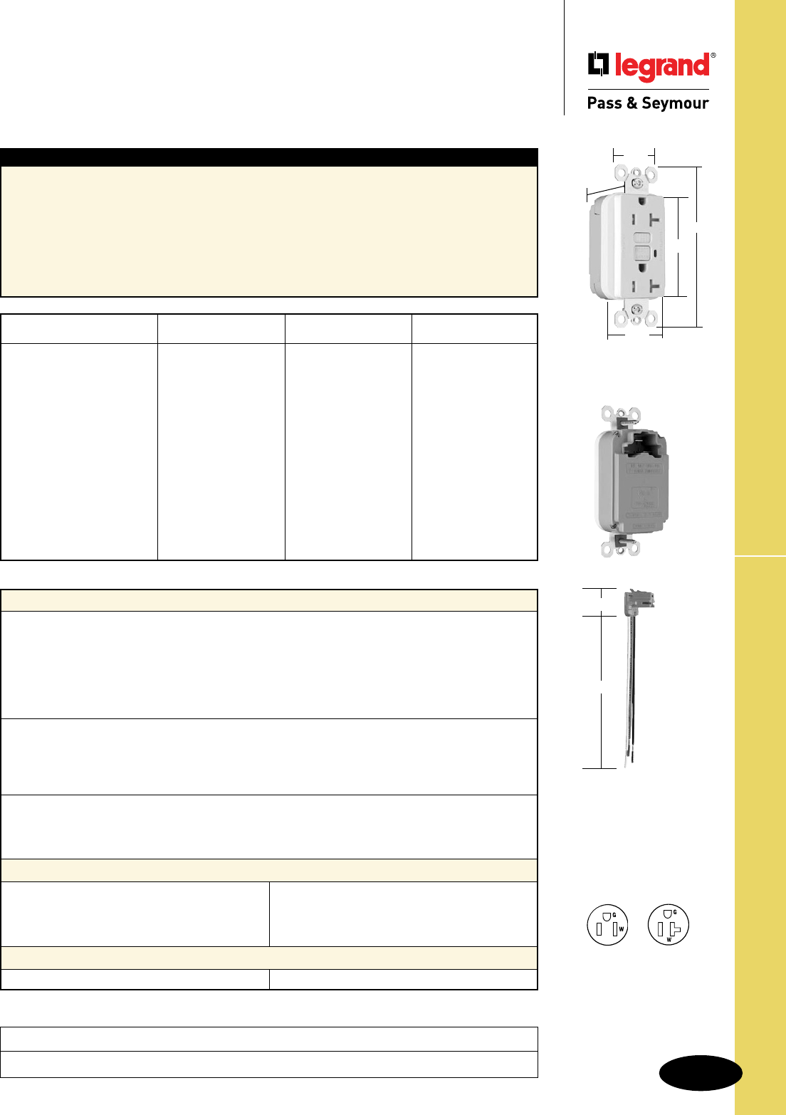
Technical Specifications
S-69
PlugTailTM Tamper-Resistant GFCIs
Technical Specifications
PlugTailTM Specification Grade
Tamper-Resistant GFCI Receptacles
2 Pole, 3 Wire Grounding 15 & 20A, 125VAC
Project
Location/Type
1.20"
1.25"
4.20"
2.62"
1.72"
PTRA6STR
1.125"
6.375"
Dimensions for
15 & 20 Amp
Typical Specications
Manufacturer’s Identification: Legrand/Pass & Seymour PT1595NTL
Description: PlugTail™ Straight Blade Duplex Tamper-Resistant GFCI Receptacle
Type: 2 Pole, 3 Wire Grounding
Rating: 20A, 125VAC Feed Thru; 15 or 20A, 125VAC Face
3rd Party Compliance: cULus Listed File Number E42190 and E140596, Standard UL498 Tamper-
Resistant, Attachment Plugs and Receptacles, UL943 GFCIs. Federal Specification WC596. Standard
CSA C22.2 No. 42 General Use Receptacles, CSA C22.2 No. 144 GFCIs. Conforms to NEMA WD-1
and WD-6.
NEMA
Catalog Number Color Rating Conguration No.
❐PT1595TRI Ivory 15A 125VAC 5-15R
❐PT1595TRW White 15A 125VAC 5-15R
❐PT1595TR Brown 15A 125VAC 5-15R
❐PT1595TRGRY Gray 15A 125VAC 5-15R
❐PT1595TRBK Black 15A 125VAC 5-15R
❐PT1595TRRED Red 15A 125VAC 5-15R
❐PT1595TRLA Light Almond 15A 125VAC 5-15R
❐PT2095TRI Ivory 20A 125VAC 5-20R
❐PT2095TRW White 20A 125VAC 5-20R
❐PT2095TR Brown 20A 125VAC 5-20R
❐PT2095TRGRY Gray 20A 125VAC 5-20R
❐PT2095TRBK Black 20A 125VAC 5-20R
❐PT2095TRRED Red 20A 125VAC 5-20R
❐PT2095TRLA Light Almond 20A 125VAC 5-20R
NEMA
5-15R
NEMA
5-20R
Performance
Electrical
Dielectric Withstands 1500V minimum
Trip Level 4 to 6 mA
Trip Time .025 Second Nominal
Frequency 60 Hz
Voltage 125VAC
Voltage Range 102-132VAC
Mechanical
Indicator Light (LED) Red, ON when GFCI is tripped
PlugTail Connector Identification #12 AWG, THHN, copper conductor, 6" leads, stripped,
solid or stranded, for use with PlugTail Receptacles only
Product Identification Ratings are a permanent part of the device
Environmental
Operating Temperature -35°C to +66°C
Maximum Humidity 95%
Flammability UL94 V2
PlugTail™ GFCI Receptacle Materials
PlugTail Connector Materials
Face Nylon
Body Nylon
Contacts .03" Brass (.8)
Mounting Strap .05" Zinc-Plated Steel (1.3)
Flat Head Mounting Screws Zinc-Plated Steel
Test/Reset Buttons Nylon
Tamper-Resistant Shutter Thermoplastic
Housing Polycarbonate Contacts .030" Brass
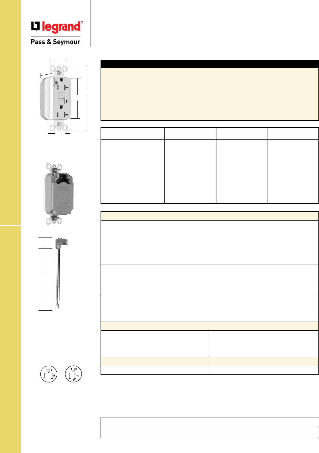
Technical Specifications
S-70
PlugTailTM HG Tamper-Resistant GFCIs
Technical Specifications
PlugTailTM Hospital Grade
Tamper-Resistant GFCI Receptacles
2 Pole, 3 Wire Grounding 15 & 20A, 125VAC
Project
Location/Type
Typical Specications
Manufacturer’s Identification: Legrand/Pass & Seymour PT1595HGTR
Description: PlugTail™ Straight Blade Duplex Hospital Grade Tamper-Resistant GFCI Receptacle
Type: 2 Pole, 3 Wire Grounding
Rating: 20A, 125VAC Feed Thru; 15 or 20A, 125VAC Face
3rd Party Compliance: cULus Listed File Number E42190 and E140596, Standard UL498 Tamper-
Resistant, Attachment Plugs and Receptacles, UL943 GFCIs. Federal Specification WC596 Hospital
Grade. Standard CSA C22.2 No. 42 General Use Receptacles, CSA C22.2 No. 144 GFCIs.
Conforms to NEMA WD-1 and WD-6.
NEMA
Catalog Number Color Rating Conguration No.
❐PT1595HGTRI Ivory 15A 125VAC 5-15R
❐PT1595HGTRW White 15A 125VAC 5-15R
❐PT1595HGTRGRY Gray 15A 125VAC 5-15R
❐PT1595HGTRRED Red 15A 125VAC 5-15R
❐PT1595HGTRLA Light Almond 15A 125VAC 5-15R
❐PT2095HGTRI Ivory 20A 125VAC 5-20R
❐PT2095HGTRW White 20A 125VAC 5-20R
❐PT2095HGTRGRY Gray 20A 125VAC 5-20R
❐PT2095HGTRRED Red 20A 125VAC 5-20R
❐PT2095HGTRLA Light Almond 20A 125VAC 5-20R
Performance
Electrical
Dielectric Withstands 1500V minimum
Trip Level 4 to 6 mA
Trip Time .025 Second Nominal
Frequency 60 Hz
Voltage 125VAC
Voltage Range 102-132VAC
Mechanical
Indicator Light (LED) Red, ON when GFCI is tripped
PlugTail Connector Identification #12 AWG, THHN, copper conductor, 6" leads, stripped,
solid or stranded, for use with PlugTail Receptacles only
Product Identification Ratings are a permanent part of the device
Environmental
Operating Temperature -35°C to +66°C
Maximum Humidity 95%
Flammability UL94 V2
PlugTail™ GFCI Receptacle Materials
PlugTail Connector Materials
Face Nylon
Body Nylon
Contacts .03" Brass (.8)
Mounting Strap .05" Zinc-Plated Steel (1.3)
Flat Head Mounting Screws Zinc-Plated Steel
Test/Reset Buttons Nylon
Tamper-Resistant Shutter Thermoplastic
Housing Polycarbonate Contacts .030" Brass
PTRA6STR
1.125"
6.375"
Dimensions for
15 & 20 Amp
NEMA
5-15R
NEMA
5-20R
1.25"
1.20"
4.20"
2.62"
1.72"
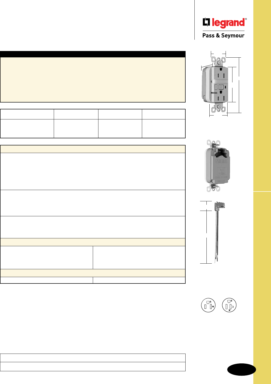
Technical Specifications
S-71
PlugTailTM TR Nightlight/GFCIs
Technical Specifications
PlugTailTM Specification Grade Tamper-Resistant
Nightlight/GFCI Receptacles
2 Pole, 3 Wire Grounding 15 & 20A, 125VAC
Project
Location/Type
1.25"
1.20"
4.20"
2.62"
1.72"
PTRA6STR
1.125"
6.375"
Performance
Electrical
Dielectric Withstands 1500V minimum
Trip Level 4 to 6 mA
Trip Time .025 Second Nominal
Frequency 60 Hz
Voltage 125VAC
Voltage Range 102-132VAC
Mechanical
Indicator Light (LED) Red, ON when GFCI is tripped
PlugTail Connector Identification #12 AWG, THHN, copper conductor, 6" leads, stripped,
solid or stranded, for use with PlugTail Receptacles only
Product Identification Ratings are a permanent part of the device
Environmental
Operating Temperature -35°C to +66°C
Maximum Humidity 95%
Flammability UL94 V2
PlugTail™ GFCI Receptacle Materials
PlugTail Connector Materials
Face Nylon
Body Nylon
Contacts .03" Brass (.8)
Mounting Strap .05" Nickel-Plated Steel (1.3)
Flat Head Mounting Screws Zinc-Plated Steel
Test/Reset Buttons Nylon
Nightlight Lens Lexan®
Tamper-Resistant Shutter Thermoplastic
Housing Polycarbonate Contacts .030" Brass
Typical Specications
Manufacturer’s Identification: Legrand/Pass & Seymour PT1595NTL
Description: PlugTail™ Straight Blade Duplex Tamper-Resistant Nightlight/GFCI Receptacle
Type: 2 Pole, 3 Wire Grounding
Rating: 20A, 125VAC Feed Thru; 15 or 20A, 125VAC Face
3rd Party Compliance: cULus Listed File Number E42190 and E140596, Standard UL498 Tamper-
Resistant, Attachment Plugs and Receptacles, UL943 GFCIs. Federal Specification WC596. Standard
CSA C22.2 No. 42 General Use Receptacles, CSA C22.2 No. 144 GFCIs. Conforms to NEMA WD-1
and WD-6.
NEMA
Catalog Number Color Rating Conguration No.
❐PT1595NTLTRI Ivory 15A 125VAC 5-15R
❐PT2095NTLTRI Ivory 20A 125VAC 5-20R
❐PT2095NTLTRW White 20A 125VAC 5-20R
NEMA
5-15R
NEMA
5-20R
Dimensions for
15 & 20 Amp
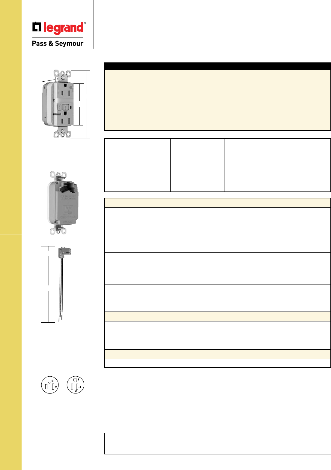
Technical Specifications
S-72
PlugTailTM HG TR Nightlight/GFCIs
Technical Specifications
PlugTailTM Hospital Grade Tamper-Resistant
Nightlight/GFCI Receptacles
2 Pole, 3 Wire Grounding 15 & 20A, 125VAC
Project
Location/Type
Performance
Electrical
Dielectric Withstands 1500V minimum
Trip Level 4 to 6 mA
Trip Time .025 Second Nominal
Frequency 60 Hz
Voltage 125VAC
Voltage Range 102-132VAC
Mechanical
Indicator Light (LED) Red, ON when GFCI is tripped
PlugTail Connector Identification #12 AWG, THHN, copper conductor, 6" leads, stripped,
solid or stranded, for use with PlugTail Receptacles only
Product Identification Ratings are a permanent part of the device
Environmental
Operating Temperature -35°C to +66°C
Maximum Humidity 95%
Flammability UL94 V2
PlugTail™ GFCI Receptacle Materials
PlugTail Connector Materials
Face Nylon
Body Nylon
Contacts .03" Brass (.8)
Mounting Strap .05" Zinc-Plated Steel (1.3)
Flat Head Mounting Screws Zinc-Plated Steel
Test/Reset Buttons Nylon
Nightlight Lens Lexan®
Housing Polycarbonate Contacts .030" Brass
Typical Specications
Manufacturer’s Identification: Legrand/Pass & Seymour PT1595HG
Description: PlugTail™ Straight Blade Duplex Hospital Grade Tamper-Resistant
Nightlight/GFCI Receptacle
Type: 2 Pole, 3 Wire Grounding
Rating: 20A, 125VAC Feed Thru; 15 or 20A, 125VAC Face
3rd Party Compliance: cULus Listed File Number E42190 and E140596, Standard UL498 Attachment
Plugs and Receptacles, UL943 GFCIs. Federal Specification WC596, Hospital Grade. Standard CSA
C22.2 No. 42 General Use Receptacles, CSA C22.2 No. 144 GFCIs. Conforms to NEMA WD-1 and
WD-6.
NEMA
Catalog Number Color Rating Conguration No.
❐PT1595HGNTLTRI Ivory 15A 125VAC 5-15R
❐PT1595HGNTLTRW White 15A 125VAC 5-15R
❐PT1595HGNTLTRRED Red 15A 125VAC 5-15R
❐PT2095HGNTLTRI Ivory 20A 125VAC 5-20R
❐PT2095HGNTLTRW White 20A 125VAC 5-20R
❐PT2095HGNTLTRLA Light Almond 20A 125VAC 5-20R
NEMA
5-15R
NEMA
5-20R
Dimensions for
15 & 20 Amp
PTRA6STR
1.125"
6.375"
1.25"
1.20"
4.20"
2.62"
1.72"
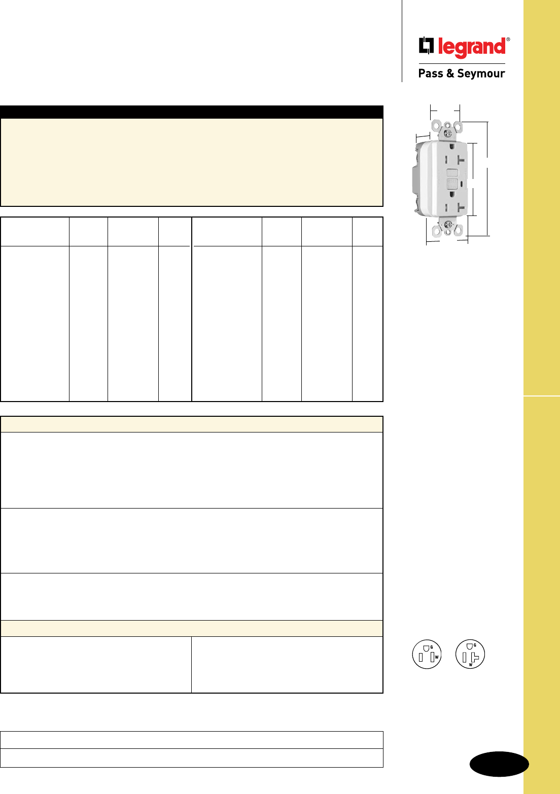
Technical Specifications
S-73
NAFTA-Compliant & RoHS-Compliant GFCIs
Technical Specifications
NAFTA-Compliant & RoHS-Compliant
GFCI Receptacles
2 Pole, 3 Wire Grounding 15 & 20A, 125VAC
Project
Location/Type
Typical Specications
Manufacturer’s Identification: Legrand/Pass & Seymour 1595TRNA, 1595NA, 1595R
Description: Straight Blade Duplex NAFTA-Compliant GFCI Receptacle, Duplex NAFTA-Compliant
Tamper-Resistant GFCI Receptacle & Duplex RoHS-Compliant GFCI Receptacle
Type: 2 Pole, 3 Wire Grounding
Rating: 20A, 125VAC Feed Thru; 15 or 20A, 125VAC Face
3rd Party Compliance: cULus Listed, File Number E42190; Standard UL498, Attachment Plugs and
Receptacles UL943 GFCIs. Federal Specification WC596. Standard CSA-C22.2 No. 42, General Use
Receptacles, CSA-C22.2 No. 144 GFCIs. Conforms to NEMA WD-1 and WD-6.
Performance
Electrical
Dielectric Withstands 1500V minimum
Trip Level 4 to 6 mA
Trip Time .025 Second Nominal
Frequency 60 Hz
Voltage 125VAC
Voltage Range 102-132VAC
Mechanical
Indicator Light (LED) Red, ON when GFCI is tripped
Terminal Identification Terminals identified in accordance with UL498
(Hot, White, Green)
Terminal Accommodation #14 – #10 AWG solid or stranded copper conductor only
Product Identification Ratings are a permanent part of device
Environmental
Operating Temperature -35°C to +66°C
Maximum Humidity 95%
Flammability UL94 V2
Materials
Face Nylon
Body Nylon
Contacts .03" Brass (.8)
Mounting Straps .05" Zinc-Plated Steel (1.3)
Terminal Screws Steel #8 - 32
Hex Head Grounding Screw Steel (Green)
Flat Head Mounting Screws Zinc-Plated Steel
Test/Reset Buttons Nylon
Tamper-Resistant Shutter* Thermoplastic
Dimensions for
15 & 20 Amp
1.13"
1.72"
1.25"
2.62"
4.20"
NEMA
5-15R
NEMA
5-20R
NAFTA-Compliant GFCI
Receptacles are ideal for
use on projects subject to
the provisions of the Buy
American Act.
Catalog NEMA
Number Color Rating Cong.
No.
r
1595TRNAI Ivory 15A 125VAC 5-15R
r 1595TRNAW White 15A 125VAC 5-15R
r 1595TRNA Brown 15A 125VAC 5-15R
r 1595TRNAGRY Gray 15A 125VAC 5-15R
r 1595TRNABK Black 15A 125VAC 5-15R
r 1595TRNALA Lt Almond 15A 125VAC 5-15R
r 2095TRNAI Ivory 20A 125VAC 5-20R
r 2095TRNAW White 20A 125VAC 5-20R
r 2095TRNA Brown 20A 125VAC 5-20R
r 2095TRNAGRY Gray 20A 125VAC 5-20R
r 2095TRNABK Black 20A 125VAC 5-20R
r 2095TRNALA Lt Almond 20A 125VAC 5-20R
r 1595NAI Ivory 15A 125VAC 5-15R
r 1595NAW White 15A 125VAC 5-15R
Catalog NEMA
Number Color Rating Cong.
No.
r 1595NA Brown 15A 125VAC 5-15R
r 1595NAGRY Gray 15A 125VAC 5-15R
r 1595NABK Black 15A 125VAC 5-15R
r 1595NALA Lt Almond 15A 125VAC 5-15R
r 2095NAI Ivory 20A 125VAC 5-20R
r 2095NAW White 20A 125VAC 5-20R
r 2095NA Brown 20A 125VAC 5-20R
r 2095NAGRY Gray 20A 125VAC 5-20R
r 2095NABK Black 20A 125VAC 5-20R
r 2095NALA Lt Almond 20A 125VAC 5-20R
r
1595RI Ivory 15A 125VAC 5-15R
r 1595RW White 15A 125VAC 5-15R
r 1595RLA Lt. Almond 15A 125VAC 5-15R
RoHS-Compliant GFCI
Receptacles meet
the requirements of
Restriction of Hazardous
Substances directives and
regulations.
*Tamper-Resistant GFCIs.
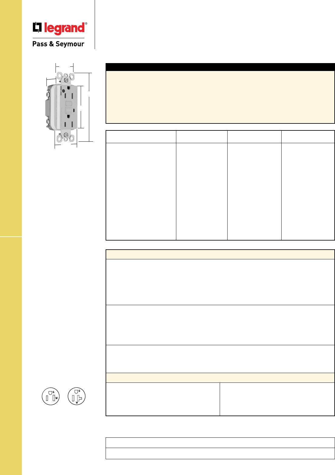
Technical Specifications
S-74
NAFTA-Compliant Hospital Grade
GFCI Receptacles
2 Pole, 3 Wire Grounding 15 & 20A, 125VAC
NAFTA-Compliant Hospital Grade GFCIs
Project
Location/Type
Typical Specications
Manufacturer’s Identification: Legrand/Pass & Seymour 2095HGTRNA, 1595HTNA
Description: Straight Blade Duplex Hospital Grade NAFTA-Compliant GFCI Receptacle & Duplex
Tamper-Resistant Hospital Grade NAFTA-Compliant GFCI Receptacle
Type: 2 Pole, 3 Wire Grounding
Rating: 20A, 125VAC Feed Thru; 15 or 20A, 125VAC Face
3rd Party Compliance: cULus Listed, File Number E42190, Standard UL498, Attachment Plugs and
Receptacles UL943 GFCIs. Federal Specification WC596 Hospital Grade. Standard CSA-C22.2 No. 42,
General Use Receptacles, CSA-C22.2 No. 144 GFCIs. Conforms to NEMA WD-1 and WD-6.
Performance
Electrical
Dielectric Withstands 1500V minimum
Trip Level 4 to 6 mA
Trip Time .025 Second Nominal
Frequency 60 Hz
Voltage 125VAC
Voltage Range 102-132VAC
Mechanical
Indicator Light (LED) Red, ON when GFCI is tripped
Terminal Identification Terminals identified in accordance with UL498
(Hot, White, Green)
Terminal Accommodation #14 – #10 AWG solid or stranded copper conductor only
Product Identification Ratings are a permanent part of the device
Environmental
Operating Temperature -35°C to +66°C
Maximum Humidity 95%
Flammability UL94 V2
Materials
Face Nylon
Body Nylon
Contacts .03" Brass (.8)
Mounting Strap .05" Zinc-Plated Steel (1.3)
Terminal Screws Steel #8 - 32
Hex Head Grounding Screw Steel (Green)
Flat Head Mounting Screw Zinc-Plated Steel
Test/Reset Buttons Nylon
Tamper-Resistant Shutter* Thermoplastic
NEMA
Catalog Number Color Rating Conguration No.
r 2095HGTRNAI Ivory 20A 125VAC 5-20R
r 2095HGTRNAW White 20A 125VAC 5-20R
r 2095HGTRNAGRY Gray 20A 125VAC 5-20R
r 2095HGTRNARED Red 20A 125VAC 5-20R
r 2095HGTRNALA Light Almond 20A 125VAC 5-20R
r 1595HGNAI Ivory 15A 125VAC 5-15R
r 1595HGNAW White 15A 125VAC 5-15R
r 1595HGNARED Red 15A 125VAC 5-15R
r 2095HGNAI Ivory 20A 125VAC 5-20R
r 2095HGNAW White 20A 125VAC 5-20R
r 2095HGNA Brown 20A 125VAC 5-20R
r 2095HGNAGRY Gray 20A 125VAC 5-20R
r 2095HGNARED Red 20A 125VAC 5-20R
r 2095HGNALA Light Almond 20A 125VAC 5-20R
Dimensions for
15 & 20 Amp
1.72"
1.25"
2.62"
.98"
4.20"
NEMA
5-15R
NEMA
5-20R
NAFTA-Compliant GFCI
Receptacles are ideal for
use on projects subject to
the provisions of the Buy
American Act.

Technical Specifications
S-75
NAFTA-Compliant PlugTail™ GFCI Receptacles
Technical Specifications
NAFTA-Compliant
PlugTail™ GFCI Receptacles
2 Pole, 3 Wire Grounding 15 & 20A, 125VAC
Project
Location/Type
Typical Specications
Manufacturer’s Identification: Legrand/Pass & Seymour PT1595NA, PT1595TRNA
Description: PlugTail™ Straight Blade Duplex NAFTA-Compliant GFCI Receptacle & Straight Blade
Duplex Tamper-Resistant NAFTA-Compliant GFCI Receptacle
Type: 2 Pole, 3 Wire Grounding
Rating: 20A, 125VAC Feed Thru; 15 or 20A, 125VAC Face
3rd Party Compliance: cULus Listed File Number E42190 and E140596, Standard UL498, Attachment
Plugs and Receptacles, UL943 GFCIs. Federal Specification WC596. Standard CSA C22.2 No. 42
General Use Receptacles, CSA C22.2 No. 144 GFCIs. Conforms to NEMA WD-1 and WD-6.
NEMA
Catalog Number Color Rating Conguration No.
❐PT1595NAI Ivory 15A 125VAC 5-15R
❐PT1595NAW White 15A 125VAC 5-15R
❐PT1595NAGRY Gray 15A 125VAC 5-15R
❐PT1595NALA Light Almond 15A 125VAC 5-15R
❐PT2095NAI Ivory 20A 125VAC 5-20R
❐PT2095NAW White 20A 125VAC 5-20R
❐PT2095NAGRY Gray 20A 125VAC 5-20R
❐PT2095NABK Black 20A 125VAC 5-20R
❐PT2095NALA Light Almond 20A 125VAC 5-20R
❐PT2095TRNAI Ivory 20A 125VAC 5-20R
❐PT2095TRNAW White 20A 125VAC 5-20R
❐PT2095TRNAGRY Gray 20A 125VAC 5-20R
❐PT2095TRNALA Light Almond 20A 125VAC 5-20R
❐PT1595NTLTRNAI Ivory 15A 125VAC 5-15R
❐PT1595NTLTRNAW White 15A 125VAC 5-15R
❐PT2095NTLTRNAI Ivory 15A 125VAC 5-15R
❐PT2095NTLTRNAW White 15A 125VAC 5-15R
Performance
Electrical
Dielectric Withstands 1500V minimum
Trip Level 4 to 6 mA
Trip Time .025 Second Nominal
Frequency 60 Hz
Voltage 125VAC
Voltage Range 102-132VAC
Mechanical
Indicator Light (LED) Red, ON when GFCI is tripped
PlugTail Connector Identification #12 AWG, THHN, copper conductor, 6" leads, stripped,
solid or stranded, for use with PlugTail Receptacles only
Product Identification Ratings are a permanent part of the device
Environmental
Operating Temperature -35°C to +66°C
Maximum Humidity 95%
Flammability UL94 V2
PlugTail™ GFCI Receptacle Materials
PlugTail Connector Materials
Face Nylon
Body Nylon
Contacts .03" Brass (.8)
Mounting Strap .05" Zinc-Plated Steel (1.3)
Flat Head Mounting Screws Zinc-Plated Steel
Test/Reset Buttons Nylon
Tamper-Resistant Shutter Thermoplastic
Housing Polycarbonate Contacts .030" Brass
1.20"
1.25"
4.20"
2.62"
1.72"
PTRA6STR
1.125"
6.375"
Dimensions for
15 & 20 Amp
NEMA
5-15R
NEMA
5-20R
NAFTA-Compliant GFCI
Receptacles are ideal for
use on projects subject to
the provisions of the Buy
American Act.
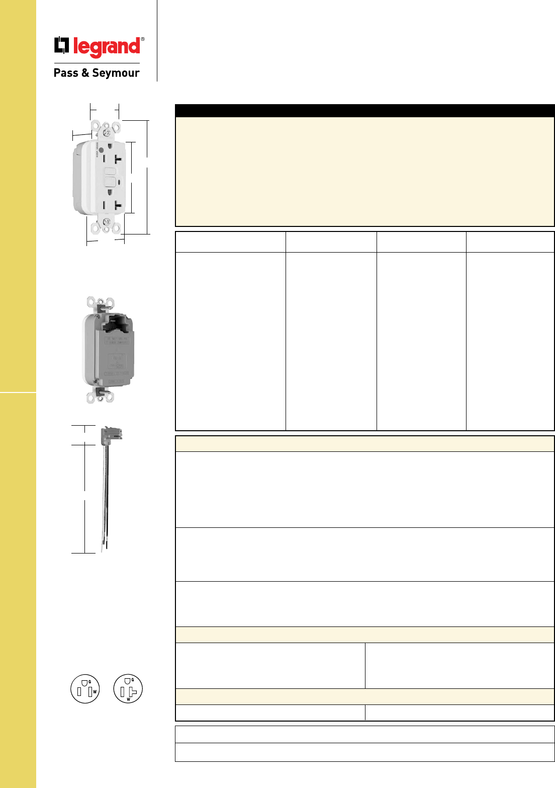
Technical Specifications
S-76
Dimensions for
15 & 20 Amp
1.72"
1.25"
2.62"
4.20"
.98"
NAFTA-Compliant PlugTail™ Hospital Grade GFCIs
Technical Specifications
NAFTA-Compliant PlugTail™
Hospital Grade GFCI Receptacles
15 & 20A, 125VAC 2 Pole, 3 Wire Grounding
PTRA6STR
1.125"
6.375"
Typical Specications
Manufacturer’s Identification: Legrand/Pass & Seymour PT1595HG
Description: PlugTail™ Straight Blade Duplex Hospital Grade NAFTA-Compliant GFCI Receptacle,
Straight Blade Duplex Hospital Grade Tamper-Resistant NAFTA-Compliant GFCI Receptacle & Straight
Blade Duplex Tamper-Resistant NAFTA-Compliant Nightlight/GFCI Receptacle
Type: 2 Pole, 3 Wire Grounding
Rating: 20A, 125VAC Feed Thru; 15 or 20A, 125VAC Face
3rd Party Compliance: cULus Listed File Number E42190 and E140596, Standard UL498, Attachment
Plugs and Receptacles, UL943 GFCIs. Federal Specification WC596, Hospital Grade. Standard CSA
C22.2 No. 42 General Use Receptacles, CSA C22.2 No. 144 GFCIs. Conforms to NEMA WD-1 and
WD-6.
NEMA
Catalog Number Color Rating Conguration No.
❐PT2095HGNAI Ivory 20A 125VAC 5-20R
❐PT2095HGNAW White 20A 125VAC 5-20R
❐PT2095HGNAGRY Gray 20A 125VAC 5-20R
❐PT2095HGNARED Red 20A 125VAC 5-20R
❐PT2095HGNALA Light Almond 20A 125VAC 5-20R
❐PT1595HGTRNAI Ivory 15A 125VAC 5-15R
❐PT1595HGTRNAW White 15A 125VAC 5-15R
❐PT1595HGTRNAGRY Gray 15A 125VAC 5-15R
❐PT1595HGTRNARED Red 15A 125VAC 5-15R
❐PT1595HGTRNALA Light Almond 15A 125VAC 5-15R
❐PT1595HGNTLTRNAI Ivory 15A 125VAC 5-15R
❐PT1595HGNTLTRNAW White 15A 125VAC 5-15R
❐PT1595HGNTLTRNARED Red 15A 125VAC 5-15R
❐PT2095HGNTLTRNAI Ivory 20A 125VAC 5-20R
❐PT2095HGNTLTRNAW White 20A 125VAC 5-20R
❐PT2095HGNTLTRNARED Red 20A 125VAC 5-20R
NEMA
5-15R
NEMA
5-20R
Performance
Electrical
Dielectric Withstands 1500V minimum
Trip Level 4 to 6 mA
Trip Time .025 Second Nominal
Frequency 60 Hz
Voltage 125VAC
Voltage Range 102-132VAC
Mechanical
Indicator Light (LED) Red, ON when GFCI is tripped
PlugTail Connector Identification #12 AWG, THHN, copper conductor, 6" leads, stripped,
solid or stranded, for use with PlugTail Receptacles only
Product Identification Ratings are a permanent part of the device
Environmental
Operating Temperature -35°C to +66°C
Maximum Humidity 95%
Flammability UL94 V2
PlugTail™ GFCI Receptacle Materials
PlugTail Connector Materials
Face Nylon
Body Nylon
Contacts .03" Brass (.8)
Mounting Strap .05" Zinc-Plated Steel (1.3)
Flat Head Mounting Screws Zinc-Plated Steel
Test/Reset Buttons Nylon
Tamper-Resistant Shutter Thermoplastic
Housing Polycarbonate Contacts .030" Brass
Project
Location/Type
NAFTA-Compliant GFCI
Receptacles are ideal for
use on projects subject to
the provisions of the Buy
American Act.

Technical Specifications
S-77
HG Surge Protective Receptacles
Technical Specifications
Hospital Grade Surge Protective
Receptacles
2 Pole, 3 Wire Grounding 15 & 20A, 125VAC
Project
Location/Type
Conforms to the latest revision ANSI/IEEE C62.41 (formerly IEEE587), ANSI/IEEE C62.45.
Typical Specications
Manufacturer’s Identification: Legrand/Pass & Seymour 8200ISP
3rd Party Compliance: UL Listed, File Number E140596, Standard UL498, Attachment Plugs and
Receptacles UL1449 Transient Voltage Surge Suppressor. Federal Specification WC596. CSA Certified,
File Number LR16063, Standard CSA-C22.2 No. 42, ANSI/EEE C62.41 (Formerly IEEE 587),
ANSI/IEEE C62.45 Installation Categories “A” (Ring Wave) “B” (Unidirectional Impulse). Complies with
NEC 410-56(c) and 250-74 exception 4. Conforms to NEMA WD-1 and WD-6.
Catalog NEMA
Number Color Rating Cong.No.
r
8200ISP Ivory 15A 125VAC 5-15R
r
8200WSP White 15A 125VAC 5-15R
r
8200SP Brown 15A 125VAC 5-15R
r
8200GRYSP Gray 15A 125VAC 5-15R
r
8200REDSP Red 15A 125VAC 5-15R
r
8200LASP Lt. Almond 15A 125VAC 5-15R
r
8200BLSP Blue 15A 125VAC 5-15R
Catalog NEMA
Number Color Rating Cong. No.
r
8300ISP Ivory 20A 125VAC 5-20R
r
8300WSP White 20A 125VAC 5-20R
r
8300SP Brown 20A 125VAC 5-20R
r
8300GRYSP Gray 20A 125VAC 5-20R
r
8300REDSP Red 20A 125VAC 5-20R
r
8300LASP Lt. Almond 20A 125VAC 5-20R
r
8300BLSP Blue 20A 125VAC 5-20R
Performance
Electrical
Frequency 60 Hz
Voltage 125VAC
MOV Rating 130V 17mm Dual Pack
Suppressed Voltage 500V
Energy Rating 340 Joules
Max Surge Capability 24kA
Protection Modes Normal and Common Modes; Normal Mode (L-N) 500V Clamping;
Common Mode (L-G) 500V Clamping, (N-G) 500V Clamping
Noise Attenuation Normal Mode (L-N)
Capacitance Value = 0.0056 µF
7:1 Average Noise Reduction
Thermal Protection Three Thermal Fuses (128°C or 262°F)
Overcurrent Protection Three Fuses Protects 3 Modes
Operating Temperature -20°C to 55°C (-4 to 131°F)
Storage Temperature -40°C to 85°C (-40 to 185°F)
Mechanical
Terminal Identification Brass = Hot, Nickel = Neutral, Green = Ground
Terminal Accommodation #14 – 10 AWG copper conductor only
Product Identification Ratings are a permanent part of device
Weight 125 grams
Environmental
Flammability UL94 V2
Materials
Warranty 1 year
Face Nylon
Body Nylon
Line Terminal Olin #260 EH, 0.8mm thick
Grounding Terminal 70/30 Brass, 0.4mm thick
(Uni-Ground Assembly)
Mounting Strap Super Dyma Cold-Rolled
Steel, 1.2mm thick
Clamping Plate Cold-Rolled Steel, 1.6mm
Terminal Screws Tri-Drive Brass #8 - 32
Hex Head Grounding Tri-Drive Steel (Green)
Screw
Auto-Ground Clip Stainless Steel
Mounting Screws Tri-Drive Zinc-Plated
Steel
LED Green/Red
Encapsulation Conformal Coating
Features
• LED Indication:
- Steady green = protected
- Flashing red = not protected
- OFF = no power to unit
• Alarm
• Alarm shut off/override
• Brass 1-piece ground
terminal assembly
• Back and side wire capability
including ground terminal
NEMA
5-15R
NEMA
5-20R
8300GRYSP
3.75"
1.70"
.875"
1.25"
Behind Strap
2.75"

Technical Specifications
S-78
HG IG Surge Protective Receptacles
Technical Specifications
Hospital Grade Isolated Ground
Surge Protective Receptacles
2 Pole, 3 Wire Grounding 15 & 20A, 125VAC
Project
Location/Type
Performance
Electrical
Frequency 60 Hz
Voltage 125VAC
MOV Rating 130V 17mm Dual Pack
Suppressed Voltage 500V
Energy Rating 340 Joules
Max Surge Capability 24kA
Protection Modes Normal and Common Modes: Normal Mode (L-N) 500V Clamping;
Common Mode (L-G) 500V Clamping, (N-G) 500V Clamping
Noise Attenuation Normal Mode (L-N)
Capacitance Value = 0.0056 µF
7:1 Average Noise Reduction
Thermal Protection Three Thermal Fuses (128°C or 262°F)
Overcurrent Protection Three Fuses Protects 3 Modes
Operating Temperature -20°C to 55°C (-4 to 131°F)
Storage Temperature -40°C to 85°C (-40 to 185°F)
Mechanical
Terminal Identification Brass = Hot, Nickel = Neutral, Green = Ground
Terminal Accommodation #14 – 10 AWG copper conductor only
Product Identification Ratings are a permanent part of device
Weight 125 grams
Environmental
Flammability UL94 V2
Materials
Warranty 1 year
Face Nylon
Body Nylon
Line Terminal Olin #260 EH, 0.8mm thick
Grounding Terminal 70/30 Brass, 0.4mm thick
(Uni-Ground Assembly)
Mounting Strap Super Dyma Cold-Rolled
Steel, 1.2mm thick
Clamping Plate Cold-Rolled Steel, 1.6mm
Terminal Screws Tri-Drive Brass #8 - 32
Hex Head Grounding Tri-Drive Steel (Green)
Screw
Auto-Ground Clip Stainless Steel
Mounting Screws Tri-Drive Zinc-Plated
Steel
LED Green/Red
Encapsulation Conformal Coating
Catalog NEMA
Number Color Rating Cong.No.
r
IG8200ISP Ivory 15A 125VAC 5-15R
r
IG8200WSP White 15A 125VAC 5-15R
r
IG8200GRYSP Gray 15A 125VAC 5-15R
r
IG8200REDSP Red 15A 125VAC 5-15R
r
IG8200LASP Lt. Almond 15A 125VAC 5-15R
r
IG8200BLSP Blue 15A 125VAC 5-15R
r
IG8200OSP Orange 15A 125VAC 5-15R
Catalog NEMA
Number Color Rating Cong.No.
r
IG8300ISP Ivory 20A 125VAC 5-20R
r
IG8300WSP White 20A 125VAC 5-20R
r
IG8300SP Brown 20A 125VAC 5-20R
r
IG8300GRYSP Gray 20A 125VAC 5-20R
r
IG8300REDSP Red 20A 125VAC 5-20R
r
IG8300LASP Lt. Almond 20A 125VAC 5-20R
r
IG8300BLSP Blue 20A 125VAC 5-20R
r
IG8300OSP Orange 20A 125VAC 5-20R
Typical Specications
Manufacturer’s Identification: Legrand/Pass & Seymour IG8200ISP
3rd Party Compliance: UL Listed, File Number E140596, Standard UL498, Attachment Plugs and
Receptacles UL1449 Transient Voltage Surge Suppressor. Federal Specification WC596. CSA Certified,
File Number LR16063, Standard CSA-C22.2 No. 42, ANSI/EEE C62.41 (Formerly IEEE 587), ANSI/IEEE
C62.45 Installation Categories “A” (Ring Wave) “B” (Unidirectional Impulse). Complies with NEC
410-56(c) & 250-74 exception 4. Conforms to NEMA WD-1 and WD-6.
NEMA
5-20R
NEMA
5-15R
Features
• LED Indication:
- Steady green = protected
- Flashing red = not protected
- OFF = no power to unit
• Alarm
• Alarm shut off/override
• Brass 1-piece ground
terminal assembly
• Back and side wire capability
including ground terminal
Conforms to the latest revision ANSI/IEEE C62.41 (formerly IEEE587), ANSI/IEEE C62.45.
IG8300GRYSP
3.75"
1.70"
.875"
1.25"
Behind Strap
2.75"
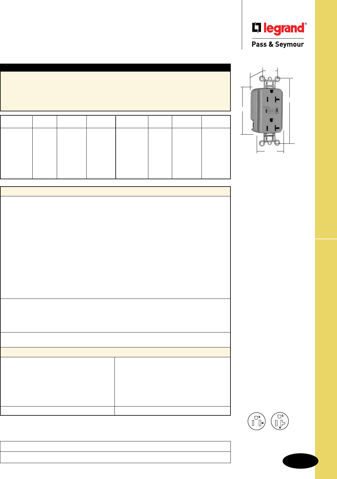
Technical Specifications
S-79
Spec Grade EHD Surge Protective Receptacles
Technical Specifications
Specification Grade
Extra Heavy-Duty
Surge Protective Receptacles
2 Pole, 3 Wire Grounding 15 & 20A, 125VAC
Project
Location/Type
Typical Specications
Manufacturer’s Identification: Legrand/Pass & Seymour 5262ISP
3rd Party Compliance: UL Listed, File Number E140596, Standard UL498, Attachment Plugs and
Receptacles UL1449 Transient Voltage Surge Suppressor. Federal Specification WC596. CSA Certified,
File Number LR16063, Standard CSA-C22.2 No. 42, ANSI/EEE C62.41 (Formerly IEEE 587), ANSI/IEEE
C62.45 Installation Categories “A” (Ring Wave) “B” (Unidirectional Impulse). Complies with NEC
410-56(c) and 250-74 exception 4. Conforms to NEMA WD-1 and WD-6.
Performance
Electrical
Frequency 60 Hz
Voltage 125VAC
MOV Rating 130V 17mm Dual Pack
Suppressed Voltage 500V
Energy Rating 340 Joules
Max Surge Capability 24kA
Protection Modes Normal and Common Modes: Normal Mode (L-N) 500V Clamping;
Common Mode (L-G) 500V Clamping, (N-G) 500V Clamping
Noise Attenuation Normal Mode (L-N)
Capacitance Value = 0.0056 µF
7:1 Average Noise Reduction
Thermal Protection Three Thermal Fuses (128°C or 262°F)
Overcurrent Protection Three Fuses Protects 3 Modes
Operating Temperature -20°C to 55°C (-4 to 131°F)
Storage Temperature -40°C to 85°C (-40 to 185°F)
Mechanical
Terminal Identification Brass = Hot, Nickel = Neutral, Green = Ground
Terminal Accommodation #14 – 10 AWG copper conductor only
Product Identification Ratings are a permanent part of device
Weight 125 grams
Environmental
Flammability UL94 V2
Materials
Warranty 1 year
Face Nylon
Body Nylon
Line Terminal Olin #260 EH, 0.8mm thick
Grounding Terminal 70/30 Brass, 0.4mm thick
(Uni-Ground Assembly)
Mounting Strap Super Dyma Cold-Rolled
Steel, 1.2mm thick
Clamping Plate Cold-Rolled Steel, 1.6mm
Terminal Screws Tri-Drive Brass #8 - 32
Hex Head Grounding Tri-Drive Steel (Green)
Screw
Auto-Ground Clip Stainless Steel
Mounting Screws Tri-Drive Zinc-Plated
Steel
LED Green/Red
Encapsulation Conformal Coating
Catalog NEMA
Number Color Rating Cong. No.
r
5262ISP Ivory 15A 125VAC 5-15R
r
5262WSP White 15A 125VAC 5-15R
r
5262SP Brown 15A 125VAC 5-15R
r
5262GRYSP Gray 15A 125VAC 5-15R
r
5262BKSP Black 15A 125VAC 5-15R
r
5262REDSP Red 15A 125VAC 5-15R
r
5262LASP Lt. Almond 15A 125VAC 5-15R
r
5262BLSP Blue 15A 125VAC 5-15R
Catalog NEMA
Number Color Rating Cong. No.
r
5362ISP Ivory 20A 125VAC 5-20R
r
5362WSP White 20A 125VAC 5-20R
r
5362SP Brown 20A 125VAC 5-20R
r
5362GRYSP Gray 20A 125VAC 5-20R
r
5362BKSP Black 20A 125VAC 5-20R
r
5362REDSP Red 20A 125VAC 5-20R
r
5362LASP Lt. Almond 20A 125VAC 5-20R
r
5362BLSP Blue 20A 125VAC 5-20R
NEMA
5-20R
NEMA
5-15R
Features
• LED Indication:
- Steady green = protected
- Flashing red = not protected
- OFF = no power to unit
• Alarm
• Alarm shut off/override
• Brass 1-piece ground
terminal assembly
• Back and side wire capability
including ground terminal
Conforms to the latest revision ANSI/IEEE C62.41 (formerly IEEE587), ANSI/IEEE C62.45.
5362GRYSP
3.75"
1.70"
.875"
1.25"
Behind Strap
2.75"
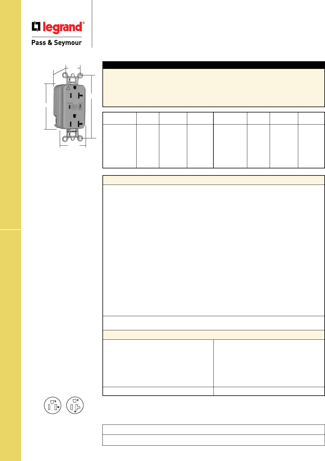
Technical Specifications
S-80
Spec Grade IG Surge Protective Receptacles
Technical Specifications
Specification Grade Isolated Ground
Surge Protective Receptacles
2 Pole, 3 Wire Grounding 15 & 20A, 125VAC
Project
Location/Type
NEMA
5-20R
NEMA
5-15R
Features
• LED Indication:
- Steady green = protected
- Flashing red = not protected
- OFF = no power to unit
• Alarm
• Alarm shut off/override
• Brass 1-piece ground
terminal assembly
• Back and side wire capability
including ground terminal
Conforms to the latest revision ANSI/IEEE C62.41 (formerly IEEE587), ANSI/IEEE C62.45.
Typical Specications
Manufacturer’s Identification: Legrand/Pass & Seymour IG5262ISP
3rd Party Compliance: UL Listed, File Number E140596, Standard UL498, Attachment Plugs and
Receptacles UL1449 Transient Voltage Surge Suppressor. Federal Specification WC596. CSA Certified,
File Number LR16063, Standard CSA-C22.2 No. 42, ANSI/EEE C62.41 (Formerly IEEE 587), ANSI/IEEE
C62.45 Installation Categories “A” (Ring Wave) “B” (Unidirectional Impulse). Complies with NEC
410-56(c) and 250-74 exception 4. Conforms to NEMA WD-1 and WD-6.
Performance
Electrical
Frequency 60 Hz
Voltage 125VAC
MOV Rating 130V 17mm Dual Pack
Suppressed Voltage 500V
Energy Rating 340 Joules
Max Surge Capability 24kA
Protection Modes Normal and Common Modes: Normal Mode (L-N) 500V Clamping;
Common Mode (L-G) 500V Clamping, (N-G) 500V Clamping
Noise Attenuation Normal Mode (L-N)
Capacitance Value = 0.0056 µF
7:1 Average Noise Reduction
Thermal Protection Three Thermal Fuses (128°C or 262°F)
Overcurrent Protection Three Fuses Protects 3 Modes
Operating Temperature -20°C to 55°C (-4 to 131°F)
Storage Temperature -40°C to 85°C (-40 to 185°F)
Mechanical
Terminal Identification Brass = Hot, Nickel = Neutral, Green = Ground
Terminal Accommodation #14 – 10 AWG copper conductor only
Product Identification Ratings are a permanent part of device
Weight 125 grams
Environmental
Flammability UL94 V2
Materials
Warranty 1 year
Face Nylon
Body Nylon
Line Terminal Olin #260 EH, 0.8mm thick
Grounding Terminal 70/30 Brass, 0.4mm thick
(Uni-Ground Assembly)
Mounting Strap Super Dyma Cold-Rolled
Steel, 1.2mm thick
Clamping Plate Cold-Rolled Steel, 1.6mm
Terminal Screws Tri-Drive Brass #8 - 32
Hex Head Grounding Tri-Drive Steel (Green)
Screw
Auto-Ground Clip Stainless Steel
Mounting Screws Tri-Drive Zinc-Plated
Steel
LED Green/Red
Encapsulation Conformal Coating
Catalog NEMA
Number Color Rating Cong.No.
r
IG5262ISP Ivory 15A 125VAC 5-15R
r
IG5262WSP White 15A 125VAC 5-15R
r
IG5262GRYSP Gray 15A 125VAC 5-15R
r
IG5262LASP Lt. Almond 15A 125VAC 5-15R
r
IG5262BLSP Blue 15A 125VAC 5-15R
r
IG5262OSP Orange 15A 125VAC 5-15R
Catalog NEMA
Number Color Rating Cong. No.
r
IG5362ISP Ivory 20A 125VAC 5-20R
r
IG5362WSP White 20A 125VAC 5-20R
r
IG5362SP Brown 20A 125VAC 5-20R
r
IG5362GRYSP Gray 20A 125VAC 5-20R
r
IG5362LASP Lt. Almond 20A 125VAC 5-20R
r
IG5362BLSP Blue 20A 125VAC 5-20R
r
IG5362OSP Orange 20A 125VAC 5-20R
IG5362GRYSP
3.75"
1.70"
.875"
1.25"
Behind Strap
2.75"
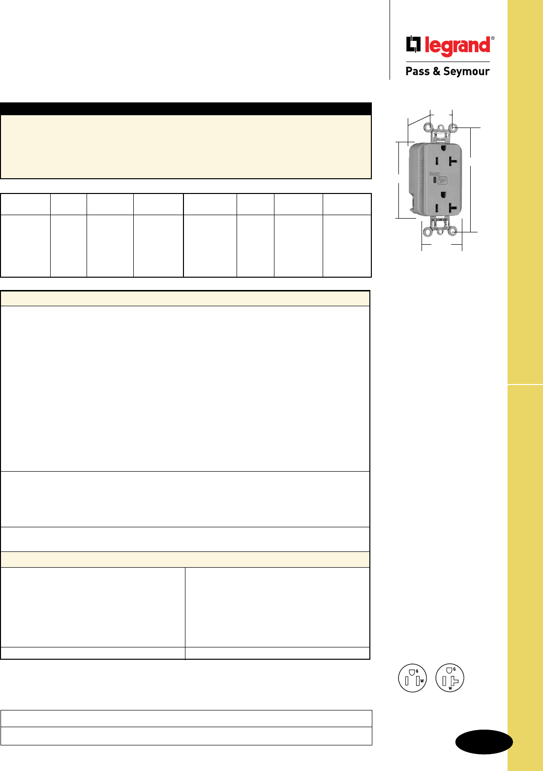
Technical Specifications
S-81
Spec Grade EHD Surge PRote4ctive Receptacles
Technical Specifications
Surge Protective Receptacles
2 Pole, 3 Wire Grounding 15 & 20A, 125VAC
Project
Location/Type
Typical Specications
Manufacturer’s Identification: Legrand/Pass & Seymour 5252ISP
3rd Party Compliance: UL Listed, File Number E140596, Standard UL498, Attachment Plugs and
Receptacles UL1449 Transient Voltage Surge Suppressor. Federal Specification WC596. CSA
Certified, File Number LR16063, Standard CSA-C22.2 No. 42, ANSI/EEE C62.41 (Formerly IEEE 587),
ANSI/IEEE C62.45 Installation Categories “A” (Ring Wave) “B” (Unidirectional Impulse). Complies with
NEC 410-56(c) and 250-74 exception 4. Conforms to NEMA WD-1 and WD-6.
Catalog NEMA
Number Color Rating Cong. No.
r
5252ISP Ivory 15A 125VAC 5-15R
r
5252WSP White 15A 125VAC 5-15R
r
5252GRYSP Gray 15A 125VAC 5-15R
r
5252BKSP Black 15A 125VAC 5-15R
r
5252LASP Lt Almond 15A 125VAC 5-15R
r
5252BLSP Blue 15A 125VAC 5-15R
Catalog NEMA
Number Color Rating Cong. No.
r
5352ISP Ivory 20A 125VAC 5-20R
r
5352WSP White 20A 125VAC 5-20R
r
5352GRYSP Gray 20A 125VAC 5-20R
r
5352BKSP Black 20A 125VAC 5-20R
r
5352LASP Lt Almond 20A 125VAC 5-20R
r
5352BLSP Blue 20A 125VAC 5-20R
NEMA
5-20R
NEMA
5-15R
Features
• LED Indication:
- Steady green = protected
- Flashing red = not protected
- OFF = no power to unit
• Brass 1-piece ground
terminal assembly
• Back and side wire capability
including ground terminal
Conforms to the latest revision ANSI/IEEE C62.41 (formerly IEEE587), ANSI/IEEE C62.45.
Performance
Electrical
Frequency 60 Hz
Voltage 125VAC
MOV Rating 130V 17mm Dual Pack
Suppressed Voltage 500V
Energy Rating 340 Joules (L-N) and (L-G) Modes; 680 Joules (N-G) Mode
Max Surge Capability 24kA
Protection Modes Normal and Common Mode: Normal Mode (L-N) 500V Clamping;
Common Mode (L-G) 500V Clamping, (N-G) 1000V Clamping
Noise Attenuation Normal Mode (L-N)
Capacitance Value = 0.0056 µF
7:1 Average Noise Reduction
Thermal Protection Two Thermal Fuses (128°C or 262°F)
Overcurrent Protection Two Fuses Protects 3 Modes
Operating Temperature -20°C to 55°C (-4 to 131°F)
Storage Temperature -40°C to 85°C (-40 to 185°F)
Mechanical
Terminal Identification Brass = Hot, Nickel = Neutral, Green = Ground
Terminal Accommodation #14 – 10 AWG copper conductor only
Product Identification Ratings are a permanent part of device
Weight 125 grams
Environmental
Flammability UL94 V2
Materials
Warranty 1 year
Face Nylon
Body Nylon
Line Terminal Olin #260 EH, 0.8mm thick
Grounding Terminal 70/30 Brass, 0.4mm thick
(Uni-Ground Assembly)
Mounting Strap Super Dyma Cold-Rolled
Steel, 1.2mm thick
Clamping Plate Cold-Rolled Steel, 1.6mm
Terminal Screws Tri-Drive Brass #8 - 32
Hex Head Grounding Tri-Drive Steel (Green)
Screw
Auto-Ground Clip Stainless Steel
Mounting Screws Tri-Drive Zinc-Plated
Steel
LED Green/Red
Encapsulation Conformal Coating
5352GRYSP
3.75"
1.70"
.875"
1.29"
Behind Strap
2.75"
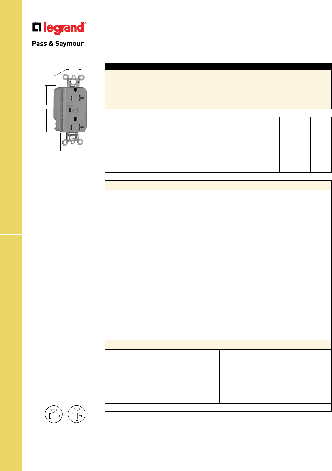
Technical Specifications
S-82
TR Surge Protective Receptacles
Project
Location/Type
Technical Specifications
Tamper-Resistant
Surge Protective Receptacles
2 Pole, 3 Wire Grounding 15 & 20A, 125VAC
Typical Specications
Manufacturer’s Identification: Legrand/Pass & Seymour TR5252ISP
3rd Party Compliance: UL Listed, File Number E140596, Standard UL498, Attachment Plugs and
Receptacles UL1449 Transient Voltage Surge Suppressor. Federal Specification WC596. CSA Certified,
File Number LR16063, Standard CSA-C22.2 No. 42, ANSI/EEE C62.41 (Formerly IEEE 587), ANSI/IEEE
C62.45 Installation Categories “A” (Ring Wave) “B” (Unidirectional Impulse). Complies with NEC
410-56(c) and 250-74 exception 4. Conforms to NEMA WD-1 and WD-6.
NEMA
Catalog Cong.
Number Color Rating No.
r
TR5252ISP Ivory 15A 125VAC 5-15R
r
TR5252WSP White 15A 125VAC 5-15R
r
TR5252GRYSP Gray 15A 125VAC 5-15R
r
TR5252BKSP Black 15A 125VAC 5-15R
r
TR5252LASP Lt Almond 15A 125VAC 5-15R
r
TR5252BLSP Blue 15A 125VAC 5-15R
NEMA
Catalog Cong.
Number Color Rating No.
r
TR5352ISP Ivory 20A 125VAC 5-20R
r
TR5352WSP White 20A 125VAC 5-20R
r
TR5352GRYSP Gray 20A 125VAC 5-20R
r
TR5352BKSP Black 20A 125VAC 5-20R
r
TR5352LASP Lt Almond 20A 125VAC 5-20R
r
TR5352BLSP Blue 20A 125VAC 5-20R
NEMA
5-20R
NEMA
5-15R
Features
• LED Indication:
- Steady green = protected
- Flashing red = not protected
- OFF = no power to unit
• Brass 1-piece ground
terminal assembly
• Back and side wire capability
including ground terminal
Conforms to the latest revision ANSI/IEEE C62.41 (formerly IEEE587), ANSI/IEEE C62.45.
Performance
Electrical
Frequency 60 Hz
Voltage 125VAC
MOV Rating 130V 17mm Dual Pack
Suppressed Voltage 500V
Energy Rating 340 Joules (L-N) and (L-G) Modes; 680 Joules (N-G) Mode
Max Surge Capability 24kA
Protection Modes Normal and Common Mode: Normal Mode (L-N) 500V Clamping;
Common Mode (L-G) 500V Clamping, (N-G) 1000V Clamping
Noise Attenuation Normal Mode (L-N)
Capacitance Value = 0.0056 µF
7:1 Average Noise Reduction
Thermal Protection Two Thermal Fuses (128°C or 262°F)
Overcurrent Protection Two Fuses Protects 3 Modes
Operating Temperature -20°C to 55°C (-4 to 131°F)
Storage Temperature -40°C to 85°C (-40 to 185°F)
Mechanical
Terminal Identification Brass = Hot, Nickel = Neutral, Green = Ground
Terminal Accommodation #14 – 10 AWG copper conductor only
Product Identification Ratings are a permanent part of device
Weight 125 grams
Environmental
Flammability UL94 V2
Materials
Warranty 1 year
Face Nylon
Body Nylon
Line Terminal Olin #260 EH, 0.8mm thick
Grounding Terminal 70/30 Brass, 0.4mm thick
(Uni-Ground Assembly)
Mounting Strap Super Dyma Cold-Rolled
Steel, 1.2mm thick
Clamping Plate Cold-Rolled Steel, 1.6mm
Terminal Screws Tri-Drive Brass #8 - 32
Hex Head Grounding Tri-Drive Steel (Green)
Screw
Auto-Ground Clip Stainless Steel
Mounting Screws Tri-Drive Zinc-Plated
Steel
LED Green/Red
Tamper Shutter Thermoplastic
Encapsulation Conformal Coating
TR5352GRYSP
3.75"
1.70"
.875"
1.40"
Behind Strap
2.75"
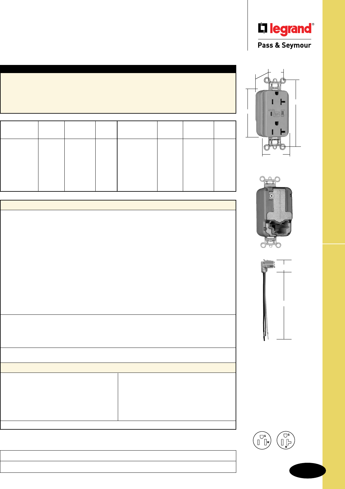
Technical Specifications
S-83
PlugTail™ Surge Protective Receptacles
Project
Location/Type
Technical Specifications
PlugTail™ Extra Heavy-Duty
Surge Protective Receptacles
2 Pole, 3 Wire Grounding, 15 & 20A, 125VAC
Typical Specications
Manufacturer’s Identification: Legrand/Pass & Seymour PT5262ISP
3rd Party Compliance: UL Listed, File Number E140596, Standard UL498, Attachment Plugs and
Receptacles UL1449 Transient Voltage Surge Suppressor. Federal Specification WC596. CSA Certified,
File Number LR16063, Standard CSA-C22.2 No. 42, ANSI/EEE C62.41 (Formerly IEEE 587), ANSI/IEEE
C62.45 Installation Categories “A” (Ring Wave) “B” (Unidirectional Impulse). Complies with NEC
410-56(c) and 250-74 exception 4. Conforms to NEMA WD-1 and WD-6.
Performance
Electrical
Frequency 60 Hz
Voltage 125VAC
MOV Rating 130V 17mm Dual Pack
Suppressed Voltage 500V
Energy Rating 340 Joules (L-N) and (L-G) Modes; 680 Joules (N-G) Mode
Max Surge Capability 24kA
Protection Modes Normal and Common Modes: Normal Mode (L-N) 500V Clamping;
Common Mode (L-G) 500V Clamping, (N-G) 1000V Clamping
Noise Attenuation Normal Mode (L-N)
Capacitance Value = 0.0056 µF
7:1 Average Noise Reduction
Thermal Protection Two Thermal Fuses (128°C or 262°F)
Overcurrent Protection Two Fuses Protects 3 Modes
Operating Temperature -20°C to 55°C (-4 to 131°F)
Storage Temperature -40°C to 85°C (-40 to 185°F)
Mechanical
PlugTail Connector Identification #12 AWG, THHN, copper conductor, 6" leads, stripped, solid or
stranded, for use with Plugtail Receptacles only
Product Identification Ratings are a permanent part of device
Weight 125 grams
Environmental
Flammability UL94 V2
Materials
Warranty 1 year
Face Nylon
Body Nylon
Line Terminal Olin #260 EH, 0.8mm thick
Grounding Terminal 70/30 Brass, 0.4mm thick
(Uni-Ground Assembly)
Mounting Strap Super Dyma Cold-Rolled
Steel, 1.2mm thick
Auto-Ground Clip Stainless Steel
Mounting Screws Tri-Drive Zinc-Plated Steel
LED Green/Red
Encapsulation Conformal Coating
PlugTail Connector
Housing Polycarbonate
Contacts .030" Brass
NEMA
Catalog Cong.
Number Color Rating No.
r
PT5262ISP Ivory 15A 125VAC 5-15R
r
PT5262WSP White 15A 125VAC 5-15R
r
PT5262SP Brown 15A 125VAC 5-15R
r
PT5262GRYSP Gray 15A 125VAC 5-15R
r
PT5262BKSP Black 15A 125VAC 5-15R
r
PT5262REDSP Red 15A 125VAC 5-15R
r
PT5262LASP Lt. Almond 15A 125VAC 5-15R
r
PT5262BLSP Blue 15A 125VAC 5-15R
NEMA
Catalog Cong.
Number Color Rating No.
r
PT5362ISP Ivory 20A 125VAC 5-20R
r
PT5362WSP White 20A 125VAC 5-20R
r
PT5362SP Brown 20A 125VAC 5-20R
r
PT5362GRYSP Gray 20A 125VAC 5-20R
r
PT5362BKSP Black 20A 125VAC 5-20R
r
PT5362REDSP Red 20A 125VAC 5-20R
r
PT5362LASP Lt. Almond 20A 125VAC 5-20R
r
PT5362BLSP Blue 20A 125VAC 5-20R
Conforms to the latest revision ANSI/IEEE C62.41 (formerly IEEE587), ANSI/IEEE C62.45.
NEMA
5-20R
NEMA
5-15R
Features
• LED Indication:
- Steady green = protected
- Flashing red = not protected
- OFF = no power to unit
• Alarm
• Alarm shut off/override
• Brass 1-piece ground
terminal assembly
1.125"
6.375"
PTRA6STR
PT5362GRYSP
3.75"
1.70"
.875"
1.20"
Behind Strap
2.75"
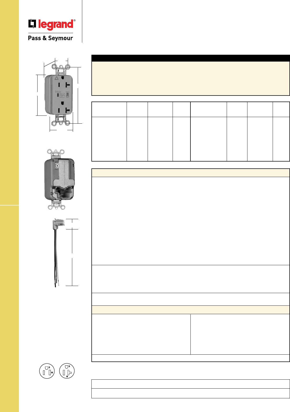
Technical Specifications
S-84
Project
Location/Type
PlugTail™ IG Surge Protective Receptacles
Technical Specifications
PlugTail™ Isolated Ground
Surge Protective Receptacles
2 Pole, 3 Wire Grounding 15 & 20A, 125VAC
Typical Specications
Manufacturer’s Identification: Legrand/Pass & Seymour PTIG5262ISP
3rd Party Compliance: UL Listed, File Number E140596, Standard UL498, Attachment Plugs and
Receptacles UL1449 Transient Voltage Surge Suppressor. Federal Specification WC596. CSA Certified,
File Number LR16063, Standard CSA-C22.2 No. 42, ANSI/EEE C62.41 (Formerly IEEE 587), ANSI/IEEE
C62.45 Installation Categories “A” (Ring Wave) “B” (Unidirectional Impulse). Complies with NEC
410-56(c) and 250-74 exception 4. Conforms to NEMA WD-1 and WD-6.
Performance
Electrical
Frequency 60 Hz
Voltage 125VAC
MOV Rating 130V 17mm Dual Pack
Suppressed Voltage 500V
Energy Rating 340 Joules (L-N) and (L-G) Modes; 680 Joules (N-G) Mode
Max Surge Capability 24kA
Protection Modes Normal and Common Modes: Normal Mode (L-N) 500V Clamping;
Common Mode (L-G) 500V Clamping, (N-G) 1000V Clamping
Noise Attenuation Normal Mode (L-N)
Capacitance Value = 0.0056 µF
7:1 Average Noise Reduction
Thermal Protection Two Thermal Fuses (128°C or 262°F)
Overcurrent Protection Two Fuses Protects 3 Modes
Operating Temperature -20°C to 55°C (-4 to 131°F)
Storage Temperature -40°C to 85°C (-40 to 185°F)
Mechanical
PlugTail Connector Identification #12 AWG, THHN, copper conductor, 6" leads, stripped, solid or
stranded, for use with Plugtail Receptacles only
Product Identification Ratings are a permanent part of device
Weight 125 grams
Environmental
Flammability UL94 V2
Materials
Warranty 1 year
Face Nylon
Body Nylon
Line Terminal Olin #260 EH, 0.8mm thick
Grounding Terminal 70/30 Brass, 0.4mm thick
(Uni-Ground Assembly)
Mounting Strap Super Dyma Cold-Rolled
Steel, 1.2mm thick
Auto-Ground Clip Stainless Steel
Mounting Screws Tri-Drive Zinc-Plated Steel
LED Green/Red
Encapsulation Conformal Coating
PlugTail Connector
Housing Polycarbonate
Contacts .030" Brass
NEMA
Catalog Cong.
Number Color Rating No.
r
PTIG5262ISP Ivory 15A 125VAC 5-15R
r
PTIG5262WSP White 15A 125VAC 5-15R
r
PTIG5262GRYSP Gray 15A 125VAC 5-15R
r
PTIG5262BKSP Black 15A 125VAC 5-15R
r
PTIG5262REDSP Red 15A 125VAC 5-15R
r
PTIG5262LASP Lt. Almond 15A 125VAC 5-15R
r
PTIG5262BLSP Blue 15A 125VAC 5-15R
r
PTIG5262OSP Orange 15A 125VAC 5-15R
NEMA
Catalog Cong.
Number Color Rating No.
r
PTIG5362ISP Ivory 20A 125VAC 5-20R
r
PTIG5362WSP White 20A 125VAC 5-20R
r
PTIG5362GRYSP Gray 20A 125VAC 5-20R
r
PTIG5362BKSP Black 20A 125VAC 5-20R
r
PTIG5362REDSP Red 20A 125VAC 5-20R
r
PTIG5362LASP Lt. Almond 20A 125VAC 5-20R
r
PTIG5362BLSP Blue 20A 125VAC 5-20R
r
PTIG5362OSP Orange 20A 125VAC 5-20R
Conforms to the latest revision ANSI/IEEE C62.41 (formerly IEEE587), ANSI/IEEE C62.45.
NEMA
5-20R
NEMA
5-15R
Features
• LED Indication:
- Steady green = protected
- Flashing red = not protected
- OFF = no power to unit
• Alarm
• Alarm shut off/override
• Brass 1-piece ground
terminal assembly
1.125"
6.375"
PTRA6STR
PTIG5362GRYSP
3.75"
1.70"
.875"
1.20"
Behind Strap
2.75"
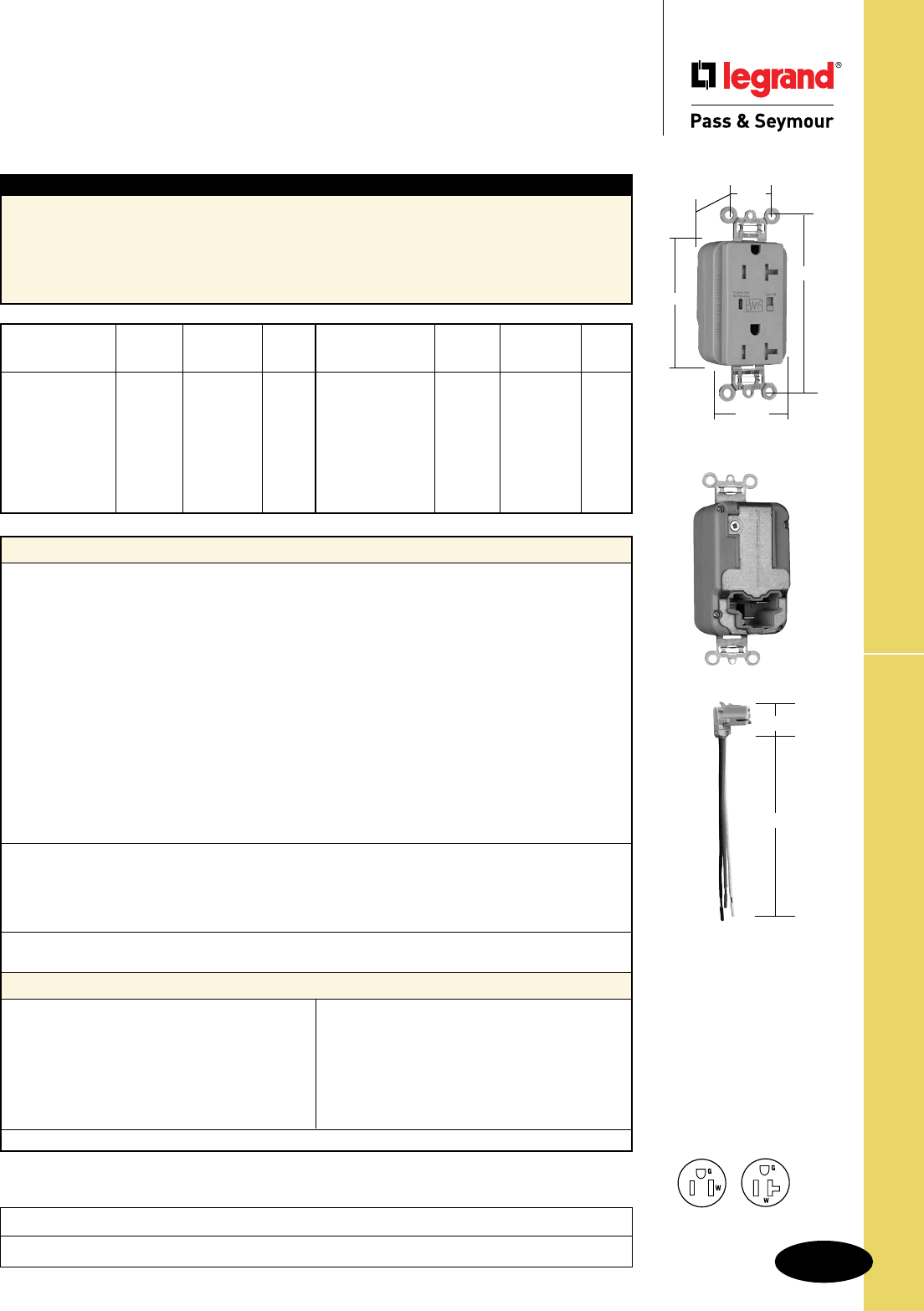
Technical Specifications
S-85
PlugTail™ TR Surge Protective Receptacles
Technical Specifications
PlugTail™ Tamper-Resistant
Surge Protective Receptacles
2 Pole, 3 Wire Grounding 15 & 20A, 125VAC
Project
Location/Type
Typical Specications
Manufacturer’s Identification: Legrand/Pass & Seymour PTTR5262ISP
3rd Party Compliance: UL Listed, File Number E140596, Standard UL498, Attachment Plugs and
Receptacles UL1449 Transient Voltage Surge Suppressor. Federal Specification WC596. CSA Certified,
File Number LR16063, Standard CSA-C22.2 No. 42, ANSI/EEE C62.41 (Formerly IEEE 587), ANSI/IEEE
C62.45 Installation Categories “A” (Ring Wave) “B” (Unidirectional Impulse). Complies with NEC
410-56(c) and 250-74 exception 4. Conforms to NEMA WD-1 and WD-6.
Performance
Electrical
Frequency 60 Hz
Voltage 125VAC
MOV Rating 130V 17mm Dual Pack
Suppressed Voltage 500V
Energy Rating 340 Joules (L-N) and (L-G) Modes; 680 Joules (N-G) Mode
Max Surge Capability 24kA
Protection Modes Normal and Common Modes: Normal Mode (L-N) 500V Clamping;
Common Mode (L-G) 500V Clamping, (N-G) 1000V Clamping
Noise Attenuation Normal Mode (L-N)
Capacitance Value = 0.0056 µF
7:1 Average Noise Reduction
Thermal Protection Two Thermal Fuses (128°C or 262°F)
Overcurrent Protection Two Fuses Protects 3 Modes
Operating Temperature -20°C to 55°C (-4 to 131°F)
Storage Temperature -40°C to 85°C (-40 to 185°F)
Mechanical
PlugTail Connector Identification #12 AWG, THHN, copper conductor, 6" leads, stripped, solid or
stranded, for use with Plugtail Receptacles only
Product Identification Ratings are a permanent part of device
Weight 125 grams
Environmental
Flammability UL94 V2
Materials
Warranty 1 year
Face Nylon
Body Nylon
Line Terminal Olin #260 EH, 0.8mm thick
Grounding Terminal 70/30 Brass, 0.4mm thick
(Uni-Ground Assembly)
Mounting Strap Super Dyma Cold-Rolled
Steel, 1.2mm thick
Auto-Ground Clip Stainless Steel
Mounting Screws Tri-Drive Zinc-Plated Steel
LED Green/Red
Encapsulation Conformal Coating
PlugTail Connector
Housing Polycarbonate
Contacts .030" Brass
NEMA
Catalog Cong.
Number Color Rating No.
r
PTTR5262ISP Ivory 15A 125VAC 5-15R
r
PTTR5262WSP White 15A 125VAC 5-15R
r
PTTR5262SP Brown 15A 125VAC 5-15R
r
PTTR5262GRYSP Gray 15A 125VAC 5-15R
r
PTTR5262BKSP Black 15A 125VAC 5-15R
r
PTTR5262REDSP Red 15A 125VAC 5-15R
r
PTTR5262LASP Lt. Almond 15A 125VAC 5-15R
r
PTTR5262BLSP Blue 15A 125VAC 5-15R
NEMA
Catalog Cong.
Number Color Rating No.
r
PTTR5362ISP Ivory 20A 125VAC 5-20R
r
PTTR5362WSP White 20A 125VAC 5-20R
r
PTTR5362SP Brown 20A 125VAC 5-20R
r
PTTR5362GRYSP Gray 20A 125VAC 5-20R
r
PTTR5362BKSP Black 20A 125VAC 5-20R
r
PTTR5362REDSP Red 20A 125VAC 5-20R
r
PTTR5362LASP Lt. Almond 20A 125VAC 5-20R
r
PTTR5362BLSP Blue 20A 125VAC 5-20R
Conforms to the latest revision ANSI/IEEE C62.41 (formerly IEEE587), ANSI/IEEE C62.45.
NEMA
5-20R
NEMA
5-15R
Features
• LED Indication:
- Steady green = protected
- Flashing red = not protected
- OFF = no power to unit
• Alarm
• Alarm shut off/override
• Brass 1-piece ground
terminal assembly
1.125"
6.375"
PTRA6STR
PTTR5362GRYSP
3.75"
1.70"
.875"
1.40"
Behind Strap
2.75"
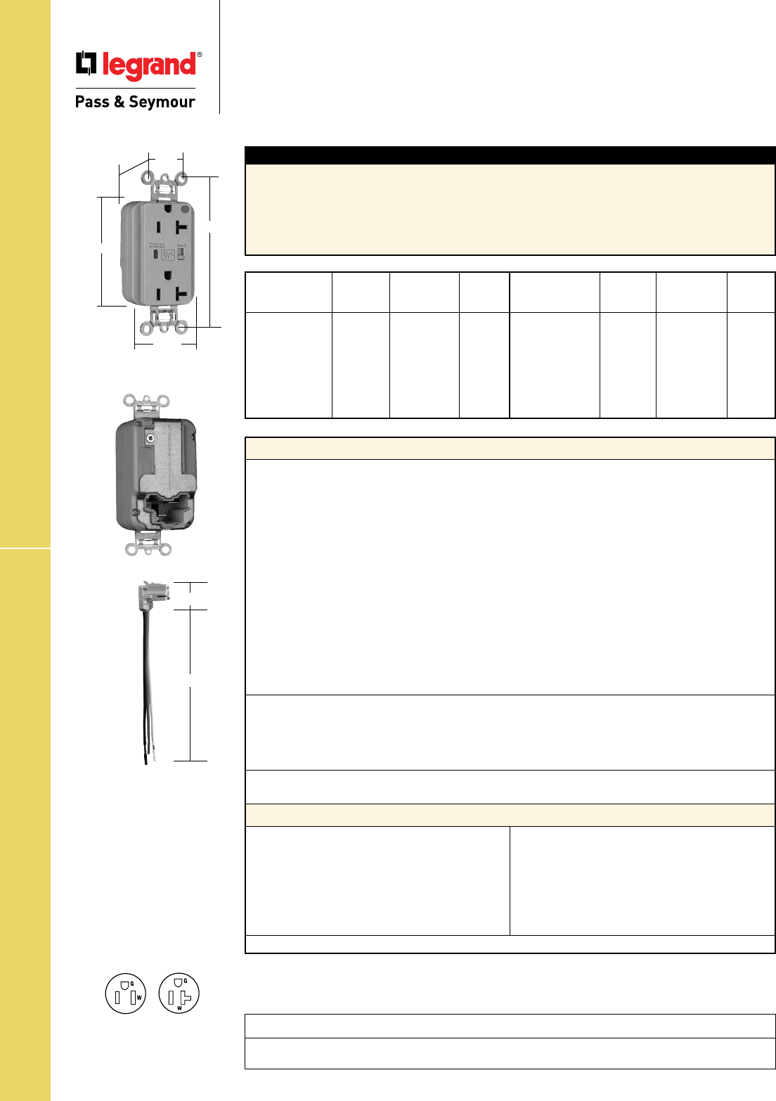
Technical Specifications
S-86
PlugTail™ HG EHD Surge Protective Receptacles
Technical Specifications
PlugTail™ Hospital Grade Extra Heavy-Duty
Surge Protective Receptacles
2 Pole, 3 Wire Grounding, 15 & 20A, 125VAC
Project
Location/Type
Typical Specications
Manufacturer’s Identification: Legrand/Pass & Seymour PT8200ISP
3rd Party Compliance: UL Listed, File Number E140596, Standard UL498, Attachment Plugs and
Receptacles UL1449 Transient Voltage Surge Suppressor. Federal Specification WC596. CSA Certified,
File Number LR16063, Standard CSA-C22.2 No. 42, ANSI/EEE C62.41 (Formerly IEEE 587), ANSI/IEEE
C62.45 Installation Categories “A” (Ring Wave) “B” (Unidirectional Impulse). Complies with NEC
410-56(c) and 250-74 exception 4. Conforms to NEMA WD-1 and WD-6.
Performance
Electrical
Frequency 60 Hz
Voltage 125VAC
MOV Rating 130V 17mm Dual Pack
Suppressed Voltage 500V
Energy Rating 340 Joules (L-N) and (L-G) Modes; 680 Joules (N-G) Mode
Max Surge Capability 24kA
Protection Modes Normal and Common Modes: Normal Mode (L-N) 500V Clamping;
Common Mode (L-G) 500V Clamping, (N-G) 1000V Clamping
Noise Attenuation Normal Mode (L-N)
Capacitance Value = 0.0056 µF
7:1 Average Noise Reduction
Thermal Protection Two Thermal Fuses (128°C or 262°F)
Overcurrent Protection Two Fuses Protects 3 Modes
Operating Temperature -20°C to 55°C (-4 to 131°F)
Storage Temperature -40°C to 85°C (-40 to 185°F)
Mechanical
PlugTail Connector Identification #12 AWG, THHN, copper conductor, 6" leads, stripped, solid or
stranded, for use with Plugtail Receptacles only
Product Identification Ratings are a permanent part of device
Weight 125 grams
Environmental
Flammability UL94 V2
Materials
Warranty 1 year
Face Nylon
Body Nylon
Line Terminal Olin #260 EH, 0.8mm thick
Grounding Terminal 70/30 Brass, 0.4mm thick
(Uni-Ground Assembly)
Mounting Strap Super Dyma Cold-Rolled
Steel, 1.2mm thick
Auto-Ground Clip Stainless Steel
Mounting Screws Tri-Drive Zinc-Plated Steel
LED Green/Red
Encapsulation Conformal Coating
PlugTail Connector
Housing Polycarbonate
Contacts .030" Brass
NEMA
Catalog Cong.
Number Color Rating No.
r
PT8200ISP Ivory 15A 125VAC 5-15R
r
PT8200WSP White 15A 125VAC 5-15R
r
PT8200SP Brown 15A 125VAC 5-15R
r
PT8200GRYSP Gray 15A 125VAC 5-15R
r
PT8200REDSP Red 15A 125VAC 5-15R
r
PT8200LASP Lt. Almond 15A 125VAC 5-15R
r
PT8200BLSP Blue 15A 125VAC 5-15R
NEMA
Catalog Cong.
Number Color Rating No.
r
PT8300ISP Ivory 20A 125VAC 5-20R
r
PT8300WSP White 20A 125VAC 5-20R
r
PT8300SP Brown 20A 125VAC 5-20R
r
PT8300GRYSP Gray 20A 125VAC 5-20R
r
PT8300REDSP Red 20A 125VAC 5-20R
r
PT8300LASP Lt. Almond 20A 125VAC 5-20R
r
PT8300BLSP Blue 20A 125VAC 5-20R
Conforms to the latest revision ANSI/IEEE C62.41 (formerly IEEE587), ANSI/IEEE C62.45.
NEMA
5-20R
NEMA
5-15R
Features
• LED Indication:
- Steady green = protected
- Flashing red = not protected
- OFF = no power to unit
• Alarm
• Alarm shut off/override
• Brass 1-piece ground
terminal assembly
1.125"
6.375"
PTRA6STR
PT8300GRYSP
3.75"
1.70"
.875"
1.20"
Behind Strap
2.75"
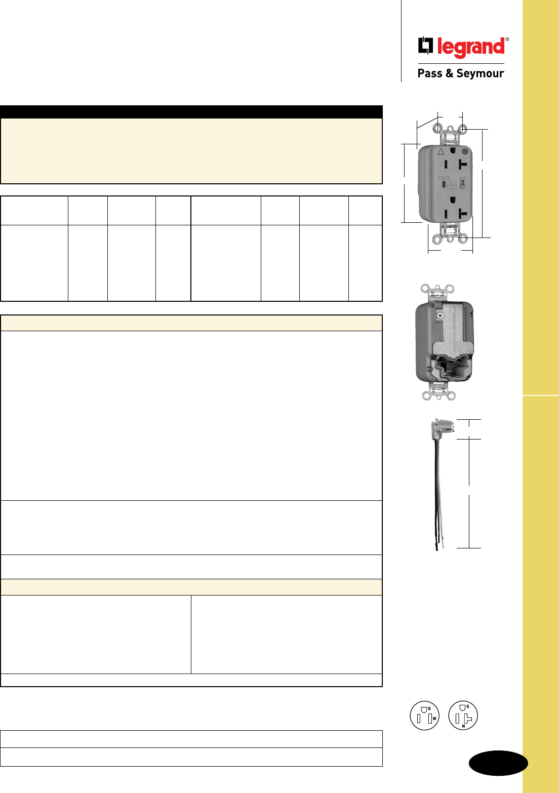
Technical Specifications
S-87
PlugTail™ HG IG Surge Protective Receptacles
Project
Location/Type
Technical Specifications
PlugTail™ Hospital Grade Isolated Ground
Surge Protective Receptacles
2 Pole, 3 Wire Grounding, 15 & 20A, 125VAC
Typical Specications
Manufacturer’s Identification: Legrand/Pass & Seymour PTIG8200ISP
3rd Party Compliance: UL Listed, File Number E140596, Standard UL498, Attachment Plugs and
Receptacles UL1449 Transient Voltage Surge Suppressor. Federal Specification WC596. CSA Certified,
File Number LR16063, Standard CSA-C22.2 No. 42, ANSI/EEE C62.41 (Formerly IEEE 587),
ANSI/IEEE C62.45 Installation Categories “A” (Ring Wave) “B” (Unidirectional Impulse). Complies with
NEC 410-56(c) and 250-74 exception 4. Conforms to NEMA WD-1 and WD-6.
Performance
Electrical
Frequency 60 Hz
Voltage 125VAC
MOV Rating 130V 17mm Dual Pack
Suppressed Voltage 500V
Energy Rating 340 Joules (L-N) and (L-G) Modes; 680 Joules (N-G) Mode
Max Surge Capability 24kA
Protection Modes Normal and Common Modes: Normal Mode (L-N) 500V Clamping;
Common Mode (L-G) 500V Clamping, (N-G) 1000V Clamping
Noise Attenuation Normal Mode (L-N)
Capacitance Value = 0.0056 µF
7:1 Average Noise Reduction
Thermal Protection Two Thermal Fuses (128°C or 262°F)
Overcurrent Protection Two Fuses Protects 3 Modes
Operating Temperature -20°C to 55°C (-4 to 131°F)
Storage Temperature -40°C to 85°C (-40 to 185°F)
Mechanical
PlugTail Connector Identification #12 AWG, THHN, copper conductor, 6" leads, stripped, solid or
stranded, for use with Plugtail Receptacles only
Product Identification Ratings are a permanent part of device
Weight 125 grams
Environmental
Flammability UL94 V2
Materials
Warranty 1 year
Face Nylon
Body Nylon
Line Terminal Olin #260 EH, 0.8mm thick
Grounding Terminal 70/30 Brass, 0.4mm thick
(Uni-Ground Assembly)
Mounting Strap Super Dyma Cold-Rolled
Steel, 1.2mm thick
Auto-Ground Clip Stainless Steel
Mounting Screws Tri-Drive Zinc-Plated Steel
LED Green/Red
Encapsulation Conformal Coating
PlugTail Connector
Housing Polycarbonate
Contacts .030" Brass
NEMA
Catalog Cong.
Number Color Rating No.
r
PTIG8200ISP Ivory 15A 125VAC 5-15R
r
PTIG8200WSP White 15A 125VAC 5-15R
r
PTIG8200GRYSP Gray 15A 125VAC 5-15R
r
PTIG8200REDSP Red 15A 125VAC 5-15R
r
PTIG8200LASP Lt. Almond 15A 125VAC 5-15R
r
PTIG8200BLSP Blue 15A 125VAC 5-15R
r
PTIG8200OSP Orange 15A 125VAC 5-15R
NEMA
Catalog Cong.
Number Color Rating No.
r
PTIG8300ISP Ivory 20A 125VAC 5-20R
r
PTIG8300WSP White 20A 125VAC 5-20R
r
PTIG8300GRYSP Gray 20A 125VAC 5-20R
r
PTIG8300REDSP Red 20A 125VAC 5-20R
r
PTIG8300LASP Lt. Almond 20A 125VAC 5-20R
r
PTIG8300BLSP Blue 20A 125VAC 5-20R
r
PTIG8300OSP Orange 20A 125VAC 5-20R
Conforms to the latest revision ANSI/IEEE C62.41 (formerly IEEE587), ANSI/IEEE C62.45.
NEMA
5-20R
NEMA
5-15R
Features
• LED Indication:
- Steady green = protected
- Flashing red = not protected
- OFF = no power to unit
• Alarm
• Alarm shut off/override
• Brass 1-piece ground
terminal assembly
1.125"
6.375"
PTRA6STR
PTIG8300GRYSP
3.75"
1.70"
.875"
1.20"
Behind Strap
2.75"
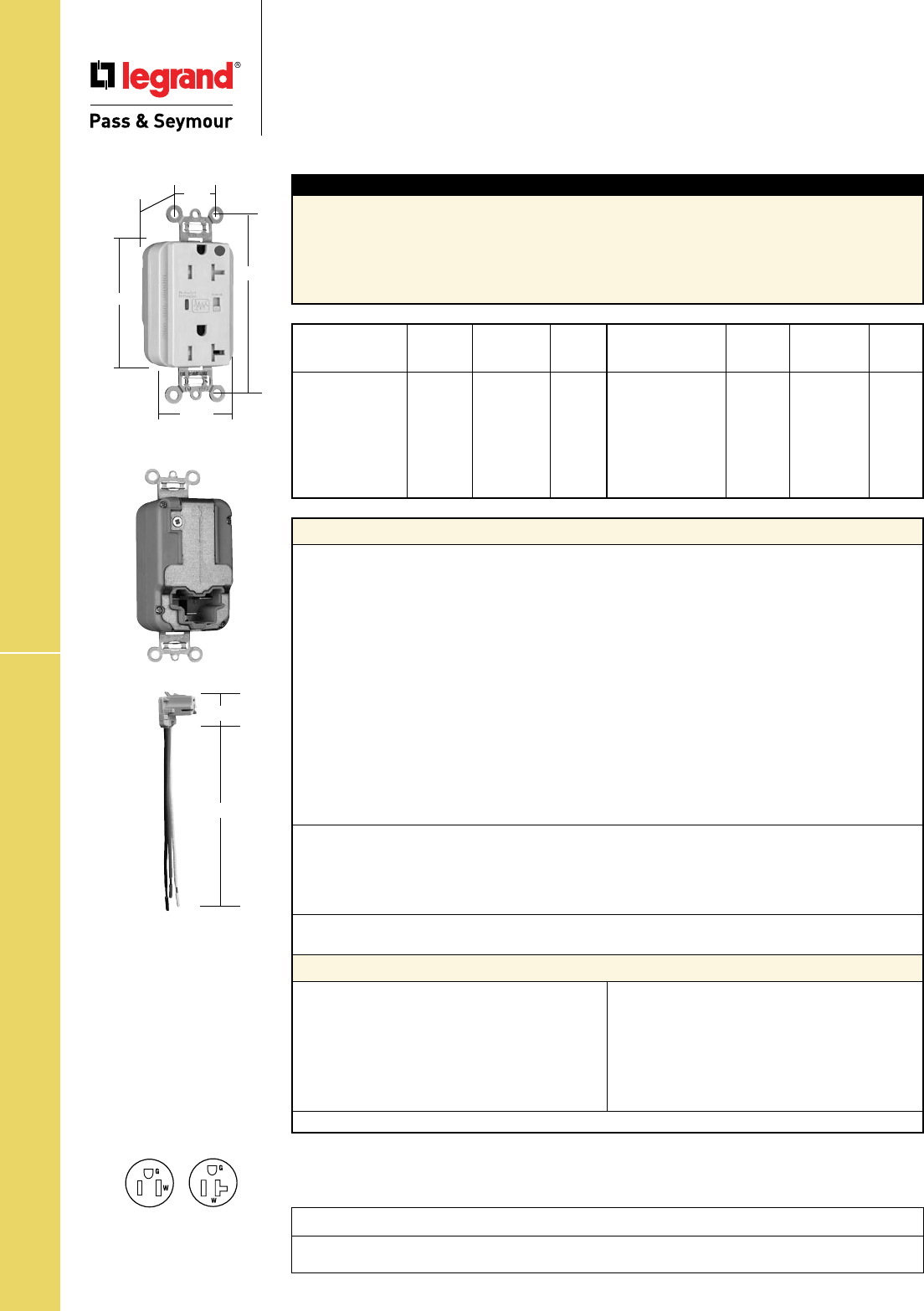
Technical Specifications
S-88
PlugTail™ HG TR Surge Protective Receptacles
Technical Specifications
PlugTail™ Hospital Grade Tamper-Resistant
Surge Protective Receptacles
2 Pole, 3 Wire Grounding, 15 & 20A, 125VAC
Project
Location/Type
Typical Specications
Manufacturer’s Identification: Legrand/Pass & Seymour PTTR8200ISP
3rd Party Compliance: UL Listed, File Number E140596, Standard UL498, Attachment Plugs and
Receptacles UL1449 Transient Voltage Surge Suppressor. Federal Specification WC596. CSA Certified,
File Number LR16063, Standard CSA-C22.2 No. 42, ANSI/EEE C62.41 (Formerly IEEE 587),
ANSI/IEEE C62.45 Installation Categories “A” (Ring Wave) “B” (Unidirectional Impulse). Complies with
NEC 410-56(c) and 250-74 exception 4. Conforms to NEMA WD-1 and WD-6.
Performance
Electrical
Frequency 60 Hz
Voltage 125VAC
MOV Rating 130V 17mm Dual Pack
Suppressed Voltage 500V
Energy Rating 340 Joules (L-N) and (L-G) Modes; 680 Joules (N-G) Mode
Max Surge Capability 24kA
Protection Modes Normal and Common Modes: Normal Mode (L-N) 500V Clamping;
Common Mode (L-G) 500V Clamping, (N-G) 1000V Clamping
Noise Attenuation Normal Mode (L-N)
Capacitance Value = 0.0056 µF
7:1 Average Noise Reduction
Thermal Protection Two Thermal Fuses (128°C or 262°F)
Overcurrent Protection Two Fuses Protects 3 Modes
Operating Temperature -20°C to 55°C (-4 to 131°F)
Storage Temperature -40°C to 85°C (-40 to 185°F)
Mechanical
PlugTail Connector Identification #12 AWG, THHN, copper conductor, 6" leads, stripped, solid or
stranded, for use with Plugtail Receptacles only
Product Identification Ratings are a permanent part of device
Weight 125 grams
Environmental
Flammability UL94 V2
Materials
Warranty 1 year
Face Nylon
Body Nylon
Line Terminal Olin #260 EH, 0.8mm thick
Grounding Terminal 70/30 Brass, 0.4mm thick
(Uni-Ground Assembly)
Mounting Strap Super Dyma Cold-Rolled
Steel, 1.2mm thick
Auto-Ground Clip Stainless Steel
Mounting Screws Tri-Drive Zinc-Plated Steel
LED Green/Red
Encapsulation Conformal Coating
PlugTail Connector
Housing Polycarbonate
Contacts .030" Brass
NEMA
Catalog Cong.
Number Color Rating No.
r
PTTR8200ISP Ivory 15A 125VAC 5-15R
r
PTTR8200WSP White 15A 125VAC 5-15R
r
PTTR8200SP Brown 15A 125VAC 5-15R
r
PTTR8200GRYSP Gray 15A 125VAC 5-15R
r
PTTR8200REDSP Red 15A 125VAC 5-15R
r
PTTR8200LASP Lt. Almond 15A 125VAC 5-15R
r
PTTR8200BLSP Blue 15A 125VAC 5-15R
NEMA
Catalog Cong.
Number Color Rating No.
r
PTTR8300ISP Ivory 20A 125VAC 5-20R
r
PTTR8300WSP White 20A 125VAC 5-20R
r
PTTR8300SP Brown 20A 125VAC 5-20R
r
PTTR8300GRYSP Gray 20A 125VAC 5-20R
r
PTTR8300REDSP Red 20A 125VAC 5-20R
r
PTTR8300LASP Lt. Almond 20A 125VAC 5-20R
r
PTTR8300BLSP Blue 20A 125VAC 5-20R
Conforms to the latest revision ANSI/IEEE C62.41 (formerly IEEE587), ANSI/IEEE C62.45.
NEMA
5-20R
NEMA
5-15R
Features
• LED Indication:
- Steady green = protected
- Flashing red = not protected
- OFF = no power to unit
• Alarm
• Alarm shut off/override
• Brass 1-piece ground
terminal assembly
1.125"
6.375"
PTRA6STR
PTTR8300ISP
3.75"
1.70"
.875"
1.40"
Behind Strap
2.75"

Technical Specifications
S-89
EHD TR Surge Protective Receptacles
Technical Specifications
Extra Heavy-Duty Tamper-Resistant
Surge Protective Receptacles
2 Pole, 3 Wire Grounding, 15 & 20A, 125VAC
Project
Location/Type
Typical Specications
Manufacturer’s Identification: Legrand/Pass & Seymour TR5262ISP
3rd Party Compliance: UL Listed, File Number E140596, Standard UL498, Attachment Plugs and
Receptacles UL1449 Transient Voltage Surge Suppressor. Federal Specification WC596. CSA Certified,
File Number LR16063, Standard CSA-C22.2 No. 42, ANSI/EEE C62.41 (Formerly IEEE 587), ANSI/IEEE
C62.45 Installation Categories “A” (Ring Wave) “B” (Unidirectional Impulse). Complies with NEC
410-56(c) and 250-74 exception 4. Conforms to NEMA WD-1 and WD-6.
Performance
Electrical
Frequency 60 Hz
Voltage 125VAC
MOV Rating 130V 17mm Dual Pack
Suppressed Voltage 500V
Energy Rating 340 Joules
Max Surge Capability 24kA
Protection Modes Normal and Common Modes: Normal Mode (L-N) 500V Clamping;
Common Mode (L-G) 500V Clamping, (N-G) 500V Clamping
Noise Attenuation Normal Mode (L-N)
Capacitance Value = 0.0056 µF
7:1 Average Noise Reduction
Thermal Protection Three Thermal Fuses (128°C or 262°F)
Overcurrent Protection Three Fuses Protects 3 Modes
Operating Temperature -20°C to 55°C (-4 to 131°F)
Storage Temperature -40°C to 85°C (-40 to 185°F)
Mechanical
Terminal Identification Brass = Hot, Nickel = Neutral, Green = Ground
Terminal Accommodation #14 – 10 AWG copper conductor only
Product Identification Ratings are a permanent part of device
Weight 125 grams
Environmental
Flammability UL94 V2
Materials
Warranty 1 year
Face Nylon
Body Nylon
Line Terminal Olin #260 EH, 0.8mm thick
Grounding Terminal 70/30 Brass, 0.4mm thick
(Uni-Ground Assembly)
Mounting Strap Super Dyma Cold-Rolled
Steel, 1.2mm thick
Clamping Plate Cold-Rolled Steel, 1.6mm
Terminal Screws Tri-Drive Brass #8 - 32
Hex Head Grounding Tri-Drive Steel (Green)
Screw
Auto-Ground Clip Stainless Steel
Mounting Screws Tri-Drive Zinc-Plated Steel
LED Green/Red
Encapsulation Conformal Coating
Tamper Shutter Thermoplastic
NEMA
Catalog Cong.
Number Color Rating No.
r
TR5262ISP Ivory 15A 125VAC 5-15R
r
TR5262WSP White 15A 125VAC 5-15R
r
TR5262SP Brown 15A 125VAC 5-15R
r
TR5262GRYSP Gray 15A 125VAC 5-15R
r
TR5262BKSP Black 15A 125VAC 5-15R
r
TR5262REDSP Red 15A 125VAC 5-15R
r
TR5262LASP Lt. Almond 15A 125VAC 5-15R
r
TR5262BLSP Blue 15A 125VAC 5-15R
NEMA
Catalog Cong.
Number Color Rating No.
r
TR5362ISP Ivory 20A 125VAC 5-20R
r
TR5362WSP White 20A 125VAC 5-20R
r
TR5362SP Brown 20A 125VAC 5-20R
r
TR5362GRYSP Gray 20A 125VAC 5-20R
r
TR5362BKSP Black 20A 125VAC 5-20R
r
TR5362REDSP Red 20A 125VAC 5-20R
r
TR5362LASP Lt. Almond 20A 125VAC 5-20R
r
TR5362BLSP Blue 20A 125VAC 5-20R
Conforms to the latest revision ANSI/IEEE C62.41 (formerly IEEE587), ANSI/IEEE C62.45. NEMA
5-20R
NEMA
5-15R
Features
• LED Indication:
- Steady green = protected
- Flashing red = not protected
- OFF = no power to unit
• Alarm
• Alarm shut off/override
• Brass 1-piece ground
terminal assembly
• Back and side wire capability
including ground terminal
TR5362GRYSP
3.75"
1.70"
.875"
2.75"
1.40"
Behind Strap
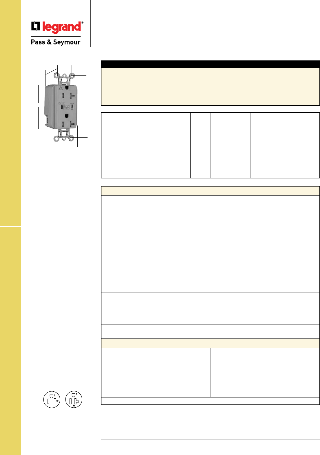
Technical Specifications
S-90
Project
Location/Type
TR IG Surge Protective Receptacles
Technical Specifications
Tamper-Resistant Isolated Ground
Surge Protective Receptacles
2 Pole, 3 Wire Grounding 15 & 20A, 125VAC
Typical Specications
Manufacturer’s Identification: Legrand/Pass & Seymour TRIG5262ISP
3rd Party Compliance: UL Listed, File Number E140596, Standard UL498, Attachment Plugs and
Receptacles UL1449 Transient Voltage Surge Suppressor. Federal Specification WC596. CSA Certified,
File Number LR16063, Standard CSA-C22.2 No. 42, ANSI/EEE C62.41 (Formerly IEEE 587), ANSI/IEEE
C62.45 Installation Categories “A” (Ring Wave) “B” (Unidirectional Impulse). Complies with NEC
410-56(c) and 250-74 exception 4. Conforms to NEMA WD-1 and WD-6.
Performance
Electrical
Frequency 60 Hz
Voltage 125VAC
MOV Rating 130V 17mm Dual Pack
Suppressed Voltage 500V
Energy Rating 340 Joules
Max Surge Capability 24kA
Protection Modes Normal and Common Modes: Normal Mode (L-N) 500V Clamping;
Common Mode (L-G) 500V Clamping, (N-G) 500V Clamping
Noise Attenuation Normal Mode (L-N)
Capacitance Value = 0.0056 µF
7:1 Average Noise Reduction
Thermal Protection Three Thermal Fuses (128°C or 262°F)
Overcurrent Protection Three Fuses Protects 3 Modes
Operating Temperature -20°C to 55°C (-4 to 131°F)
Storage Temperature -40°C to 85°C (-40 to 185°F)
Mechanical
Terminal Identification Brass = Hot, Nickel = Neutral, Green = Ground
Terminal Accommodation #14 – 10 AWG copper conductor only
Product Identification Ratings are a permanent part of device
Weight 125 grams
Environmental
Flammability UL94 V2
Materials
Warranty 1 year
Face Nylon
Body Nylon
Line Terminal Olin #260 EH, 0.8mm thick
Grounding Terminal 70/30 Brass, 0.4mm thick
(Uni-Ground Assembly)
Mounting Strap Super Dyma Cold-Rolled
Steel, 1.2mm thick
Clamping Plate Cold-Rolled Steel, 1.6mm
Terminal Screws Tri-Drive Brass #8 - 32
Hex Head Grounding Tri-Drive Steel (Green)
Screw
Auto-Ground Clip Stainless Steel
Mounting Screws Tri-Drive Zinc-Plated Steel
LED Green/Red
Encapsulation Conformal Coating
Tamper Shutter Thermoplastic
NEMA
Catalog Cong.
Number Color Rating No.
r
TRIG5262ISP Ivory 15A 125VAC 5-15R
r
TRIG5262WSP White 15A 125VAC 5-15R
r
TRIG5262GRYSP Gray 15A 125VAC 5-15R
r
TRIG5262BKSP Black 15A 125VAC 5-15R
r
TRIG5262REDSP Red 15A 125VAC 5-15R
r
TRIG5262LASP Lt. Almond 15A 125VAC 5-15R
r
TRIG5262BLSP Blue 15A 125VAC 5-15R
r
TRIG5262OSP Orange 15A 125VAC 5-15R
NEMA
Catalog Cong.
Number Color Rating No.
r
TRIG5362ISP Ivory 20A 125VAC 5-20R
r
TRIG5362WSP White 20A 125VAC 5-20R
r
TRIG5362GRYSP Gray 20A 125VAC 5-20R
r
TRIG5362BKSP Black 20A 125VAC 5-20R
r
TRIG5362REDSP Red 20A 125VAC 5-20R
r
TRIG5362LASP Lt. Almond 20A 125VAC 5-20R
r
TRIG5362BLSP Blue 20A 125VAC 5-20R
r
TRIG5362OSP Orange 20A 125VAC 5-20R
Conforms to the latest revision ANSI/IEEE C62.41 (formerly IEEE587), ANSI/IEEE C62.45.
NEMA
5-20R
NEMA
5-15R
Features
• LED Indication:
- Steady green = protected
- Flashing red = not protected
- OFF = no power to unit
• Alarm
• Alarm shut off/override
• Brass 1-piece ground
terminal assembly
• Back and side wire capability
including ground terminal
TRIG5362GRYSP
3.75"
1.70"
.875"
2.75"
1.40"
Behind Strap
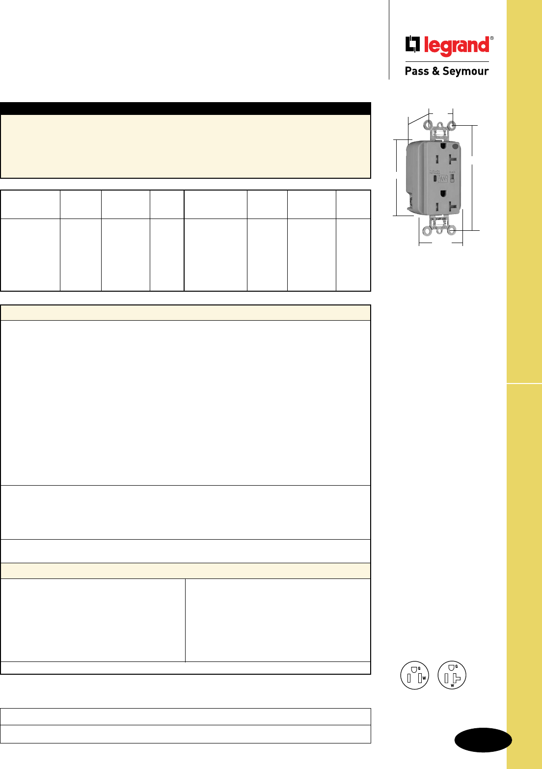
Technical Specifications
S-91
EHD TR HG Surge Protective Receptacles
Technical Specifications
Extra Heavy-Duty Tamper-Resistant
Hospital Grade Surge Protective Receptacles
2 Pole, 3 Wire Grounding, 15 & 20A, 125VAC
Project
Location/Type
Typical Specications
Manufacturer’s Identification: Legrand/Pass & Seymour TR8200ISP
3rd Party Compliance: UL Listed, File Number E140596, Standard UL498, Attachment Plugs and
Receptacles UL1449 Transient Voltage Surge Suppressor. Federal Specification WC596. CSA Certified,
File Number LR16063, Standard CSA-C22.2 No. 42, ANSI/EEE C62.41 (Formerly IEEE 587), ANSI/IEEE
C62.45 Installation Categories “A” (Ring Wave) “B” (Unidirectional Impulse). Complies with NEC
410-56(c) and 250-74 exception 4. Conforms to NEMA WD-1 and WD-6.
Performance
Electrical
Frequency 60 Hz
Voltage 125VAC
MOV Rating 130V 17mm Dual Pack
Suppressed Voltage 500V
Energy Rating 340 Joules
Max Surge Capability 24kA
Protection Modes Normal and Common Modes: Normal Mode (L-N) 500V Clamping;
Common Mode (L-G) 500V Clamping, (N-G) 500V Clamping
Noise Attenuation Normal Mode (L-N)
Capacitance Value = 0.0056 µF
7:1 Average Noise Reduction
Thermal Protection Three Thermal Fuses (128°C or 262°F)
Overcurrent Protection Three Fuses Protects 3 Modes
Operating Temperature -20°C to 55°C (-4 to 131°F)
Storage Temperature -40°C to 85°C (-40 to 185°F)
Mechanical
Terminal Identification Brass = Hot, Nickel = Neutral, Green = Ground
Terminal Accommodation #14 – 10 AWG copper conductor only
Product Identification Ratings are a permanent part of device
Weight 125 grams
Environmental
Flammability UL94 V2
Materials
Warranty 1 year
Face Nylon
Body Nylon
Line Terminal Olin #260 EH, 0.8mm thick
Grounding Terminal 70/30 Brass, 0.4mm thick
(Uni-Ground Assembly)
Mounting Strap Super Dyma Cold-Rolled
Steel, 1.2mm thick
Clamping Plate Cold-Rolled Steel, 1.6mm
Terminal Screws Tri-Drive Brass #8 - 32
Hex Head Grounding Tri-Drive Steel (Green)
Screw
Auto-Ground Clip Stainless Steel
Mounting Screws Tri-Drive Zinc-Plated Steel
LED Green/Red
Encapsulation Conformal Coating
Tamper Shutter Thermoplastic
NEMA
Catalog Cong.
Number Color Rating No.
r
TR8200ISP Ivory 15A 125VAC 5-15R
r
TR8200WSP White 15A 125VAC 5-15R
r
TR8200SP Brown 15A 125VAC 5-15R
r
TR8200GRYSP Gray 15A 125VAC 5-15R
r
TR8200REDSP Red 15A 125VAC 5-15R
r
TR8200LASP Lt. Almond 15A 125VAC 5-15R
r
TR8200BLSP Blue 15A 125VAC 5-15R
NEMA
Catalog Cong.
Number Color Rating No.
r
TR8300ISP Ivory 20A 125VAC 5-20R
r
TR8300WSP White 20A 125VAC 5-20R
r
TR8300SP Brown 20A 125VAC 5-20R
r
TR8300GRYSP Gray 20A 125VAC 5-20R
r
TR8300REDSP Red 20A 125VAC 5-20R
r
TR8300LASP Lt. Almond 20A 125VAC 5-20R
r
TR8300BLSP Blue 20A 125VAC 5-20R
Conforms to the latest revision ANSI/IEEE C62.41 (formerly IEEE587), ANSI/IEEE C62.45. NEMA
5-20R
NEMA
5-15R
Features
• LED Indication:
- Steady green = protected
- Flashing red = not protected
- OFF = no power to unit
• Alarm
• Alarm shut off/override
• Brass 1-piece ground
terminal assembly
• Back and side wire capability
including ground terminal
TR8300GRYSP
3.75"
1.70"
.875"
1.40"
Behind Strap
2.75"
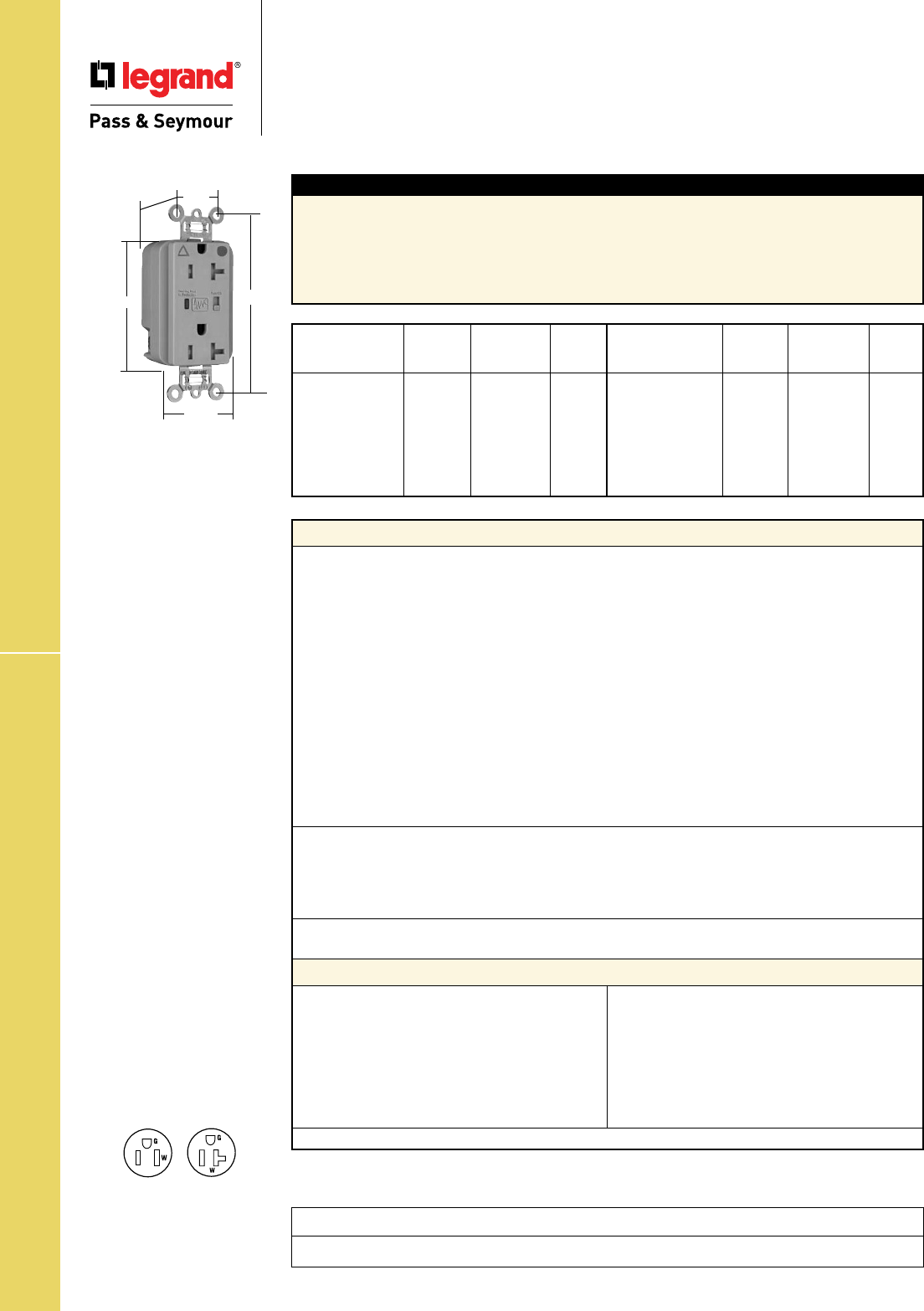
Technical Specifications
S-92
TR HG IG Surge Protective Receptacles
Project
Location/Type
Technical Specifications
Tamper-Resistant Hospital Grade
Isolated Ground Surge Protective Receptacles
2 Pole, 3 Wire Grounding 15 & 20A, 125VAC
Typical Specications
Manufacturer’s Identification: Legrand/Pass & Seymour TRIG8200ISP
3rd Party Compliance: UL Listed, File Number E140596, Standard UL498, Attachment Plugs and
Receptacles UL1449 Transient Voltage Surge Suppressor. Federal Specification WC596. CSA Certified,
File Number LR16063, Standard CSA-C22.2 No. 42, ANSI/EEE C62.41 (Formerly IEEE 587), ANSI/IEEE
C62.45 Installation Categories “A” (Ring Wave) “B” (Unidirectional Impulse). Complies with NEC
410-56(c) and 250-74 exception 4. Conforms to NEMA WD-1 and WD-6.
Performance
Electrical
Frequency 60 Hz
Voltage 125VAC
MOV Rating 130V 17mm Dual Pack
Suppressed Voltage 500V
Energy Rating 340 Joules
Max Surge Capability 24kA
Protection Modes Normal and Common Modes: Normal Mode (L-N) 500V Clamping;
Common Mode (L-G) 500V Clamping, (N-G) 500V Clamping
Noise Attenuation Normal Mode (L-N)
Capacitance Value = 0.0056 µF
7:1 Average Noise Reduction
Thermal Protection Three Thermal Fuses (128°C or 262°F)
Overcurrent Protection Three Fuses Protects 3 Modes
Operating Temperature -20°C to 55°C (-4 to 131°F)
Storage Temperature -40°C to 85°C (-40 to 185°F)
Mechanical
Terminal Identification Brass = Hot, Nickel = Neutral, Green = Ground
Terminal Accommodation #14 – 10 AWG copper conductor only
Product Identification Ratings are a permanent part of device
Weight 125 grams
Environmental
Flammability UL94 V2
Materials
Warranty 1 year
Face Nylon
Body Nylon
Line Terminal Olin #260 EH, 0.8mm thick
Grounding Terminal 70/30 Brass, 0.4mm thick
(Uni-Ground Assembly)
Mounting Strap Super Dyma Cold-Rolled
Steel, 1.2mm thick
Clamping Plate Cold-Rolled Steel, 1.6mm
Terminal Screws Tri-Drive Brass #8 - 32
Hex Head Grounding Tri-Drive Steel (Green)
Screw
Auto-Ground Clip Stainless Steel
Mounting Screws Tri-Drive Zinc-Plated Steel
LED Green/Red
Encapsulation Conformal Coating
Tamper Shutter Thermoplastic
NEMA
Catalog Cong.
Number Color Rating No.
r
TRIG8200ISP Ivory 15A 125VAC 5-15R
r
TRIG8200WSP White 15A 125VAC 5-15R
r
TRIG8200GRYSP Gray 15A 125VAC 5-15R
r
TRIG8200REDSP Red 15A 125VAC 5-15R
r
TRIG8200LASP Lt. Almond 15A 125VAC 5-15R
r
TRIG8200BLSP Blue 15A 125VAC 5-15R
r
TRIG8200OSP Orange 15A 125VAC 5-15R
NEMA
Catalog Cong.
Number Color Rating No.
r
TRIG8300ISP Ivory 20A 125VAC 5-20R
r
TRIG8300WSP White 20A 125VAC 5-20R
r
TRIG8300GRYSP Gray 20A 125VAC 5-20R
r
TRIG8300REDSP Red 20A 125VAC 5-20R
r
TRIG8300LASP Lt. Almond 20A 125VAC 5-20R
r
TRIG8300BLSP Blue 20A 125VAC 5-20R
r
TRIG8300OSP Orange 20A 125VAC 5-20R
Conforms to the latest revision ANSI/IEEE C62.41 (formerly IEEE587), ANSI/IEEE C62.45.
NEMA
5-20R
NEMA
5-15R
Features
• LED Indication:
- Steady green = protected
- Flashing red = not protected
- OFF = no power to unit
• Alarm
• Alarm shut off/override
• Brass 1-piece ground
terminal assembly
• Back and side wire capability
including ground terminal
TRIG8300GRYSP
3.75"
1.70"
.875"
1.40"
Behind Strap
2.75"
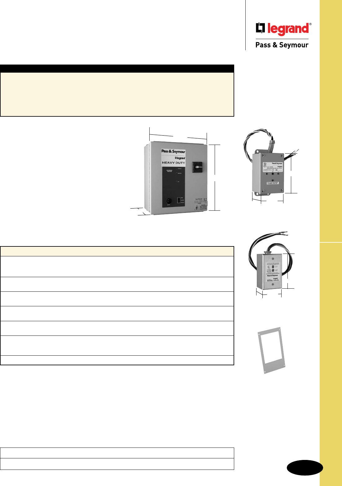
Technical Specifications
S-93
Surge Protection Panels
Technical Specifications
Surge Protection Panels
Heavy-, Medium- & Light-Duty
Project
Location/Type
16.00"
Heavy-Duty
14.00"
8.00" Medium-Duty
6.00"
4.00"
3.00"
Light-Duty
2.8" 2.2"
4.6"
MFKIT
Typical Specications
Manufacturer’s Identification: Legrand/Pass & Seymour 1224SL
3rd Party Compliance: UL Listed: Basic UL File Number – E324279; ML File Number – E332797.
Standard UL1449, 3rd Edition (effective 9/29/09):
– Light Duty: UL1449 3rd Edition Type 2 SPD, cUL
– Medium Duty: UL1449 3rd Edition Type 2 SPD, cUL
– Heavy Duty: UL1449 3rd Edition Type 1 SPD
UL1283, CSA, CE, NEMA LS-1.
Performance
LED Indicators
Green LED is illuminated at all times while unit is functioning with no faults.
A red LED will come on if any phase/mode has a fault.
Audible Alarm
Visible on the enclosure cover; will sound whenever surge protection is lost.
Rotary Disconnect Switch
Lockable only in the off position for increased safety.
NEMA 12 Enclosure
Epoxy painted steel with gasketing, rated for indoor operating use.
Three-Position Test Switch
Used for the audible alarm and LEDs – functions are: enable/switch/test.
Environmental
Recommended ambient temperature range Designed for -40 degrees C to +60 degrees C,
with a relative humidity of 0% to 5% (non-condensing)
Warranty 5 years
Conforms to the latest revision ANSI/IEEE C62.41 (formerly IEEE587), ANSI/IEEE C62.45.
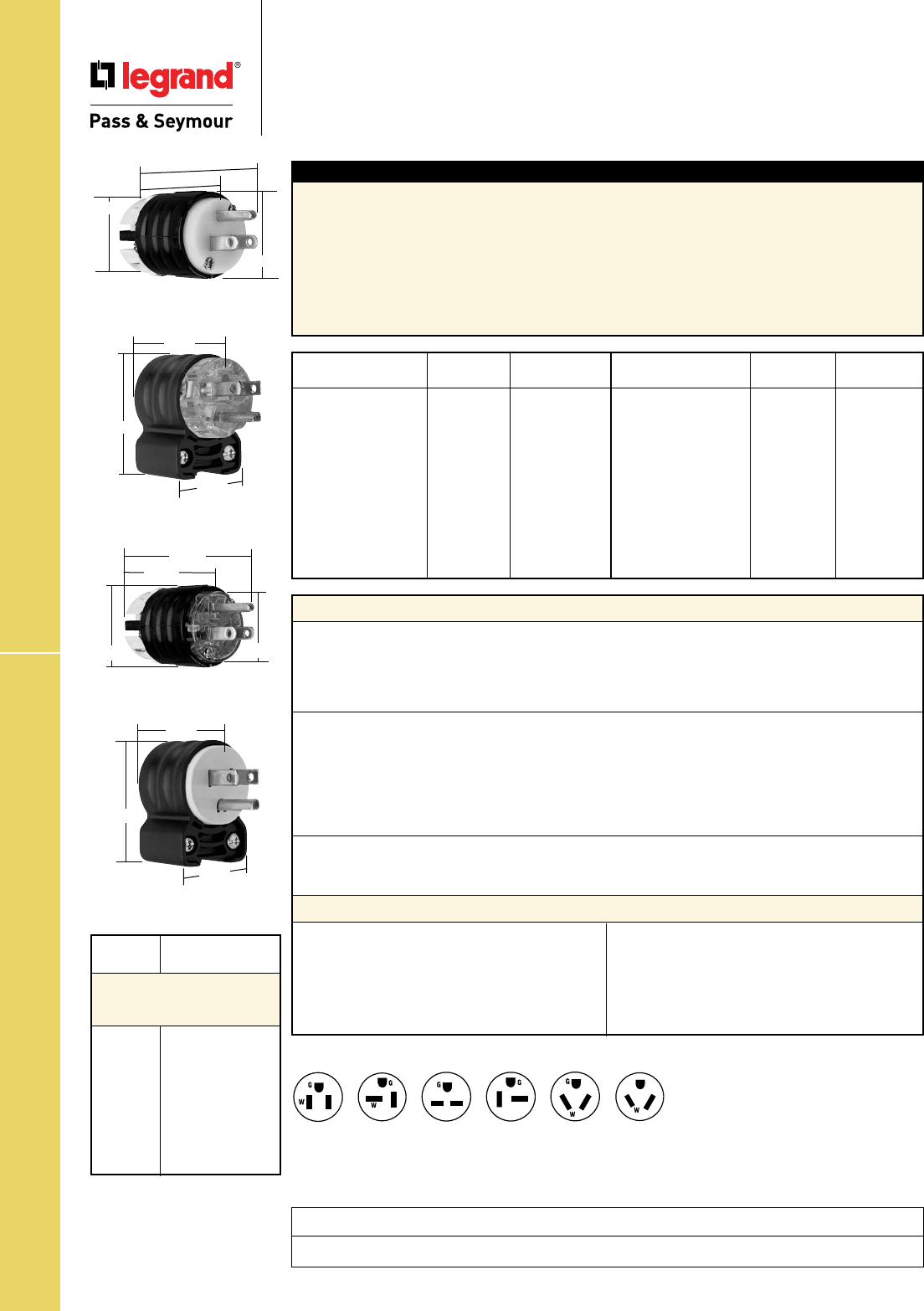
Technical Specifications
S-94
Straight Blade Plugs
Technical Specifications
Straight Blade Plugs
2 Pole, 3 Wire Grounding 15 & 20A, 125, 250 & 277V
Typical Specications
Manufacturer’s Identification: Legrand/Pass & Seymour PS5266X
Description: Straight Blade Plug, Power Supply
Type: 2 Pole, 3 Wire Grounding
Rating: 15A, 125V
Configuration: NEMA 5-15P
3rd Party Compliance:UL Listed, File Number E146159, Standard UL498, Attachment Plugs and
Receptacles. Federal Specification WC596. CSA Certified, File Number LR1765, Standard CSA-C22.2
No. 42, General Use Receptacles and Attachment Plugs. Conforms to NEMA WD-1 and WD-6.
NEMA
Catalog Number Rating Cong. No.
r
PS5266XHG 15A 125V 5-15P
r
PS5266HGAN 15A 125V 5-15P
r
PS5366XHG 20A 125V 5-20P
r
PS5366HGAN 20A 125V 5-20P
r
PS5666XHG 15A 250V 6-15P
r
PS5666HGAN 15A 250V 6-15P
r
PS5466XHG 20A 250V 6-20P
r
PS5466HGAN 20A 250V 6-20P
r
PS5266X 15A 125V 5-15P
r
PS5266SSAN 15A 125V 5-15P
r
PS5266XGRY 15A 125V 5-15P
NEMA
Catalog Number Rating Cong. No.
r
PS5266XBK 15A 125V 5-15P
r
CR5266X 15A 125V 5-15P
r
PS5366X 20A 125V 5-20P
r
PS5366SSAN 20A 125V 5-20P
r
PS5666X 15A 250V 6-15P
r
PS5666SSAN 15A 250V 6-15P
r
PS5466X 20A 250V 6-20P
r
PS5466SSAN 20A 250V 6-20P
r PS5766X 15A 277V 7-15P
r PS5866X 20A 277V 7-20P
NEMA
6-15P
NEMA
6-20P
NEMA
5-15P
NEMA
7-15P
NEMA
5-20P NEMA
7-20P
*Nickel-Plated for Corrosion-Resistant Product.
Performance
Electrical
Dielectric Withstand Voltage 1500V minimum
Maximum Working Voltage 277V
Current Interrupting Certified for current interrupting at full-rated current
Temperature Rise 30°C maximum after 50 cycles at 150% rated current
Mechanical
Cord Accommodation Round portable service cords of diameters in accordance with
the device rating as defined in UL62
Cord Grip Accommodation .230"–.720" diameter, Angle Plugs – .320"–.655"
Terminal Identification Green = Ground, White = Neutral, Brass = Hot
Terminal Accommodation #18 AWG min. – #10 AWG max.
Product Identification Amperage, Voltage, 3rd Party Compliance, NEMA Configuration
Environmental
Flammability UL94 V2
Operating Temperature Maximum continuous +75°C, minimum -40°C without impact
Materials
Back Body Nylon
Front Body Nylon
Terminal Chamber Polycarbonate
Cord Clamp Nylon
Insert Nylon
Blades * Brass
Terminal Clamp * Zinc-Plated Steel
Terminal Screws Nickel- or Brass-Plated Steel
Ground Screws Nickel-Plated Steel
Cord Clamp Screws Nickel-Plated Steel #8
Assembly Screws Nickel-Plated Steel
Consult Straight Blade Plugs & Connectors Section G for complete compliance listing.
2.791"
1.752"
PS5266X
1.516"
1.358"
PS5266XHG
1.752"
2.791"
1.516" 1.358"
PS5266HGAN
2.130"
1.350"
1.530"
PS5266SSAN
2.130"
1.350"
1.530"
Project
Location/Type
* Suitable for 208V motor
applications at the HP rating
specified.
NEMA AC HP
Cong. Rating
Straight Blade
Horsepower Rating for
NEMA Configuration
5-15 1⁄2
6-15 11⁄2*
7-15 2
5-20 1
6-20 2*
7-20 2
10-20 2 Line to Line*
1 Line to Neutral
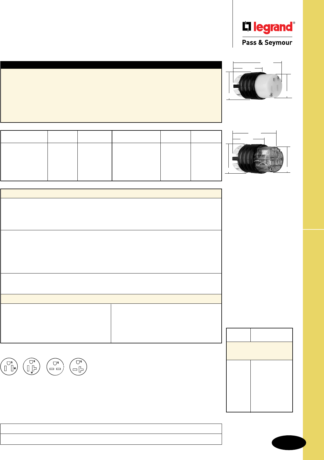
Technical Specifications
S-95
Straight Blade Connectors
Technical Specifications
Straight Blade Connectors
2 Pole, 3 Wire Grounding 15 & 20A, 125 & 250V
Typical Specications
Manufacturer’s Identification: Legrand/Pass & Seymour PS5269X
Description: Straight Blade Connector, Power Supply
Type: 2 Pole, 3 Wire Grounding
Rating: 15A. 125V
Configuration: NEMA 5-15R
3rd Party Compliance:UL Listed, File Number E146159, Standard UL498, Attachment Plugs and
Receptacles. Federal Specification WC596. CSA Certified, File Number LR1765, Standard CSA-C22.2
No. 42, General Use Receptacles and Attachment Plugs. Conforms to NEMA WD-1 and WD-6.
Performance
Electrical
Dielectric Withstand Voltage 1500V minimum
Maximum Working Voltage 250V
Current Interrupting Certified for current interrupting at full-rated current
Temperature Rise 30°C maximum after 50 cycles at 150% rated current
Mechanical
Cord Accommodation Round portable service cords of diameters in accordance with
the device rating as defined in UL62
Cord Grip Accommodation .230"–.720" diameter
Terminal Identification Green = Ground, White = Neutral, Brass = Hot
Terminal Accommodation #18 AWG min. – #10 AWG max.
Product Identification Amperage, Voltage, 3rd Party Compliance, NEMA Configuration
Environmental
Flammability UL94 V2
Operating Temperature Maximum continuous +75°C, minimum -40°C without impact
Materials
Back Body Nylon
Front Body Nylon
Terminal Chamber Polycarbonate
Cord Clamp Nylon
Insert Nylon
Contacts * Brass
Terminal Clamp * Zinc-Plated Steel
Terminal Screws Nickel- or Brass-
Plated Steel
Ground Screws Nickel-Plated Steel
Cord Clamp Screws Nickel-Plated Steel #8
Assembly Screws Nickel-Plated Steel
* Nickel-Plated for Corrosion-Resistant Product.
NEMA
Catalog Number Rating Cong. No.
r
PS5269XHG 15A 125V 5-15R
r
PS5369XHG 20A 125V 5-20R
r
PS5669XHG 15A 250V 6-15R
r
PS5469XHG 20A 250V 6-20R
r
PS5269X 15A 125V 5-15R
r
PS5269XGRY 15A 125V 5-15R
NEMA
Catalog Number Rating Cong. No.
r
PS5269XBK 15A 125V 5-15R
r
CR5269X 15A 125V 5-15R
r
PS5369X 20A 125V 5-20R
r
PS5669X 15A 250V 6-15R
r
PS5469X 20A 250V 6-20R
PS5269XHG
2.638"
1.516" 1.358"
1.752"
PS5269X
1.516" 1.358"
1.752"
2.638"
Consult Straight Blade Plugs & Connectors Section G for complete compliance listing.
* Suitable for 208V motor
applications at the HP rating
specified.
NEMA AC HP
Cong. Rating
Straight Blade
Horsepower Rating for
NEMA Configuration
5-15 1⁄2
6-15 11⁄2*
7-15 2
5-20 1
6-20 2*
7-20 2
10-20 2 Line to Line*
1 Line to Neutral
Project
Location/Type
NEMA
5-15R
NEMA
5-20R
NEMA
6-15R
NEMA
6-20R
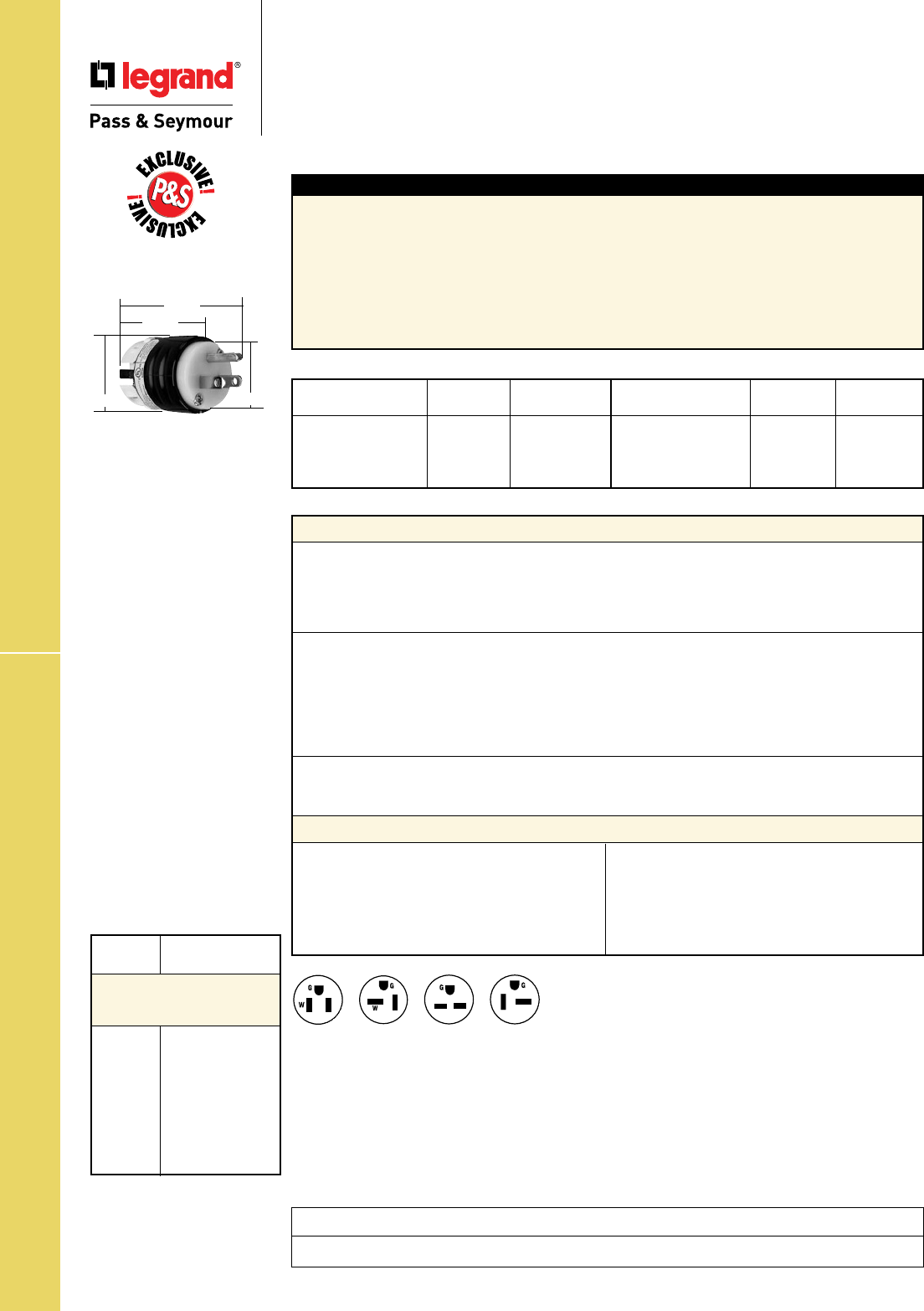
Technical Specifications
S-96
Straight Blade GCM Plugs
Technical Specifications
Straight Blade Ground Continuity
Monitoring (GCM) Plugs
2 Pole, 3 Wire Grounding 15 & 20A, 125 & 250V
Typical Specications
Manufacturer’s Identification: Legrand/Pass & Seymour PS5266XGCM
Description: Straight Blade Plug, Power Supply
Type: 2 Pole, 3 Wire Grounding
Rating: 15A, 125V
Configuration: NEMA 5-15P
3rd Party Compliance: cULus Listed, File Number E146159, Standard UL498, Attachment Plugs and
Receptacles. Federal Specification WC596. Standard CSA-C22.2 No. 42, General Use Receptacles and
Attachment Plugs. Conforms to NEMA WD-1 and WD-6.
NEMA
Catalog Number Rating Cong. No.
r
PS5266XGCM 15A 125V 5-15P
r
PS5266XGCMAN 15A 125V 5-15P
r
PS5366XGCM 20A 125V 5-20P
r
PS5366XGCMAN 20A 125V 5-20P
NEMA
Catalog Number Rating Cong. No.
r
PS5666XGCM 15A 250V 6-15P
r
PS5666XGCMAN 15A 250V 6-15P
r
PS5466XGCM 20A 250V 6-20P
r
PS5466XGCMAN 20A 250V 6-20P
NEMA
5-15P
NEMA
5-20P
NEMA
6-15P
NEMA
6-20P
Performance
Electrical
Dielectric Withstand Voltage 1500V minimum
Maximum Working Voltage 250V
Current Interrupting Certified for current interrupting at full-rated current
Temperature Rise 30°C maximum after 50 cycles at 150% rated current
Mechanical
Cord Accommodation Round portable service cords of diameters in accordance with
the device rating as defined in UL62
Cord Grip Accommodation .230"–.720" diameter, Angle Plugs – .320"–.655"
Terminal Identification Green = Ground, White = Neutral, Brass = Hot
Terminal Accommodation #18 AWG min. – #10 AWG max.
Product Identification Amperage, Voltage, 3rd Party Compliance, NEMA Configuration
Environmental
Flammability UL94 V2
Operating Temperature Maximum continuous +75°C, minimum -40°C without impact
Materials
Back Body Nylon
Front Body Nylon
Terminal Chamber Polycarbonate
Cord Clamp Nylon
Insert Nylon
Blades Brass
Terminal Clamp Zinc-Plated Steel
Terminal Screws Nickel- or Brass-Plated Steel
Ground Screws Nickel-Plated Steel
Cord Clamp Screws Nickel-Plated Steel #8
Assembly Screws Nickel-Plated Steel
Consult Straight Blade Plugs & Connectors Section G for complete compliance listing.
PS5266XGCM
1.516" 1.358"
1.752"
2.791"
* Suitable for 208V motor
applications at the HP rating
specified.
NEMA AC HP
Cong. Rating
Straight Blade
Horsepower Rating for
NEMA Configuration
5-15 1⁄2
6-15 11⁄2*
7-15 2
5-20 1
6-20 2*
7-20 2
10-20 2 Line to Line*
1 Line to Neutral
Project
Location/Type
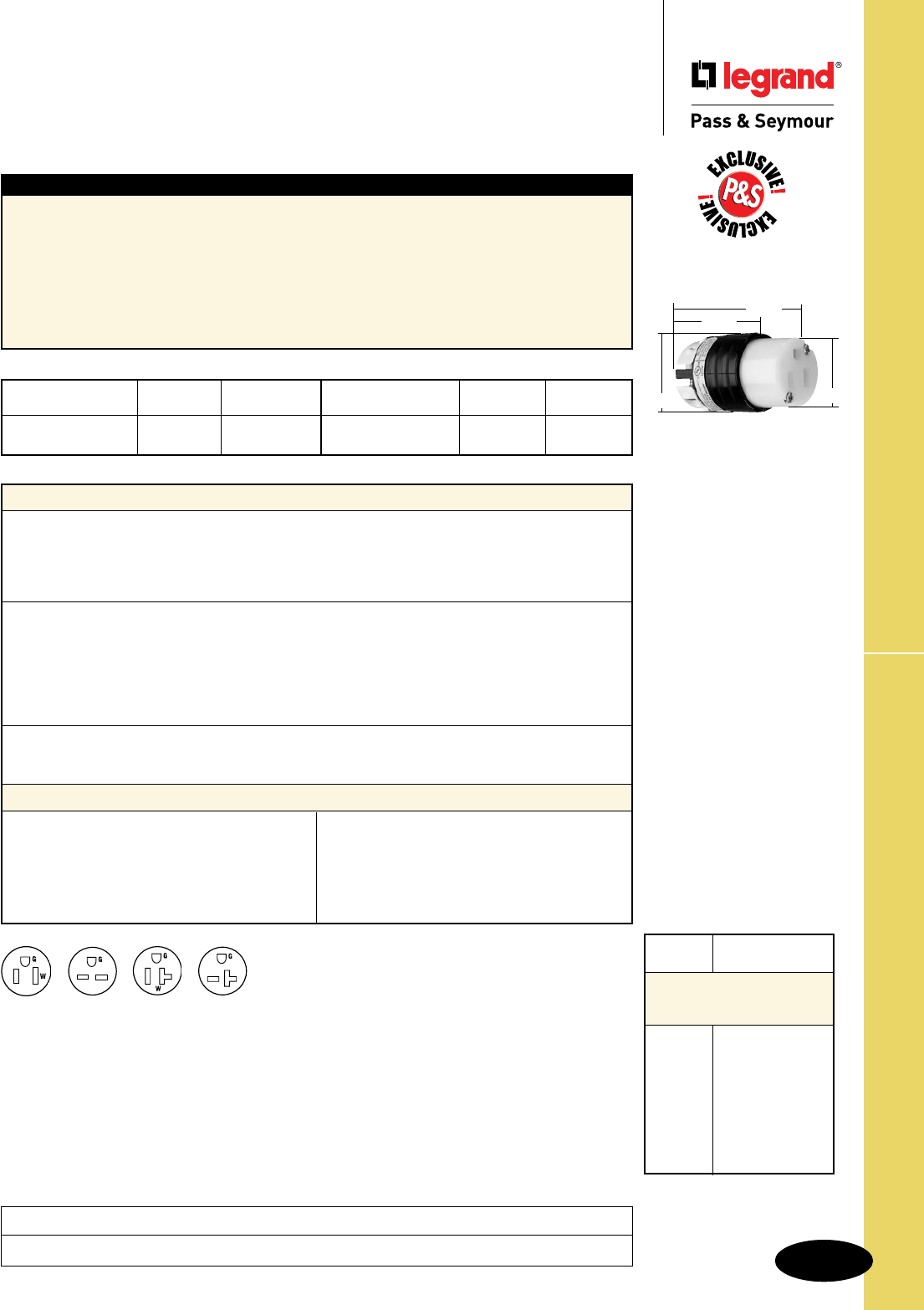
Technical Specifications
S-97
Straight Blade GCM Connectors
Technical Specifications
Straight Blade Ground Continuity
Monitoring (GCM) Connectors
2 Pole, 3 Wire Grounding 15 & 20A, 125 & 250V
Typical Specications
Manufacturer’s Identification: Legrand/Pass & Seymour PS5269XGCM
Description: Straight Blade Connector, Power Supply
Type: 2 Pole, 3 Wire Grounding
Rating: 15A. 125V
Configuration: NEMA 5-15R
3rd Party Compliance: cULus Listed, File Number E146159, Standard UL498, Attachment Plugs and
Receptacles. Federal Specification WC596. Standard CSA-C22.2 No. 42, General Use Receptacles and
Attachment Plugs. Conforms to NEMA WD-1 and WD-6.
Performance
Electrical
Dielectric Withstand Voltage 1500V minimum
Maximum Working Voltage 250V
Current Interrupting Certified for current interrupting at full-rated current
Temperature Rise 30°C maximum after 50 cycles at 150% rated current
Mechanical
Cord Accommodation Round portable service cords of diameters in accordance with
the device rating as defined in UL62
Cord Grip Accommodation .230"–.720" diameter
Terminal Identification Green = Ground, White = Neutral, Brass = Hot
Terminal Accommodation #18 AWG min. – #10 AWG max.
Product Identification Amperage, Voltage, 3rd Party Compliance, NEMA Configuration
Environmental
Flammability UL94 V2
Operating Temperature Maximum continuous +75°C, minimum -40°C without impact
Materials
Back Body Nylon
Front Body Nylon
Terminal Chamber Polycarbonate
Cord Clamp Nylon
Insert Nylon
Contacts Brass
Terminal Clamp Zinc-Plated Steel
Terminal Screws Nickel- or Brass-
Plated Steel
Ground Screws Nickel-Plated Steel
Cord Clamp Screws Nickel-Plated Steel #8
Assembly Screws Nickel-Plated Steel
NEMA
Catalog Number Rating Cong. No.
r
PS5269XGCM 15A 125V 5-15R
r
PS5369XGCM 20A 125V 5-20R
NEMA
Catalog Number Rating Cong. No.
r
PS5669XGCM 15A 250V 6-15R
r
PS5469XGCM 20A 250V 6-20R PS5269XGCM
1.516" 1.358"
1.752"
2.638"
Consult Straight Blade Plugs & Connectors Section G for complete compliance listing.
* Suitable for 208V motor
applications at the HP rating
specified.
NEMA AC HP
Cong. Rating
Straight Blade
Horsepower Rating for
NEMA Configuration
5-15 1⁄2
6-15 11⁄2*
7-15 2
5-20 1
6-20 2*
7-20 2
10-20 2 Line to Line*
1 Line to Neutral
Project
Location/Type
NEMA
6-20R
NEMA
6-15R
NEMA
5-15R
NEMA
5-20R
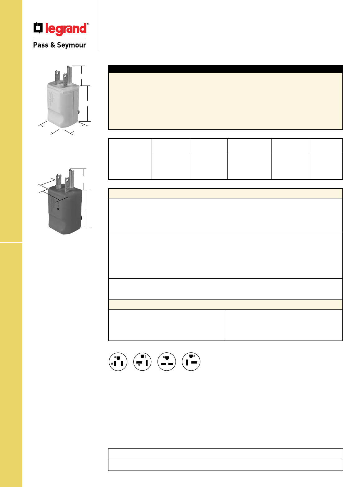
Technical Specifications
S-98
MaxGrip® M3 Plugs
Technical Specifications
MaxGrip® M3 Plugs
2 Pole, 3 Wire Grounding 15 & 20A, 125 & 250V
NEMA
Catalog Number Rating Cong. No.
r
PS8115 15A 125V 5-15P
r
PS5965Y 15A 125V 5-15P
r
PS5965GRY 15A 125V 5-15P
r
PS5965O 15A 125V 5-15P
NEMA
Catalog Number Rating Cong. No.
r
PS5364Y 20A 125V 5-20P
r
PS5364GRY 20A 125V 5-20P
r
PS5666Y 15A 250V 6-15P
r
PS5464Y 20A 250V 6-20P
Typical Specications
Manufacturer’s Identification: Legrand/Pass & Seymour PS5965Y
Description: Plug Straight Blade, Power Supply
Type: 2 Pole, 3 Wire Grounding
Rating: 15A, 125V
Configuration: NEMA 5-15P
3rd Party Compliance:UL Listed, File Number E146159, Standard UL498, Attachment Plugs and
Receptacles. Federal Specification WC596. CSA Certified, File Number LR1765, Standard CSA-C22.2
No. 42, General Use Receptacles and Attachment Plugs. Conforms to NEMA WD-1 and WD-6.
Consult Straight Blade Plugs & Connectors Section G for complete compliance listing.
Performance
Electrical
Dielectric Withstand Voltage 1500V minimum
Maximum Working Voltage 250V
Current Interrupting Certified for current interrupting at full-rated current
Temperature Rise 30°C, maximum after 50 cycles at 150% rated current
Mechanical
Cord Accommodation Round portable service cords of diameters in accordance
with the device rating as defined in UL62
Cord Grip Accommodation .230"–.720" diameter cord
Terminal Identification Green = Ground, Silver = Neutral, Brass = Hot
Terminal Accommodation #18 AWG min. – #12 AWG max.
Product Identification Amperage, Voltage, 3rd Party Compliance, NEMA Configuration
Environmental
Flammability UL94 HB
Operating Temperatures Maximum continuous +75°C, minimum -40°C without impact
Materials
Body/Housing Nylon
Cord Grip Insert Nylon
Terminal Clamp Brass
Terminal Screws Zinc- and Brass-Plated Steel
Ground Screw Zinc-Plated Steel
Blades Brass
Cord Clamp Assembly Screws Zinc-Plated Steel
PS5965Y
.77"
1.83"
1.34" 1.21"
1.34"
1.21"
1.83"
PS8115
.77"
Project
Location/Type
NEMA
5-15P
NEMA
5-20P
NEMA
6-15P
NEMA
6-20P
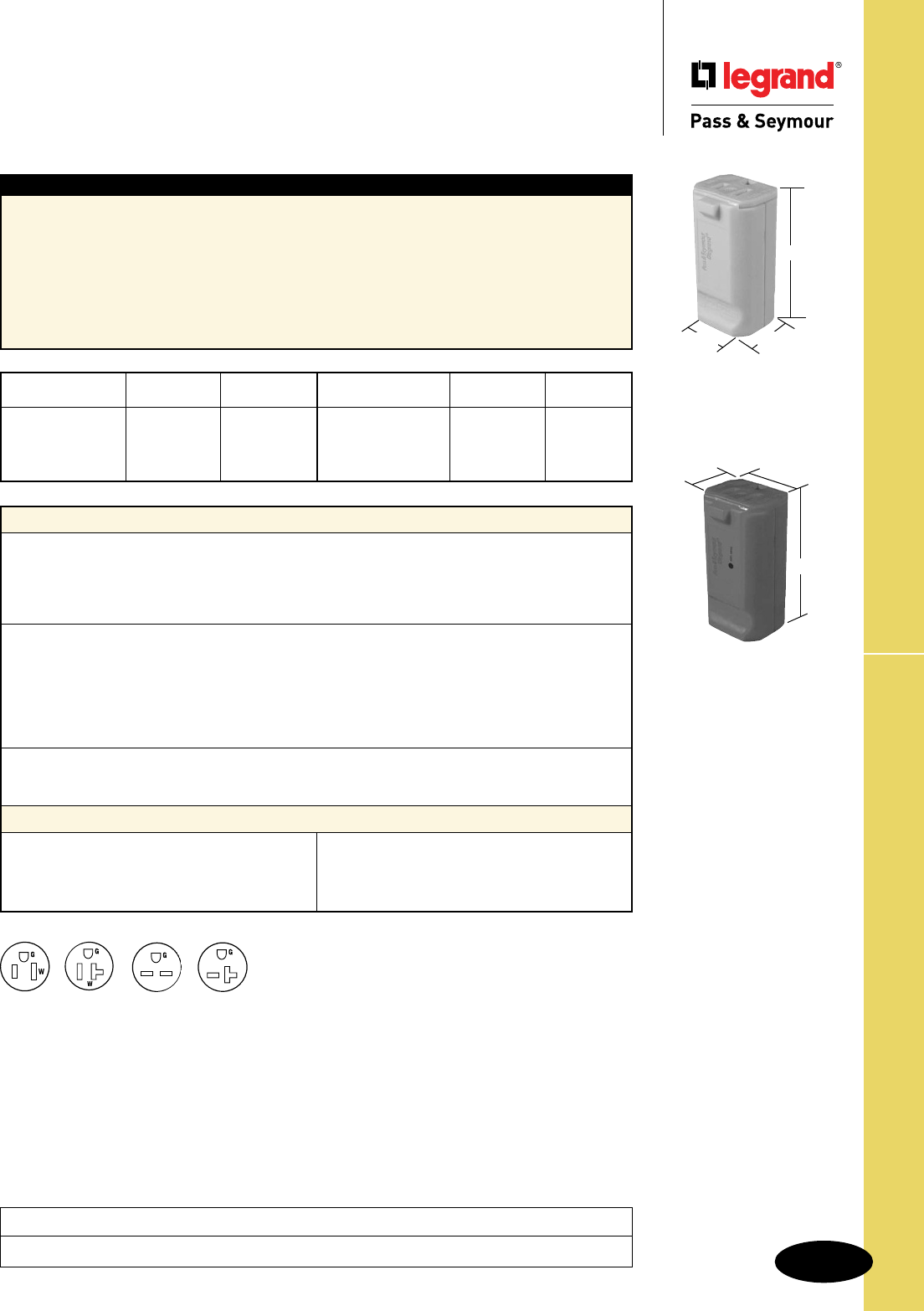
Technical Specifications
S-99
MaxGrip® M3 Connectors
Technical Specifications
MaxGrip® M3 Connectors
2 Pole, 3 Wire Grounding 15 & 20A, 125 & 250V
NEMA
Catalog Number Rating Cong. No.
r
PS8119 15A 125V 5-15R
r
PS5969Y 15A 125V 5-15R
r
PS5969GRY 15A 125V 5-15R
r
PS5969O 15A 125V 5-15R
NEMA
Catalog Number Rating Cong. No.
r
PS5369Y 20A 125V 5-20R
r
PS5369GRY 20A 125V 5-20R
r
PS5669Y 15A 250V 6-15R
r
PS5469Y 20A 250V 6-20R
Typical Specications
Manufacturer’s Identification: Legrand/Pass & Seymour PS5969Y
Description: Connector Straight Blade, Power Supply
Type: 2 Pole, 3 Wire Grounding
Rating: 15A, 125V
Configuration: NEMA 5-15R
3rd Party Compliance:UL Listed, File Number E146159, Standard UL498, Attachment Plugs and
Receptacles. Federal Specification WC596. CSA Certified, File Number LR1765, Standard CSA-C22.2
No. 42, General Use Receptacles and Attachment Plugs. Conforms to NEMA WD-1 and WD-6.
Consult Straight Blade Plugs & Connectors Section G for complete compliance listing.
Performance
Electrical
Dielectric Withstand Voltage 1500V minimum
Maximum Working Voltage 250V
Current Interrupting Certified for current interrupting at full-rated current
Temperature Rise 30°C, maximum after 50 cycles at 150% rated current
Mechanical
Cord Accommodation Round portable service cords of diameters in accordance
with the device rating as defined in UL62
Cord Grip Accommodation .230"–.720" diameter cord
Terminal Identification Green = Ground, Silver = Neutral, Brass = Hot
Terminal Accommodation #18 AWG min. – #12 AWG max.
Product Identification Amperage, Voltage, 3rd Party Compliance, NEMA Configuration
Environmental
Flammability UL94 HB
Operating Temperatures Maximum continuous +75°C, minimum -40°C without impact
Materials
Body/Housing Nylon
Cord Grip Insert Nylon
Terminal Clamp Brass
Terminal Screws Zinc- and Brass-Plated Steel
Ground Screw Zinc-Plated Steel
Contacts Brass
Cord Clamp Assembly Screws Zinc-Plated Steel
PS5969Y
1.83"
1.21"
1.34"
1.34"
1.21"
1.83"
PS8119
Project
Location/Type
NEMA
5-15R
NEMA
5-20R
NEMA
6-15R
NEMA
6-20R
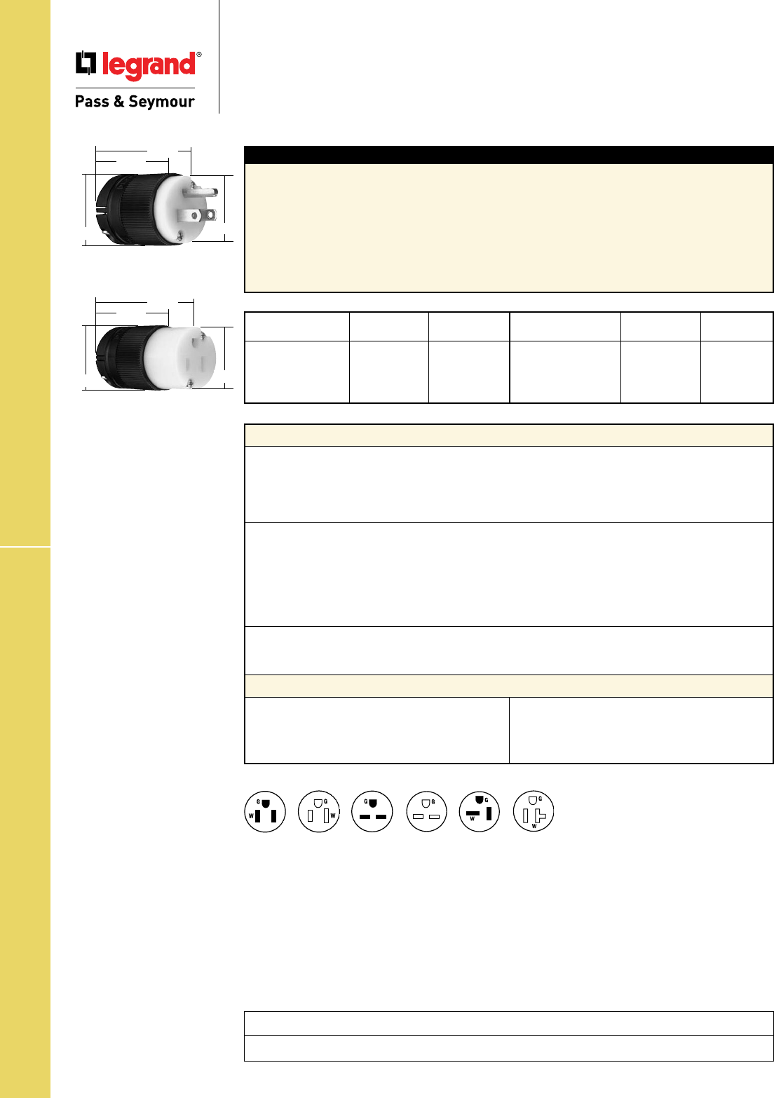
Technical Specifications
S-100
Technical Specifications
Clamp-Lock™ Plugs & Connectors
2 Pole, 3 Wire Grounding 15A, 125 & 250V; 20A, 125V
Clamp-Lock™ Plugs & Connectors
NEMA
Catalog Number Rating Cong. No.
r
PS515PCLB 15A 125V 5-15P
r
PS515CCLB 15A 125V 5-15R
r
PS520PCLB 20A 125V 5-20P
r
PS520CCLB 20A 125V 5-20R
NEMA
Catalog Number Rating Cong. No.
r
PS615PCLB 15A 250V 6-15P
r
PS615CCLB 15A 250V 6-15R
Typical Specications
Manufacturer’s Identification: Legrand/Pass & Seymour PS515PCLB
Description: Connector Straight Blade, Power Supply
Type: 2 Pole, 3 Wire Grounding
Rating: 15A, 125V
Configuration: NEMA 5-15R
3rd Party Compliance:UL Listed, File Number E146159, Standard UL498, Attachment Plugs and
Receptacles. Federal Specification WC596. CSA Certified, File Number LR1765, Standard CSA-C22.2
No. 42, General Use Receptacles and Attachment Plugs. Conforms to NEMA WD-1 and WD-6.
Consult Straight Blade Plugs & Connectors Section G for complete compliance listing.
Performance
Electrical
Dielectric Withstand Voltage 1500V minimum
Maximum Working Voltage 250V
Current Interrupting Certified for current interrupting at full-rated current
Temperature Rise 30°C, maximum after 50 cycles at 150% rated current
Mechanical
Cord Accommodation Round portable service cords of diameters in accordance
with the device rating as defined in UL62
Cord Grip Accommodation .20"–.470" diameter cord
Terminal Identification Green = Ground, Silver = Neutral, Brass = Hot
Terminal Accommodation #18 AWG min. – #12 AWG max.
Product Identification Amperage, Voltage, 3rd Party Compliance, NEMA Configuration
Environmental
Flammability UL94 HB
Operating Temperatures Maximum continuous +75°C, minimum -40°C without impact
Materials
Body/Housing Nylon
Cord Grip Insert Nylon
Terminal Clamp Brass
Terminal Screws Zinc- and Brass-Plated Steel
Ground Screw Zinc-Plated Steel
Contacts Brass
Cord Clamp Assembly Screws Zinc-Plated Steel
Project
Location/Type
NEMA
5-15P
NEMA
6-15P
NEMA
6-15R
NEMA
5-15R
NEMA
5-20P
NEMA
5-20R
PS515PCLB
1.55" 1.40"
1.85"
2.10"
PS515CCLB
1.55"
1.85"
2.80"
1.40"
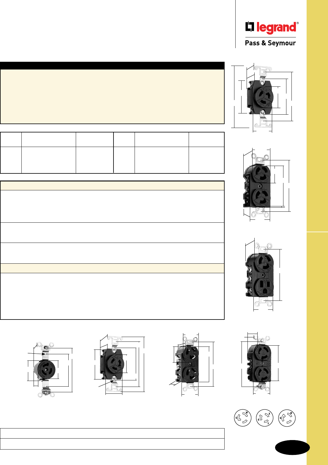
S-101
Technical Specifications 15A Turnlok® Receptacles
Technical Specifications
15A Turnlok® Receptacles
4550
1.150"
.940"
3.281"
1.500"
2.270"
4750
1.104"
3.281"
2.635"
.938"
1.199"
1.322"
1.50"
4760
2.375"
2.25"
1.203"
1.0"
1.375"
3.281"
4.031"
1.437"
#6-32
TAP
2.375"
1.375"
1.500"
#6-32
TAP
.922"
1.125"
3.281"
4560
4710
1.203"
2.25"
3.281"
1.437"
1.375"
2.375"
1.0"
4.031"
4792
3.28"
1.50"
1.199"
NEMA
Amps Catalog Number Cong. No.
15
r 4710
L5-15R
15
r
4700 L5-15R
15
r
4792 L5-15R
15
r
4560 L5-15R
NEMA
Amps Catalog Number Cong. No.
15
r
4550 L6-15R
15
r
4760 L7-15R
15
r
4750 L7-15R
Typical Specications
Manufacturer’s Identification: Legrand/Pass & Seymour 4700
Description: Locking Receptacle, Power Supply
Type: 2 Pole, 3 Wire Grounding
Rating: 15A, 125V
Configuration: NEMA L5-15R
3rd Party Compliance: UL Listed, File Number E146159, Standard UL498, Attachment Plugs and
Receptacles. Federal Specification WC596. CSA Certified, File Number LR1765, Standard CSA-C22.2
No. 42, General Use Receptacles and Attachment Plugs. Conforms to NEMA WD-1 and WD-6.
Performance
Electrical
Dielectric Withstand Voltage 2000V minimum
Maximum Working Voltage 600VAC
Current Interrupting Certified for current interrupting at full-rated current
Temperature Rise 30°C max. after 50 cycles at 150% rated current
Mechanical
Terminal Accommodation #18 AWG min. – #10 AWG max.
Product Identification Amperage, Voltage, NEMA Configuration molded into face
Environmental
Flammability UL94 V2
Operating Temperature Maximum continuous +75°C, minimum -40°C without impact
Materials
Front Body Nylon
Back Body Nylon
Mounting Strap Steel
Contacts Brass
Terminal Clamps Brass
Terminal Screws Brass
Mounting Screws Zinc-Plated Steel
Consult Turnlok® Section H for complete compliance listing.
4700
1.104"
.0625"
3.281"
2.635"
1.50"
1.199"
.9375"
1.322"
Project
Location/Type
NEMA
L6-15R
NEMA
L5-15R NEMA
L7-15R
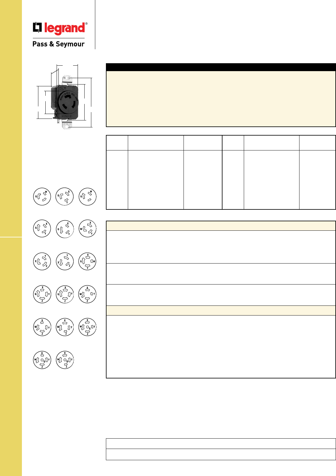
S-102
Technical Specifications20A Turnlok® Receptacles
Technical Specifications
20A Turnlok® Receptacles
NEMA
Amps Catalog Number Cong. No.
20
r
L520R L5-20R
20
r
CRL520R L5-20R
20
r
L620R L6-20R
20
r
L720R L7-20R
20
r
L820R L8-20R
20
r
L920R L9-20R
20
r
L1020R L10-20R
20
r
L1120R L11-20R
20
r
L1220R L12-20R
NEMA
Amps Catalog Number Cong. No.
20
r
L1420R L14-20R
20
r
L1520R L15-20R
20
r
L1620R L16-20R
20
r
L1820R L18-20R
20
r
L1920R L19-20R
20
r
L2020R L20-20R
20
r
L2120R L21-20R
20
r
L2220R L22-20R
20
r
L2320R L23-20R
20A Receptacle
2.29"
1.19"
1.61"
2.37"
3.28"
1.545"
.14"
Typical Specications
Manufacturer’s Identification: Legrand/Pass & Seymour L520R
Description: Locking Receptacle, Power Supply
Type: 2 Pole, 3 Wire Grounding
Rating: 20A, 125V
Configuration: NEMA L5-20R
3rd Party Compliance: UL Listed, File Number E146159, Standard UL498, Attachment Plugs and
Receptacles. Federal Specification WC596. CSA Certified, File Number LR1765, Standard CSA-C22.2
No. 42, General Use Receptacles and Attachment Plugs. Conforms to NEMA WD-1 and WD-6.
Performance
Electrical
Dielectric Withstand Voltage 2000V minimum
Maximum Working Voltage 600VAC
Current Interrupting Certified for current interrupting at full-rated current
Temperature Rise 30°C max. after 50 cycles at 150% rated current
Mechanical
Terminal Accommodation #14 AWG min. – #10 AWG max.
Product Identification Amperage, Voltage, NEMA Configuration molded into face
Environmental
Flammability UL94 V2
Operating Temperature Maximum continuous +75°C, minimum -40°C without impact
Materials
Standard Corrosion-Resistant
Front Body Nylon Nylon
Back Body Nylon Nylon
Mounting Strap Brass Nickel-Plated Brass
Pressure Plate Brass Nickel-Plated Brass
Contacts Brass Nickel-Plated Brass
Terminal Clamps Brass Nickel-Plated Brass
Terminal Screws Brass Brass
Mounting Screws Zinc-Plated Steel Stainless Steel
Consult Turnlok® Section H for complete compliance listing.
Project
Location/Type
NEMA
L9-20R
NEMA
L8-20R
NEMA
L15-20R
NEMA
L10-20R
NEMA
L6-20R
NEMA
L5-20R
NEMA
L11-20R
NEMA
L7-20R
NEMA
L16-20R
NEMA
L12-20R
NEMA
L18-20R
NEMA
L14-20R
NEMA
L19-20R
NEMA
L20-20R
NEMA
L21-20R
NEMA
L22-20R
NEMA
L23-20R
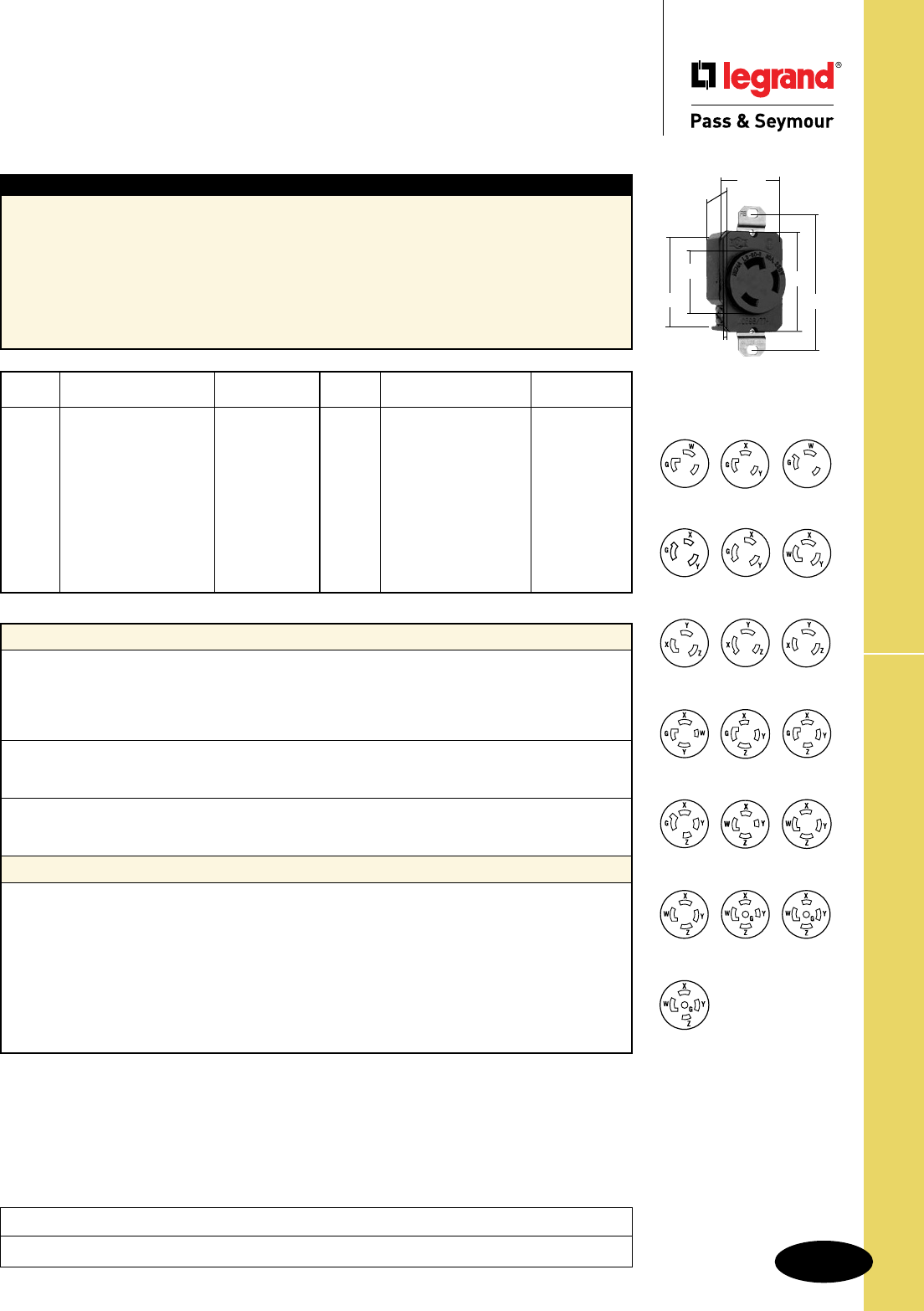
S-103
Technical Specifications 30A Turnlok® Receptacles
Technical Specifications
30A Turnlok® Receptacles
NEMA
Amps Catalog Number Cong. No.
30
r
L530R L5-30R
30
r
CRL530R L5-30R
30
r
L630R L6-30R
30
r
L730R L7-30R
30
r
L830R L8-30R
30
r
L930R L9-30R
30
r
L1030R L10-30R
30
r
L1130R L11-30R
30
r
L1230R L12-30R
30
r
L1330R L13-30R
NEMA
Amps Catalog Number Cong. No.
30
r
L1430R L14-30R
30
r
L1530R L15-30R
30
r
L1630R L16-30R
30
r
L1730R L17-30R
30
r
L1830R L18-30R
30
r
L1930R L19-30R
30
r
L2030R L20-30R
30
r
L2130R L21-30R
30
r
L2230R L22-30R
30
r
L2330R L23-30R
Typical Specications
Manufacturer’s Identification: Legrand/Pass & Seymour L530R
Description: Locking Receptacle, Power Supply
Type: 2 Pole, 3 Wire Grounding
Rating: 30A, 125V
Configuration: NEMA L5-30R
3rd Party Compliance: UL Listed, File Number E146159, Standard UL498, Attachment Plugs and
Receptacles. Federal Specification WC596. CSA Certified, File Number LR1765, Standard CSA-C22.2
No. 42, General Use Receptacles and Attachment Plugs. Conforms to NEMA WD-1 and WD-6.
Performance
Electrical
Dielectric Withstand Voltage 2000V minimum
Maximum Working Voltage 600VAC
Current Interrupting Certified for current interrupting at full-rated current
Temperature Rise 30°C max. after 50 cycles at 150% rated current
Mechanical
Terminal Accommodation #14 AWG min. – #10 AWG max.
Product Identification Amperage, Voltage, NEMA Configuration molded into face
Environmental
Flammability UL94 V2
Operating Temperature Maximum continuous +75°C, minimum -40°C without impact
Materials
Standard Corrosion-Resistant
Front Body Nylon Nylon
Back Body Nylon Nylon
Mounting Strap Brass Nickel-Plated Brass
Pressure Plate Brass Nickel-Plated Brass
Contacts Brass Nickel-Plated Brass
Terminal Clamps Brass Nickel-Plated Brass
Terminal Screws Brass Brass
Mounting Screws Zinc-Plated Steel Stainless Steel
Consult Turnlok® Section H for complete compliance listing.
30A Receptacle
2.29"
1.19"
1.61"
2.37"
3.28"
1.545"
.14"
NEMA
L5-30R
NEMA
L6-30R
NEMA
L7-30R
NEMA
L8-30R
NEMA
L9-30R
NEMA
L10-30R
NEMA
L11-30R
NEMA
L12-30R
NEMA
L13-30R
NEMA
L14-30R
NEMA
L15-30R
NEMA
L16-30R
NEMA
L18-30R
NEMA
L19-30R
NEMA
L20-30R
NEMA
L21-30R
NEMA
L17-30R
NEMA
L22-30R
NEMA
L23-30R
Project
Location/Type
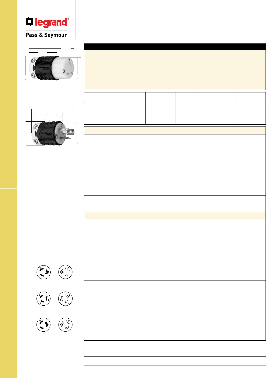
S-104
Technical Specifications15A Turnlok® EHU Plugs & Connectors
Project
Location/Type
Technical Specifications
15A Turnlok® EHU Plugs & Connectors
NEMA
Amps Catalog Number Cong. No.
15
r
PSL515C L5-15R
15
r
PSL515P L5-15P
15
r
CRL515C L5-15R
15
r
CRL515P L5-15P
NEMA
Amps Catalog Number Cong. No.
15
r
PSL615C L6-15R
15
r
PSL615P L6-15P
15
r
PSL715C L7-15R
15
r
PSL715P L7-15P
Typical Specications
Manufacturer’s Identification: Legrand/Pass & Seymour PSL515C
Description: Locking Connector, Power Supply
Type: 2 Pole, 3 Wire Grounding
Rating: 15A, 125V
Configuration: NEMA L5-15R
3rd Party Compliance: UL Listed, File Number E146159, Standard UL498, Attachment Plugs and
Receptacles. Federal Specification WC596. CSA Certified, File Number LR1765, Standard CSA-C22.2
No. 42, General Use Receptacles and Attachment Plugs. Conforms to NEMA WD-1 and WD-6.
Performance
Electrical
Dielectric Withstand Voltage 1600V minimum
Max. Working Voltage 277VAC
Current Interrupting Certified for current interrupting at full-rated current.
Temperature Rise 30°C max. after 50 cycles at 150% rated current.
Mechanical
Cord Accommodations Round portable service cords of diameters in accordance
with the device rating as defined in UL62.
Cord Grip Accommodations .230"-.720" diameter
Terminal Identification Green = Ground, White = Neutral, Brass = Hot
Terminal Accommodation #18 AWG min. – #10 AWG max.
Product Identification Amperage, Voltage, 3rd Party Compliance, NEMA Configuration
Environmental
Flammability UL94 V2
Operating Temperature Maximum continuous +75°C, minimum -40°C without impact
Materials
Plugs Standard Corrosion-Resistant
Back Body Nylon Nylon
Front Body Nylon Nylon
Terminal Chamber Separator Polycarbonate Polycarbonate
Cord Clamp Nylon Nylon
Insert Nylon Nylon
Blades Brass Nickel-Plated Brass
Terminal Clamp Zinc-Plated Steel Nickel-Plated Steel
Terminal Screws Nickel- or Brass-Plated Steel Nickel-Plated Steel
Ground Screws Nickel-Plated Steel Nickel-Plated Steel
Cord Clamp Screws Nickel-Plated Steel Nickel-Plated Steel
Assembly Screws Nickel-Plated Steel Nickel-Plated Steel
Connectors Standard Corrosion-Resistant
Back Body Nylon Nylon
Front Body Nylon Nylon
Terminal Chamber Separator Polycarbonate Polycarbonate
Cord Clamp Nylon Nylon
Insert Nylon Nylon
Contacts Brass Nickel-Plated Brass
Terminal Clamp Zinc-Plated Steel Nickel-Plated Steel
Terminal Screws Nickel- or Brass-Plated Steel Nickel-Plated Steel
Ground Screws Nickel-Plated Steel Nickel-Plated Steel
Cord Clamp Screws Nickel-Plated Steel Nickel-Plated Steel
Assembly Screws Nickel-Plated Steel Nickel-Plated Steel
Consult Turnlok® Section H for complete compliance listing.
NEMA
L5-15R
NEMA
L5-15P
NEMA
L6-15R
NEMA
L6-15P
NEMA
L7-15R
NEMA
L7-15P
15A Connector
1.358"
1.516"
2.598"
1.752"
15A Plug
1.516" 1.358"
2.617"
1.844"
1.752"
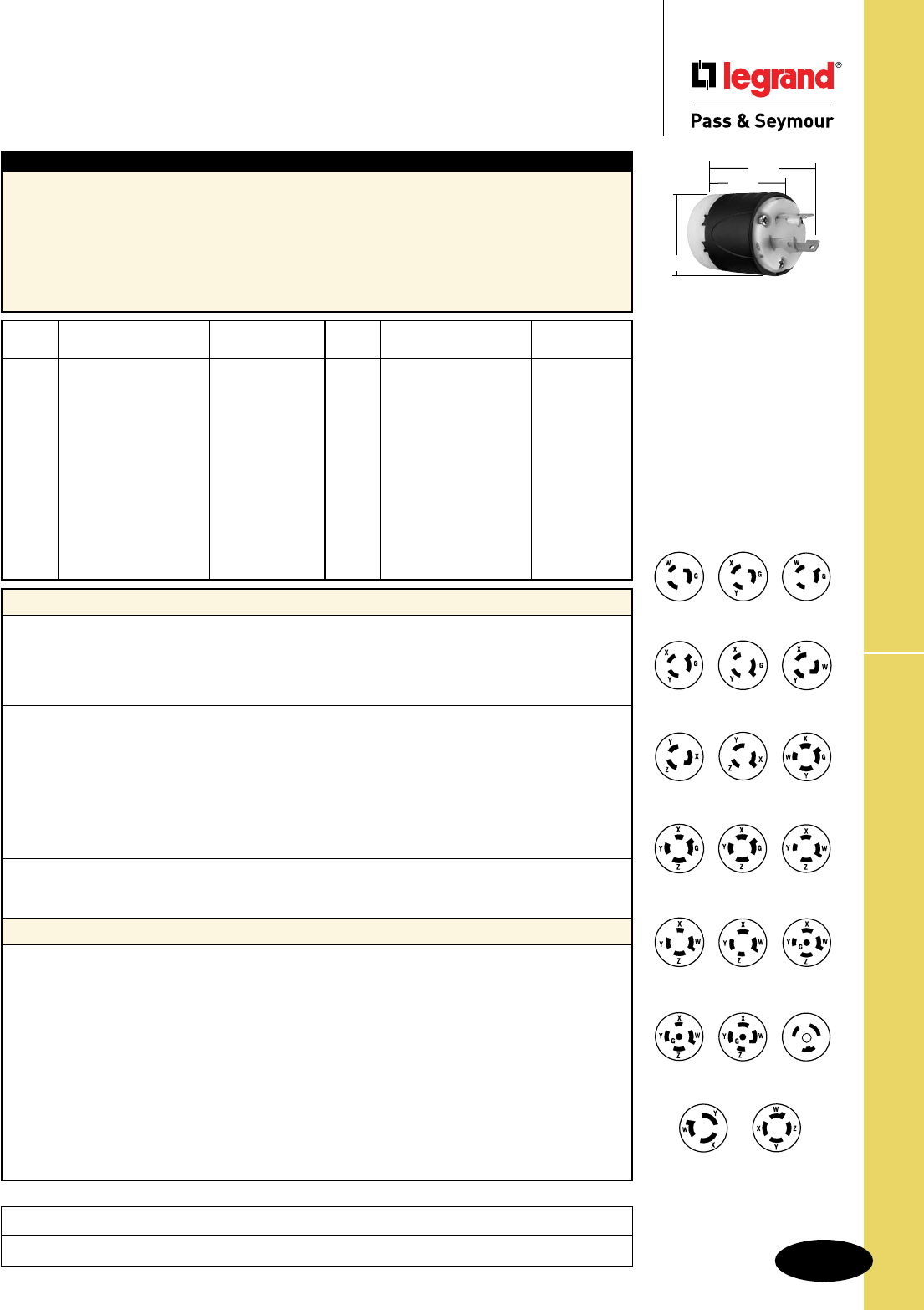
S-105
Technical Specifications 20A Turnlok® Plugs
Technical Specifications
20A Turnlok® Plugs
NEMA
Amps Catalog Number Cong. No.
20
r
L520P L5-20P
20
r
L520PBK L5-20P
20
r
CRL520P L5-20P
20
r
L620P L6-20P
20
r
CRL620P L6-20P
20
r
L720P L7-20P
20
r
L820P L8-20P
20
r
L920P L9-20P
20
r
L1020P L10-20P
20
r
L1120P L11-20P
20
r
L1220P L12-20P
20
r
L1420P L14-20P
20
r
CRL1420P L14-20P
NEMA
Amps Catalog Number Cong. No.
20
r
L1520P L15-20P
20
r
L1520PBK L15-20P
20
r
L1620P L16-20P
20
r
L1820P L18-20P
20
r
L1920P L19-20P
20
r
L2020P L20-20P
20
r
L2120P L21-20P
20
r
L2220P L22-20P
20
r
L2320P L23-20P
20
r
L3720P L24-20P
20
r
7311SS Non-NEMA
20
r
7411SS Non-NEMA
Typical Specications
Manufacturer’s Identification: Legrand/Pass & Seymour L520P
Description: Locking Plug, Power Supply
Type: 2 Pole, 3 Wire Grounding
Rating: 20A, 125V
Configuration: NEMA L5-20P
3rd Party Compliance: UL Listed, File Number E146159, Standard UL498, Attachment Plugs and
Receptacles. Federal Specification WC596. CSA Certified, File Number LR1765, Standard CSA-C22.2
No. 42, General Use Receptacles and Attachment Plugs. Conforms to NEMA WD-1 and WD-6.
Performance
Electrical
Dielectric Withstand Voltage 2200V minimum
Maximum Working Voltage 600VAC
Current Interrupting Certified for current interrupting at full-rated current
Temperature Rise 30°C maximum after 50 cycles at 150% rated current
Mechanical
Cord Accommodations Round portable service cords of diameters in accordance
with the device rating as defined in UL62
Cord Grip Accommodations 3 Wire = .225"–.750" diameter; 4 & 5 Wire = .225"–1.150" diameter
Terminal Identification “GR” and Green Color = Ground, “WH” and
White Color = Neutral, “X”, “Y”, “Z” = Hot
Terminal Accommodation #18 AWG min. – #8 AWG max.
Product Identification Amperage, Voltage, 3rd Party Compliance,
NEMA Configuration hot stamped onto device
Environmental
Flammability UL94 V2
Operating Temperature Maximum continuous +75°C, minimum -40°C without impact
Materials
Standard Corrosion-Resistant
Back Body Super Tough Nylon Super Tough Nylon
Front Body Nylon Nylon
Terminal Chamber Polycarbonate Polycarbonate
Cord Clamp Nylon Nylon
Insert Nylon Nylon
Dust Cover Neoprene Neoprene
Blades Brass Nickel-Plated Brass
Terminal Clamp Nickel-Plated Steel Nickel-Plated Steel
Terminal Screws Brass Nickel-Plated Brass
Ground Screws Brass Nickel-Plated Brass
Cord Clamp Screws Nickel-Plated Steel Nickel-Plated Steel
Assembly Screws Nickel-Plated Steel Nickel-Plated Steel
Consult Turnlok® Section H for complete compliance listing.
NEMA
L5-20P
NEMA
L7-20P
NEMA
L8-20P
NEMA
L9-20P
NEMA
L10-20P
NEMA
L11-20P
NEMA
L12-20P
NEMA
L14-20P
NEMA
L15-20P
NEMA
L16-20P
NEMA
L18-20P
NEMA
L20-20P
NEMA
L21-20P
NEMA
L22-20P
NEMA
L23-20P
NEMA
L24-20P
NEMA
L19-20P
NEMA
L6-20P
Non-NEMA
7311SS
Non-NEMA
7411SS
20A Plug
3.75"
2.57"
2.20"
Project
Location/Type
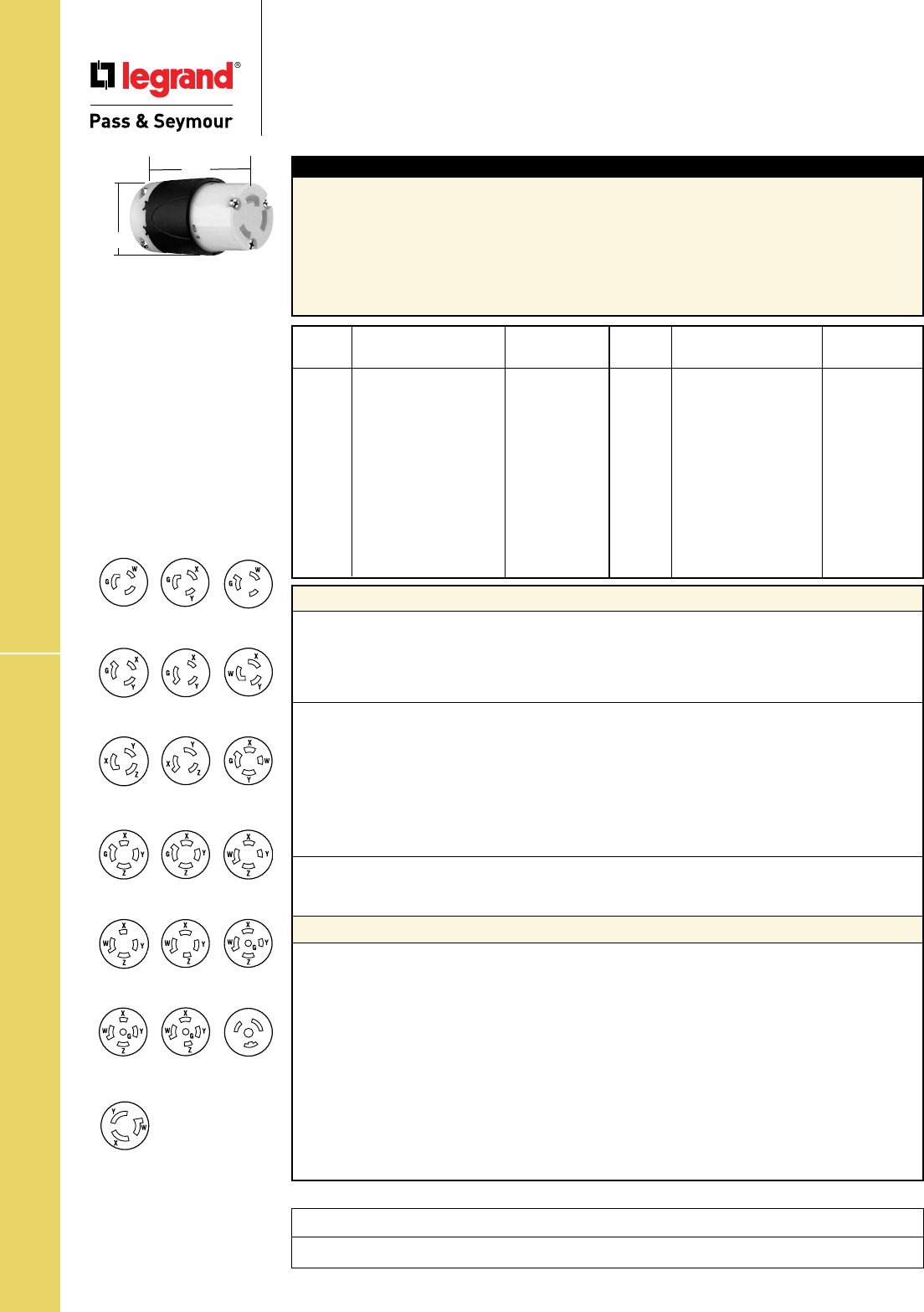
S-106
Technical Specifications20A Turnlok® Connectors
Technical Specifications
20A Turnlok® Connectors
Typical Specications
Manufacturer’s Identification: Legrand/Pass & Seymour L520C
Description: Locking Connector, Power Supply
Type: 2 Pole, 3 Wire Grounding
Rating: 20A, 125V
Configuration: NEMA L5-20R
3rd Party Compliance: UL Listed, File Number E146159, Standard UL498, Attachment Plugs and
Receptacles. Federal Specification WC596. CSA Certified, File Number LR1765, Standard CSA-C22.2
No. 42, General Use Receptacles and Attachment Plugs. Conforms to NEMA WD-1 and WD-6.
NEMA
Amps Catalog Number Cong. No.
20
r
L520C L5-20R
20
r
L520CBK L5-20R
20
r
CRL520C L5-20R
20
r
L620C L6-20R
20
r
CRL620C L6-20R
20
r
L720C L7-20R
20
r
L820C L8-20R
20
r
L920C L9-20R
20
r
L1020C L10-20R
20
r
L1120C L11-20R
20
r
L1220C L12-20R
20
r
L1420C L14-20R
NEMA
Amps Catalog Number Cong. No.
20
r
CRL1420C L14-20R
20
r
L1520C L15-20R
20
r
L1520CBK L15-20R
20
r
L1620C L16-20R
20
r
L1820C L18-20R
20
r
L1920C L19-20R
20
r
L2020C L20-20R
20
r
L2120C L21-20R
20
r
L2220C L22-20R
20
r
L2320C L23-20R
20
r
L3720C L24-20R
20
r
7313SS Non-NEMA
Performance
Electrical
Dielectric Withstand Voltage 2200V minimum
Maximum Working Voltage 600VAC
Current Interrupting Certified for current interrupting at full-rated current
Temperature Rise 30°C maximum after 50 cycles at 150% rated current
Mechanical
Cord Accommodations Round portable service cords of diameters in accordance
with the device rating as defined in UL62
Cord Grip Accommodations 3 Wire = .225"–.750" diameter; 4 & 5 Wire = .225"–1.150" diameter
Terminal Identification “GR” and Green Color = Ground, “WH” and
White Color = Neutral, “X”, “Y”, “Z” = Hot
Terminal Accommodation #18 AWG min. – #8 AWG max.
Product Identification Amperage, Voltage, 3rd Party Compliance,
NEMA Configuration hot stamped onto device
Environmental
Flammability UL94 V2
Operating Temperature Maximum continuous +75°C, minimum -40°C without impact
Materials
Standard Corrosion-Resistant
Back Body Super Tough Nylon Super Tough Nylon
Front Body Nylon Nylon
Terminal Chamber Polycarbonate Polycarbonate
Cord Clamp Nylon Nylon
Insert Nylon Nylon
Dust Cover Neoprene Neoprene
Contacts Brass Nickel-Plated Brass
Terminal Clamp Nickel-Plated Steel Nickel-Plated Steel
Terminal Screws Brass Nickel-Plated Brass
Ground Screws Brass Nickel-Plated Brass
Cord Clamp Screws Nickel-Plated Steel Nickel-Plated Steel
Assembly Screws Nickel-Plated Steel Nickel-Plated Steel
Consult Turnlok® Section H for complete compliance listing.
NEMA
L5-20R
NEMA
L7-20R
NEMA
L8-20R
NEMA
L9-20R
NEMA
L10-20R
NEMA
L11-20R
NEMA
L12-20R
NEMA
L14-20R
NEMA
L15-20R
NEMA
L16-20R
NEMA
L18-20R
NEMA
L20-20R
NEMA
L21-20R
NEMA
L22-20R
NEMA
L23-20R
NEMA
L19-20R
NEMA
L6-20R
Non-NEMA
7313SS
NEMA
L24-20R
20A Connector
2.20"
3.33"
Project
Location/Type
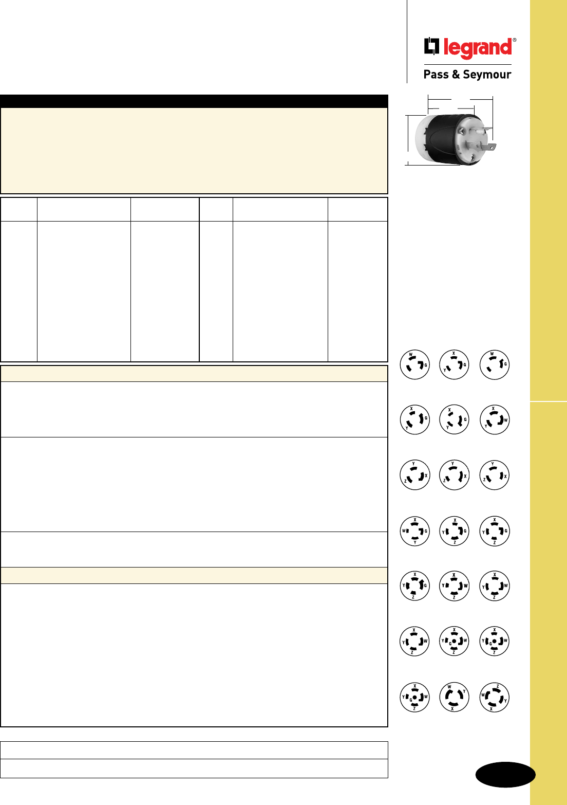
Technical Specifications
S-107
30A Turnlok® Plugs
Technical Specifications
30A Turnlok® Plugs
NEMA
Amps Catalog Number Cong. No.
30
r
L530P L5-30P
30
r
CRL530P L5-30P
30
r
L630P L6-30P
30
r
CRL630P L6-30P
30
r
L730P L7-30P
30
r
L830P L8-30P
30
r
L930P L9-30P
30
r
L1030P L10-30P
30
r
L1130P L11-30P
30
r
L1230P L12-30P
30
r
L1330P L13-30P
30
r
L1430P L14-30P
30
r
CRL1430P L14-30P
NEMA
Amps Catalog Number Cong. No.
30
r
L1530P L15-30P
30
r
L1630P L16-30P
30
r
L1730P L17-30P
30
r
L1830P L18-30P
30
r
L1930P L19-30P
30
r
L2030P L20-30P
30
r
L2130P L21-30P
30
r
L2230P L22-30P
30
r
L2230PBK L22-30P
30
r
L2330P L23-30P
30
r
3331SS Non-NEMA
30
r
3431SS Non-NEMA
Typical Specications
Manufacturer’s Identification: Legrand/Pass & Seymour L530P
Description: Locking Plug, Power Supply
Type: 2 Pole, 3 Wire Grounding
Rating: 30A, 125V
Configuration: NEMA L5-30P
3rd Party Compliance: UL Listed, File Number E146159, Standard UL498, Attachment Plugs and
Receptacles. Federal Specification WC596. CSA Certified, File Number LR1765, Standard CSA-C22.2
No. 42, General Use Receptacles and Attachment Plugs. Conforms to NEMA WD-1 and WD-6.
NEMA
L5-30P
NEMA
L6-30P
NEMA
L7-30P
NEMA
L8-30P
NEMA
L9-30P
NEMA
L10-30P
NEMA
L11-30P
NEMA
L12-30P
NEMA
L13-30P
NEMA
L14-30P
NEMA
L15-30P
NEMA
L16-30P
NEMA
L18-30P
NEMA
L19-30P
NEMA
L20-30P
NEMA
L21-30P
NEMA
L17-30P
NEMA
L22-30P
NEMA
L23-30P
Non-NEMA
3331-SS
Non-NEMA
3431-SS
Performance
Electrical
Dielectric Withstand Voltage 2200V minimum
Maximum Working Voltage 600VAC
Current Interrupting Certified for current interrupting at full-rated current
Temperature Rise 30°C maximum after 50 cycles at 150% rated current
Mechanical
Cord Accommodations Round portable service cords of diameters in accordance
with the device rating as defined in UL62
Cord Grip Accommodations 3 Wire = .225"–.750" diameter; 4 & 5 Wire = .225"–1.150" diameter
Terminal Identification “GR” and Green Color = Ground, “WH” and
White Color = Neutral, “X”, “Y”, “Z” = Hot
Terminal Accommodation #18 AWG min. – #8 AWG max.
Product Identification Amperage, Voltage, 3rd Party Compliance,
NEMA Configuration hot stamped onto device
Environmental
Flammability UL94 V2
Operating Temperature Maximum continuous +75°C, minimum -40°C without impact
Materials
Standard Corrosion-Resistant
Back Body Super Tough Nylon Super Tough Nylon
Front Body Nylon Nylon
Terminal Chamber Polycarbonate Polycarbonate
Cord Clamp Nylon Nylon
Insert Nylon Nylon
Dust Cover Neoprene Neoprene
Blades Brass Tin-Plated Brass
Terminal Clamp Brass Nickel-Plated Brass
Terminal Screws Brass Nickel-Plated Brass
Ground Screws Brass Nickel-Plated Brass
Cord Clamp Screws Nickel-Plated Steel Nickel-Plated Steel
Assembly Screws Nickel-Plated Steel Nickel-Plated Steel
Consult Turnlok® Section H for complete compliance listing.
30A Plug
3.75"
2.57"
2.20"
Project
Location/Type
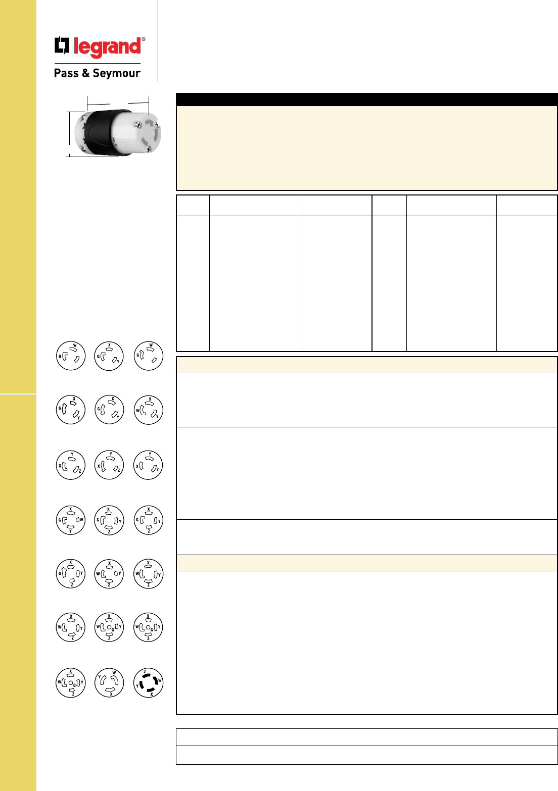
Technical Specifications
S-108
30A Turnlok® Connectors
NEMA
Amps Catalog Number Cong. No.
30
r
L530C L5-30R
30
r
CRL530C L5-30R
30
r
L630C L6-30R
30
r
CRL630C L6-30R
30
r
L730C L7-30R
30
r
L830C L8-30R
30
r
L930C L9-30R
30
r
L1030C L10-30R
30
r
L1130C L11-30R
30
r
L1230C L12-30R
30
r
L1330C L13-30R
30
r
L1430C L14-30R
30
r
CRL1430C L14-30R
NEMA
Amps Catalog Number Cong. No.
30
r
L1530C L15-30R
30
r
L1630C L16-30R
30
r
L1730C L17-30R
30
r
L1830C L18-30R
30
r
L1930C L19-30R
30
r
L2030C L20-30R
30
r
L2130C L21-30R
30
r
L2230C L22-30R
30
r
L2330C L23-30R
30
r
3333SS Non-NEMA
30
r
3433SS Non-NEMA
Typical Specications
Manufacturer’s Identification: Legrand/Pass & Seymour L530C
Description: Locking Connector, Power Supply
Type: 2 Pole, 3 Wire Grounding
Rating: 30A, 125V
Configuration: NEMA L5-30R
3rd Party Compliance: UL Listed, File Number E146159, Standard UL498, Attachment Plugs and
Receptacles. Federal Specification WC596. CSA Certified, File Number LR1765, Standard CSA-C22.2
No. 42, General Use Receptacles and Attachment Plugs. Conforms to NEMA WD-1 and WD-6.
Consult Turnlok® Section H for complete compliance listing.
Performance
Electrical
Dielectric Withstand Voltage 2200V minimum
Maximum Working Voltage 600VAC
Current Interrupting Certified for current interrupting at full-rated current
Temperature Rise 30°C maximum after 50 cycles at 150% rated current
Mechanical
Cord Accommodations Round portable service cords of diameters in accordance
with the device rating as defined in UL62
Cord Grip Accommodations 3 Wire = .225"–.750" diameter; 4 & 5 Wire = .225"–1.150" diameter
Terminal Identification “GR” and Green Color = Ground, “WH” and
White Color = Neutral, “X”, “Y”, “Z” = Hot
Terminal Accommodation #18 AWG min. – #8 AWG max.
Product Identification Amperage, Voltage, 3rd Party Compliance,
NEMA Configuration hot stamped onto device
Environmental
Flammability UL94 V2
Operating Temperature Maximum continuous +75°C, minimum -40°C without impact
Materials
Standard Corrosion-Resistant
Back Body Super Tough Nylon Super Tough Nylon
Front Body Nylon Nylon
Terminal Chamber Polycarbonate Polycarbonate
Cord Clamp Nylon Nylon
Insert Nylon Nylon
Dust Cover Neoprene Neoprene
Contacts Brass Tin-Plated Brass
Terminal Clamp Brass Nickel-Plated Brass
Terminal Screws Brass Nickel-Plated Brass
Ground Screws Brass Nickel-Plated Brass
Cord Clamp Screws Nickel-Plated Steel Nickel-Plated Steel
Assembly Screws Nickel-Plated Steel Nickel-Plated Steel
NEMA
L5-30R
NEMA
L6-30R
NEMA
L7-30R
NEMA
L8-30R
NEMA
L9-30R
NEMA
L10-30R
NEMA
L11-30R
NEMA
L12-30R
NEMA
L13-30R
NEMA
L14-30R
NEMA
L15-30R
NEMA
L16-30R
NEMA
L18-30R
NEMA
L19-30R
NEMA
L20-30R
NEMA
L21-30R
NEMA
L17-30R
NEMA
L22-30R
NEMA
L23-30R
Non-NEMA
3333-SS
Non-NEMA
3433-SS
30A Connector
2.20"
3.33"
Technical Specifications
30A Turnlok® Connectors
Project
Location/Type

Technical Specifications
S-109
Turnlok® Ground Continuity Monitoring
Technical Specifications
Turnlok® Heavy-Duty Ground Continuity
Monitoring (GCM) Plugs
15, 20 & 30A; 125, 250, 277 & 347V, 125/250V
Typical Specications
Manufacturer’s Identification: Legrand/Pass & Seymour PSL515PGCM
Description: Ground Continuity Monitoring (GCM) Locking Plug, Power Supply
Type: 2 Pole, 3 Wire Grounding
Rating: 15A, 125V
Configuration: NEMA 5-15P
3rd Party Compliance: cULus Listed, File Number E146159, Standard UL498, Attachment Plugs and
Receptacles. Federal Specification WC596. Standard CSA-C22.2 No. 42, General Use Receptacles
and Attachment Plugs. Conforms to NEMA WD-1 and WD-6.
**Dust Shield for 20 & 30 Amp Plugs.
Consult Turnlok® Section H for complete compliance listing.
Performance
Electrical
Dielectric Withstand Voltage 15A = 1600V minimum, 20 & 30A = 2200V minimum
Maximum Working Voltage 15A = 277VAC, 20 & 30A = 600VAC
Current Interrupting Certified for current interrupting at full-rated current
Temperature Rise 30°C maximum after 50 cycles at 150% rated current
Mechanical
Cord Accommodations Round portable service cords of diameters in accordance with
the device rating as defined in UL62
Cord Grip Accommodations 15A = .230"–.720" diameter, 20 & 30A 3 Wire = .225"–.750" diameter,
20 & 30A 4 & 5 Wire = .225"–1.150" diameter
Terminal Identification 15A = Green = Ground, White = Neutral, Brass = Hot
20 & 30A = "GR" and Green Color = Ground,
"WH" and white Color = Neutral, "X", "Y", "Z" = Hot
Terminal Accommodation 15A = #18 AWG min. - #10 AWG max.
20A = #18 AWG min. - #8 AWG max.
30A = #18 AWG min. - #6 AWG max.
Product Identification Amperage, Voltage, 3rd Party Compliance,
NEMA Configuration hot stamped onto device
Environmental
Flammability UL94 V2
Operating Temperature Maximum continuous +75°C, minimum -40°C without impact
Materials
Terminal Clamp 15A = Zinc-Plated Steel
20A = Nickel-Plated Steel
30A = Brass
Terminal Screws 15A = Nickel- or Brass-Plated Steel
20 & 30A = Brass
Ground Screws 15A = Nickel-Plated Steel
20 & 30A = Brass
Cord Clamp Screws Nickel-Plated Steel
Assembly Screws Nickel-Plated Steel
Back Body Super Tough Nylon
Front Body Nylon
Terminal Chamber Polycarbonate
Cord Clamp Nylon
Insert Nylon
Dust Shield** Neoprene
Blades Brass
NEMA
Catalog Number Rating Cong. No.
r
PSL515PGCM 15 125 L5-15P
r
L520PGCM 20 125 L5-20P
r
L530PGCM 30 125 L5-30P
r
PSL615PGCM 15 250 L6-15P
r
L620PGCM 20 250 L6-20P
r
L630PGCM 30 250 L6-30P
NEMA
Catalog Number Rating Cong. No.
r
PSL715PGCM 15 277 L7-15P
r
L720PGCM 20 277 L7-20P
r
L730PGCM 30 277 L7-30P
r
L3720PGCM 20 347 L24-20P
r
L1420PGCM 20 125/250 L14-20P
r
L1430PGCM 30 125/250 L14-30P
20 & 30A Plug
2.20"
2.57"
3.75"
15A Plug
1.358"
1.516"
1.752"
1.844"
2.617"
Project
Location/Type
NEMA
L6-20P
NEMA
L6-15P
NEMA
L14-20P
NEMA
L6-30P
NEMA
L5-20P
NEMA
L5-15P
NEMA
L7-15P
NEMA
L5-30P
NEMA
L14-30P
NEMA
L7-20P
NEMA
L24-20P
NEMA
L7-30P
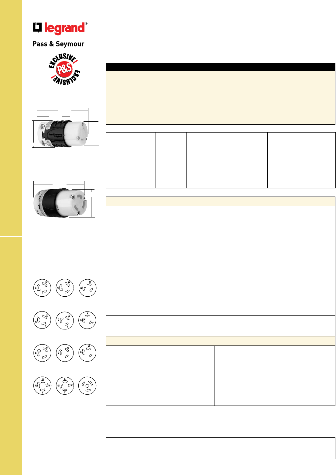
Technical Specifications
S-110
Turnlok® Ground Continuity Monitoring
Technical Specifications
Turnlok® Heavy-Duty Ground Continuity
Monitoring (GCM) Connectors
15, 20 & 30A; 125, 250, 277 & 347V, 125/250V
Typical Specications
Manufacturer’s Identification: Legrand/Pass & Seymour PSL515CGCM
Description: Ground Continuity Monitoring (GCM) Locking Connector, Power Supply
Type: 2 Pole, 3 Wire Grounding
Rating: 15A, 125V
Configuration: NEMA 5-15R
3rd Party Compliance: cULus Listed, File Number E146159, Standard UL498, Attachment Plugs and
Receptacles. Federal Specification WC596. Standard CSA-C22.2 No. 42, General Use Receptacles and
Attachment Plugs. Conforms to NEMA WD-1 and WD-6.
**Dust Shield for 20 & 30A Connectors.
Consult Turnlok® Section H for complete compliance listing.
Performance
Electrical
Dielectric Withstand Voltage 15A = 1600V minimum, 20 & 30A = 2200V minimum
Maximum Working Voltage 15A = 277VAC, 20 & 30A = 600VAC
Current Interrupting Certified for current interrupting at full-rated current
Temperature Rise 30°C maximum after 50 cycles at 150% rated current
Mechanical
Cord Accommodations Round portable service cords of diameters in accordance with
the device rating as defined in UL62
Cord Grip Accommodations 15A = .230"–.720" diameter, 20 & 30A 3 Wire = .225"–.750" diameter
20 & 30A 4 & 5 Wire = .225"–1.150" diameter
Terminal Identification 15A = Green = Ground, White = Neutral, Brass = Hot
20 & 30A = "GR" and Green Color = Ground,
"WH" and white Color = Neutral, "X", "Y", "Z" = Hot
Terminal Accommodation 15A = #18 AWG min. - #10 AWG max.
20A = #18 AWG min. - #8 AWG max.
30A = #18 AWG min. - #6 AWG max.
Product Identification Amperage, Voltage, 3rd Party Compliance,
NEMA Configurationhot stamped onto device
Environmental
Flammability UL94 V2
Operating Temperature Maximum continuous +75°C, minimum -40°C without impact
Materials
Terminal Clamp 15A = Zinc-Plated Steel
20A = Nickel-Plated Steel
30A = Brass
Terminal Screws 15A = Nickel- or Brass-
Plated Steel
20 & 30A = Brass
Ground Screws 15A = Nickel-Plated Steel
20 & 30A = Brass
Cord Clamp Screws Nickel-Plated Steel
Assembly Screws Nickel-Plated Steel
Back Body Super Tough Nylon
Front Body Nylon
Terminal Chamber Polycarbonate
Cord Clamp Nylon
Insert Nylon
Dust Shield** Neoprene
Contacts Brass
NEMA
Catalog Number Rating Cong. No.
r
PSL515CGCM 15 125 L5-15R
r
L520CGCM 20 125 L5-20R
r
L530CGCM 30 125 L5-30R
r
PSL615CGCM 15 250 L6-15R
r
L620CGCM 20 250 L6-20R
r
L630CGCM 30 250 L6-30R
NEMA
Catalog Number Rating Cong. No.
r
PSL715CGCM 15 277 L7-15R
r
L720CGCM 20 277 L7-20R
r
L730CGCM 30 277 L7-30R
r
L3720CGCM 20 347 L24-20R
r
L1420CGCM 20 125/250 L14-20R
r
L1430CGCM 30 125/250 L14-30R
15A Connector
20 & 30A Connector
2.20"
3.33"
1.516" 1.358"
1.752"
2.598"
Project
Location/Type
NEMA
L6-20R
NEMA
L6-15R
NEMA
L14-20R
NEMA
L6-30R
NEMA
L5-20R
NEMA
L5-15R
NEMA
L7-15R
NEMA
L5-30R
NEMA
L14-30R
NEMA
L7-20R
NEMA
L24-20R
NEMA
L7-30R
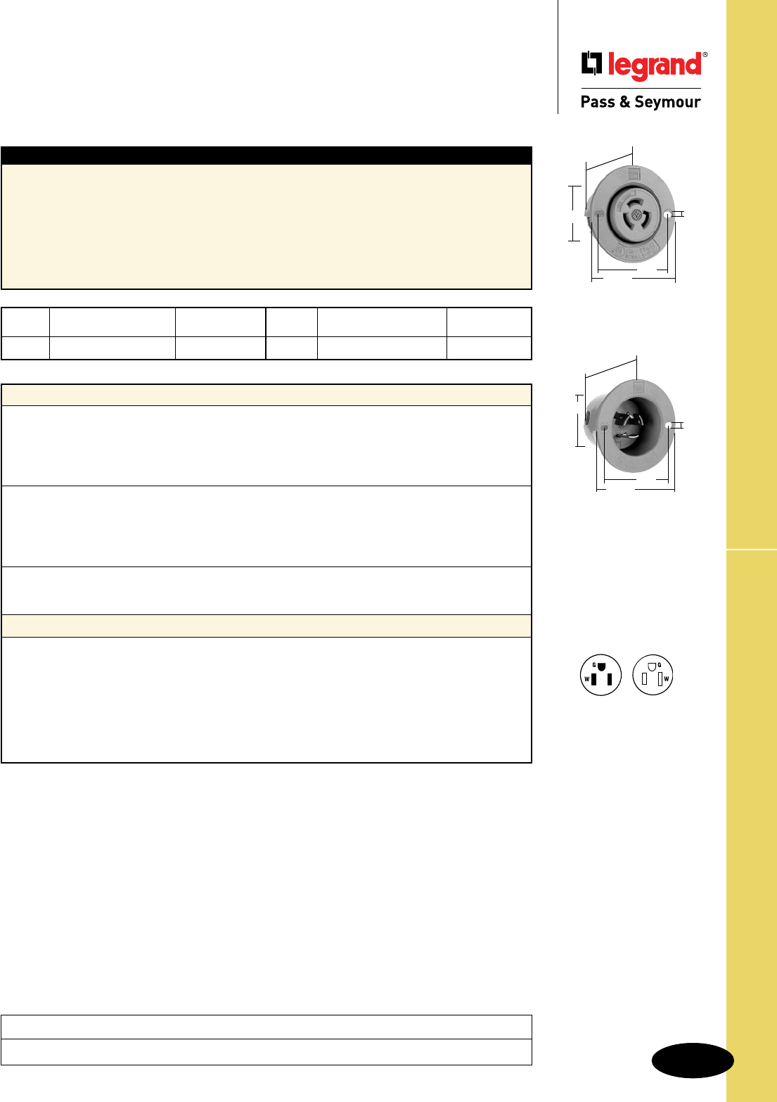
Technical Specifications
S-111
15A Turnlok® Flanged Inlets & Outlets
Technical Specifications
15A Turnlok® Flanged Inlets & Outlets
Project
Location/Type
4715SS
2.0"
.156"
2.562"
1.374"
1.660"
4716SS
2.0"
.156"
2.562"
1.655"
1.725"
NEMA
5-15P
NEMA
5-15R
Typical Specications
Manufacturer’s Identification: Legrand/Pass & Seymour 4715SS
Description: Locking Flanged Outlet, Power Supply
Type: 2 Pole, 3 Wire Grounding
Rating: 15A, 125V
Configuration: NEMA L5-15R
3rd Party Compliance: UL Listed, File Number E146159, Standard UL498, Attachment Plugs and
Receptacles. Federal Specification WC596. CSA Certified, File Number LR1765, Standard CSA-C22.2
No. 42, General Use Receptacles and Attachment Plugs. Conforms to NEMA WD-1 and WD-6.
Consult Turnlok® Section H for complete compliance listing.
Performance
Electrical
Dielectric Withstand Voltage 2000V minimum
Maximum Working Voltage 277VAC
Current Interrupting Certified for current interrupting at full-rated current
Temperature Rise 30°C max. after 50 cycles at 150% rated current
Mechanical
Terminal Identification Green = Ground, White = Neutral, Brass = Hot
Terminal Accommodation #18 AWG min. – #10 AWG max.
Product Identification Amperage, Voltage, 3rd Party Compliance,
NEMA Configuration
Environmental
Flammability UL94 V2
Operating Temperature Maximum continuous +115°C, minimum -40°C without impact
Materials
Inlet Outlet
Flanged Casing Polycarbonate Polycarbonate
Body Contact Polycarbonate Polycarbonate
Blades Nickel-Plated Brass Brass
Terminal Clamp Zinc-Plated Steel Zinc-Plated Steel
Terminal Screws Zinc- or Brass-Plated Steel Zinc- or Brass-Plated Steel
Ground Screws Zinc-Plated Steel Zinc-Plated Steel
Assembly Screws Zinc-Plated Steel Zinc-Plated Steel
NEMA
Amps Catalog Number Cong. No.
15
r
4715SS L5-15R
NEMA
Amps Catalog Number Cong. No.
15
r
4716SS L5-15P
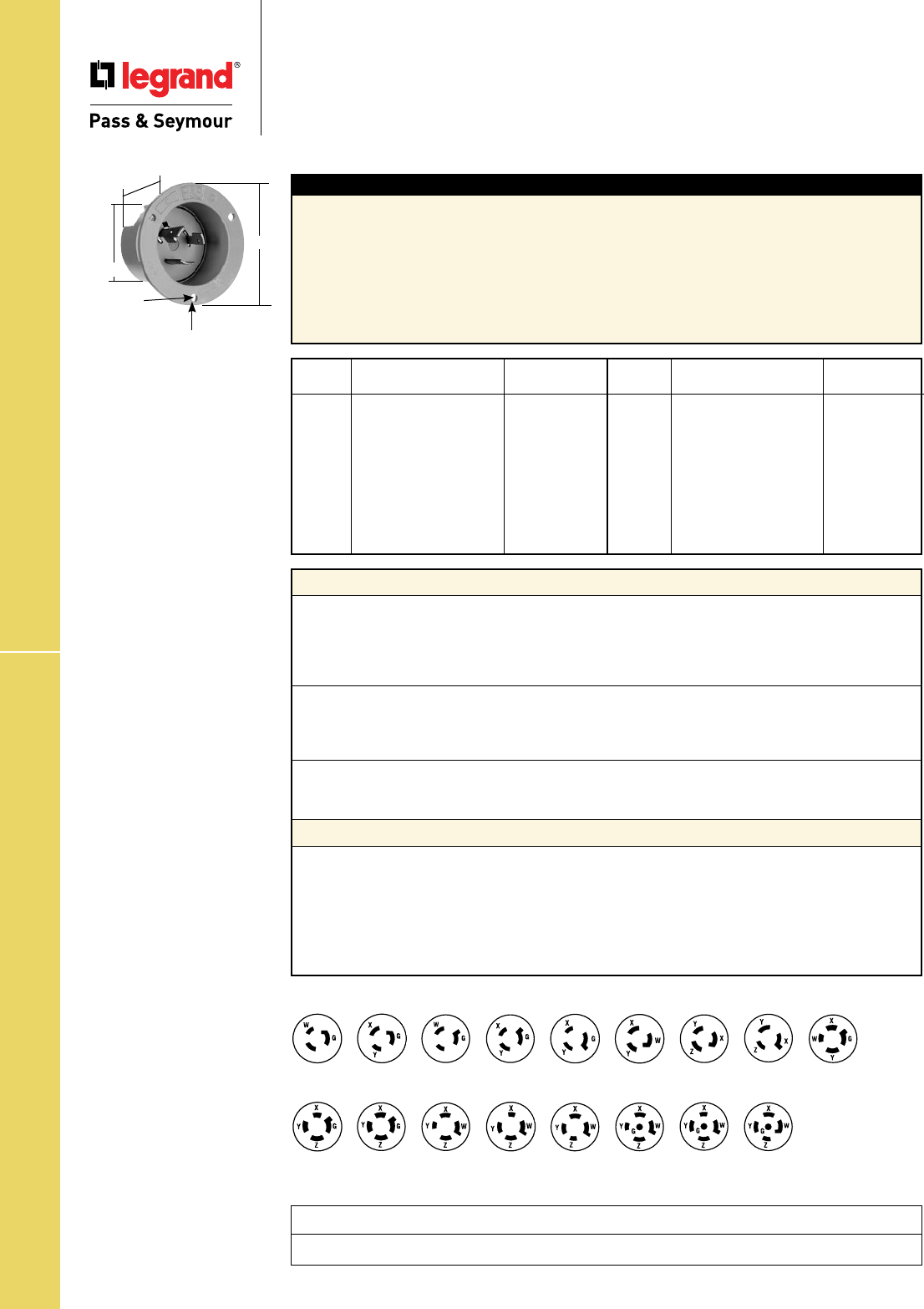
Technical Specifications
S-112
20A Turnlok® Flanged Inlets
Technical Specifications
20A Turnlok® Flanged Inlets
Project
Location/Type
NEMA
Amps Catalog Number Cong. No.
20
r
L520FI L5-20P
20
r
L620FI L6-20P
20
r
L720FI L7-20P
20
r
L820FI L8-20P
20
r
L920FI L9-20P
20
r
L1020FI L10-20P
20
r
L1120FI L11-20P
20
r
L1220FI L12-20P
20
r
L1420FI L14-20P
NEMA
Amps Catalog Number Cong. No.
20
r
L1520FI L15-20P
20
r
L1620FI L16-20P
20
r
L1820FI L18-20P
20
r
L1920FI L19-20P
20
r
L2020FI L20-20P
20
r
L2120FI L21-20P
20
r
L2220FI L22-20P
20
r
L2220FIBK L22-20P
20
r
L2320FI L23-20P
Performance
Electrical
Dielectric Withstand Voltage 3000V minimum
Maximum Working Voltage 600VAC
Current Interrupting Certified for current interrupting at full-rated current
Temperature Rise 30°C max. after 50 cycles at 150% rated current
Mechanical
Terminal Identification Green = Ground, White = Neutral, Brass = Hot
Terminal Accommodation #12 AWG min. – #8 AWG max.
Product Identification Amperage, Voltage, 3rd Party Compliance, NEMA Configuration
Environmental
Flammability UL94 V2
Operating Temperature Maximum continuous +115°C, minimum -40°C without impact
Materials
Flanged Casing Polycarbonate
Blade Holder Polycarbonate
Blades Brass
Terminal Clamp Zinc-Plated Steel
Terminal Screws Zinc- or Brass-Plated Steel
Ground Screws Zinc-Plated Steel
Assembly Screws Zinc-Plated Steel
Consult Turnlok® Section H for complete compliance listing.
Typical Specications
Manufacturer’s Identification: Legrand/Pass & Seymour L520FI
Description: Locking Flanged Inlet, Power Supply
Type: 2 Pole, 3 Wire Grounding
Rating: 20A, 125V
Configuration: NEMA L5-20P
3rd Party Compliance: UL Listed, File Number E146159, Standard UL498, Attachment Plugs and
Receptacles. Federal Specification WC596. CSA Certified, File Number LR1765, Standard CSA-C22.2
No. 42, General Use Receptacles and Attachment Plugs. Conforms to NEMA WD-1 and WD-6.
NEMA
L5-20P
NEMA
L7-20P
NEMA
L8-20P
NEMA
L9-20P
NEMA
L10-20P
NEMA
L11-20P
NEMA
L12-20P
NEMA
L14-20P
NEMA
L15-20P
NEMA
L16-20P
NEMA
L18-20P
NEMA
L20-20P
NEMA
L21-20P
NEMA
L22-20P
NEMA
L23-20P
NEMA
L19-20P
NEMA
L6-20P
2.09"
ø.187"
1.65"
2.87"
3 HOLES ON ø2.50" C/L@ 120°
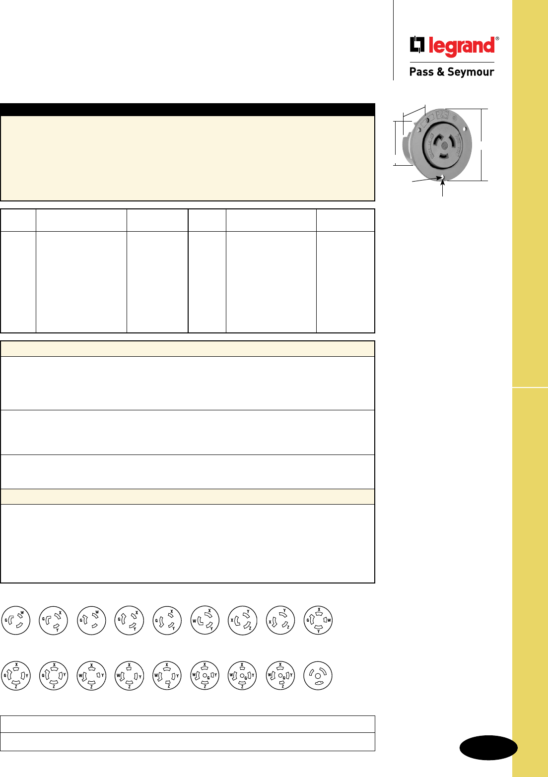
Technical Specifications
S-113
20A Turnlok® Flanged Outlets
Technical Specifications
20A Turnlok® Flanged Outlets
Project
Location/Type
NEMA
Amps Catalog Number Cong. No.
20
r
L520FO L5-20R
20
r
L620FO L6-20R
20
r
L720FO L7-20R
20
r
L820FO L8-20R
20
r
L920FO L9-20R
20
r
L1020FO L10-20R
20
r
L1120FO L11-20R
20
r
L1220FO L12-20R
20
r
L1420FO L14-20R
NEMA
Amps Catalog Number Cong. No.
20
r
L1520FO L15-20R
20
r
L1620FO L16-20R
20
r
L1820FO L18-20R
20
r
L1920FO L19-20R
20
r
L2020FO L20-20R
20
r
L2120FO L21-20R
20
r
L2220FO L22-20R
20
r
L2220FOBK L22-20R
20
r
L2320FO L23-20R
20
r
L3720FO L24-20R
Performance
Electrical
Dielectric Withstand Voltage 3000V minimum
Maximum Working Voltage 600VAC
Current Interrupting Certified for current interrupting at full-rated current
Temperature Rise 30°C max. after 50 cycles at 150% rated current
Mechanical
Terminal Identification Green = Ground, White = Neutral, Brass = Hot
Terminal Accommodation #12 AWG min. – #8 AWG max.
Product Identification Amperage, Voltage, 3rd Party Compliance, NEMA Configuration
Environmental
Flammability UL94 V2
Operating Temperature Maximum continuous +115°C, minimum -40°C without impact
Materials
Flanged Casing Polycarbonate
Contact Carrier Polycarbonate
Contacts Brass
Terminal Clamp Zinc-Plated Steel
Terminal Screws Zinc- or Brass-Plated Steel
Ground Screws Zinc-Plated Steel
Assembly Screws Zinc-Plated Steel
Consult Turnlok® Section H for complete compliance listing.
Typical Specications
Manufacturer’s Identification: Legrand/Pass & Seymour L520FO
Description: Locking Flanged Outlet, Power Supply
Type: 2 Pole, 3 Wire Grounding
Rating: 20A, 125V
Configuration: NEMA L5-20R
3rd Party Compliance: UL Listed, File Number E146159, Standard UL498, Attachment Plugs and
Receptacles. Federal Specification WC596. CSA Certified, File Number LR1765, Standard CSA-C22.2
No. 42, General Use Receptacles and Attachment Plugs. Conforms to NEMA WD-1 and WD-6.
NEMA
L7-20R
NEMA
L9-20R NEMA
L11-20R
NEMA
L14-20R
NEMA
L16-20R
NEMA
L20-20R NEMA
L22-20R
NEMA
L19-20R NEMA
L24-20R
2.09"
1.34"
ø.187"
2.87"
3 HOLES ON ø2.50" C/L @ 120°
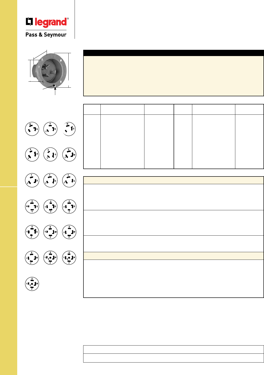
Technical Specifications
S-114
30A Turnlok® Flanged Inlets
Technical Specifications
30A Turnlok® Flanged Inlets
Project
Location/Type
NEMA
Amps Catalog Number Cong. No.
30
r
L530FI L5-30P
30
r
L630FI L6-30P
30
r
L730FI L7-30P
30
r
L830FI L8-30P
30
r
L930FI L9-30P
30
r
L1030FI L10-30P
30
r
L1130FI L11-30P
30
r
L1230FI L12-30P
30
r
L1430FI L14-30P
NEMA
Amps Catalog Number Cong. No.
30
r
L1530FI L15-30P
30
r
L1530FIBK L15-30P
30
r
L1630FI L16-30P
30
r
L1730FI L17-30P
30
r
L1830FI L18-30P
30
r
L1930FI L19-30P
30
r
L2030FI L20-30P
30
r
L2130FI L21-30P
30
r
L2230FI L22-30P
30
r
L2230FIBK L22-30P
30
r
L2330FI L23-30P
Performance
Electrical
Dielectric Withstand Voltage 3000V minimum
Maximum Working Voltage 600VAC
Current Interrupting Certified for current interrupting at full-rated current
Temperature Rise 30°C max. after 50 cycles at 150% rated current
Mechanical
Terminal Identification Green = Ground, White = Neutral, Brass = Hot
Terminal Accommodation #12 AWG min. – #8 AWG max.
Product Identification Amperage, Voltage, 3rd Party Compliance,
NEMA Configuration
Environmental
Flammability UL94 V2
Operating Temperature Maximum continuous +75°C, minimum -40°C without impact
Materials
Flanged Casing Polycarbonate
Blade Holder Nylon
Blades Tin-Plated Stresscon
Terminal Clamp Brass
Terminal Screws Brass
Ground Screws Brass
Assembly Screws Zinc-Plated Steel
Consult Turnlok® Section H for complete compliance listing.
Typical Specications
Manufacturer’s Identification: Legrand/Pass & Seymour L530FI
Description: Locking Flanged Inlet, Power Supply
Type: 2 Pole, 3 Wire Grounding
Rating: 30A, 125V
Configuration: NEMA L5-30P
3rd Party Compliance: UL Listed, File Number E146159, Standard UL498, Attachment Plugs and
Receptacles. Federal Specification WC596. CSA Certified, File Number LR1765, Standard CSA-C22.2
No. 42, General Use Receptacles and Attachment Plugs. Conforms to NEMA WD-1 and WD-6.
NEMA
L5-30P
NEMA
L6-30P
NEMA
L7-30P
NEMA
L8-30P
NEMA
L9-30P
NEMA
L10-30P
NEMA
L11-30P
NEMA
L12-30P
NEMA
L13-30P
NEMA
L14-30P
NEMA
L15-30P
NEMA
L16-30P
NEMA
L18-30P
NEMA
L19-30P
NEMA
L20-30P
NEMA
L21-30P
NEMA
L17-30P
NEMA
L22-30P
NEMA
L23-30P
2.26"
3.12"
1.750"
ø.187"
3 HOLES ON ø2.72" C/L @ 120°
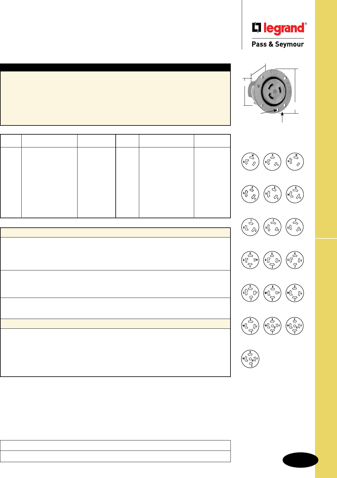
Technical Specifications
S-115
30A Turnlok® Flanged Outlets
Technical Specifications
30A Turnlok® Flanged Outlets
Project
Location/Type
NEMA
Amps Catalog Number Cong. No.
30
r
L530FO L5-30R
30
r
L630FO L6-30R
30
r
L730FO L7-30R
30
r
L830FO L8-30R
30
r
L930FO L9-30R
30
r
L1030FO L10-30R
30
r
L1130FO L11-30R
30
r
L1230FO L12-30R
30
r
L1330FO L13-30R
30
r
L1430FO L14-30R
NEMA
Amps Catalog Number Cong. No.
30
r
L1530FO L15-30R
30
r
L1530FOBK L15-30R
30
r
L1630FO L16-30R
30
r
L1730FO L17-30R
30
r
L1830FO L18-30R
30
r
L1930FO L19-30R
30
r
L2030FO L20-30R
30
r
L2130FO L21-30R
30
r
L2230FO L22-30R
30
r
L2230FOBK L22-30R
30
r
L2330FO L23-30R
Performance
Electrical
Dielectric Withstand Voltage 3000V minimum
Maximum Working Voltage 600VAC
Current Interrupting Certified for current interrupting at full-rated current
Temperature Rise 30°C max. after 50 cycles at 150% rated current
Mechanical
Terminal Identification Green = Ground, White = Neutral, Brass = Hot
Terminal Accommodation #12 AWG min. – #8 AWG max.
Product Identification Amperage, Voltage, 3rd Party Compliance, NEMA Configuration
Environmental
Flammability UL94 V2
Operating Temperature Maximum continuous +75°C, minimum -40°C without impact
Materials
Flanged Casing Polycarbonate
Contact Carrier Nylon
Contacts Tin-Plated Brass
Terminal Clamp Brass- or Nickel-Plated Steel
Terminal Screws Brass- or Nickel-Plated Steel
Ground Screws Nickel-Plated Brass
Assembly Screws Zinc-Plated Steel
Typical Specications
Manufacturer’s Identification: Legrand/Pass & Seymour L530FO
Description: Locking Flanged Outlet, Power Supply
Type: 2 Pole, 3 Wire Grounding
Rating: 30A, 125V
Configuration: NEMA L5-30R
3rd Party Compliance: UL Listed, File Number E146159, Standard UL498, Attachment Plugs and
Receptacles. Federal Specification WC596. CSA Certified, File Number LR1765, Standard CSA-C22.2
No. 42, General Use Receptacles and Attachment Plugs. Conforms to NEMA WD-1 and WD-6.
Consult Turnlok® Section H for complete compliance listing.
NEMA
L5-30R
NEMA
L6-30R
NEMA
L7-30R
NEMA
L8-30R
NEMA
L9-30R
NEMA
L10-30R
NEMA
L11-30R
NEMA
L12-30R
NEMA
L13-30R
NEMA
L14-30R
NEMA
L15-30R
NEMA
L16-30R
NEMA
L18-30R
NEMA
L19-30R
NEMA
L20-30R
NEMA
L21-30R
NEMA
L17-30R
NEMA
L22-30R
NEMA
L23-30R
2.26"
3.12"
ø.187"
1.765"
3 HOLES ON ø2.72" C/L @ 120°
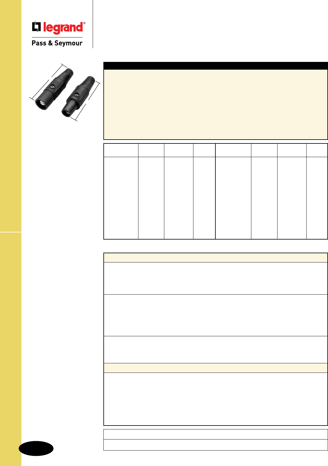
S-116
Technical SpecificationsCam-Type Devices
Project
Location/Type
Technical Specifications
Cam-Type Devices
Series 16 In-Line Connectors
Performance
Electrical
Dielectric Withstand Voltage 2200V minimum
Maximum Working Voltage 600VAC
Current Interrupting Not for interrupting current
Temperature Rise 45°C maximum
Mechanical
Cord Accommodation Individual conductor, Type SC, SCE, SCT or W, 75°C,
copper wire only
Terminal Accommodation PS20 Series = #2 AWG min. – 2/0 AWG max.
PS40 Series = 2/0 AWG min. – 4/0 AWG max.
Product Identification Amperage, Voltage, 3rd Party Compliance, NEMA Standards
molded into external product body
Environmental
Flammability UL94V2
Operating Temperature Maximum continuous +75°C, minimum -40°C without impact
Enclosure NEMA Type 3R and 4
Materials
Body – Connectors Thermoplastic Elastomer
Body – Panel Mounts Nylon
Body – Adapters Thermoplastic Elastomer
Terminal / Pin / Cam Brass
Terminal Screw Plated Steel
Retaining Screw Plastic
Strain Relief Wire Copper
Shim Copper
Typical Specications
Manufacturer’s Identification: Legrand/Pass & Seymour PS40MBBK, PS40FBBK
Description: Series 16 Single Pole In-Line Connector
Type: Single Pole
Electrical Rating: 400A, 600V
Enclosure Rating: NEMA 3R, 4
3rd Party Compliance: UL Listed, File Number E111198, cCSAus Certified, File Number LR81290.
Applicable standards: UL50, Enclosures for Electrical Equipment, UL498, Attachment Plugs and
Receptacles, UL1682, Plugs, Receptacles and Cable Connectors of the Pin & Sleeve Type, CSA-C22.2
No. 65-93, Wire Connectors, CSA-C22.2 No. 94-M91, Special Purpose Enclosures, CSA-C22.2 No.
182.1-1988, Industrial Type, Special Use Attachment Plugs, Receptacles. Conforms to NEMA WD-1
and WD-6.
PS40MBBK
PS40FBBK
6.875"
6.800"
Catalog
Number Rating* Cable Size Color
r
PS20MBBK 400 600 #2 - 2/0 Black
r
PS20MBW 400 600 #2 - 2/0 White
r
PS20MBR 400 600 #2 - 2/0 Red
r
PS20MBBL 400 600 #2 - 2/0 Blue
r
PS20MBG 400 600 #2 - 2/0 Green
r
PS20MBBR 400 600 #2 - 2/0 Brown
r
PS20MBO 400 600 #2 - 2/0 Orange
r
PS20MBY 400 600 #2 - 2/0 Yellow
r
PS40MBBK 400 600 2/0 - 4/0 Black
r
PS40MBW 400 600 2/0 - 4/0 White
r
PS40MBR 400 600 2/0 - 4/0 Red
r
PS40MBBL 400 600 2/0 - 4/0 Blue
r
PS40MBG 400 600 2/0 - 4/0 Green
r
PS40MBBR 400 600 2/0 - 4/0 Brown
r
PS40MBO 400 600 2/0 - 4/0 Orange
r
PS40MBY 400 600 2/0 - 4/0 Yellow
Catalog
Number Rating* Cable Size Color
r
PS20FBBK 400 600 #2 - 2/0 Black
r
PS20FBW 400 600 #2 - 2/0 White
r
PS20FBR 400 600 #2 - 2/0 Red
r
PS20FBBL 400 600 #2 - 2/0 Blue
r
PS20FBG 400 600 #2 - 2/0 Green
r
PS20FBBR 400 600 #2 - 2/0 Brown
r
PS20FBO 400 600 #2 - 2/0 Orange
r
PS20FBY 400 600 #2 - 2/0 Yellow
r
PS40FBBK 400 600 2/0 - 4/0 Black
r
PS40FBW 400 600 2/0 - 4/0 White
r
PS40FBR 400 600 2/0 - 4/0 Red
r
PS40FBBL 400 600 2/0 - 4/0 Blue
r
PS40FBG 400 600 2/0 - 4/0 Green
r
PS40FBBR 400 600 2/0 - 4/0 Brown
r
PS40FBO 400 600 2/0 - 4/0 Orange
r
PS40FBY 400 600 2/0 - 4/0 Yellow
*All ratings are both AC/DC.
S-117
Technical Specifications Cam-Type Devices
Technical Specifications
Cam-Type Devices
Series 15 In-Line Connectors
Catalog
Number Rating Cable Size Color
r
PSM2MBK 150 600 #8 – #2 Black
r
PSM2MW 150 600 #8 – #2 White
r
PSM2MR 150 600 #8 – #2 Red
r
PSM2MBL 150 600 #8 – #2 Blue
r
PSM2MG 150 600 #8 – #2 Green
Catalog
Number Rating Cable Size Color
r
PSM2FBK 150 600 #8 – #2 Black
r
PSM2FW 150 600 #8 – #2 White
r
PSM2FR 150 600 #8 – #2 Red
r
PSM2FBL 150 600 #8 – #2 Blue
r
PSM2FG 150 600 #8 – #2 Green
Typical Specications
Manufacturer’s Identification: Legrand/Pass & Seymour PSM2MBK, PSM2FBK
Description: Series 15 Single Pole In-Line Connector
Type: Single Pole
Electrical Rating: 150A, 600V
Enclosure Rating: NEMA 3R, 4
3rd Party Compliance: UL Listed, File Number E111198, cCSAus Certified, File Number LR81290.
Applicable standards: UL50, Enclosures for Electrical Equipment, UL498, Attachment Plugs and
Receptacles, UL1682, Plugs, Receptacles and Cable Connectors of the Pin & Sleeve Type, CSA-C22.2
No. 65-93, Wire Connectors, CSA-C22.2 No. 94-M91, Special Purpose Enclosures, CSA-C22.2 No.
182.1-1988, Industrial Type, Special Use Attachment Plugs, Receptacles. Conforms to NEMA WD-1
and WD-6.
Performance
Electrical
Dielectric Withstand Voltage 2200V minimum
Maximum Working Voltage 600VAC
Current Interrupting Not for interrupting current
Temperature Rise 45°C maximum
Mechanical
Cord Accommodation Individual conductor, Type SC, SCE, SCT or W, 75°C,
copper wire only
Terminal Accommodation PSM Series = #8 AWG min. – #2 AWG max.
Product Identification Amperage, Voltage, 3rd Party Compliance, NEMA Standards
molded into external product body
Environmental
Flammability UL94V2
Operating Temperature Maximum continuous +75°C, minimum -40°C without impact
Enclosure NEMA Type 3R and 4
Materials
Body – Connectors Thermoplastic Elastomer
Body – Panel Mounts Nylon
Body – Adapters Thermoplastic Elastomer
Terminal / Pin / Cam Brass
Terminal Screw Plated Steel
Retaining Screw Plastic
Strain Relief Wire Copper
Shim Copper
PSM2MBK
PSM2FBK
4.300"
4.300"
Project
Location/Type
S-118
Technical SpecificationsCam-Type Devices
Technical Specifications
Cam-Type Devices
Series 18 In-Line Connectors
Project
Location/Type
Performance
Electrical
Dielectric Withstand Voltage 2200V minimum
Maximum Working Voltage 600VAC
Current Interrupting Not for interrupting current
Temperature Rise 45°C maximum
Mechanical
Cord Accommodation Individual conductor, Type SC, SCE, SCT or W, 75°C,
copper wire only
Terminal Accommodation PLS182 Series = #6 AWG min. – #2 AWG max.
PLS1820 Series = #2 AWG min. – 2/0 AWG max.
PLS1840 Series = 2/0 AWG min. – 4/0 AWG max.
Product Identification Amperage, Voltage, 3rd Party Compliance, NEMA Standards
molded into external product body
Environmental
Flammability UL94V2
Operating Temperature Maximum continuous +75°C, minimum -40°C without impact
Enclosure NEMA Type 3R and 4
Materials
Body – Connectors Thermoplastic Elastomer
Body – Panel Mounts Nylon
Body – Adapters Thermoplastic Elastomer
Terminal / Pin / Cam Brass
Terminal Screw Plated Steel
Retaining Screw Plastic
Strain Relief Wire Copper
Shim Copper
Typical Specications
Manufacturer’s Identification: Legrand/Pass & Seymour PLS182MBK, PLS182FBK
Description: Series 18 Single Pole In-Line Connector
Type: Single Pole
Electrical Rating: 400A, 600V
Enclosure Rating: NEMA 3R, 4
3rd Party Compliance: UL Listed, File Number E111198, cCSAus Certified, File Number LR81290.
Applicable standards: UL50, Enclosures for Electrical Equipment, UL498, Attachment Plugs and
Receptacles, UL1682, Plugs, Receptacles and Cable Connectors of the Pin & Sleeve Type, CSA-C22.2
No. 65-93, Wire Connectors, CSA-C22.2 No. 94-M91, Special Purpose Enclosures, CSA-C22.2 No.
182.1-1988, Industrial Type, Special Use Attachment Plugs, Receptacles. Conforms to NEMA WD-1
and WD-6.
PLS182MBK
PLS182FBK
6.875"
6.800"
Catalog Cable
Number Rating* Size Color
r
PLS182MBK 400 600 #6 - #2 Black
r
PLS182MW 400 600 #6 - #2 White
r
PLS182MR 400 600 #6 - #2 Red
r
PLS182MBL 400 600 #6 - #2 Blue
r
PLS182MG 400 600 #6 - #2 Green
r
PLS1820MBK 400 600 #2 - 2/0 Black
r
PLS1820MW 400 600 #2 - 2/0 White
r
PLS1820MR 400 600 #2 - 2/0 Red
r
PLS1820MBL 400 600 #2 - 2/0 Blue
r
PLS1820MG 400 600 #2 - 2/0 Green
r
PLS1840MBK 400 600 4/0 Black
r
PLS1840MBL 400 600 4/0 Blue
Catalog Cable
Number Rating* Size Color
r
PLS182FBK 400 600 #6 - #2 Black
r
PLS182FW 400 600 #6 - #2 White
r
PLS182FR 400 600 #6 - #2 Red
r
PLS182FBL 400 600 #6 - #2 Blue
r
PLS182FG 400 600 #6 - #2 Green
r
PLS1820FBK 400 600 #2 - 2/0 Black
r
PLS1820FW 400 600 #2 - 2/0 White
r
PLS1820FR 400 600 #2 - 2/0 Red
r
PLS1820FBL 400 600 #2 - 2/0 Blue
r
PLS1820FG 400 600 #2 - 2/0 Green
r
PLS1840FBK 400 600 4/0 Black
r
PLS1840FBL 400 600 4/0 Blue
*All ratings are both AC/DC.
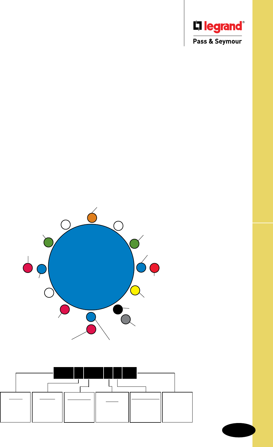
S-119
Technical Specifications
Configuration & Clocking System
Technical Specifications
Configuration & Clocking System
Adapting To Worldwide Configuration
Standards
Application
Legrand/Pass & Seymour’s Pin & Sleeve products are designed
to meet IEC 309-1, 309-2 specifications. These specifications
are recognized around the world and are intended to prevent
the mating of plugs and receptacles of different voltage and
current ratings (see Section 406.3(F) of the National Electrical
Code® relating to this noninterchangeability feature).
Global Product Offering
Legrand/Pass & Seymour provides IEC 309-1, 309-2 Pin &
Sleeve products in both Series I (International) and Series II
(North American) current ratings:
Series I (International) 16, 32, 63, 125 Amps
Series II (North American) 20, 30, 60, 100 Amps
North American Catalog Numbering System
Catalog numbers within the North American product offering
are structured to communicate the following: manufacturer,
number of conductors, amperage rating, device type, clocking
position of the ground sleeve, and environmental rating. This
applies to all receptacles, inlets, plugs, and connectors in
the Legrand/Pass & Seymour North American Pin & Sleeve
product line (see sample below).
Here’s How It Works
The amperage rating is determined by the size of the device.
Voltage rating is determined by the location of the ground
sleeve on the receptacle and/or connector along with the
number of conductors.
Ground sleeve position for all connectors and receptacles is
based on a clock face with the keyway always being at 6
o’clock. The ground sleeve is positioned at a specific hour
point, depending on the device’s voltage rating.
The clocking position for plugs and inlets is a mirror image
of the mating device, allowing for interconnection.
In addition, voltage ratings for all Pin & Sleeve products are
color coded for visual identification.
IEC 309 Clocking System
12
3
9
6
1
2
11
10
8
75
4
125/250VAC 3 POLE, 4 WIRE
277VAC 2 POLE, 3 WIRE
250VAC 2 POLE, 3 WIRE
380-415VAC 3 POLE, 4 WIRE
220/380-240/415VAC 4 POLE, 5 WIRE
480VAC 2 POLE, 3 WIRE
3ø 480VAC 3 POLE, 4 WIRE
3øY 277VAC 4 POLE, 5 WIRE
3ø 250VAC
3 POLE, 4 WIRE
3øY 120/208VAC
4 POLE, 5 WIRE
380-415VAC
2 POLE, 3 WIRE
250VDC
2 POLE, 3 WIRE
380/440VAC
3 POLE, 4 WIRE
(REFRIGERANT
CONTAINERS)
125VAC 2 POLE, 3 WIRE
600VAC 3 POLE, 4 WIRE
600VAC 4 POLE, 5 WIRE
PREFIX
PS
=
PASS &
SEYMOUR
1ST DIGIT
3 = 3 WIRE
4 = 4 WIRE
5 = 5 WIRE
2ND-4TH DIGIT
20 = 20 AMP
30 = 30 AMP
60 = 60 AMP
100 = 100 AMP
LETTER
R = RECEPTACLE
P = PLUG
C = CONNECTOR
B = INLET
CLOCK POSITION
POSITION OF
GROUNDING
SLEEVE
WATERTIGHT
OR
SPLASHPROOF
W = WATERTIGHT
S = SPLASH-
PROOF
P S 4 6 0 R 7 W
North American Catalog Numbering System
s
Application
Specific
50-500VAC
300-500 Hz
2 POLE, 3 WIRE
3 POLE, 4 WIRE
4 POLE, 5 WIRE
50-500VAC
100-300 Hz
3 POLE, 4 WIRE
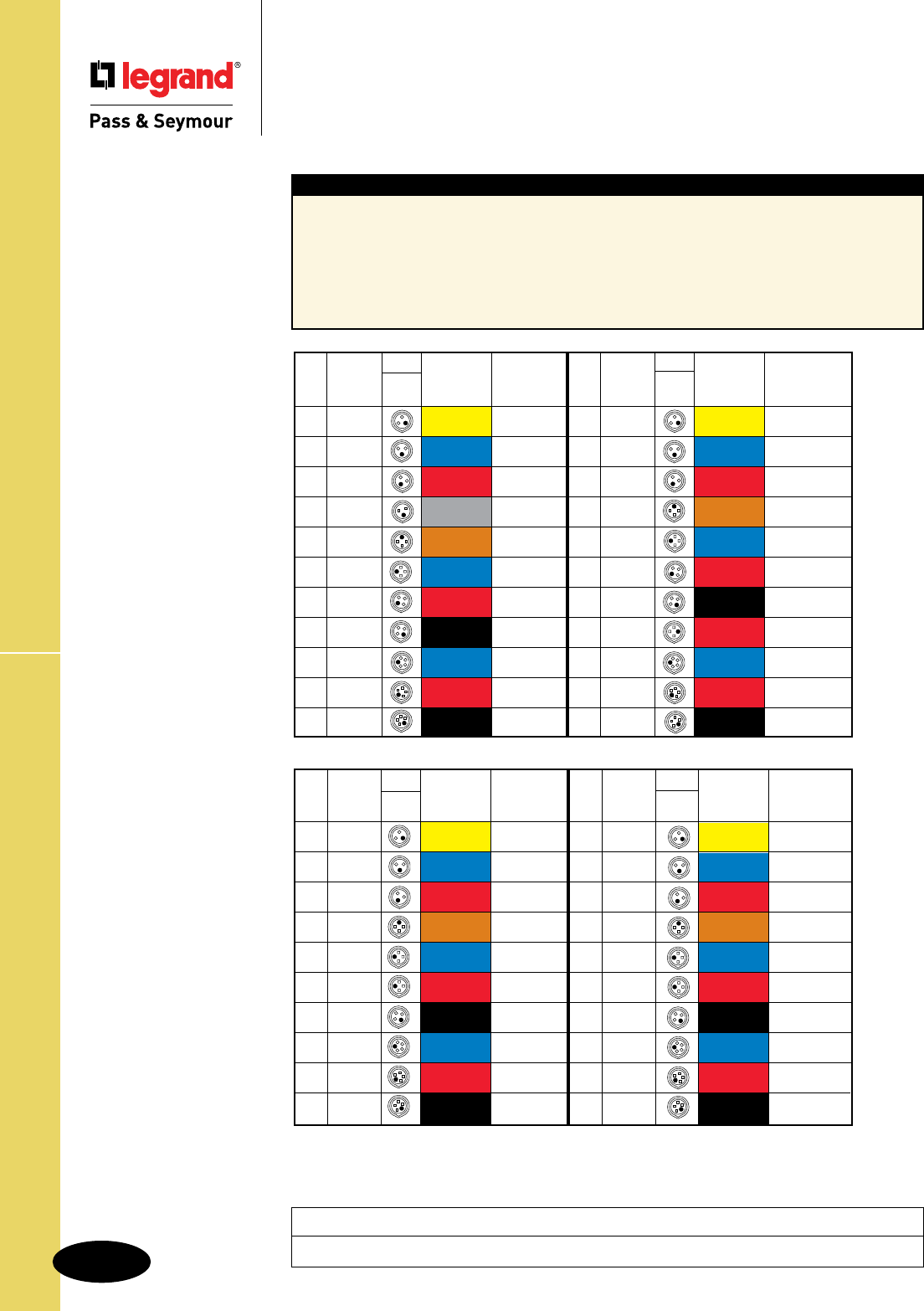
S-120
Technical SpecificationsWatertight Pin & Sleeve Receptacles
Technical Specifications
Watertight Pin & Sleeve Receptacles
20, 30, 60 & 100A
Typical Specications
Manufacturer’s Identification: Legrand/Pass & Seymour PS460R7W
Description: Receptacle, Power Supply
Type: 3 Pole, 4 Wire Grounding
Rating: 60A, 3 Phase 480VAC
Configuration: IEC 309-2, Clock Position 7, Watertight (IP67)
3rd Party Compliance: UL Listed to UL Standard 1682; CSA Certified to CSA 22.2 No. 182.2;
UL Classified to IEC 309-1 and IEC 309-2
Project
Location/Type
*Application specific.
Cong.
Poles & Recep/ Voltage/ Catalog
Amps
Wires Conn. Color Coding Number
60 r2P3W 125 PS360R4W
60 r2P3W 250 PS360R6W
60 r2P3W 480 PS360R7W
60 r3P4W 125/250 PS460R12W
60 r3P4W 3ø250 PS460R9W
60 r3P4W 3ø480 PS460R7W
60 r3P4W 3ø600 PS460R5W
60 r4P5W 3øY120/208 PS560R9W
60 r4P5W 3øY277/480 PS560R7W
60 r4P5W 3øY347/600 PS560R5W
Cong.
Poles & Recep/ Voltage/ Catalog
Amps
Wires Conn. Color Coding Number
100 r2P3W 125 PS3100R4W
100 r2P3W 250 PS3100R6W
100 r2P3W 480 PS3100R7W
100 r3P4W 125/250 PS4100R12W
100 r3P4W 3ø250 PS4100R9W
100 r3P4W 3ø480 PS4100R7W
100 r3P4W 3ø600 PS4100R5W
100 r4P5W 3øY120/208 PS5100R9W
100 r4P5W 3øY277/480 PS5100R7W
100 r4P5W 3øY347/600 PS5100R5W
Cong.
Poles & Recep/ Voltage/ Catalog
Amps
Wires Conn. Color Coding Number
20 r2P3W 125 PS320R4W
20 r2P3W 250 PS320R6W
20 r2P3W 480 PS320R7W
20 r2P3W 277 PS320R5W
20 r3P4W 125/250 PS420R12W
20 r3P4W 3ø250 PS420R9W
20 r3P4W 3ø480 PS420R7W
20 r3P4W 3ø600 PS420R5W
20 r4P5W 3øY120/208 PS520R9W
20 r4P5W 3øY277/480 PS520R7W
20 r4P5W 3øY347/600 PS520R5W
Cong.
Poles & Recep/ Voltage/ Catalog
Amps
Wires Conn. Color Coding Number
30 r2P3W 125 PS330R4W
30 r2P3W 250 PS330R6W
30 r2P3W 480 PS330R7W
30 r3P4W 125/250 PS430R12W
30 r3P4W 3ø250 PS430R9W
30 r3P4W 3ø480 PS430R7W
30 r3P4W 3ø600 PS430R5W
30 r3P4W 380/440 *PS430R3W
30 r4P5W 3øY120/208 PS530R9W
30 r4P5W 3øY277/480 PS530R7W
30 r4P5W 3øY347/600 PS530R5W
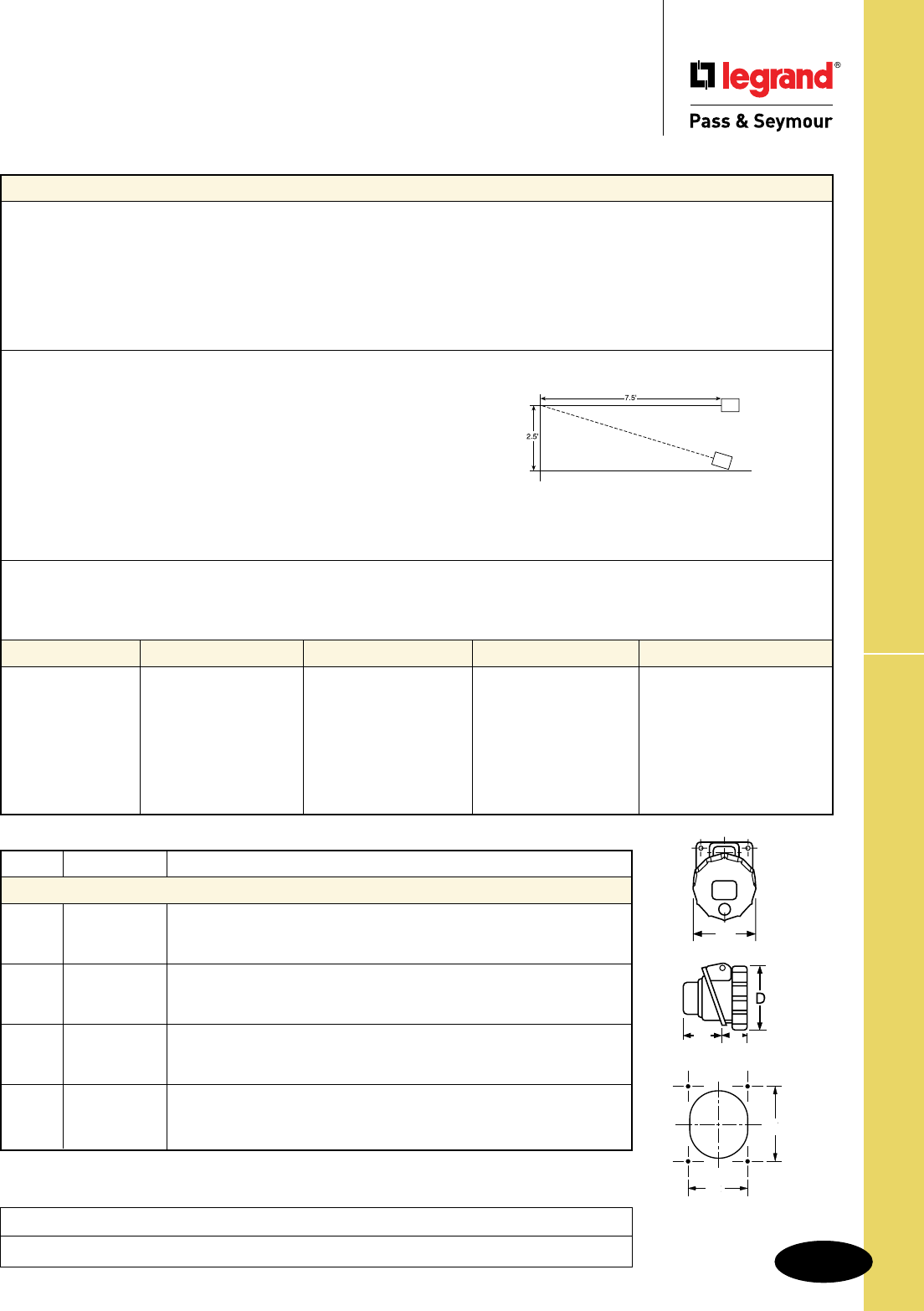
S-121
Technical Specifications Watertight Pin & Sleeve Receptacles
Technical Specifications
Watertight Pin & Sleeve Receptacles
20, 30, 60 & 100A
Performance
Electrical
Dielectric Voltage Withstand 3000V maximum
Maximum Working Voltage 600 RMS
Current Interrupting Certified for current interrupting at full-rated current
Temperature Rise Maximum 30°C temperature rise at full-rated current
after 50 cycles of 150% overload (at 0.75 to 0.80 power factor)
Endurance 20 Amp: 5000 cycles with full-rated current and voltage
30, 60 & 100 Amp: 2000 cycles with full-rated current and voltage applied on every other cycle
Mechanical
Impact Resistance Device dropped 8 times from a height of 2.5 feet with 7.5 feet of cord attached (per CSA 182.1)
Cord Grip Retention Force, Lbs.* Torque, Ft. lbs.*
20A 30 .4
30A 75 .5
60A 150 1
100A 150 1
*Applied to minimum recommended cable size
Cord Accommodation Round portable service cords. Diameters commensurate with the device rating as defined in UL62,
CSA C22.2, No. 49, and the harmonized (HAR) European Standard
Terminal Identification Identified in accordance with North American convention, UL1682, and IEC 309-1, 309-2
Product Identification Identification and ratings are labeled on the device housing
Environmental
Moisture Resistance Watertight per IEC 309-1.
Flammability Contact with live parts: V2 or V0. Enclosure: HB or better per UL94
Operating Temperature +80°C maximum continuous, -50°C minimum without impact
Materials 20 Amp 30 Amp 60 Amp 100 Amp
Housing Polyamide 6 Polyamide 6 Valox Valox
Cover Polyamide 66 Polyamide 66 Valox Valox
Cover Spring Stainless Steel Stainless Steel Stainless Steel Stainless Steel
Sealing Gasket Neoprene Neoprene Neoprene Neoprene
Mounting Gasket Neoprene Neoprene Neoprene Neoprene
Contact Carrier Polyamide 6 Polyamide 6 Polyamide 6 Polyamide 6
Sleeves Brass with Nickel Plate Brass with Nickel Plate Brass with Nickel Plate Brass with Nickel Plate
Terminal Screws Zinc-Plated Steel Zinc-Plated Steel Zinc-Plated Steel Zinc-Plated Steel
Specimen
Amps Wire Cong. A B C D E F
Watertight Receptacles
2 Pole, 3 Wire inch 2.85 1.80 1.60 3.40 2.05 2.36
20 3 Pole, 4 Wire inch 3.20 1.90 1.60 3.80 2.36 2.75
4 Pole, 5 Wire inch 3.40 2.00 1.70 3.80 2.36 2.75
2 Pole, 3 Wire inch 3.72 2.60 1.80 4.30 2.75 3.15
30 3 Pole, 4 Wire inch 3.72 2.60 1.90 4.30 2.75 3.15
4 Pole, 5 Wire inch 3.98 2.70 1.95 4.30 2.75 3.15
2 Pole, 3 Wire inch 4.20 3.10 3.50 5.00 3.03 3.35
60 3 Pole, 4 Wire inch 4.20 3.10 3.50 5.00 3.03 3.35
4 Pole, 5 Wire inch 4.20 3.10 3.50 5.00 3.03 3.35
2 Pole, 3 Wire inch 5.20 2.20 4.40 5.60 4.88 4.88
100 3 Pole, 4 Wire inch 5.20 2.20 4.40 5.60 4.88 4.88
4 Pole, 5 Wire inch 5.20 2.20 4.40 5.60 4.88 4.88
A
E
F
CB
Project
Location/Type
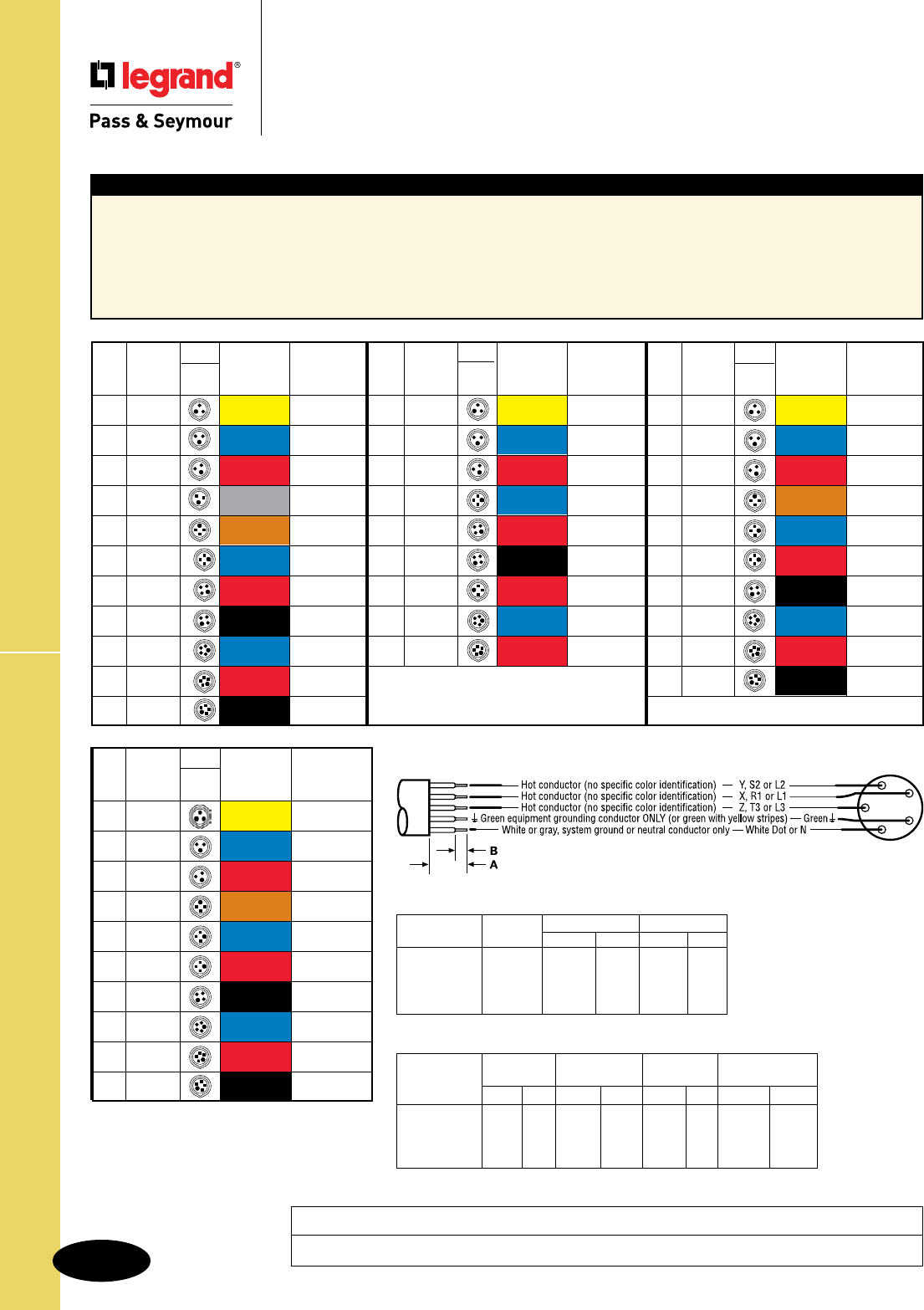
S-122
Technical SpecificationsWatertight Pin & Sleeve Plugs
Technical Specifications
Watertight Pin & Sleeve Plugs
20, 30, 60 & 100A
Typical Specications
Manufacturer’s Identification: Legrand/Pass & Seymour PS460P7W
Description: Plug, Power Supply
Type: 3 Pole, 4 Wire Grounding
Rating: 60A, 3 Phase 480VAC
Configuration: IEC 309-2, Clock Position 7, Watertight (IP67)
3rd Party Compliance: UL Listed to UL Standard 1682; CSA Certified to CSA 22.2 No. 182.2; UL Classified to IEC 309-1 and IEC 309-2
Cong.
Poles & Plug/ Voltage/ Catalog
Amps
Wires Inlet Color Coding Number
100 r2P3W 125 PS3100P4W
100 r2P3W 250 PS3100P6W
100 r2P3W 480 PS3100P7W
100 r3P4W 125/250 PS4100P12W
100 r3P4W 3ø250 PS4100P9W
100 r3P4W 3ø480 PS4100P7W
100 r3P4W 3ø600 PS4100P5W
100 r4P5W 3øY120/208 PS5100P9W
100 r4P5W 3øY277/480 PS5100P7W
100 r4P5W 3øY347/600 PS5100P5W
Device Size Con- A B
ductors Inches (mm) Inches (mm)
20 Amp All 1-1/8 29 1/2 12
30 Amp All 1-1/2 38 13/16 21
60 Amp All 2-3/4 70 13/16 21
100 Amp All 5-5/16 135 1-3/8 35
CABLE STRIPPING GUIDE
Terminal Cable Clamp Assembly Compression
Device Size Screw Screw Screw Nut
In-lbs N-m In-lbs N-m In-lbs N-m In-lbs N-m
20 Amp 7 .8 6 .8 7 .8 18-36 2-4
30 Amp 7 .8 6 .8 7 .8 18-36 2-4
60 Amp 17 1.9 12 1.4 7 .8 45-90 5-10
100 Amp 70 7.9 15 1.8 7 .8 45-90 5-10
TIGHTENING GUIDE
Project
Location/Type
*Application specific.
Cong.
Poles & Plug/ Voltage/ Catalog
Amps
Wires Inlet Color Coding Number
20 r2P3W 125 PS320P4W
20 r2P3W 250 PS320P6W
20 r2P3W 480 PS320P7W
20 r2P3W 277 PS320P5W
20 r3P4W 125/250 PS420P12W
20 r3P4W 3ø250 PS420P9W
20 r3P4W 3ø480 PS420P7W
20 r3P4W 3ø600 PS420P5W
20 r4P5W 3øY120/208 PS520P9W
20 r4P5W 3øY277/480 PS520P7W
20 r4P5W 3øY347/600 PS520P5W
Cong.
Poles & Plug/ Voltage/ Catalog
Amps
Wires Inlet Color Coding Number
60 r2P3W 125 PS360P4W
60 r2P3W 250 PS360P6W
60 r2P3W 480 PS360P7W
60 r3P4W 125/250 PS460P12W
60 r3P4W 3ø250 PS460P9W
60 r3P4W 3ø480 PS460P7W
60 r3P4W 3ø600 PS460P5W
60 r4P5W 3øY120/208 PS560P9W
60 r4P5W 3øY277/480 PS560P7W
60 r4P5W 3øY347/600 PS560P5W
Cong.
Poles & Plug/ Voltage/ Catalog
Amps
Wires Inlet Color Coding Number
30 r2P3W 125 PS330P4W
30 r2P3W 250 PS330P6W
30 r2P3W 480 PS330P7W
30 r3P4W 3ø250 PS430P9W
30 r3P4W 3ø480 PS430P7W
30 r3P4W 3ø600 PS430P5W
30 r3P4W 380/440 *PS430P3W
30 r4P5W 3øY120/208 PS530P9W
30 r4P5W 3øY277/480 PS530P7W

S-123
Technical Specifications Watertight Pin & Sleeve Plugs
Technical Specifications
Watertight Pin & Sleeve Plugs
20, 30, 60 & 100A
Performance
Electrical
Dielectric Voltage Withstand 3000V maximum
Maximum Working Voltage 600 RMS
Current Interrupting Certified for current interrupting at full-rated current
Temperature Rise Maximum 30°C temperature rise at full-rated current
after 50 cycles of 150% overload (at 0.75 to 0.80 power factor)
Endurance 20 Amp: 5000 cycles with full-rated current and voltage
30, 60 & 100 Amp: 2000 cycles with full-rated current and voltage applied on every other cycle
Mechanical
Impact Resistance Device dropped 8 times from a height of 2.5 feet with 7.5 feet of cord attached (per CSA 182.1)
Cord Grip Retention Force, Lbs.* Torque, Ft. lbs.*
20A 30 .4
30A 75 .5
60A 150 1
100A 150 1
*Applied to minimum recommended cable size
Cord Accommodation Round portable service cords. Diameters commensurate with the device rating as defined in UL62,
CSA C22.2, No. 49, and the harmonized (HAR) European Standard
Terminal Identification Identified in accordance with North American convention, UL1682, and IEC 309-1, 309-2
Product Identification Identification and ratings are labeled on the device housing
Environmental
Moisture Resistance Watertight per IEC 309-1.
Flammability Contact with live parts: V2 or V0. Enclosure: HB or better per UL94
Operating Temperature +80°C maximum continuous, -50°C minimum without impact
Materials 20 Amp 30 Amp 60 Amp 100 Amp
Housing Polyamide 6 Polyamide 6 Valox Valox
Locking Ring Polyamide 66 Polyamide 66 Valox Valox
Sealing Gasket Neoprene Neoprene Neoprene Neoprene
Housing Gasket Neoprene Neoprene Neoprene Neoprene
Back Body Polyamide 6 Polyamide 6 Valox Valox
Contact Carrier Polyamide 6 Polyamide 6 Polyamide 6 Polyamide 6
Pins Brass with Nickel Plate Brass with Nickel Plate Brass with Nickel Plate Brass with Nickel Plate
Terminal Screws Zinc-Plated Steel Zinc-Plated Steel Zinc-Plated Steel Zinc-Plated Steel
Cord Grip Polyamide 6 Polyamide 6 Polyamide 66 Polyamide 66
Grommet Natural Rubber Natural Rubber Natural Rubber Natural Rubber
Cord Grip Screws Stainless Steel Stainless Steel Stainless Steel Stainless Steel
Assembly Screws Stainless Steel Stainless Steel Stainless Steel Stainless Steel
Specimen
Amps Wire Cong. A B C D E F
Watertight Plugs
2 Pole, 3 Wire inch 5.30 2.85 .31-.59
20 3 Pole, 4 Wire inch 5.50 3.20 .31-.59
4 Pole, 5 Wire inch 6.00 3.40 .39-.71
2 Pole, 3 Wire inch 6.50 3.70 .39-.71
30 3 Pole, 4 Wire inch 6.50 3.70 .47-.87
4 Pole, 5 Wire inch 6.70 3.98 .47-.87
2 Pole, 3 Wire inch 10.00 4.50 .63-1.04
60 3 Pole, 4 Wire inch 10.00 4.50 .73-1.14
4 Pole, 5 Wire inch 10.00 4.50 .80-1.26
2 Pole, 3 Wire inch 13.40 5.20 .59-1.97
100/125 3 Pole, 4 Wire inch 13.40 5.20 .59-1.97
4 Pole, 5 Wire inch 13.40 5.20 .59-1.97
A
B
D
Project
Location/Type
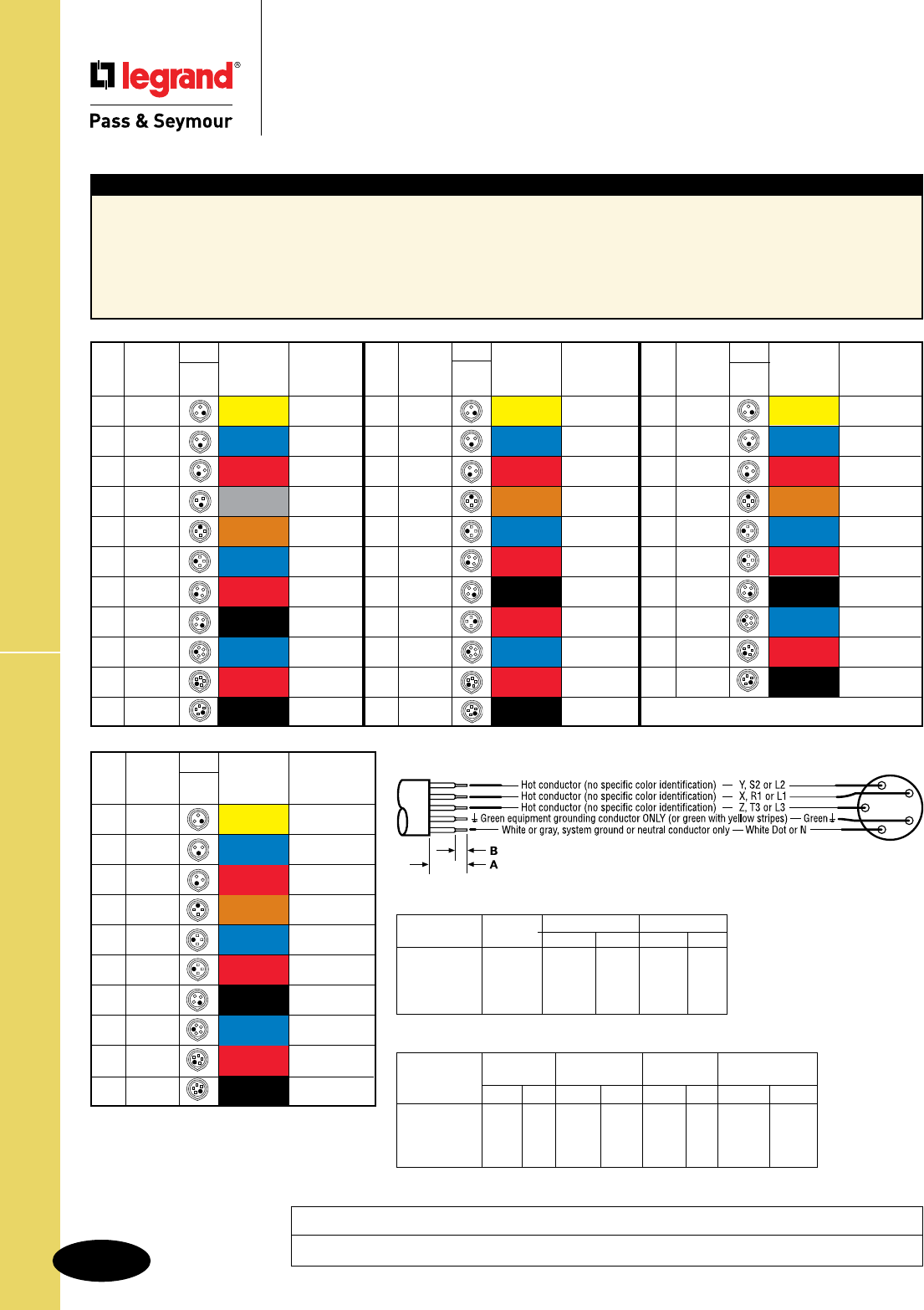
S-124
Technical SpecificationsWatertight Pin & Sleeve Connectors
Technical Specifications
Watertight Pin & Sleeve Connectors
20, 30, 60 & 100A
Typical Specications
Manufacturer’s Identification: Legrand/Pass & Seymour PS460C7W
Description: Connector, Power Supply
Type: 3 Pole, 4 Wire Grounding
Rating: 60A, 3 Phase 480VAC
Configuration: IEC 309-2, Clock Position 7, Watertight (IP67)
3rd Party Compliance: UL Listed to UL Standard 1682; CSA Certified to CSA 22.2 No. 182.2; UL Classified to IEC 309-1 and IEC 309-2
Cong.
Poles & Recep/ Voltage/ Catalog
Amps
Wires Conn. Color Coding Number
100 r2P3W 125 PS3100C4W
100 r2P3W 250 PS3100C6W
100 r2P3W 480 PS3100C7W
100 r3P4W 125/250 PS4100C12W
100 r3P4W 3ø250 PS4100C9W
100 r3P4W 3ø480 PS4100C7W
100 r3P4W 3ø600 PS4100C5W
100 r4P5W 3øY120/208 PS5100C9W
100 r4P5W 3øY277/480 PS5100C7W
100 r4P5W 3øY347/600 PS5100C5W
Device Size Con- A B
ductors inches (mm) inches (mm)
20 Amp All 1-1/8 29 1/2 12
30 Amp All 1-1/2 38 13/16 21
60 Amp All 2-3/4 70 13/16 21
100 Amp All 5-5/16 135 1-3/8 35
CABLE STRIPPING GUIDE
Terminal Cable Clamp Assembly Compression
Device Size Screw Screw Screw Nut
In-lbs N-m In-lbs N-m In-lbs N-m In-lbs N-m
20 Amp 7 .8 6 .8 7 .8 18-36 2-4
30 Amp 7 .8 6 .8 7 .8 18-36 2-4
60 Amp 17 1.9 12 1.4 7 .8 45-90 5-10
100 Amp 70 7.9 15 1.8 7 .8 45-90 5-10
TIGHTENING GUIDE
Project
Location/Type
Config.
Poles & Recep/ Voltage/ Catalog
Amps
Wires Conn. Color Coding Number
60 r2P3W 125 PS360C4W
60 r2P3W 250 PS360C6W
60 r2P3W 480 PS360C7W
60 r3P4W 125/250 PS460C12W
60 r3P4W 3ø250 PS460C9W
60 r3P4W 3ø480 PS460C7W
60 r3P4W 3ø600 PS460C5W
60 r4P5W 3øY120/208 PS560C9W
60 r4P5W 3øY277/480 PS560C7W
60 r4P5W 3øY347/600 PS560C5W
Cong.
Poles & Recep/ Voltage/ Catalog
Amps
Wires Conn. Color Coding Number
20 r2P3W 125 PS320C4W
20 r2P3W 250 PS320C6W
20 r2P3W 480 PS320C7W
20 r2P3W 277 PS320C5W
20 r3P4W 125/250 PS420C12W
20 r3P4W 3ø250 PS420C9W
20 r3P4W 3ø480 PS420C7W
20 r3P4W 3ø600 PS420C5W
20 r4P5W 3øY120/208 PS520C9W
20 r4P5W 3øY277/480 PS520C7W
20 r4P5W 3øY347/600 PS520C5W
Cong.
Poles & Recep/ Voltage/ Catalog
Amps
Wires Conn. Color Coding Number
30 r2P3W 125 PS330C4W
30 r2P3W 250 PS330C6W
30 r2P3W 480 PS330C7W
30 r3P4W 125/250 PS430C12W
30 r3P4W 3ø250 PS430C9W
30 r3P4W 3ø480 PS430C7W
30 r3P4W 3ø600 PS430C5W
30 r 3P4W 380/440 *PS430C3W
30 r4P5W 3øY120/208 PS530C9W
30 r4P5W 3øY277/480 PS530C7W
30 r4P5W 3øY347/600 PS530C5W
*Application specific.
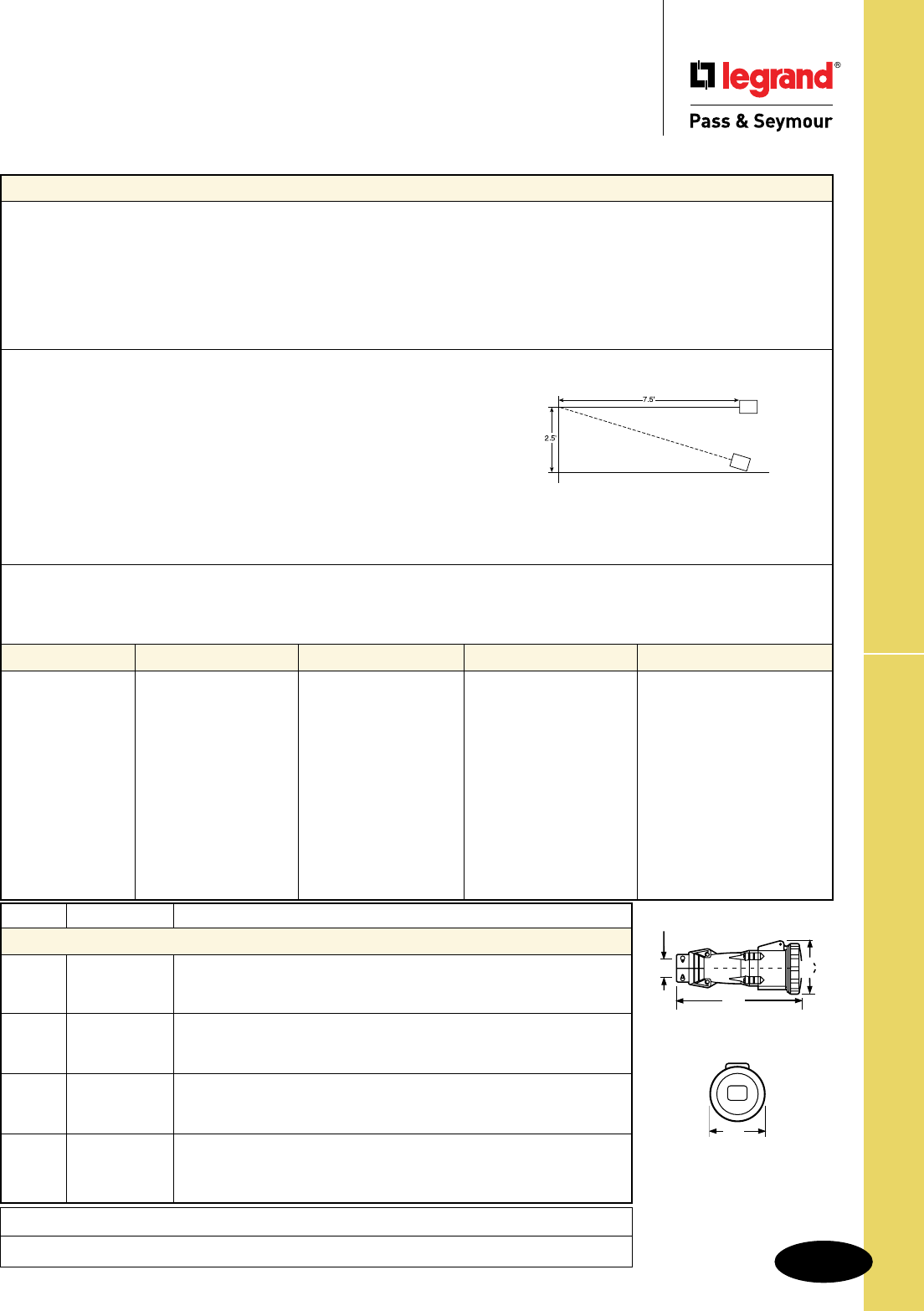
S-125
Technical Specifications Watertight Pin & Sleeve Connectors
Technical Specifications
Watertight Pin & Sleeve Connectors
20, 30, 60 & 100A
Performance
Electrical
Dielectric Voltage Withstand 3000V maximum
Maximum Working Voltage 600 RMS
Current Interrupting Certified for current interrupting at full-rated current
Temperature Rise Maximum 30°C temperature rise at full-rated current
after 50 cycles of 150% overload (at 0.75 to 0.80 power factor)
Endurance 20 Amp: 5000 cycles with full-rated current and voltage
30, 60 & 100 Amp: 2000 cycles with full-rated current and voltage applied on every other cycle
Mechanical
Impact Resistance Device dropped 8 times from a height of 2.5 feet with 7.5 feet of cord attached (per CSA 182.1)
Cord Grip Retention Force, Lbs.* Torque, Ft. lbs.*
20A 30 .4
30A 75 .5
60A 150 1
100A 150 1
*Applied to minimum recommended cable size
Cord Accommodation Round portable service cords. Diameters commensurate with the device rating as defined in UL62,
CSA C22.2, No. 49, and the harmonized (HAR) European Standard
Terminal Identification Identified in accordance with North American convention, UL1682, and IEC 309-1, 309-2
Product Identification Identification and ratings are labeled on the device housing
Environmental
Moisture Resistance Watertight per IEC 309-1.
Flammability Contact with live parts: V2 or V0. Enclosure: HB or better per UL94
Operating Temperature +80°C maximum continuous, -50°C minimum without impact
Materials 20 Amp 30 Amp 60 Amp 100 Amp
Housing Polyamide 6 Polyamide 6 Valox Valox
Cover Polyamide 66 Polyamide 66 Valox Valox
Cover Spring Stainless Steel Stainless Steel Stainless Steel Stainless Steel
Sealing Gasket Neoprene Neoprene Neoprene Neoprene
Housing Gasket Neoprene Neoprene Neoprene Neoprene
Back Body Polyamide 6 Polyamide 6 Valox Valox
Contact Carrier Polyamide 6 Polyamide 6 Polyamide 6 Polyamide 6
Sleeves Brass with Nickel Plate Brass with Nickel Plate Brass with Nickel Plate Brass with Nickel Plate
Terminal Screws Zinc-Plated Steel Zinc-Plated Steel Zinc-Plated Steel Zinc-Plated Steel
Cord Grip Polyamide 6 Polyamide 6 Polyamide 66 Polyamide 66
Grommet Natural Rubber Natural Rubber Natural Rubber Natural Rubber
Cord Grip Screws Stainless Steel Stainless Steel Stainless Steel Stainless Steel
Assembly Screws Stainless Steel Stainless Steel Stainless Steel Stainless Steel
Specimen
Amps Wire Cong. A B C D E F
Watertight Connectors
2 Pole, 3 Wire inch 5.90 2.85 3.00 .31-.59
20 3 Pole, 4 Wire inch 6.00 3.20 3.40 .31-.59
4 Pole, 5 Wire inch 6.70 3.40 3.50 .39-.71
2 Pole, 3 Wire inch 7.00 3.70 3.90 .39-.71
30 3 Pole, 4 Wire inch 7.00 3.70 3.90 .47-.87
4 Pole, 5 Wire inch 7.30 3.98 4.10 .47-.87
2 Pole, 3 Wire inch 10.90 4.50 4.70 .63-1.04
60 3 Pole, 4 Wire inch 10.90 4.50 4.70 .73-1.14
4 Pole, 5 Wire inch 10.90 4.50 4.70 .80-1.26
2 Pole, 3 Wire inch 14.30 5.20 5.30 .59-1.97
100 3 Pole, 4 Wire inch 14.30 5.20 5.30 .59-1.97
4 Pole, 5 Wire inch 14.30 5.20 5.30 .59-1.97
C
A
D
B
Project
Location/Type
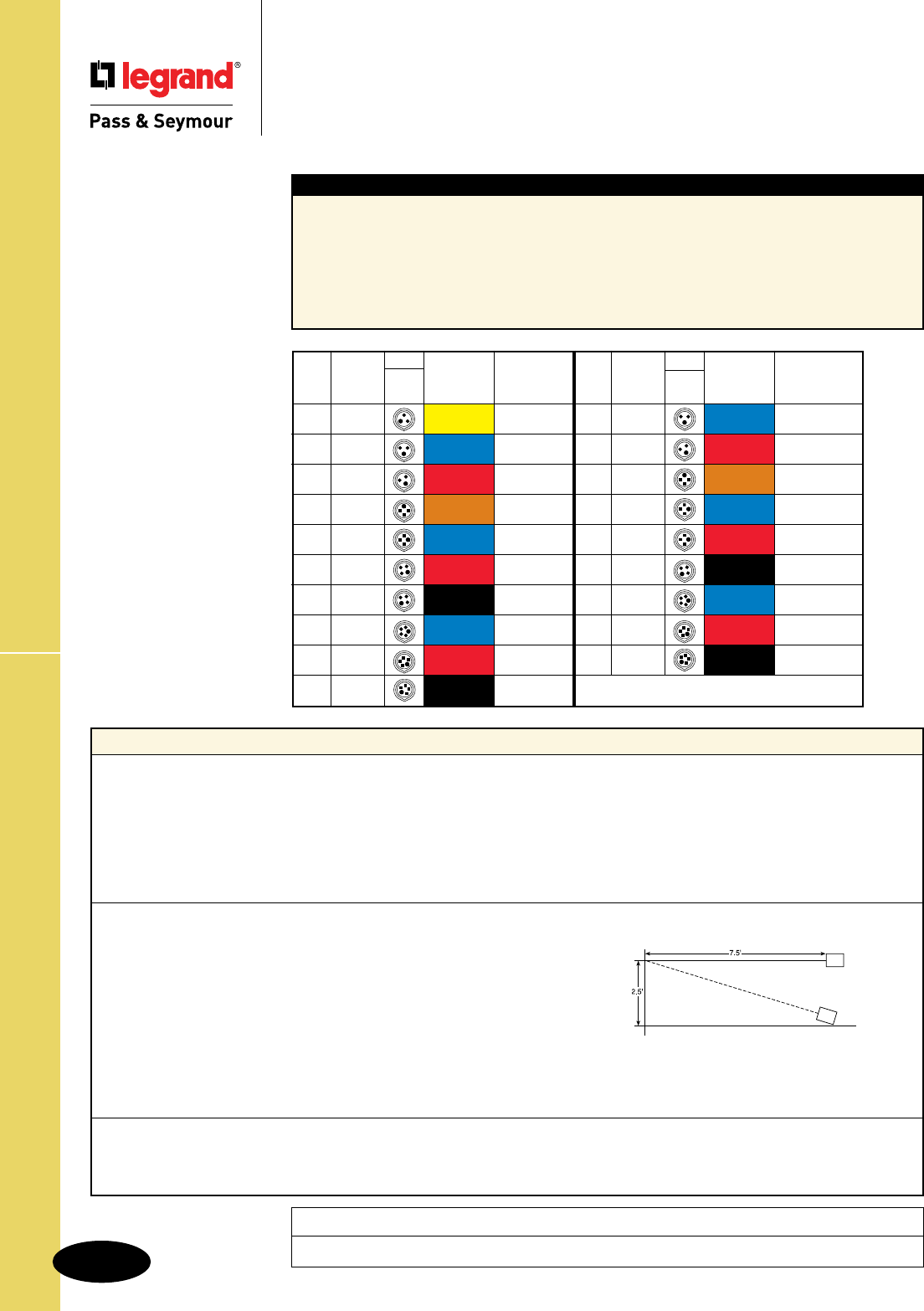
S-126
Technical SpecificationsWatertight Pin & Sleeve Inlets
Technical Specifications
Watertight Pin & Sleeve Inlets
60 & 100A
Performance
Electrical
Dielectric Voltage Withstand 3000V maximum
Maximum Working Voltage 600 RMS
Current Interrupting Certified for current interrupting at full-rated current
Temperature Rise Maximum 30°C temperature rise at full-rated current
after 50 cycles of 150% overload (at 0.75 to 0.80 power factor)
Endurance 20 Amp: 5000 cycles with full-rated current and voltage
30, 60 & 100 Amp: 2000 cycles with full-rated current and voltage applied on every other cycle
Mechanical
Impact Resistance Device dropped 8 times from a height of 2.5 feet with 7.5 feet of cord attached (per CSA 182.1)
Cord Grip Retention Force, Lbs.* Torque, Ft. lbs.*
20A 30 .4
30A 75 .5
60A 150 1
100A 150 1
*Applied to minimum recommended cable size
Cord Accommodation Round portable service cords. Diameters commensurate with the device rating as defined in UL62,
CSA C22.2, No. 49, and the harmonized (HAR) European Standard
Terminal Identification Identified in accordance with North American convention, UL1682, and IEC 309-1, 309-2
Product Identification Identification and ratings are labeled on the device housing
Environmental
Moisture Resistance Watertight per IEC 309-1.
Flammability Contact with live parts: V2 or V0. Enclosure: HB or better per UL94
Operating Temperature +80°C maximum continuous, -50°C minimum without impact
Specimen
Typical Specications
Manufacturer’s Identification: Legrand/Pass & Seymour PS460B7W
Description: Inlet, Power Supply
Type: 3 Pole, 4 Wire Grounding
Rating: 60A, 3 Phase 480VAC
Configuration: IEC 309-2, Clock Position 7, Watertight (IP67)
3rd Party Compliance: UL Listed to UL Standard 1682; CSA Certified to CSA 22.2 No. 182.2;
UL Classified to IEC 309-1 and IEC 309-2
Project
Location/Type
Cong.
Poles & Plug/ Voltage/ Catalog
Amps
Wires Inlet Color Coding Number
60 r2P3W 125 PS360B4W
60 r2P3W 250 PS360B6W
60 r2P3W 480 PS360B7W
60 r3P4W 125/250 PS460B12W
60 r3P4W 3ø250 PS460B9W
60 r3P4W 3ø480 PS460B7W
60 r3P4W 3ø600 PS460B5W
60 r4P5W 3øY120/208 PS560B9W
60 r4P5W 3øY277/480 PS560B7W
60 r4P5W 3øY347/600 PS560B5W
Cong.
Poles & Plug/ Voltage/ Catalog
Amps
Wires Inlet Color Coding Number
100 r2P3W 250 PS3100B6W
100 r2P3W 480 PS3100B7W
100 r3P4W 125/250 PS4100B12W
100 r3P4W 3ø250 PS4100B9W
100 r3P4W 3ø480 PS4100B7W
100 r3P4W 3ø600 PS4100B5W
100 r4P5W 3øY120/208 PS5100B9W
100 r4P5W 3øY277/480 PS5100B7W
100 r4P5W 3øY347/600 PS5100B5W
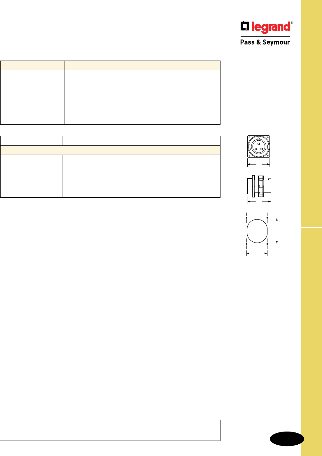
S-127
Technical Specifications Watertight Pin & Sleeve Inlets
Technical Specifications
Watertight Pin & Sleeve Inlets
60 & 100A
Amps Wire Cong. A B C D E F
Watertight Inlets
2 Pole, 3 Wire inch 4.50 4.25 3.03 3.35
60 3 Pole, 4 Wire inch 4.50 4.25 3.03 3.35
4 Pole, 5 Wire inch 4.50 4.25 3.03 3.35
2 Pole, 3 Wire inch 5.75 5.71 4.88 4.88
100 3 Pole, 4 Wire inch 5.75 5.71 4.88 4.88
4 Pole, 5 Wire inch 5.75 5.71 4.88 4.88
Materials 60 Amp 100 Amp
Housing Valox Valox
Mounting Flange Valox Valox
Locking Ring Valox Valox
Sealing Gasket Neoprene Neoprene
Mounting Gasket Neoprene Neoprene
Contact Carrier Polyamide 6 Polyamide 6
Pins Brass with Nickel Plate Brass with Nickel Plate
Terminal Screws Zinc-Plated Steel Zinc-Plated Steel
A
B
E
F
Project
Location/Type
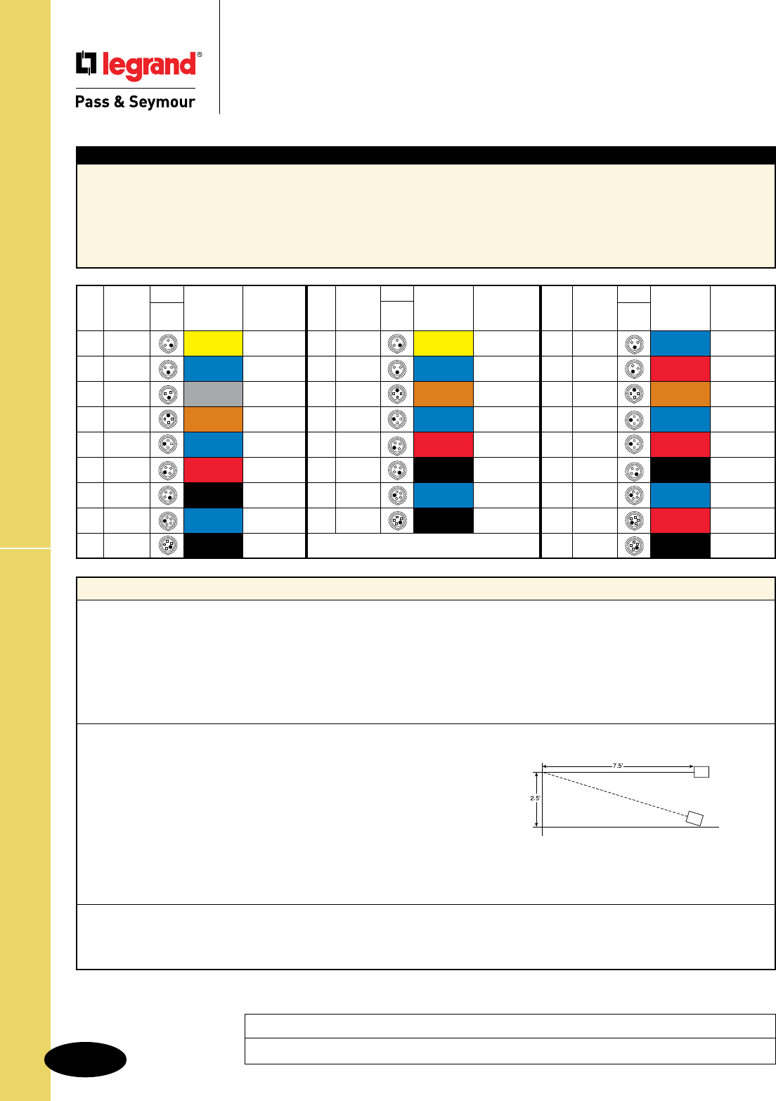
S-128
Technical Specifications
Technical Specifications
Splashproof Pin & Sleeve Receptacles
20, 30 & 60A
Typical Specications
Manufacturer’s Identification: Legrand/Pass & Seymour PS460R7S
Description: Receptacle, Power Supply
Type: 3 Pole, 4 Wire Grounding
Rating: 60A, 3 Phase 480VAC
Configuration: IEC 309-2, Clock Position 7, Splashproof (IP44)
3rd Party Compliance: UL Listed to UL Standard 1682; CSA Certified to CSA 22.2 No. 182.2; UL Classified to IEC 309-1 and IEC 309-2
Performance
Electrical
Dielectric Voltage Withstand 3000V maximum
Maximum Working Voltage 600 RMS
Current Interrupting Certified for current interrupting at full-rated current
Temperature Rise Maximum 30°C temperature rise at full-rated current
after 50 cycles of 150% overload (at 0.75 to 0.80 power factor)
Endurance 20 Amp: 5000 cycles with full-rated current and voltage
30, 60 & 100 Amp: 2000 cycles with full-rated current and voltage applied on every other cycle
Mechanical
Impact Resistance Device dropped 8 times from a height of 2.5 feet with 7.5 feet of cord attached (per CSA 182.1)
Cord Grip Retention Force, Lbs.* Torque, Ft. lbs.*
20A 30 .4
30A 75 .5
60A 150 1
100A 150 1
*Applied to minimum recommended cable size
Cord Accommodation Round portable service cords. Diameters commensurate with the device rating as defined in UL62,
CSA C22.2, No. 49, and the harmonized (HAR) European Standard
Terminal Identification Identified in accordance with North American convention, UL1682, and IEC 309-1, 309-2
Product Identification Identification and ratings are labeled on the device housing
Environmental
Moisture Resistance Watertight per IEC 309-1.
Flammability Contact with live parts: V2 or V0. Enclosure: HB or better per UL94
Operating Temperature +80°C maximum continuous, -50°C minimum without impact
Specimen
Project
Location/Type
Splashproof Pin & Sleeve Receptacles
Cong.
Poles & Recep/ Voltage/ Catalog
Amps
Wires Conn. Color Coding Number
20 r2P3W 125 PS320R4S
20 r2P3W 250 PS320R6S
20 r2P3W 277 PS320R5S
20 r3P4W 125/250 PS420R12S
20 r3P4W 3ø250 PS420R9S
20 r3P4W 3ø480 PS420R7S
20 r3P4W 3ø600 PS420R5S
20 r4P5W 3øY120/208 PS520R9S
20 r4P5W 3øY347/600 PS520R5S
Cong.
Poles & Recep/ Voltage/ Catalog
Amps
Wires Conn. Color Coding Number
30 r2P3W 125 PS330R4S
30 r2P3W 250 PS330R6S
30 r3P4W 125/250 PS430R12S
30 r3P4W 3ø250 PS430R9S
30 r3P4W 3ø480 PS430R7S
30 r3P4W 3ø600 PS430R5S
30 r4P5W 3øY120/208 PS530R9S
30 r4P5W 3øY347/600 PS530R5S
Cong.
Poles & Recep/ Voltage/ Catalog
Amps
Wires Conn. Color Coding Number
60 r2P3W 250 PS360R6S
60 r2P3W 480 PS360R7S
60 r3P4W 125/250 PS460R12S
60 r3P4W 3ø250 PS460R9S
60 r3P4W 3ø480 PS460R7S
60 r3P4W 3ø600 PS460R5S
60 r4P5W 3øY120/208 PS560R9S
60 r4P5W 3øY277/480 PS560R7S
60 r4P5W 3øY347/600 PS560R5S
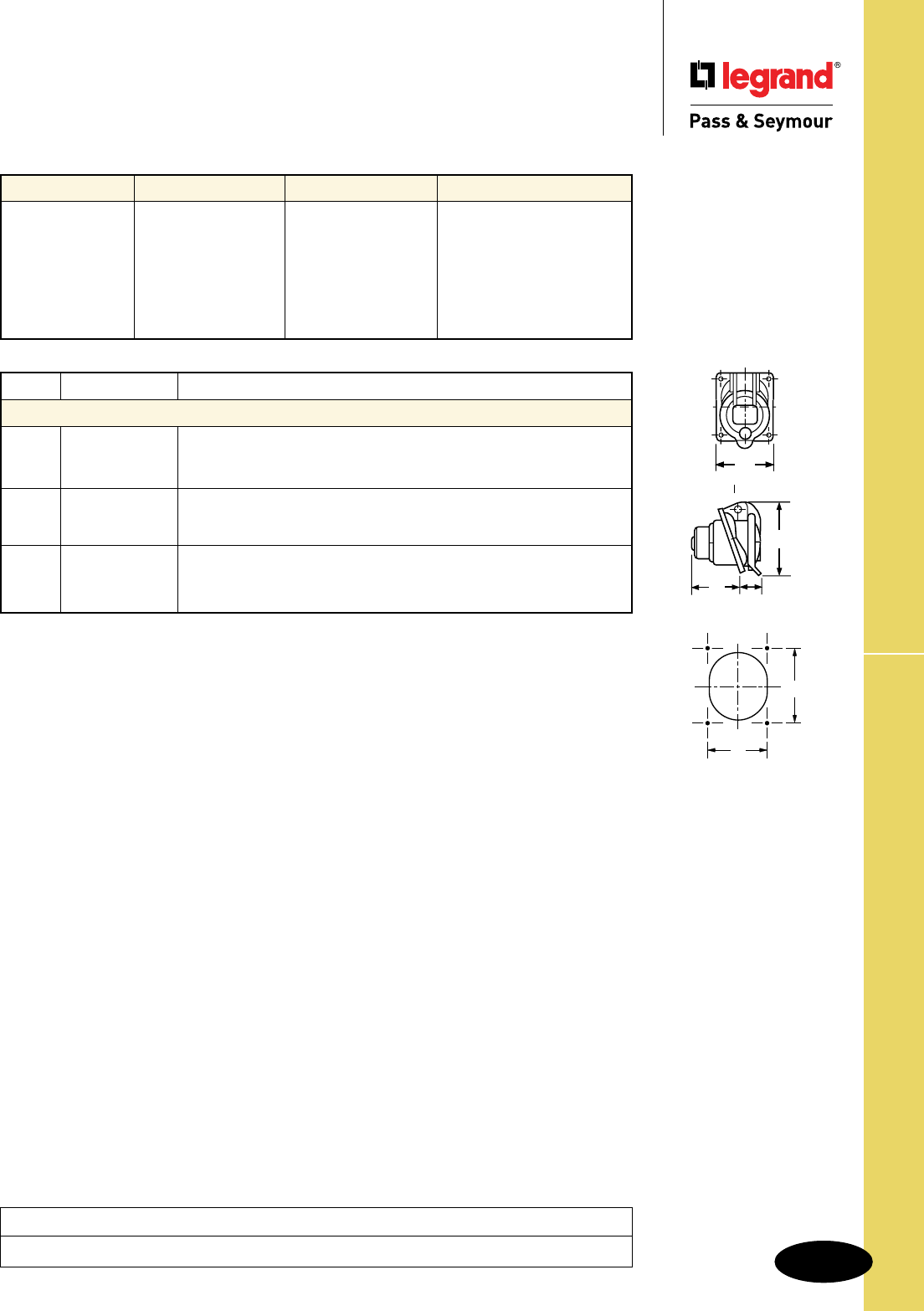
S-129
Technical Specifications Splashproof Pin & Sleeve Receptacles
Technical Specifications
Splashproof Pin & Sleeve Receptacles
20, 30 & 60A
Materials 20 Amp 30 Amp 60 Amp
Housing Polyamide 6 Polyamide 6 Valox
Cover Polyamide 66 Polyamide 66 Valox
Cover Spring Stainless Steel Stainless Steel Stainless Steel
Mounting Gasket Neoprene Neoprene Neoprene
Contact Carrier Polyamide 6 Polyamide 6 Polyamide 6
Sleeves Brass Brass Brass with Nickel Plate
Terminal Screws Zinc-Plated Steel Zinc-Plated Steel Zinc-Plated Steel
Amps Wire Cong. A B C D E F
Splashproof Receptacles
2 Pole, 3 Wire inch 2.50 1.57 1.60 3.10 2.05 2.36
20 3 Pole, 4 Wire inch 2.90 1.57 1.73 3.46 2.36 2.75
4 Pole, 5 Wire inch 2.90 1.73 1.73 3.66 2.36 2.75
2 Pole, 3 Wire inch 3.30 2.10 1.97 4.06 2.75 3.15
30 3 Pole, 4 Wire inch 3.30 2.10 1.97 4.06 2.75 3.15
4 Pole, 5 Wire inch 3.30 2.20 2.05 4.20 2.75 3.15
2 Pole, 3 Wire inch 4.20 3.50 2.76 5.08 3.03 3.35
60 3 Pole, 4 Wire inch 4.20 3.50 2.76 5.08 3.03 3.35
4 Pole, 5 Wire inch 4.20 3.50 2.76 5.08 3.03 3.35
F
E
A
D
CB
Project
Location/Type
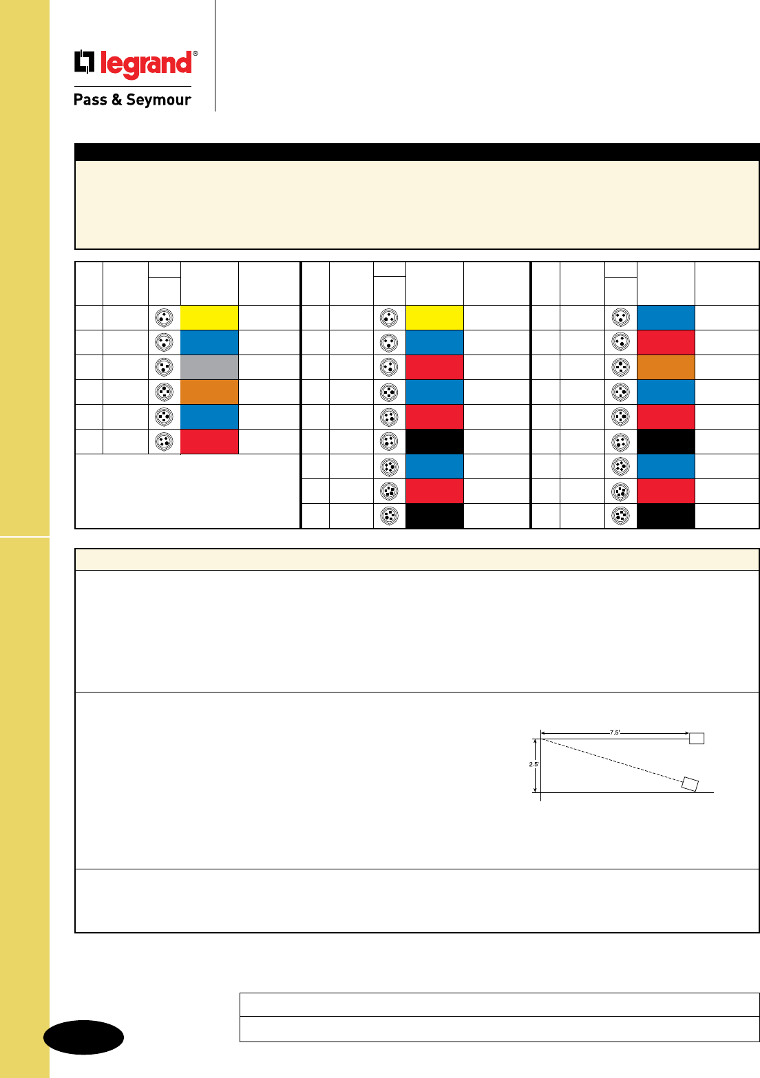
S-130
Technical SpecificationsSplashproof Pin & Sleeve Plugs
Technical Specifications
Splashproof Pin & Sleeve Plugs
20, 30 & 60A
Typical Specications
Description: Plug, Power Supply
Type: 3 Pole, 4 Wire Grounding
Rating: 60A, 3 Phase 480VAC
Configuration: IEC 309-2, Clock Position 7, Splashproof (IP44)
3rd Party Compliance: UL Listed to UL Standard 1682; CSA Certified to CSA 22.2 No. 182.2; UL Classified to IEC 309-1 and IEC 309-2
Performance
Electrical
Dielectric Voltage Withstand 3000V maximum
Maximum Working Voltage 600 RMS
Current Interrupting Certified for current interrupting at full-rated current
Temperature Rise Maximum 30°C temperature rise at full-rated current
after 50 cycles of 150% overload (at 0.75 to 0.80 power factor)
Endurance 20 Amp: 5000 cycles with full-rated current and voltage
30, 60 & 100 Amp: 2000 cycles with full-rated current and voltage applied on every other cycle
Mechanical
Impact Resistance Device dropped 8 times from a height of 2.5 feet with 7.5 feet of cord attached (per CSA 182.1)
Cord Grip Retention Force, Lbs.* Torque, Ft. lbs.*
20A 30 .4
30A 75 .5
60A 150 1
100A 150 1
*Applied to minimum recommended cable size
Cord Accommodation Round portable service cords. Diameters commensurate with the device rating as defined in UL62,
CSA C22.2, No. 49, and the harmonized (HAR) European Standard
Terminal Identification Identified in accordance with North American convention, UL1682, and IEC 309-1, 309-2
Product Identification Identification and ratings are labeled on the device housing
Environmental
Moisture Resistance Watertight per IEC 309-1.
Flammability Contact with live parts: V2 or V0. Enclosure: HB or better per UL94
Operating Temperature +80°C maximum continuous, -50°C minimum without impact
Specimen
Project
Location/Type
Cong.
Poles & Plug/ Voltage/ Catalog
Amps
Wires Inlet Color Coding Number
20 r2P3W 125 PS320P4S
20 r2P3W 250 PS320P6S
20 r2P3W 277 PS320P5S
20 r3P4W 125/250 PS420P12S
20 r3P4W 3ø250 PS420P9S
20 r3P4W 3ø480 PS420P7S
Cong.
Poles & Plug/ Voltage/ Catalog
Amps
Wires Inlet Color Coding Number
30 r2P3W 125 PS330P4S
30 r2P3W 250 PS330P6S
30 r2P3W 480 PS330P7S
30 r3P4W 3ø250 PS430P9S
30 r3P4W 3ø480 PS430P7S
30 r3P4W 3ø600 PS430P5S
30 r4P5W 3øY120/208 PS530P9S
30 r4P5W 3øY277/480 PS530P7S
30 r4P5W 3øY347/600 PS530P5S
Cong.
Poles & Plug/ Voltage/ Catalog
Amps
Wires Inlet Color Coding Number
60 r2P3W 250 PS360P6S
60 r2P3W 480 PS360P7S
60 r3P4W 125/250 PS460P12S
60 r3P4W 3ø250 PS460P9S
60 r3P4W 3ø480 PS460P7S
60 r3P4W 3ø600 PS460P5S
60 r4P5W 3øY120/208 PS560P9S
60 r4P5W 3øY277/480 PS560P7S
60 r4P5W 3øY347/600 PS560P5S
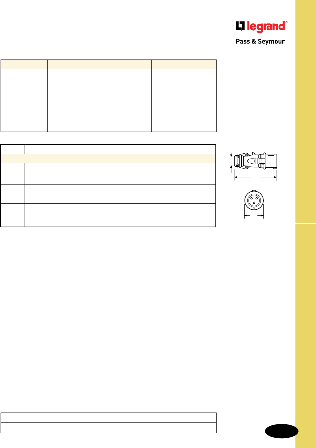
S-131
Technical Specifications Splashproof Pin & Sleeve Plugs
Technical Specifications
Splashproof Pin & Sleeve Plugs
20, 30 & 60A
Materials 20 Amp 30 Amp 60 Amp
Housing Polyamide 6 Polyamide 6 Valox
Housing Gasket Neoprene Neoprene Neoprene
Back Body Polyamide 6 Polyamide 6 Valox
Contact Carrier Polyamide 6 Polyamide 6 Polyamide 6
Pins Brass Brass Brass with Nickel Plate
Terminal Screws Zinc-Plated Steel Zinc-Plated Steel Zinc-Plated Steel
Cord Grip Polyamide 6 Polyamide 6 Polyamide 66
Grommet Natural Rubber Natural Rubber Natural Rubber
Cord Grip Screws Stainless Steel Stainless Steel Stainless Steel
Assembly Screws Stainless Steel Stainless Steel Stainless Steel
Amps Wire Cong. A B C D E F
Splashproof Plugs
2 Pole, 3 Wire inch 5.30 2.17 .31-.59
20 3 Pole, 4 Wire inch 5.50 2.36 .31-.59
4 Pole, 5 Wire inch 6.00 2.60 .39-.71
2 Pole, 3 Wire inch 6.50 2.78 .39-.71
30 3 Pole, 4 Wire inch 6.50 2.78 .47-.87
4 Pole, 5 Wire inch 6.70 3.03 .47-.87
2 Pole, 3 Wire inch 10.00 4.02 .63-1.04
60 3 Pole, 4 Wire inch 10.00 4.02 .73-1.14
4 Pole, 5 Wire inch 10.00 4.02 .80-1.26 B
A
D
Project
Location/Type
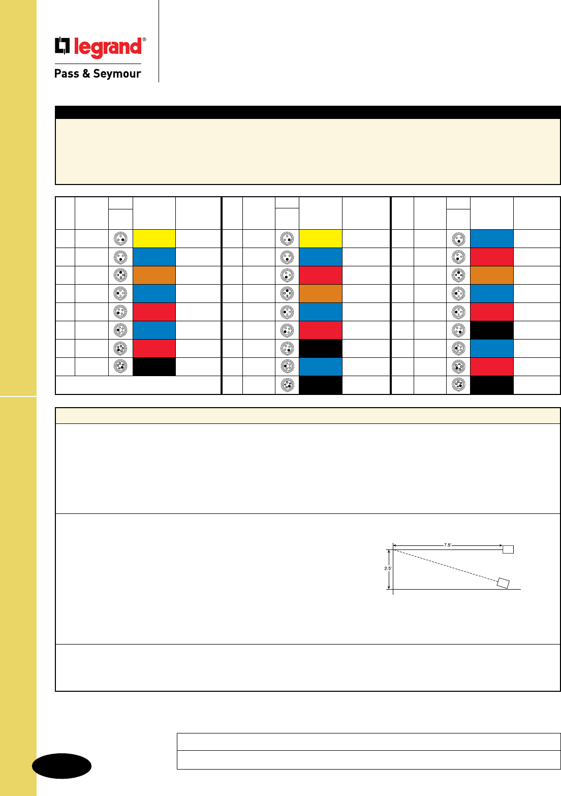
S-132
Technical Specifications
Technical Specifications
Splashproof Pin & Sleeve Connectors
20, 30 & 60A
Typical Specications
Description: Connector, Power Supply
Type: 3 Pole, 4 Wire Grounding
Rating: 60A, 3 Phase 480VAC
Configuration: IEC 309-2, Clock Position 7, Splashproof (IP44)
3rd Party Compliance: UL Listed to UL Standard 1682; CSA Certified to CSA 22.2 No. 182.2; UL Classified to IEC 309-1 and IEC 309-2
Performance
Electrical
Dielectric Voltage Withstand 3000V maximum
Maximum Working Voltage 600 RMS
Current Interrupting Certified for current interrupting at full-rated current
Temperature Rise Maximum 30°C temperature rise at full-rated current
after 50 cycles of 150% overload (at 0.75 to 0.80 power factor)
Endurance 20 Amp: 5000 cycles with full-rated current and voltage
30, 60 & 100 Amp: 2000 cycles with full-rated current and voltage applied on every other cycle
Mechanical
Impact Resistance Device dropped 8 times from a height of 2.5 feet with 7.5 feet of cord attached (per CSA 182.1)
Cord Grip Retention Force, Lbs.* Torque, Ft. lbs.*
20A 30 .4
30A 75 .5
60A 150 1
100A 150 1
*Applied to minimum recommended cable size
Cord Accommodation Round portable service cords. Diameters commensurate with the device rating as defined in UL62,
CSA C22.2, No. 49, and the harmonized (HAR) European Standard
Terminal Identification Identified in accordance with North American convention, UL1682, and IEC 309-1, 309-2
Product Identification Identification and ratings are labeled on the device housing
Environmental
Moisture Resistance Watertight per IEC 309-1.
Flammability Contact with live parts: V2 or V0. Enclosure: HB or better per UL94
Operating Temperature +80°C maximum continuous, -50°C minimum without impact
Specimen
Project
Location/Type
Splashproof Pin & Sleeve Connectors
Cong.
Poles & Recep/ Voltage/ Catalog
Amps
Wires Conn. Color Coding Number
60 r2P3W 250 PS360C6S
60 r2P3W 480 PS360C7S
60 r3P4W 125/250 PS460C12S
60 r3P4W 3ø250 PS460C9S
60 r3P4W 3ø480 PS460C7S
60 r3P4W 3ø600 PS460C5S
60 r4P5W 3øY120/208 PS560C9S
60 r4P5W 3øY277/480 PS560C7S
60 r4P5W 3øY347/600 PS560C5S
Cong.
Poles & Recep/ Voltage/ Catalog
Amps
Wires Conn. Color Coding Number
30 r2P3W 125 PS330C4S
30 r2P3W 250 PS330C6S
30 r2P3W 480 PS330C7S
30 r3P4W 125/250 PS430C12S
30 r3P4W 3ø250 PS430C9S
30 r3P4W 3ø480 PS430C7S
30 r3P4W 3ø600 PS430C5S
30 r4P5W 3øY120/208 PS530C9S
30 r4P5W 3øY347/600 PS530C5S
Cong.
Poles & Recep/ Voltage/ Catalog
Amps
Wires Conn. Color Coding Number
20 r2P3W 125 PS320C4S
20 r2P3W 250 PS320C6S
20 r3P4W 125/250 PS420C12S
20 r3P4W 3ø250 PS420C9S
20 r3P4W 3ø480 PS420C7S
20 r4P5W 3øY120/208 PS520C9S
20 r4P5W 3øY277/480 PS520C7S
20 r4P5W 3øY347/600 PS520C5S
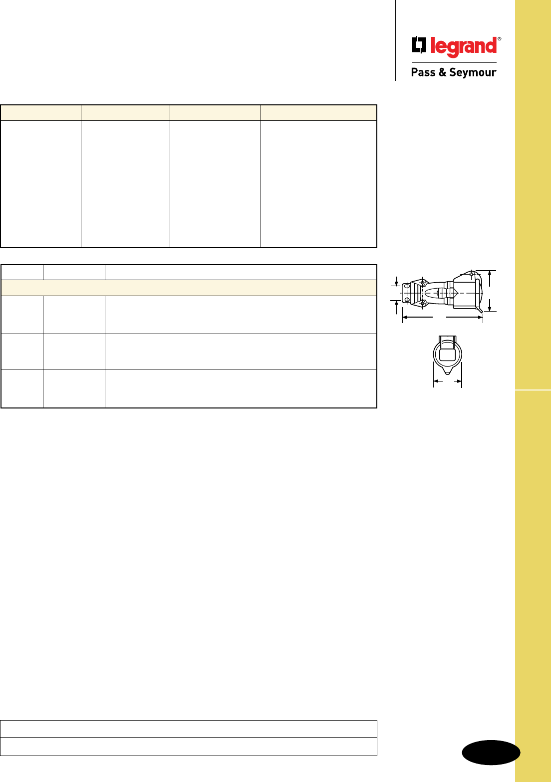
S-133
Technical Specifications Splashproof Pin & Sleeve Connectors
Technical Specifications
Splashproof Pin & Sleeve Connectors
20, 30 & 60A
Materials 20 Amp 30 Amp 60 Amp
Housing Polyamide 6 Polyamide 6 Valox
Cover Polyamide 66 Polyamide 66 Valox
Cover Spring Stainless Steel Stainless Steel Stainless Steel
Housing Gasket Neoprene Neoprene Neoprene
Back Body Polyamide 6 Polyamide 6 Valox
Contact Carrier Polyamide 6 Polyamide 6 Polyamide 66
Sleeves Brass Brass Brass with Nickel Plate
Terminal Screws Zinc-Plated Steel Zinc-Plated Steel Zinc-Plated Steel
Cord Grip Polyamide 6 Polyamide 6 Polyamide 66
Grommet Natural Rubber Natural Rubber Natural Rubber
Cord Grip Screws Stainless Steel Stainless Steel Stainless Steel
Assembly Screws Stainless Steel Stainless Steel Stainless Steel
A
D
C
B
A
D
C
B
B
A
C
D
Amps Wire Cong. A B C D E F
Splashproof Connectors
2 Pole, 3 Wire inch 5.79 2.15 2.91 .31-.59
20 3 Pole, 4 Wire inch 5.94 2.42 3.19 .31-.59
4 Pole, 5 Wire inch 6.77 2.73 3.54 .39-.71
2 Pole, 3 Wire inch 6.97 2.80 3.66 .39-.71
30 3 Pole, 4 Wire inch 6.97 2.80 3.66 .47-.87
4 Pole, 5 Wire inch 7.20 3.05 3.94 .47-.87
2 Pole, 3 Wire inch 10.75 3.78 4.67 .63-1.04
60 3 Pole, 4 Wire inch 10.75 3.78 4.67 .73-1.14
4 Pole, 5 Wire inch 10.75 3.78 4.67 .80-1.26
Project
Location/Type
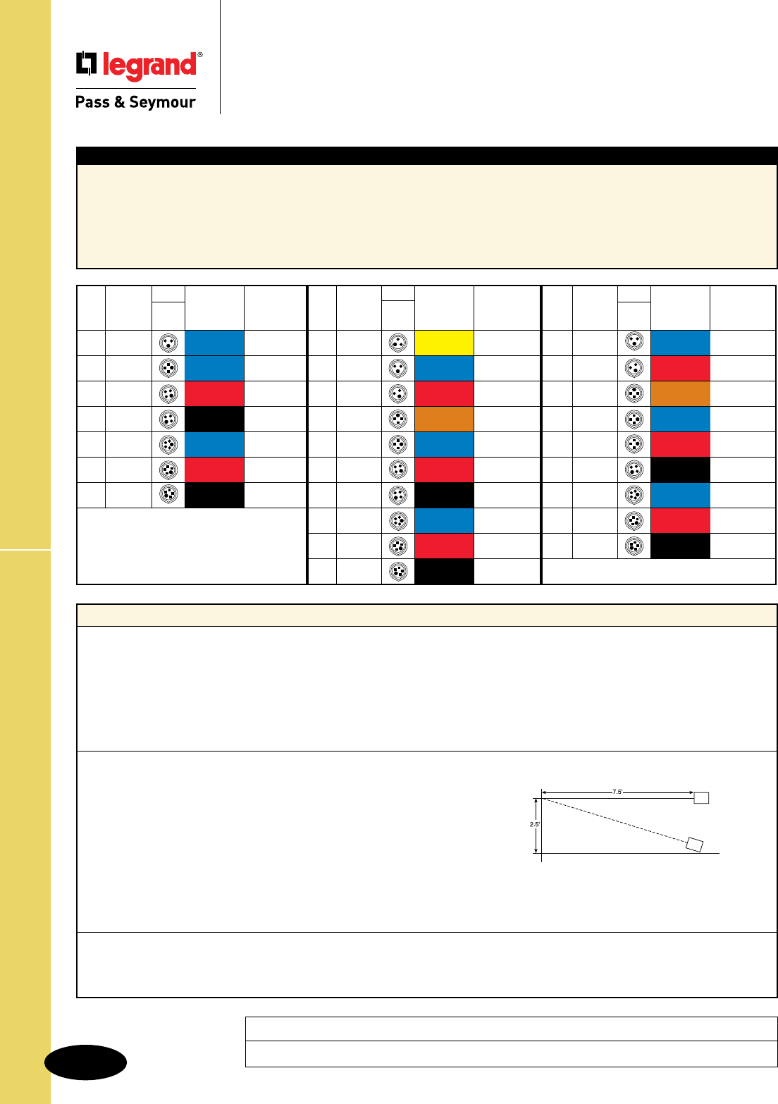
S-134
Technical SpecificationsSplashproof Pin & Sleeve Inlets
Technical Specifications
Splashproof Pin & Sleeve Inlets
20, 30 & 60A
Typical Specications
Manufacturer’s Identification: Legrand/Pass & Seymour PS460B7S
Description: Inlet, Power Supply
Type: 3 Pole, 4 Wire Grounding
Rating: 60A, 3 Phase 480VAC
Configuration: IEC 309-2, Clock Position 7, Splashproof (IP44)
3rd Party Compliance: UL Listed to UL Standard 1682; CSA Certified to CSA 22.2 No. 182.2; UL Classified to IEC 309-1 and IEC 309-2
Performance
Electrical
Dielectric Voltage Withstand 3000V maximum
Maximum Working Voltage 600 RMS
Current Interrupting Certified for current interrupting at full-rated current
Temperature Rise Maximum 30°C temperature rise at full-rated current
after 50 cycles of 150% overload (at 0.75 to 0.80 power factor)
Endurance 20 Amp: 5000 cycles with full-rated current and voltage
30, 60 & 100 Amp: 2000 cycles with full-rated current and voltage applied on every other cycle
Mechanical
Impact Resistance Device dropped 8 times from a height of 2.5 feet with 7.5 feet of cord attached (per CSA 182.1)
Cord Grip Retention Force, Lbs.* Torque, Ft. lbs.*
20A 30 .4
30A 75 .5
60A 150 1
100A 150 1
*Applied to minimum recommended cable size
Cord Accommodation Round portable service cords. Diameters commensurate with the device rating as defined in UL62,
CSA C22.2, No. 49, and the harmonized (HAR) European Standard
Terminal Identification Identified in accordance with North American convention, UL1682, and IEC 309-1, 309-2
Product Identification Identification and ratings are labeled on the device housing
Environmental
Moisture Resistance Watertight per IEC 309-1.
Flammability Contact with live parts: V2 or V0. Enclosure: HB or better per UL94
Operating Temperature +80°C maximum continuous, -50°C minimum without impact
Specimen
Project
Location/Type
Cong.
Poles & Plug/ Voltage/ Catalog
Amps
Wires Inlet Color Coding Number
60 r2P3W 250 PS360B6S
60 r2P3W 480 PS360B7S
60 r3P4W 125/250 PS460B12S
60 r3P4W 3ø250 PS460B9S
60 r3P4W 3ø480 PS460B7S
60 r3P4W 3ø600 PS460B5S
60 r4P5W 3øY120/208 PS560B9S
60 r4P5W 3øY277/480 PS560B7S
60 r4P5W 3øY347/600 PS560B5S
Cong.
Poles & Plug/ Voltage/ Catalog
Amps
Wires Inlet Color Coding Number
30 r2P3W 125 PS330B4S
30 r2P3W 250 PS330B6S
30 r2P3W 480 PS330B7S
30 r3P4W 125/250 PS430B12S
30 r3P4W 3ø250 PS430B9S
30 r3P4W 3ø480 PS430B7S
30 r3P4W 3ø600 PS430B5S
30 r4P5W 3øY120/208 PS530B9S
30 r4P5W 3øY277/480 PS530B7S
30 r4P5W 3øY347/600 PS530B5S
Cong.
Poles & Plug/ Voltage/ Catalog
Amps
Wires Inlet Color Coding Number
20 r2P3W 250 PS320B6S
20 r3P4W 3ø250 PS420B9S
20 r3P4W 3ø480 PS420B7S
20 r3P4W 3ø600 PS420B5S
20 r4P5W 3øY120/208 PS520B9S
20 r4P5W 3øY277/480 PS520B7S
20 r4P5W 3øY347/600 PS520B5S
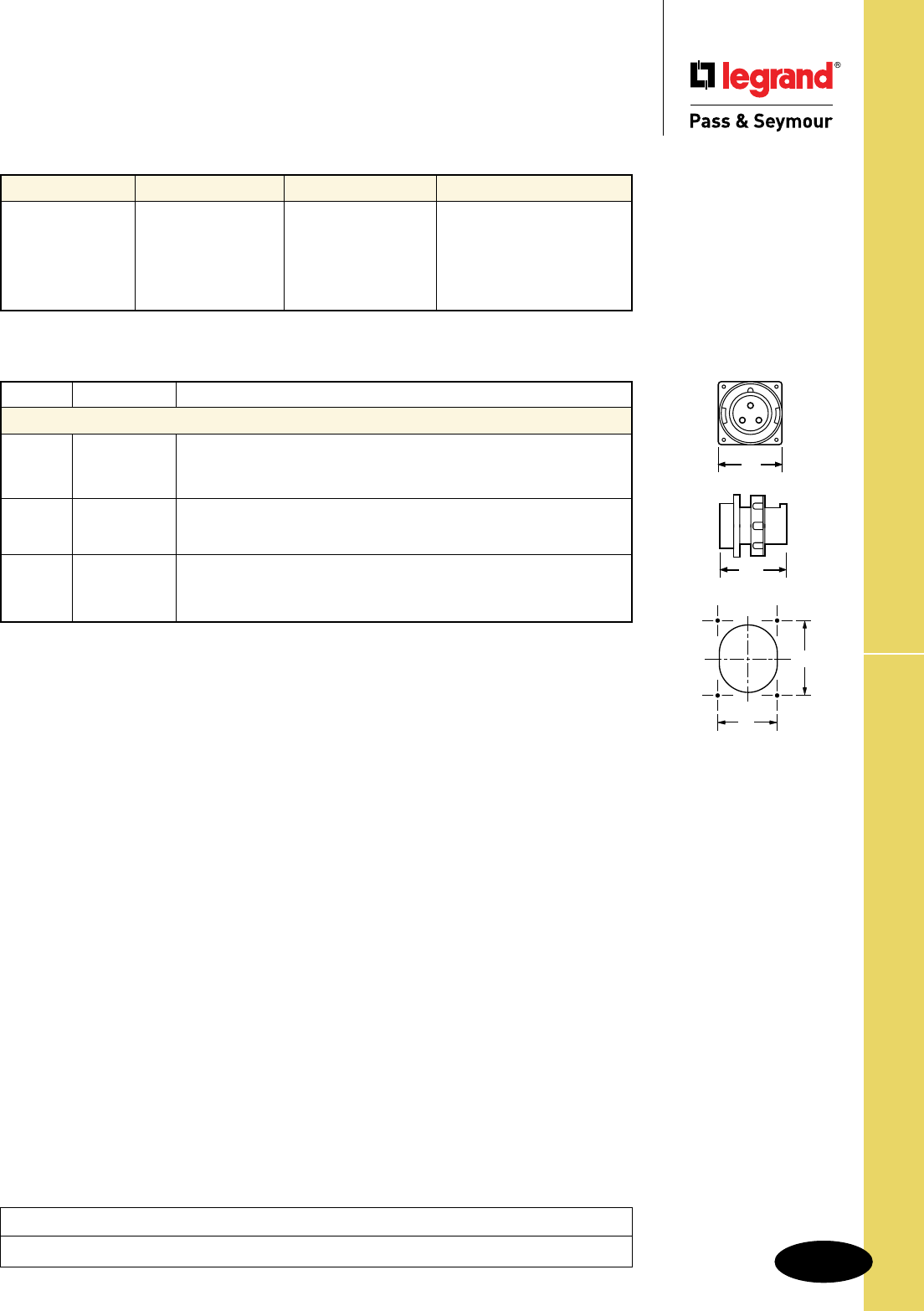
S-135
Technical Specifications Splashproof Pin & Sleeve Inlets
Technical Specifications
Splashproof Pin & Sleeve Inlets
20, 30 & 60A
Materials 20 Amp 30 Amp 60 Amp
Housing Polyamide 6 Polyamide 6 Valox
Mounting Flange Polyamide 6 Polyamide 6 Valox
Mounting Gasket Neoprene Neoprene Neoprene
Contact Carrier Polyamide 6 Polyamide 6 Polyamide 6
Pins Brass Brass Brass with Nickel Plate
Terminal Screws Zinc-Plated Steel Zinc-Plated Steel Zinc-Plated Steel
Amps Wire Cong. A B C D E F
Splashproof Inlets
2 Pole, 3 Wire inch 2.83 3.07 2.44 3.70
20 3 Pole, 4 Wire inch 3.70 3.39 3.27 4.29
4 Pole, 5 Wire inch 3.70 3.39 3.27 4.29
2 Pole, 3 Wire inch 3.98 4.37 3.54 5.86
30 3 Pole, 4 Wire inch 3.98 4.37 3.54 5.86
4 Pole, 5 Wire inch 3.98 4.25 3.54 5.86
2 Pole, 3 Wire inch 4.50 4.25 3.03 3.35
60 3 Pole, 4 Wire inch 4.50 4.25 3.03 3.35
4 Pole, 5 Wire inch 4.50 4.25 3.03 3.35
A
B
F
E
Project
Location/Type
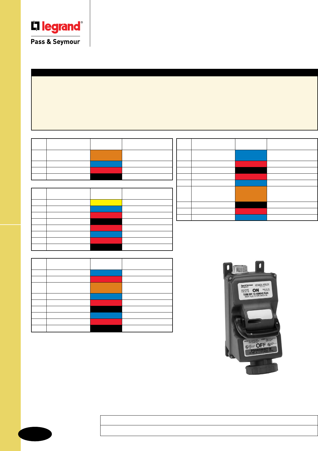
S-136
Technical SpecificationsNon-Fusible Mechanical Interlock
Technical Specifications
Watertight Pin & Sleeve Non-Fusible
Mechanical Interlock
20, 30, 60 & 100A
Typical Specications
Manufacturer’s Identification: Legrand/Pass & Seymour PS560MIR5W
Description: Non-Fusible Pin & Sleeve Mechanical Interlock
Electrical Type: 3 Pole + Neutral + Earth
Rating: 60A, 3ø, 600VAC 15 HP standard, 40 HP maximum
Configuration: IEC Clock Position 5
Enclosure Type: NEMA 4X (watertight, hosedown), 12K (dusttight, falling dirt), IP67 suitability
Conduit Location: Top or bottom feed. Unit shipped with no holes drilled; a top and bottom feed spot drill is provided for locating hole saw
or knockout. End user decides at installation whether top or bottom feed is appropriate. No closure plug kits required.
Voltage/Color Horsepower Rating
Amps Catalog Number Coding
20 rPS420MIR12W 120/240VAC 1 HP @ 120V
2 HP @ 208-240V L-L
20 rPS420MIR9W 3ø 240VAC 5
20 rPS420MIR7W 3ø 480VAC 10
20 rPS420MIR5W 3ø 600VAC 15
Voltage/Color Horsepower Rating
Amps Catalog Number Coding
60 rPS360MIR6W 240VAC 7.5 @ 208-240V
60 rPS360MIR7W 480VAC 10
60 rPS460MIR12W 120/240VAC 3 @ 120V
7.5 @ 208-240VAC L-L
60 rPS460MIR9W 3ø 240VAC 15
60 rPS460MIR7W 3ø 480VAC 30
60 rPS460MIR5W 3ø 600VAC 40
60 rPS560MIR9W 3øY 120/208VAC 15
60 rPS560MIR7W 3øY 277/480VAC 30
60 r PS560MIR5W 3øY 347/600VAC 40
Voltage/Color Horsepower Rating
Amps Catalog Number Coding
100 rPS3100MIR6W 240VAC 10 @ 208V
15 @ 240V
100 rPS3100MIR7W 480VAC 30
100 rPS4100MIR5W 3ø 600VAC 50
100 rPS4100MIR7W 3ø 480VAC 50
100 rPS4100MIR9W 3ø 240VAC 25
100 rPS4100MIR12W 120/240VAC 5 @ 120V
10 @ 208V L-L
15 @ 240V L-L
100 rPS5100MIR5W 3øY 347/600VAC 50
100 rPS5100MIR7W 3øY 277/480VAC 50
100 rPS5100MIR9W 3øY 120/208VAC 20
Project
Location/Type
Voltage/Color Horsepower Rating
Amps Catalog Number Coding
30 rPS330MIR4W 120VAC 2
30 rPS430MIR9W 3ø 240VAC 7.5
30 rPS430MIR7W 3ø 480VAC 15
30 rPS430MIR5W 3ø 600VAC 20
30 rPS430MIR3W 380/440VAC 15
30 rPS530MIR9W 3øY 120/208VAC 5
30 rPS530MIR7W 3øY 277/480VAC 15
30 rPS530MIR5W 3øY347/600 20
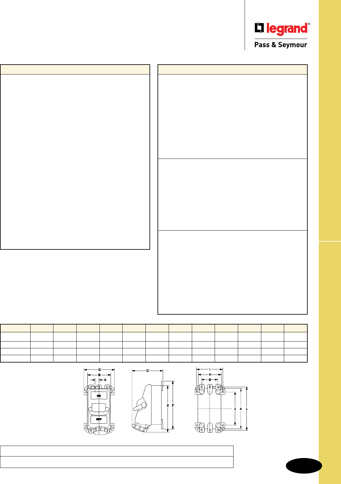
S-137
Technical Specifications Non-Fusible Mechanical Interlock
Technical Specifications
Watertight Pin & Sleeve Non-Fusible
Mechanical Interlock
20, 30, 60 & 100A
Materials
Enclosure Cover Valox 357®
Enclosure Base Valox 357®
Enclosure Gasket Neoprene
Switch Handle Valox 357®
Switch Handle Seal Neoprene
Shaft Brass
Gear Mechanism 1/8" Zinc-Plated Steel
Locktab 10% Glass-Filled Nylon
Switch Key 10% Glass-Filled Nylon
Mounting Feet Valox 357®
Mounting Feet Screws 300 Series Stainless Steel
Enclosure Assembly Screws 300 Series Stainless Steel
Enclosure Assembly Inserts Brass
Receptacle Lid Valox 357®
Receptacle Gasketing Neoprene
Receptacle Lid Hinge Spring 300 Series Stainless Steel
Receptacle Contact Carrier Polyamide 6
Receptacle Sleeves Brass/Nickel-Plate
Receptacle Terminal Screws Zinc-Plated Steel
Grounding Plate Zinc-Plated Steel
Cover Chain 300 Series Stainless Steel
Conduit Hub Aluminum/Zinc
20/30 amp shipped with one (1) 1"
60 amp shipped with one (1) 11⁄4"
100 amp shipped with one (1) 11⁄2"
(will also fit a 2" hub, not provided)
Performance
Electrical
Dielectric Voltage Withstand 3000V minimum
Maximum Working Voltage 600V RMS
Current Interrupting Listed for current interrupting at
full-rated current and voltage
Short Circuit Withstand Rating For use on circuit capable of
delivering not more than 10,000
RMS amps at receptacle voltage
rating
Operations Mechanical: 15,000 cycles
Electrical: 10,000 cycles
Auxiliary Contacts 10A @ 600V
1 N.O. & 1 N.C.
Mechanical
Impact Resistance Per UL746C
Terminal Identification Per UL, CSA, and IEC
specifications
Product Identification Identification and rating on
external and internal labels
Mounting External adjustable feet with five
(5) positions.
Can be mounted directly
to channel or strut
(no washer required)
Environmental
Moisture Resistance Per UL50, section 35, NEMA
Enclosure Type 4X (watertight,
hosedown)
Per UL50, section 35, NEMA
Enclosure Type 12K (dusttight,
falling dirt) IP67 suitability
Flammability UL94 5VA and VO Classification
Operating Temperature Maximum continuous: +60ºC
Minimum continuous: -50ºC
without impact
UV Resistance All enclosure materials are
UV stable
Front
Non-Fusible Mechanical Interlock Dimensions
Side Back
All measurements shown in inches.
(See dimensions above.)
Amps A B C D E F G H I J K L
20 1.38 6.88 9.13 8.00 12.38 11.06 4.75 6.88 7.75 8.00 10.13 11.00
30 1.38 6.88 9.13 8.25 12.38 11.50 4.75 6.88 7.75 8.00 10.13 11.00
60 1.19 6.88 9.13 9.00 13.63 14.13 4.75 6.88 7.75 9.75 11.88 12.75
100 1.19 6.88 9.13 9.50 14.13 14.13 4.75 6.88 7.75 9.75 11.88 12.75
Project
Location/Type
S-138
Technical Specifications
Occupancy Sensors
PWP120277 & AR120/277 Features
Load Rating at 120V 20A Ballast 13A Incandescent
Load Rating at 277V 20A Ballast
Add-A-Relay Rating at 120V 20A Ballast 13A Incandescent
Add-A-Relay Rating at 277V 20A Ballast
HP Rating 1HP
Output Rating* 24VDC; 225mA
Power Packs & Add-A-Relay
Mounting Method 1/2" Knockout
Sized to Fit into Approved
Enclosure for Plenum Applications Yes
Teflon-Coated Leads Yes
Five Year Warranty Yes
*PWP unit only.
General Specications
1. Occupancy sensors shall control lighting and/or HVAC in
the sensed area only.
2. Controlled lighting and/or HVAC zones shall not be larger
than 2500 sq. ft.
3. The contractor shall be responsible for a complete,
operable system, and installation should be warranted for
a period of one year after acceptance.
4. The product shall be warranted for a period of (5) five years
for wall switch sensors, ceiling sensors, and power packs.
5. Occupancy sensors shall be installed as per manufacturer’s
recommendations.
6. Specific low-voltage wire surface routing shall be approved
by the facilities engineer.
7. Sensor and control unit manufacturer must have experience
in the lighting and/or HVAC controls industry equal to a
minimum of (5) five years with a minimum of (5) five similar
projects.
8. Contractor shall be responsible for contacting the
manufacturer for proper placement and adjustment of sensor.
Technical Specifications
Occupancy Sensors
Project
Location/Type
Wall- and Ceiling-Mount Sensors
Feature WA1001 HS1001 CS500/CS1200 CSU600/1100/2200 CSD1000
Technology Passive Infrared Passive Infrared Passive Infrared Ultrasonic* Dual Technology
Coverage Pattern Wide Angle Long Range 360° 360° 360°
Mounting Method Wall or Ceiling Wall or Ceiling Ceiling Ceiling Ceiling
Adjustable Sensitivity Yes Yes Yes Yes Yes
Viewing Range 1200 sq. ft. 90 x 20 ft. 500/1200 sq. ft. 600/1100/2200 sq. ft. 1000 sq. ft.
Fresnel Lens** Yes Yes Yes N/A Yes
ASIC† Yes Yes Yes Yes Yes
5-Year Warranty Yes Yes Yes Yes Yes
* Provides occupancy detection around obstacles.
** Dual tech has both Ultrasonic and PIR Fresnel lens.
† Improves reliability and boosts immunity to RFI and EMI.
Wall Box Switches
WSP250, WDT100*, WDT200*, OS300S, OSR300S Features & Benets
Zero Crossing This feature ensures the closing of the contacts as close to 0° as possible, extending the life of the
relay contacts, and limiting the effect of inrush current from some electronic ballasts.
ASIC Chip Application Specific Integrated Component chip is a custom-designed microprocessor that
improves reliability and boosts immunity to RFI and EMI.
30 sec. - 30 min. Time Delay
Such a large range allows users to adjust time delay to fit the application and ensure maximum
savings without compromising convenience.
180° Coverage Provides detection even along the wall it is mounted on.
Maximum Rating Allows for the combining of potential savings with room size. Wall switches that offer too much
wattage handling capacity are used in larger rooms where ceiling sensors should be used,
compromising the reliability of the installation.
Self-Adaptive On the OS units only: Units automatically adjust the delay time by monitoring room usage patterns.
No user adjustment required, automatically sets delay time for most efficient use of energy.
2 relays for bi-level switching The OSR300S is designed for areas with two lighting zones or bi-level lighting applications.
Adjustable Sensitivity
Enables the installer or user to adjust the sensitivity level to suit the application.
Voltage Drop Protection Protects the electronics to ensure long-term performance.
Five-Year Warranty Allows installer or user to receive a replacement or refund if a sensor is found to be defective
within 5 years of purchase.
*Dual Technology
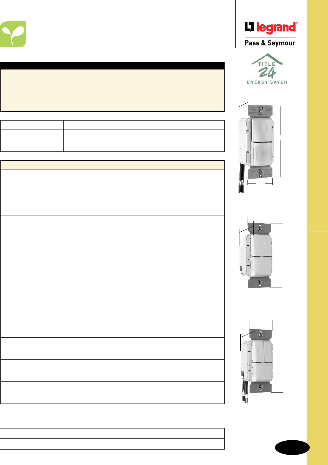
S-139
Technical Specifications
WSP250W
WSP250, OS300S, OSR300S
Technical Specifications
Wall Switch – WSP250,
OS300S, OSR300S
Catalog Number Description
r
WSP250 Passive Infrared Wall Switch
r
OS300S Self-Adaptive Passive Infrared Occupancy/Vacancy Sensor
r
OSR300S Dual-Relay Self-Adaptive Passive Infrared Occupancy/Vacancy Sensor
Performance
Electrical
Supply Voltage 120/277 Volt AC 60 Hz
Maximum Load 800W Incandescent/Fluorescent at 120V 1/4 HP
1200W Fluorescent at 277V
Minimum Load None
AC Switching WSP250, OS300S: Normally Open Relay, Zero Crossing Circuitry
OSR300S: 2 Normally Open Relays, Zero Crossing Circuitry
Sensor
Technology WSP250: Passive Infrared
OS300S, OSR300S: Self-Adaptive Passive Infrared
Time Delay WSP250: Adjustable 30 sec. to 30 min.
OS300S, OSR300S: Adjustable 5 min. to 30 min.
Light Level Adjustment WSP250: Adjustable from full daylight to 10 foot-candles
OS300S, OSR300S: 8-180 fcs
Sensitivity Adjustment WSP250: 20% to 100%
OS300S, OSR300S: Self-Adaptive and Fixed Low
Spectral Response WSP250: 6 to 14 µm
OS300S: 7 to 14 µm
OSR300S: 8 to 14 µm
Field of View Horizontal: 180°
Vertical: 2° and 8.6° down from the center
Indicator Light Red LED flashes when motion is detected
Lens Type Two-tier lens
Walk-through Mode WSP250: No; OS300S, OSR300S: Yes
Audible Alert WSP250: No; OS300S, OSR300S: Yes
Test Mode WSP250: No; OS300S, OSR300S: Yes
Environmental
Temperature Range 0°C to 35°C
Non-condensing Relative Humidity 20 to 90%
Mechanical
Enclosure Material Thermoplastic, UV-resistant plastic
Color(s) Ivory, White, Gray, Light Almond
Third Party Compliance cULus Listed – UL508 and C22.2 No. 14
California Title 24 Compliant
Typical Specications
Wall switch occupancy sensors shall be cULus Listed, and California Title 24 Compliant as provided
by Legrand/Pass & Seymour. Sensors shall be self-contained and fit in a standard wall box. Sensors
shall be capable of detecting changes in the infrared background caused by motion. Sensors shall be
capable of switching incandescent and fluorescent lighting loads on and off. Sensors shall use optics
that operate with a 180° field of view. The wall switch occupancy sensor shall be equipped with controls
to adjust sensitivity and ambient light threshold. The sensor shall also offer a time-delay adjustment from
30 seconds to 30 minutes, as well as an override. Conforms to NEMA WD-1 and WD-6.
Project
Location/Type
OSR300SW
1.76"
2.73"
1.83"
Wiring Diagrams on Pages L-8, L-10, and L-11.
1.55"
2.6"
1.7"
OS300SW
1.76"
2.73"
1.83"
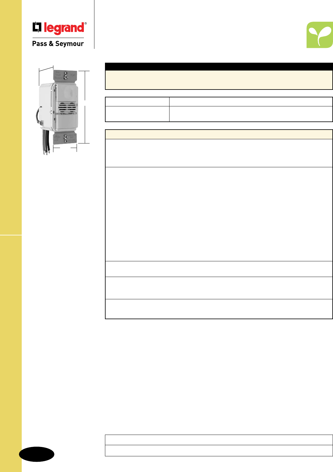
S-140
Technical Specifications
Technical Specifications
Dual Technology Wall Switch –
WDT100, WDT200
Catalog Number Description
r
WDT100 Dual Technology Wall Switch Sensor
r
WDT200 Bi-Level Dual Technology Wall Switch Sensor
Performance
Electrical
Supply Voltage 120/230/277VAC
Maximum Supply Voltage 277VA
Frequency 50-60 Hz
Sensor
Technology Passive Infrared and Ultrasonic
PIR Adjustment Two Settings – Maximum (100%) and Minimum (50%)
Ultrasonic Adjustment Ultrasonic sensitivity can be adjusted using a trimpot. Output
frequency of transmitter is fixed at 40kHz.
Time Delay Adjustable 5 min. to 30 min.
Light Level Adjustment 8fc to 180+fc
Spectral Response 6 to 14 µm
Field of View 88°; 110° Vertical, 360° Horizontal
Coverage 1050 sq. ft., 180°
Indicator Light(s) Red and Green LEDs
Lens Type Two Horizontal Layers
Sensor Type Multi-Directional Transmitter/Receiver with Quartz Oscillator
Audible Alert Selectable
Environmental
Temperature Range 0°C to 55°C
Mechanical
Enclosure Material ABS KJW Flame-Retardant Cycolac, 940-0 or Equivalent
Color(s) Ivory, White, Black, Gray, Light Almond
Third Party Compliance cULus Listed – UL508 and C22.2 No. 14
California Title 24 Compliant
RoHS-Compliant
Typical Specications
Dual technology wall switch occupancy sensors shall be cULus Listed UL508 and C22.2 No. 14,
California Title 24 Compliant and RoHS-Compliant as provided by Legrand/Pass & Seymour.
Conforms to NEMA WD-1 and WD-6.
WDT100W
1.76"
2.73"
1.83"
Project
Location/Type
Coverage Diagram on Page L-9.
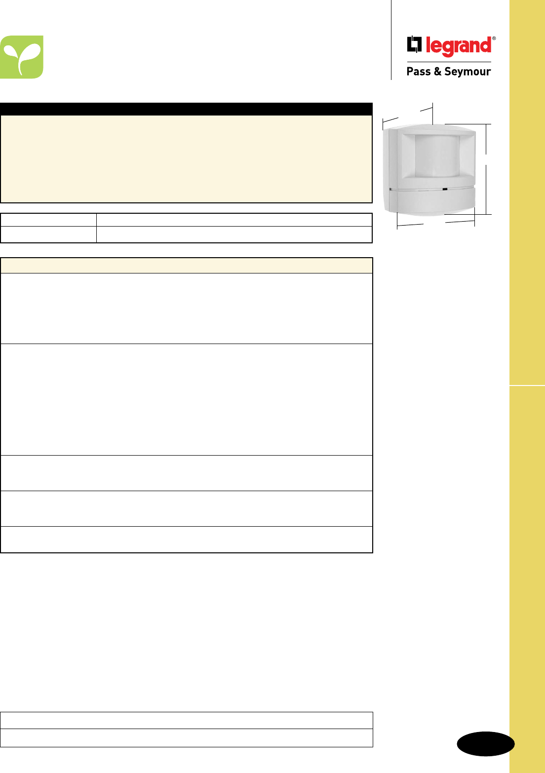
S-141
Technical Specifications WA1001
Technical Specifications
PIR Wide Angle Sensor – WA1001
Typical Specications
Wide angle motion sensors shall be cULus Listed, and California Title 24 Compliant as provided by
Legrand/Pass & Seymour. Sensors shall be ceiling or wall mount type, capable of detecting infrared
emissions from personnel movement, and switching lighting and HVAC systems on and off based
on occupancy. Wide angle motion sensor switch shall make use of optics that operate within an 88°
field of view, offering a typical coverage of up to 1200 sq ft. Mounting shall be wall or ceiling. Motion
sensor switch must be used in conjunction with the PWP120 (120VAC supply) or PWP277 (277VAC
supply) switching modules, and capable of handling additional loads with the support of an Add-A-Relay
AR120/277. Also, the sensor shall offer a time delay adjustment from 15 seconds to 30 minutes, as well
as an override. Conforms to NEMA WD-1 and WD-6.
Performance
Electrical
Supply Voltage + 24VDC Typical
Minimum Supply Voltage + 20VDC
Maximum Supply Voltage + 30VDC
Sensor Output + 24VDC for external relay DC coil drive
Maximum Output Current: 100mA DC
Sensor
Technology Passive Infrared
Time Delay Adjustable 15 sec. to 30 min.
Light Level Adjustment No
Sensitivity Adjustment 14% to 100%
Spectral Response 6 to 14 µm
Field of View 88°
Coverage Up to 1200 sq. ft.
Indicator Light Red LED flashes when motion is detected
Lens Type Four horizontal layers
Environment
Temperature Range 0°C to 35°C
Non-condensing Relative Humidity 20 to 90%
Mechanical
Enclosure Material Thermoplastic, UV-resistant plastic
Color White
Third Party Compliance cULus Listed – UL508 and C22.2 No. 14
California Title 24 Compliant
Catalog Number Description
r
WA1001 Passive Infrared Wall/Ceiling Sensor WA1001
2.034"
3.335"
3.367"
Project
Location/Type
Wiring Diagrams on Page L-12.
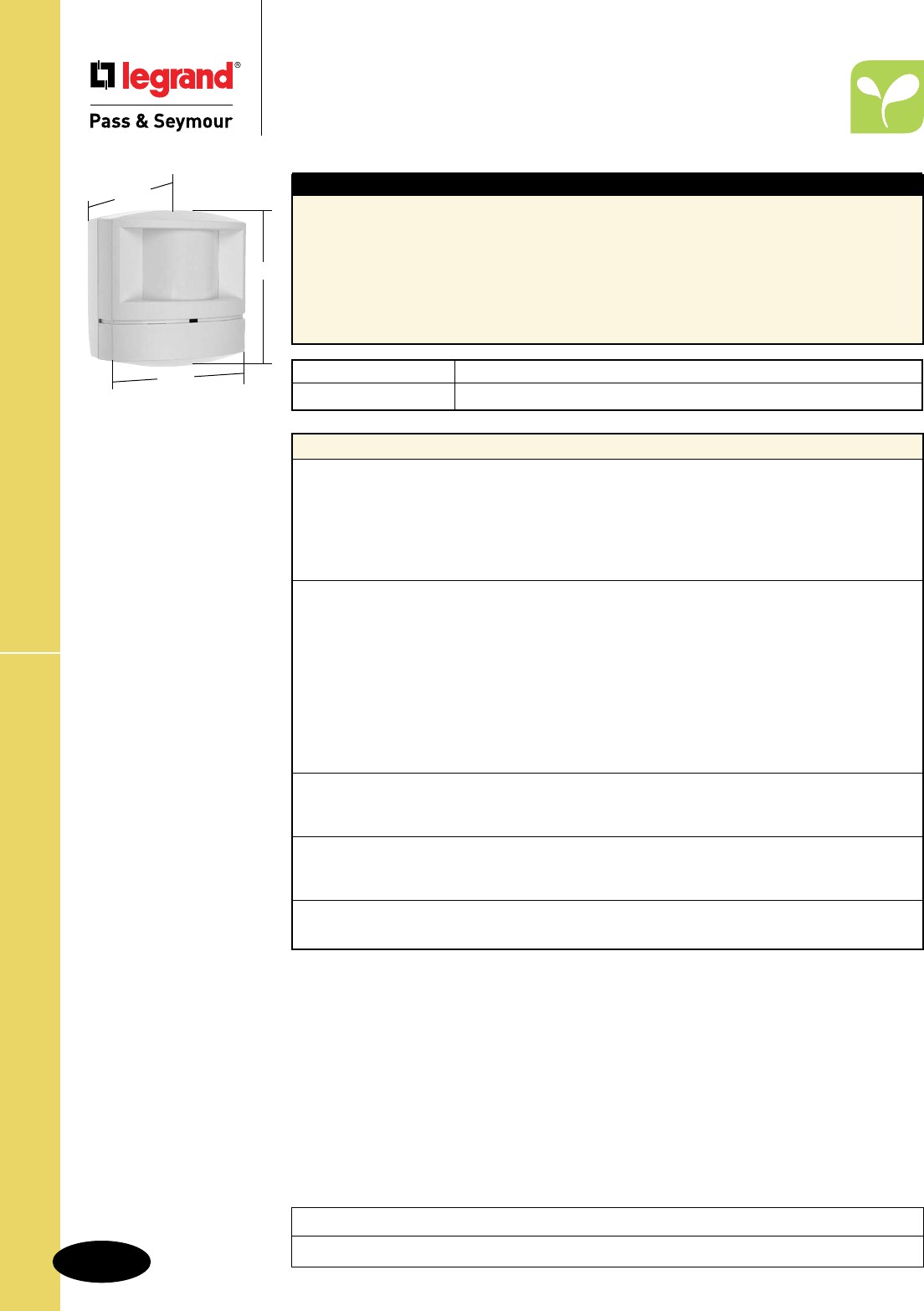
S-142
Technical SpecificationsHS1001
Technical Specifications
PIR Hallway Sensor – HS1001
Project
Location/Type
Wiring Diagrams on Page L-12.
Performance
Electrical
Supply Voltage + 24VDC Typical
Minimum Supply Voltage + 20VDC
Maximum Supply Voltage + 30VDC
Sensor Output + 24VDC for external relay DC coil drive
Maximum Output Current: 100mA DC
Sensor
Technology Passive Infrared
Time Delay Adjustable 15 sec. to 30 min.
Light Level Adjustment No
Sensitivity Adjustment 14% to 100%
Spectral Response 6 to 14 µm
Field of View 13°
Coverage 90 linear feet typical
Indicator Light Red LED flashes when motion is detected
Lens Type Two horizontal layers
Environment
Temperature Range 0°C to 35°C
Non-condensing Relative Humidity 20 to 90%
Mechanical
Enclosure Material Thermoplastic, UV-resistant plastic
Color White
Third Party Compliance cULus Listed – UL508 and C22.2 No. 14
California Title 24 Compliant
Catalog Number Description
r
HS1001 Passive Infrared Wall/Ceiling Sensor for hallway applications
Typical Specications
Hallway motion sensors shall be cULus Listed, and California Title 24 Compliant as provided by
Legrand/Pass & Seymour. Sensors shall be ceiling or wall mount type, capable of detecting infrared
emissions from personnel movement, and switching lighting and HVAC systems on and off based on
occupancy. Hallway motion sensor switches shall make use of optics that operate within field of view
90 feet long by 20 feet wide. Mounting shall be wall or ceiling. Motion sensor switch must be used in
conjunction with the PWP120 (120VAC supply) or PWP277 (277VAC supply) switching modules, and
capable of handling additional loads by including the support of an Add-A-Relay AR120/277. Also,
the sensor shall offer a time delay adjustment from 15 seconds to 30 minutes, as well as an override.
Conforms to NEMA WD-1 and WD-6.
HS1001
2.034"
3.335"
3.367"
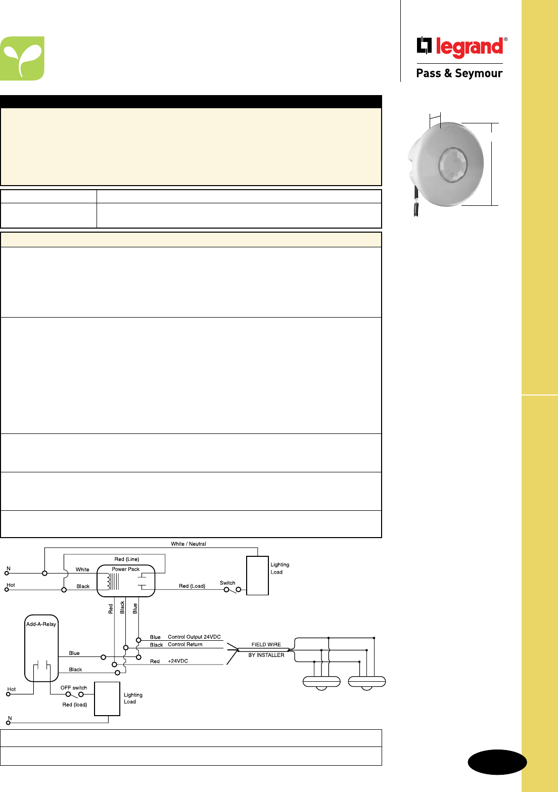
S-143
Technical Specifications
-
CS500, CS1200
Wiring Diagram
Wiring Diagrams on Page L-13.
Typical Specications
Motion sensor switches shall be cULus Listed, and California Title 24 Compliant as provided by
Legrand/Pass & Seymour. Sensors shall be ceiling mount type, capable of detecting infrared emissions
from personnel movement and switching incandescent and fluorescent lighting loads on and off.
Motion sensor switches shall make use of optics that operate within a 110° field of view. Motion
sensors may be mounted in a drop ceiling, solid ceiling, or wall. Motion sensor switch must be used
in conjunction with the PWP120 (120VAC supply) or PWP277 (277VAC supply) switching modules,
and capable of handling additional loads with the support of an Add-A-Relay AR120/277. Conforms to
NEMA WD-1 and WD-6.
Catalog Number Description
r
CS500 Ceiling Sensor , 500 sq. ft.
r
CS1200 Ceiling Sensor , 1200 sq. ft.
Performance
Electrical
Supply Voltage + 24VDC Typical
Minimum Supply Voltage + 20VDC
Maximum Supply Voltage + 30VDC
Sensor Output + 24VDC for external relay DC coil drive
Maximum Output Current: 100mA DC
Sensor
Technology Passive Infrared
Time Delay 15 sec. to 30 min.
Light Level Adjustment No
Sensitivity Adjustment Yes
Spectral Response 6 to 14 µm
Field of View 110° Vertical, 360° Horizontal
Coverage Up to 900 sq. ft.
Indicator Light Red LED flashes when motion is detected
Lens Type Multi-zone fresnel type
Environment
Temperature Range 0°C to 35°C
Non-condensing Relative Humidity 20 to 90%
Mechanical
Enclosure Material Thermoplastic, UV-resistant plastic
Color White
Third Party Compliance cULus Listed – UL508 and C22.2 No. 14
California Title 24 Compliant
CS500, CS1200
Technical Specifications
PIR Occupancy Ceiling Sensors –
CS500, CS1200
Project
Location/Type
CS500
CS1200
2.2"
3.3"

S-144
Technical Specifications
CSU600
1.5"
4.8"
CSU600, CSU1100, CSU2200
Technical Specifications
Ultrasonic Ceiling Sensors –
CSU600, CSU1100, CSU2200
Project
Location/Type
Performance
Electrical
Supply Voltage + 24VDC Typical
Minimum Supply Voltage + 20VDC
Maximum Supply Voltage + 30VDC
Sensor Output + 24VDC for external relay DC coil drive
Maximum Output Current: 100mA DC
Sensor
Technology Ultrasonic
Time Delay Adjustable 15 sec. to 30 min.
Light Level Adjustment No
Sensitivity Adjustment 14% to 100%
Frequency 32 kHz +/- 4 Hz
Coverage Up to 600/1100/2200 sq. ft.
Indicator Light Red LED flashes when motion is detected
Sensor Type Multidirectional transmitter/receiver with quartz oscillator
Environment
Temperature Range 0°C to 35°C
Non-condensing Relative Humidity 20 to 90%
Mechanical
Enclosure Material Thermoplastic, UV-resistant plastic
Color White
Third Party Compliance cULus Listed – UL508 and C22.2 No. 14
California Title 24 Compliant
Catalog Number Description
r
CSU600 Ultrasonic Ceiling Sensor
r
CSU1100 Ultrasonic Ceiling Sensor
r
CSU2200 Ultrasonic Ceiling Sensor
Typical Specications
Ultrasonic motion sensors shall b e cULus Listed, and California Title 24 Compliant as provided by
Legrand/Pass & Seymour. Sensors shall be ceiling or wall mount ceiling mount type, capable of
detecting motion from personnel movement, and switching lighting and HVAC systems on and off
based on occupancy. Ultrasonic motion sensor switches shall use a multi-directional transmitter/receiver
system to broadcast ultrasonic 32 kHz sound waves generated by a quartz oscillator. The ultrasonic
motion sensor switch must be used in conjunction with PWP2120 (120VAC supply) or PWP2277
(277VAC supply) switching modules, and capable of handling additional loads by including the support
of an Add-A-Relay AR120/277. Also, the sensor shall offer a time delay adjustment from 15 seconds to
30 minutes, as well as an override. Conforms to NEMA WD-1 and WD-6.
CSU1100
CSU2200
1.5"
4.8"
Wiring Diagrams on Page L-14.
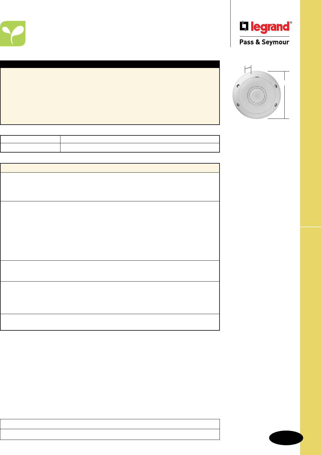
S-145
Technical Specifications CSD1000
Technical Specifications
Dual-Technology Ceiling Sensor –
CSD1000
Project
Location/Type
Performance
Electrical
Supply Voltage + 24VDC Typical
Sensor output + 24VDC for external relay DC coil drive
Current Consumption 35mA
Sensor
Technology Ultrasonic and Passive Infrared
Time Delay 15 seconds to 30 minutes
Ultrasonic Sensitivity Adjustment Min to max (trim pot)
Passive Infrared Sensitivity Adjustment 30% to 100% (dip switches)
Frequency 40 kHz
Ultrasonic Coverage 1076 sq. ft. (100 sq. m)
Passive Infrared Coverage 1290 sq. ft. (120 sq m)
Indicator Lights Red and Green LEDs
Environment
Temperature Range 32° to 131°F (0° to 55°C)
Non-condensing Relative Humidity 20 to 90%
Mechanical
Material Thermoplastic, UV-resistant plastic
Color White
Mounting Mounting hardware for acoustic ceiling tile and keyhole
mounting template included
Third Party Compliance cULus Listed – UL508 and C22.2 No. 14
California Title 24 Compliant
Catalog Number Description
r
CSD1000 Dual-Technology Ceiling Sensor
Typical Specications
The P&S CSD1000 Dual Technology Ceiling Sensor shall be cULus Listed, and California Title 24
Compliant as provided by Legrand/Pass & Seymour. The sensor shall detect occupancy in the control
area by detecting Doppler shifts in transmitted ultrasound and passive infrared heat changes. Detection
verification of both technologies must occur in order to activate lighting systems. Upon verification,
detection by either shall hold lighting on. Unit shall be white, ceiling mounted with a flat, unobtrusive
appearance and provide 360° coverage. CSD1000 sensor shall operate at 24 VDC/VAC and utilize a
P&S power pack. For additional loads use the P&S Add-A-Relay Pack. Sensor shall have a time delay
that is adjustable from 15 seconds to 30 minutes, set by DIP switch. Each sensing technology shall
have an LED indicator that remains active at all times in order to verify detection within the area to be
controlled. Sensor shall have standard 5 year warranty. Conforms to NEMA WD-1 and WD-6.
Wiring Diagrams on Page L-15
CSD1000
1.02"
4.5"
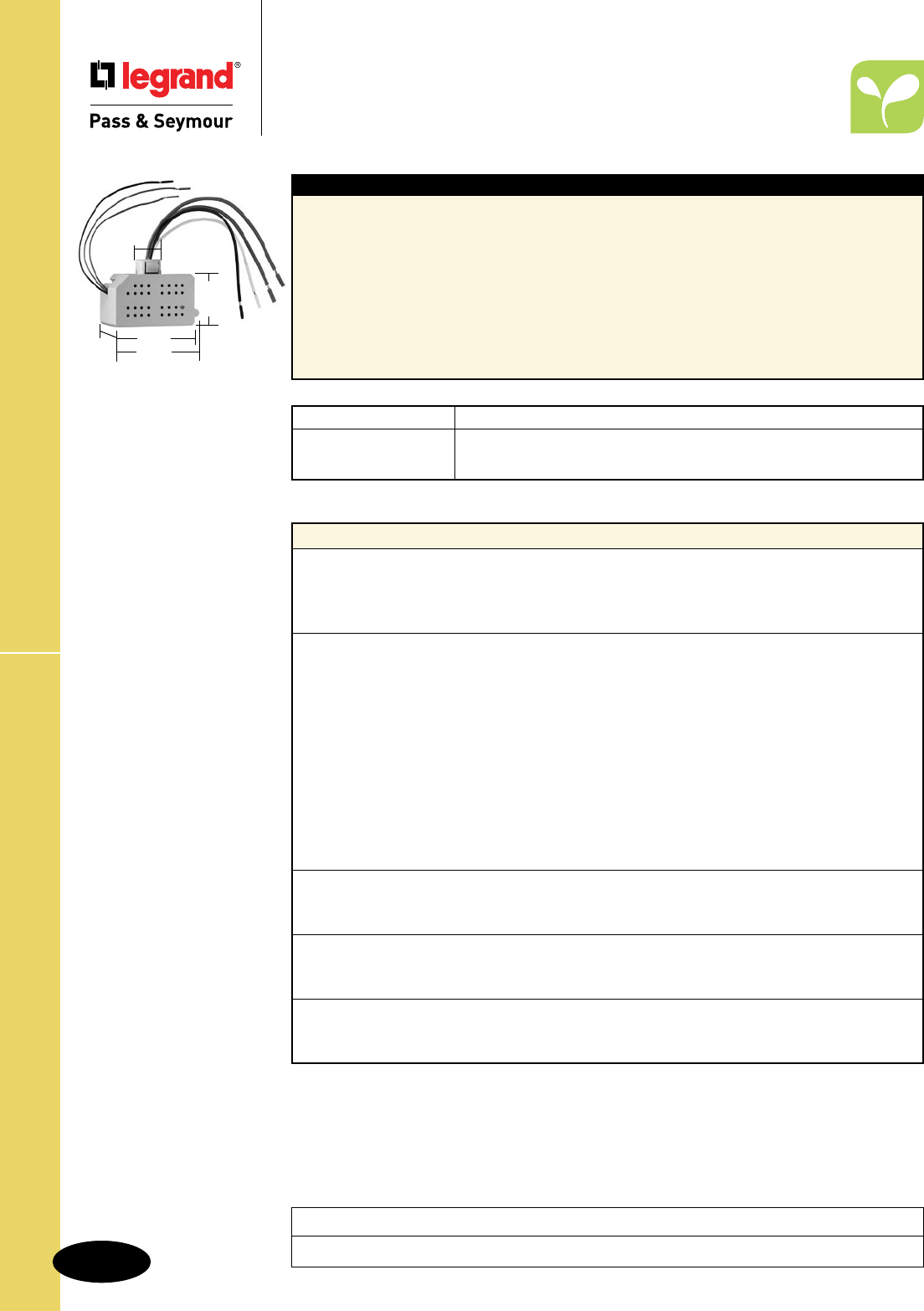
S-146
Technical SpecificationsPWP120277 & AR120/277
Technical Specifications
Power Pack – PWP120277
Add-A-Relay – AR120/277
Project
Location/Type
Typical Specications
Switching modules shall be cULus Listed as provided by Legrand/Pass & Seymour. Switching modules
shall contain a 24VAC transformer, a full wave bridge rectifier, and a 24VDC coil-isolated relay capable
of handling both incandescent and fluorescent lighting loads as well as inductive loads. Normal current
consumption for the relay shall be 36mA, and the coil resistance shall be 660 Ohms. The transformer
input shall be 120VAC or 277VAC; output shall be 24VDC, with a maximum current of 114mA. Power
Packs shall have Teflon-coated wire leads for use in plenum ceilings.
Add-A-Relay modules shall be UL and CUL Listed as provided by Legrand/Pass & Seymour. Add-A-
Relay modules shall contain a 24VDC coil-isolated relay capable of handling both incandescent and
fluorescent lighting loads as well as inductive loads. Nominal current consumption for the relay shall be
36mA, and the coil resistance shall be 660 Ohms. Add-A-Relay modules shall have Teflon-coated wire
leads for use in plenum ceilings. Conforms to NEMA WD-1 and WD-6.
Performance
Transformer
Supply Voltage PWP120277: 120/230/277 Volt AC 50/60 Hz
Output 24VDC
Maximum Current: 225mA (with relay connected)
Relay
Type Normally Open
Control Input:
Nominal Current 36mA
Coil Resistance 660 Ohms
Nominal Voltage 24VDC
Maximum Voltage 28.8VDC
Minimum Voltage 18VDC
AC Load Output:
Incandescent 13 Amp Max. (120V, 50 Hz only)
Fluorescent 20 Amp Max. (120V, 50 Hz or 277V, 60 Hz)
Motor Load 1 HP (120V, 60 Hz only or 240VAC)
Environment
Temperature Range 0°C to 35°C
Non-condensing Relative Humidity 20 to 90%
Mechanical
Enclosure Material Thermoplastic, UL flame class rating 94 V2
Color Gray
Third Party Compliance cULus Listed – UL508 and C22.2 No. 14
California Title 24 Compliant
Catalog Number Description
r
PWP120277 Power Pack
r
AR120/277 Add-A-Relay (120V or 277V)
Wiring Diagrams on Page L-16.
PWP120277
AR120/277
2.805"
2.916"
1.634"
.842"
1.673"
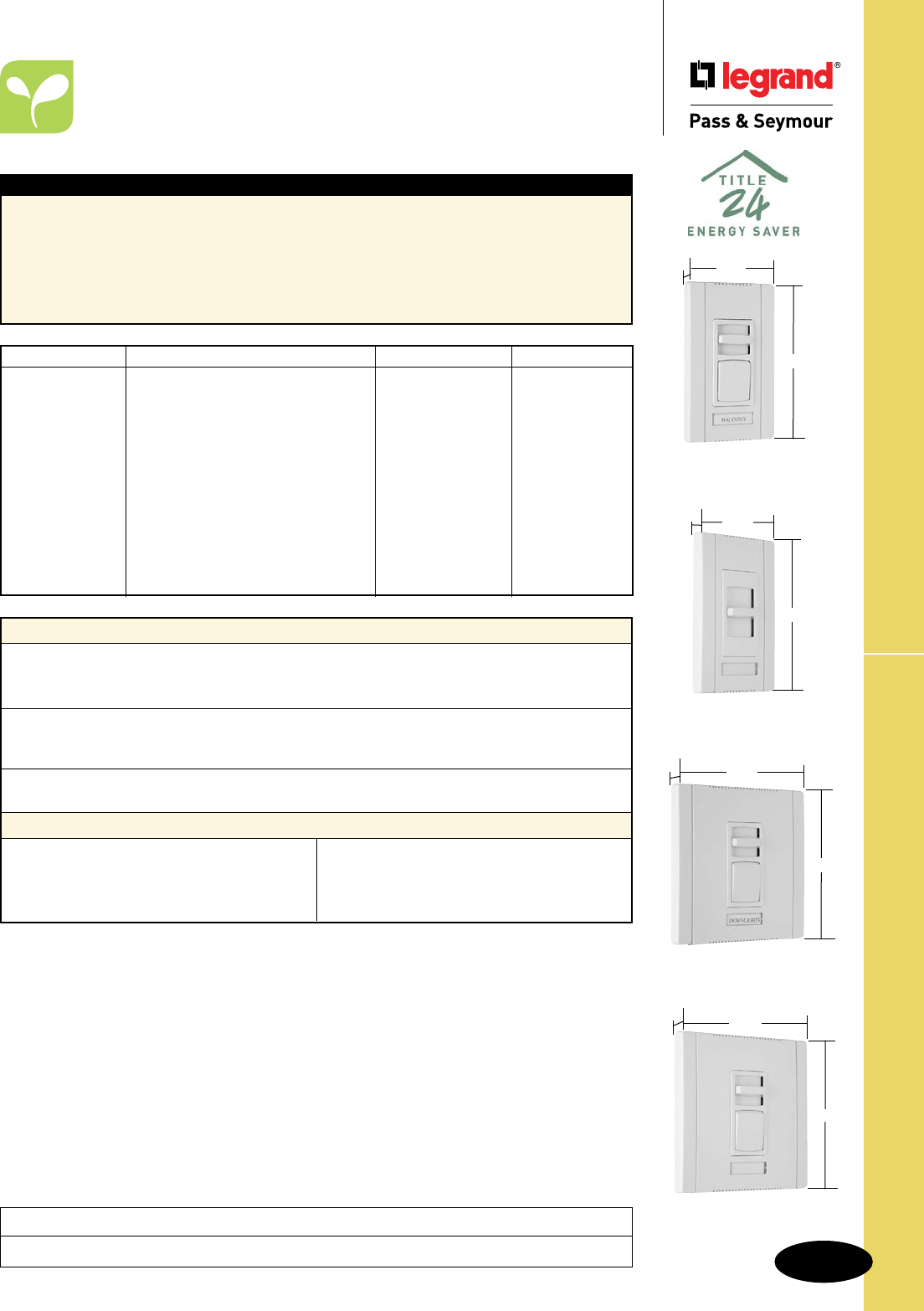
S-147
Technical Specifications Titan™ Series
Technical Specifications
Titan™ Series Incandescent &
Magnetic Low-Voltage
Project
Location/Type
Typical Specications
Manufacturer’s Identification: Legrand/Pass & Seymour CD700
Description: Incandescent Dimmer
Type: Single Pole
Rating: 120V, 700W
3rd Party Compliance: cULus Listed, File Number E95219 Standard UL1472 Solid State Dimming
Controls, Standard C22.2 No. 184-1; File Number E109655 Standard UL1917 Solid State Fan Controls,
Standard C22.2 No. 156. California Title 24 Compliant. Conforms to NEMA WD-1 and WD-6.
Performance
Electrical
Supply Voltage 120VAC 60Hz
Maximum Load Up to rating of device (including derating)
Environment
Ambient Temperature Between 0° and 40°C
Humidity Less than 95% non-condensing
Mechanical
Aluminum Heat Sink Thermoplastic enclosure, wall plate, and ganging parts
Materials
Back Body Thermoplastic Spacers Thermoplastic
Front Body Thermoplastic Heat Sink/Strap Aluminum
Wall Plate Thermoplastic Screws Plated Steel
End Caps Thermoplastic
Catalog Number Description Ratings Narrow or Wide
rCD700 Single Pole, Slide-to-OFF 120V, 700W Narrow
rCD703P Single Pole/3-Way, Preset 120V, 700W Narrow
rCD1100 Single Pole, Slide-to-OFF 120V, 1100W Narrow
rCD1103P Single Pole/3-Way, Preset 120V, 1100W Narrow
rCD1600 Single Pole, Slide-to-OFF 120V, 1600W Wide
rCD1603P Single Pole/3-Way, Preset 120V, 1600W Wide
r
CD2000 Single Pole, Slide-to-OFF 120V, 2000W Wide
r
CD2003P Single Pole/3-Way, Preset 120V, 2000W Wide
rCDLV700 Single Pole, Slide-to-OFF 120V, 700W Narrow
rCDLV703P Single Pole/3-Way, Preset 120V, 700W Narrow
rCDLV1100 Single Pole, Slide-to-OFF 120V, 1100W Narrow
rCDLV1103P Single Pole/3-Way, Preset 120V, 1100W Narrow
rCDLV1600 Single Pole, Slide-to-OFF 120V, 1600W Wide
rCDLV1603P Single Pole/3-Way, Preset 120V, 1600W Wide
CDLV1103PW
Wide
4.65"
4.87"
1.44"
CD1100W
Narrow
2.85"
4.87"
1.44"
CD703PW
Narrow
2.85"
4.87"
1.44"
CD1603PW
Wide
4.65"
4.87"
1.44"
S-148
Technical Specifications
Technical Specifications
Titan™ Series Incandescent &
Magnetic Low-Voltage
Titan™ Series
Project
Location/Type
Fins: NOT Removed Fins: Removed
Dimmer 1-Gang 2-Gang 3- or More Gang 2-Gang 3- or More Gang
Catalog No. Installation Installation Installation Installation Installation
CD700 700W 700W 700W 700W 700W
CDLV700 700VA 700VA 700VA 700VA 700VA
CD703P 700W 700W 700W 700W 700W
CDLV703P 700VA 700VA 700VA 700VA 700VA
CD1100 1100W 1100W 1000W 1000W 900W
CDLV1100 1100VA 1100VA 1000VA 1000VA 850VA
CD1103P 1100W 1100W 1000W 1000W 950W
CDLV1103P 1100VA 1100VA 1000VA 1000VA 850VA
CD1600 1600W 1600W 1600W 1600W 1550W
CDLV1600 1600VA 1600VA 1600VA 1600VA 1550VA
CD1603P 1600W 1600W 1600W 1600W 1550W
CDLV1603P 1600VA 1600VA 1600VA 1600VA 1550VA
CD2000 2000W 2000W 2000W — —
CD2003P 2000W 2000W 2000W — —
De-Rating for Multi-Gang Installations
FINS: NOT Removed
Wide Narrow Dimmers
Dimmers 0 1 2 3 4 5 6
0 0 1 1+1* 4 4+1* 7 7+1*
1 1 3 5 6 8 9 11
2 4 5 7 8 10 11 13
3 6 8 9 11 12 14 15
4 9 10 12 13 15 16
5 11 13 14 16
6 14 15
Wall box gang requirements
1. Choose fin style (not removed or removed).
2. Select the column for the number of narrow
dimmers to be installed.
3. Select the row for the number of wide dimmers
to be installed.
4. The number at the intersection of the selected
column and row indicates the number of wall
box gangs required.
* Refer to instruction sheets for exact placement of boxes
for even number of narrow dimmers.
FINS: Removed
Wide Narrow Dimmers
Dimmers 0 1 2 3 4 5 6
0 0 1 2 3 4 5 6
1 1 3 4 5 6 7 8
2 3 4 5 6 7 8 9
3 5 6 7 8 9 10 11
4 7 8 9 10 11 12 13
5 9 10 11 12 13 14 15
6 11 12 13 14 15 16 17

S-149
Technical Specifications Titan™ Series
Technical Specifications
Titan™ Series Fluorescent
2, 3 & 4 Wire
Project
Location/Type
Typical Specications
Manufacturer’s Identification: Legrand/Pass and Seymour CDFB5
Description: Fluorescent Dimmer
Type: Single Pole 2 Wire
Rating: 5A, 120V
3rd Party Compliance: cULus Listed, File Number E95219 Standard UL1472 Solid State Dimming
Controls, Standard C22.2 No. 184-1; File Number E109655 Standard UL1917 Solid State Fan Controls,
Standard C22.2 No. 156. California Title 24 Compliant. Conforms to NEMA WD-1 and WD-6.
Performance
Electrical
Supply Voltage 2 & 3 Wire – 120VAC or 277VAC, 60Hz
4 Wire – 24VDC Class Two Wiring
Maximum Load Up to rating of device (including de-rating)
Environment
Ambient Temperature Between 0° and 40°C
Humidity Less than 95% non-condensing
Mechanical
Aluminum Heat Sink Thermoplastic enclosure, wall plate, and ganging parts
Materials
Back Body Thermoplastic Spacers Thermoplastic
Front Body Thermoplastic Heat Sink/Strap Aluminum
Wall Plate Thermoplastic Screws Plated Steel
End Caps Thermoplastic
Catalog Number Description Ratings Narrow or Wide
rCDFB5 2 Wire, Electronic, Single Pole, Slide-to-OFF 5A, 120V Narrow
rCDFB8 2 Wire, Electronic, Single Pole, Slide-to-OFF 8A, 120V Narrow
rCDFB10 2 Wire, Electronic, Single Pole, Slide-to-OFF 10A, 120V Wide
rCDFB16 2 Wire, Electronic, Single Pole, Slide-to-OFF 16A, 120V Wide
rCDFB7277 2 Wire, Electronic, Single Pole, Slide-to-OFF 7A, 277V Wide
rCDFB10277 2 Wire, Electronic, Single Pole, Slide-to-OFF 10A, 277V Wide
rCDFB53P 2 Wire, Electronic, Single Pole/3-Way, Preset 5A, 120V Narrow
rCDFB83P 2 Wire, Electronic, Single Pole/3-Way, Preset 8A, 120V Narrow
rCDFB103P 2 Wire, Electronic, Single Pole/3-Way, Preset 10A, 120V Wide
rCDFB163P 2 Wire, Electronic, Single Pole/3-Way, Preset 16A, 120V Wide
rCDFB73P277 2 Wire, Electronic, Single Pole/3-Way, Preset 7A, 277V Wide
rCDFB103P277 2 Wire, Electronic, Single Pole/3-Way, Preset 10A, 277V Wide
rCD3FB16 3 Wire, Electronic, Single Pole, Slide-to-OFF 16A, 120V Narrow
rCD3FB163P 3 Wire, Electronic, Single Pole/3-Way, Preset 16A, 120V Narrow
rCD3FB10277 3 Wire, Electronic, Single Pole, Slide-to-OFF 10A, 277V Narrow
rCD3FB103P277 3 Wire, Electronic, Single Pole/3-Way, Preset 10A, 277V Narrow
rCD4FB* 4 Wire, Electronic, Single Pole, Slide-to-OFF 24VDC Narrow
rCD4FB3P* 4 Wire, Electronic, Single Pole/3-Way, Preset 24VDC Narrow
Narrow
2.85"
4.87"
1.44"
Narrow Preset
2.85"
4.87"
1.44"
4.65"
4.87"
1.44
Wide Preset
*4 Wire Dimmers require PWP120277 Power Pack, refer to Technical Specifications Page S-146.
S-150
Technical SpecificationsTitan™ Series
Technical Specifications
Titan™ Series Fluorescent
2, 3 & 4 Wire
Project
Location/Type
Fins: NOT Removed Fins: Removed
Dimmer 1-Gang 2-Gang 3- or More Gang 2-Gang 3- or More Gang
Catalog No. Installation Installation Installation Installation Installation
CDFB5 5A 5A 5A 5A 5A
CDFB8 8A 8A 8A 7.7A 6.3A
CDFB53P 5A 5A 5A 5A 5A
CDFB83P 8A 8A 8A 7.7A 6.3A
CDFB10 10A 10A 10A 10A 10A
CDFB16 16A 16A 16A — —
CDFB7277 7A 7A 7A 7A 7A
CDFB10277 10A 10A 10A 10A 10A
CDFB103P 10A 10A 10A 10A 10A
CDFB163P 16A 16A 16A — —
CDFB73P277 7A 7A 7A 7A 7A
CDFB103P277 10A 10A 10A 10A 10A
CD3FB16 16A 16A 16A 16A 16A
CD3FB163P 16A 16A 16A 16A 16A
CD3FB10277 10A 10A 10A 10A 10A
CD3FB103P277 10A 10A 10A 10A 10A
CD4FB DONOTEXCEED60BALLASTS
CD4FB3P DONOTEXCEED60BALLASTS
De-Rating for Multi-Gang Installations
2 & 4 Wire Electronic Fluorescent Dimmer Ballast Compatibility
Compatible P&S
Catalog Number Voltage Ballast Manufacturer Model & Series
2 Wire Ballast Compatability
CDFB5
CDFB8
CDFB53P
CDFB83P
CDFB10
CDFB16
CDFB103P
CDFB163P
120VAC
60Hz
Advance REZ-132-SC, REZ-2S32-SC, REZ-3S32-SC,
REZ-154, REZ-2554, REZ-1Q18-M2, REZ-
2Q18-M2, REZ-1T42-M2, REZ-2T42-M3,
REZ-1TTS40/REZ-1TTS40-SC, REZ-2TTS40/
REZ-2TTS40-SC, IEZ-2S24-D, REB-2S26-M1-
LS-DIM/REB-2S26-M1-BS-DIM
Lutron 2W-T426-120-1-S, 2W-T426-120-2-S,
2W-T432-120-1-S, 2W-T432-120-2-S,
2W-T832-120-1-S, 2W-T832-120-2-S
Sylvania/Osram
CDFB7277
CDFB10277
CDFB73P277
CDFB103P277
277VAC
60Hz
Advance VEZ-132-SC, VEZ-2S32-SC, VEZ-3S32-SC,
VEZ-154, VEZ2S54, VEZ-1Q18-M2,
VEZ-2Q18-M2, VEZ-2T42-M3, VEZ-1TTS40/
VEZ-1TTS40-SC, VEZ-2TTS40/
VEZ-2TTS40-SC, IEZ-2S24-D
Sylvania/Osram QTP1x32T8/UNV DIM, QTP2x32T8/UNV DIM,
QTP3x32T8/UNV DIM, QTP4x32T8/UNV DIM
4 Wire Ballast Compatability*
CD4FB
CD4FB3
24VDC Advance Transformer
Lutron
Sylvania/Osram
Universal
GE
Mark 7, Xitanium, IZT, RZT, VZT, LED120
Eco-10 TVE
Quicktronic Powersense, Helios, Optotronic
QTP, QT, OT
SuperDim, Ballastar ES, B132, B232, B332,
B432
T8 Dimming Ballasts B132, B232, B332
* Additional 0-10V ballasts and/or LED drivers may also be compatible with this control.
Contact Legrand/Pass & Seymour to verify compatibility.
S-151
Technical Specifications
Technical Specifications
Titan™ Series Fluorescent
2, 3 & 4 Wire
Titan™ Series
Project
Location/Type
3 Wire Electronic Fluorescent Dimmer Ballast Compatibility
Compatible P&S
Catalog Number Voltage
Ballast
Manufacturer
Compatible Dimmer Ballast Model & Series
1% Hi-Lume, Hi-Lume 3D 5% Compact SE 10% Eco-10
3 Wire Ballast Compatability
CD3FB16
CD3FB163P
120VAC
60Hz
Lutron HL3-T426-120-1-S, HL3-T432-
120-1-S, FDB-T524-120-1,
FDB-T524-120-2, FDB-T539-
120-1, FDB-T539-120-2, FDB-
T554-120-1, FDB-T554-120-2,
FDB-2427-120-1, FDB-2427-
120-2, FDB-2427-120-3, FDB-
3627-120-1, FDB-3627-120-2,
FDB-3627-120-3, FDB-4827-
120-1, FDB-4827-120-2, FDB-
4827-120-3, FDB-6027-120-1,
FDB-6027-120-2, FDB-7280-
120-1, FDB-8480-120-1,
FDB-9680-120-1,
H3DT832CUNV110,
H3DT832CUNV117,
H3DT832CUNV210,
H3DT832CUNV217
FDB-T418-120-1-S, FDB-
T418-120-2-S, FDB-T426-
120-1-S, FDB-T426-120-
2-S, FDB-T418-120-1-S,
FDB-T418-120-2-S, FDB-
T426-120-1-S, FDB-T426-
120-2-S, FDB-T432-120-
1-S, FDB-T432-120-2-S,
FDB-T442-120-1-S, FDB-
T442-120-2-S, FDB-1643-
120-1, FDB-1643-120-2,
FDB-1643-120-3, FDB-
2227-120-1, FDB-2227-
120-2, FDB-2227-120-3,
FDB-2243-120-1, FDB-
2243-120-2
E3-T514C-120-1, E3-T514C-120-2,
E3-T521C-120-1, E3-T521C-120-2,
ECO-T528-120-1, ECO-T528-120-2,
ECO-T524-120-1, ECO-T524-120-2,
ECO-T5H39-120-1, ECO-T5H39-120-2,
ECO-T554-120-1, ECO-T554-120-2,
ECO-T539-120-1, ECO-T539-120-2,
ECO-T539-120-3, ECO-T540-120-1,
ECO-T540-120-2, ECO-T540-120-3,
ECO-T550-120-1, ECO-T550-120-2,
ECO-T817-120-1, ECO-T817-120-2,
ECO-T817-120-3, ECO-T825-120-1,
ECO-T825-120-2, ECO-T832-120-1-L,
ECO-T832-120-1-T, ECO-T832-120-
2-L, ECO-T832-120-2-T, ECO-T832-
120-3
CD3FB10277
CD3FB103P277
277VAC
60Hz
Lutron HL3-T426-277-1-S, HL3-T432-
277-1-S, FDB-T524-277-1,
FDB-T524-277-2, FDB-T539-
277-1, FDB-T539-277-2, FDB-
T554-277-1, FDB-T554-277-2,
FDB-2427-277-1, FDB-2427-
277-2, FDB-2427-277-3, FDB-
3627-277-1, FDB-3627-277-2,
FDB-3627-277-3, FDB-4827-
277-1, FDB-4827-277-2, FDB-
4827-277-3, FDB-6027-277-1,
FDB-6027-277-2,
H3DT832CUNV110,
H3DT832CUNV117,
H3DT832CUNV210,
H3DT832CUNV217
FDB-T418-277-1-S, FDB-
T418-277-2-S, FDB-T426-
277-1-S, FDB-T426-277-
2-S, FDB-T418-277-1-S,
FDB-T418-277-2-S, FDB-
T426-277-1-S, FDB-T426-
277-2-S, FDB-T432-277-
1-S, FDB-T432-277-2-S,
FDB-T442-277-1-S, FDB-
T442-277-2-S, FDB-1643-
277-1, FDB-1643-277-2,
FDB-1643-277-3, FDB-
2227-277-1, FDB-2227-
277-2, FDB-2227-277-3,
FDB-2243-277-1, FDB-
2243-277-2
E3-T514C-277-1, E3-T514C-277-2,
E3-T521C-277-1, E3-T521C-277-2,
ECO-T528-277-1, ECO-T528-277-2,
ECO-T524-277-1, ECO-T524-277-2,
ECO-T5H39-277-1, ECO-T5H39-277-2,
ECO-T554-277-1, ECO-T554-277-2,
ECO-T539-277-1, ECO-T539-277-2,
ECO-T539-277-3, ECO-T540-277-1,
ECO-T540-277-2, ECO-T540-277-3,
ECO-T550-277-1, ECO-T550-277-2,
ECO-T817-277-1, ECO-T817-277-2,
ECO-T817-277-3, ECO-T825-277-1,
ECO-T825-277-2, E3-T832C-277-1,
ECO-T832-277-1-L, ECO-T832-277-
1-T, ECO-T832-277-1,
E3-T832C-277-2, ECO-T832-277-2-L,
ECO-T832-277-2-T, ECO-T832-277-2,
ECO-T832-277-3
FINS: NOT Removed
Wide Narrow Dimmers
Dimmers 0 1 2 3 4 5 6
0 0 1 1+1* 4 4+1* 7 7+1*
1 1 3 5 6 8 9 11
2 4 5 7 8 10 11 13
3 6 8 9 11 12 14 15
4 9 10 12 13 15 16
5 11 13 14 16
6 14 15
* Refer to instruction sheets for exact placement of boxes
for even number of narrow dimmers.
FINS: Removed
Wide Narrow Dimmers
Dimmers 0 1 2 3 4 5 6
0 0 1 2 3 4 5 6
1 1 3 4 5 6 7 8
2 3 4 5 6 7 8 9
3 5 6 7 8 9 10 11
4 7 8 9 10 11 12 13
5 9 10 11 12 13 14 15
6 11 12 13 14 15 16 17
Wall box gang requirements
4. The number at the intersection of the selected column and
row indicates the number of wall box gangs required.
1. Choose fin style (not removed or removed).
2. Select the column for the number of narrow dimmers to be installed.
3. Select the row for the number of wide dimmers to be installed.
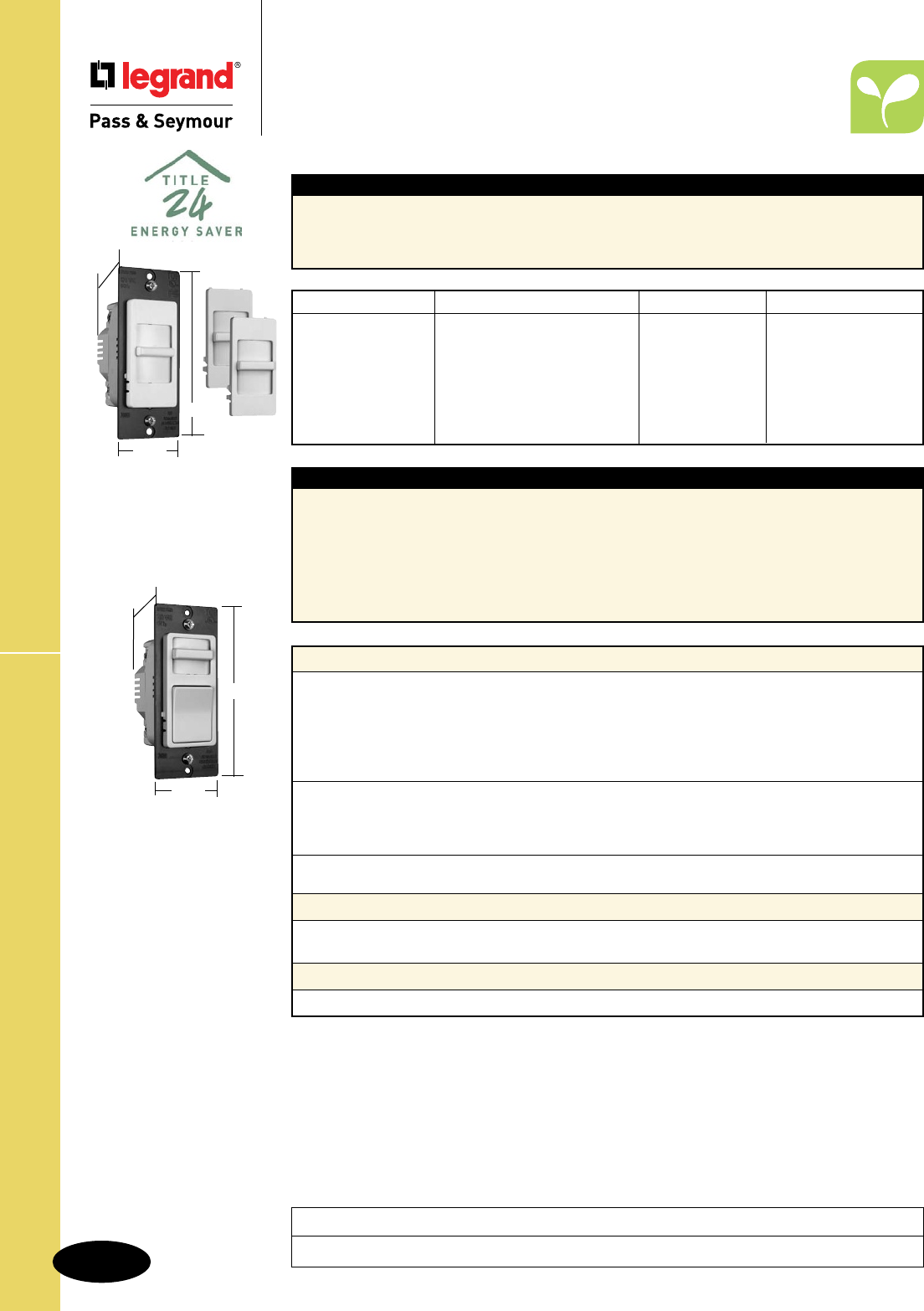
S-152
Technical SpecificationsIncandescent Wide Slide
Technical Specifications
Incandescent Wide Slide Dimmers
120VAC, 60 Hz
Project
Location/Type
Catalog Number Description Rating Color
r
WS700TC Single Pole, Slide to OFF 120V, 700W Ivory/White/Lt. Almond
r
WS700W Single Pole, Slide to OFF 120V, 700W White
r
WS703PTC Preset, Single Pole/3-Way 120V, 700W Ivory/White/Lt. Almond
r
WS703PW Preset, Single Pole/3-Way 120V, 700W White
r
WS1100TC Preset, Single Pole/3-Way 120V, 1100W Ivory/White/Lt. Almond
r
WS1100W Preset, Single Pole/3-Way 120V, 1100W White
r
WS1103PTC Preset, Single Pole/3-Way 120V, 1100W Ivory/White/Lt. Almond
r
WS1103PW Preset, Single Pole/3-Way 120V, 1100W White
Performance
Electrical
Voltage 120VAC 60 Hz
Rated Load (See Above) Incandescent Only
Filtering Radio Frequency Interference Filtering
Construction Printed Circuit Board for Reliability
3rd Party Compliance UL Listed, CSA Certified
Physical
Size One Gang
Heat Sink Black Anodized Aluminum Mounting Strap
Wiring 6" Color-Coded Leads Pre-Stripped
Environmental
Application Indoor Use Only
Materials
Front Cover and Knob Flame Retardant UL94 V0, UV Stable Polycarbonate
Back Body Unbreakable ABS
Accessories
Installation and Operating Instructions Provided
Typical Specications
Incandescent dimmer shall be UL Listed/CSA Certified Legrand/Pass & Seymour Specification Grade, with full
range solid-state circuitry that shall provide even control by means of a slide mechanism. Preset lighting levels
may be maintained by means of a separate ON/OFF switch. Dimmers shall fit in standard single gang wall boxes.
California Title 24 Compliant. Conforms to NEMA WD-1 and WD-6.
Features
n Maximum ratings are for continuous full load.
n Preset models include ON/OFF rocker switch
that allows ON/OFF switching without disturbing
preset intensity levels.
n 700 Watt models may be ganged without
de-rating.
n RFI suppression built-in.
n Installs in NEMA standard single-gang wall boxes.
n Screw-pressure-plate back and side wire.
n Package comes with three face colors –
Ivory, White, Light Almond (TC).
n White only option also available (W).
n Interchangeable faces available in four colors
(sold separately, see Page M-17).
Preset Models
4.25"
1.75"
1.25"
WS700TC
Shown with the Three
Interchangeable Faces
4.25"
1.75"
1.25"
All 1100W versions
are 2.50" W
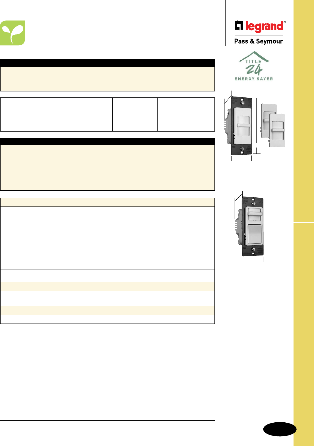
S-153
Technical Specifications
Magnetic Low-Voltage Wide Slide
Project
Location/Type
Technical Specifications
Magnetic Low-Voltage
Wide Slide Dimmers
120VAC, 60 Hz
WSLV700TC
Shown with the Three
Interchangeable Faces
4.25"
1.75"
1.25"
Typical Specications
Low-voltage dimmer shall be UL Listed/CSA Certified Legrand/Pass & Seymour Specification Grade,
with full range solid-state circuitry that shall provide even control by means of a slide mechanism. Preset
lighting levels may be maintained by means of a separate ON/OFF switch. Dimmers shall fit in standard
single gang wall boxes. California Title 24 Compliant. Conforms to NEMA WD-1 and WD-6.
Features
n Maximum ratings are for continuous full load.
n 700VA dimmers may be ganged without de-rating.
n Installs in NEMA standard single-gang wall boxes.
n Preset models include ON/OFF rocker switch
that allows ON/OFF switching without disturbing
preset intensity levels.
n RFI suppression built-in.
n Screw-pressure-plate back and side wire.
n Package comes with three face colors –
Ivory, White, Light Almond (TC).
n White only option also available (W).
n Interchangeable faces available in four
colors (sold separately, see Page M-17).
Catalog Number Description Rating Color
r
WSLV700TC Single Pole 120V, 700VA Ivory/White/Lt. Almond
r
WSLV700W Single Pole 120V, 700VA White
r
WSLV703PTC Preset, Single Pole/3-Way 120V, 700VA Ivory/White/Lt. Almond
r
WSLV703PW Preset, Single Pole/3-Way 120V, 700VA White
WSLV703PW
4.25"
1.75"
1.25"
Performance
Electrical
Voltage 120VAC 60 Hz
Rated Load (See Above) Low-Voltage Only
Filtering Radio Frequency Interference Filtering
Construction Printed Circuit Board for Reliability
3rd Party Compliance UL Listed, CSA Certified
Physical
Size One Gang
Heat Sink Black Anodized Aluminum Mounting Strap
Wiring 6" Color-Coded Leads Pre-Stripped
Environmental
Application Indoor Use Only
Materials
Front Cover and Knob Flame Retardant UL94 V0, UV Stable Polycarbonate
Back Body Unbreakable ABS
Accessories
Installation and Operating Instructions Provided
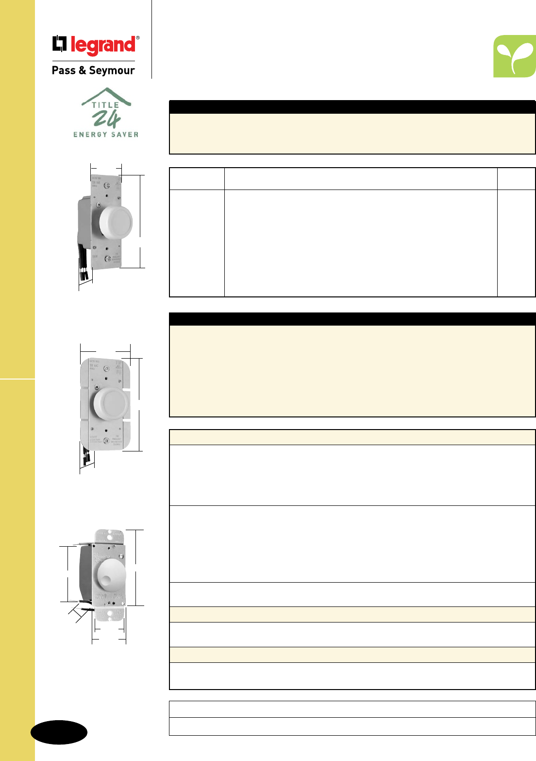
S-154
Technical SpecificationsIncandescent Rotary Dimmers
Technical Specifications
Incandescent Rotary Dimmers
120VAC, 60 Hz
Project
Location/Type
Typical Specications
Incandescent dimmer shall be UL Listed/CSA Certified Legrand/Pass & Seymour Specification Grade,
with full range solid-state circuitry giving even control by means of rotary action and positive ON/OFF
switching. All dimmers shall fit standard single gang wall boxes. California Title 24 Compliant. Conforms
to NEMA WD-1 and WD-6.
Performance
Electrical
Voltage 120VAC 60 Hz
Rated Load 600 Watt Incandescent Only
Construction Printed Circuit Board for Reliability
3rd Party Compliance UL Listed
CSA Certified
Controls
Range Dial with Push On and Off
Output Safety Power Off Switch
Physical
Size Single Gang, No Derating Necessary
Heat Sink Aluminum Mounting Strap
Wiring 6" Color-Coded Leads Pre-Stripped
Environmental
Application Indoor Use Only
Materials
Knob Unbreakable ABS
Back Body Unbreakable ABS
Accessories
Twist Wire Connectors Provided
Installation and Operating Instructions Provided
Features
n Maximum ratings are for continuous full load.
n Push-ON/OFF rotary switch permits full-range
dimming control and switching at any pre-set level.
n Excellent state-of-the-art solid-state electronic
circuitry design saves energy and extends bulb
life when lighting level is reduced.
n 600V, UL/CSA hook-up wire, multi-stranded,
fray-resistant, pre-tinned, 18-gauge wire,
insulation rated at 105°C.
n Thick aluminum mounting strap provides
heat sink for electronic components.
n Installs in NEMA standard single-gang
wall boxes.
n May be ganged without de-rating.
n RFI protected.
90621
4"
1.672"
2.672"
1.453"
1.438"
R600PWV
1.74"
4.19"
1.28"
R1000WV
2.50"
4.19"
1.28"
Catalog Rated
Number Description Load
r
R600V Rotary Dial ON/Dial OFF Incandescent Dimmer, Single Pole Rotate to OFF 600W
r
R1000V Rotary Dial ON/Dial OFF Incandescent Dimmer, Single Pole Rotate to OFF 1000W
r
R600P Rotary Preset Incandescent Dimmer, Single Pole Push ON/Push OFF 600W
r
R603P Rotary Preset Incandescent Dimmer, 3-Way Push ON/Push OFF 600W
r
R1000P Rotary Preset Incandescent Dimmer, Single Pole Push ON/Push OFF 1000W
r
R1003P Rotary Preset Incandescent Dimmer, 3-Way Push ON/Push OFF 1000W
r
R600PLV Rotary Preset Lighted Incandescent Dimmer, Single Pole Push ON/Push OFF 600W
r
R603PLV Rotary Preset Lighted Incandescent Dimmer, 3-Way Push ON/Push OFF 600W
r
90621V Low-Profile Rotary Dimmer, Rotate to OFF 600W
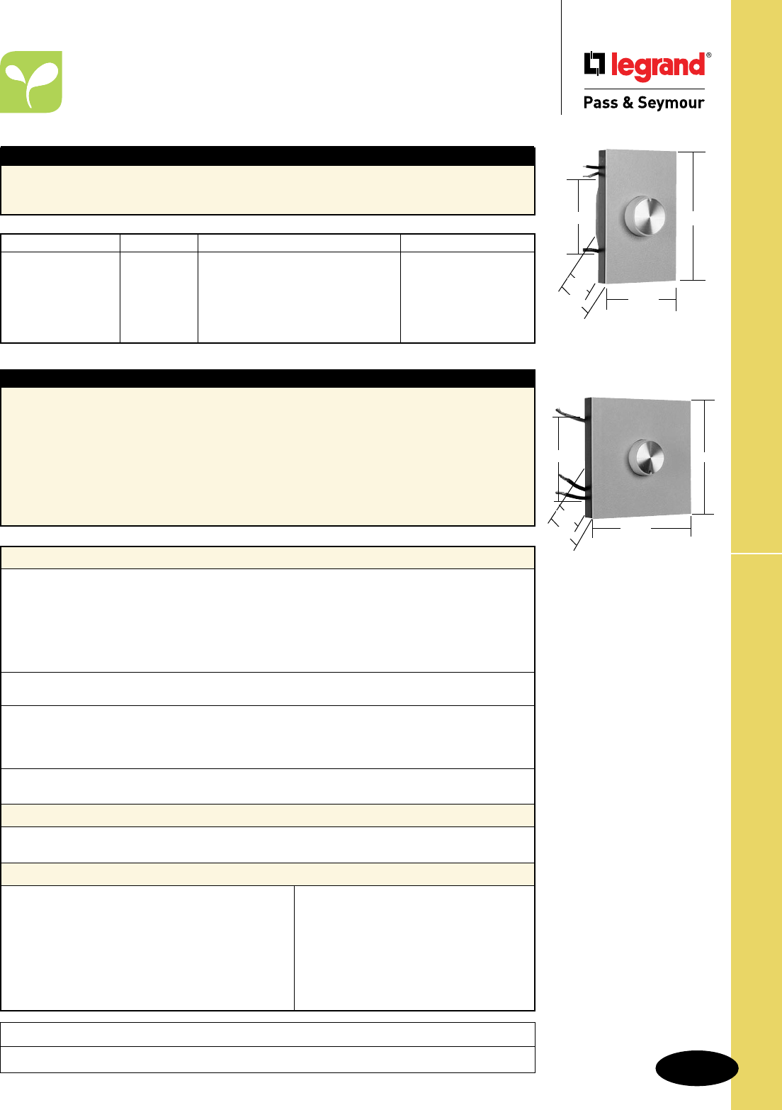
S-155
Technical Specifications High Wattage Rotary Dimmers
Project
Location/Type
Technical Specifications
High Wattage Rotary Dimmers
Dial On/Off Incandescent 120VAC, 60 Hz
91501
92001
Performance
Electrical
Voltage 120VAC 60 Hz
Rated Load (See Above) Incandescent Only
Filtering Radio Frequency Interference Filtering
Construction Printed Circuit Board for Reliability
3rd Party Compliance UL Listed
CSA Certified
Controls
Output Safety Power Off Switch
Physical
Size Gangable
Heat Sink Finned Aluminum
Wiring 6" Color-Coded Leads Pre-Stripped
Environmental
Application Indoor Use Only
Materials
Knob Flame Retardant UL94 V0, UV Stable Polycarbonate
Back Body Unbreakable ABS
Accessories
Snap-On Cover Plate Provided
Twist Wire Connectors Provided
Installation and Operating Instructions Provided
1000 Watt White Cover Plate and Knob Kit Available: DAPK1W
1500/2000 Watt White Cover Plate and Knob Kit Available: DAPK2W
1000 Watt Brown Cover Plate and Knob Kit Available: DAPK1
1500/2000 Watt Brown Cover Plate and Knob Kit Available: DAPK2
Matching Rotary Switch Available: 90200
Typical Specications
Incandescent dimmer shall be UL Listed/CSA Certified Legrand/Pass & Seymour Specification Grade,
with full range solid-state circuitry giving even control by means of rotary action and positive ON/OFF
switching. All dimmers shall fit standard single gang wall boxes. Conforms to NEMA WD-1 and WD-6.
Features
n Maximum ratings are for continuous full load.
n Superior state-of-the-art solid-state electronic
circuitry design increases energy savings and
extends bulb life as lighting level is reduced.
n Field-adjustable trim control permits user to
set minimum light level as desired.
n Includes line voltage compensation circuitry,
to reduce changes in light level caused by
line voltage fluctuation.
n 600V, UL/CSA hook-up wire, multi-stranded,
fray-resistant, pre-tinned, insulation rated
at 105°C.
n Anodized extruded aluminum fins provide heat
sink for electronic components.
n Installs in NEMA standard single-gang wall boxes.
n De-rating required when fins are removed.
n Includes the soft-start feature on some models,
to increase bulb life.
91001
4.516"
2.734"
1.313"
1.906"
2.672"
4.453"
1.313"
1.906"
2.672" 4.516"
Catalog Number Color Description Rated Load
r
91001I Ivory Single Pole – Dial ON/OFF 1000W
r
91001W White Single Pole – Dial ON/OFF 1000W
r
91501I Ivory Single Pole – Dial ON/OFF 1500W
r
91501W White Single Pole – Dial ON/OFF 1500W
r
92001I Ivory Single Pole – Dial ON/OFF 2000W
r
92001W White Single Pole – Dial ON/OFF 2000W
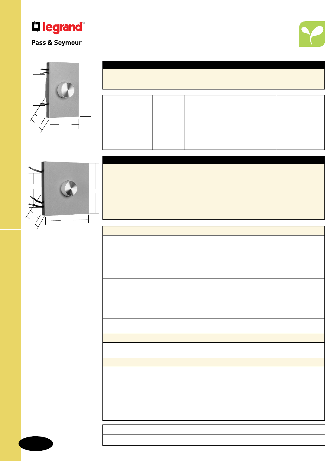
S-156
Technical SpecificationsHigh Wattage Rotary Dimmers
Project
Location/Type
Technical Specifications
High Wattage Rotary Dimmers
Preset Push On/Off Incandescent 120VAC, 60 Hz
Typical Specications
Incandescent dimmer shall be UL Listed/CSA Certified Legrand/Pass & Seymour Specification Grade,
with full range solid-state circuitry giving even control by means of rotary action and positive ON/OFF
switching. All dimmers shall fit standard single gang wall boxes. Conforms to NEMA WD-1 and WD-6.
Catalog Number Color Description Rated Load
r
91000I Ivory Single Pole – Preset Push ON/OFF 1000W
r
91000W White Single Pole – Preset Push ON/OFF 1000W
r
91003I Ivory Three-Way – Preset Push ON/OFF 1000W
r
91003W White Three-Way – Preset Push ON/OFF 1000W
r
91500I Ivory Single Pole – Preset Push ON/OFF 1500W
r
91503I Ivory Three-Way – Preset Push ON/OFF 1500W
r
91503W White Three-Way – Preset Push ON/OFF 1500W
Performance
Electrical
Voltage 120VAC 60 Hz
Rated Load (See Above) Incandescent Only
Filtering Radio Frequency Interference Filtering
Construction Printed Circuit Board for Reliability
3rd Party Compliance UL Listed
CSA Certified
Controls
Output Safety Power Off Switch
Physical
Size Gangable
Heat Sink Finned Aluminum
Wiring 6" Color-Coded Leads Pre-Stripped
Environmental
Application Indoor Use Only
Materials
Knob Flame Retardant UL94 V0, UV Stable Polycarbonate
Back Body Unbreakable ABS
Accessories
Snap-On Cover Plate Provided
Twist Wire Connectors Provided
Installation and Operating Instructions Provided
1000 Watt White Cover Plate and Knob Kit Available: DAPK1W
1500/2000 Watt White Cover Plate and Knob Kit Available: DAPK2W
1000 Watt Brown Cover Plate and Knob Kit Available: DAPK1
1500/2000 Watt Brown Cover Plate and Knob Kit Available: DAPK2
Matching Rotary Switch Available: 90200
Features
n Maximum ratings are for continuous full load.
n Superior state-of-the-art solid-state electronic
circuitry design increases energy savings and
extends bulb life as lighting level is reduced.
n Field-adjustable trim control permits user to set
minimum light level as desired.
n Includes line voltage compensation circuitry, to
reduce changes in light level caused by line
voltage fluctuation.
n 600V, UL/CSA hook-up wire, multi-stranded,
fray-resistant, pre-tinned, insulation rated at
105°C.
n Anodized extruded aluminum fins provide
heat sink for electronic components.
n Installs in NEMA standard single-gang wall
boxes.
n De-rating required when fins are removed.
91000
91003
4.516"
2.734"
2.672"
1.313"
1.906"
91500
91503
4.453"
1.313"
1.906"
4.516"
2.672"
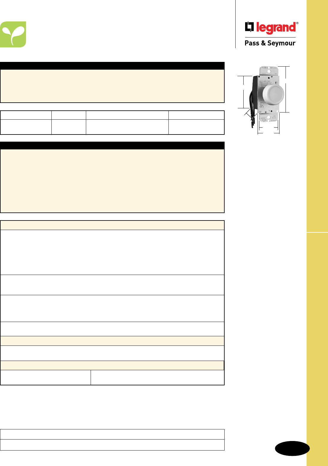
S-157
Technical Specifications Magnetic Low-Voltage Rotary Dimmer
Technical Specifications
Magnetic Low-Voltage
Rotary Dimmer
Magnetic Low-Voltage Rotary Strap – 120VAC, 60 Hz
Typical Specications
Magnetic Low-Voltage lighting dimmer shall be UL Listed/CSA Certified Legrand/Pass & Seymour
low voltage, rated 600VA max., to control the primary side of the magnetic transformer for low voltage
fixtures. Dimmer shall provide even control by means of rotary action and positive ON/OFF switching.
They shall be capable of maintaining a desired preset lighting level. Dimmers shall fit in standard single
gang wall boxes. Conforms to NEMA WD-1 and WD-6.
95600
Catalog Number Color Description Rated Load
r
95600I Ivory Preset – Push ON/OFF 600VA max.
r
95600W White Preset – Push ON/OFF 600VA max.
Performance
Electrical
Voltage 120VAC 60 Hz
Rated Load 600VA Magnetic Ballast Low-Voltage Only
Filtering Radio Frequency Interference Filtering
Construction Printed Circuit Board for Reliability
3rd Party Compliance UL Listed
CSA Certified
Controls
Range Dial with Push On and Off
Output Safety Power Off Switch
Physical
Size Single Gang, No Derating Necessary
Heat Sink Aluminum Mounting Strap
Wiring 6" Color-Coded Leads Pre-Stripped
Environmental
Application Indoor Use Only
Materials
Knob Unbreakable ABS
Back Body Unbreakable ABS
Accessories
Twist Wire Connectors Provided
Installation and Operating Instructions Provided
Features
n Maximum ratings are for continuous load.
n Push-ON/OFF at any setting.
n Superior state-of-the-art solid-state electronic
circuitry design increases energy savings and
extends bulb life as lighting level is reduced.
n Field-adjustable trim control permits user to set
minimum light level as desired.
n 600V, UL/CSA hook-up wire, multi-stranded,
fray-resistant, pre-tinned, 18-gauge wire, insulation
rated at 105°C.
n Thick aluminum mounting strap provides
heat sink for electronic components.
n Installs in NEMA standard single-gang wall
boxes.
n Includes line voltage compensation circuitry,
to reduce changes in light level caused by
line voltage fluctuation.
4"
1.672"
2.672"
1.438"
1.453"
Project
Location/Type
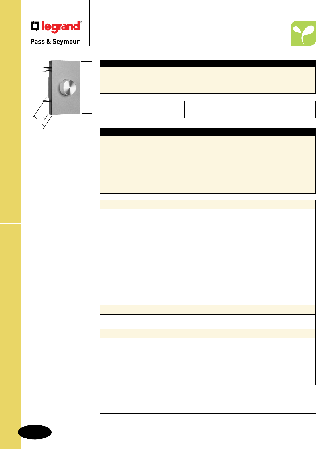
S-158
Technical SpecificationsMagnetic Low-Voltage Rotary Dimmer
Technical Specifications
Magnetic Low-Voltage
Rotary Dimmer
High Wattage Rotary 120VAC, 60 Hz
Catalog Number Color Description Rated Load
r
95100I Ivory Dial ON/OFF 1000VA
Performance
Electrical
Voltage 120VAC 60 Hz
Rated Load 1000VA
Filtering Radio Frequency Interference Filtering
Construction Printed Circuit Board for Reliability
3rd Party Compliance UL Listed
CSA Certified
Controls
Output Safety Power Off Switch
Physical
Size Gangable
Heat Sink Finned Aluminum
Wiring 6" Color-Coded Leads Pre-Stripped
Environmental
Application Indoor Use Only
Materials
Knob Flame Retardant UL94 V0, UV Stable Polycarbonate
Back Body Unbreakable ABS
Accessories
Snap-On Cover Plate Provided
Twist Wire Connectors Provided
Installation and Operating Instructions Provided
1000 Watt White Cover Plate and Knob Kit Available: DAPK1W
1500/2000 Watt White Cover Plate and Knob Kit Available: DAPK2W
1000 Watt Brown Cover Plate and Knob Kit Available: DAPK1
1500/2000 Watt Brown Cover Plate and Knob Kit Available: DAPK2
Features
n Maximum ratings are for continuous full load.
n Superior state-of-the-art solid-state electronic
circuitry design increases energy savings and
extends bulb life as lighting level is reduced.
n Field-adjustable trim control permits user to set
minimum light level as desired.
n Includes line voltage compensation circuitry, to
reduce changes in light level caused by line
voltage fluctuation.
n 600V, UL/CSA hook-up wire, multi-stranded,
fray-resistant, pre-tinned, 16-gauge wire,
insulation rated at 105°C.
n Anodized extruded aluminum fins provide heat
sink for electronic components.
n Installs in NEMA standard single-gang wall
boxes.
n De-rating required when fins are removed for
multi-gang installations.
Typical Specications
Magnetic Low-Voltage lighting dimmer shall be UL Listed and CSA Certified Legrand/Pass & Seymour,
rated at 1000 VA max., to control the primary side of the magnetic transformer for low voltage lighting
fixtures. Dimmer shall provide even control by means of rotary action and positive ON/OFF switching.
Dimmers shall fit in standard single wall boxes. Conforms to NEMA WD-1 and WD-6.
95100
4.516"
2.734"
1.313"
1.906"
2.67"
Project
Location/Type
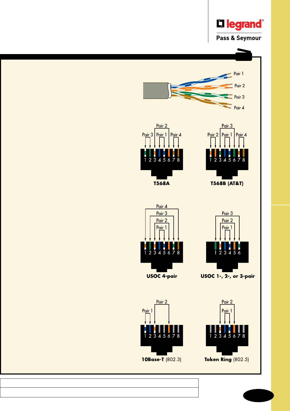
S-159
Technical Specifications UTP Outlet Wiring Configurations
Technical Specifications
UTP Outlet Wiring Configurations
CABLING TIP
UTP Cable
T568A
n Adopted by TIA/EIA
and 11801 standards.
n Compatible with one- or
two-pair USOC.
n May be used for ISDN.
n Supports Categories
3, 4, 5, 5e, and 6.
UTP Outlet Wiring Configurations
Pair PIN
ID Number
T1 5
R1 4
T2 3
R2 6
T3 1
R3 2
T4 7
R4 8
T568B
n Adopted by TIA/EIA
and 11801 standards.
n Not compatible with
one- or two-pair USOC.
n May be used for ISDN.
n Supports Categories 3,
4, 5, 5e, and 6.
Pair PIN
ID Number
T1 5
R1 4
T2 1
R2 2
T3 3
R3 6
T4 7
R4 8
USOC
n Available for 1-, 2-, 3-, or
4-pair systems.
n Maintains pair continuity in
6-position plugs configured
with one, two, or three pairs.
n Inferior performance compared
to T568A or T568B.
n Not cabling standard compliant.
Pair PIN
ID Number
T1 5
R1 4
T2 3
R2 6
T3 2
R3 7
T4 1
R4 8
10Base-T/100Base-T
n Eight-position jack, but only
two pairs used.
Pair PIN
ID Number
T1 1
R1 2
T2 3
R2 6
Token Ring
n Uses either a six-position or
eight-position jack.
n Eight-position compatible with
T568A, T568B, and USOC.
n Six-position compatible with
one- or two-pair USOC.
Pair PIN
ID Number
T1 5
R1 4
T2 3
R2 6
Project
Location/Type
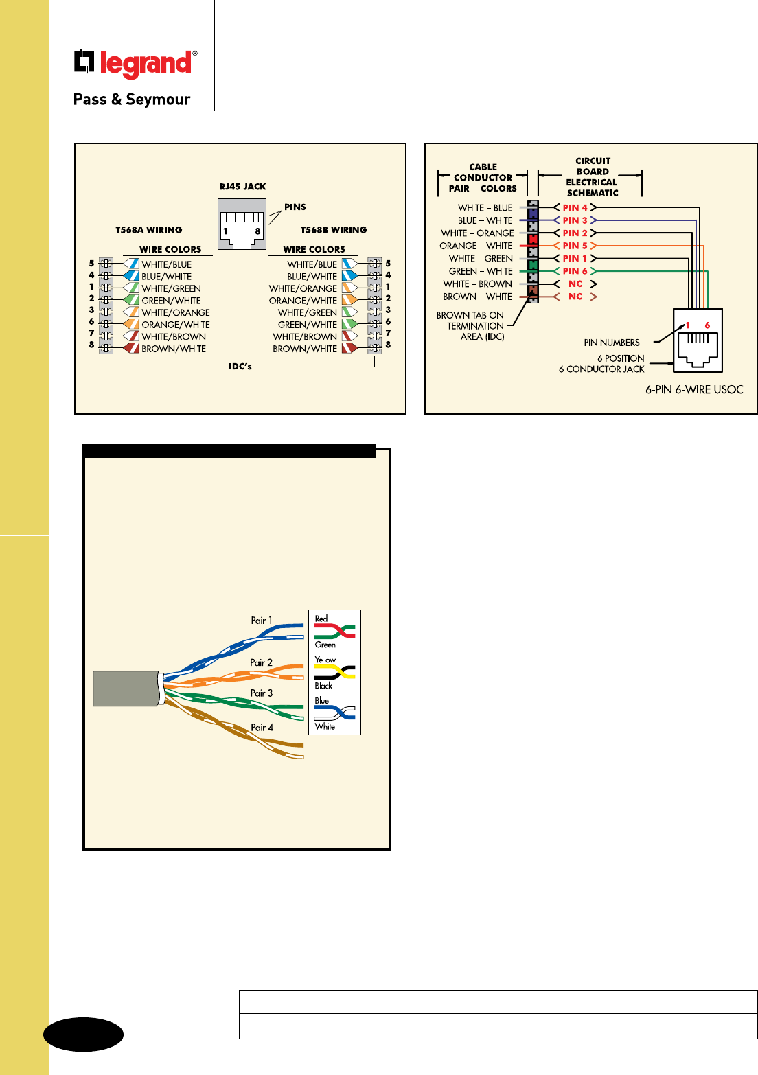
S-160
Technical SpecificationsUniversal & Six-Pin Wiring Guides
Technical Specifications
Universal & Six-Pin Wiring Guides
& UTP Cabling Installation
Basic practices for installing
unshielded twisted-pair (UTP)
network cabling
Minimize untwisting of twisted pairs.
When making terminations at jack modules, untwist no more than
1/2" for Category 5e cable or above; no more than 1" for Category
3. Untwisting pairs beyond these specifications can increase the
risk of failed cable performance testing.
Limit cable bend radius.
Cable should not bend more sharply than four times its diameter.
For Category 5e cable or above, that means a minimum bend
radius of about one inch. Bending cable to tighter-than-minimum
bend radius causes pairs to separate, compromising cable
performance.
Observe maximum pulling tension.
Cable is commonly pulled through walls, raceways, and other
passage ways. No more than 25 pounds of tension should be
applied. Excess pulling tension can distort twisted pairs, again
posing a threat to performance.
Stay away from high-voltage and
electromagnetism.
Avoid running cable in proximity to high-voltage sources or
electromagnetic fields, as these can cause interference. Examples
include ballasts, electric motors, transformers, and copiers.
Test to ensure performance.
Test completed cabling to ensure that customers get what they’re
paying for — and to prevent insufficient-perfor mance liability. Test
parameters are outlined in TIA/EIA-568-B.1 and vary depending on
type of cable.
Universal Wiring Guide Six-Pin
Wiring Guide
APPLICATION EXAMPLE
Pair 1 T White/Blue
R Blue/White
Pair 2 T White/Orange
R Orange/White
Pair 3 T White/Green
R Green/White
Pair 4 T White/Brown
R Brown/White
Twisted-pair wire
with band stripes
Solid-color
twisted-pair wire
Standard Four-Pair Wiring
In some retrofit applications you may encounter quad-wire.
This is the red, green, yellow, and black phone cable that
was common in most phone installations before the 90’s.
Legrand/Pass & Seymour recommends that you remove
this cable whenever possible and replace it with Category
5e cable and connectors. If removal is not possible, follow
the color-code guidelines below to make connections to
jacks bearing current UTP color markings.
Project
Location/Type
S-161
Technical Specifications Wall Plate Specifications
Technical Specifications
Wall Plate Specifications
Thermoset Smooth
TP Nylon Smooth
Application
Legrand/Pass & Seymour’s broad line of Standard Size Plastic and Metal Wall Plates features the most
complete range of types, sizes, colors, and finishes available. Choose from more than 1,900 standard
plates in non-combustible thermoset plastic material, self-extinguishing nylon material, screwless
polycarbonate material, or attractively finished metal, for residential, commercial, institutional, and
industrial applications. All plastic wall plates color match to Legrand/Pass & Seymour devices.
Materials
Wall Plate Material Urea
Mounting Screws Metal, oval heads painted to match plate color
Thermoset Plastic Wall Plates
n Molded of non-combustible mar-proof material.
n Available in “SP” series in Standard, Junior-Jumbo,
and Jumbo sizes.
n Seven standard colors available – Ivory, White,
Brown, Gray, Black, Red, and Light Almond.
n Individually wrapped with color-matching
screws.
n Resistant to discoloration, grease, oil, solvent
and moisture.
n Nominal thickness, .070"
TradeMaster® Thermoplastic Wall Plates
n Molded of rugged, practically indestructible
self-extinguishing nylon. (“TP” series only.)
n Available in “TP” series, extra 3/16" width and
height than Standard size plates; and “TPJ” series,
extra 3/16" width and height than Junior-Jumbo
size plates.
n Available in Ivory, White, Brown, Gray, Black,
Blue, Orange, Red, and Light Almond.
n Preferred for hospital, industrial, institutional,
and other high-abuse applications.
n Nominal thickness, .070"
Performance
Mechanical
Mechanical Strength Exceeds UL514 Bend Test
Deformation Exceeds UL514 Corner Peel
Environmental
Chemical-Resistant
Flammability UL94 V2
Materials
Wall Plate Material .070" Nylon 6
Wall Plate Finish Matte
Mounting Screws Steel, oval heads painted to match plate color
3rd Party Compliance
UL Listed, Standard UL514, Cover Plates for Flush-Mounted Wiring Devices.
Plastic Wall Plates UL File No. E143222.
Metal Wall Plates UL File No. E143223.
CSA Certified.
Project
Location/Type
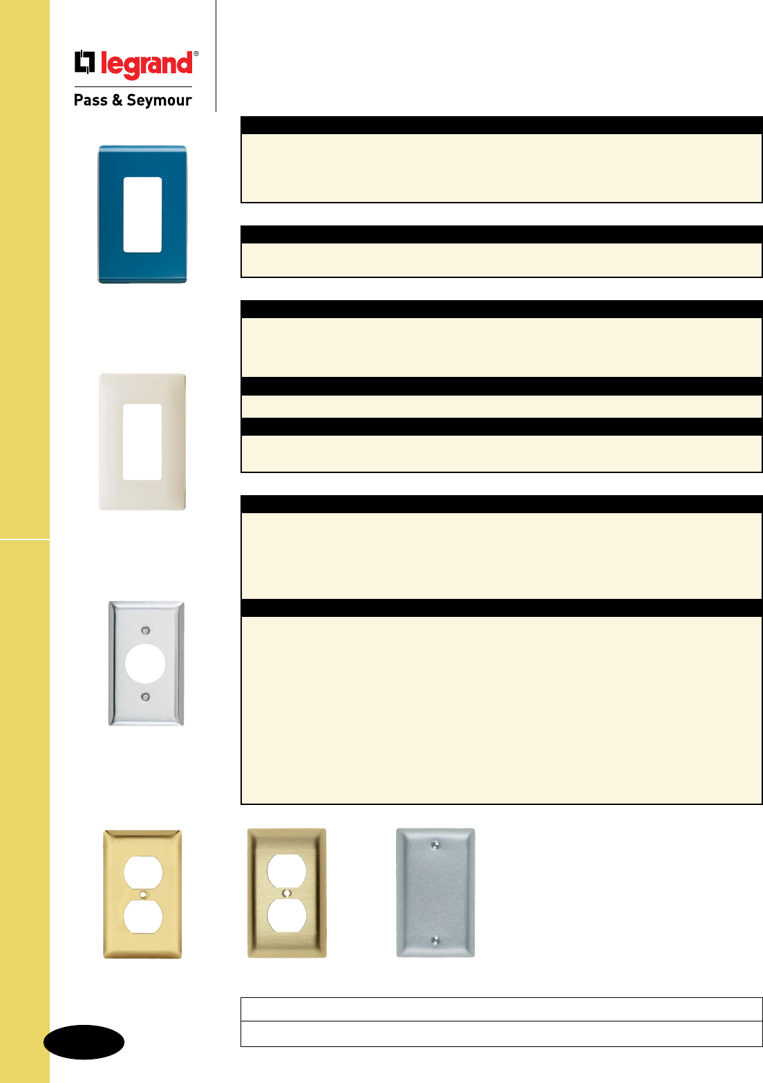
S-162
Technical SpecificationsWall Plate Specifications
Technical Specifications
Wall Plate Specifications
Brushed Brass Aluminum
302
Stainless Steel
Metal Wall Plates
Materials
n Constructed of corrosion-resistant stainless
steel, brass, aluminum, chrome, brushed bronze
or galvanized steel.
n Standard, Jumbo, and Tandem plates available,
as well as special Panel plates up to 5-gangs
high and 10-gangs wide.
n Packaged in protective film, with finish-matching
screws.
n Variety of special plated finishes. Paintable to
match plastic plates.
n Can be silk-screened or engraved, and custom
punched with over 300 opening styles.
n Type 302 Stainless Steel, non-magnetic, .032"
nominal thickness, brushed finish. This alloy
contains 18% chromium and 8% nickel for
superior resistance to corrosion. Recommended
for use in food processing plants, dairies,
chemical plants, and other industrial, institutional,
and commercial applications where corrosive
atmospheres exist.
n Type 430 Stainless Steel, magnetic, .032"
nominal thickness, brushed finish. Less
corrosion-resistant than Type 302, but ideal for
general service in high abuse applications in
industrial plants, commercial, and institutional
buildings.
n Chrome, Brushed and Polished Brass, .040"
thick. 70% copper, 30% zinc alloy gives warm,
appealing finish to modern decor as well as
retrofit applications. Lacquered to prevent
corrosion.
n Aluminum, .040" thick. Lustrous satin finish.
Lacquered to prevent corrosion.
n Galvanized Steel. Used only for Handy Box
Plates.
n Brushed Bronze, .040" thick. 90% copper,
10% zinc. Lacquered to prevent corrosion.
Polished Brass
Project
Location/Type
Performance
Flammability UL94 V2
Materials
Wall Plate Material .065" Polycarbonate Plastic Subplate Material Polycarbonate
Wall Plate Finish Matte
Screwless Polycarbonate Wall Plates
n Molded of .065" thick polycarbonate, matte finish.
n 2-piece plastic subplate made of polycarbonate.
n Extra 1/8" width and height than Standard size
plates.
n Available in Ivory, White, Brown, Gray, Black,
and Light Almond; and five metallic and three
wood finishes.
Studio Polycarbonate Wall Plates
n Wall plate and back plate made of polycarbonate
Lexan 241R opaque.
n Wall plate thickness: 0.210
Back plate thickness: 0.28
Screwless
Polycarbonate
Studio
Polycarbonate
3rd Party Compliance
UL Listed, Standard UL514, Cover Plates for Flush-Mounted Wiring Devices.
Plastic Wall Plates UL File No. E143222.
Metal Wall Plates UL File No. E143223.
CSA Certified.
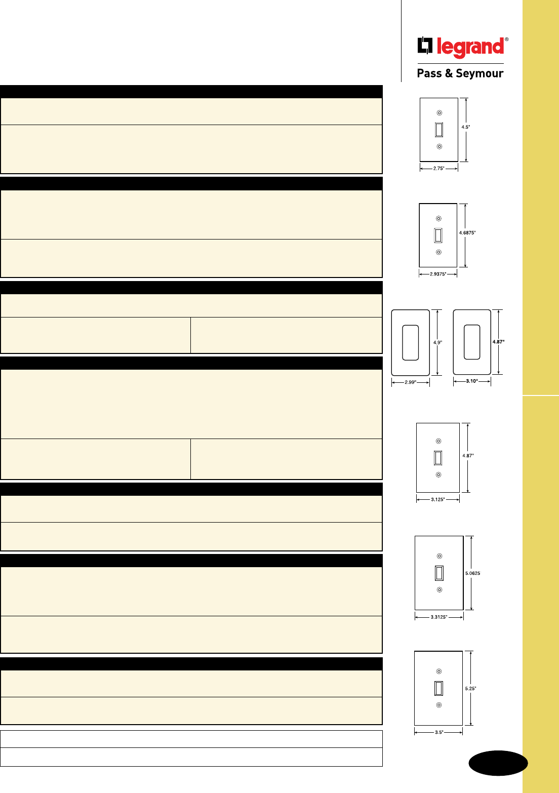
S-163
Technical Specifications
JUMBO
Wall Plate Dimensions
Technical Specifications
Wall Plate Dimensions
Project
Location/Type
STANDARD
TRADEMASTER STANDARD
TRADEMASTER JUMBO
JUNIOR-JUMBO
TradeMaster® Wall Plates
n Extra 3/16" width and height than Standard size wall plates.
n Provide better sheet rock coverage with standard size appearance.
n Available in unbreakable nylon 6 construction only.
n Screws pre-installed in the duplex, toggle, and decorator single gang plates.
Dimensions
1 gang 2.9375" x 4.6875"
2 gang 4.75" x 4.6875"
3 gang 6.563" x 4.6875"
4 gang 8.375" x 4.6875"
5 gang 10.188" x 4.6875"
6 gang 12" x 4.6875"
TradeMaster Jumbo Wall Plates
n Extra 3/16" width and height than Junior-Jumbo size wall plates.
n Provide additional coverage for sheet rock gaps, matching the appearance of the TradeMaster Plates.
n Available in unbreakable nylon 6 construction only.
n Screws pre-installed in the duplex, toggle, and decorator single gang plates.
Dimensions
1 gang 3.3125" x 5.0625"
2 gang 5.125" x 5.0625"
3 gang 6.9375" x 5.0625"
4 gang 8.75" x 5.0625"
Standard Size Wall Plates
n Standard size wall plates for all applications.
n Best fit for surface mount boxes.
Dimensions
1 gang 2.75" x 4.5"
2 gang 4.56" x 4.5"
3 gang 6.375" x 4.5"
4 gang 8.125" x 4.5"
5 gang 10" x 4.5"
6 gang 11.812" x 4.5"
7 gang 13.62" x 4.5"
8 gang 15.44" x 4.5"
n Available in plastic and metal only.
Jumbo Wall Plates
n Extra 3/4" width and height than Standard size wall plates.
n Largest size wall plates to cover larger wall damage.
Dimensions
1 gang 3.5" x 5.25" 2 gang 5.31" x 5.25" 3 gang 7.12" x 5.25" 4 gang 8.93" x 5.25"
n Available in plastic and metal only.
STUDIO
Junior-Jumbo Wall Plates
n Extra 3/8" width and height than Standard size wall plates.
n Additional coverage for sheet rock gaps.
Dimensions
1 gang 3.125" x 4.87" 2 gang 4.93" x 4.87" 3 gang 6.75" x 4.87" 4 gang 8.56" x 4.87"
n Available in plastic and metal only.
Screwless Polycarbonate Wall Plates
n Available in decorator, toggle, and duplex openings.
n Extra 1/8" width and height than Standard size wall plates.
n Provide better sheet rock coverage with standard size appearance.
n Molded of .065" thick polycarbonate.
n 2-piece plastic subplate made of polycarbonate.
n Available in five metallic and three wood finishes; and six standard colors.
Wall Plate Dimensions
1 gang 3.10" x 4.87"
2 gang 4.912" x 4.87"
3 gang 6.724" x 4.87"
4 gang 8.536" x 4.87"
Subplate Dimensions
1 gang 2.85" x 4.62"
2 gang 4.662" x 4.62"
3 gang 6.474" x 4.62"
4 gang 8.286" x 4.62"
Studio Polycarbonate Wall Plates
n Wall plate and back plate made of polycarbonate
Lexan 241R opaque.
n Wall plate thickness: 0.210
Back plate thickness: 0.28
Wall Plate Dimensions
1 gang 2.988" x 4.901"
2 gang 4.80" x 4.901"
3 gang 6.613" x 4.901"
4 gang 8.425" x 4.901"
Back Plate Dimensions
1 gang 3.158" x 4.97"
2 gang 4.97" x 4.97"
3 gang 6.783" x 4.97"
4 gang 8.595" x 4.97"
SCREWLESS
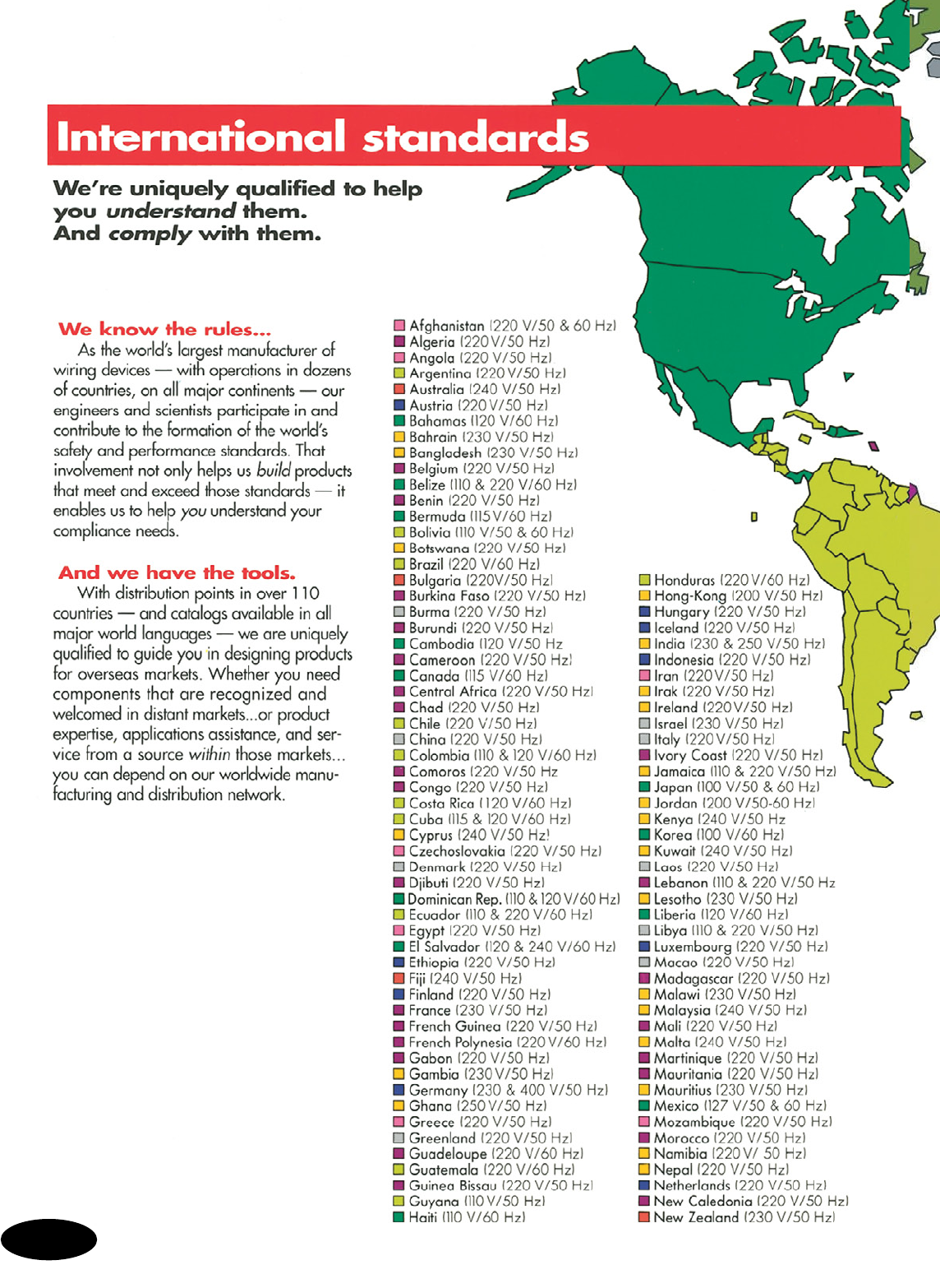
S-164
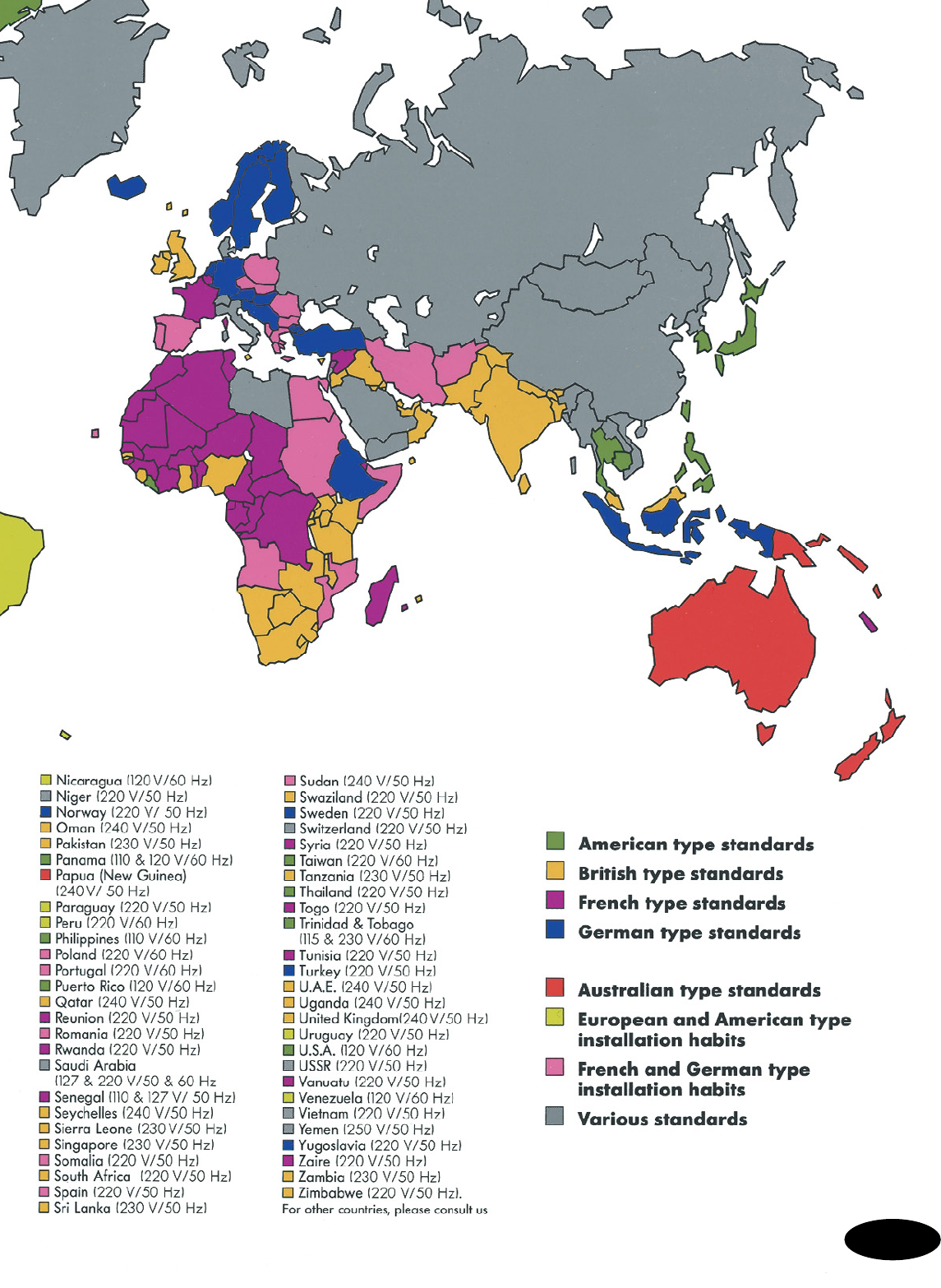
S-165
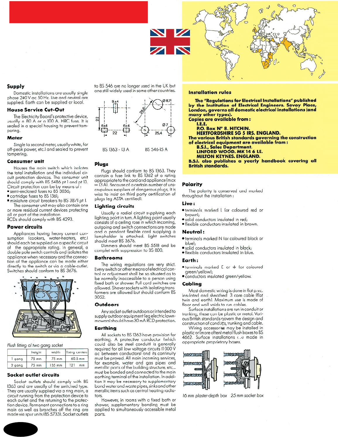
British standardBritish standard
S-166
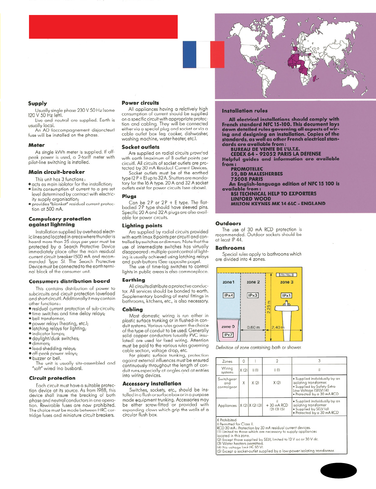
French standard
S-167

German standard
S-168

Glossary of Terms
Glossary of Terms
T-1
A.C. (Alternating Current) – An electric current, such as
normal household current, that reverses direction in a circuit at
regular intervals.
A.C. Only – A device for use on alternating current (A.C.)
circuits only.
Active Equipment – Energized equipment used for receiving or
transmitting analog or digital signals (e.g., hubs, routers, PBXs, etc.).
Adapter – An accessory used for interconnecting non–mating devices
or converting an existing device to a new or modified use.
Administration – The method for labeling, documentation, and
usage needed to implement moves, additions, and changes to a
telecommunications infrastructure.
AFCI – An arc-fault circuit interrupter is a device intended to provide
protection from the effects of arc faults.
Air Gap Switch – A mechanical switch which is capable of creating
a space between two contacts.
AL/CU – A marking designation used on certain devices to indicate
their suitability for connection to either aluminum or copper conductors.
Also referred to as CO/ALR.
Analog Signal – A signal that uses continuous physical variables
such as voltage amplitude or frequency variations to transmit
information. Contrast with Digital Signal.
Angle Plug – A plug that allows the attached flexible cord to exit at
a right angle to the plug face.
ANSI (American National Standards Institute) – An
organization that identifies industrial and public requirements for
national consensus standards and coordinates and manages their
development, resolves national standards problems, and ensures
effective participation in international standardization.
ANSI/ASHRAE/IESNA Standard 90.1 – An energy standard
for buildings except low-rise residential buildings, adopted by the
Department of Energy as the commercial building reference standard
for state building energy codes under the federal Energy Policy Act.
Asynchronous Transfer Mode (ATM) – A high-speed switching
transmission protocol that uses payload packages organized into
53-byte cells to carry data.
Attenuation – The decrease in power received from power
transmitted due to loss through transmission lines; measured
in decibels.
Attenuation-to-Crosstalk Ratio (ACR) – The difference between
attenuation and crosstalk measured in decibels (dB) at a given
frequency. This difference is critical to ensure that the signal sent down
the twisted-pair cable is stronger at the receiving end of the cable than
any interference signals (crosstalk) from other cable pairs.
Attenuator – Electrical or optical element that reduces (attenuates)
the intensity of the signal passing through it.
Automatic Grounding – A component that provides automatic
grounding of an electrical wiring device when installed in a grounded
metal enclosure. Eliminates the need for a bonding jumper.
AWG (American Wire Gauge) – Standard American measuring
scheme for classifying wires according to the diameter of the
conductors.
Auto ON/OFF - A control strategy used with occupancy sensors
of turning lights on and off automatically; OFF when a space is
unoccupied and ON whenever occupancy is detected.
Back Wire Terminal – A termination that can be accomplished
by inserting a pre-stripped solid or stranded conductor into a wiring
device terminal opening, followed by tightening the adjacent terminal
screw.
Backbone Cabling – The physical interconnections between
the entrance facility, equipment room, and various floors or
telecommunications rooms.
Ballast – A device used with an electric-discharge lamp to obtain
the necessary circuit conditions (voltage, current, and waveform) for
starting and operating.
Bandwidth – A measure of the amount of information which can
pass through a channel, expressed in Hertz (Hz). Higher bandwidth
means greater capacity to carry data.
Bar Coil – A bar coil is constructed of a ferrite bar and is wrapped
with copper wire. This device is used to reduce RFI generated by a
dimmer or other electronic switching devices.
Bend Radius – The minimum radius to which a cable or fiber can be
bent before excessive signal attenuation occurs.
BICSI (Building Industry Consulting Service International)
– An industry association dedicated to the design and installation of
communication wiring.
Bi-level Switching – A control strategy that focuses on switching
individual lamps within a luminaire, or groups of luminaires to achieve
a reduced, balanced lighting level.
Binding Post – Type of connecting device used in audio speaker
circuits. A knurled nut is tightened over a speaker wire conductor
inserted through a hole in a threaded post. Binding posts may also
offer a female jack connection for use of banana-type jacks.
Bit Error Rate (BER) – The ratio of incorrectly transmitted bits to total
transmitted bits. A primary specification for all transmission systems, it
is usually expressed as a power of 10. The number of errors made in
a digital transmission as compared to complete accuracy.
Box Mounted Dimmers/Fan Speed Control – Any dimmer or fan
speed control that mounts in or on a NEMA standard switch box.
Bulb Sing (Filament Hum) – The audible noise which can come
from an incandescent lamp controlled by a dimmer.
Bundle – More than one cable held in a single Grip.
Byte – A data unit made up of eight bits, sometimes referred to as
an octet. Megabytes and gigabytes are commonly used measures of
storage or memory capacity.
Cable – One or more electrical and/or optical conductors within a
protective sheath.
Cable Assembly – A cable that has connectors installed on one or
both ends. See Jumper and Pigtail.
Cable Modem – A modem used to link cable-supplied data to a
computer network; for example, when a CATV provider offers high-
speed, cable-based Internet service.
California Title 24 – In an effort to reduce electrical
power consumption, California has enacted new
requirements for residential lighting. These requirements
are that all permanently installed fixtures must be either
high efficacy, controlled by a manual-on/automatic-off
vacancy sensor or controlled by a dimmer. Visit www.
energy.ca.gov/title24 for additional information.
Campus – A complex of buildings which operates as one continuous
facility – e.g., multibuilding corporate headquarters, university,
military base.
Candelabra – A small screw-base threaded lampholder accepting a
bulb approximately 1/2" in diameter commonly used in night lights,
indicator lights and Christmas tree bulbs.
Candlepower – a measurement of light at the source, not the object
you light up.
Cascade Cable – A specialized cable used to link compatible
computer network hardware (usually hubs) together to form a
compound device that acts as a single, larger device. In the P&S
Home Network Center, a cascade cable can link two hub modules
to increase the number of ports available.

Category 3 – 100 ohm twisted-pair copper cable that meets or
exceeds specifications in ANSI/TIA/EIA-568-B.2, Commercial Building
Telecommunications Cabling Standard, and ISO/IEC 11801, Generic
Cabling for Customer Premises, for transmissions up to 16 MHz.
Category 5 – 100 ohm twisted-pair copper cable that meets
or exceeds specifications in ANSI/TIA/EIA-568-B.2 Annex N,
Commercial Building Telecommunications Cabling Standard.
Category 5 is no longer recognized for new commercial installation.
Category 5e – An enhanced form of Category 5, supporting high-
speed data transmission per TIA/EIA-568-B.1.
Category 6 – 100 ohm twisted-pair copper cable that meets or
exceeds specifications in ANSI/TIA/EIA-568-B.2-1, Commercial
Building Telecommunications Cabling Standard, and ISO/IEC 11801,
Generic Cabling for Customer Premises, for transmissions up to 250
MHz. Positive power sum attenuation-to-crosstalk ratio is characterized
to 200 MHz.
Capacitor – An electronic device capable of storing an electrical
charge. Used in circuits for a variety of functions often to reduce or
eliminate noise.
CATV – Community Antenna Television, known as cable television.
CE Marking – A product marking required in Europe that indicates
conformity to the “common level of safety” and is used to insure “free
movement of goods” within the 19 countries of the European Union.
CEC – Canadian Electrical Code.
Centralized Cabling – An optical fiber cabling configuration,
based on TIA/EIA-568-B.1, Optical Fiber Cabling Guidelines, from the
work area to a centralized cross-connect using pull-through cables, an
interconnect, or splice in the telecommunications room.
CFL – Compact fluorescent lamp. CFLs are a type of fluorescent lamp
that provide similar light levels compared with incandescent lamps but
offer longer lifecycles and consume less electricity.
Channel – The complete communications path between telecommuni-
cations room equipment and workstation equipment, which includes
cross-connects and patch cords.
Choke – A device used to filter RFI noise generated by dimmers or
other electronic switching devices.
Circuit Breaking Capability – Capability of a plug/receptacle
combination to break live circuits up to their maximum load rating.
Except in emergency situations, plugs and receptacles should not be
engaged or disengaged while power is on.
Circuit Breaking Rating – A rating which indicates the ability of a
connector to make and/or break a circuit under load. Such ratings are
determined through testing by qualified laboratories.
Cladding – In fiber cable, the transparent outer concentric glass
layer that surrounds the optical fiber core and has a lower index of
refraction than the core. It provides total internal reflection and protects
against scattering from contaminants at the core surface.
Clamping Voltage – The peak voltage that can be measured after
a surge protective device has limited or “clamped” a transient voltage
surge. Clamping voltage must be determined by using IEEE Standard
C62 testing and evaluated by UL Standard 1449.
Clock Hanger – A single receptacle generally recessed behind a
special cover plate having a hook or other means of supporting a
wall-hung clock.
CO/ALR – A marking designation used on certain devices to indicate
their suitability for connection to either aluminum or copper conductors.
Coaxial Cable – An electrical-transmission cable with a center
conductor, insulating spacer, and an outer electrical shield. Provides
high quality signal transmission for video and data applications.
Combination Wall Plates – A multiple gang wall plate with
different openings in each gang for different devices.
Communications Plenum Cable (CMP) – Cable listed as suitable
for use in ducts, plenums, and other spaces used for environmental air.
It has adequate fire-resistant and low smoke-producing characteristics.
Cables must pass required test for fire and smoke characteristics of
wires and cables, NFPA 262 or UL 910.
Communications Riser Cable (CMR) – Cable listed as suitable for
use in a vertical run in a shaft or from floor to floor. It has fire-resistant
characteristics capable of preventing the carrying of fire from floor to
floor. Cables must pass requirements of the Standard Test for Flame
Propagation Height of Electrical and Optical-Fiber Cable Installed
Vertically in Shafts, ANSI/UL 1666.
Configuration – A description of the arrangement, size, and number
of contacts in an insert assembly. Typical configuration descriptions
include the number of wires and poles and the presence of a separate
grounding contact. The combination of such factors determine the
connector’s electrical rating.
Connecting Block – A plastic block with metal wiring clips used to
establish an electrical connection.
Connector – A mechanical device used to provide a means for
aligning, attaching, and achieving continuity between conductors
or optical fibers.
Connector Grip – A strain-relief grip for specific customer require-
ments. Usually attached to a connector retaining nut.
Connector, Small Form Factor – An optical fiber duplex connector
with a footprint approximating that of an 8-position outlet connector
typically used with 4-pair copper connectors.
Consolidation Point (CP) – A location for interconnection between
horizontal cables extending from building pathways and horizontal
cables extending into furniture pathways.
Cord Connector – A portable receptacle, which is provided, with
means for attachment to a flexible cord and which is not intended for
permanent mounting.
Core – The central, light-carrying part of an optical fiber through
which light pulses are transmitted.
Corrosion-Resistant – A device constructed of special materials
and/or suitably plated to withstand corrosive environments.
Cross-Connect – System component where jumper wires and patch
cords are used to rearrange communications circuits in order to
administer the network. Usually located in a telecommunications room
or equipment room.
Crosstalk – Undesired signal in one circuit transferred from another
circuit by induction.
CSA (Canadian Standards Association) – An organization
serving a function for Canadian electrical manufacturers similar to
that provided in the U.S. by Underwriters Laboratories, Inc. (UL). CSA
develops safety and performance standards for electrical products
that parallel, but are not always identical to, UL standards. CSA tests
products and grants paying clients “certification” that their products
meet CSA standards.
C-UL – UL certification to CSA requirements, C-UL is a marking
approved by the Standards Council of Canada. C-UL can be used on
products to be installed in accordance with the Canadian
Electrical Code.
Current – The flow of electrons through an electrical conductor,
measured in amperes.
Daisy Chain – A cabling method (topology) of connecting devices in
series. Daisy chaining is no longer recommended.
DALI – Digital Addressable Lighting Interface. A communication
protocol developed primarily for fluorescent dimming systems. Part of
an IEC standard.
Daylighting Control – A lighting control method that changes the
amount of light provided by lighting fixtures as the contribution of
ambient daylight changes.
Glossary of Terms
Glossary of Terms
T-2

Glossary of Terms
Glossary of Terms
dB (Decibel) – The standard unit of measure of signal gain or loss,
used in attenuation and crosstalk measurements.
DBS (Direct Broadcast Satellite) – Satellite television service that is
purchased through a subscription (DirecTV, DISH Network).
D.C. (Direct Current) – An electric current, for example, battery
power, that flows only in one direction through a circuit.
Dedicated Circuit – A circuit established to provide control voltage
and current to one load or one type of load, such as an electric range
or a computer.
Deep Wall Plate – A wall plate that provides greater clearance for
device mounting straps than standard wall plates.
Demarcation Point – The interface which marks the division
between telephone company facilities and private building wiring,
where ownership and operational control changes.
De-Rating – When two or more dimmers are ganged and heat
sinking material is removed, it is important to “de-rate” or lower the
wattage rating of the dimmer. This is due to the heat rise caused by
the devices.
Digital Signal (DS) – A signal with a fixed number of discrete
values. Commonly, a binary signal with two values that are used to
transmit the two states (0,1) used by digital computers. Most data
transmission in optical fibers is by digital optical pulses. Contrast with
Analog Signal.
Dimmer – A switch with electronic components that permits variable
control of lighting intensity.
Dimmer Derating – The reduced maximum load for a dimmer
in a specific application. When dimmers are used in a multigang
application they run hotter and therefore must be derated depending
upon the number of dimmers being used and their locations within
the box.
Dimming Ballast – A special ballast used with fluorescent dimmers
to control the light intensity of fluorescent lamps.
DIN Rail – Metal component found in enclosures used for mounting
control devices or power packs.
Direct-Buried Cable – A telecommunications cable designed to be
installed under the surface of the earth, in direct contact with the soil.
Disconnect Use Only – Description of a connector not designed for
engaging or disengaging under load. Such connectors are commonly
used as cost-effective hard wiring alternatives.
“Disconnect Use Only” Rating – A rating of the current-carrying
capability of individually engaged pin and sleeve contacts. Such
ratings are established through testing for compliance with applicable
standards or codes, as well as wire conductor size and insulation as
defined in the National Electrical Code® (NEC®).
Dispersion – The spreading of light pulses as they travel through an
optical fiber.
Door Switch – A momentary contact switch normally installed in a
door-jamb. The switch is activated when the door is opened or closed.
Double Pole Switch (double-pole single-throw) – A switch
that makes or breaks the connection of conductors of a single
branch circuit.
Double Weave – Mesh braid with rows of two strands each.
DSL (Digital Subscriber Line) – A new digital connection method
that provides high-speed Internet or other network connections over
standard telephone wire.
Dual Cable Systems – CATV systems in which the incoming service
is provided over two different cables, sometimes called A/B cable
systems. For example, a system in which one cable (cable A) carries
channels 2-50 and the other cable (cable B) carries channels 51-100.
This is an older method of providing service, used when the initially
installed cable lacks capacity to meet current needs.
Dual Relay – Control device containing two relays that enables
simultaneous but independent control of two different loads.
Dual Technology – The combination of passive infrared and
ultrasonic technologies used to detect occupancy.
Duplex Receptacle – Two receptacles in a common housing or
mounting means which accepts two plugs.
Dustproof – A receptacle so constructed or protected that dust will
not interfere with its operation.
DVD (Digital Video Disc) – An acronym commonly used to
describe a device that plays DVD-format discs. Such devices (both
dedicated DVD players and computer DVD drives) can supply video or
other signals through a video or computer network.
DV/DT (Delta Voltage/Delta Time) – DV/DT is the rate of change
in voltage over a certain time frame.
Electronic Dimming Ballast – A variable output electronic
fluorescent ballast.
Electronic Industries Alliance (EIA) —Industry trade association
which works with the Telecommunications Industry Association (TIA) in
developing standards.
EMI – Electromagnetic interference or unwanted signal pick-up. One
of two types of electrical “noise” caused by varying magnetic fields
conducted into branch wiring from inductive load switching.
Energy – A measure of electrical power rated in joules.
Entrance Facility (EF) (telecommunications) – An entrance
to a building for both public and private network service cables
(including antennae) encompassing the entrance point at the building
wall and continuing to the entrance room or space.
Equipment Room (ER) – A centralized space for telecommunications
equipment serving one or multiple buildings. It contains more complex
equipment than the telecommunications room, which serves each floor
of a building.
Ethernet – The most commonly used protocol (language) in
computer networking. Originally supported (and still commonly used)
in 10 Mbps form (10Base-T), 100 Mbps Ethernet (Fast Ethernet or
100Base-T) is also available.
External Video – A video signal provided by an external source,
such as cable, satellite, or antenna-received broadcast.
Fan Hum – Noise created by a fan motor when controlled by a
standard speed control.
Far-End Crosstalk (FEXT) – Crosstalk measured at the cable end
opposite from where the signal originates.
FCC – Federal Communications Commission.
F Connector – The 75 ohm radio frequency connector used with
coaxial cable to attach drop cables to taps and other devices. The
F connector does not have center pins. The F connector uses the solid
copper center conductor of the coaxial cable itself as the center pin to
establish the connection.
FDDI (Fiber Distributed Data Interface) – An ANSI standard
for 100 Mbps fiber physical and data protocols, generally used in
“backbone” applications.
Fed Spec – Devices which comply with Federal Specifications such
as W-C-596 for connecting and W-S-896 for switches. Fed Spec
Standards for switches and connecting devices include NEMA
Performance Standards.
Feed Through – The practice of wiring a single branch circuit
through a device and feeding power to other devices wired down-
stream. (Feeding through a GFCI would provide protection to
downstream receptacles.)
Fiber (Optical Fiber) – A thin filament of glass or plastic capable
of carrying information in the form of light.
Fiber Optics – Communications scheme which converts electrical
energy to light in order to transmit through optical fiber.
T-3

Field Adjustable Trim Potentiometer – A small, typically
screwdriver-adjustable, variable resistor. Used to adjust minimum
level of light or speed of a fan.
Firestop – A material or device installed in a cable pathway to
prevent the passage of flames, smoke, and gases.
Flanged Inlet – A plug which is intended for flush mounting on
an appliance or equipment and which serves to connect utilization
equipment to a cord connector.
Flanged Outlet – A receptacle which is intended for flush mounting
on an appliance or equipment which is intended to establish electrical
connection with an inserted plug.
Fluorescent Lamp – A glass housing that contains phosphorus in
a sealed vacuum. When the phosphorus is excited from a voltage
charge, it becomes ionized and gives off light.
Fluorescent Starter – A device rated in watts having a voltage-
sensitive switch and a capacitor whose function is to provide a
high-voltage pulse to start a fluorescent lamp.
Flush Wall Plate – A wall plate designed to mount flush with the
wall surface or the plane surface of electrical equipment.
Foot-Candle – The amount of light one candle generates one foot
away.
Four-Way Switch – A switch which is used in conjunction with two
three-way switches to control one light or other connected equipment
from three or more locations.
Floor Receptacle – A receptacle with a protective cover plate
intended for mounting flush with the surface of the floor.
Frequency – The number of cycles completed by a signal in one
second, expressed in Hertz.
Fresnel Lens – A lens recognized by its concentric rings that is used
for passive infrared sensors.
Fusible Mechanical Interlock – A switchable IEC pin and sleeve
receptacle that is mechanically interlocked to ensure that a plug cannot
be engaged or disengaged under load. Fusible mechanical interlocks
include a fusible disconnect switch inside a single, non-metallic
enclosure. They are typically used to provide overload protection for
portable equipment at the source of power access.
Fusion Splice – A permanent joint accomplished by applying
localized heat sufficient to fuse or melt the ends of two optical fibers
together, forming a continuous single fiber.
Gang – The space required for one wiring device, wall plate, etc.
GFCI (Ground Fault Circuit Interrupter) – A personnel protection
device that detects current leakage and removes power to the
receptacle.
Gigabit Ethernet – A carrier-sense multiple access with collision
detection LAN standard developed by the IEEE 802 group operating
at one Gb/s.
GigaHertz – A unit of frequency equal to one billion Hertz.
Grip – A flexible wire mesh cable holding device.
Ground Conductor – A conductor (identified as the bare or green
conductor, normally non-current carrying) which is intentionally
connected to earth ground to provide an intentional path for fault
current to ground.
Grounding – A system in a connector assembly to ensure ground
continuity. Ground conductors connect normally nonenergized metal
components to earth and are not part of the electrical circuit.
GSA (General Services Administration, Federal Supply
Service) – The U.S. Government administration responsible for the
approval of Federal Specifications used in the purchase of products
by all Federal agencies.
Headroom – The overhead or margin, expressed in decibels, by
which a communications system exceeds minimum requirements.
Heat Sink – A metal plate used for absorbing or removing heat from
the switching device (triac) in a dimmer or fan speed control.
Heat Sink Dimmer/Fan Speed Control – Any dimmer or fan
speed control that mounts onto a NEMA standard switch box, but
whose strap protrudes beyond the box and onto the surface of the wall
itself. Heat sink dimmers and fan controls will not accept a traditional
wall plate and usually are supplied with their own unique cover.
Hertz – A unit of frequency, one cycle.
Home Network Center – In the P&S Home Network Wiring
System, the center point for all network cabling. The Home Network
Center is configured for varying network needs, with modules.
Home Run – Also known as star topology, a cabling system where
individual cables are run directly from the telecommunications room to
each work area outlet.
Home Theater – Home entertainment system using television video
and multi-channel audio to more closely approximate a movie theater
experience. Typical home theater systems incorporate traditional front
right and left audio channels, a front center channel, and a
two-speaker rear channel.
Horsepower Rated – A device having a marked horsepower rating
is intended for control of motor loads.
Horizontal Cabling – The portion of the wiring system extending
from the workstation to the horizontal cross-connect in the
telecommunications room.
Horizontal Cross-Connect – The cross-connection between
horizontal and other cabling, such as backbone cabling.
Horizontal Length – The cable distance from the workstation to
the telecommunications room cross-connect, a maximum of 295 ft.
(100 meters).
Hospital Grade – A device constructed to meet performance
require ments of high abuse areas found in hospital locations, tested to
“Hospital Grade” requirements of Underwriters Laboratories Standard
UL 498.
Hub – Equipment which serves as a centralized connection point
for a network or a portion of network. Hubs contain multiplexing,
switching, and bridging functions and are not considered part of the
cabling infrastructure.
IEC (International Electrotechnical Commission) – The IEC
is a worldwide standards organization having 43 countries as its
members. The United States is active in many areas of the IEC and the
standards it develops.
IECC – The International Energy Conservation Code, developed by the
International Code Council® (ICC®), that provides the minimum energy
efficiency provisions for residential and commercial buildings. It is
written so that state and local jurisdictions can easily adopt the model
as their energy code.
IEEE – Institute of Electrical and Electronic Engineers.
Illuminated – A device that, when connected to an electrical circuit,
is lighted in the area of the face or handle.
Illumination – What results from light use. Point a flashlight on an
object and you light it up or “illuminate” it.
Impedance – The resistance or opposition to the flow of alternating
current within a circuit.
Impedance Matching – Matching impedances of adjoining circuit
elements so that power transfer across the interface is maximized,
in order to improve performance or to accomplish a specific effect.
Incandescent Lamp – A light bulb which contains a filament in
a sealed vacuum. When voltage is applied to the filament, it heats,
producing light.
Glossary of Terms
Glossary of Terms
T-4

Inductive Load – Electrical devices made of coiled or wound wire
that create a magnetic field when energized. Components such as
motors, solenoids and coils are all inductive loads.
Infrared (I.R.) – The invisible light emitted by all people, animals,
and objects. Infrared is measured in terms of micrometers on the
wavelength spectrum.
Inlet (Male Base) – A plug which is intended for flush or surface
mounting on an appliance or equipment and which serves to connect
utilization equipment to a connector.
Inrush Current – The maximum current drawn by a device during
the starting period.
Insertion Loss – 1. The loss resulting from the insertion of a device
in a transmission line. 2. In an optical fiber system, the loss of optical
power caused by inserting a component, such as a connector,
coupler, or splice into a previously continuous optical path.
Insulation Displacement Connection (IDC) – An electrical
connection made by “punching down” a wire in a terminal, which
cuts through the insulation to make contact with the conductor.
Interbuilding (Campus) Backbone – A backbone network
providing communications among multiple buildings.
Interbuilding Backbone Cable – 1. Cable that runs between
buildings in a campus environment. 2. Outside plant cabling.
Interchangeable – A device or combination of devices, each
individually housed and having common mounting dimensions and
intended for field installation on a single or multiple opening mounting
strap. Also known as Despard®.
Interconnection – A connection scheme that provides for the
connection of a cable to another cable or to an equipment cable.
Intermediate Cross-Connect (IC) – The cross-connection between
the first and second level of backbone cabling.
Internal Video – A video signal provided by such in-home sources
as a DVD player, VCR, camcorder, or video camera.
Intrabuilding Backbone Cable – Cable that runs between
telecommunications rooms inside a building. Can be vertical or
horizontal in physical configuration.
ISDN (Integrated Services Digital Network) – An integrated
digital network in which the same time division switches and digital
transmission paths are used to establish connections for different
services, for example, telephony, data, telex, and fax.
Isolated Ground – A grounding type device in which the equipment
ground contact and terminal are electrically isolated from the
receptacle mounting means.
Jack – A device into which a plug is inserted in order to make
electrical contact in a communication circuit.
Joule Rating – The measurement of a surge protective device’s
ability to absorb heat energy created by transient surges. Note that
the Joule rating is not a part of IEEE or UL Standards. It is not as
significant a specification as clamping voltage, maximum surge current
and other parameters recognized by these agencies.
Jumper – 1. An assembly of twisted pairs without connectors, used
to join telecommunications circuits/links at the cross-connect. 2. An
optical fiber cable with connectors installed on both ends. See Cable
Assembly.
Jumper Wire – A short length of twisted pair cable used to route a
circuit between two cross-connect termination points.
Key – A lampholder with a means of switching the lamp on or off as
part of the device.
Keyless – A lampholder with no means of switching the light on or
off at the lampholder.
Lace – Strand of wire usually the same material as the mesh used to
weave closed a split mesh.
Lampholder – A device that establishes mechanical and electrical
connection to an inserted lamp.
LAN (Local Area Network) – A network of computers and
peripheral devices with a limited area such as a department, single
building, or campus environment.
Launch Cable – Length of optical fiber cable used to condition the
launch of the optical time domain reflectometer test signal so that the
correct results will be obtained.
LEED – Leadership in Energy and Environmental Design, a voluntary
program administered by the U.S. Green Building Council. Projects
achieve Certified, Silver, Gold, or Platinum ratings by satisfying
standard prerequisites and going beyond this threshold to earn points
in specific categories.
Lighted Handle – A switch with an integral lamp in the actuator that
lights when the switch is in the “OFF” position.
Light Source – Used in conjunction with a power meter, the test
equipment unit that normally contains a light-emitting diode or laser
used to create a light wavelength for testing optical fiber cable loss
or continuity.
Link – The basic, permanently installed, horizontal cabling path
between the work area outlet and telecommunications room cross-
connect. Often referred to as the contractor link.
Load Shedding – A lighting control strategy for selectively reducing
the output of lighting fixtures or lamps on a temporary basis as a
means to reduce peak demand charges.
Locking (Turnlok) – A device designated to lock in place when it is
rotated in a clockwise direction. The device can then only be removed
when turned in a counterclockwise direction.
Locking Switch – A switch with a separate actuator key, rather than
a toggle, to prevent unauthorized use.
Loss – Attenuation of the optical signal, usually measured in dB.
Loss Budget – The total allowable loss between source and detector
allocated among fiber, connectors, splices, and safety margin.
Low-Voltage – A device designed for use under 50 volts.
Lumen – One foot-candle falling on one square foot of area.
Lux – Luminance measured in metric units vs. English units. Lux is the
measurement of actual light available at a given distance. Lux = one
lumen incident per square meter of illuminated surface area.
Main Cross-Connect (MC) – A cross-connect used with first level
backbone, entrance, or equipment cables.
Maintained Contact Switch – When the actuator is moved to the
“ON” position, this switch makes and retains the circuit contact until
the actuator is manually moved to the “OFF” position.
MAN (Metropolitan Area Network) – A data communications
network that covers an area larger than a campus area and smaller
than that of a wide area network. It usually interconnects two or more
LANs and covers an entire metropolitan area, such as a large city and
its suburbs.
Manual Controller – A horsepower rated switch without overload
protection. Used for the operation of small A.C. or D.C. motors.
Maximum (Peak) Surge Current – The peak surge current a surge
protective device can withstand, based on IEEE Standard C62.45 test
waveforms.
Mbps (MegaBits Per Second) – One million bits per second.
Mechanical Interlock – A switchable IEC pin and sleeve receptacle
that is mechanically interlocked to ensure that a plug cannot be
engaged or disengaged under load. They are typically used to provide
a disconnect point in power circuits supplying portable equipment.
Glossary of Terms
Glossary of Terms
T-5

Mechanical Splicing – For optical fibers, permanently joining two
fibers together by mechanical means to enable a continuous signal.
Media (telecommunications) – Wire, cable, or conductors used
for telecommunications.
Medium Base (Edison) – The most common type of screw-in
lampholder found in everyday lighting fixtures, table lamps and
accepting incandescent bulbs with screw bases approximately
1" in diameter.
Megahertz (MHz) – A unit of frequency equal to one million cycles
per second (Hertz).
Mesh – The tubular open braid portion of a wire mesh grip.
Mesh Termination – The method of securing woven strands at the
ends of a wire mesh grip.
Microprocessor – Single chip computer element containing the
control unit, central processing circuitry; arithmetic and logic function.
Midget – A device with a body diameter smaller than those of
devices of a similar rating.
MLD (Multi-Location Dimming) – This is achieved through the
use of specific components designed to interface and allow dimming
control from any location, master or remote. In a true MLD situation,
the master unit performs all dimming and switching functions. The
remote units provide input to the master (i.e.; dim, bright, on or off,
as desired).
Mode – 1. Loosely, a possible light path followed by light rays, as in
multimode or single-mode. 2. Strictly, a distribution of electromagnetic
energy that satisfies Maxwell’s equations and boundary conditions in
guided wave propagation, such as through a waveguide or optical
fiber.
Modular Jack – A female telecommunications connector, which is
mounted in a fixed location. Jacks are specified in IEC 603-7 and
FCC Part 68 Subpart F. Also see Outlet.
Modular Plug – A male telecommunications connector, specified in
IEC 603-7 and FCC Part 68 Subpart F.
Modulation – A process whereby certain characteristics of a wave,
often called the carrier, are varied or selected in accordance with a
modulating function. This includes amplitude, frequency or phase, and
other modulation techniques.
Mogul – The largest screw-in type of lampholder accepting
incandescent lamp bulbs having screw bases approximately 1-1/2"
in diameter. Used in street lighting fixtures and industrial high bay
fixtures.
Molded On – A connector that is factory molded to a length of
flexible cord.
Momentary Contact – A switch which establishes circuit contact
when its actuator is moved to, and held in, the “ON” position. The
circuit is broken when the actuator is allowed to return, of itself, to the
“OFF” position (such a switch may also be furnished to operate in the
opposite mode).
M.O.V. – Metal Oxide Varistor, primary component of TVSS.
MTP™ – Factory-terminated multiple-termination fiber optic connector
for 12-strand ribbon-fiber optic cable. Most commonly used in back-
bone (riser) applications such as the P&S PFOB System. MTP is a
trademark of US Conec Ltd.
Multimedia – Applications which communicate information using
more than one cabling means.
Multimode Optical Fiber – An optical fiber cable that allows light
to travel in many bound modes; used in LAN applications. Multimode
fibers have a larger core than single-mode (core/cladding 62.5/125
micrometers).
Multiple Weave – Wire mesh grips woven utilizing single, double,
and triple strands of each wire material.
Multiplexing – Combining a number of individual messages over a
common path – usually by frequency division or time division.
Multi-User Telecommunications Outlet Assembly (MUTOA) –
A device grouping several telecommunications outlets into one location.
Narrow Wall Plate – A cover plate designed for flush mounting on
narrow partitions having a width dimension of two inches or less.
Near-End Crosstalk (NEXT) – Electrical noise coupled from one
pair of wires to another, measured from where the signal is transmitted.
NEC (National Electrical Code®) – A code providing for practical
safeguarding of persons and property from hazards arising from the
use of electricity.
NEC Amperage Rating – The most widely recognized rating for
industrial applications. A current-carrying capability of a pin and
sleeve system in accordance with Underwriters Laboratories Standards
and wire conductor size and insulation per the National Electrical
Code. Determined by qualified laboratory testing.
NEMA (National Electrical Manufacturers’ Association) – An
organization of electrical manufacturers that establishes standards for
manufacturing and testing of performance and reliability of electrical
products. NEMA tests are often the basis or prerequisite for approval
by the Federal Government and/or by Underwriters’ Laboratories, Inc.
NEMA Type 1 Enclosures – Intended for indoor use primarily to
provide a degree of protection against limited amounts of falling dirt
in locations where unusual service conditions do not exist.
NEMA Type 3 Enclosures – Intended for outdoor use primarily to
provide a degree of protection against rain, sleet, and windblown
dust; and to be undamaged by the formation of ice on the enclosure.
They are not intended to provide protection against conditions such as
internal condensation or internal icing.
NEMA Type 3R Enclosures – Intended for outdoor use primarily
to provide a degree of protection against rain and sleet; and to be
undamaged by the formation of ice on the enclosure. They are not
intended to provide protection against conditions such as internal
condensation, or internal icing.
NEMA Type 4 Enclosures – Enclosures intended for indoor or
outdoor use primarily to provide a degree of protection against
windblown dust and rain, splashing water, hose-directed water, and
external ice formation.
NEMA Type 4X Enclosures – Enclosures intended for indoor
or outdoor use primarily to provide a degree of protection against
corrosion, windblown dust and rain, splashing water, hose-directed
water, and external ice formation.
NEMA Type 7 Enclosures – Intended for indoor use in locations
classified as Class 1, Group A, B, C, or D, as defined in the National
Electrical Code. They shall be capable of withstanding the pressures
resulting from an internal explosion of specified gases, and contain
such an explosion sufficient that an explosive gas-air mixture existing
in the atmosphere surrounding the enclosure will not be ignited.
Enclosed heat generating devices shall not cause external surfaces
to reach tempera tures capable of igniting explosive gas-air mixtures
in the surrounding atmosphere. Enclosures shall meet explosion,
hydrostatic, and temperature design tests.
NEMA Type 9 Enclosures – Intended for indoor use in locations
classified as Class II, Groups E, F, or G, as defined in the National
Electrical Code. They shall be capable of preventing the entrance
of dust. Enclosed heat generating devices shall not cause external
surfaces to reach temperatures capable of igniting or discoloring
dust on the enclosure or igniting dust-air mixtures in the surrounding
atmosphere. Enclosures shall meet dust penetration and temperature
design tests, and aging of gaskets (if used).
NEMA Type 12 Enclosures – Intended for indoor use primarily
to provide a degree of protection against circulating dust, falling dirt,
and dripping non-corrosive liquids. They are not intended to provide
protection against such conditions as internal condensation.
Glossary of Terms
Glossary of Terms
T-6

Glossary of Terms
Glossary of Terms
NEMA Type 13 Enclosures – Intended for indoor use primarily to
provide a degree of protection against lint, dust, spraying of water,
oil, and non-corrosive coolant. They are not intended to provide
protection against conditions such as internal condensation.
Network – An interconnection of computers, peripherals, and data/
voice communications facilities.
NFPA (National Fire Protection Association) – An organization
devoted to promoting the science and improving the methods of Fire
Protection. Membership is open to anyone interested. Every three
years the NFPA produces a new edition of the NEC (see above).
The NFPA also provides many other useful publications dealing with
fire prevention.
N.P.S. – National Pipe Straight Thread.
N.P.T. – National Pipe Tapered Thread.
Occupancy Sensor – A device that switches lights on and off
or dims and brightens lights based on the presence or absence of
people.
OFNP (Optical Fiber Non-conductive Plenum) – NFPA
designation for optical fiber cable that contains no electrically
conductive components and meets fire rating requirements for plenum
(backbone) applications.
Ohm – The unit of measurement for electrical resistance.
Ohm’s Law – States that, in a given electrical circuit, the amount
at current in amps is equal to the pressure in volts divided by the
resistance in ohms. The formula is:
I (Current) = V voltage or V = I x R
R resistance or R = V/I
Open System Architecture – International standards for data
networking which allow multi-vendor/multi-product applications.
Optical Fiber – A thin filament of glass or plastic capable of carrying
information in the form of light.
Optical Power Meter – Test equipment that measures in dBm the
strength of a light wave over a fiber cable.
Optical Time Domain Reflectometer (OTDR) – An instrument
that measures transmission characteristics of fiber by measuring the
backscatter and reflection of injected light as a function of time. Used
to measure attenuation of fiber, splices, connectors, and locate faults.
OSHA (Occupational Safety and Health Administration) –
That part of the U.S. Department of Labor responsible for assuring
that employers provide safe and healthful working conditions
and equipment for employees, and that employees properly avail
themselves of these conditions. Note: OSHA does not approve
products. Compliance with OSHA regulations is contingent on
approval or listing of the product by an authorized testing laboratory,
such as UL, and proper installation and/or use of the product in
accordance with OSHA guidelines.
Oversized Wall Plate – A wall plate with length and width
dimensions greater than standard wall plates.
Outlet – A point on the wiring system at which current is taken to
supply utilization equipment.
Outlet (DataCom) – A fixed connection where horizontal cable
terminates and work area equipment can be connected.
Outside Plant (OSP) – Telecommunications infrastructure designed
for installation exterior to buildings.
Pair – Two wires, twisted together with a reciprocal color code.
Pair Twist – The uniform twist of an insulated copper pair that helps
to improve the effects of capacitance imbalance and electromagnetic
induction.
Passive Infrared-(P.I.R.) – Typically this term is used in reference to
detecting infrared. A P.I.R. detector functions as a receiver of infrared
emitted from a transmitter, such as the human body.
Patch Cord – A length of cable, with connectors on the ends, used to
join telecommunications links at a cross-connect.
Patch Panel – Connecting hardware that can be accessed
with patch cords to form cross-connection (usually located in a
telecommunications room) used to modify, reconfigure, or administer
communications networks.
PBX (Private Branch Exchange) – A telephone switching system
serving one organization or business, which is connected to the public
telephone system.
Peripherals – Devices used to extend the capability of a computer
or network. These can include printers, scanners, external drives,
modems, and more.
Permanent Link – The transmission path between any two interfaces
of cabling, excluding patch cords, equipment, and work area cables.
Phase Control – The electronic process of chopping or turning
on and off the AC line every half line cycle. It is commonly used in
dimming and fan speed control applications.
Pigtail – A short length of copper or optical fiber cable that has a
pre-installed connector on one end. See Cable Assembly and Jumper.
Pin and Sleeve – Industrial wiring devices utilizing round pin-shaped
blades and tubular designed sleeve contacts.
Pilot Light – A switch with an integral lamp in the actuator which
lights when the switch is in the “ON” position.
Plenum – A chamber which forms part of a building’s air distribution
system.
Plug – A device utilizing blades which, when inserted into a
receptacle, establishes connection between the conductors of the
attached flexible cord and the conductors connected to the receptacle.
Polarization (plugs and receptacles) – A means of assuring the
mating of plugs and receptacles of the same rating in only the correct
position.
Polarity – The alignment of a plug and receptacle to ensure correct
connection.
Pole – The term “pole” as used in designating plugs and receptacles
refers to a terminal to which a circuit conductor (always current
carrying) is connected. In switches, the number of poles indicates the
number of conductors being controlled.
Port – Hardware entity at the end of each link.
Potentiometer (POT) – A variable resistor, when used in a phase
control it adjusts the light intensity.
Power Budget – In fiber optics, the difference between the strength
of the signal transmitter and the sensitivity of the signal receiver.
It represents the maximum acceptable loss for the combination of
components and connectors used on a link.
Power Connector – A plug or receptacle that provides connection
for distribution of secondary electrical power from a power source to
electrical equipment, either portable or stationary.
Powersum – A test method for four-pair cable which compares the
sum of the pair-to-pair crosstalk from three pairs to the fourth pair.
Premises Wiring – The technology of wiring buildings and
equipment for data, telephone, video and other electrical/electronic
functions.
Preset – The ability of a dimmer or fan speed control to “remember”
a desired level of output.
Pressure Termination – An electrical connection in which a
stripped cable is secured in a wire well by a set screw. The simplest
method of termination.
Propagation Delay – Time between when a signal is transmitted
and when it is received at the opposite end of the cable.
Protocol – A set of rules governing the transmission of information
over a data channel.
T-7

PDN (Public Data Network) – A network established and operated
for the specific purpose of providing data transmission services to the
public.
Pulling Grip – A reusable wire mesh grip for pulling cable, rope, or
bare conductor.
Pulling Tension – The amount of pull (foot-pounds of tension) placed
on a cable during installation.
Pull Switch – A switch with an actuator mechanism operated by a
downward or outward pull.
Punchdown – Securing a conductor to a wiring terminal by placing
the insulated conductor in the terminal groove and pushing down with
a “punchdown” (impact) tool — creating an insulation displacement
connection (IDC).
Push/Push – A means of achieving the preset features on a rotary
dimmer or fan speed control. The secondary switching mechanism is
activated by pushing the knob at any preset of light or speed.
RBOC – Regional Bell Operating Company, e.g., Bell Atlantic.
RCDD (Registered Communications Distribution Designer) –
Professional certification granted by BICSI (Building Industry Consulting
Services International).
Recessed F Connector – A type of video connector in which the
termination is recessed for a smoother appearance and greater
termination protection.
Receptacle – A contact device which is intended to establish
electrical connection with an inserted plug.
Refractive Index – The ratio of the velocity of light in a vacuum to
the velocity of light in a given material.
Relay Rack – A vertical metal frame that is equipped with threaded
holes at a predefined spacing in accordance with EIA- 310-D, on
the front of the rack (or on both the front and rear sides of the rack).
It is used to mount termination hardware, electronic equipment, or
a combination of both. It can be floor mounted (free standing) or
wall mounted.
Resistive Load – A device which opposes the flow of electric current.
There is a voltage drop across a resistive load, which causes the
device to dissipate heat.
Response Time – The interval time required for a device to perform
its stated function in reaction to specific condition(s), such as a
transient voltage surge or ground fault.
Return Loss – 1. Noise or interference caused by impedance of
a cable, expressed in decibels. 2. The amount of reflected power
compared to the amount of incident power at an interface, expressed
in dB. Return loss is a critical factor in single-mode links because
reflected light can destabilize some lasers.
RF Control – Radio Frequency Control. Systems that use RF
communication to propagate control messages between devices
and/or throughout the system.
RFI (Radio Frequency Interference) – Electrical noise.
Ring – One of the two conductors or cable pair in a telephone circuit.
Riser – The path between floors of a building.
RJ (Registered Jack) – Telephone and data jack applications
registered with FCC.
RJ31X – A specialized jack used to allow security systems to take
immediate control of a phone line, even when it is already in use.
The security module used in the P&S Home Network Wiring Center
includes an RJ31X jack for this purpose.
R.M.S. (Root Means Square) – Used as an A.C. value of voltage
or current. Expressed, for example, as 120 volts AC RMS.
Rocker Switch – A switch that is operated by a paddle-type actuator,
such as a decorator switch.
RoHS – Restriction of Hazardous Substances Directive. This directive
restricts the use of six hazardous materials in the manufacture of
various types of electronic and electrical equipment. It has been
adopted by the European Union and in modified form by some
jurisdictions in the U.S.
Rotary Dimming – Is achieved through the rotation of a knob of any
style to control the lighting level components.
Rough-In – Stage of network installation during which boxes are
mounted and cabling is run.
Safety Switch – Common term for an enclosed switch, commonly
used in service or motor-circuit disconnect applications or as a motor
controller. It is typically used to provide a disconnect point in power
circuits supplying stationary or permanently installed equipment. Safety
switches may be either fusible or non-fusible.
Scattering – A property of a fiber that causes light to deflect from the
fiber, contributing to losses.
Sectional Wall Plate – Individual section wall plates with different
openings that can be field assembled into a custom multi-gang
wall plate.
Self Modulating – A video device, for example, a VCR or video
camera, which supplies video signals to a specified CATV or UHF
channel. No separate modulator is required.
Series Circuit – A circuit in which the components are arranged end
to end to form a single path for current.
Service Loop – The slack which should be left in the cable at the
communications outlet to accommodate future needs.
Shield – Metallic layer placed around a conductor or group of
conductors to prevent electrostatic or electromagnetic coupling
between the enclosed wires and external fields.
Side Wire Terminal – A termination that can be accomplished by
a 3/4" turn looping pre-stripped solid or stranded conductor under
terminal screws.
Signal-to-Noise Ratio (SNR) – The ratio between the detected
signal power and noise in a receiver, expressed in dB. The prime
determining factor in bit error rate.
Single-Mode Fiber – An optical fiber that will allow only one mode
to propagate. This fiber is typically a step index fiber.
Single Receptacle – A receptacle which accepts only one plug.
Single Pole Switch – (single-pole single-throw)-A switch that makes
or breaks the connection of one conductor and controls one load from
one location.
Single Weave – A wire mesh grip woven with single strands of
wire material.
Slant Symbol (/) – As used in wiring device ratings, indicates that
two or more voltage potentials can be used.
Slide Switch – A switch having a sliding actuating member which
makes or breaks the switch contact mechanism.
Slide Dimming – Is achieved through the linear movement up and
down or horizontal of a slide mechanism to control the lighting level.
Splice Tray – A container used to organize and protect fiber splices,
as well as a means for storing fiber slack.
Split Circuit – A duplex receptacle that can be wired for two
separate circuits.
Split Mesh – A wire mesh grip separated at one row along the
wire mesh axis utilizing an additional lace or rods to weave closed
around cable.
Star Wiring – Called Star Topology and Home Run, a method
of cabling each telecommunications outlet directly to the horizontal
cross-connect in the telecommunications room with an individual pair
of cables.
Straight Blade – A plug, connector, receptacle, flanged inlet or
flanged outlet providing no locking features.
Glossary of Terms
Glossary of Terms
T-8

Straight Tip (ST) – A type of optical fiber connector identified by its
bayonet housing. The ferrule may be metallic, ceramic, or plastic.
Strain Relief Grip – A wire mesh grip used to relieve strain or stress
at the transition point between relatively flexible cable or conduit and
the rigid connection point.
Stranded – A number of solid wires twisted together to form a
flexible conductor.
Strap Dimmer/Fan Speed Control – Any dimmer or fan speed
control that will fit into a traditional NEMA standard switch box,
without an external heat sink.
Subscriber Connector (SC) – A type of optical fiber identified by
the square cross-section of its plastic housing.
Support Grip – A wire mesh grip used for permanent or temporary
support of a length of cable.
Surface-Mounted – A device intended to be installed on the surface
of a wall, panel, or equipment.
Surge-Suppression – The use of a device containing electronic
components which limits peak voltage to a predetermined value when
voltage spikes or surges appear on the connected line.
Switch – A device for making, breaking, or changing the connections
in an electric current. An enclosed switch is located in a box or
cabinet, may be fusible or non-fusible, and is commonly used in a
service or motor-circuit disconnect capacity, as a disconnect when
equipment is to be serviced, or as a motor controller.
“T” Rated Switch – A switch for tungsten filament lamps for both AC
and DC current.
Tamper-Resistant – A receptacle which by its construction limits
improper access to its energized contacts.
Tandem – A wall plate in which individual gangs are arranged
vertically one above the other.
Telecommunications Room (TR) – An enclosed space for housing
telecommunications equipment, cable terminations, and cross-connects.
The room is the recognized cross-connect between the backbone
cable and horizontal cabling.
Terminal – A terminal is a fixed location on a wiring device where
a conductor is intended to be connected.
Three Position Center “OFF” – A two-circuit, three-position switch
of either the maintained or momentary type, in which the “OFF”
position is indicated by the centered position of the actuator.
Three-Way Switch (single-pole double-throw) – A switch which
is used in pairs to control one load from two or more locations.
TIA (Telecommunications Industry Association) – Industry trade
association which works with the Electronics Industry Association (EIA)
in developing standards.
Tight-Buffered Cable – Type of cable construction in which each
glass fiber is tightly buffered by a protective thermoplastic coating
to a diameter of 900 microns. Increased buffering provides ease of
handling and installing connectors.
Time Delay – A period of time when a load is energized or
de-energized. At the end of the desired time period, the load changes
state (i.e.; on or off).
Time Switch – An electronic or electromechanical control, used to
schedule “turn on” and “turn off” time based on the time of day.
Timer – An electronic or electromechanical control, used to produce
a time delay to control a load.
Tip – The positive conductor of a pair in a basic telephone circuit. The
tip is grounded.
Toggle Switch – A switch having a lever-type actuating member
which makes or breaks the switch contacts when its position is
changed.
Toggle Dimming – Is achieved through up or down toggling of
traditional switch style toggle used to control the dimming components.
Topology – The physical or geometric configuration of a local area
network.
Toroid Choke – An electronic component constructed of a ferrite
ring wrapped with copper wire, used to reduce RFI generated by an
electronic switching device.
Touch Dimming – The ability of a dimmer to control lighting levels
by sensing the touch of a hand to its sensor plate.
Transient Voltage Surge Suppressor (TVSS) – A device
designed to protect sensitive electronic equipment from the harmful
effects of transient voltage surges having entered the power line to
which it is connected.
Transmitter (TX) – 1. An optoelectronic circuit that converts an
electrical logic signal to an optical signal. 2. In fiber optics, using a
source such as light-emitting diode or laser.
TRIAC (Bidirectional Triode Thyristor) – A solid-state output
device capable of switching alternating current.
Trim Kit – For P&S Home Network Centers, a set of components
enabling complete installation of capability-providing modules and
cabling following cabinet rough-in, as well as providing a finished
appearance.
Turnkey – An installation in which the user receives a complete,
operational system, ready to be used.
Twisted Pair – Two insulated copper wires twisted together to
reduce interference from each other.
UL (Underwriters’ Laboratories, Inc.) – “An independent not-for-
profit organization testing for public safety.”
UL Listed – Indicates an item that has been tested and approved to
the standards established by UL for safety.
UL Recognized – Refers to products that have been tested and
approved to be used as component parts of equipment or products
that are to be UL listed.
Ultrasonic – Technology to detect occupancy using high frequency
(ultrasonic) sound waves and measuring the changes in the returning
waves. Can sense around partitions.
USOC (Uniform Service Order Code) – Bell system term to denote
varying pin configurations on registered jacks (RJs).
UTP (Unshielded Twisted Pair) – Twisted-pair copper cables
without metallic braid shielding – capable of high-speed voice and
data transmission. The most common cabling used in the U.S. in
structured wiring.
Ultraviolet – The invisible rays of the spectrum of light which are at
its violet end. Sometimes abbreviated U.V.
Vacancy Sensor – A device that operates as a standard ON/
OFF switch that will automatically turn lights off if the space becomes
vacant. Required for certain residential applications under California
Title 24.
Varistor – Variable resistor.
Voltage – A difference of potential measured in volts. The electric
pressure available to cause a flow of electrons.
Voltage Rating – Ratings that indicate the current-carrying
capability of a connector up to a specified voltage. Voltage ratings
are determined by the air gap between contacts and between
contacts and the shell.
Wall Plate – A plate designed to enclose a device box, with or
without a device installed in the box.
Watertight – A classification of a device and/or enclosure with
design considerations for preventing water from entering under
specific conditions.
Glossary of Terms
Glossary of Terms
T-9

Glossary of Terms
Glossary of Terms
T-10
Wavelength – The length of a wave measured from any point
on one wave to the corresponding point on the next wave, such as
from crest to crest. The wavelength of light is usually measured in
nanometers (nm).
WD-1 – Standards Publications by NEMA. General requirements for
wiring devices.
WD-5 – Has been merged with WD-1.
WD-6 – Standards Publications by NEMA. Wiring devices —
dimensional requirements.
Weatherproof – A device constructed or protected such that
exposure to weather will not interfere with successful operation
(N.E.C.).
Wet Location; Cover Open – A cover, UL listed, in accordance
with specific test standards for use in wet and damp locations with the
cover opened (plug cap inserted) or closed.
Wet Location; Only with Cover Closed – A cover, UL listed, in
accordance with specific test standards for use in damp locations with
the cover closed, or wet locations only when the cover is closed.
Wide-Area Network (WAN) – Computer networks where devices
are connected over extended distances using telecommunications links,
such as telephone lines, satellites, and microwave connections, rather
than a length of cable.
Wire Size – Conductors for building wiring are available in AWG
(American Wire Gauge) sizes ranging from #14 to 4/0. The larger
the number size, the smaller the diameter. For example: #10 is smaller
than #8. The larger the diameter of a wire, the less the resistance.
Wire Mesh Grip (Flexcor) – Woven wire mesh holding devices
used to support, pull, or relieve strain exerted upon cables, conduit,
tubing, and various other items.
Wiring Closet – Termination point for customer premises wiring
offering access to service personnel.
Work Area Outlet – A connecting device in the work area
where horizontal cable terminates and work area equipment can
be connected. Also called information outlet and telecommunications
outlet.
Workstation – The location where telecommunications cabling is
connected to work area equipment (PCs and peripherals) by means
of a telecommunications outlet. Also called work area outlet and
information outlet.
Note: Some definitions courtesy of BICSI.

Catalog Page
Number Number
Catalog Page
Number Number
Catalog Page
Number Number
Catalog Page
Number Number
Index
Index
U-1
CR6370 H-29
CR6375 H-30
CR6377 H-29
CR7716N H-29, H-30, H-35
CR7717N H-29, H-30, H-35
CRB5262 B-20
CRB5262S B-20
CRB5362 B-20
CRB5362S B-20
CRL515C H-7
CRL515P H-7
CRL520C H-9
CRL520P H-9
CRL520R H-9
CRL530C H-12
CRL530P H-12
CRL530R H-12
CRL620C H-10
CRL620P H-10
CRL630C H-13
CRL630P H-13
CRL1420C H-18
CRL1420P H-18
CRL1430C H-19
CRL1430P H-19
CRL2030RBC H-35
CRL2030RBP H-35
CS15AC1 A-7
CS15AC3 A-7
CS20AC1 A-7
CS20AC3 A-7
CS500 L-13
CS1200 L-13
CS6360 H-29
CS6361 H-29
CS6364 H-30
CS6365 H-30
CS6369 H-30
CS6370 H-29
CS6375 H-30
CS6377 H-29
CS8164 H-30
CS8165 H-30
CS8169 H-30
CS8175 H-30
CS8177 H-30
CS8264 H-29
CS8265 H-29
CS8269 H-29
CS8275 H-29
CS8364 H-30
CS8365 H-30
CS8369 H-30
CS8375 H-30
CS8464 H-29
CS8465 H-29
CS8469 H-29
CS8475 H-29
CSB15AC1 A-7
CSB15AC2 A-7
CSB15AC3 A-7
CSB15AC4 A-7
CSB20AC1 A-7
CSB20AC2 A-7
CSB20AC3 A-7
CG1442 K-6
CG1630 K-6
CG1634 K-6
CG1636 K-6
CG1638 K-6
CG1640 K-6
CG1642 K-6
CG1830 K-6
CG1834 K-6
CG1836 K-6
CG1838 K-6
CG1840 K-6
CG1842 K-6
CG1844 K-6
CG1846 K-6
CG1848 K-6
CG1850 K-6
CG40545 K-6
CG40590 K-6
CG40645 K-6
CG40690 K-6
CG40790 K-6
CG40890 K-6
CG40945 K-6
CG40990 K-6
CG41090 K-6
CG60845 K-6
CG60890 K-6
CG60945 K-6
CG60990 K-6
CG61090 K-6
CG61190 K-6
CG61245 K-6
CG61290 K-6
CG81245 K-6
CG81290 K-6
CG81445 K-6
CG81490 K-6
CG81645 K-6
CG81690 K-6
CG101690 K-6
CG101890 K-6
CG102245 K-6
CG122090 K-6
CG122245 K-6
CG122290 K-6
CG142290 K-6
CG142490 K-6
CG142690 K-6
CG142890 K-6
CG143090 K-6
CG143290 K-6
CR15 B-21
CR20 B-21
CR5266X G-4
CR5269X G-4
CR6200 B-9
CR6207 B-71
CR6300 B-9
CR6307 B-71
CR6360 H-29
CR6361 H-29
CR6364 H-30
CR6365 H-30
CR6369 H-30
CD1603P D-75, M-25
CD2000 D-75, M-25
CD2003P D-75, M-25
CDADAPTORKIT D-76, M-26
CDDH16 D-81, M-31, M-38
CDFB5 D-77, M-27
CDFB8 D-77, M-27
CDFB10 D-77, M-27
CDFB16 D-77, M-27
CDFB53P D-78, M-28
CDFB73P277 D-78, M-28
CDFB83P D-78, M-28
CDFB103P D-78, M-28
CDFB103P277 D-78, M-28
CDFB163P D-78, M-28
CDFB7277 D-77, M-27
CDFB10277 D-77, M-27
CDLV700 D-76, M-26
CDLV703P D-76, M-26
CDLV1100 D-76, M-26
CDLV1103P D-76, M-26
CDLV1600 D-76, M-26
CDLV1603P D-76, M-26
CDSC6 D-81, M-31, M-38
CDSC12 D-81, M-31, M-38
CG405 K-6
CG406 K-6
CG407 K-6
CG408 K-6
CG409 K-6
CG410 K-6
CG410F K-6
CG411 K-6
CG412 K-6
CG606 K-6
CG607 K-6
CG608 K-6
CG609 K-6
CG610 K-6
CG611 K-6
CG612 K-6
CG809 K-6
CG811 K-6
CG812 K-6
CG812F K-6
CG814 K-6
CG816 K-6
CG816F K-6
CG1016 K-6
CG1018 K-6
CG1020 K-6
CG1022 K-6
CG1218 K-6
CG1220 K-6
CG1222 K-6
CG1422 K-6
CG1424 K-6
CG1426 K-6
CG1428 K-6
CG1430 K-6
CG1432 K-6
CG1434 K-6
CG1436 K-6
CG1438 K-6
CG1440 K-6
ACD1 R-11
ACD201 R-11
ACD203 R-11
ACD3 R-11
ACDAP R-17
ACMFB R-17
ACSAP R-17
ACSFP R-17
ACSWRP R-17
AR120/277 L-16
AX30 J-22
AX60 J-22
BOX120 K-7
BOX140 K-7
BOX22 K-7
BOX30 K-7
BOX40 K-7
BOX52 K-7
BOX70 K-7
BOX94 K-7
C5EF R-18
C25E2F R-18
C118HAC N-12
C118HGAC N-12
C118RAC N-12
C118RGAC N-12
C118WAC N-12
C118WACX N-12
C118WGAC N-12
C118WGACX N-12
CA126GRY P-8
CA1G P-7
CA1GL P-7
CA1GS P-7
CA1U2681G P-6
CA2G P-8
CA2GS P-8
CA2U2681G P-6
CA7GV P-6
CA8GH P-6
CA8GJ P-6
CA8GVFS P-6
CA17G P-8
CA18G P-8
CA26GH P-7
CA26GV P-7
CA72G P-8
CA78G P-8
CA82G P-8
CA262G P-8
CA268G P-8
CA721G P-6
CA723G P-6
CA726G P-8
CD3FB16 D-79, M-29
CD3FB103P277 D-79, M-29
CD3FB163P D-79, M-29
CD3FB10277 D-79, M-29
CD4FB D-80, M-30
CD4FB3P D-80, M-30
CD700 D-75, M-25
CD703P D-75, M-25
CD1100 D-75, M-25
CD1103P D-75, M-25
CD1600 D-75, M-25

Catalog Page
Number Number
Catalog Page
Number Number
Catalog Page
Number Number
Catalog Page
Number Number
Index
Index
U-2
FS2 R-10
FS4 R-10
FS5 R-10
FS25 R-10
FS050LB K-10
FS050OF K-10
FS050U K-10
FS050UU K-10
FS062LB K-10
FS062OF K-10
FS062U K-10
FS062UU K-10
FS075OF K-10
FS075U K-10
FS100LB K-10
FS100OF K-10
FS100U K-10
FS100UU K-10
FS125LB K-10
FS125OF K-10
FS125U K-10
FS125UU K-10
FS150LB K-10
FS150OF K-10
FS150U K-10
FS150UU K-10
FS175LB K-10
FS175OF K-10
FS175U K-10
FS175UU K-10
FS200LB K-10
FS200OF K-10
FS200U K-10
FS200UU K-10
FS250LB K-10
FS250OF K-10
FS250U K-10
FS250UU K-10
FS300LB K-10
FS300OF K-10
FS300U K-10
FS300UU K-10
FS350LB K-10
FS350OF K-10
FS350U K-10
FS350UU K-10
FSHL075U K-12
FSHL075UU K-12
FSHL100U K-12
FSHL100UU K-12
FSHL125U K-12
FSHL125UU K-12
FSHL150U K-12
FSHL150UU K-12
FSHL200UU K-12
FSHL250UU K-12
FSHL300UU K-12
FSHL350UU K-12
FSHL400UU K-12
GARD3GR P-21
GASKET1 Q-39
GASKET2 P-23
GASKET38 P-23
GASKET3726 P-23
GASKET3780 P-23
FCHL300UU K-12
FCHL350UU K-12
FCSD22 K-13
FCSD30 K-13
FCSD30LB K-13
FCSD40 K-13
FCSD52 K-13
FCSD52LB K-13
FCSD70 K-13
FCSD70LB K-13
FCSD94 K-13
FCSD94LB K-13
FFO18LB K-14
FFO18U K-14
FFO24LB K-14
FFO24U K-14
FFO30LB K-14
FFO30U K-14
FFO38LB K-14
FFO38U K-14
FFO46LB K-14
FFO46U K-14
FFO56LB K-14
FFO56U K-14
FFO70LB K-14
FFO70U K-14
FFRO18U K-14
FFRO24U K-14
FFRO30U K-14
FFRO38U K-14
FFRO46U K-14
FFRO56U K-14
FFRO70U K-14
FR050LB K-11
FR050OF K-11
FR050U K-11
FR050UU K-11
FR062LB K-11
FR062OF K-11
FR062U K-11
FR062UU K-11
FR075LB K-11
FR075OF K-11
FR075U K-11
FR075UU K-11
FR100LB K-11
FR100OF K-11
FR100U K-11
FR100UU K-11
FR125LB K-11
FR125OF K-11
FR125U K-11
FR125UU K-11
FR150LB K-11
FR150OF K-11
FR150U K-11
FR150UU K-11
FR175LB K-11
FR175OF K-11
FR175U K-11
FR175UU K-11
FR200LB K-11
FR200OF K-11
FR200U K-11
FR200UU K-11
FC40 K-13
FC40GL E-28, G-3, G-4,
H-36, K-7
FC40LB K-13
FC52 K-13
FC52GL E-28, G-3, G-4,
H-36, K-7
FC52LB K-13
FC70 K-13
FC70GL H-36, K-7
FC70LB K-13
FC94 K-13
FC94GL H-36, K-7
FC94LB K-13
FC050LB K-9
FC050OF K-9
FC050U K-9
FC050UU K-9
FC062LB K-9
FC062OF K-9
FC062U K-9
FC062UU K-9
FC075LB K-9
FC075OF K-9
FC075U K-9
FC075UU K-9
FC100LB K-9
FC100OF K-9
FC100U K-9
FC100UU K-9
FC125LB K-9
FC125OF K-9
FC125U K-9
FC125UU K-9
FC150LB K-9
FC150OF K-9
FC150U K-9
FC150UU K-9
FC175LB K-9
FC175OF K-9
FC175U K-9
FC175UU K-9
FC200LB K-9
FC200OF K-9
FC200U K-9
FC200UU K-9
FC250LB K-9
FC250OF K-9
FC250U K-9
FC250UU K-9
FC300LB K-9
FC300OF K-9
FC300U K-9
FC350LB K-9
FC350OF K-9
FCHL075U K-12
FCHL075UU K-12
FCHL100U K-12
FCHL100UU K-12
FCHL125U K-12
FCHL125UU K-12
FCHL150U K-12
FCHL150UU K-12
FCHL200UU K-12
FCHL250UU K-12
CSB20AC4 A-7
CSD1000 L-15
CSU600 L-14
CSU1100 L-14
CSU2200 L-14
CT1 N-7
D0531 B-72, G-13
D0533 B-72, G-13
D0551 B-72, G-13
D0553 B-72, G-13
D0631 B-72, G-13
D0633 B-72, G-13
D0651 B-72, G-13
D0653 B-72, G-13
D0731 G-13
D0751 G-13
D600MIV D-66, M-10
D703P D-67, M-11
D703PTC D-67, M-11
D703PWC D-67, M-11
D1000MIV D-66, M-10
D1103P D-67, M-11
D1103PTC D-67, M-11
D1103PWC D-67, M-11
D1861 B-72, G-13
DAPK1I M-32, M-33, M-39
DAPK2I M-32, M-33, M-39
DC1 H-35
DFB8P D-68, M-12
DDH15MIV D-66, M-10, M-34
DDH16P D-68, M-12, M-34
DFB600MIV D-66, M-10
DKIT D-67, M-11
DLV600MIV D-66, M-10
DLV703P D-67, M-11
DLV1103P D-67, M-11
DR703PV D-72, M-16
DR1103PV D-72, M-16
DRD2I D-62, M-5
DRD3IV2 D-62, M-5
DRD4I D-62, M-5
DRD5IV2 D-63, M-6
DRD6IV2 D-63, M-6
DRD8IV2 D-62, M-5
DRD9I D-63, M-6
DRDH163PV D-72, M-16, M-34
DRLV703PV D-72, M-16
DRLV1103PV D-72, M-16
DRMIV D-66, M-10
DRSC53PV D-72, M-16, M-34
EHU15AN E-28, G-3, G-4, G-5
EXT1 N-2
EXT2 N-2
FB1TRDRB N-13
FB1TRSRB N-13
FB2TRDR2B N-14
FB2TRDRKS4B N-14
FBOX1 P-10
FC22 K-13
FC22GL E-28, G-3, G-4,
H-36, K-7
FC30 K-13
FC30GL E-28, G-3, G-4,
H-36, K-7
FC30LB K-13

Catalog Page
Number Number
Catalog Page
Number Number
Catalog Page
Number Number
Catalog Page
Number Number
Index
Index
U-3
L1430C H-19
L1430CGCM H-5
L1430FI H-19
L1430FIKIT H-19, P-16
L1430FO H-19
L1430P H-19
L1430PGCM H-5
L1430R H-19
L1520C H-18
L1520FI H-18
L1520FO H-18
L1520P H-18
L1520R H-18
L1530C H-19
L1530FI H-19
L1530FO H-19
L1530P H-19
L1530R H-19
L1620C H-18
L1620FI H-18
L1620FO H-18
L1620P H-18
L1620R H-18
L1630C H-20
L1630FI H-20
L1630FO H-20
L1630P H-20
L1630R H-20
L1730C H-20
L1730FI H-20
L1730FO H-20
L1730P H-20
L1730R H-20
L1820C H-23
L1820FI H-23
L1820FO H-23
L1820P H-23
L1820R H-23
L1830C H-24
L1830FI H-24
L1830FO H-24
L1830P H-24
L1830R H-24
L1920C H-23
L1920FI H-23
L1920FO H-23
L1920P H-23
L1920R H-23
L1930C H-24
L1930FI H-24
L1930FO H-24
L1930P H-24
L1930R H-24
L2020C H-23
L2020FI H-23
L2020FO H-23
L2020P H-23
L2020R H-23
L2030C H-24
L2030FI H-24
L2030FO H-24
L2030P H-24
L2030R H-24
L2030RBC H-35
L2030RBP H-35
L730FO H-13
L730P H-13
L730PGCM H-5
L730R H-13
L820C H-11
L820FI H-11
L820FO H-11
L820P H-11
L820R H-11
L830C H-14
L830FI H-14
L830FO H-14
L830P H-14
L830R H-14
L920C H-11
L920FI H-11
L920FO H-11
L920P H-11
L920R H-11
L930C H-14
L930FI H-14
L930FO H-14
L930P H-14
L930R H-14
L1020C H-16
L1020FI H-16
L1020FO H-16
L1020P H-16
L1020R H-16
L1030C H-17
L1030FI H-17
L1030FO H-17
L1030P H-17
L1030R H-17
L1120C H-16
L1120FI H-16
L1120FO H-16
L1120P H-16
L1120R H-16
L1130C H-17
L1130FI H-17
L1130FO H-17
L1130P H-17
L1130R H-17
L1220C H-16
L1220FI H-16
L1220FO H-16
L1220P H-16
L1220R H-16
L1230C H-17
L1230FI H-17
L1230FO H-17
L1230P H-17
L1230R H-17
L1330C H-17
L1330FO H-17
L1330P H-17
L1330R H-17
L1420C H-18
L1420CGCM H-5
L1420FI H-18
L1420FO H-18
L1420P H-18
L1420PGCM H-5
L1420R H-18
KS426 R-16
KSBL10 R-16
KSBNC R-16
KSFF R-16
KSFFST R-16
KSRCAB R-16
KSRCAF R-16
KSRCAR R-16
KSRCAY R-16
KSSC R-16
KSST R-16
KSSV R-16
KTPD1 R-16
KTPD2 R-16
KTPD3 R-16
KTPD4 R-16
KTPD6 R-16
KTPDL1 R-16
KTPDL2 R-16
KTPDL3 R-16
KTPDL4 R-16
KTPDL6 R-16
L15AN H-27, H-36
L15RBC G-4, H-35
L15RBP G-4, H-35
L0115 H-6
L0714 H-8
L520C H-9
L520CGCM H-5
L520FI H-9
L520FO H-9
L520P H-9
L520PGCM H-5
L520R H-9
L530C H-12
L530CGCM H-5
L530FI H-12
L530FO H-12
L530P H-12
L530PGCM H-5
L530R H-12
L620C H-10
L620CGCM H-5
L620FI H-10
L620FO H-10
L620P H-10
L620PGCM H-5
L620R H-10
L630C H-13
L630CGCM H-5
L630FI H-13
L630FO H-13
L630P H-13
L630PGCM H-5
L630R H-13
L720C H-10
L720CGCM H-5
L720FI H-10
L720FO H-10
L720P H-10
L720PGCM H-5
L720R H-10
L730C H-13
L730CGCM H-5
L730FI H-13
GH5 K-13
HP30EX A-11
HS1001 L-12
IG26262 B-30, D-15, F-17
IG26262HG B-30, B-33, D-15,
E-12, E-15, F-17
IG26362 B-30, D-15, F-17
IG26362HG B-30, B-33, D-15,
E-12, E-15, F-17
IG415 B-69
IG420 B-69
IG420HISP B-69, E-29
IG4700 F-19, H-7
IG4710 F-19, H-7
IG4760 F-19, H-8
IG5261 B-30, F-17
IG5262 B-30, F-17
IG5262ISP B-63, D-45, F-5
IG5361 B-30, F-17
IG5362 B-30, F-17
IG5362SP B-63, D-45, F-5
IG5662 B-30, F-17
IG5862 B-30, F-17
IG8200 B-12, B-30, E-8,
E-12, F-17
IG8200ISP B-62, D-44, E-25, F-4
IG8300 B-12, B-30, E-8,
E-12, F-17
IG8300SP B-62, D-44, E-25, F-4
IG8301 B-30, E-12, F-17
IG8800 B-12, B-30, E-8,
E-12, F-17
IGL520P F-19
IGL520R F-19, H-9
IGL530R F-19, H-12
IGL620R F-19, H-10
IGL630P F-19
IGL630R F-19, H-13
IGL720R F-19, H-10
IGL820R F-19, H-11
IGL1420R F-19, H-18
IGL1430R F-19, H-19
IGL1520R F-19, H-18
IGL1530R F-19, H-19
IGL1620R F-19, H-18
IGL2120R F-19, H-25
IGL2130R F-19, H-26
IGL2220R F-19, H-25
IGL2230R F-19, H-26
IGL2320R F-19, H-25
IGL2330R F-19, H-26
JP12845C5E R-19
JP24845C5E R-19
JP36845C5E R-19
K1 Q-19
K2 Q-19
KS2BP R-16
K3 Q-19
K4 Q-19
KS6U R-16
KS58AB R-16
KS68AB R-16
KS88 R-16
KS226 R-16
KS326 R-16
Catalog Page
Number Number
Catalog Page
Number Number
Catalog Page
Number Number
Catalog Page
Number Number
Index
Index
U-4
PL2002 K-15
PL2501 K-15
PL2502 K-15
PL3002 K-15
PLS182F I-9
PLS182M I-9
PLS1820F I-9
PLS1820M I-9
PLS1840F I-9
PLS1840M I-9
PLV1B N-5
PLV1R N-5
PLV1S N-5
PLV1W N-5
PLV2B N-5
PLV2W N-5
PLV3W N-5
PM1KIT K-16
PM037 K-16
PM050 K-16
PM075 K-16
PM100 K-16
PM125 K-16
PM150 K-16
PM0501 K-16
PM0751 K-16
PM0752 K-16
PM0753 K-16
PM1001 K-16
PM1002 K-16
PM1003 K-16
PM1501 K-16
PM1502 K-16
PM1503 K-16
PM2001 K-16
PM2002 K-16
PM2003 K-16
PM2501 K-16
PM2502 K-16
PM2503 K-16
PM3001 K-16
PM3002 K-16
PM3003 K-16
PM3501 K-16
PM3502 K-16
PM3503 K-16
PNS6 B-76, F-20
PNS7L B-76, F-20
PNS10 B-76, F-20
PS0501 K-17
PS0502 K-17
PS0622 K-17
PS0751 K-17
PS0752 K-17
PS1 B-76, F-20
PS1P B-76, F-20
PS3F I-4
PS3M I-4
PS6 B-76, F-20
PS7 B-76, F-20
PS7L B-76, F-20
PS7P B-76, F-20
PS8C B-76, F-20
PS8HWLI B-37, D-20, Q-36
PS8LM A-23, D-9
P122N N-3
P122R N-3
P122RN N-3
P235RAC N-3
P235RACMH N-3
P242RRD N-8
P242SRD N-8
P354RACMH N-3
P0501 K-18
P0751 K-18
P0752 K-18
P1001 K-18
P1002 K-18
P1501 K-18
P1502 K-18
P2001 K-18
P2002 K-18
P2501 K-18
P2502 K-18
P3001 K-18
P3002 K-18
P3501 K-18
P3502 K-18
PAR1 P-21
PCC6 R-19
PDV2B N-5
PF100 K-19
PF210 K-19
PF350 K-19
PF420 K-19
PF540 K-19
PF640 K-19
PH122B N-6
PH122R N-3
PJ1KIT K-15
PJ25 K-15
PJ37 K-15
PJ50 K-15
PJ62 K-15
PJ75 K-15
PJ100 K-15
PJSC1I Q-25
PJSC7I Q-25
PJSC8I Q-25
PJSC14I Q-25
PJSC26I Q-25
PJSE1I Q-25
PJSE7I Q-25
PJSE8I Q-25
PJSE14I Q-25
PJSE26I Q-25
PL204L C-23
PL0501 K-15
PL0621 K-15
PL0622 K-15
PL0751 K-15
PL0752 K-15
PL1001 K-15
PL1002 K-15
PL1251 K-15
PL1252 K-15
PL1501 K-15
PL1502 K-15
PL1751 K-15
PL2001 K-15
MB4S2SPTSTR B-18
MBD4S1PTSOL B-18
MBD4S1PTSTR B-18
MBD4S1SPTSOL B-18
MBD4S1SPTSTR B-18
MBD4S2PTSOL B-18
MBD4S2PTSTR B-18
MBD4S2SPTSOL B-18
MBD4S2SPTSTR B-18
MFKIT F-12
MKFOB M-7
ML114 H-31
ML115 H-31
ML214 H-31
ML215 H-31
ML314 H-31
ML315 H-31
ML1113 H-31
ML1133 H-31
ML2113 H-31
ML2133 H-31
ML3113 H-31
ML3133 H-31
MR232G M-7
MR2000 M-5
MRC1 B-18
MRC2 B-18
MRH5G M-6
MRH6G M-6
MRHC3G M-7
MRIR1 M-7
MRP6W M-6
MRP7W M-6
MRR2G M-7
MRRC3G M-7
MSP025 K-19
MSP050 K-19
MSP075 K-19
MSP100 K-19
MSP125 K-19
MSP150 K-19
MSP175 K-19
MSP200 K-19
MSP250 K-19
MSPS025 K-19
MSPS050 K-19
MSPS075 K-19
MSPS100 K-19
MSPS125 K-19
MSPS150 K-19
MSPS175 K-19
MSPS200 K-19
MSPS250 K-19
MSPS300 K-19
OS300SI D-57, L-10
OSR300SI D-58, L-11
P100ND N-5
P100WD N-5
P108N N-4
P108W N-4
P116W N-4
P118R N-3
P118RN N-3
P122B N-6
P122C N-3
L2120C H-25
L2120FI H-25
L2120FO H-25
L2120P H-25
L2120R H-25
L2130C H-26
L2130FI H-26
L2130FO H-26
L2130P H-26
L2130R H-26
L2220C H-25
L2220FI H-25
L2220FO H-25
L2220P H-25
L2220R H-25
L2230C H-26
L2230FI H-26
L2230FO H-26
L2230P H-26
L2230R H-26
L2320C H-25
L2320FI H-25
L2320FO H-25
L2320P H-25
L2320R H-25
L2330C H-26
L2330FI H-26
L2330FO H-26
L2330P H-26
L2330R H-26
L3720C H-11
L3720CGCM H-5
L3720FO H-11
L3720P H-11
L3720PGCM H-5
L3720R H-11
L20303AN H-27, H-36
L203045AN H-27, H-36
LLRKV D-70, M-14, M-35
LRKV D-70, M-14, M-35
LS600 D-69, M-13
LS600P D-69, M-13
LS603P D-69, M-13
LS1000 D-69, M-13
LS1000P D-69, M-13
LS1003P D-69, M-13
LSDC16V D-71, M-15, M-35
LSDC163PV D-71, M-15, M-35
LSDD300 D-70, M-14
LSDH16V D-71, M-15, M-35
LSDS300P D-70, M-14
LSDV25V D-71, M-15, M-35
LSLV600 D-69, M-13
LSLV600P D-69, M-13
LSLV603P D-69, M-13
LSSC5 D-71, M-15, M-35
LSSC5P D-71, M-15, M-35
LVDIV1 N-5
MB4S1PTSOL B-18
MB4S1PTSTR B-18
MB4S1SPTSOL B-18
MB4S1SPTSTR B-18
MB4S2PTSOL B-18
MB4S2PTSTR B-18
MB4S2SPTSOL B-18

Catalog Page
Number Number
Catalog Page
Number Number
Catalog Page
Number Number
Catalog Page
Number Number
Index
Index
U-5
PS420FMIR9W J-6
PS420MIR12W J-12
PS420MIR5W J-12
PS420MIR7W J-12
PS420MIR9W J-12
PS420P12S J-29
PS420P12W J-6, J-12, J-27
PS420P12WR J-27
PS420P5W J-6, J-12, J-27
PS420P5WR J-27
PS420P7S J-29
PS420P7W J-6, J-12, J-27
PS420P7WR J-27
PS420P9S J-29
PS420P9W J-6, J-12, J-27
PS420P9WR J-27
PS420R12S J-29
PS420R12W J-27
PS420R12WL J-27
PS420R5S J-29
PS420R5W J-27
PS420R7S J-29
PS420R7W J-27
PS420R9S J-29
PS420R9W J-27
PS420R9WL J-27
PS430B12S J-29
PS430B5S J-29
PS430B7S J-29
PS430B9S J-29
PS430C12S J-29
PS430C12W J-27
PS430C12WL J-27
PS430C12WR J-27
PS430C3W J-27
PS430C3WL J-27
PS430C3WR J-27
PS430C5S J-29
PS430C5W J-27
PS430C5WL J-27
PS430C7S J-29
PS430C7W J-27
PS430C7WR J-27
PS430C9S J-29
PS430C9W J-27
PS430C9WL J-27
PS430C9WR J-27
PS430FMIR12W J-6
PS430FMIR3W J-6
PS430FMIR5W J-6
PS430FMIR7W J-6
PS430FMIR9W J-6
PS430MIR3W J-12
PS430MIR5W J-12
PS430MIR7W J-12
PS430MIR9W J-12
PS430P12W J-6, J-27
PS430P12WR J-27
PS430P3W J-6, J-12, J-27
PS430P3WR J-27
PS430P5S J-29
PS430P5W J-6, J-12, J-27
PS430P7S J-29
PS430P7W J-6, J-12, J-27
PS430P7WR J-27
PS330P6S J-29
PS330P6W J-6, J-27
PS330P6WR J-27
PS330P7S J-29
PS330P7W J-27
PS330P7WR J-27
PS330R4S J-29
PS330R4W J-27
PS330R4WL J-27
PS330R6S J-29
PS330R6W J-27
PS330R6WL J-27
PS330R7W J-27
PS330R7WL J-27
PS360B4W J-28
PS360B6S J-29
PS360B6W J-28
PS360B7S J-29
PS360B7W J-28
PS360C4W J-28
PS360C4WL J-28
PS360C4WR J-28
PS360C6S J-29
PS360C6W J-28
PS360C6WL J-28
PS360C6WR J-28
PS360C7S J-29
PS360C7W J-28
PS360C7WL J-28
PS360C7WR J-28
PS360FMIR6W J-6
PS360MIR6W J-12
PS360MIR7W J-12
PS360P4W J-28
PS360P4WR J-28
PS360P6S J-29
PS360P6W J-6, J-12, J-28
PS360P6WR J-28
PS360P7S J-29
PS360P7W J-12, J-28
PS360P7WR J-28
PS360R4W J-28
PS360R4WL J-28
PS360R6S J-29
PS360R6W J-28
PS360R7S J-29
PS360R7W J-28
PS360R7WL J-28
PS420B5S J-29
PS420B7S J-29
PS420B9S J-29
PS420C12S J-29
PS420C12W J-27
PS420C12WR J-27
PS420C5W J-27
PS420C5WR J-27
PS420C7S J-29
PS420C7W J-27
PS420C7WR J-27
PS420C9S J-29
PS420C9W J-27
PS420C9WR J-27
PS420FMIR12W J-6
PS420FMIR5W J-6
PS420FMIR7W J-6
PS40WTCSBK I-5
PS55A1 D-61, L-20
PS55B1 D-61, L-20
PS55G1 D-61, L-20
PS60FSS J-18
PS60SS J-22
PS60SSAX J-22
PS60SSRC J-22
PS100FSS J-18
PS100SS J-22
PS100SSAX J-22
PS100SSRC J-22
PS154S C-23
PS204S C-23
PS320B6S J-29
PS320C4S J-29
PS320C4W J-27
PS320C4WR J-27
PS320C5W J-27
PS320C5WR J-27
PS320C6S J-29
PS320C6W J-27
PS320C6WR J-27
PS320C7W J-27
PS320C7WR J-27
PS320P4S J-29
PS320P4W J-27
PS320P4WR J-27
PS320P5S J-29
PS320P5W J-27
PS320P5WR J-27
PS320P6S J-29
PS320P6W J-27
PS320P6WR J-27
PS320P7W J-27
PS320P7WR J-27
PS320R4S J-29
PS320R4W J-27
PS320R4WL J-27
PS320R5S J-29
PS320R5W J-27
PS320R5WL J-27
PS320R6S J-29
PS320R6W J-27
PS320R6WL J-27
PS320R7W J-27
PS320R7WL J-27
PS330B4S J-29
PS330B6S J-29
PS330B7S J-29
PS330C4S J-29
PS330C4W J-27
PS330C4WL J-27
PS330C6S J-29
PS330C6W J-27
PS330C6WL J-27
PS330C6WR J-27
PS330C7S J-29
PS330C7W J-27
PS330C7WL J-27
PS330C7WR J-27
PS330FMIR6W J-6
PS330MIR4W J-12
PS330P4S J-29
PS330P4W J-12, J-27
PS8P B-76, F-20
PS10PC B-76, F-20
PS15AC1 A-5
PS15AC1CPL A-5
PS15AC1CSL A-5
PS15AC1L A-5
PS15AC1RPL A-5
PS15AC2 A-5
PS15AC3 A-5
PS15AC3CPL A-5
PS15AC3CSL A-5
PS15AC3L A-5
PS15AC3RPL A-5
PS15AC4 A-5
PS16CLF I-6
PS16CLM I-6
PS20AC1 A-5
PS20AC1CPL A-5
PS20AC1CSL A-5
PS20AC1KL A-6
PS20AC1L A-5
PS20AC1RPL A-5
PS20AC2 A-5
PS20AC2CPL A-5
PS20AC2HP A-11
PS20AC2KL A-6
PS20AC2L A-5
PS20AC2RPL A-5
PS20AC3 A-5
PS20AC3CPL A-5
PS20AC3CSL A-5
PS20AC3KL A-6
PS20AC3L A-5
PS20AC3RPL A-5
PS20AC4 A-5
PS20AC4IL A-5
PS20AC4KL A-6
PS20FB I-2
PS20MB I-2
PS26W47 H-28
PS27W47 H-28
PS28W47 H-28
PS29W47 H-28
PS30AC1 A-5
PS30AC1RPL A-5
PS30AC2 A-5
PS30AC2HP A-11
PS30AC2RPL A-5
PS30AC3 A-5
PS30AC3RPL A-5
PS30FSS J-18
PS30RSAX J-22
PS30SS J-22
PS30SSAX J-22
PS30SSRC J-22
PS40FB I-2
PS40FC I-4
PS40FRB I-3
PS40FRSB I-3
PS40MB I-2
PS40MC I-4
PS40MRB I-3
PS40MRSB I-3
PS40WTCLBK I-5
PS40WTCMBK I-5

Catalog Page
Number Number
Catalog Page
Number Number
Catalog Page
Number Number
Catalog Page
Number Number
Index
Index
U-6
PS3100C4WR J-28
PS3100C6W J-28
PS3100C6WL J-28
PS3100C6WR J-28
PS3100C7W J-28
PS3100C7WL J-28
PS3100C7WR J-28
PS3100MIR6W J-12
PS3100MIR7W J-12
PS3100P4W J-28
PS3100P4WR J-28
PS3100P6W J-12, J-28
PS3100P7W J-12, J-28
PS3100P7WR J-28
PS3100R4W J-28
PS3100R4WL J-28
PS3100R6W J-28
PS3100R6WL J-28
PS3100R7W J-28
PS3100R7WL J-28
PS3501 K-17
PS3502 K-17
PS4001 K-17
PS4002 K-17
PS4100B12W J-28
PS4100B5W J-28
PS4100B7W J-28
PS4100B9W J-28
PS4100C12W J-28
PS4100C12WL J-28
PS4100C12WR J-28
PS4100C5W J-28
PS4100C5WL J-28
PS4100C5WR J-28
PS4100C7W J-28
PS4100C7WL J-28
PS4100C9W J-28
PS4100C9WL J-28
PS4100C9WR J-28
PS4100FMIR12W J-6
PS4100FMIR5W J-6
PS4100FMIR7W J-6
PS4100FMIR9W J-6
PS4100MIR12W J-12
PS4100MIR5W J-12
PS4100MIR7W J-12
PS4100MIR9W J-12
PS4100P12W J-6, J-12, J-28
PS4100P5W J-6, J-12, J-28
PS4100P7W J-6, J-12, J-28
PS4100P9W J-6, J-12, J-28
PS4100R12W J-28
PS4100R12WL J-28
PS4100R5W J-28
PS4100R7WL J-28
PS4100R9W J-28
PS4100R9WL J-28
PS4100R5WL J-28
PS4100R7W J-28
PS4502 K-17
PS4720SSAN H-27
PS5100B5W J-28
PS5100B7W J-28
PS5100B9W J-28
PS5100C5W J-28
PS560B9S J-29
PS560B9W J-28
PS560C5S J-29
PS560C5W J-28
PS560C5WL J-28
PS560C5WR J-28
PS560C7S J-29
PS560C7W J-28
PS560C7WL J-28
PS560C7WR J-28
PS560C9S J-29
PS560C9W J-28
PS560FMIR5W J-6
PS560FMIR7W J-6
PS560FMIR9W J-6
PS560MIR5W J-12
PS560MIR7W J-12
PS560MIR9W J-12
PS560P5S J-29
PS560P5W J-6, J-12, J-28
PS560P5WR J-28
PS560P7S J-29
PS560P7W J-6, J-12, J-28
PS560P7WR J-28
PS560P9S J-29
PS560P9W J-6, J-12, J-28
PS560P9WR J-28
PS560R5S J-29
PS560R5W J-28
PS560R5WL J-28
PS560R7S J-29
PS560R7W J-28
PS560R7WL J-28
PS560R9S J-29
PS560R9W J-28
PS615CCLB G-14
PS615PCLB G-14
PS862 N-15
PS862KIT N-15
PS862TRC N-15
PS862TRT N-15
PS862TRTGFI N-15
PS862TRTGFIC N-15
PS863TRC N-16
PS863TRGFIC N-16
PS895C N-16
PS895GFIC N-16
PS895T N-16
PS895TGFI N-16
PS1001 K-17
PS1002 K-17
PS1251 K-17
PS1501 K-17
PS1502 K-17
PS154S C-23
PS2001 K-17
PS2002 K-17
PS2501 K-17
PS2502 K-17
PS3001 K-17
PS3002 K-17
PS3100B6W J-28
PS3100B7W J-28
PS3100C4W J-28
PS3100C4WL J-28
PS520B5S J-29
PS520B7S J-29
PS520B9S J-29
PS520C5S J-29
PS520C5W J-27
PS520C5WR J-27
PS520C7S J-29
PS520C7W J-27
PS520C7WR J-27
PS520C9S J-29
PS520C9W J-27
PS520C9WR J-27
PS520CCLB G-14
PS520P5W J-27
PS520P5WR J-27
PS520P7W J-27
PS520P7WR J-27
PS520P9W J-27
PS520P9WR J-27
PS520PCLB G-14
PS520R5S J-29
PS520R5W J-27
PS520R7W J-27
PS520R9S J-29
PS520R9W J-27
PS530B5S J-29
PS530B7S J-29
PS530B9S J-29
PS530C5S J-29
PS530C5W J-27
PS530C5WL J-27
PS530C5WR J-27
PS530C7W J-27
PS530C7WL J-27
PS530C7WR J-27
PS530C9S J-29
PS530C9W J-27
PS530C9WL J-27
PS530C9WR J-27
PS530FMIR7W J-6
PS530FMIR9W J-6
PS530MIR5W J-12
PS530MIR7W J-12
PS530MIR9W J-12
PS530P5S J-29
PS530P5W J-12, J-27
PS530P5WR J-27
PS530P7S J-29
PS530P7W J-6, J-12, J-27
PS530P7WR J-27
PS530P9S J-29
PS530P9W J-6, J-12, J-27
PS530P9WR J-27
PS530R5S J-29
PS530R5W J-27
PS530R5WL J-27
PS530R7W J-27
PS530R7WL J-27
PS530R9S J-29
PS530R9W J-27
PS530R9WL J-27
PS560B5S J-29
PS560B5W J-28
PS560B7S J-29
PS560B7W J-28
PS430P9S J-29
PS430P9W J-6, J-12, J-27
PS430P9WR J-27
PS430R12S J-29
PS430R12W J-27
PS430R12WL J-27
PS430R3W J-27
PS430R3WL J-27
PS430R5S J-29
PS430R5W J-27
PS430R5WL J-27
PS430R7S J-29
PS430R7W J-27
PS430R7WL J-27
PS430R9S J-29
PS430R9W J-27
PS430R9WL J-27
PS460B12S J-29
PS460B12W J-28
PS460B5S J-29
PS460B5W J-28
PS460B7S J-29
PS460B7W J-28
PS460B9S J-29
PS460B9W J-28
PS460C12S J-29
PS460C12W J-28
PS460C12WL J-28
PS460C12WR J-28
PS460C5S J-29
PS460C5W J-28
PS460C7S J-29
PS460C7W J-28
PS460C9S J-29
PS460C9W J-28
PS460C9WR J-28
PS460FMIR12W J-6
PS460FMIR5W J-6
PS460FMIR7W J-6
PS460FMIR9W J-6
PS460MIR12W J-12
PS460MIR5W J-12
PS460MIR7W J-12
PS460MIR9W J-12
PS460P12S J-29
PS460P12W J-6, J-12, J-28
PS460P12WR J-28
PS460P5S J-29
PS460P5W J-6, J-12, J-28
PS460P7S J-29
PS460P7W J-6, J-12, J-28
PS460P9S J-29
PS460P9W J-6, J-12, J-28
PS460R12S J-29
PS460R12W J-28
PS460R12WL J-28
PS460R5S J-29
PS460R5W J-28
PS460R5WL J-28
PS460R7S J-29
PS460R7W J-28
PS460R9S J-29
PS460R9W J-28
PS515CCLB G-14
PS515PCLB G-14

Catalog Page
Number Number
Catalog Page
Number Number
Catalog Page
Number Number
Catalog Page
Number Number
Index
Index
U-7
PT15AC3CSL A-3
PT20AC1 A-3
PT20AC1CSL A-3
PT20AC3 A-3
PT20AC3CSL A-3
PT1595 B-54, C-13, D-36
PT1595HG B-55, C-14,
D-37, E-20
PT1595HGNTLTRI B-57, C-16,
D-39, E-22, Q-38
PT1595HGNTLTRNAI B-61,
C-20, D-43, E-24
PT1595HGTRI B-56, C-15,
D-38, E-21
PT1595NAI B-60, C-19, D-42
PT1595NTLTRI B-57, C-16,
D-39, Q-38
PT1595NTLTRNAI B-60,
C-19, D-42
PT1595TR B-56, C-15, D-38
PT2095 B-54, C-13, D-36
PT2095HG B-55, C-14,
D-37, E-20
PT2095HGNAI B-61, C-20,
D-43, E-24
PT2095HGNTLTRI B-57, C-16,
D-39, E-22, Q-38
PT2095HGNTLTRNAI B-61,
C-20, D-43, E-24
PT2095HGTRI B-56, C-15,
D-38, E-21
PT2095HGTRNAI B-61, C-20,
D-43, E-24
PT2095NAI B-60, C-19, D-42
PT2095NTLTRIP B-57, C-16,
D-39, Q-38
PT2095NTLTRNAI B-60,
C-19, D-42
PT2095TR B-56, C-15, D-38
PT2095TRNAI B-60, C-19, D-42
PT2601 A-14, D-3
PT2603 A-14, D-3
PT2621 A-14, D-3
PT2623 A-14, D-3
PT2625I A-14, D-3
PT2626I A-14, D-3
PT5262 B-14
PT5262SC B-16
PT5262A B-3
PT5262SP B-65, D-47, F-7
PT5362 B-14
PT5362A B-3
PT5362SC B-16
PT5362SP B-65, D-47, F-7
PT8200 B-4, E-3
PT8200IL B-5, E-4
PT8200SP B-66, D-48, E-26, F-8
PT8300 B-4, E-3,
PT8300IL B-5, E-4
PT8300SP B-66, D-48, E-26, F-8
PT26252 B-32, D-14
PT26352 B-32, D-14
PT26262HGI B-32, D-14, E-14
PT26362HGI B-32, D-14, E-14
PTIG5262 B-14, F-16
PSF1185835 B-18
PSF1187525 B-18
PSF1187535 B-18
PSF2185825 B-18
PSF2185835 B-18
PSF2187525 B-18
PSF2187535 B-18
PSFFC I-4
PSFS1185825 B-18
PSFS1185835 B-18
PSFS1187525 B-18
PSFS1187535 B-18
PSFS2185825 B-18
PSFS2185835 B-18
PSFS2187525 B-18
PSFS2187535 B-18
PSIG5266X F-17
PSL515C H-7
PSL515CGCM H-4
PSL515P H-7
PSL515PGCM H-4
PSL615C H-8
PSL615CGCM H-4
PSL615P H-8
PSL615PAN H-8, H-27
PSL615PGCM H-4
PSL715C H-8
PSL715CGCM H-4
PSL715P H-8
PSL715PAN H-8, H-27
PSL715PGCM H-4
PSM2F I-7
PSM2M I-7
PSMADFM I-7
PSMADMF I-7
PSMFCBK I-7
PSMFR I-8
PSMFRS I-8
PSMM I-4
PSMMCBK I-7
PSMMR I-8
PSMMRS I-8
PSPC5B R-19
PSPT I-4
PSTT I-4
PSVT R-17
PSW15825 B-18
PSW15835 B-18
PSW17525 B-18
PSW17535 B-18
PSW25825 B-18
PSW25835 B-18
PSW27525 B-18
PSW27535 B-18
PSWS15825 B-18
PSWS15835 B-18
PSWS17525 B-18
PSWS17535 B-18
PSWS25825 B-18
PSWS25835 B-18
PSWS27525 B-18
PSWS27535 B-18
PT15AC1 A-3
PT15AC1CSL A-3
PT15AC3 A-3
PS5669 G-7
PS5669X G-4
PS5669XGCM G-6
PS5669XHG E-28, G-3
PS5766X G-4
PS5866X B-75
PS5866X G-4
PS5965 G-7
PS5969 G-7
PS8115 E-28, G-3, G-7
PS8119 E-28, G-3, G-7
PS8200H B-11, E-7
PS8200HS B-11, E-7
PS8300H B-11, E-7
PS8300HS B-11, E-7
PS81120I A-23, D-9
PS371510 A-6
PS371530 A-6
PS372010 A-6
PS372010KL A-6
PS372010L A-6
PS372030 A-6
PS372030L A-6
PS430171 I-8
PS430244 I-6, I-8
PS430245 I-6
PS430246 I-8
PS500017PLT I-6
PS500072 I-6
PS520710 I-6
PS665089V R-19
PS811120I A-23, D-9
PSAD301 J-36
PSAD601 J-36
PSAD1002 J-36
PSAD2034 J-36
PSAD2050 J-36
PSAD3034 J-36
PSAD3050 J-36
PSAD60125 J-36
PSAD60150 J-36
PSAD100125 J-36
PSAD100150 J-36
PSAP30CA J-31
PSAP60HB J-31
PSAP320CA J-31
PSAP320HBL J-31
PSAP420HBL J-31
PSAP4520CA J-31
PSAP52030HBL J-31
PSBB1001W J-28, J-35
PSBB1002W J-35
PSBB201SP J-29, J-35
PSBB201W J-27, J-29, J-35
PSBB202W J-27, J-29, J-35
PSBB301SP J-29, J-35
PSBB301W J-27, J-29, J-35
PSBB601W J-28, J-29, J-35
PSBBN201W J-27, J-29, J-35
PSBBN202W J-27, J-29, J-35
PSBBN301W J-27, J-29, J-35
PSBBN601W J-28, J-29, J-35
PSCLSPRESS I-6
PSDT R-17
PSF1185825 B-18
PS5100C5WL J-28
PS5100C5WR J-28
PS5100C7W J-28
PS5100C7WL J-28
PS5100C9W J-28
PS5100C9WL J-28
PS5100C9WR J-28
PS5100FMIR5W J-6
PS5100FMIR7W J-6
PS5100FMIR9W J-6
PS5100MIR5W J-12
PS5100MIR7W J-12
PS5100MIR9W J-12
PS5100P5W J-6, J-12, J-28
PS5100P5WR J-28
PS5100P7W J-6, J-12, J-28
PS5100P7WR J-28
PS5100P9W J-6, J-12, J-28
PS5100P9WR J-28
PS5100R5W J-28
PS5100R5WL J-28
PS5100R7W J-28
PS5100R7WL J-28
PS5100R9W J-28
PS5100R9WL J-28
PS5262 B-10
PS5266HGAN E-28, G-3, G-5
PS5266SSAN G-5
PS5266X G-4
PS5266XGCM G-6
PS5266XGCMAN G-6
PS5266XHG E-28, G-3
PS5269X G-4
PS5269XGCM G-6
PS5269XHG E-28, G-3
PS5362 B-10
PS5364 G-7
PS5366HGAN E-28, G-3, G-5
PS5366SSAN G-5
PS5366X G-4
PS5366XGCM G-6
PS5366XGCMAN G-6
PS5366XHG E-28, G-3
PS5369 G-7
PS5369X G-4
PS5369XGCM G-6
PS5369XHG E-28, G-3
PS5464 G-7
PS5466HGAN E-28, G-3, G-5
PS5466SSAN G-5
PS5466X G-4
PS5466XGCM G-6
PS5466XGCMAN G-6
PS5466XHG E-28, G-3
PS5469 G-7
PS5469X G-4
PS5469XGCM G-6
PS5469XHG E-28, G-3
PS5666 G-7
PS5666HGAN E-28, G-3, G-5
PS5666SSAN G-5
PS5666X G-4
PS5666XGCM G-6
PS5666XGCMAN G-6
PS5666XHG E-28, G-3

Catalog Page
Number Number
Catalog Page
Number Number
Catalog Page
Number Number
Catalog Page
Number Number
Index
Index
U-8
SB182PB Q-18
SB262 D-85, Q-10
SB263 D-85, Q-10
SB264 D-85, Q-10
SB771 Q-21
SB760 Q-21
SB826PB Q-17
SBJ1 Q-22
SBJ2 Q-22
SBJ8 Q-22
SBJ26 D-86, Q-23
SBO1 Q-22
SBO8 Q-22
SBO26 D-86, Q-23
SC600IV D-65, M-9
SCDH15IV D-65, M-9, M-34
SCELV300IV D-65, M-9
SCFB600IV D-65, M-9
SCIR D-65, M-9
SCK0751 K-20
SCK1001 K-20
SCK1251 K-20
SCK1501 K-20
SCK1502 K-20
SCK1751 K-20
SCK2002 K-20
SCK2501 K-20
SCK2502 K-20
SCK3001 K-20
SCK3002 K-20
SCK3501 K-20
SCMC5IV D-65, M-9
SCMCK D-65, M-9
SCRIV D-65, M-9
SDV2B N-5
SF326 R-18
SH1 Q-26
SH7 Q-26
SH8 Q-26
SH13 Q-26
SH26 Q-26
SH122B N-6
SHL20 A-23, B-28
SHL100 A-23, B-28
SL1 Q-8
SL2 Q-8
SL3 Q-8
SL4 Q-8
SL7 Q-13
SL8 Q-9
SL12 Q-32
SL13 Q-11
SL14 Q-12
SL23 Q-11
SL24 Q-12
SL26 D-85, Q-9
SL82 Q-9
SL262 D-85, Q-10
SLV1B N-5
SLV1R N-5
SLV1S N-5
SLV1W N-5
SLV2B N-5
SLV2W N-5
SLV3W N-5
S3733 B-71
S3862C Q-14
S3863C Q-14
S4418BAC N-8
S4421RAC N-8
S4421SAC N-8
S4435RAC N-8
S4435SAC N-8
SA1 Q-8
SA2 Q-8
SA3 Q-8
SA4 Q-8
SA7 Q-13
SA8 Q-9
SA13 Q-11
SA14 Q-12
SA23 Q-11
SA24 Q-12
SA26 D-85, Q-9
SA78 Q-17
SA82 Q-9
SA126 Q-15
SA155CC10 R-7
SA262 D-85, Q-10
SA399WCC10 R-7
SA440CC10 R-7
SA540CC10 R-7
SA716 Q-14
SA840CC10 R-7
SA993WCC10 R-7
SAN11 Q-27
SAN14 Q-27
SAN85 Q-27
SAN144 Q-27
SANK14 Q-27
SANK24 Q-27
SANK41 Q-27
SANK43 Q-27
SANK44 Q-27
SANK51 Q-27
SANK53 Q-27
SANK54 Q-27
SB1 Q-8
SB2 Q-8
SB3 Q-8
SB4 Q-8
SB5 Q-8
SB6PB Q-8
SB7 Q-13
SB8 Q-9
SB11 Q-32
SB12 Q-32
SB13 Q-11
SB14 Q-12
SB18 Q-15
SB23 Q-11
SB24 Q-12
SB26 D-85, F-4, Q-9
SB28 Q-15
SB33PB Q-11
SB38PB Q-15
SB82 Q-9
SB83 Q-9
SB84PB Q-9
SB126 Q-15
R603PIV M-21
R1000IV M-21
R1000PIV M-21
R1003PIV M-21
RC1 N-8
RC2 N-8
RRKIGV M-21, M-33, M-39
RRKIV M-21, M-33, M-39
RS30 J-22
RS60 J-22
RT12I D-60, L-19
RT1I D-59, L-18
RT24I D-60, L-19
RW3U600I D-53, L-6
RW3U603I D-53, L-6
RW500BI D-51, L-4
RW500U D-52, L-5
RW600BTC D-51, L-4
RWDU500I D-54, L-7
RWU600BI D-51, L-4
RWU600UI D-52, L-5
S40 K-13
S80 K-13
S109FAN N-10
S116FAN N-10
S116W N-4
S118B50 N-6
S118R N-2
S118RS N-7
S118S50 N-6
S118W N-4
S120BFAN N-10
S120HAC N-11
S120HGAC N-11
S120JAC N-11
S120JFAN N-10
S120JGAC N-11
S120RAC N-11
S120RACS N-11
S120RFAN N-10
S120RGAC N-11
S122B N-6
S122R N-2
S122RS N-7
S122S50 N-6
S122W N-4
S232W N-4
S235RAC N-2
S235RACMH N-2
S235RACS N-7
S235RACSMH N-7
S235S50AC N-6
S352W N-4
S354RAC N-2
S354RACS N-7
S354S50AC N-6
S384C Q-13
S468RAC N-2
S468RACS N-7
S468S50AC N-6
S752WCC10 R-5
S2347 H-15
S2348DF H-15
S3713I B-71
S3713TRI B-71
PTIG5262ISP B-65, D-47, F-7
PTIG5362 B-14, F-16
PTIG5362ISP B-65, D-47, F-7
PTIG8200 B-14, F-16, E-9
PTIG8200ISP B-66, D-48,
E-26, F-8
PTIG8300 B-14, F-16, E-9
PTIG8300ISP B-66, D-48,
E-26, F-8
PTIG26262 B-32, D-14, F-16
PTIG26362 B-32, D-14, F-16
PTJ A-3, A-14, D-3
PTRA6SOL B-3, B-54, B-55,
B-61, C-13, C-14, C-20,
D-36, D-37, D-43, E-14,
E-20, E-24, F-16
PTRA6SOLB25 B-3, E-14
PTRA6SOLBP B-3, E-14
PTRA6SOLG B-3, E-14
PTRA6SOLNA B-3, E-14
PTRA6STR B-3, B-54, B-55,
B-61, C-13, C-14, C-20,
D-36, D-37, D-43, E-14,
E-20, E-24, F-16
PTRA6STRB25 B-3, E-14
PTRA6STRBP B-3, E-14
PTRA6STRG B-3, E-14
PTRA6STRNA B-3, E-14
PTS6SOL3 A-14, D-3
PTS6SOL3BP A-14, D-3
PTS6SOL3277 A-14, D-3
PTS6SOL3277BP A-14, D-3
PTS6SOL4 A-14, D-3
PTS6SOL4BP A-14, D-3
PTS6SOL4277 A-14, D-3
PTS6SOL4277BP A-14, D-3
PTS6STR3 A-3, A-14, D-3
PTS6STR3BP A-14, D-3
PTS6STR3277 A-3, A-14, D-3
PTS6STR3277BP A-14, D-3
PTS6STR4 A-3, A-14, D-3
PTS6STR4BP A-14, D-3
PTS6STR4277 A-3, A-14, D-3
PTS6STR4277BP A-14, D-3
PTTESTER B-5, E-4
PTTR5262 B-15
PTTR5262SC B-16
PTTR5262SP B-65, D-47, F-7
PTTR5362 B-15
PTTR5362SC B-16
PTTR5362SP B-65, D-47, F-7
PTTR62 B-3
PTTR62H B-4, E-3
PTTR63 B-3
PTTR63H B-4, E-3
PTTR8200 B-15, E-9
PTTR8200SP B-66, D-48,
E-26, F-8
PTTR8300 B-15, E-9
PTTR8300SP B-66, D-48,
E-26, F-8
PTWSP250I D-55, L-8
PWP120277 D-80, L-16 , M-30
R600IV M-21
R600PIV M-21

Catalog Page
Number Number
Catalog Page
Number Number
Catalog Page
Number Number
Catalog Page
Number Number
Index
Index
U-9
SS772 Q-21
SS785 Q-33
SS787 Q-33
SS791 Q-34
SS792 Q-34
SS826 Q-17
SS1214 Q-17, Q-34
SS1226 Q-17, Q-34
SS1262 Q-15
SS1426 Q-18
SS6013 Q-11
SS6023 Q-11
SS8148 Q-18
SS14114 Q-18
SS14814 Q-18
SSJ1 Q-22
SSJ2 Q-22
SSJ3 Q-22
SSJ7 Q-22
SSJ8 Q-22
SSJ13 Q-23
SSJ18 Q-24
SSJ26 D-86, Q-23
SSJ82 Q-22
SSJ126 Q-24
SSJ262 D-86, Q-23
SSJ263 D-86, Q-23
SSK0751 K-20
SSK1 Q-19
SSK2 Q-19
SSK3 Q-19
SSK12 Q-19
SSK13 Q-19
SSK22 Q-19
SSK32 Q-19
SSK33 Q-19
SSK1002 K-20
SSK1251 K-20
SSK1252 K-20
SSK1501 K-20
SSK1502 K-20
SSK1751 K-20
SSK2001 K-20
SSK2002 K-20
SSK2502 K-20
SSK3001 K-20
SSK3002 K-20
SSK3501 K-20
SSMF J-22
SSN11 Q-27
SSN14 Q-27
SSN15 Q-27
SSN85 Q-27
SSN117 Q-27
SSN121 Q-27
SSN142 Q-27
SSN144 Q-27
SSNK14 Q-27
SSNK24 Q-27
SSNK34 Q-27
SSNK41 Q-27
SSNK43 Q-27
SSNK44 Q-27
SSNK51 Q-27
SSNK53 Q-27
SS38 Q-15
SS43 Q-11
SS44 Q-12
SS48 Q-15
SS53 Q-11
SS63 Q-11
SS72 Q-13
SS73 Q-13
SS78 Q-17
SS82 Q-9
SS82IG Q-41
SS83 Q-9
SS84 Q-9
SS85 Q-9
SS86 Q-9
SS113 Q-17
SS114 Q-16
SS126 Q-15
SS128 Q-17, Q-34
SS138 Q-17
SS147 Q-18
SS148 Q-18
SS182 Q-18
SS214 Q-16
SS226 Q-15
SS262 D-85, Q-10
SS263 D-85, Q-10
SS264 D-85, Q-10
SS265 D-85, Q-10
SS266 D-85, Q-10
SS267 D-85, Q-10
SS268 D-85, Q-10
SS282 Q-18
SS314 Q-16
SS326 Q-15
SS601 Q-8
SS602 Q-8
SS701 B-72, Q-14
SS702 B-72, Q-14
SS703 Q-14
SS705 Q-14
SS710 Q-14
SS716 Q-14
SS717 Q-20
SS720 H-9, H-36, Q-13
SS721 Q-13
SS723 Q-13
SS724 Q-13
SS725 Q-13
SS727 Q-20
SS730 Q-32
SS736 Q-32
SS740 Q-20
SS741 Q-34
SS742 Q-34
SS743 Q-20
SS746 Q-20
SS747 Q-20
SS748 Q-20
SS751 Q-33
SS752 Q-33
SS753 Q-33
SS754 Q-33
SS760 Q-21
SS771 Q-21
SPJ113 Q-24
SPJ126 Q-24
SPJ138 Q-24
SPJ262 D-86, Q-23
SPJ263 D-86, Q-23
SPJ264 D-86, Q-23
SPJ826I Q-24
SPJ1426 Q-24
SPO1 Q-22
SPO2 Q-22
SPO8 Q-22
SPO13 Q-23
SPO18 Q-24
SPO23 Q-23
SPO26 D-86, Q-23
SPO82 Q-22
SPO113 Q-24
SPO138 Q-24
SPO262 D-86, Q-23
SPO1326 Q-24
SRK050OF K-20
SRK062OF K-20
SRK075OF K-20
SRK100OF K-20
SRK125OF K-20
SRK150OF K-20
SRK175OF K-20
SRK200OF K-20
SRK250OF K-20
SRK300OF K-20
SRK350OF K-20
SS1 Q-8
SS1GBRED Q-42
SS1OBRED Q-42
SS2 Q-8
SS3 Q-8
SS4 Q-8
SS5 Q-8
SS6 Q-8
SS7 B-72, H-36, Q-13
SS8 H-36, Q-9
SS8EE Q-41
SS8ES Q-41
SS8IG Q-41
SS9 Q-21
SS11 Q-32
SS12 Q-32
SS13 Q-11
SS13.5 Q-11
SS14 Q-12
SS14.5 Q-12
SS17 Q-17
SS18 Q-15
SS21 Q-32
SS22 Q-32
SS23 Q-11
SS23.5 Q-11
SS24 Q-12
SS24.5 Q-12
SS26 D-85, F-4, Q-9
SS26IG F-4, Q-41
SS28 Q-15
SS33 Q-11
SS33.5 Q-11
SS34 Q-12
SMTE14I Q-30
SP1 Q-8
SP2 Q-8
SP3 Q-8
SP4 Q-8
SP5 Q-8
SP6I Q-8
SP7 Q-13
SP8 Q-9
SP11 Q-32
SP12 Q-32
SP13 Q-11
SP14 Q-12
SP17 Q-17
SP18 Q-15
SP21I Q-32
SP23 Q-11
SP24 Q-12
SP26 D-85, Q-9
SP28 Q-15
SP33 Q-11
SP34 Q-12
SP38 Q-15
SP43 Q-11
SP44 Q-12
SP60I Q-32
SP72 Q-13
SP78 Q-17
SP82 Q-9
SP83 Q-9
SP84 Q-9
SP112 Q-17, Q-34
SP126 Q-15
SP128 Q-17, Q-34
SP138 Q-17
SP147I Q-18
SP148 Q-18
SP182 Q-18
SP226 Q-15
SP262 D-85, Q-10
SP263I D-85, Q-10
SP264 D-85, Q-10
SP265I D-85, Q-10
SP266 D-85, Q-10
SP326 Q-15
SP703 Q-14
SP720 Q-13
SP732 Q-32
SP826 Q-17
SP1214I Q-17, Q-34
SP1226 Q-17, Q-34
SP1262 Q-15
SP1426 Q-18
SP2262 Q-16
SPJ1 Q-22
SPJ2 Q-22
SPJ3 Q-22
SPJ4 Q-22
SPJ7 Q-22
SPJ8 Q-22
SPJ11 Q-34
SPJ13 Q-23
SPJ18 Q-24
SPJ26 D-86, Q-23
SPJ82 Q-22

Catalog Page
Number Number
Catalog Page
Number Number
Catalog Page
Number Number
Catalog Page
Number Number
Index
Index
U-10
TP226 Q-15
TP262 D-85, Q-10
TP263 D-85, Q-10
TP264 D-85, Q-10
TP265 D-85, Q-10
TP266 D-85, Q-10
TP703 B-72, Q-14
TP720 Q-13
TP724 B-72, Q-13
TP826 Q-17
TPCATV Q-31
TPCATV2 Q-31
TPD1 R-18
TPD2 R-18
TPD3 R-18
TPD4 R-18
TPD6 R-18
TPD9 R-18
TPJ1 Q-22
TPJ2 Q-22
TPJ3 Q-22
TPJ4 Q-22
TPJ7 Q-22
TPJ8 Q-22
TPJ13 Q-23
TPJ18 Q-24
TPJ26 D-86, Q-23
TPJ82 Q-22
TPJ113 Q-24
TPJ126 Q-24
TPJ262 D-86, Q-23
TPJ263 D-86, Q-23
TPJ264 D-86, Q-23
TPJ826 Q-24
TPTE1 Q-29
TPTE2 Q-29
TPTELTV Q-31
TR15 B-27
TR20 B-27
TR62 B-25
TR62H B-26, E-11
TR63 B-25
TR63H B-26, E-11
TR5251 B-28
TR5252ISP B-64, D-46, F-6
TR5262 B-27
TR5262SP B-67, D-49, F-9
TR5351 B-28
TR5352ISP B-64, D-46, F-6
TR5362 B-27
TR5362SP B-67, D-49, F-9
TR8200SP B-68, D-50,
E-27, F-10
TR8300SP B-68, D-50,
E-27, F-10
TR26261 B-36, D-19
TR26262 B-35, D-18
TR26262HGI B-35, D-18, E-16
TR26361 B-36, D-19
TR26362 B-35, D-18
TR26362HGI B-35, D-18, E-16
TRIG5262 B-31, F-18
TRIG5262ISP B-67, D-49, F-9
TRIG5362 B-31, F-18
TRIG5362ISP B-67, D-49, F-9
TM838TRCC A-26, D-12
TM870 A-20, D-6
TM870ISL A-21, D-7
TM870NA A-20, D-6
TM870S A-21, D-7
TM870STMWCC10 A-22, D-8
TM873 A-20, D-6
TM873ISL A-21, D-7
TM873NA A-20, D-6
TM873S A-21, D-7
TM874 A-20, D-6
TM874ISL A-21, D-7
TM874S A-21, D-7
TM885 B-41, D-23
TM885I150 B-41, D-23
TM885SI B-41, D-23
TM1542BOX N-17
TM1542TRCF N-17
TM1542TRFM N-17
TM1542TRW N-17
TM8111CC A-25, D-11
TM8113CC A-25, D-11
TM8118TRCC A-26, D-12
TM81111CC A-25, D-11
TMHWLCC B-43, D-24, Q-36
TMHWLECC B-43, D-24, Q-36
TMHWLENSCC B-43,
D-24, Q-36
TMHWLLOUVCC B-43,
D-24, Q-36
TP1 Q-8
TP1ERED Q-41
TP2 Q-8
TP2ERED Q-41
TP3 Q-8
TP4 Q-8
TP5 Q-8
TP6 Q-8
TP7 Q-13
TP7CI Q-42
TP7IG Q-41
TP8 Q-9
TP8CI Q-42
TP8EI Q-41
TP8EMPOWER Q-42
TP8GFI Q-42
TP8IG Q-41
TP11 Q-32
TP12 Q-32
TP13 Q-11
TP14 Q-12
TP18 Q-15
TP23 Q-11
TP24 Q-12
TP26 D-85, Q-9
TP26CI Q-42
TP26ERED Q-42
TP26IG F-4, Q-41
TP28 Q-15
TP60I Q-32
TP82 Q-9
TP82ERED Q-41
TP113 Q-17
TP126 Q-15
TP138 Q-17
SWP26BR D-82, Q-5
SWP26MA D-82, Q-5
SWP26MH D-82, Q-5
SWP26SS D-82, Q-5
SWP26WA D-82, Q-5
SWP82 Q-6
SWP262 D-83, Q-6
SWP262BB D-82, Q-5
SWP262BC D-82, Q-5
SWP262BN D-82, Q-5
SWP262BR D-82, Q-5
SWP262MA D-82, Q-5
SWP262MH D-82, Q-5
SWP262SS D-82, Q-5
SWP262WA D-82, Q-5
SWP263 D-83, Q-6
SWP263BB D-82, Q-5
SWP263BC D-82, Q-5
SWP263BN D-82, Q-5
SWP263BR D-82, Q-5
SWP263MA D-82, Q-5
SWP263MH D-82, Q-5
SWP263SS D-82, Q-5
SWP263WA D-82, Q-5
SWP264 D-83, Q-6
SWP264BB D-82, Q-5
SWP264BC D-82, Q-5
SWP264BN D-82, Q-5
SWP264BR D-82, Q-5
SWP264MA D-82, Q-5
SWP264MH D-82, Q-5
SWP264SS D-82, Q-5
SWP264WA D-82, Q-5
T600 M-20
T600LI M-20
T603 M-20
T603LI M-20
T1000 M-20
T1000LI M-20
T1003 M-20
T1003LI M-20
TD703P M-18
TD1103P M-18
TDDH163P M-19, M-36
TDFB83P M-19
TDLV703P M-19
TDLV1103P M-19
TLV600I M-20
TLV603I M-20
TLV1000I M-20
TLV1003I M-20
TM8HWLCC B-43, D-24, Q-36
TM8HWLTRCC B-43,
D-24, Q-36
TM8IDCC A-24, D-10
TM8LMCC A-24, D-10, D-70,
M-14, M-35
TM8LOCATORI A-28, D-13
TM811CC A-25, D-11
TM811DTMAI A-22, D-8
TM811DTMOI A-22, D-8
TM813CC A-25, D-11
TM818TRCC A-26, D-12
TM818TRPLICC A-26, D-12
TM833CC A-25, D-11
SSNK54 Q-27
SSO1 Q-22
SSO2 Q-22
SSO3 Q-22
SSO4 Q-22
SSO7 Q-22
SSO8 Q-22
SSO11 Q-34
SSO12 Q-34
SSO13 Q-23
SSO14 Q-23
SSO18 Q-24
SSO23 Q-23
SSO24 Q-23
SSO26 D-86, Q-23
SSO28 Q-24
SSO33 Q-23
SSO34 Q-23
SSO82 Q-22
SSO83 Q-22
SSO114 Q-24
SSO126 Q-24
SSO138 Q-24
SSO262 D-86, Q-23
SSTK424 Q-26
STB38SF K-8
STB50SF K-8
STB75SF K-8
STB100SF K-8
STB125SF K-8
STB150SF K-8
STB200SF K-8
STB250SF K-8
STB300SF K-8
STB4538SF K-8
STB4550SF K-8
STB4575SF K-8
STB9050SF K-8
STB9075SF K-8
STB45100SF K-8
STB45125SF K-8
STB45200SF K-8
STB45250SF K-8
STB45300SF K-8
STB90100SF K-8
STB90125SF K-8
STB90150SF K-8
STB90200SF K-8
STB90300SF K-8
STBN38SF K-8
STBN50SF K-8
STBN75SF K-8
STBN100SF K-8
STBN125SF K-8
STBN150SF K-8
STBN200SF K-8
SWP1 Q-6
SWP2 Q-6
SWP3 Q-6
SWP4 Q-6
SWP8 Q-6
SWP26 D-83, Q-6
SWP26BB D-82, Q-5
SWP26BC D-82, Q-5
SWP26BN D-82, Q-5

Catalog Page
Number Number
Catalog Page
Number Number
Catalog Page
Number Number
Catalog Page
Number Number
Index
Index
U-11
WS700TC D-73, M-17
WS700W D-73, M-17
WS703PTC D-73, M-17
WS703PW D-73, M-17
WS1100TC D-73, M-17
WS1100W D-73, M-17
WS1103PTC D-73, M-17
WS1103PW D-73, M-17
WSKIT D-73, M-17
WSKITP D-73, M-17
WSLV700TC D-73, M-17
WSLV700W D-73, M-17
WSLV703PTC D-73, M-17
WSLV703PW D-73, M-17
WSP250I D-55, L-8
WSSC53PTC D-73, M-17, M-36
WSSC53PW D-73, M-17, M-36
2A145C5EU R-17
2A145CC6 R-17
2A245C5EU R-17
2A245CC6 R-17
2ABL R-17
4AP B-69
4RBC N-11
4SBC N-8
5SC R-9
14W33 G-9
14W47 G-9
14W48 G-9
14W49 G-9
14WPS G-9, H-28
15W33 G-9
15W47 G-9
15W48 G-9
15W49 G-9
24W34 H-28
24W47 H-28
25W34 H-28
25W47 H-28
26CATVI Q-31
26TE14I Q-29
26TE16I Q-29
26TE24I Q-30
26TE26I Q-30
26TELTVICC10 Q-31
50W50PS G-9, H-28
61 R-5
63 R-8
68 R-8
69 R-8
83CC4 R-7
84BKCC20 R-7
101 R-7
111GMC R-7
111MC R-7
114GMC R-7
123C3W R-8
123P R-7
123PQC R-8
125 R-8
128 R-8
201 R-5
210G R-8
220 R-2
226PA R-9
WPB35 P-16
WPB36 P-16
WPB232 P-17
WPB242 P-17
WPB252 P-17
WPB262 P-17
WPB272 P-17
WPB276 P-17
WPB282 P-17
WPB287 P-17
WPB332 P-17
WPB342 P-17
WPB352 P-17
WPB362 P-17
WPB373 P-18
WPB382 P-17
WPB387 P-17
WPBD23 P-18
WPBD33 P-18
WPBD43 P-18
WPBD252 P-18
WPBD352 P-18
WPBD452 P-18
WPBJ22 P-21
WPBL100 P-23
WPBP50 P-23
WPBP75 P-23
WPBP100 P-23
WPD8 Q-28
WPEX1 P-23
WPEX2 P-23
WPEX3 P-23
WPEX4 P-23
WPEX5 P-23
WPEX6 P-23
WPFLDKIT P-19
WPG1 G-11, H-33, H-36, P-12
WPG2 H-9, H-36, P-12
WPGAS100 P-23
WPGAS101 P-23
WPGASR101 P-23
WPGFIKIT P-19
WPH1L Q-28
WPH7L Q-28
WPH8 Q-28
WPH8L Q-28
WPH26 Q-28
WPLKIT1 P-21
WPLKIT2 P-21
WPLKIT3 P-21
WPLKIT4 P-21
WPOUTKIT P-19
WPRB1 P-20
WPRB11 P-20
WPRB12 P-20
WPRB13 P-20
WPRB25 P-19
WPRB35 P-19
WPWIUKITC P-19
WPWIUKITSC P-19
WR20TR B-29
WR5262I B-29
WR5362I B-29
WR5662I B-29
WR5862I B-29
WP5002AE D-84, Q-7
WP5002BD D-84, Q-7
WP5002CM D-84, Q-7
WP5002CP D-84, Q-7
WP5002CR D-84, Q-7
WP5002CY D-84, Q-7
WP5002CZ D-84, Q-7
WP5002GB D-84, Q-7
WP5002KK D-84, Q-7
WP5002LA D-84, Q-7
WP5002MS D-84, Q-7
WP5002NV D-84, Q-7
WP5002SD D-84, Q-7
WP5002SP D-84, Q-7
WP5002TI D-84, Q-7
WP5002TP D-84, Q-7
WP5002WH D-84, Q-7
WP5003AE D-84, Q-7
WP5003BD D-84, Q-7
WP5003CM D-84, Q-7
WP5003CP D-84, Q-7
WP5003CR D-84, Q-7
WP5003CY D-84, Q-7
WP5003CZ D-84, Q-7
WP5003GB D-84, Q-7
WP5003KK D-84, Q-7
WP5003LA D-84, Q-7
WP5003MS D-84, Q-7
WP5003NV D-84, Q-7
WP5003SD D-84, Q-7
WP5003SP D-84, Q-7
WP5003TI D-84, Q-7
WP5003TP D-84, Q-7
WP5003WH D-84, Q-7
WP5004AE D-84, Q-7
WP5004BD D-84, Q-7
WP5004CM D-84, Q-7
WP5004CP D-84, Q-7
WP5004CR D-84, Q-7
WP5004CY D-84, Q-7
WP5004CZ D-84, Q-7
WP5004GB D-84, Q-7
WP5004KK D-84, Q-7
WP5004LA D-84, Q-7
WP5004MS D-84, Q-7
WP5004NV D-84, Q-7
WP5004SD D-84, Q-7
WP5004SP D-84, Q-7
WP5004TI D-84, Q-7
WP5004TP D-84, Q-7
WP5004WH D-84, Q-7
WP7 H-36, Q-28
WP8 H-36, Q-28
WPB1 P-20
WPB2 P-20
WPB3 P-20
WPB11 P-20
WPB12 P-20
WPB13 P-20
WPB23 P-16
WPB24 P-16
WPB25 P-16
WPB26 P-16
WPB33 P-16
WPB34 P-16
TRIG8200 B-31, E-13, F-18
TRIG8200ISP B-68, D-50,
E-27, F-10
TRIG8300 B-31, E-13, F-18
TRIG8300ISP B-68, D-50,
E-27, F-10
TRIG26262 B-31, D-16, F-18
TRIG26262HG B-31, D-16,
E-13, F-18
TRIG26362 B-31, D-16, F-18
TRIG26362HG B-31, D-16,
E-13, F-18
TSC5I M-20, M-36
TV1WTVSSW B-44, D-25, N-18
TV1WW B-44, D-25, N-18
TV3WTVSSW B-44,
D-25, N-18
TV3WW B-44, D-25, N-18
VG100 P-22
VG200 P-22
VPC100G P-22
VPC200G P-22
VPG100 P-22
VPG200 P-22
VPP100G P-22
VPP200G P-22
VPW100G P-22
VPW200G P-22
WA1001 L-12
WDT100 D-56, L-9
WDT200 D-56, L-9
WIU10PK P-3
WIU20PK P-3
WIUC10DGL P-3
WIUC10GL P-3
WIUC10SG P-3
WIUC20GL P-3
WIUCAST1 P-5
WIUFC10S P-4
WMPPSS R-18
WMTE14I Q-30
WP1 Q-28
WP2 Q-28
WP13 P-14
WP13FS P-14
WP23 P-14
WP26 Q-28
WP26L Q-28
WP5001AE D-84, Q-7
WP5001BD D-84, Q-7
WP5001CM D-84, Q-7
WP5001CP D-84, Q-7
WP5001CR D-84, Q-7
WP5001CY D-84, Q-7
WP5001CZ D-84, Q-7
WP5001GB D-84, Q-7
WP5001KK D-84, Q-7
WP5001LA D-84, Q-7
WP5001MS D-84, Q-7
WP5001NV D-84, Q-7
WP5001SD D-84, Q-7
WP5001SP D-84, Q-7
WP5001TI D-84, Q-7
WP5001TP D-84, Q-7
WP5001WH D-84, Q-7

Catalog Page
Number Number
Catalog Page
Number Number
Catalog Page
Number Number
Catalog Page
Number Number
Index
Index
U-12
C-9, D-32
1595TR B-45, C-3, D-26
1595TRNA B-58, C-17, D-40
1595TRSI B-45, C-3, D-26
1595TRWR B-52, C-11, D-34
2005 R-6
2006 R-6
2085 C-8, D-31
2094PC2A C-22
2094PC2M C-22
2094TL2A C-22
2094TL2M C-22
2095 B-47, C-5, D-28
2095DSWRBK B-53, C-12, D-35
2095HG B-48, C-6, D-29, E-17
2095HGIL B-49, C-7, D-30, E-18
2095HGNA B-59, C-18,
D-41, E-23
2095HGNTLTRI B-51, C-10,
D-33, E-19, Q-37
2095HGTR B-46, C-4,
D-27, E-17
2095HGTRNAI B-59, C-18,
D-41, E-23
2095IL B-49, C-7, D-30
2095NA B-58, C-17, D-40
2095NTLTR B-51, C-10,
D-33, Q-37
2095S B-47, C-5, D-28
2095TR B-45, C-3, D-26
2095TRNA B-58, C-17, D-40
2095TRS B-45, C-3, D-26
2095TRWR B-52, C-11, D-34
2151RED Q-39
2152 Q-39
2156 Q-39
2200PL Q-39
2219PL Q-39
2220PL Q-39
2434 H-28
2447 H-28
2534 H-28
2536 R-3
2537 R-3
2547 H-28
2601I A-19, D-4
2603I A-19, D-4
2604I A-19, D-4
2621 A-19, D-4
2622 A-19, D-4
2623 A-19, D-4
2624 A-19, D-4
2625I A-19, D-4
2626I A-19, D-4
2628I A-19, D-4
2629I A-19, D-4
2748TWH F-12
2748TWH4B F-12
2748TWHB F-12
2748TWLI F-12
2748TWM F-12
3232 B-42
3232MH B-42
3232S B-42
3232TR B-38
1225 A-12
1226 A-12
1227 A-12
1228 A-12
1250 A-12
1251 A-12
1255 A-12
1256 A-12
1264 R-8
1275 A-12
127 A-12
1332 R-11
1333 R-11
1354 R-12
1375 R-11
1376 R-11
1377 R-11
1403 R-8
1406 R-8
1431 B-72, G-13
1432 R-11
1433 R-11
1433P G-8
1447 G-8
1448 G-8
1449 G-8
1451 B-72, G-13
1475 R-11
1482ICC10 R-8
1498 A-5, A-12
1498NT A-5, A-12
1532 R-11
1533 G-8
1542TRDR N-17
1542TRFBA N-17
1547 G-8
1548 G-8
1549 G-8
1575 R-11
1594CMA C-21
1594CMM C-21
1594CS1A C-22
1594CS1M C-22
1594PC2A C-22
1594PC2M C-22
1594PC6M C-22
1594TC2A C-22
1594TC2M C-22
1594TPA C-8, D-31
1595 B-47, C-5, D-28
1595DSWRBKCC4 B-53,
C-12, D-35
1595HG B-48, C-6, D-29, E-17
1595HGNAI B-59, C-18,
D-41, E-23
1595HGNTLTR B-51, C-10,
D-33, E-19, Q-37
1595HGTR B-46, C-4,
D-27, E-17
1595NA B-58, C-17, D-40
1595NTLTR B-51, C-10,
D-33, Q-37
1595RI B-58, C-17, D-40
1595S B-47, C-5, D-28
1595SWTTR A-27, B-50,
680IG A-18
680W A-18
681I A-18
690 A-18
690G A-17
691 A-17
691TR A-17
692 A-18
692G A-17
693 A-18
693G A-17
695 A-18
695G A-17
696 A-18
696G A-17
697 R-9
697RI R-9
699CC25 R-9
735CC10 R-9
738 R-2
746ICC10 R-9
779CC5 R-9
880 B-42
880MH B-42
880TR B-39, D-21
880TRWMH B-39, D-21
885 B-41, D-23
885SI B-41, D-23
885TR B-39, D-21
885TRNA B-39, D-21
885TRSI B-39, D-21
885TRWR B-40, D-22
911LOCATOR A-28
975ABDCC10 R-5
1031 B-72, G-13
1033 G-13
1038 R-15
1039 R-15
1050K R-14
1051 B-72, G-13
1053 B-72, G-13
1070B R-14
1081 R-14
1081K R-14
1091 R-14
1091K R-14
1200 A-28
1201 A-28
1205 A-28
1205A A-28
1206 A-28
1206A A-28
1220TWES F-12
1220TWH F-12
1220TWH4B F-12
1220TWHB F-12
1220TWLI F-12
1220TWM F-12
1221 A-12
1222 A-12
1224SH F-12
1224SHB F-12
1224SL F-12
1224SLI F-12
1224SM F-12
240TDM F-12
267 R-6
272 R-4
274 R-4
276WH R-4
280WH R-4
280WH6 R-4
282 R-4
284 R-4
288 R-4
313CC10 R-8
325 R-10
326 Q-35, R-10
327 Q-35, R-10
340 Q-35
341DU4 R-6
342 Q-35, R-12
347 Q-35, R-12
348 Q-35, R-12
384 Q-13
385 B-72
388 B-72
405RED Q-35
406RED Q-35
410W R-2
415I B-69
420H B-69, E-29
420I B-69
420ISP B-69
423 R-2
464 R-3
465 R-3
466 R-3
467 R-3
480TDH F-12
500K A-5, R-14
509 Q-40
510 Q-40
511 Q-40
512 Q-40
513 Q-40
528I Q-40
531S Q-40
532S Q-40
533D Q-40
574T R-2
575 R-2
614 H-8
623 R-3
653 R-2
660G A-15
660GMH A-15
660ISLG A-16
660NAG A-15
660SG A-16
663G A-15
663ISLG A-16
663SG A-16
664G A-15
664ICN A-15
664SG A-16
670 A-18
670G A-17
671 A-17
671TR A-17
Catalog Page
Number Number
Catalog Page
Number Number
Catalog Page
Number Number
Catalog Page
Number Number
Index
Index
U-13
7556SS H-15
7557SS H-15
7572G H-15
7580 H-15
7580G H-15
7582 H-15
7621 B-75
7764 H-30
7765 H-30
7770 H-29, H-30, H-36, P-12
7801P A-9
7802 A-9
7802MD A-9
7803 A-9
7803MD A-9
7806P A-9
7812EX A-9
7812P A-9
7812PMD A-9
7813EX A-9
7813P A-9
7813PMD A-9
7830 A-9
7832 A-9
7832MD A-9
7833 A-9
7833MD A-9
7842 A-10
7842MD A-10
7843 A-10
7843MD A-10
7860 A-11
7862 A-11
7862R A-11
7863 A-11
7863R A-11
7958P H-30
8002M R-4
8052CC10 R-5
8101 R-5
8200 B-6, E-5
8200H B-12, E-8
8200ILI B-6, E-5
8200MRI B-7, E-6
8200SP B-62, D-44, E-25, F-4
8201 B-22, E-10
8284 B-22, E-10
8300H B-12, E-8
8300ILI B-6, E-5
8300IMRI B-7, E-6
8300SP B-62, D-44, E-25, F-4
8302AN B-72, G-12
8300 B-6, E-5
8301 B-22, E-10
8384 B-22, E-10
8601 R-6
8678 R-6
8681 R-8
8694 R-6
8800 B-6, E-5
8801 B-22, E-10
9814 R-5
9880 R-5
9977 B-75, G-12
10020 R-6
5658 B-24
5662 B-10
5666 G-10
5669 G-10
5671 B-23
5678SS G-11
5679SS G-11
5740 B-72
5741AN B-72, G-12
5745AN B-72, G-12
5746AN B-72, G-12
5750 B-72
5751AN B-72, G-12
5760 B-72
5761AN B-72, G-12
5762 B-75
5765 G-10
5850I B-21
5851 B-24
5858 B-24
5862 B-10
5862A B-9
5864 G-10
5866 G-10
5871 B-23
5890 B-19
6098PG R-4
6207 B-71
6307 B-71
6810 B-75
7088 B-75, G-12
7070M R-4
7070PG R-4
7080M R-4
7090M R-4
7090MH R-4
7090PG R-4
7101 H-6
7102 H-6
7210 H-6
7251DF B-72, G-12
7310 H-15
7311G H-15
7311SS H-15
7311SSBK H-15
7313SS H-15
7313SSBK H-15
7379 H-30
7408SS H-21
7409SS H-21
7410 H-21
7410G H-21
7411G H-21
7411SS H-21
7413G H-21
7413SS H-21
7420 P-13
7427 H-31
7506 H-6
7526 H-6
7535 H-6
7547DF H-6
7554SS H-15
7555G H-15
7555SS H-15
3864 B-72
3867 B-72, G-12
3869 B-72, G-12
3870 B-72
3884 B-72
3890 B-72
3894 B-72
3901W R-3
3911W R-3
4015D4F R-6
4017CC10 R-6
4063CC10 R-6
4155 R-6
4510 P-13
4511 P-13
4512 P-13
4515 P-14
4515FS P-14
4515FSGAS P-14
4515GAS P-14
4516 P-14
4516GAS P-14
4517 P-14
4550 H-8
4560 H-8
4600 P-12
4609 P-12
4700 H-7
4710 H-7
4715SS H-7
4716SS H-7
4750 H-8
4760 H-8
4792 H-7
4867 G-10
4887 G-10
5251 B-24
5251SSBKI B-24
5252ISP B-64, D-46, F-6
5258 B-24
5261 B-23
5262 B-19
5262A B-9
5262SP B-63, D-45, F-5
5276 G-10
5278SS G-11
5279SS G-11
5290 B-19
5296 G-10
5351 B-24
5352ISP B-64, D-46, F-6
5358 B-24
5361 B-23
5362 B-19
5362A B-9
5362SP B-63, D-45, F-5
5371 B-24
5374 G-10
5378SS G-11
5379SS G-11
5410 R-2
5478SS G-11
5479SS G-11
5662A B-9
5651 B-24
3232TRNA B-38
3232TRS B-38
3232TRWR B-40
3330 H-15
3330G H-15
3331G H-15
3331SS H-15
3333SS H-15
3334SS H-15
3335SS H-15
3352F R-5
3393 P-13
3430 H-22
3431G H-22
3431SS H-22
3433SS H-22
3434SS H-22
3435SS H-22
3700 P-9
3700FS P-9
3703 P-9
3703FS P-9
3703T P-9
3703TCW P-9
3710 P-9
3710FS H-36, P-9
3720 P-9
3720FS H-36, P-9
3722FS H-36, P-9
3723 P-9
3723FS P-9
3724FS P-9
3726SC P-11
3760 H-36, P-11
3762 H-29
3763 P-11
3763M H-29
3764 H-30
3765 H-30
3769 H-30
3770SC P-11
3771 H-29
3775 H-30
3777 H-29
3778 P-7
3780 P-11
3780SC P-11
3780SCFBX P-10
3780SCLV P-10
3780SCMH P-10
3795 P-9
3796 P-13
3797 P-13
3801 B-72
3802 B-72
3804 B-72
3820 B-72
3822 B-72
3854NA B-72
3830 B-72
3852 B-72
3854 B-72
3860 B-72
3861 B-72, G-12
3862 Q-14

Catalog Page
Number Number
Catalog Page
Number Number
Catalog Page
Number Number
Catalog Page
Number Number
Index
Index
U-14
67705 O-5
77700 O-4
77702 O-3
77705 O-4
77706 O-5
77708 O-5
80700I Q-35, R-10
83300 O-2
85502 O-3
90577 R-2
90621IV M-22, M-32
91000I M-32
91001I M-32
91003I M-32
91500I M-32
91501I M-32
91503I M-32
92001I M-32
94003I M-23, M-37
94004I M-23, M-37
94084I D-73, M-17, M-36
94121I M-33, M-39
94215I M-23, M-37
94301I M-33, M-39
94315I M-23, M-37
94331I M-23, M-37
94503I M-33, M-39
94601I M-33, M-39
94801I M-33, M-39
95100I M-32
95600I M-22, M-32
97015I D-61, L-20
97030I D-61, L-20
97060I D-61, L-20
97115I D-61, L-20
97160I D-61, L-20
97352I L-20
109018V M-23, M-37
109019V M-23, M-37
109020V M-23, M-37
168950 R-2
385440 B-72
388440 B-72
460026P P-12
941904 R-9
1008316 R-4
1375220 R-11
1475277 R-11
2601347I A-19, D-4
2603347I A-19, D-4
2621347I A-19, D-4
2623347I A-19, D-4
2624347I A-19, D-4
52279 J-31
52282 J-30
52283 J-30
52284 J-30
52371 J-31
52402 J-31
52421 J-31
52718 J-30
52742 J-30
52743 J-30
52744 J-30
52773 J-30
52774 J-30
52782 J-30
52783 J-30
52872 J-30
52873 J-30
52942 J-30
52943 J-30
52944 J-30
52972 J-30
52982 J-30
52983 J-30
52984 J-30
53542 J-30
53582 J-30
53622 J-30
53623 J-30
53642 J-30
53643 J-30
53644 J-30
53682 J-30
53683 J-30
53684 J-30
53772 J-30
53773 J-30
53774 J-30
53823 J-30
53824 J-30
53843 J-30
53844 J-30
53879 J-31
53883 J-30
53884 J-30
53889 J-30
55015 O-4
55020 O-4
55025 O-4
55500 O-5
55501 O-3
55505 O-4
55528 O-4
65501 O-5
65505 O-5
65521 O-3
26415 H-33
26420 H-33
26426 H-33
26427 H-33
26514 H-34
26514A H-34
26515 H-34
26515A H-34
26520 H-34
26526 H-34
26527 H-34
26652 B-34, D-17
26661I B-37, D-20
26852 B-34, D-17
26861 B-37, D-20
29816C2 R-4
31528 R-5
32324 B-42
33300 O-2
33303 O-4
33310 O-2
43308 R-6
43379 G-12
43399 G-12
44400 O-4
44859 H-7
46001P P-12
46007P P-12
46008P P-12
48643 R-7
48845C5E R-19
48845CC6 R-19
51920 J-30
51940 J-30
51970 J-30
51972 J-30
51980 J-30
52022 J-30
52023 J-30
52029 J-30
52042 J-30
52043 J-30
52044 J-30
52073 J-30
52074 J-30
52079 J-31
52082 J-30
52083 J-30
52084 J-30
52172 J-30
52173 J-30
52174 J-30
52222 J-30
52223 J-30
52224 J-30
52229 J-30
52242 J-30
52243 J-30
52244 J-30
52272 J-30
10027 R-6
10028 R-6
10045 R-5
10083M R-4
10085 R-5
12845C5E89 R-19
13053UN R-3
13057UN R-3
13741 R-9
14629 G-12
15010 O-5
15040 O-5
19062 R-5
19980PG R-4
20403N H-33
20414 H-33
20414N H-33
20415 H-33
20415N H-33
20416N H-33
20417N H-33
20418 H-33
20443N H-33
20444N H-33
20445N H-33
20446N H-33
21414 H-33
21415 H-33
21420 H-33
21426 H-33
21426S H-33
22200 O-2
23000 H-32
23000G H-32
23000HG H-32
23002N H-32
23005N H-32
23035N H-32
23050 H-32
23054N H-32
23056N H-32
24845C5E R-19
24845CC6 R-19
25250 H-34
25414 H-34
25414N H-34
25415 H-34
25415N H-34
26222HGI B-33, D-15, E-15
26262HGI B-33, D-15, E-15
26252 B-34, D-17
26322HGI B-33, D-15, E-15
26352 B-34, D-17
26362HG B-33, D-15, E-15
26415A H-33
26400 H-33, H-34
26401 H-33, H-34
26402 H-33, H-34
26404 H-33, H-34
26414 H-33

©2010, Legrand/Pass & Seymour PCA206F 10/10 EMA/AGI/QG
P.O. Box 4822
Syracuse, NY 13221-4822
800-776-4035
www.legrand.us/PassandSeymour
Legrand Canada
570 Applewood Crescent
Vaughan, ON, L4K 4B4
Phone: 905.738.9195, Fax: 905.738.9721
www.legrand.ca
For additional technical or application-specific
information, call 800-223-4185 or visit our website
at www.legrand.us/PassandSeymour. We’re eager
to put our expertise to work for you.
Distributed by:
