Product Detail Manual
2014-09-04
: Pdf 530325-Attachment 530325-Attachment 002346 Batch7 unilog
Open the PDF directly: View PDF ![]() .
.
Page Count: 224 [warning: Documents this large are best viewed by clicking the View PDF Link!]

SALISBURY
YOUR SINGLE SOURCE FOR PERSONAL ELECTRICAL-SAFETY PROTECTION
101 E CROSSROADS PARKWAY
SUITE A
BOLINGBROOK IL 60440 USA
TOLL FREE PH. (USA) 877.406.4501
TOLL FREE FAX (USA) 866.824.4922
630-343-3800
salisburybyhoneywell.com
SALISBURY BY HONEYWELL
© 2011 HONEYWELL INTERNATIONAL INC. ALL RIGHTS RESERVED.
10M PRINTED IN USA 2011
PART# FULLUTILITY V.090811
ISO 9001:2008 Registered
FACEBOOK.COM/SALISBURYBYHONEYWELL
TWITTER.COM/SALISBURY1855
UTILITY PRODUCTS
SALISBURY
UTILITY PRODUCTS
AUTHORIZED DISTRIBUTOR
2012
SALISBURY

Ask your local SALISBURY representative for these
additional safety products materials from SALISBURY.
Industrial Products
DVDs
YOUR SINGLE SOURCE FOR INDUSTRIAL ELECTRICAL PROTECTION
S
ALISBURY
SALISBURY BY HONEYWELL
© 2011 HONEYWELL INTERNATIONAL INC. ALL RIGHTS RESERVED.
10M PRINTED IN USA 2011
PART# FULLUTILITY V.090811

101 E. Crossroads Pkwy., Ste. A Bolingbrook, IL 60440 toll free ph (USA):877.406.4501 toll free fax (USA):866.824.4922 ph:630.343.3800
SaliSbury by honeywell iS everywhere.
Salisbury by Honeywell has manufacturing facilities, distributors, and/or representatives located throughout the
United States and the world. Safety is our priority and we understand it is your priority too. It is important to us that
you are able to reach us no matter where you are. Salisbury by Honeywell is there for you when you need us most.
To nd your local distributor or representative, please visit our website to get up-to-date contact information.
Visit www.salisburybyhoneywell.com
Bolingbrook, IL
Charleston, SC
Clover, SC
SaliSbury by honeywell
iS available world-wide.
Salisbury by Honeywell has become a world leader in the manu-
facture and distribution of personal electrical safety products. No
matter where you are in the world, Salisbury has you covered.
To nd your international representative, please visit our website
to get up-to-date contact information.
Visit www.salisburybyhoneywell.com
world-wide locationS
www.salisburybyhoneywell.com
Salisbury by Honeywell has been setting
industry standards since 1855. For over 150
years, Salisbury by Honeywell has been the name
an entire industry trusts to provide the finest
safety products available. Salisbury by Honeywell
pioneered the manufacturing of linemen’s Rubber
Protective Equipment in the early 1920’s.
Back in the early 1900’s, Salisbury was approached
by a local utility in the Chicago area about general
safety. The question raised was how to create a safer
working environment for linemen working on energized
lines. Salisbury worked with the local utility by taking
garden hose and cutting them lengthwise in a way that
would cover the lines. These hoses were then secured
by electrical tape and this led to the Salisbury patent of
line hose in 1924. Over the years, line hose has evolved
into the high-quality SALCOR rubber product you have
come to expect.
Today, Salisbury by Honeywell is the leader in
Personal Electrical-Safety Protection. We know
that lives depend on the quality of our products,
Salisbury by Honeywell’s production facilities are
all ISO 9001:2008 registered and are equipped and
staffed to manufacture products which conform to the
highest possible standards. This has allowed Salisbury
by Honeywell to become the world-wide leader in
electrical safety equipment. Salisbury by Honeywell
has three plants which manufacture Personal Protective
Equipment, Hot Line Equipment, and SALVAR®
Polymer Insulators. Salisbury by Honeywell produces its
rubber products in its own plants using four methods of
rubber manufacturing: Injection Molding, Compression/
Transfer Molding, Extruding and Dipping. Salisbury by
Honeywell’s dedication to quality has also been carried
over to the manufacturing of Hot Line Tools and SALVAR
Insulators. As a result, the name Salisbury by Honeywell
on safety products is your assurance that you are using
the nest equipment available for the job.
1855 Founded in Chicago by John B. Idson. First organization in the Mid-West serving
as an independent rubber products dealer.
1871 After a complete loss in the great Chicago Fire, organization opens with a belting
and hose line of products. Company becomes Salisbury & Cline.
1880 Company becomes W.H. Salisbury & Co.
1902 Established leather belt factory
1902 Linemen regularly use W.H. Salisbury & Co. garden hoses slit lengthwise and
secured with electrical tape as personal protective equipment.
1904 W.H. Salisbury & Co. incorporates
1912 Organized electrical safety movement begins and creates Safety Departments
and employs Safety Inspectors.
1915 First molded Rubber Insulating Blanket made by W.H. Salisbury & Co.
1919 A rubber mill was erected to manufacture molded and extruded rubber products.
1921 A local utility discusses lineman safety needs with W.H. Salisbury & Co. after a
fatal accident occurs.
1922 Manufacturing of full utility line of products begins.
1922 W.H. Salisbury & Co. first perfects and begins to offer Rubber Insulating Line Hose.
1923 W.H. Salisbury & Co. first perfects and begins to offer Insulator Hoods.
1924 W.H. Salisbury & Co. patents Line Hose design
1926 W.H. Salisbury & Co. patents Insulator Hood design
1929 Rubber mill and belt factory were expanded and an adjoining building, including
warehouse and offices, was constructed.
1929 W.H. Salisbury & Co. patents Insulating Stool
1932 W.H. Salisbury & Co. patents Rubber Insulating Sleeve design
1933 Began distributing industrial rubber goods as well as continuing
manufacturing.
1941 W.H.Salisbury&Co.patentsLeatherProtectorsforLineman’s’RubberGloves
1943 W.H.Salisbury&Co.patentsCouplingforLinemen’sProtectiveDevices
1948 Charleston, SC factory established manufacturing insulating gloves
1960 W.H. Salisbury & Co. patents Protective Device design
1960 Addison,ILplantopensinearly1960’s
1962 W.H. Salisbury & Co. patents Protective Cover design
1972 Skokie, IL plant and offices open
1980 Groundingequipment,hotsticksandinsulatorsareaddedtoproductlineinthe
1980’s
1999 North Hand Protection and W.H. Salisbury & Co. hand protection merge under
the Salisbury name
2001 Arc Flash Protection garments and equipment added to product line
2005 W.H. Salisbury & Co. patents Insulating Blanket design
2005 Company becomes Salisbury Electrical Safety, LLC
2006 Salisbury Electrical Safety, LLC patents Locking Clamp Assembly design
2006 Salisbury Electrical Safety, LLC patents Clamp Pin for Use by Electrician os Electrical
Line workers
2007 Salisbury Electrical Safety, LLC patents Rubber Insulating Blanket & Method
2008 Salisbury Electrical Safety, LLC becomes Salisbury by Honeywell.
2009 Salisbury by Honeywell moves Chicago, IL manufacturing plant and Skokie, IL
corporate offices to a new facility in Bolingbrook, IL
SaliSbury by honeywell line equipment

101 E. Crossroads Pkwy., Ste. A Bolingbrook, IL 60440 toll free ph (USA):877.406.4501 toll free fax (USA):866.824.4922 ph:630.343.3800
ASTM Specifications for Salisbury Equipment
Gloves, Sleeves and Footwear
ASTM D120 Standard Specication for Rubber Insulating Gloves
ASTM D1051 Standard Specication for Rubber Insulating Sleeves
ASTM F696 Standard Specication for Leather Protectors for Rubber Insulating Gloves and Mittens
ASTM F496 Standard Specication for In-Service Care of Insulating Gloves and Sleeves
ASTM F1116 Standard Test Method for Determining Dielectric Strength of Dielectric Footwear
ASTM F1117 Standard Specication for Dielectric Footwear
Insulating Blanket, Matting and Sheeting
ASTM D 178 Standard Specication for Rubber Insulating Matting
ASTM D1048 Standard Specication for Rubber Insulating Blankets
ASTM F479 Standard Specication for In-Service Care of Insulating Blankets
ASTM F2320 Standard Specication for Rubber Insulating Sheeting
ASTM F1742 Standard Specication for PVC Insulating Sheeting
ASTM F2676 Test Method for Determining the Protective Performance of an Arc Protective Blanket for Electric Arc Hazards
Line Hose and Covers
ASTM D1049 Standard Specication for Rubber Insulating Covers
ASTM D1050 Standard Specication for Rubber Insulating Line Hose
ASTM F478 Standard Specication for In-Service care of Insulating Line Hose and Covers
Hotstick Grounds and Bypass Jumpers
ASTM F711 Standard Specication for Fiberglass Reinforced Plastic (FRP) Rod and Tube used in Live Line Tools
ASTM F1825 Standard Specication for Clampstick Type Live Line Tools
ASTM F855 Standard Specification for Temporary Protective Grounds to be used on De-energized Electric Power Lines & Equipment
ASTM F2321 Standard Specication for Flexible Insulated Temporary By-Pass Jumpers
ASTM F2249 Standard Specication for In-Service Test Methods for Temporary Grounding Jumper Assemblies
Used on De-Energized Electric Power Lines & Equipment
Plastic Equipment
ASTM F712 Standard Test Methods and Specications for Electrically Insulating Plastic Guard Equipment for Protection of Workers
Inspection
ASTM F1236 Guide for Visual Inspection of Electrical Protective Rubber Products
Caution
Salisbury by Honeywell Line Equipment should only be used by electrical workers who
have been thoroughly trained in its correct and safe use. Training should be conducted in
accordance with the employer’s work procedures and standards.
Our Warranty
Salisbury by Honeywell Line Equipment is warranted to be free from defects in materials
and workmanship, and to meet the requirements of current ASTM standards at time of
shipment. Our only obligation will be, at our option, to replace any portion proving defective
or to refund the purchase price thereof. The buyer assumes all other risk, if any, such as
the risk of any direct, indirect or consequential loss or damage arising out of the use of, or
inability to use, these products.
THIS Wa RRan Ty IS Ex Clu SIv E and In l IEu OF THE Wa RRan TIES OF
mERCHanT abIlITy, FITnESS FOR PaRTICulaR PuRPOSE and all OTHER
WaRRanTIES, ExPRESSEd OR ImPlIEd, and may nOT bE vaRIEd OR ExTEndEd
ExCEPT In WRITIng by an auTHORIzEd OFFICIal OF SalISbuR y.
SaliSbury by honeywell line equipment

www.salisburybyhoneywell.com
contentS
Applicators, SU System ...A-13
ASTM Chart, labeling ........ E-2
Bags
Glove ............................ E-11
Line Hose ........................ X-3
Line & Pole Guards ........C-10
Sleeve ........................... E-15
Tool ................................ X-3
Bandages, Cable .............. X-4
Barrier, Insulating ............C-10
Barrier, Switch ..................C-9
Blankets ................................
Arc Suppression ............ B-12
Eyelet .............................. B-3
Lo-Volt & Zip Style ............ B-6
Roll Blankets .................... B-7
Slotted ............................ B-4
Switchboard/URD .......... B-11
w/out Eyelets ................... B-5
Boots ............................. F-3-6
Brushes, Cleaning ...........H-23
Buckets, Tool ..................... X-3
Buttons,
Blanket ............................ B-9
Sleeve ........................... E-15
Cable,
Jumper ........................... G-9
Grounding ....................H-17
Cable End Caps .............A-12
Canister, Blanket ............. B-10
Clamps, Grounding
Ball & Socket System ...H-14,15
“C” ..............................H-5-9
Cable Penetrating ..........H-16
Cutout ...........................H-16
Duck Bill ..........................H-4
Flats, Angles & Rounds ..H-12,13
Hanger Studs .................H-20
Pressure Terminal ...........H-11
Stringing .......................H-16
Substation Buses ............H-10
Cleaners ........................ E-18
Covers
Bushing ...........................D-3
Conductor, plastic ............C-6
Conventional, pin ..........A-6,7
Elbow ...........................C-11
Insulator ...................A-10,11
Lightning Arrester...........A-12
Meter Terminal ...............A-14
Pole bracket ..................C-11
Spade ...........................A-14
Stinger ............................D-5
SU System Post & Pin........A-10,11
Cross Arm Guards, Plastic ...C-7
Flexible ........................A-6,7
Cut-Out Covers ............A-6,7
Dead End Protectors
Conventional ...................A-6
SU System .......................A-9
Elbows, Grounding .........H-31
Ferrules, Cable ............... G-9
Grounding ....................H-18
Jumper ......................... G-10
Plain .............................H-19
Footwear....................... F-3-6
Gloves
High Voltage ............... E-6, 7
Low Voltage ..................... E-5
Selection ......................... E-5
Rubber Insulating .......... E-5-7
Glove Dust ..................... E-18
Glove Inflators ................ E-4
Glove Liners .................. E-16
Glove Protectors ..................
Leather, Primary .......... E-8-10
Mitten ........................... E-10
Work ............................ E-17
Salpol ........................... E-17
Grounding
Cable ............................H-17
Clamps ......................H-4-20
Clusters ....................H-26-31
Pole Mounted Bars .........H-21
Sets, Jumper ....................H-3
Harness, Sleeve............. E-15
Hook, Belt ......................... X-5
Hot Sticks
Clampsticks ...................... I-4
Sleeve Splice .................... I-7
Storage ............................ I-9
Switch Stick ................... I-5-7
Universal Fittings ........ I-10,11
Universal Switch Stick ..... I-5,7
Instant Insulation ..........D-6
Insulators, SALVAR®
Dead End/Suspension ....J-4,5
Jumpers, Grounding ........H-3
Jumpers, Insulated
Cables ........................... G-9
Clamps ....................... G-4-7
Connector Link ................ G-7
Parking Stand ................. G-7
Stirrup Clamp ................. G-7
Sure-Lok® ...................... G-4
Line Guards, Hard Cover
Link Guards .....................C-5
Versa Guards ..................C-5
Line Hose
Bags ............................... X-3
Conventional Style ........A-4,5
SU System, Extd Lip ..........A-8
Magnetic Blanket Button .. B-9
Matting, Switchboard ...... B-11
Pins, Blanket Clamp .......... B-8
Pole Guards ....................C-4
Pots, Compound ................ X-4
Roll-ups
Blanket .......................... B-10
Sleeve ........................... E-15
Saddle, Insulating ............. X-4
Silicone Spray .............. E-18
Sleeves, Insulating ...... E-12-14
Spiking Tool ................... I-12
Straps ...................................
Dead End Protector .......A-6,7
Sleeve ........................... E-15
Ty Straps ......................... B-9
Static Discharge Stick ...... I-8
Substation Cover .........C-8,9
Tagging Device ............A-14
Tool Holders ..................... I-9
Voltage Detector ........ K-3-4
J. INSULATORS
I. HOT STICKS & TOOLS
H. GROUNDING EQUIPMENT
G. INSULATED JUMPERS
F. DIELECTRIC BOOTS
D. OUTAGE PROTECTION
C. PLASTIC GUARDS & COVERS
B. BLANKETS
A. LINE HOSE & COVERS
E. GLOVES & SLEEVES
K. VOLTAGE DETECTORS
X. ACCESSORIES
contentS
LINE HOSE & COVERS

A-2 Insulating Line Hose and Covers. www.salisburybyhoneywell.com
LINE HOSE & COVERS
FAQ
Q: What is SALCOR® Rubber and why does Salisbury use it to make their
line hose products?
A:
preferred material for line hose and other insulating products because it easily
HISTORY
Filed: United States Patent Ofce, December 21, 1922 Serial No 605,340
“To all whom it may concern:Be it known that I, Moses B. Salisbury, a citizen of the United States, and a resident of Chicago, in the county of
Cook and State of Illinois, have invented an Improved Protective Insulating Sleeve, of which the following is a specication. . .”
This application, one of hundreds led in the US Patent Ofce for Salisbury, proved to be the most effective device for protecting linemen from
accidental contact with energized lines, and is still regarded as indispensable to the electrical industry today.
With over ninety years of research and development on linemen’s protective equipment, Salisbury offers the most comprehensive line of
protection up to 69 kV in the industry.
NOTE
All Salisbury Co
designed for personal protection only.
They are not to be used for
mechanical protection.
A-3
101 E. Crossroads Pkwy., Ste. A Bolingbrook, IL 60440 toll free ph (USA):877.406.4501 toll free fax (USA):866.824.4922 ph:630.343.3800
LINE HOSE & COVERS
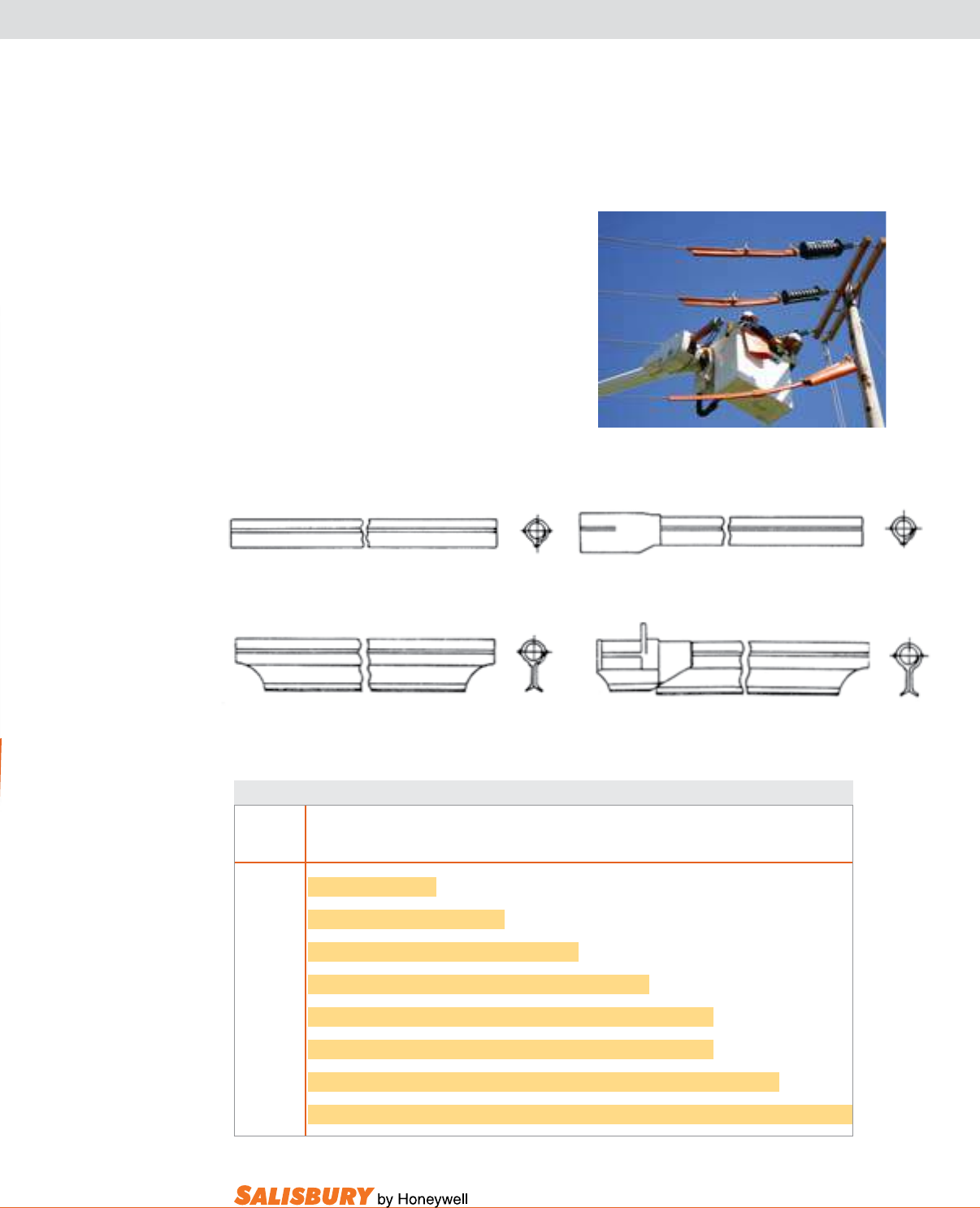
LINE HOSE SELECTION CHART
Salisbury Line Hose is available in four
ASTM D1050 styles, as shown below:
Style C
Class 4
Extended Lip Straight
Style a
Class 2 & 3
Straight Conventional
Style b
Class 2 & 3
Connector End Conventional
Style d
Class 4
Extended Lip Connector End
The connector, formed at one end, receives and
overlaps the end of an adjoining hose for a distance
of 6.5” (165mm).
Use the chart below to determine the maximum
conductor diameter recommended for use with
each size line hose. For ease of installation and to
minimize the potential of ashover through the
overlapping lips, line hose is always sized larger
than the maximum conductor diameter.
Line Hose Size Selector Chart
I.D. of Conductors and Diameters in. (mm)
Line Hose 4/0 266,800 336,400 477,000 556,500 795,000 954,000 1,351,500
in. (mm) .46 ( 12 ) .609 ( 15.5 ) .677 ( 17 ) .793 ( 20 ) .858 (22) 1.028 ( 26 ) 1.126 ( 29 ) 1.34 ( 35 )
1 ( 25 ) 20kV Conventional
1 1/4 ( 31 ) 20kV Conventional
1 1/2 ( 38 ) 30kV Conventional
1 1/2 ( 38 ) 40kV SU System
2 ( 51 ) 30kV Conventional
2 ( 51 ) 40kV SU System
2 1/2 ( 64 ) 30kV Conventional
2 1/2 ( 64 ) 40kV SU System

A-4 Insulating Line Hose and Covers. www.salisburybyhoneywell.com
LINE HOSE & CONNECTORS
CONVENTIONAL SYSTEM
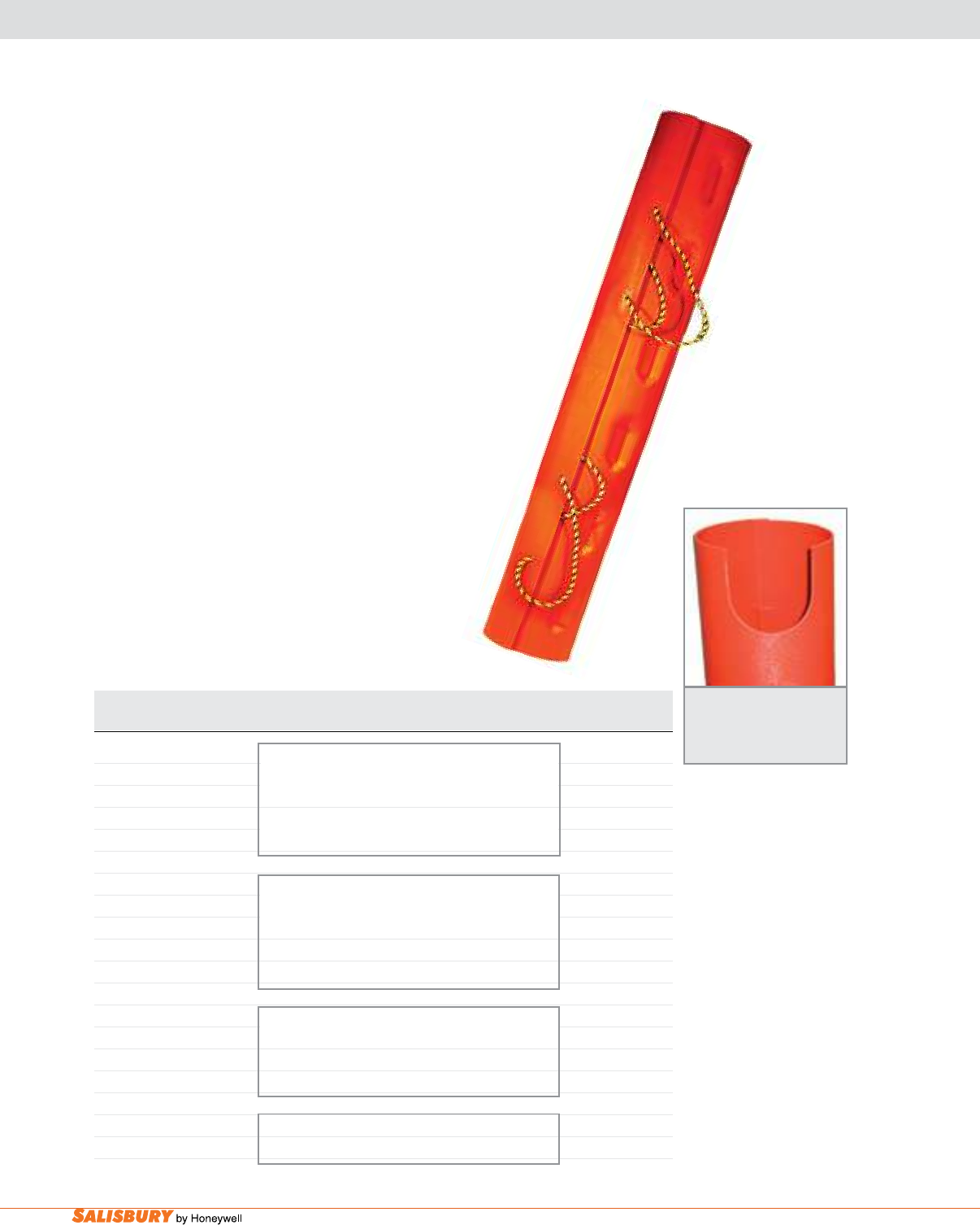
Conventional Style line Hose is available in
orange Type II SALCOR®. SALCOR remains
exible even in cold weather and it is not damaged
by ozone or ultraviolet rays. Each line hose has
Salisbury’s RIB-GRIP Locking System. The
straight or connector end style is available in three
sizes: 1” and 1.25” I.D. rated at 17kV, Class 2 and
1.5” I.D. rated at 26.5kV, Class 3.
Straight style SalCOR hose is also available in
2” or 2.5” I.D. rated at Class 3.
Conventional line Hose Connectors are made
from Type II orange SALCOR and can be used on
1”, 1.25”, or 1.5” I.D. conventional line hose. To
connect 2” and 2.5” I.D. conventional line hose,
use the SU System Connector.
The tightest grip in the industry.
The self-locking lip, Salisbury patented, prevents
line hose from coming off the conductor after an
installation is complete. Often, as a lineman is
working on an installation and making adjustments,
the angle of connection shifts, causing line hose
and covers to separate. To prevent this, Salisbury
developed an ingenious solution for ensuring that any
two protective devices would hold together yet still
be easy for a lineman to assemble and take apart.
OR125-45C
ORC125
OR150-3
Sectional view of typical insulator cover
showing arrangement of ribs. Ribs are
engineered to grip the serrations on its
corresponding line hose, regardless of angle.
Saw-tooth serrations on the ends of
line hose are angled to make it easy to
insert, but resist coming apart.
A row of serrations on both sides of
connector line hose grips snugly inside
the large arm of insulator covers.
Connector end line hose with rubber
ribs that grasp tightly and hold an
adjoining length of hose.
RIB GRIP Locking System
RIb gRIP® construction takes advantage of rubber’s
natural tendency to grip and tighten its grip through
compression. By creating curving rib congurations slit
at a specic angle, two pieces easily slip together but
resist coming apart. To quickly disengage the lineman
needs only to compress the rubber on either side.

A-5
101 E. Crossroads Pkwy., Ste. A Bolingbrook, IL 60440 toll free ph (USA):877.406.4501 toll free fax (USA):866.824.4922 ph:630.343.3800
LINE HOSE & CONNECTORS
CONVENTIONAL SYSTEM
Cat. No. ASTM Class Type Dimensions I.D. x Length Weight ea.
in. ( mm ) lbs. ( kgs )
SALCOR® Straight Line Hose
OR100-3 2 II 1” x 3’ ( 25 x 915 ) 3 ( 1.4 )
OR100-45 2 II 1” x 4.5’ ( 25 x 1372 ) 4 ( 1.8 )
OR100-6 2 II 1” x 6’ ( 25 x 1820 ) 5.5 ( 2.5 )
OR125-3 2 II 1.25” x 3’ ( 31.5 x 915 ) 4 ( 1.8 )
OR125-45 2 II 1.25” x 4.5’ ( 31.5 x 1372 ) 6 ( 2.7 )
OR125-6 2 II 1.25” x 6’ ( 31.5 x 1820 ) 7.5 ( 3.4 )
OR150-3 3 II 1.5” x 3’ ( 40 x 915 ) 5 ( 2.3 )
OR150-45 3 II 1.5” x 4.5’ ( 40 x 1372 ) 7 ( 3.2 )
OR150-6 3 II 1.5” x 6’ ( 40 x 1820 ) 9.5 ( 4.3 )
OR200-3 3 II 2” x 3’ ( 50 x 915 ) 5.5 ( 2.5 )
OR200-45 3 II 2” x 4.5’ ( 50 x 1372 ) 8 ( 3.6 )
OR200-6 3 II 2” x 6’ ( 50 x 1820 ) 11 ( 5.0 )
OR250-3 3 II 2.5” x 3’ ( 63 x 915 ) 7 ( 3.2 )
OR250-45 3 II 2.5” x 4.5’ ( 63 x 1372 ) 10.5 ( 4.8 )
OR250-6 3 II 2.5” x 6’ ( 63 x 1820 ) 14 ( 6.4 )
SALCOR Connector End Line Hose
OR100-3C 2 II 1” x 3’ ( 25 x 915 ) 3.5 ( 1.6 )
OR100-45C 2 II 1” x 4.5’ ( 25 x 1372 ) 5 ( 2.3 )
OR100-6C 2 II 1” x 6’ ( 25 x 1820 ) 6.5 ( 2.9 )
OR125-3C 2 II 1.25” x 3’ ( 31.5 x 915 ) 4.5 ( 2.0 )
OR125-45C 2 II 1.25” x 4.5’ ( 31.5 x 1372 ) 6.5 ( 2.9 )
OR125-6C 2 II 1.25” x 6’ ( 31.5 x 1820 ) 9 ( 4.1 )
OR150-3C 3 II 1.5” x 3’ ( 40 x 915 ) 6 ( 2.7 )
OR150-45C 3 II 1.5” x 4.5’ ( 40 x 1372 ) 8 ( 3.6 )
OR150-6C 3 II 1.5” x 6’ ( 40 x 1820 ) 9 ( 4.1 )
Line Hose Connectors
ORC100 2 II 1” x 12” ( 25.4 x 305 ) 2.5 ( 1.1 )
ORC125 2 II 1.25” x 12” ( 32 x 305 ) 3.5 ( 1.6 )
ORC150 3 II 1.5” x 12” ( 38 x 305 ) 3 ( 1.4 )
All Line Hose complies with current ASTM D1050 specifications.
A-6 Insulating Line Hose and Covers. www.salisburybyhoneywell.com
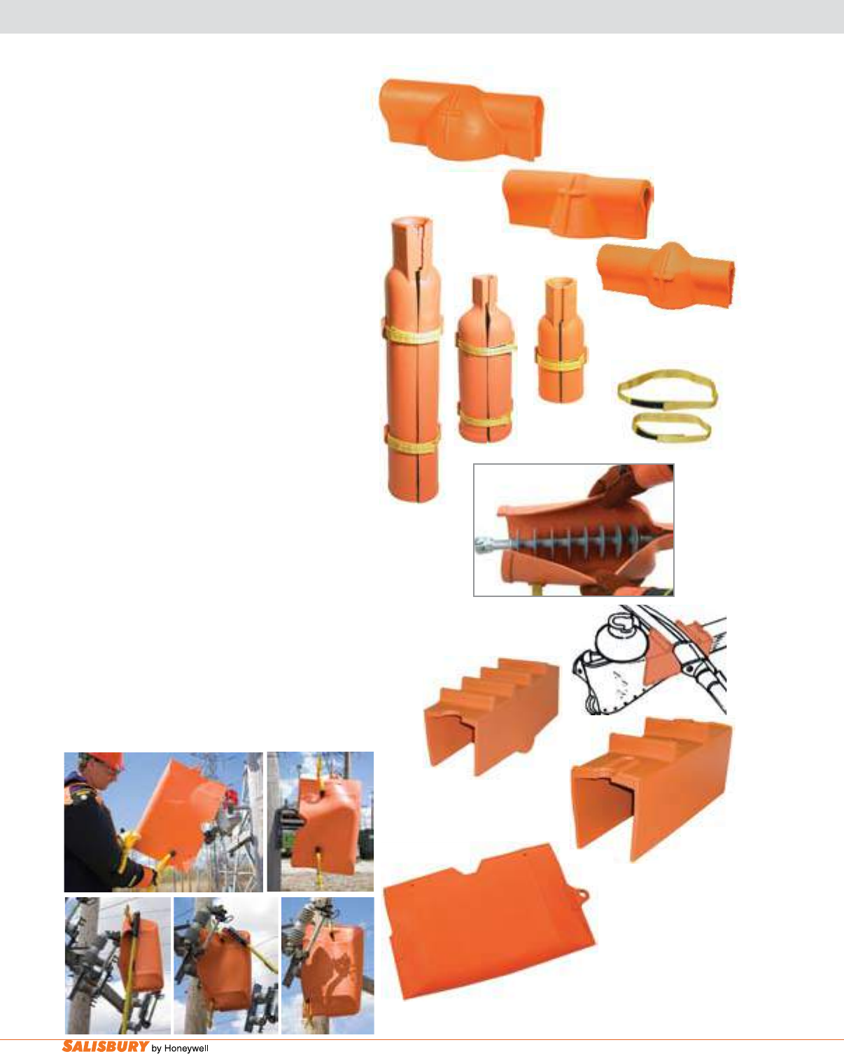
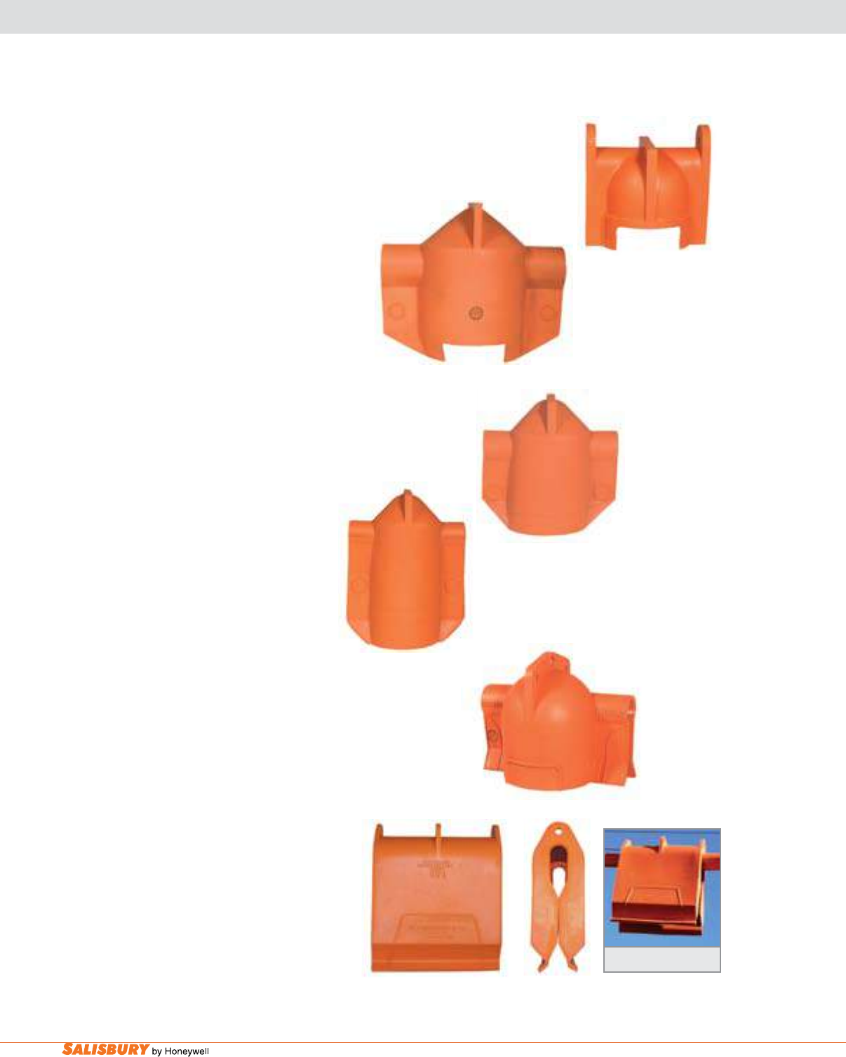
PROTECTORS & COVERS
CONVENTIONAL SYSTEM
OKRG
OR124
OR114
OR101
OFRG
OJRG
N24
N36
Insulator Covers, in orange, weather resistant Type
II SALCOR®, are used with conventional line hose to
cover pin-type insulators. All covers feature RIB-GRIP
construction to lock to the underside of the insulators.
The large diameter arm overlaps the small arm of the
adjoining cover on double arm constructions which
provides complete insulation at the joint regardless of
the varying distance between pins.
dead End Protectors cover 4.25” and 6” bells
or polymer insulators with a skirt diameter of less
than 6”. The protectors are made from orange Type
II SALCOR with RIB-GRIP construction. OR101
has outer ribs that allow it to be used with 2” and
2.5” I.D. Conventional Line Hose when using the
UC2 connector. The smaller OR114 may also be
used to cover transformer bushings up to 4.75” in
diameter. OR124 can cover polymer insulators up to
4.75” in diameter and 25” overall length including
hardware. Replacement Straps are available.
To work on live lines safely, conductors encased
in a line hose should never be placed directly on
a cross arm. Cross arm Covers reduce electrical
stresses on line hose or jumpers. Cross Arm Covers
t standard cross arm pin spacing and each unit has
interior ribs to minimize shifting on the arm.
Flexible Cutout Covers can be used for overhead
cutouts as well as for underground pad-mount
applications. Cutout Covers comply with the current
ASTM D1049 (ASTM Specications for Rubber
Insulating Covers) specications.
CC24
145
1186
A-7
101 E. Crossroads Pkwy., Ste. A Bolingbrook, IL 60440 toll free ph (USA):877.406.4501 toll free fax (USA):866.824.4922 ph:630.343.3800
PROTECTORS & COVERS
CONVENTIONAL SYSTEM
Cat. No. Class Description Overall Dimensions Weight ea.
in (mm) in ( mm ) lbs. ( kgs )
f o r u s e w i t h
INSULATOR COVERS Insulator Class Line Hose Size
OFRG 2 55-1/2/3 1” (25.4) 14.5” x 5” ( 368 x 127 ) 5 ( 2.3 )
OJRG 2 55-4 1” ( 25.4 ) 16” x 6.5” ( 406 x 165 ) 6 ( 2.7 )
OKRG 3 55-5 1.25”, 1.5” ( 32 , 38 ) 16” x 8” ( 406 x 203 ) 7 ( 3.2 )
f o r u s e w i t h
DEAD END PROTECTORS Bell Size Line Hose Size
OR101 2 2-6”( 152.4 ) 1” ( 25.4 ) 6.5” x 23” ( 165 x 584 ) 10 ( 4.6 )
OR114 3 1-4.25” ( 108 ) 1.5” ( 38 ) 4.75” x 14” ( 121 x 356 ) 4 ( 1.8 )
OR124 3 2-4.25” ( 108 ) 15” ( 38 ) 4.75” x 29” ( 121 x 737 ) 7.5 ( 3.4 )
CROSS ARM COVERS Use on Cross Arms up to
145 2 4” x 4.5” ( 102 x 114 ) 14.5” x 4.63” x 4.15” ( 368 x 117 x 105 ) 3 ( 1.4 )
1186 4 5.5” x 6” ( 140 x 152 ) 17.0” x 6.0” x 5.5” ( 432 x 152 x 140 ) 5 ( 2.3 )
CUTOUT COVERS
CC24 2 24” x 15” x 3.5” ( 600 x 376 x 88 ) 5 ( 2.3 )
CC30 4 30” x 20” x 7” ( 750 x 500 x 175 ) 10 ( 4.5 )
REPLACEMENT STRAPS
N24 For 114 & 124 Series .75 x 30 ( 18 x 588 ) 2 oz. ( 56.7 g )
N36 For 101 Series .75 x 36 ( 18 x 882 ) 2 oz. ( 56.7 g )
All covers comply with current ASTM D1049 specifications.
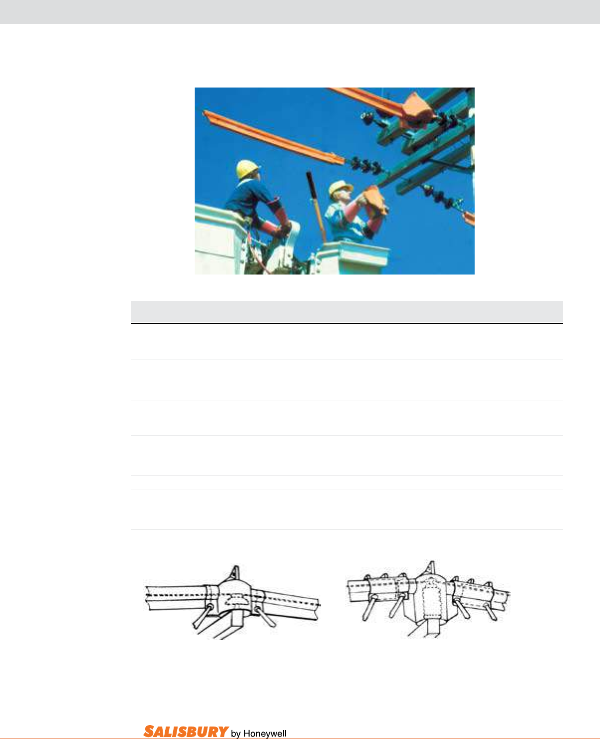
Put on with a firm
downward pressure.
Attaching the hoods to opposite
insulators on double arms.
On double arm poles the larger
extending arm of the one hood fits
easily over the small arm of the
hood on the opposite insulator.
Remove by “rolling off”
sideways.
Small Arm
Small Arm
Large Arm
Large Arm
A-8 Insulating Line Hose and Covers. www.salisburybyhoneywell.com
LINE HOSE
SU150-3C
Cat. No. Dimensions -- in. ( mm ) Weight ea.
I.D. Length lbs. ( kgs )
STRAIGHT LINE HOSE Class 4, Type II
SU150-3 1.5” ( 38 ) 3’ ( 915 ) 6 ( 2.7 )
SU150-45 1.5” ( 38 ) 4.5’ ( 1372 ) 8.5 ( 3.8 )
SU150-6 1.5” ( 38 ) 6’ ( 1829 ) 12 ( 5.4 )
SU200-3 2” ( 51 ) 3’ ( 915 ) 6 ( 2.7 )
SU200-45 2” ( 51 ) 4.5’ ( 1372 ) 10 ( 4.5 )
SU200-6 2” ( 51 ) 6’ ( 1829 ) 14 ( 6.4 )
SU250-3 2.5” ( 63.5 ) 3’ ( 915 ) 7 ( 3.2 )
SU250-45 2.5” ( 63.5 ) 4.5’ ( 1372 ) 11 ( 5.0 )
SU250-6 2.5” ( 63.5 ) 6’ ( 1829 ) 15 ( 6.8 )
CONNECTOR END LINE HOSE Class 4, Type II
SU150-3C 1.5” ( 38 ) 3’ ( 915 ) 7 ( 3.2 )
SU150-45C 1.5” ( 38 ) 4.5’ ( 1372 ) 9 ( 4.1 )
SU150-6C 1.5” ( 38 ) 6’ ( 1829 ) 12 ( 5.4 )
SU SYSTEM CONNECTORS Class 4, Type II ASTM D1049
Length x Height Use w/ Line Hose I.D.
UC 10.5” x 6” ( 263 x 150 ) 1.5” ( 40 ) 2 ( .9 )
UC2 10.5” x 7.75” ( 263 x 194 ) 2”&2.5” ( 51&64 ) 3 ( 1.4 )
Add Suffix “E” to Catalog Number to order with
#2323 Shot Gun Eye Assembly (see page A-13).
Complies with current ASTM D1050 specifications.
UC
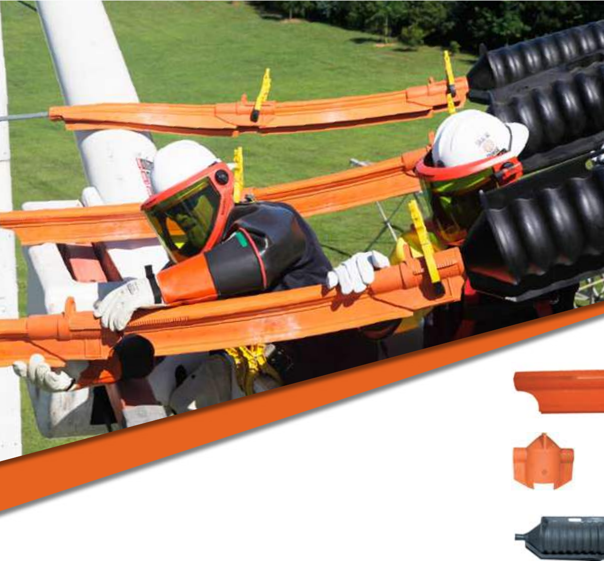
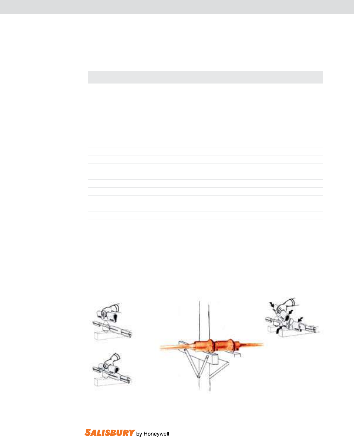
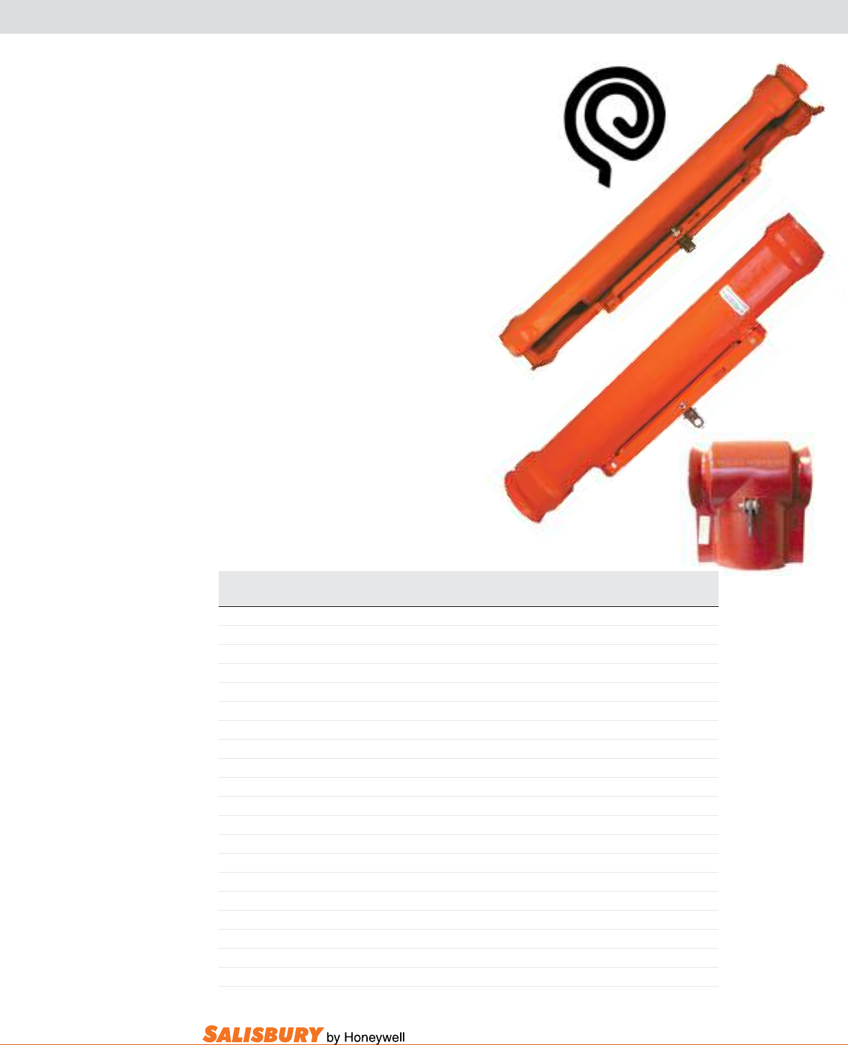
The Extended lip Su System is the only
complete exible cover-up available for
use on voltages through 34.5kV. Extremely
versatile, it may be installed by hand,
wearing rubber insulating gloves, from
an insulated aerial device or
platform, or with hot sticks
using the SU applicators.
Manufactured from superior
SALCOR® Type II elastomer,
it is resistant to the effects of
ozone and ultraviolet deterioration.
It remains flexible even at sub-zero
temperatures.
Salisbury’s RIB GRIP® construction
securely interlocks with its corresponding
covers and connectors. Tapered lips facilitate
easy starting on the conductors. The contour
cut ends accommodate the skirts of pin type
insulators and permit the hose to cover the
line snug to a saddle or clamp.
Available as Straight line Hose or with
a Connector End for easier connection
of line hose and covers. A lifting eye is
molded on the connector end for removal
with hot sticks. Line hose is also available
with the #2323 Shot Gun Eye Assembly.
Just add a sufx of “E” to the catalog
number to order the #2323 Shot Gun
Assembly installed on the hose or order
the #2323 separately.
Su System Connectors are made from
orange SALCOR Type II. RIB-GRIP
construction is used to ensure a strong
lock to the straight lengths of SU System
Line Hose and covers. The uC2 is used
to connect Extended Lip Hose to PTHL
and LRG Insulator Covers, OR134 Dead
End Protectors, and 2” (51mm) and 2.5”
(64mm) SU System and Conventional
Line Hose.
SU150-45
A-9
101 E. Crossroads Pkwy., Ste. A Bolingbrook, IL 60440 toll free ph (USA):877.406.4501 toll free fax (USA):866.824.4922 ph:630.343.3800
Cat. No. ASTM Fits Bell Size Dimensions in. ( mm ) Color Weight ea.
Class / Type in. ( mm ) I.D. body Overall Length lbs. ( kgs )
DEAD END PROTECTORS
OR134 4 / II 3-4.25 ( 108 ) 5 ( 127 ) 37 ( 940 ) Orange 13 ( 6 )
Add Suffix “E” to Catalog Number to order with #2323 Shot Gun Eye Assembly (see page A-13).
U106 3 / II 2-6 ( 152 ) 7 ( 178 ) 28.5 ( 724 ) Black 6 ( 2.7 )
U110 3 / II 2-10 ( 254 ) 10.5 ( 267 ) 28.5 ( 724 ) Black 10 ( 4.5 )
Add Suffix “E” to Catalog Number to order with #2340 Shot Gun Eye Assembly (see page A-13).
U110
OR134
All Protectors comply with current ASTM D1049 specifications.
dead End Protectors quickly cover dead
end bells or polymer insulators providing
complete electrical protection for Class 3
and Class 4 applications.
Easily installed and removed from an
insulated platform or aerial device with
rubber gloves or SU System Applicators.
All styles have RIB-GRIP® construction
to interlock with 1.5” (38mm) I.D. line
hose. The Class 3 U106 and U110 must be
used with Connector End style line hose or
separate Line Hose Connectors. OR134,
Class 4, accepts Straight Line Hose. The
outer ribs interlock with 2” and 2.5” I.D. line
hose when the UC2 SU System Connector
is used.
RIB-GRIP® Construction
A-10 Insulating Line Hose and Covers. www.salisburybyhoneywell.com
INSULATOR COVERS
LRG
PTHS
UH
PTHL
USC USC (side view)
The uH Pin-Type Cover covers insulators
up to ANSI standard C29.5 Class 5. The sides
are cut to be used on small insulators without
resting on the crossarm. When covering
a 7” diameter insulator on a double arm
construction, the ends of the cover will meet
ush on 10.5” pin centers.
The lRg Su System Pin-Type Cover ts
insulators 10.5” (267mm) in diameter and is
used with 2.5” (64mm) Class 4 Extended Lip
SU System Line Hose. Always use clamp pins
to secure the device into position. Pinning
rings have been placed on the cover’s arms
to prevent separation.
Post-Type Insulator Covers interlock with
1.5” (38mm) Class 4 Extended Lip SU System
or Conventional Line Hose. The PTHS for
insulators up to 12” (305mm) and the PTHl
for insulators up to 16” (406mm) in height.
The PTHl cover also has external ribs on the
ears which secures 2.5” (64mm) I.D. line hose.
Always use clamp pins to secure the device
into position.
The Class 4 mRg universal Cover covers
pin-type insulators through 8.5” (216mm)
diameter and 13.8kV post-type insulators. A
trim bead permits use on both 35kV and 15kV
crossarm construction.
The uSC Stirrup Cover is a lightweight
cover that can be installed using rubber gloves
or a hot stick. The USC also feature RIB-GRIP
construction and is meant to be used with
Extended Lip SU Systems or Conventional
Line Hose.
All covers are made from orange SALCOR®
and feature RIB-GRIP® Construction. They
can be installed with a hot stick or rubber
gloves. All covers comply with ASTM D1049
specications.
MRG
Application of USC.
A-11
101 E. Crossroads Pkwy., Ste. A Bolingbrook, IL 60440 toll free ph (USA):877.406.4501 toll free fax (USA):866.824.4922 ph:630.343.3800
Cat. ASTM Fits Line Hose Fits Insul. For Use w/ Insul. Class Overall Dimensions-in.(mm) Weight ea.
No. Class / Type in ( mm ) Max Dia in (mm) I.D. body Height lbs. ( kgs )
PIN TYPE Insulator Covers
LRG 4 / II 2.5 ( 63 ) 10.5 ( 263 ) 55-6 12 ( 305 ) 16 ( 400 ) 8 ( 3.6 )
MRG 4 / II 1.5-2.5 ( 40-63 ) 8.5 ( 213 ) Pin Type 55-5 9 ( 221 ) 12.25 ( 306 ) 7 ( 3.2 )
Post Type 13.2kV F Neck
Post Type 13.2kV C Neck
Add Suffix “E” to Catalog Number to order with #2359 Shot Gun Eye Assembly (see page A-13).
UH 3 / II 1.5 ( 40 ) 7 ( 175 ) 55-1, 2, 3, 4, 5 7.5 ( 184 ) 12 ( 300 ) 6 ( 4.4 )
POST TYPE Insulator Covers
PTHL 4 / II 1.5-2.5 ( 40-63 ) 6.5 ( 163 ) 57-2 7 ( 172 ) 16 ( 400 ) 8 ( 3.6 )
PTHS 4 / II 1.5 ( 40 ) 7 ( 175 ) 57-2 7.5 ( 184 ) 12 ( 300 ) 4 ( 1.8 )
Stirrup Cover
USC 4 / II 1.5 ( 40 ) 14 ( 263 ) 15.5 ( 388 ) 5 ( 2.3 )
INSULATOR COVERS
All Covers comply with current ASTM D1049 specifications.
Pin Type Insulator Cover - LRG or MRG Line
Hose is inserted
in the ears of the cover.
Post Type Insulator Cover
PTHL 2.5” (64mm) Line Hose held in
place with UC2 Connector.
A-12 Insulating Line Hose and Covers. www.salisburybyhoneywell.com
178
117
Cat. No. ASTM Type Dimensions in. ( mm ) For use w/ Cable Size Weight ea.
Class I.D. x Length lbs. ( kgs )
SELF-SECURING CABLE END CAPS
117 2 II 1.38” x 10” ( 35 x 254 ) #4/0 to 500 MCM .50 ( .23 )
173 2 II .81” x 6” ( 21 x 152 ) #4 to #4/0 AWG .25 ( .1 )
177 2 II 2.25” x 12” ( 57 x 305 ) 350 to 750 MCM .75 ( .35 )
178 2 II 3.19” x 16” ( 81 x 406 ) 800 to 1000 MCM 1.5 ( .7 )
LIGHTNING ARRESTER COVERS
536A 4 II 4.5 x 15 ( 113 x 375 ) - 3 ( 1.4 )
636A 4 II 5.5 x 22 ( 138 x 550 ) - 5 ( 2.3 )
536A
636A
These Covers comply with current ASTM D1049 specifications.
173
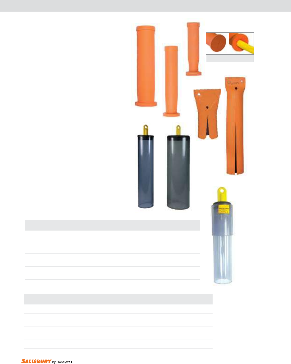
Cable End Caps are applied with rubber gloves.
They are used on high voltage distribution cable ends
found in vaults, cubicles and substations when cable
remains energized during work. Cable End Caps are
made from Type II orange SALCOR®.
Self-securing Cable End Caps for Underground
Distribution are rated at 20kV, and have a minimum
wall thickness of .25”. They keep moisture and
contamination off trimmed cable ends. The self-
securing slot keeps the cable locked safely inside
the end cap. These Cable End Caps are applied with
rubber gloves.
lightning arrester Covers are made from Type
II orange SALCOR . The slot allows the cap to t
directly over the energized lightning arrestor and the
line connection. Lightning Arrester Covers can be
applied with rubber gloves or a hot stick.
Clear Cable Covers are made from clear PVC round or
oval tube. Each cover has a grip all handle attachment
for installation with an insulated grip all hotstick.
Clear PvC Stress Cone Cover has a grip all
attachment that allows this cover to be installed with
an insulated grip all hotstick. The inspection window
can be opened for testing with a voltage sensor.
Self-Securing Cable End Caps
Cat. No. Description ASTM F712 Dimensions Weight
Class / Rating kV Length in. / I.D. in. / O.D. in. lbs. ( kgs )
CLEAR CABLE COVERS
14200032P 2” s PVC Cable Cover 2 / 14.6 20 / 2 / 2.38 1.5 ( 0.68 )
14200033P 3” s PVC Cable Cover 2 / 14.6 20 / 3 / 3.38 3.2 ( 1.45 )
14200034P 4” s PVC Cable Cover 2 / 14.6 20 / 4 / 4.38 4.3 ( 1.95 )
14200036P 6” s PVC Cable Cover 2 / 14.6 20 / 6 / 6.5 5.3 ( 2.41 )
CLEAR PVC STRESS CONE COVER
14200011 - 2 / 14.6 13 / 3 / 3.5 3 ( 1.36 )
14200034P
14200011
14200036P
A-13
101 E. Crossroads Pkwy., Ste. A Bolingbrook, IL 60440 toll free ph (USA):877.406.4501 toll free fax (USA):866.824.4922 ph:630.343.3800
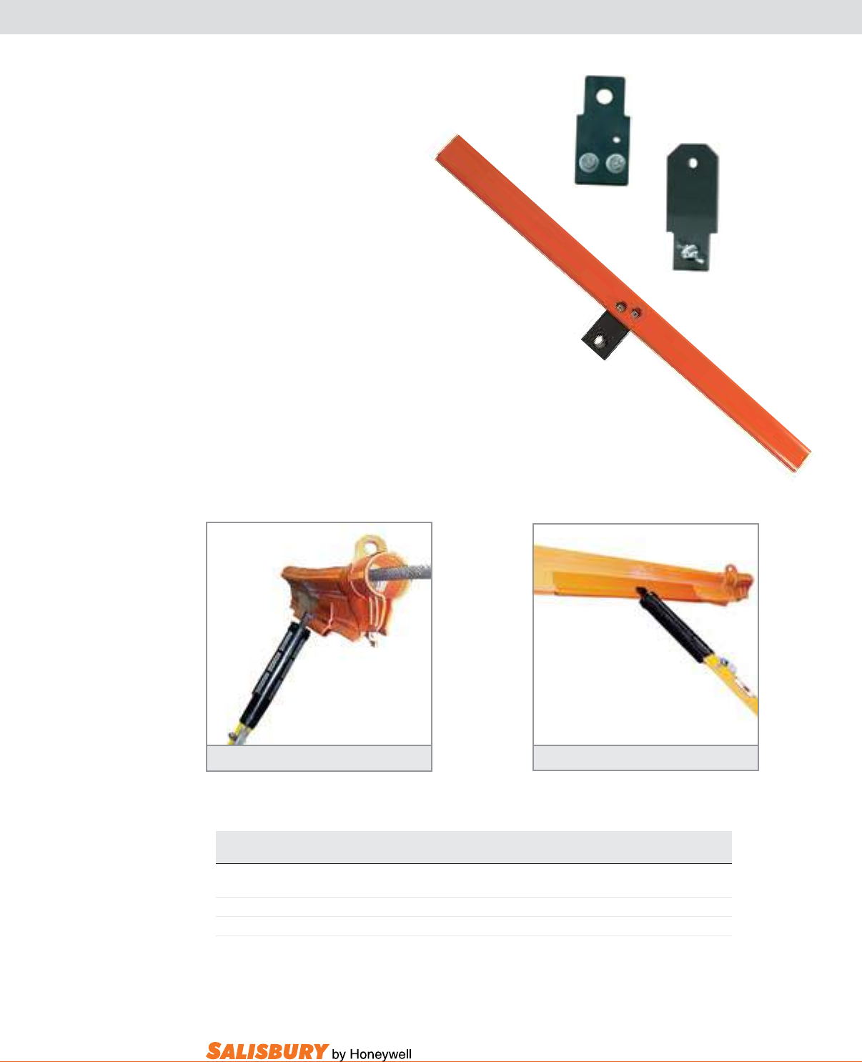
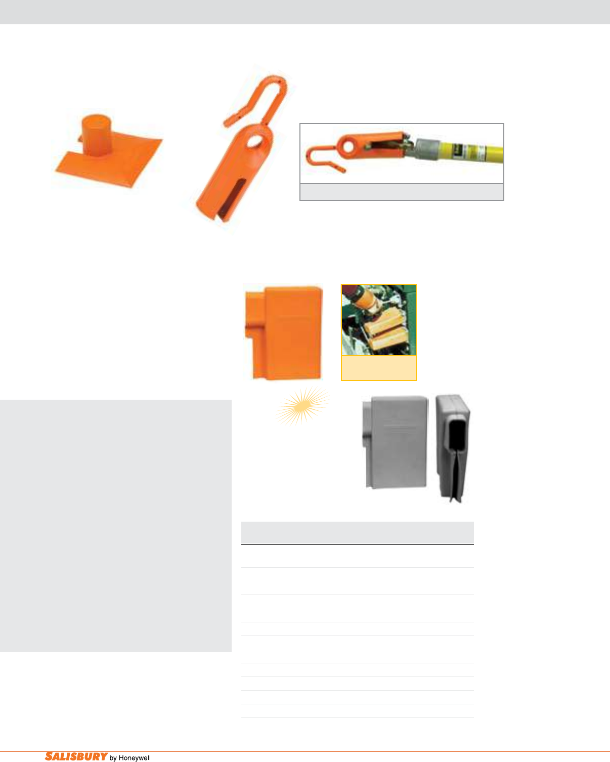
2323 Shot Gun Assembly
SU SYSTEM APPLICATORS
The Extended Lip SU System may
be installed by using rubber gloves
or hot sticks on distribution voltages
up to 34.5kV.
The Shot Gun Eye Assembly
for the SU System equipment
may be purchased separately for
installation on the appropriate
cover-up device.
The addition of these eye assemblies
enable all SU System equipment to
be easily handled with a standard
shotgun stick.
Cat. No. Description For Use w/ Weight ea.
Hot Stick Style lbs. ( kgs )
2323 Shot Gun Eye Assembly for SU Hose / OR134 Shot Gun 1 ( .4 )
2340 Eye Assembly for SU System D.E. Protectors Shot Gun .5 ( .2 )
2359 Eye Assembly for SU System Insulator Covers Shot Gun .5 ( .2 )
2323 Shotgun Assembly allows easy installation 2323 Shotgun Assembly attaches easily to SU Systems
2340
2359
A-14 Insulating Line Hose and Covers. www.salisburybyhoneywell.com
SPECIAL EQUIPMENT
Cat. No. Description / Dimensions Weight ea.
in. ( mm ) lbs. ( kgs )
TAGGING DEVICE
TD 7.25 ( 184 ) long slot: 2.13 x .63 (5 4 x 16 ) .25 ( .1 )
cup: 2.5 x 1.75 ( 64 x 44 )
METER TERMINAL COVER
TH111 3 x 3.5 x 1.5 ( 76 x 89 x 38 ) 1.6oz. ( .05 )
SPADE COVER - CLASS 2, TYPE II, ASTM D1049
SC4 2.75 x 4.4 x 10.75 ( 70 x 112 x 273 ), 1 (25.4) Lip Extension 1.4 ( .5 )
SC5 3 x 6 x 10 ( 76 x 152 x 254 ), 2 (51) Lip Extension 2 ( .9 )
SC6 3 x 6 x 10 ( 76 x 152 x 254 ), 1.25 (32) Lip Extension 1.4 ( .5 )
SC6G 3 x 6 x 10 ( 76 x 152 x 254 ), 1.25 (32) Lip Extension 1.4 ( .5 )
TD
TH111
Spade Cover
Application
SC5
SC6G
The Td Tagging device, made from
molded orange SALCOR®, is used to
tag opened disconnect switches. It allows
“Hold” cards to be placed on the circuit and
ts over the heads of 1-1/4” (32 mm) and
1-1/2” (38 mm) switch sticks.
The TH111 meter Terminal Cover is
used to avoid accidental contact with
energized parts on 100 and 200 Amp single
phase meter sockets. Made of orange
SALCOR.
THE SALISBURY ADVANTAGE
Spade Covers are easily installed to
provide temporary insulation when
working in padmount transformers and
other electrical apparatus. If spade covers
are securely held in place, they may be left
on spades or connectors indenitely for
front end protection. The larger SC5, SC6,
or SC6G are also used to cover primary
elbows as well as the larger and longer
multiple lead primary and secondary
fittings and lugs used in underground
enclosures and vaults. Molded from
exible SALCOR, they have excellent
aging and weathering characteristics. The
opening at the top end of the slot holds
the cover on to the terminal. Wide lips
extending along the slot provide additional
protection over the connection.
Tagging Device fits over the head of switch sticks for application.
ADVANTAGE

BLANKETS

B-2 Insulating Blankets. www.salisburybyhoneywell.com
FAQ
Q: How often do I need to test blankets?
A: Blankets issued for service need to be tested once a year.
See ASTM D479 8.1 for testing requirements.
SALISBURY EXCLUSIVE
Only Salisbury formulates compounds, mixes, molds and tests blankets in
our own ISO 9000:2008 registered facilities.
NOTE
General Care & Inspection of Salisbury Rubber Goods
Type I natural (non-ozone resistant) and Type II SalCOR® synthetic rubber (resistant to
ozone) both provide electrical workers with the highest level of electrical insulating protection.
However, in order to maintain this level of protection and ensure long life, it is essential that
rubber goods are properly cared for. Before each use, rubber goods should be visually inspected
for holes, embedded wires, rips or tears, ozone cutting, UV checking and signs of chemical
deterioration. For additional information, refer to ASTM F1236, standard guide for visual
inspection of electrical protective rubber products.
BLANKETS
B-3
101 E. Crossroads Pkwy., Ste. A Bolingbrook, IL 60440 toll free ph (USA):877.406.4501 toll free fax (USA):866.824.4922 ph:630.343.3800
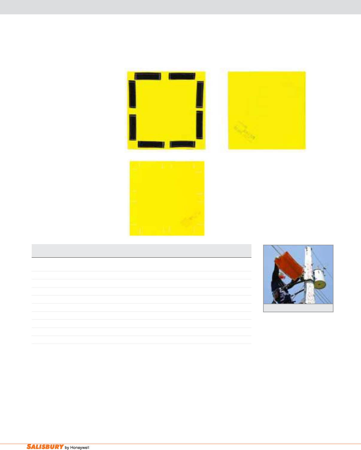
INSULATING BLANKETS
EYELET STYLE
Cat. Eyelets/ ASTM Class Type Size Color Weight ea.
No. Style in. ( mm ) lbs. ( kgs)
12 28 2 II 22 x 22 ( 559 x 559 ) Black 3 ( 1.4 )
13 28 4 II 22 x 22 ( 559 x 559 ) Orange 3 ( 1.4 )
13-10 10 4 II 22 x 22 ( 559 x 559 ) Orange 3 ( 1.4 )
400E 6 2 II 27 x 36 ( 686 x 914 ) Black 6 ( 2.3 )
1000E 6 4 II 27 x 36 ( 686 x 914 ) Orange 6 ( 2.3 )
1001E 6 4 II 27 x 36 ( 686 x 914 ) Black 6 ( 2.3 )
300E 6 2 I 36 x 36 ( 914 x 914 ) Black 8 ( 3.6 )
900E 6 4 II 36 x 36 ( 914 x 914 ) Orange 8 ( 3.6 )
901E 6 4 II 36 x 36 ( 914 x 914 ) Black 8 ( 3.6 )
1500 28 2 II 36 x 36 ( 914 x 914 ) Black 8 ( 3.6 )
1700 28 4 II 36 x 36 ( 914 x 914 ) Orange 8 ( 3.6 )
ZIP-ON STYLE
183OS Zip 4 II 18x36 ( 457x914 ) Orange 3.5 ( 1.6 )
900EV Zip 4 II 36x36 ( 914x914 ) Orange 8.5 ( 3.9 )
1000EV Zip 4 II 27x36 ( 686x914 ) Orange 8.1 ( 3.7 )
All blankets comply with current ASTM D1048 specifications.
THE SALISBURY ADVANTAGE
HIgH QualITy
Salisbury’s Type II SalCOR® blankets are of the
highest quality available today. They will hold their color
and exibility, and will maintain physical properties and
dielectric strength, required by ASTM standard, in the
eld longer than any other blanket on the market.
OzOnE RESISTanT
The Orange SALCOR is manufactured from a well
researched blend of prime EPDM, which is naturally
resistant to Ozone. This blend of Prime EPDM offers
superb exibility; similar to that of a Type I natural rubber
blanket. This ensures the Salisbury Type II SALCOR
blanket will pass the ASTM D 1048 Ozone Tests both,
Method A and Method B.
Eyelet Style Insulating blankets were designed
to be easily secured in place by using blanket
pins, Snap Buttons or Ty-Straps (available on
page B-9) Eyelet blankets are exible and
feature a reinforced beaded edge and eyelets
for added strength and tear-resistance.
Our zip-On Style (zip) features one-inch
wide strips of hook and pile double stitched to
the blanket with nylon thread, so installation
and removal is safe and fast.
400E (27 x 36)
Reinforced Beaded Edge
183OS
B-4 Insulating Blankets. www.salisburybyhoneywell.com
INSULATING BLANKETS
SLOTTED STYLE
Cat. Eyelets ASTM Class Type Size Color Weight ea.
No. in. ( mm ) lbs. ( kgs )
14 28 2 II 22 x 22 ( 559 x 559 ) Black 2.5 ( 1.1 )
15 28 4 II 22 x 22 ( 559 x 559 ) Orange 2.5 ( 1.1)
15-1 28 4 II 22 x 22 ( 559 x 559 ) Black 2.5 ( 1.1 )
1100 28 2 II 36 x 36 ( 914 x 914 ) Black 7 ( 3.2 )
1300 28 4 II 36 x 36 ( 914 x 914 ) Orange 7 ( 3.2 )
1301 28 4 II 36 x 36 ( 914 x 914 ) Black 7 ( 3.2 )
1302 2” hole 4 II 36 x 36 ( 914 x 914 ) Orange 7 ( 3.2 )
1304 4.5” hole 4 II 36 x 36 ( 914 x 914 ) Orange 7 ( 3.2 )
ZIP-ON STYLE
1300V Zip 4 II 36x36 ( 914x914 ) Orange 7 ( 3.2 )
All blankets comply with current ASTM D1048 specifications.
Slotted Style Insulating blankets are made of Type
II SALCOR® rubber and designed for increased
versatility and flexibility in special cover-up
situations. Use for covering ridge pins, cross arms
with insulators or any place a wire, pin or projection
interferes with proper placement of other cover-up
devices.
Three sizes are available with reinforced beaded
edges and reinforced eyelets which can be
secured with blanket pins, Snap Buttons or Ty-
straps (available on Page 9). Our 36”(914mm)
slotted blanket is also available with 2” (51mm)
or 4.5”(114mm) center holes and with hook and
pile (Zip Style). Our 46”(1168mm) slotted blanket
features extra thickness at the end of the slot for
added strength.
Our zip-On Style (zip) features one-inch wide
strips of hook and pile double stitched to the blanket
with nylon thread, so installation and removal is
safe and fast.
1301 (36 x 36)
1300 (36 x 36)
1300V (36 x 36)
B-5
101 E. Crossroads Pkwy., Ste. A Bolingbrook, IL 60440 toll free ph (USA):877.406.4501 toll free fax (USA):866.824.4922 ph:630.343.3800
INSULATING BLANKETS
WITHOUT EYELETS
Cat. No. ASTM Class Type Size Color Weight ea.
in. ( mm ) lbs. ( kgs )
186 4 II 18 x 36 ( 457 x 914 ) Orange 3.5 ( 7.7 )
300 2 I 36 x 36 ( 914 x 914 ) Black 8 ( 3.6 )
All blankets comply with current ASTM D1048 specifications.
THE SALISBURY ADVANTAGE
COnSISTEnCy
The Salisbury blanket is manufactured from materials
that are precisely measured in an automated weighing
system to ensure batch-to-batch consistency.
valuE
SALCOR® blankets will last longer and provide
maximum value and protection. Not all rubber
blankets are manufactured equally. Ask for the best,
ask for Salisbury’s rubber insulating blankets.
Salisbury Insulating blankets without Eyelets
are available in Class 2 and Class 4 in two types of
material: Type I natural rubber, and Type II SALCOR,
which is a highly exible, corona-resistant polymer
with excellent aging and weathering qualities.
Salisbury insulating blankets feature a reinforced
beaded edge for added strength and tear-resistance.
186 (18 x 36)
300 (36 x 36)
B-6 Insulating Blankets. www.salisburybyhoneywell.com
LOW VOLTAGE BLANKETS
WITH & WITHOUT HOOK AND PILE
Cat. Style ASTM Class Type Size Color Weight ea.
No. in. ( mm ) lbs. ( kgs )
1212YLV Zip 0 II 12x12 ( 305x305 ) Yellow 1 ( .45 )
1212YLVNV Plain 0 II 12x12 ( 305x305 ) Yellow 1 ( .45 )
1236YLV Zip 0 II 12x36 ( 305x914 ) Yellow 1.5 ( .48 )
1236YLVNV Plain 0 II 12x36 ( 305x914) Yellow 1.5 ( .48 )
1818YLV Zip 0 II 18x18 ( 457x457 ) Yellow 1.1 ( .48 )
1818YLVNV Plain 0 II 18x18 ( 457x457 ) Yellow 1.1 ( .48 )
1836YLV Zip 0 II 18x36 ( 457x914 ) Yellow 1.5 ( .68 )
1836YLVNV Plain 0 II 18x36 ( 457x914 ) Yellow 1.5 ( .68 )
3636YLV Zip 0 II 36x36 ( 914x914 ) Yellow 2.2 ( 1.0 )
3636YLVNV Plain 0 II 36x36 ( 914x914 ) Yellow 2.2 ( 1.0 )
All blankets comply with current ASTM D1048 specifications.
Installing a Zip-On Blanket
1212YLVNV1212YLV
low voltage Insulating blankets
are made of Type II SALCOR®
rubber. Insulating blankets are
available with or without hook and
pile (Zip) or Plain style, as noted in
the chart below.
Covering energized equipment is
easier than ever using Salisbury’s
Zip-On blankets. Our zip-On
Style (zip) features one-inch wide
strips of hook and pile double
stitched to the blanket with nylon
thread, so installation and removal
is safe and fast. Zip-On blankets
can be manufactured to t special
requirements. Contact your
Salisbury representative for more
information.
1212YLV
Back
B-7
101 E. Crossroads Pkwy., Ste. A Bolingbrook, IL 60440 toll free ph (USA):877.406.4501 toll free fax (USA):866.824.4922 ph:630.343.3800
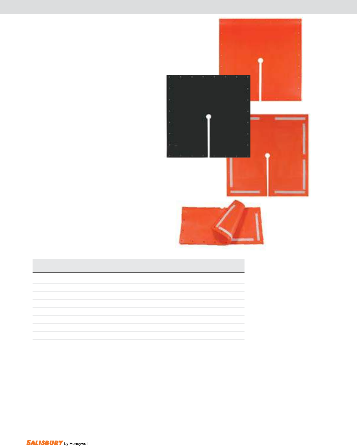
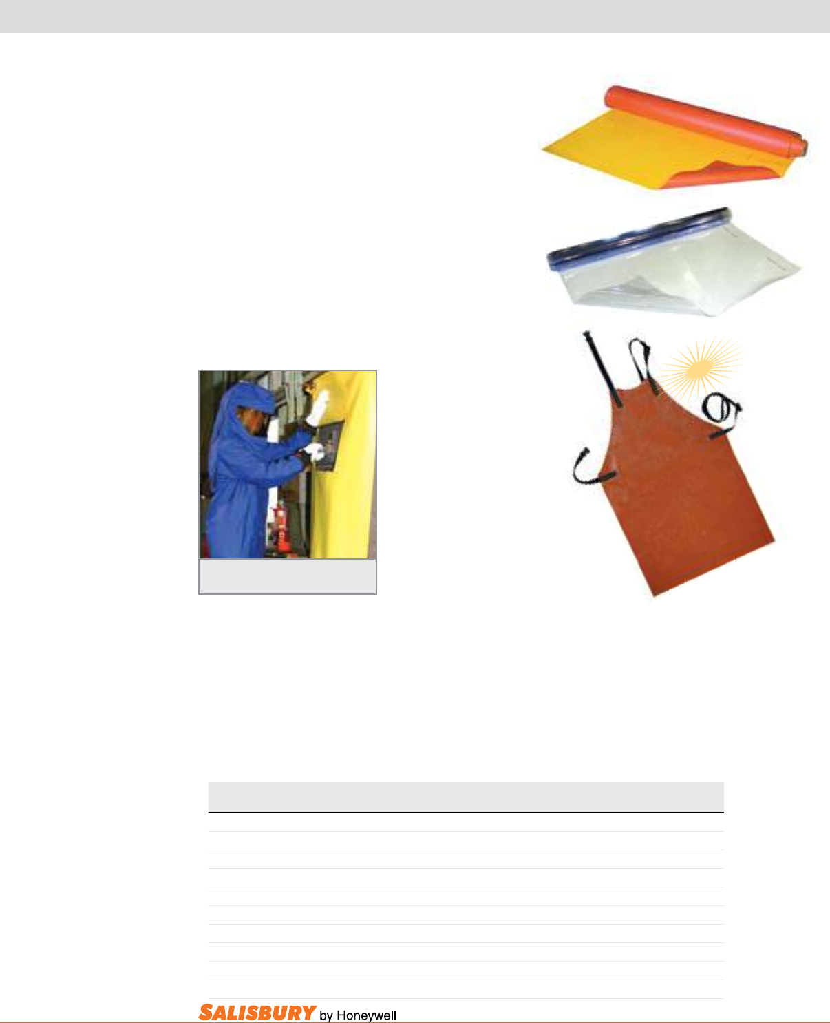
ROLL BLANKETS & INSULATING APRONS
RLB1
Cat. ASTM Class Type Size Color Weight ea.
No. feet ( m ) lbs. ( kgs )
ROLL BLANKETS
RLB00 00 II 3’ x 30’ ( .9 x 9 ) Brown 20 ( 9 )
RLB0 0 II 3’ x 30’ ( .9 x 9 ) Yellow 26 ( 11.8 )
RLB1 1 II 3’ x 30’ ( .9 x 9 ) Yellow / Orange 36 ( 16.4 )
RLBPVC1 1 - 3’ x 30’ ( .9 x 9 ) Clear 36 ( 16.4 )
RLBPVC1-48 1 - 4’ x 30’ ( 1.2 x 9 ) Clear 48 ( 21.7 )
INSULATING APRONS
APR00 00 II One Size Fits Most Brown 1.95 ( .88 )
APR0 0 II One Size Fits Most Yellow 2.53 ( 1.15 )
APR1 1 II One Size Fits Most Yellow / Orange 3.5 ( 1.59 )
RLBPVC1
Salisbury has gone to great lengths to protect workers from
low voltage electrical hazards, by now offering insulating
roll blankets and insulating aprons. Salisbury’s insulating
Roll blankets and Insulating aprons are made from a
high strength fabric reinforced Type II rubber in unique
colors making it easy to identify and highly visible in
the work area. Salisbury’s insulating Type II rubber Roll
Blankets and Insulating Aprons, meet ASTM F2320
standards.
Salisbury’s Roll blanket line includes a Class 1 (7,500v)
Clear PvC material that permits complete visibility,
yet provides the necessary insulating properties meeting
ASTM F1742 standards.
Roll Blankets can be easily cut to size and fit
for customized applications to each job.
The Roll blankets can
be easily custom-cut to
t each application at the
job site. This minimizes
the number of different
low voltage blankets
sizes and shapes that
would otherwise need to
be carries from job to job.
Each blanket comes in a
convenient 36” wide roll,
30 feet in length.
All classes of Roll Blankets are easy to cut, and exible to -40°F/C. Highly puncture and tear resistant,
each class of blanket is also ame (self-extinguishing), oil, and ozone resistant.
The Insulating apron includes two Nomex (R) webbed bib straps and two Nomex waist straps with
nonmetallic buckles. All the straps are attached with reinforced stitching and Nomex thread. The
insulating apron has straps that can be buckled around the back and around the neck which gives wearers
a comfortable and supportive t. The straps are adjustable so that one size will t most wearers. The
apron measures 42” from the top of the bib and has a full width of 30” to wrap around the front of most
workers. Use these aprons where there is a possibility of accidental contact with energized equipment
or lines. These products are not intended for purposeful contact with energized equipment.
APR00
NEW
B-8 Insulating Blankets. www.salisburybyhoneywell.com
HS21
21
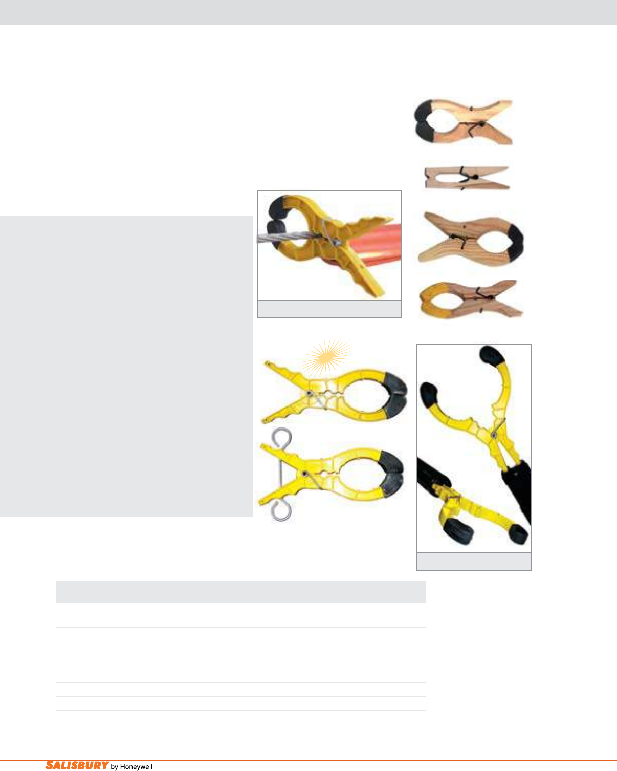
BLANKET ACCESSORIES
CLAMP PINS
Cat. No. Description Length Jaw Opening Weight ea.
in. ( mm ) in. ( mm ) lbs. ( kgs )
20 Wood w/ pin boots 8.5 ( 216 ) 4.75 ( 121 ) .33 ( .15 )
25 Wood w/o pin boots 7 ( 178 ) 1.6 ( 41 ) .25 ( .11 )
26 Wood w/ pin boots 10 ( 254 ) 7 ( 178 ) .5 ( .23 )
YN20 Wood w/ Sure grip 8.5 ( 216 ) 4.75 ( 121 ) .33 ( .15 )
HS21 Nylon w/ pin boots 9.5 ( 241 ) 5 ( 127 ) .37 ( .17 )
21 Nylon w/ pin boots 9.5 ( 241 ) 5 ( 127 ) .37 ( .17 )
Optionally applied with Shotgun Stick
20
YN20
In addition to other uses in the utility industry,
blanket Clamp Pins can be effectively used to
hold insulating blankets and rubber cover-up in
place. Springs are used for tension while extra
holes in the body of the pin are used to grip
conductors and prevent line hose from sliding.
THE SALISBURY ADVANTAGE
Improved!
The Salisbury 21 blanket pin is more functional
than ever. The new 21 pin has been improved
to make it the most versatile pin on the
market. Although the 21 pin always opened
to accommodate just about any width needed,
it has now been redesigned to open to a full 5
1/2 inches. That’s the widest of any standard
plastic pin in the industry. To accommodate
application using a hot stick, the ends of the pin
have been tapered to t into the end of any brand
clampstick. This allows the same 21 pin to be
installed in line with the stick. For applications
where a 90 degree angle of application and
removal is necessary, the time proven HS21
pin lls the bill. Look for the new 21 pin to be
supplied with your next pin order.
Blanket pins are made of berglass reinforced
nylon or sliver-free hardwoods. Most pins have
molded rubber tips to increase slip resistance.
26
25
Salisbury 21 Blanket Pin
ADVANTAGE
Clamp Pins help line hose from slipping
B-9
101 E. Crossroads Pkwy., Ste. A Bolingbrook, IL 60440 toll free ph (USA):877.406.4501 toll free fax (USA):866.824.4922 ph:630.343.3800
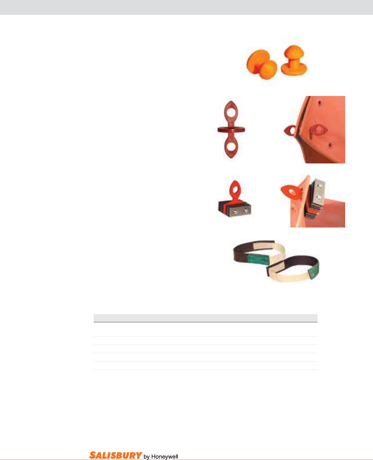
BLANKET ACCESSORIES
FASTENERS
B1
MB6
TY14
Cat. No. Description Weight ea. lbs. ( kgs )
B1 Snap-Button, Orange 1 oz. ( .03 )
B23 Two-Way Button, Orange 1 oz. ( .03 )
MB6 Magnetic Blanket Button 7 oz. ( .2 )
TY14 Ty-Straps, 14” ( 356mm ) long 2 oz. ( .06 )
TY30 Ty-Straps, 30” ( 762mm ) long 4 oz. ( .12 )
B23
blanket buttons are designed to secure
eyelet-style insulating blankets. The b1
button, made of yellow plastic, snaps through
the eyelet with thumb pressure on the large
head. The bright orange polystyrene b23 two-
way buttons are inserted into the eyelets for
use with a shotgun clamp stick or standard-
duty switch stick.
magnetic blanket buttons are designed
for use in eyelets of insulating blankets
when covering energized portions in
hard-to-cover areas like pad mounts,
cubicles, switchboards and substations. Four
permanent oating magnets are mounted
between nickel-plated steel plates. May be
applied manually, wearing rubber gloves, or
with a shot-gun stick.
Ty-Straps are 14” (356mm) and 30” (762mm)
long and made of 1 1/2” (38mm) wide strips
of rubber with hook and pile fasteners afxed
to each end. The worker simply wraps the
Ty-Strap around the positioned blanket and
presses the hook and pile ends together.
Contact your local Salisbury representative
for custom length Ty-Straps.
B-10 Insulating Blankets. www.salisburybyhoneywell.com
BLANKET ACCESSORIES
STORAGE
Cat. No. Description Fits Blanket Dimensions Capacity Weight ea.
Max Size in.( mm ) in. ( mm ) lbs. ( kgs )
P2 Canister 36 ( 914 ) 5 x 37 ( 127 x 940 ) 1-2 blankets 2 ( .9 )
P3 Canister 36 ( 914 ) 6 x 37 ( 152 x 940 ) 1-3 blankets 3 ( 1.4 )
P4 Canister 36 ( 914 ) 7 x 37 ( 178 x 940 ) 1-4 blankets 3.5 ( 1.6 )
P4H Canister 36 ( 914 ) 7 x 37 ( 178 x 940 ) 1-4 blankets 3.5 ( 1.6 )
P6 Canister 36 ( 914 ) 9 x 37 ( 229 x 940 ) 1-6 blankets 5 ( 2.3 )
P3-47 Canister 46 ( 1168 ) 6 x 47 ( 152 x 1194 ) 1-2 blankets 4 ( 1.8 )
22 Roll-up (vinyl) 22 ( 559 ) 56 x 42 ( 1651 x 1067 ) 1-4 blankets 1.5 ( .68 )
36 Roll-up (vinyl) 36 ( 914 ) or 46 ( 1168 ) 67 x 55 ( 1702 x 1397 ) 1-4 blankets 2.5 ( 1.1 )
46 Roll-up (vinyl) 36 ( 914 ) or 46 ( 1168 ) 70 x 55 ( 1778 x 1397 ) 1-4 blankets 4 ( 1.8 )
22
P6
P4
P2
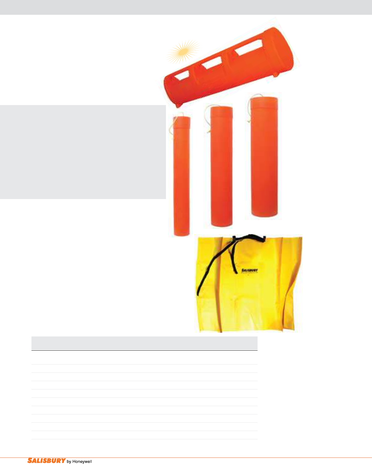
blanket Canisters
-
molded in bright orange, hi-
impact polyethylene
-
protect insulating blankets
when not in use. A tight-tting cap is secured to the
canister with polypropylene rope.
THE SALISBURY ADVANTAGE
Salisbury’s New P4H Blanket Canister
revolutionizes the way you’ll store your blankets.
The new canister has a sturdier construction than the
original P4, with integrated feet to keep the canister
from rolling while being transported by truck or
stored at the workplace. The new ergonomic handle
runs the entire length of the canister, making lifting
and carrying up to four 36 x 36” blankets much
easier. Slots are provided within the canister to allow
it to be secured in buckets or on trucks.
blanket Roll ups provide a safe and convenient
means for protecting blankets from damage while
in transport or storage. Ruggedly constructed of
18 oz. vinyl with side aps to conne the blankets
into position and prevent damage to the edges. Two
heavy 33” web straps with buckles close the roll-up,
and includes a web carrying handle.
STORAGE TIPS: When more than one blanket
is stored, the most convenient method of loading
is to roll and insert each blanket into the canister
independently. A single blanket can then be removed
without removing the others. For maximum useful
life, never fold, crease or compress insulating
blankets while in storage.
P4H
ADVANTAGE
B-11
101 E. Crossroads Pkwy., Ste. A Bolingbrook, IL 60440 toll free ph (USA):877.406.4501 toll free fax (USA):866.824.4922 ph:630.343.3800
SWITCHBOARD MATTING
Matting Cross-Section
Cat. ASTM Class Type Size Weight ea.
No. in. ( mm ) lbs. ( kgs )
SWITCHBOARD MATTING
M24-2 2 II 1/4 x 24 ( 6 x 610 ) 9 ( 4.1 )
M30-2 2 II 1/4 x 30 ( 6 x 762 ) 12 ( 5.4 )
M36-2 2 II 1/4 x 36 ( 6 x 914 ) 15 ( 6.8 )
M48-2 2 II 1/4 x 48 ( 6 x 1219 ) 18 ( 8.2 )
SWITCHBOARD MATTING
M36-4* 4 II 1/2 x 36” x 60 feet long ( 12 x 914 mm x 18.3 m long ) 684 (307.8 )
All switchboard matting comply with current ASTM D178 standards
*Sold in full rolls only.
GROUND BARRIER
R96 Carrier Vinyl Roll-Up / Ground Barrier 3.5 ( 1.6 )
M24-2
R96
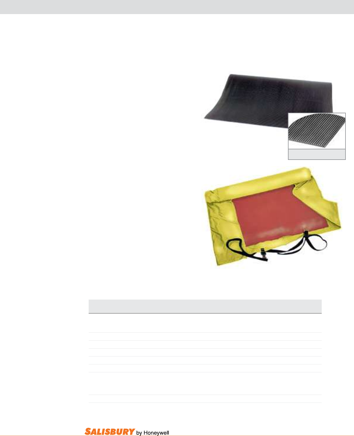
Switchboard matting is permanently placed
in front of switchgear, motor control centers
and other high voltage apparatus to provide
personal protection for workers. It is also used
when tending take-up and pay out reels and
when adding or replacing conductors. Made
from high quality Type II material, Class 2
matting is 1/4” (6.4mm) thick and is tested
to 20kV, and Class 4 matting is 1/2” thick
and tested to 40kV. Both Classes of matting
comply with ASTM D178, Class 2 and Class
4 specications. The corrugated surface acts
as a safety tread while reducing the possibility
of metal particles becoming embedded. Class
2 Switchboard matting is available in 25 yard
rolls or custom cut to specied lengths, while
Class 4 matting is sold in 20 yard rolls only.
Maximum Use AC Voltage Class 2, 17,000
volts; Class 4, 36,000 volts.
The R96 vinyl/roll-up carrier is recommended
as a ground barrier.
B-12 Insulating Blankets. www.salisburybyhoneywell.com
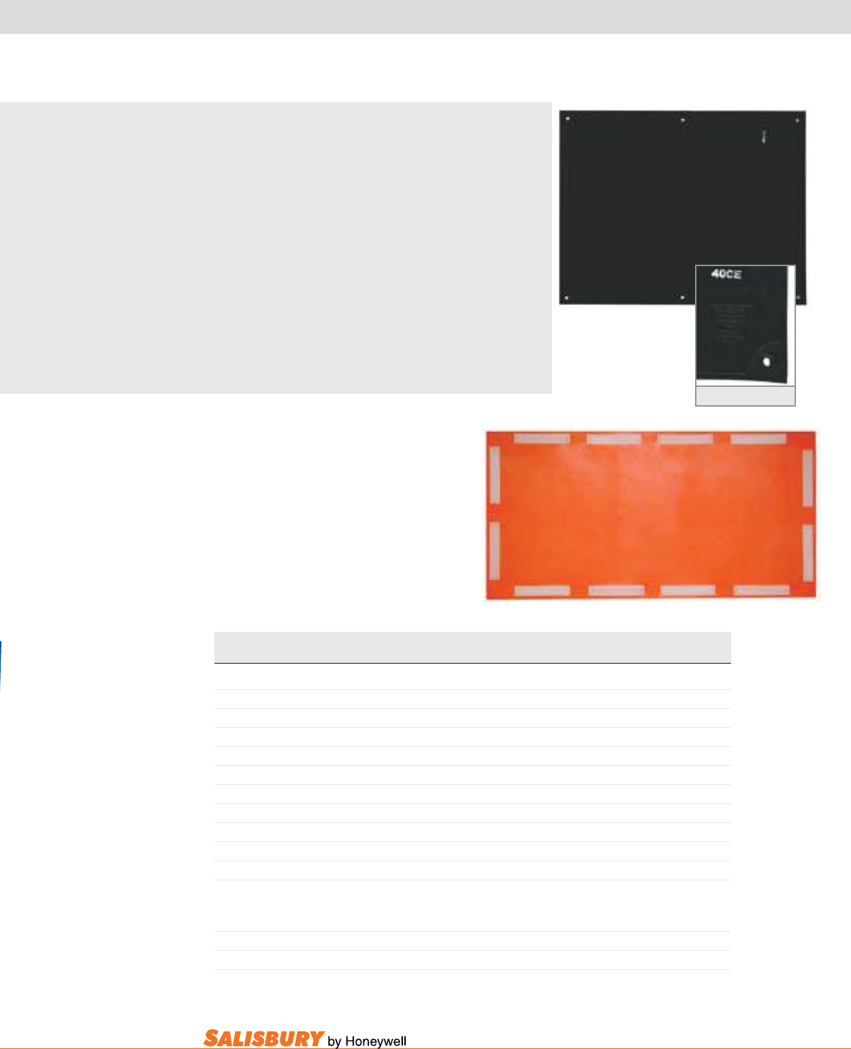
ARC SUPPRESSION BLANKET
Cat. No. Dimensions Description Weight ea.
in. ( mm ) lbs. ( kgs )
ARC45-15 48 x 60 ( 1219 x 1524 ) 15kA rating - navy blue 10 ( 4.5 )
ARC45-40 48 x 60 ( 1219 x 1524 ) 40kA rating -gray/khaki 10 ( 4.5 )
ARC48-15 48 x 96 ( 1219 x 2438 ) 15kA rating - navy blue 15 ( 6.8 )
ARC48-40 48 x 96 ( 1219 x 2438 ) 40kA rating -gray/khaki 15 ( 6.8 )
-Addsufx“P”toincludestoragebag.-Addsufx“PS”toincludestoragebagandtie-straps.
-Addsufx“C”toincludeP4canister.-Addsufx“CS”toincludeP4canisterandtie-straps.
ARC142 1 x 42 ( 25.4 x 1067 ) Single Kevlar Strap w/ Buckle
ARC142-K16 Arc48 Strap Kit With 16 Buckles 4 ( 1.8 )
ARC142-K12 Arc45 Strap Kit With 12 Buckles 3 ( 1.4 )
P4 7 x 37 ( 178 x 940 ) Canister holds 1-4 blankets w/ max. size 36” (914mm) 3.5 ( 1.6 )
MEETS NEW ASTM F2676 STANDARD
ASTM Standard for Testing of Arc Blankets
Arc protective blankets are used in many electrical applications to
protect workers who are stationed near energized electrical parts.
While these blankets have been used for years, there have been no
testing criteria for their evaluation. A new ASTM International standard
will be used to determine the effectiveness of arc protective blankets
in suppressing the combined effect of an arc ash and an arc blast.
The new standard, ASTM F2676, Test Method for Determining the
Protective Performance of an Arc Protective Blanket for Electric Arc
Hazards, was developed by Subcommittee F18.65 on Wearing Apparel,
part of ASTM International Committee F18 on Electrical Protective
Equipment for Workers.
This new standard gives companies the ability to evaluate blankets
with a repeatable standard that can be done at many test labs using
an electric arc and a high speed camera.
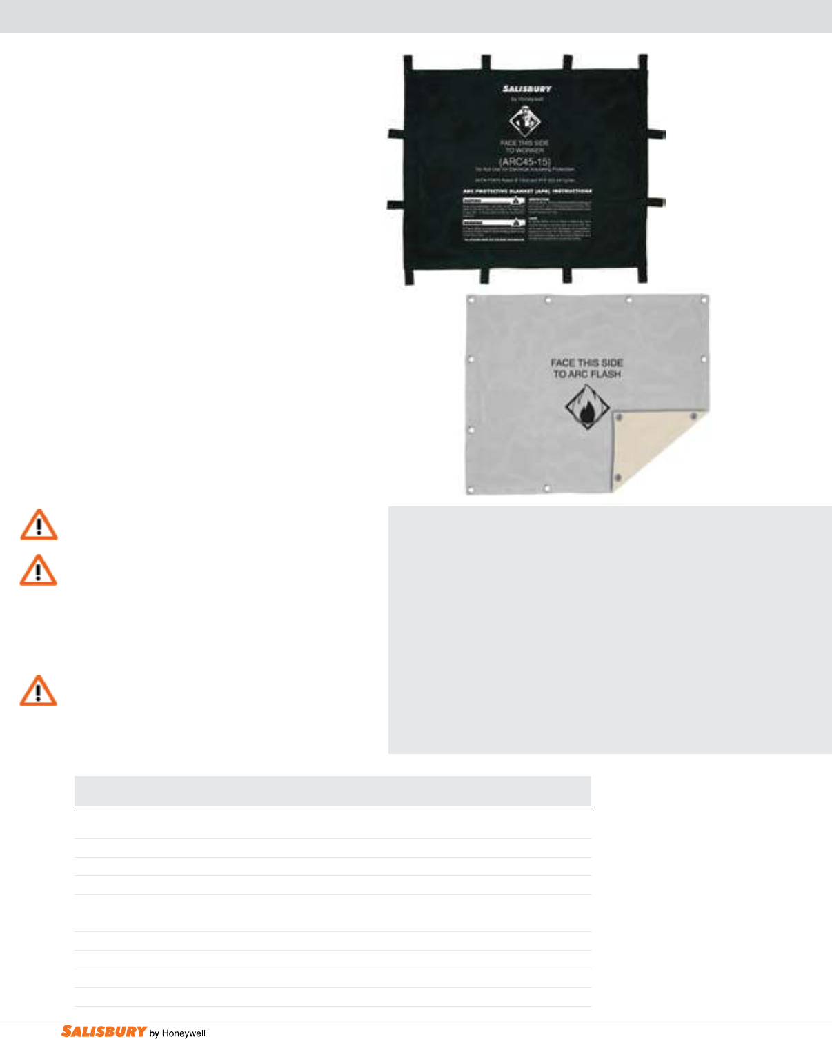
Salisbury by Honeywell arc Protection blankets are
now available in 4’ x 5’ and 4’ x 8’ sizes. Each size is
available in 15kA or 40kA ratings. The 15kA blankets
include convenient loops and the 40kA blankets include
grommets to easily keep the blanket in place. These new
blankets are sold individually or with a storage bag or
storage bag and tie-strap kit.
The Arc Suppression Blanket is used as a barrier
for protection from the explosive and incendiary
effects of electrical arcs and ashes. These hazardous
electrical discharges can be caused by faults in
cables, in cable splices and joints, and at transformer
terminals, or they may be generated by the operation
of switch gear, circuit breakers and lightning arrestors.
The blanket can be used for worker protection in
underground vaults, switchyards, and other locations
where electrical equipment poses a risk of exposure
to explosive electrical discharges.
NOTE These products do not eliminate or reduce requirements
for proper PPE for arc ash protection
WARNING
Because of the unpredictability of electrical Arcs, the Arc Protective
Blanket (APB) may not totally contain the arc and ashes, but only
reduce or limit explosive and incendiary effects. Properly installed
APB’s can reduce the risk of injury from the blast and heat. They
do not provide any personal protection for hearing, eyes, smoke
inhalation, hazardous gas inhalation, or burns.
WARNING
Arc Protective Blankets are not designed for electrical insulating
protection. Using the Arc Protective Blanket for electrical
insulating protection can result in serious injury or death.
ARC45-40
ARC45-15

insulating plastic
guards & covers

C-2 Insulating Plastic Guards and Covers. www.salisburybyhoneywell.com
insulating plastic guards & covers
testing
Types of Guards Energized Inner Electrode Outer Ground ElectrodeA
for All Tests A
Proof Test Withstand Voltage Flashover Leakage Tests
Line guards and line guard con-
nectors
Round metal tube or bar. Complete electrodeB shall be
spaced back from openings
through which the energized
electrode protrudes during
the test only as necessary to
avoid flashover. Therefore,
the entire area of each cover
shall be tested as nearly as
practical.
4 x 6” flexible conduc-
tive pad placed alternately
on all exterior surfaces
and across conductor
opening of guard and as-
sembled guard system
joints spaced back from
openings through which
the energized electrode
protrudes during the test
only as necessary to avoid
ashover at outer ends.
Insulator covers and deadend
covers
Maximum conductor, hardware and insulator as-
sembly for which rated or similar mock-up including
mandrelC of conducive material approximate. D
Pole guards, ridge pin and switch
blade covers
E Round metal tube, fabricated mandrelC or cluster
small metal tubes. D
Arm guards
Cutout covers
Round or rectangular metal tube or fabricated
madrelDC Largest cutout with bare leads covered with
equal rated line hose. Or similar mock-up including
mandrelC of conductive material. D
Structural barrier Rectangular metal sheets approximately 3mm
(0.06”) thick, having smoothly rounded edges and
corners, have been found to be satisfactory for this
purpose. Also satisfactory are wet felt or sponge-top
electrodes.
A Moistened electrodes may be secured with rubber straps or blanket pins. Pressure-sensitive tape is helpful in securing dry metal foil electrodes.
B Suitable materials include: metal foil or screen; tap water-moistened sponge sheeting, or blanket made of wool, or similar material including synthetics.
C Thin metal sheet or screen wire secured on wood frames make suitable electrodes. Carved synthetic sponge moistened with tap water is suitable for small forms.
D The dimensions of the mandrel are to approximate the maximum size of equipment to which the guard system is to be applied.
E Metal canisters made for storing rubber blankets make suitable electrodes for pole guard tests.
ASTM F 712-06 TABLE 3 Typical Electrodes for Testing Plastic Guard Equipment
Reprinted, with permission, from ASTM International, 100 Barr Harbor Drive, West Conshohocken, PA 19428. A copy
of the complete standard may be obtained from ASTM, www.astm.org
C-3
101 E. Crossroads Pkwy., Ste. A Bolingbrook, IL 60440 toll free ph (USA):877.406.4501 toll free fax (USA):866.824.4922 ph:630.343.3800
insulating plastic guards and covers
guards and Covers are intended for brush
contact applications. All guards can be coupled
together to cover any length required.
Guards and covers are available in three different
grades: Grade 1 with hot stick handles attached
for application and removal and Grade 2 with eye
ttings for standard shotgun sticks and Grade 3
without eye ttings. Guards are designed to nest
within each other for storage.
The guards and covers are made from two different
orange thermoplastics: Type I is an ABS standard
cold weather high impact plastic and Type III
is an ABS/PVC weather resistant material that
offers advantages in tensile and impact strength,
hardness, UV stability, and ame resistance.
ALWAYS FOLLOW YOUR COMPANY SAFETY PROCEDURES.
4. Significance and Use
4.1 All three tests may be used for product design qualifi-
cation.
4.2 This specification covers the minimum electrical,
chemical, and physical properties designated by the manufac-
turer and the detailed procedures by which such properties are
to be determined. The purchaser has the option to perform or
have performed any of these tests and may reject equipment
that fails to meet the standard criteria. Claims concerning
failure to meet the specification are subject to verification by
the manufacturer.
4.3 Plastic guard equipment is used for protection against
accidental brush contact by the worker. A margin of safety shall
be provided between the maximum voltage at which they are
used and the proof-test voltage at which they are tested. This
relationship is shown in Table 1 and Table 2. The equipment is
designed only for phase-to-ground or covered phase-to-
covered-phase exposure.
NOTE 1—Rubber insulating equipment is realistically limited to Class 4
material in the design specification standards. Plastic guard equipment has
been designed to go beyond these voltages and provide a satisfactory
degree of worker protection. Major differences exist in use criteria
between the rubber and the plastic guard equipment. Each glove, sleeve,
or other article of rubber insulating equipment has a given safety factor for
the phase to phase voltage on which it may be used and the class or proof
voltage at which it is tested. Plastic guard equipment, however, is designed
to provide a satisfactory safety factor only when used in a phase-to-ground
exposure. If exposure is phase-to-phase, then a satisfactory safety factor is
only provided if the exposure is covered-phase-to-covered-phase.
4.4 Work practices vary from user to user, dependent upon
many factors. These may include, but are not limited to,
operating system voltages, construction design, work proce-
dure techniques, weather conditions, etc. Therefore, except for
the restrictions set forth in this specification because of design
limitations, the use and maintenance of this equipment is
beyond the scope of this specification.
4.5 It is common practice and the responsibility of the user
of this type of protective equipment to prepare complete
instructions and regulations to govern in detail the correct and
safe use of such equipment.
5. Apparatus
5.1 Voltage Source and Test Techniques—See Test Method
D 149. The test equipment shall have adequate power and
provide relatively stepless variable test voltage that can be
raised at a rate of approximately 1000 V/s ac or 3000 V/s dc.
5.2 Energized Inner Electrodes, in accordance with Table 3
and Table 4. The length should be sufficient to extend past the
ends of the guard or guard assemblies where appropriate.
5.3 Outer Ground Electrode—A conductive material with
size and location as indicated in Table 3.
5.4 Shielded Cable—To reduce the “room influence” when
conducting ac leakage tests, the cable from the pickup elec-
trode to the current-measuring device should be a shielded
cable with the cable shield grounded.
6. Sampling
6.1 Design tests of each product model shall be conducted
to verify that the requirements of Table 1 and Table 2 are met.
6.2 Design Tests—Samples shall consist of sufficient speci-
mens of each product used in a specific guard system to form
one of each assembly intended for field use.
6.2.1 The design tests will be used to qualify a specific
product model and normally will not be repeated during
production.
6.2.2 Acceptance Tests— A test sample shall consist of one
or more specimens dependent on the percentage of the lot
being tested.
6.2.3 A lot is represented either by all the guards produced
in one production run or in one shipment.
6.2.4 Lots of new or unused guards shall have test speci-
mens selected at random.
7. Classification
7.1 Guards are furnished in three types of materials speci-
fied in Section 9and explained as follows:
7.1.1 Type I guards are constructed of plastic material
having mechanical impact properties suitable for cold weather
service.
7.1.2 Type II guards have self-extinguishing plastic con-
struction.
7.1.3 Type III guards are constructed of self-extinguishing
plastic material having mechanical impact properties suitable
for cold weather service.
7.2 Guards are furnished in three grades in accordance with
provisions for installation as follows:
7.2.1 Grade 1 guards have hot stick handles attached for
installation.
TABLE 1 Withstand Voltage Proof Test
A
Class Rating,
kV Max Use
60 Hz Proof Test Withstand Voltage
(in-service testing) Criteria
0-0
A
0-Ground 0-Ground kV Duration,
min
60 Hz DC
2 14.6 8.4 13.0 18 1 No flashover
other than
momentary
as a result of
too-close
spacing of
electrode
3 26.4 15.3 24.0 34 1
4 36.6 21.1 32.0 45 1
5 48.3 27.0 42.0 60 0.5
6 72.5 41.8 64.0 91 0.25
A
Cover-up materials are tested at values greater than the maximum use phase
to ground values. The maximum use phase to phase values relate to guarded
phase to guarded phase. The units are not rated for bare phase to guarded phase
potentials.
TABLE 2 Minimum Flashover Test
A
Rating,
kV Max Use
60 Hz Min Flashover Voltage
Test f-Ground kV Criteria
0-0
A
0-Ground 60 Hz DC
2 14.6 8.4 14.0 20 No flashover
other than
momentary
as a result of
too-close
spacing of
electrode
3 26.4 15.3 25.0 35
4 36.6 21.1 34.0 48
5 48.3 27.0 43.0 61
6 72.5 41.8 67.0 95
A
Cover-up materials are tested at values greater than the maximum use phase
to ground values. The maximum use phase to phase values relate to guarded
phase to guarded phase. The units are not rated for bare phase to guarded phase
potentials.
F 712 – 06
2
ASTM F712-06
Rubber insulating equipment is realistically limited to Class 4 material in the design
specication standards. Plastic guard equipment has been designed to go beyond these
voltages and provide a satisfactory degree of worker protection. Major differences
exist in use criteria between the rubber and the plastic guard equipment. Each glove,
sleeve, or other article of rubber insulating equipment has a given safety factor for
the phase to phase voltage on which it may be used and the class or proof voltage
at which it is tested. Plastic guard equipment, however, is designed to provide a
satisfactory safety factor only when used in a phase-to-ground exposure. If exposure
is phase-to-phase, then a satisfactory safety factor is only provided if the exposure is
covered-phase-to-covered-phase.
Reprinted, with permission, from ASTM International, 100 Barr
Harbor Drive, West Conshohocken, PA 19428. A copy of the
complete standard may be obtained from ASTM, www.astm.org
C-4 Insulating Plastic Guards and Covers. www.salisburybyhoneywell.com
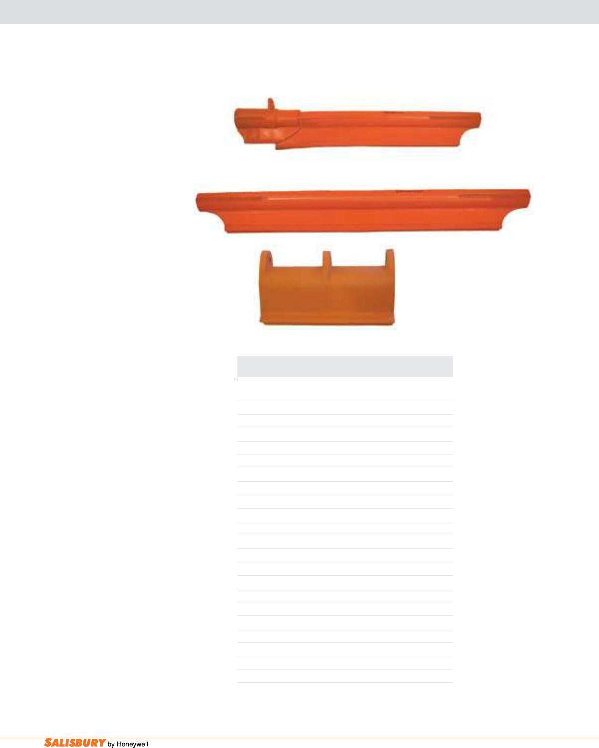
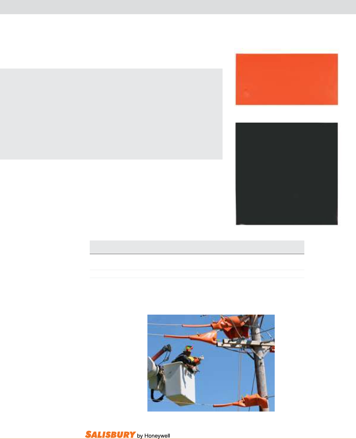
air gap® pole guards
2856
All guards are tested to ASTM F712
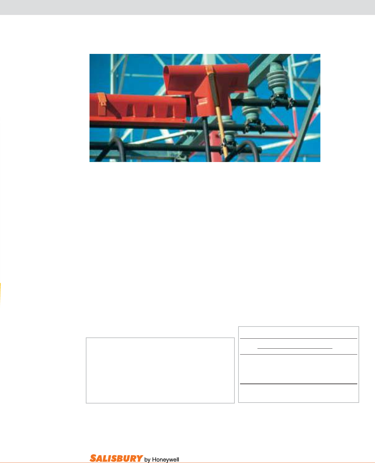
Pole guards are installed before setting new poles to guard against
accidental line contact. They also guard against pole contacts by personnel
working in insulating aerial buckets or on platforms. Pole Guards are
made from orange, Type I ABS, cold weather, high impact thermoplastic.
Salisbury Pole Guards feature the unique Air Gap® design. Uniformly
spaced dimples minimize the amount of surface area contacting the
pole. This provides added insulation to keep electrical leakage to a
minimum. When two pole guards are used to cover longer lengths, the
Air Gap dimples nest together “locking” the two together with ample
overlap. This is an exclusive feature to Salisbury Pole guards.
The Air Gap design also allows for air ow between it and the pole
minimizing moisture condensation and contamination buildup.
All Salisbury Pole Guards include drilled handles for easy
application. Pole Guards should be used for brush contact.
The opening should face away from possible line contacts,
whenever possible. Pole Guards should be stored indoors to
avoid prolonged exposure to UV rays and can be cleaned
with a warm detergent solution.
Cat. No. Length Dia. Class Weight ea.
ft. ( m ) in. ( mm ) lbs. ( kgs )
2851 1’ ( .3 ) 3.3 ( 1.5 )
2852 2’ ( .61 ) 6.3 ( 2.9 )
2853 3’ ( .92 ) 6” ( 152.4 ) 4 9.0 ( 4.1 )
2854 4’ ( 1.2 ) 11.0 ( 5.0 )
2856 6’ ( 1.8 ) 17.0 ( 7.7 )
1385 1’ ( .3 ) 3.6 ( 1.6 )
1386 2’ ( .61 ) 7.0 ( 3.2 )
1356 3’ ( .92 ) 9” ( 228.6 ) 4 10.0 ( 4.5 )
1357 4’ ( 1.2 ) 12.0 ( 5.4 )
2496 6’ ( 1.8 ) 19.0 ( 8.6 )
2461 1’ (.3 ) 5.0 ( 2.3 )
2462 2’ ( .61 ) 12” ( 304.8 ) 4 8.0 ( 3.6 )
2464 4’ ( 1.2 ) 15.0 ( 6.8 )
2466 6’ ( 1.8 ) 22.0 ( 10.0 )
21837 4’ ( 1.2 ) 9” ( 228.6 ) 4 - FR Pole Guard 12.0 ( 5.4 )
21936 2’ ( .61 ) 7” ( 177.8 ) 4 2.8 ( 1.27 )
The 21936 Pole Guard includes
cut-out to allow clearance for a
line post insulator base which is
mounted to a utility pole.
C-5
101 E. Crossroads Pkwy., Ste. A Bolingbrook, IL 60440 toll free ph (USA):877.406.4501 toll free fax (USA):866.824.4922 ph:630.343.3800
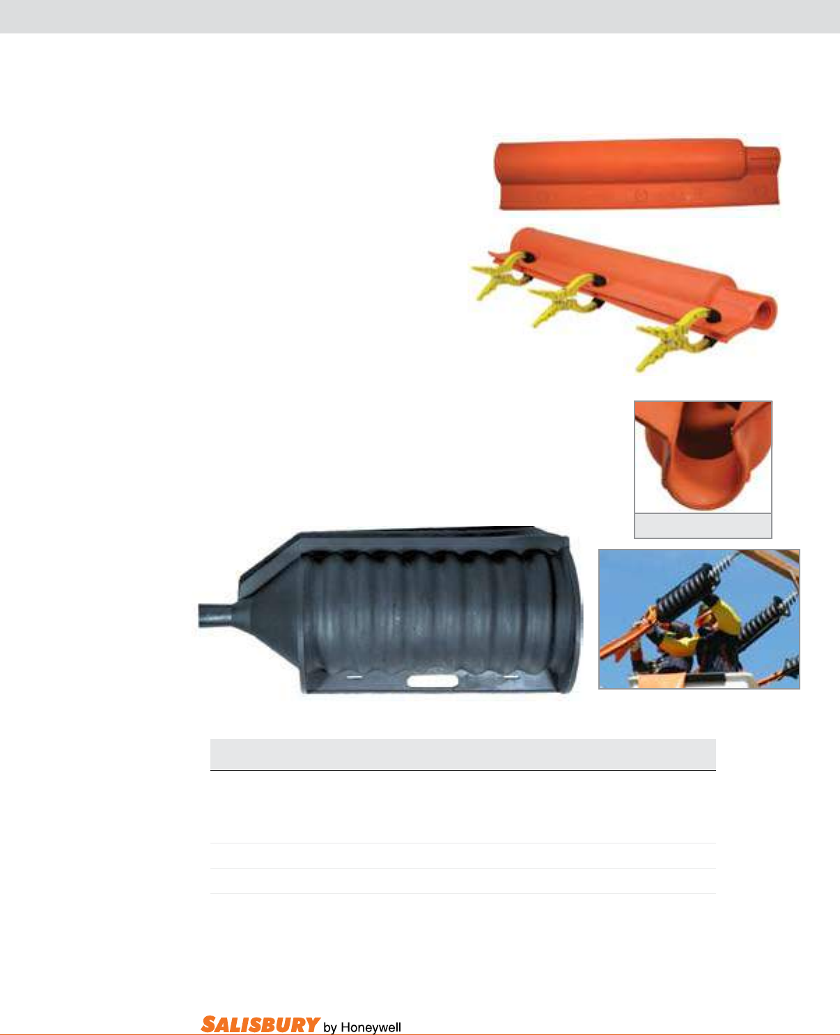
versa® and link® guards
1686
2475
Bags are available on
page C-10.
Versa Guards® and
Link Guard® Cross Section
Cat. No. Description Type ASTM Grade Weight ea.
Voltage Class lbs. ( kgs)
VERSA GUARDS®- 4.5’ ( 1.37 m )
1686 ABS Eye I 4 2 8.8 ( 4.0 )
1687 ABS 4’ Stick I 4 1 10.8 ( 4.9 )
1688 ABS 6’ Stick I 4 1 11.8 ( (5.4 )
2373 ABS/PVC Eye III 4 2 8.8 ( 4.0 )
2377 ABS/PVC 4 ’Stick III 4 1 10.8 ( 4.9 )
2378 ABS/PVC 6’ Stick III 4 1 11.8 ( 5.4 )
VERSA GUARDS®- 3.92’ ( 1.19 m )
2389 ABS/PVC 4’ Stick III 4 1 6.1 ( 2.8 )
2689 ABS/PVC Eye III 4 2 8.1 ( 3.7 )
LINK GUARDS- 4.5’ ( 1.37 m )
1680 ABS Eye I 6 2 10.5 ( 4.8 )
1681 ABS 4’ Stick I 6 1 12.5 ( 5.7 )
1682 ABS 6’ Stick I 6 1 13.5 ( 6.1 )
2475 ABS/PVC Eye III 6 2 10.5 ( 4.8 )
2476 ABS/PVC 4’ Stick III 6 1 12.5 ( 5.7 )
2477 ABS/PVC 6’ Stick III 6 1 13.5 ( 6.1
TEE CONNECTORS
2224 69 kV I 6 2 7.8 ( 3.5 )
2884 46 kV I 5 2 6.0 ( 2.7 0
All guards are tested to ASTM F712
2884
versa guards® and link guards® make use of air as well
as the dielectric strength of plastic to provide total insulating
value. Both guards have a 7” diameter and a hook shaped
inner lip to keep the guard in place.
versa guards, with a voltage rating of 36.6 kV*, are designed
so that two guards can be coupled together to cover most 13 kV
single and double arm, pin and post constructions. A lighter 47”
version (2389) of the standard 4.5’ Versa Guard is available in
a Type III ABS/PVC weather resistant material.
link guards, with a voltage rating of 72.5kV*,
have inner and outer shells that run full length
to include male and female couple ends. Two
guards connected provide four overlapping
thicknesses of plastic plus air at a joint.
Tee Connectors are used on horizontal and vertical posts and
suspension insulator strings when plastic line guards are
used on the conductor. Made from Type I, ABS plastic
with eye ttings, the connector accommodates the
male end of a guard. Available in two ratings:
72.5 kV* and 48.3 kV*. Accepts 34.5 kV pin
insulators along with post and insulator strings.
*guarded Ø to guarded Ø .
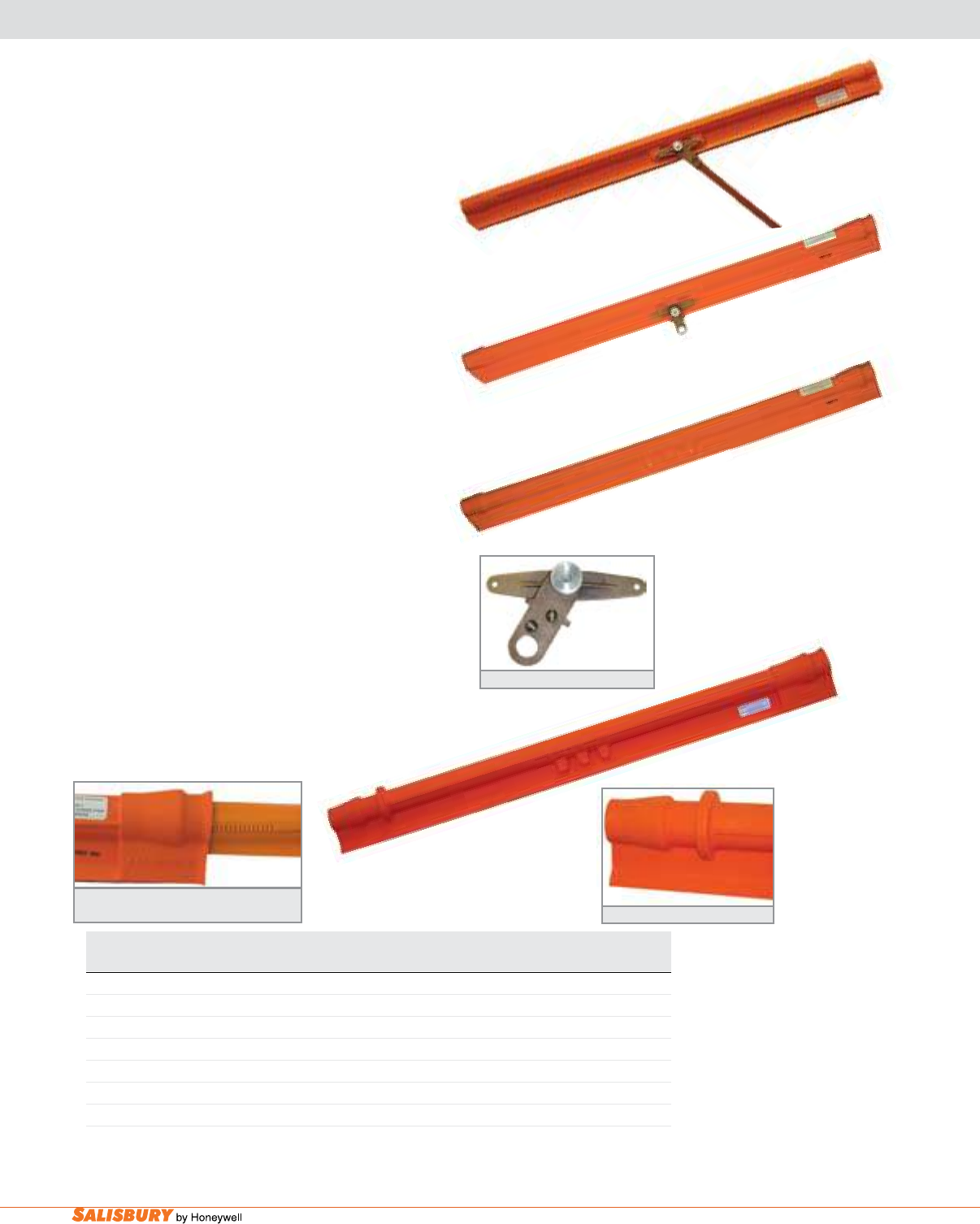
C-6 Insulating Plastic Guards and Covers. www.salisburybyhoneywell.com
lightweight conductor covers
Cat. No. Description ASTM Grade Weight ea.
ft. ( m ) Voltage Class lbs. ( kgs )
27 kV CONDUCTOR COVERS
21172 5’ ( 1.5 ) Cover w/ Eye 3 2 4.0 ( 1.8 )
21173 5’ ( 1.5 ) Cover w/o Eye 3 -- 3.0 ( 1.4 )
21315 5’ ( 1.5 ) Cover w/ 4’ ( 1.2) Fiberglass Stick 3 1 5.0 ( 2.25 )
21234 Adapter Eye 3 -- 1.5 ( 0.7 )
35kV CONDUCTOR COVER
21826 6’ ( 1.8 ) Cover 4 -- 6.5 ( 2.95 )
21172
21173
All guards are tested to ASTM F712
21315
21234 Adapter Eye
Conductor Covers connect easily with either
plastic or rubber line hose
21826
21826 Unique Connector Stop
lightweight Conductor Covers are ideal to cover
long spans when weight is a consideration. They can
be applied when wearing rubber gloves or with a
berglass stick. Available with an eye for application
with shotgun sticks. These covers have a voltage
rating of 26.4 kV*. The inside diameter is 2”. This
product can connect with Salisbury 1.5” I.D. Class 3
or 4 exible cover-up equipment.
The 21826 lightweight Conductor Cover is a six (6’,
1.8m) foot, cover rated Class 4 (36.6 kV*). It is applied
using rubber gloves when following appropriate
company work rules. The inside diameter is 3” making
it useful on a wide range of conductor sizes.
The unique “connector-stop” molded into one end
prevents covers from overlapping during installation.
This eliminates wasted time when trucks have to
be moved to reconnect sections that did not couple
correctly. This cover is also compatible with Salisbury
1.5” I.D. Class 3 or 4 exible rubber line hose.
All of our lightweight covers are made from safety
orange Type I high density cross link polyethylene.
*guarded Ø to guarded Ø .
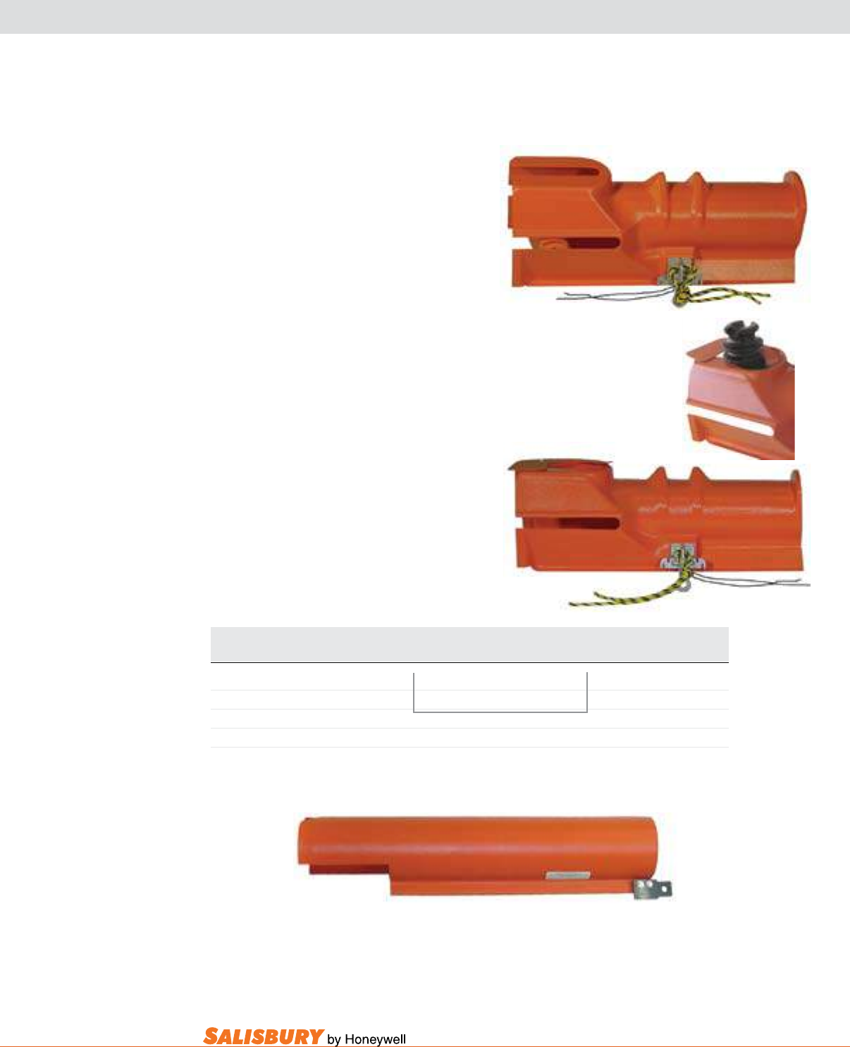
C-7
101 E. Crossroads Pkwy., Ste. A Bolingbrook, IL 60440 toll free ph (USA):877.406.4501 toll free fax (USA):866.824.4922 ph:630.343.3800
crossarm guards
Cat. No. Description Dimensions ASTM Weight ea.
in. ( mm ) Voltage Class lbs. ( kgs )
1370 Crossarm or Pin Type Guard 9 x 9 x 25.5 ( 229 x 229 x 648 ) 4 5.7 ( 2.6 )
1371 Crossarm or Post Type Guard Fits Crossarm:5 x 6 ( 127 x 152 ) 4 6.0 ( 2.7 )
736PH Slide-On Crossarm Guard 7” I.D. x 36” ( 178 I.D. x 914 ) 4 4.5 ( 2 )
1370
1371
All guards are tested to ASTM F712
736PH
Crossarm guards are available in two
different styles: the 1370 pin type and the
1371 post type. They are used to prevent tie
wires from contacting crossarms during hot
line operations. Two different tie downs are
provided: a neoprene and a polypropylene
rope. Both are secured in the slots provided
in the eye tting. The post type model has an
automatic gap closer which covers the insulator
slot opening over the end of the arm.
The Slide-On Crossarm guard 736PH is
applied by sliding the cover on to the arm
from the end using the shotgun eye until the
unit locks onto the insulator pins. The cover
overlaps on top and has notches to ease
application and removal.
Both of these guards are made from orange Type
I ABS cold weather high impact plastic. These
guards have a voltage rating of 36.6 kV*.
*guarded Ø to guarded Ø .
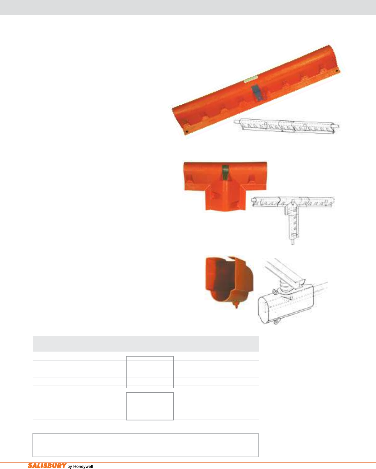
C-8 Insulating Plastic Guards and Covers. www.salisburybyhoneywell.com
substation cover-up
bus guards
Substation Cover-up and barrier equipment is
used during routine maintenance where accidental
contact may occur. This barrier equipment is often
used where outages are difcult to reach and the
occurrence of accidental contact is high. These covers
may be applied with rubber gloves or hot sticks. These
covers are made from Type I orange ABS plastic.
This equipment is not intended for permanent or
semipermanent barrier or insulating applications. Use
these covers to protect against accidental contact only.
These covers are not to be left installed for extended
periods of time especially when in contact with both
a grounded and energized object.
bus guards are easily interlocked with each other.
To interlock units determine the length of bus to be
covered. Place one unit on the bus then the other,
pulling it over the first cover until the dimples
interlock at the required length. This guard has a
voltage rating of 36.6 kV*.
bus “T” guards interlock two or three bus guards
at bus tap “T” connections and 90 degree angles. To
interlock units, rst position the bus guard then slide
the “T” guard over the top interlocking the dimples.
This guard has a voltage rating of 36.6 kV*.
bus End guards cover the ends of a substation bus
supported by station post insulators. The slot and
insulator grip hole can be easily enlarged in the eld
with a sharp knife. This cover also has a guide bead for a
trim t. This guard has a voltage rating of 26.4 kV*.
Eye kit is available on page C-10.
Cat. No. Dimension Description ASTM Weight ea.
in. ( mm ) Voltage Class lbs. ( kgs )
Bus Guard
1374 5.25”x 9.5”x4.5’ ( 133 x241x1.4m ) Impact Resistant 4 6.0 ( 2.7 )
Bus “T” Guard
1375 5”x15”x25” ( 127x381 x635 ) ABS Plastic 4 4.0 ( 1.8 )
Bus End Guard
9992 8.5”x12”x24” ( 216x305x610 ) UV Resistant 3 5.0 ( 2.3 )
High Density Cross
Linked Polyethylene
9992
1375
1374
Bus Guard
Bus “T” Guard
Bus End Guard
All guards are tested to ASTM F712
*guarded Ø to guarded Ø .
All Bus Guards may be applied with rubber gloves or hot sticks. Contact your local Salisbury representative for Hot Stick purchasing
or check out salisburybyhoneywell.com for more information on our line of hot stick products. Use Salisbury Insualting Rubber
Blankets as additional or alternative cover-up in situations where Bus Guards may be used.
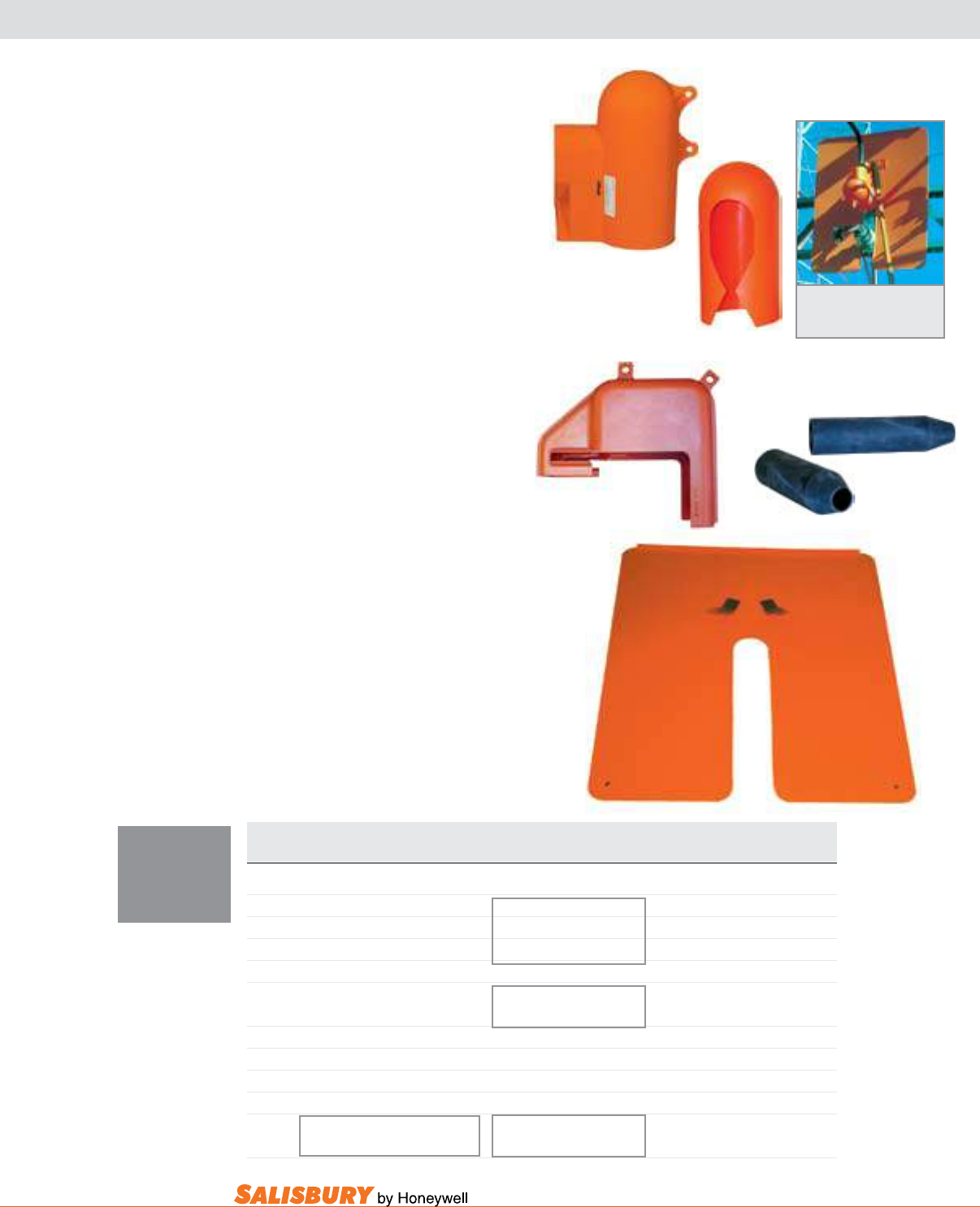
C-9
101 E. Crossroads Pkwy., Ste. A Bolingbrook, IL 60440 toll free ph (USA):877.406.4501 toll free fax (USA):866.824.4922 ph:630.343.3800
1376
2418
Barrier and Switch
Jaw Guard installed on a Substa-
tion Switch.
24455
24219 T1
Switch Jaw guards insulate the energized
upper switch jaw and insulator when work is
being done on the switch blade, lower insulator
or other de-energized equipment ahead of the
open switch. These guards easily slide over the
upper insulator on open substation switches
and lock over the bus. Jaw Guards are made
from Type I UV resistant plastic. This guard
has a voltage rating of 26.4 kV*.
The 24219 Switch Jaw Cover provides an
insulated barrier to the energized upper switch
jaw and insulator, when work is being done on the
switch blade, lower insulator, or other de-energized
equipment ahead of the open switch. This guard
slides easily over the upper insulator on
open substation neutral disconnect cabinet
switches and locks over the bus. The 24219
Cover is made from Type I cold weather
high impact plastic. This guard has a voltage
rating of 14.6 kV*.
The T1, Terminal Sleeve disconnect Switch is
used on open style disconnects and made from Type
II SALCOR®, EPDM rubber.
Switch barriers slide between the last two skirts
on the post or pin cap insulators of the substation
disconnect switch. This locks the barrier in place.
When switches are mounted back to back and work
is needed on one, the barrier can be placed on the
energized switch to form a visible, electrical and
mechanical barrier. Work can then be done on the
opposite switch or other de-energized equipment.
This guard has a voltage rating of 36.6 kV*.
*guarded Ø to guarded Ø .
Cat. No. Dimensions Description ASTM Weight ea.
in. (mm) Voltage Class lbs. ( kgs )
JAW GUARD
2418 8” D. x 18” ( 203 D. x 457 ) Use w/ switch 8”(203) Dia. 3 4 ( 1.8 )
2424 8” D. x 24” ( 203 D. x 610 ) Insulated 3 5 ( 2.3 )
24455 8” D. x 16” ( 203 D. x 406 ) 2 2.25 ( 1.14 )
2413 13” D. x 24” ( 330 D. x 610 ) Use w/ switch 13”(330) Dia. 3 7 ( 3.2 )
Pin Cap Insulators
JAW COVER & TERMINAL SLEEVE
24219 Jaw Cover 2 4 ( 1.8 )
T1 10” x 2” I.D. ( 254 x 51 I.D. ) Terminal Sleeve .33 ( .15 )
BARRIER
1376 .125”x43”x52” ( 3.2x1092x1320) Orange Type I High Impact 4 12 ( 5.5 )
5” ( 127 ) slot to center ABS Plastic
NOTE: If your substation
needs are not fulfilled by
the products on this page,
please contact your local
Salisbury representative
for custom applications.
substation cover-up
switch Jaw guard & barrier
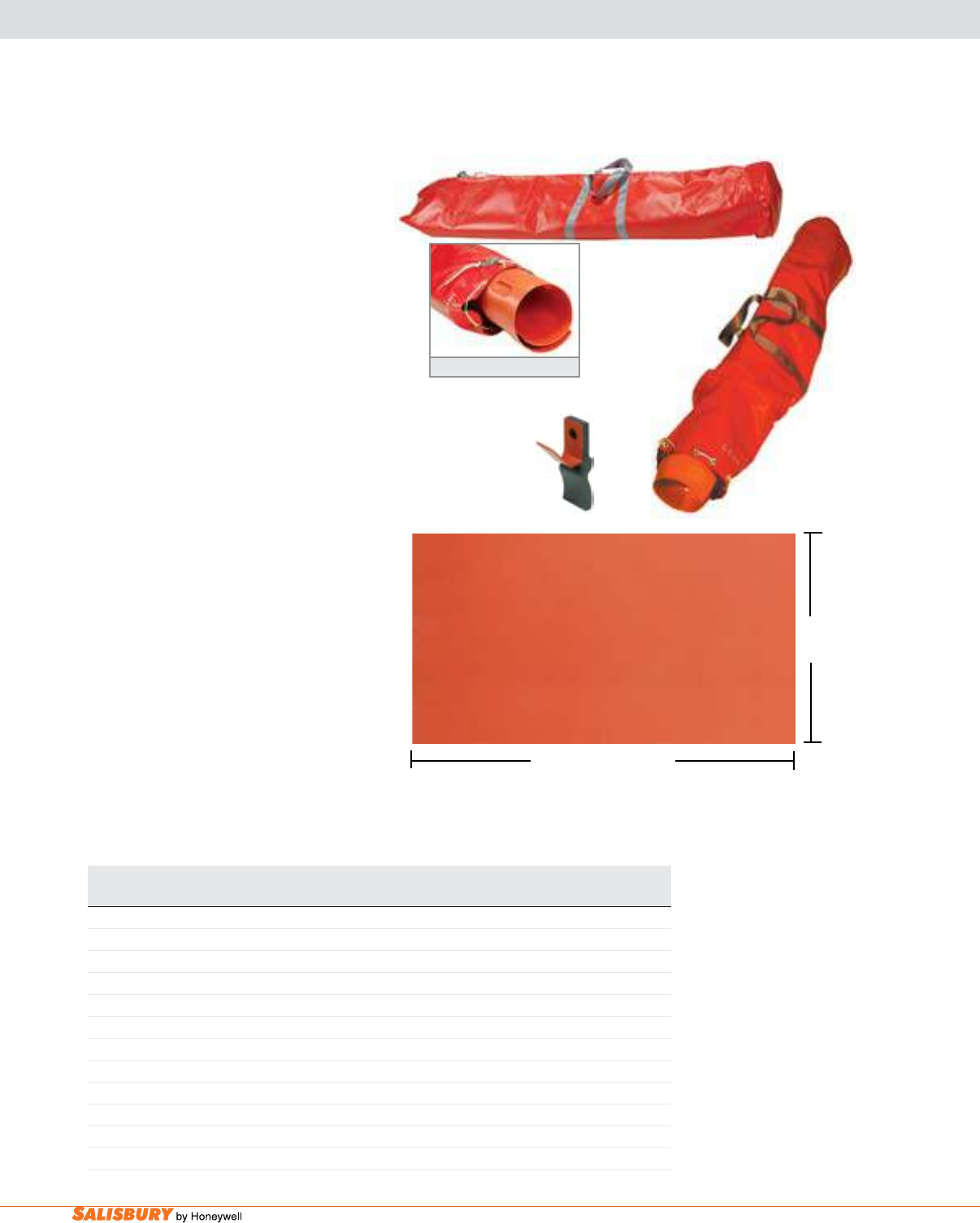
C-10 Insulating Plastic Guards and Covers. www.salisburybyhoneywell.com
guard and cover accessories
Cat. No. Dimensions Weight ea.
ft. ( m ) in. ( mm ) lbs. ( kgs )
BAGS - LINE GUARDS
1841 2 - 6’ ( 1.8 ) line guards or 2 - 9” x 6’ ( 229 x 1.8 ) Line Guards 4.5 ( 2.0 )
1933 2 - 4.5’ ( 1.4 ) line guards or 2 - 9” x 4’ ( 229 x 1.22 ) Line Guards 3.5 ( 1.6 )
BAGS - POLE GUARDS
1871 2 - 12” x 6’ ( 305 x 1.8 ) Pole Guards 5.2 ( 2.4 )
EYE KIT
1378 1 eye per kit .25 ( .11 )
BARRIER SHEET
2842 4’ x 8’ x .125” ( 1.2m x 2.4m x 3.2 ) 36 ( 16.4 )
1933
2842
4’ (1219mm)
8’ (2439mm)
bags for line guards and Pole guards come
in two different sizes and can hold two nested
line guards.
The 1871 Pole guard bag is designed to hold
two nested pole guards.
All of these bags are made from soil resistant
vinyl coated nylon and equipped with a
drawstring and mail bag lock.
The applicator Eye Kit is used to apply a new
or extra shotgun eye where needed. If a Bus or
“T” guard needs to be shortened or inverted,
this kit allows modications to be made. Clear
PVC pipe cement may be used to secure the
eye. Directions are included.
The Insulating barrier Sheet can be used to
create barriers in the eld. This sheet is made
from Type I ABS plastic and can be worked
with ordinary hand tools, saws, tin snips and
drills. It can also be hot formed using a heat
gun. For example, this sheet can be bent at
right angles over a table top to produce anges
for joining with other parts. Pipe adhesive
can be used to join to other parts. The rated
puncture is 50kV. This sheet is not intended
for permanent or semipermanent barrier or
insulating applications. It should be used for
accidental brush applications. The 2842 barrier
material meets the requirements of ASTM
F712, 9.1.1 Type 1 Guards. The nal application
and classication of the barrier/cover is the
responsibility of the user.
1871 Pole Guard Bag
1871
1378
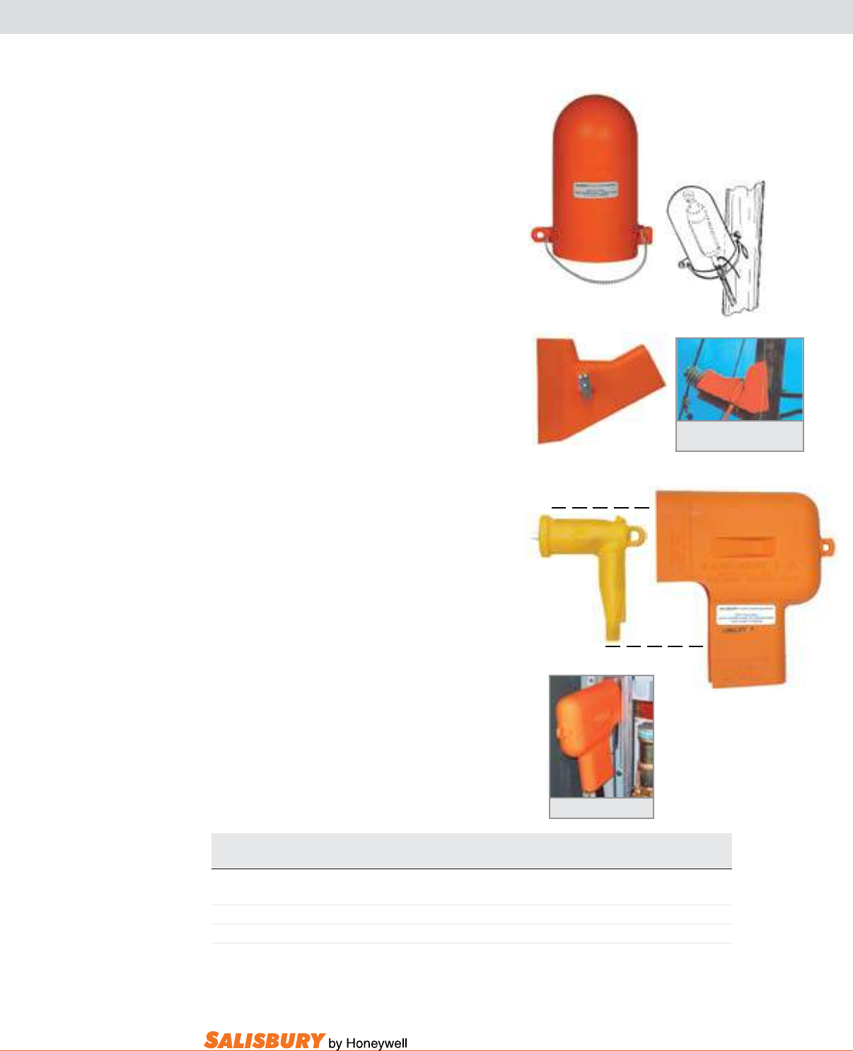
C-11
101 E. Crossroads Pkwy., Ste. A Bolingbrook, IL 60440 toll free ph (USA):877.406.4501 toll free fax (USA):866.824.4922 ph:630.343.3800
guard and cover accessories
Cat. No. Description ASTM Weight ea.
Voltage Class lbs. ( kgs )
816 Hot Cover 8” x 16” ( 203 x 406 ) 3 2.5 ( 1.1 )
4314 Underground Distribution Elbow Cover 15” x 14.25” ( 381 x 362 ) 3 2.0 ( .9 )
4333 Pole Bracket & Insulator Base Cover 20” x 25” ( 508 x 635 ) 3 2.5 ( 1.1 )
816
4314
Elbow
4333
Pole Bracket and
Insulator Base Cover
All guards are tested to ASTM F712
The universal Hot Cover is used to provide additional
cover-up and clearances. This cover is made from orange
Type I polyethylene plastic. The hot stick eye allows
this cover to be placed and removed with a shotgun type
clamp stick or with rubber gloves. To secure in place
use the elastic tie-down cord. This cover can be used on
overhead or underground energized cable terminators,
potheads or while inverted, on lightning arrestors. This
cover has a voltage rating of 26.4 kV*.
The Pole bracket and Insulator base Cover guards
against accidental contact with pole, bracket and
insulator base during routine maintenance. It is made
from an orange UV resistant Type I polyethylene plastic.
The Grade 2 hot stick eye allows this cover to be applied
and removed with a hot stick or with rubber gloves. It
covers metal or berglass brackets 8-12” long and pole
mounting plates. This cover also interlocks with a pole
insulator. This cover has a voltage rating of 26.4 kV*.
The underground distribution Elbow Cover covers
primary elbows and spade terminals during routine
maintenance. It covers up to the face plate and cable
connection. This cover is made from orange Type I
polyethylene plastic. The hot stick eye allows this cover
to be applied and removed with a hot stick. This cover
self locks for a secure t in conned areas. The bead can
be trimmed in the eld to meet clearance requirements.
This cover has a voltage rating of 26.4 kV*.
*guarded Ø to guarded Ø .
Elbow Cover Application
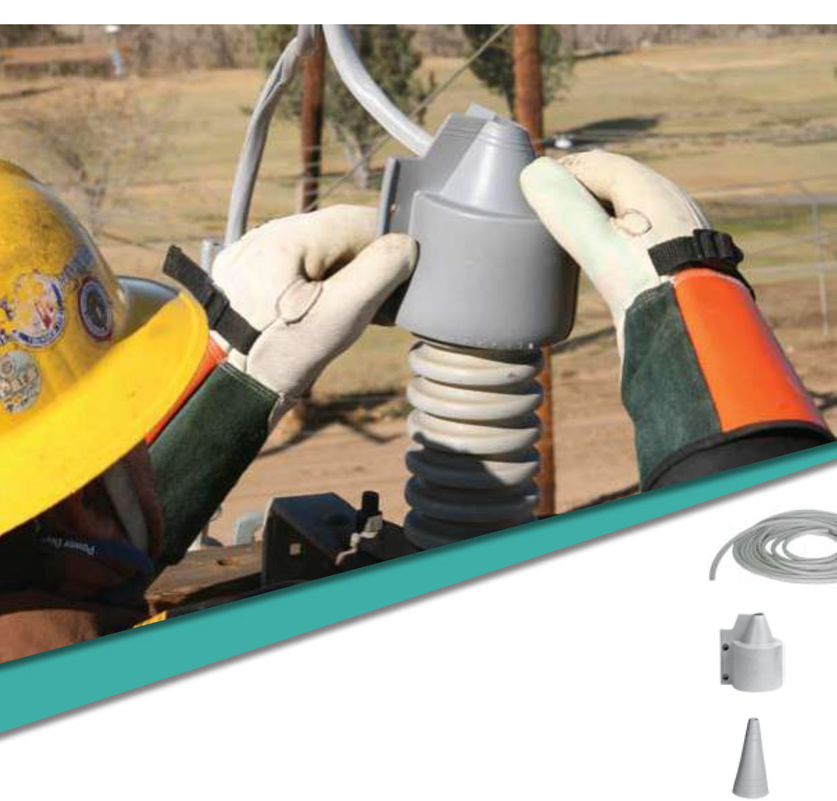
outage protection

D-2 Outage Protection. www.salisburybyhoneywell.com
OUTAGE PROTECTION
FAQ
Q: Why should I use outage protection?
A: The cost of animal caused outages to the utilities is preventable. Animals
cause power outages daily, creating time lost to utilities. Salisbury offers
an easy solution to this expensive problem.
Animals cannot be stopped, but these products can prevent them from causing
costly outages. It’s only a matter of time before an animal caused outage
happens. Salisbury’s Outage Protection Product Line includes the essential
items you need to protect yourself from costly outages.
All of these products are completely made from material that is resistant to
the effects of UV and ozone. Designed to withstand the test of time, sun and
weather, to keep you protected longer.
Designed for linemen. These lightweight products are easy to use and
install.
NOTE
Outage protection is not to be used as
Personal Protective Equipment (PPE).

D-3
101 E. Crossroads Pkwy., Ste. A Bolingbrook, IL 60440 toll free ph (USA):877.406.4501 toll free fax (USA):866.824.4922 ph:630.343.3800
SILICONE BUSHING COVERS
Cat. No. Description Dimensions Quantity Flashover Test Weight ea.
in. ( mm ) Voltage lbs. ( kgs )
BUSHING COVERS
21116 Cover Only - 24 pcs. 16 kV 16 ( 7.3 )
21116TC Cover Only w/ 21644 - 24 pcs. 16 kV 16 ( 7.3 )
21644 Tube Closure - - - -
21183 Cover Kit w/Stinger Cover* .375 x 18 ( 9.5 x 457 ) 24 pcs. n/a 20 ( 9 )
BC512 Cone Bushing Cover 12H x 5 W ( 305 H x 127 W ) 1 n/a 1.5 ( .7 )
TRI-PORT® BUSHING COVERS
21317 Cover Only 24 pcs. 16 kV 28 ( 12.7 )
24140 Cover Kit w/ Stinger Cover* 3/8 x 18 ( 9.5 x 457 ) 24 pcs. n/a 35 ( 16 )
* See page D-5 for more Stinger Covers
Standard Salisbury bushing Covers and Salisbury
Tri-Port® bushing Covers are made from Ozone and
UV resistant silicone rubber, maximizing the outdoor
durability and tracking resistance. These covers have
been accepted by Rural utilities Service (RuS).
Bushing Covers protect against wildlife contacts
between energized equipment and ground by
insulating exposed energized bushing parts.
Standard and Tri-Port bushing Covers interlock
with the top weathershed of the bushing and are
securely fastened by inserting lock buttons (provided).
The 21116TC, Standard bushing Cover, includes
the 21644 Tube Closure. The 21644 Tube Closure
provides an easier and quicker way to securely close
the standard bushing cover.
Bushing Covers can be installed without disconnecting
equipment using rubber insulating gloves. Covering a
small area of the lead wire, the opening can be trimmed
to accommodate larger wires or 5/8” and 3/4” Salisbury
Stinger Covers.
Cone bushing Covers
For complete 360 degree coverage, the BC512 is the
right choice. Complete with upper and lower trim
rings for a custom t size and internal ribs for added
air ow and water drainage. Made from Ozone and
UV resistant silicone rubber, the BC512 permanently
protects bushings from all sources of potential outages.
Installation requires de-energizing equipment.
- 3.87” (98.3mm) -
Standard Bushing Guard
Port
Port
Port
Tri-Port Bushing Guard
BC512
21116 - Standard
21317 - Tri-Port®
12” (305mm)
1” (25.4mm)
21116 TC- Standard
21644
3.37”
(85.6mm)
7”
(178mm)
5” (127mm)
Dia.
5”
(127mm)
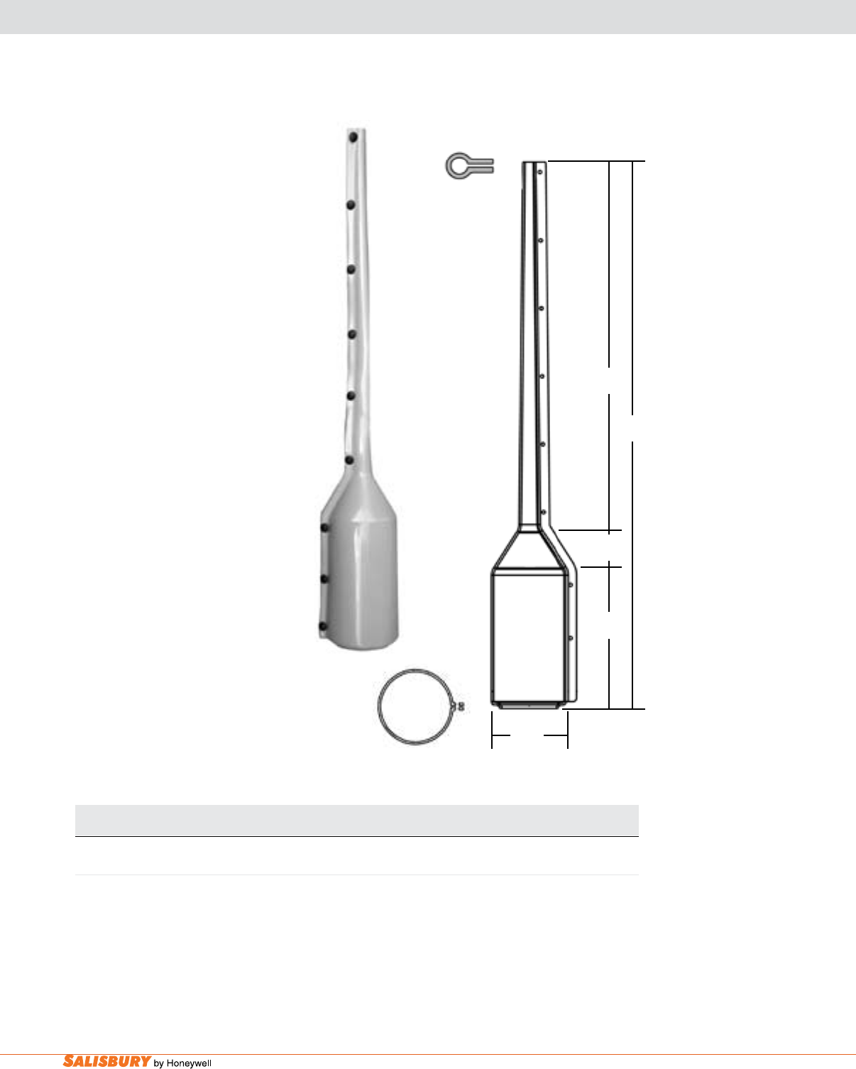
D-4 Outage Protection. www.salisburybyhoneywell.com
COMPLETE BUSHING-STINGER COVER
Complete bushing-Stinger Cover
This product is made from UV resistant
PVC plastic to maximize the outdoor
durability. The Complete Bushing/
Stinger Cover interlocks with the
top weathershed of the bushing and
securely fastens by inserting lock
buttons (provided). The Complete
Bushing/Stinger Cover can be installed
without disconnecting equipment
using rubber insulating gloves. This
product offers an integrated stinger
cover which will cover the lead wire
for an easy solution.
Cat. No. Description Dimensions Quantity Weight ea.
in. ( cm ) lbs. ( kgs )
COMPLETE BUSHING-STINGER COVER
27148 Bushing Cover & Stinger Cover Unit see gure A 20 pcs. 48 ( 21.9 )
27148
40.2”
(102cm)
9.84”
(24.9cm)
3.15”
(8cm)
26.9”
(68.3cm)
5.625”
(14.2cm)
Bushing-Stinger Cover
Cross-Section
Bushing-Stinger Cover
Cross-Section
Figure A
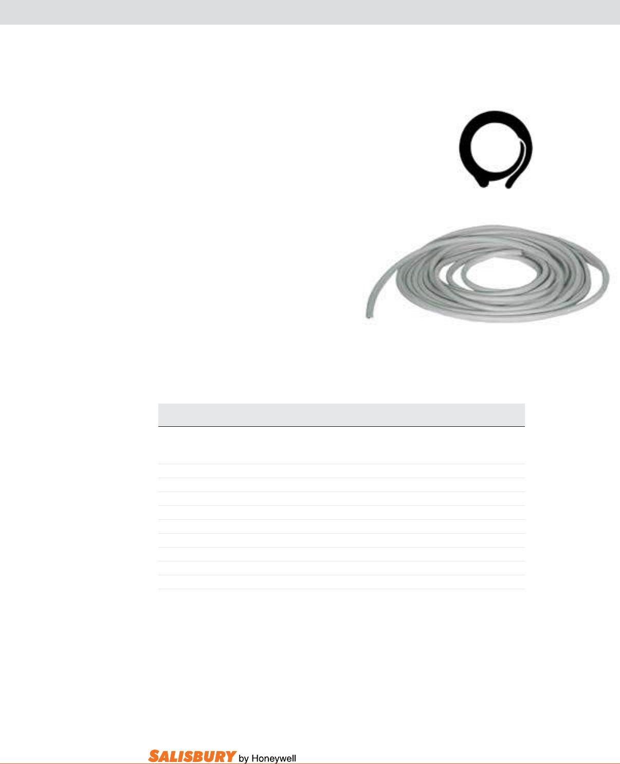
D-5
101 E. Crossroads Pkwy., Ste. A Bolingbrook, IL 60440 toll free ph (USA):877.406.4501 toll free fax (USA):866.824.4922 ph:630.343.3800
STINGER COVERS
Cat. No. I.D. Dimensions Quantity Flashover Test Weight
in. ( mm ) ft. ( m ) Voltage kV lbs. ( kgs )
EPDM
38-2SC 3/8 ( 9.5 ) 2 ( .61 ) 25 pcs. 10.5 9.5 ( 4.3 )
38-50SC 3/8 ( 9.5 ) 50 ( 15.3 ) 1 coil 10.5 9.5 ( 4.3 )
38-12SC 3/8 ( 9.5 ) 12 ( 3.7 ) 4 pcs. 10.5 9.5 ( 4.3 )
38-18SC 3/8 ( 9.5 ) 18” ( 457mm ) 50 pcs. 10.5 11 ( 5 )
38-100SC 3/8 ( 9.5 ) 100 ( 30.5 ) 1 coil 10.5 16 ( 7.25 )
58-12SC 5/8 ( 15.9 ) 12 ( 3.7 ) coil 4 pcs. 12.5 22 ( 10 )
58-50SC 5/8 ( 15.9 ) 50 ( 15.3 ) coil 1 pc. 12.5 21 ( 9.5 )
58-100SC 5/8 ( 15.9 ) 100 ( 30.5 ) coil 1 pc. 12.5 45( 20.5 )
34-12SC 3/4 ( 25.4 ) 12 ( 3.7 ) coil 4 pcs. 14.9 22 ( 10 )
34-25SC 3/4 ( 25.4 ) 25 ( 7.6 ) coil 2 pc. 14.9 22 ( 10 )
Stinger Cover Cross-Section
38-50SC
For sizes and lengths other than those listed above, contact your local Salisbury representative.
Stinger Covers protect against phase to
phase and phase to ground wildlife contacts.
These covers have been accepted by Rural
utilities Service (RuS).
The stinger cover can be installed without
disconnecting the lead wire from the bushing.
Available in three diameters, it is easily cut in
the eld to the needed length.
Stinger covers are track resistant and made
from Ozone and UV resistant SALCOR®
elastomer in a grey color. The covers are
proven to provide years of reliable service
either independently or when used with
bushing covers.
D-6 Outage Protection. www.salisburybyhoneywell.com
1127
INSTANT INSULATION
Instant Insulation may be installed
as permanent cover to protect against
outages caused by weather, trees and
animals. Instant Insulation resists ozone
and ultraviolet deterioration while
remaining flexible even at sub-zero
conditions.
Instant Insulation is made of orange
or grey SALCOR® elastomer. Instant
Insulation is sold in three diameters,
each 12 feet in length. Each include six
nylon UV resistant bar-lock cable ties
to secure it to the conductor.
Instant Insulation can be installed using
the 2494 applicator. To install, insert
one end of the Instant Insulation into the
applicator prongs, then roll and coil the
insulation as shown. Secure the coil end
with tape, cable ties, or rubber bands.
To install, release the secured end and
the Instant Insulation will unroll and
enclose the conductor.
Cat No. Dimensions Color Weight ea.
in. mm lbs. kgs
INSTANT INSULATION 12’ / 3.6m long
1127 .75 I.D. 19 I.D. Grey 7 3.2
1128 .75 I.D. 19 I.D. Orange 7 3.2
1129 1.00 I.D. 25 I.D. Grey 8 3.6
1130 1.00 I.D. 25 I.D. Orange 8 3.6
1131 1.25 I.D. 32 I.D. Grey 10 4.5
1132 1.25 I.D. 32 I.D. Orange 10 4.5
2494 Universal Hot Stick Applicator 1 .5
2494

D-7
101 E. Crossroads Pkwy., Ste. A Bolingbrook, IL 60440 toll free ph (USA):877.406.4501 toll free fax (USA):866.824.4922 ph:630.343.3800
GREENJACKET® ANIMAL CAUSED OUTAGE PROTECTION
Salisbury by Honeywell is proud to offer Greenjacket® Outage
Protection products and services. Here is more information about
this great new service. For additional information please visit
GreenjacketSalisbury.com.
1. It is the only industry comprehensive product line designed for energized installation
2. It is custom designed to precisely fi t each piece of equipment – “It Fits”
3. It is offered as part of a service where site plans are made to identify what exactly is needed for coverage
WHaT WE OFFER
Greenjacket provides world-class patented products, tools, and processes for preventing animal-
caused power outages at electrical substations. Our customized, turnkey outage protection solutions
make it easy for managers to select the best option for improving power reliability. Greenjacket
custom-manufactures its dielectric covers to ensure that each cover has the right fi t for the electrical
component being protected. We provide a product that is quick and easy to install—even in an
energized environment.
HOW WE dO IT
1. We evaluate schematics and/or images of existing facilities to develop a budgetary estimate for a
solution.
2. On agreement, we conduct a site assessment to determine points of risk in the substation, then use
3D photogrammetry to obtain equipment dimensions off energized equipment.
3. We create a Site Protection Plan that includes a prioritized, itemized list of the protective covers
required to mitigate bird- and animal-caused outages. The plan includes detailed installation
instructions.
4. The product is manufactured using existing and/or custom-developed moulds, as required to
protect the substation that has been evaluated.
5. Product is delivered to the customer’s site for installation. Greenjacket provides optional
consulting support for both customer and contractor based installations.
6. Follow-up risk mitigation programs are available to optimize ongoing risk management.
THE valuE WE dElIvER
z Improved Power Reliability: by reducing the number of bird- and animal-caused contacts, the
number of power interruptions is reduced.
z dollar Savings: bird and animal-caused outages can result in the costly replacement of equipment,
expensive overtime repair charges, and fi re-drill management of work schedules.
z Increased Revenues: outages can dramatically reduce billable electric services to customers or
negatively impact revenues through production downtime.
z Improved Community and Public Relations: outages create stress for everyone, from the
customer through to power system managers and executive teams.
z Reduced Penalties: wildlife protection agencies are increasing the scope and dollar amount of
fi nes related to animal “takes”; fi nes currently range as high as $500,000 per incident.
z Comprehensive, Turnkey Solutions: no more piecemeal coverage with ill-fi tting products.
Greenjacket provides a customized solution that is tailored to fi t the specifi c components of a substation.
5_outage2011.indd 75_outage2011.indd 7 9/14/11 12:38:59 PM9/14/11 12:38:59 PM

gloves & sleeves
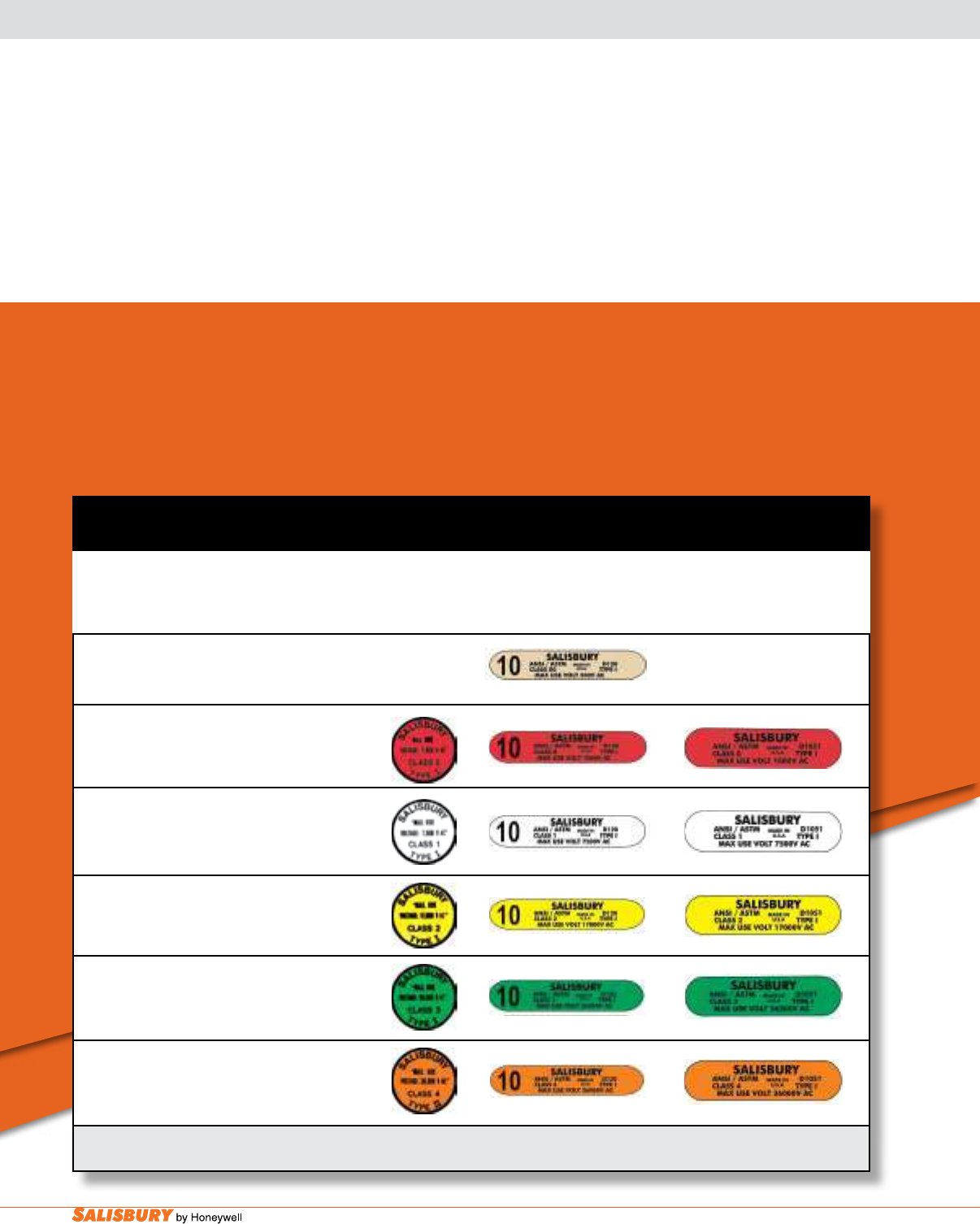
E-2 Gloves and Sleeves. www.salisburybyhoneywell.com
GLOVES & SLEEVES
Rubber and SALCOR® Protective Equipment
Rubber insulating gloves are available in six ASTM dened voltage classes. Rubber insulating
sleeves are available in Class 00 through 4. The chart below identies the class, proof test voltage
and maximum allowable exposure voltage.
For an 8.5 x 11 reprint of this chart, contact your local Salisbury representative.
Proof Test Max. Use Rubber
Class Voltage Voltage* Molded Glove Label Rubber Dipped
Color AC / DC AC / DC Products Sleeve Label
Label
Protective Rubber Equipment Labeling Chart
for Salisbury Linemen’s Natural Rubber and SALCOR® Rubber Protective Equipment
Insulating Gloves and Sleeves must have a color coded label to meet appropriate ASTM Specifications.
* Max. Use Voltage when worn with leather protectors.
00 2,500 / 10,000 500 / 750
Beige
0 5,000 / 20,000 1,000 / 1,500
Red
1 10,000 / 40,000 7,500 / 11,250
White
2 20,000 / 50,000 17,000 / 25,500
Yellow
3 30,000 / 60,000 26,500 / 39,750
Green
4 40,000 / 70,000 36,000 / 54,000
Orange

E-3
101 E. Crossroads Pkwy., Ste. A Bolingbrook, IL 60440 toll free ph (USA):877.406.4501 toll free fax (USA):866.824.4922 ph:630.343.3800
Manufactured for
outstanding protection,
comfort and long-life
Rubber insulating gloves are among
the most important articles of personal
protection for electrical workers.
Incorporating high dielectric and physical
strength, exibility and durability, Salisbury
rubber insulating gloves have earned the
reputation for superior performance
-
meeting and exceeding the requirements
of current ASTM D120 specications and
IEC EN60903 Standards.
Salisbury rubber insulating gloves are
manufactured by dipping porcelain forms
into a tank of liqueed rubber. The thin
layer of rubber which results is allowed
to dry and the process is repeated until the
required thickness is reached. Depending
on the voltage class of the glove, this
dipping-drying-dipping cycle may need
to be repeated over 30 times. After the
desired thickness is achieved, the gloves
are allowed to dry. Once dry, they are cut to length, the reinforcing bead
is rolled, and the ASTM label and manufacturing information is applied
along with any additional permanent marking that may be requested.
The gloves are cured in an autoclave under steam pressure and heat.
After curing, the gloves are visually inspected. Gloves with visual
imperfections are rejected. The gloves are then given a halogenation
treatment (chlorination) to increase the comfort and wearability. The gloves
are electrically tested following ASTM D120/IEC 903 specications.
Following the electrical test, the gloves are given a nal visual inspection.
The gloves are then ready to be boxed and shipped.
SALISBURY LINEMEN’S GLOVES
Glove Congurator
Visit www.salisburybyhoneywell.com to use Salisbury’s
exclusive Glove Congurator™. This interactive web
tool allows you to easily determine which Salisbury
gloves you need to meet your requirements.
ARE YOU NOT SURE WHAT
GLOVES YOU NEED?
Salisbury has made it easy
with the Salisbury Glove ConfiguratorTM
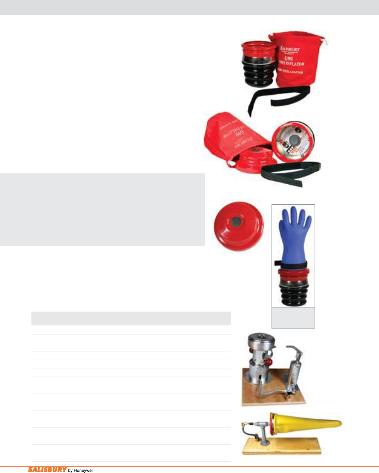
E-4 Gloves and Sleeves. www.salisburybyhoneywell.com
MAKING A PROPER INSPECTION
Cat. No. Description
G99 Glove Inator Kit
G99B Replacement Bag
G99S Replacement Strap
G99V Replacement Check Valve
G100 Glove Inator Kit w/ Adapter
G100A Lo-Volt Glove Adapter
INF-1 Standard Bench Model Inator with Hand Pump
INF-2 Standard Bench Model Inator with AIr-Line Connection
INF-3 Standard Floor Model
INF-4 Bench Model Air-Bag Inator for High Voltage Gloves
INF-5 Bench Model Air-Bag Inator for High and Low Voltage Gloves
INF-6 Standard Sleeve Expander
INF-7 Replacement Glove Inator Boots for Air Bag Glove Inators
INF-8 Replacement Bladders for Sleeve Expander (with closed ends) - Set of three
INF-9 Single Replacement Bladders for Sleeve Expander (with closed ends) - Outside Bladder only
INF-10 Hand Held Glove Inator
G99
G100
G100A
G100 with inflated
lo-volt glove ready for
inspection.
OSHA 1910.137 states “Insulating equipment shall be inspected
before each day’s use and immediately following any incident that
can reasonably be suspected of having caused damage. Insulating
gloves shall be given an air test, along with the inspection.”
Salisbury’s New g100 (Patent Pending), with g100a adapter for
Class 00 and 0 and smaller size gloves, and the g99, without
additional adapter, are the perfect answer for inating your gloves
for inspection.
The g99 is a simple, easy to use, portable glove inator. The G99
provides a quality means of inspecting gloves in the eld. The glove
is secured to the inator using a nylon strap and fastened with a
hook and pile closure. Ination is accomplished by pumping the
bellows of the inator against any surface. nOTE: gloves should
be expanded no more than 1.5 times their normal size for Type
I, and 1.25 times normal for Type II SalCOR.
SALISBURY ADVANTAGE
The g100 is also a simple and easy to use, portable glove inator.
The G100 operates exactly like the G99, but includes an additional
g100a adapter to also inspect Class 00 and 0 and smaller gloves.
To use the adapter, the glove is secured to the G100A adapter
using a nylon strap with a hook and pile closure. The adapter,
with glove attached, is then placed on top of the inator to be
inated for inspection.
INF Series Glove Inators & Sleeve Expanders
Proper safety requires frequent inspection of gloves and sleeves.
These glove inators and sleeve expanders provide an efcient way
to conduct complete and thorough visual inspections before and after
use in the eld. Easy to install. Simple to operate. Accommodates
all sleeve and glove sizes. Minimum oor space. Compressed air
source required.
INF-1
INF-6
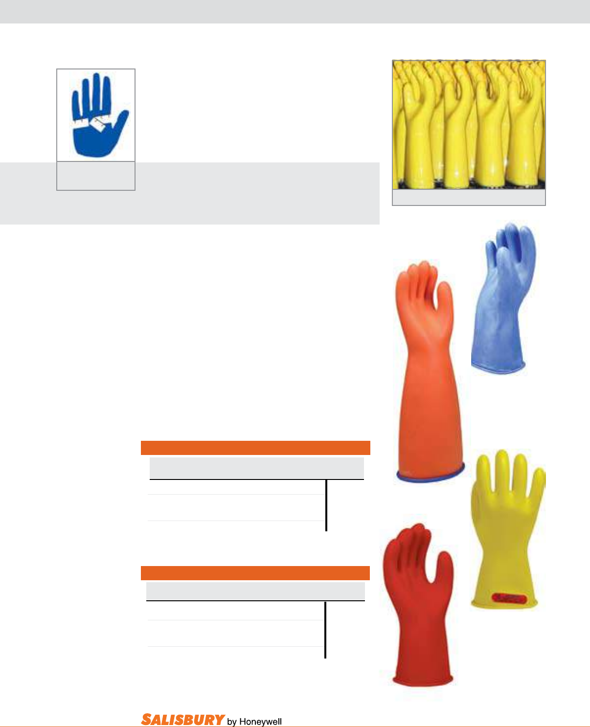
E-5
101 E. Crossroads Pkwy., Ste. A Bolingbrook, IL 60440 toll free ph (USA):877.406.4501 toll free fax (USA):866.824.4922 ph:630.343.3800
Cat. No. Breakdown for Class 00 Gloves
Class Length Color Size
SALISBURY LINEMEN’S GLOVES
LOW VOLTAGE - ASTM CLASS 00, 0
Measure the circumference
around the palm.
E 00 11 R, B, BL, or BLO 7, 8, 8H
9, 9H
E 00 14 R, B, BL, or BLO 10, 10H
R=red B=black Type I Natural Rubber 11, 12
BL=blue BLO=blue in, orange out :Type II SALCOR
Example: E0011BL/8 NOTE: Size 11H no longer available.
Cat. No. Breakdown for Class 0 Gloves
Class Length Color Size
E 0 11 Y, B, R, BL, BLO, or BY 7, 8, 8H
9,9H
E 0 14 Y, B, R, BL, BLO, or BY 10, 10H
R=red B=black Y=yellow:Type I Natural Rubber 11, 12
BY=black in, yellow out:Type I Natural Rubber
BL=blue BLO=blue in, orange out :Type II SALCOR
Example: E014R/9 NOTE: Size 11H no longer available.
E011Y Gloves being manufactured.
Selecting the right size, length and style
Salisbury linemen’s gloves are available in a full range
of sizes, from 7 through 12, including half sizes on 8, 9,
and 10. Proper t is important. To determine glove size,
measure the circumference around the palm. Allow for
additional room if fabric glove liners are to be worn,
especially with thermal liners.
SALISBURY ADVANTAGE
Type I and Type II gloves are extremely exible to make
working with small parts easy. The gloves meet or exceed
ASTM D120 and IEC EN60903 Standards.
Class 00 and 0 gloves are available in 11 and 14 inch
lengths. Class 00 Electrical Insulating Rubber gloves
are made from red or black Type I natural rubber, blue
Type II SALCOR®, or in contrasting blue/orange Type
II SALCOR. The contrast between the outer orange color
against the inner blue color makes inspecting for cuts and
tears easier when the glove is inated or stretched.
Class 0 Electrical Insulating Rubber gloves are
available in red, black, yellow, and contrasting black/
yellow colors in Type I Natural Rubber. The contrast
between the outer yellow color against the inner black
color makes inspecting for cuts and tears easier when
the glove is inated or stretched. These gloves are also
available in blue or contrasting blue/orange colors Type
II SALCOR rubber.
E0011BL/9
E0014BLO/9
E011R/9
E011Y/10
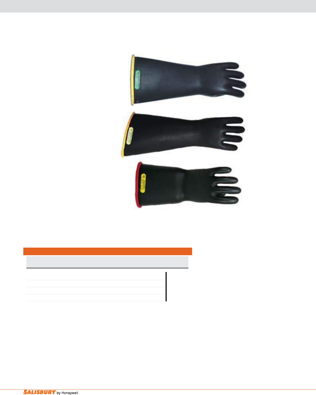
E-6 Gloves and Sleeves. www.salisburybyhoneywell.com
SALISBURY LINEMEN’S GLOVES
HIGH VOLTAGE - ASTM CLASS 1, 2, 3, 4
Straight Cuff
E316YB/10
Cat. No. Breakdown for Class 1,2,3,4 Gloves
Class Glove Length Cuff Style Color Size
in.
E 1 14, 16 or 18 BC***, C B, YB or RB 7, 8, 8H
E 2 14, 16 or 18 BC***, C B, YB or RB 9,9H
E 3* 14, 16 or 18 BC***, C B, YB or RB 10, 10H
E 4** 14, 16 or 18 BC***, C B, YB or RB 11, 12
BC***=bell cuff C=contour cuff (Contour cuff available for 18” only.)
*available in sizes 8 through 12 including half sizes only
**available in sizes 9 through 12 including half sizes only
***bell cuff gloves available in sizes 9 through 12 including half sizes
B=black YB=Y inside, B out RB=R inside, B out:Type I Natural Rubber
Example: E116BCYB/10
NOTE: Size 11H no longer available.
Class 1 through 4 gloves are available
in the industry standard color black, or
in contrasting two-color combinations.
The contrast between the thin outer
color against the inner color makes
inspecting for cuts and tears easier when
the glove is inated or stretched.
Class 1 through 4 gloves are available in
14, 16 and 18 inch lengths. A straight
cuff is standard on 14” (356 mm), 16”
(406 mm) & 18” (457 mm) gloves. The
straight cuff is the default style.
A contour cuff is angled to prevent
bunching or binding at the elbow when
the arm is bent. Available on all 18”
(457mm) gloves only.
The bell cuff accommodates heavier
winter clothing and allows for greater
air ow in warmer weather. These are
available for Class 1 through 4 gloves.
Bell cuff gloves are not available in sizes
7, 8 or 8H.
Contour Cuff
E218CYB/10
Bell Cuff
E214BCRB/10
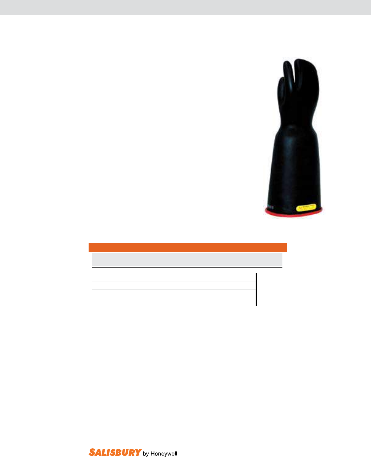
E-7
101 E. Crossroads Pkwy., Ste. A Bolingbrook, IL 60440 toll free ph (USA):877.406.4501 toll free fax (USA):866.824.4922 ph:630.343.3800
SALISBURY LINEMEN’S MITTENS
HIGH VOLTAGE - ASTM CLASS 1, 2, 3, 4
Salisbury lineman’s mittens are made from the same
durable, lightweight rubber as the ve nger gloves yet keep
the user warmer during harsh temperatures. The three nger
mitten allows for precise hand movement as well.
Class 1 through 4 mittens are available in the industry
standard black or in contrasting two-color combinations.
The contrast between the thin outer color against the inner
color makes inspecting for cuts and tears easier when the
glove is inated or stretched.
Class 1 through Class 2 mittens are available in 14, 16 and
18 inch lengths. Class 3 through Class 4 mittens are available
in 16 and 18 inch lengths. A bell cuff design is standard on
all mittens. BC=Bell Cuff.
Mittens are available in sizes 9, through 11 full sizes only.
Cat. No. Breakdown for Class 1,2,3,4 Gloves
Class Glove Length Cuff Style Color Size
in.
EM 1 14, 16 or 18 BC B, YB or RB 9
EM 2 14, 16 or 18 BC B, YB or RB 10
EM 3 16 or 18 BC B, YB or RB 11
EM 4 16 or 18 BC B, YB or RB
Bell Cuff colors B=black YB=Yellow inside, Black out RB=Red inside, Black out
EM216BCRB/10
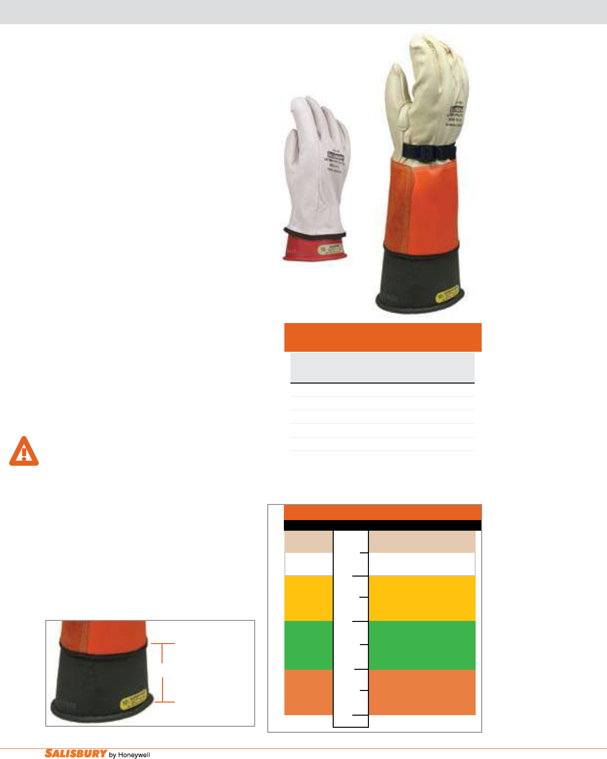
E-8 Gloves and Sleeves. www.salisburybyhoneywell.com
LEATHER PROTECTORS
CLEARANCE TABLE FOR LEATHER
PROTECTORS PER ASTM F496 - Table 4
Glove Min. Distance Between
Class Protectors and Rubber Gloves
in. mm
00, 0 1/2 13
1 1 25
2 2 51
3 3 76
4 4 102
leather Protector gloves should always be
worn over Rubber Insulating Gloves to provide
the needed mechanical protection against
cuts, abrasions and punctures. All Salisbury
protectors are steamed pressed on curved hand
forms to insure proper t over Rubber Gloves.
Manufactured from top grade leather, all are sewn
with heavy duty nylon thread in the “gunn cut”
inseam construction pattern. Each protector for
Class 1-4 gloves are equipped with a nonmetallic
buckle on the pull strap and an extra wide leather
reinforcement over the thumb seam. Protectors
for Class 00 and 0 gloves are available with non-
metallic buckle and pull strap or elastic wrist.
all Salisbury leather Protectors meet aSTm
F696 standards.
It is the responsibility of the purchaser to specify
the overall length of the protector gloves. The
Clearance Table shows the minimum distance
which shall be allowed between the protector
glove cuff and the bead of the rubber glove per
ASTM F496 Specications.
WaRnIng: do not use leather protectors
alone for protection against electric shock.
Serious injury or death will result. always
use a properly rated insulating glove for the
voltage being worked.
Proper care of leather protectors is essential
to user safety. Inspect the leather protectors
when inspecting rubber gloves. Metal particles,
imbedded wire, abrasive materials or any
substance that could physically damage the
rubber gloves must be removed from the
protector before use.
1/2
1
2
3
4
Minimum Distance from Protector and Rubber Glove
Glove Class Leather Protector Cuff
--------- Cuff Line --------
00, 0 1/2” from cuff
1 1” from cuff
2 2” from cuff
3 3” from cuff
4 4” from cuff
2” from cuff
The minimum
distance from
the leather
protector cuff
to the bead
of the rubber
glove for this
Class 2 glove is
2 inches.
Adapted, with permission, from F496-08 Standard Specication for In-Service
Care of Insulating Gloves and Sleeves, copyright ASTM International, 100 Barr
Harbor Drive, West Conshohocken, PA 19428. A copy of the complete stan-
dard may be obtained from ASTM, www.astm.org.

E-9
101 E. Crossroads Pkwy., Ste. A Bolingbrook, IL 60440 toll free ph (USA):877.406.4501 toll free fax (USA):866.824.4922 ph:630.343.3800
156 Premium Series
Salisbury’s SALCOR® cuff provides maximum
protection.
These protectors are made from specially tanned
Grade A Red Boulevard buffed leather and an
orange colored SALCOR “Super Cuff” in the 4”
(102 mm) and 6” (152 mm) cuff lengths. The “Super
Cuff” has better characteristics than leather or vinyl
cuffs; it does not absorb water, has greater track
resistance, and creepage.
PREMIUM LEATHER PROTECTORS
Cat. No. Cuff Length OAL Length Weight ea.
in. ( mm ) in. ( mm ) lbs. ( kgs )
156-4 4 ( 102 ) Straight Cuff 12 ( 305 ) 1 ( .5 )
156-6 6 ( 152 ) Straight Cuff 14 ( 356 ) 1.2 ( .5 )
Available in dual sizes: 8/8.5, 9/9.5, 10/10.5, 11/11.5, 12
SALISBURY ADVANTAGE
156-4
156-6
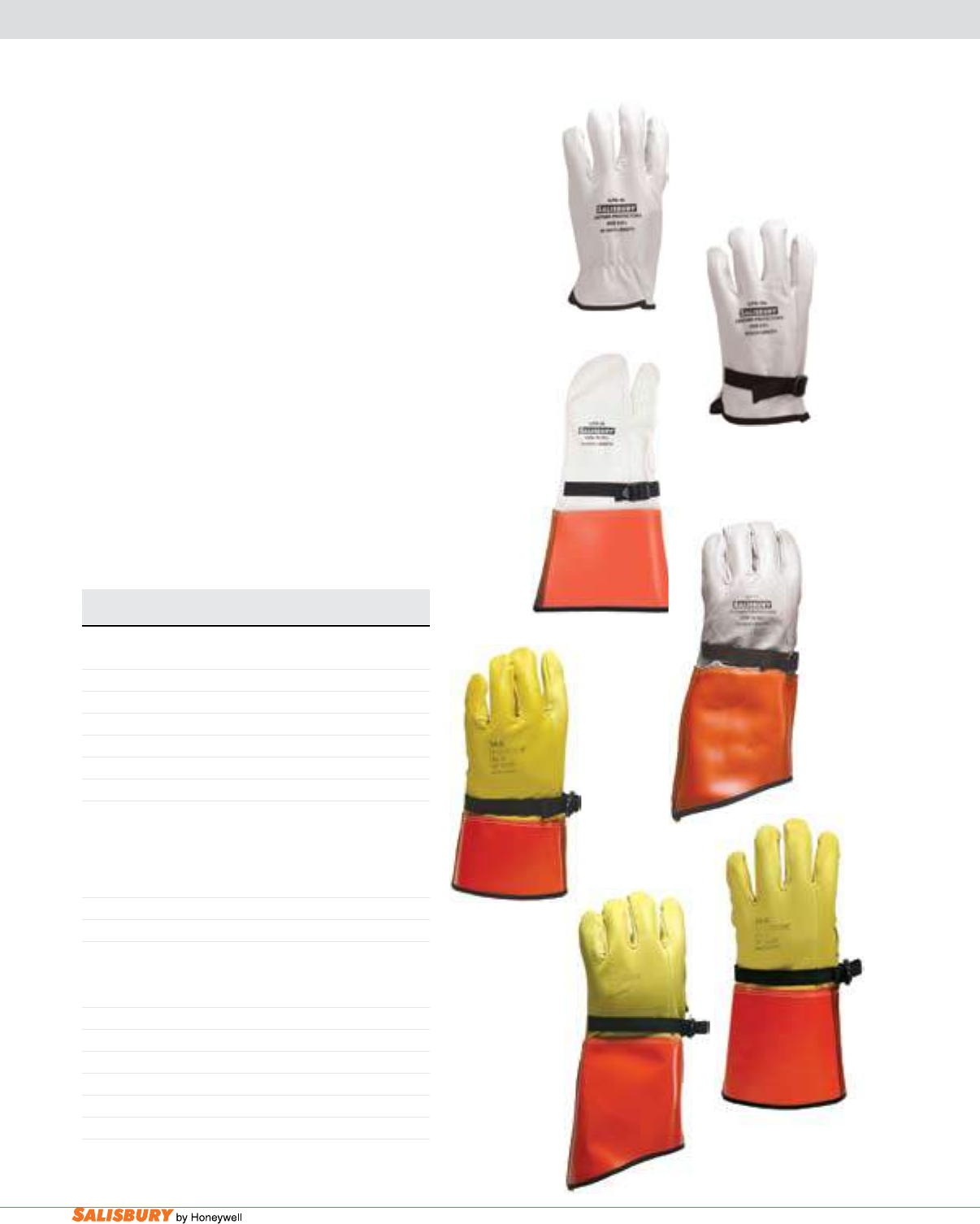
E-10 Gloves and Sleeves. www.salisburybyhoneywell.com
LEATHER PROTECTORS
IlP Series
Manufactured from top grain cowhide, or goatskin, these protectors
provide excellent protection for rubber insulating gloves at a very
economical price. Cowhide cuffs are tough leather on palm side
and orange vinyl on the back, while the goatskin cuffs are green
leather on palm side and orange vinyl on back. Full complement
of styles from low-volt through 16” contour cuff. Comes in size
7, dual sizes 8/8.5 through 11/11.5 and size 12.
IlPm Series mitten Protector
Manufactured from top grain cowhide, these protectors offer
excellent comfort and protection. The ILPM Series mitten
protectors feature adjustable straps with non-metallic buckles
and are stitched with polyester thread for strong seams. Cuffs are
tough leather on palm side and orange vinyl on the back of the
hand. Comes in sizes 9, 10 and 11.
lP Series
Manufactured from top grain cowhide or goatskin, these protectors
offer excellent comfort and protection. The LP Series protectors
feature adjustable straps with non-metallic buckles and are stitched
with polyester thread for strong seams. Cuffs are tough leather
on palm side and orange vinyl on the back of the hand. Comes in
sizes 7 to 12, including half sizes 8 1/2 to 11 1/2.
Cat. No. OAL Length Weight ea.
in. ( mm ) lbs. ( kgs )
ILP SERIES - COWHIDE
ILP3S* 12 ( 305 ) 1 ( .5 )
ILP4S* 13 ( 330 ) 1 ( .5 )
ILP5S* 14 ( 356 ) 1.2 ( .5 )
ILP6S* / ** 15 ( 381 ) 1.2 ( .5 )
ILP7C* / ** 16 ( 406 ) 1.5 ( .7 )
ILP10* 10 ( 254 ) .7 ( .32 )
ILP10A* w/ pull strap 10 ( 254 ) .7 ( .32 )
*To specify goatskin, use ILPG. Goatskin not available in size 7.
Available in dual sizes: 7, 8/8.5, 9/9.5, 10/10.5, 11/11.5, 12
** Not available in size 7.
ILPM SERIES - COWHIDE
ILPM3S 12 ( 305 ) 1 ( .5 )
ILPM4S 13 ( 330 ) 1 ( .5 )
ILPM5S 14 ( 356 ) 1.2 ( .5 )
Available in sizes: 9, 10, 11
LP SERIES
LP3S 12 ( 305 ) 1 ( .5 )
LP4S 13 ( 330 ) 1 ( .5 )
LP5S 14 ( 356 ) 1.2 ( .5 )
LP6S 15 ( 381 ) 1.2 ( .5 )
LP7C 16 ( 406 ) 1.5 ( .7 )
LP10 10 ( 254 ) .7 ( .32 )
LP10A w/ pull strap 10 ( 254 ) .7 ( .32 )
To specify goatskin, use LPG.
Available in single sizes: 8, 8.5, 9, 9.5, 10, 10.5, 11, 11.5, 12
ILPG10
LPG3S
ILPG10A
ILP7C
LP7C
ILPM5S
LPG5S
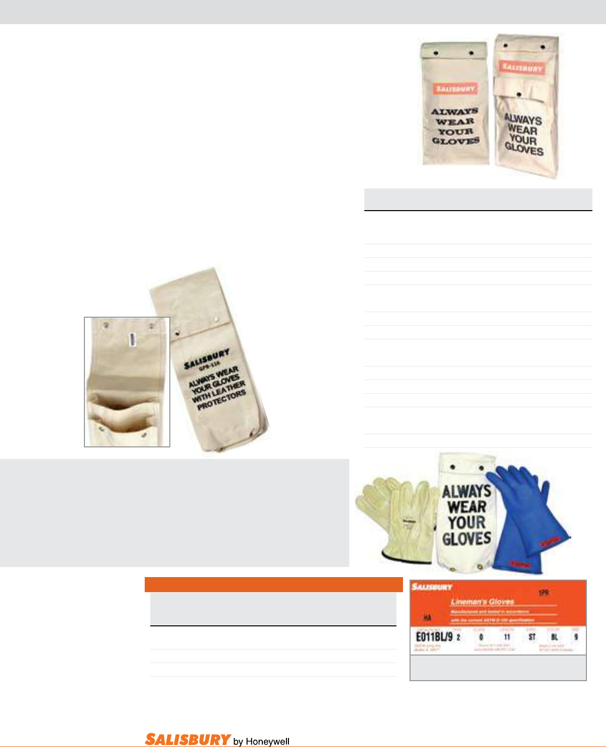
E-11
101 E. Crossroads Pkwy., Ste. A Bolingbrook, IL 60440 toll free ph (USA):877.406.4501 toll free fax (USA):866.824.4922 ph:630.343.3800
by Honeywell
SALISBURY ADVANTAGE
glove Kits
Salisbury’s insulating rubber gloves are necessary
for every electrical worker’s complete safety. And
to insure your safety, Salisbury’s leather protectors
provide needed protection from cuts, abrasions,
and punctures. To keep these safety items in top
condition, proper storage is very important.
GLOVE STORAGE & GLOVES KITS
Product Numbering Chart for Glove Kits
Class Length Color Size
(inches) of Gloves
(choose one below)
GK 00 11 or 14 B, R, BL 7, 8, 9, 10, 11, 12
GK 0 11 or 14 R, BL, B, Y 7, 8, 9, 10, 11, 12
GK 2 14, 16, or 18 B, RB 7, 8, 9, 10, 11, 12
Example: GK011BL/9
Type I Natural Rubber available in: R=Red, Y=Yellow, B=Black,
RB=Red in, Black out
Type II SALCOR® Rubber available in: BL=Blue
Cat. No. For Glove Dimensions Weight ea.
length in. ( mm ) inches ( mm ) lbs. ( kgs )
26 oz. CANVAS GLOVE BAGS
GB112 11 ( 280 ) 9” x 14” ( 229 x 356 ) 1 ( .5 )
GB114 14 ( 356 ) 9” x 16” ( 229 x 406 ) 1 ( .5 )
GB116 16 ( 406 ) 9” x 18” ( 229 x 457 ) 1.2 ( .6 )
GB118 18 ( 457 ) 9” x 20” ( 229 x 508 ) 1.5 ( .7 )
26 oz. CANVAS GLOVE BAGS w/ goggle case
GB114GC 14 ( 356 ) 9” x 16” ( 229 x 406 ) 1 ( .5 )
GB116GC 16 ( 406 ) 9” x 18” ( 229 x 457 ) 1.2 ( .6 )
GB118GC 18 ( 457 ) 9” x 20” ( 229 x 508 ) 1.5 ( .7 )
14.75 oz. CANVAS GLOVE & PROTECTOR BAGS
GPB112 12 ( 305 ) 9” x 14” ( 229 x 356 ) 1 ( .5 )
GPB114 14 ( 356 ) 9” x 16” ( 229 x 406 ) 1 ( .5 )
GPB116 16 ( 406 ) 9” x 18” ( 229 x 457 ) 1.2 ( .6 )
GPB118 18 ( 457 ) 9” x 20” ( 229 x 508 ) 1.5 ( .7 )
GLOVE & PROTECTOR COMBO BAGS
2C16 14 ( 356 ) 16 ( 406 ) 9” x 18” ( 229 x 457 ) 1.2 ( .6 )
2C18 18 ( 457 ) 9” x 20” ( 229 x 508 ) 1.5 ( .7 )
Proper storage extends the service life of
linemen’s gloves and sleeves.
Folds and creases strain rubber and cause it to
crack from ozone prematurely. By storing rubber
gloves in the right size bag, and never forcing
more than one pair into each bag, equipment will
lie at and last longer.
Salisbury bags are constructed of heavy duty
canvas duck and are double stitched and riveted
at stress points for extra durability. Canvas bags
feature a D ring for hanging in trucks or on work
belts. Bags feature tapered gussets with wide
opening tops for easy insertion.
glove and Protector Combo
bags contain two layered
pockets in one bag. Now,
both a pair of gloves
and protectors can be
properly stored in
one convenient bag.
Never worry about
having to bring
more than one
bag from job site
t o job site.
GB116 GB116GC
GK011BL/9
Note: If you require test date stamping, please specify
when ordering.
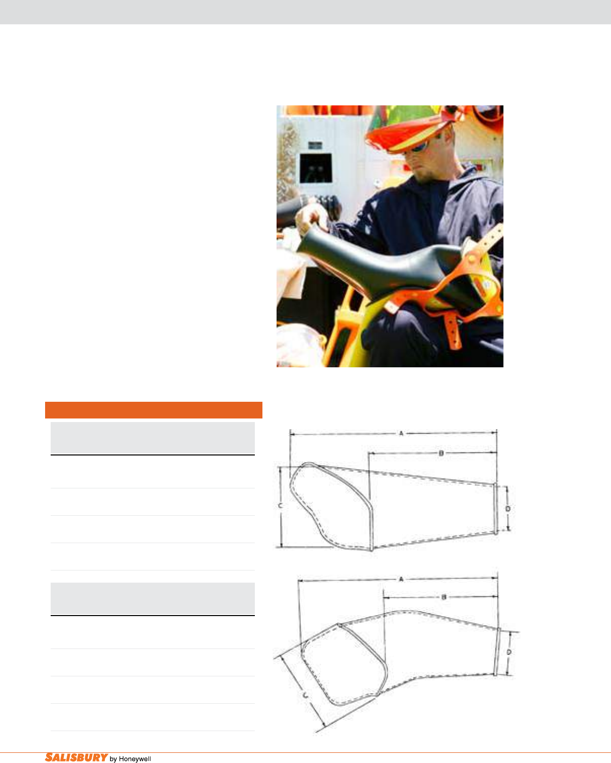
E-12 Gloves and Sleeves. www.salisburybyhoneywell.com
LINEMEN’S SLEEVES
Rubber Insulating Sleeves extend coverage of
the arm from the cuff of rubber insulating gloves
to the shoulder
-
fully protecting these areas from
accidental contact with energized conductors and
equipment. Salisbury sleeves feature a reinforcing
fold at the cuff. This fold is preferred over a rolled
bead because it adds less bulk to the cuff and ts
into the glove easier without pushing. Two different
processes are used to manufacture insulating
sleeves; dipping and molding. Both meet the current
requirements of ASTM D1051 and offer the same
high level of quality and protection.
Sizing
Sleeves should be selected to t the arm comfortably,
covering from the top of the shoulder to inside the
top of the glove. Regular size sleeves are the shortest
and have the smallest arm and wrist openings. To
minimize the possibility of the sleeves pushing gloves
off the hand, size the sleeve to the shortest length
possible while maintaining complete coverage to
the shoulder.
Figure 1
Figure 2
Sizing Linemen’s Sleeves
STRAIGHT ARM SLEEVE- Figure 1
A B C D
in. ( mm ) in. ( mm ) in. ( mm ) in. ( mm )
Small
24.25 ( 616 ) 15.13 ( 384 ) 12.5 ( 317 ) 5.75 ( 146 )
Regular
26.25 ( 667 ) 15.5 ( 394 ) 11.25 ( 286 ) 5.5 ( 140 )
Large
28.5 ( 724 ) 17 ( 432 ) 12.87 ( 327 ) 6.87 ( 175 )
Extra Large
30 ( 762 ) 19 ( 483 ) 13.25 ( 337 ) 6.87 ( 175 )
EXTRA CURVED ARM SLEEVE- Figure 2
A B C D
in. ( mm ) in. ( mm ) in. ( mm ) in. ( mm )
Small
24.25 ( 616 ) 15.13 ( 384 ) 12.5 ( 317 ) 5.75 ( 146 )
Regular
26.5 ( 673 ) 15.5 ( 394 ) 12.25 ( 311 ) 5.25 ( 140 )
Large
27.75 ( 705 ) 16 ( 406 ) 12.87 ( 327 ) 6.87 ( 175 )
Extra Large
29.5 ( 749 ) 17.5 ( 445 ) 12.87 ( 327 ) 7 ( 178 )
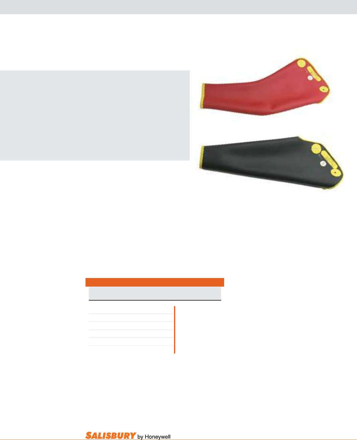
E-13
101 E. Crossroads Pkwy., Ste. A Bolingbrook, IL 60440 toll free ph (USA):877.406.4501 toll free fax (USA):866.824.4922 ph:630.343.3800
Cat. No. Breakdown for Dipped Type I Sleeves
Voltage Size Color
Class
D0 S, R, L or XL Y=yellow
D1 S, R, L or XL
B=black
D2 S, R, L or XL
YB=Y inside, B out
D3 S, R, L or XL
RB=R inside, B out
D4
S, R, L or XL
YR=Y inside, R out
S=small, R=regular, L=large
XL=extra large
Example: D2LYB-ST
Extra-Curved Arm
D2LYR-EC
Add suffix “-ST” to order straight cuff or “-EC” to order extra-curved cuff
Straight Arm
D2RYB-ST
LINEMEN’S SLEEVES
DIPPED
SALISBURY ADVANTAGE
dipped sleeves are manufactured in the
same way as Salisbury rubber insulating
gloves. Porcelain forms are dipped into
liqueed rubber, dried, trimmed, marked
and cured. Every sleeve receives the
same quality inspections and electrical
testing before shipping. Dipped sleeves
are available in the same colors as
dipped gloves, including two color
combinations.
Salisbury is the only manufacturer that
offers two popular styles of dipped
lineman’s sleeves: straight and extra-
curved. Both styles are available in every
color or color combination, size, and
voltage class. Most importantly, all are
made to the same rigid levels of quality
demanded by Salisbury.
Only Salisbury offers both dipped and
molded sleeves.
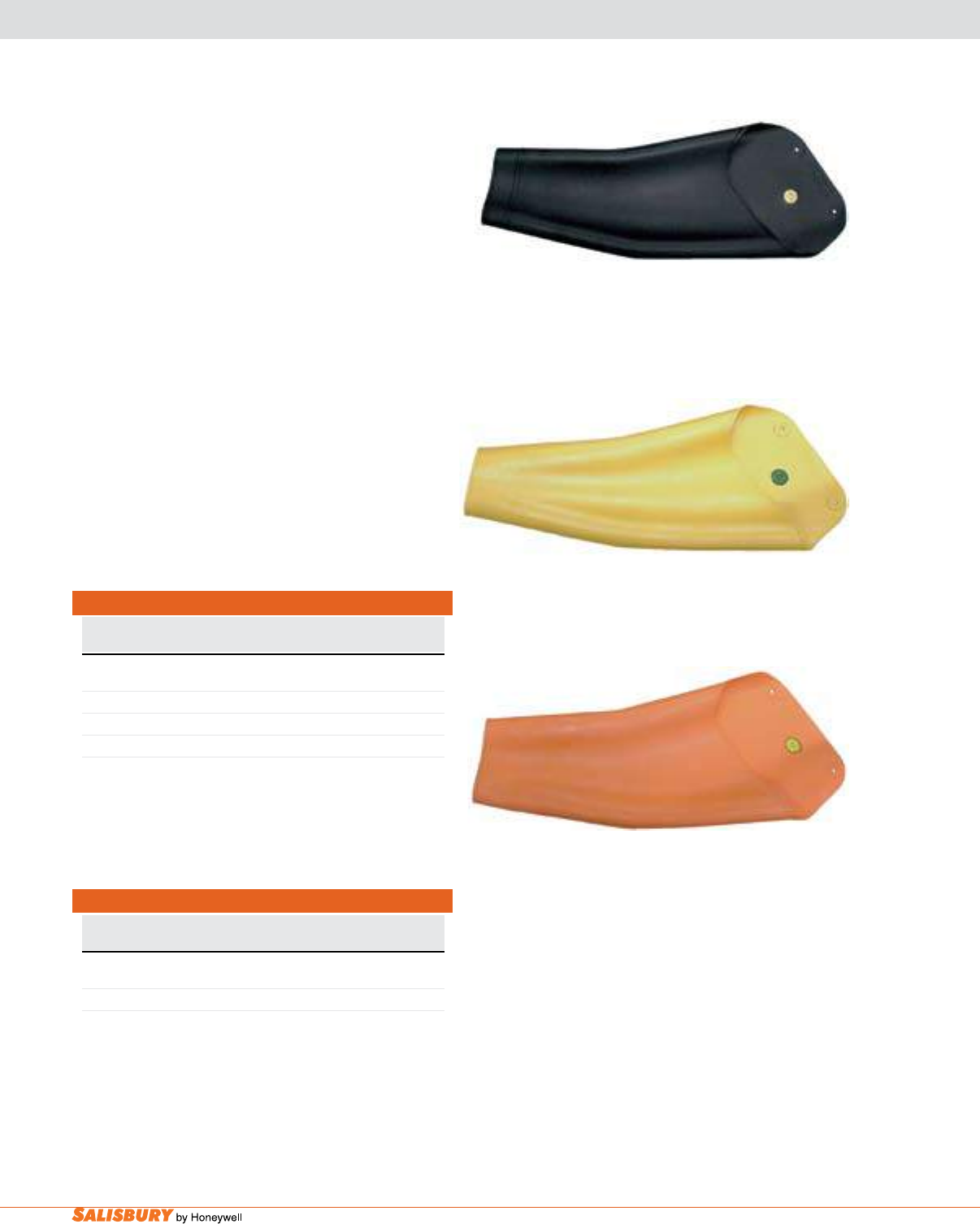
E-14 Gloves and Sleeves. www.salisburybyhoneywell.com
LINEMEN’S SLEEVES
MOLDED
Cat. No. Breakdown for Molded Type II Sleeves
Voltage Size Color
Class
1 R or L
BS or OS
2 R, L or XL
BS or OS
R=regular L=large XL=extra large BS=black SALCOR
Example: 2LOS OS=orange SALCOR
Cat. No. Breakdown for Molded Type I Sleeves
Voltage Size Color
Class
1 R or L
Y
2 R, L or XL
B, Y, M
3 R or L
Y, M
4
R or L
M
R=regular L=large XL=extra large B=black Y=yellow
Example: 2LB M=maroon
molded sleeves are manufactured by either injection
or compression molding methods. The advantage
these methods offer is the ability to produce sleeves
of Type I or SALCOR® Type II synthetic rubber.
SALCOR sleeves provide the same high quality
and electrical protection as natural rubber, with
the added benet of being resistant to ozone and
ultraviolet radiation. Type I sleeves are available in
black, yellow or maroon. Type II SALCOR sleeves
are black or orange. Molded sleeves are available in
curved arm style only.
Black
Type I
2RB
Yellow
Type I
3LY
Orange
Type II
2ROS
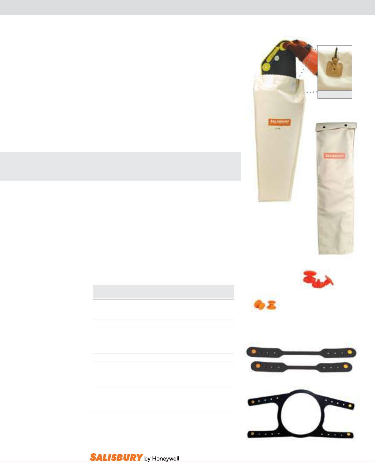
E-15
101 E. Crossroads Pkwy., Ste. A Bolingbrook, IL 60440 toll free ph (USA):877.406.4501 toll free fax (USA):866.824.4922 ph:630.343.3800
T32
D Ring on back
SLEEVE STORAGE & ACCESSORIES
Proper storage extends the service life of linemen’s sleeves.
Folds and creases strain rubber and cause it to crack
from ozone prematurely. By storing rubber sleeves in
the right size bag, and never forcing more than one pair
into each bag, equipment will lie at and extend the life
of the product.
Salisbury bags are constructed of heavy duty canvas
duck and are double stitched and riveted at stress points
for extra durability. Canvas bags feature a D ring for
hanging in trucks or on work belts. Bags feature tapered
gussets with wide opening tops for easy insertion.
SALISBURY ADVANTAGE
The T32 bag contains a crush resistant lining to create
a more protective environment for your sleeves.
Sleeve buttons, straps, and harnesses are required to
wear rubber insulating sleeves properly. Four buttons
are required per pair of sleeves. Two straps are required
per pair of sleeves. One harness is required per pair of
sleeves.
Cat. No. For Sleeve Dimensions Weight ea.
length in. ( mm ) inches ( mm ) lbs. ( kgs )
CANVAS SLEEVE BAG
T31
-
30” x 9.5” ( 762 x 241mm) 1.5 ( . 7 )
T32
-
30” x 13” ( 762 x 330 mm) 3 ( 1.4 )
BUTTONS
B2
-
One Piece Sleeve Button .2 ( .01 )
B22
-
4 Screw Type Buttons .8 ( .04 )
STRAPS
S1
15”(381mm) Strap w/ 4 B2 Buttons .1 ( .005 )
HARNESS
H1
Harness w/ 4 B2 Buttons 1 ( .45 )
T31
S1
H1
B2
B22
Two-piece sleeve button
4 required per pair of sleeves
One piece sleeve button
4 required per pair of sleeves

E-16 Gloves and Sleeves. www.salisburybyhoneywell.com
SALISBURY LINEMEN’S GLOVE LINERS
L10JK L10J
L12J
Cat. No. Description Wrist Length Weight ea.
Style in. ( mm ) lbs. ( kgs )
L10JK Jersey Style, Light Weight, Seams Out Knit 10 ( 254 ) .14 (.06)
L10J Jersey Style, Light Weight, Seams Out Open 10 ( 254 ) .12 (.06)
L12J Jersey Style, Light Weight, Seams Out Open 12 ( 305 ) .14 (.07)
L10MKC Machine Knit, 100% Cotton Knit 10 ( 254 ) .12 (.05)
L12MKC Machine Knit, 100% Cotton Knit 12 ( 305 ) .12 (.05)
L10MKW Machine Knit, Wool Blend Knit 10 ( 254 ) .14 (.06)
L12MKW Machine Knit, Wool Blend Knit 12 ( 305 ) .14 (.07)
89/1402 White Machine Knit, 100% Cotton Knit 10 ( 254 ) .12 (.06)
89/4702 Rust Machine Knit, 100% Acrylic Knit 10 ( 254 ) .12 (.06)
One size ts all.
L12MKC
89/1402 89/4702
liner gloves enhance the comfort of
wearing Rubber Insulating Gloves in
every season. Liners provide warmth in
the cold season and absorb perspiration
in the warm months. Many styles and
fabrics are available with either an open
or knit wrist.
The knit wrist style grips the wrist rather
than allowing the cuff to roll down and
bunch at the palm. All Liner Gloves
are for year round use with Rubber
Insulating Gloves and Mittens. All liners
are made from stretch fabric that can t
any hand size.
The l Series has a tough outer cotton
fabric while the inner lining is soft and
comfortable. The lmKC Series is light,
airy and allows ease of movement. The
lmKW Series is made from a wool
blend fabric that moves easily yet gives
a substantial layer of lining.
The 89 Series is Salisbury’s classic
summer and winter glove liner. Liners
absorb perspiration from hands. The
summer liner is white in color and 100%
cotton. The winter blend is a rust color
and 100% acrylic.
L10MKW
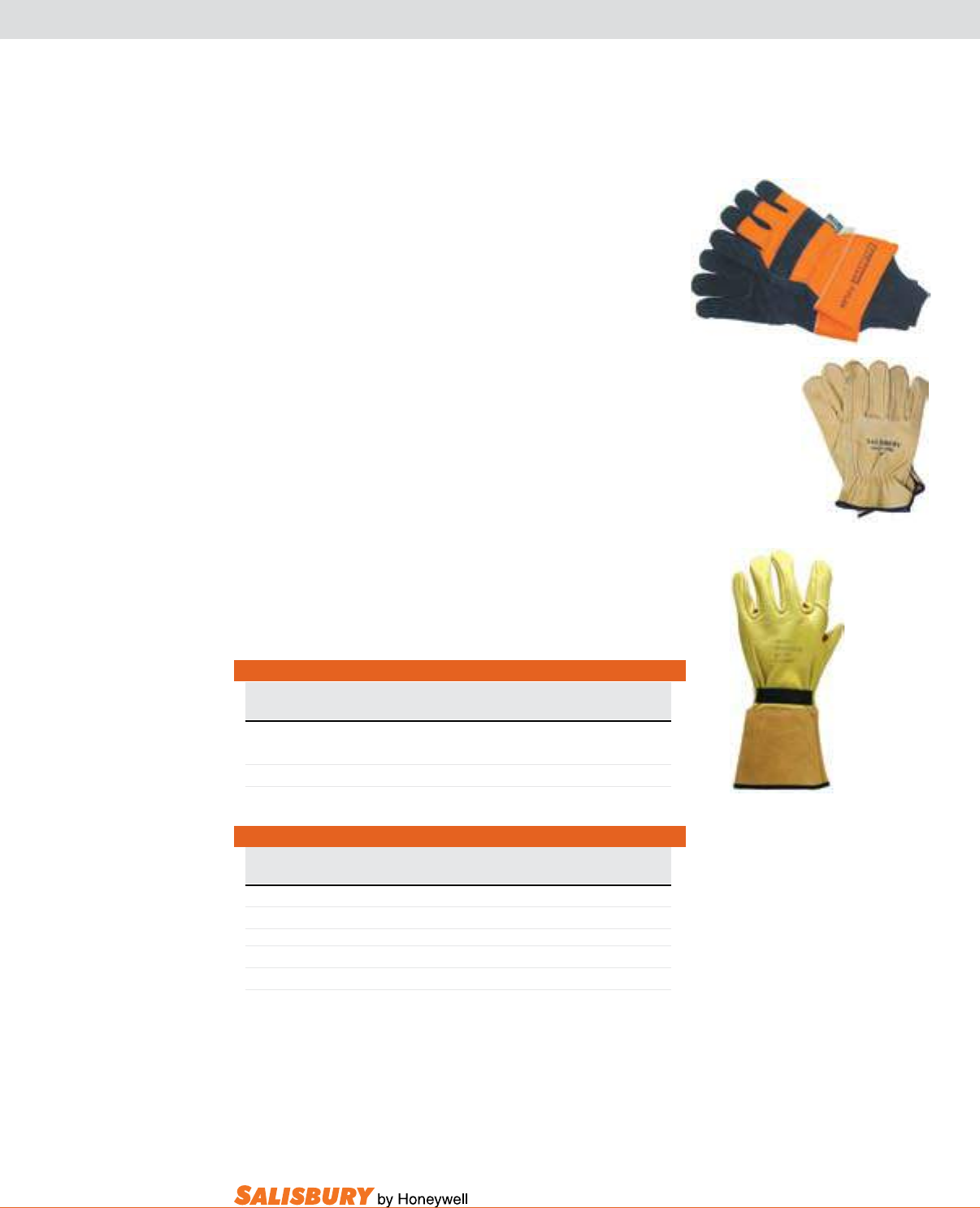
E-17
101 E. Crossroads Pkwy., Ste. A Bolingbrook, IL 60440 toll free ph (USA):877.406.4501 toll free fax (USA):866.824.4922 ph:630.343.3800
SALPOL & WORK GLOVES
Salisbury’s SalPOl gloves protect hands during cold
weather jobs. The black split cowhide leather has a 3M
Thinsulate* lining to keep hands warm. For extra warmth
a long knit wrist is sewn into the safety cuff to keep out
snow and ice. The glove also has a full leather index nger,
knuckle strap, leather ngertips, and pull patch.
*Thinsulate is a registered Trademark of the 3M Company.
drivers Work gloves set the standard for quality at
an affordable price. Combining comfort, durability and
economy, Salisbury leather Drivers Work Gloves meet
the tough challenges of today’s demanding workplace.
Available in lined or unlined styles. The bindings are
color coded to indicate size: red-small, green-medium,
brown-large, purple-extra large.
linemen Work gloves are designed specically for
use by linemen and offers many of the quality features
found in our leather protectors. Made from high quality
grain cowhide or goatskin, this glove is soft and exible,
while still being highly abrasion and cut resistant for
long wear.
Cat. No. Description Weight ea.
lbs. ( kgs )
I95/217/WHS* Unlined .3 ( .14 )
I95/317/WHS* Lined .3 ( .14 )
*Add “-S” for small, “-M” for medium, “-L” for large, “-XL” for extra-large.
LW2SPE** Cowhide leather, natural pigskin cuff .4 ( .18 )
LWG2SPE** Goatskin leather, natural pigskin cuff .4 ( .18 )
**Add “-M” for medium, “-L” for large, “-XL” for extra-large.
DRIVERS & LINEMEN WORK GLOVES
Cat. No. Description Length Weight ea.
in. ( mm ) lbs. ( kgs )
SALPOL GLOVES
SP-S Small Size Polar Glove n / a .5 ( .23 )
SP-L Large Size Polar Glove n / a .5 ( .23 )
SALPOL GLOVES
I95/217/WHS
SP-L
LW2SPE
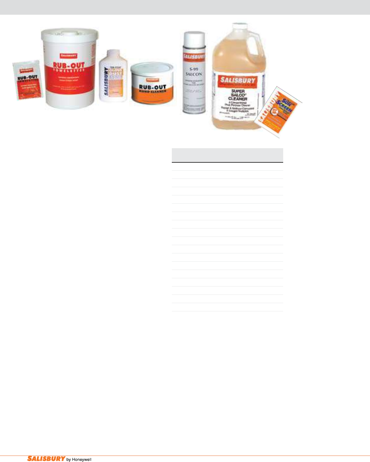
E-18 Gloves and Sleeves. www.salisburybyhoneywell.com
Rub-OuT® is a non-petroleum-based hand cleaner
for workers who wear rubber gloves and sleeves.
Dissolves and removes grease, oil, ink, tar, pipe
dope, creosote, paint and more without harming
natural rubber or SALCOR® rubber. Cleans with
or without water. Contains natural skin conditioners
and leaves a fresh citrus scent.
Salisbury’s Rub-OuT® Towelettes are
premoistened heavy duty hand cleaner towels
that work fast to loosen, dissolve, and absorb dirt
and grease, and will not harm rubber gloves! Our
powerful yet safe cleaning agents work together with
an absorbent, nonscratching abrasive cleaning towel.
The citrus-based formula easily removes soil from
your hands and leaves them cleaned and conditioned
anywhere you’re working. And after cleaning your
hands there is enough absorbency to clean your tools
and other surfaces with the same towel. These shop
size (10.5” x 12.25”) durable towels quickly remove
tough-to-clean substances including lubricants, tar,
oils, wax, caulk and much more.
TEn-FOuR® glOvE duST is a cooling,
frictionless powder that absorbs moisture and
perspiration when wearing rubber gloves. Provides
extra comfort while preventing gloves from getting
sticky. The 5-oz. bottle easily ts in a pocket or glove
bag. The 4-quart bulk package is used in test labs as
a dusting powder when cleaning and testing.
SuPER SalCO® Cleaner is a concentrated
detergent with a special grease release formula that
removes oils, grease and dirt from natural rubber and
SALCOR rubber equipment. Suitable for washing
linemen’s rubber gloves, sleeves and other specialty
equipment, by hand or in commercial washing
machines. Also works well on berglass and other
materials. Just dilute with water, apply with a rag or
sponge and rinse thoroughly.
Cat. No. Description Weight ea.
lbs. ( kgs )
RUB-OUT® HAND CLEANER
1451 16 oz. ( .45kg ) can, 12/pack 16 ( 7.3 )
1452 4.5 lbs. ( 2kgs ) cans, 6/pack 28 ( 12.7 )
1453 Dispenser for 4.5lb. ( 2kg ) can 1 ( .5 )
RUB-OUT® TOWELETTES
1460 Bucket of 60, 6 buckets / Case 14 ( 6.4 )
1461 Single Packets, 100 Singles / Case 3 ( 1.4 )
TEN-FOUR® GLOVE DUST
10-4 12 @ 5 oz. ( 170g ) squeeze bottles 5.5( 2.2 )
10-4-4QT 4 quarts ( 3.8 ltrs. ) bulk, single 8 ( 3.6 )
SUPER SALCO® DETERGENT
S4 1 gal ( 3.8 ltr. ) jugs, 4 pack 54( 24.5 )
S5 5 gal ( 19 ltr. ) drum 49 ( 22.3 )
S55 55 gal ( 208 ltr. ) drum 540 ( 245 )
SALCON® SILICONE SPRAY
S99 Aerosol can 16 oz. ( .454 )
SUNSCREEN 30
SS30 100 towelettes 6 ( 2.72 )
S99
S5
SalCOn® Silicone Spray is specially formulated
to reduce friction on SALCOR or natural rubber
products. Reduces surface creepage on rubber
gloves and sleeves. Forms an oxygen barrier which
helps reduce corona cutting and weather checking
on rubber equipment. May also be used to spray
spark plugs and battery terminals in damp weather
to assist in starting.
SunSCREEn 30 is a non-oily sunscreen that
does the job for at least four hours. Safe for leather
and rubber gloves, leaves no residue
-
no slippery
hands. Large convenient towelettes.
CLEANERS, SUNSCREEN AND SUPPLIES
SS30
1460
1461
10-4 1451
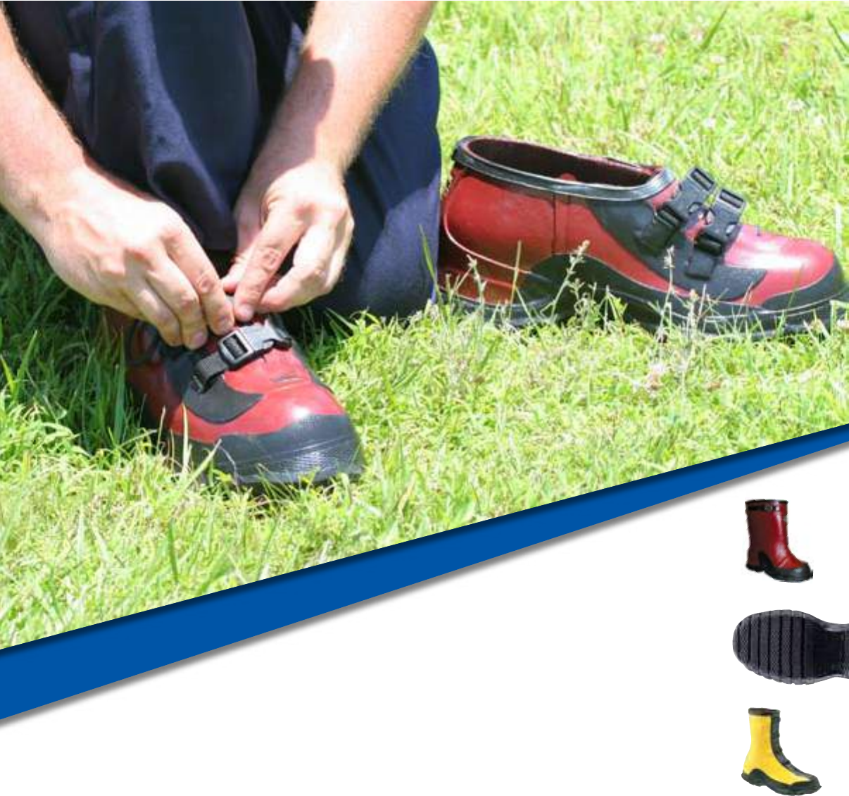
PROTECTIVE FOOTWEAR

F-2 Protective Footwear. www.salisburybyhoneywell.com
PROTECTIVE FOOTWEAR
FAQ
Q: What is the difference between the yellow/black Salisbury ASTM F2413-05
EH Footwear and the red/black ASTM Dielectric Footwear?
A: The yellow/black Salisbury ASTM F2413-05 EH Footwear are
manufactured per the requirements of ASTM F2413-05 EH. Which means
the outsole of these overshoes and boots have been lot tested to 20,000
volts to the electrical hazard requirements of ASTM F2413-05. Salisbury’s
red/black ASTM dielectric footwear conforms with ASTM F1117 and are
all 100% tested to the electrical hazard requirements of ASTM F1116 at
20,000 volts.
Q: What are the benets of ASTM Dielectric Footwear?
A: ASTM Dielectric Footwear protects ground workers from step and touch
potential in the whole work zone, not just one conned work area, like a
grounding mat.
ASTM Dielectric Footwear can help reduce the amount of electrical workers
in a work area since they are not conned.
ASTM Dielectric Footwear allows personnel to safely mount and
dismount equipment in the work zone.
ASTM Dielectric Footwear allows personnel
to safely retrieve material from
truck bins.
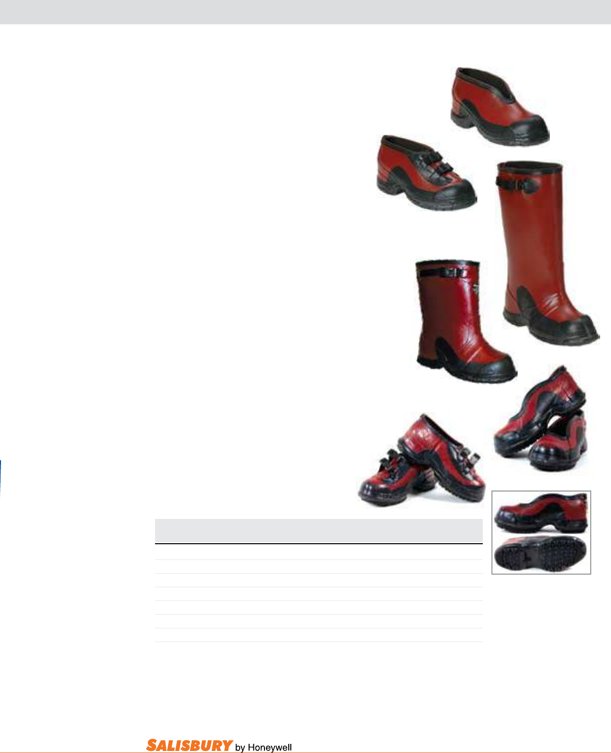
F-3
101 E. Crossroads Pkwy., Ste. A Bolingbrook, IL 60440 toll free ph (USA):877.406.4501 toll free fax (USA):866.824.4922 ph:630.343.3800
BOB SOLE
ASTM DIELECTRIC FOOTWEAR
DEEP HEEL OVERSHOES - 100% TESTED TO 20KV
aSTm dielectric Footwear provides extra safety
when climbing ladders and poles where the deep
heel cavity can lock onto the rungs. These boots
and overshoes are 100% waterproof and made
from premium grade ozone resistant rubber. The
construction is hand-layered in full-cut patterns
to t over work boots. The fabric lining makes
them easy to get on and off. The sole has a durable
construction with a non-skid bar tread outsole.
all of Salisbury’s aSTm dielectric Footwear
conforms with aSTm F1117 and all are 100%
TESTEd to the electrical hazard requirements
of aSTm F1116 at 20,000 volts.
ASTM Dielectric Footwear comes in four styles
all with pole-climbing reinforcement patch. The
Overshoe is available without buckles or with two
buckles. The Overboot with adjustable side strap
features a 14” height or a 17” height. The attached
buckle and hardware is nonmetallic.
nEW Improved Overshoes-Salisbury now offers
improved 51511 non-buckle overshoe and 51512 2-
buckle overshoe. The improved overshoes include
a bob sole with aggressive tread for better traction.
The deep heel and improved arch are specially
designed for climbing ladders comfortably. The
wider opening allows for easier on/off.
21406
21405
51508
51509
Cat. No. Description Sizes Weight pr.
in. ( mm ) lbs. ( kgs )
21405 17”, 1 Buckle Overboot Whole Sizes 7 - 16 5.8 ( 2.6 )
21406 14” 1 Buckle Overboot Whole Sizes 7 - 17 5.0 ( 2.3 )
51508 Non-Buckle Overshoe Whole Sizes 7 - 17 3.3 ( 1.5 )
51509 2 Buckle Overshoe Whole Sizes 7 - 17 4.4 ( 2 )
51511 Bob Sole - Non-Buckle Overshoe Whole Sizes 7 - 16 3.3 ( 1.5 )
51512 Bob Sole - 2 Buckle Overshoe Whole Sizes 7 - 16 4.4 ( 2 )
NOTE: When ordering, add size as sufx to part number. Be sure to add a space between
the part number and size. Example: 51511 7
51511
51512
PROTECTIVE FOOTWEAR
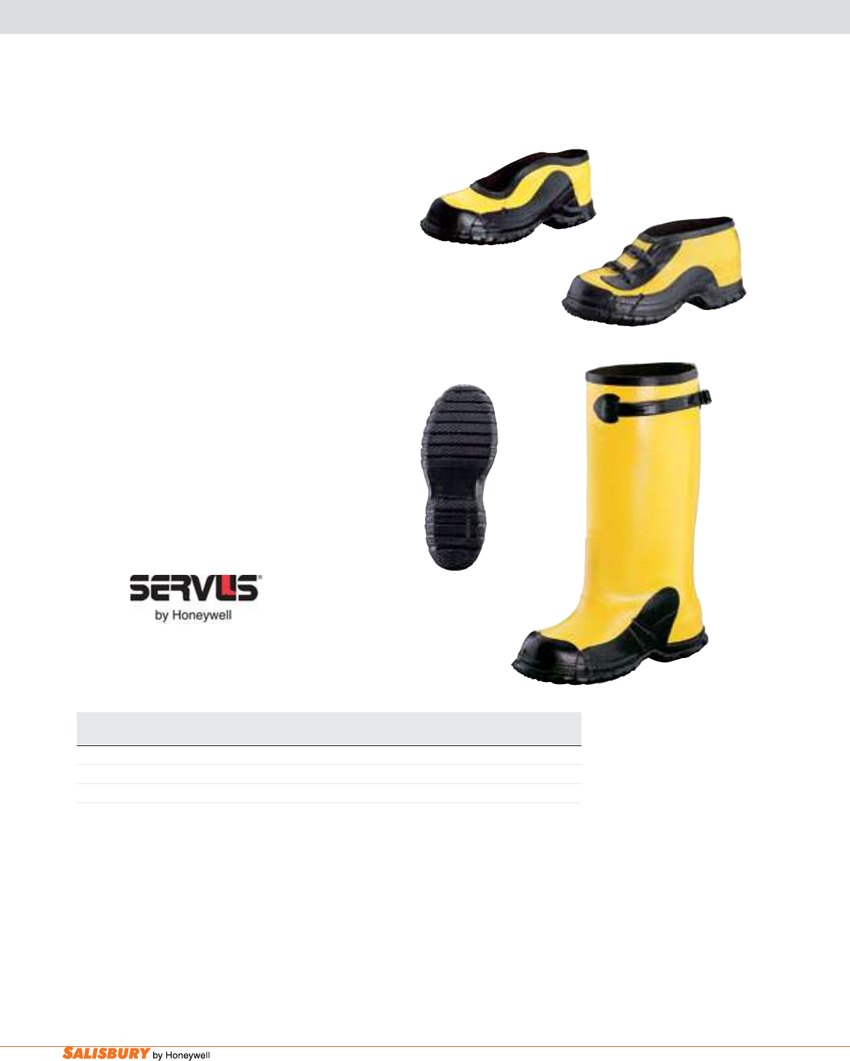
F-4 Protective Footwear. www.salisburybyhoneywell.com
ASTM F2413-05 EH FOOTWEAR
DEEP HEEL OVERSHOES, OUTSOLE TESTED TO 20KV
aSTm F2413-05 EH deep Heel Overshoes
provide extra safety when climbing ladders and
poles where the deep heel cavity can lock onto
the rungs. These boots and overshoes are made
from an ozone resistant yellow rubber that’s 100%
waterproof. The construction is hand-layered
in full-cut patterns to t over work boots. The
fabric lining makes them easy get on and off.
The sole is an anti-skid bar tread. The outsole
of these overshoes and boots have been lot
tested to 20,000 volts to the electrical hazard
requirements of aSTm F2413-05.
ASTM F2413-05 EH Deep Heel Overshoes
come in three styles all with pole-climbing
reinforcement patch. The Storm Rubber
Overshoe is available without buckles or with
two buckles. The Full-Cut Overshoe with
adjustable side strap features a 17” height.
Cat. No. Sizes Description Weight pr.
in. ( mm ) lbs. ( kgs )
21402 Whole Sizes 7-17 17” ( 432 ) Overshoe 5.8 ( 2.6 )
51530 Whole Sizes 6-17 2-Buckle 4.4 ( 2 )
51581 Whole & Half Sizes 7-12, Whole Sizes 6, 13-17 Storm Rubber 3.3 ( 1.5 )
NOTE: When ordering, add size as sufx to part number. Be sure to add a space between the part
number and size. Example: 51511 7
51581
51530
21402
Anti-Skid
Bar Tread
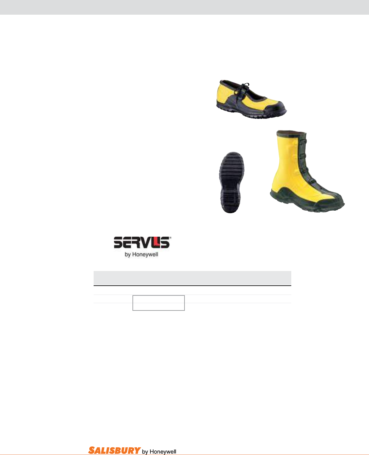
F-5
101 E. Crossroads Pkwy., Ste. A Bolingbrook, IL 60440 toll free ph (USA):877.406.4501 toll free fax (USA):866.824.4922 ph:630.343.3800
ASTM F2413-05 EH FOOTWEAR
OVERSHOES, OUTSOLE TESTED TO 20KV
aSTm F2413-05 EH Overshoes are made
from an ozone resistant yellow rubber. The
construction is hand-layered in full-cut
patterns to easily fit over work boots.
These overshoes are 100% waterproof.
The lining is fabric so they easily slip on
and off. The sole is an anti-skid bar tread.
The outsole of these overshoes and boots
have been lot tested to 20,000 volts to
the electrical hazard requirements of
aSTm F2413-05.
ASTM F2413-05 EH Overshoes are
available in two styles: a Storm Rubber
Overshoe and an 11” 4-Buckle Arctic
both with a pole-climbing reinforcement
patch. 31924
51824
Anti-Skid
Bar Tread
Cat. No. Sizes Description Weight pr.
in. ( mm ) lbs. ( kgs )
31924 Whole Sizes 6-17 11” ( 279 ) 4-Buckle Arctic 4.6 ( 2.1 )
51824 Whole & Half Sizes 7-12 Storm Rubber 3.25 ( 1.5 )
Whole Sizes 13-16
NOTE: When ordering, add size as sufx to part number. Be sure to add a space between
the part number and size. Example: 51511 7
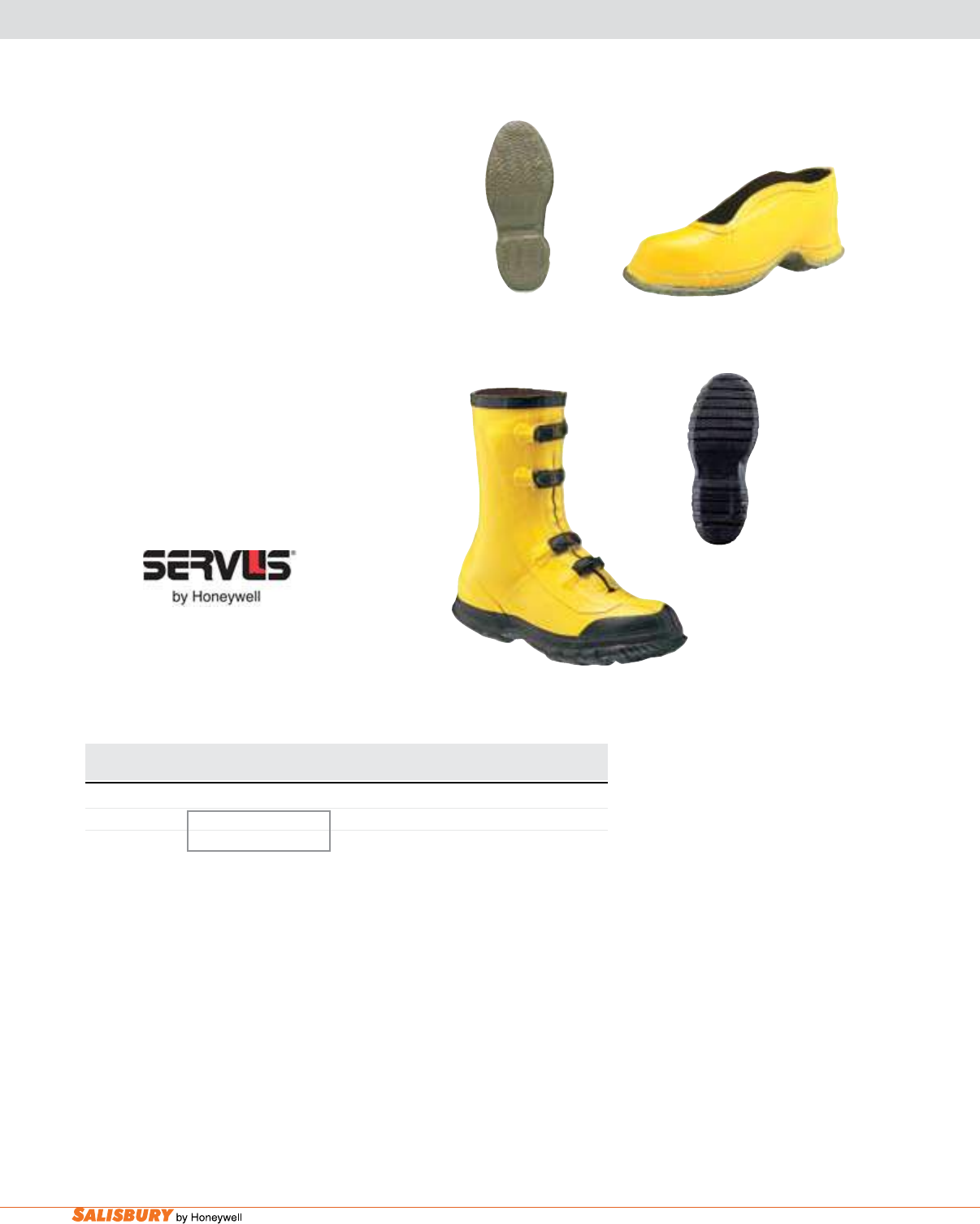
F-6 Protective Footwear. www.salisburybyhoneywell.com
ASTM F2413-05 EH FOOTWEAR
OVERSHOES, OUTSOLE TESTED TO 14KV
aSTm F2413-05 EH Overshoes are made
from yellow ozone resistant rubber that’s 100%
waterproof. The construction is hand-layered in
full-cut patterns to easily slip over work shoes.
The lining is fabric so they easily slip on and off.
The outsole of these overshoes and boots have
been lot tested to 14,000 volts to the electrical
hazard requirements of aSTm F2413-05.
ASTM F2413-05 EH Overshoes come in two
styles. The deep Heel lineman’s Storm
Rubber has a diamond V-grip outsole and pole-
climbing reinforcement patch. The 11” 4-buckle
has an anti-skid bar tread sole and heel.
Diamond V-grip
Outsole
51510
31910
Anti-Skid
Bar Tread
Cat. No. Sizes Description Weight pr.
in. ( mm ) lbs. ( kgs )
31910 Whole Sizes 7-17 11” ( 279 ) 4-Buckle 3.8 ( 1.7 )
51510 Whole & Half Sizes 6-12, Deep Heel Storm Rubber 3.1 ( 1.4 )
Whole Sizes 13-17
NOTE: When ordering, add size as sufx to part number. Be sure to add a space between
the part number and size. Example: 51511 7
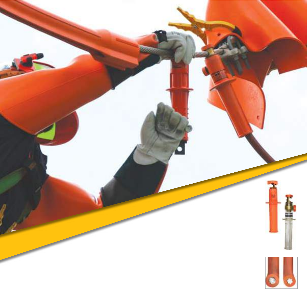
insulated jumpers

G-2 Insulated Jumpers. www.salisburybyhoneywell.com
insulated jumpers
FaQ
Q:
a:
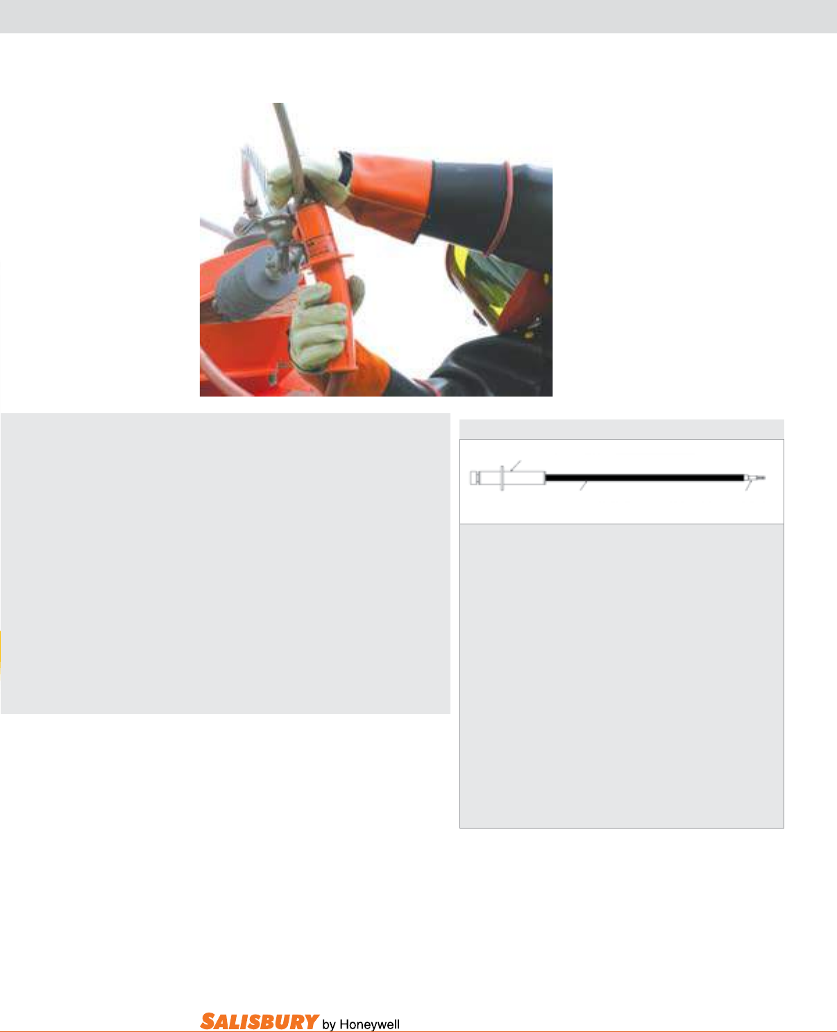
G-3
101 E. Crossroads Pkwy., Ste. A Bolingbrook, IL 60440 toll free ph (USA):877.406.4501 toll free fax (USA):866.824.4922 ph:630.343.3800
insulated jumpers
SALISBURY ADVANTAGE
Insulated bypass jumper sets consist
of three basic components: one pair
of clamps, one pair of ferrules, and a
length of insulated cable. Many of the
most popular jumper sets are listed on
the following pages associated with each
of the different types of jumper clamps.
When a custom jumper is required, follow
this procedure to ensure that a complete
and functional jumper is specied.
If you need assembled jumper sets,
quickly, please contact your local
Salisbury Representative for more
information.
Let Salisbury professionally assemble
your sets for you.
All Salisbury Insulating Jumpers meet
ASTM F2321 standards.
1. Specify the style of insulated clamps. All of the clamps are hand installed wearing
rubber insulating gloves, accept either shrouded or unshrouded ferrules, and accept
insulated cable up to 4/0, 35kV. Insulated jumper clamps are sold in pairs.
2. Specify the size and length of insulated cable. Salisbury offers 15kV cable from
#2 to 4/0. 25 and 35 kV cable are both available in sizes 1/0 and
2/0. Be sure to specify the length of the cable chosen.
3. Specify the size and style of ferrules required. The size of the ferrule will be
determined by the size of the cable. Specify the appropriate ferrule catalog number
for either shrouded or unshrouded ferrules. Both types are sold in pairs.
4. Specify if the jumpers are to be factory assembled. A complete jumper set with
crimped ferrules and installed jumper clamps will be supplied. Salisbury has state
of the art computer controlled crimping available.
5. Specify if there are any special requirements. This could include heat shrink
tubing, special assembly instructions, markings, packaging etc.
1. Clamp
2. Ferrules
3. Cable
Insulated Jumper Checklist
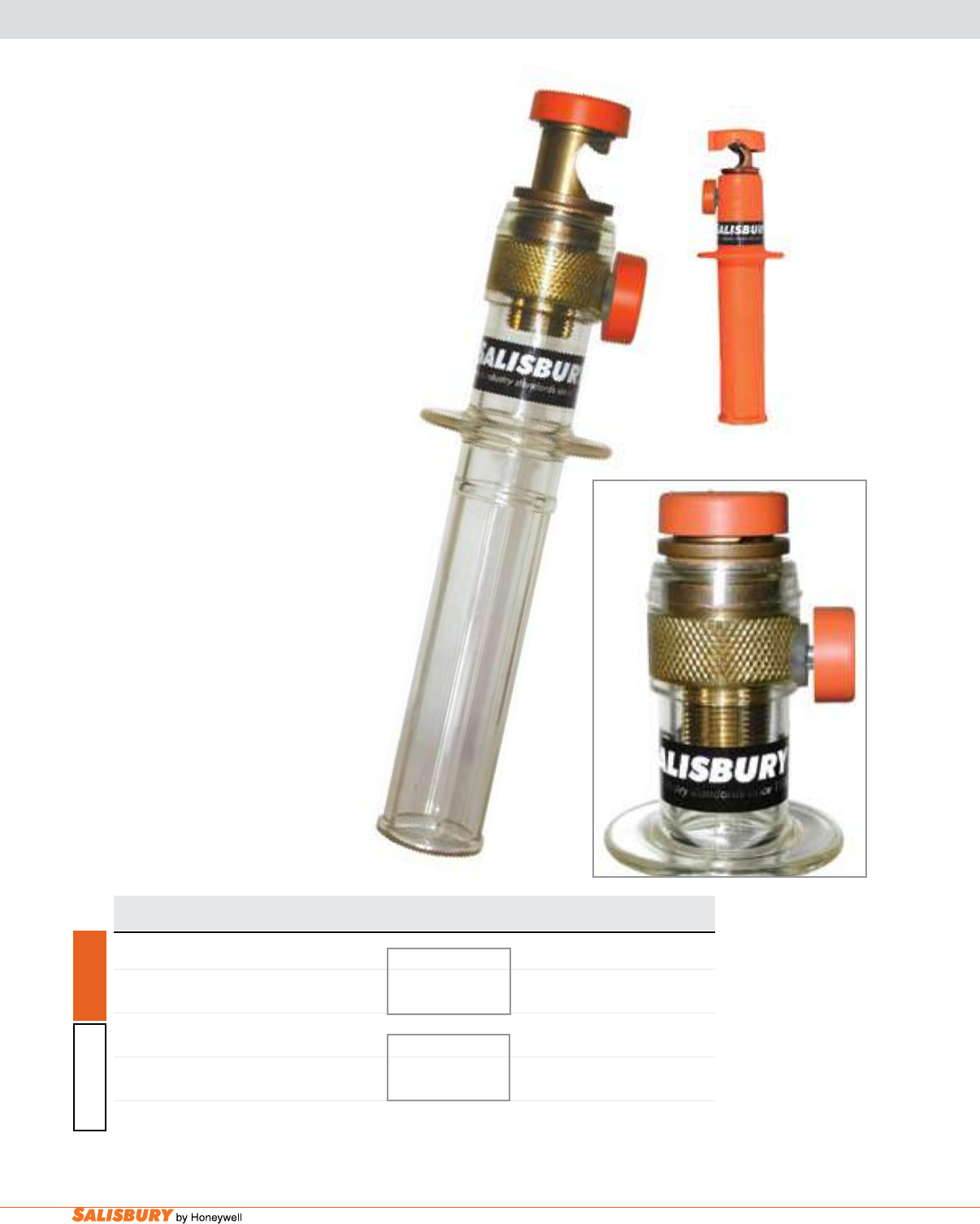
G-4 Insulated Jumpers. www.salisburybyhoneywell.com
Cat. No. Main Line Max Amps Rating OAL Length Weight ea.
Range Continuous in. ( mm ) lbs. ( kgs )
2261 477 MCM (.9”-.162”) 400 36 kV Ø-Ø 11.5 ( 292 mm ) 10 ( 4.5 )
2271 954 MCM (1.25”-.162”) 400 21 kV Ø-GRD 11.5 ( 292 mm ) 11 ( 5 )
1786 477 MCM (.9”-.162”) 400 36 kV Ø-Ø 11.5 ( 292 mm ) 8 ( 3.6 )
2116 954 MCM (1.25”-.162”) 400 21 kV Ø-GRD 11.5 ( 292 mm ) 10 ( 4.5 )
The Salisbury Sure-lok®
Jumper Clamp
The Salisbury Sure-lok® Jumper clamp is a revolutionary
improvement over any other jumper clamp in the world.
Featuring a ratchet type locking mechanism (patent
pending), this is the only clamp available guaranteed
not to loosen once installed on a line.
Loose Jumper clamps not only jeopardize
your safety but can also cause res and power
outages. Even when torqued using wrenches or
pliers, traditional clamps will eventually loosen
from line vibrations and thermal cycling. This
clamp tightens with a ratchet action using one
hand, with no extra tools for a secure, positive
connection. It can’t come loose until you want it
to. Pull and turn the locking knob and it loosens
like any traditional clamp.
Available in our exclusive SALCOR®
material and the industry’s most durable
single piece clear plastic jumper clamps.
Custom built assemblies are available.
Contact your local Salisbury
Representative for more information.
locking insulated jumper clamps
SALCOR®
Clear Plastic
2261
SALCOR® Sure-lok®
1786
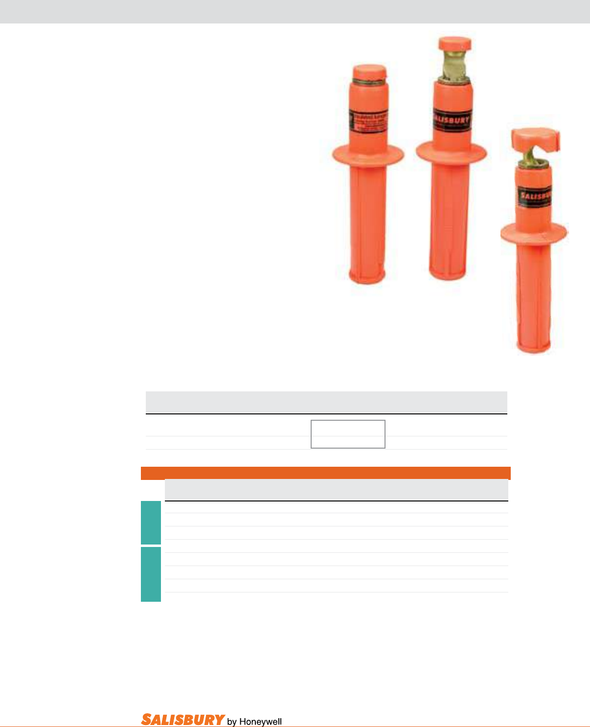
G-5
101 E. Crossroads Pkwy., Ste. A Bolingbrook, IL 60440 toll free ph (USA):877.406.4501 toll free fax (USA):866.824.4922 ph:630.343.3800
SalCOR® Jumper Clamps are available
in two main line sizes with a maximum use
voltage of 35kV.
The SalCOR Jumper Clamp not only
provides a superior grip, but also resists ozone
cutting and tracking. Being molded of rubber,
these handles are inherently impact resistant
and extremely durable. The body and jaw are
made from a copper base alloy. The lower ring
contact is made of self lubricating bronze.
Assemble jumpers with insulated jumper
cable and 5/8”- 11 NC threaded ferrules.
Assembled kits are sold with a 10 ft. ( 3m )
cable and unshrouded ferrules.
Custom built assemblies are available.
Contact your local Salisbury
Representative for more information.
2270
Assembled 10 ft. / 3m Jumper Sets ( Unshrouded Ferrules)
Jumper Cable Size Cable Ferrule Max Amps Weight ea.
Cat. No. Cat. No. Cat. No. Continuous lbs. ( kgs )
2264 #2-15 kV 2754 2022 200 10.9 ( 4.9 )
2265 1/0-15 kV 2755 2023 250 13.5 ( 6.1 )
2266 2/0-15 kV 2756 2024 300 14.8 ( 6.8 )
2274 #2-15 kV 2754 2022 200 11.9 ( 5.4 )
2275 1/0-15 kV 2755 2023 250 14.6 ( 6.8 )
2276 2/0-15 kV 2756 2024 300 15.9 ( 7.2 )
2260 Clamp
2270 Clamp
2260
Cat. No. Main Line Max Amps Rating OAL Length Weight ea.
Range Continuous in. ( mm ) lbs. ( kgs )
2260 477 MCM (.9”-.162”) 400 36 kV Ø-Ø 11.5 ( 292 mm ) 10 ( 4.5 )
2270 954 MCM (1.25”-.162”) 400 21 kV Ø-GRD 11.5 ( 292 mm ) 11 ( 5 )
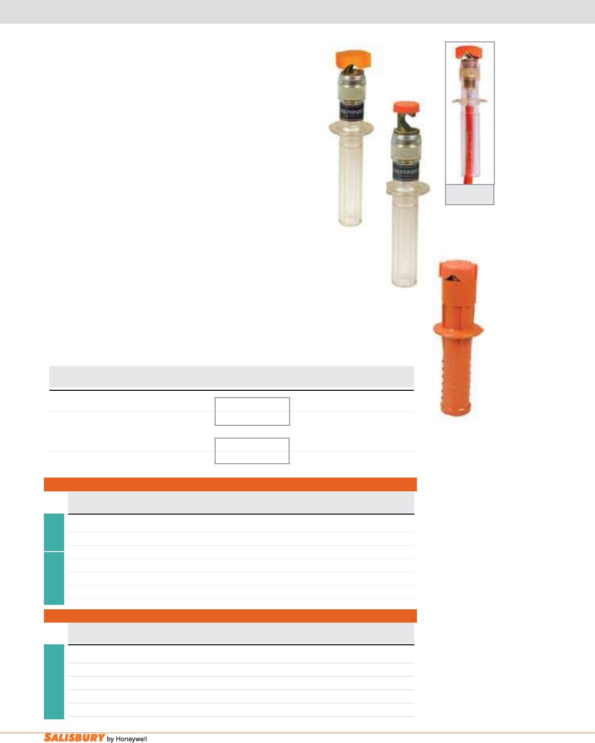
G-6 Insulated Jumpers. www.salisburybyhoneywell.com
clear plastic & Frp insulated jumper clamps
Salisbury’s superior stress cracking resistant Clear Jumper
Clamps are available in two main line sizes with a maximum use
voltage of 35kV. Assemble these clamps with insulated jumper
cable and 5/8” - 11 NC threaded ferrules.
Clear Plastic Jumper Clamps are compact, lightweight, and
virtually unbreakable. The transparency allows easy inspection of
the ferrule and cable inside of the handle. The body and jaw are
made from a copper base alloy. The lower oating ring contact is
bronze. These handles should be cleaned only with a mild detergent
to maintain the transparency of the handle. Assembled kits are sold
with a 10 ft. (3m) cable and unshrouded ferrules.
FRP Jumper Clamps are designed for maximum loads, voltages,
and cables. During a temperature rise test at 25% overload, these
clamps heated 35% less than 4/0 cu. cable. Blunted points on the
handle provide optimum grip, resist impact, and will not soften
with overloads. The body and jaw are made from a copper based
alloy. The lower jaw is made of self lubricating bronze. The
assembled jumpers are sold with a 10ft. (3m) or 12 ft. (3.7m) cable
and unshrouded ferrules.
Custom built assemblies are available. Contact your local
Salisbury Representative for more information.
1610
Assembled Jumper Sets ( Unshrouded Ferrules)
Jumper Cable Length Cable Size Cable Ferrule Max Amps Weight ea.
Cat. No. Cat. No. Cat. No. Continuous lbs. ( kgs )
2772 10’ 2/0-15kV 2756 2024 300 5.8 ( 2.9 )
2773 10’ 4/0-15kV 2757 2025 400 20.3 ( 9.2 )
2450 10’ 1/0-15kV 2755 2023 250 15 ( 6.8 )
2066 12’ 1/0-35kV 2059 2023 250 20.3 ( 9.2 )
20876 12’ 2/0-35kV 4370 2024 300 21.5 ( 9.8 )
1610 Clamp
Assembled 10 ft. / 3m Jumper Sets ( Unshrouded Ferrules)
Jumper Cable Size Cable Ferrule Max Amps Weight ea.
Cat. No. Cat. No. Cat. No. Continuous lbs. ( kgs )
2067 #2-15 kV 2754 2022 200 9.9 ( 4.5 )
2178 2/0-15 kV 2756 2024 300 13.9 ( 6.3 )
2074R1 #2-15 kV 2754 2022 200 10.9 ( 4.9 )
2164 2/0-15 kV 2756 2024 300 14.8 ( 6.8 )
2174R1 1/0-15 kV 2755 2023 250 16.8 ( 7.6 )
1785
Clamp
2115 Clamp
2115
Clear Jumper
with Cable
1785
Cat. No. Main Line Max Amps Rating OAL Length Weight ea.
Range Continuous in. ( mm ) lbs. ( kgs )
1610 954 MCM (1.25”-.162”) 400 36 kV Ø-Ø 11 ( 279 ) 14 ( 6.4 )
21 kV Ø-GRD
1785 477 MCM (.9”-.162”) 400 36 kV Ø-Ø 11.5 ( 292 mm ) 8 ( 3.6 )
2115 954 MCM (1.25”-.162”) 400 21 kV Ø-GRD 11.5 ( 292 mm ) 10 ( 4.5 )
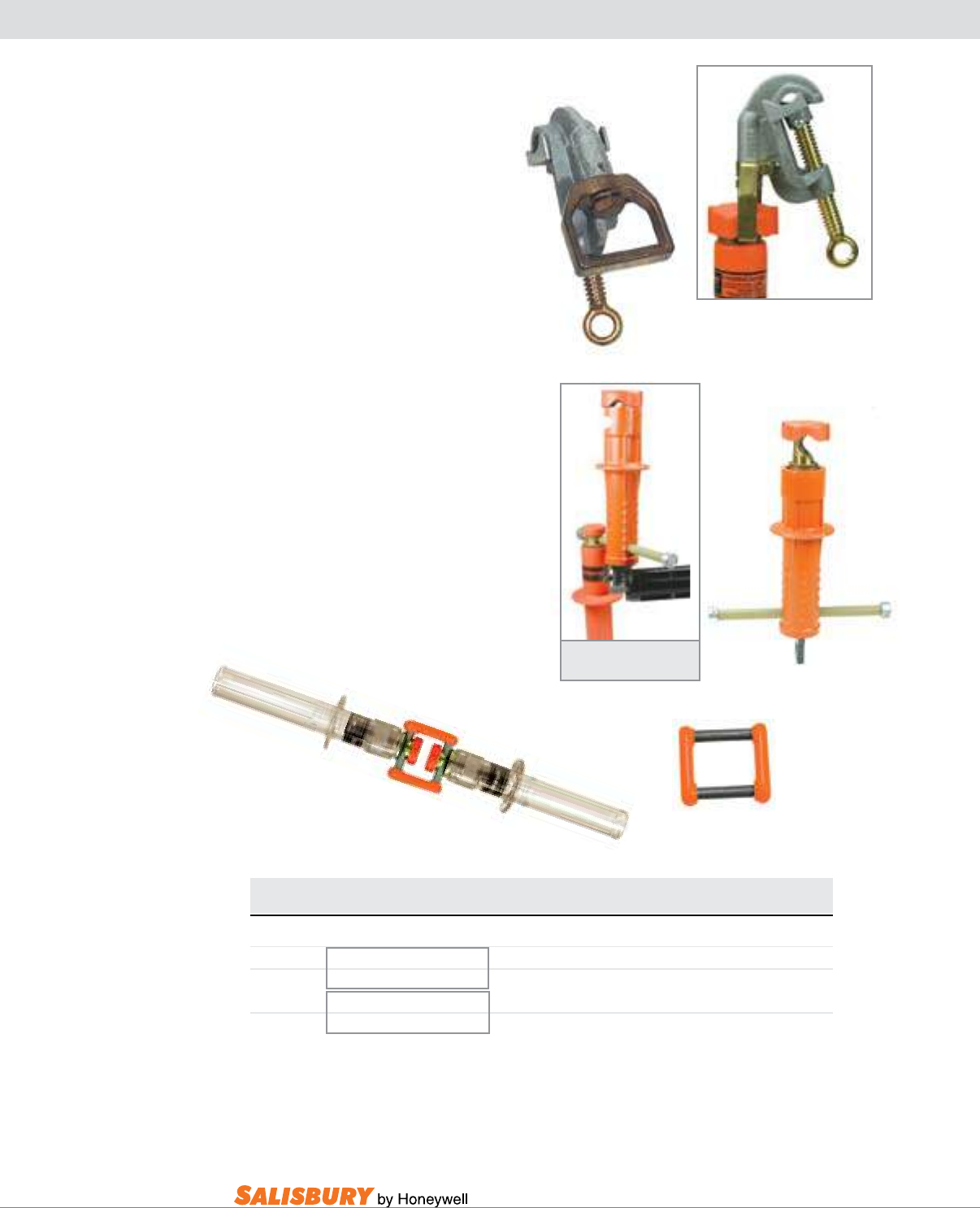
G-7
101 E. Crossroads Pkwy., Ste. A Bolingbrook, IL 60440 toll free ph (USA):877.406.4501 toll free fax (USA):866.824.4922 ph:630.343.3800
insulated jumper clamps accessories
2750
Stirrup Clamps are used to convert
a hand installed jumper into a stick
installed jumper. The stirrup is
designed to accept all conventional
jumper heads.
The Hot Jumper Parking Stand
safely holds either hand or stick
installed hot bypass jumpers. This
insulated tool removes the risk of
accidental contact with the uninstalled
end of an energized jumper. Installs
by hand using rubber insulating
gloves or with a standard shotgun
stick. The berglass jumper hanger
bar will accommodate standard size
mechanical jumper heads.
The Connector link connects two
insulated jumpers to create a longer
jumper length. After the two clamps
are connected to the link, the assembly
can be wrapped with a small rubber
insulating blanket.
Cat. No. Main Line Description Max. Amps Weight ea.
Range Continuous lbs. ( kgs )
2750 -- Connector Link 400 .3 ( .1 )
21132RG 1033 MCM ASCR to #6 Sol. Hot Jumper Stirrup Clamp 400 3.0 ( 1.4 )
1.25”-.16” ( 32-4.1mm )
4245 954 MCM ACSR to #6 Sol. Parking Stand for Hot Jumpers n / a 3.5 ( 1.6 )
1.14”- .16” ( 29- 4.1 mm )
Parking Stand Installation with
Shotgun Stick
4245
21132RG
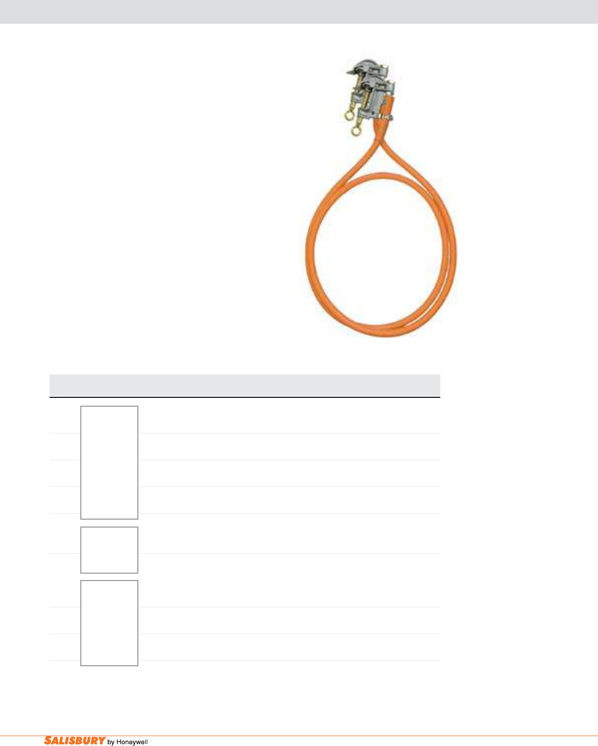
G-8 Insulated Jumpers. www.salisburybyhoneywell.com
stick installed Flexible jumpers
Stick Installed Flexible Jumpers can
be manufactured for hot stick operations
using Salisbury heavy-duty eye clamps.
Clamps are rated for continuous current
and fit all standard shotgun type hot
sticks. For ease of application, a Hanger
Stud is recommended. Shrouded ferrules
are not recommended for use with eye
type clamps.
Custom built assemblies are available.
Contact your local Salisbury
Representative for more information.
Cat. No. Main Line Max Amps Components Rating Weight ea.
Range Continuous lbs. ( kgs )
2300 250 2#1895 Alum “C” Clamp 1#1928A Hanger Stud 15 kV Ø-Ø 16 ( 7.3 )
1431 ACSR 1#2027 Alum Ferrule 10’ #2755 1/0 15kV Cable
2308 200 2#1895 Alum “C” Clamp 1#1928A Hanger Stud 15 kV Ø-Ø 10.8 ( 4.9 )
1#2026 Alum Ferrule 12’ #2754 #2 15kV Cable
2317 to #6 Sol. 250 2#2195 Alum “C” Clamp 1#1928A Hanger Stud 35 kV Ø-Ø 16 ( 7.3 )
1#2027 Alum Ferrule 12’ #2059 1/0 35kV Cable
2318 1.5”- .16” 300 2#2318 Alum “C” Clamp 1#1928A Hanger Stud 15 kV Ø-Ø 15.6 ( 7.1 )
1#2620 Alum Ferrule 12’ #2756 2/0 15kV Cable
2559 1033 ASCR 250 2#1853 Alum Duckbill Clamp 1#1858A Hanger Stud 15 kV Ø-Ø 16 ( 7.3 )
to #6 Sol. 1#2027 Alum Ferrule 10’ #2755 1/0 15kV Cable
1.25”- .16”
2877 795 ASCR 250 2#2532 Alum “C” Clamp 1#2537A Hanger Stud 15 kV Ø-Ø 11 ( 5.0 )
1#2027 Alum Ferrule 10’ #2755 1/0 15kV Cable
9976 to #8 Sol. 250 2#9985 Brnz “C” Clamp 1#9983A Hanger Stud 15 kV Ø-Ø 12 ( 5.4 )
1#2023 Cu Ferrule 10’ #2755 1/0 15kV Cable
9977 1.12”- .12” 250 2#2937 Brnz “C” Clamp 1#9983A Hanger Stud 35 kV Ø-Ø 12.5 ( 5.6 )
1#2023 Cu Ferrule 10’ #2059 1/0 35kV Cable
2300
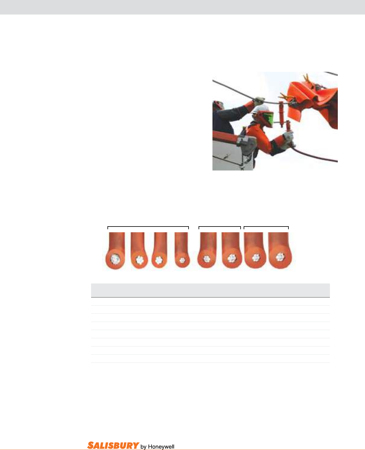
G-9
101 E. Crossroads Pkwy., Ste. A Bolingbrook, IL 60440 toll free ph (USA):877.406.4501 toll free fax (USA):866.824.4922 ph:630.343.3800
Flexible insulated jumper cables
Flexible Insulated Jumper Cables are
lightweight and resistant to oil, heat,
moisture, ozone and abrasion. The cable is
embossed every three feet with conductor
size and kV rating.
All jumper cables use ne stranded conductor
and a new EPR low temperature Unipass orange
CV cured jacket. The ne stranded copper
conductor is alloy coated and assembled in a
unidirectional rope lay for extra exibility.
The conductor has a semiconducting shield
surrounding it to relieve voltage stress and
improve dielectric strength and service life.
Cable meets requirements of ASTM F2321.
Cat. Size & Str. kV Rating Nominal Str. Dia. O.A. Dia. Max Amps Weight per 1000 ft.
No. AWG Ø to Ø Ø to Grd in. ( mm ) in. ( mm ) Continuous lbs. kgs
2754 #2-259W 15 10 .320 ( 8.1 ) .75 ( 19 ) 200 440 199
2755 1/0-413W 15 10 .403 ( 10.2 ) .83 ( 21 ) 250 600 272
2756 2/0-427W 15 10 .456 ( 11.5 ) .90 ( 23 ) 300 710 322
2757 4/0-437W 15 10 .592 ( 15.0 ) 1.01 ( 25.6 ) 400 1050 476
21300 1/0-413W 25 15 .403 ( 10.2 ) 1.06 ( 27 ) 250 650 295
21060 2/0-427W 25 15 .456 ( 11.5 ) 1.10 ( 28 ) 300 750 341
2059 1/0-413W 35 20 .403 ( 10.2 ) 1.22 ( 31 ) 250 950 431
4370 2/0-427W 35 20 .48 ( 12.1 ) 1.31 ( 33.1 ) 300 1060 482
4/0 2/0 1/0 #2 1/0 2/0 1/0 2/0
15kV 25kV 35kV
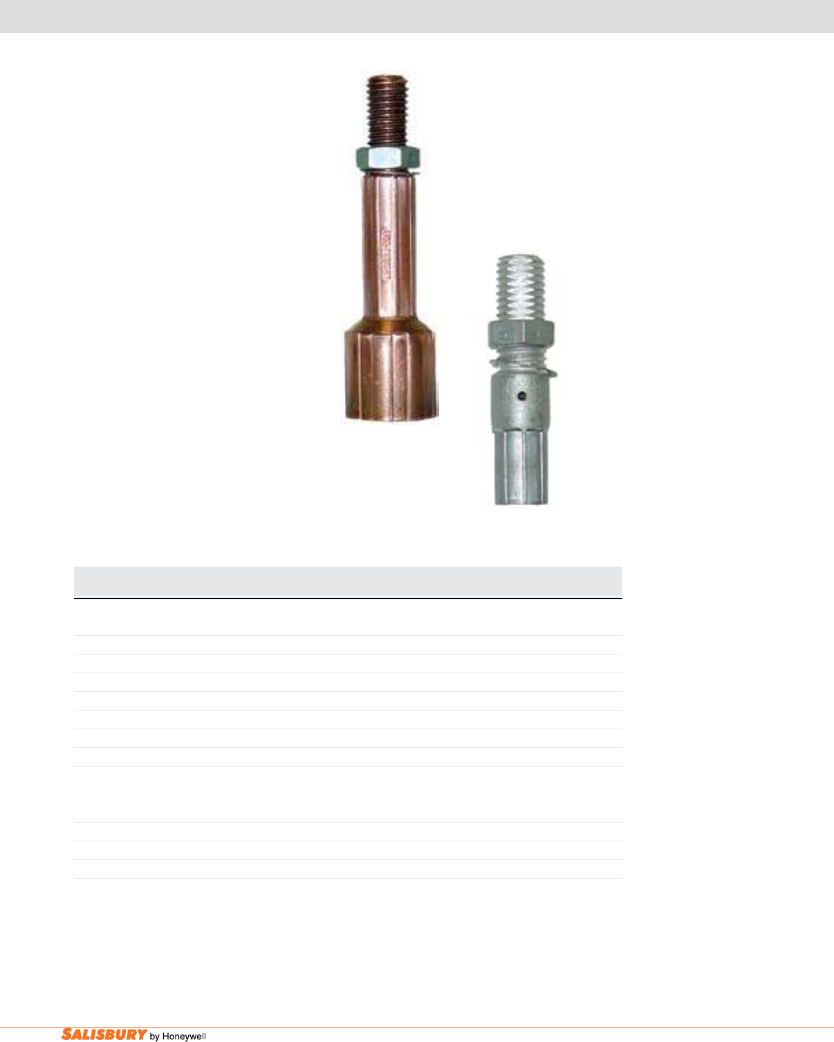
G-10 Insulated Jumpers. www.salisburybyhoneywell.com
Ferrules
shrouded / unshrouded
Ferrules are manufactured in two different
styles: unshrouded and shrouded. Shrouded
ferrules are compressed on both the
conductor and the insulating jacket of the
high voltage EPR cable to reduce bending
stress. Shrouded ferrules are designed to be
used on glove-installed high voltage jumpers.
Unshrouded ferrules are crimped to the
conductor strands only and can be used on
either stick- or glove-installed jumpers.
Ferrules are manufactured of 99.5% pure
copper with industry standard 5/8”-11 NC
threads. Ferrules are topped with a brass
hex jam nut and toothed stainless steel
lockwasher.
Add suffix “A” to the catalog number when requesting a custom insulated jumper set.
shrouded
unshrouded
Cat. No. Cable Size Strand Die Codes Jacket Die Codes Burndy Weight ea.
Pair T&B T&B Die Number lbs. ( kgs )
SHROUDED
2012 #2-15 kV ERP 66 106 - 1.2 ( .5 )
2013 1/0-15 kV ERP 66 106 - 1.2 ( .5 )
2014 2/0-15 kV ERP 66 106 - 1.1 ( .5 )
2015 4/0-15 kV ERP 66 106 - 0.9 ( .4 )
21353 1/0-25 kV 66 112 - 1.1( .5 )
21354 2/0-25 kV 66 112 - 1.1 ( .5 )
21356 2/0-35 kV 66 125 - 1.1 ( .5 )
UNSHROUDED - Tin Plated Strand Die Codes
2022 #2 50 - U243 0.5 ( .2 )
2023 1/0 50 - U243 0.4 ( .2 )
2024 2/0 60 - U245 0.4 ( .2 )
2025 4/0 66 - U247 0.6 ( .3 )
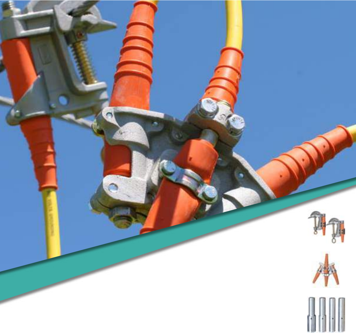
TEMPORARY PROTECTIVE
GROUNDING EQUIPMENT
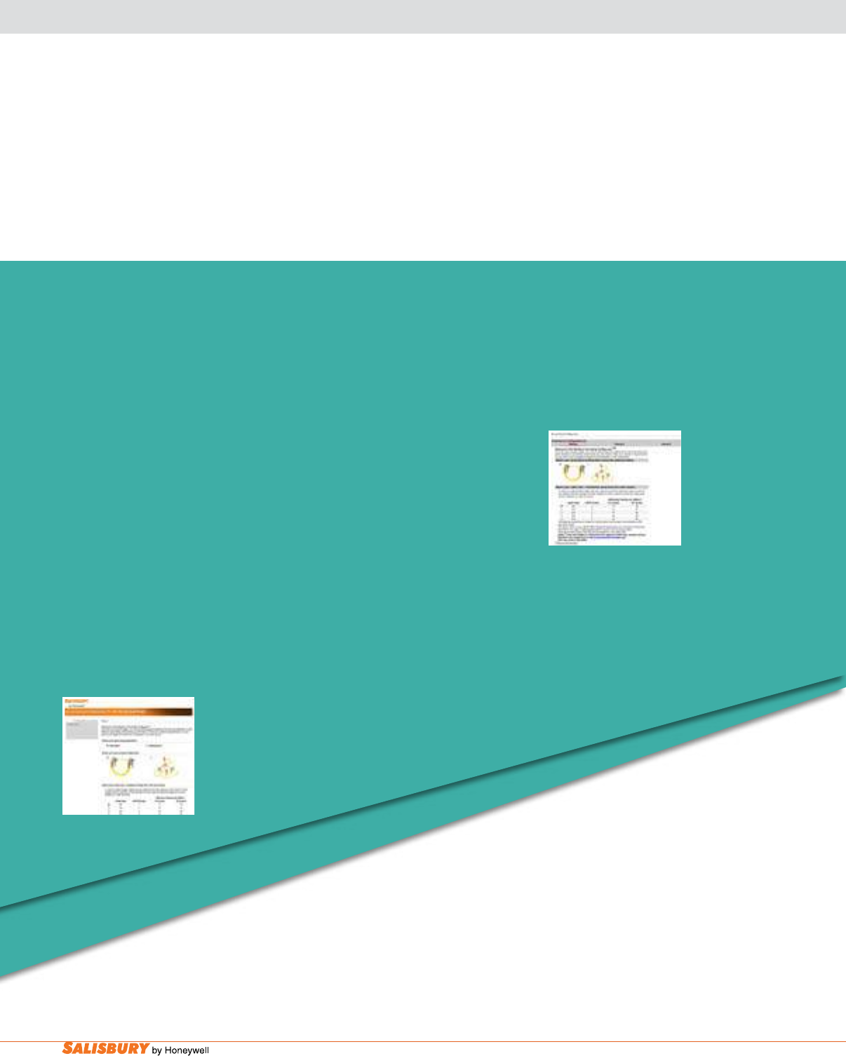
H-2 Grounding Equipment. www.salisburybyhoneywell.com
TEMPORARY PROTECTIVE
GROUNDING EQUIPMENT
NOTE:
When ordeing assemblies of grounding products, please make sure all
items included in the assembly are only from the product line found within
this section. Including items from other grounding equipment sections of
this book will add additional shipping time.
The Grounding Congurator™ makes ordering grounding equipment simple
and easy. This interactive web tool allows you to easily build the proper temporary
grounding equipment for your specic needs. The step by step process takes out
the guess work, and makes it easy to change components until the most appropriate
ground set is developed.
Just go to our web site and give it a try. You will be prompted from start to nish. All you need to know
is the maximum fault current, its duration and the size of cable required on the fault, and the congurator
will do the rest. No more second guessing quantities or parts to be sure that you have put together a
ground set that will function just as you expect. When you nish, enter your personal information and
the congurator will instantly provide you with the bill of materials including part numbers. All that’s
left to do is to place the order!
Need grounding equipment fast? Salisbury’s 48-Hour Shipping Grounding
Congurator™ works just as great as our standards Grounding
Congurator, but it includes only our quick-ship items.
Get the grounding equipment you need as fast
as you need it.
Visit salisburybyhoneywell.com to use
the exclusive Grounding ConfiguratorTM
and 48-Hour Grounding ConfiguratorTM.
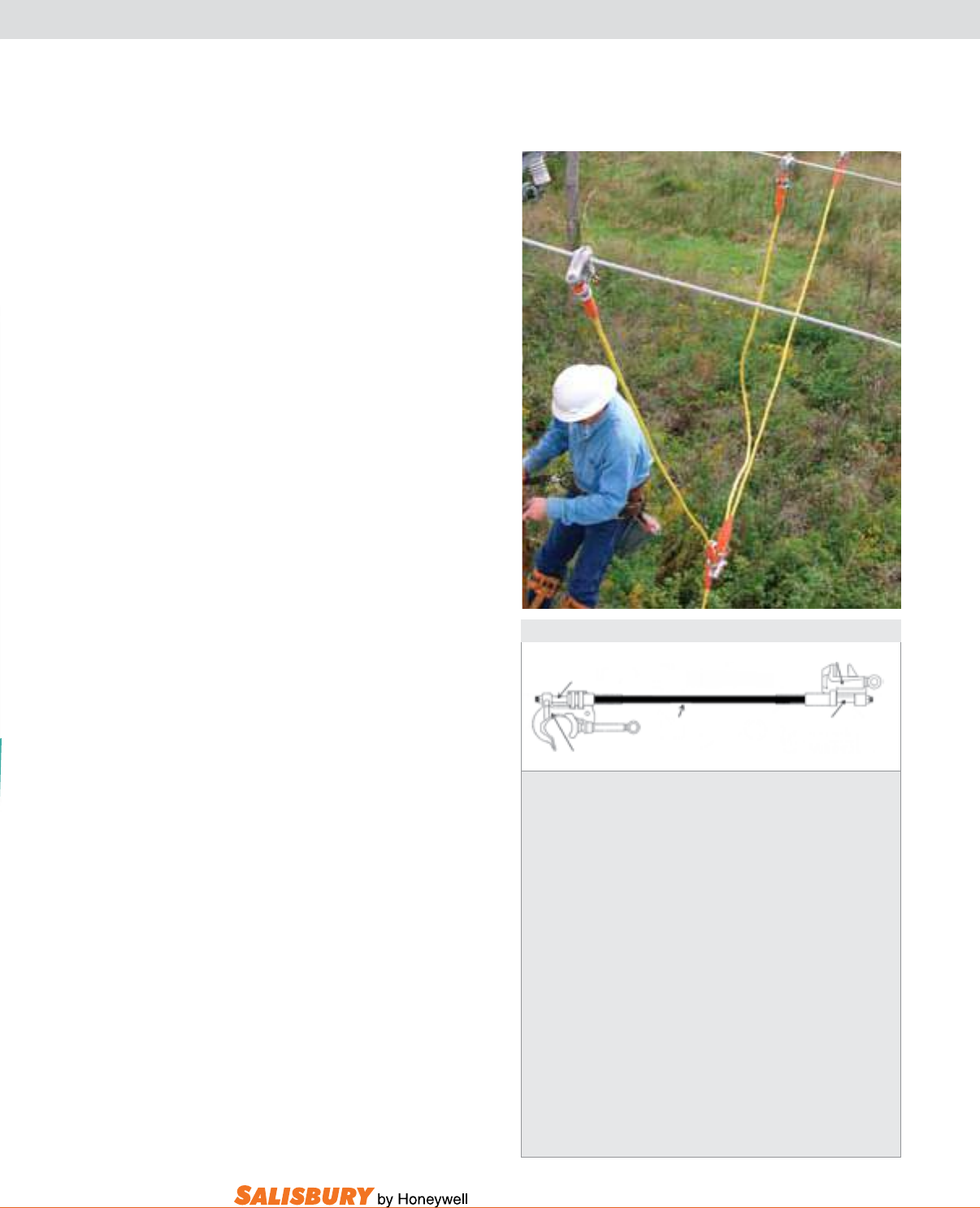
H-3
101 E. Crossroads Pkwy., Ste. A Bolingbrook, IL 60440 toll free ph (USA):877.406.4501 toll free fax (USA):866.824.4922 ph:630.343.3800
TEMPORARY PROTECTIVE GROUNDING EQUIPMENT
1. Specify the clamps. Two are required for a complete assembly. The
maximum amperage of the clamp is designated by the ASTM grade of
each clamp. Be sure that the clamp will meet or exceed the maximum
amperage rating of the ground cable that it will be used with.
2. Specify the cable. Once the short circuit capacity of the system has
been determined, choose the appropriate size cable. Specify the cable
length, and the color of the jacket desired.
3. Specify the ferrules. One pair of ferrules is required per assembly. The
size of the ferrule must match the size of the cable that it will be used
with. Specify whether copper or aluminum, and threaded or plain.
4. Specify the options. List any optional equipment that is desired. This
can include hanger studs, contact studs, heat shrink tubing, markings,
clear strain relief, etc.
Options also include a ground set label. These optional labels include the
date of manufacture and are available upon request when ordering.
1. Flat Jaw Clamp
1.“C” Clamp
3. Ferrules
3. Ferrules
2. Cable
Ground Set Checklist
How to specify temporary protective
grounding assemblies.
A grounding assembly in its basic form
consists of two clamps, one pair of
ferrules and a length of cable.
The clamps can be identical to each other
or quite different depending on each
grounding application. Because of this,
ground clamps are sold individually, not
in pairs. Salisbury offers a wide variety
of clamps including C-clamps, flat
jaw clamps, socket clamps, duckbill
clamps and specialty clamps for
unique situations. Clamps are offered
in either bronze or aluminum alloys and
are manufactured to meet the current
specications of ASTM F 855.
To attach a clamp to the grounding cable
requires the use of a ferrule. Ferrules are
compressed on the strands of the cable
to provide a low resistance permanent
connection. The size of the ferrule is
determined by the size of the cable.
Ferrules are available in aluminum or
plated copper. Plated copper ferrules can
be used with either aluminum or bronze
clamps. Two ferrules are required for
each assembly therefore they are sold in
pairs. Ferrules are manufactured to the
specications of ASTM F 855.
The nal component that makes up a
ground set is the grounding cable itself.
The size of the cable is dependent on
the short circuit current capacity of the
system being grounded. Once this is
determined, only the length of the cable
and the color of the jacket need to be
specied to complete the assembly.
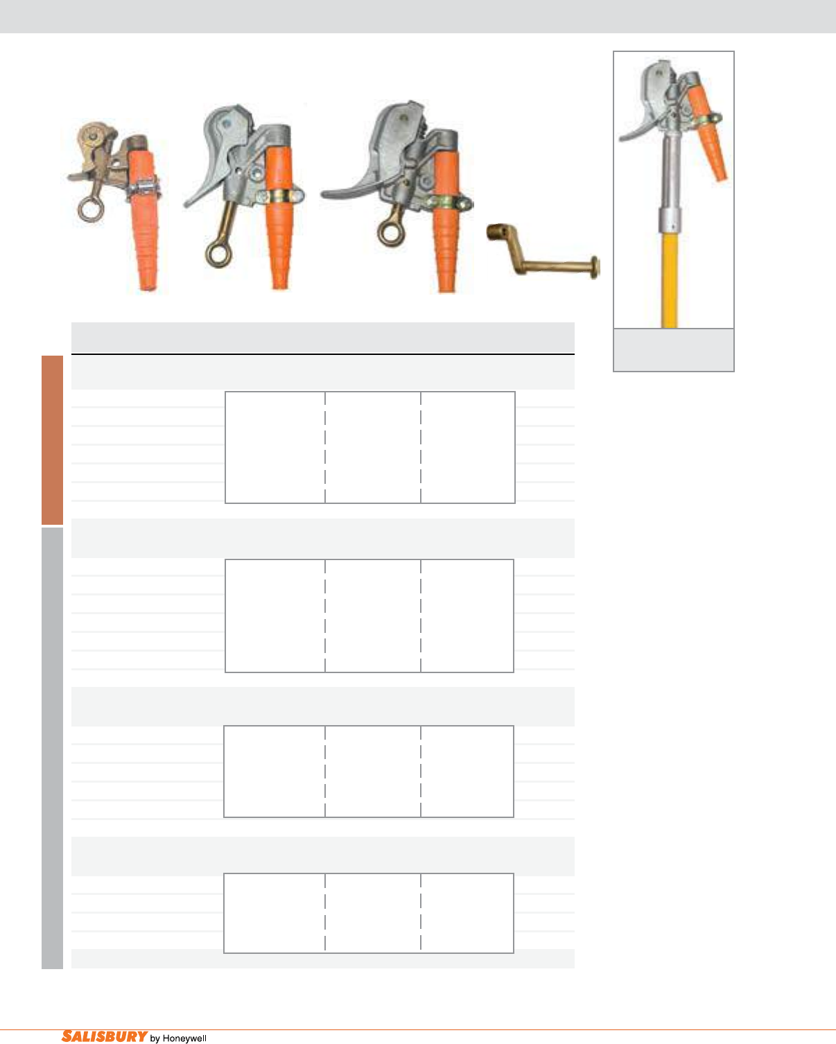
H-4 Grounding Equipment. www.salisburybyhoneywell.com
DUCK BILL GROUNDING CLAMPS
.96”, 1.1”, AND 1.65” SIZES
B R O N Z E
ALUMINUM
Cat. No. Eye & Clamp ASTM Grade / Main Line Continuous Weight ea.
Description Class Range Current Rating lbs. ( kgs )
556 KCM SMOOTH JAW BRONZE DUCK BILL --Gravity Actuated - “V” Thread
1793 Eye 1.3 ( .6 )
w/ strain relief sleeve 556 MCM ACSR
21080 Eye 4 / A to #6 350 RMS Amps 1.1 ( .5 )
w/o strain relief sleeve Smooth Jaw 60 Hz
1797* Mounted .96” - .16” 4.3 ( 2 )
w/ strain relief sleeve 24mm - 4mm Dia.
2093 Hanger Stud only .4 ( .1 )
1.1” SMOOTH JAW ALUMINUM DUCK BILL --Spring Loaded - “V” Thread
21030 Eye 1.1 ( .5 )
w/ strain relief sleeve 795 KCM ACSR
21059 Eye 5 / A to #6 400 RMS Amps 1.0 ( .5 )
w/o strain relief sleeve Smooth Jaw 60 Hz
21081* Mounted 1.1” - .16” 4.3 ( 2 )
w/ strain relief sleeve 28mm - 4mm Dia.
21754 Hanger Stud only .3 ( .1 )
1.66” SERRATED JAW ALUMINUM DUCK BILL --Spring Loaded - “V” Thread
2553 Eye 5 / B 1590 MCM ACSR 400 RMS Amps 1.4 ( .6 )
w/o strain relief sleeve to #6
1855* Mounted Serrated Jaw 60 Hz 4.7 ( 2.1 )
w/ strain relief sleeve 1.65” - .16”
42mm - 4mm Dia.
21754 Hanger Stud only .3 ( .1 )
1.66” SERRATED JAW ALUMINUM DUCK BILL - Acme thread
1853 Eye 1590 MCM ACSR 1.5 ( .7 )
w/ strain relief sleeve 5 / B to #6 400 RMS Amps
Serrated Jaw 1.65” - .16” 60 Hz
42mm - 4mm Dia.
*Mounted: 1.25” dia x 6’ Fiberglass Hot Stick permanently mounted
21030 1853
1793
1855 - Stick Mounted
Duck Bill Clamp
21754
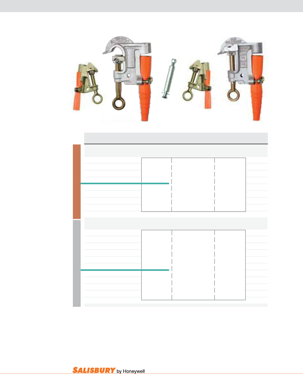
H-5
101 E. Crossroads Pkwy., Ste. A Bolingbrook, IL 60440 toll free ph (USA):877.406.4501 toll free fax (USA):866.824.4922 ph:630.343.3800
B R O N Z E
ALUMINUM
Cat. No. Eye & Clamp ASTM Grade / Main Line Continuous Weight ea.
Description Class Range Current Rating lbs. ( kgs )
477 MCM BRONZE “C” CLAMP w/ Curved Lower Jaw - “V” Thread
4200 Eye 1.1 ( .5 )
w/ strain relief sleeve 5 / A 477 MCM 18 x 1 ACSR
21067 Eye Smooth Jaw to 1.0 ( .4 )
w/o strain relief sleeve #8 400 RMS Amps
4260 Eye 60 Hz 1.1 ( .5 )
w/ strain relief sleeve 5 / B .83” - .12”
21068 Eye Serrated Jaw 21mm - 3mm Dia. 1.0 ( .4 )
w/o strain relief sleeve
2093 Hanger Stud only .4 ( .2 )
1” ALUMINUM “C” CLAMP - Acme thread
2531 Eye 1.1 ( .5 )
w/ strain relief sleeve 5 / A 795 MCM 26 x 7 ACSR
2532 Eye Smooth Upper to 1.1 ( .5 )
w/o strain relief sleeve Jaw w/ #8
2533* Mounted Flat Lower Jaw 400 RMS 4.2 ( 19 )
w/ strain relief sleeve 60 Hz
4388 Eye 5 / B 1.12” - .12” 1.5 ( .7 )
w/ strain relief sleeve Smooth Upper 29mm - 3mm Dia.
4389 Eye Jaw w/ 1.1 ( .5 )
w/o strain relief sleeve Curved Lower Jaw
2537 Hanger Stud only .2 ( .1 )
*Mounted: 1.25” dia x 6’ Fiberglass Hot Stick permanently mounted
4388
4260
4200
2531
2537
“C” TYPE GROUNDING CLAMPS
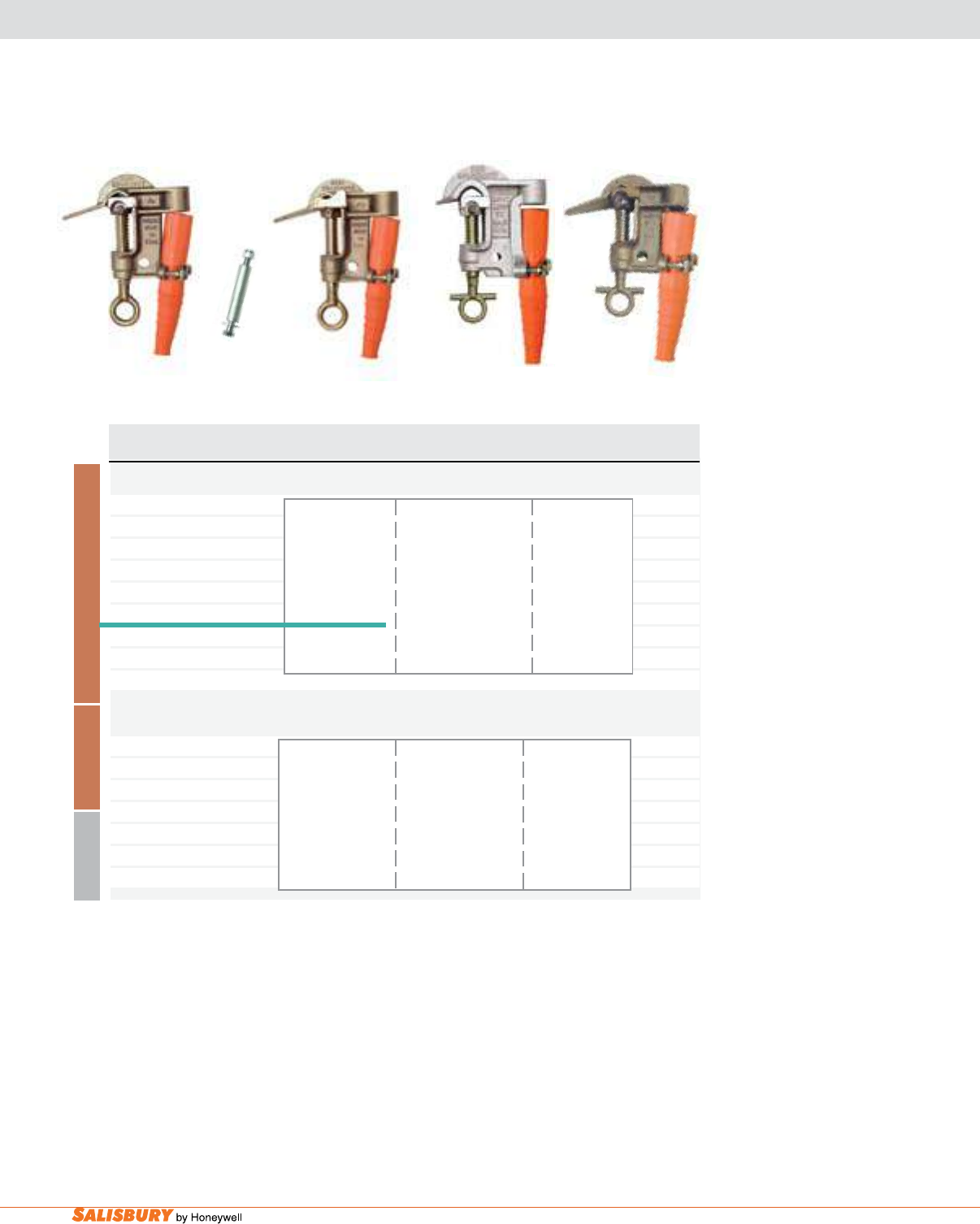
H-6 Grounding Equipment. www.salisburybyhoneywell.com
*Mounted: 1.25” dia x 6’ Fiberglass Hot Stick permanently mounted
9993
B R O N Z E
A L U M I N U M B R O N Z E
Cat. No. Eye & Clamp ASTM Grade / Main Line Continuous Weight ea.
Description Class Range Current Rating lbs. ( kgs )
1” Bronze “C” Clamp - Acme thread
9985 Eye 1.9 ( .9 )
w/ strain relief sleeve 795 MCM 26 x 7 ACSR
2937 Eye 5 / A to 1.8 ( .8 )
w/o strain relief sleeve Smooth Jaw #8 400 RMS Amps
4280* Mounted 60 Hz 4.9 ( 2.2 )
w/ strain relief sleeve 1.12” - .12”
4187 Eye 5 / B 29mm - 3mm Dia. 1.9 ( .9 )
w/ strain relief sleeve Serrated Jaw
2537 Hanger Stud only .4 ( .2 )
GRADE 5 “T” / EYE “C” CLAMP - Acme Thread
4242 “T” w/ strain 1.9 ( .9 )
sleeve & “T” 795 MCM
eye screw 26” x 7”ACSR
5 / A to #6 400 RMS Amps
9993 “T” w/ strain Smooth Jaw 60 Hz 1.6 ( .7 )
sleeve & “T” 1.12” - .16”
eye screw 29mm - 4mm Dia.
4187
2537
“C” TYPE GROUNDING CLAMPS
4242
9985
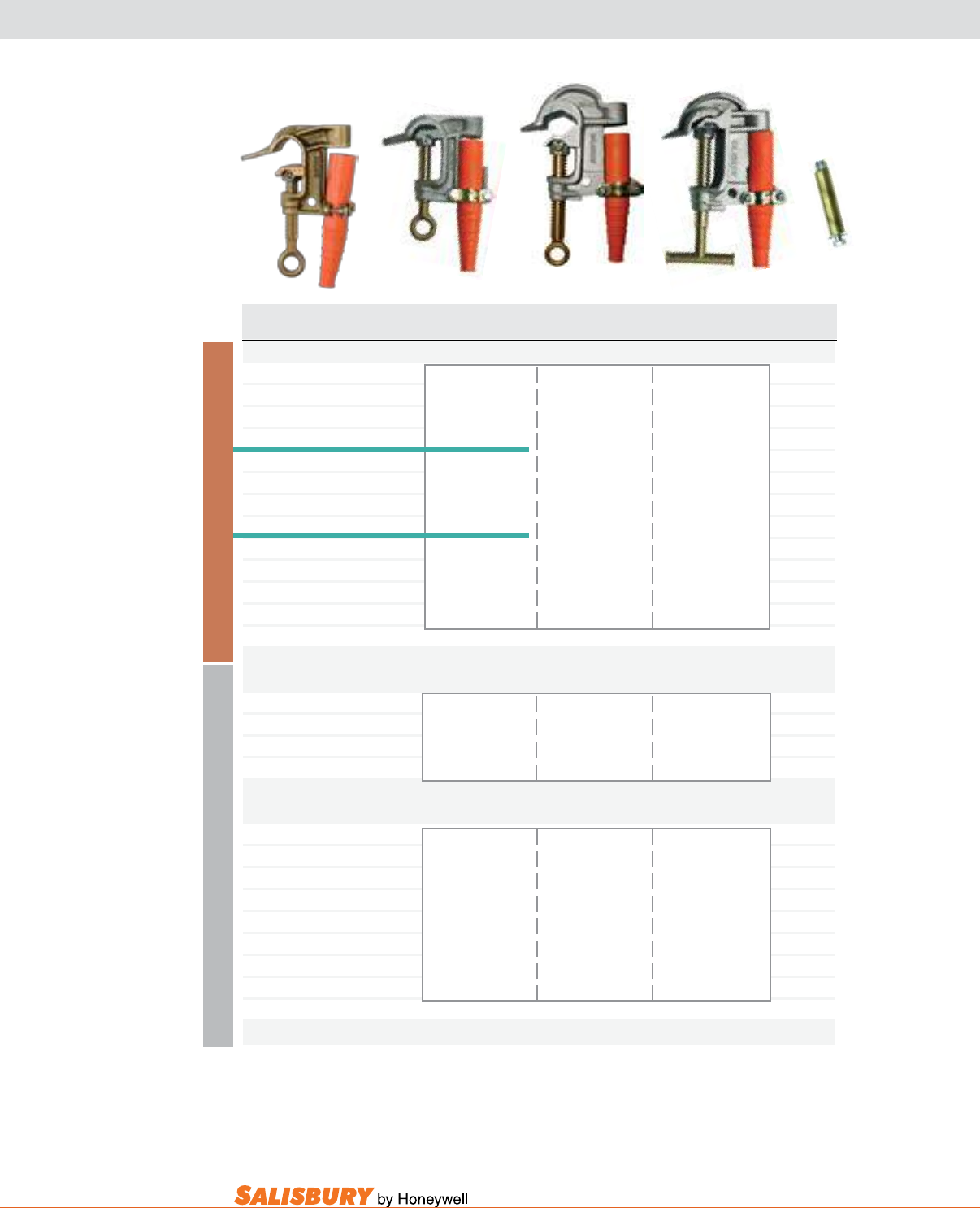
H-7
101 E. Crossroads Pkwy., Ste. A Bolingbrook, IL 60440 toll free ph (USA):877.406.4501 toll free fax (USA):866.824.4922 ph:630.343.3800
B R O N Z E
ALUMINUM
“C” TYPE GROUNDING CLAMPS
Cat. No. Eye & Clamp ASTM Grade / Main Line Continuous Weight ea.
Description Class Range Current Rating lbs. ( kgs )
1.25” BRONZE “C” CLAMP - Acme Thread
9984 Eye 5 / A 2.2 ( 1.0 )
w/ strain relief sleeve Smooth Jaw
1897 Eye w/ 2.1 ( .9 )
w/o strain relief sleeve Flat Lower Jaw 1035.5 KCM ACSR
4255 Eye 5 / A to #6 2.2 ( 1.0 )
w/ strain relief sleeve Smooth Jaw 400 RMS Amps
21069 Eye w/ 60Hz 2.1 ( .9 )
w/o strain relief sleeve Curved Lower Jaw 1.26 “ - .16”
4279 Eye 5 / B 32mm - 4mm Dia. 2.2 ( 1.0 )
w/ strain relief sleeve Serrated Jaw
21070 Eye w/ 2.1 ( .9 )
w/o strain relief sleeve Flat Lower Jaw
9983 Hanger Stud only .4 ( .2 )
1.25” ALUMINUM “C” CLAMP - Acme Thread
24410 Eye 5 / A 1035.5 KCM ACSR 2.2 ( 1.0 )
w/ strain relief sleeve Smooth Jaw to #6 400 RMS Amps
w/ Flat Lower Jaw 1.26 “ - .16” 60Hz
32mm - 4mm Dia.
1.5” ALUMINUM “C” CLAMP, w/ at lower jaw - Acme Thread
1895 Eye 1.7 ( .8 )
w/ strain relief sleeve
2195 Eye 1431 KCM ACSR 1.5 ( .7 )
w/o strain relief sleeve 5 / B to #6 400 RMS Amps
1896* Mounted Serrated Jaw 1.5” - .16” 60 Hz 4.8 ( 2.1 )
w/ strain relief sleeve to #6
21099 “T” 38mm - 4mm Dia. 1.7 ( .8 )
w/ strain relief sleeve
1928 Hanger Stud only .2 ( .1 )
*Mounted: 1.25” dia x 6’ Fiberglass Hot Stick permanently mounted
1895
9983
24410
21099
4255
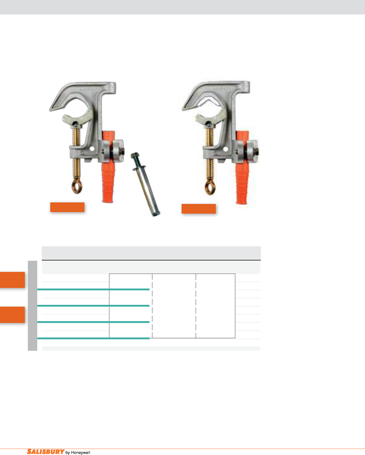
H-8 Grounding Equipment. www.salisburybyhoneywell.com
“C” TYPE GROUNDING CLAMPS
ALUMINUM
Cat. No. Eye & Clamp ASTM Grade / Main Line Continuous Weight ea.
Description Class Range Current Rating lbs. ( kgs )
2 “ ALUMINUM “C” CLAMP w/ Curved Lower Jaw - Acme Thread
21074 Eye 5H / A 2.1 ( 1.0 )
w/ strain relief sleeve Smooth Jaw 3000 KCM ACSR
21075 Eye 5 / A 400 RMS Amps 2 ( .9 )
w/o strain relief sleeve Smooth Jaw to #6
20882 Eye 5H / B 60 Hz 2.1 ( 1.0 )
w/ strain relief sleeve Serrated Jaw
21077 Eye 5 / B 2”-.16” 2 ( .9 )
w/o strain relief sleeve Serrated Jaw 51mm - 4 mm
1928 Hanger Stud only .2 ( .1 )
20882
21074
1928
20882
Now
Grade 5H!
Now
Grade 5H!
Now Grade 5H! Now Grade 5H!
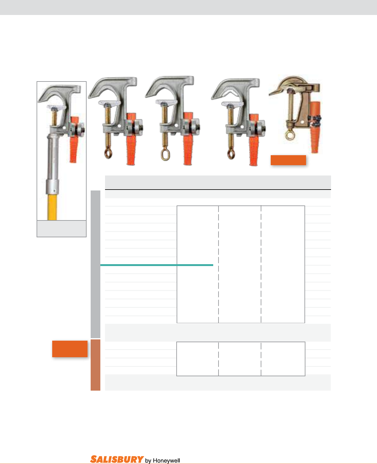
H-9
101 E. Crossroads Pkwy., Ste. A Bolingbrook, IL 60440 toll free ph (USA):877.406.4501 toll free fax (USA):866.824.4922 ph:630.343.3800
“C” TYPE GROUNDING CLAMPS
*Mounted: 1.25” dia x 6’ Fiberglass Hot Stick permanently mounted
ALUMINUM
B R O N Z E
Cat. No. Eye & Clamp ASTM Grade / Main Line Continuous Weight ea.
Description Class Range Current Rating lbs. ( kgs )
2.4 “ ALUMINUM “C” CLAMP w/ Flat Lower Jaw - Acme Thread
1923 Eye 2.1 ( 1.0 )
w/ strain relief sleeve
4377 Eye strain relief 2.1 ( 1.0 )
sleeve & oval eye 5 / A
4240 Eye Smooth Jaw 2.0” I.P.S. 2.0 ( 1.0 )
w/o strain relief sleeve to #6
1924* Mounted 5.1 ( 2.3 )
w/ strain relief sleeve 400 RMS Amps
1921 Eye 60 Hz 2.2 ( 1.0 )
w/ strain relief sleeve 2.4” - .16”
4390 Eye strain relief 5 / B 61mm - 4mm Dia. 2.2 ( 1.0 )
sleeve & oval eye Serrated Jaw
1922* Mounted 5.2 ( 2.3 )
w/ strain relief sleeve
1928 Hanger Stud only
2.4” BRONZE “C” CLAMP w/ at lower jaw - Acme Thread
4295 Eye 2.0 “ I.P.S. to #6 4.1 ( 1.8 )
w/ strain relief sleeve 5H / A 400 RMS Amps
4311 Eye Smooth Jaw 2.4” - .16” 60 Hz 4.0 ( 1.7 )
w/o strain relief sleeve 61mm - 4 mm Dia.
1921
1923 4377
4295
1924 - Stick Mounted
“C” Type Clamp
Now
Grade 5H!
Now Grade 5H!
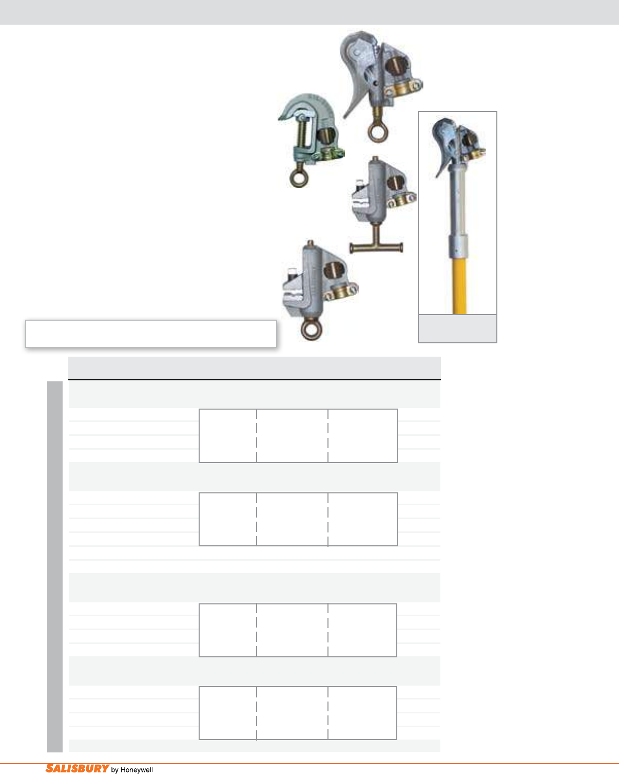
H-10 Grounding Equipment. www.salisburybyhoneywell.com
PRESSURE TERMINAL CLAMPS
ALUMINUM
24404
24405
24406
24466
24407 - Stick Mounted
Duck Bill Clamp
Cat. No. Eye & Clamp ASTM Grade / Main Line Continuous Weight ea.
Description Class Range Current Rating lbs. ( kgs )
1.1” SMOOTH JAW ALUMINUM --Spring Loaded - “V” Thread
24404 Duckbill 795 KCM ACSR 1.5 ( .68 )
Eye w/o strain relief sleeve 5 / A to #6 400 RMS Amps
Smooth Jaw 1.1” - .16” 60 Hz
28mm - 4mm Dia.
1.25” SMOOTH JAW ALUMINUM --Spring Loaded - Acme Thread
24466 “C” Type 1035.5 KCM ACSR 2.2 ( 1.0 )
Eye w/o strain relief sleeve 5 / B to #6 400 RMS Amps
Serrated 1.26” - .06” 60 Hz
32mm - 1.5mm Dia.
24407 Stick mounted duckbill clamp 4.5 ( 2.05 )
21754 Hanger Stud only .3 ( .1 )
2” SMOOTH JAW ALUMINUM --Spring Loaded - Acme Thread
21942 “C” Type 1035.5 KCM ACSR 2.2 ( 1.0 )
Eye w/o strain relief sleeve 5 / B to #6 400 RMS Amps
Serrated 1.26” - .06” 60 Hz
32mm - 1.5mm Dia.
ALUMINUM FLAT JAW Grounding Clamp - Acme Thread
24405 “T” screw 1.5” - .06” 2.1 ( .9 )
no strain relief sleeve 5 / B Flat or Square 400 RMS Amps
24406 Eye screw Serrated Jaw 1.26” - .06” 60Hz 2.0 ( .9 )
no strain relief sleeve 32 - 1.5 mm Dia.
These Duckbill and “C” Clamps feature pressure
terminations for use with plain ferrules. Made of
high strength aluminum, with bronze eye-screws,
these Grade 5 clamps are designed for smooth
operation and long service life. Duckbill clamps for
all grounding applications from .16 to 1.1” diameter.
“C” clamps for all grounding applications from .06
to 1.26” diameter.
Flat Jaw Grounding Clamps are now available
with pressure terminals for use with plain cable
ferrules. These clamps are made of a high strength
aluminum, and a bronze eye screw or “T” handle
for durability and smooth operation. Also featured
is a hardened aluminum alloy serrated insert. This
insert is designed to grip tightly to at surfaces and
cut through surface contamination and oxidation for
low resistance contact. The pressure termination is
designed on an angle keeping the cable out of the way
during installation. The cable termination is angled to
minimize interface with the “T” handle or eye when
installing or removing the clamp.
Salisbury’s 24438 Plain Ferrule 4-way Connector
is available on page H-25.
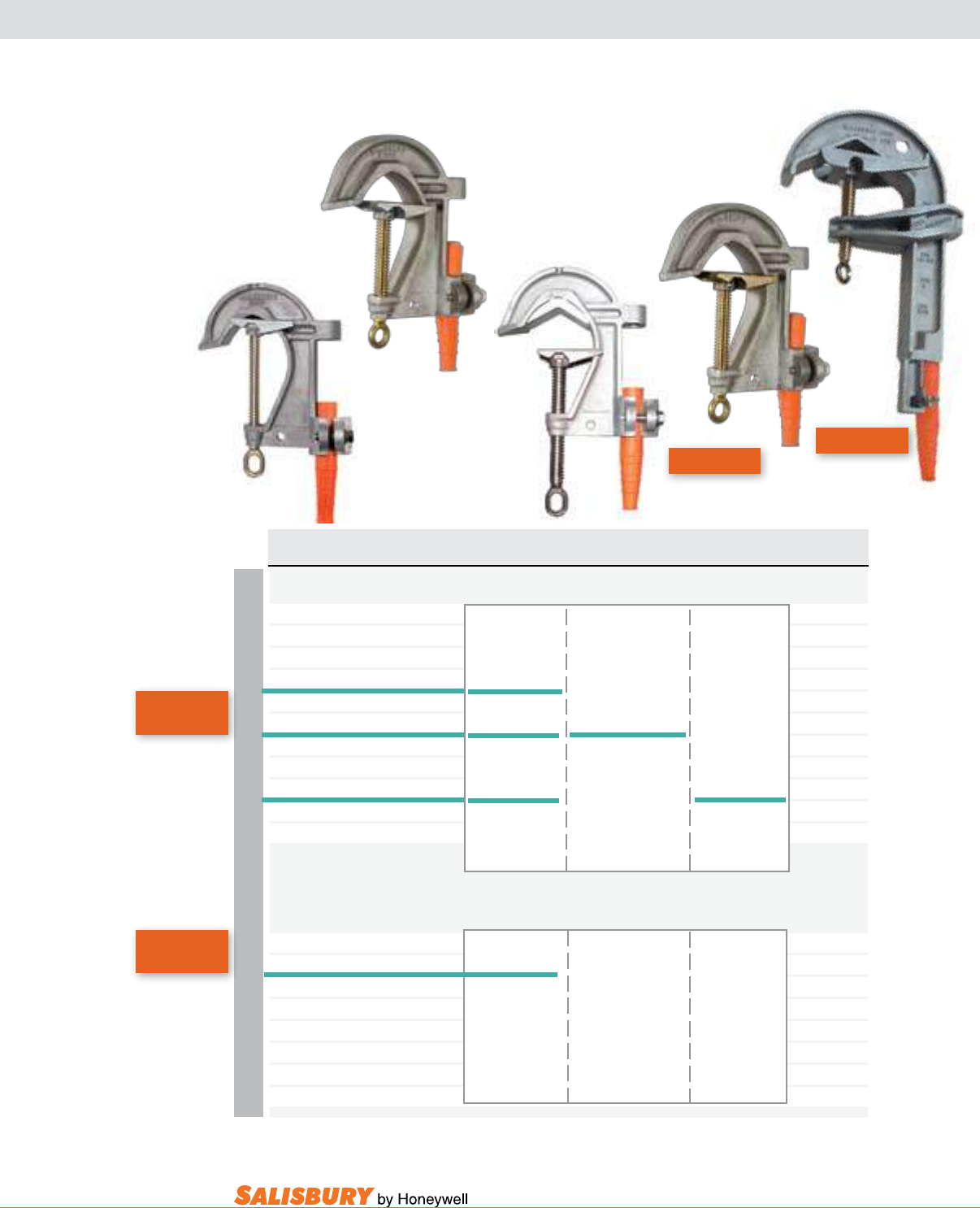
H-11
101 E. Crossroads Pkwy., Ste. A Bolingbrook, IL 60440 toll free ph (USA):877.406.4501 toll free fax (USA):866.824.4922 ph:630.343.3800
GROUNDING CLAMPS FOR SUBSTATION BUSES
4341
*Mounted: 1.25” dia x 6’ Fiberglass Hot Stick permanently mounted
**No Ferrule Connection
+Accepts 3/4 - 10 ferrule threads
ALUMINUM
Cat. No. Eye & Clamp ASTM Grade / Main Line Continuous Weight ea.
Description Class Range Current Rating lbs. ( kgs )
3.5” ALUMINUM “C” CLAMP for Substation Buses - Acme Thread
4282 Eye 5 /A 2.8 ( 1.3 )
w/ strain relief sleeve Smooth Jaw 3” - 1.5” I.P.S.
4283* Mounted w/ 3.5” - 1.75” 5.8 ( 2.5 )
w/ strain relief sleeve Flat Lower Jaw 89mm - 44mm Dia. 400 RMS Amps
21953 Eye 5H /A
w/ strain relief sleeve Smooth Jaw w/ Flat Lower 60 Hz
4341 Eye, strain relief w/ 5 /A 2.9 ( 1.4 )
sleeve & long eye screw Smooth Jaw w/ 3” I.P.S. to #6
(Main line range 3.5”-.16”(89-4mm) Flat Lower Jaw 3.5” - .16”
21985+ Eye, strain relief 6 / B 89mm - 4 mm Dia. 450 RMS Amps 3.0 ( 1.5 )
sleeve & long eye screw Serrated Jaw 60 Hz
w/ Flat Lower Jaw
6.62” ADJUSTABLE ALUMINUM “ C “ CLAMP for Round, Square, Rectangle or “H” Section Substation
Buses - Acme Thread
2991 Eye 5H / A 6.9 ( 3.1 )
w/ strain relief sleeve Smooth Jaw w/ Flat Lower
2993**Eye 5 / A 7.0 ( 3.2 )
w/ welded single contact stud Smooth Jaw 6.12” I.P.S. 400 RMS Amps
9967**Eye w/ 6.62” - .4” 60 Hz 7.3 ( 3.3 )
w/ welded double contact stud Flat Lower Jaw 168mm - 10mm Dia.
4378 Eye, strain relief 6.9 ( 3.1 )
sleeve & oval eye
2991
4282
21985
21953
21953 Now
Grade 5H!
2991 Now
Grade 5H!
Now Grade 5H!
Now Grade 5H!
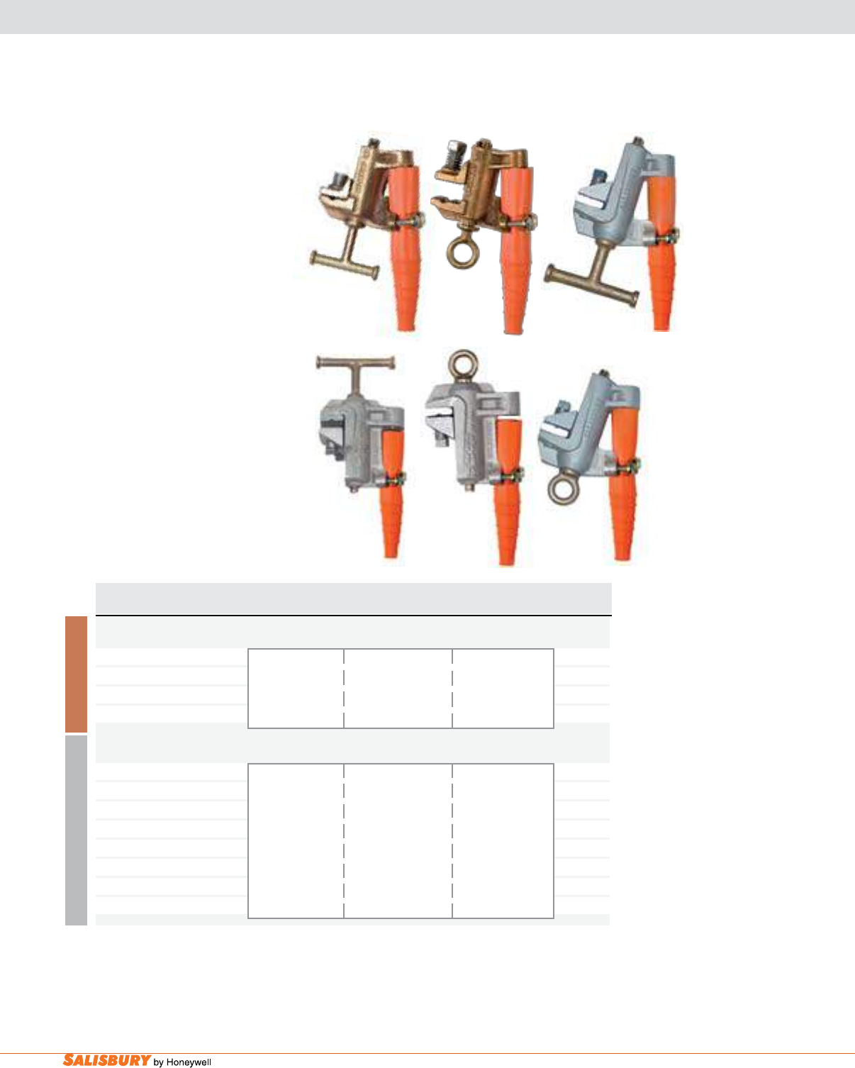
H-12 Grounding Equipment. www.salisburybyhoneywell.com
GROUNDING CLAMPS
FOR FLATS, ANGLES & ROUNDS
Flat Jaw Grounding Clamps are
available with either a large “T”
handle or with an eye for clampstick
application. The handles and eyes
are designed so that the cable will
not interfere with the torquing of the
clamp. The set screw that secures
the clamp to a at surface is located
on the movable jaw on all designs.
When tightened, the set screw forces
the fixed jaw of the clamp firmly
against the at ensuring a consistent
low resistance current path directly
through the body of the clamp to the
cable connection. With other designs
having a set screw on the xed jaw,
current is required to ow through
mechanical connections between the
movable jaw, the eye screw, and the
body of the clamp before passing to
the cable connection.
BRONZE
ALUMINUM
Cat. No. Eye & Clamp ASTM Grade / Main Line Continuous Weight ea.
Description Class Range Current Rating lbs. ( kgs )
GRADE 3 BRONZE FLAT JAW Grounding Clamps - “V” Thread
1814 “T” w/ strain 1.5” - .06” 1.7 ( .8 )
sleeve & “T” screw 3 / B Flat or Square 300 RMS Amps
1815 Eye w/ strain Serrated Jaw 1.26” - .06” 60Hz 1.6 ( .7 )
sleeve & eye screw 32mm - 1.5 mm Dia.
GRADE 5 ALUMINUM FLAT JAW Grounding Clamp - Acme Thread
4345 “T” w/ strain 2.1 ( .9 )
sleeve & “T” screw
24442 “T” w/ strain 1.5” - .06” 2.1 ( .9 )
sleeve & “T” screw 5 / B Flat or Square 400 RMS Amps
4369 Eye w/ strain 2.0 ( .9 )
sleeve & eye screw Serrated Jaw 1.26” - .06” 60Hz
24441 Eye w/ strain 32mm - 1.5 mm Dia. 2.0 ( .9 )
sleeve & eye screw
1814
4369
1815
24441
*Mounted: 1.25” dia x 6’ Fiberglass Hot Stick permanently mounted
24442
4345
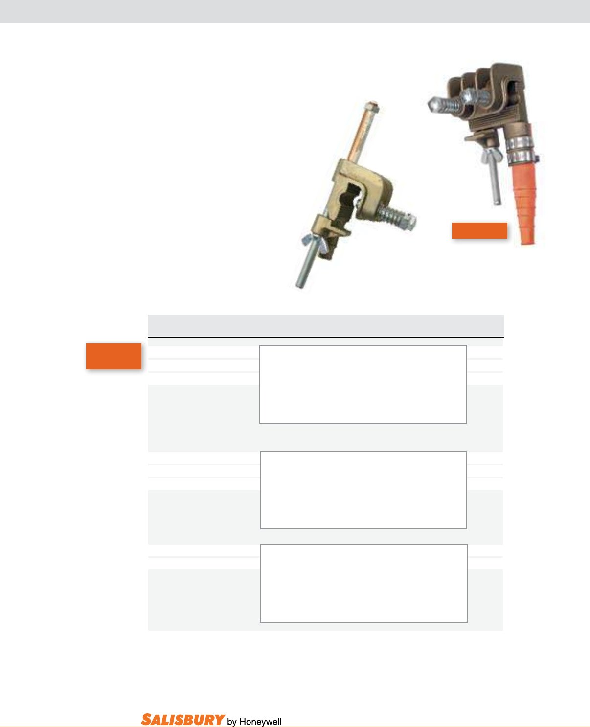
H-13
101 E. Crossroads Pkwy., Ste. A Bolingbrook, IL 60440 toll free ph (USA):877.406.4501 toll free fax (USA):866.824.4922 ph:630.343.3800
The Heavy Duty Bronze “C”
Type Flat Jaw Clamp with anti-
blow off keeper is made to fit
structural angles, ats, and copper
or copperweld stranded grounding
assemblies. To install, rst use an
abrasive cloth or wire brush to
clean the surface to be clamped.
Then, wipe the surface clean,
position the clamp, nger tighten
and set the screws. Use a wrench to
secure and tighten. A 2667 clamp
with contact stud offers greater
versatility.
2567
2667
2567 Now
Grade 5H!
Cat. No. Eye & Clamp ASTM Grade / Main Line Continuous Weight ea.
Description Class Range Current Rating lbs. ( kgs )
2567 w/ Strain Angles & Flats: 5/8-11UNC 4 ( 1.8 )
Relief Sleeve 5H / B 2.5”-4” WX Max. Cable
5/8”-11NC Connection Serrated Jaw ( 64-101 x 3-19mm ) Size 4/0 Type V
Rounds: Compression Ferrules
.25”-.75”
( 6-19mm ) Dia.
2577 w/ Strain Angles & Flats: 3/4-10UNC 4 ( 1.8 )
Relief Sleeve 6 / B 2.5”-4” WX Max. Cable
3/4”-10NC Connection Serrated Jaw ( 64-101x3-19mm ) Size 250 MCM
Rounds: Type V
.25”-.75” Compression Ferrules
( 6-19mm ) Dia.
2667 2567 Clamp 5 / B Angles & Flats: 5/8-11UNC 5 ( 2.3 )
w/ Contact Stud Serrated Jaw 2.5”-4” WX Max. Cable
( 64-101 x 3-19mm ) Size 4/0 Type V
Rounds: Compression Ferrules
.25”-.75”
( 6-19mm ) Dia.
Now Grade 5H!
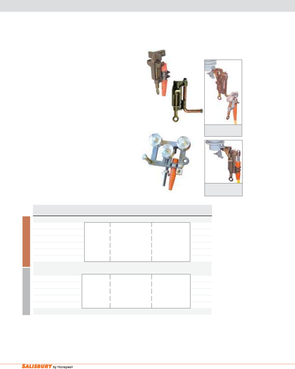
H-14 Grounding Equipment. www.salisburybyhoneywell.com
2155
SPECIALTY CLAMPS
B R O N Z E
A L U M I N U M
Cutout Clamp with
Contact Stud
Cutout Clamp
Jumper Assembly
Cat. No. & Description ASTM Grade / Main Line Continuous Weight ea.
Class Range Current Rating lbs. ( kgs)
BRONZE CUTOUT CLAMPS - “V” Thread
4310 Eye 5/8 - 11 UNC 2.1 ( 1.1 )
w/ ferrule connection Max. Cable Size: 470
4373 Eye 400 RMS Amps 3.3 ( 1.5 )
w/ contact stud Grade 5 Type VI
4379 Contact stud only Threaded Stud 60 Hz 1.2 ( .5 )
Compression Ferrule
STRINGING GROUND
2155 Stringing ground Alloy Rollers 1033.5 KCM ACSR- 5.3 ( 2.4 )
Smooth Contacts to #2 Sol 300 RMS Amps
5 / A 1.26”-.25”
32mm - 6mm Dia 60 HZ
Splice: 1.5” ( 38mm ) Dia
Cutout Clamps are applied with a clampstick into the
bottom hinge contact of a cutout. This clamp can be used as
part of a ground assembly or by using a contact stud using
a standard grounding assembly with “C” clamps from the
stud to ground.
Lightweight, heavy duty Stringing Ground installs
anywhere along the length of conductor to provide a
continuous grounding bond, even if the conductor is slack.
Constructed of high-strength aluminum alloy with large
diameter sheaves and bronze bushing bearings. Side opening
for quick, easy installation. Adjustable compression spring
assures proper contact for different sizes of conductor and
for easy passage of splices. In tests, this clamp withstood
a 25kA, 28 cycle short circuit. The three options for a
ground tap connection are: termination for ground cables,
contact/hanger stud and connector for ground wire.
4373
4310
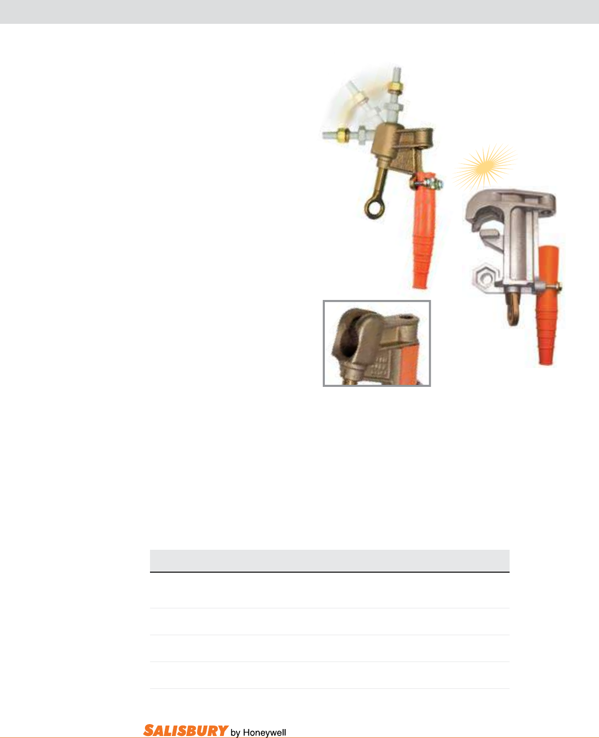
H-15
101 E. Crossroads Pkwy., Ste. A Bolingbrook, IL 60440 toll free ph (USA):877.406.4501 toll free fax (USA):866.824.4922 ph:630.343.3800
BALL & SOCKET SYSTEM
SOCKET CLAMP & BALL STUD “C” CLAMP
21190
Cat. No. Description ASTM Continuous Current Weight ea.
Grade Rating lbs. ( kgs)
21190 w/ Strain 5 400 Amps 1.2 ( .54 )
Relief Sleeve
21277 w/o Strain 5 400 Amps 1.1 ( .5 )
Relief Sleeve
22675 1” Ball Stud C-Clamp 5 400 Amps 2.7 ( x )
w/ strain relief
22704 1” Ball Stud C-Clamp 5 400 Amps 2.6 ( x )
w/o strain relief
The Ball and Socket Grounding
System allows for variable angle
accessibility. This system is compact
and lightweight. There are fixed
grounding points on the socket clamp.
The 21190 Socket Clamp, made from
bronze alloy, has a socket size of 1 inch
(25.4mm) and a threaded bore boss of
5/8”-11 UNC. The socket clamp has
an integral cable support with strain
relief sleeve.
The Ball Stud “C” Clamp is an
universal clamp that can be used in
substations and on overhead lines. This
universal clamp can be used as a socket
clamp on a 1 inch (25.4mm) Ball Stud
and as a 1 ½ inch (38mm) C-Clamp
on overhead lines. The eye screw is
not extended beyond the body of the
clamp, minimizing possible thread
damage during handling. Double lead
V-thread allows for faster installation,
minimizing worker fatigue. External
and internal ball studs assembly can be
used as a current carrying contact stud.
See page J-3 for ball socket studs and
accessories available for both Ball & Socket
clamps and Ball Stud “C” Clamps.
Specications for Ball Stud “C” Clamp
• Aluminum clamp body
• Double lead V-thread eye screw is bronze alloy
• ASTM Type 1, Class A, Grade 5 rating
• Fault current ratings:
• 43,000 Amps – 15 cycles
• 30,000 Amps – 30 cycles
• Ferrule attachment:5/8” x 11 UNC for Grade 5 rating
• Grounding cable: #2 min size to 4/0 max size
22675
NEW
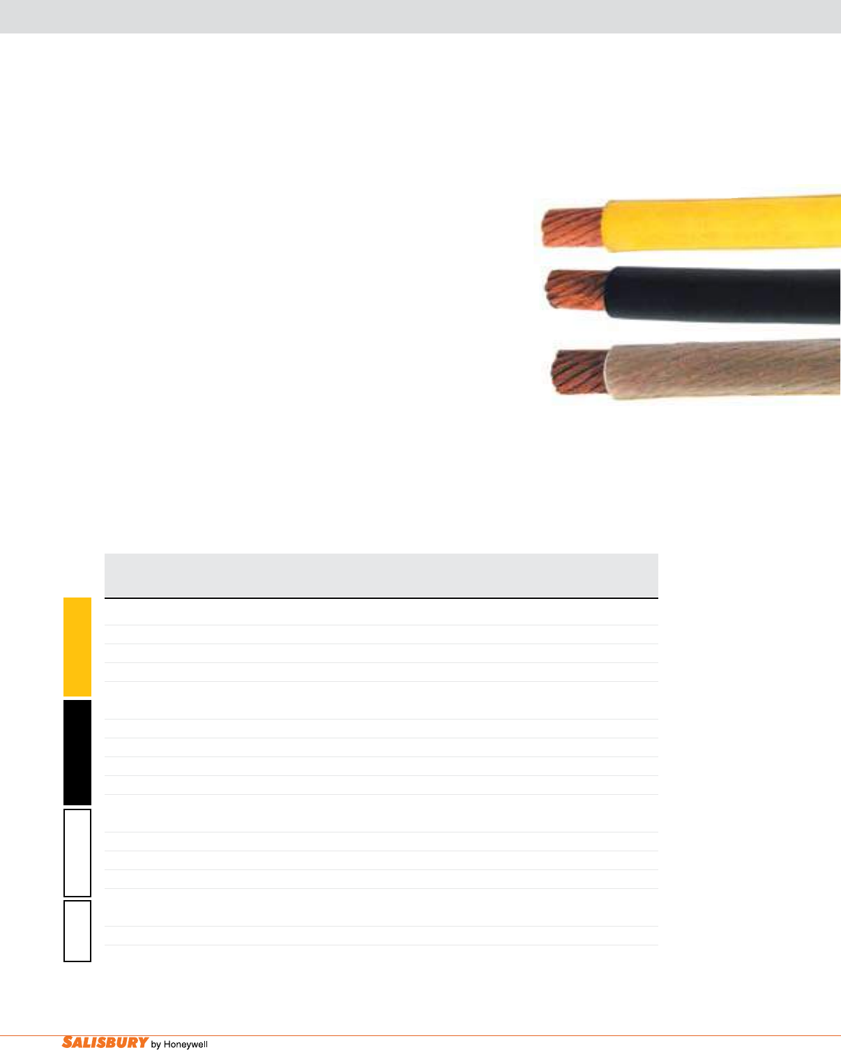
H-16 Grounding Equipment. www.salisburybyhoneywell.com
Grounding Cables are made with extra exible strand of soft drawn #30
AWG (.01”) copper and are available in three different jackets.
The yellow thermoplastic elastomer jacketed cable is the standard for
grounding service. It provides a combination of economy, exibility, and
durability. The service temperature ranges from 200º to -50ºF per ASTM
F 855, Type I requirements.
The black thermoplastic elastomer jacketed cable has a smaller diameter
and thinner jacket material giving it better exibility than the yellow
cable. The service temperature ranges from 200º to -50ºF per ASTM F
855, Type I requirements.
The PVC transparent flexible thermoplastic jacketed cable allows
easy inspection for strand breakage. The exibility decreases with low
temperatures. The service temperature ranges from 140º to -40ºF per
ASTM F 855, Type III requirements.
The silicone transparent exible thermoplastic jacketed cable allows easy
inspection for strand breakage. The service temperature ranges from 302º
to -40ºF per ASTM F 855, Type I requirements.
Cat No. Size Strand Dia. Jacket Short Circuit Withstand Continuous Wt. / 1000 ft.
in. ( mm ) in. ( mm ) AMPS, RMS, 60Hz Current lbs. ( kgs )
15 Cycles 30 Cycles AMPS, RMS, 60Hz
2136 #2-665W .35 ( 8.9 ) .5 ( 12.7 ) 14500 10000 200 282 ( 127 )
2137 1/0-1064W .45 ( 11.4 ) .62 ( 15.7 ) 21000 15000 250 488 ( 221 )
2138 2/0-1330W .49 ( 12.4 ) .65 ( 16.5 ) 27000 20000 300 537 ( 243 )
2139 4/0-2109W .62 ( 1.7 ) .83 ( 21.1 ) 43000 30000 400 836 ( 379 )
2636 #2-665W .35 ( 8.9 ) .47 ( 12 ) 14500 10000 200 263 ( 119 )
2637 1/0-1064W .45 ( 11.4 ) .58 ( 14.7 ) 21000 15000 250 404 ( 183 )
2638 2/0-1330W .49 ( 12.4 ) .63 ( 16 ) 27000 20000 300 497 ( 225 )
2649 3/0-1672W .55 ( 14 ) .72 ( 18.3 ) 36000 25000 350 680 ( 308 )
2639 4/0-2109W .62 ( 1.7 ) .78 ( 19.8 ) 43000 30000 400 770 ( 349 )
2128 #2-665W .35 ( 8.9 ) .53 ( 13.5 ) 14500 10000 200 289 ( 131 )
2129 1/0-1064W .45 ( 11.4 ) .64 ( 16.3 ) 21000 15000 250 520 ( 235 )
2133 2/0-1330W .49 ( 12.4 ) .7 ( 17.8 ) 27000 20000 300 546 ( 247 )
2288 4/0-2109W .62 ( 1.7 ) .84 ( 21.3 ) 43000 30000 400 841 ( 381 )
21930 2/0-1330W .49 ( 12.4 ) .62 ( 15.7 ) 27000 20000 300 487 ( 221 )
21931 4/0-2109W .62 ( 1.7 ) .78 ( 19.8 ) 43000 30000 400 579 ( 263 )
B L A C K Y E L L O W
PVC C L E A R
C L E A R
SILICONE
GROUNDING CABLES
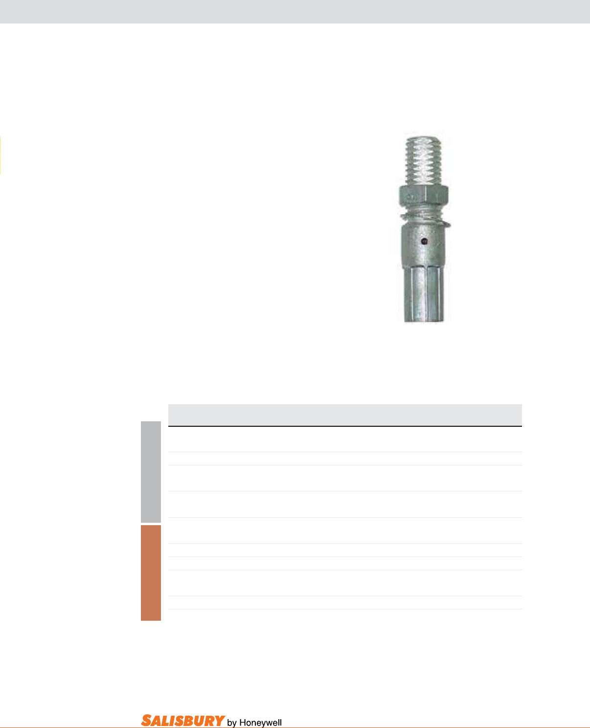
H-17
101 E. Crossroads Pkwy., Ste. A Bolingbrook, IL 60440 toll free ph (USA):877.406.4501 toll free fax (USA):866.824.4922 ph:630.343.3800
Cat. No. ASTM Size Installing Die Codes Burndy Weight ea.
Pair Grade T&B Die Numbers lbs. ( kgs )
2026 1 #2 50 - .2 ( .1 )
2027 2 1/0 50 - .2 ( .1 )
2620 3 2/0 60 - .3 ( .1 )
2640 5 4/0 71 - .3 ( .1 )
2022 1 #2 50 U243 .5 ( .2 )
2023 2 1/0 50 U243 .4 ( .2 )
2024 3 2/0 60 U245 .4 ( .2 )
4277 4 3/0 66 .6 ( .3 )
2025 5 4/0 66 U247 .6 ( .3 )
Salisbury compression Threaded
Grounding Ferrules provide low resistant
connection to cable strands with a threaded
stud that securely screws into a clamp.
Nut and lock washers increase contact
pressure and secure the assembly. Tin
plated copper ferrules can be used on
either bronze or aluminum body clamps.
All Salisbury threaded grounding ferrules
are unshrouded and manufactured with a
5/8-11 UNC threaded stud and meets the
requirements of ASTM F855.
A L U M I N U M C O P P E R
Add suffix “A” to the catalog number when requesting a custom insulated grounding set.
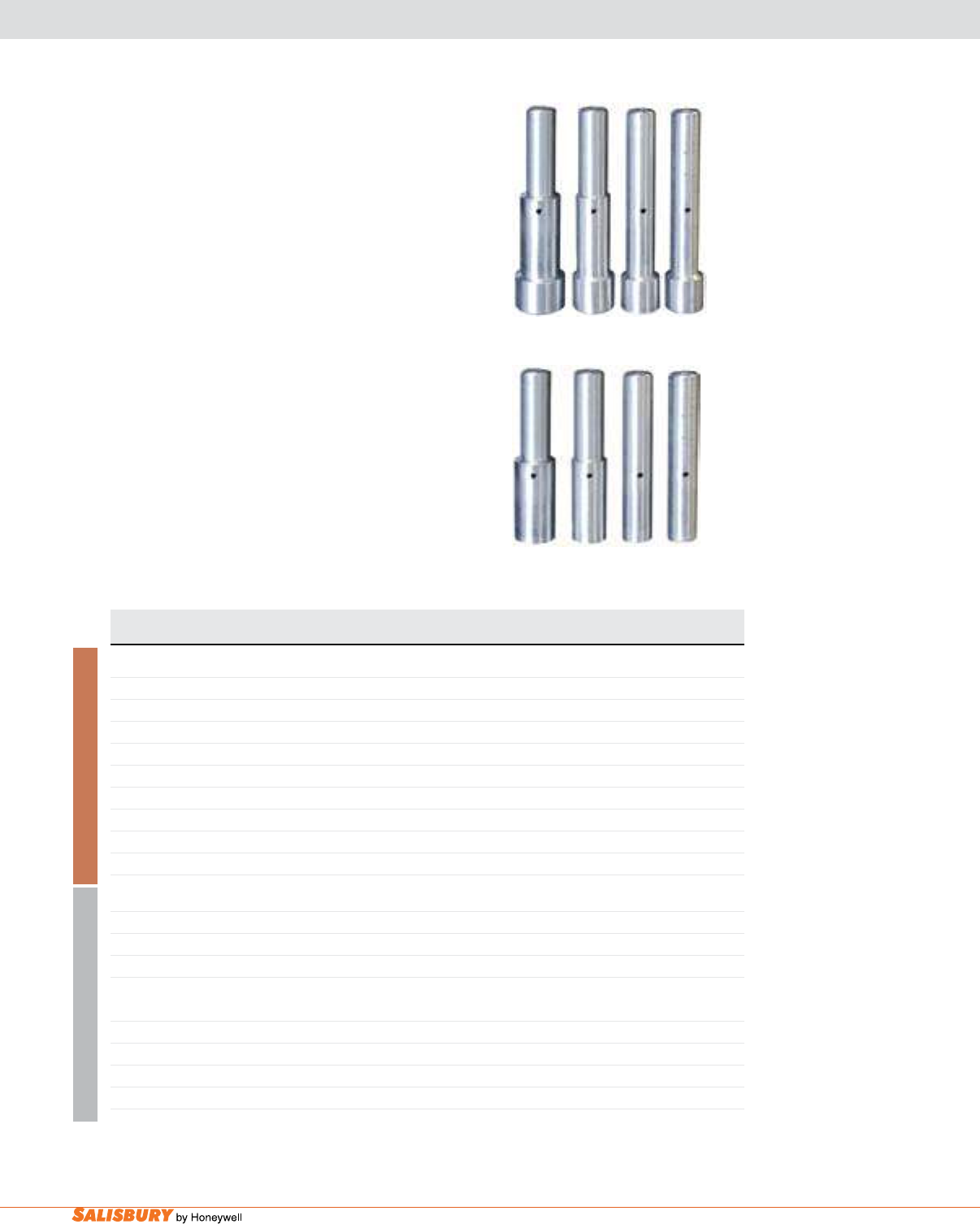
H-18 Grounding Equipment. www.salisburybyhoneywell.com
Plain Ferrules are designed for use with all grounding
clamps that feature pressure terminal including the 1”
duckbill and 1.5” at jaw clamp.
Copper Ferrules are available in two different styles:
unshrouded and shrouded. Shrouded ferrules are
compressed on both the conductor and the jacket of the
cable to reduce bending stress. Unshrouded ferrules are
crimped on the conductor strands only. These ferrules
are manufactured of tin plated, 99.5% pure copper.
Aluminum Ferrules are available in two different
styles: unshrouded and shrouded. Shrouded ferrules are
compressed on both the conductor and the jacket of the
cable to reduce bending stress. Unshrouded ferrules are
crimped on the conductor strands only.
plain shrouded
plain unshrouded
Cat. No. Cable Size Strand Die Codes Jacket Die Codes Burndy Weight ea.
Pair T&B T&B Die Number lbs. ( kgs )
SHROUDED
24424 #2 50 71 - 0.3 ( .14 )
24425 1/0 50 71 - 0.35 ( .16 )
24426 2/0 60 76 - 0.4 ( .18 )
24427 4/0 66 106 - 0.45 ( .20 )
UNSHROUDED
24420 #2 50 - 0.3 ( .14 )
24421 1/0 50 - U243 0.3 ( .14 )
24422 2/0 60 - U245 0.35 ( .16 )
24423 4/0 66 - U247 0.35 ( .16 )
SHROUDED
24434 #2 50 71 - 0.1 ( .045 )
24436 2/0 60 76 - 0.15 ( .07 )
24437 4/0 71 106 - 0.15 ( .07 )
UNSHROUDED
24430 #2 50 - - 0.12 ( .54 )
24431 1/0 50 - - 0.12 ( .54 )
24432 2/0 60 - - 0.16 ( .073 )
24433 4/0 71 - - 0.16 ( .073 )
ALUMINUM COPPER
Add suffix “A” to the catalog number when requesting a custom insulated grounding set.
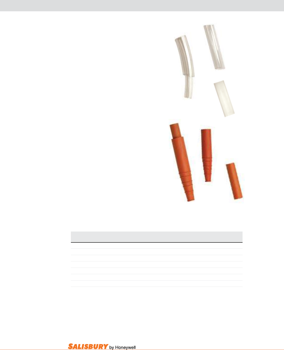
H-19
101 E. Crossroads Pkwy., Ste. A Bolingbrook, IL 60440 toll free ph (USA):877.406.4501 toll free fax (USA):866.824.4922 ph:630.343.3800
GROUNDING ACCESSORIES
Cat. No. Description Weight ea.
lbs. ( kgs )
CABLE STRAIN RELIEF SLEEVES
0786 Tapered Outer SALCOR Sleeve Only .1 ( .04 )
1758 Inner SALCOR Sleeve Only .1 ( .04 )
1788 Complete SALCOR Strain Relief Assembly .1 ( .04 )
2633 Clear Sleeve for 4/0 Grounding Cable .1 ( .04 )
2983 Clear Sleeve for #2 to 2/0 Grounding Cable .1 ( .04 )
20886 Clear Heat Shrink, 5”( 127mm ) for All Grounding Cables .1 ( .04 )
Strain Relief Sleeves reinforce cables at
the termination points when used with the
cable support system. This decreases strand
damage to cables from age or mishandling
which reduces current carrying capacity
and service life. SALCOR® Strain Relief
Sleeves accept all grounding cables #2
through 4/0. Sleeve assembly consists
of two parts: the inner sleeve which is
discarded if the cable diameter exceeds
.72” and tapered outer sleeve, 6.5” long,
which can be cut to match the diameters.
Clear strain relief sleeves and heat shrink
are available to t ground clamps.
2633
2983
20886
1758
0786
1788
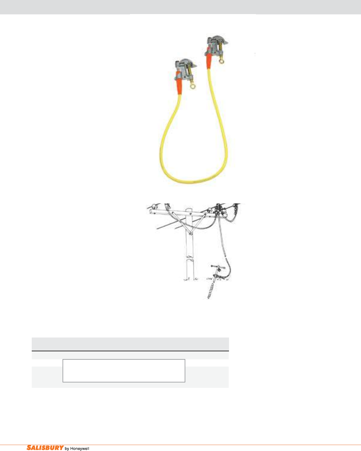
H-20 Grounding Equipment. www.salisburybyhoneywell.com
SINGLE GROUNDING ASSEMBLIES
SINGLE GROUNDING ASSEMBLIES & SETS
Salisbury offers a variety of single
grounding assemblies. These single
ground assemblies offer versatility to
the user when performing temporary
grounding.
For ordering convenience, completed
Single Grounding Assemblies are
listed which cover many standard
application needs. Modification
to these sets to meet specific
needs can be made. Contact your
local Salisbury representative for
assistance or visit www.whsalisbury.
com/congurator/ to use our helpful
online grounding congurator.
24309
Typical Ground Cluster Set
Cat. No. Description ASTM Weight ea.
Grade lbs. ( kgs )
SINGLE GROUNDING ASSEMBLIES
24309 2 ea. #1895 Serrated Aluminum “C” Clamp 1.5” 3 5.9 ( 2.7 )
1 pr. #2024 Ferrules
6 ft. #2138 2/0 Cu. Cable yellow
Optional ground set label available upon request when ordering.
H-21
101 E. Crossroads Pkwy., Ste. A Bolingbrook, IL 60440 toll free ph (USA):877.406.4501 toll free fax (USA):866.824.4922 ph:630.343.3800
SINGLE GROUNDING ASSEMBLIES
SINGLE GROUNDING ASSEMBLIES & SETS
Cat. No. Description ASTM Weight ea.
Grade lbs. ( kgs )
SINGLE GROUNDING ASSEMBLIES
2299 2 ea. #1895 Serrated Aluminum “C” Clamp 1.5” 2 5.9 ( 2.7 )
1 ea. #1928 Hanger Stud, 1 pr. #2027 Ferrules
6 ft. #2137 1/0 Cu. Cable
2319 2 ea. #1923 Smooth Aluminum “C” Clamp 2.4” 3 8.7 ( 3.9 )
1 ea. #1928 Hanger Stud, 1 pr. #2620 Ferrules
10 ft. #2138 2/0 Cu. Cable
2320 1 ea. #1923 Smooth Aluminum “C” Clamp 3 7.4 ( 3.4 )
1 ea. #4345 Aluminum Flat Jaw “T” Handle Clamp
1 pr. #2620 Ferrules, 15 ft. #2138 2/0 Cu. Cable
2321 2 ea. #1793 Bronze Duck Bill 556 KCM 2 5.4 ( 2.5 )
1 ea. #2093 Hanger Stud, 1 pr. #2023 Ferrules
6 ft. #2137 1/0 Cu. Cable
2329 2 ea. #1921 Serrated Aluminum “C” Clamp 2.4” 3 9 ( 4.1 )
1 ea. #1928 Hanger Stud, 1 pr. #2620 Ferrules
10 ft. #2138 2/0 Cu. Cable
2556 2 ea. #1852 Smooth Aluminum Duck Bill Clamp 1.66” 2 5.2 ( 2.4 )
1 ea. #1858 Hanger Stud, 1 pr. #2027 Ferrules
6 ft. #2137 1/0 Cu. Cable
2558 2 ea. #1853 Serrated Aluminum Duck Bill Clamp 1.25” 2 5.5 ( 2.5 )
1 ea. #1858 Hanger Stud, 1 pr. #2027 Ferrules
6 ft. #2137 1/0 Cu. Cable
2876 2 ea. #2531 Smooth Aluminum “C” Clamp 1.0” 2 4.9 ( 2.2 )
1 ea. #2537 Hanger Stud, 1 pr. #2027 Ferrules
6 ft. #2137 1/0 Cu. Cable
9975 2 ea. #9985 Smooth Bronze “C” Clamp 1.0” 2 6.9 ( 3.1 )
1 ea. #9983 Hanger Stud, 1 pr. #2023 Ferrules
6 ft. #2137 1/0 Cu. Cable
9982 2 ea. #9984 Smooth Bronze “C” Clamp 1.25” 2 8.3 ( 3.7 )
1 ea. #9983 Hanger Stud, 1 pr. #2023 Ferrules
6 ft. #2137 1/0 Cu. Cable
Optional ground set label available upon request when ordering.
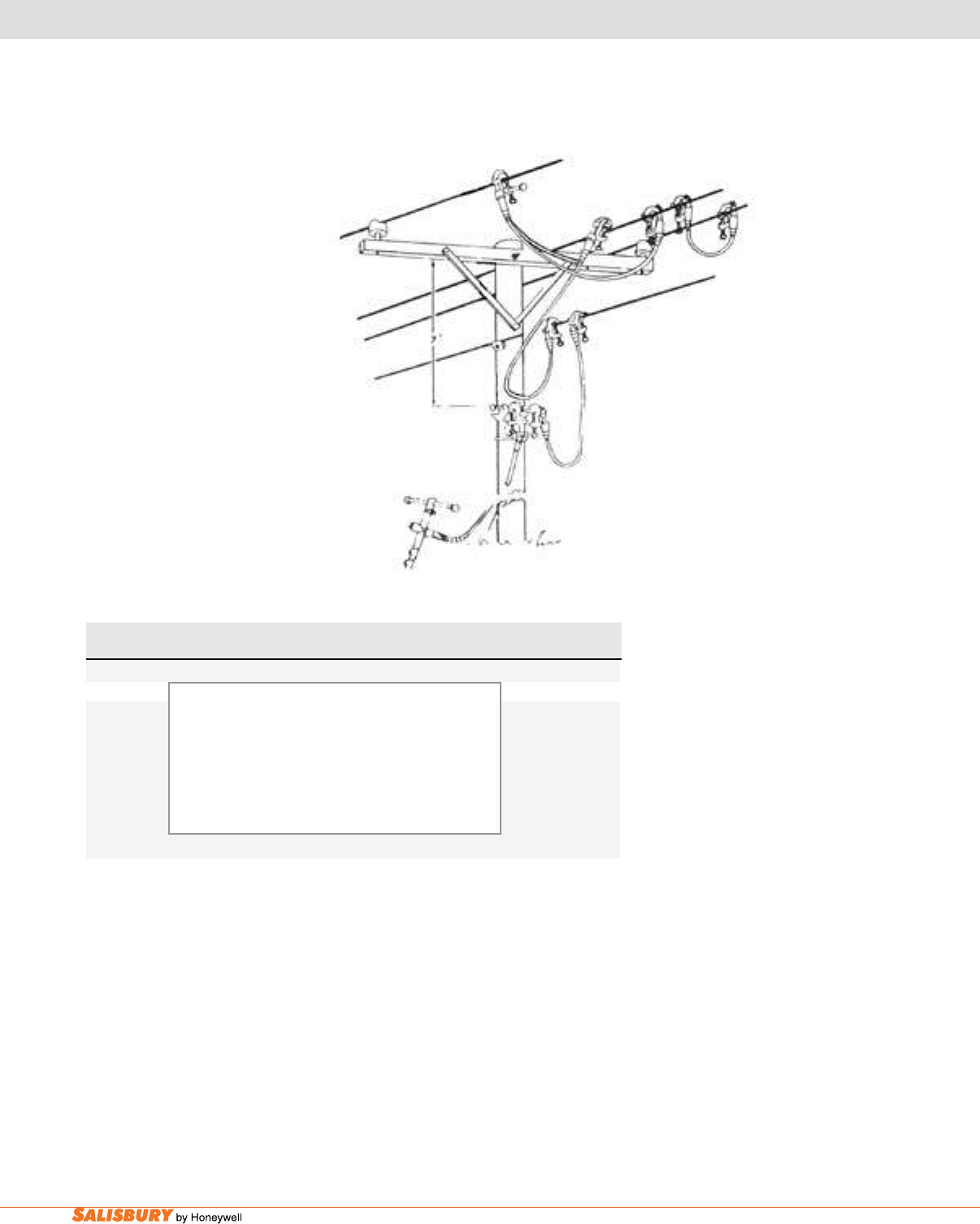
H-22 Grounding Equipment. www.salisburybyhoneywell.com
GROUNDING SETS
SINGLE POINT DISTRIBUTION GROUNDING SET
Additional Single Point Sets are available. Contact your local Salisbury representative.
4246
Cat. No. Description ASTM Weight ea.
Grade lbs. ( kgs )
4246 Complete Distribution Grounding Set 1 45.5 ( 20.6 )
10 ea. #2531 Smooth Aluminum “C” Clamps 795 KCM
1 ea. #9998 Aluminum Pole Mount Contact Bar
5 pr. #2026 Ferrules
3 ea. #2537 Hanger studs
60 ft. #2636 # Cu. Cable
1 ea. #2103 Screw Ground Rod w/ Connector
This Single Point Distribution
Grounding Set creates an equal
potential zone on the working
structure. This is accomplished
by bonding all conductors and the
structure to a ground source using
individual assemblies as shown in
the adjacent drawing.
Going from either the ground rod
or the system ground to the pole
mounted contact bar under the
worker’s feet, to the assemblies
bonding the conductors creates an
equal potential zone.
Optional ground set label available upon request when ordering.
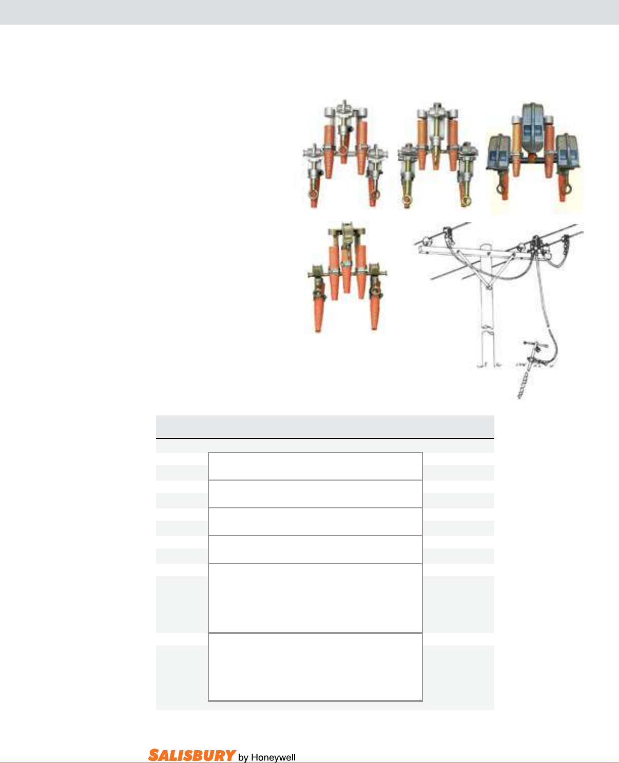
H-23
101 E. Crossroads Pkwy., Ste. A Bolingbrook, IL 60440 toll free ph (USA):877.406.4501 toll free fax (USA):866.824.4922 ph:630.343.3800
2547
2534
GROUNDING SETS
Cat. No. Description ASTM Weight ea.
Grade lbs. ( kgs )
1790 Cluster w/ 3 #1793 Smooth Jaw 4 6 ( 2.7 )
556 KCM Bronze Duck Bill Clamps
1957 Cluster w/ 3 #1895 Serrated Jaw 5 6.4 ( 2.9 )
1.5” Aluminum “C” Clamps
2534 Cluster w/ 3 #2531 Smooth Jaw 5 4.9 ( 2.2 )
1” Aluminum “C” Clamps
2547 Cluster w/ 3 #1853 Serrated Jaw 5 5.4 ( 2.5 )
1.66” Aluminum Duck Bill Clamps
2685 Assembled Ground Cluster Set 2 54.2 ( 24.6 )
1 ea. #2516 Serrated Aluminum “C” Clamp 1.25” Cluster
74 ft. #2637 1/0 Cu. Cable
3 pr. #2027 Ferrules, 1 ea. #2103 Screw Ground Rod
1 ea. #2654 Storage Bag
4248 Assembled Ground Cluster Set 1 54.2 ( 24.6 )
1 ea. #1790 Smooth Bronze Duck Bill Cluster
76 ft. #2636 #2 Cu. Cable
3 pr. #2022 Ferrules, 1 ea. #2103 Screw Ground Rod
1 ea. #2654 Storage Bag
Clusters are also available with Mounted Clamps, consult the factory for more information.
1790
2685
1957
Grounding Clusters are used
to make it easy for a single
line worker to apply multiple
grounding assemblies on a
three phase system. All clusters
have an option of a ground lead
by using the extra connection
point on each cluster. Three
wire clusters are recommended
for three phase Delta systems.
Complete grounding cluster
assemblies are available from
the factory. Specify cable
size and length required and
assembly will be made to your
specications.
Optional ground set label available upon request when ordering.
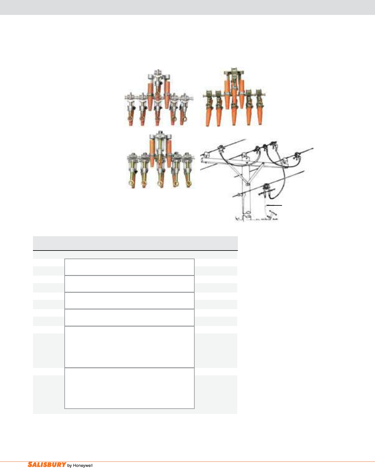
H-24 Grounding Equipment. www.salisburybyhoneywell.com
GROUNDING SETS
Grounding Clusters are used to
make it easy to apply multiple
grounding assemblies easy for a
single line worker. All clusters
have an option of a ground lead
by using the extra connection
point on each cluster. Four
wire clusters are recommended
for three phase Wye systems.
Complete grounding cluster
assemblies are available from
the factory. Specify cable
size and length required and
assembly will be made to your
specications.
Cat. No. Description ASTM Weight ea.
Grade lbs. ( kgs )
1794 Cluster w/ 6 #1793 Smooth Jaw 4 9 ( 4.1 )
556 KCM Bronze Duck Bill Clamps
2192 Cluster w/ 6 #1895 Serrated Jaw 5 11.8 ( 5.4 )
1.5” Aluminum “C” Clamps
2536 Cluster w/ 6 #2531 Smooth Jaw 5 8.8 ( 4 )
1” Aluminum “C” Clamps
2604 Cluster w/ 6 #1853 Serrated Jaw 5 6.2 ( 2.8 )
1.66” Aluminum Duck Bill Clamps
2682 Assembled Ground Cluster 1 14.5 ( 6.6 )
1 ea. #1794 Smooth Bronze Duck Bill Cluster
18 ft. #2636 #2 Cu. Cable
3 pr. #2022 Ferrules
1 ea. #2654 Storage Bag
4247 Assembled Ground Cluster 2 18 ( 8.2 )
1 ea. #2536 Smooth Aluminum “C” Cluster
18 ft. #2637 1/0 Cu. Cable
3 pr. #2027 Ferrules
1 ea. #2654 Storage Bag
Clusters are also available with Mounted Clamps, consult the factory for more information.
2536 1794
2192
optional
4247
Assembled Ground
Set
Optional ground set label available upon request when ordering.
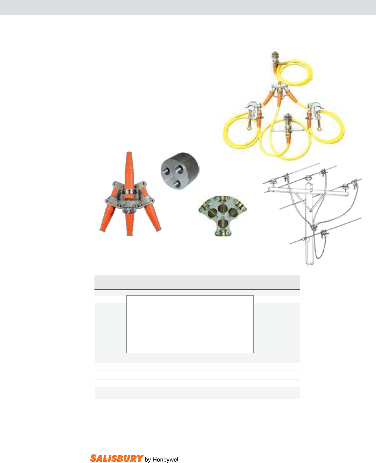
H-25
101 E. Crossroads Pkwy., Ste. A Bolingbrook, IL 60440 toll free ph (USA):877.406.4501 toll free fax (USA):866.824.4922 ph:630.343.3800
GROUNDING SETS
Cat. No. Description ASTM Weight ea.
Grade lbs. ( kgs )
2680 Four Way Connector Ground Set - Grade 2 2 28 ( 12.7 )
21 kA 15 cycles
1 #2374 Four Way Connector w/ Sleeves
4 #1895 1.5” Serrated Jaw Clamps w/ Sleeves
1 #2427 Double Hanger Stud, 1 #2402 Contact Stud
34 ft. #2137 1/0 Cu. Cable
4 pr. #2027 Ferrules
2374 Threaded Ferrule Four Way Connector 5 1.8 ( .8 )
21702 Threaded Ferrule Four Way Connector 1 ¾ long x 2 ¼ dia. 5 .5 ( .23 )
24438 Plain Ferrule Four Way Connector 5 2 ( .9 )
2374
2680
24438
8’ cable
10’ cable 10’ cable
6’ cable
21702
2680
The 2680 4-way connector ground set
provides an excellent system for the
grounding of a 3 phase system.
4-way connectors are used to create a
common connection between the conductor
leads and the ground lead of a ground set.
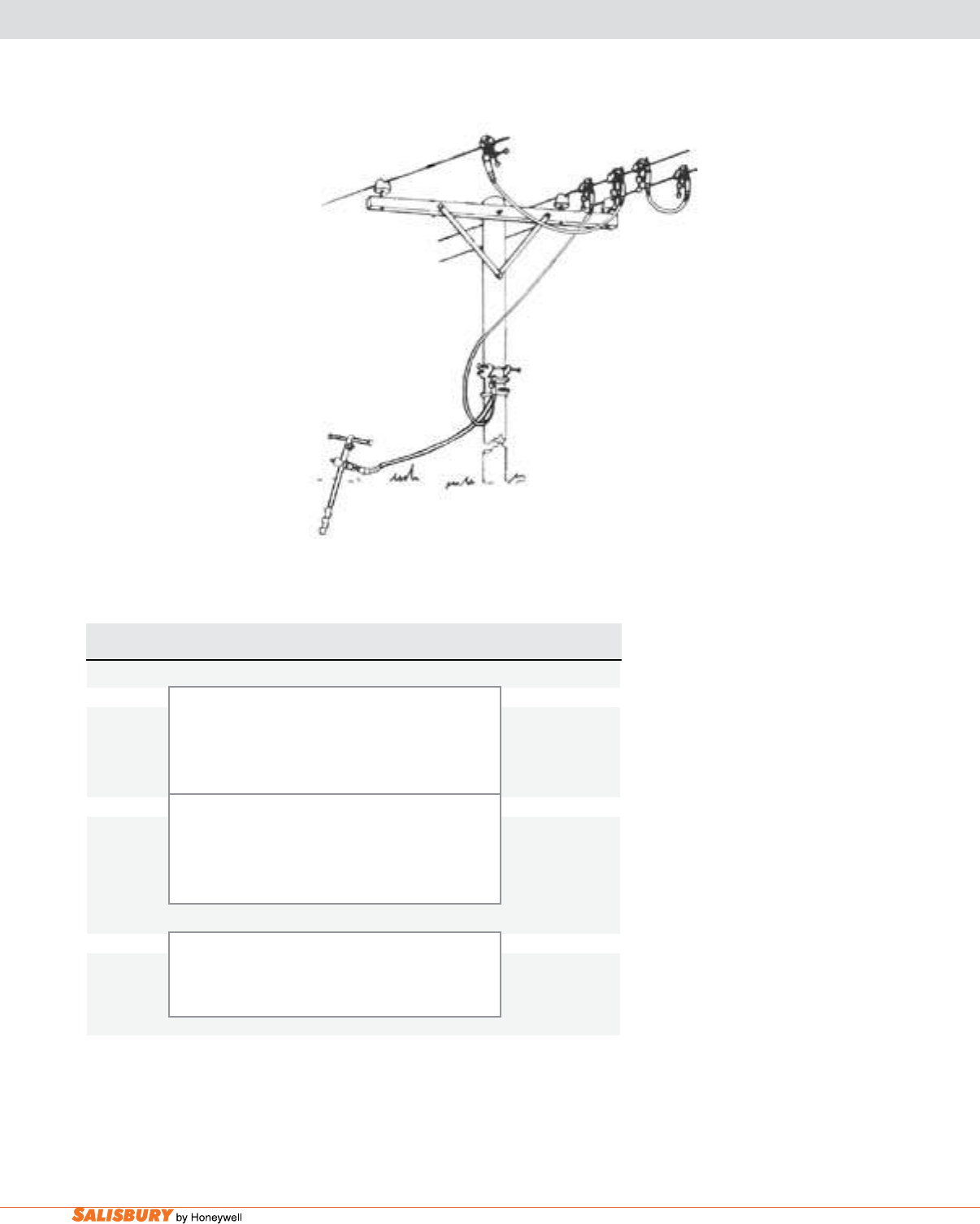
H-26 Grounding Equipment. www.salisburybyhoneywell.com
GROUNDING SETS
FOR SPECIAL APPLICATIONS
Listed are some typical
complete personal protection
ground sets for common line
construction. These sets,
although practical for many
applications, are shown as
a guide to help determine
individual system needs and
for ease of ordering. Variations
of these sets may be requested
to meet specic situations or
user preferences. Your local
Salisbury representative can
answer any questions you have
on personal protection grounding
needs and applications.
2684
Cat. No. Description ASTM Weight ea.
Grade lbs. ( kgs )
COMPLETE 3 PHASE DELTA
2684 2 ea. #20880 Contact Bar 2 63.5 ( 28.8 )
7 ea. #1895 Serrated Aluminum “C” Clamp 1.5”
84 ft. #2637 1/0 Cu. Black Cable, 4 pr. #2027 Ferrules
2 ea. #1928 Hanger Studs, 1 ea. #2654 Storage Bag
1 ea. #2103 Screw Ground Rod
4249 2 ea. #20880 Contact Bar 2 63.5 ( 28.8 )
7 ea. #2531 Smooth Aluminum “C” Clamp 795 KCM
86 ft. #2637 1/0 Cu. Cable, 4 pr. #2027 Ferrules
2 ea. #2537 Hanger Studs, 1 ea. #2654 Storage Bag
1 ea. #2103 Screw Ground Rod
COMPLETE 4 WIRE WYE
4276 1 ea. #20880A Contact Bar 2 34 ( 15.4 )
7 ea. #2531 Smooth Aluminum “C” Clamp 795 KCM
32 ft. #2637 1/0 Cu. Cable, 4 pr. #2027 Ferrules
3 ea. #2537 Hanger Studs, 1 ea. #2654 Storage Bag
Optional ground set label available upon request when ordering.
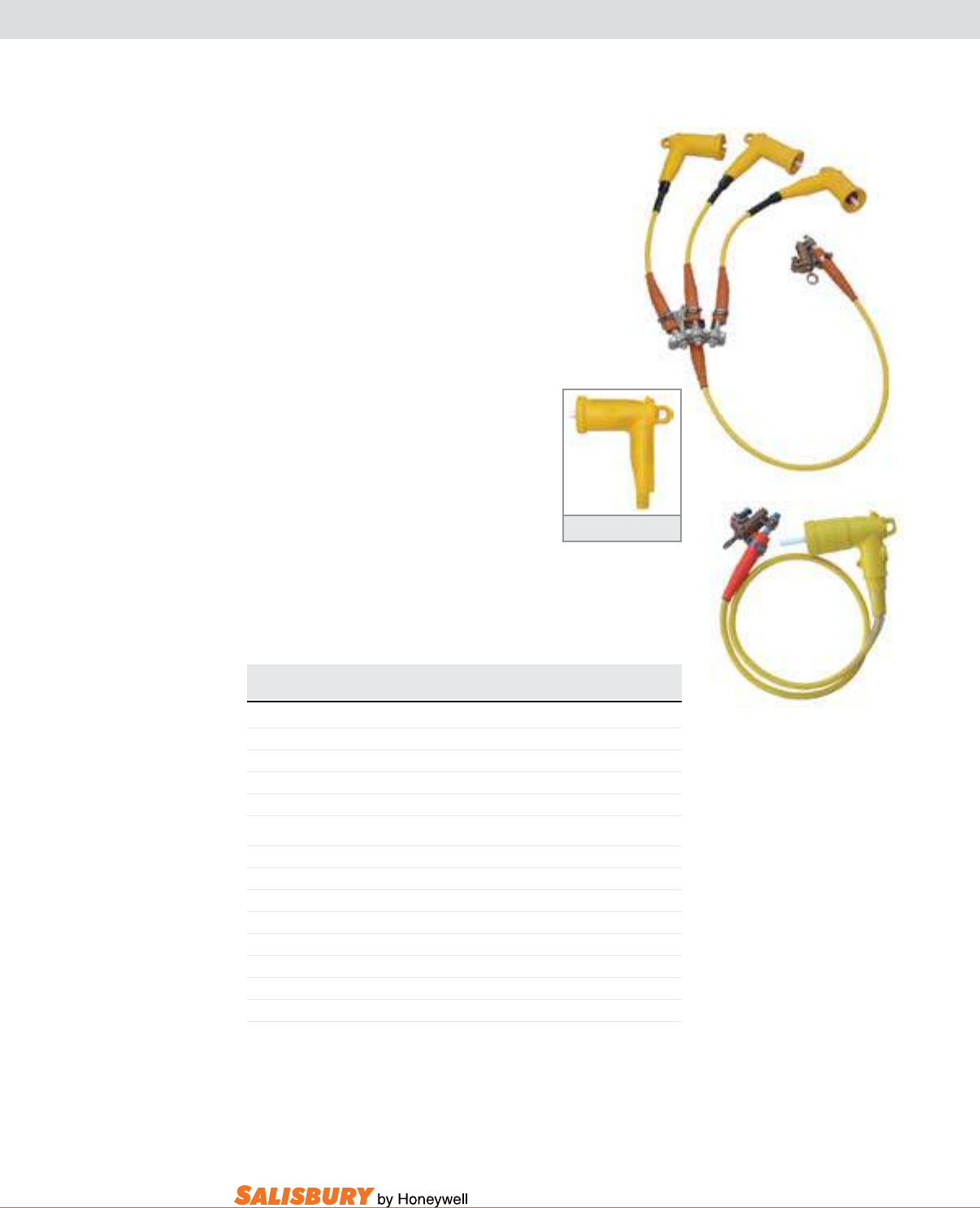
H-27
101 E. Crossroads Pkwy., Ste. A Bolingbrook, IL 60440 toll free ph (USA):877.406.4501 toll free fax (USA):866.824.4922 ph:630.343.3800
GROUNDING SETS
DEAD FRONT GROUNDING JUMPERS & ELBOWS
Dead Front Ground Sets are supplied
with an insulated grounding elbow, yellow
jacketed copper grounding cable, and a
1815 bronze at jaw ground clamp for the
ground connection. Grounding Elbows are
equipped with arc quenching tips as provided
on standard load break elbows.
Both 15kV and 25kV elbows are available with
connectors for 1/0 or 2/0 cable. Assembled sets
for 15kV and 25kV are available for single
phase or three phase grounding requirements.
The fault duty rating for 200 amp grounding
elbows is 10kA for 10 cycles per IEEE 386.
Standard three phase sets have a 4 ft. tail
connecting to a 2374 four wire connector with
2 ft. leads for the elbows. Sets can be factory
assembled to customer specications.
Cat. No. Description Weight ea.
lbs. ( kgs )
INSULATED GROUNDING ELBOWS
2910 15kV Elbow w/ 1/0 Cable Connector 1.7 ( .7 )
2912 15kV Elbow w/ 2/0 Cable Connector 1.7 ( .7 )
2935 25kV Elbow w/ 1/0 Cable Connector 2 ( .9 )
2936 25kV Elbow w/ 2/0 Cable Connector 2 ( .9 )
ASSEMBLED GROUNDING SETS
2961 15kV Single Phase, 6 ft. 1/0 Cable w/ Bag 10 ( 4.5 )
2962 15kV Single Phase, 6 ft. 1/0 Cable w/o Bag 8 ( 3.6 )
2963 15kV Three Phase, 1/0 Cable w/ Bag 22 ( 10 )
22630 15kV Three Phase, 1/0 Cable w/o Bag 20 ( 9 )
2971 25kV Single Phase, 6 ft. 1/0 Cable w/ Bag 13 ( 5.9 )
22631 25kV Single Phase, 6 ft. 1/0 Cable w/o Bag 11 ( 5 )
2973 25kV Three Phase, 1/0 Cable w/ Bag 24 ( 10.9 )
22632 25kV Three Phase, 1/0 Cable w/o Bag 22 ( 10 )
Elbow
2962
22630
Optional ground set label available upon request when ordering.

H-28 Grounding Equipment. www.salisburybyhoneywell.com
ASTM TABLES
Reprinted, with permission, from ASTM F 855-09 Standard Specification for Temporary Protective Grounds to Be Used on De-energized Electric Power Lines and Equipment
Table 1, copyright ASTM International, 100 Barr Harbor Drive, West Conshohocken, PA 19428. A copy of the complete standard may be obtained from ASTM, www.astm.org
Reprinted, with permission, from ASTM F 855-09 Standard Specification for Temporary Protective Grounds to Be Used on De-energized Electric Power Lines and Equipment Table 2,
copyright ASTM International, 100 Barr Harbor Drive, West Conshohocken, PA 19428. A copy of the complete standard may be obtained from ASTM, www.astm.org
2.2 ANSI Standard:
4
C 37.09 Standard Test Procedure for AC High-Voltage
Circuit Breakers Rated on a Symmetrical Basis
2.3 ICEA/NEMA Standard:
5
ICEA S-19-81/NEMA WC 3-80 (R 1986) Rubber Insulated
Wire and Cable for the Transmission and Distribution of
Electrical Energy
2.4 IEC Standard:
6
IEC 61230 Ed. 2, 2008, Portable Equipment for Earthing or
Earthing and Short-Circuiting
2.5 IEEE Standard:
7
IEEE 386 Standard for Separable Insulated Connector Sys-
tems for Power Distribution Systems Above 600V
IEEE 1048 Guide for Protective Grounding of Power Lines
IEEE 1246 Guide for Temporary Protective Grounding Sys-
tems Used in Substations
3. Terminology
3.1 Definitions of Terms Specific to This Standard:
3.1.1 continuous current rating—designated RMS current
which can be carried continuously under specified conditions.
3.1.2 protective ground assembly—a temporary electrical
connection between a source of potential energization and the
earth, rated for the maximum anticipated fault current or
continuous induced current, or both.
3.1.2.1 Discussion—Throughout this specification, kc
mil = 1000 circular mils.
3.1.3 protective grounding equipment—devices installed
temporarily on de-energized electric power circuits for the
4
Available from American National Standards Institute, 11 West 42nd St., 13th
Floor, New York, NY 10036.
5
Available from Insulated Cable Engineers Assoc., P.O. Box P, South Yarmouth,
MA 02664.
6
Available from International Electrotechnical Commission (IEC), 3 rue de
Varembé, Case postale 131, CH-1211, Geneva 20, Switzerland, http://www.iec.ch.
7
Available from Institute of Electrical and Electronics Engineers, Inc. (IEEE),
445 Hoes Ln., P.O. Box 1331, Piscataway, NJ 08854-1331, http://www.ieee.org.
TABLE 1 Protective Ground Cable, Ferrule, Clamp and Assembly Ratings for Symmetrical Current
Grade
Grounding Clamp Torque
Strength, min Short Circuit Properties
A
Continuous
Current
Rating, A
RMS, 60
Hz
Yield
B
Ultimate Withstand Rating, Symmetrical
kA
RMS, 60 Hz
Ultimate Rating Capacity
CD
, Symmetrical
kA
RMS, 60 Hz
lbf·in. n·m lbf·in. n·m 15
cycles
(250 ms)
30 cycles
(500
ms)
Copper Cable
Size
15
cycles
(250
ms)
30
cycles
(500
ms)
60
cycles
(1 s)
Maximum
Copper Test
Cable Size
1 280 32 330 37 14 10 #2 18 13 9 2/0 200
2 280 32 330 37 21 15 1/0 29 21 14 4/0 250
3 280 32 330 37 27 20 2/0 37 26 18 4/0 300
4 330 37 400 45 34 25 3/0 47 33 23 250 kcmil 350
5 330 37 400 45 43 30 4/0 59 42 29 250 kcmil 400
6 330 37 400 45 54 39 250 kcmil or
2 2/0 70 49 35 350 kcmil 450
7 330 37 400 45 74 54 350 kcmil or
2 4/0 98 69 48 550 kcmil 550
A
Withstand and ultimate short circuit properties are based on performance with surges not exceeding 20 % asymmetry factor (see 9.1 and 12.3.4.2).
B
Yield shall mean no permanent deformation such that the clamp cannot be reused throughout its entire range of application.
C
Ultimate rating represents a symmetrical current which the assembly or individual components shall carry for the specified time.
D
Ultimate values are based upon application of Onderdonk’s equation to 98 % of nominal circular mil area allowed by Specifications B 172 and B 173.
TABLE 2 Ultimate Assembly Rating for High X/R Ratio Applications
High Asymmetrical Test Requirements
Grade Size Rating
Rated Current
(kA)
X/R = 30
1st Cycle Current Peak
(kA)
X 2.69
Last Cycle
Current Peak
(kA) Test Duration (cycles)
1H No. 2 15 41 23 15
2H 1/0 25 65 37 15
3H 2/0 31 84 46 15
4H 3/0 39 105 58 15
5H 4/0 47 126 70 15
6H 250 MCM 55 148 82 15
7H 350 MCM 68 183 101 15
N
OTE
1—The above current values are based on electromechanical test values.
N
OTE
2—Assemblies that have been subjected to these shall not be re-used.
N
OTE
3—For use with currents exceeding 20 % asymmetry factor.
N
OTE
4—See X4.7.2 for additional information.
N
OTE
5—Alternate testing circuits are available for laboratories that cannot achieve the above requirements. See Appendix X4 for details.
F 855 – 09
2
Copyright by ASTM Int'l (all rights reserved); Fri Nov 6 13:35:55 EST 2009
Downloaded/printed by
Huel Gunter (Salisbury by Honeywell) pursuant to License Agreement. No further reproductions authorized.
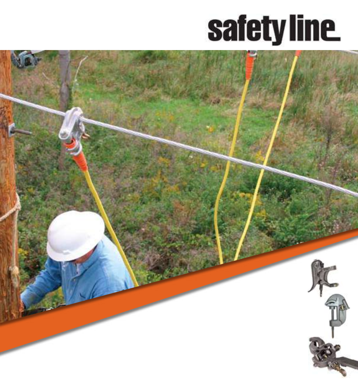
SAFETY LINE
TEMPORARY PROTECTIVE
GROUNDING EQUIPMENT
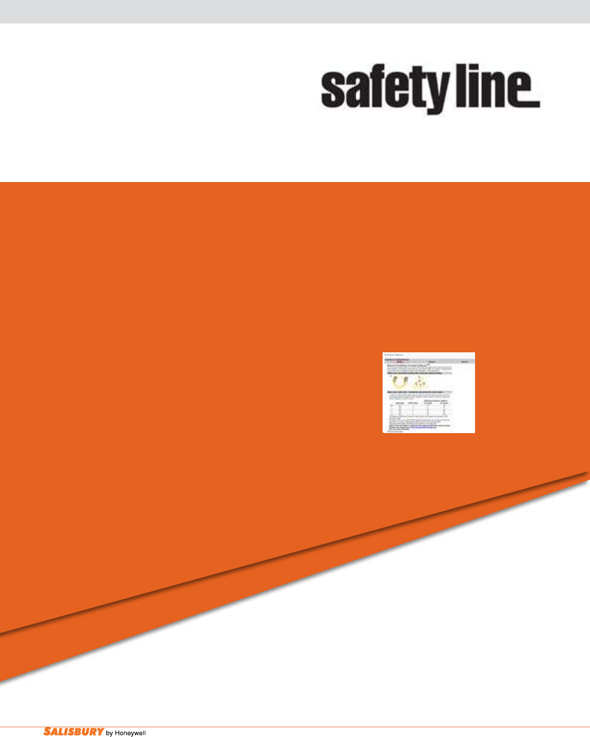
I-2 Safety Line Grounding Equipment. www.salisburybyhoneywell.com
NOTE:
When ordeing assemblies of grounding products, please make sure all
items included in the assembly are only from the product line found within
this section. Including items from other grounding equipment sections of
this book will add additional shipping time.
SAFETY LINE
TEMPORARY PROTECTIVE
GROUNDING EQUIPMENT
NOTE:
Salisbury by Honeywell’s Safety Line grounding equipment offers solutions
for all applications. This line of temporaty protective grounding equipment
offers a wide variety of products to meet many individual needs. These
products are available in complete assemblies or individual components.
PLEASE NOTE: When ordeing assemblies of grounding products, please
make sure all items included in the assembly are only from the product line
found within this section. Including items from other grounding equipment
sections of this book will add additional shipping time.
The Grounding Congurator™ makes ordering grounding equipment simple
and easy. This interactive web tool allows you to easily build the proper temporary
grounding equipment for your specic needs. The step-by-step process takes out
the guess work, and makes it easy to change components until the most appropriate
ground set is developed.
Just go to our web site and give it a try. You will be prompted from start to nish. All you need to know
is the maximum fault current, its duration and the size of cable required on the fault, and the congurator
will do the rest. No more second guessing quantities or parts to be sure that you have put together a
ground set that will function just as you expect. When you nish, enter your personal information and
the congurator will instantly provide you with the bill of materials including part numbers. All that’s
left to do is to place the order!
Visit salisburybyhoneywell.com to use
the exclusive Grounding ConfiguratorTM.
Grounding Congurator™
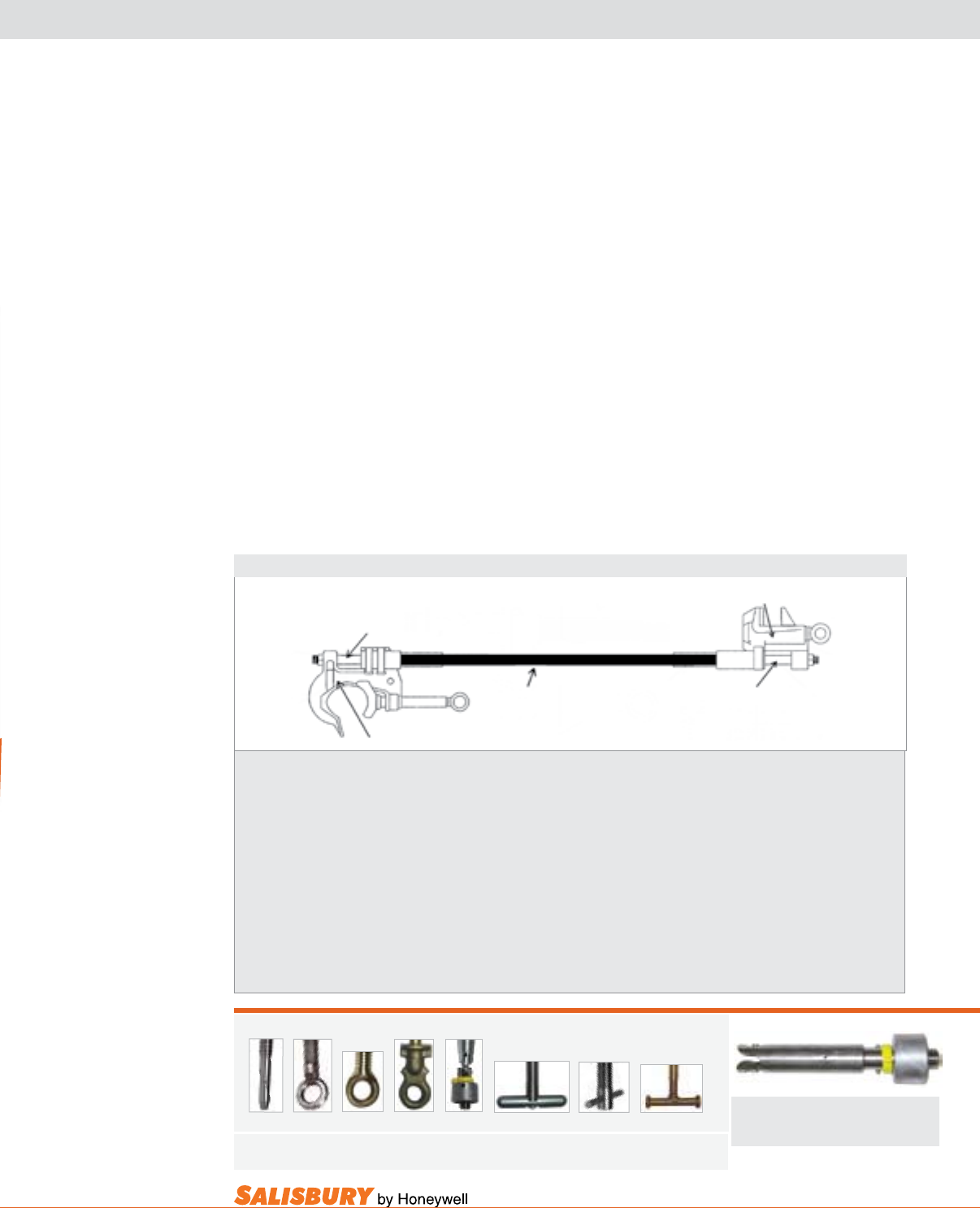
I-3
101 E. Crossroads Pkwy., Ste. A Bolingbrook, IL 60440 toll free ph (USA):877.406.4501 toll free fax (USA):866.824.4922 ph:630.343.3800
SAFETY LINE TEMPORARY PROTECTIVE GROUNDING EQUIPMENT
1. Specify the clamps. Two are required for a complete assem-
bly. The maximum amperage of the clamp is designated by the
ASTM grade of each clamp. Be sure that the clamp will meet or
exceed the maximum amperage rating of the ground cable that
it will be used with.
2. Specify the cable. Once the short circuit capacity of the sys-
tem has been determined, choose the appropriate size cable.
Specify the cable length, and the color of the jacket desired.
1. Flat Jaw Clamp
1.“C” Clamp
3. Ferrules
3. Ferrules
2. Cable
Ground Set Checklist
How to specify temporary protective
grounding assemblies.
A grounding assembly in its basic form consists
of two clamps, one pair of ferrules and a length
of cable.
The clamps can be identical to each other or
quite different depending on each grounding
application. Because of this, ground clamps are
sold individually, not in pairs. Salisbury offers a
wide variety of clamps including C-clamps, at
jaw clamps, socket clamps, duck bill clamps and
specialty clamps for unique situations. Clamps
are offered in either bronze or aluminum alloys
and are manufactured to meet the current
specications of ASTM F 855.
Additional Screw Options Available Where Designated
Bayonet Stainless Steel Bronze Posigrip Quick Removable Stainless Steel Bronze
Eye Eye Change T-Handle T-Handle T-Handle
B E EB PG QC RT T TB
Bayonet Ferrule
Installs/removes ground heads equipped with
bayonet studs.
98B Quick Change 1 lbs. (0.45 kgs)
Add suffix “U” for Universal, “Q” for Quick Change
To attach a clamp to the grounding cable requires
the use of a ferrule. Ferrules are compressed
on the strands of the cable to provide a low
resistance permanent connection. The size of
the ferrule is determined by the size of the cable.
Ferrules are available in aluminum, copper and
tin plated copper, shrouded and non-shrouded.
Plated copper ferrules can be used with either
aluminum or bronze clamps. Two ferrules are
required for each assembly therefore they are
sold in pairs. Ferrules are manufactured to the
specications of ASTM F 855.
The nal component that makes up a ground
set is the grounding cable itself. The size of the
cable is dependent on the short circuit current
capacity of the system being grounded. Once
this is determined, only the length of the cable
and the color of the jacket need to be specied
to complete the assembly.
3. Specify the ferrules. One pair of ferrules is required per assem-
bly. The size of the ferrule must match the size of the cable that it
will be used with. Make sure to specify whether the ferrule should
be copper or aluminum and threaded or plain.
4. Specify the options. List any optional equipment that is desired.
This can include hanger studs, contact studs, heat shrink tubing,
markings, clear strain relief, etc.
Options also include a ground set label. These optional labels in-
clude the date of manufacture and are available upon request
when ordering.
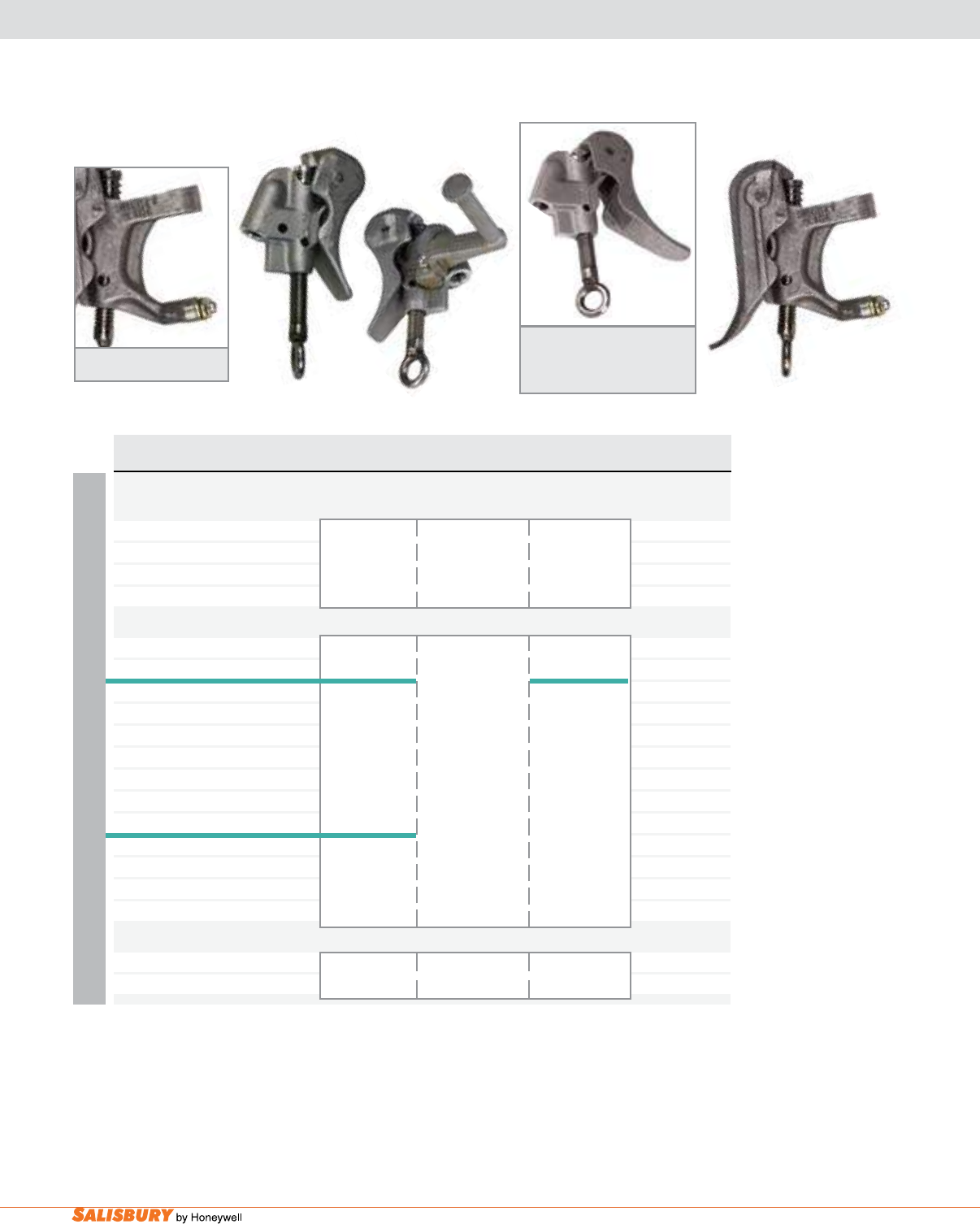
I-4 Safety Line Grounding Equipment. www.salisburybyhoneywell.com
ALUMINUM
Cat. No. Eye & Clamp ASTM Grade / Main Line Continuous Weight ea.
Description Class Range Current Rating lbs. ( kgs )
1.13” SMOOTH JAW ALUMINUM DUCK BILL CLAMPS - Threaded - w/o strain relief system
767E Eye, Stainless Steel 3 / A 795 KCM ACSR 1.4 ( 0.63 )
to #6 300 RMS Amps
768E Eye, Stainless Steel Smooth Jaw .19” - 1.13” 60Hz 1.4 ( 0.63 )
Open Clamp 4.8mm - 28.7mm
1.63” SMOOTH JAW ALUMINUM DUCK BILL CLAMPS - Threaded
767PSE Eye, Stainless Steel 3 / A 300 RMS Amps 1.6 ( 0.73 )
w/ AL Parking Stand Smooth Jaw 60Hz
760006E Eye, Stainless Steel 3.0 ( 1.36 )
5 / A 954 KCM ACSR
760SR6E Eye, Stainless Steel to #6 400 RMS Amps 2.2 ( 1.00 )
w/ strain relief system Smooth Jaw
760SR6PSE Eye, Stainless Steel .19” - 1.63” 60Hz 1.6 ( 0.73 )
w/ AL parking stand & 4.8mm - 41mm
w/ strain relief system
7600S6E Eye, Stainless Steel 3.0 ( 1.36 )
5 / B
760SRS6E Eye, Stainless Steel Serrated 2.2 ( 1.00 )
w/ strain relief system
1.63” SMOOTH JAW ALUMINUM DUCK BILL CLAMPS - Pin - w/o strain relief system
761E Eye, Stainless Steel 3 / A 954 KCM ACSR to #6 300 RMS Amps 1.4 ( 0.63 )
w/ AL Parking Stand Smooth .19” - 1.63” 4.8mm - 41mm 60Hz
767E 767PSE
768E
760SRS6E
DUCK BILL GROUNDING CLAMPS
1.13”, AND 1.63” SIZES
Additional screw options available. See page 3 or contact your local Salisbury Representative for more information.
Strain Relief System
Open Duck Bill Clamp: Includes
springs that keep jaw open for
easy application.
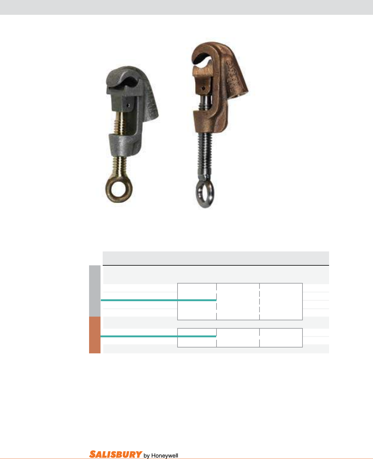
I-5
101 E. Crossroads Pkwy., Ste. A Bolingbrook, IL 60440 toll free ph (USA):877.406.4501 toll free fax (USA):866.824.4922 ph:630.343.3800
“C” TYPE GROUNDING CLAMPS
.75” SIZES
ALUMINUM
Cat. No. Eye & Clamp ASTM Grade / Main Line Continuous Weight ea.
Description Class Range Current Rating lbs. ( kgs )
0.75” ALUMINUM “C” CLAMP - Threaded - w/o strain relief system
7640001E Eye, Stainless Steel 5 / A 2 q KCM ACSR 1.0 ( 0.45 )
7640001EB Eye, Bronze Smooth Jaw to #6 400 RMS Amps 1.0 ( 0.45 )
76400S1E Eye, Stainless Steel 5 / B .19” - .75” 60Hz 1.0 ( 0.45 )
76400S1EB Eye, Bronze Serrated Jaw 4.8mm - 19mm 1.0 ( 0.45 )
0.75” BRONZE “C” CLAMP - Threaded - w/o strain relief system
7640CM1E Eye, Stainless Steel 5 / A Smooth Jaw 2 q KCM ACSR to #6 400 RMS Amps 3.0 ( 1.40 )
7640CMS1E Eye, Stainless Steel 5 / B Smooth Jaw .19” - .75” 4.8mm - 19mm 60Hz 3.0 ( 1.40 )
7640001EB 7640CMS1E
BRONZE
Additional screw options available. See page 3 or contact your local Salisbury Representative for more information.
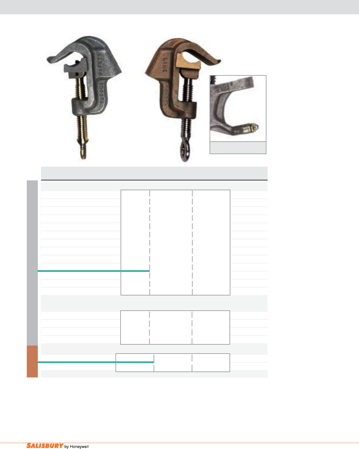
I-6 Safety Line Grounding Equipment. www.salisburybyhoneywell.com
760001E 760CM1E
ALUMINUM
Cat. No. Eye & Clamp ASTM Grade / Main Line Continuous Weight ea.
Description Class Range Current Rating lbs. ( kgs )
1.25” ALUMINUM “C” CLAMPS - Threaded - w/o strain relief system
760001E Eye, Stainless Steel 1.0 ( 0.45 )
760001EB Eye, Bronze 1.0 ( 0.45 )
760001RT Removable T 1.0 ( 0.45 )
Stainless Steel 5 / A 900 KCM ACSR
760001T T-Handle Smooth Jaw to #6 1.0 ( 0.45 )
Stainless Steel 400 RMS Amps
760001PSE Eye, Stainless Steel .19” - 1.25” 60Hz 1.3 ( 0.59 )
w/ Parking Stand 4.8mm - 31.8mm
760001CS Eye, Stainless Steel 1.3 ( 0.59 )
w/ steel parking stand
7600S1PSE Eye, Stainless Steel 5 / B 1.3 ( 0.59 )
w/ Parking Stand Serrated Jaw
7600S1EB Eye, Bronze 1.0 ( 0.45 )
1.5” ALUMINUM “C” CLAMPS - Threaded
760SR1EB Eye, Bronze 1035.5 KCM ACSR 1.6 ( 0.75 )
w/ strain relief system 5 / A to #6 400 RMS Amps
760SRS1E Eye, Stainless Steel Smooth Jaw .19” - 1.5” 60Hz 5.0 ( 2.27 )
w/ strain relief system 4.8mm - 38mm
1.25” BRONZE “C” CLAMPS - Threaded - w/o strain relief system
760CM1E Eye, Stainless Steel 5 / A Smooth Jaw 900 KCM ACSR to #6 400 RMS Amps 3.3 ( 1.50 )
760MS1E Eye, Stainless Steel 5 / B Serrated Jaw .19” - 1.25” 4.8-31.8mm 60Hz 3.3 ( 1.50 )
BRONZE
“C” TYPE GROUNDING CLAMPS
1.25” AND 1.5” SIZES
Additional screw options available. See page 3 or contact your local Salisbury Representative for more information.
Strain Relief System
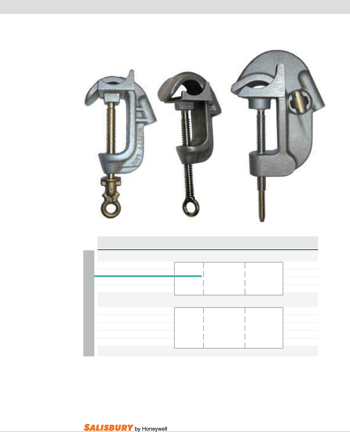
I-7
101 E. Crossroads Pkwy., Ste. A Bolingbrook, IL 60440 toll free ph (USA):877.406.4501 toll free fax (USA):866.824.4922 ph:630.343.3800
“C” TYPE GROUNDING CLAMPS
2.13” - 2.5” SIZE
ALUMINUM
Cat. No. Eye & Clamp ASTM Grade / Main Line Continuous Weight ea.
Description Class Range Current Rating lbs. ( kgs )
2.13” ALUMINUM “C” CLAMP - Threaded - w/o strain relief system
7660001E Eye, Stainless Steel 5 / A 3000 KCM ACSR 2.0 ( 0.91 )
Smooth Jaw to #6 400 RMS Amps
76600S1E Eye, Stainless Steel 5 / B 0.25” - 2.13” 60Hz 2.0 ( 0.91 )
76600S1PG Posigrip, Stainless Steel Serrated Jaw 6.4mm - 54mm 2.0 ( 0.91 )
2.5” ALUMINUM “C” CLAMP - Threaded - w/o strain relief system
7512B Bayonet, 2.0” I.P.S. 4.0 ( 1.82 )
Stainless Steel 5 / A to #6 400 RMS Amps
7512Q Quick Change, Smooth Jaw 60Hz 4.0 ( 1.82 )
Stainless Steel 0.5” - 2.5”
7512E Eye, Stainless Steel 12.7mm - 63.5mm 4.0 ( 1.82 )
7660001E
7512B
7660001PG
Additional screw options available. See page 3 or contact your local Salisbury Representative for more information.
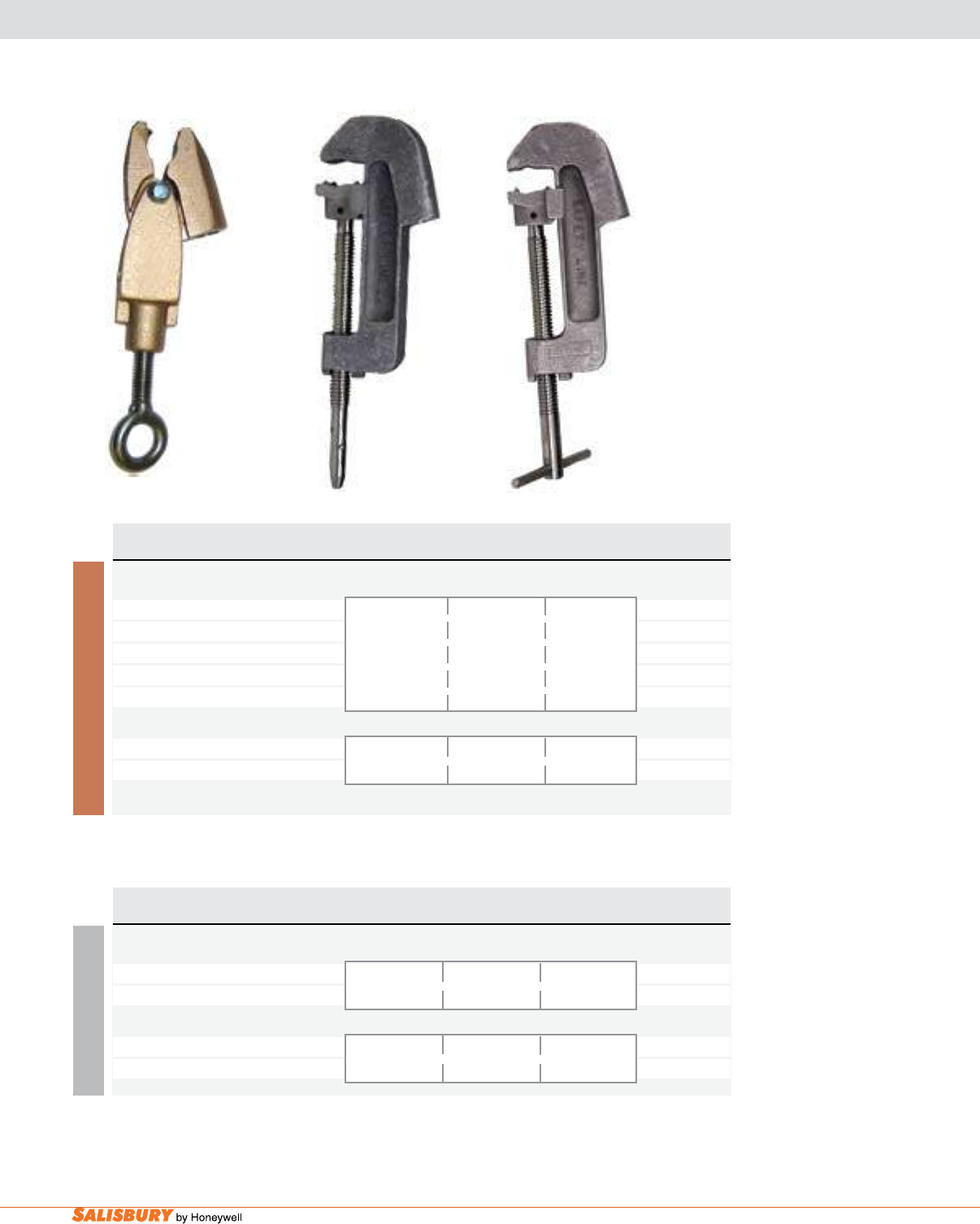
I-8 Safety Line Grounding Equipment. www.salisburybyhoneywell.com
Cat. No. Eye & Clamp ASTM Grade / Main Line Continuous Weight ea.
Description Class Range Current Rating lbs. ( kgs )
0.5” BRONZE BUS BAR ALLIGATOR CLAMPS - Threaded - w/o strain relief system
7575FE Eye, Stainless Steel 2.0 ( 0.91 )
7575FEST Eye-T, Stainless Steel 2.0 ( 0.91 )
7575FGA Grip-All, Stainless Steel 2 / A 0.234” - 0.5” 250 RMS Amps 2.0 ( 0.91 )
7575FPSE Eye, Stainless Steel Smooth Jaw 6mm - 12.7mm 60 Hz 2.0 ( 0.91 )
w/ Parking Stand
0.5” BRONZE BUS BAR ALLIGATOR CLAMPS with TEETH - Threaded - w/o strain relief system
7575FTE Eye, Stainless Steel 2 / B 250 RMS Amps 2.0 ( 0.91 )
7575FTGA Grip-All, Stainless Steel Serrated Jaw 0.234”-0.5” 6-12.7mm 60 Hz 2.0 ( 0.91 )
BUS BAR AND BUS BAR ALLIGATOR CLAMPS
Cat. No. Eye & Clamp ASTM Grade / Main Line Continuous Weight ea.
Description Class Range Current Rating lbs. ( kgs )
4.4” ALUMINUM BUS BAR CLAMPS - Threaded - w/o strain relief system
7541E Eye, Stainless Steel 5 / B 0.31” - 4.25” 400 RMS Amps 2.0 ( 0.91 )
7541T T-Handle, Stainless Steel Serrated Jaw 7.9mm - 112mm 60Hz 2.0 ( 0.91 )
4.4” ALUMINUM BUS BAR CLAMPS - Pin - w/o strain relief system
7542B Bayonet, Stainless Steel 5 / B 0.31” - 4.25” 400 RMS Amps 2.0 ( 0.91 )
Serrated Jaw 7.9mm - 112mm 60Hz
7575FTE
7542B
ALUMINUM BRONZE
7541T
Additional screw options available. See page 3 or contact your local Salisbury Representative for more information.
Additional screw options available. See page 3 or contact your local Salisbury Representative for more information.

I-9
101 E. Crossroads Pkwy., Ste. A Bolingbrook, IL 60440 toll free ph (USA):877.406.4501 toll free fax (USA):866.824.4922 ph:630.343.3800
ALUMINUM
Cat. No. Eye & Clamp ASTM Grade / Main Line Continuous Weight ea.
Description Class Range Current Rating lbs. ( kgs )
4.5” ALUMINUM SUBSTATION BUS CLAMPS - Threaded - w/o strain relief system
7311E Eye, Stainless Steel 5 / A 0.5” - 4.5” 400 RMS Amps 4.0 ( 1.82 )
Smooth Jaw 12.7mm - 114mm 60Hz
6” ALUMINUM SUBSTATION BUS CLAMPS - Threaded - w/o strain relief system
R101DE Eye, Stainless Steel 5 / B 1 q I.P.S. 400 RMS Amps 4.0 ( 1.82 )
Serrated Jaw 0.5” - 6” 60Hz
12.7mm - 152mm
7” ALUMINUM SUBSTATION BUS CLAMPS - Threaded - w/o strain relief system
73065E Eye, Stainless Steel 5 / B 0.4” - 7” 400 RMS Amps 6.7 ( 3.00 )
Smooth Jaw 10.2mm - 178mm 60Hz
4.5” ALUMINUM SUBSTATION BUS CLAMPS - Pin - w/o strain relief system
7310E Eye, Stainless Steel 5 / A Smooth Jaw 1/2” I.P.S. 400 RMS Amps 4.0 ( 1.82 )
0.5”-4.5” 12.7-114mm 60Hz
LARGE SUBSTATION BUS CLAMPS
7310E
R101DE
73065E
Additional screw options available. See page 3 or contact your local Salisbury Representative for more information.
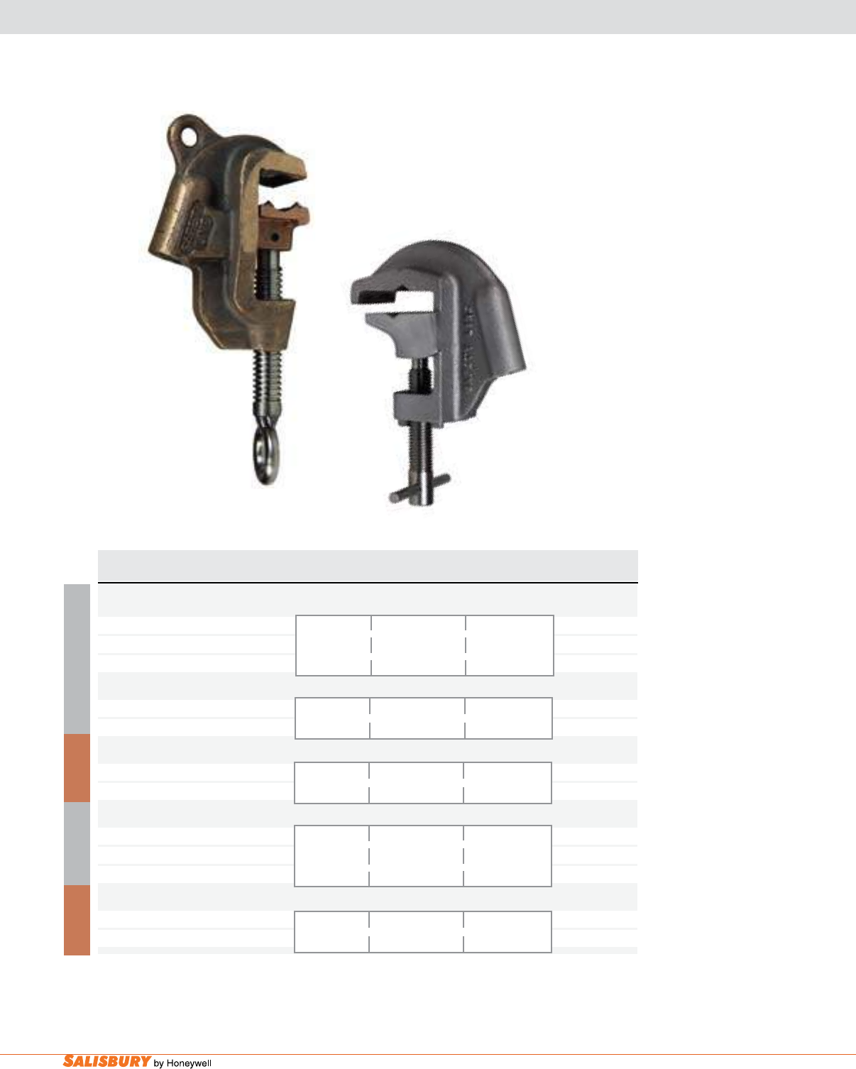
I-10 Safety Line Grounding Equipment. www.salisburybyhoneywell.com
ALUMINUM
Cat. No. Eye & Clamp ASTM Grade / Main Line Continuous Weight ea.
Description Class Range Current Rating lbs. ( kgs )
1.4” ALUMINUM FLAT FACE CLAMPS - Pin - w/o strain relief system
760002E Eye, Stainless Steel 5 / B 400 RMS Amps 1.0 ( 0.45 )
760002EB Eye, Bronze Serrated Jaw 0.19” - 1.4” 60Hz 1.0 ( 0.45 )
760002T T-Handle, Stainless Steel 4.8mm - 35.6mm 1.0 ( 0.45 )
1.4” ALUMINUM FLAT FACE CLAMPS - Threaded
760SR3E Eye, Stainless Steel 5 / B 0.19” - 1.4” 400 RMS Amps 1.5 ( 0.68 )
w/ strain relief system Serrated Jaw 4.8mm - 35.6mm 60Hz
1.4” BRONZE FLAT FACE CLAMPS - Threaded
760CMSR3E Eye, Stainless Steel 5 / B 0.19” - 1.4” 400 RMS Amps 4.5 ( 2.0 )
w/ strain relief system Serrated Jaw 4.8mm - 35.6mm 60Hz
1.5” ALUMINUM FLAT FACE CLAMPS - Threaded - w/o strain relief system
760003B Bayonet, Stainless Steel 5 / B 400 RMS Amps 1.2 ( 0.54 )
760003E Eye, Stainless Steel Serrated Jaw 0.19” - 1.5” 60Hz 1.2 ( 0.54 )
760003EB Eye, Stainless Steel 4.8mm - 38mm 1.2 ( 0.54 )
1.5” BRONZE FLAT FACE CLAMPS - Threaded - w/o strain relief system
760CM3T T-Handle, Stainless Steel 5 / B 0.19” - 1.5” 400 RMS Amps 3.2 ( 1.40 )
Serrated Jaw 4.8mm - 38mm 60Hz
GROUNDING CLAMPS FOR FLATS & ANGLES
BRONZE
760CM3E
ALUMINUM
BRONZE
73025T
Additional screw options available. See page 3 or contact your local Salisbury Representative for more information.
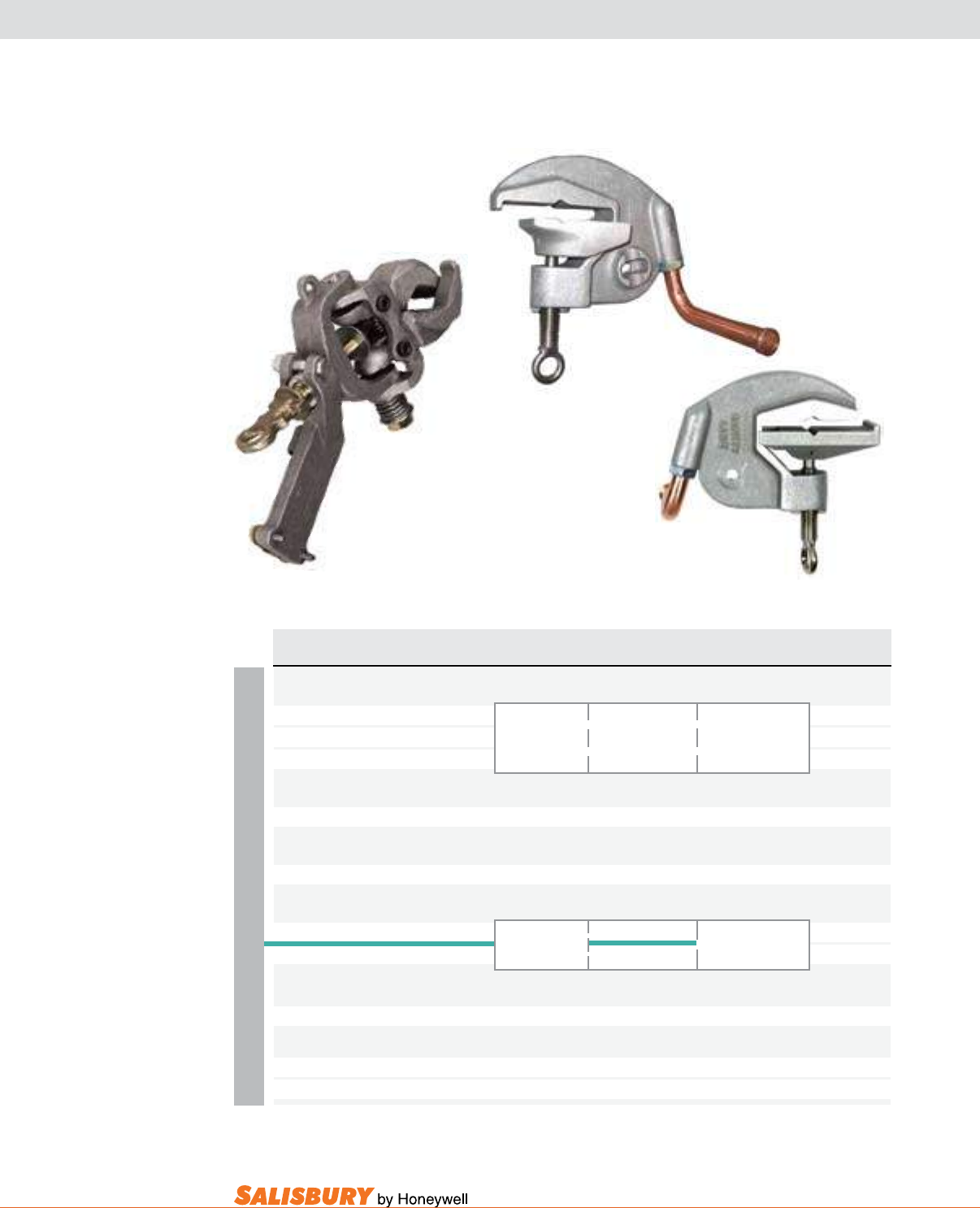
I-11
101 E. Crossroads Pkwy., Ste. A Bolingbrook, IL 60440 toll free ph (USA):877.406.4501 toll free fax (USA):866.824.4922 ph:630.343.3800
ALUMINUM
Cat. No. Eye & Clamp ASTM Grade / Main Line Continuous Weight ea.
Description Class Range Current Rating lbs. ( kgs )
2.5” ALUMINUM ALL ANGLE CLAMPS - Threaded - w/o strain relief system
7315E Eye, Stainless Steel 5 / B 2” I.P.S. to #4 400 RMS Amps 4.3 ( 2.00 )
7315B Bayonet, Stainless Steel Serrated Jaw 0.25” - 2.5” 60Hz 4.3 ( 2.00 )
7315PG Posigrip, Bronze 6.4mm - 57mm 4.3 ( 2.00 )
2.5” ALUMINUM TOWER ANGLE CLAMPS - Threaded - w/o strain relief system
73025T T-Handle, Stainless Steel 5 / A Smooth Jaw 0.3” - 1.6” 8-41mm 400 RMS Amps 60Hz 2.5 ( 1.14 )
4” ALUMINUM TOWER ANGLE CLAMPS - Threaded - w/o strain relief system
7304T T-Handle, Stainless Steel 5 / A Smooth Jaw 0.25” - 0.94” 6-24mm 400 RMS Amps 60Hz 3.3 ( 1.50 )
4” ALUMINUM TOWER ANGLE CLAMPS - Pin + Threaded - w/o strain relief system
7314T T-Handle, Stainless Steel 5 / A 0.25” - 0.94” 6-24mm 400 RMS Amps 3.3 ( 1.50 )
7320SB Bayonet, Stainless Steel Smooth Jaw 0.4” - 2.5” 10-64mm 60Hz 5.0 ( 2.27 )
4” ALUMINUM TOWER ANGLE CLAMP - Pin - with Spike Point, No Ground Lead
7320PGA Grip-All, Stainless Steel 5 / A Smooth Jaw 0.25” - 0.94” 6-24mm 400 RMS Amps 60Hz 3.3 ( 1.50 )
4” AL. TOWER ANGLE CLAMPS with Copper Parking Stand - Rated for 49kA for 15 cycles w/ X/R=25
7316E Eye, Stainless Steel Exceeds Grade 5 Smooth Jaw - Inside Angle Clamp 4” max. -
7304DE Eye, Stainless Steel Exceeds Grade 5 Smooth Jaw - Outside Angle Clamp 4” max. -
7315PG
7304DE
7316E
GROUNDING CLAMPS FOR FLATS & ANGLES
Additional screw options available. See page 3 or contact your local Salisbury Representative for more information.
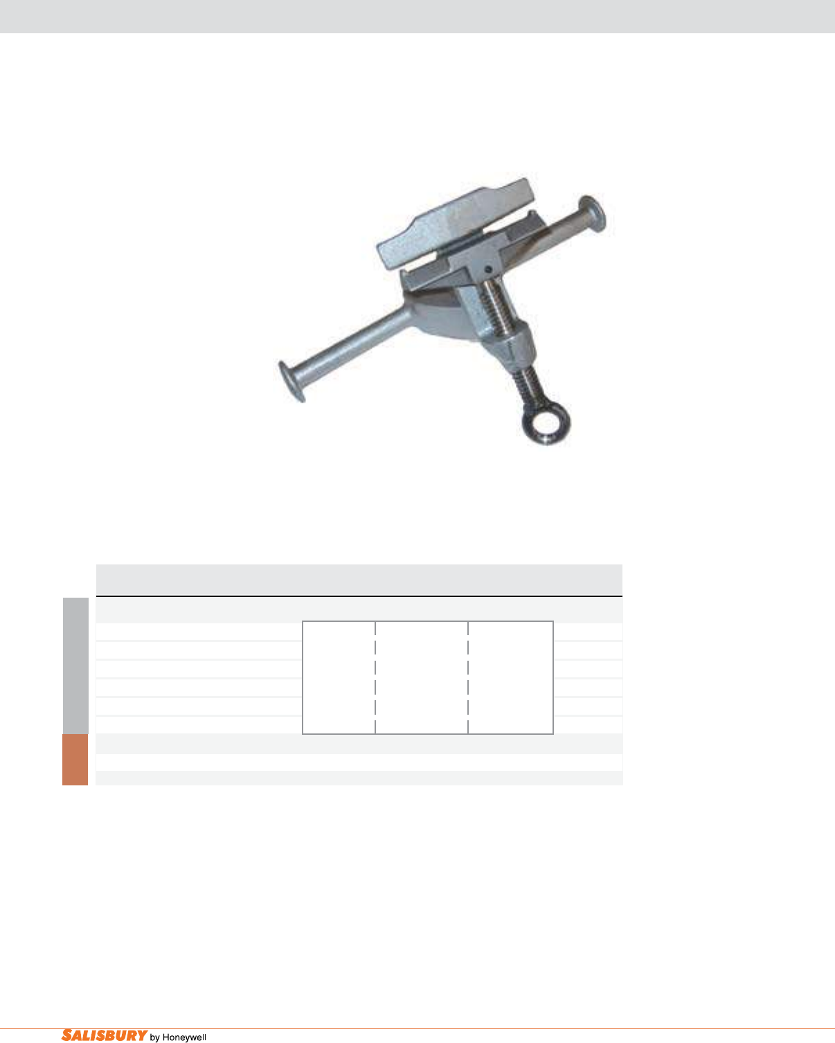
I-12 Safety Line Grounding Equipment. www.salisburybyhoneywell.com
CUTOUT CLAMPS
ALUMINUM
Cat. No. Eye & Clamp ASTM Grade / Main Line Continuous Weight ea.
Description Class Range Current Rating lbs. ( kgs )
1.63” ALUMINUM CUTOUT CLAMPS - Threaded - w/o strain relief sleeve
7640002E Eye, Stainless Steel 1.0 ( 0.45 )
7640002EB Eye, Bronze 1.0 ( 0.45 )
7640002PSE Eye, Stainless Steel 3 / A 0.188” - 1.63” 300 RMS Amps 1.2 ( 0.5 )
w/ Al. Dbl. Parking Stand Smooth Jaw 60Hz
7640002PSEB Eye, Bronze 1.2 ( 0.5 )
w/ Al. Dbl. Parking Stand
1.63” BRONZE CUTOUT CLAMPS - Threaded - w/o strain relief sleeve
7640CM2T T-Handle, Stainless Steel 3 / A Smooth Jaw 0.188” - 1.63” 300 RMS Amps 60Hz 2.0 ( 0.91 )
Cutout Clamps are applied with a
clampstick into the bottom hinge contact
of a cutout. This clamp can be used as
part of a ground assembly or by using a
contact stud using a standard grounding
assembly with “C” clamps from the stud
to ground.
B R O N Z E
7640002PSE
Additional screw options available. See page 3 or contact your local Salisbury Representative for more information.
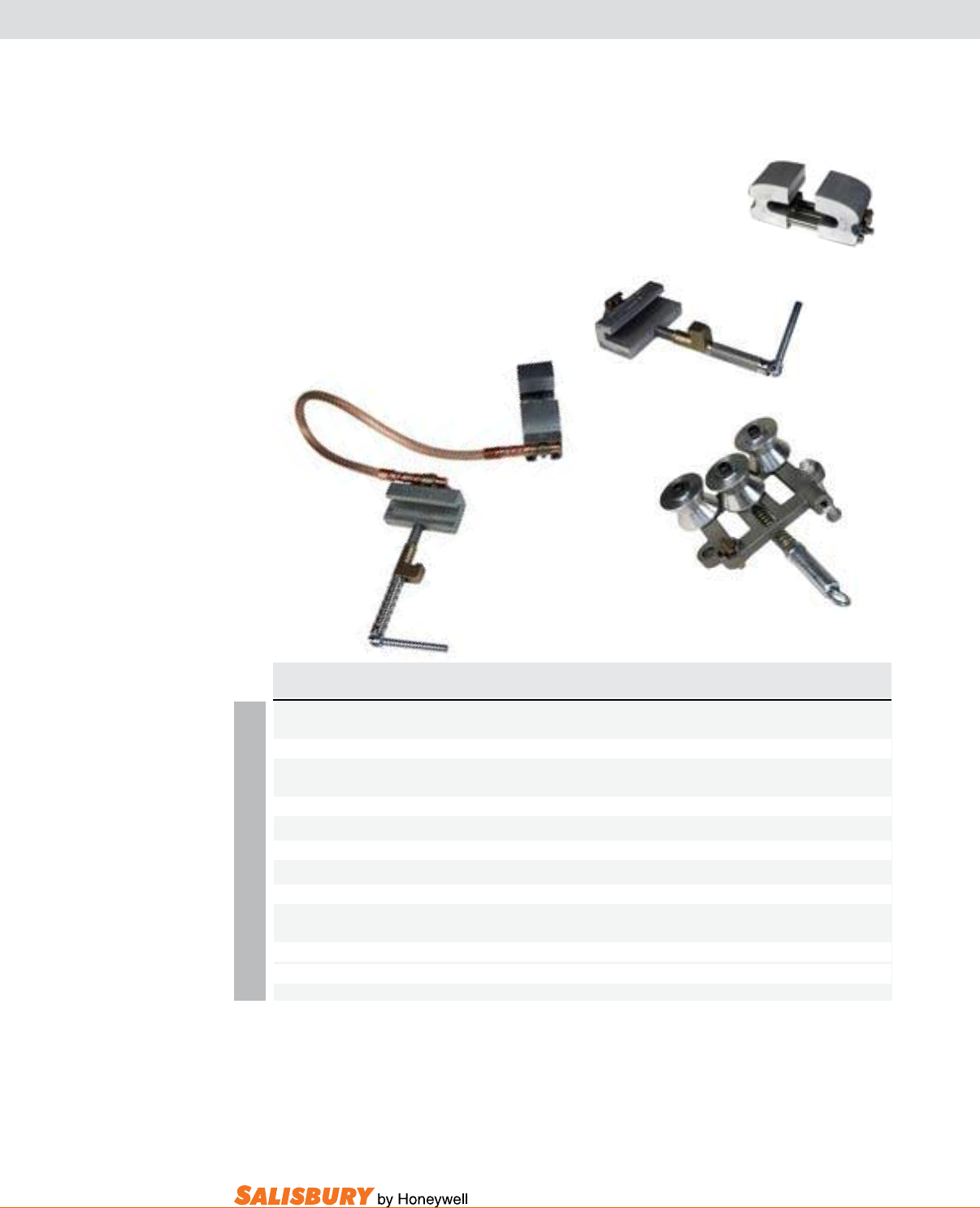
I-13
101 E. Crossroads Pkwy., Ste. A Bolingbrook, IL 60440 toll free ph (USA):877.406.4501 toll free fax (USA):866.824.4922 ph:630.343.3800
ALUMINUM
Cat. No. Eye & Clamp ASTM Grade / Main Line Continuous Weight ea.
Description Class Range Current Rating lbs. ( kgs )
5.75” ALUMINUM RUNNING RAIL CLAMP - Pin
7560 Toggle Handle, Stainless Steel 5 / B Smooth Jaw 5” - 5.75” 400 RMS Amps 60Hz 5.0 ( 2.27 )
4” ALUMINUM POWER RAIL CLAMP - Pin
7561A Bayonet, SS 5 / B Smooth Jaw 0” - 4” 400 RMS Amps 60Hz 7.0 ( 3.17 )
4” ALUMINUM POWER RAIL CLAMP - Threaded
7561B Bayonet, SS 5 / B Smooth Jaw 0” - 4” 400 RMS Amps 60Hz 7.0 ( 3.17 )
TRAVELING GROUND
7561 Running Power Rail Ground Set Grade 5 15 ( 6.80 )
1.63” ALUMINUM TRAVELING GROUND CLAMPS - Pin/Threaded
78000 Eye, Stainless Steel 3 / A Smooth Jaw 0.125” - 1.63” 300 RMS Amps 60Hz 10 ( 4.54 )
w/ Contact Stud
7560
7561A
7561
78000
Additional screw options available. See page 3 or contact your local Salisbury Representative for more information.
The Running Power Rail Ground
Set is made up of 7561A power rail
clamp and 7560 running rail clamp
connected with three feet (91.4 cm) of
4/0 PVC-jacketed copper cable. Set
includes one 10024BC, 1” x 24” (2.5 x
61 cm) berglass handle with bayonet
to operate the power rail clamp.
RUNNING RAIL CLAMPS
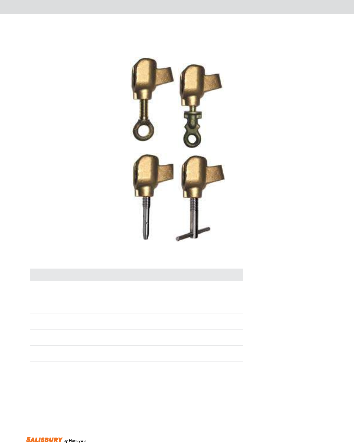
I-14 Safety Line Grounding Equipment. www.salisburybyhoneywell.com
BALL & SOCKET SYSTEM
SOCKET CLAMP
Cat. No. Description ASTM Continuous Current Weight ea.
Grade Rating lbs. ( kgs)
7542CM1B Smooth Jaw, Threaded 5 400 1.5 ( .68 )
w/ Bayonet, SS
7542CM1E Smooth Jaw, Threaded 5 400 1.5 ( .68 )
w/ Eye, SS
7542CM1PG Smooth Jaw, Threaded 5 400 1.5 ( .68 )
w/ Posigrip, BR
7542CM1T Smooth Jaw, Threaded 5 400 1.5 ( .68 )
w/ T-Handle, SS
7542CM2E Smooth Jaw, Pin 5 400 1.9 ( .86 )
w/ Eye, SS
The Ball and Socket
Grounding System has a
lightweight compact design
and allows for variable angle
accessibility. These clamps
are made from bronze alloy
and have a socket size of 1”
(25.4mm) with a threaded
bore boss of 5/8”-11 UNC.
There are fixed grounding
points on the socket clamp.
See page J-3 for ball socket
studs and accessories
available.
7542CM1EB
7542CM1B
7542CM1T
7542CM1PG
Additional screw options available. See page 3 or contact your local Salisbury Representative for more information.
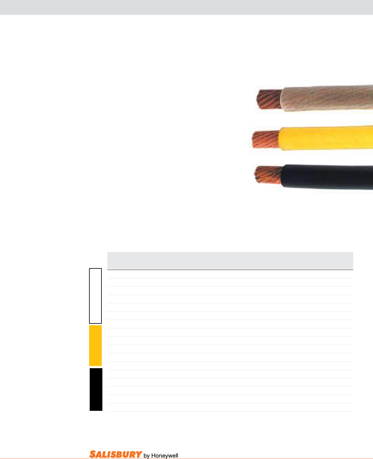
I-15
101 E. Crossroads Pkwy., Ste. A Bolingbrook, IL 60440 toll free ph (USA):877.406.4501 toll free fax (USA):866.824.4922 ph:630.343.3800
Grounding Cables are made with extra exible strand of
soft drawn #30 AWG (.01”) copper and are available in three
different jackets.
The transparent exible thermoplastic (PVC) jacketed cable
allows easy inspection for strand breakage. The exibility
decreases with low temperatures. The service temperature
ranges from 140º to -40ºF per ASTM F 855, Type III
requirements.
The yellow thermoplastic elastomer jacketed cable is the
standard for grounding service. It provides a combination of
economy, exibility, and durability. The service temperature
ranges from 200º to -50ºF per ASTM F 855, Type I
requirements.
The black thermoplastic elastomer jacketed cable has a smaller
diameter and thinner jacket material giving it better exibility
than the yellow cable. The service temperature ranges from
200º to -50ºF per ASTM F 855, Type I requirements.
GROUNDING CABLES FOR SAFETY LINE SETS
Cat. No. Conductor Conductor Jacket ASTM F855 Fault Duty Wt. / ft.
Size Typ. O.D. Typ. O.D. Grade 15 Cycles lbs. ( kgs )
73310XF #10 .11” .25” n/a n/a 0.06 ( 0.09 )
7336XF #6 .21” .37” n/a 3.5 0.13 ( 0.19 )
7340XF #2 .33” .50” 1 14.0 0.29 ( 0.43 )
7341XF 1/0 .45” .64” 2 21.0 0.52 ( 0.77 )
7342XF 2/0 .47” .66” 3 27.0 0.54 ( 0.80 )
7343XF 4/0 .63” .84” 5 43.0 0.84 ( 1.25 )
7340XFY #2 .33” .50” 1 14.0 0.29 ( 0.43 )
7341XFY 1/0 .45” .64” 2 21.0 0.52 ( 0.77 )
7342XFY 2/0 .47” .66” 3 27.0 0.54 ( 0.80 )
7343XFY 4/0 .63” .84” 5 43.0 0.84 ( 1.25 )
7340XFB #2 .33” .50” 1 14.0 0.29 ( 0.43 )
7341XFB 1/0 .45” .64” 2 21.0 0.52 ( 0.77 )
7342XFB 2/0 .47” .66” 3 27.0 0.54 ( 0.80 )
7333XFB 3/0 .55” .72” 4 36.0 0.68 ( 0.30 )
7343XFB 4/0 .62” .78” 5 43.0 0.77 ( 0.35 )
Y E L L O W C L E A R P V C
B L A C K
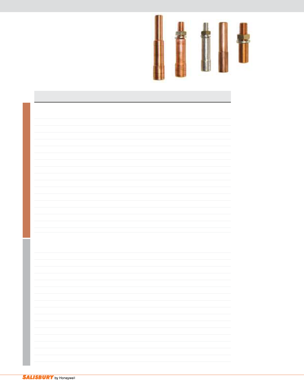
I-16 Safety Line Grounding Equipment. www.salisburybyhoneywell.com
THREADED & PIN FERRULES FOR SAFETY LINE SETS
For Threaded Ferrules (Terminals) the recommended
torque applied during installation of jam nut for threaded
ferrules is 20 ft.-lb. These threaded ferrules include one
brass jam nut and one lock washer. For Pin Terminals
the recommended torque applied during installation of pin
ferrule eye bolts is 28 ft.-lb.
Cat. No. Conductor Style Stud Body Die Shroud Die Length
Size Size Codes Codes Stripped inches
SHROUDED
760001CT40* #2 Threaded 5/8-11 U27RT U27ART 1-5/8
7600011CT41* 1/0 Threaded 5/8-11 T&B 66 B75-AH 1-15/16
7600011CT42* 2/0 Threaded 5/8-11 T&B 66 B75-AH 2
76CT43* 4/0 Threaded 5/8-11 T&B 66 B75-AH 2
760001PT40* #2 Pin 11/16 U27RT U27ART 1-5/8
7600011PT41* 1/0 Pin 11/16 T&B 66 B75-AH 1-15/16
7600011PT42* 2/0 Pin 11/16 T&B 66 B75-AH 2
76PT43* 4/0 Pin 11/16 T&B 66 B75-AH 2
UNSHROUDED
98132022* #2 Threaded 5/8-11 U243 - 1-5/16
98132023* 1/0 Threaded 5/8-11 U243 - 1-5/16
98132024* 2/0 Threaded 5/8-11 T&B 60 - 1-5/16
98132025* 4/0 Threaded 5/8-11 T&B 62 - 1-5/16
98132022P* #2 Pin 11/16 U243 - 1-5/16
98132023P* 1/0 Pin 11/16 U243 - 1-5/16
98132024P* 2/0 Pin 11/16 T&B 60 - 1-5/16
98132025P* 4/0 Pin 11/16 T&B 62 - 1-5/16
SHROUDED
760001AT40* #2 Threaded 5/8-11 U27RT U27ART 1-5/8
7600011AT41* 1/0 Threaded 5/8-11 T&B 66 B75-AH 1-15/16
7600011AT42* 2/0 Threaded 5/8-11 T&B 66 B75-AH 2
76AT43* 4/0 Threaded 5/8-11 T&B 66 B75-AH 2
760001PA40* #2 Pin 11/16 U27RT U27ART 1-5/8
7600011PA41* 1/0 Pin 11/16 T&B 66 B75-AH 1-15/16
7600011PA42* 2/0 Pin 11/16 T&B 66 B75-AH 2
76PA43* 4/0 Pin 11/16 T&B 66 B75-AH 2
UNSHROUDED
98132A22* #2 Threaded 5/8-11 U243 - 1-5/16
98132A23* 1/0 Threaded 5/8-11 U243 - 1-5/16
98132A24* 2/0 Threaded 5/8-11 T&B 60 - 1-5/16
98132A25* 4/0 Threaded 5/8-11 T&B 62 - 1-5/16
98132A22P* #2 Pin 11/16 U243 - 1-5/16
98132A23P* 1/0 Pin 11/16 U243 - 1-5/16
98132A24P* 2/0 Pin 11/16 T&B 60 - 1-5/16
98132A25P* 4/0 Pin 11/16 T&B 62 - 1-5/16
ALUMINUM COPPER
Add suffix “T” to the catalog number when requesting tin-plated copper.
7600011CT42 7600011PT42
7600011CT41T 9813023P
9813023
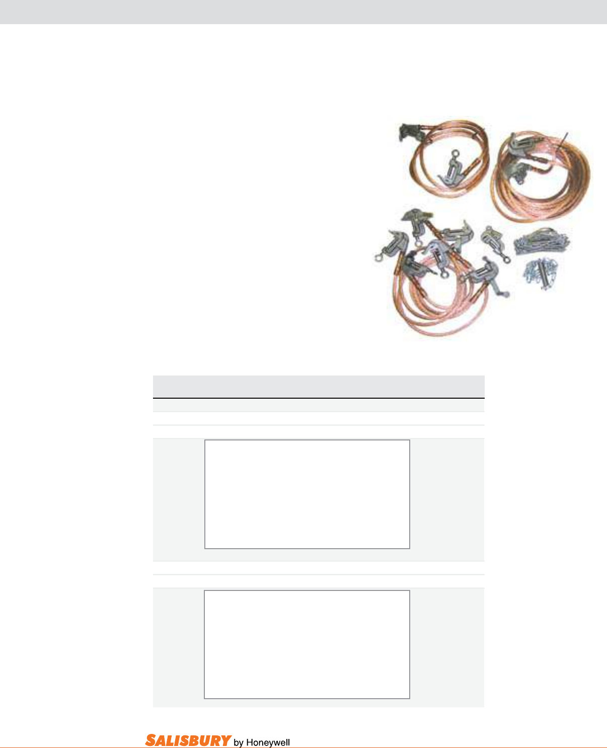
I-17
101 E. Crossroads Pkwy., Ste. A Bolingbrook, IL 60440 toll free ph (USA):877.406.4501 toll free fax (USA):866.824.4922 ph:630.343.3800
GROUNDING SETS
SINGLE POINT DISTRIBUTION GROUNDING SET
Sets for Grounded “Y” Systems provide all the
equipment required to safely ground a variety of
structures on a grounded “Y” distribution systems.
Factory assembled kits are for conductors ranging
from #6 to 1-1/2” (3.8 cm) diameter, with serrated
jaw “C” clamps with threaded terminals. All
clamps are supplied with eye screws for installation
with clampstick (not included). Other lengths and
congurations are available.
Standard Equipotential Grounding Sets provide
all the equipment required to safely ground a variety
of structures on delta distribution systems. Factory
assembled kits are for conductors ranging from #6
to 1-1/2” (3.8 cm) diameter, with smooth or serrated
jaw clamps with threaded terminals. All clamps are
supplied with eye screws for installation with grip-
all clampsticks (not included). Other lengths and
congurations are available.
Cat. No. Cable Fault Duty ASTM Weight ea.
Size 15 Cycles Grade lbs. ( kgs )
GROUNDED “Y” SYSTEMS
763S011 2/0 27 kA 3 69 ( 31.3 )
763S45 4/0 43kA 5 110 ( 49.9 )
Complete Grounded “Y” Set Includes
3 - 6’ (1.83 m) Line Jumpers
1 - 12’ (3.66 m) Line to Ground Jumper
1 - 60’ (18.3 m) Ground Lead
1 - Pole Band
1 - Pole Band Extension
1 - Flat Face Clamp (760003E)
1 - Protective Bag
EQUIPOTENTIAL DELTA
7600011 2/0 27 kA 3 62 ( 28.1 )
760045 4/0 43 kA 5 100 ( 45.4 )
Complete Delta Set Includes
2 - 6’ (1.83 m) Line Jumpers
1 - 12’ (3.66 m) Line to Ground Jumper
1 - 60’ (18.3 m) Ground Lead
1 - Pole Band
1 - Pole Band Extension
1 - Flat Face Clamp (760003E)
1 - Protective Bag
Optional ground set label available upon request when ordering.
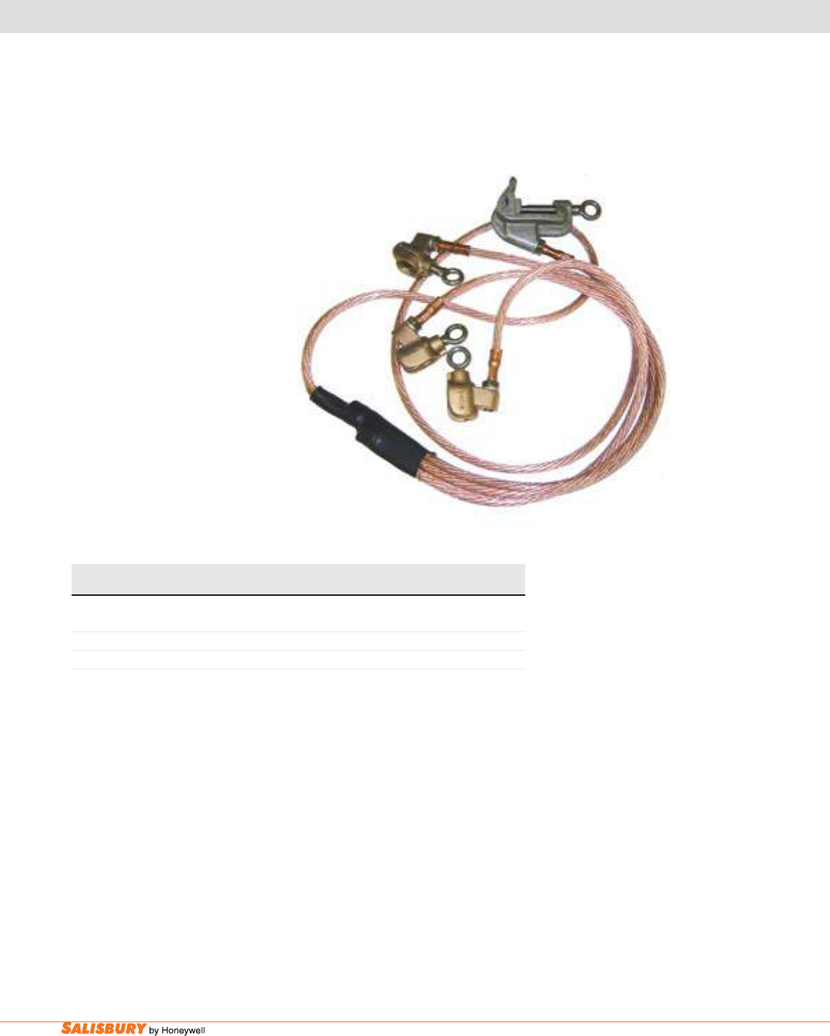
I-18 Safety Line Grounding Equipment. www.salisburybyhoneywell.com
GROUNDING SETS
BALL SOCKET 4-WAY CONNECTER SETS
Ball Socket 4-Way Connecter Sets are
designed for variable angle accessibility,
three-phase grounding. It is supplied with
three-foot leads and six feet of cable from
a common connection to ground. Upper
heads are ball socket clamps (7542CM1E).
Lower ground head is standard “C” type
ground head (760001E) with a range of #6
to 1-1/4” (32 mm). Ball studs needed but
not included.
Cat. No. Cable Fault Duty ASTM Weight ea.
Size 15 Cycles Grade lbs. ( kgs )
75420010236 #2 14.5 kA 1 9 ( 4.08 )
75420011036 1/0 21 kA 2 12 ( 5.44 )
75420012036 2/0 27 kA 3 14 ( 6.35 )
Optional ground set label available upon request when ordering.
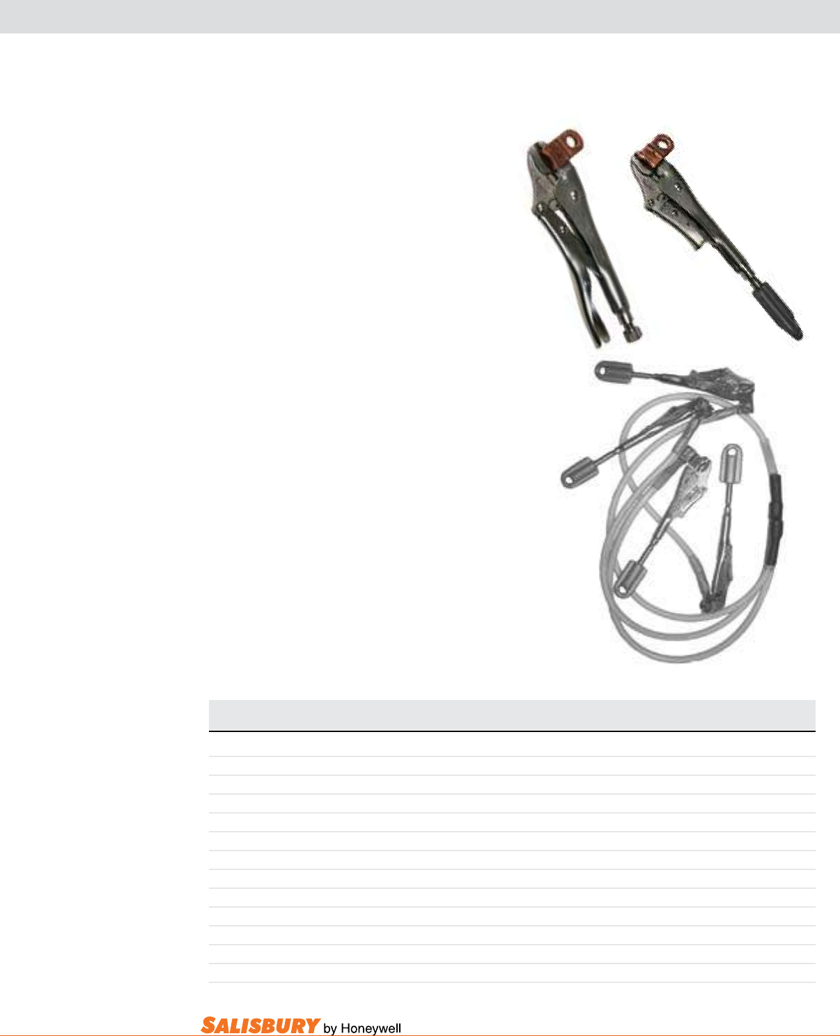
I-19
101 E. Crossroads Pkwy., Ste. A Bolingbrook, IL 60440 toll free ph (USA):877.406.4501 toll free fax (USA):866.824.4922 ph:630.343.3800
GROUNDING SETS
QUICK GRIP GROUND CLAMPS & GROUNDING SETS
Quick Grip Clamps are specically designed
and ideally suited for temporary grounding where
spacing and orientation of components limit the
use of traditional ground clamps. The Quick Grip
Ground Clamp is available with a Grip-All eye
or a Bayonet tting for installation with a live
line tool.
Cat. No. Cat. No. Description Cable Length ASTM Weight
Standard Flat Jaw ft. ( m ) Grade lbs. ( kgs )
QUICK GRIP GROUND CLAMPS & GROUNDING SETS, Clamp Opening: Min. 0.125” - Max. 1.5”
VG01 VGF01 Locking Pliers, Cu Overlay N/A 3 1.5 ( 0.68 )
VG01B VGF01B Locking Pliers, Cu Overlay. Bayonet N/A 3 1.6 ( 0.73 )
VG01GA VGF01GA Locking Pliers, Cu Overlay. Grip-All N/A 3 1.6 ( 0.73 )
VG01013 VGF01013 Single Lead, 1/0 x 3’ with VG01 3 ( 0.914 ) 3 3.6 ( 1.63 )
VG01033 VGF01033 Grounding Set, 3 Leads, 1/0 x 3’ with VG01 9 ( 2.743 ) 3 10.5 ( 4.77 )
VG01034 VGF01034 Grounding Set, 4 Leads, 1/0 x 3’ with VG01 12 ( 3.657 ) 3 13.2 ( 5.99 )
VG11013 VGF11013 Single Lead, 1/0 x 3’ with VG01GA 3 ( 0.914 ) 3 3.7 ( 1.68 )
VG11013B VGF11013B Single Lead, 1/0 x 3’ with VG01GB 3 ( 0.914 ) 3 3.7 ( 1.68 )
VG11033 VGF11033 Grounding Set, 3 Leads, 1/0 x 3’ with VG01GA 9 ( 2.743 ) 3 10.8 ( 4.9 )
VG11033B VGF11033B Grounding Set, 3 Leads, 1/0 x 3’ with VG01GB 9 ( 2.743 ) 3 10.8 ( 4.9 )
VG11034 VGF11034 Grounding Set, 4 Leads, 1/0 x 3’ with VG01GA 12 ( 3.657 ) 3 13.6 ( 6.17 )
VG11034B VGF11034B Grounding Set, 4 Leads, 1/0 x 3’ with VG01GA 12 ( 3.657 ) 3 13.6 ( 6.17 )
• Available in both the traditional style (VG0l) and a hot
stick operated version (VG01GA and VG01B).
• Available in a single lead ground jumper or
grounding set with 1, 3 or 4 leads for grounding of
single or three-phase secondary terminals.
• Fitted with a copper overlay, riveted to the stationary
jaw, connected to a grounding jumper with one hole
NEMA connector to assure a low resistance connection.
• The grounding set connection is made using standard
copper compression connectors and all connections are
covered with a heat-shrink tube to reduce fatigue at stress points.
• The locking jaw pliers are equally suited for at or
rounded terminals.
Optional at jaw available.
VG11034
VG01 VG01GA
Optional ground set label available upon request when ordering.
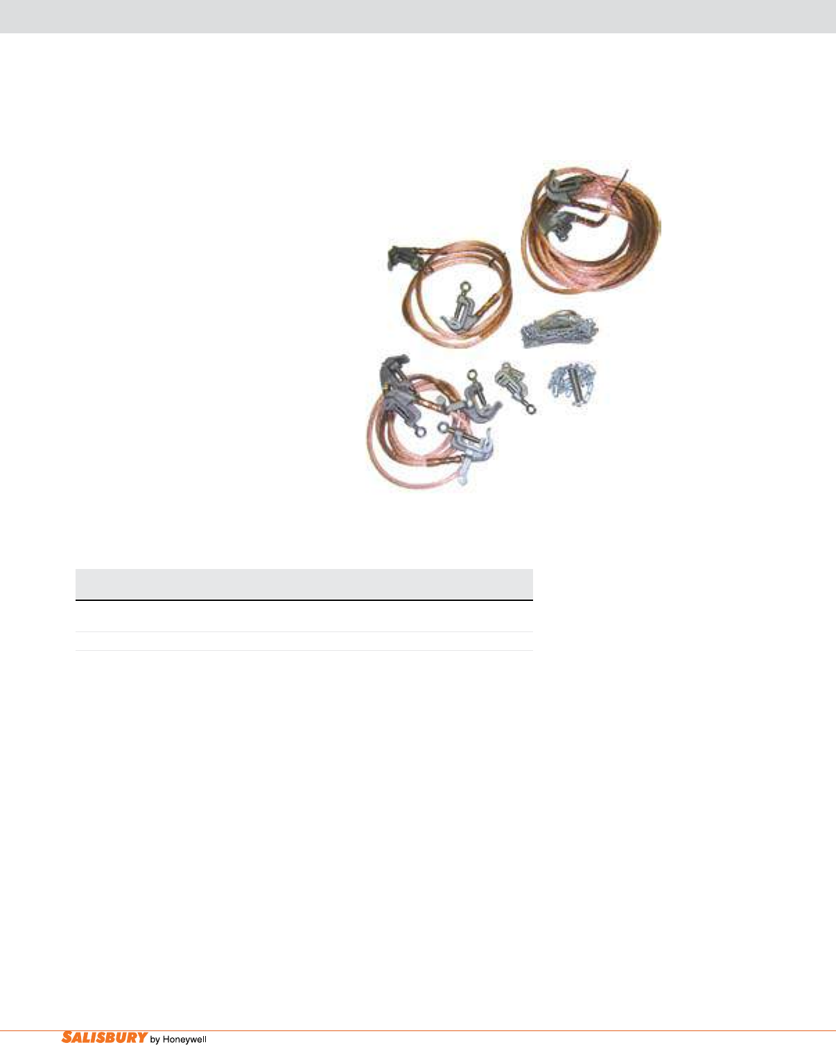
I-20 Safety Line Grounding Equipment. www.salisburybyhoneywell.com
GROUNDING SETS
4 WAY CONNECTOR SET
Cat. No. Description Max. Opening ASTM Weight ea.
in. ( cm ) Grade lbs. ( kgs )
752076 4-Way Connector Set w/ “C” Type Clamps, Bayonet 1 1/4 ( 3.2 ) 1 32 ( 14.5 )
752576 4-Way Connector Set w/ “C” Type Clamps, Eye 1 1/4 ( 3.2 ) 1 39 ( 17.9 )
The 4-Way Connecter Sets are made with
#2 clear-jacketed, extra exible cable, three
8-foot (2.44 m) leads from the heads to the
common connection, and one 50-foot (15.25
m) lead from the common connection to the
ground connection. The grounding 4-way
connector set has a xture to raise and lower
the set which can be easily tied onto the pole.
The 752076 grounding 4-way connector set
is also supplied with 3 berglass handles
(10078BC) and bag. The 752576 grounding
4-way connector set requires a clampstick.
Sets come with bags. Other lengths and
congurations available. Meets ASTM F 855
Grade 1 specications. Maximum fault duty
is 14.5 kA for 15 cycles.
Optional ground set label available upon request when ordering.
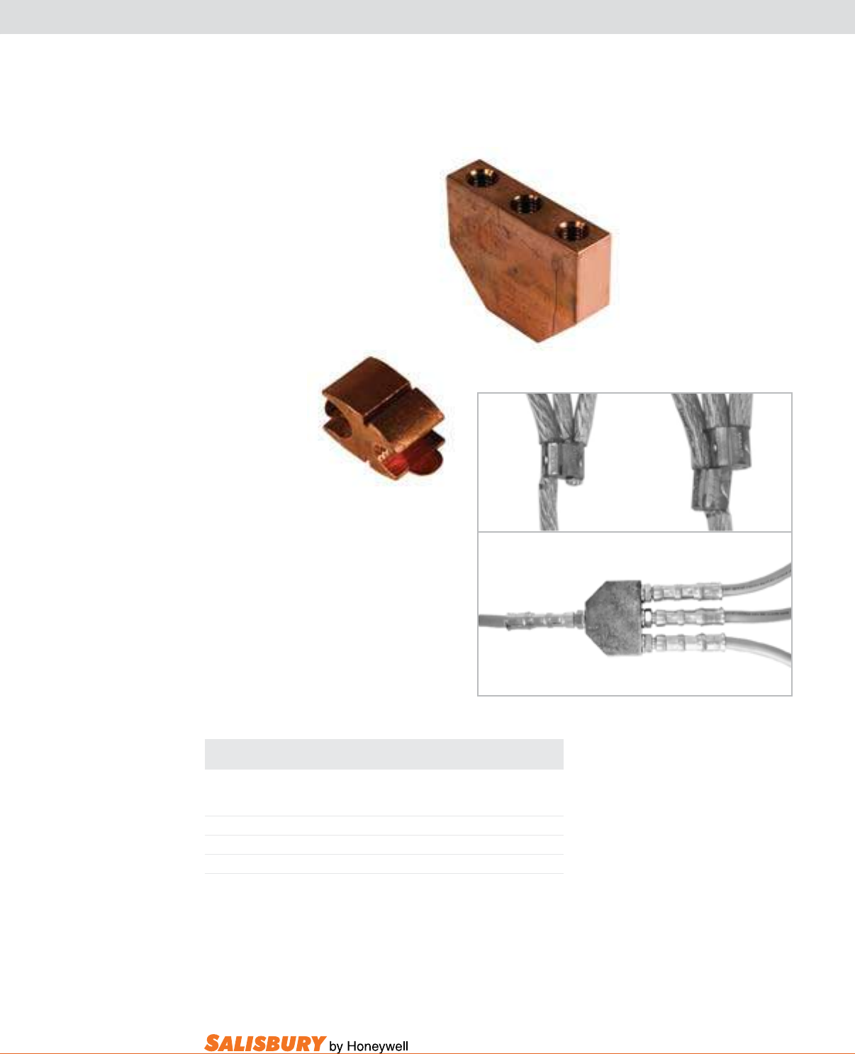
I-21
101 E. Crossroads Pkwy., Ste. A Bolingbrook, IL 60440 toll free ph (USA):877.406.4501 toll free fax (USA):866.824.4922 ph:630.343.3800
GROUNDING SETS
4 WAY CONNECTOR & SQUEEZE-ONS
4-way connectors are used to
create a common connection
between the conductor leads and
the ground lead of a ground set.
CB36
76630882
Cat. No. Description Qty. Weight
Required oz. ( g )
CONNECTORS For Ground Sets
76630882 Squeeze-on for #2 Cable 1 4 ( 112 )
76630782 Squeeze-on for 1/0 - 4/0 Cable 2 4 ( 112 )
CB36 4-Way Set Block , Cu 1 3 ( 1.36 )
CA36 4-Way Set Block, Al 1 2 ( 0.9 )
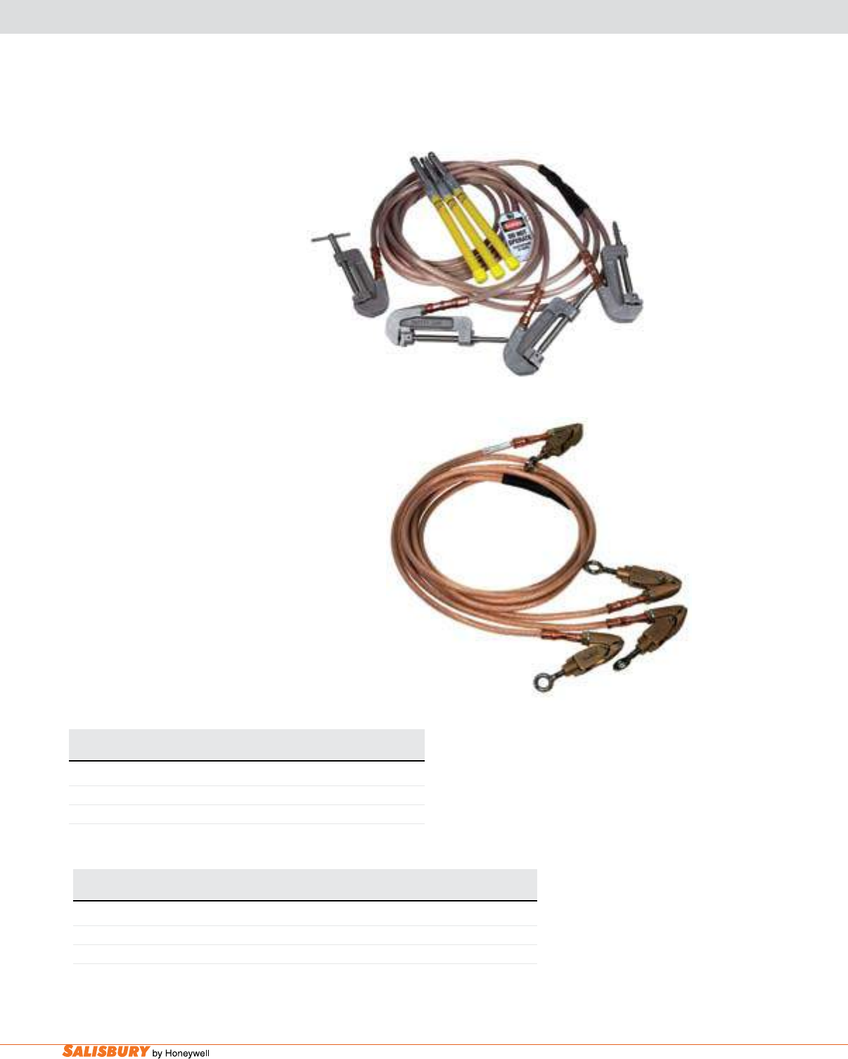
I-22 Safety Line Grounding Equipment. www.salisburybyhoneywell.com
Cat. No. Description ASTM Weight
Grade lbs. ( kgs )
INDUSTRIAL GROUND SETS
7551 Industrial Ground Set - with Bayonet 1 35 ( 15.8 )
7551GA Industrial Ground Ser - with Grip-All 3 35 ( 15.8 )
The Industrial Ground Set consists of three
upper ground heads, one lower head, visible
trifurcation, six-foot (1.83m) leads to common
connections, and a twenty foot lead
from common to ground connection.
All ground heads (7541B and 7541T)
will accept 4”x 4”(10.2 x 10.2 cm) copper
or aluminum bus congurations.
Also includes a bag and a tag for installation
at the main disconnect point. The 7551 includes a
one-foot berglass handle (10012BC) for installing
upper heads.
NOTE: 8106C clampstick (not included) must be used
to apply 7551GA grounds. Other lengths available.
Conductor size is 2/0 copper. Meets ASTM F-855 Grade 3
specications. Maximum fault duty is 27kA for 15 cycles.
Lightweight Industrial Ground Sets are designed
for smaller conductor size applications. Clamps used
include screws with eyes (GA attachments) for use
with a clampstick. #2 extra exible copper ground
cable is used throughout. The 75FGT0266 has six-
foot (1.83 m) leads to the common connection and
a six-foot lead from the common connection to
ground. The 7640244GA uses four-foot (1.22 m)
leads throughout. Sets include a bag. Other lengths
and congurations are available.
GROUNDING SETS
INDUSTRIAL GROUND 4-WAY GROUND SETS
7551
Cat. No. Description Clamp Fault Duty ASTM Weight ea.
Used 15 Cycles Grade lbs. ( kgs )
LIGHTWEIGHT INDUSTRIAL GROUND SETS
75FGT0266 Lightweight 7575FTE 14.5 kA 1 15 ( 6.80 )
7640244GA Ultra Lightweight 7640001E 14.5 kA 1 13 ( 5.90 )
75FGT0266
Optional ground set label available upon request when ordering.
Optional ground set label available upon request when ordering.
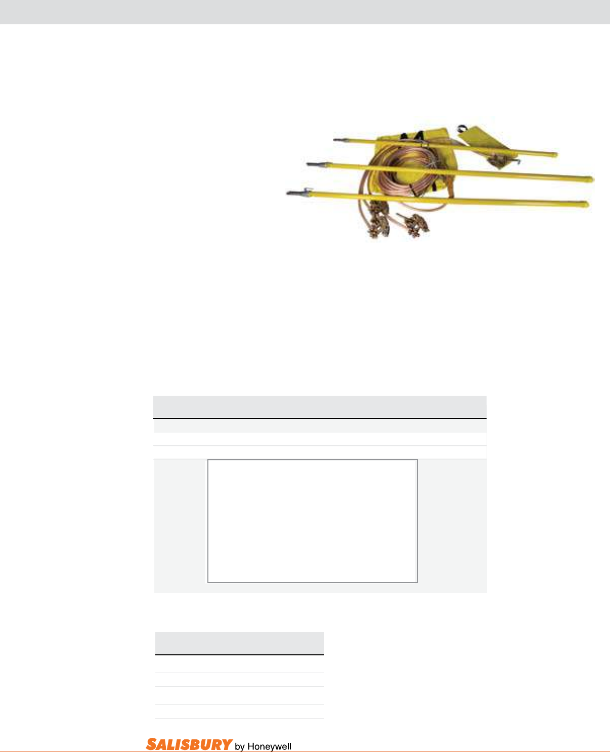
I-23
101 E. Crossroads Pkwy., Ste. A Bolingbrook, IL 60440 toll free ph (USA):877.406.4501 toll free fax (USA):866.824.4922 ph:630.343.3800
GROUNDING SETS
Ground Sets include three upper
heads and are easily and safely
attached to the line with the
berglass handles. The ground
heads have a maximum opening
of 1-3/4” (4.4 cm) and can
be applied to angle irons, at
busses as well as on-line wires.
A tight, four-point contact is made with
the quick adjusting screw. The handles are
easily removed when necessary. The lifting xture provides
ease when raising and lowering the set, and eliminates hanging
the entire ground set’s weight on the conductor. Other lengths
and congurations available.
Parking studs provide a temporary location to attach ground
clamps when raising or lowering multiple ground leads.
Shrink tube for terminal connection strain relief ts #2 through
4/0 terminals and ground cable.
Cat. No. Cable Fault Duty ASTM Weight ea.
Size 15 Cycles Grade lbs. ( kgs )
766FG #2 14.5 kA 1 42 ( 19.0 )
7661FG 1/0 21 kA 2 43 ( 19.5 )
Standard Ground Set Includes
3 - Upper Heads
1 - Lower Head
1 - Leather, Lace and Lifting Ring
74 - Cable only with 8-foot leads to common connection,
and 50’ from common connection to ground connection
3 - 6’6” (1.98 m) Fiberglass Handles
1 - Bag for Handles
1 Bag for Ground Set
7661FG
Cat. No. Description Weight
oz. ( g )
PARKING STUDS
76000APS Single Stud 3 ( 84 )
SHRINK TUBE
761ST 6” (15 cm) for Shrouded Ferrules 6 ( 168 )
Optional ground set label available upon request when ordering.
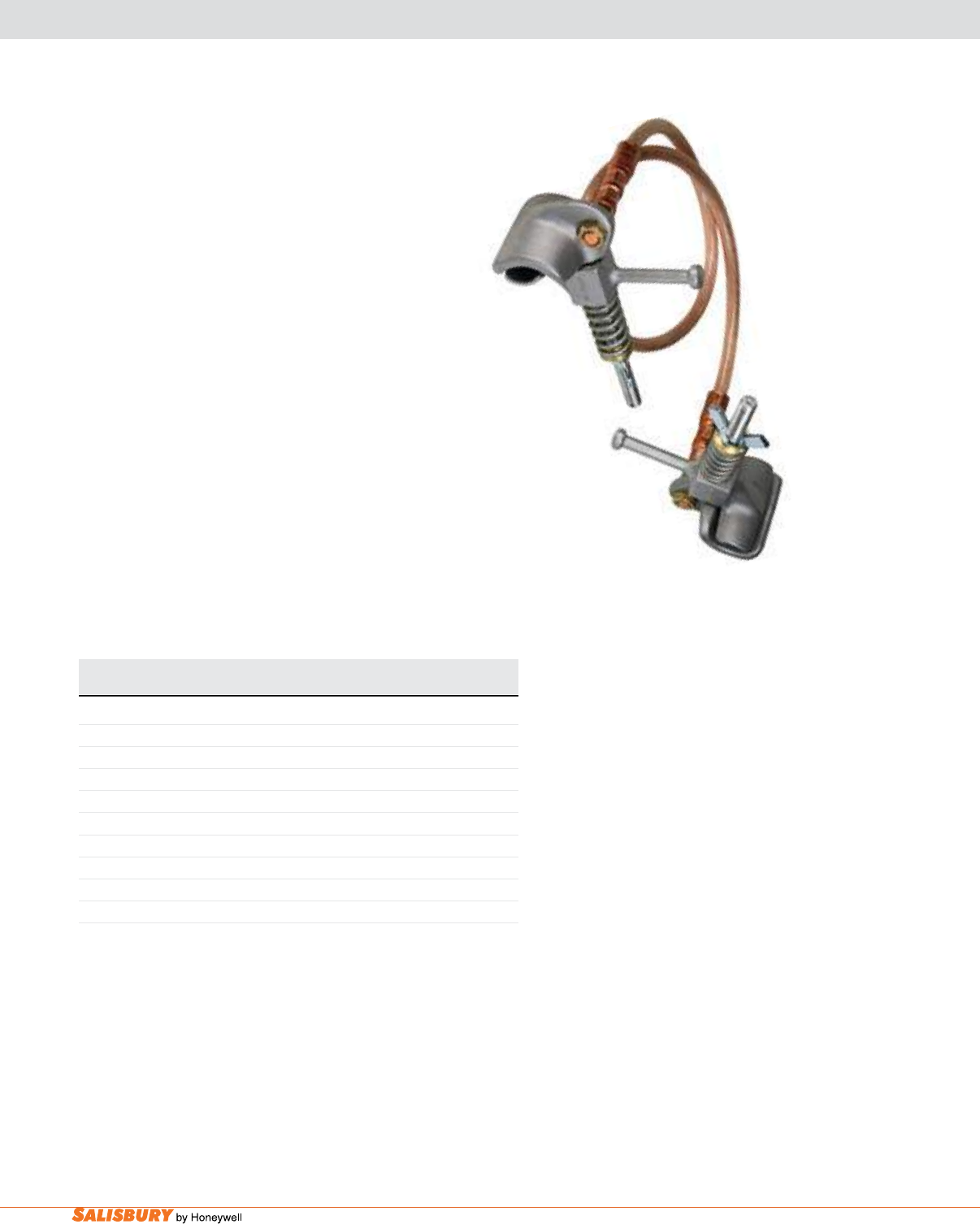
I-24 Safety Line Grounding Equipment. www.salisburybyhoneywell.com
Cat. No. Description For Cable Diameter Weight
in. ( cm ) lbs. ( kgs )
CONCENTRIC NEUTRAL JUMPER ASSEMBLY
7603 Assembly 3/4 to 2 ( 1.9 - 5.1 ) 12 ( 5.44 )
7603GA Grip-All Assembly 3/4 to 2 ( 1.9 - 5.1 ) 12 ( 5.44 )
7604 Assembly 2 to 4 ( 5.1 - 10.2 ) 12 ( 5.44 )
7604GA Grip-All Assembly 2 to 4 ( 5.1 - 10.2 ) 12 ( 5.44 )
Parts
7603C Clamp with Wing Nut 4 ( 1.81 )
7603CGA Clamp with Grip-All 4 ( 1.81 )
7604C Clamp with Wing Nut 4 ( 1.81 )
7604CGA Clamp with Grip-All 4 ( 1.81 )
The Concentric Neutral Jumper Assembly is used for
bonding purposes on non-jacketed cable. It is usually
installed across a portion of cable to be cut, repaired, or
spliced. The assembly is left in place until the concentric
neutral is spliced. As a safety precaution, follow all of your
organization’s applicable rules and/or policies pertaining
to faulted cable, spiking, and grounding.
Made with two ground clamps and 4 feet (1.22 m) of 1/0
clear jacketed extra exible copper cable. The concentric
neutral ground clamp is spring pressured. The assemblies
have a continuous current rating of 250 amps and fault
rated to ASTM Grade 1, 14 KA for 15 cycles. Other
lengths are available. Bag not included.
NEUTRAL JUMPER ASSEMBLY
7603
Optional ground set label available upon request when ordering.
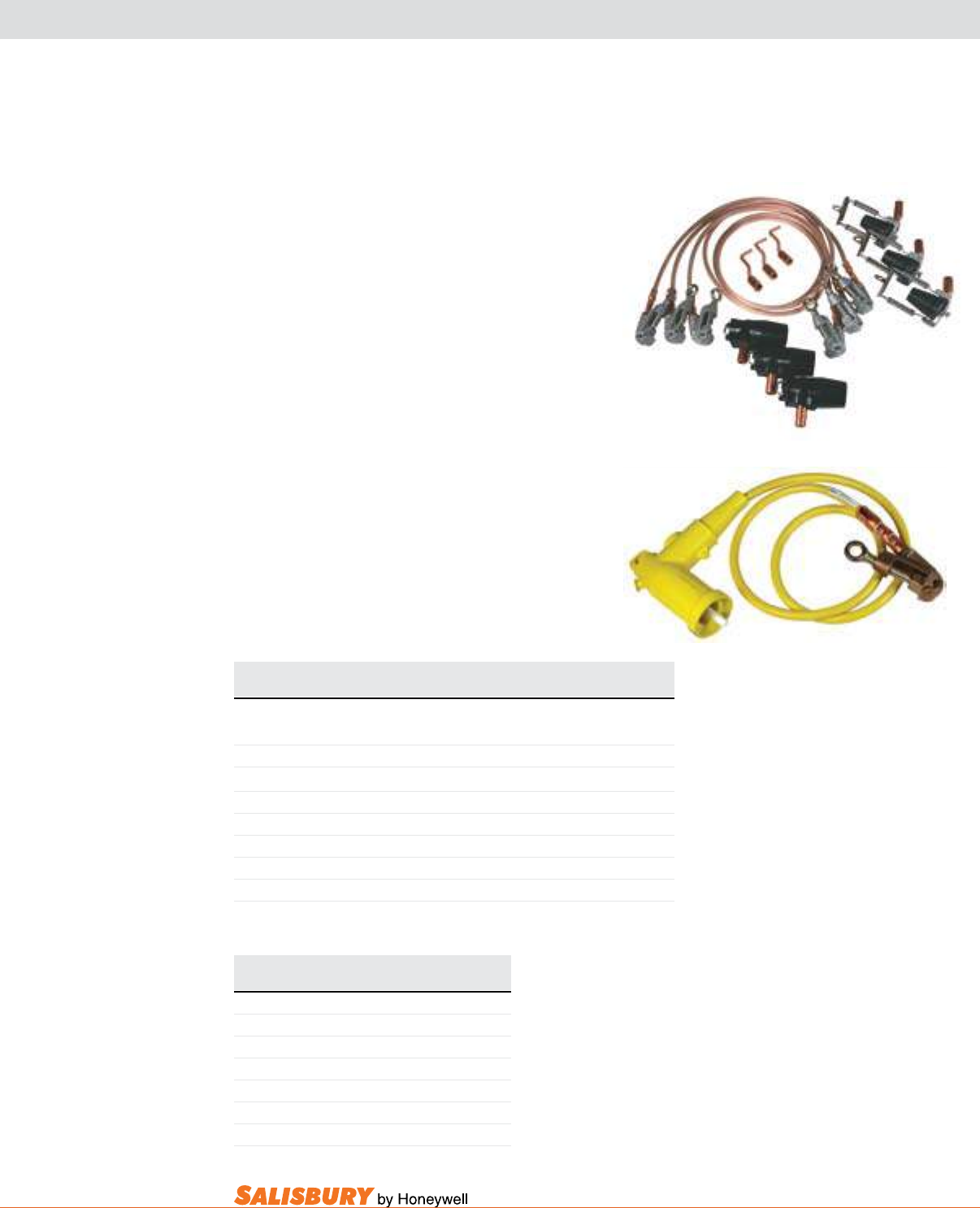
I-25
101 E. Crossroads Pkwy., Ste. A Bolingbrook, IL 60440 toll free ph (USA):877.406.4501 toll free fax (USA):866.824.4922 ph:630.343.3800
The components of the Underground Dead Break
Ground Set provide safe and simple grounding
methods on padmount transformers or any related URD
equipment. These grounds can be ordered in complete
sets or individual components. The jumpers are made
with 6 foot (1.83 m) lengths of #2, clear-jacketed, extra
exible cable. Clamps (7640001E) supplied include an
eye for a grip-all insulating stick application.
The URD Grounding Assembly is used for
underground personal protective grounding elbow
used for grounding pad-mounted equipment, switches
and transformers when performing de-energized
maintenance on URD distribution systems, and
draining DC capacitive charges from de-energized
URD cables.
Cat. No. QTY Description Weight
lbs. ( kgs )
15 KV UNDERGROUND DEAD BREAK GROUND SET
Local Loop
764156STGESO Full Assembly with Bag 21 ( 9.52 )
Assembly Includes:
764156234H 3 Ground Jumper, 6’ (1.83 m) 6 ( 2.72 )
764000ST 3 Ground Stud for Low Prole Transformer 1 ( 0.45 )
764015GE 3 15 kV Ground Elbow 1 ( 0.45 )
764015S0 3 15 kV Ground Standoff with Spring Bail 1 ( 0.45 )
B1715 1 Protective Bag 2 ( 0.91 )
UNDERGROUND DEAD BREAK SET & URD ASSEMBLY
Cat. No. Description Weight
lbs. ( kgs )
URD GROUNDING ASSEMBLY
ES10Y615LB Single, 15 kV 9 ( 4.08 )
ES1Y21015LB Set, 15 kV 22 ( 9.98 )
ES10Y625LB Single, 25 kV 10 ( 4.53 )
ES1Y21025LB Set, 25 kV 23 ( 10.43 )
ES10Y635LB Single, 35 kV 10 ( 4.53 )
ES1Y21035LB Set, 35 kV 23 ( 10.43 )
764156STGESO
ES10YB615LB
Optional ground set label available upon request when ordering.
Optional ground set label available upon request when ordering.
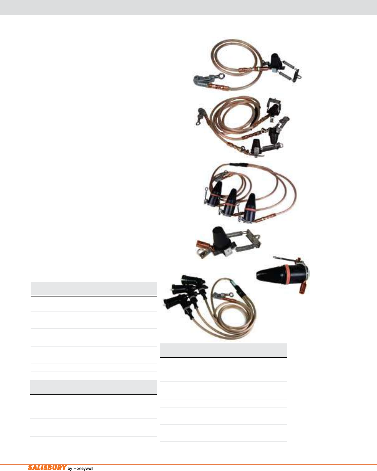
I-26 Safety Line Grounding Equipment. www.salisburybyhoneywell.com
Cat. No. Description Weight
lbs. ( kgs )
200 AMP GROUNDED BUSHING SETS
Dead Break
EB100615 Single, 15 kV 8 ( 3.63 )
EB1021015 Set, 15 kV 20 ( 9.30 )
Load Break
EB100615LB Single, 15 kV 9 ( 4.08 )
EB1021015LB Set, 15 kV 22 ( 9.98 )
EB100625LB Single, 25 kV 10 ( 4.53 )
EB1021025LB Set, 25 kV 23 ( 10.43 )
Cat. No. Description Weight
lbs. ( kgs )
200 AMP GROUNDED BUSHINGS WITH CONNECTIONS
Dead Break
764015SO 15 kV 1 ( 0.45 )
Load Break
764150015LSO 15 kV 2 ( 0.91 )
764150025LSO 25 kV 4 ( 1.81 )
The single Grounded Bushing Set is a single lead made
from 6 feet (1.83 m) of 1/0 cable. The bushing set consists
of 3 bushing assemblies connected together with 3-foot (0.92
m) leads to a common connection, and 10 feet (3.05 m) from
common connection to ground. The conductor is made of
1/0 clear jacketed copper stranded cable. The ground clamp
(7640001E) can be applied with a clampstick. Sets come
complete with bag; single leads do not. All sets are rated
for 10 kA for 10 cycles. Other lengths and congurations
are available.
Ground Bushings with Connections (parking stands for ‘J’
boxes or padmounts) provide a safe, convenient ground for
elbows and a “positive” test to ensure a de-energized elbow.
The Elbow Grounding Set includes a single lead made
from 6 feet (1.83 m) of 1/0 cable. This set consists of 3
elbow assemblies connected together with 3-foot (0.92 m)
leads to a common connection, and 10-feet (3.05 m) from
a common connection to ground. The conductor is made of
1/0 clear jacketed copper stranded cable. A ground clamp
(7640001E) can be applied with a clampstick. Sets are rated
for a maximum fault current of 10,000 amps for 10 cycles.
Sets come complete with bag; single leads do not. Other
lengths and congurations are available.
GROUNDED BUSHING SETS & ELBOW GROUNDING SETS
200 AMP
EB100615
EB1021015
EB1021015LB
764015SO
764150025LSO
Cat. No. Description Weight
lbs. ( kgs )
200 AMP ELBOW GROUNDING SETS
Dead Break
ES100615 Single, 15 kV 8 ( 3.63 )
ES1021015 Set, 15 kV 20 ( 9.30 )
Load Break
ES100615LB Single, 15 kV 9 ( 4.08 )
ES1021015LB Set, 15 kV 22 ( 9.98 )
ES1LY635 Single, 35 kV 10 ( 4.53 )
ES3LY635 Set, 35 kV 23 ( 10.43 )
ES100625LB Single, 25/35 kV 10 ( 4.53 )
ES1021025LB Set, 25/35 kV 23 ( 10.43 )
ES1021015LB
Optional ground set label available upon request when ordering.
Optional ground set label available upon request when ordering. Optional ground set label available upon request when ordering.
I-27
101 E. Crossroads Pkwy., Ste. A Bolingbrook, IL 60440 toll free ph (USA):877.406.4501 toll free fax (USA):866.824.4922 ph:630.343.3800
Optional ground set label available upon request when ordering.
ASTM TABLES
Reprinted, with permission, from ASTM F 855-09 Standard Specification for Temporary Protective Grounds to Be Used on De-energized Electric Power Lines and Equipment
Table 1, copyright ASTM International, 100 Barr Harbor Drive, West Conshohocken, PA 19428. A copy of the complete standard may be obtained from ASTM, www.astm.org
Reprinted, with permission, from ASTM F 855-09 Standard Specification for Temporary Protective Grounds to Be Used on De-energized Electric Power Lines and Equipment Table 2,
copyright ASTM International, 100 Barr Harbor Drive, West Conshohocken, PA 19428. A copy of the complete standard may be obtained from ASTM, www.astm.org
2.2 ANSI Standard:
4
C 37.09 Standard Test Procedure for AC High-Voltage
Circuit Breakers Rated on a Symmetrical Basis
2.3 ICEA/NEMA Standard:
5
ICEA S-19-81/NEMA WC 3-80 (R 1986) Rubber Insulated
Wire and Cable for the Transmission and Distribution of
Electrical Energy
2.4 IEC Standard:
6
IEC 61230 Ed. 2, 2008, Portable Equipment for Earthing or
Earthing and Short-Circuiting
2.5 IEEE Standard:
7
IEEE 386 Standard for Separable Insulated Connector Sys-
tems for Power Distribution Systems Above 600V
IEEE 1048 Guide for Protective Grounding of Power Lines
IEEE 1246 Guide for Temporary Protective Grounding Sys-
tems Used in Substations
3. Terminology
3.1 Definitions of Terms Specific to This Standard:
3.1.1 continuous current rating—designated RMS current
which can be carried continuously under specified conditions.
3.1.2 protective ground assembly—a temporary electrical
connection between a source of potential energization and the
earth, rated for the maximum anticipated fault current or
continuous induced current, or both.
3.1.2.1 Discussion—Throughout this specification, kc
mil = 1000 circular mils.
3.1.3 protective grounding equipment—devices installed
temporarily on de-energized electric power circuits for the
4
Available from American National Standards Institute, 11 West 42nd St., 13th
Floor, New York, NY 10036.
5
Available from Insulated Cable Engineers Assoc., P.O. Box P, South Yarmouth,
MA 02664.
6
Available from International Electrotechnical Commission (IEC), 3 rue de
Varembé, Case postale 131, CH-1211, Geneva 20, Switzerland, http://www.iec.ch.
7
Available from Institute of Electrical and Electronics Engineers, Inc. (IEEE),
445 Hoes Ln., P.O. Box 1331, Piscataway, NJ 08854-1331, http://www.ieee.org.
TABLE 1 Protective Ground Cable, Ferrule, Clamp and Assembly Ratings for Symmetrical Current
Grade
Grounding Clamp Torque
Strength, min Short Circuit Properties
A
Continuous
Current
Rating, A
RMS, 60
Hz
Yield
B
Ultimate Withstand Rating, Symmetrical
kA
RMS, 60 Hz
Ultimate Rating Capacity
CD
, Symmetrical
kA
RMS, 60 Hz
lbf·in. n·m lbf·in. n·m 15
cycles
(250 ms)
30 cycles
(500
ms)
Copper Cable
Size
15
cycles
(250
ms)
30
cycles
(500
ms)
60
cycles
(1 s)
Maximum
Copper Test
Cable Size
1 280 32 330 37 14 10 #2 18 13 9 2/0 200
2 280 32 330 37 21 15 1/0 29 21 14 4/0 250
3 280 32 330 37 27 20 2/0 37 26 18 4/0 300
4 330 37 400 45 34 25 3/0 47 33 23 250 kcmil 350
5 330 37 400 45 43 30 4/0 59 42 29 250 kcmil 400
6 330 37 400 45 54 39 250 kcmil or
2 2/0 70 49 35 350 kcmil 450
7 330 37 400 45 74 54 350 kcmil or
2 4/0 98 69 48 550 kcmil 550
A
Withstand and ultimate short circuit properties are based on performance with surges not exceeding 20 % asymmetry factor (see 9.1 and 12.3.4.2).
B
Yield shall mean no permanent deformation such that the clamp cannot be reused throughout its entire range of application.
C
Ultimate rating represents a symmetrical current which the assembly or individual components shall carry for the specified time.
D
Ultimate values are based upon application of Onderdonk’s equation to 98 % of nominal circular mil area allowed by Specifications B 172 and B 173.
TABLE 2 Ultimate Assembly Rating for High X/R Ratio Applications
High Asymmetrical Test Requirements
Grade Size Rating
Rated Current
(kA)
X/R = 30
1st Cycle Current Peak
(kA)
X 2.69
Last Cycle
Current Peak
(kA) Test Duration (cycles)
1H No. 2 15 41 23 15
2H 1/0 25 65 37 15
3H 2/0 31 84 46 15
4H 3/0 39 105 58 15
5H 4/0 47 126 70 15
6H 250 MCM 55 148 82 15
7H 350 MCM 68 183 101 15
N
OTE
1—The above current values are based on electromechanical test values.
N
OTE
2—Assemblies that have been subjected to these shall not be re-used.
N
OTE
3—For use with currents exceeding 20 % asymmetry factor.
N
OTE
4—See X4.7.2 for additional information.
N
OTE
5—Alternate testing circuits are available for laboratories that cannot achieve the above requirements. See Appendix X4 for details.
F 855 – 09
2
Copyright by ASTM Int'l (all rights reserved); Fri Nov 6 13:35:55 EST 2009
Downloaded/printed by
Huel Gunter (Salisbury by Honeywell) pursuant to License Agreement. No further reproductions authorized.
ASTM F855-09 Table 1 - Protective Grounding Clamp Ratings
ASTM F855-09 Table 2 - Grounding Cable Ferrule and Assembly Ratings
2.2 ANSI Standard:
4
C 37.09 Standard Test Procedure for AC High-Voltage
Circuit Breakers Rated on a Symmetrical Basis
2.3 ICEA/NEMA Standard:
5
ICEA S-19-81/NEMA WC 3-80 (R 1986) Rubber Insulated
Wire and Cable for the Transmission and Distribution of
Electrical Energy
2.4 IEC Standard:
6
IEC 61230 Ed. 2, 2008, Portable Equipment for Earthing or
Earthing and Short-Circuiting
2.5 IEEE Standard:
7
IEEE 386 Standard for Separable Insulated Connector Sys-
tems for Power Distribution Systems Above 600V
IEEE 1048 Guide for Protective Grounding of Power Lines
IEEE 1246 Guide for Temporary Protective Grounding Sys-
tems Used in Substations
3. Terminology
3.1 Definitions of Terms Specific to This Standard:
3.1.1 continuous current rating—designated RMS current
which can be carried continuously under specified conditions.
3.1.2 protective ground assembly—a temporary electrical
connection between a source of potential energization and the
earth, rated for the maximum anticipated fault current or
continuous induced current, or both.
3.1.2.1 Discussion—Throughout this specification, kc
mil = 1000 circular mils.
3.1.3 protective grounding equipment—devices installed
temporarily on de-energized electric power circuits for the
4
Available from American National Standards Institute, 11 West 42nd St., 13th
Floor, New York, NY 10036.
5
Available from Insulated Cable Engineers Assoc., P.O. Box P, South Yarmouth,
MA 02664.
6
Available from International Electrotechnical Commission (IEC), 3 rue de
Varembé, Case postale 131, CH-1211, Geneva 20, Switzerland, http://www.iec.ch.
7
Available from Institute of Electrical and Electronics Engineers, Inc. (IEEE),
445 Hoes Ln., P.O. Box 1331, Piscataway, NJ 08854-1331, http://www.ieee.org.
TABLE 1 Protective Ground Cable, Ferrule, Clamp and Assembly Ratings for Symmetrical Current
Grade
Grounding Clamp Torque
Strength, min Short Circuit Properties
A
Continuous
Current
Rating, A
RMS, 60
Hz
Yield
B
Ultimate Withstand Rating, Symmetrical
kA
RMS, 60 Hz
Ultimate Rating Capacity
CD
, Symmetrical
kA
RMS, 60 Hz
lbf·in. n·m lbf·in. n·m 15
cycles
(250 ms)
30 cycles
(500
ms)
Copper Cable
Size
15
cycles
(250
ms)
30
cycles
(500
ms)
60
cycles
(1 s)
Maximum
Copper Test
Cable Size
1 280 32 330 37 14 10 #2 18 13 9 2/0 200
2 280 32 330 37 21 15 1/0 29 21 14 4/0 250
3 280 32 330 37 27 20 2/0 37 26 18 4/0 300
4 330 37 400 45 34 25 3/0 47 33 23 250 kcmil 350
5 330 37 400 45 43 30 4/0 59 42 29 250 kcmil 400
6 330 37 400 45 54 39 250 kcmil or
2 2/0 70 49 35 350 kcmil 450
7 330 37 400 45 74 54 350 kcmil or
2 4/0 98 69 48 550 kcmil 550
A
Withstand and ultimate short circuit properties are based on performance with surges not exceeding 20 % asymmetry factor (see 9.1 and 12.3.4.2).
B
Yield shall mean no permanent deformation such that the clamp cannot be reused throughout its entire range of application.
C
Ultimate rating represents a symmetrical current which the assembly or individual components shall carry for the specified time.
D
Ultimate values are based upon application of Onderdonk’s equation to 98 % of nominal circular mil area allowed by Specifications B 172 and B 173.
TABLE 2 Ultimate Assembly Rating for High X/R Ratio Applications
High Asymmetrical Test Requirements
Grade Size Rating
Rated Current
(kA)
X/R = 30
1st Cycle Current Peak
(kA)
X 2.69
Last Cycle
Current Peak
(kA) Test Duration (cycles)
1H No. 2 15 41 23 15
2H 1/0 25 65 37 15
3H 2/0 31 84 46 15
4H 3/0 39 105 58 15
5H 4/0 47 126 70 15
6H 250 MCM 55 148 82 15
7H 350 MCM 68 183 101 15
N
OTE
1—The above current values are based on electromechanical test values.
N
OTE
2—Assemblies that have been subjected to these shall not be re-used.
N
OTE
3—For use with currents exceeding 20 % asymmetry factor.
N
OTE
4—See X4.7.2 for additional information.
N
OTE
5—Alternate testing circuits are available for laboratories that cannot achieve the above requirements. See Appendix X4 for details.
F 855 – 09
2
Copyright by ASTM Int'l (all rights reserved); Fri Nov 6 13:35:55 EST 2009
Downloaded/printed by
Huel Gunter (Salisbury by Honeywell) pursuant to License Agreement. No further reproductions authorized.
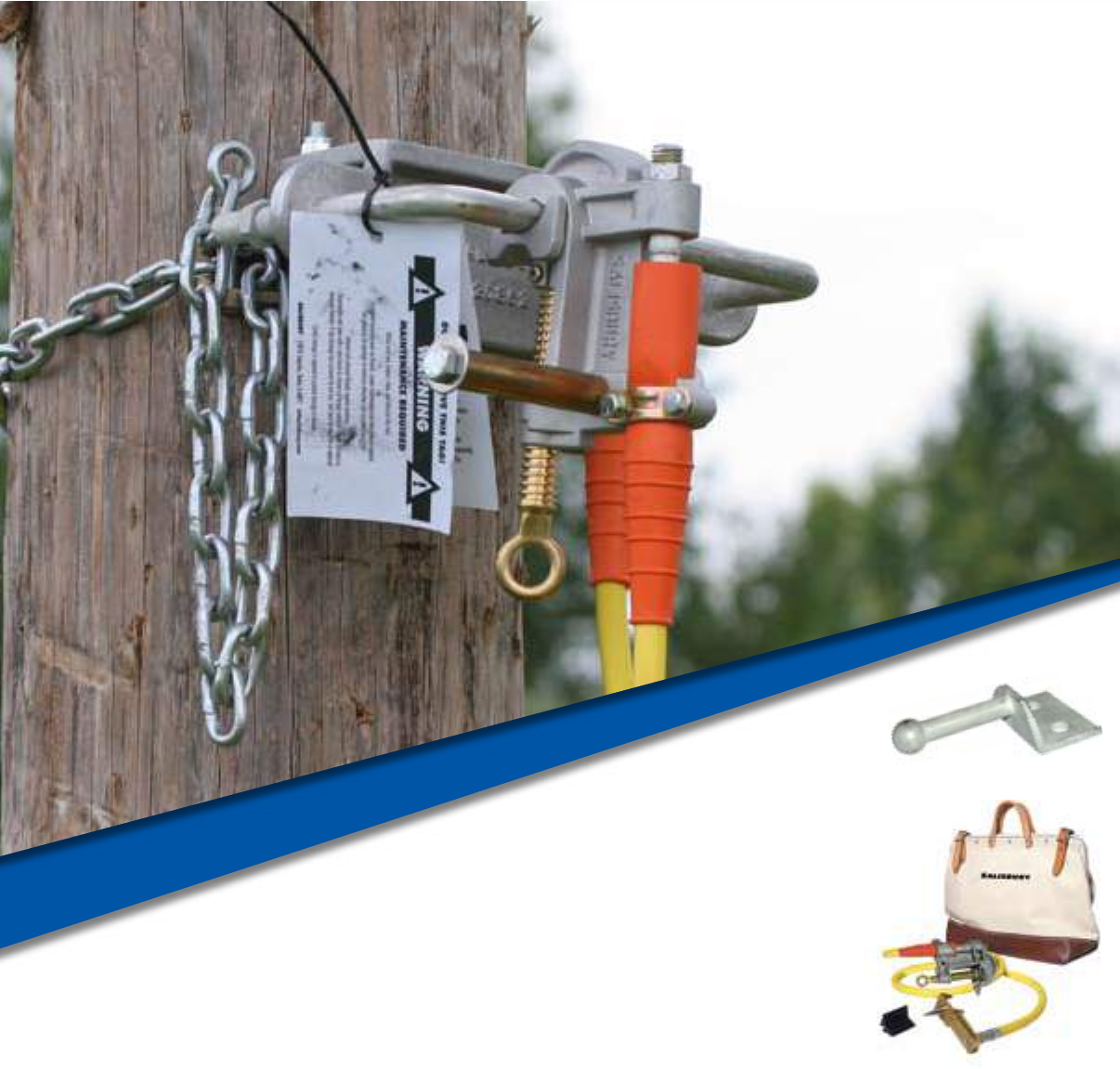
TEMPORARY PROTECTIVE
GROUNDING EQUIPMENT
ACCEssORIEs

J-2 Grounding Equipment Accessories. www.salisburybyhoneywell.com
TEMPORARY PROTECTIVE
GROUNDING EQUIPMENT
ACCEssORIEs
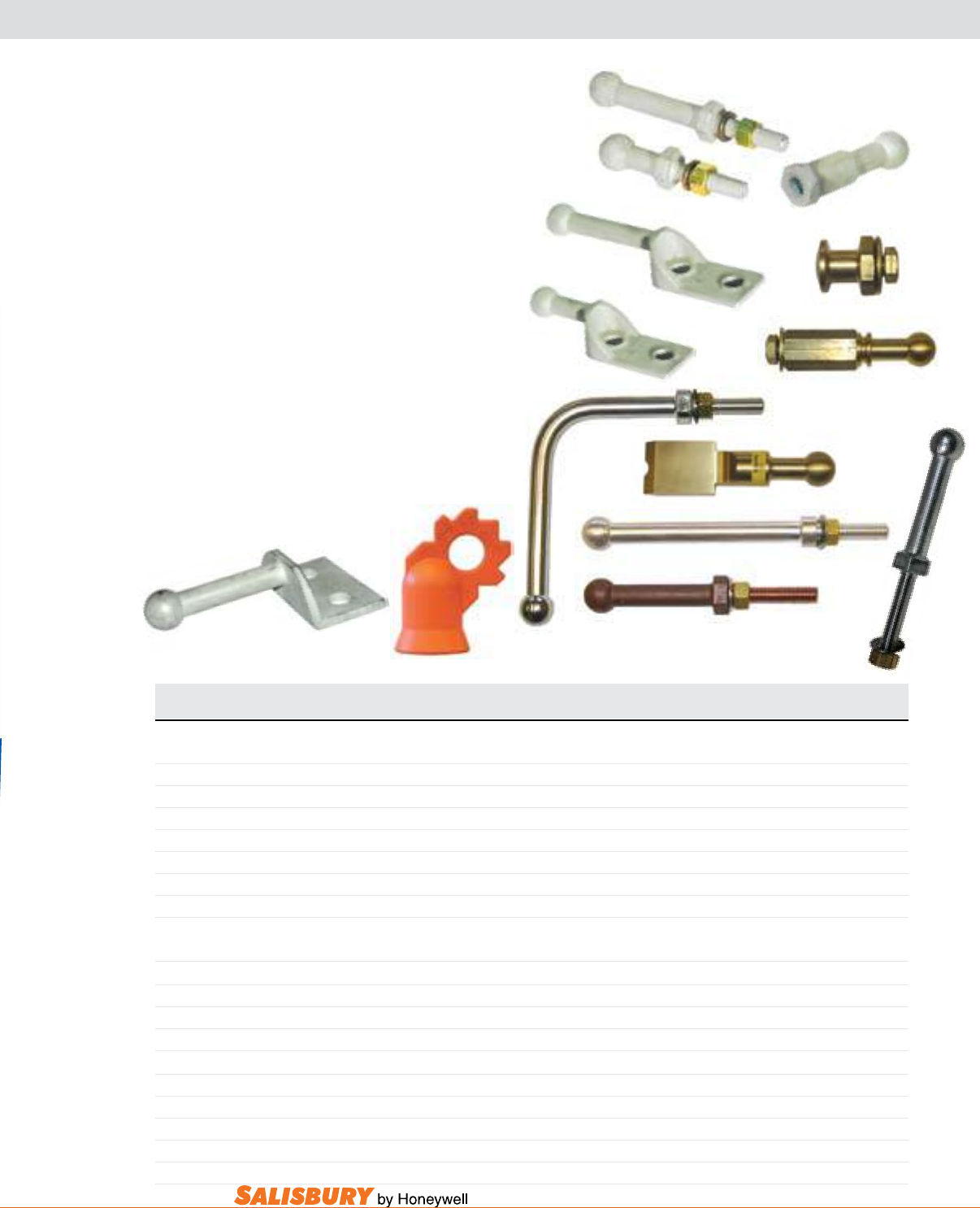
J-3
101 E. Crossroads Pkwy., Ste. A Bolingbrook, IL 60440 toll free ph (USA):877.406.4501 toll free fax (USA):866.824.4922 ph:630.343.3800
21191
21192
21236
21228
24087
BAll & sOCkET sYsTEM
BAll sTUDs
21846
7542K
7542001BSF
7542PHS
7542125BST
7542123BS
24082
7542905BST
Cat. No. Description Dimensions in. ( mm ) ASTM Weight ea.
OAL Thread Shank Grade lbs. ( kgs )
Thread Size - 1/2” - 13 UNC - 2A
21191 Ball Stud Short, Tin-Plated Copper Alloy 4.38 ( 111 ) 2.12 ( 54 ) 1 ( 25 ) 5 .53 ( .23 )
7542121BS Ball Stud, Copper Alloy 4.7 ( 119 ) 2.25 ( 57 ) 1 ( 25 ) 5 9 ( 16 )
21192 Ball Stud Long, Tin-Plated Copper Alloy 6.13 ( 156 ) 2.12 ( 54 ) 2.75 ( 70 ) 5 .81 ( .37 )
7542123BST Ball Stud, Tin-Plated Copper Alloy 6.78 ( 172 ) 2.5 ( 64 ) 2.875 ( 73 ) 5 13 ( 23 )
7542123BS Ball Stud, Copper Alloy 6.78 ( 172 ) 2.5 ( 64 ) 2.875 ( 73 ) 5 13 ( 23 )
7542125BST Ball Stud, Tin-Plated Copper Alloy 9 ( 229 ) 2.12 ( 54 ) 5.5 ( 140 ) 5 16 ( 28 )
7542905BS 900 Ball Stud, Copper Alloy 7 ( 178 ) x 5.2 ( 132 ) 2.12 ( 54 ) 5.5 ( 140 ), 2 ( 51 ) 3 20 ( 35 )
7542905BST 900 Ball Stud, Tin-Plated Copper Alloy 7 ( 178 ) x 5.2 ( 132 ) 2.12 ( 54 ) 5.5 ( 140 ), 2 ( 51 ) 3 20 ( 35 )
Thread Size - 3/8” - 16 UNC - 2A
7542385BST Ball Stud, Tin-Plated Copper Alloy 9 ( 229 ) 2.12 ( 54 ) 5.5 ( 140 ) 5 16 ( 28 )
NEMA Pads and Pothead Stud
21846 90° Offset NEMA Pad, Tin-Plated Copper Alloy 5.75 ( 147 ) - 2.7 ( 69 ) 5 1 ( .45 )
21228 Offset NEMA Pad Short, Tin-Plated Copper Alloy 5.14 ( 131 ) - 1 ( 25 ) 5 .84 ( .38 )
24087 Offset NEMA Pad Long, Tin-Plated Copper Alloy 6.9 ( 175 ) - 2.7 ( 69 ) 5 1 ( .45 )
7542PHS Pothead Stud, Spade, Brass 5.4 ( 137 ) - - 2 14 ( 25 )
Internal Thread - 1/2” - 13 UNC - 2A
24082 Internal Thread Ball Stud, Tin-Plated Copper Alloy 3.85 ( 98 ) 1.5 ( 38 ) .75 ( 19 ) 5 .54 ( .25 )
7542K 3/4” Ground Knob, Brass 1.4 ( 36 ) 1 ( 25 ) .75 ( 19 ) 3 6 ( 11 )
7542001BSF Female Ball Stud, Brass - 1.5 ( 38 ) 1 ( 25 ) 2 14 ( 25 )
21236 Cover for Ball Stud 3 ( 76 ) n / a n / a n / a .09 ( .04 )
The ball Studs and the Offset nema
Pad ball Studs are made from tin-
plated copper alloy or copper. They
each have a 1” (25.4mm) diameter
ball. Recommended installation torque
of 300 in. lbs. The short stud is used
conventionally. The long stud can also
be used as the grounding point for “C” or
Duck bill clamps that have a jaw width
of 2.75” or less. The Offset Nema Pad
Ball Stud has the standard Nema bolt
hole spacing and also comes in both long
and short lengths.
The ball Stud Cover, made from
orange SALCOR®, allows for multiple
angle application when installed using
a clampstick.
7542123BST
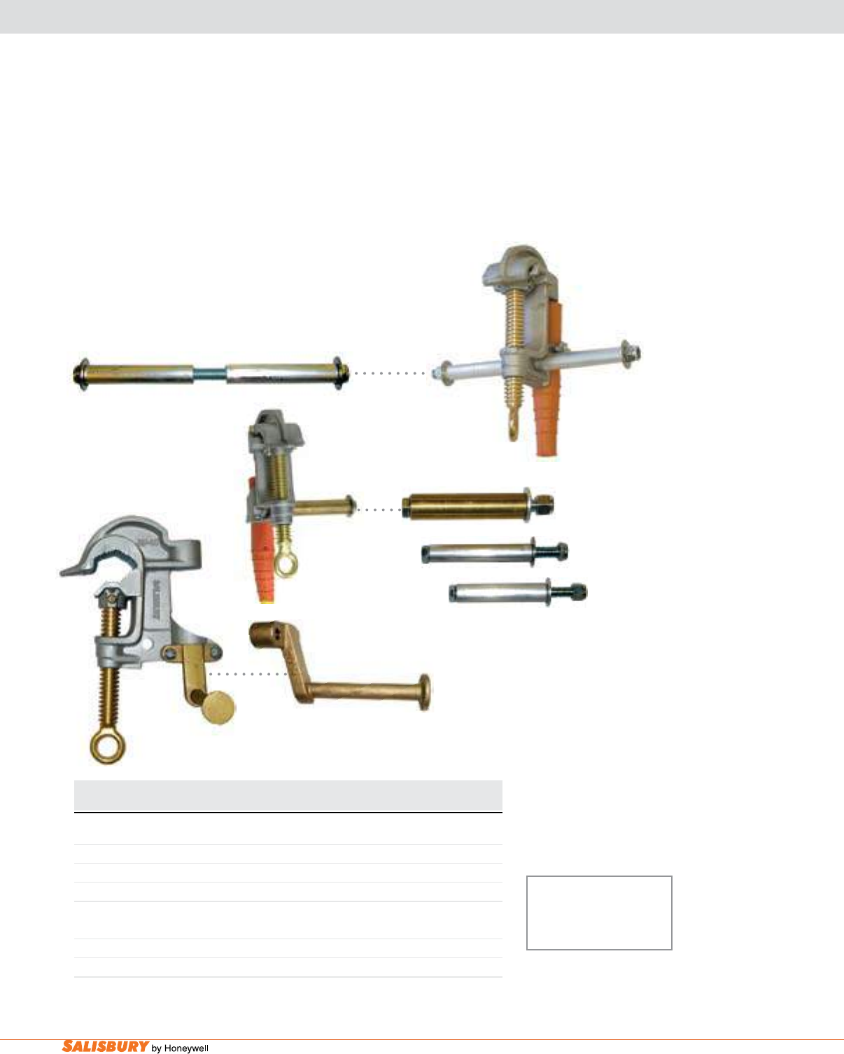
J-4 Grounding Equipment Accessories. www.salisburybyhoneywell.com
GROUNDING ClAMP HANGER sTUDs
Hanger Studs are designed to be used with
all “C” and Duck Bill ground clamps. Hanger
Studs are used to hold one clamp of a set while
the other is being installed on the de-energized
line. Hanger Studs are not designed or tested to
carry current.
21754 grounding Clamp Hanger Stud can
only be placed on clamps designed with a
screw down strain relief system.
Cat. No. Stud For Use With Weight ea.
lbs. ( kgs )
1858 Hanger Aluminum Duck Bill 1”, 1.25”, 1.66” .5 ( .2 )
1928 Hanger Aluminum “C” Clamps 1.25”, 1.5”, 2.4”, 3.5” .5 ( .2 )
2427 Double Hanger Aluminum “C” Clamps 1.25”, 1.5”, 2.4”, 3.5” .5 ( .2 )
2537 Hanger Aluminum “C” Clamps 1” .5 ( .2 )
2093 Hanger 556 Bronze Duck Bill, 477 Brz. “C”Clamp .5 ( .2 )
9983 Hanger Brass 1”, 1.25”, 2.4” “C”Clamps .5 ( .2 )
21754* Hanger Bronze 1”, 1.25”, 2.4” “C”Clamps .5 ( .2 )
2427
2537
21754*
*For use with only Plain Fer-
rule Clamps and Threaded Fer-
rule Clamps with a screw down
strain relief restraint system.
9983
1928
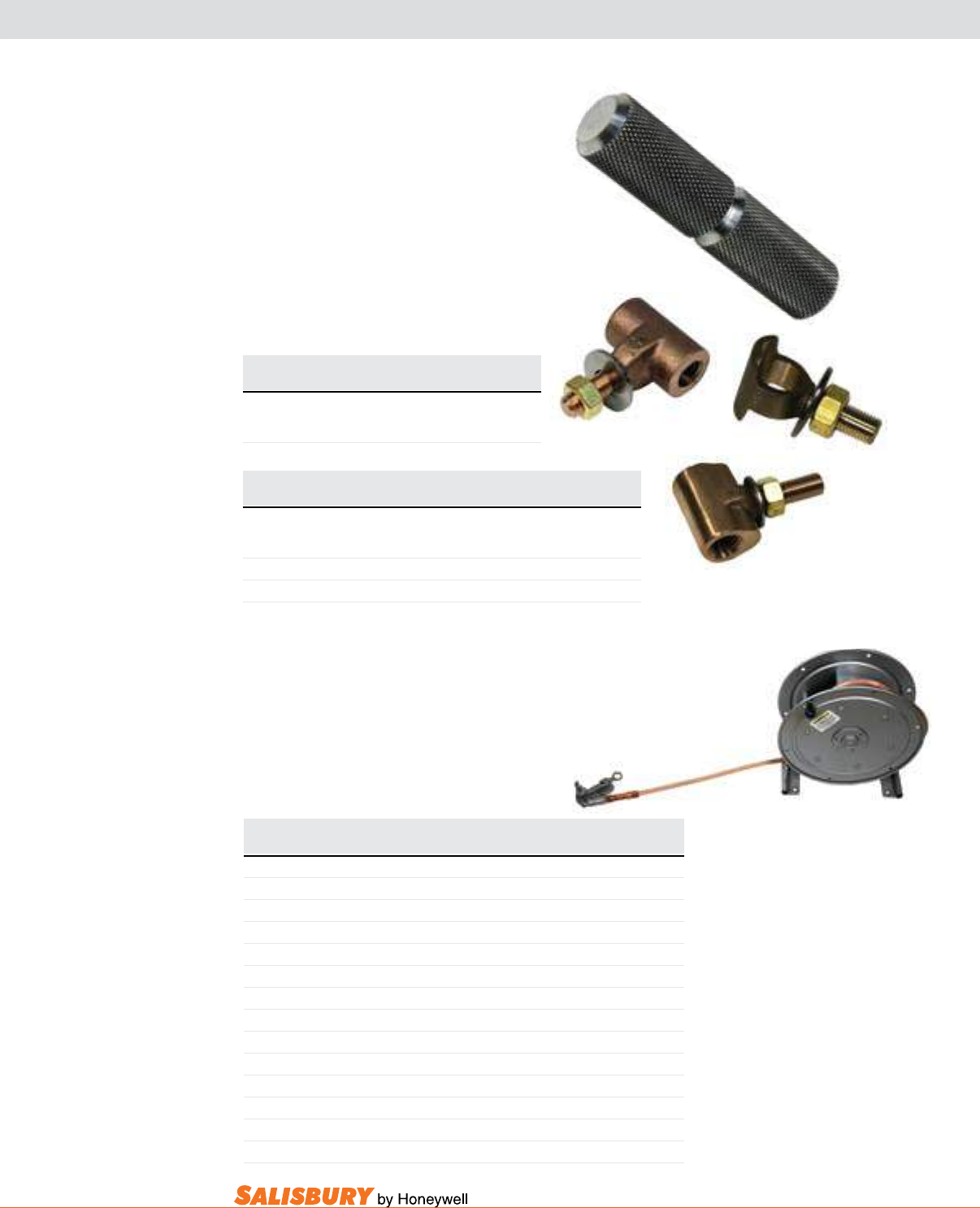
J-5
101 E. Crossroads Pkwy., Ste. A Bolingbrook, IL 60440 toll free ph (USA):877.406.4501 toll free fax (USA):866.824.4922 ph:630.343.3800
Cat. No. Description Weight
lbs. ( kgs )
ADAPTERS
7300ABC Pin to Threaded Adapter 0.5 ( 0.21 )
7310G Eye Bolt Assembly 0.5 ( 0.21 )
7300AET Pin to Threaded Adapter 0.5 ( 0.21 )
Cat. No. Weight
lbs. ( kgs )
“T” HANDLE ADAPTER
760001HDL 0.5 ( 0.21 )
The “T” Handle adapter allows the user
to quickly and easily change an eye screw
into a “T” handle screw.
adapters are used on any pin type ground
clamps. Meets ASTM F-855 Grade 5
specications. Maximum fault duty is 43
kA for 15 cycles.
ADAPTERs & TRUCk GROUNDING REEl
7300ABC
760001HDL
7310G
7300AET
Cable Cable Fault Duty ASTM F-855 Weight
Cat. No. Length Size 15 CYCLES Grade lbs. ( kgs )
TRUCK GROUNDING REEL SPRING REWIND, 760001E Clamp
HSCR0240 40’ (12.2 m) #2 14.5 kA 1 39 (17.7 )
HSCR0250 50’ (15.2 m) #2 14.5 kA 1 42 (19.0 )
HSCR1040 40’ (12.2 m) 1/0 21 kA 2 48 (21.7 )
HSCR1050 50’ (15.2 m) 1/0 21 kA 2 53 (24.0 )
TRUCK GROUNDING REEL HAND REWIND, 760001E Clamp
HCR0240 40’ (12.2 m) #2 14.5 kA 1 36 (16.3 )
HCR0250 50’ (15.2 m) #2 14.5 kA 1 39 (17.7 )
HCR1040 40’ (12.2 m) 1/0 21 kA 2 46 (20.8 )
HCR1050 50’ (15.2 m) 1/0 21 kA 2 51 (23.1 )
REELS WITHOUT CABLE
HSCR1 Reel only, spring rewind 21 kA 2 27 (12.2 )
HCR1 Reel only, hand rewind 21 kA 2 25 (11.3 )
HC1 Reel storage only, hand rewind N/A N/A 26 (11.8 )
vehicle.
NOTE:
• Model HSCR1, with spring rewind, will store and
operate with a maximum of 60 feet (18.3 m) of
#2 cable and 50 feet (15.2 m) of 1/0 cable.
• Reel models HCR1 and HC1 will store a
maximum length of 150 feet (45.8 m) of #2
cable and 85 feet (25.9 m) of 1/0 cable.
• To order factory installed cable of lengths
different than shown above, give reel model
number and length of cable required. Lengths
should not exceed maximum operating and
storage capacities.
• The use of 2/0 and 4/0 cable is not recom-
mended since the fault duty rating of these cables
exceeds that of the truck grounding reel.
Truck grounding Reels are designed to provide a secure
and efcient way to ground trucks and equipment when
working on or near energized lines. Bolt-down design allows
easy removal of reels for installation on vehicles. Heavy
duty construction for rugged eld use. Independently tested
to 14.5 kA for 30 cycles. Reels with factory installed cable
include 6-foot equal gauge and frame bonding
jumper. Other end must be attached to frame of
HCR0250
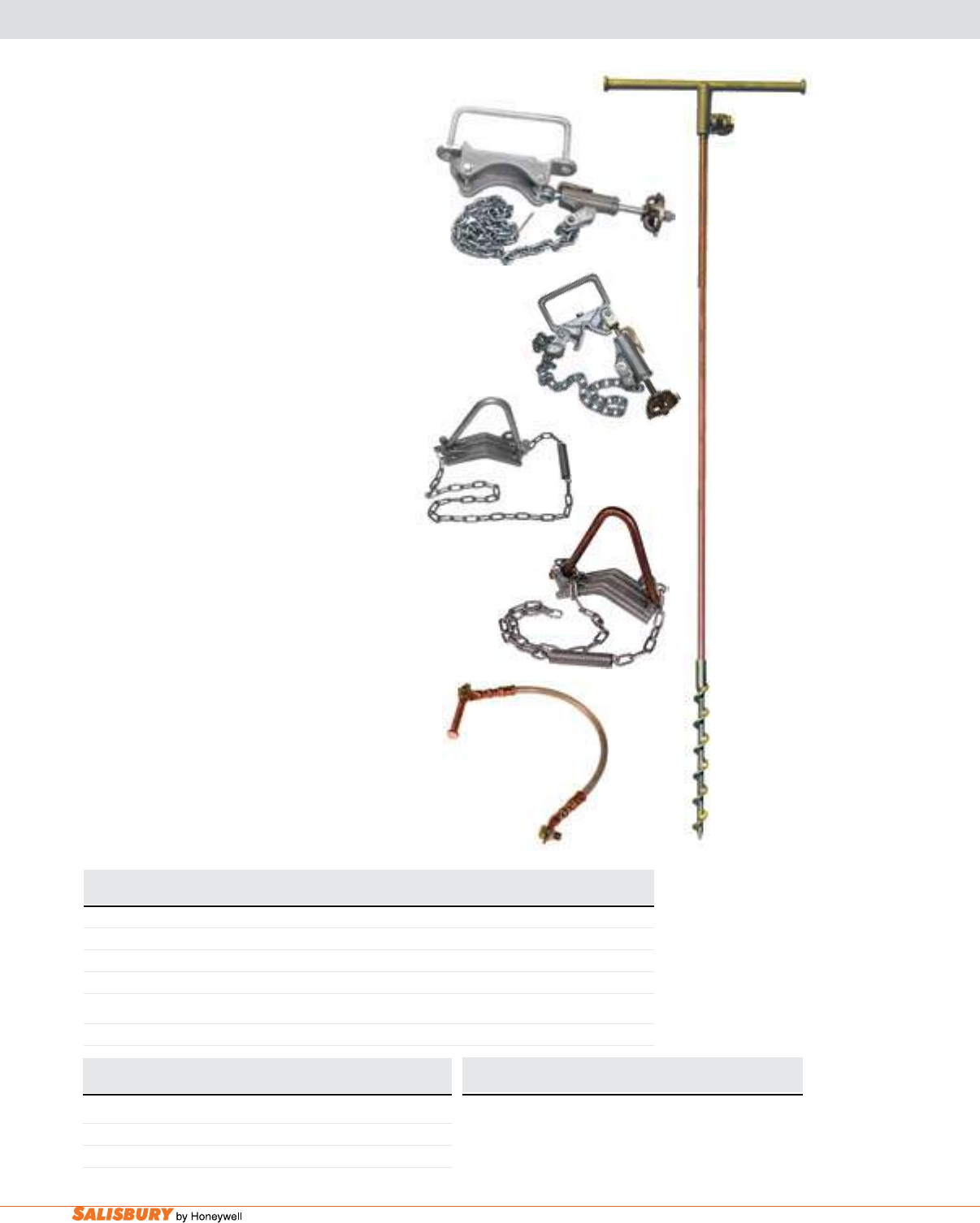
J-6 Grounding Equipment Accessories. www.salisburybyhoneywell.com
GROUNDING ACCEssORIEs
Cat. No. ASTM Description Weight ea.
Grade lbs. ( kgs )
Pole Mounted Contact Bars
9998 5 Contact Bar No Connection 40” Chain w/ Adjustable Wheel Binder 9.1 ( 4.1 )
21840 5 Contact Bar No Connection 40” Chain w/ Adjustable Wheel Binder 7 ( 3.3 )
20880 5 Contact Bar One Connection 40” Chain w/ Adjustable Wheel Binder 9.1 ( 4.1 )
SCREW GROUND ROD
2103 75” ( 1.9m ) long 8 ( 3.6 )
2103
21840
Pole mounted Contact bars are designed to
act as a convenient common point for electrical
connections and also as a hanger for grounding
sets during installation and removal. Supplied
with a chain and an adjustable wheel binder that
will accommodate most common pole diameters.
Catalog #20880 has one 5/8-11UNC tapped hole
for the permanent connection of a ground lead.
The Salisbury 21840 is a lighter-weight pole
mounted contact bar.
The Pole band is lightweight and easy to install.
It is a required component of equiotential zone
grounding systems.
Truck grounding Kit contains 2/0 cable,
24 inches (61 cm) long, with a chassis/frame
attachment on one end and a grounding stud on
the other for Cat. No. 7542TGK. Brings body
and chassis to the same ground potential. Other
lengths are available. Meets ASTM F-855 Grade
3 specications.
The Salisbury 2103 Screw Type Temporary
ground Rod is used when an adequate system
ground is not available. The design incorporates
a copperweld rod with bronze ttings screwed
and pinned on both ends. The terminal on the
handle is designed to accept cables equipped with
a 5/8-11 UNC threaded ferrule. As an alternative,
a “C” clamp may also be attached directly to the
ground rod shaft.
Cat. No. Description Fault Duty Grade Weight
15 Cycles lbs. ( kgs )
POLE BAND
760001PB Aluminum Bar 27 kA 3 4 ( 1.81 )
760045PB Copper Bar 43 kA 5 5 ( 2.27 )
Cat. No. Description Weight
lbs. ( kgs )
TRUCK GROUNDING KIT
7542TGK Truck Grounding Kit w/ Stud 2 ( 0.91 )
7542TGKLS Truck Grounding Kit w/o Stud 1.5 ( 0.68 )
760001PB
760045PB
7542TGK
9998
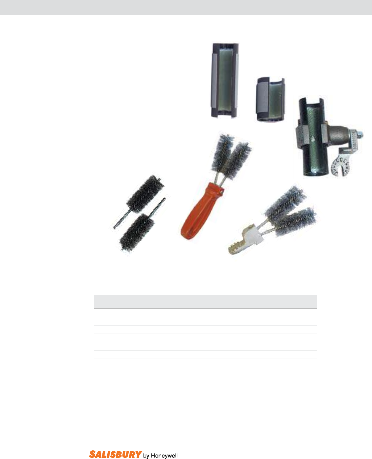
J-7
101 E. Crossroads Pkwy., Ste. A Bolingbrook, IL 60440 toll free ph (USA):877.406.4501 toll free fax (USA):866.824.4922 ph:630.343.3800
CONDUCTOR & ClEANING TOOls
Tubular brushes are preferred when
rubber gloving or working on de-energized
conductors. The steel bristles are internal to
prevent damaging rubber gloves. The 2.5”
tubular brush is used in conned areas such
as between two connectors or clamps.
The “v” Type Wire brushes are available
with epoxy-coated handle or universal
attachment that can be used with hot sticks.
Replacement brushes are available.
4337
4110
4112
Cat. No. Description Weight ea.
in. ( mm ) lbs. ( kgs )
4108 Universal Tubular 1.3 ( 0.6 )
4110 5” ( 127 ) Tubular 0.4 ( 0.2 )
4111 Universal “V” Line Cleaner 1 ( 0.5 )
4112 “V” Type handle w/ brushes 1.2 ( 0.6 )
4113 “V” Type carton of 10 replacement brushes 3 ( 1.4 )
4337 2.5” ( 63.5 ) Tubular 0.2 ( 0.1 )
4108
4113 4111
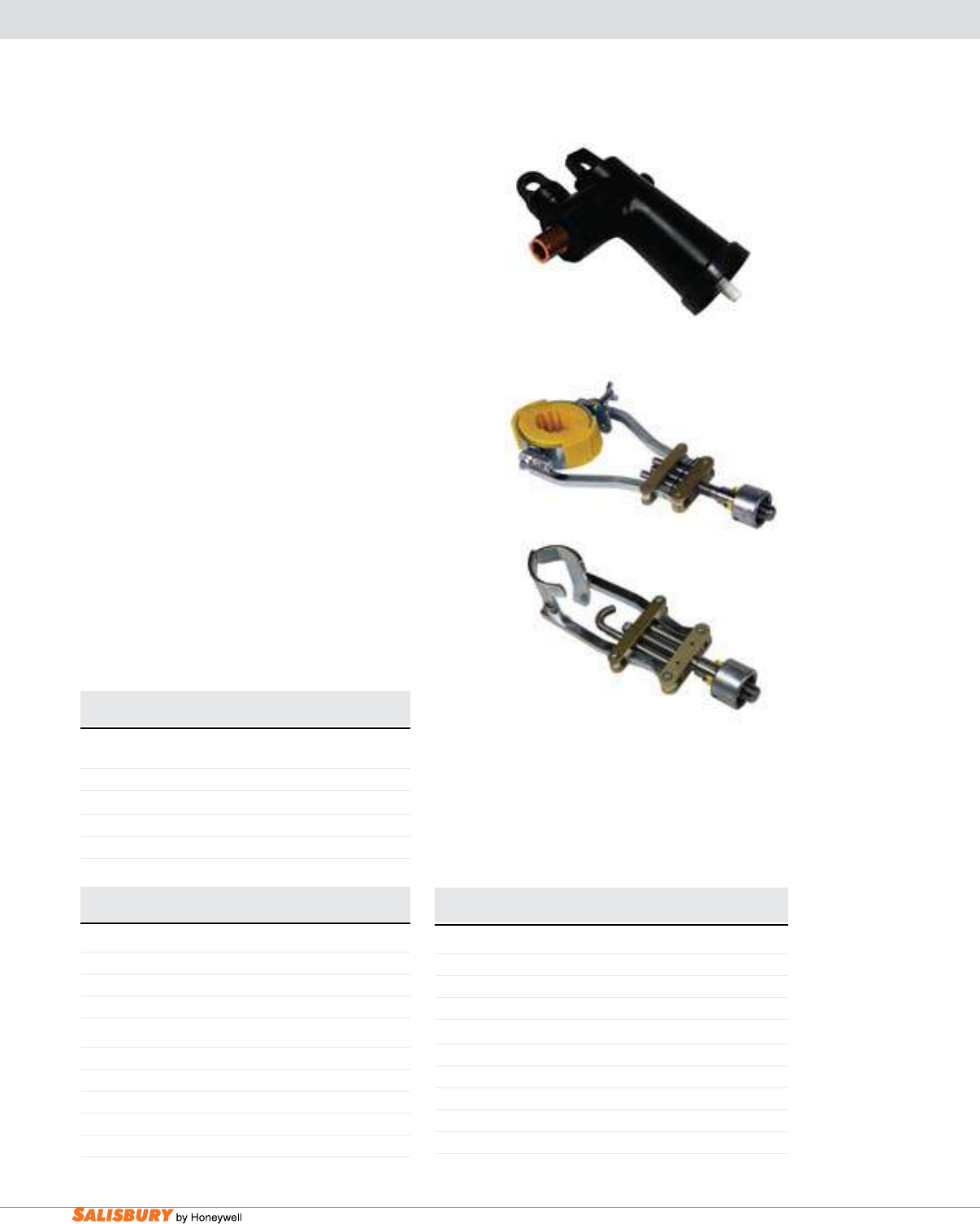
J-8 Grounding Equipment Accessories. www.salisburybyhoneywell.com
GROUND ElBOw & ACCEssORIEs
200 AMP & 600 AMP
Cat. No. Description Weight
lbs. ( kgs )
200 AMP GROUND ELBOW WITH CONNECTIONS
Dead Break
764015GE 15 kV 1 ( 0.45 )
Load Break
764150015LGE 15 kV 1 ( 0.45 )
764150025LGE 25/35 kV Small Interface 2 ( 0.91 )
The 200 amP ground Elbow with Connections may
be used on single phase or three phase installations.
Grounding sets come complete with extra exible cable
and connections. Elbows are rated for a maximum fault
current of 10,000 amps for 10 cycles. All the clamps come
with grip-all eyes for use with a clampstick.
The 200 amP Elbow Connector Tool is designed to t
all the 15kV and 25 kV rated loadbreak and non-loadbreak
elbows. The jaws are contoured to provide a positive
grip and not interfere with the contact interface area,
allowing the elbow to operate properly while connecting
or disconnecting.
The 600 amP Elbow Connector Tool is designed to t
all the 15kV and 25 kV rated loadbreak and non-loadbreak
elbows. The jaws are contoured to provide a positive
grip and not interfere with the contact interface area,
allowing the elbow to operate properly while connecting
or disconnecting.
The Insulated Elbow Remover is used by inserting a
hook in the loop on the back of any elbow while applying a
hammering action. This tool can also be used to seal elbows
when installing them. Other lengths available.
Cat. No. Description Weight
lbs. ( kgs )
200 AMP ELBOW CONNECTOR TOOL
9202Q Quick Change Fitting 2 ( 0.91 )
9202U Universal Fitting 2 ( 0.91 )
9202GA Grip-All Fitting 2 ( 0.91 )
600 AMP ELBOW CONNECTOR TOOL
9206Q Quick Change 2 ( 0.91 )
9206U Universal 2 ( 0.91 )
9206GA Grip-All 2 ( 0.91 )
9206GAS With Insert Pair for 200 AMP Elbows 2 ( 0.91 )
9202I Insert Pair 8 ( 0.22 )
Cat. No. Description Weight
lbs. ( kgs )
INSULATED ELBOW REMOVER
9204HIP 4’ (1.22 m) with 9202HQ 10 ( 4.53 )
9206HIP 6’ (1.83 m) with 9202HQ 11 ( 4.99 )
9208HIP 8’ (2.44 m) with 9202HQ 12 ( 5.44 )
Parts
9202HQ Elbow Remover Head with Quick Change 2 ( 0.91 )
9202HPQ Impact Hammer with Quick Change 6 ( 2.72 )
12524HH Insulated Stick for 2’ (0.61 m) Remover 2 ( 0.91 )
12548HH Insulated Stick for 4’ (1.22 m) Remover 3 ( 1.36 )
12572HH Insulated Stick for 6’ (1.83 m) Remover 4 ( 1.81 )
764150015LGE
9202HQ
9206GAS
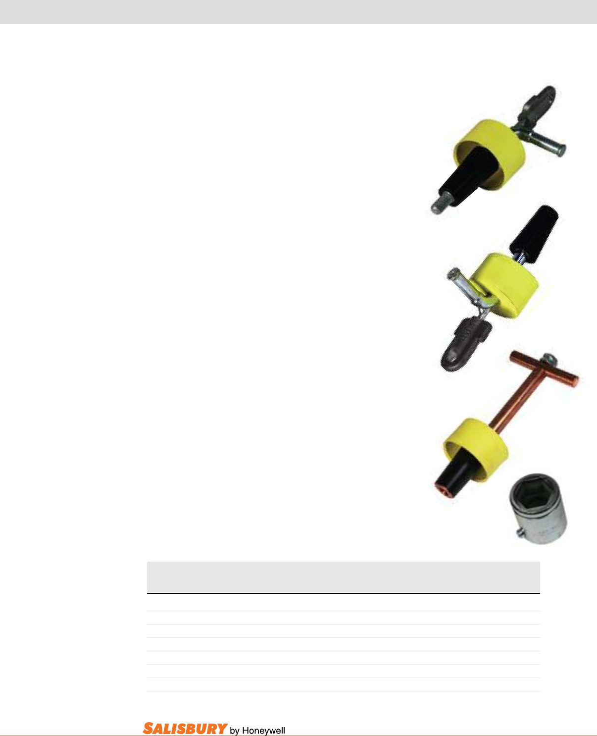
J-9
101 E. Crossroads Pkwy., Ste. A Bolingbrook, IL 60440 toll free ph (USA):877.406.4501 toll free fax (USA):866.824.4922 ph:630.343.3800
UNDERGROUND GROUNDING sTUDs
ASTM F855
Cat. No. Description Threads Material Grade Fault Duty Weight
(Stud) 15 Cycles lbs. ( kgs )
UNDERGROUND GROUNDING STUDS
1725001 Copper Electrode, Female, Hex Drive, w/Guide 5/8-11 (F) Cu 1 17 kA 2.2 ( 1.0 )
17250003 Steel Electrode, Male, Grip-All, w/Guide 5/8-11 (M) Steel 3 27 kA 2.0 ( 0.9 )
17250004 Steel Electrode, Female, Grip-All, w/Guide 5/8-11 (F) Steel 3 27 kA 2.0 ( 0.9 )
17250005 Steel Electrode, Male, Grip-All 3/4-10 (M) Steel 3 27 kA 1.8 ( 0.8 )
1735 Copper Electrode, Female, Hex Drive, w/Guide 5/8-11 (F) Cu 4 35 kA 3.5 ( 1.6 )
5900CS Captured Socket for 1725001 and 1735
The 1712 and 1725 grounding stud series are used for grounding
when the fault duty on the 600 amp Deadbreak elbow/ “T” body
exceeds the rating of a 200 amp grounding elbow, as rated by
IEEE 386 @ 10kA for 10 cycles. Grounding studs consist of a
10” conductor stud with male or female threads for replacing 200
amp bushing wells and/or insulating plugs and a ground clamp
bar for use with regular grounding jumper assemblies. After the
cable has been proven de-energized, the stud is installed and a
ground is applied.
The 1725001 grounding stud is made of 7/8” diameter copper with
a 5/8-11 female thread on one end and a 1” (2.5 cm) hex drive on
the other end. This stud is tted with a tapered guide and a 3/8”
diameter copper cross bar perch used for installing the ground. A
socket drive is used for installation. For application, use catalog
number 5900CS captured socket.
The 17250003, 17250004, and 17250005 are steel grounding
plugs and studs with one 5/8” diameter perch. The perch has a
sturdy lip to ensure clamp contact during faults. These models
are supplied with grip-all attachments for application with
insulated clampstick tools and connectors. These studs are used
for grounding equipment such as non load-break connectors or
power distribution connectors.
The 1735 grounding stud is made of 7/8” diameter copper with a
5/8-11 female thread on one end and a 1” (2.5 cm) hex drive on
the other end for application with a socket drive. The cross bar
perch is 3/4” diameter copper, providing heavy duty service. This
ground plug also comes equipped with a tapered guide and the
yellow protective cap.
17250003
17250004
1735
5900CS

J-10 Grounding Equipment Accessories. www.salisburybyhoneywell.com
Cat. No. Description
PADMOUNT SWITCH HOOK
190UGQ With Quick Change
190UGU With Universal
The Padmount Switch Hook is designed to operate the
secondary switch on a padmount transformer. Also used as a
standard switch hook for cutouts. Weight - 1 lbs. (0.45 kgs).
The underground Spanner Wrench is designed for
installing and removing the connector bushing, and reducing
bushing inserts. Can be used when the conductor is de-
energized, but not grounded. The tool is used one way for
installation, and turned over for removal. A universal toggle
and spring is used with this tool and should be ordered
separately (5900Q). Weight -1 lbs. (0.45 kgs).
The Plug Installing Tool is used to install or remove 600
amp reducing plugs. Weight:2 lbs. (0.91 kgs).
The ground adapter device Kit enables application of
personal grounds up to a 600 amp separable pre-molded
component system when used with a clampstick.
Cat. No. Description
UNDERGROUND SPANNER WRENCH
1720 For 600 AMP Connector
Cat. No. Description
PLUG INSTALLING TOOL
172300 1/2” (1.3cm) Female Square Drive
172300Q Quick Change
UNDERGROUND TOOls & GROUND ADAPTER DEVICE kIT
190UGU
1720
172300
Cat. No. Description QTY Weight lbs. ( kgs )
GROUND ADAPTER DEVICE KIT - Non-Load Break
76174459 15 ( 6.8 )
Each Set Includes The Following:
44C Ratchet Wrench with Ball and Ring 1 2 ( 0.91 )
5900Q Universal Toggle and Spring 1 1 ( 0.45 )
5900CS Captured Socket with Friction Balls 1 8 oz ( 0.22 kgs )
9206GAS Elbow Connector Tool with Inserts 1 2.5 ( 1.1 )
1725001 Ground Stud 3 2.5 ( 1.1 )
B1715 Protective Bag with Zipper 1 1 ( 0.45 )
76174459
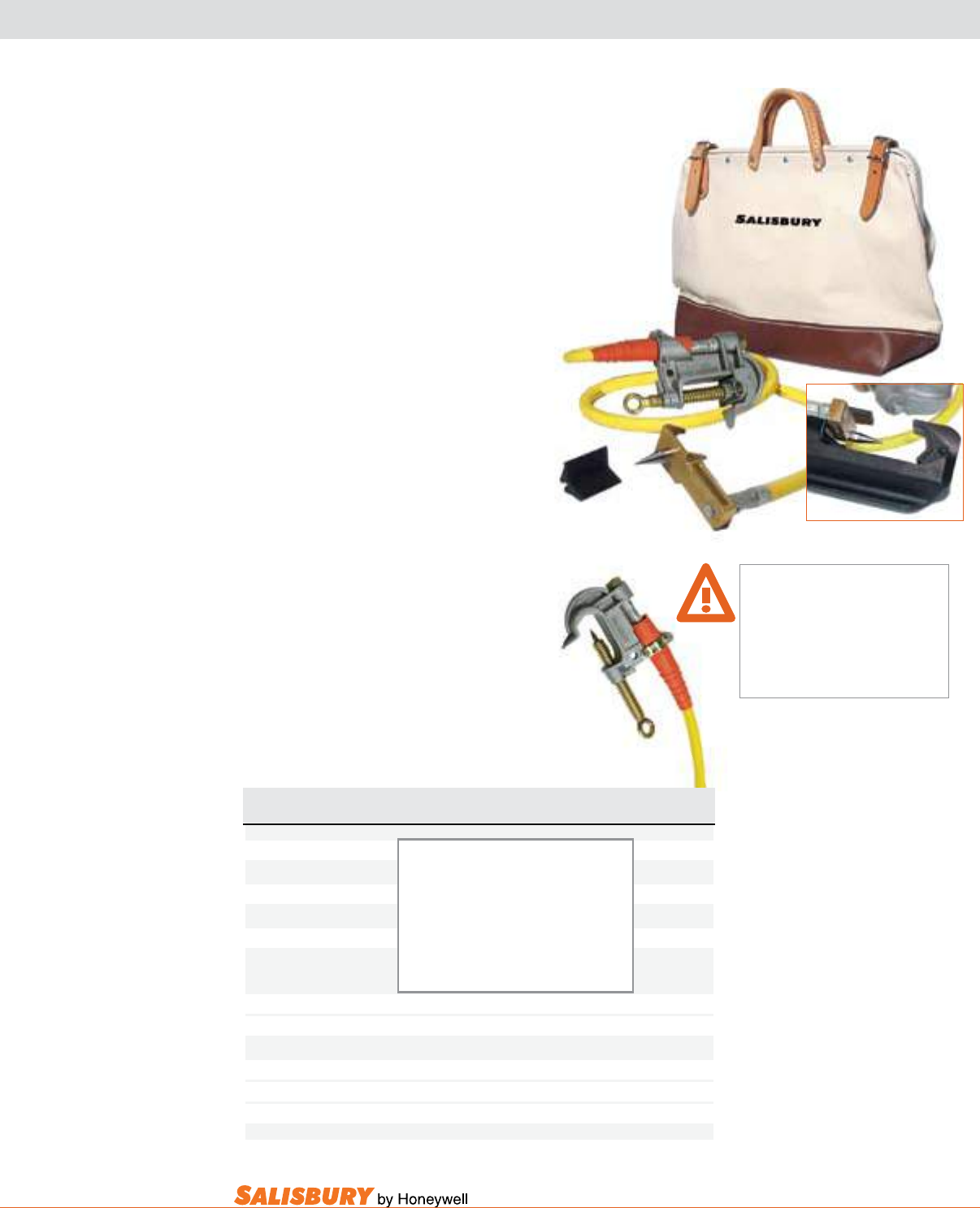
J-11
101 E. Crossroads Pkwy., Ste. A Bolingbrook, IL 60440 toll free ph (USA):877.406.4501 toll free fax (USA):866.824.4922 ph:630.343.3800
2607
HYDRAUlIC CABlE sPIkE
The Hydraulic Cable Spike is designed to
verify underground cable, up to 1000MCM,
is de-energized before cutting, repairing,
splicing or replacing.
The cable spike, a solid brass body with
a stainless steel piercing tip, is fitted to
hydraulic compression tools so that the cable
can be accurately spiked from a safe distance.
An anodized aluminum insert is included to
position the cable precisely.
The Cable Penetrating ground Clamp
is designed to be used either as a tool for
“spiking” jacketed cable or as a part of a
grounding assembly used to bond both ends
of an opened cable. The 7/8” long plated
steel point is inserted into the eye screw
making a low resistant one piece spear. If one
point becomes blunted it may be sharpened
or replaced with a new spear. Clamps are
aluminum body with either smooth or serrated
upper jaws. The hard aluminum serrated
insert makes optimum contact with the
stranded neutral shield.
WARNING: ELECTRIC
SHOCK HAZARD
This tool is not insulated. Use only
certified, non-conductive hoses,
dielectric fluids, and proper personal
protective equipment when using this
unit. Failure to do so could result in
severe injury or death.
24320
Improves Control,
Accuracy and Safety
Saves Time
Remote Controlled
Adapter fits the following tools:
Huskie EP610H
Burndy Y46
Brock 13-H
Cat. No. Cable Length Description Weight ea.
ft ( m ) lbs. ( kgs )
24320 6 ( 1.8 ) Spiking Tool & Grounding Assembly: 9.5 ( 4.3 )
Cable Spiking Tool & Insert
24321 8 ( 2.4 ) 4388 C Clamp 11.2 ( 5.1 )
2139 4/0 Cu Cable
24322 10 ( 3 ) 2025 4/0 Cu Ferrules (Pair) 12.9 ( 5.86 )
616 Bag
US Patent # 544 7450
RPT1 Replacement Piercing Tip 1 oz ( 28 g )
CABLE PENETRATING GROUND CLAMP - Acme Thread - Pointed Lower Jaw
2607 - Aluminum 1.5” Opening, Class B, Serrated Jaw 1.7 ( .8 )
20867 - Aluminum 2.40” Opening, Class B, Serrated Jaw 2.2 ( 1 )
4290 - Aluminum 2.40” Opening, Class A, Smooth Jaw 2.1 ( 1 )
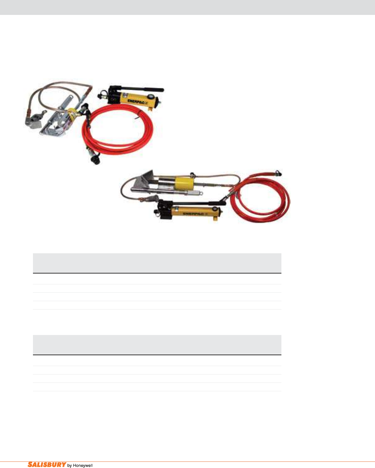
J-12 Grounding Equipment Accessories. www.salisburybyhoneywell.com
HYDRAUlIC GROUND, BlADE, & CABlE sPIkE ClAMPs
Cat. No. Description Pump Cable Assembly ASTM Weight
MDL / p.s.i. Cable Fault / Duty lbs. ( kgs )
Cycles / Grade
HYDRAULIC GROUND SPIKE CLAMPS: Clamp Cat. No. 760001E, Spike Depth 1 5/8”, Conductor Min. 1” - Max. 3”
1715EPP Spike Point w/ Eye Screw 1715PE / 1200 1/0 Clear 14.5kA / 15 / 1 28 ( 12.7 )
17150060EPP Spike Point w/ Eye-T Screw 1715PE / 1200 1/0 Clear 14.5kA / 15 / 1 28 ( 12.7 )
17150060PFP Spike Point w/ Eye-T Screw 1715PE / 1200 1/0 Clear 14.5kA / 15 / 1 32 ( 14.5 )
NOTE: Sufx EPP = Enerpac Pump Sufx PFP = Porter Ferguson Pump
Cat. No. Pump Spike Conductor Cable Assembly ASTM Weight
MDL / p.s.i. Depth Max Cable Fault / Duty lbs. ( kgs )
in. ( cm ) Cycles / Grade
HYDRAULIC BLADE SPIKE CLAMPS: Spike Blade w/ Eye Screw, Clamp Cat. No. 760001E
17150063EPP 1715EP25 / 2500 3” 2 1/4 ( 5.7 ) 1/0 Clear 14.5kA / 15 / 1 30 ( 13.6 )
17150063PFP 1715PF25 / 2500 3” 2 1/4 ( 5.7 ) 1/0 Clear 14.5kA / 15 / 1 34 (15.4 )
17150066 1715P392 / 10000 6” 4 1/2 ( 10.8 ) 1/0 Clear 14.5kA / 15 / 1 85 ( 38.6 )
NOTE: Sufx EPP = Enerpac Pump Sufx PFP = Porter Ferguson Pump
1715EPP
17150066
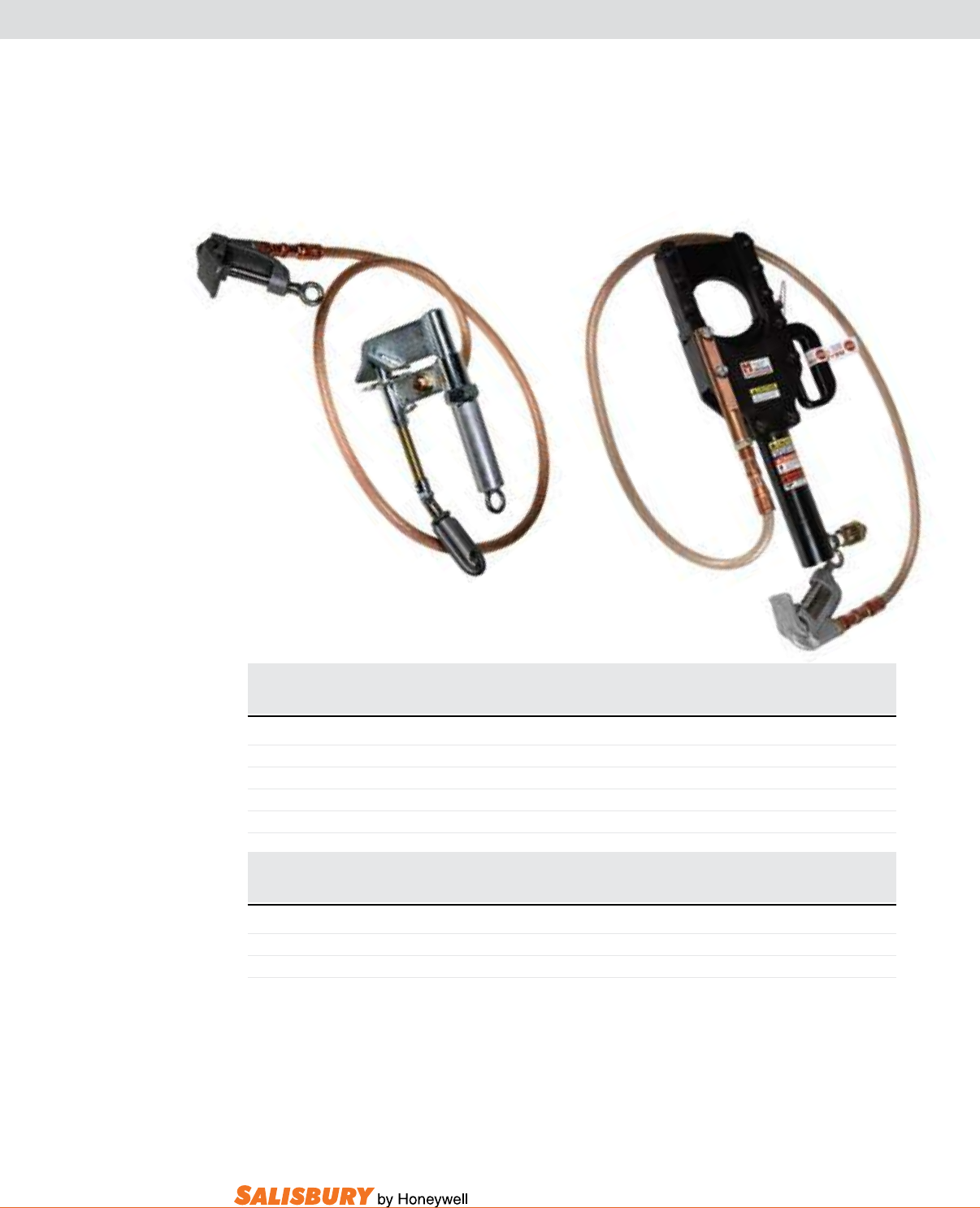
J-13
101 E. Crossroads Pkwy., Ste. A Bolingbrook, IL 60440 toll free ph (USA):877.406.4501 toll free fax (USA):866.824.4922 ph:630.343.3800
HAND OPERATED GROUND sPIkE & HYDRAUlIC CUTTER
Cat. No. Description Pump Cable Assembly ASTM Weight
MDL / p.s.i. Cable Fault / Duty lbs. ( kgs )
Cycles / Grade
HYDRAULIC CUTTER SPIKE: Clamp Cat. No. 760001E, Conductor Min. 0” - Max. 3 1/2”
17150050 Huskie Head N/A / N/A #2 Clear 14.5kA / 15 / 1 23 ( 10.5 )
17150050WPH Huskie Head 1715P392 /10,000 #2 Clear 14.5kA / 15 / 1 52 ( 23.6 )
1712GA
17150050
Cat. No. Description Cable Assembly ASTM Weight
Cable / Clamp Cat. No. Fault / Duty lbs. ( kgs )
Cycles / Grade
HAND OPERATED GROUND SPIKE: Spike Depth 1 3/4”, Conductor Min. 1” - Max. 3 1/2”
1712CS 3’ FG Hndl, Toggle /GA 1/0 Clear / 760001E 14.5kA / 15 / 1 15 ( 6.8 )
1712Q Spike Point w/QC 1/0 Clear / 760001E 14.5kA / 15 / 1 10 ( 4.5 )
1712U Spike Point w/U 1/0 Clear / 760001E 14.5kA / 15 / 1 10 ( 4.5 )
1712GA Spike Point w/GA 1/0 Clear / 760001E 14.5kA / 15 / 1 10 ( 4.5 )
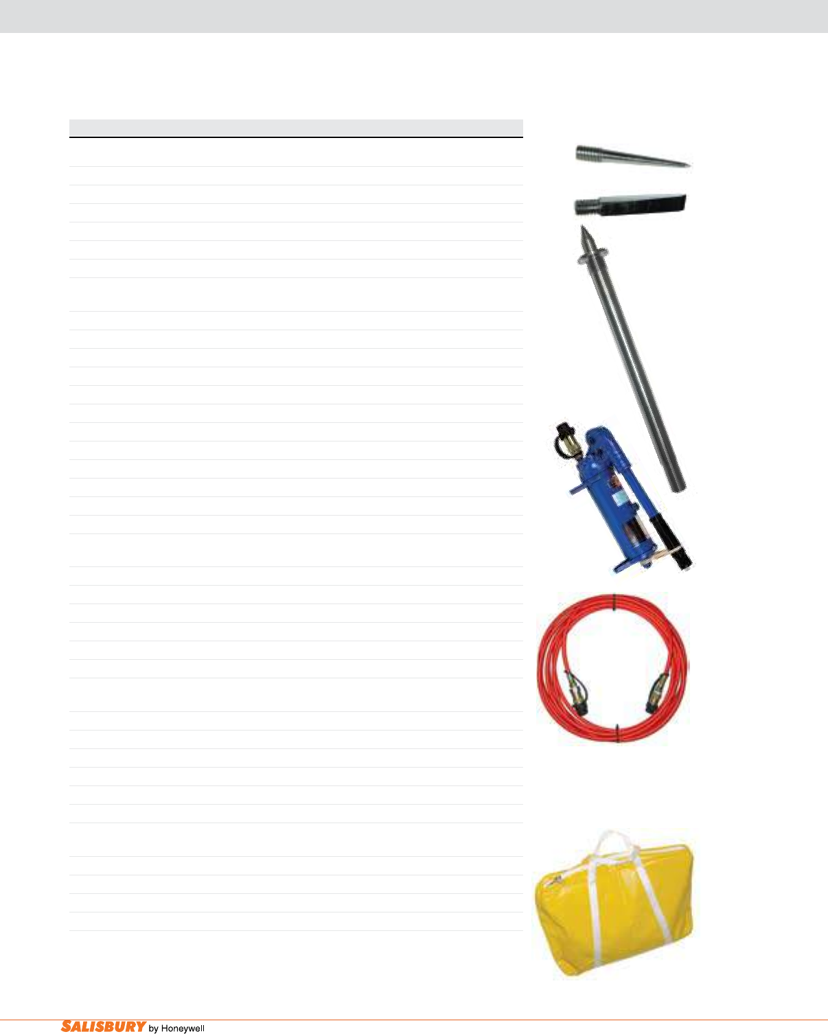
J-14 Grounding Equipment Accessories. www.salisburybyhoneywell.com
ACCEssORIEs FOR UNDERGROUND sPIkE TOOls
Cat. No. Description
Spikes, Blades and Tool Heads
1710E Spike Point Complete for 1710
1710F Spike Blade Complete for 1710
1712E Carbide Spike Point Only
1715E Spike Point Complete for 1715
1715GS Ground Shaft Complete for 1715 (Includes Shaft and Spike Point)
171550SP100A Huskie Cutter Head Only
Hydraulic Pump Assemblies and Pumps
1715PE Enerpac Pump w/ Fittings, 1200 psi
1715P142 Enerpac Pump Only, 1200 psi
1715PE25 Enerpac Pump w/ Fittings, 2500 psi
1715PE14225 Enerpac Pump Only, 2500 psi
1715PE100 Enerpac Pump w/ Fittings, 10000 psi
1715P392 Enerpac Pump Only, 10000 psi
1715PE Enerpac Pump w/ Fittings, 1200 psi
1715PF Porter Ferguson Pump w/ Fittings, 1200 psi
1715SM0033 Porter Ferguson Pump Only, 1200 psi
1715PFSD Porter Ferguson Pump w/ 1/4” Fittings, 1200 psi
1715PF25 Porter Ferguson Pump w/ Fittings, 2500 psi
1715SM003325 Porter Ferguson Pump Only, 2500 psi
Hydraulic Hose Assemblies and Hoses
1715H 30’ Non-conductive Hose w/ Fittings, 3000 psi
1715H1 30’ Hose Only, 3000 psi
1715HSD 30’ Non-conductive Hose w/ 1/4” Fittings, 3000 psi
1715HSD1 30’ Hose Only, 3000 psi
17150066H 30’ High Pressure Non-conductive Hose w/ Fittings, 10000 psi
17150066H1 30’ High Pressure Hose Only, 10000 psi
Hydraulic Ram Assemblies and Rams
1715R Enerpac Ram w/ Fittings, 1 5/8” Stroke
1715RCH121 Enerpac Ram Only, 1 5/8” Stroke
1715RSD Enerpac Ram w/ 1/4” Fittings, 1 5/8” Stroke
171561RCH123 Enerpac Ram Only, 3” Stroke
17150066R Enerpac Ram w/ Fittings, 6” Stroke
1715RCH306 Enerpac Ram Only, 6” Stroke
Protective Bags
B1710 Bag for 1710: 52” x 15” Yellow Vinyl Strap Tie Bag, 4 Tool Compartments, Outer Pocket
B1715 Bag for 1712, 1715, 17150060: 20” x 14” x 5” Yellow Vinyl, Zipper, Outer Pocket, Straps
B17150050 Bag for 17150050, 17150063: 26” x 12” x 8” Yellow Vinyl, Zipper, Outer Pocket, Straps
1370BF1 Storage Box for 17150066: 44” x 12” x 15” Wooden, Hinged, Latched, Forklift Stringers
1710E
1710F
1715PF
1715GS
1715H
B1715

HOT STICKS & TOOLS

K-2 Hot Sticks and Tools. www.salisburybyhoneywell.com
HOT STICKS & TOOLS
FAQ
Q: Are rescue sticks required to be periodically electrically tested?
A: Yes, see OSHA 1910.269(j) for specic testing requirements.
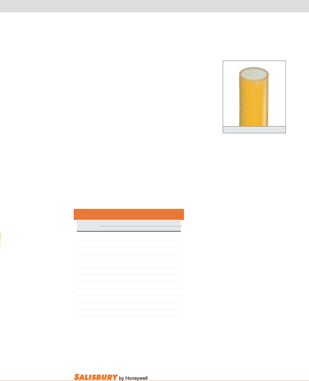
K-3
101 E. Crossroads Pkwy., Ste. A Bolingbrook, IL 60440 toll free ph (USA):877.406.4501 toll free fax (USA):866.824.4922 ph:630.343.3800
FIBERGLASS HOT STICKS
STANDARD SPECIFICATIONS
There are a variety of Fiberglass Reinforced Plastic
(FRP) constructions used for hot sticks. Included are
used in live line tools and IEC 855.
Foam filled hot sticks are manufactured using the
reinforcement in a resin matrix which creates a
moisture resistant laminate with excellent electrical and
Hot Stick blanks must conform with ASTM F711
Live Line Work
Minimum Approach Distance
Nominal Exposure Distance ft.-in ( m )
Voltage kV Phase to Ground Phase to Phase
.05 to 1 avoid contact avoid contact
1.1 to 15 2-1 ( .64 ) 2-2 ( .66 )
15.1 to 36 2-4 ( .72 ) 2-7 ( .77 )
36.1 to 46 2-7 ( .77 ) 2-10 ( .85 )
46.1 to 72.5 3-0 ( .9 ) 3-6 ( 1.05 )
72.6 to 121 3-2 ( .95 ) 4-3 ( 1.29 )
138 to 145 3-7 ( 1.09 ) 4-11 ( 1.5 )
161 to 169 4-0 ( 1.22 ) 5-8 ( 171 )
230 to 242 5-3 ( 1.59 ) 7-6 ( 2.27 )
345 to 362 8-6 ( 2.59 ) 12.6 ( 3.8 )
500 to 550 11-3 ( 3.42 ) 18-1 ( 5.5 )
765 to 800 14-11 ( 4.53 ) 26-0 ( 7.91 )
- These distances take into consideration the highest switch surge an
employee will be exposed to on any system with air as the insulating
medium and the maximum voltage shown.
-The clear live-line total distances shall equal or exceed the values for the
indicated voltage ranges.
Foam Filled Hot Stick
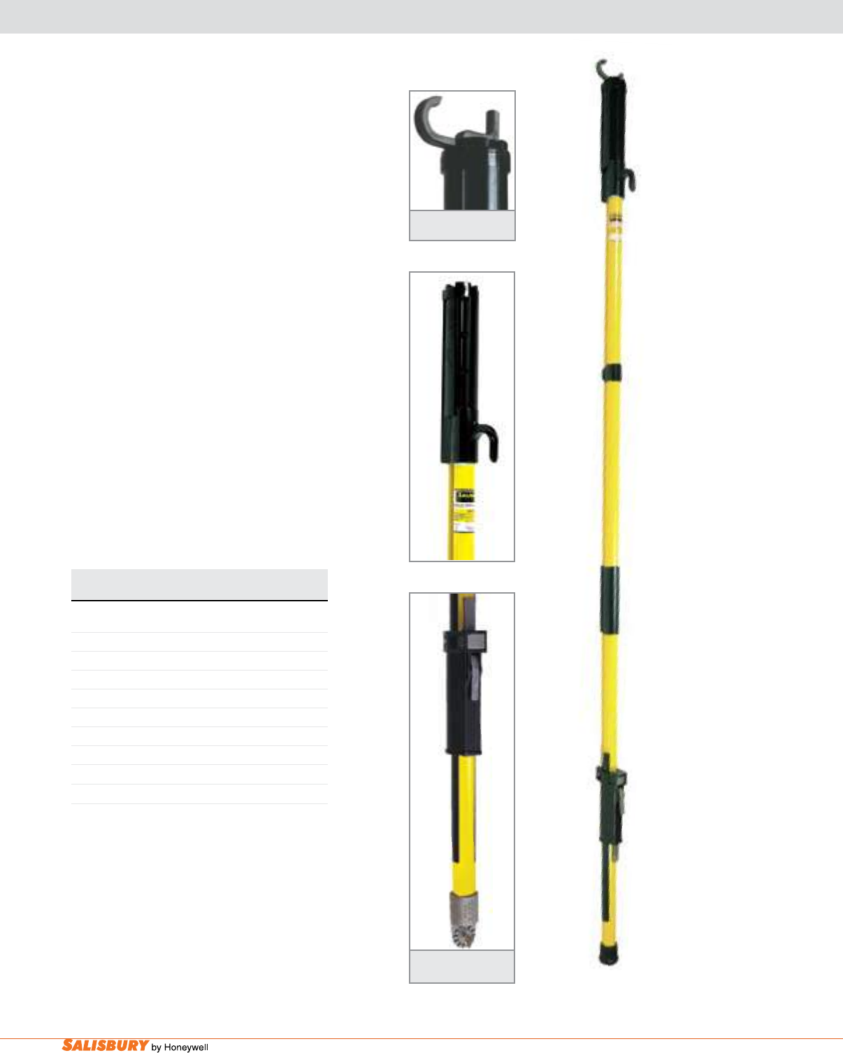
K-4 Hot Sticks and Tools. www.salisburybyhoneywell.com
FRP CLAMPSTICKS
Cat. No. Length Weight ea.
Feet Meters lbs. kgs
EXTERNAL ROD CLAMPSTICK
4007* 4’ 8” 1.32 4.2 1.9
4008* 5’ 8” 1.62 4.6 2.1
4009* 6’ 8” 1.93 5.2 2.4
4010* 8’ 8” 2.54 6.2 2.8
4011* 10’ 8” 3.15 7.0 3.2
4012* 12’ 8” 3.76 7.7 3.5
4013* 14’ 8” 4.37 9.4 4.3
EXTERNAL ROD CLAMPSTICK - PLAIN CAP
8106C 6’6” 1.98 5 2.27
Tough Thermoplastic head ferrule.
EZ Grip plastic hand grip.
Wide opening 15/16” ( 23.8mm)
stainless steel hook.
Heavy duty rubber end cap.
External Rod Clampsticks are constructed
in accordance with ASTM standard F711.
on the exterior of the tool so that it can be
Standards.
Side Opening
Hook
9840 Splined
Universal Head
*Add a “9864” suffix for a Switch Stick Head or a “9840” suffix for
a Splined Universal Head. Clamp sticks may be ordered with these
fittings attached to the end by adding the appropriate suffix to the
catalog number.
External Rod Clampstick
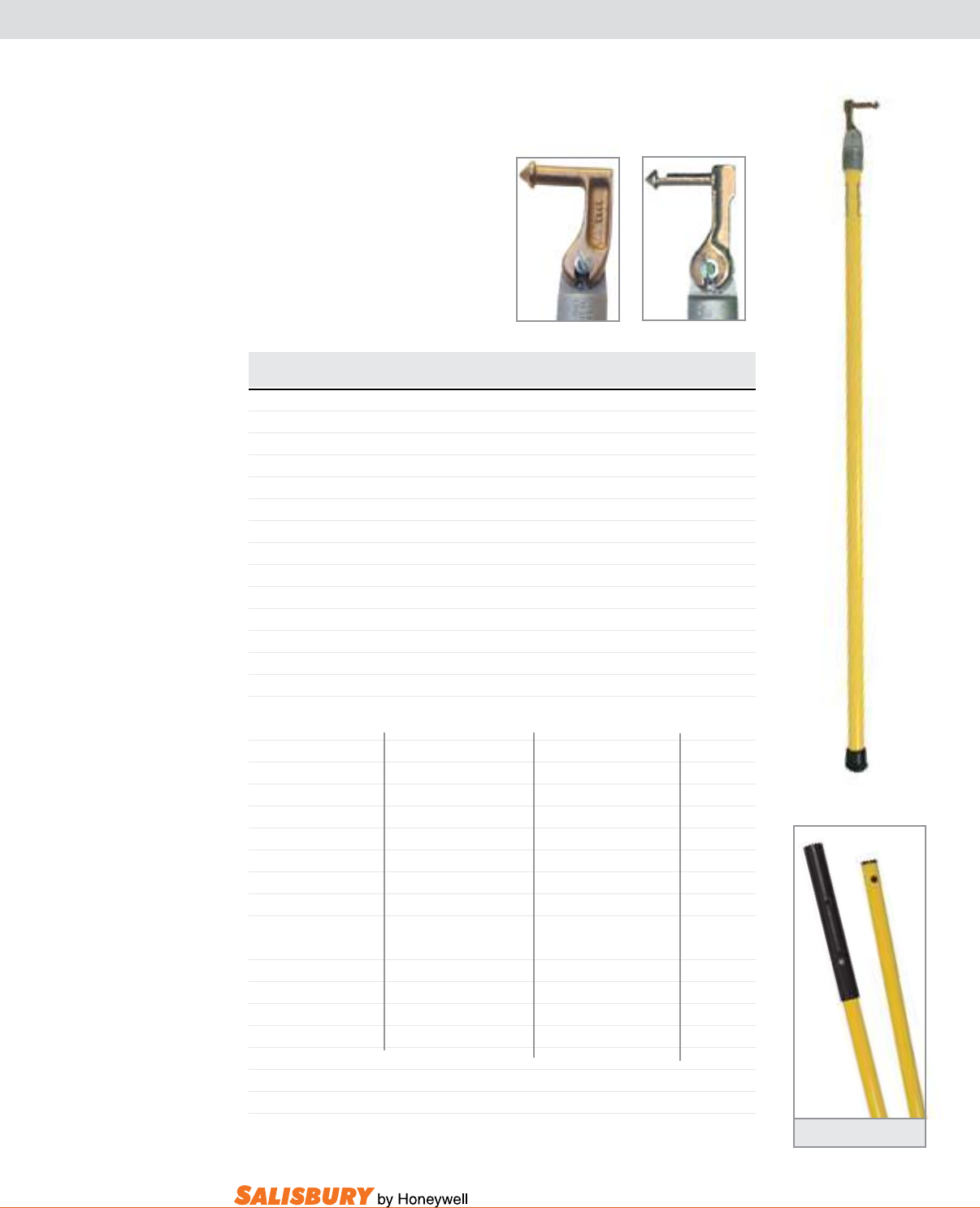
K-5
101 E. Crossroads Pkwy., Ste. A Bolingbrook, IL 60440 toll free ph (USA):877.406.4501 toll free fax (USA):866.824.4922 ph:630.343.3800
UNIVERSAL SWITCH STICKS
FRP Splices with Button
Cat. No. Dimensions: Dia. x Length Weight ea.
lbs. kgs
ONE SECTION in x ft. mm x m
4213 1.25 x 4 31.7 x 1.2 2.6 1.2
4214 1.25 x 6 31.7 x 1.8 3.4 1.5
4215 1.25 x 8 31.7 x 2.4 4.1 1.9
4216 1.25 x 10 31.7 x 3 4.9 2.2
4217 1.25 x 12 31.7 x 3.6 5.6 2.5
4218 1.25 x 14 31.7 x 4.3 6.4 2.9
4219 1.5 x 8 38.1 x 2.4 5.4 2.5
4220 1.5 x 10 38.1 x 3 6.5 3
4221 1.5 x 12 38.1 x 3.6 7.5 3.4
4222 1.5 x 14 38.1 x 4.3 8.6 3.9
4223 1.5 x 16 38.1 x 4.9 9.8 4.3
4225 1.5 x 20 38.1 x 6 11.7 5.3
TWO SECTIONS
OAL Length Top Bottom lbs. kgs
ft. m in. x ft. mm x m in. x ft. mm x m
4036 8 2.4 1.25 x 4 31.7 x 1.2 1.25 x 4 31.7 x 1.2 4.2 1.9
4037 10 3 1.25 x 5 31.7 x 1.5 1.25 x 5 31.7 x 1.5 5.2 2.2
4038 12 3.6 1.25 x 6 31.7 x 1.8 1.5 x 6 38.1 x 1.8 6.9 3.1
4039 14 4.3 1.25 x 6 31.7 x 1.8 1.5 x 8 38.1 x 2.4 7.9 3.1
4040 16 4.9 1.25 x 8 31.7 x 2.4 1.5 x 8 38.1 x 2.4 8.6 3.9
4041 18 5.5 1.25 x 8 31.7 x 2.4 1.5 x 10 38.1 x 3 9.6 4.4
4042 20 6 1.25 x 10 31.7 x 3 1.5 x 10 38.1 x 3 10.4 4.7
THREE SECTION
OAL Length Top Middle / Bottom lbs. kgs
ft. m in x ft. mm x m in. x ft. mm x m
4043 12 3.6 1.25 x 4 31.7 x 1.2 1.5 x 4 38.1 x 1.2 7.7 3.5
4044 15 4.6 1.25 x 5 31.7 x 1.5 1.5 x 5 38.1 x 1.5 9.1 4.1
4045 18 5.5 1.25 x 6 31.7 x 1.8 1.5 x 6 38.1 x 1.8 10.5 4.7
4046 20 6 1.25 x 8 31.7 x 2.4 1.5 x 6 38.1 x 1.8 16.5 7.5
HEAD ONLY
9840 1.25 31.7 Universal Head 0.2 0.1
9841 1.5 38.1 Universal Head 0.3 0.1
9971 Prong
9969 Prong
with a #9971 Prong. A Heavy Duty
on all others.
Universal Switch Stick
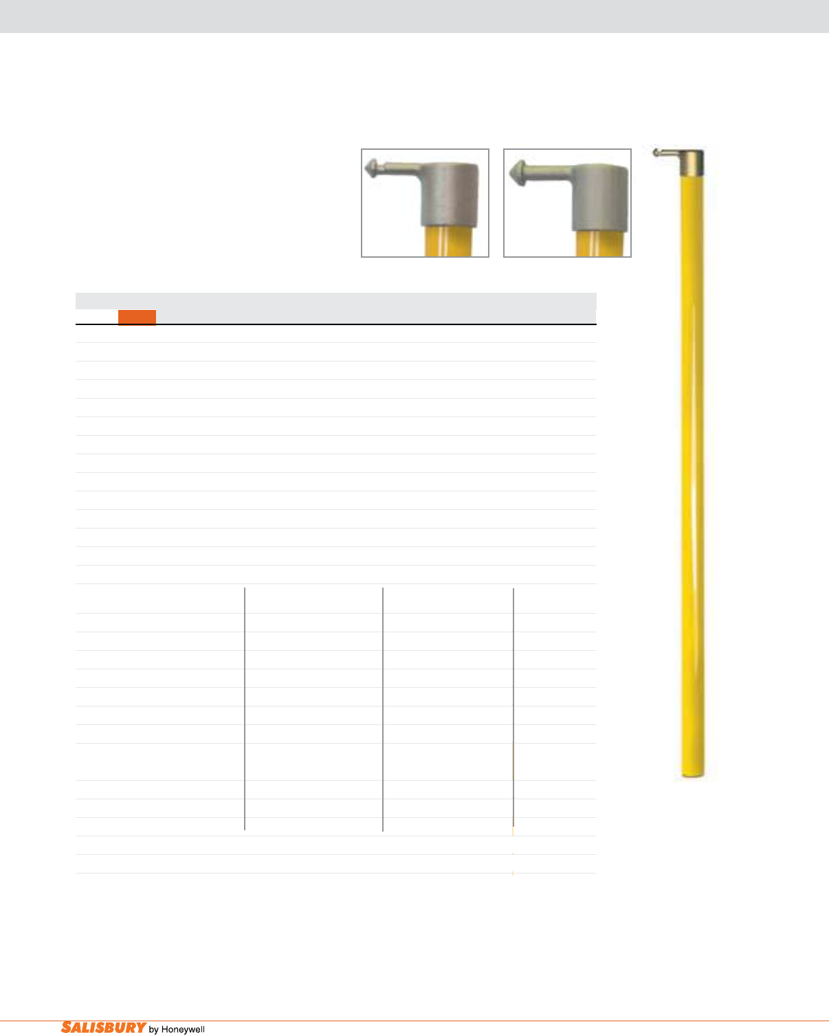
K-6 Hot Sticks and Tools. www.salisburybyhoneywell.com
FIBERGLASS HOT SWITCH STICKS
Switch Sticks
fiberglass made in accordance with ASTM
Standard F711. Both the standard head and the
high strength aluminum bronze alloy.
Standard Prong
Cat. No. Dimensions: Dia. x Length Weight ea.
HD Std Prong in. x ft. mm x m lbs. kgs
ONE SECTION
9950 9933 1.25 x 4 31.7 x 1.2 2.1 1
9951 9934 1.25 x 6 31.7 x 1.8 2.9 1.3
9952 9935 1.25 x 8 31.7 x 2.4 3.6 1.6
9953 9936 1.25 x 10 31.7 x 3 4.4 2
9954 9937 1.25 x 12 31.7 x 3.6 5.1 2.3
9955 9938 1.25 x 14 31.7 x 4.3 5.9 2.7
9956 9939 1.5 x 8 38.1 x 2.4 5 2.3
9957 9940 1.5 x 10 38.1 x 3 6 2.7
9958 9941 1.5 x 12 38.1 x 3.6 7 3.2
9959 9942 1.5 x 14 38.1 x 4.3 8.1 3.7
9960 9943 1.5 x 16 38.1 x 4.9 9.1 4.1
9961 9944 1.5 x 18 38.1 x 5.5 10.2 4.6
9962 9945 1.5 x 20 38.1 x 6 11.2 5.1
TWO SECTION OAL Length Top Bottom
ft. m in. x ft. mm x m in. x ft. mm x m lbs. kgs
4024 - 8 2.4 1.25 x 4 31.7 x 1.2 1.25 x 4 31.7 x 1.2 3.8 1.7
4025 - 10 3 1.25 x 5 31.7 x 1.5 1.25 x 5 31.7 x 1.5 4.6 2.1
4026 4016 12 3.6 1.25 x 6 31.7 x 1.8 1.25 x 6 31.7 x 1.8 5.3 2.4
- 4017 14 4.3 1.25 x 7 31.7 x 2.1 1.25 x 7 31.7 x 2.1 6.1 2.7
4028 4018 16 4.9 1.25 x 8 31.7 x 2.4 1.5 x 8 38.1 x 2.4 8 3.6
4029 - 18 5.5 1.25 x 8 31.7 x 2.4 1.5 x 10 38.1 x 3 9.5 4.3
4030 - 20 6 1.25 x 10 31.7 x 3 1.5 x 10 38.1 x 3 10.3 4.6
THREE SECTION OAL Length Top Middle / Bottom
in. mm in. x ft. mm x m in. x ft. mm x m lbs. kgs
4033 - 18 5.5 1.25 x 6 31.7 x 1.8 1.5 x 6 38.1 x 1.8 10.4 4.7
4034 4035 20 2 1.25 x 8 31.7 x 2.4 1.5 x 6 38.1 x 1.8 11.1 5
HEAD ONLY
- 9864 1.25 31.7 Universal Head 0.4 0.2
9861 - 1.5 38.1 Universal Head 0.5 0.2
Heavy Duty Prong
Fiberglass Hot
Switch Stick
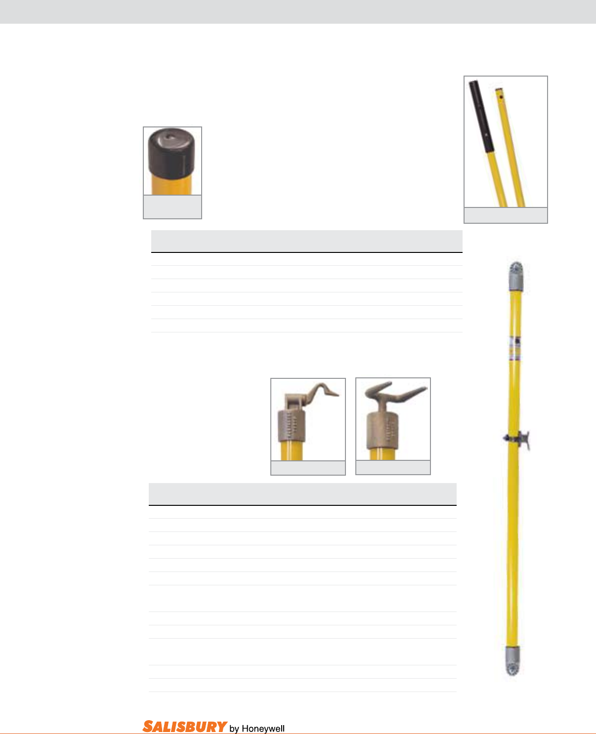
K-7
101 E. Crossroads Pkwy., Ste. A Bolingbrook, IL 60440 toll free ph (USA):877.406.4501 toll free fax (USA):866.824.4922 ph:630.343.3800
UNIVERSAL SWITCH STICKS & ACCESSORIES
DOUBLE ENDED & TIE HEADS
Sticks are manufactured
with extremely high
electrical and mechanical
4084 Rotary Prong 4088 Double Prong Head
Cat. No. Dimensions: Dia. x Length Weight ea.
in. x ft. mm x m lbs. kgs
DOUBLE ENDED UNIVERSAL
4230 1.25 x 6 31.7 x 1.8 3.3 1.5
4231 1.25 x 8 31.7 x 2.4 4 1.8
4232 1.25 x 10 31.7 x 3 4.8 2.2
4233 1.25 x 12 31.7 x 3.6 5.5 2.5
4234 1.25 x 14 31.7 x 4.3 6.3 2.8
UNIVERSAL w/ Rotary Prong or Blade
4084 Rotary Prong 1.25 x 6 31.7 x 1.8 3.8 1.7
4085 Rotary Prong 1.25 x 8 31.7 x 2.4 4.5 2
UNIVERSAL w/ Double Prong
4088 1.25 x 6 31.7 x 1.8 3.8 1.7
4089 1.25 x 8 31.7 x 2.4 4.5 2 Double Ended Universal
Switch Stick
FRP Sleeve Splices
Splice guards
FRP Splices with Button
4182 Cap
Splice Guard
Cat. No. Dimensions Weight ea.
in. mm lbs. kgs
FRP SLEEVE SPLICES
9898 1.25 to 1.25 31.7 to 31.7 0.4 0.2
9897 1.5 to 1.25 38.1 to 31.7 0.8 0.4
9899 1.5 to 1.5 38.1 to 38.1 0.9 0.4
SPLICE GUARD CAP
4182 1.25 I.D. 31.7 I.D. 0.2 0.1
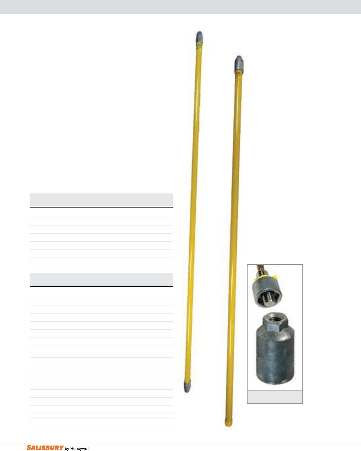
K-8 Hot Sticks and Tools. www.salisburybyhoneywell.com
Cat. No. Diameter x Overall Length Weight
lbs. ( kgs )
CAP & THREADED FERRULE
10078CH 1” x 6’6” ( 2.5 cm x 1.98 m ) 2 ( 0.91 )
10096CH 1” x 8’ ( 2.5 cm x 2.44 m ) 2 ( 0.91 )
12578CH 1 1/4” x 6’6” ( 3.2 cm x 1.98 m ) 2 ( 0.91 )
12596CH 1 1/4” x 8’ ( 3.2 cm x 2.44 m ) 3 ( 1.36 )
15078CH 1 1/2” x 6’6” ( 3.8 cm x 1.98 m ) 5 ( 2.27 )
15096CH 1 1/2” x 8’ ( 3.8 cm x 2.44 m ) 6 ( 2.72 )
FIBERGLASS HOT SWITCH STICKS
DOUBLE ENDED
12578HH
15078CH
Cat. No. Diameter x Overall Length Weight
lbs. ( kgs
TWO THREADED FERRULES
10078HH 1” x 6’6” ( 2.5 cm x 1.98 m ) 2 ( 0.91 )
10096HH 1” x 8’ ( 2.5 cm x 2.44 m ) 2 ( 0.91 )
12578HH 1 1/4” x 6’6” ( 3.2 cm x 1.98 m ) 3 ( 1.36 )
12596HH 1 1/4” x 8’ ( 3.2 cm x 2.44 m ) 4 ( 1.81 )
15078HH 1 1/2” x 6’6” ( 3.8 cm x 1.98 m ) 3 ( 1.36 )
15096HH 1 1/2” x 8’ ( 3.8 cm x 2.44 m ) 6 ( 2.72 )
150120HH 1 1/2” x 10’ ( 3.8 cm x 3.05 m ) 6 ( 2.72 )
TWO INSULATED HEX FERRULES
12578HHM 1 1/4” x 6’6” ( 3.2 cm x 1.98 m ) 4 ( 1.81 )
12596HHM 1 1/4” x 8’ ( 3.2 cm x 2.44 m ) 4 ( 1.81 )
CAP & UNIVERSAL FERRULE
10078CU 1” x 6’6” (2.5 cm x 1.98 m) 2 ( 0.91 )
12578CU 1 1/4” x 6’6” (3.2 cm x 1.98 m) 2 ( 0.91 )
15096CU 1 1/2” x 8’ (3.8 cm x 2.44 m) 6 ( 2.72 )
RAIN GUARD
8900 Rain Guard w/ Hose Clamp 0.2 ( 0.1 )
Fiberglass Handles are manufactured in accordance with the
with a silicote cloth before and after every use.
The most commonly used combinations are shown below.
Other lengths are available. Bags are not included but are
available.
The 8900 rain guard is a yellow molded EPDM shield held in
area if the sticks are used in the rain.
Quick Change Head
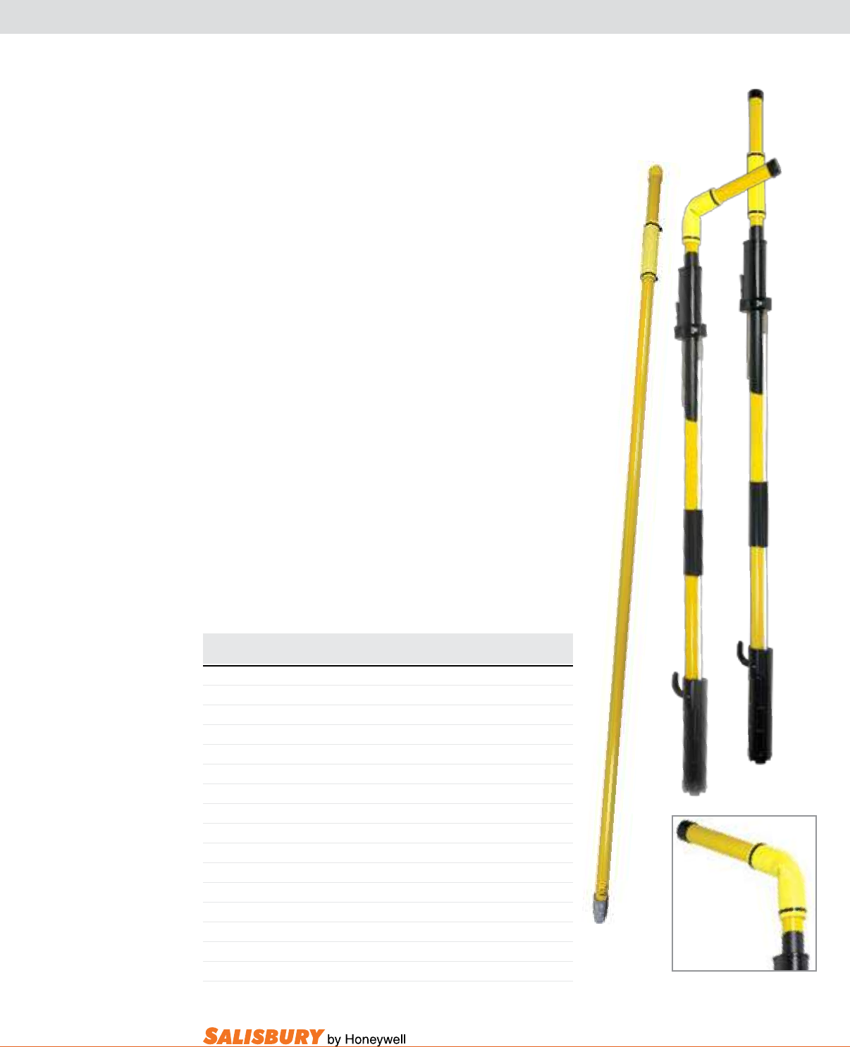
K-9
101 E. Crossroads Pkwy., Ste. A Bolingbrook, IL 60440 toll free ph (USA):877.406.4501 toll free fax (USA):866.824.4922 ph:630.343.3800
TOGGLE HANDLE FIBERGLASS CLAMPSTICKS
MAKE THE JOB EASIER.
Specialized Toggle Handle Increases Leverage.
Fiberglass Hot Switchsticks are manufactured in accordance with
before and after every use.
All Fiberglass Clampsticks
of ASTM F711.
Cat. No. Description Weight
lbs. ( kgs
TOGGLE HANDLE & THREADED FERRULE
12578HE 1 1/4” x 6’6” ( 3.2 cm x 1.98 m ) 4 ( 1.81 )
12596HE 1 1/4” x 8’ ( 3.2 cm x 2.44 m ) 4 ( 1.81 )
12548HE 1 1/4” x 4’ ( 3.2 cm x 1.22 m ) 4 ( 1.81 )
TOGGLE HANDLE & UNIVERSAL FERRULE
12578UE 1 1/4” x 6’6” (3.2 cm x 1.98 m) 4 ( 1.81 )
12596UE 1 1/4” x 8’ (3.2 cm x 2.44 m) 4 ( 1.81 )
12548UE 1 1/4” x 4’ (3.2 cm x 1.22 m) 4 ( 1.81 )
TOGGLE HANDLE & INSULATED HEX FERRULE
12578HEM 1 1/4” x 6’6” (3.2 cm x 1.98 m) 4 ( 1.81 )
12596HEM 1 1/4” x 8’ (3.2 cm x 2.44 m) 4 ( 1.81 )
TOGGLE HANDLE & CLAMPSTICK
8104E 4’6” (1.37m) OAL Toggle Handle Fiberglass Clampstick 4.5 (2.04)
8106E 6’6” (1.98m) OAL Toggle Handle Fiberglass Clampstick 5 (2.27)
8108E 8’6” (2.59m) OAL Toggle Handle Fiberglass Clampstick 6.5 (2.95)
8110E 10’6” (3.2m) OAL Toggle Handle Fiberglass Clampstick 7 (3.18)
12578HE
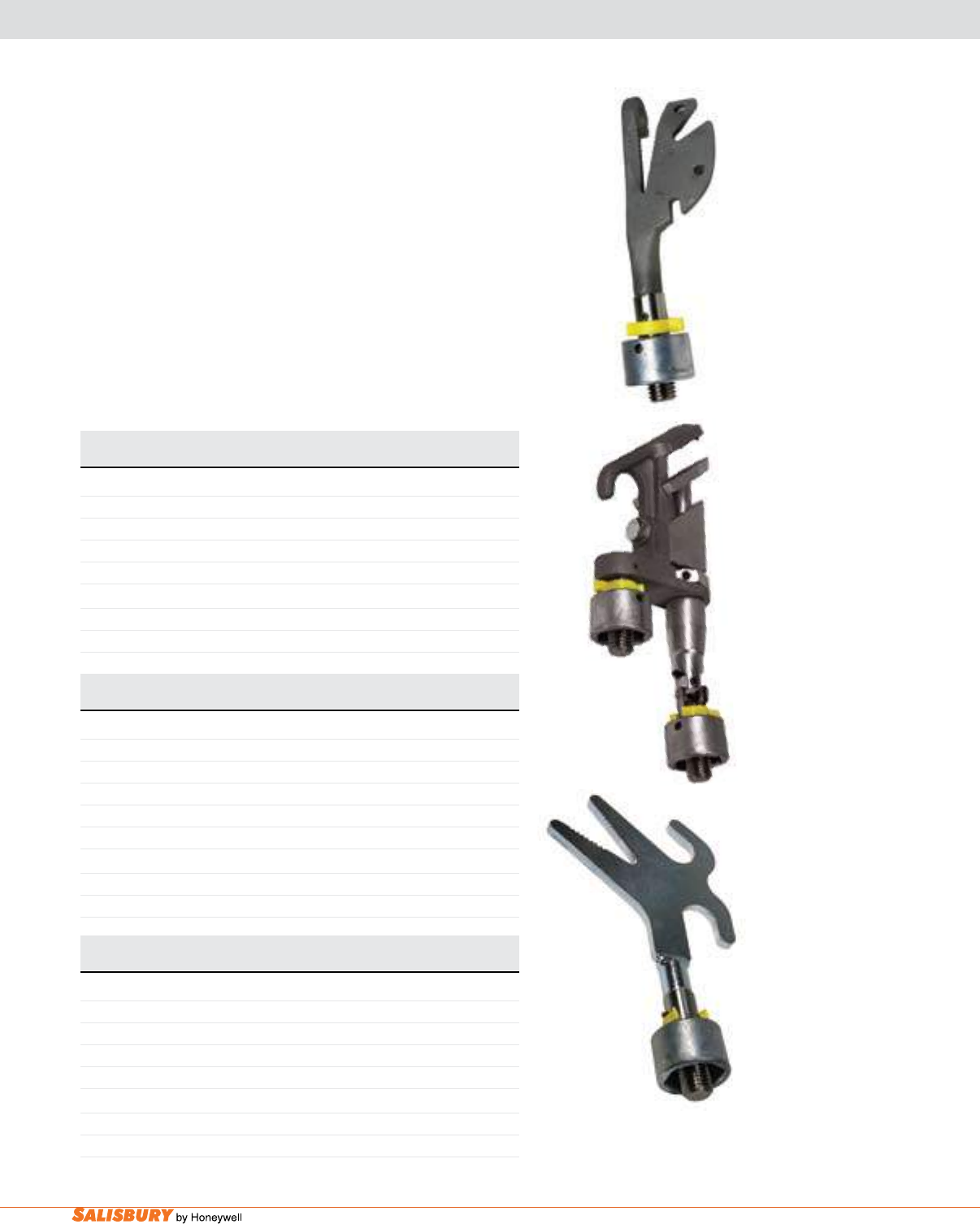
K-10 Hot Sticks and Tools. www.salisburybyhoneywell.com
Cat. No. Description Handle Length Weight
lbs. ( kgs )
ALLIGATOR STICK, Fiberglass handle diameter: 1-1/4” (3.2 cm)
4FGQ Quick Change 6’6” ( 1.98m ) 4 ( 1.81 )
4FGU Universal 6’6” ( 1.98m ) 4 ( 1.81 )
408FGQ Quick Change 8’ ( 2.43 m ) 7 ( 3.18 )
408FGU Universal 8’ ( 2.43 m ) 7 ( 3.18 )
Head Only
4DQ Alligator with Quick Change 1 ( 0.45 )
4DU Alligator with Universal 1 ( 0.45 )
Cat. No. Description Handle Length Weight
lbs. ( kgs )
MECHANICAL HAND STICK, Fiberglass handle diameter: 1-1/4” (3.2 cm)
1FGQ Quick Change 6’6” ( 1.98m ) 4 ( 1.81 )
1FGU Universal 6’6” ( 1.98m ) 4 ( 1.81 )
101FGQ Quick Change 8’ ( 2.43 m ) 5 ( 2.27 )
101FGU Universal 8’ ( 2.43 m ) 5 ( 2.27 )
Head Only
1CQ Mechanical Hand w/ Quick Change 1 ( 0.45 )
1CU Mechanical Hand w/ Universal 1 ( 0.45 )
The mechanical Hand Stick
The Wire Clamp Stick
when cutting and removing.
Use the alligator Stick to install and remove single sheave or double
when changing dead ends.
Cat. No. Description Handle Length Weight
lbs. ( kgs )
WIRE CLAMP STICK
2FGQ Quick Change 6’6” ( 1.98m ) 6 ( 2.72 )
2FGU Universal 6’6” ( 1.98m ) 6 ( 2.72 )
201FGQ Quick Change 8’ ( 2.43 m ) 9 ( 4.08 )
201FGU Universal 8’ ( 2.43 m ) 9 ( 4.08 )
201CFGQ Top Hook and Quick Change 8’ ( 2.43 m ) 9 ( 4.08 )
Head Only
2CQ Wire with Quick Change 3 ( 1.36 )
2CU Wire with Universal 3 ( 1.36 )
1CQ
2CQ
4DQ
SPECIALTY HOT SWITCH STICKS
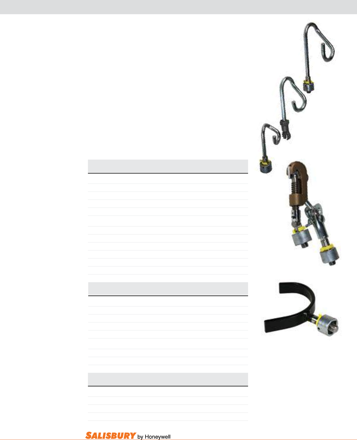
K-11
101 E. Crossroads Pkwy., Ste. A Bolingbrook, IL 60440 toll free ph (USA):877.406.4501 toll free fax (USA):866.824.4922 ph:630.343.3800
Cat. No. Description Handle Length Weight
lbs. ( kgs )
PIGTAIL STICK
5FGQ Quick Change 6’6” ( 1.98m ) 6 ( 2.72 )
5FGU Universal 6’6” ( 1.98m ) 6 ( 2.72 )
501FGQ Quick Change 8’ ( 2.43 m ) 7 ( 3.18 )
501FGU Universal 8’ ( 2.43 m ) 7 ( 3.18 )
Head Only
5C2Q Pigtail w/ Quick Change 7/8” ( 2.2cm ) 1 ( 0.45 )
5C2U Pigtail w/ Universal 7/8” ( 2.2cm ) 1 ( 0.45 )
5C3Q Pigtail w/ Quick Change 1 1/2” ( 3.8cm ) 1 ( 0.45 )
5C3U Pigtail w/ Universal 1 1/2” ( 3.8cm ) 1 ( 0.45 )
5C4Q Pigtail w/ Quick Change 2” ( 5.1cm ) 1 ( 0.45 )
5C4U Pigtail w/ Universal 2” ( 5.1cm ) 1 ( 0.45 )
The Pigtail Stick
The Stranded Wire Holding Stick
(3.8 cm). Other lengths available. Bag not included.
The Cable Handler
SPECIALTY HOT SWITCH STICKS
Cat. No. Description Handle Length Weight
lbs. ( kgs )
STRANDED WIRE HOLDING STICK
121FGQ Quick Change 6’6” ( 1.98m ) 6 ( 2.72 )
1211FGQ Quick Change 8’ ( 2.43 m ) 6 ( 2.72 )
1226FGQ Quick Change 6’6” ( 1.98 m ) 8 ( 3.63 )
1228FGQ Quick Change 8’ ( 2.43 m ) 8 ( 3.63 )
Head Only
121CQ Stranded Wire w/ Quick Change 2 ( 0.91 )
122CQ Stranded Wire w/ Quick Change 2 ( 0.91 )
Cat. No. Description Length Weight
lbs. ( kgs )
CABLE HANDLER
50206 Handle and head 6’6” ( 1.98m ) 3 ( 1.36 )
50208 Handle and head 8’ ( 2.44 m ) 4 ( 1.81 )
5020H Head only 1 ( 0.45 )
5C4Q
5C3U
5C2Q
121CQ
5020H
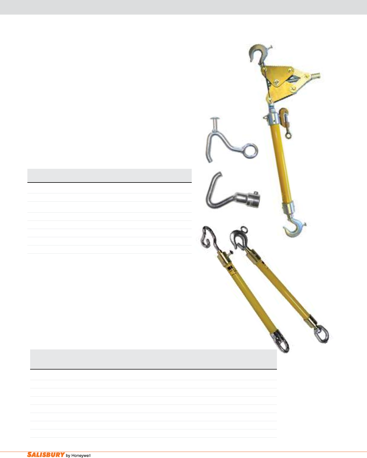
K-12 Hot Sticks and Tools. www.salisburybyhoneywell.com
Cat. No. Overall Length Length Between Fiberglass WLL Weight Cat. No. Weight
in. ( cm ) Ferrules Diameter lbs. ( kgs ) lbs. ( kgs ) lbs. ( kgs )
in. ( cm ) in. ( cm )
INSULATING LINK STICKS
50012EH 22 ( 55.9 ) 12 ( 30.5 ) 1 ( 2.5 ) 2,500 ( 1,134 ) 3 ( 1.36 ) B522 Bag 1 ( 0.45 )
50012EP 22 ( 55.9 ) 12 ( 30.5 ) 1 ( 2.5 ) 2,500 ( 1,134 ) 3 ( 1.36 ) B522 Bag 1 ( 0.45 )
5012EH 22 ( 55.9 ) 12 ( 30.5 ) 1 1/4 ( 3.2 ) 2,500 ( 1,134 ) 2 ( 0.91 ) B522 Bag 1 ( 0.45 )
5012 22 ( 55.9 ) 12 ( 30.5 ) 1 1/4 ( 3.2 ) 1,500 ( 682 ) 2 ( 0.91 ) B522 Bag 1 ( 0.45 )
5012R 22 ( 55.9 ) 12 ( 30.5 ) 1 1/4 ( 3.2 ) 1,500 ( 682 ) 2 ( 0.91 ) B522 Bag 1 ( 0.45 )
5112 24 ( 61.0 ) 12 ( 30.5 ) 1 1/2 ( 3.8 ) 2,500 ( 1,134 ) 2 ( 0.91 ) B522 Bag 1 ( 0.45 )
2512 28 ( 71.1 ) 12 ( 30.5 ) 1 ( 2.5 ) 10,000 ( 4,536 ) 2 ( 0.91 ) B522 Bag 1 ( 0.45 )
The Insulating link Sticks
available.All bags hold 3 link sticks.Bags not included.
SECTIONALIZER KIT & INSULATING LINK STICKS
5012 5012EH
The Sectionalizer Kit
sectionalizers to isolate the section of line that is in trouble.
The conductor is then cut and cleared.
Cat. No. Description Weight
lbs. ( kgs )
SECTIONALIZER KIT
1370SL Set includes: 3 of 1370A, 1 of 1370H, 1 of 1370FB 100 ( 45.3 )
PARTS
1370A One Sectionalizer Only, 25 kV, 36” (0.91 m) 12 ( 0.91 )
1370H Hook with 1/2” Drive 1 ( 0.45 )
1370HR Hold Down Hook with Ring 1 ( 0.45 )
1370V Wire Holder, 9/16” (1.43 cm) max. size wire 2 ( 0.91 )
1370FB Box w/ Inserts 44” x 12” x 16” (112 x 31 x 41 cm) 60 ( 27.22 )
1370H
1370A
1370HR
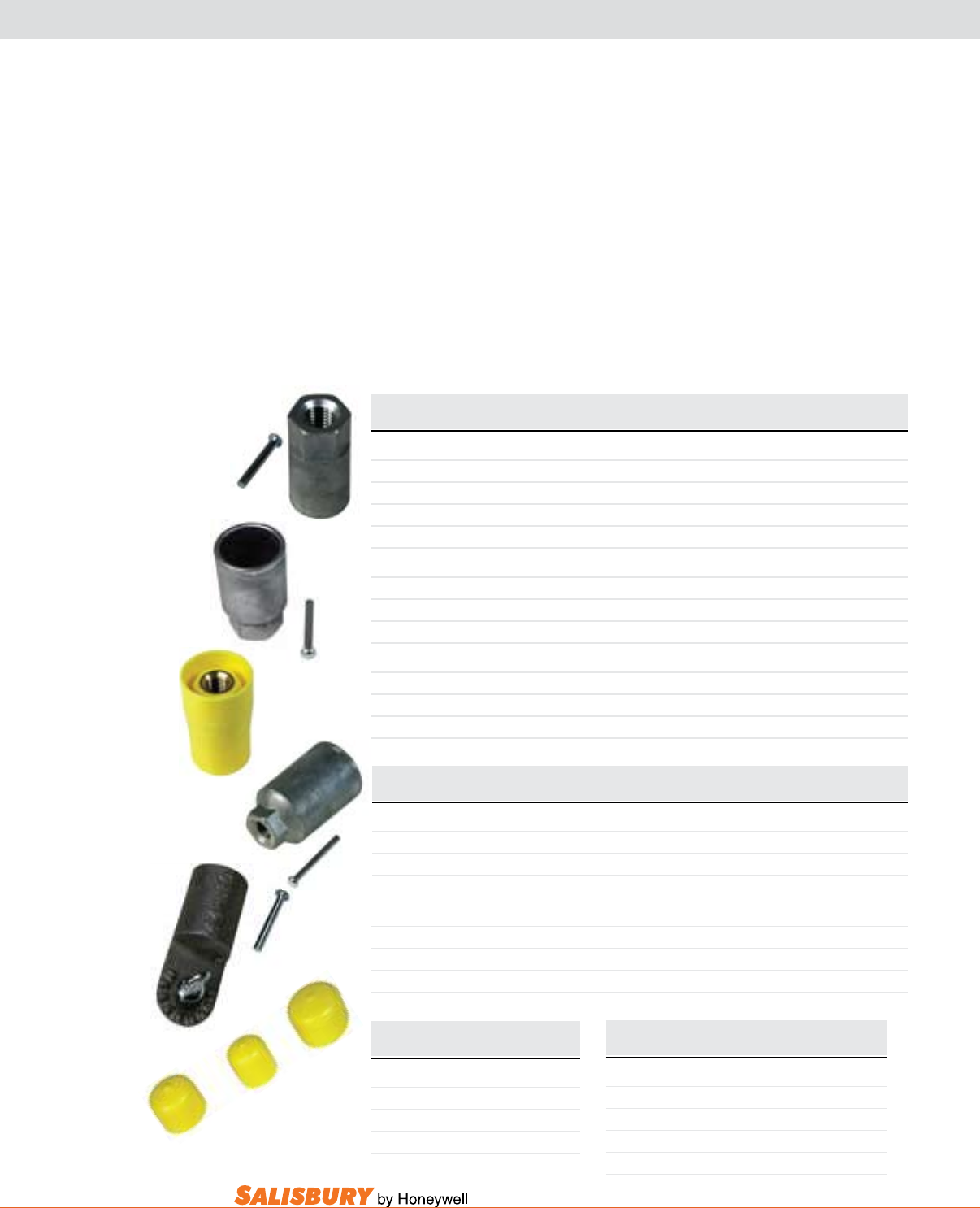
K-13
101 E. Crossroads Pkwy., Ste. A Bolingbrook, IL 60440 toll free ph (USA):877.406.4501 toll free fax (USA):866.824.4922 ph:630.343.3800
FERRULES & ACCESSORIES
Universal and 5/8”-11 threaded hex
include a disc and rivet.
Kits
adhesive and instructions.
Cat. No. Description Size Weight
oz ( g )
HEXAGONAL FERRULES
44DFG 5/8”-11 - Zinc 1” ( 2.5 cm ) 4 ( 124 )
4EFG 5/8”-11 - Zinc 1 1/4” ( 3.2 cm ) 5 ( 156 )
4EFGM Insulated Hex Ferrule w/ Brass Threaded Insert 5/8”-11 1 1/4” ( 3.2 cm ) 5 ( 156 )
5EFG 5/8”-11 - Zinc 1 1/2” ( 3.8 cm ) 12 ( 373 )
UNIVERSAL FERRULES
44UFG Aluminum with Thumb Screw 1” ( 2.5 cm ) 4 ( 124 )
3400 Aluminum with Thumb Screw 1 1/4” ( 3.2 cm ) 5 ( 156 )
5EFGU Zinc/Bronze with Thumb Screw 1 1/2” ( 3.8 cm ) 1 lbs. (450 g)
RIVETS
RH1881375 For 1” Ferrules 3/16” x 13/8” ( 5 x 34 mm ) 1 ( 31 )
RH1881625 For 1-1/4” Ferrules 3/16” x 15/8” ( 5 x 41 mm ) 1 ( 31 )
RH1882000 For 1-1/2” Ferrules 3/16” x 2” ( 5 x 51 mm ) 2 ( 62 )
Cat. No. Handle Diameter Weight
oz ( g )
HEXAGONAL FERRULE KITS
44EK001 1” ( 2.5 cm ) 4 ( 124 )
4EK001 1 1/4” ( 3.2 cm ) 4 ( 124 )
5EK001 1 1/2” ( 3.8 cm ) 4 ( 124 )
UNIVERSAL FERRULE KITS
44UK001 1” ( 2.5 cm ) 4 ( 124 )
4UK001 1 1/4” ( 3.2 cm ) 4 ( 124 )
5UK001 1 1/2” ( 3.8 cm ) 4 ( 124 )
Cat. No. Description
CAPS
C100 1” ( 2.5 cm ) Cap
C125 1 1/4” ( 3.2 cm ) Cap
C150 1-1/2” ( 3.8 cm ) Cap
Cat. No. Description Weight
oz ( g )
HANDLE CLEANERS
2000SC Silicote Cloth 4 ( 124 )
2001 Towelette 1 ( 31 )
2002 1-Gal Bottle 9 lbs. (4 kgs)
2003 16ozSprayBottle 19(.53)
Use the Silicote Cloth
which leaves a thin coating on the insulating handles.
using the silicote cloth. Regular use of the silicote cloth will
add to the life and safety of insulating handles. Packaged
Handle Cleaner is formulated to clean and condition
44DFG
4EFG
4EFGM
5EFG
44UFG
C100
C125
C150
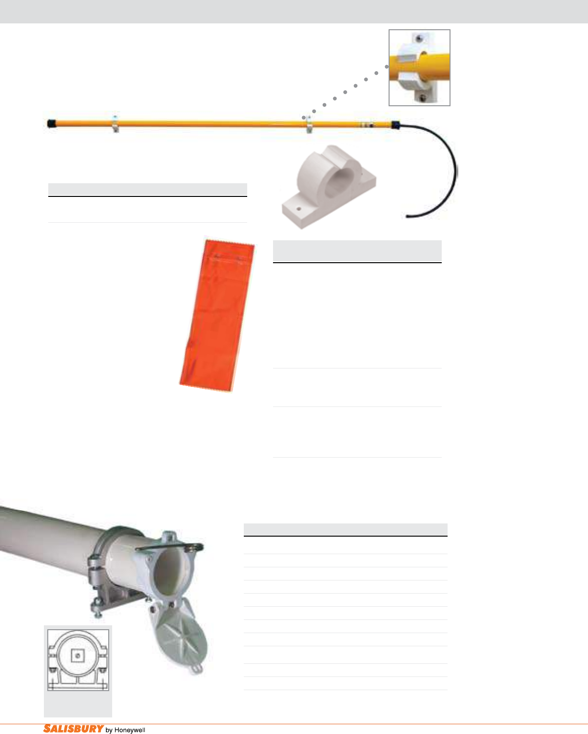
K-14 Hot Sticks and Tools. www.salisburybyhoneywell.com
4155
STORAGE FOR HOT STICKS & TOOLS
Cat. No. Length Weight ea.
Feet meters lbs. ( kgs )
HOT STICK BAGS
4297 5 1.5 .7 ( .3 )
4298 6 1.8 .8 ( .3)
4299 6’ 4” 1.9 .9( .4 )
4300 7 2 1 ( .4 )
4301 8’4” 2.5 1.1 ( .5 )
4302 9 2.7 1.2 ( .5 )
4303 10’4” 3 1.4 ( .6 )
4” I.D. TUBULAR PVC STORAGE KIT
4155 7 2.13 17 ( 7.7 )
4156 9 2.74 20 ( 9 )
6” I.D. TUBULAR PVC STORAGE KIT
4167 6 1.82 20 ( 9 )
4168 7 2.13 22 ( 10 )
4169 9 2.74 26 ( 11.7 )
Hot Stick bags are constructed of
heavy vinyl with double stitched
shorter than bag length shown
on chart.
1192
Cat. No. Description lbs. ( kgs )
1192 1.25 ( 32mm ) I.D. Tool Holder 3.5 ( 1.6 )
SalCOR® Tool Holders
Hot Stick Bag
Cat. No. Description/Dimensions in. ( mm ) lbs. ( kgs )
9822 Kit for 6” ( 152 ) I.D. 6.6” ( 168 ) O.D. tube 8 ( 3.5 )
9823 Kit for 4.1” ( 104 ) I.D. 4.5” ( 114 ) O.D. tube 6 ( 2.7 )
C4007 I.D. 4” ( 102 ) 7’ ( 2.13m ) 19 ( 8.62 )
C4009 I.D. 4” ( 102 ) 9’ ( 2.75m ) 22 ( 9.98 )
C4011 I.D. 4” ( 102 ) 11’ ( 3.35m ) 26 ( 11.79 )
C4013 I.D. 4” ( 102 )13’ ( 3.96m ) 29 ( 13.15 )
C4017 I.D. 4” ( 102 ) 17’ ( 5.18m ) 36 ( 16.33 )
C4020 I.D. 4” ( 102 ) 20’ ( 6.08m ) 40 ( 18.15 )
CONTAINER KITS
C4000 Kit w/o Lock I.D. 4” ( 102 ) 6 ( 2.72 )
C4000L Kit w/ Lock I.D. 4” ( 102 ) 9 ( 4.08 )
Tubular PvC Storage Containers
weather tight storage. Kit includes two mounting
with mounting brackets only.
5.75” (146mm) or
8” (203mm) width
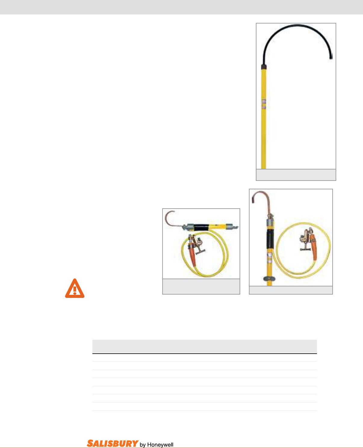
K-15
101 E. Crossroads Pkwy., Ste. A Bolingbrook, IL 60440 toll free ph (USA):877.406.4501 toll free fax (USA):866.824.4922 ph:630.343.3800
RESCUE HOOK, STATIC DISCHARGE STICK
Salisbury Insulated Rescue Hook is an invaluable tool
insulation and a coated heat treated body hook with an
of 6 and 8-foot lengths. Other lengths are available as a
The Static discharge Stick is designed to safely
remove the static charge after de-energizing. This
filled tubular fiberglass
grounding cable attached
1’ length stick.
WaRnIng:
Discharge sticks are not
grounding tools as described
carry no fault duty rating.
Cat. No. Dimensions Weight ea.
in. mm lbs. kgs
INSULATED RESCUE HOOK
24400 Rescue Hook 3’ (0.9 m) length 3.4 ( 1.5 )
24401 Rescue Hook 6’ (1.8 m) length 4.5 ( 2 )
24403 Rescue Hook 8’ (2.4 m) length 5.5 ( 2.5 )
STATIC DISCHARGE STICK
20817 Static Discharge Stick OAL 3’8” (1.08m) length 8 ( 3.6 )
22629 Static Discharge Stick w/ Universal Attachment 1’ (0.3m) length .38 ( 0.17 )
Insulated Rescue Hook
Static Discharge Stick
Static Discharge Stick
w/ Universal Attachment
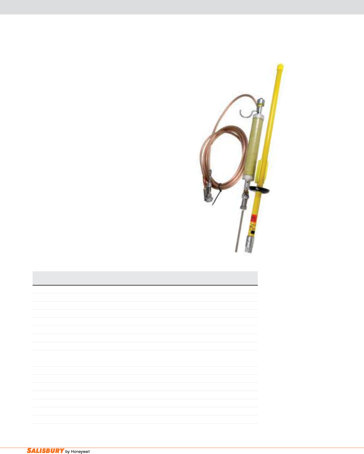
K-16 Hot Sticks and Tools. www.salisburybyhoneywell.com
STATIC DISCHARGE STICKS
a discharge Hook
A discharge Hook
Resistive discharge Hooks/Probes
resistors for residual discharge. Resistive discharge hooks
FOR DISCHARGE ONLY. DO NOT USE AS LIVE LINE TOOL OR GROUNDING DEVICE.
Cat. No. Description Weight ea.
lbs. ( kgs )
FUSED DISCHARGE HOOK
1930535415Q Fused Discharge Hook 10 ( 4.53 )
DISCHARGE HOOK Ground Lead Length
1925 5’ ( 1.52 m ) 2 ( 0.91 )
19257 7’ ( 2.13 m ) 2.5 ( 1.13 )
19258 8’ ( 2.44 m ) 3 ( 1.36 )
192510 10’ ( 3.05 m ) 4.5 ( 2.04 )
192520 20’ ( 6.10 m ) 5 ( 2.27 )
RESISTIVE DISCHARGE HOOK/PROBES
Handle Length Ground Lead Length
19250005 23” ( 0.58 m ) 5’ ( 1.52 m ) 2 ( 0.91 )
192500655 7’ ( 2.13 m ) 10’ ( 3.05 m ) 4.5 ( 2.04 )
19250007 5’ ( 1.52 m ) 7’ ( 2.13 m ) 4 ( 1.81 )
ACCESSORIES
1925SSMC Mounting Clip, Stainless Steel 3 oz ( 84 g )
1925MC Mounting Clip 3 oz ( 84 g )
1925DMC Mounting Clip with Hardware 4 oz ( 112 g )
1930535415Q
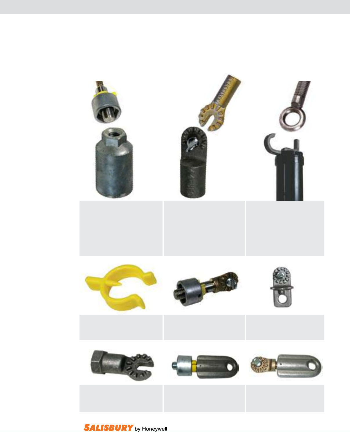
K-17
101 E. Crossroads Pkwy., Ste. A Bolingbrook, IL 60440 toll free ph (USA):877.406.4501 toll free fax (USA):866.824.4922 ph:630.343.3800
TOOLS
Tool Heads are used in live line applications. This
equipment should be mounted on suitable handles to
ensure proper distance from live conductors. Below are
the choices of end tings available. All tools have one of
these three ttings.
QUICK CHANGE END FITTING
Has a 5/8”-11 threaded stud that threads into
the top of a hexagonal ferrule. A hexagonal
collar slides down and over the hexagonal ferrule
making a strong, positive connection. A plastic
safety clip is used to lock the quick change end
fitting to an insulating handle.
UNIVERSAL END FITTING
Gives the user the option to position and secure
an universal tool head at several angles. It also
allows meters to be attached to universal handles.
Universal fittings can be installed on universal
sticks by using the 2500 shotgun adapter.
GRIP ALL or EYE SCREW
END FITTING
For use with the clamp stick. The hook from the
clamp stick is hooked through the eye hole of
the eye screw, then drawn into the clamp stick
and secured.
Safety Clip for Quick Change
Locks a quick change tool head to handle.
320E .1 oz (3 g)
Convertible Adapter
3402Q Changes QC to GA 8 oz (224 g)
Convertible Adapter
3401Q Changes QC to U 1 lbs. (0.45 kgs)
3401TS Thumb Screw Only 1 lbs. (0.45 kgs)
Convertible Adapter
5/8” - 11 Internal Thread
3403 Changes QC to U 3 oz (93 g)
Convertible Adapter
3402U Changes GA to U 6 oz (168 g)
Convertible Adapter
2500 Shotgun Adaptor .4 lbs ( .2 kgs )
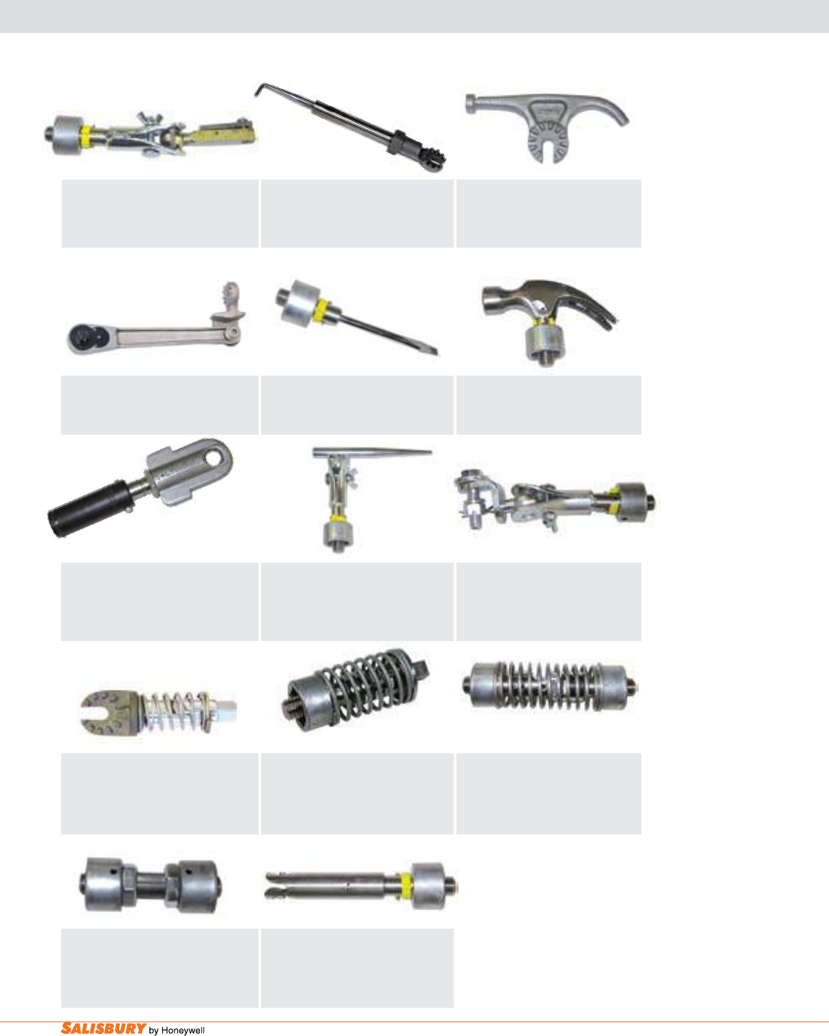
K-18 Hot Sticks and Tools. www.salisburybyhoneywell.com
Quick Change Handle Splice Joint
3301 2 lbs (0.91 kgs)
Bayonet Ferrule
Installs/removes ground heads with bayonet studs.
98B 1 lbs. (0.45 kgs)
Add suffix “U” for Universal, “Q” for Quick Change
Screwdriver
13 Screwdriver 8 oz (0.23 kgs)
Add suffix “U” for Universal, “Q” for Quick Change
Hammer
165 1 lbs. (0.45 kgs)
Add suffix “U” for Universal, “Q” for Quick Change
Toggle & Spring
The 1/2” (1.3 cm) square drive converts
handles into a socket stick.
5900 2 lbs. (0.91 kgs)
Add suffix “U” for Universal, “Q” for Quick Change
Handle Splice Joint & Spring
Splices two handles together creating a flexible
handle.
3302 2 lbs (0.91 kgs)
Add suffix “U” for Universal, “Q” for Quick Change
Locating Drift
Use where aligning or hardware fitting is difficult.
8A 2 lbs. (.91 kgs)
Add suffix “U” for Universal, “Q” for Quick Change
Cotter Key Remover
11 Remover 12 oz (0.38 kgs)
1101 Spring Loaded Remover 12 oz (0.38 kgs)
Add suffix “U” for Universal, “Q” for Quick Change
TOOLS
Wrench Attachment
9 2 lbs. (0.91 kgs)
Add suffix “U” for Universal, “Q” for Quick Change
Switch Disconnect w/ Hammer Head
1900U .19 lbs. (.08 kgs)
GA Adapter w/ Square Drive & Spring-
Loaded Socket
3402L5934 1/2” (1.3 cm) Square Drive
3/4” (1.9 cm) Socket
2 lbs (0.91 kgs)
Flex Head Socket Wrench
4114 1.2 lbs ( .5 kgs )
Ratchet Wrench
4115 1/2” ( 12.7 mm ) sq. drive
.5 lbs ( .22 kgs )
Cotter Key Installer
3500 1 lbs. (0.45 kgs)
Add suffix “U” for Universal, “Q” for Quick Change
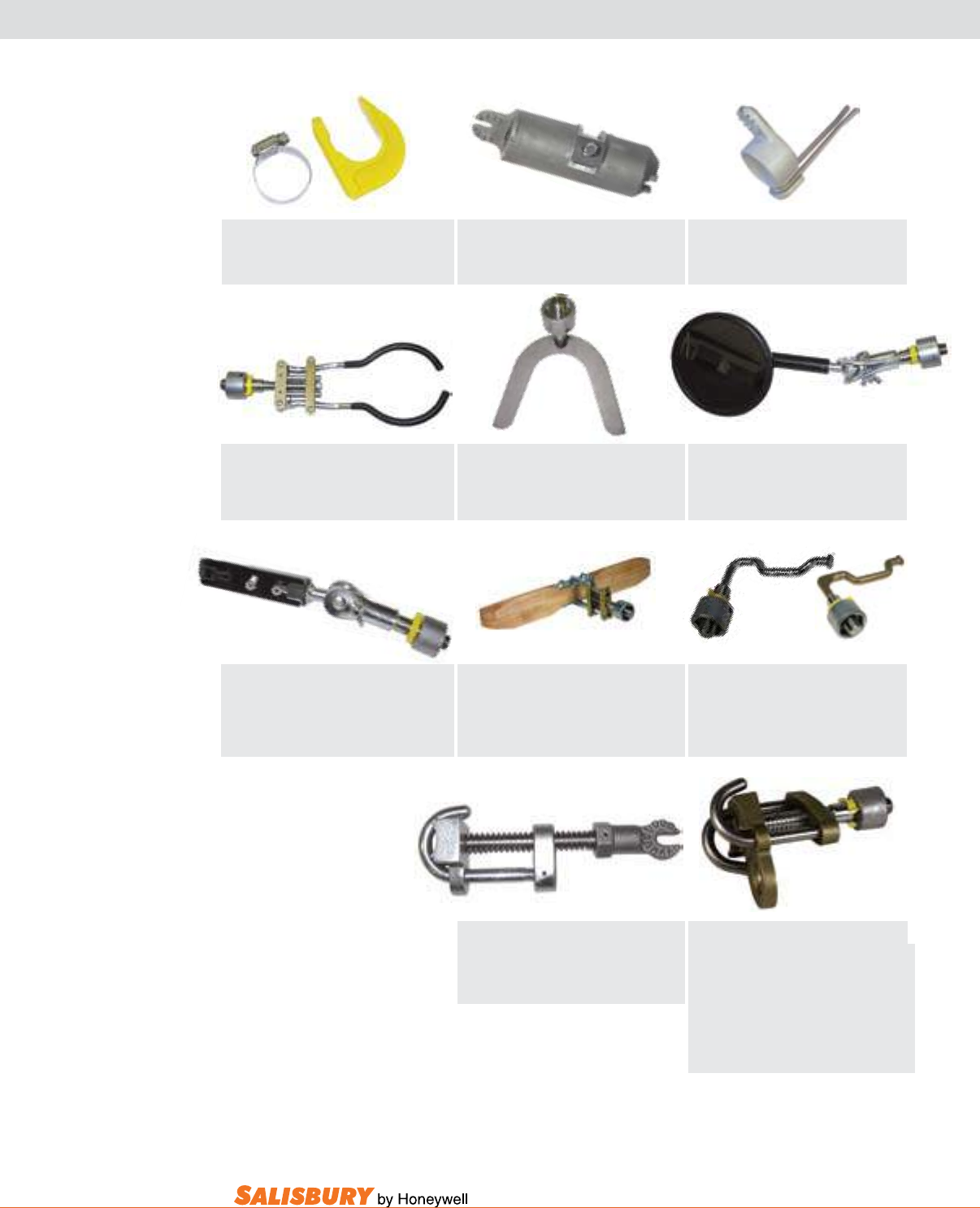
K-19
101 E. Crossroads Pkwy., Ste. A Bolingbrook, IL 60440 toll free ph (USA):877.406.4501 toll free fax (USA):866.824.4922 ph:630.343.3800
Adjustable Insulator Fork
8300 2 lbs. (0.91 kgs)
Add suffix “U” for Universal, “Q” for Quick Change
Insulator Fork
Used in handling ball and socket insulators.
8301 2 lbs. (0.91 kgs)
Add suffix “U” for Universal, “Q” for Quick Change
Pin Holder for Clevis-Type Insulators
2900 1 lbs. (0.45 kgs)
Add suffix “U” for Universal, “Q” for Quick Change
Inspection Mirror
9900 5” (12.7 cm) dia. 8 oz. (224 g)
Add suffix “U” for Universal, “Q” for Quick Change
Hanging Hook
Attaches to all fiberglass handles.
190HC 3 oz. (84 kgs)
Wire Grip
Grips conductor, has hole for block or line hook.
WWL for grip is 1,000 lbs (454 kgs) at a 4:1 ratio.
3600 Opening min.5/16” max.7/8” 2 lbs (0.91 kgs)
(7.9mm, 2.2cm)
3601 Opening min.1/2” max.1-1/2” 3 lbs. (1.36 kgs)
(1.3cm, 3.8cm)
Add suffix “U” for Universal, “Q” for Quick Change
TOOLS
Clamp Stick Head
9834 Clamp Stick Head 1.4 lbs ( .6 kgs )
Universal System Tool Blanket Pin
UST 1 lb. ( .45 kgs )
Dead End Automatic Sleeve Applicator
Dia. 1/4” to 1 1/2” (6.4 to 38 mm)
16 2 lbs. (0.91 kgs)
Add suffix “U” for Universal, “Q” for Quick Change
Extension Offset Switch Hook
Safely removes fuses from outdoor disconnects.
190001 Steel 1 lbs. (0.45 kgs)
190002 Aluminum/Bronze 1 lbs. (0.45 kgs)
Add suffix “U” for Universal, “Q” for Quick Change
Line Hose Applicator
2” x 18” (5.1 x 45.7 cm) jaws
1680 4 lbs (1.81 kgs)
Add suffix “U” for Universal, “Q” for Quick Change
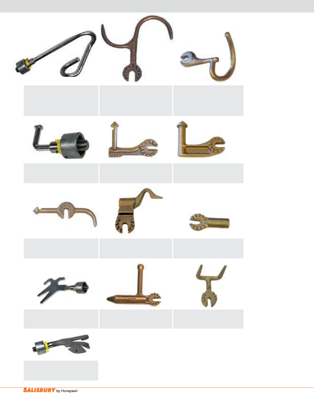
K-20 Hot Sticks and Tools. www.salisburybyhoneywell.com
Tree / Wire Hook
4236 .36 lbs. ( .2kgs )
Pig Tail Disconnect
9878 .4 lbs ( .2 kgs )
Light Duty Cutout Prong
9971 .4 lbs ( .2 kgs )
Heavy Duty Disconnect Head
9969 .6 lbs ( .3 kgs )
Prong Disconnect
9970 .4 lbs ( .2 kgs )
Rotary Prong Tie Head
4099 .6 lbs ( .27 kgs )
Pointed Disconnect
9839 .4 lbs ( .2 kgs )
Double Prong Tie Head
4101 .5 lbs ( .22 kgs )
TOOLS
Pig Tail
5C2 7/8” (2.2cm) opening 1 lbs. (.45 kgs)
5C3 1-1/2” (3.8cm) opening 2 lbs. (.91 kgs)
5C4 2” (5.1cm) opening 2 lbs. (.91 kgs)
Add suffix “U” for Universal, “Q” for Quick Change
Switch Hook
190 8 oz. (0.25 kgs)
Add suffix “U” for Universal, “Q” for Quick Change
Mechanical Hand
1C 1 lbs. (0.45 kgs)
Add suffix “U” for Universal, “Q” for Quick Change
Alligator
4D Alligator 1 lbs. (0.45 kgs)
Add suffix “U” for Universal, “Q” for Quick Change
Chuck Blank
Inside Depth: 1/2” x 1 1/2” ( 13 x 38mm )
9838 .4 lbs ( .2 kgs )
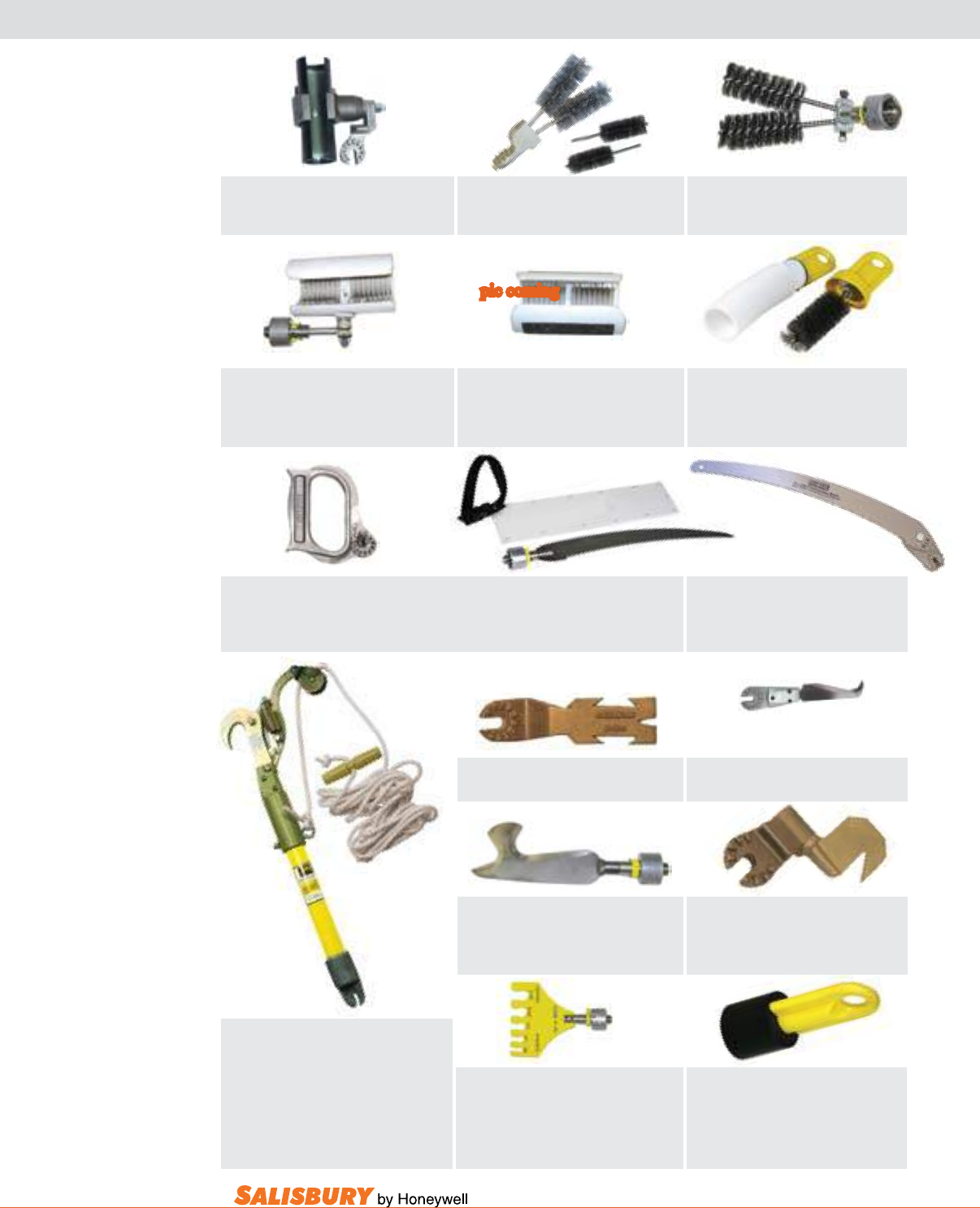
K-21
101 E. Crossroads Pkwy., Ste. A Bolingbrook, IL 60440 toll free ph (USA):877.406.4501 toll free fax (USA):866.824.4922 ph:630.343.3800
4108 Tubular Line Cleaner 1.3 lbs ( .6 kgs )
4109 Replacement Brush .5 lbs ( .22 kgs )
4111 “V” Line Cleaner 1.3 lbs ( .6 kgs )
4113 Replacement Brushes (10) 3 lbs ( 1.4 kgs )
4106 Curved Blade Skinning Knife .4 lbs ( .2 kgs )
4107 Replacement Blade .1 lbs ( .05 kgs )
4103 Handle for Pruning Saw .5 lbs ( .22 kgs ) 4104 Pruning Saw w/ 18”(457mm) blade
.5 lbs ( .22 kgs )
4100 Rotary Blade Tie Head .7 lbs ( .3 kgs )
4102 Fixed Blade Tie Head .5 lbs ( .22 kgs )
1521 Semi-Tube Brush 1.5 lbs. (0.68 kgs)
Add suffix “U” for Universal, “Q” for Quick Change,
“GA” for Grip All
1521B Replacement Brush 12 ozs. (0.37 kgs)
152 “V” Brush 1.5 lbs. (0.68 kgs)
Add suffix “Q” for Quick Change, “GA” for Grip All
152B Replacement Brush 3 ozs. (0.09 kgs)
7991 Pruning Saw w/ 14” (35.6 cm)
1 lbs. (0.45 kgs)
7991WS Saw Sheath .5 lbs. (0.22 kgs)
Add suffix “U” for Universal, “Q” for Quick Change
TOOLS
12 Stripping Knife 1 lbs. (0.45 kgs)
12S Sheath 4 oz. (0.12 kgs)
Add suffix “U” for Universal, “Q” for Quick Change,
“GA” for Grip All
Wire Gauges
860002 Aluminum Fits:#4 to 397.5 1 lbs. (0.45 kgs)
860004 ACSR/Aluminum Fits: #4 to .556 1 lbs. (0.45 kgs)
860005 Copper Fits: #8 to 4/0 1 lbs. (0.45 kgs)
Add suffix “U” for Universal, “Q” for Quick Change
1521003 Semi-Tube Side Brush
1.5 lbs. (0.68 kgs)
Add suffix “U” for Universal, “Q” for Quick Change,
“GA” for Grip All
1520010GAH Brush w/ Handle & Cover
1 lbs. (0.45 kgs)
Test Point Cap Seal Cleaner
1520006 1lbs. (0.45 kgs)
Add suffix “U” for Universal, “Q” for Quick Change,
“GA” for Grip All
Mounted on 12” ( 30.6cm ) fiberglass pole
4105 Tree Pruner - Universal
25’ ( 7.62m ) of line 4 lbs. (1.81 kgs)
7992FGQ Tree Pruner - Quick Change
12’ ( 3.06m ) of line 4 lbs. (1.81 kgs)
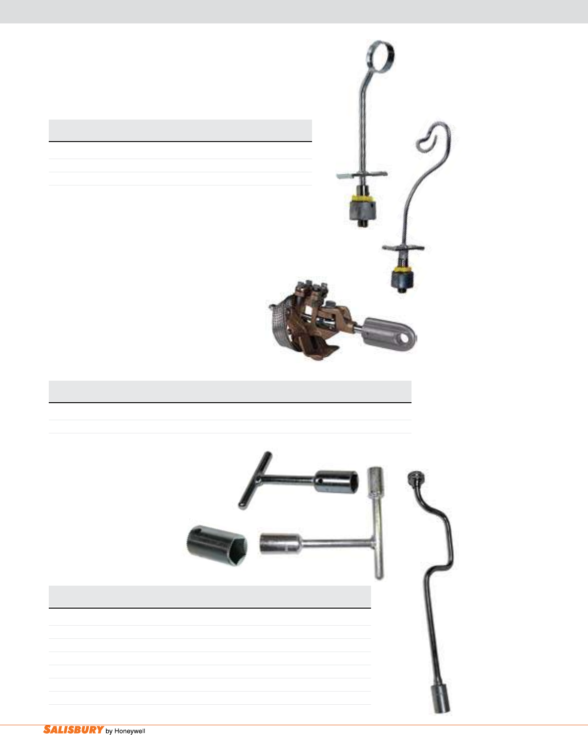
K-22 Hot Sticks and Tools. www.salisburybyhoneywell.com
ARMOR ROD TOOLS, JUMPER HEADS & PENTA SOCKETS
Cat. No. Description Weight
lbs. ( kgs )
ARMOR ROD TOOLS
124 Armor Rod Applicators 2 ( 0.91 )
1241 Formed Wire Tools 2 ( 0.91 )
Add suffix “Q” for quick change, “U” for universal, “HDQ” for heavy duty w/ quick change, “HDU” for
heavy duty w/ universal.
The Jumper Heads
5/8-11 threaded non-shrouded ferrules. A hose
Cat. No. Description Max. Opening Continuous Weight
Duty lbs. ( kgs )
JUMPER HEADS WITH THREADED ADAPTERS
98SADGA Grip All Wide Jaw 1-9/16” 600 amps 3 ( 1.36 )
98SADGA
Use the Penta Socket to tighten or loosen
Cat. No. Description Weight
lbs. ( kgs )
PENTA SOCKET
590001S 3/4” (19 mm) Penta head Socket Only 1 ( 0.45 )
590001 “T” Wrench with 3/4” (19 mm) Penta head Socket 1 ( 0.45 )
590002 Speed Wrench with 3/4” (19 mm) Penta head Socket 2 ( 0.91 )
59P34916SD Penta Wrench, 3/4” (11 mm), 9/16” (14 mm), and Screw Driver 3 ( 1.36 )
5900017/16T “T” Wrench with 3/4” (11 mm) Penta head Socket and 7/16” depth 1 ( 0.45 )
593412PHT “T” Wrench with 3/4” (11 mm) and 1/2” (13 mm) Penta head Sockets 1 ( 0.45 )
590001S
590002
590001
593412PHT
124Q
1241Q
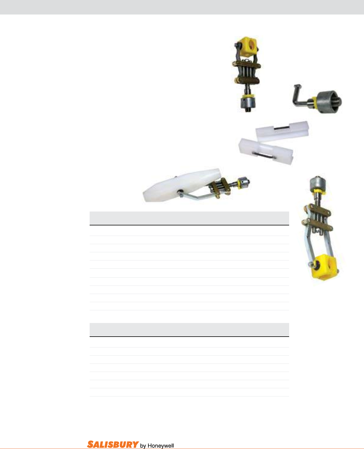
K-23
101 E. Crossroads Pkwy., Ste. A Bolingbrook, IL 60440 toll free ph (USA):877.406.4501 toll free fax (USA):866.824.4922 ph:630.343.3800
FUSE PULLER TOOLS
The standard Fuse Puller
hook. Other lengths available. Bag not included.
Cat. No. Description Handle Length Weight
lbs. ( kgs )
FUSE PULLER TOOL
196FGQ Quick Change 6’6” ( 1.98 m ) 5 ( 2.27 )
196FGU Universal 6’6” ( 1.98 m ) 5 ( 2.27 )
198FGQ Quick Change 8’ ( 2.43 m ) 6 ( 2.72 )
198FGU Universal 8’ ( 2.43 m ) 6 ( 2.72 )
Parts
92Q Head Only, Quick Change 2 ( 0.91 )
92U Head Only, Universal 2 ( 0.91 )
190Q Switch Hook, Quick Change 1 ( 0.45 )
190NLF Insert Jaws for 13/16” (2.1 cm) diameter S & C Liquid Fuse 1 ( 0.45 )
Cat. No. Description Maximum Weight
Diameter lbs. ( kgs )
FUSE PULLER HEADS
9209Q Liquid Fuse, Quick Change 13/16” ( 2.1 cm ) 3 ( 1.36 )
9209U Liquid Fuse, Universal, Head Only 13/16” ( 2.1 cm ) 3 ( 1.36 )
9209GA Liquid Fuse, Grip All 13/16” ( 2.1 cm ) 3 ( 1.36 )
92225001Q Quick Change 2 1/4” ( 5.7 cm ) 3 ( 1.36 )
92225001U Universal 2 1/4” ( 5.7 cm ) 3 ( 1.36 )
92225001GA Grip All 2 1/4” ( 5.7 cm ) 3 ( 1.36 )
92Q 190Q
190NLF
9209Q
92225001Q
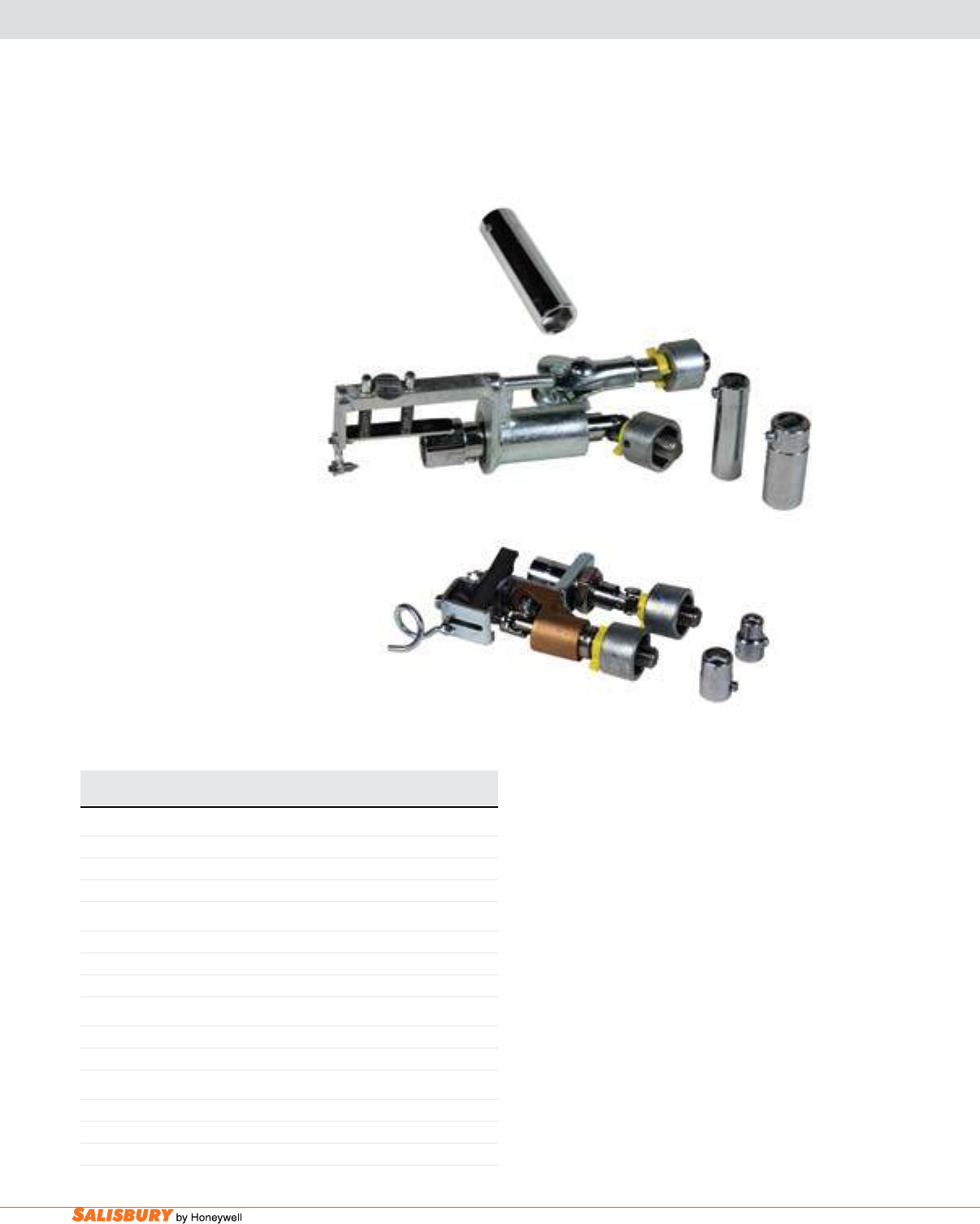
K-24 Hot Sticks and Tools. www.salisburybyhoneywell.com
CONNECTOR TOOL HEADS & PARALLEL GROOVE CLAMP
The Parallel groove Clamp Tool
can be installed from almost any angle by
included. Other lengths available.
Cat. No. Description Weight
lbs. ( kgs )
PARALLEL GROOVE CLAMP TOOL HEAD
1800CQ Quick Change Head 3 ( 1.96 )
1800CU Universal Head 3 ( 1.96 )
1800CQS Quick Change Head with Top Hook 3 ( 1.96 )
PARALLEL GROOVE CLAMP TOOL SOCKET
1800SS 9/16” (1.4 cm) 1 ( 0.45 )
1800SM 3/4” (1.9 cm) 1 ( 0.45 )
1800SL 15/16” (2.4 cm) 1 ( 0.45 )
CONNECTOR TOOL VISE TYPE HEAD
72CQ Quick Change Head Only 3 ( 1.96 )
72CU Universal Head Only 3 ( 1.96 )
CONNECTOR TOOL VISE TYPE
72S3/8 3/8” ( 0.95 cm ) 2 oz. ( 45 g )
72S9/16 9/16” ( 1.4 cm ) 2 oz. ( 45 g )
72S3/4 3/4” ( 1.9 cm ) 2 oz. ( 45 g )
1800CQ
1800SS
The vise Type Connector Tool installs and
connectors on energized lines. With this
diameter. Bag not included. Other lengths
available.
72CQ
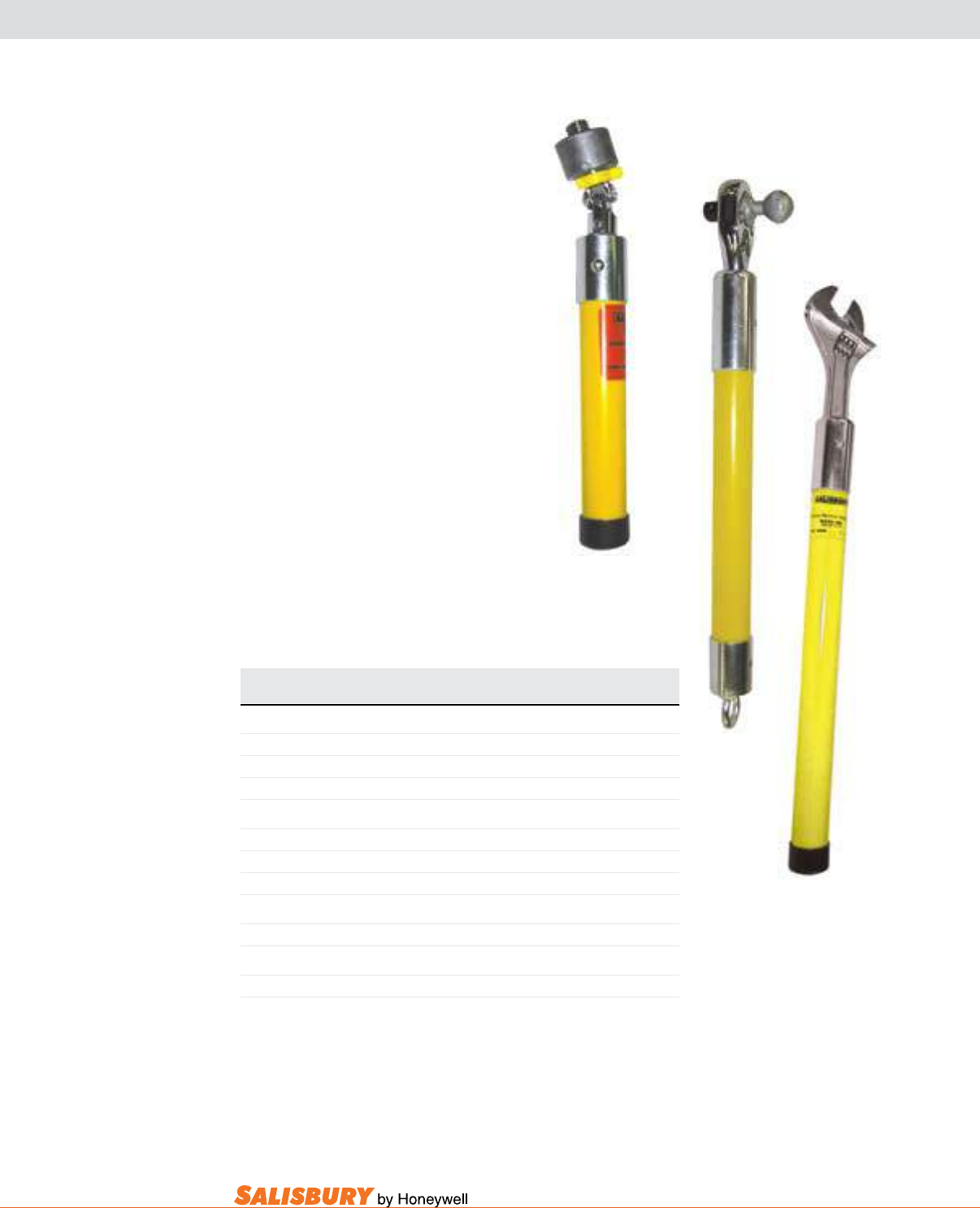
K-25
101 E. Crossroads Pkwy., Ste. A Bolingbrook, IL 60440 toll free ph (USA):877.406.4501 toll free fax (USA):866.824.4922 ph:630.343.3800
HAND TOOLS
All Insulated adjustable Wrenches
accidentally moving while in use. These
Insulated Ratchet Wrench comes with a
The Insulated Ratchet Wrench for
Clamp Top
The Toggle Handle is used to convert any
double threaded ferrule stick to a toggle
Cat. No. Handle Length Weight
lbs. ( kgs )
INSULATED ADJUSTABLE WRENCH
1160 12” (30.5 cm) 1 (0.45 )
1161 18” (45.7 cm) 2 (0.91 )
1162 24” (61.0 cm) 3 (1.36 )
INSULATED RATCHET WRENCH
4412 12” (30.5 cm) 2 ( 0.91 )
4418 18” (45.7 cm) 3 (1.36 )
4436 36” (91.5 cm) 4.5 ( 2.0 )
INSULATED RATCHET WRENCH FOR CLAMP TOP
44CFG 8” (20.3 cm) 2 ( 0.91 )
TOGGLE HANDLE
1258HEQ Quick Change - 8” (20.3 cm) 1 ( 0.45 )
44CFG
1161
1258HEQ
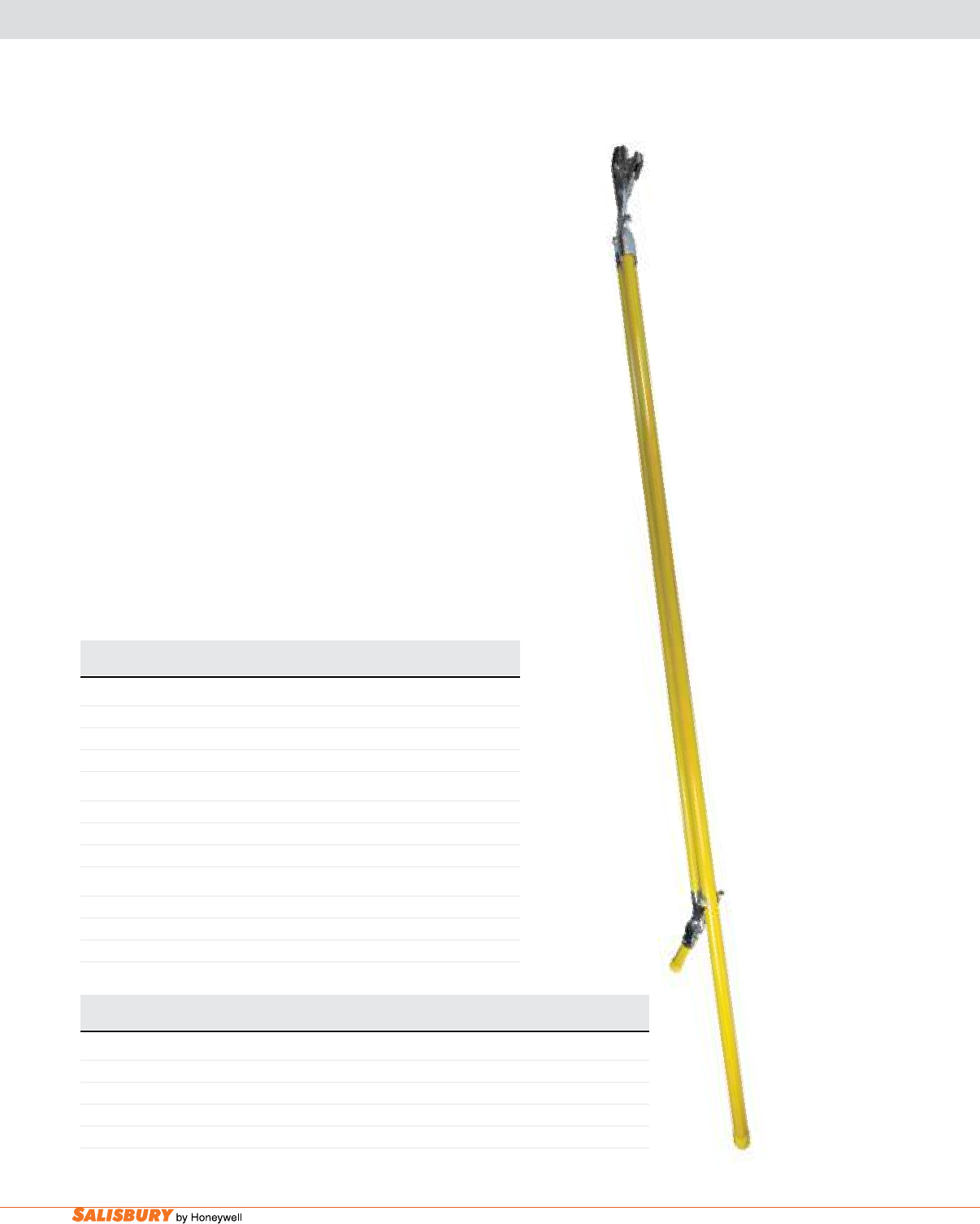
K-26 Hot Sticks and Tools. www.salisburybyhoneywell.com
CUTTERS
live line lever Cutters
wires should be cut with ACSR lever cutters.
Bags available. NOT FOR USE ON ACSR.
The all aluminum & Soft Copper Cutter cutting head is
NOT FOR USE ON
ACSR OR STEEL.
aCSR Cutters with Permanent Heads
The Soft Cable Cutter with Removable Head
cuts. Bags available. NOT FOR USE ON ACSR OR STEEL.
Cat. No. Description Weight
lbs. ( kgs )
LIVE LINE LEVER CUTTERS
3004FG 4’ (1.22 m) 11 (4.99 )
3006FG 6’ (1.83 m) 11 (4.99 )
3008FG 8’ (2.44 m) 11 (4.99 )
ALL ALUMINUM & SOFT COPPER CUTTERS
670 24” (61.0 cm) 5 (2.27 )
671 30” (76.2 cm) 6 (2.72 )
672 36” (91.4 cm) 7 (3.18 )
ACSR CUTTERS WITH PERMANENT HEADS
67124ACFG 24” (61.0 cm) 28” (71.1 cm) 5 (2.27 )
67130ACFG 30” (76.2 cm) 34” (86.4 cm) 5 (2.27 )
67136ACFG 36” (91.4 cm) 40” (102.0 cm) 6 (2.72 )
3008FG
Cat. No. Maximum Cable Size Handle Weight
Copper Power Aluminum Power Communication Length lbs. ( kgs )
SOFT CABLE CUTTER WITH REMOVABLE HEAD
670001 500 kcmil 750 kcmil 1 3/8” (3.5 cm) 24” (61.0 cm) 5 (2.27 )
6700011 750 kcmil 1200 kcmil 1 3/4” (4.5 cm) 24” (61.0 cm) 6 (2.72 )
671001 500 kcmil 750 kcmil 1 3/8” (3.5 cm) 30” (76.2 cm) 5 (2.27 )
6710011 750 kcmil 1200 kcmil 1 3/4” (4.5 cm) 30” (76.2 cm) 7 (3.18 )
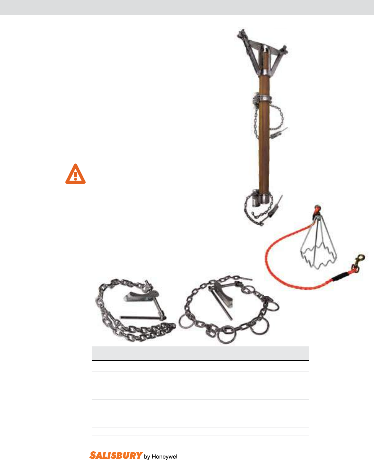
K-27
101 E. Crossroads Pkwy., Ste. A Bolingbrook, IL 60440 toll free ph (USA):877.406.4501 toll free fax (USA):866.824.4922 ph:630.343.3800
TRANSFORMER GIN ASSEMBLY & TOOL FRAME
Transformer gin assemblies are designed to lift
included.
LIMIT SUBJECT GIN TO SIDE LOADING THAT
WILL REDUCE WLL.
The Tool Frame
frame to rotate.
The Rope-Snibbing bracket
handling loads.
Cat. No. Description Weight WLL
lbs. ( kgs )
TRANSFORMER GIN ASSEMBLY
112 Transformer Gin Assembly 89 (40.36 ) 2,500 LBS
TRANSFORMER GIN ASSEMBLY
100T Tool Frame 1 (0.45 )
100TR Tool Frame with Rope and Snap 2 (0.91 )
ROPE-SNUBBING BRACKET
8200 Pole Type Bracket with Rings, Chain Length: 51” (1.30 m) 10 (4.55 )
8200S Pole Type Bracket without Rings Chain Length: 51” (1.30 m) 10 (4.55 )
112
100TR
8200
8200S
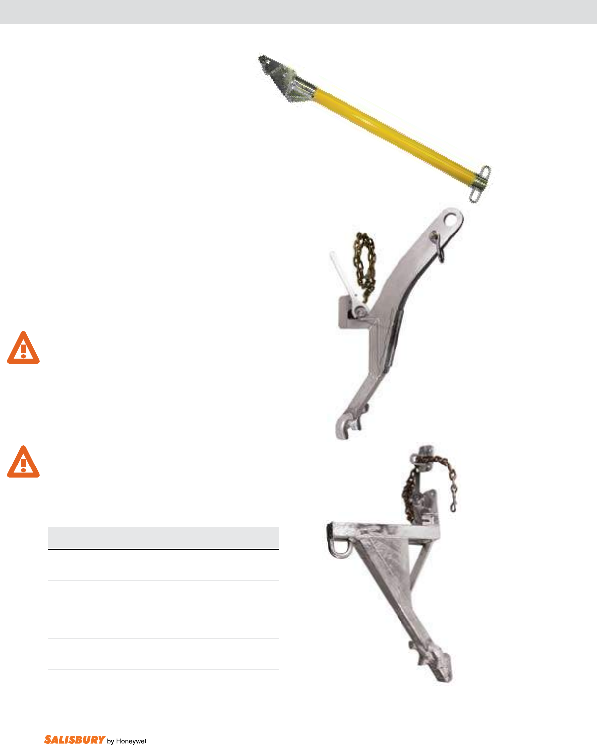
K-28 Hot Sticks and Tools. www.salisburybyhoneywell.com
CROSS ARM GIN & TRANSFORMER GIN ASSEMBLIES
Cat. No. Length Weight WLL
lbs. ( kgs ) lbs.
CROSS ARM GIN
7003 3’ (0.91 m) 12 ( 5.44 ) 600 ( 272 )
7004 4’ (1.22 m) 12 ( 5.44 ) 600 ( 272 )
7005 5’ (1.52 m) 13 ( 5.90 ) 600 ( 272 )
TRANSFORMER GIN ASSEMBLY
133 25 ( 11.34 ) 2,000
HEAVY DUTY TRANSFORMER GIN ASSEMBLY
1200SL 39 ( 17.73 ) 5,000
Cross arm gins are used on cross arms when only one
conductor needs to be raised. Use the arm gin to change
shims are needed for smaller arms.
The Transformer gin assembly is made from steel.Can be
The assembly can also be installed over a cross arm.Blocks can
for the fall line are located on both sides of the gin assembly. The
The safe working load limit is the total load on the gin assembly
SIDE LOADING THAT WILL REDUCE THE WLL.
The Heavy duty Transformer gin assembly designed for easy
handle. The gin can also be installed over a cross arm. The
The safe working load limit is the total load on the gin assembly
WARN
SIDE LOADING THAT WILL REDUCE THE WLL.
133
1200SL
7004
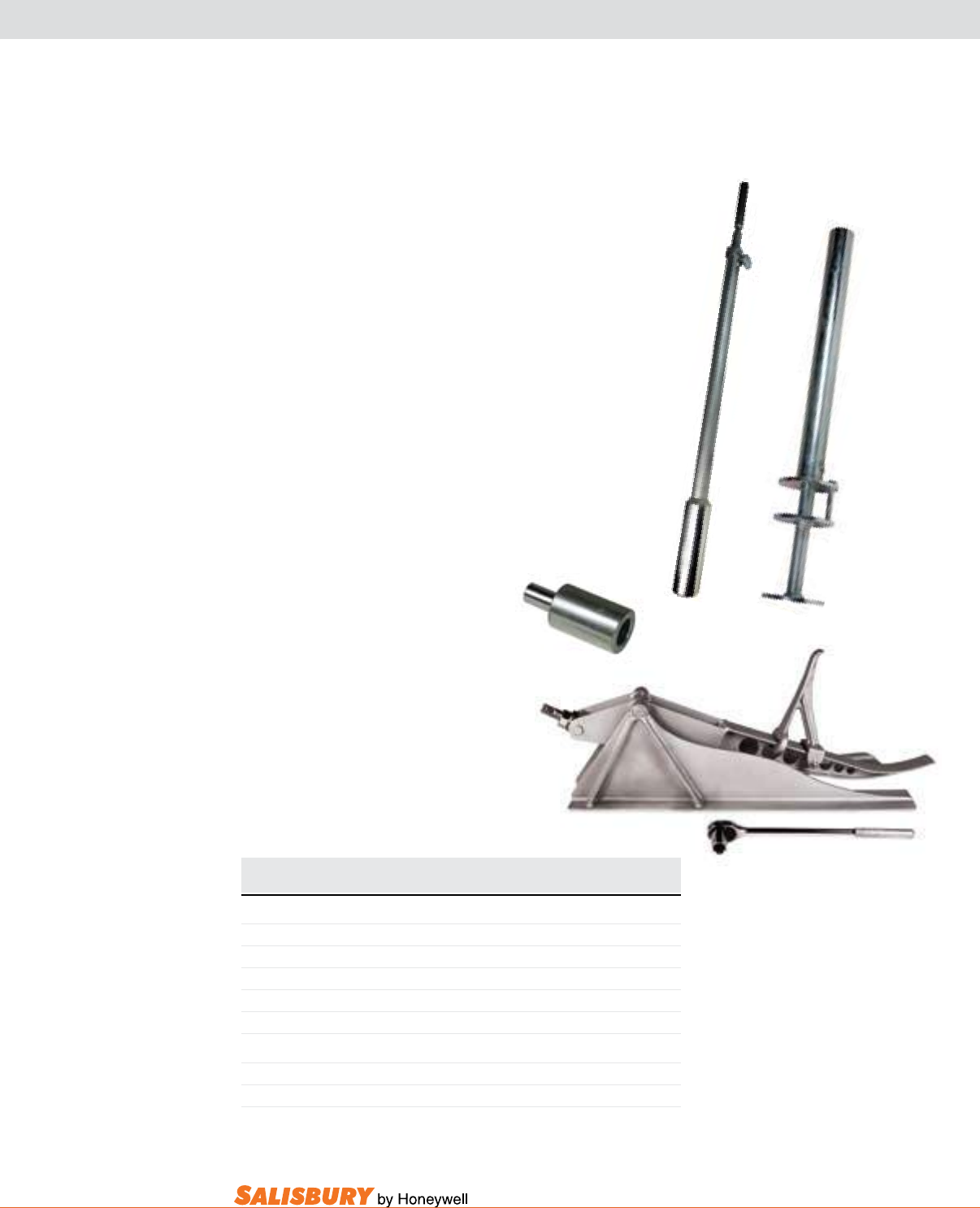
K-29
101 E. Crossroads Pkwy., Ste. A Bolingbrook, IL 60440 toll free ph (USA):877.406.4501 toll free fax (USA):866.824.4922 ph:630.343.3800
GROUND ROD DRIVERS & FRAMING JACK
ground Rod drivers
directly to the rod.
rods with less effort than conventional methods. Discs
(35.6 cm) stroke.
adapters
are available.
The Framing Jack
over. Measures 15” (38.1 cm) long.
Cat. No. Description Length Weight
lbs. ( kgs )
GROUND ROD DRIVERS
1350 Ground Rod Driver 60” (1.52 m) 45 (20.40 )
1350001 Ground Rod Driver 26” (0.66 m) 15 (6.80 )
ADAPTERS
1350058A For 5/8” (1.6 cm) Ground Rods 1/2 (0.21 )
1350034A For 3/4” (1.9 cm) Ground Rods 1/2 (0.21 )
FRAMING JACK
640001 Framing Jack with Ratchet Wrench 58 (26.38 )
6400B Ratchet Wrench Only 1 (0.45 )
1350
1350001
1350034A
640001
6400B
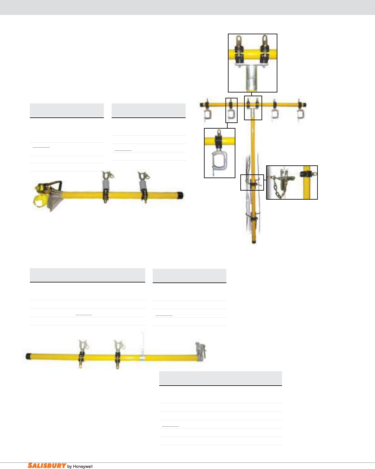
K-30 Hot Sticks and Tools. www.salisburybyhoneywell.com
154466
TEMPORARY SIDE ARMS & TRANSFER ARMS
The Temporary Transfer arm
Cat. No. Number of Arm Weight
Wire Holders Length lbs. ( kgs )
TEMPORARY SIDE ARM - POLE MOUNTED
Nylon Strap Binder with Insulators
156024NI 2 4’ (1.22 m) 17 ( 7.71 )
Nylon Strap Binder without Insulators
156024N 2 4’ (1.22 m) 16 ( 7.26 )
Cat. No. For Cross Arm Size Weight
lbs. ( kgs )
TEMPORARY SIDE ARM - CROSS ARM MOUNTED
With Insulators
154466I 4 1/4” x 63/4” (10.3 x 17.1 cm) 23 ( 10.43 )
15466I 6” x 6” (15.2 x 15.2 cm) 23 ( 10.43 )
Without Insulators
154466 4 1/4” x 63/4” (10.3 x 17.1 cm) 20 ( 9.07 )
154666 6” x 6” (15.2 x 15.2 cm) 20 ( 9.07 )
Cat. No. Weight
lbs. ( kgs )
TEMPORARY TRANSFER ARMS
With Insulators
13068I 65 ( 29.48 )
Without Insulators
13068 65 ( 29.48 )
Insulators
1309GIB 1 ( 0.45 )
13068I
1304D
1340WHI
156024
The Temporary Side arm - Pole mounted holds energized conductors
The 6 foot (1.83 m) side-mounted Temporary
Side arm - Cross arm mounted
diameter foam- filled fiberglass. Both wire
KGS) PER WIRE HOLDER.
Cat. No. Weight
lbs. ( kgs )
WIRE HANGER
With Insulators
1300WHI 4 ( 1.81 )
Without Insulators
1300WH 3 ( 1.36 )
Cat. No. Weight
lbs. ( kgs )
WIRE HANGER
With Insulators
1309DI 3 ( 1.36 )
Without Insulators
1309D 2.5 ( 1.13 )
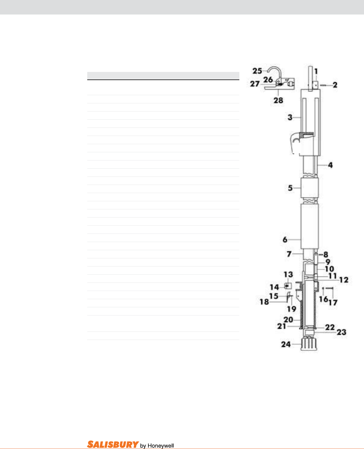
K-31
101 E. Crossroads Pkwy., Ste. A Bolingbrook, IL 60440 toll free ph (USA):877.406.4501 toll free fax (USA):866.824.4922 ph:630.343.3800
FIBERGLASS HOT CLAMPSTICKS REPAIR PARTS LIST
EXTERNAL ROD
Ref. No. Cat. No. Description
1 20178 Guide Assembly
2 20260 Roll Pin .125” Dia. x .5” Lg. ( 3.2 x 13mm )
3 20174 Ferrule
4* 20265-1 Operating Rod
5* 20381 Operating Rod Guide
6 20250 Handguard Sleeve
7 20114 Hot Stick Blank 1.25” Dia. (32mm)
8 20262 Roll Pin .125 Dia. x .56 Lg. ( 3.2 x 14mm )
9 20251 Operating Rod Connector
10 20258 Hex Socket Set Screw .375-16 x 1.25
11 20257 Flat Head Screw 10-32 x 1.125 Lg. ( 254-813 x 29 )
12 20253 Adjustment Block
13 20254 Compression Spring
14 20139 Button
15 20263 Roll Pin .125 Dia. x .75 Lg. ( 3.2 x 19 )
16 20445 10-32 Hex Jam Nut
17 20443 Hex Head Machine Screw 10-32 x 1.25
18 20140 Trigger
19 20255 Torsion Spring
20 20141 Handgrip
21 20142 Rack for Handgrip
22 20257 Flat Head Screw 10-32 x 1.125 Lg. ( 254-813 x 29 )
23 20252 Handgrip Sleeve
24 1959 End Cap
25 20176 Jaw Hook
26 20332 Roll Pin .25 Dia. x .47 Lg. ( 6 x 12 )
27 20470 Hook Spring
28 20177 Hook Holder
Assembly No. Description Consist of Parts
4317 Hook Assembly 28, 29, 30, 31
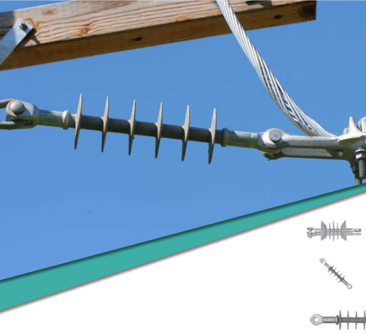
INSULATORS

L-2 Insulators. www.salisburybyhoneywell.com
INSULATORS
NEW
IMPROVED 23613 DEAD END/SUSPENSION INSULATOR
Salisbury’s Improved 23613 Dead End/Suspension Insulator has
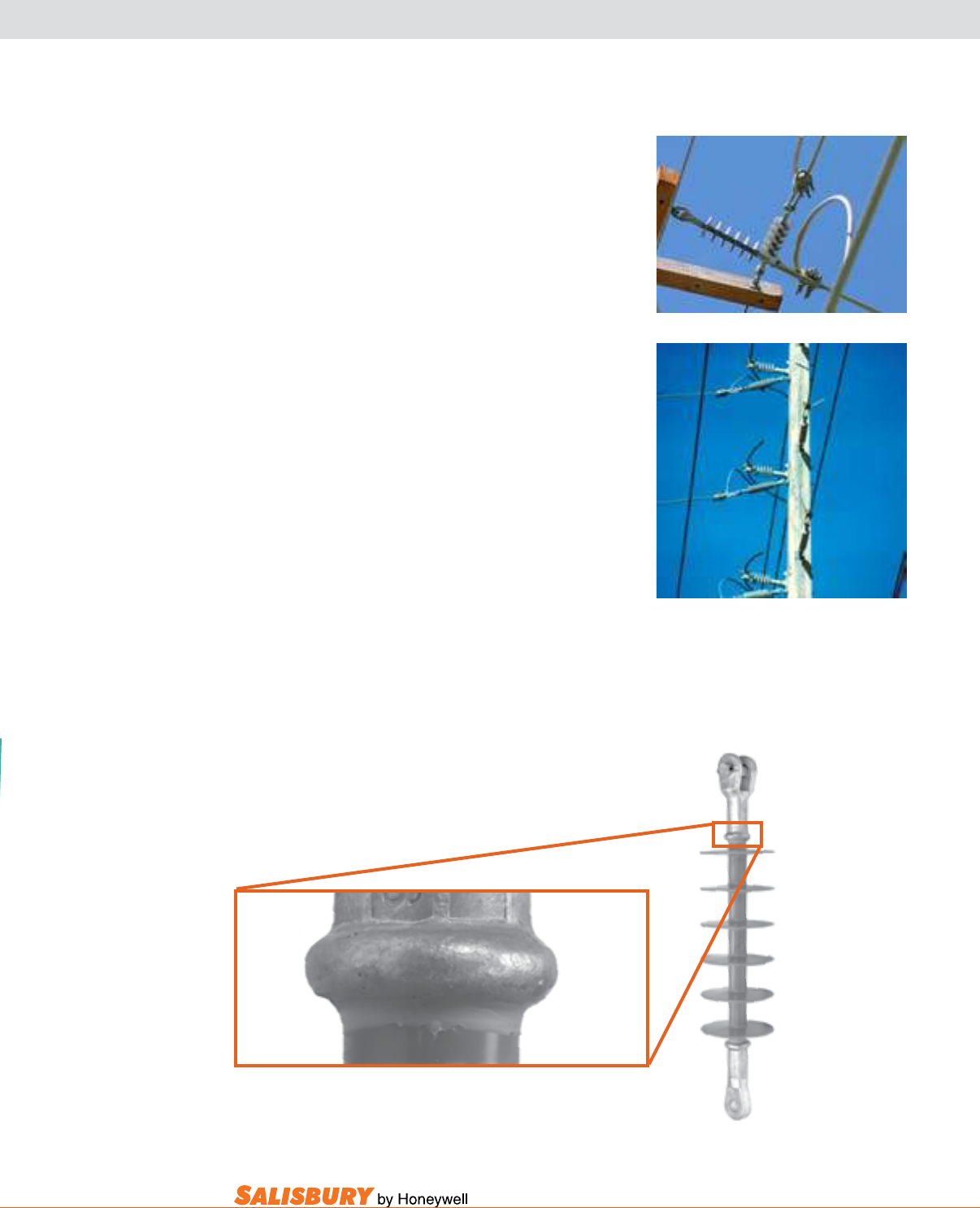
L-3
101 E. Crossroads Pkwy., Ste. A Bolingbrook, IL 60440 toll free ph (USA):877.406.4501 toll free fax (USA):866.824.4922 ph:630.343.3800
Unibody insulators have end fittings sealed with silicone to eliminate any possibility of moisture
or contamination from reaching the fiberglass rod.
SalvaR® & Silicone Composite Insulators combine
the technologies of berglass reinforced rod, metal ttings
and our extensive knowledge of elastomeric insulation to
produce a high quality composite insulator. Since 1980
thousands of SALVAR® and Silicone Insulators have been
installed by utilities worldwide in a variety of environments.
Continued outstanding performance is proof of their
superior quality and design.
design: Two designs are used to manufacture SALVAR®
and Silicone Insulators: Unibody and Modular. Unibody
Design insulators are one-piece injection molded directly to
the rod and sealed to the end ttings with a bead of silicone
to give the insulator high dielectric strength and protect it
from all environmental conditions. This design is used for
standard distribution dead end/suspension insulators.
Fiberglass Rod: A high quality berglass reinforced rod
is the core of every insulator with ultimate mechanical
strength at least twice the maximum working load.
End Fittings: Standard distribution dead/end suspension
units are supplied with clevis and tongue ttings meeting
ANSI C29-2 specications. Ball, socket, and eye ttings
are also available. All are made of hot dipped galvanized
high strength carbon steel and have an ultimate tensile
strength rating of 15,000 pounds. All end ttings on dead/
end suspension insulators are attached by compression.
Every insulator is proof tested to verify the crimp.
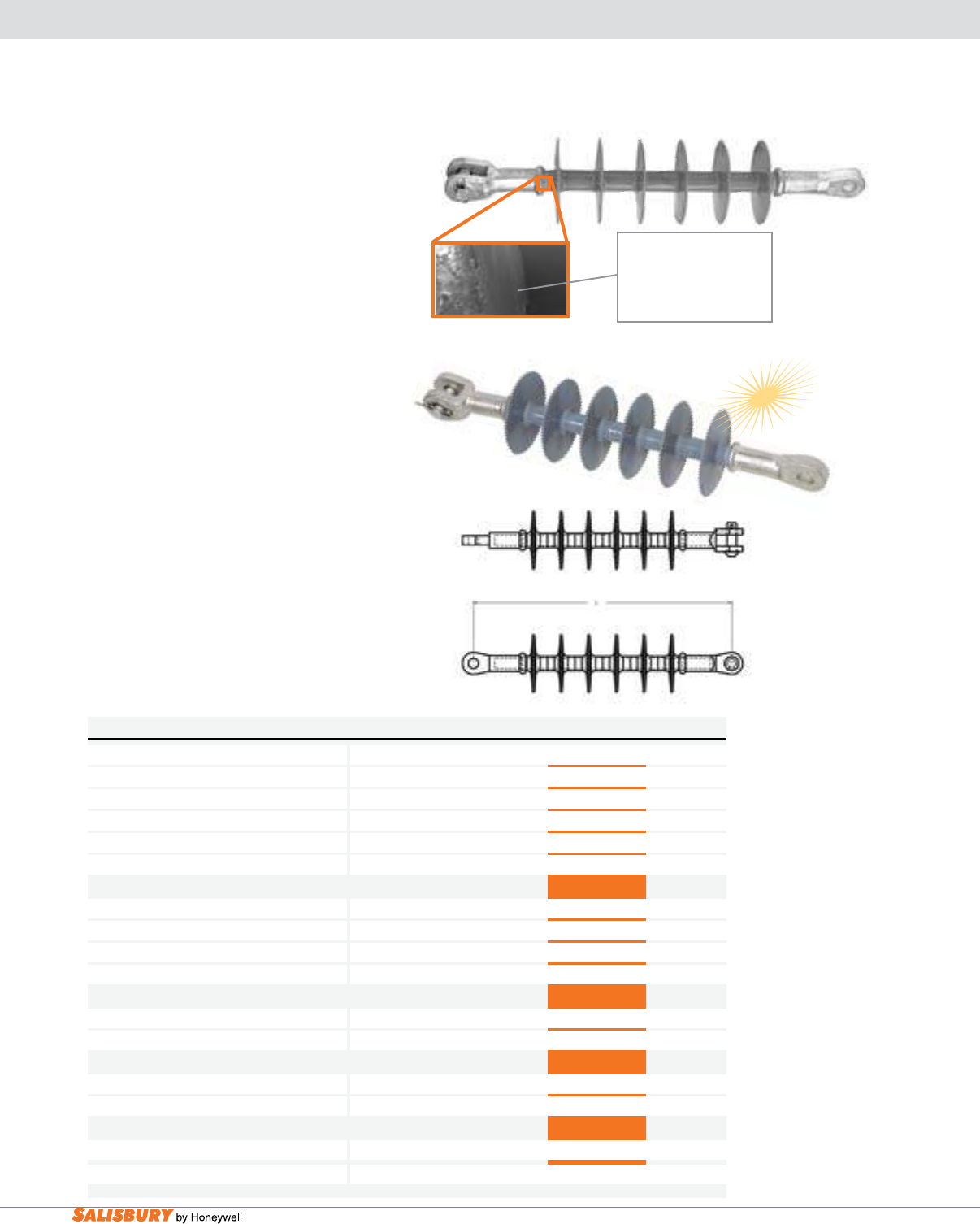
L-4 Insulators. www.salisburybyhoneywell.com
Unibody insulators have end
fittings sealed with silicone to
eliminate any possibility of
moisture or contamination from
reaching the fiberglass rod.
The SI Series of Silicone Insulators features
a silicone formulation weathershed material.
Salisbury combined the excellent hydrophobic
and electrical qualities of silicone with an
optimum weathershed design and corrosion
resistant berglass rod to produce a state-of-the-
art insulator which meets or exceeds industry
requirements. The insulators were tested in
accordance with ANSI C29 and IEC1109. End
ttings are hot dipped galvanized high strength
carbon steel, providing a 15,000 pound ultimate
tensile strength. 100% proof testing ensures
trouble-free installation. RuS accepted.
Salisbury’s Improved 23613 dead End/
Suspension Insulator has aluminum end ttings.
These new end fittings create a lightweight
product that is easier to handle and provides
a 15,000 pound ultimate tensile strength. The
new aluminum end ttings withstands corrosion
better than the previous galvanized steel SI series
insulators, adding to the life of the insulator. 100%
proof testing ensures trouble-free installation. This
insulator includes the same silicone weathershed
material as th SI Series.
The insulator was tested in accordance with
ANSI C29 and IEC1109.
NEW
23613
9501U-SI 9502U-SI 23613 9503U-SI
Class DS-15 DS-28 DS-28 DS-35
No. of Weathersheds 4 6 6 8
Length
-
in ( m ) 13.5 ( .34 ) 17.5 ( .45 ) 17.5 ( .45 ) 21.3 ( .54 )
Dia. of Weathersheds
-
in ( mm ) 3.8 ( 97 ) 3.8 ( 97 ) 3.8 ( 97 ) 3.8 ( 97 )
Leakage Distance
-
in ( m ) 17.1 ( .44 ) 26( .66 ) 26( .66 ) 35.1 ( .89 )
Dry Arc Distance
-
in ( m ) 8.4 ( .22 ) 12.13 ( .31 ) 12.13 ( .31 ) 16 ( .41 )
Flash Over Voltage Critical Impulse, Pos 173 217 217 258
Critical Impulse, Neg 250 310 310 340
Dry, 60 Hz 97 145 145 168
Wet, 60Hz 67 115 115 137
Radio Inuence Test, kV Ground 15 25 25 25
Max RIV
-
1000kHz µV 1 1 1 1uV
Ultimate Strength lbs. 15,000 15,000 15,000 15,000
FRP Rod Dia.
-
in ( mm ) .73 ( 18.63 ) .73 ( 18.63 ) .73 ( 18.63 ) .73 ( 18.63 )
Typ. Appl
-
kV, Ø-Ø 15 27 27 35
Net Weight ea.
-
lbs. ( kgs ) 2.6 ( 1.20 ) 3.1 ( 1.39 ) 2.2 ( .99 ) 3.5 ( 1.57 )
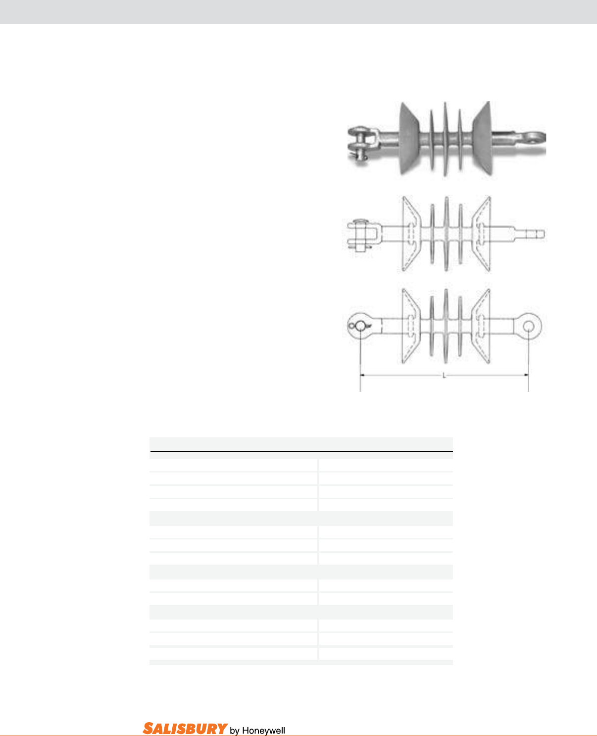
L-5
101 E. Crossroads Pkwy., Ste. A Bolingbrook, IL 60440 toll free ph (USA):877.406.4501 toll free fax (USA):866.824.4922 ph:630.343.3800
The 9502l-EP Silicone Insulator combines
two essential characteristics:
PERFORmanCE - The 9502L-EP is the
only composite insulator manufactured as a
replacement for two 10” (254mm) porcelain
disks. Installation is limited to horizontal
dead-end applications only.
InnOvaTIOn - Unlike any other insulator
on the market, the unique shed design
of the 9502L-EP minimizes the material
content without compromising electrical or
dimensional requirements.
End ttings are hot dipped galvanized high
strength carbon steel.
Must be used as a dead end insulator only.
RuS accepted.
No. of Weathersheds 5
Length
-
in ( m ) 11.5 (. 29 )
Dia. of Weathersheds
-
in ( mm ) 5 ( 127 )
Leakage Distance
-
in ( m ) 22 ( .56 )
Electrical Critical Impulse 189
Ratings Dry, 60 Hz 116
kV Wet, 60 Hz 92
Radio Test--kV Ground 20
Inuence Max RIV--1000Hz µV 1
Typ. Appl--kV, Ø-Ø 27
Ultimate Strength
-
SML
-
lbs / kN 15000 / 70
Net Weight ea.
-
lbs ( kgs ) 2.8 ( 1.3 )
9502L-EP
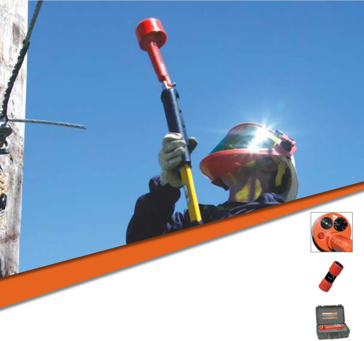
VOLTAGE DETECTORS

M-2 Voltage Detectors. www.salisburybyhoneywell.com
VOLTAGE DETECTORS
FAQ
Q: Are there any precautions, besides wearing the proper safety equipment,
when using voltage detectors?
A: Do not assume conductors that have been tested de-energized will stay
de-energized. Always install proper grounding devices before working.
Failure to do so may result in serious injury or death.
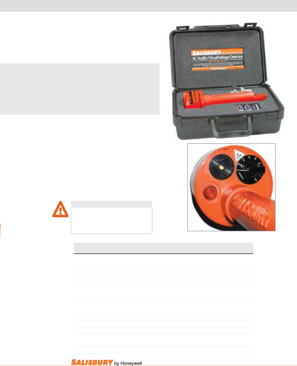
M-3
101 E. Crossroads Pkwy., Ste. A Bolingbrook, IL 60440 toll free ph (USA):877.406.4501 toll free fax (USA):866.824.4922 ph:630.343.3800
Cat. No. Dimensions Settings Weight ea.
in. ( mm ) phase to phase lbs. ( kgs )
4544 11 x 3.5 ( 279.4 x 89 ) Off / 240V / 4.2kV / 15kV/25kV/35kV/69kV/115kV/230kV 15oz. ( .43 )
4644 11 x 3.5 ( 279.4 x 89 ) Off / 240V / 4.2kV /35kV/69kV/115kV/230kV/345kV/500kV 15oz. ( .43 )
4744 11 x 3.5 ( 279.4 x 89 ) Off / Test-240V / Battery / URD:15kV/25kV/35kV 15oz. ( .43 )
Overhead: 4.2kV / 15kV/25kV/35kV/46kV/69kV
4745 11 x 3.5 ( 279.4 x 89 ) Off / Test-240V / Battery / URD:4.8kV/7.2kV/16kV 15oz. ( .43 )
Overhead: 2.4/4.2kV / 4.8/8.3kV / 8.0/13.8-7.2/12.5kV / 14.4/25-16/27.6kV / 44kV
COMPLETE KIT
4556 1-4544 Tester 240V to 230kV, 1-21517 Case, 1-2500 Shotgun Adapter 2 ( .91 )
4667 1-4644 Tester 240V to 500kV, 1-21517 Case, 1-2500 Shotgun Adapter 2 ( .91 )
4769 1-4744 Tester 240V to 69kV, 1-21517 Case, 1-2500 Shotgun Adapter 2 ( .91 )
2500 Shotgun Adapter .4 ( .2 )
21517 12 x 8 x 4.5 ( 305 x 203 x 114 ) Storage Case 1 ( .45 )
THE SALISBURY ADVANTAGE
Salisbury’s Self-Testing
voltage detectors allow
testing to be continuous and
automatic. An intermittent ash
and beep conrms the detector
is functioning properly.
Self-Testing voltage detectors are used to
verify live or de-energized conductors. These
testers may be used with rubber insulating
gloves or hot sticks using the splined
universal end tting. Testers indicate the
presence of voltage with an extra bright LED
light and a distinctive audible signal. It is
recommended that the tester be moved closer
to the conductor until a warning is indicated,
or it touches the conductor, apparatus, or
elbow test point. Each tester requires three
“C” batteries (included).
VOLTAGE DETECTORS
SELF TESTING AUDIO / VISUAL
Do not assume conductors that have been tested
de-energized will stay de-energized. Always install
proper grounding devices before working. Failure to
do so may result in serious injury or death.
WARNING
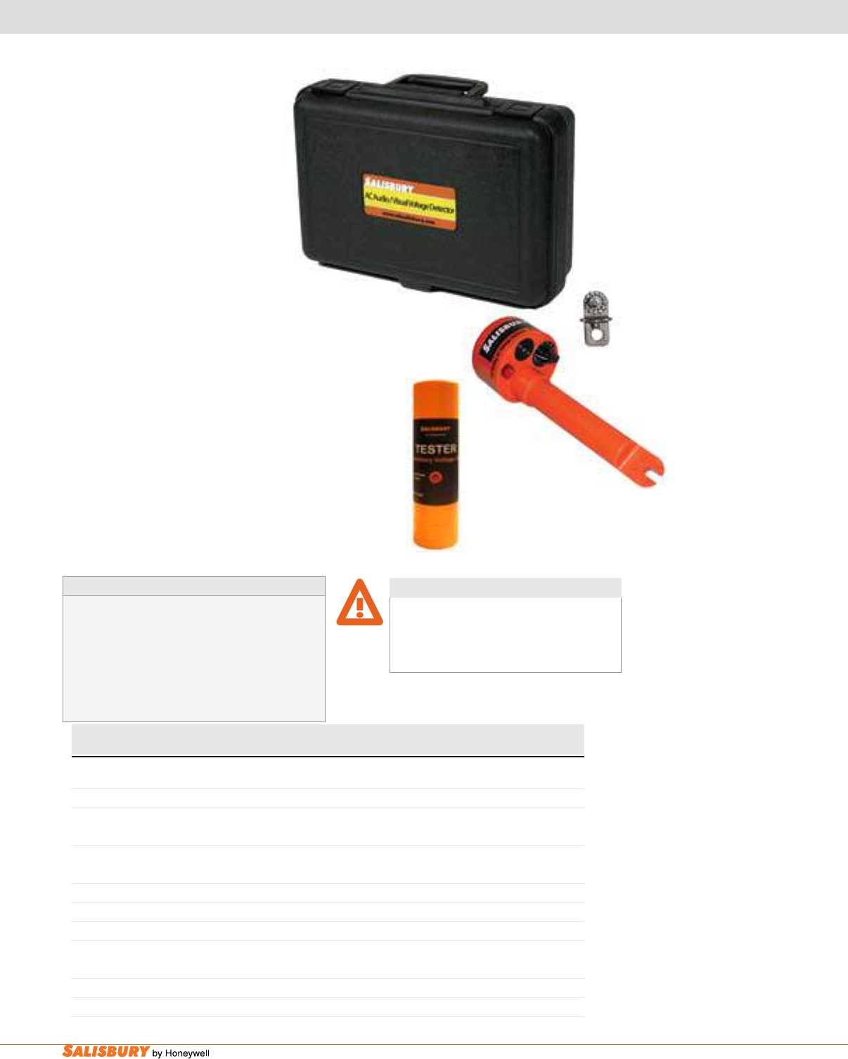
M-4 Voltage Detectors. www.salisburybyhoneywell.com
VOLTAGE DETECTORS
AUDIO / VISUAL
Test Procedures
To assure unit is in operable condition switch tester into “Test-240V”
position. The tester may now be tested in several different ways.
1. Place head as marked against live wire outlet or equivalent
above 110V A.C.
2. Rub the head as marked on cloth or clothing to obtain static
charge. Unit will only indicate intermittently.
Test Procedures
Cat. No. Dimensions Settings Weight ea.
in. ( mm ) phase to phase lbs. ( kgs )
4244 11 x 3.5 ( 279.4 x 89 ) Off / 240V / 4.2kV / 15kV/25kV/35kV/69kV/115kV/230kV 15oz. ( .43 )
4344 11 x 3.5 ( 279.4 x 89 ) Off / 240V / 4.2kV /35kV/69kV/115kV/230kV/345kV/500kV 15oz. ( .43 )
4444 11 x 3.5 ( 279.4 x 89 ) Off / Test-240V / Battery / URD:15kV/25kV/35kV 15oz. ( .43 )
Overhead: 4.2kV / 15kV/25kV/35kV/46kV/69kV
COMPLETE KIT
4356 1-4244 Tester 240V to 230kV, 1-21517 Case, 1-2500 Shotgun Adapter 2 ( .91 )
4367 1-4344 Tester 240V to 500kV, 1-21517 Case, 1-2500 Shotgun Adapter 2 ( .91 )
4469 1-4444 Tester 240V to 69kV, 1-21517 Case, 1-2500 Shotgun Adapter 2 ( .91 )
2500 Shotgun Adapter .4 ( .2 )
21517 12 x 8 x 4.5 ( 305 x 203 x 114 ) Storage Case 1 ( .45 )
4445 Voltage Detector Tester 1 ( .45 )
4445
2500
21517
voltage detectors are used to verify
live or de-energized conductors.
These testers may be used with
rubber insulating gloves or hot
sticks using the splined universal
end fitting. Testers indicate the
presence of voltage with an extra
bright LED light and a distinctive
audible signal. It is recommended that
the tester be moved closer to conductor
until warning is indicated, or it touches
conductor, apparatus, or test point. Test the unit on
a nearby energized conductor. Each tester requires
three “C” batteries (included).
The 4445 voltage detector Tester provides the
most convenient and reliable means of verifying
operation of Salisbury Voltage Detectors. The tester
features instant push-button operation and requires a
standard 9-volt battery (included). It’s portable and
lightweight. To operate, push the button and move
the tester toward the voltage detector being veried.
The tester generates an electric eld that activates
the detector verifying the audible and visual signals
are operational.
Do not assume conductors that have been tested
de-energized will stay de-energized. Always install
proper grounding devices before working. Failure to
do so may result in serious injury or death.
WARNING
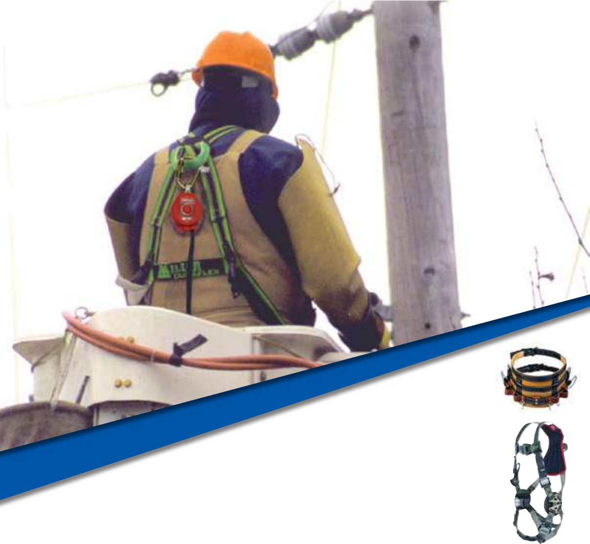
FALL PROTECTION
MILLER®

N-2 Miller® Fall Protection. www.salisburybyhoneywell.com
FALL PROTECTION
MILLER®
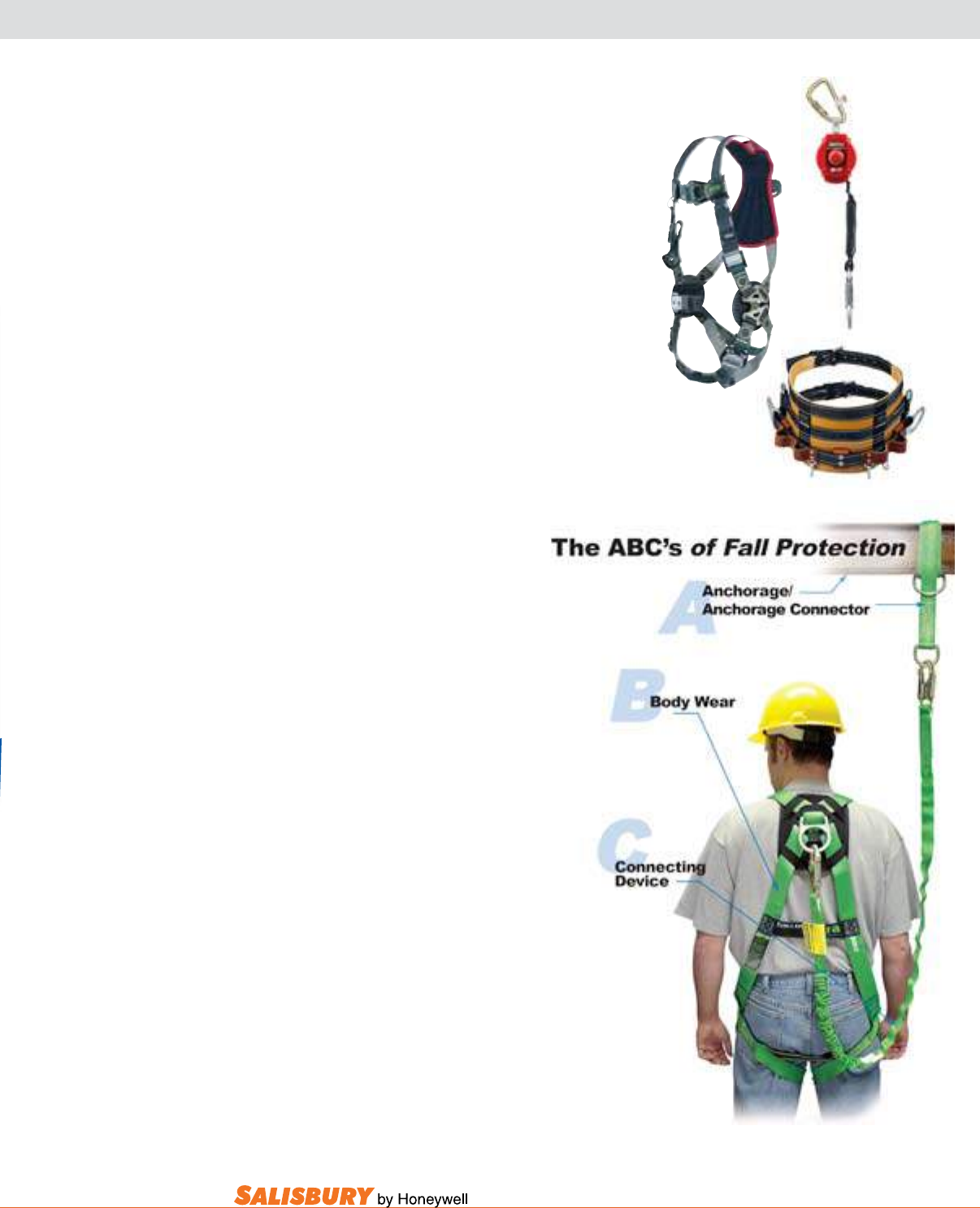
N-3
101 E. Crossroads Pkwy., Ste. A Bolingbrook, IL 60440 toll free ph (USA):877.406.4501 toll free fax (USA):866.824.4922 ph:630.343.3800
MILLER® FALL PROTECTION
Innovative Products and Services for the utilities
Industry. The Miller® brand of fall protection products
has been meeting market demands for fall protection
equipment for over 60 years.
We have built a reputation for delivering superior quality
products with exceptional customer service, enabling
our customers to prevent accidents and injuries, while
maintaining on-the-job ef ciencies.
Today, we take particular pride in bringing to the market
innovative solutions that not only enhance safety and
productivity, but increase user acceptance and lower
overall cost.
PERSONAL FALL ARREST SYSTEM
KEy SySTEm COmPOnEnTS
Three key components of the Personal Fall
Arrest System (PFAS) must be in place and
properly used to provide maximum worker
protection.
Individually these components will not
provide protection from a fall. However,
when used properly and in conjunction with
each other, they form a Personal Fall Arrest
System that becomes vitally important for
safety on the job site.
Anchorage: Commonly referred to as a
tie-off point
Anchorage Connector: Used to join the
connecting device to the anchorage
The personal
protective equipment
worn by the worker
The critical link which
joins the body wear to the
anchorage /anchorage
connector
[Ex: shock-absorbing
lanyard, (shown), or self-
retracting lifeline]
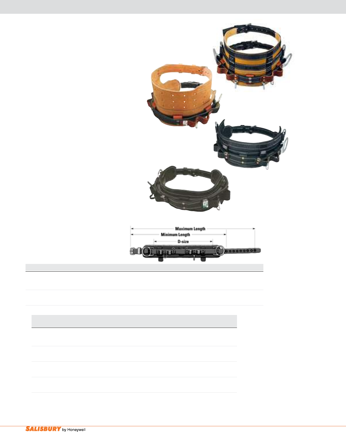
N-4 Miller® Fall Protection. www.salisburybyhoneywell.com
LINEMEN’S EquIPMENT
bELTS, LANYARdS & LAddER
Cat. No. Width Description Weight ea.
lbs. ( kgs )
SAL88N 9-in. (229 mm) Leather back-saver body pad with a D-saddle & 5.6 ( 2.5)
1-3/4-in. (44 mm) waist strap
SAL844 9 5-in. (127 mm) “Black Beauty” leather, cushioned body pad with 4.5 ( 2.0 )
1-3/4-in. (44 mm) leather D-saddle & waist strap
SAL88N-1 9-in. (229 mm) Leather back-saver body pad with a D-saddle, 5.6 ( 2.5 )
1-3/4-in. (44 mm) waist strap & scaffolding D-ring
SAL8449-1 5-in. (127 mm) “Black Beauty” leather, cushioned body pad with 4.5 ( 2.0 )
1-3/4-in. (44 mm) leather D-saddle, waist strap & scaffolding D-ring
miller linemen’s belts: Full-Floating belts.
Full-oating belts allow for lateral movement of
the D-saddle with D-rings during use. As a lineman
changes position on a pole, the D-rings easily adjust
to the movement. As a result, the pole strap rubs
against the pole less frequently and receives less
wear. Any load or pull does not bind tools to the
tool loops.
all belts feature:
• Side positioning D-rings • Tape thong
• Leather tool loops • Accessory snap
• Support belt rings • Accessory ring
linemen’s belt Sizing
The degree of comfort a lineman receives from a
belt depends on the construction of the belt and the
location of the D-rings. For best t, order by D-size.
The D-size is the distance between the heels of the
D-rings. When wearing a belt, the D-rings should be
located 1 inch (25 mm) in front of the hip bones. To
determine proper D-size, measure across the back
from hip bone to hip bone and add 2 inches (51 mm).
This measurement is the D-size.
SAL88N
SKU numbers are listed without a size. You must add the appropriate size to the end of the SKU by referencing the Linemen’s Belt Sizing
Chart. For models SAL88N and SAL88N-1, you must add a forward slash plus size (Ex: SAL88N/D18, SAL88N-1/D25). For models SAL8449
and SAL8449-1, you must add a forward slash plus size plus BK (Ex: SAL8449/D27BK, SAL8449-1/D24BK).
LINEMEN’S BELT SIZING CHART
D-Size D18 D19 D20 D21 D22 D23 D24 D25 D26 D27 D28 D29 D30
Min. 32-in. 33-in. 34-in. 35-in. 36-in. 38-in. 40-in. 42-in. 44-in. 46-in. 47-in. 48-in. 49-in.
(mm) ( 813 ) ( 838 ) ( 864 ) ( 889 ) ( 914 ) ( 965 ) ( 1,016 ) ( 1,067 ) ( 1,118 ) ( 1,168 ) ( 1,194 ) ( 1,219 ) ( 1,245 )
Max. 42-in. 43-in. 44-in. 45-in. 46-in. 48-in. 50-in. 52-in. 54-in. 56-in. 57-in. 58-in. 59-in.
(mm) ( 1,067 ) ( 1,092 ) ( 1,118 ) ( 1,143 ) ( 1,168 ) ( 1,219 ) ( 1,270 ) ( 1,321 ) ( 1,372 ) ( 1,422 ) ( 1,448 ) ( 1,473 ) ( 1,499 )
SAL88N-1
SAL8449-1
SAL8449
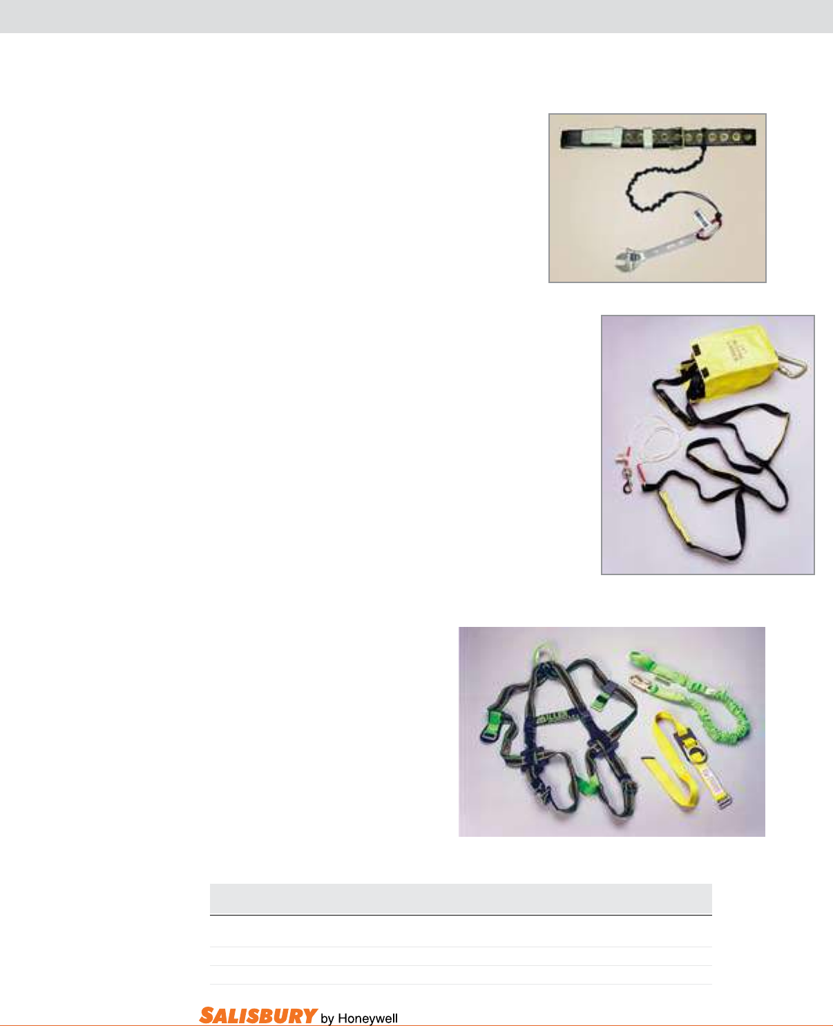
N-5
101 E. Crossroads Pkwy., Ste. A Bolingbrook, IL 60440 toll free ph (USA):877.406.4501 toll free fax (USA):866.824.4922 ph:630.343.3800
LANYARd, LAddER & buCkET kIT
Cat. No. Description
SAL9077X/12 Consists of a box of 12 Bandit Tool Lanyards
SAL9058/15FT 15-ft. (4.6 m) Self-rescue ladder
SAL8112L/UGN Includes full-body harness, shock-absorbing lanyard & aerial lift boom strap
miller bandit™ Tool lanyards. Prevent tools from
dropping that can cause serious injuries on the job
site. Lanyard conveniently attaches to the user’s belt.
Tools are attached with the carabiner or by cinching
the cord around tool.
miller aerial lift Rescue ladder. The Miller Aerial
Lift Self-Rescue Ladder is a portable 15-ft. (4.6 m)
web ladder designed and intended to assist with self-
rescue for applications such as aerial lifts, bucket
trucks, and elevated work surfaces.
In the event of a fall, the user releases the ladder by
pulling on the drawstring and then climbs back to the
work surface.
miller aerial bucket Kit
The Miller Aerial Bucket Kit offers a complete personal
fall arrest system for bucket truck applications.
The kit includes:
• DuraFlex® Utility Harness (SALE752/UGN)
• Manyard® II Shock-Absorbing Lanyard
(SAL233M/6FTGN)
• Aerial Lift Boom Strap (SAL6404/50INYL)
SAL9077X/12
SAL9058/15FT
SAL8112L/UGN
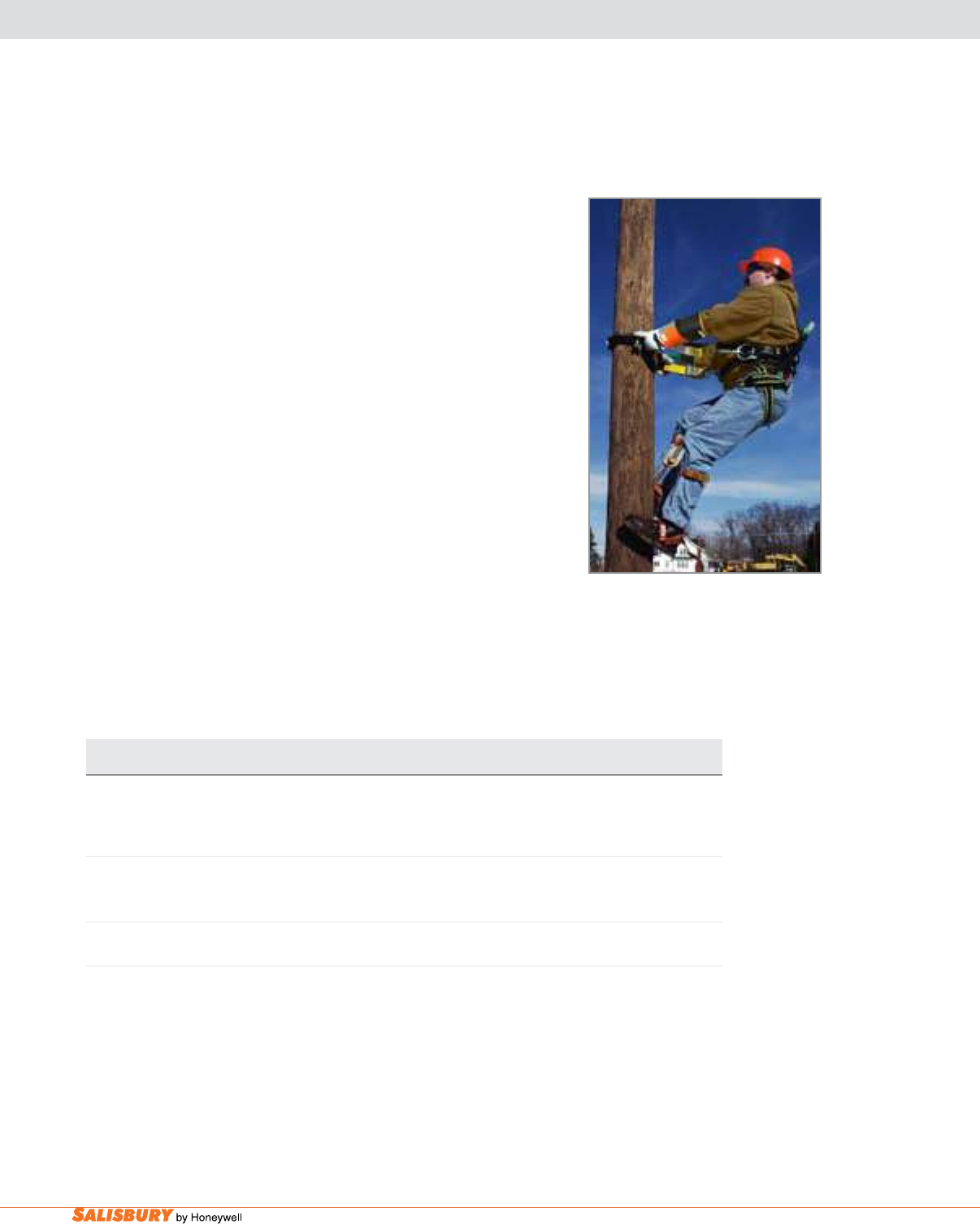
N-6 Miller® Fall Protection. www.salisburybyhoneywell.com
STOPFALL™ FALL RESTRAINT SYSTEM
Cat. No. Description
SAL7600A/YL/GP-1 StopFallSystemfitswoodpolesizes25-in.-50-in.(635mm-1270mm)
circumference with friction buckle adjustment and attached
Gaff Pullers (SAL7600GP-1) with leather screw-attachment straps
SAL7600B/YL/GP-1 StopFallSystemfitswoodpolesizes25-in.-50-in.(635mm-1270mm)
circumference with tongue buckle adjustment and attached
Gaff Pullers (SAL7600GP-1) with leather screw-attachment straps
SAL7600GP-1 GAFF PULLER ACCESSORY – For use on existing StopFall units
Gaff Pullers with leather attachments
SAL7600A/YL/GP-1
The Miller StopFall System provides a user-friendly and reliable work
positioning and fall arrest system for climbing wooden poles. The
StopFall System is speci cally designed with a 75-in. (1,905 mm) pole
strap (maximum length) and features a 21-in. (533 mm) security strap
with unique gaffs that “bite” into wooden poles. Meets CSA Standard
Z259.14-99 for Type A and Type AB.
■ The polyester pole strap comprises:
• An integral steel reinforcement band, which prevents “hour-
glassing” and maintains shape
• A rugged neoprene wear pad for increased service life
• Double-locking snap hooks and length adjuster assembly
• Two-piece spring assembly to prevent a continual electric path
• Stainless steel dome stops to prevent the security strap from
inadvertently sliding off the end of the wear pad
■ Specially-designed security strap:
• Corrosion-resistant, stainless steel hardware
• Spring-loaded gaffs that provide instant grip on wooden poles
• Nylon rollers permit free movement of the gaffs and minimize
abrasion on the strap
• A disconnect and length adjuster with a “parking” feature for when
the security strap is not in use
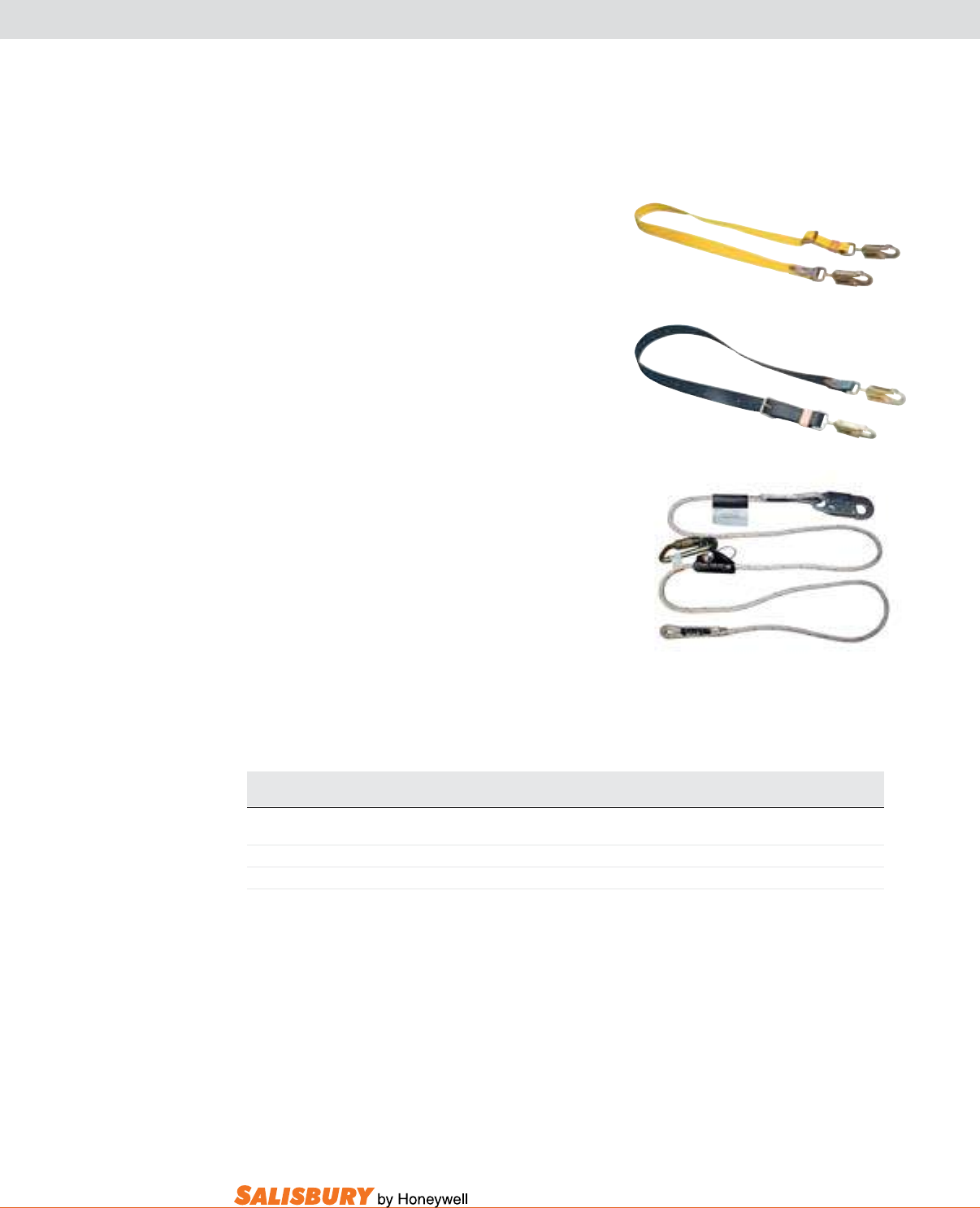
N-7
101 E. Crossroads Pkwy., Ste. A Bolingbrook, IL 60440 toll free ph (USA):877.406.4501 toll free fax (USA):866.824.4922 ph:630.343.3800
POSITIONINg & RESTRAINT LANYARdS
SAL6NFLS/6FTYL
nF Series Safety Strap
A 1-3/4-in. (44 mm) wide, 100% nylon safety strap
offers a friction buckle to adjust the length of the strap
quickly and easily.
yR Series Safety Strap
Strong safety strap, made of a six-ply neoprene,
remains exible in all types of weather conditions.
Tongue buckle adjuster included for quick, safe
adjustment.
adjustable Rope lanyard
Designed for work positioning while transitioning
around obstacles.
Cat. No. Length
SAL6NFLS/6FTYL NF Series Safety Strap 6-ft. (1.8 m)
SAL6YRLS/6FTBR YR Series Safety Strap 6-ft. (1.8 m)
SALARL-100-Z7/8FT Adjustable Rope Lanyard 8-ft. (2.4 m)
All Have Locking Snap Hooks – 3/4-in. (19 mm) gate opening.
SAL6YRLS/6FTBR
SALARL-100-Z7/8FT
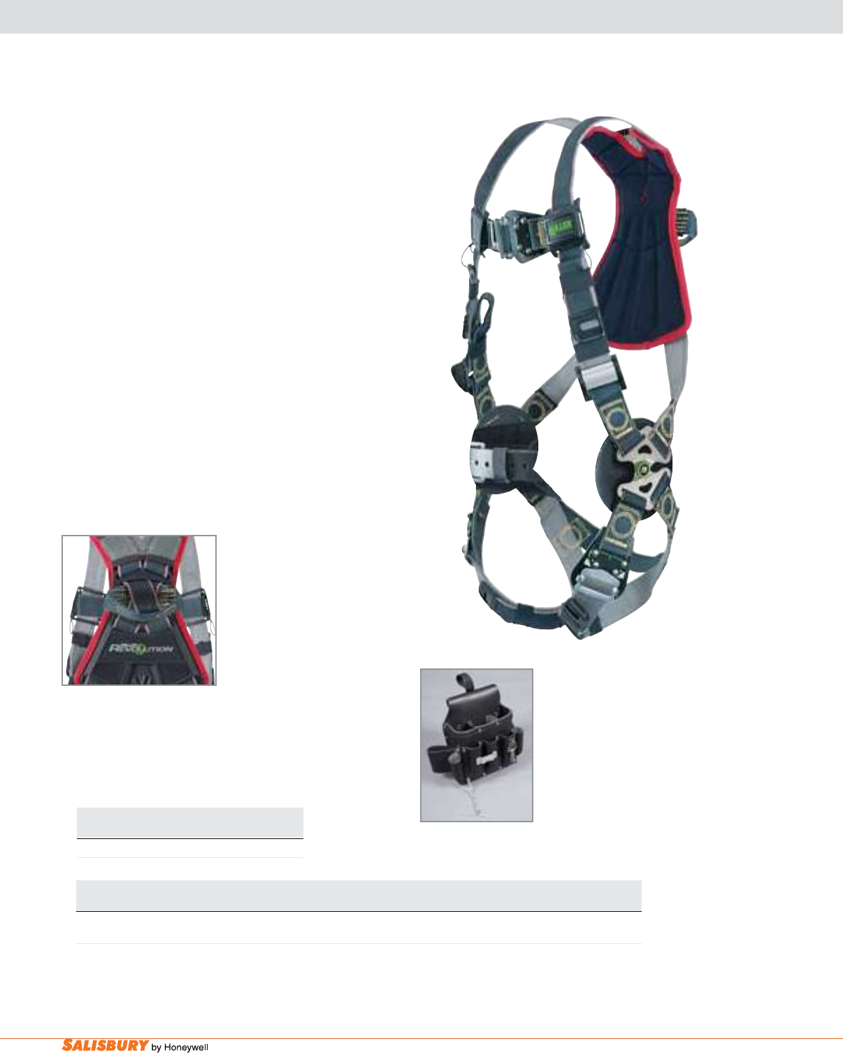
N-8 Miller® Fall Protection. www.salisburybyhoneywell.com
MILLER REvOLuTION™ ARC-RATEd HARNESS
guARdS AgAINST ARC-FLASH & ARC-bLAST EXPOSuRE
Cat. No. Size Leg Strap Rescue Special Features.
Buckles Loops
SALRKNAR-QC/UBK U Quick-Connect No Leather insulators / web back D-ring26
SKU number listed is for Universal (Lg./XL) size. Harness is also available in small/medium, XXL and XXXL, by replacing the “U” in the SKU number
with “S/M”, “XXL” or “XXXL” (Ex: SALRKNAR-QC/XXLBK).
Kevlar® is a registered trademark of E.I. DuPont.
SALRKNAR-QC/UBK
The miller Revolution arc-Rated Harness is designed
to protect workers from falls caused by electric arc-
ash and arc-blast exposure when working at heights or
in con ned space applications near energized electrical
sources.
Rated to 400 lbs. (181.4 kg) Capacity.
Meets ASTM F887-05 Arc Flash Standards.
Kevlar®/nomex® miller dualT ech™ Webbing
Patent-pending 10,000 lb. tensile strength webbing
is engineered with permanent fi re retardant (FR)
properties. The webbing offers the durability and FR
properties of Kevlar on the outer side, with softer FR
Nomex on the inside of the webbing for greater comfort.
The webbing assures arc protection and durability that
eclipses any nylon webbing.
Leather insulators under all metal hardware offer
additional protection for the worker.
Kevlar Web loop back
Pad allows for a “metal-
less” connection when
used with a Kevlar shock-
absorbing lanyard with
a choke-off loop. Bright
Red Pad Stitching for easy
identi cation as an arc-
rated product.
leather utility bag
Specialty tool bag features multiple compartments
and durable, oil-tanned leather construction. Designed
to attach directly to the Miller Revolution harness by
simply snapping on or off.
SALRIA-T11/1
Cat. No. Description
SALRIA-T11/1 Leather Utility Bag
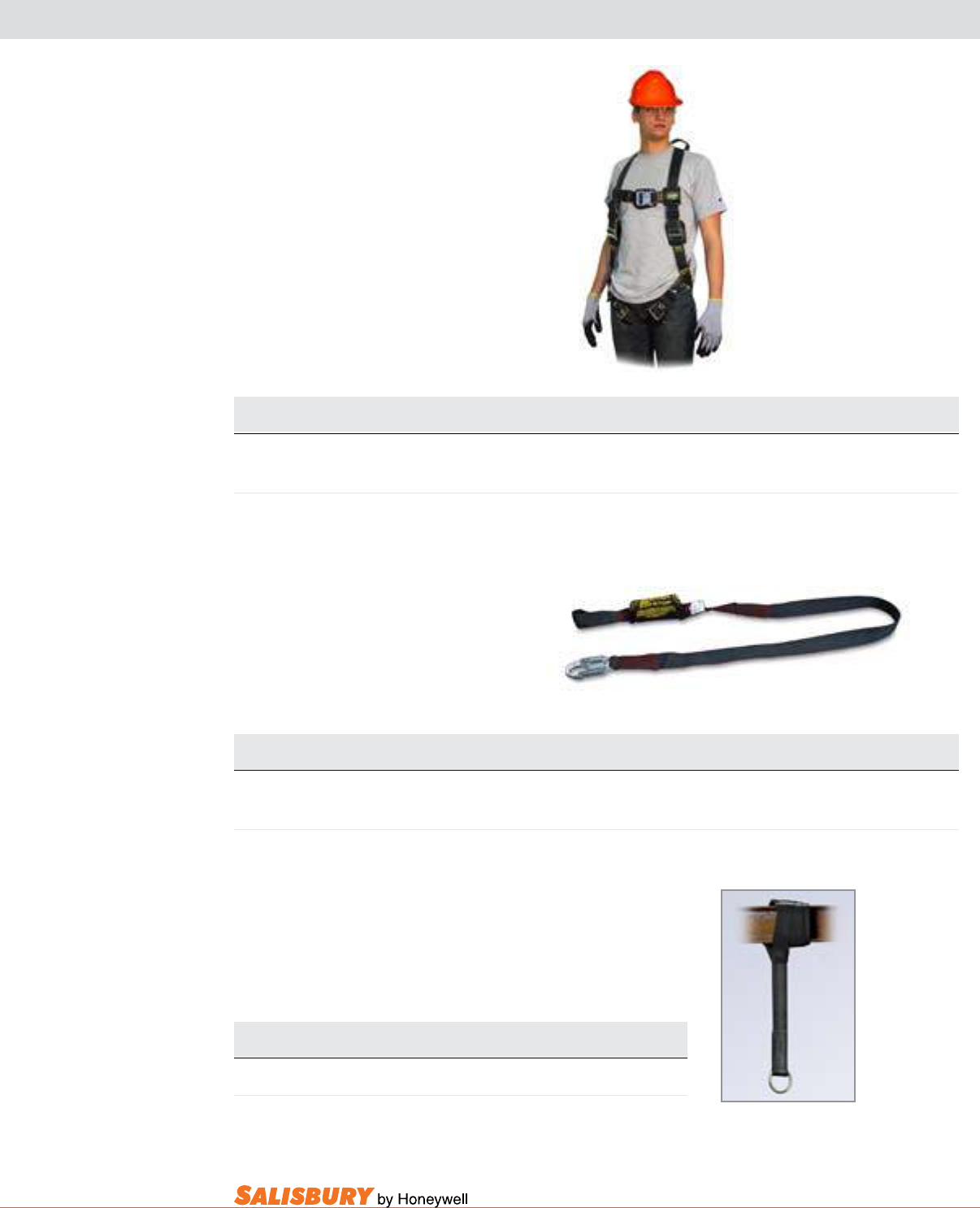
N-9
101 E. Crossroads Pkwy., Ste. A Bolingbrook, IL 60440 toll free ph (USA):877.406.4501 toll free fax (USA):866.824.4922 ph:630.343.3800
ARC-RATEd HARNESS, LANYARd & STRAP
SAL933K/6FTBK
Heavy-duty arc-Rated Harness
• Rugged black Kevlar® webbing for harsh
welding environments
• Meets ASTM F887 Arc-Test requirements
and is rated for arc exposure
• Quick-connect buckles on the chest strap
for easy/fast donning
• Leather insulators
• Web back D-ring
arc-Rated Shock-absorbing lanyards
• Meets stringent ASTM F887-05 arc-ash
standards
• Designed to protect workers from electric
arc-ash and arc-blast exposure
• Available with Kevlar choke-off loop for
a “metal-less” connection
arc-Rated Cross-arm anchorage Strap
• Features Kevlar webbing with 2-in. (51
mm) D-ring and choke-off loop.
Cat. No. Back Front Side Chest Strap Shoulder Strap Leg Strap Sub-Pelvic Special
Size D-Ring D-Ring D-Rings Buckle Buckles Buckles Strap Features
SAL650KQC/UBK U Yes Option No Quick-Connect Friction Quick-Connect Yes Pull-up
adjustment
SKU number listed is for Universal (Lg./XL) size. Harness is also available in small/medium, XXL and XXXL, by replacing the “U” in the SKU number with “S/M”, “XXL”
or “XXXL” (Ex: SAL650KQC/XXLBK).
For front D-ring vest-style option, add “FD” to the harness SKU number (Ex: SAL650KQCFD/UBK).
SAL650KQC/UBK
Cat. No. Material Style Harness Anchorage Standard
Connection Connection Length
SAL933K/6FTBK Kevlar webbing Lanyard w/SofStop Choke-off loop Locking snap hook 6-ft. (1.8 m)
shock absorber
Meets all applicable OSHA, ANSI A10.32 and CSA requirements. Note: Locking Snap Hook – 3/4-in. (19 mm) gate opening.
Cat. No. Material Style Length
SAL8185K/6FTBK Kevlar webbing Cross-arm strap 6-ft. (1.8 m)
*Kevlar is a registered trademark of E.I. DuPont. SAL8185K/6FTBK
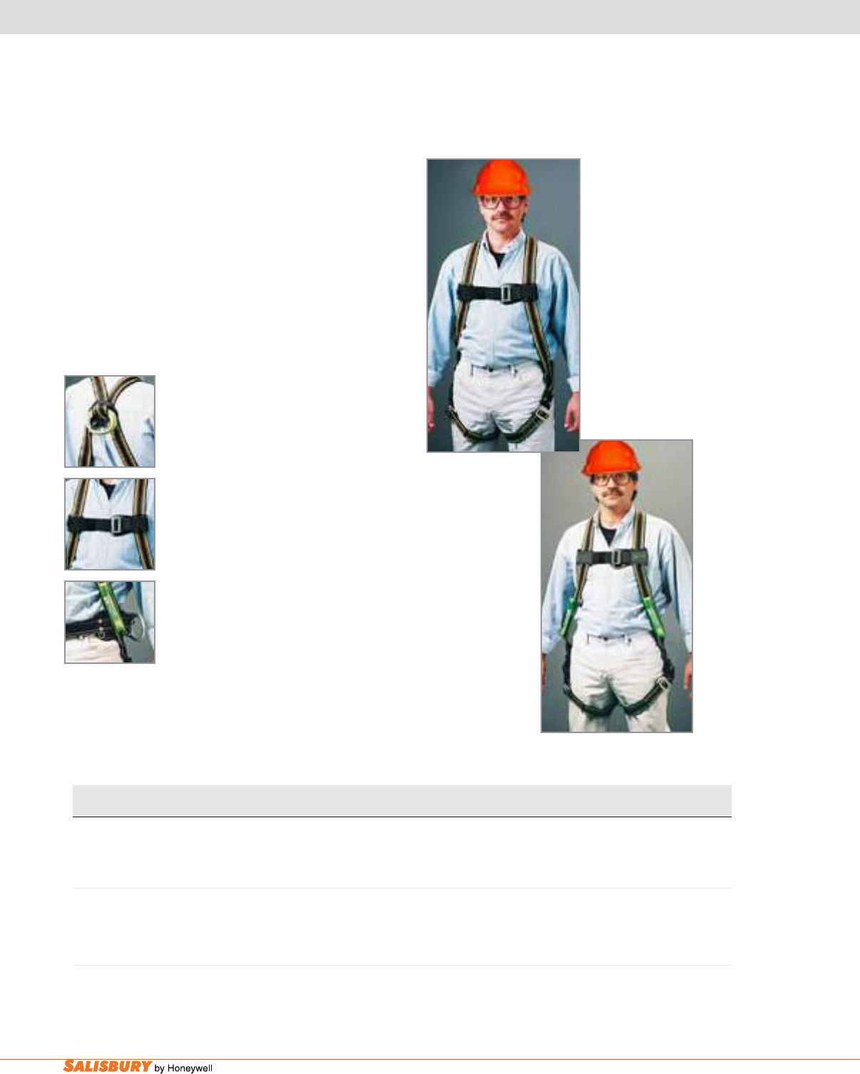
N-10 Miller® Fall Protection. www.salisburybyhoneywell.com
duRAFLEX® uTILITY HARNESSES
miller duraFlex utility Harnesses are uniquely designed
with minimal hardware above the waist to reduce
electrical conductivity. In addition, all harness materials
are independently thermal-arc tested to ensure superior
performance.
Patented Miller DuraFlex Harnesses feature specially-
formulated elastomer webbing that stretches to maximize
comfort, improve safety and increase productivity.
Rated to 400 lbs. (181.4 kg) Capacity.
Web loop lanyard attachment
• Reduces the chance of electric shock
near high-voltage sources
• Minimizes harness weight for added
comfort
Chest Strap with Protective Pads
• Holds shoulder straps in place
• Pads keep chest strap in place and protect
user from potential shock and injury
adjustable belt loops
• Allow for attachment of linemen’s belts
• Adjustable to fit most manufacturer
models
Self-Rescue Positioning loops
(SalE753/ugn only)
• For use with bucket escape systems
• Provides a positioning attachment point SALE753/UGN
Cat. No. Back Front Side Chest Strap Leg Strap Sub-Pelvic Special
Size D-Ring D-Ring D-Rings Buckle Buckles Strap Features
SALE752/UGN U Web Loop* No No Mating Mating Yes Chest strap adjustment /
protective pads /
adjustable belt loops
SALE753/UGN U Web Loop* No No Mating Mating Yes Chest strap adjustment /
protective pads /
adjustable belt loops /
self-rescue positioning loops
*In Canada, utility harnesses include a back D-ring extension in place of the web loop to meet CSA requirements.
SKU numbers listed are for Universal (Lg./XL) size. Harnesses are also available in small/medium, XXL and XXXL, by replacing the “U”
in the SKU number with “S/M”, “XXL” or “XXXL” (Ex: SALE752/XXLGN).
SALE752/UGN

N-11
101 E. Crossroads Pkwy., Ste. A Bolingbrook, IL 60440 toll free ph (USA):877.406.4501 toll free fax (USA):866.824.4922 ph:630.343.3800
NON-STRETCH uTILITY HARNESS
SAL752/UYK
Traditional non-stretch full-body harness
in lightweight, durable, yellow polyester
webbing. Rated to 400-lbs. (181.4 kg) capacity.
Accommodates linemen’s belts
Web loop lanyard attachment
• Reduces the chance of electric shock near
high-voltage sources
• Minimizes harness weight for added
comfort
Cat. No. Back Front Side Chest Strap Leg Strap Sub-Pelvic Special
Size D-Ring D-Ring D-Rings Buckle Buckles Strap Features
SAL752/UYK U Web Loop No No Mating Mating Yes Adjustable linemen’s
belt attachment
SKU number listed is for Universal (Lg./XL) size. Harness is also available in small/medium, XXL and XXXL, by replacing the “U” in the SKU number with
“S/M”, “XXL” or “XXXL” (Ex: SAL752/XXLYK).
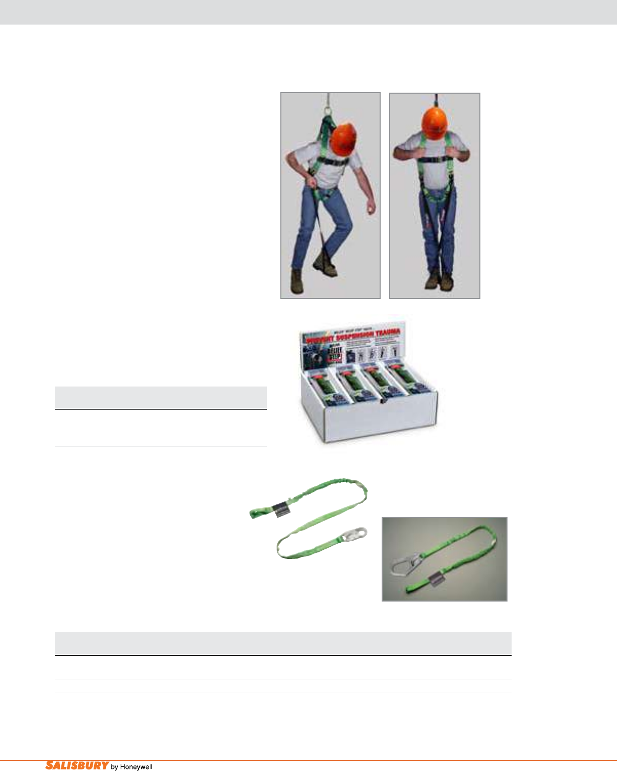
N-12 Miller® Fall Protection. www.salisburybyhoneywell.com
RELIEF STEP™ SAFETY dEvICE & MANYARd® LANYARdS
The miller Relief Step Safety device alleviates
the effects of orthostatic intolerance, also known as
suspension trauma.
• OSHA states that potentially fatal suspension
trauma can occur within minutes while waiting
for rescue after a fall
• Average fall rescue time is 15 minutes
• When used, the Relief Step Safety Device
provides support and enhances blood circulation
until rescue – permitting the ability to move and
ex leg muscles
• Small and lightweight; the Relief Step Safety
Device attaches to any brand full-body
harness
• Utilizing two (2) Relief Steps (one for each
leg/foot) assures greater comfort until rescue
is completed
• Low prole design eliminates hindrances or
hang-ups
SAL9099X/12
Cat. No. Description
SAL9099X/12 Consists of a box of 12
Relief Step Safety Devices
miller manyard® Shock-absorbing
lanyards
• Specially-woven shock-absorbing
inner core smoothly expands to reduce
fall arrest forces
• After a fall occurs, a warning ag is
released
• Meets ANSI Z359 requirements SAL233TWLS-Z7/6FTGN
SAL233TWRS-Z7/6FTGN
Cat. No. Material Number Harness Anchorage Standard
of Legs Connection Connection Length
SAL233TWLS-Z7/6FTGN Green web One Web choke-off loop Locking snap hook 6-ft. (1.8 m)
SAL233TWRS-Z7/6FTGN Green web One Web choke-off loop Locking rebar hook 6-ft. (1.8 m)
Note: Locking snap hook – 3/4-in. (19 mm) gate opening. Locking rebar hook – 2-1/2-in. (64 mm) gate opening.
Meets all applicable OSHA, ANSI and CSA requirements.
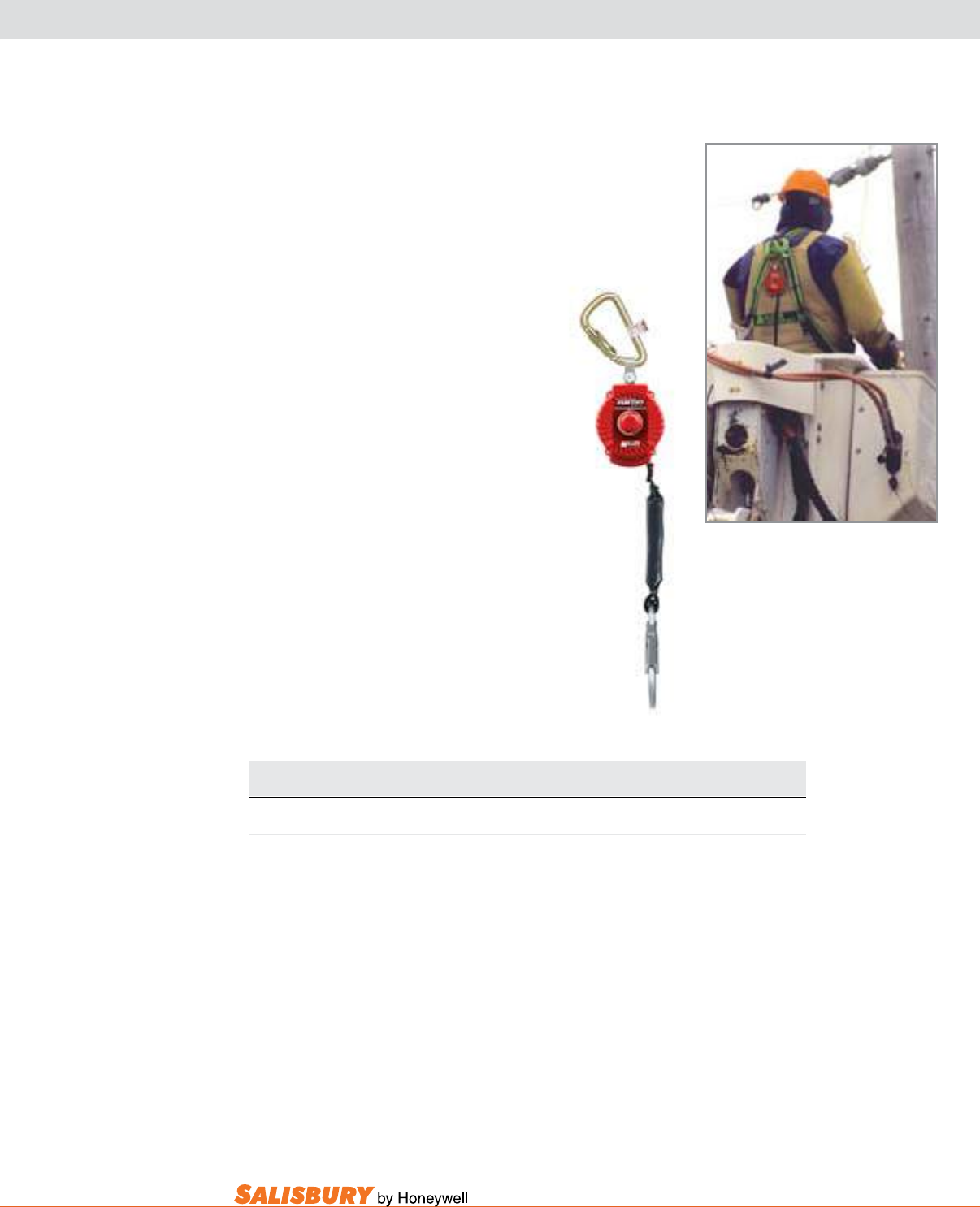
N-13
101 E. Crossroads Pkwy., Ste. A Bolingbrook, IL 60440 toll free ph (USA):877.406.4501 toll free fax (USA):866.824.4922 ph:630.343.3800
TuRbOLITE™ PERSONAL FALL LIMITER
Never need a shock-absorbing lanyard again!
The cost-effective and competitively priced
Miller TurboLite Personal Fall Limiter will
make shock-absorbing lanyards obsolete on
the job site. Workers will no longer need to
“switch-out” equipment to maintain a safe
fall distance.
• Extremely compact and lightweight provides
6-ft. (1.8 m) working capacity lifeline; unit
attaches directly to the harness back D-ring
for greater mobility and versatility
• Engineered webbing for greater abrasion
resistance and long service life
• High-strength, impact-resistant nylon
housing for maximum durability
• Built-in swivel prevents lifeline from
twisting
• Rated for up to a 400 lb. (181.4 kg) user
• No annual factory recerti cation required
• Meets ANSI Z359 requirements
Cat. No. Description and Lanyard
Unit Connector End Connector
SALMFL-1-Z7/6FT TurboLite with steel twist-lock carabiner Locking snap hook
Note: Locking snap hook – 3/4-in. (19 mm) gate opening.
Meets all applicable OSHA, ANSI A10.32, ANSI Z359 and CSA requirements.
SALMFL-1-Z7/6FT
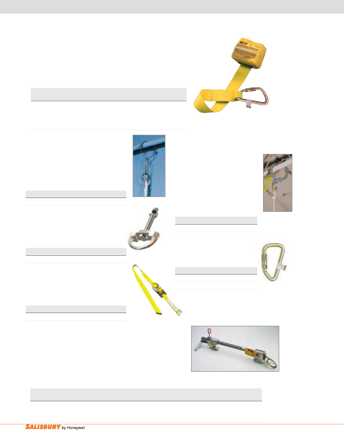
N-14 Miller® Fall Protection. www.salisburybyhoneywell.com
RETRACTAbLE LANYARd, ANCHOR CONNECTORS & bEAM
The Side Winder Retractable Web lanyard is a positioning device
designed to allow linesmen to bypass obstructions safely in pole
climbing applications. The length is easily adjustable up to 8-ft. (2
m) and includes a carabiner and attachment bracket for installation
on linemen‘s belts.
Cat. No. Description Weight
SAL8327SW/8FTYL Compact, retractable lanyard 3.7 lbs. (1.7 kg)
with up to 8-ft. (2 m)
of polyester webbing
SAL8327SW/8FTYL
Stainless steel Wire Hook anchor connects
to various approved anchorages including
railings, small I-beams, angle iron and
scaffolding. Simply squeeze the spring-
loaded hook and slip the large opening over
the approved structure. 400-lbs. (181.4 kg)
maximum capacity.
Cat. No. Description
SAL470/ Wire Hook Anchor
miller Permanent anchorage Connector.
D-Bolt Anchor for up to 4-in. (102 mm)
working thickness includes a 5/8-in. (16 mm)
diameter bolt with lockwasher and nut.
Cat. No. Description
SAL416/ Permanent Anchor Connector
aerial lift boom Strap. Made of 2-in. (51 mm)
nylon webbing. Includes a sliding D-ring for
proper placement on booms and an adjustable
buckle that easily tightens into position.
Cat. No. Description
SAL6404/50INYL Aerial Boom Strap
Extension Pole & Hook anchor.
The 20-ft. (6 m) berglass pole and
spring-loaded hook is ideal for use
with climbing ladders and towers.
Installs fall arrest systems up to 20-ft.
(6 m) from ground level to angle iron,
piping and related structures. 400-
lbs. (181.4 kg) maximum capacity.
Cat. No. Description
SAL475/ Pole & Hook Anchor
Steel Twist-lock Carabiner. Meets
ANSI Z359. 400-lbs. (181.4 kg)
maximum capacity.
Cat. No. Description
SAL17D-1/ 1” (25mm) Carabiner
SAL18D-1/ 2” (51mm) Carabiner
The miller Fixed beam anchor connects horizontally to a wide range
of I- and H-beam anges from 4-in. (102 mm) to 12-in. (305 mm)
wide and up to 1-1/4-in. (32 mm) thick.
This unit is designed to be tightened horizontally or vertically, rmly
gripping the beam or column to provide a temporary or permanent
anchorage attachment.
Cat. No. Description Fits Flange Sizes
SAL8815-12/ Lightweight,fixedbeamanchor 4-in.to12-in.(102mmto305mm)
stainless steel & high-strength aluminum
SAL8815-12/
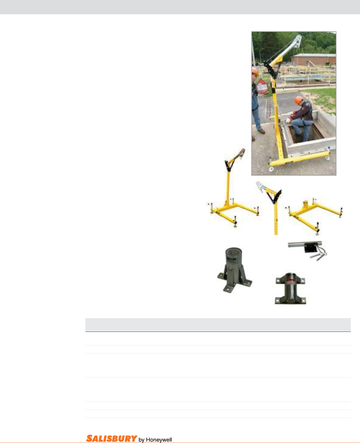
N-15
101 E. Crossroads Pkwy., Ste. A Bolingbrook, IL 60440 toll free ph (USA):877.406.4501 toll free fax (USA):866.824.4922 ph:630.343.3800
duRAHOIST™ PORTAbLE CONFINEd SPACE SYSTEMS
Miller DuraHoist Portable Conned Space
Systems provide safe, lightweight and portable
solutions for a variety of confined space
applications, including con ned space entry,
rescue, positioning and personnel/material
handling.
• Lightweight, high-strength aluminum
construction for easy handling and long
service life
• No tools required for assembly
• Modular design allows the use of
components in various congurations and
applications, lowering cost of ownership
and providing effective safety solutions
Floor mount Sleeve is a xed base for the
One-piece Adjustable Mast (SALDH-3/).
Mounts to horizontal concrete or steel
structures.
Wall mount Sleeve is a xed base for the
One-piece Adjustable Mast (SALDH-3/).
Mounts to vertical concrete or steel structures.
Compact design creates minimal intrusion into
work space.
SALDH-19-MILLER
SALDH-2/ SALDH-3/
SALDH-4/
SALDH-7ZP/
SALDH-8ZP/
Cat. No. Description Weight
SALDH-2/ Four-piece system without ManHandler® hoist/winch 91 lbs. (41.3 kg)
SALDH-3/ One-piece Adjustable Mast: 12-in. (305 mm) to 29-in. (737 mm) offset 29 lbs. (13.2 kg)
SALDH-4/ Three-piece Portable Base, lightweight, powder-coated aluminum. 61 lbs. (27.7 kg)
Features adjustable aluminum screws and a built-in level indicator
for easy set-up on uneven surfaces. No tools required for assembly.
SALDH-19-MILLER Complete bracket assembly for mounting a Miller ManHandler 3.1 lbs. (1.4 kg)
hoist/winch or a Miller MightEvac® SRL to the
DuraHoistPortableConfinedSpaceSystem
SALDH-7ZP/ Zinc-plated, mild steel 13 lbs. (5.9 kg)
SALDH-8ZP/ Zinc-plated, mild steel 12 lbs. (5.4 kg)
Meets all applicable OSHA and ANSI requirements.
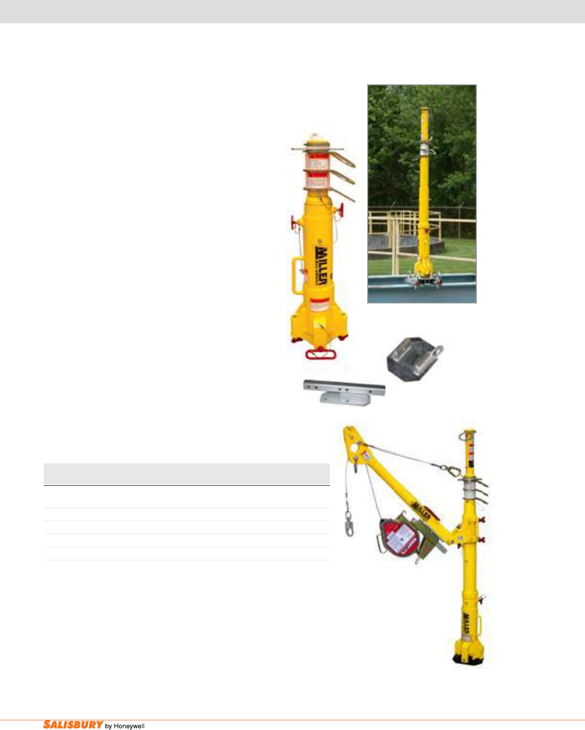
N-16 Miller® Fall Protection. www.salisburybyhoneywell.com
duRAHOIST™ PORTAbLE FALL ARREST POST
The duraHoist Portable Fall arrest Post provides
three independent swivel tie-off points for fall arrest
anchorage. Three-stage/four-position telescoping design
and aluminum construction for easy transportation
and set-up. The leveling screws allow the system to
be plumbed to vertical for proper working stability on
inclines up to 15 degrees. Adjustable from 32.75-in (832
mm) to 57.25-in. (1,454 mm).
Fixed anchor Plate for the Portable Fall Arrest Post.
Designed to be permanently welded to existing structures
in locations of frequent work, or where the use of a
portable base is impractical.
Rescue/material Handling davit arm attaches
quickly and easily to the Portable Fall Arrest Post for
rescue and material handling applications. Lightweight
aluminum construction makes the Davit Arm easy to
transport and set-up.
Complete adapter Plate w/bracket assembly is used
to mount a ManHandler Hoist/Winch or a MightEvac
SRL to the Rescue/Material Handling Davit Arm.
SALDH-AP-1/
SALDH-AP-4/
SALDH-AP-3/
SALDH-AP-11/
Cat. No. Description Weight
SALDH-AP-1/ Portable Fall Arrest Post 38 lbs. (17.2 kg)
SALDH-AP-4/ Fixed anchor plate with tie-off anchor 11.8 lbs. (5.4 kg)
SALDH-AP-9/ Portable I-beam anchor base 56 lbs. (25.4 kg)
SALDH-AP-3/ Rescue/Material Handling Davit Arm 20.5 lbs. (9.3 kg)
SALDH-AP-11/ Complete Adapter Plate w/Bracket Assembly 2.7 lbs. (1.2 kg)
Meets all applicable OSHA and ANSI requirements.
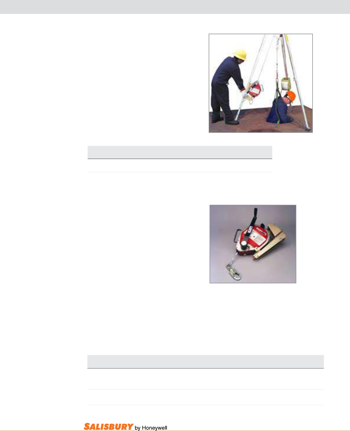
N-17
101 E. Crossroads Pkwy., Ste. A Bolingbrook, IL 60440 toll free ph (USA):877.406.4501 toll free fax (USA):866.824.4922 ph:630.343.3800
RESCuE SYSTEM & RETRIEvAL HOIST
The miller Confined Space and Rescue
System includes:
• 7-ft. (2 m) lightweight aluminum tripod and
MightEvac mounting bracket
• Miller MightEvac Unit w/ 50-ft. (15 m) of
3/16-in. (4.8 mm) galvanized wire rope
• ManHandler Hoist/Winch with 65-ft. (20 m)
of 3/16-in. (4.8 mm) galvanized wire rope
• Pulley, carabiner and two heavy-duty
equipment bags
• Meets ANSI Z359 requirements SALMR50GCM-Z7/50FT
Cat. No. Description
SALMR50GCM-Z7/50FT MillerConfinedSpace&RescueSystem
Meets all applicable OSHA, ANSI and CSA requirements. For stainless steel wire rope, change the “G” to an “S” in
the corresponding model number (Ex: SALMR50GCM-Z7/50FT becomes SALMR50SCM-Z7/50FT).
The miller mightEvac® Self-Retracting
lifeline w/ Emergency Retrieval Hoist
combines the superior performance and
reliability of the best-selling MightyLite™
Self-Retracting Lifeline Series with a quick-
activating retrieval mechanism for emergency
evacuation.
• No annual factory recerti cation required*
• 20% lighter than competitive models
• Corrosion-resistant stainless steel/aluminum
housing and internal components
• Promotes quick and easy rescue with a 4:1
mechanical advantage (average speed of
25 ft. [7.6 m] per minute)
*Does not apply to Canada due to CSA Z259.2.2-
98 requirements. Must be inspected by a Miller
authorized service center if involved in a fall or if
fails user visual or functional inspection.
• Convenient, heavy-duty carrying handle
• 310 lb. (140.6 kg) working capacity; rated
to 400 lbs. (181.4 kg) working capacity
when using a SofStop shock absorber
(SAL928LS/18INBK)
• For emergency evacuation only
• SALMR50GB-Z7/50FT meets ANSI Z359
SALMR50GB-Z7/50FT
Cat. No. Description Weight
SALMR50GB-Z7/50FT Miller MightEvac w/50-ft. (15 m) of 3/16-in. (4.8 mm) 39 lbs. (17.7 kg)
galvanizedwirerope,mountingbracket&carabiner
SALMR40KB/40FT Miller MightEvac w/40-ft. (12 m) of 3/16-in. (4.8 mm) 37 lbs. (16.8 kg)
polyester Spectra® rope, mounting bracket & carabiner
Meets all applicable OSHA, ANSI and CSA requirements. Spectra is a registered trademark.
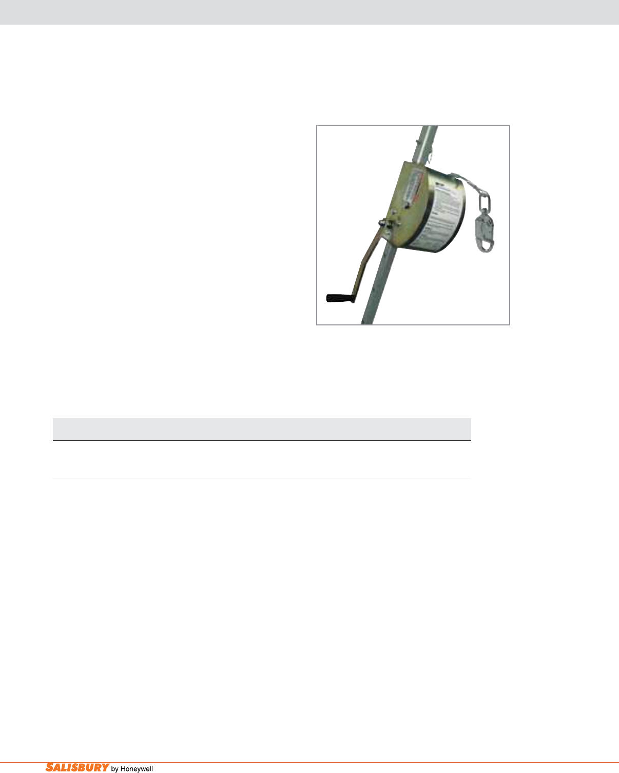
N-18 Miller® Fall Protection. www.salisburybyhoneywell.com
MILLER MANHANdLER® HOIST
The miller manHandler Hoist is the perfect solution for
a range of applications including con ned space entry,
rescue, positioning and personnel/material handling.
• Compact, durable steel construction
• Smooth, controlled winding action
• Effortless lifting and lowering with a 5:1 gear ratio
• Built-in mounting bracket
• Anti-backlash crank handle braking system prevents
freewheeling
• 400 lbs. (181.4 kg) working capacity
• Meets ANSI Z359 requirements
Cat. No. Description Weight
SAL8442-Z7/65FT ANSI Z359-2007 Compliant ManHandler personnel-rated 40.1 lbs. (18.2 kg)
hoistw/65-ft.(20m)of3/16-in.(4.8mm)galvanizedsteelcable
Meets all applicable OSHA, ANSI and CSA requirements.
SAL8442-Z7/65FT
ACCESSORIES
X-2 Accessories. www.salisburybyhoneywell.com
ACCESSORIES
ALSO AVAILABLE
Salisbury offers an entire line of Arc Flash Protective Clothing
and Equipment ranging from 8 cal/cm2 to 100 cal/cm2.
Ask your local Salisbury representative for a copy of our Arc Flash Protection
Catalog or download it from our website at salisburybyhoneywell.com.
Salisbury also offers Salisbury Insulated Tools and Tool Kits.
These tools are all tested to 10,000 VAC for use up to 1,000 VAC. These tools meet or
exceed ASTM F1505-01 and IEC 900 Standards for Insulated Hand Tools and will help you
to be compliant with OSHA 1910.333 (c)(2), and NFPA 70E 2009. Ask your local Salisbury
representative for more information or visit our website at salisburybyhoneywell.com.
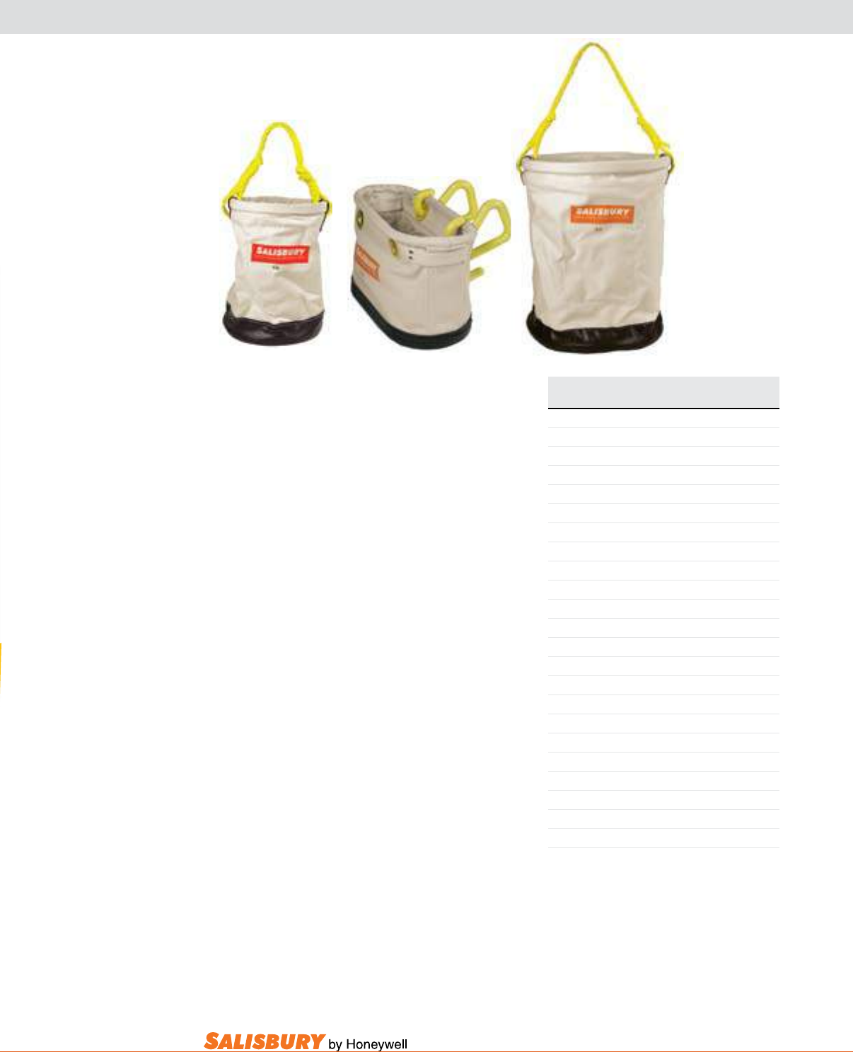
X-3
101 E. Crossroads Pkwy., Ste. A Bolingbrook, IL 60440 toll free ph (USA):877.406.4501 toll free fax (USA):866.824.4922 ph:630.343.3800
CANVAS BUCKETS AND BAGS
Salisbury Tool buckets are constructed of
extra-heavy-duty canvas duck and reinforced
with a one-piece formed leather bottom with
a 3” (76mm) cuff for rugged service and long
life. The standard tool buckets, 30 and 40, are
both collapsible for easy storage and feature a
poly braid rope handle. The 30 features a 6” x 8”
interior pocket. The oval tool bucket, 50, designed
to attach to aerial baskets, features 6 inner tool
pockets and two plastic hanging hooks.
Salisbury Tool bags are useful for carrying
and storing all sorts of equipment and tools.
Constructed for long life and rugged service
from one piece of #8 natural canvas fastened
to a steel frame. The vinyl coated nylon bottom
is cemented and double stitched to the bag and
protected with steel studs and a reinforcing 3.5”
(89mm) cuff. Handles are made from a heavy
polypropylene webbing and straps are made of
top grain harness leather.
line Hose and blanket bags are convenient for
raising and lowering bulky items up and down
a pole, as well as for storage. Constructed of #6
duck, sewn with nylon thread, and reinforced
with a heavy rubber bottom. Features a top
ring to hold the bag open and a strong 1/2”
(12.7mm) poly braid rope handle, reinforced
with polymer. 8” (178mm) diameter bags are
used for conventional style line hose, while the
12” (305mm) diameter bags were designed for
Class 4 extended lip line hose.
Cat. No. Dimensions Weight ea.
in. ( mm ) lbs. ( kgs )
STANDARD TOOL BUCKETS
30* 12 x 16 ( 305 x 406 ) 3.2 ( 1.45 )
40* 8 x 14 ( 203 x 356 ) 2 ( .91 )
OVAL TOOL BUCKET
50C* 7x14x10 ( 1715x356x254 ) 2.5 ( 1.14 )
PH55 yellow vinyl hooks for #50 .5 ( .23 )
STANDARD Tool Bags- 5.5” (140mm) wide
616 16 x 13.5 ( 406 x 343 ) 3.3 ( 1.5 )
618 18 x 15.5 ( 457 x 394 ) 3.8 ( 1.73 )
620 20 x 15.5 ( 508 x 394 ) 4.2 ( 1.91 )
622 22 x 15.5 ( 559 x 394 ) 4.3 ( 1.95 )
624 24 x 15.5 ( 610 x 394 ) 4.5 ( 2.04 )
EXTRA WIDE Tool Bags-9.5” (241mm) wide
2419B 24 x 19 ( 610 x 483 ) 4.1 ( 1.86 )
LINE HOSE BAGS
48* 8 x 48 ( 178 x 1219 ) 2.8 ( 1.27 )
60* 8 x 60 ( 178 x 1524 ) 3.0 ( 1.36 )
66* 8 x 66 ( 178 x 1676 ) 3.3 ( 1.5 )
72* 8 x 72 ( 178 x 1829 ) 3.5 ( 1.59 )
1248* 12 x 48 ( 305 x 1219 ) 3.8 ( 1.73 )
1266* 12 x 66 ( 305 x 1676 ) 5.3 ( 2.41 )
BLANKET BAG
1230 12 x 30 ( 305 x 762 ) 3.2 ( 1.45 )
*add suffix “S” if optional iron swivel snap is desired
30
50
40
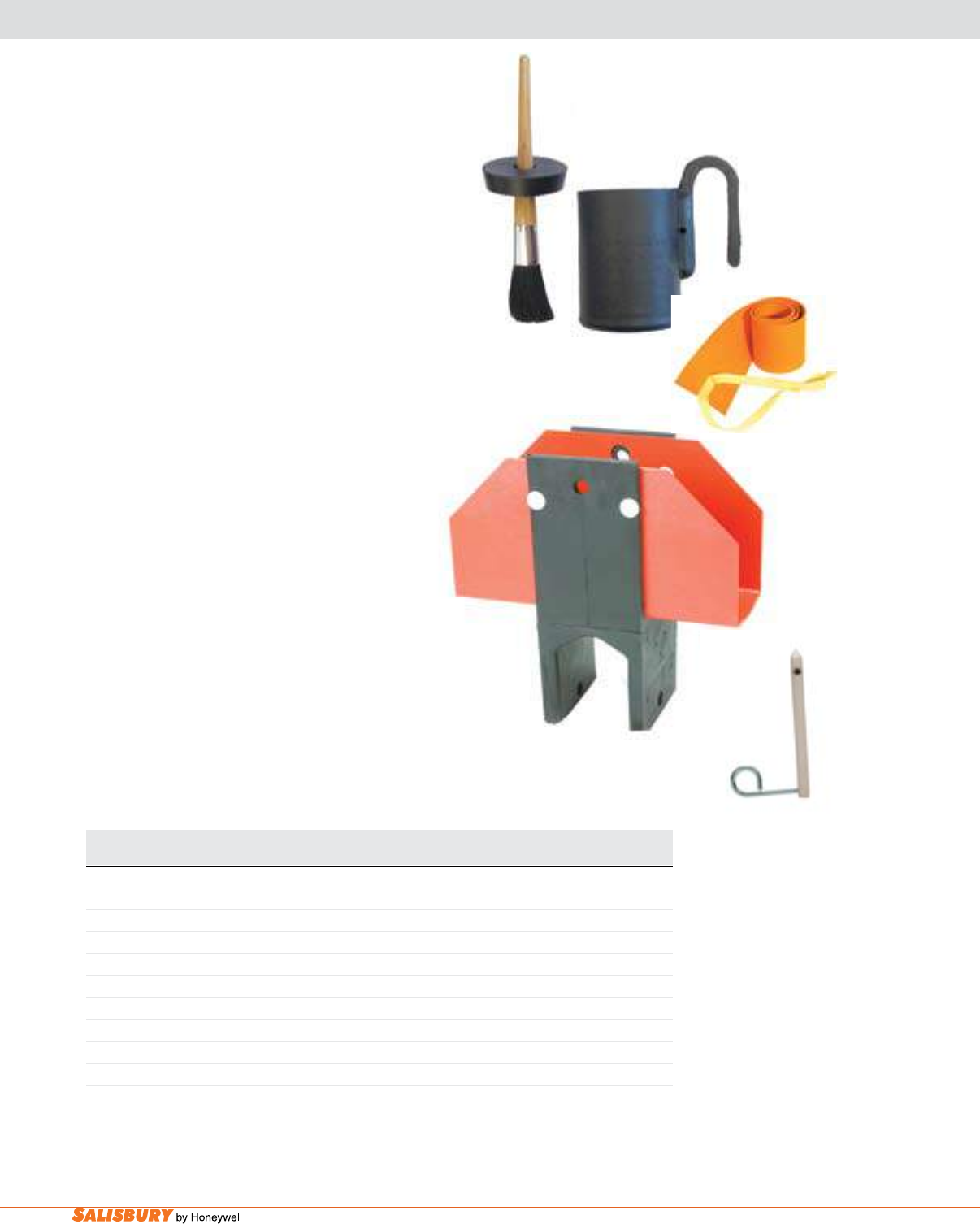
X-4 Accessories. www.salisburybyhoneywell.com
IS10
ACCESSORIES
Compound Pots are made of hard rubber that is
nonconductive and breakage resistant. The applicator
brush and compound are held in one unit that can be
hung from aerial devices or t into cross arm holes.
Offered in single and double compartment styles.
Cable bandages provide temporary insulation for
bare conductors and splices. A single thickness of
the orange SALCOR® Bandage can withstand 15kV
on puncture test. The black neoprene bandage is
intended to provide fast and complete temporary
cover for cable splicers.
Insulating Saddles are ideal for temporary or
emergency line work such as stringing light
conductors over short spans. The large 3” (76mm)
upper saddle opening will hold bare or insulated
conductors in either an upright or inverted position.
The IS10 has a voltage rating of 15kV. When
necessary to leave energized conductors or jumpers
in the saddle for extended periods, it is recommended
that they be encased in orange SALCOR® RIB-
GRIP® line hose. Molded of hard rubber and
furnished with two nylon holding pins supplied
with steel loops for easy hot-stick application. A
12” (305mm) orange plastic shoe is afxed to the
crossarm opening to help prevent ashover during
inclement weather. Designed to t crossarms with
dimensions up to 3.75” x 5” (95mm x 127 mm).
Cat. No. Description Weight ea.
in. ( mm ) lbs. ( kgs )
COMPOUND POT SINGLE COMPARTMENT
PJB1 1pt. w/ bristle brush 4.5” x 3.5” ( 114 x 89 ) 1.5 ( .681 )
PJB2 1 pt. w/ wire brush 4.5” x 3.5 ( 114 x 114 ) 1.5 ( .681 )
CABLE BANDAGES
44OS Orange SALCOR 4’ ( 1.2m ) w/ strap 1 ( .5 )
414PG Pure Gum Rubber 14’ ( 4.3m ) w/o strap 1 ( .5 )
414BN Black Neoprene 14’ ( 4.3m ) w/o strap 1 ( .5 )
INSULATING SADDLE
IS10 11.25 x 4.75 ( 286 x 121 ) 4 ( 1.8 )
ISP Replacement Pin .25 ( .1 )
PJB1
44OS
ISP
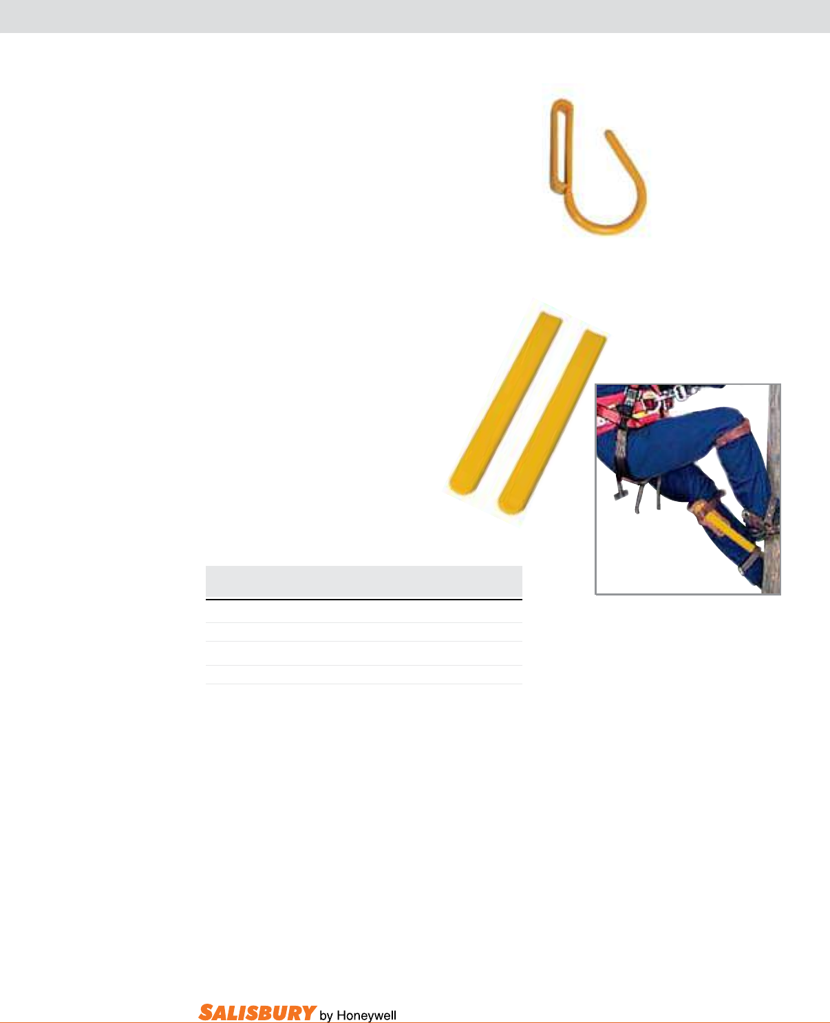
X-5
101 E. Crossroads Pkwy., Ste. A Bolingbrook, IL 60440 toll free ph (USA):877.406.4501 toll free fax (USA):866.824.4922 ph:630.343.3800
Cat. No. Description / Dimensions Weight ea.
in. ( mm ) lbs. ( kgs )
BELT HOOK / BREAK-AWAY
H7 Break-Away Belt Hook 1 oz. ( .03 )
CLIMBER GUARDS
21187 sold in pairs .5 ( .23 )
H7
bElT HOOK/bREaK-aWay is
nonconductive yellow nylon hand-line
belt hook that will bend or break if
suddenly pulled.
Climber guards are manufactured
by the dipping process using the
same formulation of rubber as our
lineman’s insulating gloves and sleeves.
Climber Guards are furnished un-slit
to accommodate any length, regular or
adjustable climbers. Sold in pairs only.
SPECIAL EQUIPMENT
21187
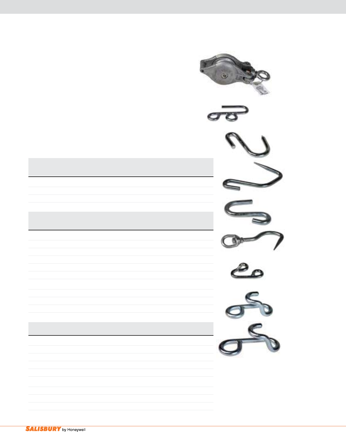
X-6 Accessories. www.salisburybyhoneywell.com
HAND LINES, HAND LINE ASSEMBLIES & LINE HOOKS
Premium all-purpose Hand line is a light weight and durable three-
strand laid rope. Filament polyester yarns are “jacket-wrapped” over
mono-lament polypro center yarns, providing excellent abrasion
resistance and gripping properties with moderate elongation. When
used properly, polydac is perfect for capstans, block and tacklework,
and many other rough applications. Other lengths available.
Hand line assemblies with Polydac Rope is used for lifting objects
to the lineman on the pole. Other lengths are available.
Hooks are used for snatch and hand line blocks. Steel line Hooks
designed to hug the conductor when strain is applied to rope after
splicing rope into the eye. Hooks will not damage conductor or fall
off, and are easily applied and removed.
Cat. No. Diameter Length Approx. Tensile Weight / Reel
Strength
in. cm ft. m lbs. kgs lbs. kgs
POLYPROPYLENE AND POLYESTER (POLYDAC) ROPE
5000E600 1/2 1.3 600 182.9 5,400 2,449 40 18.1
6250E600 5/8 1.6 600 182.9 7,200 3,266 56 25.4
Cat. No. Description Total Rope For Pole Weight
Length Height
ft. m lbs. kgs lbs. kgs
HAND LINE ASSEMBLIES WITH POLYDAC ROPE
1491250 Standard Hand Line, Fixed Sling 100 30.5 50 15.2 11 4.99
1492250 Standard Hand Line, Adjustable Sling 100 30.5 50 15.2 11 4.99
1492375 Standard Hand Line, Adjustable Sling 150 45.8 75 22.9 13 5.90
1494250 Alternate Hook Assembly, Adjustable Sling 100 30.5 50 15.2 11 4.99
1494375 Alternate Hook Assembly, Adjustable Sling 150 45.8 75 22.9 13 5.90
PARTS
42 Hand Line Block (only) 2 0.91
149H Hook for Hand Line (only) 1 0.45
149S Swivel Snaps (only) 1 0.45
Cat. No. Description Opening Size WLL Weight
in. ( cm ) lbs. ( kgs ) lbs. ( kgs )
HOOKS
40H Pointed Hook 1,000 ( 454 ) 1 ( 0.45 )
40HPP Pointed Hook 1,000 ( 454 ) 1 ( 0.45 )
40CH Blunt Hook 1,000 ( 454 ) 1 ( 0.45 )
40SHB Swivel Hook 1,000 ( 454 ) 1 ( 0.45 )
LINE HOOKS
27 Small 7/8” (2.2 cm) 1,000 (454 ) 1 ( 0.45 )
27A Medium 1-1/2” (3.8 cm) 1,325 (601 ) 2 ( 0.91 )
27S Large 2” (5.1 cm) 1,650 (748 ) 3 ( 1.36 )
149H
42
40H
40HPP
40CH
40SHB
27
27A
27S
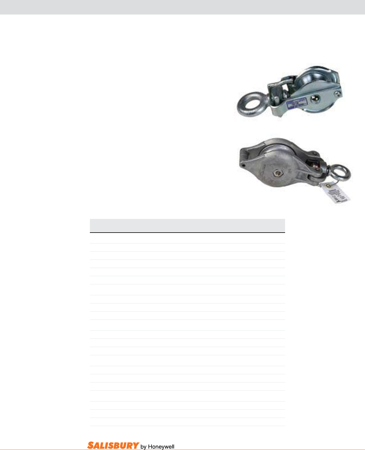
X-7
101 E. Crossroads Pkwy., Ste. A Bolingbrook, IL 60440 toll free ph (USA):877.406.4501 toll free fax (USA):866.824.4922 ph:630.343.3800
BLOCKS
blocks are made of high strength aluminum alloy
except for Cat. No. 42PS which is made of high impact
plastic. The hand line block has a 5/8” (1.6 cm) diameter
rope maximum. “S” denotes side opening block. Other
hooks are available.
Wood Shell blocks are used with polypropylene or
synthetic rope. The 4” blocks have a 1/2” (1.3 cm)
diameter rope maximum; the 5” blocks a 5/8” (1.6
cm) maximum; and the 6” blocks a 3/4” (1.9 cm)
maximum.
Single blocks are tted with a swivel hook; double
and triple block with a loose, at hook. Swivel hooks
are not recommended on double or triple blocks. The
double and triple blocks are tted with a special live
line pin so they can easily be handled with an alligator
stick (Cat. No. 4FGQ).
42S
Cat. No. Description Weight WLL
lbs. ( kgs ) lbs. ( kgs )
BLOCKS
40 Aluminum Hand Line Block 2 ( 0.91 ) 1,000 ( 454 )
42A Aluminum Hand Line Block with Pointed Hook 3 ( 1.36 ) 1,000 ( 454 )
42S Aluminum Snatch Block 2 ( 0.91 ) 1,000 ( 454 )
42SA Aluminum Snatch Block with Pointed Hook 3 ( 1.36 ) 1,000 ( 454 )
42PS Insulated Plastic Block 3 ( 1.36 ) 1,000 ( 454 )
WOOD SHELL BLOCKS - SINGLE BLOCK WITH SWIVEL HOOK & BECKET
904 4” ( 10.2 cm ) 2 ( 0.91 ) 1,000 ( 454 )
905 5” ( 12.7 cm ) 3 ( 1.36 ) 1,200 ( 544 )
906 6” ( 15.2 cm ) 5 ( 2.27 ) 1,800 ( 816 )
WOOD SHELL BLOCKS - DOUBLE BLOCK WITH FLAT HOOK & BECKET
284 4” ( 10.2 cm ) 3 ( 1.36 ) 1,400 ( 635 )
285 5” ( 12.7 cm ) 5 ( 2.27 ) 1,800 ( 816 )
286 6” ( 15.2 cm ) 7 ( 3.17 ) 2,500 ( 1,134 )
WOOD SHELL BLOCKS - DOUBLE BLOCK WITH FLAT HOOK, BECKET & SWIVEL
284A 4” ( 10.2 cm ) 3 ( 1.36 ) 1,400 ( 635 )
285A 5” ( 12.7 cm ) 5 ( 2.27 ) 1,800 ( 816 )
286A 6” ( 15.2 cm ) 8 ( 3.63 ) 2,500 ( 1,134 )
WOOD SHELL BLOCKS - TRIPLE BLOCK WITH FLAT HOOK, BECKET & SWIVEL
284A3 4” ( 10.2 cm ) 4 ( 1.81 ) 1,800 ( 816 )
285A3 5” ( 12.7 cm ) 7 ( 3.17 ) 2,400 ( 1,089 )
286A3 6” ( 15.2 cm ) 11 ( 4.99 ) 3,200 ( 1,451 )
40
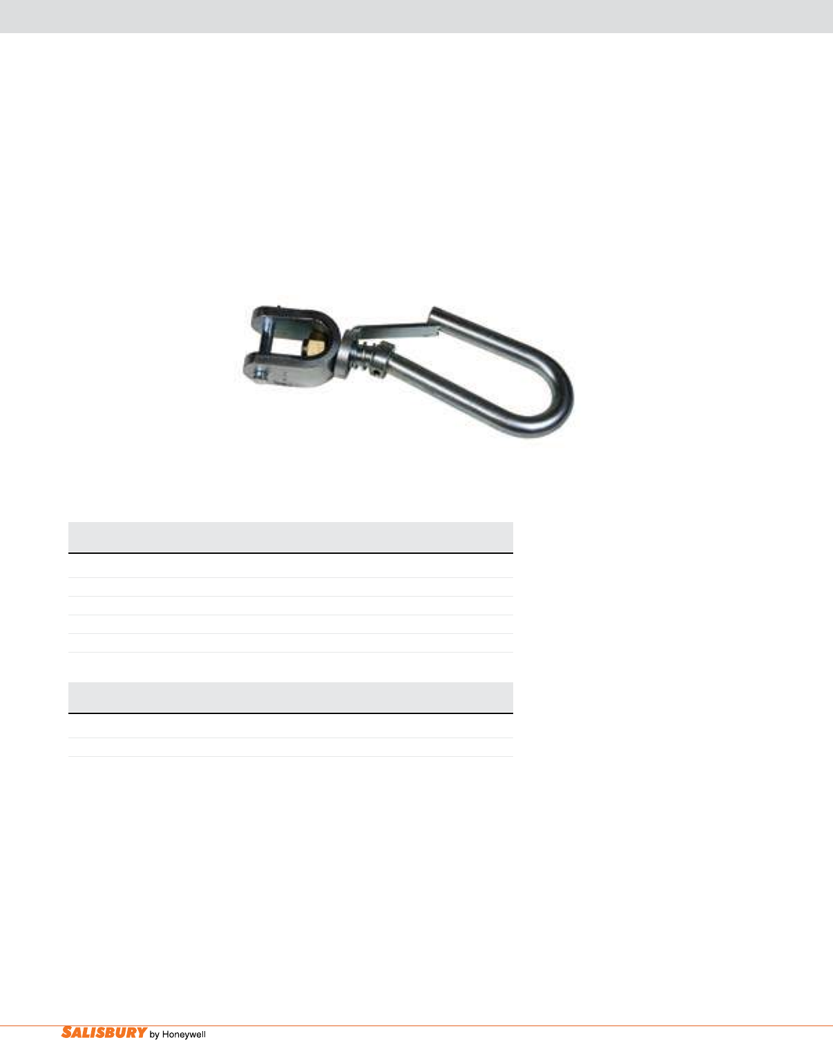
X-8 Accessories. www.salisburybyhoneywell.com
BLOCKS & SAFETY HOOKS
nylon blocks are light-weight and self-lubricating.
The nylon blocks will handle 1/2” (1.3 cm) diameter
rope and smaller.
WARNING: DO NOT EXCEED THE WORKING
LOAD LIMIT.
Cat. No. Description Weight WLL
lbs. ( kgs ) lbs. ( kgs )
NYLON BLOCKS
3101E Single Block with Swivel Hook & Becket 1 ( 0.45 ) 500 ( 227 )
3101W Single Block with Flat Hook & Becket 1 ( 0.45 ) 500 ( 227 )
3102W Double Block with Flat Hook & Becket 2 ( 0.91 ) 1,000 ( 454 )
3103W Triple Block with Flat Hook & Becket 2 ( 0.91 ) 1,200 ( 544 )
Cat. No. Description WLL Weight
lbs. ( kgs ) lbs. ( kgs )
SAFETY HOOK
4003SH Conductor Lifting Hook 2,000 ( 907 ) 6.2 ( 2.8 )
4003SH
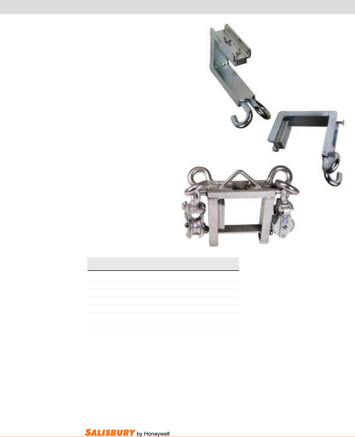
X-9
101 E. Crossroads Pkwy., Ste. A Bolingbrook, IL 60440 toll free ph (USA):877.406.4501 toll free fax (USA):866.824.4922 ph:630.343.3800
26E
Cat. No. Opening Size WLL
in. ( cm ) lbs. ( kgs )
FABRICATED ARM SLINGS
26E 4 x 6 ( 10.2 x 15.2 ) 2,000 ( 907 )
26G 5 x 6 ( 12.7 x 15.2 ) 2,000 ( 907 )
26K 6 x 6 ( 15.2 x 15.2 ) 2,000 ( 907 )
26H 6 1/8 x 8 ( 15.6 x 20.3 ) 2,000 ( 907 )
DOUBLE ARM SLING
266 With 2 Steel Snatch Blocks 750 ( 340 )
Fabricated arm Slings are used as an all-
purpose sling for non-energized and live
line work, the fabricated arm sling is made
to t snugly over the arm by using the ller
plates (included) to adjust the opening.
Weight - 6 lbs. (2.7 kgs).
double arm Slings are made for dead
ending. Adjustable to cross arms 4” to 5”
(10.2 to 12.7 cm) wide and 5” to 6” (12.7
to 15.2 cm) high, the double arm sling can
be installed with insulating sticks.Weight
- 15 lbs. (6.8 kgs).
ARM SLINGS
26K
266
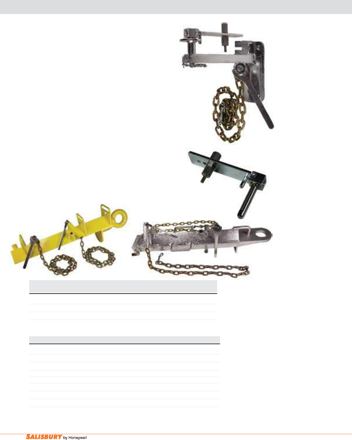
X-10 Accessories. www.salisburybyhoneywell.com
9300
POLE ADAPTER KIT & POLE DRAW BAR
The Pole adapter Kit is a mounting bracket that safely
attaches a saw to the pole. The saw pivots on a plate which
is attached to the side of the saw. The pole adapter has a
chain tightening base, and a safety stop to halt the swing
of the saw after the cut has been made. Use this adapter kit
while cutting off sections of a pole when the pole has to be
removed. Chain saw not included.
The Pole draw bar attaches to the pole by placing the end
stop of the bar against the end of the pole. Secure the bar
to the pole with the two chain and screw binders afxed to
the bar. The pole draw bar is supplied with lifting handles
on each side and a safety loop through which a chain is
attached. The oval hole is large enough to t all hitches.
(Check local vehicle safety chain regulations.)
9300 - SAFE TOWING CAPACITY: 10,000 LBS. (4,530 Kgs).
9301 - SAFE TOWING CAPACITY: 15,000 LBS. (6,804 Kgs).
Cat. No. Type of Saw Description Weight
lbs. ( kgs )
POLE ADAPTER KIT
3115 Stihl / Homelite Full Adapter Kit 14 ( 6.35 )
3115ES Stihl / Homelite XL Swivel Plate w/ Stand-Off 1 ( 0.45 )
Cat. No. Description Weight lbs. ( kgs )
POLE DRAW BAR
9300 Pole Draw Bar (complete) 60 (27.21 )
9301 Heavy Duty Pole Draw Bar 78 (35.37 )
Replacement Parts
9300C Chain, Screw and Snap 4 ( 1.81 )
9300E Toggle Handle and Nut 1 ( 0.45 )
9300M Pointed Screw 3 oz. ( 84 g)
3115
3115ES
9301
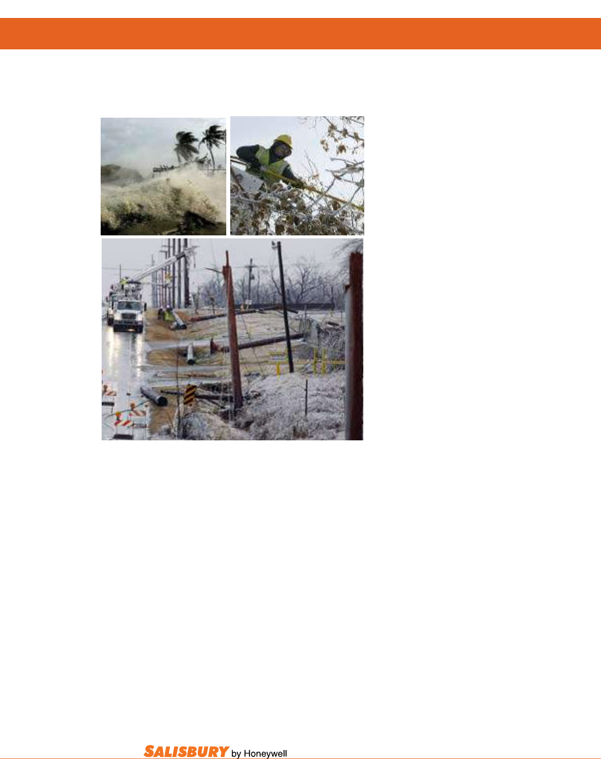
X-11
101 E. Crossroads Pkwy., Ste. A Bolingbrook, IL 60440 toll free ph (USA):877.406.4501 toll free fax (USA):866.824.4922 ph:630.343.3800
Na t i o N a l Di s a s t e r re s p o N s e pr o g r a m
af t e r Ho u r s em e r g e N c y cu s t o m e r se r v i c e
Do you know what to do
in times of disaster?
Do you know who to contact
in case of emergency?
You can count on Salisbury,
to be there when you need it most.
Salisbury understands your safety needs. But,
Salisbury also understands that your safety needs
don’t always happen between 9am and 5pm. This
is why Salisbury has developed the National
Disaster Response Emergency Contact.
Salisbury’s National Disaster Response will
be able to help your emergency safety product
orders and customer service needs. While
facing national disasters and weather related
catastrophes, Salisbury will be there.
NATIONAL DISASTER RESPONSE PROGRAM :
After Hours Emergency Customer Service
You can now contact Salisbury after regular business hours during severe emergencies using our new NATIONAL
DISASTER RESPONSE Contact Line. This new contact line allows product ordering, even after-hours and
weekends. A National Disaster Response Team is ready to fulll your emergency order requirements around the
clock during national and international severe weather or natural disasters such as Winter Ice Storms, Tornadoes,
Tropical Storms, Hurricanes and Earthquakes.
Our team is ready to fulll emergency orders of Personal Protective Equipment and Linemen Utility Products
required to (1) Restore electrical power and utilities to U.S. and Global regions as a result of natural disaster and
(2) provide Personal Protective Equipment to the Industrial or Utility work force resulting from natural disaster.
Department in Bolingbrook, IL
during regular business hours:
877-406-4501
Monday - Friday 7:30AM-5:00 PM
Central Standard Time
National Disaster Response emergency contact
for after-hour and weekend emergencies
as dened above.
866-957-7515
National Disaster Response After-Hours
Emergency Contact

SALISBURY
YOUR SINGLE SOURCE FOR PERSONAL ELECTRICAL-SAFETY PROTECTION
101 E CROSSROADS PARKWAY
SUITE A
BOLINGBROOK IL 60440 USA
TOLL FREE PH. (USA) 877.406.4501
TOLL FREE FAX (USA) 866.824.4922
630-343-3800
salisburybyhoneywell.com
SALISBURY BY HONEYWELL
© 2011 HONEYWELL INTERNATIONAL INC. ALL RIGHTS RESERVED.
10M PRINTED IN USA 2011
PART# FULLUTILITY V.090811
ISO 9001:2008 Registered
FACEBOOK.COM/SALISBURYBYHONEYWELL
TWITTER.COM/SALISBURY1855
UTILITY PRODUCTS
SALISBURY
UTILITY PRODUCTS
AUTHORIZED DISTRIBUTOR
2012
SALISBURY
