550857 LVD
2016-04-12
: Pdf 550857 Lvd 550857_LVD CertsReports 550857 ProductFiles
Open the PDF directly: View PDF ![]() .
.
Page Count: 41
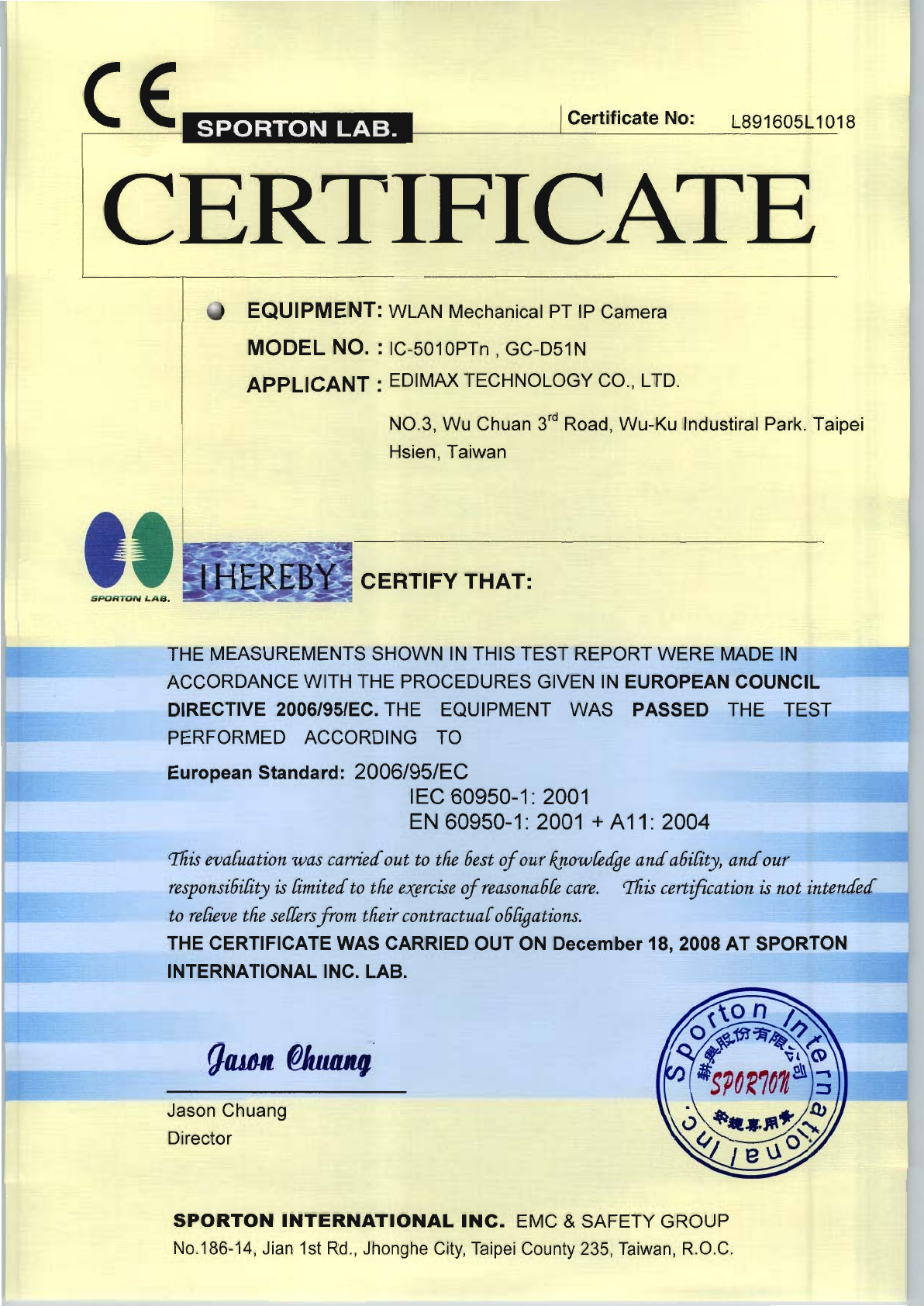
page 1 of 27 Report No.: L891605L1018
Sporton International Inc. Issued: December 18, 2008
LOW VOLTAGE DIRECTIVE TEST REPORT
IEC 60950-1 / EN 60950-1, First Edition
Information technology equipment – Safety –
Part 1: General requirements
Report Reference No. .......................: L891605L1018
Compiled by (+ signature).................: John Jan
Project Engineer John Jan
Approved by (+ signature) ................: Jason Chuang
Director
Date of Issue .....................................: December 18, 2008
Testing laboratory.............................. : Sporton International Inc.
Address..............................................: 14Fl.-2, No. 186, Jianyi Rd.,
Junghe City, Taipei Hsien,
Testing location .................................: Taiwan
Applicant............................................: EDIMAX TECHNOLOGY CO., LTD.
Address..............................................: NO.3, Wu Chuan 3rd Road, Wu-Ku Industiral Park. Taipei Hsien, Taiwan.
Standard ............................................ : IEC 60950-1: 2001
EN 60950-1: 2001 + A11: 2004
Test Report Form No. .......................: LVD 60950-1
Test procedure ................................: Sporton LVD type test approval
Procedure deviation ..........................: N/A
Non-standard test method ................: N/A
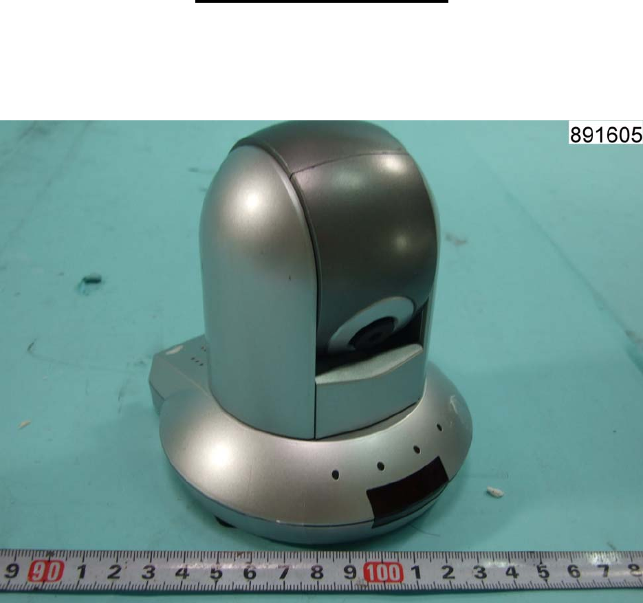
Type of test object.............................: WLAN Mechanical PT IP Camera
Trademark ......................................... : EDIMAX
Model/type reference ........................: IC-5010PTn,GC-D51N
Manufacturer .....................................: EDIMAX TECHNOLOGY CO., LTD.
NO.3, Wu Chuan 3rd Road, Wu-Ku Industiral Park. Taipei Hsien, Taiwan.
Rating ................................................: + 12 Vdc , 1 A (Optional)

page 2 of 27 Report No.: L891605L1018
Sporton International Inc. Issued: December 18, 2008
Test item particulars:
Equipment mobility........................................................: Movable
Operating condition.......................................................: continuous
Tested for IT power systems ........................................: No
IT testing, phase-phase voltage (V)..............................: N.A.
Class of equipment .......................................................: Class III
Mass of equipment (kg) ................................................: approx. 0.32kg
Protection against ingress of water ..............................: IP 20
Possible test case verdicts:
- test case does not apply to the test object .................: N.A.
- test object does meet the requirement.......................: Pass
- test object does not meet the requirement.................: Fail
Testing:
- Date of receipt of test item..........................................: December 18, 2008
- Date(s) of performance of test....................................: December 12 – December 16, 2008
General remarks:
"(see remark #)" refers to a remark appended to the report.
"(see appended table)" refers to a table appended to the report.
Throughout this report a point is used as the decimal separator.
The test results presented in this report relate only to the object tested.
This report shall not be reproduced except in full without the written approval of the testing laboratory.
Comments:
The test results are true for the test sample(s) only.
A part of this test report or certificate should not be duplicated in any way; however, the duplication of the whole
document is allowed.
This test-report includes the following documents:
Test report - ( 27 pages)
Photo - ( 13 pages)
page 3 of 27 Report No.: L891605L1018
Sporton International Inc. Issued: December 18, 2008
Brief description of the test sample:
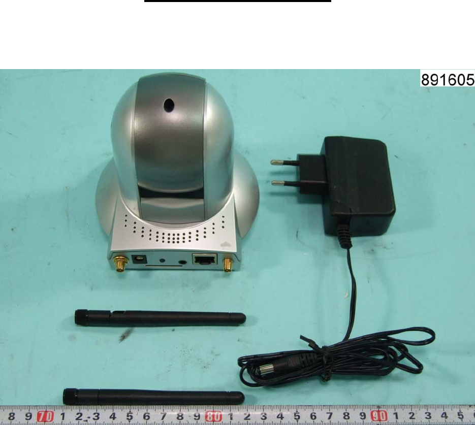
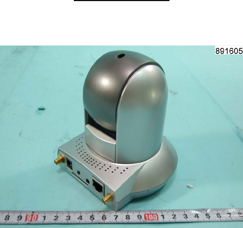
The equipment is a WLAN Mechanical PT IP Camera, intended for used with information technology equipment.
The external power adaptor is approved product and complied with the requirements of sub-clause 2.5 as a
limited power source, see appended table 1.5.1 for detail.
Models GC-D51N identical to model IC-5010PTn except for model designation.
The equipment was evaluated for use in a maximum air ambient of 40 ºC.
The test sample is pre-production without serial number.
page 4 of 27 Report No.: L891605L1018
Sporton International Inc. Issued: December 18, 2008
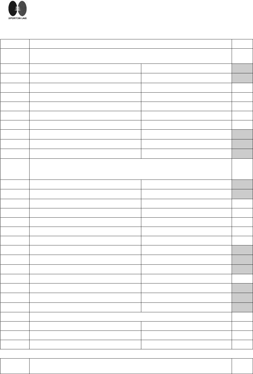
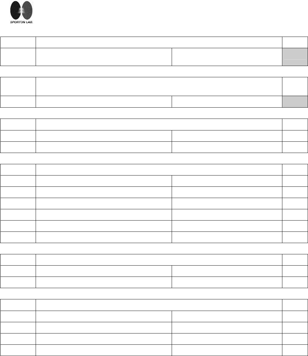
Clause Requirement - Test Result - Remark Verdict
1 GENERAL Pass
1.5 Components Pass
1.5.1 Comply with IEC 60950 or relevant component
standard Safety involved components comply
with the requirements of this standard
or within the safety aspects of the
relevant IEC component standards
(refer to appended table 1.5.1 below).
Pass
1.5.2 Evaluation and testing of components Components which are certified to IEC
and/or national standards are used
correctly within their ratings.
Components not covered by IEC
standards are tested under the
conditions present in the equipment.
Pass
1.5.3 Thermal controls N.A.
1.5.4 Transformers N.A.
1.5.5 Interconnecting cables N.A.
1.5.6 Capacitors in primary circuits N.A.
1.5.7 Double or reinforced insulation bridged by
components N.A.
1.5.7.1 General N.A.
1.5.7.2 Bridging capacitors N.A.
1.5.7.3 Bridging resistors N.A.
1.5.7.4 Accessible parts N.A.
1.5.8 Components in equipment for IT power systems N.A.
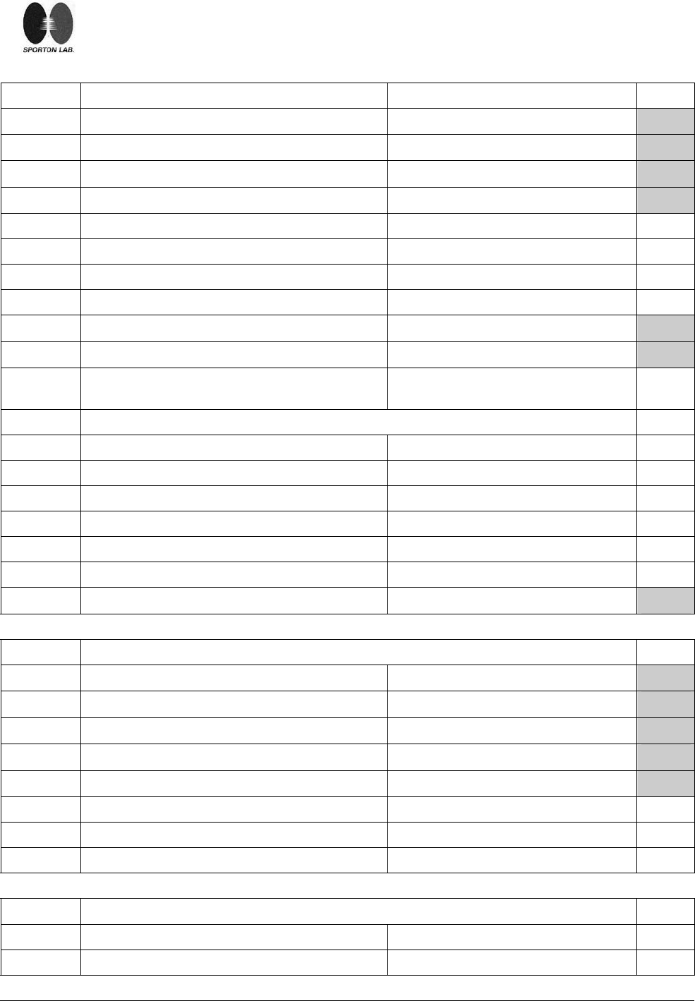
1.6 Power interface Pass
1.6.1 AC power distribution systems ............................
.
N.A.
1.6.2 Input current See appended table 1.6.2 Pass
1.6.3 Voltage limit of hand-held equipment N.A.
1.6.4 Neutral conductor N.A.
1.7 Marking and instructions Pass
1.7.1 Power rating See below. Pass
Rated voltage(s) or voltage range(s) (V) ...........
.
12 V ,Optional Pass
Symbol for nature of supply for d.c. ...................... IEC 60417, No. 5031: Pass
Rated frequency or frequency range (Hz) ............ N.A.
page 5 of 27 Report No.: L891605L1018
Sporton International Inc. Issued: December 18, 2008
Rated current (mA or A) ........................................ 1 A ,Optional Pass
Manufacturer’s name/Trademark .......................... See page 1. Pass
Type/model ............................................................ See page 1. Pass
Symbol of Class II .................................................. The unit is a Class III equipment. N.A.
Other symbols ....................................................... Additional symbols or marking does not
give rise to misunderstanding. Pass
Certification marks ................................................. CE mark Pass
1.7.2 Safety instructions Operation/installation instruction is
provided with each unit. Pass
1.7.3 Short duty cycles N.A.
1.7.4 Supply voltage adjustment ................................... N.A.
1.7.5 Power outlets on the equipment ........................... N.A.
1.7.6 Fuse identification ................................................. N.A.
1.7.7 Wiring terminals N.A.
1.7.7.1 Protective earthing and bonding terminals N.A.
1.7.7.2 Terminal for a.c. mains supply conductors N.A.
1.7.8 Controls and indicators N.A.
1.7.8.1 Identification, location and marking ....................... N.A.
1.7.8.2 Colours ................................................................. N.A.
1.7.8.3 Symbols according to IEC 60417........................... N.A.
1.7.8.4 Markings using figures ......................................... N.A.
1.7.9 Isolation of multiple power sources ....................... N.A.
1.7.10 IT power distribution systems N.A..
1.7.11 Thermostats and other regulating devices N.A.
1.7.12 Language .............................................................. Installation instruction and equipment
markings are in English.
Versions in other languages should by
provide when submitted for national
approval.
Pass
1.7.13 Durability Complied Pass
1.7.14 Removable parts N.A.
1.7.15 Replaceable batteries N.A..
Language................................................................ ⎯
1.7.16 Operator access with a tool.................................... N.A.
1.7.17 Equipment for restricted access locations ............. N.A.
2 PROTECTION FROM HAZARDS Pass
2.1 Protection from electric shock and energy hazards Pass
page 6 of 27 Report No.: L891605L1018
Sporton International Inc. Issued: December 18, 2008
2.1.1 Protection in operator access areas See below Pass
2.1.1.1 Access to energized parts The unit is supplied from approved
power supply adaptor that provides
SELV.
Only SELV circuit inside the unit. No
electrical shock or energy hazards see
below.
Pass
Test by inspection ................................................. N.A.
Test with test finger ............................................... N.A.
Test with test pin ................................................... N.A.
Test with test probe ............................................... N.A.
2.1.1.2 Battery compartments ............................................ N.A.
2.1.1.3 Access to ELV wiring N.A.
Working voltage (V); distance (mm) trough
insulation ⎯
2.1.1.4 Access to hazardous voltage circuit wiring No hazardous voltage wiring in
operator accessible area. N.A.
2.1.1.5 Energy hazards ..................................................... No energy hazard in operator access
area. The connectors of the equipment
below 240VA.
Pass
2.1.1.6 Manual controls N.A.
2.1.1.7 Discharge of capacitors in the primary circuit N.A.
Time-constant (s); measured voltage (V) .............. ⎯
2.1.2 Protection in service access areas N.A.
2.1.3 Protection in restricted access locations N.A.
2.2 SELV circuits. Pass
2.2.1 General requirements See below. Pass
2.2.2 Voltages under normal conditions (V).................... Between any SELV circuits 42.4
Vpeak and 60 Vdc are not exceeded. Pass
2.2.3 Voltages under fault conditions (V) ........................ Single fault did not cause excessive
voltage in accessible SELV circuits.
Limits of 71V peak and 120Vd.c. were
not exceeded within 0.2s and limits
42.4V peak and 60Vd.c. were not
exceeded for longer than 0.2s.
Pass
2.2.3.1 Separation by double or reinforced insulation
(method 1) ⎯
2.2.3.2 Separation by earthed screen (method 2) ⎯
2.2.3.3 Protection by earthing of the SELV circuit
(method 3) ⎯
2.2.4 Connection of SELV circuits to other circuits......... See 2.2.2 and 2.2.3. Pass
page 7 of 27 Report No.: L891605L1018
Sporton International Inc. Issued: December 18, 2008
2.3 TNV circuits N.A.
2.3.1 Limits N.A.
Type of TNV circuits ............................................... ⎯
2.3.2 Separation from other circuits and from
accessible parts N.A.
Insulation employed................................................ ⎯
2.3.3 Separation from hazardous voltages N.A.
Insulation employed................................................ ⎯
2.3.4 Connection of TNV circuits to other circuits N.A.
Insulation employed................................................ ⎯
2.3.5 Test for operating voltages generated externally N.A.
2.4 Limited current circuits N.A.
2.4.1 General requirements N.A.
2.4.2 Limit values N.A.
Circuit capacitance ................................................. ⎯
Frequency (Hz)......................................................
:
⎯
Measured current (mA)..........................................
:
⎯
Measured voltage (V) : ⎯
Measured capacitance (μF) ..................................
:
⎯
2.4.3 Connection of limited current circuits to other
circuits N.A.
2.5 Limited power sources N.A.
Inherently limited output N.A.
Impedance limited output N.A.
Overcurrent protective device limited output N.A.
Regulating network limited output under normal
operating and single fault condition N.A.
Regulating network limited output under normal
operating conditions and overcurrent protective
device limited output under single fault condition
N.A.
Output voltage (V), output current (A), apparent
power (VA).............................................................. ⎯
Current rating of overcurrent protective device
(A) ⎯

page 8 of 27 Report No.: L891605L1018
Sporton International Inc. Issued: December 18, 2008
2.6 Provisions for earthing and bonding
The unit is a Class III equipment.
N.A.
2.6.1 Protective earthing N.A.
2.6.2 Functional earthing N.A.
2.6.3 Protective earthing and protective bonding
conductors N.A.
2.6.3.1 General N.A.
2.6.3.2 Size of protective earthing conductors N.A.
Rated current (A), cross-sectional area (mm2),
AWG........................................................................ ⎯
2.6.3.3 Size of protective bonding conductors N.A.
Rated current (A), cross-sectional area (mm2),
AWG........................................................................ ⎯
2.6.3.4 Resistance (Ω) of earthing conductors and their
terminations, test current (A) .................................. N.A.
2.6.3.5 Colour of insulation................................................. N.A.
2.6.4 Terminals N.A.
2.6.4.1 General N.A.
2.6.4.2 Protective earthing and bonding terminals N.A.
Rated current (A), type and nominal thread
diameter (mm)......................................................... ⎯
2.6.4.3 Separation of the protective earthing conductor
from protective bonding conductors N.A.
2.6.5 Integrity of protective earthing N.A.
2.6.5.1 Interconnection of equipment N.A.
2.6.5.2 Components in protective earthing conductors
and protective bonding conductors N.A.
2.6.5.3 Disconnection of protective earth N.A.
2.6.5.4 Parts that can be removed by an operator N.A.
2.6.5.5 Parts removed during servicing N.A.
2.6.5.6 Corrosion resistance N.A.
2.6.5.7 Screws for protective bonding N.A.
2.6.5.8 Reliance on telecommunication network or cable
distribution system N.A.
2.7 Overcurrent and earth fault protection in primary circuits
The unit is a Class III equipment.
N.A.
2.7.1 Basic requirements N.A.
Instructions when protection relies on building
installation. N.A.
page 9 of 27 Report No.: L891605L1018
Sporton International Inc. Issued: December 18, 2008
2.7.2 Faults not covered in 5.3 N.A.
2.7.3 Short-circuit backup protection N.A.
2.7.4 Number and location of protective devices ........
.
N.A.
2.7.5 Protection by several devices N.A.
2.7.6 Warning to service personnel.................................
.
N.A.
2.8 Safety interlocks
No safety interlocks provided.
N.A.
2.8.1 General principles N.A.
2.8.2 Protection requirements N.A.
2.8.3 Inadvertent reactivation N.A.
2.8.4 Fail-safe operation N.A.
2.8.5 Moving parts N.A.
2.8.6 Overriding N.A.
2.8.7 Switches and relays N.A.
2.8.7.1 Contact gaps (mm) ............................................... N.A.
2.8.7.2 Overload test N.A.
2.8.7.3 Endurance test N.A.
2.8.7.4 Electric strength test (V) N.A.
2.8.8 Mechanical actuators N.A.
2.9 Electrical insulation N.A.
2.9.1 Properties of insulating materials N.A.
2.9.2 Humidity conditioning N.A.
Humidity (%) --
Temperature (℃) --
2.9.3 Grade of insulation N.A.
2.10 Clearances, creepage distances and distances through insulation Pass
2.10.1 General Only SELV circuit inside the Unit. Pass
2.10.2 Determination of working voltage N.A.
2.10.3 Clearances N.A.
2.10.3.1 General N.A.
2.10.3.2 Clearances in primary circuit N.A.
2.10.3.3 Clearances in secondary circuits N.A.
2.10.3.4 Measurement of transient voltage levels N.A.
2.10.4 Creepage distances N.A.
page 10 of 27 Report No.: L891605L1018
Sporton International Inc. Issued: December 18, 2008
CTI tests.................................................................. ⎯
2.10.5 Solid insulation N.A.
2.10.5.1 Minimum distance through insulation N.A.
2.10.5.2 Thin sheet material N.A.
Number of layers (pcs) ........................................... ⎯
Electric strength test N.A.
2.10.5.3 Printed boards .....................................................
.
N.A.
Distance through insulation N.A.
Electric strength test for thin sheet insulating
material N.A.
Number of layers (pcs) ........................................
.
N.A.
2.10.5.4 Wound components................................................ N.A.
Number of layers (pcs) ..........................................
:
N.A.
Two wires in contact inside wound component;
angle between 45° and 90° .................................: N.A.
2.10.6 Coated printed boards N.A.
2.10.6.1 General N.A.
2.10.6.2 Sample preparation and preliminary inspection ...: N.A.
2.10.6.3 Thermal cycling....................................................... N.A.
2.10.6.4 Thermal ageing....................................................... N.A.
2.10.6.5 Electric strength test N.A.
2.10.6.6 Abrasion resistance test ......................................... N.A.
Electric strength test N.A.
2.10.7 Enclosed and sealed parts..................................... N.A.
Temperature T1=T2 = Tma – Tamb +10K (°C)........... N.A.
2.10.8 Spacings filled by insulating compound................. N.A.
Electric strength test ⎯
2.10.9 Component external terminations N.A.
2.10.10 Insulation with varying dimensions N.A.
3 WIRING, CONNECTIONS AND SUPPLY Pass
3.1 General N.A.
3.1.1 Current rating and overcurrent protection N.A.
3.1.2 Protection against mechanical damage N.A.
3.1.3 Securing of internal wiring N.A.
3.1.4 Insulation of conductors N.A.
3.1.5 Beads and ceramic insulators N.A.
page 11 of 27 Report No.: L891605L1018
Sporton International Inc. Issued: December 18, 2008
3.1.6 Screws for electrical contact pressure N.A.
3.1.7 Insulation materials in electrical connections N.A.
3.1.8 Self-tapping and spaced thread screws N.A.
3.1.9 Termination of conductors N.A.
10 N pull test N.A.
3.1.10 Sleeving on wiring N.A.
3.2 Connection to a.c. mains supplies or d.c. mains supply N.A.
3.2.1 Means of connection N.A.
3.2.1.1 Connection to an a.c. mains supply N.A.
3.2.1.2 Connection to a d.c. mains supply N.A.
3.2.2 Multiple supply connections N.A.
3.2.3 Permanently connected equipment N.A.
Number of conductors, diameter (mm) of cable
and conduits .......................................................
.
⎯
3.2.4 Appliance inlets N.A.
3.2.5 Power supply cords N.A.
3.2.5.1 AC Power supply cords N.A.
Type ........................................................................ ⎯
Rated current (A), cross-sectional area (mm2),
AWG........................................................................ ⎯
3.2.5.2 DC power supply cords N.A.
3.2.6 Cord anchorages and strain relief N.A.
Mass of equipment (kg), pull (N) ........................ ⎯
Longitudinal displacement (mm) .......................... ⎯
3.2.7 Protection against mechanical damage N.A.
3.2.8 Cord guards N.A.
D (mm); test mass (g) ........................................... ⎯
Radius of curvature of cord (mm)........................... ⎯
3.2.9 Supply wiring space N.A.
3.3 Wiring terminals for connection of external conductors N.A.
3.3.1 Wiring terminals N.A.
3.3.2 Connection of non-detachable power supply
cords N.A.
3.3.3 Screw terminals N.A.
3.3.4 Conductor sizes to be connected N.A.
page 12 of 27 Report No.: L891605L1018
Sporton International Inc. Issued: December 18, 2008
Rated current (A), cord/cable type,
cross-sectional area (mm2) .................................... ⎯
3.3.5 Wiring terminal sizes N.A.
Rated current (A), type and nominal thread
diameter (mm)......................................................... N.A.
3.3.6 Wiring terminals design N.A.
3.3.7 Grouping of wiring terminals N.A.
3.3.8 Stranded wire N.A.
3.4 Disconnection from the a.c. mains supply N.A.
3.4.1 General requirement N.A.
3.4.2 Disconnect devices N.A.
3.4.3 Permanently connected equipment N.A.
3.4.4 Parts which remain energized N.A.
3.4.5 Switches in flexible cords N.A.
3.4.6 Single-phase equipment and d.c. equipment N.A.
3.4.7 Three-phase equipment N.A.
3.4.8 Switches as disconnect devices N.A.
3.4.9 Plugs as disconnect devices N.A.
3.4.10 Interconnected equipment N.A.
3.4.11 Multiple power sources N.A.
3.5 Interconnection of equipment Pass
3.5.1 General requirements See below. Pass
3.5.2 Types of interconnection circuits............................ Interconnection circuits of SELV output
connectors. Pass
3.5.3 ELV circuits as interconnection circuits N.A.
4 PHYSICAL REQUIREMENTS Pass
4.1 Stability Pass
Angle of 10° Pass
Test: force (N)......................................................... N.A.
4.2 Mechanical strength Pass
4.2.1 General Pass
4.2.2 Steady force test, 10 N N.A.
4.2.3 Steady force test, 30 N N.A.
page 13 of 27 Report No.: L891605L1018
Sporton International Inc. Issued: December 18, 2008
4.2.4 Steady force test, 250 N N.A.
4.2.5 Impact test N.A.
Fall test N.A.
Swing test N.A.
4.2.6 Drop test N.A.
4.2.7 Stress relief test N.A.
4.2.8 Cathode ray tubes ⎯
Picture tube separately certified ..........................
.
N.A.
4.2.9 High pressure lamps N.A.
4.2.10 Wall or ceiling mounted equipment; force (N) .....
:
Force applied:50N Pass
4.3 Design and construction Pass
4.3.1 Edges and corners All edges and corners of the exterior
enclosure are properly rounded. Pass
4.3.2 Handles and manual controls; force (N)..............
.
N.A.
4.3.3 Adjustable controls N.A.
4.3.4 Securing of parts Mechanical fixings in such a way
designed that they will withstand
mechanical stress occurring in normal
use
Pass
4.3.5 Connection of plugs and sockets N.A.
4.3.6 Direct plug-in equipment N.A.
Dimensions (mm) of mains plug for direct plug-in N.A.
Torque and pull test of mains plug for direct
plug-in; Torque (Nm); pull (N)................................. --
4.3.7 Heating elements in earthed equipment N.A.
4.3.8 Batteries N.A.
4.3.9 Oil and grease N.A.
4.3.10 Dust, powders, liquids and gases N.A.
4.3.11 Containers for liquids or gases N.A.
4.3.12 Flammable liquids................................................... N.A.
Quantity of liquid (l)................................................. N.A.
Flash point (°C)....................................................... N.A.
4.3.13 Radiation; type of radiation ................................... Pass
4.3.13.1 General For LED user as indicating lights Pass
4.3.13.2 Ionizing radiation N.A.
Measured radiation (pA/kg) .................................. ⎯
Measured high-voltage (kV) .................................. ⎯
Measured focus voltage (kV) ................................. ⎯
page 14 of 27 Report No.: L891605L1018
Sporton International Inc. Issued: December 18, 2008
CRT markings ........................................................ ⎯
4.3.13.3 Effect of ultraviolet (UV) radiation on materials N.A.
Part, property, retention after test, flammability
classification .......................................................... N.A.
4.3.13.4 Human exposure to ultraviolet (UV) radiation ...... N.A.
4.3.13.5 Laser (including LEDs) See above Pass
Laser class ............................................................ See above ⎯
4.3.13.6 Other types ............................................................ ⎯
4.4 Protection against hazardous moving parts
No hazardous moving parts .
N.A.
4.4.1 General N.A.
4.4.2 Protection in operator access areas N.A.
4.4.3 Protection in restricted access locations N.A.
4.4.4 Protection in service access areas N.A.
4.5 Thermal requirements Pass
4.5.1 Maximum temperatures See appended table 4.5.1 Pass
Normal load condition per Annex L See 1.6.2 Pass
4.5.2 Resistance to abnormal heat N.A.
4.6 Openings in enclosures Pass
4.6.1 Top and side openings See table 4.6.1 Pass
Dimensions (mm) ..............................................
.
⎯
4.6.2 Bottoms of fire enclosures See table 4.6.1 Pass
Construction of the bottom ..................................... ⎯
4.6.3 Doors or covers in fire enclosures
4.6.4 Openings in transportable equipment N.A.
4.6.5 Adhesives for constructional purposes N.A.
Conditioning temperature (℃)/time (weeks) ⎯
4.7 Resistance to fire Pass
4.7.1 Reducing the risk of ignition and spread of flame See below. Pass
Method 1, selection and application of
components wiring and materials Use of materials with the required
flammability classes. Pass
Method 2, application of all of simulated fault
condition tests N.A.
page 15 of 27 Report No.: L891605L1018
Sporton International Inc. Issued: December 18, 2008
4.7.2 Conditions for a fire enclosure With having the following parts :
Components in secondary
(supplied by LPS).
Components mounted on
material of flammability Class
V-1.
The fire enclosure is not required.
Pass
4.7.2.1 Parts requiring a fire enclosure See above. N.A.
4.7.2.2 Parts not requiring a fire enclosure See above. Pass
4.7.3 Materials See appendix table 1.5.1 for details. Pass
4.7.3.1 General Pass
4.7.3.2 Materials for fire enclosures N.A.
4.7.3.3 Materials for components and other parts
outside fire enclosures N.A.
4.7.3.4 Materials for components and other parts inside
fire enclosures N.A.
4.7.3.5 Materials for air filter assemblies N.A.
4.7.3.6 Materials used in high-voltage components N.A.
5 ELECTRICAL REQUIREMENTS AND SIMULATED ABNORMAL CONDITIONS Pass
5.1 Touch current and protective conductor current N.A.
5.1.1 General N.A.
5.1.2 Equipment under test (EUT) N.A.
5.1.3 Test circuit N.A.
5.1.4 Application of measuring instrument N.A.
5.1.5 Test procedure N.A.
5.1.6 Test measurements N.A.
Test voltage (V) .................................................
.
⎯
Measured touch current (mA) .............................. ⎯
Max. allowed touch current (mA) ......................... ⎯
Measured protective conductor current (mA) ..... : ⎯
Max. allowed protective conductor current (mA)..: ⎯
5.1.7 Equipment with touch current exceeding 3.5
mA ........................................................................ N.A.
5.1.8 Touch currents to and from telecommunication
networks and cable distribution systems and
from telecommunication networks
N.A.
page 16 of 27 Report No.: L891605L1018
Sporton International Inc. Issued: December 18, 2008
5.1.8.1 Limitation of the touch current to a
telecommunication network and a cable
distribution system
N.A.
Test voltage (V) ..................................................... ⎯
Measured current (mA) ........................................ ⎯
Max. allowed current (mA) ................................... ⎯
5.1.8.2 Summation of touch currents from
telecommunication networks.................................. N.A.
5.2 Electric strength N.A.
5.2.1 General N.A.
5.2.2 Test procedure N.A.
5.3 Abnormal operating and fault conditions Pass
5.3.1 Protection against overload and abnormal
operation See below Pass
5.3.2 Motors N.A.
5.3.3 Transformers N.A.
5.3.4 Functional insulation............................................
.
Method C.
Considered due to
- all components are mounted on PCB
of flammability V-1.
- no risk of electrical shock no test had
been performed.
Pass
5.3.5 Electromechanical components N.A.
5.3.6 Simulation of faults See appended table 5.3. Pass
5.3.7 Unattended equipment N.A.
5.3.8 Compliance criteria for abnormal operating and
fault conditions Neither fire the equipment nor molten
metal was emitted. Pass
6 CONNECTION TO TELECOMMUNICATION NETWORKS N.A.
6.1 Protection of telecommunication network service personnel, and users of other
equipment connected to the network, from hazards in the equipment N.A.
6.1.1 Protection from hazardous voltages N.A.
6.1.2 Separation of the telecommunication network from earth N.A.
6.1.2.1 Requirements N.A.
Test voltage (V) .................................................
.
⎯
Current in the test circuit (mA) ........................... ⎯
6.1.2.2 Exclusions............................................................... N.A.
page 17 of 27 Report No.: L891605L1018
Sporton International Inc. Issued: December 18, 2008
6.2 Protection of equipment users from overvoltages on telecommunication networks N.A.
6.2.1 Separation requirements N.A.
6.2.2 Electric strength test procedure N.A.
6.2.2.1 Impulse test N.A.
6.2.2.2 Steady-state test N.A.
6.2.2.3 Compliance criteria N.A.
6.3 Protection of telecommunication wiring system from overheating N.A.
Max. output current (A)........................................
.
⎯
Current limiting method .......................................... ⎯
7 CONNECTION TO CABLE DISTRIBUTION SYSTEMS N.A.
7.1 Protection of cable distribution system service
persons, and users of other equipment
connected to the system, from hazardous
voltages in the equipment
N.A.
7.2 Protection of equipment users from overvoltages
on the cable distribution system N.A.
7.3 Insulation between primary circuits and cable
distribution systems N.A.
7.3.1 General N.A.
7.3.2 Voltage surge test N.A.
7.3.3 Impulse test N.A.
page 18 of 27 Report No.: L891605L1018
Sporton International Inc. Issued: December 18, 2008
A ANNEX A, TESTS FOR RESISTANCE TO HEAT AND FIRE N.A.
A.1 Flammability test for fire enclosures of movable equipment having a total mass exceeding
18 kg, and of stationary equipment (see 4.7.3.2) N.A.
A.1.1 Samples ⎯
Wall thickness (mm) ............................................ ⎯
A.1.2 Conditioning of samples; temperature (°C) ........... N.A.
A.1.3 Mounting of samples .............................................. N.A.
A.1.4 Test flame N.A.
A.1.5 Test procedure N.A.
A.1.6 Compliance criteria N.A.
Sample 1 burning time (s) ................................... ⎯
Sample 2 burning time (s) ...................................... ⎯
Sample 3 burning time (s) ...................................... ⎯
A.2 Flammability test for fire enclosures of movable equipment having a total mass not
exceeding 18 kg, and for material and components located inside fire enclosures (see
4.7.3.2 and 4.7.3.4)
N.A.
A.2.1 Samples ⎯
Wall thickness (mm) ............................................... ⎯
A.2.2 Conditioning of samples......................................... N.A.
A.2.3 Mounting of samples .............................................. N.A.
A.2.4 Test flame N.A.
A.2.5 Test procedure N.A.
A.2.6 Compliance criteria N.A.
Sample 1 burning time (s) ...................................... ⎯
Sample 2 burning time (s) ...................................... ⎯
Sample 3 burning time (s) ...................................... ⎯
A.2.7 Alternative test acc. to IEC 60695-2-2, cl. 4, 8 N.A.
Sample 1 burning time (s) ...................................... ⎯
Sample 2 burning time (s) ...................................... ⎯
Sample 3 burning time (s) ...................................... ⎯
A.3 Hot flaming oil test (see 4.6.2) N.A.
A.3.1 Mounting of samples .............................................. N.A.
A.3.2 Test procedure N.A.
A.3.3 Compliance criterion............................................... N.A.
B ANNEX B, MOTOR TESTS UNDER ABNORMAL CONDITIONS (see 4.7.2.2 and 5.3.2)
Pass
page 19 of 27 Report No.: L891605L1018
Sporton International Inc. Issued: December 18, 2008
B.1 General requirements Used stepping motor Pass
Position ..............................................................
.
See 1.5.1 ⎯
Manufacturer ......................................................... See 1.5.1 ⎯
Type ...................................................................... See 1.5.1 ⎯
Rated values ....................................................... See 1.5.1 ⎯
B.2 Test conditions N.A.
B.3 Maximum temperatures N.A.
B.4 Running overload test N.A.
B.5 Locked-rotor overload test N.A.
Test duration (days) .............................................. ⎯
Electric strength test: test voltage (V) ................ ⎯
B.6 Running overload test for DC motors in
secondary circuits N.A.
B.7 Locked-rotor overload test for DC motors in secondary circuits N.A.
B.7.1 Test procedure N.A.
B.7.2 Alternative test procedure; test time (h)................. N.A.
B.7.3 Electric strength test N.A.
B.8 Test for motors with capacitors N.A.
B.9 Test for three-phase motors N.A.
B.10 Test for series motors N.A.
Operating voltage (V) ........................................... ⎯
C ANNEX C, TRANSFORMERS (see 1.5.4 and 5.3.3) N.A.
Position ................................................................. ⎯
Manufacturer ......................................................... ⎯
Type ...................................................................... ⎯
Rated values ....................................................... ⎯
Method of protection ............................................. ⎯
C.1 Overload test --
C.2 Insulation
Protection from displacement of windings N.A.
D ANNEX D, MEASURING INSTRUMENTS FOR TOUCH-CURRENT TESTS N.A.
D.1 Measuring instrument N.A.
D.2 Alternative measuring instrument N.A.
page 20 of 27 Report No.: L891605L1018
Sporton International Inc. Issued: December 18, 2008
E ANNEX E, TEMPERATURE RISE OF A WINDING (see 1.4.13)
Thermocouple method used.
N.A.
F ANNEX F, MEASUREMENT OF CLEARANCES AND CREEPAGE DISTANCES
(see 2.10)
Pass
G ANNEX G, ALTERNATIVE METHOD FOR DETERMINING MINIMUM CLEARANCES N.A.
G.1 Summary of the procedure for determining
minimum clearances N.A.
G.2 Determination of mains transient voltage (V)......
.
N.A.
G.2.1 AC mains supply N.A.
G.2.2 DC mains supply N.A.
G.3 Determination of telecommunication network
transient voltage (V) ............................................... N.A.
G.4 Determination of required withstand voltage (V) ... N.A.
G.5 Measurement of transient levels (V) ...................... N.A.
G.6 Determination of minimum clearances .................. N.A.
H ANNEX H, IONIZING RADIATION (see 4.3.13) N.A.
J ANNEX J, TABLE OF ELECTROCHEMICAL POTENTIALS (see 2.6.5.6) N.A.
Metal used ............................................................. ⎯
K ANNEX K, THERMAL CONTROLS (see 1.5.3 and 5.3.7) N.A.
K.1 Making and breaking capacity N.A.
K.2 Thermostat reliability; operating voltage (V)........
.
N.A.
K.3 Thermostat endurance test; operating voltage
(V) ......................................................................... N.A.
K.4 Temperature limiter endurance; operating
voltage (V) ............................................................. N.A.
K.5 Thermal cut-out reliability N.A.
K.6 Stability of operation N.A.
L ANNEX L, NORMAL LOAD CONDITIONS FOR SOME TYPES OF ELECTRICAL
BUSINESS EQUIPMENT (see 1.2.2.1 and 4.5.1) Pass
L.1 Typewriters N.A.
L.2 Adding machines and cash registers N.A.
L.3 Erasers N.A.
L.4 Pencil sharpeners N.A.
page 21 of 27 Report No.: L891605L1018
Sporton International Inc. Issued: December 18, 2008
L.5 Duplicators and copy machines N.A.
L.6 Motor-operated files N.A.
L.7 Other business equipment Considered. Pass
M ANNEX M, CRITERIA FOR TELEPHONE RINGING SIGNALS (see 2.3.1) N.A.
M.1 Introduction N.A.
M.2 Method A N.A.
M.3 Method B N.A.
M.3.1 Ringing signal N.A.
M.3.1.1 Frequency (Hz)....................................................
.
M.3.1.2 Voltage (V) ............................................................
M.3.1.3 Cadence; time (s), voltage (V) ..............................
M.3.1.4 Single fault current (mA).........................................
M.3.2 Tripping device and monitoring voltage................. N.A.
M.3.2.1 Conditions for use of a tripping device or a
monitoring voltage N.A.
M.3.2.2 Tripping device N.A.
M.3.2.3 Monitoring voltage (V) ............................................ N.A.
N ANNEX N, IMPULSE TEST GENERATORS (see 2.10.3.4, 6.2.2.1, 7.3.2 and
clause G.5) N.A.
N.1 ITU-T impulse test generators N.A.
N.2 IEC 60065 impulse test generator N.A.
P ANNEX P, NORMATIVE REFERENCES Pass
Q ANNEX Q, BIBLIOGRAPHY Pass
R ANNEX R, EXAMPLES OF REQUIREMENTS FOR QUALITY CONTROL
PROGRAMMES N.A.
R.1 Minimum separation distances for unpopulated
coated printed boards (see 2.10.6) N.A.
R.2 Reduced clearances (see 2.10.3) N.A.
S ANNEX S, PROCEDURE FOR IMPULSE TESTING (see 6.2.2.3) N.A.
S.1 Test equipment N.A.
S.2 Test procedure N.A.
S.3 Examples of waveforms during impulse testing N.A.
page 22 of 27 Report No.: L891605L1018
Sporton International Inc. Issued: December 18, 2008
T ANNEX T, GUIDANCE ON PROTECTION AGAINST INGRESS OF WATER N.A.
See separate test report (reference to
standard clause 1.1.2) ⎯
U ANNEX U, INSULATED WINDING WIRES FOR USE WITHOUT INTERLEAVED
INSULATION (see 2.10.5.4). N.A.
Separate test report ⎯
V ANNEX V, AC POWER DISTRIBUTION SYSTEMAS (see 16.1) N.A.
V.1 Introduction N.A.
V.2 TN power distribution systems N.A.
W ANNEX W, SUMMATION OF TOUCH CURRENTS N.A.
W.1 Touch current from electronic circuits N.A.
W.1.2 Earthed circuits N.A.
W.2 Interconnection of several equipments N.A.
W.2.1 Isolation N.A.
W.2.2 Common return, isolated from earth N.A.
W.2.3 Common return, connected to protective earth N.A.
X ANNEX X, MAXIMUM HEATING EFFECT IN TRANSFORMER TESTS (see clause C.1) N.A.
X.1 Determination of maximum input current N.A.
X.2 Overload test procedure N.A.
Y ANNEX Y, ULTRAVIOLET LIGHT CONDITIONING TEST (see 4.3.13.3) N.A.
Y.1 Test apparatus N.A.
Y.2 Mounting of test samples N.A.
Y.3 Carbon-arc light-exposure apparatus N.A.
Y.4 Xenon-arc light-exposure apparatus N.A.
page 23 of 27 Report No.: L891605L1018
Sporton International Inc. Issued: December 18, 2008
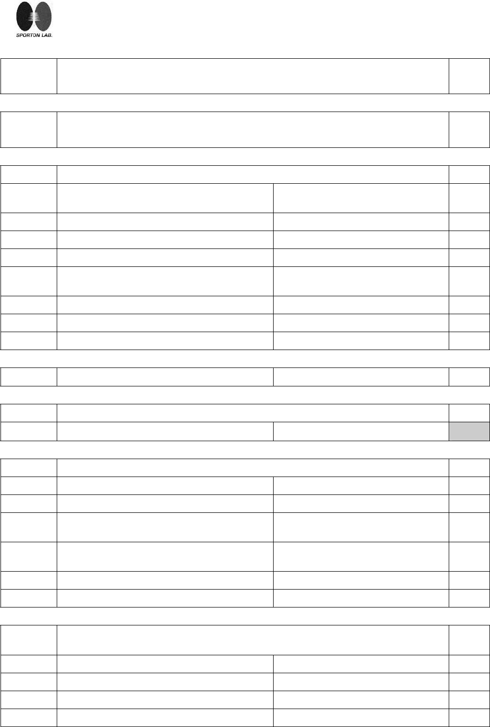
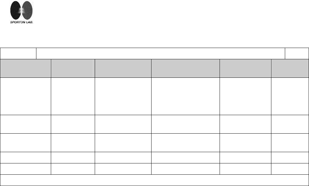
1.5.1 TABLE: list of critical components Pass
object/part No. manufacturer/
trademark type/model technical data standard mark(s) of
conformity
Adaptor DVE DSA-12R-12 AEU I/p: AC 200-240V,
50/60Hz, 300mA
o/p: DC 12V, 1A
Class II, 40 °C, LPS
EN 60950-1:
2001+A11 TUV Rh
Vertical Motor
(stepping motor) AFREEY 60.7010V.202 12Vdc,0.5A -- --
Horizontal Motor
(stepping motor) AFREEY 60.7010V.201 12Vdc,0.14A -- --
PCB -- -- Min. V-1, Min. 105 °C UL 94 UL
Enclosure -- -- Min. HB UL 94 UL
page 24 of 27 Report No.: L891605L1018
Sporton International Inc. Issued: December 18, 2008
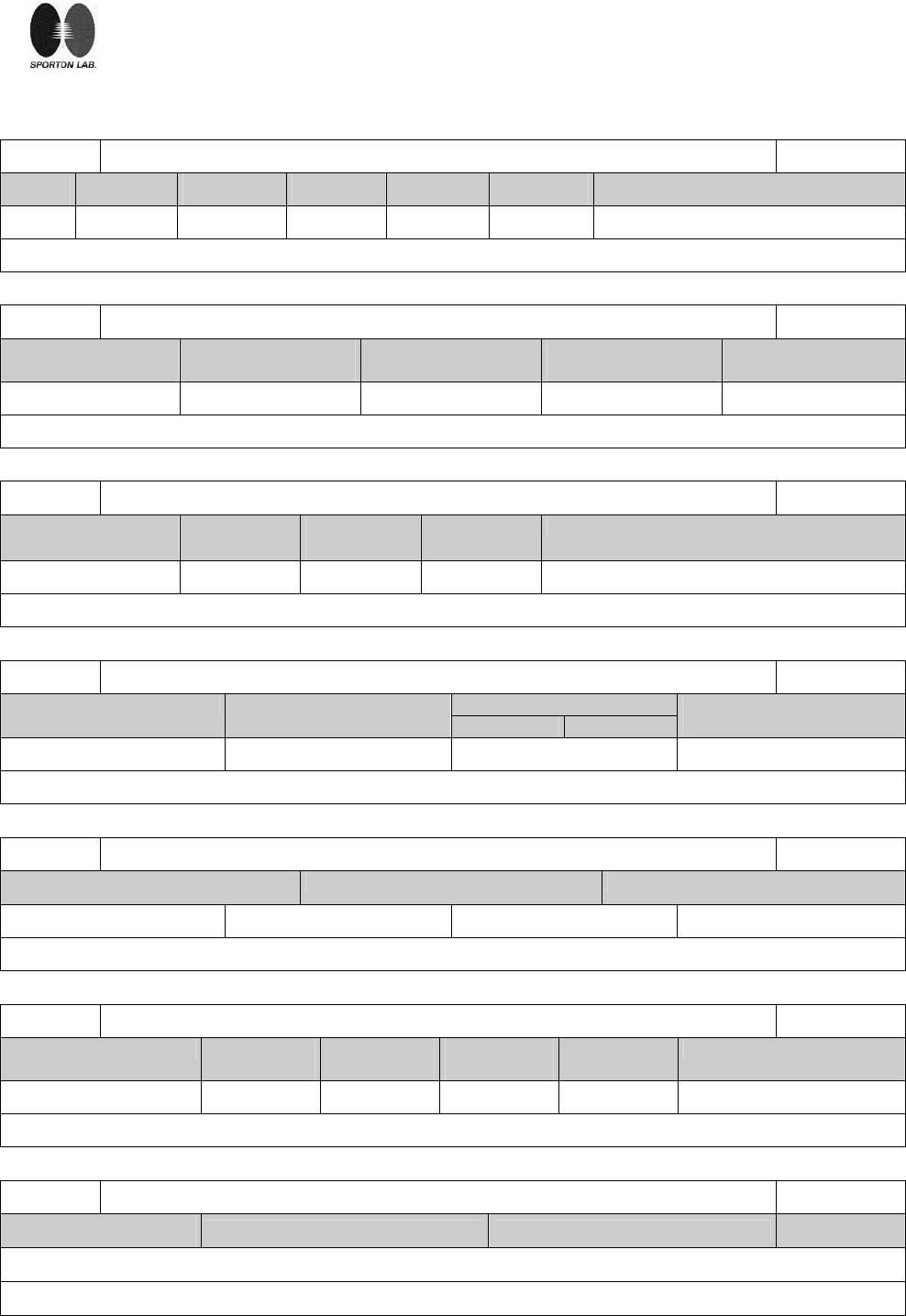
1.6.2 TABLE: electrical data (in normal conditions) Pass
fuse # Irated (A) U (V) P (W) I (A) Ifuse (A) condition/status
-- 1.0 12 Vdc 4.32 0.36 -- Max. Normal load.
Note(s):
2.1.1.5 TABLE: max. V, A, VA test N.A.
Voltage (rated)
(V) Current (rated)
(A) Voltage (max.)
(V) Current (max.)
(A) VA (max.)
(VA)
Note(s):
2.1.1.7 TABLE: discharge test N.A.
Condition τcalculated
(s)
τmeasured
(s)
tu → 0V
(s)
Comments
Note(s):
2.2.2 TABLE: Hazardous voltage measurement N.A.
max. Voltage Transformer Location V peak V d.c. Voltage Limitation
Componet
Note(s):
2.2.3 TABLE: SEL voltage measurement N.A.
Location Voltage measured (V) Comments
Note(s):
2.4.2 TABLE: limited current circuit measurement N.A.
Location Voltage
(V) Current
(Ma) Freq.
(kHz) Limit
(mA) Comments
Note(s):
2.5 TABLE: limited power source measurement N.A.
Limits Measured Verdict
According to Table 2B (normal condition), Uoc=
page 25 of 27 Report No.: L891605L1018
Sporton International Inc. Issued: December 18, 2008
current (in A) N.A.
Apparent power (in VA) N.A.
Note(s):
2.6.3.4 TABLE: ground continue test N.A.
Location Resistance measured(mΩ) Comments
Note(s):
2.10.2 TABLE: working voltage measurement N.A.
Location Resistance measured(mΩ) Comments
Note(s):
2.10.3 and
2.10.4 TABLE: clearance and creepage distance measurements N.A.
clearance cl and creepage
distance dcr at/of: Up
(V) U r.m.s.
(V) required cl
(mm) cl
(mm) required dcr
(mm) dcr
(mm)
Note(s). Functional insulation only.
2.10.5 TABLE: distance through insulation measurements N.A.
distance through insulation di at/of: U r.m.s. (V) test voltage
(V) required di
(mm) di (mm)
Note(s):
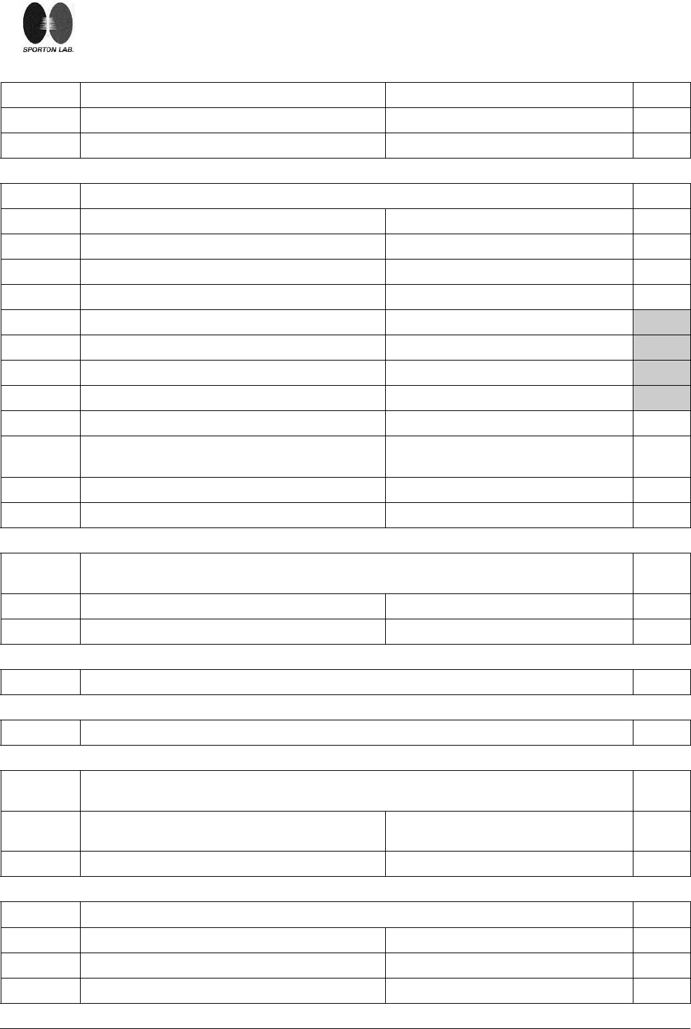
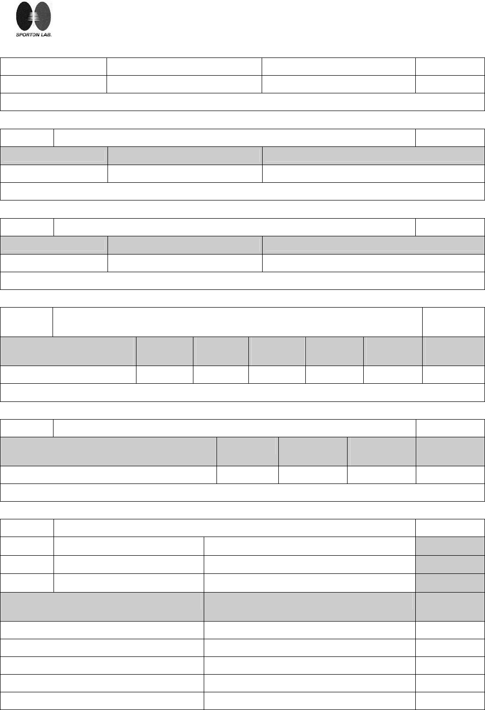
4.5.1 TABLE: maximum temperatures Pass
test voltage (V)................................ 12 Vdc ⎯
t
amb1 (ºC).......................................... -- ⎯
t
amb2 (ºC).......................................... 40 ⎯
Maximum temperature T of part/at: T (ºC) allowed
Tmax (ºC)
PWB near U13 71.2 105
PWB near U10 69.8 105
PWB near U4 71.7 105
PWB near U3 70.1 105
PWB near wireless card chip 71.6 105
page 26 of 27 Report No.: L891605L1018
Sporton International Inc. Issued: December 18, 2008
PWB near U1 76.5 105
Horizontal motor body 75.6 105
Vertical motor body 51.8 105
Enclosure inside near U1 65.4 --
Enclosure outside near U1 53.8 95
temperature T of winding: R1 (Ω) R2 (Ω) dT (ºK) allowed
Tmax (ºC) insulation
class
Note(s):
1) All values for T (℃) are re-calculated from Tamb respectively.
2) The maximum ambient temperatures specified by manufacturer is 40℃(Tma).
4.5.2 TABLE: ball pressure test of thermoplastics parts N.A.
allowed impression diameter (mm)........................: ≤ 2 mm ⎯
part: test temperature
(ºC) impression diameter
(mm)
4.6.1,
4.6.2 TABLE: Enclosure openings Pass
Location Size(mm) Comments
Top Each openings diameter
measured approx. 1.4mm. Numerous circular openings.
side No openings --
1.9 x 25 mm Three rectangle openings. bottom
Each openings diameter
measured approx. 1.9mm. Numerous circular openings.
Note(s):
4.7 TABLE: resistance to fire Pass
part: Manufacturer of material Type of material Thickness
(mm) Flammability
class
Note(s): See appended table 1.5.1
5.1.6 TABLE: touch current measurement N.A.
Condition L→terminal A
(mA)
N→terminal A
(mA)
Limit Comments
page 27 of 27 Report No.: L891605L1018
Sporton International Inc. Issued: December 18, 2008
Note(s):
5.2 TABLE: electric strength tests and impulse tests N.A.
Test voltage applied between: Test voltage (V) Breakdown
5.3 TABLE: fault condition tests Pass
ambient temperature (ºC).....................................: See below ⎯
model/type of power supply .................................: -- ⎯
manufacturer of power supply..............................: -- ⎯
rated markings of power supply...........................: -- ⎯
No. component
No. fault test voltage
(V) test time fuse
No. fuse current
(A) result
1 Openings Blocked 12 3.5hrs -- -- Unit normal operation . No
damaged. No hazardous.
Maximum Temperature:
PWB near U1:64.5 ℃,
Ambient:24.4 ℃.
Note(s)
Page 1 Report No.: L891605L1018
Sporton International Inc. Issued: December 18, 2008
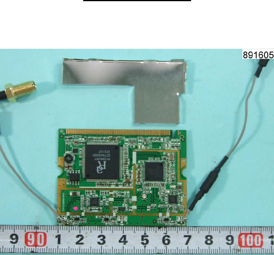
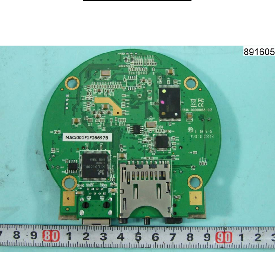
Appendix - Photo
Page 2 Report No.: L891605L1018
Sporton International Inc. Issued: December 18, 2008
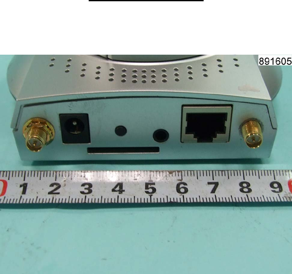
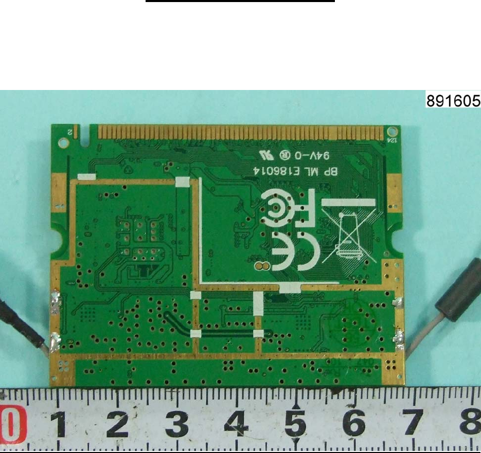
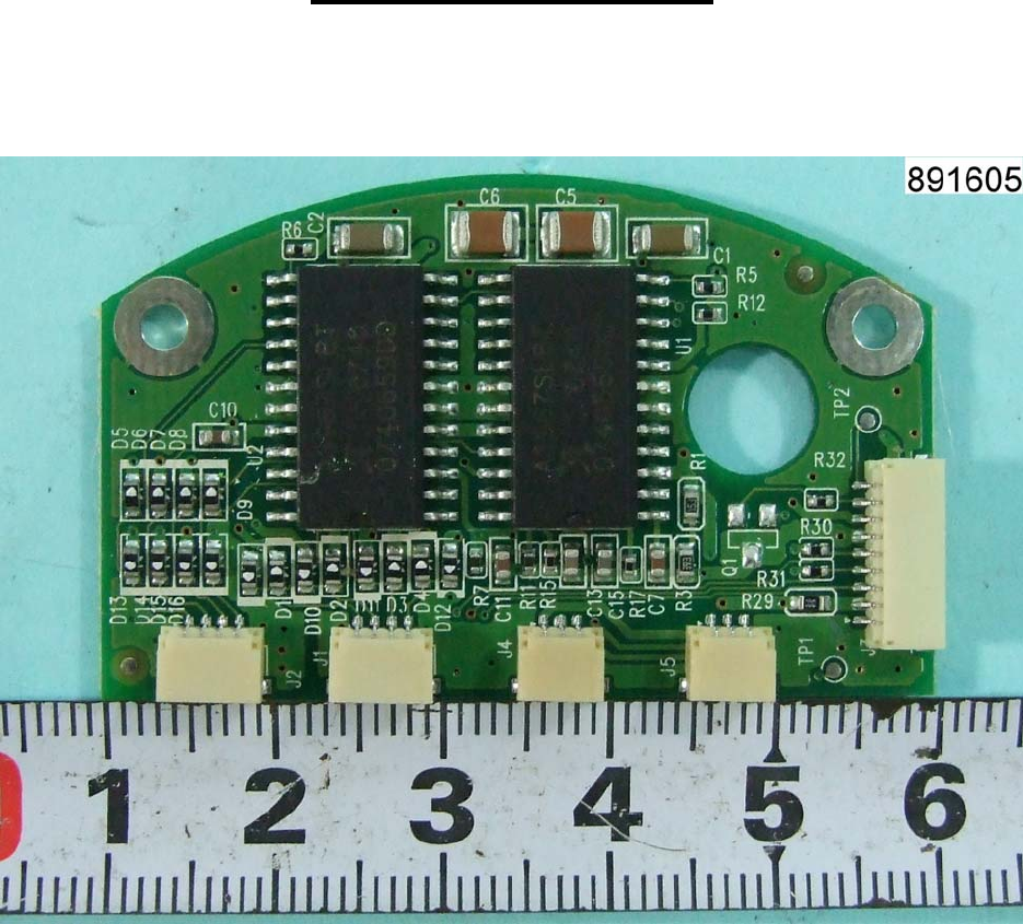
Appendix - Photo
Page 3 Report No.: L891605L1018
Sporton International Inc. Issued: December 18, 2008
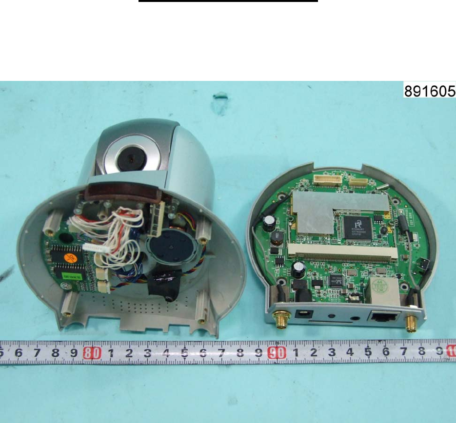
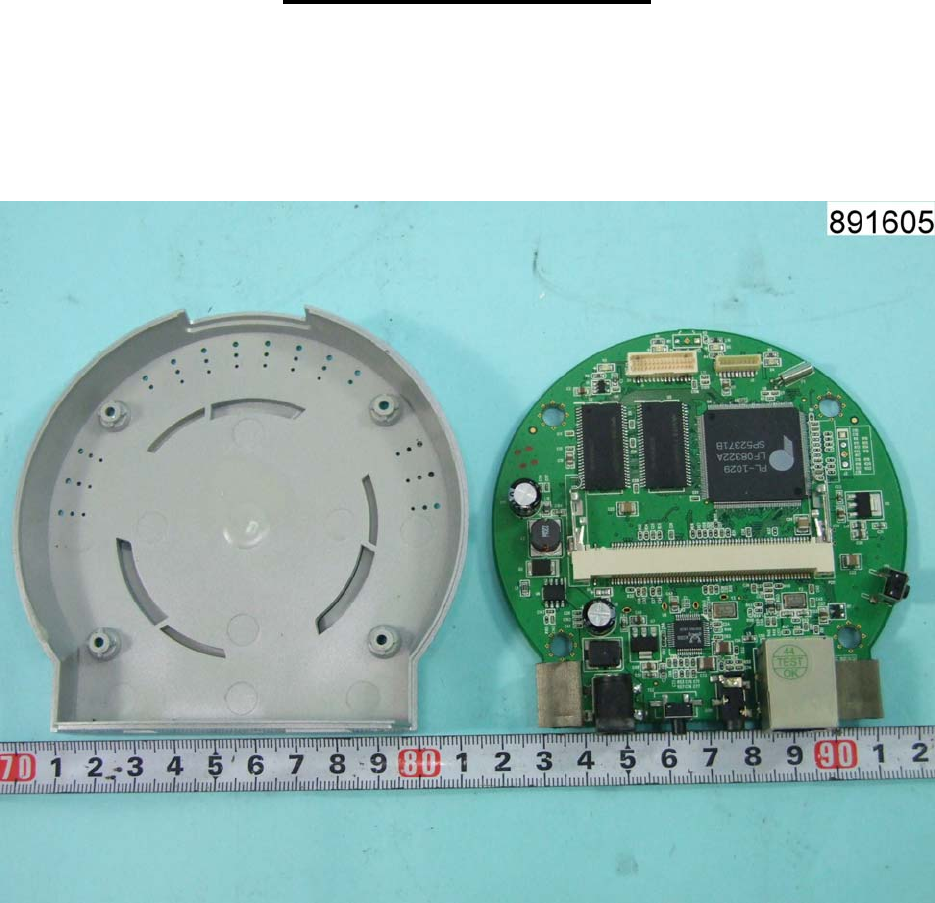
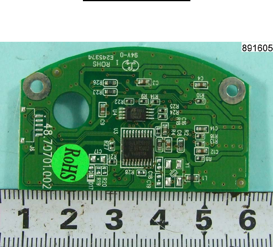
Appendix - Photo
Page 4 Report No.: L891605L1018
Sporton International Inc. Issued: December 18, 2008
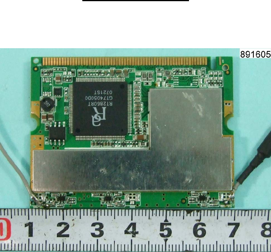
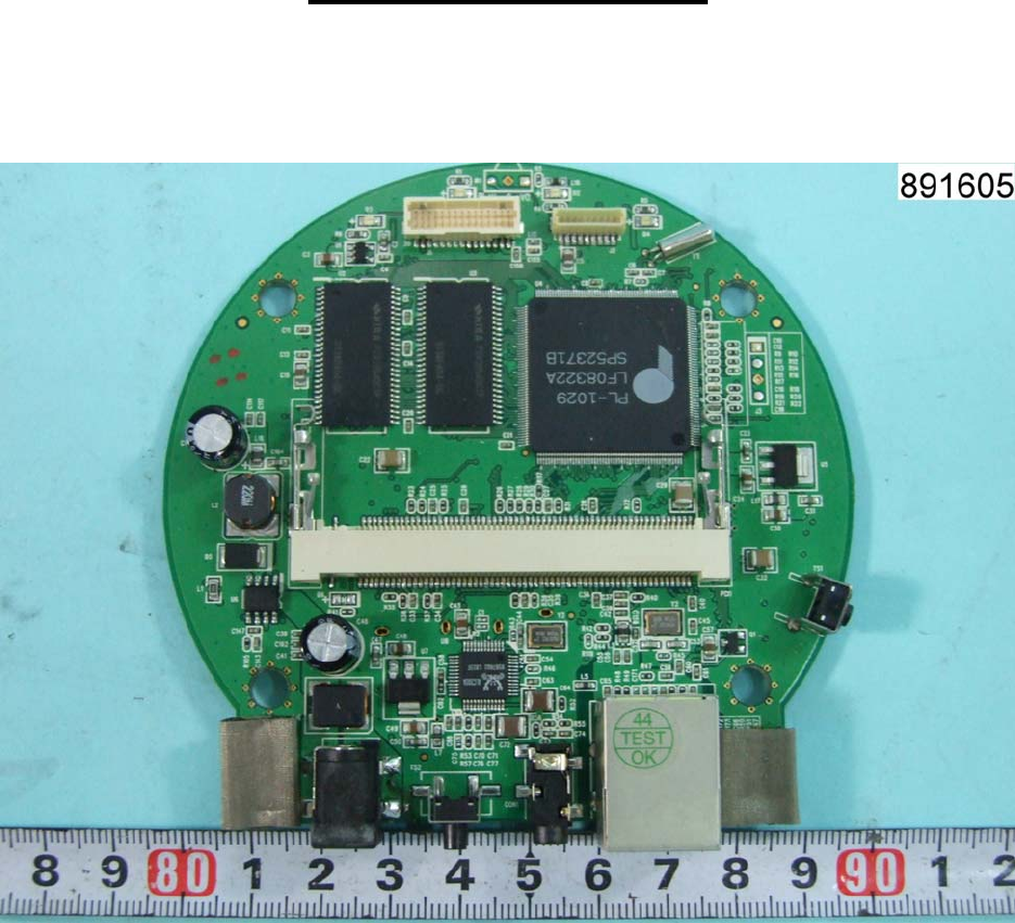
Appendix - Photo
Page 5 Report No.: L891605L1018
Sporton International Inc. Issued: December 18, 2008
Appendix - Photo
Page 6 Report No.: L891605L1018
Sporton International Inc. Issued: December 18, 2008
Appendix - Photo
Page 7 Report No.: L891605L1018
Sporton International Inc. Issued: December 18, 2008
Appendix - Photo
Page 8 Report No.: L891605L1018
Sporton International Inc. Issued: December 18, 2008
Appendix - Photo
Page 9 Report No.: L891605L1018
Sporton International Inc. Issued: December 18, 2008
Appendix - Photo
Page 10 Report No.: L891605L1018
Sporton International Inc. Issued: December 18, 2008
Appendix - Photo
Page 11 Report No.: L891605L1018
Sporton International Inc. Issued: December 18, 2008
Appendix - Photo
Page 12 Report No.: L891605L1018
Sporton International Inc. Issued: December 18, 2008
Appendix - Photo
Page 13 Report No.: L891605L1018
Sporton International Inc. Issued: December 18, 2008
Appendix - Photo
