550956 & 550970 Report(EN 55022 EN55024)
550956 & 550970 Report(En 55022 En55024) 550956_&_550970_Report(EN_55022_EN55024) 550956_&_550970_Report(EN_55022_EN55024) CertsReports 550970 ProductFiles assets.mhint
2016-04-12
: Pdf 550956 & 550970 Report(En 55022 En55024) 550956_&_550970_Report(EN_55022_EN55024) CertsReports 550956 ProductFiles
Open the PDF directly: View PDF ![]() .
.
Page Count: 57
Compliance Certification Services Inc.
Report No.:91230301-E
Page 1 of 57
This report shall not be reproduced except in full, without the written approval of Compliance Certification Services.
CE EMC
TEST REPORT
For
IP Cam
Model : F511W
Data Applies To : F510W
Trade Name : ZAVIO
Issued for
ZAVIO Inc.
B3,1F,NO. 1,Lising 1st Rd.,
Science-Based Industrial Park,Hsinchu,Taiwan
Issued by
Compliance Certification Services Inc.
Hsinchu Lab.
NO. 989-1 Wen Shan Rd., Shang Shan Village,
Qionglin Shiang Hsinchu County 30741, Taiwan, R.O.C
TEL: +886-3-5921698
FAX: +886-3-5921108
http://www.ccsrf.com
E-Mail : service@ccsrf.com
Note: This report shall not be reproduced except in full, without the written approval of
Compliance Certification Services Inc. This document may be altered or revised by Compliance
Certification Services Inc. personnel only, and shall be noted in the revision section of the document.
The client should not use it to claim product endorsement by TAF or any
government agencies. The test results in the report only apply to the tested sample.
Compliance Certification Services Inc.
Report No.:91230301-E
Page 2 of 57
This report shall not be reproduced except in full, without the written approval of Compliance Certification Services.
Revision History
Rev. Issue Date Revisions Effect Page Revised By
00 04/30/2010 Initial Issue All Page 57 Kate Shi

Compliance Certification Services Inc.
Report No.:91230301-E
Page 3 of 57
This report shall not be reproduced except in full, without the written approval of Compliance Certification Services.
TABLE OF CONTENTS
TITLE PAGE NO.
1. TEST REPORT CERTIFICATION................................................................................4
2. EUT DESCRIPTION .....................................................................................................5
2.1 DESCRIPTION OF EUT & POWE .........................................................................5
3. DESCRIPTION OF TEST MODES ...............................................................................5
4. TEST METHODOLOGY ...............................................................................................5
5. FACILITIES AND ACCREDITATION...........................................................................6
5.1 FACILITIES ............................................................................................................6
5.2 TABLE OF ACCREDITATIONS AND LISTINGS....................................................6
5.3 MEASUREMENT UNCERTAINTY .........................................................................7
6. SETUP OF EQUIPMENT UNDER TEST......................................................................8
7. EMISSION TEST..........................................................................................................9
7.1 RADIATED EMISSION...........................................................................................9-14
7.2 CONDUCTED EMISSION......................................................................................15-22
7.3 HARMONIC CURRENT EMISSION.......................................................................23-27
7.4 VOLTAGE FLUCTUATION AND FLICKER............................................................28-29
8. IMMUNITY TEST..........................................................................................................30
8.1 ELECTROSTATIC DISCHARGE (ESD).................................................................31-33
8.2 RF ELECTROMAGNETIC FIELD (RS) ..................................................................34-35
8.3 FAST TRANSIENTS COMMON MODE (EFT).......................................................36-38
8.4 SURGE ..................................................................................................................39-40
8.5 CONDUCTED RADIO FREQUENCY DISTURBANCES (CS) ...............................41-42
8.6 POWER FREQUENCY MAGNETIC FIELDS (PFMF)............................................43-44
8.7 VOLTAGE DIPS & VOLTAGE INTERRUPTIONS (DIP) ........................................45-46
APPENDIX SETUP PHOTOS ..........................................................................................47-57
Compliance Certification Services Inc.
Report No.:91230301-E
Page 4 of 57
This report shall not be reproduced except in full, without the written approval of Compliance Certification Services.
1. TEST REPORT CERTIFICATION
Applicant : ZAVIO Inc.
Address : B3, 1F, NO. 1, Lising 1st Rd.,
Science-Based Industrial Park,Hsinchu, Taiwan
Equipment Under Test: IP Cam
Model : F511W
Data Applies To : F510W
Trade Name : ZAVIO
Tested Date : April 22 ~ May 04, 2010
APPLICABLE STANDARD
Emission Standard Item Test Result
Radiated Emission PASS
EN 55022:2006 + A1:2007, CLASS B Conducted Emission PASS
EN 61000-3-2:2006 Harmonic Current Emissions PASS
EN 61000-3-3:1995 + A1:2001 + A2:2005 Voltage Fluctuation & Flicker PASS
Immunity Standard
EN 55024:1998 + A1:2001 + A2:2003 Item Test Result
IEC 61000-4-2:1995 + A1:1998 + A2:2000 Electrostatic Discharge PASS
IEC 61000-4-3:2006 RF Electromagnetic Field PASS
IEC 61000-4-4:2004 Fast Transients Common Mode PASS
IEC 61000-4-5:2005 Surge PASS
IEC 61000-4-6:2003 + A1:2004 + A2:2006 Conducted Radio Frequency
Disturbances PASS
IEC 61000-4-8:1993 + A1:2000 Power Frequency Magnetic Fields PASS
IEC 61000-4-11:2004 Voltage Dips & Voltage Interruptions PASS
WE HEREBY CERTIFY THAT: The above equipment has been tested by Compliance
Certification Services Inc., and found compliance with the requirements set forth in the
technical standards mentioned above. The results of testing in this report apply only to the
product/system, which was tested. Other similar equipment will not necessarily produce the
same results due to production tolerance and measurement uncertainties.
Compliance Certification Services Inc.
Report No.:91230301-E
Page 5 of 57
This report shall not be reproduced except in full, without the written approval of Compliance Certification Services.
2. EUT DESCRIPTION
2.1 DESCRIPTION OF EUT & POWE
Product Name IP Cam
Model Number F511W
Data Applies To F510W
Received Date April 23, 2010
Power Source 12VDC, 1.25A (From Power Adapter)
RJ-45 port × 1, Audio In port × 1, Audio Out port × 1,
I/O Port Power port × 1, DI+DI-Com No port × 1
Power Adapter :
No. Manufacturer Model No. Power Input Power Output
1 FAIRWAY WRG15F-120B
100-240VAC, 1.0A max,
50/60Hz 12V, 1.25A
The difference of the series model :
Model Number Difference
F511W The CMOS camera has a LED light around
F510W The CMOS camera has no LED light around
Remark : For more details, please refer to the User’s manual of the EUT.
3. DESCRIPTION OF TEST MODES
The EUT(F511W) has been tested under normal operating condition.
4. TEST METHODOLOGY
The tests documented in this report were performed in accordance with the following
standards : EN 55022:2006 + A1:2007, EN 61000-3-2:2006, EN 61000-3-3:1995 +
A1:2001 + A2:2005, EN 55024:1998 + A1:2001 + A2:2003.
Compliance Certification Services Inc.
Report No.:91230301-E
Page 6 of 57
This report shall not be reproduced except in full, without the written approval of Compliance Certification Services.
5. FACILITIES AND ACCREDITATION
5.1 FACILITIES
All measurement facilities used to collect the measurement data are located at
NO. 989-1 Wen Shan Rd., Shang Shan Village,
Qionglin Shiang Hsinchu County 30741, Taiwan, R.O.C
The sites are constructed in conformance with the requirements of ANSI C63.4 :2003 and
CISPR 22. All receiving equipment conforms to CISPR 16-1-1, CISPR 16-1-2, CISPR
16-1-3, CISPR 16-1-4, CISPR 16-1-5.
5.2 TABLE OF ACCREDITATIONS AND LISTINGS
Our laboratories are accredited and approved by the following approval agencies
according to ISO/IEC 17025.
Taiwan TAF
The measuring facility of laboratories has been authorized or registered by the following
approval agencies.
Germany TÜV NORD
Taiwan BSMI
USA FCC MRA
Copies of granted accreditation certificates are available for downloading from our web
site, http:///www.ccsrf.com
Compliance Certification Services Inc.
Report No.:91230301-E
Page 7 of 57
This report shall not be reproduced except in full, without the written approval of Compliance Certification Services.
5.3 MEASUREMENT UNCERTAINTY
The following table is for the measurement uncertainty, which is calculated as per the
document CISPR 16-4-2.
PARAMETER UNCERTAINTY
Open Area Test Site (OATS No.3) /
Radiated Emission, 30 to 200 MHz +/- 3.9267
Open Area Test Site (OATS No.3) /
Radiated Emission, 200 to 1000 MHz +/- 3.6899
Semi Anechoic Chamber (966 Chamber) /
Radiated Emission, 30 to 200 MHz +/- 3.6878
Semi Anechoic Chamber (966 Chamber) /
Radiated Emission, 200 to 1000 MHz +/- 3.0885
Semi Anechoic Chamber (966 Chamber) /
Radiated Emission, 1 to 26.5GHz +/- 3.2000
Conducted Emission, 9kHz to 30MHz +/- 1.7468
This uncertainty represents an expanded uncertainty expressed at approximately the
95% confidence level using a coverage factor of k=2.
Consistent with industry standard (e.g. CISPR 22: 2006, clause 11, Measurement
Uncertainty) determining compliance with the limits shall be base on the results of the
compliance measurement. Consequently the measure emissions being less than the
maximum allowed emission result in this be a compliant test or passing test.
The acceptable measurement uncertainty value without requiring revision of the
compliance statement is base on conducted and radiated emissions being less than
UCISPR which is 3.6dB and 5.2dB respectively. CCS values (called ULab in CISPR
16-4-2) is less than UCISPR as shown in the table above. Therefore, MU need not be
considered for compliance.
Compliance Certification Services Inc.
Report No.:91230301-E
Page 8 of 57
This report shall not be reproduced except in full, without the written approval of Compliance Certification Services.
6. SETUP OF EQUIPMENT UNDER TEST
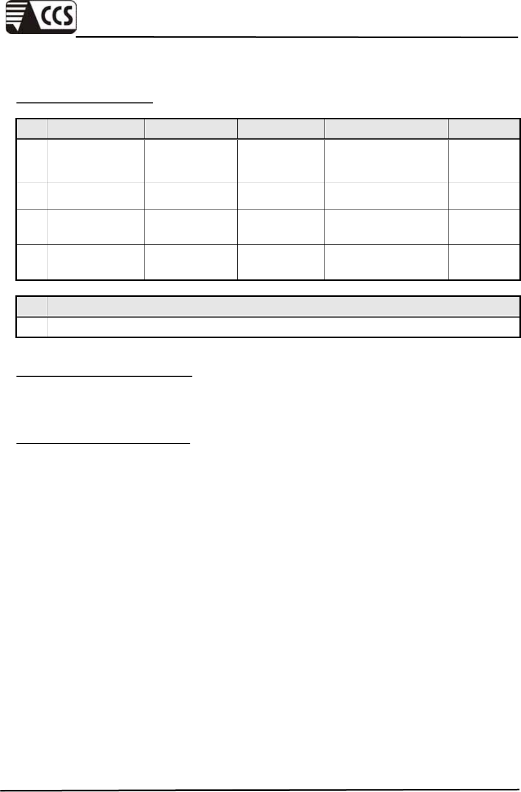
SUPPORT EQUIPMENT
No. Product Manufacturer Model No. Serial No. FCC ID
1 Notebook PC DELL Latitude D610
CN-0C4708-48643-6
25
-5565
E2K24BNH
M
2 Notebook PC HP nx6130 CNU543274R CNTWM3B2
200BGA
3 Headset/Microph
one ERGOTECH ET-E203 4719405008042 -----
4 Wireless Gigabit
Router D-Link DI-724GU ----- -----
No. Signal Cable Description
1 Unshielded RJ-45 cable, 12m ×1
SETUP DIAGRAM FOR TESTS
EUT & peripherals setup diagram is shown in appendix setup photos.
EUT OPERATING CONDITION
1. Setup whole system for test as shown on diagram
2. Wireless Router to provide IP to the EUT.
3. Notebook PC (1) ping 192.168.1.90 to EUT.
4. Notebook PC (2) ping 192.168.0.151 to EUT.
5. Audio In/Out link Headset/Microphone.
6. All of the function are under run.
7. Start test.
Compliance Certification Services Inc.
Report No.:91230301-E
Page 9 of 57
This report shall not be reproduced except in full, without the written approval of Compliance Certification Services.
7. EMISSION TEST
7.1 RADIATED EMISSION
LIMITS
(1) Frequency Range below 1GHz
Field Strength Quasi-peak limits (dBµV/m)
Frequency range
(MHz) Class A Class B
Distance
(meters)
30 - 230 40 30 10
230 - 1000 47 37 10
Remark: (1) The lower limit shall apply at the transition frequency.
(2) Additional provisions may be required for cases where interference occurs.
(2) Frequency Range above 1GHz
Field Strength Limit (dBµV/m)
Class A Class B
Frequency range
(GHz) Peak Average Peak Average
Distance
(meters)
1 - 3 76 56 70 50 3
3 - 6 80 60 74 54 3
Remark: The lower limit shall apply at the transition frequency.
According to EN55022: 2006 + A1: 2007 clause 6.2, the measurement frequency range
shown in the following table:
Highest frequency generated or used
within the EUT or on which the EUT
operates or tunes (MHz)
Upper frequency of measurement range
(MHz)
Less than 108 1000
108-500 2000
500-1000 5000
Above 1000 5 times of the highest frequency or 6GHz,
whichever is less

Compliance Certification Services Inc.
Report No.:91230301-E
Page 10 of 57
This report shall not be reproduced except in full, without the written approval of Compliance Certification Services.
TEST EQUIPMENT
Radiated Emission below 1GHz / OATS3
Name of Equipment Manufacturer Model Serial Number Calibration
Due
Bi-log Antenna SCHAFFER CBL6112B 2696 12/10/2010
EMI Test Receiver ROHDE & SCHWARZ ESCS 30 835418/008 10/27/2010
N Type Coaxial Cable MIYAZAKIN 8D-FB 03 07/26/2010
Pre-Amplifier Agilent 8447D
2944A10052 07/26/2010
Remark: Each piece of equipment is scheduled for calibration once a year.
Radiated Emission above 1GHz / 966Chamber_A
Name of Equipment Manufacturer Model Serial Number Calibration
Due
Spectrum Analyzer Agilent E4446A MY43360132 06/09/2010
EMI Test Receiver ROHDE & SCHWARZ ESCI 100221 05/17/2010
Bi-log Antenna SCHWARZBECK VULB 9168 9168-249 11/12/2010
Double-Ridged
Waveguide Horn ETS-LINDGREN 3117 00078732 06/30/2010
Pre-Amplifier Agilent 8449B 3008A01471 08/02/2010
Pre-Amplifier HP 8447F 2944A03748 09/24/2010
RF Coaxial Cable HUBER-SUHNER SF104PEA 31347 07/21/2010
RF Coaxial Cable HUBER-SUHNER SF104PEA 31350 07/21/2010
RF Coaxial Cable HUBER-SUHNER SF104PEA 31355 07/21/2010
Band Reject Notch
Filter Micro-Tronics BRM05702-01 009 N.C.R
Remark: 1. Each piece of equipment is scheduled for calibration once a year.
2. N.C.R = No Calibration Request.
Compliance Certification Services Inc.
Report No.:91230301-E
Page 11 of 57
This report shall not be reproduced except in full, without the written approval of Compliance Certification Services.
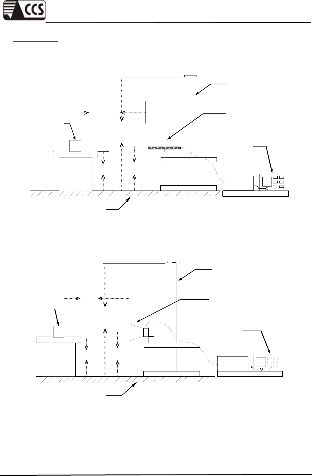
TEST SETUP
The diagram below shows the test setup that is utilized to make the measurements for
emission from below 1GHz.
EMI Test
Receiver
10m
1~4m
1m
Turntable
EUT
0.8m
Antenna
Tower
Reference ground plane
Bi-log
Antenna
Pre-amp
Coaxial Cable
The diagram below shows the test setup that is utilized to make the measurements for
emission above 1GHz.
Spectrum
Analyzer
Horn
Antenna
3m
1~4m
1m
Turntable
EUT
0.8m
Antenna
Tower
Pre-amp
Reference ground plane
Coaxial Cable

Compliance Certification Services Inc.
Report No.:91230301-E
Page 12 of 57
This report shall not be reproduced except in full, without the written approval of Compliance Certification Services.
TEST PROCEDURE
The basic test procedure was in accordance with EN 55022.
The EUT were placed on a turn table top 0.8 meter above ground. The table was rotated
360 degrees to determine the position of the maximum emission level. EUT is set 3 or 10
meters from the interference receiving antenna which is mounted on the top of a variable
height mast. The antenna height is varied between one meter and four meters above
ground to find the maximum emission level, both horizontal and vertical polarization of the
antenna is set on the measurement.
Radiated emissions were invested over the frequency range from 30 MHz to 1000 MHz
using a receiver bandwidth of 120 kHz.
The resolution bandwidth and video bandwidth of test receiver/spectrum analyzer is 1
MHz for Peak detection and frequency above 1GHz.
The resolution bandwidth of test receiver/spectrum analyzer is 1 MHz and the video
bandwidth is 10 Hz for Average detection (AV) at frequency above 1GHz.
Compliance Certification Services Inc.
Report No.:91230301-E
Page 13 of 57
This report shall not be reproduced except in full, without the written approval of Compliance Certification Services.
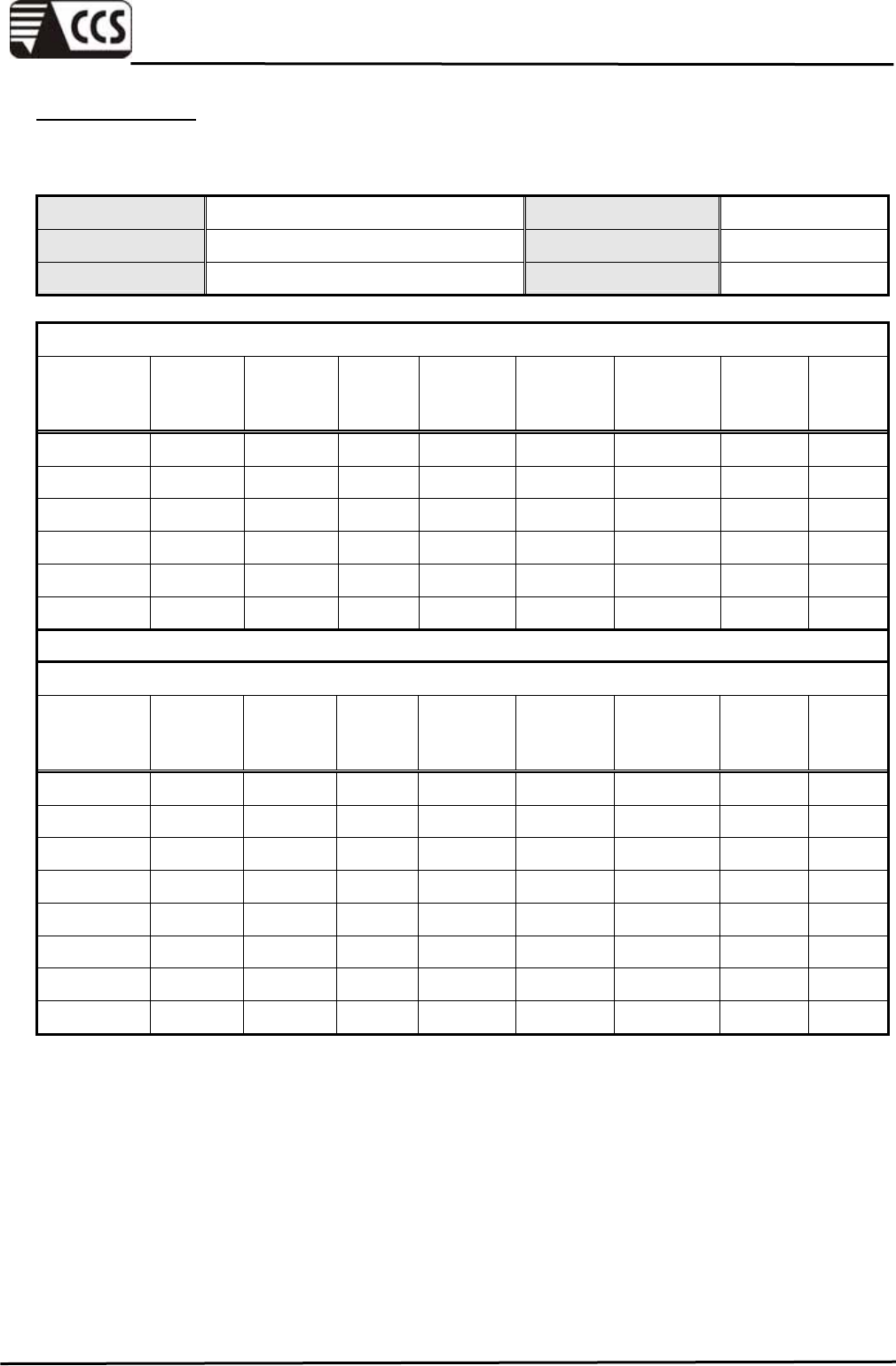
TEST RESULTS
Below 1 GHz
Product Name IP Cam Test By Rick Lin
Model F511W Test Date 2010/04/26
Test Mode Normal operating Temp. & Humidity 23°C, 85%
OATS3 at 10Meter / Horizontal
Frequency
(MHz)
Antenna
Factor
(dB/m)
Pre Amp.
Gain
(dB)
Cable
Loss
(dB)
Meter
Reading
(dBµV)
Limits
(dBµV/m)
Emission
Level
(dBµV/m)
Margin
Limit
(dB)
Remark
225.01 10.80 28.62 2.35 37.40 30.00 21.92 -8.08 QP
368.80 15.02 28.89 3.28 39.20 37.00 28.61 -8.39 QP
398.14 15.75 29.10 3.44 43.10 37.00 33.20 -3.80 QP
527.99 17.76 29.57 4.13 34.90 37.00 27.22 -9.78 QP
551.99 18.08 29.61 4.23 36.90 37.00 29.60 -7.40 QP
575.99 18.39 29.64 4.33 34.80 37.00 27.87 -9.13 QP
OATS3 at 10Meter / Vertical
Frequency
(MHz)
Antenna
Factor
(dB/m)
Pre Amp.
Gain
(dB)
Cable
Loss
(dB)
Meter
Reading
(dBµV)
Limits
(dBµV/m)
Emission
Level
(dBµV/m)
Margin
Limit
(dB)
Remark
156.00 10.36 29.06 1.91 46.70 30.00 29.91 -0.09 QP
168.00 9.74 29.03 1.99 45.60 30.00 28.30 -1.70 QP
191.99 9.20 28.82 2.14 42.50 30.00 25.02 -4.98 QP
225.01 10.80 28.62 2.35 42.80 30.00 27.32 -2.68 QP
390.79 15.57 29.04 3.40 37.70 37.00 27.62 -9.38 QP
527.99 17.76 29.57 4.13 36.60 37.00 28.92 -8.08 QP
597.21 18.66 29.68 4.42 39.70 37.00 33.11 -3.89 QP
750.00 19.45 29.59 5.15 34.90 37.00 29.91 -7.10 QP
Remark:
1. Quasi-peak test would be performed if the peak result were greater than the quasi-peak limit.
2. Data of measurement within this frequency range shown " --- " in the table above means the
reading of emissions are attenuated more than 20dB below the permissible limits or the field
strength is too small to be measured.
3 .Emission Level = Antenna Factor (dB/m) + Cable Loss (dB) + Meter Reading (dBµV) –
PreAmp.Gain (dB)
4. Margin (dB) = Emission Level (dBuV/m) - Quasi-peak limit (dBuV/m)
Compliance Certification Services Inc.
Report No.:91230301-E
Page 14 of 57
This report shall not be reproduced except in full, without the written approval of Compliance Certification Services.
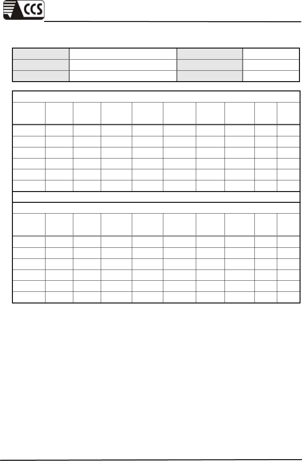
Above 1 GHz
Product Name IP Cam Test By Rick Lin
Model F511W Test Date 2010/04/26
Test Mode Normal operating Temp. & Humidity 25.6°C, 61%
966 Chamber_A at 3Meter / Horizontal
Frequency
(MHz)
Reading-
PK
(dBuV)
Reading-
AV
(dBuV)
Correction
Factor
(dB/m)
Result-PK
(dBuV/m)
Result-AV
(dBuV/m)
Limit-PK
(dBuV/m)
Limit-AV
(dBuV/m)
Margin
(dB) Remark
1145.00 53.53 --- -4.28 49.25 --- 70.00 50.00 -0.75 Peak
1655.00 49.16 --- -1.59 47.56 --- 70.00 50.00 -2.44 Peak
2175.00 44.06 --- 1.96 46.02 --- 70.00 50.00 -3.98 Peak
2595.00 44.68 --- 2.61 47.29 --- 70.00 50.00 -2.71 Peak
3250.00 44.20 --- 3.82 48.02 --- 74.00 54.00 -5.98 Peak
4585.00 42.09 --- 6.96 49.05 --- 74.00 54.00 -4.95 Peak
966 Chamber_A at 3Meter / Vertical
Frequency
(MHz)
Reading-
PK
(dBuV)
Reading-
AV
(dBuV)
Correction
Factor
(dB/m)
Result-PK
(dBuV/m)
Result-AV
(dBuV/m)
Limit-PK
(dBuV/m)
Limit-AV
(dBuV/m)
Margin
(dB) Remark
1035.00 48.74 --- -4.65 44.09 --- 70.00 50.00 -5.91 Peak
1295.00 50.39 --- -3.77 46.62 --- 70.00 50.00 -3.38 Peak
1630.00 48.08 --- -1.83 46.24 --- 70.00 50.00 -3.76 Peak
2620.00 45.05 --- 2.66 47.71 --- 70.00 50.00 -2.29 Peak
3250.00 50.39 48.48 3.82 54.21 52.30 74.00 54.00 -1.70 AVG
4875.00 51.77 37.50 7.11 58.88 44.61 74.00 54.00 -9.39 AVG
Remark:
1. Average test would be performed if the peak result were greater than the average limit.
2. Data of measurement within this frequency range shown “ --- ” in the table above means the reading
of emissions are attenuated more than 20dB below the permissible limits or the field strength is too
small to be measured.
3. Measurements above show only up to 6 maximum emissions noted, or would be lesser, with “ N/A ”
remark, if no specific emissions from the EUT are recorded (ie: margin>20dB from the applicable
limit) and considered that's already beyond the background noise floor.
4. Result = Reading + Correction Factor
Margin = Result – Limit
Remark Peak = Result(PK) – Limit(AV)
Remark AVG = Result(AV) – Limit(AV)
Compliance Certification Services Inc.
Report No.:91230301-E
Page 15 of 57
This report shall not be reproduced except in full, without the written approval of Compliance Certification Services.
7.2 CONDUCTED EMISSION
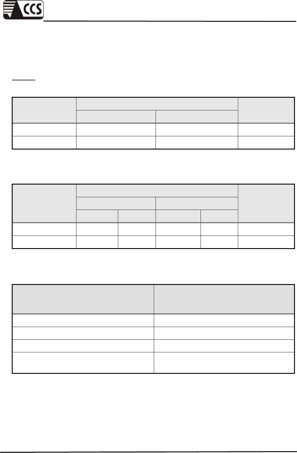
LIMITS
(1) Mains Ports
Voltage Limits (dBµV)
Class A Class B
Frequency Range
(MHz) Quasi-peak Average Quasi-peak Average
0.15 - 0.50 79 66 66 - 56 56 - 46
0.50 - 5.00 73 60 56 46
5.00 - 30.0 73 60 60 50
Remark: (1) The limit decreases linearly with logarithm of the frequency in the range 0.15 MHz to
0.50 MHz.
(2) The lower limit shall apply at the transition frequency.
(2) Telecommunication Ports
Voltage Limits (dBµV) Current Limits (dBµA)
Class A Class B Class A Class B
Frequency
Range
(MHz) Quasi-peak Average Quasi-peak Average Quasi-peak Average Quasi-peak Average
0.15 - 0.50 97 - 87 84 - 74 84 - 74 74 - 64 53 - 43 40 - 30 40 - 30 30 - 20
0.50 - 30.0 87 74 74 64 43 30 30 20
Remark: (1) The limit decreases linearly with logarithm of the frequency in the range 0.15 MHz to
0.50 MHz.
(2) The current and voltage disturbance limits are derived for use with an impedance
stabilization network (ISN) which presents a common mode (asymmetric mode) impedance
of 150Ω to the telecommunication port under test (conversion factor is 20 log10 150 / I = 44
dB).
TEST EQUIPMENT
Name of Equipment Manufacturer Model Serial Number Calibration
Due
L.I.S.N SCHWARZBECK
NSLK 8127 8127-465 08/13/2010
L.I.S.N SCHWARZBECK
NSLK 8127 8127-473 03/22/2011
EMI Test Receiver ROHDE & SCHWARZ ESHS 30 838550/003 01/28/2011
Pulse Limit ROHDE & SCHWARZ ESH3-Z2 100117 09/17/2010
N Type Coaxial Cable BELDEN 8268 M17/164 003 07/09/2010
I.S.N. SCHAFFNER T800 24313 05/25/2010
Ferrite Clamp SCHAFFNER KEMA801 15937 05/25/2010
Current Probe SCHAFFNER SMZ11 14802 N.C.R.
Remark: 1. Each piece of equipment is scheduled for calibration once a year.
2. N.C.R = No Calibration Request.
Compliance Certification Services Inc.
Report No.:91230301-E
Page 16 of 57
This report shall not be reproduced except in full, without the written approval of Compliance Certification Services.
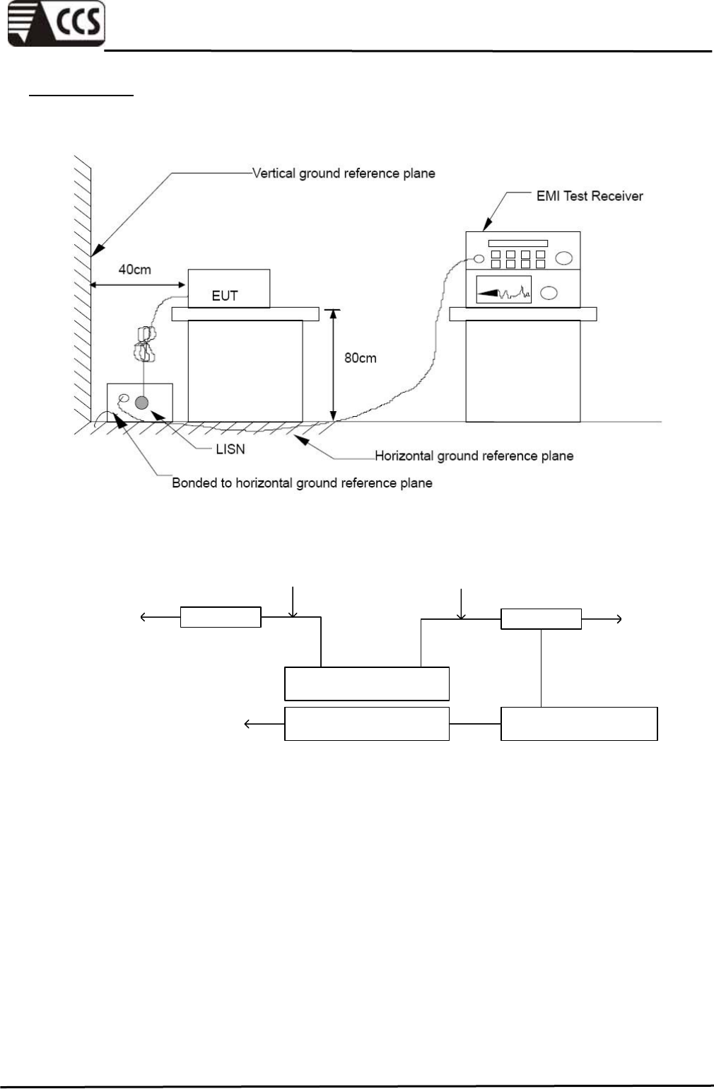
TEST SETUP
(1) Mains Ports
L.I.S.N.
230VAC
/ 50Hz
EUT & Peripherals
Powerline of
Peripherals
L.I.S.N.
Powerline of
EUT
230VAC
/ 50Hz
EMI Test ReceiverIsolate Transformer
230VAC
/ 50Hz
Compliance Certification Services Inc.
Report No.:91230301-E
Page 17 of 57
This report shall not be reproduced except in full, without the written approval of Compliance Certification Services.
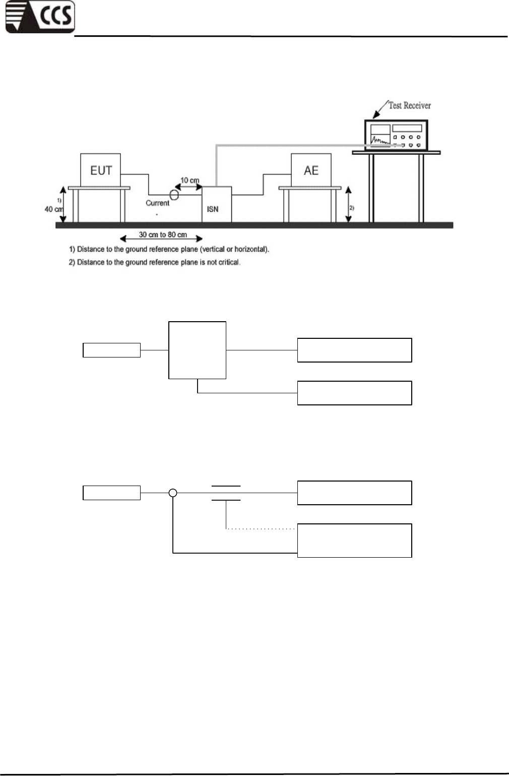
(2) Telecommunication Ports
EUT Peripherals
EMI Test Receiver
Current probe Capacitive voltage probe
I.S.N.
o.r.
C.D.N.
EUT Peripherals
EMI Test Receiver

Compliance Certification Services Inc.
Report No.:91230301-E
Page 18 of 57
This report shall not be reproduced except in full, without the written approval of Compliance Certification Services.
TEST PROCEDURE
The basic test procedure was in accordance with EN 55022
The test procedure is performed in a 4m × 3m × 2.4m (L×W×H) shielded room.
The EUT along with its peripherals were placed on a 1.0m (W) × 1.5m (L) and 0.8m in
height wooden table and the EUT was adjusted to maintain a 0.4 meter space from a
vertical reference plane.
The EUT was connected to power mains through a line impedance stabilization network
(LISN) which provides 50 ohm coupling impedance for measuring instrument and the
chassis ground was bounded to the horizontal ground plane of shielded room. All
peripherals were connected to the second LISN and the chassis ground also bounded to
the horizontal ground plane of shielded room.
Mains ports:
The EUT was located so that the distance between the boundary of the EUT and the
closest surface of the LISN is 0.8 m. Where a mains flexible cord was provided by the
manufacturer shall be 1 m long, or if in excess of 1 m, the excess cable was folded back
and forth as far as possible so as to form a bundle not exceeding 0.4 m in length.
Telecommunication ports:
The telecommunication port of the EUT was connected to the test receiver through the
ISN/Current Probe and communication in normal condition. ISN shall be nominally 0.8 m
from the EUT and bounded to a ground reference plane.
Conducted emission were investigated over the frequency range from 0.15 MHz to 30
MHz using a receiver, where the resolution bandwidth of the receiver is set as 9 kHz at
frequency range from 0.15 MHz to 30 MHz.
Compliance Certification Services Inc.
Report No.:91230301-E
Page 19 of 57
This report shall not be reproduced except in full, without the written approval of Compliance Certification Services.
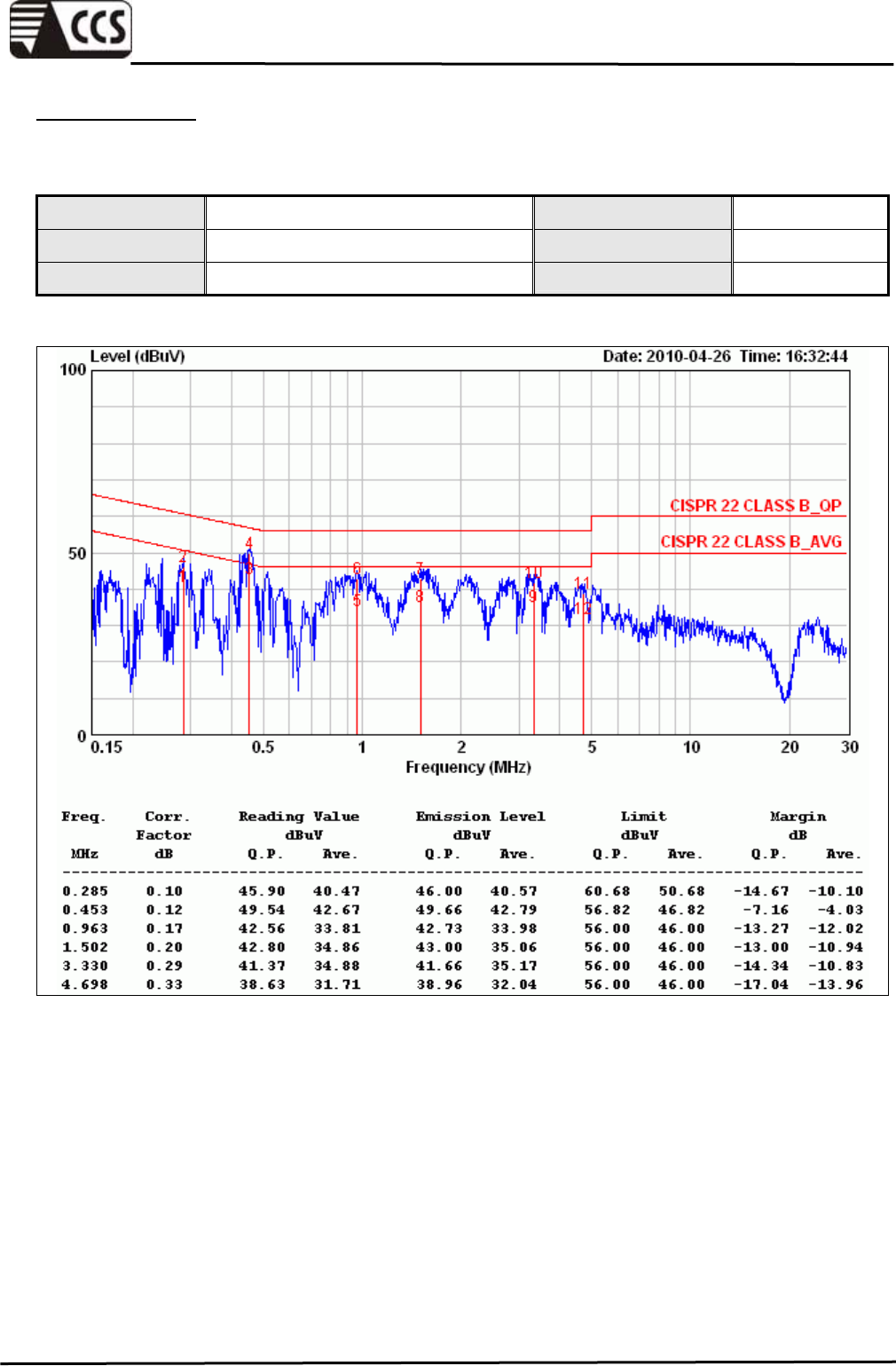
TEST RESULTS
Mains Ports
Product Name IP Cam Test By Joe Peng
Model F511W Test Date 2010/04/26
Test Mode Normal operating Temp. & Humidity 22.4°C, 47%
LINE
Remark:
1. Correction Factor = Insertion loss + cable loss
2. Margin value = Emission level – Limit value
Compliance Certification Services Inc.
Report No.:91230301-E
Page 20 of 57
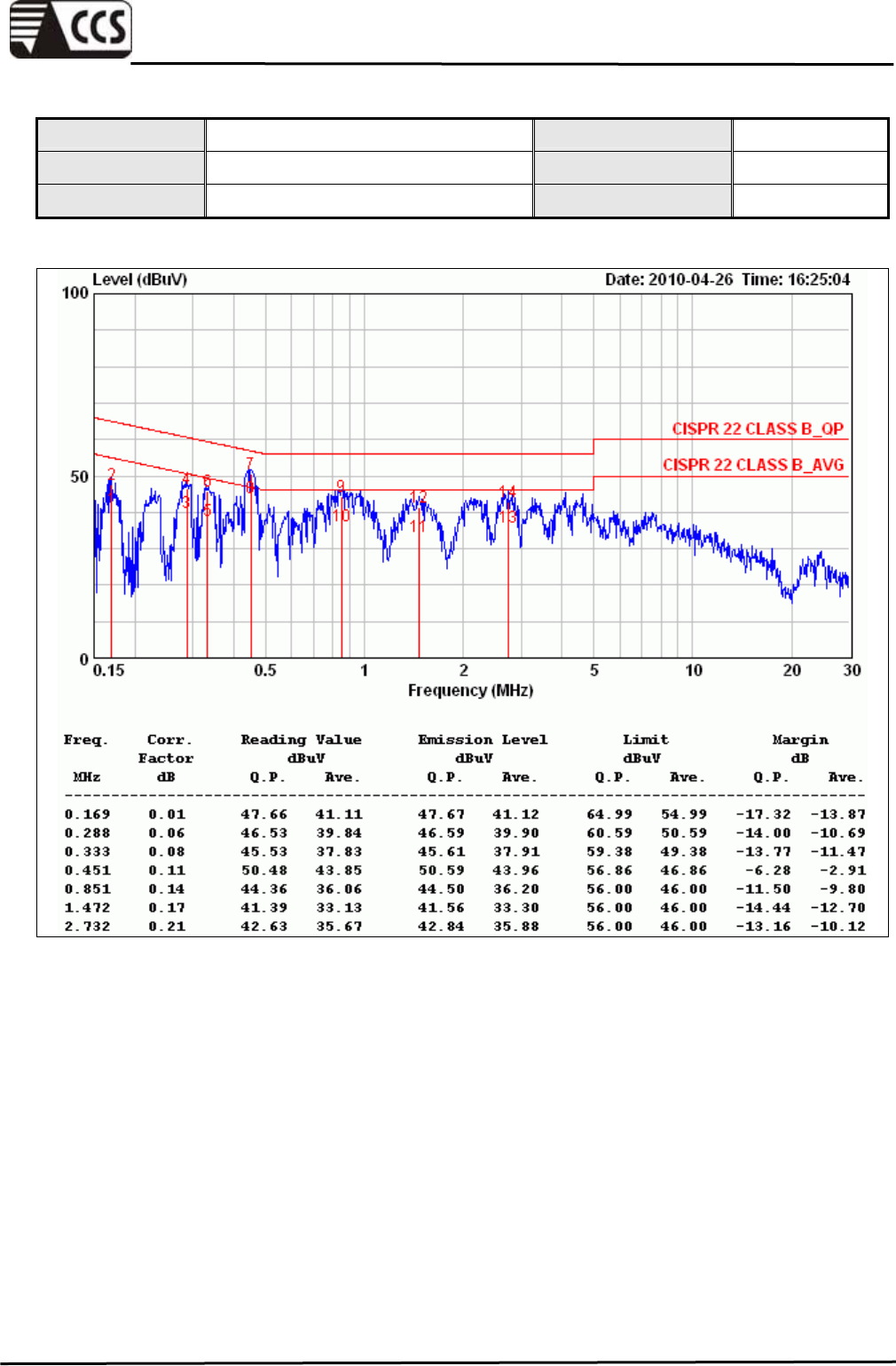
This report shall not be reproduced except in full, without the written approval of Compliance Certification Services.
Product Name IP Cam Test By Joe Peng
Model F511W Test Date 2010/04/26
Test Mode Normal operating Temp. & Humidity 22.4°C, 47%
NEUTRAL
Remark:
1. Correction Factor = Insertion loss + cable loss
2. Margin value = Emission level – Limit value
Compliance Certification Services Inc.
Report No.:91230301-E
Page 21 of 57
This report shall not be reproduced except in full, without the written approval of Compliance Certification Services.
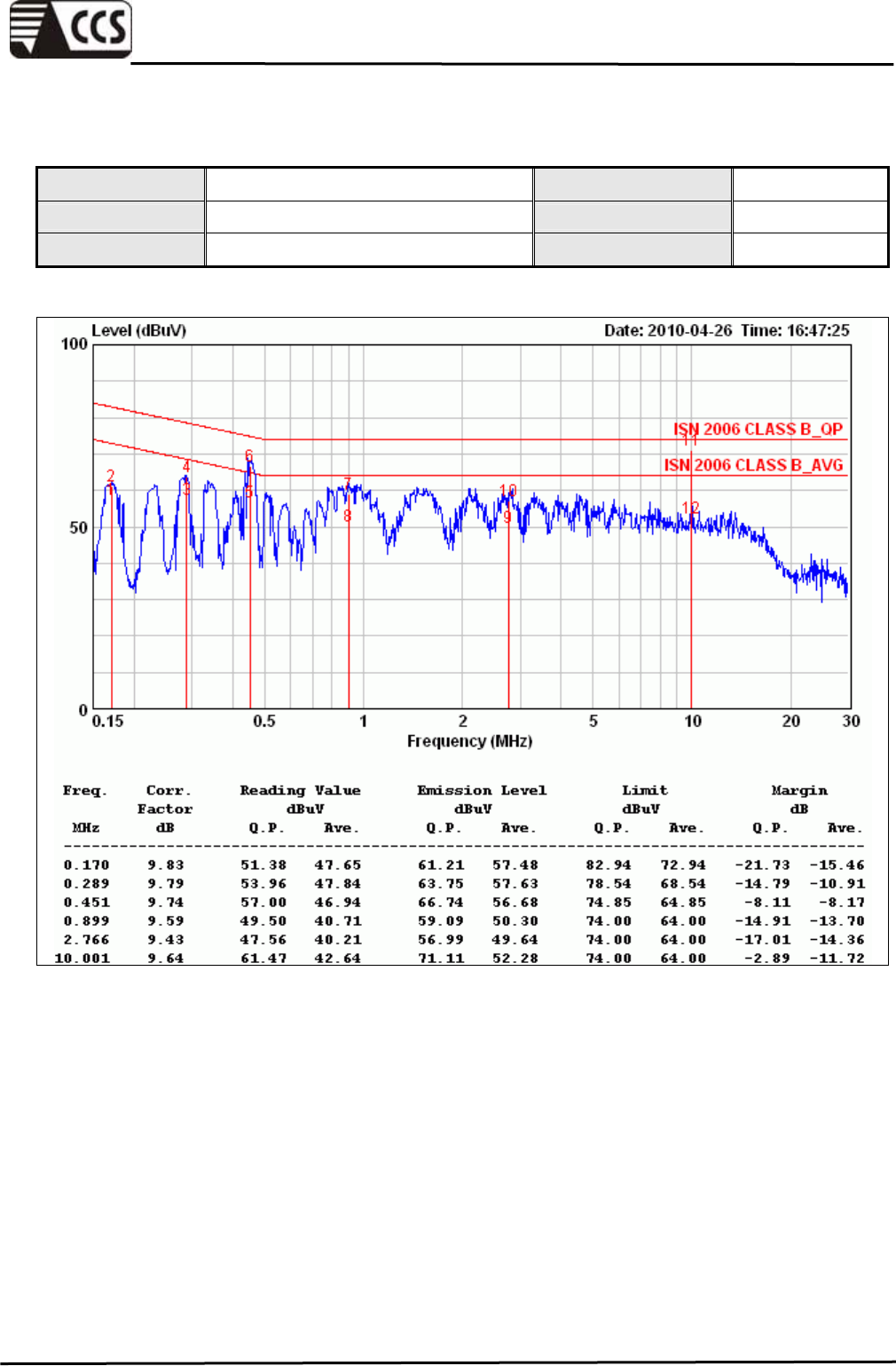
Telecommunication Ports
Product Name IP Cam Test By Joe Peng
Model F511W Test Date 2010/04/26
Test Mode LAN - 10Mbps Temp. & Humidity 22.4°C, 47%
Remark:
1. Correction Factor = Insertion loss + cable loss
2. Margin value = Emission level – Limit value
Compliance Certification Services Inc.
Report No.:91230301-E
Page 22 of 57
This report shall not be reproduced except in full, without the written approval of Compliance Certification Services.
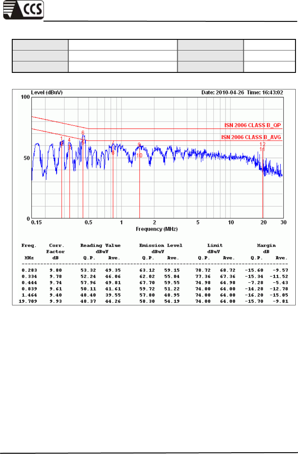
Product Name IP Cam Test By Joe Peng
Model F511W Test Date 2010/04/26
Test Mode LAN - 100Mbps Temp. & Humidity 22.4°C, 47%
Remark:
1. Correction Factor = Insertion loss + cable loss
2. Margin value = Emission level – Limit value
Compliance Certification Services Inc.
Report No.:91230301-E
Page 23 of 57
This report shall not be reproduced except in full, without the written approval of Compliance Certification Services.
7.3 HARMONIC CURRENT EMISSION
LIMITS
(1) Limits For Class A Equipment Disturbance Voltage Limits At Mains Terminals
Harmonic Order
(n)
Maximum Permissible
Harmonic Current
(A)
Odd Harmonics
3 2.30
5 1.14
7 0.77
9 0.40
11 0.33
13 0.21
15 N 39≦≦ 0.15*15/N
Even Harmonics
2 1.08
4 0.43
6 0.30
8 ≦ n ≦ 40 0.23*8/n
(2) Limits for Class B equipment
For Class B equipment, the harmonic of the input current shall not exceed the
maximum permissible values given in table that is the limit of Class A multiplied by a
factor of 1.5.
(3) Limits For Class C Equipment
Harmonic order
(n)
Maximum permissible harmonic current
expressed as a percentage of the input
current at fundamental frequency
(%)
Odd Harmonics
2 2
3 30*λ*
5 10
7 7
9 5
11 ≦ n ≦ 39 3
( odd harmonics only )
Remark: *λ is the circuit power factor
Compliance Certification Services Inc.
Report No.:91230301-E
Page 24 of 57
This report shall not be reproduced except in full, without the written approval of Compliance Certification Services.
(4) Limits For Class D Equipment
Harmonic order
(n)
Maximum permissible
harmonic current per watt
(mA/W)
Maximum permissible
Harmonic current
(A)
3 3.4 2.30
5 1.9 1.14
7 1.0 0.77
9 0.5 0.40
11 0.35 0.33
13 ≦ n ≦ 39 3.85/n See Table 1
( odd harmonics only )
Remark: *λ is the circuit power factor
TEST EQUIPMENT
Name of Equipment Manufacturer Model Serial Number Calibration
Due
Harmonics & Flicker
Test System EMC PARTNER HARMONIC-1000 071 01/17/2011
Remark: Each piece of equipment is scheduled for calibration once a year.
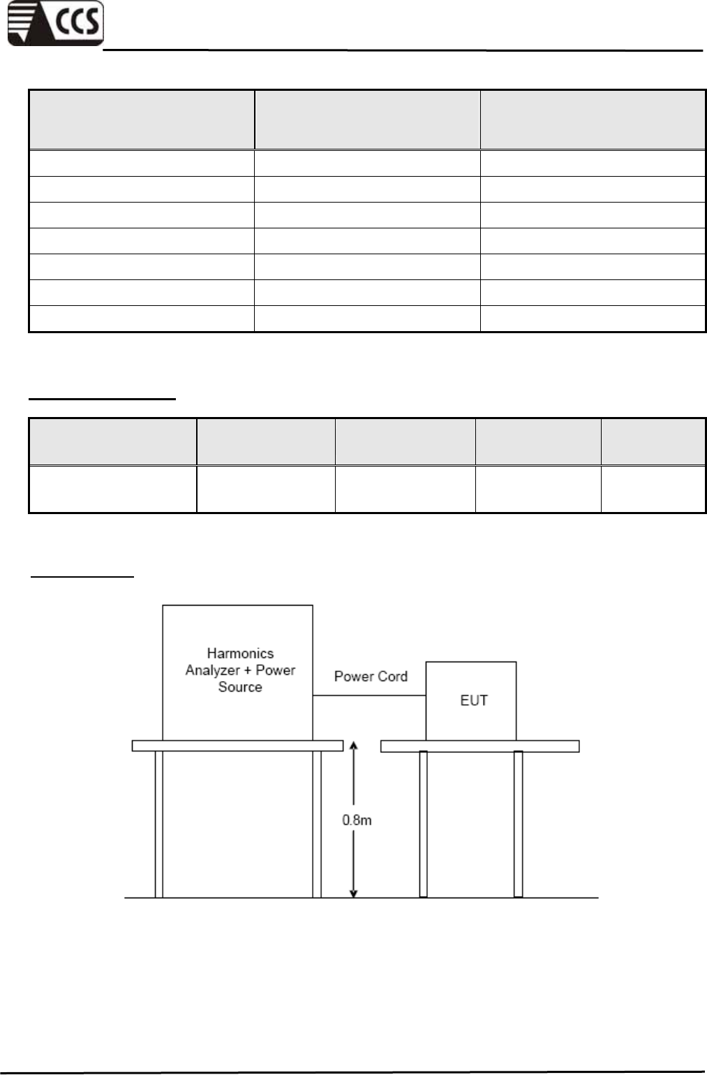
TEST SETUP

Compliance Certification Services Inc.
Report No.:91230301-E
Page 25 of 57
This report shall not be reproduced except in full, without the written approval of Compliance Certification Services.
TEST SETUP
The basic test procedure was in accordance with EN 61000-3-2.
The EUT was placed on the top of a wooden table 0.8 meters above the ground and
operated to produce the maximum harmonic components under normal operating
conditions for each successive harmonic component in turn.
The classification of EUT is according to section 5 of EN 61000-3-2.
The EUT is classified as follows:
Class A: Balanced three-phase equipment, Household appliances excluding equipment as
Class D, Tools excluding portable tools, Dimmers for incandescent lamps, audio
equipment, equipment not specified in one of the three other classes.
Class B: Portable tools; Arc welding equipment which is not professional equipment.
Class C: Lighting equipment.
Class D: Equipment having a specified power less than or equal to 600 W of the following
types: Personal computers and personal computer monitors and television receivers.
The correspondent test program of test instrument to measure the current harmonics
emanated from EUT is chosen. The measure time shall be not less than the time
necessary for the EUT to be exercised.
Compliance Certification Services Inc.
Report No.:91230301-E
Page 26 of 57
This report shall not be reproduced except in full, without the written approval of Compliance Certification Services.
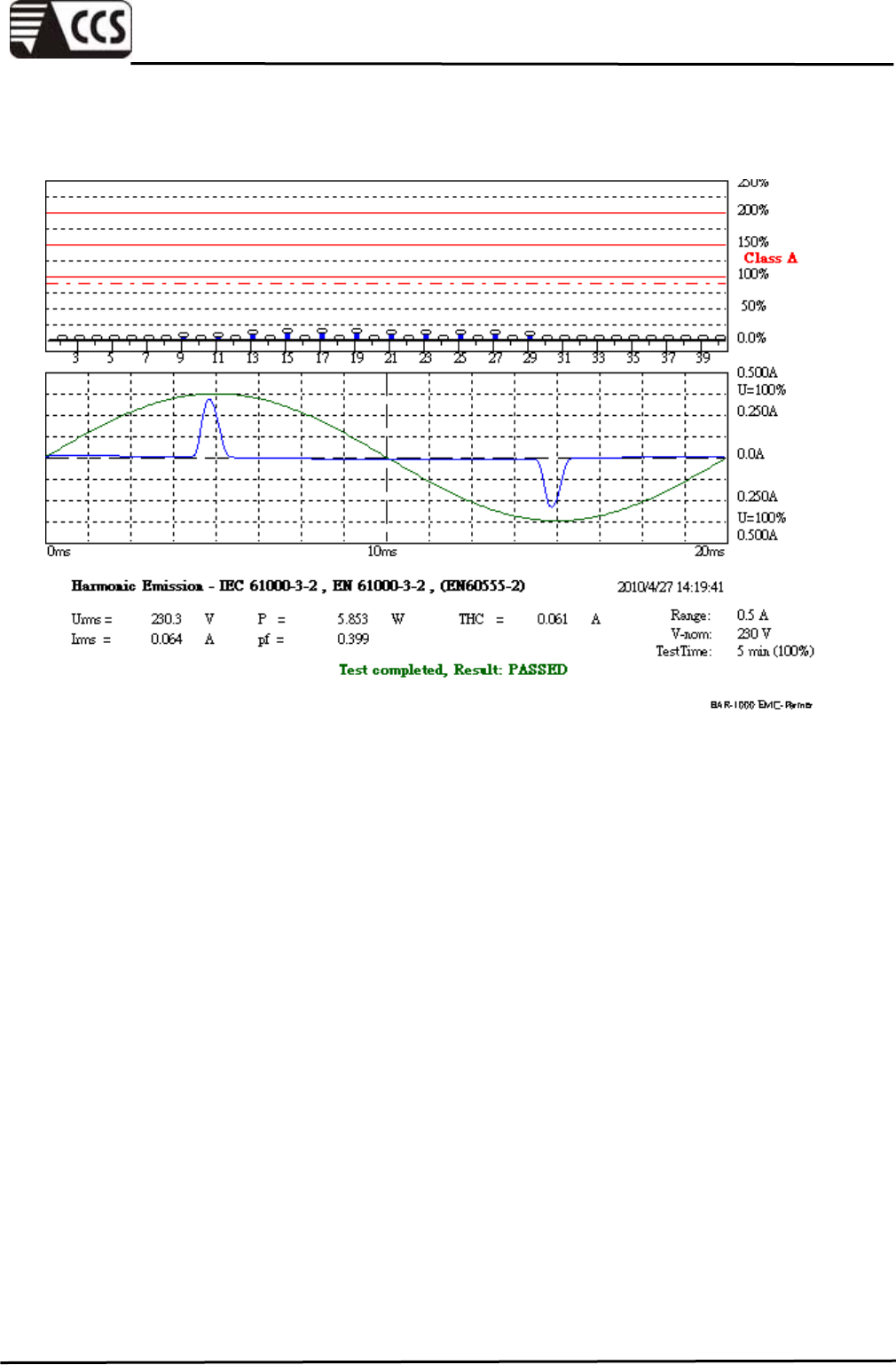
TEST RESULTS
Ambient Temperature 26 °C Test By Vic Lin
Relative Humidity 52 % Test Date 2010/04/27
Atmospheric Pressure 1005.6 mbar
Urms = 230.3V Freq = 49.987 Range: 0.5 A
Irms = 0.064A Ipk = 0.355A cf = 5.567
P = 5.853W S = 14.68VA pf = 0.399
THDi = 91.6 % THDu = 0.10 % Class A
Test - Time : 5min ( 100 %)
Test completed, Result: PASSED
Order Freq. Iavg Iavg%L Imax Imax%L Limit Status
[Hz] [A] [%] [A] [%] [A]
1 50 0.0261 0.0271
2 100 0.0000 0.0000 0.0024 0.2204 1.0800
3 150 0.0226 0.9844 0.0231 1.0031 2.3000
4 200 0.0000 0.0000 0.0023 0.5465 0.4300
5 250 0.0222 1.9468 0.0226 1.9836 1.1400
6 300 0.0000 0.0000 0.0023 0.7731 0.3000
7 350 0.0215 2.7872 0.0219 2.8377 0.7700
8 400 0.0000 0.0000 0.0023 0.9819 0.2300
9 450 0.0205 5.1231 0.0208 5.2109 0.4000
10 500 0.0000 0.0000 0.0022 1.1776 0.1840
11 550 0.0193 5.8459 0.0196 5.9463 0.3300
12 600 0.0000 0.0000 0.0020 1.3335 0.1533
13 650 0.0179 8.5404 0.0182 8.6757 0.2100
14 700 0.0000 0.0000 0.0020 1.4861 0.1314
15 750 0.0164 10.940 0.0167 11.108 0.1500
16 800 0.0000 0.0000 0.0018 1.5922 0.1150
17 850 0.0148 11.175 0.0150 11.321 0.1324
18 900 0.0000 0.0000 0.0017 1.6718 0.1022
19 950 0.0131 11.087 0.0133 11.210 0.1184
20 1000 0.0000 0.0000 0.0016 1.7249 0.0920
21 1050 0.0114 10.660 0.0115 10.767 0.1071
22 1100 0.0000 0.0000 0.0015 1.7879 0.0836
23 1150 0.0098 9.9682 0.0098 10.045 0.0978
24 1200 0.0000 0.0000 0.0014 1.7912 0.0767
25 1250 0.0081 9.0262 0.0082 9.0875 0.0900
26 1300 0.0000 0.0000 0.0013 1.8112 0.0708
27 1350 0.0066 7.9261 0.0067 7.9834 0.0833
28 1400 0.0000 0.0000 0.0012 1.7647 0.0657
29 1450 0.0052 6.6810 0.0053 6.8441 0.0776
30 1500 0.0000 0.0000 0.0011 1.7912 0.0613
31 1550 0.0000 0.0000 0.0042 5.7183 0.0726
32 1600 0.0000 0.0000 0.0010 1.7514 0.0575
33 1650 0.0000 0.0000 0.0031 4.6102 0.0682
34 1700 0.0000 0.0000 0.0009 1.7481 0.0541
35 1750 0.0000 0.0000 0.0023 3.5129 0.0643
36 1800 0.0000 0.0000 0.0009 1.7315 0.0511
37 1850 0.0000 0.0000 0.0016 2.5594 0.0608
38 1900 0.0000 0.0000 0.0008 1.7017 0.0484
39 1950 0.0000 0.0000 0.0013 2.2746 0.0577
40 2000 0.0000 0.0000 0.0008 1.6586 0.0460
Compliance Certification Services Inc.
Report No.:91230301-E
Page 27 of 57
This report shall not be reproduced except in full, without the written approval of Compliance Certification Services.

Compliance Certification Services Inc.
Report No.:91230301-E
Page 28 of 57
This report shall not be reproduced except in full, without the written approval of Compliance Certification Services.
7.4 VOLTAGE FLUCTUATION AND FLICKER
LIMITS
Test item Limit Remark
Pst 1.0 Pst means short-term flicker indicator.
Plt 0.65 Plt means long-term flicker indicator.
Tdt (ms) 500 Tdt means maximum time that dt exceeds 3.3 %.
dmax (%) 4% dmax means maximum relative voltage change.
dc (%) 3.3% dc means relative steady-state voltage change
TEST EQUIPMENT
Name of Equipment Manufacturer Model Serial Number Calibration
Due
Harmonics & Flicker
Test System EMC PARTNER HARMONIC-1000 071 01/17/2011
Remark: Each piece of equipment is scheduled for calibration once a year.
TEST SETUP
TEST SETUP
The basic test procedure was in accordance with EN 61000-3-3.
The EUT was placed on the top of a wooden table 0.8 meters above the ground and
operated to produce the most unfavorable sequence of voltage changes under normal
operating conditions.
During the flick measurement, the measure time shall include that part of whole operation
cycle in which the EUT produce the most unfavorable sequence of voltage changes. The
observation period for short-term flicker indicator is 10 minutes and the observation period
for long-term flicker indicator is 2 hours.
Compliance Certification Services Inc.
Report No.:91230301-E
Page 29 of 57
This report shall not be reproduced except in full, without the written approval of Compliance Certification Services.
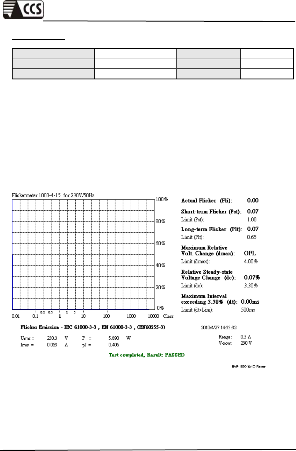
TEST RESULTS
Ambient Temperature 26 °C Test By Vic Lin
Relative Humidity 52 % Test Date 2010/04/27
Atmospheric Pressure 1005.6 mbar
Urms = 230.3V Freq = 50.000 Range: 0.5 A
Irms = 0.063A Ipk = 0.339A cf = 5.384
P = 5.890W S = 14.51VA pf = 0.406
Test - Time : 1 x 10min = 10min ( 100 %)
Limits : Plt : 0.65 Pst : 1.00
dmax : 4.00 % dc : 3.30 %
dtLim: 3.30 % dt>Lim: 500ms
Test completed, Result: PASSED
Compliance Certification Services Inc.
Report No.:91230301-E
Page 30 of 57
This report shall not be reproduced except in full, without the written approval of Compliance Certification Services.
8. IMMUNITY TEST
PERFORMANCE CRITERIA DESCRIPTION
Criterion A
The apparatus shell continues to operate as intended without operator
intervention. No degradation of performance or loss of function is
allowed below a performance level specified by the manufacturer,
when the apparatus is used as intended. The performance level may
be replaced by a permissible loss of performance. If the manufacturer
does not specify the minimum performance level or the permissible
performance loss, then either of these may be derived from the product
description and documentation, and by what the user may reasonably
expect from the equipment if used as intended.
Criterion B
After test, the apparatus shell continues to operate as intended without
operator intervention. No degradation of performance or loss of
function is allowed, after the application of the phenomenon below a
performance level specified by the manufacturer, when the apparatus
is used as intended. The performance level may be replaced by a
permissible loss of performance.
During the test, degradation of performance is however allowed.
However, no change of operating state if stored data is allowed to
persist after the test. If the manufacturer does not specify the minimum
performance level or the permissible performance loss, then either of
these may be derived from the product description and documentation,
and by what the user may reasonably expect from the equipment if
used as intended.
Criterion C
Temporary loss of function is allowed, provided the functions is
self-recoverable or can be restored by the operation of controls by the
user in accordance with the manufacturer instructions.
Functions, and/or information stored in non-volatile memory, or
protected by a battery backup, shall not be lost.

Compliance Certification Services Inc.
Report No.:91230301-E
Page 31 of 57
This report shall not be reproduced except in full, without the written approval of Compliance Certification Services.
8.1 ELECTROSTATIC DISCHARGE (ESD)
TEST SPECIFICATION
Product Standard EN 55024:1998 + A1:2001 + A2:2003
Basic Standard IEC 61000-4-2:1995 + A1:1998 + A2:2000
Discharge Impedance 330 ohm / 150 pF
Discharge Voltage Air Discharge: 2, 4, 8 kV (Direct)
Contact Discharge: 2, 4 kV (Direct/Indirect)
Polarity Positive & Negative
Number of Discharge
Air Discharge: min. 10 times at single test point for each
negative and positive polarity
Contact Discharge: min. 200 times in total
Discharge Mode Single Discharge
1 second minimum
TEST EQUIPMENT
Name of Equipment Manufacturer Model Serial Number Calibration
Due
Electrostatic
Discharge Simulator NoiseKen ESS-2000 0189C01569 09/17/2010
Remark: Each piece of equipment is scheduled for calibration once a year.
TEST SETUP
Compliance Certification Services Inc.
Report No.:91230301-E
Page 32 of 57
This report shall not be reproduced except in full, without the written approval of Compliance Certification Services.
TEST SETUP
The basic test procedure was in accordance with IEC 61000-4-2.
The EUT was located 0.1 m minimum from all side of the HCP (dimensions 1.6m x 0.8m).
The support units were located another table 30 cm away from the EUT, but direct support
unit was/were located at same location as EUT on the HCP and keep at a distance of 10
cm with EUT.
The time interval between two successive single discharges was at least 1 second.
Contact discharges were applied to the non-insulating coating, with the pointed tip of the
generator penetrating the coating and contacting the conducting substrate.
Air discharges were applied with the round discharge tip of the discharge electrode
approaching the EUT as fast as possible (without causing mechanical damage) to touch
the EUT. After each discharge, the ESD generator was removed from the EUT and
re-triggered for a new single discharge. The test was repeated until all discharges were
complete.
At least ten single discharges (in the most sensitive polarity) were applied at the front
edge of each HCP opposite the center point of each unit of the EUT and 0.1 meters from
the front of the EUT. The long axis of the discharge electrode was in the plane of the HCP
and perpendicular to its front edge during the discharge.
At least ten single discharges (in the most sensitive polarity) were applied to the center of
one vertical edge of the Vertical Coupling Plane (VCP) in sufficiently different positions
that the four faces of the EUT were completely illuminated. The VCP (dimensions 0.5m x
0.5m) was placed vertically to and 0.1 meters from the EUT.
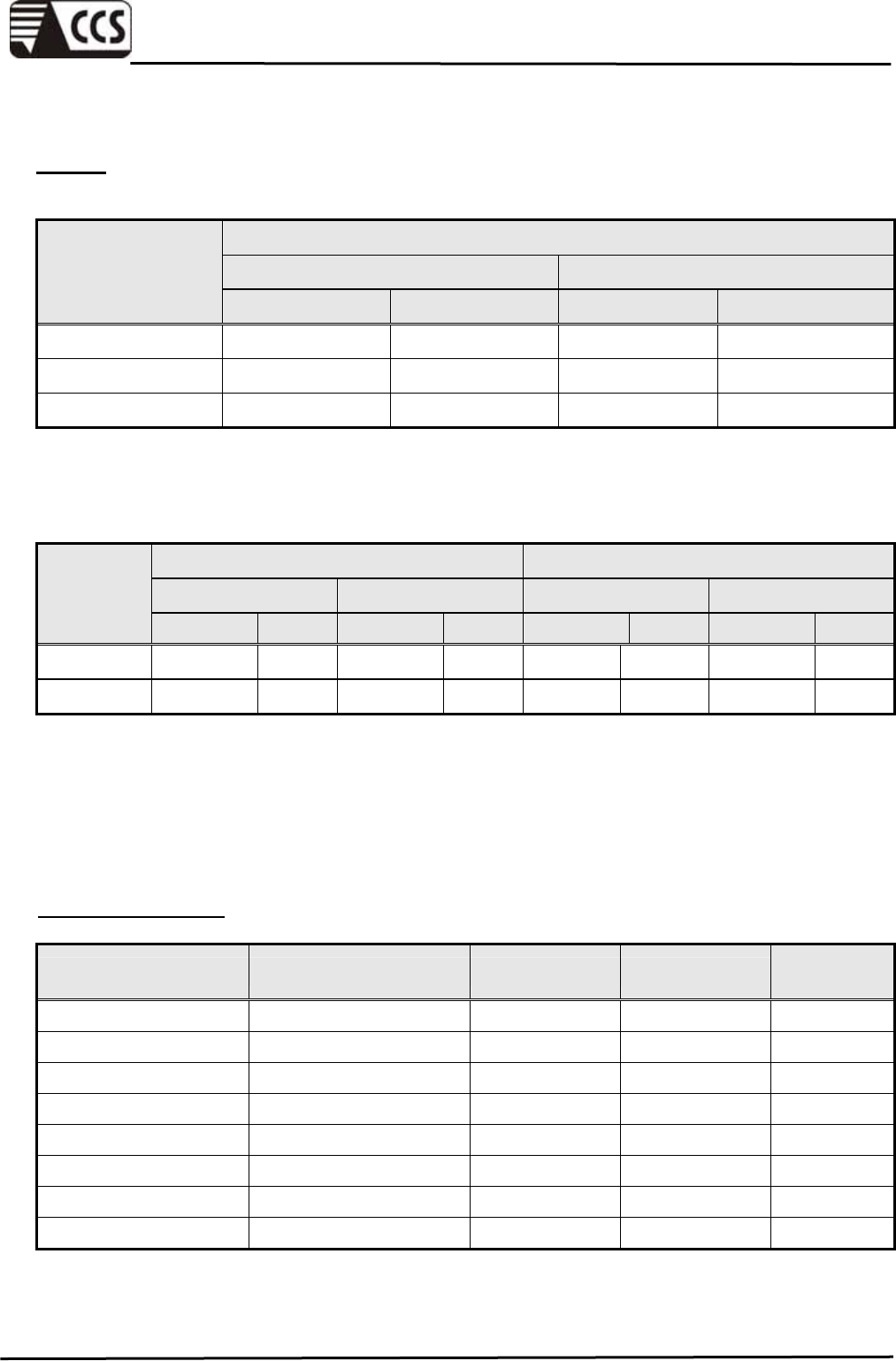
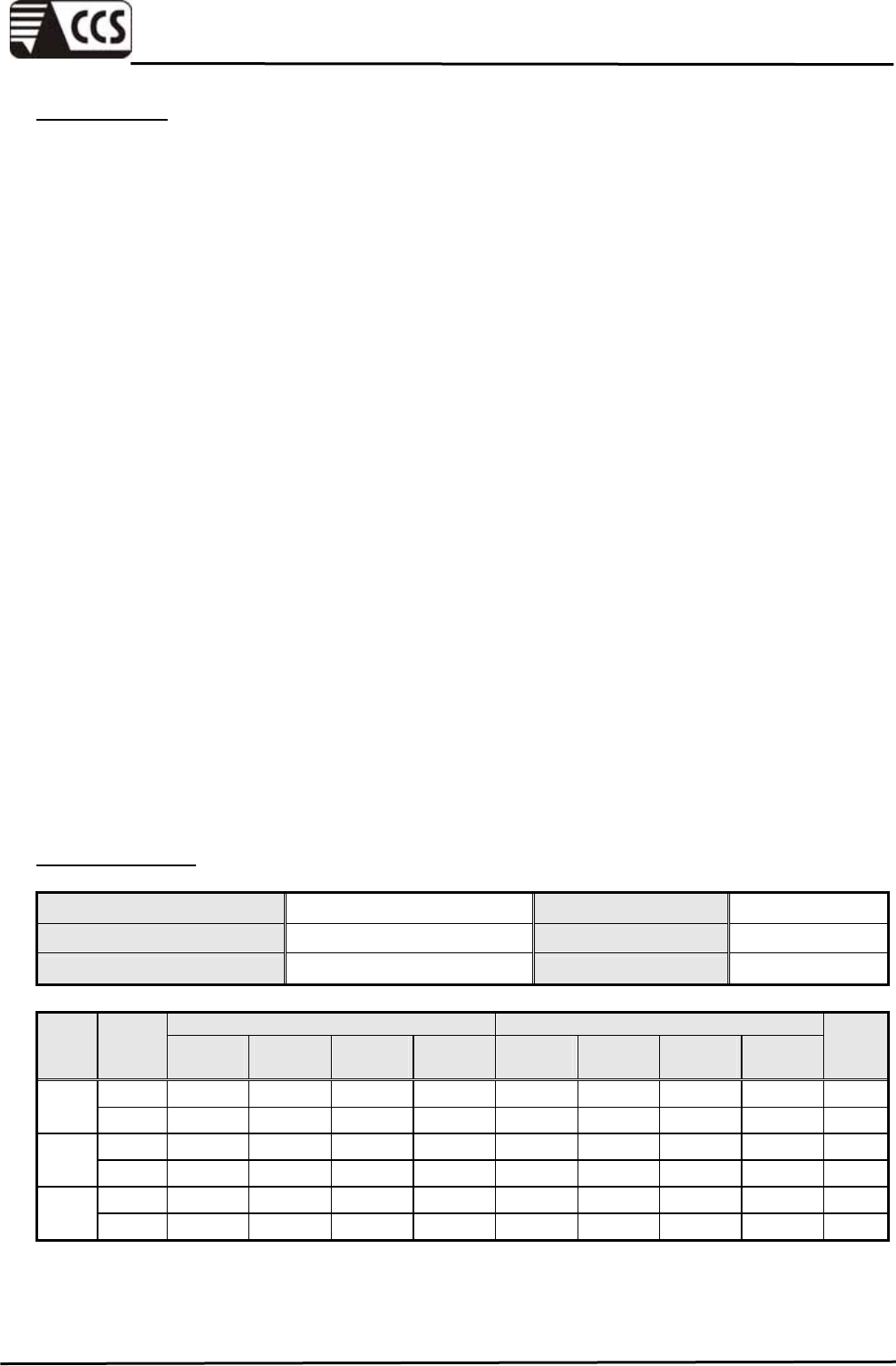
TEST RESULTS
Ambient Temperature 26 °C Test By Eason Chou
Relative Humidity 52 % Test Date 2010/04/28
Atmospheric Pressure 1005.6 mbar
Required Criterion Performance Criterion
Test
Level Polarity Air
discharge
Contact
discharge
HCP
discharge
VCP
discharge
Air
discharge
Contact
discharge
HCP
discharge
VCP
discharge
Result
+ B B B B B B A A PASS
2 kV - B B B B B B A A PASS
+ B B B B B B A A PASS
4 kV - B B B B B B A A PASS
+ B NR NR NR B NR NR NR PASS
8 kV - B NR NR NR B NR NR NR PASS
Remark: NR means there is no requirement.
Compliance Certification Services Inc.
Report No.:91230301-E
Page 33 of 57
This report shall not be reproduced except in full, without the written approval of Compliance Certification Services.
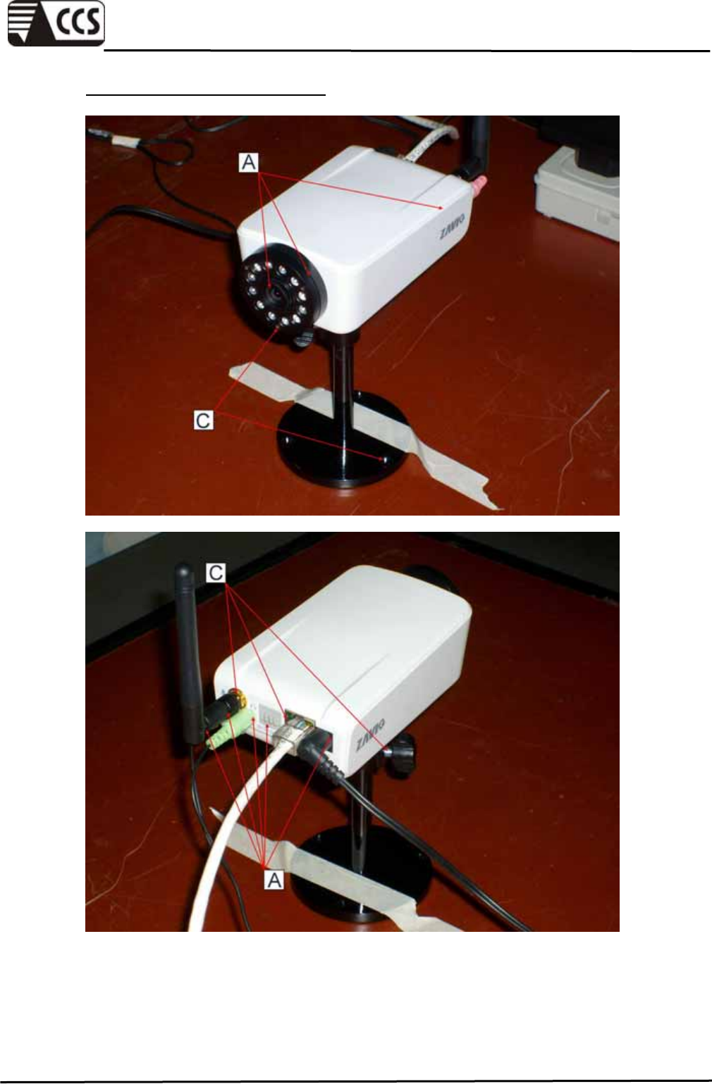
THE TESTED POINTS OF EUT
※ A:Air Discharge, C:Contact Discharge
Compliance Certification Services Inc.
Report No.:91230301-E
Page 34 of 57
This report shall not be reproduced except in full, without the written approval of Compliance Certification Services.
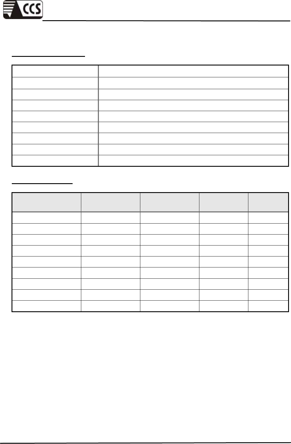
8.2 RF ELECTROMAGNETIC FIELD (RS)
TEST SPECIFICATION
Product Standard EN 55024:1998 + A1:2001 + A2:2003
Basic Standard IEC 61000-4-3:2006
Frequency Range 80 MHz ~1000 MHz
Field Strength 3 V/m
Modulation 1kHz Sine Wave, 80%, AM Modulation
Frequency Step 1 % of preceding frequency value
Polarity of Antenna Horizontal and Vertical
Test Distance 3 m
Antenna Height 1.5m
TEST EQUIPMENT
Name of Equipment Manufacturer Model Serial Number Calibration
Due
S.G. Agilent 8648C 4108A05772 11/05/2010
Power Meter R&S NRVD 837794/029 08/11/2010
Power Sensor R&S URV5-Z2 835640/015 08/11/2010
Power Sensor R&S URV5-Z2 835640/016 08/11/2010
Power Amplifier ar 150W1000 300300 N.C.R
Power Amplifier ar 60S1G3M3 0328274 N.C.R
Bilog Antenna SCHAFFNER CBL 6140A 1221 N.C.R
Horn Antenna EMCO 3115 00022257 12/20/2010
EM PROBE ar FL7006 0330722 02/17/2010
Remark: 1. Each piece of equipment is scheduled for calibration once a year.
2. N.C.R = No Calibration Request.
Compliance Certification Services Inc.
Report No.:91230301-E
Page 35 of 57
This report shall not be reproduced except in full, without the written approval of Compliance Certification Services.
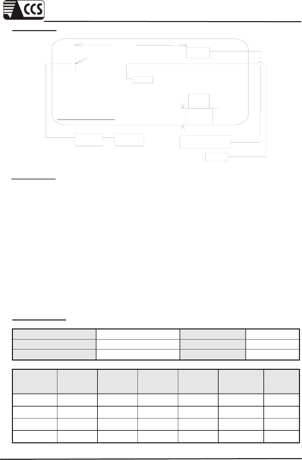
TEST SETUP
Probe
Camera
EUT
SYSTEM
Power
Amplifer Signal
Generator Data Processing
/Interface Unit
Monitor
ANECHOIC/SHIELDED ROOM 0.8m
3.0 m
ANTENNA
TEST SETUP
The test procedure was in accordance with IEC 61000-4-3.
The testing was performed in a fully anechoic chamber. The transmit antenna was located
at a distance of 3 meters from the EUT.
The frequency range is swept from 80 MHz to 1000 MHz, with the signal 80% amplitude
modulated with a 1kHz sine-wave. The rate of sweep did not exceed 1.5 x 10 -3 decade/s,
where the frequency range is swept incrementally, the step size was 1% of preceding
frequency value.
The dwell time at each frequency shall be not less than the time necessary for the EUT to
be able to respond.
The test was performed with the EUT exposed to both vertically and horizontally polarized
fields on each of the four sides.
TEST RESULTS
Ambient Temperature 28 °C Test By Louis Shen
Relative Humidity 46 % Test Date 2010/05/04
Atmospheric Pressure 998 mbar
Frequency
(MHz) Polarity Azimuth
(°)
Field
Strength
(V/m)
Required
Criterion Performance
Criterion Result
80 ~ 1000 V&H 0 3 A A PASS
80 ~ 1000 V&H 90 3 A A PASS
80 ~ 1000 V&H 180 3 A A PASS
80 ~ 1000 V&H 270 3 A A PASS
Remark : This test item is test by CCS- Linkuo.
Compliance Certification Services Inc.
Report No.:91230301-E
Page 36 of 57
This report shall not be reproduced except in full, without the written approval of Compliance Certification Services.
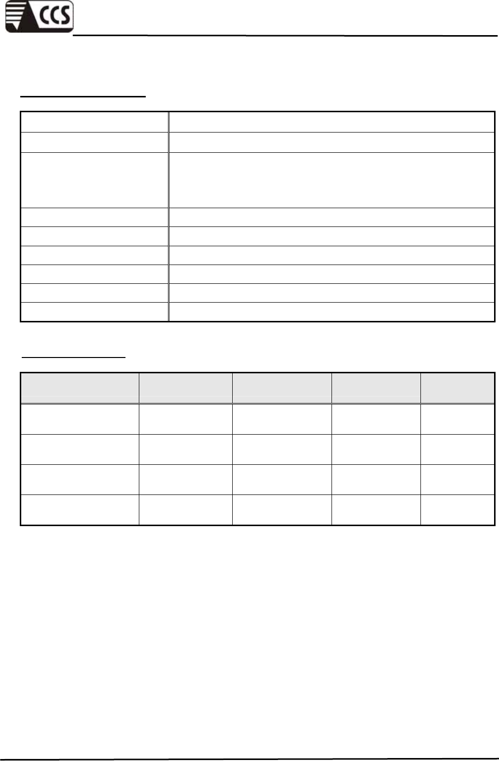
8.3 FAST TRANSIENTS COMMON MODE (EFT)
TEST SPECIFICATION
Product Standard EN 55024:1998 + A1:2001 + A2:2003
Basic Standard IEC 61000-4-4:2004
Test Voltage
AC Power Port: 1kV
DC Power Port: 0.5kV
Signal Ports and Telecommunication Ports: 0.5kV
Polarity Positive & Negative
Impulse Frequency 5 kHz
Impulse Wave-shape 5/50 ns
Burst Duration 15 ms
Burst Period 300 ms
Test Duration Not less than 1 min.
TEST EQUIPMENT
Name of Equipment Manufacturer Model Serial Number Calibration
Due
True-EFT Simulator
Module KeyTek E421 9306421 06/28/2010
Control Center KeyTek E-CLASS
Series-100 -------- N.C.R
Combined EFT/Surge
Coupler/Decoupler KeyTek E4552 -------- N.C.R
Capacitive Coupling
Clamp KeyTek CCL-4/S 9306414 N.C.R
Remark: 1. Each piece of equipment is scheduled for calibration once a year.
2.N.C.R = No Calibration Request.
Compliance Certification Services Inc.
Report No.:91230301-E
Page 37 of 57
This report shall not be reproduced except in full, without the written approval of Compliance Certification Services.
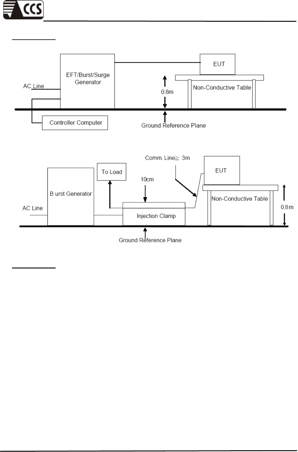
TEST SETUP
TEST SETUP
The test procedure was in accordance with IEC 61000-4-4.
The EUT is placed on a table that is 0.8 meter height. A ground reference plane is placed
on the table, and uses a 0.1 m insulation between the EUT and ground reference plane.
The minimum area of the ground reference plane is 1 m *1 m, and 0.65 mm thick min, and
projected beyond the EUT by at least 0.1 m on all sides.
Test on I/O and communication ports: The EFT/B interference signal is through coupling
clamp device couples to the signal and control lines of the EUT with burst noise.
Test on power supply ports: The EUT is connected to the power mains through a coupling
device that directly couples the EFT/B interference signal. The length of the signal and
power lines between the coupling device and the EUT is 0.5 m.
Fast transient are carried out during 1 min with a positive polarity and during 1 min with
negative polarity.
Compliance Certification Services Inc.
Report No.:91230301-E
Page 38 of 57
This report shall not be reproduced except in full, without the written approval of Compliance Certification Services.
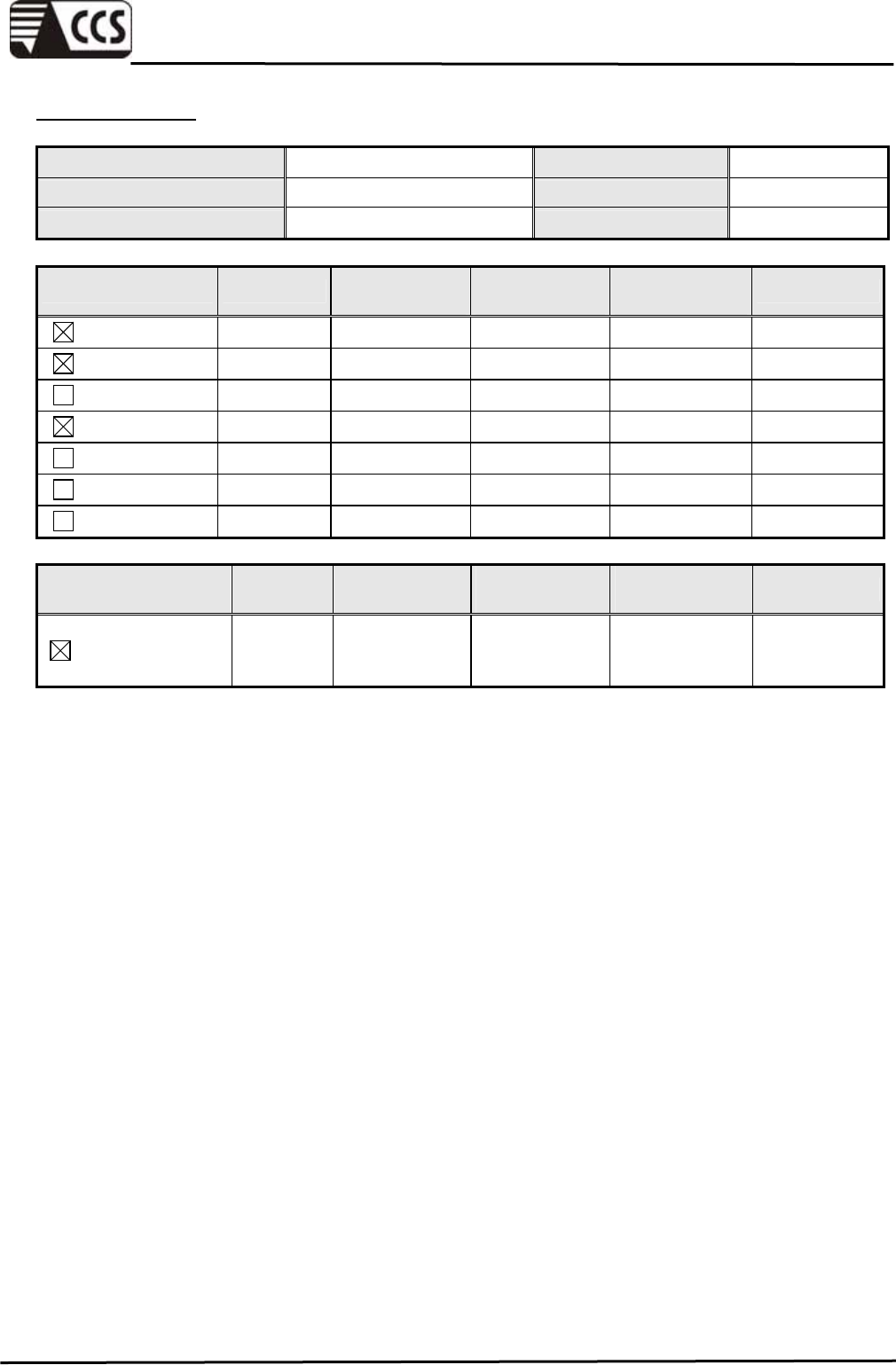
TEST RESULTS
Ambient Temperature 24.9 °C Test By Vic Lin
Relative Humidity 50 % Test Date 2010/04/27
Atmospheric Pressure 1006 mbar
Test Point Polarity Test Level
(kV) Required
Criterion Performance
Criterion Result
L +/- 1 B A PASS
N +/- 1 B A PASS
PE +/- 1 B NR NR
L+N +/- 1 B A PASS
L+PE +/- 1 B NR NR
N+PE +/- 1 B NR NR
L+N+PE +/- 1 B NR NR
Test Point Polarity Test Level
(kV) Required
Criterion Performance
Criterion Result
I/O and
communication
ports
+/- 0.5 B A PASS
Remark: NR means there is no requirement.
Compliance Certification Services Inc.
Report No.:91230301-E
Page 39 of 57
This report shall not be reproduced except in full, without the written approval of Compliance Certification Services.
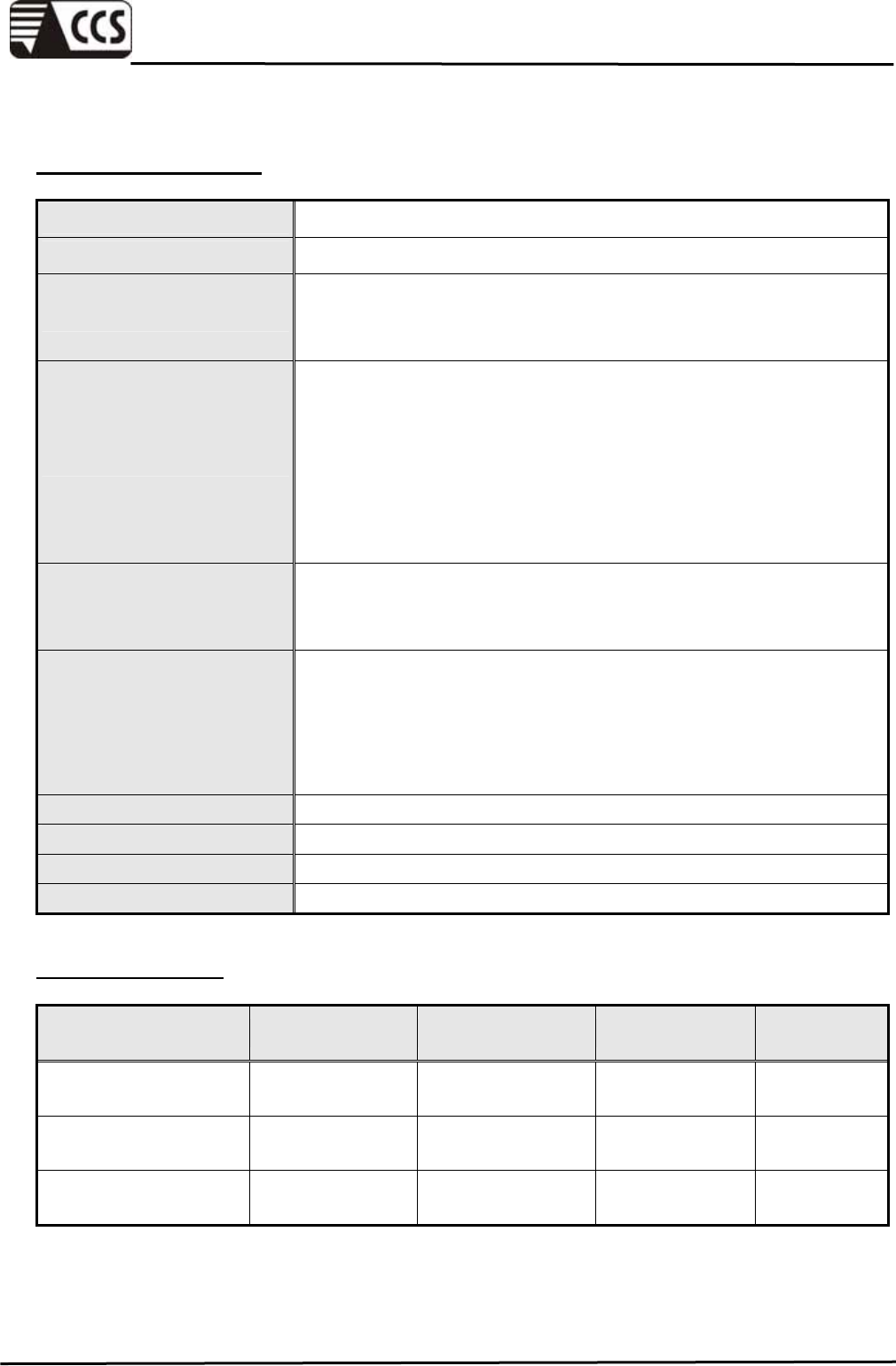
8.4 SURGE
TEST SPECIFICATION
Product Standard EN 55024:1998 + A1:2001 + A2:2003
Basic Standard IEC 61000-4-5:2005
Wave-Shape
Combination Wave
1.2/50 us Open Circuit Voltage
8/20 us Short Circuit Current
Test Voltage
AC Power Port
~ line to line: 1kV,
line to ground: 2kV
DC Power Port
~ line to ground: 0.5kV
Signal Ports and Telecommunication Ports
~ line to ground: 1kV
Surge Input/Output: AC Power Port: L-N / L-PE / N-PE
DC Power Port: L1-PE
Telecommunication Ports: Tip + Ring to ground
Generator Source
Impedance AC Power Port:
2 ohm between networks
12 ohm between network and ground
Telecommunication Ports:
42 ohm between network and ground
Polarity Positive/Negative
Phase Angle 0 / 90 / 180 / 270
Pulse Repetition Rate 1 time / min. (maximum)
Number of Tests 5 positive and 5 negative at selected points
TEST EQUIPMENT
Name of Equipment Manufacturer Model Serial Number Calibration
Due
Surge Simulator
Module KeyTek E510A 0206173 09/17/2010
Control Center KeyTek E-CLASS
Series-100 -------- N.C.R
Combined EFT/Surge
Coupler/Decoupler KeyTek E4552 -------- N.C.R
Remark: 1. Each piece of equipment is scheduled for calibration once a year.
2.N.C.R = No Calibration Request.
Compliance Certification Services Inc.
Report No.:91230301-E
Page 40 of 57
This report shall not be reproduced except in full, without the written approval of Compliance Certification Services.
TEST SETUP
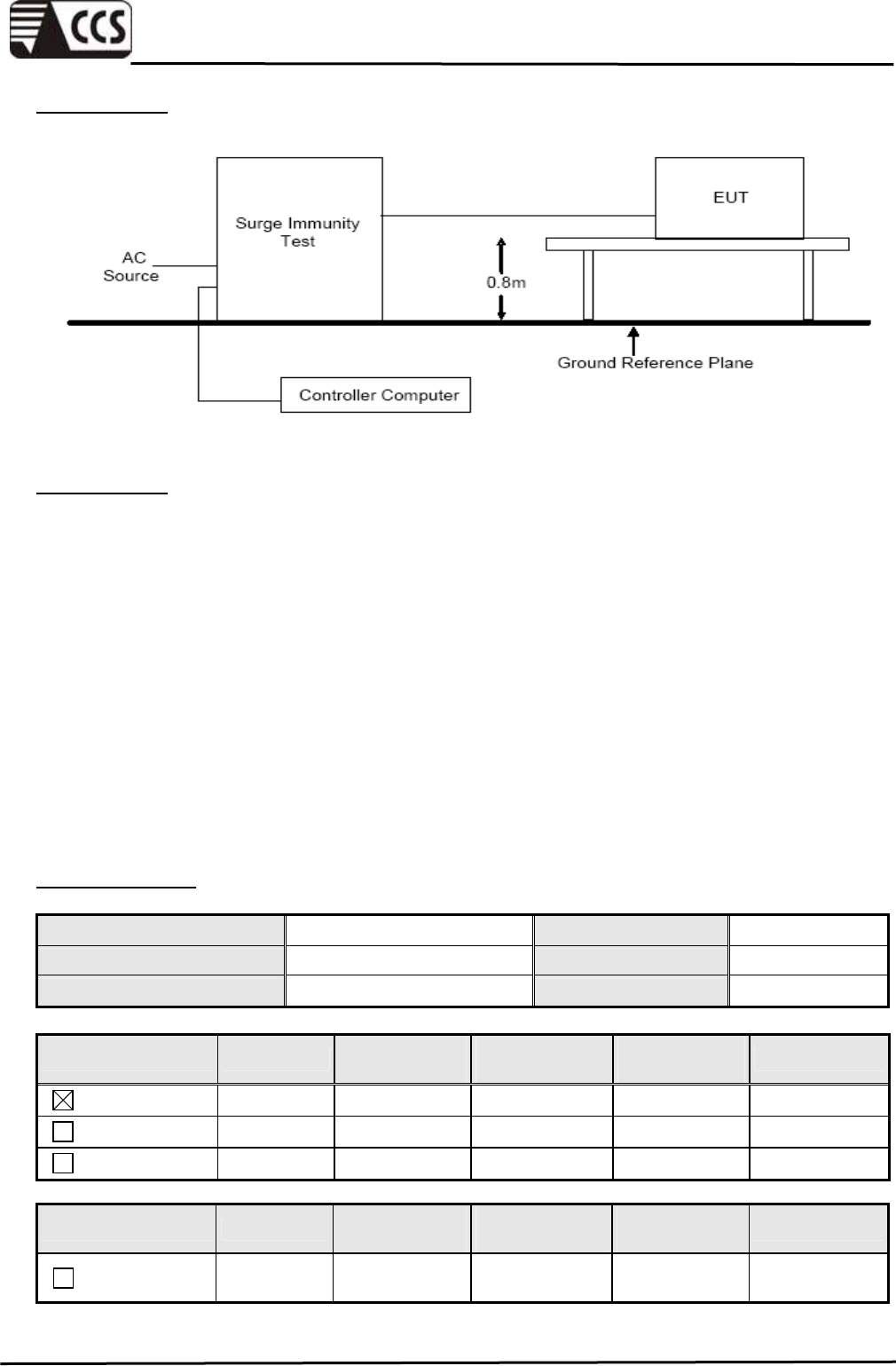
TEST SETUP
The test procedure was in accordance with IEC 61000-4-5.
The EUT and its load are placed on a table that is 0.8 meter above a ground reference
plane. The minimum area of the ground reference plane is 1 m *1 m, and 0.65 mm thick
min, and projected beyond the EUT by at least 0.1 m on all sides. The length of power
cord/interconnection line between the coupling device and the EUT shall be 2 m or less.
Test on Input AC Power ports:
The EUT is connected to the power mains through a coupling device that directly couples
the Surge interference signal.
The surge noise shall be applied synchronized to voltage phase at 0°, 90°, 180°, 270°
and the peak value of the a.c. voltage wave.
TEST RESULTS
Ambient Temperature 24.9 °C Test By Vic Lin
Relative Humidity 50 % Test Date 2010/04/27
Atmospheric Pressure 1006 mbar
Test Point Polarity Test Level
(kV) Required
Criterion Performance
Criterion Result
L-N +/- 1 B A PASS
L-PE +/- 2 B NR NR
N-PE +/- 2 B NR NR
Test Point Polarity Test Level
(kV) Required
Criterion Performance
Criterion Result
Telecom
Ports +/- 1 B NR NR
Remark: NR means there is no requirement.
Compliance Certification Services Inc.
Report No.:91230301-E
Page 41 of 57
This report shall not be reproduced except in full, without the written approval of Compliance Certification Services.
8.5 CONDUCTED RADIO FREQUENCY DISTURBANCES (CS)
TEST SPECIFICATION
Product Standard EN 55024:1998 + A1:2001 + A2:2003
Basic Standard IEC 61000-4-6:2003 + A1:2004 + A2:2006
Frequency Range 0.15 MHz ~ 80 MHz
Voltage Level 3 Vrms
Modulation 1kHz Sine Wave, 80%, AM Modulation
Frequency Step 1 % of preceding frequency value
Dwell Time 3 seconds
Coupled cable Power Mains, Unshielded
Coupling device CDN-M2 (2 wires) / CDN-M3 (3 wires)
CDN-T2/CDN-T4/EM Clamp (signal and control lines)
TEST EQUIPMENT
Name of Equipment Manufacturer Model Serial Number Calibration
Due
Emv-Mess-System FRANKONIA CIT-10/75 102D3226 10/12/2010
Coupling and
Decoupling Network SCHAFFNER M225 16500 01/03/2011
Coupling and
Decoupling Network SCHAFFNER M325 17457 01/03/2011
EM Clamp SCHAFFNER KEMZ 801 19239 05/13/2010
Remark: 1. Each piece of equipment is scheduled for calibration once a year.
2.N.C.R = No Calibration Request.
TEST SETUP
Compliance Certification Services Inc.
Report No.:91230301-E
Page 42 of 57
This report shall not be reproduced except in full, without the written approval of Compliance Certification Services.
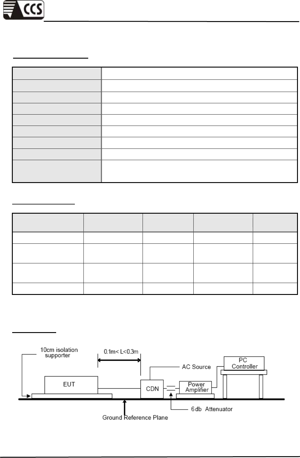
TEST SETUP
The test procedure was in accordance with IEC 61000-4-6.
The EUT is placed on an insulating support of 0.1 m height above a ground reference
plane. All cables exiting the EUT shall be supported at a height at least 30 mm above the
ground reference plane.
Test on signal ports and telecommunication ports:
The disturbance signal is through a coupling and decoupling networks (CDN) or
EM-clamp device couples to the signal and telecommunication lines of the EUT.
Test on DC and AC ports: The EUT is connected to the power mains through a coupling
and decoupling networks for power supply lines. And directly couples the disturbances
signal into EUT.
TEST RESULTS
Ambient Temperature 24.9 °C Test By Vic Lin
Relative Humidity 50 % Test Date 2010/04/27
Atmospheric Pressure 1006 mbar
Frequency
(MHz)
V
oltage
Level
(V)
Injection
Method Test port Required
Criterion Performance
Criterion Result
CDN-M2
AC Input
0.15 ~ 80 3
CDN-M3
DC Input A A PASS
Signal lines
0.15 ~ 80 3 EM Clamp
Control lines A A PASS
Compliance Certification Services Inc.
Report No.:91230301-E
Page 43 of 57
This report shall not be reproduced except in full, without the written approval of Compliance Certification Services.
8.6 POWER FREQUENCY MAGNETIC FIELDS (PFMF)
TEST SPECIFICATION
Product Standard EN 55024:1998 + A1:2001 + A2:2003
Basic Standard IEC 61000-4-8:1993 + A1:2000
Frequency Range 50/60Hz
Field Strength 1 A/m
Observation Time 1 minute
Inductance Coil Rectangular type, 1mx1m
TEST EQUIPMENT
Name of Equipment Manufacturer Model Serial Number Calibration
Due
Power Frequency
Magnetic Field
DANA
TORINO-ITALY
DAS-G60
DAS 1 S 1000 96DA6-101 11/04/2010
Remark: Each piece of equipment is scheduled for calibration once a year.
TEST SETUP
Compliance Certification Services Inc.
Report No.:91230301-E
Page 44 of 57
This report shall not be reproduced except in full, without the written approval of Compliance Certification Services.
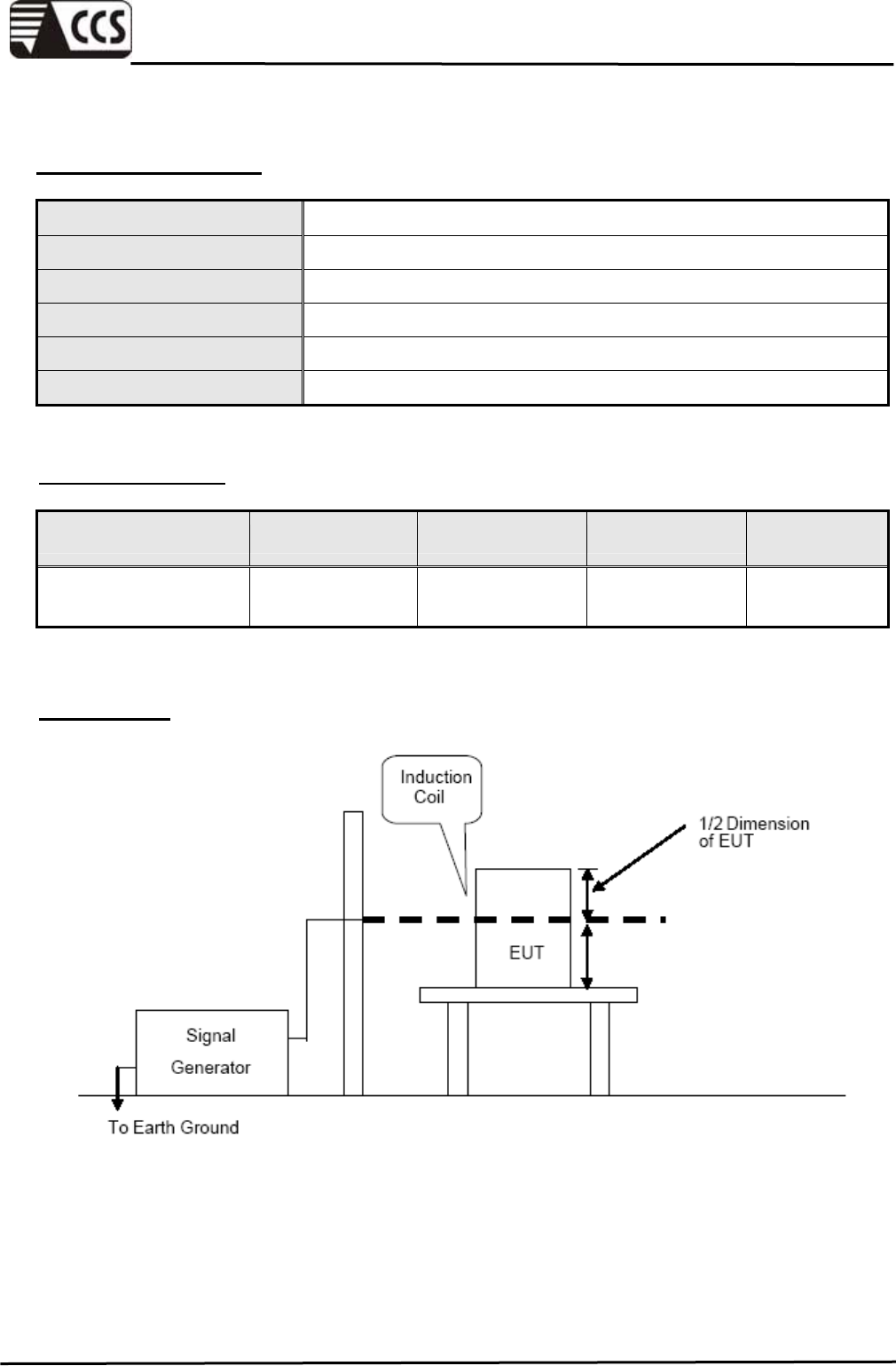
TEST SETUP
The test procedure was in accordance with IEC 61000-4-8.
The equipment was configured and connected to satisfy its functional requirements. It
shall be placed on the GRP with the interposition of a 0.1m-thick insulating support.
The cables supplied or recommended by the equipment manufacturer shall be used. 1
meter of all cables used shall be exposed to the magnetic field.
The equipment shall be subjected to the test magnetic field by using the induction coil of
standard dimension (1 m x 1 m). The induction coil shall then be rotated by 90 degrees in
order to expose the EUT to the test field with different orientations.
TEST RESULTS
Ambient Temperature 24.9 °C Test By Vic Lin
Relative Humidity 50 % Test Date 2010/04/27
Atmospheric Pressure 1006 mbar
Direction Field Strength
(A/m) Required
Criterion Performance
Criterion Results
X 1 A A Pass
Y 1 A A Pass
Z 1 A A Pass
Compliance Certification Services Inc.
Report No.:91230301-E
Page 45 of 57
This report shall not be reproduced except in full, without the written approval of Compliance Certification Services.
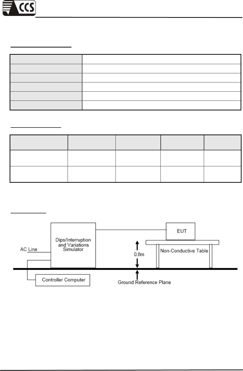
8.7 VOLTAGE DIPS & VOLTAGE INTERRUPTIONS (DIP)
TEST SPECIFICATION
Product Standard EN 55024:1998 + A1:2001 + A2:2003
Basic Standard IEC 61000-4-11:2004
Test duration time Minimum three test events in sequence
Interval between event Minimum 10 seconds
Angle 0~360 degree
Step 45 degree
TEST EQUIPMENT
Name of Equipment Manufacturer Model Serial Number Calibration
Due
Swell/Dip/Interrupt
Simulator KeyTek EP62 9308252 08/04/2010
Control Center KeyTek E-CLASS
Series-100 -------- N.C.R
Remark: 1. Each piece of equipment is scheduled for calibration once a year.
2.N.C.R = No Calibration Request.
TEST SETUP
Compliance Certification Services Inc.
Report No.:91230301-E
Page 46 of 57
This report shall not be reproduced except in full, without the written approval of Compliance Certification Services.
TEST SETUP
The test procedure was in accordance with IEC 61000-4-11.
The EUT and its load are placed on a table that is 0.8 meter above a ground reference
plane. The minimum area of the ground reference plane is 1 m *1 m, and 0.65 mm thick
min, and projected beyond the EUT by at least 0.1 m on all sides. The cables supplied or
recommended by the equipment manufacturer shall be used.
The EUT shall be tested for 30% voltage dip of supplied voltage and duration 10 periods,
for 100% voltage reduction of supplied voltage and duration 0.5 periods with a sequence
of three voltage reduction with intervals of 10 seconds.
Voltage phase shifting are shall occur at 0, 45, 90, 135, 180, 225, 270, 315 degrees.
TEST RESULTS
Ambient Temperature 24.9 °C Test By Vic Lin
Relative Humidity 50 % Test Date 2010/04/27
Atmospheric Pressure 1006 mbar
Voltage
Reduction
(%)
Test
Duration
(Periods)
Required
Criterion Performance
Criterion Results
>95 0.5 B A PASS
30 25 C A PASS
>95 250 C C PASS
Compliance Certification Services Inc.
Report No.:91230301-E
Page 47 of 57
This report shall not be reproduced except in full, without the written approval of Compliance Certification Services.
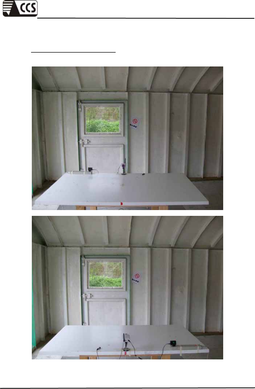
APPENDIX SETUP PHOTOS
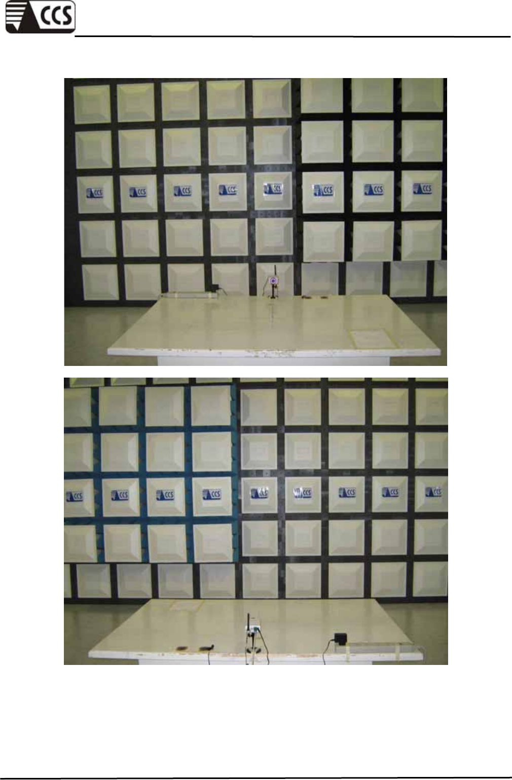
RADIATED EMISSION SETUP
Below 1 GHz
Compliance Certification Services Inc.
Report No.:91230301-E
Page 48 of 57
This report shall not be reproduced except in full, without the written approval of Compliance Certification Services.
Compliance Certification Services Inc.
Report No.:91230301-E
Page 49 of 57
This report shall not be reproduced except in full, without the written approval of Compliance Certification Services.
Above 1 GHz
Compliance Certification Services Inc.
Report No.:91230301-E
Page 50 of 57
This report shall not be reproduced except in full, without the written approval of Compliance Certification Services.
Compliance Certification Services Inc.
Report No.:91230301-E
Page 51 of 57
This report shall not be reproduced except in full, without the written approval of Compliance Certification Services.
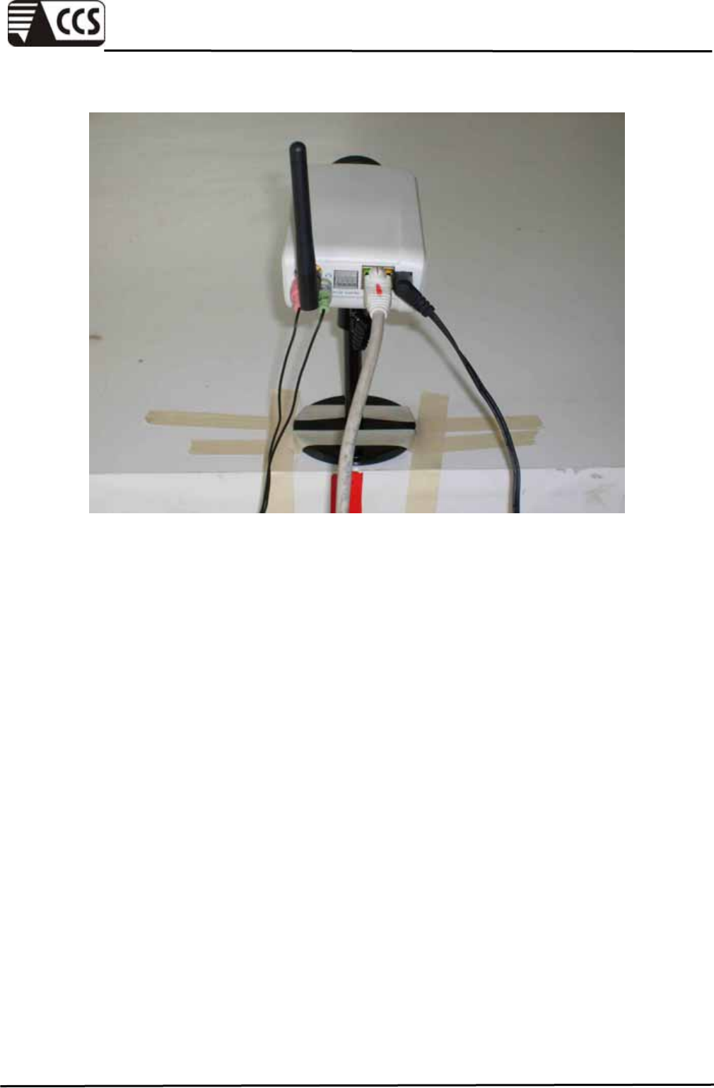
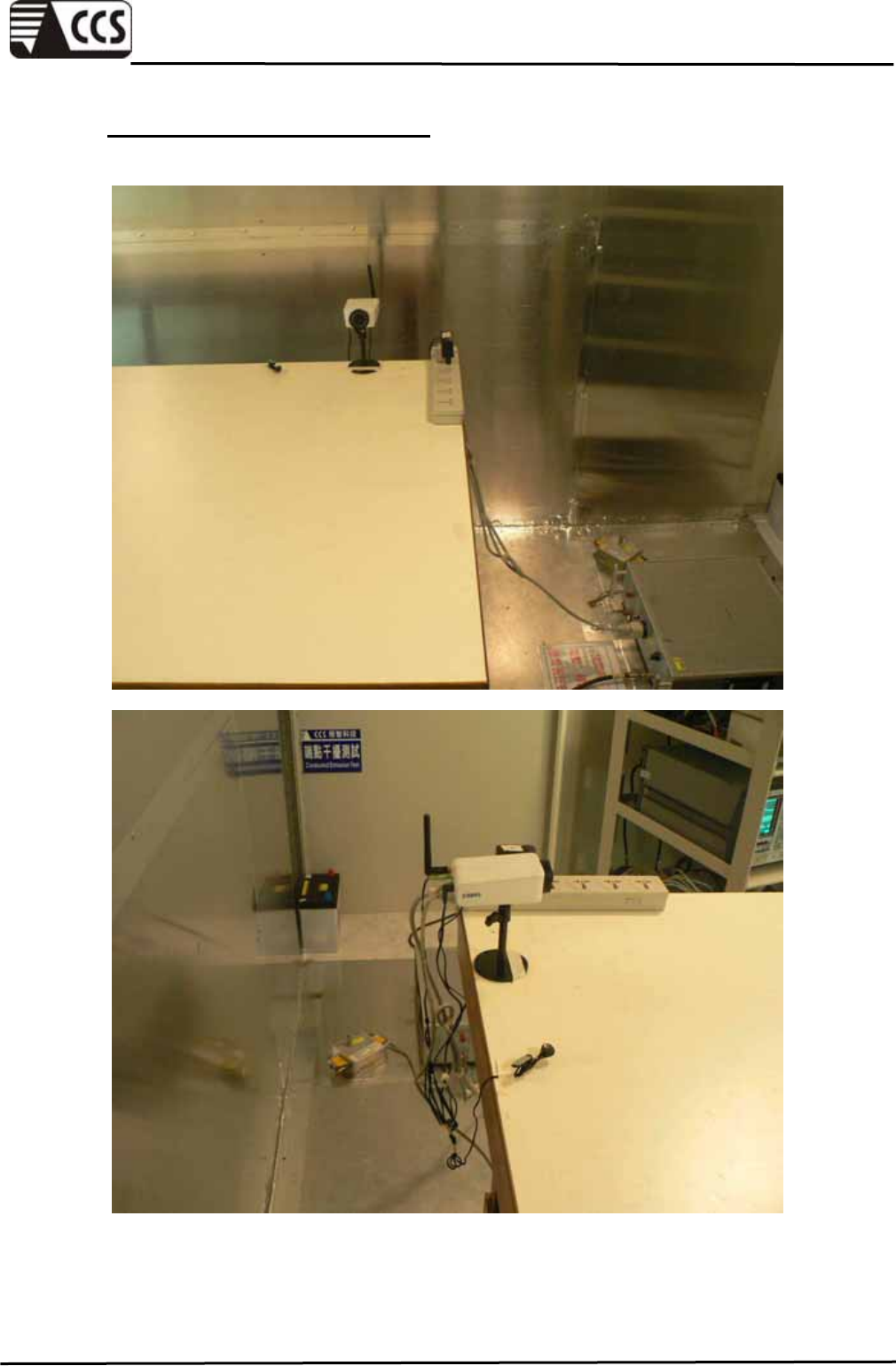
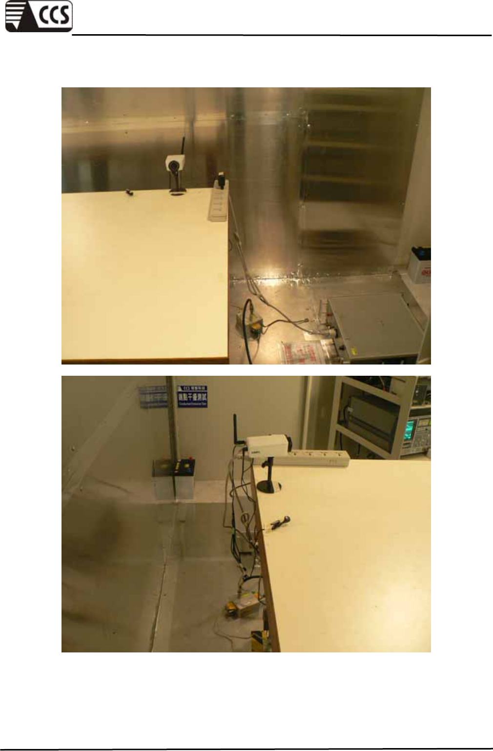
CONDUCTED EMISSION SETUP
Mains Ports
Compliance Certification Services Inc.
Report No.:91230301-E
Page 52 of 57
This report shall not be reproduced except in full, without the written approval of Compliance Certification Services.
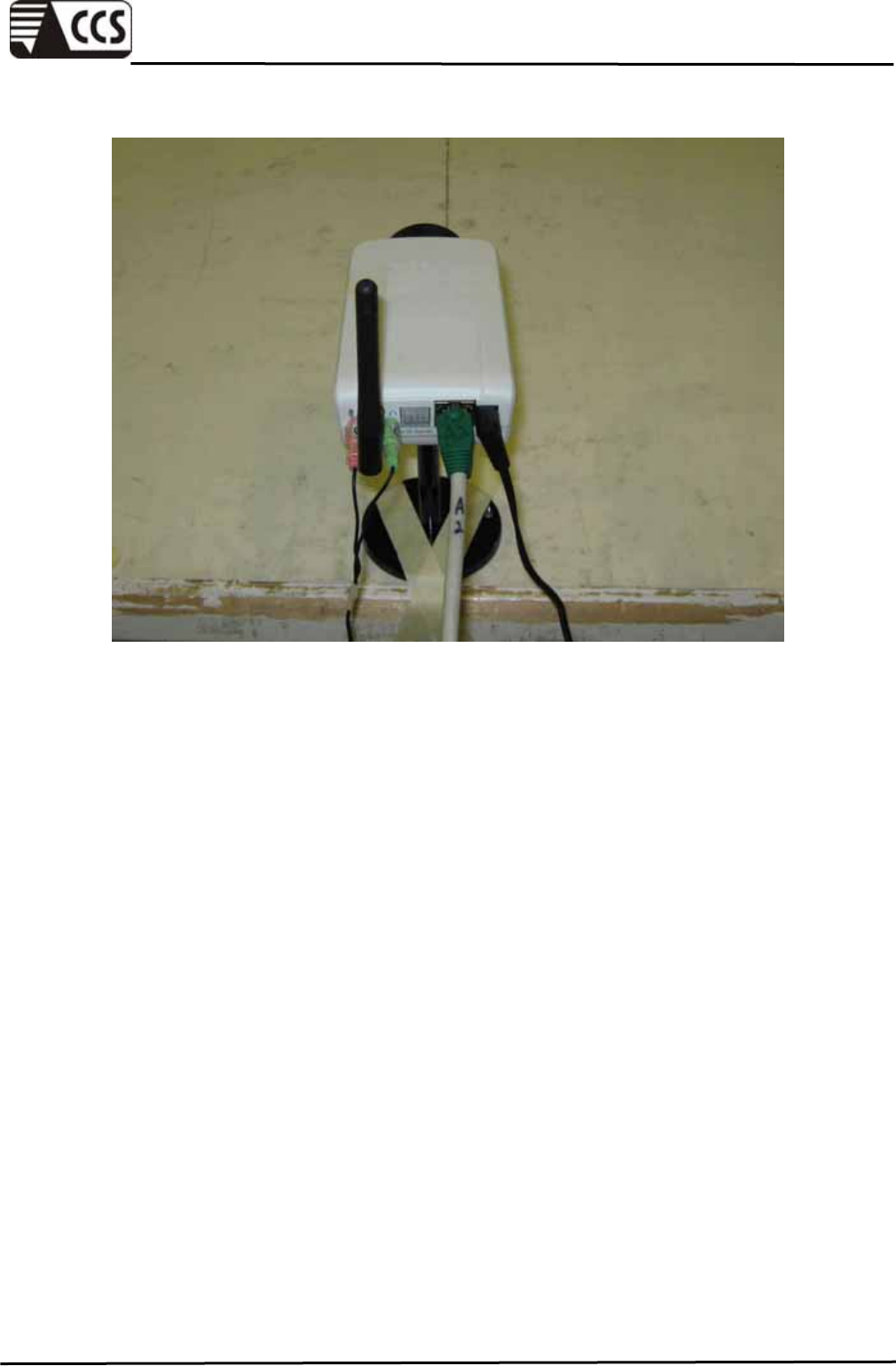
Telecommunication Ports
Compliance Certification Services Inc.
Report No.:91230301-E
Page 53 of 57
This report shall not be reproduced except in full, without the written approval of Compliance Certification Services.
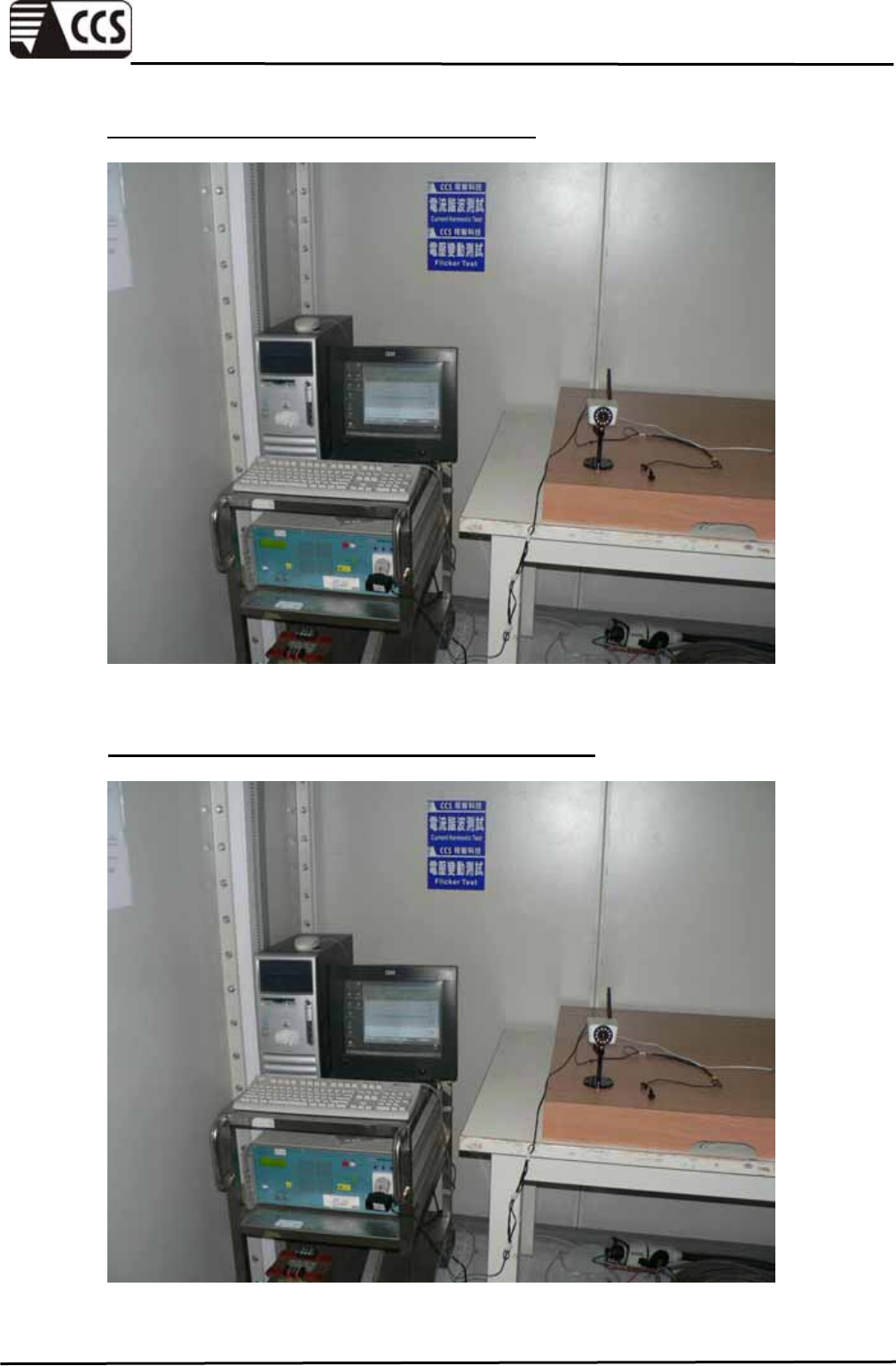
HARMONIC CURRENT EMISSIONS SETUP
VOLTAGE FLUCTUATION AND FLICKER SETUP
Compliance Certification Services Inc.
Report No.:91230301-E
Page 54 of 57
This report shall not be reproduced except in full, without the written approval of Compliance Certification Services.
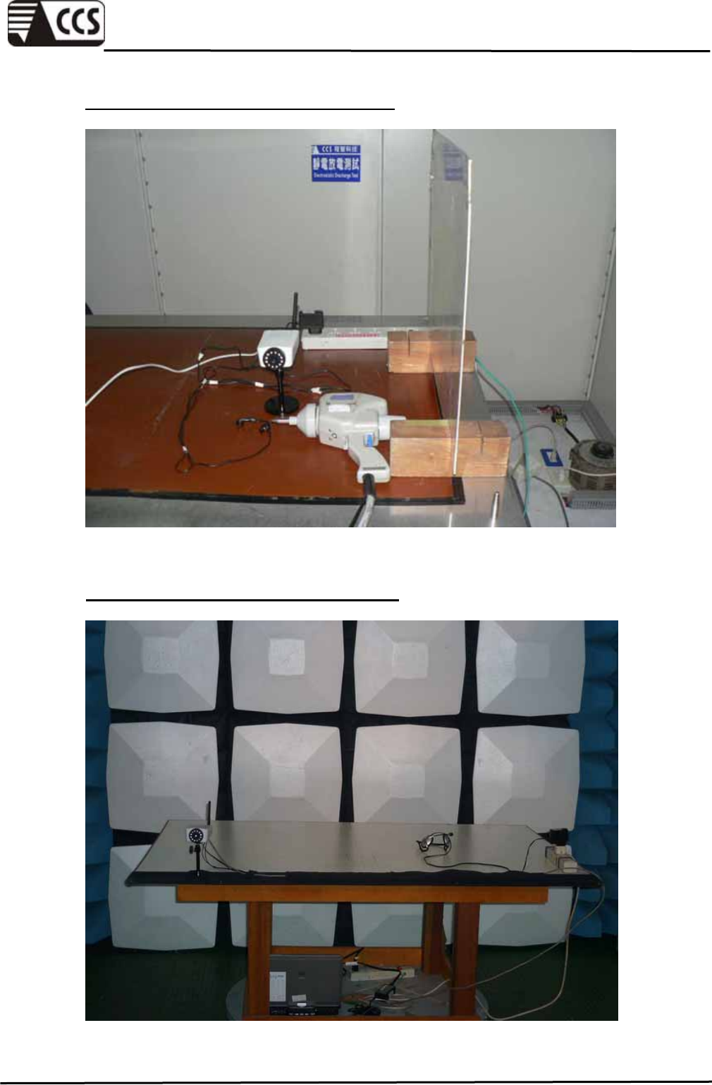
ELECTROSTATIC DISCHARGE SETUP
RF ELECTROMAGNETIC FIELD SETUP
Compliance Certification Services Inc.
Report No.:91230301-E
Page 55 of 57
This report shall not be reproduced except in full, without the written approval of Compliance Certification Services.
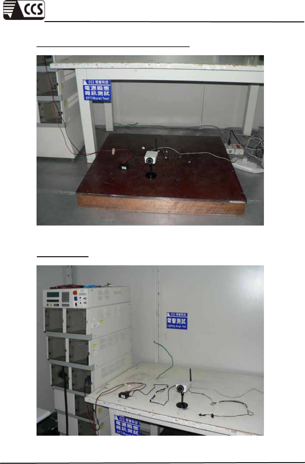
FAST TRANSIENTS COMMON MODE SETUP
SURGE SETUP
Compliance Certification Services Inc.
Report No.:91230301-E
Page 56 of 57
This report shall not be reproduced except in full, without the written approval of Compliance Certification Services.
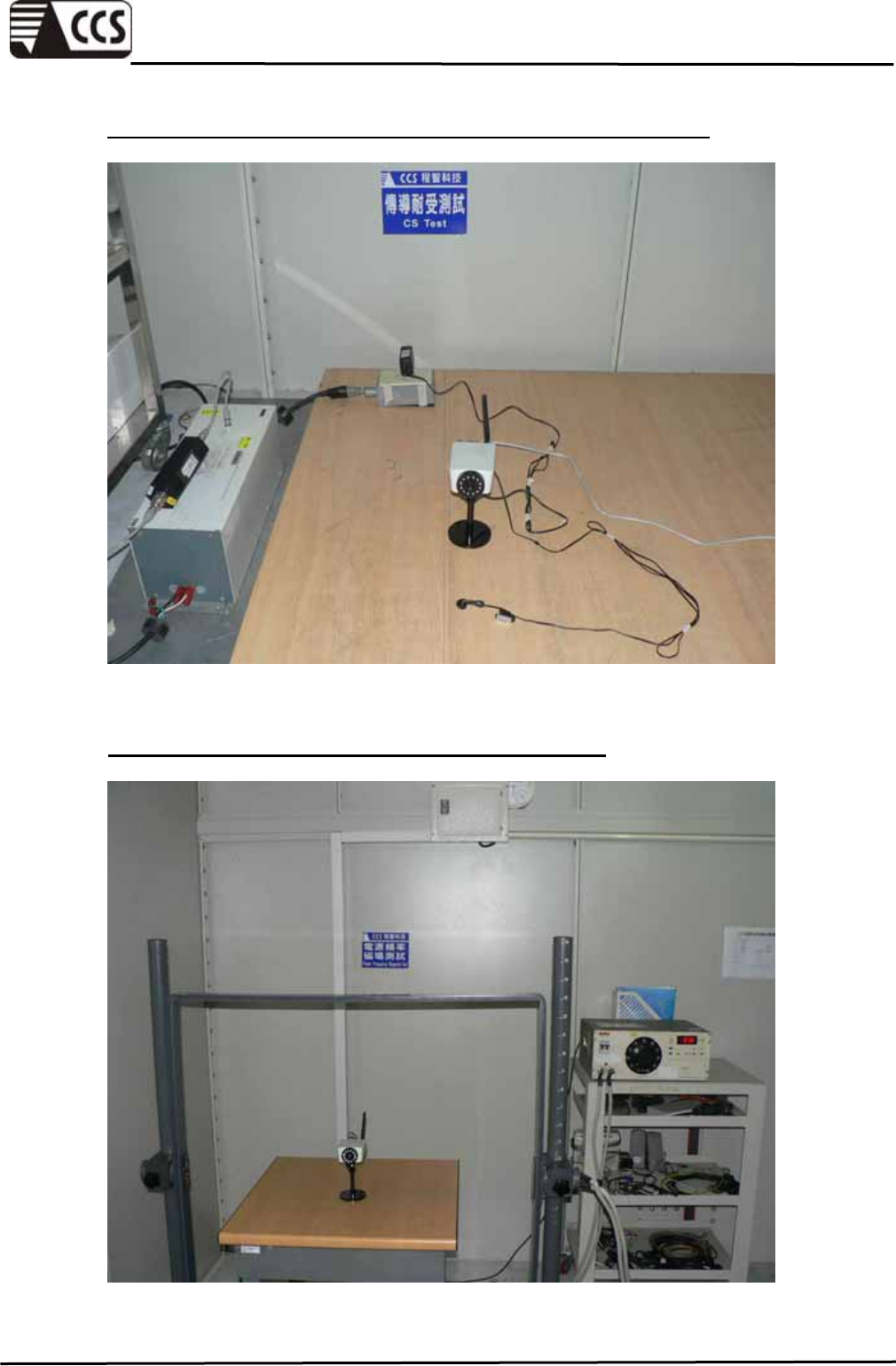
CONDUCTED RADIO FREQUENCY DISTURBANCES SETUP
POWER FREQUENCY MAGNETIC FIELDS SETUP
Compliance Certification Services Inc.
Report No.:91230301-E
Page 57 of 57
This report shall not be reproduced except in full, without the written approval of Compliance Certification Services.
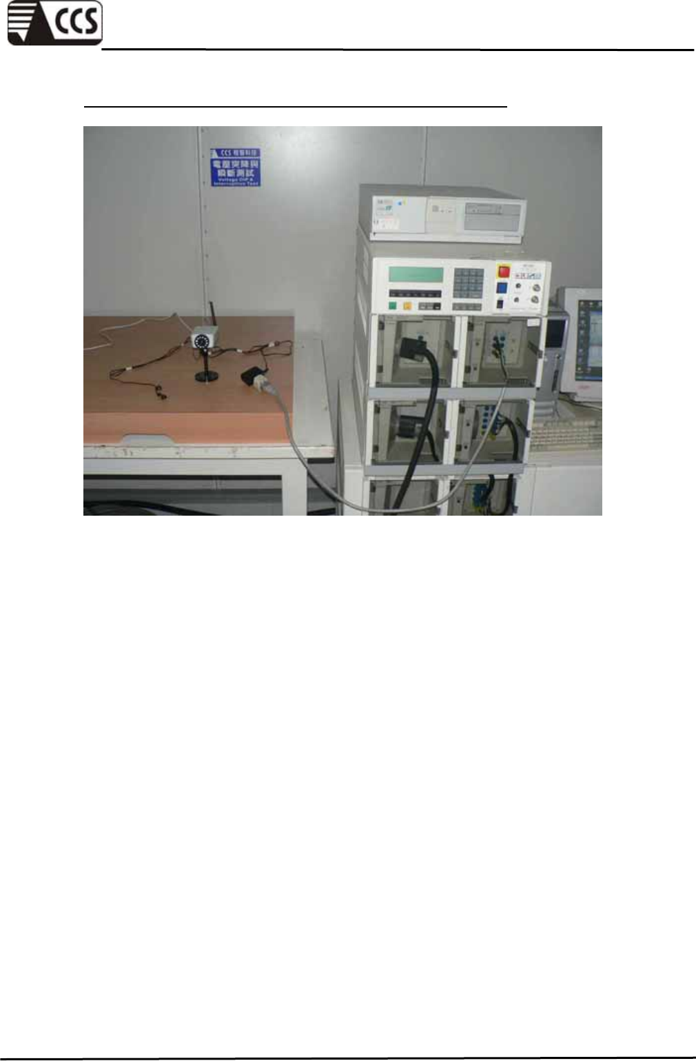
VOLTAGE DIPS & VOLTAGE INTERRUPTIONS SETUP
