Tools For Industrial Electrical Applications 56695 Catalog
111586-Catalog 111586-Catalog 111586-Catalog 783310 Batch5 unilog cesco-content
101668-Catalog 101668-Catalog 101668-Catalog 783786 Batch6 unilog cesco-content
175180-Brochure 175180-Brochure 175180-Brochure 783786 Batch6 unilog cesco-content
101668-Catalog 101668-Catalog 101668-Catalog 786210 Batch6 unilog cesco-content
101831-Catalog 101831-Catalog 101831-Catalog 786210 Batch7 unilog cesco-content
2014-11-11
: Pdf 56695-Catalog 56695-Catalog Batch12 unilog
Open the PDF directly: View PDF ![]() .
.
Page Count: 176 [warning: Documents this large are best viewed by clicking the View PDF Link!]

MORE POWER TO YOU
Thomas & Betts
For over 70 years, Canadian electrical contractors, plant
engineers and engineering consultants have placed their
trust in Thomas & Betts electrical components. Today,
Thomas & Betts offers a complete package of market-
driven products and services designed to give you the
power to succeed in today's economy.
THE POWER OF T&B ENGINEERED PRODUCTS
AND SERVICES
Our products and services continue to set new
standards for quality, reliability and innovation.
•Highly-focused sales, product support and customer
service teams dedicated to serving the industrial
MRO and OEM markets
•Guaranteed, competitive pricing
•The broadest offering of field-proven, brand name
products available from one manufacturer
•“One order, one shipment” for thousands of standard
products through Thomas & Betts and your Signature
Service distributor
•Reduced lead time on critical products through your
Signature Service distributor
•Technical support via phone, fax on demand
and the internet
•ISO-certified manufacturing — quality engineering
and manufacturing
•Local and national inventory support
•T&B Tool Lease program — the tools you need today
without tomorrow's investment
section_1_E.pdf 1 9/26/2011 10:36:24 AM

Every effort is made to ensure the accuracy of the information contained in this catalogue at the time of publication. As part of our ongoing quality
control program, we actively encourage customer input. Should you have any comments regarding the content of our catalogues, please forward
them via e-mail to mrkt_canada@tnb.com or contact your Thomas & Betts sales representative.
THE POWER OF CHOICE
As North America's largest single source for electrical components, Thomas & Betts is powered by
the longest and most complete list of reputable brand name products available from one
manufacturer in the industry today. With services like "one order, one shipment" available through
your Thomas & Betts distributor, the more T&B purchases you make, the more you can save.
To request information about any of these products, contact your Regional Sales Office.
All-Struct aluminum and steel structures
Amerace airfield lighting
Battpac battery-powered compression tools
Blackburn compression connectors
Blackburn grounding products
Color-Keyed compression connectors
Deltec aerial cable support systems
Diamond pole line hardware
Elastimold premolded connectors
for underground distribution applications
Emergi-Lite emergency lighting systems
ExpressTray wire-mesh cable management system
E-Z-Code wire marker systems
E Z Ground compression connectors
Furseweld exothermic connectors
Hazlux hazardous location lighting
Iberville “roughing-in” products
Iberville steel boxes and covers
Kold-n-Klose forced encapsulated closures
and sheath repair systems
LRC connectors, splices, adaptors and accessories
Lumacell emergency lighting systems
Marrette wire connectors and nonmetallic boxes
Meyer transmission and light duty
engineered steel poles
Microlectric meter sockets and pole line hardware
Mipco plugs, receptacles, modules,
power outlets and connectors
Ocal coated products
Partex wire marker systems
Pos-E-Kon industrial connectors
Ready-Lite emergency lighting systems
Red•Dot weatherproof boxes and covers
Reznor heating, ventilation and cooling systems
Russellstoll plugs, receptacles and connectors
Sachs drop line and construction hardware, grounding
and bonding products, signal security hardware
Safe-Ty low profile in-line fasteners
Shield-Kon grounding connectors and tools
Shrink-Kon insulation products
South River wireless antenna mounts and hardware
Sta-Kon terminals and application tools
StarTeck fittings for teck cable
Steel City floor boxes, access modules and poke throughs
Superstrut metal framing, channel and accessories
T&B cable tray systems
T&B conduit fittings
Ty-Duct wiring duct
Ty-Fast one-piece ties and accessories
Ty-Rap cable ties
®
®
™
®
®
®
™
™
®
®
®
®
®
™
™
®
®
™
™
®
®
®
®
®
™
™
®
®
®
®
®
™
™
®
™
™
®
®
®
™
™
™
®
®
section_1_E.pdf 2 9/26/2011 10:36:24 AM

Section 1
Mechanical Connectors and
Accessories — Quick Reference . . . . . . . . . . . . . . . .4–5
Mechanical Connectors . . . . . . . . . . . . . . . . . . . . . .6–36
Compression Connectors — Quick Reference . . . . . . .37
Compression Connectors . . . . . . . . . . . . . . . . . . .38–57
Section 2
Quick Reference . . . . . . . . . . . . . . . . . . . . . . . . . .58–62
Grounding Connectors and Accessories . . . . . . .63–102
Section 3
Quick Reference . . . . . . . . . . . . . . . . . . . . . . . .103–105
Installation Dies and Tools . . . . . . . . . . . . . . . .106–140
Reference Tables
Competitive Cross Reference . . . . . . . . . . . . . .141–157
Tool Cross Reference . . . . . . . . . . . . . . . . . . . .158–159
Conductor Reference . . . . . . . . . . . . . . . . . . . .160–168
Index Alphanumerical
. . . . . . . . . . .171–176
section_1_E.pdf 3 9/26/2011 10:36:25 AM
4
Mechanical
and Accessories
Quick Reference
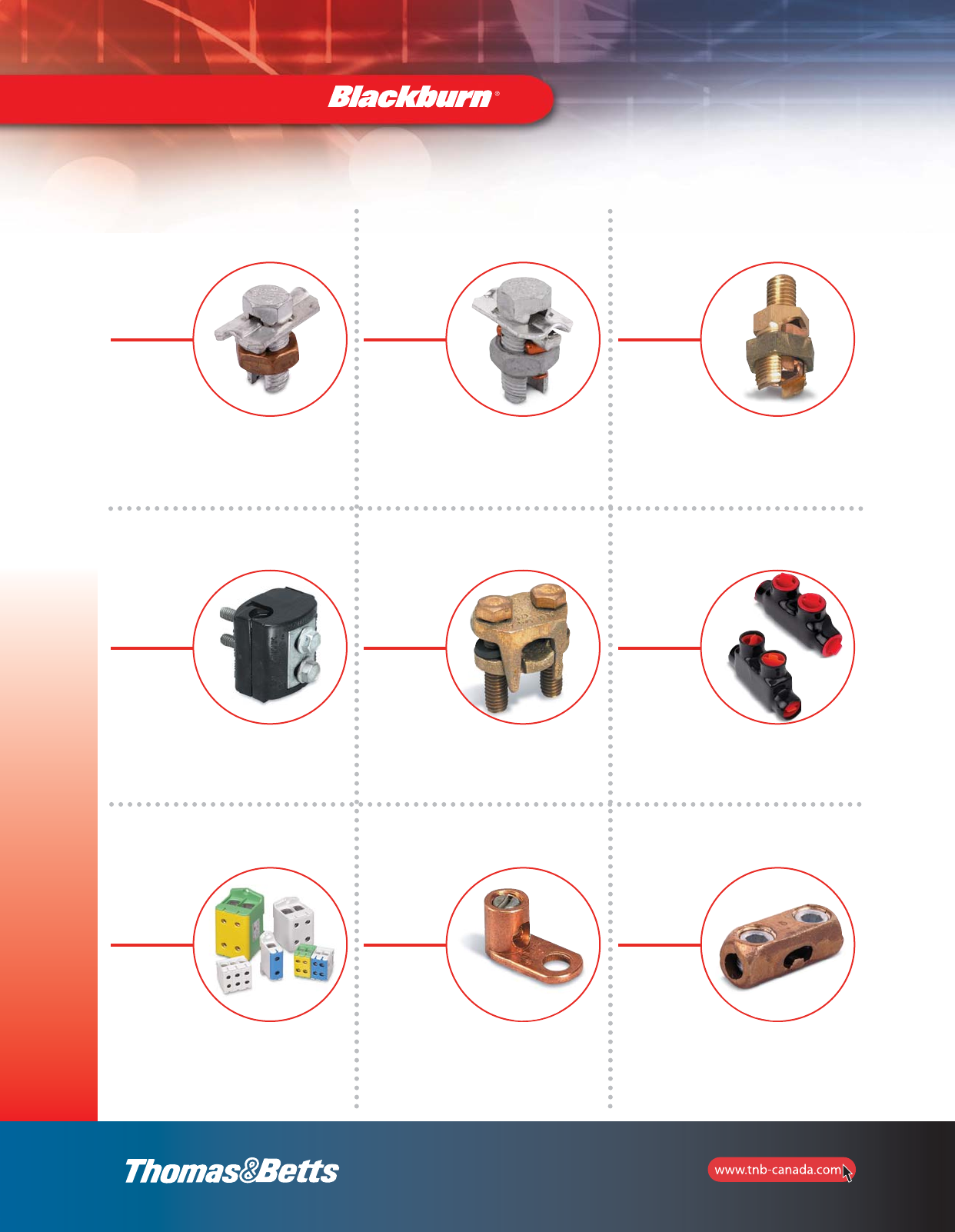
Mechanical Connectors and Accessories — Quick Reference
Type H, HPS, HPW
Copper Split Bolt
Connectors
pp. 6–7
Type APS, AAW
Aluminum Split Bolt
Connectors
pp. 8–9
Type SP
Service Post
Connectors
pp. 10–11
Type IPC
Insulator Piercing
Connectors
p. 12
Type 2B, 2BX, 2BW
Two-Bolt
Connectors
pp. 13–14
AMT
AMT
Connectors
pp. 15–19
Type PDS
Power Distribution
Blocks
pp. 20–21
Type L, TL
Copper Mechanical
Connectors
pp. 22–23
Type S
Copper Splice
Connectors
p.
section_1_E.pdf 4 9/26/2011 10:36:26 AM
5
Mechanical
and Accessories
Quick Reference
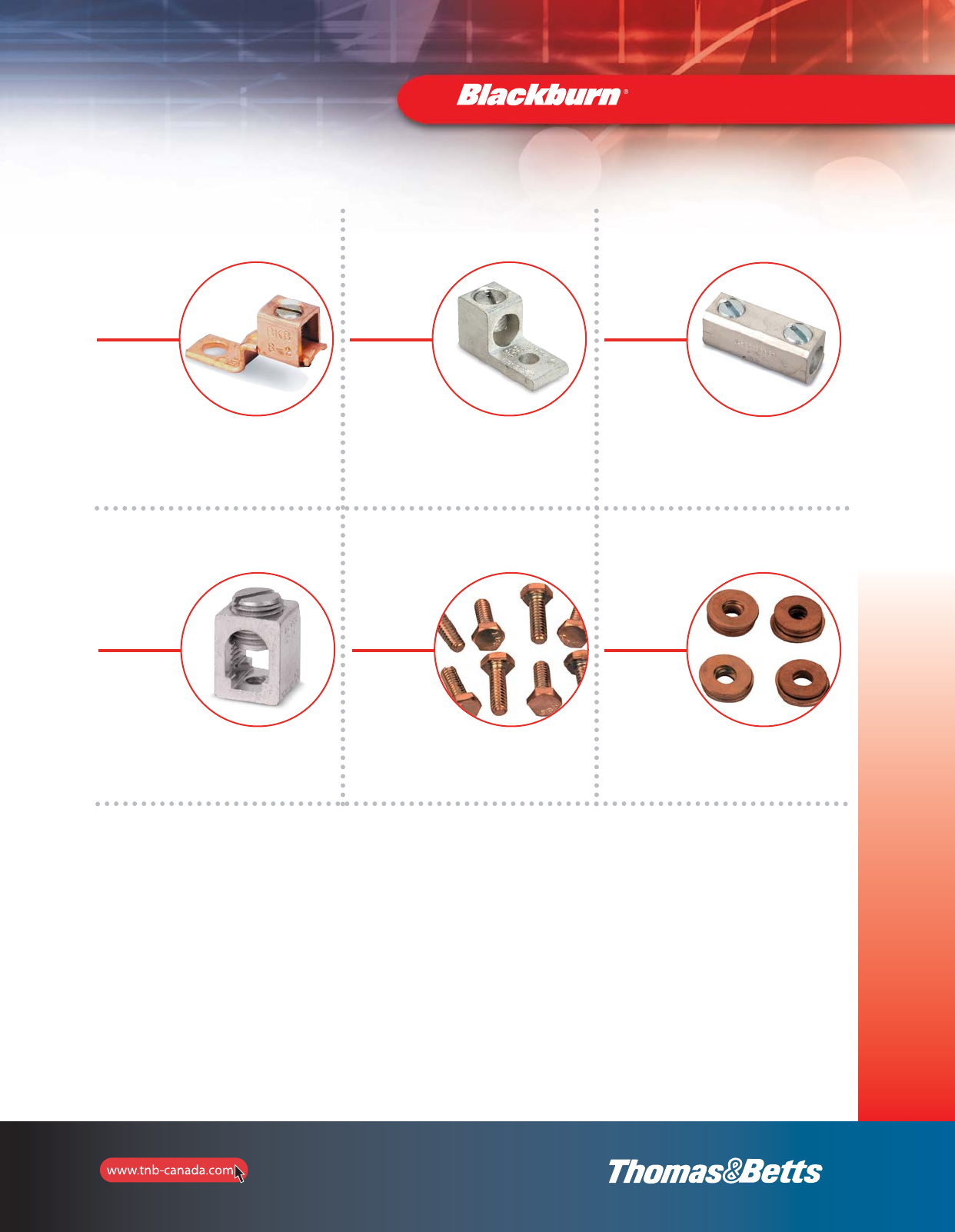
Mechanical Connectors and Accessories — Quick Reference
Type STC, BTC
Copper Mechanical
Connectors
p. 24
Type ADR, ASL
One, Two, Three and four Conductor-Dual-Rated
mechanical connectors
pp. 25–32
Type ASR
Splice Reducer
p. 33
Type BX
Rectangular
Connectors
pp. 33–34
Type BB, HN, SW
Silicon Bronze
Hardware
p. 35
Type BW, FW
Washers
p. 36
section_1_E.pdf 5 9/26/2011 10:36:27 AM
6
Mechanical and
Accessories
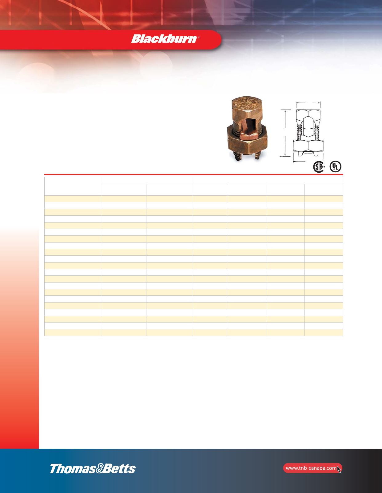
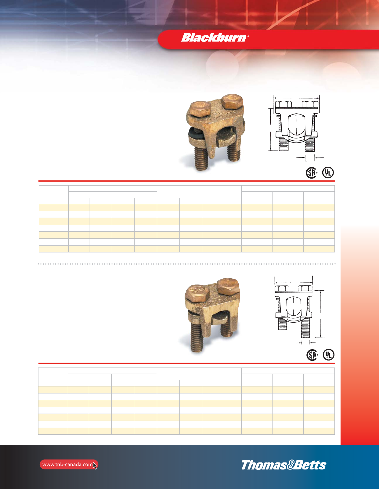
Split Bolt Connectors
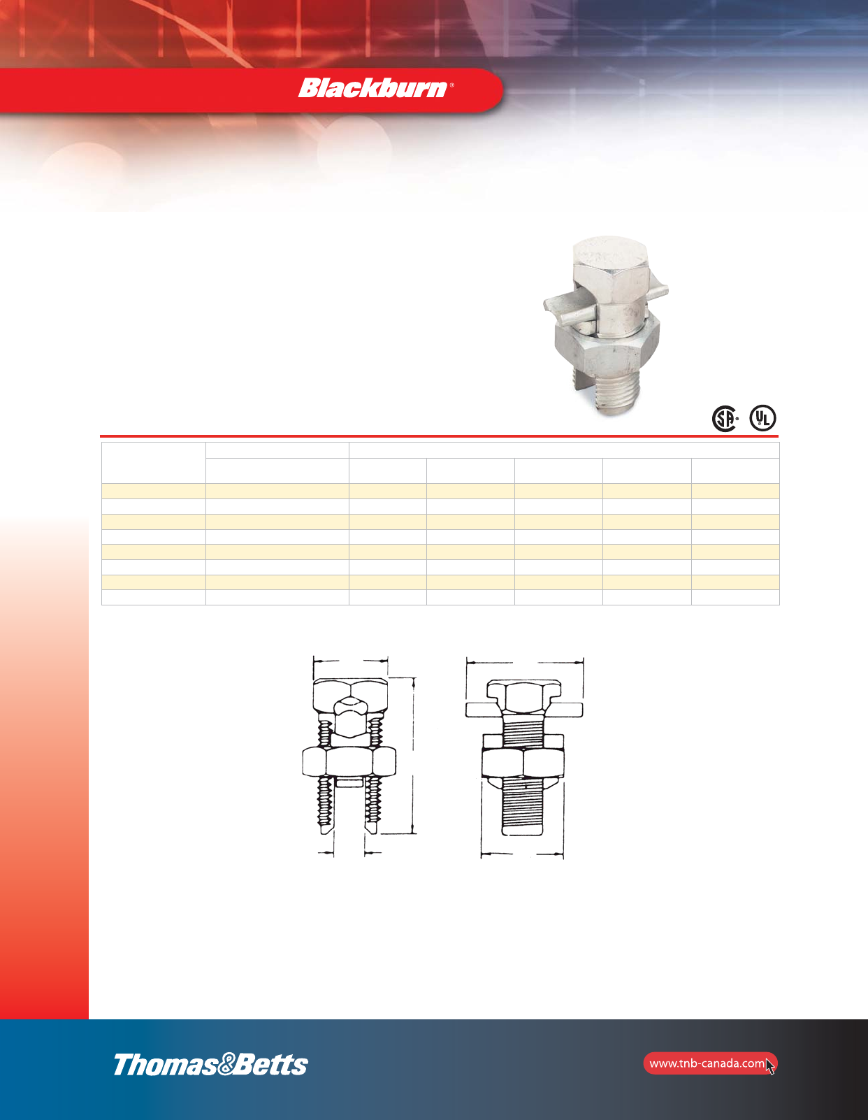
•Bolt and nut of high strength corrosion-resistant
bronze alloy
•Pressure bar is copper through 40H; copper alloy
is used for 350 kcmil and above
•Bolt and nut of hex design up to 350 kcmil
•CSA Certified and UL Listed
Cat. No.
Conductor Range (AWG or kcmil) Dimensions (in.)
Range for equal
Main and Tap Min. Tap with one
Max. Main A B C D
9H 10 str.–12 sol. 14 sol. 3/8 0.146 1/2 25/32
8H 8 str.–10 sol. 14 sol. 3/8 0.146 1/2 25/32
8H3* 8 str.–12 sol. 16 str. 3/8 0.146 1/2 29/32
6H 6 sol.–8 sol. 14 sol. 15/32 0.170 21/32 31/32
6H3* 6 sol.–10 sol. 16 str. 15/32 0.170 21/32 1-1/8
4H 4 sol.–8 sol. 14 sol. 17/32 0.235 23/32 1-1/16
4H3* 4 sol.–8 sol. 16 str. 17/32 0.235 23/32 1-9/32
3H 3 sol.–8 sol. 16 str. 17/32 0.235 23/32 1-1/16
3H3* 4 str.–8 sol. 16 str. 17/32 0.235 23/32 1-9/32
2H 2 sol.–6 sol. 14 sol. 19/32 0.271 25/32 1-1/4
2H3* 2 sol.–6 sol. 14 sol. 19/32 0.271 25/32 1-15/32
1H 2 str.–6 sol. 14 sol. 11/16 0.330 7/8 1-11/32
1H3** 2 str.–6 sol. 14 sol. 11/16 0.330 7/8 1-5/8
10H 1/0 str.–4 sol. 14 sol. 3/4 0.385 15/16 1-19/32
20H 2/0 str.–2 sol. 14 sol. 7/8 0.443 1-1/16 1-13/16
30H 4/0 str.–2 sol. 6 sol 1 0.580 1-5/16 2-5/32
40H 250 kcmil–1 str. 8 sol 1 0.580 1-5/16 2-5/32
350M 350 kcmil–250 kcmil 1/0 str. 1-5/16 0.717 1-21/32 2-11/16
500M 500 kcmil–400 kcmil 2/0 str. 1-1/2 0.842 1-7/8 3-1/32
750M 750 kcmil–600 kcmil 4/0 str. 1-15/16 1.029 2-1/4 3-21/32
1000M 1000 kcmil–800 kcmil 4/0 str. 2-1/4 1.185 2-17/32 4-1/32
* Will accommodate 3 wires of maximum size.
** Will accommodate 3 #2 str. wires.
U.L. recognizes solid and stranded conductor configurations for sizes #8 and smaller and stranded configurations only for sizes #6 and larger.
For copper to copper connections
Type H — High Strength Split Bolt Connectors A
D
C
B
section_1_E.pdf 6 9/26/2011 10:36:29 AM
7
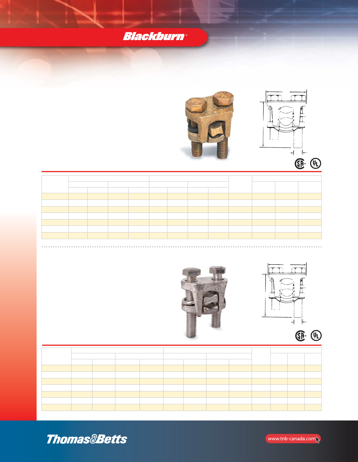
Split Bolt Connectors
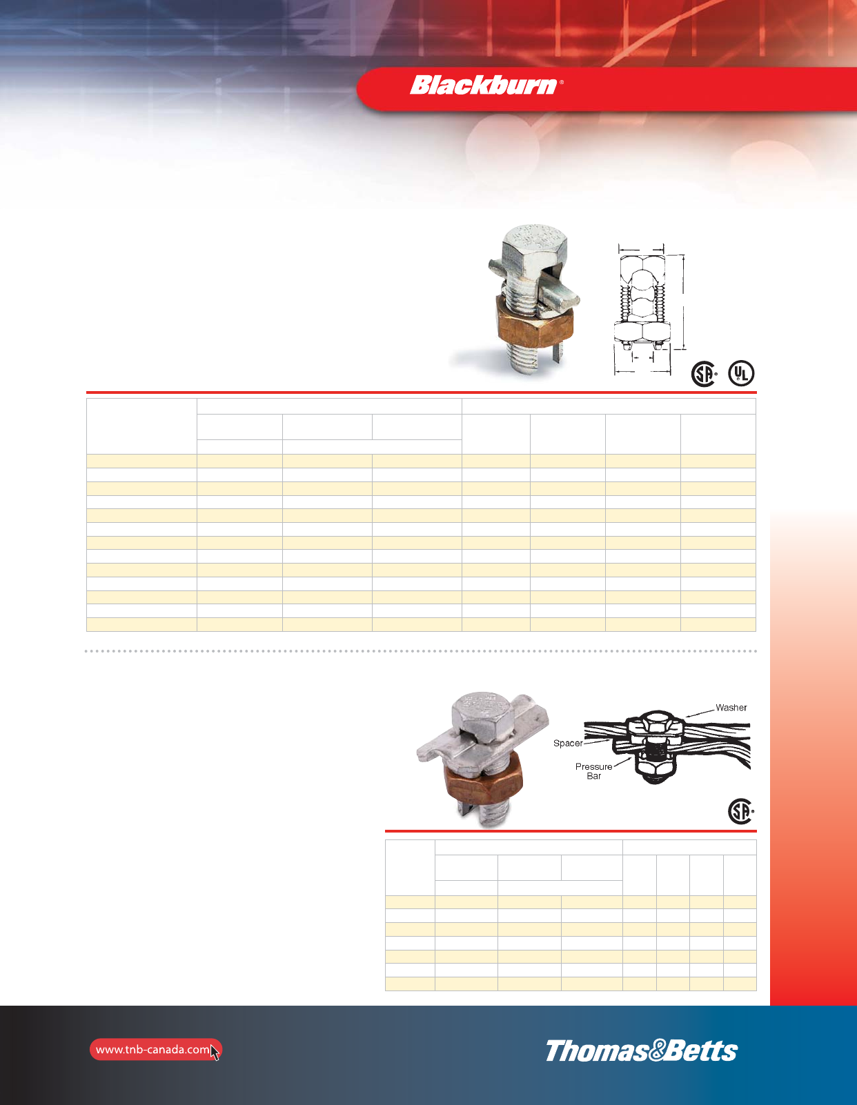
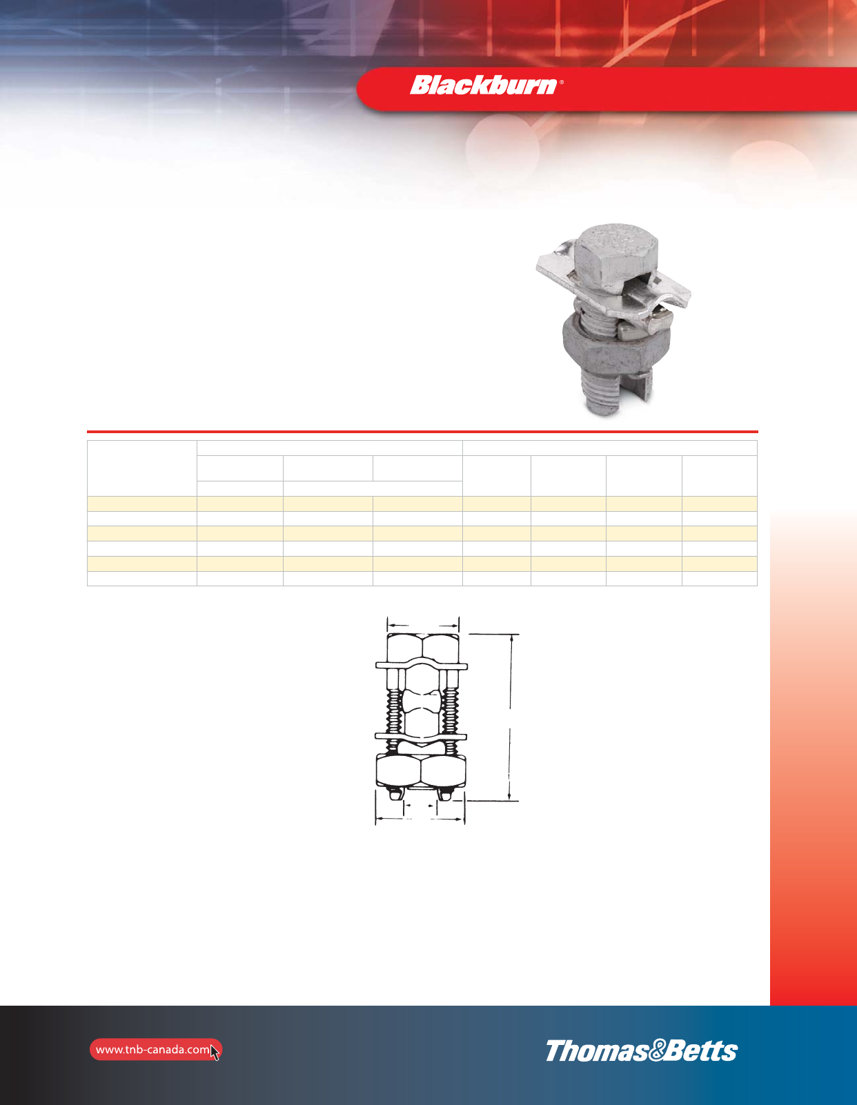
For use on copper, aluminum and ACSR conductors
Type HPS — Plated Split-Bolt
Connectors with Spacer
•Most connectors are CSA Certified and U.L. Listed
for copper conductors only
•Bolt and pressure bar of copper alloy completely tin plated
•Contoured spacer of electrolytic copper up through 4/0; bronze alloy
350 kcmil and above, all tin plated
•Blackburn Contax recommended when used on aluminum conductors
Mechanical and
Accessories
Cat. No.
Conductor Range (AWG or kcmil) Dimensions (in.)
Range for equal
Main and Tap Range for equal
Main and Tap Min. Tap with
One Max. Main A B C D
ACSR Copper or Aluminum
9HPS –10 str.–12 sol. 12 sol. 3/8 0.146 1/2 29/32
8HPS – 8 str.–12 sol. 12 sol. 3/8 0.146 1/2 29/32
6HPS 86 str.–12 sol. 12 sol. 15/32 0.170 21/32 1-1/8
4HPS 6–8 4 sol.–12 sol. 12 sol. 17/32 0.235 23/32 1-9/32
2HPS 4–8 2 sol.–8 sol. 8 sol. 19/32 0.274 25/32 1-15/32
1HPS 2–8 1 str.–8 sol. 8 sol. 11/16 0.330 7/8 1-5/8
10HPS 1–6 1/0 str.–6 sol. 6 sol. 3/4 0.385 15/16 1-13/16
20HPS 1/0–6 2/0 str.–6 sol. 6 sol. 7/8 0.443 1-1/16 2-1/16
40HPS 4/0–4 4/0 str.–4 sol. 4 sol. 1 0.580 1-5/16 2-15/32
350HPS 266.8–1/0 350 kcmil–1/0 str. 2 sol. 1-5/16 0.717 1-21/32 2-11/16
500HPS* 397.5–1/0 500 kcmil–1/0 str. 1/0 str. 1-1/2 0.842 1-7/8 3-1/32
750HPS* 666.6–4/0 750 kcmil–4/0 str. 2/0 str. 1-15/16 1.029 2-1/4 3-21/32
1000HPS* 900–477 1000 kcmil–500 kcmil 4/0 str. 2-1/4 1.185 2-17/32 4-1/32
* CSA non applicable U.L. 486A.
For use on combinations of copper, aluminum and ACSR conductors
Type HPW — Plated Split-Bolt
Connectors with spacer and washer
•Bolt and pressure bar of high strength copper alloy
completely tin plated; spacer and washer of
electrolytic copper up through 4/0; bronze alloy
350 kcmil and above, all tin plated
•Contoured spacer and bell mouth washer distribute
pressure over large area of conductor
•Large contoured spacer provides wide separation
between copper and aluminum conductors
•Blackburn Contax recommended when used with
aluminum conductors
•CSA Certified and UL Listed
Cat. No.
Conductor Range (AWG or kcmil) Dimensions (in.)
Range for equal
Main and Tap Range for equal
Main and Tap Min. Tap with
One Max. Main A B C D
ACSR Copper or Aluminum
6HPW 86 sol.–12 sol. 12 sol. 15/32 0.170 21/32 1-1/8
4HPW 6–8 4 sol.–12 sol. 12 sol. 17/32 0.235 23/32 1-9/32
2HPW 4–8 2 sol.–8 sol. 8 sol. 19/32 0.271 25/32 1-15/32
1HPW 2–8 1 str.–8 sol. 8 sol. 11/16 0.330 7/8 1-5/8
10HPW 1–6 1/0 str.–6 sol. 6 sol. 3/4 0.385 15/16 1-13/16
20HPW 1/0–6 2/0 str.–6 sol. 6 sol. 7/8 0.443 1-1/16 2-1/16
40HPW* 4/0–4 4/0 str.–4 sol. 4 sol. 10.580 1-5/16 2-15/32
* CSA non applicable.
D
C
B
A
section_1_E.pdf 7 9/26/2011 10:36:32 AM
8
Mechanical and
Accessories
Split Bolt Connectors
Accommodate all aluminum and copper conductor combinations
Type APS — Aluminum
Dual-Rated Split Bolts
•6 bolts cover the range from #10 to 4/0 AWG
•Can be installed with standard wrenches
•Corrosion resistant tin plated aluminum
•CSA Certified and UL Listed to 90oC 600V
Cat. No.
Conductor Range (AWG or kcmil) Dimensions (in.)
Range for equal
Main and Tap A B C D E
APS06 6–10 str. 17/32 0.21 23/32 1.27 1-1/4
APS04 4–10 str. 19/32 0.27 25/32 1.48 1-1/4
APS02 2–8 str. 11/16 0.33 7/8 1.63 1-1/4
APS11 1/0–4 str. 7/8 0.44 1-1/8 2.07 1-1/2
APS21 2/0–4 str. 7/8 0.44 1-1/8 2.07 1-1/2
APS41 4/0–2 str. 1 0.57 1-1/4 2.47 1-23/32
APS350* 350 kcmil–4 str. 1-7/16 0.70 1-11/16 3.36 2-1/4
APS500* 500 kcmil–2 str. 1-11/16 0.84 2 3.62 2-5/8
* Square head design CSA non applicable.
D
A
B
E
C
section_1_E.pdf 8 9/26/2011 10:36:32 AM
9
Mechanical and
Accessories
Split Bolt Connectors
For all aluminum applications
Type AAW — Aluminum Split Bolt
Connectors with Spacer and Washers
•Bolt, nut, pressure bar and contoured spacer of
aluminum alloy
•Large contoured spacer gives wide separation
•Nut anodized to prevent thread galling
•Blackburn Contax recommended when used on
aluminum conductors
Cat. No.
Conductor Range (AWG or kcmil) Dimensions (in.)
Range for equal
Main and Tap Range for equal
Main and Tap Min. Tap with
One Max. Main A B C D
ACSR Aluminum
6AAW 6–8 4 sol.–8 sol. 10 sol. 17/32 0.236 23/32 1-9/32
4AAW 4–8 2 sol.–8 sol. 8 sol. 19/32 0.272 25/32 1-15/32
2AAW 2–8 1 str.–8 sol. 8 sol. 11/16 0.330 7/8 1-5/8
1AAW 1–4 1/0 str.–8 sol. 4 sol. 7/8 0.443 1-1/8 2-1/16
10AAW 1/0–4 2/0 str.–8 sol. 4 sol. 7/8 0.443 1-1/8 2-1/16
40AAW 4/0–4 4/0 str.–4 sol. 4 sol. 1 0.580 1-1/4 2-15/32
D
A
C
B
section_1_E.pdf 9 9/26/2011 10:36:33 AM
10
Mechanical and
Accessories
Service Post Connectors
Cat. No. Cat. No.
Conductor Range (AWG mm2)Maximum
Diameter
Range
(in.)
Stud
Size
Dimensions (in.)
Stranded Solid A AA B C D E
max. min. max. min.
SP0DS SP0SS 8
–
8
4 mm2
8
10 mm2
12
4 mm20.146–0.080 1/4 – 20 x 1/2 11/16 13/16 1/2 23/64 15/32 1/2
SP1DS SP1SS 7
10 mm2
10
6 mm2
6
10 mm2
10
6 mm20.170–0.102 1/4 – 20 x 1/2 13/16 31/32 1/2 23/64 15/32 21/32
SP2DS SP2SS 5
16 mm2
10
6 mm2
4
16 mm2
10
6 mm20.217–0.102 5/16 – 18 x 5/8 15/16 1-1/8 5/8 25/64 17/32 23/32
SP3DS SP3SS 3
25 mm2
10
6 mm2
2
35 mm2
10
6 mm20.271–0.102 3/8 – 16 x 5/8 1/2 1-1/4 5/8 29/64 5/8 25/32
SP4DS SP4SS 1
35 mm2
8
6 mm2
2
35 mm2
8
10 mm20.332–0.128 3/8 – 16 x 5/8 1-1/16 1-3/8 5/8 29/64 11/16 7/8
SP5DS SP5SS 1/0
50 mm2
2
35 mm2
2
35 mm2
–
–0.385–0.258 1/2 – 13 x 3/4 1-1/4 1-19/32 3/4 37/64 3/4 15/16
SP6DS SP6SS 2/0
70 mm2
2
35 mm2
2
35 mm2
–
–0.443–0.258 1/2 – 13 x 3/4 1-13/32 1-13/16 3/4 37/64 7/8 1-1/16
SP8DS SP8SS 4/0
95 mm2
1
35 mm2
–
–
–
–0.570–0.289 5/8 – 11 x 1 1-9/16 2-1/16 1 51/64 1 1-5/16
SP9DS SP9SS 350
150 mm2
1/0
70 mm2
–
–
–
–0.715–0.373 5/8 – 11 x 1 2 2-3/4 1 51/64 1-5/16 1-11/16
SP10DS SP10SS 500
240 mm2
3/0
95 mm2
–
–
–
–0.840–0.464 3/4 – 10 x 1-1/4 2-1/4 3-1/8 1-1/4 63/64 1-1/2 1-7/8
Single Conductor
Short Stud
Double Conductors
Short Stud
Application
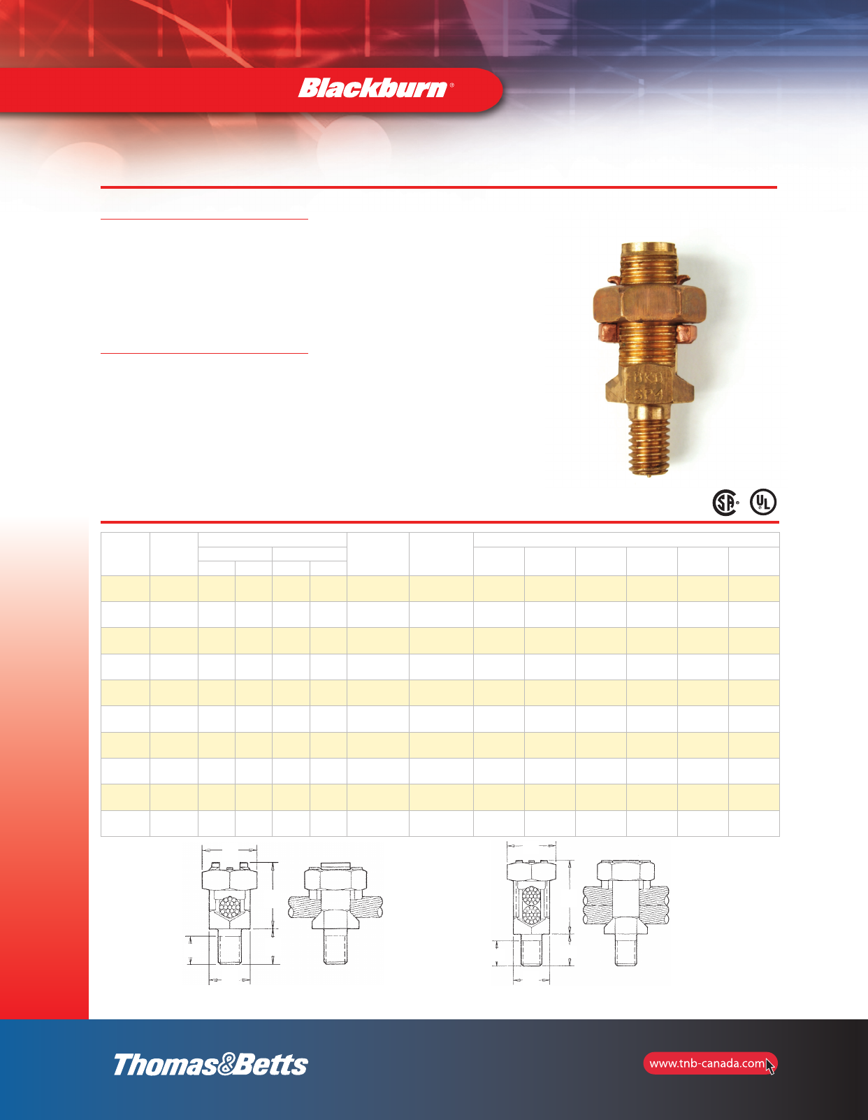
The Blackburn line of Service Post
Connectors is designed for applications
including steel structure, fence post or
transformer grounding involving one or
two cables. Service Posts can also be
used to tap one or two cables from a
bus bar.
Construction and Ratings
Bolts used in the Service Post are
machined from high conductivity
bronze alloy while the nuts are
cold-formed from high strength,
corrosion resistant copper alloy.
Pressure bars are copper through
4/0 size, while copper alloy is used for
350 kcmil size and above. Bolts and
nuts are of the traditional Blackburn
hex design for easy installation.
Service Post Connectors are available
in sizes accommodating AWG copper
conductor ranges of #12-500 kcmil
stranded (4mm2-240mm2) and #12-#2
solid (4mm2-35mm2).
The line includes single conductor and
double conductor connectors.
•For copper to copper connections
•For grounding of steel structures,
fence posts, transformers using one
or two cables
•For tapping one or two cables from
a bus bar
•Hex design bolts machined from
high conductivity bronze alloy
•Nuts and pressure bars
cold-formed from high-strength
copper or copper alloy
•CSA Certified and UL Listed
Single or Double Conductors Short Stud
E
A
B
D
C
AA
E
CB
D
10-11-e.pdf 1 8/31/2012 8:27:03 AM
11
Mechanical and
Accessories
Service Post Connectors
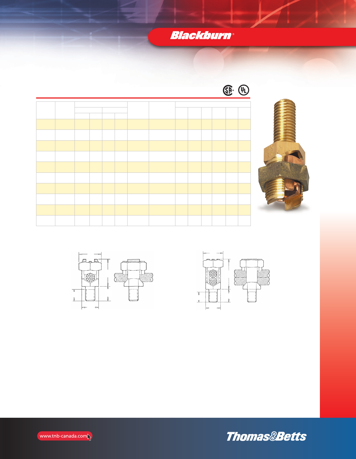
Single or Double Conductors Long Stud
Cat. No. Cat. No.
Conductor Range (AWG mm2)Maximum
Diameter
Range
(in.)
Stud
Size
Dimensions (in.)
Stranded Solid A AA B C D E
max. min. max. min.
SP0SL SP0DL 8
–
8
4 mm2
8
10 mm2
12
4 mm20.146–0.080 1/4 – 20 x 1 11/16 13/16 1 55/64 15/32 1/2
SP1SL SP1DL 7
10 mm2
10
6 mm2
6
10 mm2
10
6 mm20.170–0.102 1/4 – 20 x 1 13/16 31/32 1 55/64 15/32 21/32
SP2SL SP2DL 5
16 mm2
10
6 mm2
4
16 mm2
10
6 mm20.217–0.102 5/16 – 18 x 1 15/16 1-1/8 1 53/64 17/32 23/32
SP3SL SP3DL 3
25 mm2
10
6 mm2
2
35 mm2
10
6 mm20.271–0.102 3/8 – 16 x 1-1/8 1/2 1-1/4 1-1/8 61/64 5/8 25/32
SP4SL SP4DL 1
35 mm2
8
6 mm2
2
35 mm2
8
10 mm20.332–0.128 3/8 – 16 x 1-1/8 1-1/16 1-3/8 1-1/8 61/64 11/16 7/8
SP5SL SP5DL 1/0
50 mm2
2
35 mm2
2
35 mm2
–
–0.385–0.258 1/2 – 13 x 1-1/4 1-1/4 1-19/32 1-1/4 1-5/64 3/4 15/16
SP6SL SP6DL 2/0
70 mm2
2
35 mm2
2
35 mm2
–
–0.443–0.258 1/2 – 13 x 1-1/4 1-13/32 1-13/16 1-1/2 1-19/64 7/8 1-1/16
SP8SL SP8DL 4/0
95 mm2
1
35 mm2
–
–
–
–0.570–0.289 5/8 – 11 x 1-1/2 1-9/16 2-1/16 1-1/2 1-19/64 1 1-5/16
SP9SL SP9DL 350
150 mm2
1/0
70 mm2
–
–
–
–0.715–0.373 5/8 – 11 x 1-1/2 2 2-3/4 1-1/2 1-19/64 1-5/16 1-11/16
SP10SL SP10DL 500
240 mm2
3/0
95 mm2
–
–
–
–0.840–0.464 3/4 – 10 x 1-3/4 2-1/4 3-1/8 1-3/4 1-31/64 1-1/2 1-7/8
Single Conductor
Long Stud
Double Conductors
Long Stud
E
A
B
D
C
AA
E
CB
D
10-11-e.pdf 2 8/31/2012 8:27:03 AM
12
Mechanical and
Accessories
Insulated Conductor Connectors
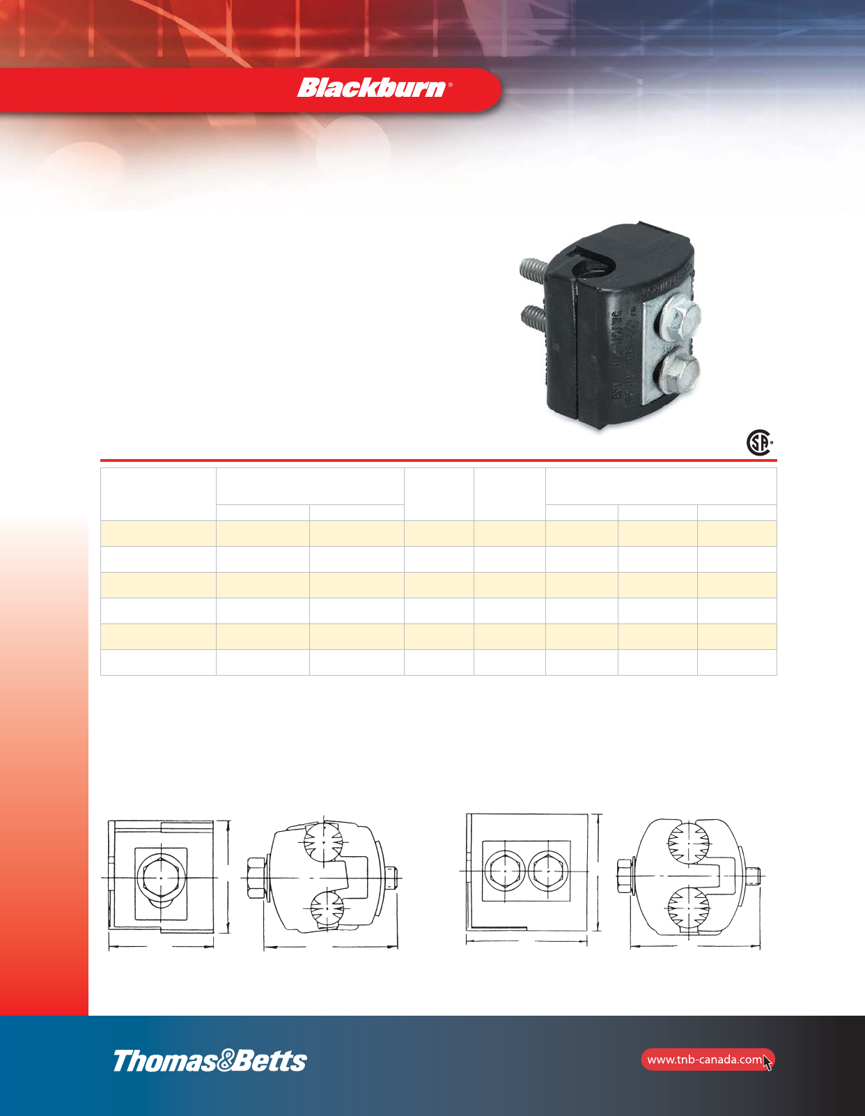
Type IPC — Talon™Insulation Piercing Connectors
•Perform as a splice or tap for non-tension applications
up to 600 Volts depending on the size of the connector
•Eliminate need for conductor insulation stripping
•Self-insulated for hot line applications
•No taping required after installation
•For copper to copper, copper to aluminum and
aluminum to aluminum applications
•For use on insulated conductors only
•Six connector line covers the range from #10-500 kcmil
•CSA Certified and UL Listed (AL9CU – 90oC rated)
Cat. No.
AL or CU
Conductor Range
(AWG/kcmil) No. of
Bolts Fig. Dimensions (in.)
Main Tap W H L
IPC1102* 1/0–8
50–6
2–8
35–6 1 1 2-9/16 2 1-17/32
IPC4111 4/0–1/0
95–50
1/0–6
50–16 2 2 2-1/2 3 1-19/32
IPC4141 4/0–1/0
95–50
4/0–1/0
95–50 2 2 2-5/8 3-1/4 1-29/32
IPC5041* 500–350
240–185
4/0–4
90–25 1 1 2 2-1/2 2-1/8
IPC3535 350–4/0
185–95
350–4/0
185–95 2 2 2-1/16 2-1/2 2-1/8
IPC3541 350–4/0
185–95
4/0–10
95–6 1 1 2-3/4 3 2-5/8
* 600 Volt Rating (All others 300 Volts).
Fig. 2
Fig. 1
W
HH
L
W
L
section_1_E.pdf 12 9/26/2011 10:36:36 AM
13
Mechanical and
Accessories
Two-Bolt Connectors without Spacer
Type 2B — Two-Bolt Connectors without Spacer
•Castings and bolts of high-strength copper alloy
•Removable neoprene washers capture each bolt in
bottom casting, aiding installation
•CSA Certified and UL Listed
Cat. No.
Conductor Range (AWG or kcmil) Conductor
Diameter (B) Bolt
Head
(in.)
Dimensions (in.)
Main Tap L H D
max. min. max. min max. min.
2B10 1/0 str. 2 str. 1/0 str. 10 sol. 0.746 0.394 1/2 1-5/16 1-3/4 5/16
2B20BB 2/0 str. 2 str. 2/0 str. 8 sol. 0.838 0.420 1/2 1-5/16 1-1/4 5/16
2B40 4/0 str. 1/0 str. 4/0 str. 6 sol. 1.056 0.530 9/16 1-23/32 1-3/4 3/8
2B350 350 kcmil 4/0 str. 350 kcmil 4 sol. 1.362 0.726 3/4 2-1/8 2 1/2
2B500 500 kcmil 350 kcmil 500 kcmil 4 sol. 1.626 0.883 3/4 2-1/4 2-1/2 1/2
2B800 800 kcmil 600 kcmil 800 kcmil 2 sol. 2.062 1.149 3/4 2-1/2 2-1/2 1/2
2B1000 1000 kcmil 750 kcmil 1000 kcmil 2 sol. 2.304 1.255 15/16 2-31/32 2-3/4 5/8
U.L. 486A
Type 2B — One-Piece Two-Bolt Connectors without Spacer
•Castings and bolts of high-strength copper alloy
•One-piece construction
•Free bolt is held in place with neoprene washer during
installation
•One extra length bolt allows top casting to swing free
over two conductors of maximum range
•CSA Certified and UL Listed
Cat. No.
Conductor Range (AWG or kcmil) Conductor
Diameter (B) Bolt
Head
(in.)
Dimensions (in.)
Main Tap L H D
max. min. max. min max. min.
2B10X 1/0 str. 2 str. 1/0 str. 10 sol. 0.746 0.394 1/2 1-5/16 1-1/2 5/16
2B20X 2/0 str. 2 str. 2/0 str. 8 sol. 0.838 0.420 1/2 1-5/16 1-1/2 5/16
2B40X 4/0 str. 1/0 str. 4/0 str. 6 sol. 1.056 0.530 9/16 1-23/32 1-7/8 3/8
2B350X 350 kcmil 4/0 str. 350 kcmil 4 sol. 1.362 0.726 3/4 2-1/8 2-1/4 1/2
2B500X 500 kcmil 350 kcmil 500 kcmil 4 sol. 1.626 0.883 3/4 2-1/4 2-1/2 1/2
2B800X 800 kcmil 600 kcmil 800 kcmil 2 sol. 2.062 1.149 3/4 2-1/2 2-3/4 1/2
2B1000X 1000 kcmil 750 kcmil 1000 kcmil 2 sol. 2.304 1.255 15/16 2-31/32 3-1/4 5/8
U.L. 486A
H
L
D
B
H
L
D
B
section_1_E.pdf 13 9/26/2011 10:36:37 AM
14
Mechanical and
Accessories
Two-Bolt Connectors with Spacer
Type 2BW — One-Piece Two-Bolt Connectors with Spacer
•CSA Certified and UL Listed
•For use on copper conductors only
•Castings and bolts of high-strength copper alloy;
spacer of ductile, high-conductivity copper alloy
•One-piece construction; contoured spacer is
ringed and swings easily over the conductor
Cat. No.
Conductor Range (AWG or kcmil) Conductor Diameter Bolt
Head
(in.)
Dimensions (in.)
Main Tap A B L H E
max. min. max. min max. min. max. min.
2B10W 1/0 str. 2 str. 1/0 str. 10 sol. 0.373 0.292 0.373 0.102 1/2 1-5/16 1-5/8 5/16
2B20W 2/0 str. 2 str. 2/0 str. 8 sol. 0.419 0.292 0.419 0.128 1/2 1-5/16 1-5/8 5/16
2B40W 4/0 str. 1/0 str. 4/0 str. 6 sol. 0.528 0.368 0.528 0.162 9/16 1-23/32 2-1/8 3/8
2B350W 350 kcmil 4/0 str. 350 kcmil 4 sol. 0.681 0.522 0.681 0.204 3/4 2-1/8 2-1/2 1/2
2B500W 500 kcmil 350 kcmil 500 kcmil 4 sol. 0.813 0.679 0.813 0.204 3/4 2-1/4 2-3/4 1/2
2B800W 800 kcmil 600 kcmil 800 kcmil 2 sol. 1.031 0.891 1.031 0.258 3/4 2-1/2 3-1/4 1/2
2B1000W 1000 kcmil 750 kcmil 1000 kcmil 2 sol. 1.152 0.997 1.152 0.258 15/16 2-31/32 3-3/4 5/8
Type 2BPW — One-Piece Two-Bolt Connectors with Spacer
•CSA Certified and UL Listed
•For use on copper, aluminum and ACSR conductors
Cat. No.
Conductor Range (AWG or kcmil) Conductor Diameter Bolt
Head
(in.)
Dimensions (in.)
Main Tap A B L H E
max. min. max. min max. min. max. min.
2B10PW 1/0–2 1/0–6 1/0 str.–2 str. 1/0 str.–2 str. 0.398 0.292 0.398 0.102 1/2 1-5/16 1-5/8 5/16
2B20PW 2/0–2 2/0–6 2/0 str.–2 str. 1/0 str.–2 str. 0.447 0.292 0.447 0.128 1/2 1-5/16 1-5/8 5/16
2B40PW 4/0–1/0 4/0–6 4/0 str.–1/0 str. 4/0 str.–1/0 str. 0.563 0.368 0.563 0.162 9/16 1-23/32 2-1/8 3/8
2B350PW 350–4/0 350–4 350–4/0 350–4 sol. 0.680 0.522 0.680 0.204 3/4 2-1/8 2-1/2 1/2
2B500PW 397.5–336.4 397.5–4 500–350 500–4 sol. 0.813 0.679 0.813 0.204 3/4 2-1/4 2-3/4 1/2
2B800PW 666.6–397.5 666.6–2 800–600 800–2 sol. 1.031 0.891 1.031 0.258 3/4 2-1/2 3-1/4 1/2
2B1000PW 900–666.6 900–2 1000–750 1000–2 sol. 1.162 0.997 1.162 0.258 15/16 2-31/32 3-3/4 5/8
H
L
E
B
A
H
L
B
A
E
section_1_E.pdf 14 9/26/2011 10:36:38 AM
15
Mechanical and
Accessories
AMT Connectors
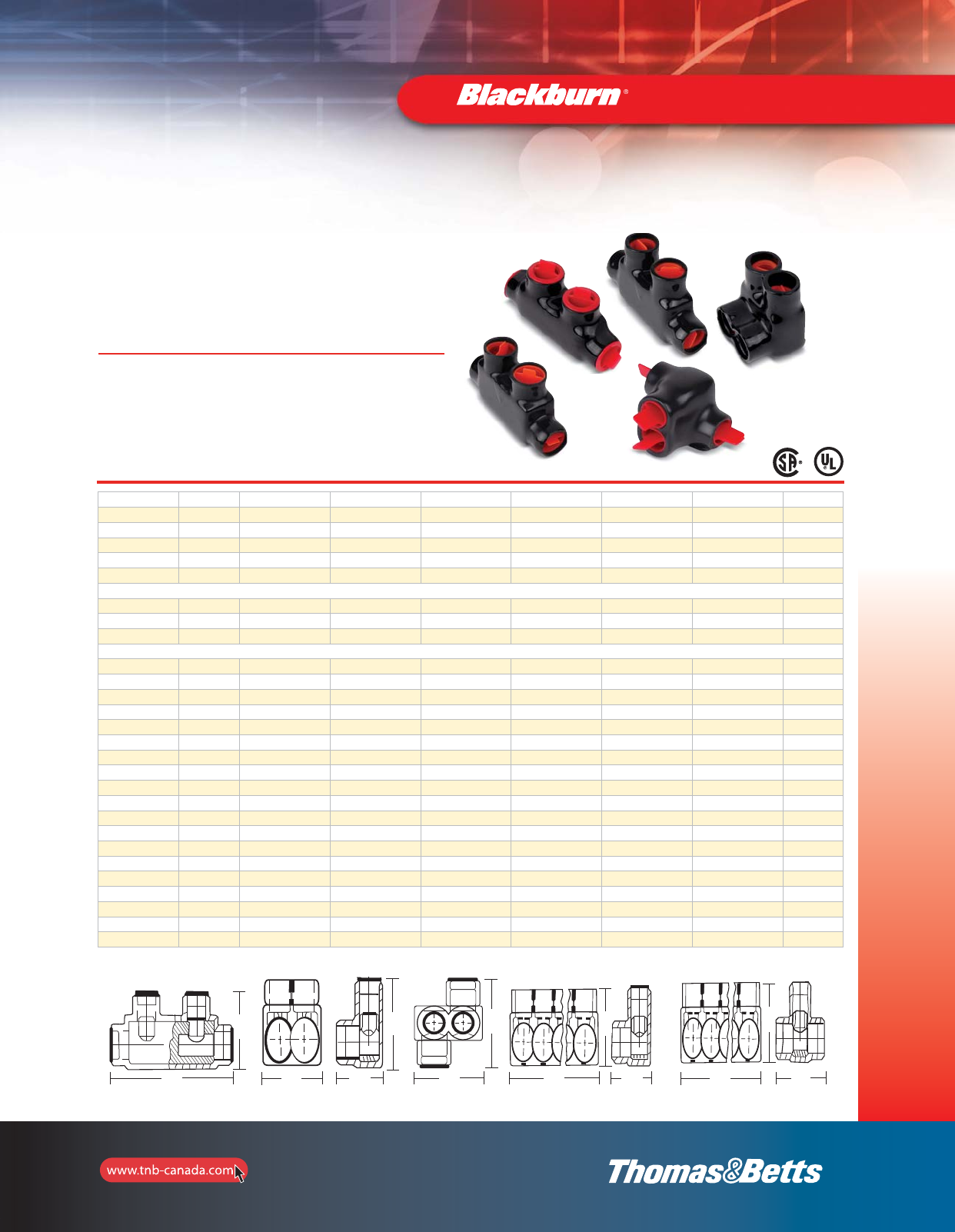
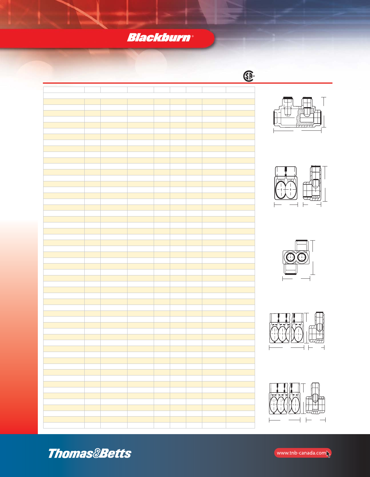
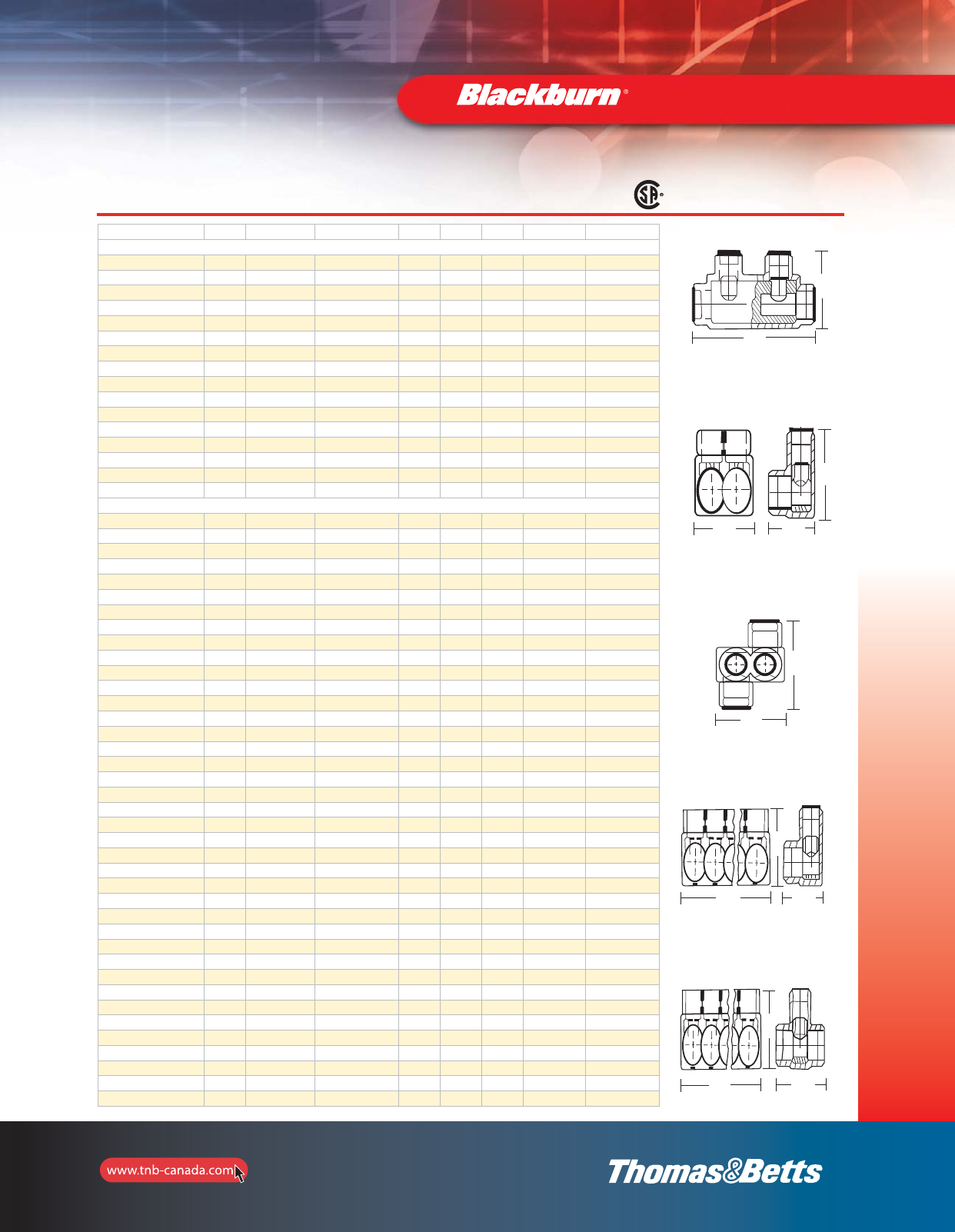
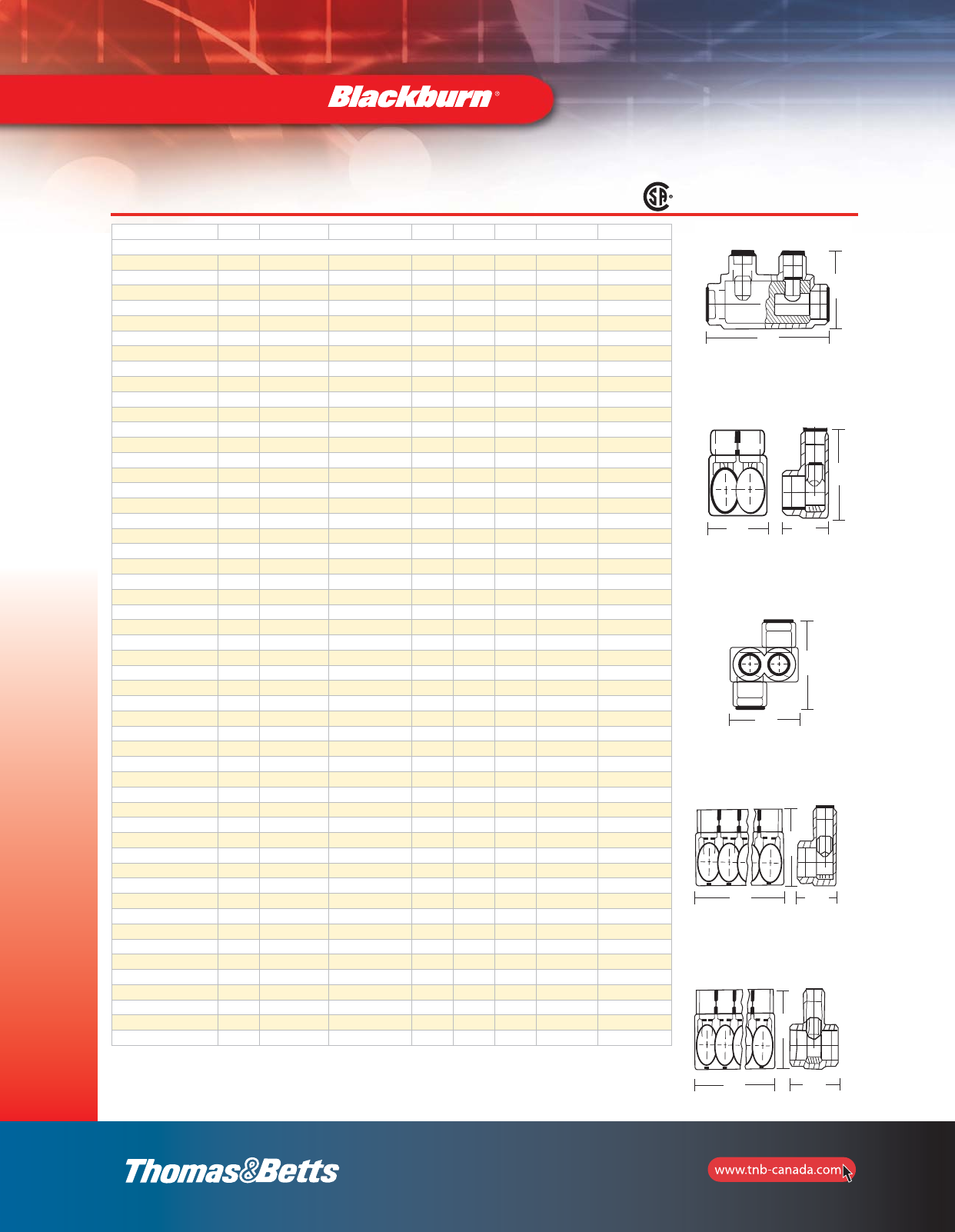
AMT Connectors
The high quality and built-in flexibility of the Blackburn®
AMT Connectors reduce the cost of field installations on
splices, taps, and terminations. They’re easy and quick to
install, and provide superior insulation that lasts the life of
the connection.
Features and Benefits
•PVC insulation eliminates failures and reduces
outage costs
•UV resistant material
•Compact design provides space efficiencies
•Dual-Rated for copper and aluminum conductors
(CSA Certified and UL Listed, for 600V, 90oC).
Cat. No. Figure No. of Ports Wire Range Length (in.) Width (in.) Height (in.) Hex Head Size Std Pkg. Qty
AMTSR10 1 – 1/0–14 str. 3.25 0.94 1.63 3./16 4
AMTSR250 1 – 250 kcmil–6 str. 3.96 1.19 2.17 5/16 4
AMTSR350 1 – 350 kcmil–6 str. 4.43 1.31 2.62 5/16 2
AMTSR500 1 – 500 kcmil–4 str. 5.38 1.44 3.03 3/8 2
AMTSR750 1 – 750 kcmil–250 kcmil 7.25 1.75 3.16 1/2 2
AMT Splices Offset
AMTTC4 3 2 4–14 str. 1.24 1.25 1.42 1/8 12
AMTT10 3 2 1/0–14 str. 1.63 1.63 1.63 3/16 6
AMTT30 3 2 3/0–6 str. 1.89 1.68 1.86 3/16 6
AMT Multi-Port Connectors “Same Side”
AMTS4142 2 2 4–14 str. 1.24 1.22 1.42 1/8 12
AMTS4143 4 3 4–14 str. 1.70 1.22 1.42 1/8 12
AMTS4144 4 4 4–14 str. 2.16 1.22 1.42 1/8 6
AMTS4145 4 5 4–14 str. 2.61 1.22 1.42 1/8 6
AMTS4146 4 6 4–14 str. 3.07 1.22 1.42 1/8 6
AMTS4147 4 7 4–14 str. 3.53 1.22 1.42 1/8 4
AMTS4148 4 8 4–14 str. 3.99 1.22 1.42 1/8 4
AMTS4149 4 9 4–14 str. 4.45 1.22 1.42 1/8 4
AMTS41410 4 10 4–14 str. 4.90 1.22 1.42 1/8 4
AMTS41411 4 11 4–14 str. 5.36 1.22 1.42 1/8 3
AMTS41412 4 12 4–14 str. 5.82 1.22 1.42 1/8 3
AMTS41413 4 13 4–14 str. 6.28 1.22 1.42 1/8 2
AMTS41414 4 14 4–14 str. 6.74 1.22 1.42 1/8 2
AMTS10142 2 2 1/0–14 str. 1.67 1.53 1.63 3/16 12
AMTS10143 4 3 1/0–14 str. 2.29 1.53 1.63 3/16 12
AMTS10144 4 4 1/0–14 str. 2.92 1.53 1.63 3/16 6
AMTS10145 4 5 1/0–14 str. 3.54 1.53 1.63 3/16 6
AMTS10146 4 6 1/0–14 str. 4.17 1.53 1.63 3/16 6
AMTS10147 4 7 1/0–14 str. 4.79 1.53 1.63 3/16 4
LLLW
W
W
LL
HH
H
H
H
Fig. 1 Fig. 2 Fig. 3 Fig. 4 Fig. 5
LW
L L L L
W
W
H
H
H
H
H
section_1_E.pdf 15 9/26/2011 10:36:39 AM
16
Mechanical and
Accessories
Cat. No. Figure No. of Ports Wire Range Length Width Height Hex Size Std Pkg. Qty
AMT Multi-Port Connectors “Same Side” (continued)
AMTS10148 4 8 1/0–14 str. 5.42 1.53 1.63 3/16 4
AMTS10149 4 9 1/0–14 str. 6.04 1.53 1.63 3/16 4
AMTS101410 4 10 1/0–14 str. 6.67 1.53 1.63 3/16 4
AMTS101411 4 11 1/0–14 str. 7.29 1.53 1.63 3/16 3
AMTS101412 4 12 1/0–14 str. 7.92 1.53 1.63 3/16 3
AMTS101413 4 13 1/0–14 str. 8.54 1.53 1.63 3/16 2
AMTS101414 4 14 1/0–14 str. 9.17 1.53 1.63 3/16 2
AMTS3062 2 2 3/0–6 str. 1.89 1.58 1.86 3/16 12
AMTS3063 4 3 3/0–6 str. 2.65 1.58 1.86 3/16 6
AMTS3064 4 4 3/0–6 str. 3.42 1.58 1.86 3/16 6
AMTS3065 4 5 3/0–6 str. 4.18 1.58 1.86 3/16 4
AMTS3066 4 6 3/0–6 str. 4.95 1.58 1.86 3/16 4
AMTS3067 4 7 3/0–6 str. 5.71 1.58 1.86 3/16 3
AMTS3068 4 8 3/0–6 str. 6.48 1.58 1.86 3/16 3
AMTS3069 4 9 3/0–6 str. 7.24 1.58 1.86 3/16 3
AMTS30610 4 10 3/0–6 str. 8.00 1.58 1.86 3/16 2
AMTS30611 4 11 3/0–6 str. 8.77 1.58 1.86 3/16 2
AMTS30612 4 12 3/0–6 str. 9.54 1.58 1.86 3/16 2
AMTS30613 4 13 3/0–6 str. 10.30 1.58 1.86 3/16 2
AMTS30614 4 14 3/0–6 str. 11.07 1.58 1.86 3/16 2
AMTS25062 4 2 250 kcmil–6 str. 2.17 1.91 2.17 5/16 6
AMTS25063 4 3 250 kcmil–6 str. 3.07 1.91 2.17 5/16 6
AMTS25064 4 4 250 kcmil–6 str. 3.96 1.91 2.17 5/16 6
AMTS25065 4 5 250 kcmil–6 str. 4.85 1.91 2.17 5/16 4
AMTS25066 4 6 250 kcmil–6 str. 5.75 1.91 2.17 5/16 4
AMTS25067 4 7 250 kcmil–6 str. 6.64 1.91 2.17 5/16 3
AMTS25068 4 8 250 kcmil–6 str. 7.53 1.91 2.17 5/16 3
AMTS25069 4 9 250 kcmil–6 str. 8.42 1.91 2.17 5/16 3
AMTS250610 4 10 250 kcmil–6 str. 9.32 1.91 2.17 5/16 2
AMTS250611 4 11 250 kcmil–6 str. 10.21 1.91 2.17 5/16 2
AMTS250612 4 12 250 kcmil–6 str. 11.10 1.91 2.17 5/16 2
AMTS250613 4 13 250 kcmil–6 str. 12.00 1.91 2.17 5/16 1
AMTS250614 4 14 250 kcmil–6 str. 12.89 1.91 2.17 5/16 1
AMTS35062 2 2 350 kcmil–6 str. 2.51 2.03 2.62 5/16 4
AMTS35063 4 3 350 kcmil–6 str. 3.56 2.03 2.62 5/16 4
AMTS35064 4 4 350 kcmil–6 str. 4.61 2.03 2.62 5/16 3
AMTS35065 4 5 350 kcmil–6 str. 5.66 2.03 2.62 5/16 3
AMTS35066 4 6 350 kcmil–6 str. 6.71 2.03 2.62 5/16 2
AMTS35067 4 7 350 kcmil–6 str. 7.76 2.03 2.62 5/16 2
AMTS35068 4 8 350 kcmil–6 str. 8.81 2.03 2.62 5/16 2
AMTS35069 4 9 350 kcmil–6 str. 9.86 2.03 2.62 5/16 2
AMTS350610 4 10 350 kcmil–6 str. 10.91 2.03 2.62 5/16 2
AMTS350611 4 11 350 kcmil–6 str. 11.96 2.03 2.62 5/16 1
AMTS350612 4 12 350 kcmil–6 str. 13.01 2.03 2.62 5/16 1
AMTS350613 4 13 350 kcmil–6 str. 14.06 2.03 2.62 5/16 1
AMTS350614 4 14 350 kcmil–6 str. 15.11 2.03 2.62 5/16 1
AMTS50042 2 2 500 kcmil–4 str. 2.97 2.28 3.04 3/8 3
AMTS50043 4 3 500 kcmil–4 str. 4.12 2.28 3.04 3/8 3
AMTS50044 4 4 500 kcmil–4 str. 5.28 2.28 3.04 3/8 3
AMTS50045 4 5 500 kcmil–4 str. 6.44 2.28 3.04 3/8 2
AMTS50046 4 6 500 kcmil–4 str. 7.59 2.28 3.04 3/8 2
AMTS50047 4 7 500 kcmil–4 str. 8.75 2.28 3.04 3/8 2
AMTS50048 4 8 500 kcmil–4 str. 9.90 2.28 3.04 3/8 2
AMTS50049 4 9 500 kcmil–4 str. 11.06 2.28 3.04 3/8 2
AMTS500410 4 10 500 kcmil–4 str. 12.22 2.28 3.04 3/8 1
AMTS500411 4 11 500 kcmil–4 str. 13.37 2.28 3.04 3/8 1
L
H
Fig. 1
W
L
H
Fig. 2
LW
H
Fig. 5
L
H
Fig. 3
LW
H
Fig. 4
AMT Connectors
LW
H
L
H
L
H
LW
H
L
H
W
section_1_E.pdf 16 9/26/2011 10:36:40 AM
17
Mechanical and
Accessories
AMT Connectors
Cat. No. Figure No. of Ports Wire Range Length Width Height Hex Size Std Pkg. Qty
AMT Multi-Port Connectors “Same Side” (continued)
AMTS500412 4 12 500 kcmil–4 str. 14.53 2.28 3.04 3/8 1
AMTS500413 4 13 500 kcmil–4 str. 15.68 2.28 3.04 3/8 1
AMTS500414 4 14 500 kcmil–4 str. 16.84 2.28 3.04 3/8 1
AMTS7502502 4 2 750 kcmil–250 kcmil 3.47 2.75 3.31 1/2 3
AMTS7502503 4 3 750 kcmil–250 kcmil 4.89 2.75 3.31 1/2 3
AMTS7502504 4 4 750 kcmil–250 kcmil 6.32 2.75 3.31 1/2 2
AMTS7502505 4 5 750 kcmil–250 kcmil 7.74 2.75 3.31 1/2 1
AMTS7502506 4 6 750 kcmil–250 kcmil 9.16 2.75 3.31 1/2 1
AMTS7502507 4 7 750 kcmil–250 kcmil 10.58 2.75 3.31 1/2 1
AMTS7502508 4 8 750 kcmil–250 kcmil 12.00 2.75 3.31 1/2 1
AMTS7502509 4 9 750 kcmil–250 kcmil 13.43 2.75 3.31 1/2 1
AMTS75025010 4 10 750 kcmil–250 kcmil 14.85 2.75 3.31 1/2 1
AMTS75025011 4 11 750 kcmil–250 kcmil 16.27 2.75 3.31 1/2 1
AMTS75025012 4 12 750 kcmil–250 kcmil 17.69 2.75 3.31 1/2 1
AMTS75025013 4 13 750 kcmil–250 kcmil 19.11 2.75 3.31 1/2 1
AMTS75025014 4 14 750 kcmil–250 kcmil 20.54 2.75 3.31 1/2 1
AMT Multi-Port Connectors “Double” Both Sides
AMTD4142 5 2 4–14 str. 1.24 1.25 1.42 1/8 12
AMTD4143 5 3 4–14 str. 1.70 1.25 1.42 1/8 12
AMTD4144 5 4 4–14 str. 2.16 1.25 1.42 1/8 6
AMTD4145 5 5 4–14 str. 2.61 1.25 1.42 1/8 6
AMTD4146 5 6 4–14 str. 3.07 1.25 1.42 1/8 6
AMTD4147 5 7 4–14 str. 3.53 1.25 1.42 1/8 4
AMTD4148 5 8 4–14 str. 3.99 1.25 1.42 1/8 4
AMTD4149 5 9 4–14 str. 4.45 1.25 1.42 1/8 4
AMTD41410 5 10 4–14 str. 4.90 1.25 1.42 1/8 4
AMTD41411 5 11 4–14 str. 5.36 1.25 1.42 1/8 3
AMTD41412 5 12 4–14 str. 5.82 1.25 1.42 1/8 3
AMTD41413 5 13 4–14 str. 6.28 1.25 1.42 1/8 2
AMTD41414 5 14 4–14 str. 6.74 1.25 1.42 1/8 2
AMTD10142 5 2 1/0–14 str. 1.67 1.63 1.63 3/16 12
AMTD10143 5 3 1/0–14 str. 2.29 1.63 1.63 3/16 12
AMTD10144 5 4 1/0–14 str. 2.92 1.63 1.63 3/16 6
AMTD10145 5 5 1/0–14 str. 3.54 1.63 1.63 3/16 6
AMTD10146 5 6 1/0–14 str. 4.17 1.63 1.63 3/16 6
AMTD10147 5 7 1/0–14 str. 4.79 1.63 1.63 3/16 4
AMTD10148 5 8 1/0–14 str. 5.42 1.63 1.63 3/16 4
AMTD10149 5 9 1/0–14 str. 6.04 1.63 1.63 3/16 4
AMTD101410 5 10 1/0–14 str. 6.67 1.63 1.63 3/16 4
AMTD101411 5 11 1/0–14 str. 7.29 1.63 1.63 3/16 3
AMTD101412 5 12 1/0–14 str. 7.92 1.63 1.63 3/16 3
AMTD101413 5 13 1/0–14 str. 8.54 1.63 1.63 3/16 2
AMTD101414 5 14 1/0–14 str. 9.17 1.63 1.63 3/16 2
AMTD3062 5 2 3/0–6 str. 1.89 1.68 1.86 3/16 6
AMTD3063 5 3 3/0–6 str. 2.65 1.68 1.86 3/16 6
AMTD3064 5 4 3/0–6 str. 3.42 1.68 1.86 3/16 6
AMTD3065 5 5 3/0–6 str. 4.18 1.68 1.86 3/16 4
AMTD3066 5 6 3/0–6 str. 4.95 1.68 1.86 3/16 4
AMTD3067 5 7 3/0–6 str. 5.71 1.68 1.86 3/16 3
AMTD3068 5 8 3/0–6 str. 6.48 1.68 1.86 3/16 3
AMTD3069 5 9 3/0–6 str. 7.24 1.68 1.86 3/16 3
AMTD30610 5 10 3/0–6 str. 8.01 1.68 1.86 3/16 2
AMTD30611 5 11 3/0–6 str. 8.77 1.68 1.86 3/16 2
AMTD30612 5 12 3/0–6 str. 9.54 1.68 1.86 3/16 2
AMTD30613 5 13 3/0–6 str. 10.30 1.68 1.86 3/16 2
AMTD30614 5 14 3/0–6 str. 11.07 1.68 1.86 3/16 2
L
H
Fig. 1
W
L
H
Fig. 2
LW
H
Fig. 5
L
H
Fig. 3
LW
H
Fig. 4
L
H
LW
H
L
H
LW
H
LW
H
section_1_E.pdf 17 9/26/2011 10:36:41 AM
18
Mechanical and
Accessories
Cat. No. Figure No. of Ports Wire Range Length Width Height Hex Size Std Pkg. Qty
AMT Multi-Port Connectors “Double” Both Sides (continued)
AMTD25062 5 2 250 kcmil–6 str. 2.17 2.13 2.17 5/16 6
AMTD25063 5 3 250 kcmil–6 str. 3.07 2.13 2.17 5/16 6
AMTD25064 5 4 250 kcmil–6 str. 3.96 2.13 2.17 5/16 6
AMTD25065 5 5 250 kcmil–6 str. 4.85 2.13 2.17 5/16 4
AMTD25066 5 6 250 kcmil–6 str. 5.75 2.13 2.17 5/16 4
AMTD25067 5 7 250 kcmil–6 str. 6.64 2.13 2.17 5/16 3
AMTD25068 5 8 250 kcmil–6 str. 7.53 2.13 2.17 5/16 3
AMTD25069 5 9 250 kcmil–6 str. 8.42 2.13 2.17 5/16 3
AMTD250610 5 10 250 kcmil–6 str. 9.32 2.13 2.17 5/16 2
AMTD250611 5 11 250 kcmil–6 str. 10.21 2.13 2.17 5/16 2
AMTD250612 5 12 250 kcmil–6 str. 11.10 2.13 2.17 5/16 2
AMTD250613 5 13 250 kcmil–6 str. 12.00 2.13 2.17 5/16 1
AMTD250614 5 14 250 kcmil–6 str. 12.89 2.13 2.17 5/16 1
AMTD35062 5 2 350 kcmil–6 str. 2.51 2.25 2.62 5/16 4
AMTD35063 5 3 350 kcmil–6 str. 3.56 2.25 2.62 5/16 4
AMTD35064 5 4 350 kcmil–6 str. 4.61 2.25 2.62 5/16 3
AMTD35065 5 5 350 kcmil–6 str. 5.67 2.25 2.62 5/16 3
AMTD35066 5 6 350 kcmil–6 str. 6.71 2.25 2.62 5/16 2
AMTD35067 5 7 350 kcmil–6 str. 7.76 2.25 2.62 5/16 2
AMTD35068 5 8 350 kcmil–6 str. 8.81 2.25 2.62 5/16 2
AMTD35069 5 9 350 kcmil–6 str. 9.86 2.25 2.62 5/16 2
AMTD350610 5 10 350 kcmil–6 str. 10.91 2.25 2.62 5/16 2
AMTD350611 5 11 350 kcmil–6 str. 11.96 2.25 2.62 5/16 1
AMTD350612 5 12 350 kcmil–6 str. 13.01 2.25 2.62 5/16 1
AMTD350613 5 13 350 kcmil–6 str. 14.06 2.25 2.62 5/16 1
AMTD350614 5 14 350 kcmil–6 str. 15.11 2.25 2.62 5/16 1
AMTD50042 5 2 500 kcmil–4 str. 2.97 2.63 3.04 3/8 3
AMTD50043 5 3 500 kcmil–4 str. 4.12 2.63 3.04 3/8 3
AMTD50044 5 4 500 kcmil–4 str. 5.28 2.63 3.04 3/8 3
AMTD50045 5 5 500 kcmil–4 str. 6.44 2.63 3.04 3/8 2
AMTD50046 5 6 500 kcmil–4 str. 7.59 2.63 3.04 3/8 2
AMTD50047 5 7 500 kcmil–4 str. 8.75 2.63 3.04 3/8 2
AMTD50048 5 8 500 kcmil–4 str. 9.90 2.63 3.04 3/8 2
AMTD50049 5 9 500 kcmil–4 str. 11.06 2.63 3.04 3/8 2
AMTD500410 5 10 500 kcmil–4 str. 12.22 2.63 3.04 3/8 1
AMTD500411 5 11 500 kcmil–4 str. 13.37 2.63 3.04 3/8 1
AMTD500412 4 12 500 kcmil–4 str. 14.53 2.63 3.04 3/8 1
AMTD500413 4 13 500 kcmil–4 str. 15.68 2.63 3.04 3/8 1
AMTD500414 4 14 500 kcmil–4 str. 16.84 2.63 3.04 3/8 1
AMTD7502502 4 2 750 kcmil–250 kcmil 3.47 3.25 3.31 1/2 3
AMTD7502503 4 3 750 kcmil–250 kcmil 4.89 3.25 3.31 1/2 3
AMTD7502504 4 4 750 kcmil–250 kcmil 6.32 3.25 3.31 1/2 2
AMTD7502505 4 5 750 kcmil–250 kcmil 7.74 3.25 3.31 1/2 1
AMTD7502506 4 6 750 kcmil–250 kcmil 9.16 3.25 3.31 1/2 1
AMTD7502507 4 7 750 kcmil–250 kcmil 10.58 3.25 3.31 1/2 1
AMTD7502508 4 8 750 kcmil–250 kcmil 12.00 3.25 3.31 1/2 1
AMTD7502509 4 9 750 kcmil–250 kcmil 13.43 3.25 3.31 1/2 1
AMTD75025010 4 10 750 kcmil–250 kcmil 14.85 3.25 3.31 1/2 1
AMTD75025011 4 11 750 kcmil–250 kcmil 16.27 3.25 3.31 1/2 1
AMTD75025012 4 12 750 kcmil–250 kcmil 17.69 3.25 3.31 1/2 1
AMTD75025013 4 13 750 kcmil–250 kcmil 19.11 3.25 3.31 1/2 1
AMTD75025014 4 14 750 kcmil–250 kcmil 20.54 3.25 3.31 1/2 1
L
H
Fig. 1
W
L
H
Fig. 2
LW
H
Fig. 5
L
H
Fig. 3
LW
H
Fig. 4
AMT Connectors
L
W
H
L
H
L
H
L W
H
LW
H
section_1_E.pdf 18 9/26/2011 10:36:42 AM

19
Mechanical and
Accessories
AMT Connectors
Cat. No. Figure No. of Ports Wire Range Length Width Height Hex Size Std Pkg. Qty
AMT Multi-Port Connectors “Double” Both sides (continued)
AMTDM3062 5 2 3/0–6 str. 3.42 1.68 1.86 3/16 6
AMTDM3063 5 3 3/0–6 str. 4.18 1.68 1.86 3/16 4
AMTDM3064 5 4 3/0–6 str. 4.95 1.68 1.86 3/16 4
AMTDM3065 5 5 3/0–6 str. 5.71 1.68 1.86 3/16 3
AMTDM3066 5 6 3/0–6 str. 6.48 1.68 1.86 3/16 3
AMTDM3067 5 7 3/0–6 str. 7.24 1.68 1.86 3/16 3
AMTDM3068 5 8 3/0–6 str. 8.01 1.68 1.86 3/16 2
AMTDM3069 5 9 3/0–6 str. 8.77 1.68 1.86 3/16 2
AMTDM30610 5 10 3/0–6 str. 9.54 1.68 1.86 3/16 2
AMTDM30611 5 11 3/0–6 str. 10.30 1.68 1.86 3/16 22644
AMTDM30612 5 12 3/0–6 str. 11.07 1.68 1.86 3/16 3
AMTDM25062 5 2 250 kcmil–6 str. 3.96 2.13 2.17 5/16 332
AMTDM25063 5 3 250 kcmil–6 str. 4.85 2.13 2.17 5/16 2
AMTDM25064 5 4 250 kcmil–6 str. 5.73 2.13 2.17 5/16 2
AMTDM25065 5 5 250 kcmil–6 str. 6.64 2.13 2.17 5/16 1
AMTDM25066 5 6 250 kcmil–6 str. 7.53 2.13 2.17 5/16 1
AMTDM25067 5 7 250 kcmil–6 str. 8.42 2.13 2.17 5/16 3
AMTDM25068 5 8 250 kcmil–6 str. 9.32 2.13 2.17 5/16 3
AMTDM25069 5 9 250 kcmil–6 str. 10.21 2.13 2.17 5/16 3
AMTDM250610 5 10 250 kcmil–6 str. 11.10 2.13 2.17 5/16 2
AMTDM250611 5 11 250 kcmil–6 str. 12.00 2.13 2.17 5/16 2
AMTDM250612 5 12 250 kcmil–6 str. 12.89 2.13 2.17 5/16 2
AMTDM35062 5 2 350 kcmil–6 str. 4.61 2.25 2.62 5/16 2
AMTDM35063 5 3 350 kcmil–6 str. 5.67 2.25 2.62 5/16 1
AMTDM35064 5 4 350 kcmil–6 str. 6.71 2.25 2.62 5/16 1
AMTDM35065 5 5 350 kcmil–6 str. 7.76 2.25 2.62 5/16 1
AMTDM35066 5 6 350 kcmil–6 str. 8.81 2.25 2.62 5/16 1
AMTDM35067 5 7 350 kcmil–6 str. 9.86 2.25 2.62 5/16 3
AMTDM35068 5 8 350 kcmil–6 str. 10.91 2.25 2.62 5/16 2
AMTDM35069 5 9 350 kcmil–6 str. 11.96 2.25 2.62 5/16 2
AMTDM350610 5 10 350 kcmil–6 str. 13.01 2.25 2.62 5/16 2
AMTDM350611 5 11 350 kcmil–6 str. 14.06 2.25 2.62 5/16 2
AMTDM350612 5 12 350 kcmil–6 str. 15.11 2.25 2.62 5/16 2
AMTDM50042 5 2 500 kcmil–4 str. 5.25 2.63 3.04 3/8 1
AMTDM50043 5 3 500 kcmil–4 str. 6.44 2.63 3.04 3/8 1
AMTDM50044 5 4 500 kcmil–4 str. 7.59 2.63 3.04 3/8 1
AMTDM50045 5 5 500 kcmil–4 str. 8.75 2.63 3.04 3/8 1
AMTDM50046 5 6 500 kcmil–4 str. 9.90 2.63 3.04 3/8 1
AMTDM50047 5 7 500 kcmil–4 str. 11.06 2.63 3.04 3/8 2
AMTDM50048 5 8 500 kcmil–4 str. 12.22 2.63 3.04 3/8 1
AMTDM50049 5 9 500 kcmil–4 str. 13.37 2.63 3.04 3/8 1
AMTDM500410 5 10 500 kcmil–4 str. 14.53 2.63 3.04 3/8 1
AMTDM500411 5 11 500 kcmil–4 str. 15.68 2.63 3.04 3/8 1
AMTDM500412 5 12 500 kcmil–4 str. 16.84 2.63 3.04 3/8 1
AMTDM7502502 5 2 750 kcmil–250 kcmil 6.32 3.25 3.31 1/2 2
AMTDM7502503 5 3 750 kcmil–250 kcmil 7.74 3.25 3.31 1/2 1
AMTDM7502504 5 4 750 kcmil–250 kcmil 9.16 3.25 3.31 1/2 1
AMTDM7502505 5 5 750 kcmil–250 kcmil 10.58 3.25 3.31 1/2 1
AMTDM7502506 5 6 750 kcmil–250 kcmil 12.00 3.25 3.31 1/2 1
AMTDM7502507 5 7 750 kcmil–250 kcmil 13.43 3.25 3.31 1/2 1
AMTDM7502508 5 8 750 kcmil–250 kcmil 14.85 3.25 3.31 1/2 1
AMTDM7502509 5 9 750 kcmil–250 kcmil 16.27 3.25 3.31 1/2 1
AMTDM75025010 5 10 750 kcmil–250 kcmil 17.69 3.25 3.31 1/2 1
AMTDM75025011 5 11 750 kcmil–250 kcmil 19.11 3.25 3.31 1/2 1
AMTDM75025012 5 12 750 kcmil–250 kcmil 20.54 3.25 3.31 1/2 1
L
H
Fig. 1
W
L
H
Fig. 2
LW
H
Fig. 5
L
H
Fig. 3
LW
H
Fig. 4
W
L
H
L
H
L
H
W
L
H
W
L
H
section_1_E.pdf 19 9/26/2011 10:36:42 AM
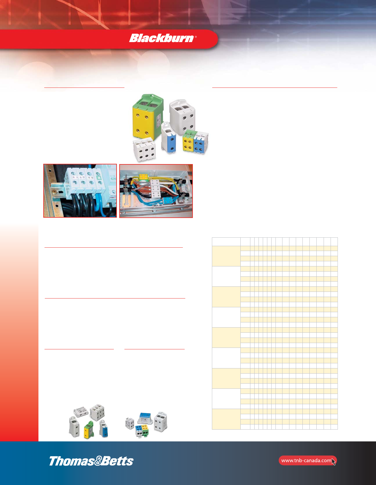
Typical Applications
•Ideal for OEM use in electrical, electronics, panel, switchboard,
switchgear, automation and control manufacturing
•Also suitable for industrial/commercial retrofit contractors,
installation technicians, maintenance and service providers
•Used in distribution panels, control boxes, automation products,
ESS centers and more
20
Mechanical and
Accessories
Features
•Insulated housing provides fast,
clean, safe installation and
controlled dielectric strength
•Grooved contact surfaces
penetrate conductor oxides for
best contact
•Easily installed and position-locked
with DIN rail or screw mounting
Specifications
•Max. Voltage: 600V
•Max. Temperature: 80°C
•Flammability Rating: V-2 (UL94)
•Standard & Testing: UL1059, Category XCFR2, File Numbers
E66436; SFS 2663; VDE 0220, Teil 1/11.71, Teil 2/11.71,
Sen 241510, SEN 245012; IEC 61238 class B
Tapping Blocks
•One pole, four identical
terminals
•Suitable for extending
or branching both
aluminum and copper
conductors
Terminal Blocks
•One-pole feedthrough terminal
blocks
•Three-pole version
(Cat. No. PDS3610) supports
three-phase systems
•Designed for connecting
or extending both aluminum
and copper conductors
Conductor Table
Conductors that can be used with the power Distribution
Blocks: number, cross-section and type.
•Requirements of a specific apparatus may restrict
the number of conductors
•Usually a maximum of three adjacent standard
cross-sections in one space
•In general, the conductors connected to one conductor
space of a connector must be of the same type
•Table values require careful installation
•We recommend use of ferrules when using fine-stranded
conductors
•After installation, check that all conductors are pressed
into a connection
•The nominal current of the power distribution blocks must
not be exceeded
•According to some installation standards, each incoming
and outgoing protection and neutral conductor in a panel
must have its own separate power distribution block
•The conductor numbers below refer only to industrially
installed power distribution blocks (internal connections in
a panel)
Blackburn Power Distribution Blocks are suitable for all panel building
applications and various terminal enclosure solutions; for extending or
branching the cables or changing the conductor type.
Power Distribution Blocks
Cat. No. AWG/
kcmil 8 6 4 3 2 1 1/0 2/0 3/0 4/0 250 300 350 400 500
PDS610
Al 1 1 1 1 1
Cu 11111
Cu 2
Cu 3
PDS3610
Al 1 1 1 1 1
Cu 11111
Cu 2
Cu 3
PDS440
Al 1 1 1 1 1 1 1 1
Cu 1111 1 1 1 1
Cu 2 2 2 2
Cu 3
PDS2300
Al 1 1 1 1 1 1 1 1
Cu 1 1 1 1 1 1 1 1
Cu 2 2 2
Cu 3
PDS30500
Al 1 1 1 1 1 1 1
Cu 1111111
Cu 2 2 2 2
Cu 3 3 3
PDS2610
Al 1 1 1 1 1 1
Cu 11111 1
Cu 2
Cu 3
PDS2440
Al 1 1 1 1 1 1 1 1
Cu 1111 1 1 1 1
Cu 2 2 2 2
Cu 3
PDS22300
Al 1 1 1 1 1 1 1 1
Cu 11111111
Cu 2 2 2
Cu 3
PDS230500
Al 1 1 1 1 1 1 1
Cu 1111111
Cu 2 2 2 2
Cu 3 3 3
Cross-sections of conductors (AWG/kcmil) and number of conductors/space.
section_1_E.pdf 20 9/26/2011 10:36:43 AM

21
Mechanical and
Accessories
Power Distribution Blocks
Cat. No. Wire
Range Max.
Current Tightening
Torque
Allen Hex
Socket Head
Terminal Screw Mounting Dimensions
W x H x D
(in.) Colour Std.
Pkg.
Terminal Blocks
PDS610 1/0–6 AWG
Cu or AI
150A Cu/
120A AI 90 lb./in. 5 mm Top Hat rail 0.7 x 1.9 x 1.7 Grey 30
PDS610B 1/0–6 AWG
Cu or AI
150A Cu/
120A AI 90 lb./in. 5 mm Top Hat rail 0.7 x 1.9 x 1.7 Blue 30
PDS610G 1/0–6 AWG
Cu or AI
150A Cu/
120A AI 90 lb./in. 5 mm Top Hat rail 0.7 x 1.9 x 1.7 Yellow – Green 30
PDS3610 1/0–6 AWG
Cu or AI
150A Cu/
120A AI 90 lb./in. 5 mm Top Hat rail 1.9 x 1.9 x 1.7 Grey 30
PDS440 4/0–4 AWG
Cu or AI
230A Cu/
180A AI 126 lb./in. 5 mm Top Hat rail
or screw 0.9 x 3.4 x 1.7 Grey 30
PDS440B 4/0–4 AWG
Cu or AI
230A Cu/
180A AI 126 lb./in. 5 mm Top Hat rail
or screw 0.9 x 3.4 x 1.7 Blue 30
PDS440G 4/0–4 AWG
Cu or AI
230A Cu/
180A AI 126 lb./in. 5 mm Top Hat rail
or screw 0.9 x 3.4 x 1.7 Yellow – Green 30
PDS2300 300–2 AWG
Cu or AI
285A Cu/
230A AI 216 lb./in. 8 mm Top Hat rail
or screw 1.2 x 3.7 x 2.3 Grey 30
PDS2300B 300–2 AWG
Cu or AI
285A Cu/
230A AI 216 lb./in. 8 mm Top Hat rail
or screw 1.2 x 3.7 x 2.3 Blue 30
PDS2300G 300–2 AWG
Cu or AI
285A Cu/
230A AI 216 lb./in. 8 mm Top Hat rail
or screw 1.2 x 3.7 x 2.3 Yellow – Green 30
PDS30500 500–3/0
Cu or AI
380A Cu/
310A AI 360 lb./in. 8 mm Screw 1.5 x 5.1 x 2.6 Grey 30
PDS30500B 500–3/0
Cu or AI
380A Cu/
310A AI 360 lb./in. 8 mm Screw 1.5 x 5.1 x 2.6 Blue 30
PDS30500G 500–3/0
Cu or AI
380A Cu/
310A AI 360 lb./in. 8 mm Screw 1.5 x 5.1 x 2.6 Yellow – Green 30
Tapping Blocks
PDS2610 1/0–6 AWG
Cu or AI
150A Cu/
120A AI 90 lb./in. 5 mm Top Hat rail 1.2 x 1.9 x 1.7 Grey 30
PDS2610B 1/0–6 AWG
Cu or AI
150A Cu/
120A AI 90 lb./in. 5 mm Top Hat rail 1.2 x 1.9 x 1.7 Blue 30
PDS2610G 1/0–6 AWG
Cu or AI
150A Cu/
120A AI 90 lb./in. 5 mm Top Hat rail 1.2 x 1.9 x 1.7 Yellow – Green 30
PDS2440 1/0–6 AWG
Cu or AI
150A Cu/
120A AI 90 lb./in. 5 mm Top Hat rail 1.7 x 3.4 x 1.9 Grey 30
PDS2440B 4/0–4 AWG
Cu or AI
230A Cu/
180A AI 126 lb./in. 5 mm Top Hat rail
or screw 1.7 x 3.4 x 1.9 Blue 30
PDS2440G 4/0–4 AWG
Cu or AI
230A Cu/
180A AI 126 lb./in. 5 mm Top Hat rail
or screw 1.7 x 3.4 x 1.9 Yellow – Green 30
PDS22300 4/0–4 AWG
Cu or AI
230A Cu/
180A AI 126 lb./in. 5 mm Top Hat rail
or screw 2 x 3.7 x 2.3 Grey 30
PDS22300B 300–2 AWG
Cu or AI
285A Cu/
230A AI 216 lb./in. 8 mm Top Hat rail
or screw 2 x 3.7 x 2.3 Blue 30
PDS22300G 300–2 AWG
Cu or AI
285A Cu/
230A AI 216 lb./in. 8 mm Top Hat rail
or screw 2 x 3.7 x 2.3 Yellow – Green 30
PDS230500 300–2 AWG
Cu or AI
285A Cu/
230A AI 216 lb./in. 8 mm Top Hat rail
or screw 2.5 x 5.1 x 2.6 Grey 30
PDS230500B 500–3/0
Cu or AI
380A Cu/
310A AI 360 lb./in. 8 mm Screw 2.5 x 5.1 x 2.6 Blue 30
PDS230500G 500–3/0
Cu or AI
380A Cu/
310A AI 360 lb./in. 8 mm Screw 2.5 x 5.1 x 2.6 Yellow – Green 30
section_1_E.pdf 21 9/26/2011 10:36:44 AM
22
Mechanical and
Accessories
Copper Mechanical Connectors
•For copper conductors
•Screws are plated steel
•Compact design
•Add suffix P to catalogue number for tin plating
•One-piece construction for strength and durability
•Excellent for confined quarters
•Cat. Nos. L400 and L650 are cast from high strength
bronze alloy
•Cat. Nos. L35, L70, L125 and L250 are cold forged from
pure electrolytic copper. Other models are cast from high
strength bronze alloy
•CSA Certified and UL Listed
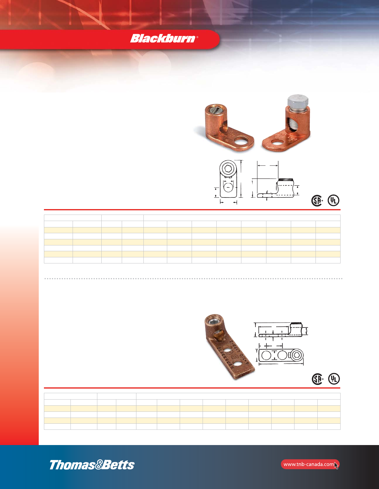
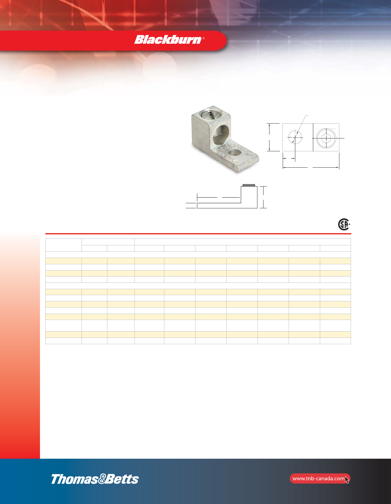
Type L — Single Conductor, One Hole Mount
Cat. No. Conductor Range Dimensions (in.)
Socket Hex max. min. L W H F D J E G
L35* – 8 str. 14 sol. 13/16 3/8 3/8 3/32 13/64 11/64 13/64 1/2
L70* – 4 str. 14 sol. 1-1/8 17/32 35/64 3/32 9/32 9/32 9/32 21/32
L125** L125H 1/0 str. 8 sol. 1-1/2 47/64 3/4 3/32 3/8 27/64 21/64 27/32
L250** L250H 250 kcmil 6 str. 1-61/64 15/16 1-1/16 1/8 29/64 5/8 13/32 1-3/32
L400B** L400H 500 kcmil 4/0 str. 3 1-13/32 1-15/32 9/32 5/8 7/8 9/16 1-5/8
L650** L650H 1000 kcmil 500 kcmil 4 2 2-3/16 17/32 3/4 1-1/4 9/16 2
* Sizes L35 and L70 have screwdriver slot head screws only.
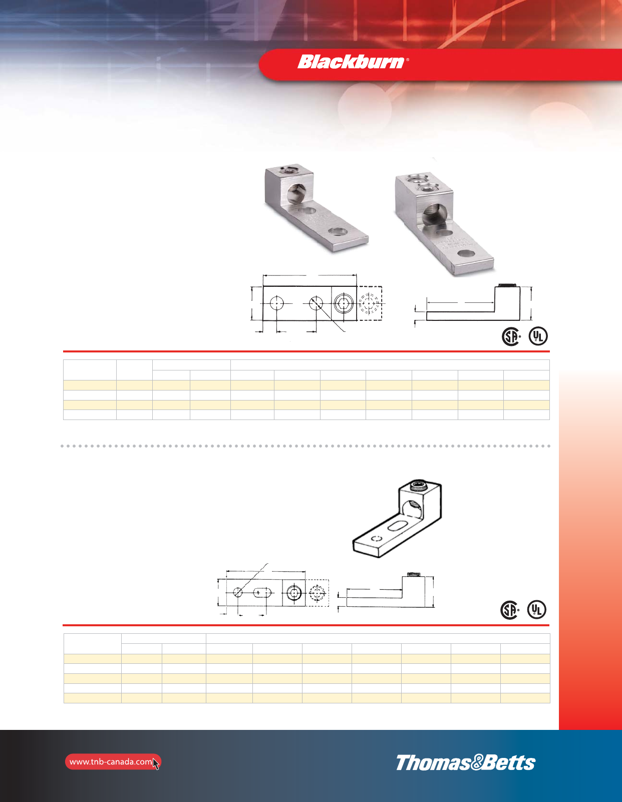
•Cast from high strength bronze alloy
•For use where large contact area is required to provide a
more secure mounting
•CSA Certified and UL Listed
Type L — Single Conductor, Two Hole Mount
Cat. No. Conductor Range Dimensions (in.)
Socket Hex max. min. L W H F D K E G J
L1252 L1252H 1/0 str. 4 str. 2-13/16 25/32 13/16 3/16 7/16 1 11/32 2 27/64
L2502 L2502H 250 kcmil 1/0 str. 3 3 1-1/32 15/64 7/16 1 13/32 1-7/8 5/8
L4002 L4002H 500 kcmil 4/0 str. 3-3/8 3-3/8 1-15/32 5/16 7/16 1 13/32 1-15/16 57/64
L6502 L6502H 1000 kcmil 500 kcmil 4-15/16 4-15/16 2 3/8 9/16 1-1/2 9/16 2-3/4 1-1/4
** Sizes L125 and up are Allen head screws.
W
L
G
H
DFJ
E
G
F
H
K
D
L
E
W
section_1_E.pdf 22 9/26/2011 10:36:44 AM
23
Mechanical and
Accessories
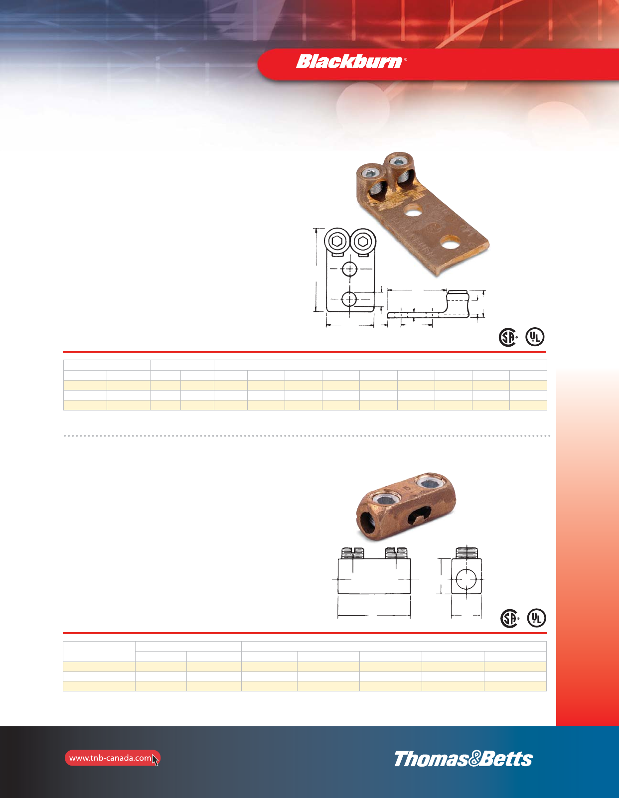
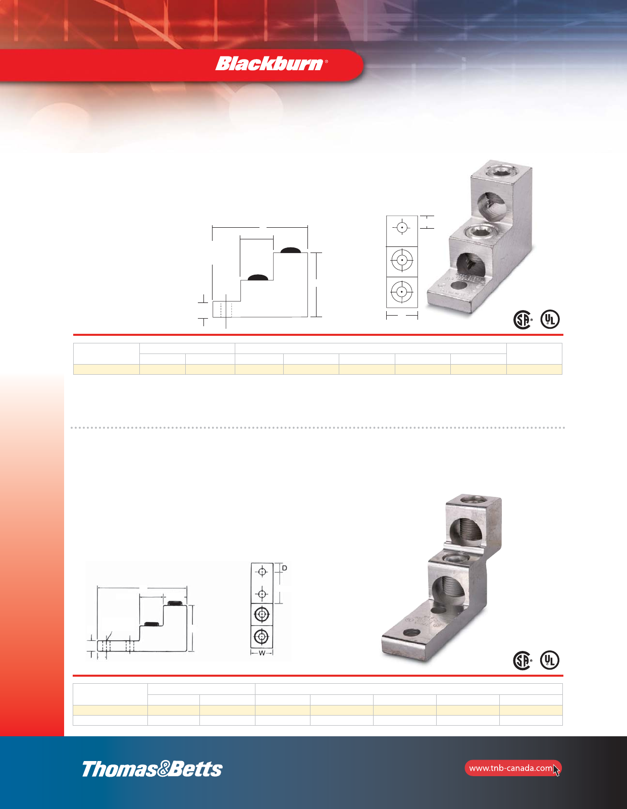
Copper Mechanical Connectors
•Conveniently terminates parallel conductors
•For copper conductors
•Screws are plated steel
•Compact design
•Add suffix P to catalogue number for tin plating
•One-piece construction for strength and durability
•Excellent for confined quarters
•CSA Certified and UL Listed
•Cast from high strength bronze alloy
Type TL — Two Conductors, Two Hole Mount
Cat. No. Conductor Range Dimensions (in.)
Socket Hex max. min. L W H F K E D G J
TL250 TL250H 250 kcmil 1/0 str. 4-5/16 1-7/8 9/32 5/8 1-3/4 9/16 1-1/16 3-3/16 5/8
TL400 TL400H 500 kcmil 4/0 str. 4-3/4 2-9/16 13/32 11/16 1-3/4 9/16 1-9/16 3 7/8
TL650 TL650H 1000 kcmil 500 kcmil 5-9/16 3-1/4 9/16 5/8 1-3/4 9/16 2-3/16 3-3/8 1-1/4
Four hole NEMA tang on TL650.
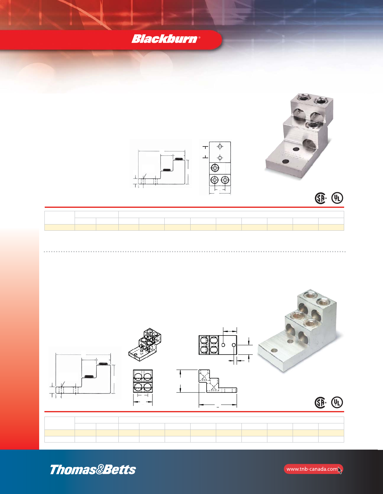
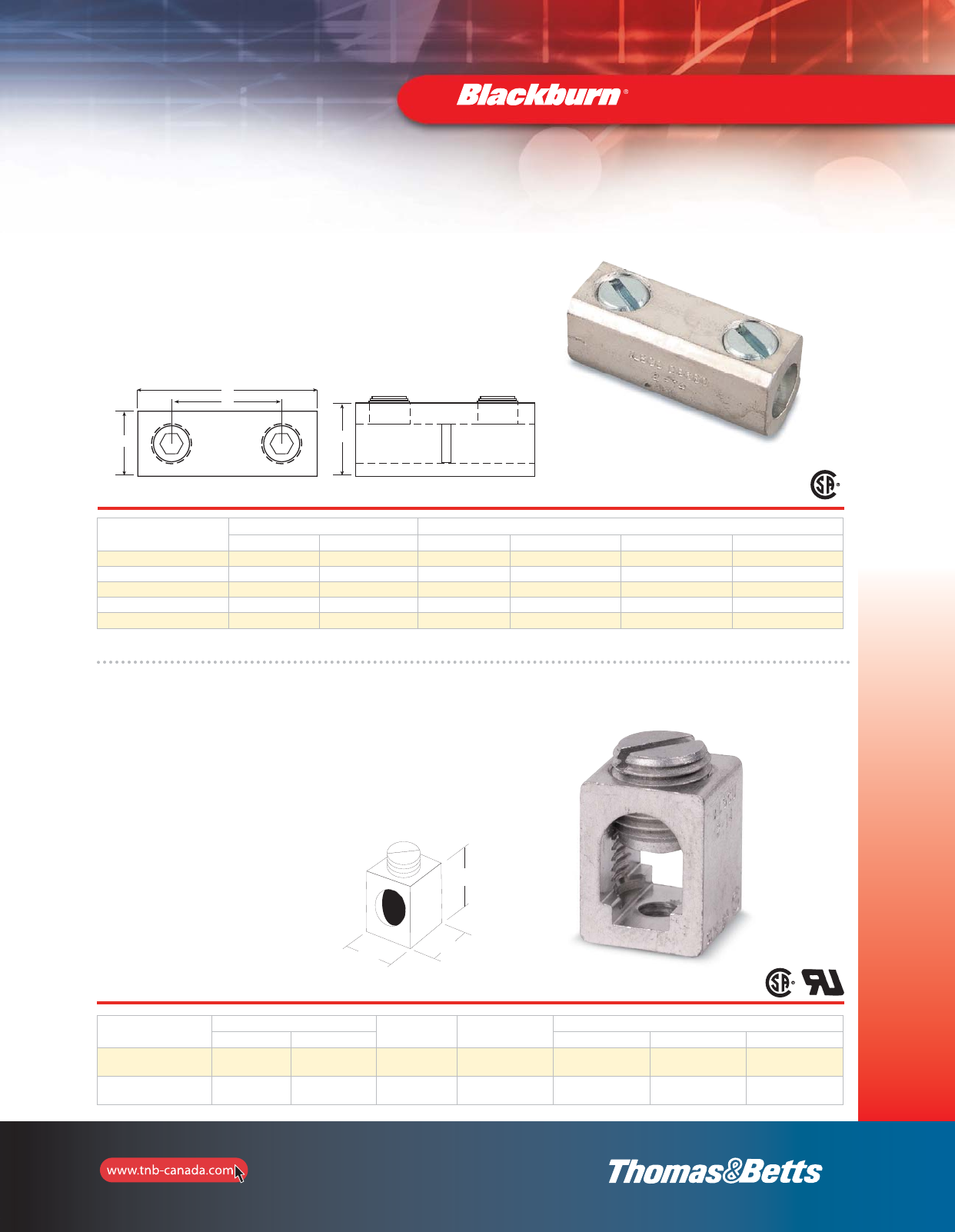
•Cast of high strength bronze alloy
•Plated steel socket head set screws
•For copper conductors
•Compact design
•Add suffix P to catalogue number for tin plating
•One-piece construction for strength and durability
•Excellent for confined quarters
•CSA Certified and UL Listed
Type S — Copper End-to-End Splice Connectors
Cat. No. Conductor Range Dimensions (in.)
max. min. L W H J I
S100BB 1 str. 4 str. 1-11/16 5/8 11/16 3/8 15/16
S225BB* 4 str. 1 str. 2-3/16 27/32 31/32 9/16 1-3/16
S400BB 500 kcmil 4/0 str. 2-7/8 1-3/16 1-5/16 7/8 1-5/8
* Not U.L. Listed.
G
F
L
E
WDK
JH
IH J
LW
section_1_E.pdf 23 9/26/2011 10:36:45 AM
24
Mechanical and
Accessories
Copper Mechanical Connectors
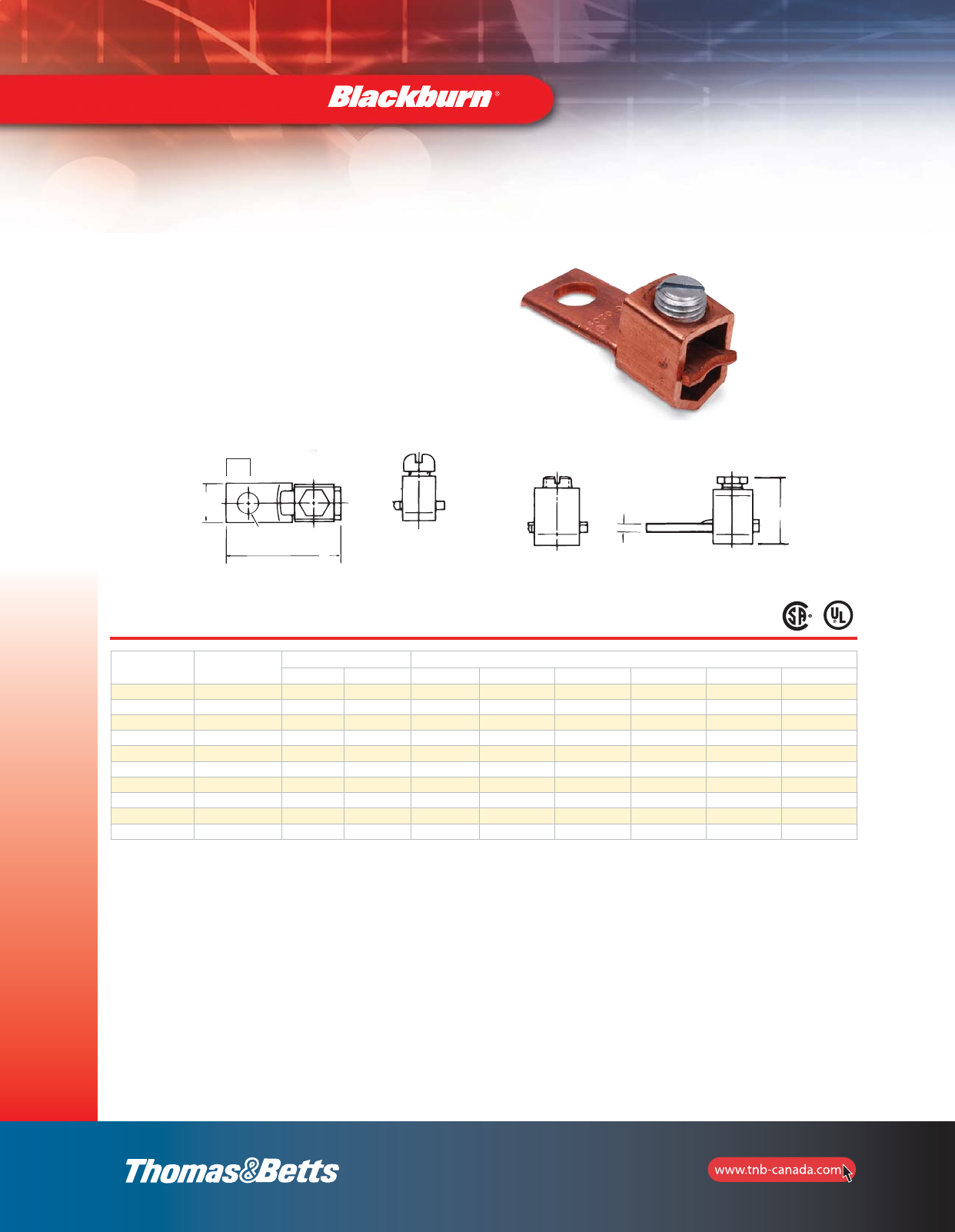
Type STC — Copper Single Conductor, One Hole Mount (Straight Tang)
Cat. No. Fig.
No.
Conductor Range Dimensions (in.)
max. min. L W H F E D
STC1014* 110 AWG 14 AWG 1 5/16 1/2 5/64 5/32 3/16
STC0614 2 6 str. 14 AWG 1-9/64 3/8 11/16 5/64 13/64 7/32
STC0414 24 str. 14 AWG 1-1/4 1/2 37/32 3/32 17/64 1/4
STC0208 3 2 str. 8 str. 1-15/32 1/2 31/32 3/32 17/64 1/7
STC1102 31/0 str. 2 str. 1-15/16 5/8 1-1/4 1/8 17/64 7/16
STC3104 3 3/0 str. 4 str. 2-1/4 3/4 1-9/16 1/8 13/32 7/16
STC4102 34/0 str. 2 str. 2-3/8 1 1-21/32 1/8 11/32 1/2
STC3511 3 350 kcmil 1/0 str. 3-1/4 1 1-5/8 3/16 13/32 5/8
STC5011 3500 kcmil 1/0 str. 3-7/8 1-1/2 1-13/16 3/16 13/32 15/16
STC9960 3 1000 kcmil 600 kmcil 5 2 2-5/8 1/4 17/32 1-1/8
*
CSA not applicable
.
W
E
D
•Uniquely designed pressure bar and notched v-bottom
collar provide a vise-like grip between conductor and
terminal
•CSA Certified and UL Listed for copper conductors
•Made of electrolytic seamless coppers
•Screws are zinc plated steel
Fig. 1
Fig. 2 Fig. 3
E Dia.
D
W
L
F
H
section_1_E.pdf 24 9/26/2011 10:36:46 AM
25
Mechanical and
Accessories
Copper Mechanical Connectors
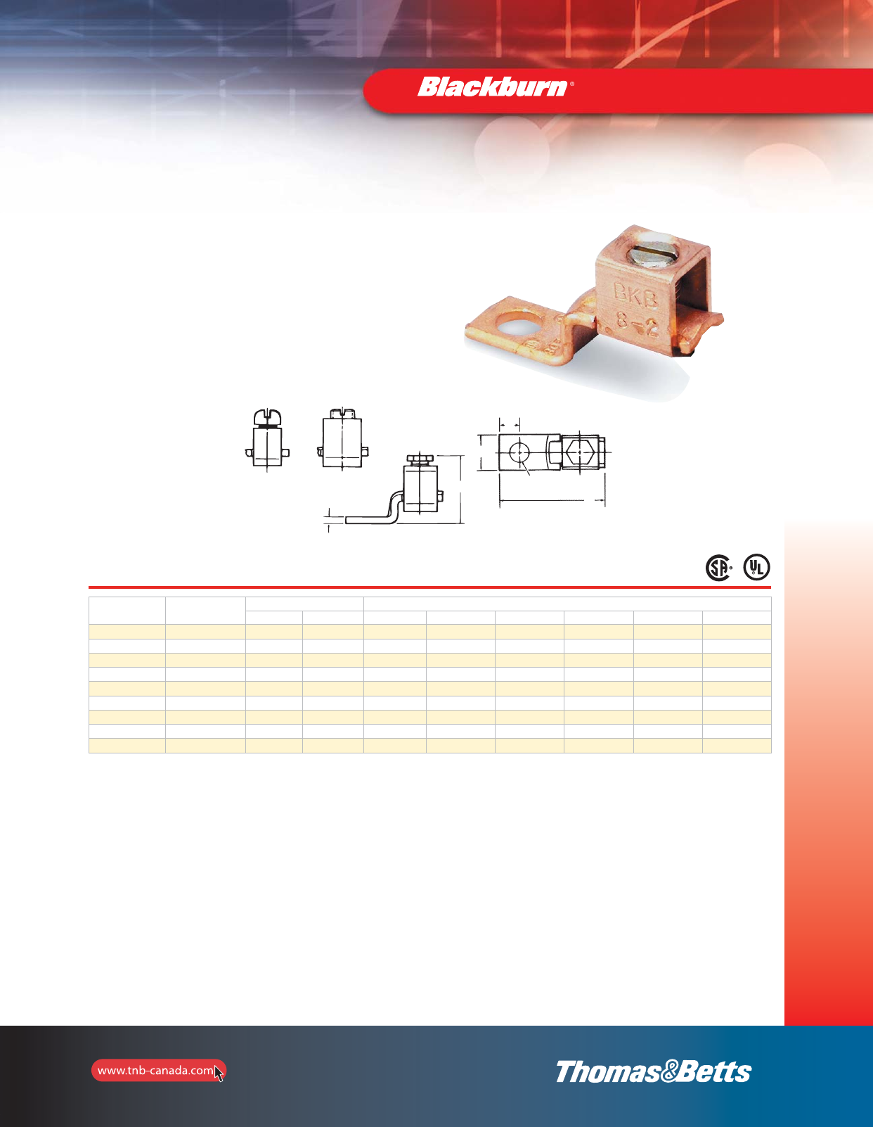
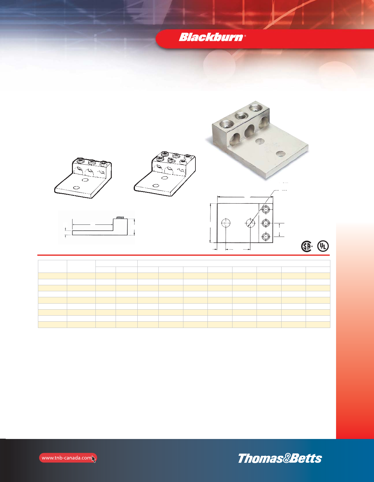
Type BTC — Copper Single Conductor, One Hole Mount (Offset Tang)
Fig. 1 Fig. 2
Fig. 3
E Dia.
•CSA Certified and UL Listed,
tested for copper conductors
•Made of electrolytic seamless copper
•Screws are zinc plated steel
Cat. No. Fig.
No.
Conductor Range Dimensions (in.)
max. min. L W H F E D
BTC1014* 110 AWG 14 AWG 1 5/16 43/64 5/64 5/32 3/16
BTC0614 2 6 str. 14 AWG 1-3/32 3/8 25/32 5/64 13/64 7/32
BTC0208 22 str. 8 str. 1-15/32 1/2 27/32 3/32 17/64 1/4
BTC1102 3 1/0 str. 2 str. 1-25/32 5/8 1-13/32 1/8 17/64 7/16
BTC3104 33/0 str. 4 str. 2-3/64 3/4 1-9/16 1/8 13/32 7/16
BTC4102 3 4/0 str. 2 str. 2-9/16 1 1-61/64 1/8 11/32 1/2
BTC3511 3350 kcmil 1/0 str. 3-1/4 1 2-1/2 3/16 13/32 5/8
BTC5011 3 500 kcmil 1/0 str. 4-1/4 1-1/2 2-21/32 3/16 13/32 15/16
BTC9960 31000 kcmil 600 kcmil 4-3/4 2 3-9/16 1/4 17/32 1-1/8
*
CSA not applicable
.
F
H
W
D
L
section_1_E.pdf 25 9/26/2011 10:36:47 AM
26
Mechanical and
Accessories
Dual-Rated Mechanical Connectors
•For copper and aluminum conductors
•Easy installation—no special tools required
•Tin plated for low contact resistance
•CSA Certified and UL Listed, AL9CU, 600V Rated
•All aluminum bodies
•Slotted screw on lugs up through 2/0 str.; 5/16
socket screw on sizes 250 through 350 kcmil;
3/8 hex socket on sizes 500 kcmil and above
Type ADR–ALCÜL™— Single Conductor, One Hole Mount
Cat. No. Conductor Range Dimensions (in.)
max. min. L W H D E F G
Slotted Screw
ADR6 6 str. 14 AWG 1-3/64 1/2 31/64 15/64 1/4 5/64 43/64
ADR2 2 str. 14 AWG 1-5/32 1/2 9/16 19/64 1/4 7/64 11/16
ADR11 1/0 str. 14 AWG 1-15/32 5/8 25/32 7/16 1/4 3/16 27/32
ADR21 2/0 str. 14 AWG 1-15/32 5/8 25/32 7/16 1/4 3/16 27/32
Socket Screw
ADR25 250 kcmil 6 str. 2 1 1-1/8 15/32 5/16 1/4 1
ADR30 300 kcmil 6 str. 2 1 1-1/8 15/32 5/16 1/4 1
ADR35 350 kcmil 6 str. 2-1/4 1-1/8 1-1/4 1/2 3/8 1/4 1-1/8
ADR50 500 kcmil 4 str. 2-13/16 1-1/2 1-9/16 3/4 3/8 5/16 1-19/32
ADR60 600 kcmil 2 str. 3-3/16 1-1/2 1-9/16 13/16 3/8 7/16 1-13/16
ADR6004* 600 kcmil
(2) 250 kcmil
4 str.
(2) 1/0 str. 2-13/16 1-3/8 1-13/16 5/8 3/8 5/16 1-1/2
ADR80 800 kcmil 300 kcmil 3-3/8 1-3/4 1-15/16 7/8 5/8 1/2 1-3/4
ADR99 1000 kcmil 500 kcmil 3-3/8 1-3/4 1-15/16 7/8 5/8 1/2 1-3/4
* U.L. and CSA not applicable.
E Hole Dia.
W
D
L
F
G H
section_1_E.pdf 26 9/26/2011 10:36:48 AM
27
Mechanical and
Accessories
Dual-Rated Mechanical Connectors
Type ADR–ALCÜL™— Single Conductor, Two Hole Mount*
Cat. No. Figure Conductor Range (AL or CU) Dimensions (in.)
max. min. L W H D E F G
ADR35-12D 1350 kcmil 6 str. 4-1/4 1-1/4 1-3/8 5/8 1/2 5/16 3
ADR60-12D 2 600 kcmil 2 str. 5-5/16 1-1/2 1-1/2 5/8 1/2 3/8 3-1/16
ADR80-12D 2800 kcmil 300 kcmil 6-3/16 1-3/4 1-7/8 5/8 1/2 9/16 3-7/16
ADR99-12D 2 1,000 kcmil 350 kcmil 6-3/16 1-3/4 1-7/8 5/8 1/2 9/16 3-7/16
* NEMA spacing: 1-3/4” centers.
Connectors accommodating conductors 600 kcmil and larger have double row of set screws ( D suffix).
E Bolt Hole dia.
Type ADR–ALCÜL™— Single Conductor, Switchgear Mount*
Cat. No. Conductor Range (AL or CU) Dimensions (in.)
max. min. L W H D E F G
ADR25-12S 250 kcmil 3/0 str. 3 1 13-16 1/2 3/8 1/4 2
ADR35-12S 350 kcmil 4 str. 4-11/16 1-1/4 1-9/16 23/32 1/2 7/16 3-5/16
ADR50-12S 500 kcmil 400 kcmil 4-11/16 1-1/4 1-9/16 23/32 1/2 7/16 3-5/16
ADR80-12DS 800 kcmil 300 kcmil 6-3/16 1-5/8 1-7/8 23/32 1/2 9/16 3-7/16
ADR99-12DS 1000 kcmil 350 kcmil 6-3/16 1-5/8 1-7/8 23/32 1/2 9/16 3-7/16
* NEMA spacing: 1-3/4” centers except ADR25-12S: 1” centers.
Connectors accommodating conductors 600 kcmil and larger have double row of set screws ( D suffix).
•For copper and aluminum conductors
•Easy installation—no special tools required
•Tin plated for low contact resistance
•CSA Certified and UL Listed
•All aluminum bodies
•For copper and aluminum conductors
•Easy installation—no special tools required
•Tin plated for low contact resistance
•CSA Certified and UL Listed
•All aluminum bodies
Fig. 1
Fig. 2
E Bolt Hole dia.
FGH
D
L
W
F G H
D
L
W
1-3/4
Max.
1-3/4
section_1_E.pdf 27 9/26/2011 10:36:49 AM
28
Mechanical and
Accessories
Dual-Rated Mechanical Connectors
Type ASL–ALCÜL™— Two Conductors, One-Hole Mount
Cat. No. Conductor Range Dimensions (in.) Mtg. Hole
Dia.
max. min. L W H D F
ASL30-21 300 kcmil 6 str. 3 1-1/8 2 15/32 1/2 5/16
Type ASL–ALCÜL™— Two Conductors, Two-Hole Mount
Cat. No. Conductor Range Dimensions (in.)
max. min. L W H D F
ASL60-22 600 kcmil 2 str. 4-29/32 1-1/2 3 3/4 3/8
ASL75-22 750 kcmil 3/0 str. 4-49/32 1-1/2 3 3/4 3/8
13/32 dia.
2 holes
1-3/16 1-3/8
1-3/8
•For copper and aluminum conductors
•Easy installation—no special tools required
•Tin plated for low contact resistance
•CSA Certified and UL Listed
•All aluminum bodies
•For copper and aluminum conductors
•Easy installation—no special tools required
•Tin plated for low contact resistance
•CSA Certified and UL Listed
•All aluminum bodies
13/32 1-3/16
1-3/8
L
F
D
F
D
W
D
FH
L
section_1_E.pdf 28 9/26/2011 10:36:50 AM

29
Mechanical and
Accessories
Type ADR–ALCÜL™— Two Conductor, One-Hole Mount
Cat. No. Conductor Range Dimensions (in.)
max. min. L W H D E F G I
ADR11-21 1/0 str. 14 AWG 1-15/32 1-7/32 25/32 7/16 1/4 3/16 27/32 35/64
ADR21-21* 2/0 str. 14 AWG 1-15/32 1-1/4 25/32 27/64 1/4 3/16 27/32 21/32
ADR25-21 250 kcmil 6 str. 2-9/16 1-41/64 1-3/16 7/8 3/8 1/4 1-9/16 13/16
ADR35-21 350 kcmil 6 str. 2-7/8 1-59/64 1-1/4 7/8 1/2 1/4 1-3/4 61/64
ADR60-21 600 kcmil 2 str. 3-3/16 2-13/32 1-9/16 5/8 1/2 7/16 1-13/16 1-7/32
ADR80-21 800 kcmil 300 kcmil 3-3/8 3-3/16 1-15/16 7/8 5/8 1/2 1-3/4 1-5/8
ADR99-21 1000 kcmil 500 kcmil 3-3/8 3-3/16 1-15/16 7/8 5/8 1/2 1-3/4 1-5/8
Type ADR–ALCÜL™— Two Conductor, Two-Hole Mount*
Cat. No. Figure Conductor Range Dimensions (in.)
max. min. L W H D E F G I
ADR35-22** 1350 kcmil 6 str. 4-1/4 2-19/64 1-3/8 5/8 1/2 5/16 3 1-7/32
ADR60-22D 2 600 kcmil 2 str. 5-5/16 2-3/4 1-1/2 5/8 1/2 3/8 3-1/16 1-7/16
ADR80-22D 2800 kcmil 300 kcmil 6-3/16 3-1/2 1-7/8 5/8 1/2 9/16 3-7/16 1-13/16
ADR99-22D 2 1000 kcmil 350 kcmil 6-3/16 3-1/2 1-7/8 5/8 1/2 9/16 3-7/16 1-13/16
“E” Bolt Size
* CSA not applicable.
1-3/4 “E” Bolt Size
Fig. 1
Fig. 2
* NEMA Spacing: 1-3/4” centers.
** Not CSA Certified.
Connectors accommodating conductors 600 kcmil and larger have double row of set screws (D suffix).
Dual-Rated Mechanical Connectors
•For copper and aluminum conductors
•Easy installation—no special tools required
•Tin plated for low contact resistance
•CSA Certified and UL Listed
•All aluminum bodies
•For copper and aluminum conductors
•Easy installation—no special tools required
•Tin plated for low contact resistance
•CSA Certified and UL Listed
•All aluminum bodies
D
L
I
WFG
L
W
D
I
GH
F
section_1_E.pdf 29 9/26/2011 10:36:51 AM
30
Mechanical and
Accessories
Dual-Rated Mechanical Connectors
Type ASL–ALCÜL™— Three Conductors, Two-Hole Mount
Type ASL–ALCÜL™— Four Conductors, Two-Hole Mount
Cat. No. Conductor Range Dimensions (in.)
max. min. L W H F D I X2 X1 Y
ASL60-42 600 kcmil 2 str. 4-29/32 2-1/2 3 3/4 3/8 1-7/32 1.75 0.375 1.234
ASL75-42 750 kcmil 3/0 str. 4-49/32 2-27/21 3 3/4 3/8 1-5/16 1.75 0.375 1.31
Cat. No. Conductor Range Dimensions (in.)
max. min. L W H F D I X2 X1 Y
ASL60-32 600 kcmil 2 str. 4-29/32 2-1/2 3 3/4 3/8 1-7/32 1.75 0.375 1.234
1-3/16 1-3/8
55/64 DIA.
2 HOLES
1-3/16
1-3/8
•For copper and aluminum conductors
•Easy installation—no special tools required
•Tin plated for low contact resistance
•CSA Certified and UL Listed
•All aluminum bodies
•For copper and aluminum conductors
•Easy installation—no special tools required
•Tin plated for low contact resistance
•CSA Certified and UL Listed
•All aluminum bodies
I
H
L
D
F
u Dia.
2 holes
W
H
L
X1
X2
Y
H
L
F
D
1-3/8
W
I
section_1_E.pdf 30 9/26/2011 10:36:53 AM
31
Mechanical and
Accessories
Dual-Rated Mechanical Connectors
Type ADR–ALCÜL™— Three Conductors, Two-Hole Mount**
Cat. No. Fig.
No.
Conductor Range Dimensions (in.)
max. min. L W H D E F G I
ADR02-32 12 str. 14 AWG 2-3/16 1-5/8 5/8 11/32 5/16 3/16 1-11/16 9/16
ADR11-32 1 1/0 str. 14 AWG 2-29/32 2 7/8 11/32 3/8 1/4 2-5/32 45/64
ADR31-32 13/0 str. 6 str. 4 2-13/16 1-3/16 5/8 1/2 5/16 3 31/32
ADR25-32* 1 250 kcmil 6 str. 4-3/16 2-13/16 1-1/4 5/8 1/2 1/4 3-1/16 31/32
ADR35-32* 1350 kcmil 6 str. 4-3/16 3-3/16 1-1/4 5/8 1/2 1/4 3-1/16 1-1/32
ADR50-32* 1 500 kcmil 4 str. 4-11/16 3-3/4 1-9/16 5/8 1/2 7/16 3-5/16 1-1/4
ADR60-32D 2600 kcmil 2 str. 5-5/16 4-3/16 1-1/2 5/8 1/2 3/8 3-1/6 1-7/16
ADR80-32* 2 800 kcmil 300 kcmil 6-3/16 4-1/2 1-7/8 5/8 1/2 9/16 3-7/16 1-9/16
ADR99-32* 21000 kcmil 500 kcmil 6-3/16 4-3/4 1-7/8 5/8 1/2 9/16 3-7/16 1-41/64
** NEMA Spacing: 1-3/4” centers except ADR02-32; 7/8” centers and ADR11-32; 1” centers.
Connectors accommodating conductors 600 kcmil and larger have double row of set screws (D suffix).
Fig. 1 Fig. 2
E Bolt Size
•For copper and aluminum conductors
•Easy installation—no special tools required
•Tin plated for low contact resistance
•CSA Certified and UL Listed
•All aluminum bodies
13⁄4
H
G
FW
L
D
I
1-3/4
section_1_E.pdf 31 9/26/2011 10:36:53 AM
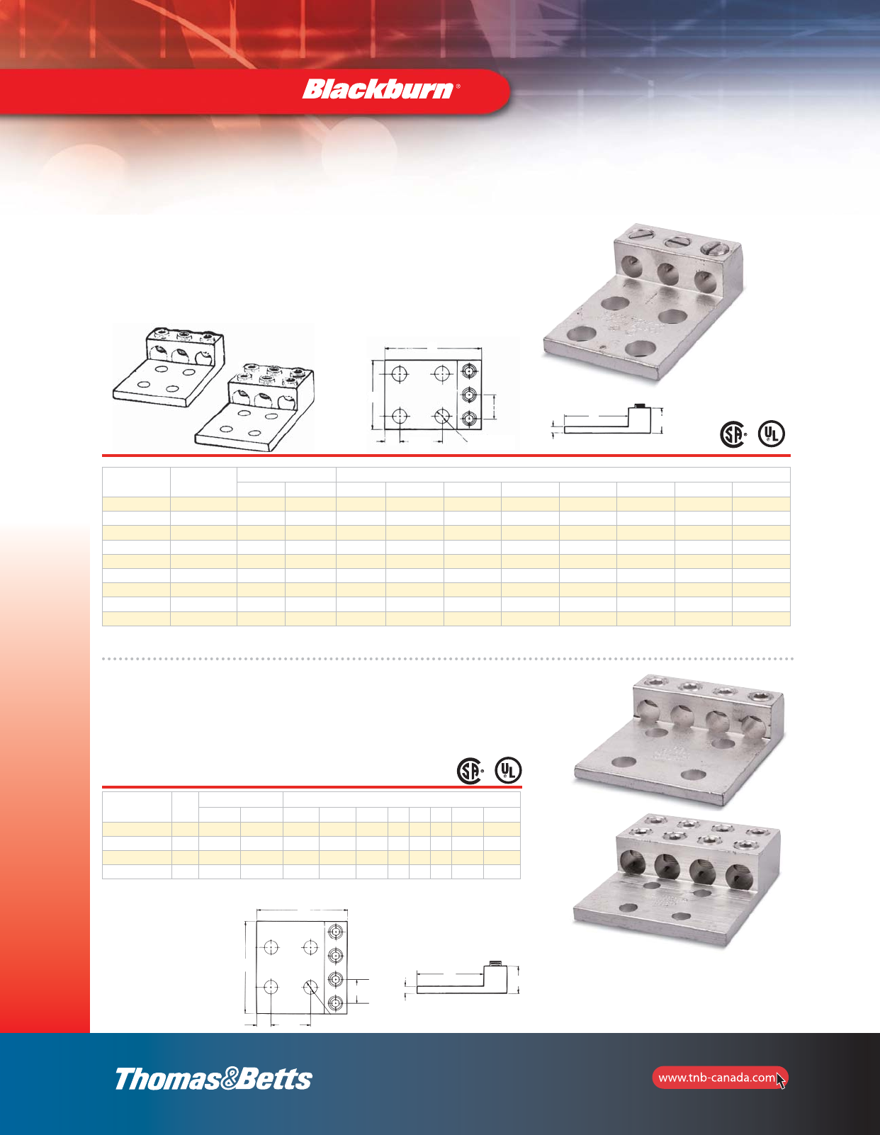
Fig. 1
Fig. 2
32
Mechanical and
Accessories
Dual-Rated Mechanical Connectors
Type ADR–ALCÜL™— Three Conductors, Four-Hole Mount**
1-3/4 “E” Bolt Size
Cat. No. Fig.
No.
Conductor Range Dimensions (in.)
max. min. L W H D E F G I
ADR02-34 12 str. 14 AWG 2-3/16 1-5/8 5/8 11/32 5/16 3/16 1-11/16 9/16
ADR11-34 1 1/0 str. 14 AWG 2-29/32 2 7/8 11/32 3/8 1/4 2-5/32 45/64
ADR31-34 13/0 str. 6 str. 4 2-13/16 1-3/16 5/8 1/2 5/16 3 31/32
ADR25-34* 1 250 kcmil 6 str. 4-3/16 2-13/16 1-1/4 5/8 1/2 1/4 3-1/16 31/32
ADR35-34* 1350 kcmil 6 str. 4-3/16 3-3/16 1-1/4 5/8 1/2 1/4 3-1/16 1-1/32
ADR50-34* 1 500 kcmil 4 str. 4-11/16 3-3/4 1-9/16 5/8 1/2 7/16 3-5/16 1-1/4
ADR60-34D 2600 kcmil 2 str. 5-5/16 4-3/16 1-1/2 5/8 1/2 3/8 3-1/16 1-7/16
ADR80-34* 2 800 kcmil 300 kcmil 6-3/16 4-1/2 1-7/8 5/8 1/2 9/16 3-7/16 1-9/16
ADR99-34* 21000 kcmil 500 kcmil 6-3/16 4-3/4 1-7/8 5/8 1/2 9/16 3-7/16 1-41/64
** NEMA Spacing: 1-3/4” centers except ADR02-34; 7/8” centers and ADR11-34; 1” centers.
Connectors accommodating conductors 600 kcmil and larger have double row of set screws (D suffix).
Type ADR–ALCÜL™— Four Conductors, Four-Hole Mount*
Fig. 2
Cat. No. Fig.
No.
Conductor Range Dimensions (in.)
max. min. L W H D E F G I
ADR25-44 1250 kcmil 6 str. 4 4-1/16 1-3/16 5/8 1/2 5/16 3 1-3/64
ADR35-44 1 350 kcmil 6 str. 4-1/4 4-23/32 1-3/8 5/8 1/2 5/16 3 1-7/32
ADR60-44D 2600 kcmil 2 str. 5-5/16 5-5/8 1-1/2 5/8 1/2 3/8 3-1/16 1-7/16
ADR80-44D 2 800 kcmil 350 kcmil 6-3/16 7-1/8 1-7/8 5/8 1/2 9/16 3-7/16 1-13/16
Fig. 1
Fig. 2
* NEMA Spacing: 1-3/4” centers.
Connectors accommodating conductors 600 kcmil and larger have double row of set screws (D suffix).
•For copper and aluminum conductors
•Easy installation—no special tools required
•Tin plated for low contact resistance
•CSA Certified and UL Listed
•All aluminum bodies
•For copper and aluminum conductors
•Easy installation—no special tools required
•Tin plated for low contact resistance
•CSA Certified and UL Listed
•All aluminum bodies
L
W
D
FGH
1-3/4 E Bolt Size
L
w
D
I
FGH
section_1_E.pdf 32 9/26/2011 10:36:54 AM
33
Mechanical and
Accessories
Dual-Rated Mechanical Connectors
Type ASR–ALCÜL™— Splice Reducers with Solid Barrier Wire Stop
Type BX–ALCÜL™— Rectangular Connectors
Cat. No. Conductor Range Style & Size
of Boss Boss
Hole Tapped
Dimensions (in.)
max. min. L W H
BX0214 214CU
12AL
Square
0.229” 10–32 15/32 15/32 9/16
BX1114 1/0 14CU
12AL
Square
0.229” 10–32 5/8 17/32 39/64
Cat. No. Conductor Range (AL or CU) Dimensions (in.)
max. min. L W H I
ASR0214* 2 str. 14 AWG 1-1/4 33/64 39/64 21/32
ASR1114* 1/0 str. 14 AWG 1-1/2 39/64 23/32 51/64
ASR2506 250 kcmil 6 str. 2-1/8 55/64 31/32 1-7/64
ASR3506 350 kcmil 6 str. 2-3/8 1-1/32 1-1/8 1-1/4
ASR7525** 750 kcmil 250 kcmil 6-1/4 1-5/8 1-3/4 1-5/8
W
L
I
H
* Slotted screws.
** Two set screws per end. CSA not applicable.
•For copper and aluminum conductors
•Easy installation—no special tools required
•Tin plated for low contact resistance
•CSA Certified and UL Listed
•All aluminum bodies
•Recognized component in accordance with U.L. 486B
standard—90°C rating
•Anti-rotational boss
•For copper and aluminum conductors
•Easy installation—no special tools required
•Tin plated for low contact resistance
•CSA Certified and UL Listed
•All aluminum bodies
W
L
H
H
L
I
W
L
H
W
section_1_E.pdf 33 9/26/2011 10:36:54 AM

34
Mechanical and
Accessories
Dual-Rated Mechanical Connectors
Tightening Torque Values for Aluminum Dual-Rated Socket Screw Connectors
AWG or
Circular
Mil Size
Tightiening Torque in
(in.-lb) AWG or
Circular
Mil Size
Tightiening Torque in
(in.-lb)
Screwdriver Wrench Screwdriver Wrench
12 20 75 4/0 – 200
10 20 75 250 – 250
8 20 75 350 – 250
6 35 100 500 – 300
4 35 100 600 – 300
2 50 125 700 – 300
1 50 125 750 – 300
1/0 50 150 800 – 300
2/0 50 150 1000 – 400
3/0 – 200 – – 400
section_1_E.pdf 34 9/26/2011 10:36:55 AM
35
Mechanical and
Accessories
Hardware
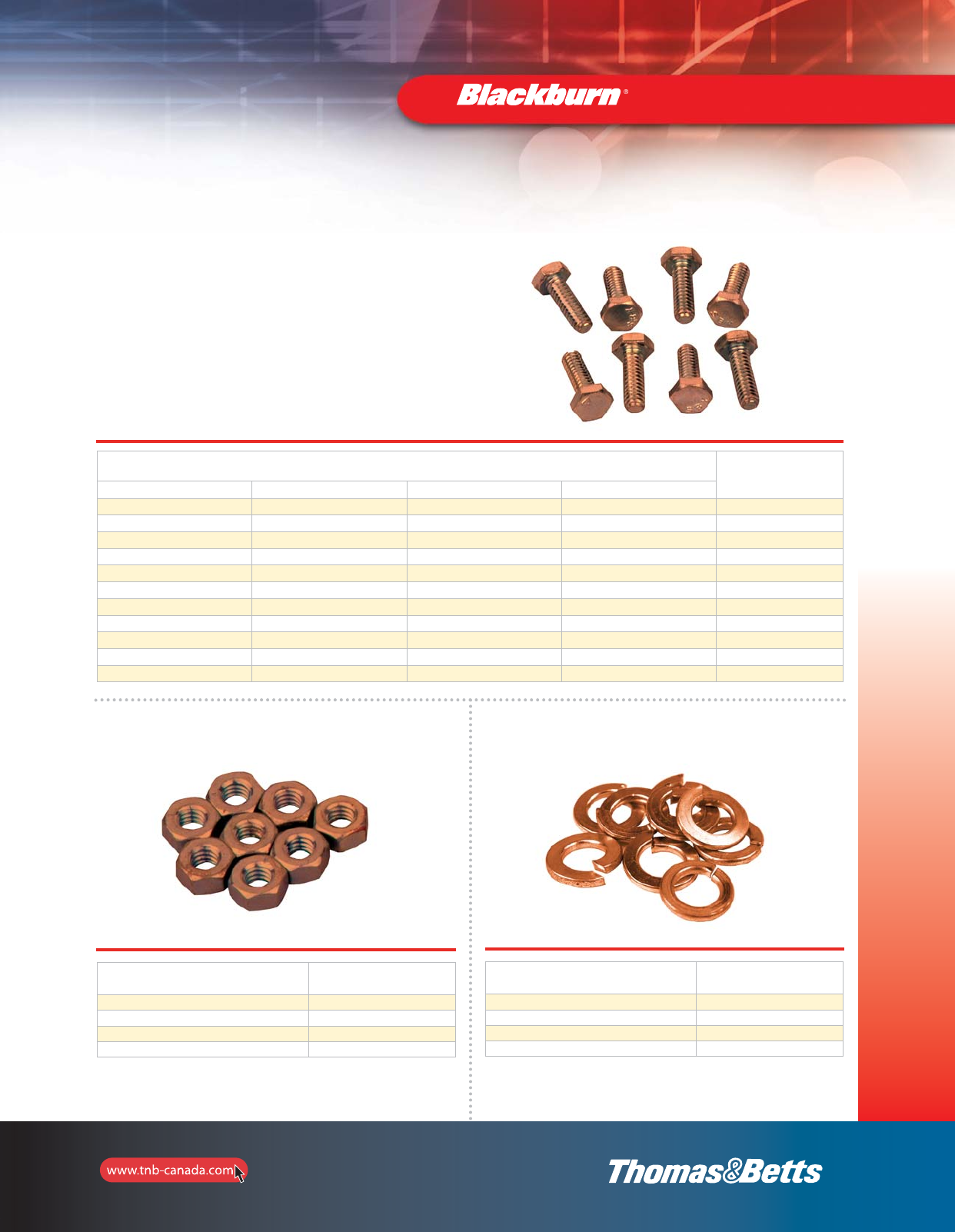
Type BB — Silicon Bronze Hardware Hex Head Bolts
•For tin plated silicon bronze hardware,
add suffix P to Catalogue Number
•Bolts 2” long or less have full thread; longer bolts have 2”
of thread, except 1/4”–20 bolts have 1/4” min. thread
Cat. No.
Diameter and Threads per inch Length
(in.)
1/4”–20 5/16”–18 3/8”–16 1/2”–13
25100BB-C 31100BB-C 37100BB-C 50100BB-C 1
– 31125BB-C 37125BB-C 50125BB-C 1-1/4
– 31150BB-C 37150BB-C 50150BB-C 1-1/2
– 31175BB-C 37175BB-C 50175BB-C 1-3/4
– 31200BB-C 37200BB-C 50200BB-C 2
25225BB-C 31225BB-C 37225BB-C 50225BB-C 2-1/4
– 31250BB-C 37250BB-C 50250BB-C 2-1/2
– 31275BB-C 37275BB-C 50275BB-C 2-3/4
– 31300BB-C 37300BB-C 50300BB-C 3
– – 37325BB-C 50325BB-C 3-1/4
– – 37350BB-C 50350BB-C 3-1/2
Type HN — Bronze Hex Nuts
Cat. No. Diameter
and Threads per inch
14010HN-C 1/4–20
31010HN-C 5/16–18
37010HN-C 3/8–16
50010HN-C 1/2–13
Type SW — Bronze Split Lockwashers
Cat. No. Bolt Size
(in.)
14030SW-C 1/4
31030SW-C 5/16
37030SW-C 3/8
50030SW-C 1/2
section_1_E.pdf 35 9/26/2011 10:36:56 AM
36
Mechanical and
Accessories
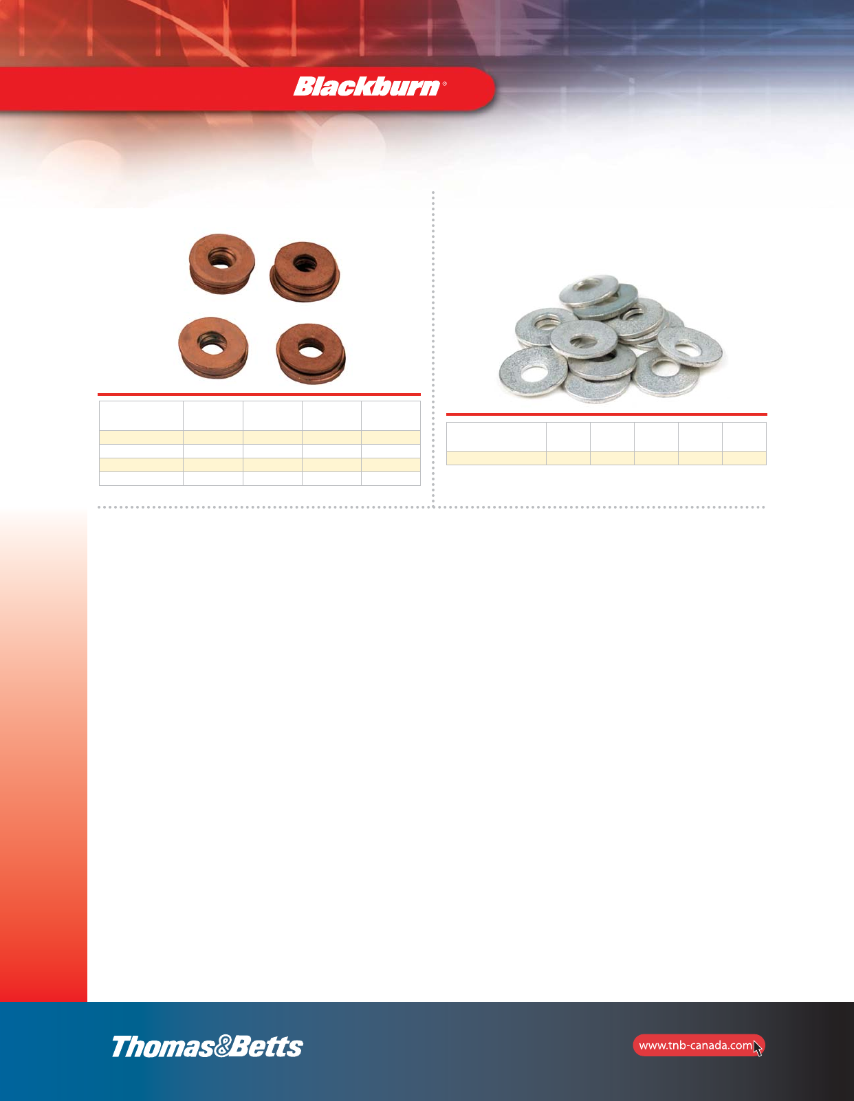
Type FW — Bronze Flat Washers
Cat. No. Bolt Size
(in.) O.D.
(in.) I.D.
(in.) Thickness
(in.)
14040FW-C 1/4 11/16 0.260 0.040
31040FW-C 5/16 7/8 0.336 0.064
37040FW-C 3/8 1 0.395 0.064
50040FW-C 1/2 1-1/4 0.562 0.091
Cat. No. Bolt Size
(in.) O.D.
(in.) I.D.
(in.) Thickness
(in.) Height
(in.)
50050BW-C 1/2 1-1/8 17/32 0.062 1/8
Type BW — Belleville Washers
301 Series Stainless Steel
Hardware
section_1_E.pdf 36 9/26/2011 10:36:57 AM
37
Compression
Quick Reference
Compression Connectors — Quick Reference
Type WR
Wide Range
Compression Connectors
pp. 38–44
Type CF
Copper Compression
Tap Connectors
p. 45
Type C
Compression Tap
Covers
p. 46
Type CTL
Copper Short Barrel
Connectors
p. 47
Type CTL-L, LCN
Copper Long Barrel
Connectors
pp. 48–50
Type CU, CSP
Copper
Compression Splices
pp. 51–52
Type ATL
Aluminum
Compression Connectors
pp. 53–54
Type ASP
Aluminum Splices
p. 55
Type PA
Pin Adapter
Terminals
p. 56
Wedge Clamps
p. 57
section_1_E.pdf 37 9/26/2011 10:37:00 AM
38
Compression
Connectors
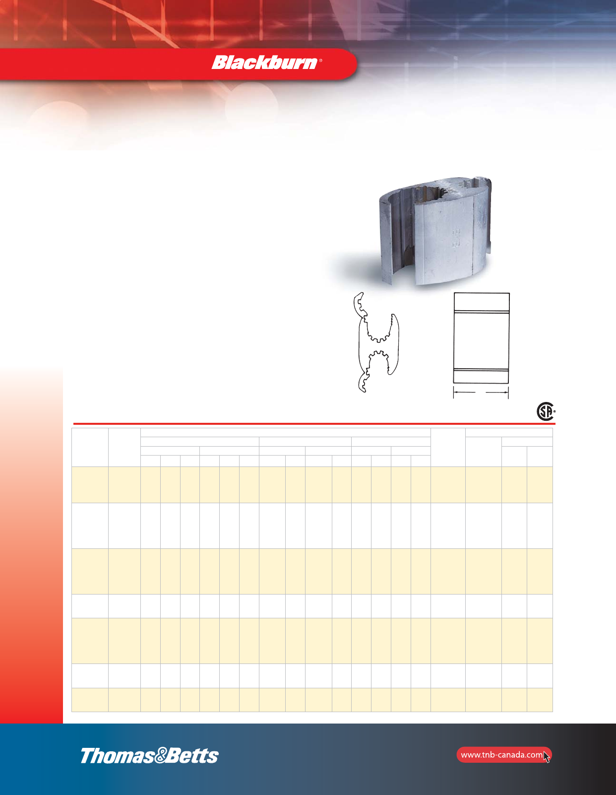
Compression H-Taps Connectors
•For combinations of aluminum-aluminum and
aluminum-copper conductors
•Pass the requirements of ANSI C119.4
•Standard compression tools and dies install all sizes
•Seven Connector Program provides superior connector
performance, lower connection costs and simplified
installation procedures
•Fold-in tabs provide positive tab interlock as tool closes
•Field-proven ribbed design provides unparalled
connector/conductor contact, without distorting the
conductor’s shape
•Made of 1350 aluminum alloy
•Pre-filled with an oxide inhibitor which is held captive
in the rib/connection area
•For copper to copper combinations, use CF type
shown on page 45.
•CSA Certified
Cat. No. Connector
No.
Conductor Range
Connector
Length
L (in.)
Installation Information
Standard Conductor Compact Conductor Diameter (in.)
Connector
Die
No. Indents
Main Tap Main Tap Main Tap Mech.
Tool Hyd.
Tool
ACSR Str. Sol. ACSR Str. Sol. ACSR Str. ACSR Str. max. min. max. min.
WR159 1
2
3
4
6
1
2
3
4
6
2
3
4
6
2
3
4
6
1
2
3
4
6
2
3
4
6
2
3
4
6
1
2
3
4
6
2
3
4
6
1
2
3
4
6
0.332 0.162 0.332 0.162 1-7/16 0 4 2
WR189 21/0
1
2
3
2/0
1/0
1
2
3/0
2/0
1/0
1
2
3
4
6
1
2
3
4
6
1/0
1
2
3
4
6
2/0
1/0
1
2
2/0
1/0
1
2
1
2
3
4
6
1
2
3
4
6
0.419 0.266 0.332 0.162 1-11/16 0 5 2
WR289 3
2/0
1/0
3/0
2/0
4/0
3/0
2
3
4
6
1
2
3
4
6
1/0
1
2
3
4
6
3/0
2/0 30
1
2
3
4
6
1
2
3
4
6
0.470 0.398 0.332 0.162 1-13/16 D 5 2
WR279 4
2/0
1/0
1
3/0
2/0
1/0
4/0
3/0
2/0
2/0
1/0
1
3/0
2/0
1/0
3/0
2/0
3/0
2/0
1/0
3/0
2/0
1/0
3/0
2/0
1/0
3/0
2/0
1/0
0.470 0.336 0.470 0.36 1-13/16 D 5 2
WR379 5
4/0
3/0 4/0 –
2
3
4
6
1
2
3
4
6
1/0
1
2
3
4
6
266-18/1
250
4/0
266
250
4/0
1
2
3
4
6
1
2
3
4
6
0.563 0.475 0.332 0.162 1-13/16 D 5 2
WR399 6
4/0
3/0
4/0
3/0
– 2/0
1/0
1
2/0
1/0
3/0
2/0
266-18/1
4/0
3/0
266
250
4/0
2/0
1/0
3/0
2/0
1/0
0.563 0.461 0.447 0.338 2-3/16 D 6 2
WR419 7
4/0
3/0
4/0
3/0
– 4/0
3/0
4/0
3/0
– 266-18/1
4/0
3/0
266
250
4/0
266-18/1
4/0
3/0
266
250
4/0
0.563 0.461 0.563 0.461 2-7/16 D 7 3
Type WR — Wide Range Aluminum Tap Connectors
Type WR — “O” and “D” Die Seven Connector Program
Tap
Main
"O" and "D" Die Seven Connector Program
L
A
B
Main
Tap
section_1_E.pdf 38 9/26/2011 10:37:01 AM
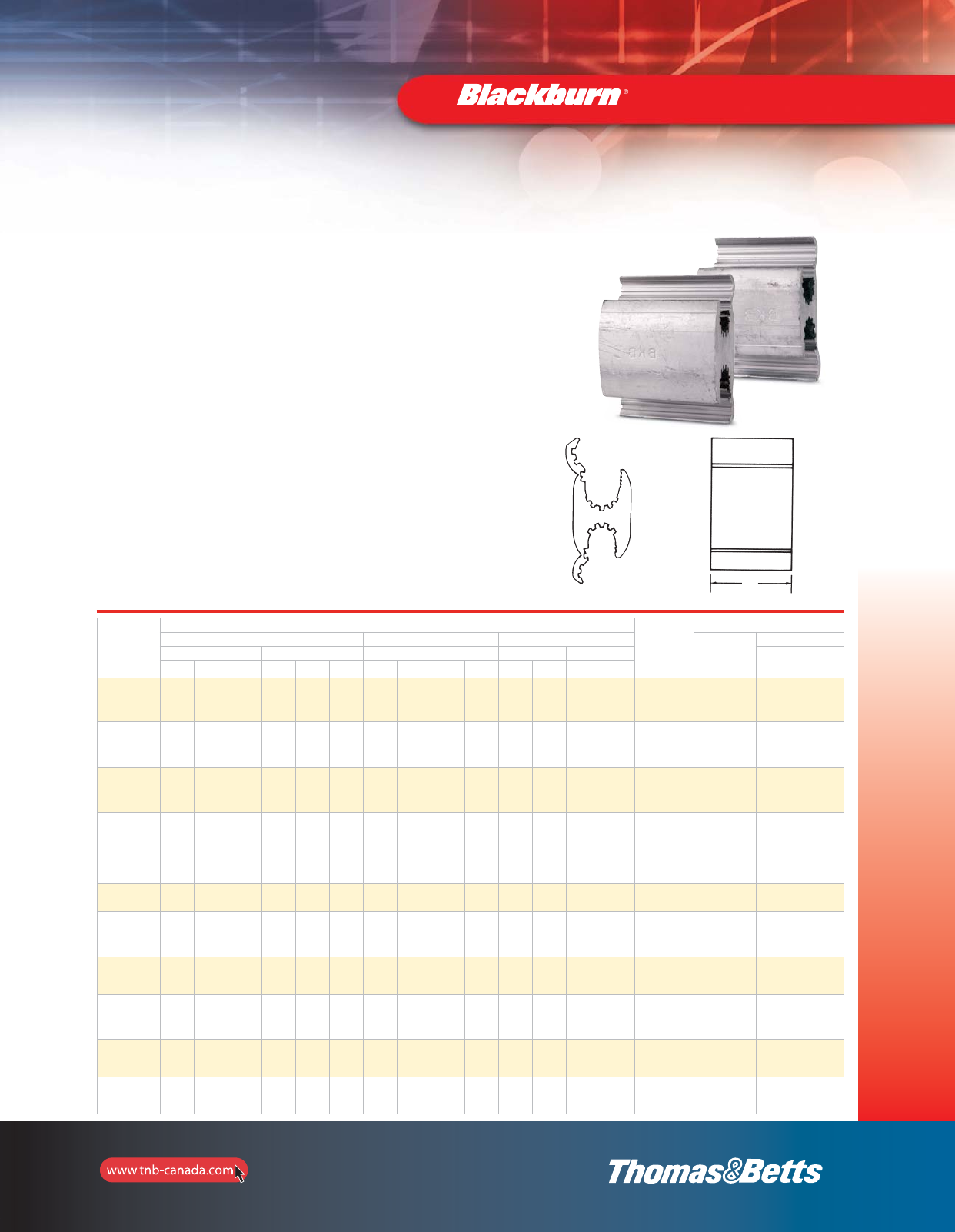
Tap
Main
39
Compression
Connectors
Compression H-Taps Connectors
Cat. No.
Conductor Range
Connector
Length
L (in.)
Installation Information
Standard Conductor Compact Conductor Diameter (in.)
Connector Die
No. Indents
Main Tap Main Tap Main Tap Mech.
Tool Hyd.
Tool
ACSR Str. Sol. ACSR Str. Sol. ACSR Str. ACSR Str. max. min. max. min.
WR149 4
6
3
4
6
2
3
4
6
4
6
3
4
6
2
3
4
6
4
6
2
3
4
6
3
4
6
2
3
4
6
0.266 0.162 0.266 0.162 1-1/2 0 5 2
WR179
1/0
1
2
3
1/0
1
2
14
6
3
4
6
2
3
4
6
1/0
1
2
2/0
1/0
1
2
4
6
2
3
4
6
0.398 0.266 0.266 0.162 1-3/4 0 5 2
WR199
1/0
1
2
3
1/0
1
2
1
2
3
4
1
2
3
4
1
2
1/0
1
2
2/0
1/0
1
2
1
2
3
4
1
20.398 0.066 0.332 0.232 1-3/4 0 5 2
WR1010
1/0
1
2
3
4
2/0
1/0
1
2
3
4
1
2
1/0
1
2
3
4
2/0
1/0
1
2
3
4
1
2
2/0
1/0
1
2
3
4
2/0
1/0
1
2
2/0
1/0
1
2
3
4
2/0
1/0
1
2
0.419 0.232 0.419 0.232 1-3/4 0 4 2
WR259 1/0
1
2/0
1/0 –1/0
1
2/0
1/0 –2/0
1/0
2/0
1/0
2/0
1/0
2/0
1/0 0.419 0.326 0.412 0.292 1-7/8 D 5 2
WR299 2/0
1/0
3/0
2/0 –4
6
3
4
6
2
3
4
6
3/0
2/0 3/0 4
6
2
3
4
6
0.470 0.398 0.266 0.162 1-1/2 D 4 2
WR219 1/0
1
1/0
1–
1/0
1
2
1/0
1– 1/0 2/0
1/0 1/0 2/0
1/0 0.398 0.324 0.398 0.316 1-7/8 D 5 2
WR239 2/0
1/0
2/0
1/0 –
2
3
4
1
2
3
1
2
2/0
1/0
4/0
3/0
1
2
3
4
1
20.447 0.365 0.332 0.236 1-7/8 D 5 2
WR229 2/0 3/0
2/0 –
1/0
1
2
1/0
1–3/0
2/0 3/0 1/0
1
2/0
1/0 0.470 0.410 0.398 0.316 1-7/8 D 5 2
WR269 2/0 2/0 – 2/0
1/0
2/0
1/0 – 2/0 3/0 2/0
1/0
3/0
2/0
1/0
0.447 0.410 0.447 0.336 1-7/8 D 5 2
Type WR — Wide Range Aluminum Tap Connectors
Type WR — Supplemental “O” and “D” Die Connectors
•For combinations of aluminum-aluminum and
aluminum-copper conductors
•Pass the requirements of ANSI C119.4
•Standard compression tools and dies install all sizes
•Seven Connector Program provides superior connector
performance, lower connection costs and simplified
installation procedures
•Fold-in tabs provide positive tab interlock as tool closes
•Field-proven ribbed design provides unparalled
connector/conductor contact, without distorting the
conductor’s shape
•Made of 1350 aluminum alloy
•Pre-filled with an oxide inhibitor which is held captive
in the rib/connection area
•For copper to copper combinations, use CF type
shown on page 45.
Products on this page are not CSA Certified.
Supplemental "O" and "D" Die Seven Connector Program
L
A
B
Main
Tap
section_1_E.pdf 39 9/26/2011 10:37:01 AM
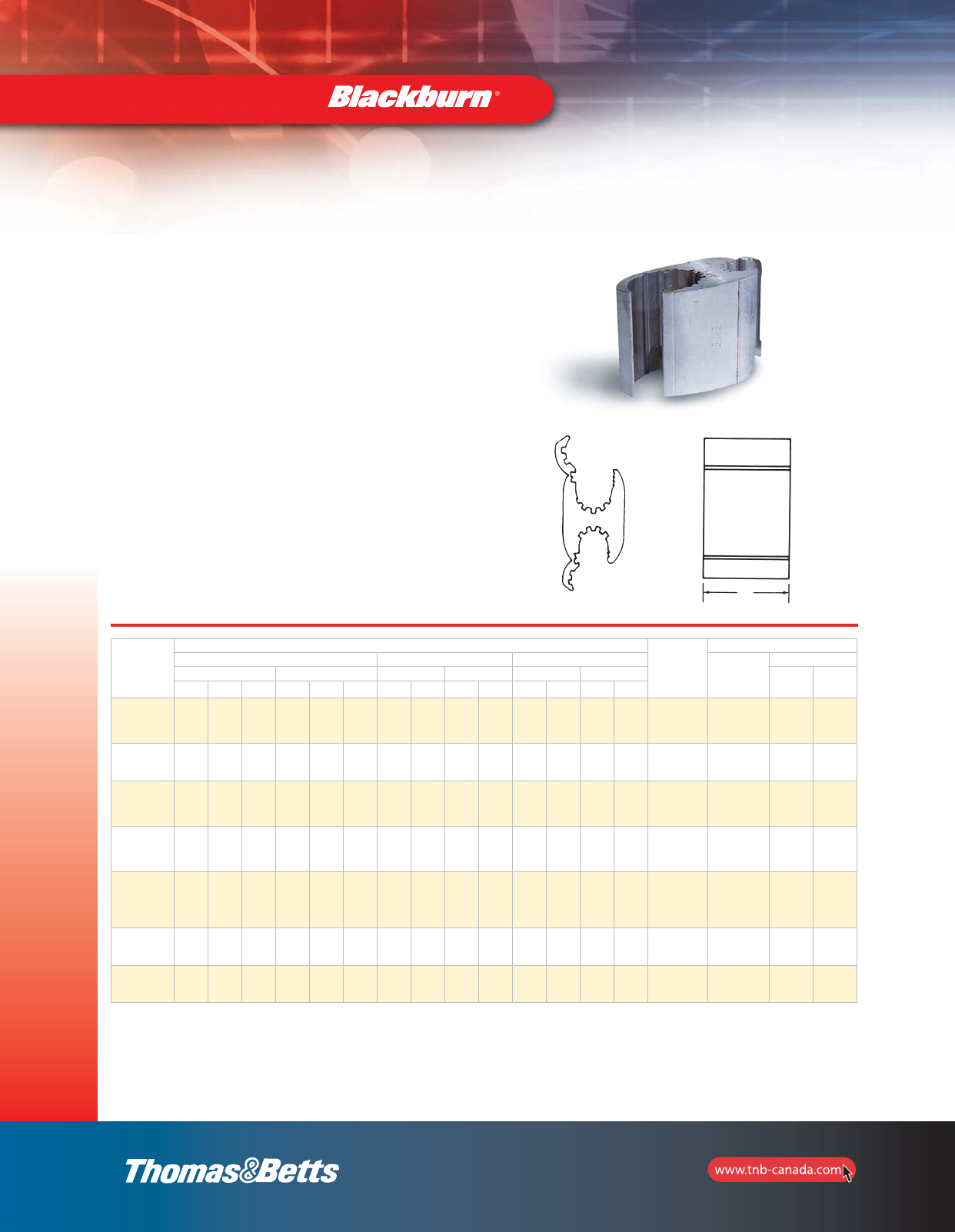
40
Compression H-Taps Connectors
Cat. No.
Conductor Range
Connector
Length
L (in.)
Installation Information
Standard Conductor* Compact Conductor Diameter (in.)
Connector Die
No. Indents
Main Tap Main Tap Main Tap Mech.
Tool Hyd.
Tool
ACSR Str. Sol. ACSR Str. Sol. ACSR Str. ACSR Str. max. min. max. min.
WR319 3/0 3/0 –
2
3
4
1
2
3
4
1
23/0 4/0
1
2
3
4
1
20.502 0.461 0.332 0.229 1-7/8 D 5 2
WR339 3/0 3/0 –
2/0
1/0
1
2/0
1/0 – 3/0 4/0 2/0
1/0
3/0
2/0
1/0
0.502 0.461 0.447 0.336 2-1/8 D 6 2
WR359 4/0
3/0
4/0
3/0 –4
6
3
4
6
2
3
4
6
266
4/0
3/0
266
250
4/0
1/0
1
2
1/0
1
2
0.563 0.461 0.266 0.162 1-7/8 D 4 2
WR369 4/0
3/0
4/0
3/0 –
1
2
3
4
1/0
1
2
3
1
266
4/0
3/0
266
250
4/0
1/0
1
2
1/0
1
2
0.563 0.461 0.374 0.266 1-7/8 D 4 2
WR369**
4/0
3/0
2/0
4/0
3/0 –
1/0
1
2
3
4
1/0
1
2
3
4
1/0
1
2
266
4/0
3/0
266
250
4/0
3/0
1/0
1
2
3
4
1/0
1
2
0.63 0.423 0.3763 0.232 1-7/8 D 5 2
WR389 4/0
3/0
4/0
3/0 –2/0
1/0
3/0
2/0 –
266
4/0
3/0
266
250
4/0
3/0
2/0
3/0
2/0 0.563 0.461 0.470 0.376 2-3/16 D 6 2
WR389**
4/0
3/0
2/0
4/0
3/0 –
2/0
1/0
1
3/0
2/0
1/0
–
266
4/0
3/0
266
250
4/0
3/0
2/0
1/0
3/0
2/0
1/0
0.563 0.423 0.470 0.336 2-3/16 D 6 2
Type WR — Wide Range Aluminum Tap Connectors
Tap
Main
*Will accept conductors of these same wire sizes with a 3% reduction of diameter (compressed).
**This range possible only when crimped with hydraulic tool TBM14M or JB12B.
Compression
Connectors
•For combinations of aluminum-aluminum and
aluminum-copper conductors
•Pass the requirements of ANSI C119.4
•Standard compression tools and dies install all sizes
•Seven Connector Program provides superior connector
performance, lower connection costs and simplified
installation procedures
•Fold-in tabs provide positive tab interlock as tool closes
•Field-proven ribbed design provides unparalled
connector/conductor contact, without distorting the
conductor’s shape
•Made of 1350 aluminum alloy
•Pre-filled with an oxide inhibitor which is held captive
in the rib/connection area
•For copper to copper combinations, use CF type
shown on page 45.
Products on this page are not CSA Certified.
Supplemental "O" and "D" Die
seven Connector Program
L
A
B
Main
Tap
section_1_E.pdf 40 9/26/2011 10:37:02 AM
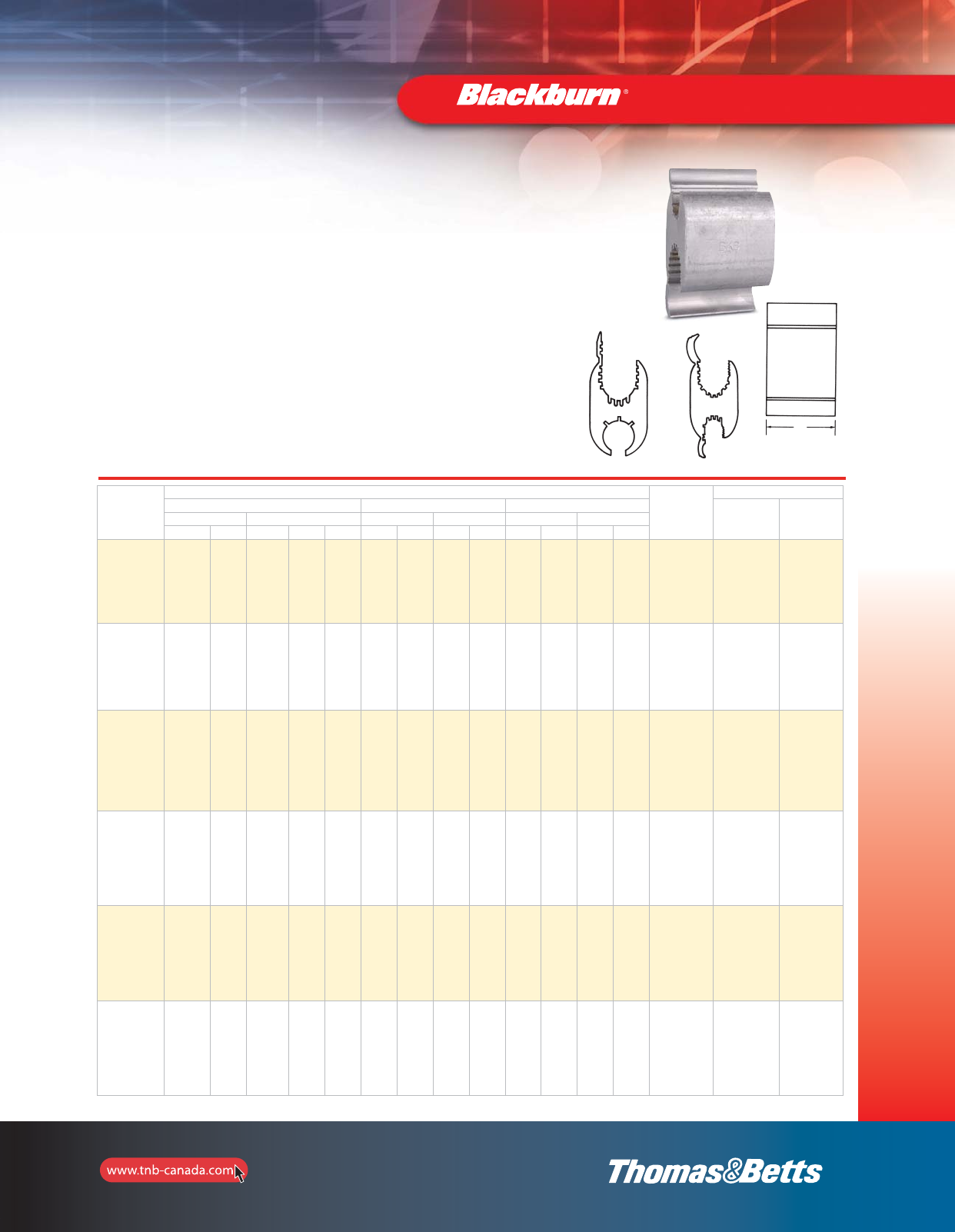
41
Compression H-Taps Connectors
Cat. No.
Conductor Range Connector
Length
L (in.)
Installation Information
Standard Conductor* Compact Conductor Diameter (in.) For Use
with Tool No. of
Indents
Main Tap Main Tap Main Tap
ACSR Str. ACSR Str. Sol. ACSR Str. ACSR Str. max. min. max. min.
WR715
397-18/1
336
266
400
397
350
336
300
266
250
2/0
1/0
1
2
3
4
6
2/0
1/0
1
2
3
4
6
3/0
2/0
1/0
1
2
3
4
6
477
397
336
500
477
394
350
2/0
1/0
1
2
3
4
6
3/0
2/0
1/0
1
2
3
4
6
0.753 0.520 0.447 0.162 2
TBM12,
JB12B and
Y-35
2
WR775
397-18/1
336
266
4/0
400
397
350
336
300
266
250
4/0
397-18/1
336
266
4/0
400
397
350
336
300
266
250
4/0
–
477
397
336
266
500
400
397
350
336
300
266
250
477
397
336
266
500
400
397
336
300
266
250
0.743 0.520 0.743 0.520 3
TBM12,
JB12B and
Y-35
3
WR815
477-18/1
397
336
266
4/0
556
500
400
397
350
336
300
266
250
2/0
1/0
1
2
3
4
6
2/0
1/0
1
2
3
4
6
3/0
2/0
1/0
1
2
3
4
6
556
477
397
350
336
266
556
477
397
350
336
266
250
2/0
1/0
1
2
3
4
6
3/0
2/0
1/0
1
2
3
4
6
0.858 0.520 0.447 0.162 2
TBM12,
JB12B and
Y-35
2
WR835
477-18/1
397
336
266
4/0
556
500
400
397
350
336
300
266
250
4/0
3/0
2/0
1/0
4/0
3/0
2/0
1/0
4/0
3/0
2/0
556
477
397
350
336
266
556
500
400
397
350
336
300
266
250
266
4/0
3/0
2/0
250
4/0
3/0
0.858 0.520 0.563 0.368 2
TBM12,
JB12B and
Y-35
2
WR875**
477-18/1
397
336
266
4/0
556
500
400
397
350
336
300
266
250
556
477
397
350
336
266
556
500
400
397
350
336
300
266
250
397
336
266
400
397
350
336
300
266
250
0.858 0.520 0.684 0.520 3
TBM12,
JB12B and
Y-35
3
WR885
477-18/1
397
336
266
4/0
500
400
397
350
336
300
266
250
4/0
556
477
397
350
336
266
556
500
400
397
350
336
300
266
250
556
477
394
336
266
556
477
397
350
336
300
266
250
0.814 0.520 0.814 0.520 3
TBM12,
JB12B and
Y-35
3
Main
Tap
Fig. 1
Type WR — Wide Range Aluminum Tap Connectors
“N” Die for Hydraulic Tools, 12–Ton and Greater
* Will accept conductors of these same wire sizes with a 3% reduction of diameter (compressed).
** Not reversible (Fig. 2)
Compression
Connectors
•For combinations of aluminum-aluminum and aluminum-copper conductors
•Pass the requirements of ANSI C119.4
•Standard compression tools and dies install all sizes
•Seven Connector Program provides superior connector performance,
lower connection costs and simplified installation procedures
•Fold-in tabs provide positive tab interlock as tool closes
•Field-proven ribbed design provides unparalled connector/conductor
contact, without distorting the conductor’s shape
•Made of 1350 aluminum alloy
•Pre-filled with an oxide inhibitor which is held captive in the rib/connection area
•For copper to copper combinations, use CF type shown on page 45.
Main
Tap
Fig. 2
Products on this page
are not CSA Certified.
L
Main
Tap
Main
Tap
section_1_E.pdf 41 9/26/2011 10:37:02 AM
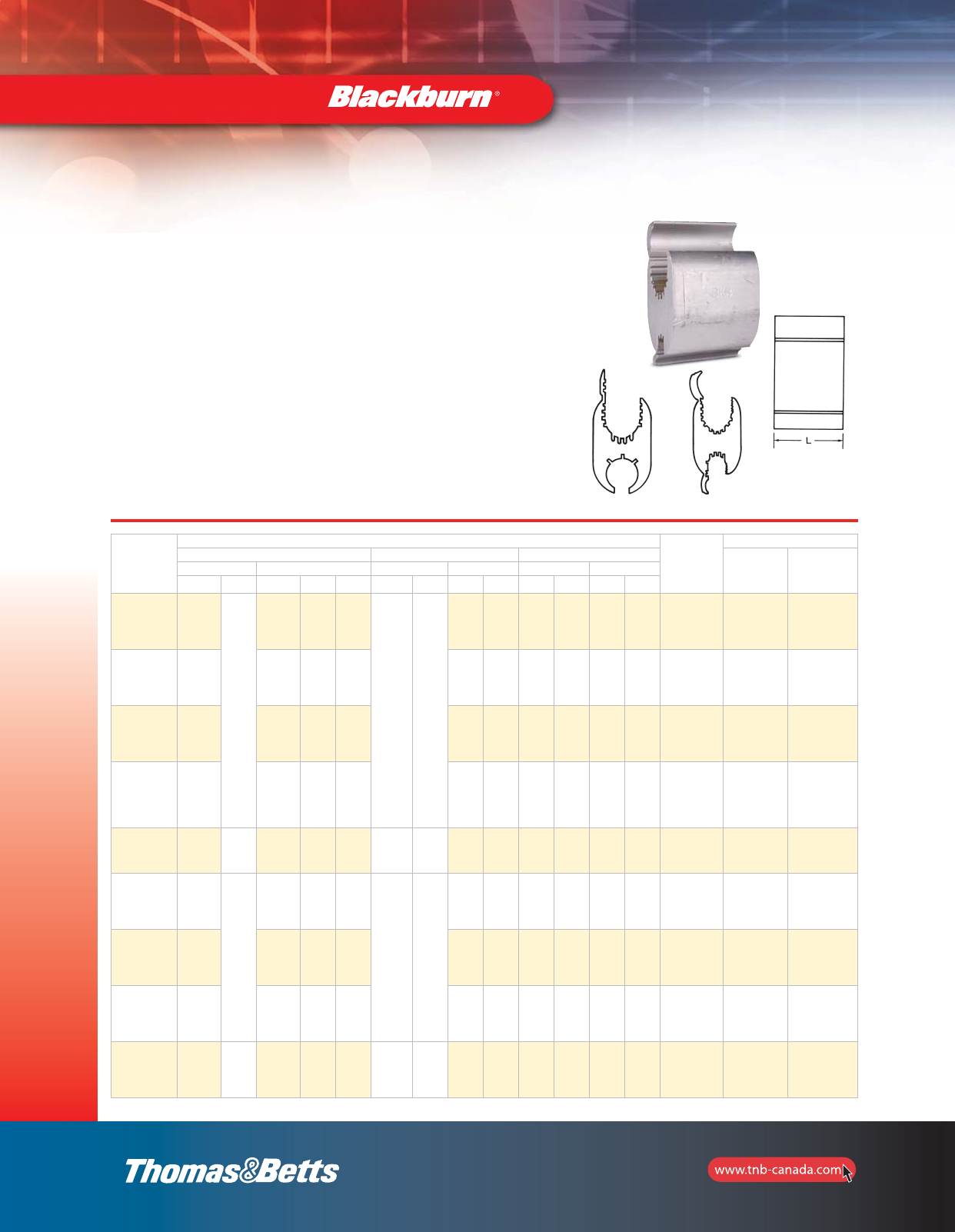
42
Compression H-Taps Connectors
Cat. No.
Conductor Range
Connector
Length
L (in.)
Installation Information
Standard Conductor* Compact Conductor Diameter (in.)
For Use
with Tool No. of Indents
Main Tap Main Tap Main Tap
ACSR Str. ACSR Str. Sol. ACSR Str. ACSR Str. max. min. max. min.
WR699
397-18/1
336
266
400
397
350
336
300
266
250
4
6
3
4
6
2
3
4
6
477
397
350
336
477
397
350
336
300
4
6
2
3
4
6
0.743 0.570 0.266 0.162 2
TBM12,
JB12B
and 13642M
2
WR719
397-18/1
336
266
2/0
1/0
1
2
3
2/0
1/0
1
2
3/0
2/0
1/0
1
2/0
1/0
1
2
3/0
2/0
1/0
1
2
0.743 0.570 0.447 0.289 2
TBM12,
JB12B
and 13642M
2
WR739
397-18/1
336
266
4/0
3/0
2/0
1/0
4/0
3/0
2/0
4/0
266
4/0
3/0
266
250
4/0
0.743 0.570 0.563 0.398 2
TBM12,
JB12B
and 13642M
2
WR779
397-18/1
336
266
397-18/1
336
266
400
397
350
336
266
250
477
397
477
397
336
477
397
336
0.743 0.570 0.743 0.570 3
TBM12,
JB12B
and 13642M
3
WR799 477-18/1
266
500
250
4
6
3
4
6
2
3
4
6
477-18/1
250
500
250
3
4
6
2
3
4
6
0.814 0.575 0.270 0.160 2
TBM12,
JB12B
and 13642M
2
WR819
477-18/1
397
336
556
500
477
450
400
397
350
336
2/0
1/0
1
2
3
2/0
1/0
1
2
3/0
2/0
1/0
1
556
477
397
556
477
397
2/0
1/0
1
2
3/0
2/0
1/0
1
2
0.858 0.659 0.477 0.289 2
TBM12,
JB12B
and 13642M
2
WR839
477-18/1
397
336
4/0
3/0
2/0
4/0
3/0 4/0
266
4/0
3/0
266
250
4/0
0.858 0.659 0.563 0.477 2
TBM12,
JB12B
and 13642M
2
WR879**
477-18/1
397
336
336-18/1
266
350
336
300
266
397 397
336
397
350
336
0.858 0.659 0.684 0.593 2
TBM12,
JB12B
and 13642M
3
WR889
477-18/1
397
336
500
400
397
350
336
477-18/1
397
336
500
400
397
350
336
–
556
477
397
336
556
477
397
350
556
477
397
336
556
477
397
350
0.814 0.666 0.814 0.666 2
TBM12,
JB12B
and 13642M
3
*Will accept conductors of these same wire sizes with a 3% reduction of diameter (compressed).
**Not reversible (Fig. 2).
Compression
Connectors
•For combinations of aluminum-aluminum and aluminum-copper
conductors
•Pass the requirements of ANSI C119.4
•Standard compression tools and dies install all sizes
•Seven Connector Program provides superior connector performance,
lower connection costs and simplified installation procedures
•Fold-in tabs provide positive tab interlock as tool closes
•Field-proven ribbed design provides unparalled connector/conductor
contact, without distorting the conductor’s shape
•Made of 1350 aluminum alloy
•Pre-filled with an oxide inhibitor which is held captive in the
rib/connection area
•For copper to copper combinations, use CF type shown on page 45.
Main
Tap
Fig. 1
Main
Tap
Fig. 2
Type WR — Wide Range Aluminum Tap Connectors
“N” Die for Hydraulic Tools, 10–Ton and Greater
Products on this page
are not CSA Certified.
section_1_E.pdf 42 9/26/2011 10:37:03 AM
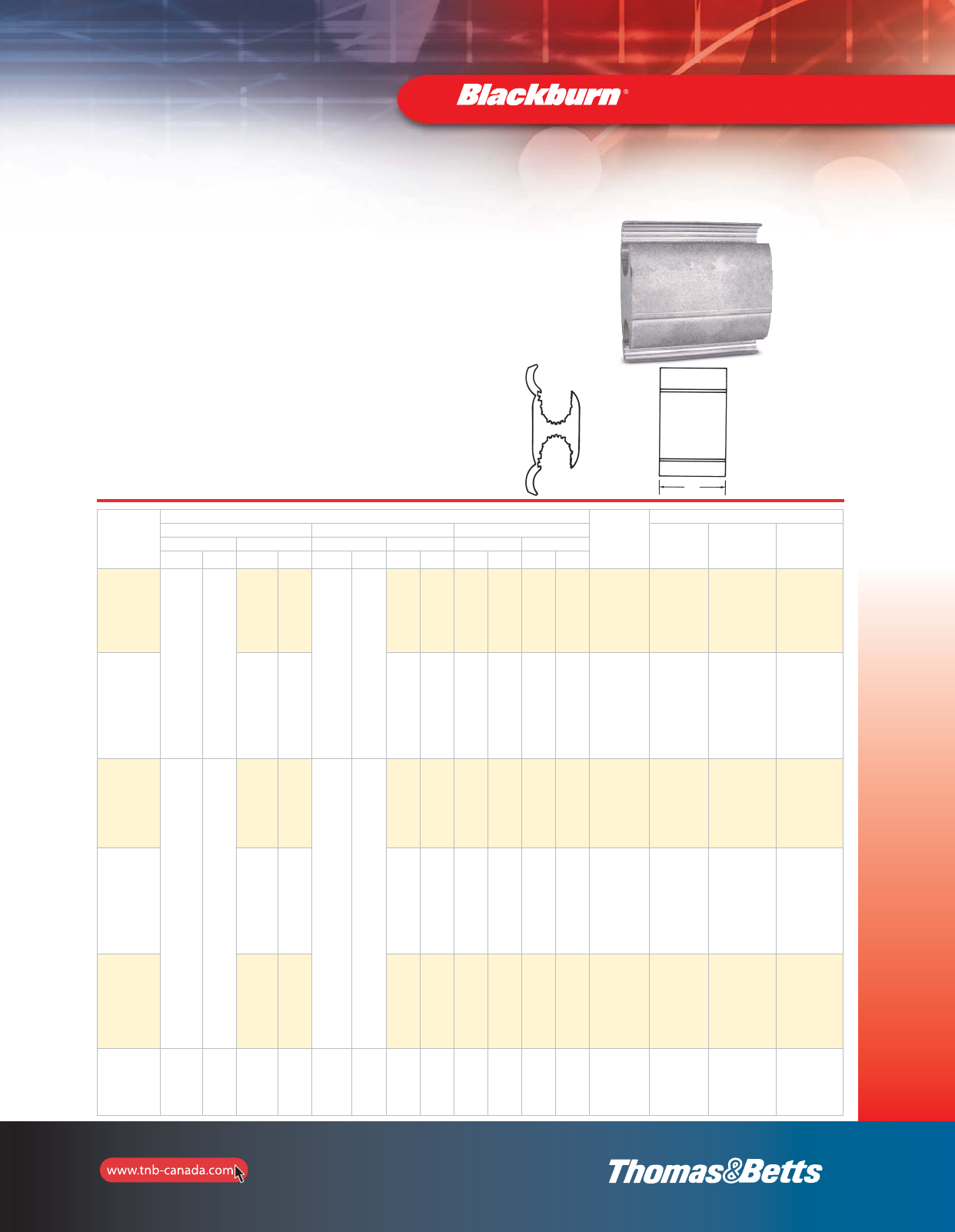
43
Compression H-Taps Connectors
Type WR — Wide Range Aluminum Tap Connectors
“R” Die Seven Connector Program
Cat. No.
Conductor Range
Connector
Length
L (in.)
Installation Information
Standard Conductor Compact Conductor Diameter (in.)
For Use
with Tool Connector
Die No. of Indents
Main Tap Main Tap Main Tap
ACSR Str. ACSR Str. ACSR Str. ACSR Str. max. min. max. min.
WR909
556-18/1
477
397
336
300
600
556
550
500
400
477
450
400
397
350
336
336-1/81
266
4/0
3/0
2/0
1/0
350
336
266
250
4/0
3/0
2/0 636
556
477
397
700
636
556
500
477
450
397-
1/2
336
266
4/0
3/0
2/0
397
350
336
300
266
250
4/0
3/0
0.893 0.666 0.684 0.398 4-3/4 TBM15I
(15620) R 4
WR929
556-18/1
477
397
336
300
600
556
550
500
477
450
400
397
350
336
636
556
477
397
700
636
556
477
450
0.893 0.666 0.893 0.666 4-3/4 TBM15I
(15620) R4
WR949
795-26/7
715
666
636
606
556
477-30/7
900
874
800
795
750
715
700
636
600
336-18/1
266
4/0
3/0
2/0
1/0
350
336
266
250
4/0
3/0
2/0
954
874
795
1000
954
874
795
750
397-
18/1
336
266
4/0
3/0
2/0
397
350
336
300
266
250
4/0
3/0
1.108 0.883 0.684 0.398 4-3/4 TBM15I
(15620) R 4
WR969
556-18/1
477
397
336
300
600
556
550
500
477
450
400
397
350
336
636
556
477
397
700
363
556
477
450
1.108 0.883 0.893 0.666 4-3/4 TBM15I
(15620) R4
WR989
795-26/7
715
666
636
605
556
477-30/7
900
874
800
795
750
715
700
636
600
954
874
795
1000
954
874
795
750
1.108 0.883 1.108 0.883 4-3/4 TBM15I
(15620) R 4
WR999
954-45/7
900
874
795
715
666
1033
1000
900
800
795
750
954-45/7
900
874
7985
715
666
1033
1000
900
800
795
750
954
900
1000
900
954
900
874
1000
900 1.172 0.997 1.172 0.997 4-3/4 TBM15I
(15620) R4
Main
Tap
Compression
Connectors
•For combinations of aluminum-aluminum and aluminum-copper
conductors
•Pass the requirements of ANSI C119.4
•Standard compression tools and dies install all sizes
•Seven Connector Program provides superior connector performance,
lower connection costs and simplified installation procedures
•Fold-in tabs provide positive tab interlock as tool closes
•Field-proven ribbed design provides unparalled connector/conductor
contact, without distorting the conductor’s shape
•Made of 1350 aluminum alloy
•Pre-filled with an oxide inhibitor which is held captive in the
rib/connection area
•For copper to copper combinations, use CF type shown on page 45.
Products on this page
are not CSA Certified.
Main
Tap
L
section_1_E.pdf 43 9/26/2011 10:37:04 AM
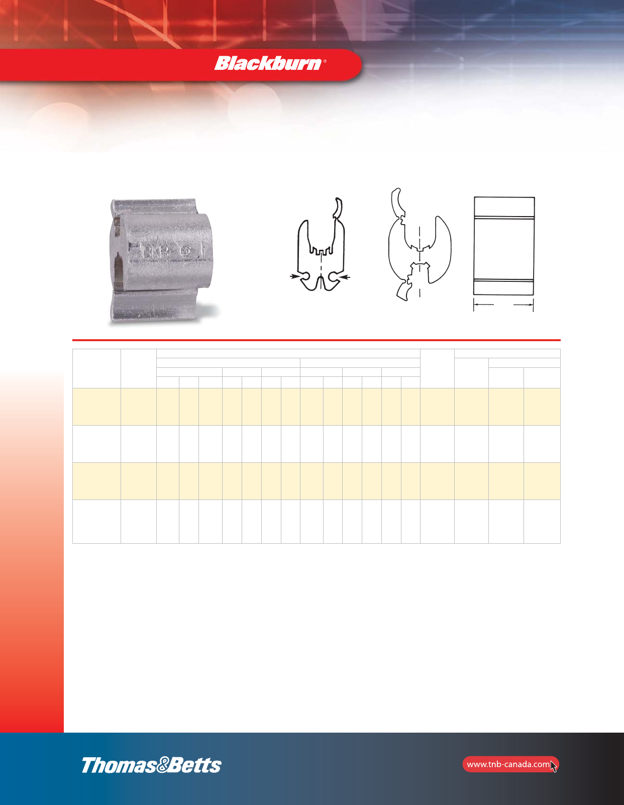
44
Compression H-Taps Connectors
Cat. No. Figure
No.
Conductor Range
Connector
Length
L (in.)
Installation Information
Standard Conductor Diameter (in.)
For Use
with Tool
No. of Indents
Main Tap A Tap B Main Tap A Tap B Mech.
Tool Hyd.
Tool
ACSR Str. Sol. Str. Sol. Str. Sol. max. min. max. min. max. min.
WR9** 2
3
4
6
2
3
4
6
1
2
3
4
8
10
12
14
8
10
12
14
– – 0.292 0.184 0.146 0.064 – – 13/16 5/8
BG 3 –
WR139 1
1/0
1
2
3
4
2/0
1/0
1
2
3
1
2
8
10
6
8
10
12
14
12
14 0.419 0.250 0.162 0.100 0.092 0.064 1-1/2 0 4 2
WR502 14/0
3/0
4/0
3/0 –8
10
6
8
10
12
14
12
14 0.563 0.461 0.162 0.100 0.092 0.064 1-1/2 D 4 –
WR502* 1
4/0
3/0
2/0
1/0
4/0
3/0
2/0
1/0
–8
10
6
8
10
12
14
12
14 0.563 0.365 0.162 0.100 0.092 0.064 1-1/2 D – 2
Type WR — Street Lighting Compression Connectors
2.giF1.giF
Main
Tap A
Main
Tap A
Tap B
Will accept conductors of these same wire sizes with a 3% reduction of diameter (compressed).
* This range possible only when crimped with hydraulic tool TBM14M or JB12B.
** CSA Certified.
Compression
Connectors
Products on this page
are not CSA Certified.
Main
Tap B
Main
Tap A Tap A
L
section_1_E.pdf 44 9/26/2011 10:37:04 AM
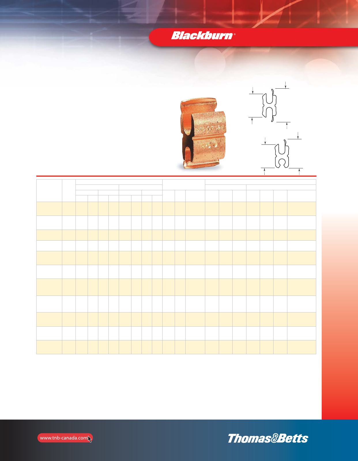
45
Compression H-Taps Connectors
Type CF — Copper Compression Tap Connectors
A
B
«H» 1 «H»
(MIN)
• For tapping copper conductors to unbroken
main copper conductors
•Extruded pure electrolytic copper
•Full length tab for easy installation
•Efficient design for lower crimping force
•Standard compression tools and dies
•Single and double tab designs
Cat. No. Figure
No.
Conductor Range Dimensional
Information
Installation Information
Standard Conductor Diameter (in.) Mechanical Tools*** Hydraulic Tools***
Main A Tap B Main A Tap B H
(min.) H
1Connector
Length (in.) OD 58 Type
0MD
Series JB12B H
Series Y-35 TBM15/TBM15PF
Y45/Y46
ACSR Str. Sol. Str. max. min. max. min.
CF44-1 14
66
4
6
8
6 0.204 0.162 0.204 0.128 0.971 0.729 13/16 B, T
5/8
B, T
5/8
W-KB
W-BG BKT BBKT
U-BG
BKT
U-BG
CFS44-1 24
66
4
6
8
8 0.204 0.162 0.204 0.128 0.864 0.743 13/16 B, T
5/8
B, T
5/8
W-KB
W-BG BKT BKT BKT
U-BG
BKT
U-BG
CF22-1 12
442
44 0.258 0.204 0.258 0.204 1.162 0.813 13/16 K K W-KK – BKT
CFS22-1 22
442
66 0.258 0.204 0.258 0.162 1.017 0.842 13/16 K K W-KK HBKC BKT BKT BKT
CF102-1 1 –
1/0
1
2
2
4
6
4 0.373 0.292 0.258 0.162 1.540 1.100 27/32 – – – 0 0 0 0
CF1010-1 1–
1/0
1
2
–
1/0
1
2
0.373 0.292 0.373 0.292 1.610 1.050 27/32 – – – 0 0 0 0
CF202-1 1 – 2/0
1/0 –
2/0
1/0
1
2
0.419 0.368 0.259 0.204 1.670 1.269 7/8 – – – K-C C K-C BK-C
CF2020-1 1–
2/0
1/0 –
2/0
1/0
1
2
0.419 0.368 0.414 0.292 1.740 1.220 7/8 – – – K-C C K-C BK-C
CF402-1 1 –
4/0
3/0
2/0
2
44 0.528 0.414 0.259 0.204 1.983 1.423 1-1/8 – – – D** D** D** D**
CF4010-1 1–
4/0
3/0
2/0
–
1/0
1
2
0.528 0.414 0.373 0.292 1.992 1.423 1-1/8 – – – D** D** D** D**
CF4040-1 1 –
4/0
3/0
2/0
–
4/0
3/0
2/0
0.528 0.414 0.528 0.414 2.252 1.483 1-1/8 – – – D** D** D** D**
*Decimal dimensions are for conventional conductor, not Copperweld or Alumoweld.
**Blackburn “D” dies.
***Three indents with mechanical tools and one indent with hydraulic tools. 15-Ton/head use appropriate die adapters.
Compression
Connectors
A
B
«H» 1 «H»
(MIN)
«H» 1
«H»
(Min)
«H» 1
«H»
(Min)
A
B
A
B
section_1_E.pdf 45 9/26/2011 10:37:04 AM
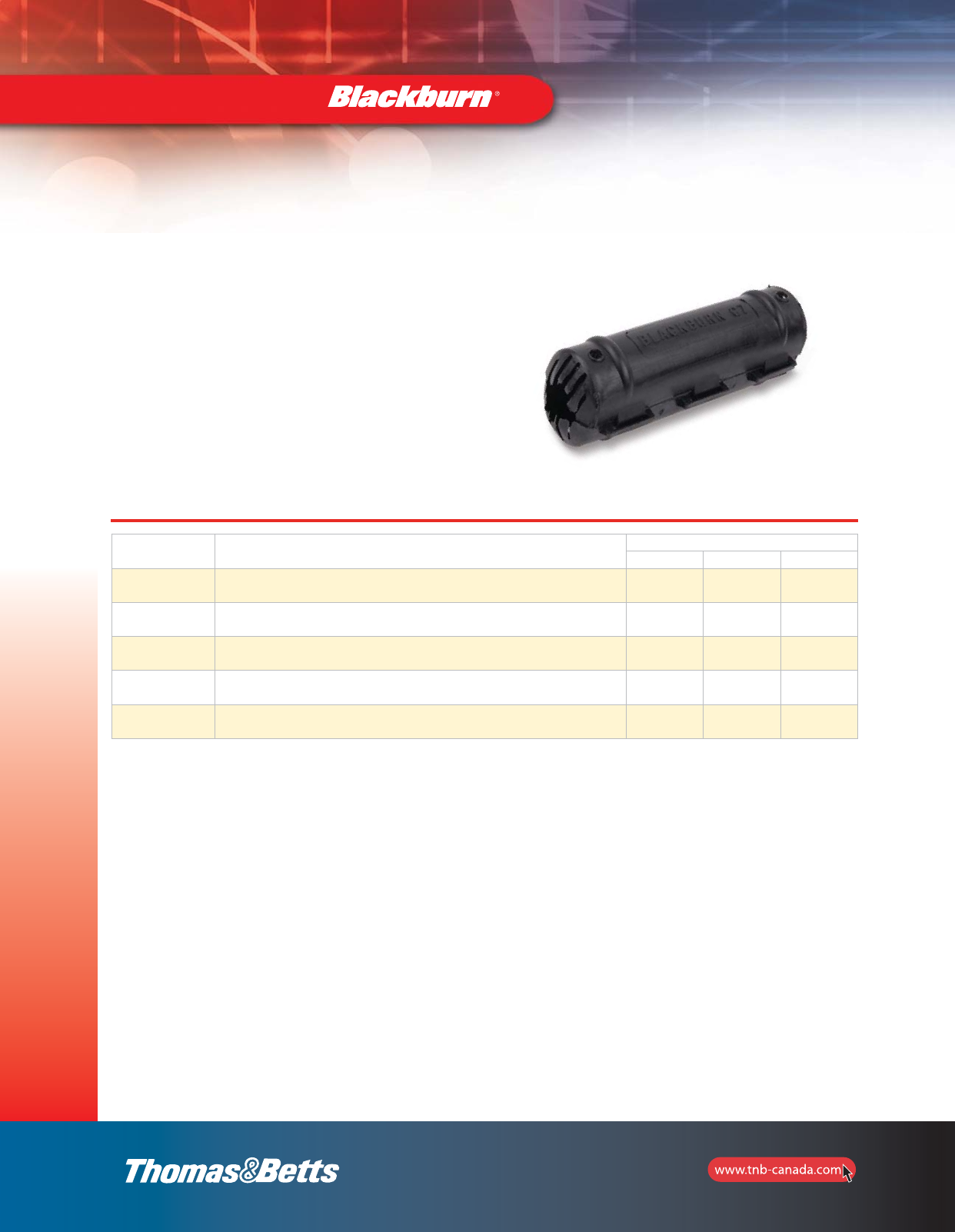
46
Compression
Connectors
Compression H-Taps Connectors
Cat. No. Capacity* Dimensions (in.)
Height Length Width
C2BB All 5/8” and O.D. Die taps, 2” long or less 1.10 4.00 1.05
C5C All “O” Die taps, 1-3/4” long or less 1.60 3.75 1.25
C7C All “D” Die taps, 2-1/2” long or less 1.80 5.00 1.45
C9 All “N” and “D” Die taps, up to 2” long 2.75 4.25 2.00
C9L All “N” and “D” Die taps, up to 5” long 2.75 7.25 2.00
Type C — Compression Connectors Covers
* Before compression.
•Hinged polyethylene cover
•Installs easily, quickly–less expensive than taping
•Positive snap-locks fasten securely
•Drain ports prevent accumulation of
corrosion-causing moisture
•Ultra-violet stabilized
section_1_E.pdf 46 9/26/2011 10:37:05 AM
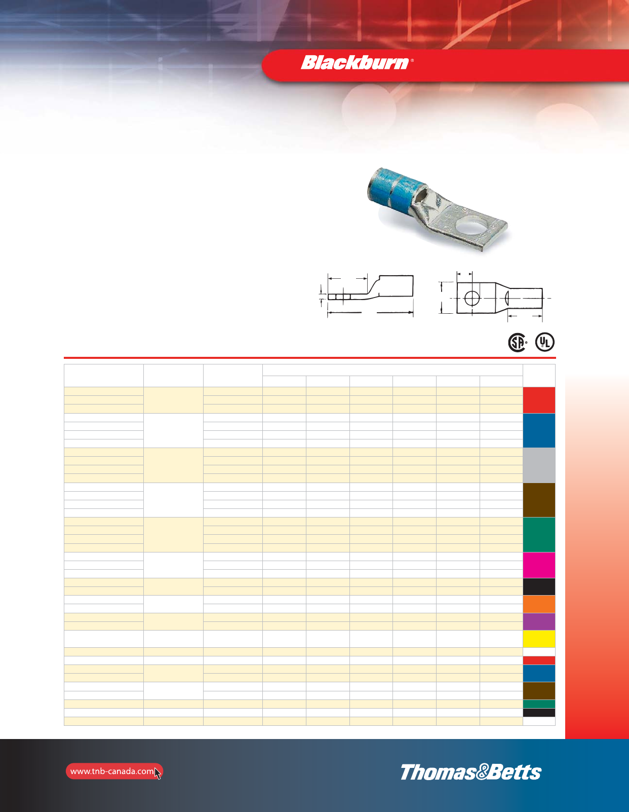
47
Compression
Connectors
Colour Coded Compression Connectors
Type CTL — Copper Lugs, 1–Hole Mount, Short Barrel
Copper Compression Connectors
•For use with copper conductors: AWG stranded, flexible cable, welding
cable and portable cord
•Specially designed for industrial and building applications
•Made of high conductivity seamless copper tubing
•Tin plated for corrosion resistance
•Specially chamfered barrel for ease of installation
•Colour coded for matching die identification
•Can be used for medium voltage application up to 35 kV provided
proper insulation techniques are used
•CSA Certified and U.L. Listed for AWG conductors when installed with
Blackburn, Burndy, T&B or Anderson tools, as specified by CSA
•Comply with Subpart 111.60-17 of Federal Register’s Coast Guard
Electrical Engineering Rules and Regulations
Short Barrel Connectors
•Short barrel connectors designed for regular duty applications
•Ideal for confined areas
Cat. No. Conductor
Size
(CU)
Stud
Size
(in.)
Dimensions (in.) Die
Colour
Code
A B C L W T
CTL8-10
8 str.
10 13/32 1/2 7/32 1-5/32 3/8 1/16
RedCTL8-14 1/4 13/32 19/32 1/4 1-3/16 7/16 1/16
CTL8-516 5/16 13/32 5/8 9/32 1-5/16 9/16 1/16
CTL6-10
6 str.
10 7/16 17/32 7/32 1-7/32 7/16 1/16
Blue
CTL6-14 1/4 7/16 17/32 7/32 1-7/32 7/16 1/16
CTL6-516 5/16 7/16 21/32 9/32 1-13/32 19/32 1/16
CTL6-38 3/8 7/16 21/32 9/32 1-13/32 19/32 1/16
CTL4-10
4 str.
10 1/2 19/32 1/4 1-3/8 17/32 3/32
Grey
CTL4-14 1/4 1/2 19/32 1/4 1-3/8 17/32 3/32
CTL4-516 5/16 1/2 21/32 5/16 1-13/32 19/32 1/16
CTL4-38 3/8 1/2 21/32 5/16 1-13/32 19/32 1/16
CTL2-14
2 + 3 str.
1/4 19/32 21/32 1/4 1-1/2 9/16 3/32
Brown
CTL2-516 5/16 19/32 7/8 3/8 1-23/32 9/16 3/32
CTL2-38 3/8 19/32 29/32 3/8 1-3/4 9/16 3/32
CTL2-12 1/2 19/32 1-1/16 1/2 1-29/32 3/4 1/16
CTL1-14
1 str.
1/4 19/32 21/32 1/4 1-1/2 21/32 3/32
Green
CTL1-516 5/16 19/32 7/8 3/8 1-23/32 21/32 3/32
CTL1-38 3/8 19/32 29/32 3/32 1-3/4 21/32 3/32
CTL1-12 1/2 19/32 1-1/4 1/2 2-3/32 3/4 3/32
CTL10-516
1/0 str.
5/16 11/16 7/8 3/8 1-13/16 3/4 1/8
PinkCTL10-38 3/8 11/16 29/32 3/8 1-7/8 3/4 1/8
CTL10-12 1/2 11/16 1-1/4 1/2 2-3/16 3/4 1/8
CTL20-38 2/0 str. 3/8 13/16 29/32 3/8 2-1/32 13/16 1/8 Black
CTL20-12 1/2 13/16 1-1/4 1/2 2-11/32 13/16 1/8
CTL30-38 3/0 str. 3/8 13/16 29/32 3/8 2-1/32 29/32 1/8 Orange
CTL30-12 1/2 13/16 1-1/4 1/2 2-11/32 29/32 1/8
CTL40-38 4/0 str. or
3/0 weld
3/8 15/16 29/32 3/8 2-5/32 1-3/32 1/8 Purple
CTL40-12 1/2 15/16 1-1/4 1/2 2-1/2 1-1/32 1/8
CTL250-12 250 kcmil
or 4/0 weld 1/2 1-1/32 1-1/4 1/2 2-19/32 1-1/8 1/8 Yellow
CTL300-12 300 kcmil 1/2 1-1/32 1-1/4 1/2 2-25/32 1-3/16 5/32 White
CTL350-12 350 kcmil 1/2 1-1/32 1-1/4 1/2 2-25/32 1-11/32 5/32 Red
CTL400-12 400 kcmil 1/2 1-1/32 1-1/4 1/2 3-3/16 1-13/32 5/32 Blue
CTL400-58 5/8 1-1/32 1-9/16 5/8 3-1/2 1-13/32 5/32
CTL500-12 500 kcmil 1/2 1-1/32 1-1/4 1/2 3-1/4 1-19/32 7/32 Brown
CTL500-58 5/8 1-1/32 1-9/16 5/8 3-9/16 1-19/32 7/32
CTL600-58 600 kcmil 5/8 1-9/16 1-9/16 5/8 3-23/32 1-3/4 7/32 Green
CTL750-58 750 kcmil 5/8 1-1/2 1-9/16 5/8 3-25/32 1-29/32 1/4 Black
CTL1000-58 1000 kcmil 5/8 1-3/4 1-9/16 5/8 4-1/32 2-1/4 9/32 –
See pages 110–135 for more tool and die information.
B
A
W
TL
C
section_1_E.pdf 47 9/26/2011 10:37:06 AM
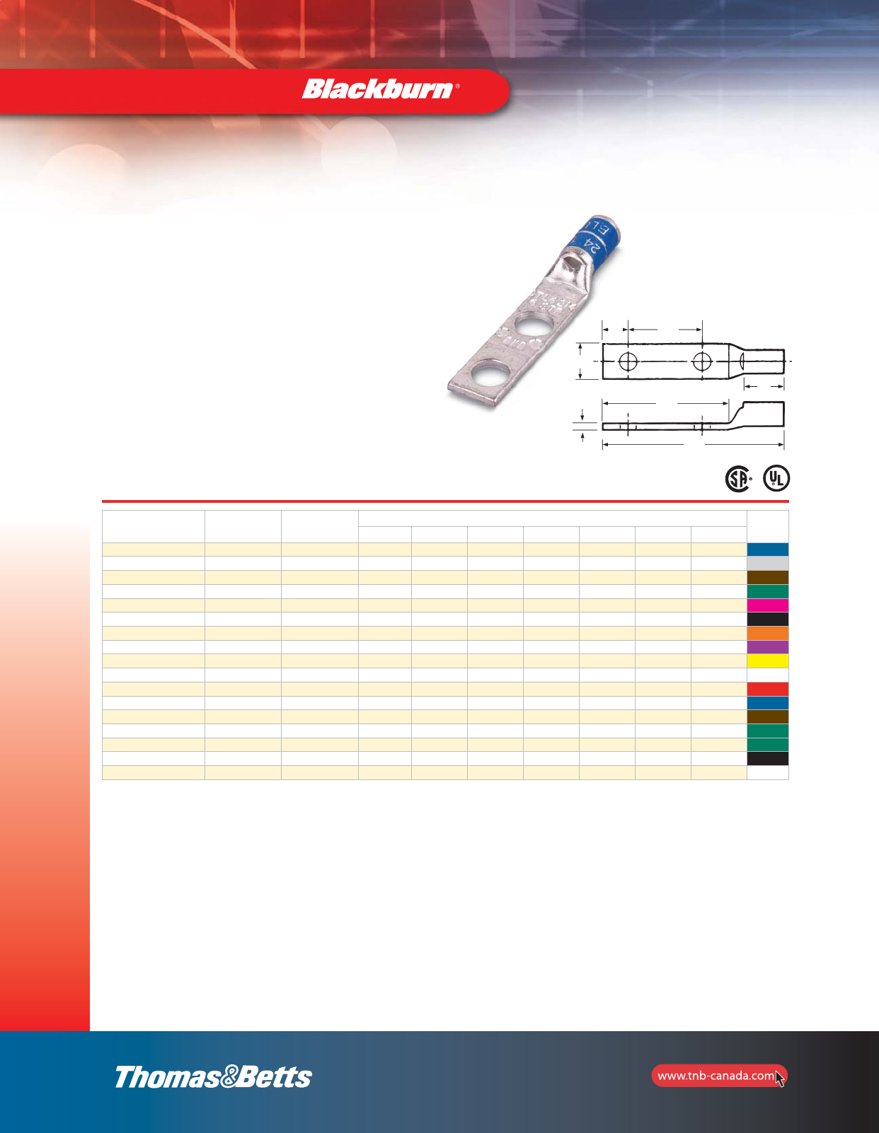
48
Colour Coded Compression Connectors
CD
A
W
B
L
T
Cat. No. Conductor
Size
(CU)
Stud
Size
(in.)
Dimensions (in.) Die
Colour
Code
A B C D L W T
CTL6-214 6 str. 1/4 1/2 1-1/4 1/4 5/8 1-31/32 13/32 1/16 Blue
CTL4-214 4 str. 1/4 1/2 1-1/4 1/4 5/8 2-1/32 1/2 3/32 Grey
CTL2-2516 2 + 3 str. 5/16 19/32 1-5/8 3/8 3/4 2-15/32 9/16 3/32 Brown
CTL1-2516 1 str. 5/16 19/32 1-3/4 3/8 7/8 2-19/32 21/32 3/32 Green
CTL10-2516 1/0 str. 5/16 11/16 1-3/4 3/8 7/8 2-11/16 3/4 1/8 Pink
CTL202 2/0 str. 1/2 13/16 2-13/16 1/2 1-3/4 3-13/16 13/16 1/8 Black
CTL302 3/0 str. 1/2 25/32 2-13/16 1/2 1-3/4 3-15/16 15/16 1/8 Orange
CTL402 4/0 str. 1/2 15/16 3 1/2 1-3/4 4-1/4 1-3/32 1/8 Purple
CTL2502 250 kcmil 1/2 1-1/32 3 1/2 1-3/4 4-11/32 1-1/8 5/32 Yellow
CTL3002 300 kcmil 1/2 1-1/32 3 1/2 1-3/4 4-17/32 1-3/16 5/32 White
CTL3502 350 kcmil 1/2 1-1/32 3 1/2 1-3/4 4-17/32 1-11/32 5/32 Red
CTL4002 400 kcmil 1/2 1-11/32 3 1/2 1-3/4 4-15/16 1-13/32 5/32 Blue
CTL5002 500 kcmil 1/2 1-3/8 3 1/2 1-3/4 5 1-17/32 7/32 Brown
CTL6002-38 600 kcmil 3/8 1-17/32 1-29/32 3/8 1-3/4 5-1/8 1-23/32 7/32 Green
CTL6002-12 600 kcmil 1/2 1-17/32 3 1/2 1-3/4 5-1/8 1-23/32 7/32 Green
CTL7502 750 kcmil 1/2 1-1/2 3 1/2 1-3/4 5-7/32 1-29/32 1/4 Black
CTL10002 1000 kcmil 1/2 1-3/4 3 1/2 1-3/4 5-7/16 2-1/4 9/32 –
See pages 110–135 for more tool and die information.
Type CTL — Copper Lugs, 2–Hole Mount, Short Barrel
Copper Compression Connectors
•For use with copper conductors: AWG stranded, flexible cable,
welding cable an portable cord
•Specially designed for industrial and building applications
•Made of high conductivity seamless copper tubing
•Tin plated for corrosion resistance
•Specially chamfered barrel for ease of installation
•Colour coded for matching die identification
•Can be used for medium voltage application up to 35 kV provided
proper insulation techniques are used
•CSA Certified and U.L. Listed for AWG conductors when installed
with Blackburn, Burndy, T&B or Anderson tools, as specified by CSA
•Comply with Subpart 111.60-17 of Federal Register’s Coast Guard
Electrical Engineering Rules and Regulations
Short Barrel Connectors
•Short barrel connectors designed for regular duty applications
•Ideal for confined areas
Compression
Connectors
B
D
W
TL
A
C
section_1_E.pdf 48 9/26/2011 10:37:06 AM
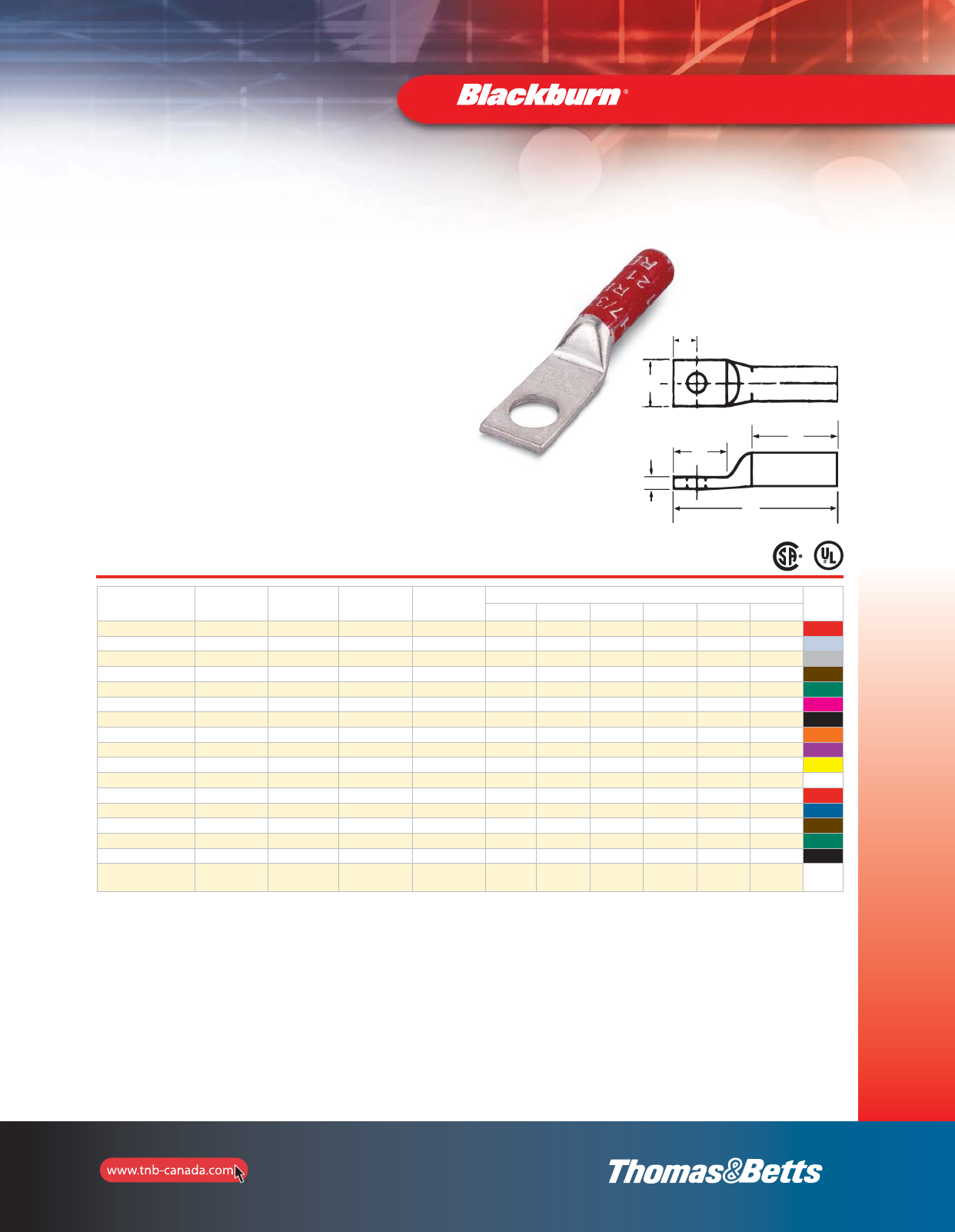
49
Colour Coded Compression Connectors
A
B
C
W
L
T
Cat. No. Conductor
Size
(CU)
Flexible
Conductor
Size Stranded Stud
Size
(in.)
Dimensions (in.) Die
Colour
Code
A B C L W T
CTL8L-14 8 str. 1/4 37/24 1/4 25/32 5/8 1/4 1-5/8 13/32 1/16 Red
CTL6L-14 6 str. 1/4 61/24 1/4 25/32 5/8 1/4 1-5/8 13/32 1/16 Blue
CTL4L-14 4 str. 5/16 91/24 1/4 25/32 5/8 1/4 1-11/16 1/2 3/32 Grey
CTL2L-516 2 + 3 str. 5/16 125/24 5/16 7/8 7/8 3/8 2-1/32 9/16 3/32 Brown
CTL1L-516 1 str. 5/16 150/24 5/16 1-3/32 7/8 3/8 2-5/32 21/32 3/32 Green
CTL10L-516 1/0 str. 1/2 225/24 5/16 1-3/32 7/8 3/8 2-7/32 3/4 1/8 Pink
CTL20L-38 2/0 str. 1/2 275/24 3/8 1-3/32 29/32 3/8 2-1/4 13/16 1/8 Black
CTL30L-12 3/0 str. 1/2 325/24 1/2 1-1/8 1-1/4 1/2 2-11/16 29/32 1/8 Orange
CTL40L-12 4/0 str. 1/2 – 1/2 1-3/8 1-1/4 1/2 2-15/16 1-1/32 1/8 Purple
CTL250L-12 250 kcmil 1/2 450/24 1/2 1-19/32 1-1/4 1/2 3-1/8 1-1/8 1/8 Yellow
CTL300L-12 300 kcmil 1/2 550/24 1/2 1-25/32 1-1/4 1/2 3-17/32 1-3/16 1/8 White
CTL350L-12 350 kcmil 1/2 650/24 1/2 1-27/32 1-1/4 5/8 3-19/32 1-11/32 5/32 Red
CTL400L-58 400 kcmil 1/2 775/24 5/8 1-27/32 1-9/16 5/8 4-1/32 1-13/32 5/32 Blue
CTL500L-58 500 kcmil 3/8 925/24 5/8 2-11/32 1-9/16 5/8 4-1/2 1-19/32 3/16 Brown
CTL600L-58 600 kcmil 1/2 1100/24 5/8 2-1/8 1-9/16 5/8 4-5/16 1-23/32 7/32 Green
CTL750L-58 750 kcmil 1/2 1325/24 5/8 2-3/8 1-9/16 5/8 4-21/32 1-29/32 1/4 Black
CTL1000L-58 1000 kcmil 1/2 1600/24
1925/24 5/8 2-7/8 1-9/16 5/8 5-5/32 2-1/4 9/32 –
See pages 110–135 for more tool and die information.
Type CTL — Copper Lugs, 1–Hole Mount, Long Barrel
Copper Compression Connectors
•For use with copper conductors: AWG stranded, flexible cable,
welding cable and portable cord
•Specially designed for industrial and building applications
•Made of high conductivity seamless copper tubing
•Tin plated for corrosion resistance
•Specially chamfered barrel for ease of installation
•Colour coded for matching die identification
•Can be used for medium voltage application up to 35 kV provided
proper insulation techniques are used
•CSA Certified and U.L. Listed for AWG conductors when installed with
Blackburn, Burndy, T&B or Anderson tools, as specified by CSA
•Comply with Subpart 111.60-17 of Federal Register’s Coast Guard
Electrical Engineering Rules and Regulations
Long Barrel Connectors
•Ideal for industrial, oil rig, mining, welding and transportation
electrical termination applications
•Heavy duty design which permits additional crimp for added -
mechanical strength
Compression
Connectors
B
L
A
T
W
C
section_1_E.pdf 49 9/26/2011 10:37:07 AM
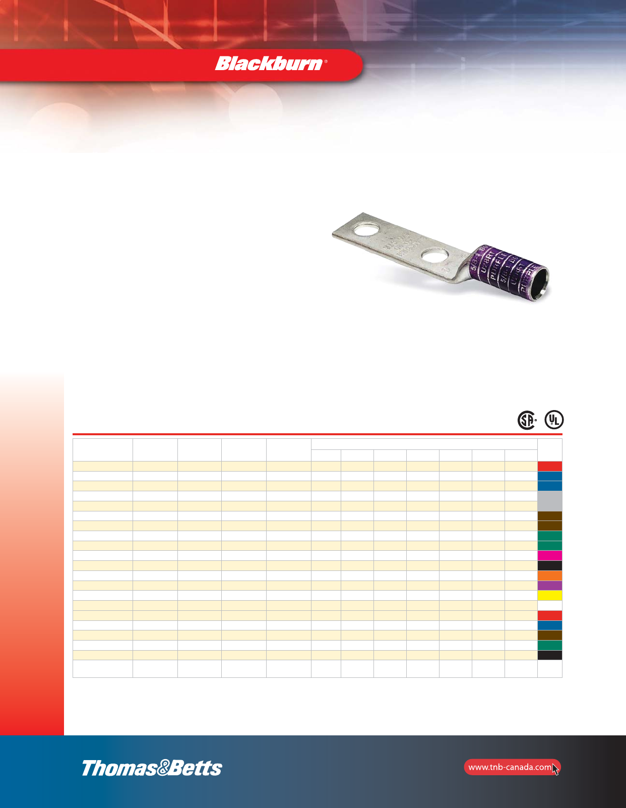
Cat. No. Conductor
Size
(CU)
Flexible
Conductor
Size Stranded Stud
Size
(in.)
Dimensions (in.) Die
Colour
Code
A B C D L W T
LCN8-14 8 str. 8 37/24 1/4 25/32 1-3/16 1/4 5/8 2-1/8 15/32 1/16 Red
LCN6-14 6 str. 6 61/24 1/4 25/32 1-1/4 1/4 5/8 1-1/4 13/32 1/16 Blue
LCN6-12 6 str. 6 61/24 1/2 25/32 3 1/2 1-3/4 4-5/32 7/8 3/32 Blue
LCN4-14 4 str. 5 91/24 1/4 25/32 1-3/16 1/4 5/8 2-3/16 17/32 3/16 Grey
LCN4-12 4 str. 5 91/24 1/2 25/32 3 1/2 1-3/4 4-5/32 7/8 3/32 Grey
LCN2-516 2 + 3 str. 3 125//24 5/16 7/8 1-5/8 3/8 3/4 2-15/16 9/16 3/32 Brown
LCN2-12 2 str. 3 125/24 1/2 7/8 3 1/2 1-3/4 4-1/4 7/8 3/32 Brown
LCN1-516 1 str. 2 150/24 5/16 1-1/32 1-5/8 3/8 7/8 2-31/32 21/32 3/32 Green
LCN1-12 1 str. 2 150/24 1/2 1-1/32 3 1/2 1-3/4 4-13/32 7/8 3/32 Green
LCN10 1/0 str. 1 225/24 1/2 1-1/32 3 1/2 1-3/4 3-31/32 3/4 1/8 Pink
LCN20 2/0 str. 1/0 275/24 1/2 1-5/16 3 1/2 1-3/4 4-3/16 13/16 1/8 Black
LCN30 3/0 str. 2/0 325/24 1/2 1-1/8 2-15/16 1/2 1-3/4 4-7/16 15/16 1/8 Orange
LCN40 4/0 str. – – 1/2 1-3/8 3 1/2 1-3/4 4-11/16 1-1/32 1/8 Purple
LCN250 250 kcmil 3/0 450/24 1/2 1-19/32 3 1/2 1-3/4 4-29/32 1-1/16 1/8 Yellow
LCN300 300 kcmil 4/0 550/24 1/2 1-25/32 3 1/2 1-3/4 5-9/32 1-3/16 1/8 White
LCN350 350 kcmil 263 650/24 1/2 1-27/32 3 1/2 1-3/4 5-11/32 1-11/32 5/32 Red
LCN400 400 kcmil 313 775/24 1/2 1-27/32 3 1/2 1-3/4 5-7/16 1-13/32 5/32 Blue
LCN500 500 kcmil 373 925/24 1/2 2-11/32 3 1/2 1-3/4 5-15/16 1-19/32 3/16 Brown
LCN600 600 kcmil 444 1100/24 1/2 2-1/8 3 1/2 1-3/4 5-3/4 1-23/32 7/32 Green
LCN75 750 kcmil 535 1325/24 1/2 2-3/8 3 1/2 1-3/4 6-3/32 1-29/32 1/4 Black
LCN99 1000 kcmil 646
777
1600/24
1925/24 1/2 2-7/8 3 1/2 1-3/4 6-19/32 2-1/4 9/32 –
50
See pages 110–135 for more tool and die information.
Type LCN — Copper Lugs, 2–Hole Mount, Long Barrel
Copper Compression Connectors
•For use with copper conductors: AWG stranded, flexible cable, welding
cable and portable cord
•Specially designed for industrial and building applications
•Made of high conductivity seamless copper tubing
•Tin plated for corrosion resistance
•Specially chamfered barrel for ease of installation
•Colour coded for matching die identification
•Can be used for medium voltage application up to 35 kV provided
proper insulation techniques are used
•CSA Certified and U.L. Listed for AWG conductors when installed with
Blackburn, Burndy, T&B or Anderson tools, as specified by CSA
•Comply with Subpart 111.60-17 of Federal Register’s Coast Guard
Electrical Engineering Rules and Regulations
Long Barrel Connectors
•Ideal for industrial, oil rig, mining, welding and transportation electrical
termination applications
•Heavy duty design which permits additional crimp for added mechanical
strength
Colour Coded Compression Connectors
Compression
Connectors
section_1_E.pdf 50 9/26/2011 10:37:07 AM
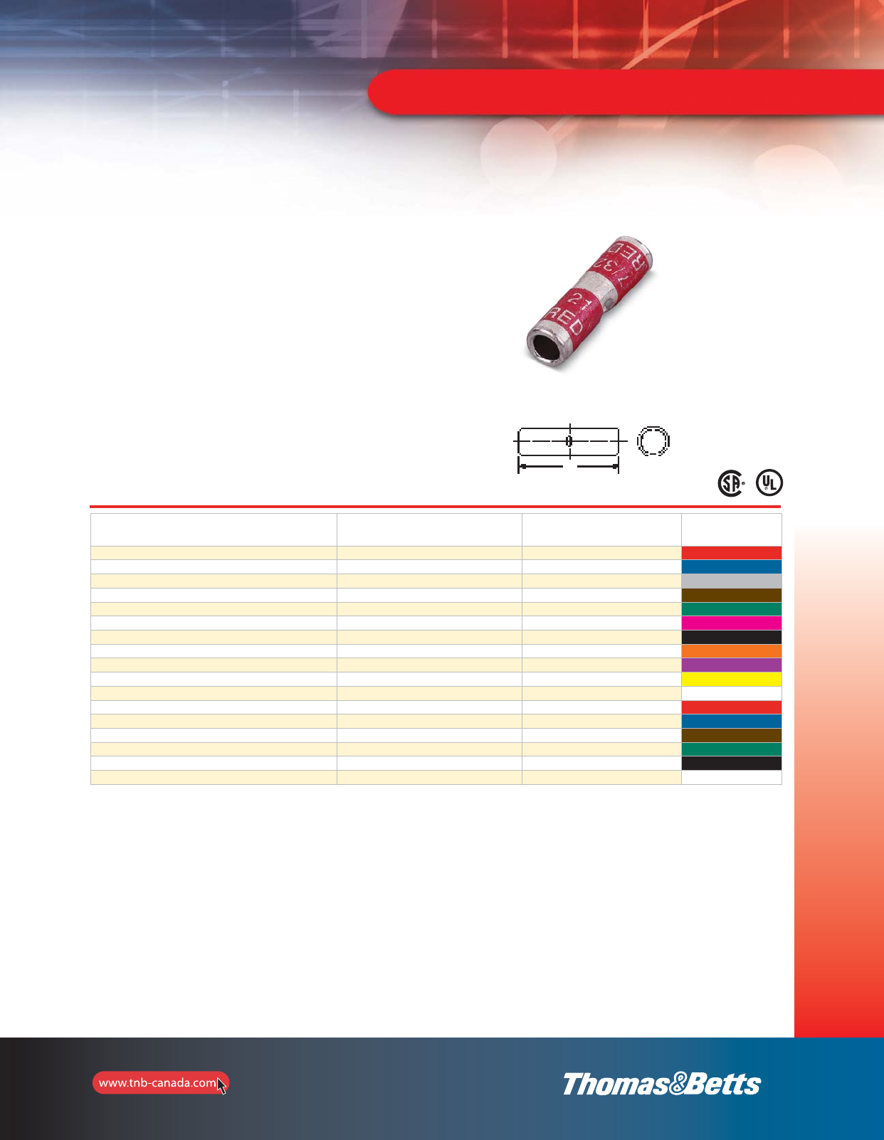
51
Compression
Connectors
Colour Coded Compression Connectors
See pages 110–135 for more tool and die information.
Type CSP — Copper Splices, Short Barrel
Copper Compression Connectors
• For use with copper conductors: AWG stranded, flexible cable, welding
cable and portable cord
•Specially designed for industrial and building applications
•Made of high conductivity seamless copper tubing
•Tin plated for corrosion resistance
•Specially chamfered barrel for ease of installation
•Colour coded for matching die identification
•Can be used for medium voltage application up to 35 kV provided proper
insulation techniques are used
•CSA Certified and U.L. Listed for AWG conductors when installed with
Blackburn, Burndy, T&B or Anderson tools, as specified by CSA
•Comply with Subpart 111.60-17 of Federal Register’s Coast Guard
Electrical Engineering Rules and Regulations
Short Barrel Connectors
•Short barrel connectors designed for regular duty applications
•Ideal for confined areas
Cat. No. Conductor
Size
(CU)
Length
L
(in.)
Die
Colour
Code
CSP8 8 str. 1Red
CSP6 6 str. 1 Blue
CSP4 4 str. 1Grey
CSP2 2 + 3 str. 1-1/4 Brown
CSP1 1 str. 1-1/2 Green
CSP10 1/0 str. 1-5/8 Pink
CSP20 2/0 str. 1-3/4 Black
CSP30 3/0 str. 1-3/4 Orange
CSP40 4/0 str. 1-7/8 Purple
CSP250 250 kcmil 2-1/4 Yellow
CSP300 300 kcmil 1-1/8 White
CSP350 350 kcmil 2-1/4 Red
CSP400 400 kcmil 2-3/4 Blue
CSP500 500 kcmil 2-3/4 Brown
CSP600 600 kcmil 3Green
CSP750 750 kcmil 3 Black
CSP1000 1000 kcmil 3-5/8 –
L
section_1_E.pdf 51 9/26/2011 10:37:08 AM
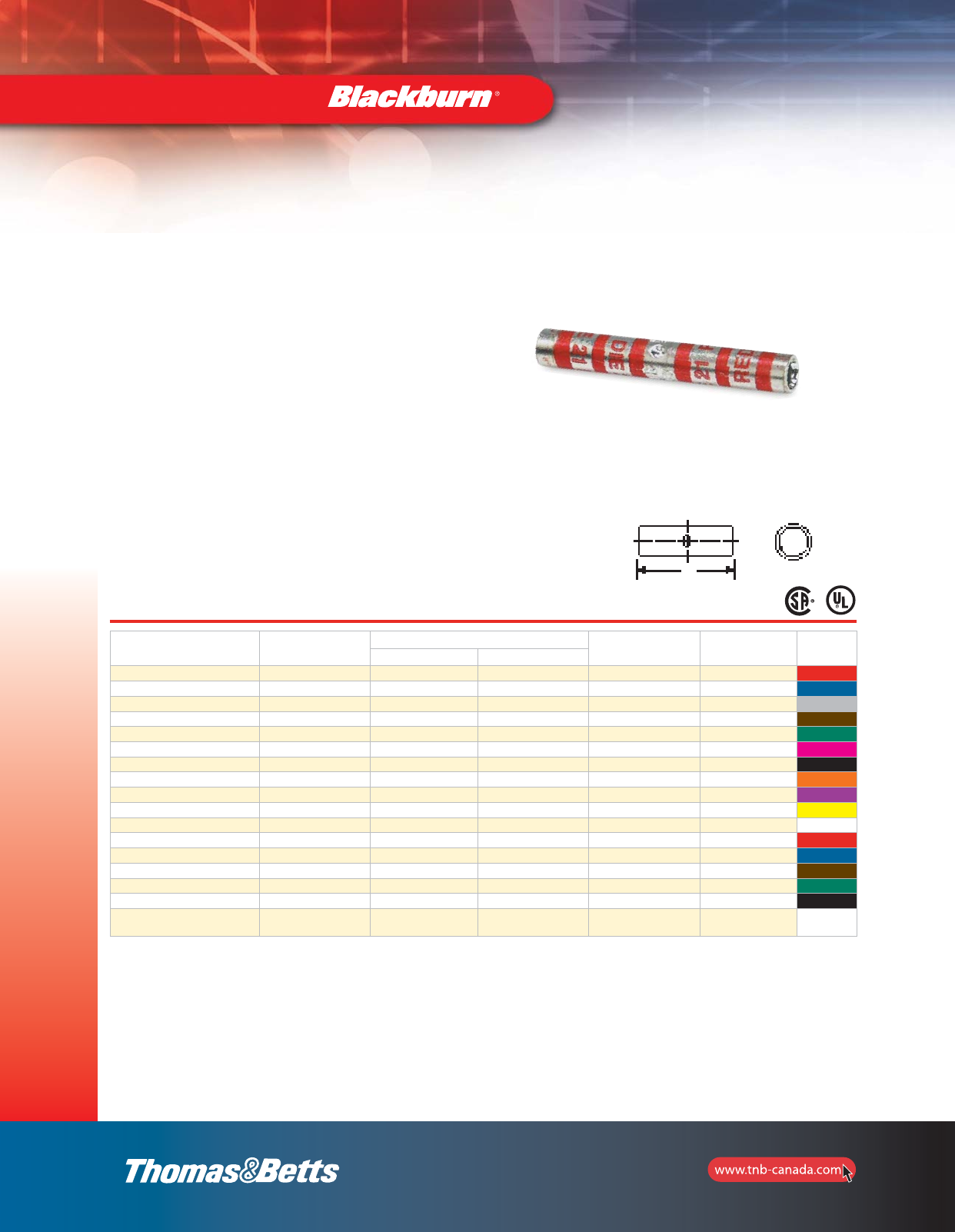
52
Compression
Connectors
Cat. No. Conductor
Size
(CU)
Flexible Conductor Stud
Size
(in.)
Length
L
(in.)
Die
Colour
Code
CMA Stranded
CU8 8 str. 8 37/24 1/4 1-3/4 Red
CU6 6 str. 6 61/24 1/4 1-3/4 Blue
CU4 4 str. 5 91/24 1/4 1-3/4 Grey
CU2 2 + 3 str. 3 125/24 5/16 1-7/8 Brown
CU1 1 str. 2 150/24 5/16 2 Green
CU10 1/0 str. 1 225/24 5/16 2 Pink
CU20 2/0 str. 1/2 275/24 3/8 2-1/8 Black
CU30 3/0 str. 2/0 325/24 1/2 2-1/4 Orange
CU40 4/0 str. – – 1/2 2-3/4 Purple
CU250 250 kcmil 3/0 450/24 1/2 3-3/8 Yellow
CU300 300 kcmil 4/0 550/24 1/2 3-1/2 White
CU350 350 kcmil 263 650/24 1/2 3-3/4 Red
CU400 400 kcmil 313 775/24 5/8 3-3/4 Blue
CU500 500 kcmil 373 925/24 5/8 4-3/4 Brown
CU600 600 kcmil 444 1100/24 5/8 4-1/4 Green
CU750 750 kcmil 535 1325/24 5/8 4-3/4 Black
CU1000 1000 kcmil 646
777
1600/24
1925/24 5/8 5-5/8 –
See pages 110–135 for more tool and die information.
Type CU — Copper Splices, Long Barrel
Copper Compression Connectors
•For use with copper conductors: AWG stranded, flexible cable,
welding cable and portable cord
• Specially designed for industrial and building applications
• Made of high conductivity seamless copper tubing
•Tin plated for corrosion resistance
•Specially chamfered barrel for ease of installation
•Colour coded for matching die identification
•Can be used for medium voltage application up to 35 kV provided
proper insulation techniques are used
•CSA Certified and U.L. Listed for AWG conductors when installed
with Blackburn, Burndy, T&B or Anderson tools, as specified by CSA
•Comply with Subpart 111.60-17 of Federal Register’s Coast Guard
Electrical Engineering Rules and Regulations
Long Barrel Connectors
•Ideal for industrial, oil rig, mining, welding and transportation
electrical termination applications
•Heavy duty design which permits additional crimp for added
mechanical strength
Colour Coded Compression Connectors
L
section_1_E.pdf 52 9/26/2011 10:37:08 AM
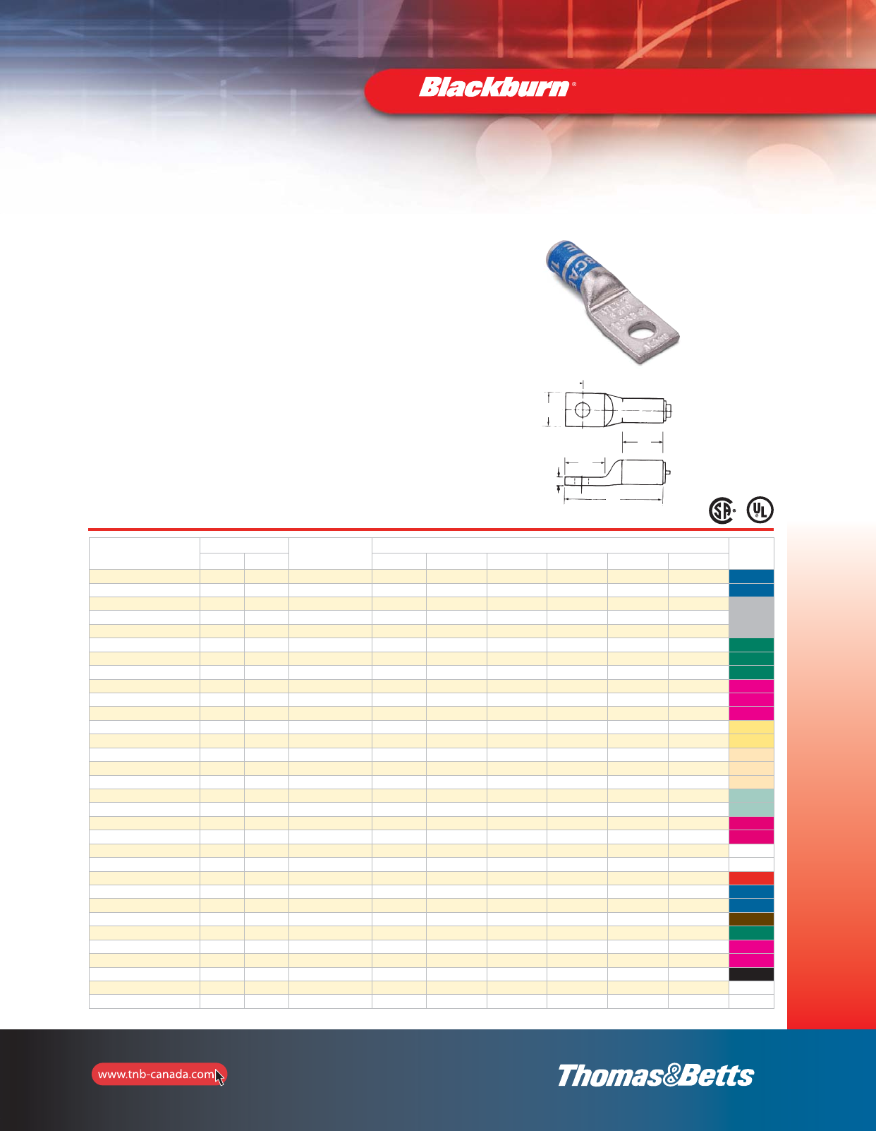
Cat. No. Conductor Size Stud
Size
(in.)
Dimensions (in.) Die
Colour
Code
(AL) (CU) A B C L W T
ATL8-10 8 str. 6 AWG 10 1/2 19/32 7/32 1-9/32 13/32 3/32 Blue
ATL8-14 8 str. 6 AWG 1/4 1/2 11/16 11/32 1-3/8 7/16 3/32 Blue
ATL6-10 6 str. 4 AWG 10 25/32 9/16 7/32 1-1/2 15/32 1/8 Grey
ATL6-14 6 str. 4 AWG 1/4 25/32 23/32 15/32 1-21/32 15/32 1/8 Grey
ATL6-38 6 str. 4 AWG 3/8 27/32 29/32 7/16 1-27/32 5/8 3/32 Grey
ATL4-14 4 str. 1 AWG 1/4 27/32 13/16 11/32 1-29/32 5/8 3/16 Green
ATL4-516 4 str. 1 AWG 5/16 27/32 1 7/16 2-1/16 5/8 3/16 Green
ATL4-38 4 str. 1 AWG 3/8 27/32 29/32 7/16 2 5/8 3/16 Green
ATL2-14 2 + 3 str. 1/0 AWG 1/4 27/32 25/32 11/32 1-15/16 23/32 3/16 Pink
ATL2-516 2 + 3 str. 1/0 AWG 5/16 27/32 7/8 7/16 2-11/32 3/4 3/16 Pink
ATL2-38 2 + 3 str. 1/0 AWG 3/5 27/32 29/32 7/16 2-1/16 23/32 3/16 Pink
ATL1-516 1 str. – 5/16 27/32 7/8 7/16 2-1/32 23/32 3/16 Gold
ATL1-38 1 str. – 3/8 27/32 29/32 7/16 2-3/8 3/4 3/16 Gold
ATL10-516 1/0 str. – 5/16 1-5/32 1 7/16 2-17/32 7/8 3/16 Tan
ATL10-38 1/0 str. – 3/8 1-5/32 1-1/16 7/16 2-19/32 7/8 3/16 Tan
ATL10-12 1/0 str. – 1/2 1-5/32 1-3/8 11/16 2-15/16 15/16 3/16 Tan
ATL20-38 2/0 str. – 3/8 1-3/16 1 7/16 2-5/8 31/32 7/32 Olive
ATL20-12 2/0 str. – 1/2 1-3/16 1-3/8 11/16 3 1-1/32 7/32 Olive
ATL30-38 3/0 str. – 3/8 1-11/32 1-1/16 7/16 2-13/16 1-1/16 7/32 Ruby
ATL30-12 3/0 str. – 1/5 1-11/32 1-3/8 11/16 3-1/8 1-1/16 7/32 Ruby
ATL40-38 4/0 str. 300 kcmill 3/8 1-7/8 1-3/32 3/8 3-3/4 1-3/16 1/4 White
ATL40-12 4/0 str. 300 kcmill 1/2 1-7/8 1-1/4 1/2 3-7/8 1-3/16 1/4 White
ATL250-12 250 kcmil 350 kcmil 1/5 2-1/32 1-1/4 1/2 4-1/32 1-9/32 1/4 Red
ATL300-38 300 kcmill 400 kcmill 3/8 2 1-5/16 3/8 4-3/16 1-3/8 9/32 Blue
ATL300-12 300 kcmil 400 kcmil 1/2 2 1-5/16 1/2 4-3/16 1-3/8 9/32 Blue
ATL350-12 350 kcmil 500 kcmil 1/2 2-11/16 1-5/16 1/2 4-7/8 1-1/2 5/16 Brown
ATL400-58 400 kcmil 600 kcmil 5/8 2-11/16 1-1/4 1/2 4-15/16 1-5/8 3/8 Green
ATL500-12 500 kcmil 700 kcmil 1/2 2-11/16 1-1/4 1/2 4-15/16 1-25/32 3/8 Pink
ATL500-58 500 kcmil 700 kcmil 5/8 2-11/16 2 3/4 5-11/16 1-25/32 3/8 Pink
ATL600-12 – 600 kcmil 1/2 2-11/16 2 3/4 5-13/16 1-29/32 11/32 Black
ATL750-12 750 kcmil 900 kcmil 1/2 2-7/8 1-1/4 1/2 5-1/4 2-1/8 3/8 –
ATL750-58 750 kcmil 900 kcmil 5/8 2-7/8 2 3/4 6-1/32 2-1/8 3/8 –
53
Colour Coded Compression Connectors
See pages 110–135 for more tool and die information.
Type ATL — Aluminum Lugs, 1-Hole
Aluminum Compression Connectors
•Specifically designed for use with aluminum conductors
(concentric, compressed or compact)
•Also listed for use with copper conductors
•Made of high conductivity seamless aluminum tubing
•Tin plated for corrosion resistance
•Chamfered barrels for ease of installation
•Can be used for medium voltage applications up to 35 kV
provided proper insulation techniques are used
•CSA Certified and U.L. Listed for AWG conductors when
installed with Blackburn, Burndy, T&B or Anderson tools,
as specified by CSA
•Colour coded for quick, easy die identification
•Pre-filled with oxide inhibiting compound
Compression
Connectors
W
C
A
L
B
T
section_1_E.pdf 53 9/26/2011 10:37:08 AM
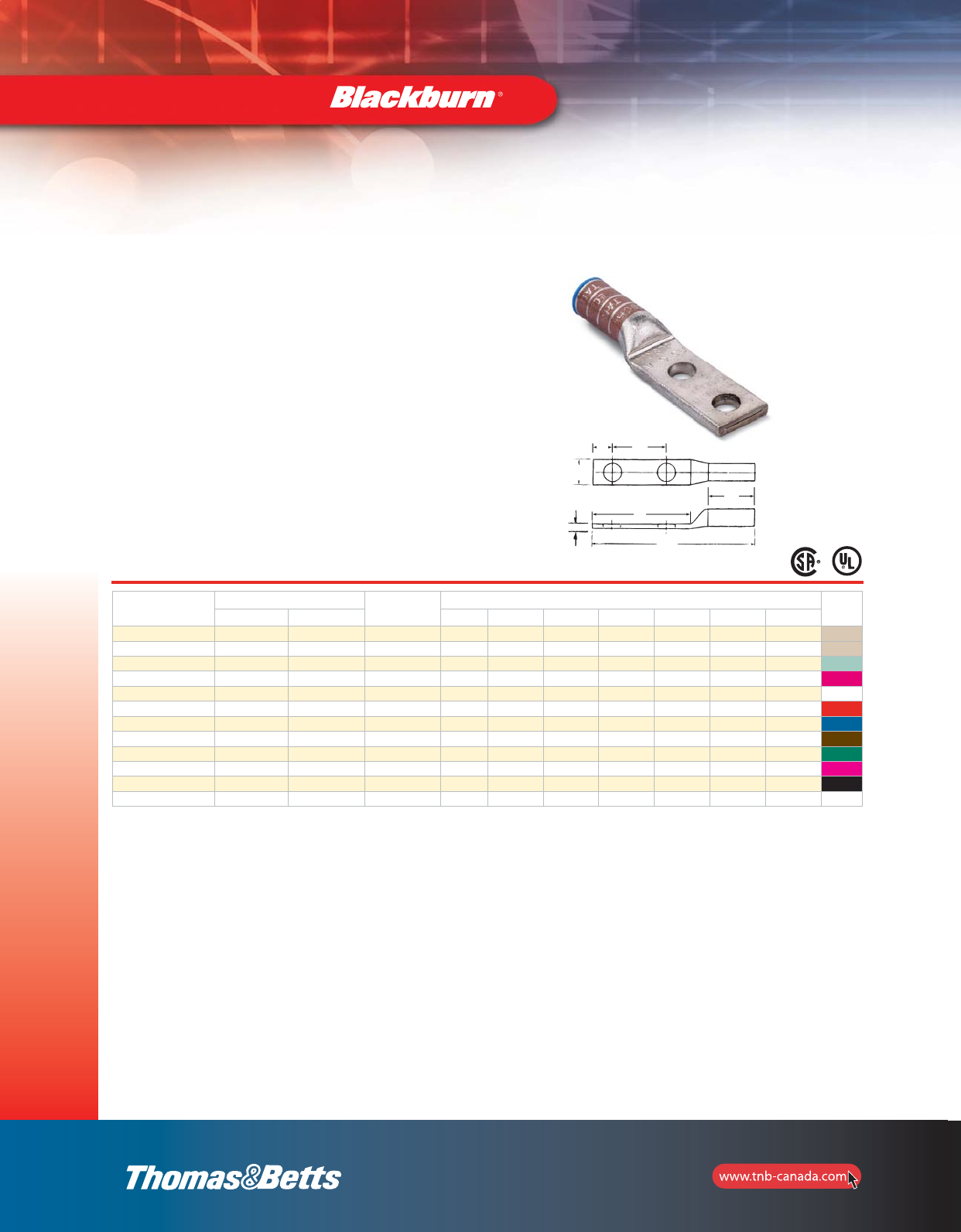
54
Compression
Connectors
Cat. No. Conductor Size Stud
Size
(in.)
Dimensions (in.) Die
Colour
Code
(AL) (CU) A B C D L W T
ATL102-38 1/0 str. –3/8 1-5/32 2-1/16 3/8 1 3-19/32 7/8 3/16 Tan
ATL102 1/0 str. – 1/2 1-3/16 3 1/2 1-3/4 4-9/16 15/16 3/16 Tan
ATL202 2/0 str. –1/2 1-3/16 3-3/8 3/4 1-3/4 5 31/32 7/32 Olive
ATL302 3/0 str. – 1/2 1-11/32 3-3/8 3/4 1-3/4 5-5/32 1-1/16 7/32 Ruby
ATL402 4/0 str. 300 kcmil 1/2 1-7/8 3 1/2 1-3/4 5-5/8 1-3/16 1/4 White
ATL2502 250 kcmil 350 kcmil 1/2 2-1/32 3 1/2 1-3/4 5-25/32 1-9/32 1/4 Red
ATL3002 300 kcmil 400 kcmil 1/2 2 3 1/2 1-3/4 5-7/8 1-3/8 9/32 Blue
ATL3502 350 kcmil 500 kcmil 1/2 2-11/16 3 1/2 1-3/4 6-9/16 1-1/2 5/16 Brown
ATL4002 400 kcmil 600 kcmil 1/2 2-11/16 3 1/2 1-3/4 6-11/16 1-5/8 3/8 Green
ATL5002 500 kcmil 700 kcmil 1/2 2-11/16 3 1/2 1-3/4 6-11/16 1-25/32 3/8 Pink
ATL6002 –600 kcmil 1/2 2-11/16 3 1/2 1-3/4 6-13/16 1-29/32 11/32 Black
ATL7502 750 kcmil 900 kcmil 1/2 2-7/8 3 1/2 1-3/4 7-1/8 2-1/8 3/8 –
Colour Coded Compression Connectors
See pages 110–135 for more tool and die information.
Type ATL — Aluminum Lugs, 2-Hole
Aluminum Compression Connectors
•Specifically designed for use with aluminum conductors
(concentric, compressed or compact)
•Also listed for use with copper conductors
•Made of high conductivity seamless aluminum tubing
•Tin plated for corrosion resistance
•Chamfered barrels for ease of installation
•Can be used for medium voltage applications up to 35 kV
provided proper insulation techniques are used
•Colour coded for quick, easy die identification
•Pre-filled with oxide inhibiting compound
•CSA Certified and U.L. Listed for AWG conductors when
installed with Blackburn, Burndy, T&B or Anderson tools,
as specified by CSA
D
W
L
A
T
C
B
section_1_E.pdf 54 9/26/2011 10:37:09 AM
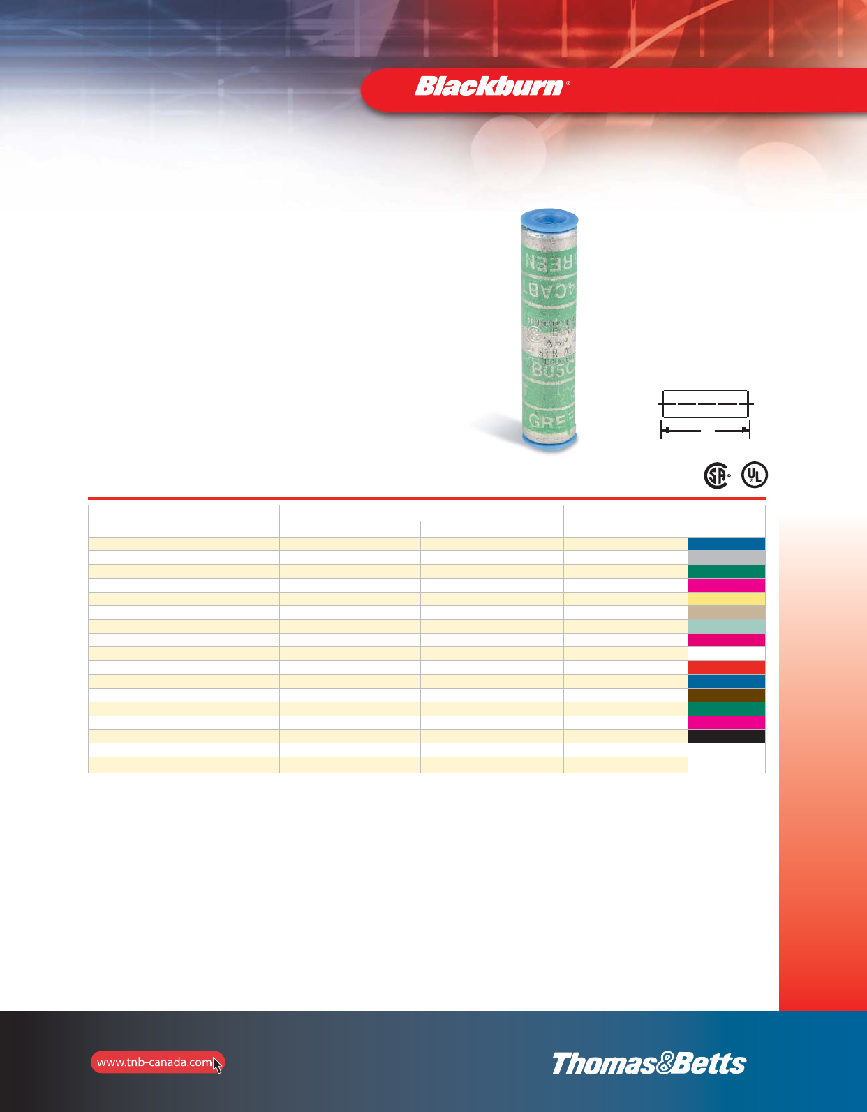
55
Colour Coded Compression Connectors
See pages 110–135 for more tool and die information.
Type ASP — Aluminum Splices
Aluminum Compression Connectors
•Specifically designed for use with aluminum conductors
(concentric, compressed or compact)
•Also listed for use with copper conductors
•Made of high conductivity seamless aluminum tubing
•Tin plated for corrosion resistance
•Chamfered barrels for ease of installation
•Can be used for medium voltage applications up to 35 kV
provided proper insulation techniques are used
•Colour coded for quick, easy die identification
•Pre-filled with oxide inhibiting compound
•CSA Certified and U.L. Listed when installed with Blackburn,
Burndy, T&B or Anderson tools, as specified by CSA
Cat. No. Conductor Size Length
L
(in.)
Die
Colour
Code
(AL) (CU)
ASP8 8 str. 6 AWG 1-1/4 Blue
ASP6 6 str. 4 AWG 1-5/8 Grey
ASP4 4 str. 1 AWG 1-7/8 Green
ASP2 2 + 3 str. 1/0 AWG 1-7/8 Pink
ASP1 1 str. – 2-3/8 Gold
ASP10 1/0 str. – 2-3/8 Tan
ASP20 2/0 str. – 2-1/2 Olive
ASP30 3/0 str. – 2-7/8 Ruby
ASP40 4/0 str. 300 kcmil 3-3/4 White
ASP250 250 kcmil 350 kcmil 4 Red
ASP300 300 kcmil 400 kcmil 4Blue
ASP350 350 kcmil 500 kcmil 3-7/8 Brown
ASP400 400 kcmil 600 kcmil 4-7/8 Green
ASP500 500 kcmil 700 kcmil 5 Pink
ASP600 –600 kcmil 5-1/8 Black
ASP750 750 kcmil 900 kcmil 5-3/8 –
ASP1000 1000 kcmil 6–
Compression
Connectors
L
section_1_E.pdf 55 9/26/2011 10:37:09 AM
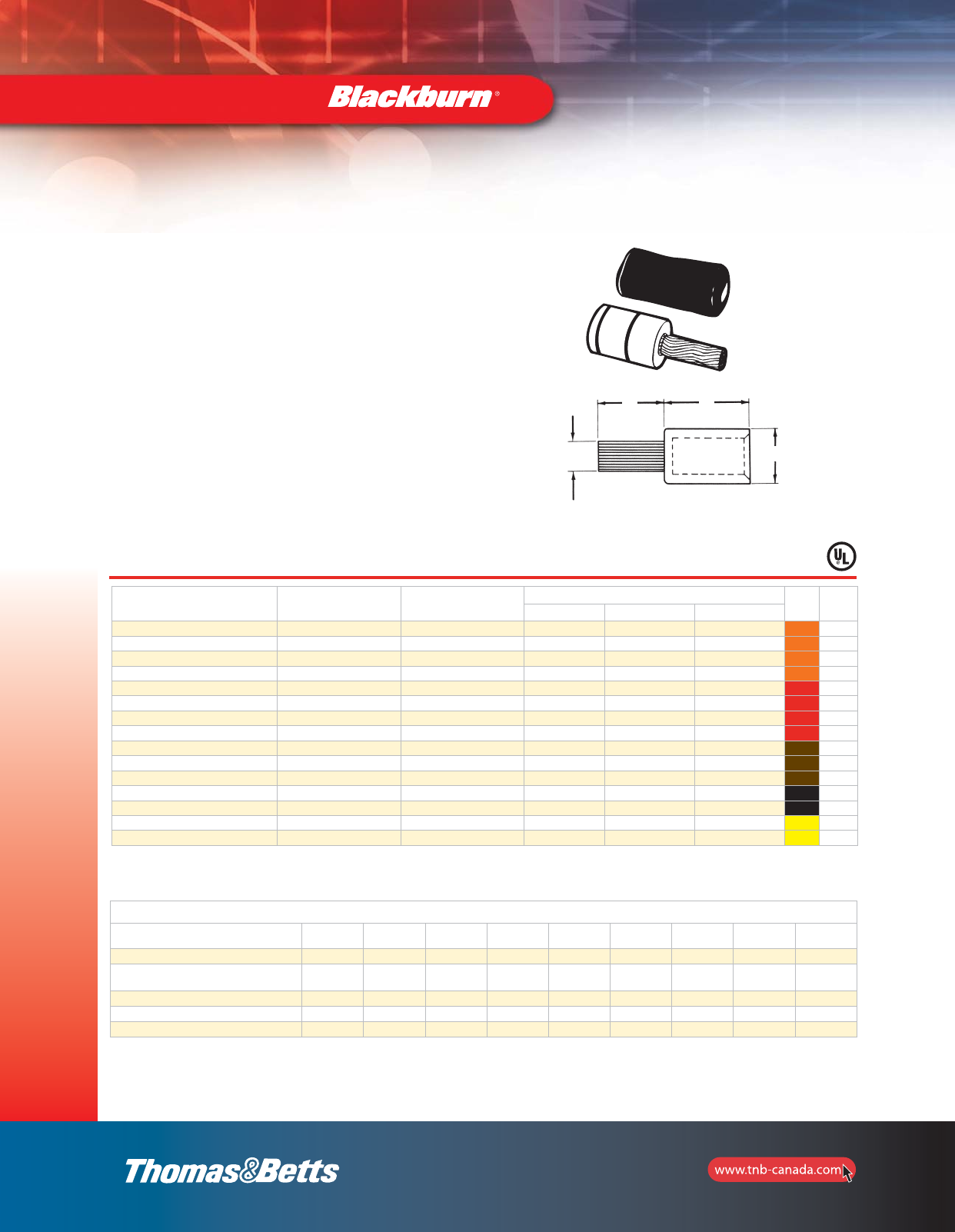
56
Compression
Connectors
Cat. No.
Conductor
Size
(Al)
Copper
Stud Size
Dimensions (in.) Die
Colour
Code
Die #
A B O.D.
PA06 6 str. 8 7/8 1-11/32 0.640 Orange 50
PA04 4 str. 6 7/8 1-11/32 0.640 Orange 50
PA02 2 str. 4 7/8 1-11/32 0.640 Orange 50
PA01 1 str. 3 1 1-11/32 0.640 Orange 50
PA11 1/0 str. 2 1-1/4 1-19/32 0.906 Red 76
PA21 2/0 str. 1 1-1/4 1-19/32 0.906 Red 76
PA31 3/0 str. 1/0 1-3/8 1-7/8 0.906 Red 76
PA41 4/0 str. 2/0 1-3/8 1-7/8 0.906 Red 76
PA25 250 kcmil 3/0 1-1/2 2-1/16 1.155 Brown 87H
PA30 300 kcmil 4/0 1-5/8 2-1/16 1.155 Brown 87H
PA35 350 kcmil 4/0 1-5/8 2-1/16 1.155 Brown 87H
PA40 400 kcmil 250 kcmil 1-7/8 2-3/32 1.375 Black 106H
PA50 500 kcmil 350 kcmil 1-7/8 2-3/32 1.375 Black 106H
PA60 600 kcmil 350 kcmil 1-7/8 2-3/4 1.500 Yellow 115H
PA75 750 kcmil 500 kcmil 2 2-3/4 1.500 Yellow 115H
Colour Coded Compression Connectors
U.L. Listed AL9CU.
Products on this page are not CSA Certified.
Type PA — Pin Adapter Terminals
•Connector for aluminum conductors only; pigtail may be
inserted into either aluminum or copper connectors
•Insulating cover included
•90°C Rating per U.L. 486B
•Tin plated stranded copper wire pigtail
•Tin plated aluminum barrel pre-filled with oxide
inhibitor and capped
T&B Dies
Alum. Wire Size Die
Code UT3 UT5 TBM5 TBM6 TBM8 13642
12-Ton
TBM15
UT15
21920
20-Ton
#6 – #1 50 5/8 TU Orange – – – 15529 –
1/0 – 4/0 76 or
76H –TX–
13472 Red
13476 Red 13467 11744 15512 11170
250 kcmil – 350 kcmil 87H – TH – – 13468 11746 15506 11176
400 kcmil – 500 kcmil 106H – – – – – 11749 15515 11140
600 kcmil – 750 kcmil 115H – – – – – 11753 15504 11157
CU
Stud
A B
OD
56-e.pdf 1 6/15/2012 1:35:58 PM
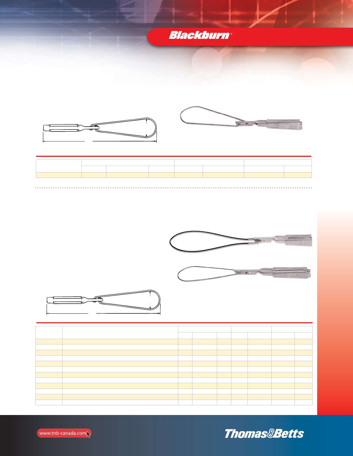
D
L
D
L
57
Compression
Connectors
Cat. No. Description Conductor Range Dimensions (in.) Typical Tensile Values
ACSR AL AAAC D L Conductor Value (lb.)
W62-1 W-1 Series Aluminum Wedge and Slider 2–6 1 str. – 6 sol. 2–6 2-3/8 flex. 12, 17-1/2 2 6 x 1 ACSR 1200
W62-1FC W-1 Series Aluminum Wedge and Slider 2–6 1 str. – 6 sol. 2–6 2-3/8 flex. 12, 17-1/2 2 6 x 1 ACSR 1200
W20-1 W-1 Series Aluminum Wedge and Slider 1/0–4 2/0 str. – 2 sol. 1/0–4 2-3/8 flex. 12-1/2, 18-1/2 1/0 6 x 1 ACSR 1800
W20-1FC W-1 Series Aluminum Wedge and Slider 1/0–4 2/0 str. – 2 sol. 1/0–4 2-3/8 flex. 12-1/2, 18-1/2 1/0 6 x 1 ACSR 1800
W40-1* W-1 Series Aluminum Wedge and Slider 4/0–2/0 4/0 str. – 2 sol. 4/0–2/0 2-3/8 flex. 12-3/4, 18-1/2 4/0 6 x 1 ACSR 1900
W40-1FC* W-1 Series Aluminum Wedge and Slider 4/0–2/0 4/0 str. – 2 sol. 4/0–2/0 2-3/8 flex. 12-3/4, 18-1/2 4/0 6 x 1 ACSR 1900
W62-1B W-1B Series for extremely corrosive areas. Iridited Aluminum Wedge and Slider 2–6 1 str. – 6 sol. 2–6 2-3/8 flex. 12, 17-1/2 2 6 x 1 ACSR 1200
W62-1BFC W-1B Series for extremely corrosive areas. Iridited Aluminum Wedge and Slider 2–6 1 str. – 6 sol. 2–6 2-3/8 flex. 12, 17-1/2 2 6 x 1 ACSR 1200
W20-1B W-1B Series for extremely corrosive areas. Iridited Aluminum Wedge and Slider 1/0–4 2/0 str. – 2 sol. 1/0–4 2-3/8 flex. 12-1/2, 18-1/2 1/0 6 x 1 ACSR 1800
W20-1BFC W-1B Series for extremely corrosive areas. Iridited Aluminum Wedge and Slider 1/0–4 2/0 str. – 2 sol. 1/0–4 2-3/8 flex. 12-1/2, 18-1/2 1/0 6 x 1 ACSR 1800
W40-1B* W-1B Series for extremely corrosive areas. Iridited Aluminum Wedge and Slider 4/0–2/0 4/0 str. – 2 sol. 4/0–2/0 2-3/8 flex. 12-3/4, 18-1/2 4/0 6 x 1 ACSR 1900
W40-1BFC* W-1B Series for extremely corrosive areas. Iridited Aluminum Wedge and Slider 4/0–2/0 4/0 str. – 2 sol. 4/0–2/0 2-3/8 flex. 12-3/4, 18-1/2 4/0 6 x 1 ACSR 1900
* W40 series clamps rated 850 lb ultimate tension for 1/0 ACSR, AL, or AAAC.
Type W — Aluminum Service Wedge Clamps for use with
ACSR, Aluminum, AAAC Conductors
•For dead-ending self-supporting drop wire
•Saves conductor—drop wire may be cut to exact length
•Can be attached to bare neutral at any point in the span
•Adjustments in drop wire sag are easily made
•Grips ACSR, AAAC, or aluminum conductors
Rigid Stainless Steel Bail
(Bail Length – 6-1/2”)
“FC” Flexible Bail
(Bail Length – 11-1/2”)
Type W — Stainless Steel Wedge Clamps
Cat. No. Conductor Range Dimensions (in.) Typical Tensile Values
ACSR AL AAAC D L Conductor Value (lb.)
W62D 2–6 1 str. – 6 sol. 2–6 2-3/8 flex. 12 2 6 x 1 ACSR 1200
•For use on copper neutral
•Stainless Steel wedge and slider
Service Wedge Clamps
L
D
D
L
section_1_E.pdf 57 9/26/2011 10:37:09 AM
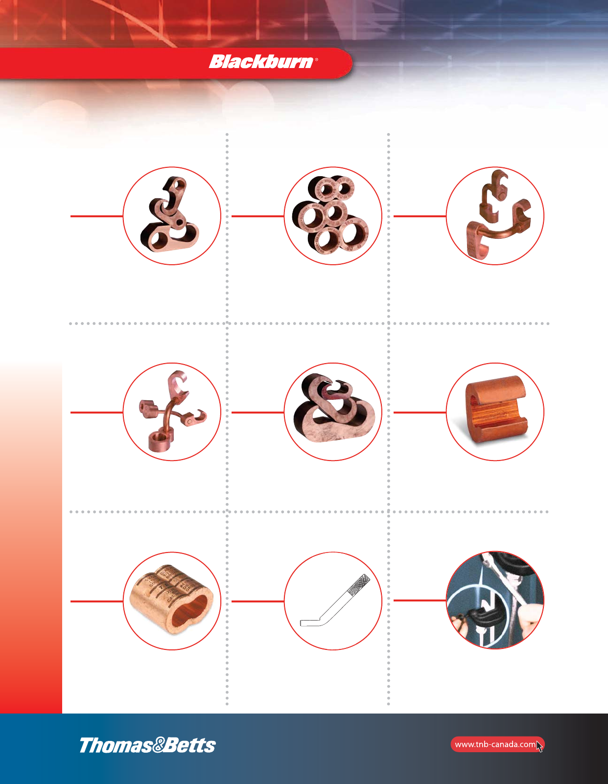
58
Grounding Connectors
Quick Reference
Grounding Connectors and Accessories — Quick Reference
Figure 6
p. 65
Figure 8
p. 65
Figure 6–6
p. 66
Figure 6–8
p. 66
C-Taps
pp. 67–68
C-Crimp
p. 69
Type GR
Pigtail Connectors
p. 69
45°
TBGS-34
0.705" Dia
Minimum at contact
surface WIDTH 0.450
LENGTH 1.000
Intersecting medium knuring
(2.10" long)
Grounding Studs
p. 70
I-Beam Ground Clamps
p. 71
2_BLKBRNMRO5_E_58to167_Grounding.pdf 1 10/6/2011 1:00:46 PM
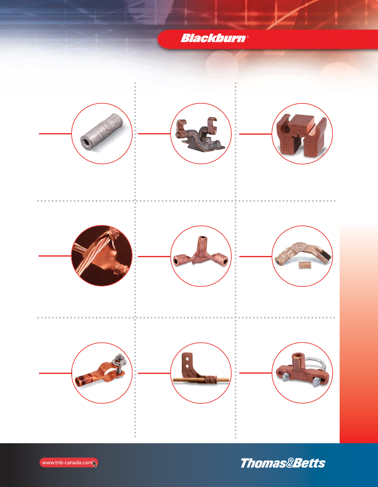
59
Grounding Connectors
Quick Reference
Grounding Connectors and Accessories — Quick Reference
Grounding Plates
p. 72
Ground Bus
Bar Connectors
p. 73
Types GRD, GG
Ground Grid
Connectors
pp. 74–75
Cast Copper
Two-Way Cast Copper Connectors
Heavy-Duty
p. 71
Two Cables to Ground Rod
pp. 75–76
53065
Grounding Grid Connectors
Heavy-duty
Cast Copper
p. 76
Ground Clamps
p. 77
Flat-Surface Ground Clamps
p. 77
Grid-to-Fence Ground Clamps
p. 77
2_BLKBRNMRO5_E_58to167_Grounding.pdf 2 10/6/2011 1:00:46 PM
60
Grounding Connectors and Accessories — Quick Reference
Type GUV
U-Bolt Ground Clamps
p. 80
Ground Rods
pp. 81–82
Couplings
p. 82
Driving Studs
p. 82
Threadless Couplings
p. 83
Ground Rod Drivers
For installing
Ground Rods
p. 84
Types JAB, G, JWR, GG, GGH
Ground Rod Clamps
pp. 78–79
Type DGC
Drive-on Ground
Clamps
p. 83
Ground Electrode Boxes
p. 85
Grounding Connectors
Quick Reference
2_BLKBRNMRO5_E_58to167_Grounding.pdf 3 10/6/2011 1:00:46 PM
61
Grounding Connectors and Accessories — Quick Reference
Type GP
Pole Bottom
Ground Plates
p. 85
Type PB
Bar Connectors
p. 85
CTG250
Wide Range Tower
Ground Clamps
p. 86
Types LL, CULL
Lay-in Lug
Connectors
p. 87
Type DS
Service Post Connectors
Short Stud
p. 89
Metallic Gradient Control Mat
p. 85
Type GTC
Tower Ground Clamps
p. 86
Parallel Connectors
p. 88
Grounding Connectors
Quick Reference
Type SP
Service Post Connectors
Long Stud
p. 90
2_BLKBRNMRO5_E_58to167_Grounding.pdf 4 10/6/2011 1:00:47 PM
62
Grounding Connectors and Accessories — Quick Reference
Type TTC
Transformer Tank
Grounding Connectors
p. 91
Clamps
Die Cast Clamps
p. 101
Conduit Hubs
p. 92
Type FB
Flexible Braid
Connectors
pp. 93–100
Waterpipe Ground Clamps
p. 102
Grounding Connectors
Quick Reference
2_BLKBRNMRO5_E_58to167_Grounding.pdf 5 10/6/2011 1:00:47 PM
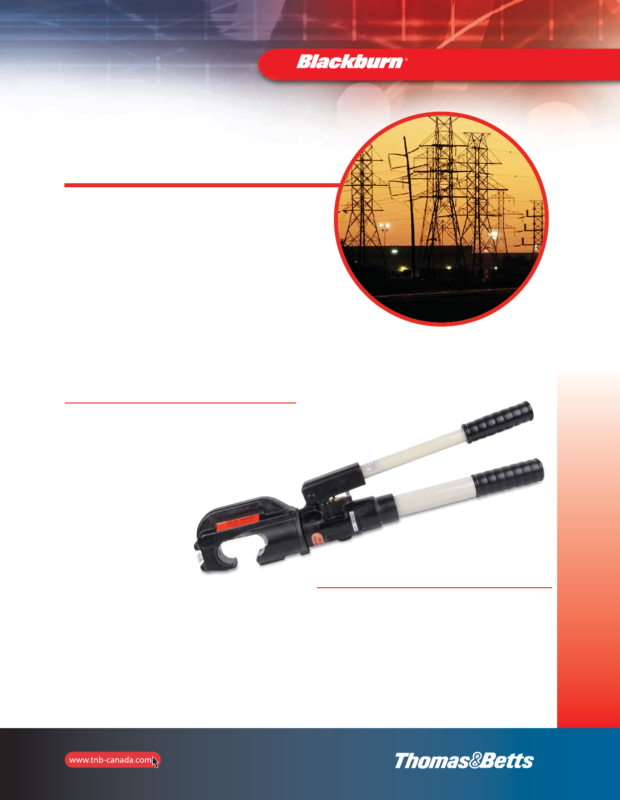
63
Grounding
Grounding Connectors
Compression Method Grounding
Connectors save 50 – 75% in time
and labor costs.
•Eliminates exothermic welding
•Reduces time and labor costs
•Minimizes possibility of poor connections
Thomas & Betts introduces a method of compression to replace exothermic
welding and its associated disadvantages. This compression method is
designed to provide quick, reliable connections for grid grounding at
significantly lower installed costs because compression connectors install in
less time, in any weather, and are unaffected by moisture, reducing downtime.
In addition, our compression connectors for grid grounding require no special
training for installation. They are made of high-conductivity wrought and cast
copper, and are used for connecting and tapping cross grid, loop lines and
ground rods for direct burial or concrete embedded ground grid systems. The
Thomas & Betts compression system uses standard electrical connector
installation tools.
Meets all applicable specifications
This installation method results in a long-lasting low installed cost
connection. You can install it and forget it.
Before compression, typical cable connector cross section of cable and
connector consists of about 75% metal and 25% air. After Thomas & Betts
method compression, the cross section shows 100% metal with
virtually no air spaces.
Reliable installations through compression connections
Dies that are used in Thomas & Betts hand and hydraulic tools
contain the “die code” numbers which are engraved on the
compression surface of the die. Under compression, this number
becomes embossed on the completed connection for inspection
purposes.
The inspector compares the die code number embossed on the
connector with the die table to ensure that the proper connector was
compressed with the correct die for that particular size conductor.
Thomas & Betts grid and ground rod connectors satisfy the
requirements of CEC SECTION 10 for connecting to the Grounding
Electrode System. They also meet the requirements of UL Std. 467,
UL Std. 486, CSA Std. C22.2 No. 41 and CSA Std. C22.2 No. 65
being acceptable as grounding and bonding equipment suitable for
direct burial. Thomas & Betts grid and ground rod connectors also
satisfy the recommended practice for the selection of
grounding connector joints described in IEEE
837 standard for qualifying permanent
connections used in substation
grounding.
The connectors conform to
the following IEEE Standard
837 requirements:
•350oC current cycling
•Freeze-thaw test
•Accelerated aging – nitric
acid/salt spray
•Mechanical, tensile and electromagnetic
force (EMF) criteria
•Install in any weather – cut downtime
•Enhance safety
•Easy to install – no special training
TBM14M
(Suggested tool for E-Z-Ground®connectors
to ground up to 5/8” diameter.)
2_BLKBRNMRO5_E_58to167_Grounding.pdf 6 10/6/2011 1:00:47 PM
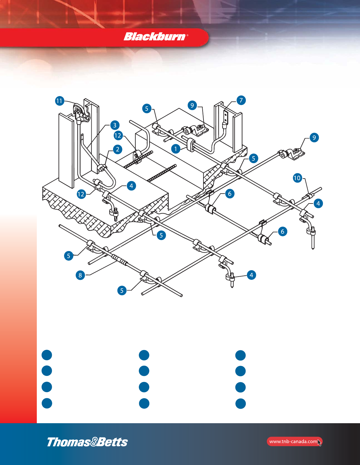
Grounding Connectors
Thomas & Betts offers a complete line of grid-ground compression
connectors. Our E-Z-Ground®connectors are designed for direct
burial and offer a safe, efficient alternative to exothermic welding
products. Grid ground installations do not require explosive charges,
and can be installed in various climate conditions. These
range-taking products will reduce the number of connectors and
dies needed for your installation.
Thomas & Betts E-Z-Ground®products meet all applicable standards
(IEEE837, UL467, CSA22.2). Connectors are prefilled with oxide
inhibitors and sealed.
1C-Tap
2Figure 8 Connector
3Steel Grounding Stud TBG Series
4Figure 6–8 Connectors
5Figure 6–6 Connectors
6Grid to Ground Connectors
7Lug
8Splice/Two-Way Connector
9Ground Plates
10 Figure 8 Connector
11 I-Beam Clamp
12 Figure 6 Connectors
64
Grounding
2_BLKBRNMRO5_E_58to167_Grounding.pdf 7 10/6/2011 1:00:47 PM
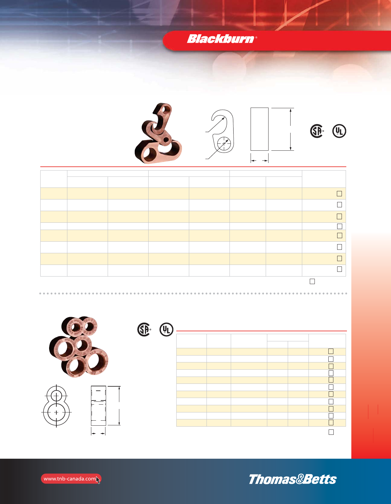
65
Grounding
MEETS
IEEE
837 REQUIREMENTS
Grounding Connectors
Figure 6 — Compression Ground Tap Connectors
Cat. No.
Application Cable to rebar application* Dimensions in. (mm) Dies for
TBM14M, 13100A
or TBM15I
Main Tap Main Tap T H
54855 1/0 Str.–250 kcmil
or 1/2”–5/8” Rod #4 Sol.–#2 Str. #3 Rebar 3/8 thru
1/2” #4 Rebar #4 Sol.–#2 Str. 0.75 (19.1) 1.94 (49.3) 15G86R
54860 1/0 Str.–250 kcmil
or 1/2”–5/8” Rod 1/0 Str.–2/0 Str. #3 Rebar 3/8 thru
1/2” #4 Rebar 1/0 Str.–2/0 Str. 0.75 (19.1) 2.19 (55.6) 15G86R
54865-CK 1/0 Str.–250 kcmil
or 1/2”–5/8” Rod 3/0 Str. – 250 kcmil #3 Rebar 3/8 thru
1/2” #4 Rebar 3/0 Str. – 250 kcmil 0.75 (19.1) 2.19 (55.6) 15G86R
54875 #6 Sol.–#2 Str. #6 Sol.–#2 Str. – – 0.75 (19.1) 2.56 (65.0) 15501A
54885 250 kcmil–500 kcmil
or 5/8”–3/4” Rod #4 Sol.–#2 Str. #5 Rebar 5/8 thru
3/4” #6 Rebar #4 Sol.–#2 Str. 0.75 (19.1) 1.94 (49.3) 15G126R
54890 250 kcmil–500 kcmil
or 5/8”–3/4” Rod 1/0 Str.–2/0 Str. #5 Rebar 5/8 thru
3/4” #6 Rebar 1/0 Str.–2/0 Str. 0.75 (19.1) 2.13 (54.1) 15G126R
54895 250 kcmil–500 kcmil
or 5/8”–3/4” Rod 3/0 Str. – 250 kcmil #5 Rebar 5/8 thru
3/4” #6 Rebar 3/0 Str. – 250 kcmil 0.75 (19.1) 2.19 (55.6) 15G126R
54900 250 kcmil–500 kcmil
or 5/8”–3/4” Rod 350 kcmil–500 kcmil #5 Rebar 5/8 thru
3/4” #6 Rebar 350 kcmil–500 kcmil 1.38 (35.1) 2.44 (62.0) 15G121R
•Material: High conductivity copper
•Acceptable for direct burial
1
1
1
1
1
1
1
3
Tin plated version of galvanized ground rods available. Add suffix-TP to catalogue number.
Use 15500TB adaptor for 15-Ton Tool TBM15.
* CSA not applicable.
*Number of crimps
Figure 8 — Compression Ground Rod Tap Connectors
Cat. No. A (in.)
Ground Rod
B
Cable Range
Dimensions in. (mm) Dies for TBM14M,
13100A or TBM15I
T H
GR12-202* 1/2 2 AWG–2/0 AWG 0.88 (22.4) 1.94 (49.3) 15G121R
GR58-202* 5/8 2 AWG–2/0 AWG 0.88 (22.4) 1.97 (50.0) 15G121R
GR34-202* 3/4 2 AWG–2/0 AWG 0.88 (22.4) 2.19 (55.6) 15G121R
GR1-202 1 2 AWG–2/0 AWG 0.88 (22.4) 2.56 (65.0) 15G121R
GR12-40250* 1/2 3/0 AWG–250 kcmil 0.88 (22.4) 1.94 (49.3) 15G121R
GR58-40250* 5/8 3/0 AWG–250 kcmil 0.88 (22.4) 2.13 (54.1) 15G121R
GR34-40250* 3/4 3/0 AWG–250 kcmil 0.88 (22.4) 2.19 (55.6) 15G121R
GR1-40250 1 3/0 AWG–250 kcmil 0.88 (22.4) 2.44 (62.0) 15G121R
GR58-300500* 5/8 300–500 kcmil 0.88 (22.4) 2.13 (54.1) 15G121R
GR34-300500* 3/4 300–500 kcmil 0.88 (22.4) 2.44 (62.0) 15G121R
GR1-300500 1300–500 kcmil 0.88 (22.4) 2.69 (68.3) 15G121R
2
2
2
2
2
2
2
2
2
2
2
T
H
A
B
*Tin plated version of galvanized ground rods available. Add suffix-TP to catalogue number.
Use 15500TB adaptor for or 15-Ton Tool TBM15I.
Optional Ground Rod Knurling die for 14-15 ton tool: 15508.
Knurling tool: 240-31565-94
Tooling: pages 125–136
*Number
of crimps
•Material: High conductivity copper
•Acceptable for direct burial
MEETS
IEEE
837 REQUIREMENTS
Tap
Main
T
H
Main
Tap
H
T
H
T
B
A
2_BLKBRNMRO5_E_58to167_Grounding.pdf 8 10/6/2011 1:00:48 PM
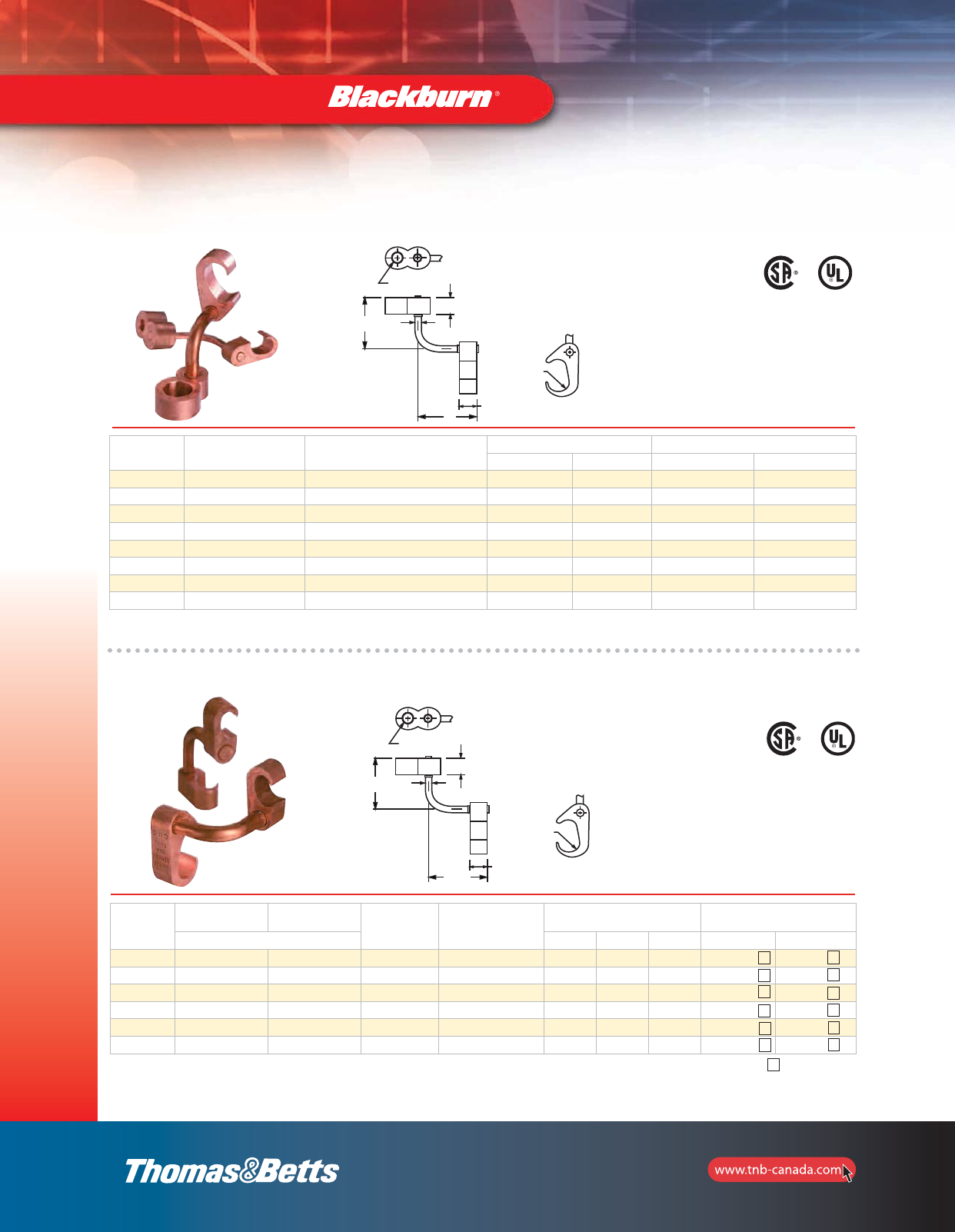
Element A
Element B
L
T
LD
TT
66
Grounding Connectors
MEETS
IEEE
837 REQUIREMENTS
Figure 6 to 8 — Compression Ground Rod to Grid Connectors
Cat. No. A in. (mm)
Ground Rod
B
Cable Range
Dimensions in. (mm) Dies for TBM14M, 13100A or TBM15I
D L Element A Element B
54855LR12* 1/2 (12.7) 2 AWG–250 kcmil 0.31 (7.8) 2.50 (63.5) 15G121R 15G86R
54885LR12* 1/2 (12.7) 250 kcmil–500 kcmil 0.31 (7.8) 2.50 (63.5) 15G121R 15G126R
54865LR58* 5/8 (16.0) 2 AWG–250 kcmil 0.31 (7.8) 2.50 (63.5) 15G121R 15G86R
54895LR58* 5/8 (16.0) 250 kcmil–500 kcmil 0.31 (7.8) 2.50 (63.5) 15G121R 15G126R
54875LR34* 3/4 (19.1) 2 AWG–250 kcmil 0.50 (12.7) 2.63 (66.8) 15G121R 15G86R
54900LR34* 3/4 (19.1) 250 kcmil–500 kcmil 0.50 (12.7) 2.63 (66.8) 15G121R 15G126R
54910LR100 1 (25.4) 2 AWG–250 kcmil 0.50 (12.7) 2.63 (66.8) 15G121R 15G86R
54920LR100 1 (25.4) 250 kcmil–500 kcmil 0.50 (12.7) 2.63 (66.8) 15G121R 15G126R
*Tin plated version of galvanized ground rods available. Add suffix-TP to catalogue number.
MEETS
IEEE
837 REQUIREMENTS
Figure 6 to 6 — Compression Ground Rod to Grid Connectors
Cat. No. Element A Element B Element A to
Ground Rod (po)
*Element B to
Rebar (po)
Dimensions in. (mm) Die Selection for
TBM14M, 13100A or TBM15I
Cable to Cable D T T-T A B
54855L #6 sol.–#2 str. #6 sol.–#2 str. – – 0.88 (22.4) 0.75 (19.1) 0.75 (19.1) 15501A 15501A
54865L #1 Str.–250 kcmil #6 sol.–#2 str. 1/2 – 5/8 3/8 – 1/2 #3–#4 Rebar 0.88 (22.4) 0.75 (19.1) 0.75 (19.1) 15501A 15G86R
54875L #2 Str.–250 kcmil #2 str.–250 kcmil 1/2 – 5/8 3/8 – 1/2 #3–#4 Rebar 0.88 (22.4) 0.75 (19.1) 0.75 (19.1) 15G86R 15G86R
54885L 250 kcmil–500 kcmil #6 sol.–#2 str. 5/8 – 3/4 5/8 – 3/4 #5–#6 Rebar 0.88 (22.4) 0.75 (19.1) 0.75 (19.1) 15501A 15G126R
54895L 250 kcmil–500 kcmil #2 Str.–250 kcmil 5/8 – 3/4 5/8 – 3/4 #5–#6 Rebar 0.88 (22.4) 0.75 (19.1) 0.75 (19.1) 15G86R 15G126R
54900L 250 kcmil–500 kcmil 250 kcmil–500 kcmil 5/8 – 3/4 5/8 – 3/4 #5–#6 Rebar 0.88 (22.4) 1.13 (28.7) 1.13 (28.7) 15G121R 15G121R
Tooling: pages 125–136.
Die Selector Chart: pages 121–123.
*CSA not applicable.
Use 15500TB adaptor for 15-Ton Tool TBM15I.
1
*Number of crimps
1
1
1
1
3
1
1
1
1
1
3
Element A
Element B
L
T
LD
TT
T-T
•Material: High conductivity copper
•Acceptable for direct burial
7/8
Grounding
L
7/8
3/4
D
L
D
2-1/2
2-1/2
T
T-T
2_BLKBRNMRO5_E_58to167_Grounding.pdf 9 10/6/2011 1:00:48 PM
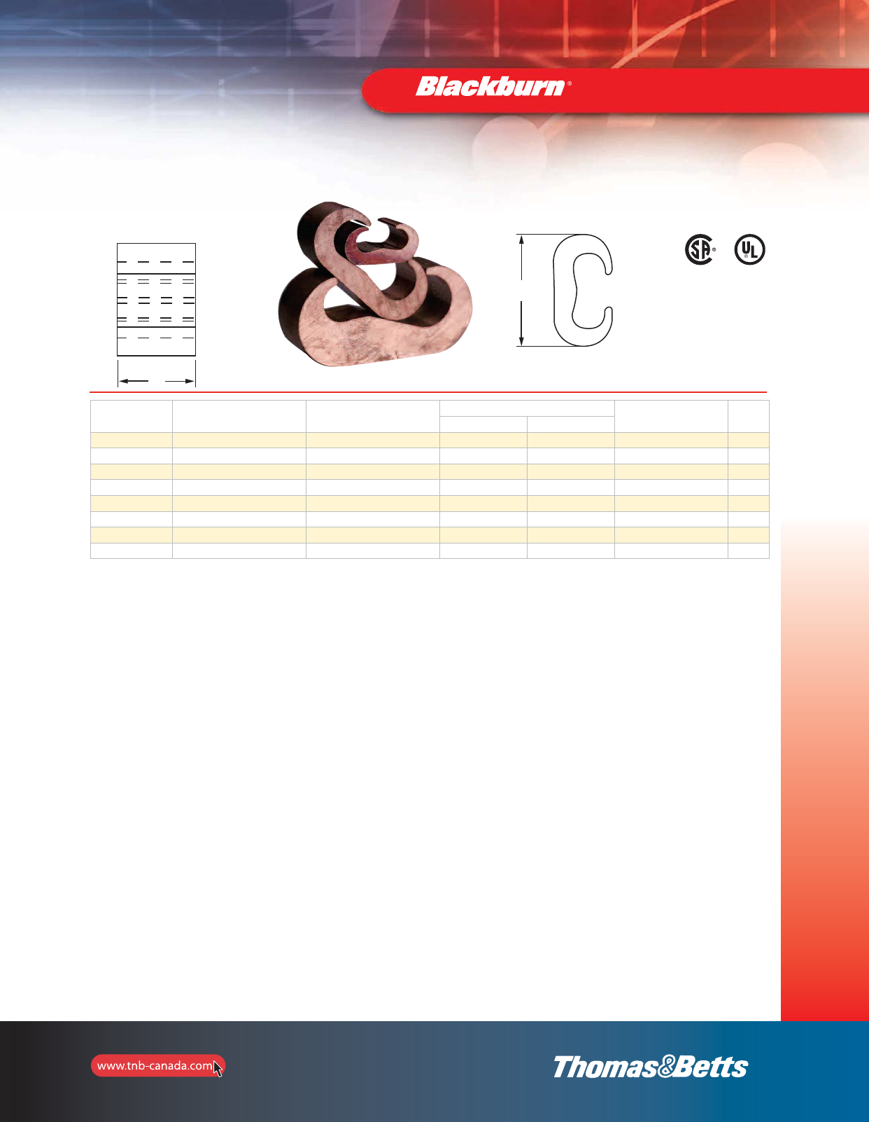
67
Grounding
L
H
MEETS
IEEE
837 REQUIREMENTS
C-Taps
Grounding Connectors
Cat. No. Main Tap Dimensions in. (mm) Dies for TBM14M,
13100A or TBM15I* Crimps
H L
CTP22 #6 sol.–#2 str. #6 sol.–#2 str.** 1.16 (29.5) 0.75 (19.1) HBKC 1
CTP202 #1 str.–2/0 str. #6 sol.–#2 str.** 1.41 (35.8) 0.75 (19.1) 15501A 1
CTP2020 #1 str.–2/0 str. #1 str.–2/0 str. 1.54 (39.1) 0.75 (19.1) 15501A 1
CTP25020 3/0 str.–250 kcmil #6 sol.–2/0 AWG** 1.97 (50.0) 0.75 (19.1) 15G86R 1
CTP250250 3/0 str.–250 kcmil 3/0 str.–250 kcmil 2.06 (52.3) 0.88 (22.4) 15G86R 1
CTP50020 300–500 kcmil #6 sol.–2/0 AWG** 2.42 (61.5) 0.88 (22.4) 15G121R 2
CTP500250 300–500 kcmil 3/0 str.–250 kcmil 2.67 (67.8) 0.88 (22.4) 15G121R 2
CTP500500 300–500 kcmil 300–500 kcmil 2.91 (73.9) 1.10 (27.9) 15G121R 3
Material: High-Conductivity Copper.
* Cat. No. 15500TB adaptor required if using TBM15I and 155XX Dies Series.
** #6 AWG branch must be doubled.
L
H
2_BLKBRNMRO5_E_58to167_Grounding.pdf 10 10/6/2011 1:00:48 PM
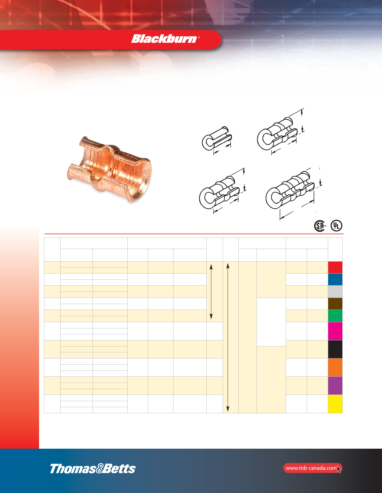
68
Grounding
Grounding Connectors
C-Taps — Small Size
Fig. 1 Fig. 2
Fig. 3 Fig. 4
Cat.
No.
Code Wire Comb. Cir. Mils Area Range Die Group
2
Group
3
Insulation Choice Dimensions in.
(mm) Colour
Code
Main Branch 1 Group 1 TMB62BSCR Smart Adhesive Shrink Tubing L H
54705 12 14 6TON21 TBM6221 –
Accommodates this range
Accommodates this entire range
AC5X3
HS12-6
0.31 (7.9) 0.31 (7.9) Red
14 16
54710 10 10 6TON24 TBM6224 0.56 (14,2) 0.44 (11.2) Blue
812
54715 610, 12 6TON29 TBM6229 – 0.56 (14.2) 0.63 (16.0) Grey
88, 10, 12
54720 4 or 5 8, 10, 12 6TON33 TBM6233 TBM8-750C20
HS6-1
1.16 (29.5) 0.69 (17.5) Brown
6 6, 8
54725 36, 8, 10, 12*** 6TON37 TBM6237 TBM8-750C2530 1.16 (29.5) 0.81 (20.6) Green
4 or 5 6, 5
54730
2 6, 8, 10, 12
6TON42 TBM6242 TBM8-750C2530 1.16 (29.5) 0.84 (21.3) Pink35
43
54735
14, 5, 6, 8, 10, 12
6TON45 TBM6245 TBM8-750C3540 0.06 (1.5) 0.88 (22.4) Black2 4,5
HS4-30
3 3,4
54740
1/0 4, 5, 6, 8, 10, 12
6TON50 TBM6250 TBM8-750C3540 1.69 (42,9) 0.97 (24.6) Orange1 3, 4
2 2, 3
54745
2/0 3, 4, 5, 6, 8, 10, 12
6TON54 TBM6254 TBM8-750C4550 1.69 (42,9) 1.06 (26.9) Purple1/0 2, 3
11, 3
54750
3/0 2, 3, 4, 5, 6, 8, 10, 12
6TON62 TBM6262 TBM8-750C-4550 1.69 (42.9) 1.19 (30.2) Yellow2/0 1, 2
1/0 1/0, 1
*** When using 3 AWG on main and 12 AWG on branch with Smart tools and dies, 12 AWG wire must be doubled (hair-pinned) and placed on branch for crimping.
Group 1 = TBM6H, TBM6BSCR.
Group 2 = TBM25S, TBM21E (require 2 compressions within each crimp area).
Group 3 = TBM4/4S, TBM5/5S, TBM6/6S, TBM8/8S, TBM6H (require 1 compression within each crimp area).
L
LL
L
H
H
H
68-e.pdf 1 4/20/2012 2:14:30 PM
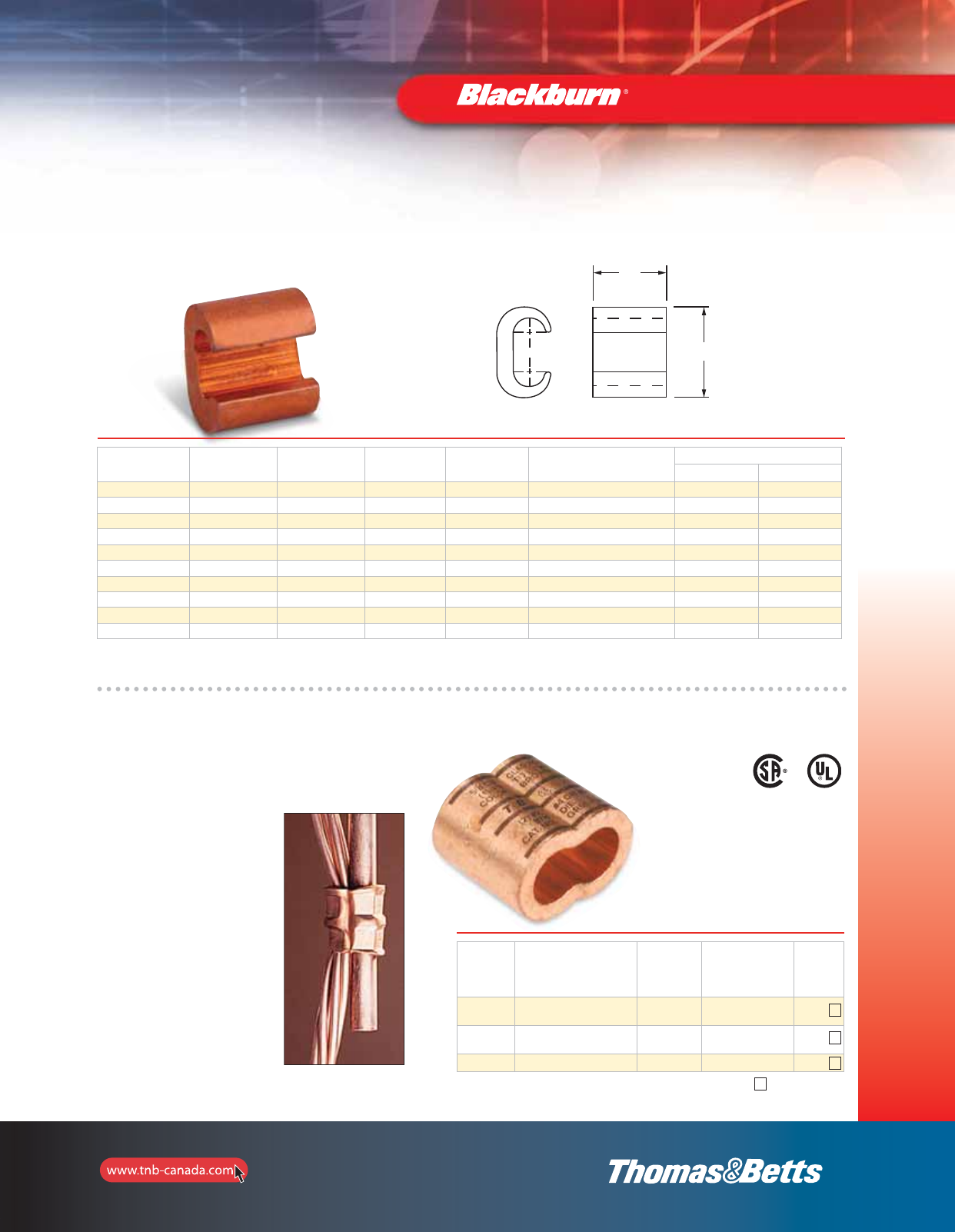
69
Grounding
Hex Compression Intimately Bonds Directly to copper clad ground rod
MEETS
IEEE
837 REQUIREMENTS
Pigtail Figure 8 Connectors
Cat. No. Cable Range
Copper clad
Ground Rod
(in.)
Die Code for
TBM14M,
TBM15, 13100A or
TBM15I
Die
GR12-306 One Cable: 3/0 to 6 AWG
Two Cables: 2 to 6 AWG 1/2 87H 15506
GR58-406 One Cable: 4/0 to 6 AWG
Two Cables: 2 to 6 AWG 5/8 87H 15506
GR34-4010 One Cable:4/0 to 1/0 AWG 3/4 99H 15506
2
2
2
*Number of crimps
Grounding Connectors
H
L
††
Cat. No. Run Tap Die
Index
Manual Tool
OD Series
Installing Die
14 and 15-Ton Tools
Dimensions in. (mm)
L H
BC48 6 sol.–4 str. 8 sol.–8 str. BG or 5/8 BY31 B58CR 0.64 (16.3) 0.56 (14.2)
BC46-BB 6 sol.–4 str. 6 sol.–6 str. BG or 5/8 BY31 B58CR 0.64 (16.3) 0.75 (19.1)
BC44 6 sol.–4 str. 4 sol.–4 str. BG or 5/8 BY31 B58CR 0.64 (16.3) 0.80 (20.3)
BC24 2 sol.–2 str. 8 sol.–4 str. C BY33 HBKC 0.75 (19.1) 0.98 (24.9)
BC22 2 sol.–2 str. 2 sol.–2 str. C BY33 HBKC 0.75 (19.1) 1.05 (26.7)
BC202 1/0 sol.–2/0 str. 8 sol.–2 str. E or O – HO 0.94 (23.9) 1.31 (33.3)
BC2020-BB 1/0 sol.–2/0 str. 1/0 str.–2/0 str. E or O – HO 0.94 (23.9) 1.34 (34.0)
BC402 3/0 str.–4/0 str. 6 sol.–2 str. F or D3 – HD 1.06 (26.9) 1.63 (41.4)
BC4020 3/0 str.–4/0 str. 1/0 sol.–2/0 str. F or D3 – HD 1.06 (26.9) 1.63 (41.4)
BC4040 3/0 str.–4/0 str. 3/0 sol.–4/0 str. F or D3 – HD 1.06 (26.9) 1.63 (41.4)
Copper C-Crimps Wire Combinations**
**Do not meet IEEE837
Tooling: pages 125–136
Die Selector Chart: pages 111–120
L
H
When connecting cable to
copper clad ground rod for
direct burial or embedding in
concrete, the connector shall
be wrought copper with a
minimum conductivity of
99% IACS such as
Thomas & Betts
series GR-120b. Hex
compression with die code
embossing shall be used.
69-e.pdf 1 12/22/2011 3:46:35 PM
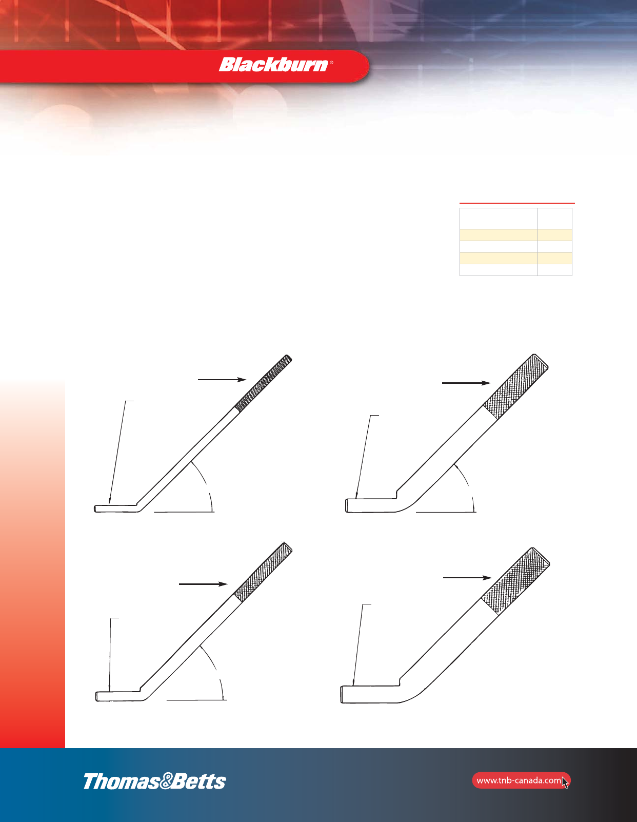
70
Grounding
Knurling ensures excellent mechanical
pullout and electrical continuity
•Easily welded to steel structures with minimal construction welding equipment
•Connect to grounding conductors with appropriate Thomas & Betts grounding connectors
•Knurled portion of stud resists pullout and provides electrical continuity to ensure the
integrity of the grounding circuit
•Constructed of high-strength steel and coated with corrosion-resistant copper cyanide
Cat. No. Rod Size
(in.)
TBGS-14 0.25
TBGS-38 0.38
TBGS-58 0.63
TBGS-34 0.75
45°45°
45°
TBGS-14
TBGS-38
TBGS-58
TBGS-34
0.235" Dia
0.360" Dia
0.705" Dia
0.580" Dia
Minimum at contact
surface WIDTH 0.135
LENGTH 1.000
Minimum at contact
surface WIDTH 0.215
LENGTH 1.000
Minimum at contact
surface WIDTH 0.420
LENGTH 1.000
Minimum at contact
surface WIDTH 0.450
LENGTH 1.000
Intersecting medium knuring
(2.10" long)
Intersecting medium knuring
(2.10" long)
Intersecting medium knuring
(2.10" long)
Intersecting medium knuring
(2.10" long)
Type TBGS
Structural Grounding Studs
Grounding Connectors
2_BLKBRNMRO5_E_58to167_Grounding.pdf 13 10/6/2011 1:00:49 PM
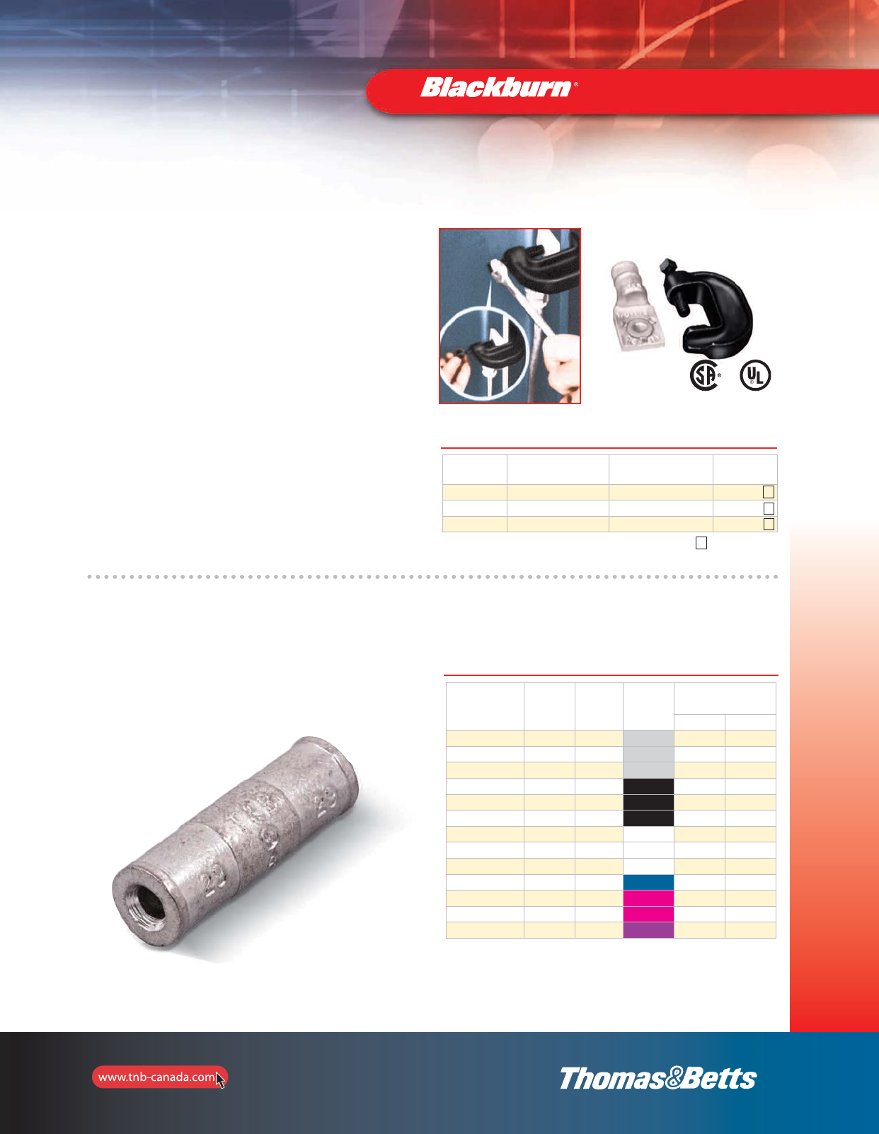
71
Grounding
Grounding Connectors
Connect ground cable to I-Beam or any 1” maximum
structural steel member without welding or drilling
I-Beam Ground Clamps
•Breakaway bolt head shears at predetermined torque to
ensure tight connection
•Heavy-duty compression lug provides excellent current
carrying capabilities
•Surface of steel must be cleaned in accordance with
installation instruction sheet provided with product
•Connector made of high-conductivity cast copper bright dip
•Clamp made of drop-forged high-grade steel, zinc plated
Cat. No. Wire Range TBM15I, TBM15
Installing Tool, Die Code
Die
Cat. No.
IBG2-10 2 thru 1/0 AWG 66H 15534
IBG20-40 2/0 thru 4/0 AWG 87H 15506
IBG350-500 350 kcmil thru 500 kcmil 115H 15504
MEETS
IEEE
837 REQUIREMENTS
2
2
2
Hydraulic tooling with hex crimp dies.
Use 15500TB adaptor for T&B 15-Ton Tools.
Cast Copper Two-Way Connectors — Heavy-Duty
•Made from high-conductivity cast cooper
•Electro-tin plated finish
Cat. No. Cable
Size
Die
Code
Die
Colour
Hydraulic Tooling
with hex dies
13642M 21940
53504 8 AWG 29 Grey 111734 11401
53505 6 AWG 29 Grey 111734 11401
53506 4 AWG 29 Grey 111734 11401
53507 2 AWG 45 Black 11738 11405
53508 1 AWG 45 Black 11738 11405
53509 1/0 AWG 45 Black 11738 11405
53510 2/0 AWG 66 White 11742 11409
53511 3/0 AWG 66 White 11742 11409
53512 4/0 AWG 66 White 11742 11409
53513 250 kcmil 76 Blue 11744 11410
53515 350 kcmil 99 Pink 11744 11410
53518 500 kcmil 99 Pink 11748 11424
53523 750 kcmil 112 Purple 11751 11426
*Number of crimps
71-e.pdf 1 11/18/2011 9:54:08 AM
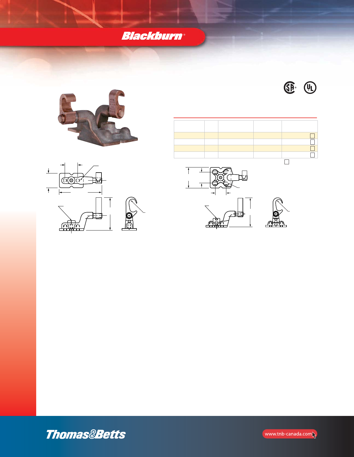
72
Grounding
H
c-16 UNC
Cable Range
2X d-13 UNC
1f
2
5A
Cable Range
H
3b1f
c-16 UNC
4X d-13 UNC
1 3/4
Fig. 1 Fig. 2
13⁄4
31⁄4
13⁄4
3⁄4
2
525⁄32
2X 1⁄2-13 UNC
4X 1⁄2-13 UNC
3⁄8-16 UNC
Cable Range Cable Range
3⁄8-16 UNC
MEETS
IEEE
837 REQUIREMENTS
Cat. No. Fig. Cable Range H
in. (mm)
Die Code for
14 and 15-Ton Tools
GP2250-2 12–250 kcmil 3.63 (92.2) 15G86R
GP2250-4 2 2–250 kcmil 4.22 (107.2) 15G121R
GP250500-2 1250–500 kcmil 3.63 (92.2) 15G86R
GP250500-4 2 250–500 kcmil 4.22 (107.2) 15G121R
Ground Plates
1
2
1
2
*Number of crimps
Grounding Connectors
H
3/8-16 UNC
Cable Range
1-3/4
2
5-25/32
2 x 1/2-13 UNC
3-1/4 3/4
1-3/4
4x 1/2-13 UNC
H
3/8-16 UNC
Cable Range
2_BLKBRNMRO5_E_58to167_Grounding.pdf 15 10/6/2011 1:00:49 PM
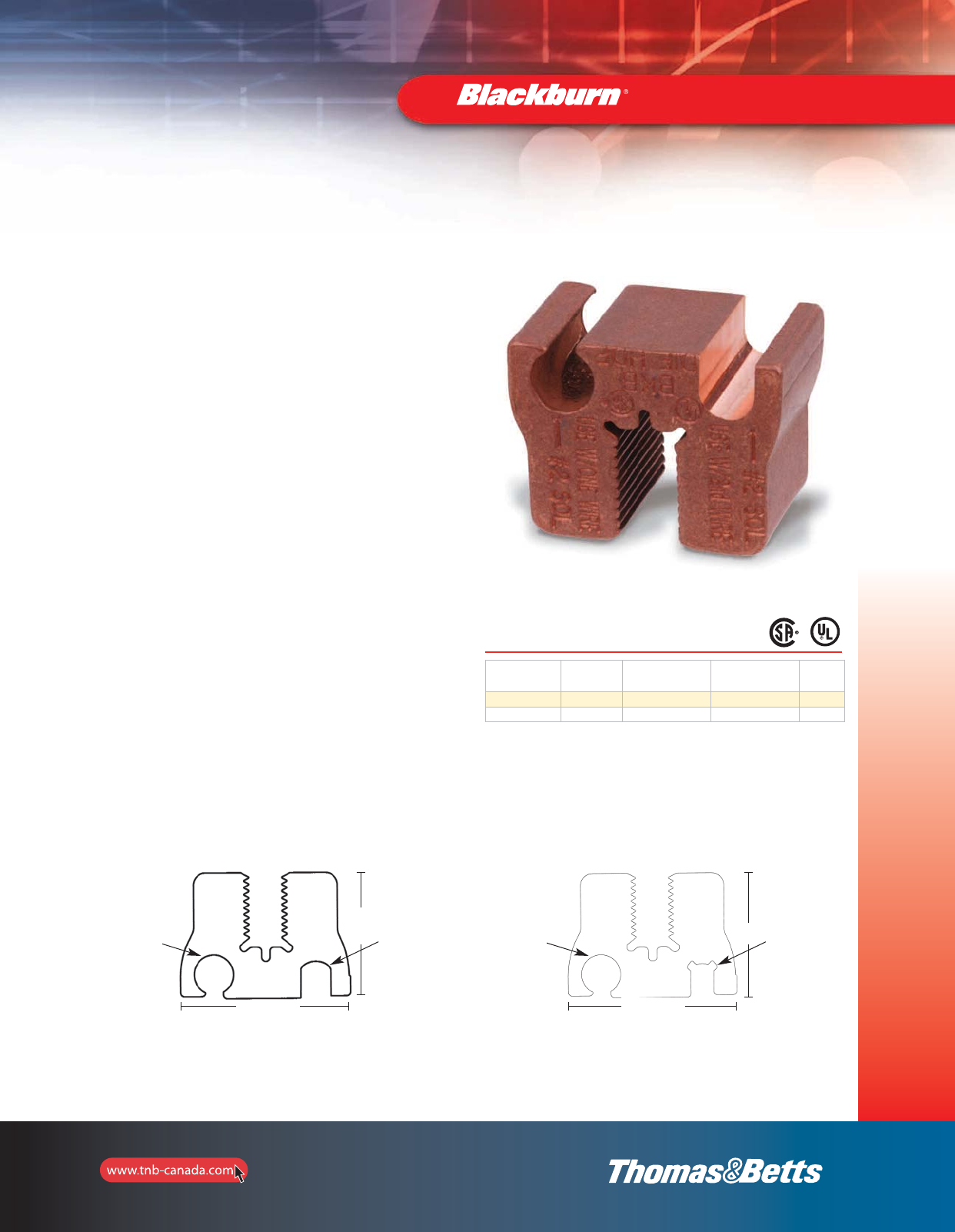
73
Grounding
Grounding Connectors
Cuts installation time in half – with results
superior to conventional connectors
E-Z-Ground®Bus Bar Connectors
•Unique
•Fast and easy installation
•Superior low-resistance, high-conductivity connections
•Installs with conventional compression tools
•Produces a permanent connection with any combination of
copper from #6 to #2 solid or stranded conductors, to
1/4 in. copper bus bar
•Made from pure wrought copper and prefilled with
oxide inhibitor
•CSA certified and UL Listed
•Installed with die HDF
E-Z-Ground®Bus Bar Connectors install in less than 2 minutes with
one easy crimp! The connector attaches directly to the bus, saving
the labor-intensive process of drilling and tapping. The unique jaw
interface of the E-Z-Ground®Bus Bar Connector grips the copper
bus, resulting in a low-resistance, high-conductivity connection.
The E-Z-Ground®Bus Bar Connector can be used in OEM
applications or telecom applications – Cellular, PCS and others. It
provides a continuous ground to the copper bus bar, making it ideal
for tower applications. The design enables installation in virtually any
position, horizontal or vertical, and is suitable for inside and outside
plant use. Installation can be completed using any T&B 12, 14 or 15
ton compression tool that accepts U-shaped die sets.
Cat. No. Die
Cat. No.
Ground
Cable Range (in.)
Conductor
Range
Std. Pkg.
Qty.
GBBC22 HDF 1/4 #2 AWG–#2 AWG 1
GBBC26 HDF 1/4 #6 AWG–#2 AWG 1
1
⁄
4
Bus GBBC22
Use this side of the connector when using only one wire. Use this side of the connector only when using two wires.
Use with
ONE WIRE
#2 AWG
Use with
2nd WIRE
#2 AWG
1.03"
1.40"
1
⁄
4
Bus GBBC26
Use with
ONE WIRE
#2-#6 AWG
Use with
2nd WIRE
#6 AWG
1.03"
1.40"
1.40"
1.40"
1/4 Bus GBBC22
Use with
2nd Wire
#2 AWG
Use with
One Wire
#2 AWG
Use with
2nd Wire
#6 AWG
Use with
One Wire
#2-#6 AWG
1/4 Bus GBBC26
1.40"
2_BLKBRNMRO5_E_58to167_Grounding.pdf 16 10/6/2011 1:00:49 PM
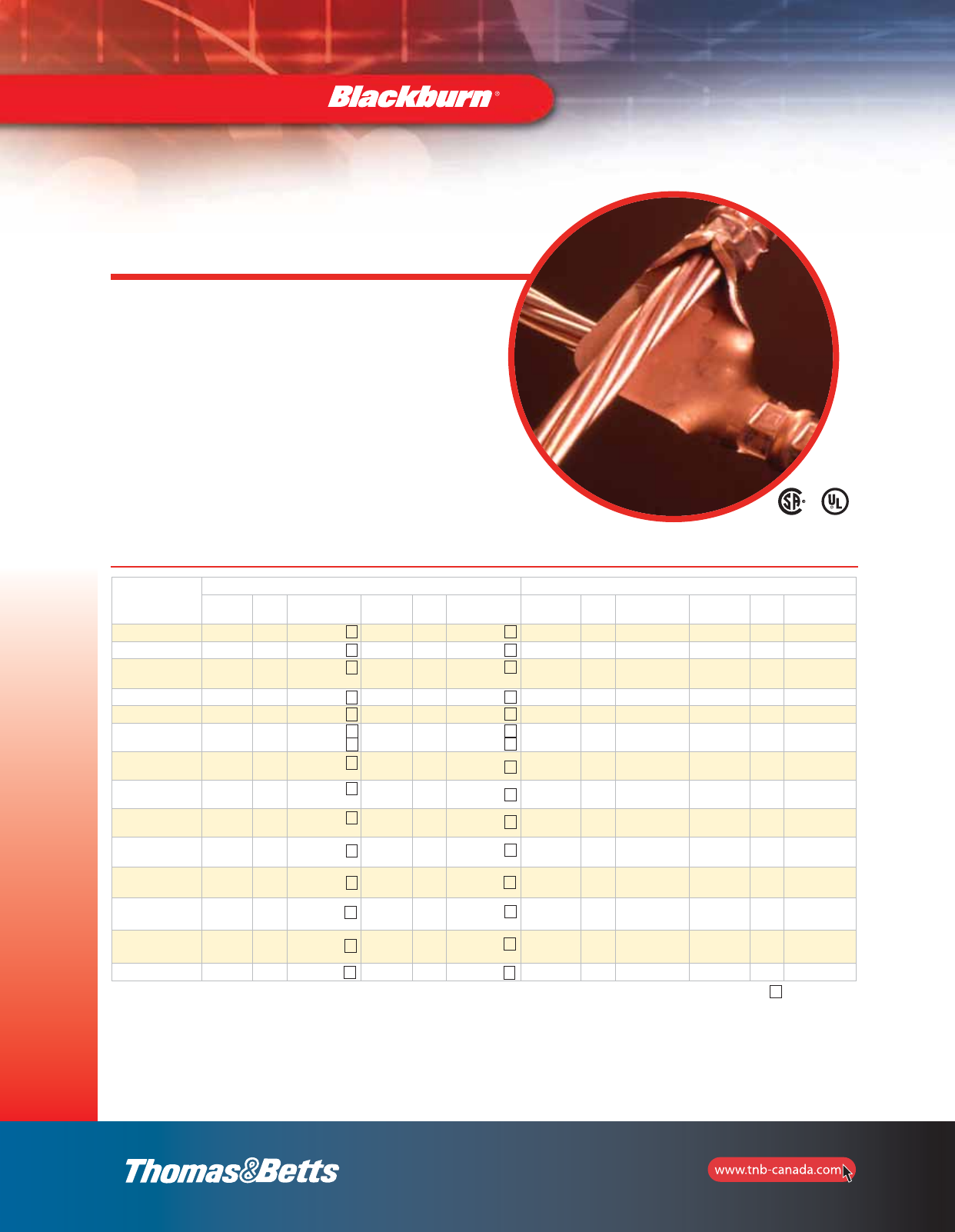
74
Grounding
Grounding Connectors
One-piece construction
for cable-to-cable, cable-to-rod,
“T” and “X” connections
•Suitable for direct burial or in concrete
•Replaces exothermic welds
•Made from high-conductivity wrought copper
Cable-to-Cable or Cable-to-Rod
Connectors
MEETS
IEEE
837 REQUIREMENTS
Cat. No.
Cable to Cable Range Rod to Cable range
Main Die
Code
TBM14 and 15
Die Cat. No. Branch Die
Code
TBM14 and 15
Die Cat. No.
Ground Rod
(in.)
Die
Code
TBM14 and 15
Die Cat. No. Cable Die
Code
TBM14 and 15
Die Cat. No.
GG21-21 #2 or #1 45 15526 #2 or #1 45 15526 – – – – – –
GG10-10 1/0 54 15511 1/0 54 15511 – – – – – –
GG2030-21 2/0 or 3/0 60 15532 #2 or #1 50–45 15526
15530 – – – – – –
GG2030-10 2/0 or 3/0 60 15532 1/0 54H 15511 – – – – – –
GG2030-2030 2/0 or 3/0 60 15532 2/0–3/0 60 15532 – – – – – –
GG40250-21 4/0 or
250 kcmil 71H 15514-CK #2 45
50
15526
15530
1/2
5/8
71
80H
15514-CK
15517
#2 or #1
#2 or #1
45
50
15526
15530
GG40250-10 4/0 or
250 kcmil 71H 15514-CK 1/0 kcmil 54H 15511 1/2
5/8
71
80H
15514-CK
15517
1/0 54 15511
GG40250-2030 4/0 or
250 kcmil 71H 15514-CK 2/0 or 3/0 60 15532-CK 1/2
5/8
71
80H
15514-CK
15517
2/0 or 3/0
2/0 or 3/0
60
60
15532
15532
GG40250-40250 4/0 or
250 kcmil 71H 15514-CK 4/0 or
250 kcmil 71H 15514-CK 1/2
5/8
71
80H
15514-CK
15517
4/0 or 250
4/0 or 250
71H
71H
15514-CK
15514-CK
GG500-40250 500 kcmil 87H 15506 4/0 or
250 kcmil 71H 15514-CK 3/4
5/8 87H 15506 4/0 or 250 71H 15514-CK
GG500-500 500 kcmil 87H 15506 500 kcmil 87H 15506 3/4
5/8 87H 15506 500 87H 15506
GG500-350 500 kcmil 87H 15506 350 kcmil 80H 15606 3/4
5/8 87H 15506 350 80H 15606
GG500-2030 500 kcmil 87H 15506 2/0 or 3/0 60 15532-CK 3/4
5/8 87H 2/0 or 3/0 60 15532CK
GG350-350 350 kcmil 80H 15606 350 kcmil 80H 15606
2
2
2
2
2
2
2
2
2
2
2
2
2
2
2
Tooling: pages 125–136.
Use 15500TB adaptor for 15-ton hyphen ton tools.
Optional ground rod knurling die for TBM14 and 15 tools: 15508.
Optional ground rod knurling tool: 240-31565-94.
*Number of crimps.
2
2
2
2
2
2
2
2
2
2
2
2
2
2
2
74-E.pdf 1 12/6/2011 9:20:58 AM
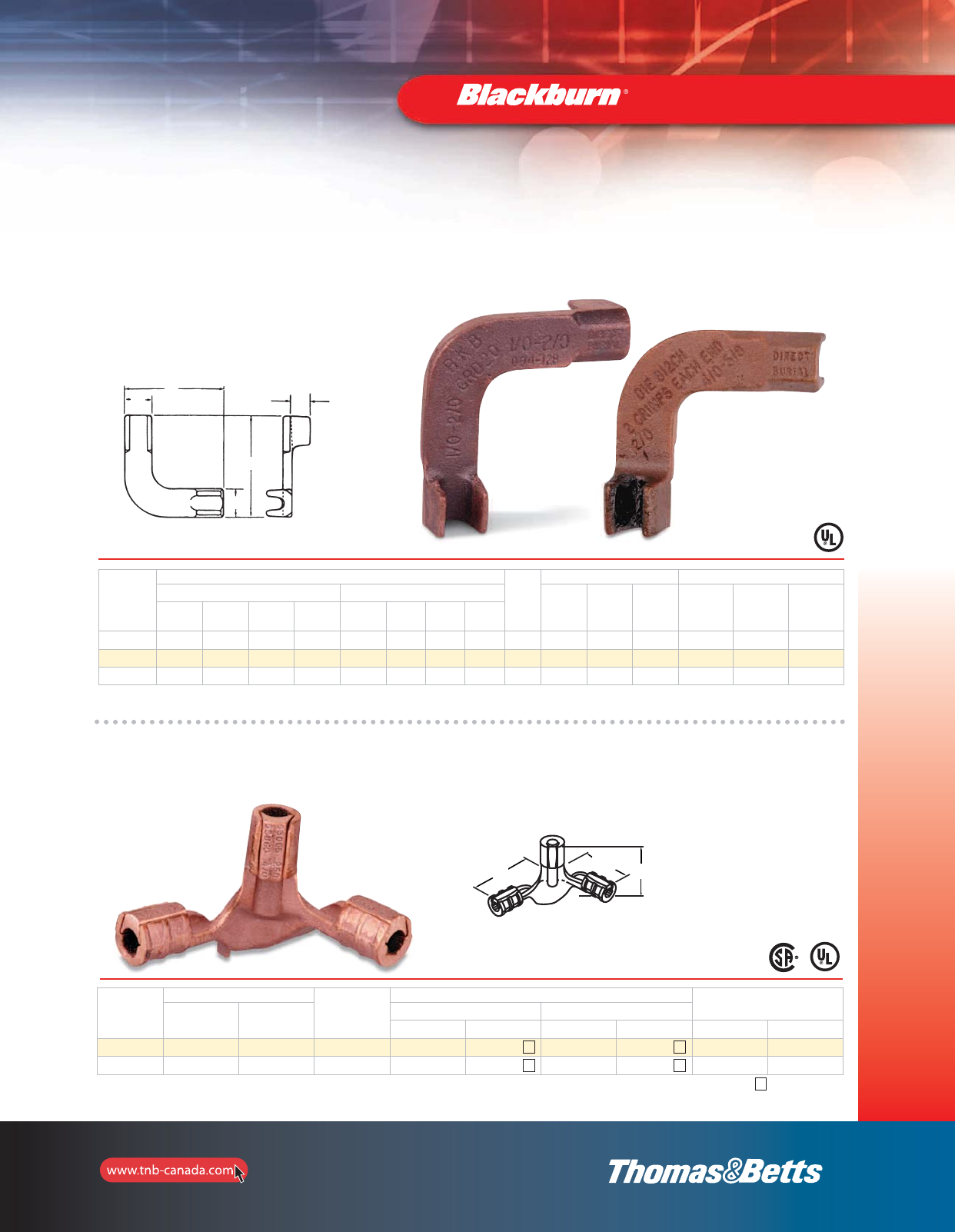
L1 Nom. L1 Nom. L2 Nom.
75
Grounding
Grounding Connectors
For copper cable-to-cable ground-grid connections
Cable-to-Cable Connectors
Cat. No.
Conductor Size
Ground
Rod
Installation Information Dimensions in. (mm)
Main Tap Hyd.
Tool Die No.
Crimps A B C
Max. Min. Max.
(mm2)
Min.
(mm2)Max. Min. Max.
(mm2)
Min.
(mm2)
GRD20 2/0 1/0 67.4 53 2/0 1/0 67.4 53 – TBM14M B10CH 1 3.00 (76.2) 0.81 (20.6) 0.88 (22.4)
GRD420 250 kcmil 4/0 126.6 107 2/0 1/0 67.4 53 0.63 TBM14M B12CH 2 3.63 (92.2) 0.69 (17.5) 0.81 (20.6)
GRD40 250 kcmil 4/0 126.6 107 250 kcmil 4/0 126.6 107 0.63 TBM14M B12CH 2 3.63 (92.2) 0.69 (17.5) 0.81 (20.6)
For connecting perpendicular runs of stranded copper cable to ground rod
Two Cables to Ground Rod
Cat. No.
Cable Size
Ground
Rod Dia.
Installing Dies for TBM14 and 15 Overall
Dimensions in. (mm)
Main Tap Ground Cable Ground Rod
Die Code Cat. No. Die Code Cat. No. L1 L2
53065-58GR 250 or 4/0 250 or 4/0 5/8 and 1/2 87H 15506 87H 15506 4.94 (125.5) 3.25 (82.6)
53065-34GR 250 or 4/0 250 or 4/0 3/4 87H 15515-CK 106H 15515 4.94 (125.5) 3.25 (82.6)
*Number of crimps
2
2
2
2
Use T&B hydraulic tools with hex crimp dies. Optional ground rod knurling die for TBM14 and 15 Tools: 15508.
Optional ground rod knurling Tool: 240-31565-94.
Use 15500TB adapter for T&B 15-Ton tools.
A
C
A
B
B
L2 Nom.
L1 Nom. L1 Nom.
2_BLKBRNMRO5_E_58to167_Grounding.pdf 18 10/6/2011 1:00:49 PM
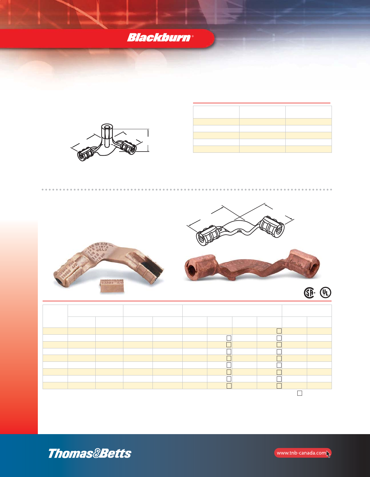
76
Grounding
L1 Nom.
L2 Nom.
53055
53065
Grounding Connectors
Copperweld* Conductors and Rebar
For Use with Cast Copper Connectors
L1 Nom. L1 Nom. L2 Nom.
Cable Size Reinforcing
Rod Size
Copperweld
Conductor Size
2, 1 AWG –3 #8 or 3 #6
1/0, 2/0 AWG #3 3/8 (7 #8) or 7/16 (7 #7)
4/0, 250 kcmil #4 7/16 (19 #9) or (7 #5)
300–350 #5 21/32 (19 #8) or 5/8 (7 #4)
500 kcmil #6 13/16 (19 #6)
*Reg. Trademark Copperweld Corporation.
UL Listed for use with cast copper connectors.
Tooling: see pages 125–136.
Grounding Grid Connectors
Heavy-duty Cast Copper**
Cat. No.
Rod to Cable Range Cable to Cable Range Rod and Cable
Installing Die Code for TBM14 or TBM15
Overall Dimensions
in. (mm)
Rod Size
(in.) Cable Range Main Branch Rod
Die Code
Rod
Cat. No.
Cable
Die Code
Cable
Cat. No. L1 L2
53055 – – 1/0–2/0 AWG 1/0–2/0 AWG – – 66 15534 3.88 (98.6) 3.88 (98.6)
53059* 1/2–5/8 2–1 AWG 4/0–250 kcmil 2–1 AWG 87H 15506 54H 15511 4.16 (105.7) 4.56 (115.8)
53060* 1/2–5/8 1/0–2/0 AWG 4/0–250 kcmil 1/0–2/0 AWG 87H 15506 87H 15506 4.44 (112.8) 4.44 (112.8)
53065* 1/2–5/8 4/0–250 kcmil 4/0–250 kcmil 4/0–250 kcmil 87H 15506 87H 15506 4.44 (112.8) 4.44 (112.8)
53069* 3/4 1/0–2/0 AWG 300–350 kcmil 1/0–2/0 AWG 106H 15515-CK 66 15534 4.59 (116.6) 4.59 (116.6)
53071* 3/4 4/0–250 kcmil 300–350 kcmil 4/0–250 kcmil 106H 15515-CK 106H 15515-CK 5.25 (133.4) 4.78 (121.4)
53073* 11/0–2/0 AWG 500 kcmil 1/0–2/0 AWG 125H 15603 66 15534 4.81 (122.2) 4.88 (124.0)
53075* 1 4/0–250 kcmil 500 kcmil 4/0–250 kcmil 125H 15603 87H 15506 6.56 (166.6) 5.00 (127.0)
53080* 1500 kcmil 500 kcmil 500 kcmil 125H 15603 125H 15603 5.19 (131.8) 5.19 (131.8)
2
2
2
2
2
3
3
3
1
2
2
2
1
2
1
2
3
Cat. No. 15500TB adaptor is required for all 15500 Series dies, not for 15600 Series, crimp with 15-Ton Tools.
*4/0–250 kcmil wire barrels suitable for 1/2” and 5/8” rod; 300–500 kcmil wire barrels suitable for 3/4” rods; 500 kcmil wire barrels suitable for 1” rods
Hydraulic tools only.
**Do not meet IEEE837.
*Number of crimps
L2 Nom.
L1 Nom. L1 Nom.
L2 Nom.
L1 Nom.
2_BLKBRNMRO5_E_58to167_Grounding.pdf 19 10/6/2011 1:00:49 PM
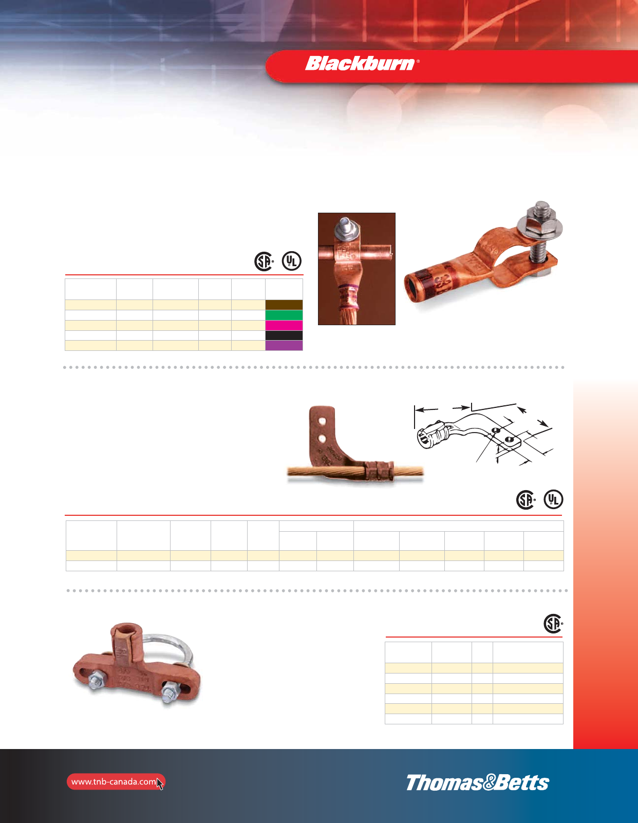
C
H
G
Bolt size D
77
Grounding
Grounding Connectors
For permanent, reliable connection
•Crimps to cable
•Clamps to ground rod and rebar
•Uses standard Color-Keyed®hand and hydraulic tools
•Colour coded for easy installation die selection
•Made from high-conductivity wrought copper
•Furnished with stainless steel hardware,
1/4” washers, bolts and nuts
Ground Clamps
Cat. No. Wire
Size
Ground Rod
Diameter (in.)
Rebar
(in.)
Bolt
Size (in.)
Die Code
and Colour
CC2C-45R #2–#3 AWG 1/2 or 5/8 0.80 0.25 33 Brown
CC1C-45R #1 AWG 1/2 or 5/8 0.80 0.25 37 Green
CC10C-56R 1/0 AWG 5/8 or 3/4 0.83 0.38 42 Pink
CC20C-56R 2/0 AWG 5/8 or 3/4 0.83 0.38 45 Black
CC40C-56R 4/0 AWG 5/8 or 3/4 0.83 0.38 54 Purple
UL467–Approved for direct burial.
Terminates or connects continuous runs of copper cable to flat surfaces
•Captive “Keeper bar” design extends cable
range and helps hold cable prior to crimping,
facilitating installation
•Saddles marked with conductor size and die code
•Conductor can be assembled to saddle with
standard dies and hydraulic tools
•Made from high-conductivity cast copper
Flat-Surface Ground Clamps
Cat. No. Wire
Range
G
Bolt Hole
(in.)
Die Code
No.
Wt.
Per 100
Hex Die Dimensions in. (mm)
Cat. No. Die Code
No. L1 L2 D C H
53055FL 1/0–2/0 AWG 3/8 66 75 15534* 66 4.09 (103.9) 3.66 (93.0) 0.28 (7.1) 1.38 (35.1) 1.00 (25.4)
53065FL 4/0–250 kcmil 3/8 87H 112 15506** 87H 4.50 (114.3) 4.09 (103.9) 0.31 (7.9) 1.38 (35.1) 1.00 (25.4
* TBM14M, 13100A, TBM15I with hex crimp dies.
** TBM15I with hex crimp dies only.
Grid-to-Fence Ground Clamps
•Bonds copper conductors to steel or
aluminum fence posts
•Top rail of round fence posts
•Provide quick, dependable installation
at low installed cost
•Use no incendiary materials
•Body made from cast copper alloy
with steel U-bolt
Cat. No. Ground
Cable Range
Die
Code
Steel and Aluminum
Line Post Range (in)
FG2040R2 2/0–3/0–4/0 76 2.00
FG2040R25 2/0–3/0–4/0 76 2.50
FG2040R3 2/0–3/0–4/0 76 3.00
FG210R2 2–1–1/0 66 2.00
FG210R25 2–1–1/0 66 2.50
FG210F3 2–1–1/0 66 3.00
Install with hydraulic tooling with hex crimp dies.
L1
L2
D
G
C
H
2_BLKBRNMRO5_E_58to167_Grounding.pdf 20 10/6/2011 1:00:50 PM
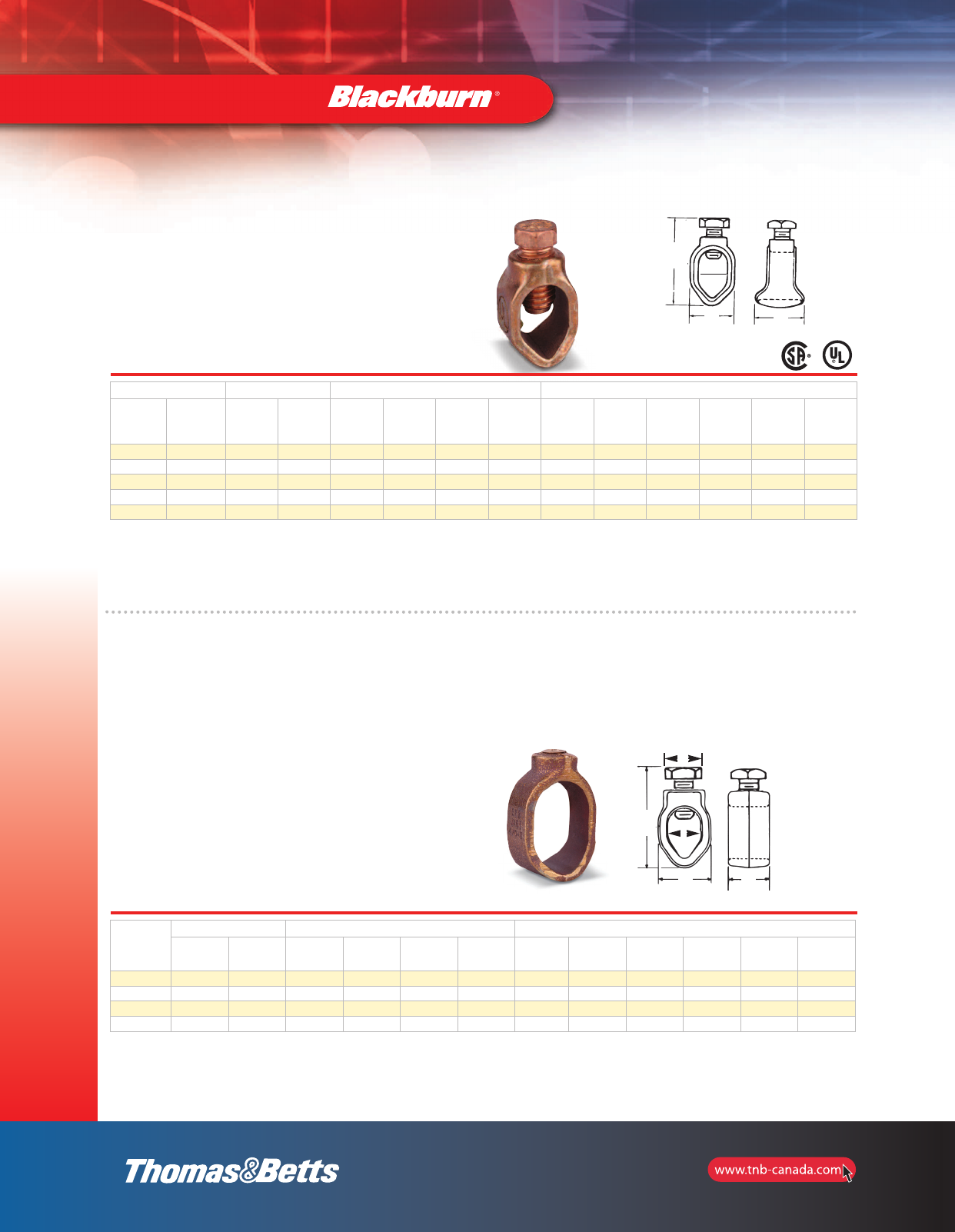
78
Grounding
Ground Rod Clamps and Accessories
Type JAB — Ground Rod Clamps
•Cast of high strength corrosion resistant copper alloy
•Both hex head and socket set screws available
•Long bearing surface of clamp on ground wire secures
ground connection
•Listed for direct burial
Cat. No. Nominal Rod Dia. Wire Range Dimensions (in.)
Socket Set
Screw
Hex Head
Bolt (in.) (mm) max. min. max.
(mm2)
min.
(mm2)
A
(max.)
Socket
Screw
A
(max.)
Hex
Bolt
Screw
Thread
Size
UNC-2A
B C D
JAB12* JAB12H 1/2 12.7 2 str. 10 sol. 33.6 5.2 1-19/32 2-3/32 7/16-14 27/32 7/8 19/32
JAB58 JAB58H 5/8 15.8 1/0 str. 8 sol. 53.4 8.3 1-27/32 2-13/64 7/16-14 29/32 1 11/16
JAB34 JAB34H 3/4 19.0 1/0 str. 8 sol. 53.4 8.3 2 2-11/32 7/16-14 11/16 1 51/64
– JAB34C 3/4 + 5/8 15.8 to 19.0 4/0 str. 8 sol. 95.0 8.3 – 2-11/32 7/16-14 1-1/8 1-1/32 13/16
JAB1 JAB1H 1 25.0 4/0 str. 8 sol. 107.1 8.3 2-1/4 3 7/16-14 1-11/32 1-1/16 1
* CSA not applicable.
Add suffix P to Cat. No. for tin plated clamp.
E
D
Type G — Budget Line Ground Clamps
•A dependable ground connection offered at
a substantial saving
•Cast of high strength corrosion-resistant copper alloy
•Hex head bolts
•Simplified compact design will make a lasting,
trouble-free connection
•Listed for direct burial
Cat. No.
Nominal Rod Dia. Wire Range Dimensions (in.)
(in.) (mm) max. min. max.
(mm2)
min.
(mm2)
A
(max.)
Bolt
Screw
Thread Size
UNC-2A
B C D E
G3 3/8 9.5 4 str. 10 sol. 21.1 5.2 1-3/8 5/16-18 11/16 1/2 27/64 3/8
G4 1/2 12.7 2 str. 10 sol. 33.6 5.2 – 3/8-16 27/32 3/8 37/64 1/2
G5 5/8 15.8 2 str. 10 sol. 33.6 5.2 – 3/8-16 29/32 3/8 43/64 1/2
G6 3/4 19.0 2 str. 10 sol. 33.6 5.2 – 3/8-16 1-1/16 3/8 13/16 1/2
Add suffix P to Cat. No. for tin plated clamp.
DC
A
Max.
C
E
A
Max.
B
78-e.pdf 1 8/13/2012 1:15:01 PM
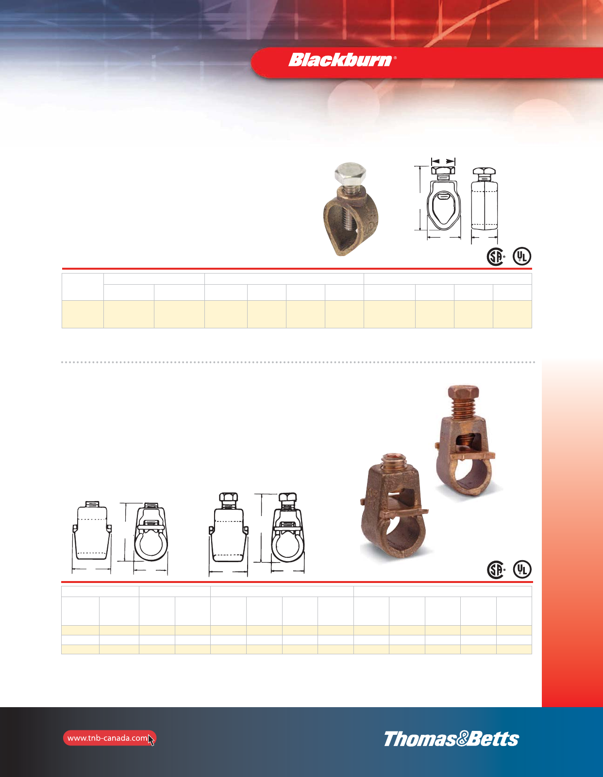
79
Grounding
Ground Rod Clamps and Accessories
E
D
Type JWR — Wide-Range Ground Rod Clamps
•Listed for direct burial in earth/concrete
•Constructed from bronze alloy and high-performance
stainless steel bolt
•Provides wide range of connection sizes
•More than 300 lb. torque capacity
Cat. No.
Nominal Rod Dia. Wire Range Dimensions (in.)
(in.) (mm) max. min. max. (mm2)min. (mm2)A (max.) Bolt B C D
JWR
3/8*
1/2
5/8
3/4
9.5
12.7
15.8
19.0
1/0 str.
1/0 str.
1/0 str.
1/0 str.
10 sol.
10 sol.
10 sol.
10 sol.
53.4
53.4
53.4
53.4
5.2
5.2
5.2
8.3
1.535
1.535
1.535
1.535
1.050
1.050
1.050
1.050
0.812
0.812
0.812
0.812
0.652
0.652
0.652
0.652
* 3/8” rod CSA not applicable/listed by UL.
Types GG and GGH — Heavy Duty Ground Rod Clamps
•Cast of high strength corrosion-resistant
copper alloy; two types of screws available
•Type GG has a socket set screw
•Type GGH has a hex head bolt
•Floating pressure bar distributes pressure evenly over a
large area of the ground wire
•Axial groove keeps wire and rod in perfect alignment
Cat. No. Nominal Rod Dia. Wire Range Dimensions (in.)
Socket Set
Screw
Hex Head
Bolt (in.) (mm) max. min. max.
(mm2)
min.
(mm2)
A
(max.)
Socket
Screw
A
(max.)
Hex
Bolt
Screw
Thread
Size
UNC-2A
B C
GG12 GG12H 1/2 12.7 2 str. 8 sol. 33.6 8.3 1-13/64 1-13/16 7/16-14 27/32 15/16
GG58 GG58H 5/8 15.8 2/0 str. 8 sol. 53.6 8.3 1-51/64 2-7/32 7/16-14 61/64 15/16
– GG34H** 3/4 19.0 4/0 str. 8 sol. 120.6 8.3 – 3 1/2-14 1-3/8 1-1/4
Add suffix P to catalogue number for tin plated clamp.
GG34H has no pressure bar or axial groove.
** CSA not applicable.
C
D
A
Max.
B
C
A
Max.
BC
A
Max.
B
2_BLKBRNMRO5_E_58to167_Grounding.pdf 22 10/6/2011 1:00:50 PM
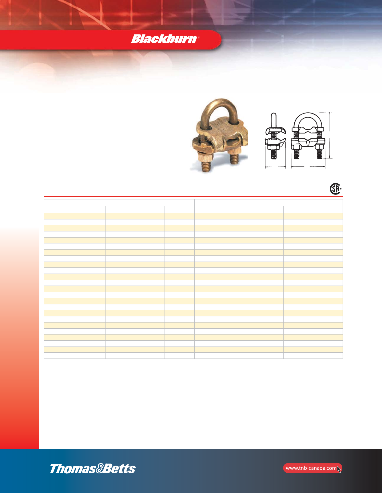
80
Grounding
C
A
B
Ground Rod Clamps and Accessories
Type GUV — U-Bolt Clamps
•Listed for direct burial
•For connecting copper or copper clad steel grounding
conductor to ground rod or pipe
•Excellent for connecting multiple electrodes with a single
cable as in substation grounding
•All components are cast or forged from copper alloy
•Specially designed spacer provides proper alignment
between cable and electrode and affords more positive
contact area
Cat. No. Conductor Range (CU) Nominal Rod Size (in.) IPS Pipe Size (in.) Dimensions (in.)
max. min. max. min. max. min. A B C
GUV584 4 8 3/4 5/8 3/8 – 2-13/16 1-9/16 2-1/4
GUV5821 2/0 4 3/4 5/8 3/8 – 2-13/16 1-9/16 2-1/4
GUV5825 250 2/0 3/4 5/8 3/8 – 2-13/16 1-9/16 2-1/4
GUV784 4 8 1 7/8 3/4 1/2 2-3/4 1-9/16 2-5/8
GUV7821 2/0 4 1 7/8 3/4 1/2 2-3/4 1-9/16 2-5/8
GUV7825 250 2/0 1 7/8 3/4 1/2 2-3/4 1-9/16 2-5/8
GUV1184 4 8 1-1/4 1-1/8 1 – 3-5/16 1-9/16 2-3/4
GUV11821 2/0 4 1-1/4 1-1/8 1 – 3-5/16 1-9/16 2-3/4
GUV1384 4 8 1-1/2 1-3/8 1-1/4 – 3-7/16 1-9/16 2-15/16
GUV13821 2/0 4 1-1/2 1-3/8 1-1/4 – 3-7/16 1-9/16 2-15/16
GUV13825 250 2/0 1-1/2 1-3/8 1-1/4 – 3-7/16 1-9/16 2-15/16
GUV1584 4 8 1-7/8 1-5/8 1-1/2 – 3-15/16 1-9/16 3-3/16
GUV15821 2/0 4 1-7/8 1-5/8 1-1/2 – 3-15/16 1-9/16 3-3/16
GUV15825 250 2/0 1-7/8 1-5/8 1-1/2 – 3-15/16 1-9/16 3-3/16
GUV204 4 8 2-3/8 2 2 – 4-7/16 1-9/16 3-11/16
GUV2021 2/0 4 2-3/8 2 2 – 4-7/16 1-9/16 3-11/16
GUV2025 250 2/0 2-3/8 2 2 – 4-7/16 1-9/16 3-11/16
GUV21221 2/0 4 2-7/8 2-1/2 2-1/2 – 4-15/16 1-9/16 4-3/16
GUV21225 250 2/0 2-7/8 2-1/2 2-1/2 – 4-15/16 1-9/16 4-3/16
GUV3021 2/0 4 3-1/2 3 3 – 5-9/16 1-9/16 4-13/16
GUV3025 250 2/0 3-1/2 3 3 – 5-9/16 1-9/16 4-13/16
GUV31221 2/0 4 4 3-1/2 3-1/2 – 6-1/16 1-9/16 5-1/2
GUV4021 2/0 4 4-1/2 4 4 – 6-5/16 1-9/16 5-11/16
GUV4025 250 2/0 4-1/2 4 4 – 6-5/16 1-9/16 5-11/16
For tin plating, add suffix TP to Catalogue number.
C
A
B
80-e.pdf 1 3/12/2012 3:54:08 PM
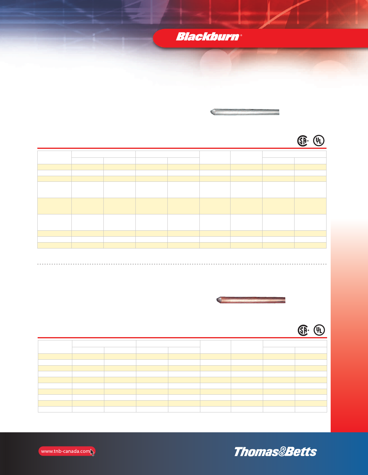
81
Grounding
Galvanized Ground Rods
•Made of high strength quality cold drawn steel,
(1035) hot dip galvanized
•Meet ANSI CI35.30-1979 requirements
•Stainless steel rods are also available (for more detailed
information, contact your T&B regional sales office)
Cat. No. Trade Size Rod Size (nominal diameter x length) Plating
Thickness
Standard
Packaging
Weight per 100
in. ft. mm mlb. kg
GR5006 1/2 6 12.7 1.8 4 mils 10 410 186
GR6256 5/8 6 15.8 1.8 4 mils 5 600 272
GR6258 5/8 8 15.8 2.4 4 mils 5 800 363
GR6250
(0.543 – 0.555) 5/8 10 15.8 3.0 4 mils 5 1000 454
GR6260
(0.625 – 0.640) 5/8 10 15.8 3.0 4 mils 5 1000 454
GR6250B*
(0.618 – 0.623) 5/8 10 15.8 3.0 4 mils 5 1000 454
GR7506 3/4 6 15.8 1.8 4 mils 5 700 318
GR7508 3/4 8 19.0 2.4 4 mils 5 1200 545
GR7510 3/4 10 19.0 3.0 4 mils 5 1500 681
* B suffix denotes black iron bare steel ground rod (CSA not applicable).
CSA lists rods 1/2 in. and larger, 10 ft and longer.
Grounding Electrodes and Accessories
Copper Bonded Steel Ground Rods
•All Blackburn®ground rods have a heavy uniform covering
of electrolytic copper bonded to a rigid steel core
•Copper ions are forced electrically to join with the
steel core, establishing a corrosion-resistant bond
between the copper and the steel
Cat. No. Trade Size Rod Size (nominal diameter x length) Plating
Thickness
Standard
Packaging
Weight per 100
in. ft. mm mlb. kg
5005 1/2 5 12.7 1.8 5 mils 10 305 138
5006 1/2 6 15.8 1.8 5 mils 5 370 168
5008 1/2 8 15.8 2.4 5 mils 5 545 247
5010 1/2 10 15.8 3.0 5 mils 5 611 277
6256 5/8 6 15.8 3.0 5 mils 5 508 230
6258* 5/8 8 15.8 3.0 10 mils 5 678 308
6260* 5/8 10 15.8 1.8 10 mils 5 847 384
7508* 3/4 8 19.0 2.4 10 mils 5 992 450
7510* 3/4 10 19.0 3.0 10 mils 5 1240 462
1010* 1 10 25.4 3.0 10 mils 1 2248 1020
* Ground rods are UL listed (425H), except for regular rods shorter than 8 ft or less than 1/2 inch.
CSA lists rods 1/2 in. and larger, 10 ft and longer.
81-e.pdf 1 9/10/2012 11:26:34 AM
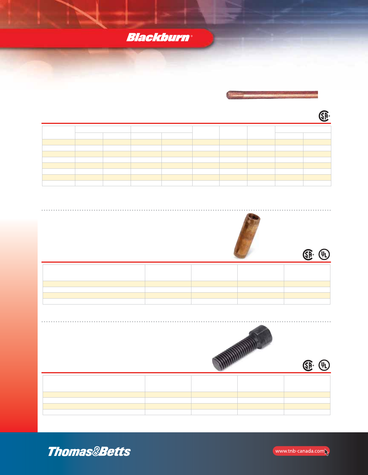
82
Grounding
•Sectional type ground rods have the same high
quality as regular copper bonded steel ground rods,
and are threaded top and bottom
CSA lists rods 1/2* in. and larger, 10 ft and longer.
Couplings
•Threaded couplings are made of high strength,
corrosion resistant alloy. Streamlined design reduces
driving friction. Couplings are tapped for use on all
standard threaded sectional rods
Cat. No.
Rod Size
Diameter
(in.)
Thread
Size
Standard
Packaging
Weight
Per 100
(lb.)
50LC 1/2 9/16” – 12 UNS 25 17
60C 5/8 5/8” – 11 UNS 25 25
70C 3/4 3/4” – 10 UNS 25 38
80C 1 1” – 8 UNS 10 75
Driving Studs
•Driving Studs of high strength steel may be used
with all standard threaded couplings
Cat. No.
Rod Size
Diameter
(in.)
Thread
Size
Standard
Packaging
Weight
Per 100
(lb)
50LDS* 1/2 9/16” – 12 UNS 10 16
60DS*+5/8 5/8” – 11 UNS 25 23
70DS* 3/4 3/4” – 10 UNS 5 35
80DS 1 1” – 8 UNS 10 75
Cat. No. Trade Size Rod Size (nominal diameter x length) Plating
Thickness
Thread
Size
Standard
Packaging
Weight per 100
in. ft. mm mlb. kg
5008LS 5/8 6 15.8 1.8 10 mils 9/16–12 5 546 248
5010LS 5/8 8 15.8 2.4 10 mils 9/16–12 5 682 309
6258S 5/8 8 15.8 3.0 10 mils 5/8–11 5 670 308
6260S 5/8 10 15.8 3.0 10 mils 5/8–11 5 837 384
7506S 3/4 6 15.8 1.8 5 mils 3/4–10 5 774 160
7508S 3/4 8 19.0 2.4 10 mils 3/4–10 5 992 450
7510S 3/4 10 19.0 3.0 10 mils 3/4–10 5 1040 562
1010S 1 10 25.4 3.0 10 mils 8–1 1 2248 1020
Grounding Electrodes and Accessories
* UL Listed.
+ CSA Listed.
Sectional Copper Bonded Steel Ground Rods
82-e.pdf 1 12/18/2012 11:34:24 AM
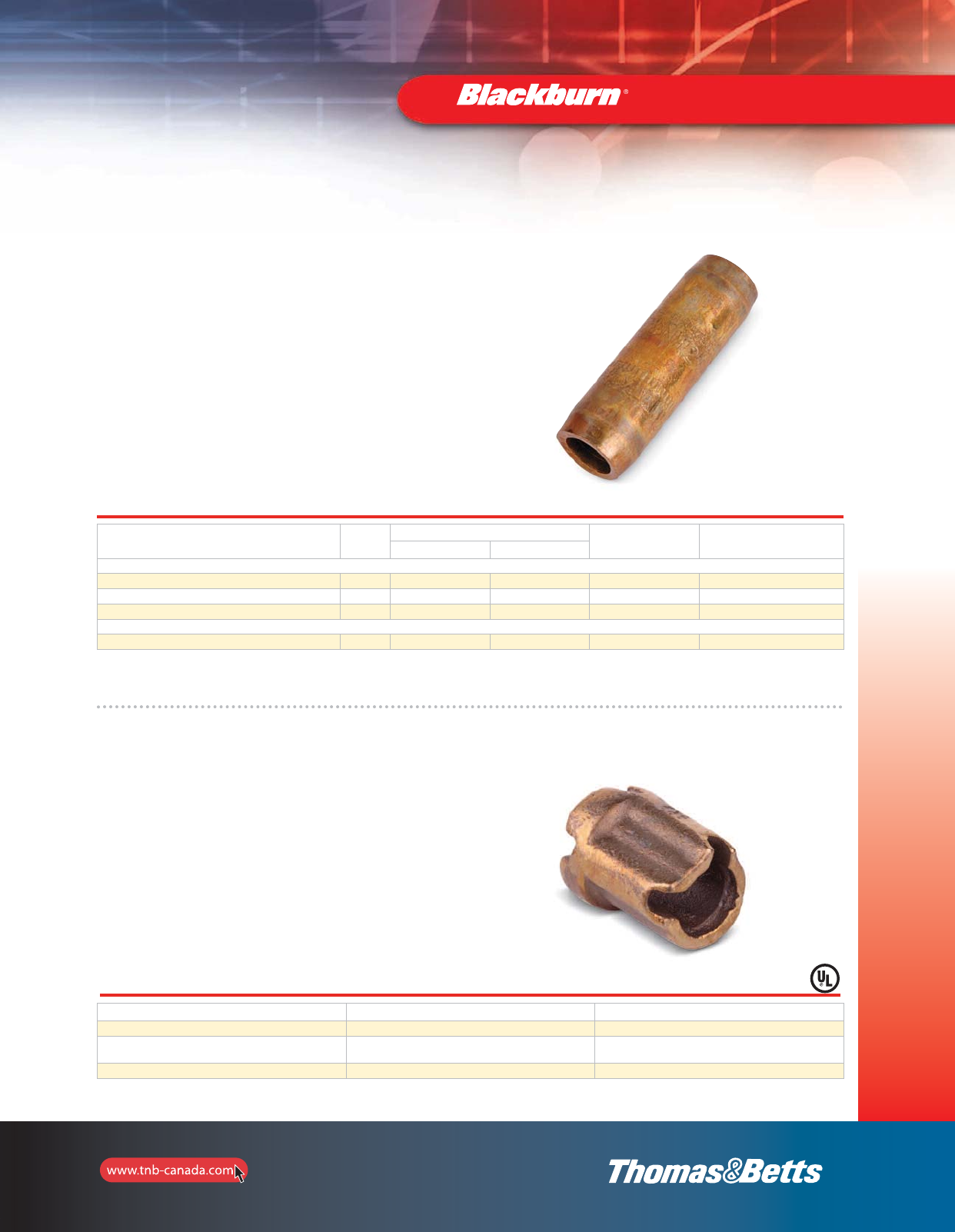
83
Grounding
Threadless Couplings and Driving Caps for Standard
Copper Bonded Ground Rods
Threadless Couplings
•For joining non-threaded, sectional, copper bonded, steel
ground rods
•Coupling is manufactured of a high strength, corrosion
resistant, silicone bronze
Threadless Driving Caps
•Prevent “mushrooming” of ground rod while driving to
insure proper fit of coupling
•Driving cap is manufactured of high strength, hardened
steel
Cat. No. Size
(in.)
Dimensions (in.) Standard
Packaging
Weight
Per 100 (lb.)
Length Diameter
Threadless couplings
50CNT* 1/2 3.0 0.78 25 34
60CNT2* 5/8 2.5 0.69 25 34
70CNT* 3/4 3.0 0.97 25 31
Driving Caps
60DSNT 5/8 4.0 0.88 10 43
* UL Listed.
Grounding Electrodes and Accessories
Type DGC — Drive-On
Ground Clamps
•Drive-on design provides easy tool free installation, high
reliability compression fit connection, and room for one or
two ground leads
•High-strength copper alloy provides increased tensile
strength and long-term corrosion resistance for direct
burial applications
•U.L. 486A and U.L. 467 Listed
Cat. No. Ground Rod Size in. (mm) Ground Wire Size
DGC58-44* 5/8 (0.555–0.565) 1 or 2–#4 sol.
DGC58-66* 5/8 (0.555–0.565) 1 or 2–#4 sol.
1–#4 sol.
DGC58-46 5/8 (0.555–0.565) 1–#6 sol.
* RUS Listed.
83-e.pdf 1 11/14/2011 8:53:42 AM
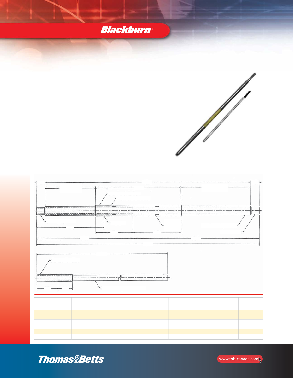
84
Grounding
Ground Rod Drivers
For installing ground rods, there’s no safer, simpler or more efffective tool than the
Thomas & Betts Ground Rod Driver. It can be used on all types of ground rods
including copper-bonded, galvanized and stainless steel.
Integral inserts prevent the driver from slipping off the rod near ground level. The
inserts are 5/8” and 3/4”, and are interchangeable with the standard driver body.
The convenient retaining collar holds the insert in the tool when not in use.
Thomas & Betts Ground Rod Drivers have a heavy-duty steel construction that
allows maximum force for driving ground rods, while the efficient design ensures
that minimal lifting force is required. The ground rod end is designed for high impact
applications to ensure quality connections.
•Unique design allows installation of 10-foot rods from ground level
•Heavy-duty steel construction
•Ergonomic grip provides ease and comfort with increased safety
•Complete with interchangeable parts that are range-taking for different
diameter ground rods
•Two interchangeable inserts allow the same tool to be used with all sizes
of rods
•Completely self-contained and easy to store
Photo includes ground rod driver and insert
Cat. No. Description Weight
(lb.)
Maximum
Rod Diameter
(in.)
Std.
Pkg.
TBRD58 5 ft. Ground Rod Driver with
5/8” insert 25 0.63 1
TBRD34 5 ft. Ground Rod Driver with
3/4” insert 25 0.75 1
TBS58 Replacement 5/8” insert 4 0.63 1
TBS34 Replacement 3/4” insert 4 0.75 1
Grounding Electrodes and Accessories
51.00
1" OD 0.090 wall tube
1.25
23.50
Black foam here
White PVC shrink wrap
1.25
12.00 16.00
Black foam here
30.00
1-1/2" OD .120 wall tube
9.50
Apply label
5.25 6.75
1/2" rosette
welds-4 PL 1-1/4" OD 0.120 wall tube
1" Dia. CRS Bar
23.50
53.50
35.50
1" OD 0.120 wall tube
3/4" Dia. CRS Bar
1.75
3.00
2_BLKBRNMRO5_E_58to167_Grounding.pdf 27 10/6/2011 1:00:51 PM
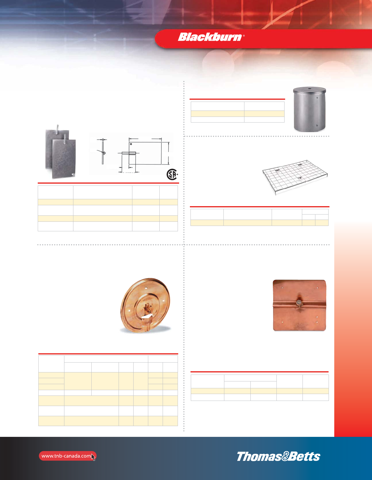
85
Grounding
Cat. No.
Pigtail Wire Range Diameter of Plate
min. max. min.
(mm2)
max.
(mm2)(in.) (mm)
GP100
82 sol. 6.3 25.6
7-1/2 191
GP110 10 254
GP114 14 356
GP1003 #6 AWG solid CU Pigtail
with 18” conductor – – 7-1/2 191
GP1008 #6 AWG solid CU Pigtail
with 18” conductor – – 7-1/2 191
GP1108 #6 AWG solid CU Pigtail
with 18” conductor – – 7-1/2 254
Galvanized Grounding Plates
•Made of high quality steel, hot dip galvanized
•Major time and cost saving vs ground rods
Cat. No. Description Wire
Range
Std.
Pkg.
1016TB Galvanized grounding plate — 1
1016BTB Galvanized grounding plate
complete with JAB34C connector 8 sol. to 4/0 str. 1
1016TB-NG* Grounding plate (not galvanized) 8 sol. to 4/0 str. 1
1016BTB-NG* Grounding plate (not galvanized)
(complete with ground rod clamp) 8 sol. to 4/0 str. 1
* CSA not applicable.
Grounding Electrodes and Accessories
Ground Electrode Boxes
Cat. No. Description
51628 Pregalvanized Steel
51629 Hot dip galvanized
14 gauge steel 10 inch diameter, 12 inch depth.
Metallic Gradient Control Mats
•To reduce risk and prevent
build up of dangerous
potential differences
between high voltage
equipment or structures and
the user standing on the
ground surface. CEC Rule
36-308
Cat. No. Description Std.
Pkg.
Wt/100
lb. kg
64663 Mat with connectors 1 3000 1363
4 ft x 6 ft hot dip galvanized mat is made from 6” x 6” welded mesh. 1/4” diameter.
With hardware 3-1/2 x 1-1/2 galvanized bolts, 3 gal. washers and 3 gal. nuts.
Type GP — Copper Pole Bottom
Ground Plates for Multigrounded
Neutral Construction
•More efficient than butt
wrapping poles
•Made of electrolytic sheet
copper
•Built-in high pressure
connector for ground lead,
or supplied with #6 AWG
copper pigtail pre-attached
•Plates are grooved for
trapping moisture
Type PB — Copper Pole Ground Plates
•Installed on butt end of utility
poles to provide an economical,
low resistance neutral ground
•Installed cost considerably less
than butt-wrapped poles. Plate
portion fabricated of .025” pure
copper
•PBGW connector is eye-bolt type,
cast of corrosion resistant
aluminum bronze alloy, with
silicon bronze nut and lock
washer. Riveted all copper
terminal lug is an integral part of
the PBH, and provides the means
of connection to the grounding
conductor
Cat. No. Wire Range Finished
Size (in.)
Surface Area
sq. in.
max. min.
PBGW 2/0 str. 10 sol. 7 x 7-5/8 56
PBH* 4 str. 14 sol. 7 x 7-3/8 56
* RUS Listed.
1/4
5/8
3-7/8 ± 1/4
14-3/4
9-3/4
2 ± 1/4
85-e.pdf 1 7/26/2012 8:56:50 AM
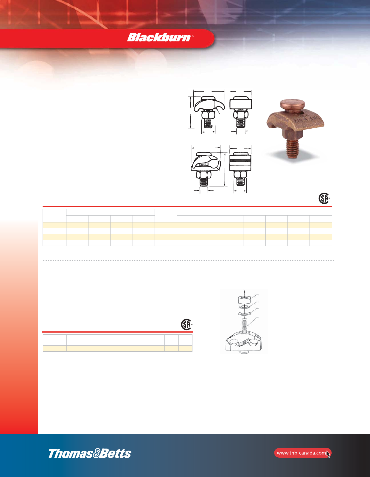
86
Grounding
Mechanical Grounding Connectors
Type GTC — Tower Ground Clamps
•Bolt has square shank to prevent turning and allow
clamp to be tightened with one wrench
•GTC 23 and 24 are two-piece clamps for connecting
ground lead cable to flat metal surface; ideal for
grounding substations on tower footings
•Castings are of high strength, corrosion resistant copper
alloy
•GTC 13 and 14 are economical one-piece clamps which
perform the same function as two-piece clamps except
the under pad support is omitted and conductor is
connected directly to tower
•Add suffix L to Cat. No. for 1/2”channel thickness
Cat. No. Conductor Range Channel
Thickness
Dimensions (in.)
max. min. max. (mm2)min. (mm2) A B D E G H R
GTC13 2/0 str. 4 sol. 67.4 21.1 1/4 1-15/32 – 9/16 1-21/32 13/32 3/8 7/32
GTC14 250 kcmil 2/0 str. 126.6 67.4 1/4 1-15/16 – 3/4 1-15/16 1-13/32 1/2 5/16
GTC23 2/0 str. 4 sol. 67.4 21.1 1/4 1-41/64 7/16 9/16 2-21/32 1-3/32 3/8 –
GTC24 250 kcmil 2/0 str. 126.6 21.1 1/4 1-61/64 5/8 3/4 1-15/16 1-3/8 1/2 –
CTG250 Wide Range Tower Ground Clamps
•For use with aluminum or copper conductors and in
aluminum or galvanized steel cable tray.
•Ribbed neck on the bolt prevents rotation during
tightening if 0.440 dia. hole is used
Cat. No. Wide Range
(2 sides) Height Width Depth Nut
(Flats)
CTG250 #2 sol. (0.258 Dia.), 250 kcmil (0.575 Dia.) 1.95 2.00 1.13 0.560
3/8 nut
Split Washer
Flat Washer
3/8 Bolt with Ribbed neck and
Phillips recessed head
Tin plated body
Galvanized hardware
Type GTC 13 and 14
Type GTC 23 and 24
A
A
G
R
E
B
H
G
E
A
D
H
D
2_BLKBRNMRO5_E_58to167_Grounding.pdf 29 10/6/2011 1:00:52 PM
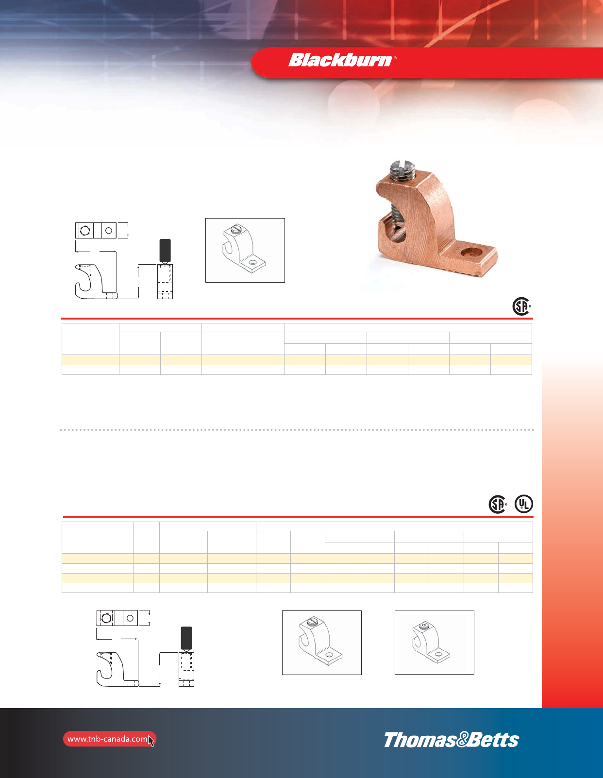
87
Grounding
Mechanical Grounding Connectors
Lay-In Lug Connectors
These grounding connectors are manufactured with high strength 6061-T6 aliminum alloy to insure both maximum strength and
conductivity. Dual-rated for both copper and aluminum conductor. The open-faced design allows the installer to
quickly lay-in the grounding conductor as a jumper to multiple conduits with no break in the ground conductor.
Cat. No. Fig.
No.
Conductor Range Stud Size Dimensions
AWG
in.
AWG
mm2in. mm2
H W L
in. mm in. mm in. mm
LL414 1 4-14 16-1.5 0.22 5.59 0.78 19.81 0.38 9.65 1.07 27.18
LL1014 1 1/0-14 50-1.5 0.27 6.86 1.17 29.72 0.60 15.24 1.50 38.10
LL306 2 3/0-6 70-16 0.33 8.38 1.56 39.62 0.80 20.32 2.00 50.80
LL2506 2 250-6 120-16 0.33 8.38 1.79 45.47 0.80 20.32 2.20 55.88
Copper Lay-In Lug Connectors
•Ideal for swimming pool grounding applications
•Carries “DB” marking for direct burial
•Open-faced design enables installer to quickly lay-in grounding conductor
as jumper to multiple conduits with no break in ground conductor
Cat. No.
Conductor Range Stud Size Dimensions
in. AWG
mm2in. mm
H W L
in. mm in. mm in. mm
CULL414 4-14 16-1.5 0.22 5.59 0.78 19.81 0.38 9.65 1.07 27.18
CULL414TP* 4-14 16-1.5 0.22 5.59 0.78 19.81 0.38 9.65 1.07 27.18
90°C Rating.
* Tin plated.
Figure 1
Figure 2
Figure 1
W
H
L
L
W
H
2_BLKBRNMRO5_E_58to167_Grounding.pdf 30 10/6/2011 1:00:53 PM
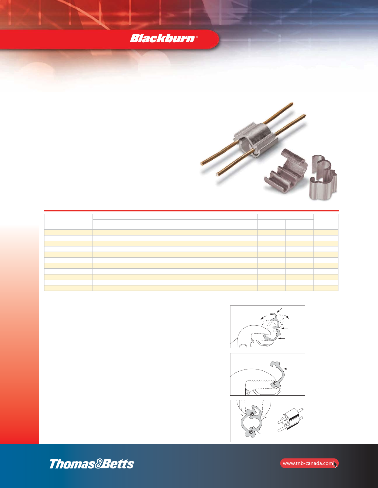
88
Grounding
Mechanical Grounding Connectors
SnapTap®Parallel Connectors
•Designed for bonding and grounding applications using
copper, steel stranded and ground rod
•Easily installed with channel locks or pliers
•Made from high-strength aluminum alloy with tin plating
•Offers excellent electrical and mechanical characteristics
•UL467 tested – exceed performance requirements
•CSA Std C22.2 No 41 for 1/2” ground rods to 2–#6 AWG sol.
Cat. No.
Conductor Description Packaging Std.
Order
Qty
Main Branch Inner
Pack
Outer
Pack
JP62* #2 AWG Sol. Copper #6 AWG Sol. Copper 20 200 200
JP66-TB* #2 AWG Sol. Copper #6 AWG Sol. Copper 20 200 200
JP146 1/4” Steel Stranded #6 AWG Sol. Copper 20 200 200
JP5166 5/8” Steel Stranded #6 AWG Sol. Copper 20 200 200
JP386 3/8” Steel Stranded #6 AWG Sol. Copper 20 200 200
JP126 1/2” Steel Stranded #6 AWG Sol. Copper 20 200 200
JP126G 1/2” Ground Rod #6 AWG Sol. Copper 20 200 200
JP2614 1/4” Steel Stranded 2–#6 AWG Sol. Copper 20 200 200
JP26516 5/16” Steel Stranded 2–#6 AWG Sol. Copper 20 200 200
JP2638 3/8” Steel Stranded 2–#6 AWG Sol. Copper 20 200 200
JP2612G* 1/2” Ground Rod 2–#6 AWG Sol. Copper 20 200 200
NOTE: All Toolless Connectors are UL Listed. Only items with (*) are CSA listed.
FIG. 1
Bend back and forth
to separate
Separation
point
Body piece
Body
piece
INSTALL
FIG. 2
FIG. 4
FIG. 3
Snap
piece
Pivot
groove
Body
piece
SEPARATE
With the SnapTap®Connectors, you can achieve an electrically
superior, pressure-fit connection in seconds without expensive
tooling. The connector is also easy to disassemble, requiring only a
flat-head screwdriver to release the connected body. A one-piece
design keeps parts together, minimizing loss of components prior to
assembly. Simply separate the pieces and snap them in place for
installation. An audible “Snap” indicates that the connection is
complete and properly installed.
General Usage Instructions
Separate
No special tools required. Use ordinary parallel jaw pliers to separate the
connector into two parts. Hold one side of connector with pliers and bend opposite
side back and forth until parts separate (see Fig. 1).
Caution: Be careful not to pinch fingers or thumb when separating parts. Keep
fingers out of bend part when bending part against plier jaws.
Installation
1. Strip the insulation from each conductor. Be careful not to nick the conductor.
Clean the conductor ends with a wire brush or emery cloth if necessary.
2. Place each conductor into the grooves in BODY piece. Press conductors with
pliers to align and seat into grooves (see Fig. 2)
3. Hold the conductors and BODY piece until it closes. Use parallel jaw pliers and
grip the SNAP and BODY pieces as shown (see Fig. 3). Apply pressure until
connector “snaps” into place. Visulally inspect snap to verify full insertion. The
connection is now complete (see Fig. 4).
Removal
The connector can be disassembled using a flat-head screwdriver to pry the SNAP
piece from BODY piece.
2_BLKBRNMRO5_E_58to167_Grounding.pdf 31 10/6/2011 1:00:54 PM
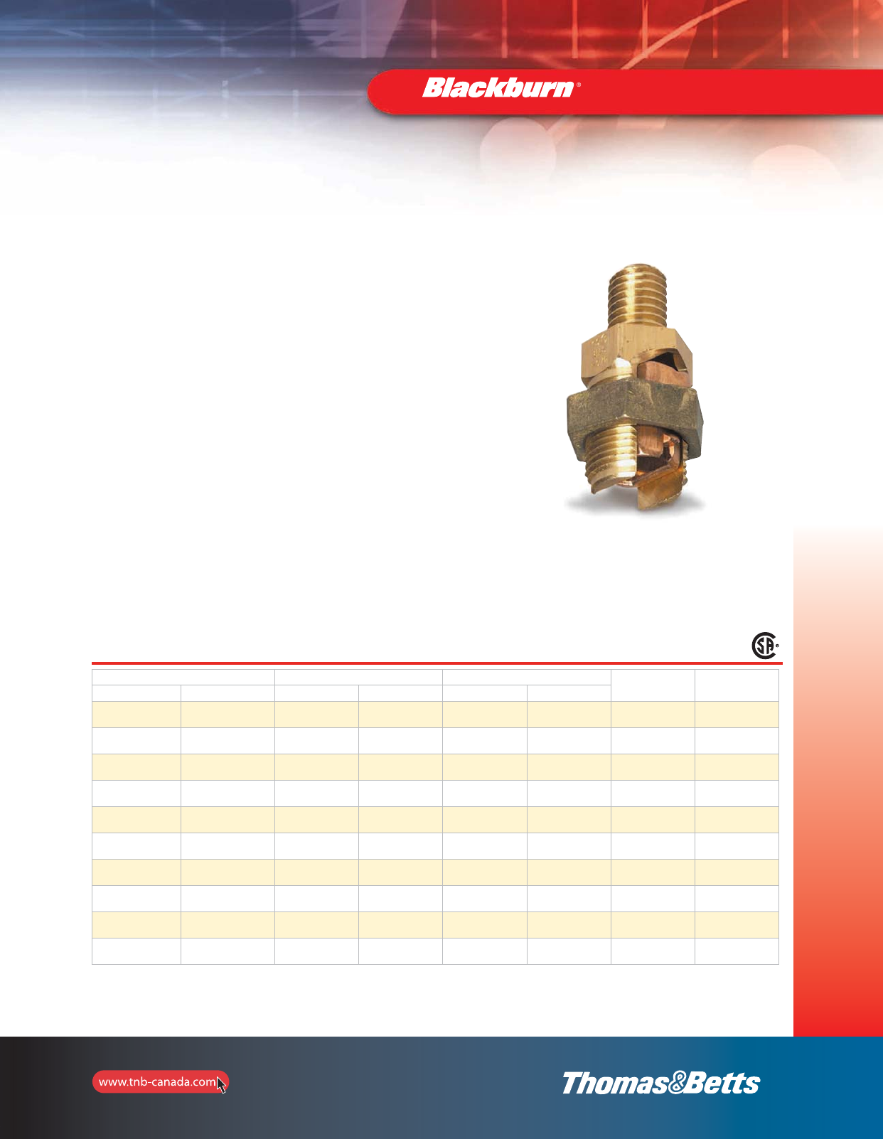
89
Grounding
Mechanical Grounding Connectors
Application
The Blackburn®line of Service Post Connectors is designed for applications
including steel structure, fence post or transformer grounding involving one
or two cables. Service Posts can also be used to tap one or two cables from
bus bar.
Construction & Ratings
Bolts used in the Service Post are machined from high conductivity bronze
alloy while the nuts are cold-formed from high strength, corrosion resistant
copper alloy. Pressure bars are copper through 4/0 size, while copper alloy
is used for 350 kcmil size and above. Bolts and nuts are of the traditional
Blackburn®hex design for easy installation.
Service Post Connectors are available in sizes accommodating AWG copper
conductor ranges of #12 – 500 kcmil stranded (4 mm2- 240 mm2) and
#12-#2 solid (4 mm2- 35 mm2).
The line includes both short and long stud versions for single conductor
and double conductor connectors.
Cat. No. Conductor Range Stranded (AWG/mm2)Conductors Range Solid (AWG/mm2)Maximum
Diameter
Range (in.)
Stud Size
(in.)
Double Conductor Single Conductor max. min. max. min.
SP0DS SP0SS 8
6 mm2
12
4 mm2
8
6 mm2
12
4 mm20.146–0.080 1/4–20 x 1/2
SP1DS SP1SS 7
10 mm2
10
6 mm2
6
10 mm2
10
6 mm20.170–0.102 1/4–20 x 1/2
SP2DS SP2SS 5
16 mm2
10
6 mm2
4
16 mm2
10
6 mm20.217–0.102 5/16–18 x 5/8
SP3DS SP3SS 3
25 mm2
10
6 mm2
2
35 mm2
10
6 mm20.271–0.102 3/8–16 x 5/8
SP4DS SP4SS 1
35 mm2
8
6 mm2
2
35 mm2
8
10 mm20.332–0.128 3/8–16 x 5/8
SP5DS SP5SS 1/0
50 mm2
2
35 mm2
2
35 mm2
–
–0.385–0.259 1/2–13 x 3/4
SP6DS SP6SS 2/0
70 mm2
2
35 mm2
2
35 mm2
–
–0.443–0.258 1/2–13 x 3/4
SP8DS SP8SS 4/0
95 mm2
1
35 mm2
–
–
–
–0.570–0.289 5/8–11 x 1
SP9DS SP9SS 350
150 mm2
1/0
70 mm2
–
–
–
–0.715–0.373 5/8–11 x 1
SP10DS SP10SS 500
240 mm2
3/0
95 mm2
–
–
–
–0.840–0.464 3/4–10 x 1-1/4
Type DS — Service Post Connectors, Short Stud
•For copper to copper connections
•For grounding of steel structures, fence posts or transformers using one or two cables
•For tapping one or two cables from bus bar
•Hex design bolts are machined from high conductivity bronze alloy
•Nuts and pressure bars are cold-formed from high-strength copper or copper alloy
Physical dimensions can be found on page 10.
2_BLKBRNMRO5_E_58to167_Grounding.pdf 32 10/6/2011 1:00:54 PM
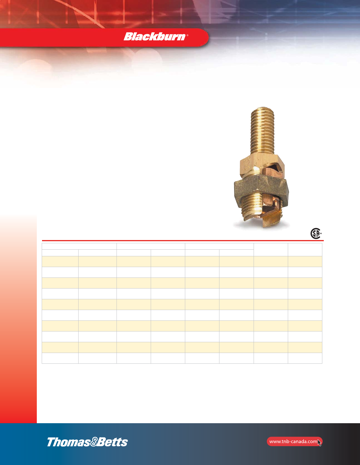
90
Grounding
Mechanical Grounding Connectors
Cat. No. Conductors Range Stranded (AWG/mm2)Conductors Range Solid (AWG/mm2)Maximum
Diameter
Range (in.)
Stud Size
(in.)
Double Conductor Single Conductor max. min. max. min.
SP0DL SP0SL 8
6 mm2
12
4 mm2
8
6 mm2
12
4 mm20.146–0.080 1/4–20 x 1/2
SP1DL SP1SL 7
10 mm2
10
6 mm2
6
10 mm2
10
6 mm20.170–0.102 1/4–20 x 1/2
SP2DL SP2SL 5
16 mm2
10
6 mm2
4
16 mm2
10
6 mm20.217–0.102 5/16–18 x 5/8
SP3DL SP3SL 3
25 mm2
10
6 mm2
2
35 mm2
10
6 mm20.271–0.102 3/8–16 x 5/8
SP4DL SP4SL 1
35 mm2
8
6 mm2
2
35 mm2
8
10 mm20.332–0.128 3/8–16 x 5/8
SP5DL SP5SL 1/0
50 mm2
2
35 mm2
2
35 mm2
–
–0.385–0.259 1/2–13 x 3/4
SP6DL SP6SL 2/0
70 mm2
2
35 mm2
2
35 mm2
–
–0.443–0.258 1/2–13 x 3/4
SP8DL SP8SL 4/0
95 mm2
1
35 mm2
–
–
–
–0.570–0.289 5/8–11 x 1
SP9DL SP9SL 350
150 mm2
1/0
70 mm2
–
–
–
–0.715–0.373 5/8–11 x 1
SP10DL SP10SL 500
240 mm2
3/0
95 mm2
–
–
–
–0.840–0.464 3/4–10 x 1-1/4
Type SP — Service Post Connectors, Long Stud
•For copper to copper connections
•For grounding of steel structures, fence posts,
transformers using one or two cables
•For tapping one or two cables from bus bar
•Hex design bolts are machined from high conductivity
bronze alloy
•Nuts and pressure bars are cold-formed from
high-strength copper or copper alloy
•Pressure bars are copper through 4/0 size; copper
alloy is used for 350 kcmil size and above
•Available in sizes accommodating AWG copper
conductor ranges of #12–500 kcmil stranded
(4mm2–240mm2) and #12–#2 solid (4mm2–35mm2)
•Line includes single conductor and double conductor
connectors
Physical dimensions can be found on page 11.
2_BLKBRNMRO5_E_58to167_Grounding.pdf 33 10/6/2011 1:00:54 PM
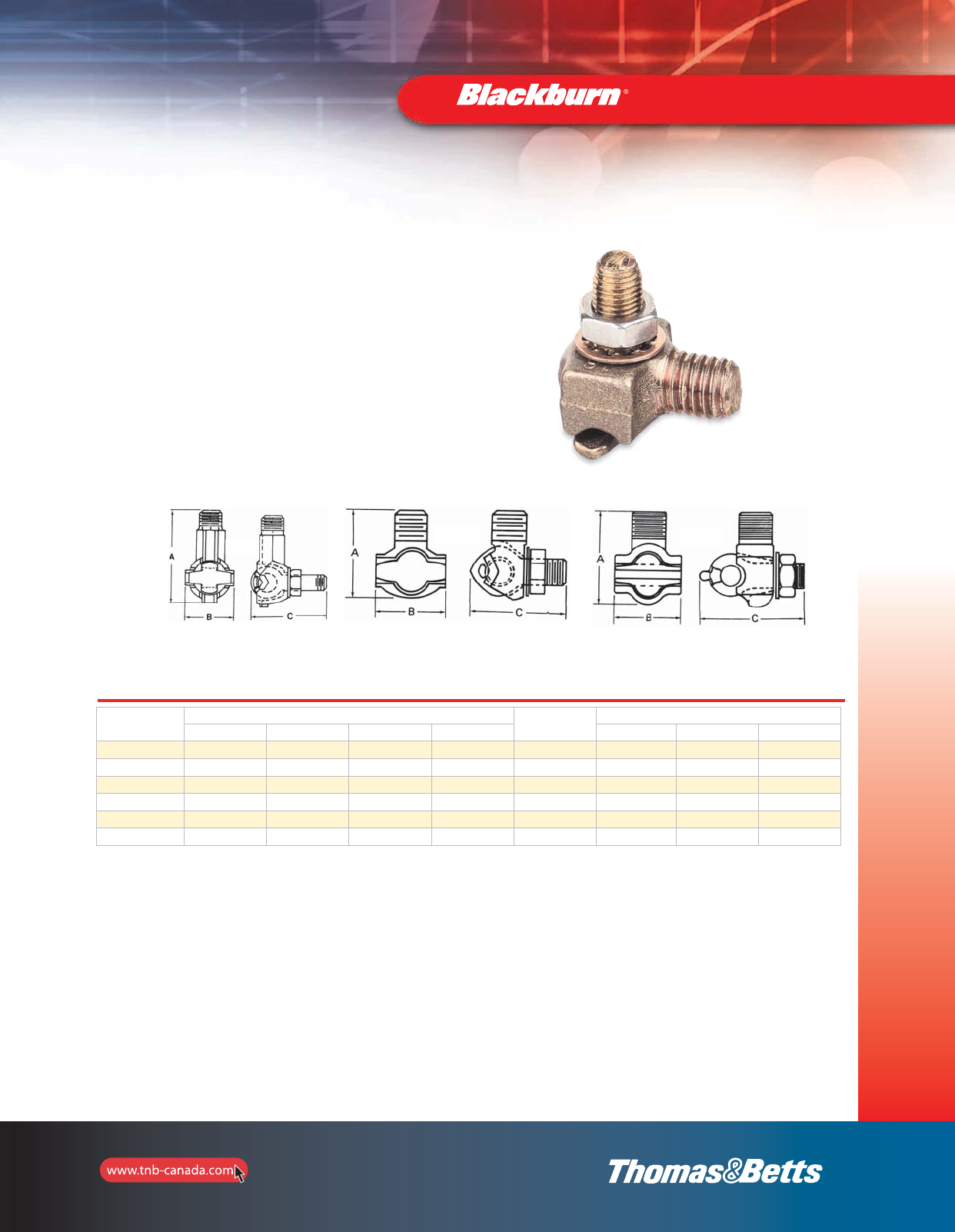
91
Grounding
Cat. No. Conductor Range Stud Thread
Size
UNC-2A
Dimensions (in.)
max. min. max. (mm2)min. (mm2) A B C
TTC2 2/0 str. 8 sol. 67.4 8.3 1/2”–13 1-51/64 1-9/64 1-21/32
TTC3 1 str. 10 sol. 42.4 5.2 1/2”–13 1-3/8 1-3/64 1-9/16
TTC4 1 str. 10 sol. 42.4 5.2 1/2”–13 1-1/4 7/8 1-3/8
TTC2P 2/0 str. 8 sol. 67.4 8.3 1/2”–13 1-51/64 1-9/64 1-21/32
TTC3P* 1 str. 10 sol. 42.4 5.2 1/2”–13 1-3/8 1-3/64 1-9/16
TTC4P* 1 str. 10 sol. 42.4 5.2 1/2”–13 1-1/4 7/8 1-3/8
Type TTC — Transformer Tank Ground Connectors
•Transformer Grounding Connectors are cast of high
conductivity bronze; 1/2”–13 stud fits all standard
EEI-NEMA distribution transformers
•Eye bolt on TTC2 rotates to accommodate cable in either
vertical or horizontal direction
•One size connector to handle full range of grounding
conductors from #8 through 2/0 str.
•No special tools required
Mechanical Grounding Connectors
TTC2 TTC4 TTC3
* Tin Plated.
2_BLKBRNMRO5_E_58to167_Grounding.pdf 34 10/6/2011 1:00:54 PM
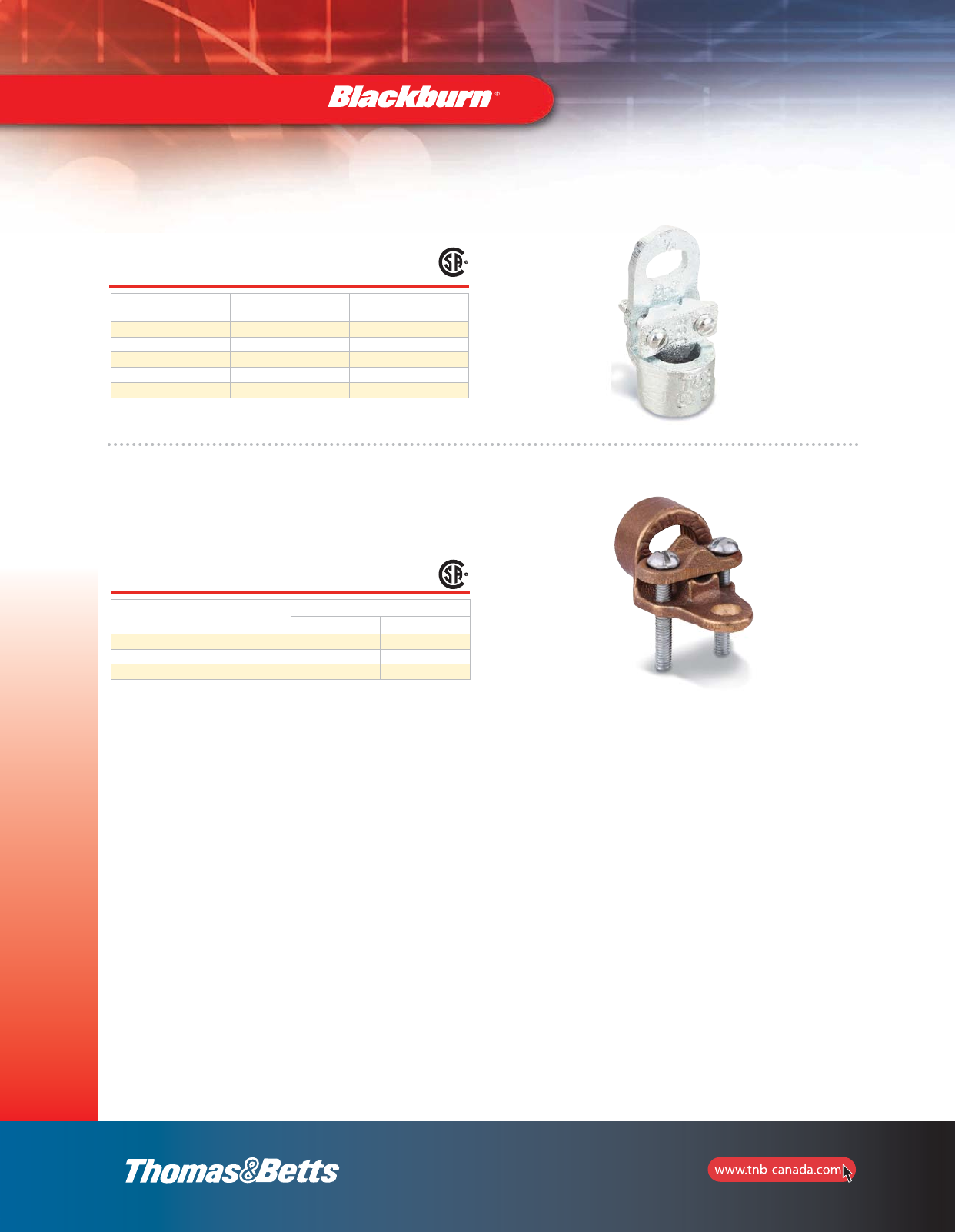
92
Grounding
Conduit Hubs
Cat. No. Ground Wire
Size AWG
Conduit/Wire
Size
3930 #8 to #2 1/2” Conduit
3940 #8 to #2 3/4” Conduit
3950 #8 to #3/0 1” Conduit
3951 #8 to #4/0 1-1/4” Conduit
3960 #8 to #4 Armored Wire
Material: Malleable iron.
Type CH — Bronze Conduit Hubs
•Rugged cast bronze threaded hubs
•Provide positive connection between rigid conduit and
water system in conjunction with “J” clamp
Cat. No. Conduit Size
(in.)
Conductor Range
max. min.
CH12 1/2 6 sol. 10 sol.
CH34 3/4 2/0 str. 10 sol.
CH1 13/0 str. 10 sol.
Mechanical Grounding Connectors
2_BLKBRNMRO5_E_58to167_Grounding.pdf 35 10/6/2011 1:00:55 PM
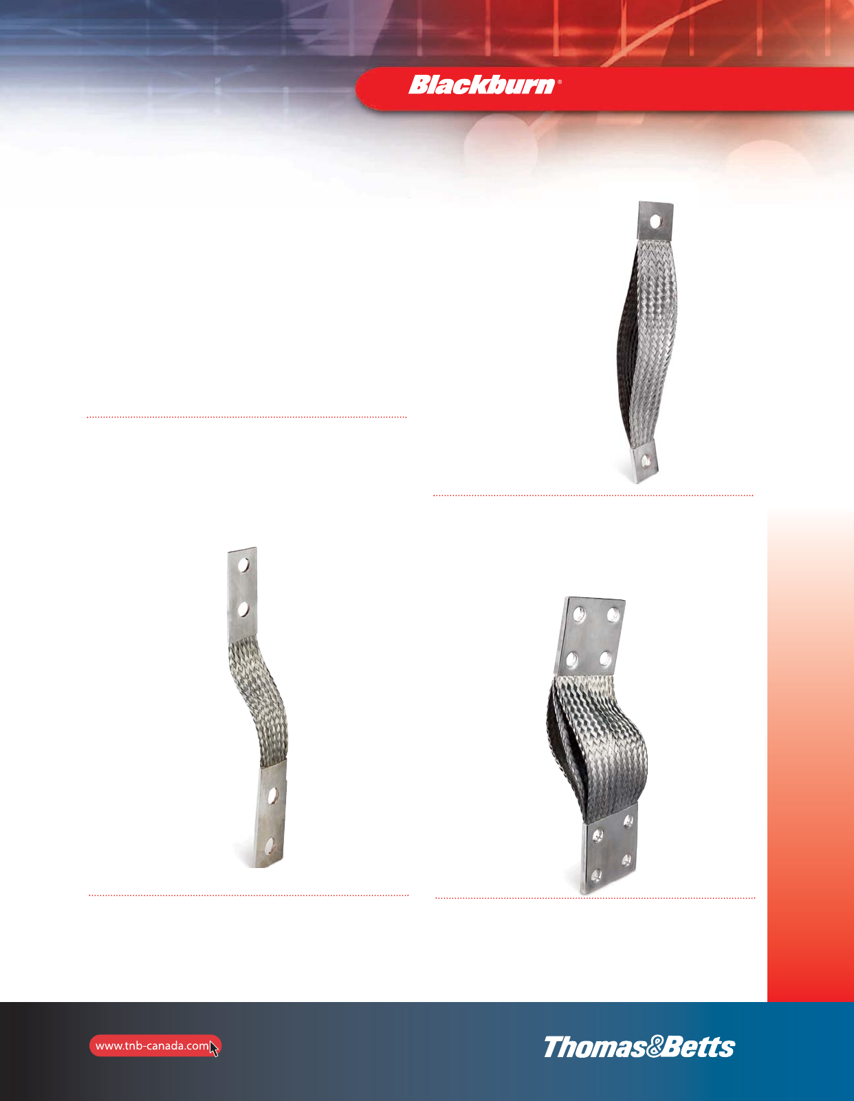
93
Grounding
Flexible Braids for Continuous current, Grounding and
Bonding Applications (i.e.: Cable Tray)
Mechanical Grounding Connectors
Rating of the Connectors
Standard construction using 30 AWG individual
wires are suitable for medium duty
applications. If needed, all constructions and/or
configurations in this Guide, can be supplied
using 36 AWG for extra flexibility.
It is important to note that the Ampere ratings in this Guide are
suggested for use as a reference only. If needed, we can certify
ampacity of all connectors in our top of the line automatic heat cycle
laboratory using CEI60694 standards. Performance certificate gives you
the assurance that our connectors are suitable for your application.
Actual values used for a given application will depend on such factors
as temperature rise, number of braids, voltage ratings and other
conditions of service needs to be verified by application engineers.
Ferrules and Plating
Ferrules are made of high conductivity seamless 99.9% pure copper that
are electro-tin plated prior to forming on each end of the assembly. This
procedure is important to eliminate surface corrosion between the inside
of the ferrule and the braids before compression can affect the
connector’s performance.
For increased pad conductivity, 30, 50 or 100 micron silver plated
ferrules are available. Nickel plating or bare copper also available upon
request.
Length of the assemblies
All braid lengths are mesured in inches and are measured from end to
end. The last digits of the part numbers determine the length of the
connector. (i.e.: FBD12, “12” = 12 inches)
Options
For special requests, provide a copy of your drawing with your specific
requirements so we can design and build the flexible connectors to your
exact specifications.
If needed, a wide range of insulation products are available depending
on the application, voltage and temperature ratings.
2_BLKBRNMRO5_E_58to167_Grounding.pdf 36 10/6/2011 1:00:55 PM
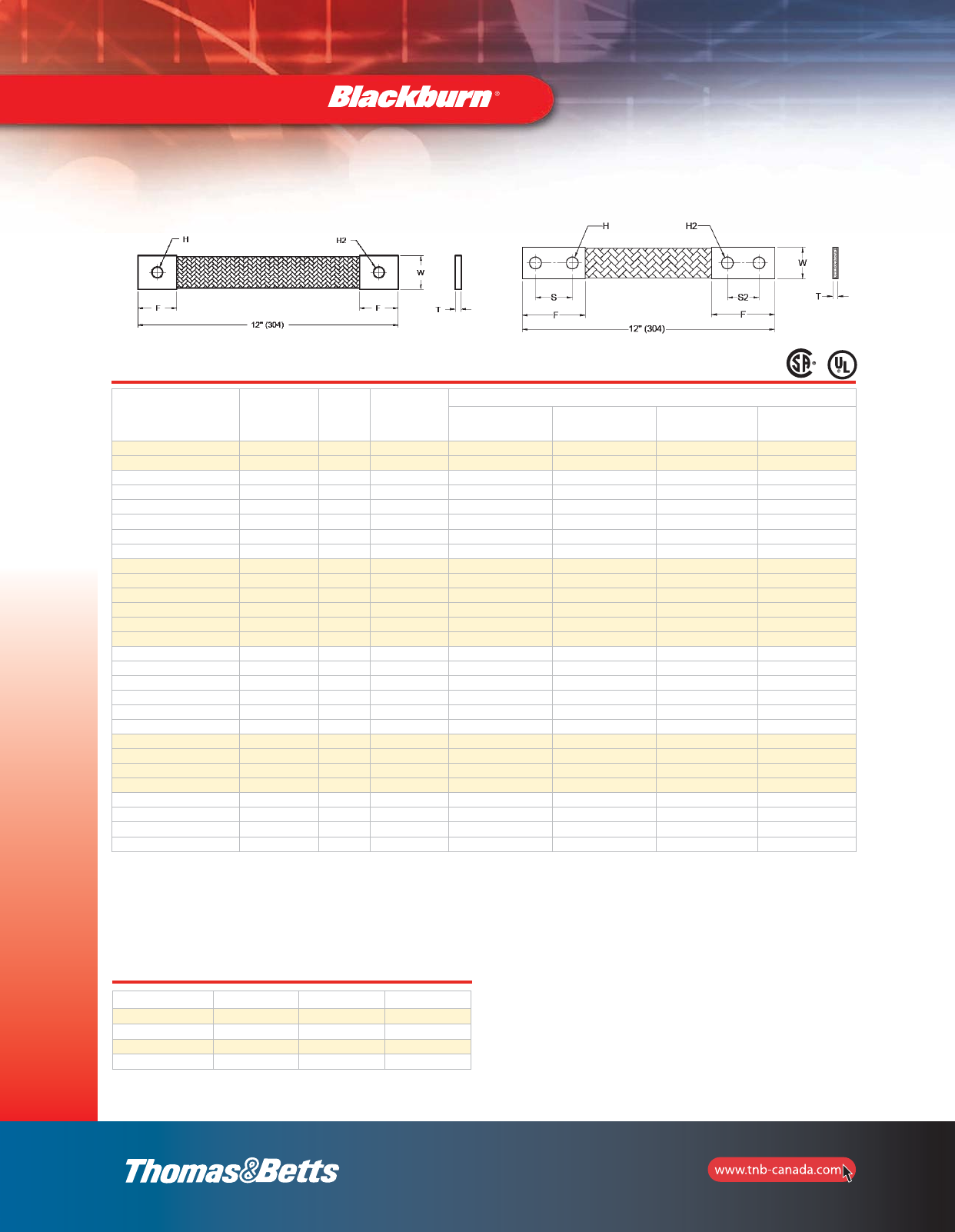
94
Grounding
Cat. No. Circular
Mils
Bolt
Hole
(H or H2)
No. of Braids
in
Ferrule
Dimensions in. (mm)
(T)
Thickness
(W)
Width
(F)
Ferrule Length
(S or S2)
Distance
Ctr. to Ctr
FBB12-1* 24000 1/4 1 0.140 (3.6) 0.625 (15.9) 0.750 (19.1) N/A
FBC12-1* 48000 7/16 1 0.148 (3.8) 1.000 (25.4) 1.300 (33.0) N/A
FBD12-1* 76800 7/16 1 0.200 (5.1) 1.000 (25.4) 1.300 (33.0) N/A
FBD12* 76800 7/16 1 0.200 (5.1) 1.000 (25.4) 2.500 (63.5) 1.25 (31.8)
FB2D12-1* 153600 7/16 2 0.250 (6.4) 1.250 (31.8) 1.500 (38.1) N/A
FB2D12* 153600 7/16 2 0.250 (6.4) 1.250 (31.8) 2.500 (63.5) 1.25 (31.8)
FB3D12-1* 230400 7/16 3 0.350 (8.9) 1.250 (31.8) 1.500 (38.1) N/A
FB3D12* 230400 7/16 3 0.350 (8.9) 1.250 (31.8) 2.500 (63.5) 1.25 (31.8)
FBXD12-1* 105600 9/16 1 0.250 (6.4) 1.250 (31.8) 1.500 (38.1) N/A
FBXD12* 105600 9/16 1 0.250 (6.4) 1.250 (31.8) 2.500 (63.5) 1.25 (31.8)
FB2XD12-1* 211200 9/16 2 0.350 (8.9) 1.250 (31.8) 1.500 (38.1) N/A
FB2XD12* 211200 9/16 2 0.350 (8.9) 1.250 (31.8) 2.500 (63.5) 1.25 (31.8)
FB3XD12-1* 316800 9/16 3 0.400 (10.2) 1.250 (31.8) 1.500 (38.1) N/A
FB3XD12* 316800 9/16 3 0.400 (10.2) 1.250 (31.8) 2.500 (63.5) 1.25 (31.8)
FBE12-1* 168000 9/16 1 0.500 (12.7) 1.250 (31.8) 2.500 (63.5) N/A
FBE12* 168000 9/16 1 0.250 (6.4) 1.250 (31.8) 3.500 (88.9) 1.75 (44.5)
FB2E12-1* 336000 9/16 1 0.500 (12.7) 1.250 (31.8) 2.500 (63.5) N/A
FB2E12* 336000 9/16 2 0.500 (12.7) 1.250 (31.8) 3.500 (88.9) 1.75 (44.5)
FB3E12 504000 9/16 3 0.750 (19.1) 1.250 (31.8) 3.500 (88.9) 1.75 (44.5)
FB4E12 672000 9/16 4 1.000 (25.4) 1.250 (31.8) 3.500 (88.9) 1.75 (44.5)
FBF12 230400 9/16 1 0.300 (7.6) 1.500 (38.1) 3.500 (88.9) 1.75 (44.5)
FB2F12 460800 9/16 2 0.450 (11.4) 1.500 (38.1) 3.500 (88.9) 1.75 (44.5)
FB3F12 691200 9/16 3 0.600 (15.2) 1.625 (41.2) 3.500 (88.9) 1.75 (44.5)
FB4F12 921600 9/16 4 0.750 (19.1) 1.625 (41.2) 3.500 (88.9) 1.75 (44.5)
FBG12 307200 9/16 1 0.380 (9.7) 1.500 (38.1) 3.500 (88.9) 1.75 (44.5)
FB2G12 614400 9/16 2 0.630 (16.0) 1.625 (41.2) 3.500 (88.9) 1.75 (44.5)
FB3G12 921600 9/16 3 0.850 (21.6) 1.625 (41.2) 3.500 (88.9) 1.75 (44.5)
FB4G12 1228800 9/16 4 1.000 (25.4) 1.880 (47.9) 3.500 (88.9) 1.75 (44.5)
Cat. No. Circular Mils Thickness in. (mm) Width in. (mm)
FBBRL 24000 0.140 (3.6) 0.625 (15.9)
FBCRL 48000 0.148 (3.8) 1.000 (25.4)
FBDRL 76800 0.200 (5.1) 1.000 (25.4)
FBXDRL 105600 0.250 (6.4) 1.250 (31.8)
Flexible Braids in a roll (10 feet minimum)
Ferrules or lugs not included.
Add suffix for desired length, i.e.: FBCRL “–10” for 10’ roll.
* Listed UL 467 and 486A, certified CSA C22.2 No. 41 as Grounding and Bonding Equipment.
Special lengths offered in 6, 18, 24, 30 and 36 inches (end to end).
Change the 12 in the above catalogue numbers to the desired length.
(-1) indicates 1 bolt hole per ferrule.
S2 and H2 measurements are used for customized braids only.
Mechanical Grounding Connectors
SEE SPECIAL LENGTH INFORMATION
SEE SPECIAL LENGTH INFORMATION
2_BLKBRNMRO5_E_58to167_Grounding.pdf 37 10/6/2011 1:00:55 PM
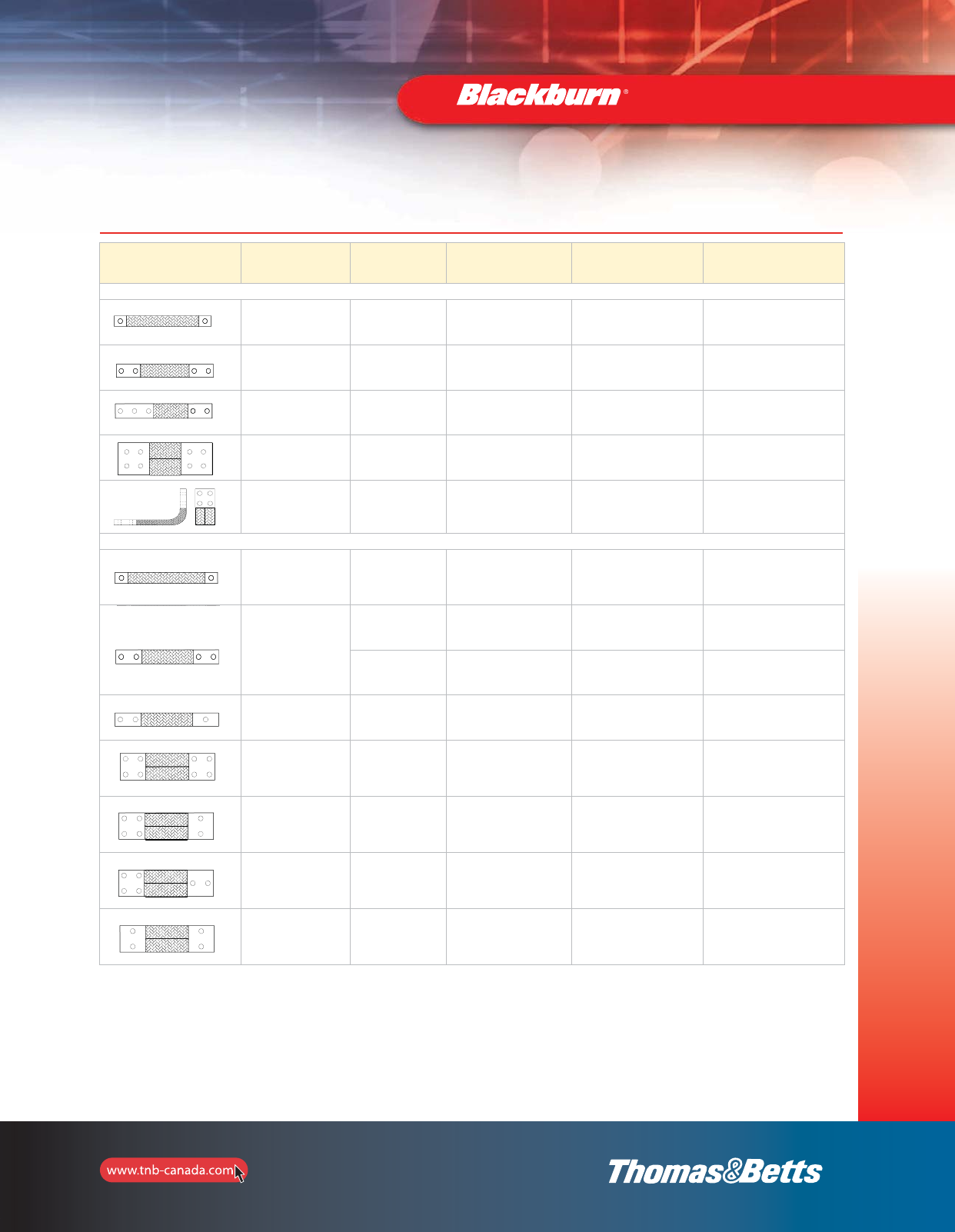
95
Grounding
Technical Specifications
Configuration Type Ind. Wire
Gauge Size
Width
Range
(in.)
Rating
Range
(Amps)
Comments
Extra-flexible Links for Heavy-Duty Application
FBEXA 36 AWG 1-1/2 – 1-5/8 350 – 1000 A Extra Flexible 1 hole NEMA Boreal's
Top of the line
FBEXB 36 AWG 1-1/2 – 1-5/8 400 – 2000 A Extra Flexible 2 hole NEMA
Boreal's top of the line
FBEXG 36 AWG 1-3/4 – 2 900 – 1650 A Extra Flexible Transformer Link
FBEXH 36 AWG 3 – 4 1400 – 4000 A Extra Flexible 4 hole NEMA
Boreal's top of the line
FBEXJ 36 AWG 3-1/4 – 3-3/4 2300 – 3600 A Extra Flexible 90º 4 hole NEMA
Boreal's top of the line
Standard flexible Links for Medium-Duty Application
FBB**-1
FBC**-1
FBD**-1
30 AWG 1-1/4 – 1-3/4 350 – 1000 A NEMA std. Grounding Connectors
FBD**
FB2D**
FB3D**
FBXD**
FB2XD**
30 AWG 1-1/2 – 1-5/8 400 – 2000 A Same as EXB with 30 AWG wires
30 AWG 1-1/2 – 2 700 – 1750 A Standard Transformer Link
FBSWB 30 AWG 1-1/2 – 2 700 – 1750 A Same construction as SWB with
different hole pattern
FBSWC 30 AWG 31300 – 2350 A
4 hole pads also available in wider
configuration, refer to EXH, SWD
and LTL series
FBSWC 30 AWG 31300 – 2350 A Same construction as SWC Type A with
different hole configuration
FBSWC 30 AWG 31300 – 2350 A Same construction as SWC Type A with
different hole configuration
FBSWC 30 AWG 31300 – 2350 A Same construction as SWC Type A with
different hole configuration
** Specify desired length.
Mechanical Grounding Connectors
2_BLKBRNMRO5_E_58to167_Grounding.pdf 38 10/6/2011 1:00:55 PM
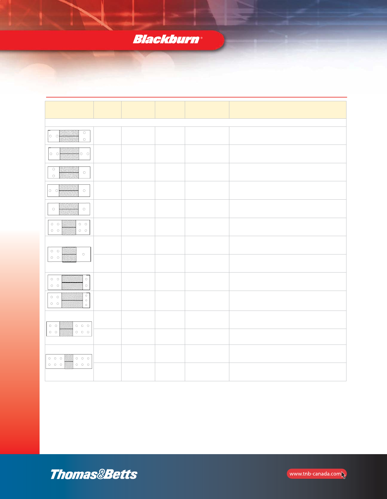
96
Grounding
Mechanical Grounding Connectors
Configuration Type Ind. Wire
Gauge Size
Width
Range
(in.)
Rating
Range (Amps) Comments
Standard Flexible Links for Medium-Duty Application
FBSWC 30 AWG 31300 – 2350 A Same construction as SWC with
different hole configuration
FBSWC 30 AWG 31300 – 2350 A Same construction as SWC with
different hole configuration
FBSWC 30 AWG 31300 – 2350 A Same construction as SWC with
different hole configuration
FBSWC 30 AWG 31300 – 2350 A Same construction as SWC with
different hole configuration
FBSWC 30 AWG 2 – 4 600 – 1850 A Same construction as SWC with
different hole configuration
FBSWD 30 AWG 3-3/4 – 4-3/4 1600 – 2100 A 4 hole
Transformer Link
FBSWC 30 AWG 31300 – 2100 A 1 to 4 hole
Transformer Link
FBSWD 30 AWG 3-3/4 – 4-3/4 1300 – 2100 A 1 to 4 hole
Transformer Link
FBSWD 30 AWG 3-3/4 – 4-3/4 1600 – 2100 A 2 to 4 hole
Transformer Link
FBSWD 30 AWG 3-3/4 – 4-3/4 1600 – 2100 A 3 to 4 hole
Transformer Link
FBSWE 30 AWG 31400 – 1600 A 6 to 4 hole
Transformer Link
FBSWF 30 AWG 3-3/4 – 4-3/4 1700 – 2300 A 6 to 4 hole
Transformer Link
FBSWE 30 AWG 31400 – 1600 A 6 hole
Transformer Link
FBSWF 30 AWG 3-3/4 – 4-3/4 1700 – 2300 A 6 hole
Transformer Link
Technical Specifications
2_BLKBRNMRO5_E_58to167_Grounding.pdf 39 10/6/2011 1:00:55 PM
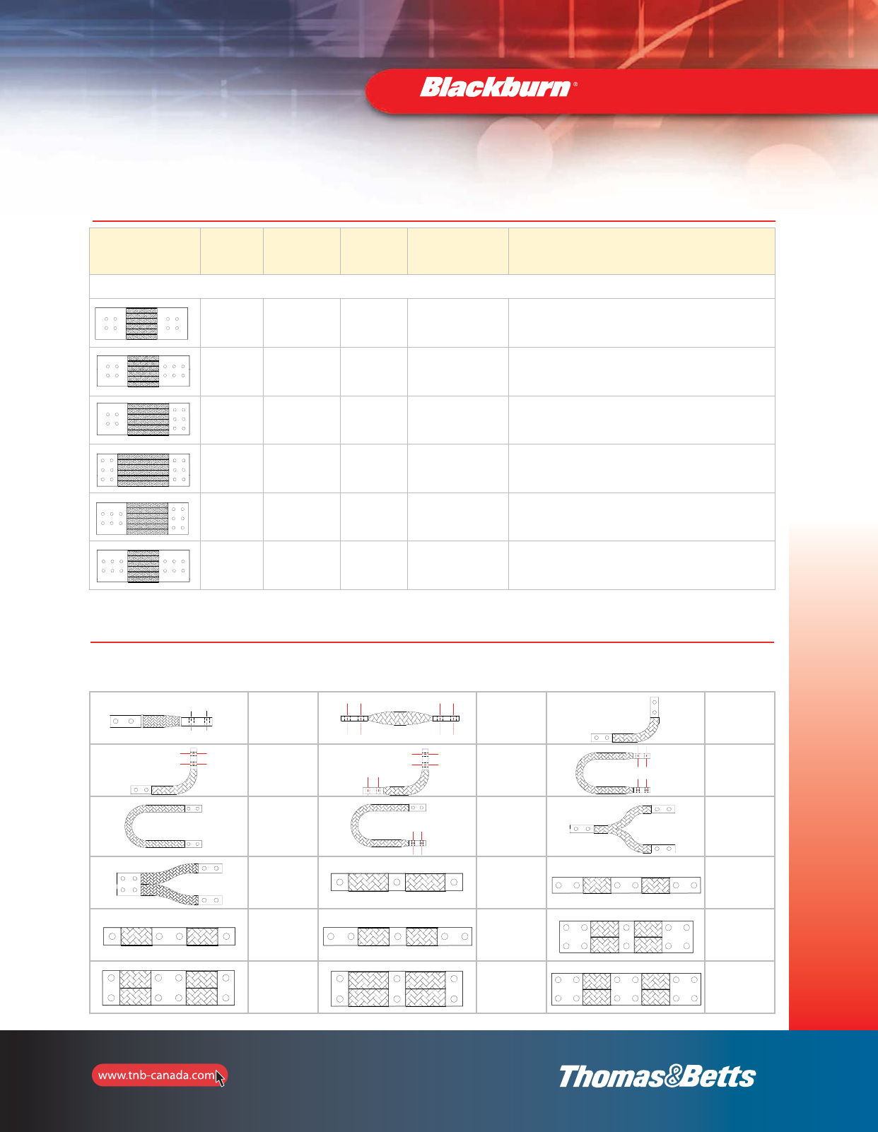
97
Grounding
Mechanical Grounding Connectors
Technical Specifications
Configuration Type Ind. Wire
Gauge Size
Width
Range
(in.)
Rating
Range (Amps) Comments
Large Transformer Links
FBLTL 30 AWG 6 – 6-3/8 2500 – 4000 A 4 hole
Transformer Link
FBLTL 30 AWG 6 – 6-3/8 2500 – 4000 A 4 to 6 hole
Transformer Link
FBLTL 30 AWG 6 – 6-3/8 2500 – 4000 A 4 to 6 hole
Transformer Link
FBLTL 30 AWG 6 – 6-3/8 2500 – 4000 A 6 hole
Transformer Link
FBLTL 30 AWG 6 – 6-3/8 2500 – 4000 A 6 hole
Transformer Link
FBLTL 30 AWG 6 – 6-3/8 2500 – 4000 A 6 hole
Transformer Link
Model FBBI
Type A
Model FBBI
Type B
Model FBBL
Type A
Model FBBL
Type B
Model FBBL
Type C
Model FBBU
Type A
Model FBBU
Type B
Model FBBU
Type C
Model FBBY
Type A
Model FBBY
Type B
Model FBBE
Type A
Model FBBE
Type B
Model FBBE
Type C
Model FBBE
Type D
Model FBBE
Type E
Model FBBE
Type F
Model FBBE
Type G
Model FBBE
Type H
Miscellaneous Configurations and Shapes
The following sketches represent the most popular configurations and shapes. For other non standard flexible links and/or dimensions, send us
a copy of your drawing with your specific requirements so that we can design and build the flexible connectors to your exact specification.
2_BLKBRNMRO5_E_58to167_Grounding.pdf 40 10/6/2011 1:00:56 PM
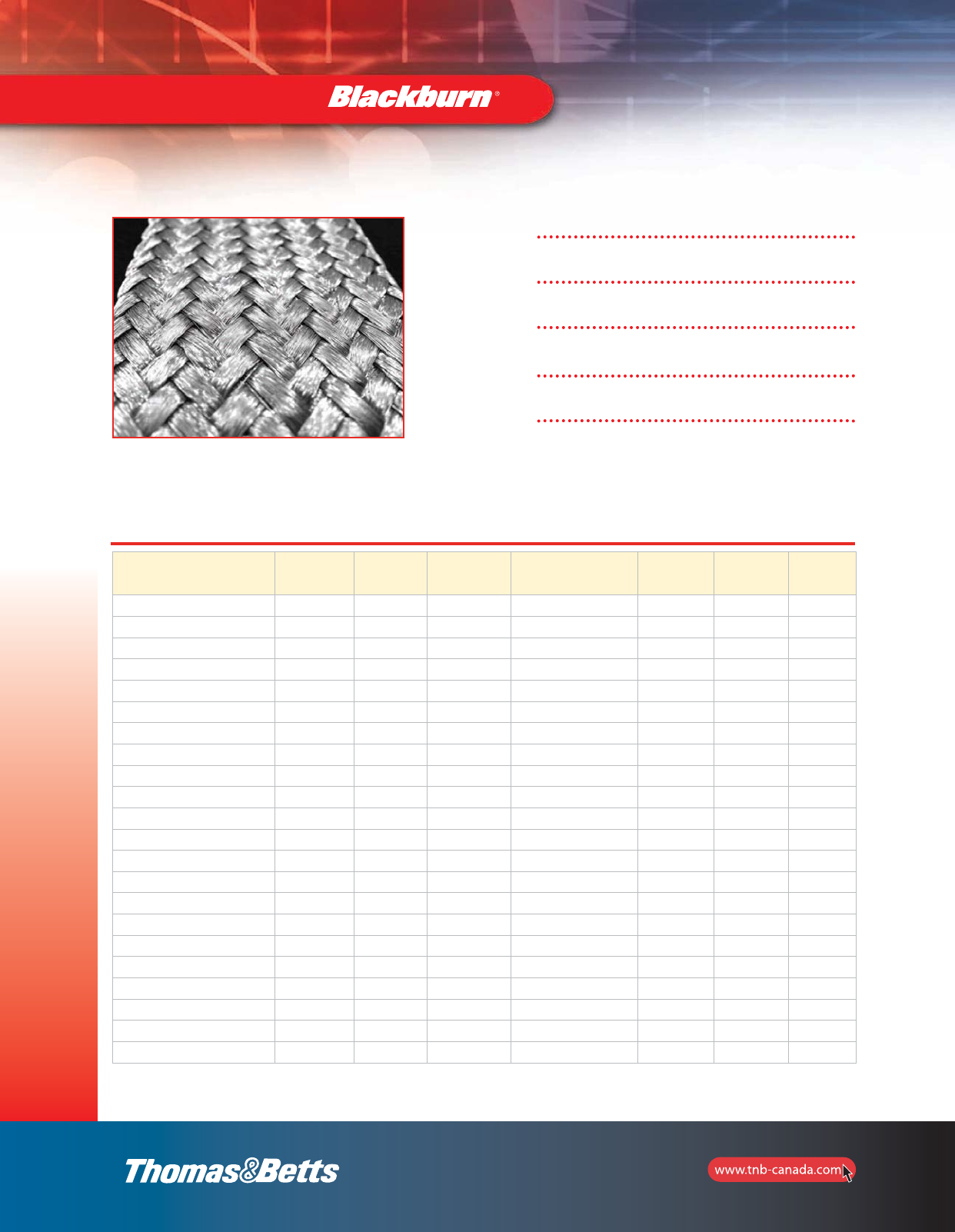
98
Grounding
Mechanical Grounding Connectors
Conductors
Strands are soft-drawn bare or tinned copper.
Construction
Strands are woven into a tubular braid and rolled flat.
Application
For bonding, grounding or connecting moving parts.
Specification
ASTM-B33
Assemblies
Factory Installed molded connectors also available.
Cat. No. AWG
Size
Circular
Mil
Area
Numbers
and Size
of Wires
Construction
Nominal
Width
(in.)
Nominal
Thick.
(in.)
Approx.
Weight
(lb./m)
FB-4243230-1* 300 kcmil 307,200 3,072 / 30 4 x (24 x 32/30) 1-3/8 0.420 1,110
FB-1485230-1 250 kmcil 249,600 2,496 / 30 48 x 52/30 2-1/2 0.190 900
FB-3243230-1 4/0 230,400 2,304 / 30 3 x (24 x 32/30) 1-1/4 0.375 825
FB-2243230-1 3/0 153,600 1,536 / 30 2 x (24 x 32/30) 1-1/8 0.250 560
FBXDRL 1/0 105,600 1,056 / 30 24 x 44/30 1 0.135 365
FB-1482230-1 1/0 105,600 1,056 / 30 48 x 22/30 1-3/8 0.120 365
FB-1488436-1 1/0 100,800 4,032 / 36 48 x 84/36 1-5/8 0.080 360
FBDRL 1 76,800 768 / 30 24 x 32/30 1 0.125 200
FB-12412036-1 2 72,000 2,880 / 36 24 x 120/36 1 0.135 240
FB-1485036-1 2 60,000 2,400 / 36 48 x 50/36 1-1/4 0.090 205
FBCRL 3 48,000 480 / 30 24 x 20/30 3/4 0.110 170
FB-1484036-1 3 48,000 1,920 / 36 48 x 40/36 1 0.090 160
FB-1488640-1 4 41,280 4,128 / 40 48 x 86/40 1 0.060 140
FB-1246736-1 4 40,200 1,608 / 36 24 x 67/36 3/4 0.090 135
FB-1241630-1 4 38,400 384 / 30 24 x 16/30 5/8 0.085 125
FBBRL 6 24,000 210 / 30 24 x 10/30 1/2 0.080 83
FB-1244036-1 6 24,000 960 / 36 24 x 40/36 1/2 0.090 80
FB-14810644-2 7 20,350 5,088 / 44 48 x 106/44 5/8 0.050 68
FB-1480836-1 10 9,600 384 / 36 48 x 8/36 1/2 0.030 39
FB-1241636-1 10 9,600 384 / 36 24 x 16/36 3/8 0.060 39
FB-1480636-1 12 7,200 288 /36 48 x 6/36 3/8 0.030 28
FB-1481036-1 12 6,000 240 / 36 24 x 10/36 1/4 0.030 23
* The suffix "-1" denotes tinned copper braid. For bare copper braid, replace "-1" with "-2".
NOTE: Dimensions shown are only approximate due to the extreme flexibility of braided cables.
The following listing represents the most popular flat braid constructions used in
specialized electrical industry applications. For other constructions, contact a T&B
sales representative or your regional T&B sales office.
2_BLKBRNMRO5_E_58to167_Grounding.pdf 41 10/6/2011 1:00:56 PM
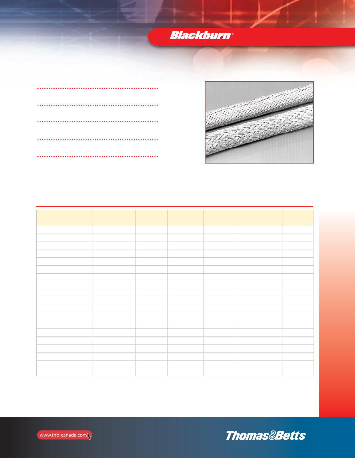
99
Grounding
Mechanical Grounding Connectors
* Denotes QQ-B-575 construction.
NOTE: Because Tubular Braid is very pliable, the I.D.'s are approximate.
Cat. No.
Nominal I.D.
when
Rounded
Nominal
Circular
Mil Area
AWG Size
Equivalent
Number
and Size
of Wires
Construction
Approx.
Weight
(lb./m)
TB - 481630 2-1/4 77,180 1 768 / 30 48 x 16 / 30 260
TB - 481430* 2 67,540 2 672 / 30 48 x 14 / 30 230
TB - 481230* 1-1/2 57,890 3 576 / 30 48 x 12 / 30 200
TB - 481130* 1-3/8 53,060 3 528 / 30 48 x 11 / 30 185
TB - 481030 1-1/4 48,240 3 480 / 30 48 x 10 / 30 168
TB - 480930* 1-1/8 43,420 4 432 / 30 48 x 9 / 30 155
TB - 480830* 1 38,600 4 384 / 30 48 x 8 / 30 140
TB - 480730* 7/8 33,770 5 336 / 30 48 x 7 / 30 123
TB - 481234 13/16 22,896 7 576 / 34 48 x 12 / 34 85
TB - 481836* 25/32 21,600 7 864 / 36 48 x 18 / 36 79
TB - 480734* 1/2 13,356 9 336 / 34 48 x 7 / 34 53
TB - 481136* 1/2 13,200 9 528 / 36 48 x 11 / 36 53
TB - 240730* 3/8 16,880 8 168 / 30 24 x 7 / 30 62
TB - 480836* 3/8 9,600 10 384 / 36 48 x 8 / 36 40
TB - 240834 3/8 7,632 11 192 / 34 24 x 8 / 34 30
TB - 241336* 13/64 7,800 11 312 / 36 24 x 13 / 36 31
TB - 240734 1/4 6,678 12 168 / 34 24 x 7 /34 26
TB - 240536* 1/8 3,000 15 120 / 36 24 x 5 / 36 13
TB - 240436* 7/64 2,400 16 96 / 36 24 x 4 /36 11
The following listing represents the most popular tubular braid constructions used in
today's electrical and electronic industries. For other constructions, contact a T&B
sales representative or your regional T&B sales office.
Conductors
Strands are soft-drawn bare or tinned copper.
Construction
Strands are woven into a tubular braid.
Application
For bonding, grounding or connecting moving parts.
Specification
ASTM-B33, QQ-B-375
Shield Coverage
Braid is formed to maintain coverages of 90% shielding
over the nominal diameters specified.
2_BLKBRNMRO5_E_58to167_Grounding.pdf 42 10/6/2011 1:00:56 PM
100
Grounding
Mechanical Grounding Connectors
Cat. No. Circular Mils Amperage
Capacity
FBB12-1 24000 95
FBC12-1 48000 145
FBD12-1 76800 190
FBD12 76800 190
FB2D12-1 153600 330
FB2D12 153600 630
FB3D12-1 230400 470
FB312 230400 470
FBXD12-1 105600 235
FBXD12 105600 235
FB2XD12-1 211200 400
FB2XD12 211200 400
FB3XD12-1 316800 600
FB3XD12 316800 600
Cat. No. Circular Mils Amperage
Capacity
FBE12-1 168000 340
FBE12 168000 340
FB2E12-1 336000 530
FB2E12 336000 530
FB3E12 504000 700
FB4E12 672000 805
FBF12 230400 360
FB2F12 460800 600
FB3F12 691200 820
FB4F12 921600 1000
FBG12 307200 415
FB2G12 614400 700
FB3G12 921600 760
FB4G12 1228800 1200
Grounding and Bonding Information
Rating or Setting of overcurrent Device in
Circuit Ahead of Equipment, Conduit, etc.
Not Exceeding – Amperes
Copper Wire
Circular Mils
200 26 240 (6 AWG)
300 41 740 (4 AWG)
400 52 620 (3 AWG)
500 66 360 (2 AWG)
600 83 690 (1 AWG)
800 105 600 (1/0)
1000 133 100 (2/0)
1200 167 800 (3/0)
1600 211 600 (4/0)
2000 250 000
2500 350 000
3000 400 000
4000 500 000
5000 700 000
6000 800 000
Maximum Available
Short Circuit
Current Amperes
Maximum Fault Duration with Exothermic Weld,
Compression or Bolted Joint
0.5 Second
Circular Mils
1.0 Second
Circular Mils
5000 26 240 41 740
10 000 52 620 83 690
15 000 83 690 105 600
20 000 105 600 167 800
25 000 133 100 211 600
35 000 211 600 250 000
40 000 211 600 300 000
50 000 250 000 350 000
60 000 30 000 500 000
70 000 350 000 600 000
80 000 400 000 600 000
90 000 500 000 700 000
100 000 500 000 700 000
Minimum Size Conductors for Bonding
Raceways and Equipment
Minimum Size of Bare Copper
Grounding Conductors
Based on table 16 C.E.C.
Based on table 51 C.E.C.
Size calculated in accordance with IEEE No. 80.
Minimum Size Flexible Braid for Continuous Current Applications
Flexible Braids Selection Guide
2_BLKBRNMRO5_E_58to167_Grounding.pdf 43 10/6/2011 1:00:56 PM
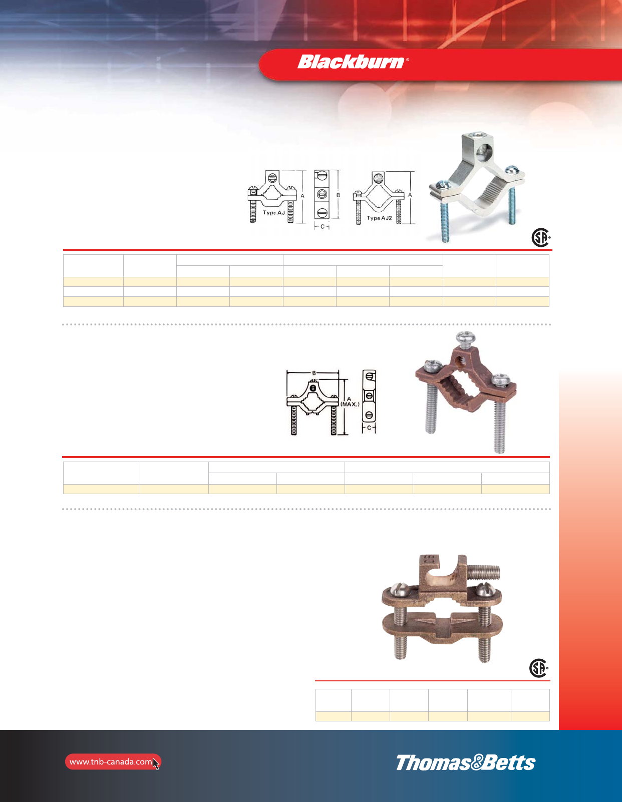
101
Grounding
Aluminum Water Pipe Clamps
•For connecting grounding conductor to either
steel or copper pipe, rod or tubing
•Tin plated for corrosion resistance
•For use with copper or aluminum conductors
Cat. No.
Water Pipe
Size
(in.)
Conductor Range Dimensions (in.) Steel Clamp
Screw
Aluminum
Wire Screw
max. min. A B C
AJ 1/2–1 1/0 str. #14 sol. 2-1/2 2-1/4 5/8 1/4–20 7/16–20 slot
AJ2 1-1/2–2 250 kcmil #6 3-7/8 3-3/4 7/8 5/16–18 11/16–20 socket
AJ-2124 2-1/2–4 250 kcmil #6 5-9/16 6-5/16 7/8 3/8–16 11/16–20 socket
For both copper and aluminum conductors to steel pipe and copper water tubing.
Mechanical Grounding Connectors
Budget Price Cast Bronze Clamp
•For connecting grounding conductor to either steel or
copper pipe, rod or tubing
•For use with copper conductors only
Cat. No.
Water Pipe
Size
(in.)
Conductor Range Dimensions (in.)
max. min. A B C
JJR 1/2–1 #4 str. #10 sol. 2-15/32 25/32 17/32
•UL Listed for direct burial in earth/concrete.
•UL Listed for connection to ground rod,
pipe or rebar up to 1".
•Constructed from bronze alloy and high-performance
stainless steel bolts.
•Designed for easy installation or difficult bends or
continuous loops .
Cat. No. Pipe
Size
Rebar
Size
Ground Rod
Size
Conductor
Range
Mech. Conn./
Splice
(UL Listed)
JDLI 1/2"–1" 3/8"–1" 1/4"–1" #10 sol.–#2 Str. (2) #8 sol.
Type JDLI — Direct Burial Ground Clamp
Lay-in feature reduces installation time for difficult
bends or continuous loops of ground wire.
101-e.pdf 1 11/18/2011 1:03:21 PM
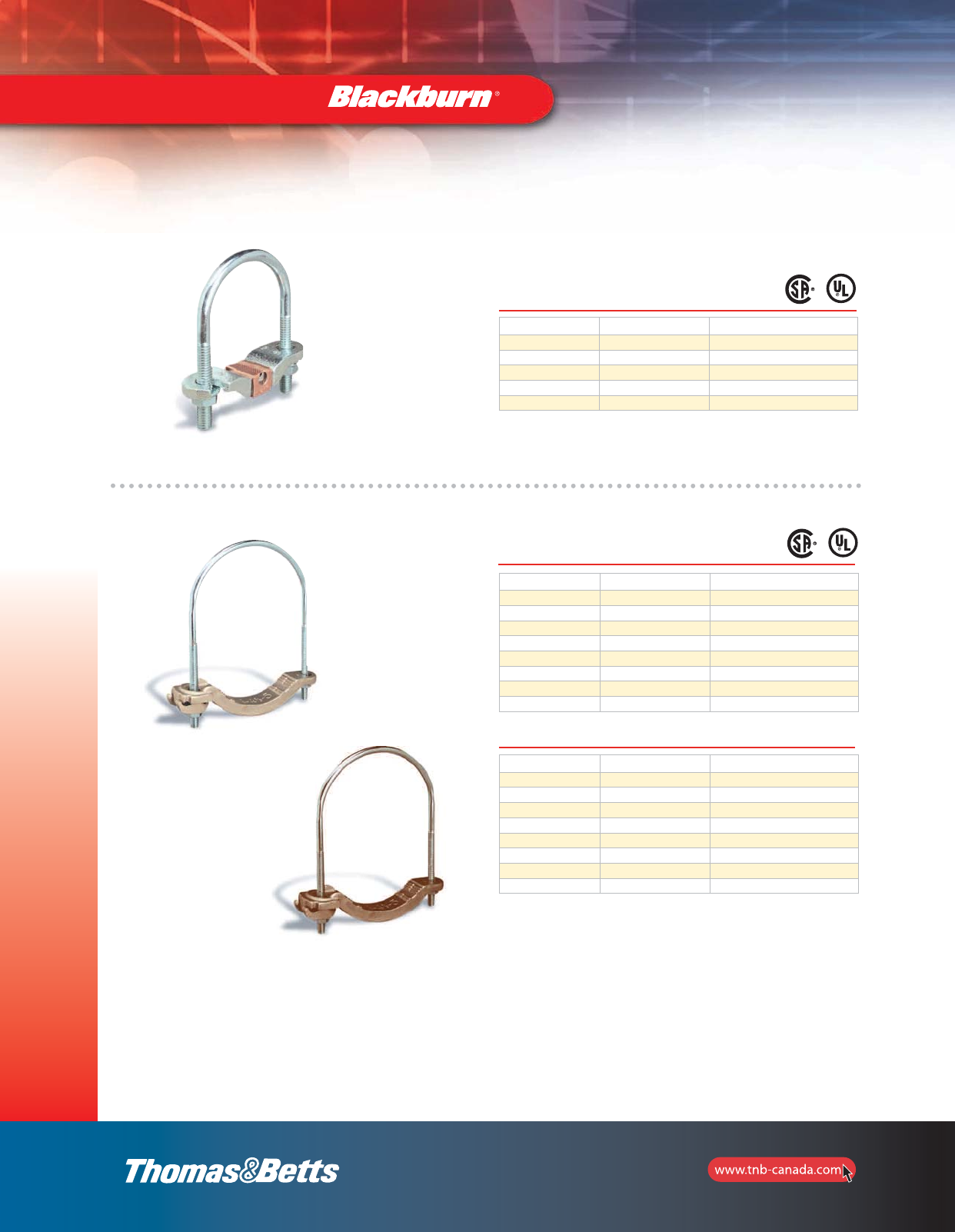
Mechanical Grounding Connectors
Waterpipe Ground Clamps
Cat. No. Ground Wire Size Water Pipe Size
2-TB #6, #4, #2 1/2”, 3/4”, 1” or rebar 4-10
3-TB #6, #4, #2 1-1/4”, 1-1/2” or 2”
4#6, #4, #2 2-1/2”, 3” or 3-1/2”
5-TB #6, #4, #2 4”, 4-1/2” or 5”
6#6, #4, #2 6”
Malleable iron crossbar, steel U-Bolt c/w copper cable clamp with serrations.
Cat. No. Ground Wire Size Water Pipe Size
3902 #4–4/0 AWG 1/2”–1”
3903 #4–4/0 AWG 1-1/4”–2”
3904 #4–4/0 AWG 2-1/2”–3-1/2”
3905-TB #4–4/0 AWG 4”–5”
3906-TB #4–4/0 AWG 6”
3907 #4–4/0 AWG 8”
3908 #4–4/0 AWG 10”
3909-TB #4–4/0 AWG 12”
Cat. No. Ground Wire Size Water Pipe Size
3902BU* #4–4/0 AWG 1/2”–1”
3903BU* #4–4/0 AWG 1-1/4”–2”
3904BU* #4–4/0 AWG 2-1/2”–3-1/2”
3905BU* #4–4/0 AWG 4”–5”
3906BU* #4–4/0 AWG 6”
3907BU* #4–4/0 AWG 8”
3908BU* #4–4/0 AWG 10”
3909BU* #4–4/0 AWG 12”
Material: Steel U-bolt and nut c/w bronzed aluminum cap and crossbar cadmium plated plus
gold chromate finish.
Material: Bronze U-bolt and nut c/w bronzed aluminum cap and crossbar with a bright dip finish.
*UL Listed for Direct Burial.
102
Grounding
2_BLKBRNMRO5_E_58to167_Grounding.pdf 45 10/6/2011 1:00:57 PM
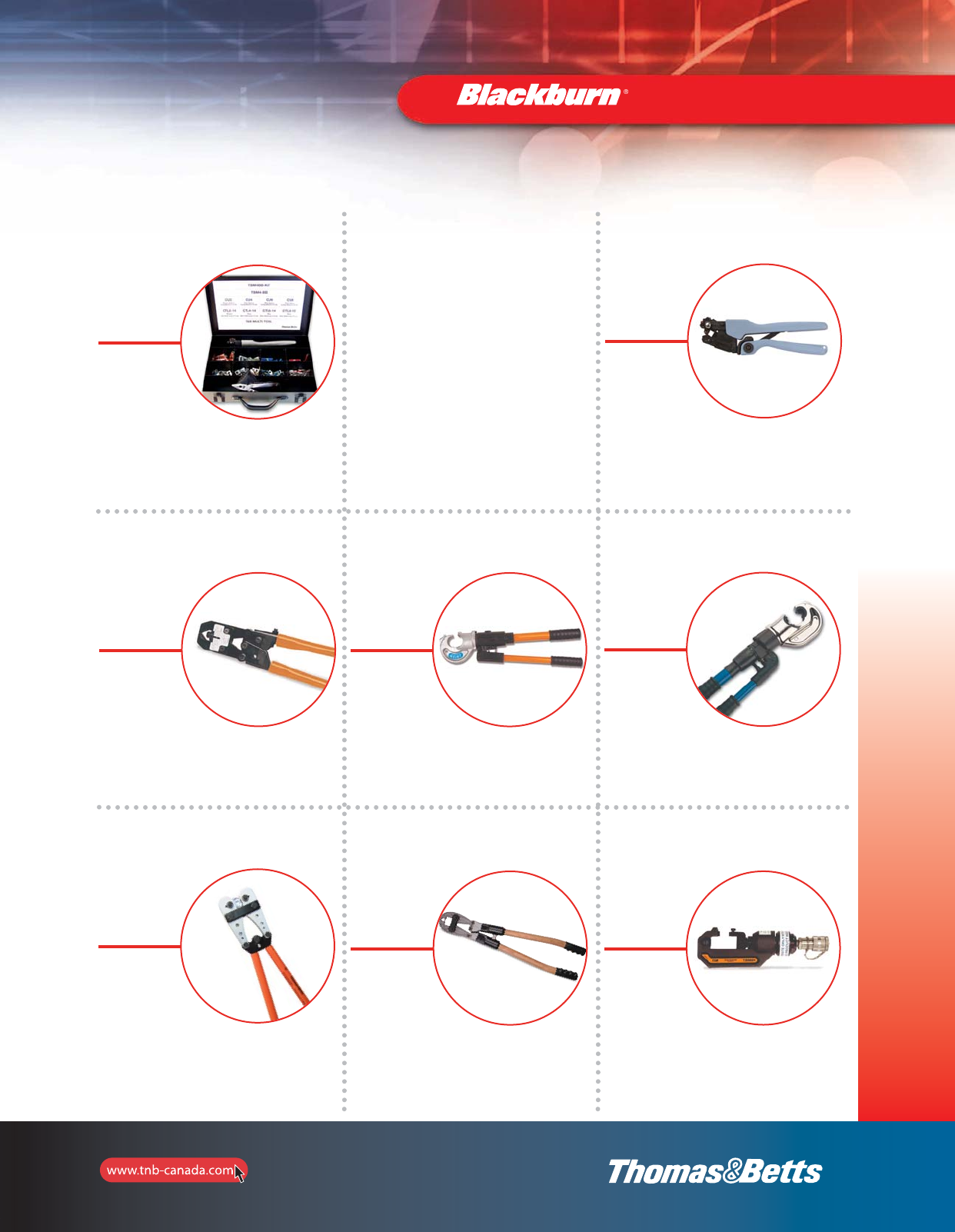
103
Installation Dies and Tools — Quick Reference
Die Kits
Metal cases
of assorted Die Kits
pp. 106–108
TBM4BB
p. 125
JB12B
12-Ton Manual
Hydraulic Crimp Tool
p. 126
TBM4S
p. 125
TBM14MC
14-Ton Compact
Manual Hydraulic Crimp Tool
p. 126
TBM840
Crimp Tool
p. 126
OD581
Manual
Compression Tool
p. 127
TBM6H
6-Ton Hydraulic
Crimping Head
p. 128
Introduction . . . . . . . . . . . . . . . . . .109
Warranty . . . . . . . . . . . . . . . . . . . .110
Tool Die Selection Chart . . . .111–112
Tool and Die Index for Copper
Compression Connectors . . .113–117
Installing Dies . . . . . . . . . . . .118–124
Tools . . . . . . . . . . . . . . . . . . .125–138
Installation Dies
and Tools
2_BLKBRNMRO5_E_58to167_Grounding.pdf 46 10/6/2011 1:00:57 PM
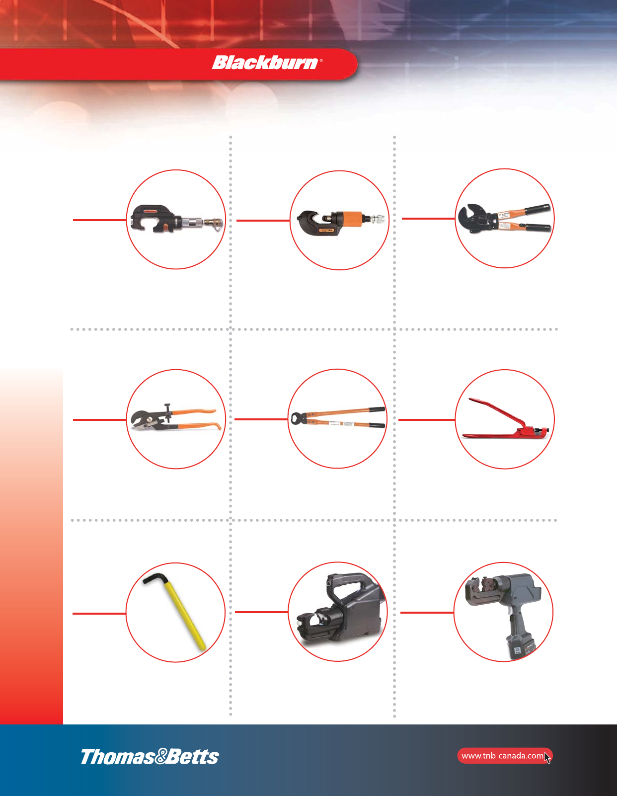
104
Installation Dies and Tools — Quick Reference
Installation Dies
and Tools
13100A
14-Ton Hydraulic
Crimping Head
p. 129
TBM8-750 and TBM8-750M
12-Ton Smart®Tools
pp. 130–131
368-CK
Cable Stripper
p. 132
HM-250-TOOL
Single Indent
Dieless Crimper
p. 133
Allen Wrench
p. 133
CSR750
Cable Cutter
p. 132
CTR-1
C-Tap
Removal Tool
p. 132
TBM14BSCR
Hermetically Sealed
14-Ton Battery-Powered
Compression Tool
p. 134
TBM6BSCR
6-Ton Battery
Compression Tool
p. 134
2_BLKBRNMRO5_E_58to167_Grounding.pdf 47 10/6/2011 1:00:57 PM
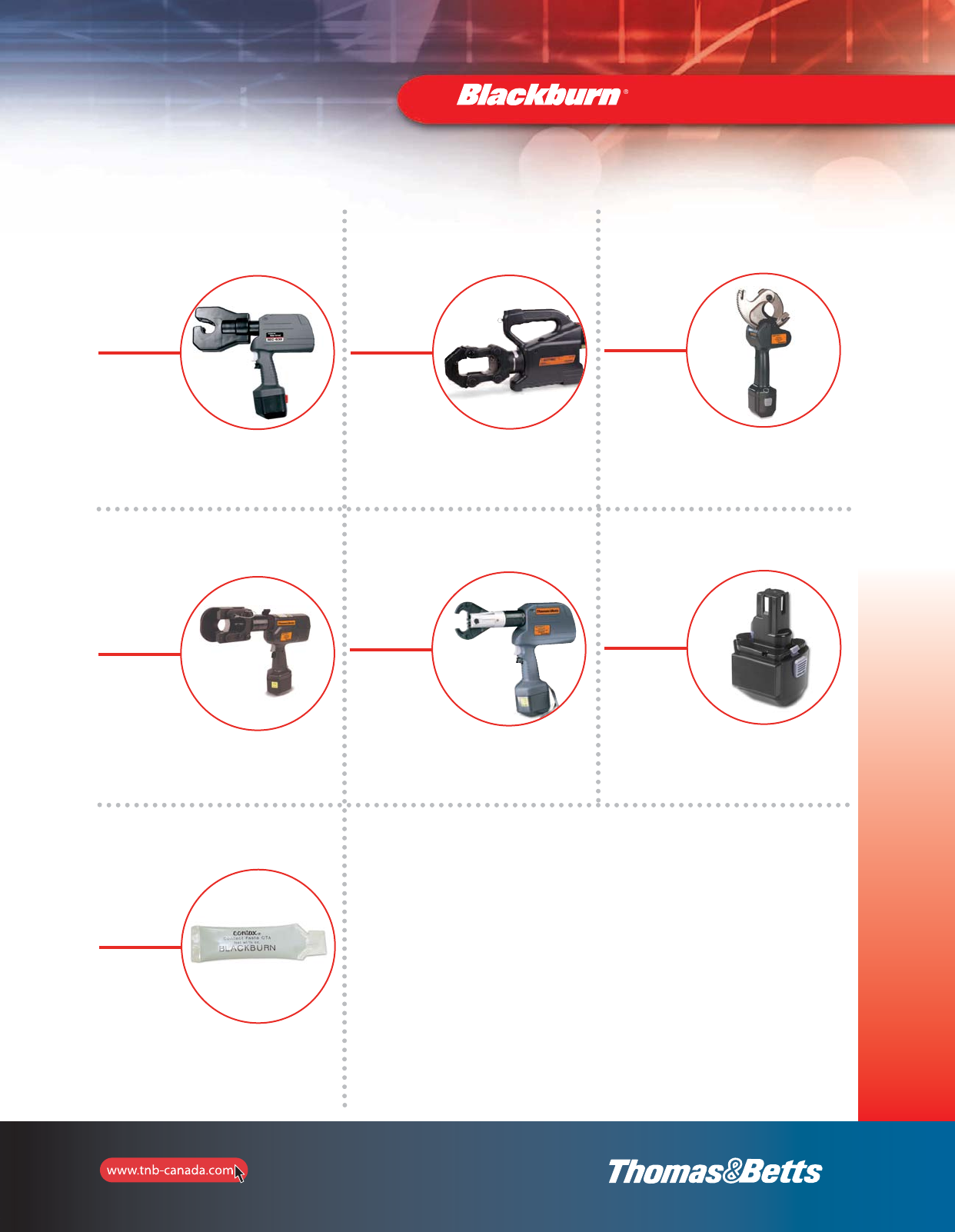
105
Installation Dies
and Tools
TBM15BSCR
Hermetically Sealed
15-Ton Battery-Powered
Compression Tool
p. 135
TBM54BSCT and TBM54BSCTS
Battery-Powered
Cutters
p. 135
TBMODBSCR
6-Ton
Battery-Powered
Compression Tool
p. 136
Replacement Battery
pp. 137–138
Installation Dies and Tools — Quick Reference
REC-630 and REC-750
ROBO CRIMPTM, 6-Ton
Battery Powered Dieless
Crimping Tool Kits
p. 134
Sealants and Lubricants
pp. 139–140
TBM58BSCT
Battery-Powered
Cutter
p. 136
2_BLKBRNMRO5_E_58to167_Grounding.pdf 48 10/6/2011 1:00:57 PM
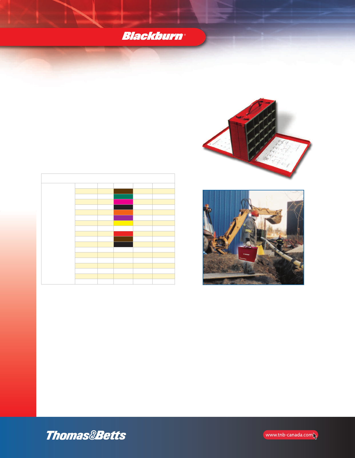
106
Installation Dies
and Tools
EZ-CK DIEKIT — Die sets Kit
All the Thomas & Betts dies you need to crimp the complete
T&B E-Z-Ground®connector offering, presented in a two sided
metal carrying case. The reverse side of this kit allows you to keep
all your colour coded Blackburn®crimping dies in one convenient
location. A cable vs die reference chart inside each cover lets you
sort and organize all your Blackburn®compression connector dies
for either copper or aluminum conductors. Additional compartments
for cutting dies and adaptors round off this great package.
Cat. No.: EZ-CK DIEKIT
BKB
Die Cat. No. Qty Die Colour Copper Aluminum
B75CH 1 Brown 2 AWG n/a
B05CH 1 Green 1 AWG 4 AWG
B06CH1 1 Pink 1/0 AWG 2 AWG
B72CH 1 Black 2/0 AWG 1 AWG (Gold)
B08CH 1 Orange 3/0 AWG 1/0 AWG (Tan)
B09CH 1 Purple 4/0 AWG 2/0 AWG (Olive)
B26CH 1 Yellow 250 kcmil n/a
B10CH1 1 White 300 kcmil 4/0 AWG
B11CH 1 Red 350 kcmil 250 kcmil
B12CH 1 Brown 500 kcmil 350 kcmil
B39CH 1 Black 750 kcmil 650 kcmil
15G121R 1
15G86R 1
15501A 1
15G126 1
CTB8 1
COLCHA2-E 1
GRNDIESEL-E 1
Assorted Blackburn®Die Kits
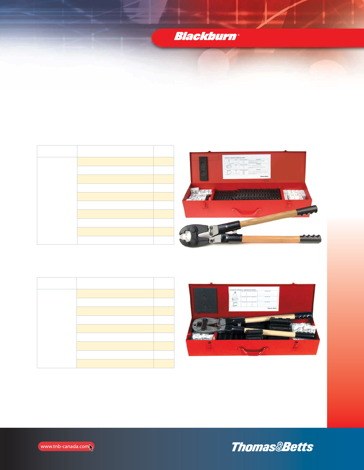
107
Installation Dies
and Tools
OD-TOOL-KIT and OD-TOOL-KIT-I
Cat. No. Kit includes Qty
OD-TOOL-KIT-I
Metallic carrying case 1
ODB1 – Blackburn®Compression Tool 1
ODH1 Insulating Heat Cover (installed on ODB1) 1
WR159 – Compression connectors 18
WR189 – Compression connectors 12
WR289 – Compression connectors 5
WR379 – Compression connectors 5
WR419 – Compression connectors 5
C5C – Insulating covers 30
C7C – Insulating covers 15
Assorted Blackburn®Die Kits
These kits are offered in a metal carrying case with heavy duty handle and sturdy
closures. The best way to carry the connectors and tools you need for commercial
and residential hook-ups.
Cat. No. Kit includes Qty
OD-TOOL-KIT
Metallic carrying case 1
ODB – Blackburn®Compression Tool 1
WR159 – Compression connectors 18
WR189 – Compression connectors 12
WR289 – Compression connectors 5
WR379 – Compression connectors 5
WR419 – Compression connectors 5
C5C – Insulating covers 30
C7C – Insulating covers 15
2_BLKBRNMRO5_E_58to167_Grounding.pdf 50 10/6/2011 1:00:58 PM
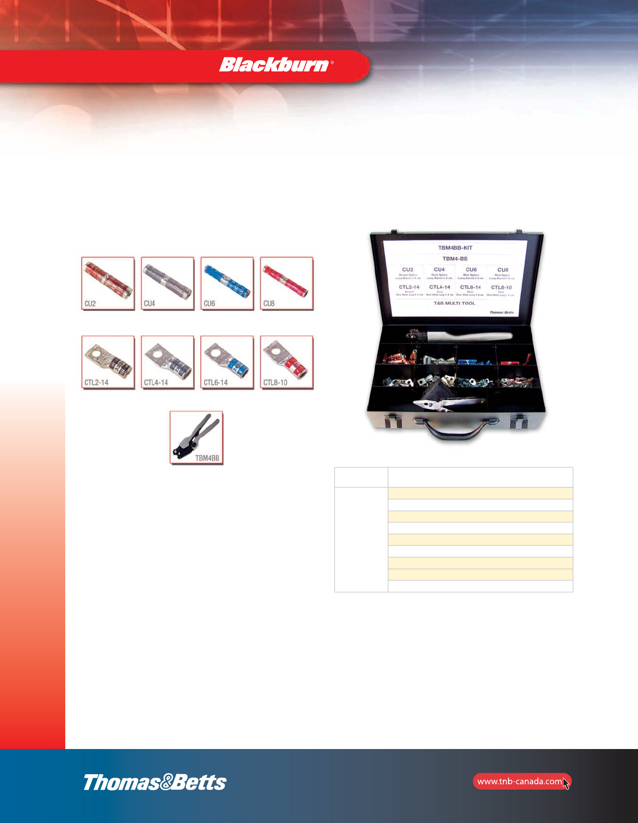
108
Installation Dies
and Tools
Assorted Blackburn®Die Kits
Cat. No. Kit includes
TBM4BB-KIT
(1) TBM4BB – Colour Coded Comfort Crimp™ Installation Tool
(25) CU2 – Long Brown Barrel #2 str. Splice
(25) CU4 – Long Grey Barrel #4 str. Splice
(25) CU6 – Long Blue Barrel #6 str. Splice
(25) CU8 – Long Red Barrel #8 str. Splice
(25) CTL2-14 – One Hole Brown Lug #2 str.
(50) CTL4-14 – One Hole Grey Lug #4 str.
(50) CTL6-14 – One Hole Blue Lug #6 str.
(50) CTL8-10 – One Hole Red Lug #8 str.
TBM4BB-KIT — Die set Kit
Comes in a metal carrying case with heavy duty handle and sturdy closures.
2_BLKBRNMRO5_E_58to167_Grounding.pdf 51 10/6/2011 1:00:58 PM

109
Installation Dies
and Tools
An Unbeatable Tool Selection
Thomas & Betts offers a complete range of tools for industrial electrical applications. This catalogue provides a look at our extensive tool
offering including manual, hydraulic, and battery-operated compression tools. You’ll also find a comprehensive die selection chart that
makes matching dies to tools fast and easy.
Whatever the application or budget, there’s a Thomas & Betts tool that will help you get the job done faster and more efficiently.
Introduction
Thomas & Betts Tool Service
Thomas & Betts Tool Service has a staff of highly trained, experienced and dedicated technicians and application specialists to support our
customers in every aspect of their tooling needs.
The Tool Service Department is capable of repairing all Thomas & Betts tools, from small tools to large hydraulic pumps and crimping heads.
The department is also responsible for warranty repairs and will supply a loaner tool when necessary.
For customers capable of repairing their own tools, Tool Service also sells the component parts. In addition, they can provide the technical data
and information required.
Other services include the calibration or certification of tools to meet applicable standards including “in house” certification of tools for larger
OEMs in conjunction with the ISO 9000 programs.
Warranty and Service Providers
Corporate Thomas & Betts
Tool Service
8735 Hamilton Road, Southaven, MS 3867
Tel.: 662-342-1545 ext. 3930
1-800-284-8665
Fax: 662-393-3929
Centre de réparation
hydraulique Uptown Ltée
464 St-Hubert
Laval, Quebec H7G 2Y9
Tel.: 514-387-6143
Fax: 450-667-8335
Trydor Industries Ltd.
1201 Franklin Street
Vancouver, British Columbia V6A 1L2
Tel.: 604-254-1695
1-800-567-8558
Fax: 604-254-6666
2_BLKBRNMRO5_E_58to167_Grounding.pdf 52 10/6/2011 1:00:58 PM

110
Direct all inquiries to the Thomas & Betts Regional Sales Office in your area.
Limited Warranty
Thomas & Betts manufactures its tools to be free of defects in material and workmanship for the time specified below. Should any defect occur
during the specified time period, Thomas & Betts will repair or replace the tool at its option.
Limitations and Exclusions
This Warranty is in lieu of all other representations and expressed and implied warranties (including the implied warranties of merchantability
and fitness for use) and under no circumstances shall Thomas & Betts be liable for any incidental or consequential property damages or losses.
This warranty is non-transferable and replacement of defective parts must be made at a facility designated by the manufacturer.
90 DAYS
• Electronically operated tools (printers, testers)
• Individual dies
2 YEARS
• Mechanical hand tools with ratchet or
Shure-Stake® mechanism
• Hydraulic pumps (battery operated tools
included)
1 YEAR
• Pneumatic tools
• Cable cutters, strippers
• ID printers
5 YEARS
• Mechanical hand tools without ratchet or
Shure-Stake® mechanism
• Hydraulic tools
(self-contained and remote heads)
Warranty and Service Providers
Installation Dies
and Tools
2_BLKBRNMRO5_E_58to167_Grounding.pdf 53 10/6/2011 1:00:58 PM

111
Installation Dies
and Tools
Connector Size Die
Colour Code TBM4BB TBM4S TBM840 TBM8-750/-1
OD58 JB12B
Copper AL Die
Cat. No.
Die
Cat. No.
8 AWG 10 AWG Red BY15C B71CH
6 AWG 8 AWG Blue BY17C B73CH
4 AWG 6 AWG Grey BY19C B74CH
2 AWG Brown BY21C B75CH
1 AWG 4 AWG Green BY53C B05CH
1/0 2 AWG Pink BY23C B06CH1
2/0 Black BY28C B72CH
3/0 Orange BY25C B08CH
4/0 Purple BY31C B09CH
250 kcmil Yellow B26CH
1 AWG Gold
1/0 Tan
2/0 Olive B09CH
3/0 Ruby
300 kcmil 4/0 White B10CH1
350 kcmil 250 kcmil Red B11CH
400 kcmil 300 kcmil Blue B11CH
925/24 Black
500 kcmil 350 kcmil Brown B12CH
600 kcmil 400 kcmil Green B36CH
Green
700 kcmil 500 kcmil Pink B76CH
750 kcmil 650 kcmil Black B39CH
800 kcmil Orange
700 kcmil Purple
900 kcmil 750 kcmil Yellow 6024 AH
1000 kcmil 800 kcmil
1000 kcmil 6030 H
Tool Die Selection Chart
This chart does not apply to catalogue
series 61905-61975, 61102-61178,
IBG2-10, IBG20-40, 63105-63180, 53000,
52000 and 15kV copper and aluminum
connectors.
For installation die information, see pages
illustrating these connector series.
On some sizes, for special flexible
strandings, consult your Regional Sales
Office.
All colour coded die series require die
adapter 15500TB for TBM15 tools only.
2_BLKBRNMRO5_E_58to167_Grounding.pdf 54 10/6/2011 1:00:58 PM

112
Installation Dies
and Tools
Tool Die Selection Chart
Connector Size Die
Colour
Code
TBM6BSCR/6H TBM14BCSR/14M/
13100A *TBM15BSCR 21940 (40-TON)
Copper AL Die
Cat. No.
Die
Code No.
Die
Cat. No.
Die
Code No.
Die
Cat. No.
Die
Code No.
Die
Cat. No.
Die
Code No.
8 AWG 10 AWG Red 6TON21 21 B71CH 21 B71CH 21 21
6 AWG 8 AWG Blue 6TON24 24 B73CH 24 B73CH 24 24
4 AWG 6 AWG Grey 6TON29 29 B74CH 29 B74CH 29 11401 29
2 AWG Brown 6TON33 33 B75CH 33 B75CH 33 11402 33
1 AWG 4 AWG Green 6TON37 37 B05CH 37 B05CH 37 11333 37
1/0 2 AWG Pink 6TON42 42 B06CH 42 B06CH1 42 11334 42
2/0 Black 6TON45 45 B72CH 45 B72CH 45 11405 45
3/0 Orange 6TON50 50 B08CH 50 B08CH 50 11406 50
4/0 Purple 6TON54 54 B09CH 54 B09CH 54H 11407 54H
250 kcmil Yellow 6TON62 62 B26CH 62 B26CH 62 297-31669-7 62
1 AWG Gold 6TON45 45 B72CH 45 B72CH 45 11405 45
1/0 Tan 6TON50 50 B08CH 50 B08CH 50 11406 50
2/0 Olive 6TON54 54 B08CH 54 B09CH 54 11407 54
3/0 Ruby 6TON60 60 60 60 11408 60
300 kcmil 4/0 White 6TON66 66H B10CH1 66H B10CH1 66H 11409 66
350 kcmil 250 kcmil Red 6TON71 71H B11CH 71H B11CH 71H 11363 71
400 kcmil 300 kcmil Blue 6TON76 76H B11CH 76H B11CH 76H 11410 76
925/24 Black 6TON80 80H 80H 80H
Black 80
500 kcmil 350 kcmil Brown 6TON87 87H B12CH 87H B12CH 87H 11423 87
600 kcmil 400 kcmil Green 6TON94 94H B36CH 94H 11364 94
Green 94H
700 kcmil 500 kcmil Pink 99H B76CH 99H 11424 99
750 kcmil 650 kcmil Black 106H B39CH B39CH 106H 74506 106
800 kcmil Orange 107H 107H 11425 107
700 kcmil Purple 112H 112H 11426 112
900 kcmil 750 kcmil Yellow 115H 115H 11308 115
1000 kcmil 800 kcmil 125H 11416 125
1000 kcmil 140H 11418 140
150H 11419 150
*Colour coded dies require 15500TB adapter when used with TBM15BSCR tool.
2_BLKBRNMRO5_E_58to167_Grounding.pdf 55 10/6/2011 1:00:58 PM

113
Installation Dies
and Tools
Short Barrel — Types CTL, CTL-2 and CSP
Blackburn Tools Burndy Tools T&B Tools Anderson Tools
Stranded
Copper Die Crimps Crimps Crimps Crimps Hyd. Crimps Crimps Crimps Crimps CU VC6†VC7†
Wire Colour Mech. per Mech. per Hyd. per Mech. per Y35, per Mech. per Mech. per Hyd. per Wire VC6F†VC7F†VC8C††
Size Code 0D58 End HM-250 TOOL End JB12B End MY29-3 End Y39, Y46 End TBM5S End TBM8S End TBM15 End Range Crimps per End
8 Red 7/32 3 ** 1 B71CH 1 ** 1 13454 2 13461 2 21 2
J
6 Blue 1/4 3 ** 1 B73CH 1 ** 1 U5CRT 2 13454 2 13461 2 24 2
4 Grey 5/16 3 ** 1 B74CH 1 ** 1 U4CRT 2 13454 2 13461 2 29 2
3 White ** 2 ** 2 U3CRT 2
2 Brown 3/8 4 ** 2 B75CH 1 ** 2 U2CRT 2 13454 2 13461 2 33 2 6-2 1* 2
1 Green P 4 ** 2 B05CH 1 ** 2 U1CRT 2 13455 3 13462 3 37 2 6-1 1 2
1/0 Pink 1/2 4 ** 2 B06CHI 2 ** 2 U25RT 2 13455 3 13462 3 42H 3 6-1/0 1 2
2/0 Black 17/32 4 ** 2 B72CH 1 ** 2 U26RT 2 13455 3 13462 3 45 2 4-2/0 1 2
3/0 Orange 9/16 4 ** 2 B08CH 1 ** 2 U27RT 2 13455 4 13462 4 50 2 2-3/0 2 2
4/0 Purple 5/8-1 4 ** 2 B09CH 2 ** 2 U28RT 2 13456 4 13463 4 54H 3 1-4/0 2 2
250 Yellow 11/16 4 ** 2 B26CH 2 ** 2 U29RT 2 13456 4 13463 4 62 2 1/0-250† 2 2
300 White B10CHI
B10CH 2 U30RT 2 13465 4 66 2 2/0-300† 2 2
350 Red B11CH 2 U31RT 2 13465 4 71H 3 3/0-350† 2 3
400 Blue B11CH 2 U32RT 3 13467 4 76 2 4/0-400† 2 3
500 Brown B12CHI
B12CH 2 U34RT 3 13468 5 87H 3 4/0-500† 2 3
600 Green B36CH13 U36RT33 94H 3 250-600 3
VC7FT
only
750 Black B39CH1
3
1 U39RT33 106H 3 500-750 4
VC7FT
only 2
1000 — 1 P44RT44 125H 4 750-1000 2
* CSA Listed range 4-2 with YC6 and VC6FT.
** Adjustable Indent Tool. No insert dies required.
1 HCT7508-12, HCT1239, HCT7508H only.
3 Y39, Y46 only.
4 Y46 only.
† Users of VC6 and VC7 tools must strip off an extra 1-5/8” of insulation from end of cable to permit removal of tool over conductor sizes
250 kcmil and larger on CSP connectors.
†† Also use VC8 tool with aluminum nibs.V.C8 tool crimps 500 MCM only
†††† VC8 tool crimps 500-600 MCM only
Tool and Die Index for Copper Compression Connectors
2_BLKBRNMRO5_E_58to167_Grounding.pdf 56 10/6/2011 1:00:59 PM

114
Tool and Die Index for Copper Compression Connectors
Long Barrel — Types CTL-L, LCN and CU
Blackburn Tools Burndy Tools T&B Tools Anderson Tools
Stranded
Copper Die Crimps Crimps Crimps Crimps Hyd. Crimps Crimps Crimps Crimps CU VC6†VC7†
Wire Colour Mech. per Mech. per Hyd. per Mech. per Y35, per Mech. per Mech. per Hyd. per Wire VC6F†VC7F†VC8C††
Size Code 0058 End HM-250 TOOL End JB12B End MY29-3 End Y39, Y46 End TBM5S End TBM8S End TBM15 End Range Crimps per End
8 Red 7/32 4 ** 2 B71CH 2 ** 2 13454 2 13461 2 21 3
J
6 Blue 1/4 4 ** 2 B73CH 2 ** 2 U5CRT 2 13454 2 13461 2 24 3
4 Grey 5/16 4 ** 2 B74CH 2 ** 2 U4CRT 2 13454 2 13461 2 29 3
3 White ** 3 ** 2 U3CRT 2
2 Brown 3/8 5 ** 3 B75CH 2 ** 3 U2CRT 2 13454 2 13461 2 33 3 6-2 2 4
1 Green P 5 ** 3 B05CH 2 ** 3 U1CRT 2 13455 4 13462 3 37 3 6-1 2 5
1/0 Pink 1/2 5 ** 3 B06CHI 2 ** 3 U25RT 2 13455 4 13462 4 42H 4 6-1/0 2 5
2/0 Black 17/32 5 ** 3 B72CH 2 ** 3 U26RT 2 13455 4 13462 4 45 3 4-2/0 2 5
3/0 Orange 9/16 5 ** 4 B08CH 2 ** 4 U27RT 3 13455 6 13462 6 50 3 2-3/0 3 6
4/0 Purple 5/8-1 6 ** 4 B09CH 3 ** 4 U28RT 3 13456 6 13463 6 54H 5 1-4/0 3 6
250 Yellow 11/16 6 ** 4 B26CH 3 ** 4 U29RT 3 13456 6 13463 6 62 3 1/0-250 3 6
300 White B10CHI
B10CH 3 U30RT 3 13465 6 66 3 2/0-300 3 6
350 Red B11CH 3 U31RT 4 13465 6 71H 4 3/0-350 3 6
400 Blue B11CH 4 U32RT 4 13467 6 76 3 4/0-400 3 6
500 Brown B12CHI
B12CH 4 U34RT 5 13468 8 87H 4 4/0-500 3 6 2†††
600 Green B36CH16 U36RT35 94H 4 250-600 8
VC7FT
only 3††††
750 Black B39CH1
6
2 U39RT36 106H 6 500-750 9
VC7FT
only
4
1000 — 2 P44RT46 125H 5 750-1000 2
** Adjustable Indent Tool. No insert dies required.
1 HCT7508-12, HCT1239, HCT7508H only.
3 Y39, Y46 only.
4 Y46 only.
† Users of VC6 and VC7 tools must strip off an extra 1-5/8” of insulation from end of cable to permit removal of tool over conductor sizes
250 kcmil and larger on CU connectors.
†† Also use VC8 tool with aluminum nibs.
††† VC8 tool crimps 500 kcmil only.
†††† VC8 tool crimps 500-600 kcmil only.
Installation Dies
and Tools
2_BLKBRNMRO5_E_58to167_Grounding.pdf 57 10/6/2011 1:00:59 PM

115
Installation Dies
and Tools
For Flexible Rope Stranded or Flexible Stranded Tinned Copper
Locomotive Conductor Welding Cable and Portable Cord
Short Barrel — Types CTL, CTL-2 and CSP
Conductor Type Blackburn Tools Burndy Tools T&B Tools Anderson Tools
Stranded Hyd. CU Wire
Flex CU Die Crimps Crimps Y35 Crimps Crimps Range for VC6†VC7†
Stranded Locomotive Welding Portable AWG Colour Hyd. per Mech. per Y39 per Hyd. per Locomotive VC6FT VC7FT VC8C††
Size Stranding Cable Cord Size Code JB12B End MY29-11 End Y46 End TBM15 End Cable Crimps per End
6 37/24 — 8 8 Red B71CH 1 ** 1 — — 21 2
6 61/24 6 6 6 Blue B73CH 1 ** 1 U5CD-1
Y34PR31242
5 91/24 4 Grey B74CH 1 ** 1 U4CD-1
Y34PR 1 29 2
4 105/24 4 4 3 White ** 2 U3CD-1
Y34PR 1
3 125/24 3 3 2 Brown B75CH 1 ** 2 U2CD-1
Y34PR 1 33 2 4-3 1 2
2 150/24 2 2 1 Green B05CH 1 ** 2 U1CD-1
Y34PR 1 37 2 4-2 1 2
1 225/24 1 1 1/0 Pink B06CHI 2 ** 2 U250-1
Y34PR 1 42H 3 4-1 1 2
1/0 275/24 1/0 1/0 2/0 Black B72CH 1 ** 2 U26CD-1
Y34PR 1 45 2 4-1/0 1 2
2/0 325/24 2/0 2/0 3/0 Orange B08CH 1 ** 2 U270-1
Y34PR 2 50 2 2-2/0 2 2
— — 3/0 3/0 4/0 Purple B09CH 2 ** 2 U280-1
Y34PR 2 54H 3
3/0 450/24 4/0 250 Yellow B26CH 2 ** 2 U290-1
Y34PR32 62 2 1/0-3/0†22
4/0 550/24 4/0 300 White B12CHI
B12CH 2 U300-1
Y34PR32 66 2 2/0-4/0†2
263 650/24 300 Red B11CH 2 U310-1
Y34PR32 71H 3 3/0-263†23
313 775/24 400 Blue B11CH 2 Y320-1
Y34PR32 76 2 4/0-313†23
373 925/24 500 Brown B10CHI
B10CH 2 U340-1
Y34PR387H 3 4/0-373†23 2
†††
444 1100/24 600 Green B36CH 3 C360 3
Y46PR42 94H 3 262-444 VC7FT
Only 2†††
535 1325/24 750 Black B39CH1
1 C390 4
Y46PR42 106H 3 373-535 VC7FT
Only 2
646 1600/24
777 1925/24 1000 — 1 C440
Y46PR42 125H 4 535-777 2
** Adjustable Indent Tool. No insert dies required.
1 HCT7508-12, HCT1239, HCT7508H only.
3 Y39 only.
4 Y48B only.
† User of VC6 and VC7 tools must strip off an extra 1-5/8” of insulation from end of cable to permit removal of tool over conductor sizes
250 kcmil and larger on CSP connectors.
†† Also use VC8 tool with aluminum nibs.
††† VC8 tool crimps 500 kcmil only.
Tool and Die Index for Copper Compression Connectors
2_BLKBRNMRO5_E_58to167_Grounding.pdf 58 10/6/2011 1:00:59 PM

116
Installation Dies
and Tools
Tool and Die Index for Copper Compression Connectors
Long Barrel — Types CTL-L, LNC and CU
Conductor Type Blackburn Tools Burndy Tools T&B Tools Anderson Tools
Stranded Hyd. CU Wire
Weld- Port- CU Die Crimps Crimps Y35 Crimps Crimps Range for VC6†VC7†
Locomotive ing able AWG Colour Hyd. per Mech. per Y39 per Hyd. per Locomotive VC6F†VC7F†VC8C††
Size Stranding Cable Cord Size Code JB12B End MY29-11 End Y46 End TBM15 End Cable Crimps per End
8 37/24 — 8 8 Red B71CH 2 ** 2 — — 21 3
6 61/24 6 6 6 Blue B73CH 2 ** 2 U5CD-1
Y34PR32243
5 91/24 4 Grey B74CH 2 ** 2 U4CD-1
Y34PR 2 29 3
4 105/24 4 4 3 White ** 3 U3CD-1
Y34PR 2
3 125/24 3 3 2 Brown B75CH 2 ** 3 U2CD-1
Y34PR 2 33 3 4-2 2 4
2 150/24 2 2 1 Green B05CH 2 ** 3 U1CD-1
Y34PR 2 37 3 4-2 2 5
1 225/24 1 1 1/0 Pink B06CHI 3 ** 3 U250-1
Y34PR 2 42H 4 4-1 2 5
1/0 275/24 1/0 1/0 2/0 Black B72CH 2 ** 3 U26CD-1
Y34PR 2 45 3 4-1/0 2 5
2/0 325/24 2/0 2/0 3/0 Orange B08CH 2 ** 4 U270-1
Y34PR 2 50 3 2-2/0 3 6
— — 3/0 3/0 4/0 Purple B09CH 3 ** 4 U280-1
Y34PR 3 54H 5
3/0 450/24 4/0 250 Yellow B26CH 3 ** 4 U290-1
Y34PR33 62 3 1/0-3/0† 3 6
4/0 550/24 4/0 300 White B12CHI
B12CH 3 U300-1
Y34PR33 66 3 2/0-4/0† 3 6
263 650/24 350 Red B11CH 3 U310-1
Y34PR33 71H 4 3/0-263† 3 6
313 775/24 400 Blue B11CH 2 Y320-1
Y34PR33 76 3 4/0-313† 3 6
373 925/24 500 Brown B2CHI
B12CH 4 U340-1
Y34PR387H 3 4/0-373† 3 6 3†††
444 1100/24 600 Green B36CH 6 C360 8
Y46PR42 94H 4 262-444 VC7FT
Only 3†††
535 1325/24 750 Black B39CH1
2 C390 9
Y48PR4 2 106H 6 373-535 VC7FT
Only 4
646 1600/24
777 1925/24 1000 — 2 C440
Y46PR42 125H 5 535-777 4
1111 2750/24 1500 — 2 C460
Y46PR42 — — 1111 — — 4
** Adjustable Indent Tool. No insert dies required.
1 HCT7508-12, HCT1239, HCT7508H only.
3 Y39 only.
4 Y48B only.
† Users of VC6 and VC7 tools must strip off an extra 1-5/8” of insulation from end of cable to permit removal of tool over conductor sizes
250 kcmil and larger on CU connectors.
†† Also use VC8 tool with aluminum nibs.
††† VC8 tool crimps 500 kcmil only.
2_BLKBRNMRO5_E_58to167_Grounding.pdf 59 10/6/2011 1:00:59 PM

117
Installation Dies
and Tools
Tool and Die Index for Copper Compression Connectors
One and two hole Lugs, Splices — Types ATL and ASP
Blackburn Tools Burndy Tools T&B Tools Anderson Tools
Stranded Stranded Stranded VC6†
AL CU Die Crimps Crimps Crimps Crimps Hyd. Crimps Crimps Crimps Crimps AL or CU VC6FT VC8C
Wire Wire Colour Mech. per Mech. per Hyd. per Mech. per Y35 per Mech. per Mech. per Hyd. per Wire Crimps
Size Size Code 0D58 End HM-250 TOOL End JB12B End MY29-3 End Y39 End TBM5S End TBM8S End TBM15 End Range per End
8 6 Blue 1/4 2 ** 1 B73CH 1 ** 1 U8CABT 1 13454 2 13461 2 24 2
6 4 Grey 5/16 2 ** 1 B74CH 1 ** 1 U6CABT 2 13454 2 13461 2 29 2
4 1 Green P 3 ** 2 B05CH 1 ** 2 U4CABT 2 13455 2 13462 2 37 2
2 1/0 Pink 1/2 4 ** 2 B06CHI 2 ** 2 U2CABT 2 13455 3 13462 3 42H 3 6-2 2
1 Gold 1/2-1 3 ** 2 B06CHI 2 ** 2 U1CABT 2 13455 3 13464 3 45 2 4-1 2
1/0 Tan 9/16 4 ** 2 B08CH 2 ** 2 U25ART 2 13457 3 13464 3 50 2 6-1/0 2
2/0 Olive 5/8-1 4 ** 2 B09CH 2 ** 2 U26ART 2 13457 3 13464 3 54H 3 4-2/0 2
3/0 Ruby 688 5 ** 2 B26CH 2 ** 2 U27ART 2 13457 3 13464 3 60 2 4-3/0 2
4/0 300 White 781 5 ** 2 B10CHI 2 ** 2 U28ART 2 13457 3 13465 4 66 3 2-4/0 2
250 350 Red 781 5 ** B11CH 3 ** 2 U29ART 2 13473 4 13466 5 71H 4 1/0-250†2
300 400 Blue 840 B11CH 3 U30ART 2 76 2 1/0-300†
350 500 Brown B12CHI 4 U31ART 2 13468 7 87H 4 2/0-350†2
400 600 Green B36CH 6 U32ART 4 94 2 3/0-400†2
500 700 Pink B76CH 4 U34ART 4 99H 4 4/0-500†2
600 Black B39CH 2 U36ART 4 106 2 350-600 AL
350-600 CU 3††
750 900 6024AH11 U39RT224 U39ART-234 125H 5 500-750 AL
600 CU 2†††
1000 — 6030AH12 P44ART23 150H 5 750-1000 AL 2†††
** Adjustable Indent Tool. No insert dies required.
1 HCT7508-12, HCT1239, HCT7508H only.
2 Y46 only.
3 Y39 only.
† Users of VC6 and VC7 tools must strip off an extra 1-5/8” of insulation from end of cable to permit removal of tool over conductor sizes
250 kcmil and larger on ASP connectors.
†† VC6FT tool only.
††† With AL nibs for VC8C.
2_BLKBRNMRO5_E_58to167_Grounding.pdf 60 10/6/2011 1:00:59 PM
Fig. 2 Fig. 1
118
Installation Dies
and Tools
Installing Dies
Gauging Information for Standard Hex Dies
Blackburn and T&B
12,
14- & 15-Ton Tools
21940 Hex
Die Code TBM6H Colour Coded Dies Dies Gaging
Red 6 ton 21 B71CH — .191-.207
Blue 6 ton 24 B73CH — .222-.234
27 — 11330 .262-.268
Grey 6 ton 29 B74CH 11401 .282-.294
32 — 11332 .329-.335
Brown 6 ton 33 B75CH 11402 .326-.337
35 — *11403 .353-.359
Green 6 ton 37 B05CH 11333 .369-.383
40 — *11404 .397-.403
42 15508F 11334 .409-.423
Pink 6 ton 42 B06CHI — .409-.423
Black 6 ton 45 B08CH 11405 .445-.459
Orange 6 ton 50 B09CH 11406 .494-.506
Olive B09CH 11407 .535-.553
Purple 6 ton 54 B09CH — .535-.553
57 — — .585-.591
58 — 11338 .585-.591
60 6 ton 60 — 11408 .587-.605
Yellow 6 ton 62 B06CH 11340 .613-.631
White 6 ton 66 B10CHI 11409 .657-.675
66H — — .657-.675
Red B11CH 11363 .707-.725
Red 6 ton 71 B11CH — .707-.725
Blue 6 ton 76 B11CH 11410 .751-.769
76H — — .751-.769
78 — 11306 .751-.769
80 6 ton 80 — 11411 .790-.802
— 15517 .790-.802
83 — *11370 .825-.831
* Obsolete, consult your Regional Sales Office for availability.
Gauges may be ordered from T&B Tool Service.
Hex
Gauging
Gauging Information for Standard Hex Dies
T&B
14- & 15-Ton Tools 21940 Hex
Die Code TBM6H Dies Dies Gaging
87 — 11423 .861-.879
Brown 6 ton 87 B12CH — .861-.879
94 — 11364 .935-.953
94H — — .935-.953
96 — 11304 .959-.977
96H — — .959-.977
99 — 11424 .979-.997
99H — — .979-.997
100 — 11365 1.005-1.011
106A — — 1.049-1.071
Black B39CH — 1.049-1.071
107 — 11425 1.064-1.076
107H — — 1.064-1.076
112 — 11426 1.118-1.131
112H — — 1.118-1.131
115 — 11308 1.141-1.163
115H — — 1.141-1.163
125 — 11416 1.239-1.261
125H — — 1.239-1.261
126 — 11443 1.247-1.253
130 — 11417 1.299-1.305
138 — 11366 1.377-1.383
140 — 11418 1.369-1.391
140H — — 1.369-1.391
150 — 11419 1.459-1.481
150H — — 1.459-1.481
160 — 11442 1.609-1.615
161 — 11420 1.609-1.615
168 — 11447 1.684-1.690
175 — 11421 1.752-1.744
204 — 11448 2.037-2.043
212 — 11449 2.120-2.126
214 — 11337 2.140-2.146
Gauges may be ordered from T&B Tool Service.
Hex
Gauging
2_BLKBRNMRO5_E_58to167_Grounding.pdf 61 10/6/2011 1:00:59 PM
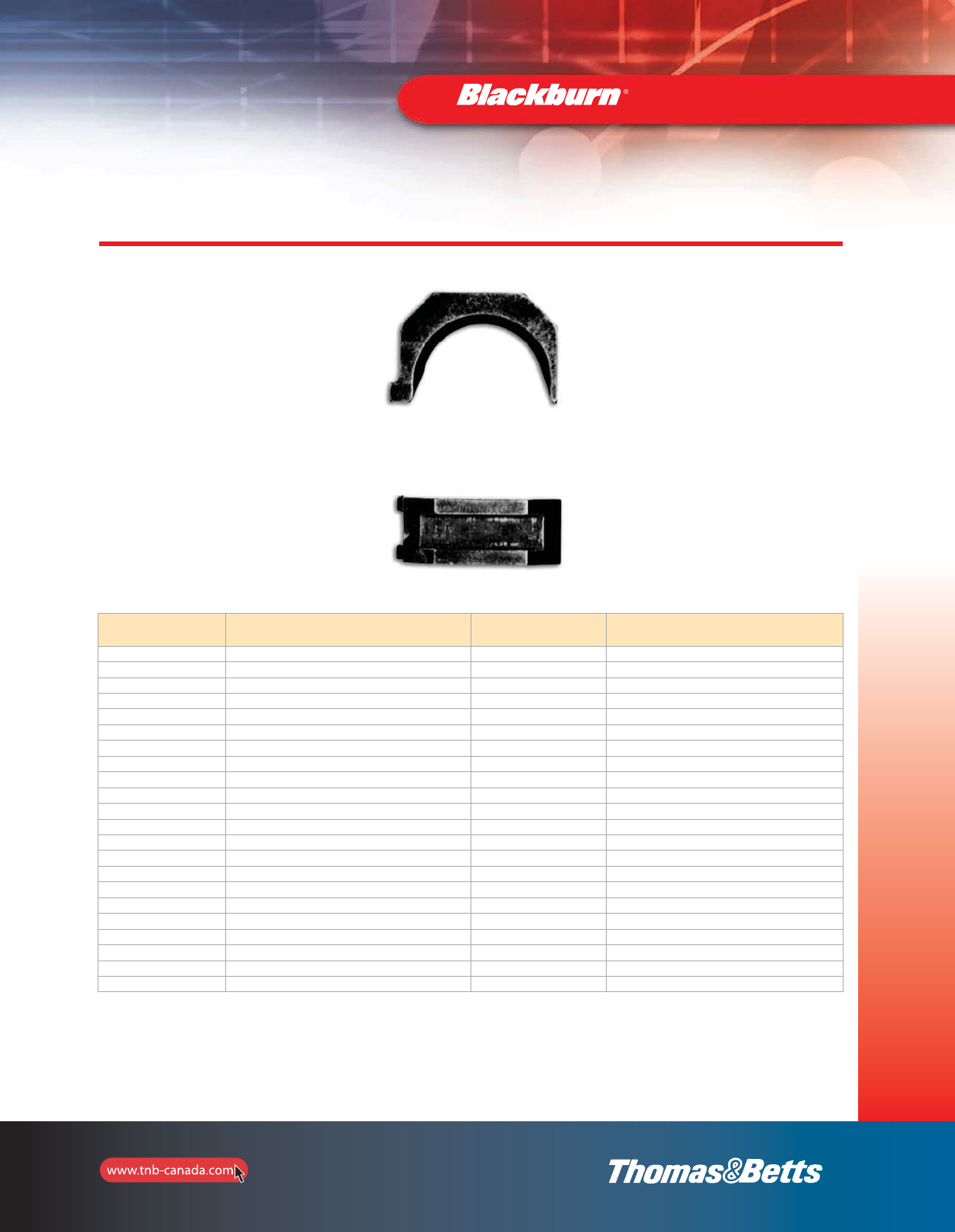
119
Installation Dies
and Tools
Cat. No. Description
or Colour Codes Cat. No. Description
or Colour Codes
OJB 0BY37 840 (EEI 11A)
DBL DBY55 Wire Cutter (2/0 max.)
BY39 510 Hex (non-bow) BY63 Orange (Nicopress)
BY41 635 Hex (non-bow) BY65 Plum
BY43 747 Hex (non-bow) BY15C* 7/32 Red
BY45 TBY17C* 1/4 Blue
BY47 KBY19C* 5/16 Grey
BY49 BBY21C* 3/8 Brown
BY51 JBY23C* 1/2 Pink
BY53 PBY24C* 1/2–1 Gold
BY13 3/16 BY25C* 9/16 Tan/Orange
BY15* 7/32 (EEI–1 index 236) BY27C* 11/16 Yellow
BY17 1/4 BY31C* 5/8–1 Olive/Purple
BY19 5/16 (index 161.242) BY32C* Ruby
BY21 3/8 BY35C* 781 White
BY23 1/2 (index 163) BY37C* 840 Red
BY25 9/16 BY28C* 17/32 Black
BY27 11/16 BY53C* P Green
BY29 19/32 BG1 Canvas Bag for OD58
BY31 5/8–1 (index 165) ODH1 Insulating Head Cover
BY33 737
BY35 781
*Can also be used with OD58 tool.
Insert Dies for TBM6H Hydraulic Head and Type OD Tools
Installing Dies
2_BLKBRNMRO5_E_58to167_Grounding.pdf 62 10/6/2011 1:00:59 PM
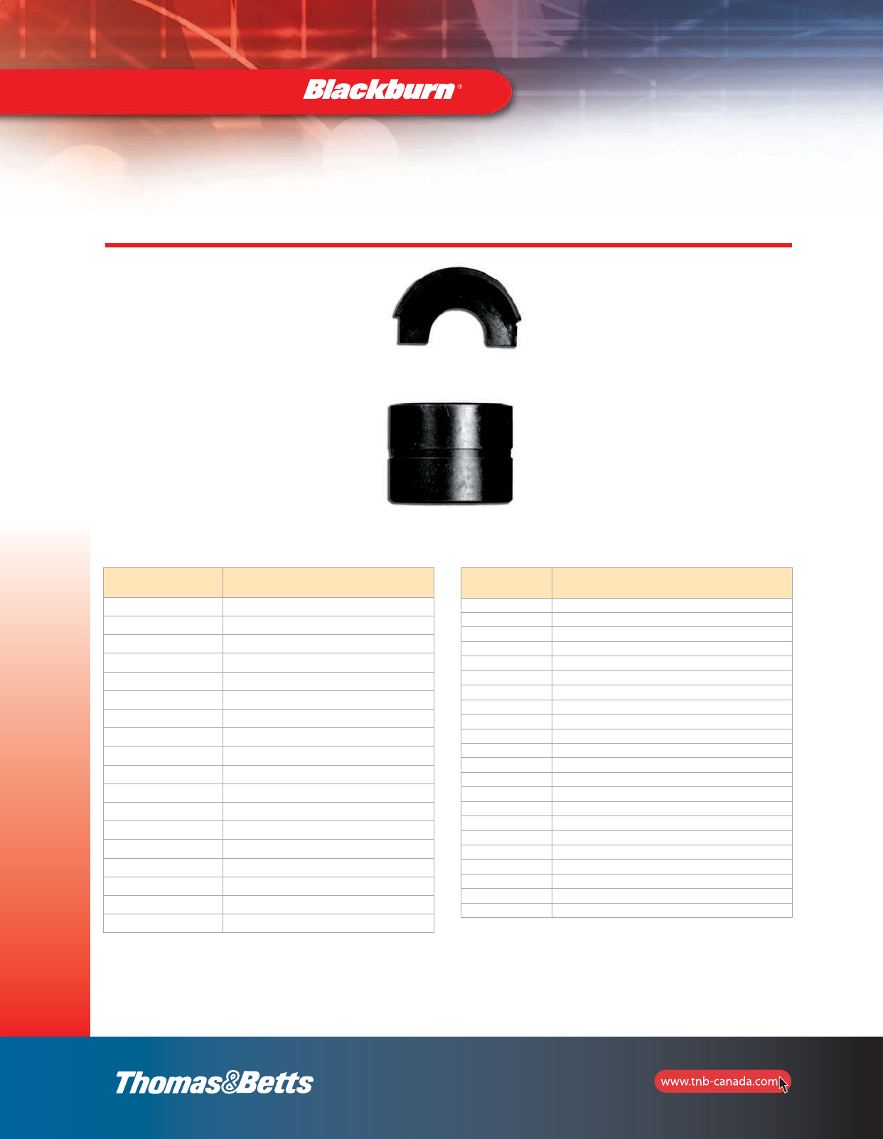
120
Installation Dies
and Tools
Cat. No. Description or Colour Codes
B58CS 5/8 Die Set
HO “O” Die Set
HD “D” Die Set
HN “N” Die Set
HU “U” Die Set
HBKC BKC
HBKT BKT
B24EA EEI 8A
B30EA EEI 9A
B39EA EEI 10A
B49EA EEI 11A (840)
B61EA EEI 12A
B80EA EEI 13A
B20AH EEI14A
B71AH –
B72AH –
B73AH –
B74AH –
Insert Dies for Hydraulic Heads* JB12B, 13100A, TBM14M, TBM14MC, TBM14BSCR,
TBM14RH, TBM15I, TBM15BSCR, BPLT14BSCR, BPLT15BSCR
*Adaptor 15500-TB required with T&B 15-ton tools.
Installing Dies
Cat. No. Description or Colour Codes
B75AH –
B76AH –
B76SH –
B06CHI Pink/Gold 1/0 AWG CU – 2 AWG AL
B08CH Tan/Orange 3/0 AWG CU – 1 AWG AL
B09CH Olive/Purple 4/0 AWG CU – 2/0 AWG AL
B11CH Red/Blue 350/400 kcmil CU – 250-300 kcmil AL
B10SH –
B05CH Green #1 AWG CU – 4 AWG AL
B26CH Ruby/Yellow 250 kcmil CU, 3/0 AWG AL
B71CH Red #8 AWG CU – 10 AWG AL
B72CH Black 2/0 AWG CU
B73CH Blue #6 AWG CU – 8 AWG AL
B74CH Grey #4 AWG CU – 6 AWG AL
B75CH Brown #2 AWG CU
B76CH Pink 700 kcmil CU – 500 kcmil AL
B10CHI White 300 kcmil CU – 4/0 AWG AL
B12CHI Brown 500 kcmil CU – 350 kcmil AL
B36CH Green 600 kcmil CU – 400 kcmil AL
B39CH Black 750 kcmil CU – 600 kcmil AL
6024AH Yellow 900 kcmil CU – 750 kcmil AL
6030H No colour 1000 kcmil AL only
2_BLKBRNMRO5_E_58to167_Grounding.pdf 63 10/6/2011 1:01:00 PM
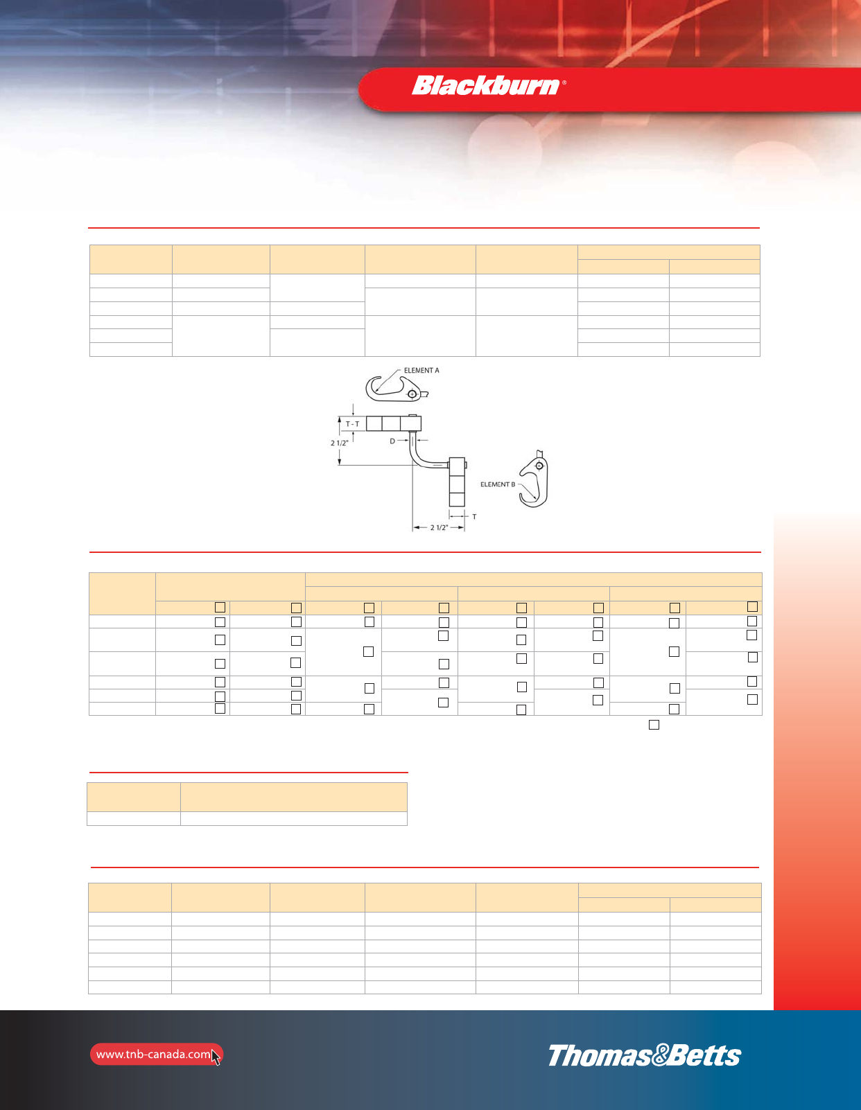
121
Installation Dies
and Tools
Installing Dies
Cat. No. Cable Element A To Cable Element B To Ground Rod Element A To Rebar Element B Die Selection
Element A Element B
54855L #6 sol. – #2 str. #6 sol. – #2 str. – – 15501A 15501A
54865L #1 str. – 250 kcmil 1/2” – 5/8” Rod 3/8” – 1/2” #3 – #4 Rebar 15501A 15G86R
54875L #2 str. – 250 kcmil #2 str. – 250 kcmil 15G86R 15G86R
54885L
250 kcmil – 500 kcmil
#6 sol. – #2 str.
5/8” – 3/4” Rod 5/8” – 3/4” #3 – #4 Rebar
15501A 15G126R
54895L #2 str. – 250 kcmil 15G86R 15G126R
54900L 15G121R 15G121R
Cat. No.
Dies for T&B
14- and 15-Ton Tools
Burndy Tools and dies
Y750 Y45 Y46
Element A Element B ABABAB
54900L 15G121R 15G121R U1011 U1011 S1011 S1011 P1011 P1011
54895L 15G86R 15G126R PU998
or PU998
U997 S998
or PU998
U997
P998
U997
54885L 15501A 15G126R U-0
or PU998
S998 U-0 U-0
54875L 15G86R 15G86R U997 U997 U997 U997 U997 U997
54865L 15501A 15G86R U-0 U-0 U-0
54855L 15501A 15501A U-0 U-0 U-0
Dies for Figure 6 to 6 – Ground Connectors and Cross Reference
**
3
1
1
1
1
3
1
1
11
*
3
1
1
1
3
1
1
1
*
1
3
1
1
1
*
1
3
1
1
1
*
1
3
1
1
1
*
3
1
1
1
1
Use 15500-TB adaptor for T&B 15-ton tools.
*
*= Number of crimps
1
1
Dies for Figure 6 to 6 — Ground Connectors
Cat. No. Description
15500TB To be used with TBM15I tool only
Die Adapters
Cat. No. Cable
Element A
To Cable
Element B
To Ground Rod
Element B
To Rebar
Element B
Die Selection
Element A Element B
54855L #6 Sol. - #2 Str. #6 Sol. - #2 Str – – 15501A 15501A
54865L #1 Str. - 250 kcmil #6 Sol. - #2 Str. 1/2” - 5/8” Rod 3/8” - 1/2” #3 - #4 Rebar 15G86R 15501A
54875L #2 Str. - 250 kcmil #2 Str. - 250 kcmil 1/2” - 5/8” Rod 3/8” - 1/2” #3 - #4 Rebar 15G86R 15G86R
54885L 250 kcmil - 500 kcmil #6 Sol. - #2 Str. 5/8” - 3/4” Rod 5/8” - 3/4” #5 - #6 Rebar 15G126R 15501A
54895L 250 kcmil - 500 kcmil #2 Str. - 250 kcmil 5/8” - 3/4” Rod 5/8” - 3/4” #5 - #6 Rebar 15G126R 15G86R
54900L 250 kcmil - 500 kcmil #2 Str. - 250 kcmil 5/8” - 3/4” Rod 5/8” - 3/4” #5 - #6 Rebar 15G121R 15G121R
Installation Dies for Figure 6 and Figure 8 — Ground Connectors
2_BLKBRNMRO5_E_58to167_Grounding.pdf 64 10/6/2011 1:01:00 PM
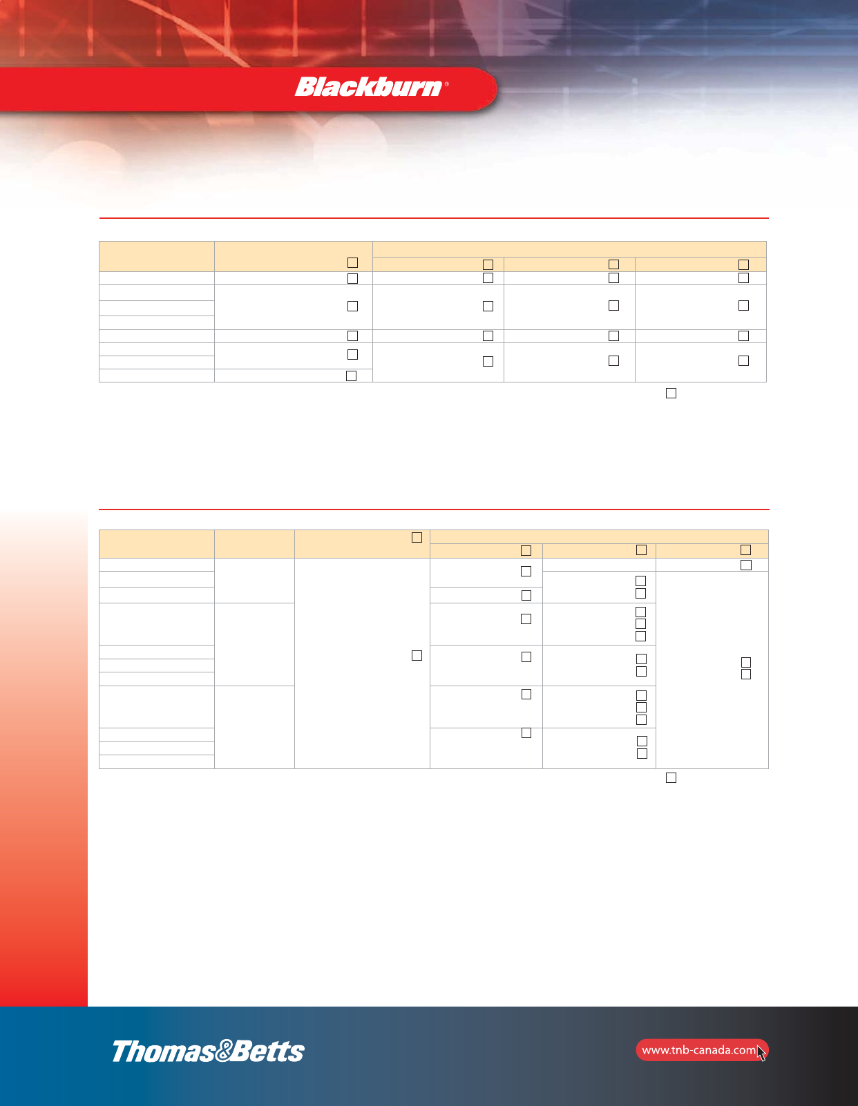
122
Installing Dies
Installation Dies
and Tools
Cat. No. Dies for T&B
14- and 15-Ton Tools
Burndy Tools and dies
Y750 Y45 Y46
54900 15G121R U1011 S1011 P1011
54895
15G126R PU998 PU996
or S998
PU996
or S998
54890
54885
54875 15501A UO UO UO
54865CK 15G86R 997 U997 U997
54860
54855 15G86R
Dies for Figure 6 — Ground Connectors and Cross Reference
*
3
1
1
1
Use 15500-TB adaptor for T&B 15-ton tools. *= Number of crimps
*
3
1
1
1
*
3
1
1
1
*
3
1
1
1
Cat. No. Cable Range Dies for T&B
14- and 15-Ton Tools
Burndy Tools and dies
Y750 Y45 Y46
GR1-300500*
300-500 kcmil
15G121R
U1011 S1011 P1011
GR34-300500 & TP* S1012
or PU998
P1011
or PU998
GR58-30050 & TP PU998
GR1-40250*
4/0 AWG-250 kcmil
U1011
S1011
S1012
or PU998
GR34-40250 & TP*
PU998 S1012
or PU998
GR58-40250 & TP
GR12-40250 & TP
GR1-202*
2 AWG-2/0 AWG
U1011
S1011
S1012
or PU998
GR34-202 & TP
PU998 S1012
or PU998
GR58-202 & TP
GR12-202 & TP
*
22
1
Optional ground rod knurling die for TBM 14- and 15-ton tools: 15508.
Use 15500-TB adaptor for T&B 15-ton tools.
Optional ground rod knurling tool: 240-31565-94.
*Use 15-ton tool only.
*= Number of crimps
*
2
*
2
1
2
1
2
1
*
2
1
2
1
2
2
1
2
2
1
2
1
Dies for Figure 8 — Ground Connectors and Cross Reference
1
2_BLKBRNMRO5_E_58to167_Grounding.pdf 65 10/6/2011 1:01:00 PM
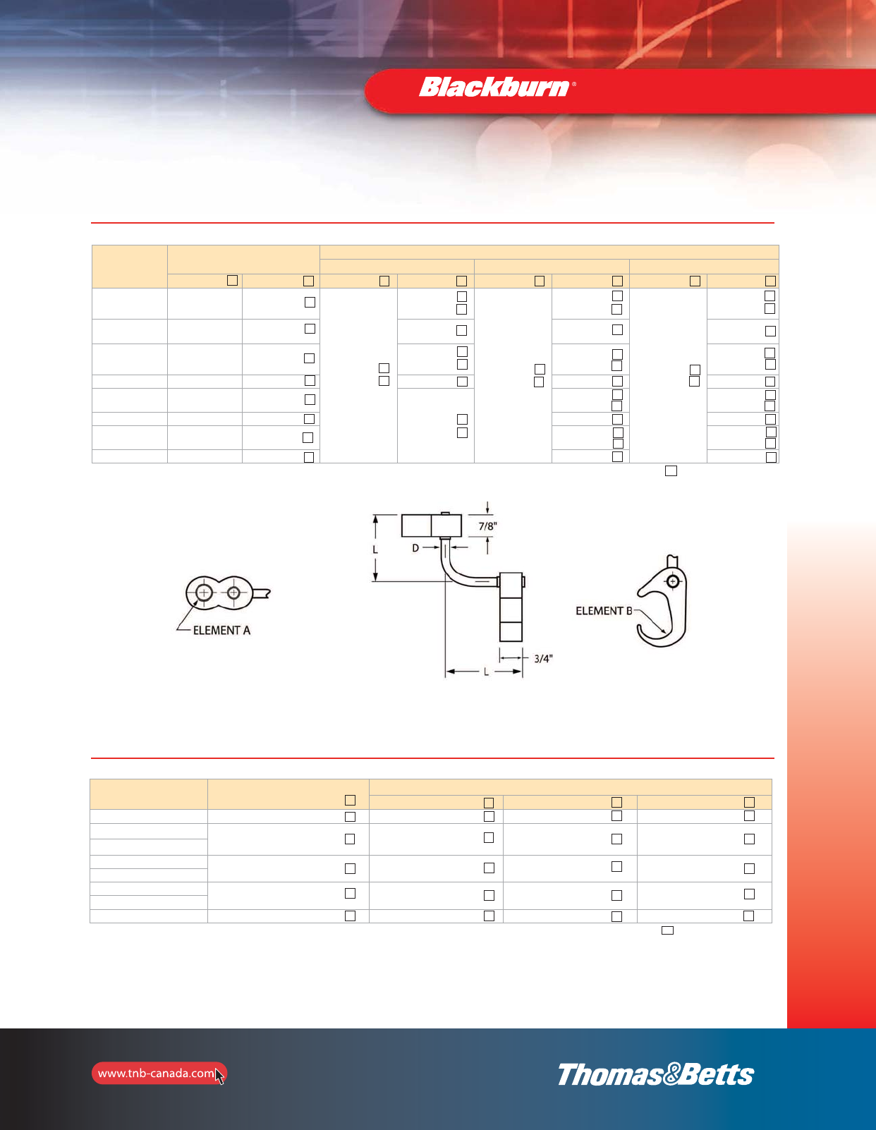
123
Installation Dies
and Tools
Installing Dies
Cat. No.
Dies for T&B
14- and 15-Ton Tools
Burndy Tools and dies
Y750 Y45 Y46
Element A Element B ABABAB
54920LR100 15G121R 15G126R
U1011
or PU998
U1011
or PU998
S1011
or PU998
U1011
or PU998
P1011
or PU998
U1011
or PU998
54910LR100 15G121R 15G86R U997 U997 U997
54900L34 & TP 15G121R 115G126R U1011
or PU998
U1011
or PU998
U1011
or PU998
54875L34 & TP 15G121R 15G86R U997 U997 U997
54895LR58 & TP 15G121R 15G126R
U1011
or PU998
S998
or PU998
P998
or PU998
54865L58 & TP 15G121R 15G86R U997 U997
54885LR12 & TP 15G121R 15G126R S998
or PU998
P998
or PU998
54855LR12 & TP 15G121R 15G86R U997 U997
Dies for Figure 6 to 8 — Ground Connectors and Cross Reference
**
1
1
1
1
*
2
1
1
*
2
*
1
2
1
1
2
*
12
1
*
2
1
1
2
1
*
*= Number of crimps
1
1
1
0
1
2
Optional ground rod knurling die for TBM 14- and 15-ton tools: 15508.
Use 15500-TB adaptor for T&B 15-ton tools.
Optional ground rod knurling tool: 240-31565-94.
1
2
1
2
1
1
1
1
1
1
1
1
1
1
1
1
1
1
1
Cat. No. Dies for T&B
14- and 15-Ton Tools
Burndy Tools and dies
Y750 Y45 Y46
CTP500500 15G121R U1011 S1011 P1011
CTP500250 15G121R U1011 S1011 P1011
CTP50020
CTP250250 15G86R U997 U997 U997
CTP25020
CTP2020 15501A U-0 U-0 U-0
CTP202
CTP22* HBKC U-C U-C U-C
Dies for E-Z-Ground®C-Taps and Cross Reference
*
3
1
1
1
*= Number of crimps
*
3
2
1
1
*
3
2
1
1
*
3
2
1
1
2
111
Cat. No. 15500-TB adaptor required if using T&B 15-ton tools with 155XX dies series.
*#6 AWG branch must be doubled.
2_BLKBRNMRO5_E_58to167_Grounding.pdf 66 10/6/2011 1:01:00 PM
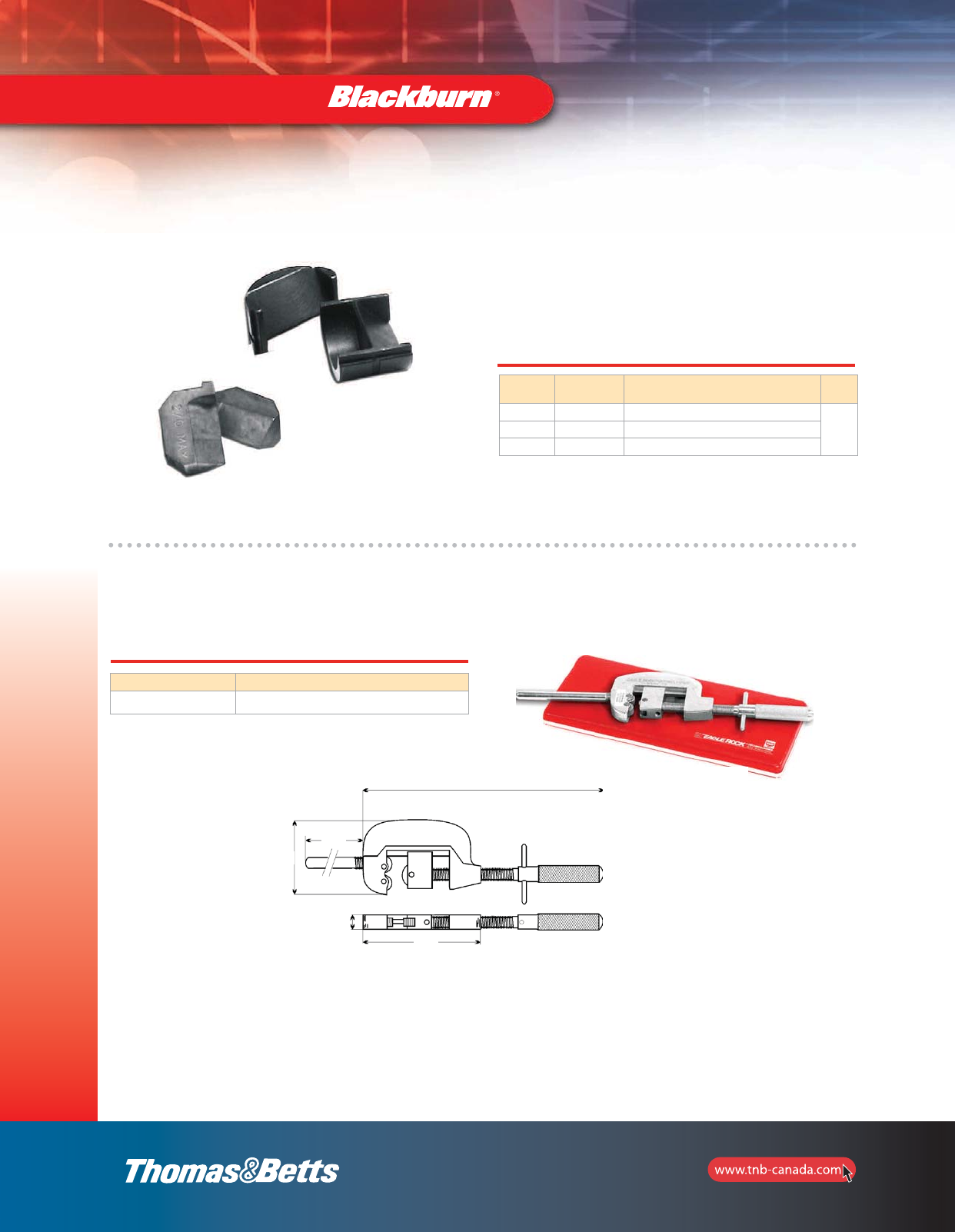
124
Installing Dies
Installation Dies
and Tools
Cable Slicing Die Sets
BY55
•Cut copper and aluminum insulated cable sizes
from #8 AWG through 500 kcmil
•Produce clean, squared-end cuts which eliminates extra
trimming of conductor strands
Cat. No. Maximum
Cable Size Tools Pkg.
Qty
BY55 2/0 TBM6H, BPLT6BSCR, BPLT6500BSCR
1
40CS 4/0 TBM14M, 13100A and TBM14BSC
156CS 500 kcmil TBM15I and TBM15BSCR
40CS
Knurling Tool
Cat. No. Description
240-31565-94 Hand knurling tool for all ground rods
Hand knurling Tool
for all Ground Rods
9/16
4-1/4
2-3/4
3-1/2
8” min. 9” max.
2_BLKBRNMRO5_E_58to167_Grounding.pdf 67 10/6/2011 1:01:00 PM
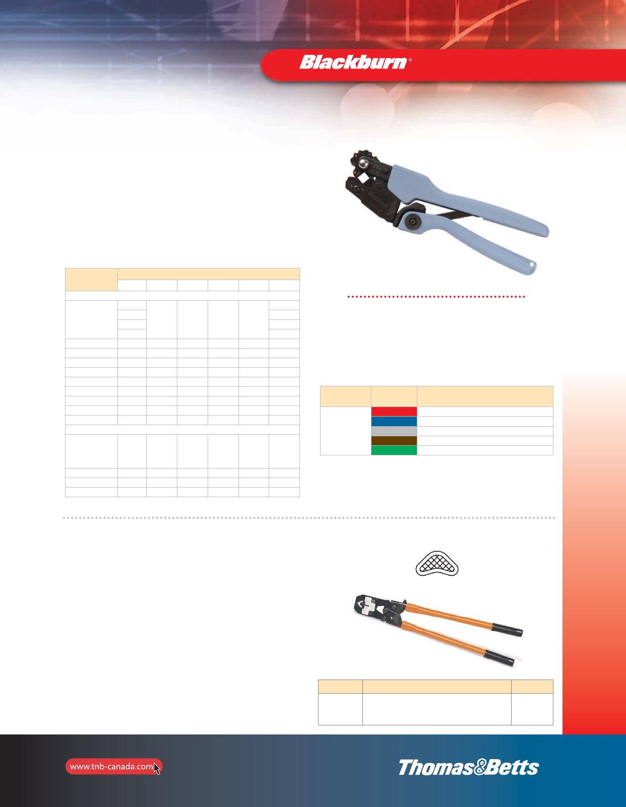
125
Installation Dies
and Tools
Installation Tools
Cat. No. Colour Code Gauging
Nom. – Tol.
TBM4BB
Red 0.183 ± 0.006
Blue 0.220 ± 0.008
Grey 0.273 ± 0.008
Brown 0.332 ± 0.008
Green 0.414 ± 0.008
Gauging Procedure
1. Rotate wheel to the desired nest.
2. Squeeze handles with 5 to 15 lb. force.
3. Holding handles tightly closed, insert GO, NO-GO gauge into
nest. GO gauge should enter freely. NO-GO gauge may enter
partially, but not pass completely through the length of the
nest area.
4. Equivalent to TBM25S.
•Installs lugs and splices over a wire range of #8 to #2
copper and #10 to #6 aluminum
•Also installs up to the green colour coded C-Taps and
MD2 Series motor disconnect
•A colour coded die wheel is rotated into position and each
die has die code embossing
•Shure Stake®tool
Conductor Size
#10 #8 #6 #4 #2 #1
Copper
One hole, short CTL8-10
CTL8-14
CTL8-516
54132
CTL6-10
CTL6-14
CTL6-516
CTL6-38
CTL4-10
CTL4-14
CTL4-516
CTL4-38
CTL2-14
CTL2-516
CTL2-38
CTL2-12
Two hole, short 54204 CTL6-214 CTL4-214 54207
Splice, short CSP8 CSP6 CSP4 CSP2
One hole, long CTL8L-14 CTL6L-14 CTL4L-14 54942BE
Two hole, short LCN8-14 LCN6-14 LCN4-14 LCN2-516
Splice, long CU8 CU6 CU4 CU2
Cable Joints 54610 54615 54620
Narrow Tongue 55112 55116
C-Taps 54705 54710 54715 54720 54725
Motor Disconnects MD8 Series MD6 Series MD4 Series MD2 Series
Aluminum
One hole
60096
60099
ATL8-10
ATL8-14
60103
60104
ATL6-10
ATL6-14
60108
60109
Splices 60500 ASP8 ASP6
Bi-Pins 61905A 61910A
Equipment Lugs 61102 61107
TBM4BB Crimp Tool
TBM4S Dieless Crimp Tool
•Wide range of #8 to 250 kcmil for copper lugs and
#8 to 4/0 for aluminum lugs
•Adjustable indenter eliminates the need to buy and
maintain numerous individual dies
•Shure-Stake®mechanism ensures a properly completed
crimp each time
•Easily adjusted by turning knurled adjusting wheel and
aligning pointer with proper terminal size
•Dieless adjustable crimper for Color-Keyed®compression
connectors
Cat. No. Description Pkg. Qty
TBM4S Dieless crimp tool with Shure-Stake®mechanism for
#8–250 kcmil copper and #8–4/0 aluminum lugs 1
Creates Indent-style crimp
2_BLKBRNMRO5_E_58to167_Grounding.pdf 68 10/6/2011 1:01:00 PM
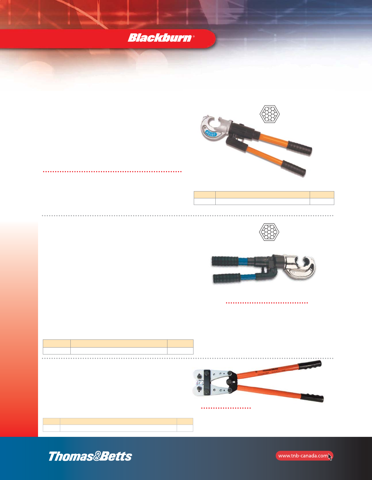
126
Installation Dies
and Tools
Installation Tools
JB12B — 12-Ton Manual Hydraulic Crimp Tool
•Self-contained hydraulic crimping tool for copper, aluminum
and ACSR connectors
•Two-stage, rapid-ram advance mechanism for fast
installation
•180º head rotation
•Accepts all U-type dies used for Alcoa, Burndy,
Thomas & Betts and Blackburn tools of equivalent tonnage
•Uses standard T&B Color-Keyed®15500 dies Series
(refer to pages 111–117)
Specifications
• Installing Range:
Up to 750 kcmil copper lugs & splices
Up to 650 kcmil aluminum lugs & splices
CHT814-10 to CHT2502-6 copper H-taps
63105 to 63148 aluminum H-taps
54755 to 54770 C-taps
• Output Force: 12 tons
• Dimensions (L x W x H):
22-3/4” x 2-1/2” x 4-7/8”
• Weight without Dies: 13 lb.
Cat. No. Description Pkg. Qty
JB12B 12-Ton Compression Tool 1
Creates Hex-style crimp
•Improved ergonomic design requires less force
•180º rotating head for use in tight spaces
•1.65" jaw opening accommodates large compression
terminals and joints
•Dual-speed action pump offers fast advancing speed for
approach of die to connector and slower, more powerful
speed for crimping
•Built-in safety valve bypasses oil supply at maximum
pressure
•Pressure-release system can be activated at any stage of
compression
•Uses standard T&B Blackburn®and Color-Keyed®15500
dies series (refer to pages 112–117)
TBM14M C 14-Ton Compact
Manual Hydraulic Crimp Tool
Cat. No. Description Pkg. Qty
TBM14MC 14-Ton Compact Hydraulic Crimp Tool 1
Specifications
• Installing Range:
Up to 900 kcmil copper lugs & splices
Up to 750 kcmil aluminum lugs & splices
• Output Force: 14 tons
• Length: 20-1/2”
• Weight without Dies: 14 lb.
• TBM14MG–Gauge and testing dies
in carrying case
Creates Hex-style crimp
TBM840 Crimp Tool
•Wide range of #8 to 4/0 for copper connectors and splices
•Installs Blackburn®and Thomas & Betts lugs and splices
•8-position colour coded rotatable die
•Comfort hand grip
•Die index embossed for permanent inspectability
Cat. No. Description Pkg. Qty
TBM840 Crimp Tool for #8 to 4/0 Copper Lugs c/w Rotating Colour Coded Die Wheel 1
Specifications
• Overall length: 23-3/4
"
• Handle length: 16-1/2
"
• Weight: 8.8 lb.
2_BLKBRNMRO5_E_58to167_Grounding.pdf 69 10/6/2011 1:01:00 PM
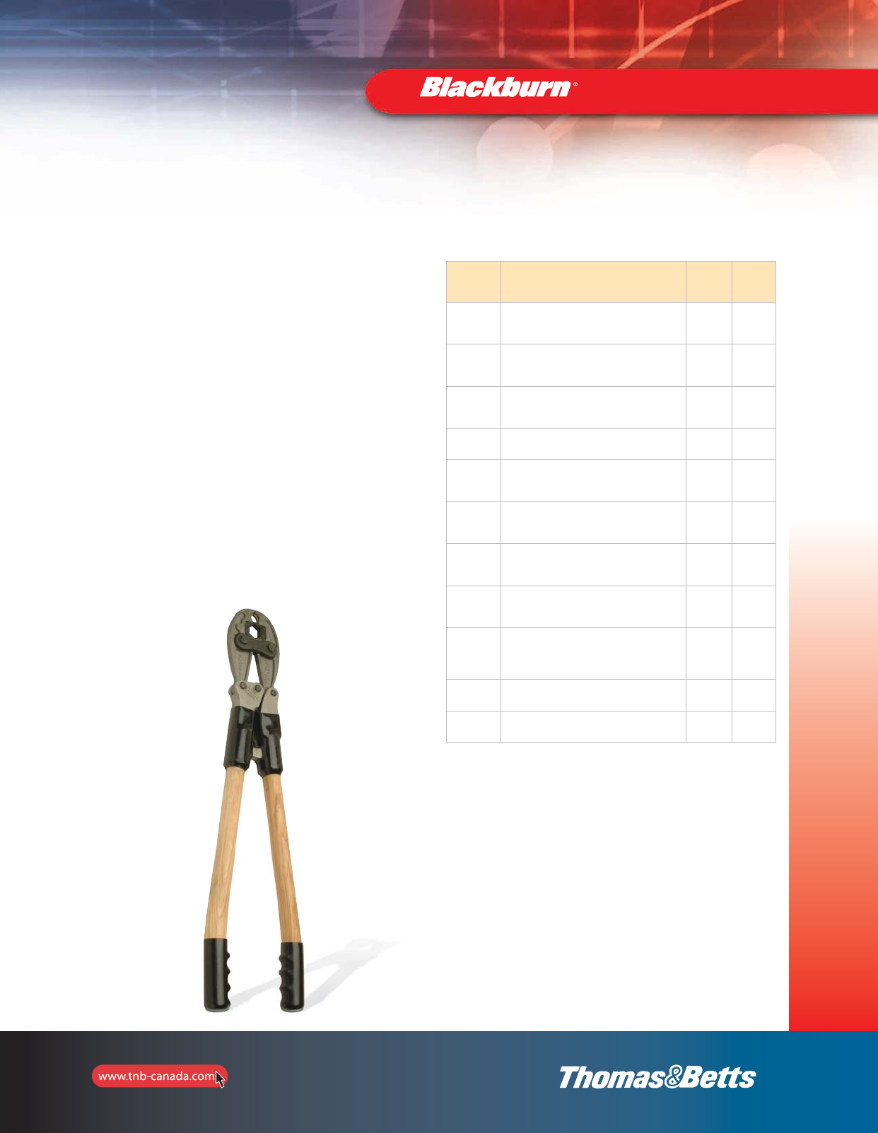
127
Installation Dies
and Tools
Cat. No. Description
Handle
Length
(in.)
Weight
(lb.)
OD58
Manual Tool with 5/8”
Nose Die and Insert Die Cavity
Straight Wooden handles
– 6.5
OD581
Manual Tool with 5/8”
Nose Die and Insert Die Cavity
Straight Fiberglass handles
– 6.0
OD583
Manual Tool with 5/8”
Nose Die and Insert Die Cavity
Curved Wooden handles
– 6.5
ODF1 Manual Tool with fixed O & D dies
Fiberglass handles – 6.0
ODB
Manual Tool with fixed O & D dies
“D” die cavity accepts MD6 tool insert dies
Straight Wooden handles
– –
ODB1
Manual Tool with fixed O & D dies
“D” die cavity accepts MD6 tool insert dies
Fiberglass handles
– 6.0
ODB3
Manual Tool with fixed O & D dies
“D” die cavity accepts MD6 tool insert dies
Curved Wooden handles
– 6.5
OD58L72
Manual Tool with 5/8”
Nose Die and Insert Die Cavity
Hot Stick Handles – 1.5” x 72”
72 10.5
ODBL72
Manual Tool with 5/8”
Nose Die and Insert Die Cavity Accepts MD6 tool
insert dies
Hot Stick Handles – 1.5” x 72”
– –
BG1-BB Canvas bag for OD58 – 1.00
ODH1 Insulating head cover – 0.40
For Hand Tool with insulated head, add suffix 5 to catalogue number.
OD581 Manual Compression Tool
Installation Tools
•Integral self-gauging system in tool head assures proper
adjustment before each crimp
•Improved design reduces force to crimp by as much as 20%
•Teflon over bronze bearings greatly reduce wear at linkage
and pins; far superior to steel bearing surfaces
•All standard insert dies available for OD58 tool: “O” and “D”,
840, etc., 5/8” fixed die in nose
•ODF tool has fixed “O” and “D” dies
•ODB tool has fixed “O” and “D” dies; accepts standard insert
dies designed for MD6 tool
•Distribution of weight over tool length gives better balance,
results in easier handling and positioning
•Optional fiberglass handles for greater strength, lighter
weight, better insulating properties and lower moisture
absorption rate
•ODF and ODB tools with insulated heads available as an
option
•Lever action tool with hot stick handles of Glastrux
Fiberglass, rated and tested for 100kV/ft/5 minutes
•Lever action results in minimum applied force to crimp
2_BLKBRNMRO5_E_58to167_Grounding.pdf 70 10/6/2011 1:01:01 PM
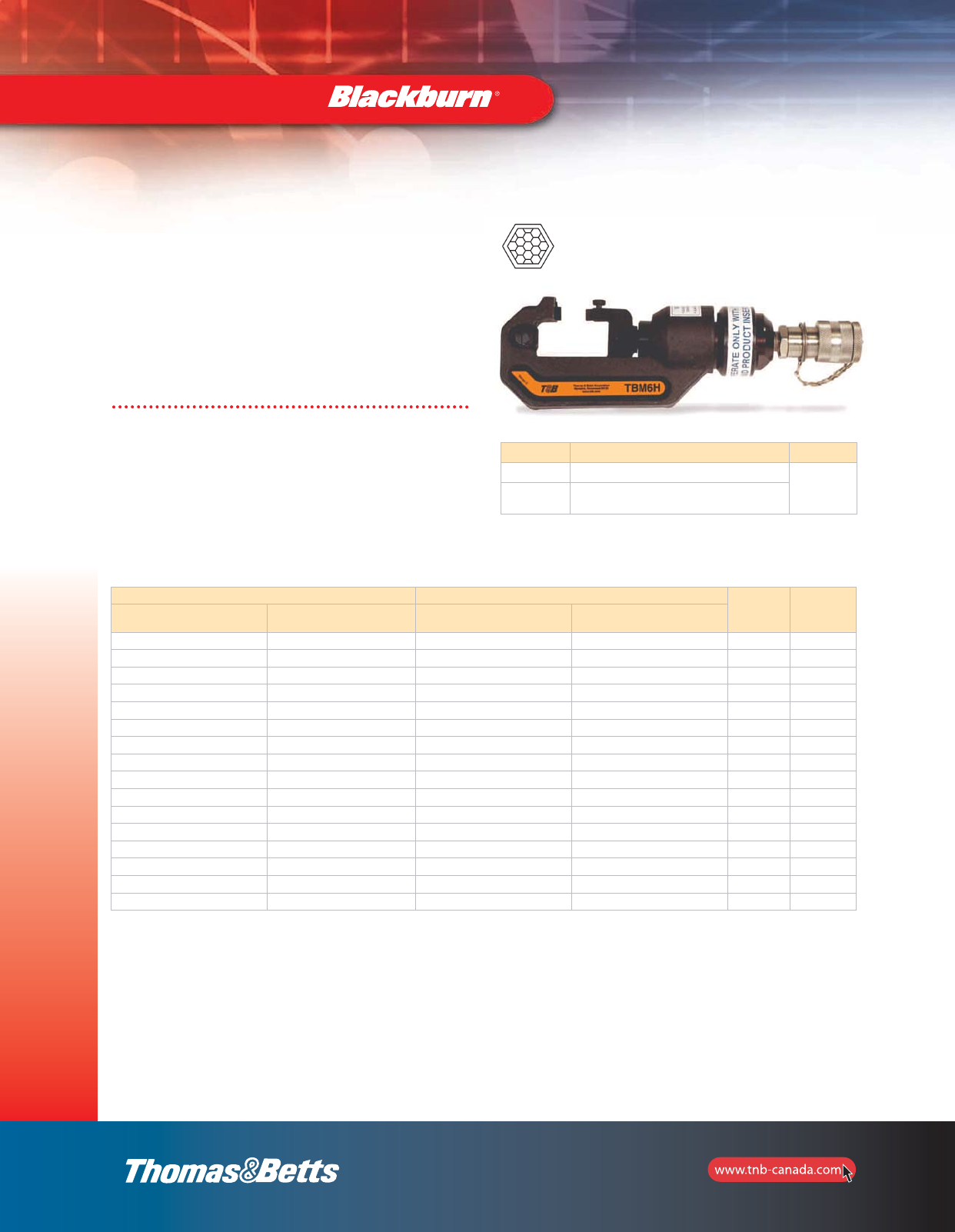
128
Installation Dies
and Tools
Cat. No. Description Pkg. Qty
TBM6H 6-Ton Hydraulic Head with Steel Case
1
TBM6HD-1 Die Set for #8 thru 500 kcmil
(6-TON21 thru 6-TON87)
TBM6H — 6-Ton Hydraulic
Crimping Head
•Lightweight design – weighs less than 7 lb., including dies
•Embosses die code on connection for easy inspection
•Uses 6-TON Series and Blackburn “O” & “D” dies Series
and colour coded insert dies for easy matching with
Blackburn®and Color-Keyed®connectors (refer to page 118)
Creates Hex-style crimp
Installation Tools
Specifications
• Output Force: 6 tons
• Dimensions (L x W x H):
12" x 2-1/4" x 3-9/16”
• Battery: Ni-MH 14.4V 3.0Ah
• Weight: 6.5 lb.
• Installing Range:
Up to 600 kcmil copper lugs & splices
Up to 400 kcmil aluminum lugs & splices
CHT814-10 to CHT214-9 copper H-taps
63105 to 63148 aluminum H-taps
54705 to 54750 C-taps
Connector Size TBM6H Hydraulic Head BKB
Die No.
Colour
Code
Copper Aluminum Color-Keyed
Die Cat. No. Die Code
8 AWG 10 AWG 6TON21 21 BY15C Red
6 AWG 8 AWG 6TON24 24 BY17C Blue
4 AWG 6 AWG 6TON29 29 BY19C Grey
2 AWG 6TON33 33 BY21C Brown
1 AWG 4 AWG 6TON37 37 Green
1/0 AWG 2 AWG 6TON42 42H BY23C Pink
2/0 AWG 1 AWG 6TON45 45 BY24C Black/Gold
3/0 AWG 1/0 AWG 6TON50 50 BY25C Orange/Tan
4/0 AWG 2/0 AWG 6TON54 54H BY31C Purple/Olive
3/0 AWG 6TON60 60 BY32C Ruby
250 kcmil 6TON62 62 BY27C Yellow
300 kcmil 4/0 AWG 6TON66 66 BY35C White
350 kcmil 250 kcmil 6TON71 71H BY37C Red
400 kcmil 300 kcmil 6TON76 76 Blue
925/24 6TON80 80 BY28C Black
500 kcmil 350 kcmil 6TON87 87H Brown
TBM6H — Application Information Connector Dies
Consult Connector Stuffer Sheets for series 61900, 61100 & 61300.
Consult Connector Stuffer Sheets for Wire Ranges.
2_BLKBRNMRO5_E_58to167_Grounding.pdf 71 10/6/2011 1:01:01 PM
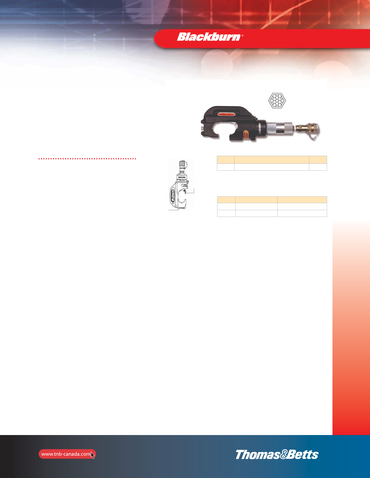
129
Installation Dies
and Tools
Installation Tools
13100A — 14-Ton
Hydraulic Crimping Head
•Rugged design, made to last in field or on bench
•C-yoke provides maximum flexibility for crimping
•Uses standard T&B Color-Keyed®Series 15500 dies
(refer to pages 111–112)
•Operates on 10,000 psi hydraulic pumps
Cat. No. Description Pkg. Qty
13100A 14-Ton Hydraulic Head with Steel Case 1
Creates Hex-style crimp
Specifications
• Installing Range:
Up to 900 kcmil copper lugs & splices
Up to 750 kcmil aluminum lugs & splices
CHT814-10 to CHT2502-6 copper H-taps
63105 to 63148 aluminum H-taps
54755 to 54775 C-taps
• Output Force: 14 tons
• Operating Pressure: 10,000 psi nominal
• Dimensions (L x W x H): 11-1/2" x 2-1/2" x 4-1/4”
• Weight: 10 lb.
Die Release Knob
Retainer Pin
Lugs Splices
Copper #8 AWG to 900 kcmil #8 AWG to 900 kcmil
Aluminum #10 AWG to 750 kcmil #10 AWG to 750 kcmil
Installation Range for Connectors
2_BLKBRNMRO5_E_58to167_Grounding.pdf 72 10/6/2011 1:01:01 PM
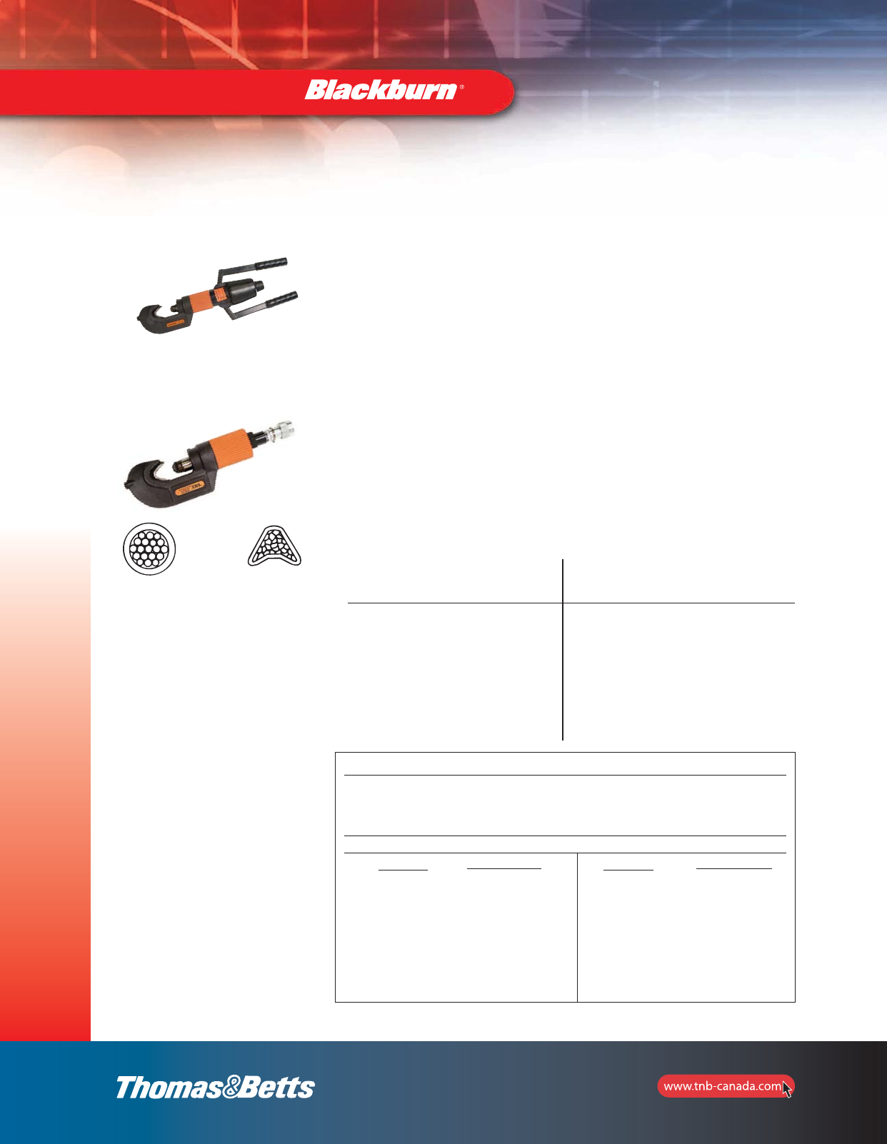
130
Installation Dies
and Tools
TBM8-750
TBM8-750M-1
Rugged Hydraulic Tool Gives
You Uniform Dependable
Connections — Lower
Installed Costs
The new Smart®Tools are designed to give
you uniform, high quality compression
connections over a wide connector range. It
easily installs copper and aluminum lugs and
two-way connectors from #8 AWG through
750 kcmil—without changing dies. For the
specified wire range, all you need is one
hydraulic tool and one set of dies. You always
have the right die size selection; mistakes
are virtually eliminated. Productivity will be
greatly im proved, especially when installing a
variety of connector sizes or types. Initial
investment is low and requires only a
minimum tool/die inventory. These benefits
add up to lower installed cost.
Smart®Tool Range Taking Features
The following size copper Blackburn®lugs and 2-way connectors, when crimped with
the Smart®Tools, Cat. Nos. TBM8-750 and TBM8-750-M1, produce these range taking
capabilities:
Copper Aluminum
Standard Range Standard Range
Wire Size Taking Wire Size Taking
1/0-AWG #6-1/0 AWG 1/0-AWG #6-1/0 AWG
2/0-AWG #1-2/0 AWG 2/0-AWG #1-2/0 AWG
4/0-AWG #2-4/0 AWG 4/0-AWG #2-4/0 AWG
300 kcmil #2/0-300 kcmil 300 kcmil #2/0-300 kcmil
350 kcmil 250-350 kcmil 350 kcmil 250-350 kcmil
500 kcmil 250-500 kcmil 500 kcmil 4/0-500 kcmil
750 kcmil 500-750 kcmil 750 kcmil 500-750 kcmil
Wire Barrel Before
Compression
After Compression—the
connector and conductor
are formed into a solid
mass.
Specifications
TBM8-750 TBM8-750M-1
Remote Head tool Self-Contained Tool
Weight: 9 lb. (approx.) Weight: 13 lb. (approx.)
Height: 14-1/2 in. Height: 21-1/2 in.
Width: 4-7/32 in. Width: 4-7/32 in.
Depth: 2-9/16 in. Wire Range: #8 AWG through 750 kcmil
Wire Range: #8 AWG through 750 kcmil copper and aluminum
copper and aluminum Operating Pressure: 9,800 psi
Operating Pressure: 9,800 psi Output Pressure: 12 tons
Output Pressure: 12 tons
Coupler: Pioneer, female
Installation Tools
Smart®Tools From T&B to Crimp 17 Blackburn®
Connector Sizes with No Die Changes
How It Works
The tool, which operates from a 9,800 psi
hydraulic pump, has an engineered, built-in
“intelligence*”. The tool will sense the
connector barrel diameter and apply just
the right amount of compression force. This
eliminates virtually all air spaces and forms
the connector and conductor strands into a
solid mass resulting in a high quality, low
resistance connection. In addition, the tool
clearly embosses “T&B” with each
compression for positive verification that
the correct tool was used.
* System Novopress
“C”-Type Yoke Offers
Installation Convenience
The “C”-type yoke configuration and the
large die spacing allows the tool to slip
directly over the connector. This means
added speed and convenience when
installing 2-way connectors, especially in
confined spaces.
Rugged Construction
These ruggedly built tools are made from
forged steel, and are well suited for both
field and bench work. Their C-shaped
heads, light weight, and compact size
make them easy to use just about
anywhere.
2_BLKBRNMRO5_E_58to167_Grounding.pdf 73 10/6/2011 1:01:01 PM
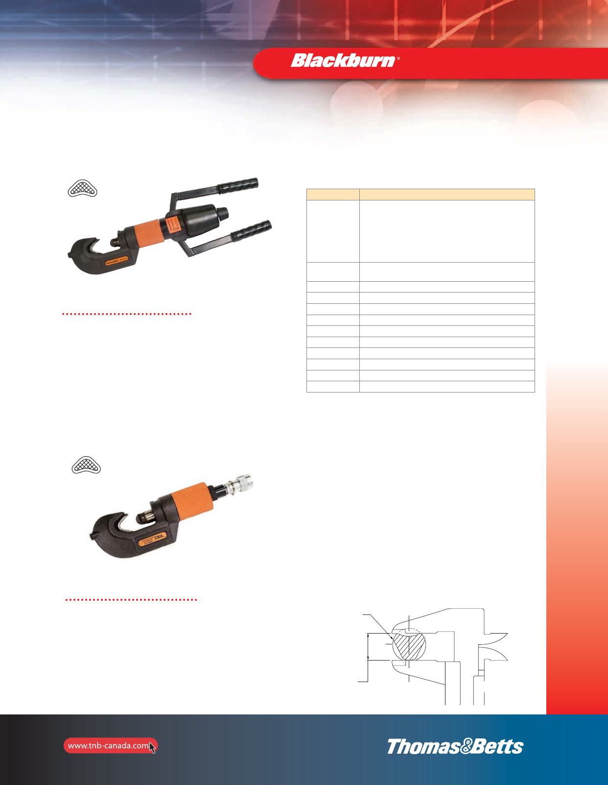
131
Installation Dies
and Tools
TBM8-750M-1 — 12-Ton Dieless
Manual Hydraulic SMART®Tool
Creates
Indent-style crimp
• Installing Range:
Up to 900 kcmil copper lugs & splices
Up to 750 kcmil aluminum lugs & splices
• Output Force: 12 tons
• Dimensions (L x W): 21-1/2" x 4-7/32"
Cat. No. Description
TBM8-750
Remote Head installs Blackburn®#8 AWG through 750 kcmil
aluminum and copper lugs, 2 way connectors, and “D” through
“M” bare Sta-Kon®terminals with no die change; the only
additional die sets required are for “H” and “C” type compression
taps; the tool weighs only 9 lb. and is 13 in. long; operates on
standard 10,000 psi electric and manual pumps. UL and CSA
Listed for T&B connectors and uninsulated terminals.
TBM8-750M-1 Self-contained head installs same connectors as above tool; “C”
Head swivels 90° for easy crimp positioning in confined spaces
TBM8-750G Field compression gauging kit for both above tools
TBM8-750C20 Die set installs Cat. No. 54720 copper “C” taps
TBM8-750C2530 Die set installs Cat. Nos. 54735, 54730 copper “C” taps
TBM8-750C3540 Die set installs Cat. Nos. 54735, 54740 copper “C” taps
TBM8-750C4550 Die set installs Cat. Nos. 54745, 54750 copper “C” taps
TBM8-750CL Die set installs Cat. No. 54755 through 54775 copper “C” taps
TBM8-750HG Die set installs Cat. No. 63110 through 63118 and 63125 “H” taps
TBM8-750HB Die set installs Cat. No. 63140 through 63148 “H” taps
297-31804-6 TBM8-750 with insulated head
297-31804-4 TBM8-750M-1 with insulated head
TBM8-750 — 12-Ton Dieless
SMART®Hydraulic Head
Specifications
• Installing Range:
Up to 900 kcmil copper lugs & splices
Up to 750 kcmil aluminum lugs & splices
• Output Force:12 tons
• Operating Pressure: 10,000 psi nominal
• Dimensions (L x W x H):
14-1/2" x 4-7/32" x 2-9/16"
• Weight: 9 lb
Installation Tools
Specifications
Creates
Indent-style crimp
Gauging Procedure
1. Insert the test bar in the die opening: allow 3/4” from the end of
the bar or the last crimp to prevent poor crimping.
2. Start the pump, holding pressure on the tool until full pressure is
shown on the gauge.
3. Release the pressure.
4. Measure the crimped area of the test bar with a Vernier Caliper as
shown in the sketch.
5. Accept the tool if the crimped bar is within the listed dimension
and no leaks or functional problems are observed.
6. Tools not crimping the test bar to specification, that leak or have
a functional problem should be returned to T&B Tool Service.
CALIPE
0
TEST BAR
.531± .020 CALIPERS
Hydraulic Smart®Tool
TBM8-750M-1
TBM8-750
2_BLKBRNMRO5_E_58to167_Grounding.pdf 74 10/6/2011 1:01:01 PM

132
Installation Dies
and Tools
Installation Tools
Cat. No. Description Pkg. Qty
CSR750 Cutter for up to 750 kcmil copper or aluminum 1
•Special advance stroke mechanism requires less handle force
•Cuts copper or aluminum cables up to 750 kcmil
•Short handles (only 10" long) enable use in tight spaces
Contact Tool Service for replacement blades.
CSR750 Cable Cutter
368-CK Cable Stripper
Cat. No. Description Pkg. Qty
368-CK Cable stripper for #1 to 1,000 kcmil 1
CTR-1 — C-Tap Removal Tool
Cat. No. Description Pkg. Qty
CTR-1 C-Tap Removal Tool 1
HM-250 TOOL — Mechanical
Single Indent Dieless Crimper
•Manually operated single-indent compression tool
•For copper wire #8 to 250 kcmil
•For aluminum wire #8 to 4/0
Cat. No. Description Pkg. Qty
HM-250 TOOL Mechanical Single Indent Dieless Crimper 1
Blackburn®Allen Wrench
Cat. No. Description Pkg. Qty
WA 516 PVC dipped handle – Hex size 5/16 1
WA 38 PVC dipped handle – Hex size 3/8
PVC dipped handle
132-133-e.pdf 1 10/12/2011 11:23:23 AM

133
Installation Dies
and Tools
Battpac™Battery-Powered Compression and Cutting Tools
4-Ton Battery-Powered
Crimping Tool
This new 4-Ton Battery-Powered Crimping Tool weighs only
6.4 lb — including battery — but yields 4 tons of output
force for crimping T&B service entry connectors and lugs or
splices up to 300 kcmil copper or 4/0 AWG aluminum. The
jaws automatically return to the open position after the
completion of a crimp, but you can stop the automatic jaw
return at any time for ease of positioning in confined spaces.
•Offers extremely quiet operation with minimal vibration
•Equipped with maximum pressure valve for safety
•Durable molded body offers high resistance to wear and
damage in tough field confitions.
•Fixed 5/8” BG and D grooves; accepts all
W style dies
•Includes 0 die insert
•Crimps select Homac®, Blackburn®and
Color-Keyed®connectors
Specifications
• Installing Range:
Up to 300 kcmil copper or 4/0 AWG
aluminum lugs and splices
• Output Force: 4 tons
• Dimensions (L x W x H): 17.7" x 2.6" x 4.7”
• Battery: Ni-MH 9.6V 3.0Ah
• Weight with Battery: 6.4 lb
Cat. No. Description Pkg. Qty
BP4UCR Includes tool, 0 die insert, two batteries, charger and durable plastic carrying case. 1
NEW!
NEW!
Balanced, Inline Design for Better
Handling and Greater Control.
132-133-e.pdf 2 10/12/2011 11:23:23 AM
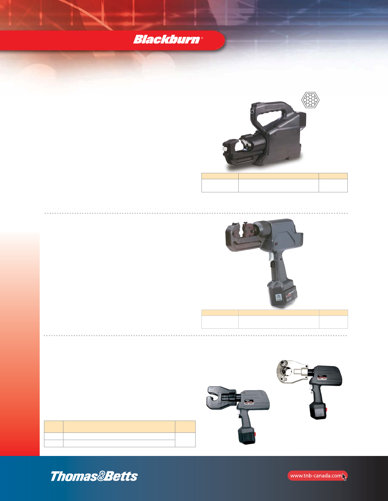
134
Installation Dies
and Tools
REC-750
REC-630
Battpac™Battery-Powered Compression and Cutting Tools
Cat. No. Description Pkg. Qty
TBM14BSCR Hermetically sealed unit. Includes carrying case,
charger, two batteries, carry strap 1
Creates
Hex-style crimp
Battpac™TBM14BSCR Hermetically Sealed 14-Ton
Battery-Powered Compression Tool
The TBM6BSCR is designed to crimp commonly used lugs, splices,
service entrance connectors, H and C-taps. It can be easily carried
and used in limited access areas because of its swivel head and
compact design. The unique open yoke is also advantageous for
C-tap, H-tap and splicing applications. Its six-ton output is equal to
any comp arable hand-held, hydraulic compression tool and far
exceeds any mechanical crimper.
A built-in factory pre-set 10,000 psi by-pass cartridge assures a
complete compression every time. Consult your Regional Sales
Office for proper die/connector combinations or read the
information on the connector package. Accepts standard T&B
six-ton dies and Blackburn®OD58 dies Series.
NOTE: When ordering the Smart ®battery, add suffix “-SM” (Example: TBM14BSCR-SM).
Suggested replacement oil T&B Cat. No. 21061 or any light weight hydraulic fluid or automatic
transmission fluid is recommended. Do not use silicon based fluids.
6-Ton Battery Compression Tool
The TBM14BSCR is a self-contained battery operated 14-ton
compression tool. The large jaw opening, 1.65 inches, accepts
mid-span copper and aluminum splices and cables up to 750 kcmil.
When the splices are compressed, they can be removed through
the large jaw. This tool accepts T&B and Blackburn®shell type dies.
A built-in, pre-set 10,000 psi bypass cartridge will audibly kick out
when the 14-ton pressure is achieved.
Portability and handling is easy because the TBM14BSCR system is
self-contained and compact. There is no tool set-up time or extra
power source needed. Makes splicing a breeze. And with one finger
trigger operation, fatigue and muscle related strains are nearly
eliminated. Safer work habits result from using this tool.
Cat. No. Description Pkg. Qty
TBM6BSCR 6-Ton Battery Powered Compression Tool 1
Cat. No. Description Pkg.
Qty
REC-630 #10 AWG – 500 kcmil 1
REC-750 #6 AWG – 750 kcmil
ROBO*CRIMPTM is a registered trademark of Huskies Tools.
ROBO*CRIMPTM 6-Ton Dieless,
Battery-Powered
Crimping Tool Kits
Both kits include:
•(1) Battery powered tool
•(1) Carrying strap
•(1) Carrying case
•(1) BP-70R battery
•(1) CH-3TR 15 minute AC charger
2_BLKBRNMRO5_E_58to167_Grounding.pdf 77 10/6/2011 1:01:02 PM

135
Installation Dies
and Tools
Suggested replacement oil T&B Cat. No. 21061 or any light weight hydraulic fluid or automatic
transmission fluid is recommended. Do not use silicon based fluids.
Cat. No. Description Pkg. Qty
TBM15BSCR
15-Ton Battery Powered Compression Tool. Hermetically
sealed unit. Includes carrying case, charger, two
batteries, carry strap 1
15500-TB Die adaptor for 15500 series and Blackburn dies
Creates
Hex-style crimp
Specifications
• Installing Range:
Up to 1500 kcmil copper lugs & splices
Up to 1000 kcmil aluminum lugs & splices
CHT814-10 to CHT750-350-1F copper H-taps
63105 to 63180 aluminum H-taps
54755 to 54790 C-taps
•Weather-resistant, non-ventilated body for use in the most
corrosive environments
•High grade forged steel head rotates 180˚
•Rapid jaw-advance feature allows the operator quicker
compression cycles
•75kV live line rated
•20-minute rapid battery charger
•Approx. 60 crimps per battery charge
(based of 3/0 AWG cable)
•Uses Series 15600 dies ; can also use Series 15500 and
Blackburn®dies with 15500-TB adaptor (refer to pages 112–118)
•The only tool that can be used with all Thomas & Betts
connectors
Battpac™TBM15BSCR Hermetically Sealed
15-Ton Battery-Powered Compression Tool
Battpac™Battery-Powered Compression and Cutting Tools
• Output Force: 15 tons
• Dimensions (L x W x H):
21" x 3-1/2" x 11”
• Battery: 14.4V 3.0Ah Ni-Cd
• Weight with Battery: 23.75 lb.
Battpac™TBM54BSCT and TBM54BSCTS Battery Powered Cutters
•One-handed control of blade advancement and retraction
•TBM54BSCTS cuts up to 750 kcmil copper,
2-1/8” O.D. aluminum and 636 kcmil ACSR
•TMB54BSCT cuts up to 1,500 kcmil copper and 2-1/8”
O.D. aluminum (not for use on ACSR)
Guide to Cutting Cycles
This guide indicates the number of cutting cycles that the
TBM54BSCT and TBM54BSCTS can be expected to perform when
the battery is fully charged. These figures are approximate and will
vary according to the charging and other operating conditions, such
as temperature, humidity and battery condition.
Cat. No. Conductor Approx. Cutting Cycles
CRCTBPI and CRCTBP
TBM54BSCTS 750 kcmil Cu, 2-1/8" Al
636 kcmil ACSR
35
50
TBM54BSCT 1,000 kcmil Cu
1,500 kcmil Cu; 2-1/8” Al
45
30
Battery Unit: CRCTBP
Battery Type: Sealed NIckel Cadmium
Voltage: 14.4V DC
Rated Current: 1.9Ah
Dimensions: 3.5" L x 2.7" W x 5.3" H
Weight: 1.6 lb.
Battery Charger: CRCTQC
Input Voltage: 120V AC Single Phase
Charging Capacity: 20V AC
Charging Time: 15 min. CRCTBP and CRCTBPI
Dimensions: 7.5" L x 3.7" W x 3.5" H
Weight: 4 lb.
Optional Accessories:
Battery Cartridge: CRCTBPI or CRCTBP
DC Charger: CRCTQC
(refer to page 137)
Specifications
Cat. No. Description Pkg. Qty
TBM54BSCTS Battery powered cutter for up to 750 kcmil Cu,
2-1/8” O.D. Al and 636 kcmil ACSR 1
TBM54BSCT Battery powered cutter for up to 1,500 kcmil Cu,
2-1/8” O.D. Al (not for use on ACSR)
Contact Tool Service for replacement blades.
• Battery: 14.4V DC
• Dimensions (L x W x H): 16" x 4" x 4.5"
• Weight with Battery: 7.2 lb.
• Approx. 25 cuts per battery charge
2_BLKBRNMRO5_E_58to167_Grounding.pdf 78 10/6/2011 1:01:02 PM

136
Installation Dies
and Tools
Battpac™Battery-Powered Compression and Cutting Tools
Battpac™TBM58BSCT Battery-Powered Cutter
•To operate, simply remove pin latch, place over cable,
re-insert pin and cut
•Built-in bypass pops off if material is beyond cutter’s
capacity
•Cuts ACSR, aluminum and copper cables up to 1-1/2”,
regular guy wires and ground rods up to 5/8”
•Approx. 25 cuts per battery charge
NOTE: Not recommended for use on hardened steel.
Specifications
• Output Force: 6 tons
• Max. Cutting Capacity:
Soft steel bolts: 1-1/16" (17mm)
Rebar & ground rod: 5/8" (16mm)
ACSR : 1-1/2" (40mm) CU & AL
Strands: 1-1/2" (40mm)
Standard guy wire: 5/8" (16mm)
Wire rope: 3/4" (20mm)
• Dimensions (H x W x D): 17" x 12" x 3"
• Weight with battery: 14 lb.
Cat. No. Description Pkg. Qty
TBM58BSCT Battery-Powered Cutter 1
Standard Battpac™
Kit Includes:
1 battery-powered tool
1 carrying strap
1 carrying case
2 CRCTBP batteries
1 CRCTQC 15-minute AC charger
Contact Tool Service for replacement blades.
TBMODBSCR — 6-Ton Battery-Powered Compression Tool
•Versatile battery-powered crimp tool combines
the features of an open yoke tool with the weight and
balance of a closed yoke tool
•Reduces stress for operator when crimping connectors
•Ideal for industrial, commercial, telecom and utility
applications
•Accepts T&B Color-Keyed®6-TON and Blackburn®“O”
and “D” dies (refer to pages 112–120)
Specifications
• Dimensions (L x W x H):
12" x 3" x 13"
• Battery: Ni-MH 14.4V 3.0 Ah
• Weight with Battery: 8 lb.
• Installing Range:
Up to 4/0 aluminum H-taps
Standard C-taps
• Approx. 200 crimps per
battery charge
• Output Force: 6 tons
Cat. No. Description Pkg. Qty
TBMODBSCR
Battery-Powered 6-Ton Crimping Tool – Includes
Shoulder Strap, Charger, Carrying Case, Battery
Cartridge and Owner’s Manual
1
2_BLKBRNMRO5_E_58to167_Grounding.pdf 79 10/6/2011 1:01:02 PM
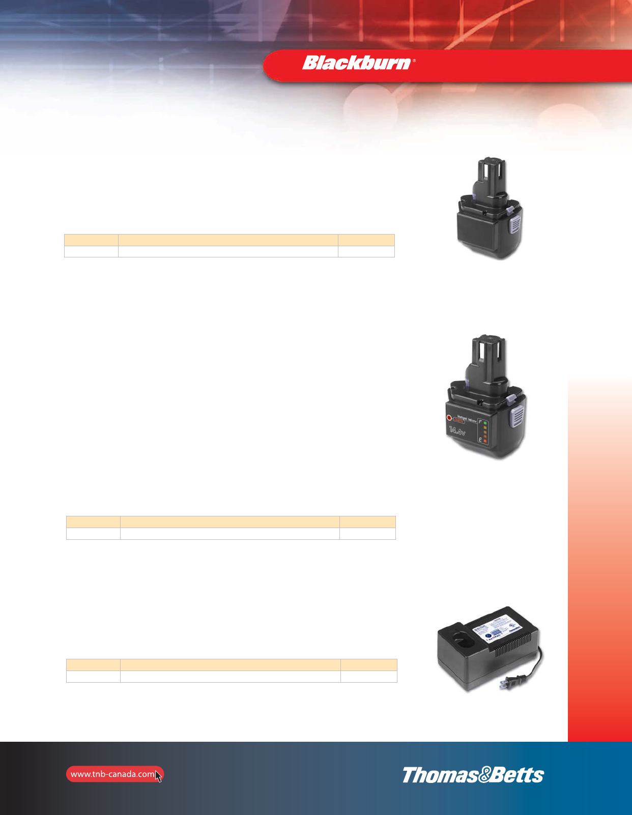
137
Installation Dies
and Tools
Standard 15-Minute Quick Charger
Battpac™Battery-Powered Compression and Cutting Tools
Cat. No. Description Pkg. Qty
CRCTBP Standard Replacement Battery 1
One hour standard battery charger for
CRCTBP and CRCTBPI Battpac®batteries.
Do not use the charger for any other devices.
The CRCTBP is a standard replacement
battery. The battery’s life expectancy is
approximately 600 recharges.
Cycles per charge will vary depending on the
type and size of the material being cut or
compressed.
Standard Replacement Battery
The CRCTBPI Smart®battery is the same as
the standard CRCTBP with the addition of an
L.E.D. display that will indicate its power
capabilities for you. The 14.4 volt battery is
interchangeable with all T&B Battpac®
products. It is self evaluating which allows
the user to monitor the status of the battery’s
life and power between charges.
The battery’s capacity is shown with an
L.E.D. indicator of five red lights on its side.
Different light patterns will give the user
specific battery information. For instance,
when the bottom red light begins to flash, it
is a warning that only 10% of the battery
power remains and it must be recharged
soon. You’ll know that the battery is fully
charged if you push the “check” button and
all five lights turn on.
To check battery recharge cycles, depress
“check” button once, release, depress again
while L.E.D. lights are on, and hold
approximately 10 seconds until L.E.D. pattern
is displayed.
Note: All L.E.D. lights will flash if the battery
has internal problems. If this occurs, battery
must be returned to factory for evaluation.
Recycling: T&B will gladly accept any used
Ni-Cd batteries for recycling. Please call your
Regional Sales Office for more details.
Smart
®Replacement Battery
Cat. No. Description Pkg. Qty
CRCTQC Standard 15-minute Quick Charger 1
Cat. No. Description Pkg. Qty
CRCTBPI Smart®Replacement Battery 1
2_BLKBRNMRO5_E_58to167_Grounding.pdf 80 10/6/2011 1:01:02 PM

Battpac™Die Information
Connector Size TBM6BSCR TBM6H TBM14BSCR / TBM15BSCR
Copper Aluminum Cat. No. Dies Cat. No. Dies Cat. No. Dies Die Code
8 AWG 10 AWG 6TON21 BY15C B71CH Red
6 AWG 8 AWG 6TON24 BY17C B73CH Blue
4 AWG 6 AWG 6TON29 BY19C B74CH Grey
2 AWG – 6TON33 BY21C B75CH Brown
1 AWG 4 AWG 6TON37 B05CH Green
1/0 AWG 2 AWG 6TON42 BY23C B06CH1 Pink
2/0 AWG 1 AWG 6TON45 BY24C B72CH Black/Gold
3/0 AWG 1/0 AWG 6TON50 BY25C B08CH Orange
4/0 AWG 2/0 AWG 6TON54 BY31C B09CH Purple/Olive
250 kcmil – 6TON62 BY27C B26CH Yellow
– 1 BY24C B72CH Black/Gold
1/0 BY25C B08CH Tan
2/0 BY31C B09CH Purple/Olive
3/0 AWG 6TON60 BY32C – Ruby
300 kcmil 4/0 AWG 6TON66 BY35C B10CH1 White
350 kcmil 250 kcmil 6TON71 BY37C B11CH Red
400 kcmil 300 kcmil 6TON76 – Blue
925/24 – 6TON80 – Black
500 kcmil 350 kcmil 6TON87 B12CH Brown
600 kcmil 400 kcmil B36CH Green
700 kcmil 500 kcmil 15505 Pink
750 kcmil 600 kcmil BY28C B39CH Black
– Orange
700 kcmil – Purple
750 kcmil – Yellow
1000 kcmil 125H
1000 kcmil 140H
138
Installation Dies
and Tools
Battpac™Battery-Powered Compression and Cutting Tools
Cable Slicing Die Sets
Cat. No. Maximum Cable Size Tools
BY55 2/0 TBM6H, BPLT6BSCR and BPLT6500BSCR
40CS 4/0 TBM14M, 13100A and TBM14BSC
156CS 500 kcmil TBM15I and TBM15BSCR
2_BLKBRNMRO5_E_58to167_Grounding.pdf 81 10/6/2011 1:01:02 PM
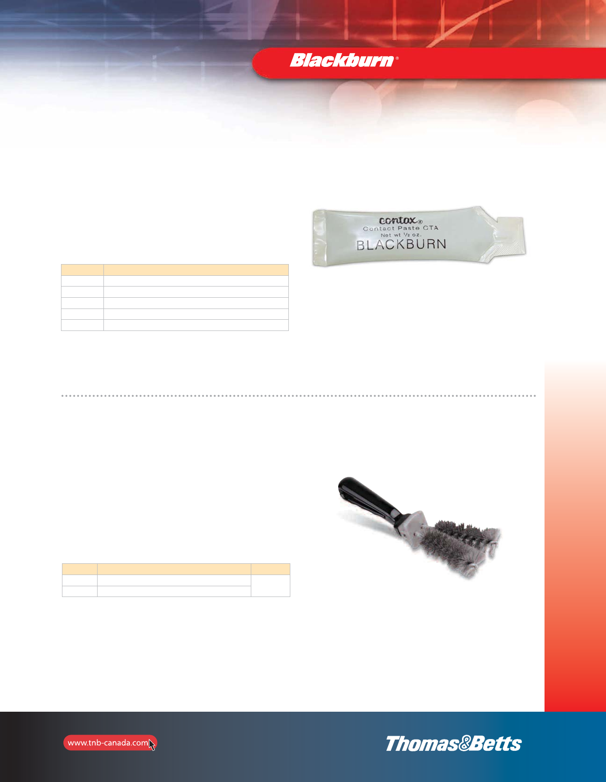
139
Installation Dies
and Tools
Sealants and Lubricants
Type WW — Wire Bristle Brush
•Removes oxides from conductor surfaces
•Easy-grip handle with guard to prevent rubber-
glove puncture
•Replaceable long-life brushes can be rotated
•Handle and guard coated with durable,
nonconductive plastic for safety
Cat. No. Description Pkg. Qty
WWB1 Complete Brush with Handle 1
WRB1 Brush Replacement
Type CT — CONTAX™Oxide Inhibiting Coumpound
•Seals electrical connections from oxygen and
moisture
•Non-water soluble, non-petroleum based polymer
grease
•Nontoxic, will not irritate the skin
•Service temperature to 238 oC (460 oF) can be
applied in -18 oC (0 oF) weather
Cat. No. Description
CTA 1/2 oz. Package
CTB 4 oz. Plastic Bottle
CTB8 8 oz. Plastic Bottle
CTQ Quart Can
CTG Gallon Can
2_BLKBRNMRO5_E_58to167_Grounding.pdf 82 10/6/2011 1:01:03 PM
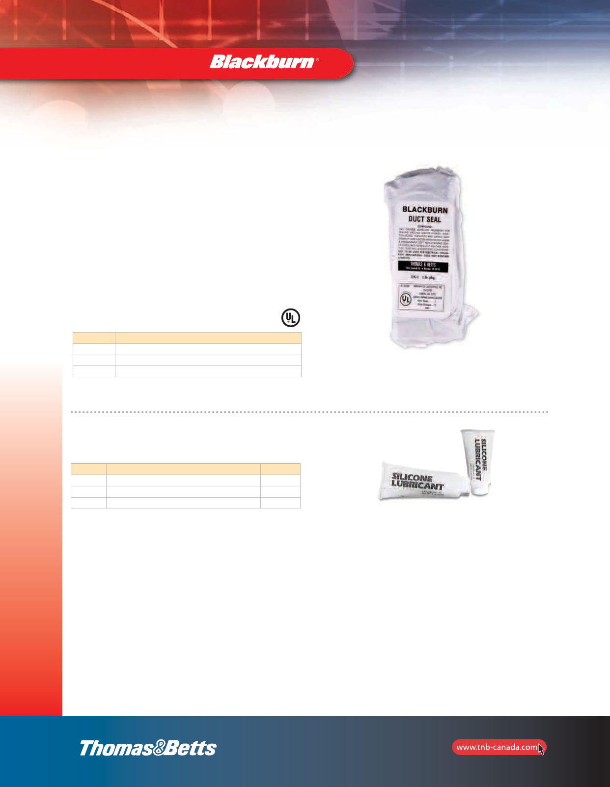
140
Installation Dies
and Tools
Sealants and Lubricants
Type DX — Duct Seal
•Seals around junction boxes, flashings, service mast entries,
service cable entries and countless other applications
•Easy to use, forms around irregular surfaces and
configurations
•Highly resistant to cracking, drying and shrinking
•Cuts and trims easily
•Can be painted immediately after application
•Grey colour
•No unpleasant odor
•-6.7 °C to 100 °C (20 °F to 212 °F) workable
temperature range
•-40 °C to 121 °C (-40 °F to 250 °F) service
temperature range
•Contains no asbestos
Cat. No. Description
DX-1 1 lb Slug
DX-5 5–1 lb Slugs
DX-5S 5 lb Slug
U.L. Classified R13335.
Silicone Lubricant for High Voltage Electrical Work
Cat. No. Description Pkg. Qty
2012 2 grams 250 tubes
2015 5 grams 100 tubes
SL5 5 oz./142 grams 12 tubes
2_BLKBRNMRO5_E_58to167_Grounding.pdf 83 10/6/2011 1:01:03 PM

141
Mechanical Connectors
Split Bolts
Type H — High Strength Split-Bolt Connector
Blackburn Penn Union Burndy Ilsco/Utilco Anderson Joslyn Dossert Eritech
9H S-10 KS90 IK-10 C-10 J3657 DS-09F ESB10
8H S-8 KS15 IK-8 C-8 J3608 DS-1F ESB8
8H3 SEL-8 SEL8S C-8-L
6H S-6 KS17 IK-6 C-6 J3606 DS-2F ESB6
6H3 SEL-6 KS17-3 SEL6S C-6-L J3608 DS-2-3
4H S-4 KS20 IK-4 C-4 J3604 DS-3F ESB4
4H3 SEL-4 KS20-3 SEL4S C-4-L J3604 DS-3-3
3H ESB3
3H3
2H S-3 KS22 IK-3 C-2 J3602 DS-5F ESB2
2H3 SEL-3 KS22-3 C-2-L J3602 DS-5-3
1H S-2 KS23 IK-2 C-1 DS-6F
1H3 SEL-2 SEL-2S C-1-L DS-6-3
10H S-1/0 KS25 IK-1/0 C-1/0 J3610 DS-10F ESB1/0
20H S-2/0 KS26 IK-2/0 C-2/0 DS-13F ESB2/0
30H S-3/0 KL27 IK-3/0 C-3/0 DS-17 ESB4/0
40H S-4/0-250 KS29 IK-250 C-4/0 J3640 DS-25C ESB250
350M S-350 KS31 IK-350 C-350 J3635 DS-35 ESB350
500M S-500 KS34 IK-500 C-500 J2650 DS-50 ESB500
750M S-750 KS39 IK-750 C-750 J3675 DS-75 ESB750
1000M S-1000 KS44 IK-1000 C-1000 J3679 DS-100
Type HPS — Plated Split-Bolt Connector
Blackburn Penn Union Burndy Ilsco/ Utilco Dossert Eritech
9HPS SW-1
8HPS SW-2 ESBP8
6HPS SW-3 KSU17 SK-6 DSNS2 ESBP9
4HPS SW-4 KSU20 SK-4 DSNS3F ESBP6
2HPS SW-5 KSU22 SK-3 DSNS5F ESBP2
1HPS SW-6 KSO23 SK-2 DSNS6F
10HPS SW-7 KSU25 SK-1/0 DSNS10F ESBP1/0
20HPS SW-8 KSU26 SK-2/0 DSNS13F ESBP2/0
40HPS SW-9A KSU27 SK-3/0 DSNS25C ESBP4/0
350HPS SW-11 KSU31 SK-350 DSNS35 ESBP350
500HPS SW-12 KSU34 SK-500 DSNS50 ESBP500
750HPS SW-13 DSNS75
1000HPS SW-14 DSNS100
Type APS — Aluminum Dual-Rated Split-Bolt
Blackburn Penn Union Burndy Ilsco Eritech
APS06 KSA-6 AK-6 ASBP6
APS04 KSA-4 AK-4 ASBP4
APS02 SW-6 KSA-2 AK-2 ASBP2
APS11 SW-7 KSA-1/0 AK-1/0 ASBP1/0
APS21 SW-8 KSA-2/0 AK-2/0 ASBP2/0
APS41 SW-9 KSA-4/0 AK-4/0 ASBP4/0
APS350 SW-11 KSA-350 AK-350
APS500 SW-12 KSA-500 AK-500
Competitive Cross Reference
Reference Tables
2_BLKBRNMRO5_E_58to167_Grounding.pdf 84 10/6/2011 1:01:03 PM

142
Reference Tables
Competitive Cross Reference
Mechanical Connectors
Service Post Connectors
Type SP — Service Post Connector
Blackburn Penn Union Burndy
SPODL SCS-0A1 K2C15B1
SP1DL SCS-1A1 K2C17B1
SP2DL SCS-2A1 K2C20B1
SP3DL SCS-3A1 K2C22B1
SP4DL SCS-4A1 K2C23B1
SP5DL SCS-5A1 K2C25B1
SP6DL SCS-6A1 K2C26B1
SP8DL SCS-8A1 K2C28B1
SP9DL SCS-9A1 K2C31B1
SP10DL SCS-10A1 K2C34B1
SP0SL SSS-0A1 KC15B1
SP1SL SSS-1A1 KC17B1
SP2SL SSS-2A1 KC20B1
SP3SL SSS-3A1 KC22B1
SP4SL SSS-4A1 KC23B1
SP5SL SSS-5A1 KC25B1
SP6SL SSS-6A1 KC26B1
SP8SL SSS-8A1 KC28B1
SP9SL SSS-9A1 KC31B1
SP10SL SSS-10A1 KC34B1
Insulated Conductor Connectors
Type IPC — TalonTM Insulation Piercing Connectors
Blackburn Ilsco Kupler
IPC1102 IPC-1/0-2 130001
IPC4111 IPC-4/0-1/0 130003
IPC4141 IPC-4/0-4/0 130004
IPC5041 IPC-500-4/0 130005
IPC3535 IPC-350-350 130012
IPC3541 IPC-350-4/0 130013
2_BLKBRNMRO5_E_58to167_Grounding.pdf 85 10/6/2011 1:01:03 PM

143
Reference Tables
Competitive Cross Reference
Mechanical Connectors
Two-Bolt Connectors
Type 2B — Two-Bolt Connector without Spacer
Blackburn Penn Union Burndy Ilsco Kearney Anderson Chance Dossert
2B10 VT-0 17280 K-1 DSU10
2B20BB VT-1 KVS26 16369 K-2 00UC DSU13
2B40 VT-2 KVS28 IKB-4/0 K-3 DSU21
2B350 VT-3 KVS31 IKB-350 16371 K-4 35UC DSU35
2B500 VT-4 KVS34 IKB-500 16372 K-5 50UC DSU50
2B800 VT-5 KVS40 IKB-800 K-6 75UC DSU80
2B1000 VT-6 KVS44 IKB-1000 16374 K-7 100UC DSU100
Type 2BX — One-Piece Two-Bolt Connector without Spacer
Blackburn Penn Union
2B10X VT-0L
2B20X VT-1L
2B40X VT-2L
2B350X VT-3L
2B500X VT-4L
2B800X VT-5L
2B1000X VT-6L
Type 2BPW — Plated Two-Bolt Connector with Spacer
Blackburn Penn Union Burndy Ilsco Anderson Dossert
2B10PW VTA-0 KR-1TP DSUN10
2B20PW VTA-1 KVSU26 KR-2TP DSUN13
2B40PW VTA-2 KVSU28 IKS-4/0 KR-3TP DSUN21
2B350PW VTA-3 KVSU31 IKS-350 KR-4TP DSUN35
2B500PW VTA-4 KVSU34 IKS-500 KR-5TP DSUN50
2B800PW VTA-5 KVSU40 IKS-800 KR-6TP DSUN80
2B1000PW VTA-6 KVSU44 IKS-1000 KR-7TP DSUN100
Type 2BW — One-Piece Two-Bolt Connector with Spacer
Blackburn Penn Union Burndy Anderson Dossert
2B10W VTW-0 KR-1 DSUS10
2B20W VTW-1 KVSW26 KR-2 DSUS13
2B40W VTW-2 KVSW28 KR-3 DSUS21
2B350W VTW-3 KVSW31 KR-4 DSUS35
2B500W VTW-4 KVSW34 KR-5 DSUS50
2B800W VTW-5 KVSW40 KR-6 DSUS80
2B1000W VTW-6 KVSW44 KR-7 DSUS100
2_BLKBRNMRO5_E_58to167_Grounding.pdf 86 10/6/2011 1:01:03 PM

144
Competitive Cross Reference
Reference Tables
Mechanical Connectors
AMT Mechanical Connector
Blackburn Ilsco* Burndy NSI
AMTC4 N/A BIT-4 IT-4
AMTTC4 N/A BITO-4 ITO-4
AMT20 N/A BIT-2/0 IT-1/0
AMTT20 PCT-2-2/0 BITO-2/0 ITO-1/0
AMT250 PCT-2-4/0 BIT-250 IT-250
AMTT250 N/A BITO-250 ITO-250
AMT350 PCT-2-350 BIT-350 IT-350
AMT500 PCT-2-600 BIT-500 N/A
AMTD250103 N/A BIBD-250-3 IPLD-250-3
AMTD250104 PCT-4-4/0 BIBD-250-4 IPLD-250-4
AMTSR10 N/A BISR-1/0 ISR-1/0
AMTSR250 N/A BISR-250 ISR-250
AMTSR350 N/A BISR-350 ISR-350
AMTSR500 N/A BISR-500 ISR-500
AMTS414 N/A BISR-4-4 IPL4-4
AMTS250108 PCT-8-4/0 BISR-250-8 IPL250-8
AMTS350103 N/A BISR-350-3 IPL350-3
AMTS350104 PED-4-350-CPZ BISR-350-4 IPL350-4
AMTS350105 N/A BISR-350-5 IPL350-5
AMTS350106 PED-6-350-CPZ BISR-350-6 IPL350-6
AMTD250105 N/A BIBD-250-5 IPLD250-5
AMTD250106 PCT-6-4/0 BIBD-250-6 IPLD250-6
AMTD350103 N/A BIBD-350-3 IPLD350-3
AMTD350104 PCT-4-350 BIBD-350-4 IPLD350-4
AMTD350105 N/A BIBD-350-5 IPLD350-5
AMTD350106 PCT-6-350 BIBD-350-6 IPLD350-6
AMTD50063 N/A BIBD-500-3 IPLD500-3
AMTD50064 PCT-4-500 BIBD-500-4 IPLD500-4
AMTD50065 N/A BIBD-500-5 IPLD500-5
AMTD50066 PCT-6-500 BIBD-500-6 IPLD500-6
* Not an exact match. Closest proximities of wire size and types.
It would be necessary to disclose the T&B product specifications to the customer to avoid discrepancies.
2_BLKBRNMRO5_E_58to167_Grounding.pdf 87 10/6/2011 1:01:03 PM

145
Reference Tables
Competitive Cross Reference
Mechanical Connectors
Copper Mechanical Connectors
Types L and LH — Copper Mechanical Connectors, Single Conductor, One Hole Mount
Blackburn Penn Union Burndy Ilsco T&B Anderson Dossert Gedney
L35 PNL-8 KA8C SLU-35 31003 LU-08 D-35 SL081
L70 PNL-4 KA4C SLU-70 31005 LU-04 D-70 SL041
L125 PNL-1/0 KA25 LO-0 31007 LU-1/0 D-10 SL211
L250 PNL-250 KA28 LO-250 31011 D-25 SL241
L400 PNL-500 KA34 LO-500 31015 LU-500 D-50 SL501
L650 PNL-1000 QA44B LO-1000 31019 LU-1000 D-100 SL921
Types L and LH — Copper Mechanical Connectors, Single Conductor, Two Hole Mount
Blackburn Penn Union Burndy Ilsco T&B Gedney
L1252 PNL-1/0-2 QA1C-2B E-125 32007 SL212
L2502 PNL-250-2 QA28-2B E-225 32011 SL242
L4002 PNL-500-2 QA35-2B E-400 32015 S1502
L6502 PNL-1000-2 QA44-2B E-650 32019 SL922
Types TL and TLH — Copper Mechanical Connectors, Two Conductor, Two Hole Mount
Blackburn Penn Union Burndy Ilsco T&B Anderson Dossert Gedney
TL250 Q2A31-2N LU-4 32013BD D2-25 SLL302
TL400 SLL504 Q2A34-2N 32015BD LU2-500-2N D2-50 SLL504
TL650 Q2A44-2N 32019BD D2-100 SLL924
Type STC — Copper Single Conductor, One Hole Mount, Straight Tang
Blackburn Burndy Ilsco
STC1014 SLS25
STC0614 KPA8CUP SLS35
STC0414 KPA4CUP SAS70
STC0208 SLS70
STC1102 KPA25UP SLS125
STC3104 SLS175
STC4102 KPA28UP SLS225
STC3511 SLS300
STC5011 KPA34UP SLS400
STC9960 SLS650
Type BTC — Copper Single Conductor, One Hole Mount, Offset Tang
Blackburn Penn Union Burndy Ilsco Dossert
BTC1014 SLU-25 SLU-25
BTC0614 SLU-35 KPA8C SLU-35 G-35-1
BTC0208 SLU-70 KPA4C SLU-70 G-70-1
BTC1102 SLU-125 KPA25 SLU-125 G-125-1
BTC3104 SLU-175 SLU-175
BTC4102 SLU-225 KPA28 SLU-225 G-225-1
BTC3511 SLU-300 SLU-300
BTC5011 SLU-400 KPA34 SLU-400 G-400-1
BTC9960 SLU-650 SLU-650 G-650-1
2_BLKBRNMRO5_E_58to167_Grounding.pdf 88 10/6/2011 1:01:03 PM

146
Reference Tables
Competitive Cross Reference
Mechanical Connectors
Dual-Rated Mechanical Connectors
Type ADR ALCÜLTM — Aluminum Dual-Rated Connectors, Single Conductor, One-Hole Mount
Blackburn Penn Union Burndy Ilsco
ADR6 LA-6 KA6U TA-6-S
ADR2 LA-2 KA2U TA-2
ADR11 LA-0 KA-26U TA-0
ADR21 LA-2/0 KA26U TA-2/0
ADR25 LA-250 KA29U TA-250
ADR30 KA30U TA-300
ADR35 LA-350 KA31U TA-350
ADR50 LA-500 KA34U TA-500
ADR60 LA-600 KA36U TA-600
ADR6004 TA-500S
ADR80 LA-800 KA40U TA-800
ADR99 LA-1000 KA44U TA-1000
Type ADR ALCÜLTM — Aluminum Dual-Rated Connectors, Two Conductor, One-Hole Mount
Blackburn Penn Union Burndy Ilsco
ADR11-21 L2A-0 K2A25U AU-0
ADR21-21 K2A28U AU-2/0
ADR25-21 L2A-250 K2A29U AU-250
ADR35-21 L2A-350 K2A31U AU-350
ADR60-21 L2A-600 K2A36U AU-600
ADR80-21 L2A-800 K2A40U AU-800
Type ADR ALCÜLTM — Aluminum Dual-Rated Connectors, Three Conductor, Two-Hole Mount
Blackburn Penn Union Burndy Ilsco
ADR02-32 K3A20-2 T3A2-2
ADR11-32 K3A25U2 T3A2-0
ADR31-32 K3A27-2N T3A2-3/0
ADR25-32 L3A-250-2 K3A29U-2N T3A2-250
ADR35-32 L3A-350-2 K3A31U-2N T3A2-350
ADR50-32 L3A-500-2 K3A36U-2N T3A2-500
ADR60-32D KK3A-36U-2N T3A2-600N
ADR80-32 L3A-800-2 K3A40U-2N T3A2-800N
ADR99-32 KK3A-44U2N T3A2-1000N
Type ADR ALCÜLTM — Aluminum Dual-Rated Connectors, Four Conductors, Four-Hole Mount
Blackburn Penn Union Burndy Ilsco
ADR25-44 LA4M4-250 K4A29U-4N T4A4-250N
ADR35-44 LA4M4-350 K4A31U-4N T4A4-350N
ADR60-44D LA4M4-600 KK4A36U-4N T4A4-600N
ADR80-44D LA4M4-800 KK4A40U-4N T4A4-800N
Type ASL ALCÜLTM — Aluminum Dual-Rated Panelboard Lug, Two Conductors, One-Hole Mount
Blackburn Penn Union Burndy Ilsco
ASL30-21 PB2-300 K11A30U PB2300
Type ASL ALCÜLTM — Aluminum Dual-Rated Panelboard Lug, Two Conductors, Two-Hole Mount
Blackburn Ilsco Burndy
ASL60-22 PB2-600 K11A-36U-2
ASL75-22 PB2-750
2_BLKBRNMRO5_E_58to167_Grounding.pdf 89 10/6/2011 1:01:03 PM

Mechanical Connectors
Type ASL ALCÜLTM — Aluminum Dual-Rated Panelboard Lug, Three Conductor, Two-Hole Mount
Blackburn Ilsco Burndy
ASL60-32 PB3-600 K21A36U-2
ASL75-32
Type ASR ALCÜLTM — Splice Reducer with Solid Barrier Wire Stop
Blackburn Ilsco
ASR0214 SPA-2
ASR1114 SPA-0
ASR2506 SPA-250
ASR3506 SPA-350
ASR7525 SPA-750
Flexible Braid
T&B Burndy Penn-Union
FB2D12 B2D12N FXB2A-12-Q
FB2E12 B2E12N FXB2C-12N-Q
FB2F12 B2F12N FXB2D-12N-Q
FB3D12 B3D12N FXB3A-12-Q
FB3E12 B3E12N FXB3C-12N-Q
FB3F12 B3F12N
FB3XD12 B4D12N
FB4E12 B4E12N FXB4C-12N-Q
FB4F12 B4F12N FXB4D-12N-Q
FBD12 BD12N FXBA-12-Q
FBD18 FXBA-18-Q
FBD24 FXBA-24-Q
FBE12 BE12N FXBB-12N-Q
FBF12 BF12N FXBD-12N-Q
FBG12 FXBE-12N-Q
FBG18 FXBE-18S-Q
FBG24 FXBE-24S-Q
147
Reference Tables
Competitive Cross Reference
2_BLKBRNMRO5_E_58to167_Grounding.pdf 90 10/6/2011 1:01:03 PM

148
Competitive Cross Reference
Reference Tables
Compression Connectors
Compression H-Tap Connectors
Type WR “O” and “D” — Dies Seven Connector Program
Blackburn Penn Union Burndy Homac Kearney
WR159 KO-R06 YHO100, YHO1 OB44 506-82
WR189 KO-R08 YHO150, YHO2 OB101 508-82
WR289 KD-R02 YHD200,YHD3 DB202 502-82
WR279 KD-R04 YHD300, YHD4 DB2020 504-82
WR379 KD-R03 YHD250, YHD5 DB404 503-82
WR399 KD-R05 YHD350, YHD6 DB4020 505-82
WR419 KD-R28 YHD400, YHD7 DB4040 507-82
Type WR — Supplemental “O” and “D” Die Connectors
Blackburn Penn Union Burndy Kearney Anderson Homac
WR149 KO-R33 YNO125 333-81 VCP44
WR179 KO-R08 YC25A2 325-81
WR199 KO-R08 YP26AU2 (ALT) 329-81
WR1010 YHO2-ONE OB1010D
WR259 KD-R04 YC25A25
WR299 KD-R02 YHD200
WR219 KD-R26 326-81
WR239
WR229 KD-R30
WR269 KD-R27
WR319
WR339 KD-R96
WR359 KD-R49 349-81
WR369 KD-R94 394-81
WR389 KD-R95 395-8
Type WR — Wide Range “N” Die Tap Connectors for Hydraulic Tools, 12-Ton and Greater
Blackburn Penn Union Burndy Homac
WR715 KN-1 NB50040
WR775 YHN450
WR815 YHN500
WR835 KN-R2
WR875
WR885 YHN525 NB500
Type WR — Wide Range “N” Die Tap Connectors for Hydraulic Tools, 10-Ton and Greater
Blackburn Penn Union Burndy Kearney Homac
WR699 KN-0 480
WR719 481
WR739 KN-R2 YHN550 482-81
WR779 KN-4 YHN600 483
WR799 KN-R5 485-81
WR819 KN-R6 YC33R26 486-81 NB60020
WR839 KN-R7 487-81
WR879 KN-8 488
WR889
Type WR — Wide Range “R” Die Tap Connectors
Blackburn Penn Union Burndy Homac Kearney
WR909 KR-R03 YHR700 603-82
WR929 KR-R04 YHR750 ZB-954 604-82
WR949 KR-R05 YHR800 605-82
WR969 KR-R06 YHR850 ZB-954 606-82
WR989 KR-R07 YHR900 ZB954 607-82
WR999
2_BLKBRNMRO5_E_58to167_Grounding.pdf 91 10/6/2011 1:01:03 PM

149
Reference Tables
Competitive Cross Reference
Compression Connectors
Type WR — Street Lighting Compression Connectors
Blackburn Penn Union Burndy Kearney
WR9 KO-R22 YP2A9U 421-8
WR139 KO-R24 YPC26R8U
WR502
Type CF — Copper Compression Taps
Blackburn Penn Union Kearney
CF44-1 CDT-399-8 399-8
CFS44-1 CDT-301
CF22-1 CDT-398-8 398-8
CFS22-1 CDT-302
CF102-1 CDT-304-8 304-8
CF1010-1 CDT-303-8 303-8
CF202-1
CF2020-1 CDT-305-8 305-8
CF402-1 CDT-309-8 309-8
CF4010-1 CDT-308-8 308-8
CF4040-1 CDT-307-8 307-8
Type C — Compression Connector Covers
Blackburn Burndy Homac Kearney Anderson
C2BB CO20B 48480 SEC-4
C5-BB CCO CO20B 601O PTC-1
C7 CCD CD40B 601D PTC-2
C9 CCN CN600B
C9L CCNL CN600B
2_BLKBRNMRO5_E_58to167_Grounding.pdf 92 10/6/2011 1:01:04 PM

150
Reference Tables
Competitive Cross Reference
Compression Connectors
Colour Coded Compression Connectors
Type CTL — Copper Lugs, 1-Hole Mount, Short Barrel
Blackburn Penn Union Burndy Ilsco T&B Anderson Dossert Panduit 3M
CTL8-10 BLU-8S14 CRA-8 54104
CTL8-14 BLU-8S15 54130
CTL8-516 BLU-8S16 54131
CTL6-10 BLU-6S YA6C B131C 54134 VHCS-6-10/8 DPLS2-1-18 LCA6-10 30014
CTL6-14 BLU-6S1 YA6C-L1 B132C 54105 VHCS-6-14 DPLS2-1 LCA6-14 30015
CTL6-516 BLU-6S2 YA6C-L3 54135 VHCS-6-516 DPLS2-1-31 LCA6-56 30016
CTL6-38
CTL4-10 BLU-4S YA4C-L1 B133C 54138 VHCS-4-10/8 DPLS4-1-18 LCA4-10 30018
CTL4-14 BLU-4S1 YA4C-L B134C 54106 VHCS-4-14 DPLS4-1 LCA4-14 30019
CTL4-516 BLU-4S10 YA4C-L3 54139 VHCS-4-516 DPLS4-2 LCA4-56
CTL4-38 BLU-4S2 YA4CL4 54140 VHCS-4-38 DPLS4-1-38 LCA4-38 30021
CTL2-14 BLU-2S YA2C-L2 CRA-2 54107 VHCS-2-14 DPLS6-1-125 LCA2-14 30022
CTL2-516 BLU-2S1 YA2C-L CRB-2 54142 VHCS-2-516 DPLS6-1 LCA2-56 30023
CTL2-38 BLU-2S2 YA2C-L4 54143 VHCS-2-38 DPLS6-1-38 LCA2-38 30024
CTL2-12
CTL1-14 BLU-1S9 54108 VHCS-1-14 LCA1-14
CTL1-516 BLU-1S YA1C-L CRA-1 54147 VHCS-1-516 DPLS8-1 LCA1-56 30027
CTL1-38 BLU-1S1 YA1C-L4 54148 VHCS-1-38 DPLS8-2 LCA1-38 30028
CTL1-12
CTL10-516 BLU-1/0S YA25-L CRA-0 54153 VHCS-1/0-516 DPLS10-1 LCA1/0-56 30031
CTL10-38 BLU-1/0S1 YA25-L4 CRB-0 54109 VHCS-Y0-38 DPLS10-1-38 LCA1/0-38 30032
CTL10-12
CTL20-38 BLU-2/0S YA26-L CRA-2/0 54110 VHCS-2/0-38 DPLS31-1 LCA2/0-37 30036
CTL20-12 BLU-2/0S4 YA26-L6 54160 VHCS-2/0-12 LCA2/0-12
CTL30-38 BLU-3/0S YA27-L4 CRA-3/0 54111 VHCS-3/0-38 DPLS17-1-38 LCA3/0-38
CTL30-12 BLU-3/0S1 YA27-L CRB-3/0 54165 VHCS-3/0-12 DPLS17-1 LCA3/0-12 30041
CTL40-38 BLU-4/0S YA28-L4 CRA-4/0 54112 VHCS-4/0-38 DPLS21-1-38 LCA4/0-38
CTL40-12 BLU-4/0S1 YA28-L CRB-4/0 54170 VHCS-4/0-12 DPLS21-1 LCA4/0-12 30045
CTL250-12 BLU-025S YA29-L CRA-250 54113 VHCS-250-12 DPLS25-1 LCA250-12
CTL300-12 BLU-030S YA30-L CRA-300 54114 VHCS-300-12 DPLS30-1 LCA300-12
CTL350-12 BLU-035S YA31-L CRA-350 54115 VHCS-350-12 DPLS35-1 LCA350-12
CTL400-12 BLU-040S YA32-L CRA-400 54185 VHCS-400-12
CTL400-58 BLU-4/0S YA32-L
CTL500-12 BLU-050S YA34-L CRA-500 54187 VHCS-500-12 LCA500-12
CTL500-58 LCA500-58-6
CTL600-58 YA36-L CRA-600
CTL750-58 YA39-L
CTL1000-58
2_BLKBRNMRO5_E_58to167_Grounding.pdf 93 10/6/2011 1:01:04 PM

151
Reference Tables
Compression Connectors
Type CTL — Copper Lugs, 2-Hole Mount, Short Barrel
Blackburn Penn Union Burndy Ilsco T&B Anderson
CTL6-214 YA6CL2TC14 , YA6C2L 54205
CTL4-214 54206
CTL2-2516 VHCS-2-516
CTL1-2516 YA1C-2L
CTL10-2516 54255
CTL202 54260
CTL302 54265
CTL402 BLU-3/0D YA27-2LN CRA-4/0L2 54270
CTL2502 BLU-4/0D YA28-2LN CRA-350L2 54275
CTL3002 BLU-025D YA29-2LN CRA-300L2 54280
CTL3502 BLU-030D YA30-2LN CRA-350L2 54282
CTL4002 BLU-035D YA31-2LN CRA-400L2
CTL5002 BLU-040D YA32-2LN CRA-500L2 54286 VHCS-500-12BN,
VHCS-500-12B
CTL6002-38 VHCS-600-38B
CTL6002-12
CTL7502 BLU-060D YA36-2LN CRA-750L2 54223
CTL10002 BLU-075D YA39-2LN CRA-1000L2 54223
Type CTL — Copper Lugs, 1-Hole Mount, Long Barrel
Blackburn Penn Union Burndy Ilsco T&B
CTL8L-14 54930BE
CTL6L-14 BBLU-6S CRB-6L 54905BE
CTL4L-14 BBLU-4S YA4C CRB-4L 54906BE
CTL2L-516 BBLU-2S YA2C 54942BE
CTL1L-516 BBLU-1S YA1C CRA-1L 54947BE
CTL10L-516 BBLU-1/0S YA25 CRA-1/0L
CTL20L-38 BBLU-2/0S YA26 CRA-2/0L 54910BE
CTL30L-12 BBLU-3/0S YA27 CRB-3/0L 54965BE
CTL40L-12 BBLU-4/0S YA28 CRB-4/0B 54970BE
CTL250L-12 BBLU-025S CRA-250L 54913BE
Type CTL — Copper Lugs, 1-Hole Mount, Long Barrel
Blackburn Penn Union Burndy Ilsco T&B
CTL300L-12 BBLU-030S YA30 CRA-300L 54914BE
CTL350L-12 BBLU-035S YA31 CRA-350L 54915BE
CTL400L-58 BBLU-040S YA32 CRA-400L
CTL500L-58 BBLU-050S YA34 CRA-500L
CTL600L-58 BBLU-060S YA36 CRA-600L 54920BE
CTL750L-58 BBLU-075S YA39 CRA-750L 54923BE
CTL1000L-58 BBLU-100S YA44 CRA-1000L 54928BE
Competitive Cross Reference
2_BLKBRNMRO5_E_58to167_Grounding.pdf 94 10/6/2011 1:01:04 PM

152
Reference Tables
Competitive Cross Reference
Compression Connectors
Type LCN — Copper Lugs, 2-Hole Mount, Long Barrel
Blackburn Penn Union Burndy Ilsco T&B Anderson Dossert 3M
LCN8-14 54850BE
LCN6-14 BBLU-6D YA6C-2TC14 CRB-6L2 54852BE
LCN6-12 YA6C-2N
LCN4-14 BBLU-4D YA4C-2TC14 CRB-4L2 54854BE
LCN4-12 YA4C-2N CRC-4L2
LCN2-516 BBLU-2D CRB-2L2 54856BE
LCN2-12 YA2C-2N CRC-2L2
LCN1-516 BBLU-1D CRA-1L2 54858BE
LCN1-12 YA1C-2N
LCN10 BBLU-1/0D YA25-2 CRA-1/0L2 54860BE DPL10-2
LCN20 BBLU-2/0D YA26-2N CRA-2/0L2 54862BE VHCL-2/0-12BN DPL13-2N
LCN30 BBLU-3/0D YA27-2N CRB-3/0L2 54864BE VHCL-3/0-12BN DPL17-2N
LCN40 BBLU-4/0D YA28-2N CRA-4/0L2 54866BE VHCL-4/0-12BN DPL21-2N 31145
LCN250 BBLU-025D YA29-2N CRA-250L2 54868BE VHCL-250-12BN DPL25-2N 31149
LCN300 BBLU-030D YA32-2N
LCN350 BBLU-035D YA31-2N CRA-350L2 54872BE VHCL-350-12BN DPL35-2N 31156
LCN400 BBLU-040D
LCN500 BBLU-050D YA34-2N CRA-500L2 54876BE VHCL-500-12BN DPL50-2N 31166
LCN600 BBLU-0600D
LCN75 BBLU-075D
LCN99 BBLU-100D
Type CU — Copper Splices, Long Barrel
Blackburn Penn Union Burndy Ilsco T&B Homac Kearney Anderson Dossert Panduit 3M
CU8 YS8C 54804
CU6 BBCU-6 YS6C LTL-6 54805
CU4 BBCU-4 YS4C LTL-4 54806
CU2 BBCU-2 YS2C LTL-2 54807
CU1 BBCU-1 YS1C LTL-1 54809
CU10 BBCU-1/0 YS25 CTL-1/0 54809 C1/0 136700-010 VHS-1/0 DPC-10 SCL1/0
CU20 BBCU-2/0 YS26 CTL-2/0 54810 C2/0 136700-020 VHS-2/0 DPC-13 SCL2/0 11006
CU30 BBCU-3/0 YS27 CTL-3/0 54811 VHS-3/0 DPC-17 SCL3/0 11007
CU40 BBCU-4/0 YS28 CTL-4/0 54812 C4/0 136700-040 VHS-4/0 DPC-21 SCL4/0 11008
CU250 BBCU-025 YS29 CTL-250 54813 C250 136700-250 VHS-250 DPC-25 SCL250 11009
CU300 BBCU-030 YS30
CU350 BBCU-035 YS31 CTL-350 54815 C350 VHS-350 DPC-35 SCL350 11011
CU400 BBCU-040 YS32
CU500 BBCU-050 YS34 CTL-500 54818 C500 136700-500 VHS-500 DPC-50 SCL500 11014
CU600 BBCU-060 YS36
CU750 BBCU-075 YS39 CTL-750 54823 C750 136700-750 VHS-750 DPC-75 SCL750 11019
CU1000 BBCU-100 YS44 CTL-1000 54828 C1000 136700-1000 VHS-1000 DPC-100 SCL1000 11024
Type CSP — Copper Splices, Short Barrel
Blackburn Penn Union Burndy Ilsco T&B Anderson Dossert Panduit 3M
CSP8 BCU-8 CT-8 54504 SCS8
CSP6 BCU-6 YS6C-L CT-6 54505 VHSS-6 DPCS-2 SCS6 10001
CSP4 BCU-4 YS4C-L CT-4 54506 VHSS-4 DPCS-4 SCS4 10002
CSP2 BCU-2 YS2C-L CT-2 54507 VHSS-2 DPCS-6 SCS2 10003
CSP1 BCU-1 YS1C-L CT-1 54508 VHSS-1 DPCS-8 SCS1 10004
CSP10 BCU-1/0 YS25-L CT-1/0 54509 VHSS-1/0 DPCS-10 SCS1/0 10005
CSP20 BCU-2/0 YS26-L CT-2/0 54510 VHSS-2/0 DPCS-13 SCS2/0 10006
CSP30 BCU-3/0 YS27-L CT-3/0 54511 VHSS-3/0 DPCS-17 SCS3/0 10007
CSP40 BCU-4/0 YS28-L CT-4/0 54512 VHSS-4/0 DPCS-21 SCS4/0 10008
CSP250 BCU-025 YS29-L CT-250 54513 VHSS-250 DPCS-25 SCS250 10009
CSP300 BCU-030 YS30-L CT-300 54514 VHSS-300 DPCS-30 SCS300 10010
CSP350 BCU-035 YS31-L CT-350 54515 VHSS-350 DPCS-35 SCS350 10011
CSP400 BCU-040 YS32-L CT-400 54516 VHSS-400 DPCS-40 SCS400
CSP500 BCU-050 YS34-L CT-500 54518 VHSS-500 DPCS-50 SCS500 10014
CSP600
CSP750 BCU-075 YS39-L CT-750 54523 VHSS-750 DPCS-75 SCS750 10019
CSP1000 BCU-100 YS44-L CT-1000 54528 VHSS-1000 DPCS-100 SCS1000 10024
2_BLKBRNMRO5_E_58to167_Grounding.pdf 95 10/6/2011 1:01:04 PM

153
Reference Tables
Competitive Cross Reference
Compression Connectors
Type ATL — Aluminum Lugs, 1-Hole
Blackburn Penn Union Burndy Ilsco T&B Anderson Dossert Panduit 3M
ATL8-10 YA8CA1 ACN-8 60101 VACL-8-10
ATL8-14 BLUA-8S YA8C-A3 ACL-8 60102 VACL-8-14 DPL-1-1-AA
ATL6-10 60106 VACL-6-10
ATL6-14 BLUA-6S YA6C-A1 ACL-6 60107 VACL-6-14 DPL2-1-AA LAA46-14
ATL6-38
ATL4-14 BLUA-4S3 YA4C-A1 ACL-4 60112 VACL-4-14 LAA4-14
ATL4-516 BLUA-4S2 YA4C-A3 ACN-4 60113 VACL-4-516 DPL-4-1-AA LAA4-56 40020
ATL4-38 YA4CA6 VACL-4-38 LAA4-38
ATL2-14 BLUA-2S3 ACL-2 60116 VACL-2-14 LAA2-14
ATL2-516 BLUA-2S4 YA2C-A1 ACN-2 60117 VACL-2-516 LAA2-56
ATL2-38 BLUA-2S YA2C-A3 60118 VACL-2-38 DPL-6-1-AA LAA2-38 40024
ATL1-516 BLUA-1S3 60123 LAA1-56
ATL1-38 BLUA-1S YA1C-A1 60124 VACL-1-38 DPL-8-1-AA LAA1-38 40028
ATL10-516 BLUA-1/0S3 YA25-A1 ACN-1/0 60129 VACL-1/0-516 LAA1/0-56
ATL10-38 BLUA-1/0S YA25-A3 ACL-1/0 60130 VACL-1/0-38 DPL-10-1-AA LAA1/0-38 40032
ATL10-12
ATL20-38 BLUA-2/0S6 YA26-A6 ACL-2/0 60136 VACL-2/0-38 LAA2/0-38
ATL20-12 BLUA-2/0S YA26-A1 ACN-2/0 60138 VACL-2/0-12 DPL-13-1-AA LAA2/0-12 40037
ATL30-38 BLUA-3/0S2 YA27-A1 ACL-3/0 60142 VACL-3/0-38 LAA3/0-38
ATL30-12 BLUA-3/0S YA27A3 ACN-3/0 60144 VACL-3/0-12 DPL-17-1-AA LAA3/0-12 40041
ATL40-38 BLUA-4/0S2 YA28-A1 ACL-4/0 60148 VACL-4/0-38 LAA4/0-38
ATL40-12 BLUA-4/0S YA28-A3 60150 VACL-4/0-12 DPL-21-1-AA LAA4/0-12 40045
ATL250-12 BLUA-025S YA29-A1 ACL-250 60156 VACL-250-12 LAA250-12 40049
ATL300-38
ATL300-12
ATL350-12 BLUA-035S YA31A1 ACL-350 60166 VACL-350-12 LAA350-12 40056
ATL400-58
ATL500-12 BLUA-050S2 YA34A1 ACL-500 60171 VACL-500-12 LAA500-12
ATL500-58
ATL600-12
ATL750-12
ATL750-58 BLUA-075S1 YA39A3 ACL-750 60178 VACL-750-58 LAA750-58 40073
Type ATL — Aluminum Lugs, 2-Hole
Blackburn Penn Union Burndy Ilsco T&B Anderson Dossert Panduit 3M
ATL102-38 BLUA-1/0D1 YA25A5 2ACL-1/0 60230 VACL-1/0-38B LAB1/0-38 40132
ATL102
ATL202 BLUA-2/0D YA26-A3 2ACL-2/0 60238 VACL-2/0-12BN DPL-13-2N-AA LAB2/0-12 40137
ATL302 BLUA-3/0D YA27A5 2ACL-3/0 60244 VACL-3/0-12BN DPL-17-2N-AA LAB3/0-12 40141
ATL402 BLUA-4/0D YA28-A5 2ACL-4/0 60250 VACL-4/0-12VN DPL-21-2N-AA LAB4/0-12 40145
ATL2502 BLUA-025D YA29-A3 2ACL-250 60256 VACL-250-12BN DPL-25-2N-AA LAB250-12
ATL3002
ATL3502 BLUA-035D YA31-A1 2ACL-350 60267 VACL-350-12BN DPL-35-2N-AA LAB350-12 40156
ATL4002
ATL5002 BLUA-050D2 YA34A3 2ACL-750 60273 VACL-500-12BN DPL-50-2N-AA LAB500-12 40166
ATL6002
ATL7502 BLUA-075D1 YA39-A5 2ACL-750 60278 VACL-750-12BN DPL-75-2N-AA LAB750-12 40172
2_BLKBRNMRO5_E_58to167_Grounding.pdf 96 10/6/2011 1:01:04 PM

154
Competitive Cross Reference
Compression Connectors
Type ASP — Aluminum Splices
Blackburn Penn Union Burndy Ilsco T&B Anderson Dossert Panduit 3M
ASP8 YS8CA1 AS-8 60501 VACS-8
ASP6 BCUA-6 YS6CA1 AS-6 60507 VACS-6 DPC-2-AA SA6 20001
ASP4 BCUA-4 YS4CA1 AS-4 60512 VACS-4 DPC-4-AA SA4 20002
ASP2 BCUA-2 YS2CA1 AS-2 60516 VACS-2 DPC-6-AA SA2 20003
ASP1 BCUA-1 YS1CA1 AS-1 60522 VACS-1 DPC-8-AA SA1 20004
ASP10 BCUA-1/0 YS25A1 AS-1/0 60530 VACS-1/0 DPC-10-AA SA1/0 20005
ASP20 BCUA-2/0 YS26A1 AS-2/0 60536 VACS-2/0 DPC-13-AA SA2/0 20006
ASP30 BCUA-3/0 YS27A1 AS-3/0 60542 VACS-3/0 DPC-17-AA SA3/0 20007
ASP40 BCUA-4/0 YS28A1 AS-4/0 60548 VACS-4/0 DPC-21-AA SA4/0 20008
ASP250 BCUA-025 YS29A1 AS-250 60554 VACS-250 DPC-25-AA SA250 20009
ASP300
ASP350 BCUA-035 YS31A1 AS-350 60565 VACS-350 DPC-35-AA SA350 20011
ASP400
ASP500 BCUA-050 YS34A1 AS-500 60571 VACS-500 DPC-50-AA SA500 20014
ASP600
ASP750 BCUA-075 YS39A1 AS-750 60578 VACS-750 DPC-75-AA SA750 20019
ASP1000 BCUA-100 YS44A1 AS-1000 60584 VACS-1000 DPC-100-AA SA1000 20024
Type PA — Pin Adapter Terminals
Blackburn Penn Union Burndy Ilsco
PA06 TP-6 AYP-6 ACM-6
PA04 TP-4 AYP-4 ACM-4
PA02 TP-2 AYP-2 ACM-2
PA01 TP-1 AYP-1 ACM-1
PA11 TP-1/0 AYP-1/0 ACM-1/0
PA21 TP-2/0 AYP-2/0 ACM-2/0
PA31 TP-3/0 AYP-3/0 ACM-3/0
PA41 TP-4/0 AYP-4/0 ACM-4/0
PA25 TP-250 AYP-250 ACM-250
PA30 TP-300 AYP-300 ACM-300
PA35 TP-350 AYP-350 ACM-350
PA40 TP-400 AYP-400 ACM-400
PA50 TP-500 AYP-500 ACM-500
PA60 TP-600 AYP-600 ACM-600
PA75 TP-750 AYP-750 ACM-750
Wedge Clamps
Type W — Aluminum Service Wedge Clamps for use with ACSR, Aluminum, AAAC Conductors
Blackburn Reliable
W62-1 7195
W62-1FC 7195F
W20-1 7187
W20-1FC 7187F
W40-1 7197
W40-1FC 7187F
W62-1B 7195I
W62-1BFC 7195FI
W20-1B 7187I
W20-1BFC 7187FI
W40-1B 7187I
W40-1BFC 7187FI
Reference Tables
2_BLKBRNMRO5_E_58to167_Grounding.pdf 97 10/6/2011 1:01:04 PM

155
Reference Tables
Competitive Cross Reference
Ground Connectors
Figure 6 — Compression Ground Tap Connectors
E-Z-Ground Burndy Ilsco
54855 YGHP29C2 GGC-2
54860 YGHP29C26 GGC-3
54865 YGHP29C29 GGC-4
54875 YGHP2C2 GGC-1
54885 YGHP34C2 GGC-5
54890 YGHP34C26 GGC-6
54895 YGHP34C29 GGC-7
54900 YGHP34C34 GGC-8
Figure 6 to Figure 6 — Compression Ground Grid Connectors
E-Z-Ground Burndy Ilsco
54855L YGL2C2
54855LR12 YGLR29C12
54865L YGL29C2 GGA-2
54865LR58 YGLR29C58
54875L YGL29C29 GGA-3
54875LR34 YGLR29C34
54885L YGL34C2 GGA-4
54885LR12 YGLR34C12
54895L YGL34C29 GGA-5
54895LR58 YGLR34C58
54900L YGL34C34 GGA-6
54900LR34 YGLR34C34
54910LR100 YGLR29C100
54920LR100 YGLR34C100
C-Crimp Series BC
E-Z-Ground Burndy Ilsco
BC202 YC26C2
BC2020-BB YC26C26
BC22 YC2C2 ULT-7-Z
BC24 YC2C4 ULT-6-Z
BC402 YC28C2
BC4020 YC28C26
BC4040 YC28C28 ULT-12-Z
BC44 YC4C4 ULT-5-Z
BC46-BB YC4C6 ULT-4-Z
BC48 YC4C8
C-Taps
E-Z-Ground Burndy Ilsco
CTG250 GCM28CG3
CTP202 YGHC26C2 ELT-4
CTP2020 YGHC26C26 ELT-2
CTP22 YGHC2C2 ELT-1
CTP25020 YGHC29C26
CTP250250 YGHC29C29 ELT-3
CTP50020 YGHC34C26
CTP500250 YGHC34C29 ELT-6
CTP500500 YGHC34C34
2_BLKBRNMRO5_E_58to167_Grounding.pdf 98 10/6/2011 1:01:04 PM

156
Reference Tables
Competitive Cross Reference
Ground Connectors
Ground Plates
E-Z-Ground Burndy
GP2250-2 YGF29-2N
GP2250-4 YGF29-4N
GP250500-2 YGF34-2N
GP250500-4 YGF34-4N
Figure 8 — Compression Tap Connectors for Copper Ground Rods
E-Z-Ground Burndy
GR1-202 YGHR26C100
GR12-202 YGHR26C12
GR12-40250 YGHR29C12
GR1-300500 YGHR34C100
Figure 8 — Compression Tap Connectors for Copper Ground Rods
E-Z-Ground Burndy
GR1-202 YGHR26C100
GR12-202 YGHR26C12
GR12-40250 YGHR29C12
GR1-300500 YGHR34C100
GR1-40250 YGHR29C100
GR34-202 YGHR26C34
GR34-300500 YGHR34C34
GR34-40250 YGHR29C34
GR58-202 YGHR26C58
GR58-300500 YGHR34C58
GR58-40250 YGHR29C58
Type TBGS — Structural Grounding Studs
E-Z-Ground Burndy
TBGS14 GSTUD14HY
TBGS34 GSTUD34HY
TBGS38 GSTUD38HY
TBGS58 GSTUD916HY
Type JAB — Ground Rod Clamps
Blackburn Penn Union Burndy Ilsco Eritech Anderson Joslyn Dossert
JAB12 CAB-1 GRC12 CGRC48 HDC12 J8391AB GNA50
JAB58 CAB-2 GRC58 CGRC58 J8392AB GNA62
JAB34 CAB-3 HDC34 J8393AB GNA75
JAB34C GRC3426 CGRC68
JAB1
JAB12H CAB-1 HDC12 GC-103-01 J8491AB GN-50
JAB58H CAB-2 HDC58R GC-103-02 A8393AB GN-62
JAB34H CAB-3 HDC34 GC-103-03 J8493AB GN-75
JAB1H
Type G — Budget Line Ground Rod Clamps
Blackburn Penn Union Burndy Ilsco Eritech Anderson Dossert
G3 CAB-1 GRC12 CP38
G4 CEB-1 GRC-12 GRC-48 CP12 GC-4 GNL50
G5 CEB-2 GRC-58 GRC-58 CP58 GC-5 GNL62
G6 CEB-3 GRC34 GRC-68 CP34 GC-6 GNL75
2_BLKBRNMRO5_E_58to167_Grounding.pdf 99 10/6/2011 1:01:04 PM

157
Reference Tables
Ground Connectors
Type GUV — U-Bolt Clamps
Blackburn Penn Union Burndy
GUV4021 GAR2226
GUV4025 GAR2229
Type GUV — U-Bolt Clamps
Blackburn Penn Union Burndy
GUV584 GAR644C
GUV5821 GAR6426
GUV5825 GAR6429
GUV784 GPL-8 GAR144C
GUV7821 GPL-9 GAR1426
GUV7825 GPL-10 GAR1429
GUV1184 GPL-14 GAR154C
GUV11821 GPL-15 GAR1526
GUV1384 GPL-20 GAR164C
GUV13821 GAR1626
GUV13825 GPL-22 GAR1629
GUV1584 GPL-26 GAR174C
GUV15821 GPL-27 GAR1726
GUV15825 GPL-28 GAR1729
GUV204 GPL-32 GAR184C
GUV2021 GPL-33 GAR1826
GUV2025 GPL-34 GAR1829
GUV21221 GPL-39 GAR1926
GUV21225 GPL-40 GAR1929
GUV3021 GPL-45 GAR2026
GUV3025 GPL-46 GAR2029
GUV31221 GPL-51 GAR2126
Type GTC — Tower Ground Clamps
Blackburn Penn Union Burndy Anderson Dossert
GTC13 GMS-2 GBM26 GC140-01 GFM-13
GTC14 GMS-3 GBM29 GC-140-02 GFM-25
GTC23 GM-2 GB26 GC141-01 GF13
GTC24 GM-3 GB29 GF25
Type TTC — Transformer Tank Ground Connectors
Blackburn Penn Union Burndy Anderson Dossert Eritech
TTC2 HGSE-020 EQC632C GTCL-34A TGC210
TTC3 HGSE-C1 GTCL-23A TGC8-50
TTC4
TTC2P
TTC3P GSE-C1TN GTC23A-TP TGC8-50SN
TTC4P
Type GP — Copper Pole Bottom Ground Plates
Blackburn Eritech Homac
GP100 EGP100 5575
Competitive Cross Reference
2_BLKBRNMRO5_E_58to167_Grounding.pdf 100 10/6/2011 1:01:05 PM

158
Reference Tables
Tool Cross Reference
Die Cross Reference
Blackburn/T&B
Mechanical Hydraulic
OD58 Series & TBM6H
Die Hydraulic Head JB12B, TBM14M Burndy Alcoa/
Designation (Except as Noted) 13100A, TBM15 Mechanical Hydraulic Other EEI
BY31
5/8 13474/13477* B58CS W-BG U-BG G, TU, Peach
(Orange/Tan Nest)
BY37 B49EA W-K840 U-K840
840 13474/13477* 15512 U-249 TX
(Red/Blue Nest)
OOJB HO W-O U-O B11AH
13470* 15501-A
DDBL HD U-D BD
13471* 15502
NHN U-N BN
15612**
R 15620** U-R
B, T, BKT BY45, BY49 HBKT W-KB
W-BG
K BY47 HBKT W-KK
C BY33 HBKC W-C U-C
KC B39EA W-247 U-247
U-167
J, 5/16 BY19 B73AH W161 U-161 TP
BY51 W-242 U-242
P, 3/8 BY21 B71AH W-162 U-162 TK
BY53 15513 TL, TN, TB
B17EA
1/2, 510, 500 BY23 15526 W-163 U-163 B06AH 6A
B72AH TQ, TS
W-BG U-BG, U-165 B08AH 8A
5/8-1, 620 BY31 B24EA W-165
W-243 U-243 TU
635 BY41 B30EA W-245 U-245 TWTY 9A
W-687 B09AH
W-C
737 B39EA W-247 U-247 B10AH
W-167 U-167
747 BY33 15534 W-694 U-694 TV 10A
W-702
781 BY35 B74AH W-247 U-247
U-659
B49EA U-249 TX 11A
840, 845 BY37 15514 W-249 U-658
15512 U-168 B11AH
B75AH U-251 TH
1 15506
B61EA U654 B12AH 12A
B80EA U-321
1 1/8-1 B20AH U-490, U-317 B13AH 13A
15536 U468, U426
15505 U547, U-655 14A
B76AH U-318, U-327
1 5/16 B78AH U-261 B14AH 14A
B20AH
15515 U-788
All Blackburn and Alcoa “B” Series Dies and Burndy “U” Dies fit the T&B/Blackburn Hydraulic Tools listed.
Adapter 15500TB required with TBM15.
* Fit TBM6, 6S, and TBM60RS. (Same as Homac UT5 and “H” dies Series.
** Fit TBM15 only.
For reference only. Connectors may require a specific die for proper application.
2_BLKBRNMRO5_E_58to167_Grounding.pdf 101 10/6/2011 1:01:05 PM

159
Reference Tables
Tool Cross Reference
Anderson/
Tool Type Blackburn/T&B Burndy Kearny Huskie Homac Alcoa
OD58, OD581 MD5, MD6, MD7 OS49, OS50
Mechanical
ODF, ODF1, ODF3 061, 062, 063 ND Series UT5
ODB, ODB1, ODB3 Series O68 Series
TBM-250 TOOL MY28, MY29 UT3
Series
TBM5, 5S, 6, 6S, MD5, MD6, MD7
8, 8S, TBM60RS Series UT5
(For Colour Coded (Only to 4/0)
Copper & Aluminum
series only except as
noted on die chart)
Self-Contained
JB12B, TBM14M Y35, Y39, Y750 WH2 12A
Hydraulic
WH3 EP Series 12AC
Remote
13100A, TBM15, Y35BH, Y39BH, PH13-10 12HA
Hydraulic
TBM6H Y750BH, Y45, Y46 PH14 EP Series UT15 12HAC
TBM6BSCR BAT500
TBM62BSCR BCT500
Battpac
TM TBM14BSCR BAT35
Battery-Powered
TBM15BSCR BAT750
Compression
BATCUT TBM58BSCT
and Cutting
TBM40BSCT
TBM54BSCT
Y700DC-1B 13650A
Tools may have limits on connector range capabilities. Consult your T&B Regional Sales Office if necessary.
All Hydraulic heads listed are for 10,000 psi systems only.
TBM8-750 and TBM8-750M-1 are dieless, indent type crimp hydraulic tools equivalent to the Anderson Versa-Crimp
tools and the Burndy Y644.
Consult your T&B Regional Sales Office for application if necessary.
2_BLKBRNMRO5_E_58to167_Grounding.pdf 102 10/6/2011 1:01:05 PM

160
Reference Tables
Conductor Reference
Bare Conductor Information AWG or kcmil
Compacted Copper or
Conductor ACSR or Rated Aluminum Rated ACSR or Rated Rated Copperweld Rated
Diameter All Breaking Alloy Breaking All Breaking Breaking Copper Breaking
(in.) Aluminum Strength (5005-6201) Strength Aluminum Strength AWAC Strength Composite Strength
.162 #6, Solid 474.0 #6, Solid 1,280
.169 #6, 7W 528
.174 91¼2D 1,743
.179 8C 1,362
.182 #5, Solid 597.7 #6, 6/1 1,170 #5, Solid 1,591
.184 #6, 7W 560 #6, 7W 1,228
.198 #6, 6/1 1,170 #6, 7W 555
.199 8A 2,233
.201 #6, 3W 915
.202 #6, 3W 1,204
.204 #4, Solid 753.9 #4, Solid 1,970
.206 #5, 7W 1,542
.213 #4, 7W 826
.219 8D 3,256
.223 #5, 6/1 1,460 7A 2,754
.225 6C 2,143
.226 #5, 3W 1,516
.229 #3, Solid 929.9 #4, 6/1 1,830 #3, Solid 2,439
.230 6A 2,585
.232 #4, 7W 915 #4, 7W 1,938
.236 #4, 7/1 2,288
.245 #4, 6/1 1,783
.246 7D 4,022
.250 #4, 6/1 1,830 #4, 7W 875
.257 #4, 7/1 2,290
.258 #2, Solid 1,172.6 #3, 6/1 2,250 #2, Solid; 5A 3,003; 3,193
.260 #3, 7W 1,100 #3, 7W 2,433
.261 #4, 5/2 2,830
.268 #2, 7W 1,266
.276 6D 4,942
.281 #3, 6/1 2,250 #4, 4/3 4,305
.286 #3, 3W 2,359
.289 #1, Solid 3,688
.290 #2, 6/1 2,790 4A 3,938
.292 #2, 7W 1,340 #2, 7W 3,045
.298 #2, 7/1 3,525
.301 #1, 7W 1,537
.307 #4, 3/4 6,325
.308 2F 4,233
.309 #2, 6/1 2,760
.310 5D 6,035
.316 #2, 6/1 2,790 #2, 7W 2,195
.320 #2, 3W 2,913
.325 #2, 7/1 3,525 1/0, Solid 4,517
.326 #1, 6/1 3,480 5P 9,311
.327 2G 5,626
.328 #1, 7W 1,620 #1, 7W; 4N 3,804; 8,460
.330 #2, 5/2 4,436
.332 #1, 19W 1,685 #1, 19W 3,899
.338 1/0, 7W 1,865
.340 1/0, 19W 2,090 #4, 2/5 9,314
.346 1F 5,266
2_BLKBRNMRO5_E_58to167_Grounding.pdf 103 10/6/2011 1:01:05 PM

Conductor Reference
Bare Conductor Information AWG or kcmil — continued
Compacted Copper or
Conductor ACSR or Rated Aluminum Rated ACSR or Rated Rated Copperweld Rated
Diameter All Breaking Alloy Breaking All Breaking Breaking Copper Breaking
(in.) Aluminum Strength (5005-6201) Strength Aluminum Strength AWAC Strength Composite Strength
.348 4D 7,340
.349 2J 7,322
.355 #1, 6/1 3,480 #2, 4/3 6,785
.360 #1, 3W 3,620
.365 1/0, 6/1 4,280 2/0, Solid 5,519
.366 2A; 4P 5,876; 11,420
.367 80, 8/1 5,200 1G 6,956
.368 1/0, 7W 1,970 1/0, 7W; 3N 4,750; 10,390
.372 1/0, 19W 4,901
.373 1/0, 19W 2,090
.377 2K 9,730
.381 2/0, 7W 2,350
.382 2/0, 19W 2,586
.386 #2, 3/4 9,793
.388 1/0F 6,536
.390 1/0, 6/1 4,246 1/0, 12W 4,841
.392 1J 9,000
.398 1/0, 6/1 4,280 1/0, 7W 3,405
.410 2/0, 6/1 5,345
.411 3P 13,910
.412 1/0G 8,563
.413 2N 12,680
.414 2/0, 7W 2,485 2/0, 7W 5,927
.416 1/0, 5/2 6,712
.419 2/0, 19W 2,586 2/0, 19W 6,152
.423 1K 11,900
.426 3/0, 7W 2,845
.428 3/0, 19W 3,200
.429 #2, 2/5 14,060
.436 2/0F 8,094
.438 2/0, 6/1 5,135 2/0, 12W 6,048
.440 1/0J 10,970
.447 2/0, 6/1 5,345 2/0, 7W 4,230 1/0, 4/3 10,020
.461 101.8, 12/7 9,860 3/0, 6/1 6,675
.462 2P 16,870
.463 2/0G 10,510
.464 3/0, 7W 3,005 3/0, 7W; IN 7,366; 15,410
.467 2/0, 5/2 8,040
.470 3/0, 19W 3,200 3/0, 19W 7,698
.475 1/0K 14,490
.480 4/0, 7W 3,590
.481 110.8, 12/7 10,730 4/0, 19W 3,890
.487 1/0, 3/4 14,006
.492 3/0, 12W 7,556
.494 2/0J 13,430
.502 3/0, 6/1 6,675 3/0, 7W 4,965 2/0, 4/3 12,000
.517 4/0, 6/1 8,420
.522 4/0, 7W 3,590 4/0, 7W 9,154
.523 250, 19W 4,506
.528 4/0, 19W 3,980 4/0, 19W 9,617
.530 134.6, 12/7 12,920
.534 2/0K 17,600
.537 266.8, 7W 4,775
.540 266.8, 19W 4,800
.541 1/0, 2/5 20,030
.550 4/0F 12,290
161
Reference Tables
2_BLKBRNMRO5_E_58to167_Grounding.pdf 104 10/6/2011 1:01:05 PM

162
Reference Tables
Bare Conductor Information AWG or kcmil — continued
Compacted Copper or
Conductor ACSR or Rated Aluminum Rated ACSR or Rated Rated Copperweld Rated
Diameter All Breaking Alloy Breaking All Breaking Breaking Copper Breaking
(in.) Aluminum Strength (5005-6201) Strength Aluminum Strength AWAC Strength Composite Strength
.552 4/0, 6/1 7,685 4/0, 12W 9,483
.559 266.8, 18/1 7,100
.563 4/0, 6/1 8,420 4/0, 7W 6,265
.571 4/0EK 15,370
.573 300, 19W 5,301
.574 250, 19W 250, 19W 11,360
.575 250, 37W 4,860 4/0, 15/4 10,870 250, 37W 11,560
.576 159, 12/7 15,200
.583 4/0G 15,640
.586 266.8, 7W 4,780
.593 266.8, 19W 4,810 300, 18/1 7,990
.594 266.8, 37W
.600 250, 12W 11,130
.603 336.4, 7W 5,885
.607 176.9, 12/7 16,440 336.4, 19W 5,940
.609 266.8, 18/1 7,100
.613 4/0E 20,730
.618 350, 19W 6,185
.621 250EK 17,840
.628 300, 19W 5,890 336.4, 18/1 8,950 300, 19W 13,510
.630 300, 37W 5,830 300, 37W 13,870
.631 190.8, 12/7 17,730
.633 266.8, 6/7 9,645
.642 266.8, 26/7 11,250 266.8, 19W 8,180
.657 300, 12W 13,170
.660 397.5, 19W 6,880
.664 211.3, 12/7 19,640
.666 336.4, 19W 5,945 250E 23,920
.678 350, 19W 15,590
.679 350, 19W 6,180 336.4, 18/1 8,650
.680 300, 26/7 12,650 300EK 20,960
.681 350, 37W 6,680 350, 37W 16,060
.682 397.5, 18/1 10,040
.684 336.4, 18/1 8,950
.700 300, 30/7 15,430
.710 350, 12W 15,140
.714 203.2, 16/19 27,500
.721 336.4, 26/7 14,050
.722 477, 19W 8,090
.724 397.5, 19W 6,885
.726 400, 19W 17,560
.728 400, 37W 7,350 400, 37W 18,320
.729 300E 27,770
.735 350EK 23,850
.739 500, 19W 8,480
.741 336.4, 30/7 17,040
.742 477, 18/1 11,870
.743 397.5, 18/1 10,400
.770 450, 19W 19,750
.772 450, 37W 8,110 450, 37W 20,450
.780 556, 19W 9,440
.782 397.5, 19W 11,840
.783 397.5, 26/7 16,190
.788 350E 32,420
.793 477, 19W 8,090
.795 477, 37W 8,600
Conductor Reference
2_BLKBRNMRO5_E_58to167_Grounding.pdf 105 10/6/2011 1:01:05 PM

163
Reference Tables
Conductor Reference
Bare Conductor Information AWG or kcmil — continued
Compacted Copper or
Conductor ACSR or Rated Aluminum Rated ACSR or Rated Rated Copperweld Rated
Diameter All Breaking Alloy Breaking All Breaking Breaking Copper Breaking
(in.) Aluminum Strength (5005-6201) Strength Aluminum Strength AWAC Strength Composite Strength
.801 556.5, 18/1 13,850
.806 397.5, 30/7 19,980
.811 500, 19W 9,425 500, 19W 21,950
.813 500, 37W 9,010 500, 37W 22,510
.814 477, 18/1 12,300
.834 636, 19W 10,790
.846 477, 24/7 17,200
.853 550, 37W 24,760
.855 500, 61W 10,490 550, 61W 25,230
.856 556, 19W 9,440
.858 477, 26/7 19,430 477, 19W 13,450
556.5, 37W 9,835
.862 636, 18/1 15,830
.879 556.5, 18/1 14,300
.883 477, 30/7 23,300
.891 600, 37W 27,020
.893 600, 61W 11,450 600, 61W 27,530
.904 500, 30/7 24,450
.914 556.5, 24/7 9,925
.918 636, 37W 11,240
.927 556.5, 26/7 19,850 556.5, 19W 15,680
.928 650, 37W 29,130
.929 650, 61W 11,940 650, 61W 29,770
.932 795, 19W 16,540
.940 636, 18/1 16,400
.953 556.5, 30/7 27,200
.953 605, 24/7 21,500
.953 605, 54/7 22,500
.962 700, 37W 31,170
.964 700, 61W 12,860 700, 61W 31,820
.966 605, 26/7 24,100
.974 715.5, 37W 12,640
.975 715.5, 61W 13,150
.977 636, 24/7 22,600
.977 636, 54/7 23,600
.981 874.5, 37W 14,830
.990 636, 26/7 25,000 636, 37W 19,110
.994 605, 30/19 30,000 874.5, 36/1 17,900
.997 750, 37W 14,430 750, 37W 33,400
.998 750, 61W 13,510 750, 61W 34,090
1.000 666.6, 24/7 23,700
1.000 666.6, 54/7 24,500
1.019 636, 30/19 30,500
1.024 954, 37W 16,180
1.026 795, 37W 13,770
1.028 795, 61W 14,330
1.029 800, 37W 35,120
1.031 800, 61W 14,410 800, 61W 36,360
1.039 954, 36/1 19,520
1.040 795, 36/1 10,000
1.051 715.5, 26/7 28,100
1.061 850, 37W 37,310
1.062 850, 61W 38,270
1.063 795, 45/7 22,900
1.077 874.5, 37W 14,840
1.078 874.5, 61W 15,760
2_BLKBRNMRO5_E_58to167_Grounding.pdf 106 10/6/2011 1:01:05 PM

164
Reference Tables
Conductor Reference
Bare Conductor Information AWG or kcmil — continued
Compacted Copper or
Conductor ACSR or Rated Aluminum Rated ACSR or Rated Rated Copperweld Rated
Diameter All Breaking Alloy Breaking All Breaking Breaking Copper Breaking
(in.) Aluminum Strength (5005-6201) Strength Aluminum Strength AWAC Strength Composite Strength
1.081 715.5, 30/19 34,600
1.092 900, 37W 39,510
1.093 795, 54/7 28,500
1.094 900, 61W 15,900 900, 61W 40,520
1.108 795, 26/7 31,200 795, 37W 23,590
1.124 954, 37W 16,180
1.126 954, 61W 16,860
1.140 795, 30/19 38,400
1.146 874.5, 54/7 31,400
1.151 1,000, 37W 1,000, 37W 43,830
1.152 1,000, 61W 17,670 1,000, 61W 45,030
1.162 900, 54/7 32,300
1.165 954, 45/7 26,900
1.170 1,033.5, 37W 17,530
1.172 1,033.5, 61W 18,260
1.196 954, 54/7 34,200
1.213 1,033.5, 45/7 28,900
1.216 1,113, 61W 19,670
1.246 1,033.5, 54/7 37,100
1.258 1,192.5, 61W 21,070
1.259 1,113, 45/7 30,900
1.288 1,468 36/1 30,000
1.293 1,113, 54/19 40,200
1.300 1,272, 61W 22,030
1.302 1,192.5, 45/7 33,200
1.333 1,192.5, 54/19 43,100
1.340 1,351.5, 61W 23,400
1.345 1,272, 45/7 35,400
1.379 1,431, 61W 23,400
1.382 1,272, 54/19 44,800
1.417 1,510.5, 61W 25,630
1.424 1,351.5, 54/19 47,600
1.427 1,431, 45/7 39,800
1.443 1,431, 54/19, 50,400
1,590, 61W 26,970
1.454 1,590, 91W 28,100
1.465 1,431, 54/19 50,400
1.504 1,590, 45/7 43,800
1.506 1,510.5, 54/19 53,300
1.545 1,590, 54/19 56,000
1.602 1,780, 84/19 53,600
1.630 2,000, 91W 34,640
1.823 2,500, 91W 42,410
1.996 3,000, 127W 50,890
2.158 3,500, 127W 59,380
2_BLKBRNMRO5_E_58to167_Grounding.pdf 107 10/6/2011 1:01:05 PM

165
Reference Tables
Conductor Reference
AWG/kcmil vs. Metric Wire Sizes — Option 1
Stranding/Wire Approximate
Metric Wire Diameter Overall
Circ. Mils AWG Size Equivalent per Strand Diameter
Typical Size mm2Circ. Mils in. mm in. mm
0.50 987 1/.032 1/.813 .032 0.81
1020 20 7/.0121 7/.307 .036 0.91
0.75 1480 1/.039 1/.991 .039 0.99
1620 18 1/.0403 1/1.02 .040 1.02
1620 18 7/.0152 7/.386 .046 1.16
1.0 1974 1/.045 1/1.14 .045 1.14
1.0 1974 7/.017 7/.432 .051 1.30
2580 16 1/.0508 1/1.29 .051 1.29
2580 16 7/.0192 7/.488 .058 1.46
1.5 2960 1/.055 1/1.40 .055 1.40
1.5 2960 7/.021 7/5.33 .063 1.60
4110 14 1/.0641 1/1.63 .064 1.63
4110 14 7/.0242 7/.615 .073 1.84
2.5 4934 1/.071 1/1.80 .071 1.80
2.5 4934 7/.027 7/.686 .081 2.06
6530 12 1/.0808 1/2.05 .081 2.05
6530 12 7/.0305 7/.775 .092 2.32
4 7894 1/.089 1/2.26 .089 2.26
4 7894 7/.034 7/.864 .102 2.59
10380 10 1/.1019 1/2.59 .102 2.59
10380 10 7/.0385 7/.978 .116 2.93
6 11840 1/.109 1/2.77 .109 2.77
6 11840 7/.042 7/.107 .126 3.21
13090 9 1/.1144 1/2.91 .1144 2.91
13090 9 7/.0432 7/1.10 .130 3.30
16510 8 1/.1285 1/3.26 .128 3.26
16510 8 7/.0486 7/1.23 .146 3.70
10 19740 1/.141 1/3.58 .141 3.58
10 19740 7/.054 7/1.37 .162 4.12
20820 7 1/.1443 1/3.67 .144 3.67
20820 7 7/.0545 7/1.38 .164 4.15
26240 6 1/.162 1/4.11 .162 4.11
26240 6 7/.0612 7/1.55 .184 4.66
16 31580 7/.068 7/1.73 .204 5.18
33090 5 7/.0688 7/1.75 .206 5.24
41740 4 7/.0772 7/1.96 .232 5.88
25 49340 7/.085 7/2.16 .255 6.48
25 49340 19/.052 19/1.32 .260 6.60
52620 3 7/.0867 7/2.20 .260 6.61
66360 2 7/.0974 7/2.47 .292 7.42
35 69070 7/.100 7/2.54 .300 7.62
35 69070 19/.061 19/1.55 .305 7.75
2_BLKBRNMRO5_E_58to167_Grounding.pdf 108 10/6/2011 1:01:05 PM

166
Reference Tables
Conductor Reference
AWG/kcmil vs. Metric Wire Sizes — Option 1 — Continued
Stranding/Wire Approximate
Metric Wire Diameter Overall
Circ. Mils AWG Size Equivalent per Strand Diameter
Typical Size mm2Circ. Mils in. mm in. mm
83690 1 19/.0664 19/1.69 .332 8.43
50 98680 19/.073 19/1.85 .365 9.27
105600 1/0 19/.0745 19/1.89 .373 9.46
133100 2/0 19/.0837 19/2.13 .419 10.6
70 138100 19/.086 19/2.18 .430 10.9
167800 3/0 19/.094 19/2.39 .470 11.9
167800 3/0 37/.0673 37/1.71 .471 12.0
95 187500 19/.101 19/2.57 .505 12.8
95 187500 37/.072 37/1.83 .504 12.8
211600 4/0 19/.1055 19/2.68 .528 13.4
120 237.8 kcmil 37/.081 37/2.06 .567 14.4
250 kcmil 37/.0822 37/2.09 .575 14.6
300 kcmil 150 37/.090 37/2.29 .630 16.0
350 kcmil 37/.0973 37/2.47 .681 17.3
185 365.1 kcmil 37/.100 37/2.54 .700 17.8
400 kcmil 37/.104 37/2.64 .728 18.5
240 473.6 kcmil 37/.114 37/2.90 .798 20.3
240 473.6 kcmil 61/.089 61/2.26 .801 20.3
500 kcmil 37/.1162 37/2.95 .813 20.7
500 kcmil 61/.0905 61/2.30 .814 20.7
300 592.1 kcmil 61/.099 61/2.51 .891 22.6
600 kcmil 61/.0992 61/2.52 .893 22.7
700 kcmil 61/.1071 61/2.72 .964 24.5
750 kcmil 61/.1109 61/2.82 .998 25.4
750 kcmil 91/.0908 91/2.31 .999 25.4
400 789.4 kcmil 61/.114 61/2.90 1.026 26.1
800 kcmil 61/.1145 61/2.91 1.031 26.2
800 kcmil 91/.0938 91/2.38 1.032 26.2
1000 kcmil 500 986.8 kcmil 61/.1280 61/3.25 1.152 29.3
1000 kcmil 91/.1048 91/2.66 1.153 29.3
625 1233.7 kcmil 91/.117 91/2.97 1.287 32.7
1250 kcmil 91/.1172 91/2.98 1.289 32.7
1250 kcmil 127/.0992 127/2.52 1.290 32.8
1500 kcmil 91/.1284 91/3.26 1.412 35.9
1500 kcmil 127/.1087 127/2.76 1.413 35.9
800 1578.8 kcmil 91/.132 91/3.35 1.452 36.9
1000 1973.5 kcmil 91/.147 91/3.73 1.617 41.1
2000 kcmil 127/.1255 127/3.19 1.632 41.5
2000 kcmil 169/.1088 169/2.76 1.632 41.5
2_BLKBRNMRO5_E_58to167_Grounding.pdf 109 10/6/2011 1:01:06 PM

167
Reference Tables
Conductor Reference
AWG/kcmil vs. Metric Wire Sizes — Option 2
Stranding/ Wire
Approximate Overall Metric Wire Diameter
Diameter Circ. AWG Size Equivalent per Strand
in. mm Mils Size mm2Circ. Mils in. mm
.032 0.81 0.50 987 1/.032 1/.813
.036 0.91 1020 20 7/.0121 7/.307
.039 0.99 0.75 1480 1/.039 1/.991
.040 1.02 1620 18 1/.0403 1/1.02
.046 1.16 1620 18 7/.0152 7/.386
.045 1.14 1.0 1974 1/.045 1/1.14
.051 1.30 1.0 1974 7/.017 7/.432
.051 1.29 2580 16 1/.0508 1/1.29
.058 1.46 2580 16 7/.0192 7/.488
.055 1.40 1.5 2960 1/.055 1/1.40
.063 1.60 1.5 2960 7/.021 7/5.33
.064 1.63 4110 14 1/.0641 1/1.63
.073 1.84 4110 14 7/.0242 7/.615
.071 1.80 2.5 4934 1/.071 1/1.80
.081 2.06 2.5 4934 7/.027 7/.686
.081 2.05 6530 12 1/.0808 1/2.05
.092 2.32 6530 12 7/.0305 7/.775
.089 2.26 4 7894 1/.089 1/2.26
.102 2.59 4 7894 7/.034 7/.864
.102 2.59 10380 10 1/.1019 1/2.59
.116 2.93 10380 10 7/.0385 7/.978
.109 2.77 6 11840 1/.109 1/2.77
.126 3.21 6 11840 7/.042 7/.107
.1144 2.91 13090 9 1/.1144 1/2.91
.130 3.30 13090 9 7/.0432 7/1.10
.128 3.26 16510 8 1/.1285 1/3.26
.146 3.70 16510 8 7/.0486 7/1.23
.141 3.58 10 19740 1/.141 1/3.58
.162 4.12 10 19740 7/.054 7/1.37
.144 3.67 20820 7 1/.1443 1/3.67
.164 4.15 20820 7 7/.0545 7/1.38
.162 4.11 26240 6 1/.162 1/4.11
.184 4.66 26240 6 7/.0612 7/1.55
.204 5.18 16 31580 7/.068 7/1.73
.206 5.24 33090 5 7/.0688 7/1.75
.232 5.88 41740 4 7/.0772 7/1.96
.255 6.48 25 49340 7/.085 7/2.16
.260 6.60 25 49340 19/.052 19/1.32
.260 6.61 52620 3 7/.0867 7/2.20
.292 7.42 66360 2 7/.0974 7/2.47
.300 7.62 35 69070 7/.100 7/2.54
.305 7.75 35 69070 19/.061 19/1.55
2_BLKBRNMRO5_E_58to167_Grounding.pdf 110 10/6/2011 1:01:06 PM

168
Reference Tables
Conductor Reference
AWG/kcmil vs. Metric Wire Sizes — Option 2 (continued)
Stranding/ Wire
Approximate Overall Metric Wire Diameter
Diameter Circ. AWG Size Equivalent per Strand
in. mm Mils Size mm2Circ. Mils in. mm
.332 8.43 83690 1 19/.0664 19/1.69
.365 9.27 50 98680 19/.073 19/1.85
.373 9.46 105600 1/0 19/.0745 19/1.89
.419 10.6 133100 2/0 19/.0837 19/2.13
.430 10.9 70 138100 19/.086 19/2.18
.470 11.9 167800 3/0 19/.094 19/2.39
.471 12.0 167800 3/0 37/.0673 37/1.71
.505 12.8 95 187500 19/.101 19/2.57
.504 12.8 95 187500 37/.072 37/1.83
.528 13.4 211600 4/0 19/.1055 19/2.68
.567 14.4 120 237.8 kcmil 37/.081 37/2.06
.575 14.6 250 kcmil 37/.0822 37/2.09
.630 16.0 300 kcmil 150 37/.090 37/2.29
.681 17.3 350 kcmil 37/.0973 37/2.47
.700 17.8 185 365.1 kcmil 37/.100 37/2.54
.728 18.5 400 kcmil 37/.104 37/2.64
.798 20.3 240 473.6 kcmil 37/.114 37/2.90
.801 20.3 240 473.6 kcmil 61/.089 61/2.26
.813 20.7 500 kcmil 37/.1162 37/2.95
.814 20.7 500 kcmil 61/.0905 61/2.30
.891 22.6 300 592.1 kcmil 61/.099 61/2.51
.893 22.7 600 kcmil 61/.0992 61/2.52
.964 24.5 700 kcmil 61/.1071 61/2.72
.998 25.4 750 kcmil 61/.1109 61/2.82
.999 25.4 750 kcmil 91/.0908 91/2.31
1.026 26.1 400 789.4 kcmil 61/.114 61/2.90
1.031 26.2 800 kcmil 61/.1145 61/2.91
1.032 26.2 800 kcmil 91/.0938 91/2.38
1.152 29.3 1000 kcmil 500 986.8 kcmil 61/.1280 61/3.25
1.153 29.3 1000 kcmil 91/.1048 91/2.66
1.287 32.7 625 1233.7 kcmil 91/.117 91/2.97
1.289 32.7 1250 kcmil 91/.1172 91/2.98
1.290 32.8 1250 kcmil 127/.0992 127/2.52
1.412 35.9 1500 kcmil 91/.1284 91/3.26
1.413 35.9 1500 kcmil 127/.1087 127/2.76
1.452 36.9 800 1578.8 kcmil 91/.132 91/3.35
1.617 41.1 1000 1973.5 kcmil 91/.147 91/3.73
1.632 41.5 2000 kcmil 127/.1255 127/3.19
1.632 41.5 2000 kcmil 169/.1088 169/2.76
2_BLKBRNMRO5_E_58to167_Grounding.pdf 111 10/6/2011 1:01:06 PM

169
NOTES
2_BLKBRNMRO5_E_58to167_Grounding.pdf 112 10/6/2011 1:01:06 PM

NOTES
170
2_BLKBRNMRO5_E_58to167_Grounding.pdf 113 10/6/2011 1:01:06 PM

171
Cat. No. Page Cat. No. Page Cat. No. Page
4 . . . . . . . . . . . . . . . . . . . . . . . . . . . . . . . . . . .102
6 . . . . . . . . . . . . . . . . . . . . . . . . . . . . . . . . . . .102
80 . . . . . . . . . . . . . . . . . . . . . . . . . . . . . . . . . . .82
1010 . . . . . . . . . . . . . . . . . . . . . . . . . . . . . . . . .81
2012 . . . . . . . . . . . . . . . . . . . . . . . . . . . . . . . .140
2015 . . . . . . . . . . . . . . . . . . . . . . . . . . . . . . . .140
3902 . . . . . . . . . . . . . . . . . . . . . . . . . . . . . . . .102
3903 . . . . . . . . . . . . . . . . . . . . . . . . . . . . . . . .102
3904 . . . . . . . . . . . . . . . . . . . . . . . . . . . . . . . .102
3907 . . . . . . . . . . . . . . . . . . . . . . . . . . . . . . . .102
3908 . . . . . . . . . . . . . . . . . . . . . . . . . . . . . . . . .02
3930 . . . . . . . . . . . . . . . . . . . . . . . . . . . . . . . . .92
3940 . . . . . . . . . . . . . . . . . . . . . . . . . . . . . . . . .92
3950 . . . . . . . . . . . . . . . . . . . . . . . . . . . . . . . . .92
3951 . . . . . . . . . . . . . . . . . . . . . . . . . . . . . . . . .92
3960 . . . . . . . . . . . . . . . . . . . . . . . . . . . . . . . . .92
5005 . . . . . . . . . . . . . . . . . . . . . . . . . . . . . . . . .81
5006 . . . . . . . . . . . . . . . . . . . . . . . . . . . . . . . . .81
5008 . . . . . . . . . . . . . . . . . . . . . . . . . . . . . . . . .81
5010 . . . . . . . . . . . . . . . . . . . . . . . . . . . . . . . . .81
6256 . . . . . . . . . . . . . . . . . . . . . . . . . . . . . . . . .81
6258 . . . . . . . . . . . . . . . . . . . . . . . . . . . . . . . . .81
6260 . . . . . . . . . . . . . . . . . . . . . . . . . . . . . . . . .81
7508 . . . . . . . . . . . . . . . . . . . . . . . . . . . . . . . . .81
7510 . . . . . . . . . . . . . . . . . . . . . . . . . . . . . . . . .81
51628 . . . . . . . . . . . . . . . . . . . . . . . . . . . . . . . .85
51629 . . . . . . . . . . . . . . . . . . . . . . . . . . . . . . . .85
53055 . . . . . . . . . . . . . . . . . . . . . . . . . . . . . . . .76
53059 . . . . . . . . . . . . . . . . . . . . . . . . . . . . . . . .76
53060 . . . . . . . . . . . . . . . . . . . . . . . . . . . . . . . .76
53065 . . . . . . . . . . . . . . . . . . . . . . . . . . . . . . . .76
53069 . . . . . . . . . . . . . . . . . . . . . . . . . . . . . . . .76
53071 . . . . . . . . . . . . . . . . . . . . . . . . . . . . . . . .76
53073 . . . . . . . . . . . . . . . . . . . . . . . . . . . . . . . .76
53075 . . . . . . . . . . . . . . . . . . . . . . . . . . . . . . . .76
53080 . . . . . . . . . . . . . . . . . . . . . . . . . . . . . . . .76
53504 . . . . . . . . . . . . . . . . . . . . . . . . . . . . . . . .71
53505 . . . . . . . . . . . . . . . . . . . . . . . . . . . . . . . .71
53506 . . . . . . . . . . . . . . . . . . . . . . . . . . . . . . . .71
53507 . . . . . . . . . . . . . . . . . . . . . . . . . . . . . . . .71
53508 . . . . . . . . . . . . . . . . . . . . . . . . . . . . . . . .71
53509 . . . . . . . . . . . . . . . . . . . . . . . . . . . . . . . .71
53510 . . . . . . . . . . . . . . . . . . . . . . . . . . . . . . . .71
53511 . . . . . . . . . . . . . . . . . . . . . . . . . . . . . . . .71
53512 . . . . . . . . . . . . . . . . . . . . . . . . . . . . . . . .71
53513 . . . . . . . . . . . . . . . . . . . . . . . . . . . . . . . .71
53515 . . . . . . . . . . . . . . . . . . . . . . . . . . . . . . . .71
53518 . . . . . . . . . . . . . . . . . . . . . . . . . . . . . . . .71
53523 . . . . . . . . . . . . . . . . . . . . . . . . . . . . . . . .71
54705 . . . . . . . . . . . . . . . . . . . . . . . . . . . . . . . .68
54710 . . . . . . . . . . . . . . . . . . . . . . . . . . . . . . . .68
54715 . . . . . . . . . . . . . . . . . . . . . . . . . . . . . . . .68
54720 . . . . . . . . . . . . . . . . . . . . . . . . . . . . . . . .68
54725 . . . . . . . . . . . . . . . . . . . . . . . . . . . . . . . .68
54730 . . . . . . . . . . . . . . . . . . . . . . . . . . . . . . . .68
54735 . . . . . . . . . . . . . . . . . . . . . . . . . . . . . . . .68
54740 . . . . . . . . . . . . . . . . . . . . . . . . . . . . . . . .68
54745 . . . . . . . . . . . . . . . . . . . . . . . . . . . . . . . .68
54750 . . . . . . . . . . . . . . . . . . . . . . . . . . . . . . . .68
54855 . . . . . . . . . . . . . . . . . . . . . . . . . . . .65, 122
54860 . . . . . . . . . . . . . . . . . . . . . . . . . . . .65, 122
54875 . . . . . . . . . . . . . . . . . . . . . . . . . . . .65, 122
54885 . . . . . . . . . . . . . . . . . . . . . . . . . . . .65, 122
54890 . . . . . . . . . . . . . . . . . . . . . . . . . . . .65, 122
54895 . . . . . . . . . . . . . . . . . . . . . . . . . . . .65, 122
54900 . . . . . . . . . . . . . . . . . . . . . . . . . . . .65, 122
64660 . . . . . . . . . . . . . . . . . . . . . . . . . . . . . . . .85
64663 . . . . . . . . . . . . . . . . . . . . . . . . . . . . . . . .85
1000HPS . . . . . . . . . . . . . . . . . . . . . . . . . . . . . . .7
1000M . . . . . . . . . . . . . . . . . . . . . . . . . . . . . . . . .6
1010S . . . . . . . . . . . . . . . . . . . . . . . . . . . . . . . .82
1016BTB . . . . . . . . . . . . . . . . . . . . . . . . . . . . . .85
1016BTB-NG . . . . . . . . . . . . . . . . . . . . . . . . . . .85
1016TB . . . . . . . . . . . . . . . . . . . . . . . . . . . . . . .85
1016TB-NG . . . . . . . . . . . . . . . . . . . . . . . . . . . .85
10AAW . . . . . . . . . . . . . . . . . . . . . . . . . . . . . . . . .9
10H . . . . . . . . . . . . . . . . . . . . . . . . . . . . . . . . . . .6
10HPS . . . . . . . . . . . . . . . . . . . . . . . . . . . . . . . . .7
10HPW . . . . . . . . . . . . . . . . . . . . . . . . . . . . . . . . .7
13100A . . . . . . . . . . . . . . . . . . . . . . . . . . . . . .129
14010HN-C . . . . . . . . . . . . . . . . . . . . . . . . . . . .35
14030SW-C . . . . . . . . . . . . . . . . . . . . . . . . . . . .35
14040FW-C . . . . . . . . . . . . . . . . . . . . . . . . . . . .36
15500-TB . . . . . . . . . . . . . . . . . . . . . . . . . . . . .121
156CS . . . . . . . . . . . . . . . . . . . . . . . . . . .124, 138
1AAW . . . . . . . . . . . . . . . . . . . . . . . . . . . . . . . . . .9
1H . . . . . . . . . . . . . . . . . . . . . . . . . . . . . . . . . . . .6
1H3 . . . . . . . . . . . . . . . . . . . . . . . . . . . . . . . . . . .6
1HPS . . . . . . . . . . . . . . . . . . . . . . . . . . . . . . . . . .7
1HPW . . . . . . . . . . . . . . . . . . . . . . . . . . . . . . . . . .7
20H . . . . . . . . . . . . . . . . . . . . . . . . . . . . . . . . . . .6
20HPS . . . . . . . . . . . . . . . . . . . . . . . . . . . . . . . . .7
20HPW . . . . . . . . . . . . . . . . . . . . . . . . . . . . . . . . .7
240-31565-91 . . . . . . . . . . . . . . . . . . . . . . . . .124
25100BB-C . . . . . . . . . . . . . . . . . . . . . . . . . . . .35
25225BB-C . . . . . . . . . . . . . . . . . . . . . . . . . . . .35
297-31804-4 . . . . . . . . . . . . . . . . . . . . . . . . . .131
297-31804-6 . . . . . . . . . . . . . . . . . . . . . . . . . .131
2AAW . . . . . . . . . . . . . . . . . . . . . . . . . . . . . . . . . .9
2B10 . . . . . . . . . . . . . . . . . . . . . . . . . . . . . . . . .13
2B1000 . . . . . . . . . . . . . . . . . . . . . . . . . . . . . . .13
2B1000PW . . . . . . . . . . . . . . . . . . . . . . . . . . . . .14
2B1000W . . . . . . . . . . . . . . . . . . . . . . . . . . . . . .14
2B1000X . . . . . . . . . . . . . . . . . . . . . . . . . . . . . .13
2B10PW . . . . . . . . . . . . . . . . . . . . . . . . . . . . . . .14
2B10W . . . . . . . . . . . . . . . . . . . . . . . . . . . . . . . .14
2B10X . . . . . . . . . . . . . . . . . . . . . . . . . . . . . . . .13
2B20BB . . . . . . . . . . . . . . . . . . . . . . . . . . . . . . .13
2B20PW . . . . . . . . . . . . . . . . . . . . . . . . . . . . . . .14
2B20W . . . . . . . . . . . . . . . . . . . . . . . . . . . . . . . .14
2B20X . . . . . . . . . . . . . . . . . . . . . . . . . . . . . . . .13
2B350 . . . . . . . . . . . . . . . . . . . . . . . . . . . . . . . .13
2B350PW . . . . . . . . . . . . . . . . . . . . . . . . . . . . . .14
2B350W . . . . . . . . . . . . . . . . . . . . . . . . . . . . . . .14
2B350X . . . . . . . . . . . . . . . . . . . . . . . . . . . . . . .13
2B40 . . . . . . . . . . . . . . . . . . . . . . . . . . . . . . . . .13
2B40PW . . . . . . . . . . . . . . . . . . . . . . . . . . . . . . .14
2B40W . . . . . . . . . . . . . . . . . . . . . . . . . . . . . . . .14
2B40X . . . . . . . . . . . . . . . . . . . . . . . . . . . . . . . .13
2B500 . . . . . . . . . . . . . . . . . . . . . . . . . . . . . . . .13
2B500PW . . . . . . . . . . . . . . . . . . . . . . . . . . . . . .14
2B500W . . . . . . . . . . . . . . . . . . . . . . . . . . . . . . .14
2B500X . . . . . . . . . . . . . . . . . . . . . . . . . . . . . . .13
2B800 . . . . . . . . . . . . . . . . . . . . . . . . . . . . . . . .13
2B800PW . . . . . . . . . . . . . . . . . . . . . . . . . . . . . .14
2B800W . . . . . . . . . . . . . . . . . . . . . . . . . . . . . . .14
2B800X . . . . . . . . . . . . . . . . . . . . . . . . . . . . . . .13
2H . . . . . . . . . . . . . . . . . . . . . . . . . . . . . . . . . . . .6
2H3 . . . . . . . . . . . . . . . . . . . . . . . . . . . . . . . . . . .6
2HPS . . . . . . . . . . . . . . . . . . . . . . . . . . . . . . . . . .7
2HPW . . . . . . . . . . . . . . . . . . . . . . . . . . . . . . . . . .7
2-TB . . . . . . . . . . . . . . . . . . . . . . . . . . . . . . . . .102
30H . . . . . . . . . . . . . . . . . . . . . . . . . . . . . . . . . . .6
31010HN-C . . . . . . . . . . . . . . . . . . . . . . . . . . . .35
31030SW-C . . . . . . . . . . . . . . . . . . . . . . . . . . . .35
31040FW-C . . . . . . . . . . . . . . . . . . . . . . . . . . . .36
31100BB-C . . . . . . . . . . . . . . . . . . . . . . . . . . . .35
31125BB-C . . . . . . . . . . . . . . . . . . . . . . . . . . . .35
31150BB-C . . . . . . . . . . . . . . . . . . . . . . . . . . . .35
31175BB-C . . . . . . . . . . . . . . . . . . . . . . . . . . . .35
31200BB-C . . . . . . . . . . . . . . . . . . . . . . . . . . . .35
31225BB-C . . . . . . . . . . . . . . . . . . . . . . . . . . . .35
31250BB-C . . . . . . . . . . . . . . . . . . . . . . . . . . . .35
31275BB-C . . . . . . . . . . . . . . . . . . . . . . . . . . . .35
31300BB-C . . . . . . . . . . . . . . . . . . . . . . . . . . . .35
350HPS . . . . . . . . . . . . . . . . . . . . . . . . . . . . . . . .7
350M . . . . . . . . . . . . . . . . . . . . . . . . . . . . . . . . . .6
368-CK . . . . . . . . . . . . . . . . . . . . . . . . . . . . . . .132
37010HN-C . . . . . . . . . . . . . . . . . . . . . . . . . . . .35
37030SW-C . . . . . . . . . . . . . . . . . . . . . . . . . . . .35
37040FW-C . . . . . . . . . . . . . . . . . . . . . . . . . . . .36
37100BB-C . . . . . . . . . . . . . . . . . . . . . . . . . . . .35
37125BB-C . . . . . . . . . . . . . . . . . . . . . . . . . . . .35
37150BB-C . . . . . . . . . . . . . . . . . . . . . . . . . . . .35
37175BB-C . . . . . . . . . . . . . . . . . . . . . . . . . . . .35
37200BB-C . . . . . . . . . . . . . . . . . . . . . . . . . . . .35
37225BB-C . . . . . . . . . . . . . . . . . . . . . . . . . . . .35
37250BB-C . . . . . . . . . . . . . . . . . . . . . . . . . . . .35
37275BB-C . . . . . . . . . . . . . . . . . . . . . . . . . . . .35
37300BB-C . . . . . . . . . . . . . . . . . . . . . . . . . . . .35
37325BB-C . . . . . . . . . . . . . . . . . . . . . . . . . . . .35
37350BB-C . . . . . . . . . . . . . . . . . . . . . . . . . . . .35
3902BU . . . . . . . . . . . . . . . . . . . . . . . . . . . . . .102
3903BU . . . . . . . . . . . . . . . . . . . . . . . . . . . . . .102
3904BU . . . . . . . . . . . . . . . . . . . . . . . . . . . . . .102
3905BU . . . . . . . . . . . . . . . . . . . . . . . . . . . . . .102
3905-TB . . . . . . . . . . . . . . . . . . . . . . . . . . . . . .102
3906BU . . . . . . . . . . . . . . . . . . . . . . . . . . . . . .102
3906-TB . . . . . . . . . . . . . . . . . . . . . . . . . . . . . .102
3907BU . . . . . . . . . . . . . . . . . . . . . . . . . . . . . .102
3908BU . . . . . . . . . . . . . . . . . . . . . . . . . . . . . .102
3909BU . . . . . . . . . . . . . . . . . . . . . . . . . . . . . .102
3909-TB . . . . . . . . . . . . . . . . . . . . . . . . . . . . . .102
3H . . . . . . . . . . . . . . . . . . . . . . . . . . . . . . . . . . . .6
3H3 . . . . . . . . . . . . . . . . . . . . . . . . . . . . . . . . . . .6
3-TB . . . . . . . . . . . . . . . . . . . . . . . . . . . . . . . . .102
40AAW . . . . . . . . . . . . . . . . . . . . . . . . . . . . . . . . .9
40CS . . . . . . . . . . . . . . . . . . . . . . . . . . . .124, 138
40H . . . . . . . . . . . . . . . . . . . . . . . . . . . . . . . . . . .6
40HPS . . . . . . . . . . . . . . . . . . . . . . . . . . . . . . . . .7
40HPW . . . . . . . . . . . . . . . . . . . . . . . . . . . . . . . . .7
4AAW . . . . . . . . . . . . . . . . . . . . . . . . . . . . . . . . . .9
4H . . . . . . . . . . . . . . . . . . . . . . . . . . . . . . . . . . . .6
4H3 . . . . . . . . . . . . . . . . . . . . . . . . . . . . . . . . . . .6
4HPS . . . . . . . . . . . . . . . . . . . . . . . . . . . . . . . . . .7
4HPW . . . . . . . . . . . . . . . . . . . . . . . . . . . . . . . . . .7
50010HN-C . . . . . . . . . . . . . . . . . . . . . . . . . . . .35
50030SW-C . . . . . . . . . . . . . . . . . . . . . . . . . . . .35
50040FW-C . . . . . . . . . . . . . . . . . . . . . . . . . . . .36
50050BW-C . . . . . . . . . . . . . . . . . . . . . . . . . . . .36
5008LS . . . . . . . . . . . . . . . . . . . . . . . . . . . . . . .82
500HPS . . . . . . . . . . . . . . . . . . . . . . . . . . . . . . . .7
500M . . . . . . . . . . . . . . . . . . . . . . . . . . . . . . . . . .6
50100BB-C . . . . . . . . . . . . . . . . . . . . . . . . . . . .35
5010LS . . . . . . . . . . . . . . . . . . . . . . . . . . . . . . .82
50125BB-C . . . . . . . . . . . . . . . . . . . . . . . . . . . .35
50150BB-C . . . . . . . . . . . . . . . . . . . . . . . . . . . .35
50175BB-C . . . . . . . . . . . . . . . . . . . . . . . . . . . .35
50200BB-C . . . . . . . . . . . . . . . . . . . . . . . . . . . .35
50225BB-C . . . . . . . . . . . . . . . . . . . . . . . . . . . .35
50250BB-C . . . . . . . . . . . . . . . . . . . . . . . . . . . .35
50275BB-C . . . . . . . . . . . . . . . . . . . . . . . . . . . .35
50300BB-C . . . . . . . . . . . . . . . . . . . . . . . . . . . .35
50325BB-C . . . . . . . . . . . . . . . . . . . . . . . . . . . .35
50350BB-C . . . . . . . . . . . . . . . . . . . . . . . . . . . .35
50CNT . . . . . . . . . . . . . . . . . . . . . . . . . . . . . . . .83
50LC . . . . . . . . . . . . . . . . . . . . . . . . . . . . . . . . .82
50LDS . . . . . . . . . . . . . . . . . . . . . . . . . . . . . . . .82
53055FL . . . . . . . . . . . . . . . . . . . . . . . . . . . . . . .77
53065-34GR . . . . . . . . . . . . . . . . . . . . . . . . . . .75
53065-58GR . . . . . . . . . . . . . . . . . . . . . . . . . . .75
53065FL . . . . . . . . . . . . . . . . . . . . . . . . . . . . . . .77
54855L . . . . . . . . . . . . . . . . . . . . . . . . . . .66, 121
54855LR12 . . . . . . . . . . . . . . . . . . . . . . . .66, 123
54865-CK . . . . . . . . . . . . . . . . . . . . . . . . .65, 122
54865L . . . . . . . . . . . . . . . . . . . . . . . . . . .66, 121
54865LR58 . . . . . . . . . . . . . . . . . . . . . . . .66, 123
54875L . . . . . . . . . . . . . . . . . . . . . . . . . . .66, 121
54875LR34 . . . . . . . . . . . . . . . . . . . . . . . .66, 123
54885L . . . . . . . . . . . . . . . . . . . . . . . . . . .66, 121
54885LR12 . . . . . . . . . . . . . . . . . . . . . . . .66, 123
54895L . . . . . . . . . . . . . . . . . . . . . . . . . . .66, 121
54895LR58 . . . . . . . . . . . . . . . . . . . . . . . .66, 123
54900L . . . . . . . . . . . . . . . . . . . . . . . . . . .66, 121
54900LR34 . . . . . . . . . . . . . . . . . . . . . . . .66, 123
54910LR100 . . . . . . . . . . . . . . . . . . . . . . .66, 123
54920LR100 . . . . . . . . . . . . . . . . . . . . . . .66, 123
5-TB . . . . . . . . . . . . . . . . . . . . . . . . . . . . . . . . .102
60C . . . . . . . . . . . . . . . . . . . . . . . . . . . . . . . . . .82
60CNT2 . . . . . . . . . . . . . . . . . . . . . . . . . . . . . . .83
60DS . . . . . . . . . . . . . . . . . . . . . . . . . . . . . . . . .82
Alphanumerical Index
171-176-e.pdf 1 12/18/2012 11:35:02 AM

172
Alphanumerical Index
Cat. No. Page Cat. No. Page Cat. No. Page
60DSNT . . . . . . . . . . . . . . . . . . . . . . . . . . . . . . .83
6258S . . . . . . . . . . . . . . . . . . . . . . . . . . . . . . . .82
6260S . . . . . . . . . . . . . . . . . . . . . . . . . . . . . . . .82
6AAW . . . . . . . . . . . . . . . . . . . . . . . . . . . . . . . . . .9
6H . . . . . . . . . . . . . . . . . . . . . . . . . . . . . . . . . . . .6
6H3 . . . . . . . . . . . . . . . . . . . . . . . . . . . . . . . . . . .6
6HPS . . . . . . . . . . . . . . . . . . . . . . . . . . . . . . . . . .7
6HPW . . . . . . . . . . . . . . . . . . . . . . . . . . . . . . . . . .7
70C . . . . . . . . . . . . . . . . . . . . . . . . . . . . . . . . . .82
70CNT . . . . . . . . . . . . . . . . . . . . . . . . . . . . . . . .83
70DS . . . . . . . . . . . . . . . . . . . . . . . . . . . . . . . . .82
7506S . . . . . . . . . . . . . . . . . . . . . . . . . . . . . . . .82
7508S . . . . . . . . . . . . . . . . . . . . . . . . . . . . . . . .82
750HPS . . . . . . . . . . . . . . . . . . . . . . . . . . . . . . . .7
750M . . . . . . . . . . . . . . . . . . . . . . . . . . . . . . . . . .6
7510S . . . . . . . . . . . . . . . . . . . . . . . . . . . . . . . .82
80C . . . . . . . . . . . . . . . . . . . . . . . . . . . . . . . . . .82
80DS . . . . . . . . . . . . . . . . . . . . . . . . . . . . . . . . .82
8H . . . . . . . . . . . . . . . . . . . . . . . . . . . . . . . . . . . .6
8H3 . . . . . . . . . . . . . . . . . . . . . . . . . . . . . . . . . . .6
8HPS . . . . . . . . . . . . . . . . . . . . . . . . . . . . . . . . . .7
9H . . . . . . . . . . . . . . . . . . . . . . . . . . . . . . . . . . . .6
9HPS . . . . . . . . . . . . . . . . . . . . . . . . . . . . . . . . . .7
ADR02-32 . . . . . . . . . . . . . . . . . . . . . . . . . . . . .31
ADR02-34 . . . . . . . . . . . . . . . . . . . . . . . . . . . . .32
ADR11 . . . . . . . . . . . . . . . . . . . . . . . . . . . . . . . .26
ADR11-21 . . . . . . . . . . . . . . . . . . . . . . . . . . . . .29
ADR11-32 . . . . . . . . . . . . . . . . . . . . . . . . . . . . .31
ADR11-34 . . . . . . . . . . . . . . . . . . . . . . . . . . . . .32
ADR2 . . . . . . . . . . . . . . . . . . . . . . . . . . . . . . . . .26
ADR21 . . . . . . . . . . . . . . . . . . . . . . . . . . . . . . . .26
ADR21-21 . . . . . . . . . . . . . . . . . . . . . . . . . . . . .29
ADR25 . . . . . . . . . . . . . . . . . . . . . . . . . . . . . . . .26
ADR25-12S . . . . . . . . . . . . . . . . . . . . . . . . . . . .27
ADR25-21 . . . . . . . . . . . . . . . . . . . . . . . . . . . . .29
ADR25-32 . . . . . . . . . . . . . . . . . . . . . . . . . . . . .31
ADR25-34 . . . . . . . . . . . . . . . . . . . . . . . . . . . . .32
ADR25-44 . . . . . . . . . . . . . . . . . . . . . . . . . . . . .32
ADR30 . . . . . . . . . . . . . . . . . . . . . . . . . . . . . . . .26
ADR31-32 . . . . . . . . . . . . . . . . . . . . . . . . . . . . .31
ADR31-34 . . . . . . . . . . . . . . . . . . . . . . . . . . . . .32
ADR35 . . . . . . . . . . . . . . . . . . . . . . . . . . . . . . . .26
ADR35-21 . . . . . . . . . . . . . . . . . . . . . . . . . . . . .29
ADR35-12D . . . . . . . . . . . . . . . . . . . . . . . . . . . .27
ADR35-12S . . . . . . . . . . . . . . . . . . . . . . . . . . . .27
ADR35-22 . . . . . . . . . . . . . . . . . . . . . . . . . . . . .29
ADR35-32 . . . . . . . . . . . . . . . . . . . . . . . . . . . . .31
ADR35-34 . . . . . . . . . . . . . . . . . . . . . . . . . . . . .32
ADR35-44 . . . . . . . . . . . . . . . . . . . . . . . . . . . . .32
ADR50 . . . . . . . . . . . . . . . . . . . . . . . . . . . . . . . .26
ADR50-12S . . . . . . . . . . . . . . . . . . . . . . . . . . . .27
ADR50-32 . . . . . . . . . . . . . . . . . . . . . . . . . . . . .31
ADR50-34 . . . . . . . . . . . . . . . . . . . . . . . . . . . . .32
ADR6 . . . . . . . . . . . . . . . . . . . . . . . . . . . . . . . . .26
ADR60 . . . . . . . . . . . . . . . . . . . . . . . . . . . . . . . .26
ADR6004 . . . . . . . . . . . . . . . . . . . . . . . . . . . . . .26
ADR60-12D . . . . . . . . . . . . . . . . . . . . . . . . . . . .27
ADR60-21 . . . . . . . . . . . . . . . . . . . . . . . . . . . . .29
ADR60-22D . . . . . . . . . . . . . . . . . . . . . . . . . . . .29
ADR60-32D . . . . . . . . . . . . . . . . . . . . . . . . . . . .31
ADR60-34D . . . . . . . . . . . . . . . . . . . . . . . . . . . .32
ADR60-44D . . . . . . . . . . . . . . . . . . . . . . . . . . . .32
ADR80 . . . . . . . . . . . . . . . . . . . . . . . . . . . . . . . .26
ADR80-12D . . . . . . . . . . . . . . . . . . . . . . . . . . . .27
ADR80-12DS . . . . . . . . . . . . . . . . . . . . . . . . . . .27
ADR80-21 . . . . . . . . . . . . . . . . . . . . . . . . . . . . .29
ADR80-22D . . . . . . . . . . . . . . . . . . . . . . . . . . . .29
ADR80-32 . . . . . . . . . . . . . . . . . . . . . . . . . . . . .31
ADR80-34 . . . . . . . . . . . . . . . . . . . . . . . . . . . . .32
ADR80-44D . . . . . . . . . . . . . . . . . . . . . . . . . . . .32
ADR99 . . . . . . . . . . . . . . . . . . . . . . . . . . . . . . . .26
ADR99-12D . . . . . . . . . . . . . . . . . . . . . . . . . . . .27
ADR99-12DS . . . . . . . . . . . . . . . . . . . . . . . . . . .27
ADR99-21 . . . . . . . . . . . . . . . . . . . . . . . . . . . . .29
ADR99-22D . . . . . . . . . . . . . . . . . . . . . . . . . . . .29
ADR99-32 . . . . . . . . . . . . . . . . . . . . . . . . . . . . .31
ADR99-34 . . . . . . . . . . . . . . . . . . . . . . . . . . . . .32
AJ . . . . . . . . . . . . . . . . . . . . . . . . . . . . . . . . . .101
AJ2 . . . . . . . . . . . . . . . . . . . . . . . . . . . . . . . . .101
AJ-2124 . . . . . . . . . . . . . . . . . . . . . . . . . . . . . .101
AMTD101410 . . . . . . . . . . . . . . . . . . . . . . . . . . .17
AMTD101411 . . . . . . . . . . . . . . . . . . . . . . . . . . .17
AMTD101412 . . . . . . . . . . . . . . . . . . . . . . . . . . .17
AMTD101413 . . . . . . . . . . . . . . . . . . . . . . . . . . .17
AMTD101414 . . . . . . . . . . . . . . . . . . . . . . . . . . .17
AMTD10142 . . . . . . . . . . . . . . . . . . . . . . . . . . . .17
AMTD10143 . . . . . . . . . . . . . . . . . . . . . . . . . . . .17
AMTD10144 . . . . . . . . . . . . . . . . . . . . . . . . . . . .17
AMTD10145 . . . . . . . . . . . . . . . . . . . . . . . . . . . .17
AMTD10146 . . . . . . . . . . . . . . . . . . . . . . . . . . . .17
AMTD10147 . . . . . . . . . . . . . . . . . . . . . . . . . . . .17
AMTD10148 . . . . . . . . . . . . . . . . . . . . . . . . . . . .17
AMTD10149 . . . . . . . . . . . . . . . . . . . . . . . . . . . .17
AMTD250610 . . . . . . . . . . . . . . . . . . . . . . . . . . .18
AMTD250611 . . . . . . . . . . . . . . . . . . . . . . . . . . .18
AMTD250612 . . . . . . . . . . . . . . . . . . . . . . . . . . .18
AMTD250613 . . . . . . . . . . . . . . . . . . . . . . . . . . .18
AMTD250614 . . . . . . . . . . . . . . . . . . . . . . . . . . .18
AMTD25062 . . . . . . . . . . . . . . . . . . . . . . . . . . . .18
AMTD25063 . . . . . . . . . . . . . . . . . . . . . . . . . . . .18
AMTD25064 . . . . . . . . . . . . . . . . . . . . . . . . . . . .18
AMTD25065 . . . . . . . . . . . . . . . . . . . . . . . . . . . .18
AMTD25066 . . . . . . . . . . . . . . . . . . . . . . . . . . . .18
AMTD25067 . . . . . . . . . . . . . . . . . . . . . . . . . . . .18
AMTD25068 . . . . . . . . . . . . . . . . . . . . . . . . . . . .18
AMTD25069 . . . . . . . . . . . . . . . . . . . . . . . . . . . .18
AMTD30610 . . . . . . . . . . . . . . . . . . . . . . . . . . . .17
AMTD30611 . . . . . . . . . . . . . . . . . . . . . . . . . . . .17
AMTD30612 . . . . . . . . . . . . . . . . . . . . . . . . . . . .17
AMTD30613 . . . . . . . . . . . . . . . . . . . . . . . . . . . .17
AMTD30614 . . . . . . . . . . . . . . . . . . . . . . . . . . . .17
AMTD3062 . . . . . . . . . . . . . . . . . . . . . . . . . . . . .17
AMTD3063 . . . . . . . . . . . . . . . . . . . . . . . . . . . . .17
AMTD3064 . . . . . . . . . . . . . . . . . . . . . . . . . . . . .17
AMTD3065 . . . . . . . . . . . . . . . . . . . . . . . . . . . . .17
AMTD3066 . . . . . . . . . . . . . . . . . . . . . . . . . . . . .17
AMTD3067 . . . . . . . . . . . . . . . . . . . . . . . . . . . . .17
AMTD3068 . . . . . . . . . . . . . . . . . . . . . . . . . . . . .17
AMTD3069 . . . . . . . . . . . . . . . . . . . . . . . . . . . . .17
AMTD350610 . . . . . . . . . . . . . . . . . . . . . . . . . . .18
AMTD350611 . . . . . . . . . . . . . . . . . . . . . . . . . . .18
AMTD350612 . . . . . . . . . . . . . . . . . . . . . . . . . . .18
AMTD350613 . . . . . . . . . . . . . . . . . . . . . . . . . . .18
AMTD350614 . . . . . . . . . . . . . . . . . . . . . . . . . . .18
AMTD35062 . . . . . . . . . . . . . . . . . . . . . . . . . . . .18
AMTD35063 . . . . . . . . . . . . . . . . . . . . . . . . . . . .18
AMTD35064 . . . . . . . . . . . . . . . . . . . . . . . . . . . .18
AMTD35065 . . . . . . . . . . . . . . . . . . . . . . . . . . . .18
AMTD35066 . . . . . . . . . . . . . . . . . . . . . . . . . . . .18
AMTD35067 . . . . . . . . . . . . . . . . . . . . . . . . . . . .18
AMTD35068 . . . . . . . . . . . . . . . . . . . . . . . . . . . .18
AMTD35069 . . . . . . . . . . . . . . . . . . . . . . . . . . . .18
AMTD41410 . . . . . . . . . . . . . . . . . . . . . . . . . . . .17
AMTD41411 . . . . . . . . . . . . . . . . . . . . . . . . . . . .17
AMTD41412 . . . . . . . . . . . . . . . . . . . . . . . . . . . .17
AMTD41413 . . . . . . . . . . . . . . . . . . . . . . . . . . . .17
AMTD41414 . . . . . . . . . . . . . . . . . . . . . . . . . . . .17
AMTD4142 . . . . . . . . . . . . . . . . . . . . . . . . . . . . .17
AMTD4143 . . . . . . . . . . . . . . . . . . . . . . . . . . . . .17
AMTD4144 . . . . . . . . . . . . . . . . . . . . . . . . . . . . .17
AMTD4145 . . . . . . . . . . . . . . . . . . . . . . . . . . . . .17
AMTD4146 . . . . . . . . . . . . . . . . . . . . . . . . . . . . .17
AMTD4147 . . . . . . . . . . . . . . . . . . . . . . . . . . . . .17
AMTD4148 . . . . . . . . . . . . . . . . . . . . . . . . . . . . .17
AMTD4149 . . . . . . . . . . . . . . . . . . . . . . . . . . . . .17
AMTD500410 . . . . . . . . . . . . . . . . . . . . . . . . . . .18
AMTD500411 . . . . . . . . . . . . . . . . . . . . . . . . . . .18
AMTD500412 . . . . . . . . . . . . . . . . . . . . . . . . . . .18
AMTD500413 . . . . . . . . . . . . . . . . . . . . . . . . . . .18
AMTD500414 . . . . . . . . . . . . . . . . . . . . . . . . . . .18
AMTD50042 . . . . . . . . . . . . . . . . . . . . . . . . . . . .18
AMTD50043 . . . . . . . . . . . . . . . . . . . . . . . . . . . .18
AMTD50044 . . . . . . . . . . . . . . . . . . . . . . . . . . . .18
AMTD50045 . . . . . . . . . . . . . . . . . . . . . . . . . . . .18
AMTD50046 . . . . . . . . . . . . . . . . . . . . . . . . . . . .18
AMTD50047 . . . . . . . . . . . . . . . . . . . . . . . . . . . .18
AMTD50048 . . . . . . . . . . . . . . . . . . . . . . . . . . . .18
AMTD50049 . . . . . . . . . . . . . . . . . . . . . . . . . . . .18
AMTD75025010 . . . . . . . . . . . . . . . . . . . . . . . . .18
AMTD75025011 . . . . . . . . . . . . . . . . . . . . . . . . .18
AMTD75025012 . . . . . . . . . . . . . . . . . . . . . . . . .18
AMTD75025013 . . . . . . . . . . . . . . . . . . . . . . . . .18
AMTD75025014 . . . . . . . . . . . . . . . . . . . . . . . . .18
AMTD7502502 . . . . . . . . . . . . . . . . . . . . . . . . . .18
AMTD7502503 . . . . . . . . . . . . . . . . . . . . . . . . . .18
AMTD7502504 . . . . . . . . . . . . . . . . . . . . . . . . . .18
AMTD7502505 . . . . . . . . . . . . . . . . . . . . . . . . . .18
AMTD7502506 . . . . . . . . . . . . . . . . . . . . . . . . . .18
AMTD7502507 . . . . . . . . . . . . . . . . . . . . . . . . . .18
AMTD7502508 . . . . . . . . . . . . . . . . . . . . . . . . . .18
AMTD7502509 . . . . . . . . . . . . . . . . . . . . . . . . . .18
AMTDM250610 . . . . . . . . . . . . . . . . . . . . . . . . .19
AMTDM250611 . . . . . . . . . . . . . . . . . . . . . . . . .19
AMTDM250612 . . . . . . . . . . . . . . . . . . . . . . . . .19
AMTDM25062 . . . . . . . . . . . . . . . . . . . . . . . . . .19
AMTDM25063 . . . . . . . . . . . . . . . . . . . . . . . . . .19
AMTDM25064 . . . . . . . . . . . . . . . . . . . . . . . . . .19
AMTDM25065 . . . . . . . . . . . . . . . . . . . . . . . . . .19
AMTDM25066 . . . . . . . . . . . . . . . . . . . . . . . . . .19
AMTDM25067 . . . . . . . . . . . . . . . . . . . . . . . . . .19
AMTDM25068 . . . . . . . . . . . . . . . . . . . . . . . . . .19
AMTDM25069 . . . . . . . . . . . . . . . . . . . . . . . . . .19
AMTDM30610 . . . . . . . . . . . . . . . . . . . . . . . . . .19
AMTDM30611 . . . . . . . . . . . . . . . . . . . . . . . . . .19
AMTDM30612 . . . . . . . . . . . . . . . . . . . . . . . . . .19
AMTDM3062 . . . . . . . . . . . . . . . . . . . . . . . . . . .19
AMTDM3063 . . . . . . . . . . . . . . . . . . . . . . . . . . .19
AMTDM3064 . . . . . . . . . . . . . . . . . . . . . . . . . . .19
AMTDM3065 . . . . . . . . . . . . . . . . . . . . . . . . . . .19
AMTDM3066 . . . . . . . . . . . . . . . . . . . . . . . . . . .19
AMTDM3067 . . . . . . . . . . . . . . . . . . . . . . . . . . .19
AMTDM3068 . . . . . . . . . . . . . . . . . . . . . . . . . . .19
AMTDM3069 . . . . . . . . . . . . . . . . . . . . . . . . . . .19
AMTDM350610 . . . . . . . . . . . . . . . . . . . . . . . . .19
AMTDM350611 . . . . . . . . . . . . . . . . . . . . . . . . .19
AMTDM350612 . . . . . . . . . . . . . . . . . . . . . . . . .19
AMTDM35062 . . . . . . . . . . . . . . . . . . . . . . . . . .19
AMTDM35063 . . . . . . . . . . . . . . . . . . . . . . . . . .19
AMTDM35064 . . . . . . . . . . . . . . . . . . . . . . . . . .19
AMTDM35065 . . . . . . . . . . . . . . . . . . . . . . . . . .19
AMTDM35066 . . . . . . . . . . . . . . . . . . . . . . . . . .19
AMTDM35067 . . . . . . . . . . . . . . . . . . . . . . . . . .19
AMTDM35068 . . . . . . . . . . . . . . . . . . . . . . . . . .19
AMTDM35069 . . . . . . . . . . . . . . . . . . . . . . . . . .19
AMTDM500410 . . . . . . . . . . . . . . . . . . . . . . . . .19
AMTDM500411 . . . . . . . . . . . . . . . . . . . . . . . . .19
AMTDM500412 . . . . . . . . . . . . . . . . . . . . . . . . .19
AMTDM50042 . . . . . . . . . . . . . . . . . . . . . . . . . .19
AMTDM50043 . . . . . . . . . . . . . . . . . . . . . . . . . .19
AMTDM50044 . . . . . . . . . . . . . . . . . . . . . . . . . .19
AMTDM50045 . . . . . . . . . . . . . . . . . . . . . . . . . .19
AMTDM50046 . . . . . . . . . . . . . . . . . . . . . . . . . .19
AMTDM50047 . . . . . . . . . . . . . . . . . . . . . . . . . .19
AMTDM50048 . . . . . . . . . . . . . . . . . . . . . . . . . .19
AMTDM50049 . . . . . . . . . . . . . . . . . . . . . . . . . .19
AMTDM75025010 . . . . . . . . . . . . . . . . . . . . . . .19
AMTDM75025011 . . . . . . . . . . . . . . . . . . . . . . .19
AMTDM75025012 . . . . . . . . . . . . . . . . . . . . . . .19
AMTDM7502502 . . . . . . . . . . . . . . . . . . . . . . . .19
AMTDM7502503 . . . . . . . . . . . . . . . . . . . . . . . .19
AMTDM7502504 . . . . . . . . . . . . . . . . . . . . . . . .19
AMTDM7502505 . . . . . . . . . . . . . . . . . . . . . . . .19
AMTDM7502506 . . . . . . . . . . . . . . . . . . . . . . . .19
AMTDM7502507 . . . . . . . . . . . . . . . . . . . . . . . .19
AMTDM7502508 . . . . . . . . . . . . . . . . . . . . . . . .19
AMTDM7502509 . . . . . . . . . . . . . . . . . . . . . . . .19
AMTS101410 . . . . . . . . . . . . . . . . . . . . . . . . . . .16
AMTS101411 . . . . . . . . . . . . . . . . . . . . . . . . . . .16
AMTS101412 . . . . . . . . . . . . . . . . . . . . . . . . . . .16
AMTS101413 . . . . . . . . . . . . . . . . . . . . . . . . . . .16
AMTS101414 . . . . . . . . . . . . . . . . . . . . . . . . . . .16
171-176-e.pdf 2 12/18/2012 11:35:02 AM

173
Alphanumerical Index
Cat. No. Page Cat. No. Page Cat. No. Page
AMTS10142 . . . . . . . . . . . . . . . . . . . . . . . . . . . .15
AMTS10143 . . . . . . . . . . . . . . . . . . . . . . . . . . . .15
AMTS10144 . . . . . . . . . . . . . . . . . . . . . . . . . . . .15
AMTS10145 . . . . . . . . . . . . . . . . . . . . . . . . . . . .15
AMTS10146 . . . . . . . . . . . . . . . . . . . . . . . . . . . .15
AMTS10147 . . . . . . . . . . . . . . . . . . . . . . . . . . . .15
AMTS10148 . . . . . . . . . . . . . . . . . . . . . . . . . . . .16
AMTS10149 . . . . . . . . . . . . . . . . . . . . . . . . . . . .16
AMTS250610 . . . . . . . . . . . . . . . . . . . . . . . . . . .16
AMTS250611 . . . . . . . . . . . . . . . . . . . . . . . . . . .16
AMTS250612 . . . . . . . . . . . . . . . . . . . . . . . . . . .16
AMTS250613 . . . . . . . . . . . . . . . . . . . . . . . . . . .16
AMTS250614 . . . . . . . . . . . . . . . . . . . . . . . . . . .16
AMTS25062 . . . . . . . . . . . . . . . . . . . . . . . . . . . .16
AMTS25063 . . . . . . . . . . . . . . . . . . . . . . . . . . . .16
AMTS25064 . . . . . . . . . . . . . . . . . . . . . . . . . . . .16
AMTS25065 . . . . . . . . . . . . . . . . . . . . . . . . . . . .16
AMTS25066 . . . . . . . . . . . . . . . . . . . . . . . . . . . .16
AMTS25067 . . . . . . . . . . . . . . . . . . . . . . . . . . . .16
AMTS25068 . . . . . . . . . . . . . . . . . . . . . . . . . . . .16
AMTS25069 . . . . . . . . . . . . . . . . . . . . . . . . . . . .16
AMTS30610 . . . . . . . . . . . . . . . . . . . . . . . . . . . .16
AMTS30611 . . . . . . . . . . . . . . . . . . . . . . . . . . . .16
AMTS30612 . . . . . . . . . . . . . . . . . . . . . . . . . . . .16
AMTS30613 . . . . . . . . . . . . . . . . . . . . . . . . . . . .16
AMTS30614 . . . . . . . . . . . . . . . . . . . . . . . . . . . .16
AMTS3062 . . . . . . . . . . . . . . . . . . . . . . . . . . . . .16
AMTS3063 . . . . . . . . . . . . . . . . . . . . . . . . . . . . .16
AMTS3064 . . . . . . . . . . . . . . . . . . . . . . . . . . . . .16
AMTS3065 . . . . . . . . . . . . . . . . . . . . . . . . . . . . .16
AMTS3066 . . . . . . . . . . . . . . . . . . . . . . . . . . . . .16
AMTS3067 . . . . . . . . . . . . . . . . . . . . . . . . . . . . .16
AMTS3068 . . . . . . . . . . . . . . . . . . . . . . . . . . . . .16
AMTS3069 . . . . . . . . . . . . . . . . . . . . . . . . . . . . .16
AMTS350610 . . . . . . . . . . . . . . . . . . . . . . . . . . .16
AMTS350611 . . . . . . . . . . . . . . . . . . . . . . . . . . .16
AMTS350612 . . . . . . . . . . . . . . . . . . . . . . . . . . .16
AMTS350613 . . . . . . . . . . . . . . . . . . . . . . . . . . .16
AMTS350614 . . . . . . . . . . . . . . . . . . . . . . . . . . .16
AMTS35062 . . . . . . . . . . . . . . . . . . . . . . . . . . . .16
AMTS35063 . . . . . . . . . . . . . . . . . . . . . . . . . . . .16
AMTS35064 . . . . . . . . . . . . . . . . . . . . . . . . . . . .16
AMTS35065 . . . . . . . . . . . . . . . . . . . . . . . . . . . .16
AMTS35066 . . . . . . . . . . . . . . . . . . . . . . . . . . . .16
AMTS35067 . . . . . . . . . . . . . . . . . . . . . . . . . . . .16
AMTS35068 . . . . . . . . . . . . . . . . . . . . . . . . . . . .16
AMTS35069 . . . . . . . . . . . . . . . . . . . . . . . . . . . .16
AMTS41410 . . . . . . . . . . . . . . . . . . . . . . . . . . . .15
AMTS41411 . . . . . . . . . . . . . . . . . . . . . . . . . . . .15
AMTS41412 . . . . . . . . . . . . . . . . . . . . . . . . . . . .15
AMTS41413 . . . . . . . . . . . . . . . . . . . . . . . . . . . .15
AMTS41414 . . . . . . . . . . . . . . . . . . . . . . . . . . . .15
AMTS4142 . . . . . . . . . . . . . . . . . . . . . . . . . . . . .15
AMTS4143 . . . . . . . . . . . . . . . . . . . . . . . . . . . . .15
AMTS4144 . . . . . . . . . . . . . . . . . . . . . . . . . . . . .15
AMTS4145 . . . . . . . . . . . . . . . . . . . . . . . . . . . . .15
AMTS4146 . . . . . . . . . . . . . . . . . . . . . . . . . . . . .15
AMTS4147 . . . . . . . . . . . . . . . . . . . . . . . . . . . . .15
AMTS4148 . . . . . . . . . . . . . . . . . . . . . . . . . . . . .15
AMTS4149 . . . . . . . . . . . . . . . . . . . . . . . . . . . . .15
AMTS500410 . . . . . . . . . . . . . . . . . . . . . . . . . . .16
AMTS500411 . . . . . . . . . . . . . . . . . . . . . . . . . . .16
AMTS500412 . . . . . . . . . . . . . . . . . . . . . . . . . . .17
AMTS500413 . . . . . . . . . . . . . . . . . . . . . . . . . . .17
AMTS500414 . . . . . . . . . . . . . . . . . . . . . . . . . . .17
AMTS50042 . . . . . . . . . . . . . . . . . . . . . . . . . . . .16
AMTS50043 . . . . . . . . . . . . . . . . . . . . . . . . . . . .16
AMTS50044 . . . . . . . . . . . . . . . . . . . . . . . . . . . .16
AMTS50045 . . . . . . . . . . . . . . . . . . . . . . . . . . . .16
AMTS50046 . . . . . . . . . . . . . . . . . . . . . . . . . . . .16
AMTS50047 . . . . . . . . . . . . . . . . . . . . . . . . . . . .16
AMTS50048 . . . . . . . . . . . . . . . . . . . . . . . . . . . .16
AMTS50049 . . . . . . . . . . . . . . . . . . . . . . . . . . . .16
AMTS75025010 . . . . . . . . . . . . . . . . . . . . . . . . .17
AMTS75025011 . . . . . . . . . . . . . . . . . . . . . . . . .17
AMTS75025012 . . . . . . . . . . . . . . . . . . . . . . . . .17
AMTS75025013 . . . . . . . . . . . . . . . . . . . . . . . . .17
AMTS75025014 . . . . . . . . . . . . . . . . . . . . . . . . .17
AMTS7502502 . . . . . . . . . . . . . . . . . . . . . . . . . .17
AMTS7502503 . . . . . . . . . . . . . . . . . . . . . . . . . .17
AMTS7502504 . . . . . . . . . . . . . . . . . . . . . . . . . .17
AMTS7502505 . . . . . . . . . . . . . . . . . . . . . . . . . .17
AMTS7502506 . . . . . . . . . . . . . . . . . . . . . . . . . .17
AMTS7502507 . . . . . . . . . . . . . . . . . . . . . . . . . .17
AMTS7502508 . . . . . . . . . . . . . . . . . . . . . . . . . .17
AMTS7502509 . . . . . . . . . . . . . . . . . . . . . . . . . .17
AMTSR10 . . . . . . . . . . . . . . . . . . . . . . . . . . . . . .15
AMTSR250 . . . . . . . . . . . . . . . . . . . . . . . . . . . . .15
AMTSR350 . . . . . . . . . . . . . . . . . . . . . . . . . . . . .15
AMTSR500 . . . . . . . . . . . . . . . . . . . . . . . . . . . . .15
AMTSR750 . . . . . . . . . . . . . . . . . . . . . . . . . . . . .15
AMTT10 . . . . . . . . . . . . . . . . . . . . . . . . . . . . . . .15
AMTT30 . . . . . . . . . . . . . . . . . . . . . . . . . . . . . . .15
AMTTC4 . . . . . . . . . . . . . . . . . . . . . . . . . . . . . . .15
APS02 . . . . . . . . . . . . . . . . . . . . . . . . . . . . . . . . .8
APS04 . . . . . . . . . . . . . . . . . . . . . . . . . . . . . . . . .8
APS06 . . . . . . . . . . . . . . . . . . . . . . . . . . . . . . . . .8
APS11 . . . . . . . . . . . . . . . . . . . . . . . . . . . . . . . . .8
APS21 . . . . . . . . . . . . . . . . . . . . . . . . . . . . . . . . .8
APS350 . . . . . . . . . . . . . . . . . . . . . . . . . . . . . . . .8
APS41 . . . . . . . . . . . . . . . . . . . . . . . . . . . . . . . . .8
APS500 . . . . . . . . . . . . . . . . . . . . . . . . . . . . . . . .8
ASL30-21 . . . . . . . . . . . . . . . . . . . . . . . . . . . . . .28
ASL60-22 . . . . . . . . . . . . . . . . . . . . . . . . . . . . . .28
ASL60-32 . . . . . . . . . . . . . . . . . . . . . . . . . . . . . .30
ASL60-42 . . . . . . . . . . . . . . . . . . . . . . . . . . . . . .30
ASL75-22 . . . . . . . . . . . . . . . . . . . . . . . . . . . . . .28
ASL75-42 . . . . . . . . . . . . . . . . . . . . . . . . . . . . . .30
ASP1 . . . . . . . . . . . . . . . . . . . . . . . . . . . . . . . . .55
ASP10 . . . . . . . . . . . . . . . . . . . . . . . . . . . . . . . .55
ASP1000 . . . . . . . . . . . . . . . . . . . . . . . . . . . . . .55
ASP2 . . . . . . . . . . . . . . . . . . . . . . . . . . . . . . . . .55
ASP20 . . . . . . . . . . . . . . . . . . . . . . . . . . . . . . . .55
ASP250 . . . . . . . . . . . . . . . . . . . . . . . . . . . . . . .55
ASP30 . . . . . . . . . . . . . . . . . . . . . . . . . . . . . . . .55
ASP300 . . . . . . . . . . . . . . . . . . . . . . . . . . . . . . .55
ASP350 . . . . . . . . . . . . . . . . . . . . . . . . . . . . . . .55
ASP4 . . . . . . . . . . . . . . . . . . . . . . . . . . . . . . . . .55
ASP40 . . . . . . . . . . . . . . . . . . . . . . . . . . . . . . . .55
ASP400 . . . . . . . . . . . . . . . . . . . . . . . . . . . . . . .55
ASP500 . . . . . . . . . . . . . . . . . . . . . . . . . . . . . . .55
ASP6 . . . . . . . . . . . . . . . . . . . . . . . . . . . . . . . . .55
ASP600 . . . . . . . . . . . . . . . . . . . . . . . . . . . . . . .55
ASP750 . . . . . . . . . . . . . . . . . . . . . . . . . . . . . . .55
ASP8 . . . . . . . . . . . . . . . . . . . . . . . . . . . . . . . . .55
ASR0214 . . . . . . . . . . . . . . . . . . . . . . . . . . . . . .33
ASR1114 . . . . . . . . . . . . . . . . . . . . . . . . . . . . . .33
ASR2506 . . . . . . . . . . . . . . . . . . . . . . . . . . . . . .33
ASR3506 . . . . . . . . . . . . . . . . . . . . . . . . . . . . . .33
ASR7525 . . . . . . . . . . . . . . . . . . . . . . . . . . . . . .33
ATL10-12 . . . . . . . . . . . . . . . . . . . . . . . . . . . . . .53
ATL102 . . . . . . . . . . . . . . . . . . . . . . . . . . . . . . .54
ATL102-38 . . . . . . . . . . . . . . . . . . . . . . . . . . . . .54
ATL10-38 . . . . . . . . . . . . . . . . . . . . . . . . . . . . . .53
ATL10-516 . . . . . . . . . . . . . . . . . . . . . . . . . . . . .53
ATL1-38 . . . . . . . . . . . . . . . . . . . . . . . . . . . . . . .53
ATL1-516 . . . . . . . . . . . . . . . . . . . . . . . . . . . . . .53
ATL20-12 . . . . . . . . . . . . . . . . . . . . . . . . . . . . . .53
ATL202 . . . . . . . . . . . . . . . . . . . . . . . . . . . . . . .54
ATL20-38 . . . . . . . . . . . . . . . . . . . . . . . . . . . . . .53
ATL2-14 . . . . . . . . . . . . . . . . . . . . . . . . . . . . . . .53
ATL2-38 . . . . . . . . . . . . . . . . . . . . . . . . . . . . . . .53
ATL250-12 . . . . . . . . . . . . . . . . . . . . . . . . . . . . .53
ATL2502 . . . . . . . . . . . . . . . . . . . . . . . . . . . . . .54
ATL2-516 . . . . . . . . . . . . . . . . . . . . . . . . . . . . . .53
ATL300-12 . . . . . . . . . . . . . . . . . . . . . . . . . . . . .53
ATL3002 . . . . . . . . . . . . . . . . . . . . . . . . . . . . . .54
ATL300-38 . . . . . . . . . . . . . . . . . . . . . . . . . . . . .53
ATL30-12 . . . . . . . . . . . . . . . . . . . . . . . . . . . . . .53
ATL302 . . . . . . . . . . . . . . . . . . . . . . . . . . . . . . .54
ATL30-38 . . . . . . . . . . . . . . . . . . . . . . . . . . . . . .53
ATL350-12 . . . . . . . . . . . . . . . . . . . . . . . . . . . . .53
ATL3502 . . . . . . . . . . . . . . . . . . . . . . . . . . . . . .54
ATL4002 . . . . . . . . . . . . . . . . . . . . . . . . . . . . . .54
ATL400-58 . . . . . . . . . . . . . . . . . . . . . . . . . . . . .53
ATL40-12 . . . . . . . . . . . . . . . . . . . . . . . . . . . . . .53
ATL402 . . . . . . . . . . . . . . . . . . . . . . . . . . . . . . .54
ATL40-38 . . . . . . . . . . . . . . . . . . . . . . . . . . . . . .53
ATL4-14 . . . . . . . . . . . . . . . . . . . . . . . . . . . . . . .53
ATL4-38 . . . . . . . . . . . . . . . . . . . . . . . . . . . . . . .53
ATL4-516 . . . . . . . . . . . . . . . . . . . . . . . . . . . . . .53
ATL500-12 . . . . . . . . . . . . . . . . . . . . . . . . . . . . .53
ATL5002 . . . . . . . . . . . . . . . . . . . . . . . . . . . . . .54
ATL500-58 . . . . . . . . . . . . . . . . . . . . . . . . . . . . .53
ATL600-12 . . . . . . . . . . . . . . . . . . . . . . . . . . . . .53
ATL6002 . . . . . . . . . . . . . . . . . . . . . . . . . . . . . .54
ATL6-10 . . . . . . . . . . . . . . . . . . . . . . . . . . . . . . .53
ATL6-14 . . . . . . . . . . . . . . . . . . . . . . . . . . . . . . .53
ATL6-38 . . . . . . . . . . . . . . . . . . . . . . . . . . . . . . .53
ATL750-12 . . . . . . . . . . . . . . . . . . . . . . . . . . . . .53
ATL7502 . . . . . . . . . . . . . . . . . . . . . . . . . . . . . .54
ATL750-58 . . . . . . . . . . . . . . . . . . . . . . . . . . . . .53
ATL8-10 . . . . . . . . . . . . . . . . . . . . . . . . . . . . . . .53
ATL8-14 . . . . . . . . . . . . . . . . . . . . . . . . . . . . . . .53
B05CH . . . . . . . . . . . . . . . . . . . . . . . . . . . . . . .120
B06CHI . . . . . . . . . . . . . . . . . . . . . . . . . . . . . . .120
B08CH . . . . . . . . . . . . . . . . . . . . . . . . . . . . . . .120
B09CH . . . . . . . . . . . . . . . . . . . . . . . . . . . . . . .120
B10CHI . . . . . . . . . . . . . . . . . . . . . . . . . . . . . . .120
B10SH . . . . . . . . . . . . . . . . . . . . . . . . . . . . . . .120
B11CH . . . . . . . . . . . . . . . . . . . . . . . . . . . . . . .120
B12CHI . . . . . . . . . . . . . . . . . . . . . . . . . . . . . . .120
B20AH . . . . . . . . . . . . . . . . . . . . . . . . . . . . . . .120
B24EA . . . . . . . . . . . . . . . . . . . . . . . . . . . . . . .120
B26CH . . . . . . . . . . . . . . . . . . . . . . . . . . . . . . .120
B30EA . . . . . . . . . . . . . . . . . . . . . . . . . . . . . . .120
B36CH . . . . . . . . . . . . . . . . . . . . . . . . . . . . . . .120
B39CH . . . . . . . . . . . . . . . . . . . . . . . . . . . . . . .120
B39EA . . . . . . . . . . . . . . . . . . . . . . . . . . . . . . .120
B49EA . . . . . . . . . . . . . . . . . . . . . . . . . . . . . . .120
B58CS . . . . . . . . . . . . . . . . . . . . . . . . . . . . . . .120
B61EA . . . . . . . . . . . . . . . . . . . . . . . . . . . . . . .120
B71AH . . . . . . . . . . . . . . . . . . . . . . . . . . . . . . .120
B71CH . . . . . . . . . . . . . . . . . . . . . . . . . . . . . . .120
B72AH . . . . . . . . . . . . . . . . . . . . . . . . . . . . . . .120
B72CH . . . . . . . . . . . . . . . . . . . . . . . . . . . . . . .120
B73AH . . . . . . . . . . . . . . . . . . . . . . . . . . . . . . .120
B73CH . . . . . . . . . . . . . . . . . . . . . . . . . . . . . . .120
B74AH . . . . . . . . . . . . . . . . . . . . . . . . . . . . . . .120
B74CH . . . . . . . . . . . . . . . . . . . . . . . . . . . . . . .120
B75AH . . . . . . . . . . . . . . . . . . . . . . . . . . . . . . .120
B75CH . . . . . . . . . . . . . . . . . . . . . . . . . . . . . . .120
B76AH . . . . . . . . . . . . . . . . . . . . . . . . . . . . . . .120
B76CH . . . . . . . . . . . . . . . . . . . . . . . . . . . . . . .120
B76SH . . . . . . . . . . . . . . . . . . . . . . . . . . . . . . .120
B80EA . . . . . . . . . . . . . . . . . . . . . . . . . . . . . . .120
BC202 . . . . . . . . . . . . . . . . . . . . . . . . . . . . . . . .69
BC2020-BB . . . . . . . . . . . . . . . . . . . . . . . . . . . .69
BC22 . . . . . . . . . . . . . . . . . . . . . . . . . . . . . . . . .69
BC24 . . . . . . . . . . . . . . . . . . . . . . . . . . . . . . . . .69
BC402 . . . . . . . . . . . . . . . . . . . . . . . . . . . . . . . .69
BC4020 . . . . . . . . . . . . . . . . . . . . . . . . . . . . . . .69
BC4040 . . . . . . . . . . . . . . . . . . . . . . . . . . . . . . .69
BC44 . . . . . . . . . . . . . . . . . . . . . . . . . . . . . . . . .69
BC46-BB . . . . . . . . . . . . . . . . . . . . . . . . . . . . . .69
BC48 . . . . . . . . . . . . . . . . . . . . . . . . . . . . . . . . .69
BG1 . . . . . . . . . . . . . . . . . . . . . . . . . . . . . . . . .119
BG1-BB . . . . . . . . . . . . . . . . . . . . . . . . . . . . . .127
BTC0208 . . . . . . . . . . . . . . . . . . . . . . . . . . . . . .25
BTC0614 . . . . . . . . . . . . . . . . . . . . . . . . . . . . . .25
BTC1014 . . . . . . . . . . . . . . . . . . . . . . . . . . . . . .25
BTC1102 . . . . . . . . . . . . . . . . . . . . . . . . . . . . . .25
BTC3104 . . . . . . . . . . . . . . . . . . . . . . . . . . . . . .25
BTC3511 . . . . . . . . . . . . . . . . . . . . . . . . . . . . . .25
BTC4102 . . . . . . . . . . . . . . . . . . . . . . . . . . . . . .25
BTC5011 . . . . . . . . . . . . . . . . . . . . . . . . . . . . . .25
BTC9960 . . . . . . . . . . . . . . . . . . . . . . . . . . . . . .25
BX0214 . . . . . . . . . . . . . . . . . . . . . . . . . . . . . . .33
BX1114 . . . . . . . . . . . . . . . . . . . . . . . . . . . . . . .33
BY13 . . . . . . . . . . . . . . . . . . . . . . . . . . . . . . . .119
BY15 . . . . . . . . . . . . . . . . . . . . . . . . . . . . . . . .119
171-176-e.pdf 3 12/18/2012 11:35:02 AM

174
Alphanumerical Index
Cat. No. Page Cat. No. Page Cat. No. Page
BY15C . . . . . . . . . . . . . . . . . . . . . . . . . . . . . . .119
BY17 . . . . . . . . . . . . . . . . . . . . . . . . . . . . . . . .119
BY17C . . . . . . . . . . . . . . . . . . . . . . . . . . . . . . .119
BY19 . . . . . . . . . . . . . . . . . . . . . . . . . . . . . . . .119
BY19C . . . . . . . . . . . . . . . . . . . . . . . . . . . . . . .119
BY21 . . . . . . . . . . . . . . . . . . . . . . . . . . . . . . . .119
BY21C . . . . . . . . . . . . . . . . . . . . . . . . . . . . . . .119
BY23 . . . . . . . . . . . . . . . . . . . . . . . . . . . . . . . .119
BY23C . . . . . . . . . . . . . . . . . . . . . . . . . . . . . . .119
BY24C . . . . . . . . . . . . . . . . . . . . . . . . . . . . . . .119
BY25 . . . . . . . . . . . . . . . . . . . . . . . . . . . . . . . .119
BY25C . . . . . . . . . . . . . . . . . . . . . . . . . . . . . . .119
BY27 . . . . . . . . . . . . . . . . . . . . . . . . . . . . . . . .119
BY27C . . . . . . . . . . . . . . . . . . . . . . . . . . . . . . .119
BY28C . . . . . . . . . . . . . . . . . . . . . . . . . . . . . . .119
BY29 . . . . . . . . . . . . . . . . . . . . . . . . . . . . . . . .119
BY31 . . . . . . . . . . . . . . . . . . . . . . . . . . . . . . . .119
BY31C . . . . . . . . . . . . . . . . . . . . . . . . . . . . . . .119
BY32C . . . . . . . . . . . . . . . . . . . . . . . . . . . . . . .119
BY33 . . . . . . . . . . . . . . . . . . . . . . . . . . . . . . . .119
BY35 . . . . . . . . . . . . . . . . . . . . . . . . . . . . . . . .119
BY35C . . . . . . . . . . . . . . . . . . . . . . . . . . . . . . .119
BY37 . . . . . . . . . . . . . . . . . . . . . . . . . . . . . . . .119
BY37C . . . . . . . . . . . . . . . . . . . . . . . . . . . . . . .119
BY39 . . . . . . . . . . . . . . . . . . . . . . . . . . . . . . . .119
BY41 . . . . . . . . . . . . . . . . . . . . . . . . . . . . . . . .119
BY43 . . . . . . . . . . . . . . . . . . . . . . . . . . . . . . . .119
BY45 . . . . . . . . . . . . . . . . . . . . . . . . . . . . . . . .119
BY47 . . . . . . . . . . . . . . . . . . . . . . . . . . . . . . . .119
BY49 . . . . . . . . . . . . . . . . . . . . . . . . . . . . . . . .119
BY51 . . . . . . . . . . . . . . . . . . . . . . . . . . . . . . . .119
BY53 . . . . . . . . . . . . . . . . . . . . . . . . . . . . . . . .119
BY53C . . . . . . . . . . . . . . . . . . . . . . . . . . . . . . .119
BY55 . . . . . . . . . . . . . . . . . . . . . . . .119, 124, 138
BY63 . . . . . . . . . . . . . . . . . . . . . . . . . . . . . . . .119
BY65 . . . . . . . . . . . . . . . . . . . . . . . . . . . . . . . .119
C2BB . . . . . . . . . . . . . . . . . . . . . . . . . . . . . . . . .46
C5C . . . . . . . . . . . . . . . . . . . . . . . . . . . . . . . . . .46
C7C . . . . . . . . . . . . . . . . . . . . . . . . . . . . . . . . . .46
C9 . . . . . . . . . . . . . . . . . . . . . . . . . . . . . . . . . . .46
C9L . . . . . . . . . . . . . . . . . . . . . . . . . . . . . . . . . .46
CC10C-56R . . . . . . . . . . . . . . . . . . . . . . . . . . . .77
CC1C-45R . . . . . . . . . . . . . . . . . . . . . . . . . . . . .77
CC20C-56R . . . . . . . . . . . . . . . . . . . . . . . . . . . .77
CC2C-45R . . . . . . . . . . . . . . . . . . . . . . . . . . . . .77
CC40C-56R . . . . . . . . . . . . . . . . . . . . . . . . . . . .77
CF1010-1 . . . . . . . . . . . . . . . . . . . . . . . . . . . . . .45
CF102-1 . . . . . . . . . . . . . . . . . . . . . . . . . . . . . . .45
CF2020-1 . . . . . . . . . . . . . . . . . . . . . . . . . . . . . .45
CF202-1 . . . . . . . . . . . . . . . . . . . . . . . . . . . . . . .45
CF22-1 . . . . . . . . . . . . . . . . . . . . . . . . . . . . . . . .45
CF4010-1 . . . . . . . . . . . . . . . . . . . . . . . . . . . . . .45
CF402-1 . . . . . . . . . . . . . . . . . . . . . . . . . . . . . . .45
CF4040-1 . . . . . . . . . . . . . . . . . . . . . . . . . . . . . .45
CF44-1 . . . . . . . . . . . . . . . . . . . . . . . . . . . . . . . .45
CFS22-1 . . . . . . . . . . . . . . . . . . . . . . . . . . . . . . .45
CFS44-1 . . . . . . . . . . . . . . . . . . . . . . . . . . . . . . .45
CH1 . . . . . . . . . . . . . . . . . . . . . . . . . . . . . . . . . .92
CH12 . . . . . . . . . . . . . . . . . . . . . . . . . . . . . . . . .92
CH34 . . . . . . . . . . . . . . . . . . . . . . . . . . . . . . . . .92
CRCTBP . . . . . . . . . . . . . . . . . . . . . . . . . . . . . .137
CRCTBPI . . . . . . . . . . . . . . . . . . . . . . . . . . . . . .137
CRCTQC . . . . . . . . . . . . . . . . . . . . . . . . . . . . . .137
CSP1 . . . . . . . . . . . . . . . . . . . . . . . . . . . . . . . . .51
CSP10 . . . . . . . . . . . . . . . . . . . . . . . . . . . . . . . .51
CSP1000 . . . . . . . . . . . . . . . . . . . . . . . . . . . . . .51
CSP2 . . . . . . . . . . . . . . . . . . . . . . . . . . . . . . . . .51
CSP20 . . . . . . . . . . . . . . . . . . . . . . . . . . . . . . . .51
CSP250 . . . . . . . . . . . . . . . . . . . . . . . . . . . . . . .51
CSP30 . . . . . . . . . . . . . . . . . . . . . . . . . . . . . . . .51
CSP300 . . . . . . . . . . . . . . . . . . . . . . . . . . . . . . .51
CSP350 . . . . . . . . . . . . . . . . . . . . . . . . . . . . . . .51
CSP4 . . . . . . . . . . . . . . . . . . . . . . . . . . . . . . . . .51
CSP40 . . . . . . . . . . . . . . . . . . . . . . . . . . . . . . . .51
CSP400 . . . . . . . . . . . . . . . . . . . . . . . . . . . . . . .51
CSP500 . . . . . . . . . . . . . . . . . . . . . . . . . . . . . . .51
CSP6 . . . . . . . . . . . . . . . . . . . . . . . . . . . . . . . . .51
CSP600 . . . . . . . . . . . . . . . . . . . . . . . . . . . . . . .51
CSP750 . . . . . . . . . . . . . . . . . . . . . . . . . . . . . . .51
CSP8 . . . . . . . . . . . . . . . . . . . . . . . . . . . . . . . . .51
CSR750 . . . . . . . . . . . . . . . . . . . . . . . . . . . . . .132
CTA . . . . . . . . . . . . . . . . . . . . . . . . . . . . . . . . .139
CTB . . . . . . . . . . . . . . . . . . . . . . . . . . . . . . . . .139
CTB8 . . . . . . . . . . . . . . . . . . . . . . . . . . . . . . . .139
CTG . . . . . . . . . . . . . . . . . . . . . . . . . . . . . . . . .139
CTG250 . . . . . . . . . . . . . . . . . . . . . . . . . . . . . . .86
CTL10002 . . . . . . . . . . . . . . . . . . . . . . . . . . . . .48
CTL1000L-58 . . . . . . . . . . . . . . . . . . . . . . . . . . .49
CTL1000-58 . . . . . . . . . . . . . . . . . . . . . . . . . . . .47
CTL10-12 . . . . . . . . . . . . . . . . . . . . . . . . . . . . . .47
CTL10-2516 . . . . . . . . . . . . . . . . . . . . . . . . . . . .48
CTL10-38 . . . . . . . . . . . . . . . . . . . . . . . . . . . . . .47
CTL10-516 . . . . . . . . . . . . . . . . . . . . . . . . . . . . .47
CTL10L-516 . . . . . . . . . . . . . . . . . . . . . . . . . . . .49
CTL1-12 . . . . . . . . . . . . . . . . . . . . . . . . . . . . . . .47
CTL1-14 . . . . . . . . . . . . . . . . . . . . . . . . . . . . . . .47
CTL1-2516 . . . . . . . . . . . . . . . . . . . . . . . . . . . . .48
CTL1-38 . . . . . . . . . . . . . . . . . . . . . . . . . . . . . . .47
CTL1-516 . . . . . . . . . . . . . . . . . . . . . . . . . . . . . .47
CTL1L-516 . . . . . . . . . . . . . . . . . . . . . . . . . . . . .49
CTL20-12 . . . . . . . . . . . . . . . . . . . . . . . . . . . . . .47
CTL202 . . . . . . . . . . . . . . . . . . . . . . . . . . . . . . .48
CTL20-38 . . . . . . . . . . . . . . . . . . . . . . . . . . . . . .47
CTL20L-38 . . . . . . . . . . . . . . . . . . . . . . . . . . . . .49
CTL2-12 . . . . . . . . . . . . . . . . . . . . . . . . . . . . . . .47
CTL2-14 . . . . . . . . . . . . . . . . . . . . . . . . . . . . . . .47
CTL2-2516 . . . . . . . . . . . . . . . . . . . . . . . . . . . . .48
CTL2-38 . . . . . . . . . . . . . . . . . . . . . . . . . . . . . . .47
CTL250-12 . . . . . . . . . . . . . . . . . . . . . . . . . . . . .47
CTL2502 . . . . . . . . . . . . . . . . . . . . . . . . . . . . . .48
CTL250L-12 . . . . . . . . . . . . . . . . . . . . . . . . . . . .49
CTL2-516 . . . . . . . . . . . . . . . . . . . . . . . . . . . . . .47
CTL2L-516 . . . . . . . . . . . . . . . . . . . . . . . . . . . . .49
CTL300-12 . . . . . . . . . . . . . . . . . . . . . . . . . . . . .47
CTL3002 . . . . . . . . . . . . . . . . . . . . . . . . . . . . . .48
CTL300L-12 . . . . . . . . . . . . . . . . . . . . . . . . . . . .49
CTL30-12 . . . . . . . . . . . . . . . . . . . . . . . . . . . . . .47
CTL302 . . . . . . . . . . . . . . . . . . . . . . . . . . . . . . .48
CTL30-38 . . . . . . . . . . . . . . . . . . . . . . . . . . . . . .47
CTL30L-12 . . . . . . . . . . . . . . . . . . . . . . . . . . . . .49
CTL350-12 . . . . . . . . . . . . . . . . . . . . . . . . . . . . .47
CTL3502 . . . . . . . . . . . . . . . . . . . . . . . . . . . . . .48
CTL350L-12 . . . . . . . . . . . . . . . . . . . . . . . . . . . .49
CTL400-12 . . . . . . . . . . . . . . . . . . . . . . . . . . . . .47
CTL4002 . . . . . . . . . . . . . . . . . . . . . . . . . . . . . .48
CTL400-58 . . . . . . . . . . . . . . . . . . . . . . . . . . . . .47
CTL400L-58 . . . . . . . . . . . . . . . . . . . . . . . . . . . .49
CTL40-12 . . . . . . . . . . . . . . . . . . . . . . . . . . . . . .47
CTL402 . . . . . . . . . . . . . . . . . . . . . . . . . . . . . . .48
CTL40-38 . . . . . . . . . . . . . . . . . . . . . . . . . . . . . .47
CTL40L-12 . . . . . . . . . . . . . . . . . . . . . . . . . . . . .49
CTL4-10 . . . . . . . . . . . . . . . . . . . . . . . . . . . . . . .47
CTL4-14 . . . . . . . . . . . . . . . . . . . . . . . . . . . . . . .47
CTL4-214 . . . . . . . . . . . . . . . . . . . . . . . . . . . . . .48
CTL4-38 . . . . . . . . . . . . . . . . . . . . . . . . . . . . . . .47
CTL4-516 . . . . . . . . . . . . . . . . . . . . . . . . . . . . . .47
CTL4L-14 . . . . . . . . . . . . . . . . . . . . . . . . . . . . . .49
CTL500-12 . . . . . . . . . . . . . . . . . . . . . . . . . . . . .47
CTL5002 . . . . . . . . . . . . . . . . . . . . . . . . . . . . . .48
CTL500-58 . . . . . . . . . . . . . . . . . . . . . . . . . . . . .47
CTL500L-58 . . . . . . . . . . . . . . . . . . . . . . . . . . . .49
CTL6002-12 . . . . . . . . . . . . . . . . . . . . . . . . . . . .48
CTL6002-38 . . . . . . . . . . . . . . . . . . . . . . . . . . . .48
CTL600-58 . . . . . . . . . . . . . . . . . . . . . . . . . . . . .47
CTL600L-58 . . . . . . . . . . . . . . . . . . . . . . . . . . . .49
CTL6-10 . . . . . . . . . . . . . . . . . . . . . . . . . . . . . . .47
CTL6-14 . . . . . . . . . . . . . . . . . . . . . . . . . . . . . . .47
CTL6-214 . . . . . . . . . . . . . . . . . . . . . . . . . . . . . .48
CTL6-38 . . . . . . . . . . . . . . . . . . . . . . . . . . . . . . .47
CTL6-516 . . . . . . . . . . . . . . . . . . . . . . . . . . . . . .47
CTL6L-14 . . . . . . . . . . . . . . . . . . . . . . . . . . . . . .49
CTL7502 . . . . . . . . . . . . . . . . . . . . . . . . . . . . . .48
CTL750-58 . . . . . . . . . . . . . . . . . . . . . . . . . . . . .47
CTL750L-58 . . . . . . . . . . . . . . . . . . . . . . . . . . . .49
CTL8-10 . . . . . . . . . . . . . . . . . . . . . . . . . . . . . . .47
CTL8-14 . . . . . . . . . . . . . . . . . . . . . . . . . . . . . . .47
CTL8-516 . . . . . . . . . . . . . . . . . . . . . . . . . . . . . .47
CTL8L-14 . . . . . . . . . . . . . . . . . . . . . . . . . . . . . .49
CTP202 . . . . . . . . . . . . . . . . . . . . . . . . . . .67, 123
CTP2020 . . . . . . . . . . . . . . . . . . . . . . . . . .67, 123
CTP22 . . . . . . . . . . . . . . . . . . . . . . . . . . . .67, 123
CTP25020 . . . . . . . . . . . . . . . . . . . . . . . . .67, 123
CTP250250 . . . . . . . . . . . . . . . . . . . . . . . .67, 123
CTP50020 . . . . . . . . . . . . . . . . . . . . . . . . .67, 123
CTP500250 . . . . . . . . . . . . . . . . . . . . . . . .67, 123
CTP500500 . . . . . . . . . . . . . . . . . . . . . . . .67, 123
CTR-1 . . . . . . . . . . . . . . . . . . . . . . . . . . . . . . . .132
CU1 . . . . . . . . . . . . . . . . . . . . . . . . . . . . . . . . . .52
CU10 . . . . . . . . . . . . . . . . . . . . . . . . . . . . . . . . .52
CU1000 . . . . . . . . . . . . . . . . . . . . . . . . . . . . . . .52
CU2 . . . . . . . . . . . . . . . . . . . . . . . . . . . . . . . . . .52
CU20 . . . . . . . . . . . . . . . . . . . . . . . . . . . . . . . . .52
CU250 . . . . . . . . . . . . . . . . . . . . . . . . . . . . . . . .52
CU30 . . . . . . . . . . . . . . . . . . . . . . . . . . . . . . . . .52
CU300 . . . . . . . . . . . . . . . . . . . . . . . . . . . . . . . .52
CU350 . . . . . . . . . . . . . . . . . . . . . . . . . . . . . . . .52
CU4 . . . . . . . . . . . . . . . . . . . . . . . . . . . . . . . . . .52
CU40 . . . . . . . . . . . . . . . . . . . . . . . . . . . . . . . . .52
CU400 . . . . . . . . . . . . . . . . . . . . . . . . . . . . . . . .52
CU500 . . . . . . . . . . . . . . . . . . . . . . . . . . . . . . . .52
CU6 . . . . . . . . . . . . . . . . . . . . . . . . . . . . . . . . . .52
CU600 . . . . . . . . . . . . . . . . . . . . . . . . . . . . . . . .52
CU750 . . . . . . . . . . . . . . . . . . . . . . . . . . . . . . . .52
CU8 . . . . . . . . . . . . . . . . . . . . . . . . . . . . . . . . . .52
CULL414 . . . . . . . . . . . . . . . . . . . . . . . . . . . . . .87
CULL414TP . . . . . . . . . . . . . . . . . . . . . . . . . . . .87
DBL . . . . . . . . . . . . . . . . . . . . . . . . . . . . . . . . .119
DGC58-44 . . . . . . . . . . . . . . . . . . . . . . . . . . . . .83
DGC58-46 . . . . . . . . . . . . . . . . . . . . . . . . . . . . .83
DGC58-66 . . . . . . . . . . . . . . . . . . . . . . . . . . . . .83
DX-1 . . . . . . . . . . . . . . . . . . . . . . . . . . . . . . . .140
DX-5 . . . . . . . . . . . . . . . . . . . . . . . . . . . . . . . .140
DX-5S . . . . . . . . . . . . . . . . . . . . . . . . . . . . . . .140
EZ-CK DIEKIT . . . . . . . . . . . . . . . . . . . . . . . . . .106
FB-12412036-1 . . . . . . . . . . . . . . . . . . . . . . . . .98
FB-1241630-1 . . . . . . . . . . . . . . . . . . . . . . . . . .98
FB-1241636-1 . . . . . . . . . . . . . . . . . . . . . . . . . .98
FB-1244036-1 . . . . . . . . . . . . . . . . . . . . . . . . . .98
FB-1246736-1 . . . . . . . . . . . . . . . . . . . . . . . . . .98
FB-1480636-1 . . . . . . . . . . . . . . . . . . . . . . . . . .98
FB-1480836-1 . . . . . . . . . . . . . . . . . . . . . . . . . .98
FB-1481036-1 . . . . . . . . . . . . . . . . . . . . . . . . . .98
FB-14810644-2 . . . . . . . . . . . . . . . . . . . . . . . . .98
FB-1482230-1 . . . . . . . . . . . . . . . . . . . . . . . . . .98
FB-1484036-1 . . . . . . . . . . . . . . . . . . . . . . . . . .98
FB-1485036-1 . . . . . . . . . . . . . . . . . . . . . . . . . .98
FB-1485230-1 . . . . . . . . . . . . . . . . . . . . . . . . . .98
FB-1488436-1 . . . . . . . . . . . . . . . . . . . . . . . . . .98
FB-1488640-1 . . . . . . . . . . . . . . . . . . . . . . . . . .98
FB-2243230-1 . . . . . . . . . . . . . . . . . . . . . . . . . .98
FB2D12 . . . . . . . . . . . . . . . . . . . . . . . . . . .94, 100
FB2D12-1 . . . . . . . . . . . . . . . . . . . . . . . . .94, 100
FB2E12 . . . . . . . . . . . . . . . . . . . . . . . . . . .94, 100
FB2E12-1 . . . . . . . . . . . . . . . . . . . . . . . . . .94, 100
FB2F12 . . . . . . . . . . . . . . . . . . . . . . . . . . .94, 100
FB2G12 . . . . . . . . . . . . . . . . . . . . . . . . . . .94, 100
FB2XD12 . . . . . . . . . . . . . . . . . . . . . . . . . .94, 100
FB2XD12-1 . . . . . . . . . . . . . . . . . . . . . . . .94, 100
FB3D12 . . . . . . . . . . . . . . . . . . . . . . . . . . .94, 100
FB-3243230-1 . . . . . . . . . . . . . . . . . . . . . . . . . .98
FB3D12-1 . . . . . . . . . . . . . . . . . . . . . . . . .94, 100
FB3E12 . . . . . . . . . . . . . . . . . . . . . . . . . . .94, 100
FB3F12 . . . . . . . . . . . . . . . . . . . . . . . . . . .94, 100
FB3G12 . . . . . . . . . . . . . . . . . . . . . . . . . . .94, 100
FB3XD12 . . . . . . . . . . . . . . . . . . . . . . . . . .94, 100
FB3XD12-1 . . . . . . . . . . . . . . . . . . . . . . . .94, 100
FB-4243230-1 . . . . . . . . . . . . . . . . . . . . . . . . . .98
FB4E12 . . . . . . . . . . . . . . . . . . . . . . . . . . .94, 100
FB4F12 . . . . . . . . . . . . . . . . . . . . . . . . . . .94, 100
FB4G12 . . . . . . . . . . . . . . . . . . . . . . . . . . .94, 100
FBB12-1 . . . . . . . . . . . . . . . . . . . . . . . . . . .94, 100
171-176-e.pdf 4 12/18/2012 11:35:03 AM

175
Alphanumerical Index
Cat. No. Page Cat. No. Page Cat. No. Page
FBBRL . . . . . . . . . . . . . . . . . . . . . . . . . . . . .94, 98
FBC12-1 . . . . . . . . . . . . . . . . . . . . . . . . . . .94, 100
FBCRL . . . . . . . . . . . . . . . . . . . . . . . . . . . . .94, 98
FBD12 . . . . . . . . . . . . . . . . . . . . . . . . . . . .94, 100
FBD12-1 . . . . . . . . . . . . . . . . . . . . . . . . . .94, 100
FBDRL . . . . . . . . . . . . . . . . . . . . . . . . . . . . .94, 98
FBE12 . . . . . . . . . . . . . . . . . . . . . . . . . . . .94, 100
FBE12-1 . . . . . . . . . . . . . . . . . . . . . . . . . . .94, 100
FBF12 . . . . . . . . . . . . . . . . . . . . . . . . . . . .94, 100
FBG12 . . . . . . . . . . . . . . . . . . . . . . . . . . . .94, 100
FBXD12 . . . . . . . . . . . . . . . . . . . . . . . . . . .94, 100
FBXD12-1 . . . . . . . . . . . . . . . . . . . . . . . . .94, 100
FBXDRL . . . . . . . . . . . . . . . . . . . . . . . . . . . .94, 98
FG2040R2 . . . . . . . . . . . . . . . . . . . . . . . . . . . . .77
FG2040R25 . . . . . . . . . . . . . . . . . . . . . . . . . . . .77
FG2040R3 . . . . . . . . . . . . . . . . . . . . . . . . . . . . .77
FG210F3 . . . . . . . . . . . . . . . . . . . . . . . . . . . . . .77
FG210R2 . . . . . . . . . . . . . . . . . . . . . . . . . . . . . .77
FG210R25 . . . . . . . . . . . . . . . . . . . . . . . . . . . . .77
G3 . . . . . . . . . . . . . . . . . . . . . . . . . . . . . . . . . . .78
G4 . . . . . . . . . . . . . . . . . . . . . . . . . . . . . . . . . . .78
G5 . . . . . . . . . . . . . . . . . . . . . . . . . . . . . . . . . . .78
G6 . . . . . . . . . . . . . . . . . . . . . . . . . . . . . . . . . . .78
GBBC22 . . . . . . . . . . . . . . . . . . . . . . . . . . . . . . .73
GBBC26 . . . . . . . . . . . . . . . . . . . . . . . . . . . . . . .73
GG10-10 . . . . . . . . . . . . . . . . . . . . . . . . . . . . . .74
GG12 . . . . . . . . . . . . . . . . . . . . . . . . . . . . . . . . .79
GG12H . . . . . . . . . . . . . . . . . . . . . . . . . . . . . . . .79
GG2030-10 . . . . . . . . . . . . . . . . . . . . . . . . . . . .74
GG2030-2030 . . . . . . . . . . . . . . . . . . . . . . . . . .74
GG2030-21 . . . . . . . . . . . . . . . . . . . . . . . . . . . .74
GG21-21 . . . . . . . . . . . . . . . . . . . . . . . . . . . . . .74
GG34H . . . . . . . . . . . . . . . . . . . . . . . . . . . . . . . .79
GG350-350 . . . . . . . . . . . . . . . . . . . . . . . . . . . .74
GG40250-10 . . . . . . . . . . . . . . . . . . . . . . . . . . .74
GG40250-2030 . . . . . . . . . . . . . . . . . . . . . . . . .74
GG40250-21 . . . . . . . . . . . . . . . . . . . . . . . . . . .74
GG40250-40250 . . . . . . . . . . . . . . . . . . . . . . . .74
GG500-2030 . . . . . . . . . . . . . . . . . . . . . . . . . . .74
GG500-350 . . . . . . . . . . . . . . . . . . . . . . . . . . . .74
GG500-40250 . . . . . . . . . . . . . . . . . . . . . . . . . .74
GG500-500 . . . . . . . . . . . . . . . . . . . . . . . . . . . .74
GG58 . . . . . . . . . . . . . . . . . . . . . . . . . . . . . . . . .79
GG58H . . . . . . . . . . . . . . . . . . . . . . . . . . . . . . . .79
GP100 . . . . . . . . . . . . . . . . . . . . . . . . . . . . . . . .85
GP1003 . . . . . . . . . . . . . . . . . . . . . . . . . . . . . . .85
GP1008 . . . . . . . . . . . . . . . . . . . . . . . . . . . . . . .85
GP110 . . . . . . . . . . . . . . . . . . . . . . . . . . . . . . . .85
GP1108 . . . . . . . . . . . . . . . . . . . . . . . . . . . . . . .85
GP114 . . . . . . . . . . . . . . . . . . . . . . . . . . . . . . . .85
GP2250-2 . . . . . . . . . . . . . . . . . . . . . . . . . . . . . .72
GP2250-4 . . . . . . . . . . . . . . . . . . . . . . . . . . . . . .72
GP250500-2 . . . . . . . . . . . . . . . . . . . . . . . . . . . .72
GP250500-4 . . . . . . . . . . . . . . . . . . . . . . . . . . . .72
GR1-202 . . . . . . . . . . . . . . . . . . . . . . . . . . . . . .65
GR12-202 . . . . . . . . . . . . . . . . . . . . . . . . . . . . .65
GR12-306 . . . . . . . . . . . . . . . . . . . . . . . . . . . . .69
GR12-40250 . . . . . . . . . . . . . . . . . . . . . . .65, 122
GR1-300500 . . . . . . . . . . . . . . . . . . . . . . .65, 122
GR1-40250 . . . . . . . . . . . . . . . . . . . . . . . .65, 122
GR34-202 . . . . . . . . . . . . . . . . . . . . . . . . .65, 122
GR34-300500 . . . . . . . . . . . . . . . . . . . . . .65, 122
GR34-4010 . . . . . . . . . . . . . . . . . . . . . . . . . . . .69
GR34-40250 . . . . . . . . . . . . . . . . . . . . . . .65, 122
GR5006 . . . . . . . . . . . . . . . . . . . . . . . . . . . . . . .81
GR58-202 . . . . . . . . . . . . . . . . . . . . . . . . .65, 122
GR58-300500 . . . . . . . . . . . . . . . . . . . . . .65, 122
GR58-40250 . . . . . . . . . . . . . . . . . . . . . . .65, 122
GR58-406 . . . . . . . . . . . . . . . . . . . . . . . . . . . . .69
GR6250 . . . . . . . . . . . . . . . . . . . . . . . . . . . . . . .81
GR6250B . . . . . . . . . . . . . . . . . . . . . . . . . . . . . .81
GR6256 . . . . . . . . . . . . . . . . . . . . . . . . . . . . . . .81
GR6258 . . . . . . . . . . . . . . . . . . . . . . . . . . . . . . .81
GR6260 . . . . . . . . . . . . . . . . . . . . . . . . . . . . . . .81
GR7506 . . . . . . . . . . . . . . . . . . . . . . . . . . . . . . .81
GR7508 . . . . . . . . . . . . . . . . . . . . . . . . . . . . . . .81
GR7510 . . . . . . . . . . . . . . . . . . . . . . . . . . . . . . .81
GRD20 . . . . . . . . . . . . . . . . . . . . . . . . . . . . . . . .75
GRD40 . . . . . . . . . . . . . . . . . . . . . . . . . . . . . . . .75
GRD420 . . . . . . . . . . . . . . . . . . . . . . . . . . . . . . .75
GTC13 . . . . . . . . . . . . . . . . . . . . . . . . . . . . . . . .86
GTC14 . . . . . . . . . . . . . . . . . . . . . . . . . . . . . . . .86
GTC23 . . . . . . . . . . . . . . . . . . . . . . . . . . . . . . . .86
GTC24 . . . . . . . . . . . . . . . . . . . . . . . . . . . . . . . .86
GUV11821 . . . . . . . . . . . . . . . . . . . . . . . . . . . . .80
GUV1184 . . . . . . . . . . . . . . . . . . . . . . . . . . . . . .80
GUV13821 . . . . . . . . . . . . . . . . . . . . . . . . . . . . .80
GUV13825 . . . . . . . . . . . . . . . . . . . . . . . . . . . . .80
GUV1384 . . . . . . . . . . . . . . . . . . . . . . . . . . . . . .80
GUV15821 . . . . . . . . . . . . . . . . . . . . . . . . . . . . .80
GUV15825 . . . . . . . . . . . . . . . . . . . . . . . . . . . . .80
GUV1584 . . . . . . . . . . . . . . . . . . . . . . . . . . . . . .80
GUV2021 . . . . . . . . . . . . . . . . . . . . . . . . . . . . . .80
GUV2025 . . . . . . . . . . . . . . . . . . . . . . . . . . . . . .80
GUV204 . . . . . . . . . . . . . . . . . . . . . . . . . . . . . . .80
GUV21221 . . . . . . . . . . . . . . . . . . . . . . . . . . . . .80
GUV21225 . . . . . . . . . . . . . . . . . . . . . . . . . . . . .80
GUV3021 . . . . . . . . . . . . . . . . . . . . . . . . . . . . . .80
GUV3025 . . . . . . . . . . . . . . . . . . . . . . . . . . . . . .80
GUV31221 . . . . . . . . . . . . . . . . . . . . . . . . . . . . .80
GUV4021 . . . . . . . . . . . . . . . . . . . . . . . . . . . . . .80
GUV4025 . . . . . . . . . . . . . . . . . . . . . . . . . . . . . .80
GUV5821 . . . . . . . . . . . . . . . . . . . . . . . . . . . . . .80
GUV5825 . . . . . . . . . . . . . . . . . . . . . . . . . . . . . .80
GUV584 . . . . . . . . . . . . . . . . . . . . . . . . . . . . . . .80
GUV7821 . . . . . . . . . . . . . . . . . . . . . . . . . . . . . .80
GUV7825 . . . . . . . . . . . . . . . . . . . . . . . . . . . . . .80
GUV784 . . . . . . . . . . . . . . . . . . . . . . . . . . . . . . .80
HBKC . . . . . . . . . . . . . . . . . . . . . . . . . . . . . . . .120
HBKT . . . . . . . . . . . . . . . . . . . . . . . . . . . . . . . .120
HD . . . . . . . . . . . . . . . . . . . . . . . . . . . . . . . . . .120
HM-250 TOOL . . . . . . . . . . . . . . . . . . . . . . . . .132
HN . . . . . . . . . . . . . . . . . . . . . . . . . . . . . . . . . .120
HO . . . . . . . . . . . . . . . . . . . . . . . . . . . . . . . . . .120
HU . . . . . . . . . . . . . . . . . . . . . . . . . . . . . . . . . .120
IBG20-40 . . . . . . . . . . . . . . . . . . . . . . . . . . . . . .71
IBG2-10 . . . . . . . . . . . . . . . . . . . . . . . . . . . . . . .71
IBG350-500 . . . . . . . . . . . . . . . . . . . . . . . . . . . .71
IPC1102 . . . . . . . . . . . . . . . . . . . . . . . . . . . . . . .12
IPC3535 . . . . . . . . . . . . . . . . . . . . . . . . . . . . . . .12
IPC3541 . . . . . . . . . . . . . . . . . . . . . . . . . . . . . . .12
IPC4111 . . . . . . . . . . . . . . . . . . . . . . . . . . . . . . .12
IPC4141 . . . . . . . . . . . . . . . . . . . . . . . . . . . . . . .12
IPC5041 . . . . . . . . . . . . . . . . . . . . . . . . . . . . . . .12
JAB1 . . . . . . . . . . . . . . . . . . . . . . . . . . . . . . . . .78
JAB12 . . . . . . . . . . . . . . . . . . . . . . . . . . . . . . . .78
JAB12H . . . . . . . . . . . . . . . . . . . . . . . . . . . . . . .78
JAB1H . . . . . . . . . . . . . . . . . . . . . . . . . . . . . . . .78
JAB34 . . . . . . . . . . . . . . . . . . . . . . . . . . . . . . . .78
JAB34C . . . . . . . . . . . . . . . . . . . . . . . . . . . . . . .78
JAB34H . . . . . . . . . . . . . . . . . . . . . . . . . . . . . . .78
JAB58 . . . . . . . . . . . . . . . . . . . . . . . . . . . . . . . .78
JAB58H . . . . . . . . . . . . . . . . . . . . . . . . . . . . . . .78
JB12B . . . . . . . . . . . . . . . . . . . . . . . . . . . . . . .126
JDLI . . . . . . . . . . . . . . . . . . . . . . . . . . . . . . . . .101
JJR . . . . . . . . . . . . . . . . . . . . . . . . . . . . . . . . . .101
JP126 . . . . . . . . . . . . . . . . . . . . . . . . . . . . . . . .88
JP126G . . . . . . . . . . . . . . . . . . . . . . . . . . . . . . .88
JP146 . . . . . . . . . . . . . . . . . . . . . . . . . . . . . . . .88
JP2612G . . . . . . . . . . . . . . . . . . . . . . . . . . . . . .88
JP2614 . . . . . . . . . . . . . . . . . . . . . . . . . . . . . . .88
JP2638 . . . . . . . . . . . . . . . . . . . . . . . . . . . . . . .88
JP26516 . . . . . . . . . . . . . . . . . . . . . . . . . . . . . .88
JP386 . . . . . . . . . . . . . . . . . . . . . . . . . . . . . . . .88
JP5166 . . . . . . . . . . . . . . . . . . . . . . . . . . . . . . .88
JP62 . . . . . . . . . . . . . . . . . . . . . . . . . . . . . . . . .88
JP66-TB . . . . . . . . . . . . . . . . . . . . . . . . . . . . . . .88
JWR . . . . . . . . . . . . . . . . . . . . . . . . . . . . . . . . . .79
L125 . . . . . . . . . . . . . . . . . . . . . . . . . . . . . . . . .22
L1252 . . . . . . . . . . . . . . . . . . . . . . . . . . . . . . . .22
L1252H . . . . . . . . . . . . . . . . . . . . . . . . . . . . . . .22
L125H . . . . . . . . . . . . . . . . . . . . . . . . . . . . . . . .22
L250 . . . . . . . . . . . . . . . . . . . . . . . . . . . . . . . . .22
L2502 . . . . . . . . . . . . . . . . . . . . . . . . . . . . . . . .22
L2502H . . . . . . . . . . . . . . . . . . . . . . . . . . . . . . .22
L250H . . . . . . . . . . . . . . . . . . . . . . . . . . . . . . . .22
L35 . . . . . . . . . . . . . . . . . . . . . . . . . . . . . . . . . .22
L4002 . . . . . . . . . . . . . . . . . . . . . . . . . . . . . . . .22
L4002H . . . . . . . . . . . . . . . . . . . . . . . . . . . . . . .22
L400B . . . . . . . . . . . . . . . . . . . . . . . . . . . . . . . .22
L400H . . . . . . . . . . . . . . . . . . . . . . . . . . . . . . . .22
L650 . . . . . . . . . . . . . . . . . . . . . . . . . . . . . . . . .22
L6502 . . . . . . . . . . . . . . . . . . . . . . . . . . . . . . . .22
L6502H . . . . . . . . . . . . . . . . . . . . . . . . . . . . . . .22
L650H . . . . . . . . . . . . . . . . . . . . . . . . . . . . . . . .22
L70 . . . . . . . . . . . . . . . . . . . . . . . . . . . . . . . . . .22
LCN10 . . . . . . . . . . . . . . . . . . . . . . . . . . . . . . . .50
LCN1-12 . . . . . . . . . . . . . . . . . . . . . . . . . . . . . .50
LCN1-516 . . . . . . . . . . . . . . . . . . . . . . . . . . . . .50
LCN20 . . . . . . . . . . . . . . . . . . . . . . . . . . . . . . . .50
LCN2-12 . . . . . . . . . . . . . . . . . . . . . . . . . . . . . .50
LCN250 . . . . . . . . . . . . . . . . . . . . . . . . . . . . . . .50
LCN2-516 . . . . . . . . . . . . . . . . . . . . . . . . . . . . .50
LCN30 . . . . . . . . . . . . . . . . . . . . . . . . . . . . . . . .50
LCN300 . . . . . . . . . . . . . . . . . . . . . . . . . . . . . . .50
LCN350 . . . . . . . . . . . . . . . . . . . . . . . . . . . . . . .50
LCN40 . . . . . . . . . . . . . . . . . . . . . . . . . . . . . . . .50
LCN400 . . . . . . . . . . . . . . . . . . . . . . . . . . . . . . .50
LCN4-12 . . . . . . . . . . . . . . . . . . . . . . . . . . . . . .50
LCN4-14 . . . . . . . . . . . . . . . . . . . . . . . . . . . . . .50
LCN500 . . . . . . . . . . . . . . . . . . . . . . . . . . . . . . .50
LCN600 . . . . . . . . . . . . . . . . . . . . . . . . . . . . . . .50
LCN6-12 . . . . . . . . . . . . . . . . . . . . . . . . . . . . . .50
LCN6-14 . . . . . . . . . . . . . . . . . . . . . . . . . . . . . .50
LCN75 . . . . . . . . . . . . . . . . . . . . . . . . . . . . . . . .50
LCN8-14 . . . . . . . . . . . . . . . . . . . . . . . . . . . . . .50
LCN99 . . . . . . . . . . . . . . . . . . . . . . . . . . . . . . . .50
LL1014 . . . . . . . . . . . . . . . . . . . . . . . . . . . . . . . .87
LL2506 . . . . . . . . . . . . . . . . . . . . . . . . . . . . . . . .87
LL306 . . . . . . . . . . . . . . . . . . . . . . . . . . . . . . . . .87
LL414 . . . . . . . . . . . . . . . . . . . . . . . . . . . . . . . . .87
OD58 . . . . . . . . . . . . . . . . . . . . . . . . . . . . . . . .127
OD581 . . . . . . . . . . . . . . . . . . . . . . . . . . . . . . .127
OD583 . . . . . . . . . . . . . . . . . . . . . . . . . . . . . . .127
OD58L72 . . . . . . . . . . . . . . . . . . . . . . . . . . . . .127
ODB . . . . . . . . . . . . . . . . . . . . . . . . . . . . . . . . .127
ODB1 . . . . . . . . . . . . . . . . . . . . . . . . . . . . . . . .127
ODB3 . . . . . . . . . . . . . . . . . . . . . . . . . . . . . . . .127
ODBL72 . . . . . . . . . . . . . . . . . . . . . . . . . . . . . .127
ODF1 . . . . . . . . . . . . . . . . . . . . . . . . . . . . . . . .127
ODH1 . . . . . . . . . . . . . . . . . . . . . . . . . . . .119, 127
OD-TOOL-KIT . . . . . . . . . . . . . . . . . . . . . . . . . .107
OD-TOOL-KIT-I . . . . . . . . . . . . . . . . . . . . . . . . .107
OJB . . . . . . . . . . . . . . . . . . . . . . . . . . . . . . . . .119
PA01 . . . . . . . . . . . . . . . . . . . . . . . . . . . . . . . . .56
PA02 . . . . . . . . . . . . . . . . . . . . . . . . . . . . . . . . .56
PA04 . . . . . . . . . . . . . . . . . . . . . . . . . . . . . . . . .56
PA06 . . . . . . . . . . . . . . . . . . . . . . . . . . . . . . . . .56
PA11 . . . . . . . . . . . . . . . . . . . . . . . . . . . . . . . . .56
PA21 . . . . . . . . . . . . . . . . . . . . . . . . . . . . . . . . .56
PA25 . . . . . . . . . . . . . . . . . . . . . . . . . . . . . . . . .56
PA30 . . . . . . . . . . . . . . . . . . . . . . . . . . . . . . . . .56
PA31 . . . . . . . . . . . . . . . . . . . . . . . . . . . . . . . . .56
PA35 . . . . . . . . . . . . . . . . . . . . . . . . . . . . . . . . .56
PA40 . . . . . . . . . . . . . . . . . . . . . . . . . . . . . . . . .56
PA41 . . . . . . . . . . . . . . . . . . . . . . . . . . . . . . . . .56
PA50 . . . . . . . . . . . . . . . . . . . . . . . . . . . . . . . . .56
PA60 . . . . . . . . . . . . . . . . . . . . . . . . . . . . . . . . .56
PA75 . . . . . . . . . . . . . . . . . . . . . . . . . . . . . . . . .56
PBGW . . . . . . . . . . . . . . . . . . . . . . . . . . . . . . . . .85
PBH . . . . . . . . . . . . . . . . . . . . . . . . . . . . . . . . . .85
PDS22300 . . . . . . . . . . . . . . . . . . . . . . . . . .20, 21
PDS22300B . . . . . . . . . . . . . . . . . . . . . . . . . . . .21
PDS22300G . . . . . . . . . . . . . . . . . . . . . . . . . . . .21
PDS2300 . . . . . . . . . . . . . . . . . . . . . . . . . . .20, 21
PDS2300B . . . . . . . . . . . . . . . . . . . . . . . . . . . . .21
PDS2300G . . . . . . . . . . . . . . . . . . . . . . . . . . . . .21
PDS230500 . . . . . . . . . . . . . . . . . . . . . . . . .20, 21
PDS230500B . . . . . . . . . . . . . . . . . . . . . . . . . . .21
PDS230500G . . . . . . . . . . . . . . . . . . . . . . . . . . .21
PDS2440 . . . . . . . . . . . . . . . . . . . . . . . . . . .20, 21
171-176-e.pdf 5 12/18/2012 11:35:03 AM

176
Alphanumerical Index
Cat. No. Page Cat. No. Page Cat. No. Page
PDS2440B . . . . . . . . . . . . . . . . . . . . . . . . . . . . .21
PDS2440G . . . . . . . . . . . . . . . . . . . . . . . . . . . . .21
PDS2610 . . . . . . . . . . . . . . . . . . . . . . . . . . .20, 21
PDS2610B . . . . . . . . . . . . . . . . . . . . . . . . . . . . .21
PDS2610G . . . . . . . . . . . . . . . . . . . . . . . . . . . . .21
PDS30500 . . . . . . . . . . . . . . . . . . . . . . . . . .20, 21
PDS30500B . . . . . . . . . . . . . . . . . . . . . . . . . . . .21
PDS30500G . . . . . . . . . . . . . . . . . . . . . . . . . . . .21
PDS3610 . . . . . . . . . . . . . . . . . . . . . . . . . . .20, 21
PDS440 . . . . . . . . . . . . . . . . . . . . . . . . . . . .20, 21
PDS440B . . . . . . . . . . . . . . . . . . . . . . . . . . . . . .21
PDS440G . . . . . . . . . . . . . . . . . . . . . . . . . . . . . .21
PDS610 . . . . . . . . . . . . . . . . . . . . . . . . . . . .20, 21
PDS610B . . . . . . . . . . . . . . . . . . . . . . . . . . . . . .21
PDS610G . . . . . . . . . . . . . . . . . . . . . . . . . . . . . .21
REC-630 . . . . . . . . . . . . . . . . . . . . . . . . . . . . . .134
REC-750 . . . . . . . . . . . . . . . . . . . . . . . . . . . . . .134
S100BB . . . . . . . . . . . . . . . . . . . . . . . . . . . . . . .23
S225BB . . . . . . . . . . . . . . . . . . . . . . . . . . . . . . .23
S400BB . . . . . . . . . . . . . . . . . . . . . . . . . . . . . . .23
SL5 . . . . . . . . . . . . . . . . . . . . . . . . . . . . . . . . .140
SP0DL . . . . . . . . . . . . . . . . . . . . . . . . . . . . .11, 90
SP0DS . . . . . . . . . . . . . . . . . . . . . . . . . . . . .10, 89
SP0SL . . . . . . . . . . . . . . . . . . . . . . . . . . . . .11, 90
SP0SS . . . . . . . . . . . . . . . . . . . . . . . . . . . . .10, 89
SP10DL . . . . . . . . . . . . . . . . . . . . . . . . . . . .11, 90
SP10DS . . . . . . . . . . . . . . . . . . . . . . . . . . . .10, 89
SP10SL . . . . . . . . . . . . . . . . . . . . . . . . . . . .11, 90
SP10SS . . . . . . . . . . . . . . . . . . . . . . . . . . . .10, 89
SP1DL . . . . . . . . . . . . . . . . . . . . . . . . . . . . .11, 90
SP1DS . . . . . . . . . . . . . . . . . . . . . . . . . . . . .10, 89
SP1SL . . . . . . . . . . . . . . . . . . . . . . . . . . . . .11, 90
SP1SS . . . . . . . . . . . . . . . . . . . . . . . . . . . . .10, 89
SP2DL . . . . . . . . . . . . . . . . . . . . . . . . . . . . .11, 90
SP2DS . . . . . . . . . . . . . . . . . . . . . . . . . . . . .10, 89
SP2SL . . . . . . . . . . . . . . . . . . . . . . . . . . . . .11, 90
SP2SS . . . . . . . . . . . . . . . . . . . . . . . . . . . . .10, 89
SP3DL . . . . . . . . . . . . . . . . . . . . . . . . . . . . .11, 90
SP3DS . . . . . . . . . . . . . . . . . . . . . . . . . . . . .10, 89
SP3SL . . . . . . . . . . . . . . . . . . . . . . . . . . . . .11, 90
SP3SS . . . . . . . . . . . . . . . . . . . . . . . . . . . . .10, 89
SP4DL . . . . . . . . . . . . . . . . . . . . . . . . . . . . .11, 90
SP4DS . . . . . . . . . . . . . . . . . . . . . . . . . . . . .10, 89
SP4SL . . . . . . . . . . . . . . . . . . . . . . . . . . . . .11, 90
SP4SS . . . . . . . . . . . . . . . . . . . . . . . . . . . . .10, 89
SP5DL . . . . . . . . . . . . . . . . . . . . . . . . . . . . .11, 90
SP5DS . . . . . . . . . . . . . . . . . . . . . . . . . . . . .10, 89
SP5SL . . . . . . . . . . . . . . . . . . . . . . . . . . . . .11, 90
SP5SS . . . . . . . . . . . . . . . . . . . . . . . . . . . . .10, 89
SP6DL . . . . . . . . . . . . . . . . . . . . . . . . . . . . .11, 90
SP6DS . . . . . . . . . . . . . . . . . . . . . . . . . . . . .10, 89
SP6SL . . . . . . . . . . . . . . . . . . . . . . . . . . . . .11, 90
SP6SS . . . . . . . . . . . . . . . . . . . . . . . . . . . . .10, 89
SP8DL . . . . . . . . . . . . . . . . . . . . . . . . . . . . .11, 90
SP8DS . . . . . . . . . . . . . . . . . . . . . . . . . . . . .10, 89
SP8SL . . . . . . . . . . . . . . . . . . . . . . . . . . . . .11, 90
SP8SS . . . . . . . . . . . . . . . . . . . . . . . . . . . . .10, 89
SP9DL . . . . . . . . . . . . . . . . . . . . . . . . . . . . .11, 90
SP9DS . . . . . . . . . . . . . . . . . . . . . . . . . . . . .10, 89
SP9SL . . . . . . . . . . . . . . . . . . . . . . . . . . . . .11, 90
SP9SS . . . . . . . . . . . . . . . . . . . . . . . . . . . . .10, 89
STC0208 . . . . . . . . . . . . . . . . . . . . . . . . . . . . . .24
STC0414 . . . . . . . . . . . . . . . . . . . . . . . . . . . . . .24
STC0614 . . . . . . . . . . . . . . . . . . . . . . . . . . . . . .24
STC1014 . . . . . . . . . . . . . . . . . . . . . . . . . . . . . .24
STC1102 . . . . . . . . . . . . . . . . . . . . . . . . . . . . . .24
STC3104 . . . . . . . . . . . . . . . . . . . . . . . . . . . . . .24
STC3511 . . . . . . . . . . . . . . . . . . . . . . . . . . . . . .24
STC4102 . . . . . . . . . . . . . . . . . . . . . . . . . . . . . .24
STC5011 . . . . . . . . . . . . . . . . . . . . . . . . . . . . . .24
STC9960 . . . . . . . . . . . . . . . . . . . . . . . . . . . . . .24
TB-240436 . . . . . . . . . . . . . . . . . . . . . . . . . . . . .99
TB-240536 . . . . . . . . . . . . . . . . . . . . . . . . . . . . .99
TB-240730 . . . . . . . . . . . . . . . . . . . . . . . . . . . . .99
TB-240734 . . . . . . . . . . . . . . . . . . . . . . . . . . . . .99
TB-240834 . . . . . . . . . . . . . . . . . . . . . . . . . . . . .99
TB-241336 . . . . . . . . . . . . . . . . . . . . . . . . . . . . .99
TB-480730 . . . . . . . . . . . . . . . . . . . . . . . . . . . . .99
TB-480734 . . . . . . . . . . . . . . . . . . . . . . . . . . . . .99
TB-480830 . . . . . . . . . . . . . . . . . . . . . . . . . . . . .99
TB-480836 . . . . . . . . . . . . . . . . . . . . . . . . . . . . .99
TB-480930 . . . . . . . . . . . . . . . . . . . . . . . . . . . . .99
TB-481030 . . . . . . . . . . . . . . . . . . . . . . . . . . . . .99
TB-481130 . . . . . . . . . . . . . . . . . . . . . . . . . . . . .99
TB-481136 . . . . . . . . . . . . . . . . . . . . . . . . . . . . .99
TB-481230 . . . . . . . . . . . . . . . . . . . . . . . . . . . . .99
TB-481234 . . . . . . . . . . . . . . . . . . . . . . . . . . . . .99
TB-481430 . . . . . . . . . . . . . . . . . . . . . . . . . . . . .99
TB-481630 . . . . . . . . . . . . . . . . . . . . . . . . . . . . .99
TB-481836 . . . . . . . . . . . . . . . . . . . . . . . . . . . . .99
TBM14BSCR . . . . . . . . . . . . . . . . . . . . . . . . . . .134
TBM14MC . . . . . . . . . . . . . . . . . . . . . . . . . . . .126
TBM15BSCR . . . . . . . . . . . . . . . . . . . . . . . . . . .135
TBM4BB . . . . . . . . . . . . . . . . . . . . . . . . . . . . . .125
TBM4BB-KIT . . . . . . . . . . . . . . . . . . . . . . . . . . .108
TBM4S . . . . . . . . . . . . . . . . . . . . . . . . . . . . . . .125
TBM54BSCT . . . . . . . . . . . . . . . . . . . . . . . . . . .135
TBM54BSCTS . . . . . . . . . . . . . . . . . . . . . . . . . .135
TBM58BSCT . . . . . . . . . . . . . . . . . . . . . . . . . . .136
TBM6BSCR . . . . . . . . . . . . . . . . . . . . . . . . . . . .134
TBM6H . . . . . . . . . . . . . . . . . . . . . . . . . . . . . . .128
TBM6HD-1 . . . . . . . . . . . . . . . . . . . . . . . . . . . .128
TBM840 . . . . . . . . . . . . . . . . . . . . . . . . . . . . . .126
TBM8-750 . . . . . . . . . . . . . . . . . . . . . . . .130, 131
TBM8-750C20 . . . . . . . . . . . . . . . . . . . . . . . . .131
TBM8-750C2530 . . . . . . . . . . . . . . . . . . . . . . .131
TBM8-750C3540 . . . . . . . . . . . . . . . . . . . . . . .131
TBM8-750C4550 . . . . . . . . . . . . . . . . . . . . . . .131
TBM8-750CL . . . . . . . . . . . . . . . . . . . . . . . . . .131
TBM8-750G . . . . . . . . . . . . . . . . . . . . . . . . . . .131
TBM8-750HB . . . . . . . . . . . . . . . . . . . . . . . . . .131
TBM8-750HG . . . . . . . . . . . . . . . . . . . . . . . . . .131
TBM8-750M-1 . . . . . . . . . . . . . . . . . . . . .130, 131
TBMODBSCR . . . . . . . . . . . . . . . . . . . . . . . . . .136
TBGS-14 . . . . . . . . . . . . . . . . . . . . . . . . . . . . . .70
TBGS-34 . . . . . . . . . . . . . . . . . . . . . . . . . . . . . .70
TBGS-38 . . . . . . . . . . . . . . . . . . . . . . . . . . . . . .70
TBGS-58 . . . . . . . . . . . . . . . . . . . . . . . . . . . . . .70
TBRD34 . . . . . . . . . . . . . . . . . . . . . . . . . . . . . . .84
TBRD58 . . . . . . . . . . . . . . . . . . . . . . . . . . . . . . .84
TBS34 . . . . . . . . . . . . . . . . . . . . . . . . . . . . . . . .84
TBS58 . . . . . . . . . . . . . . . . . . . . . . . . . . . . . . . .84
TL250 . . . . . . . . . . . . . . . . . . . . . . . . . . . . . . . .23
TL250H . . . . . . . . . . . . . . . . . . . . . . . . . . . . . . .23
TL400 . . . . . . . . . . . . . . . . . . . . . . . . . . . . . . . .23
TL400H . . . . . . . . . . . . . . . . . . . . . . . . . . . . . . .23
TL650 . . . . . . . . . . . . . . . . . . . . . . . . . . . . . . . .23
TL650H . . . . . . . . . . . . . . . . . . . . . . . . . . . . . . .23
TTC2 . . . . . . . . . . . . . . . . . . . . . . . . . . . . . . . . .91
TTC2P . . . . . . . . . . . . . . . . . . . . . . . . . . . . . . . .91
TTC3 . . . . . . . . . . . . . . . . . . . . . . . . . . . . . . . . .91
TTC3P . . . . . . . . . . . . . . . . . . . . . . . . . . . . . . . .91
TTC4 . . . . . . . . . . . . . . . . . . . . . . . . . . . . . . . . .91
TTC4P . . . . . . . . . . . . . . . . . . . . . . . . . . . . . . . .91
W20-1 . . . . . . . . . . . . . . . . . . . . . . . . . . . . . . . .57
W20-1B . . . . . . . . . . . . . . . . . . . . . . . . . . . . . . .57
W20-1BFC . . . . . . . . . . . . . . . . . . . . . . . . . . . . .57
W20-1FC . . . . . . . . . . . . . . . . . . . . . . . . . . . . . .57
W40-1 . . . . . . . . . . . . . . . . . . . . . . . . . . . . . . . .57
W40-1B . . . . . . . . . . . . . . . . . . . . . . . . . . . . . . .57
W40-1BFC . . . . . . . . . . . . . . . . . . . . . . . . . . . . .57
W40-1FC . . . . . . . . . . . . . . . . . . . . . . . . . . . . . .57
W62-1 . . . . . . . . . . . . . . . . . . . . . . . . . . . . . . . .57
W62-1B . . . . . . . . . . . . . . . . . . . . . . . . . . . . . . .57
W62-1BFC . . . . . . . . . . . . . . . . . . . . . . . . . . . . .57
W62-1FC . . . . . . . . . . . . . . . . . . . . . . . . . . . . . .57
W62D . . . . . . . . . . . . . . . . . . . . . . . . . . . . . . . . .57
WA 38 . . . . . . . . . . . . . . . . . . . . . . . . . . . . . . .132
WA 516 . . . . . . . . . . . . . . . . . . . . . . . . . . . . . .132
WR1010 . . . . . . . . . . . . . . . . . . . . . . . . . . . . . . .39
WR139 . . . . . . . . . . . . . . . . . . . . . . . . . . . . . . . .44
WR149 . . . . . . . . . . . . . . . . . . . . . . . . . . . . . . . .39
WR159 . . . . . . . . . . . . . . . . . . . . . . . . . . . . . . . .38
WR179 . . . . . . . . . . . . . . . . . . . . . . . . . . . . . . . .39
WR189 . . . . . . . . . . . . . . . . . . . . . . . . . . . . . . . .38
WR199 . . . . . . . . . . . . . . . . . . . . . . . . . . . . . . . .39
WR219 . . . . . . . . . . . . . . . . . . . . . . . . . . . . . . . .39
WR229 . . . . . . . . . . . . . . . . . . . . . . . . . . . . . . . .39
WR239 . . . . . . . . . . . . . . . . . . . . . . . . . . . . . . . .39
WR259 . . . . . . . . . . . . . . . . . . . . . . . . . . . . . . . .39
WR269 . . . . . . . . . . . . . . . . . . . . . . . . . . . . . . . .39
WR279 . . . . . . . . . . . . . . . . . . . . . . . . . . . . . . . .38
WR289 . . . . . . . . . . . . . . . . . . . . . . . . . . . . . . . .38
WR299 . . . . . . . . . . . . . . . . . . . . . . . . . . . . . . . .39
WR319 . . . . . . . . . . . . . . . . . . . . . . . . . . . . . . . .40
WR339 . . . . . . . . . . . . . . . . . . . . . . . . . . . . . . . .40
WR359 . . . . . . . . . . . . . . . . . . . . . . . . . . . . . . . .40
WR369 . . . . . . . . . . . . . . . . . . . . . . . . . . . . . . . .40
WR379 . . . . . . . . . . . . . . . . . . . . . . . . . . . . . . . .38
WR389 . . . . . . . . . . . . . . . . . . . . . . . . . . . . . . . .40
WR399 . . . . . . . . . . . . . . . . . . . . . . . . . . . . . . . .38
WR419 . . . . . . . . . . . . . . . . . . . . . . . . . . . . . . . .38
WR502 . . . . . . . . . . . . . . . . . . . . . . . . . . . . . . . .44
WR699 . . . . . . . . . . . . . . . . . . . . . . . . . . . . . . . .42
WR715 . . . . . . . . . . . . . . . . . . . . . . . . . . . . . . . .41
WR719 . . . . . . . . . . . . . . . . . . . . . . . . . . . . . . . .42
WR739 . . . . . . . . . . . . . . . . . . . . . . . . . . . . . . . .42
WR775 . . . . . . . . . . . . . . . . . . . . . . . . . . . . . . . .41
WR779 . . . . . . . . . . . . . . . . . . . . . . . . . . . . . . . .42
WR799 . . . . . . . . . . . . . . . . . . . . . . . . . . . . . . . .42
WR815 . . . . . . . . . . . . . . . . . . . . . . . . . . . . . . . .41
WR819 . . . . . . . . . . . . . . . . . . . . . . . . . . . . . . . .42
WR835 . . . . . . . . . . . . . . . . . . . . . . . . . . . . . . . .41
WR839 . . . . . . . . . . . . . . . . . . . . . . . . . . . . . . . .42
WR875 . . . . . . . . . . . . . . . . . . . . . . . . . . . . . . . .41
WR879 . . . . . . . . . . . . . . . . . . . . . . . . . . . . . . . .42
WR885 . . . . . . . . . . . . . . . . . . . . . . . . . . . . . . . .41
WR889 . . . . . . . . . . . . . . . . . . . . . . . . . . . . . . . .42
WR9 . . . . . . . . . . . . . . . . . . . . . . . . . . . . . . . . . .44
WR909 . . . . . . . . . . . . . . . . . . . . . . . . . . . . . . . .43
WR929 . . . . . . . . . . . . . . . . . . . . . . . . . . . . . . . .43
WR949 . . . . . . . . . . . . . . . . . . . . . . . . . . . . . . . .43
WR969 . . . . . . . . . . . . . . . . . . . . . . . . . . . . . . . .43
WR989 . . . . . . . . . . . . . . . . . . . . . . . . . . . . . . . .43
WR999 . . . . . . . . . . . . . . . . . . . . . . . . . . . . . . . .43
WRB1 . . . . . . . . . . . . . . . . . . . . . . . . . . . . . . . .139
WWB1 . . . . . . . . . . . . . . . . . . . . . . . . . . . . . . .139
171-176-e.pdf 6 12/18/2012 11:35:03 AM
