567621 Catalog
2014-07-04
: Pdf 567621-Catalog 567621-Catalog 012753 Batch5 unilog
Open the PDF directly: View PDF ![]() .
.
Page Count: 6
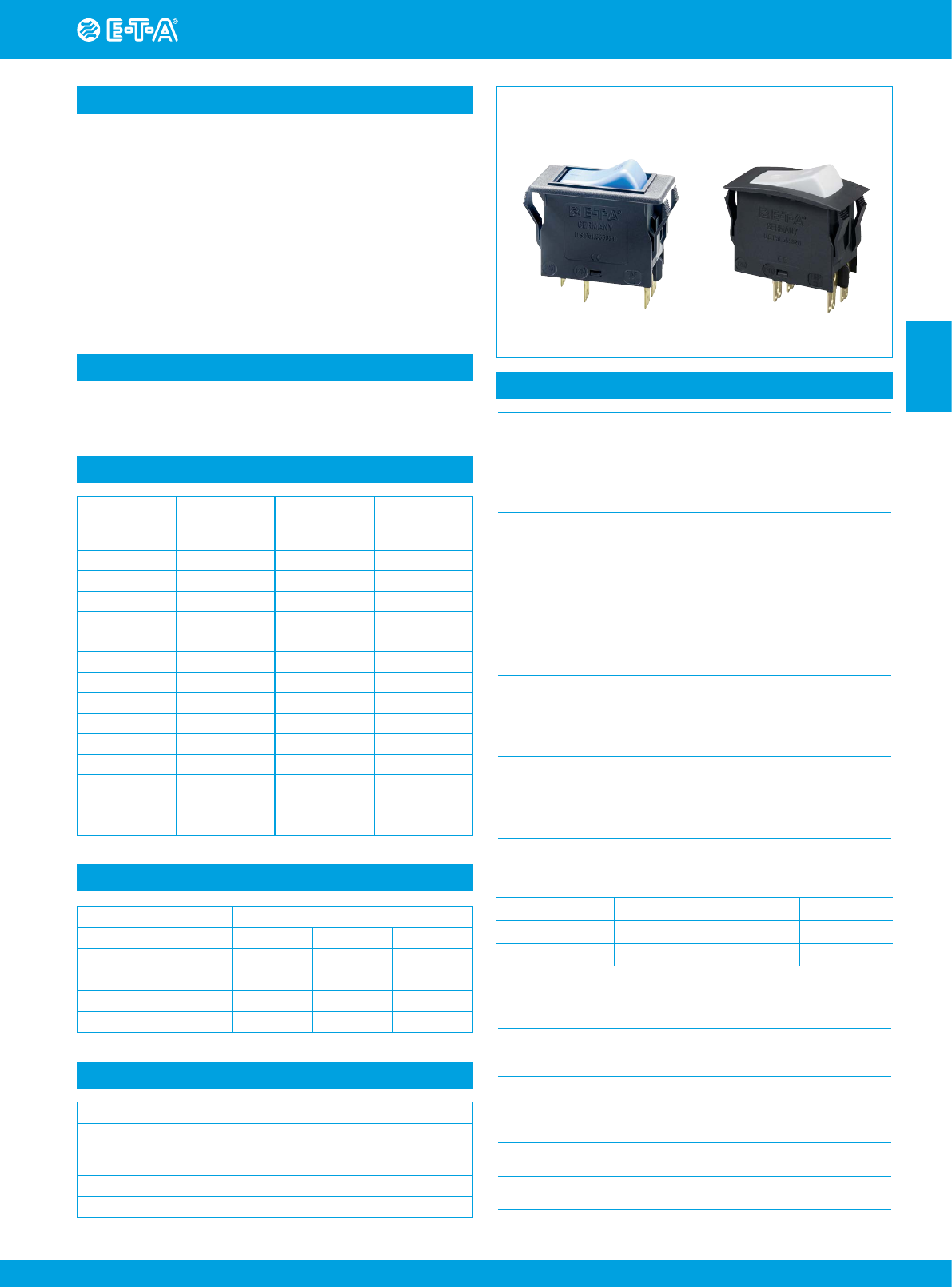
Thermal Overcurrent Circuit Breaker 3120-F...
www.e-t-a.de
2014/15
2 - 63
2
Description
Typical applications
Approvals
Technical data
An extremely versatile range of rocker switch/thermal circuit breakers
(S-type TO CBE to EN 60934 with trip free mechanism) offering the choice
of single pole, double pole with single pole protection, and double pole
with protection on both poles. Designed for snap-in panel mounting with
versions available for three different panel cut-out sizes. Illumination is
optional and there is a range of colours and markings for the rocker.
Add on modules:
l Under voltage release coil (for double pole versions only).
l Magnetic trip coil for short circuit protection.
l Magnetic trip coil for remote relay trip.
l Auxiliary contacts for status signalling.
Approved to CBE standard EN 60934 (IEC 60934).
Meets the requirements regarding fire resistance of EN 60335-1 : 2007-02
Safety of household and similar electrical appliances.
Motors, transformers, solenoids, extra low voltage wiring systems, office
machines, electro-medical equipment, power supplies, communications
systems, medical equipment to EN 60601.
3120-F3...F5 3120-F7
For further details please see chapter: Technical Information
Voltage rating AC 240 V; DC 50 V
(AC 415 V to special order)
(UL: AC 250 V; DC 50 V)
Current ratings 0.1...20 A
(up to 30 A to special order, single pole only)
Typical life 1-pole
AC 240 V: 0.1...20 A 30,000 operations at 1 x IN, inductive
DC 50 V: 0.1...4 A 30,000 operations at 1 x IN, inductive
4.5...16 A 30,000 operations at 1 x IN, resistive
DC 28 V: 0.1...20 A 30,000 operations at 1 x IN, inductive
2-pole
AC 415 V: 0.1...16 A 10,000 operations at 1 x IN, inductive
AC 240 V: 0.1...16 A 50,000 operations at 1 x IN, inductive
17...20 A 30,000 operations at 1 x IN, inductive
DC 50 V: 0.1...16 A 50,000 operations at 1 x IN, inductive
17...20 A 10,000 operations at 1 x IN, inductive
Ambient temperature -30...+60 °C (-22...+140 °F)
Insulation co-ordination rated impulse pollution
(IEC 60664 and 60664 A withstand voltage degree
2.5 kV 2
reinforced insulation in operating area
Dielectric strength
(IEC 60664 and 60664A) test voltage
operating area AC 3,000 V
between poles (2-pole) AC 1,500 V
Insulation resistance > 100 MΩ (DC 500 V)
Interrupting capacity Icn 0.1...2 A 10 x IN
2.5...20 A 250 A 2-pole, or 150 A 1-pole
Interrupting capacity (UL 1077)
Degree of protection operating area IP40
(IEC 60529/DIN 40050) (IP54 with water splash protection)
terminal area IP00
Vibration 8 g (57-500 Hz), ± 0.61 mm (10-57 Hz)
to IEC 60068-2-6, test Fc
10 frequency cycles/axis
Shock 30 g (11 ms)
to IEC 60068-2-27, test Ea
Corrosion 96 hours at 5 % salt mist,
to IEC 60068-2-11, test Ka
Humidity 240 hours at 95 % RH,
to IEC 60068-2-78, test Cab
Mass approx. 33 g (double pole)
approx. 27 g (single pole)
Standard current ratings and typical internal resistance values
Illumination voltage/power consumption
Current rating
(A)
Internal
resistance
per pole (Ω)
Current rating
(A)
Internal
resistance
per pole (Ω)
0.1 94 4 0.0435
0.2 24 4.5 0.0435
0.3 12 5 0.0325
0.4 5.30 6 0.0215
0.5 4.20 7 0.0165
0.6 2.90 8 0.0165
0.8 1.50 10 < 0.02
1 0.9 12 < 0.02
1.2 0.80 14 < 0.02
1.5 0.45 15 < 0.02
2 0.27 16 < 0.02
2.5 0.0785 18 < 0.02
3 0.0595 20 < 0.02
3.5 0.0565
Authority Voltage ratings Current ratings
VDE (EN 60934) AC 240 V; DC 28 V
DC 50 V
DC 50 V
0.1...20 A
0.1...20 A 2-pole
0.1...10 A 1-pole
UL, CSA AC 250 V; DC 50 V 0.1...20 A
CCC AC 240 V; DC 50 V 0.1...20 A
INUNInc
1, 2-pole 0.1...20 A AC 250 V 5000 A
1, 2-pole 0.1...20 A DC 50 V 1000 A
operating voltage power consumption
Y R G
12 V DC 5,2 mA 2 mA 1,4 mA
24 V DC 4,5 mA 2,2 mA 1,6 mA
115 V AC 2,8 mA 1,1 mA 1 mA
230 V AC 2,2 mA 0,9 mA 0,9 mA
Thermal Overcurrent Circuit Breaker 3120-F...
www.e-t-a.de 2014/15
2 - 64
2
0
I
I
0
ON
OFF
ADFX
Type No.
3120 rocker switch/circuit breaker
Mounting
F snap in frame
Size of frame
3 to fit mounting cut-out 50.5 x 21.5 mm
panel thickness: 1-6.35 mm (.039-.250 in)
5 to fit mounting cut-out 44.5 x 22 mm
panel thickness: 1-4 mm (.039-.157 in)
7 to fit mounting cut-out 44.5 x 22 mm
panel thickness: 1-4 mm (.039-.157 in)
Number of poles
0 2-pole, unprotected, switch only
1 1-pole, thermally protected
2 2-pole, thermally protected
5 2-pole, 1-pole thermally protected
Mounting frame design (F3 & F5)
1 collar height 1 mm
3 collar height 9 mm
4 collar height 2 mm with water splash protection (IP54)
Mounting frame design (F7)
R black
T black with snap-on splash cover
Terminal configuration
P7 blade terminals, standard for curve T1
(thermal circuit breaker)
H7 as P7, terminals 11 and 21 with flat head screws M3.5
– standard for units with undervoltage release module
N7 as P7, but with additional shunt terminals 12(i) and 22(i) –
standard for version Q1 (switch only)
Characteristic curve
T1 thermal 1.01 - 1.4 x IN
Q1 switch only
Actuator style
W standard rocker (F3 & F5)
A specially designed rocker (F7)
Colour and Illumination
01 . rocker black opaque
without illumination
02 . rocker white opaque
without illumination
04 . rocker red opaque without illumination
14 . R rocker red translucent with
LED-illumination
15 . Y rocker orange translucent with
LED-illumination
19 . G rocker green translucent with
LED-illumination
Rocker markings for F3 and F5
A
D
F
Q
X
Rocker markings for F7
Q »I« and »O« moulded in
Illumination voltage range
1 10 - 14 V DC
2 20 - 28 V DC
3 90 - 140 V AC
4 185 - 275 V AC
Current ratings
0.1...20 A
3120 - F 7 2 R - P7 T1 - A 14 Q R 4 - 10 A ordering example
3120 - F . 0 . - N7 Q1 - W .. . . . - 20 A (switch)
Ordering information
Q: as D, but
moulded in
X: without markings
Preferred types
F7/2-pole
protected
Standard current ratings (A)
0.5 1 1.5 2 3 4 5 6 8 10 12 15 16 20
3120-F72R-
P7T1-A14QR4 xxxxxx xxxxxxxx
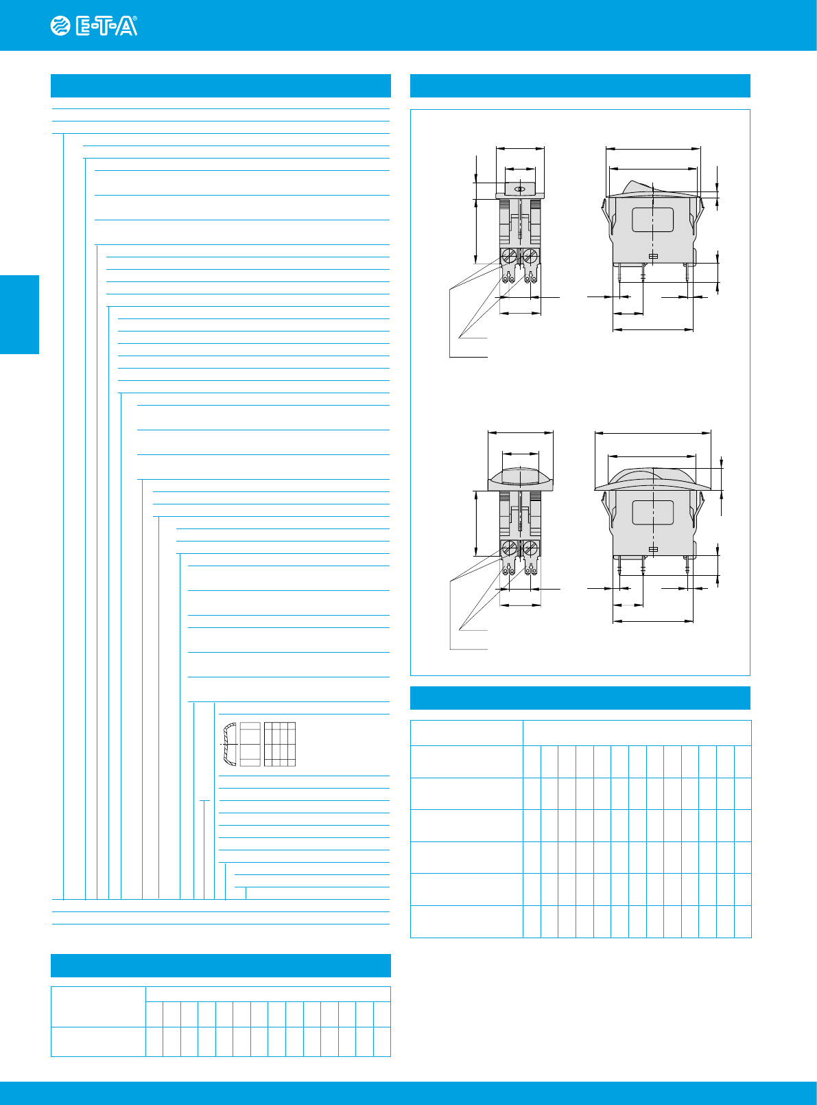
Dimensions
33
1.30
.453
15.5
15.5
25
44.2
-0.2
flat head screw ISO1580 M3.5x5-MS
tightening torque max. 0.8 Nm
blade terminals DIN 46244-C-Ms-S
(QC 2 x .110)
8.9
33
10.7
21
10
3
3.5
41
12(i) 12(k) 11
48
±0.2
3
LINE
34
44.8
10
12(i)12(k) 11
11.5
LINE
18.6
60
.984
.610
1.89
±.008
1.74
-.008
.118
1.30 .350
.421
.827
.118
.138
.394
.610
1.61
1.76
2.36
1.34
.732
.394
.827
blade terminals DIN 46244-C-Ms-S
(QC 2 x .110)
10.7
21 .421 15.5
3
41
.118
.138
.610
1.61
3.5
Style F7.R
Style F7.T
flat head screw ISO1580 M3.5x5-MS
tightening torque max. 0.8 Nm
Preferred types Standard current ratings (A)
Preferred types
F3/1-pole protected 0.5 1 2 3 4 5 6 8 10 12 15 16 20
3120-F311-P7T1-
W02D- x x x x x x x x
Preferred types
F3 /2-pole protected 0.5 1 2 3 4 5 6 8 10 12 15 16 20
3120-F321-P7T1-
W01D- xxxxx xxxxxxxx
Preferred types
F5/2-pole protected 0.5 1 2 3 4 5 6 8 10 12 15 16 20
3120-F521-P7T1-
W01D- xxxx xxxxxxxx
Preferred types
Preferred types
Thermal Overcurrent Circuit Breaker 3120-F...
www.e-t-a.de
2014/15
2 - 65
2
Thermal Overcurrent Circuit Breaker 3120-F...
Dimensions
25
16
7
33
35
10.7
21
54
10
3
3.5
15.5
41
blade terminals DIN 46244-C-Ms-S
(QC 2x. 110)
flat head screw ISO1580 M3.5x5-MS
tightening torque max. 0.8 Nm
Actuating force max. 35 N
optional illumination in ON position
OFF position
12(i) 12(k) 11
.630
.984
2.13
.394
.118
.138
.610
1.61
.276
1.38
1.30
.421
.827
Style F3.1
collar height 1 mm/.039 in.
Installation drawing
mounting area
operating area
710
15.5
778
10
12(i) 12(k)11
When installing the circuit breaker apply pressure on bezel only
.276 .276 .315 .276 .394
.610
.394
Mounting style variants
Style F 3.4
collar height 2 mm (.079 in.), with water splash protection
Style F 3.3 collar height 9 mm (.354 in.)
27
19.5
1.30
10.7
10
33
3.8
.421
.827
.150 .394
.768
1.06
21
Style F 5.1
3.5
.138
15.5
Optional illumination
48
10
3
41
12(i) 12(k) 11
.118
.394
.610
1.61
1.89
3.5
.138
56
15.5
35
3
.118
.394
.610
1.61
1.38
41
10
2.21
12(i) 12(k) 11
25
1.30
blade terminals DIN 46244-C-Ms-S
(QC 2x.110)
flat head screw M3.5x5-MS ISO1580
tightening torque max. 0.8 Nm
10.7
19.5
9
33
35
.421
.827
1.38 .354
.768
.984
21
54
12(i) 12(k) 11
15.5
3.5
35
3
.118
.394
.138
.610
1.61
1.38
41
10
2.13
25
blade terminals DIN 46244-C-Ms-S
(QC 2x.110)
10.7
21
16
7
33
35
.421
.827
1.30
1.38 .276
.630
.984
blade terminals DIN 46244-C-Ms-S
(QC 2x.110)
flat head screw M3.5x5-MS ISO1580
tightening torque max. 0.8 Nm
flat head screw M3.5x5-MS ISO1580
tightening torque max. 0.8 Nm
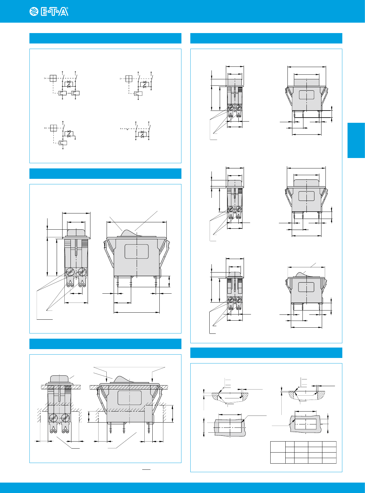
Internal connection diagrams
11 21
line
12(i)
12(k)
22(i)
22(k)
load 12(k) load
11 line
12(i)
12(k)
22(i)
load
11 21
line
12(i) 22(i)
2-pole,
thermally protected on both poles
2-pole,
thermally protected on one pole only
1-pole,
thermally protected
2-pole,
unprotected
12(i) 22(i)
line
load
11 21
This is a metric design and millimeter dimensions take precedence ( mm )
inch
Cut-out dimensions
.039-.250
1-6.35
Cut-out for mounting style -F3
with rocker and push button
Cut-out for mounting
style -F5/-F7
with rocker
min. 2.5
min .098
max. R2
max .079
50.5+0.3
21.5+0.2
max. R0.3
1.99+.012
.846+.008
max .012
- 0.4
-.016
- 0.2
-.008
±0.05
±.002
1-4 mm
.039-.157 in.
panel
thickness
1.2
+0.4
.047
+.016
1.6
+0.8
.063
+.031
2.4
+1
.094
+.039
Edges of working parts: ISO 13715
max. R1.5
max .059
min. 2
min .079
dimension
“A”
45
1.77
+.008
- .002
+0,2
- 0.05
45
1.77
45
1.77
mm
inch
mm
inch
+1.1
- 0.05 +2.2
- 0.05
+.043
- .002
+.087
- .002
- 0.4
-.016
- 0.2
-.008
±0.05
±.002
1.75+.008
22+0.3
max. R0.3
44.5+0.2
max .012
.866+.012
Thermal Overcurrent Circuit Breaker 3120-F...
www.e-t-a.de 2014/15
2 - 66
2
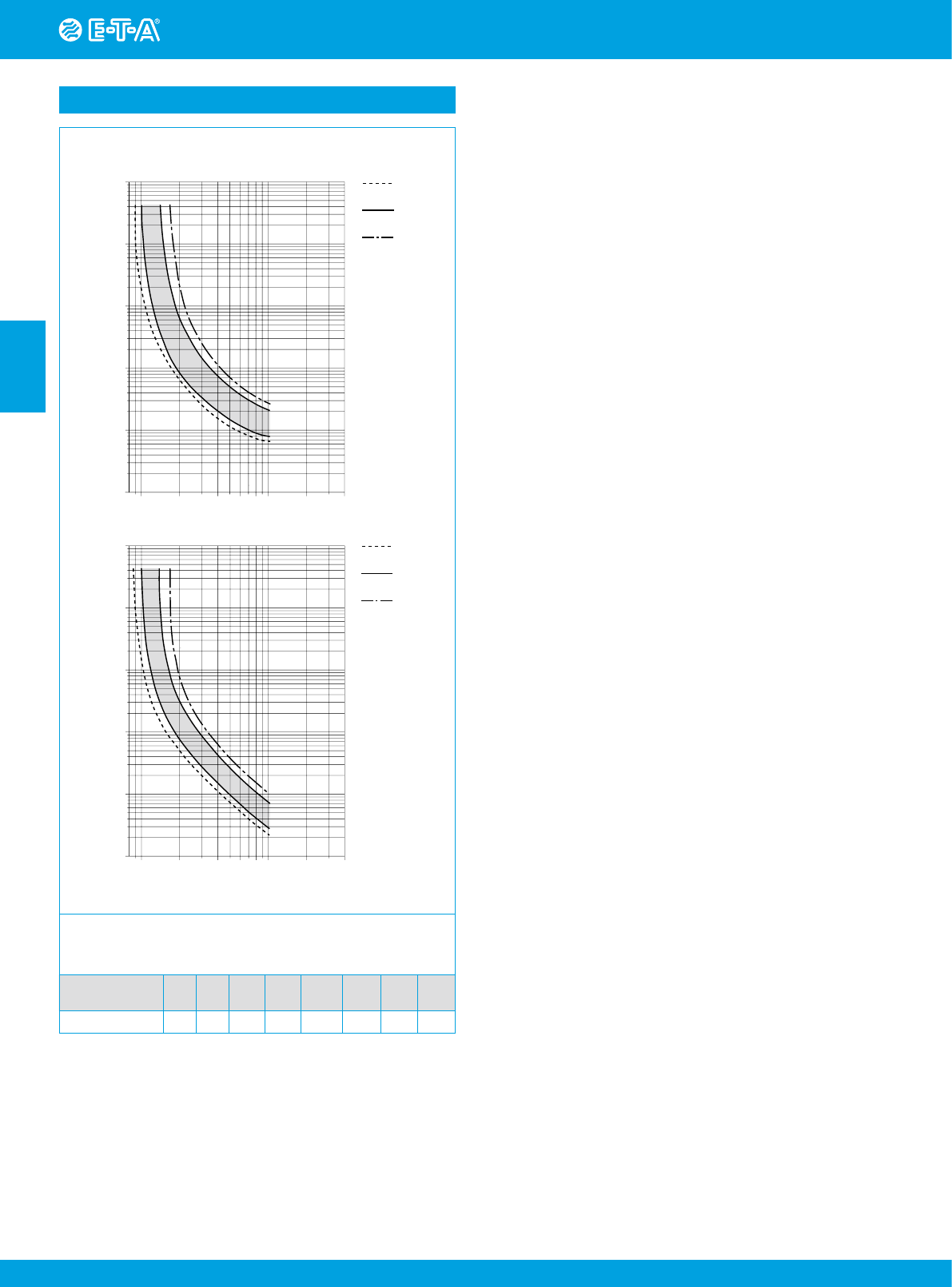
The time/current characteristic curve depends on the ambient temperature
prevailing. In order to eliminate nuisance tripping, please multiply the circuit
breaker current ratings by the derating factor shown below. See also section
Technical information.
Ambient °F
temperature °C
-22
-30 -4
-20 +14
-10 +32
0+73.4
+23 +104
+40 +122
+50 +140
+60
Derating factor 0.8 0.76 0.84 0.92 1 1.08 1.16 1.24
Typical time/current characteristics
+23 °C
+73.4 °F
+60 °C
+140 °F
-30 °C
-22 °F
12468102040
… times rated current
Trip time in seconds
10000
1000
100
10
1
0.1
+23 °C
+73.4 °F
+60 °C
+140 °F
-30 °C
-22 °F
12468102040
… times rated current
Trip time in seconds
10000
1000
100
10
1
0.1
single or double pole load
0.1…2 A
2.5…20 A
Thermal Overcurrent Circuit Breaker 3120-F...
www.e-t-a.de
2014/15
2 - 67
2
Thermal Overcurrent Circuit Breaker 3120-F...
All dimensions without tolerances are for reference only. In the interest of improved design,
performance and cost effectiveness the right to make changes in these specifications
without notice is reserved. Product markings may not be exactly as the ordering codes.
Errors and omissions excepted.
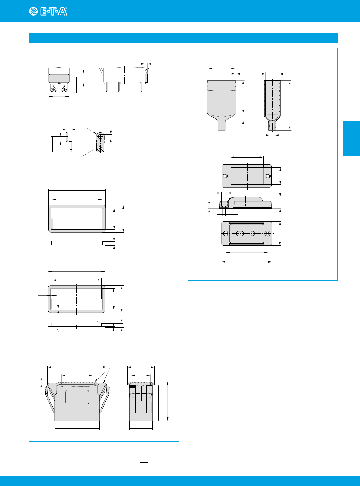
Accessories
Spacer for 3120-F3...
Y
303 675 01/02
blade terminal DIN 46244-C-Ms-S
(QC 2x.110)
Terminal adapter
Y
303 862 01
4
4
13.5
3.7
R3.5
.157
.531
.157
.138
.146
Insulated cover
Y
303 068 01
Spacer for 3120-F5...
Y
303 676 01
50.5
22
58
28
** Y 303 675 01 suitable for
panel thickness < 2 mm (.079 in)
* Y 303 675 02 suitable for
panel thickness < 4 mm (.157 in)
.866
1.10
1.99
2.28
36
25
16.5
21
33
54
.650
.984
2.13
1.42
1.30
.827
1
41
31
matt finish
1.22
1.61
.039
Blanking piece in -F3 frame
Y
303 885 31
44.5
22.5
52
2.5
0.8
1
1
without bends
sharp-edged
28
.886
1.10
1.75
2.05
.039
.039
.031
.098
0.9
20
2.5
9
.787
.354
.035
.098
16.5
48
25
3.4
60
73
35
ø8
ø4.4
1.89
.984
.650
.315
.134
.173
1.38
2.36
2.87
50
70
+5
10
40.5
1.75
ø8
+0.5
-0.25
1.59
.069+.020
-.010
2.76
+.197
1.97
.394
.315
20.5
.807
Rear terminal shroud black (IP64)
Y
304 275 01
Water splash cover, transparent (IP66)
for style -F5..
X 221 619 01
This is a metric design and millimeter dimensions take precedence ( mm )
inch

www.e-t-a.de
2 - 68
2014/15
2
