56857 Catalog
56857-Catalog 56857-Catalog 56857-Catalog Batch8 unilog cesco-content
126532-Catalog 126532-Catalog 126532-Catalog 803423 Batch5 unilog cesco-content
2014-09-27
: Pdf 56857-Catalog 56857-Catalog 803423 Batch8 unilog
Open the PDF directly: View PDF ![]() .
.
Page Count: 18

HPS Universal™
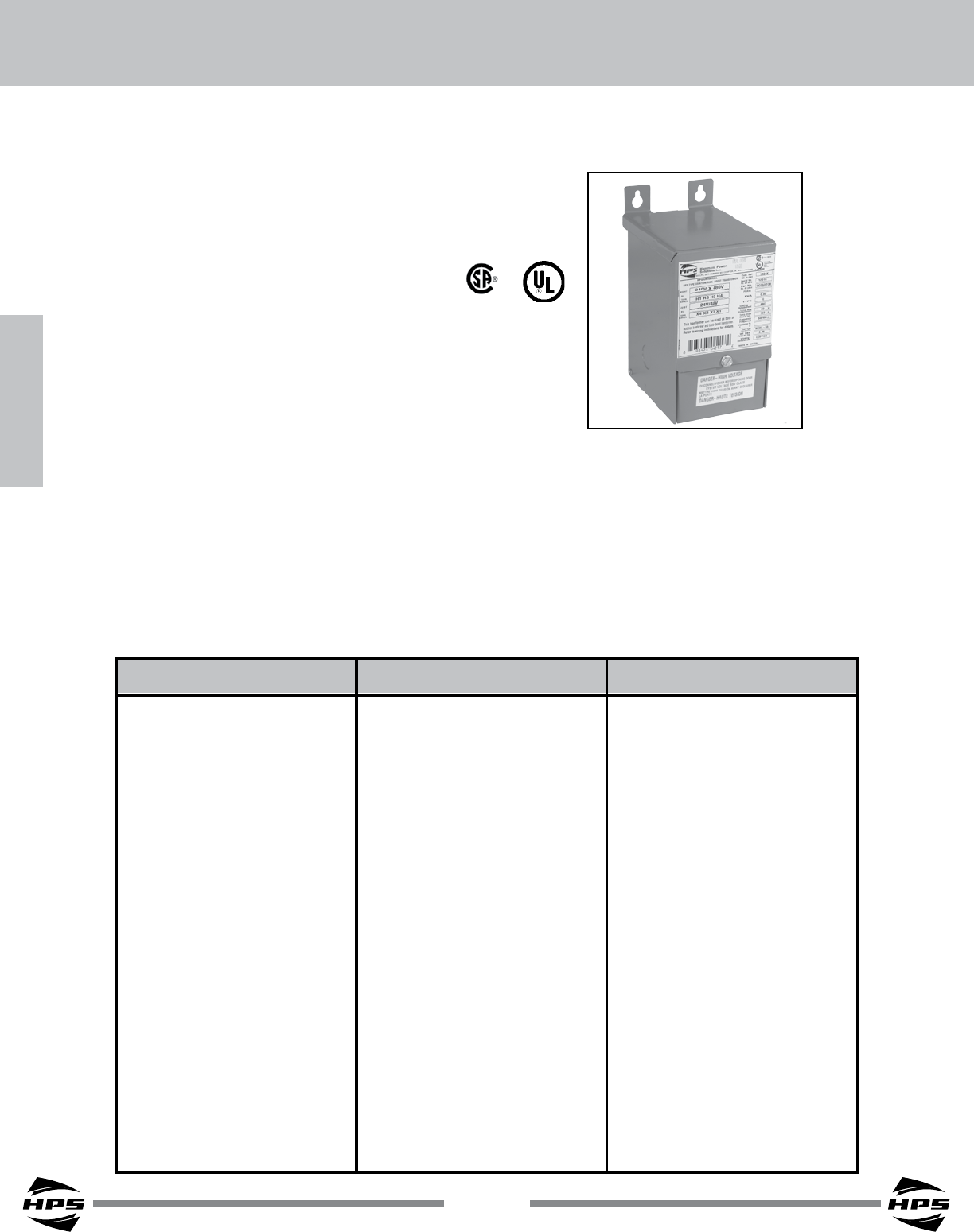
BUCK-BOOST TRANSFORMERS
Single and Three Phase Potted
Buck-Boost Transformers
Buck-Boost Applications & Standard Specication....... 82
Selecting Buck-Boost Transformers ............................... 83
Single Phase Selection Tables ........................................ 84
Three Phase Selection Tables ......................................... 87
Single Phase Specication Tables .................................. 90
Three Phase Specication Tables ................................... 91
Single Phase Connection Diagrams ............................... 93
Three Phase Connection Diagrams ................................ 94
Three Phase Buck-Boost Explained ................................ 95
SECTION 2
82
SECTION 2
SECTION 2
HPS Universal™
BUCK-BOOST STANDARD SPECIFICATIONS
© Hammond Power Solutions Inc. Data subject to change without notice.
Why Use Buck-Boost Transformers?
The advantages of using a buck-boost transformer over an equivalent standard isolation transformer are:
Advantages
1) Used in a variety of applications
2) Inexpensive
3) Smaller and lighter
4) More efcient
5) 5-10 times increase in kVA
Disadvantages
1) No circuit isolation
2) Cannot create a neutral
3) KVA and voltages do not match what’s
on the nameplate kVA and voltages.
Buck-Boost Application
Buck-boost transformers offer an economical solution to the adjustment of line voltages that are slightly
above or below normal. When a buck-boost transformer is connected as an autotransformer, only a portion of
the load kVA is actually transformed. The majority of the load kVA is passed directly through to the source. For
this reason a buck-boost transformer may be used to supply a much larger kVA load than is indicated on the
nameplate.
Buck-boost transformers can be used to adjust stable voltages only.
UL Listed File: E50394 File: E50394
CSA Certied File: LR3902 File: LR3902
Frequency 50/60 Hz 50/60 Hz
Insulation System 130°C (80°C rise) 180°C (115°C rise)
Standard Design Single Phase, welded core construction Single Phase, welded core construction
made with high quality, high permeability made with high quality, high permeability
silicon steel laminations. Computer silicon steel laminations. Computer
designed coils, accurately wound from designed coils, accurately wound from
high quality copper magnetic wire. high quality copper magnetic wire.
Encapsulation All units from 50VA to 5kVA are All units from 50VA to 5kVA are
encapsulated with electrical grade silica encapsulated with electrical grade silica
sand and resin compounds. sand and resin compounds.
Enclosure Type Heavy Duty NEMA Type 3R Heavy Duty NEMA Type 3R
(optional NEMA 4, 4X and 12 available) (optional NEMA 4, 4X and 12 available)
Enclosure Finish ANSI 61 Grey, UL50 ANSI 61 Grey, UL50
Termination Front accessible separate high and Front accessible separate high and
low voltage lead wires or copper tabs. low voltage lead wires or copper tabs.
Conduit Knock-Outs Side and rear standard on all units. Side and rear standard on all units.
Mounting Standard Wall Mounting. Standard Wall Mounting.
50 to 1000 VA 1500 to 5000 VA

SECTION 2
83
SECTION 2
BUCK-BOOST TRANSFORMERS
© Hammond Power Solutions Inc. Data subject to change without notice.
Voltage Is the Key
Buck-boost transformers represent an economical way to both raise supply voltage caused by line drop
or equipment demand on the distribution system, or lower voltage caused by increased system voltages due to
supply line adjustments. Some loads including lighting and resistive loads require a stable supply to maintain
performance. The detrimental effects of incorrect supply line voltage can cause equipment failure. Buck-boost
transformers can correct line voltage within 5 to 25% of nominal.
Steps for Selecting Buck-Boost Transformers
The following information is required before selecting a buck-boost transformer:
(1) Line Voltage - The voltage that you want to buck (decrease) or boost (increase). This can be
determined by measuring the supply line voltage with a voltmeter.
(2) Load Voltage - The voltage at which your equipment is designed to operate. This is listed on the
nameplate of the load equipment.
(3) Load kVA or Load Amps - You do not need to know both - one or the other is sufcient. This
information usually can be found on the nameplate of the equipment that you want to operate. It is the
sum of all the equipment that represents the load.
(4) Frequency - The supply line frequency must be the same as the equipment to be operated - either
50 or 60 Hertz.
(5) Phase - The supply line should be the same as the load - either single or three phase.
Four Steps to Select the Correct Buck-Boost Transformer
1. From the top row of each “Selection Chart”, select a ‘high voltage’ and ‘low voltage’ combination that is
the closest to matching the high voltage and low voltage correction that is required for your application.
2. Move down that column to the kVA or current rating equal to, or greater than, the rating required by the
total load. It is not likely that the exact value of the load will be found, so go to the next higher rating.
3. From the far left column, select the corresponding catalog number of the exact buck-boost transformer
required. Refer to specication tables for dimensional information.
4. Connect the transformer in accordance with the connection diagram referenced at the bottom of
the same column where you selected your high voltage and low voltage combination. Connection
diagrams are on pages 93 and 94 in this catalog section. They are also packaged with each
transformer.
84
SECTION 2
SECTION 2
HPS Universal™
© Hammond Power Solutions Inc. Data subject to change without notice.
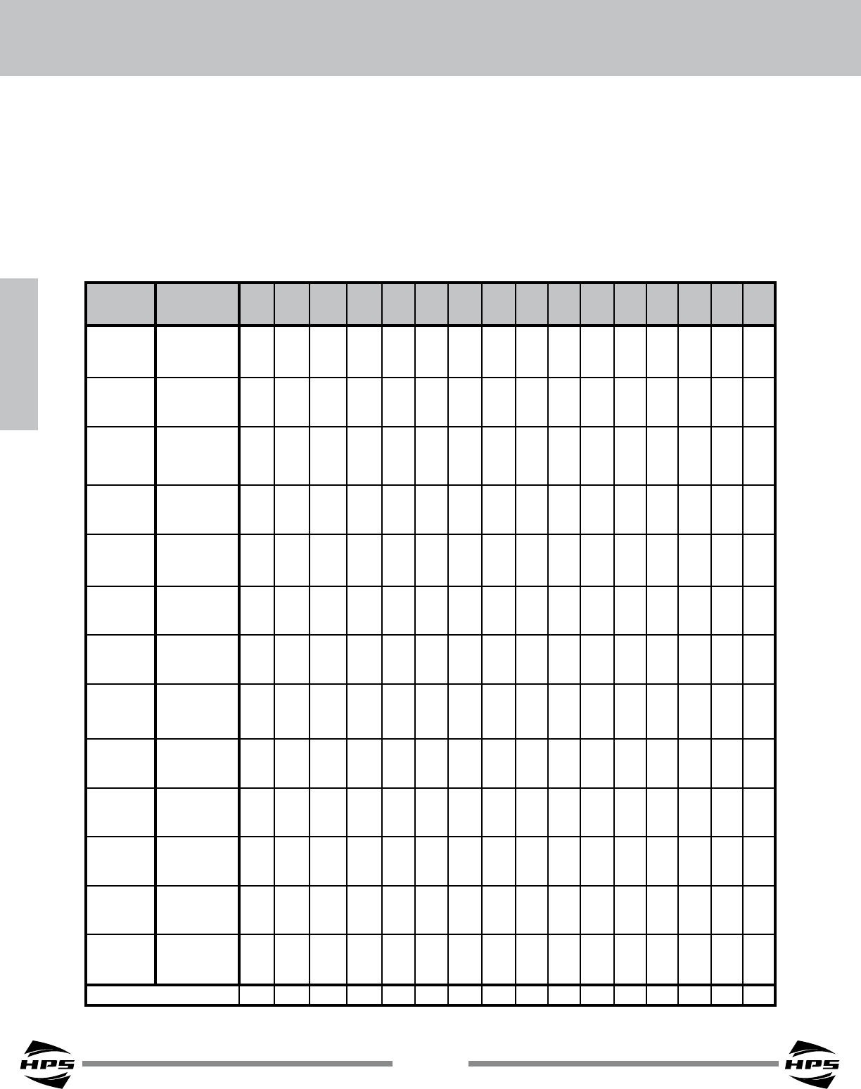
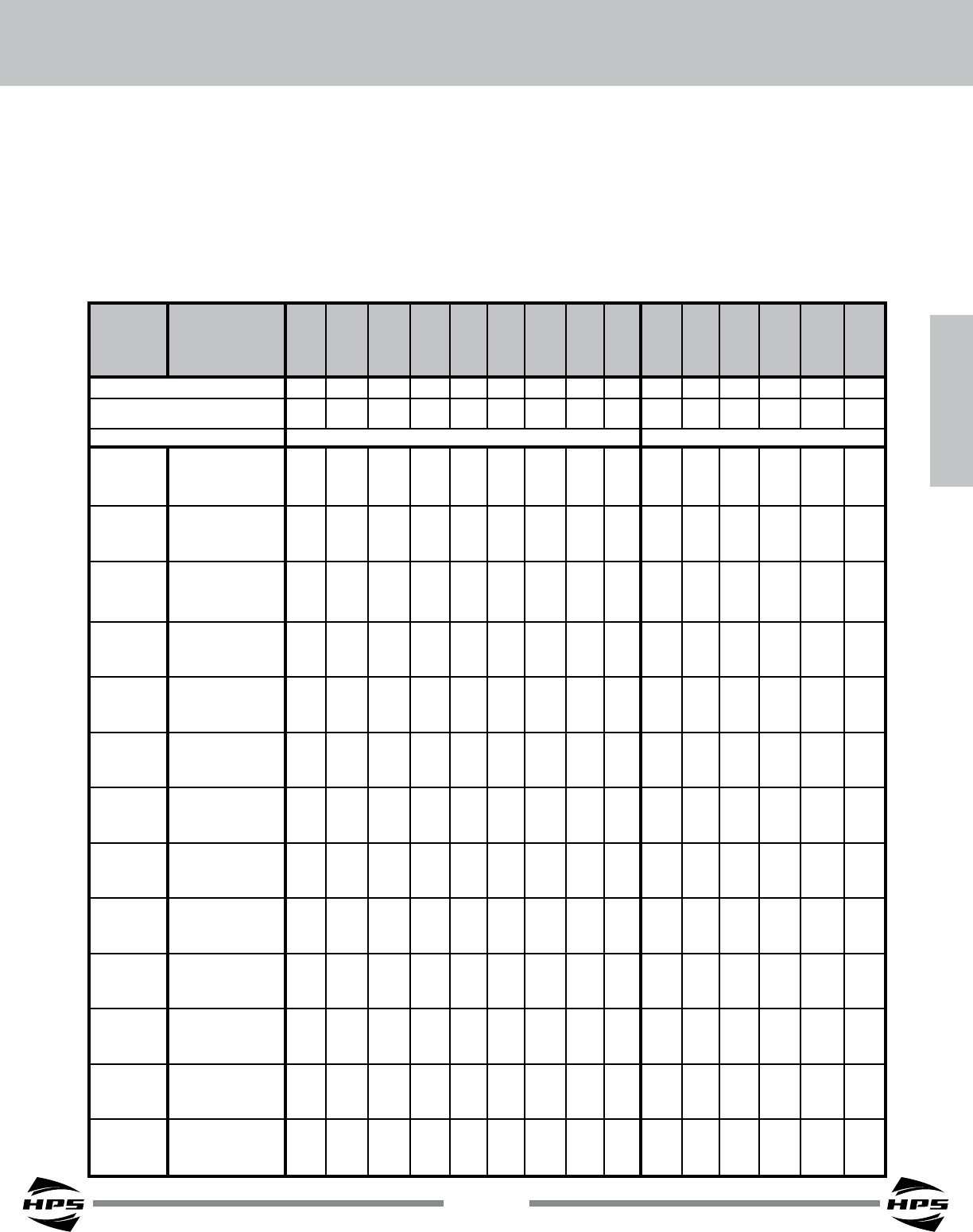
How to use the Selection Chart
1. From the top row of the “Selection Chart” locate the high and low voltage combination that is closest
to the one you require.
2. Move down that column to the kVA or Ampere rating equal to or greater than the rating required by the load.
3. From the far left column, obtain the transformer catalog number.
4. For dimensional information refer to the specications table (Group A) on page 90.
5. The corresponding connection diagram is indicated at the bottom of the Voltage / kVA column. See page 93
for the connection diagrams.
Single Phase - Group A Selection Chart
Catalog
Number
Low Voltage
High Voltage
96 100 100 105 110 110 115 115 120 120 200 208 220 220 240 240
115 110 120 115 121 132 126 138 132 144 220 229 231 242 252 264
QC05ERCB
HV Amps 2.08 4.17 2.08 4.17 4.17 2.08 4.17 2.08 4.17 2.08 2.08 2.08 4.17 2.08 4.17 2.08
KVA .240 .458 .250 .480 .504 .275 .526 .288 .550 .300 .458 .477 .963 .504 1.05 .550
LV Amps 2.50 4.58 2.50 4.58 4.58 2.50 4.58 2.50 4.58 2.50 2.29 2.29 4.38 2.29 4.38 2.29
QC10ERCB
HV Amps 4.17 8.33 4.17 8.33 8.33 4.17 8.33 4.17 8.33 4.17 4.17 4.17 8.33 4.17 8.33 4.17
KVA .480 .917 .500 .961 1.01 .550 1.05 .575 1.10 .600 .917 .953 1.92 1.01 2.10 1.10
LV Amps 5.00 9.17 5.00 9.17 9.17 5.00 9.17 5.00 9.17 5.00 4.58 4.58 8.75 4.58 8.75 4.58
QC15ERCB
HV Amps 6.25 12.5 6.25 12.5 12.5 6.25 12.5 6.25 12.5 6.25 6.25 6.25 12.5 6.25 12.5 6.25
KVA .720 1.38 .750 1.44 1.51 .825 1.58 .863 1.65 .900 1.38 1.43 2.88 1.51 3.15 1.65
LV Amps 7.50 13.8 7.50 13.8 13.8 7.50 13.8 7.50 13.8 7.50 6.88 6.88 13.1 6.88 13.1 6.88
QC20ERCB
HV Amps 8.33 16.7 8.33 16.7 16.7 8.33 16.7 8.33 16.7 8.33 8.33 8.33 16.7 8.33 16.7 8.33
KVA .960 1.83 1.00 1.92 2.02 1.10 2.11 1.15 2.20 1.20 1.83 1.91 3.85 2.02 4.20 2.20
LV Amps 10.0 18.3 10.0 18.3 18.3 10.0 18.3 10.0 18.3 10.0 9.17 9.17 17.5 9.17 17.5 9.17
QC25ERCB
HV Amps 10.4 20.8 10.4 20.8 20.8 10.4 20.8 10.4 20.8 10.4 10.4 10.4 20.8 10.4 20.8 10.4
KVA 1.20 2.29 1.25 2.40 2.52 1.37 2.63 1.44 2.75 1.50 2.29 2.38 4.81 2.52 5.25 2.75
LV Amps 12.5 22.9 12.5 22.9 22.9 12.5 22.9 12.5 22.9 12.5 11.4 11.4 21.8 11.4 21.8 11.4
QC35ERCB
HV Amps 14.6 29.2 14.6 29.2 29.2 14.6 29.2 14.6 29.2 14.6 14.6 14.6 29.2 14.6 29.2 14.6
KVA 1.68 3.21 1.75 3.36 3.53 1.92 3.68 2.01 3.85 2.10 3.21 3.34 6.74 3.53 7.35 3.85
LV Amps 17.5 32.1 17.5 32.1 32.1 17.5 32.1 17.5 32.1 17.5 16.0 16.0 30.6 16.0 30.6 16.0
QC50ERCB
HV Amps 20.8 41.6 20.8 41.7 41.7 20.8 41.7 20.8 41.7 20.8 20.8 20.8 41.7 20.8 41.7 20.8
KVA 2.39 4.58 2.50 4.80 5.04 2.75 5.26 2.87 5.50 3.00 4.58 4.77 9.62 5.04 10.5 5.50
LV Amps 24.9 45.8 25.0 45.8 45.8 25.0 45.8 25.0 45.8 25.0 22.9 22.9 43.7 22.9 43.7 22.9
QC75ERCB
HV Amps 31.2 62.5 31.2 62.5 62.5 31.2 62.5 31.2 62.5 31.2 31.2 31.2 62.5 31.2 62.5 31.2
KVA 3.60 6.87 3.75 7.20 7.56 4.12 7.89 4.31 8.25 4.50 6.87 7.15 14.4 7.56 15.7 8.25
LV Amps 37.5 68.7 37.5 68.7 68.7 37.5 68.7 37.5 68.7 37.5 34.4 34.4 65.6 34.4 65.6 34.4
Q1C0ERCB
HV Amps 41.7 83.3 41.7 83.3 83.3 41.7 83.3 41.7 83.3 41.7 41.7 41.7 83.3 41.7 83.3 41.7
KVA 4.80 9.17 5.00 9.60 10.1 5.50 10.5 5.75 11.0 6.00 9.17 9.53 19.2 10.1 21.0 11.0
LV Amps 50.0 91.7 50.0 91.7 91.7 50.0 91.7 50.0 91.7 50.0 45.8 45.8 87.5 45.8 87.5 45.8
Q1C5ERCF
HV Amps 62.5 125 62.5 125 125 62.5 125 62.5 125 62.5 62.5 62.5 125 62.5 125 62.5
KVA 7.20 13.7 7.50 14.4 15.1 8.25 15.8 8.62 16.5 9.00 13.7 14.3 28.9 15.1 31.5 16.5
LV Amps 75.0 137 75.0 137 137 75.0 137 75.0 137 75.0 68.7 68.8 131 68.7 131 68.7
Q002ERCF
HV Amps 83.3 166 83.3 166 166 83.3 166 83.3 166 83.3 83.3 83.3 166 83.3 166 83.3
KVA 9.58 18.3 10.0 19.2 20.1 11.0 21.0 11.5 22.0 12.0 18.3 19.0 38.5 20.1 42.0 22.0
LV Amps 99.8 183 100 183 183 100 183 100 183 100 91.7 91.7 175 91.6 175 91.6
Q003ERCF
HV Amps 125 250 125 250 250 125 250 125 250 125 125 125 250 125 250 125
KVA 14.4 27.5 15.0 28.8 30.2 16.5 31.5 17.2 33.0 18.0 27.5 28.6 57.7 30.2 63.0 33.0
LV Amps 150 275 150 275 275 150 275 150 275 150 137 137 262 137 262 137
Q005ERCF
HV Amps 208 417 208 417 417 208 417 208 417 208 208 208 417 208 417 208
KVA 24.0 45.8 25.0 48.0 50.4 27.5 52.7 28.7 55.0 30.0 45.8 47.7 96.3 50.4 105 55.0
LV Amps 250 458 250 458 458 250 458 250 458 250 229 229 438 229 438 229
CONNECTION DIAGRAM 2 1 2 1 1 2 1 2 1 2 4 4 3 4 3 4
SECTION 2
85
SECTION 2
BUCK-BOOST TRANSFORMERS
© Hammond Power Solutions Inc. Data subject to change without notice.
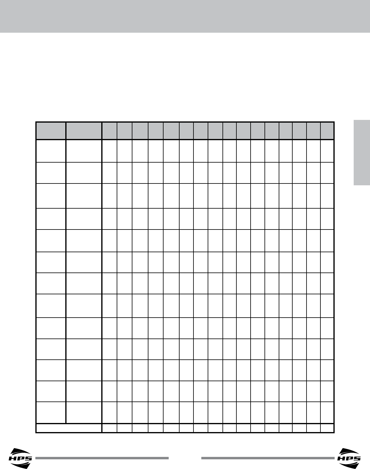
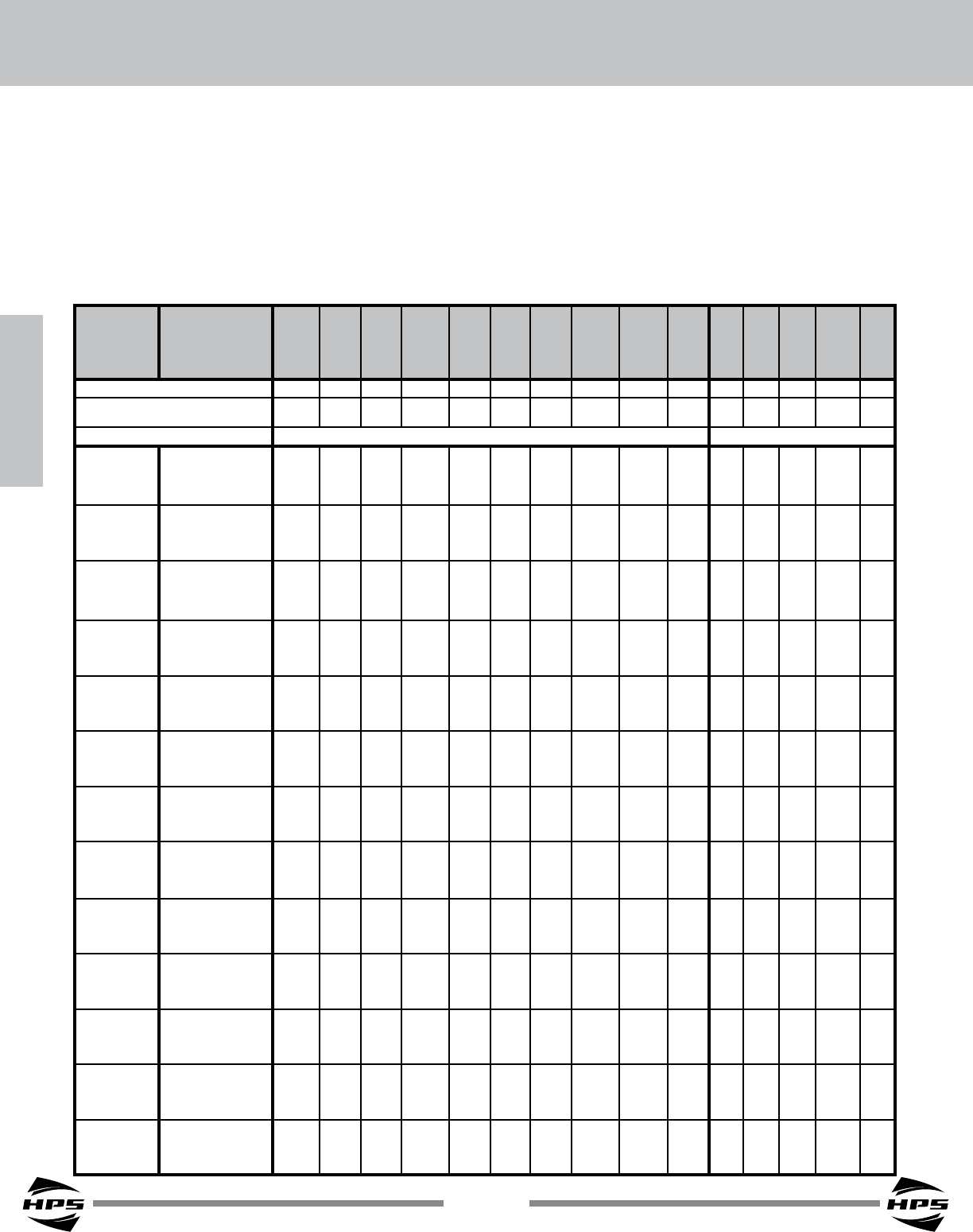
How to use the Selection Chart
1. From the top row of the “Selection Chart” locate the high and low voltage combination that is closest to the
one you require.
2. Move down that column to the kVA or Ampere rating equal to or greater than the rating required by the load.
3. From the far left column, obtain the transformer catalog number.
4. For dimensional information refer to the specications table (Group B) on page 90.
5. The corresponding connection diagram is indicated at the bottom of the Voltage / kVA column. See page 93
for the connection diagrams.
Single Phase - Group B Selection Chart
Catalog
Number
Low Voltage
High Voltage
95 101 106 110 110 115 115 120 120 203 208 220 220 230 240 240
120 115 120 125 139 130 146 136 152 230 236 235 249 261 256 272
QC05ESCB
HV Amps 1.56 3.13 3.13 3.13 1.56 3.13 1.56 3.13 1.56 1.56 1.56 3.13 1.56 1.56 3.13 1.56
KVA .188 .359 .375 .390 .218 .407 .228 .425 .238 .359 .368 .733 .390 .407 .800 .425
LV Amps 1.98 3.54 3.54 3.54 1.98 3.54 1.98 3.54 1.98 1.77 1.77 3.33 1.77 1.77 3.33 1.77
QC10ESCB
HV Amps 3.12 6.25 6.25 6.25 3.12 6.25 3.12 6.25 3.12 3.12 3.12 6.25 3.12 3.12 6.25 3.12
KVA .376 .718 .751 .779 .435 .815 .455 .850 .475 .719 .737 1.47 .779 .815 1.60 .850
LV Amps 3.96 7.08 7.08 7.08 3.96 7.08 3.96 7.08 3.96 3.54 3.54 6.67 3.54 3.54 6.67 3.54
QC15ESCB
HV Amps 4.69 9.38 9.38 9.38 4.69 9.38 4.69 9.38 4.69 4.69 4.69 9.38 4.69 4.69 9.38 4.69
KVA .564 1.07 1.13 1.17 .653 1.22 .683 1.28 .713 1.08 1.10 2.20 1.17 1.22 2.40 1.28
LV Amps 5.94 10.6 10.6 10.6 5.94 10.6 5.94 10.6 5.94 5.31 5.31 10.0 5.31 5.31 10.0 5.31
QC20ESCB
HV Amps 6.25 12.5 12.5 12.5 6.25 12.5 6.25 12.5 6.25 6.25 6.25 12.5 6.25 6.25 12.5 6.25
KVA .752 1.43 1.50 1.56 0.871 1.63 0.91 1.70 .950 1.44 1.47 2.93 1.56 1.63 3.20 1.70
LV Amps 7.92 14.2 14.2 14.2 7.92 14.2 7.92 14.2 7.92 7.08 7.08 13.3 7.08 7.08 13.3 7.08
QC25ESCB
HV Amps 7.81 15.6 15.6 15.6 7.81 15.6 7.81 15.6 7.81 7.81 7.81 15.6 7.81 7.81 15.6 7.81
KVA 0.94 1.80 1.87 1.95 1.09 2.04 1.14 2.12 1.19 1.80 1.84 3.67 1.95 2.04 4.00 2.12
LV Amps 9.90 17.7 17.7 17.7 9.87 17.7 9.90 17.7 9.90 8.85 8.85 16.7 8.85 8.85 16.7 8.85
QC35ESCB
HV Amps 10.9 21.9 21.9 21.9 10.9 21.9 10.9 21.9 10.9 10.9 10.9 21.9 10.9 10.9 21.9 10.9
KVA 1.31 2.51 2.63 2.73 1.52 2.85 1.59 2.98 1.66 2.51 2.58 5.13 2.73 2.85 5.60 2.98
LV Amps 13.9 24.8 24.8 24.8 13.9 24.8 13.9 24.8 13.9 12.4 12.4 23.3 12.4 12.4 23.3 12.4
QC50ESCB
HV Amps 15.6 31.2 31.2 31.2 15.6 31.2 15.6 31.2 15.6 15.6 15.6 31.2 15.6 15.6 31.2 15.6
KVA 1.88 3.59 3.75 3.90 2.18 4.07 2.28 4.25 2.37 3.59 3.68 7.33 3.90 4.07 8.00 4.25
LV Amps 19.8 35.4 35.4 35.4 19.8 35.4 19.8 35.4 19.8 17.7 17.7 33.3 17.7 17.7 33.3 17.7
QC75ESCB
HV Amps 23.4 46.8 46.8 46.9 23.4 46.9 23.4 46.9 23.4 23.4 23.4 46.9 23.4 23.4 46.9 23.4
KVA 2.82 5.39 5.63 5.84 3.27 6.10 3.41 6.37 3.56 5.39 5.53 11.0 5.84 6.11 12.0 6.37
LV Amps 29.7 53.1 53.1 53.1 29.7 53.1 29.7 53.1 29.7 26.6 26.6 50.0 26.6 26.6 50.0 26.6
Q1C0ESCB
HV Amps 31.2 62.5 62.5 62.5 31.2 62.5 31.2 62.5 31.2 31.2 31.2 62.5 31.2 31.2 62.5 31.2
KVA 3.76 7.18 7.50 7.79 4.35 8.15 4.55 8.50 4.75 7.19 7.37 14.7 7.79 8.15 16.0 8.50
LV Amps 39.6 70.8 70.8 70.8 39.6 70.8 39.6 70.8 39.6 35.4 35.4 66.7 35.4 35.4 66.7 35.4
Q1C5ESCF
HV Amps 46.9 93.7 93.7 93.7 46.9 93.7 46.9 93.7 46.9 46.9 46.8 93.7 46.9 46.9 93.7 46.9
KVA 5.64 10.8 11.2 11.7 6.53 12.2 6.83 12.7 7.12 10.8 11.0 22.0 11.7 12.2 24.0 12.7
LV Amps 59.4 106 106 106 59.4 106 59.4 106 59.4 53.1 53.1 100 53.1 53.1 100 53.1
Q002ESCF
HV Amps 62.5 125 125 125 62.5 125 62.5 125 62.5 62.5 62.5 125 62.5 62.5 125 62.5
KVA 7.50 14.4 15.0 15.6 8.71 16.3 9.10 17.0 9.50 14.4 14.7 29.3 15.6 16.3 32.0 17.0
LV Amps 79.1 142 142 142 79.2 142 79.2 142 79.2 70.8 70.8 133 70.8 70.8 133 70.8
Q003ESCF
HV Amps 93.7 187 187 187 93.7 187 93.7 187 93.7 93.7 93.7 187 93.7 93.7 187 93.7
KVA 11.3 21.5 22.5 23.4 13.0 24.4 13.6 25.5 14.2 21.6 22.1 44.0 23.4 24.4 48.0 25.5
LV Amps 119 212 212 212 119 212 119 212 119 106 106 200 106 106 200 106
Q005ESCF
HV Amps 156 312 312 312 156 312 156 312 156 156 156 312 156 156 313 156
KVA 18.8 35.9 37.5 39.0 21.8 40.7 22.8 42.5 23.8 35.9 36.8 73.3 39.0 40.7 80.0 42.5
LV Amps 198 354 354 354 198 354 198 354 198 177 177 333 177 177 333 177
CONNECTION DIAGRAM 2 1 1 1 2 1 2 1 2 4 4 3 4 4 3 4
86
SECTION 2
SECTION 2
HPS Universal™
© Hammond Power Solutions Inc. Data subject to change without notice.
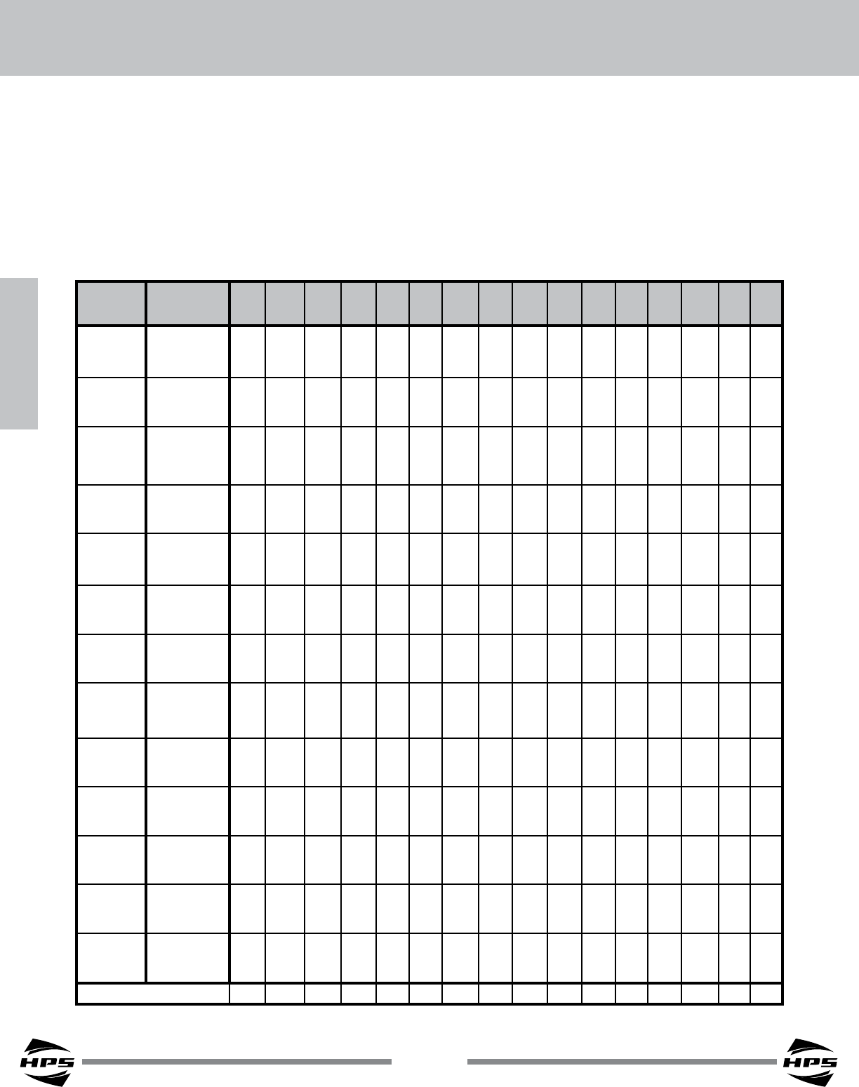
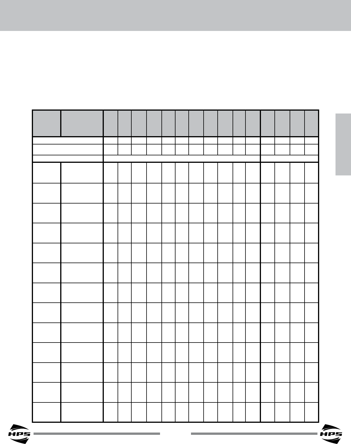
How to use the Selection Chart
1. From the top row of the “Selection Chart” locate the high and low voltage combination that is closest to the
one you require.
2. Move down that column to the kVA or Ampere rating equal to or greater than the rating required by the load.
3. From the far left column, obtain the transformer catalog number.
4. For dimensional information refer to the specications table (Group C) on page 91.
5. The corresponding connection diagram is indicated at the bottom of the Voltage / kVA column. See page 93
for the connection diagrams.
Single Phase - Group C Selection Chart
Catalog
Number
Low Voltage
High Voltage
200 208 220 230 240 380 416 430 435 436 440 440 450 456 460 480
220 229 242 276 264 418 458 473 457 480 462 484 473 479 483 504
QC05DTCB
HV Amps 2.08 2.08 2.08 1.04 2.08 1.04 1.04 1.04 2.08 1.04 2.08 1.04 2.08 2.08 2.08 2.08
KVA 0.46 0.48 0.50 0.29 0.55 0.44 0.48 0.49 0.95 0.50 0.96 0.50 0.98 1.00 1.01 1.05
LV Amps 2.29 2.29 2.29 1.25 2.29 1.15 1.15 1.15 2.19 1.15 2.19 1.15 2.19 2.19 2.19 2.19
QC10DTCB
HV Amps 4.17 4.17 4.17 2.08 4.17 2.08 2.08 2.08 4.17 2.08 4.17 2.08 4.17 4.17 4.17 4.17
KVA 0.92 0.95 1.01 0.58 1.10 0.87 0.95 0.99 1.90 1.00 1.93 1.01 1.97 2.00 2.01 2.10
LV Amps 4.58 4.58 4.58 2.50 4.58 2.29 2.29 2.29 4.38 2.29 4.38 2.29 4.38 4.38 4.38 4.38
QC15DTCB
HV Amps 6.25 6.25 6.25 3.13 6.25 3.13 3.13 3.13 6.25 3.13 6.25 3.13 6.25 6.25 6.25 6.25
KVA 1.38 1.43 1.51 0.86 1.65 1.31 1.43 1.48 2.85 1.50 2.89 1.51 2.95 2.99 3.02 3.15
LV Amps 6.88 6.88 6.88 3.75 6.88 3.44 3.44 3.44 6.56 3.44 6.56 3.44 6.56 6.56 6.56 6.56
QC20DTCB
HV Amps 8.33 8.33 8.33 4.17 8.33 4.17 4.17 4.17 8.33 4.17 8.33 4.17 8.33 8.33 8.33 8.33
KVA 1.83 1.91 2.02 1.15 2.20 1.74 1.91 1.97 3.81 2.00 3.85 2.02 3.94 3.99 4.03 4.20
LV Amps 9.17 9.17 9.17 5.00 9.17 4.58 4.58 4.58 8.75 4.58 8.75 4.58 8.75 8.75 8.75 8.75
QC25DTCB
HV Amps 10.4 10.4 10.4 5.21 10.4 5.21 5.21 5.21 10.4 5.21 10.4 5.21 10.4 10.4 10.4 10.4
KVA 2.29 2.38 2.52 1.44 2.75 2.18 2.38 2.46 4.76 2.50 4.81 2.52 4.92 4.99 5.03 5.25
LV Amps 11.5 11.5 11.5 6.3 11.5 5.73 5.73 5.73 10.9 5.73 10.9 5.73 10.9 10.9 10.9 10.9
QC35DTCB
HV Amps 14.6 14.6 14.6 7.3 14.6 7.3 7.3 7.3 14.6 7.3 14.6 7.3 14.6 14.6 14.6 14.6
KVA 3.21 3.34 3.53 2.01 3.85 3.05 3.34 3.45 6.61 3.50 6.74 3.53 6.89 6.98 7.0 7.4
LV Amps 16.0 16.0 16.0 8.8 16.0 8.0 8.0 8.0 15.3 8.0 15.3 8.0 15.3 15.3 15.3 15.3
QC50DTCB
HV Amps 20.8 20.8 20.8 10.4 20.8 10.4 10.4 10.4 20.8 10.4 20.8 10.4 20.8 20.8 20.8 20.8
KVA 4.58 4.77 5.04 2.88 5.5 4.35 4.77 4.93 9.52 5.00 9.63 5.04 9.84 9.98 10.1 10.5
LV Amps 22.9 22.9 22.9 12.5 22.9 11.5 11.5 11.5 21.9 11.5 21.9 11.5 21.9 21.9 21.9 21.9
QC75DTCB
HV Amps 31.3 31.3 31.3 15.6 31.3 15.6 15.6 15.6 31.3 15.6 31.3 15.6 31.3 31.3 31.3 31.3
KVA 6.88 7.15 7.56 4.31 8.25 6.53 7.15 7.39 14.3 7.49 14.4 7.56 14.8 15.0 15.1 15.8
LV Amps 34.4 34.4 34.4 18.8 34.4 17.2 17.2 17.2 32.8 17.2 32.8 17.2 32.8 32.8 32.8 32.8
Q1C0DTCB
HV Amps 41.7 41.7 41.7 20.8 41.7 20.8 20.8 20.8 41.7 20.8 41.7 20.8 41.7 41.7 41.7 41.7
KVA 9.17 9.53 10.1 5.75 11 8.71 9.53 9.85 19.0 9.99 19.3 10.1 19.7 20.0 20.1 21.0
LV Amps 45.8 45.8 45.8 25.0 45.8 22.9 22.9 22.9 43.8 22.9 43.8 22.9 43.8 43.8 43.8 43.8
Q1C5DTCF
HV Amps 62.5 62.5 62.5 31.3 62.5 31.3 31.3 31.3 62.5 31.3 62.5 31.3 62.5 62.5 62.5 62.5
KVA 13.8 14.3 15.1 8.6 16.5 13.1 14.3 14.8 28.5 15.0 28.9 15.1 29.5 29.9 30.2 31.5
LV Amps 68.8 68.8 68.8 37.5 68.8 34.4 34.4 34.4 65.6 34.4 65.6 34.4 65.6 65.6 65.6 65.6
Q002DTCF
HV Amps 83.3 83.3 83.3 41.7 83.3 41.7 41.7 41.7 83.3 41.7 83.3 41.7 83.3 83.3 83.3 83.3
KVA 18.3 19.1 20.2 11.5 22.0 17.4 19.1 19.7 38.1 20.0 38.5 20.2 39.4 39.9 40.3 42.0
LV Amps 91.7 91.7 91.7 50.0 91.7 45.8 45.8 45.8 87.5 45.8 87.5 45.8 87.5 87.5 87.5 87.5
Q003DTCF
HV Amps 125 125 125 62.5 125 62.5 62.5 62.5 125 62.5 125 62.5 125 125 125 125
KVA 27.5 28.6 30.3 17.3 33 26.1 28.6 29.6 57.1 30.0 57.8 30.3 59.1 59.9 60.4 63.0
LV Amps 138 138 138 75 138 68.8 68.8 68.8 131 68.8 131 68.8 131 131 131 131
Q005DTCF
HV Amps 208 208 208 104 208 104 104 104 208 104 208 104 208 208 208 208
KVA 45.8 47.7 50.4 28.8 55.0 43.5 47.7 49.3 95.2 50.0 96.3 50.4 98.4 99.8 101 105
LV Amps 229 229 229 125 229 115 115 115 219 115 219 115 219 219 219 219
CONNECTION DIAGRAM 1 1 1 2 1 4 4 4 3 4 3 4 3 3 3 3
SECTION 2
87
SECTION 2
BUCK-BOOST TRANSFORMERS
© Hammond Power Solutions Inc. Data subject to change without notice.
How to use the Selection Chart
1. From the top row of the “Selection Chart” locate the high and low voltage combination that is closest to the
one you require.
2. Determine the quantity you required.
3. The corresponding connection diagram is indicated at the top of the Voltage / kVA column. See page 94
for the connection diagrams.
4. Move down that column to the kVA or Ampere rating equal to or greater than the rating required by the load.
5. From the far left column, obtain the transformer catalog number.
6. For dimensional information refer to the specications table (Group A) on page 91.
Three Phase - Group A Selection Chart
Catalog
Number
Low Voltage 189 198 208 208 220 227 228 232 240 189 199 208 379 416 416
109 115 120 219 240 240
High Voltage 208 208 218 229 242 250 239 255 264 208 239 229 417 436 457
120 138 132 241 252 264
QUANTITY REQUIRED 2 2 2 2 2 2 2 2 2 3 3 3 3 3 3
CONNECTION DIAGRAM
(Refer to Page 94) 7 8 8 7 7 7 8 7 7 10 9 10 12 11 12
Three Phase Connection Style Delta Connected Wye Connected
QC05ERCB
HV Amps 2.08 4.17 4.17 2.08 2.08 2.08 4.17 2.08 2.08 4.17 2.08 4.17 2.08 4.17 2.08
KVA 0.76 1.51 1.58 0.83 0.88 0.91 1.73 0.93 0.96 1.50 0.86 1.65 1.51 3.15 1.65
LV Amps 2.29 4.38 4.38 2.29 2.29 2.29 4.38 2.29 2.29 4.58 2.50 4.58 2.29 4.38 2.29
QC10ERCB
HV Amps 4.17 8.33 8.33 4.17 4.17 4.17 8.33 4.17 4.17 8.33 4.17 8.33 4.17 8.33 4.17
KVA 1.51 3.01 3.16 1.66 1.75 1.81 3.46 1.85 1.91 3.00 1.73 3.30 3.01 6.30 3.30
LV Amps 4.58 8.75 8.75 4.58 4.58 4.58 8.75 4.58 4.58 9.17 5.00 9.17 4.58 8.75 4.58
QC15ERCB
HV Amps 6.25 12.50 12.50 6.25 6.25 6.25 12.50 6.25 6.25 12.5 6.25 12.5 6.25 12.50 6.25
KVA 2.26 4.51 4.73 2.48 2.62 2.71 5.19 2.77 2.86 4.50 2.59 4.95 4.52 9.45 4.95
LV Amps 6.88 13.10 13.10 6.88 6.88 6.88 13.10 6.88 6.88 13.8 7.50 13.8 6.88 13.1 6.88
QC20ERCB
HV Amps 8.33 16.70 16.70 8.33 8.33 8.33 16.70 8.33 8.33 16.7 8.33 16.7 8.33 16.70 8.33
KVA 3.01 6.01 6.31 3.31 3.50 3.61 6.92 3.69 3.82 6.00 3.45 6.60 6.03 12.6 6.60
LV Amps 9.17 17.50 17.50 9.17 9.17 9.17 17.50 9.17 9.17 18.3 10.0 18.3 9.17 17.5 9.17
QC25ERCB
HV Amps 10.4 20.8 20.8 10.4 10.4 10.4 20.8 10.4 10.4 20.8 10.4 20.8 10.4 20.8 10.4
KVA 3.76 7.51 7.89 4.13 4.37 4.51 8.64 4.61 4.77 7.50 4.31 8.25 7.53 15.75 8.25
LV Amps 11.5 21.9 21.9 11.5 11.5 11.5 21.9 11.5 11.5 22.9 12.5 22.9 11.5 21.9 11.5
QC35ERCB
HV Amps 14.6 29.2 29.2 14.6 14.6 14.6 29.2 14.6 14.6 29.2 14.6 29.2 14.6 29.2 14.6
KVA 5.26 10.50 11.00 5.78 6.12 6.31 12.10 6.45 6.67 10.50 6.04 11.55 10.54 22.05 11.60
LV Amps 16.0 30.6 30.6 16.0 16.0 16.0 30.6 16.0 16.0 32.1 17.5 32.1 16.0 30.6 16.0
QC50ERCB
HV Amps 20.8 41.7 41.7 20.8 20.8 20.8 41.7 20.8 20.8 41.7 20.8 41.7 20.8 41.7 20.8
KVA 7.51 15.00 15.80 8.26 8.74 9.02 17.30 9.21 9.53 15.0 8.60 16.5 15.1 31.5 16.5
LV Amps 22.9 43.8 43.8 22.9 22.9 22.9 43.8 22.9 22.9 45.8 25.0 45.8 22.9 43.8 22.9
QC75ERCB
HV Amps 31.3 62.5 62.5 31.3 31.3 31.3 62.5 31.3 31.3 62.5 31.3 62.5 31.3 62.5 31.3
KVA 11.3 22.5 23.7 12.4 13.1 13.5 25.9 13.8 14.3 22.5 12.9 24.8 22.6 47.3 24.8
LV Amps 34.4 65.6 65.6 34.4 34.4 34.4 65.6 34.4 34.4 68.8 37.5 68.8 34.4 65.6 34.4
Q1C0ERCB
HV Amps 41.7 83.3 83.3 41.7 41.7 41.7 83.3 41.7 41.7 83.3 41.7 83.3 41.7 83.3 41.7
KVA 15.0 30.0 31.5 16.5 17.5 18.0 34.6 18.4 19.1 30.0 17.3 33.0 30.1 63.0 33.0
LV Amps 45.8 87.5 87.5 45.8 45.8 45.8 87.5 45.8 45.8 91.7 50.0 91.7 45.8 87.5 45.8
Q1C5ERCF
HV Amps 62.5 125.0 125.0 62.5 62.5 62.5 125.0 62.5 62.5 125 62.5 125 62.5 125.0 62.5
KVA 22.5 45.0 47.3 24.8 26.2 27.0 51.8 27.6 28.6 45.0 25.9 49.5 45.2 94.5 49.5
LV Amps 68.8 131.0 131.0 68.8 68.8 68.8 131.0 68.8 68.8 138 75.0 138 68.8 131 68.8
Q002ERCF
HV Amps 83.3 167.0 167.0 83.3 83.3 83.3 167.0 83.3 83.3 167 83.3 167 83.3 167.0 83.3
KVA 30.0 60.0 63.1 33.0 34.9 36.1 69.1 36.8 38.1 60.0 34.5 66.0 60.3 126 66.0
LV Amps 91.7 175.0 175.0 91.7 91.7 91.7 175.0 91.7 91.7 183 100 183 91.7 175 91.7
Q003ERCF
HV Amps 125 250 250 125 125 125 250 125 125 250 125 250 125 250 125
KVA 45.0 90.0 94.6 49.5 52.4 54.1 103.7 55.3 57.2 90.0 51.8 99.0 90.4 189 99.0
LV Amps 138 263 263 138 138 138 263 138 138 275 150 275 138 263 138
Q005ERCF
HV Amps 208 417 417 208 208 208 417 208 208 417 208 417 208 417 208
KVA 75.0 150.0 157.6 82.6 87.3 90.1 172.8 92.1 95.3 150 86.3 165 151 315 165
LV Amps 229 438 438 229 229 229 438 229 229 458 250 458 229 438 229
88
SECTION 2
SECTION 2
HPS Universal™
© Hammond Power Solutions Inc. Data subject to change without notice.
How to use the Selection Chart
1. From the top row of the “Selection Chart” locate the high and low voltage combination that is closest to the
one you require.
2. Determine the quantity you required.
3. The corresponding connection diagram is indicated at the top of the Voltage / kVA column. See page 94
for the connection diagrams.
4. Move down that column to the kVA or Ampere rating equal to or greater than the rating required by the load.
5. From the far left column, obtain the transformer catalog number.
6. For dimensional information refer to the specications table (Group B) on page 92.
Three Phase - Group B Selection Chart
Catalog
Number
Low Voltage 184 195 208 208 225 230 234 234 240 240 184 416 379 416 416
106 240 219 240 240
High Voltage 209 208 222 236 240 245 250 265 272 256 208 236 431 443 471
120 136 249 256 272
QUANTITY REQUIRED 2 2 2 2 2 2 2 2 2 2 3 3 3 3 3
CONNECTION DIAGRAM
(Refer to Page 94) 7 8 8 7 8 8 8 7 7 8 10 10 12 11 12
Three Phase Connection Style Delta Connected Wye Connected
QC05ESCB
HV Amps 1.56 3.13 3.13 1.56 3.13 3.13 3.13 1.56 1.56 3.13 3.13 3.13 1.56 3.13 1.56
KVA 0.57 1.13 1.21 0.64 1.30 1.33 1.36 0.72 0.74 1.39 1.13 1.28 1.17 2.40 1.28
LV Amps 1.77 3.33 3.33 1.77 3.33 3.33 3.33 1.77 1.77 3.33 3.54 3.54 1.77 3.33 1.77
QC10ESCB
HV Amps 3.13 6.25 6.25 3.13 6.25 6.25 6.25 3.13 3.13 6.25 6.25 6.25 3.13 6.25 3.13
KVA 1.13 2.26 2.41 1.28 2.60 2.66 2.71 1.44 1.48 2.78 2.25 2.55 2.33 4.80 2.55
LV Amps 3.54 6.67 6.67 3.54 6.67 6.67 6.67 3.54 3.54 6.67 7.08 7.08 3.54 6.67 3.54
QC15ESCB
HV Amps 4.69 9.38 9.38 4.69 9.38 9.38 9.38 4.69 4.69 9.38 9.38 9.38 4.69 9.4 4.69
KVA 1.70 3.38 3.61 1.92 3.90 3.99 4.06 2.16 2.21 4.16 3.38 3.83 3.50 7.20 3.83
LV Amps 5.31 10.00 10.00 5.31 10.00 10.00 10.00 5.31 5.31 10.00 10.6 10.6 5.31 10.0 5.31
QC20ESCB
HV Amps 6.25 12.50 12.50 6.25 12.50 12.50 12.50 6.25 6.25 12.50 12.5 12.5 6.25 12.50 6.25
KVA 2.26 4.51 4.81 2.56 5.20 5.32 5.41 2.88 2.94 5.55 4.50 5.10 4.67 9.60 5.10
LV Amps 7.08 13.30 13.30 7.08 13.30 13.30 13.30 7.08 7.08 13.30 14.2 14.2 7.08 13.3 7.08
QC25ESCB
HV Amps 7.81 15.60 15.60 7.80 15.60 15.60 15.60 7.81 7.81 15.60 15.6 15.6 7.81 15.6 7.81
KVA 2.83 5.63 6.01 3.19 6.50 6.64 6.76 3.59 3.69 6.93 5.63 6.38 5.84 12.0 6.38
LV Amps 8.85 16.70 16.70 8.90 16.70 16.70 16.70 8.85 8.85 16.70 17.7 17.7 8.85 16.7 8.85
QC35ESCB
HV Amps 10.9 21.9 21.9 10.9 21.9 21.9 21.9 10.9 10.9 21.9 21.9 21.9 10.9 21.9 10.9
KVA 3.96 7.89 8.41 4.47 9.10 9.30 9.46 5.03 5.16 9.70 7.88 8.93 8.17 16.8 8.93
LV Amps 12.4 23.3 23.3 12.4 23.3 23.3 23.3 12.4 12.4 23.3 24.8 24.8 12.4 23.3 12.4
QC50ESCB
HV Amps 15.6 31.3 31.3 15.6 31.3 31.3 31.3 15.6 15.6 31.3 31.3 31.3 15.6 31.3 15.6
KVA 5.65 11.30 12.00 6.38 13.00 13.30 13.50 7.18 7.37 13.90 11.3 12.8 11.7 24.0 12.8
LV Amps 17.7 33.3 33.3 17.7 33.3 33.3 33.3 17.7 17.7 33.3 35.4 35.4 17.7 33.3 17.7
QC75ESCB
HV Amps 23.4 46.9 46.9 23.4 46.9 46.9 46.9 23.4 23.4 46.9 46.9 46.9 23.4 46.9 23.4
KVA 8.47 16.90 18.00 9.57 19.5 19.9 20.3 10.8 11.1 20.8 16.9 19.1 17.5 36.0 19.1
LV Amps 26.6 50.0 50.0 26.6 50.0 50.0 50.0 26.6 26.6 50.0 53.1 53.1 26.6 50.0 26.6
Q1C0ESCB
HV Amps 31.3 62.5 62.5 31.3 62.5 62.5 62.5 31.3 31.3 62.5 62.5 62.5 31.3 62.5 31.3
KVA 11.3 22.5 24.0 12.8 26.0 26.6 27.0 14.4 14.7 27.7 22.5 25.5 23.3 48.0 25.5
LV Amps 35.4 66.7 66.7 35.4 66.7 66.7 66.7 35.4 35.4 66.7 70.8 70.8 35.4 66.7 35.4
Q1C5ESCF
HV Amps 46.9 93.8 93.8 46.9 93.8 93.8 93.8 46.9 46.9 93.8 93.8 93.8 46.9 93.8 46.9
KVA 16.9 33.8 36.0 19.1 39.0 39.8 40.5 21.5 22.1 41.6 33.8 38.3 35.0 72.0 38.3
LV Amps 53.1 100.0 100.0 53.1 100.0 100.0 100.0 53.1 53.1 100.0 106 106 53.1 100 53.1
Q002ESCF
HV Amps 62.5 125.0 125.0 62.5 125.0 125.0 125.0 62.5 62.5 125.0 125 125 62.5 125.0 62.5
KVA 22.6 45.0 48.0 25.5 52.0 53.1 54.0 28.7 29.4 55.4 45.0 51.0 46.7 96.0 51.0
LV Amps 70.8 133.3 133.3 70.8 133.3 133.3 133.3 70.8 70.8 133.3 142 142 70.8 133 70.8
Q003ESCF
HV Amps 93.75 187.5 187.5 93.75 187.5 187.5 187.5 93.75 93.75 187.5 188 188 93.8 188 93.8
KVA 33.9 67.6 72.1 38.3 78.0 79.7 81.1 43.1 44.2 83.1 67.5 76.5 70.0 144 76.5
LV Amps 106.3 200 200 106.3 200 200 200 106.3 106.3 200 213 213 106 200 106
Q005ESCF
HV Amps 156.25 312.5 312.5 156.25 313 312.5 312.5 156.25 156.25 312.5 313 313 156 313 156
KVA 56.4 112.6 120.1 63.8 129.9 132.8 135.1 71.8 73.6 138.6 113 128 117 240 128
LV Amps 177.1 333.3 333.3 177.1 333.3 333.3 333.3 177.1 177.1 333.3 354 354 177 333 177
SECTION 2
89
SECTION 2
BUCK-BOOST TRANSFORMERS
© Hammond Power Solutions Inc. Data subject to change without notice.
How to use the Selection Chart
1. From the top row of the “Selection Chart” locate the high and low voltage combination that is closest
to the one you require.
2. Determine the quantity you required.
3. The corresponding connection diagram is indicated at the top of the Voltage / kVA column. See page 94
for the connection diagrams.
4. Move down that column to the kVA or Ampere rating equal to or greater than the rating required by the load.
5. From the far left column, obtain the transformer catalog number.
6. For dimensional information refer to the specications table (Group C) on page 92.
Three Phase - Group C Selection Chart
Catalog
Number
Low Voltage 173 200 208 362 380 400 419 436 457 480 480 346 379 400 416
200 219 231 240
High Voltage 208 240 250 380 418 440 440 480 480 528 504 416 456 480 499
240 263 277 288
QUANTITY REQUIRED 2 2 2 2 2 2 2 2 2 2 2 3 3 3 3
CONNECTION DIAGRAM
(Refer to Page 94) 5 5 5 6 7 7 8 7 8 7 8 9 9 9 9
Three Phase Connection Style Delta Connected Wye Connected
QC05DTCB
HV Amps 1.04 1.04 1.04 2.08 1.04 1.04 2.08 1.04 2.08 1.04 2.08 1.04 1.04 1.04 1.04
KVA 0.38 0.44 0.46 1.44 0.76 0.80 1.67 0.87 1.82 0.96 1.82 0.75 0.82 0.87 0.90
LV Amps 1.25 1.25 1.25 2.29 1.15 1.15 2.29 1.15 2.29 1.15 2.19 1.25 1.25 1.25 1.15
QC10DTCB
HV Amps 2.08 2.08 2.08 4.17 2.08 2.08 4.17 2.08 4.17 2.08 4.17 2.08 2.08 2.08 2.08
KVA 0.75 0.87 0.91 2.88 1.51 1.59 3.33 1.74 3.63 1.91 3.64 1.50 1.64 1.73 1.80
LV Amps 2.50 2.50 2.50 4.58 2.29 2.29 4.58 2.29 4.58 2.29 4.38 2.50 2.50 2.50 2.50
QC15DTCB
HV Amps 3.13 3.13 3.13 6.25 3.13 3.13 6.25 3.13 6.25 3.13 6.25 3.13 3.13 3.13 3.13
KVA 1.13 1.30 1.36 4.32 2.27 2.39 4.99 2.60 5.45 2.86 5.46 2.25 2.47 2.60 2.70
LV Amps 3.75 3.75 3.75 6.88 3.44 3.44 6.88 3.44 6.88 3.44 6.56 3.75 3.75 3.75 3.75
QC20DTCB
HV Amps 4.17 4.17 4.17 8.33 4.17 4.17 8.33 4.17 8.33 4.17 8.33 4.17 4.17 4.17 4.17
KVA 1.50 1.74 1.81 5.75 3.02 3.18 6.66 3.47 7.26 3.82 7.28 3.00 3.29 3.46 3.60
LV Amps 5.00 5.00 5.00 9.17 4.58 4.58 9.17 4.58 9.17 4.58 8.75 5.00 5.00 5.00 5.00
QC25DTCB
HV Amps 5.21 5.21 5.21 10.4 5.21 5.21 10.40 5.21 10.40 5.21 10.40 5.21 5.21 5.21 5.21
KVA 1.88 2.17 2.26 7.19 3.78 3.97 8.32 4.33 9.07 4.77 9.10 3.75 4.11 4.33 4.50
LV Amps 6.25 6.25 6.25 11.50 5.73 5.73 11.50 5.73 11.50 5.73 10.90 6.25 6.25 6.25 6.25
QC35DTCB
HV Amps 7.29 7.29 7.29 14.6 7.29 7.3 14.6 7.3 14.6 7.29 14.6 7.29 7.29 7.29 7.29
KVA 2.63 3.04 3.16 10.1 5.28 5.56 11.70 6.06 12.70 6.67 12.70 5.25 5.75 6.06 6.30
LV Amps 8.75 8.75 8.75 16.0 8.0 8.0 16.0 8.0 16.0 8.02 15.3 8.75 8.75 8.75 8.75
QC50DTCB
HV Amps 10.4 10.4 10.4 20.8 10.4 10.4 20.8 10.4 20.8 10.4 20.8 10.4 10.4 10.4 10.4
KVA 3.75 4.34 4.51 14.4 7.55 7.94 16.60 8.66 18.10 9.53 18.20 7.50 8.22 8.66 9.00
LV Amps 12.5 12.5 12.5 22.9 11.5 11.5 22.9 11.5 22.9 11.5 21.9 12.5 12.5 12.5 12.5
QC75DTCB
HV Amps 15.6 15.6 15.6 31.3 15.6 15.6 31.3 15.6 31.3 15.6 31.3 15.6 15.6 15.6 15.6
KVA 5.62 6.50 6.76 21.6 11.3 11.9 25.0 13.0 27.2 14.3 27.3 11.3 12.3 13.0 13.5
LV Amps 18.8 18.8 18.8 34.4 17.2 17.2 34.4 17.2 34.4 17.2 32.8 18.8 18.8 18.8 18.8
Q1C0DTCB
HV Amps 20.8 20.8 20.8 41.7 20.8 20.8 41.7 20.8 41.7 20.8 41.7 20.8 20.8 20.8 20.8
KVA 7.50 8.67 9.01 28.7 15.1 15.9 33.3 17.3 36.3 19.1 36.4 15.0 16.4 17.3 18.0
LV Amps 25.0 25.0 25.0 45.8 22.9 22.9 45.8 22.9 45.8 22.9 43.8 25.0 25.0 25.0 25.0
Q1C5DTCF
HV Amps 31.3 31.3 31.3 62.5 31.3 31.3 62.5 31.3 62.5 31.3 62.5 31.3 31.3 31.3 31.3
KVA 11.2 13.0 13.5 43.1 22.6 23.8 49.9 26.0 54.4 28.6 54.6 22.5 24.7 26.0 27.0
LV Amps 37.5 37.5 37.5 68.8 34.4 34.4 68.8 34.4 68.8 34.4 65.6 37.5 37.5 37.5 37.5
Q002DTCF
HV Amps 41.7 41.7 41.7 83.3 41.7 41.7 83.3 41.7 83.8 41.7 83.3 41.7 41.7 41.7 41.7
KVA 15.0 17.3 18.0 57.5 30.2 31.8 66.5 34.6 72.6 38.1 72.8 30.0 32.9 34.6 36.0
LV Amps 50.0 50.0 50.0 91.7 45.8 45.8 91.7 45.8 91.7 45.8 87.5 50.0 50.0 50.0 50.0
Q003DTCF
HV Amps 62.5 62.5 62.5 125 62.5 62.5 125.0 62.5 125.0 62.5 125.0 62.5 62.5 62.5 62.5
KVA 22.5 26.0 27.0 86.2 45.3 47.6 99.8 51.9 109.0 57.2 109.0 45.0 49.3 51.9 54.0
LV Amps 75.0 75.0 75.0 138 68.8 68.8 138.0 68.8 138.0 68.8 131.0 75.0 75.0 75.0 75.0
Q005DTCF
HV Amps 104 104 104 208 104 104 208 104 208 104 208 104 104 104 104
KVA 37.5 43.3 45.0 144.0 75.4 79.4 166.0 86.5 181.0 95.3 182.0 75.0 82.2 86.6 90.0
LV Amps 125 125 125 229 115 115 229 115 229 115 219 125 125 125 125
90
SECTION 2
SECTION 2
HPS Universal™
© Hammond Power Solutions Inc. Data subject to change without notice.
Single Phase Specication Tables
Primary
Voltage
Secondary
Voltage
120 X 240
12 X 24
Group A
50/60 Hertz
Primary
Voltage
Secondary
Voltage
120 X 240
16 X 32
Group B
50/60 Hertz
VA Catalog
Number
Case
Style
(Pages 262)
Approx. Dimensions
(Inches) Approx.
Weight
(Lbs.)
Mtg Type
W - Wall
Width Depth Height
50 QC05ERCB NQ0 3.75 5.25 7.25 6 W
100 QC10ERCB NQ0 3.75 5.25 7.25 7 W
150 QC15ERCB NQ0 3.75 5.25 7.25 8 W
200 QC20ERCB NQ1 4.50 5.75 7.25 11 W
250 QC25ERCB NQ1 4.50 5.75 7.25 13 W
350 QC35ERCB NQ1 4.50 5.75 7.25 14 W
500 QC50ERCB NQ2 5.00 4.75 9.25 15 W
750 QC75ERCB NQ2 5.00 4.75 9.25 18 W
1000 Q1C0ERCB NQ3 5.88 5.50 10.50 25 W
1500 Q1C5ERCF NQ4 7.00 6.50 11.75 36 W
2000 Q002ERCF NQ4 7.00 6.50 11.75 46 W
3000 Q003ERCF NQ5 10.00 7.75 17.25 65 W
5000 Q005ERCF NQ5 10.00 7.75 17.25 105 W
VA Catalog
Number
Case
Style
(Pages 262)
Approx. Dimensions
(Inches) Approx.
Weight
(Lbs.)
Mtg Type
W - Wall
Width Depth Height
50 QC05ESCB NQ0 3.75 5.25 7.25 6 W
100 QC10ESCB NQ0 3.75 5.25 7.25 7 W
150 QC15ESCB NQ0 3.75 5.25 7.25 8 W
200 QC20ESCB NQ1 4.50 5.75 7.25 11 W
250 QC25ESCB NQ1 4.50 5.75 7.25 13 W
350 QC35ESCB NQ1 4.50 5.75 7.25 14 W
500 QC50ESCB NQ2 5.00 4.75 9.25 15 W
750 QC75ESCB NQ2 5.00 4.75 9.25 18 W
1000 Q1C0ESCB NQ3 5.88 5.50 10.50 25 W
1500 Q1C5ESCF NQ4 7.00 6.50 11.75 36 W
2000 Q002ESCF NQ4 7.00 6.50 11.75 46 W
3000 Q003ESCF NQ5 10.00 7.75 17.25 65 W
5000 Q005ESCF NQ5 10.00 7.75 17.25 105 W
SECTION 2
91
SECTION 2
BUCK-BOOST TRANSFORMERS
© Hammond Power Solutions Inc. Data subject to change without notice.
Single Phase Specication Tables
Primary
Voltage
Secondary
Voltage
240 X 480
24 X 48
Group C
50/60 Hertz
Three Phase Specication Tables
Primary
Voltage
Secondary
Voltage
120 X 240
12 X 24
Group A
50/60 Hertz
VA Catalog
Number
Case
Style
(Pages 262)
Approx. Dimensions
(Inches) Approx.
Weight
(Lbs.)
Mtg Type
W - Wall
Width Depth Height
50 QC05DTCB NQ0 3.75 5.25 7.25 6 W
100 QC10DTCB NQ0 3.75 5.25 7.25 7 W
150 QC15DTCB NQ0 3.75 5.25 7.25 8 W
200 QC20DTCB NQ1 4.50 5.75 7.25 11 W
250 QC25DTCB NQ1 4.50 5.75 7.25 13 W
350 QC35DTCB NQ1 4.50 5.75 7.25 14 W
500 QC50DTCB NQ2 5.00 4.75 9.25 15 W
750 QC75DTCB NQ2 5.00 4.75 9.25 18 W
1000 Q1C0DTCB NQ3 5.88 5.50 10.50 25 W
1500 Q1C5DTCF NQ4 7.00 6.50 11.75 36 W
2000 Q002DTCF NQ4 7.00 6.50 11.75 46 W
3000 Q003DTCF NQ5 10.00 7.75 17.25 65 W
5000 Q005DTCF NQ5 10.00 7.75 17.25 105 W
VA Catalog
Number
Case
Style
(Pages 262)
Approx. Dimensions
(Inches) Approx.
Weight
(Lbs.)
Mtg Type
W - Wall
Width Depth Height
50 QC05ERCB NQ0 3.75 5.25 7.25 6 W
100 QC10ERCB NQ0 3.75 5.25 7.25 7 W
150 QC15ERCB NQ0 3.75 5.25 7.25 8 W
200 QC20ERCB NQ1 4.50 5.75 7.25 11 W
250 QC25ERCB NQ1 4.50 5.75 7.25 13 W
350 QC35ERCB NQ1 4.50 5.75 7.25 14 W
500 QC50ERCB NQ2 5.00 4.75 9.25 15 W
750 QC75ERCB NQ2 5.00 4.75 9.25 18 W
1000 Q1C0ERCB NQ3 5.88 5.50 10.50 25 W
1500 Q1C5ERCF NQ4 7.00 6.50 11.75 36 W
2000 Q002ERCF NQ4 7.00 6.50 11.75 46 W
3000 Q003ERCF NQ5 10.00 7.75 17.25 65 W
5000 Q005ERCF NQ5 10.00 7.75 17.25 105 W
92
SECTION 2
SECTION 2
HPS Universal™
© Hammond Power Solutions Inc. Data subject to change without notice.
Primary
Voltage
Secondary
Voltage
120 X 240
16 X 32
Group B
50/60 Hertz
Three Phase Specication Tables
Primary
Voltage
Secondary
Voltage
240 X 480
24 X 48
Group C
50/60 Hertz
VA Catalog
Number
Case
Style
(Pages 262)
Approx. Dimensions
(Inches) Approx.
Weight
(Lbs.)
Mtg Type
W - Wall
Width Depth Height
50 QC05ESCB NQ0 3.75 5.25 7.25 6 W
100 QC10ESCB NQ0 3.75 5.25 7.25 7 W
150 QC15ESCB NQ0 3.75 5.25 7.25 8 W
200 QC20ESCB NQ1 4.50 5.75 7.25 11 W
250 QC25ESCB NQ1 4.50 5.75 7.25 13 W
350 QC35ESCB NQ1 4.50 5.75 7.25 14 W
500 QC50ESCB NQ2 5.00 4.75 9.25 15 W
750 QC75ESCB NQ2 5.00 4.75 9.25 18 W
1000 Q1C0ESCB NQ3 5.88 5.50 10.50 25 W
1500 Q1C5ESCF NQ4 7.00 6.50 11.75 36 W
2000 Q002ESCF NQ4 7.00 6.50 11.75 46 W
3000 Q003ESCF NQ5 10.00 7.75 17.25 65 W
5000 Q005ESCF NQ5 10.00 7.75 17.25 105 W
VA Catalog
Number
Case
Style
(Pages 262)
Approx. Dimensions
(Inches) Approx.
Weight
(Lbs.)
Mtg Type
W - Wall
Width Depth Height
50 QC05DTCB NQ0 3.75 5.25 7.25 6 W
100 QC10DTCB NQ0 3.75 5.25 7.25 7 W
150 QC15DTCB NQ0 3.75 5.25 7.25 8 W
200 QC20DTCB NQ1 4.50 5.75 7.25 11 W
250 QC25DTCB NQ1 4.50 5.75 7.25 13 W
350 QC35DTCB NQ1 4.50 5.75 7.25 14 W
500 QC50DTCB NQ2 5.00 4.75 9.25 15 W
750 QC75DTCB NQ2 5.00 4.75 9.25 18 W
1000 Q1C0DTCB NQ3 5.88 5.50 10.50 25 W
1500 Q1C5DTCF NQ4 7.00 6.50 11.75 36 W
2000 Q002DTCF NQ4 7.00 6.50 11.75 46 W
3000 Q003DTCF NQ5 10.00 7.75 17.25 65 W
5000 Q005DTCF NQ5 10.00 7.75 17.25 105 W
SECTION 2
93
SECTION 2
BUCK-BOOST TRANSFORMERS
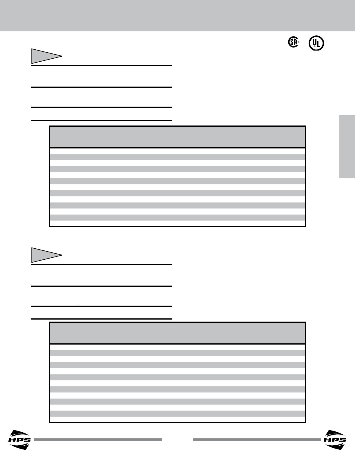
Low
Voltage
High
Voltage
H4
H2
H3
H1
X1
X3
X2
X4
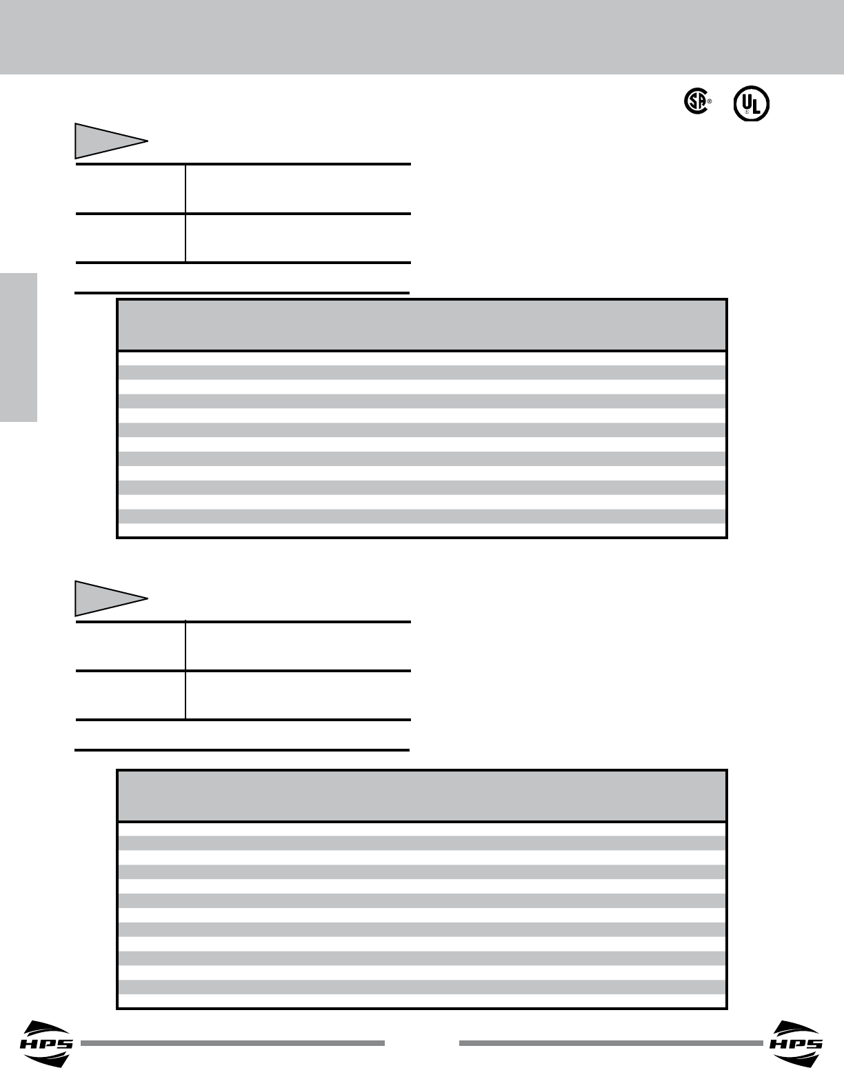
Low
Voltage
High
Voltage
H4
H2
H3
H1
X1
X3
X2
X4
Low
Voltage
High
Voltage
H4
H2
H3
H1
X1
X3
X2
X4
Low
Voltage
High
Voltage
H4
H2
H3
H1
X1
X3
X2
X4
© Hammond Power Solutions Inc. Data subject to change without notice.
Single Phase Connection Diagrams
Connection
Diagram #2
Connection
Diagram #3
Connection
Diagram #4
Connection
Diagram #1
94
SECTION 2
SECTION 2
HPS Universal™
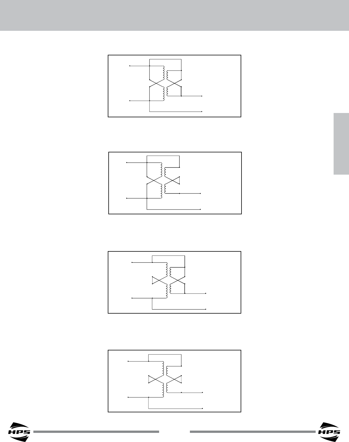
Low Voltage
3 Phase
High Voltage
3 Phase
Transformer #1
Transformer #2
X1 X1
X3 X3
H1 H1
X4 X4
X2 X2
H2 H2
H4 H4
H3 H3
2
2
1
3
3
1
Low Voltage
3 Phase
High Voltage
3 Phase
Transformer #1
Transformer #2
X1 X1
X3 X3
H1 H1
X4 X4
X2 X2
H2 H2
H4 H4
H3 H3
2
2
1
3
3
1
Low Voltage
3 Phase
High Voltage
3 Phase
Transformer #1
Transformer #2
X1 X1
X3 X3
H1 H1
X4 X4
X2 X2
H2 H2
H4 H4
H3 H3
2
2
1
3
3
1
Low Voltage
3 Phase
High Voltage
3 Phase
Transformer #1
Transformer #2
X1 X1
X3 X3
H1 H1
X4 X4
X2 X2
H2 H2
H4 H4
H3 H3
2
2
1
3
3
1
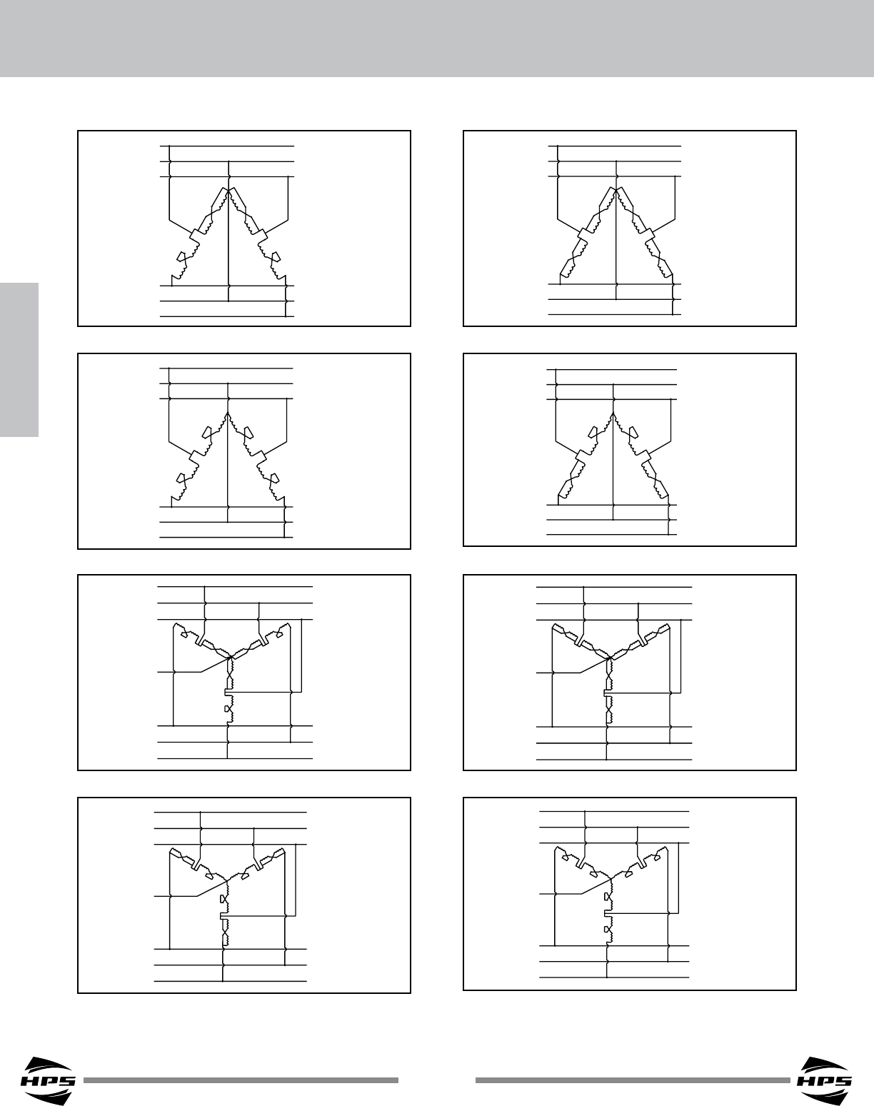
Low Voltage
3 Phase
High Voltage
3 Phase
Transformer
#1
X1
X1
X3
X3
H1
X4
X4
X2
X2
H2
H2
H4
H4
H3
H3
2
2
1
3
3
1
Transformer
#2
Transformer
#3
X1
X3
X4
X2
H2
H4
H3
Low Voltage
3 Phase
High Voltage
3 Phase
Transformer
#1
X1
X1
X3
X3
H1
X4
X4
X2
X2
H2
H2
H4
H4
H3
H3
2
2
1
3
3
1
Transformer
#2
Transformer
#3
X1
X3
X4
X2
H2
H4
H3
Low Voltage
3 Phase
High Voltage
3 Phase
Transformer
#1
X1
X1
X3
X3
H1
X4
X4
X2
X2
H2
H2
H4
H4
H3
H3
2
2
1
3
3
1
Transformer
#2
Transformer
#3
X1
X3
X4
X2
H2
H4
H3
Low Voltage
3 Phase
High Voltage
3 Phase
Transformer
#1
X1
X1
X3
X3
H1
X4
X4
X2
X2
H2
H2
H4
H4
H3
H3
2
2
1
3
3
1
Transformer
#2
Transformer
#3
X1
X3
X4
X2
H2
H4
H3
© Hammond Power Solutions Inc. Data subject to change without notice.
Three Phase Connection Diagrams
Connection
Diagram #6
Connection
Diagram #7
Connection
Diagram #8
Connection
Diagram #5
Connection
Diagram #10
Connection
Diagram #11
Connection
Diagram #12
Connection
Diagram #9

SECTION 2
95
SECTION 2
BUCK-BOOST TRANSFORMERS
© Hammond Power Solutions Inc. Data subject to change without notice.
Buck-Boost Transformers - Questions & Answers
1. What is a buck-boost transformer?
Buck-boost transformers are small single phase transformers designed to lower (buck) or raise (boost) line
voltage from 5-20%. The most common applications for buck-boost transformers include boosting 208 volts to
230 or 240 volts for air conditioning systems, boosting 110 to 120 volts and 240 to 277 volts for lighting
applications, heating systems and induction motors of all types. Many applications exist where supply voltages
are frequently above or below nominal.
Buck-boost transformers are conventional low voltage, single phase distribution transformers, with standard
primary voltages of 120, 240 or 480 volts, and secondary voltages of 12, 16, 24, 32 or 48 volts. They are
available in sizes ranging from 50 VA to 10,000 VA. The primary and secondary are wired together to form a
single-winding autotransformer. Utilizing the additive and subtractive polarity, small amounts of voltage are either
added or subtracted from a distribution circuit.
2. How does a buck-boost transformer differ from an isolating transformer?
A buck-boost transformer is manufactured as an isolating transformer, with separable primary and
secondary, and is shipped from the factory in that conguration. When the end user at site connects it, the
primary is connected to the secondary changing the transformer’s electrical characteristics to those of an
autotransformer. This provides the smaller voltage correction that is typical of buck-boost. The primary and
secondary windings are no longer isolated as they are connected together.
3. What is the difference between a buck-boost transformer and an autotransformer?
As noted above, when the primary and secondary are connected together to buck or boost voltage, the
transformer becomes an autotransformer. If the connection between the primary and secondary winding is not
made, then the unit remains as an isolation transformer.
Applications
4. Why are they used?
A buck-boost transformer is a simple and effective way of correcting off-standard voltages. Electrical and
electronic equipment is designed to operate within a standard tolerance of nominal supply voltages. When the
supply voltage is consistently too high or low - typically more than 10%, the equipment will operate below peak
efciency.
5. Can buck-boost transformers be used to power low voltage circuits?
Installed as two-winding, isolation transformers, these units can be used to power low voltage circuits
including control, lighting circuits, or other low voltage applications that require 12, 16, 24, 32 or 48 volts output,
consistent with the secondary of these designs. The unit is connected as an isolating transformer and the
nameplate kVA rating is the transformer’s capacity.
Operation and Construction
6. Why do buck-boost transformers have 4 windings?
A four winding buck-boost transformer with 2 primary and 2 secondary windings can be connected eight different
ways to provide a multitude of voltages and KVA’s. This provides the exibility necessary for the broad variety of
applications. A two-winding transformer can only be connected in two different ways.
96
SECTION 2
SECTION 2
HPS Universal™
© Hammond Power Solutions Inc. Data subject to change without notice.
7. Will a Buck-Boost transformer stabilize voltage?
Buck-boost transformers will not stabilize supply line voltage. The output voltage of a buck-boost is a
function of the input voltage. If the input voltage varies, then the output voltage will also vary by the same
percentage.
Load Data
8. Are there any restrictions on the type of load that can be operated from a Buck-Boost
transformer?
There are no restrictions as to application for Buck-Boost, including single or three-phase motor loads.
9. As an Autotransformer, how can a Buck-Boost transformer supply kVA power?
This is a function of adding voltage - a small amount of voltage is added and a small amount of
corresponding power capacity is added as well. For example, if the transformer is connected in such a way that
22 volts is added to a 208 volt primary, a 230 volt output will result.
Using this example, the calculation for autotransformer kVA is as follows:
Output Volts x Secondary Amps
1000
230V x 41.67 Amps = 9.58 KVA
1000
10. How are single phase and three phase load amps and load kVA calculated?
kVA x 1000 kVA x 1000
Volts Volts x 1.73
Volts x Amps Volts x Amps x 1.73
1000 1000
Three Phase
11. Can Buck-Boost transformers be used on three phase systems?
Interconnecting two or three single phase units will readily accommodate three phase systems - refer to the
corresponding three phase section in this catalog. The number of units to be used in a three phase installation
depends on the number of wires in the supply line. If the three phase supply is 4-wire wye, then three buck-boost
transformers are required. If the three phase supply is 3-wire wye (neutral not available), two buck-boost
transformers are needed.
12. Should Buck-Boost transformers be used to develop three phase 4 wire wye circuits from
three phase 3 wire delta circuits?
No - a three-phase “wye” buck-boost transformer connection should be used only on a 4-wire source of
supply. A delta to wye connection does not provide adequate current capacity to accommodate unbalanced
currents owing in the neutral wire of the 4-wire circuit.
kVA =
Single phase Amps = Three phase Amps =
Single phase kVA = Three phase kVA =
kVA =

SECTION 2
97
SECTION 2
BUCK-BOOST TRANSFORMERS
© Hammond Power Solutions Inc. Data subject to change without notice.
13. Why isn’t a ‘closed delta’ Buck-Boost connection recommended?
This connection requires more kVA power than a “wye” or open delta connection and phase shifting occurs
on the output. The closed delta connection is more expensive and electrically inferior to other three phase
connections.
Connection and Frequency
14. How do you know how to connect a Buck-Boost transformer?
A connection chart is provided with each unit that shows how to make the corresponding connections.
These same charts are also shown in this section.
15. Can 60 Hertz Buck-Boost transformers be operated on 50 Hertz?
Due to ‘saturation’ of the core, 60 Hertz buck-boost transformers should only be operated at 60 Hertz, and
not 50 Hertz. Units manufactured as 50 Hertz units will however, operate at 60 Hertz.
Nameplate Data
17. Why are buck-boost transformers shipped from the factory connected as isolating
transformers, and not pre-connected autotransformers?
The same 4-winding buck-boost transformer can be connected eight different ways to provide a multitude
of voltage combinations. The correct connection can best be determined by the user when assessing the supply
voltage at site.
18. Why is the isolation transformer kVA rating shown on the nameplate instead of the
autotransformer kVA rating?
Shipped as an isolating transformer, the nameplate is required to show the performance characteristics
accordingly. Additionally, as an autotransformer, the eight different combinations of voltages and kVA’s would be
impractical to list on the nameplate. A connection chart, listing the various connections, is included with each unit.
Safety
19. Do Buck-Boost transformers present a safety hazard compared to conventional
autotransformers?
Buck-boost transformers only change voltage by a small amount, such as 208 to 240 volts. This small
increase does not represent a safety hazard. Conventional autotransformers, manufactured as single winding
transformers, change much higher magnitudes of voltage, e.g. 480 to 240 volts. In a system where the line is
grounded, it is possible to have 480 volts to ground when the expectations are that 240 volts is at the output. For
this reason, qualied personnel only should maintain conventional autotransformers.
Sound Levels
20. How does the sound level differ between Buck-Boost and isolation transformers?
Buck-boost transformers, connected as autotransformers, will be quieter than an equivalent isolation
transformer capable of handling the same load. The isolation transformer would have to be physically larger than
the buck-boost transformer, and smaller transformers are quieter than larger ones. For example, a 10 kVA is 35
dba and a 75 kVA is 50 dba.

98
SECTION 2
SECTION 2
HPS Universal™
© Hammond Power Solutions Inc. Data subject to change without notice.
Cost and Life Expectancy
21. How does the costs compare between a Buck-Boost transformer and an Isolation
transformer handling the same load?
For most buck-boost applications, the savings are about 75% compared to the use of an isolation
transformer for the same application.
22. What is the life expectancy of a Buck-Boost transformer?
Buck-boost transformers have exactly the same life expectancy as other dry-type transformers.
23. Buck-Boost transformers are almost always installed as autotransformers. Does the
National Electrical Code (NEC) permit the use of autotransformers?
Autotransformers are very common and recognized by all the safety and standard authorities. You can
refer to N.E.C. Article 450-4, “Autotransformers 600 Volts, Nominal, or Less”, as a reference publication. Item
(a) details overcurrent protection for an autotransformer and item (b) covers an isolation transformer being eld
connected as an autotransformer for a buck-boost application.
24. When a Buck-Boost transformer is connected as an autotransformer, what is the
procedure for determining the current rating of the overcurrent protective device, such
as the fuse or circuit breaker?
The NEC Article 450-4 outlines overcurrent protection for autotransformers. It is reproduced as follows:
“NEC 450-4 - Autotransformers 600 Volts, Nominal, or Less
(a) Overcurrent Protection. Each autotransformer 600 volts, nominal, or less shall be protected by an
individual overcurrent device installed in series with each ungrounded input conductor. Such overcurrent device
shall be rated or set at not more than 125 percent of the rated full load input current of the autotransformer. An
overcurrent device shall not be installed in series with the shunt winding.
Exception: Where the rated input current of an autotransformer is 9 amperes or more and 125 percent of
this current does not correspond to a standard rating of a fuse or non-adjustable circuit breaker; the next higher
standard rating described in our section shall be permitted. When the rated input current is less than 9 amperes,
an overcurrent device rated or set at not more than 167 percent of the input current shall be permitted.
(b) Transformer Field-Connected as an autotransformer. A transformer eld-connected as autotransformers
shall be identied for use at “elevated voltage”.
Example: A 1 kVA transformer, Catalog No. Q1C0ERCB, is rated 120 x 240 to 12 x 24 volts. It is to be
connected as an autotransformer to raise 208 to 230 volts single phase. When connected as an autotransformer
in this application, the kVA rating is increased to 9.58 kVA, or 9,580 VA. This is the rating to be used for
determining the full load input amps and the corresponding size of the overcurrent protection device, either a fuse
or breaker.
Full load input amps = 9,580 Volt Amps = 46 Amp, 208 Volts
When the full load current is greater than 9 amps, the overcurrent protection device - usually a fuse or non-
adjustable breaker, the current rating can be up to 125 percent of the full load rating of the autotransformer input
current.
Max. current rating of the overcurrent device = 46 amps x 125% = 57.5 amps
The National Electrical Code, Article 450-4 (a) Exception, permits the use of the next higher standard ampere
rating of the overcurrent device. This is shown in Article 240-6 of the N.E.C.
Max. size of the fuse or circuit breaker = 60 amps
