56859 Catalog
56859-Catalog 56859-Catalog 56859-Catalog Batch8 unilog cesco-content
133043-Catalog 133043-Catalog 133043-Catalog Batch9 unilog cesco-content
2014-09-27
: Pdf 56859-Catalog 56859-Catalog 783510 Batch8 unilog
Open the PDF directly: View PDF ![]() .
.
Page Count: 292 [warning: Documents this large are best viewed by clicking the View PDF Link!]

SPECIFIER’S GUIDE
EQUIPMENT PROTECTION VOLUME 10
NETWORKING AND COMMUNICATIONS

NETWORKING SUBJECT TO CHANGE WITHOUT NOTICE EQUIPMENT PROTECTION
ADVANCING A HERITAGE OF LEADERSHIP
Pentair Equipment Protection is a global leader in safeguarding industrial controls, electrical components, and
communications hardware. Its premier brand, Hoffman®, provides a comprehensive range of standard, modified and
custom engineered solutions. For more information, visit pentairprotect.com
Hoffman is a leading designer and manufacturer of systems to safely and
reliably protect the electronic controls and mission critical electrical systems
in industrial, data communications, commercial construction and government
applications. Our product catalog features the wide array of enclosures,
accessories and thermal management products.
We have developed significant vertical market expertise to help us understand
and develop industry solutions to address your particular circumstances. Our
extensive network of North American distributors and our global sales channel
can help you obtain the products you need.
In addition to our broad line of standard enclosures, Hoffman has the expertise to
deliver modified standard enclosures quickly and reliably as well as complicated
co-developed and custom solutions.
Hoffman maintains a high standard of quality and operates under a global ISO
9000 certificate. We design and test our products in our in-house UL laboratory to
ensure they meet stringent quality standards. Hoffman products comply with UL,
NEMA, CSA and other international standards.
Hoffman Cooling helps create optimal conditions for the reliable operation
of electronic and electrical components in manufacturing controls, telecom
equipment, data networks, and other vital systems. From V fan assemblies
to air conditioners, to heat exchangers, to integrated cooling enclosures for a
variety of applications, Hoffman assures maximum productivity and uptime while
protecting the life cycles of controls and equipment. Flawless operation is the
expectation of OEM s, engineers, and end-users alike. That’s why choosing the
most qualified cooling technology provider reaches far beyond the implications of
product performance to include service and support benchmarks.
As a premier global provider with decades of experience in cooling industrial
automation and electrical components, Hoffman remains unrivaled with an
industry-leading portfolio of proven products, pre- and post-sale support, and
comprehensive engineering and testing services.
For more information about Hoffman Cooling products visit pentairprotect.com
Pentair (pentair.com) delivers industry-leading products, services and solutions for its customers in diverse needs in
water and other fluids, thermal management and equipment protection. With 2012 pro forma revenues of approximately
$8 billion, Pentair employs more than 30,000 people worldwide.
About Pentair Ltd.
NETWORKING

1
PH 763.422.2661 • FAX 763.422.2588 • PENTAIRPROTECT.COMEQUIPMENT PROTECTION
1
TABLE OF CONTENTS
FREESTAND CABINETS. . . . . . . . . . . . . . . . . . . . . . . . . . . . . . . . . . .2
CABLE AND POWER MANAGEMENT . . . . . . . . . . . . . . . . . . . . . . . . . . . 72
OPEN FRAME RACKS . . . . . . . . . . . . . . . . . . . . . . . . . . . . . . . . . . . 90
WALLMOUNT CABINETS . . . . . . . . . . . . . . . . . . . . . . . . . . . . . . . . .102
WALLMOUNT RACKS. . . . . . . . . . . . . . . . . . . . . . . . . . . . . . . . . . .166
CABLE PATHWAY / BONDING AND GROUNDING . . . . . . . . . . . . . . . . . . . . .176
SEISMIC PRODUCTS . . . . . . . . . . . . . . . . . . . . . . . . . . . . . . . . . . .198
COOLING . . . . . . . . . . . . . . . . . . . . . . . . . . . . . . . . . . . . . . . . . 208
OUTSIDE PLANT PRODUCTS . . . . . . . . . . . . . . . . . . . . . . . . . . . . . . 224
ACCESSORIES . . . . . . . . . . . . . . . . . . . . . . . . . . . . . . . . . . . . . . 246
TECHNICAL INFORMATION . . . . . . . . . . . . . . . . . . . . . . . . . . . . . . . 268
INDEX . . . . . . . . . . . . . . . . . . . . . . . . . . . . . . . . . . . . . . . . . . .276
763.422.2661
763.422.2588

EQUIPMENT PROTECTIONSUBJECT TO CHANGE WITHOUT NOTICENETWORKING2
1
763.422.2661
763.422.2588
NETWORKING
FREE-STAND CABINETS
Intro Page
NET SERIES CABINETS
Net Series Cabinets provide an
economical, general-purpose solution
to house servers and communication
equipment for contractors,
small computer rooms,
schools or smaller
networks. For application
flexibility, multiple sizes,
adjustable racks and
accessories are available.
CHAPTER 1
FREESTAND CABINETS
FEATURED PRODUCTS
PROLINE™
CONTAINMENT SYSTEMS
Increase cooling efficiency and
lower energy costs with PROLINE™
Containment Systems. By preventing
hot and cold airflows from mixing,
the systems allow for higher thermal
density within the cabinet and eliminate
the need for additional cooling units.
PROLINE is ideal for hot or cold air
containment and on raised and non-
raised floors.

PH 763.422.2661 • FAX 763.422.2588 • PENTAIRPROTECT.COMEQUIPMENT PROTECTION NETWORKING 3
Intro Page CHAPTER CONTENTS
FREESTAND CABINETS PRODUCT SELECTION GUIDE
Free-Stand Cabinets Product Selection Guide ..............4
NET SERIES COMMUNICATION AND SERVER
CABINETS AND ACCESSORIES
Net Series Communication and Server Cabinet ..............6
Net Series Rack Angles ...............................10
Net Series Caster Kit .................................10
Net Series Leveler Kit ................................10
Tool-less (Snap-in) Blanking Panels for 19-in. Racks ........11
Net Series Vertical Tie-Down Cable Manager ..............11
Tool-less Shelf .....................................12
Net Series Joining Kit ................................12
PROLINE™ CONTAINMENT SYSTEM
PROLINE™ Containment System ........................14
Window Ceiling Panel ................................16
Chimney Ceiling Panel ................................16
Containment System Chimney ..........................17
PROLINE™ SERVER CABINETS
PROLINE™ FLOTEK™ PC (Passive Cooling) Server Cabinet ....18
PROLINE™ FLOTEK™ HCA (Hot/Cold Aisle) Server Cabinet ....20
PROLINE™ FLOTEK™ FD (Floor Ducted) Server Cabinet ......22
PROLINE™ FLOTEK™ FD (Floor Ducted) Server Cabinet Required
Floor Cutout ......................................23
PROLINE™ FLOTEK™ TD (Top Ducted) Server Cabinet ........24
PROLINE™ Server Cabinet .............................28
PROLINE™ COMMUNICATIONS CABINETS
PROLINE™ CONNECTEK™ Communications (Patch) Cabinet ...30
PROLINE™ NETWORK SWITCH CABINETS
PROLINE™ Network Switch Cabinet .....................32
PROLINE™ NETWORK SEALED ENVIRONMENTAL
PACKAGES
PROLINE™ Voice/Data and Server Cabinet, Type 12 .........38
Cooling Product Selection App .........................39
Air Conditioner Sizing ................................40
CR Mid-Size Air Conditioners ...........................41
PROLINE™ Voice/Data and Server Cabinets with Fan and Filter
Package, Type 1 ...................................42
HEAT DISSIPATION IN ELECTRICAL ENCLOSURES
How to Dissipate Excess Heat (Watts) - Understanding T and
CFM ............................................44
PROLINE™CL COLOCATION CABINET, COMPONENTS
AND ACCESSORIES
PROLINE™-CL Colocation Server Cabinet .................46
Sides for Colocation Cabinet Packages ...................47
Colocation Cabinet Frames ............................48
Colocation Divider Shelf ..............................48
Colocation Power Cable and Data Cable Way ..............48
Colocation Cabinet External Components .................49
Colocation Cabinet Internal Components .................49
PROLINE™ CABINET CABLE MANAGERS
PROLINE™ CABLETEK™ Vertical Cable Manager. . . . . . . . . . . . 50
PROLINE™ CABLETEK™ Reducing Brackets ...............50
Front-to-Back D-Ring Bracket .........................51
PROLINE™ Tie-Down Reducing Bracket ..................51
Vertical Cable Manager for 700- and 800-mm Wide Cabinets ..52
Universal Power Strip Bracket .........................53
Vertical Cable Manager I ..............................53
Vertical Tie-Down Cable Manager .......................53
Horizontal Cable Trough ..............................54
Strut Cable Rings ...................................54
Frame Tie-Down Bracket ..............................54
Cable and PDU Manager ..............................55
PROLINE™ ACCESSORIES
L Joining Bracket ....................................56
Frame Joining Kits ...................................56
Frame Feet. . . . . . . . . . . . . . . . . . . . . . . . . . . . . . . . . . . . . . . . .57
Tool-less (Snap-in) Blanking Panels for 19-in. Racks ........57
Levelers ...........................................57
PROLINE™ Grounding Kit ..............................58
PROLINE™ Frame Floor-Mounting Bracket ................58
Grounding Bar System ................................58
Caster Kit .........................................59
Screw Packages ....................................59
Cage Nut Package ...................................59
Mounting Channel ...................................60
Grid Straps ........................................60
Full-Height Vertical Grid Straps ........................61
PROLINE™ Fastener Packages .........................61
PROLINE™ Side Barrier Panels .........................61
19-in. and 23-in. Rack Angles ..........................62
Adjustable Rack-Mounting Rails ........................62
Frame-Reducing Brackets for Frames or Grid Straps ........63
Frame-Reducing Brackets for Frames or Mounting Channel ...63
180-Degree Hinge Kit ................................63
Flush Keylocking Trigger Latch with Random Key Codes .....64
Side Cover Lock .....................................64
Door-Mount Fan Tray and Blocking Plate .................64
DIN Lock Inserts (for DIN Profile Handle Only) .............65
L Handle. . . . . . . . . . . . . . . . . . . . . . . . . . . . . . . . . . . . . . . . . . . 65
Flush Swing Handles .................................65
Pagoda Exhaust Vents ................................66
High-Performance Pagoda Exhaust Vent ..................66
Mobile Base Leveling Kit ..............................67
Mobile Base ........................................67
NETWORKING SOHO CABINET
SOHO Cabinet for Small Office and Home Office ............68
WORKSTATION AND PC CABINETS
Networking PC Cabinet, Type 1 .........................70
Network Cabinet Caster Kit ...........................71
Networking PC Cabinet Rack Angle ......................71
Networking PC Cabinet Shelf ..........................71
PROLINE SERVER CABINETS
PROLINE Server Cabinets maximize
airflow for effective cooling. With
a wide range of cooling options,
including passive,
hot/cold aisle, floor
ducted and top
ducted, PROLINE
cabinets ensure
optimum equipment
performance and
service life.
1
EQUIPMENT PROTECTIONSUBJECT TO CHANGE WITHOUT NOTICENETWORKING4
1
FREESTAND CABINETS FREESTAND CABINETS PRODUCT SELECTION GUIDE
FREE-STAND CABIN ETS PRODUCT S ELECTION GUI DE
FREESTAND CABINETS PRODUCT SELECTION GUIDE
Free-Stand cabinetS Free-Stand CabinetS ProduCt SeleCtion Guide
Spec-00451 G
EQUIPMENT PROTECTION SOLUTIONSSUBJECT TO CHANGE WITHOUT NOTICEnetworking1
763.422.2661
763.422.2588
Spec-00451
G
networking
Free-Stand cabinetS
Free-Stand cabinetS Product Selection Guide
Free-Stand cabinetS product Selection guide
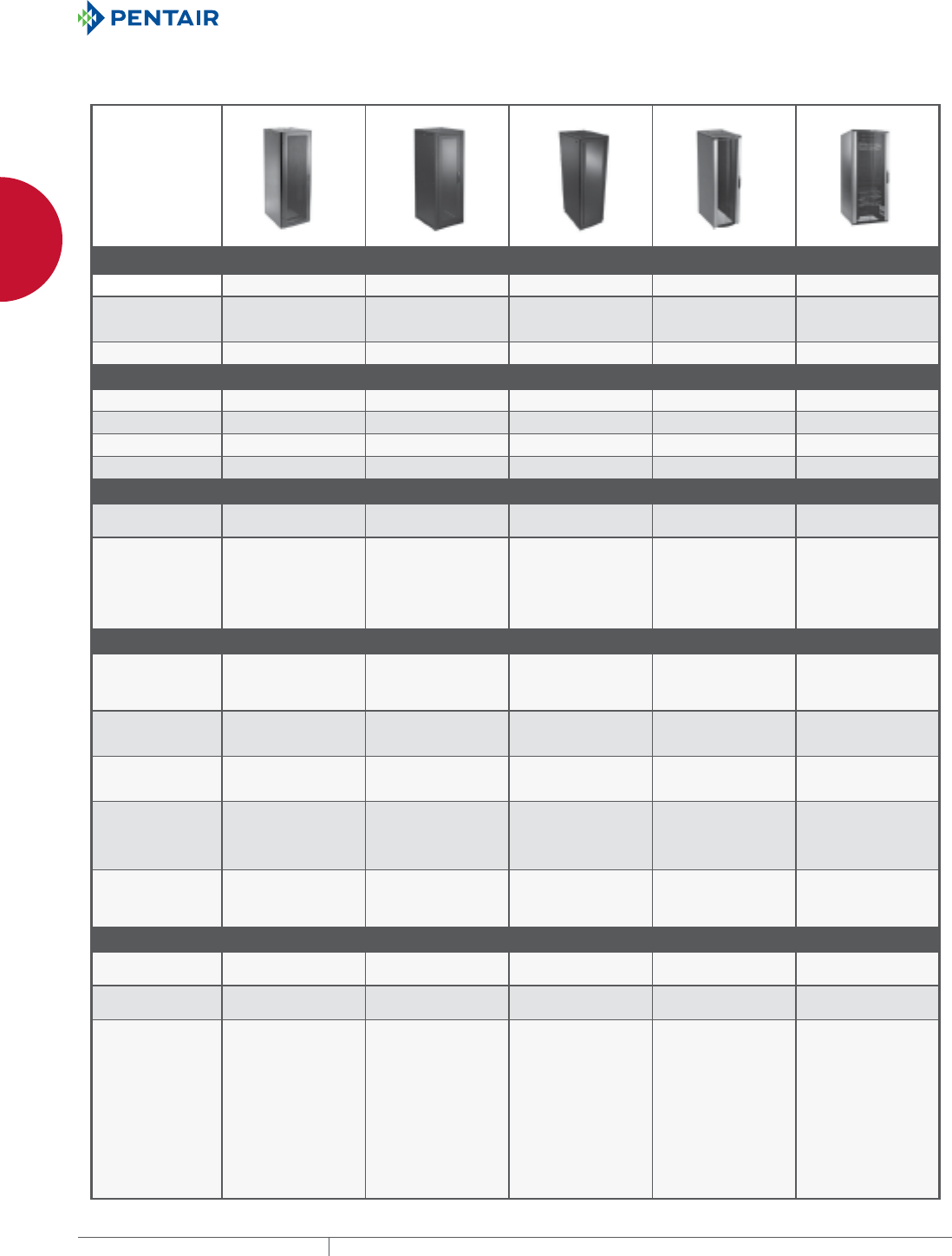
cabinet SerieS net SerieS SeiSMic proline™ proline™ proline™
Models Server & Voice/Data Seismic Server CONNECTEK™ Network Switch
Application General DataCom
computer room
General networking
Seismic Zones
Network and battery Remote networking
Vented front window
door
Data center
Network equipment Data center
Network switches
Density Low density Low density Low density Low density High density
diMenSionS
Rack Units 21 to 43 45 24 to 42 42 42
Height 49.00 in. or 84.00 in. 84.05 in. 50.75 in. or 82.30 in. 78.28 in. 78.35 in.
Width 23.52 in. - 31.50 in. 27.55 in. or 31.50 in. 23.62 in. 27.56 in. or 31.50 in. 31.50 in.
Depth 34.00 in. - 49.75 in. 31.50 in. - 47.25 in. 35.40 in. - 47.24 in. 35.40 in. - 47.24 in. 39.34 in. - 47.24 in.
ratingS
Loading - Static
(Ultimate load testing) 1,000 lbs. static 2,500 lbs. static 1,500 lbs. static 1,500 lbs. static 1,500 lbs.
Certifications and
Listings RoHS compliant
ISO 9001
EIA (rack spacing)
RoHS compliant
ISO 9001
EIA (rack spacing)
UL 1863 (static load
rating)
Telcordia GR-63-CORE,
NEBS requirements
RoHS compliant
ISO 9001
EIA (rack spacing)
RoHS compliant
ISO 9001
EIA (rack spacing)
RoHS
ISO 9001
EIA (rack spacing)
Structure
Front and Back Door Reversible, window or
perforated front, split
perforated, or louvered
rear, all with key locks
Window front, louvered
rear with multi-point
key lock
Window perforated front,
perforated rear with
key lock
Perforated front, split
perforated rear with key
locking handle
Fully perforated front,
split perforated rear
Base Open Open Open with casters,
levelers and anti-tip
bracket
Open with internal bolt
brackets Open
Top Fan-ready (2 in. x 6 in.)
top with cable cap and
grommet
Fan-ready (2 in. x 6 in.)
top with cable cap and
grommet
Removable, fully
perforated with cable
entry cap and grommet
Removable perforated
with sliding gland plate
for cable entry
Solid with sliding gland
plate for cable entry
Rack Angles 2 sets
Communications have
tapped 10-32
Server has square hole
2 sets
Communications have
tapped 10-32
Server has square hole
2 sets
Square hole
Dash mark (-) at start
and stop of RU
2 sets
Tapped hole 10-32
Dash mark (-) at start
and stop of RU
Front rack angles
tapped per EIA universal
standards RU
Sides Removable with quarter-
turn latch Removable with quarter-
turn latch andscrews Removable with 2 snap
latches, quarter-turn key
latch ready
No sides or removable
sides with 2 snap
latches, quarter-turn key
latch ready
No sides or removable
sides with fastening
screws
FeatureS
Cable Management Limited offering Robust offering Robust offering Robust offering Front and rear cable
management supports
Power Management Rack-mount and panel-
mount PDUsavailable Rack-mount and panel-
mount PDUsavailable Rack-mount and panel-
mount PDUsavailable Rack-mount and panel-
mount PDUsavailable Rack-mount PDUs
available
Unique Features • 19-in. or 23-in. rack
spacing on 27.55 in.
and 31.50 in. widths
• Heavy-gauge
construction, extra
welds, heavy-duty
washers, 3-point
vault-style latching
Zone 4 1,100 lbs.
Can be used as battery
cabinet.
• Cabinet can be rolled
into place, levelers
positioned and anti-tip
bracket attached. Anti-
tip bracket, casters,
levelers are standard.
• Includes front vertical
cable managers
with covers and rear
vertical tie-down cable
managers.
• CISCO versions
available.
• Ideal for CISCO
Network Switches
6500 series with right-
to-left airflow.
• Rear upper rack
angles (4 RU) ideal
for fiber-to-copper
transition or other
network devices.
• Complete cable
management for patch
cords and permanent
link cables.
Spec-00451.indd 1 01/28/13 9:04:45 AM
PH 763.422.2661 • FAX 763.422.2588 • PENTAIRPROTECT.COMEQUIPMENT PROTECTION NETWORKING 5
1
FREESTAND CABINETS FREESTAND CABINETS PRODUCT SELECTION GUIDE
Free-Stand cabinetS Free-Stand CabinetS ProduCt SeleCtion Guide
Spec-00451 G PH 763.422.2661 • FAX 763.422.2588 • HOFFMANONLINE.COMEQUIPMENT PROTECTION SOLUTIONS networking 2
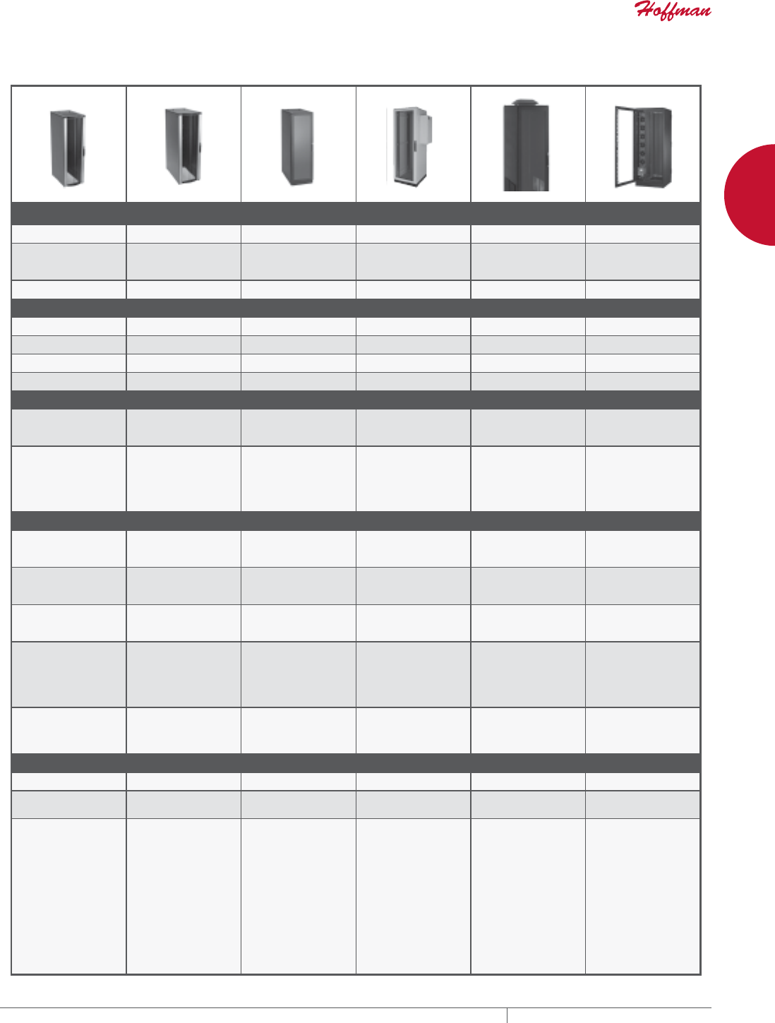
proline™ proline™ proline™ proline™ proline™ VariStar
FLOTEK™ - PC FLOTEK™ - HCA FLOTEK™ - FD Server and Voice/Data Server and Voice/Data VARISTAR LHX
Data center
Passive cooling Data center
Hot aisle/cold aisle Data center
Floor ducted Factory floor
Type 12 with/without AC Factory floor remote
location Type 1, filtered
fan
Data center Remote
non-data center
Low density High density High density Application specific Application specific Very high server density
42 (51 max.) 42 (51 max.) 42 (51 max.) 42 (51 max.) 42 (51 max.) 42 (51 max.)
78.22 in. (94.10 in. max.) 78.22 in. (94.10 in. max.) 78.22 in. (94.10 in. max.) 78.22 in. (94.10 in. max.) 78.22 in. (94.10 in. max.) 78.22 in. (94.10 in. max.)
23.62 in. 23.62 in. 23.62 in. 27.56 in. or 31.50 in. 27.56 in. or 31.50 in. 31.50 in.
35.40 in. - 47.24 in. 35.40 in. - 47.24 in. 35.40 in. - 47.24 in. 35.40 in. - 47.24 in. 35.43 in. - 47.24 in. 48.00 in.
1,500 lbs. static 1,500 lbs. static 1,500 lbs. static 1,500 lbs. static 1,500 lbs. static 2,200 lbs. Total and
19-in. equipment 880
lbs.
RoHS compliant
ISO 9001
EIA (rack spacing)
RoHS compliant
ISO 9001
EIA (rack spacing)
RoHS compliant
ISO 9001
EIA (rack spacing)
RoHS compliant
ISO 9001
EIA (rack spacing)
UL 508 Type 12
cUL Type 12
NEMA/EEMAC Type 12
RoHS compliant
ISO 9001
EIA (rack spacing)
UL 508 Type 1
cUL Type 1
NEMA/EEMAC Type 1
RoHS,
ISO 9001
EIA
IP 55
Perforated front, split
perforated rear with key
locking handle
Perforated front, split
fan rear with key locking
handle
Window front, split fan
rear with key locking
handle
Window front, solid door
rear with key locking
handle
Window front, solid door
rear with key locking
handle
Front window, rear solid,
both fully gasketed
Open with internal bolt
brackets Open with internal bolt
brackets Open base with floor
duct, casters and
levelers
Gland plate base with
casters and levelers Gland plate base with
casters and levelers 100 mm plinth
Perforated with sliding
gland plate for cable
entry
Removable solid with
sliding gland plate for
cable entry
Removable solid with
sliding gland plate for
cable entry
Removable solid Removable pagoda
top with high-capacity
10-in. fan
Solid, fully gasketed
2 sets
Square hole
Dash mark (-) at start
and stop of RU
2 sets
Square hole
Dash mark (-) at start
and stop of RU
2 sets
Square hole
Dash mark (-) at start
and stop of RU
2 sets
Communications have
tapped 10-32 holes
Server has square hole
Dash mark (-) at start
and stop of RU
2 sets
Communications have
tapped 10-32 holes
Server has square hole
Dash mark (-) at start
and stop of RU
2 sets
Square hole
EIA universal standard
No sides or removable
sides with 2 snap
latches, quarter-turn
key latch ready
No sides or removable
sides with 2 snap
latches, quarter-turn
key latch ready
No sides or removable
sides with 2 snap
latches, quarter-turn
key latch ready
Removable sides with
fastening screws Removable sides with
fastening screws Solid, fully gasketed
Robust offering Robust offering Robust offering Robust offering Robust offering Robust offering
Rack-mount and panel-
mount PDUsavailable Rack-mount and panel-
mount PDUsavailable Rack-mount and panel-
mount PDUsavailable Rack-mount and panel-
mount PDUsavailable Rack-mount and panel-
mount PDUsavailable Rack-mount PDUs
available
Provides maximum
cooling without added
fans for hot aisle/cold
aisle and other data
center configurations.
Ideal for hot aisle/
cold aisle data center
configurations in high-
density applications.
Rear split doors access
separately powered
banks of fans for
redundancy with easy
equipment access.
Integrates raised floor
cool air pathway to the
network equipment.
Raised floor cutout
required.
Configuration offered
that is air conditioner-
ready (AC cutout to side).
Data-center-within-a-
data-center concept.
Fully gasketed to keep
out side-air infiltration.
Pagoda top-mounted fan
with lower side intake
filters on access panels.
Heat exchanger provides
20 kW or 40 kW cabinet
cooling.
Totally enclosed cooling
system provides
maximum cooling
efficiency.
Integral thermal mgmt.
communication system
Ideal for high-density
servers and remote
(non-data center)
located networks.
Spec-00451.indd 2 01/28/13 9:04:48 AM
EQUIPMENT PROTECTIONSUBJECT TO CHANGE WITHOUT NOTICENETWORKING6
1
FREESTAND CABINETS NET SERIES COMMUNICATION AND SERVER CABINETS AND ACCESSORIES
NET SERIES COMMUNICATION AND SERVER CABINETS AND ACCESSORIES
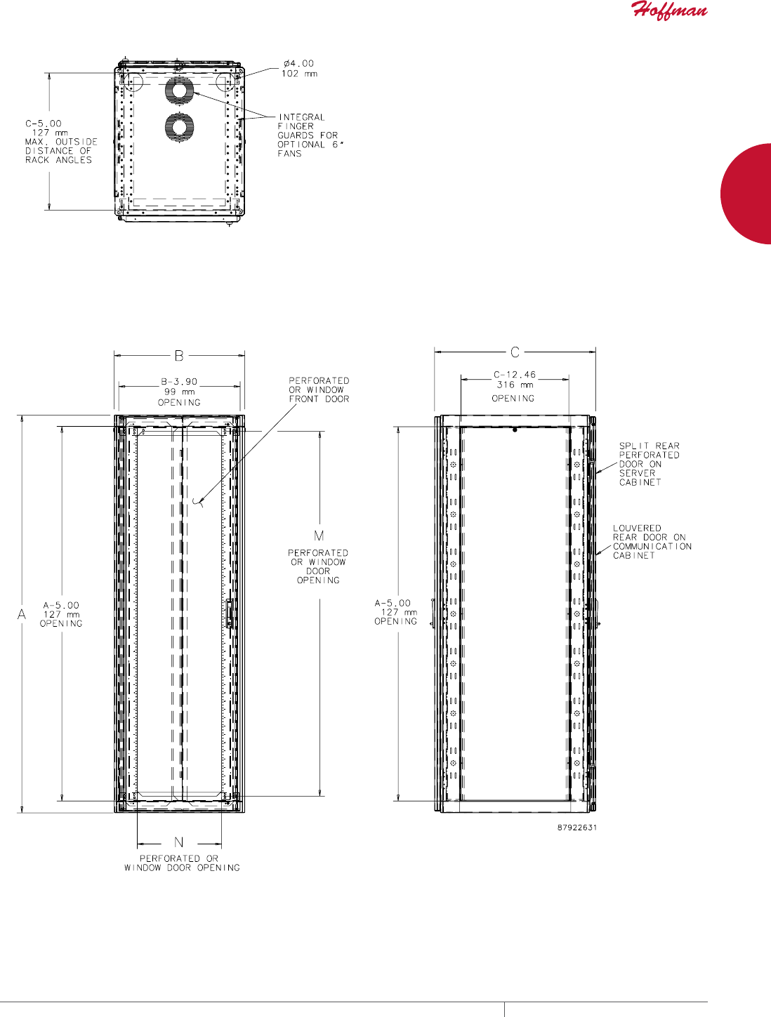
NET SERIES COMMUNICATION AND SERVER CABINET
INDUSTRY STANDARDS
UL 1863 Listed (perforated, split perforated and louvered door
models only)
EIA 310-D
IEC 60529, IP20
Perforated door material meets equipment manufacturer
ventilation requirements
APPLICATION
Net Series Cabinets are an economical solution for contractors,
small computer rooms, schools or smaller networks that require
a general-purpose cabinet to house servers and communication
equipment. Multiple sizes, adjustable rack angles and accessories
give Net Series Cabinets wide application flexibility.
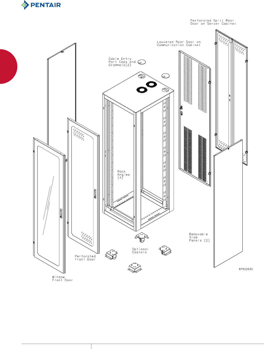
FEATURES
• Includes two sets of adjustable L-shaped rack angles for
convenient equipment mounting
• Rack angles on communication cabinets have tapped 10-32 holes
per EIA standards. Order 10-32 fasteners separately.
• Rack angles on server cabinets have square holes per EIA
standards. Order fasteners and cage nuts separately.
•
Rack angle settings on all 700- and 800-mm wide cabinets can
accommodate either 19- or 23-in. rack spacing
• In 600-mm wide cabinets, equipment mounted on 19-in. rack
angles is centered
• In 700- and 800-mm wide cabinets, 19-in. rack angles can be set
to center equipment or to mount equipment next to the left or the
right side for improved cable management
• Rack angles infinitely positionable within the cabinet for easy
adjustment to desired position
• All doors are field removable and reversible with left or right
hinging for installation flexibility
• Communication cabinet has fully perforated or window front and
louvered rear doors for equipment ventilation
• Server cabinet has fully perforated front and split rear perforated
doors for easy access to servers
• Doors have key-locking handles that provide security with
convenient access for authorized personnel
• Removable side panels with quarter-turn key-locking latch are
inset for flush appearance
• Two cable entry ports with caps and grommets on cabinet top for
wiring ease
• Fan-ready top with integral finger guard. Order up to two 6-in.
fans separately.
• Caster- and leveler-ready open base design. Order casters and
levelers separately.
SPECIFICATIONS
• Some models available with or without sides
• Welded multi-formed steel frame. The top and columns are 16
gauge; base is 14 gauge.
• Multi-formed rigid doors are 14 gauge steel
• Window made of 1/8-in. smoke-tinted acrylic
• Formed solid sides are 14 gauge steel
• Rack angles are 12 gauge steel
• Ground studs provided on doors and covers
FINISH
Pretreated steel coated with RAL 9005 black textured low-gloss
polyester powder paint. Other finishes available—contact Hoffman
Customer Service.
LOAD RATING
1000 lb. (454 kg) per UL 1863 with load evenly distributed in
enclosure
NOTE: UL 1863 requires that the cabinet be tested with a load
four times the rating. The cabinet was tested to 4000 lb. (1814
kg) without failure to meet the 1000 lb. (454 kg) rating. Contact
Hoffman if other loading specifications are required.
ACCESSORIES
Net Series Rack Angles
Net Series Caster Kit
Net Series Leveler Kit
Net Series Joining Kit
Net Series Tool-less (Snap-in) Blanking Panels for 19-in. Racks
Net Series Vertical Tie-Down Cable Manager
Net Series Tool-less Shelf
BULLETIN: DC

PH 763.422.2661 • FAX 763.422.2588 • PENTAIRPROTECT.COMEQUIPMENT PROTECTION NETWORKING 7
1
FREESTAND CABINETS NET SERIES COMMUNICATION AND SERVER CABINETS AND ACCESSORIES
Standard Product
Catalog Number AxBxC in./mm Description Rack Units
M
in./mm
N
in./mm Rack Angle Holes Additional Rack Angles
NC1268 49.00 x 23.62 x 33.99
1245 x 600 x 863
Communication Cabinet 23 42.00
1067
14.71
374
Tapped 10-32 NRAT126
NC2178 84.00 x 27.56 x 33.99
2134 x 700 x 863
Communication Cabinet 43 77.00
1956
18.65
474
Tapped 10-32 NRAT217
NC2178NS 84.00 x 27.56 x 33.98
2134 x 700 x 863
Communication Cabinet
No Sides
43 77.00
1956
18.65
474
Tapped 10-32 NRAT217
NC2179 84.00 x 27.56 x 37.93
2134 x 700 x 963
Communication Cabinet 43 77.00
1956
18.65
474
Tapped 10-32 NRAT217
NC21710 84.00 x 27.56 x 41.86
2134 x 700 x 1063
Communication Cabinet 43 77.00
1956
18.65
474
Tapped 10-32 NRAT217
NC2188 84.00 x 31.50 x 33.99
2134 x 800 x 863
Communication Cabinet 43 77.00
1956
22.58
574
Tapped 10-32 NRAT218
NC2189 84.00 x 31.50 x 37.93
2134 x 800 x 963
Communication Cabinet 43 77.00
1956
22.58
574
Tapped 10-32 NRAT218
NC21810 84.00 x 31.50 x 41.86
2134 x 800 x 1063
Communication Cabinet 43 77.00
1956
22.58
574
Tapped 10-32 NRAT218
NCW2168 84.00 x 23.62 x 33.99
2134 x 600 x 863
Communication Cabinet, Window Door 43 77.00
1956
14.71
374
Tapped 10-32 NRAT216
NCW2168NS 84.00 x 23.62 x 33.98
2134 x 600 x 863
Communication Cabinet, Window Door
No Sides
43 77.00
1956
14.71
374
Tapped 10-32 NRAT216
NCW2178 82.68 x 27.56 x 31.50
2100 x 700 x 800
Communication Cabinet, Window Door 43 77.00
1956
18.65
474
Tapped 10-32 NRAT217
NCW2178NS 84.00 x 27.56 x 33.98
2134 x 700 x 863
Communication Cabinet, Window Door
No Sides
43 77.00
1956
18.65
474
Tapped 10-32 NRAT217
NCW2188 82.68 x 31.50 x 31.50
2100 x 800 x 800
Communication Cabinet, Window Door 43 77.00
1956
22.58
574
Tapped 10-32 NRAT218
NS12610 49.00 x 23.62 x 41.86
1245 x 600 x 1063
Server Cabinet 23 42.00
1067
14.71
374
Square NRAS126
NS2169 84.00 x 23.62 x 37.93
2134 x 600 x 963
Server Cabinet 43 77.00
1956
14.71
374
Square NRAS216
NS2169NS 84.00 x 23.62 x 37.91
2134 x 600 x 963
Server Cabinet
No Sides
43 77.00
1956
14.71
374
Square NRAS216
NS21610 84.00 x 23.62 x 41.86
2134 x 600 x 1063
Server Cabinet 43 77.00
1956
14.71
374
Square NRAS216
NS21610NS 84.00 x 23.62 x 41.85
2134 x 600 x 1063
Server Cabinet
No Sides
43 77.00
1956
14.71
374
Square NRAS216
NS21611 84.00 x 23.62 x 45.80
2134 x 600 x 1163
Server Cabinet 43 77.00
1956
14.71
374
Square NRAS216
NS21612 84.00 x 23.62 x 49.74
2134 x 600 x 1263
Server Cabinet 43 77.00
1956
14.71
374
Square NRAS216
NS21711 84.00 x 27.56 x 45.80
2134 x 700 x 1163
Server Cabinet 43 77.00
1956
18.65
474
Square NRAS217
NS21811 84.00 x 31.50 x 45.80
2134 x 800 x 1163
Server Cabinet 43 77.00
1956
22.58
574
Square NRAS218
Tapped and square hole rack angles of the same size can be used interchangeably in communication and server cabinets. See rack angle table for available rack angles.
Catalog numbers with “NS” at the end have no sides.
EQUIPMENT PROTECTIONSUBJECT TO CHANGE WITHOUT NOTICENETWORKING8
1
FREESTAND CABINETS NET SERIES COMMUNICATION AND SERVER CABINETS AND ACCESSORIES
EQUIPMENT PROTECTIONSUBJECT TO CHANGE WITHOUT NOTICENETWORKING10
1
FREESTAND CABINETS NET SERIES COMMUNICATION AND SERVER CABINETS AND ACCESSORIES
NET SERIES RACK ANGLES
Rack angles are available with either
10-32 tapped or square mounting
holes. Communication and server
cabinets can use either tapped-hole
or square-hole rack angles. Finish is
RAL 9005 black, low-gloss smooth
polyester powder paint. Shipped
in sets of two with two mounting
brackets and mounting hardware.
BULLETIN: DCY
Catalog Number AxB in./mm
Length
in./mm Hole Type
Use with Net Series
Cabinet H x W
NRAT126 47.24 x 23.62
1200 x 600
40.37
1025
Tapped 1245 x 600
NRAT216 82.68 x 23.62
2100 x 600
78.87
2003
Tapped 2134 x 600
NRAT217 82.68 x 27.56
2100 x 700
78.87
2003
Tapped 2134 x 700
NRAT218 82.68 x 31.50
2100 x 800
78.87
2003
Tapped 2134 x 800
NRAS126 47.24 x 23.62
1200 x 600
40.37
1025
Square 1245 x 600
NRAS216 82.68 x 23.62
2100 x 600
78.87
2003
Square 2134 x 600
NRAS217 82.68 x 27.56
2100 x 700
78.87
2003
Square 2134 x 700
NRAS218 82.68 x 31.50
2100 x 800
78.87
2003
Square 2134 x 800
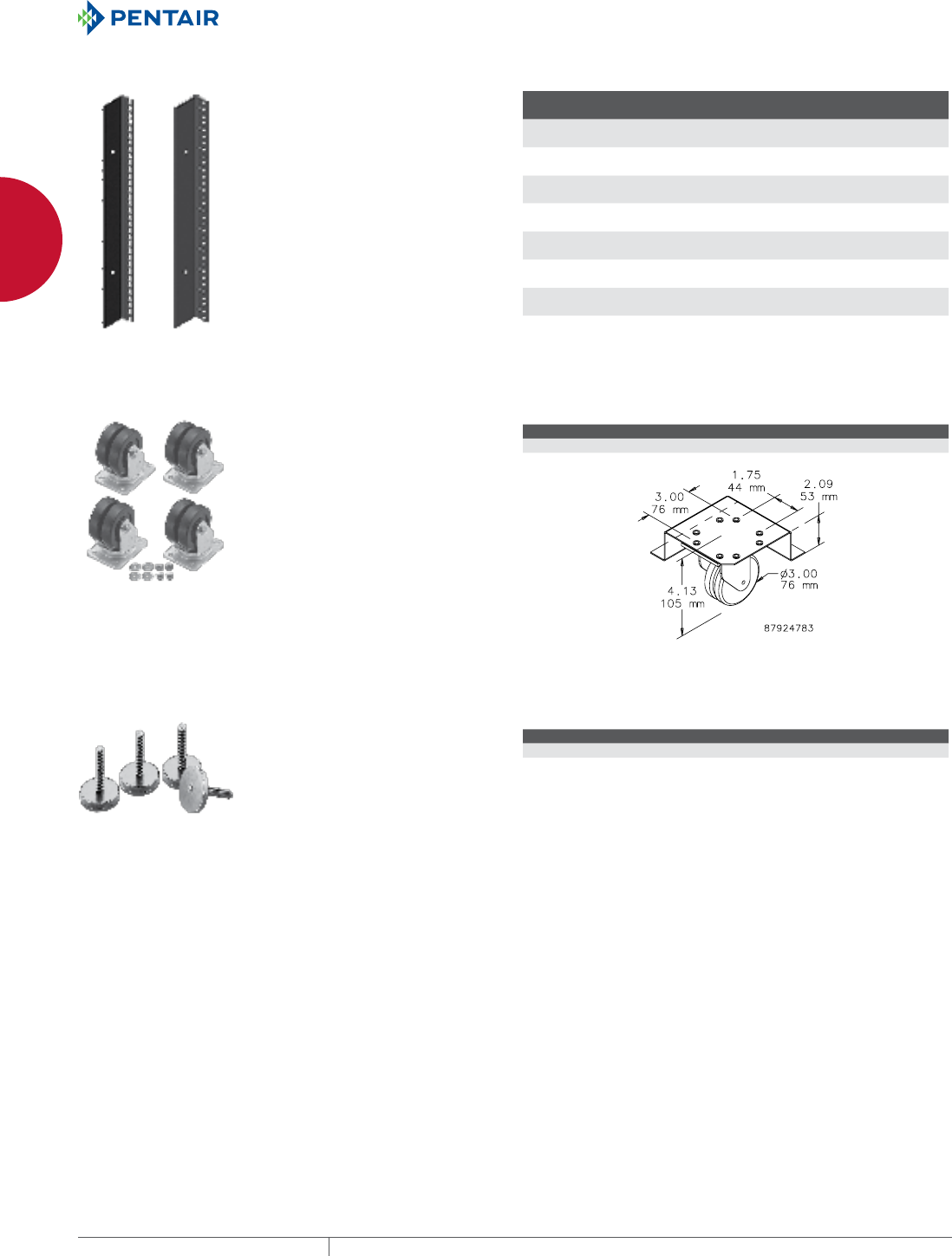
NET SERIES CASTER KIT
These recessed ball-bearing
casters allow Net Series Cabinet
repositioning with a minimal
effort. Casters add 2 in. to height of
cabinet. Kit includes four casters,
recessed brackets and mounting
hardware.
BULLETIN: DCY
Catalog Number Description
NCK Set of four casters, recessed brackets and mounting hardware
NET SERIES LEVELER KIT
Leveler Kits allow adjustment of Net
Series Cabinets for uneven floors.
Can be used with casters to stabilize
final installation.
BULLETIN: DCY
Catalog Number Description
NLK Set of four levelers
PH 763.422.2661 • FAX 763.422.2588 • PENTAIRPROTECT.COMEQUIPMENT PROTECTION NETWORKING 11
1
FREESTAND CABINETS NET SERIES COMMUNICATION AND SERVER CABINETS AND ACCESSORIES
TOOLLESS (SNAPIN) BLANKING PANELS FOR 19IN. RACKS
These Tool-less 19-in. Blanking
Panels provide easy tool-less
installation and ensure proper
airflow to equipment. Made of black
composite material and can be used
with tapped or square EIA universal
spaced rack mounting angles.
BULLETIN: DACCY
Catalog Number Description
Rack
Units Fits
Pkg.
Qty.
D19BPT1RU Blanking Panel, 19 in. 1 19 in., universal rack spacing,
tapped or square holes
10
D19BPT2RU Blanking Panel, 19 in. 2 19 in., universal rack spacing,
tapped or square holes
10
NET SERIES VERTICAL TIEDOWN CABLE MANAGER
Hold larger cable bundles securely.
VELCRO™ Cable Wraps provide
convenient cable fastening and easy
access to individual cables. One
piece design. Holes provided for
addition of cable transitions, spools,
or D-Rings (order separately). Made
of steel coated with RAL 9005 black
polyester powder paint. Includes
mounting hardware.
VELCRO is a trademark of Velcro
Industries B.V.
BULLETIN: DCY
Catalog Number A in./mm Fits Cabinet Height
NVCMTD12 40.37
1025
1245
NVCMTD21 78.87
2003
2134
EQUIPMENT PROTECTIONSUBJECT TO CHANGE WITHOUT NOTICENETWORKING12
1
FREESTAND CABINETS NET SERIES COMMUNICATION AND SERVER CABINETS AND ACCESSORIES
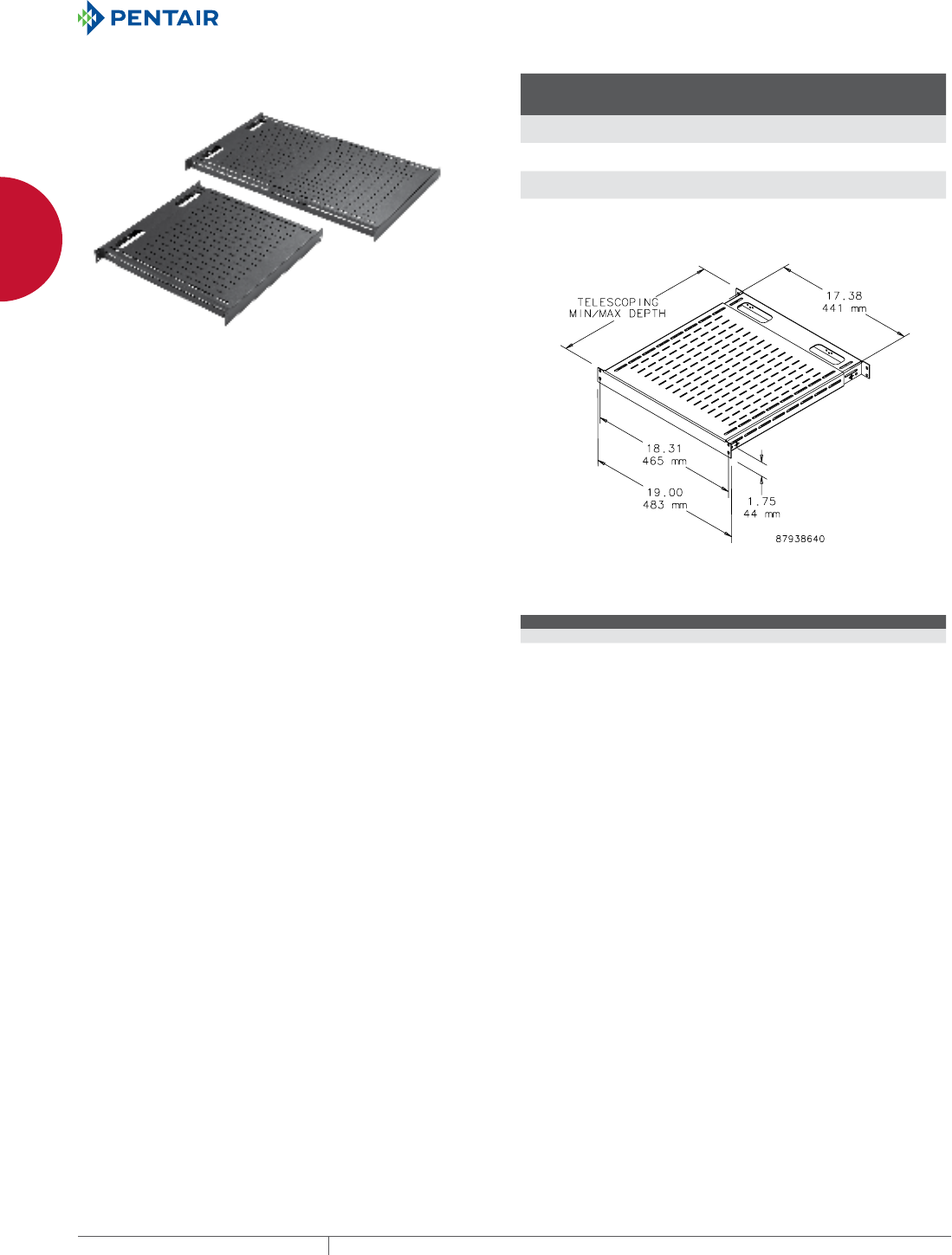
TOOLLESS SHELF
An easy-to-install tool-less vented 19-in. shelf. Mounts onto
rack angles that have EIA-spaced square holes (.375 in.). Shelf
slides open and provides a variable-sized, continuous surface
for equipment. Back of shelf has oval cutouts for power and data
cables. Accessory hole patterns at back of shelf fit small and large
D-rings to help manage cable. Made of steel with a 150 lb. (68 kg)
static load rating. Available with RAL 9005 black or RAL 7035 gray
polyester powder coat finish.
BULLETIN: DACCY
Catalog Number Description Finish
Minimum
Depth
mm/in.
Maximum
Depth
mm/in.
D19FVT69B Shelf, vented, 19 in. tool-less Black 495
19.50
851
33.50
D19FVT69G Shelf, vented, 19 in. tool-less Gray 495
19.50
851
33.50
D19FVT912B Shelf, vented, 19 in. tool-less Black 792
31.20
1151
45.30
D19FVT912G Shelf, vented, 19 in. tool-less Gray 792
31.20
1151
45.30
Minimum and maximum depth measured from rack angle to rack angle.
NET SERIES JOINING KIT
The joining kit enables joining Net Series Cabinets without sides to
form a single bank of cabinets. Each kit joins two cabinets.
BULLETIN: DCY
Catalog Number Description
NJK Net Series Joining Kit

EQUIPMENT PROTECTIONSUBJECT TO CHANGE WITHOUT NOTICENETWORKING14
1
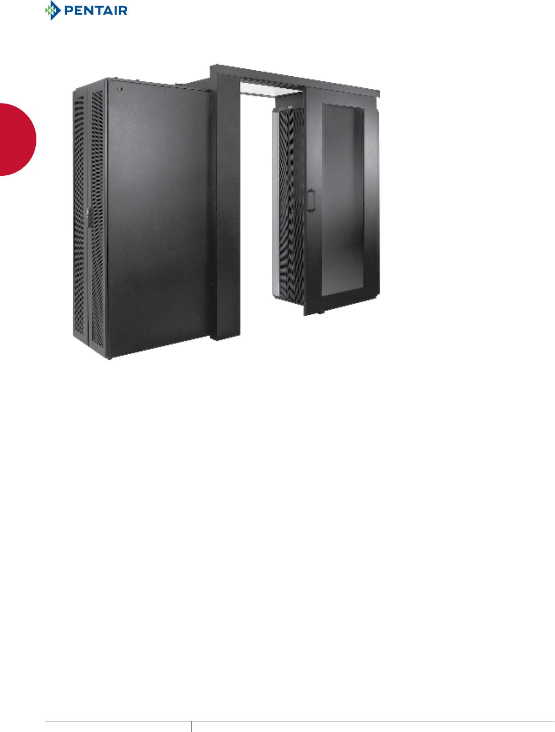
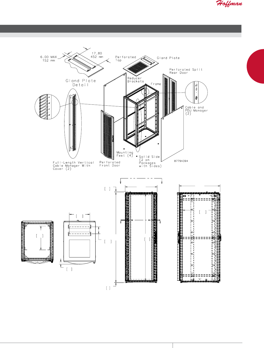
FREESTAND CABINETS PROLINE™ CONTAINMENT SYSTEM
PROLINE™ CONTAINMENT SYSTEM
PROLINE™ CONTAINMENT SYSTEM
APPLICATION
The PROLINE™ Containment System prevents hot and cold airflows
from mixing. The system increases cooling efficiency, lowers
energy costs, allows for higher thermal density with in the cabinet
and eliminates the need to buy additional cooling units. Use for
either hot or cold air containment and on raised and non-raised
floors. The PROLINE Containment System is easy to order and to
install.
Customize your Containment System by purchasing the Aisle Doors,
Ceiling Panels with Windows, Chimney and Ceiling Panels for
Chimney separately.
FEATURES
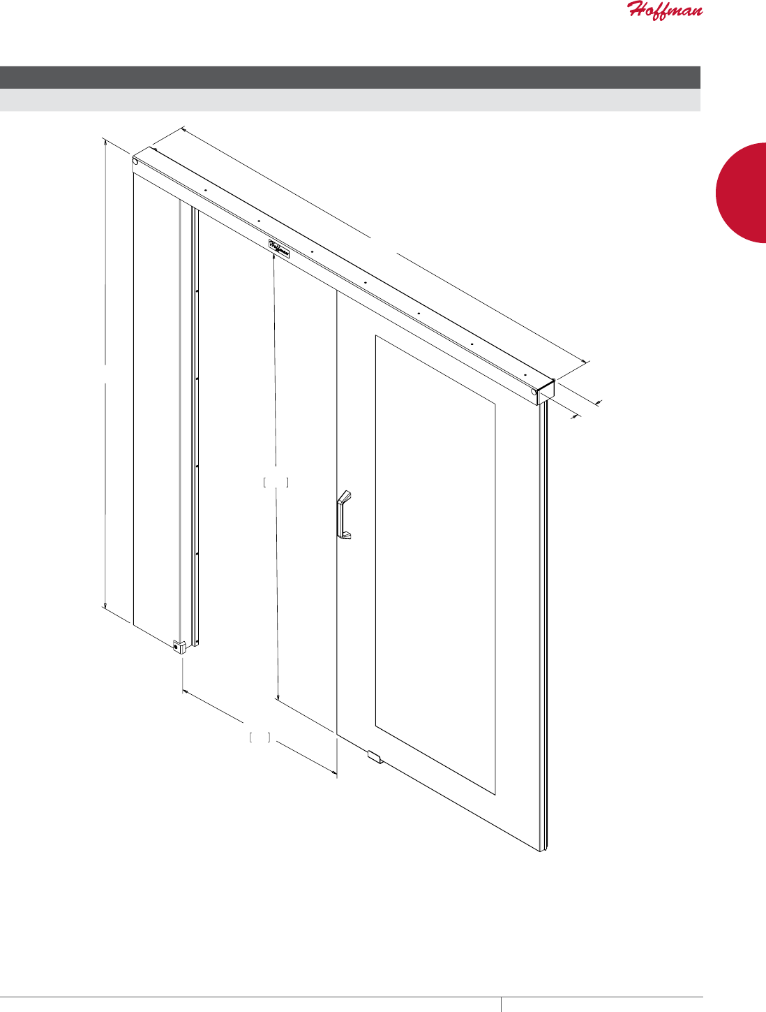
• Aisle door slides to the right to provide quick access to aisle way
• Easy to order
• Accommodates 36-in. (OSHA minimum aisle widths) and 48-in.
(two-floor-tile-wide) aisle ways
• Ergonomically positioned grab handles on interior and exterior of
contained aisle
• Clear, transparent door and roof panels provide maximum light
to aisleway
• Tool-less Ceiling Panels are easy to install and remove for
cleaning and provide above-the-cabinet access to cables,
equipment and systems
• Window Ceiling Panels have easily modified .22-in. polycarbonate
panels to accommodate local fire-suppression codes (sprinkler
heads)
• Chimney Ceiling Panels are used with chimney to direct hot
exhaust air into drop ceiling, duct work or other means back to
the computer room cooling devices
• Chimney comes in two heights to fit a wide range of applications
SPECIFICATIONS
Aisle Doors
• Composite construction of 16, 14 and 12 gauge steel
• Aluminum track and steel trolley with composite wheels
• Safety glass door is mechanically fastened to steel frame
Window Ceiling Panels
• Frame made of 16 gauge steel
• Overhead panel made of .22-in. polycarbonate
Chimney Ceiling Panels
• Frame made of 16 gauge steel
• Purchase Chimney separately
Chimney
• Made of 18 gauge steel
• Two sizes to fit various ceiling heights
• Infinite adjustment between minimum and maximum extension
• Bulb gasket seals against flat surfaces and ceilings
• S-connectors provided for duct work connection
• Purchase Chimney Ceiling Panel separately
FINISH
Prepared surface coated in polyester powder low-gloss, lightly
textured RAL 9005 black
BULLETIN: DPY
PH 763.422.2661 • FAX 763.422.2588 • PENTAIRPROTECT.COMEQUIPMENT PROTECTION NETWORKING 15
1
FREESTAND CABINETS PROLINE™ CONTAINMENT SYSTEM
Standard Product Aisle Doors
Catalog Number AxBxC mm/in.
Aisle Width
mm/in.
PCAD2 2175 x 2175 x 93
85.63 x 85.63 x 3.68
914 or 1219
36.00 or 48.00
&
%
$
EQUIPMENT PROTECTIONSUBJECT TO CHANGE WITHOUT NOTICENETWORKING16
1
FREESTAND CABINETS PROLINE™ CONTAINMENT SYSTEM
WINDOW CEILING PANEL
• Frame made of 16 gauge steel
• Overhead panel made of .22-in. polycarbonate
BULLETIN: DPY
$
&
%
Catalog Number AxBxC mm/in.
Aisle Width
mm/in.
Use With
Cabinet Width
PCP69 143 x 1309 x 597
5.63 x 51.52 x 23.50
914
36
600 mm
PCP79 143 x 1309 x 697
5.63 x 51.52 x 27.44
914
36
700 mm
PCP89 143 x 1309 x 797
5.63 x 51.52 x 31.38
914
36
800 mm
PCP612 143 x 1309 x 597
5.63 x 51.52 x 23.50
1219
48
600 mm
PCP712 143 x 1309 x 697
5.63 x 51.52 x 27.44
1219
48
700 mm
PCP812 143 x 1309 x 797
5.63 x 51.52 x 31.38
1219
48
800 mm
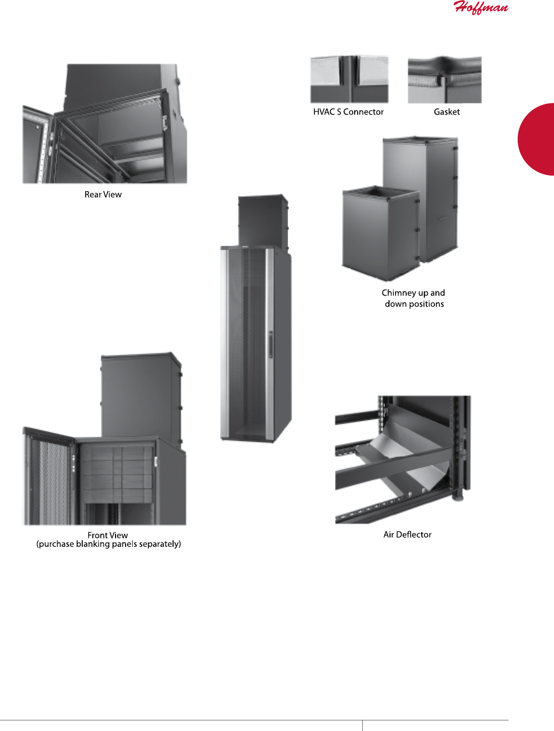
CHIMNEY CEILING PANEL
• Frame made of 16 gauge steel
• Image shows Chimney attached to the Chimney Ceiling Panel;
purchase Chimney separately
BULLETIN: DPY
$
&
%
Catalog Number AxBxC mm/in.
Fits Aisle Width
mm/in.
Use With
Cabinet Width
PCPC69 143 x 1009 x 597
5.63 x 39.71 x 23.50
914
36
600 mm
PCPC79 143 x 1009 x 697
5.63 x 39.71 x 27.44
914
36
700 mm
PCPC89 143 x 1009 x 797
5.63 x 39.71 x 31.38
914
36
800 mm
PCPC612 143 x 1009 x 597
5.63 x 39.71 x 23.50
1219
48
600 mm
PCPC712 143 x 1009 x 697
5.63 x 39.71 x 27.44
1219
48
700 mm
PCPC812 143 x 1009 x 797
5.63 x 39.71 x 31.38
1219
48
800 mm
PH 763.422.2661 • FAX 763.422.2588 • PENTAIRPROTECT.COMEQUIPMENT PROTECTION NETWORKING 17
1
FREESTAND CABINETS PROLINE™ CONTAINMENT SYSTEM
CONTAINMENT SYSTEM CHIMNEY
• Made of 18 gauge steel
• Two sizes to fit various ceiling heights
• Infinite adjustment between minimum and maximum extension
• Bulb gasket seals against flat surfaces and ceilings
• S-connectors provided for duct work connection
• Purchase Chimney Ceiling Panel separately
BULLETIN: DPY
+
Catalog Number AxBxC mm/in.
Ceiling Height
mm/in.
H min
mm/in.
H max
mm/in.
PCM1 457 x 534 x 424
18.00 x 21.01 x 16.69
2600 to 3057
102.36 to 120.36
613
24.13
1067
42.00
PCM2 762 x 534 x 424
30.00 x 21.01 x 16.69
2905 to 3667
114.36 to 144.36
918
36.13
1676
66.00
EQUIPMENT PROTECTIONSUBJECT TO CHANGE WITHOUT NOTICENETWORKING18
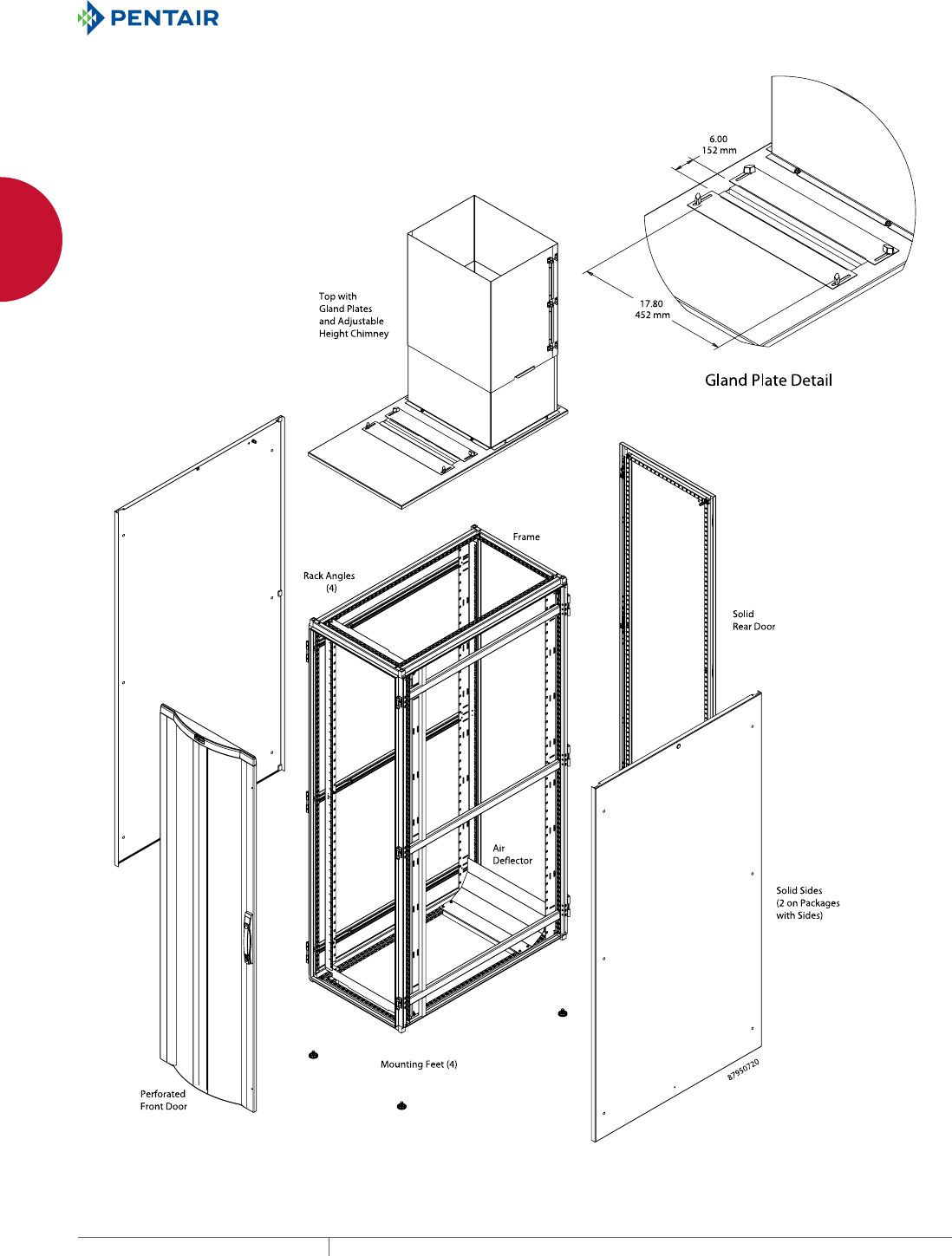
1
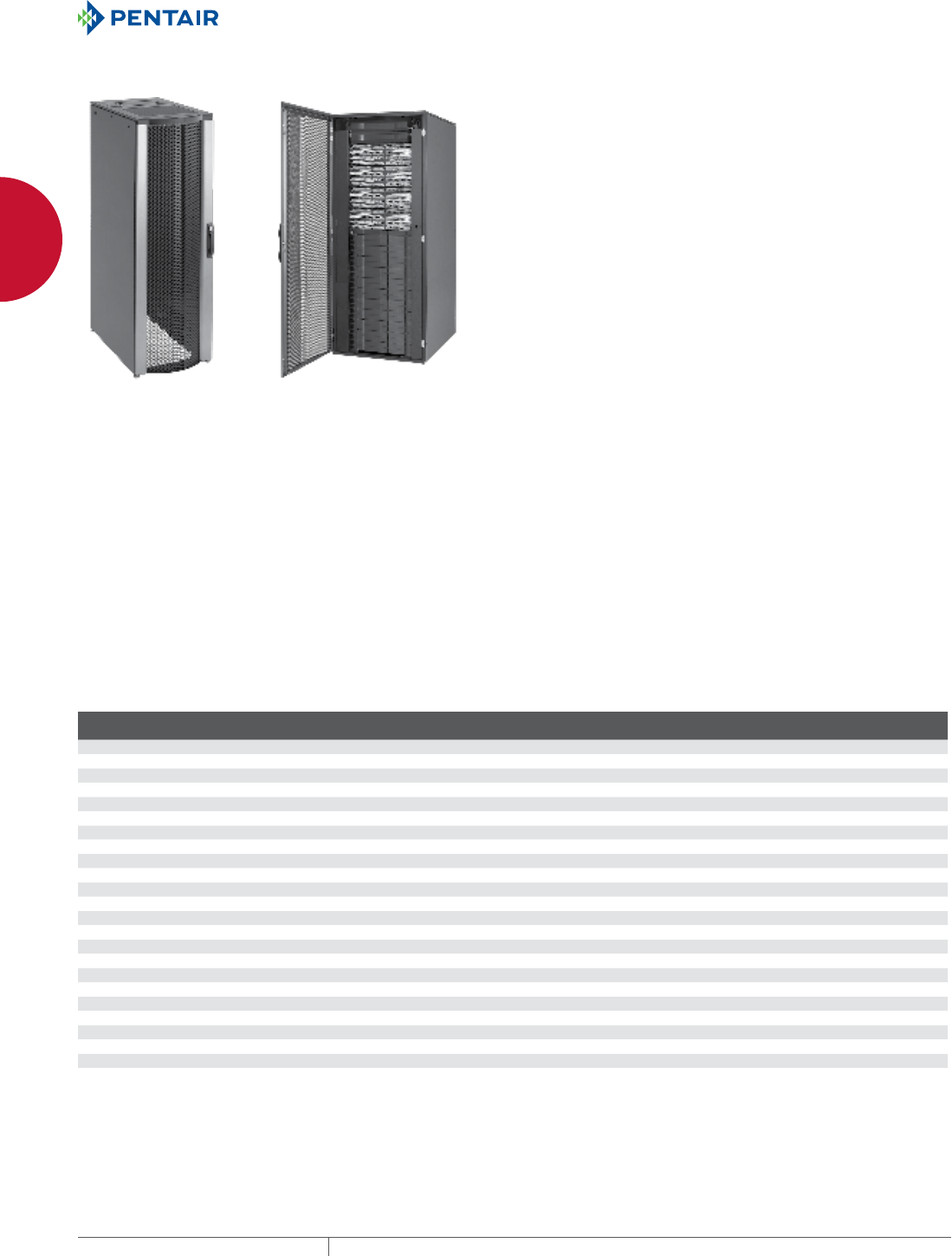
FREESTAND CABINETS PROLINE™ SERVER CABINETS
PROLINE™ SERVER CABINETS
PROLINE™ FLOTEK™ PC (PASSIVE COOLING) SERVER CABINET
APPLICATION
Designed deeper to house servers and manage power cables,
PROLINE™ FLOTEK™ Cabinets rely on optimized passive airflow
for cooling. The cabinets may be placed in data rooms randomly or
in hot/cold aisle configurations.
FEATURES
• Rigid front door made of aluminum extrusions and formed
perforated steel offers highly attractive appearance and
durability
• Fully perforated front and rear doors and fully perforated top
allow maximum air movement around equipment; conforms to
server manufacturer open space requirements
• Models without sides fit together quickly for easy installation in
ganged applications
• Three-point locking pushbutton swing handle on front door
provides easy but controlled access; two keys included
• Rear doors are split for easy access and include 3-point, low-
profile, locking swing handle
• Two sets of 19-in. square-hole rack angles support both front and
rear of equipment
• Rack angles are infinitely adjustable from front to rear for
positioning flexibility
• Large gland plate in top allows easy routing of cable, pre-
terminated cables and patch panels
• Mounting hardware (20 each of 10-32 screws and cage nuts) is
included
SPECIFICATIONS
• 16 or 14 gauge steel doors, sides and cover
• Welded 12 gauge steel frame
• Rack angles have square holes with EIA 310-D spacing
• Open bottom with integral bolt-down brackets
FINISH
Pretreated steel coated with RAL 9005 black textured, low-gloss
polyester powder paint. Other finishes available—contact Hoffman
Customer Service.
LOAD RATING
Static Load Rating: 2500 lb. (1134 kg)
A cabinet has a static load when:
• it is in its final, permanent, fully secured location, and
• its load is uniformly applied to the two sets of rack-mounting
angles
Never move a cabinet with its maximum static load applied.
Contact Hoffman if further information is needed.
BULLETIN: DPSR
Standard Product
Catalog Number AxBxC mm AxBxC in. Sides Rack Units
Additional Square
Hole Rack Angle
PSCPC2069B 1991 x 608 x 899 78.37 x 23.94 x 35.40 With sides 42 PRA1920THL1
PSCPC2069BNS 1991 x 599 x 899 78.37 x 23.58 x 35.40 Without sides 42 PRA1920THL1
PSCPC20610B 1991 x 608 x 999 78.37 x 23.94 x 39.34 With sides 42 PRA1920THL1
PSCPC20610BNS 1991 x 599 x 999 78.37 x 23.58 x 39.34 Without sides 42 PRA1920THL1
PSCPC20611B 1991 x 608 x 1099 78.37 x 23.94 x 43.28 With sides 42 PRA1920THL1
PSCPC20611BNS 1991 x 599 x 1099 78.37 x 23.58 x 43.28 Without sides 42 PRA1920THL1
PSCPC20612B 1991 x 608 x 1199 78.37 x 23.94 x 47.22 With sides 42 PRA1920THL1
PSCPC20612BNS 1991 x 599 x 1199 78.37 x 23.58 x 47.22 Without sides 42 PRA1920THL1
PSCPC2169B 2161 x 606 x 899 85.08 x 23.87 x 35.39 With sides 45 PRA1921THL1
PSCPC21610B 2161 x 606 x 999 85.08 x 23.87 x 39.33 With sides 45 PRA1921THL1
PSCPC21611B 2161 x 606 x 1099 85.08 x 23.87 x 43.27 With sides 45 PRA1921THL1
PSCPC21612B 2161 x 606 x 1199 85.08 x 23.87 x 47.20 With sides 45 PRA1921THL1
PSCPC2469B 2411 x 606 x 899 94.92 x 23.87 x 35.39 With sides 51 PRA1924THL1
PSCPC24610B 2411 x 606 x 999 94.92 x 23.87 x 39.33 With sides 51 PRA1924THL1
PSCPC24611B 2411 x 606 x 1099 94.92 x 23.87 x 43.27 With sides 51 PRA1924THL1
PSCPC24612B 2411 x 606 x 1199 94.92 x 23.87 x 47.20 With sides 51 PRA1924THL1
EQUIPMENT PROTECTIONSUBJECT TO CHANGE WITHOUT NOTICENETWORKING20
1
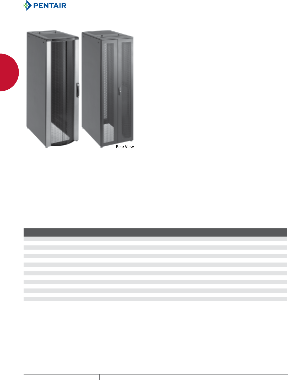
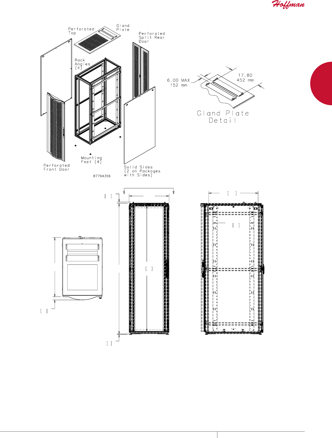
FREESTAND CABINETS PROLINE™ SERVER CABINETS
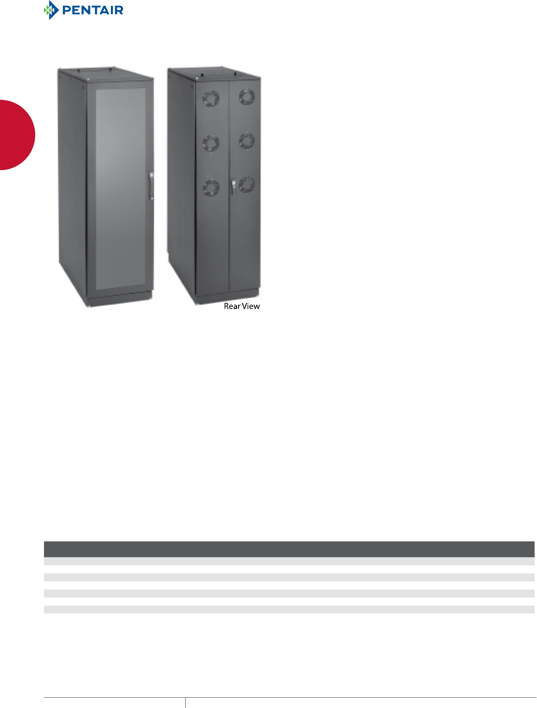
PROLINE™ FLOTEK™ HCA (HOT/COLD AISLE) SERVER CABINET
INDUSTRY STANDARDS
EIA 310-D
APPLICATION
Two independently-powered, redundant fan banks in the rear of the
PROLINE™ FLOTEK™ HCA Server Cabinet maximize cooling power
for high-density applications that generate high amounts of heat.
FEATURES
• Rigid front door made of aluminum extrusions and formed
perforated steel offers highly attractive appearance and
durability
•
Fully perforated front door offers maximum airflow from
cold aisle and conforms to server manufacturer open space
requirements
• Six 6-in. fans with integral finger guards in the rear doors pull
cold-aisle air through cabinet and exhaust it to hot aisle
• Fans provide up to 1440 CFM airflow
• Fans on each door can be independently powered to provide
redundant cooling
• Solid top helps direct airflow across equipment
• Models without sides fit together quickly for easy installation in
ganged applications
• Three-point locking pushbutton swing handle on front door
provides easy but controlled access; two keys included
• Rear doors are split for easy access and include 3-point, low-
profile, locking swing handle
• Two sets of 19-in. square-hole rack angles support both front and
rear of equipment
• Rack angles are infinitely adjustable from front to rear for
positioning flexibility
• Large gland plate in top allows easy routing of cable, pre-
terminated cables and patch panels
• Mounting hardware (20 each of 10-32 screws and cage nuts) is
included
SPECIFICATIONS
• 16 or 14 gauge steel doors, sides and cover
• Welded 12 gauge steel frame
• Rack angles have square holes with EIA 310-D spacing
• Open bottom with integral bolt-down brackets
FINISH
Pretreated steel coated with RAL 9005 black textured, low-gloss
polyester powder paint. Other finishes available—contact Hoffman
Customer Service
LOAD RATING
Static Load Rating: 2500 lb. (1134 kg)
A cabinet has a static load when:
• it is in its final, permanent, fully secured location, and
• its load is uniformly applied to the two sets of rack-mounting
angles
Never move a cabinet with its maximum static load applied.
Contact Hoffman if further information is needed.
BULLETIN: DPSR
Standard Product
Catalog Number AxBxC mm/in. Sides Rack Units Rack Angle
PSCHCA2069B 1991 x 608 x 899
78.37 x 23.94 x 35.40
With sides 42 PRA1920THL1
PSCHCA2069BNS 1991 x 599 x 899
78.37 x 23.58 x 35.40
Without sides 42 PRA1920THL1
PSCHCA20610B 1991 x 608 x 999
78.37 x 23.94 x 39.34
With sides 42 PRA1920THL1
PSCHCA20610BNS 1991 x 599 x 999
78.37 x 23.58 x 39.34
Without sides 42 PRA1920THL1
PSCHCA20611B 1991 x 608 x 1099
78.37 x 23.94 x 43.28
With sides 42 PRA1920THL1
PSCHCA20611BNS 1991 x 599 x 1099
78.37 x 23.58 x 43.28
Without sides 42 PRA1920THL1
PSCHCA20612B 1991 x 608 x 1199
78.37 x 23.94 x 47.22
With sides 42 PRA1920THL1
PSCHCA20612BNS 1991 x 599 x 1199
78.37 x 23.58 x 47.22
Without sides 42 PRA1920THL1
EQUIPMENT PROTECTIONSUBJECT TO CHANGE WITHOUT NOTICENETWORKING22
1
FREESTAND CABINETS PROLINE™ SERVER CABINETS
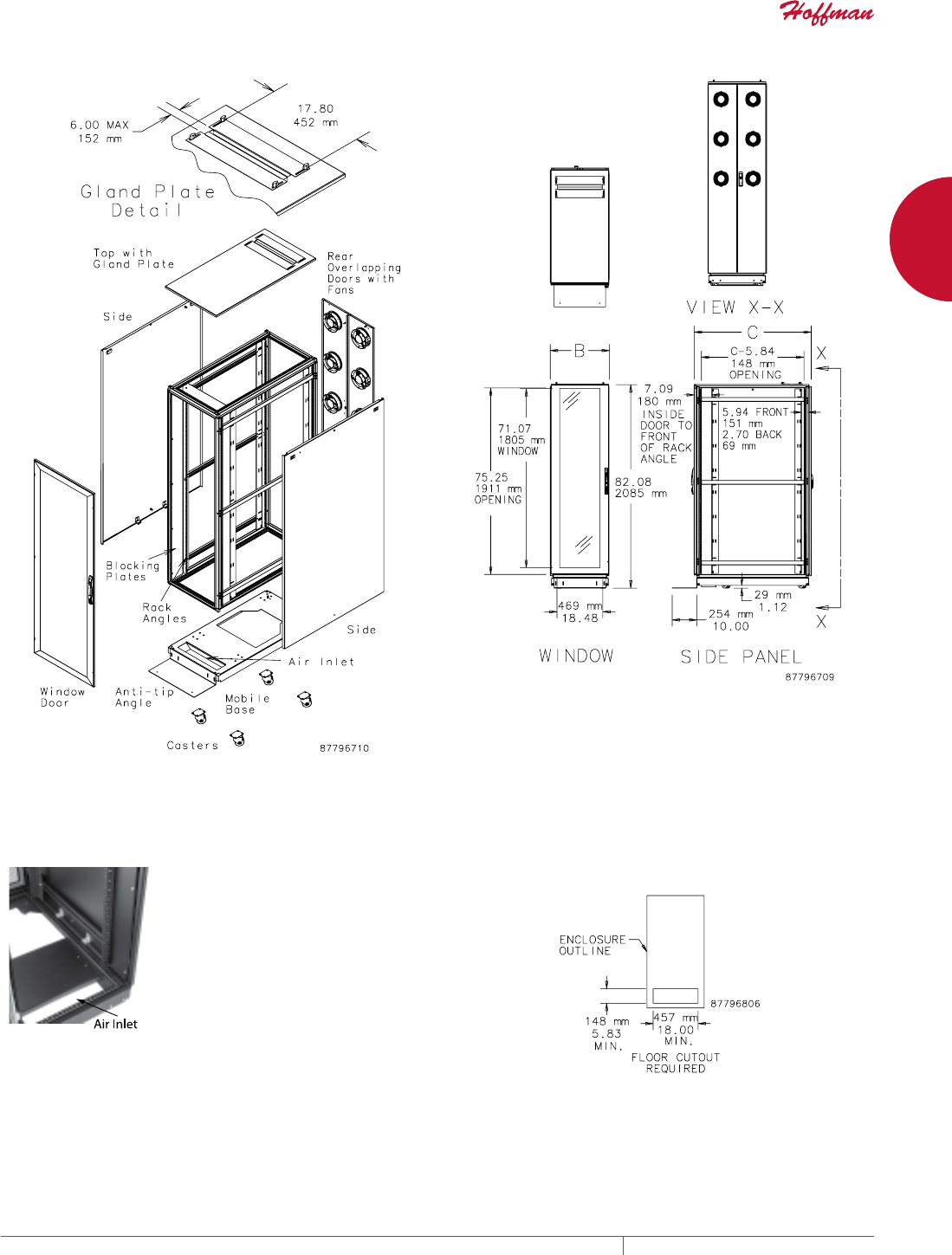
PROLINE™ FLOTEK™ FD (FLOOR DUCTED) SERVER
CABINET
INDUSTRY STANDARDS
EIA 310-D
APPLICATION
The PROLINE™ FLOTEK™ FD Server Cabinet uses the cooling
power of two banks of independently-powered fans in the back of
the cabinet and an integral front floor duct to direct air into server
intakes when positioned over a cutout in a raised data center floor.
The cabinet air inlet requires alignment with a floor cutout so
blocking plates can direct cool air from the floor plenum across the
front of the equipment.
FEATURES
• Front window door provides a view of equipment inside the
enclosure without opening the door
• Six 6-in. fans with integral finger guards in the rear doors pull
floor-ducted air through cabinet and exhaust it to hot aisle
• Fans provide up to 1400 CFM airflow
• Fans on each door can be independently powered to provide
redundant cooling
• Blocking plates inside the cabinet on both sides and the top
prevent recirculation of hot exhaust air
• Solid top helps direct airflow across equipment
• Sliding gland plate in top covers large opening that allows easy
routing of network cables, pre-terminated cables and patch
panels
• Models without sides fit together quickly for easy installation in
ganged applications
• Three-point locking pushbutton swing handle on front door
provides easy but controlled access; two keys included.
• Rear doors are split for easy access and include a low-profile,
locking swing handle
• Two sets of 19-in. square-hole rack angles with EIA universal
spacing support both front and rear of equiment
• Includes mobile base with casters and anti-tip bracket to
facilitate moving cabinet into position
• Mounting hardware (20 each of 10-32 screws and cage nuts) is
included
SPECIFICATIONS
• 16 or 14 gauge steel front door frame, rear door, sides and cover
• Welded 12 gauge steel frame
• Window is made of .125-in. thick acrylic
• Rack angles have square holes with EIA 310-D spacing
• Duct flange in base for connecting to floor duct
FINISH
Pretreated steel coated with RAL 9005 black textured, low-gloss
polyester powder paint. Rack angles are coated with RAL 9005 black
polyester powder paint. Other finishes available—contact Hoffman
Customer Service.
LOAD RATING
Static Load Rating: 2500 lb. (1134 kg)
A cabinet has a static load when:
• it is in its final, permanent, fully secured location
• its levelers are fully extended
• the anti-tip bracket is installed
• its load is uniformly applied to the two sets of rack-mounting
angles, and
• the casters are not supporting any load (use the casters only to
move the cabinet to its final location before loading)
Never move a cabinet with its maximum static load applied.
Contact Hoffman if further information is needed.
Casters Maximum Load: 1000 lb. (453 kg)
Exercise care when using casters to move the cabinet. Do not use
casters to move a cabinet with more than 1000 lb. (453 kg) load.
Avoid tipping and damage to the cabinet and its contents by slowly
moving the cabinet on its casters across smooth, flat flooring. Avoid
obstructions such as:
• large cracks
• floor displacement
• seams
• gravel
Never use casters while transporting a cabinet by truck on
roadways.
Contact Hoffman if further information is needed.
BULLETIN: DPSR
Standard Product
Catalog Number AxBxC mm AxBxC in. Sides
Rack
Units Rack Angle
PSFD2069B 2085 x 599 x 899 82.08 x 23.58 x 35.40 With sides 42 PRA1920THL1
PSFD2069BNS 2085 x 599 x 899 82.08 x 23.58 x 35.40 Without sides 42 PRA1920THL1
PSFD20610B 2085 x 599 x 999 82.08 x 23.58 x 39.34 With sides 42 PRA1920THL1
PSFD20610BNS 2085 x 599 x 999 82.08 x 23.58 x 39.34 Without sides 42 PRA1920THL1
PSFD20611B 2085 x 599 x 1099 82.08 x 23.58 x 43.28 With sides 42 PRA1920THL1
PSFD20611BNS 2085 x 599 x 1099 82.08 x 23.58 x 43.28 Without sides 42 PRA1920THL1
PSFD20612B 2085 x 599 x 1199 82.08 x 23.58 x 47.22 With sides 42 PRA1920THL1
PSFD20612BNS 2085 x 599 x 1199 82.08 x 23.58 x 47.22 Without sides 42 PRA1920THL1
PH 763.422.2661 • FAX 763.422.2588 • PENTAIRPROTECT.COMEQUIPMENT PROTECTION NETWORKING 23
1
FREESTAND CABINETS PROLINE™ SERVER CABINETS
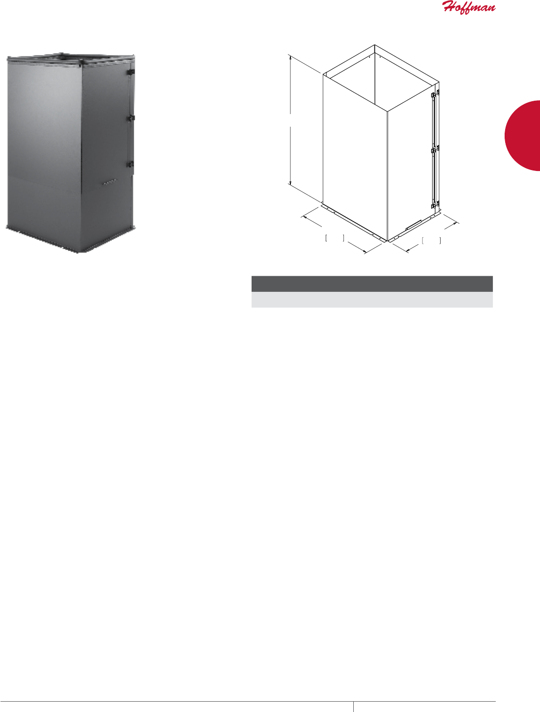
PROLINE™ FLOTEK™ FD (FLOOR DUCTED) SERVER CABINET REQUIRED FLOOR CUTOUT
A cutout that matches the air inlet in
the floor of the cabinet must be cut
in the raised floor. When installed
the cabinet air inlet is aligned with
the floor cutout, and the blocking
plates help direct cool air from the
floor plenum across the fronts of the
equipment.
Floor Cutout Dimensions
EQUIPMENT PROTECTIONSUBJECT TO CHANGE WITHOUT NOTICENETWORKING24
1
FREESTAND CABINETS PROLINE™ SERVER CABINETS
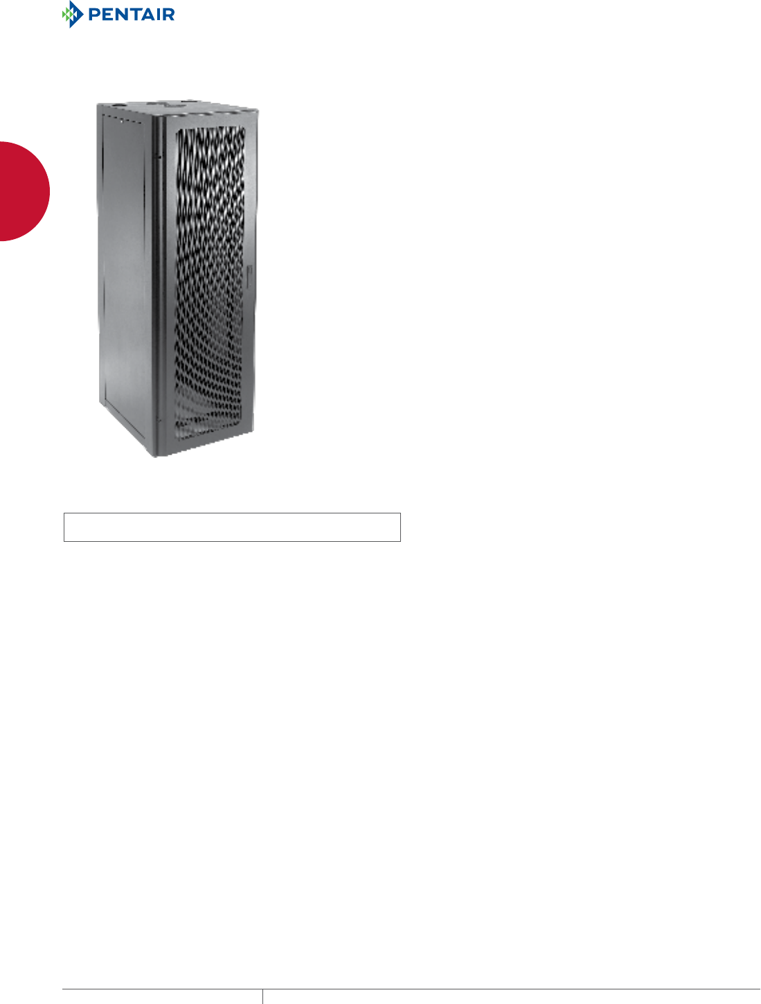
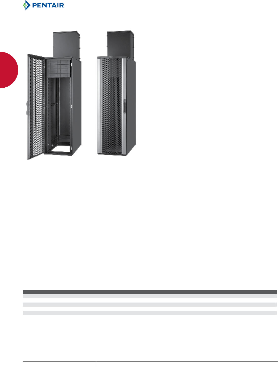
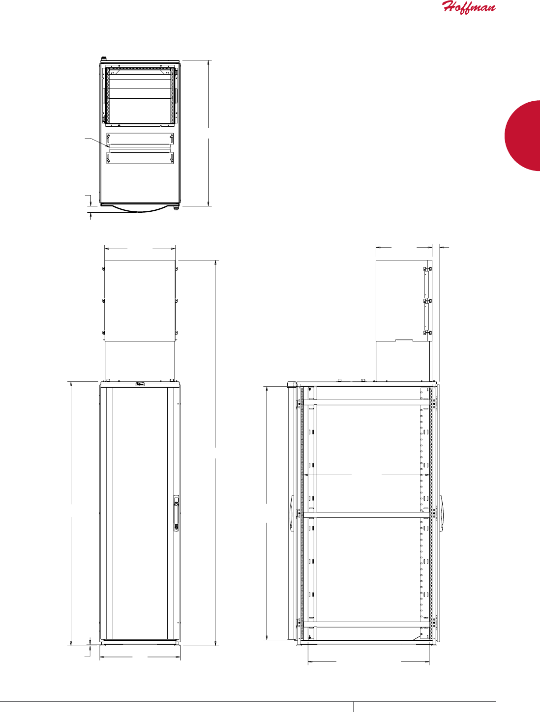
PROLINE™ FLOTEK™ TD (TOP DUCTED) SERVER CABINET
INDUSTRY STANDARDS
EIA 310-D
APPLICATION
PROLINE™ FLOTEK™ TD improves equipment efficiency and
lowers energy costs by directing hot exhaust from the cabinet up
above the plenum or drop ceiling and away from the cold room air.
Photo shown with Tool-less (Snap-in) Blanking Panels installed.
Order separately.
FEATURES
• Designed for use with 19-in. rack-mounted servers, blade
servers and other equipment
• Adjustable top duct (chimney) is provided in two different
standard heights to fit various Data Center ceilings
• Chimney is pre-assembled and shipped inside the cabinet to ease
assembly and avoid extra parcels and shipping damage
• S-connectors provided with chimney to facilitate connection to
HVAC duct work
• Edge gasket provided with chimney to prevent hot exhaust gas
from mixing with cold airflow
• Cabinet is provided with seals and blocking panels to eliminate
cold air bypass
• Includes two sets of fully adjustable mounting angles which are
RU marked front and back to facilitate assembly
•
Open base allows under-floor cable entry
• Fully perforated front door provides unrestricted cold airflow to
equipment
• Front sealed 19-in. mounting rails and top/bottom air blocking
plates prevent cold air bypass
• Solid rear door directs hot exhaust into chimney to prevent mixing
with cold airflow
• Data center efficiency increases when cold and hot airflows
are kept separate resulting in higher CRAC temperatures (cold
airflow to the equipment)
• Reduces overall energy needs with more efficient cold air
delivery to equipment
• Allows increased thermal loads and higher server densities
inside cabinet
• Can be used on raised and non-raised floors
SPECIFICATIONS
•
Top sliding gland plate accommodates cables, cable bundles and
pre-terminated patch panels
• Exhaust air deflector routes airflow to chimney to avoid hot spots
• Chimney provided with edge gasket and S-connectors
• Attractive, rigid front door made of aluminum extrusions and
formed perforated steel, with more than 60 percent open space
for free flow of cool air to equipment
• Front door is left-hinged and reversible
• Front and rear doors have keyed multi-point vault-style latch
system and central key lock to ensure security
• Solid rear door is fully gasketed to ensure all hot exhaust is
directed to top duct
• Front air dam surrounds mounting rack angles to prevent cold air
bypass
• Top and sides are formed steel
• Rack angles have .375-in. spaced square holes per EIA standards
FINISH
RAL 9005 black textured, low-gloss polyester powder paint over
pretreated steel.
Front door extrusion has a smooth, low-gloss, silver polyester
power paint finish.
LOAD RATING
Static Load Rating: 2500 lb. (1134 kg)
A cabinet has a static load when:
• it is in its final, permanent, fully secured location, and
• its load is uniformly applied to the two sets of rack-mounting
angles
Never move a cabinet with its maximum static load applied.
Contact Hoffman if further information is needed.
ACCESSORIES
19-in. Rack-Mount Environmental Monitor
Cable and PDU Manager
Rack- and Panel-Mount Power Distribution Units (PDUs)
Screw Packages
Tool-less (Snap-in) Blanking Panels for 19-in. Racks
Tool-less Shelf
Vertical Cable Manager 1
BULLETIN: DPVD
Standard Product
Catalog Number AxBxC mm AxBxC in. H MInimum (mm) H Minimum (in.) H Maximum (mm) H Maximum (in.) Rack Units
PSTD20610BM 1991 x 608 x 999 78.37 x 23.94 x 39.34 2600 102.36 3057 120.36 42
PSTD20610BT 1991 x 608 x 999 78.37 x 23.94 x 39.34 2905 114.36 3667 144.36 42
PSTD20611BM 1991 x 608 x 1099 78.37 x 23.94 x 43.28 2600 102.36 3057 120.36 42
PSTD20611BT 1991 x 608 x 1099 78.37 x 23.94 x 43.28 2905 114.36 3667 144.36 42
PSTD20612BM 1991 x 608 x 1199 78.37 x 23.94 x 47.22 2600 102.36 3057 120.36 42
PSTD20612BT 1991 x 608 x 1199 78.37 x 23.94 x 47.22 2905 114.36 3667 144.36 42
PH 763.422.2661 • FAX 763.422.2588 • PENTAIRPROTECT.COMEQUIPMENT PROTECTION NETWORKING 25
1
FREESTAND CABINETS PROLINE™ SERVER CABINETS
21.01
534 mm
B
.36
9 mm
78.40
1991 mm
H
of Rack Angles)
C - 2.50
64 mm
(Max Outside Distance
C -
5.78
147 mm
(Opening)
2.18
55 mm
16.69
424 mm
75.24
1911 mm
(Opening)
89049950
1.90
48 mm
C
Gland Plate Opening
(17.80 x 6.00)
452 mm 152 mm)
(SHOWN WITHOUT SIDES)
EQUIPMENT PROTECTIONSUBJECT TO CHANGE WITHOUT NOTICENETWORKING26
1
FREESTAND CABINETS PROLINE™ SERVER CABINETS
EQUIPMENT PROTECTIONSUBJECT TO CHANGE WITHOUT NOTICENETWORKING28
1
FREESTAND CABINETS PROLINE™ SERVER CABINETS
PROLINE™ SERVER CABINET
INDUSTRY STANDARDS
EIA 310-D
APPLICATION
The passively cooled PROLINE™ Server Cabinet has a front
viewing window and a wheeled base for application mobility and
repositioning.
FEATURES
• Front window door with key lock and vents offers visibility and
ventilation
• Open base with casters and levelers
• Fully perforated rear door provides excellent ventilation, keeping
equipment cool and extending its life
• 2000-mm tall cabinets have split rear perforated doors
• Both front and rear doors have lockable handles
•
Quick-release latches on side panels provide easy service access
• Fully perforated top cover with two cable entry ports for easy
access and service
• Mounting channels (6) provide infinite front-to-back adjustment
of rack angles
• Rack angles are coated with black polyester powder paint
• Meets industry testing standards criteria
• Mounting hardware (20 each of screws and cage nuts) is included
SPECIFICATIONS
• 16 or 14 gauge steel doors, sides and cover
• Fully welded 12 gauge steel frame
• L-shaped rack angles (4) have square holes with EIA 310-D
spacing
• Anti-tip angle made of heavy-gauge steel included
FINISH
Pretreated steel coated with RAL 7035 light-gray or RAL 9005
black textured, low-gloss polyester powder paint. Other finishes
available—contact Hoffman Customer Service.
LOAD RATING
Static Load Rating: 2500 lb. (1134 kg)
A cabinet has a static load when:
• it is in its final, permanent, fully secured location
• its levelers are fully extended
• the anti-tip bracket is installed
• its load is uniformly applied to the two sets of rack-mounting
angles, and
• the casters are not supporting any load (use the casters only to
move the cabinet to its final location before loading)
Never move a cabinet with its maximum static load applied.
Contact Hoffman if further information is needed.
Casters Maximum Load: 1000 lb. (453 kg)
Exercise care when using casters to move the cabinet. Do not use
casters to move a cabinet with more than 1000 lb. (453 kg) load.
Avoid tipping and damage to the cabinet and its contents by slowly
moving the cabinet on its casters across smooth, flat flooring. Avoid
obstructions such as:
• large cracks
• floor displacement
• seams
• gravel
Never use casters while transporting a cabinet by truck on
roadways.
Contact Hoffman if further information is needed.
BULLETIN: DPSR
Standard Product
Catalog Number AxBxC mm/in. Finish Rack Units Additional Rack Angles
PSC1269B 1285 x 608 x 899
50.59 x 23.94 x 35.40
Black RAL 9005 24 PRA1912THL1
PSC1269 1285 x 608 x 899
50.59 x 23.94 x 35.40
Light-Gray RAL 7035 24 PRA1912THL1
PSC12610B 1285 x 608 x 999
50.59 x 23.94 x 39.34
Black RAL 9005 24 PRA1912THL1
PSC12610 1285 x 608 x 999
50.59 x 23.94 x 39.34
Light-Gray RAL 7035 24 PRA1912THL1
PSC2069B 2085 x 608 x 899
82.08 x 23.94 x 35.40
Black RAL 9005 42 PRA1920THL1
PSC2069 2085 x 608 x 899
82.08 x 23.94 x 35.40
Light-Gray RAL 7035 42 PRA1920THL1
PSC20610B 2085 x 608 x 999
82.08 x 23.94 x 39.34
Black RAL 9005 42 PRA1920THL1
PSC20610 2085 x 608 x 999
82.08 x 23.94 x 39.34
Light-Gray RAL 7035 42 PRA1920THL1
PSC20611B 2085 x 608 x 1099
82.08 x 23.94 x 43.28
Black RAL 9005 42 PRA1920THL1
PSC20611 2085 x 608 x 1099
82.08 x 23.94 x 43.28
Light-Gray RAL 7035 42 PRA1920THL1
PSC20612B 2085 x 608 x 1199
82.08 x 23.94 x 47.22
Black RAL 9005 42 PRA1920THL1
PSC20612 2085 x 608 x 1199
82.08 x 23.94 x 47.22
Light-Gray RAL 7035 42 PRA1920THL1
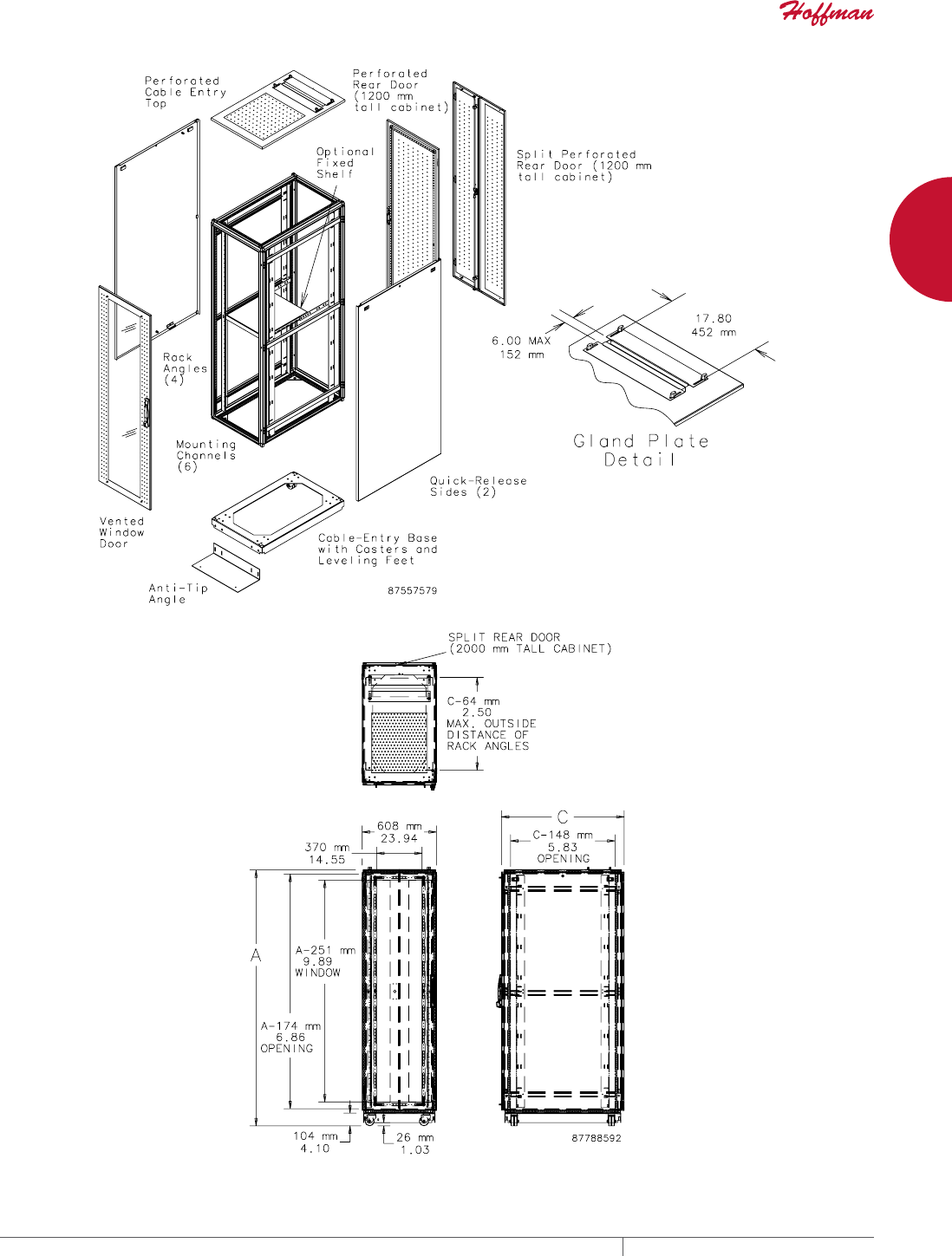
EQUIPMENT PROTECTIONSUBJECT TO CHANGE WITHOUT NOTICENETWORKING30
1
FREESTAND CABINETS PROLINE™ COMMUNICATIONS CABINETS
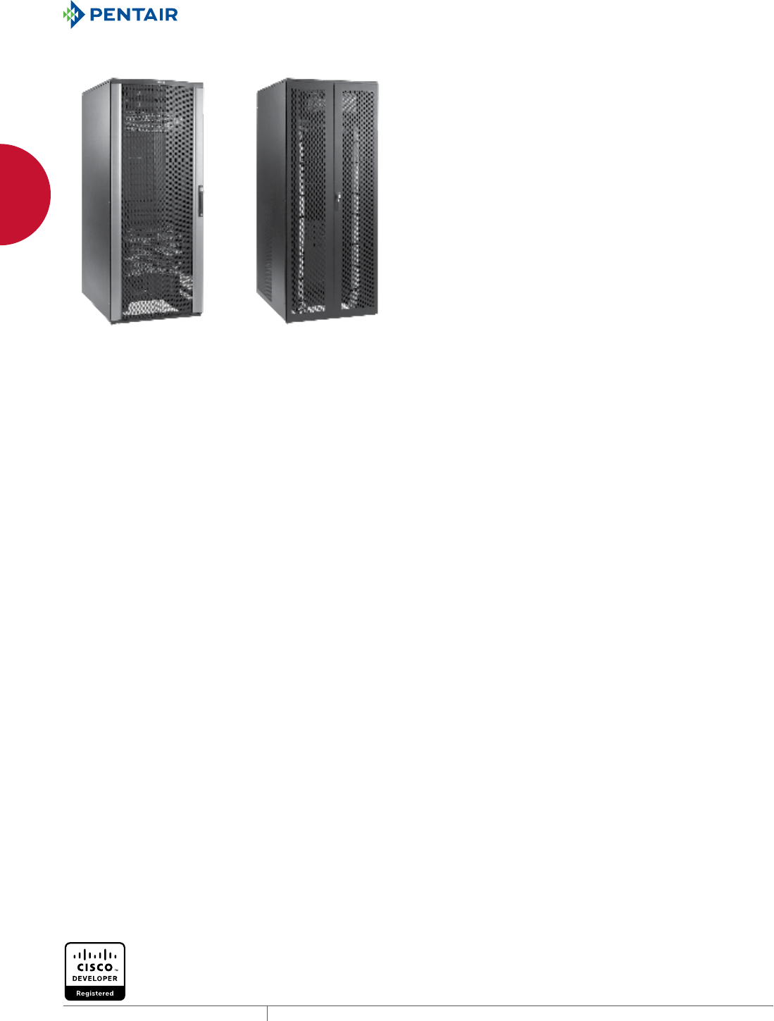
PROLINE™ COMMUNICATIONS CABINETS
PROLINE™ CONNECTEK™ COMMUNICATIONS (PATCH) CABINET
APPLICATION
The PROLINE™ CONNECTEK™ Network Communication/Patch
Cabinets feature two vertical cable managers in the front of the
cabinet and two rear cable managers for maximum cable routing
and support. Cabinets are available in two widths to accommodate
high-density cables, patch cords and networking equipment.
FEATURES
• Rigid front door made of aluminum extrusions and formed
perforated steel offers highly attractive appearance and
durability
• Fully perforated top, front door and rear doors allow maximum
air movement around cables, patch panels and other network
equipment; conforms to server manufacturer open space
requirements
• Includes front cable manager with covers and rear open
cable managers to support and route cable. See Cable/Power
Management for cable manager specifications.
• Cable managers included with 700-mm wide cabinet: Front -
PVF207; Rear - PRBTD205
• Cable managers included with 800-mm wide cabinet: Front -
PVF208; Rear - PRBTD2010
• Models without sides fit together quickly for easy installation in
ganged applications; can be ganged with server cabinets or with
additional Hoffman patch cabinets
• Three-point locking pushbutton swing handle on front door
provides easy but controlled access. Two keys included.
• Rear doors are split for easy access and include 3-point, low-
profile, locking swing handle
• Two sets of tapped 19-in. rack angles support both front and rear
of equipment
• Rack angles are infinitely adjustable from front to rear for
positioning flexibility
• Large gland plate in top allows easy routing of cable, pre-
terminated cables and patch panels
• Twenty 10-32 screws are included
SPECIFICATIONS
• 16 or 14 gauge steel doors, sides and cover
• Welded 12 gauge steel frame
• Rack angles have tapped holes with EIA 310-D spacing
• Open bottom with integral bolt-down brackets
FINISH
Pretreated steel coated with RAL 9005 black textured, low gloss
polyester powder paint. Other finishes available - contact Hoffman
Customer Service.
LOAD RATING
Static Load Rating: 2500 lb. (1134 kg)
A cabinet has a static load when:
• it is in its final, permanent, fully secured location, and
• its load is uniformly applied to the two sets of rack-mounting
angles
Never move a cabinet with its maximum static load applied.
Contact Hoffman if further information is needed.
BULLETIN: DPVD
Standard Product
Catalog Number AxBxC mm AxBxC in. Sides Rack Units
Additional Tapped
Hole Rack Angle
Additional Square
Hole Rack Angle
PNC2079B 1991 x 708 x 899 78.37 x 27.85 x 35.40 With sides 42 PRA1920TPL1 PRA1920THL1
PNC2079BNS 1991 x 699 x 899 78.37 x 27.52 x 35.40 Without sides 42 PRA1920TPL1 PRA1920THL1
PNC20710B 1991 x 708 x 999 78.37 x 27.85 x 39.34 With sides 42 PRA1920TPL1 PRA1920THL1
PNC20710BNS 1991 x 699 x 999 78.37 x 27.52 x 39.34 Without sides 42 PRA1920TPL1 PRA1920THL1
PNC20711B 1991 x 708 x 1099 78.37 x 27.85 x 43.28 With sides 42 PRA1920TPL1 PRA1920THL1
PNC20711BNS 1991 x 699 x 1099 78.37 x 27.52 x 43.28 Without sides 42 PRA1920TPL1 PRA1920THL1
PNC20712B 1991 x 708 x 1199 78.37 x 27.85 x 47.22 With sides 42 PRA1920TPL1 PRA1920THL1
PNC20712BNS 1991 x 699 x 1199 78.37 x 27.52 x 47.22 Without sides 42 PRA1920TPL1 PRA1920THL1
PNC2089B 1991 x 808 x 899 78.37 x 31.80 x 34.40 With sides 42 PRA1920TPL1 PRA1920THL1
PNC2089BNS 1991 x 799 x 899 78.37 x 31.46 x 35.40 Without sides 42 PRA1920TPL1 PRA1920THL1
PNC20810B 1991 x 808 x 999 78.37 x 31.80 x 39.34 With sides 42 PRA1920TPL1 PRA1920THL1
PNC20810BNS 1991 x 799 x 999 78.37 x 31.46 x 39.34 Without sides 42 PRA1920TPL1 PRA1920THL1
PNC20811B 1991 x 808 x 1099 78.37 x 31.80 x 43.28 With sides 42 PRA1920TPL1 PRA1920THL1
PNC20811BNS 1991 x 799 x 1099 78.37 x 31.46 x 43.28 Without sides 42 PRA1920TPL1 PRA1920THL1
PNC20812B 1991 x 808 x 1199 78.37 x 31.80 x 47.22 With sides 42 PRA1920TPL1 PRA1920THL1
PNC20812BNS 1991 x 799 x 1199 78.37 x 31.46 x 47.22 Without sides 42 PRA1920TPL1 PRA1920THL1
PNC2189B 2161 x 806 x 899 85.08 x 31.74 x 35.39 With sides 45 PRA1921TPL1 PRA1921THL1
PNC21810B 2161 x 806 x 999 85.08 x 31.74 x 39.33 With sides 45 PRA1921TPL1 PRA1921THL1
PNC21811B 2161 x 806 x 1099 85.08 x 31.74 x 43.27 With sides 45 PRA1921TPL1 PRA1921THL1
PNC21812B 2161 x 806 x 1199 85.08 x 31.74 x 47.20 With sides 45 PRA1921TPL1 PRA1921THL1
PNC2489B 2411 x 806 x 899 94.92 x 31.74 x 35.39 With sides 51 PRA1924TPL1 PRA1924THL1
PNC24810B 2411 x 806 x 999 94.92 x 31.74 x 39.33 With sides 51 PRA1924TPL1 PRA1924THL1
PNC24811B 2411 x 806 x 1099 94.92 x 31.74 x 43.27 With sides 51 PRA1924TPL1 PRA1924THL1
PNC24812B 2411 x 806 x 1199 94.92 x 31.74 x 47.20 With sides 51 PRA1924TPL1 PRA1924THL1
PH 763.422.2661 • FAX 763.422.2588 • PENTAIRPROTECT.COMEQUIPMENT PROTECTION NETWORKING 31
1
FREESTAND CABINETS PROLINE™ COMMUNICATIONS CABINETS
Cable Fill Rate for Front Vertical Cable Manager-Each Side @ 60% Fill
Cabinet Width Cross Section Area
5E
(.22-in. Diameter)
6
(.25-in. Diameter)
6A
(.30-in. Diameter)
700 mm 17.24 in.2272 210 146
800 mm 34.48 in.2544 421 293
%
$
$
;;
<<
&
&
<<
&
0$;
;;
EQUIPMENT PROTECTIONSUBJECT TO CHANGE WITHOUT NOTICENETWORKING32
1
FREESTAND CABINETS PROLINE™ NETWORK SWITCH CABINETS
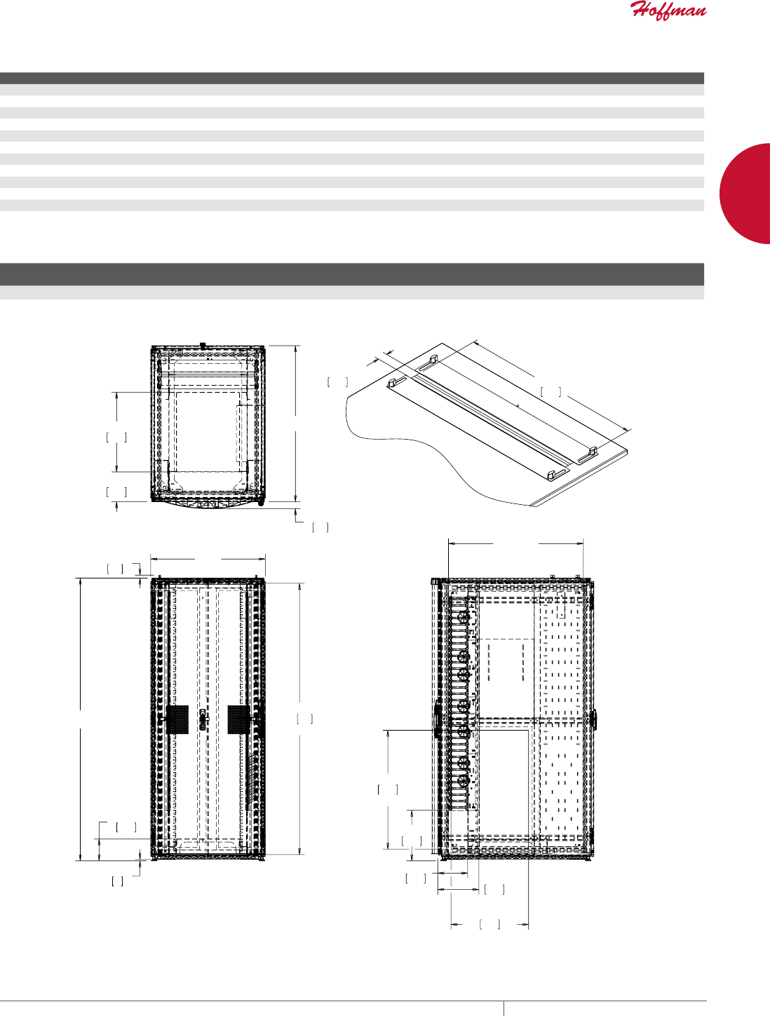
PROLINE™ NETWORK SWITCH CABINETS
PROLINE™ NETWORK SWITCH CABINET
INDUSTRY STANDARDS
EIA 310-D
APPLICATION
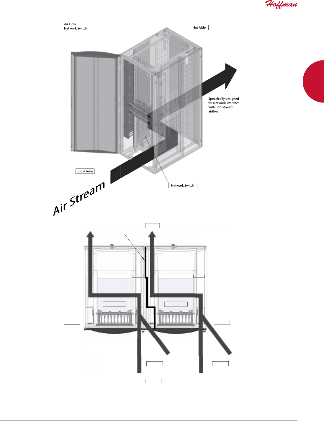
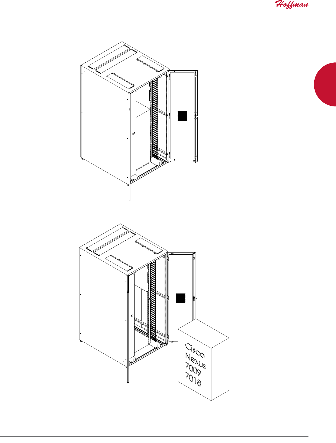
PROLINE™ Network Switch cabinet is a pre-engineered solution
for the thermal and cable management needs of large data center
network core switches. It is designed to meet Cisco 6509, 6513, 7009
and 7018 Series network switch requirements in data centers with
a hot aisle/cold aisle cabinet layout. (For other Cisco switch models,
contact Hoffman for cabinet applications.) Cabinet provides for both
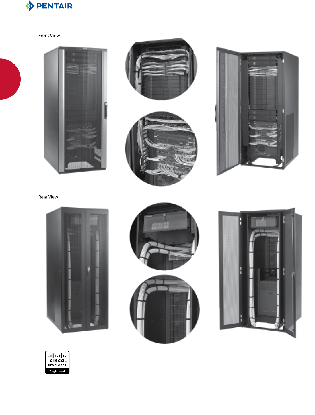
patch cords and permanent link cables with support from vertical to
horizontal transitions.
FEATURES
• Meets all CISCO 6509, 6513, 7009 and 7018 Series network
switch installation and operational requirements
• Integrated right-to-left airflow ducting ensures core switch is
supplied with air from cold aisle
• Front door has keyed multi-point vault-style latch system and
central key lock to ensure security
• Split overlapping rear doors provide quick access to equipment
without blocking aisles ( 7009 and 7018 Series have split front and
rear doors)
• Front vertical cable manager has integral hinged doors to house,
protect and provide attractive appearance
• Front cable manager uses arrowhead support fingers to support
and ensure proper bend radius, provide increased cable capacity
and facilitate assembly
• Available standard with sides or without for use in ganged
applications
• Top-mount sliding gland plate provides large opening for cables,
pre-terminated cable bundles and patch panels
• Open base allows under floor cable entry
• Network core switch shelf located at bottom of cabinet (2 RU on
65089/6513 Series; 0 RU on 7018 Series)
6509 and 6513 Series only:
• Attractive, rigid front door made of aluminum extrusions and
formed perforated steel, with more than 70 percent open space
for free flow of cool air to equipment
• Rear upper-mounted 4 RU equipment mounting angles provide
for PDUs, fiber-to-copper transition, splitter equipment and other
19-in. rack-mounted equipment
• Rear horizontal and vertical cable management provide support
and transition of permanent link cables
SPECIFICATIONS
• Switch shelf is included with cabinet
• Front set of 19-in. mounting rails are tapped (10-32) per EIA
standards
• Top and sides are formed steel
• Sides secured with fasteners
FINISH
RAL 9005 black textured, low-gloss polyester powder paint over
pretreated steel.
LOAD RATING
6509 and 6513 Series switch shelf static load rating 500 lb. (227
kg).
7009 and 7018 Series switch shelf static load rating 1000 lb. (454
kg).
Static Load Rating: 2500 lb. (1134 kg)
A cabinet has a static load when:
• it is in its final, permanent, fully secured location, and
• its load is uniformly applied to the two sets of rack-mounting
angles
Never move a cabinet with its maximum static load applied.
Contact Hoffman if further information is needed.
BULLETIN: DPVD
PH 763.422.2661 • FAX 763.422.2588 • PENTAIRPROTECT.COMEQUIPMENT PROTECTION NETWORKING 33
1
FREESTAND CABINETS PROLINE™ NETWORK SWITCH CABINETS
Standard Product6509 and 6513 Series
Catalog Number AxBxC mm AxBxC in. Description
PNS20810B 1991 x 808 x 999 78.37 x 31.80 x 39.34 Switch Cabinet
PNS20810BNS 1991 x 799 x 999 78.37 x 31.46 x 39.34 Switch Cabinet, no sides
PNS20811B 1991 x 808 x 1099 78.37 x 31.80 x 43.28 Switch Cabinet
PNS20811BNS 1991 x 799 x 1099 78.37 x 31.46 x 43.28 Switch Cabinet, no sides
PNS20812B 1991 x 808 x 1199 78.37 x 31.80 x 47.22 Switch Cabinet
PNS20812BNS 1991 x 799 x 1199 78.37 x 31.46 x 47.22 Switch Cabinet, no sides
PNS21810B 2161 x 806 x 999 85.08 x 31.74 x 39.33 Switch Cabinet
PNS21811B 2161 x 806 x 1099 85.08 x 31.74 x 43.27 Switch Cabinet
PNS21812B 2161 x 806 x 1199 85.08 x 31.74 x 47.20 Switch Cabinet
PNS24810B 2411 x 806 x 999 94.92 x 31.74 x 39.33 Switch Cabinet
PNS24811B 2411 x 806 x 1099 94.92 x 31.74 x 43.27 Switch Cabinet
PNS24812B 2411 x 806 x 1199 94.92 x 31.74 x 47.20 Switch Cabinet
Cable Fill Rate for Front Vertical Cable Manager-Each Side @ 60% Fill (6509 and 6513 Series)
Cabinet Width Cross Section Area
5E
.22-in. Diameter
6
.25-in. Diameter
6A
.30-in. Diameter
800 mm 34.48 in.2631 488 339
B
$
$
2SHQLQJ
2SHQLQJ
&
>@
3HUIRUDWLRQ
3HUIRUDWLRQ
&DEOH7URXJK
87950963
C
0$;
*ODQG3ODWH'HWDLO
6HULHV
EQUIPMENT PROTECTIONSUBJECT TO CHANGE WITHOUT NOTICENETWORKING34
1
FREESTAND CABINETS PROLINE™ NETWORK SWITCH CABINETS
Standard Product7009 and 7018 Series
Catalog Number mm in. Description
PNS201012B 1991 x 1008 x 1199 78.39 x 39.69 x 47.20 Switch Cabinet
PNS201012BNS 1991 x 999 x 1199 78.39 x 39.33 x 47.20 Switch Cabinet, no sides
PNS211012B 2161 x 1006 x 1199 85.08 x 39.62 x 47.20 Switch Cabinet
PNS241012B 2411 x 1006 x 1199 94.92 x 39.62 x 47.20 Switch Cabinet
Cable Fill Rate for Front Vertical Cable Manager-Each Side @ 60% Fill (7009 and 7018 Series)
Cabinet Width Cross Section Area
5E
.22-in. Diameter
6
.25-in. Diameter
6A
.30-in. Diameter
1000 mm 34.48 in.21736 1344 933
$
$
2SHQLQJ
;
;
;;
316%
0$;
>@
>@
*ODQG3ODWH'HWDLO
6HULHV
EQUIPMENT PROTECTIONSUBJECT TO CHANGE WITHOUT NOTICENETWORKING36
1
FREESTAND CABINETS PROLINE™ NETWORK SWITCH CABINETS
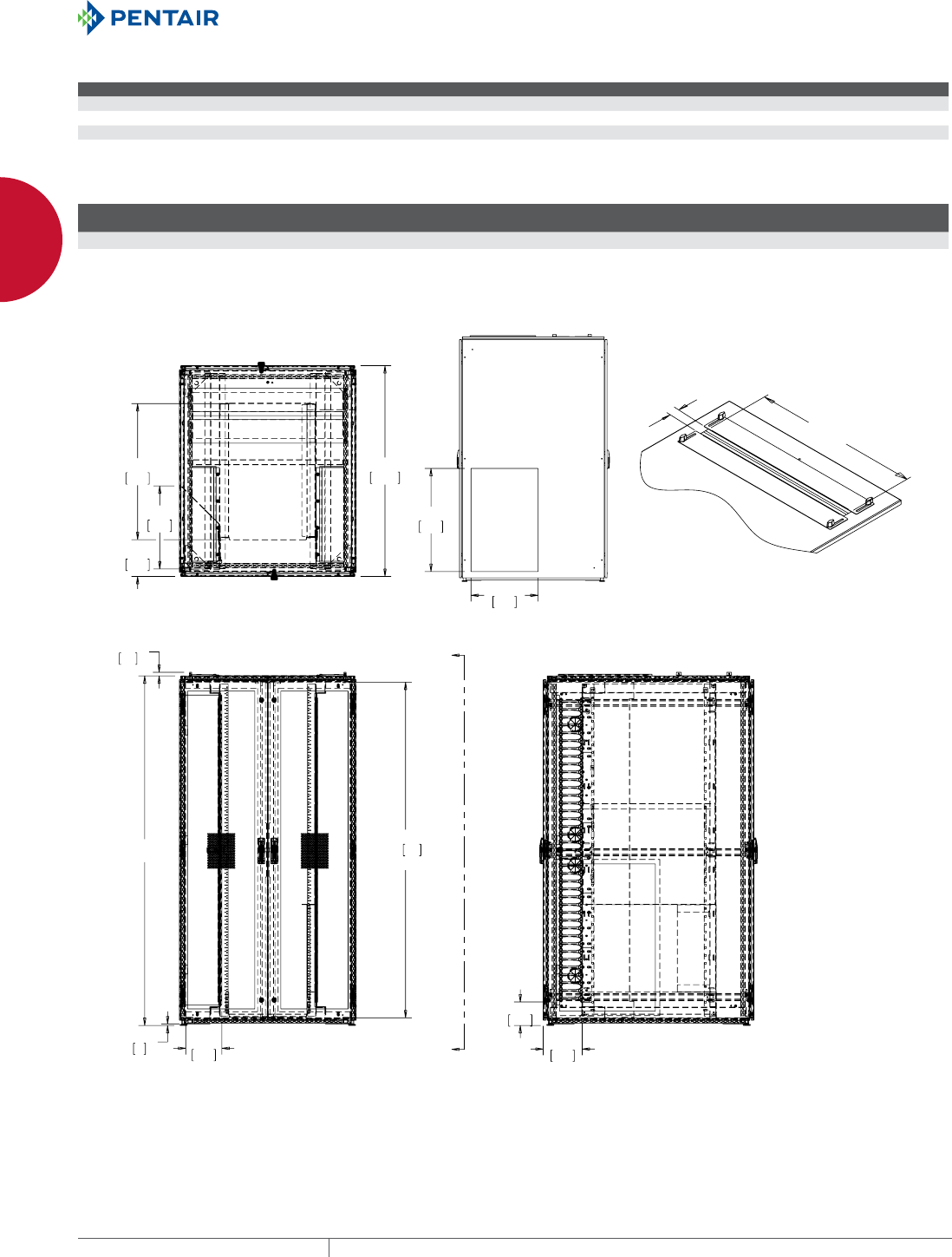
6509 and 6513 Series
EQUIPMENT PROTECTIONSUBJECT TO CHANGE WITHOUT NOTICENETWORKING38
1
FREESTAND CABINETS PROLINE™ NETWORK SEALED ENVIRONMENTAL PACKAGES
PROLINE™ NETWORK SEALED ENVIRONMENTAL PACKAGES
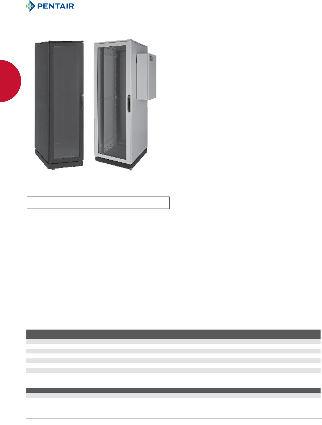
PROLINE™ VOICE/DATA AND SERVER CABINET, TYPE 12
INDUSTRY STANDARDS
EIA RS-310-D
UL 508A Listed; Type 12; File Number E61997
cUL Listed per CSA C22.2 No 94; Type 12; File Number E61997
NEMA/EEMAC, Type 12
APPLICATION
Robustly built and sealed for use in wet, dusty or hot environments,
PROLINE™ Type 12 Cabinets have optional cutouts to air condition
voice/data equipment and servers.
FEATURES
• Three-point locking handles on all doors provide easy but
controlled access; two keys included
• Fully welded frame safely supports sensitive equipment
• Fully gasketed to keep contaminants away from equipment,
reducing maintenance costs
• Two sets of 19-in. rack angles support both front and rear of
equipment
• Rack angles are infinitely adjustable from front to rear for
positioning flexibility
• Mobile base provides easy placement of cabinet
• Levelers and anti-tip bracket secure cabinet to the floor
SPECIFICATIONS
• Welded 12 gauge steel frame with integral struts
• Front window door made of 16 or 14 gauge steel with safety glass
window
• Solid 16 or 14 gauge steel back door
• Standard package has solid 16 or 14 gauge steel sides
• AC package has cutout for easy in-the-field installation of any
CR29 Series Air Conditioner (shipped separately)
• Models available with EIA Universal standard 3/8-in. square or
10-32 tapped holes
• Mobile base includes casters, levelers and gland plate
• Gland plate allows easy routing of cable
FINISH
Pretreated steel coated with RAL 9005 black or RAL 7035 light-
gray textured, low-gloss polyester powder paint. Other finishes
available—contact Hoffman Customer Service.
LOAD RATING
Static Load Rating: 2500 lb. (1134 kg)
A cabinet has a static load when:
• it is in its final, permanent, fully secured location
• its levelers are fully extended
• the anti-tip bracket is installed
• its load is uniformly applied to the two sets of rack-mounting
angles, and
• the casters are not supporting any load (use the casters only to
move the cabinet to its final location before loading)
Never move a cabinet with its maximum static load applied.
Contact Hoffman if further information is needed.
Casters Maximum Load: 1000 lb. (453 kg)
Exercise care when using casters to move the cabinet. Do not use
casters to move a cabinet with more than 1000 lb. (453 kg) load.
Avoid tipping and damage to the cabinet and its contents by slowly
moving the cabinet on its casters across smooth, flat flooring. Avoid
obstructions such as:
• large cracks
• floor displacement
• seams
• gravel
Never use casters while transporting a cabinet by truck on
roadways.
Contact Hoffman if further information is needed.
ACCESSORIES
See the Package Components table and, for AC-Ready Cabinet,
CR29 air conditioner specifications in the Thermal chapter. Air
conditioner will be shipped separately. It cannot be factory installed.
BULLETIN: DPC, DPSR
Standard Product
Catalog Number AxBxC mm AxBxC in. Cabinet, Package Type Finish
Rack
Units
Hole
Type Rack Angle
PDCP2078B12 2085 x 708 x 799 82.10 x 27.87 x 31.46 Voice Data, Standard DataCom Black 42 Tapped PRA1920TPL1
PDCP2078G12 2085 x 708 x 799 82.10 x 27.87 x 31.46 Voice Data, Standard PROLINE Gray 42 Tapped PRA1920TPL1
PSC20610B12 2085 x 608 x 999 82.10 x 23.94 x 39.34 Server, Standard DataCom Black 42 Square PRA1920THL1
PSC20610G12 2085 x 608 x 999 82.10 x 23.94 x 39.34 Server, Standard PROLINE Gray 42 Square PRA1920THL1
PDCP2078BAC 2085 x 708 x 799 82.10 x 27.87 x 31.46 Voice Data, AC Ready DataCom Black 42 Tapped PRA1920TPL1
PDCP2078GAC 2085 x 708 x 799 82.10 x 27.87 x 31.46 Voice Data, AC Ready PROLINE Gray 42 Tapped PRA1920TPL1
PSC20610BAC 2085 x 608 x 999 82.10 x 23.94 x 39.34 Server, AC Ready DataCom Black 42 Square PRA1920THL1
PSC20610GAC 2085 x 608 x 999 82.10 x 23.94 x 39.34 Server, AC Ready PROLINE Gray 42 Square PRA1920THL1
AC Ready PROLINE Cabinet
BTUs Watts
AC-Ready PROLINE Cabinet 2200/4000 650/1172
For other AC sizes, contact Hoffman.
See Air Conditioner Sizing and CR Mid-Size Air Conditioners for details.
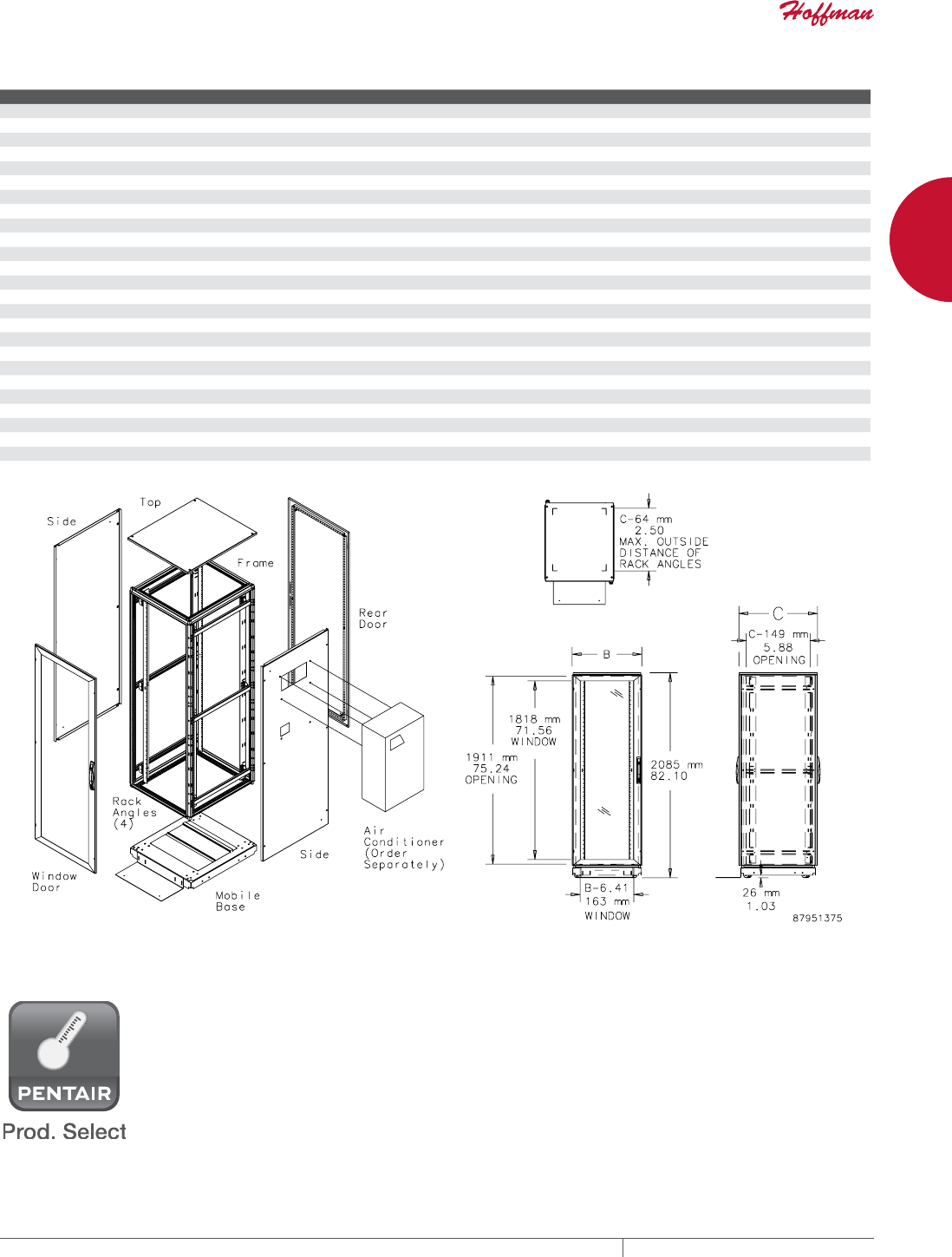
PH 763.422.2661 • FAX 763.422.2588 • PENTAIRPROTECT.COMEQUIPMENT PROTECTION NETWORKING 39
1
FREESTAND CABINETS PROLINE™ NETWORK SEALED ENVIRONMENTAL PACKAGES
Package Components
Catalog Number mm in. Description Finish
PFD2078B 2000 x 700 x 800 78.70 x 27.60 x 31.50 Frame Black
PFD2078G 2000 x 700 x 800 78.70 x 27.60 x 31.50 Frame Gray
PFD20610B 2000 x 600 x 1000 78.70 x 23.60 x 39.40 Frame Black
PFD20610G 2000 x 600 x 1000 78.70 x 23.60 x 39.40 Frame Gray
PDWG206B 2000 x 600 78.70 x 23.60 Window Doors Black
PDWG206G 2000 x 600 78.70 x 23.60 Window Doors Gray
PDWG207B 2000 x 700 78.70 x 27.60 Window Doors Black
PDWG207G 2000 x 700 78.70 x 27.60 Window Doors Gray
PDS206B 2000 x 600 78.70 x 23.60 Solid Doors Black
PDS206G 2000 x 600 78.70 x 23.60 Solid Doors Gray
PDS207B 2000 x 700 78.70 x 27.60 Solid Doors Black
PDS207G 2000 x 700 78.70 x 27.60 Solid Doors Gray
PSS208B 2000 x 800 78.74 x 31.50 Solid Sides Black
PSS208G 2000 x 800 78.74 x 31.50 Solid Sides Gray
PSS2010B 2000 x 1000 78.74 x 39.37 Solid Sides Black
PSS2010G 2000 x 1000 78.74 x 39.37 Solid Sides Gray
PSS208ACB 2000 x 800 78.74 x 31.50 Sides with AC Cutout Black
PSS208ACG 2000 x 800 78.74 x 31.50 Sides with AC Cutout Gray
PSS2010ACB 2000 x 1000 78.74 x 39.37 Sides with AC Cutout Black
PSS2010ACG 2000 x 1000 78.74 x 39.37 Sides with AC Cutout Gray
PT78B 700 x 800 27.56 x 31.50 Top Black
PT78G 700 x 800 27.56 x 31.50 Top Gray
PT610B 600 x 1000 23.62 x 39.37 Top Black
PT610G 600 x 1000 23.62 x 39.37 Top Gray
PBMG78B 700 x 800 27.60 x 31.50 Mobile Base Black
PBMG610B 600 x 1000 23.60 x 39.37 Mobile Base Black
COOLING PRODUCT SELECTION APP Designed to assist you in determining the most suitable choices
of air conditioners, heat exchangers or fans for your application.
Download a free copy of our selection software by visiting our web
site: pentairprotect.com.

EQUIPMENT PROTECTIONSUBJECT TO CHANGE WITHOUT NOTICENETWORKING40
1
FREESTAND CABINETS PROLINE™ NETWORK SEALED ENVIRONMENTAL PACKAGES
AIR CONDITIONER SIZING
Air conditioners are appropriate for applications in which:
• The temperature inside the enclosure must be maintained at or below ambient temperature.
• Humidity must be removed from the enclosure.
• Ambient air contaminants must be kept out of the enclosure.
The following air conditioner sizing procedure applies to uninsulated, sealed and gasketed enclosures in indoor locations.
Step 1. Determine the internal heat load in watts (W)
Add the maximum heat output specifications for all equipment to be installed in cabinet.
Conversion: 1 W = 3.413 BTU/hr.
Step 2. Determine the desired temperature difference (T) between the ambient temperature and the temperature inside the cabinet
Subtract the desired maximum temperature inside the cabinet (Ti) from the maximum expected temperature (To) outside the cabinet.
To - Ti = T
Conversion: 1 K or C T = 1.8 F T
Step 3. Determine the exposed surface area of the cabinet in square feet.
Use the following formula to determine area when H, W and D are the cabinet dimensions in inches.
2[(H x W) + (H x D) + (W x D)] ÷144 = Area (ft.2)
Conversion: If dimensions are in millimeters, substitute 1,000,000 for 144. Then multiply the result by 10.76 to convert from m2 to ft.2
Step 4. Determine the air conditioner capacity required
Use the following formula:
(Watts x 3.413) + [(1.25 x Area in ft.2) x T in F] = BTU/hr.
Required air conditioner capacity in BTU/hr.
Use this formula to determine the required cooling capacity needed to maintain the desired operating temperature for your enclosure.
This selection procedure applies to uninsulated, sealed, gasketed enclosures in indoor locations.
All industrial air conditioners are rated at their maximum operating point. Operating an air conditioner at temperatures below maximum
conditions will result in reduced cooling capacity. In other words, operating 95 F ambient and 95 F enclosure temperature results in a 10
percent to 20 percent reduction in the rated capacity.
Full cooling capacity is probably not necessary at lower ambient temperatures.
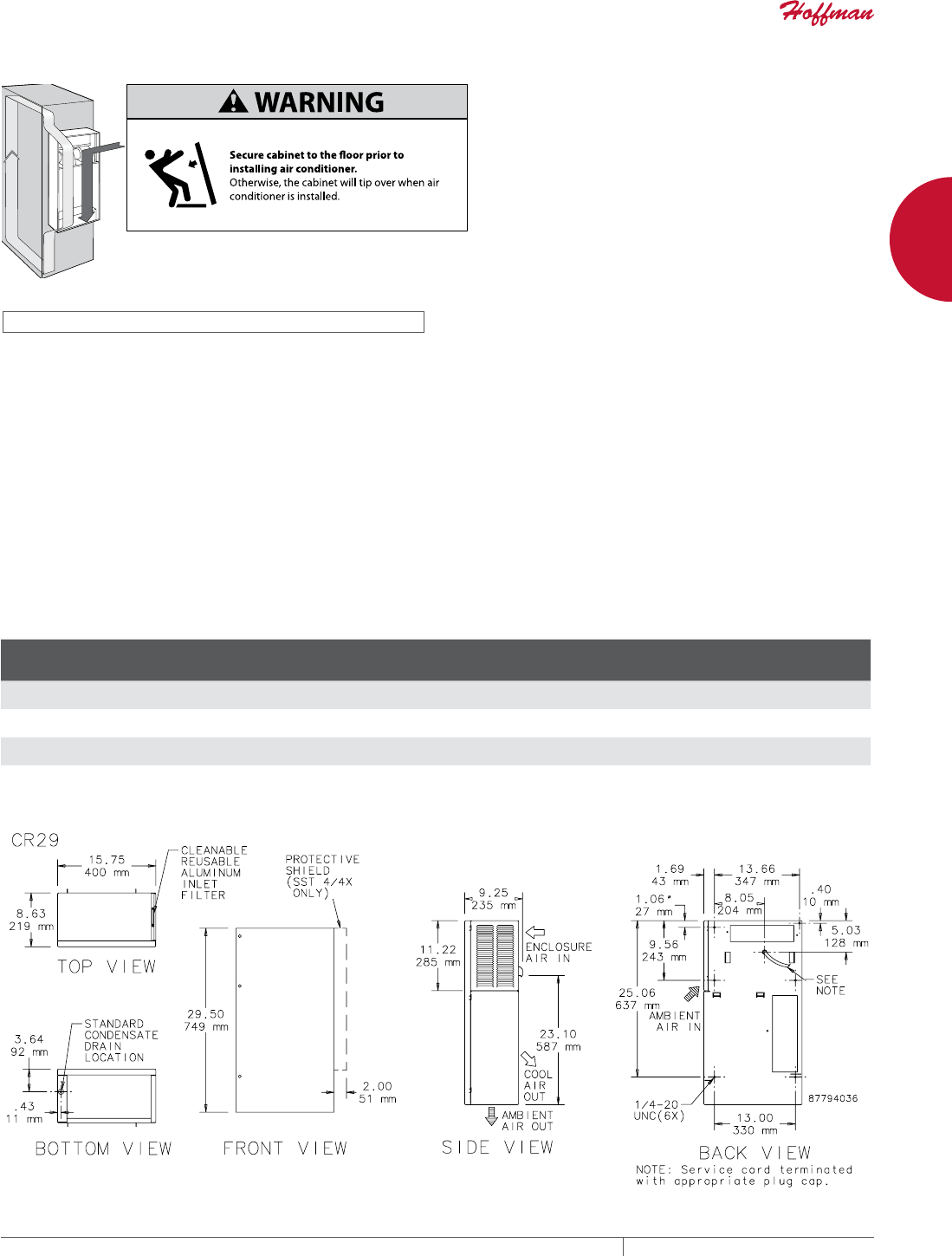
PH 763.422.2661 • FAX 763.422.2588 • PENTAIRPROTECT.COMEQUIPMENT PROTECTION NETWORKING 41
1
FREESTAND CABINETS PROLINE™ NETWORK SEALED ENVIRONMENTAL PACKAGES
CR MIDSIZE AIR CONDITIONERS
INDUSTRY STANDARDS
UL/cUL Listed; File No. SA6453
CE
Maintains UL/cUL Type 12 rating when properly installed on a UL/cUL
Type 12 rated enclosure.
APPLICATION
These air conditioners fit in the AC cutout provided in the AC-ready
Voice/Data and Server Cabinet Packages. The air conditioners are
shipped separately; they cannot be factory installed in the cabinets.
Closed Loop Cooling
Recirculated air inside the air conditioner is kept separate from
the ambient airflow system. This protects the electronic controls
and prevents shutdowns caused by heat, humidity, dust and other
contaminants.
FEATURES
• Thermostat control and EMI/RFI noise suppressor included
• Closed-loop cooling separates clean, recirculated air from
ambient airflow system
• Front cover hinges open for quick access to all components
• Filter can be inverted to double operating time between cleanings
and/or filter replacement
• Filterless operation possible in many applications
• For a typical application, unique condensate management system
evaporates moisture from enclosure
• High performance fans and blowers are ideal for densely packed
enclosures
• All units use a universally accepted CFC-free or environmentally
safe refrigerant
• Mounting hardware, gasket kit, mounting template and
instruction manual furnished
FINISH
RAL 7035 light-gray polyester powder paint
BULLETIN: MCL
Standard Product
Catalog Number AxBxC in./mm Voltage Hz Phase
BTU/Hr.
@ 131 F/131 FaAmps
@ 131 F/131 F
BTU/Hr.
@ 95 F/95 FaAmps
@ 95 F/95 F
Max Amb.
Temp. (F/C)
Ship
Wt.
(lb./kg)
CR290216G002 29.50 x 15.75 x 8.63
749 x 400 x 219
115 50/60 1 2000/2200 7.4/7.4 1700/2000 7.0/6.0 131/55 98/44
CR290226G002 29.50 x 15.75 x 8.63
749 x 400 x 219
230 50/60 1 2500/2700 4.6/3.9 1900/2300 4.4/3.3 131/55 98/44
CR290416G002 29.50 x 15.75 x 8.63
749 x 400 x 219
115 50/60 1 3500/4000 13.5/13.5 2400/2800 10.7/9.6 131/55 118/54
CR290426G002 29.50 x 15.75 x 8.63
749 x 400 x 219
230 50/60 1 3500/4000 6.7/6.6 2400/2800 5.9/5.3 131/55 118/54
a Because air conditioners provide less cooling at lower operating temperatures, two cooling capacity ratings are provided.
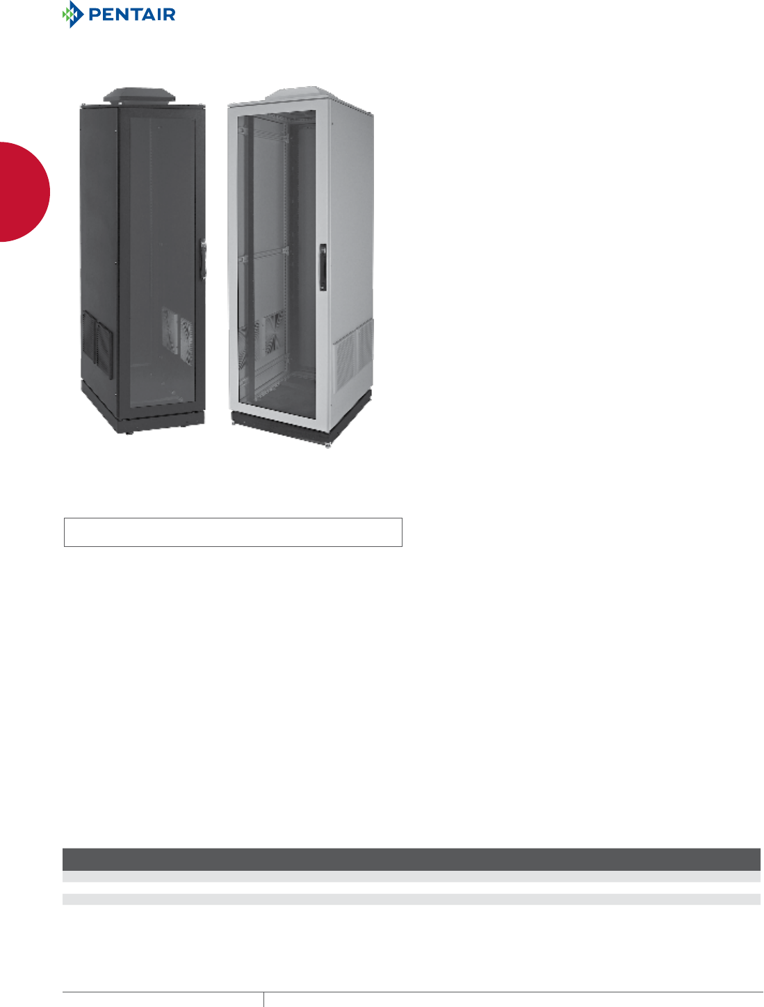
EQUIPMENT PROTECTIONSUBJECT TO CHANGE WITHOUT NOTICENETWORKING42
1
FREESTAND CABINETS PROLINE™ NETWORK SEALED ENVIRONMENTAL PACKAGES
PROLINE™ VOICE/DATA AND SERVER CABINETS WITH FAN AND FILTER PACKAGE, TYPE 1
INDUSTRY STANDARDS
EIA RS-310-D
UL508A Listed; Type 1; File No. E61997
cUL Listed per CSA C22.2 No 94; Type 1; File No. E61997
APPLICATION
PROLINE™ Voice/Data Server Cabinets are ideal for factory floors,
warehouses and other remote locations that require filtration of
ambient air to protect network equipment.
THERMAL PERFORMANCE
The thermal performance table is based on:
• Clean intake filters
• Pagoda top fan running at 600 CFM (17 cubic meters/minute)
• Equipment spaced to allow airflow (reduces “hot spot” potential)
Actual performance may vary depending on equipment layout.
FEATURES
• Three-point locking handles on all doors provide easy but
controlled access; two keys included
• Fully welded frame safely supports sensitive equipment
• Gasketed covers and air intake filters keep contaminants away
from equipment, reducing maintenance cost
• Two sets of 19-in. rack angles support both front and rear of
equipment
• Rack angles are infinitely adjustable from front to rear for
positioning flexibility
• Fan and filter package provides up to 600 CFM of filtered air to
help keep equipment cool
• Removable filters can be cleaned to maintain optimal
performance
• Mobile base provides easy placement of cabinet
• Levelers and anti-tip bracket secure cabinet to the floor
SPECIFICATIONS
• Welded 12 gauge steel frame with integral struts
• Front window door made of 16 or 14 gauge steel with safety glass
window
• Solid 16 or 14 gauge steel back door
• Solid 16 or 14 gauge steel sides with factory-installed intake
filters
• Pagoda top has 115 V fan with 6 ft. (1.8 m) cord. Fan capacity is
600 CFM (16.99 cubic meters/minute).
• Models available with EIA Universal standard 3/8-in. square or
10-32 tapped holes
• Mobile base includes casters, levelers and gland plate
• Gland plate allows easy routing of cable
FINISH
Pretreated steel coated with RAL 9005 black or RAL 7035 light
gray textured, low-gloss polyester powder paint. Other finishes
available—contact Hoffman Customer Service.
LOAD RATING
Static Load Rating: 2500 lb. (1134 kg)
A cabinet has a static load when:
• it is in its final, permanent, fully secured location
• its levelers are fully extended
• the anti-tip bracket is installed
• its load is uniformly applied to the two sets of rack-mounting
angles, and
• the casters are not supporting any load (use the casters only to
move the cabinet to its final location before loading)
Never move a cabinet with its maximum static load applied.
Contact Hoffman if further information is needed.
Casters Maximum Load: 1000 lb. (453 kg)
Exercise care when using casters to move the cabinet. Do not use
casters to move a cabinet with more than 1000 lb. (453 kg) load.
Avoid tipping and damage to the cabinet and its contents by slowly
moving the cabinet on its casters across smooth, flat flooring. Avoid
obstructions such as:
• large cracks
• floor displacement
• seams
• gravel
Never use casters while transporting a cabinet by truck on
roadways.
Contact Hoffman if further information is needed.
BULLETIN: DPC, DPSR
Standard Product
Catalog Number AxBxC mm AxBxC in.
Cabinet
Type Finish
Rack
Units Rack Angle
Hole
Type
PDCP2078BFP 2203 x 708 x 799 86.74 x 27.87 x 31.46 Voice/Data Black 42 PRA1920TPL1 Tapped
PDCP2078GFP 2203 x 708 x 799 86.74 x 27.87 x 31.46 Voice/Data Light Gray 42 PRA1920TPL1 Tapped
PSC20610BFP 2203 x 608 x 999 86.74 x 23.94 x 39.34 Server Black 42 PRA1920THL1 Square
PSC20610GFP 2203 x 608 x 999 86.74 x 23.94 x 39.34 Server Light Gray 42 PRA1920THL1 Square
Replacement filters AFLTR10 (5 filters)
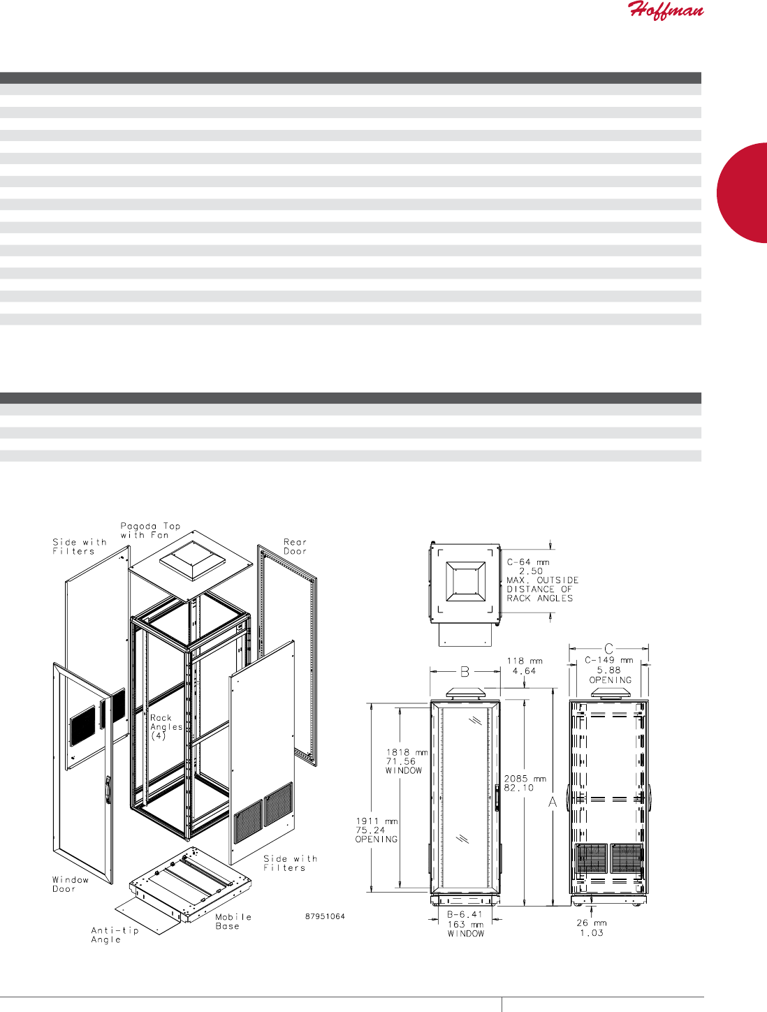
PH 763.422.2661 • FAX 763.422.2588 • PENTAIRPROTECT.COMEQUIPMENT PROTECTION NETWORKING 43
1
FREESTAND CABINETS PROLINE™ NETWORK SEALED ENVIRONMENTAL PACKAGES
Package Components
Catalog Number AxBxC mm AxBxC in. Description Finish
PFD2078B 2000 x 700 x 800 78.70 x 27.60 x 31.50 Frame Black
PFD2078G 2000 x 700 x 800 78.70 x 27.60 x 31.50 Frame Gray
PFD20610B 2000 x 600 x 1000 78.70 x 23.60 x 39.40 Frame Black
PFD20610G 2000 x 600 x 1000 78.70 x 23.60 x 39.40 Frame Gray
PDWG206B 2000 x 600 78.70 x 23.60 Window Door Black
PDWG206G 2000 x 600 78.70 x 23.60 Window Door Gray
PDWG207B 2000 x 700 78.70 x 27.60 Window Door Black
PDWG207G 2000 x 700 78.70 x 27.60 Window Door Gray
PDS206B 2000 x 600 78.70 x 23.60 Solid Door Black
PDS206G 2000 x 600 78.70 x 23.60 Solid Door Gray
PDS207B 2000 x 700 78.70 x 27.60 Solid Door Black
PDS207G 2000 x 700 78.70 x 27.60 Solid Door Gray
PSS208FPB 2000 x 800 78.70 x 31.50 Sides Black
PSS208FPG 2000 x 800 78.70 x 31.50 Sides Gray
PSS2010FPB 2000 x 1000 78.70 x 39.37 Sides Black
PSS2010FPG 2000 x 1000 78.70 x 39.37 Sides Gray
PPTHP78B 700 x 800 27.60 x 31.50 Top Black
PPTHP78G 700 x 800 27.60 x 31.50 Top Gray
PPTHP610B 600 x 1000 23.60 x 39.37 Top Black
PPTHP610G 600 x 1000 23.60 x 39.37 Top Gray
PBMG78B 700 x 800 27.60 x 31.50 Mobile Base Black
PBMG610B 600 x 1000 23.60 x 39.37 Mobile Base Black
Cooling Capacity vs. Intake Temperature
Intake Air Temperature (°F) Intake Air Temperature (°C) Cooling Capacity (W)
70 21 3,500
76 24 3,000
80 27 2,000
85 29 1,500
Above 85 Above 29 Not recommended
EQUIPMENT PROTECTIONSUBJECT TO CHANGE WITHOUT NOTICENETWORKING44
1
FREESTAND CABINETS HEAT DISSIPATION IN ELECTRICAL ENCLOSURES
HEAT DISSIPATION I N ELECTRICAL EN CLOSURES
HOW TO DISSIPATE EXCESS HEAT (WATTS) UNDERSTANDING T AND CFM
Watts: The heat load that network equipment needs to dissipate. Power coming into the cabinet equals the amount of heat load produced.
“Power In = Heat Load Out.” Alternatively, the heat load of a cabinet can be derived by measuring the Power being delivered to the network
equipment directly via a Watt meter or by measuring the current in amps and multiplying by applied voltage.
CFM: The amount of airflow that is used to dissipate the heat produced by the network equipment. It is measured in CFM or “Cubic Feet
per Minute.” The more CFM the greater amount of heat that is removed or dissipated. On passive systems, the amount of CFM needed at
the cold aisle for the intakes is the sum of all the network equipment (servers) installed in the cabinet and equals the total amount of CFM
that is exhausted. “CFM in = CFM Out”
T: Delta T is the air temperature difference between the network intakes and the exhaust or the difference between the temperatures of
the Cold Aisle and the Hot Aisle. It represents the amount of heat that is carried away by the airstream (CFM). It is measured in °F for the
equation stated above. A T between 10 F and 30 F is typical for network equipment and data centers.
• By knowing any two factors, the other can easily be obtained.
• The Cold Aisle must always provide enough CFM to the intakes of the network equipment to avoid overheating.
Graphic Representation: Watts = .316 x CFM x T (°F)
Example:
9164 Watts will need 1450 CFM at 20 F T: 9164 = .316 x 1450 x 20
30˚∆T
25,000
20,000
15,000
10,000
5,000
0
Watts = .316 x CFM x ∆T (˚F)
0
200
400
600
800
1,000
1,200
1,400
1,600
1,800
2,000
2,200
2,400
CFM
Watts
10
20
30
10˚∆T
20˚∆T

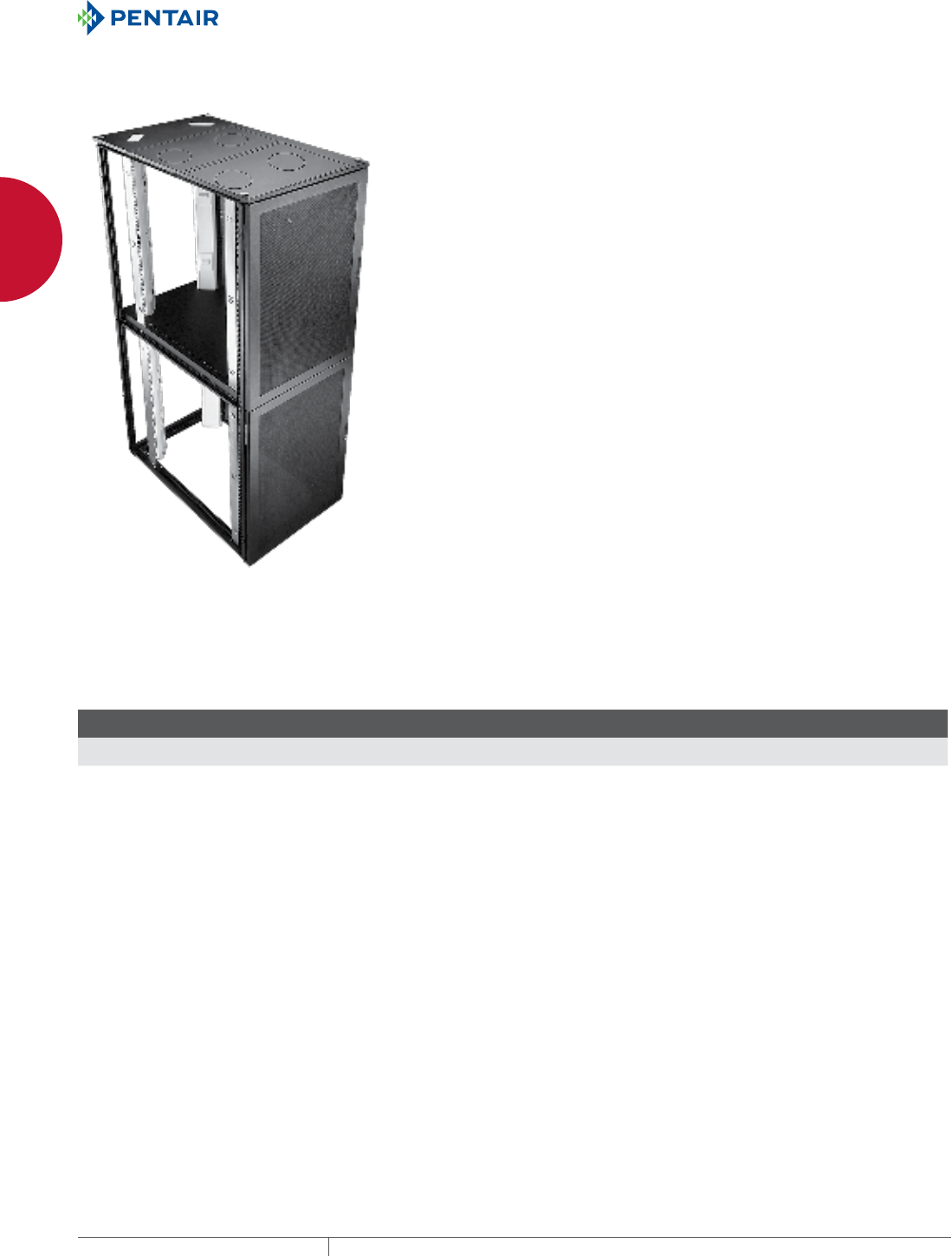
EQUIPMENT PROTECTIONSUBJECT TO CHANGE WITHOUT NOTICENETWORKING46
1
FREESTAND CABINETS PROLINE™CL COLOCATION CABINET, COMPONENTS AND ACCESSORIES
PROLINE™-CL COLOCATION CABINET, COMPONENTS AND ACCESSORIES
PROLINE™CL COLOCATION SERVER CABINET
INDUSTRY STANDARDS
EIA 310-D
APPLICATION
PROLINE™ -CL Colocation Cabinets are designed for secure data
centers that store computer equipment for multiple customers.
Standard components allow cabinets to be configured with up to
four separate, secure compartments that can be reconfigured
on-site as needs change. Each compartment has its own front and
back access and is passively cooled by virtue of the overall cabinet
design.
FEATURES
• Doors have locking trigger latch for easy access plus security
• Integral floor bolt-down brackets provide quick, secure
installation
• Cable entry and fan mounting provision on top and two access
panels on right side facilitate mounting and wiring equipment
• Usable cabinet depth is 660 mm ( 26 in.)
Dual compartment pre-assembled package also includes:
• Colocation frame shelf to divide the frame into two secure
compartments
• Cable management system to isolate the wiring to each
compartment
• Optional compact cooling fan
SPECIFICATIONS
• Welded 12 gauge steel frame
• 19-in. adjustable square hole, L-shaped rack angles front and
rear
• Square holes spaced per EIA 310-D standards
• Front and rear vented 16 gauge steel door
• Optional 16 gauge vented window door with acrylic window
• Vented 16 gauge steel top
• 16 gauge right side barrier with two access plates
FINISH
Pretreated steel coated with RAL 9005 black textured, low-gloss
polyester powder paint. Other finishes available—contact Hoffman
Customer Service.
BULLETIN: DPSR
Standard Product
Catalog Number AxBxC mm/in.
No. of
Compartments Rack Units
PCLC2069B 1991 x 608 x 898
78.39 x 23.94 x 35.34
1 42
PCL2C2069B 1991 x 608 x 898
78.39 x 23.94 x 35.34
2 20
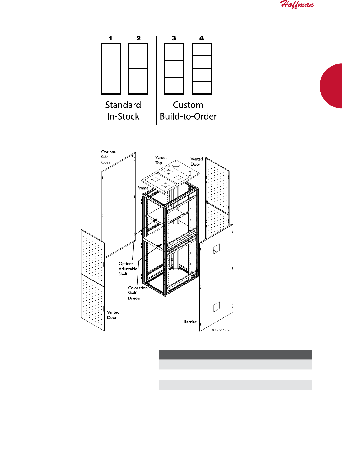
PH 763.422.2661 • FAX 763.422.2588 • PENTAIRPROTECT.COMEQUIPMENT PROTECTION NETWORKING 47
1
FREESTAND CABINETS PROLINE™CL COLOCATION CABINET, COMPONENTS AND ACCESSORIES
SIDES FOR COLOCATION CABINET PACKAGES
Order two sides for each row of cabinets for a secure, finished
appearance. Order barriers to go between cabinets. Sides are
finished with RAL 9005 fine-textured black polyester powder paint.
BULLETIN: DPC
Catalog Number AxB in./mm Type Fits Frame H x D Nominal Height x Depth
Nominal H x W
in./mm
PS209VB 78.74 x 35.43
2000 x 900
Vented 2000 x 900 1939 x 853 76.34 x 33.60
PS2010VB 78.74 x 39.37
2000 x 1000
Vented 2000 x 1000 1939 x 953 76.34 x 37.54
PBCL209B 78.74 x 35.43
2000 x 900
Barrier 2000 x 900 1939 x 853 76.34 x 33.60
PBCL2010B 78.74 x 39.37
2000 x 1000
Barrier 2000 x 1000 1939 x 953 76.34 x 37.54
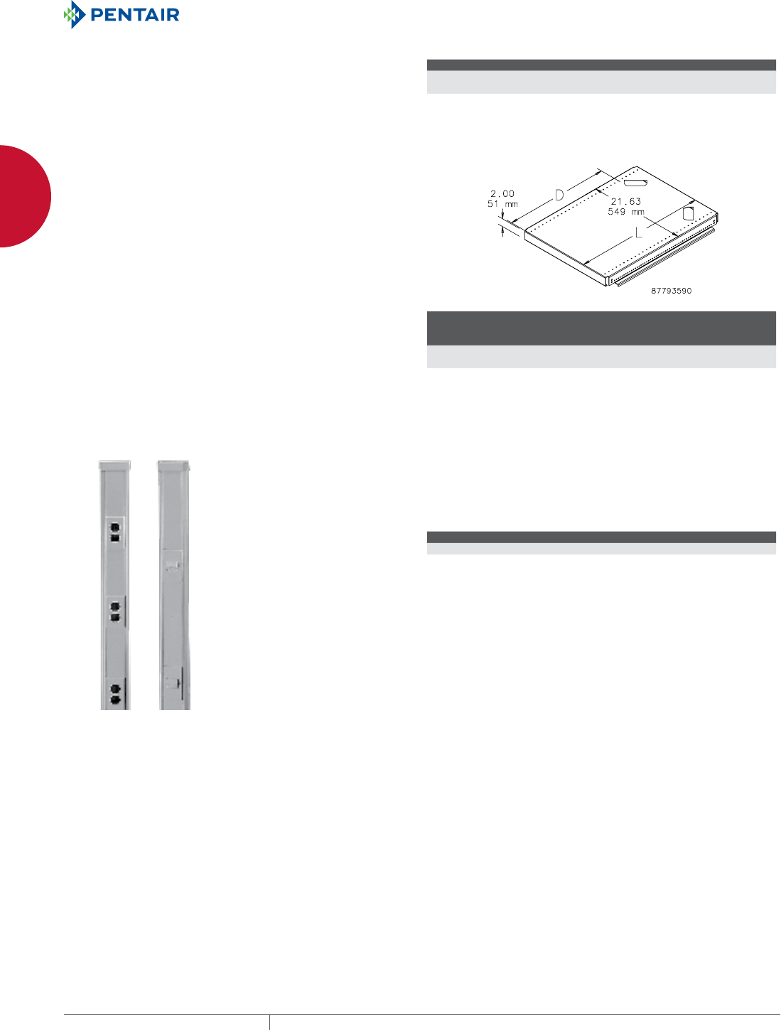
EQUIPMENT PROTECTIONSUBJECT TO CHANGE WITHOUT NOTICENETWORKING48
1
FREESTAND CABINETS PROLINE™CL COLOCATION CABINET, COMPONENTS AND ACCESSORIES
COLOCATION CABINET FRAMES
Colocation cabinet frames are available in two sizes.
BULLETIN: DPC
Catalog Number AxBxC in./mm
PF2069CLB 78.74 x 23.62 x 35.43
2000 x 600 x 900
PF20610CLB 78.74 x 23.62 x 39.37
2000 x 600 x 1000
COLOCATION DIVIDER SHELF
Provides a barrier that maintains security between compartments
in colocation applications. Made of 14 gauge steel. Provides
mounting surface for adjustable L-shaped rack angles. RAL 9005
black textured polyester paint finish. Load rating is 150 lb. (68 kg).
BULLETIN: DPC
Catalog Number AxB in./mm
L
mm/in.
D
mm/in.
Fits PROLINE
Enclosure Size
mm/in.
PFSHCL69B 23.62 x 35.43
600 x 900
842
33.14
680
26.77
600 x 900 (23.62 x 36.43)
PFSHCL610B 23.62 x 39.37
600 x 1000
942
37.08
780
30.75
600 x 1000 (23.62 x 39.37)
COLOCATION POWER CABLE AND DATA CABLE WAY Cable ways provide a means for distributing power or data
connections to each compartment in an isolated fashion. Non-
metallic light-gray composite material. Both kits include cable
runway with cover and two end caps with cable knockouts. Power
Cable Way Kit also includes four dual category 5 RJ45 connectors
and cover plates.
BULLETIN: DPC
Catalog Number Type Connectors Length
PCLCMP Power 6 duplex outlet boxes with covers 2000
PCLCMD Data 4 dual category 5 RJ45 connectors and cover plates 2000

PH 763.422.2661 • FAX 763.422.2588 • PENTAIRPROTECT.COMEQUIPMENT PROTECTION NETWORKING 49
1
FREESTAND CABINETS PROLINE™CL COLOCATION CABINET, COMPONENTS AND ACCESSORIES
COLOCATION CABINET EXTERNAL COMPONENTS
Colocation cabinet external options include vented doors, with and
without a window, vented tops and sides, a barrier side, a locking
latch kit, a cooling fan and a fan finger guard.
BULLETIN: D85, DPC
PROLINE-CL Colocation Cabinet Vented Doors
Catalog Number AxB in./mm Door Type Fits Frame H x W
Nominal H x W
mm/in.
PD206VB 78.74 x 23.62
2000 x 600
Full 2000 x 600 1939 x 592
76.34 x 23.30
PD206V2B 78.74 x 23.62
2000 x 600
1/2 2000 x 600 967 x 592
38.08 x 23.30
PD206V3B 78.74 x 23.62
2000 x 600
1/3 2000 x 600 643 x 592
25.32 x 23.30
PD206V4B 78.74 x 23.62
2000 x 600
1/4 2000 x 600 481 x 592
18.94 x 23.30
PROLINE-CL Colocation Cabinet Vented Window Doors
Catalog Number AxB in./mm Door Type Fits Frame H x W
Nominal H x W
mm/in.
Window H x W
mm/in.
PDW206VB 78.74 x 23.62
2000 x 600
Full 2000 x 600 1939 x 592
76.34 x 23.30
1805 x 370
71.08 x 14.55
PDW206V2B 78.74 x 23.62
2000 x 600
1/2 2000 x 600 967 x 592
38.08 x 23.30
833 x 370
32.81 x 14.55
PDW206V3B 78.74 x 23.62
2000 x 600
1/3 2000 x 600 643 x 592
25.32 x 23.30
509 x 370
20.06 x 14.55
PDW206V4B 78.74 x 23.62
2000 x 600
1/4 2000 x 600 481 x 592
18.94 x 23.30
347 x 370
13.68 x 14.55
PROLINE-CL Colocation Cabinet Vented Top
Catalog Number AxB in./mm Fits Frame Top W x D
Nominal W x D
mm/in.
PTCL69B 23.62 x 35.43
600 x 900
600 x 900 592 x 899
23.30 x 35.39
PTCL610B 23.62 x 39.37
600 x 1000
600 x 1000 592 x 999
23.30 x 39.32
Locking Latch, Fan and Finger Guard
Catalog
Number
AxB
in./
mm Description Includes
PTKLDC 0.00 Individually Keyed Locking Latch Set, fits all DataCom
doors
Two latches and two keys
A4AXFNPG 0.00 4-in. Compact Cooling Fan, 115V, 50/60 Hz One finger guard and
power cord
AGARD4 0.00 Finger Guard Use on 4-in. Compact
Cooling Fan
COLOCATION CABINET INTERNAL COMPONENTS
Available colocation cabinet internal components customize the
enclosure.
BULLETIN: DPC
L-Shaped, Square Hole Rack Angles
Catalog Number Door Style
Height
mm/in.
Fits Frame Height
mm/in. Rack Units
PRA1920THL1 Full 1905
75.00
2000
78.74
42
PRA1920THL2 1/2 914
36.00
2000
78.74
20
PRA1920THL3 1/3 594
23.38
2000
78.74
13
PRA1920THL4 1/4 419
16.50
2000
78.74
9
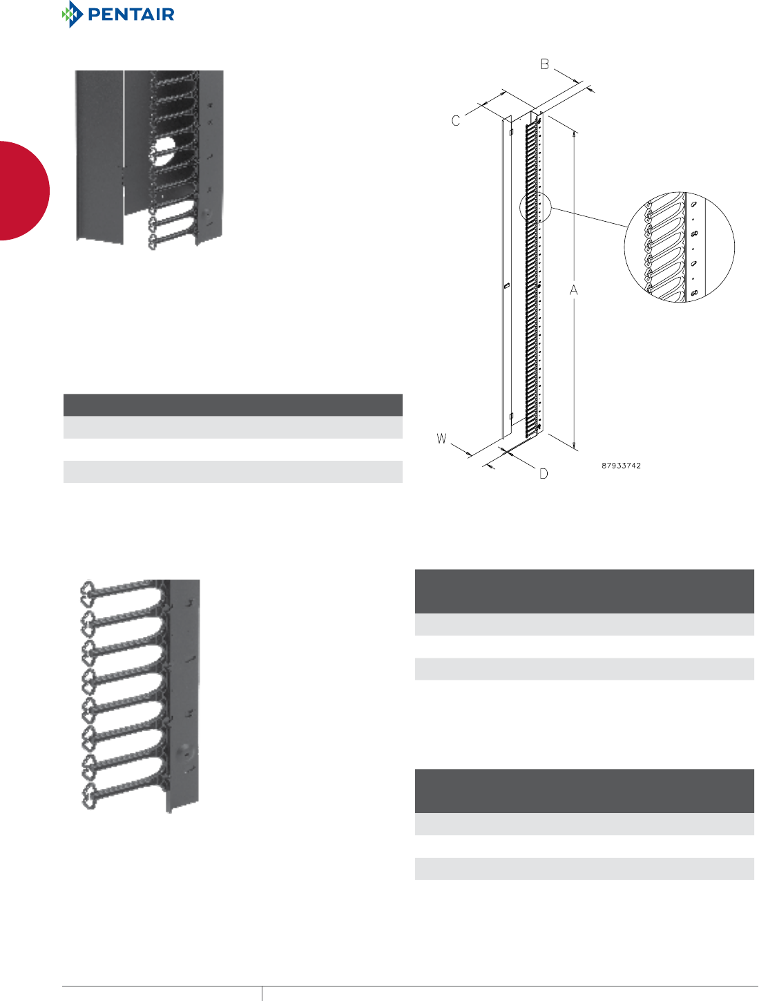
EQUIPMENT PROTECTIONSUBJECT TO CHANGE WITHOUT NOTICENETWORKING50
1
FREESTAND CABINETS PROLINE™ CABINET CABLE MANAGERS
PROLINE™ CABINET CABLE MANAGERS
PROLINE™ CABLETEK™ VERTICAL CABLE MANAGER
For routing and bundling cable inside 700- and 800-mm wide
PROLINE™ cabinets. Variety of sizes provide mounting flexibility.
Mounts between frame and rack angle so equipment can be
centered or aligned on one side. Replaces reducing brackets that
bridge space between cabinet and equipment and allows front-
to-back adjustment of rack angles. Latching hinged door on front
conceals wiring yet allows easy access. Movable plastic spools or
fingers help manage cables. 14 and 16 gauge steel with RAL 9005
black polyester powder paint finish.
BULLETIN: DPY
Catalog Number AxBxC mm/in.
D
mm/in.
W
mm/in.
Fits Cabinet
Height
PVF127 1067 x 50 x 222
42.02 x 1.97 x 8.75
13
.50
85
3.36
1200
PVF128 1067 x 100 x 222
42.02 x 3.94 x 8.75
13
.50
135
5.33
1200
PVF207 1867 x 50 x 222
73.52 x 1.97 x 8.75
13
.50
85
3.36
2000
PVF208 1867 x 100 x 222
73.52 x 3.94 x 8.75
13
.50
135
5.33
2000
PROLINE™ CABLETEK™ REDUCING BRACKETS
Fingers separate, support and manage cable. Bracket mounts on
either left or right side of 700- and 800-mm cabinets between the
frame and the rack angle to create vertical wiring space. Bracket
has RAL 9005 black polyester powder paint finish. Fingers are
molded black plastic. Mounting hardware included.
NOTE: Refer to the table to calculate the number of reducing brackets
required.
BULLETIN: DPY
Catalog Number
Height
mm/in.
Width
mm/in.
Fits Cabinet
Height
mm/in.
PRBF125 1091
42.97
50
1.91
1200
PRBF1210 1091
42.97
100
3.88
1200
PRBF205 1892
74.47
50
1.91
2000
PRBF2010 1892
74.47
100
3.88
2000
Number of reducing brackets required to accommodate 19-
and 23-in. equipment in different cabinet widths
Nominal
Bracket
Width
No. of
Reducing
Brackets
(19 in. equipment)
No. of
Reducing
Brackets
(23 in. equipment)
50 2 —
700
50 — 2
800
100 1 —
700
100 2 1
800
Support finger reducing brackets required to accommodate 19-in. and 23-in. equipment in different cabinet
widths.
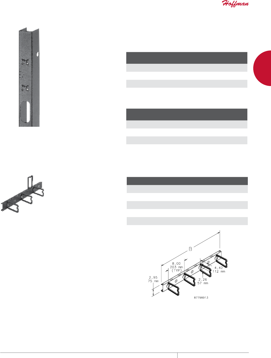
PH 763.422.2661 • FAX 763.422.2588 • PENTAIRPROTECT.COMEQUIPMENT PROTECTION NETWORKING 51
1
FREESTAND CABINETS PROLINE™ CABINET CABLE MANAGERS
PROLINE™ TIEDOWN REDUCING BRACKET
Provides convenient tie down for vertical or horizontal cable
management. Allows front-to-back cable pass through. Supports
optional D-Rings and wire management spools. Bracket mounts on
either left or right side of 700- and 800-mm cabinets between the
frame and the rack angle to create vertical wiring space. Bracket
has RAL 9005 black polyester powder paint finish. Mounting
hardware and 10 VELCRO® Cable Wraps included.
NOTE: Refer to the table to calculate the number of reducing brackets
required.
VELCRO is a trademark of VELCRO Industries B.V.
BULLETIN: DPY
Catalog Number
Height
mm/in.
Width
mm/in.
Fits Cabinet
Height
mm/in.
PRBTD125 1091
42.97
50
1.91
1200
PRBTD1210 1091
42.97
100
3.88
1200
PRBTD205 1892
74.47
50
1.91
2000
PRBTD2010 1892
74.47
100
3.88
2000
Number of reducing brackets required to accommodate 19- and
23-in. equipment in different cabinet widths
Nominal
Bracket
Width
No. of
Brackets
(19 in. equipment)
No. of
Brackets
( 23 in. equipment)
50 2 —
700
50 — 2
800
100 1 —
700
100 — 1
800
FRONTTOBACK DRING BRACKET
Manages cable routed between
front and back of cabinet. Can be
used with optional Universal D-Ring
Brackets or Transition Brackets for
increased flexibility in managing
cables. Mounts to PROLINE frame.
Secures cable with D-Rings that
snap open and closed for secure
routing with easy access for wiring
changes. D-Rings can be oriented
for vertical, front-to-back or side-
to-side cable management. RAL
9005 black polyester paint finish.
Includes D-Rings and mounting
hardware.
BULLETIN: DPY
Catalog Number
Number of
D-Rings
B
mm/in.
Fits Enclosure Depth
mm/in.
PFBDR8 3 640
25.20
800
31.50
PFBDR9 3 740
29.13
900
35.43
PFBDR10 4 840
33.07
1000
39.37
PFBDR11 5 940
37.01
1100
43.31
PFBDR12 5 1040
40.95
1200
47.24
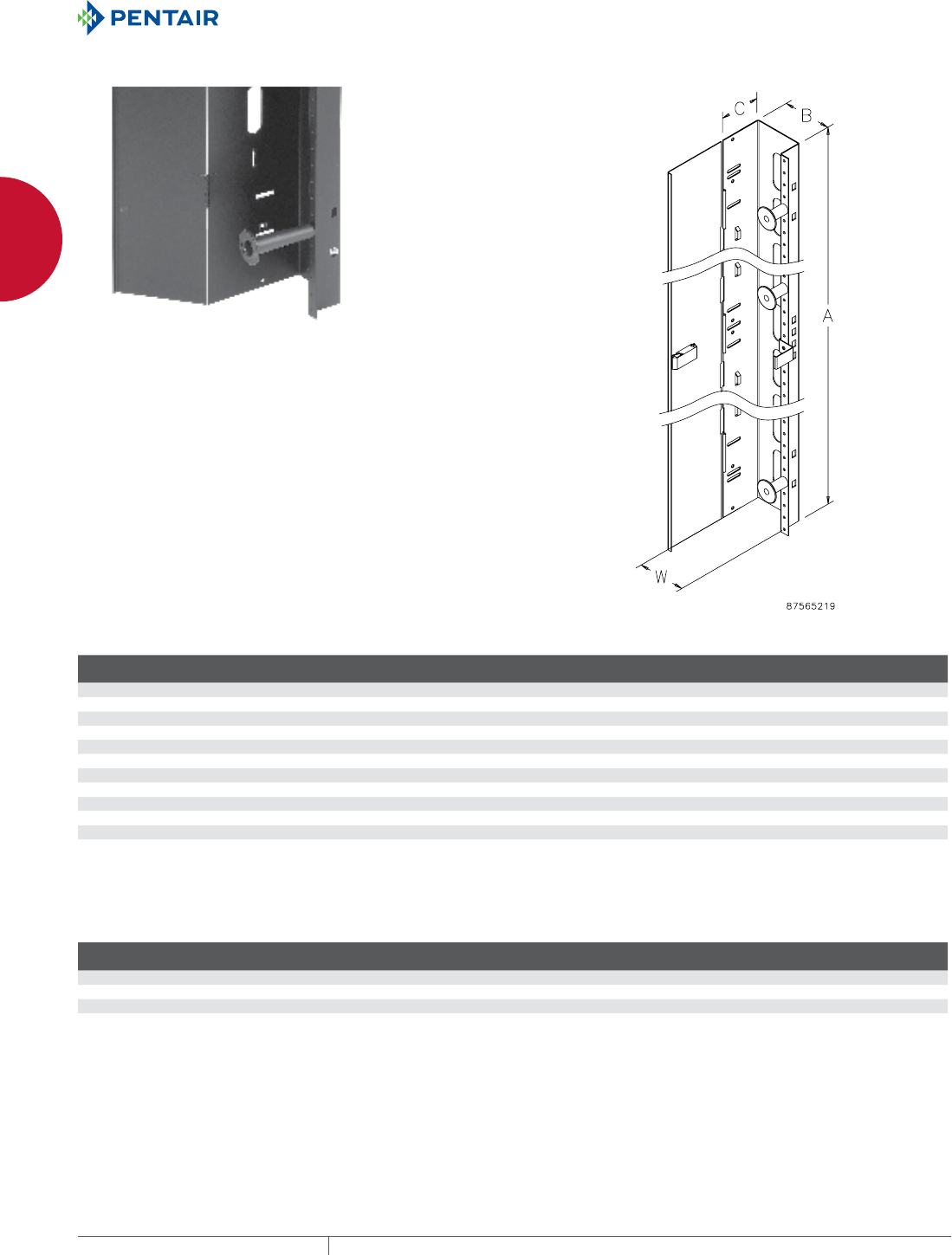
EQUIPMENT PROTECTIONSUBJECT TO CHANGE WITHOUT NOTICENETWORKING52
1
FREESTAND CABINETS PROLINE™ CABINET CABLE MANAGERS
VERTICAL CABLE MANAGER FOR 700 AND 800MM WIDE CABINETS
For routing and bundling cable inside 700- and 800-mm wide
PROLINE™ cabinets. Variety of sizes provides mounting flexibility.
Mounts between frame and rack angle so equipment can be
centered or aligned on one side. Replaces reducing brackets that
bridge space between cabinet and equipment and allows front-
to-back adjustment of rack angles. Latching hinged door on front
conceals wiring yet allows easy access. Movable plastic spools
help manage cables. 14 and 16 gauge steel with RAL 9005 black
polyester powder paint finish.
BULLETIN: DPY
Standard Product
Catalog Number AxBxC mm AxBxC in. W (mm) W (in.)
Fits Cabinet
Height (mm)
PVCM167 1467 x 50 x 98 57.77 x 1.97 x 3.87 85 3.36 1600
PVCM168 1467 x 100 x 98 57.77 x 3.94 x 3.87 135 5.33 1600
PVCM187 1690 x 50 x 98 66.52 x 1.97 x 3.87 85 3.36 1800
PVCM188 1690 x 100 x 98 66.52 x 3.94 x 3.87 135 5.33 1800
PVCM207 1867 x 50 x 98 73.52 x 1.97 x 3.87 85 3.36 2000
PVCM208 1867 x 100 x 98 73.52 x 3.94 x 3.87 135 5.33 2000
PVCM227 2090 x 50 x 98 82.27 x 1.97 x 3.87 85 3.36 2200
PVCM228 2090 x 100 x 98 82.27 x 3.94 x 3.87 135 5.33 2200
PVCMX127 1067 x 50 x 159 42.02 x 1.97 x 6.27 85 3.36 1200/2200
PVCMX128 1067 x 100 x 159 42.02 x 3.94 x 6.27 135 5.33 1200/2200
PVCMX207 1867 x 50 x 159 73.52 x 1.97 x 6.27 85 3.36 2000
PVCMX208 1867 x 100 x 159 73.52 x 3.94 x 6.27 135 5.33 2000
Use the “Cable Managers by Width” table to determine the number of cable managers required for different combinations of cable manager, cabinet and equipment widths.
Cable Manager by Width
Cable Manager Width (B)
(mm)
Cabinet Width
(mm)
No. of Cable Managers
(19 in. equipment)
No. of Cable Managers
(23 in. equipment)
50 700 2 —
50 800 — 2
100 700 1 —
100 800 2 1
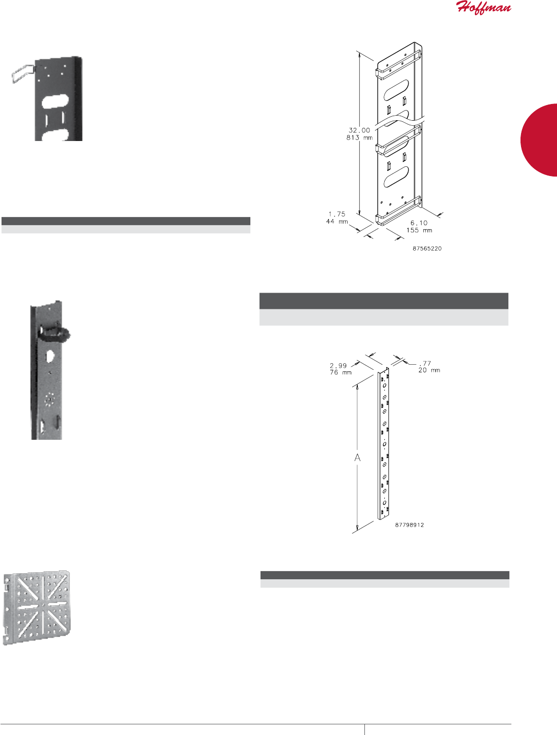
PH 763.422.2661 • FAX 763.422.2588 • PENTAIRPROTECT.COMEQUIPMENT PROTECTION NETWORKING 53
1
FREESTAND CABINETS PROLINE™ CABINET CABLE MANAGERS
VERTICAL CABLE MANAGER I
For routing and bundling cable inside cabinets. Stack two units for
full vertical runway on 1800-mm or taller enclosures. Wireform
gate hinges open to ease wire routing. Mounts to grid strap or frame
in front of rack angles. Narrow profile does not interfere with 19-in.
equipment in 600-mm wide enclosures. 16 gauge steel with RAL
9005 black polyester powder paint finish.
BULLETIN: DPY
Catalog Number Description
PVCM1 Vertical Cable Manager 1
VERTICAL TIEDOWN CABLE MANAGER
This one-piece cable manager provides mounting holes for D-Rings,
spools, universal transition brackets and other accessories (order
separately). RAL 9005 black polyester powder paint finish. Includes
hardware for mounting to strut and 10 VELCRO® Cable Wraps for
fastening cable.
VELCRO is a trademark of VELCRO Industries B.V.
BULLETIN: DPY
Catalog Number
A
mm/in.
Fits Cabinet Height
mm/in.
PVCMTD12 1091
42.97
1200
PVCMTD20 1892
74.47
2000
UNIVERSAL POWER STRIP BRACKET
This bracket fits in the corner of the
frame of all PROLINE™ cabinets
and facilitates mounting a variety of
power strips.
BULLETIN: DPY
Catalog Number Description
EPDUBK Universal Power Strip Bracket fits all PROLINE cabinets
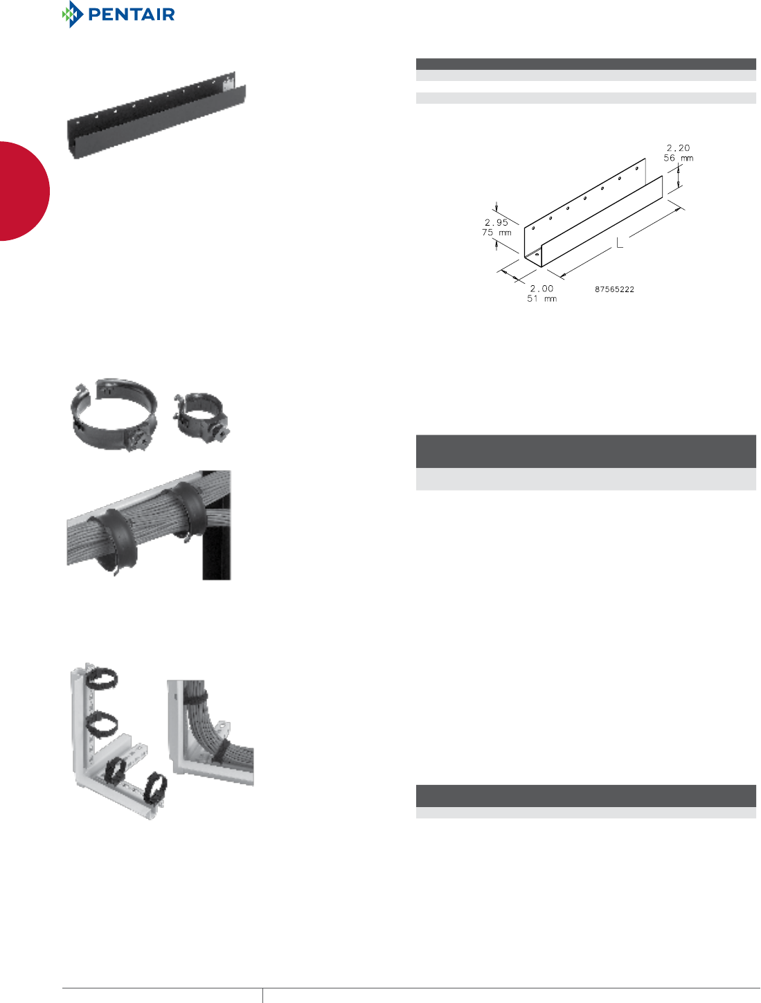
EQUIPMENT PROTECTIONSUBJECT TO CHANGE WITHOUT NOTICENETWORKING54
1
FREESTAND CABINETS PROLINE™ CABINET CABLE MANAGERS
HORIZONTAL CABLE TROUGH
For routing cable front-to-back in a server or data cabinet. Mounts
to side or top of 1- or 3-row grid strap. Can also mount directly to
mounting channels with APSM6CN Mounting Kit. Multiple units can
be used together. 16 gauge steel with RAL 9005 black polyester
powder paint finish.
BULLETIN: DPY
Catalog Number Description L (mm) L (in.)
PHCT1 Horizontal Cable Trough 200 7.87
PHCT2 Horizontal Cable Trough 350 13.78
PHCT3 Horizontal Cable Trough 500 19.69
PHCT4 Horizontal Cable Trough 650 25.59
Order APSM6CN Mounting Kit separately for channel mounting.
STRUT CABLE RINGS Cable Ring snaps into the strut for easy installation. Can be
positioned vertically or horizontally. Ring snaps open and closed
to easily position cables. It can be drawn down to snugly bundle
cables. Made of durable black plastic. Easy to install and add cable
at any time.
BULLETIN: DACCY
Catalog Number Description
Adj.
Range
mm/in.
Capacity at
Max. Size
Pkg.
Qty.
ECM2S10 2-in. Strut Cable Ring 44-25
1.75-1.00
26 CAT 6 cables 10
ECM4S10 4-in. Strut Cable Ring 1224-64
3.75-2.50
120 CAT 6 cables 10
FRAME TIEDOWN BRACKET The PROLINE™ Frame VELCRO® Tie-Down Bracket provides an
easy means to secure and bundle cables using any of the frame’s
rectangular holes. The bracket can be positioned parallel or
perpendicular to the frame and needs no tools to install—just
push into any hole and twist to fasten. Proper bend radius is easily
maintained with the flexible Velcro tie-down, plus it provides easy
initial and future cable installations. Bracket is made of a durable
plastic. Both tie-down and bracket are black.
VELCRO is a trademark of VELCRO Industries B.V.
BULLETIN: DPY
Catalog Number Description
Capacity at
Max. Size
Pkg.
Qty.
PCMFTD10 10-in. Velcro™ tie downs 55 CAT 6 cables 10
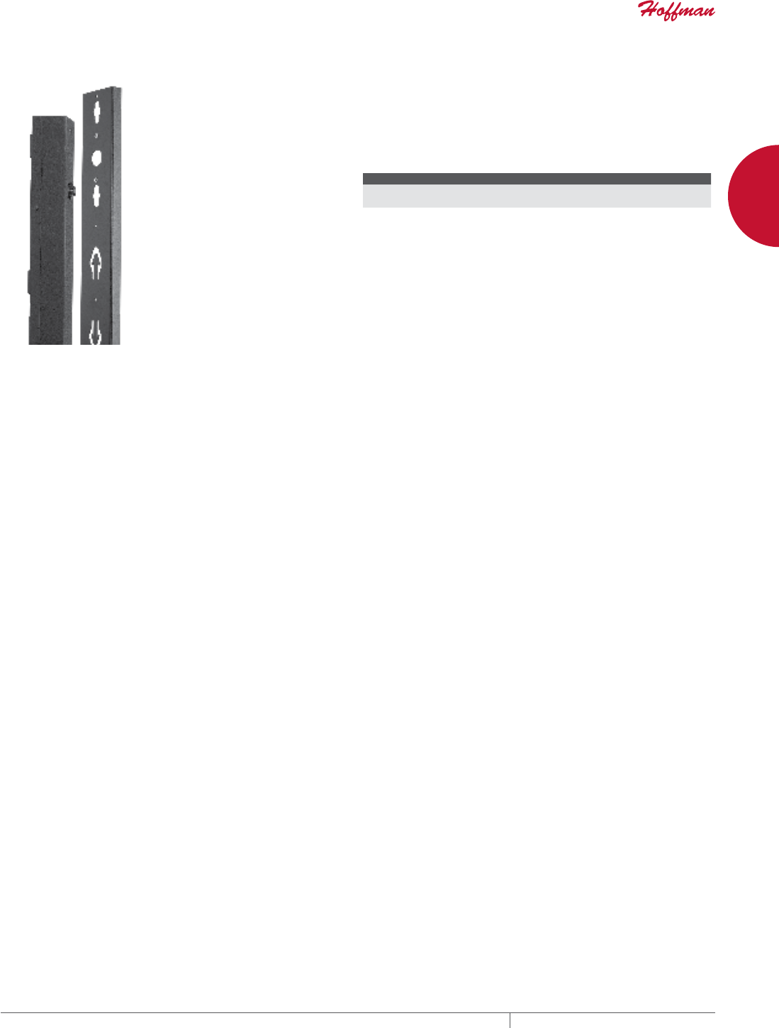
PH 763.422.2661 • FAX 763.422.2588 • PENTAIRPROTECT.COMEQUIPMENT PROTECTION NETWORKING 55
1
FREESTAND CABINETS PROLINE™ CABINET CABLE MANAGERS
CABLE AND PDU MANAGER PROLINE™ combination vertical cable manager provides increased
versatility for power and cable management for 2000-mm tall
frames. Tool-less mounting with key hole slots accept many
vertical PDUs (APC, Geist, etc.). Flush arrowhead cutouts provide
convenient cable manager tie-down points. Hardware and ten
VELCRO® cable wraps included. Finished with RAL 9005 black
polyester powder finish.
VELCRO is a trademark of Velcro Industries B.V.
BULLETIN: DPY
Catalog Number AxBxC mm/in. Fits Height
PVCPM20 1892 x 76 x 19
74.47 x 3.00 x 0.75
2000 mm
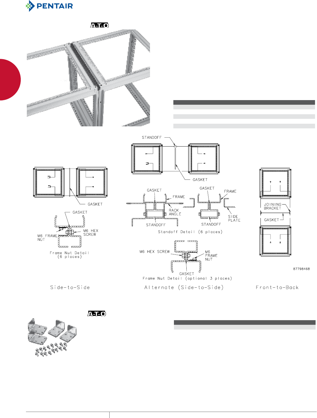
EQUIPMENT PROTECTIONSUBJECT TO CHANGE WITHOUT NOTICENETWORKING56
1
FREESTAND CABINETS PROLINE™ ACCESSORIES
PROLINE™ ACCESSORIES
FRAME JOINING KITS Permits joining two enclosure frames while maintaining an
environmental seal.
Side-to-Side Joining Kit consists of six frame nuts and screws, as
well as gasket material to maintain a dust-tight and water-tight seal
between ganged frames. Can be used if rack angles are not in the
front or rearmost positions or if a subpanel is not in the rearmost
position.
Alternate Joining Kit consists of three standoffs, six frame nuts
and screws, as well as gasket material. This kit facilitates frame
joining when rack angles are in the front or rearmost position, or if a
subpanel is in the rearmost position.
Front-to-Back Joining Kit permits front-to-back joining of two
single-bay enclosures. This kit does not fit 1200-mm or 1600-mm
wide frames.
BULLETIN: P20, P20EM
Catalog Number Description
PJ2F Standard Frame Joining, Side-to-Side
PJ2FD Standard Frame Joining, Side-to-Side, Non-gasketed
PJ2FHF2 EMC Standard Frame Joining, Side-to-Side
PJ2FF Alternate Frame Joining, Side-to-Side
PJ2FBF Frame Joining, Front-to-Back
L JOINING BRACKET
The L Joining Bracket, made of 10
gauge steel, is used in conjunction
with the standard joining kit as
additional support. Pictured
hardware is included.
BULLETIN: P20
Catalog Number Description
PJB2F L Joining Bracket
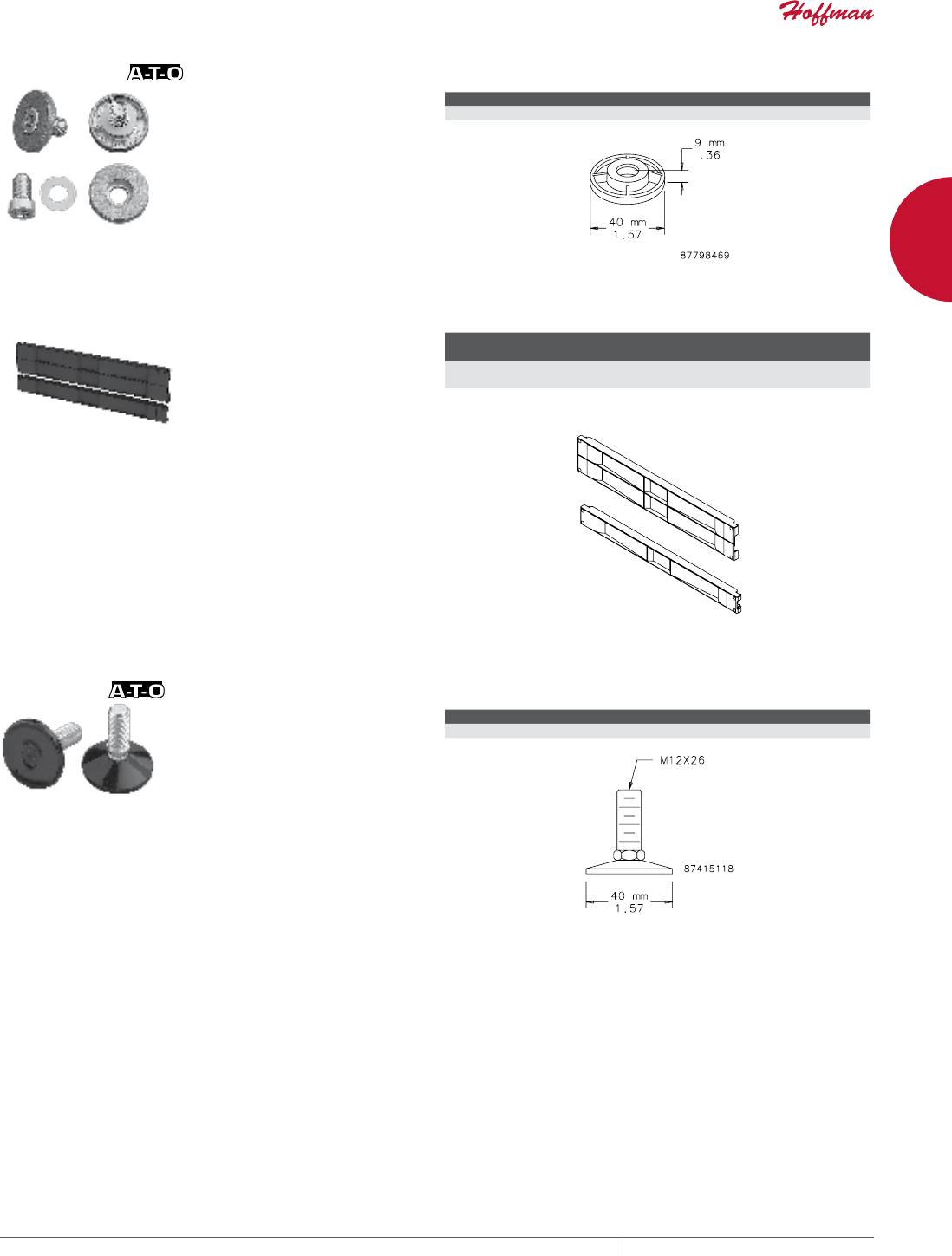
PH 763.422.2661 • FAX 763.422.2588 • PENTAIRPROTECT.COMEQUIPMENT PROTECTION NETWORKING 57
1
FREESTAND CABINETS PROLINE™ ACCESSORIES
FRAME FEET
Four die-cast feet for use on the
bottom of PROLINE™ frames that
raise the frame 9 mm.
BULLETIN: P20
Catalog Number Description
PFFM12 Frame Feet
TOOLLESS (SNAPIN) BLANKING PANELS FOR 19IN. RACKS
These Tool-less 19-in. Blanking
Panels provide easy tool-less
installation and ensure proper
airflow to equipment. Made of black
composite material and can be used
with tapped or square EIA universal
spaced rack mounting angles.
BULLETIN: DACCY
Catalog Number Description
Rack
Units Fits
Pkg.
Qty.
D19BPT1RU Blanking Panel, 19 in. 1 19 in., universal rack spacing,
tapped or square holes
10
D19BPT2RU Blanking Panel, 19 in. 2 19 in., universal rack spacing,
tapped or square holes
10
LEVELERS
Four post-type levelers allow
adjustment for uneven floors.
Levelers can be attached to the
bottom of a frame or to a 0-mm solid
base. Levelers are plated and the
leveler base is capped with plastic
to provide resistance to marring.
Adjustable for 17-mm to 35-mm
height. Ball and socket construction.
Four levelers will support a
maximum of 453.6 kg (1000 lb.).
BULLETIN: P20
Catalog Number Description
PLM12 Post-type Levelers
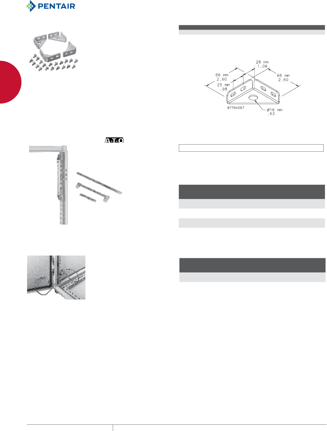
EQUIPMENT PROTECTIONSUBJECT TO CHANGE WITHOUT NOTICENETWORKING58
1
FREESTAND CABINETS PROLINE™ ACCESSORIES
PROLINE™ FRAME FLOORMOUNTING BRACKET
Provides a structural method of bolting a PROLINE™ frame to the
floor. Fits all frame sizes. Made of 12 gauge steel with plated finish.
Kit includes four brackets and mounting hardware.
Not for use on colocation frames, which include welded-in floor
mounting brackets.
BULLETIN: DPY
Catalog Number Description
PFBK PROLINE Frame Floor-Mounting Bracket
GROUNDING BAR SYSTEM INDUSTRY STANDARDS
UL Component Recognized; File No. E61997
Three sizes of grounding bars and insulated mounting brackets
are available. Bars are plated copper with M6 and M5 tapped
holes to provide a common point for grounding equipment. Fits all
enclosures if mounted vertically. See table for horizontal mounting.
BULLETIN: P20
Catalog Number Description
Length
mm/in.
Number of
Holes and
Screws M6
Number of
Holes and
Screws M5
PGS2K Fits 400-mm deep frame
front to back horizontally
200
7.87
3/5 10/10
PGS4K Fits 600-mm deep frame
front to back horizontally
400
15.75
9/11 20/20
PGS6K Fits 800-mm deep frame
front to back horizontally
600
23.62
15/17 30/31
PROLINE™ GROUNDING KIT
The Grounding Kit allows a
PROLINE™ enclosure to be
grounded to VDE specifications.
Includes six 12 gauge wires
411-mm (16.19-in.) long with ring
terminations and M6 mounting
hardware.
BULLETIN: P9
Catalog Number
Wire
Size
Length Between
Ring Terminals
mm/in.
Ring Terminal
Hole Diameter
mm/in.
PGK 12 ga. 411
16.19
7
.29
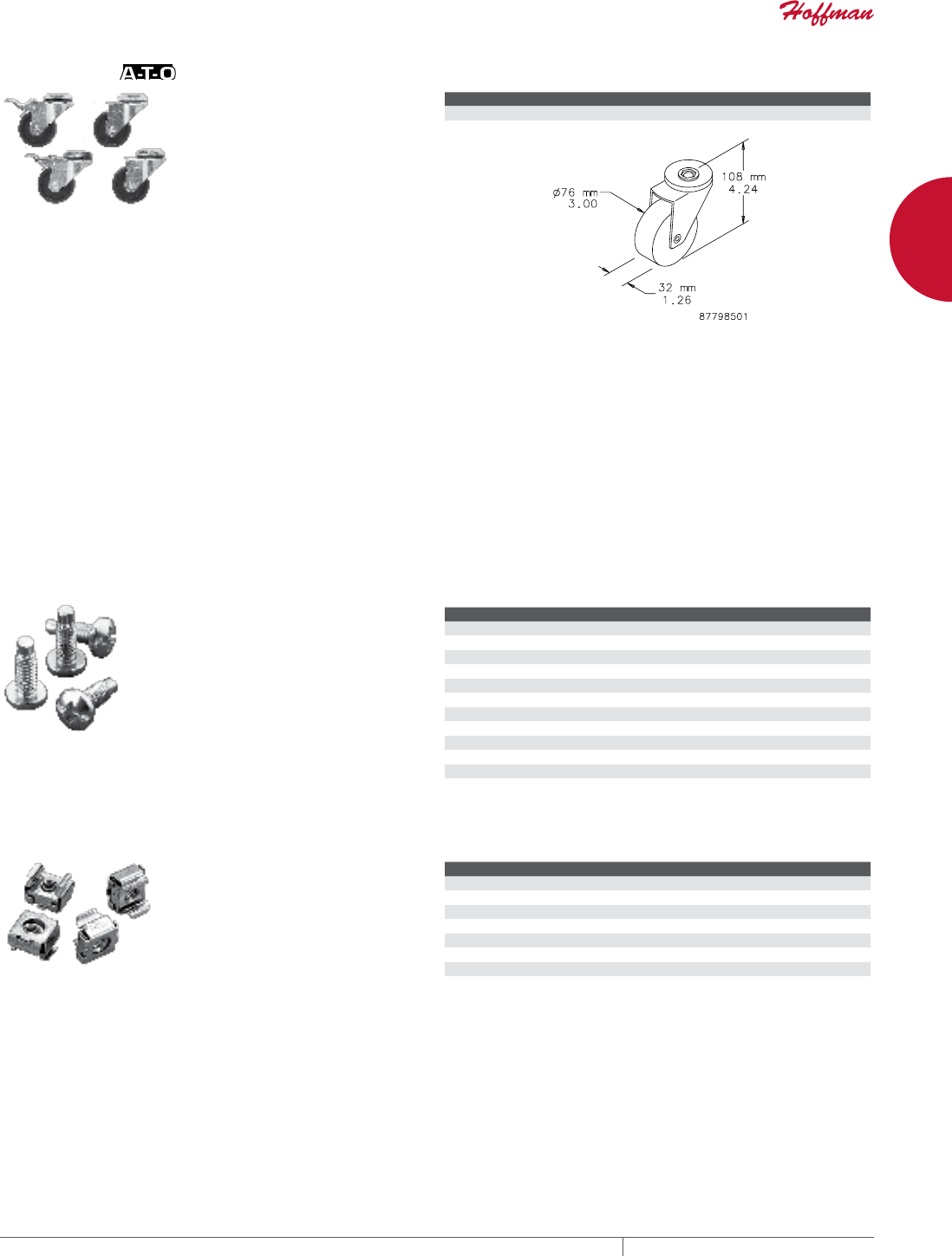
PH 763.422.2661 • FAX 763.422.2588 • PENTAIRPROTECT.COMEQUIPMENT PROTECTION NETWORKING 59
1
FREESTAND CABINETS PROLINE™ ACCESSORIES
CASTER KIT
A set of four casters (two locking,
two non-locking) that mount directly
to the bottom of a PROLINE™
frame, 0-mm, or 100-mm Solid
Base or a Console. (Do not use on
plinth bases.) Casters elevate the
enclosure 110 mm (4.33 in.) when
installed. Caster frames are plated
steel with ball-bearing pivots.
Caster wheels are made of a black
polyamide material. Kit includes
M12 mounting hardware.
Order separately.
Casters Maximum Load: 1000 lb.
(453 kg)
Exercise care when using casters
to move the cabinet. Avoid tipping
and damage to the cabinet and
its contents by slowly moving
the cabinet on its casters across
smooth, flat flooring. Avoid:
• large cracks
• floor displacement
• seams
• gravel
• any other obstruction
Never use casters while
transporting a cabinet by truck on
roadways.
Contact Hoffman if further
information is needed.
BULLETIN: P20
Catalog Number Description
PC1M12 Set of 4 Casters
SCREW PACKAGES
Screw Packages are for mounting
rack panels and equipment to rack
angles.
BULLETIN: A80, DACCY, X20
Catalog Number Color Description Pkg. Qty.
ES1224 Silver 12-24 x 5/8 in. combo head 20
ES1224250 Silver 12-24 x 5/8 in. combo head 250
ES1224B Black 12-24 x 5/8in. combo head 20
ES1224B250 Black 12-24 x 5/8 in. combo head 250
ASM5 Silver M5 x 20 mm Combo Head 20
ASM6 Silver M6 x 16 mm combo head 20
ASM5T Silver M5 x 12 mm thread-forming Phillips hex head screws 20
ASM6250 Silver M6 x 16 mm combo head 250
AS1032 Silver 10-32 x 5/8 in. combo head 20
AS1032250 Silver 10-32 x 5/8 in. combo head 250
AS1032B Black 10-32 x 5/8 in. combo head 20
Use ASM5T on PROLINE ™ frame or Net Series extruded holes.
CAGE NUT PACKAGE
Cage Nut Packages are for use with
square-hole rack angles. Cage nuts
are plated steel.
BULLETIN: DACCY
Catalog Number Color Description Pkg. Qty.
PM5CN Silver M5 cage nut 20
PM6CN Silver M6 cage nut 20
PM6CN250 Silver M6 cage nut 250
P1032CN Silver 10-32 cage nut 20
P1032CN250 Silver 10-32 cage nut 250
P1224CN Silver 12-24 cage nut 20
P1224CN250 Silver 12-24 cage nut 250
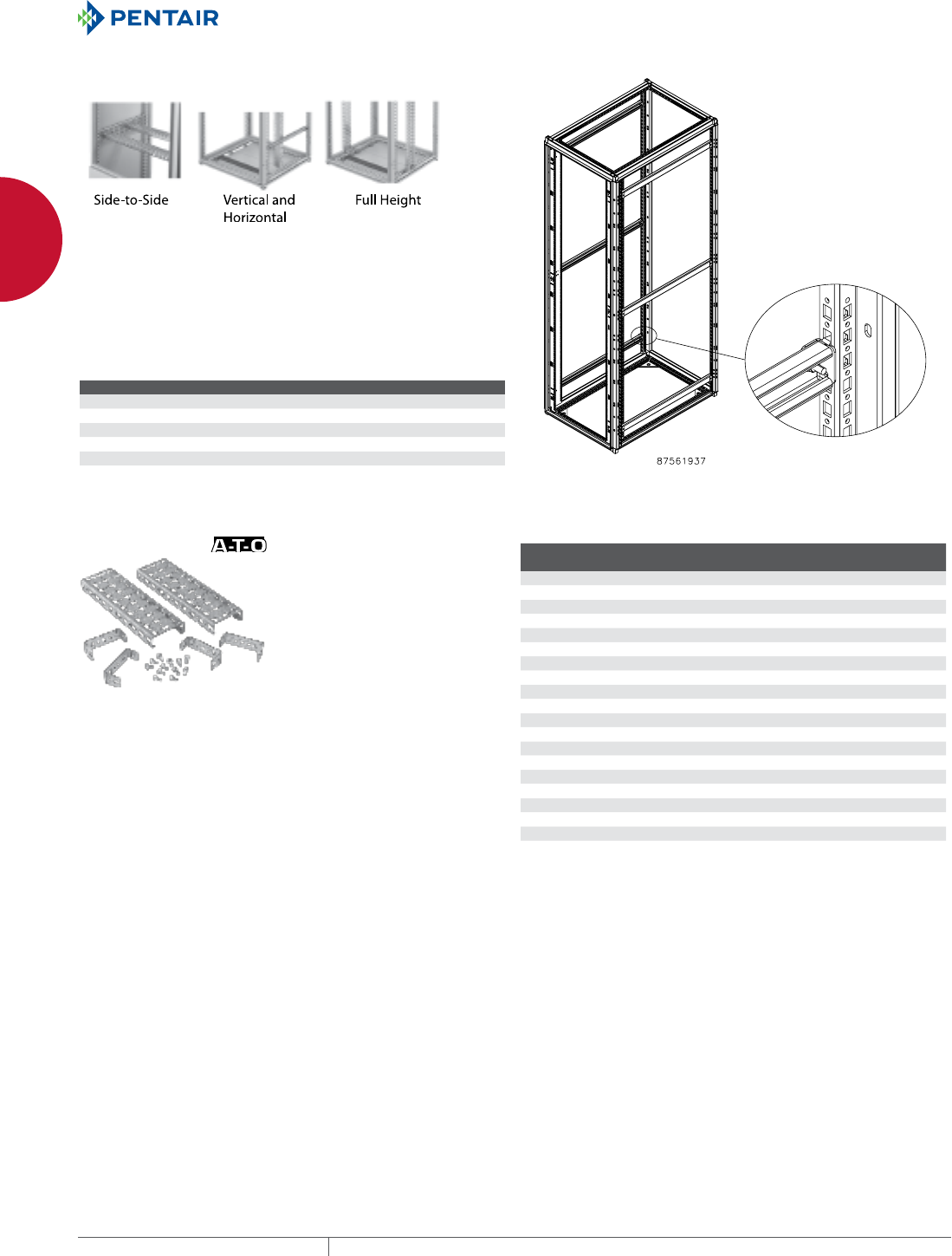
EQUIPMENT PROTECTIONSUBJECT TO CHANGE WITHOUT NOTICENETWORKING60
1
FREESTAND CABINETS PROLINE™ ACCESSORIES
MOUNTING CHANNEL
Allows rack angles and other accessories to be positioned at any
depth within the cabinet. Rails mount front to back in PROLINE™
frame. 14 gauge steel with RAL 9005 black polyester powder
paint finish. Includes two rails, mounting hardware and four M6
spring nuts for mounting accessories. Use hardware kit APSM6CN
(package of 20 screws, washers and spring nuts) for mounting
additional rack angles or other accessories to the mounting
channels.
BULLETIN: DPY
Catalog Number Description Fits Frame Depth
PMU8B Mounting Channel 800
PMU9B Mounting Channel 900
PMU10B Mounting Channel 1000
PMU11B Mounting Channel 1100
PMU12B Mounting Channel 1200
APSM6CN Mounting Channel Hardware Kit —
GRID STRAPS
Grid Straps are 14 gauge plated steel. They are provided with
specially designed rectangular holes to allow the use of cage nuts
or front-loading cage nuts. Mounting holes are provided on 25-mm
centers. Grid Straps are available with either 1 row or 3 rows of
holes and are furnished in pairs. Mounting hardware to attach Grid
Straps to the frame or to other Grid Straps is included.
• Can be mounted front-to-back horizontally across the bottom or
sides of the PROLINE™ frame
• Can be mounted left-to-right horizontally between front-to-back
pairs or from the sides of the PROLINE frame
• Can be mounted vertically between horizontally mounted Grid
Straps
BULLETIN: DPY, P20
Catalog Number AxB in. AxB mm Hole Pattern L (mm) L (in.)
Fits Frame
Depth
Fits Frame
Width
PGH1S5 13.46 x 0.98 342 x 25 One Row 342 13.46 500 —
PGH1S6 17.40 x 0.98 442 x 25 One Row 442 17.40 600 —
PGH1S7 21.34 x 0.98 542 x 25 One Row 542 21.34 700 600
PGH1S8 25.28 x 0.98 642 x 25 One Row 642 25.28 800 700
PGH1S9 29.21 x 0.98 742 x 25 One Row 742 29.21 900 800
PGH1S10 0.00 One Row 842 33.15 1000 900
PGH1S11 37.09 x 0.98 942 x 25 One Row 942 37.08 — 1000
PGH1S13 44.96 x 0.98 1142 x 25 One Row 1142 44.96 — 1200
PGH1S17 60.71 x 0.98 1542 x 25 One Row 1542 60.71 — 1600
PGH3S4 9.53 x 2.95 242 x 75 Three Row 242 9.53 400 —
PGH3S5 13.46 x 2.95 342 x 75 Three Row 342 13.46 500 —
PGH3S6 0.00 Three Row 442 17.40 600 —
PGH3S7 0.00 Three Row 542 21.34 700 600
PGH3S8 25.28 x 2.95 642 x 75 Three Row 642 25.28 800 700
PGH3S9 29.21 x 2.95 742 x 75 Three Row 742 29.21 900 800
PGH3S10 0.00 Three Row 842 33.15 1000 300
PGH3S11 37.09 x 2.95 942 x 75 Three Row 942 37.08 1100 1000
PGH3S12 0.00 Three Row 1242 48.89 1200 —
PGH3S13 44.96 x 2.95 1142 x 75 Three Row 1142 44.96 — 1200
PGH3S17 60.71 x 2.95 1542 x 75 Three Row 1542 60.71 — 1600
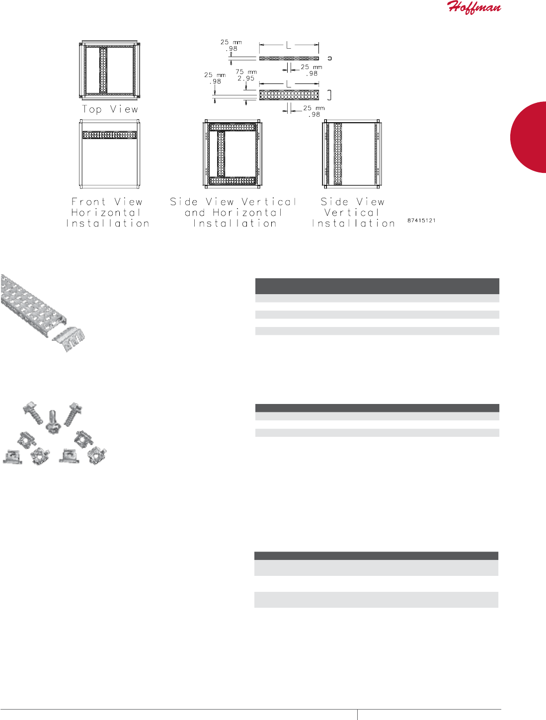
PH 763.422.2661 • FAX 763.422.2588 • PENTAIRPROTECT.COMEQUIPMENT PROTECTION NETWORKING 61
1
FREESTAND CABINETS PROLINE™ ACCESSORIES
FULLHEIGHT VERTICAL GRID STRAPS
Provide expanded vertical mounting
positions. Made of plated steel.
25-mm spacing between mounting
positions. Use cage nuts or front-
loading cage nuts. Sold in pairs.
Mounting hardware included.
BULLETIN: P20
Catalog Number AxB in. AxB mm L (mm) L (in.)
Fits Frame
Height
PGH3S14V 50.98 x 2.95 1295 x 75 1295 50.98 1400
PGH3S16V 58.86 x 2.95 1495 x 75 1495 58.86 1600
PGH3S18V 66.73 x 2.95 1695 x 75 1695 66.73 1800
PGH3S20V 74.61 x 2.95 1895 x 75 1895 74.61 2000
PGH3S22V 82.48 x 2.95 2095 x 75 2095 82.48 2200
PROLINE™ FASTENER PACKAGES
Use to fasten components to the
grid system. PGF Packages include
20 front-loading clip nuts (M6) and
20 combination-drive washer-head
bolts (M6).
Grounding Package is used with the
rectangular holes in the PROLINE™
frame to provide electrical
continuity between the frame and
the grid system. ASM5T Package is
used with PROLINE frames having
round holes. Package includes 20
M5 self-tapping screws.
BULLETIN: DACCY, P20
Catalog Number Description Use in Pkg. Qty.
ASM5T M5 x 12 mm thread-forming Phillips hex head screws Round holes 20
PGFM6 Standard Package - M6 cage nuts and bolts Rectangular holes 20
PGFGM6 Grounding Package - M6 grounding cage nuts and bolts Tapped holes 20
PROLINE™ SIDE BARRIER PANELS
Side barriers are used between frames to block airflow and provide
security between ganged PROLINE™ cabinets. Barriers fasten
to one frame and allow fasteners to secure adjoining frames. All
hardware is provided. Finished with RAL 9005 black polyester
powder paint.
BULLETIN: DPY
Catalog Number AxBxC in./mm Fits Frame Depth
PB209B 76.34 x 33.59 x 1.00
1939 x 853 x 25
900
PB2010B 76.34 x 37.52 x 1.00
1939 x 953 x 25
1000
PB2011B 76.34 x 41.46 x 1.00
1939 x 1053 x 25
1100
PB2012B 76.34 x 45.40 x 1.00
1939 x 1153 x 25
1200
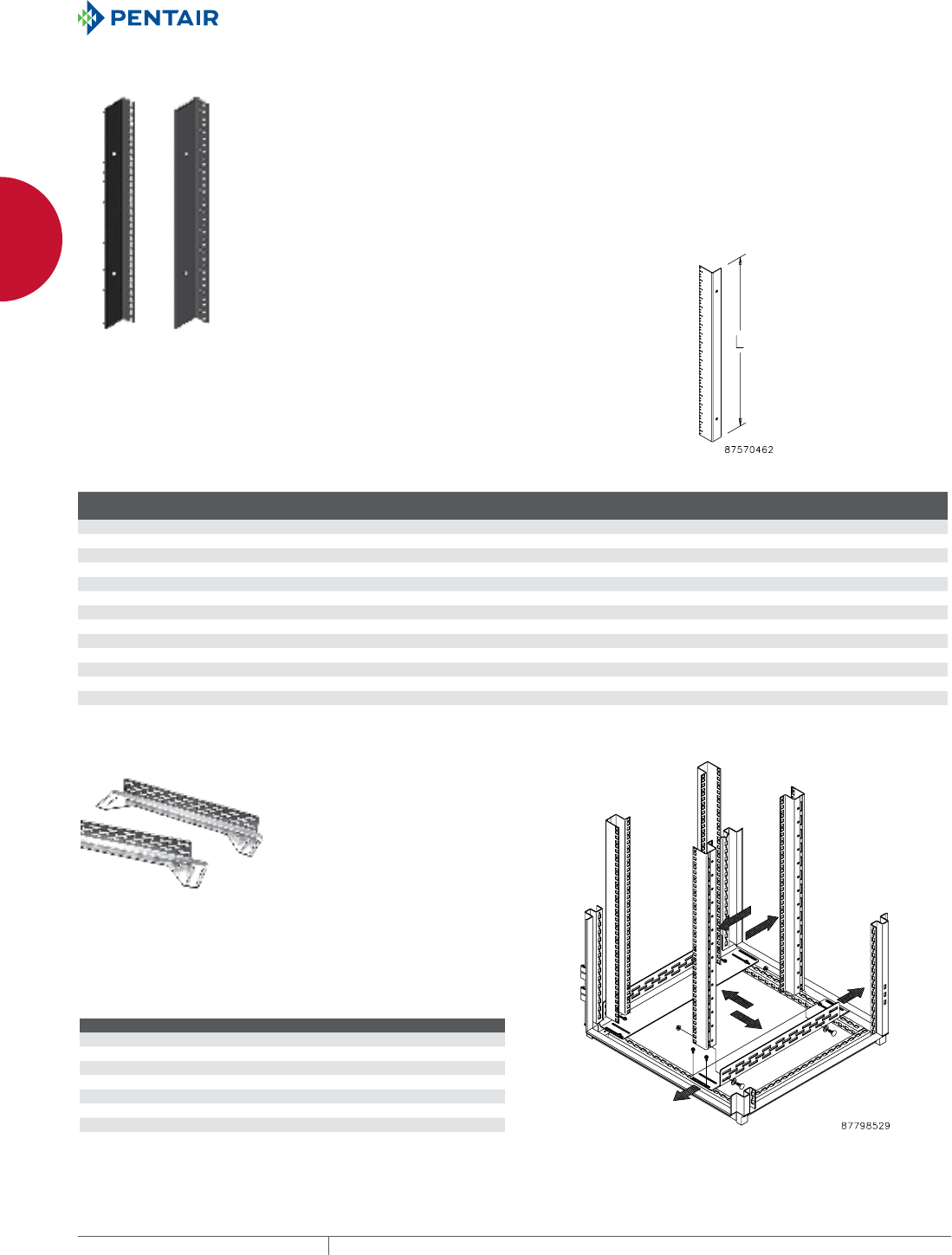
EQUIPMENT PROTECTIONSUBJECT TO CHANGE WITHOUT NOTICENETWORKING62
1
FREESTAND CABINETS PROLINE™ ACCESSORIES
19IN. AND 23IN. RACK ANGLES
Made of 14 gauge steel with square holes or 12 gauge steel with 10-
32 tapped holes. Provides 19-in. rack spacing when mounted in 600-
mm wide frames, and 23-in. rack spacing when mounted in 700-mm
wide frames. Use with frame reducing brackets to provide 19-in. or
23-in. spacing in 700-mm or 800-mm wide frames. Sizes available
for multi-compartment colocation applications. Finish is black RAL
9005 polyester powder paint with flat finish. Furnished in pairs. The
standard rack angle position is 44 mm behind the door opening.
Rack angles can be moved forward if desired. Deeper positions
require the use of grid straps or mounting channels. For joining
cabinets with rack angles in the full forward position, use Joining
Kit PJ2FF. Shelves, drawer, guides and pull-out shelves require two
sets of rack angles or frame accessory brackets installed in the
frame.
For 700- and 800-mm wide cabinets, reducer or cable manager must be
ordered.
BULLETIN: DPC
Catalog Number AxBxC in. AxBxC mm Hole Type Description (in.) Use With
Fits Frame/Cabinet
Height (mm)
Rack
Units
Length
(mm)
Length
(in.)
PRA1912THL1 0.00 Square 19 PROLINE™ DataCom Packages 1200 24 1091 42.97
PRA1916TPL1 0.00 Tapped 19 PROLINE™ DataCom Packages 1600 33 1491 58.72
PRA1918THL1 0.00 Square 19 PROLINE™ DataCom Packages 1800 38 1691 66.59
PRA1918TPL1 0.00 Tapped 19 PROLINE™ DataCom Packages 1800 38 1691 66.59
PRA1920THL1 0.00 Square 19 PROLINE™ DataCom Packages 2000 42 1892 74.47
PRA1920TPL1 0.00 Tapped 19 PROLINE™ DataCom Packages 2000 42 1892 74.47
PRA192320THL1 0.00 Square 19 & 23 PROLINE™ DataCom Packages 2000 42 1892 74.47
PRA1921TPL1 80.37 x 2.63 x 1.89 2041 x 67 x 48 Tapped 19 PROLINE™ DataCom Packages 2100 45 2041 80.37
PRA1921THL1 80.37 x 2.63 x 1.89 2041 x 67 x 48 Square 19 PROLINE™ DataCom Packages 2100 45 2041 80.37
PRA1922THL1 0.00 Square 19 PROLINE™ DataCom Packages 2200 47 2091 82.34
PRA1922TPL1 0.00 Tapped 19 PROLINE™ DataCom Packages 2200 47 2091 82.34
PRA192322THL1 0.00 Square 19 & 23 PROLINE™ DataCom Packages 2200 47 2091 82.34
PRA1924TPL1 90.21 x 2.63 x 1.89 2291 x 67 x 48 Tapped 19 PROLINE™ DataCom Packages 2400 51 2291 90.21
ADJUSTABLE RACKMOUNTING RAILS
Mounting rails allow rack angles to be positioned anywhere within
the PROLINE™ frame. The left-to-right adjustment pertains only
when the enclosure is wider than the minimum width required for
rack angles. Includes two right-hand and two left-hand 12 gauge
plated or painted steel mounting rails. Mounting hardware is
included.
BULLETIN: DPY, P20
Catalog Number L (mm) L (in.) Fits Frame Depth Finish
PBARA6 511 20.11 600 Plated
PBARA8 711 27.98 800 Plated
PBARA9 811 31.92 900 Plated
PBARA9B 811 31.92 900 Painted RAL 9005 Black
PBARA10B 911 35.86 1000 Painted RAL 9005 Black
PBARA11B 1011 39.79 1100 Painted RAL 9005 Black
PBARA12B 1111 43.73 1200 Painted RAL 9005 Black
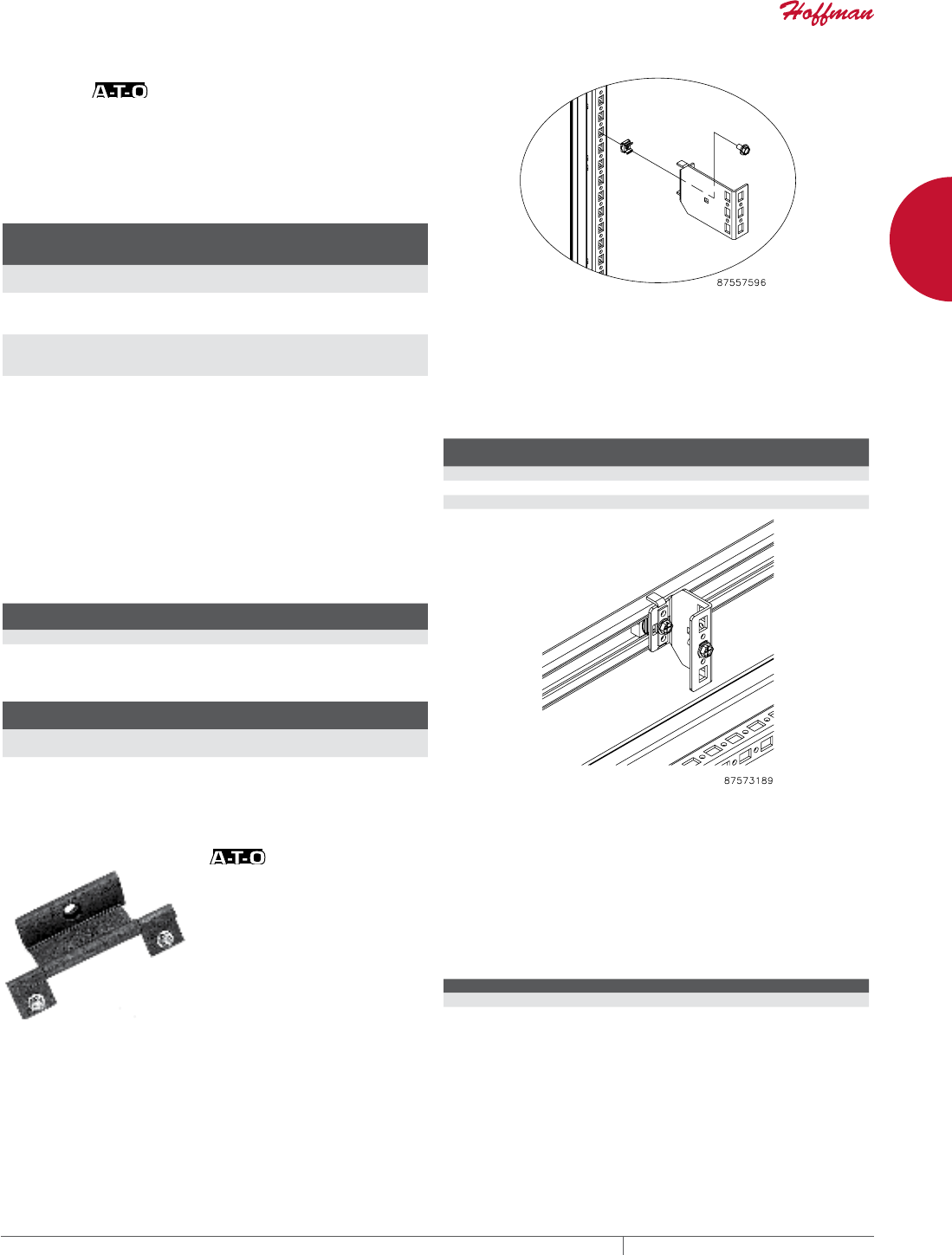
PH 763.422.2661 • FAX 763.422.2588 • PENTAIRPROTECT.COMEQUIPMENT PROTECTION NETWORKING 63
1
FREESTAND CABINETS PROLINE™ ACCESSORIES
FRAMEREDUCING BRACKETS FOR FRAMES OR GRID
STRAPS
Frame-Reducing Brackets mount directly to 700- or 800-mm wide
PROLINE™ frames or to grid straps. Converts wider frames to
600-mm wide, allowing 19-in. rack angles to fit, or to 700-mm wide,
allowing 23-in. rack angles to fit. Can be used to left- or right-justify
the rack-mounted equipment. Furnished in sets of four. 14 gauge
plated steel. Mounting hardware is included.
BULLETIN: P20
Catalog Number
Reduces
Frame
Width W (mm) W (in.) Converts Frame Width
PRB50 50 50 1.97 From 700 to 600
From 800 to 700 mm
PRB100 100 100 3.94 From 800 to 600
From 800 to 700
From 700 to 600 mm
PRB200 200 200 7.87 From 1000 to 600
From 1000 to 800
From 800 to 600 mm
FRAMEREDUCING BRACKETS FOR FRAMES OR
MOUNTING CHANNEL
Frame-reducing brackets mount directly to 700-mm or 800-mm
wide PROLINE™ frames or to mounting channel. Convert wider
frames to 600-mm wide, allowing 19-in. rack angles to fit, or to 700-
mm wide, allowing 23-in. rack angles to fit. Can be used to left- or
right-justify the rack-mounted equipment. Made of 14 gauge steel
painted with flat-black RAL 9005 polyester powder. Furnished in
sets of four. Mounting hardware is included.
BULLETIN: DPY
Catalog
Number
Reduces Frame
Width
W
(mm)
W
(in.) Converts Frame Width
PMURB50 50 50 1.97 From 700 to 600, From 800 to 700
PMURB100 100 100 3.94 From 800 to 600, From 800 to 700, From 700
to 600
Frame Reducing Bracket Selection Guide
PROLINE Frame Width
Setting 19 in.
Centered
Setting 19 in. Left
or Right
Setting 23 in.
Centered
600 mm (23.60) No reducing
brackets
No reducing
brackets
—
700 mm (27.60) with grid straps PRB50 PRB 100 No reducing brackets
PROLINE Frame Width
Setting 19 in.
Centered
Setting 19 in. Left
or Right
Setting 23 in.
Centered
700 mm (27.60) with mounting channel PMURB50 PMURB100 No reducing brackets
800 mm (31.50) with grid straps PRB100 PRB200 PRB50
800 mm (31.50) with mounting channel PMURB100 — PMURB50
180DEGREE HINGE KIT Optional hinging for steel solid, window or disconnect doors. The
180-degree hinges provide a door opening up to 260-degrees on
single-bay enclosures. These hinges mount to the door flange
and have a low-profile appearance. The kit includes three hinges
with textured black polyester powder paint and all necessary
mounting hardware. Cannot be used on PROLINE™ FLOTEK™ or
CONNECTEK™ front doors.
BULLETIN: P20
Catalog Number Description
PH180 180-Degree Hinge Kit
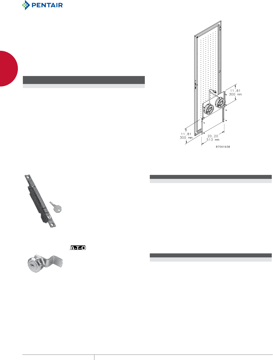
EQUIPMENT PROTECTIONSUBJECT TO CHANGE WITHOUT NOTICENETWORKING64
1
FREESTAND CABINETS PROLINE™ ACCESSORIES
DOORMOUNT FAN TRAY AND BLOCKING PLATE
The Door-Mount Fan Tray is used with perforated PROLINE™
doors to blow air through the perforations. Mounts to door bars.
Use Blocking Plates to prevent short cycling of fans. Includes two
6-in. fans and mounting plate, two finger guards, power cord and
mounting hardware.
The Blocking Plate is used with the Door-Mount Fan Tray to direct
airflow and prevent short cycling. Multiple plates can be used to
fill door opening and achieve desired airflow. Mounts to door bars.
Includes one blocking plate and mounting hardware.
BULLETIN: DPY, DTHRM
Catalog Number Description
Fits Door Width
mm/in. Voltage
PF06021DR6 Door-Mount Fan Tray 600 115 VAC
PBLNKDR6 Blocking Plate 600 —
FLUSH KEYLOCKING TRIGGER LATCH WITH RANDOM KEY CODES
Flush design. Over 100 random key
codes with available master. Black
textured polyester powder paint
finish. Includes two trigger latches
with matching key code and two
keys. Designed to replace locking
trigger latch. For use on PROLINE™
Voice/Data and Colocation doors
only.
BULLETIN: DPC
Catalog Number Description
PTKLDC Flush keylocking Trigger Latch with random key codes
SIDE COVER LOCK
Fits in pre-punched hole to
secure DataCom solid side from
unauthorized entry.
BULLETIN: DPC
Catalog Number Description Key Code
PSCLO Side Cover Lock 2233
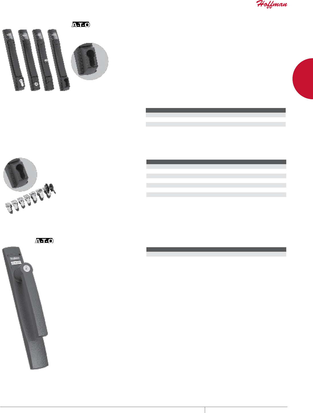
PH 763.422.2661 • FAX 763.422.2588 • PENTAIRPROTECT.COMEQUIPMENT PROTECTION NETWORKING 65
1
FREESTAND CABINETS PROLINE™ ACCESSORIES
FLUSH SWING HANDLES
Flush Handles are optional for any solid, window or disconnect door
that includes 3-point latching, except Voice/Data and Colocation
cabinets. They are ergonomically designed to provide style and
function in a low profile. The handle is die-cast zinc finished with
RAL 9005 textured black polyester powder paint. Provision to
add your logo is included. Handle can be installed to rotate either
clockwise or counterclockwise.
Handle with Screwdriver Defeater
Enclosure security is provided by the integrated tool-to-open
feature that releases the handle when rotated, allowing access to
the enclosure.
Handle with Keylock
Keylock feature locks the handle to provide security for the
enclosure. When the key is in the unlocked position, the pushbutton
releases the handle to provide access to the enclosure. Two keys
are furnished.
Handle for Padlock
Padlocking Handle provides security when using up to a 5/16
padlock. Pushbutton releases the handle to provide access to the
enclosure.
Handle with DIN Profile Provision
DIN Flush Handle is provided with the option to add your DIN profile
lock or to accept Hoffman DIN profile lock PDKL (order separately).
BULLETIN: P20
Catalog Number Description
PFHDF Flush Handle with Defeater
PFHKBL Keylocking Flush Handle
PFHPBL Padlocking Flush Handle
PFHDBL DIN Profile Flush Handle
DIN LOCK INSERTS (FOR DIN PROFILE HANDLE ONLY)
The DIN profile keylock provides
keylocking security for the Flush
Swing Handle with DIN provision.
Includes profile lock and two keys.
Order one profile lock for each
handle.
DIN Lock Kit for PROLINE™
DataCom doors includes two locks
keyed alike with one of 100 different
key codes and two keys (master key
available).
All DIN Lock Inserts are zinc die-cast.
BULLETIN: DPY, P20
Catalog Number Description
PKOSLFH Slotted insert profile cylinder
PKOTM7FH 7-mm triangle insert profile cylinder
PKOSM7FH 7-mm square insert profile cylinder
PKOTM8FH 8-mm triangle insert profile cylinder
PKODBK3FH Double-bit 3-mm insert profile cylinder
PDKL DIN keylock, 2 keys included, key code 333
PDKLRKPR DIN Lock Kit for PROLINE DataCom doors
DIN profile inserts are used with DIN flush swing handles. One key is included (except for slotted insert).
L HANDLE
The L Handle is a stylish option for
any solid, window or disconnect
door, except Voice/Data or
Colocation cabinets. It can be
installed to rotate either clockwise
or counterclockwise. Handle comes
with a bezel, includes keylocking
provision and is finished with RAL
9005 textured black polyester
powder paint. Two keys are included.
The bezel permits your logo to be
inserted.
BULLETIN: P20
Catalog Number Description
PLHK L Handle with 2 keys and logo slot, key code 333
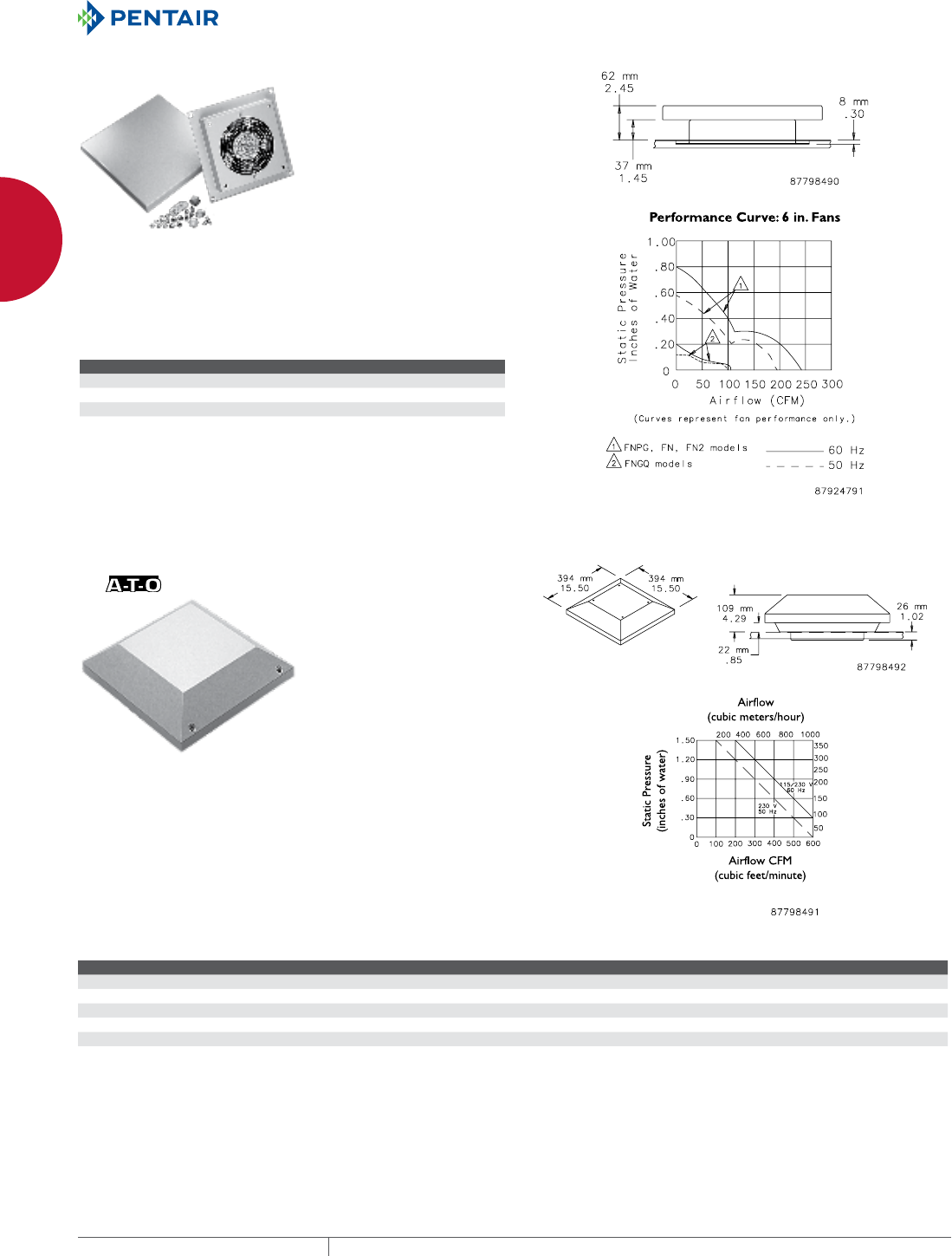
EQUIPMENT PROTECTIONSUBJECT TO CHANGE WITHOUT NOTICENETWORKING66
1
FREESTAND CABINETS PROLINE™ ACCESSORIES
PAGODA EXHAUST VENTS
Pagoda Exhaust Vents can be field-installed on any PROLINE™
solid top. An axial fan and finger guard are mounted in a housing.
A drip-proof raised cover is removable from inside the enclosure.
Gasket and mounting hardware are included. Vent housing and
raised cover are 14 gauge steel finished with RAL 7035 textured
light-gray polyester powder paint.
BULLETIN: DTHRM, P20
Catalog Number Description Volts
PPT1 Leadwires 115
PPT1C Power cord 115
PPT2 Leadwires 230
HIGHPERFORMANCE PAGODA EXHAUST VENT
Vents fit on standard PROLINE™ top with vent cutout or can be
field-installed on any PROLINE solid top. The Pagoda Vent features
an integral centrifugal blower mounted in a housing that includes
a drip-proof removable hood, wire mesh finger guard, perimeter
gasket and terminal block. Electromagnetic-compatible (EMC)
Pagoda Vents include a conductive screen, conductive gasket, line
filter and 6-ft. power cord with stripped leads. Pagoda Vent housing
and hood are rugged 16 gauge steel finished with RAL 7035 textured
light-gray polyester powder paint. EMC vents are finished with paint
over plated surfaces. Installation hardware is included.
BULLETIN: DTHRM, P20, P20EM
Catalog Number Description Voltage Full Load Amps Use With
PPTHP1 Leadwires 115 1.7 Top with high-performance pagoda vent cutout
PPTHP1C Power cord 115 1.7 Top with high-performance pagoda vent cutout
PPTHP1EMC Power cord 115 1.7 Top with high-performance pagoda vent cutout on EMC enclosures
PPTHP2 Leadwires 230 .9 Top with high-performance pagoda vent cutout
PPTHP2EMC Power cord 230 .9 Top with high-performance pagoda vent cutout
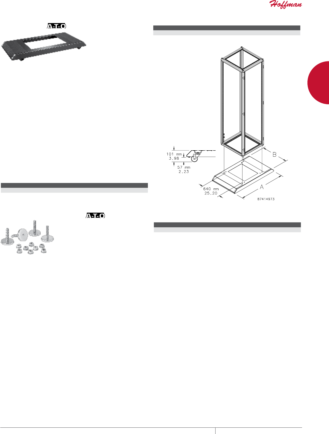
PH 763.422.2661 • FAX 763.422.2588 • PENTAIRPROTECT.COMEQUIPMENT PROTECTION NETWORKING 67
1
FREESTAND CABINETS PROLINE™ ACCESSORIES
MOBILE BASE
Mobile Bases fit 600- and 800-mm wide frames. They extend beyond
the front and rear of 600-mm cabinets to provide enhanced stability.
Provides front extension only on 800-mm cabinets. Constructed of
steel finished in RAL 9005 textured black polyester powder paint.
The base fastens to the underside of the frame and provides integral
mounting of furnished casters. The front and rear top surfaces of
the base are trimmed with black rubber mats 3-mm thick.
Casters and mounting hardware are furnished.
Four non-locking casters provide a maximum load-bearing
capacity of 1000 lb. (453.6 kg).
Exercise care when using casters to move the cabinet. Avoid tipping
and damage to the cabinet and its contents by slowly moving the
cabinet on its casters across smooth, flat flooring. Avoid:
• large cracks
• floor displacement
• seams
• gravel
• any other obstruction
Never use casters while transporting a cabinet by truck on
roadways.
Contact Hoffman if further information is needed.
BULLETIN: P20
Catalog Number AxB in. AxB mm Fits Frame B x C (mm)
PMB66 40.91 x 23.62 1039 x 600 600 x 500 and 600 x 600
PMB69 52.72 x 23.62 1339 x 600 600 x 800 and 600 x 900
Catalog Number AxB in. AxB mm Fits Frame B x C (mm)
PMB86 40.91 x 31.50 1039 x 800 800 x 500 and 800 x 600
PMB89 52.72 x 31.50 1339 x 800 800 x 800 and 800 x 900
MOBILE BASE LEVELING KIT
Levelers mount in the outer corners
of the Mobile Base, providing load-
bearing capacity of 1000 lb. (453.6
kg).
BULLETIN: P20
Catalog Number Description Use with
PMBLM12 Mobile Base Leveling Kit Mobile Base
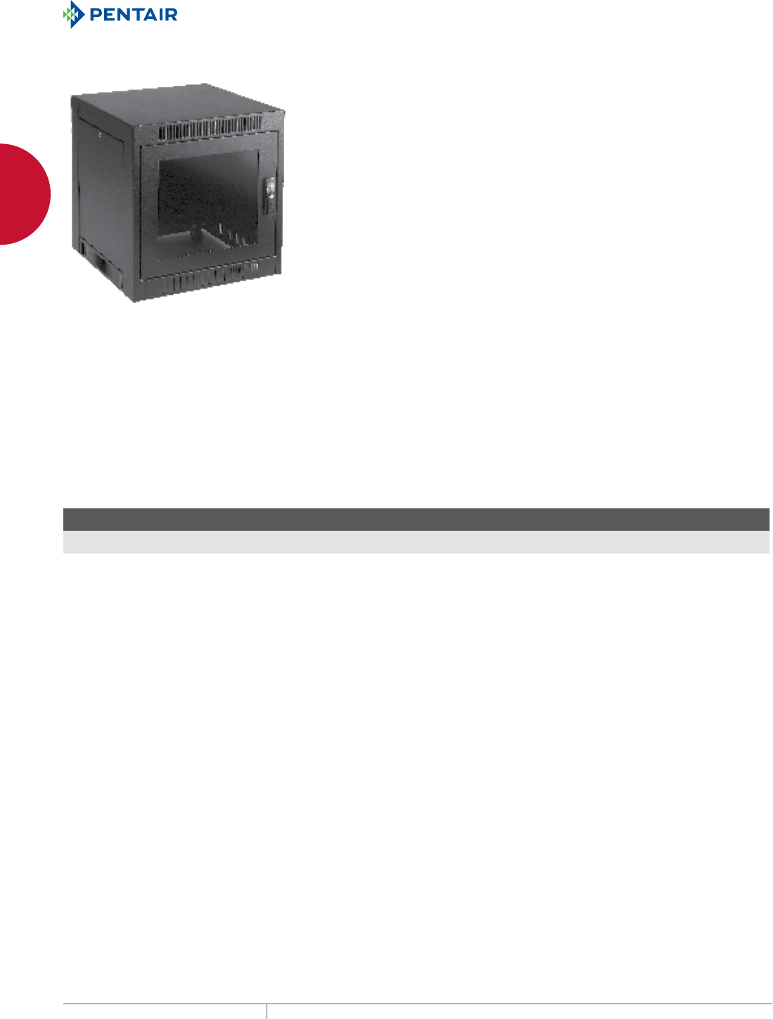
EQUIPMENT PROTECTIONSUBJECT TO CHANGE WITHOUT NOTICENETWORKING68
1
FREESTAND CABINETS NETWORKING SOHO CABINET
NETWORKING SOHO CABINET
SOHO CABINET FOR SMALL OFFICE AND HOME OFFICE
INDUSTRY STANDARDS
EIA 310-D
APPLICATION
SOHO Cabinets are designed to house servers, networking
equipment and phone and voice mail equipment under a desktop.
Casters allow the cabinet to be easily moved for access. Equipment
is passively cooled by air taken in from the front of the cabinet and
expelled through fan cutouts in the rear, which can accept optional
fans for warmer applications.
FEATURES
• Adjustable gland plate with strain relief at bottom rear of cabinet
provides easy and secure cable entry
• Rear door and side panels have quarter-turn key-locking latches
• Doors are hinged left and removable
• Front door has locking handle
• Same key provides access to all doors and side panels
• Fan cutouts with finger guards on upper half of rear door
• Doors and side panels inset flush with frame
• Open base with slotted vents includes casters
SPECIFICATIONS
• Welded steel frame with 4 rack angle mounting struts
• Includes 2 sets of painted L-shaped rack angles with holes per
EIA spacing (5/8 in. x 5/8 in. x 1/2 in.)
• Rack angles on 600-mm deep cabinet have 10-32 tapped holes,
and on 900-mm deep cabinet have square holes
• Both sizes provide 11 rack units
• Smoke-gray acrylic window in front door
• Solid top
FINISH
Pretreated steel coated with RAL 9005 black textured, low-gloss
polyester powder paint. Other finishes available—contact Hoffman
Customer Service.
ACCESSORIES
Most 19-in. rack accessories can be used with the SOHO cabinet.
PATENTS
Low Profile Handle (Design) 391,143 (U.S.)
Low Profile Handle (Utility) 5,862,690 (U.S.)
BULLETIN: DNCS
Standard Product
Catalog Number AxBxC in./mm Description
Rack
Units
Additional
Rack Angles Hole Type
ENC766SH 26.21 x 23.63 x 23.60
666 x 600 x 600
600-mm deep cabinet 11 ERA197TPLN Tapped
ENC769SH 26.21 x 23.63 x 35.40
666 x 600 x 900
900-mm deep cabinet 11 ERA197THLN Square
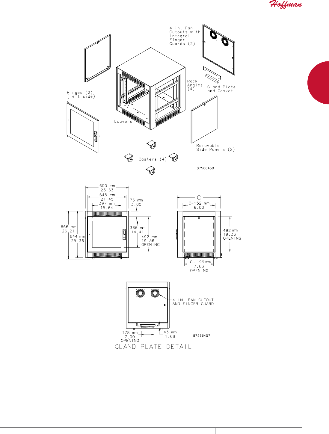
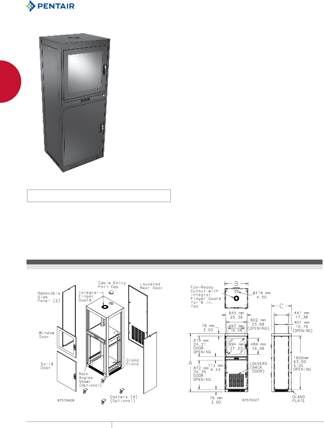
EQUIPMENT PROTECTIONSUBJECT TO CHANGE WITHOUT NOTICENETWORKING70
1
FREESTAND CABINETS WORKSTATION AND PC CABINETS
WORKSTATION AND PC CA BINETS
NETWORKING PC CABINET, TYPE 1
INDUSTRY STANDARDS
UL 508A Listed; Type 1; File Number E61997
cUL Listed per CSA C22.2 No 94; Type 1; File No. E61997
NEMA Type 1
EIA 310-D (when rack angle accessory is installed)
APPLICATION
Used for remote network access from a factory floor or warehouse,
the Networking PC Cabinet is built to house PCs, keyboards and
printers for data entry as well as LAN and WAN equipment. Key-
lock doors provide security and physical protection for equipment
that is passively cooled by air taken in from the front of the cabinet
and expelled through fan cutouts in the rear. Optional fans may be
installed for added cooling.
FEATURES
• Keylocking flush door handles on both upper and lower front
doors
• Quarter-turn keylocks on rear door, side panels and keyboard
door
• All locks keyed alike; two keys supplied with cabinet
• Front doors hinged on left; rear door can be hinged right or left
• Side panels easily removable
• Base is pre-punched for casters which are recessed when
installed. Caster kit available as an accessory.
• Adjustable gland plate with strain relief at bottom rear of cabinet
provides easy, secure cable entry
SPECIFICATIONS
• Welded steel frame with accessory mounting struts
• Steel keyboard with ball-bearing pull-out slides and keylock
• Clear safety-glass window in upper front door
• Louvers on lower quarter of rear door
• Top has one 4-in. cable entry port knockout with cap included and
one 6-in. fan-ready cutout with integral finger guard
• Doors and side panels inset flush with frame
FINISH
Pretreated steel coated with RAL 9005 black textured, low-gloss
polyester powder paint. Other finishes available—contact Hoffman
Customer Service.
ACCESSORIES
See also Accessories.
Network Cabinet Caster Kit
Networking PC Cabinet Rack Angle
Networking PC Cabinet Shelf
Rack Angle and Shelf cannot be used together.
BULLETIN: DNCS
Standard Product
Catalog Number AxBxC in. AxBxC mm Description
ENC1776PC 66.93 x 27.56 x 23.62 1700 x 700 x 600 19-in. Networking PC Cabinet
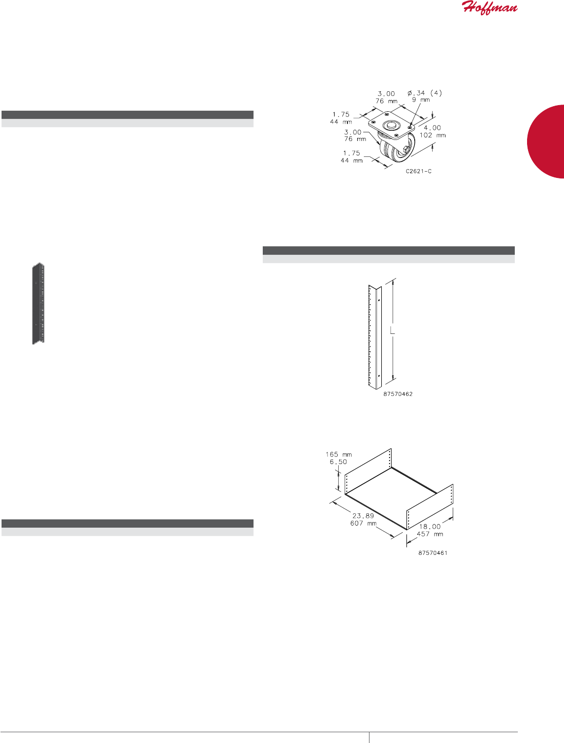
PH 763.422.2661 • FAX 763.422.2588 • PENTAIRPROTECT.COMEQUIPMENT PROTECTION NETWORKING 71
1
FREESTAND CABINETS WORKSTATION AND PC CABINETS
NETWORK CABINET CASTER KIT
Package of four. Fits Network Cabinet and Networking PC Cabinet.
Mounts to predrilled holes in base. Recessed when installed. Load
rating: 350 lb. (159 kg) per caster.
BULLETIN: DNC
Catalog Number Description
DLCASTERS Set of four double casters
NETWORKING PC CABINET RACK ANGLE
Provides 19 RU. Allows use of most 19-in. rack-mount accessories.
See Selected Networking PC Cabinet Accessories. Package
includes two rack angles and mounting hardware. Required for
accessories noted in Selected Networking PC Cabinet Accessories
table; not compatible with EPCEQS Shelf.
BULLETIN: DNCY
Catalog Number Length (mm) Length (in.) Rack Units Kit Qty.
ERA1910TPL 848 33.37 19 2
NETWORKING PC CABINET SHELF
Steel shelf for use in the lower compartment of the Networking
PC Cabinet. Compartment accommodates up to two shelves. Shelf
mounts to accessory mounting struts and can be adjusted in 1-in.
(25-mm) intervals inside cabinet. Shelf installs without rack angles.
Not compatible with ERA1910TPL.
BULLETIN: DNCS
Catalog Number Description
EPCEQS Shelf for lower compartment

EQUIPMENT PROTECTIONSUBJECT TO CHANGE WITHOUT NOTICENETWORKING72
2
763.422.2661
763.422.2588
NETWORKING
CABLE AND POWER MANAGEMENT
Intro Page
CHAPTER 2
CABLE AND POWER
MANAGEMENT
FEATURED PRODUCTS OPENFRAME RACK
CABLE MANAGERS
Define cable pathways with
CABLETEK™ Open-Frame Rack Cable
Managers. An organized environment
is safer, functions better and supports
faster, easier MACs (moves, adds,
changes). For enhanced application
flexibility and protection, customizable
vertical and horizontal cable
management solutions are available.

PH 763.422.2661 • FAX 763.422.2588 • PENTAIRPROTECT.COMEQUIPMENT PROTECTION NETWORKING 73
Intro Page CHAPTER CONTENTS
OPENFRAME RACK CABLE MANAGERS
CABLETEK™ Horizontal Cable Manager ..........................74
CABLETEK™ Vertical Cable Manager ............................76
CABLETEK™-EC Vertical Cable Manager. . . . . . . . . . . . . . . . . . . . . . . . . .78
CABLETEK™ Post and Gate Kits ................................80
Rear Cover ................................................80
Waterfall Top ..............................................81
D-Ring Assembly ...........................................81
Tie-Down Panel ............................................81
Tie-Down Rack .............................................82
Wire Form Cable Manager .....................................82
Cable Trough ...............................................82
Cable Manager .............................................83
Horizontal Cable Management Cover ............................83
Horizontal Cable Manager Bar .................................83
CABINET AND RACK CABLE MANAGERS
D-Ring Cable Managers ......................................84
Universal D-Ring Bracket .....................................84
Fiber Management Spool .....................................84
Universal Transition Bracket ...................................85
Cable Spools ...............................................85
VELCRO® Cable Wrap ................................. 85
POWER DISTRIBUTION UNITS (PDUS)
Rack- and Panel-Mount Power Distribution Units (PDUs) ............86
Universal Power Strip Bracket .................................87
IEC Cord Sets ..............................................87
IEC C-13 Retaining Clip .......................................87
Rack-Mount PDU Bracket .....................................87
Smart PDU Component Application. . . . . . . . . . . . . . . . . . . . . . . . . . . . . .88
2
POWER
DISTRIBUTION UNITS (PDUS)
Power Distribution Units (PDUs) reliably
adapt to changing power demands.
With a wide range of solutions that
provide various surge protection,
outlet configuration, dual circuit and
embedded intelligence options, PDUs
meet flexible application challenges.
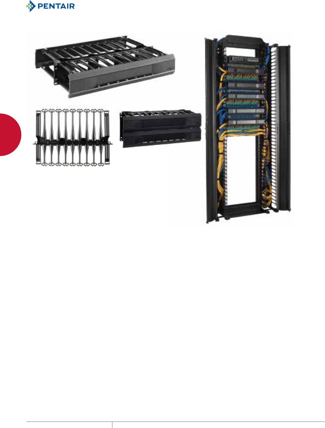
EQUIPMENT PROTECTIONSUBJECT TO CHANGE WITHOUT NOTICENETWORKING74
2
CABLE AND POWER MANAGEMENT OPENFRAME RACK CABLE MANAGERS
OPEN-FRAM E RACK CABLE MAN AGERS
CABLETEK™ HORIZONTAL CABLE MANAGER
DCHD2
shown
DCHS4
shown
Arrowhead ngers funnel
cable into base and hold
it securely
Vertical and horizontal cable manager
system installed on a 2-post rack. Vertical
and horizontal cable managers work
together to make an orderly installation.
INDUSTRY STANDARDS
EIA 310-D
APPLICATION
This cable manager features heavy-duty endposts, arrowhead
fingers and tool-less mounting to easily route Cat 5e, 6 and 6A cable
horizontally in standard 19-in. cabinets or on 2- or 4-post open
frame racks.
FEATURES
• Snap-in mounting provision holds cable manager in place while
mounting screws are installed
• Robust arrowhead fingers are shaped to funnel cables into base
and are made of black composite material
• Robust rounded end posts support cable as it enters and leaves
cable manager and maintains proper cable bend radius
• Deep cable compartments allow maximum cable density
• Rounded edges throughout protect cable jackets from damage
• Pass-through holes on double-sided models protect cable while
facilitating routing between front and back sides
• Single- and double-sided units provide high cable capacity,
including 5e, 6 and 6A cables
• 1 RU and 2 RU heights allow greater flexibility in optimizing rack
capacity
• Removable hinged cover opens top or bottom, snaps closed for
assured cable protection and professional appearance
• Double-sided model has covers on both front and back
• Covers stay open during installation and maintenance procedures
• Horizontal and vertical cable managers designed as a system for
streamlined appearance and improved functionality
• Combination head 10-32 and 12-24 screws included for mounting
SPECIFICATIONS
• Made of UL listed black composite material
FINISH
Low gloss, matches look of RAL 9005 textured paint
BULLETIN: DACCY
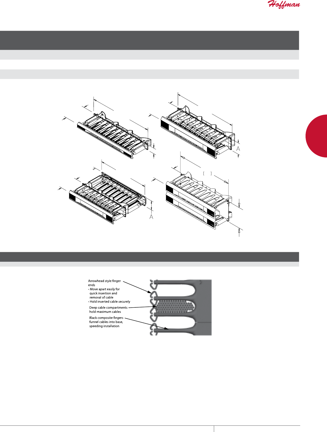
PH 763.422.2661 • FAX 763.422.2588 • PENTAIRPROTECT.COMEQUIPMENT PROTECTION NETWORKING 75
2
CABLE AND POWER MANAGEMENT OPENFRAME RACK CABLE MANAGERS
Standard Product CABLETEK™ Horizontal Cable Managers; 60% Cable Manager Fill Rate
Catalog Number Description
Rack
Units
A
in./mm
Front
Cross-Section
Area (in.2)
Front Cable
Fill Rate 60%
5e Cable
(0.22-in. dia.)
Front Cable
Fill Rate 60%
6 Cable
(0.25-in. dia.)
Front Cable
Fill Rate 60%
6A Cable
(0.30-in. dia.)
Back Cross-Section
Area (in.2)
Back Cable
Fill Rate 60%
5e Cable
(0.22-in. dia.)
Back Cable
Fill Rate 60%
6 Cable
(0.25-in. dia.)
Back Cable
Fill Rate 60%
6A Cable
(0.30-in. dia.)
DCHS1 Single-Sided 1 1.75
44
4.2 66 57 35 — — — —
DCHS2 Single-Sided 2 3.50
89
13.2 208 161 112 — — — —
DCHD2 Double-Sided 2 3.50
89
13.2 208 161 112 14.1 223 172 119
DCHS4 Single-Sided 4 7.0
178
26.9 416 322 224 — — — —
>@
$
>@
6LQJOH6LGHG
58&DEOH0DQDJHU
6LQJOH6LGHG
58&DEOH0DQDJHU
'RXEOH6LGHG
58&DEOH0DQDJHU
6LQJOH6LGHG
58&DEOH0DQDJHU
>@
$
>@
>@
>@
>@
>@
Arrowhead Cable Capacity; 60% Fill Rate
Location
Cross-Section
Area (in.2)
5e Cable
(0.22-in. dia.)
6 Cable
(0.25-in. dia.)
6A Cable
(0.30-in. dia.)
Front 5.52 90 67 46
Back 9.27 145 113 78
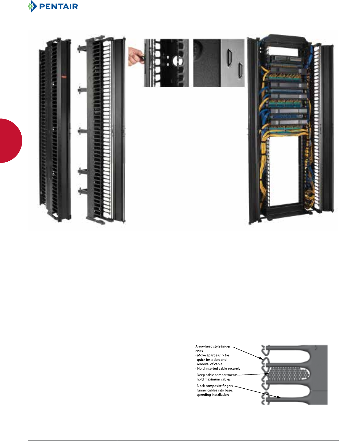
EQUIPMENT PROTECTIONSUBJECT TO CHANGE WITHOUT NOTICENETWORKING76
2
CABLE AND POWER MANAGEMENT OPENFRAME RACK CABLE MANAGERS
CABLETEK™ VERTICAL CABLE MANAGER
Spring loaded central latch
operates easily and fastens
securely. Pass-through
holes facilitate ecient
cable routing.
Tie-down loops accept
Velcro® Cable Wraps
Vertical and horizontall cable
manager system installed on
a 2-post rack. Vertical and
horizontal cable managers
work together to make an
orderly installation.
INDUSTRY STANDARDS
EIA 310-D
APPLICATION
Available in single- and double-sided models, this vertical cable
manager mounts on the sides of or between 2- and 4-post open
frame racks. The front side of the manager provides support,
management and high capacity for patch cords, while the back
supports Cat 5e, 6, 6A and fiber optic cables.
FEATURES
• Easily removable one-piece front cover with access from right or
left as needed opens 180º to allow full access to cables
• Self-aligning bolt locations minimize lifting and speed installation
• Self-captivating fasteners; bolt doesn’t turn while tightening nut
• Generous finger depth allows for maximum cable density and
allows smooth transitions from vertical to horizontal positions
• Unobstructed cable access to rack equipment—no keep-out
areas
• Rounded edges on composite material and grommets protect
cable jackets from damage
• Robust arrowhead fingers are shaped to funnel cables into base
and are made of black composite material
• Cable tiedown points provided on back
• Pass-through holes protect cable while facilitating routing
between front and back
• Single central door latch allows quick and easy access to cables
• Double-sided cable manager with front and rear supporting
fingers includes snap-on cover
• Double-sided cable manager with posts and gates support and
contain cables. Three sets of posts and gates are included;
additional sets are available as accessories
• Posts snap into prepunched holes in the back of the cable
manager
• Gates snap onto posts, open from left or right as needed and
swing 280º for cable access. Posts can be used alone as slack
spools to control long patch cords.
• Horizontal and vertical cable managers designed as a system for
streamlined appearance and improved functionality
SPECIFICATIONS
• Front door and cable channel made of multi-formed lightweight
aluminum
• Hinge points and supporting fingers made of high-strength
composite material
FINISH
Aluminum components are coated with RAL 9005 black low-gloss
lightly-textured polyester powder paint.
Composite parts have a low-gloss finish that matches look of RAL
9005 textured paint.
BULLETIN: DOFRY
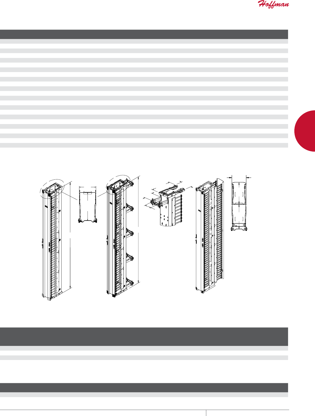
PH 763.422.2661 • FAX 763.422.2588 • PENTAIRPROTECT.COMEQUIPMENT PROTECTION NETWORKING 77
2
CABLE AND POWER MANAGEMENT OPENFRAME RACK CABLE MANAGERS
Standard Product Vertical Cable Manager
Catalog Number AxB in. AxB mm Description
Fits Rack
Height (ft.) Rack Units A (in.) A (mm) B (in.) B (mm) X (in.) X (mm)
DV6S7 6.00 x 84.00 152 x 2134 Single-Sided 7 45 U 84.00 2134 6.25 159 7.12 183
DV10S7 10.00 x 84.00 254 x 2134 Single-Sided 7 45 U 84.00 2134 10.25 260 11.21 285
DV12S7 12.00 x 84.00 305 x 2134 Single-Sided 7 45 U 84.00 2134 12.25 311 13.21 336
DV6D7 6.00 x 84.00 152 x 2134 Double-Sided, Posts and Gates 7 45 U 84.00 2134 6.25 159 7.12 183
DV10D7 10.00 x 84.00 254 x 2134 Double-Sided, Posts and Gates 7 45 U 84.00 2134 10.25 260 11.21 285
DV12D7 12.00 x 84.00 305 x 2134 Double-Sided, Posts and Gates 7 45 U 84.00 2134 12.25 311 13.21 336
DV6DF7 0.00 Double-Sided, Fingers 7 45 U 84.00 2134 6.25 159 7.12 183
DV10DF7 0.00 Double-Sided, Fingers 7 45 U 84.00 2134 10.25 260 11.21 285
DV12DF7 0.00 Double-Sided, Fingers 7 45 U 84.00 2134 12.25 311 13.21 336
DV6S8 6.00 x 96.00 152 x 2438 Single-Sided 8 51 U 96.00 2438 6.25 159 7.12 183
DV10S8 10.00 x 96.00 254 x 2438 Single-Sided 8 51 U 96.00 2438 10.25 260 11.21 285
DV12S8 12.00 x 96.00 305 x 2438 Single-Sided 8 51 U 96.00 2438 12.25 311 13.21 336
DV6D8 6.00 x 96.00 152 x 2438 Double-Sided, Posts and Gates 8 51 U 96.00 2438 6.25 159 7.12 183
DV10D8 10.00 x 96.00 254 x 2438 Double-Sided, Posts and Gates 8 51 U 96.00 2438 10.25 260 11.21 285
DV12D8 12.00 x 96.00 305 x 2438 Double-Sided, Posts and Gates 8 51 U 96.00 2438 12.25 311 13.21 336
DV12DF8 0.00 Double-Sided, Fingers 8 51 U 96.00 2438 12.25 311 13.21 336
DV6DF8 0.00 Double-Sided, Fingers 8 51 U 96.00 2438 6.25 159 7.12 183
DV10DF8 0.00 Double-Sided, Fingers 8 51 U 96.00 2438 10.25 260 11.21 285
DV6S9 6.00 x 108.00 152 x 2743 Single-Sided 9 58 U 108.00 2743 6.25 159 7.12 183
DV10S9 10.00 x 108.00 254 x 2743 Single-Sided 9 58 U 108.00 2743 10.25 260 11.21 285
DV12S9 12.00 x 108.00 305 x 2743 Single-Sided 9 58 U 108.00 2743 12.25 311 13.21 336
DV6D9 6.00 x 108.00 152 x 2743 Double-Sided, Posts and Gates 9 58 U 108.00 2743 6.25 159 7.12 183
DV10D9 10.00 x 108.00 254 x 2743 Double-Sided, Posts and Gates 9 58 U 108.00 2743 10.25 260 11.21 285
DV12D9 12.00 x 108.00 305 x 2743 Double-Sided, Posts and Gates 9 58 U 108.00 2743 12.25 311 13.21 336
B dimension represents the mounting space between ganged open-frame racks.
PP ;
$
%
$
7RS9LHZ
(QG&DSV
5HPRYHG
PP
%
PP
%
5HPRYHG
(QG&DSV
7RS9LHZ
6LQJOH6LGHG 'RXEOH6LGHG
)LQJHUV
'RXEOH6LGHG
3RVWVDQG*DWHV
Cable Manager Cable Capacity; 60% Fill Rate
Cable Manager
Width (inch)
Front
Cross-Section
Area (in.2)
Front Cable
Fill Rate 60%
5e Cable
(0.22-in. dia.)
Front Cable
Fill Rate 60%
6 Cable
(0.25-in. dia.)
Front Cable
Fill Rate 60%
6A Cable
(0.30-in. dia.)
Back
Cross-Section
Area (in.2)
Back Cable
Fill Rate 60%
5e Cable
(0.22-in. dia.)
Back Cable
Fill Rate 60%
6 Cable
(0.25-in. dia.)
Back Cable
Fill Rate 60%
6A Cable
(0.30-in. dia.)
6.00 58.1 917 710 493 27.9 441 341 236
10.00 100.8 1592 1232 855 51.7 816 631 439
12.00 122.1 1928 1492 1036 64.0 1011 782 543
Arrowhead Cable Capacity, 60% Fill Rate
Cross-Section
Area (in.2)
5e Cable
(0.22-in. dia.)
6 Cable
(0.25-in. dia.)
6A Cable
(0.30-in. dia.)
5.44 85 66 46
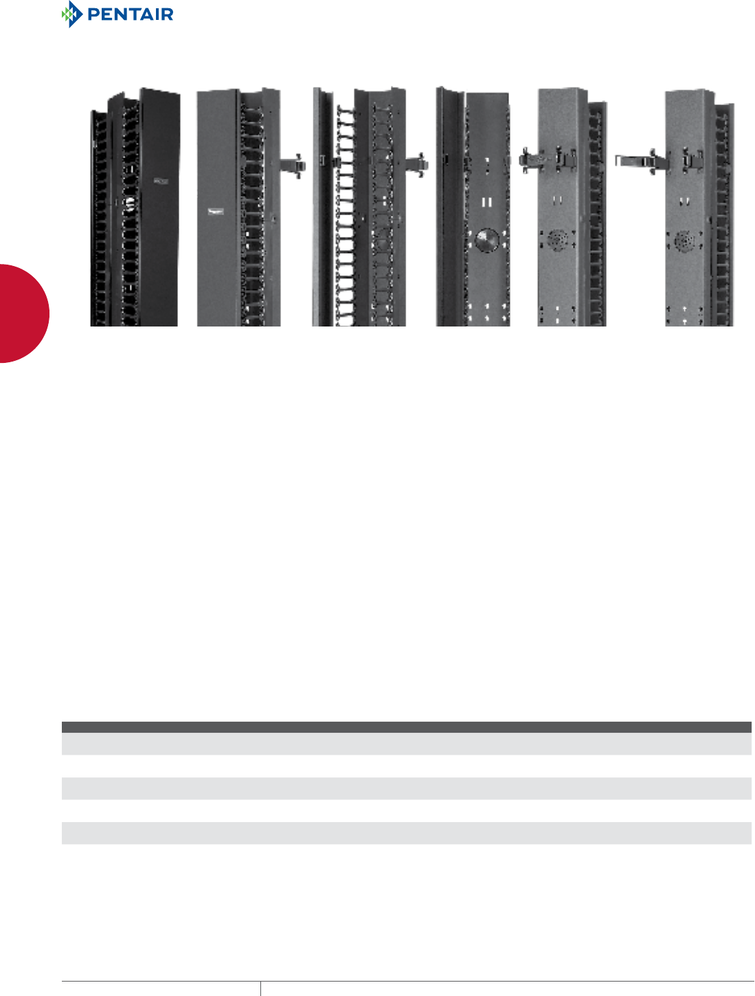
EQUIPMENT PROTECTIONSUBJECT TO CHANGE WITHOUT NOTICENETWORKING78
2
CABLE AND POWER MANAGEMENT OPENFRAME RACK CABLE MANAGERS
CABLETEK™EC VERTICAL CABLE MANAGER
APPLICATION
Attach CABLETEK™ -EC Vertical Cable Managers to the sides and/
or in between open-frame racks to economically provide support,
easy access and proper cable management with easy cable
installation for Network rack-mount equipment. The front side
provides support, management and high cable capacity for patch
cords with easy-to-remove front covers standard. The rear of the
manager provides the same support for horizontal cabling (Cat
5e, 6, 6A and fiber). CABLETEK-EC Vertical Cable Managers are
available in single- and double-sided versions.
FEATURES
• Universal mounting pattern for 2- and 4-post open-frame racks
• Easy-to-install with self-aligning, self-captivating carriage bolts
for single-sided attachment
• Arrowhead supporting fingers provide easy insertion, removal
and alignment of Cat 5e, 6, 6A and other cable types
• Deep cable depth provides smooth transition of cables from
vertical to horizontal positions
• Large feed-through holes and pre-scored grommets provide
cable feed from front to back of cable manager
• Unobstructed cable access for all rack unit locations
• Extra deep cable channel for maximum cable density has
multiple cable tie-down points
• Standard front cover, with field installed snap hinges, provides
cable access from right, left or neutral
• Double-sided models with supporting fingers include front
central latching cover and rear snap-on cover
• Double-sided models with posts and gates support and contain
cables. Five posts and gates are included; additional sets are
available as accessories
• Posts snap into prepunched holes in the back of the cable
manager
• Gates snap onto posts, open from left or right as needed and
swing 280º for cable access. Posts can be used alone as slack
spools to control long patch cords.
• The single-sided cable manager can be upgraded with CABLETEK
Post and Gates Kits
• CABLETEK Rear Cover is sold separately as an accessory for
vertical cable managers with posts and gates, and is fully field-
installable; no tools needed
SPECIFICATIONS
• Easy-to-remove front cover is multi-formed, light-weight
aluminum with high-strength, black composite snap-on hinge
points and hinges right, left or neutral
• Cable channel constructed of multi-formed 14 gauge steel
• Arrowhead supporting fingers are high-strength, black
composite with all edges rounded
• Rear posts and gates on double-sided models are high-strength,
black composite with all edges rounded
FINISH
All aluminum and steel components have a black, low-gloss, light-
textured RAL 9005 powder-coated finish.
All composite parts are provided in matching black.
BULLETIN: DOFRY
Standard Product
Catalog Number AxBxC in./mm Description Width Height RU
EC3S7 84.00 x 3.50 x 11.50
2134 x 89 x 292
Single-Sided 3.5 in. 7 ft. 45
EC3D7 84.00 x 3.50 x 18.00
2134 x 89 x 457
Double-Sided, Post/Gates 3.5 in. 7 ft. 45
EC6S7 84.00 x 6.00 x 11.50
2134 x 152 x 292
Single-Sided 6 in. 7 ft. 45
EC6D7 84.00 x 6.00 x 18.00
2134 x 152 x 457
Double-Sided, Post/Gates 6 in. 7 ft. 45
EC6DF7 84.00 x 6.50 x 20.85
2134 x 165 x 530
Double-Sided, Fingers 6 in. 7 ft. 45
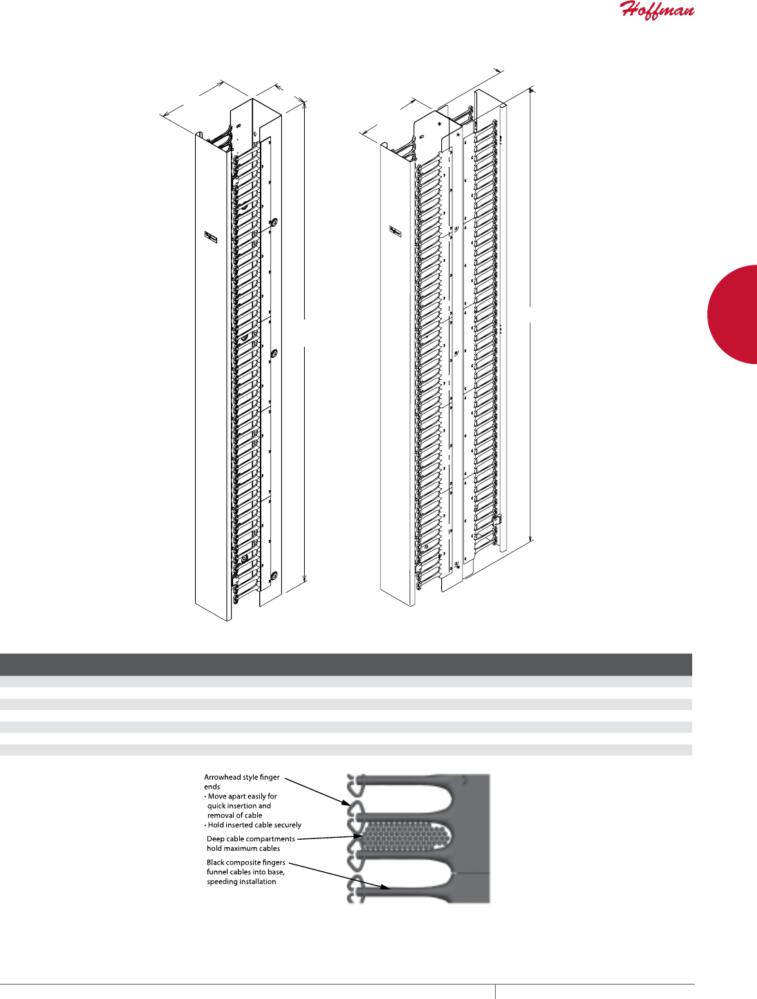
PH 763.422.2661 • FAX 763.422.2588 • PENTAIRPROTECT.COMEQUIPMENT PROTECTION NETWORKING 79
2
CABLE AND POWER MANAGEMENT OPENFRAME RACK CABLE MANAGERS
C
C
B
B
A
A
87955403
SINGLE SIDE
DOUBLE SIDE
Cable Fill Chart
Catalog Numbers
Front Capacity
@ 60 %
Front Capacity
@ 60 %
Front Capacity
@ 60 %
Rear Capacity
@ 60 %
Rear Capacity
@ 60 %
Rear Capacity
@ 60 %
Cable Category 5e 6 5A 5e 6B 6A
EC3S7 534 414 287 — — —
EC3D7 534 414 287 195 151 105
EC6S7 917 710 493 — — —
EC6D7 917 710 493 414 341 236
EC6DF7 917 710 493 414 341 236
Arrowhead 85 66 66 — — —
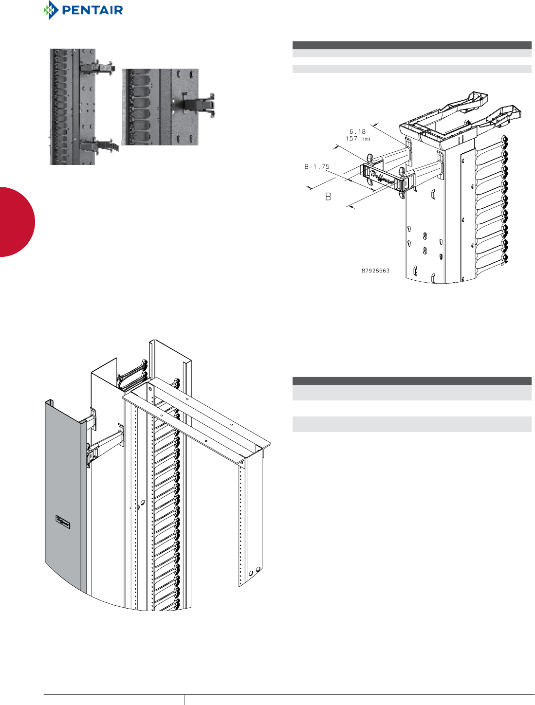
EQUIPMENT PROTECTIONSUBJECT TO CHANGE WITHOUT NOTICENETWORKING80
2
CABLE AND POWER MANAGEMENT OPENFRAME RACK CABLE MANAGERS
CABLETEK™ POST AND GATE KITS
Post and Gate Kits snap together quickly without tools. Each set
consists of two posts and one gate. Posts snap into prepunched
holes on the backs of CABLETEK™ Vertical Cable Managers
(single-sided and double-sided with posts and gates) and are easily
repositionable without tools. Gates swivel open 280 degrees left
or right to allow convenient cable access. When closed, posts and
gates contain, support and secure large volumes of cables and
cable bundles. Molded from black composite material with large
radius, these posts and gates smoothly transition cables from
vertical to horizontal positions. Order additional Post and Gate Kits
to add to single- and double-sided cable managers.
Single posts can be used alone as slack spools on the front side of
the cable manager.
BULLETIN: DOFRY
Catalog Number Description B (in.) B (mm) Pkg. Qty.
DGP3 Posts and Gates 3.00 76 10 sets
DGP6 Posts and Gates 6.00 152 10 sets
DGP10 Posts and Gates 10.00 254 10 sets
DGP12 Posts and Gates 12.00 305 10 sets
REAR COVER
87955768
Rear cover is an accessory for all CABLETEK™ Vertical Cable
Managers with post and gates. For double-sided managers, covers
attach to included post and gates. For single-sided managers,
appropriate Post and Gates Kit must be ordered.
BULLETIN: DOFRY
Catalog Number AxBxC in./mm Fits
EC3C7 84.00 x 3.50 x 1.00
2134 x 89 x 25
3.50 x 7.00 in.
EC6C7 84.00 x 6.00 x 1.00
2134 x 152 x 25
6.00 x 7.00 in.
EC10C7 84.00 x 10.00 x 1.00
2134 x 254 x 25
10.00 x 7.00 in.
EC12C7 84.00 x 12.00 x 1.00
2134 x 305 x 25
12.00 x 7.00 in.
Posts and Gates are required for assembly and to support the rear cover. For single-sided cable managers,
order the appropriate Post and Gate accessory kit.
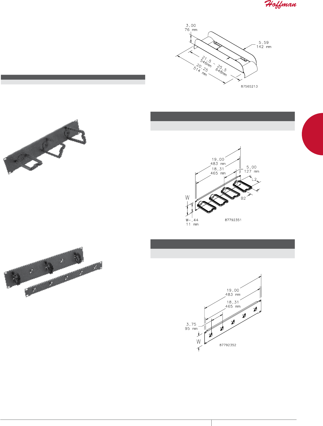
PH 763.422.2661 • FAX 763.422.2588 • PENTAIRPROTECT.COMEQUIPMENT PROTECTION NETWORKING 81
2
CABLE AND POWER MANAGEMENT OPENFRAME RACK CABLE MANAGERS
WATERFALL TOP
For routing cable across the top of an open-frame rack. Provides
horizontal-to-vertical transition bend radius for compliant
installation of Category 5, 6, 6A and fiber optic cable. Makes a
complete cable management system when used with vertical and
horizontal cable managers. Mounts on 2- and 4-post open-frame
racks. Material is steel with RAL 9005 black polyester powder paint
finish.
BULLETIN: DOFRY
Catalog Number Description Fits Open Frame Rack
EWFT Waterfall Top 19 in.
DRING ASSEMBLY
Mounts horizontally on 19-in. racks. Allows grouping vertical cable
runs. D-Rings rotate on bracket for easy cable positioning; snap
open for easy access for cable updates, yet latch securely. Back
plate made of steel with RAL 9005 black polyester powder paint
finish; D-Rings are black plastic. Mounting hardware included.
BULLETIN: DACCY
Catalog Number Description
B2
in./mm
L2
in./mm
W
in./mm Rack Units
ECM19DR1U 19-in. D-Ring Assembly 1.22
31
2.88
73
1.75
44
1
ECM19DR2U 19-in. D-Ring Assembly 2.22
56
4.42
112
3.50
89
2
TIEDOWN PANEL
Tie-Down Panels mount horizontally on 19-in. racks. Steel panels
with RAL 9005 black polyester powder paint finish have slots for
VELCRO® cable wraps. Each panel includes 10 black 8-in. (203-mm)
VELCRO cable wraps. Mounting hardware included.
VELCRO is a trademark of Velcro Industries B.V
BULLETIN: DACCY
Catalog Number Description
W
in./mm Rack Units
ECM19TP1U 19-in. Tie-Down Panel 1.75
44
1
ECM19TP2U 19-in. Tie-Down Panel 3.50
89
2
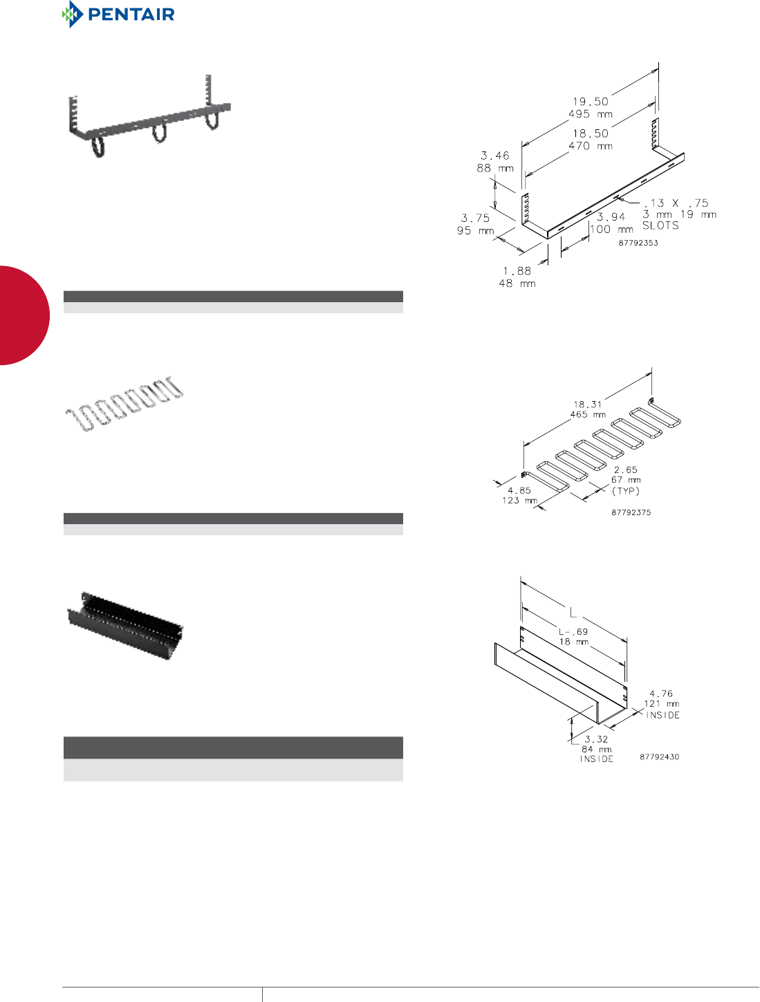
EQUIPMENT PROTECTIONSUBJECT TO CHANGE WITHOUT NOTICENETWORKING82
2
CABLE AND POWER MANAGEMENT OPENFRAME RACK CABLE MANAGERS
TIEDOWN RACK
This zero-rack-unit Tie-Down Rack mounts horizontally on 19-in.
racks. It takes up minimum space yet effectively controls and
separates cable runs. Made of steel with RAL 9005 black polyester
powder paint finish. Includes slots for cable wraps. Each rack
includes 10 black 8-in. (203-mm) VELCRO® cable wraps. Mounting
hardware included.
VELCRO is a trademark of VELCRO Industries B.V.
BULLETIN: DACCY
Catalog Number Description Rack Units
ECM19TD2U 19-in. Tie Down Rack 0
WIRE FORM CABLE MANAGER
This cable manager takes up minimum space, but provides excellent
cable sorting capability. Designed to mount on top of patch panels,
this zero-rack-unit cable manager provides support and control of
cables. Made of plated steel. Mounting hardware included.
BULLETIN: DACCY
Catalog Number Description Use With Rack Units
EWVC19H 19-in. Wire Form Cable Manager 19-in. racks 0
CABLE TROUGH
Mounts horizontally on 19-in. or 23-in. rack angles to support cables
and power cords. Made of steel with RAL 9005 black polyester
powder paint finish.
BULLETIN: DOFRY
Catalog Number Description
L
in./mm Rack Units
ECT19 19-in. Cable Trough 19.00
483
2
ECT23 23-in. Cable Trough 23.00
584
2
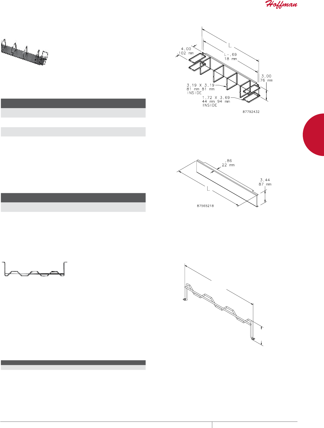
PH 763.422.2661 • FAX 763.422.2588 • PENTAIRPROTECT.COMEQUIPMENT PROTECTION NETWORKING 83
2
CABLE AND POWER MANAGEMENT OPENFRAME RACK CABLE MANAGERS
CABLE MANAGER
Mounts horizontally. For routing and bundling cable on 19-in. or
23-in. racks. Material is steel with RAL 9005 black polyester powder
paint finish. Horizontal-Vertical Cable Manager shown.
BULLETIN: DACCY, DOFRY
Catalog Number Description
L
in./mm Rack Units
ECK19H 19-in. Horizontal Cable Manager 19.00
483
2
ECK19HV 19-in. Horizontal-Vertical Cable Manager 19.00
483
2
ECK23HV 23-in. Horizontal-Vertical Cable Manager 23.00
584
2
HORIZONTAL CABLE MANAGEMENT COVER
Provides a finished appearance to a 19-in. or 23-in. open-frame
rack cable management system. Models snap onto ECK19H,
ECK19HV and ECK23HV Cable Managers. Material is steel with RAL
9005 black polyester powder paint finish.
BULLETIN: DACCY
Catalog Number Description Fits Horizontal Cable Manager
L
in./mm
ECKCVR19 19-in. Cable Manager Cover ECK19H, ECK19HV 19.00
483
ECKCVR23 23-in. Cable Manager Cover ECK23HV 23.00
594
HORIZONTAL CABLE MANAGER BAR
Supports cables between vertical and horizontal cable managers.
Designed for use with VELCRO® cable ties. Angled tie-off surfaces
allow cable to follow natural flow and maintain proper bend radius.
Can be installed behind patch panels to support large permanent
link cable bundles. Can also be installed on top of patch panels as
a zero-RU manager to separate and control patch cables. Made of
steel with a black finish. Secures standard cables, including CAT
5e, 6 and 6A cables. Meets EIA 310-D standard. Includes mounting
fasteners.
VELCRO is a trademark of VELCRO Industries B.V.
BULLETIN: DACCY
Catalog Number Description Rack Units
DCHB1 Horizontal Cable Manager Bar 1
PP
PP
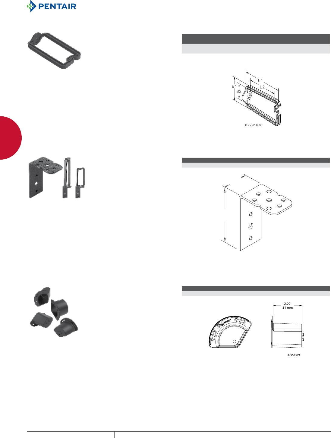
EQUIPMENT PROTECTIONSUBJECT TO CHANGE WITHOUT NOTICENETWORKING84
2
CABLE AND POWER MANAGEMENT CABINET AND RACK CABLE MANAGERS
CABINET AND R ACK CABLE MAN AGERS
DRING CABLE MANAGERS
D-Rings, made of black plastic,
can be used to manage cables
horizontally, vertically or as they
transition. Snap feature allows easy
cable access as well as forming a
tightly closed connection. Package
includes 10 rings and 10 mounting
screws.
BULLETIN: DACCY
Catalog Number AxB in./mm
B1
in./mm
B2
in./mm
L1
in./mm
L2
in./mm Pkg. Qty.
ECM3DR10 1.72 x 3.50
44 x 89
1.72
44
1.22
31
3.50
89
2.88
73
10
ECM6DR10 3.00 x 5.33
76 x 135
3.00
76
2.22
56
5.33
135
4.42
112
10
UNIVERSAL DRING BRACKET
Mounts D-Ring (order separately)
on PROLINE™ or Network Vertical
Tie-Down Cable Manager, PROLINE
Front-to-Back D-Ring Bracket or
grid strap. D-Ring locks into hole
provided. Made of steel coated with
RAL 9005 black polyester powder
paint. Includes mounting hardware.
BULLETIN: DACCY
Catalog Number Description Pkg. Qty.
EDRBK10 D-Ring mounting bracket 10
>@
>@
FIBER MANAGEMENT SPOOL
Fiber Management Spools mount
inside the cabinet and help maintain
proper bends when routing cable.
Molded of black plastic. Includes
thread-forming M5 mounting
screws. Slots provided on flange for
VELCRO® cable wrap.
VELCRO is a trademark of Velcro
Industries B.V.
BULLETIN: DTX
Catalog Number Radius (in.) Radius (mm) Pkg. Qty.
TOPTKSPL 1.18 30 4
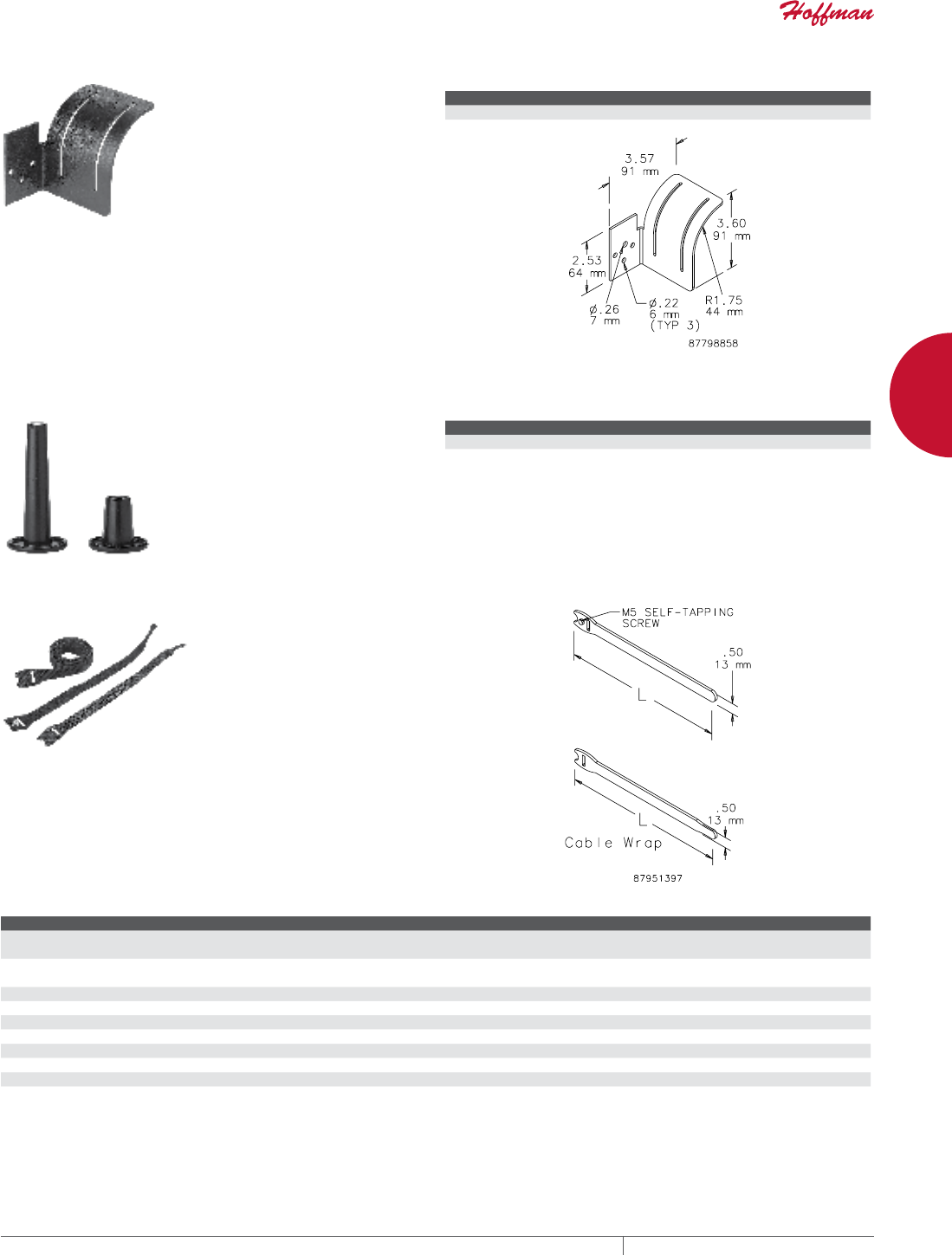
PH 763.422.2661 • FAX 763.422.2588 • PENTAIRPROTECT.COMEQUIPMENT PROTECTION NETWORKING 85
2
CABLE AND POWER MANAGEMENT CABINET AND RACK CABLE MANAGERS
UNIVERSAL TRANSITION BRACKET
Provides support for cable in
transitions between horizontal
and vertical routing. Mounts to
strut, grid strap or PROLINE™
and Network Vertical Tie-Down
Cable Managers. Can be used
with VELCRO® Cable Wrap (order
separately). Made of steel coated
with RAL 9005 black polyester
powder paint. Includes mounting
hardware.
VELCRO is a trademark of Velcro
Industries B.V.
BULLETIN: DACCY
Catalog Number Description Pkg. Qty.
ETRB8 Horizontal or vertical transition 8
CABLE SPOOLS
Spools maintain minimum cable
radius and direct cable. Fasten
easily to Heavy Duty or Seismic
racks with a single screw. Can also
be used with patch panels, grid
straps or plywood walls for general
cable management. Mounting
screws included.
BULLETIN: DACCY
Catalog Number Height (in.) Usable Height (mm) Material Pkg. Qty.
PSPOOL 1.44 37 ABS, UL-VO rated 10
P4SPOOL 3.81 97 ABS, UL-VO rated 10
VELCRO® CABLE WRAP
Securely holds cable to cable manager and unfastens easily for
cable maintenance. VELCRO® is 0.5-in. (12.7-mm) wide. Available
in 8- and 12-in. (203- and 305-mm) lengths in both screw fastener
and wrap styles. M5 self-tapping screw is used on Net Series or
PROLINE™ frames.
VELCRO is a trademark of Velcro Industries B.V.
BULLETIN: DACCY
Catalog Number Description L (in.) L (mm) Color Pkg. Qty.
ECWTD8B Screw fastener style.
Includes M5 mounting screw.
8.00 203 Black 10
ECWTD12B Screw fastener style.
Includes M5 mounting screw.
12.00 305 Black 10
ECW8B Wrap style 8.00 203 Black 10
ECW8R Wrap style 8.00 203 Red 10
ECW8BL Wrap style 8.00 203 Blue 10
ECW8Y Wrap style 8.00 203 Yellow 10
ECW12B Wrap style 12.00 305 Black 10
ECW12R Wrap style 12.00 305 Red 10
ECW12BL Wrap style 12 305 Blue 10
ECW12Y Wrap style 12 305 Yellow 10
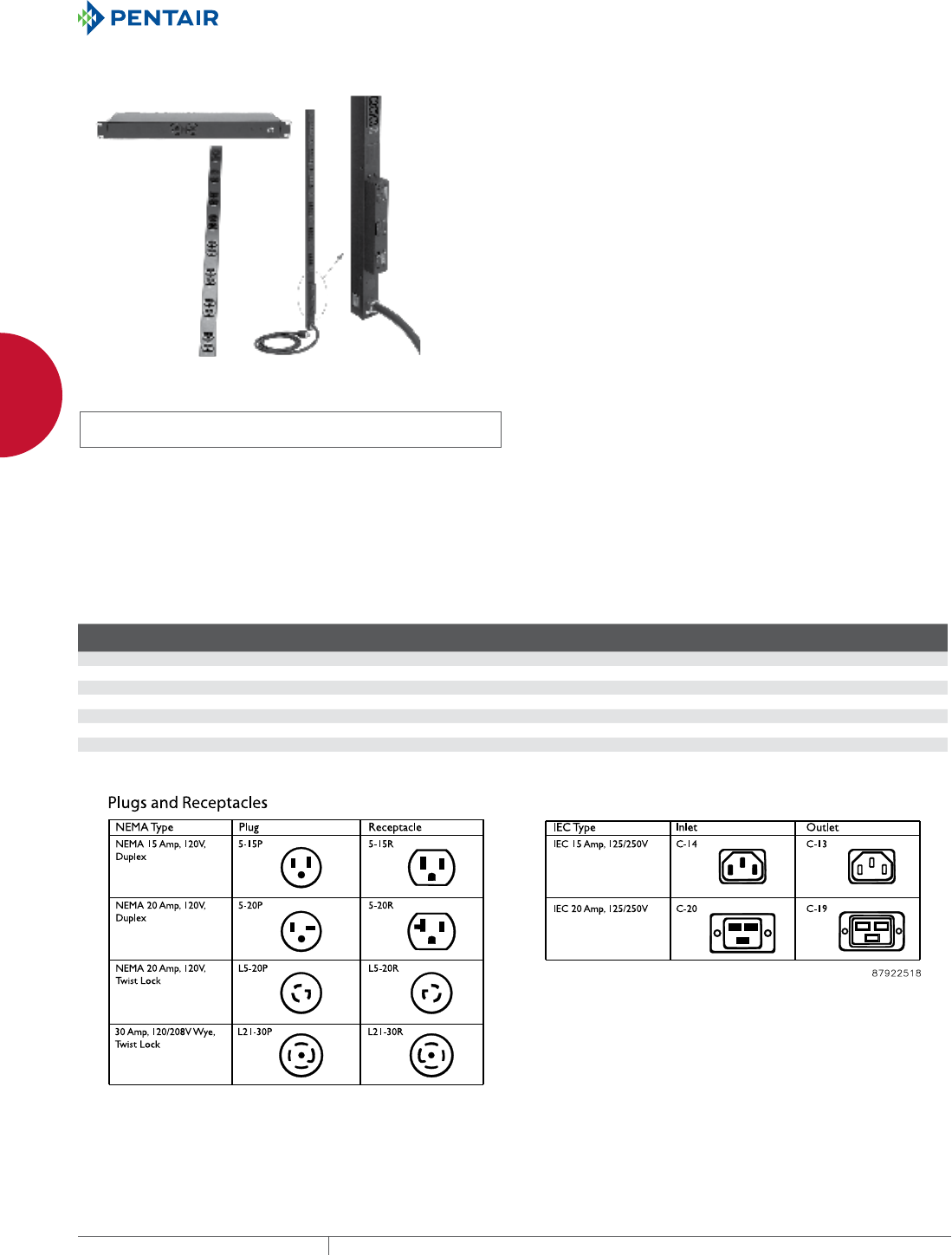
EQUIPMENT PROTECTIONSUBJECT TO CHANGE WITHOUT NOTICENETWORKING86
2
CABLE AND POWER MANAGEMENT POWER DISTRIBUTION UNITS (PDUS)
POWER DISTRI BUTION UNIT S (PDUS)
RACK AND PANELMOUNT POWER DISTRIBUTION UNITS (PDUS)
INDUSTRY STANDARDS
UL/cUL 60950 listed
UL 1449 (Surge protector models only)
EIA 310-D (19-in. rack-mount models only)
APPLICATION
Rack- and Panel-Mount PDUs not only provide convenient, reliable
power to equipment mounted in cabinets or on open frame racks,
they can also be configured to meet a wide range of design
specifications.
FEATURES
• Power on/off LED indicates whether power is available at the PDU
• External ground stud provided on single-phase models for secure
grounding
• Circuit breakers provide additional equipment protection
• Circuits are isolated on dual circuit model; each has its own
circuit breaker
• Reset button provides easy access to circuit breaker reset
• Surge protector models have an indicator LED to verify surge
circuitry protection
• Rack-mount models mount directly to rack or with adapter
bracket
• Rack-mount models designed for single-phase applications
• Panel-mount models can be mounted flush or with hanging
bracket
• Panel-mount models available for both one- and three-phase
applications
• Three-phase models have three 20 A, double-pole magnetic
breaker/switches with an integral switch guard
SPECIFICATIONS
• Steel housing
• Power cord with molded-on plug:
- 12-in. (305-mm) long single-phase model: 6 ft. (1.8 m)
- Other single-phase models: 15 ft. (4.6 m)
- Three-phase models: 10 ft. (3 m)
Contact Hoffman for custom modifications and non-standard
offerings.
FINISH
Black, low-gloss textured paint.
BULLETIN: DPS
Standard Product Single-Phase Rack-Mount
Catalog Number
Surge
Protection
Amp
Meter
Load
Rating
Voltage
(VAC)
Joule
Rating Receptacle Location
No. of
Receptacles Receptacle Style Power Cord Plug
Rack
Units
DP1N190615 No No 15A 120 — Front 6 NEMA 5-15R NEMA 5-15P 1
DP1N191415 No No 15A 120 — 6 front, 8 back 14 NEMA 5-15R NEMA 5-15P 1
DP1N191415M No Yes 15A 120 — 6 front, 8 back 14 NEMA 5-15R NEMA 5-15P 1
DP1N191015S Yes No 15A 120 2000 2 front, 8 back 10 NEMA 5-15R NEMA 5-15P 1
DP1N191020 No No 20A 120 — 2 front, 8 back 10 NEMA 5-20R NEMA 5-20P 1
DP1N191020S Yes No 20A 120 2000 2 front, 8 back 10 NEMA 5-20R NEMA 5-20P 1
DP1N191020ST Yes No 20A 120 2000 2 front, 8 back 10 NEMA 5-20R NEMA L5-20P Twist Lock 1
DP1N191420 No No 20A 120 — 6 front, 8 back 14 NEMA 5-20R NEMA 5-20P 1
Isolated circuits on dual-circuit models with separate circuit breakers.
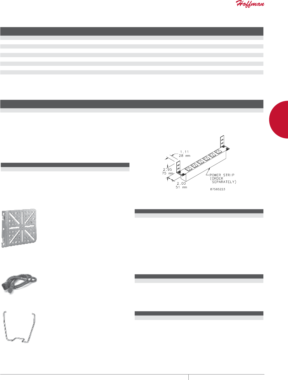
PH 763.422.2661 • FAX 763.422.2588 • PENTAIRPROTECT.COMEQUIPMENT PROTECTION NETWORKING 87
2
CABLE AND POWER MANAGEMENT POWER DISTRIBUTION UNITS (PDUS)
Standard Product Single-Phase Vertical-Mount
Catalog Number
Length
(in.)
Length
(mm)
Surge
Protection
Amp
Meter
Load
Rating
Voltage
(VAC)
Joule
Rating
No. of
Receptacles Receptacle Style Power Cord Plug
DP1N120615 12.00 305 No No 15A 120 — 6 NEMA 5-15R NEMA 5-15P
DP1N160620S 16.00 406 Yes No 20A 120 2000 6 NEMA 5-20R NEMA 5-20P
DP1N481815 48.00 1219 No No 15A 120 — 18 NEMA 5-15R NEMA 5-15P
DP1N622415 62.00 1575 No No 15A 120 — 24 NEMA 5-15R NEMA 5-15P
DP1N622420 62.00 1575 No No 20A 120 — 24 NEMA 5-20R NEMA 5-20P
DP1N622420T 62.00 1575 No No 20A 120 — 24 NEMA 5-20R NEMA L5-20P Twist Lock
DP1N622420M 62.00 1575 No Yes 20A 120 — 24 NEMA 5-20R NEMA 5-20P
DP1N622420MT 62.00 1575 No Yes 20A 120 — 24 NEMA 5-20R NEMA L5-20P Twist Lock
DP1N622040DT 62.00 1575 No No 20A per circuit 120 — 20, 10 per circuit, dual circuit NEMA 5-20R NEMA L5-20P Twist Lock
DP1E2663030MT 66.00 1676 No Yes 30A 250 — 30 24 IEC C-13, 6 IEC C-19 NEMA L6-30P Twist Lock
Isolate circuits on dual circuit models with separate circuit breakers.
DP1E2663030MT is Ethernet metered; SNMP trap provides remote current monitoring via Ethernet.
Standard Product Three-Phase Vertical-Mount
Catalog Number
Length
(in.)
Length
(mm)
Amp
Meter
Load
Rating
Voltage
(VAC) No. of Outlets per Phase Total Outlets per PDU Required Inlet Style Power Cord Plug
DP3E2663635MT 66.00 1676 Yes 35A 250 10 IEC C-13, 2 IEC C-19 30 IEC C-13, 6 IEC C-19 IEC C-14 and C-20 CA style 50A 250 Vac Twist Lock
DP3E2663635MT is Ethernet metered; SNMP trap provides remote current monitoring via Ethernet.
RACKMOUNT PDU BRACKET
Allows rack-mount power strips to be mounted to cabinet sides
without using up rack space. Made of plated steel. Includes two
brackets and mounting hardware. Order power strip separately.
BULLETIN: DPS
Catalog Number Finish Pkg. Qty.
A19PSMB Plated 2 brackets
UNIVERSAL POWER STRIP BRACKET
This bracket fits in the corner of the
frame of all PROLINE™ cabinets
and facilitates mounting a variety of
power strips.
BULLETIN: DPY
Catalog Number Description
EPDUBK Universal Power Strip Bracket fits all PROLINE cabinets
IEC CORD SETS
Cord sets help minimize cord tangle,
increasing airflow to equipment.
BULLETIN: DPS
Catalog Number Description Pkg. Qty.
DP5E 0.5-m (1.64-ft.) IEC patch cord. 18/3 SJT Black. C-14 to C-13 10
DP10E 1-m (3.28-ft.) IEC patch cord, 18/3 SJT Black. C-14 to C-13 10
IEC C13 RETAINING CLIP
Secures the IEC C-14 inlet into
the C-13 outlet. Helps to prevent
inadvertently unplugging the cord
set.
BULLETIN: DPS
Catalog Number Description Pkg. Qty.
DPCLIP IEC C-13 Retaining Clip 10
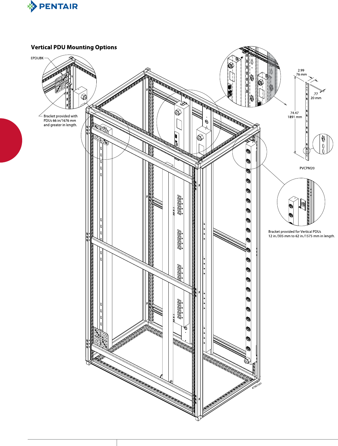
EQUIPMENT PROTECTIONSUBJECT TO CHANGE WITHOUT NOTICENETWORKING88
2
CABLE AND POWER MANAGEMENT POWER DISTRIBUTION UNITS (PDUS)
SMART PDU COMPONENT APPLICATION
Remote sensors and displays, environmental monitors and smoke alarms help to build a system that fits the unique requirements of each
individual installation.
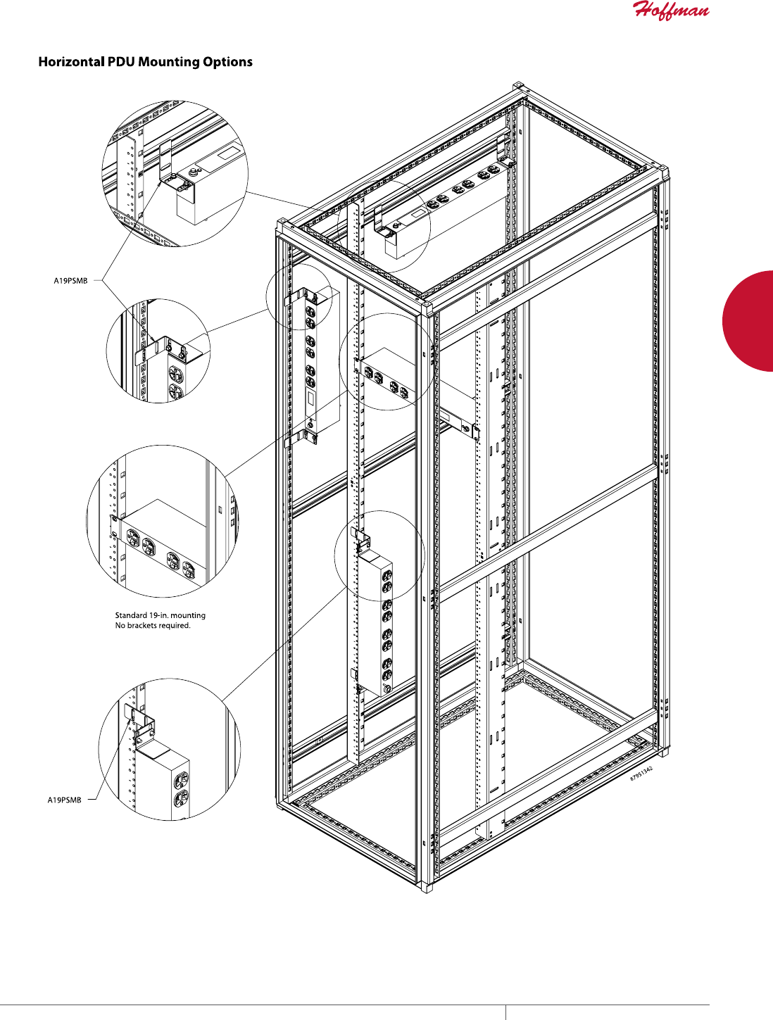
EQUIPMENT PROTECTIONSUBJECT TO CHANGE WITHOUT NOTICENETWORKING90
3
763.422.2661
763.422.2588
NETWORKING
OPEN FRAME R ACKS
Intro Page
CHAPTER 3
OPEN FRAME RACKS
2POST OPEN FRAME RACKS
2-Post Open Frame Racks satisfy
basic functional requirements for
structuring cable. Visible, permanent
RU marking on rack uprights enable
easy equipment alignment
without measuring
for communication
data centers and
telecommunication rooms.
Available in standard and
heavy-duty models.
4POST OPEN
FRAME RACKS
Support deeper, heavier
network equipment with
4-Post Open Frame
Racks. These adjustable
racks combine the
mounting security
of a cabinet with the
accessibility of a rack. To
expand existing systems, 4-post racks
can be ganged with standard 2-post or
other 4-post racks.
FEATURED PRODUCTS

PH 763.422.2661 • FAX 763.422.2588 • PENTAIRPROTECT.COMEQUIPMENT PROTECTION NETWORKING 91
Intro Page CHAPTER CONTENTS
2POST OPEN FRAME RACKS
2-Post Open Frame Rack .....................................92
4POST OPEN FRAME RACKS
4-Post Open Frame Rack .....................................94
OPEN FRAME SYSTEMS
MAXRACK™ Open Frame System ...............................96
MAXRACK™ Air Baffle and Cable Managers for CISCO Switch .........98
MAXRACK™ Dust Cover ......................................98
OPEN FRAME RACK ACCESSORIES
Mobile Base for Open Frame Racks .............................99
4-Post Open Frame Rack Front-to-Back Cable Manager ..............99
Joining Kit ................................................99
Dust Cover ...............................................100
Panel Adapter .............................................100
Concrete Expansion Bolt Anchor Kit ............................100
Electrical Isolation Kit ......................................100
3
OPEN FRAME RACK ACCESSORIES
Streamline cable management with
a broad selection of open frame rack
accessories. From cable managers to
adapters, available accessories facilitate
fast cable installation and organization,
reducing installation and maintenance
costs.
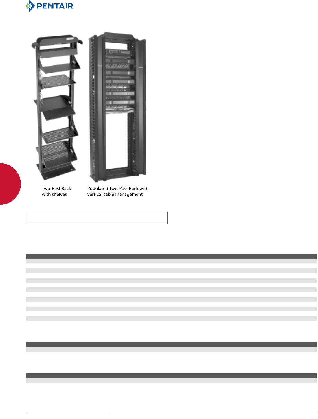
EQUIPMENT PROTECTIONSUBJECT TO CHANGE WITHOUT NOTICENETWORKING92
3
OPEN FRAME RACKS 2POST OPEN FRAME RACKS
2-POST OPEN FR AME RACKS
2POST OPEN FRAME RACK
INDUSTRY STANDARDS
UL 1863 Listed; File No. E230874
cUL Listed per CSA C22.2 No. 182.4; File No. E230874
EIA 310-D
APPLICATION
Designed for use in communication data centers and
telecommunication rooms, 2-Post Open Frame Racks satisfy basic
functional requirements for structuring cable. Racks are available
in 3-in. or 6-in. column widths.
FEATURES
• Range of heights from 4 ft. to 9 ft. (24U to 58U) to match capacity
requirements; 19-in. Rack Packages are 7-ft. high
• Side rails are tapped on both sides with 12-24UNC threads for
quick installation
• EIA Universal 5/8 in. - 5/8 in. - 1/2 in. vertical mounting hole
pattern matches industry standards
• RU markings on both front and back of uprights make it easier to
mount equipment
• Packed unassembled in individual cartons; assembly hardware
(including twenty 12-24 mounting screws) is furnished for
convenient storage and installation
• Can be shipped via FedEx or UPS
• Convenient rack and cable manager packages offered with either
one or two 6-in. cable managers; includes one-piece hinged cover
SPECIFICATIONS
• Frame is a strong and lightweight aluminum (6063-T6 alloy),
extruded or formed, with RU markings on both front and back of
uprights
FINISH
RAL 9005 black polyester powder paint or milled aluminum
LOAD RATING
Do not exceed the following recommended load ratings.
Floor Mount Rack - 1000 lb. (453.6 kg)
One-Sided Solid Shelf - 150 lb. (68.0 kg)
Double-Sided Shelf - 300 lb. (136.1 kg)
One-Sided Vented Shelf - 150 lb. (68.0 kg)
Double-Sided Vented Shelf - 300 lb. (136.1 kg)
Adjustable Vented Shelf - 60 lb. (27.2 kg)
Keyboard/Monitor Shelf - 200 lb. (90.7 kg)
BULLETIN: DMAX, DOFR2
Standard Product 3-in. Column
Catalog Number AxBxC in. AxBxC mm Description Finish Rack Units Nominal Frame Height
EDR19FM24U 48.00 x 20.25 x 15.00 1219 x 514 x 381 19-in. rack Black 24 4 ft.
EDR19FM38U 72.00 x 20.25 x 15.00 1829 x 514 x 381 19-in. rack Black 38 6 ft.
EDR19FM45U 84.00 x 20.25 x 15.00 2134 x 514 x 381 19-in. rack Black 45 7 ft.
EVR19FM45U 84.00 x 20.25 x 15.00 2134 x 514 x 381 19-in. rack Mill 45 7 ft.
EDR19FM51U 96.00 x 20.25 x 15.00 2438 x 514 x 381 19-in. rack Black 51 8 ft.
EVR19FM51U 96.00 x 20.25 x 15.00 2438 x 514 x 381 19-in. rack Mill 51 8 ft.
EDR19FM58U 108.00 x 20.25 x 15.00 2743 x 514 x 381 19-in. rack Black 58 9 ft.
EVR19FM58U 108.00 x 20.25 x 15.00 2743 x 514 x 381 19-in. rack Mill 58 9 ft.
EDR23FM24U 48.00 x 24.25 x 15.00 1219 x 616 x 381 23-in. rack Black 24 4 ft.
EDR23FM38U 72.00 x 24.25 x 15.00 1829 x 616 x 381 23-in. rack Black 38 6 ft.
EDR23FM45U 84.00 x 24.25 x 15.00 2134 x 616 x 381 23-in. rack Black 45 7 ft.
EVR23FM45U 84.00 x 24.25 x 15.00 2134 x 616 x 381 23-in. rack Mill 45 7 ft.
EDR23FM51U 96.00 x 24.25 x 15.00 2438 x 616 x 381 23-in. rack Black 51 8 ft.
EVR23FM51U 96.00 x 24.25 x 15.00 2438 x 616 x 381 23-in. rack Mill 51 8 ft.
Standard Product 3-in. Column with Cable Manager
Catalog Number AxBxC in. AxBxC mm Description Finish Rack Units Nominal Frame Height
EDR19FM45UCM1 84.00 x 27.50 x 18.00 2134 x 699 x 457 19-in. rack package, 1 cable manager , DV6D7 Black 45 7 ft.
EDR19FM45UCM2 84.00 x 34.75 x 18.00 2134 x 883 x 457 19-in. rack package, 2 cable managers , DV6D7 Black 45 7 ft.
Standard Product 6-in. Column
Catalog Number AxBxC in. AxBxC mm Description Finish Rack Units Nominal Frame Height
EDR19FM45U6 84.00 x 20.28 x 18.00 2134 x 515 x 457 19-in. rack Black 45 7 ft.
EDR19FM51U6 96.00 x 20.28 x 18.00 2438 x 515 x 457 19-in. rack Black 51 8 ft.
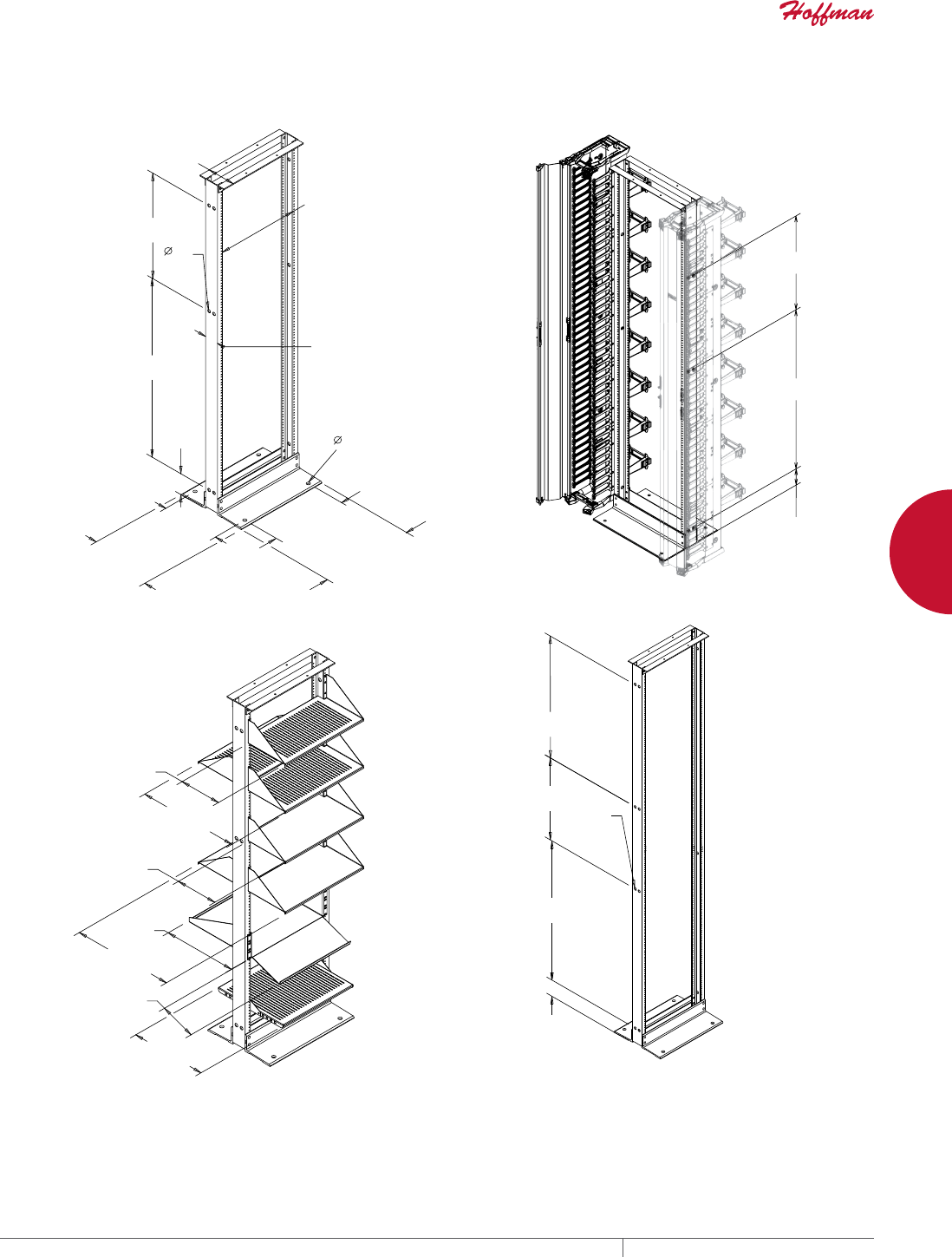
PH 763.422.2661 • FAX 763.422.2588 • PENTAIRPROTECT.COMEQUIPMENT PROTECTION NETWORKING 93
3
OPEN FRAME RACKS 2POST OPEN FRAME RACKS
8-Foot and 9-Foot Racks Only
(Width and Depth dimensions
identical to 7-foot rack
28.00
[700]
23.00
[584]
39.00
[991]
4.00
[102]
Ø.38
[10]
(16X)
19-in. Shelf Depths
One-Sided
Vented Shelf
Double-Sided
Vented Shelf
One-Sided
Solid Shelf
Double-Sided
Solid Shelf
Keyboard/
Monitor Shelf
Adjustable
Vented Shelf
9.00
[229]
21.00
[533]
9.00
[229]
15.10
[384]
21.00
[533]
7.00
[178]
15.75
[400]
LQ
>@
LQ
>@
LQ
>@
LQ
>@
,16,'(
>@
>@
>@
;
>@
>@
LQ
>@
LQ
>@
LQ
>@
LQ
>@
7<3
>@
LQ
>@
LQ
>@
LQ
>@
LQ
>@
2-Post Rack Package
(CABLETEK Vertical Cable Managers shown
with alternate mounting location)
Cable
Manager
23.00
[584]
39.00
[991]
4.00
[102]
89084966
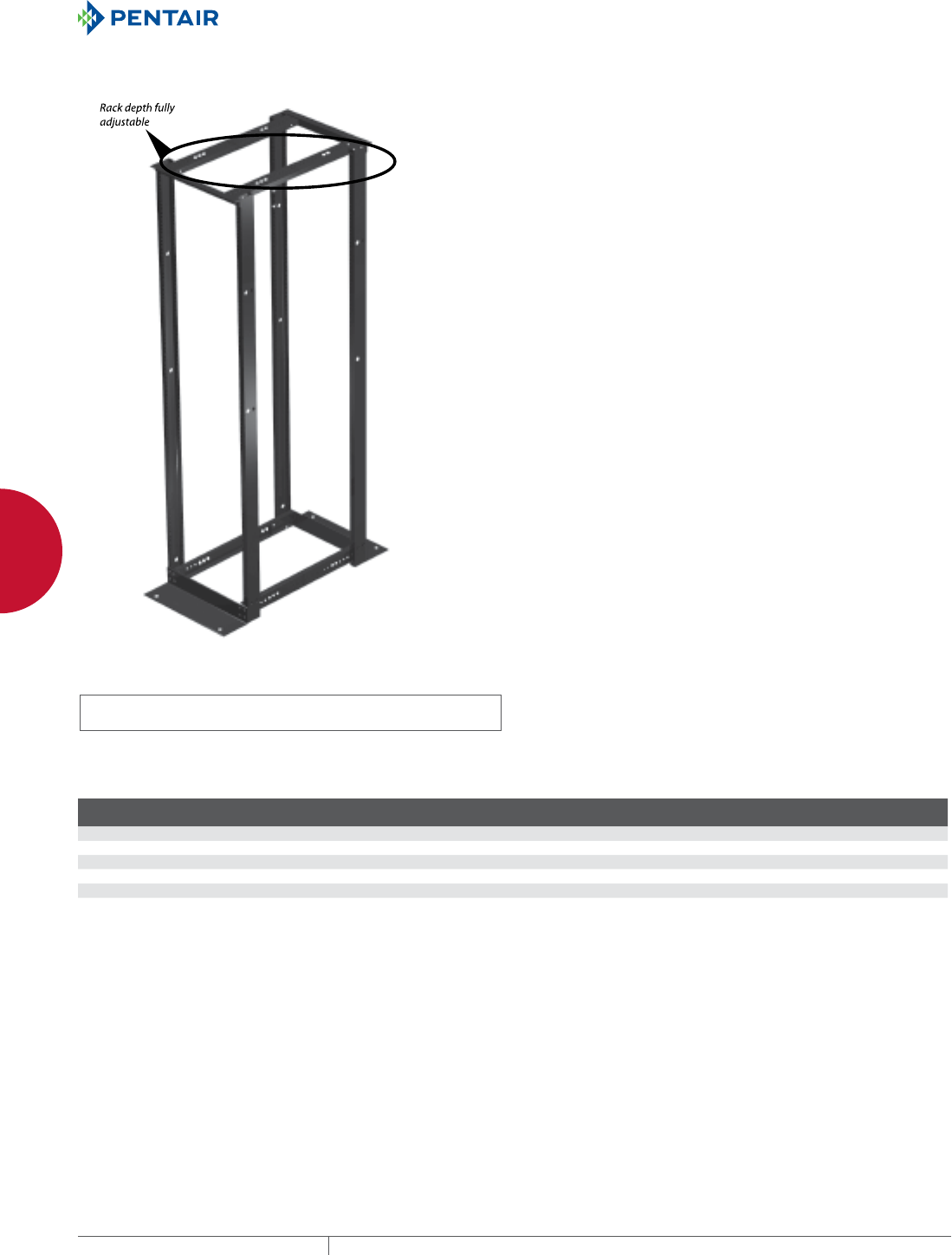
EQUIPMENT PROTECTIONSUBJECT TO CHANGE WITHOUT NOTICENETWORKING94
3
OPEN FRAME RACKS 4POST OPEN FRAME RACKS
4-POST OPEN FRA ME RACKS
4POST OPEN FRAME RACK
INDUSTRY STANDARDS
UL 1863 Listed; File No. E230874
cUL Listed per CSA C22.2 No. 182.4; File No. E230874
EIA 310-D
APPLICATION
4-Post Open Frame Racks combine the mounting security of a
cabinet with the accessibility of a rack. Used in communication data
center and telecommunication room applications, these adjustable-
depth racks support deeper, heavier network equipment and can
be ganged with standard 2-post or other 4-post racks to expand
existing systems.
FEATURES
• Depth adjustable 450 mm to 1050 mm (17.7 in. to 41.3 in.) in 25-
mm (.98-in.) increments
• EIA universal 5/8 - 5/8 - 1/2 in. spaced 12-24 tapped holes or
.375-in. square holes fit 19-in. rack equipment
• Compatible with 19-in. rack accessories
• Available with nominal frame height of 6, 7 and 8 ft.
• RU markings on both front and back of tapped-hole uprights
make it easier to mount equipment
• Floor mounting holes predrilled at .750-in. diameter
• 12-24 rack mounting screws (pkg. of 20) included with tapped-
hole model
• For square hole model, order screws and cage nuts separately
• Can be ganged with both 2- and 4-Post Open Frame racks
• Includes complete assembly instructions
• Shipped unassembled for convenient transport to job site
SPECIFICATIONS
• Uprights on the tapped-hole model are made of lightweight
extruded aluminum (6063-T6 alloy) and include RU markings on
both front and back of uprights
• Uprights on the square-hole model are made from 12 gauge steel
• Top and bottom angles made of extruded aluminum (6063-T6
alloy)
FINISH
Smooth RAL 9005 black polyester powder paint finish.
LOAD RATING
2500 lb. (1134 kg)
PATENTS
6,655,533 (U.S.A.)
BULLETIN: DOFR4
Standard Product
Catalog Number AxB mm AxB in.
Mounting
Hole Type Rack Units
Nominal Frame
Height A
E4DR19FM38U 1826 x 514 71.88 x 20.25 Tapped 38 6 ft.
E4DR19FM45U 2131 x 514 83.88 x 20.25 Tapped 45 7 ft.
E4DR19FM51U 2438 x 514 96.00 x 20.25 Tapped 51 8 ft.
E4DRS19FM45U 2131 x 514 83.88 x 20.25 Square 45 7 ft.
E4DRS19FM51U 2438 x 514 96.00 x 20.25 Square 51 8 ft.
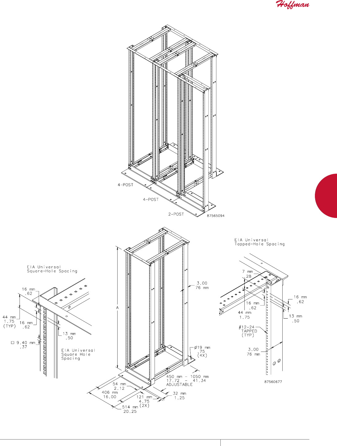
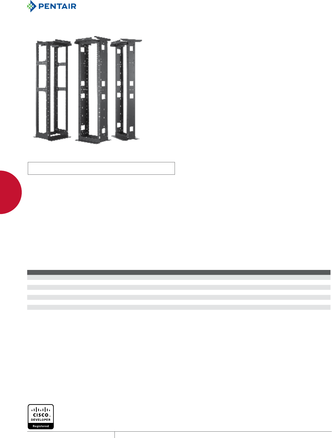
EQUIPMENT PROTECTIONSUBJECT TO CHANGE WITHOUT NOTICENETWORKING96
3
OPEN FRAME RACKS OPEN FRAME SYSTEMS
OPEN FRAME SYS TEMS
MAXRACK™ OPEN FRAME SYSTEM
INDUSTRY STANDARDS
UL 1863 Listed; File Number E230874
cUL Listed per CSA C22.2 No. 182.4; File No. E230874
Cisco developer registered
EIA 310-D
APPLICATION
MAXRACK™ is used for mounting and securing 19- or 23-in. rack
equipment that is used in data centers, telecommunication rooms
and other locations. These open frame racks are ideal for high-
density cabling applications. MAXRACK also supports the cabling
and cooling needs of large core switches (CISCO Catalyst 6509 /
6513, NEXUS 7010 and NEXUS 7018) by using the combination air
baffle/vertical cable manager accessory. MAXRACK, with its vast
features, supports many diverse applications.
FEATURES
• Rack can be assembled to accommodate either 19- or 23-in. rack
equipment
• Racks can be ganged to create rows for high density applications
• 19-in. configuration equals typical tile width of 24 in.
• Flat package to allow easy shipping and handling to job site
• Press-in nuts enable single-side easy assembly
• All structural members are grounded by special grounding and
bonding washers
• Top has integrated waterfall, which ensures proper cable radius
is achieved
• Top and top bracket support accomodate parallel or
perpendicular ladder or basket tray mounting applications
• Channel uprights provided with hole patterns to support various
cable management devices
• All RU positions marked with white lettering on front and rear
column members
• Easy-to-follow complete installation instructions included
• Upright channels tapped 12-24 holes per EIA Universal pattern
standards
• Multiple paint-free grounding points per UL double-lugged
standards
• Rack accommodates vertical cable manager accessories
SPECIFICATIONS
• Top and uprights made of multi-formed .125-in. aluminum
• Base angles made of extruded aluminum
• White RU-marked uprights per EIA standards
• Tapped 12-24 holes per EIA Universal pattern standards
LOAD RATING
Static maximum load is 2500 lbs/1134 kg.
ACCESSORIES
Vertical Cable Managers
Blanking Panels
Grounding kits
PDUs
Shelves
BULLETIN: DMAX
Standard Product MAXRACK Open Frame System
Catalog Number AxBxC in. AxBxC mm Rack Units G (in.) G (mm) K (in.) K (mm)
M846B45 86.13 x 24.00 x 16.50 2188 x 610 x 419 45 14.00 356 6.50 165
M8410B45 86.13 x 24.00 x 20.50 2188 x 610 x 521 45 18.00 457 10.50 267
M8416B45 86.13 x 24.00 x 26.25 2188 x 610 x 667 45 23.75 603 16.25 413
M8432B45 86.13 x 24.00 x 41.75 2188 x 610 x 1060 45 39.25 997 31.75 806
M966B51 98.13 x 24.00 x 16.50 2493 x 610 x 419 51 14.00 356 6.50 165
M9610B51 98.13 x 24.00 x 20.50 2493 x 610 x 521 51 18.00 457 10.50 267
M9616B51 98.13 x 24.00 x 26.25 2493 x 610 x 667 51 23.75 603 16.25 413
M9632B51 98.13 x 24.00 x 41.75 2493 x 610 x 1060 51 39.25 997 31.75 806
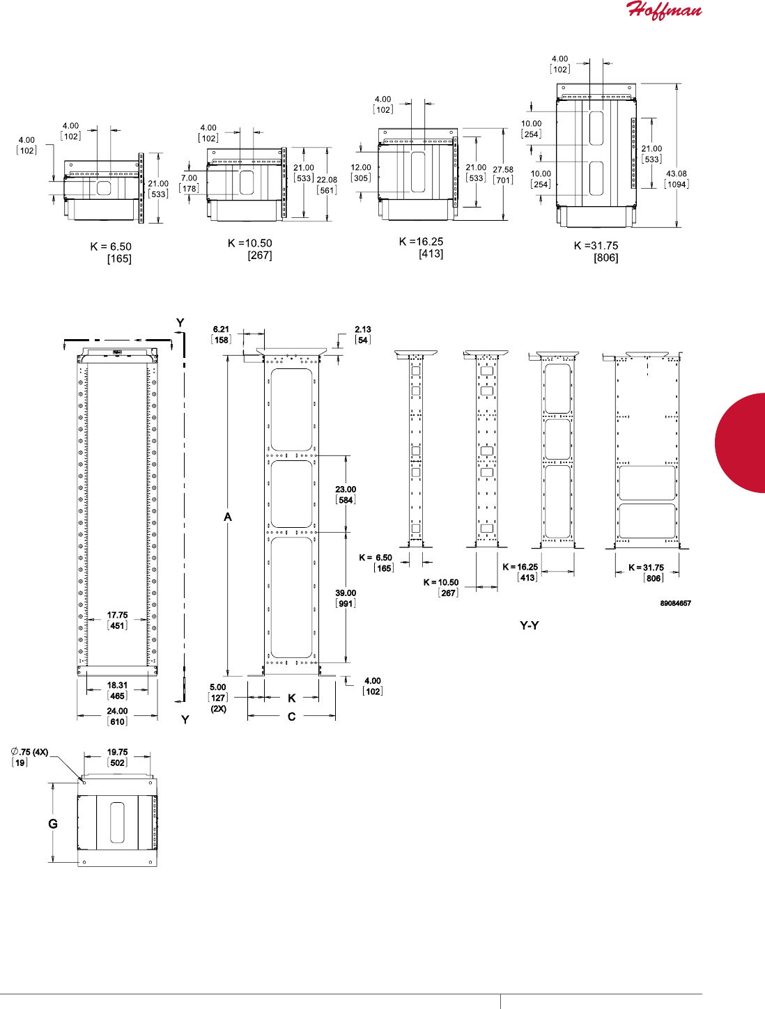
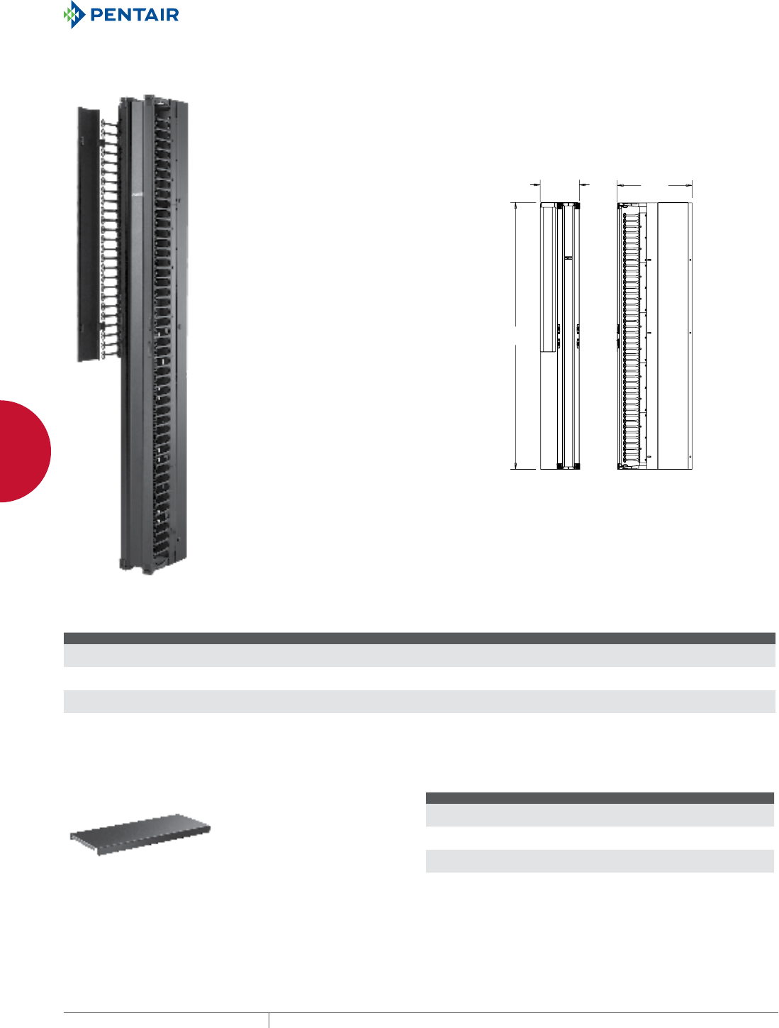
EQUIPMENT PROTECTIONSUBJECT TO CHANGE WITHOUT NOTICENETWORKING98
3
OPEN FRAME RACKS OPEN FRAME SYSTEMS
MAXRACK™ AIR BAFFLE AND CABLE MANAGERS FOR
CISCO SWITCH
MAXRACK™ Air baffle and Vertical Cable Manager accessory kits
ensure CISCO switch compliance. They provide the required cold air
access and provisions for high-density cabling. Baffles and cable
manager uprights made of aluminum; supporting fingers made
of composite. Finish is RAL 9005 black light-textured, low-gloss
polyester powder paint.
Cisco developer registered.
BULLETIN: DMAX
$
%
&
Standard Product MAXRACK Air Baffle and Cable Managers for CISCO Switch
Catalog Number AxBxC in./mm Use with CISCO Switch Use with MAXRACK
M84D12 84.13 x 12.00 x 23.68
2137 x 305 x 601
Catalyst 6509/6513 M8416B45
M84D18 84.13 x 18.00 x 39.37
2137 x 457 x 1000
NEXUS 7018 M8432B45
M96D12 96.13 x 12.00 x 23.68
2442 x 305 x 601
Catalyst 6509/6513 M9616B45
M96D18 96.13 x 18.00 x 39.37
2442 x 457 x 1000
NEXUS 7018 M9632B45
MAXRACK™ DUST COVER
Dust Cover fits over the top of the base angles, inside the uprights.
Covers are made of aluminum with matching RAL 9005 black light-
textured, low-gloss polyester powder paint.
BULLETIN: DMAX
Standard Product MAXRACK Dust Cover
Catalog Number AxBxC in./mm Fits MAXRACK Depth
MDC6 1.00 x 17.95 x 7.33
25 x 456 x 186
6-in.
MDC10 1.00 x 17.95 x 11.33
25 x 456 x 288
10-in.
MDC16 1.00 x 17.95 x 17.08
25 x 456 x 434
16-in.
MDC32 1.00 x 17.95 x 32.58
25 x 456 x 828
32-in.
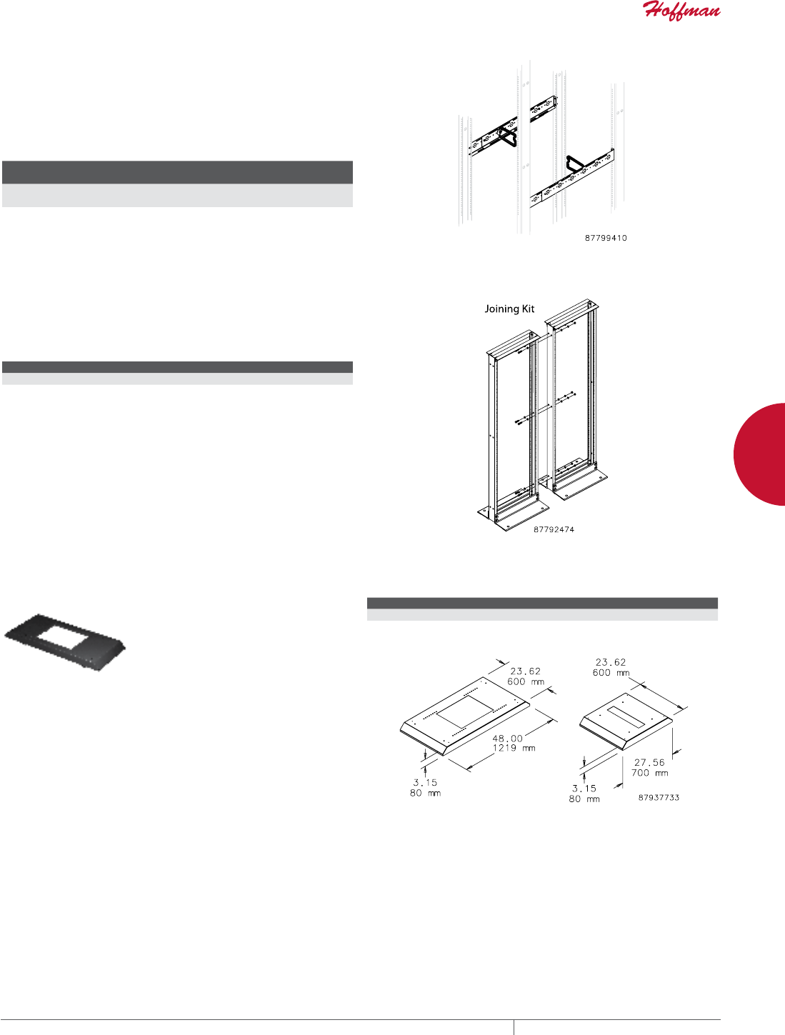
PH 763.422.2661 • FAX 763.422.2588 • PENTAIRPROTECT.COMEQUIPMENT PROTECTION NETWORKING 99
3
OPEN FRAME RACKS OPEN FRAME RACK ACCESSORIES
OPEN FRAME RACK ACCESSORIES
4POST OPEN FRAME RACK FRONTTOBACK CABLE
MANAGER
Cable Manager provides holes for mounting D-Rings and Spools
to facilitate routing and managing cable in a 4-Post Open Frame
Rack. Mounts to rack uprights. Made of steel with RAL 9005 black
polyester paint finish. Includes six large D-Rings.
BULLETIN: DOFRY
Catalog Number
Height
mm/in.
Width
mm/in.
Adjusts to Fit
4-Post Depth
Pkg.
Qty,
E4FBCM 74
2.90
22
.85
750-1050 1
JOINING KIT
Hardware kit to join two open-frame racks. Made of steel with
plated finish.
BULLETIN: DOFRY
Catalog Number Description
EJ2DR Joining Kit, Side-to-Side
MOBILE BASE FOR OPEN FRAME RACKS
Models for 19-in. 2- and 4-Post Open
Frame Racks. Includes four non-
locking casters. Will also accept
standard levelers. Order catalog
number PMBLM12 separately. The
rack mounts on the base to provide
greater stability with mobility.
Made of steel with RAL 9005 black
polyester powder paint finish.
Mounting hardware included.
BULLETIN: DOFRY
Catalog Number Fits
A19MB600 2-post open-frame racks
A19MB1000 4-post open-frame racks with depth adjustable
between 17.7- and 29.5-in. (450- and 750-mm) in 0.98-in. (25-mm) increments
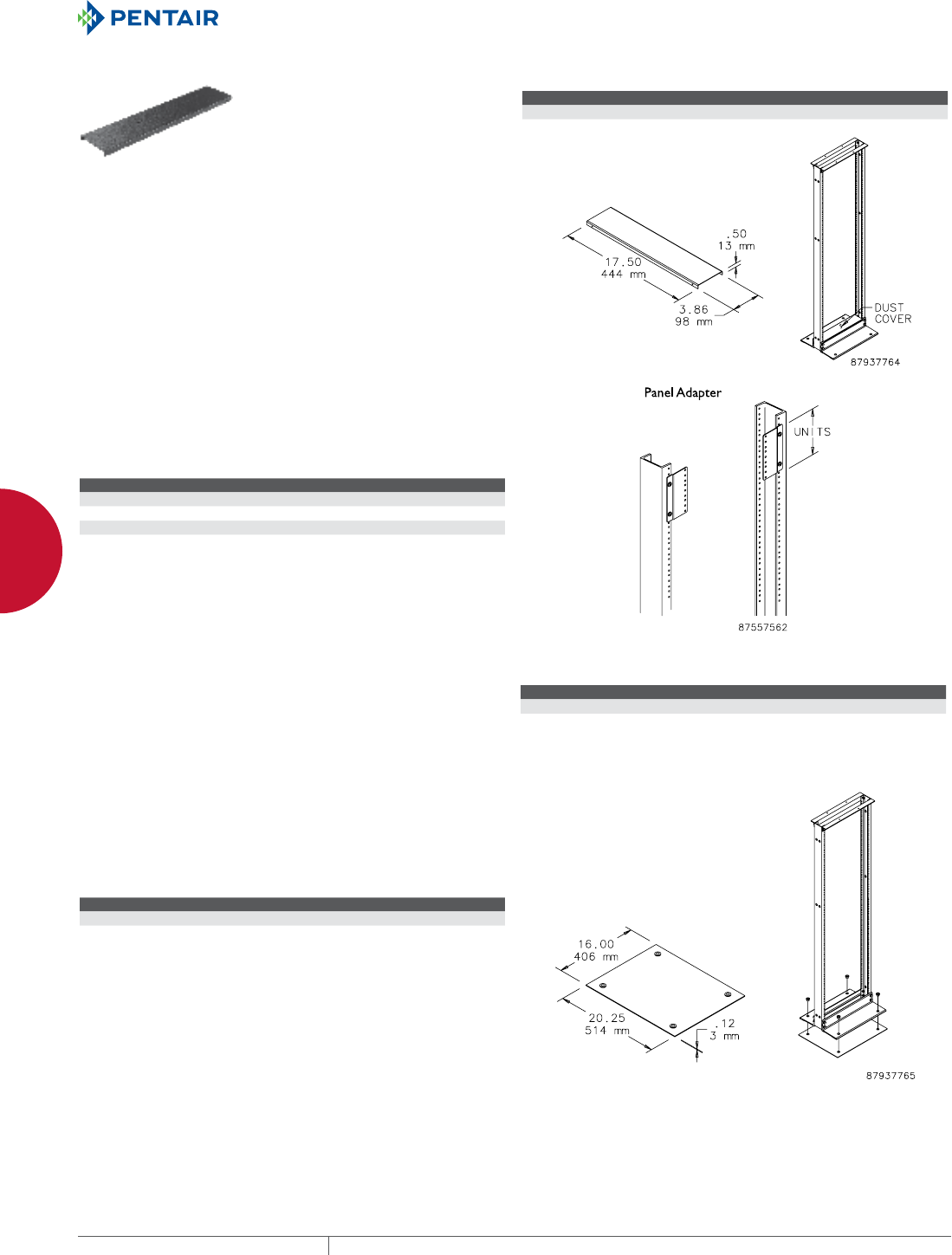
EQUIPMENT PROTECTIONSUBJECT TO CHANGE WITHOUT NOTICENETWORKING100
3
OPEN FRAME RACKS OPEN FRAME RACK ACCESSORIES
DUST COVER
Provides a finished appearance to
the base of a two-post rack. Made of
steel with RAL 9005 black polyester
powder paint finish.
BULLETIN: DOFRY
Catalog Number Use with
EDUSTCVR DataCom 2-post rack
PANEL ADAPTER
Adapts 23-in. open frame rack to accept 19-in. equipment. Offset
provides flush mounting surface. Steel with plated finish. Furnished
in pairs.
BULLETIN: DACCY
Catalog Number Rack Units
ERB1U2319 1
ERB3U2319 3
ERB5U2319 5
CONCRETE EXPANSION BOLT ANCHOR KIT
For use with seismic and non-seismic open frame racks.
BULLETIN: DACCY
Catalog Number Size Qty.
ESBDK 3/8 in. 4
ELECTRICAL ISOLATION KIT
Provides electrical isolation between the 2-Post Open Frame Rack
and the floor. Includes isolation plate and plastic bushings. Made
of 0.125-in. fiberglass. Rack and floor fastening hardware not
included.
BULLETIN: DOFRY
Catalog Number Description
A19ESOK Electrical Isolation Kit

EQUIPMENT PROTECTIONSUBJECT TO CHANGE WITHOUT NOTICENETWORKING102
4
763.422.2661
763.422.2588
NETWORKING
WALL-MOUNT CABINETS
Intro Page
CHAPTER 4
WALLMOUNT CABINETS
PROTEK™ WALLMOUNT
CABINETS
PROTEK™ Wall-Mount Cabinets
provide protection and cooling to
19-in. rack-mounted equipment in
wet or dirty environments where
floor space is minimal. Available in
a wide selection of sizes, materials
and configurations, PROTEK is an
optimal solution for intermediate
distribution frame (IDF) networks
and point-of-operation industrial
component applications.
LBOX™ AND
DBOX™ WALLMOUNT CABINETS
Low-profile, vertically-oriented
L-B OX ™ and D-BOX™ Wall-Mount
Cabinets offer a versatile solution
for mounting, storing and protecting
network equipment, patch panels and
connections in public settings.
ACCESSPLUS™ II
WALLMOUNT CABINETS
Versatile ACCESSPLUS™ Wall-
Wount Cabinets provide a secure,
practical and accessible solution
for 19-in. rack-mounted equipment
applications. The double-hinged
cabinet design ensures rugged
security, maximum cooling and
rack unit containment.
FEATURED PRODUCTS

PH 763.422.2661 • FAX 763.422.2588 • PENTAIRPROTECT.COMEQUIPMENT PROTECTION NETWORKING 103
Intro Page CHAPTER CONTENTS
WALLMOUNT CABINETS PRODUCT SELECTION GUIDE
Wall-Mount Cabinets Product Selection Guide ............104
ACCESSPLUS™ II DOUBLEHINGE
ACCESSPLUS™ II Double-Hinge, Type 1 .................106
Vertical Cable Managers for 28-in.-Wide Cabinet ..........110
Rack Angles ......................................110
Fan Kits .........................................110
DataCom Wall-Mount Cabinet with Gland Plate Application .111
PROTEK™ SINGLEDOOR AND DOUBLEHINGED CABINETS
PROTEK™ Single-Door, UL and NEMA Type 4, 12 ...........112
PROTEK™ Double-Hinged, UL and NEMA Type 4, 4X or 12 ...120
PROTEK™ Single-Door Fan Packages ...................128
PROTEK™ Double-Hinged Fan Packages ................132
Cooling Performance for Air Conditioner Packages ........135
PROTEK™ ACCESSORIES
PROTEK™ Wall-Mount Cabinet Accessory Panels .........136
PROTEK™ Rack Angles ..............................136
LBOX™ WALLMOUNT CABINET AND ACCESSORIES
L-BOX™, Type 1 ....................................138
Bonding and Grounding Kit ...........................140
Duplex Outlet Kit ..................................140
Fan Filter and Finger Guard Kit ........................140
Patch Panel Rack Angles ............................140
Shelves ..........................................141
Strut Wall-Mounting Kit .............................141
DBOX™ WALLMOUNT ENCLOSURE AND ACCESSORIES
D-BOX™, Type 1 ...................................142
Bonding and Grounding Kit ...........................144
Duplex Outlet Kit ..................................144
Equipment Rack Angles .............................144
Fan Filter and Finger Guard Kit ........................144
Padlock Kit .......................................144
Patch Panel Rack Angles ............................145
Shelves ..........................................145
Strut Wall-Mounting Kit .............................145
POLYPRO™ WIFI, TYPE 4X
POLYPRO™ WiFi, Type 4X ............................146
Adjustable Panel Block Kit ...........................147
Polyester Mounting Bracket Kits ......................148
Aluminum Swing-Out Panels .........................148
Stainless Steel Latches (Padlockable) ..................148
Hinge Retainers ...................................149
FIBERGLASS HINGECOVER TYPE 4X WIFI CABINET AND
ACCESSORIES
Hinge-Cover WiFi, Type 4X ...........................150
Threaded Panel Extenders ...........................151
Quick-Release Latch Kit .............................151
Swing-Out Panel Kit ................................152
Panels for WiFi Cabinets and Small Wall-Mount Enclosures .152
ULTRX™ FIBERGLASS TYPE 4X WIFI CABINET AND
ACCESSORIES
ULTRX™ WiFi, Type 4X ..............................153
Panel Bracket Kit ..................................155
ULTRX™ Panel ....................................155
Swing Frame ......................................155
Swing-Out Panel ...................................156
Rack Angles (Type RA) ..............................156
Grounding Device ..................................156
ULTRX™ Mounting Bracket Kit ........................157
Self-Tapping Screws ................................157
Screw Insert Kit ...................................157
Keylock Kit and Padlock Kit ..........................157
SECURITY WALLMOUNT AND ACCESSORIES
Security DVR and 19-in. Rack Equipment Cabinet, Type 1. . . .158
19-in. Electronic Case, Type 1 .........................160
Tip-Up Foot Kit for Electronic Case ....................161
Hardware Kits for Electronic Case .....................161
Slide Rails for Electronic Case ........................161
19IN. RACKMOUNT/DESKTOP CASE AND ACCESSORIES
19-in. Rack-Mount/Desktop Case, Type 1 ................162
Front Panels ......................................163
Rear Panels ......................................163
Front Handles .....................................163
Support Rail Kit ...................................164
4
POLYPRO™ WIFI
WALLMOUNT CABINETS
POLYPRO™ Enclosures
provide superior protection
for wireless equipment
in indoor and outdoor
environments, including
applications that present
harsh chemicals, weather
extremes, corrosive
elements or flames.
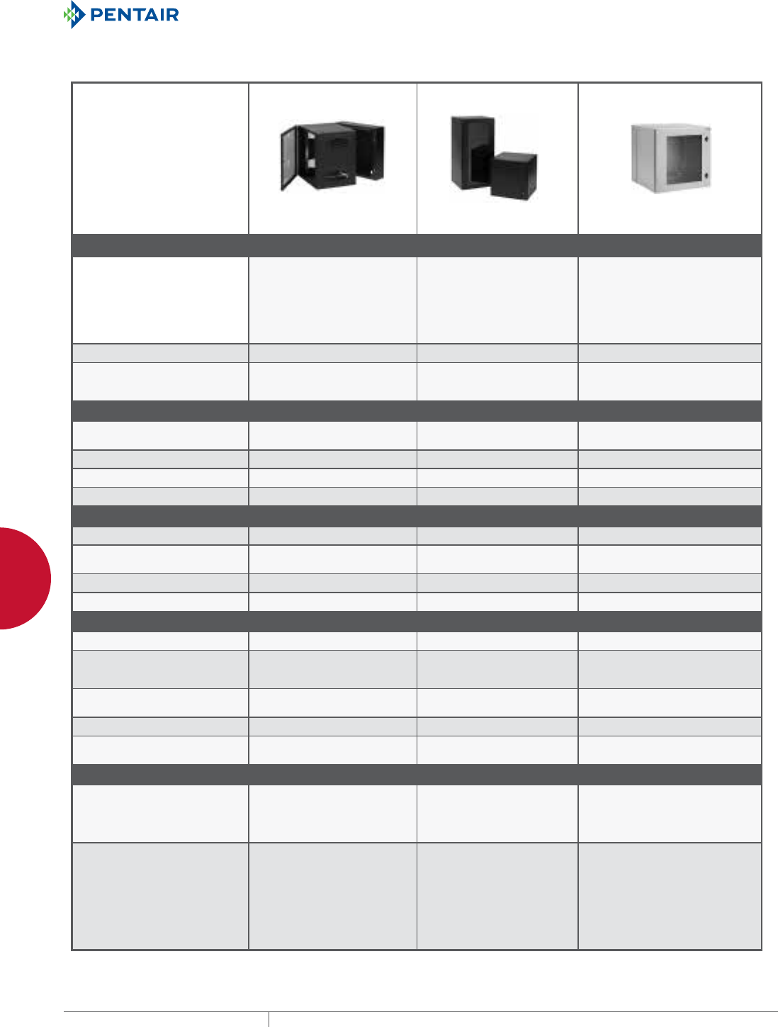
EQUIPMENT PROTECTIONSUBJECT TO CHANGE WITHOUT NOTICENETWORKING104
4
WALLMOUNT CABINETS WALLMOUNT CABINETS PRODUCT SELECTION GUIDE
WALL-MOUNT CABINE TS PRODUCT SE LECTION GUID E
WALLMOUNT CABINETS PRODUCT SELECTION GUIDE
WALLMOUNT CABINETS Wall-Mount Cabinets ProduCt seleCtion Guide
Spec-00449 D
EQUIPMENT PROTECTION SOLUTIONSSUBJECT TO CHANGE WITHOUT NOTICENETWORKING1
763.422.2661
763.422.2588
Spec-00449
D
NETWORKING
Wall-mount cabinets
Wal l- mou nt cabinets Pro duct selection Gu ide
WALLMOUNT CABINETS PRODUCT SELECTION GUIDE
WALL-MOUNT FAMILY ACCESSPLUS™ II PROTEK™ PROTEK™ DOUBLE-HINGED
Description ACCESSPLUS II Double-Hinged
Wall-Mount provides both security
and accessibility. Designed to
hold multiple pieces of voice data
equipment. Perfect where space is
at a premium.
• Double–hinged wall mount
PROTEK Wall-Mount Cabinets
are ideal for protecting network
equipment beyond typical Type 1
enclosures.
• Harsh environments
• Models with A/C units
Offers the flexibility and accessibility
of a double-hinged wall-mount and
the environmental protection of the
PROTEK Type 4/12 ratings.
• Double-hinged wall-mount
• Harsh environments
• Models with A/C units
Construction Mild steel Mild steel Mild steel
Application Rating Indoors with built-in ventilation
areas Indoors and outdoors.
Protects from dust, dirt and
splashing water.
Protects from dust, dirt and splashing
water.
DIMENSIONS
Rack Units (RU) Range 12–39 RUs 12–26 RUs 7–26 RUs
Height 25.00–72.00 in. 24.00–48.00 in. 16.00–48.00 in.
Width 24.00 in., 28.00 in. 24.00 in. 24.00 in.
Depth 18.00–25.00 in. 12.00–24.00 in. 15.00–25.00 in.
RATINGS
Loading - Static 250–500 lbs. 100–200 lbs. 100–175 lbs.
Certifications and Listings UL 508A, CSA, NEMA, IEC UL 508A, CSA, NEMA, IEC UL 508A, CSA, NEMA, IEC
Type / NEMA / IP Rating Type 1, IP40 Type 1, 4, 12, IP55/IP66 Type 1, 4, 12, IP55/IP66
Plenum Rated Yes Yes Yes
STRUCTURE
Front Door Window or solid Window or solid Window or solid
Back Keyhole mounting slots, accessory
raised pads, cable tie-down points,
large cable knock-out
Rear mounting studs, panel-ready
and wall-mounting provisions Rear mounting studs, panel-ready
and wall-mounting provisions
Top / Bottom Gland Plate/Cable knock-outs,
fan-ready Solid sheet steel construction Solid sheet steel construction
Sides Cable knock-outs, fan-ready Solid sheet steel construction Solid sheet steel construction
Rack Angles 1 set tapped 10-32 fully adjustable,
plated 1 set tapped 10-32 fully
adjustable, plated 1 set tapped 10-32 fully adjustable,
plated
APPLICATIONS
Most frequently utilized model
for mounting network equipment.
Gland-plate offering great for
retrofit applications.
Ideal for remote areas with
harsh environments for network
equipment. Extra-deep to
accommodate rack equipment.
Ideal for remote areas with harsh
environments for network equipment.
Extra-deep to accommodate rack
equipment.
Unique Features • Single person mounting
• Latch-free sides permit flush-
mounting to adjacent equipment,
enclosures and walls
• Safety glass window units
• Pole mounting kit available
• Reversible hinges (left/right)
• Grounding and bonding provisions
• Available with T4 A/C units
• Extra-deep sizes
• Fully vented with foam-in-place
gasket
• Safety Glass
Rack angle standard
• Grounding and bonding
provisions
• Available with T4 A/C units
• Extra deep sizes
• Fully vented with foam-in-place
gasket
• Safety Glass
• Rack Angle Standard
• Front and Rear Access
• Grounding and bonding provisions
Spec-00449.indd 1 01/28/13 8:50:47 AM
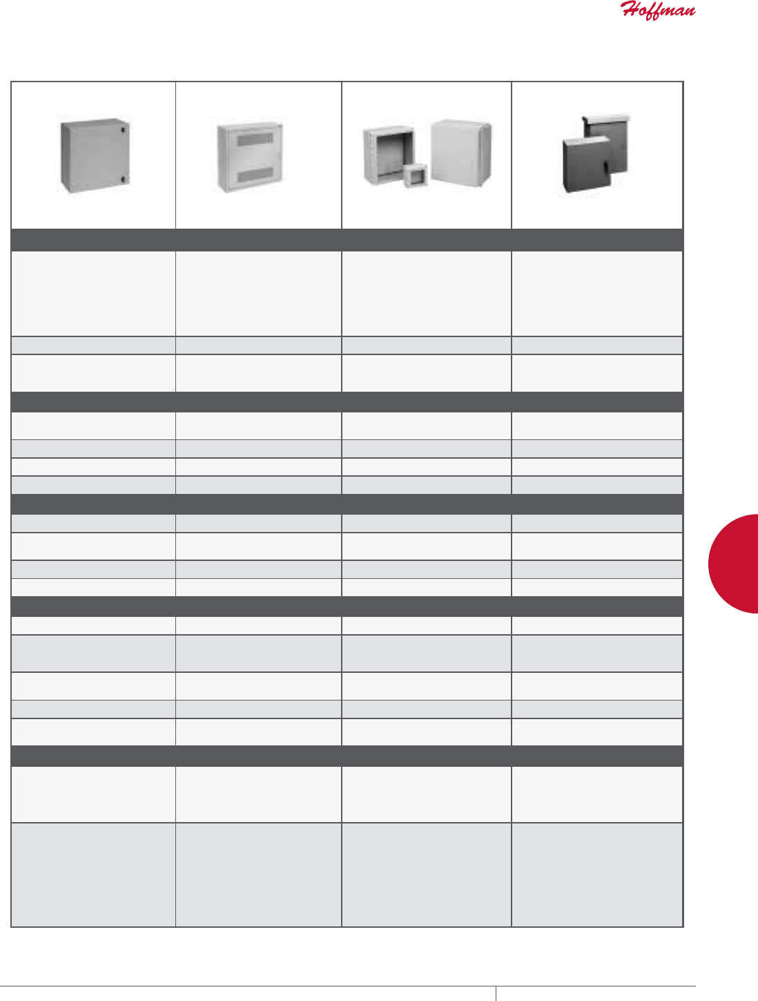
PH 763.422.2661 • FAX 763.422.2588 • PENTAIRPROTECT.COMEQUIPMENT PROTECTION NETWORKING 105
4
WALLMOUNT CABINETS WALLMOUNT CABINETS PRODUCT SELECTION GUIDE
WALLMOUNT CABINETS Wall-Mount Cabinets ProduCt seleCtion Guide
Spec-00449 D PH 763.422.2661 • FAX 763.422.2588 • HOFFMANONLINE.COMEQUIPMENT PROTECTION SOLUTIONS NETWORKING 2
L-BOX™ D-BOX™ WiFi ENCLOSURE—2 MODELS COMLINE™
L-BOX provides convenient
mounting and storage for patch
panels in a space-saving design.
• Horizontal cable distribution
• Copper to fiber
• Consolidation points
• Vertical rack angles
D-BOX provides convenient
mounting and storage for patch
panels.
• Horizontal cable distribution
• Copper to fiber
• Consolidation points
• Fixed and rotating rack angles
Provides a secure enclosure for
WiFi and other network equipment.
Fiberglass does not impede WiFi/
WLAN signals.
• Corrosion resistant
• Plenum rated
• Plywood back panel provided
Lightweight, corrosion-resistant
aluminum enclosure provides long-
lasting protection for electrical and
network components for both indoor
and outdoor environments.
• Corrosion-resistant
• Outdoor applications (OSP)
Mild steel Mild steel Fiberglass Aluminum
Indoors with built-in ventilation
areas. Indoors with built-in ventilation
areas. Indoors and outdoors plus hazardous
areas. Protects from dust, dirt and
splashing water.
Indoors and outdoors plus hazardous
areas. Protects from dust, dirt and
splashing water.
6–12 RUs 4–6 RUs Not applicable for smaller model.
Optional RU for large model. Not supplied as standard.
Optional 12–26 RUs
24.00–48.00 in. 24.00–48.00 in. 6.00–24.61 in. 11.80–59.10 in.
24.00 in. 24.00 in. 6.00–24.11 in. 11.80–35.40 in.
12.34 in. 8.34–12.34 in. 4.00–12.64 in. 5.90–11.80 in.
75 lbs. 100 lbs. 50–200 lbs. 50–200 lbs.
UL 1863/508A/60905, CSA NEMA,
IEC, EIA 310-D UL 1863/508A/60905, CSA, NEMA,
IEC, EIA 310-D UL 508A, CSA,NEMA, IEC UL 508A, CSA, NEMA, IEC
Type 1, IP40 Type 1, IP40 Type 4, 4X, 12, 13 IP66 Type 3, 3R, 4, 4X, 12, IP66
Yes Yes Yes—Solid door only Not applicable
Vented wrap-around door Solid with vents Solid or window Solid
Keyhole mounting slots, accessory
raised pads, cable tie-down points,
large cable knock-out
Keyhole mounting slots, accessory
raised pads, cable tie-down points,
large cable knock-out
Wood panel standard Rear mounting studs, panel-ready
and
wall-mounting provisions
Cable knock-outs, fan-ready Cable knock-outs, fan-ready Solid fiberglass construction Solid aluminum construction
Cable knock-outs, fan-ready Cable knock-outs, fan-ready Solid fiberglass construction Solid aluminum construction
1 set tapped 10-32, plated • 1 set fixed tapped 10-32, plated
• 1 set tapped 10-32, fully adjustable Optional on largest size • Optional based on size
• 1 set tapped 10-32, fully adjustable
Vertical equipment mounting
provides horizontal cable
distribution. Offers a lower-profile
installation.
Fixed and rotating rack angles for
easy equipment mounting. Offers a
lower-profile installation.
Indoors and outdoors: Great for
tunnels, marinas, outside walls
and rooftops. Ideal for wireless
applications; signals pass unimpeded
through fiberglass.
Indoors and outdoors: Great for
rooftop, pole mount and tower
mounting. Lightweight with corrosion
resistance.
• Removable door
• Quarter-turn latches with keyed
lock
• Cable tie-down points
• Mounting screws provided
• Top and bottom knockouts
• Cable spool mounting
• Complete accessories—fans,
shelves and others
• Grounding and bonding provisions
• Removable and reversible door
• Quarter-turn latches with keyed
lock
• Cable tie-down points
• Mounting screws provided
• Grounding and bonding provisions
• Top and bottom knockouts
• Cable spool mounting
• Complete accessories—fans,
shelves and others
• Fiberglass is easily punched or
drilled
• Foam-in-place gasketing
• Removable door with stainless
steel hinge pins
• Window models are scratch
resistant GE Lexan Margard
• Small model—screw cover
• Large model—key lock knob
• Solar shield provides cooler
interior for outdoor applications
• Foam-in-place gasketing
• Latching—one- and three-point
options
• Door stop
• Door options—removable and
heavy-duty continuous
• Grounding and bonding provisions
Spec-00449.indd 2 01/28/13 8:50:49 AM
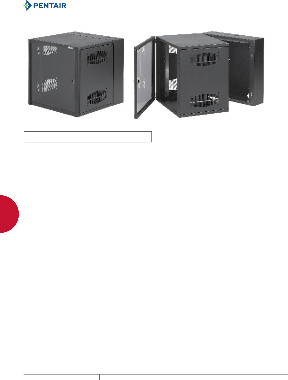
EQUIPMENT PROTECTIONSUBJECT TO CHANGE WITHOUT NOTICENETWORKING106
4
WALLMOUNT CABINETS ACCESSPLUS™ II DOUBLEHINGE
ACCESSPLUS™ II DOUBLE-HINGE
ACCESSPLUS™ II DOUBLEHINGE, TYPE 1
INDUSTRY STANDARDS
UL 508A; Type 1; File No. E61997
cUL Listed per CSA C22.2 No. 182.4; File No. E230874
EIA 310-D
NEMA/EEMAC Type 1
EIC 60529 IP20
Per BICSI TDMM Tenth edition, Chapter 7,
Telecommunication Enclosures (TE)
APPLICATION
ACCESSPLUS™ II Cabinets provide security, equipment access,
cooling and support for network and other 19-in. rack-mount
equipment. The cabinet has three components: front door, center
section and wall section.
FEATURES
• Double-hinged for easy equipment access; center section
provides 19-in. rack mounting per EIA universal spacing and is
accessed through the front door or swing the center section away
from the wall section for rear access
• Round corners; no sharp edges
• Front door has either a solid steel or hardened, tinted safety-
glass window door for superior scratch resistance
• Center section easily removed from rear section; tool-less one-
person installation possible
• Self-grounding, plated steel rack angles fully adjustable within
center section
• Wall section provides cable entry and cable management with
knockouts or gland plates
• Gland plate model provides easy retrofit and fast installation and
allows for pre-terminated cables or pre-wired patch panels; no
need to re-terminate and test
• Self-locking center-to-wall section latches in two locations
• Front access to all latches (no exposed side latches); cabinet can
be installed tightly in corners
• Vented sides provide cross flow ventilation to improve heat
dissipation
• Vertical cable manager included in 28-in.-wide models
• A full line of accessories is available
SPECIFICATIONS
Front Door (window or solid steel)
• Composite frame (injection molded top and bottom with extruded
composite sides)
• 140-degree opening door
• Field-reversible (left or right) hinge
• Quarter-turn key lock, two keys included
• Window door is scratch-resistant 1/4-in. tinted safety glass
• Solid door has 16 gauge steel insert with matching black finish
Center Section
• Welded 14 gauge steel
• Solid top of center sections provides protection against falling
debris
• Ventilated sides (to which fans can be added)
• Self-latching closure connects center section to wall section
• Self-alignment ramp supports center section to wall section
• Heavy duty center-to-rear section hinge with quick-release self-
retained hinge pin eases wall installation
Rack-Mounting Angles
• 12 gauge, plated steel
• EIA universal spaced 19-in. rack-mounting holes
• RU marked from bottom to top
• Tapped 10-32 holes, 20 mounting screws included
Rear Wall Section
• Welded 14 gauge steel
• Radius corners; no sharp edges
• Available with knockouts or gland plates
• Raised pads for accessory mounting
• Cable tie-down points for cable management
• Keyhole mounting holes allow wall section to be mounted over
fasteners and eases installation
• Three cable-entry grommets
FINISH
Pretreated steel coated with RAL 9005 black light-textured, low-
gloss polyester powder paint. Other finishes available—contact
Hoffman Customer Service.
BULLETIN: DWDH1
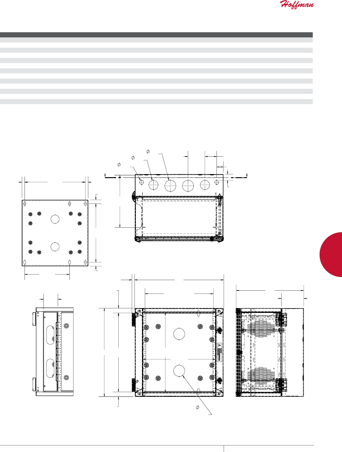
PH 763.422.2661 • FAX 763.422.2588 • PENTAIRPROTECT.COMEQUIPMENT PROTECTION NETWORKING 107
4
WALLMOUNT CABINETS ACCESSPLUS™ II DOUBLEHINGE
Standard Product Window Door
Catalog Number AxBxC in. AxBxC mm Rack Units Additional Rack Angles (S=Square Hole) (T=Tapped Hole)
EWMW242418 23.60 x 23.62 x 18.20 600 x 600 x 462 12 EWMR24T or EWMR24S
EWMW362418 36.02 x 23.62 x 18.20 915 x 600 x 462 19 EWMR36T or EWMR36S
EWMW482418 48.03 x 23.62 x 18.20 1220 x 600 x 462 26 EWMR48T or EWMR48S
EWMW602418 60.04 x 23.62 x 18.20 1525 x 600 x 462 32 EWMR60T or EWMR60S
EWMW722418 72.05 x 23.62 x 18.20 1830 x 600 x 462 39 EWMR72T or EWMR72S
EWMW242425 23.62 x 23.62 x 25.09 600 x 600 x 637 12 EWMR24T or EWMR24S
EWMW362425 36.02 x 23.62 x 25.09 915 x 600 x 637 19 EWMR36T or EWMR36S
EWMW482425 48.03 x 23.62 x 25.09 1220 x 600 x 637 26 EWMR48T or EWMR48S
EWMW602425 60.04 x 23.62 x 25.09 1525 x 600 x 637 32 EWMR60T or EWMR60S
EWMW722425 72.05 x 23.62 x 25.09 1830 x 600 x 637 39 EWMR72T or EWMR72S
EWMW242430 23.62 x 23.62 x 30.01 600 x 600 x 762 12 EWMR24T or EWMR24S
EWMW362430 36.02 x 23.62 x 30.01 915 x 600 x 762 19 EWMR36T or EWMR36S
EWMW482430 48.03 x 23.62 x 30.01 1220 x 600 x 762 26 EWMR48T or EWMR48S
B dimension does not include wall-to-center section hinge.
A
$
PP
B
PP
5$&.63$&,1*
PP
PP
PP
.12&.2876:+(1$ LQ
.12&.2876)25$//27+(5(1&/2685(6
PP
PP
%
PP
$
PP
PP
PP
7<3
PP
7<3
PP
7<3
PP
PP
&0$;
PP
;;
6+2:1:,7+'2255(029('
C
PP
87935996
PP
%
PP
$
PP
PP
PP
PP
PP
6(&7,21;;
PP
,1:,'((1&/2685(:,7+
&$%/(0$1$*(5,167$//('
6+2:1:,7+'2255(029('
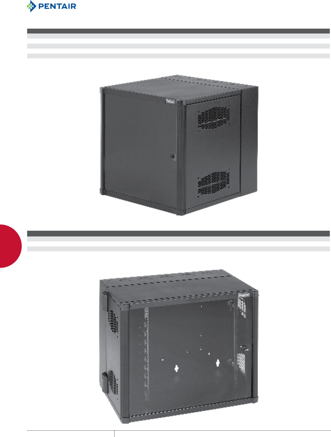
EQUIPMENT PROTECTIONSUBJECT TO CHANGE WITHOUT NOTICENETWORKING108
4
WALLMOUNT CABINETS ACCESSPLUS™ II DOUBLEHINGE
Standard Product Solid Door
Catalog Number AxBxC in. AxBxC mm Rack Units Additional Rack Angles (S=SquareHole) (T=Tapped Hole)
EWMS242418 23.62 x 23.62 x 18.20 600 x 600 x 462 12 EWMR24T or EWMR24S
EWMS362418 36.02 x 23.62 x 18.20 915 x 600 x 462 19 EWMR36T or EWMR36S
EWMS482418 48.03 x 23.62 x 18.20 1220 x 600 x 462 26 EWMR48T or EWMR48S
EWMS242425 23.62 x 23.62 x 25.09 600 x 600 x 637 12 EWMR24T or EWMR24S
EWMS362425 36.02 x 23.62 x 25.09 915 x 600 x 637 19 EWMR36T or EWMR36S
EWMS482425 48.03 x 23.62 x 25.09 1220 x 600 x 637 26 EWMR48T or EWMR48S
B dimension does not include wall-to-center section hinge.
Standard Product Window Door with Cable Manager
Catalog Number AxBxC in. AxBxC mm Rack Units Additional Rack Angles (S=Square Hole) (T=Tapped Hole) Vertical Cable Mgr. Catalog Numbera
EWMW242825 23.62 x 27.56 x 25.09 600 x 700 x 637 12 EWMR24T or EWMR24S EWMC24
EWMW362825 36.02 x 27.56 x 25.09 915 x 700 x 637 19 EWMR36T or EWMR36S EWMC36
EWMW482825 48.03 x 27.56 x 25.09 1220 x 700 x 637 26 EWMR48T or EWMR48S EWMC48
B dimension does not include wall-to-center section hinge.
a For additional rack angles, also order vertical cable manager.
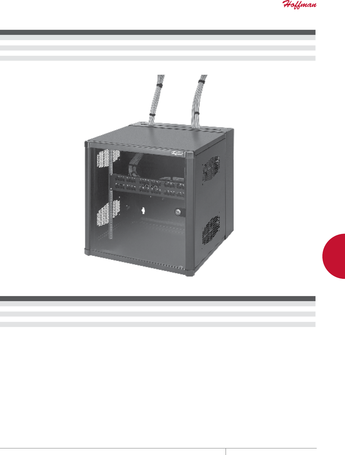
PH 763.422.2661 • FAX 763.422.2588 • PENTAIRPROTECT.COMEQUIPMENT PROTECTION NETWORKING 109
4
WALLMOUNT CABINETS ACCESSPLUS™ II DOUBLEHINGE
Standard Product Window Door with Gland Plate
Catalog Number AxBxC in. AxBxC mm Rack Units Additional Rack Angles (S=Square Hole) (T=Tapped Hole)
EWMWG242418 23.62 x 23.62 x 18.20 600 x 600 x 462 12 EWMR24T or EWMR24S
EWMWG362418 36.02 x 23.62 x 18.20 915 x 600 x 462 19 EWMR36T or EWMR36S
EWMWG482418 48.03 x 23.62 x 18.20 1220 x 600 x 462 26 EWMR48T or EWMR48S
EWMWG242425 23.62 x 23.62 x 25.09 600 x 600 x 637 12 EWMR24T or EWMR24S
EWMWG362425 36.02 x 23.62 x 25.09 915 x 600 x 637 19 EWMR36T or EWMR36S
EWMWG482425 48.03 x 23.62 x 25.09 1220 x 600 x 637 26 EWMR48T or EWMR48S
B dimension does not include wall-to-center section hinge.
Load Rating
Height Load Capacity
24 in. 250 lb.
36 in. 300 lb.
48 in. 350 lb.
60 in. 400 lb.
72 in. 500 lb.
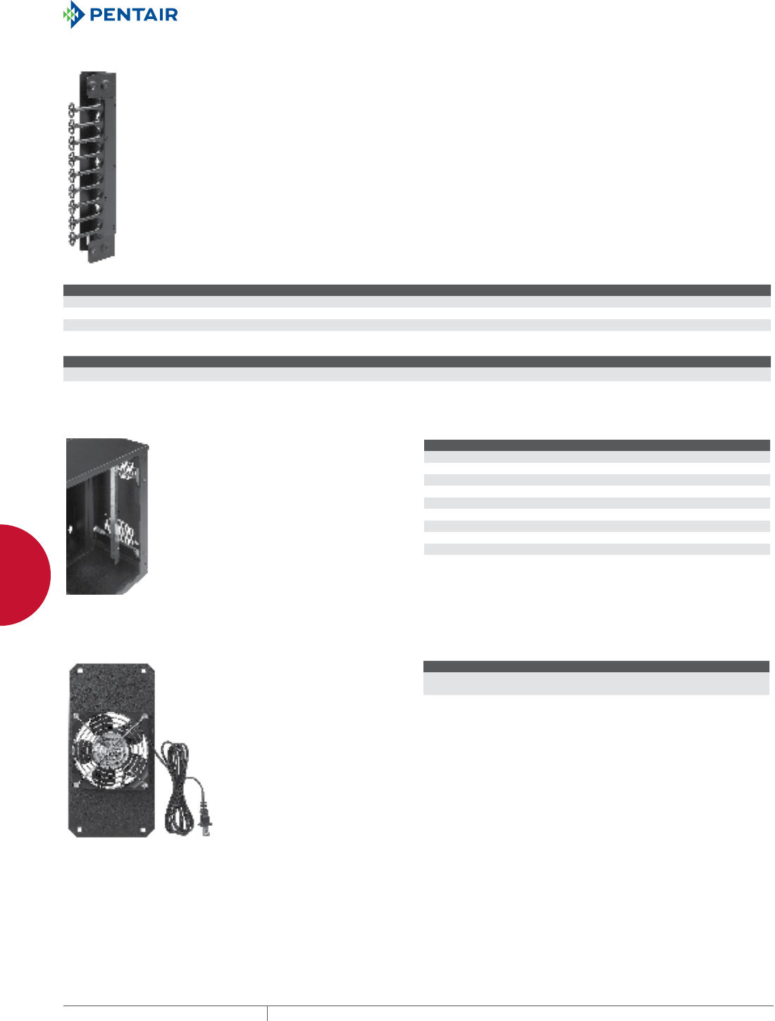
EQUIPMENT PROTECTIONSUBJECT TO CHANGE WITHOUT NOTICENETWORKING110
4
WALLMOUNT CABINETS ACCESSPLUS™ II DOUBLEHINGE
VERTICAL CABLE MANAGERS FOR 28IN.WIDE CABINET
Use ACCESSPLUS Cable Managers when ordering additional rack
angles for 28-in.-wide cabinet.
BULLETIN: DWDH1
Catalog Number Description Fits Cabinet
EWMC24 ACCESSPLUS Vertical Cable Manager 24.00 in. A = 24.00; B = 28.00
EWMC36 ACCESSPLUS Vertical Cable Manager 36.00 in. A = 36.00; B = 28.00
EWMC48 ACCESSPLUS Vertical Cable Manager 48.00 in. A = 48.00; B = 28.00
Vertical Cable Manager Capacity Number of cables at 60 percent filled
Cross Section (Area) 5e (0.22 in. dia.) 6 (0.28 in. dia.) 6A (0.35 in. dia.)
24.5 in.2380 300 208
RACK ANGLES BULLETIN: DWDH1
Catalog Number Description Rack Units Fits Cabinet
EWMR24T Fits 24-in. tapped 12 A = 24.00
EWMR36T Fits 36-in. tapped 19 A = 36.00
EWMR48T Fits 48-in. tapped 26 A = 48.00
EWMR60T Fits 60-in. tapped 32 A = 60.00
EWMR72T Fits 72-in. tapped 39 A = 72.00
EWMR24S Fits 24-in. square 12 A = 24.00
EWMR36S Fits 36-in. square 19 A = 36.00
EWMR48S Fits 48-in. square 26 A = 48.00
EWMR60S Fits 60-in. square 32 A = 60.00
EWMR72S Fits 72-in. square 39 A = 72.00
FAN KITS BULLETIN: DWDH1
Catalog Number Description Fits Cabinet
EWMF1 4-in. fan with plug and blocking plates,
115 VAC, 100 CFM small
Fits all C = 18.00
EWMF2 4-in. fan with plug and blocking plates,
115 VAC, 100 CFM, large
Fits all C = 25.00 or 30.00
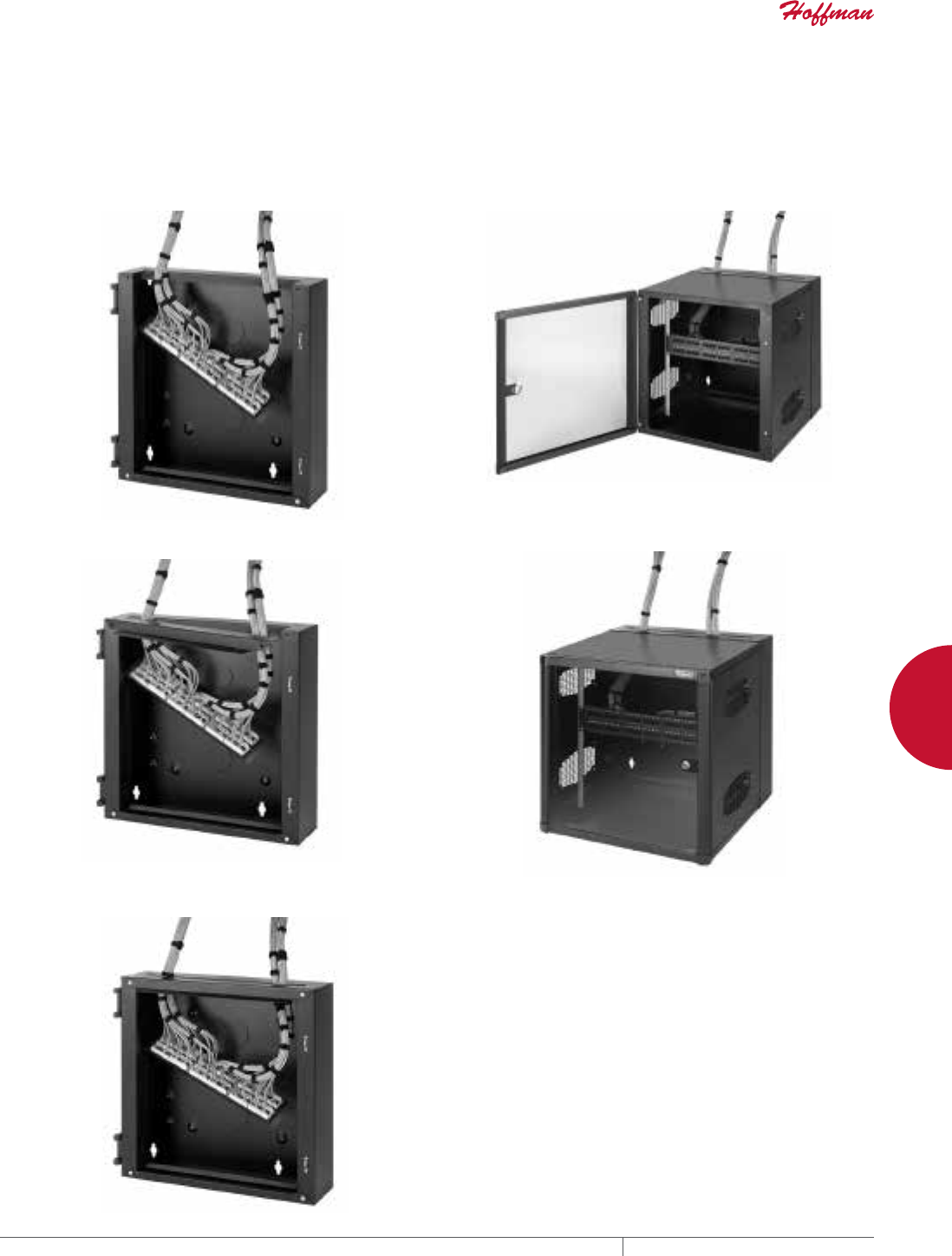
PH 763.422.2661 • FAX 763.422.2588 • PENTAIRPROTECT.COMEQUIPMENT PROTECTION NETWORKING 111
4
WALLMOUNT CABINETS ACCESSPLUS™ II DOUBLEHINGE
DATACOM WALLMOUNT CABINET WITH GLAND PLATE APPLICATION
WALLMOUNT CABINETS ACCESSPLUS™ II DoUbLE-HIngED
Spec-00554 E
EQUIPMENT PROTECTION SOLUTIONSSUBJECT TO CHANGE WITHOUT NOTICENETWORKING1
763.422.2661
763.422.2588
SPEC00554
E
NETWORKING
wall-mount cabinets
accessPlus™ ii Double-HingeD
DATACOM WALLMOUNT CABINET WITH GLAND PLATE APPLICATION
This cabinet offers significant advantages in retrofit applications. The gland plate is mounted at the top and the bottom to accommodate
cable runs from above, below or both. The gland plate casing can be removed while patch panels and associated wiring are brought to the
cabinet.
1. Once the wall section is installed on the wall, lay in the patch
panel.
2. Install the cable gland plate onto the wall section.
3. Use wire ties or cable wraps to secure the cable to the
cabinet.
4. Install the center section, then mount patch panels on rack
angles.
5. Close and lock the door.
Spec-00554.indd 1 01/28/13 9:08:10 AM
EQUIPMENT PROTECTIONSUBJECT TO CHANGE WITHOUT NOTICENETWORKING112
4
WALLMOUNT CABINETS PROTEK™ SINGLEDOOR AND DOUBLEHINGED CABINETS
PROTEK™ SINGLE-DOOR AND DOUBLE-HINGED CABINETS
PROTEK™ SINGLEDOOR, UL AND NEMA TYPE 4, 12
INDUSTRY STANDARDS
UL 508A Listed; File Number E61997
cUL Listed per CSA C22.2 No. 94; File Number E61997
Solid Door: Type 4 and 12
Window Door: Type 12
Solid Door, Stainless Steel: Type 4, 4X and 12
NEMA / EEMAC: Type 4, 4X or 12
IEC 60529, IP66 or IP55
APPLICATION
PROTEK Single-Door cabinets are an excellent, off-the-shelf choice
for mounting 19-in. rack, panel-mounted devices or other electronic
equipment. The cabinets are designed to provide both front and rear
access to 19-in. rack-mounted equipment. They provide protection
against water, dirt, corrosive agents and other contaminants.
PROTEK is an excellent choice for applications where space is at a
premium and the only option is wall mounting. PROTEK comes in
a broad range of sizes, materials and configurations to meet many
demanding applications.
FEATURES
• Solid-door cabinet provides complete physical and visual
protection
• Window door, made of scratch-resistant safety glass, provides
visual monitoring of internal equipment while maintaining
equipment protection
• All seams are fully welded and ground smooth
• Doors are provided with ground studs to facilitate proper bonding
and grounding of the cabinet
• Premium seamless, foam-in-place gasket prevents contaminants
from entering the cabinet
• Keylocking wing knob is included on painted steel offering,
providing access control to the cabinet; two keys are included
with each cabinet
• Stainless steel cabinet is provided with a quarter-turn slotted
latch
• One set of plated, self-grounding, tapped 10-32 rack angles per
EIA universal spacing standards, which can be adjusted front-
to-back, is provided with each center section of the cabinet;
additional tapped- or square-hole rack angles can be added to
the cabinet to provide additional mounting
• Wall section welded panel studs which accommodate standard
panels (steel and wood available), can be ordered separately
SPECIFICATIONS
• Doors and body made of 14 gauge steel
• Stainless steel enclosures made from Type 304 stainless steel
• Window made of .25-in. thick, scratch- and impact-resistant
safety glass
• Rack angles made of plated 12 gauge steel
• M6 ground studs on the door and body are masked from paint
• Twenty 10-32 screws included with cabinet
• Foam-in-place gasket made of durable polyurethane
FINISH
• Pretreated steel coated with RAL 7035 light-gray, low-gloss,
lightly textured polyester powder paint
• Stainless steel is provided with a smooth-grain finish
LOAD RATING
Height Maximum Load Rating
24 in. 200 lb./90.7 kg
36 in. 300 lb./136.1 kg
48 in. 400 lb./181.4 kg
ACCESSORIES
Locks and handles
Panels (steel and wood)
Grounding kits
Power Distribution Units (PDUs)
Rack angles
BULLETIN: DWS12
Technical Operating Information AC Unit (T150116G100) Replacement Filter No. 10100091
Hz Voltage VAC Phase BTU/Hr @ Max. Ambient Temp. (watts) Full Load Amp Max. Ambient Temp. (ºF) Max. Ambient Temp. (ºC) Cord and Plug
60 (50) 115 1 800 (325 watts) 3.6 (3.8) 131 (125) 52 (52) 25-in. cord length 5-15 plug
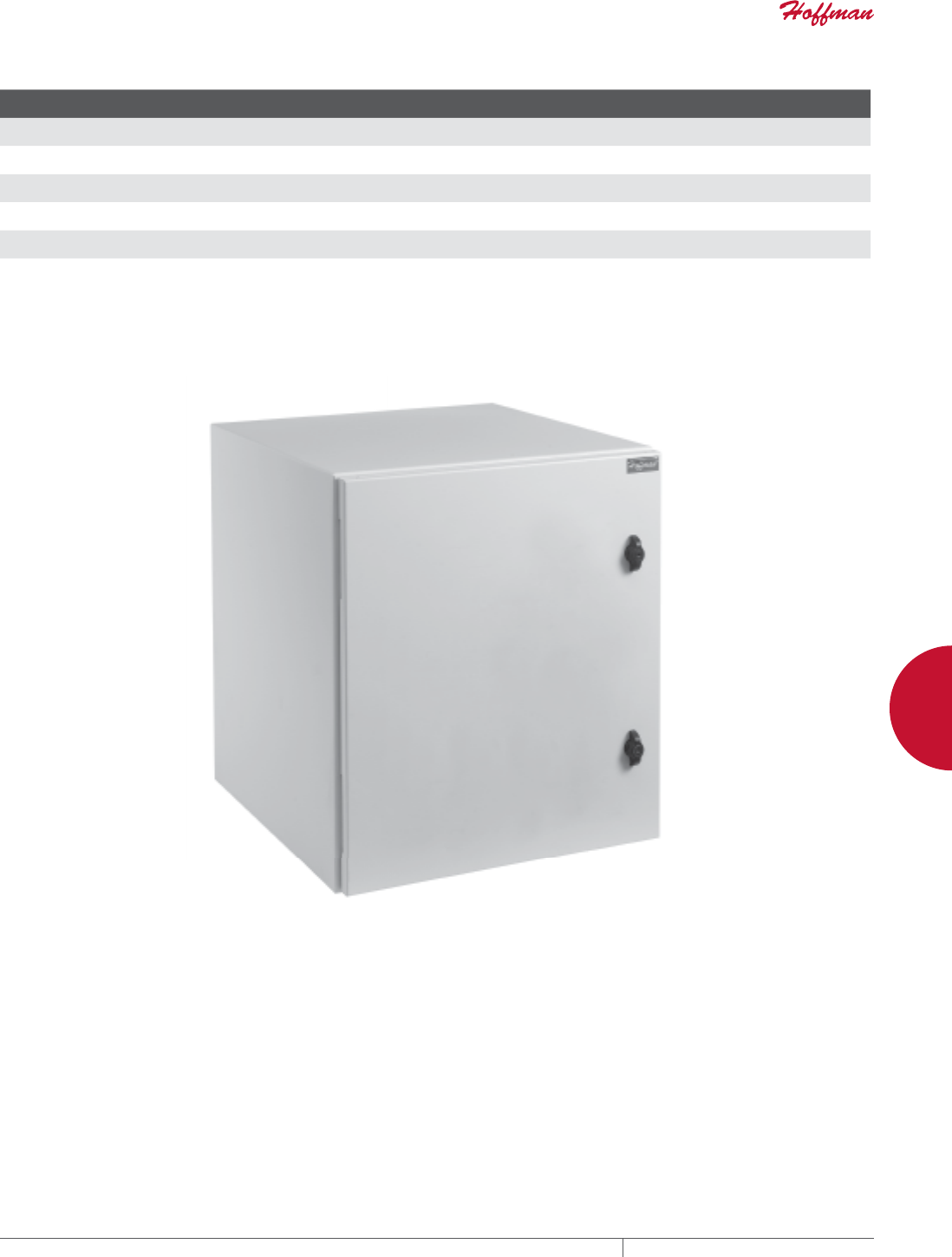
PH 763.422.2661 • FAX 763.422.2588 • PENTAIRPROTECT.COMEQUIPMENT PROTECTION NETWORKING 113
4
WALLMOUNT CABINETS PROTEK™ SINGLEDOOR AND DOUBLEHINGED CABINETS
Standard Product Solid Door, NEMA Type 4, 12
Catalog Number in./mm Rack Units
F
in./mm
P
in./mm
Q
in./mm
S
in./mm Optional Steel Panel Optional Wood Panel Additional Rack Angles a
PTRS242412G4 24.09 x 23.62 x 11.81
612 x 600 x 300
12 9.51
242
---
---
---
---
1.11
28
CP2020 CP2020W PTRA24T or PTRA24S
PTRS242424G4 24.09 x 23.62 x 24.02
612 x 600 x 610
12 21.72
552
---
---
---
---
1.11
28
CP2020 CP2020W PTRA24T or PTRA24S
PTRS362412G4 36.30 x 23.62 x 11.81
922 x 600 x 300
19 9.51
242
---
---
---
---
1.11
28
CP3220 CP3220W PTRA36T or PTRA36S
PTRS362424G4 36.30 x 23.62 x 24.02
922 x 600 x 610
19 21.72
552
---
---
---
---
1.11
28
CP3220 CP3220W PTRA36T or PTRA36S
PTRS482412G4 48.54 x 23.62 x 11.81
1233 x 600 x 300
26 9.51
242
---
---
---
---
1.11
28
CP4420 CP4420W PTRA48T or PTRA48S
PTRS482424G4 48.54 x 23.62 x 24.02
1233 x 600 x 610
26 21.72
552
---
---
---
---
1.11
28
CP4420 CP4420W PTRA48T or PTRA48S
aT = tapped 10-32, S = square hole (.375 in. x .375 in.)
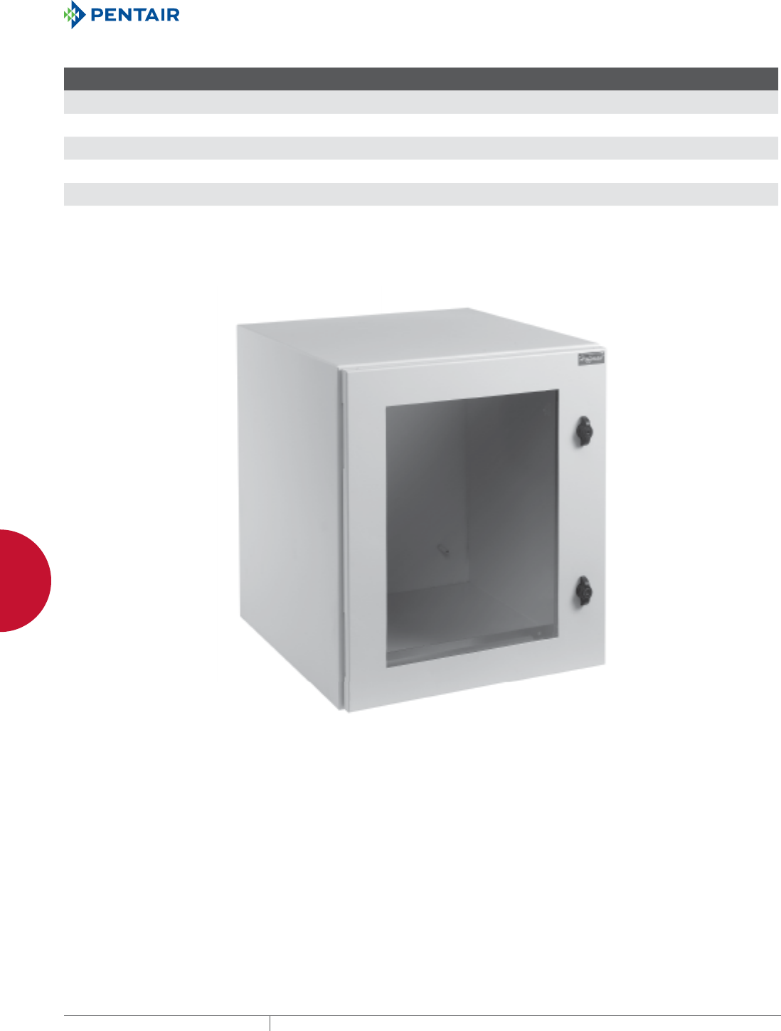
EQUIPMENT PROTECTIONSUBJECT TO CHANGE WITHOUT NOTICENETWORKING114
4
WALLMOUNT CABINETS PROTEK™ SINGLEDOOR AND DOUBLEHINGED CABINETS
Standard Product Window Door, NEMA Type 12
Catalog Number AxBxC in./mm Rack Units
F
in./mm
P
in./mm
Q
in./mm
S
in./mm Optional Steel Panel Optional Wood Panel Additional Rack Angles a
PTRW242412G2 24.09 x 23.62 x 11.81
612 x 600 x 300
12 9.51
242
18.25
464
15.38
391
1.11
28
CP2020 CP2020W PTRA24T or PTRA24S
PTRW242424G2 24.09 x 23.62 x 24.02
612 x 600 x 610
12 21.72
552
18.25
464
15.38
391
1.11
28
CP2020 CP2020W PTRA24T or PTRA24S
PTRW362412G2 36.30 x 23.62 x 11.81
922 x 600 x 300
19 9.51
242
30.75
781
15.38
391
1.11
28
CP3220 CP3220W PTRA36T or PTRA36S
PTRW362424G2 36.30 x 23.62 x 24.02
922 x 600 x 610
19 21.72
552
30.75
781
15.38
391
1.11
28
CP3220 CP3220W PTRA36T or PTRA36S
PTRW482412G2 48.54 x 23.62 x 11.81
1233 x 600 x 300
26 9.51
242
42.70
1085
15.38
391
1.11
28
CP4420 CP4420W PTRA48T or PTRA48S
PTRW482424G2 48.54 x 23.62 x 24.02
1233 x 600 x 610
26 21.72
552
42.70
1085
15.38
391
1.11
28
CP4420 CP4420W PTRA48T or PTRA48S
aT = tapped 10-32, S = square hole (.375 in. x .375 in.)
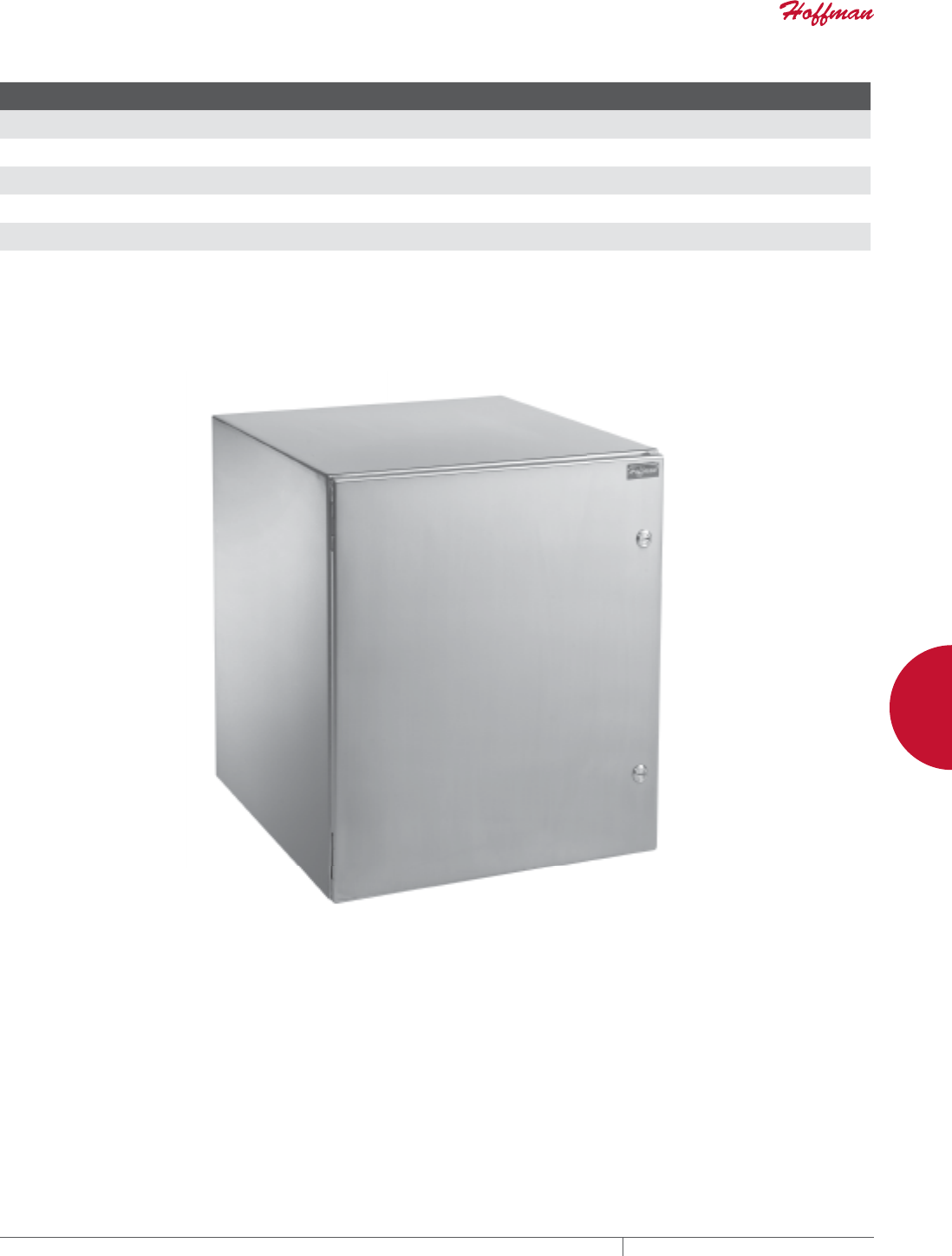
PH 763.422.2661 • FAX 763.422.2588 • PENTAIRPROTECT.COMEQUIPMENT PROTECTION NETWORKING 115
4
WALLMOUNT CABINETS PROTEK™ SINGLEDOOR AND DOUBLEHINGED CABINETS
Standard Product Solid Stainless Steel Door, NEMA Type 4, 4X, 12
Catalog Number AxBxC in./mm Rack Units
F
in./mm
P
in./mm
Q
in./mm
S
in./mm
Q
mm/in. Optional Steel Panel Optional Wood Panel Additional Rack Angles a
PTRS242412X 24.09 x 23.62 x 11.81
612 x 600 x 300
12 9.51
242
---
---
--- .80
20
--- CP2020 CP2020W PTRA24T or PTRA24S
PTRS242424X 24.09 x 23.62 x 24.02
612 x 600 x 610
12 21.72
552
---
---
--- .80
20
--- CP2020 CP2020W PTRA24T or PTRA24S
PTRS362412X 36.30 x 23.62 x 11.81
922 x 600 x 300
19 9.51
242
---
---
--- .80
20
--- CP3220 CP3220W PTRA36T or PTRA36S
PTRS362424X 36.30 x 23.62 x 24.02
922 x 600 x 610
19 21.72
552
---
---
--- .80
20
--- CP3220 CP3220W PTRA36T or PTRA36S
PTRS482412X 48.62 x 23.62 x 11.81
1235 x 600 x 300
26 9.51
242
---
---
--- .80
20
--- CP4420 CP4420W PTRA48T or PTRA48S
PTRS482424X 48.62 x 23.62 x 24.02
1235 x 600 x 610
26 21.72
552
---
---
--- .80
20
--- CP4420 CP4420W PTRA48T or PTRA48S
aT = tapped 10-32, S = square hole (.375 in. x .375 in.)
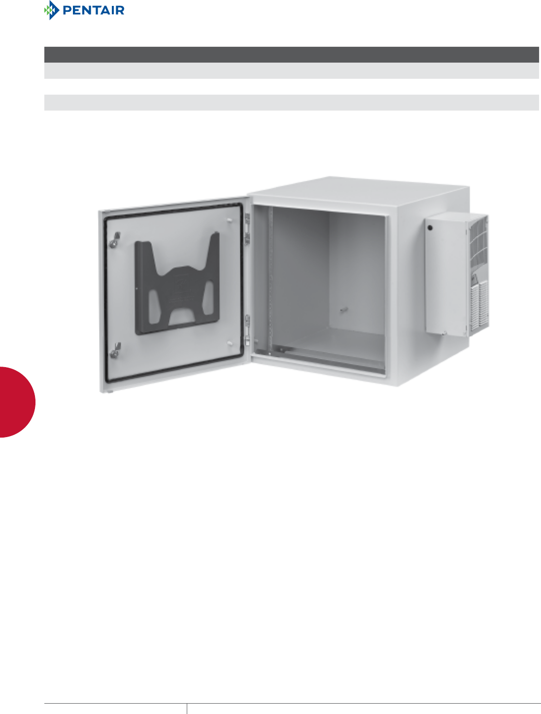
EQUIPMENT PROTECTIONSUBJECT TO CHANGE WITHOUT NOTICENETWORKING116
4
WALLMOUNT CABINETS PROTEK™ SINGLEDOOR AND DOUBLEHINGED CABINETS
Standard Product Solid Door AC, NEMA Type 4, 12
Catalog Number AxBxC in./mm Rack Units
F
in./mm
P
in./mm
Q
in./mm
S
in./mm Optional Steel Panel Optional Wood Panel Additional Rack Angles a
PTRS242424G4A 24.09 x 23.62 x 24.02
612 x 600 x 610
12 21.72
552
---
---
---
---
1.11
28
CP2020 CP2020W PTRA24T or PTRA24S
PTRS362424G4A 48.54 x 23.62 x 24.02
1233 x 600 x 610
19 21.72
552
---
---
---
---
1.11
28
CP3220 CP3220W PTRA36T or PTRA36S
PTRS482424G4A 48.62 x 23.62 x 24.02
1235 x 600 x 610
26 21.72
552
---
---
---
---
1.11
28
CP4420 CP4420W PTRA48T or PTRA48S
aT = tapped 10-32, S = square hole (.375 in. x .375 in.)
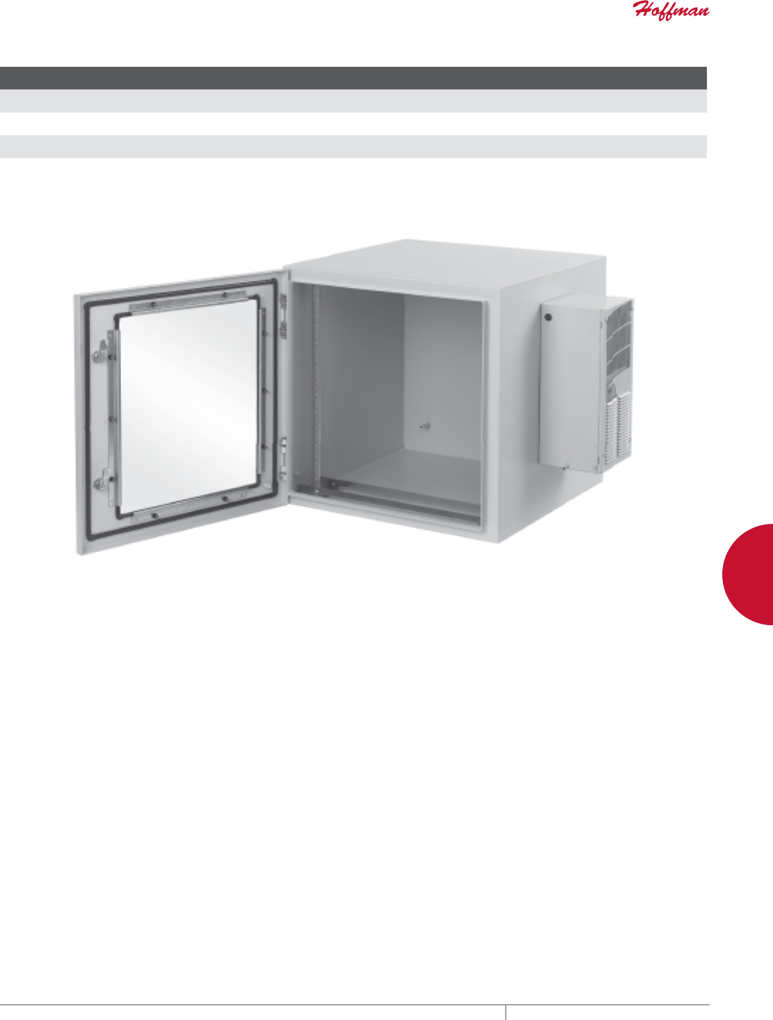
PH 763.422.2661 • FAX 763.422.2588 • PENTAIRPROTECT.COMEQUIPMENT PROTECTION NETWORKING 117
4
WALLMOUNT CABINETS PROTEK™ SINGLEDOOR AND DOUBLEHINGED CABINETS
Standard Product Window Door AC, NEMA Type 12
Catalog Number AxBxC in./mm Rack Units
F
in./mm
P
in./mm
Q
in./mm
S
in./mm Optional Steel Panel Optional Wood Panel Additional Rack Angles a
PTRW242424G2A 24.09 x 23.62 x 2.40
612 x 600 x 61
12 21.72
552
18.25
464
15.38
391
1.11
28
CP2020 CP2020W PTRA24T or PTRA24S
PTRW362424G2A 36.30 x 23.62 x 24.02
922 x 600 x 610
19 21.72
552
30.75
781
15.38
391
1.11
28
CP3220 CP3220W PTRA36T or PTRA36S
PTRW482424G2A 48.54 x 23.62 x 24.02
1233 x 600 x 610
26 21.72
552
42.70
1085
15.38
391
1.11
28
CP4420 CP4420W PTRA48T or PTRA48S
aT = tapped 10-32, S = square hole (.375 in. x .375 in.)
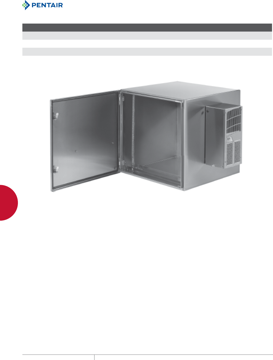
EQUIPMENT PROTECTIONSUBJECT TO CHANGE WITHOUT NOTICENETWORKING118
4
WALLMOUNT CABINETS PROTEK™ SINGLEDOOR AND DOUBLEHINGED CABINETS
Standard Product Solid Door Stainless Steel AC, NEMA Type 4,4X, 12
Catalog Number AxBxC in./mm Rack Units
F
in./mm
P
in./mm
Q
in./mm
S
in./mm Optional Steel Panel Optional Wood Panel Additional Rack Angles a
PTRS242424XA 24.09 x 23.62 x 24.02
612 x 600 x 610
12 21.32
541
---
---
---
---
.80
20
CP2020 CP2020W PTRA24T or PTRA24S
PTRS362424XA 36.30 x 23.62 x 24.02
922 x 600 x 610
19 21.32
541
---
---
---
---
.80
20
CP3220 CP3220W PTRA36T or PTRA36S
PTRS482424XA 48.62 x 23.62 x 24.02
1235 x 600 x 610
26 21.32
541
---
---
---
---
.80
20
CP4420 CP4420W PTRA48T or PTRA48S
aT = tapped 10-32, S = square hole (.375 in. x .375 in.)
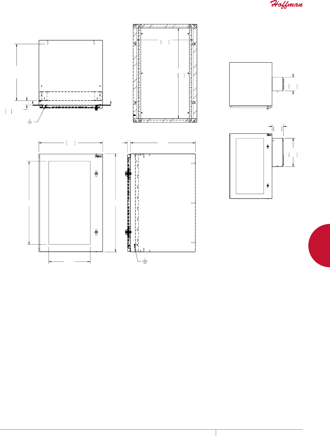
PH 763.422.2661 • FAX 763.422.2588 • PENTAIRPROTECT.COMEQUIPMENT PROTECTION NETWORKING 119
4
WALLMOUNT CABINETS PROTEK™ SINGLEDOOR AND DOUBLEHINGED CABINETS
$
%
4
3
&
6
0,1
0$;
)
;;
$
;;
3756*$3756*$3756*$
375:*$375:*$375:*$
3756;$3756;$3756;$
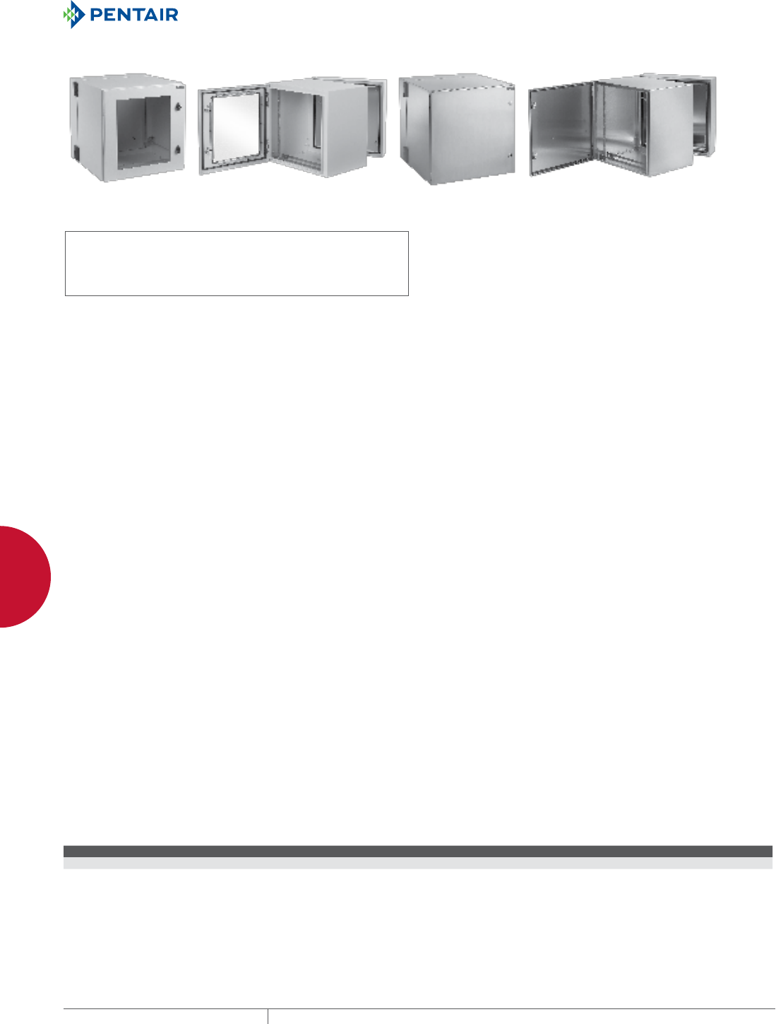
EQUIPMENT PROTECTIONSUBJECT TO CHANGE WITHOUT NOTICENETWORKING120
4
WALLMOUNT CABINETS PROTEK™ SINGLEDOOR AND DOUBLEHINGED CABINETS
PROTEK™ DOUBLEHINGED, UL AND NEMA TYPE 4, 4X OR 12
INDUSTRY STANDARDS
UL 508A Listed; File Number E61997
cUL Listed per CSA C22.2 No. 94; File Number E619967
Solid Door: Type 4 and 12
Window Door: Type 12
Solid Door, Stainless Steel: Type 4, 4X and 12
NEMA / EEMAC: Type 4, 4X or 12
IEC 60529, IP66 or IP55
APPLICATION
PROTEK Double-Hinged cabinets are an excellent, off-the-shelf
choice for mounting 19-in. rack, panel-mounted devices or other
electronic equipment. The cabinets are designed to provide both
front and rear access to 19-in. rack-mounted equipment. They
provide protection against water, dirt, corrosive agents and other
contaminants. PROTEK is an excellent choice for applications where
space is at a premium and the only option is wall mounting. PROTEK
comes in a broad range of sizes, materials and configurations to
meet many demanding applications.
FEATURES
• Front and rear access to 19-in. rack equipment provided by three-
part design: door, center section and wall section
• Solid door provides complete physical and visual protection
• Window door, made of scratch-resistant safety glass, provides
visual monitoring of internal equipment while maintaining
equipment protection
• All seams are fully welded and ground smooth
• Doors, center section and wall section are provided with ground
studs to facilitate proper bonding and grounding of the cabinet
• Premium seamless, foam-in-place gasket prevents contaminants
from entering the cabinet
• Keylocking wing knob is included on painted steel cabinet,
providing access control to the cabinet; two keys are included
with each cabinet
• Stainless steel cabinet is provided with a quarter-turn slotted
latch
• One set of plated, self-grounding, tapped 10-32 rack angles per
EIA universal spacing standards, which can be adjusted front-
to-back, is provided with each center section of the cabinet;
additional tapped- or square-hole rack angles can be added to
the cabinet to provide additional mounting
• Wall section welded panel studs which accommodate standard
panels (steel and wood available), can be ordered separately
• On 28-in. (700 mm) wide enclosures, a 4-in. vertical cable
manager with composite fingers is provided on hinge side of
cabinet
SPECIFICATIONS
• Doors made of 16 gauge; center and wall sections made of 14
gauge steel. Stainless steel enclosures made from Type 304
stainless steel
• Window made of .25-in. thick, scratch- and impact-resistant
safety glass
• Rack angles made of plated 12 gauge steel
• M6 ground studs on door, center and wall sections are masked
from paint
• Twenty 10-32 screws included with cabinet
• Foam-in-place gasket made of durable polyurethane
FINISH
• Pretreated steel coated with RAL 7035 light-gray, low-gloss,
lightly textured polyester powder paint
• Stainless steel is provided with a smooth-grain finish
LOAD RATING
Center hinged section:
Height Maximum Load Rating
16 in. 175 lb./79.4 kg
24 in. 250 lb./113.4 kg
36 in. 300 lb./136.1 kg
48 in. 350 lb./158.8 kg
60 in. 400 lb./181.4 kg
ACCESSORIES
Locks and handles
Panels (steel and wood)
Grounding kits
Power Distribution Units (PDUs)
Rack angles
BULLETIN: DWDH2
Technical Operating Information AC Unit (T150116G100) Replacement Filter No. 10100091
Hz Voltage VAC Phase BTU/hr @ Max. Ambient Temp. (watts) Full Load Amp Max. Ambient Temp. (ºF) Max. Ambient Temp. (ºC) Cord and Plug
60 (50) 115 1 800 (235 watts) 3.6 (3.8) 131 (125) 52 (52) 24-in. cord length 5-15P Plug
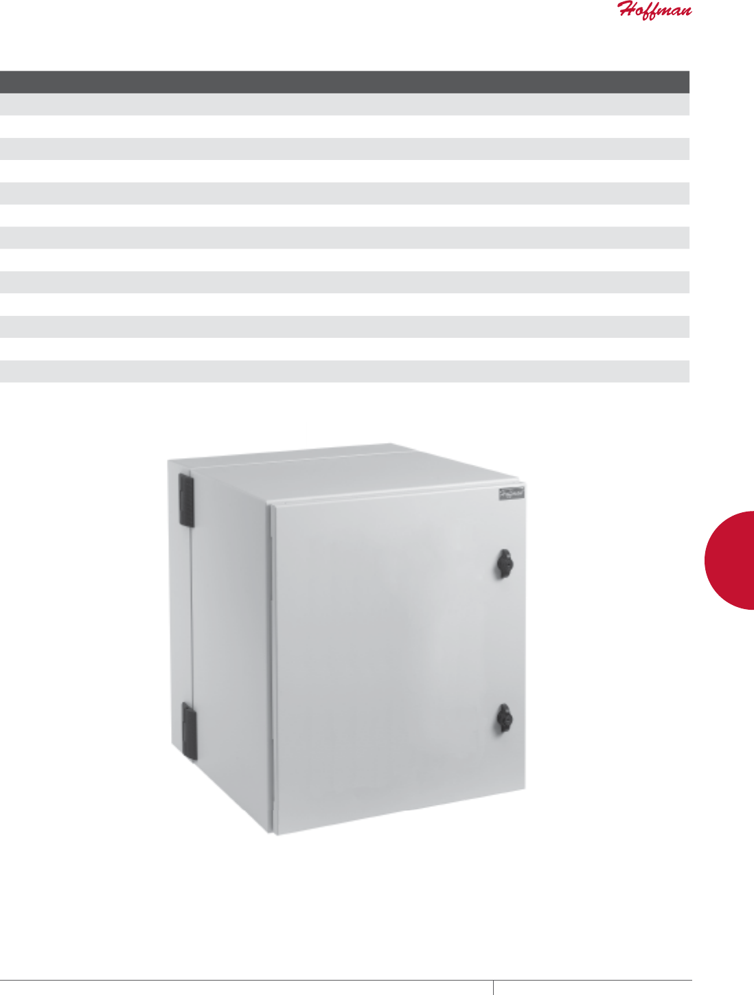
PH 763.422.2661 • FAX 763.422.2588 • PENTAIRPROTECT.COMEQUIPMENT PROTECTION NETWORKING 121
4
WALLMOUNT CABINETS PROTEK™ SINGLEDOOR AND DOUBLEHINGED CABINETS
Standard Product Solid Door, NEMA Type 4, 12
Catalog Number in./mm Rack Units
F
in./mm
P
in./mm
Q
in./mm
S
in./mm Optional Steel Panel Optional Wood Panel Additional Rack Angles a
PTHS162415G4 17.09 x 23.62 x 14.96
434 x 600 x 380
8 12.66
322
---
---
---
---
1.11
28
CP2014 --- PTRA16T or PTRA16S
PTHS242415G4 24.09 x 23.62 x 14.96
612 x 600 x 380
12 12.66
322
---
---
---
---
1.11
28
CP2020 CP2020W PTRA24T or PTRA24S
PTHS242424G4 24.09 x 23.62 x 24.02
612 x 600 x 610
12 21.72
552
---
---
---
---
1.11
28
CP2020 CP2020W PTRA24T or PTRA24S
PTHS242430G4 24.09 x 23.62 x 29.92
612 x 600 x 760
12 27.64
702
---
---
---
---
1.11
28
CP2020 CP2020W PTRA24T or PTRA24S
PTHS242824G4 24.09 x 27.56 x 24.02
612 x 700 x 610
12 21.72
552
---
---
---
---
1.11
28
CP2420 --- PTRA24T or PTRA24S
PTHS362415G4 36.30 x 23.62 x 14.96
922 x 600 x 380
19 12.66
322
---
---
---
---
1.11
28
CP3220 CP3220W PTRA36T or PTRA36S
PTHS362424G4 36.30 x 23.62 x 24.02
922 x 600 x 610
19 21.72
552
---
---
---
---
1.11
28
CP3220 CP3220W PTRA36T or PTRA36S
PTHS362824G4 36.30 x 27.56 x 24.02
922 x 700 x 610
19 21.72
552
---
---
---
---
1.11
28
CP3024 --- PTRA36T or PTRA36S
PTHS482415G4 48.54 x 23.62 x 14.96
1233 x 600 x 380
26 12.66
322
---
---
---
---
1.11
28
CP4420 CP4420W PTRA48T or PTRA48S
PTHS482424G4 48.54 x 23.62 x 24.02
1233 x 600 x 610
26 21.72
552
---
---
---
---
1.11
28
CP4420 CP4420W PTRA48T or PTRA48S
PTHS482824G4 48.54 x 27.56 x 24.02
1233 x 700 x 610
26 21.72
552
---
---
---
---
1.11
28
CP2442 --- PTRA48T or PTRA48S
PTHS602415G4 60.04 x 23.62 x 14.96
1525 x 600 x 380
32 12.66
322
---
---
---
---
1.11
28
CP5620 --- PTRA60T or PTRA60S
PTHS602424G4 60.04 x 23.62 x 24.02
1525 x 600 x 610
32 21.72
552
---
---
---
---
1.11
28
CP5620 --- PTRA60T or PTRA60S
aT = tapped 10-32, S = square hole (.375 in. x .375 in.)
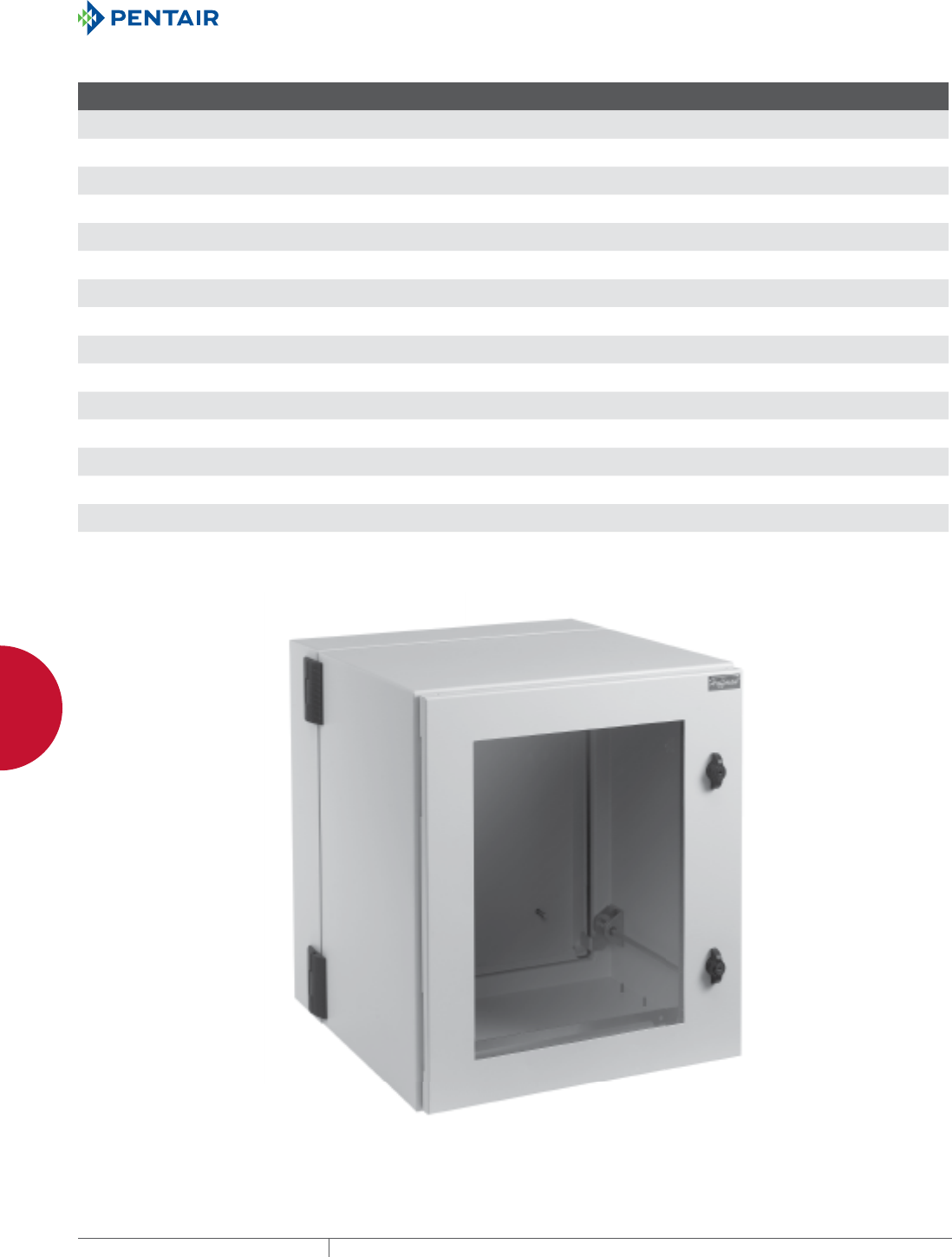
EQUIPMENT PROTECTIONSUBJECT TO CHANGE WITHOUT NOTICENETWORKING122
4
WALLMOUNT CABINETS PROTEK™ SINGLEDOOR AND DOUBLEHINGED CABINETS
Standard Product Window Door, NEMA Type 12
Catalog Number AxBxC in./mm Rack Units
F
in./mm
P
in./mm
Q
in./mm
S
in./mm Optional Steel Panel Optional Wood Panel Additional Rack Angles a
PTHW162415G2 17.09 x 23.62 x 14.96
434 x 600 x 380
8 12.66
322
11.87
301
15.38
391
1.11
28
CP2014 --- PTRA16T or PTRA16S
PTHW242415G2 24.09 x 23.62 x 14.96
612 x 600 x 380
12 12.66
322
18.25
464
15.38
391
1.11
28
CP2020 CP2020W PTRA24T or PTRA24S
PTHW242424G2 24.09 x 23.62 x 24.02
612 x 600 x 610
12 21.72
552
18.25
464
15.38
391
1.11
28
CP2020 CP2020W PTRA24T or PTRA24S
PTHW242430G2 24.09 x 23.62 x 29.92
612 x 600 x 760
12 27.64
702
18.25
464
15.38
391
1.11
28
CP2020 CP2020W PTRA24T or PTRA24S
PTHW242824G2 24.09 x 27.56 x 24.02
612 x 700 x 610
12 21.72
552
18.25
464
19.38
492
1.11
28
CP2420 --- PTRA24T or PTRA24S
PTHW362415G2 36.30 x 23.62 x 14.96
922 x 600 x 380
19 12.66
322
30.75
781
15.38
391
1.11
28
CP3220 CP3220W PTRA36T or PTRA36S
PTHW362424G2 36.30 x 23.62 x 24.02
922 x 600 x 610
19 21.72
552
30.75
781
15.38
391
1.11
28
CP3220 CP3220W PTRA36T or PTRA36S
PTHW362430G2 36.30 x 23.62 x 29.92
922 x 600 x 760
19 27.64
702
30.75
781
15.38
391
1.11
28
CP3220 CP3220W PTRA36T or PTRA36S
PTHW362824G2 36.30 x 27.56 x 24.02
922 x 700 x 610
19 21.72
552
30.75
781
19.38
492
1.11
28
CP3024 --- PTRA36T or PTRA36S
PTHW482415G2 48.54 x 23.62 x 14.96
1233 x 600 x 380
26 12.66
322
42.70
1085
15.38
391
1.11
28
CP4420 CP4420W PTRA48T or PTRA48S
PTHW482424G2 48.54 x 23.62 x 24.02
1233 x 600 x 610
26 21.72
552
42.70
1085
15.38
391
1.11
28
CP4420 CP4420W PTRA48T or PTRA48S
PTHW482430G2 48.54 x 23.62 x 29.92
1233 x 600 x 760
26 27.64
702
42.70
1085
15.38
391
1.11
28
CP4420 CP4420W PTRA48T or PTRA48S
PTHW482824G2 48.54 x 27.56 x 24.02
1233 x 700 x 610
26 21.72
552
42.70
108519
19.38
492
1.11
28
CP2442 --- PTRA48T or PTRA48S
PTHW602415G2 60.04 x 23.62 x 14.96
1525 x 600 x 380
32 12.66
322
54.39
1377
15.38
391
1.11
28
CP5620 --- PTRA60T or PTRA60S
PTHW602424G2 60.04 x 23.62 x 24.02
1525 x 600 x 610
32 21.72
552
54.39
1377
15.38
391
1.11
28
CP5620 --- PTRA60T or PTRA60S
aT = tapped 10-32, S = square hole (.375 in. x .375 in.)
Cable manager supplied with 700 mm wide enclosures
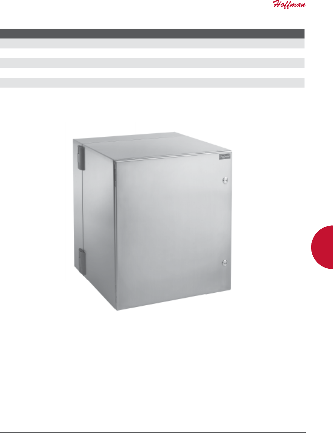
PH 763.422.2661 • FAX 763.422.2588 • PENTAIRPROTECT.COMEQUIPMENT PROTECTION NETWORKING 123
4
WALLMOUNT CABINETS PROTEK™ SINGLEDOOR AND DOUBLEHINGED CABINETS
Standard Product Solid Door Stainless Steel, NEMA Type 4, 4X, 12
Catalog Number AxBxC in./mm Rack Units
F
in./mm
P
in./mm
Q
in./mm
S
in./mm Optional Steel Panel Optional Wood Panel Additional Rack Angles a
PTHS242415X 24.09 x 23.62 x 14.96
612 x 600 x 380
12 12.65
321
---
---
---
---
.80
20
CP2020 CP2020W PTRA24T or PTRA24S
PTHS242424X 24.09 x 23.62 x 24.02
612 x 600 x 610
12 21.71
551
---
---
---
---
.80
20
CP2020 CP2020W PTRA24T or PTRA24S
PTHS362415X 36.30 x 23.62 x 14.96
922 x 600 x 380
19 12.65
321
---
---
---
---
.80
20
CP3220 CP3220W PTRA36T or PTRA36S
PTHS362424X 36.30 x 23.62 x 24.02
922 x 600 x 610
19 21.71
551
---
---
---
---
.80
20
CP3220 CP3220W PTRA36T or PTRA36S
PTHS482415X 48.62 x 23.62 x 14.96
1235 x 600 x 380
26 12.65
321
---
---
---
---
.80
20
CP4420 CP4420W PTRA48T or PTRA48S
PTHS482424X 48.62 x 23.62 x 24.02
1235 x 600 x 610
26 21.71
551
---
---
---
---
.80
20
CP4420 CP4420W PTRA48T or PTRA48S
aT = tapped 10-32, S = square hole (.375 in. x .375 in.)
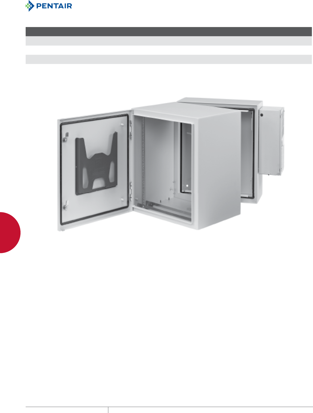
EQUIPMENT PROTECTIONSUBJECT TO CHANGE WITHOUT NOTICENETWORKING124
4
WALLMOUNT CABINETS PROTEK™ SINGLEDOOR AND DOUBLEHINGED CABINETS
Standard Product Solid Door AC, NEMA Type 4, 12
Catalog Number AxBxC in./mm Rack Units
F
in./mm
P
in./mm
Q
in./mm
S
in./mm Optional Steel Panel Optional Wood Panel Additional Rack Angles a
PTHS242428G4A 24.09 x 23.62 x 27.95
612 x 600 x 710
12 25.65
652
---
---
---
---
1.11
28
CP2020 CP2020W PTRA24T or PTRA24S
PTHS362428G4A 36.30 x 23.62 x 27.95
922 x 600 x 710
19 25.65
652
---
---
---
---
1.11
28
CP3220 CP3220W PTRA36T or PTRA36S
PTHS482428G4A 48.54 x 23.62 x 27.95
1233 x 600 x 710
26 25.65
652
---
---
---
---
1.11
28
CP4420 CP4420W PTRA48T or PTRA48S
aT = tapped 10-32, S = square hole (.375 in. x .375 in.)
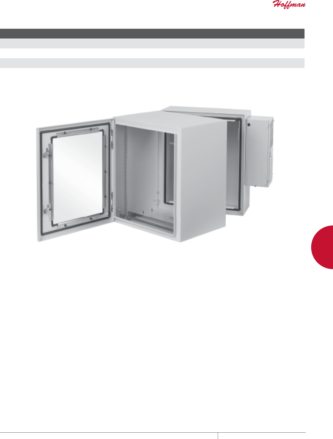
PH 763.422.2661 • FAX 763.422.2588 • PENTAIRPROTECT.COMEQUIPMENT PROTECTION NETWORKING 125
4
WALLMOUNT CABINETS PROTEK™ SINGLEDOOR AND DOUBLEHINGED CABINETS
Standard Product Window Door AC, NEMA Type 12
Catalog Number AxBxC in./mm Rack Units
F
in./mm
P
in./mm
Q
in./mm
S
in./mm Optional Steel Panel Optional Wood Panel Additional Rack Angles a
PTHW242428G2A 24.09 x 23.62 x 27.95
612 x 600 x 710
12 25.65
652
18.25
464
12.38
391
1.11
28
CP2020 CP2020W PTRA24T or PTRA24S
PTHW362428G2A 36.30 x 23.62 x 27.95
922 x 600 x 710
19 25.65
652
30.75
781
15.38
391
1.11
28
CP3220 CP3220W PTRA36T or PTRA36S
PTHW482428G2A 48.54 x 23.62 x 27.95
1233 x 600 x 710
26 25.65
652
42.70
1085
15.38
391
1.11
28
CP4420 CP4420W PTRA48T or PTRA48S
aT = tapped 10-32, S = square hole (.375 in. x .375 in.)
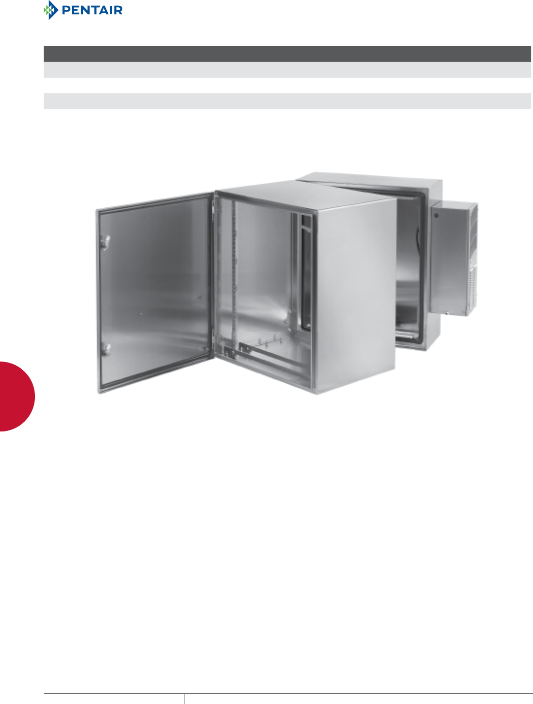
EQUIPMENT PROTECTIONSUBJECT TO CHANGE WITHOUT NOTICENETWORKING126
4
WALLMOUNT CABINETS PROTEK™ SINGLEDOOR AND DOUBLEHINGED CABINETS
Standard Product Solid Door Stainless Steel AC, NEMA Type 4, 4X, 12
Catalog Number AxBxC in./mm Rack Units
F
in./mm
P
in./mm
Q
in./mm
S
in./mm Optional Steel Panel Optional Wood Panel Additional Rack Angles a
PTHS242428XA 24.45 x 23.62 x 27.95
621 x 600 x 710
12 25.65
652
---
---
---
---
.80
20
CP2020 CP2020W PTRA24T or PTRA24S
PTHS362428XA 36.30 x 23.62 x 27.95
922 x 600 x 710
19 25.65
652
---
---
---
---
.80
20
CP3220 CP3220W PTRA36T or PTRA36S
PTHS482428XA 48.62 x 23.62 x 27.95
1235 x 600 x 710
23 25.65
652
---
---
---
---
.80
20
CP4420 CP4420W PTRA48T or PTRA48S
aT = tapped 10-32, S = square hole (.375 in. x .375 in.)
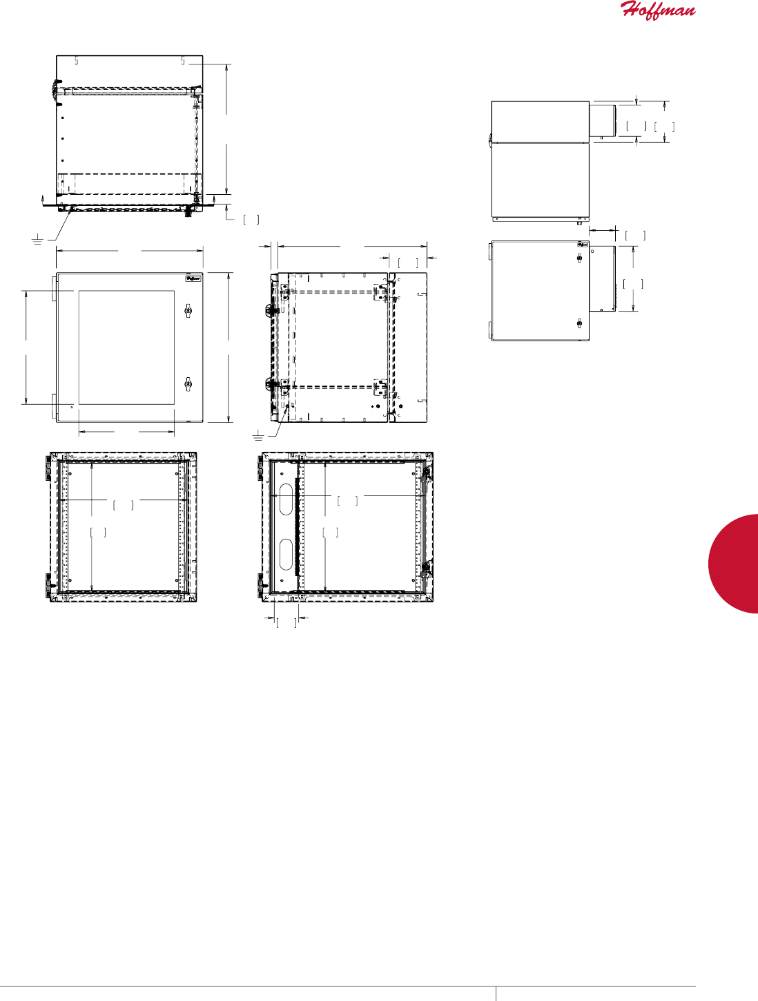
PH 763.422.2661 • FAX 763.422.2588 • PENTAIRPROTECT.COMEQUIPMENT PROTECTION NETWORKING 127
4
WALLMOUNT CABINETS PROTEK™ SINGLEDOOR AND DOUBLEHINGED CABINETS
$
%
3
4
&
6
0,1
0$;
)
;;
$
;;
% PP
$
% PP
;;
37+6*$37+6*$37+6*$
37+:*$37+:*$37+:*$
37+6;$37+6;$37+6;$
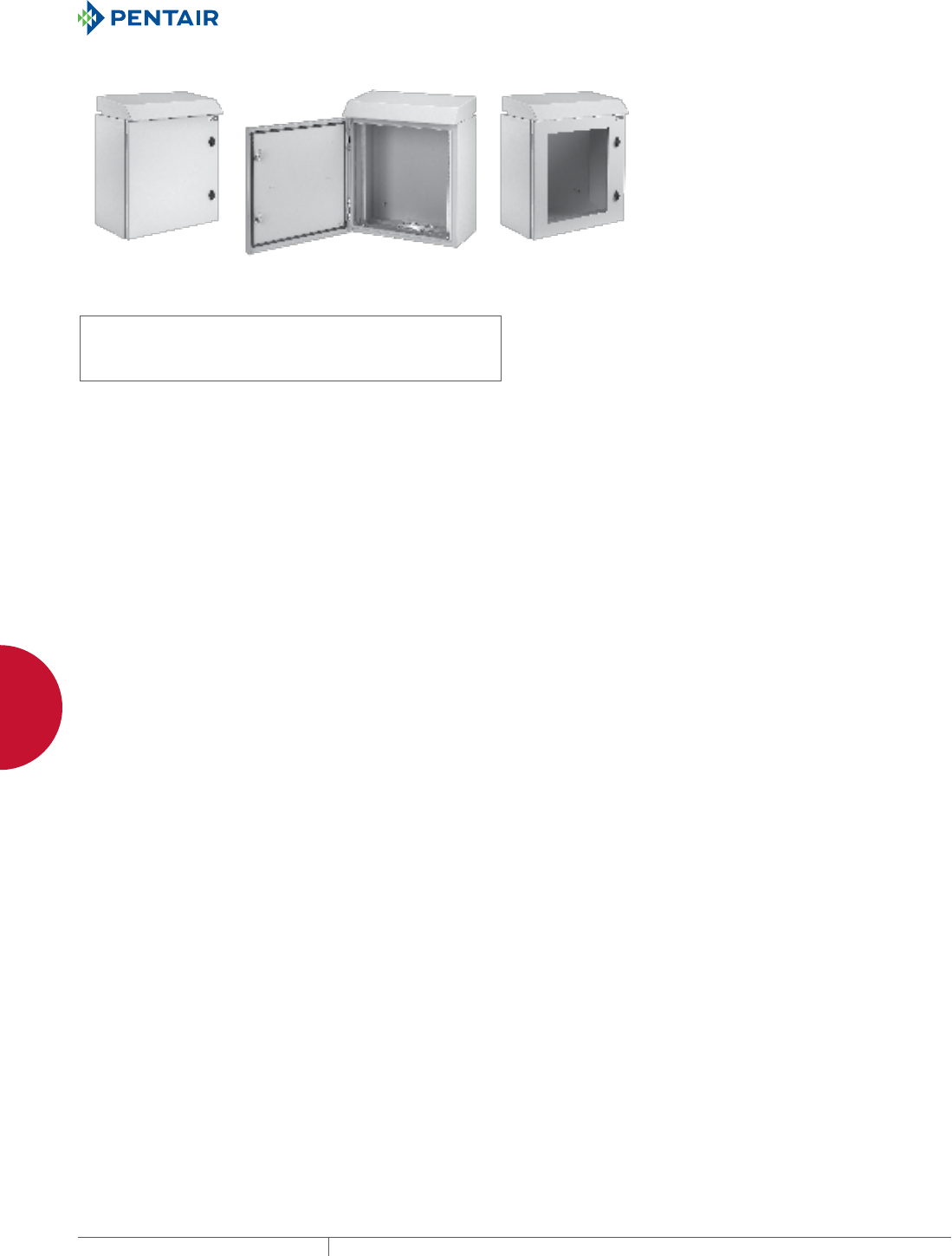
EQUIPMENT PROTECTIONSUBJECT TO CHANGE WITHOUT NOTICENETWORKING128
4
WALLMOUNT CABINETS PROTEK™ SINGLEDOOR AND DOUBLEHINGED CABINETS
PROTEK™ SINGLEDOOR FAN PACKAGES
INDUSTRY STANDARDS
UL 508A Listed; File Number E61997
cUL Listed per CSA C22.2 No. 94; File Number E61997
Solid Door: Type 3R
Window Door: Type 1
NEMA / EEMAC: Type 1 or 3R
IEC 60529, IP30 or IP 32
APPLICATION
PROTEK Single-Door Fan Package cabinets are an excellent,
off-the-shelf choice for mounting 19-in. rack, panel-mounted
devices or other electronic equipment. An integral top solar/drip
shield and thermostatically-controlled fans provide airflow to cool
internal equipment. Cabinets are available in UL Type 3R for indoor/
outdoor use. A UL Type 1 window-door version is available for
indoor applications. The integral fans provide cooling for internally-
mounted equipment. The enclosures provide protection against
water, dirt and other contaminants. PROTEK is an excellent choice
for applications where space is at a premium and the only option is
wall mounting. PROTEK comes in a broad range of sizes, materials
and configurations to meet many demanding applications.
FEATURES
• Solid-door cabinet provides complete physical and visual
protection
• Integral top solar/drip shield
• Two thermostatically-controlled, long-life, high-performance
fans mounted into top
• Perforated, vented base with internal, expanded metal,
serviceable filter
• Window door, made of scratch-resistant safety glass, provides
visual monitoring of internal equipment while maintaining
equipment protection
• All seams are fully welded and ground smooth
• Door and body are provided with ground studs to facilitate proper
bonding and grounding of the cabinet
• Premium seamless, foam-in-place gasket prevents contaminants
from entering the cabinet
• Keylocking wing knob provides access control to the cabinet; two
keys are included with each cabinet
• One set of plated, self-grounding, tapped 10-32 rack angles per
EIA universal spacing standards, which can be adjusted front-to-
back, is provided with each cabinet
• Additional rack angles in tapped and square-hole versions can be
added to the cabinet
• Wall section welded panel studs which accommodate standard
panels (steel and wood available), can be ordered separately
SPECIFICATIONS
• Doors made of 16 gauge and body made of 14 gauge steel
• Window made of .25-in. safety glass
• Integral top with two 6-in. (272 CFM) or 4-in. (113 CFM) fans
powered by 120 VAC via cord with standard NEMA plug 5-15P
• Incoming air filter made of expanded aluminum
• Rack angles made of 12 gauge plated steel
• M6 door and body ground studs are masked from paint
• Twenty 10-32 rack angle equipment mounting screws included
with cabinet
• Foam-in-place gasket made of durable polyurethane
• Inline thermostat turns fans on when temperature exceeds
85 F/30 C
FINISH
Pretreated steel coated with light-gray, low-gloss, lightly textured
RAL 7035 polyester powder
LOAD RATING
Height Rating
24 in. 250 lb./90.7 kg
36 in. 300 lb./136.1 kg
48 in. 400 lb./181.4 kg
ACCESSORIES
Locks and handles
Panels (steel and wood)
Grounding kits
Power Distribution Units (PDUs)
Rack angles
NOTES
Performance data based on:
• Effective measured airflow provided by integral fans is 272 CFM
(6-in.) or 113 CFM (4-in.)
• Delta T or T (Ambient Temperature – Maximum in-cabinet
Temperature)
- Ambient air must be cooler than maximum in-cabinet
temperature
- For applications that have less than a T of 5 F, use PROTEK
with AC unit
• Total Cooling = (Air cooling + Cabinet cooling)
• Air Cooling [Watts = .316 x CFM x T] Cabinet cooling [Watts =
(.22 x Area) / T]
Example: Cabinet height 24 in. x 24 in. deep with ambient
temperature 110 F, with a maximum internal cabinet temperature
120 F (T = 10 F). The cabinet and fans will provide a total cooling
capability of 762 Watts or 1300 BTU.
(See Performance Charts)
BULLETIN: DWS12
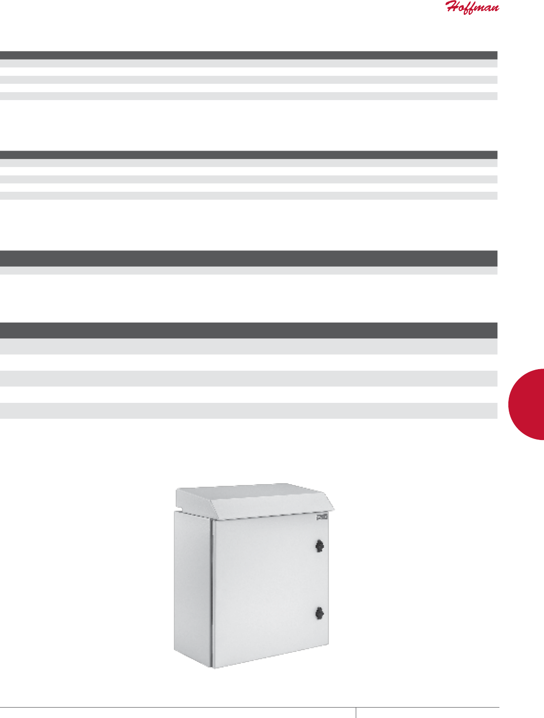
PH 763.422.2661 • FAX 763.422.2588 • PENTAIRPROTECT.COMEQUIPMENT PROTECTION NETWORKING 129
4
WALLMOUNT CABINETS PROTEK™ SINGLEDOOR AND DOUBLEHINGED CABINETS
Performance Chart 12-in. Deep Total Cooling in Watts (BTUs)
Delta T A=24 in. A=36 in. A=48 in.
25F 948 (3235) 970 (33310) 992 (2385)
20F 758 (2587) 776 (2648) 793 (2708)
15F 569 (1941) 581 (1986) 595 (2031)
10F 379 (1294) 388 (1324) 397 (1354)
5F 190 (647) 194 (662) 198 (677)
See Notes on page 1.
Performance Chart 24-in. Deep Total Cooling in Watts (BTUs)
Delta T A=24 in. A=36 in. A=48 in.
25F 2237 (7634) 2270 (7747) 2309 (7860)
20F 1789 (6107) 1816 (6197) 1842 (6288)
15F 1342 (4580) 1362 (4648) 1382 (4716)
10F 895 (3054)) 908 (3099) 921 (3144)
5F 447 (1527) 454 (1550) 460 (1572)
See Notes on page 1.
Technical Fan Data
Depth Nominal Size Qty. Voltage
Amperage
50/60 Hz Plug Effective CFM
12 in. 4 in. 2 120 VAC .52/.42 Standard NEMA 5-15P 113 (Clean Filter)
24 in. 6 in. 2 120 VAC .90/.72 Standard NEMA 5-15P 272 (Clean filter)
Standard Product PROTEK Single Solid Door Fan Package, Type 3R (indoor or outdoor)
Catalog Number in./mm Rack Units
F
in./mm
G
in./mm
P
in./mm
Q
in./mm
R
in./mm Optional Steel Panel Optional Wood Panel Additional Rack Anglesa
PTRS242412G3 24.09 x 23.62 x 11.81
612 x 600 x 300
12 9.51
242
13.38
400
---
---
---
---
9.48
241
CP2020 CP2020W PTRA24T or PTRA24S
PTRS242424G3 24.09 x 23.62 x 24.02
612 x 600 x 610
12 21.72
552
26.75
679
---
---
---
---
14.28
363
CP2020 CP2020W PTRA24T or PTRA24S
PTRS362412G3 36.30 x 23.62 x 11.81
922 x 600 x 300
19 9.51
242
13.38
400
---
---
---
---
9.48
241
CP3220 CP3220W PTRA36T or PTRA36S
PTRS362424G3 36.30 x 23.62 x 24.02
922 x 600 x 610
19 21.72
552
26.75
679
---
---
---
---
14.28
363
CP3220 CP3220W PTRA36T or PTRA36S
PTRS482412G3 48.54 x 23.62 x 11.81
1233 x 600 x 300
26 9.51
242
13.38
400
---
---
---
---
9.48
241
CP4420 CP4420W PTRA48T or PTRA48S
PTRS482424G3 48.54 x 23.62 x 24.02
1233 x 600 x 610
26 21.72
552
26.75
679
---
---
---
---
14.28
363
CP4420 CP4420W PTRA48T or PTRA48S
Cabinet dimensions do not include integral solar/drip shield and fan top. See dimensional drawing.
aT=tapped 10-32; S=Square hole (.375 in. x .375 in./10 mm x 10 mm)
Replacement filters: for 12-inch deep part number 30189028, for 24-inch deep part number 10100038
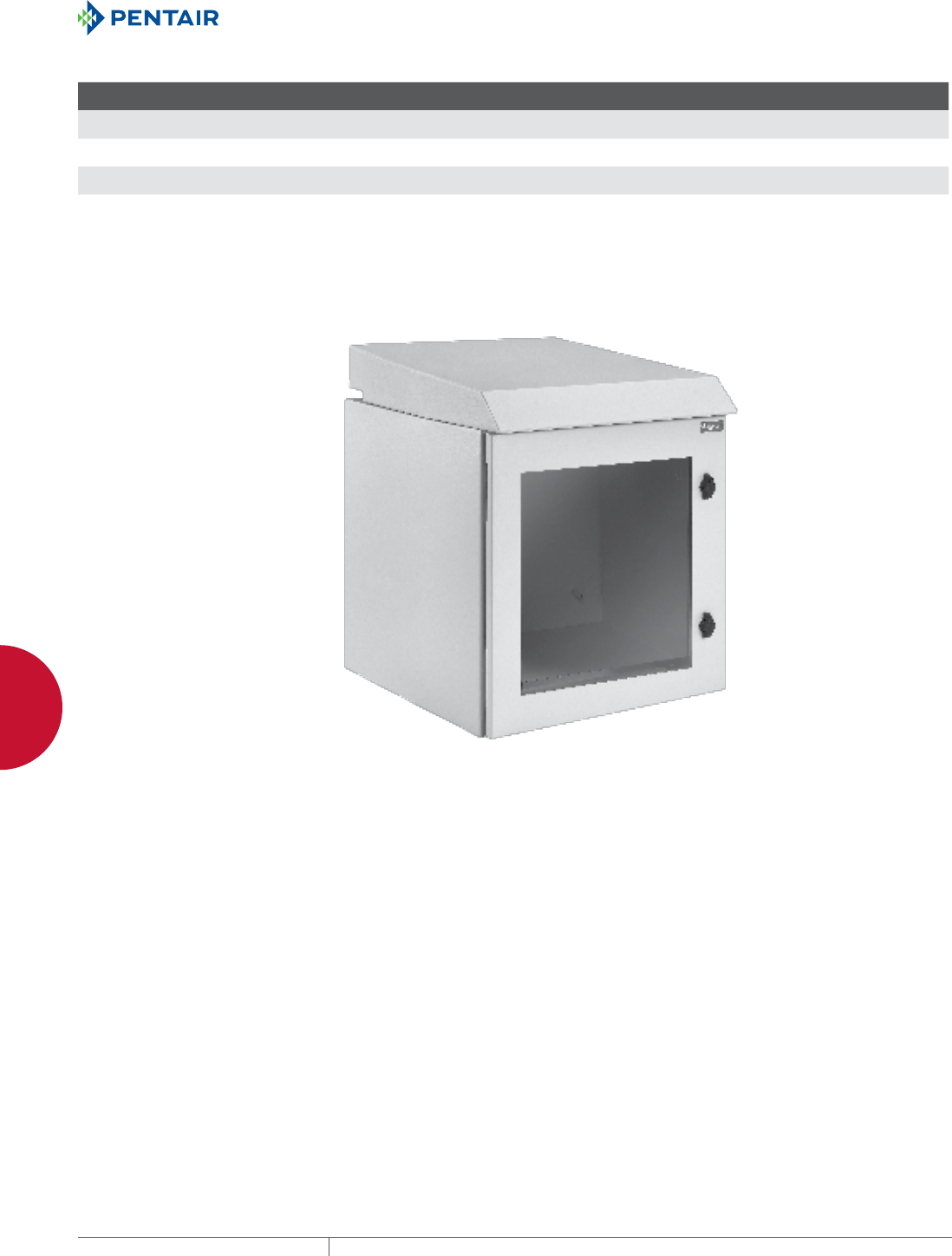
EQUIPMENT PROTECTIONSUBJECT TO CHANGE WITHOUT NOTICENETWORKING130
4
WALLMOUNT CABINETS PROTEK™ SINGLEDOOR AND DOUBLEHINGED CABINETS
Standard Product PROTEK Single Window Door Fan Package, Type 1 (indoor only)
Catalog Number AxBxC in./mm Rack Units
F
in./mm
G
in./mm
P
in./mm
Q
in./mm
R
in./mm Optional Steel Panel Optional Wood Panel Additional Rack Anglesa
PTRW242424GF 24.09 x 23.62 x 24.02
612 x 600 x 610
12 21.72
552
26.75
679
18.25
464
15.38
391
14.28
363
CP2020 CP2020W PTRA24T or PTRA24S
PTRW362424GF 36.30 x 23.62 x 24.02
922 x 600 x 610
19 21.72
552
26.75
679
30.75
781
15.38
391
14.28
363
CP3220 CP3220W PTRA36T or PTRA36S
PTRW482424GF 48.54 x 23.62 x 24.02
1233 x 600 x 610
26 21.72
552
26.75
679
42.20
1085
15.38
391
14.28
363
CP4420 CP4420W PTRA48T or PTRA48S
Cabinet dimensions do not include integral solar/drip shield and fan top. See dimensional drawing.Cabinet dimensions do not include integral solar/drip shield and fan top. See dimensional drawing.
a T=Tapped 10-32, S=Square hole (.375 in. x .375 in.)

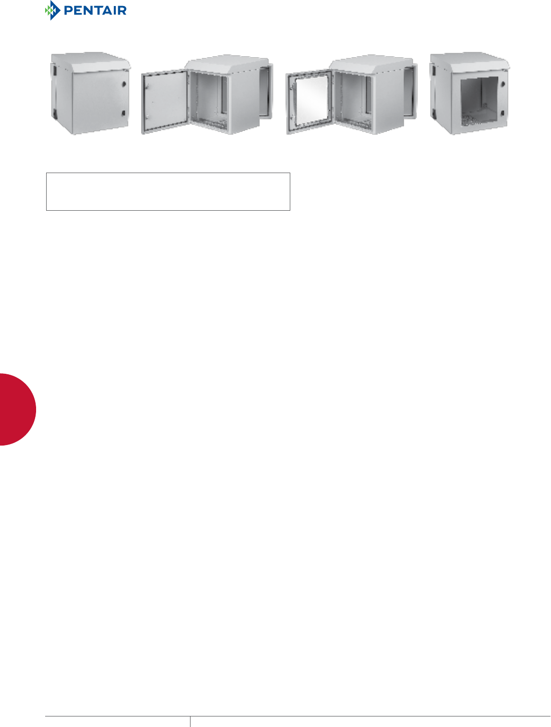
EQUIPMENT PROTECTIONSUBJECT TO CHANGE WITHOUT NOTICENETWORKING132
4
WALLMOUNT CABINETS PROTEK™ SINGLEDOOR AND DOUBLEHINGED CABINETS
PROTEK™ DOUBLEHINGED FAN PACKAGES
INDUSTRY STANDARDS
UL 508A Listed; File Number E61997
cUL Listed per CSA C22.2 No. 94; File Number E61997
Solid Door: Type 3R
Window Door: Type 1
NEMA / EEMAC: Type 1 or 3R
IEC 60529, IP30 or IP 32
APPLICATION
PROTEK Double-Hinged Fan Package cabinets are an excellent, off-
the-shelf choice for mounting 19-in. rack, panel-mounted devices
or other electronic equipment. An integral top solar/drip shield and
thermostatically-controlled fans provide airflow to cool internal
equipment. Cabinets are available in UL Type 3R for outdoor use. A
UL Type 1 window version is available for indoor applications. The
cabinets are designed to provide both front and rear access to 19-in.
rack-mounted equipment. They provide protection against water,
dirt and other contaminants. PROTEK is an excellent choice for
applications where space is at a premium and the only option is wall
mounting. PROTEK comes in a broad range of sizes, materials and
configurations to meet many demanding applications.
FEATURES
• Front and rear access to 19-in. rack equipment provided by three-
part design: door, center section and wall section
• Solid door provides complete physical and visual protection
• Integral top solar/drip shield
• Two thermostatically controlled, long-life, high-performance
fans mounted into top
• Window door, made of .25-in. scratch-resistant safety glass and
mechanically fastened, provides visual monitoring of internal
equipment while maintaining equipment protection
• All seams are fully welded and ground smooth
• Perforated, vented base with internal, expanded metal,
serviceable filter
• Door, center section and wall section are provided with ground
studs to facilitate proper bonding and grounding of the cabinet
• Premium seamless, foam-in-place gasket prevents contaminants
from entering the cabinet
• Keylocking wing knob provides access control to the cabinet; two
keys are included with each cabinet
• One set of plated, self-grounding, tapped 10-32 rack angles per
EIA universal spacing standards, adjustable front-to-back within
the center section of the cabinet
• Additional rack angles in tapped- or square-hole versions can be
added to the cabinet
• Wall section welded panel studs which accommodate standard
panels (steel and wood available), can be ordered separately
SPECIFICATIONS
• Doors made of 16 gauge; wall and center sections made of 14
gauge steel
• Integral top with two 6-in. fans powered by 120 VAC via cord with
standard NEMA plug, provide 230 CFM of airflow
• Window made of .25-in. safety glass
• Rack angles with 10-32 tapped holes per EIA universal standards
are made of 12 gauge plated steel
• Incoming air filter made of expanded aluminum
• M6 door and body ground studs are masked from paint
• Twenty 10-32 rack angle equipment mounting screws included
with cabinet
• Foam-in-place gasket made of durable polyurethane
• Inline thermostat turns fans on when temperature exceeds
85 F/30 C
FINISH
Pretreated steel coated with light-gray, low-gloss, lightly textured
RAL 7035 polyester powder
LOAD RATING
Height Rating
24 in. 250 lb./113.4 kg
36 in. 300 lb./136.0 kg
48 in. 350 lb./158.7 kg
ACCESSORIES
Locks and handles
Panels (steel and wood)
Grounding kits
Power Distribution Units (PDUs)
Rack angles
NOTES
Performance data based on:
• Effective measured airflow provided by integral fans is 272 CFM
• Delta T or T (Ambient Temperature – Maximum in-cabinet
Temperature)
- Ambient air must be cooler than maximum in-cabinet
temperature
- For applications that have less than a T of 5 F, use PROTEK
with AC unit
• Total Cooling = (Air cooling + Cabinet cooling)
• Air Cooling [Watts = .316 x CFM x T] Cabinet cooling [Watts =
(.22 x Area) / T]
Example: Cabinet height 24 in. x 24 in. deep with ambient
temperature 110 F, with a maximum internal cabinet temperature
120 F (T = 10 F). The cabinet and fans will provide a total cooling
capability of 762 Watts or 1300 BTU.
(See Performance Chart)
BULLETIN: DWDH2
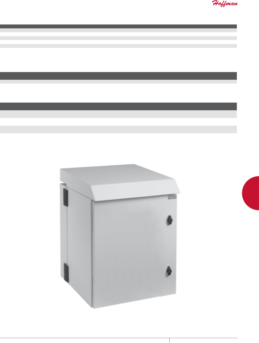
PH 763.422.2661 • FAX 763.422.2588 • PENTAIRPROTECT.COMEQUIPMENT PROTECTION NETWORKING 133
4
WALLMOUNT CABINETS PROTEK™ SINGLEDOOR AND DOUBLEHINGED CABINETS
Performance ChartTotal Cooling in Watts (BTUs)
Delta T A=24 in. A=36 in. A=48 in.
25F 2237 (7634) 2270 (7747) 2309 (7860)
20F 1789 (6107) 1816 (6197) 1842 (6288)
15F 1342 (4580) 1362 (4648) 1382 (4716)
10F 895 (3054) 908 (3099) 921 (3144)
5F 447 (1527) 454 (1550) 460 (1572)
See Notes on page 1.
Technical Fan Data
Nominal Size Qty. Voltage
Amperage
50/60 Hz Plug Effective CFM
6 in. 2 120 VAC .90/.72 Standard NEMA 5-15P 272 (Clean filter)
Standard ProductPROTEK Double-Hinged Solid Door, Type 3R (indoor or outdoor)
Catalog Number in./mm Rack Units
P
in./mm
Q
in./mm Optional Steel Panel Optional Wood Panel Additional Rack Anglesa
PTHS242424G3 24.09 x 23.62 x 24.02
612 x 600 x 610
12 ---
---
---
---
CP2020 CP2020W PTRA24T or PTRA24S
PTHS362424G3 36.30 x 23.62 x 24.02
922 x 600 x 610
19 ---
---
---
---
CP3220 CP3220W PTRA36T or PTRA36S
PTHS482424G3 48.62 x 23.62 x 24.02
1235 x 600 x 610
26 ---
---
---
---
CP4420 CP4420W PTRA48T or PTRA48S
Cabinet dimensions do not include integral solar/drip shield and fan top. See dimensional drawing.
aT=tapped 10-32; S=Square hole (.375 in. x .375 in./10 mm x 10 mm)
Replacement filter part number 10100038
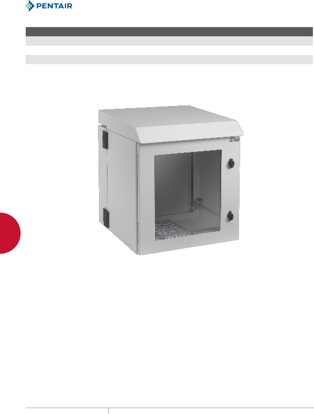
EQUIPMENT PROTECTIONSUBJECT TO CHANGE WITHOUT NOTICENETWORKING134
4
WALLMOUNT CABINETS PROTEK™ SINGLEDOOR AND DOUBLEHINGED CABINETS
Standard ProductPROTEK Double-Hinged Window Door, Type 1 (indoor only)
Catalog Number AxBxC in./mm Rack Units
P
in./mm
Q
in./mm Optional Steel Panel Optional Wood Panel Additional Rack Anglesa
PTHW242424GF 24.09 x 23.62 x 24.02
612 x 600 x 610
12 18.25
464
15.38
391
CP2020 CP2020W PTRA24T or PTRA24S
PTHW362424GF 36.30 x 23.62 x 24.02
922 x 600 x 610
19 30.75
781
15.38
391
CP3220 CP3220W PTRA36T or PTRA36S
PTHW482424GF 48.54 x 23.62 x 24.02
1233 x 600 x 610
26 42.70
1085
15.38
391
CP4420 CP4420W PTRA48T or PTRA48S
Cabinet dimensions do not include integral solar/drip shield and fan top. See dimensional drawing.
aT=tapped 10-32; S=Square hole (.375 in. x .375 in./10 mm x 10 mm)
Replacement filter part number 10100038
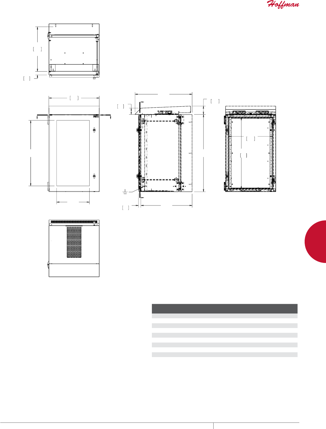
PH 763.422.2661 • FAX 763.422.2588 • PENTAIRPROTECT.COMEQUIPMENT PROTECTION NETWORKING 135
4
WALLMOUNT CABINETS PROTEK™ SINGLEDOOR AND DOUBLEHINGED CABINETS
%
3
4
<<
$
*
&
;
;
0,1
0$;
<<
$
;;
COOLING PERFORMANCE FOR AIR CONDITIONER
PACKAGES
PROTEK Air Conditioner calculated cooling performance
AC Performance: 800 BTU/hour or 235 watts
Voltage / Hertz: 115 VAC/60 Hz
Max. Ambient Temperature: 131 F
Min. Ambient Temperature: -40 F
Max. Internal Temperature: 100 F (Allowable)
Cooling Performance PROTEK™ Air Conditioner Packages
Ambient
Temperature (°F)
Watts (Heat) Dissipated
Cabinet Height: 24 in.
Watts (Heat) Dissipated
Cabinet Height: 36 in.
Watts (Heat) Dissipated
Cabinet Height: 48 in.
130 15 N/A N/A
120 88 73 59
110 161 154 146
100 234 234 234
90 308 315 322
80 381 396 410
70 454 476 498
60 527 557 586
50 601 637 674
40 674 718 762
N/A = Not applicable and not recommended in these applications
1 BTU = 3.413 watts
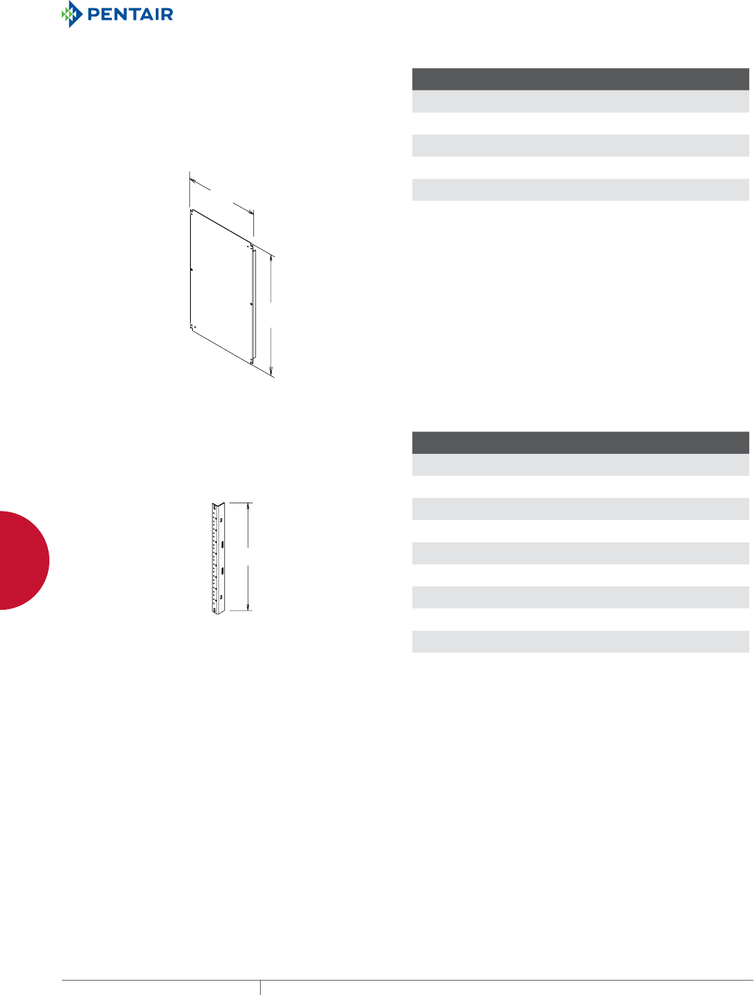
EQUIPMENT PROTECTIONSUBJECT TO CHANGE WITHOUT NOTICENETWORKING136
4
WALLMOUNT CABINETS PROTEK™ ACCESSORIES
PROTEK™ ACCESSORIES
PROTEK™ WALLMOUNT CABINET ACCESSORY
PANELS
Where equipment mounting space is limited, Accessory Panels
increase cabinet capacity by providing a mounting surface for 19-in.
equipment and accessories at the back of the cabinet. The panels
mount on collar studs provided in the cabinet. Available in painted
mild steel or wood.
BULLETIN: CWP, DWDH2
'
(
Standard Product
Catalog Number Panel Type
Panel Size D x E
in./mm Gauge
CP2014 Painted Steel 18.20 x 12.20
462 x 310
14
CP2020 Painted Steel 18.20 x 18.20
462 x 462
12
CP2442 Painted Steel 22.20 x 40.20
564 x 1021
12
CP3220 Painted Steel 30.20 x 18.20
762 x 462
12
CP4420 Painted Steel 42.20 x 18.20
1072 x 462
12
CP5620 Painted Steel 53.20 x 18.20
1351 x 462
12
PROTEK™ RACK ANGLES
Square- and tapped-hole rack angles fit into PROTEK™ single-and
double-hinged cabinets.
BULLETIN: DWDH2
/
Standard Product
Catalog Number
L
in./mm Hole Type
Fits Cabinet Height
in./mm Rack Units
PTRA16T 16.12
409
Tapped 16.00 8
PTRA16S 16.12
409
Square 16.00 8
PTRA24T 23.12
587
Tapped 24.00 12
PTRA24S 23.12
587
Square 24.00 12
PTRA36T 35.32
897
Tapped 36.00 19
PTRA36S 35.32
897
Square 36.00 19
PTRA48T 45.57
1157
Tapped 48.00 26
PTRA48S 45.57
1157
Square 48.00 26
PTRA60T 59.07
1500
Tapped 60.00 32
PTRA60S 59.07
1500
Square 60.00 32

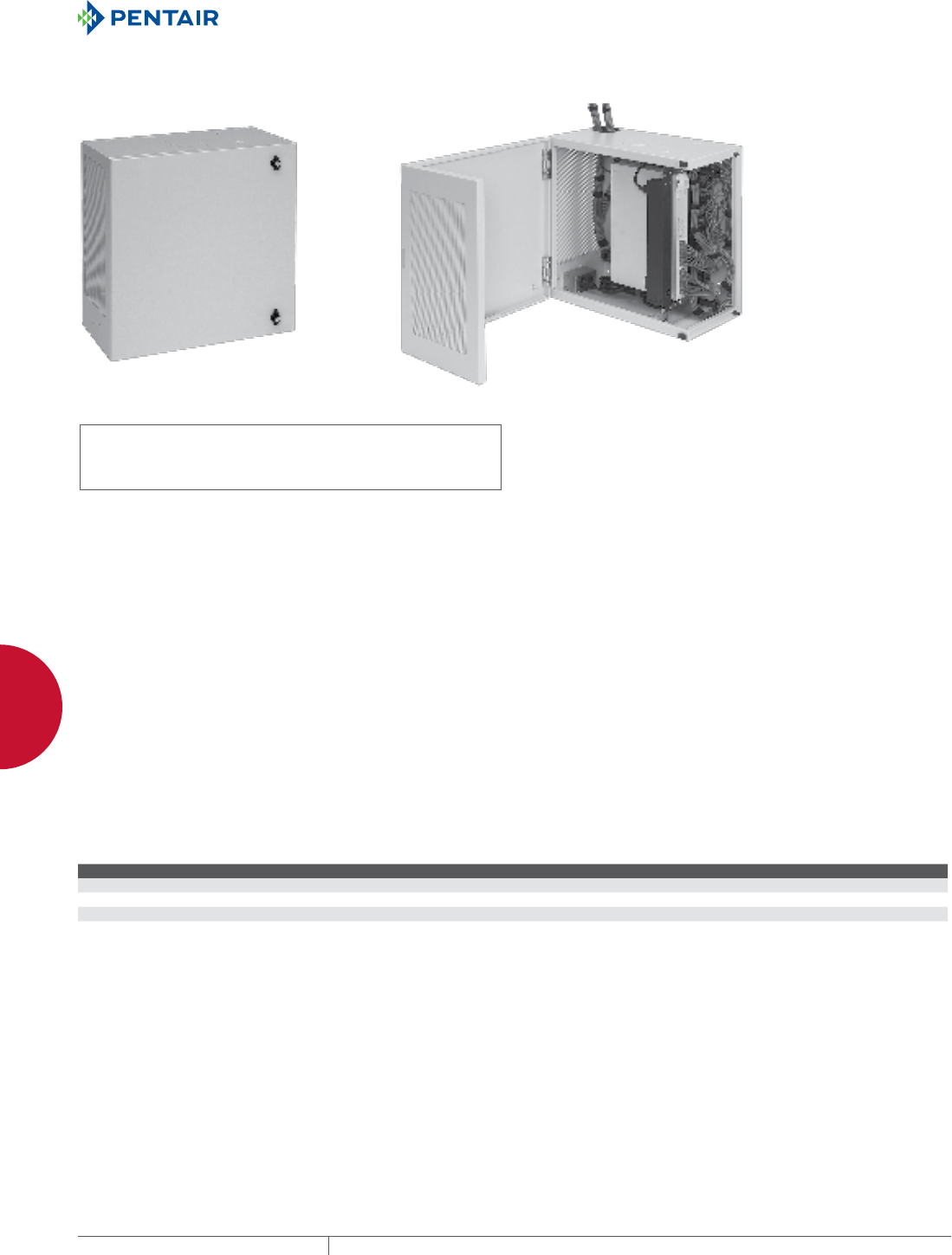
EQUIPMENT PROTECTIONSUBJECT TO CHANGE WITHOUT NOTICENETWORKING138
4
WALLMOUNT CABINETS LBOX™ WALLMOUNT CABINET AND ACCESSORIES
L-BOX™ WALL-MOUNT CABINET AND ACCESSORIES
LBOX™, TYPE 1
INDUSTRY STANDARDS
UL 1863 Listed; File No. E230874
UL 508A Listed; Type 1; File Number E61997
cUL Listed per CSA C22.2 No. 182.4; File No. E230874
Ventilation complies with UL 60950
Designed in accordance with BICSI TDMM Tenth edition,
Chapter 7, Telecommunication Enclosures (TE)
EIA 310-D
IEC 60529, IP30
APPLICATION
The low-profile, vertically-oriented L-BOX™ wall-mount cabinet
is extremely versatile and can be used in public settings to
mount, store and protect network equipment, patch panels and
connections. The hinged, L-shaped door provides full access on two
sides to installed equipment while fixed rack angles accommodate
varying equipment sizes.
FEATURES
• Spring-loaded, self-retained hinge pins allow door removal
• 120-degree door opening
• Quarter-turn latches with key lock (Code 333)
• One set of fixed rack angles is included on 24- and 36-in. (610-
and 914-mm) tall models and two on 48-in. (1219-mm) tall models
• Rack angles on 36-in. (914-mm) models can be positioned either
at the top or the bottom of the cabinet
• 36- and 48-in. (914- and 1219-mm) tall models have space for
patch panel or shelf brackets
• Knockouts for 4-in. (102-mm) fan on top and bottom of cabinet
• Wiring knockouts (7/8 in., 1-3/8 in., and 3 in.) on top and bottom of
cabinet. Two 3-in. cable entry knockouts on back.
• Multiple cable tie-down points on back of cabinet
• Keyhole mounting slots spaced 16.00 in. (406 mm) on center for
easy cabinet mounting
• Includes package of twenty 10-32 mounting screws
SPECIFICATIONS
• Manufactured from 14 gauge mild steel
• Self-grounding mounting angles made of 12 gauge plated steel
• Bonding provision on door
• Ground stud on body
• EIA Universal 5/8 - 5/8 - 1/2 in. rack angle mounting hole pattern
matches industry standards. Holes are tapped 10-32.
FINISH
Pretreated steel coated with RAL 7035 light-gray textured, low-
gloss polyester powder paint. Other finishes available—contact
Hoffman Customer Service.
LOAD RATING
75 lb. (34.0 kg)
BULLETIN: DWS1
Standard Product
Catalog Number AxBxC in. AxBxC mm H (in.) H (mm) Rack Units
DBL242412G 24.00 x 24.00 x 12.34 610 x 610 x 313 22.00 559 6
DBL362412G 36.00 x 24.00 x 12.34 915 x 610 x 313 34.00 864 6
DBL482412G 48.00 x 24.00 x 12.34 1220 x 610 x 313 46.00 1168 2 sets of 6
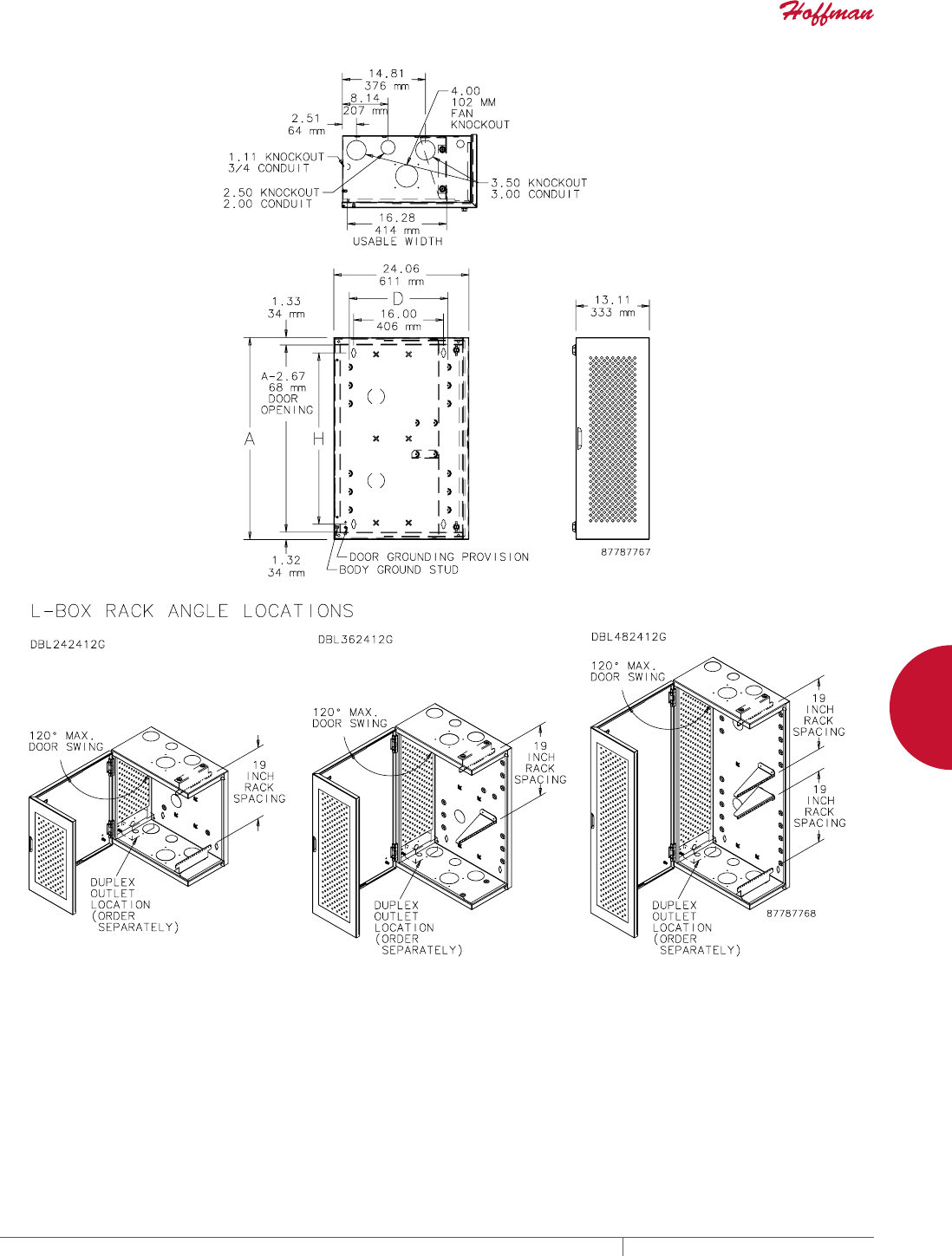
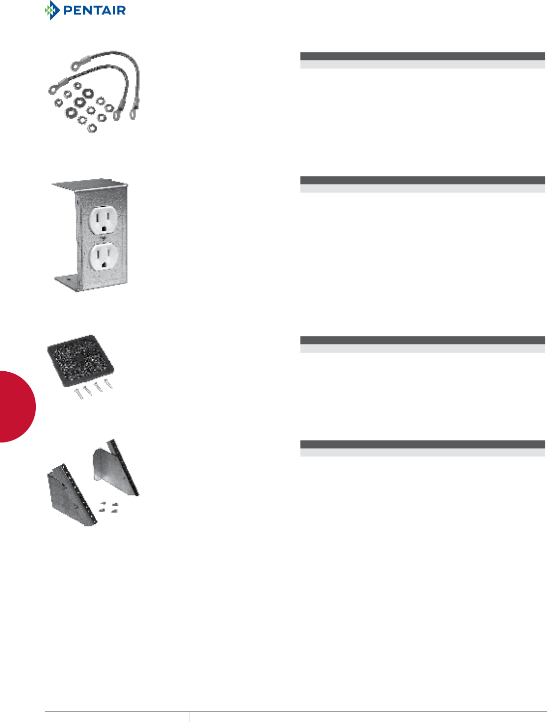
EQUIPMENT PROTECTIONSUBJECT TO CHANGE WITHOUT NOTICENETWORKING140
4
WALLMOUNT CABINETS LBOX™ WALLMOUNT CABINET AND ACCESSORIES
BONDING AND GROUNDING KIT
Provides the cable and mounting
hardware required to ground
equipment to the door and the body
of the cabinet.
BULLETIN: DWS1
Catalog Number Description
DBGRDK Bonding and Grounding Kit
DUPLEX OUTLET KIT
15 A duplex outlet is factory-
mounted in three-sided, plated steel
enclosure. Outlet enclosure mounts
on hinge side of door in lower corner
of cabinet. Mounting hardware
provided.
BULLETIN: DWS1
Catalog Number Description Current Rating
DBDXK Duplex Outlet Kit 15 A
FAN FILTER AND FINGER GUARD KIT
Low-density filter kit for 4-in.
(102-mm) and 6-in. (152-mm) fans.
Can also be used as vent. Filter
is removable and can be cleaned
and reused. Mounting hardware
included.
BULLETIN: DTHRM, DWS1
Catalog Number Description Fits
AFLTR4LD Fan Filter and Finger Guard Kit 4-in. fans
AFLTR6LD Fan Filter and Finger Guard Kit 6-in. fans
PATCH PANEL RACK ANGLES
Swiveling rack angles drop 45
degrees to provide convenient
access to equipment mounted on
patch panels. Provide additional
patch panel location in 36- and
48-in. (914- and 1219-mm) high
cabinets. Made of self-grounding,
plated 12 gauge steel. Mounting
hardware included. Set of two.
BULLETIN: DWS1
Catalog Number Description Rack Units
DBPRA4U Patch Panel Rack Angles 4

PH 763.422.2661 • FAX 763.422.2588 • PENTAIRPROTECT.COMEQUIPMENT PROTECTION NETWORKING 141
4
WALLMOUNT CABINETS LBOX™ WALLMOUNT CABINET AND ACCESSORIES
SHELVES
Shelves provide additional storage
in 36- and 48-in. (914- and 1219-mm)
tall cabinets. Made of self-grounding
plated 16 gauge steel.
75 lb. (34.0 kg) load rating.
RAL 7035 polyester powder coat
finish.
BULLETIN: DWS1
Catalog Number AxB in./mm Description
Length
in./mm
Depth
in./mm Fits Cabinet Depth
DBSHELF8 0.00 Steel Shelf 19.05
484
7.25
184
8 in.
DBSHELF12 24.00 x 12.00
610 x 305
Steel Shelf 19.05
484
11.08
281
8 or 12 in.
STRUT WALLMOUNTING KIT
Provides secure mounting for
cabinet. RAL 7035 polyester powder
coat finish.
BULLETIN: DWS1
Catalog Number Description
Length
in./mm
DB24WMTK Strut Wall-Mounting Kit 24.00
610
EQUIPMENT PROTECTIONSUBJECT TO CHANGE WITHOUT NOTICENETWORKING142
4
WALLMOUNT CABINETS DBOX™ WALLMOUNT ENCLOSURE AND ACCESSORIES
D-BOX™ WALL-MOUNT ENCLOSURE AND ACCESSORIES
DBOX™, TYPE 1
INDUSTRY STANDARDS
UL 1863 Listed; File No. E230874
UL 508A Listed; Type 1; File Number E61997
cUL Listed per CSA C22.2 No. 182.4; File No. E230874
Ventilation complies with UL 60950
Telcordia NEBSTM Requirements: Physical Protection, GR-63-CORE,
Zone 4. Tested with 100 lb. (45.4 kg) of equipment installed.
Designed in accordance with BICSI TDMM Tenth edition, Chapter 7,
Telecommunication Enclosures (TE)
EIA 310-D
IEC 60529, IP40
APPLICATION
Ideal for retail applications where it is necessary to house 19-in.
network equipment in a public location, the horizontally-oriented
D-BOX™ is a low-profile cabinet with a hinged door for convenient
front access and a combination of fixed and rotating rack angles to
accommodate varying equipment sizes.
FEATURES
• Spring-loaded, self-retained hinge pins allow door removal
• Reversible door fits flush to body with no exposed corners
• Knockouts for 4-in. fan on top and bottom of enclosure
• Wiring knockouts (7/8 in., 1-3/8 in., and 3 in.) on top and bottom of
enclosure. Two 3-in. cable entry knockouts on back.
• 120-degree door opening
• Multiple cable tie-down points on back of enclosure
• Quarter-turn latch with key lock
• Keyhole mounting slots spaced 16.00 in. (406 mm) on center for
easy enclosure mounting
• Bosses provided for mounting accessories such as cable spools
• Self-grounding mounting angles made of 12 gauge galvanized
steel
• Patch panel mounting angles rotate down for access
• Flange around door opening protects interior
• Bonding provision on door
• Ground stud on body
• EIA Universal 5/8 - 5/8 - 1/2 in. vertical mounting hole pattern
matches industry standards. Holes are tapped 10-32.
• Includes package of twenty 10-32 mounting screws
SPECIFICATIONS
• Door manufactured from 14 gauge mild steel
• Body manufactured from 16 gauge mild steel
FINISH
Pretreated steel coated with RAL 7035 light-gray textured, low-
gloss polyester powder paint. Other finishes available—contact
Hoffman Customer Service.
LOAD RATING
100 lb. (45.4 kg)
BULLETIN: DWS1

PH 763.422.2661 • FAX 763.422.2588 • PENTAIRPROTECT.COMEQUIPMENT PROTECTION NETWORKING 143
4
WALLMOUNT CABINETS DBOX™ WALLMOUNT ENCLOSURE AND ACCESSORIES
Standard Product
Catalog Number AxBxC in. AxBxC mm H (in.) H (mm) Rack Units
DBS24248G 24.00 x 24.00 x 8.34 610 x 610 x 212 22.00 559 4
DBS36248G 36.00 x 24.00 x 8.34 915 x 610 x 212 34.00 864 4
DBS48248G 48.00 x 24.00 x 8.34 1220 x 610 x 212 46.00 1168 4
DBS242412G 24.00 x 24.00 x 12.34 610 x 610 x 313 22.00 559 6
DBS362412G 36.00 x 24.00 x 12.34 915 x 610 x 313 34.00 864 6
DBS482412G 48.00 x 24.00 x 12.34 1220 x 610 x 313 46.00 1168 6
EQUIPMENT PROTECTIONSUBJECT TO CHANGE WITHOUT NOTICENETWORKING144
4
WALLMOUNT CABINETS DBOX™ WALLMOUNT ENCLOSURE AND ACCESSORIES
BONDING AND GROUNDING KIT
Provides the cable and mounting
hardware required to ground
equipment to the door and the body
of the cabinet.
BULLETIN: DWS1
Catalog Number Description
DBGRDK Bonding and Grounding Kit
DUPLEX OUTLET KIT
15 A duplex outlet is factory-
mounted in three-sided, plated steel
enclosure. Outlet enclosure mounts
on hinge side of door in lower corner
of cabinet. Mounting hardware
provided.
BULLETIN: DWS1
Catalog Number Description Current Rating
DBDXK Duplex Outlet Kit 15 A
EQUIPMENT RACK ANGLES
Fixed rack angles can be added
to 36-in. and 48-in. tall cabinets
for extra 19-in rack equipment
mounting. Made of steel with clear
zinc plating. EIA spaced holes are
tapped 10-32. Mounts to raised pads
on cabinet inside back with provided
hardware.
BULLETIN: DWS1
Catalog Number Description Rack Units
DBERA4U Equipment Rack Angles 4
DBERA6U Equipment Rack Angles 6
FAN FILTER AND FINGER GUARD KIT
Low-density filter kit for 4-in.
(102-mm) and 6-in. (152-mm) fans.
Can also be used as vent. Filter
is removable and can be cleaned
and reused. Mounting hardware
included.
BULLETIN: DTHRM, DWS1
Catalog Number Description Fits
AFLTR4LD Fan Filter and Finger Guard Kit 4-in. fans
AFLTR6LD Fan Filter and Finger Guard Kit 6-in. fans
PADLOCK KIT
Kit includes field installable hasp
and staple. Fits padlocks with
maximum 5/16 in. (8mm) shackle
diameter. No drilling or layout
required. Includes mounting
hardware.
BULLETIN: DWS1
Catalog Number Description
DBPDLK Padlocking Kit
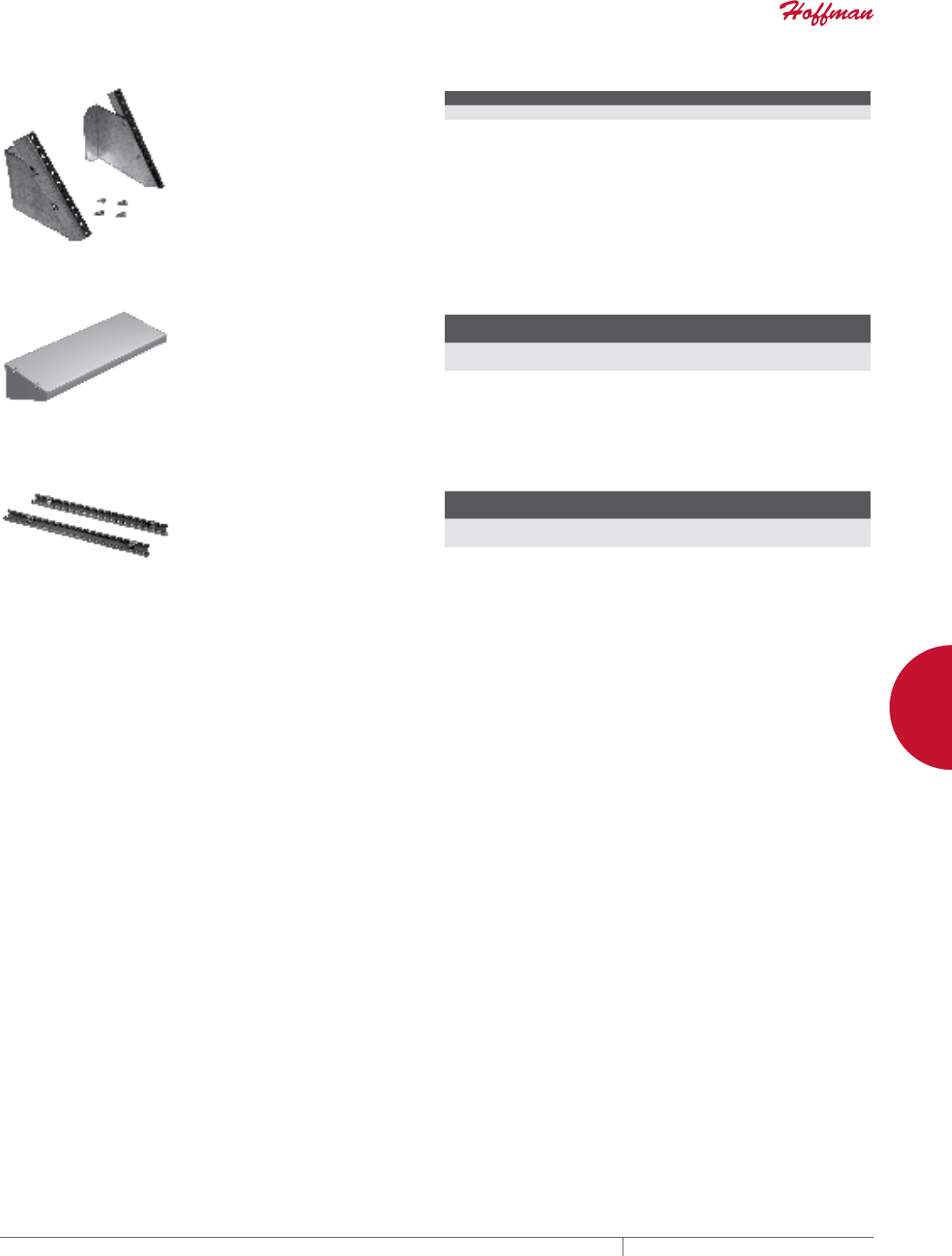
PH 763.422.2661 • FAX 763.422.2588 • PENTAIRPROTECT.COMEQUIPMENT PROTECTION NETWORKING 145
4
WALLMOUNT CABINETS DBOX™ WALLMOUNT ENCLOSURE AND ACCESSORIES
PATCH PANEL RACK ANGLES
Swiveling rack angles drop 45
degrees to provide convenient
access to equipment mounted on
patch panels. Provide additional
patch panel location in 36- and
48-in. (914- and 1219-mm) high
cabinets. Made of self-grounding,
plated 12 gauge steel. Mounting
hardware included. Set of two.
BULLETIN: DWS1
Catalog Number Description Rack Units
DBPRA4U Patch Panel Rack Angles 4
SHELVES
Shelves provide additional storage
in 36- and 48-in. (914- and 1219-mm)
tall cabinets. Made of self-grounding
plated 16 gauge steel.
75 lb. (34.0 kg) load rating.
RAL 7035 polyester powder coat
finish.
BULLETIN: DWS1
Catalog Number AxB in./mm Description
Length
in./mm
Depth
in./mm Fits Cabinet Depth
DBSHELF8 0.00 Steel Shelf 19.05
484
7.25
184
8 in.
DBSHELF12 24.00 x 12.00
610 x 305
Steel Shelf 19.05
484
11.08
281
8 or 12 in.
STRUT WALLMOUNTING KIT
Provides secure mounting for
cabinet. RAL 7035 polyester powder
coat finish.
BULLETIN: DWS1
Catalog Number Description
Length
in./mm
DB24WMTK Strut Wall-Mounting Kit 24.00
610
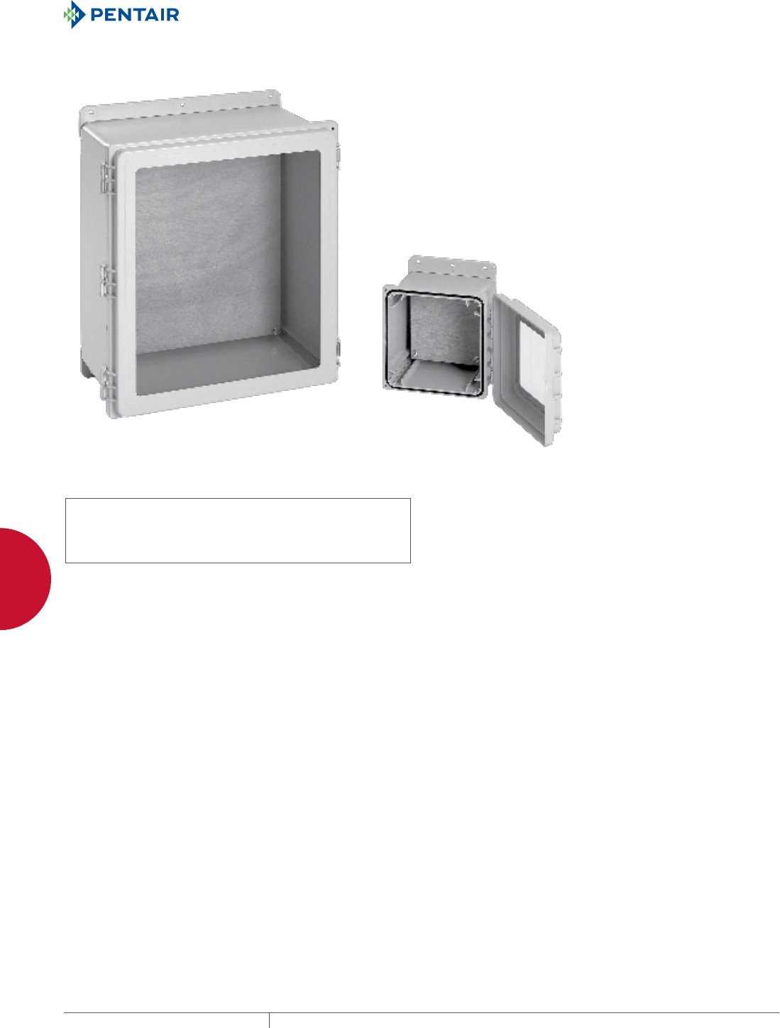
EQUIPMENT PROTECTIONSUBJECT TO CHANGE WITHOUT NOTICENETWORKING146
4
WALLMOUNT CABINETS POLYPRO™ WIFI, TYPE 4X
POLYPRO™ WIFI, TYPE 4X
POLYPRO™ WIFI, TYPE 4X
INDUSTRY STANDARDS
UL 508A Listed; Type 4, 4X, 12, 13; File No. E61997
cUL Listed per CSA C22.2 No 94; Type 4, 4X, 12, 13; File No.
E61997
Enclosure flammability evaluated per UL 508A
Window flammability evaluated per UL 508A
NEMA/EEMAC Type 4, 4X, 12, 13
CSA File No. 42186; Type 4, 4X, 12, 13 (solid covers only)
IEC 60529, IP66
APPLICATION
POLYPRO™ WiFi enclosures provide protection for wireless
equipment in both indoor and outdoor locations. The polyester
construction and wood panel allow WiFi and WLAN signals to pass
through the enclosure unimpeded. They perform exceptionally
well in applications where harsh chemicals, weather extremes,
a corrosive environment or flames demand toughness from a
lightweight enclosure. Providing excellent ultraviolet protection and
a tight environmental seal, these versatile, feature-rich enclosures
are also recyclable.
FEATURES
• Non-glass-filled polyester material offers superior UV
resistance; eliminates fiberbloom associated with fiberglass
• Provides excellent chemical resistance to a broad range of
solvents, alkalis and acids
• Resists cracking and provides excellent impact resistance
• Lighter-weight than fiberglass
• Recyclable
• Easy, dustless in-field modifications using standard tools
• Overlapping tongue-and-groove raised cover and gasket provide
secure Type 4X seal
• Removable snap-hinge cover allows for easy access to cover and
body for modifications
• Molded layout grid on inside of body and solid covers assists with
component mounting
• Molded-in embosses for rear panel mounting
• Internal rail system and adjustable panel blocks allow for panel
height adjustment and installation of multiple panels
SPECIFICATIONS
• Scratch-resistant polycarbonate windows
• Standard models include body and cover, two mounting feet, two
latch assemblies with optional cover screws and hardware, and
3/4-in. plywood panel
FINISH
Polyester material is RAL 7035 light-gray textured finish inside and
out
BULLETIN: DWS12
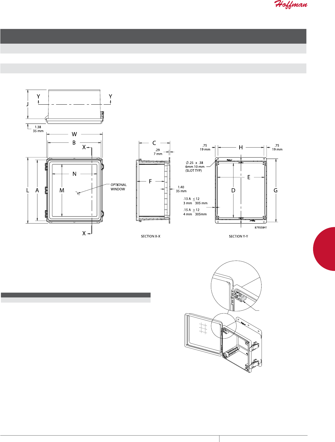
PH 763.422.2661 • FAX 763.422.2588 • PENTAIRPROTECT.COMEQUIPMENT PROTECTION NETWORKING 147
4
WALLMOUNT CABINETS POLYPRO™ WIFI, TYPE 4X
Standard Product
Catalog Number AxBxC in./mm Door Type
Panel Size
D x E
in./mm
F
in./mm
G
in./mm
H
in./mm
J
in./mm
L
in./mm
M
in./mm
N
in./mm
W
in./mm
D664WF 6.12 x 6.12 x 4.38
155 x 155 x 111
Solid 4.88 x 2.88
124 x 73
4.32
110
7.38
187
2.56
65
3.91
99
8.15
207
—
—
—
—
5.23
133
D664WFW 6.12 x 6.12 x 4.38
155 x 155 x 111
Window 4.88 x 2.88
124 x 73
4.32
110
7.38
187
2.56
65
3.91
99
8.15
207
4.25
108
2.25
57
5.23
133
D16148WF 16.12 x 14.01 x 8.35
409 x 356 x 212
Solid 14.75 x 12.88
375 x 327
8.27
210
17.27
439
12.56
319
7.91
201
18.04
458
—
—
—
—
15.32
389
D16148WFW 16.12 x 14.01 x 8.35
409 x 356 x 212
Window 14.75 x 12.88
375 x 327
8.27
210
17.27
439
12.56
319
7.91
201
18.04
458
14.25
362
12.25
311
15.32
389
ADJUSTABLE PANEL BLOCK KIT
Panel blocks slide inside POLYPRO internal rail system for
panel height adjustment within top 5 in. of enclosure. Allows for
installation of multiple panels.
BULLETIN: PCRY
Catalog Number Qty.
APNLBLK 4
Includes Allen wrench
$GMXVWDEOH
SDQHOEORFN
;
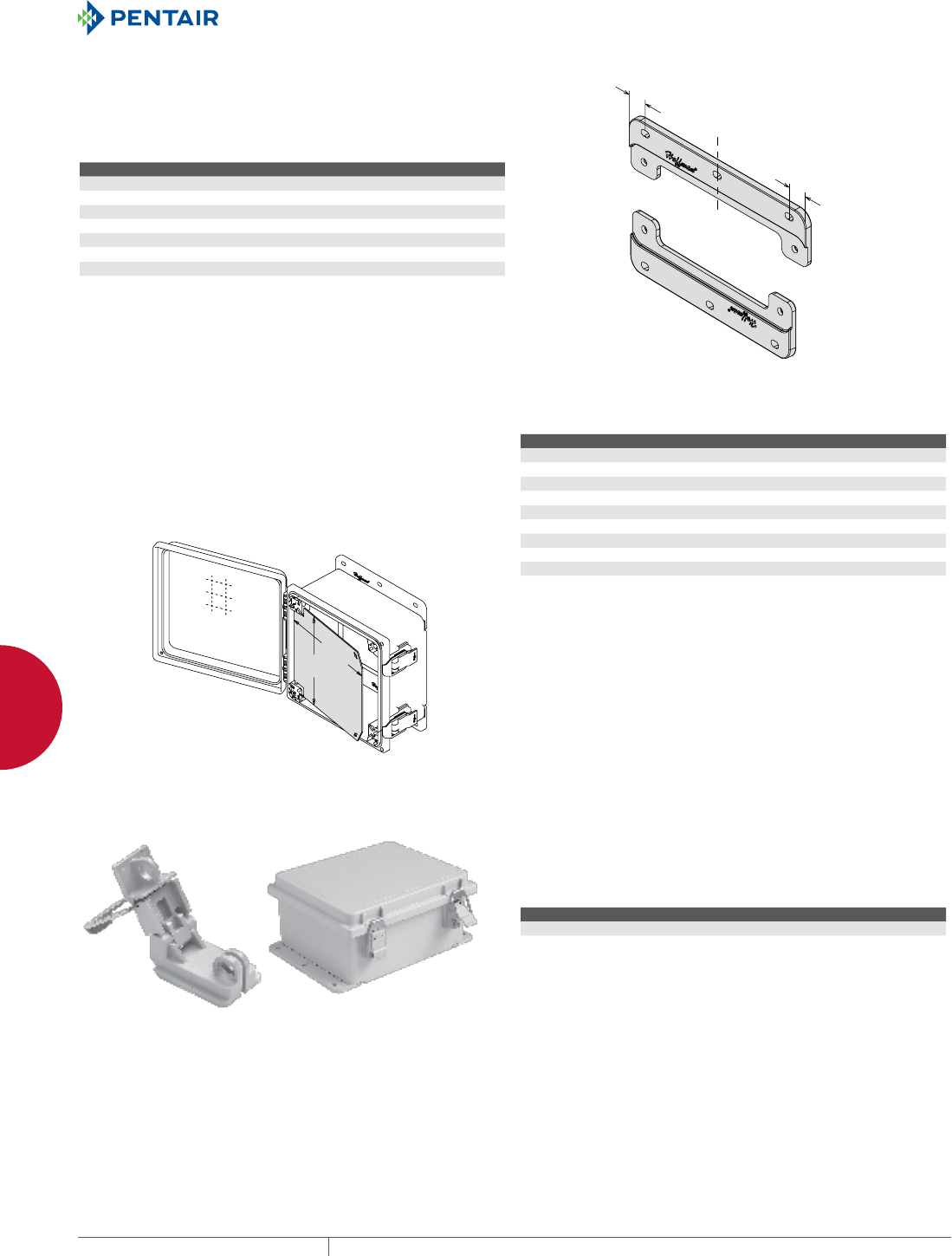
EQUIPMENT PROTECTIONSUBJECT TO CHANGE WITHOUT NOTICENETWORKING148
4
WALLMOUNT CABINETS POLYPRO™ WIFI, TYPE 4X
POLYESTER MOUNTING BRACKET KITS
Replacement POLYPRO mounting brackets are sold in sets of two
and include hardware for mounting to enclosure.
Included with standard POLYPRO models.
BULLETIN: PCRY
Catalog Number Description (in.) Qty.
APOLYFT4 4.00 2
APOLYFT6 6.00 2
APOLYFT8 8.00 2
APOLYFT10 10.00 2
APOLYFT12 12.00 2
APOLYFT14 14.00 2
APOLYFT16 16.00 2
&
/
PP
PP
ALUMINUM SWINGOUT PANELS
Includes four POLYPRO Adjustable Panel Blocks. No enclosure
modification is required for installation.
BULLETIN: PCRY
'
(
Catalog Number D x E (in.) D x E (mm)
A64PSWPNL 5.00 x 3.62 127 x 92
A66PSWPNL 5.00 x 5.62 127 x 143
A86PSWPNL 7.00 x 5.62 178 x 143
A88PSWPNL 7.00 x 7.62 178 x 194
A108PSWPNL 9.00 x 7.62 229 x 194
A1010PSWPNL 9.00 x 9.62 229 x 244
A1210PSWPNL 11.00 x 9.62 279 x 244
A1412PSWPNL 13.00 x 11.62 330 x 295
A1614PSWPNL 15.00 x 13.62 381 x 346
A1816PSWPNL 17.00 x 15.62 432 x 397
STAINLESS STEEL LATCHES (PADLOCKABLE) Stainless Steel Latches can be retrofitted on all POLYPRO models
with no modification or drilling required. Hinge/latch constructed of
corrosion-resistant polyester with a Type 316L stainless steel bail.
Included with standard POLYPRO models.
BULLETIN: PCRY
Catalog Number Qty.
AQRLSS6 2

PH 763.422.2661 • FAX 763.422.2588 • PENTAIRPROTECT.COMEQUIPMENT PROTECTION NETWORKING 149
4
WALLMOUNT CABINETS POLYPRO™ WIFI, TYPE 4X
HINGE RETAINERS Hinge Retainers can be field-installed without modification to
POLYPRO hinges for applications where easy cover removal is not
desired. Two retainers per enclosure is recommended. Kit includes
ten hinge retainers.
BULLETIN: PCRY
Catalog Number Description Pkg. Qty.
AHGCLP POLYPRO Hinge Retainers 10
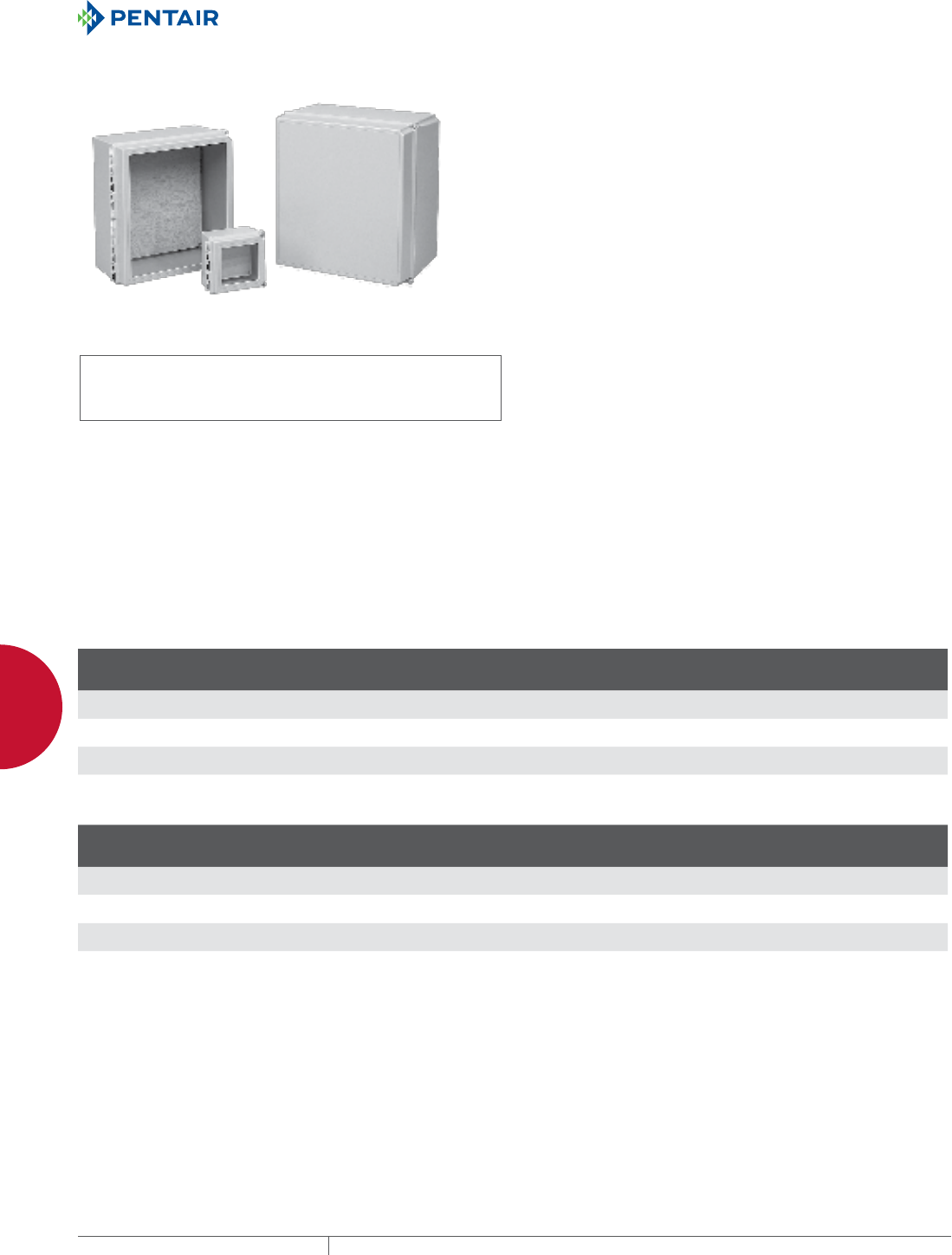
EQUIPMENT PROTECTIONSUBJECT TO CHANGE WITHOUT NOTICENETWORKING150
4
WALLMOUNT CABINETS FIBERGLASS HINGECOVER TYPE 4X WIFI CABINET AND ACCESSORIES
FIBERGLAS S HINGE-CO VER TYPE 4X WIFI C ABINET AND AC CESSORIE S
HINGECOVER WIFI, TYPE 4X
INDUSTRY STANDARDS
UL 508A Listed; Type 4, 4X, 12, 13; File No. E61997
cUL Listed per CSA C22.2 No 94; Type 4, 4X, 12, 13; File No.
E61997
Enclosure flammability rating per UL 508
NEMA/EEMAC Type 4, 4X, 12, and 13
Window flammability rating per UL 508
CSA File No. LR42186:Type 4, 4X, 12, and 13
IEC 60529, IP66
Cabinets with solid doors are plenum rated.
APPLICATION
The fiberglass WiFi Cabinet is a secure, hinged enclosure that does
not impede WiFi or WLAN signals. It is ideal for housing wireless
equipment in locations such as tunnels, floor vaults, marinas,
outside walls or rooftops.
FEATURES
• Fiberglass is easily punched, drilled, filed or sawed
• Seamless foam-in-place gasket assures watertight and dusttight
seal
• Molded-in-place threaded brass inserts and plated steel screws
are provided for mounting optional panels and terminal block kits
• Removable hinged cover attached to body with Type 316 stainless
steel hinge pin
• Screw cover enclosures are secured with two captivated Type 316
stainless steel slotted cross-point cover screws
• Available quick-release latches are corrosion-resistant polyester
located in corners to provide unobstructed access to enclosure
• Knockout padlock provisions included in each latch
SPECIFICATIONS
• Enclosure and door made of molded fiberglass polyester that
resists chemicals and temperature change
• Scratch-resistant GE Lexan Margard® windows are permanently
bonded in place
• Polyester mounting brackets and stainless steel attachment
screws are provided with each enclosure
• Hinge pin and bail are corrosion-resistant Type 316 stainless
steel
• Includes a 3/4-in. plywood panel for mounting equipment
Margard is a trademark of General Electric
FINISH
Fiberglass material is light gray inside and out.
BULLETIN: DWS12
Standard Product Solid Door
Catalog Number AxBxC in./mm Panel
Panel
D X E
in./mm
Mounting
G x H
in./mm
Overall Size
L x W
in./mm
J
in./mm
K
in./mm
O
in./mm
P
in./mm
Q
in./mm
R
in./mm
T
in./mm
U
in./mm
D664CHSCFGP 6.00 x 6.00 x 4.00
152 x 152 x 102
A6P6WD 4.88 x 4.88
124 x 124
6.94 x 4.00
176 x 102
6.50 x 6.50
165 x 165
3.25
83
1.00
25
4.25
108
4.25
108
5.64
143
5.12
130
.12
3
5.64
143
D16148CHSCFGP 16.00 x 14.00 x 8.00
406 x 356 x 203
A16P14WD 14.75 x 12.88
375 x 327
16.94 x 12.00
430 x 305
16.55 x 14.55
420 x 370
6.23
158
2.08
53
12.25
311
14.25
362
15.56
395
15.12
384
.15
4
13.56
344
D181610CHSCFGP 18.00 x 16.00 x 10.00
457 x 406 x 254
A18P16WD 16.75 x 14.88
425 x 378
18.94 x 14.00
481 x 356
18.58 x 16.58
472 x 421
7.66
195
2.66
68
14.25
362
16.25
413
17.53
445
17.12
435
.16
4
15.53
394
Wood panels included with enclosure. Optional steel panels must be ordered separately.
Standard Product Window Door
Catalog Number AxBxC in./mm Panel
Panel
D X E
in./mm
Mounting
G x H
in./mm
Overall Size
L x W
in./mm
J
in./mm
K
in./mm
O
in./mm
P
in./mm
Q
in./mm
R
in./mm
T
in./mm
U
in./mm
D664CHSCFGWP 6.00 x 6.00 x 4.00
152 x 152 x 102
A6P6WD 4.88 x 4.88
124 x 124
6.94 x 4.00
176 x 102
6.50 x 6.50
165 x 165
3.25
83
1.00
25
4.25
108
4.25
108
5.64
143
5.12
130
.12
3
5.64
143
D16148CHSCFGWP 16.00 x 14.00 x 8.00
406 x 356 x 203
A16P14WD 14.75 x 12.88
375 x 327
16.94 x 12.00
430 x 305
16.55 x 14.55
420 x 370
6.23
158
2.08
53
12.25
311
14.25
362
15.56
395
15.12
384
.15
4
13.56
344
D181610CHSCFGWP 18.00 x 16.00 x 10.00
457 x 406 x 254
A18P16WD 16.75 x 14.88
425 x 378
18.94 x 14.00
481 x 356
18.58 x 16.58
472 x 421
7.66
195
2.66
68
14.25
362
16.25
413
17.53
445
17.12
435
.16
4
15.53
394
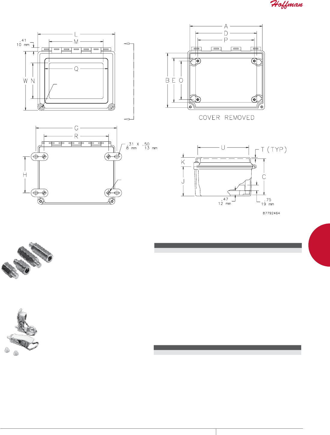
PH 763.422.2661 • FAX 763.422.2588 • PENTAIRPROTECT.COMEQUIPMENT PROTECTION NETWORKING 151
4
WALLMOUNT CABINETS FIBERGLASS HINGECOVER TYPE 4X WIFI CABINET AND ACCESSORIES
#1/4-10
#1/4-10
X-X
X
X
THREADED PANEL EXTENDERS
Threaded Panel Extenders are
made of plated steel and designed
to raise the panel mounting surface.
Extenders attach to threaded
internal pads. Male and female
thread size is 10-32. Each kit
contains 4 extenders.
BULLETIN: A80
Catalog Number Length (in.) Length (mm)
APE050 0.50 13
APE100 1.00 25
QUICKRELEASE LATCH KIT Two fiberglass-reinforced gray polyester latches with 316L
stainless steel bail and screw-hole plugs are included in each
package. Supplied with Continuous Hinge, Type 4X enclosures
and available for Fiberglass Hinged Cover WiFi Cabinet, Type 4X.
Kit converts screw-cover enclosures to quick-release without
modification. No tools needed to install. Padlocking provision is
included.
BULLETIN: A48Y
Catalog Number Description Kit Qty.
AL48 Quick-Release Latch Kit 2
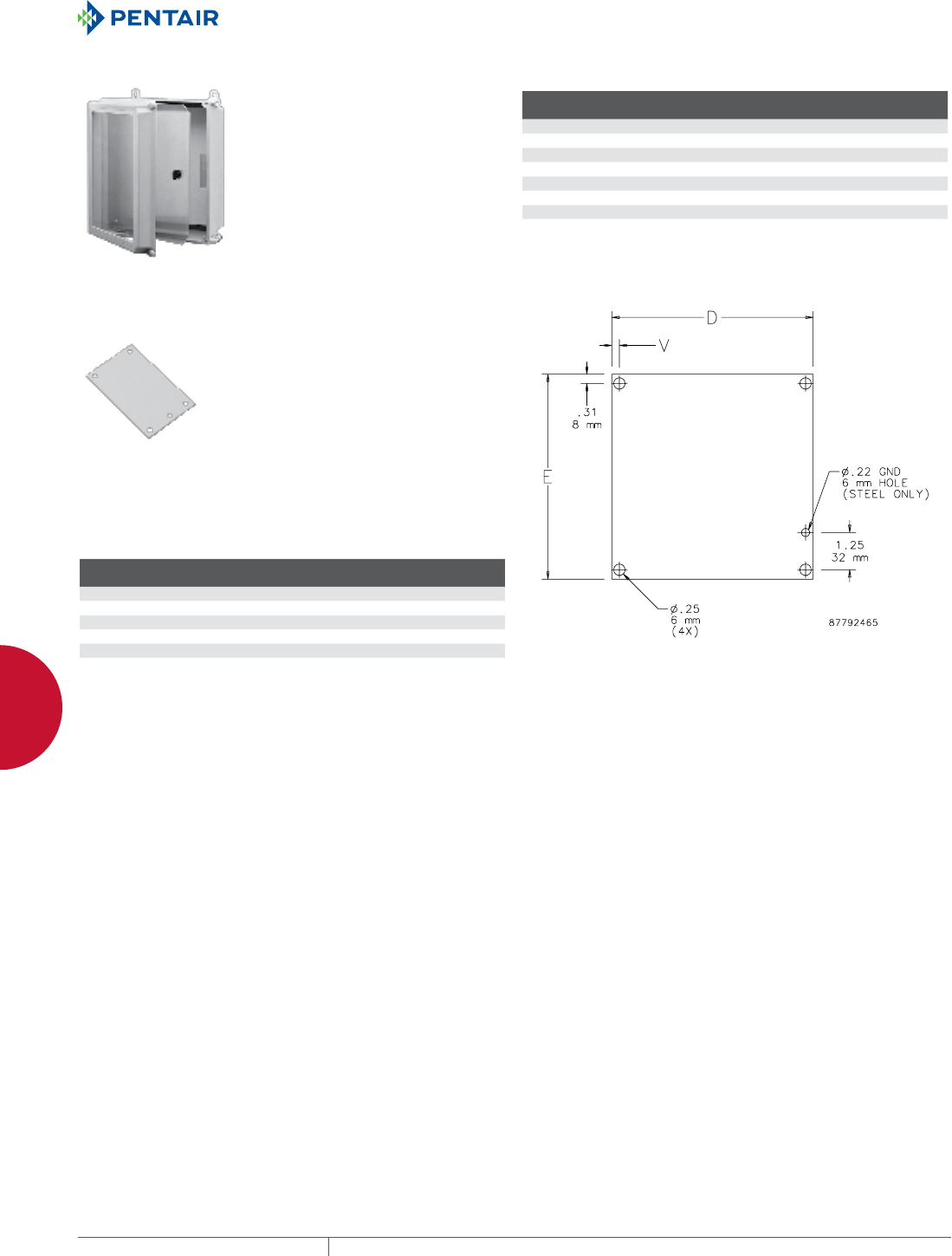
EQUIPMENT PROTECTIONSUBJECT TO CHANGE WITHOUT NOTICENETWORKING152
4
WALLMOUNT CABINETS FIBERGLASS HINGECOVER TYPE 4X WIFI CABINET AND ACCESSORIES
SWINGOUT PANEL KIT
The Swing-Out Panel Kit provides
an attractive, cost-effective solution
for installing front-mounted panels
in Continuous Hinge, Type 4X,
and Overlapping Cover, Type 4X
enclosures. No drilling required.
BULLETIN: A48Y
Catalog Number
Fits Enclosure
A x B (in.)
Fits Enclosure
A x B (mm)
A6SPK6C 6.00 x 6.00 152 x 152
A8SPK6C 8.00 x 6.00 203 x 152
A10SPK8C 10.00 x 8.00 254 x 203
A12SPK10C 12.00 x 10.00 305 x 254
A16SPK14C 16.00 x 14.00 406 x 356
A18SPK16C 18.00 x 16.00 457 x 406
A14SPK12C 14.00 x 12.00 356 x 305
PANELS FOR WIFI CABINETS AND SMALL WALL
MOUNT ENCLOSURES
Panels are available in both steel and wood. Steel panels are 14
gauge steel with a white polyester powder paint finish. Wood panels
are 3/4-in. plywood and are unfinished. Wood panels are supplied
with Fiberglass Hinged-Cover and POLYPRO™ Type 4X WiFi
Cabinets.
BULLETIN: DWS12, PNLJ, PNLWM
Catalog Number AxB in. AxB mm Material
Panel Size
D x E (in.)
Panel Size
D x E (mm) V (in.) V (mm)
A6P6 4.88 x 4.88 124 x 124 Steel 4.88 x 4.88 124 x 124 0.31 8
A6P6WD 6.00 x 6.00 152 x 152 Wood 4.88 x 4.88 124 x 124 0.31 8
A16P14 14.75 x 12.88 375 x 327 Steel 14.75 x 12.88 375 x 327 0.25 6
A16P14WD 16.00 x 14.00 406 x 356 Wood 14.75 x 12.88 375 x 327 0.25 6
A18P16 16.75 x 14.88 425 x 378 Steel 16.75 x 14.88 425 x 378 0.25 6
A18P16WD 18.00 x 16.00 457 x 406 Wood 16.75 x 14.88 425 x 378 0.25 6
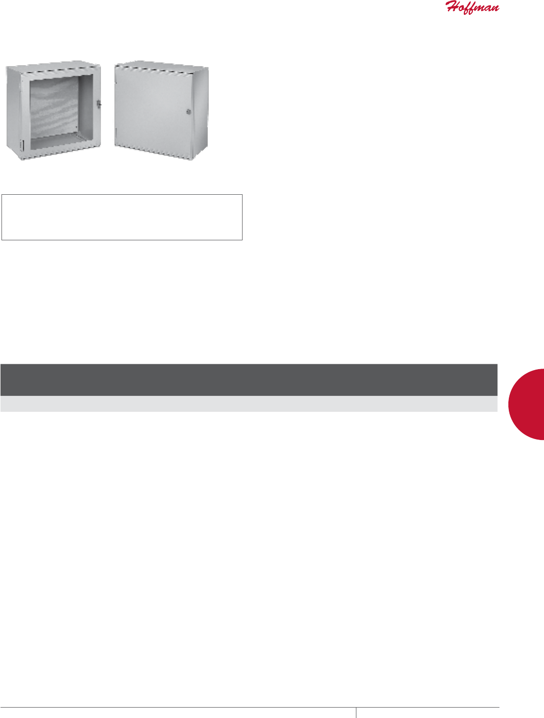
PH 763.422.2661 • FAX 763.422.2588 • PENTAIRPROTECT.COMEQUIPMENT PROTECTION NETWORKING 153
4
WALLMOUNT CABINETS ULTRX™ FIBERGLASS TYPE 4X WIFI CABINET AND ACCESSORIES
ULTRX™ FIBERGL ASS TYPE 4X W IFI CABINET A ND ACCESSOR IES
ULTRX™ WIFI, TYPE 4X
INDUSTRY STANDARDS
UL 508A Listed; Type 4, 4X, 12, 13; File No. E61997
cUL Listed per CSA C22.2 No 94; Type 4, 4X, 12, 13; File No.
E61997
Enclosure flammability rating per UL 508
Window flammability rating per UL 508
NEMA/EEMAC Type 4, 4X, 12, 13
CSA File No. LR42186: Type 4,4X, 12, 13
IEC 60529, IP66
Cabinets with solid doors are plenum rated.
APPLICATION
Ideal for locations such as tunnels, floor vaults, marinas, outside
walls or rooftops, the lightweight ULTRX™ fiberglass WiFi cabinet
does not impede WiFi or WLAN signals and has optional rack angles
that can be added to support 19-in. rack-mount equipment.
FEATURES
• Fiberglass is easily punched, drilled, filed or sawed
• Seamless foam-in-place gasket assures watertight and dusttight
seal
• Enclosure may be rotated 180 degrees for left and right hinging
• Molded-in drip shields are standard with each enclosure
• Door opens 180 degrees
• Replaceable breakaway hinges
• Keylocking handle standard
• Molded-in DIN bosses
• Molded bosses on door provide additional mounting provisions
• Integral mounting rails provide infinite panel adjustment front to
back
• Optional data pocket is high-impact thermoplastic
SPECIFICATIONS
• Enclosure and door made of molded fiberglass polyester that
resists chemicals and temperature change
• Impact-resistant polycarbonate window is permanently bonded
in place
• Fiberglass mounting brackets and stainless steel attachment
screws are provided with each enclosure
• Includes a 3/4-in. plywood panel for mounting equipment
FINISH
Exterior surface painted light-gray acrylic enamel for enhanced UV
protection.
BULLETIN: DWS12
Standard Product
Catalog Number AxBxC mm/in. Door Type
Internal
Dimensions
A x B x C
mm/in. Panel
Panel Size
D x E
mm/in.
Mounting
G x H
mm/in.
Window
Size
M x N
mm/in.
F
mm/in.
J
mm/in.
K
mm/in.
P
mm/in.
Q
mm/in.
R
mm/in.
S
mm/in.
T
mm/in.
DU606030P 608 x 595 x 321
23.94 x 23.43 x 12.64
Solid 608 x 595 x 321
23.94 x 23.44 x 12.64
A24P24WD 533 x 533
21.00 x 21.00
555 x 568
21.86 x 22.36
498 x 486
19.62 x 19.12
287
11.31
500
19.68
21
0.81
62
2.43
68
2.68
56
2.21
489
19.25
489
19.25
DU606030WP 608 x 595 x 321
23.94 x 23.43 x 12.64
Window 608 x 595 x 321
23.94 x 23.44 x 12.64
A24P24WD 533 x 533
21.00 x 21.00
555 x 568
21.86 x 22.36
498 x 486
19.62 x 19.12
287
11.31
500
19.68
21
0.81
62
2.43
68
2.68
56
2.21
489
19.25
489
19.25
Wood panel included with enclosure. Optional steel panels must be ordered separately.
Window size applies to window door cabinets only.
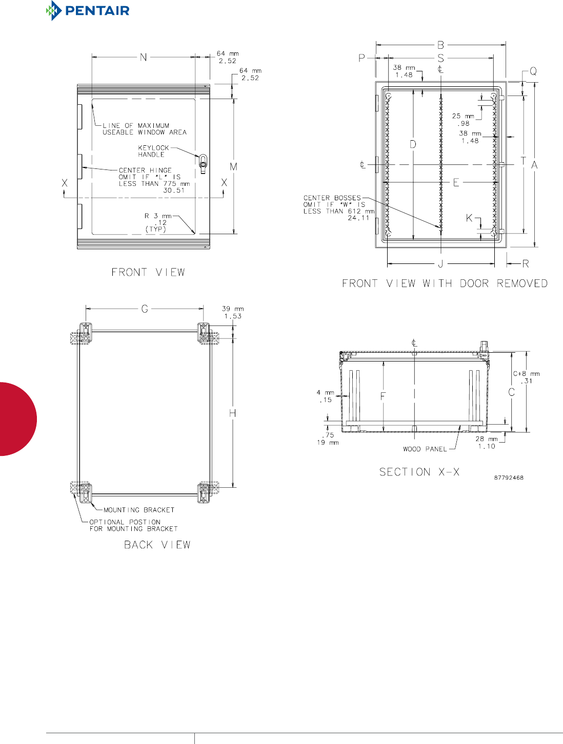
EQUIPMENT PROTECTIONSUBJECT TO CHANGE WITHOUT NOTICENETWORKING154
4
WALLMOUNT CABINETS ULTRX™ FIBERGLASS TYPE 4X WIFI CABINET AND ACCESSORIES
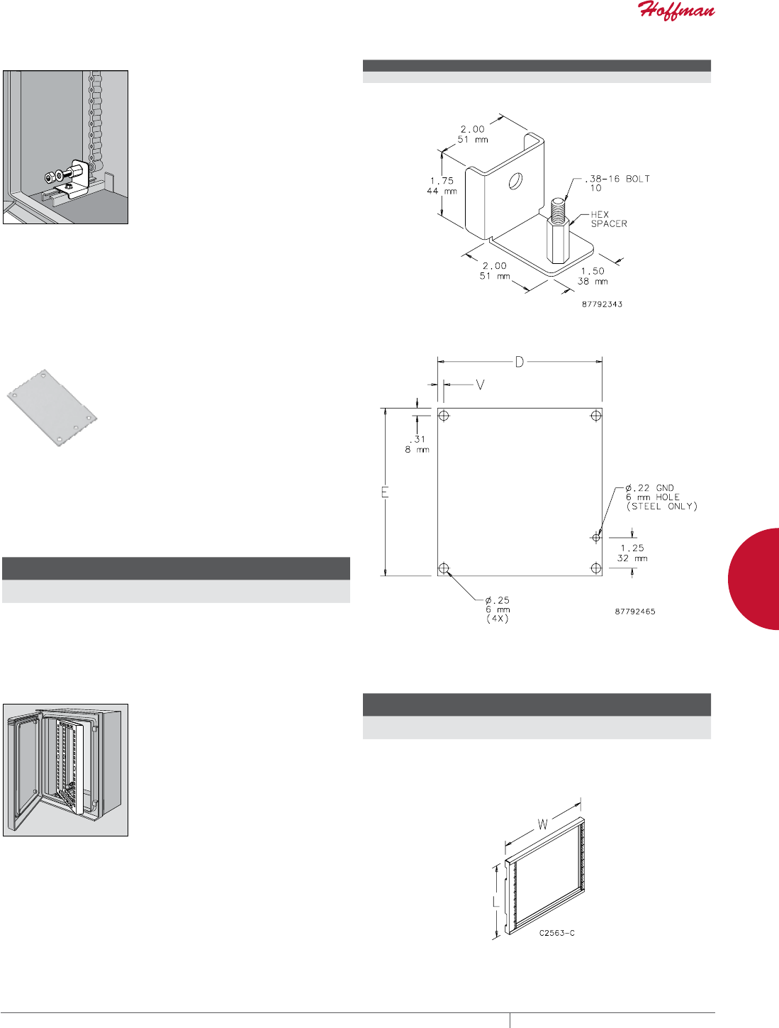
PH 763.422.2661 • FAX 763.422.2588 • PENTAIRPROTECT.COMEQUIPMENT PROTECTION NETWORKING 155
4
WALLMOUNT CABINETS ULTRX™ FIBERGLASS TYPE 4X WIFI CABINET AND ACCESSORIES
PANEL BRACKET KIT
Panel Bracket Kit is used with steel panels and permits panel
adjustment from front to rear. Fits all ULTRX sizes. Mounts on
integrally molded body rail. Brackets are plated steel. All mounting
hardware is included. Note: Front mounting position is approximately
140mm/5.5 in. back on 400mm enclosures.
BULLETIN: UX1Y
Catalog Number Description Pkg. Qty.
UUPB ULTRX Panel Bracket Kit 4
ULTRX™ PANEL
Panels are available in both steel and wood. Steel panels are 14
gauge steel and have a white finish. Panels have two .75-in. (19-mm)
high edge flanges. They require the Panel Bracket Kit, catalog
number UUPB, to mount in the enclosure. Wood panels are 3/4-in.
plywood and are unfinished. Wood panels are supplied with the
enclosures.
BULLETIN: DWS12, PNLWM
Catalog Number AxB in./mm Material
D
mm/in.
E
mm/in.
V
mm/in.
A24P24 21.00 x 21.00
533 x 533
Steel 533
21.00
533
21.00
6
.25
A24P24WD 24.00 x 24.00
610 x 610
Wood 533
21.00
533
21.00
6
.25
Requires UUPB Panel Bracket Kit to mount steel panel in cabinet.
SWING FRAME
Swing Frame provides 19-in. rack-mounting capabilities with
U-Style (Type RA) mounting hole pattern. Quarter-turn latch
has 100-degree swing. Adjustable mounting provision. 14 gauge
plated steel. Includes mounting hardware. Swing frame maintains
enclosure rating if properly installed in a Hoffman enclosure.
Note: Front mounting position is approximately 140mm/5.5 in. back on
400mm enclosures.
BULLETIN: UX1Y
Catalog Number AxB in./mm
Fits A x B
mm/in.
L
mm/in.
W
mm/in.
Rack
Units
UU6060SF 24.61 x 24.09
625 x 612
610 x 610
24.00 x 24.00
540
21.25
535
21.08
11
UU7560SF 30.51 x 24.09
775 x 612
762 x 610
30.00 x 24.00
687
27.05
535
21.08
14
Use UU6060SF with DATACOM ULTRX Fiberglass Type 4X WiFi Cabinet.
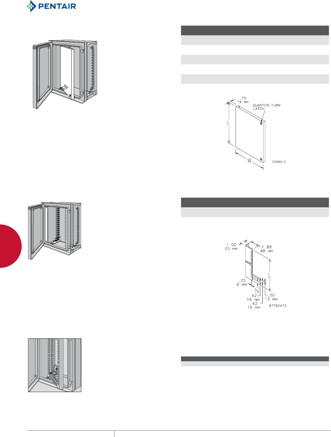
EQUIPMENT PROTECTIONSUBJECT TO CHANGE WITHOUT NOTICENETWORKING156
4
WALLMOUNT CABINETS ULTRX™ FIBERGLASS TYPE 4X WIFI CABINET AND ACCESSORIES
SWINGOUT PANEL
Installs front-mounted panels in ULTRX fiberglass enclosures. The
front-mounted swing panel complements window-door units and is
suited for any application requiring a display of gauges, dials or any
type of control equipment monitor. Made of 14 gauge plated steel.
Easy installation; no drilling required. Fully adjustable front to rear.
Panel and mounting hardware included.
Note: Front mounting position is approximately 140mm/5.5 in. back on
400mm enclosures.
BULLETIN: UX1Y
Catalog Number
Fits A x B
mm/in.
L
mm/in.
W
mm/in.
UU5040SP 513 x 413
20.20 x 16.26
432
17.00
330
12.99
UU6050SP 625 x 513
24.61 x 20.20
536
21.10
432
17.00
UU6060SP 625 x 612
24.61 x 24.09
540
21.25
535
21.08
UU7560SP 775 x 612
30.51 x 24.09
687
27.05
535
21.08
UU10080SP 1025 x 825
40.35 x 32.48
935
36.80
737
29.00
Use UU6060SP with DATACOM ULTRX Fiberglass Type 4X WiFi Cabinet.
RACK ANGLES (TYPE RA)
Pairs of full-length rack-mounting angles are available for
mounting 1- in. (483-mm) rack-mounted equipment. Type RA angles
are 14 gauge steel with .281-in. (7-mm) diameter mounting holes,
spaced per EIA standard RS-310-D (universal spacing). Use Clip
Nut Package (AN1032) to provide tapped holes at desired locations.
Angles and mounting hardware are plated steel. Mounting
hardware is furnished.
BULLETIN: UX1Y
Catalog Number
Fits A x B
mm/in.
L
mm/in.
N
mm/in.
Rack
Units
Pkg.
Qty.
UURA6060 610 x 610
24.00 x 24.00
552
21.75
10
.38
12 2
UURA7560 762 x 610
30.00 x 24.00
705
27.75
19
.75
15 2
Use UURA6060 with DATACOM ULTRX Fiberglass Type 4X WiFi Cabinet.
GROUNDING DEVICE Grounding Device provides a means to attach a grounding conductor
to an ULTRX Swing-Out Panel or Swing-Out Frame. Includes all
installation hardware and instructions.
BULLETIN: UX1Y
Catalog Number Description
UUGK ULTRX Grounding Device
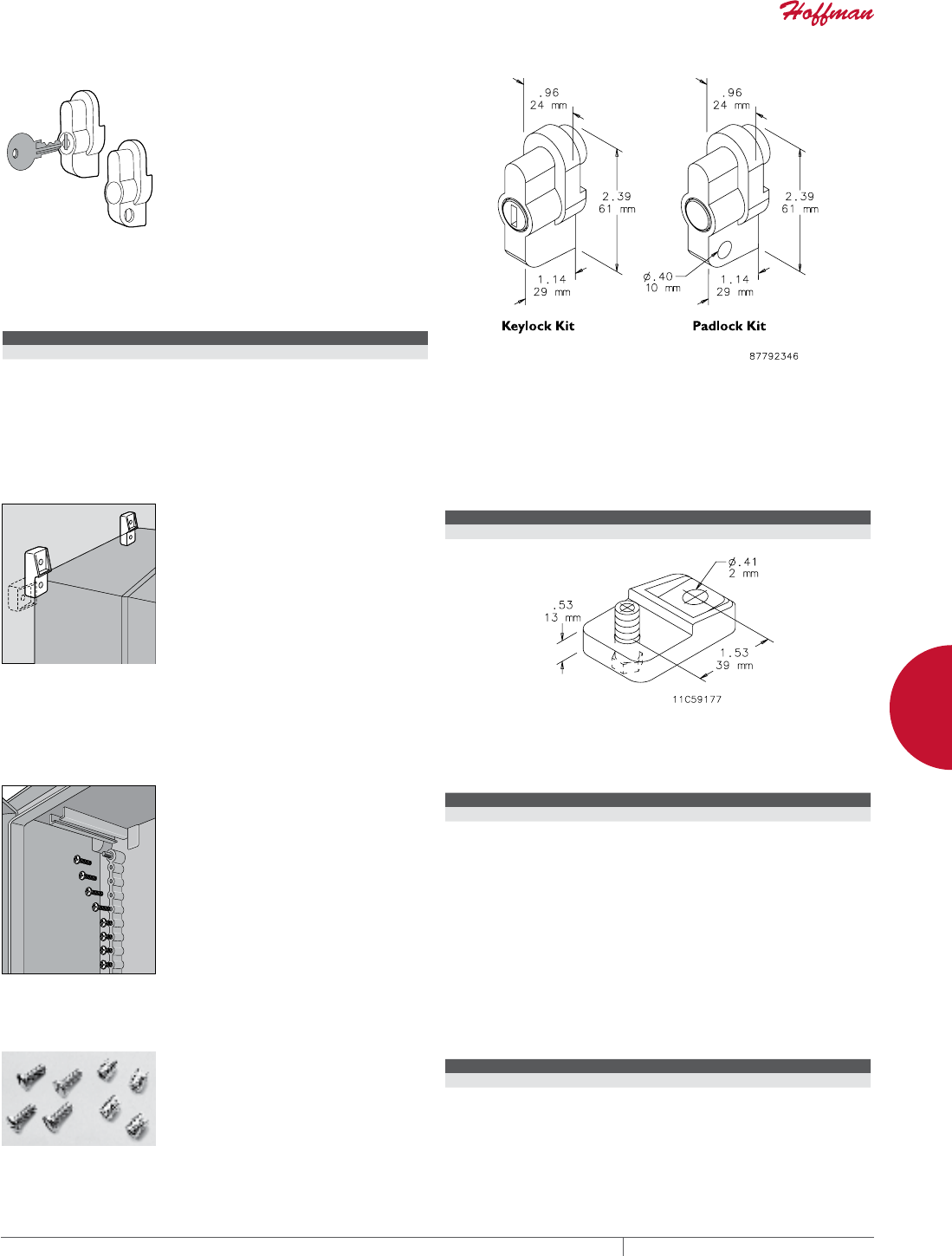
PH 763.422.2661 • FAX 763.422.2588 • PENTAIRPROTECT.COMEQUIPMENT PROTECTION NETWORKING 157
4
WALLMOUNT CABINETS ULTRX™ FIBERGLASS TYPE 4X WIFI CABINET AND ACCESSORIES
KEYLOCK KIT AND PADLOCK KIT
Keylock Kit or pushbutton-style Padlock Kit is easily inserted in
latch hole to prevent unauthorized personnel from gaining access to
enclosure contents. Each kit is fully assembled for easy installation
in the field. Type 316 stainless steel construction.
BULLETIN: UX1Y
Catalog Number Description
UUHKL Keylock Kit
UUHPL Padlock Kit
UUHKL: Internal key components are not stainless steel.
UUHPL: Handles maintain UL 508A, Type 3, 4, 4X and 12 when properly installed on a Hoffman enclosure. Set
up for 1/4-in. or 3/8-in. padlock.
ULTRX™ MOUNTING BRACKET KIT
Kit is field-installable. Corrosion-
resistant fiberglass material.
Type 316 stainless steel mounting
hardware is included. Four
mounting brackets per kit.
BULLETIN: UX1Y
Catalog Number Description Kit Qty.
UUMF Mounting Bracket Kit 4
SELFTAPPING SCREWS
Plated screws (1/4-15 x .88) mount
panels and accessories to DIN
bosses on back of enclosure.
BULLETIN: UX1Y
Catalog Number Description Pkg. Qty.
UUMH1 Self-Tapping Screws 10
SCREW INSERT KIT
Brass threaded inserts (10-32) with
plated screws. Used on door bosses
and DIN bosses.
BULLETIN: UX1Y
Catalog Number Description Kit Qty.
UUMH2 Screw Insert Kit 4 inserts and 4 screws
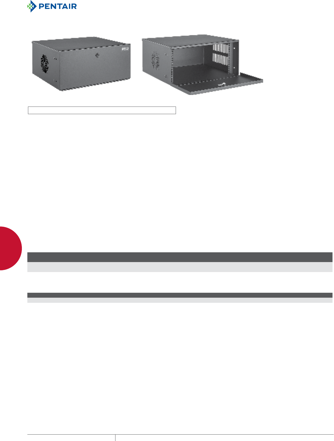
EQUIPMENT PROTECTIONSUBJECT TO CHANGE WITHOUT NOTICENETWORKING158
4
WALLMOUNT CABINETS SECURITY WALLMOUNT AND ACCESSORIES
SECURITY WALL-MOUNT AND ACCESSORIES
SECURITY DVR AND 19IN. RACK EQUIPMENT CABINET, TYPE 1
INDUSTRY STANDARDS
UL 508A Listed; Type 1
CSA; Type 1
NEMA/EEMAC; Type 1
IEC 60529 IP20
EIA 310-D (19-in. spacing for rack equipment)
Hoffman is an ISO 9001 company
APPLICATION
These cabinets provide physical protection and access control
to DVR, 19-in. equipment or other equipment. Mount the cabinet
vertically or horizontally on any surface.
FEATURES
• Houses 19-in. or shelf-mount equipment
• Top cover has tool-less removal, is captivated by door and
secured by keylock, providing easy access and installation
• Solid top cover protects equipment from falling debris
• Two standard models are 4 and 6 RU high
• Radius corners give streamlined appearance and eliminate sharp
edges
• Solid front door has 180-degree opening continuous hinge
• Quarter-turn keylock with two keys on door (code 333)
• Vented sides dissipate heat from equipment
• A fan-ready cutout is provided on left side
• 14 gauge steel rack angles are adjustable within the cabinet body
• Rack angle mounting square holes (.375 x .375 in.) with EIA
universal hole spacing (1/4 x 5/8 x 5/8 x 1/4-in.)
• Knockouts on bottom and side for data and power cables
• Rubber feet provide secure placement and prevent scratches
• Fasteners and cage nuts included
SPECIFICATIONS
• Doors and body made of 18 gauge steel; top cover is 16 gauge
steel
• Welded steel construction
• One set of rack angles included per EIA standard
• Included installation instructions show optional accessories
FINISH
Pretreated steel coated with RAL 9005 black, light-textured, low-
gloss polyester powder paint
ACCESSORIES
See also Accessories.
Rack- and Panel-Mount Power Distribution Unit (PDU)
Replacement Keys
Dual Thermostat
VELCRO® Cable Wrap
VELCRO is a trademark of Velcro Industries B.V.
BULLETIN: D85, DACCY, DWS1
Standard Product
Catalog Number
AxBxC
in./mm Rack Units (RU)
DVR4U 9.45x21.65x18.35
240x550x466
4
DVR6U 12.99x21.65x18.35
330x550x466
6
General Accessories
Catalog Number Description Key Code
E333KEY 2 replacement keys (fits all locks) 333
A4AXFNGQ Fan, 115 VAC, plus
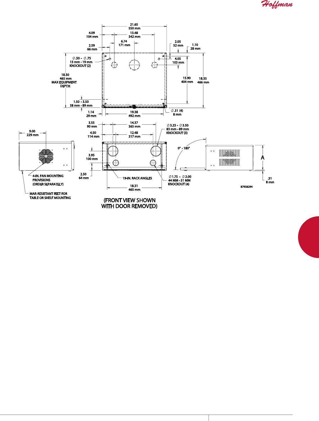
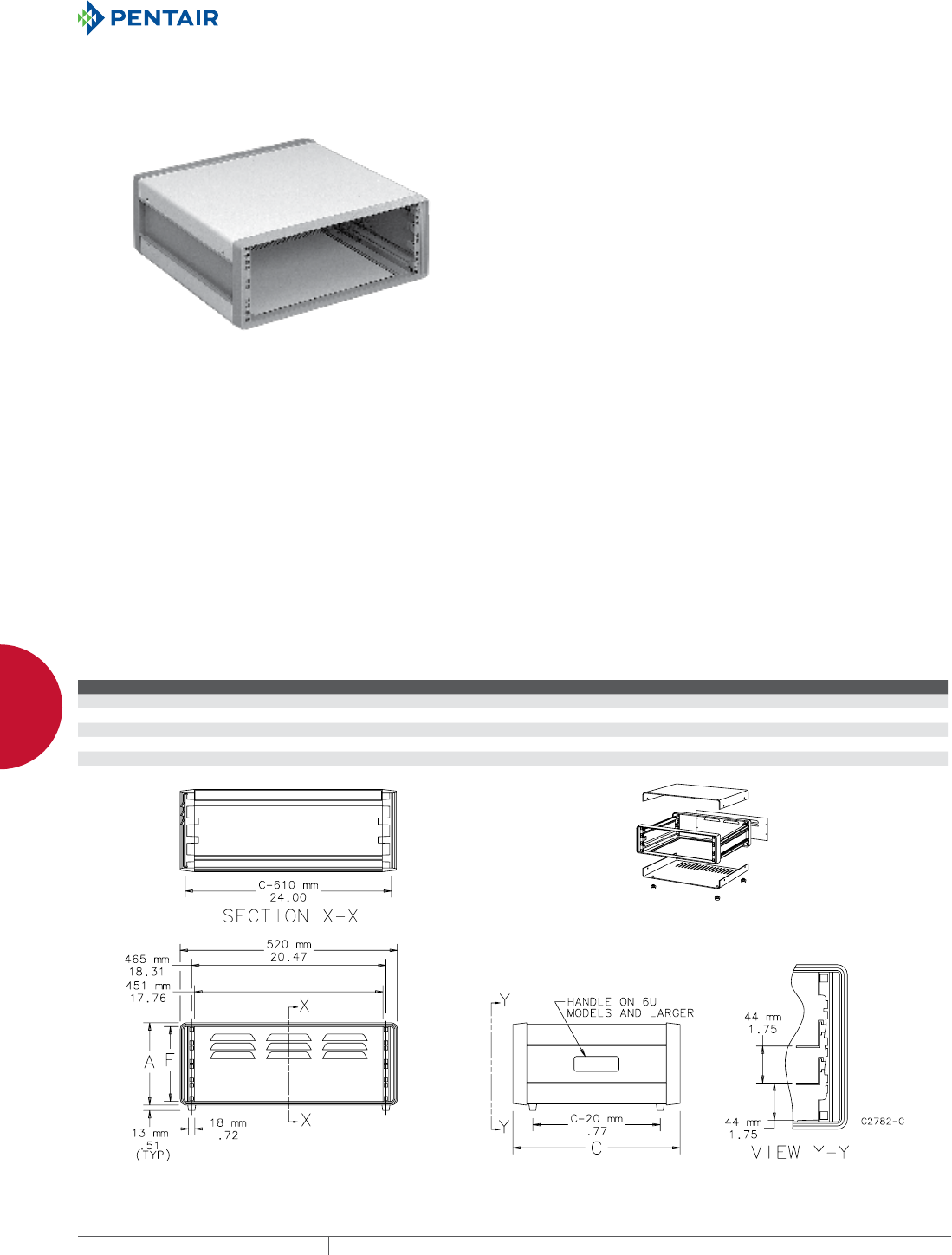
EQUIPMENT PROTECTIONSUBJECT TO CHANGE WITHOUT NOTICENETWORKING160
4
WALLMOUNT CABINETS SECURITY WALLMOUNT AND ACCESSORIES
19IN. ELECTRONIC CASE, TYPE 1
INDUSTRY STANDARDS
NEMA Type 1
EIA 310-D / IEC 297-1
IEC 60529, IP20
APPLICATION
Primarily used to house lab electronics, lightweight Electronic
Cases accommodate 19-in. sub-racks, chassis and panels in a rigid
ventilated case with integral handles.
FEATURES
• Aluminum extrusions attach to front and rear frames to create a
rigid supporting framework
• Sides on 3U and 4U tall cases are aluminum extrusions with
integral carrying handle. 6U tall cases have steel (1.5-mm) sides
with recessed handles. 9U and 12U tall cases have 1.5-mm
aluminum sides with recessed handles.
• Removable top and bottom covers attach directly to the case
framework
• Bottom cover has multiple rows of slots for ventilation
• Rear cover has ventilation louvers
• Covers are 1-mm steel on 3U, 4U, 6U tall cases and 1-mm
aluminum on 9U and 12U tall cases. Covers include grounding
provisions.
• Case framework is assembled with rear cover installed
• Top cover, bottom cover, anti-skid feet and mounting hardware
are included
• Optional tip-up foot kit, equipment guides and cage nuts are
available
SPECIFICATIONS
• One piece aluminum die-cast frame on front and rear
• 19-in. rack-mounting provisions on both front and rear frame
comply with EIA 310-D / IEC 297-1 wide spacing
• 9-mm square holes accommodate cage nuts for mounting
FINISH
Framework and rear cover have a stone-gray textured finish (RAL
7030). Top and bottom covers and metal sides have a light-gray
textured finish (RAL 7035).
ACCESSORIES
Hardware Kits
Slide Rails
Tip-Up Foot Kit
BULLETIN: DEC1
Standard Product
Catalog Number AxBxC mm AxBxC in. F (mm) F (in.)
EEC3U5250 166 x 520 x 500 6.54 x 20.47 x 19.69 133 5.24
EEC4U5250 210 x 520 x 500 8.27 x 20.47 x 19.69 178 7.01
EEC6U5260 299 x 520 x 600 11.77 x 20.47 x 23.62 267 10.51
EEC9U5260 433 x 520 x 600 17.05 x 20.47 x 23.62 400 15.75
EEC12U5260 566 x 520 x 600 22.28 x 20.47 x 23.62 533 20.98
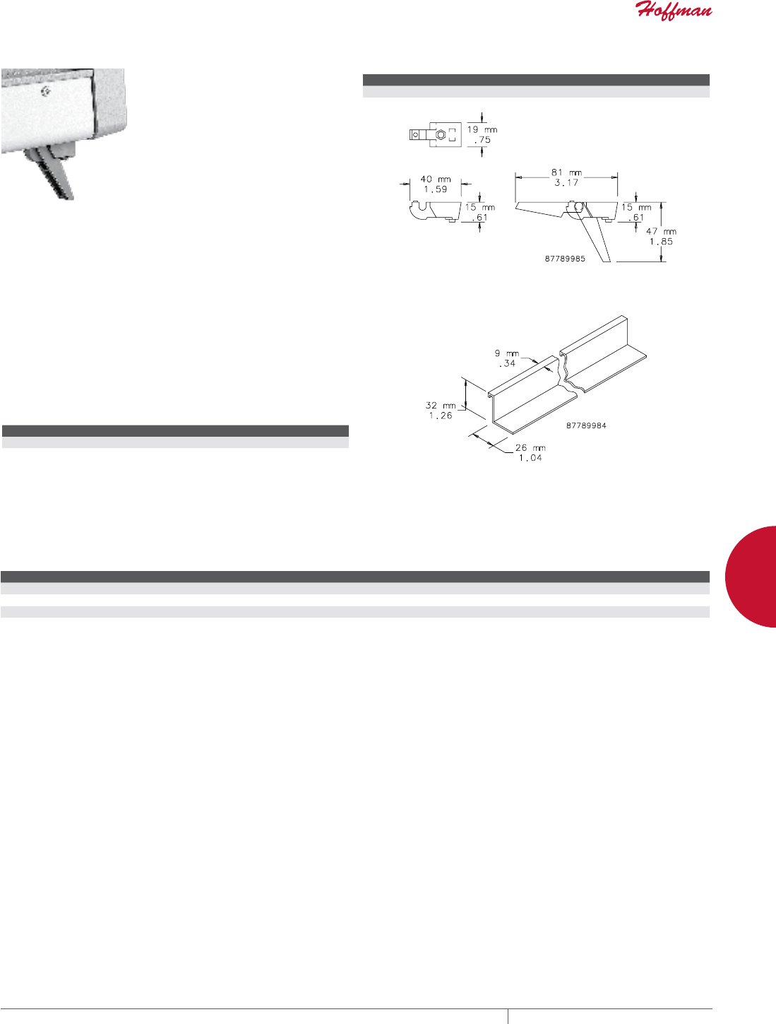
PH 763.422.2661 • FAX 763.422.2588 • PENTAIRPROTECT.COMEQUIPMENT PROTECTION NETWORKING 161
4
WALLMOUNT CABINETS SECURITY WALLMOUNT AND ACCESSORIES
TIPUP FOOT KIT FOR ELECTRONIC CASE
Tip-up feet can be mounted on
the bottom cover to provide an
improved viewing angle for rack
mounted equipment installed in an
electronic case. In tip-up position,
front of case is raised 1.38 in. (35
mm). Feet attach to holes provided
in the bottom cover and include an
anti-skid rubber insert. Feet are
gray plastic.
BULLETIN: DEC1
Catalog Number Description Kit Includes
EECFTP Tip-Up Foot Kit 2 tip-up feet, 2 standard feet and mounting hardware
SLIDE RAILS FOR ELECTRONIC CASE
Slide Rails support a 19-in. subrack or chassis when installed in
an electronic case. Rails attach to protrusions on the inside front
and back castings of the case framework. They are positionable in
increments of 1.75 in. (44 mm) vertically. Slide rails are aluminum
extrusions with a clear anodized finish. They snap into place; no
mounting hardware is required.
BULLETIN: DEC1
Catalog Number Fits Case Package Includes
EECCR50 500-mm deep 1 rail
EECCR60 600-mm deep 1 rail
HARDWARE KITS FOR ELECTRONIC CASE
Use to mount Electronic Case on rack angles with 9-mm square holes.
BULLETIN: DACCY, X20
Catalog Number Description Package Includes Package Qty.
ECNSM6 M6 fastener package Pan head Posidrive plated M6 x 16 screws, ABS black plastic cup washers and plated cage nuts 8
PM5CN M5 cage nut package M5 plated cage nuts 50
ASM5 M5 screw package Pan head combination screws 20
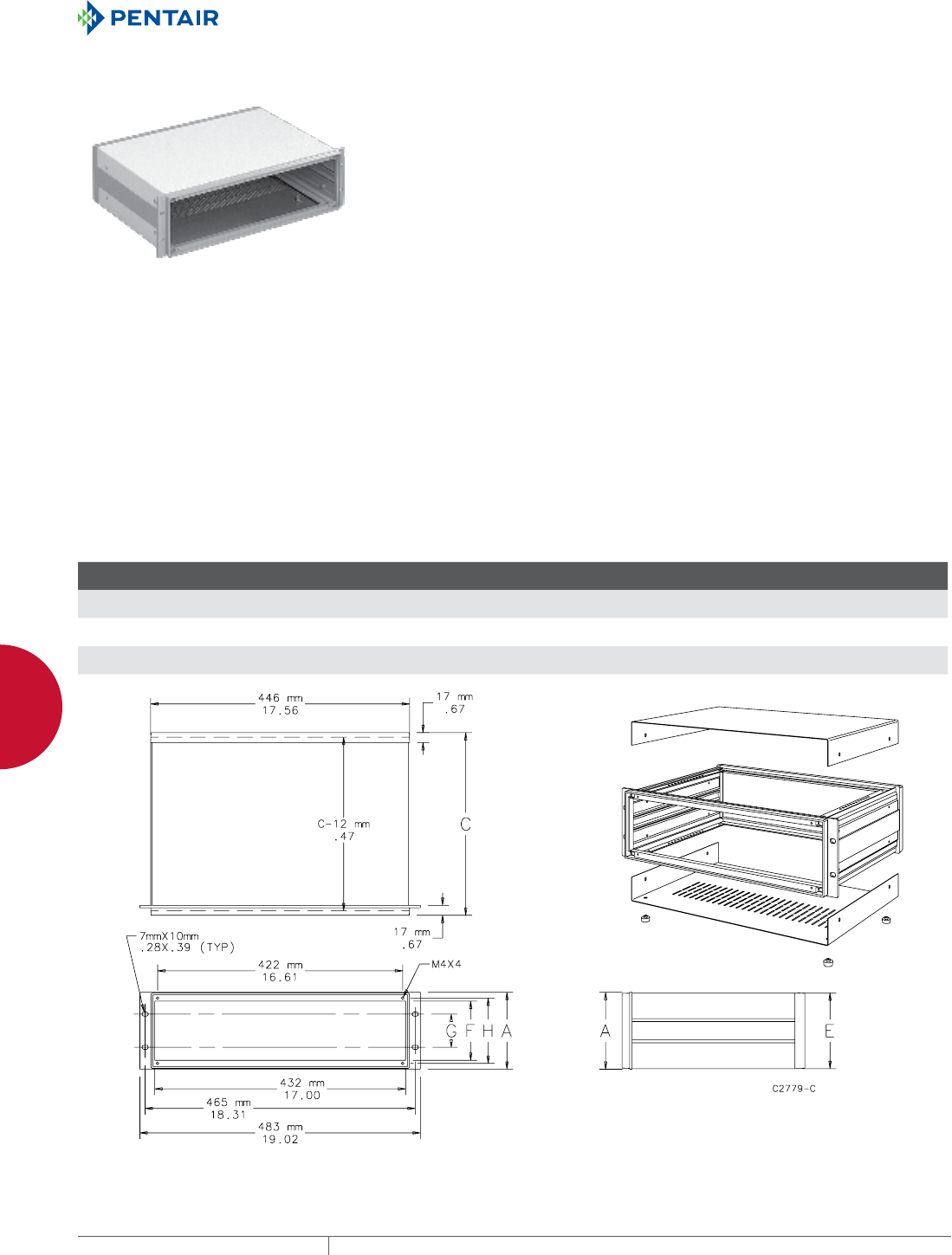
EQUIPMENT PROTECTIONSUBJECT TO CHANGE WITHOUT NOTICENETWORKING162
4
WALLMOUNT CABINETS 19IN. RACKMOUNT/DESKTOP CASE AND ACCESSORIES
19-IN. RACK-MOUNT/DESKTOP CASE AND ACCESSORIES
19IN. RACKMOUNT/DESKTOP CASE, TYPE 1
INDUSTRY STANDARDS
NEMA Type 1
IEC 60529, IP20
Exterior Dimensions
EIA 310-D / IEC 297-1
DIN 41494 Part 1
APPLICATION
Desktop cases house circuit boards and other electronic equipment
in a rigid framework with easy front and rear access. Rack cases
are 19-in. rack mountable with integral mounting provided in the
front bezel.
FEATURES
• Removable top and bottom covers attach directly to case
framework for maintenance convenience
• Bottom cover has multiple rows of holes for ventilation
• Front bezel includes mounting provisions for 19-in. rack mounting
as well as mounting for front panel options for application
flexibility
• Top and bottom of framework have mounting provisions for
optional support rails for application flexibility. Mounting holes
are spaced on 10-mm centers front to back.
• Case framework is assembled for quick installation. Top cover,
bottom cover, anti-skid feet and mounting hardware are included.
• Mounting hardware for optional front and rear panels are
included with case for installation convenience
SPECIFICATIONS
• One-piece aluminum die cast front bezel and rear bezel are
connected front-to-back with aluminum extrusions to form a rigid
structural framework
• Sides on 3U- and 4U-tall cases are the aluminum front-to-back
extrusions. The 6U-tall case has two aluminum extrusions with a
steel middle panel on each side.
• Covers are 1-mm steel and have grounding provisions
FINISH
Framework has an RAL 7030 stone-gray textured finish. Top and
bottom covers have an RAL 7035 light-gray textured finish on the
outside and a plated finish on the inside.
BULLETIN: DEC1
Standard Product
Catalog Number AxBxC mm/in.
E
mm/in.
F
mm/in.
G
mm/in.
H
mm/in. Rack Units
ERC3U4837 133 x 483 x 375
5.20 x 19.00 x 14.80
131
5.14
103
4.04
57
2.25
110
4.33
3
ERC4U4843 177 x 483 x 435
7.00 x 19.00 x 17.10
175
6.89
147
5.77
102
4.00
155
6.08
4
ERC6U4843 266 x 483 x 435
10.50 x 19.00 x 17.10
264
10.39
235
9.27
190
7.50
243
9.58
6
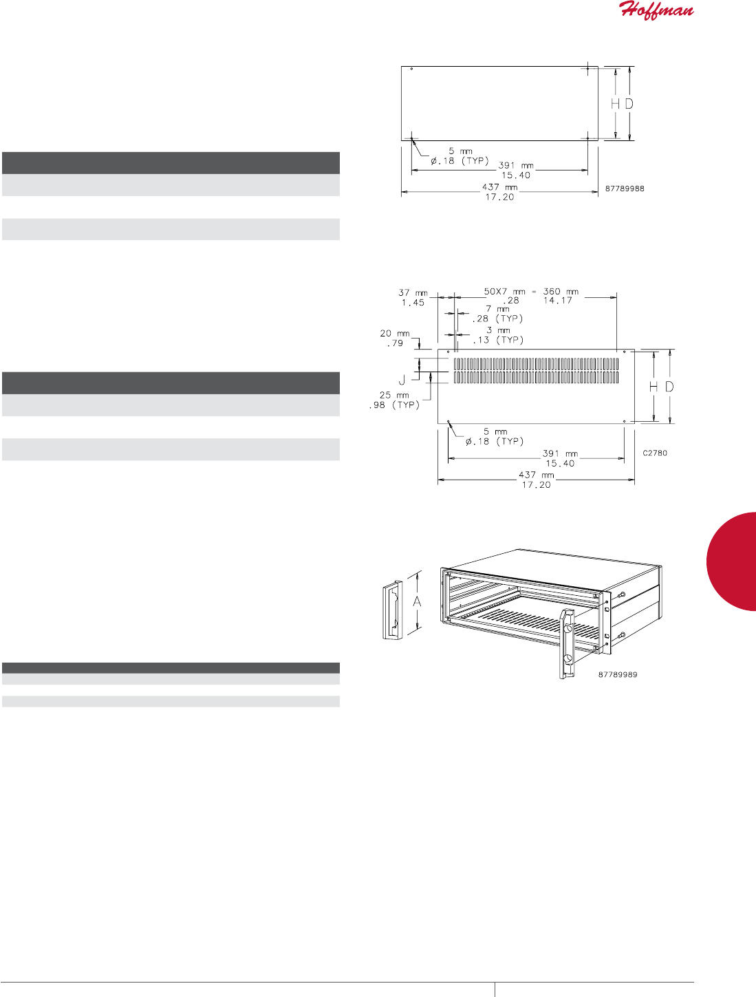
PH 763.422.2661 • FAX 763.422.2588 • PENTAIRPROTECT.COMEQUIPMENT PROTECTION NETWORKING 163
4
WALLMOUNT CABINETS 19IN. RACKMOUNT/DESKTOP CASE AND ACCESSORIES
FRONT PANELS
Blank front panel provides a means to close front or rear of a
desktop case. The smooth anodized surface is ideal for mounting
controls or meters, etc. The front panel is 2.5-mm thick and fits into
the 6-mm (0.24-in.) recess on front (or rear) of the case. Hardware
to mount front panel is furnished with case.
BULLETIN: DEC1
Catalog Number
D
mm/in.
H
mm/in.
ERCFP3U48 120.5
4.74
110.0
4.33
ERCFP4U48 165.0
6.50
154.5
6.08
ERCFP6U48 253.8
9.99
243.4
9.58
REAR PANELS
Rear panels are 2.5-mm thick anodized aluminum. They include
a row of ventilation slots (vertical) along the upper edge of panel.
6U covers have two rows of slots. Hardware to mount rear panel is
furnished with case.
BULLETIN: DEC1
Catalog Number
D
mm/in.
H
mm/in.
J
mm/in.
ERCRP3U48 121
4.74
110
4.33
25
.98
ERCRP4U48 165
6.50
155
6.08
25
.98
ERCRP6U48 254
9.99
243
9.58
25
.98
FRONT HANDLES
Handles facilitate movement of the desktop case and installation
of the case in a 19-in. rack. They are mounted to the rack-mounting
flanges on the 19-in. front bezel. Front bezels have holes partially
drilled and countersunk for location and must be drilled through
before handle installation. Handles are die-cast aluminum and
finished in light-gray (RAL 7030). Package includes two handles
with necessary mounting hardware.
BULLETIN: DEC1
Catalog Number
ERCFH3U
ERCFH4U
ERCFH6U
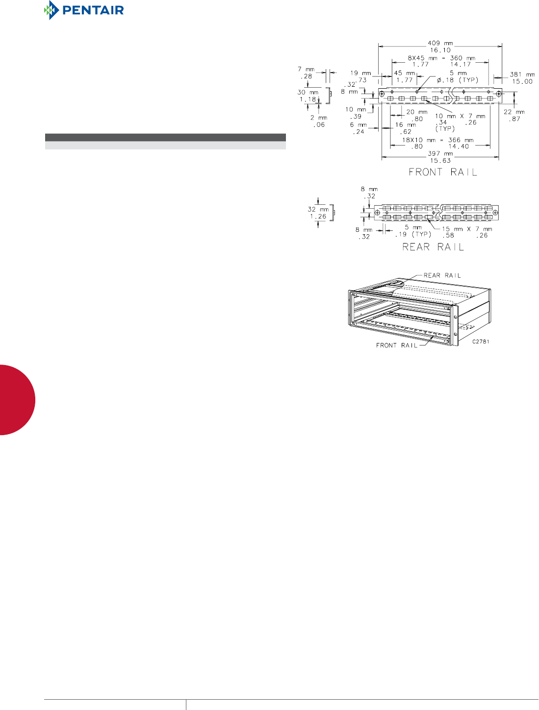
EQUIPMENT PROTECTIONSUBJECT TO CHANGE WITHOUT NOTICENETWORKING164
4
WALLMOUNT CABINETS 19IN. RACKMOUNT/DESKTOP CASE AND ACCESSORIES
SUPPORT RAIL KIT
Support rails are recommended for mounting and supporting
the weight of bulky components inside a desktop case. Support
rails have mounting holes and rectangular slots for mounting
components. Rails are 1.5-mm steel with a plated finish. M4
nuts are welded to the rail ends for easy attachment to the case.
Mounting holes in the desktop case are spaced on 10-mm centers
from front to back, allowing a variety of positions for support rails.
Support rail kit includes front rail, rear rail and mounting hardware.
BULLETIN: DEC1
Catalog Number Kit Includes
ERCRF48 1 front rail, 1 rear rail and mounting hardware


EQUIPMENT PROTECTIONSUBJECT TO CHANGE WITHOUT NOTICENETWORKING166
5
763.422.2661
763.422.2588
NETWORKING
WALL-MOUNT RACKS
Intro Page
CHAPTER 5
WALLMOUNT RACKS
WALLMOUNT RACKS
Protect sensitive electronics
with space-saving wall-mount
racks, cabinets and panels. Wall-
mount solutions are ideal for
securing networking wiring, hubs,
concentrators, patch panels and
audio/video equipment in areas that
full-size cabinets could block traffic
or airflow.
HINGED WALLMOUNT PANELS
19-in. Hinged Wall-Mount Panels provide
a solution for smaller networking
equipment such as telephone, punch-
down and patch panels. Easy access,
combined with minimal assembly,
facilitates component installation and
future expansion without disturbing
existing equipment or cabling.
FEATURED PRODUCTS

PH 763.422.2661 • FAX 763.422.2588 • PENTAIRPROTECT.COMEQUIPMENT PROTECTION NETWORKING 167
Intro Page CHAPTER CONTENTS
19IN. WALLMOUNT CABINETS, RACKS AND PANELS
VERSARACK™ .............................................168
VERSARACK™ Vertical Cable Manager ..........................169
PIVOTRACK™ .............................................170
CABLERACK™ .............................................171
19-in. Hinged Wall-Mount Panel ...............................172
CABLERACK™ Cable Bend Radius Accessory .....................172
19-in. Bottom-Hinged Panel ..................................173
19-in. Fixed Wall-Mount Rack ................................173
19-in. Side-Mount Cabinet ...................................174
5
SWINGOUT, WALLMOUNT RACKS
19-in. Swing-Out, Wall-Mount Racks
ensure superior protection for small
networking equipment, including
telephone and voicemail, routers,
switches, punch-down panels and
patch panels. Simple installation and
easy access enables expansion or rack
modifications.
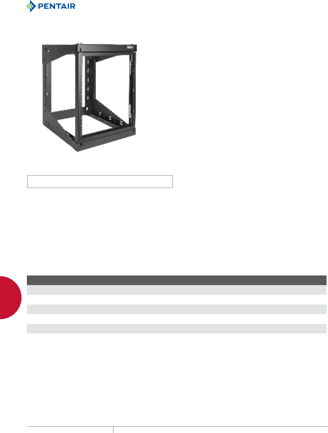
EQUIPMENT PROTECTIONSUBJECT TO CHANGE WITHOUT NOTICENETWORKING168
5
WALLMOUNT RACKS 19IN. WALLMOUNT CABINETS, RACKS AND PANELS
19-IN. WALL-MOUNT CABINETS, RACKS AND PANELS
VERSARACK™
INDUSTRY STANDARDS
UL 1863 Listed; File Number E230874
Rated to 100 lbs. with a 4X safety factor
EIA 310-D
APPLICATION
VERSARACK™ is used for wall mounting and securing 19-inch
rack equipment for Telecommunication Rooms and other locations.
The rack provides for either left or right hinging to accommodate
a variety of applications. These open frame racks are ideal for
high-density cabling application. VERSARACK is ideal for IDFs
(Intermediate Distribution Frames), remote 19-inch rack equipment,
building automation, security and many other applications.
FEATURES
• Designed to accommodate all standard 19-inch rack equipment
• Easy, single-tool assembly reduces installation time and cost
• Spring-load pivot pins provide for either left or right hinging; pins
can be arranged in unlocked or locked position
• Preassembled for fast, time-saving installation
• Temporary mounting bracket allows for rapid, single-person wall
installation
• UL double lug ground holes provide easy adherence to local
bonding and grounding codes
• Cable tie down points, sized for up to 1-inch Velcro® straps,
provided in horizontal and vertical positions in multiple locations
• Standard 12- or 24-inch deep offering to accommodate various
applications
• Open design provides for maximum access to cables and
equipment
• 19-inch rack fasteners (Phillips head, pilot point, black) 12-24,
quantity 20, included with rack
• Smart packaging with hand-carrying holes allows for easy
transportation
SPECIFICATIONS
• Wall section made of heavy gauge, cold rolled steel construction
• Welded pivoting rack section constructed of steel
• Tapped 12-24 holes per EIA Universal pattern standards (1/4-5/8-
5/8-1/4)
FINISH
• Pretreated steel coated with RAL 9005 black textured, low-gloss
polyester powder paint
• Hardware is clear or plated black
• Rack 12-24 fasteners plated black
LOAD RATING
Static working load rating is 150 lbs. for all sizes
ACCESSORIES
Vertical Cable Managers
D-Ring Cable Manager
Blanking Panels
Grounding kits
PDUs
Shelves
BULLETIN: DOFRW
Standard Product
Catalog Number AxBxC in./mm
F
in./mm
G
in./mm Rack Units Vertical Cable Manager Accessory
E19SWM12U12 27.80 x 20.91 x 12.28
706 x 531 x 312
9.24
235
22.30
566
12 E19C12U
E19SWM12U24 27.80 x 20.91 x 24.29
706 x 531 x 617
21.24
540
22.30
22.30
12 E19C12U
E19SWM20U12 41.81 x 20.91 x 12.28
1062 x 531 x 312
9.24
235
36.31
922
20 E19C20U
E19SWM20U24 41.81 x 20.91 x 24.29
1062 x 531 x 617
21.24
540
36.31
922
20 E19C20U
E19SWM25U12 50.59 x 20.91 x 12.28
1285 x 531 x 312
9.24
235
45.09
1145
25 E19C25U
E19SWM25U24 50.59 x 20.91 x 24.29
1285 x 531 x 617
21.24
540
45.09
1145
25 E19C25U
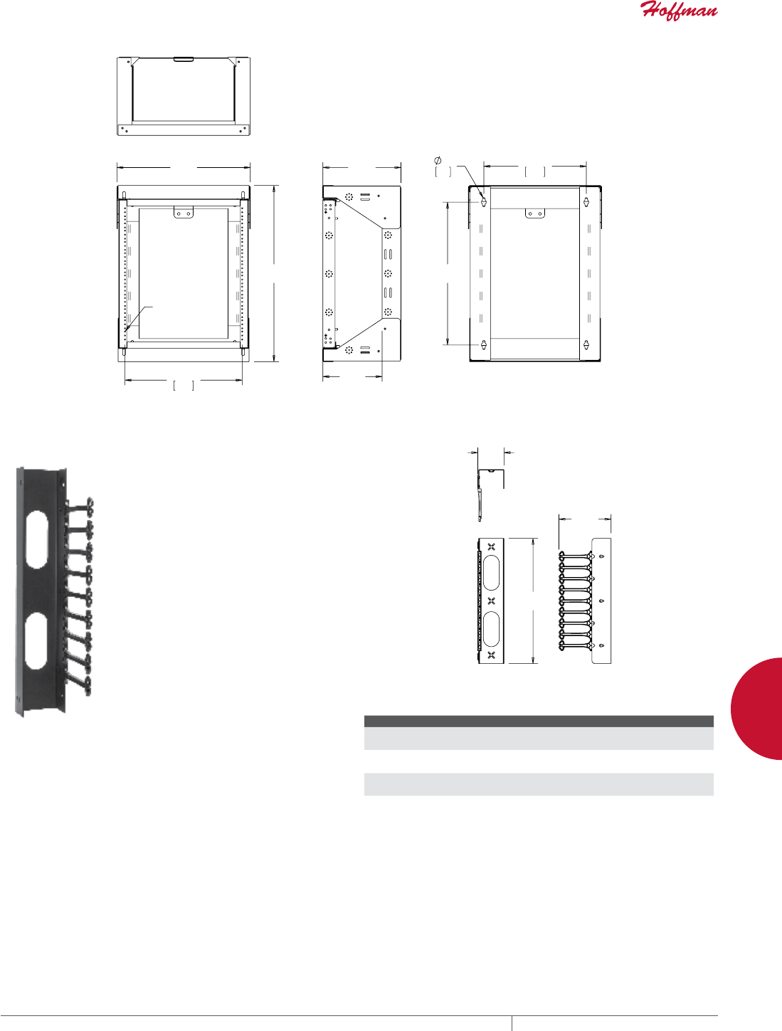
PH 763.422.2661 • FAX 763.422.2588 • PENTAIRPROTECT.COMEQUIPMENT PROTECTION NETWORKING 169
5
WALLMOUNT RACKS 19IN. WALLMOUNT CABINETS, RACKS AND PANELS
$
%
7<3
7$33('
&
)
*
;
VERSARACK™ VERTICAL CABLE MANAGER
VERSARACK™ offers a complimentary vertical cable manager that
easily attaches to the right or left side of Swing-Out Rack. Each
accessory includes one fully-assembled manager with retaining
hardware and installation instructions. One or two can be attached
to fit the application. The manager is made of formed steel with
composite support fingers. The vertical cable managers provides
for easy and convenient cable management for high-density
applications.
BULLETIN: DOFRW
$
&
%
Standard Product
Catalog Number AxBxC in./mm Use With
E19C12U 19.69 x 4.13 x 8.19
500 x 105 x 208
E19SWM12U12 or E19SWM12U24
E19C20U 28.66 x 4.13 x 8.19
728 x 105 x 208
E19SWM20U12 or E19SWM20U24
E19C25U 40.51 x 4.13 x 8.19
1029 x 105 x 208
E19SWM25U12 or E19SWM25U24
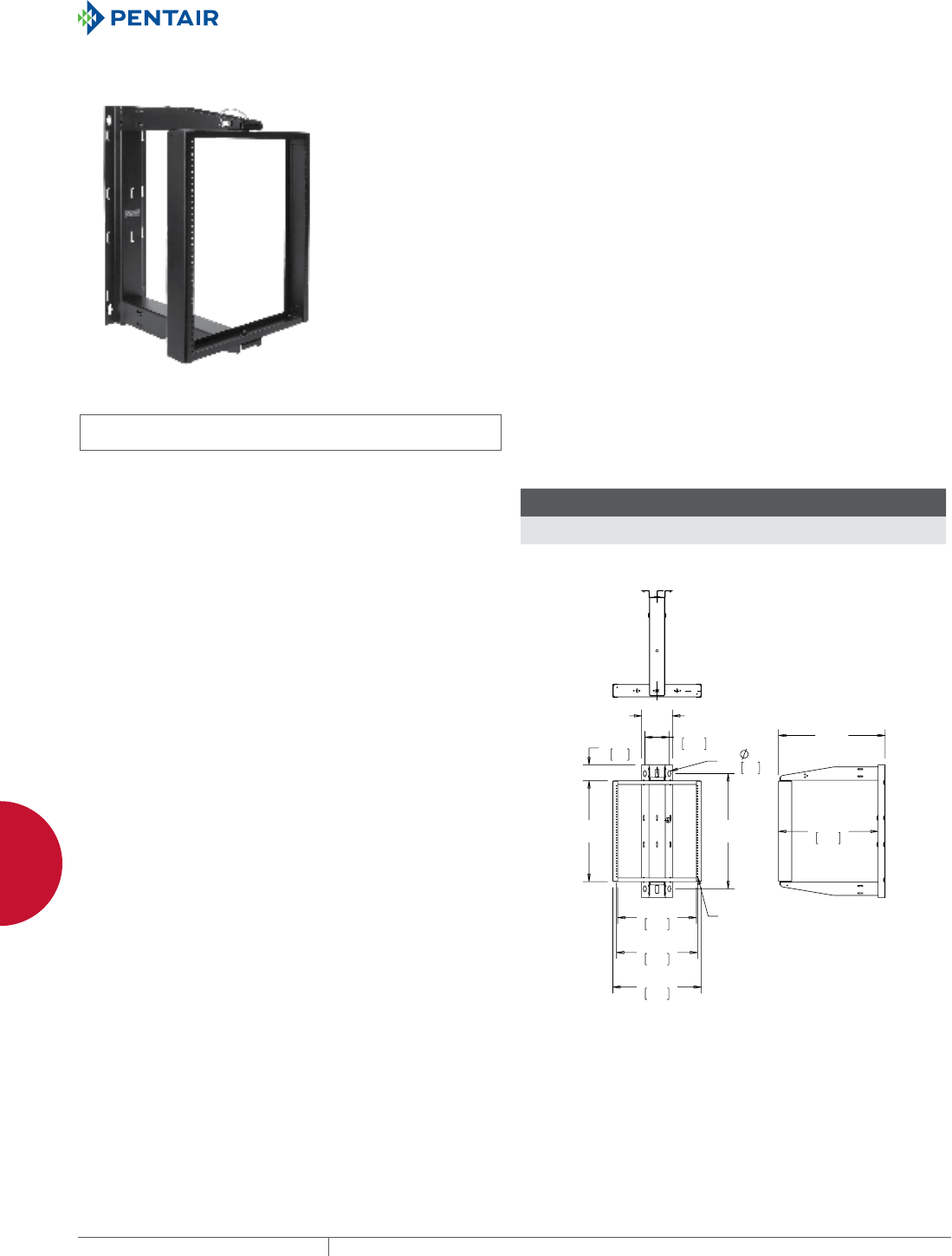
EQUIPMENT PROTECTIONSUBJECT TO CHANGE WITHOUT NOTICENETWORKING170
5
WALLMOUNT RACKS 19IN. WALLMOUNT CABINETS, RACKS AND PANELS
PIVOTRACK™
INDUSTRY STANDARDS
UL 1863 Listed; File Number E230874
Rated to 100 lbs. with a 4X safety factor
EIC 310-D
APPLICATION
PIVOTRACK™ is used for wall mounting and securing 19-inch rack
equipment for Telecommunication rooms and other locations. It
provides an economical means to support remote 19-inch rack
equipment. These open frame racks are ideal for high-density
cabling applications while providing maximum access to equipment
and cables. PIVOTRACK is ideal for IDFs (Intermediate Distribution
Frames), remote 19-inch rack equipment, building automation,
security and many other applications.
FEATURES
• Designed to accommodate all standard 19-inch rack equipment
• Easy, single-tool assembly reduces installation time and cost
• Central pivot in two-position mounting provides maximum
versatility
• UL double lug ground holes provide easy adherence to local
bonding and grounding codes
• Lanyard pin locks rack in increments of 15°, providing a stable
position for cable and equipment installs
• Preassembled for fast, time-saving installation
• Temporary mounting bracket allows for rapid, single-person wall
installation
• Smart packaging with hand carrying holes allows for easy
transportation
• Cable tie down points, sized for up to 1-inch Velcro® straps,
provided in horizontal and vertical positions in multiple locations
• Standard 24-inch deep offering to accommodate various
applications
• Open design provides for maximum access to cables and
equipment
• 19-inch rack fasteners (Phillips head, pilot point, black) 12-24,
quantity 20, included
SPECIFICATIONS
• Wall section made of heavy gauge, formed, cold rolled steel
construction
• Welded pivoting rack section made of formed, cold rolled steel
• Tapped 12-24 holes per EIA Universal pattern standards (1/4-5/8-
5/8-1/4)
FINISH
• Pretreated steel coated with RAL 9005 black textured, low-gloss
polyester powder paint
• Mounting hardware is clear or black plate
• Rack 12-24 fasteners plated black
LOAD RATING
Static working load rating is 150 lbs. for all sizes.
ACCESSORIES
Horizontal Cable Managers
Blanking Panels
Grounding kits
Velcro Tie down straps
PDUs
Shelves
BULLETIN: DOFRW
Standard Product
Catalog Number AxBxC in./mm
G
in./mm Rack Units
E19SWMC12U24 30.00 x 7.00 x 24.10
762 x 178 x 612
26.00
660
12
E19SWMC20U24 44.00 x 7.00 x 24.10
1118 x 178 x 612
40
1016
20
$
%
*
7<3
7$33('
;
&
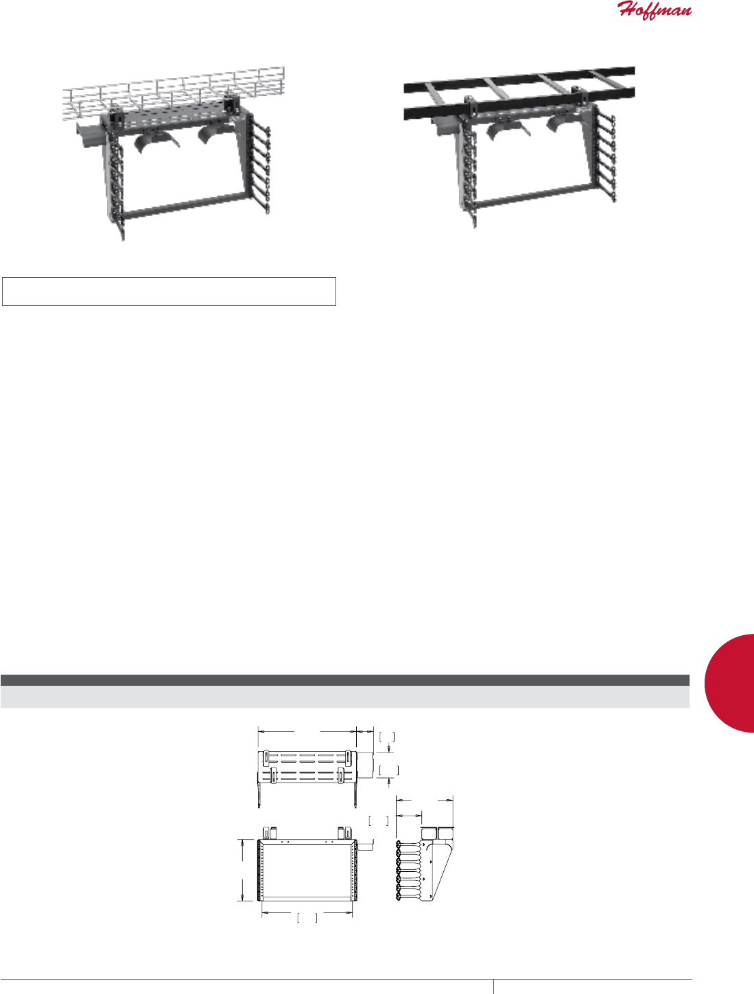
PH 763.422.2661 • FAX 763.422.2588 • PENTAIRPROTECT.COMEQUIPMENT PROTECTION NETWORKING 171
5
WALLMOUNT RACKS 19IN. WALLMOUNT CABINETS, RACKS AND PANELS
CABLERACK™
INDUSTRY STANDARDS
UL 1863 Listed; File Number E230874
Rated to 60 lbs. with a 4X safety factor
EIA 310-D
APPLICATION
CABLERACK™ is used for ladder or basket tray mounting
and securing 19-inch rack equipment for Data centers,
Telecommunication rooms and other locations. The fixed, open
frame rack allows suspending 19-inch rack equipment from Ladder
Rack or Basket Tray. The rack has universal tapped holes per
industry standards to accommodate typical applications. These
open frame racks are ideal for high-density cabling applications
which require above-the-cabinet mounting of equipment, and
provide maximum access to cables and equipment. CABLERACK
is ideal for Data Center applications, expanding equipment to
above-the-cabinet while providing increased equipment and cable
densities.
FEATURES
• Designed to accommodate all standard 19-inch rack equipment
• Easy, single-tool assembly reduces installation time and cost
• Preassembled for fast, time-saving installation
• Securely mounts to either Cable Runway (Ladder Rack) or Basket
Tray
• UL double lug ground holes provide easy adherence to local
bonding and grounding codes
• Cable tie down points, sized for up to 1-inch Velcro® straps,
provided in horizontal and vertical positions in multiple locations
• Parallel or perpendicular mounting to cable pathway
• Multi-point mounting provisions address various application
needs
• Open design provides for maximum access to cables and
equipment
• Smart packaging with hand-carrying holes allow for easy
transportation
SPECIFICATIONS
• Wall section made of heavy gauge cold rolled steel welded
construction
• Side supporting fingers made of composite material with black
finish
• Tapped holes (12-24UNC) per EIA Universal pattern standard (1/4-
5/8-5/8-1/4)
FINISH
• Pretreated steel coated with RAL 9005 black textured, low-gloss
polyester powder paint
• Hardware is clear or plated black
LOAD RATING
Static load rating is 100 lbs.
ACCESSORIES
Cable Bend Radius Accessory
Blanking Panels
Grounding kits
PDUs
Shelves
BULLETIN: DOFRW
Standard Product
Catalog Number AxBxC in./mm Rack Units Cable Bend Radius Accessory
E19T6U 12.44 x 20.16 x 11.50
316 x 512 x 292
6 ECMBA4
$
&
%
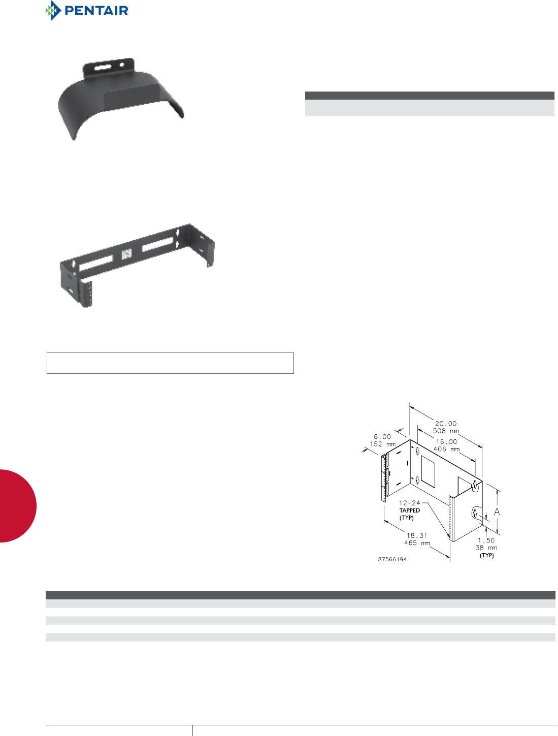
EQUIPMENT PROTECTIONSUBJECT TO CHANGE WITHOUT NOTICENETWORKING172
5
WALLMOUNT RACKS 19IN. WALLMOUNT CABINETS, RACKS AND PANELS
CABLERACK™ CABLE BEND RADIUS ACCESSORY CABLERACK™ has a complimentary cable bend radius accessory
which easily attaches to multiple locations on the rack. Each kit
includes four bend radius brackets and mounting hardware.
BULLETIN: DOFRW
Standard Product
Catalog Number AxBxC in./mm Use With
ECMBA4 2.24 x 5.16 x 3.46
57 x 131 x 88
E19T6U
19IN. HINGED WALLMOUNT PANEL
INDUSTRY STANDARDS
UL 1863 Listed; File No. E230874
cUL Listed per CSA C22.2 No. 182.4; File No. E230874
EIA 310-D
APPLICATION
The 19-in. Hinged Panel provides a solution for smaller network
equipment, punch-downs and patch panels in areas where
floor space is at a premium. Easy access facilitates component
installation and future expansion without disturbing existing
equipment or cabling. Can be mounted with hinges on left or right
side.
FEATURES
• Open design offers unrestricted airflow
• Large cable exit holes on back surface
• Keyhole mounting slots on 16-in. centers accommodate up to 3/8-
in. dia. mounting fasteners (not supplied)
• Heavy duty hinges are welded to frame
• Hinge provided for every two rack unit spacing
• One rack unit model has half-size hinge
• Provides access to rear of equipment
• 12-24 rack mounting screws (package of 20) included with
assembly
• Wall mounting hardware not included
SPECIFICATIONS
• Made of 12 gauge steel
• EIA universal 5/8, 5/8, 1/2 in. spaced 12-24 tapped holes. EIA
spacing provides 1.75 in. per rack unit.
FINISH
Finish is RAL 9005 black low-gloss polyester powder paint
BULLETIN: DOFRW
Standard Product
Catalog Number A (in.) A (mm) Load Rating (lb.) Load Rating (kg) Rack Units
E19HPM1U 1.75 44 25 11.3 1
E19HPM2U 3.50 89 50 22.7 2
E19HPM4U 8.00 203 100 45.4 4
E19HPM6U 10.50 267 150 68.0 6
E19HPM8U 14.00 356 200 90.7 8
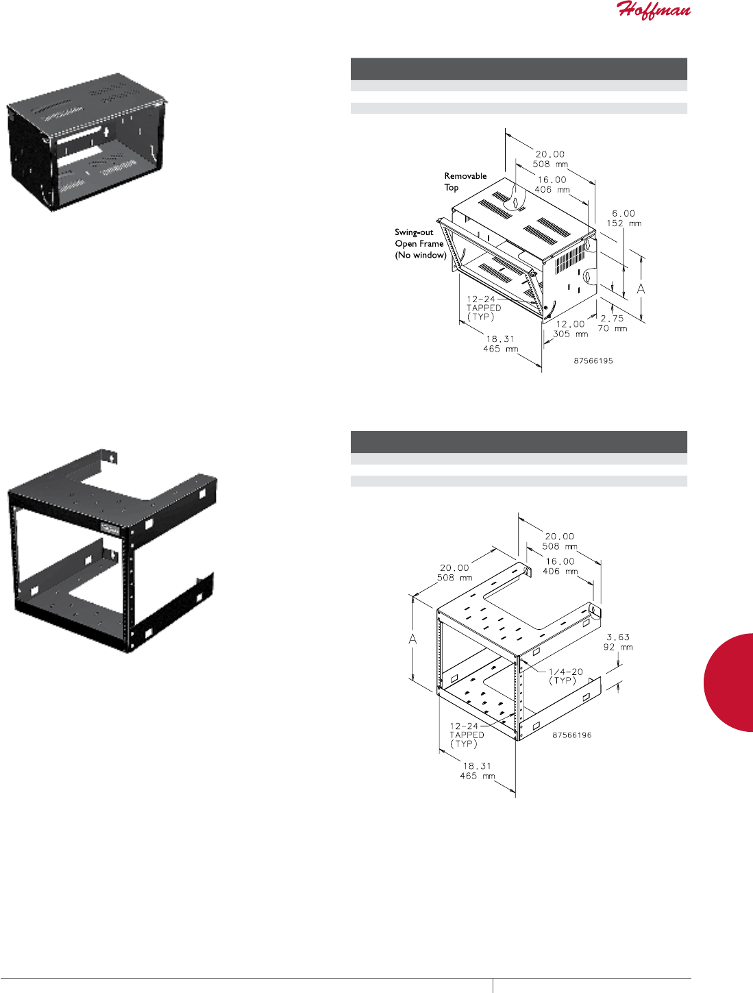
PH 763.422.2661 • FAX 763.422.2588 • PENTAIRPROTECT.COMEQUIPMENT PROTECTION NETWORKING 173
5
WALLMOUNT RACKS 19IN. WALLMOUNT CABINETS, RACKS AND PANELS
19IN. BOTTOMHINGED PANEL
Hinged panel pivots to 90 degrees with positive stop, providing
a stable platform for punch-down interconnects. Thumbscrews
secure the panel in the upright position. Integral VELCRO® cable
tiedown slots facilitate cable routing. Cover protects equipment and
cables. Made of 12 gauge steel on hinged swing-out frame; 16 gauge
on body. Finished with RAL 9005 low gloss black polyester powder
paint. Shipped fully assembled.
VELCRO® is a trademark of Velcro Industries B.V.
BULLETIN: DOFRW
Catalog Number A (in.) A (mm)
Load
Rating (lb.)
Load
Rating (kgs)
Rack
Units
E19BHPM4U12 8.00 203 25 11.3 4
E19BHPM6U12 10.50 267 50 22.7 6
E19BHPM8U12 14.00 356 50 22.7 8
19IN. FIXED WALLMOUNT RACK
Economical solution for banks of small networking equipment.
Integral VELCRO® cable tiedown slots facilitate cable routing. Made
of 16 gauge steel, finished with RAL 9005 low gloss black polyester
powder paint. Shipped in four easy-to-assemble sections.
VELCRO is a trademark of Velcro Industries B.V.
BULLETIN: DOFRW
Catalog Number A (in.) A (mm)
Load
Rating (lb.)
Load
Rating (kg)
Rack
Units
E19FWM12U20 23.00 584 150 68.0 12
E19FWM20U20 37.00 940 150 68.0 20
E19FWM25U20 45.75 1162 150 68.0 25
E19FWM32U20 58.00 1473 150 68.0 32
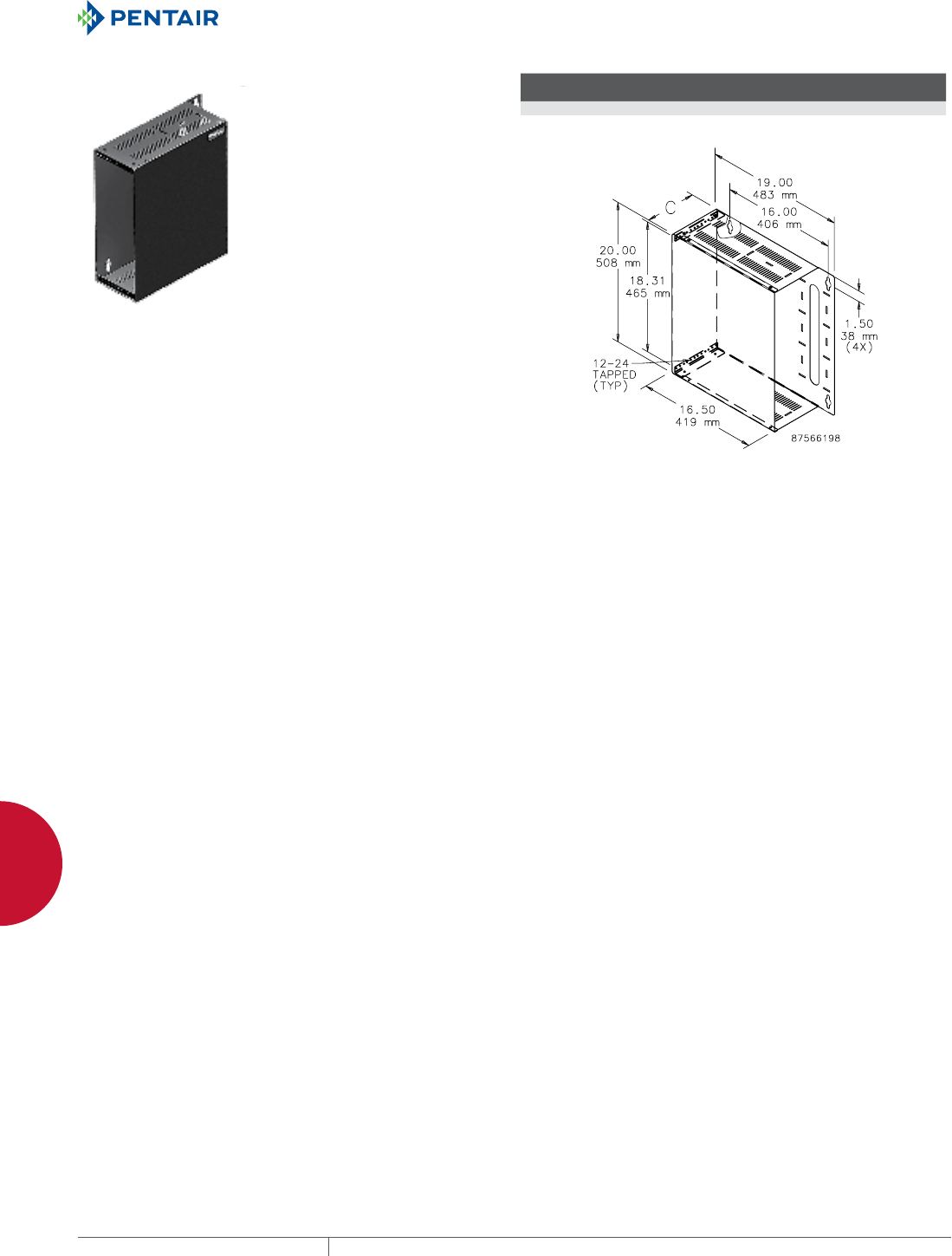
EQUIPMENT PROTECTIONSUBJECT TO CHANGE WITHOUT NOTICENETWORKING174
5
WALLMOUNT RACKS 19IN. WALLMOUNT CABINETS, RACKS AND PANELS
19IN. SIDEMOUNT CABINET
Equipment mounts sideways against the wall; ideal for applications
where a low profile is required. Easily removable front cover
protects equipment. Integral VELCRO® cable tiedown slots facilitate
cable routing. Made of 16 gauge steel, finished with RAL 9005 low
gloss black polyester powder paint. Shipped fully assembled.
VELCRO is a trademark of Velcro Industries B.V.
BULLETIN: DOFRY
Catalog Number C (in.) C (mm)
Load
Rating (lb.)
Load
Rating (kgs)
Rack
Units
E19SM2U 3.50 89 50 22.7 2
E19SM4U 7.00 178 50 22.7 4

EQUIPMENT PROTECTIONSUBJECT TO CHANGE WITHOUT NOTICENETWORKING176
6
763.422.2661
763.422.2588
NETWORKING
CABLE PATHWAY / BONDING AND GROUNDING
Intro Page
CHAPTER 6
CABLE RUNWAY SYSTEM/
BONDING AND GROUNDING
LADDER RACK SYSTEMS
From ceiling-mounted to under-floor
configurations, Ladder Rack Systems
route cables through unused space
on the floor, wall or ceiling while
keeping cables accessible for
easy maintenance. A full line of
components and accessories
facilitates a flexible, easy-to-
install cable runway system.
FEATURED PRODUCTS

PH 763.422.2661 • FAX 763.422.2588 • PENTAIRPROTECT.COMEQUIPMENT PROTECTION NETWORKING 177
Intro Page CHAPTER CONTENTS
CABLE PATHWAY AND ACCESSORIES
Ladder Rack System ........................................178
Ladder Rack Straight Sections (cULus Classified) .................179
Ladder Rack Curved Sections (cULus Classified) ..................179
90-Degree Horizontal E-Bend Section (cULus Classified) ............179
Butt-Splice Kit (cULus Classified) .............................179
Adjustable Butt-Splice Kit (cULus Classified) ....................179
Junction Splice Kit (cULus Classified) ..........................180
Adjustable Junction Splice Kit (cULus Classified) .................180
Retaining Post Kit ..........................................180
L-Bracket Kit .............................................180
Radius Drop Kit ............................................180
Stringer Radius Drop Kit .....................................180
Ceiling Support Kit .........................................181
Foot Kit ..................................................181
Rack-to-Runway Mounting Plate Kit ...........................181
Vertical Wall Bracket .......................................181
Triangle Support Bracket Kit .................................182
Modular Triangle Support Bracket Kit ...........................182
Wall Angle Support .........................................182
Corner Support Bracket Kit ...................................182
End Cap Kit ...............................................183
Runway Termination Kit .....................................183
Movable Cross Member .....................................183
Rack-to-Wall Kit ..........................................183
Runway Elevation Kit .......................................183
Runway Overhead 12-in. Stack Kit .............................184
Runway Center Support Kit ...................................184
Spool Divider Kit ...........................................184
Insulated Ground Jumper Kit .................................184
J-Bolt Kit ................................................185
CABLERACK™ .............................................185
QUICK TRAY PRO™
Straight Section ...........................................186
Splice Kit ................................................188
Splice Washer .............................................188
Splice Bars ...............................................188
Trapeze Hanging Clip .......................................189
C-Bracket ................................................189
Center Hangers ............................................189
L-Brackets ...............................................190
Reinforced Wall Bracket .....................................190
Divider Strip ..............................................191
Side-Action Bolt Cutter .....................................191
Vertical Down .............................................191
Wall-Termination Bracket ....................................192
Polymer Insert ............................................192
BONDING AND GROUNDING ACCESSORIES
Bonding and Grounding Overview ..............................194
Lay-In Lug ................................................195
Compression Lugs .........................................195
Heavy-Duty C-Taps .........................................195
Telecommunications Ground Bar Kits ...........................196
Vertical Ground Bar Kits .....................................196
Horizontal Ground Bar Kits ...................................196
Insulated Ground Jumper Kit .................................197
Rack Jumper Kit ...........................................197
6
BONDING AND GROUNDING
With a variety of bonding and grounding
accessories available—including
lugs, taps and bar kits—components
meet open frame rack and cabinet
bonding and grounding requirements
for telecommunication room and data
center applications.
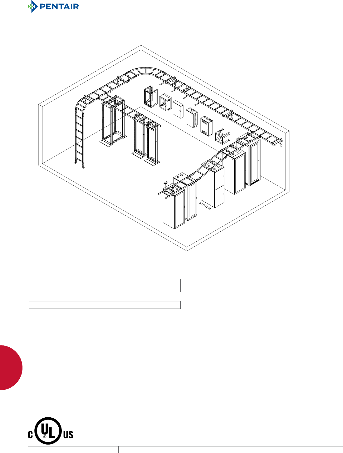
EQUIPMENT PROTECTIONSUBJECT TO CHANGE WITHOUT NOTICENETWORKING178
6
CABLE PATHWAY / BONDING AND GROUNDING CABLE PATHWAY AND ACCESSORIES
CABLE PATHWAY AND ACCES SORIES
LADDER RACK SYSTEM
INDUSTRY STANDARDS
Painted and Plated Straight Sections:
UL/cULus Classified for Equipment Grounding and Load; File No.
E236414
Curved Sections and Splice Kits:
UL/cULus Classified for Equipment Grounding; File No. E236414
cULus Bonding & Grounding
• Classified as suitable for an equipment ground conductor
- CSA C22.2 No. 126.1-02 Section 5.2.8 Load Destruction Test
• Two grounding jumper kits required per each splice kit on painted
ladder rack sections
cULus Load Testing
• Load capacity per 10 support lengths is 369.2 lb.; safety factor of
1.5X
- CSA C22.2 No. 126.1-02 Section 5.1 Electrical Continuity Test
APPLICATION
The Ladder Rack System conveniently routes cables via a modular
pathway through unused space on the floor, wall or ceiling
while keeping cables accessible for easy maintenance. A variety
of straight and curved sections are highly adaptable and can
accommodate virtually any room layout.
FEATURES
• Section cross members welded on 9-in. (229-mm) centers
• Accessory adjustable cross members
• Butt-splice kits and junction-splice kits
• Each model is boxed or bagged
SPECIFICATIONS
• Straight and curved sections made of 1-1/2-in. steel
• Sections available in 6-, 12-, 18- and 24-in. (152-, 305-, 457- and
610-mm) widths
• Steel connecting and mounting hardware
FINISH
Available in three finishes:
• ANSI 61 gray polyester powder paint
• RAL 9005 black polyester powder paint
• Plated
ACCESSORIES
Touch-up Paint
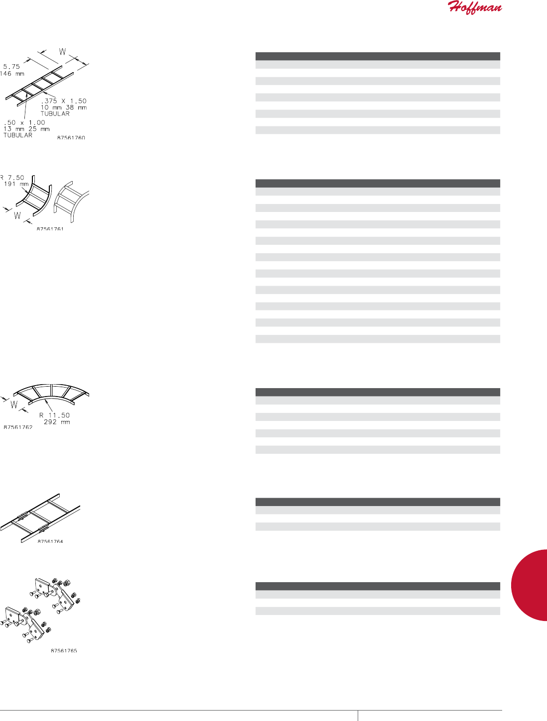
PH 763.422.2661 • FAX 763.422.2588 • PENTAIRPROTECT.COMEQUIPMENT PROTECTION NETWORKING 179
6
CABLE PATHWAY / BONDING AND GROUNDING CABLE PATHWAY AND ACCESSORIES
LADDER RACK STRAIGHT SECTIONS (CULUS CLASSIFIED)
Supports cable on straight runs.
Made of 1-1/2 in. x 3/8 in. (38 mm x
8 mm) 16 gauge tubular steel with
a painted or plated finish. Nominal
installed length is 10 ft. (3.05 m).
Each section is 9 ft. 11-1/2 in. (3.03
m) long with cross members welded
at 9-in. (229-mm) intervals.
BULLETIN: DCR
Catalog Number AxB in. AxB mm Finish W (in.) W (mm)
LSS6G 6.00 x 120.00 152 x 3048 Gray 6.00 152
LSS6BLK 6.00 x 120.00 152 x 3048 Black 6.00 152
LSS6GZ 6.00 x 120.00 152 x 3048 Plated 6.00 152
LSS12G 12.00 x 120.00 305 x 3048 Gray 12.00 305
LSS12BLK 12.00 x 120.00 305 x 3048 Black 12.00 305
LSS12GZ 12.00 x 120.00 305 x 3048 Plated 12.00 305
LSS18G 18.00 x 120.00 457 x 3048 Gray 18.00 457
LSS18BLK 18.00 x 120.00 457 x 3048 Black 18.00 457
LSS18GZ 18.00 x 120.00 457 x 3048 Plated 18.00 457
LSS24BLK 24.00 x 120.00 610 x 3048 Black 24.00 610
LADDER RACK CURVED SECTIONS (CULUS CLASSIFIED)
Provide a vertical change in
direction. They are made of 1-1/2
in. x 3/8 in. (38 mm x 8 mm) tubular
steel with a painted or plated finish.
Cross members are welded on the
inside (inside bends) or outside
(outside bends) of the section.
Connect to straight section with
butt-splice kits. Designed for
category 5e, 6, 6A and fiber optic
cable.
BULLETIN: DCR
Catalog Number Finish Vertical Bend Type W (in.) W (mm)
LIB6G Gray Inside 6.00 152
LIB6BLK Black Inside 6.00 152
LIB6GZ Plated Inside 6.00 152
LIB12G Gray Inside 12.00 305
LIB12BLK Black Inside 12.00 305
LIB12GZ Plated Inside 12.00 305
LIB18G Gray Inside 18.00 457
LIB18BLK Black Inside 18.00 457
LIB18GZ Plated Inside 18.00 457
LIB24BLK Black Inside 24.00 610
LOB6G Gray Outside 6.00 152
LOB6BLK Black Outside 6.00 152
LOB6GZ Plated Outside 6.00 152
LOB12G Gray Outside 12.00 305
LOB12BLK Black Outside 12.00 305
LOB12GZ Plated Outside 12.00 305
LOB18G Gray Outside 18.00 457
LOB18BLK Black Outside 18.00 457
LOB18GZ Plated Outside 18.00 457
LOB24BLK Black Outside 24.00 610
90DEGREE HORIZONTAL EBEND SECTION (CULUS CLASSIFIED)
Provide a 90-degree horizontal
change in cable runway direction.
Made of 1-1/2 in. x 3/8 in. (38 mm x
8 mm) tubular steel with a painted
or plated finish. Connect to straight
sections with butt-splice kits.
Designed for category 5e, 6, 6A and
fiber optic cable.
BULLETIN: DCR
Catalog Number Finish W (in.) W (mm)
L90HB12G Gray 12.00 305
L90HB12BLK Black 12.00 305
L90HB12GZ Plated 12.00 305
L90HB18G Gray 18.00 457
L90HB18BLK Black 18.00 457
L90HB18GZ Plated 18.00 457
L90HB24BLK Black 24.00 610
BUTTSPLICE KIT (CULUS CLASSIFIED)
Joins straight ladder rack sections,
inside and outside bends, and
90-degree horizontal e-bends. Each
kit connects one section to another.
Includes mounting hardware.
BULLETIN: DCR
Catalog Number Finish Kit Qty.
LBSKG Gray 2
LBSKB Black 2
LBSK Plated 2
ADJUSTABLE BUTTSPLICE KIT (CULUS CLASSIFIED)
Provides a change in up-and-down
direction of the cable runway. It
can be adjusted to any angle from
0 to 90 degrees. Made of steel with
a painted or plated finish. Each kit
connects one ladder rack section
to another. Includes mounting
hardware.
BULLETIN: DCR
Catalog Number Finish Kit Qty.
LABSKG Gray 2
LABSKB Black 2
LABSK Plated 2
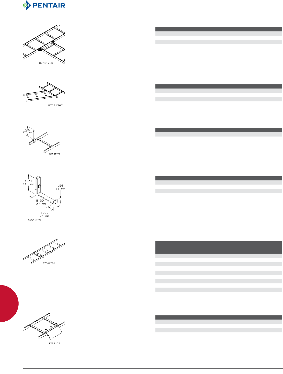
EQUIPMENT PROTECTIONSUBJECT TO CHANGE WITHOUT NOTICENETWORKING180
6
CABLE PATHWAY / BONDING AND GROUNDING CABLE PATHWAY AND ACCESSORIES
JUNCTION SPLICE KIT (CULUS CLASSIFIED)
Connects two straight ladder rack
sections at a 90-degree angle. Made
of steel with a painted or plated
finish. Each kit connects one section
to another. Includes mounting
hardware.
BULLETIN: DCR
Catalog Number Finish Kit Qty.
LJSKG Gray 2
LJSKB Black 2
LJSK Plated 2
ADJUSTABLE JUNCTION SPLICE KIT (CULUS CLASSIFIED)
Connects two ladder rack sections
at any junction angle. Made of steel
with a painted or plated finish. Each
kit connects one section to another.
Includes mounting hardware.
BULLETIN: DCR
Catalog Number Finish Kit Qty.
LAJSKG Gray 2
LAJSKB Black 2
LAJSK Plated 2
RETAINING POST KIT
Provides extra ladder rack capacity.
Mounts onto rack side stringer.
Post is unthreaded 1/2-in. tube.
Kit components are plated steel.
Includes post cap and mounting
hardware.
BULLETIN: DCR
Catalog Number Finish Kit Qty.
LRP Plated 1
LRPB Black 1
LBRACKET KIT
The L-Bracket Kit supports power
or other cables that need to be
separated from the main cable
run. Made of steel with a painted or
plated finish. Mounts onto ladder
rack stringer. Includes mounting
hardware.
BULLETIN: DCR
Catalog Number Finish Kit Qty.
LLBG Gray 1
LLBB Black 1
LLB Plated 1
RADIUS DROP KIT
Mounts over ladder rack cross
member to provide bending radius
when dropping cable. Includes
cable spools to separate cable and
all mounting hardware. Made of
extruded aluminum.
BULLETIN: DCR
Catalog Number Finish
Cable
Runway
Width (in.)
Cable
Runway
Width(mm)
Kit
Qty.
LRD6G Gray 6.00 152 1
LRD6BLK Black 6.00 152 1
LRD6GZ Aluminum 6.00 152 1
LRD12G Gray 12.00 305 1
LRD12BLK Black 12.00 305 1
LRD12GZ Aluminum 12.00 305 1
LRD18G Gray 18.00 457 1
LRD18BLK Black 18.00 457 1
LRD18GZ Aluminum 18.00 457 1
LRD24BLK Black 24.00 610 1
STRINGER RADIUS DROP KIT
Mounts over ladder rack stringer
to provide bending radius when
dropping cable. Includes cable
spools to separate cable and all
mounting hardware. Made of
extruded aluminum.
BULLETIN: DCR
Catalog Number Finish Kit Qty.
LSRDG Gray 1
LSRDBLK Black 1
LSRDGZ Aluminum 1
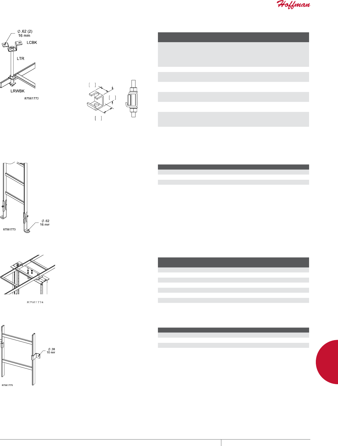
PH 763.422.2661 • FAX 763.422.2588 • PENTAIRPROTECT.COMEQUIPMENT PROTECTION NETWORKING 181
6
CABLE PATHWAY / BONDING AND GROUNDING CABLE PATHWAY AND ACCESSORIES
CEILING SUPPORT KIT
Supports ladder rack from ceiling.
Components available separately
or as a kit. Six-foot-long, 5/8-in.
diameter rod is threaded for easy
tension adjustment. Made of plated
steel. Requires surface mounting
hardware (not included).
BULLETIN: DCR
LRWSBK
Catalog Number Finish Description
Kit
Qty.
LCK Plated Kit includes one each:
- LTR Threaded Rod
- 5/8-in. nuts (4)
- LRWBK Rack Runway Bracket
- LCBK Ceiling Bracket
1
LTR Plated 5/8-in. x 6-ft. Threaded Rod 1
LRWBK Plated Rack Runway Brackets (10)
5/8-in. nuts (20)
1
LRWBKB Black Rack Runway Brackets (10)
5/8-in. nuts (20)
1
LCBK Plated Ceiling Brackets (10)
5/8-in nuts (20)
1
LCBKB Black Ceiling Brackets (10)
5/8-in nuts (20)
1
LRWSBK Plated Rack-to-Runway Brackets (10)
Slip-On
5/8 in. nuts (2)
1
LRWSBKB Black Rack-to-Runway Brackets (10)
Slip-On
5/8 in. nuts (2)
1
FOOT KIT
Secures ladder rack to floor, ceiling
or wall. Made of steel with a painted
or plated finish. One kit secures
one ladder rack section. Requires
surface mounting hardware (not
included).
BULLETIN: DCR
Catalog Number Finish Kit Qty.
LFKG Gray 2
LFKB Black 2
LFK Plated 2
RACKTORUNWAY MOUNTING PLATE KIT
Secures ladder rack to the top of
equipment racks. Made of steel with
a painted or plated finish. The plate
is designed for mounting either
parallel or perpendicular to the
rack. Includes mounting hardware.
BULLETIN: DCR
Catalog Number
Fits Ladder
Width Finish Kit Qty.
LRRMPG 6, 12 Gray 1
LRRMPBLK 6, 12 Black 1
LRRMPGZ 6, 12 Plated 1
LRRMPG18 12, 18 Gray 1
LRRMPBLK18 12, 18 Black 1
LRRMPGZ18 12, 18 Plated 1
LRRMPBLK24 18, 24 Black 1
VERTICAL WALL BRACKET
Secures ladder rack section to
wall or other flat surface. Made
of steel with a painted or plated
finish. Requires surface mounting
hardware (not included).
BULLETIN: DCR
Catalog Number Finish Kit Qty.
LVWBG Gray 2
LVWBB Black 2
LVWB Plated 2
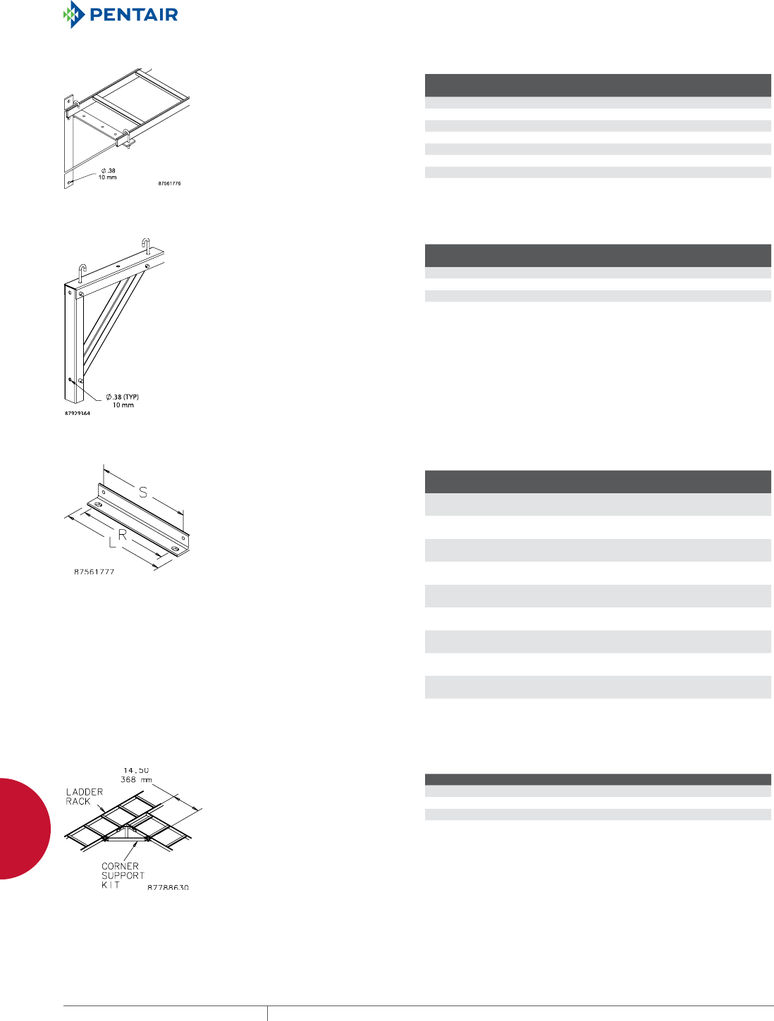
EQUIPMENT PROTECTIONSUBJECT TO CHANGE WITHOUT NOTICENETWORKING182
6
CABLE PATHWAY / BONDING AND GROUNDING CABLE PATHWAY AND ACCESSORIES
TRIANGLE SUPPORT BRACKET KIT
Supports ladder rack from wall.
Bracket is made of steel with
painted or plated finish. Brackets
have predrilled mounting holes for
two sizes of ladder rack. Includes
one J-Bolt Kit.
BULLETIN: DCR
Catalog Number A in. A mm Finish
Fits Cable
Runway Kit Qty.
LTSB12G 0.00 Gray 6, 12 1
LTSB12BLK 0.00 Black 6, 12 1
LTSB12GZ 0.00 Plated 6, 12 1
LTSB18G 0.00 Gray 12, 18 1
LTSB18BLK 0.00 Black 12, 18 1
LTSB18GZ 0.00 Plated 12, 18 1
LTSB24BLK 24.00 610 Black 12, 18, 24 1
MODULAR TRIANGLE SUPPORT BRACKET KIT
Secures and supports ladder rack to
wall. Design features three bracket
support arms that easily attach to
each other with quick-release pins
and fold down to ease assembly.
Each model accomodates two
ladder rack widths. Kit includes one
modular bracket assembly, three
quick-release pins and two J-bolts
with washers and nuts. Bracket
made of painted steel with plated
hardware.
BULLETIN: DCR
Catalog Number Finish
Fits Cable
Runway Kit Qty.
LMTSB12B Black 6, 12 1
LMTSB18B Black 12, 18 1
LMTSB24B Black 18, 24 1
WALL ANGLE SUPPORT
Supports ladder rack from wall or
other flat surface. Made of 2-in.
x 2-in. 10 gauge steel angle with
painted or plated finish. Includes
two J-bolts, nuts and screws.
BULLETIN: DCR
Catalog Number Finish
L
in./mm
R
in./mm
S
in./mm Kit Qty.
LWASK6G Gray 8.00
203
6.00
152
6.38
162
1
LWASK6BLK Black 8.00
203
6.00
152
6.38
162
1
LWASK6GZ Plated 8.00
203
6.00
152
6.38
162
1
LWASK12G Gray 14.00
356
12.00
305
12.38
314
1
LWASK12BLK Black 14.00
356
12.00
305
12.38
314
1
LWASK12GZ Plated 14.00
356
12.00
305
12.38
314
1
LWASK18G Gray 20.00
508
18.00
457
18.38
467
1
LWASK18BLK Black 20.00
508
18.00
457
18.38
467
1
LWASK18GZ Plated 20.00
508
18.00
457
18.38
467
1
LWASK24BLK Black 26.00
660
24.00
610
24.38
619
1
CORNER SUPPORT BRACKET KIT
Provides additional support for
90-degree ladder rack junction.
Made of steel with a painted or
plated finish.
BULLETIN: DCR
Catalog Number Finish Kit Qty.
LCSKG Gray 1
LCSKB Black 1
LCSK Plated 1
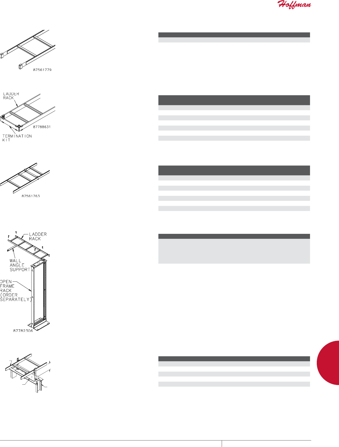
PH 763.422.2661 • FAX 763.422.2588 • PENTAIRPROTECT.COMEQUIPMENT PROTECTION NETWORKING 183
6
CABLE PATHWAY / BONDING AND GROUNDING CABLE PATHWAY AND ACCESSORIES
END CAP KIT
Provides protective covering for
ends of ladder rack. Made of black
vinyl.
BULLETIN: DCR
Catalog Number Kit Qty.
LEC 2
RUNWAY TERMINATION KIT
Provides a solid termination when
the last section of ladder rack ends
away from a wall. Made of steel with
a painted or plated finish.
BULLETIN: DCR
Catalog Number Finish
Fits Cable
Runway Kit Qty.
LRTK12G Gray 12 1
LRTK12B Black 12 1
LRTK12 Plated 12 1
LRTK18G Gray 18 1
LRTK18B Black 18 1
LRTK18 Plated 18 1
LRTK24B Black 24 1
MOVABLE CROSS MEMBER
Supports cable at drop locations
between welded cross members.
Made of steel with a painted or
plated finish. For maximum cable
protection, use with radius drop
kit. Includes hardware for secure
mounting to ladder rack stringers.
BULLETIN: DCR
Catalog Number Finish W (in.) W (mm)
Kit
Qty.
LMCM12G Gray 12.00 305 1
LMCM12BLK Black 12.00 305 1
LMCM12GZ Plated 12.00 305 1
LMCM18G Gray 18.00 457 1
LMCM18BLK Black 18.00 457 1
LMCM18GZ Plated 18.00 457 1
LMCM24BLK Black 24.00 610 1
RACKTOWALL KIT
Includes one section of straight
ladder rack and everything needed
to fasten the ladder section to an
open frame rack and to the wall.
Ladder is 54-in. (1372-mm) long by
12-in. (305-mm) wide. All parts have
a black painted finish. Order open
frame rack separately.
BULLETIN: DOFR2
Catalog Number Description
E45RUBKIT Each Rack-to-Wall Kit includes one:
- LSS12BLK [54-in. (1372-mm) long] Ladder Rack*
- LWASK12BLK Wall Angle Support with j-bolts
- LRRMPBLK Rack-to-Runway Mounting Kit
- LEC End Cap Kit
* Ladder Rack is cULus Classified
RUNWAY ELEVATION KIT
$
2SHQ
)UDP
H
5DFN
5DFNWR5XQZD\
0RXQWLQJ3ODWH.LW
2UGHU6HSDUDWHO\
6WUDLJKW
6HFWLRQ
Elevates ladder rack 3 or 6 in.
(76 or 152 mm) above rack-to-
ladder mounting plate. Use on any
width ladder rack. Kit includes
two brackets and all mounting
hardware. Made of heavy plated
steel.
BULLETIN: DCR
Catalog Number A (in.) A (mm) Finish Kit Qty.
LEK3 3.00 76 Plated 1
LEK3B 3.00 76 Black 1
LEK6 6.00 152 Plated 1
LEK6B 6.00 152 Black 1
LEK12 12.00 305 Plated 1
LEK12B 12.00 305 Black 1
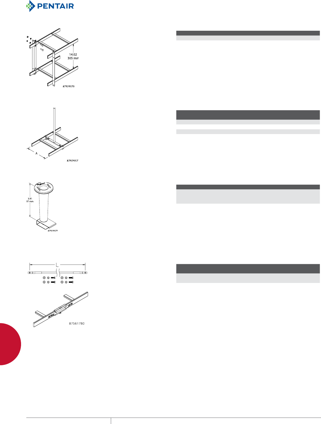
EQUIPMENT PROTECTIONSUBJECT TO CHANGE WITHOUT NOTICENETWORKING184
6
CABLE PATHWAY / BONDING AND GROUNDING CABLE PATHWAY AND ACCESSORIES
RUNWAY OVERHEAD 12IN. STACK KIT
Allows stacking any width of ladder
rack runways 12 in. (305 mm) above
each other. Each kit contains two
complete stacking brackets with all
necessary hardware. Use one kit
at least every 5 ft. (1.5 m). Brackets
and fasteners made of plated steel.
BULLETIN: DCR
Catalog Number Finish Includes Kit Qty.
LST12 Plated 2 brackets and hardware 1
LST12B Black 2 brackets and hardware 1
RUNWAY CENTER SUPPORT KIT
Threaded rod and bracket supports
center of ladder rack from ceiling.
Kit includes heavy-duty ladder rack
cross member, 5/8-in. threaded rod,
two J-bolts, protected sleeve and
5/8-in. nut. Use one kit at least every
5 ft. (1.5 m). Made of plated steel.
BULLETIN: DCR
Catalog Number Finish
Fits Cable
Runway Kit Qty.
LCSK6 Plated 6 1
LCSK12 Plated 12 1
LCSK18 Plated 18 1
LCSK24 Plated 24 1
SPOOL DIVIDER KIT
Spools separate cables to improve
cable management and to control
cable-to-cable distances. Spool
and bracket attach to ladder
rack cross member and can be
located anywhere across the
width. Kit includes ten 4-in.-tall
spools, brackets and all necessary
hardware. Spool made of black
plastic and bracket made of plated
steel.
BULLETIN: DCR
Catalog Number Finish Kit Includes
LCRDSK Black plastic spool;
plated steel bracket
10 spools,
10 brackets and
mounting hardware
INSULATED GROUND JUMPER KIT
Fastens across splices to provide
a secure ground between sections
of ladder rack. Made of #6
AWG x 7 strand wire with green
THW insulation and two-hole
compression lugs mounted on each
end. Includes fasteners.
BULLETIN: DBG
Catalog Number Conductor Type
L
in./mm
DGJ #6-7 Stranded 12.00
305
cULus requires 2 kits per splice on all painted ladder sections
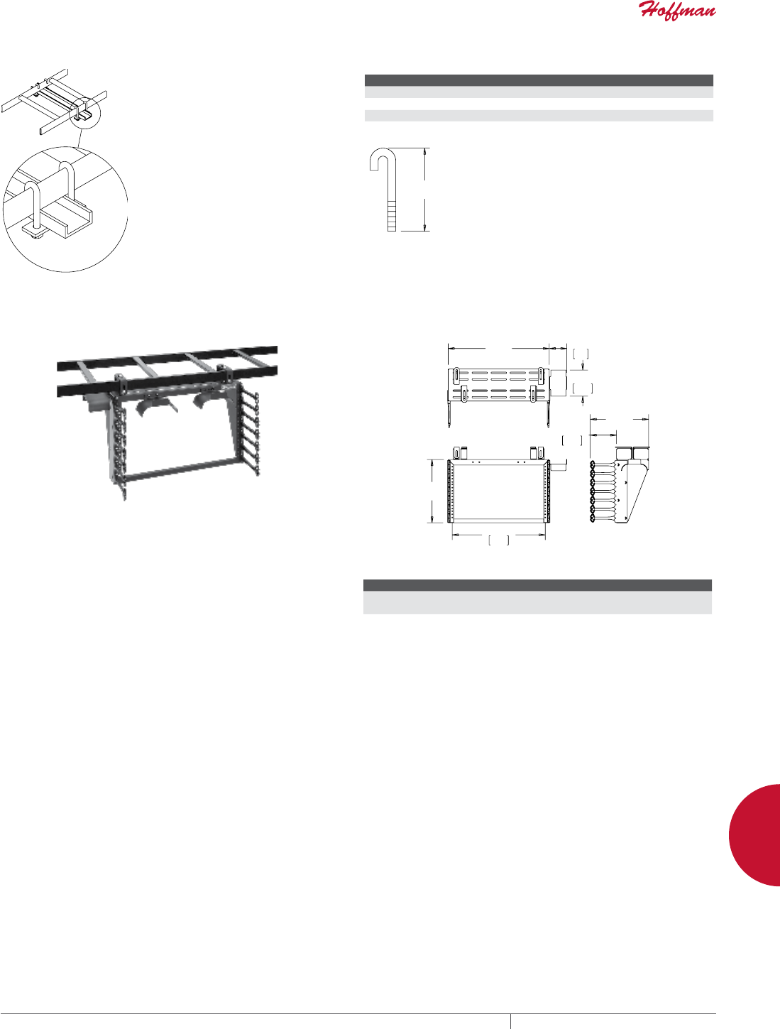
PH 763.422.2661 • FAX 763.422.2588 • PENTAIRPROTECT.COMEQUIPMENT PROTECTION NETWORKING 185
6
CABLE PATHWAY / BONDING AND GROUNDING CABLE PATHWAY AND ACCESSORIES
JBOLT KIT
Connects ladder rack to top of
cabinet or to auxiliary support
channel. Each kit includes two
J-bolts and makes one support
connection. Kit components are
plated steel. Includes mounting
hardware.
Each kit contains:
(2) J-Bolts, 5/16 in.
(2) Nuts, 5/16 in.
(2) Washers, 5/16 in.
(2) Lock Washers, 5/16 in.
(1) Plate
BULLETIN: DCR
Catalog Number J (in.) J (mm) Finish
LJBK 3.5 89 Plated
LJBK5 5.00 127 Plated
LJBK6 6.00 152 Plated
LJBK7 7.00 178 Plated
-
CABLERACK™
CABLERACK™ is used for ladder or basket tray mounting
and securing 19-inch rack equipment for Data centers,
Telecommunication rooms and other locations. The fixed, open
frame rack allows suspending 19-inch rack equipment from Ladder
Rack or Basket Tray. The rack has universal tapped holes per
industry standards to accommodate typical applications. These
open frame racks are ideal for high-density cabling applications
which require above-the-cabinet mounting of equipment, and
provide maximum access to cables and equipment. CABLERACK
is ideal for Data Center applications, expanding equipment to
above-the-cabinet while providing increased equipment and cable
densities.
BULLETIN: DOFRW
$
&
%
Standard Product
Catalog Number AxBxC in./mm Rack Units Cable Bend Radius Accessory
E19T6U 12.44 x 20.16 x 11.50
316 x 512 x 292
6 ECMBA4
EQUIPMENT PROTECTIONSUBJECT TO CHANGE WITHOUT NOTICENETWORKING186
6
CABLE PATHWAY / BONDING AND GROUNDING QUICK TRAY PRO™
QUICK TRAY PRO™
STRAIGHT SECTION
INDUSTRY STANDARDS
UL Classified for suitability as equipment ground conductor only.
NFPA 70, National Electrical Code, Article 392: Cable Trays;
provides UL Classification and labels
IEC 61537, Cable Tray Systems and Cable Ladder systems for Cable
Management
NEMA VE 1, Metal Cable Tray Systems, for materials, sizes and
configurations
APPLICATION
The QUICK TRAY PRO™ cable tray routes cables through unused
space while keeping them accessible for easy maintenance.
Combine components to configure a system that meets application
requirements.
SPECIFICATIONS
• Made of high-strength 5-mm or higher gauge steel wire
• T-weld top wire
FINISH
Pre-galvanized steel or black powder-coated finish.
BULLETIN: DQT
Standard Product
Catalog Number AxBxC in./mm Description Finish
Load per
6-ft. span
lbs./ft.
Cat6 Fill Rate*
.19-in. dia. cable
Cat6A Fill Rate*
.23-in. dia. cable
Splice
Quantity
QTP2X4 2.00 x 4.00 x 120.00
51 x 102 x 3048
2 x 4-in. Straight Section Pre-galvanized 43 108 99 2
QTP2X4BLK 2.00 x 4.00 x 120.00
51 x 102 x 3048
2 x 4-in. Straight Section Black 43 108 99 2
QTP2X6 2.00 x 6.00 x 120.00
51 x 152 x 3048
2 x 6-in. Straight Section Pre-galvanized 50 163 149 4
QTP2X6BLK 2.00 x 6.00 x 120.00
51 x 152 x 3048
2 x 6-in. Straight Section Black 50 163 149 4
QTP2X8 2.00 x 8.00 x 120.00
51 x 203 x 3048
2 x 8-in. Straight Section Pre-galvanized 52 218 200 4
QTP2X8BLK 2.00 x 8.00 x 120.00
51 x 203 x 3048
2 x 8-in. Straight Section Black 52 218 200 4
QTP2X12 2.00 x 12.00 x 120.00
51 x 305 x 3048
2 x 12-in. Straight Section Pre-galvanized 58 326 298 4
QTP2X12BLK 2.00 x 12.00 x 120.00
51 x 305 x 3048
2 x 12-in. Straight Section Black 58 326 298 4
QTP2X16 2.00 x 16.00 x 120.00
51 x 406 x 3048
2 x 16-in. Straight Section Pre-galvanized 70 439 402 4
QTP2X16BLK 2.00 x 16.00 x 120.00
51 x 406 x 3048
2 x 16-in. Straight Section Black 70 439 402 4
QTP2X18 2.00 x 18.00 x 120.00
51 x 457 x 3048
2 x 18-in. Straight Section Pre-galvanized 70 495 452 4
QTP2X18BLK 2.00 x 18.00 x 120.00
51 x 457 x 3048
2 x 18-in. Straight Section Black 70 495 452 4
QTP2X20 2.00 x 20.00 x 120.00
51 x 508 x 3048
2 x 20-in. Straight Section Pre-galvanized 73 550 503 5
QTP2X20BLK 2.00 x 20.00 x 120.00
51 x 508 x 3048
2 x 20-in. Straight Section Black 73 550 503 5
QTP2X22 2.00 x 22.00 x 120.00
51 x 559 x 3048
2 x 22-in. Straight Section Pre-galvanized 73 600 554 5
QTP2X22BLK 2.00 x 22.00 x 120.00
51 x 559 x 3048
2 x 22-in. Straight Section Black 73 600 554 5
QTP2X24 2.00 x 24.00 x 120.00
51 x 610 x 3048
2 x 24-in. Straight Section Pre-galvanized 75 660 604 5

PH 763.422.2661 • FAX 763.422.2588 • PENTAIRPROTECT.COMEQUIPMENT PROTECTION NETWORKING 187
6
CABLE PATHWAY / BONDING AND GROUNDING QUICK TRAY PRO™
Catalog Number AxBxC in./mm Description Finish
Load per
6-ft. span
lbs./ft.
Cat6 Fill Rate*
.19-in. dia. cable
Cat6A Fill Rate*
.23-in. dia. cable
Splice
Quantity
QTP2X24BLK 2.00 x 24.00 x 120.00
51 x 610 x 3048
2 x 24-in. Straight Section Black 75 660 604 5
QTP4X4 4.00 x 4.00 x 120.00
102 x 102 x 3048
4 x 4-in. Straight Section Pre-galvanized 45 205 188 4
QTP4X4BLK 4.00 x 4.00 x 120.00
102 x 102 x 3048
4 x 4-in. Straight Section Black 45 205 188 4
QTP4X6 4.00 x 6.00 x 120.00
102 x 152 x 3048
4 x 6-in. Straight Section Pre-galvanized 49 310 285 5
QTP4X6BLK 4.00 x 6.00 x 120.00
102 x 152 x 3048
4 x 6-in. Straight Section Black 49 310 285 5
QTP4X8 4.00 x 8.00 x 120.00
102 x 203 x 3048
4 x 8-in. Straight Section Pre-galvanized 78 416 380 6
QTP4X8BLK 4.00 x 8.00 x 120.00
102 x 203 x 3048
4 x 8-in. Straight Section Black 78 416 380 6
QTP4X12 4.00 x 12.00 x 120.00
102 x 305 x 3048
4 x 12-in. Straight Section Pre-galvanized 78 621 568 6
QTP4X12BLK 4.00 x 12.00 x 120.00
102 x 305 x 3048
4 x 12-in. Straight Section Black 78 621 568 6
QTP4X16 4.00 x 16.00 x 120.00
102 x 406 x 3048
4 x 16-in. Straight Section Pre-galvanized 108 837 765 7
QTP4X16BLK 4.00 x 16.00 x 120.00
102 x 406 x 3048
4 x 16-in. Straight Section Black 108 837 765 7
QTP4X18 4.00 x 18.00 x 120.00
102 x 457 x 3048
4 x 18-in. Straight Section Pre-galvanized 116 942 862 7
QTP4X18BLK 4.00 x 18.00 x 120.00
102 x 457 x 3048
4 x 18-in. Straight Section Black 116 942 862 7
QTP4X20 4.00 x 20.00 x 120.00
102 x 508 x 3048
4 x 20-in. Straight Section Pre-galvanized 116 1047 958 7
QTP4X20BLK 4.00 x 20.00 x 120.00
102 x 508 x 3048
4 x 20-in. Straight Section Black 116 1047 958 7
QTP4X22 4.00 x 22.00 x 120.00
102 x 559 x 3048
4 x 22-in. Straight Section Pre-galvanized 116 1152 1054 8
QTP4X22BLK 4.00 x 22.00 x 120.00
102 x 559 x 3048
4 x 22-in. Straight Section Black 116 1152 1054 8
QTP4X24 4.00 x 24.00 x 120.00
102 x 610 x 3048
4 x 24-in. Straight Section Pre-galvanized 116 1257 1150 8
QTP4X24BLK 4.00 x 24.00 x 120.00
102 x 610 x 3048
4 x 24-in. Straight Section Black 116 1257 1150 8
QTP6X8 6.00 x 8.00 x 120.00
152 x 203 x 3048
6 x 8-in. Straight Section Pre-galvanized 116 623 570 6
QTP6X8BLK 6.00 x 8.00 x 120.00
152 x 203 x 3048
6 x 8-in. Straight Section Black 116 623 570 6
QTP6X12 6.00 x 12.00 x 120.00
152 x 305 x 3048
6 x 12-in. Straight Section Pre-galvanized 123 931 852 6
QTP6X12BLK 6.00 x 12.00 x 120.00
152 x 305 x 3048
6 x 12-in. Straight Section Black 123 931 852 6
QTP6X16 6.00 x 16.00 x 120.00
152 x 406 x 3048
6 x 16-in. Straight Section Pre-galvanized 123 1255 1148 7
QTP6X16BLK 6.00 x 16.00 x 120.00
152 x 406 x 3048
6 x 16-in. Straight Section Black 123 1255 1148 7
QTP6X18 6.00 x 18.00 x 120.00
152 x 457 x 3048
6 x 18-in. Straight Section Pre-galvanized 127 1413 1292 7
QTP6X18BLK 6.00 x 18.00 x 120.00
152 x 457 x 3048
6 x 18-in. Straight Section Black 127 1413 1292 7
QTP6X20 6.00 x 20.00 x 120.00
152 x 508 x 3048
6 x 20-in. Straight Section Pre-galvanized 127 1571 1437 7
QTP6X20BLK 6.00 x 20.00 x 120.00
152 x 508 x 3048
6 x 20-in. Straight Section Black 127 1571 1437 7
QTP6X22 6.00 x 22.00 x 120.00
152 x 559 x 3048
6 x 22-in. Straight Section Pre-galvanized 127 1728 1580 8
QTP6X22BLK 6.00 x 22.00 x 120.00
152 x 559 x 3048
6 x 22-in. Straight Section Black 127 1728 1580 8
QTP6X24 6.00 x 24.00 x 120.00
152 x 610 x 3048
6 x 24-in. Straight Section Pre-galvanized 150 1886 1726 8
QTP6X24BLK 6.00 x 24.00 x 120.00
152 x 610 x 3048
6 x 24-in. Straight Section Black 150 1886 1726 8
* Based on 50% fill rate.
EQUIPMENT PROTECTIONSUBJECT TO CHANGE WITHOUT NOTICENETWORKING188
6
CABLE PATHWAY / BONDING AND GROUNDING QUICK TRAY PRO™
SPLICE KIT
Splice Kits are used for bolting
turns, bends and tees; connecting
QUICK TRAY PRO™ sections; and
fastening splice bars. Kit includes
three-piece staked bolt, washer and
nut.
BULLETIN: DQT
Catalog Number AxBxC in./mm Description Pkg. Qty.
QTPBNWK 2.00 x 4.00 x 2.00
51 x 102 x 51
Splice Kit (Zinc) 50
QTPBNWKBLK 2.00 x 4.00 x 2.00
51 x 102 x 51
Splice Kit (Black) 50
SPLICE WASHER
QUICK TRAY PRO Splice Washers
are used with QTPBNWK/
QTPBNWKBLK Splice Kits for
bolting turns, bends, and tees;
connecting tray sections; and
fastening splice bars.
BULLETIN: DQT
Catalog Number AxBxC in./mm Description Finish Pkg. Qty.
QTPSSW3 4.00 x 4.00 x 8.00
102 x 102 x 203
Splice Washer Pre-galvanized 50
QTPSSW3BLK 4.00 x 4.00 x 8.00
102 x 102 x 203
Splice Washer Black 50
SPLICE BARS
QUICK TRAY PRO Splice Bars provide extra support and stability
to tray sides when connecting tray sections with splice washers.
Universal bars can be cut to fit with bolt cutters and bent for use
in tees and elbows. Made of plated steel. Requires QTPSSW3/
QTPSSW3BLK Splice Washers and QTBNWK/QTPBNWKBLK Splice
Kits to fasten to side of tray.
BULLETIN: DQT
Catalog Number AxBxC in./mm Description Pkg. Qty.
QTPUS10 4.00 x 13.00 x 4.00
102 x 330 x 102
Splice Bar, 10 in. Universal (Zinc) 50
QTPUS10BLK 4.00 x 13.00 x 4.00
102 x 330 x 102
Splice Bar, 10 in. Universal (Black) 50
QTP90TKIT 1.00 x 5.00 x 5.00
25 x 127 x 127
Includes: (2) 90º bends; (8) washers, (8) nuts, (8) bolts (Zinc) 1
QTP90TKITBLK 1.00 x 5.00 x 5.00
25 x 127 x 127
Includes: (2) 90º bends; (8) washers, (8) nuts, (8) bolts (Black) 1
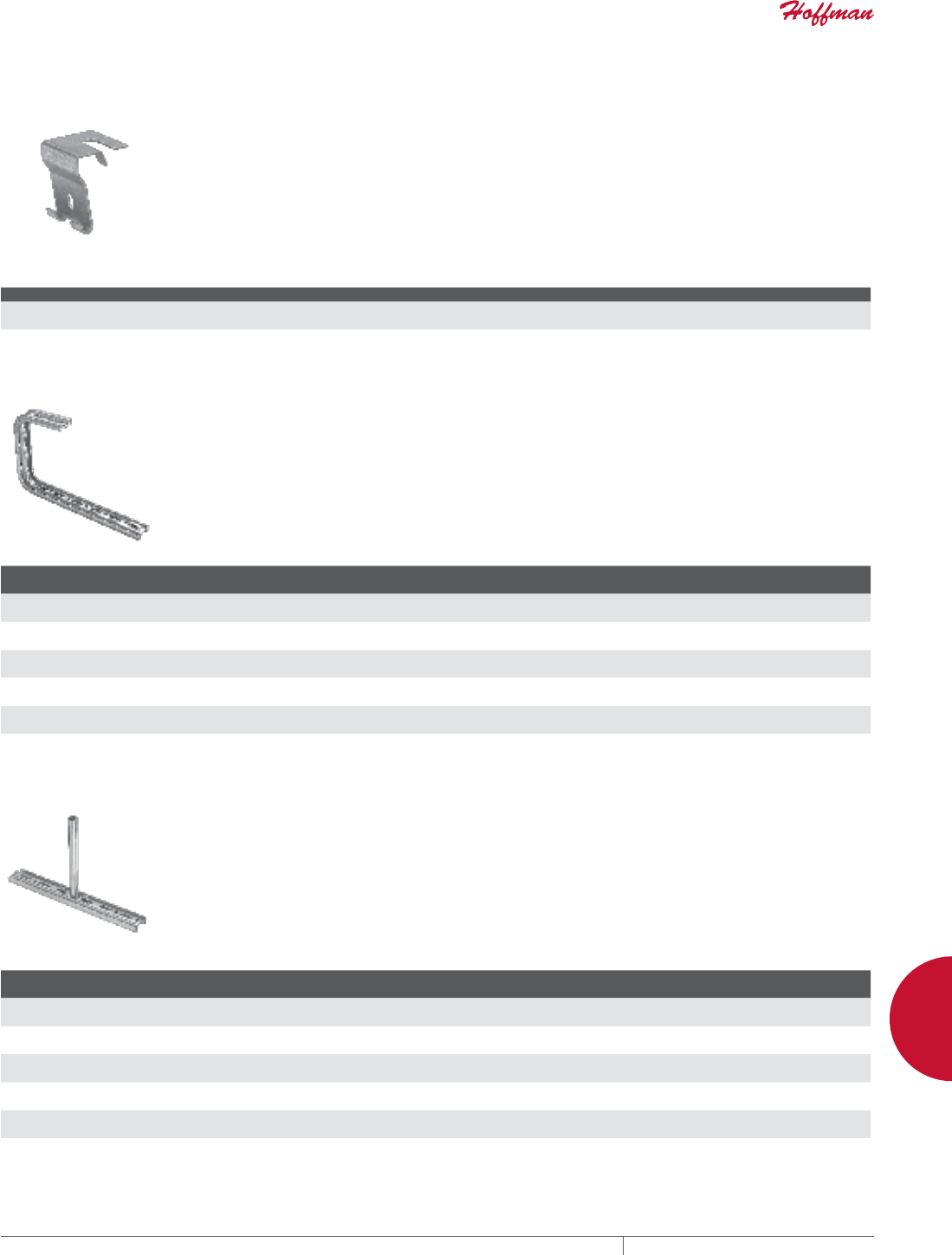
PH 763.422.2661 • FAX 763.422.2588 • PENTAIRPROTECT.COMEQUIPMENT PROTECTION NETWORKING 189
6
CABLE PATHWAY / BONDING AND GROUNDING QUICK TRAY PRO™
TRAPEZE HANGING CLIP
For trapeze hung QUICK TRAY PRO™ installations. Use with
1/4- or 3/8-in. threaded rod; obtain locally. Poly grommet retains
tray in slot-unsnaps to detach one side of tray for loading cables.
Corrosion-resistant pre-galvanized finish.
BULLETIN: DQT
Catalog Number AxBxC in./mm Description Pkg. Qty.
QTPTH 3.00 x 6.00 x 14.00
76 x 152 x 356
Trapeze Hanging Clips, Pre-galvanized 50
QTPTHBLK 3.00 x 6.00 x 14.00
76 x 152 x 356
Trapeze Hanging Clips, Black 50
CBRACKET
For QUICK TRAY PRO installations under ceiling or overhangs. Use
with tray widths up to 12 in. (305 mm). To secure tray to bracket, use
one QTPSSW3/QTPSSW3BLK Splice Washer and one QTPBNWK/
QTPBNWKBLK Splice Kit on sizes up to 8 in. (203 mm); use two
on 12-in. (305-mm) trays. Can be stacked for multi-level tray
installations. Corrosion resistant plated finish.
BULLETIN: DQT
Catalog Number AxBxC in./mm Description Finish
Tray Width
in./mm
QTPCB4 8.00 x 1.00 x 4.00
203 x 25 x 102
C-Bracket Pre-galvanized 4
102
QTPCB4BLK 8.00 x 1.00 x 4.00
203 x 25 x 102
C-Bracket Black 4
102
QTPCB8 8.00 x 1.00 x 8.00
203 x 25 x 203
C-Bracket Pre-galvanized 8
203
QTPCB8BLK 8.00 x 1.00 x 8.00
203 x 25 x 203
C-Bracket Black 8
203
QTPCB12 8.00 x 1.00 x 12.00
203 x 25 x 305
C-Bracket Pre-galvanized 12
305
QTPCB12BLK 8.00 x 1.00 x 12.00
203 x 25 x 305
C-Bracket Black 12
305
CENTER HANGERS
Use with up to 1/2-in. threaded rod (obtain locally). Only one rod
needed to suspend tray. Snap-on attachment holds QUICK TRAY
PRO cable tray secure without nuts and bolts. For use with 4- to
24-in. (102- to 610-mm) tray widths. Can be used for multiple-level
installations; 1/2-in. threaded rod recommended. Corrosion-
resistant plated finish.
BULLETIN: DQT
Catalog Number AxBxC in./mm Description Finish
Tray Width
in./mm
QTPCH4 7.50 x 4.00 x 1.00
191 x 102 x 25
Center Hanger Pre-galvanized 4
102
QTPCH4BLK 7.50 x 4.00 x 1.00
191 x 102 x 25
Center Hanger Black 4
102
QTPCH12 7.50 x 12.00 x 1.00
191 x 305 x 25
Center Hanger Pre-galvanized 12
305
QTPCH12BLK 7.50 x 12.00 x 1.00
191 x 305 x 25
Center Hanger Black 12
305
QTPCH24 7.50 x 24.00 x 1.00
191 x 610 x 25
Center Hanger Pre-galvanized 24
610
QTPCH24BLK 7.50 x 24.00 x 1.00
191 x 610 x 25
Center Hanger Black 24
610

EQUIPMENT PROTECTIONSUBJECT TO CHANGE WITHOUT NOTICENETWORKING190
6
CABLE PATHWAY / BONDING AND GROUNDING QUICK TRAY PRO™
LBRACKETS
L-Brackets mount directly to wall for overhead mounting.
Corrosion-resistant plated finish. Fasten QUICK TRAY PRO™ to
bracket with one QTPSSW3/QTPSSW3BLK Splice Washer and one
QTPBNWK/QTPBNWKBLK Splice Kit on sizes up to 8 in. (203 mm);
use two on 12-in. (305-mm) trays.
BULLETIN: DQT
Catalog Number AxBxC in./mm Description Finish
QTPLB4 6.00 x 1.00 x 4.00
152 x 25 x 102
4-in. L-Bracket Pre-galvanized
QTPLB4BLK 6.00 x 1.00 x 4.00
152 x 25 x 102
4-in. L-Bracket Black
QTPLB8 6.00 x 1.00 x 8.00
152 x 25 x 203
8-in. L-Bracket Pre-galvanized
QTPLB8BLK 6.00 x 1.00 x 8.00
152 x 25 x 203
8-in. L-Bracket Black
QTPLB12 6.00 x 1.00 x 12.00
152 x 25 x 305
12-in. L-Bracket Pre-galvanized
QTPLB12BLK 6.00 x 1.00 x 12.00
152 x 25 x 305
12-in. L-Bracket Black
REINFORCED WALL BRACKET
For heavy-duty QUICK TRAY PRO applications. Mounts on 1-5/8-in.
wide metal channel. To secure tray to bracket, use one QTPSSW3/
QTPSSW3BLK Splice Washer and one QTPBNWK/QTPBNWKBLK
Splice Kit on sizes up to 8 in. (203 mm); use two on 12-in. (305-mm)
and wider trays. Made of plated steel for corrosion resistance.
BULLETIN: DQT
Catalog Number AxBxC in./mm Description Finish
Width
in./mm
QTPRWB4 3.00 x 1.00 x 4.00
76 x 25 x 102
Reinforced Wall Bracket Pre-galvanized 4
102
QTPRWB4BLK 3.00 x 1.00 x 4.00
76 x 25 x 102
Reinforced Wall Bracket Black 4
102
QTPRWB6 3.00 x 1.00 x 6.00
76 x 25 x 152
Reinforced Wall Bracket Pre-galvanized 6
152
QTPRWB6BLK 3.00 x 1.00 x 6.00
76 x 25 x 152
Reinforced Wall Bracket Black 6
152
QTPRWB8 4.00 x 1.00 x 8.00
102 x 25 x 203
Reinforced Wall Bracket Pre-galvanized 8
203
QTPRWB8BLK 4.00 x 1.00 x 8.00
102 x 25 x 203
Reinforced Wall Bracket Black 8
203
QTPRWB12 6.00 x 1.00 x 12.00
152 x 25 x 305
Reinforced Wall Bracket Pre-galvanized 12
305
QTPRWB12BLK 6.00 x 1.00 x 12.00
152 x 25 x 305
Reinforced Wall Bracket Black 12
305
QTPRWB16 9.00 x 1.00 x 16.00
229 x 25 x 406
Reinforced Wall Bracket Pre-galvanized 16
406
QTPRWB16BLK 9.00 x 1.00 x 16.00
229 x 25 x 406
Reinforced Wall Bracket Black 16
406
QTPRWB18 3.00 x 8.00 x 3.00
76 x 203 x 76
Reinforced Wall Bracket Pre-galvanized 18
457
QTPRWB18BLK 3.00 x 8.00 x 3.00
76 x 203 x 76
Reinforced Wall Bracket Black 18
457
QTPRWB20 9.00 x 1.00 x 20.00
229 x 25 x 508
Reinforced Wall Bracket Pre-galvanized 20
508
QTPRWB20BLK 9.00 x 1.00 x 20.00
229 x 25 x 508
Reinforced Wall Bracket Black 20
508
QTPRWB24 9.00 x 1.00 x 24.00
229 x 25 x 610
Reinforced Wall Bracket Pre-galvanized 24
610
QTPRWB24BLK 9.00 x 1.00 x 24.00
229 x 25 x 610
Reinforced Wall Bracket Black 24
610
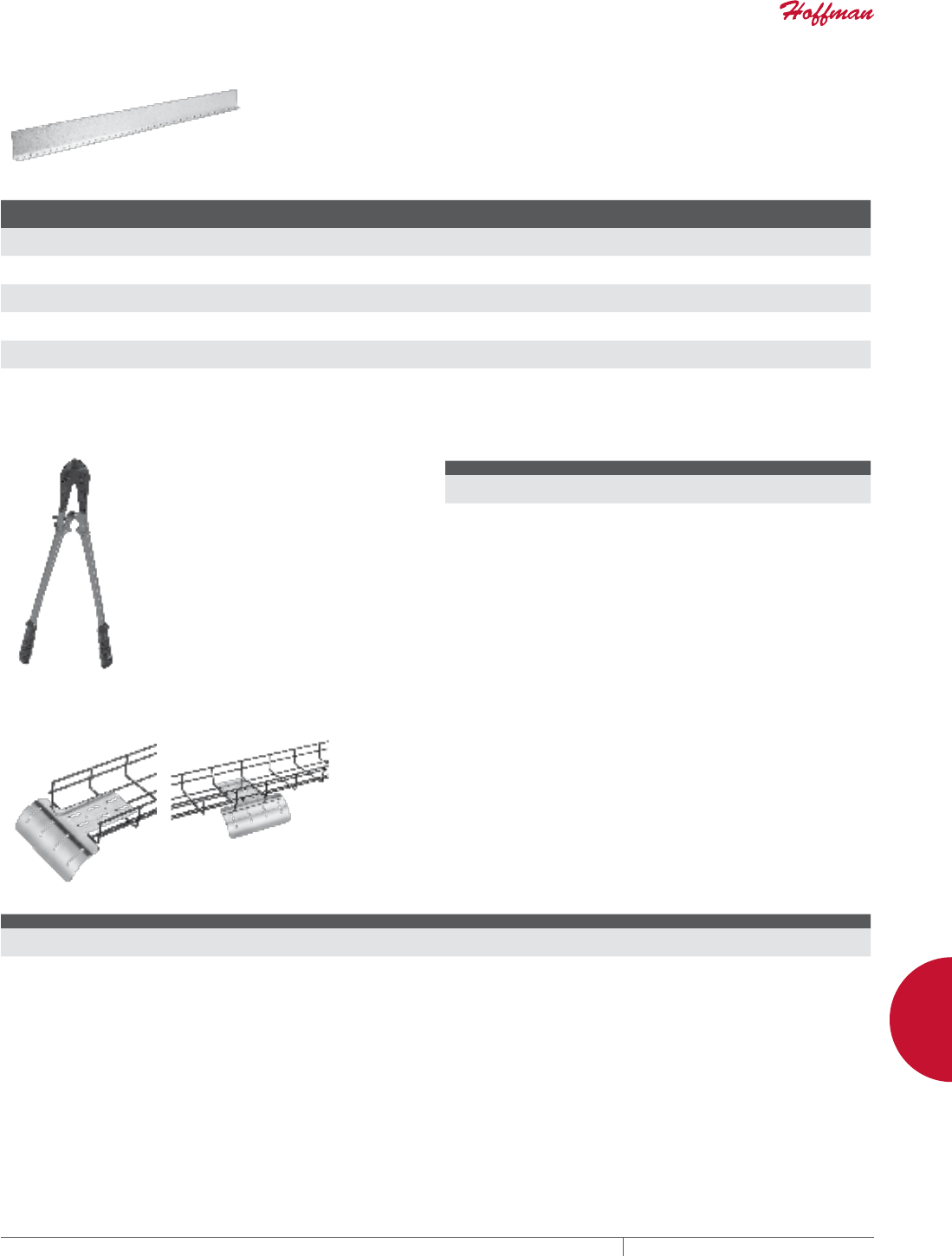
PH 763.422.2661 • FAX 763.422.2588 • PENTAIRPROTECT.COMEQUIPMENT PROTECTION NETWORKING 191
6
CABLE PATHWAY / BONDING AND GROUNDING QUICK TRAY PRO™
DIVIDER STRIP
For wire separation within a single QUICK TRAY PRO™ cable
tray. 5-ft. (1.5-m) long strips are available in 2-, 4- and and 6-in.
(51-, 102- and 152-mm) heights. To secure divider strips to tray,
use QTPSSW3/QTPSSW3BLK Splice Washer and QTPBNWK/
QTPBNWKBLK Splice Kit for each strip.
BULLETIN: DQT
Catalog Number AxBxC in./mm Descripton Finish
Tray Height
in./mm
QTPDS2 2.00 x 1.00 x 60.00
51 x 25 x 1524
Divider Strip Pre-galvanized 2
51
QTPDS2BLK 2.00 x 1.00 x 60.00
51 x 25 x 1524
Divider Strip Black 2
51
QTPDS4 4.00 x 1.00 x 60.00
102 x 25 x 1524
Divider Strip Pre-galvanized 4
102
QTPDS4BLK 4.00 x 1.00 x 60.00
102 x 25 x 1524
Divider Strip Black 4
102
QTPDS6 6.00 x 1.00 x 60.00
152 x 25 x 1524
Divider Strip Pre-galvanized 6
152
QTPDS6BLK 6.00 x 1.00 x 60.00
152 x 25 x 1524
Divider Strip Black 6
152
SIDEACTION BOLT CUTTER
The QUICK TRAY PRO Side-Action
Bolt Cutter insures a flush cut and
helps create a protective coating for
the new cut.
BULLETIN: DQT
Catalog Number AxBxC in./mm Description
QTPBC 12.00 x 1.00 x 0.50
305 x 25 x 13
Side Action Bolt Cutter
VERTICAL DOWN
The QUICK TRAY PRO Vertical Down protects cables when exiting
and entering tray. Built-in hold down method for side mount.
Attached with 1/4 in. hardware for center mount.
BULLETIN: DQT
Catalog Number AxBxC in./mm Description Finish
QTPVD 1.00 x 8.00 x 11.00
25 x 203 x 279
Vertical Down Pre-galvanized
QTPVDBLK 1.00 x 8.00 x 11.00
25 x 203 x 279
Vertical Down Black
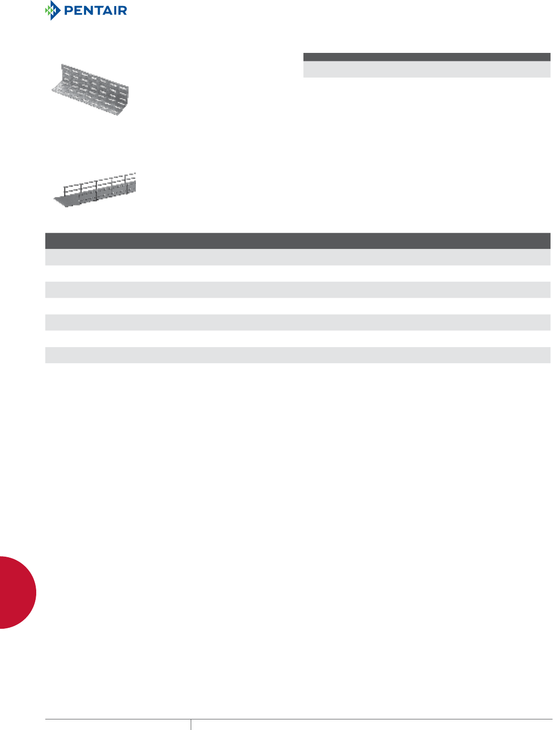
EQUIPMENT PROTECTIONSUBJECT TO CHANGE WITHOUT NOTICENETWORKING192
6
CABLE PATHWAY / BONDING AND GROUNDING QUICK TRAY PRO™
WALLTERMINATION BRACKET
Fastens the end of QUICK TRAY
PRO™ cable tray to a wall. Attach to
tray with QTPSSW3/QTPSSW3BLK
Splice Washers and QTPBNWK/
QTPBNWKBLK Splice Kits.
BULLETIN: DQT
Catalog Number AxBxC in./mm Description Finish
QTPWTB 3.00 x 12.00 x 3.00
76 x 305 x 76
Wall-Termination Bracket, 12 in. (305 mm) Pre-galvanized
QTPWTBBLK 3.00 x 12.00 x 3.00
76 x 305 x 76
Wall-Termination Bracket, 12 in. (305 mm) Black
POLYMER INSERT
Polymer inserts provide continuous support for the cables when
used as a tray liner. This flame retardant polymer material is
prescored at the factory to fit in all standard width QUICK TRAY PRO
cable trays. Easy to cut and sold in 40-foot (12 meters) roll.
BULLETIN: DQT
Catalog Number Description
Tray Width
in./mm
QTP4INST 4 x 40-foot roll (102 x 12,197-mm) Polymer Insert 4
102
QTP6INST 6 x 40-foot roll (152 x 12,197-mm) Polymer Insert 6
152
QTP8INST 8 x 40-foot roll (203 x 12,197-mm) Polymer Insert 8
203
QTP12INST 12 x 40-foot roll (305 x 12,197-mm) Polymer Insert 12
305
QTP16INST 16 x 40-foot roll (406 x 12,197-mm) Polymer Insert 16
406
QTP18INST 18 x 40-foot roll (457 x 12,197-mm) Polymer Insert 18
457
QTP20INST 20 x 40-foot roll (508 x 12,197-mm) Polymer Insert 20
508
QTP24INST 24 x 40-foot roll (610 x 12,197-mm) Polymer Insert 24
610

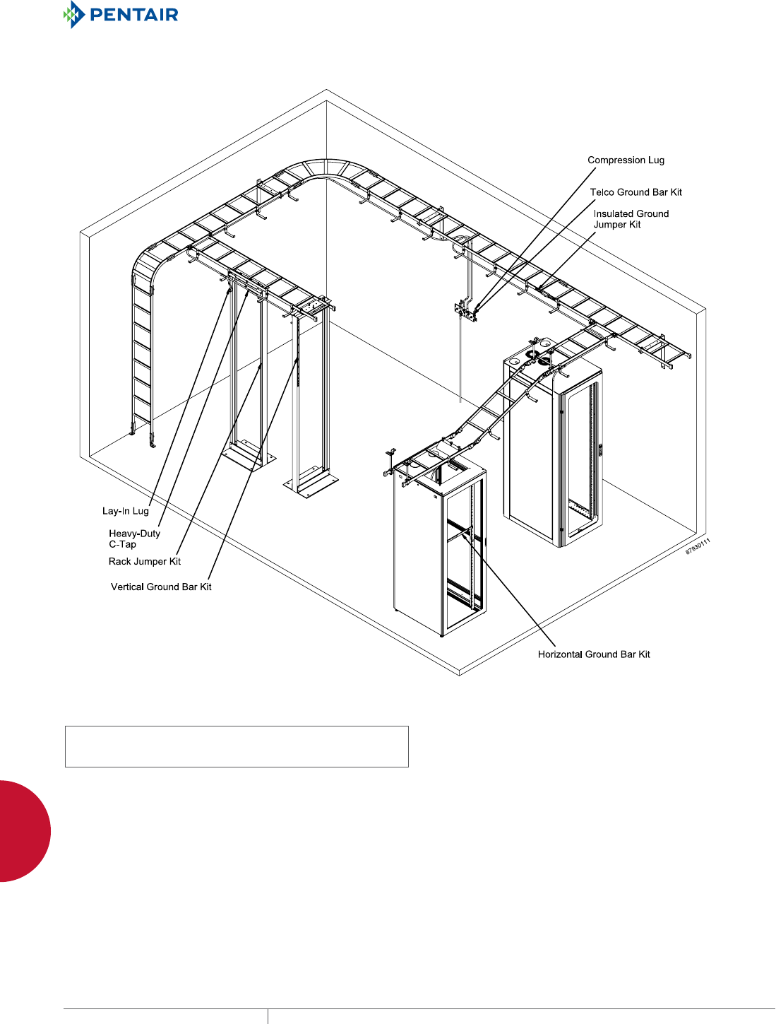
EQUIPMENT PROTECTIONSUBJECT TO CHANGE WITHOUT NOTICENETWORKING194
6
CABLE PATHWAY / BONDING AND GROUNDING BONDING AND GROUNDING ACCESSORIES
BONDING AND GROUNDING ACCESSORIES
BONDING AND GROUNDING OVERVIEW
INDUSTRY STANDARDS
Ground Bar Kits:
UL 467 Listed
cUL Listed per CSA C22.2 No. 41
File No. E319377
APPLICATION
These components meet open frame rack and cabinet bonding and
grounding requirements for telecommunication room and data
center applications.
FEATURES
• Components specially designed to efficiently facilitate reliable
connections
• Enable system to meet equipment manufacturer grounding
requirements
• Components fit EIA 310-D-rated open frame racks
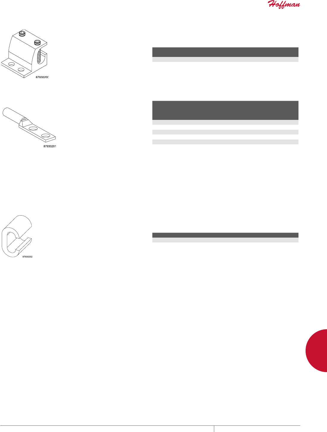
PH 763.422.2661 • FAX 763.422.2588 • PENTAIRPROTECT.COMEQUIPMENT PROTECTION NETWORKING 195
6
CABLE PATHWAY / BONDING AND GROUNDING BONDING AND GROUNDING ACCESSORIES
LAYIN LUG Dual-rated, UL486B listed lay-in lug bonds end of cable securely to
rack. Made of electroplated 6061-T6 aluminum. Requires 3/16-in.
hex key (not included).
BULLETIN: DBG
Catalog Number
For Cable
Size Range Size (in.) Size (mm) Pkg. Qty.
DGLG #14 AWG to 2/0 1.75 x 1.50 44 x 38 10
COMPRESSION LUGS
Compression lugs terminate copper or tinned-copper conductors
for connection to busbars, cabinets, racks, and cable runway.
Color-coded by conductor size. Made of electroplated, tinned
copper. Require two screws (not included).
BULLETIN: DBG
Catalog Number
Cable
Size
(#)
On-Center
Dimension
Between
Holes
Required
Screw
Size
Color
Code
Pkg.
Qty.
DGCL61 6 .625 1/4 Blue 10
DGCL62 6 1.00 3/8 Blue 10
DGCL21 2 .625 1/4 Brown 10
DGCL22 2 1.00 3/8 Brown 10
DGCL201 2/0 1.00 3/8 Black 10
DGCL402 4/0 1.00 3/8 Purple 10
HEAV YDUT Y CTAPS C-Taps splice two stranded or solid connectors together. Made of
copper. Require a crimping tool (not included) to correctly tighten
C-Taps around connectors.
BULLETIN: DBG
Catalog Number Conductor Run Conductor Tap Pkg. Qty.
DGT1 #2 stranded or solid #4 stranded, #8 solid 10
DGT2 #2 stranded or solid #2 stranded or solid 10
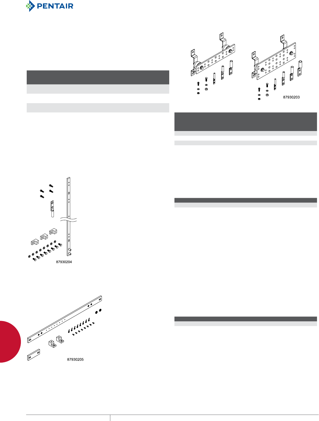
EQUIPMENT PROTECTIONSUBJECT TO CHANGE WITHOUT NOTICENETWORKING196
6
CABLE PATHWAY / BONDING AND GROUNDING BONDING AND GROUNDING ACCESSORIES
TELECOMMUNICATIONS GROUND BAR KITS
Provide a convenient central location for connecting grounds
from telecommunications equipment, computers, and other data
center equipment. Made of copper. Kits include ground bar with
two mounting brackets, an assortment of connectors, and a tube of
antioxidant.
BULLETIN: DBG
Standard Product
Catalog Number
Bar Size
in./mm
No. of
5/16-in.
Hole Sets
No. of
7/16-in.
Hole Sets
DGTB212 2.00 x 12.00 x .25
51 x 305 x 6
6 3
DGTB216 2.00 x 16.00 x .25
51 x 406 x 6
8 3
DGTB412 4.00 x 12.00 x .25
102 x 305 x 6
12 6
DGTB420 4.00 x 20.00 x .25
102 x 508 x 6
24 6
2-inch Wide Bar 4-inch Wide Bar
Compression Lugs Included with Ground Bar Kits
Catalog Number
#6 Wire
Size
(DGCL61)
#2 Wire
Size
(DGCL22)
#2/0
Wire
Size
(DGCL201)
#4/0
Wire
Size
(DGCL402)
DGTB212 6 lugs 3 lugs 1 lug 0
DGTB216 6 lugs 3 lugs 1 lug 0
DGTB412 6 lugs 3 lugs 1 lug 1 lug
DGTB420 6 lugs 3 lugs 1 lug 1 lug
VERTICAL GROUND BAR KITS Mount vertically on rack, providing a convenient place to connect
equipment grounds. Made of electrolytic tough-pitch 110 copper
alloy. Kits include ground bar with compression lug for #2 wire,
connection hardware, and mounting hardware.
BULLETIN: DBG
Catalog Number Bar Size (in.) Bar Size (mm)
DG36 36.00 x .625 x .25 914 x 16 x 6
DG72 72.00 x .625 x .25 1829 x 16 x 6
HORIZONTAL GROUND BAR KITS Mount horizontally on rack, providing a convenient place to connect
equipment grounds. Made of electrolytic tough-pitch 110 copper
alloy. Kits include ground bar with mounting hardware, eight #6-32
x 14 machine screws, and eight #6 ring terminals.
BULLETIN: DBG
Catalog Number Bar Size (in.) Bar Size (mm)
DG19 1.00 x 19.25 x .25 25 x 489 x 6
DG23 1.00 x 23.25 x .25 25 x 591 x 6
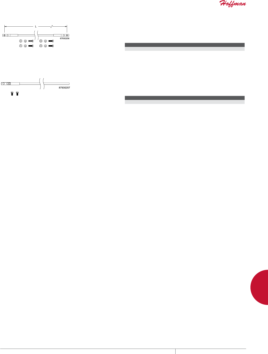
PH 763.422.2661 • FAX 763.422.2588 • PENTAIRPROTECT.COMEQUIPMENT PROTECTION NETWORKING 197
6
CABLE PATHWAY / BONDING AND GROUNDING BONDING AND GROUNDING ACCESSORIES
INSULATED GROUND JUMPER KIT Fastens across splices to provide a secure ground between sections
of ladder rack. Made of #6 AWG x 7 strand wire with green THW
insulation and two-hole compression lugs mounted on each end.
Includes fasteners.
BULLETIN: DBG
Catalog Number Conductor Type L (in.) L (mm)
DGJ #6-7 Stranded 12.00 305
cULus requires 2 kits per splice on all painted ladder sections
RACK JUMPER KIT Grounds rack or cabinet to common bonding network under floor
or overhead. Made of #6 AWG x 7 strand wire with green THW
insulation and two-hole compression lug mounted on one end.
Includes fasteners.
BULLETIN: DBG
Catalog Number Conductor Type Length (ft.) Length (m)
DGRJ #6-7 stranded 9 2.7

EQUIPMENT PROTECTIONSUBJECT TO CHANGE WITHOUT NOTICENETWORKING198
7
763.422.2661
763.422.2588
NETWORKING
SEISMIC PRODUCTS
Intro Page
CHAPTER 7
SEISMIC PRODUCTS
SEISMIC ENCLOSURES
Seismic-rated enclosures provide
the required frame strength and
rigidity to withstand environments
that are subject to vibration and
other motion that can over-stress
equipment framework, components
and connections. Ideal applications
include areas where earthquake
activity is possible, power plants,
railroads and airports.
SEISMIC CABINETS
Seismic cabinets protect
LAN and WAN network
equipment, servers
and phone/voicemail
during Zone 4 seismic
activity, or in areas with
high vibration or high load
capacities. Cabinets are Telcordia GR-63
CORE Zone 4 tested and meet California
Building Code (CBC) requirements.
FEATURED PRODUCTS

PH 763.422.2661 • FAX 763.422.2588 • PENTAIRPROTECT.COMEQUIPMENT PROTECTION NETWORKING 199
Intro Page CHAPTER CONTENTS
SEISMIC ENCLOSURES OVERVIEW
Seismic Enclosures Provide an Extra Measure of Protection .........200
SEISMIC CABINETS
Seismic Cabinet ...........................................202
Seismic Cabinet Joining Kit ..................................203
Vertical Cable Manager 2 ....................................203
SEISMIC RACKS
Seismic 2-Post Open Frame Rack ..............................204
Seismic 4-Post Open-Frame Rack .............................206
7
SEISMIC RACKS
Seismic racks, available in 2- and 4-post
open frame rack configurations, ensure
reliable protection in environments
that are subject to seismic activity or
vibration, in addition to
other applications
that require increased
strength due to static
and dynamic loading.
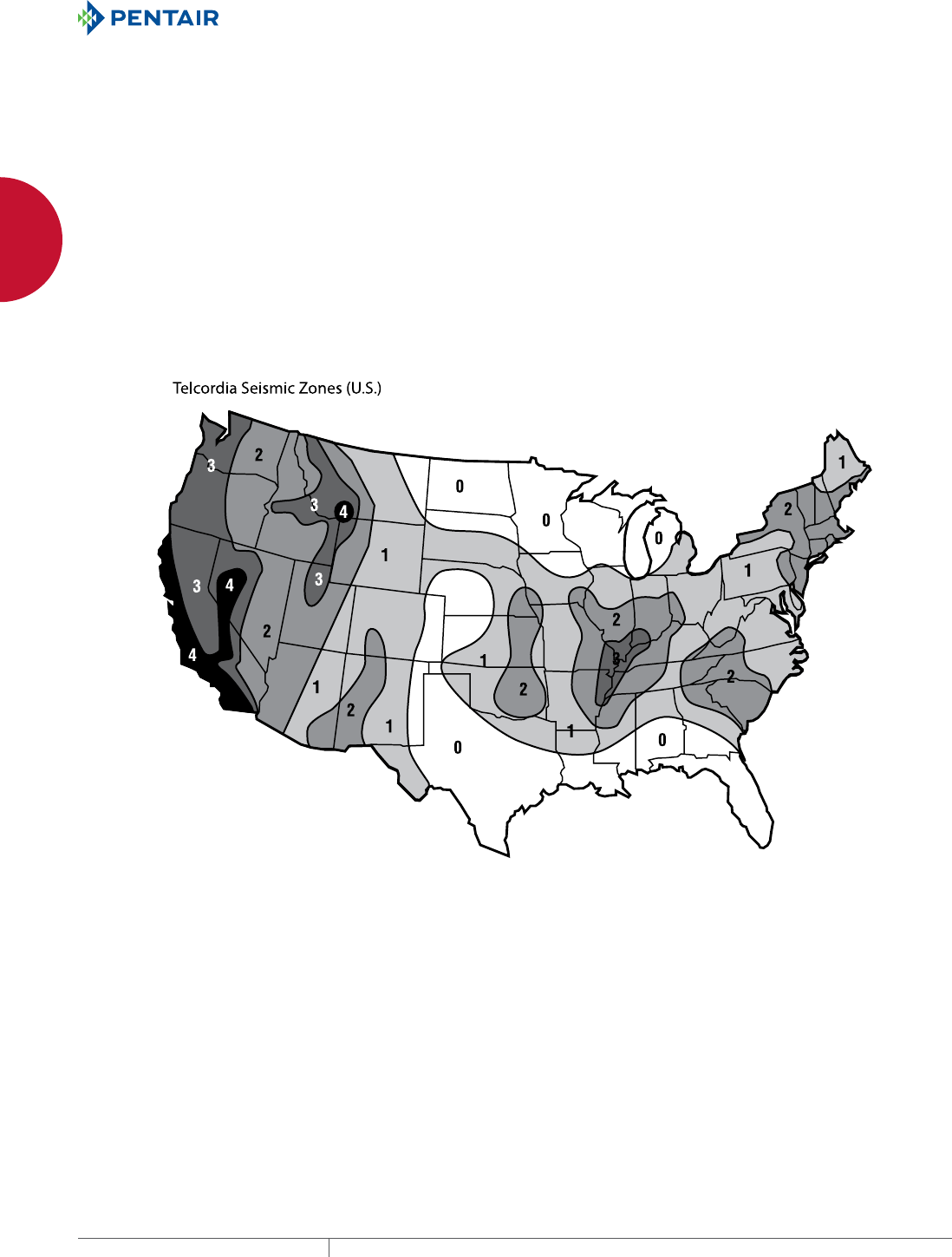
EQUIPMENT PROTECTIONSUBJECT TO CHANGE WITHOUT NOTICENETWORKING200
7
SEISMIC PRODUCTS SEISMIC ENCLOSURES OVERVIEW
SEISMIC ENCLOSURES OVERVIEW
SEISMIC ENCLOSURES PROVIDE AN EXTRA MEASURE OF PROTECTION
SEISMIC PRODUCTS seismic enclosures overview
Spec-00490 D
EQUIPMENT PROTECTION SOLUTIONSSUBJECT TO CHANGE WITHOUT NOTICETECHNICAL INFORMATION1
763.422.2211
763.422.2600
Spec-00490
D
TECHNICAL INFORMATION
seismic products
seismic enclos ures overview
SEISMIC ENCLOSURES PROVIDE AN EXTRA MEASURE OF PROTECTION
The use of seismic-rated enclosures is recommended in areas where earthquake activity is possible. In addition, power plants,
railroads, airports and other installations use rack-mounted electrical and electronic equipment that is subjected to vibration and other
motion that can over-stress equipment framework, components and connections. Adequate enclosure frame strength and rigidity are
necessary under these conditions.
Seismic Enclosure Standards
Industry standards define global geographical areas as
earthquake-risk Zones. Referring to the seismic Zone map below,
Zones are numbered from 0 to 4 with Zone 4 corresponding to
the highest risk areas. Geographic areas designated as Zone 0
present no substantial earthquake risk.
Conditions Other Than Earthquakes
Equipment may need to withstand the effects of movement or
vibration in areas close to railways, airports, power plants and
other areas subject to similar conditions.
Zone 4 is the highest risk area, Zone 3 the next highest, and
so on. Zone 0 has no earthquake requirements.
Spec-00490.indd 1 01/28/13 9:00:15 AM
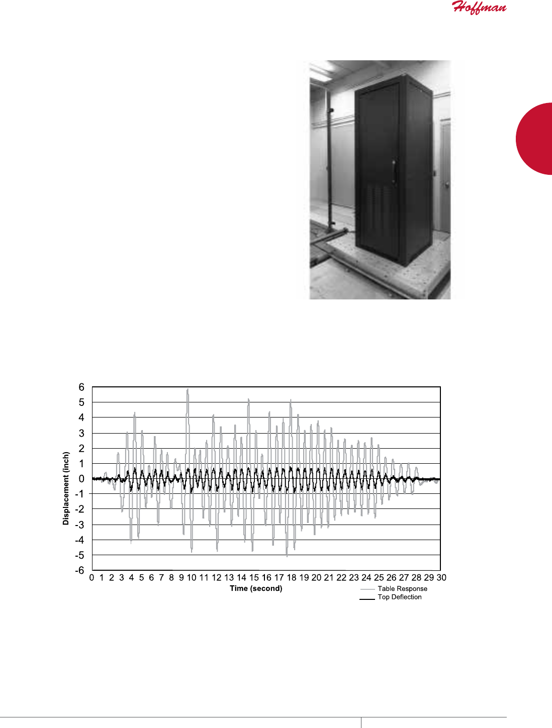
PH 763.422.2661 • FAX 763.422.2588 • PENTAIRPROTECT.COMEQUIPMENT PROTECTION NETWORKING 201
7
SEISMIC PRODUCTS SEISMIC ENCLOSURES OVERVIEW
SEISMIC PRODUCTS seismic enclosures overview
Spec-00490 D PH 763.422.2211 • FAX 763.422.2600 • HOFFMANONLINE.COMEQUIPMENT PROTECTION SOLUTIONS TECHNICAL INFORMATION 2
Hoffman Seismic Products
Hoffman performance-tests its seismic products according to
Telcordia (formerly Bellcore) GR-63-CORE Network Equipment
Building System (NEBS™) requirements for physical protection.
These enclosures can also be manufactured to comply with
all applicable national and international standards, such
as the Uniform Building Code (UBC) and the International
Electrotechnical Commission (IEC). Contact Telcordia, UBC and
IEC for more information.
Seismic Certification
A Telcordia GR-63-CORE compliant test must be conducted by
a Nationally Recognized Testing Laboratory (NRTL) or other
recognized independent laboratory before certification will
be issued. This test is conducted on an installation-specific
basis with customer-installed equipment and cabling mounted
inside the enclosure. In other cases or in addition to, a licensed
structural engineer must certify the installation. Contact Hoffman
for more information or for assistance in coordinating testing.
Enclosure mounted on shaker table
Time-motion history generated in front to back seismic enclosure test
NEBS™ IS A TRADEMARK OF TELCORDIA.
Spec-00490.indd 2 01/28/13 9:00:15 AM
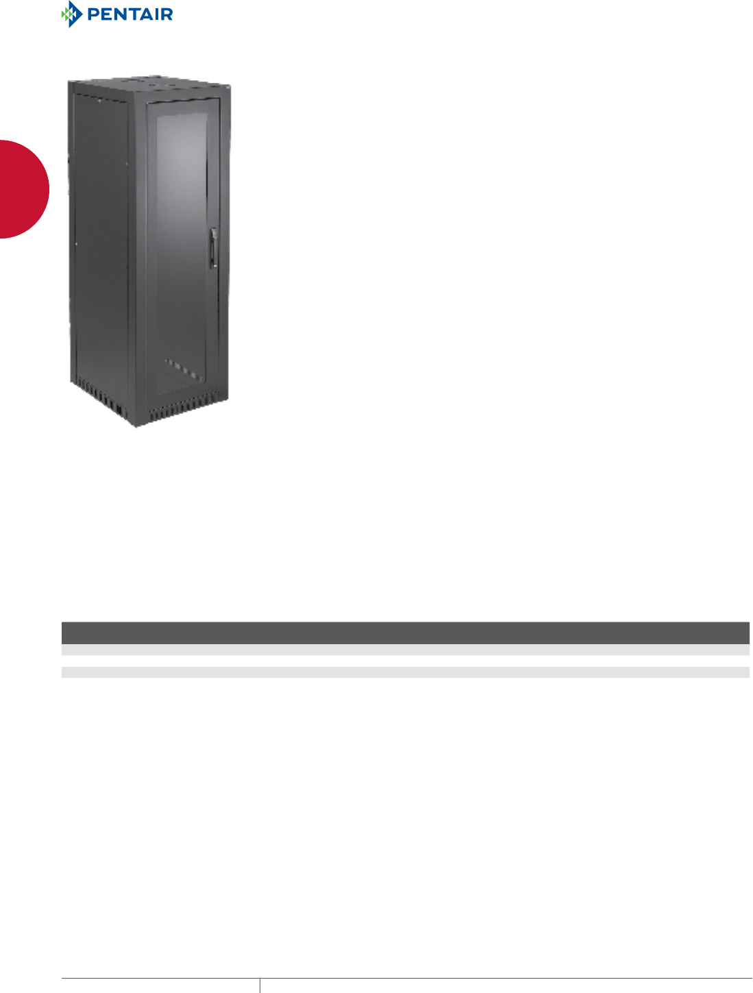
EQUIPMENT PROTECTIONSUBJECT TO CHANGE WITHOUT NOTICENETWORKING202
7
SEISMIC PRODUCTS SEISMIC CABINETS
SEISMIC CABINETS
SEISMIC CABINET
INDUSTRY STANDARDS
NEBS™ -Telcordia GR-63-CORE Zone 4: Tested with 1000 lb. (453.6
kg) of equipment installed and 100 lb. (45.4 kg) of simulated cable
weight on the top.
Meet California Building Code (CBC) requirements
EIA 310-D
NEBS is a trademark of Telcordia
APPLICATION
Seismic Cabinets protect LAN and WAN network equipment,
servers and phone/voice mail equipment during Zone 4 seismic
activity, and are also ideal for use in high vibration areas or areas
with high load capacities. The cabinet’s passive cooling design can
be augmented with optional fans.
FEATURES
• ENC2189S can be configured for 19- or 23-in. rack mounting by
reversing the rack angles
• Both front and rear doors are hinged left and equipped with
keylock flush handle and 3-point latching
• Same key provides access to all doors and side panels
• Doors and side panels are removable for easier equipment
installation and upgrades
• Doors and side panels inset flush with frame
• Vented, heavy gauge steel base is designed to bolt to floor with
seismic-rated fasteners
SPECIFICATIONS
• Heavy gauge welded steel frame with six rack angle mounting
struts
• Includes two sets of painted L-shaped rack angles with holes per
EIA spacing (5/8 in. x 5/8 in. x 1/2 in.)
• Holes are either 10-32 tapped or square, depending on model
• Top has two cable entry ports with caps and grommets and two
fan-ready cutouts with finger guards
• Smoke gray acrylic window in reinforced front door
• Louvers on lower 1/3 of rear door
FINISH
RAL 9005 textured low-gloss black polyester powder paint coating
inside and out
LOAD RATING
Dynamic: 1100 lb. (499 kg)
Static: 2500 lb. (1134 kg)
For higher loads, contact Hoffman. Static load has a safety factor of
4 applied.
ACCESSORIES
ESBDK 3/8-in. Concrete Expansion bolt Anchor Kit, package of four
Also, most 19- and 23-in. rack accessories can be used with the
seismic cabinets.
BULLETIN: DNCS
Standard ProductSeismic Cabinets
Catalog Number AxBxC in. AxBxC mm Description
Rack
Units N (in.) N (mm)
Rack Angle
Hole Type
Additional Rack
Angles
ENC2178S 84.02 x 27.56 x 31.50 2134 x 700 x 800 19-in. cabinet 45 16.40 417 Tapped ERA1921TPL
ENC2189S 84.02 x 31.50 x 35.43 2134 x 800 x 900 19- or 23-in. cabinet 45 20.40 517 Tapped ERA192321TPL
ENC21710S 2135.00 x 700.00 x 1000.00 54229 x 17780 x 25400 19-in. cabinet 45 16.40 417 Square --
ENC21712S 2135.00 x 700.00 x 1200.00 54229 x 17780 x 30480 19-in. cabinet 45 16.40 417 Square --
Rack angles on 23-in. cabinet can be reversed to accommodate 19- or 23-in. rack accessories.
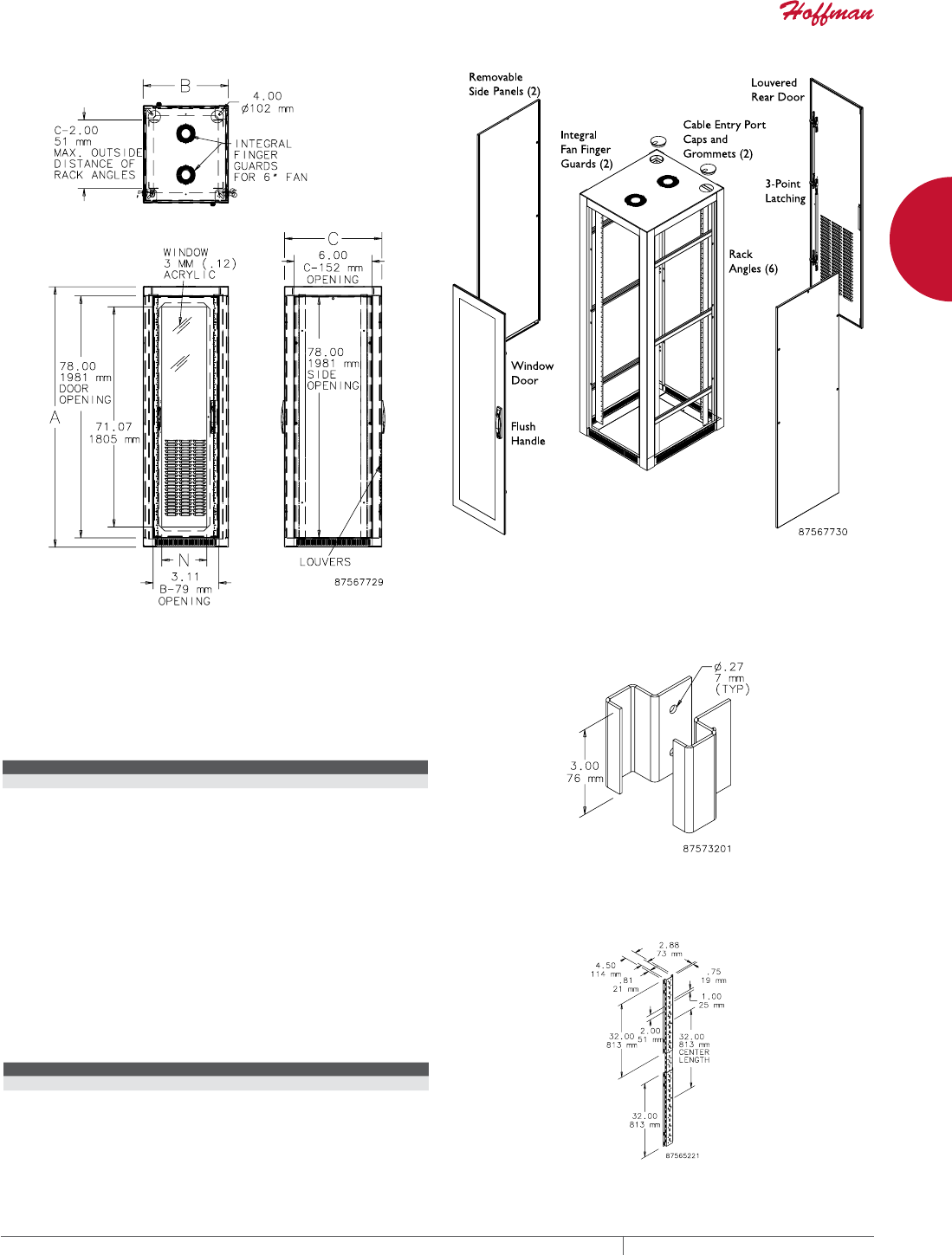
PH 763.422.2661 • FAX 763.422.2588 • PENTAIRPROTECT.COMEQUIPMENT PROTECTION NETWORKING 203
7
SEISMIC PRODUCTS SEISMIC CABINETS
SEISMIC CABINET JOINING KIT
Allows two network cabinets to be joined together. Requires
removal of side covers on both joined cabinets. Brackets are used in
pairs. Includes eight brackets and mounting brackets.
BULLETIN: DNCY
Catalog Number Description
ENCJK Seismic Cabinet Joining Kit
VERTICAL CABLE MANAGER 2
For routing and bundling cables. Mounts vertically to grid straps or
to mounting channels. Three-piece kit adjusts to fit rack height and
eliminates need for center grid strap. 16 gauge steel with RAL 9005
black polyester powder paint finish. Includes 10 black 8 in. (203mm)
long VelcroTM cable wraps.
BULLETIN: DPY
Catalog Number Description
PVCM2 Vertical Cable Manager 2
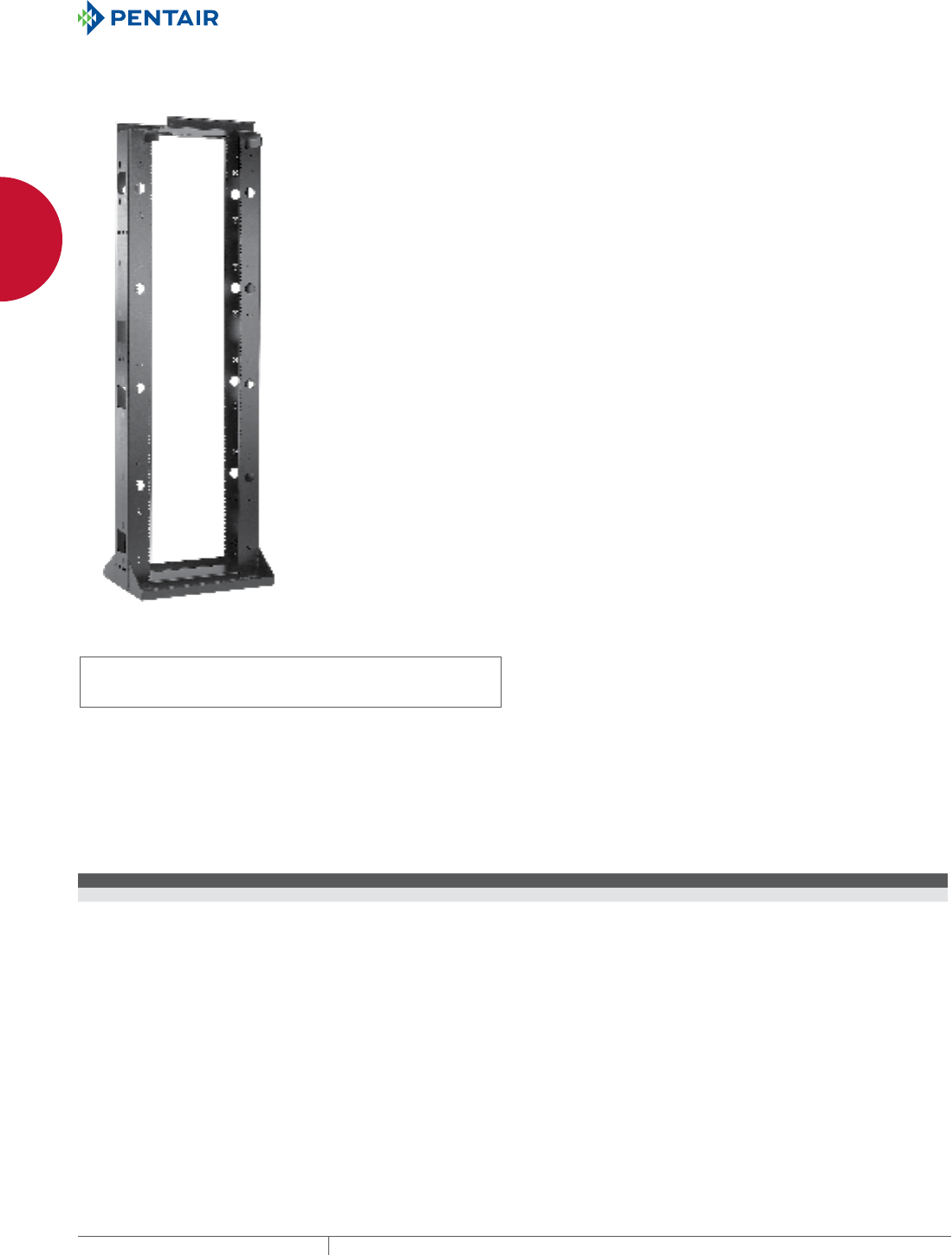
EQUIPMENT PROTECTIONSUBJECT TO CHANGE WITHOUT NOTICENETWORKING204
7
SEISMIC PRODUCTS SEISMIC RACKS
SEISMIC RACKS
SEISMIC 2POST OPEN FRAME RACK
INDUSTRY STANDARDS
UL 1863 Listed; File No. E230874,
2500 lb. (1134 kg) rated load
cUL Listed per CSA C22.2 No. 182.4; File No. E230874
OSHPD Approved OPA-2435-07 (750 lb.)
NEBS™ -Telcordia GR-63-CORE Zone 4: Tested with 500 lb.
(226.8 kg) of equipment installed
Meets California Building Code (CBC) requirements
EIA 310-D
NEBS is a trademark of Telcordia
APPLICATION
Designed for applications affected by vibrations and seismic activity,
Seismic 2-Post Open Frame Racks integrate cable management into
a fully welded, heavy gauge steel frame. Used in communication
data center and telecommunication room applications, racks can be
ganged with standard 2- or 4-post racks to expand existing systems.
FEATURES
• Nominal height is 7 ft. (2.13 m) (45U)
• Fits 19-in. rack-mount equipment
• Side rails are tapped on both sides with 12-24 UNC threads for
quick installation
• EIA Universal 5/8 - 5/8 - 1/2 in. vertical mounting-hole pattern
matches industry standards and connects to most competitive
racks
• Integral front waterfall top
• Pre-drilled holes on top to ease runway installation
• Top and bottom cable entry cutouts
• Ground provision with ground symbol
• Full complement of matching components for equipment and
cable management
SPECIFICATIONS
• Rack is 10-gauge steel, fully welded for maximum rigidity
FINISH
RAL 9005 black low-gloss polyester powder paint
LOAD RATING
Dynamic: 500 lb. (227 kg)
Static: 2500 lb. (1134 kg)
For higher loads, contact Hoffman. Static load has a safety factor of
4 applied.
BULLETIN: DOFRS
Standard Products
Catalog Number AxBxC in. AxBxC mm Rack Units
ESDR19FM45U 86.02 x 26.75 x 18.00 2185 x 679 x 457 45
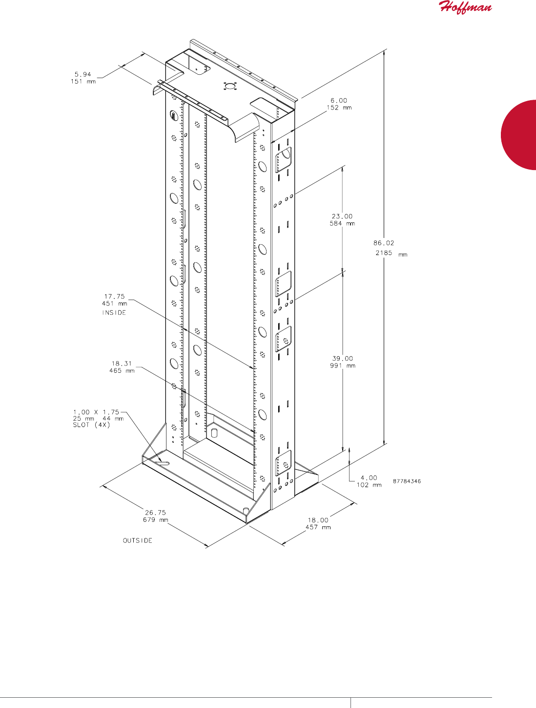
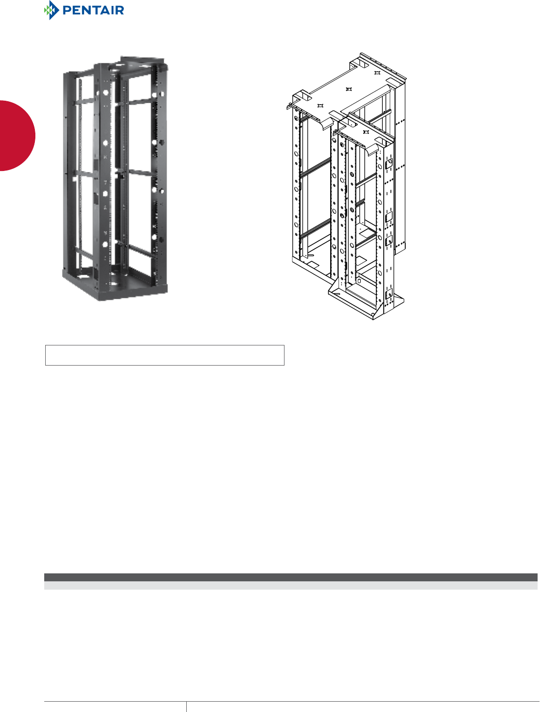
EQUIPMENT PROTECTIONSUBJECT TO CHANGE WITHOUT NOTICENETWORKING206
7
SEISMIC PRODUCTS SEISMIC RACKS
SEISMIC 4POST OPENFRAME RACK
3RVWJDQJHG
ZLWK3RVWRU
3RVW5DFNV
3RVW
3RVW
INDUSTRY STANDARDS
UL 1863 Listed; File No. E230874, 2500 lb. (1134 kg) rated load
cUL C22.2 No. 182.4 Listed; File No. E230874
NEBS™ -Telcordia GR-63-CORE Zone 4: Tested with 1000 lb. (453.6
kg) of equipment installed
Meet California Building Code (CBC) requirements
EIA 310-D
NEBS is a trademark of Telcordia
APPLICATION
Seismic 4-Post Open Frame Racks combine the mounting security
of a cabinet with the accessibility of a rack. Used in communication
data center and telecommunication room applications that are
subject to seismic activity or vibration, these adjustable-depth
racks support deeper, heavier network equipment and can be
ganged with standard 2-post or other 4-post racks to expand
existing systems.
FEATURES
• EIA universal 5/8 - 5/8 - 1/2 in. spaced square holes fit 19-in. rack
equipment and accessories
• Rear rack angle adjustable 0 to 39.09 in. (0 to 993 mm)
• Nominal height is 7 ft. (2.1 m)
• Can be ganged with both 2- and 4- post open frame racks
• Integral front waterfall top
• Pre-drilled holes on top to ease runway installation
• Top and bottom cable entry cutouts
• Ground provision with ground symbol
• Full complement of matching components for equipment and
cable management
SPECIFICATIONS
• Rack is 10-gauge steel, fully welded for maximum rigidity
FINISH
RAL 9005 smooth black low-gloss polyester powder paint
LOAD RATING
Dynamic: 1000 lb. (454 kg)
Static: 2500 lb. (1134 kg)
For higher loads, contact Hoffman. Static load has a safety factor of
4 applied.
BULLETIN: DOFRS
Standard Product
Catalog Number AxBxC in. AxBxC mm Rack Units
E4SDR19FM45U 86.02 x 26.75 x 39.87 2185 x 679 x 1013 45
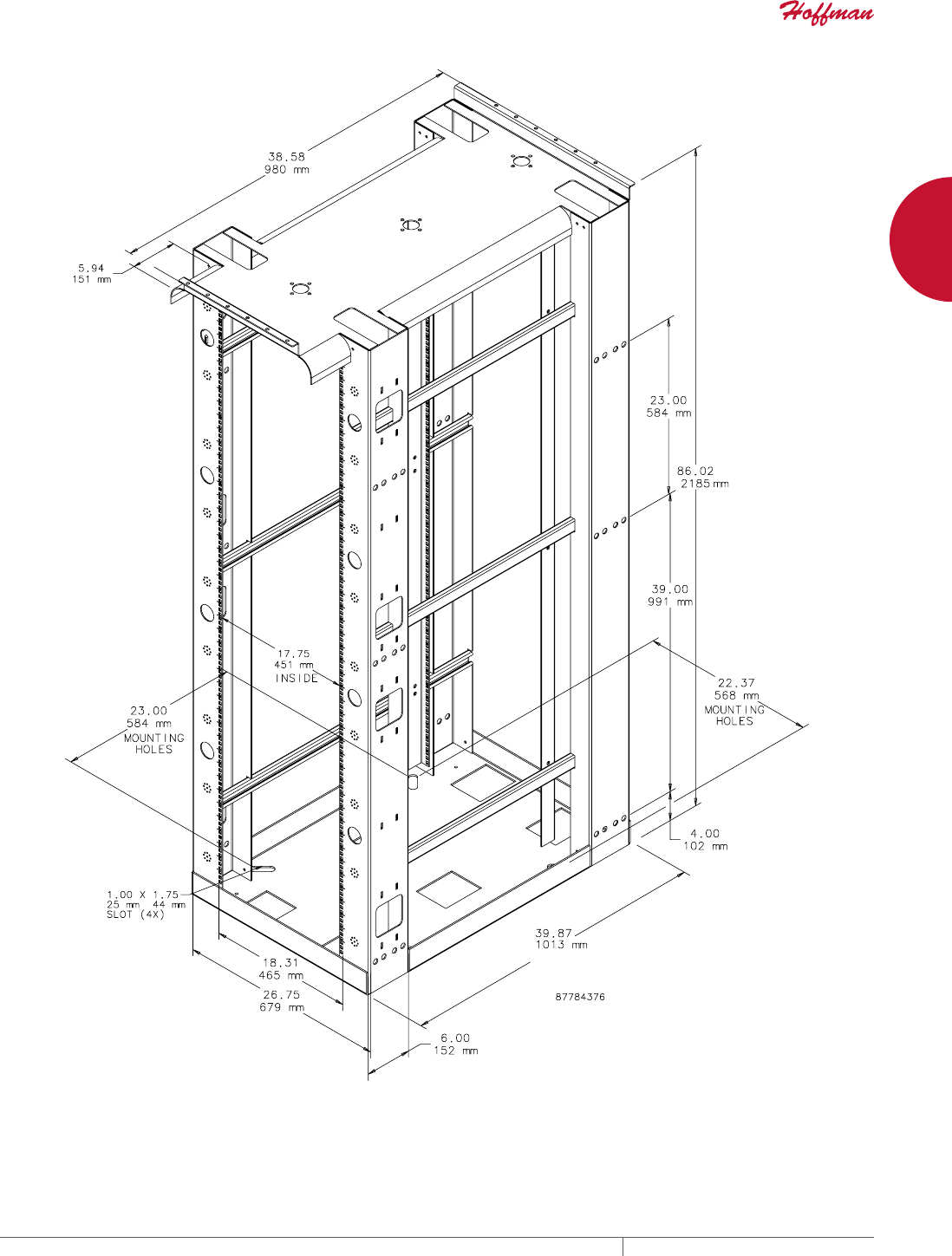
EQUIPMENT PROTECTIONSUBJECT TO CHANGE WITHOUT NOTICENETWORKING208
8
763.422.2661
763.422.2588
NETWORKING
COOLING
Intro Page
CHAPTER 8
COOLING
DATA CENTER FLOOR BRUSH KITS
Floor brush kits provide convenient, safe
passage of cables from under a data
center raised floor into a cabinet or rack.
Overlapping brushes block cold air flow,
improving data center efficiency and
reducing operating costs. Available in
2- and 1-piece configurations.
FAN TRAYS
Fan trays enhance the natural
convection airflow within a cabinet when
installed with other 19-in. rack-mounted
equipment. Fan trays are available with
quiet, 4-in. or 6-in. cooling fans with
optional fan speed controls to adjust fan
speed or airflow.
COMPACT COOLING FANS
When enclosure space is limited and
quiet, reliable cooling is required,
compact cooling fans provide the ideal
solution. Fans are engineered for 50,000
hours of continuous operation without
lubrication or service.
FEATURED PRODUCTS
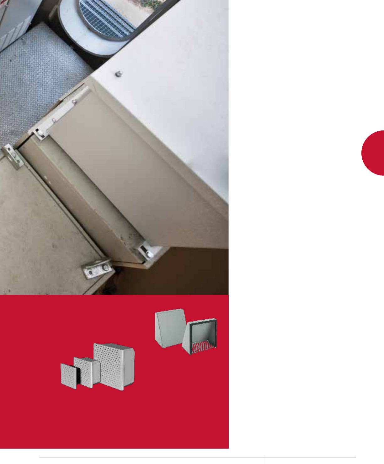
PH 763.422.2661 • FAX 763.422.2588 • PENTAIRPROTECT.COMEQUIPMENT PROTECTION NETWORKING 209
Intro Page CHAPTER CONTENTS
DATA CENTER FLOOR BRUSH KITS
Data Center Floor Brush Kits ...........................210
2-Piece Flush-Mount Floor Brush Kit with Cover ............211
1-Piece Flush-Mount Floor Brush Kit with Cover and Two-Stage
Sealing ...........................................211
2-Piece Surface-Mount Retrofit Floor Brush Kits ............ 212
Adjustable Floor Brush Kits ............................212
FAN TRAY
Rack-Mountable 19-in. Fan Tray .........................213
Fan Speed Controls. . . . . . . . . . . . . . . . . . . . . . . . . . . . . . . . . . . 214
COMPACT COOLING FANS AND ACCESSORIES
Compact Axial Fans ..................................215
Fan Cords ..........................................216
Fan Cords With Inline Thermostat .......................217
Fan Filter and Finger Guard Kit ..........................217
Finger Guards .......................................217
Fan Brackets .......................................217
Temperature Control Switches ..........................218
COOLING FAN AND EXHAUST PACKAGES WITH
ACCESSORIES
TFP Side-Mount .....................................219
TFP Optional Grilles and Replacement Filters ..............222
TFP EMC Upgrade Kit .................................222
FAN SHROUD KIT
Fan Shroud Kit, Type 3R ...............................223
8
COOLING FAN AND EXHAUST
PACKAGES
Cooling fan and exhaust packages
are designed for limited-space
enclosures that require a reliable and
filtered airflow.
FAN SHROUD KITS
Fan shroud kits protect outdoor
enclosure openings from rain,
sleet and snow.
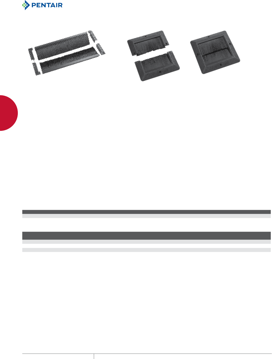
EQUIPMENT PROTECTIONSUBJECT TO CHANGE WITHOUT NOTICENETWORKING210
8
COOLING DATA CENTER FLOOR BRUSH KITS
DATA CENTER FLOOR BRUSH K ITS
DATA CENTER FLOOR BRUSH KITS
INDUSTRY STANDARDS
Designed to meet the following standards:
• Flame resistant VO rating per ANSI/UL94 (“Tests for
Flammability of Plastic Material for Parts in Devices and
Appliances”)
• RoHS compliant
• 2008 NEC code compliant with requirements of Article 645.5 (D)
(5)
• NFPA 75 Section 5-4.4
• Hoffman is an ISO 9001 company
APPLICATION
These Floor Brush Kits provide convenient, safe passage of cables
from under a data center raised floor into a cabinet or rack. The
overlapping brushes conform around the cables and block the
flow of cold air. This improves data center efficiency and reduces
operating costs by minimizing or eliminating up to 90 percent of cold
air leakage through the raised floor cutout.
FEATURES
• Blocks up to 90 percent of cold air leakage around power and data
cables
• Flush mounts provide a low profile and grommet to raised-floor
panel cutouts (required by NEC and NFPA)
• Surface mount provides an easy-to-use retrofit to existing
raised-floor cutouts
• Adjustable flush mount provides an extra-large cable capacity
and can be cut to size to fit the application
• Overlapping bristles conform around data and power cables to
minimize air leakage through raised floor and improve overall
data center cooling efficiency
• Reduction of cold air loss through raised-floor plenums helps to
increase under floor static pressure
• Cover provides protection during build out
• Smooth, rounded low-profile flush mount edges protect cables
from sharp raised-floor edges
• Two-piece surface mount and adjustable floor brush kits have
self-sticking adhesive to expedite installation
• Raised-floor tiles need not be removed for installation
• Brush kits can also be used on cabinets or other locations
that need to provide cable egress and prevent air leakage or
contaminants from entering
• Self-tapping screws included
SPECIFICATIONS
• ABS polycarbonate housing
• Nylon polymer bristles
• EPDM gasket
FINISH
Black finish inside and out
Cable Fill for Data Center Floor Brush Kits
Cable Category 5e 6 6A
Diameter (in.) .22 .25 .30
Area (in.2).0380 .0491 .0707
Cable Area and Fill
Catalog Number
Usable Cable Area
D x E (in.) Area (in.2)
No. Cables at 60% Fill
5e
No. Cables at 60% Fill
6
No. Cables at 60% Fill
6A
DFB410F 9.25 x 3.00 27.75 438 339 235
DFB57F 7.49 x 4.86 36.40 575 445 309
DFB66S 7.00 x 6.25 43.75 691 535 371
DFBA1024F 23.50 x 9.19 215.97 3409 2639 1833
DFBA1024F - at maximum size.
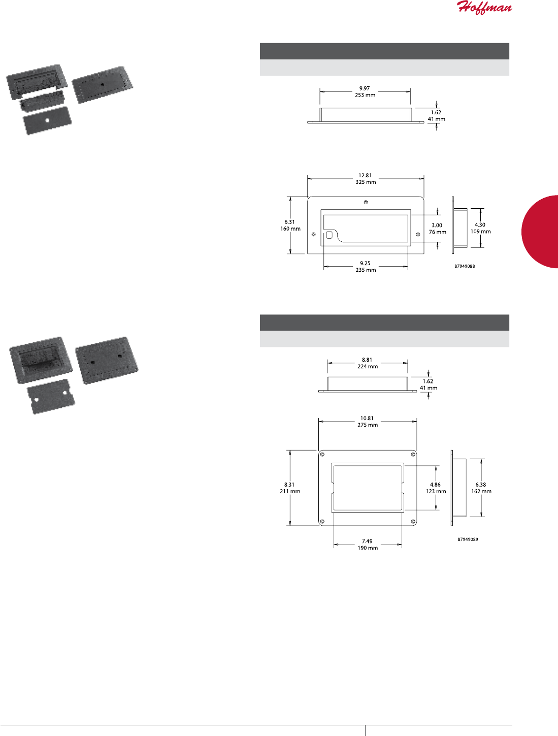
PH 763.422.2661 • FAX 763.422.2588 • PENTAIRPROTECT.COMEQUIPMENT PROTECTION NETWORKING 211
8
COOLING DATA CENTER FLOOR BRUSH KITS
2PIECE FLUSHMOUNT FLOOR BRUSH KIT WITH
COVER
Use Flush-Mount Floor Brush Kit with removable brush and solid
cover for new installations. Install two kits when large bundles of
cables are needed.
Removable back brush allows floor tile removal without
disconnecting cables. There’s no need for an oversized cutout
because the removable back brush allows large connectors to pass
through the grommet.
Removable solid safety cover allows installation of the grommet
during the construction phase and eliminates the risk of injury by
stepping through the grommet opening. OSHA jobsite standards
require open holes in floor panels to be covered.
NEC, UL and NEMA require safety covers and cable protection
against sharp edges.
BULLETIN: DACCY
Catalog Number Description
Max. H x W x D
in./mm
Cable Egress
in./mm
DFB410F Flush-Mount Floor Brush with
cover and removable brush
6.31 x 12.81 x 1.62
160 x 325 x 41
3.50 x 9.50
89 x 241
1PIECE FLUSHMOUNT FLOOR BRUSH KIT WITH
COVER AND TWOSTAGE SEALING
Flush-Mount Floor Brush Kit with Cover is a heavy-duty two-stage
sealing system. Brush and EPDM gasket provide the most effective
air seal.
Heavy-duty, integrated safety cover allows installation of the
grommet during the construction phase and eliminates the risk
of injury by stepping through the grommet opening. OSHA jobsite
standards require open holes in floor panels to be covered.
Easy-to-install system integrates with the access floor static
dissipative system.
NEC, UL and NEMA require safety covers and cable protection
against sharp edges.
BULLETIN: DACCY
Catalog Number AxBxC in./mm Description
Cable Egress
in./mm
DFB57F 8.31 x 10.81 x 1.62
211 x 275 x 41
Flush-Mount Floor Brush
Kit with Cover
7.49 x 4.86
190 x 123
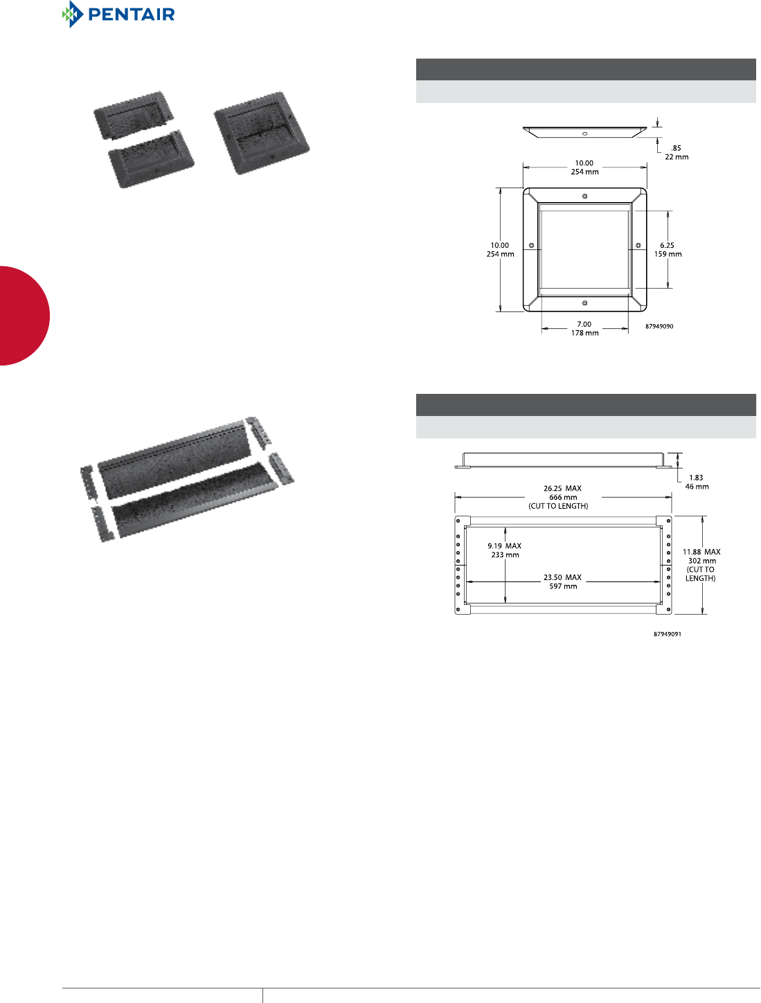
EQUIPMENT PROTECTIONSUBJECT TO CHANGE WITHOUT NOTICENETWORKING212
8
COOLING DATA CENTER FLOOR BRUSH KITS
2PIECE SURFACEMOUNT RETROFIT FLOOR BRUSH
KITS
Use Surface-Mount Floor Brush Kits to cover existing floor
cutouts. Two-piece assembly retrofits around existing cables
without disconnecting the cables. Mounting hardware and adhesive
included.
NEC, UL and NEMA require safety covers and cable protection
against sharp edges.
BULLETIN: DACCY
Catalog Number AxBxC in./mm Description
Cable Egress
in./mm
DFB66S 10.00 x 10.00 x 0.85
254 x 254 x 22
Surface-Mount Floor Brush Kit 6.50 x 6.50
165 x 165
ADJUSTABLE FLOOR BRUSH KITS
Use Floor Brush Kits to seal odd-sized cutouts. Cut-to-fit design is
easy to install with factory-applied adhesive strips. Engineered side
rail clips provide cable protection per NFPA 75, Section S-4.4.
NEC, UL and NEMA require safety covers and cable protection
against sharp edges.
BULLETIN: DACCY
Catalog Number Description
Max. H x W x D
in./mm
Cable Egress
in./mm
DFBA1024F Adjustable Floor Brush Kit 11.88 x 26.25 x 1.83
302 x 667 x 46
9.75 x 24.00
248 x 610
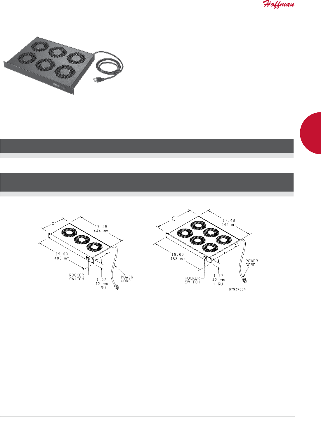
PH 763.422.2661 • FAX 763.422.2588 • PENTAIRPROTECT.COMEQUIPMENT PROTECTION NETWORKING 213
8
COOLING FAN TRAY
FAN TRAY
RACKMOUNTABLE 19IN. FAN TRAY
APPLICATION
Fan trays enhance the natural convection airflow within a cabinet
when installed with other 19-in. rack-mount equipment.
FEATURES
• Fan trays available with either three or six 4-in. fans
• Includes 72-in. (1829-mm) power cord with IEC 320 standard
power socket
• Power cord plugs into standard 115 VAC outlet
• Lighted rocker switch provides on-off control and indicates when
fans are on
FINISH
RAL 9005 black, lightly textured polyester powder paint
ACCESSORIES
Rack mounting hardware
BULLETIN: DTHRM
Standard Products
Catalog Number
Number
of Fans
Power
(W)
Max
Airflow
(CFM) C (in.) C (mm)
A19FT3B 3 45 253 8.10 206
A19FT6B 6 90 506 12.96 329
Technical Performance per 4-Inch Fan
Operating
Voltage
(VAC)
Operating
Frequency
(Hz)
Nominal
Airflow
Capacity
(CFM)
Noise
Level
(dB)
Max. Static
Pressure
(in. WC)
Max.
Operating
Temperature
(°F)
Max.
Operating
Temperature
(°C)
Power
Consumption
(W)
115 60 102 41 0.27 158 70 15
Nominal Airflow capacity rating applies to fans before installation in fan tray.
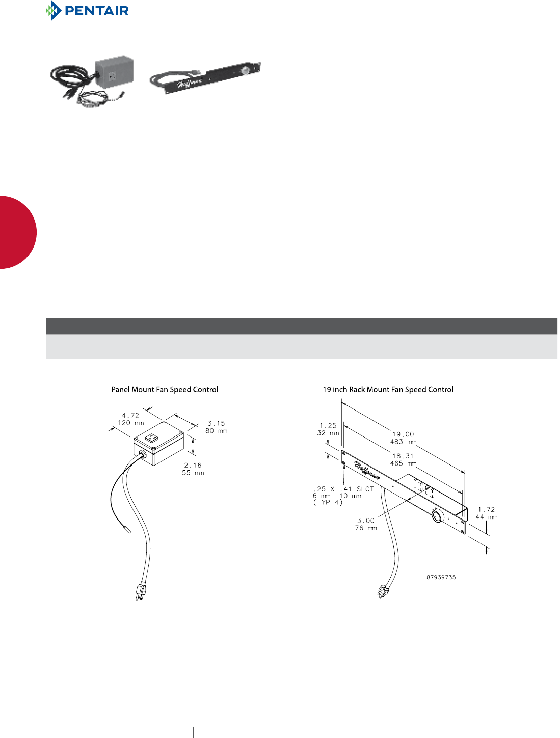
EQUIPMENT PROTECTIONSUBJECT TO CHANGE WITHOUT NOTICENETWORKING214
8
COOLING FAN TRAY
FAN SPEED CONTROLS
INDUSTRY STANDARDS
(both controls)
UL 508 Listed; File No. E249700
cUL Listed per CSA C22.2 No. 14; File No. E249700
APPLICATION
Perfect for offices, classrooms and other noise-sensitive areas, Fan
Speed Controls optimize airflow in a cabinet or rack, balancing air
volume requirements with noise level and power use.
FEATURES
AFANTSC Panel-Mount Fan Speed Control
• Automatically adjusts fan speed depending on remote
temperature sensor input
• Temperature set point is field adjustable; preset at 35 C (95 F)
• Idle speed and temperature slope are field-adjustable
• Push-to-reset thermal circuit breaker inside control housing
• Compact polycarbonate control housing can be mounted in any
position
• NEMA 5-15R outlet provides power to fan
• Six-foot (1.83-m) power cord plugs into standard 120 V, 50 or 60
Hz outlet
• Remote temperature sensor with 10-ft. (3.05-m) lead mounts in
airflow
• Mounting brackets included
A19FANSC 19-in. Rack-Mount Fan Speed Control
• Continuously variable fan speed control knob with minimum
speed adjustment
• Uses 1 RU rack space
• Steel construction
• Two NEMA 5-15R outlets provide power to fan
• Six-foot (1.83-m) power cord plugs into standard 120 V 60 Hz
outlet
FINISH
• AFANTSC: Light-gray polycarbonate control housing
• A19FANSC: RAL 9005 black polyester powder paint
BULLETIN: DTHRM
Standard Products
Catalog Number Description Application
Voltage and
Frequency
Current
Draw
Temperature
Settings (ºC)
Temperature
Settings (ºF)
AFANTSC Panel-Mount
Fan Speed Control
Fan speed controlled
automatically with remote
temperature sensor
120 VAC
50/60 Hz
2 A max. 30, 35, 40, 45 86, 95, 104, 113
A19FANSC 19-in. Rack-Mount
Fan Speed Control
Fan speed
adjusted manually
120 VAC
60 Hz
4 A max. Continuously
variable
Continuously
variable

PH 763.422.2661 • FAX 763.422.2588 • PENTAIRPROTECT.COMEQUIPMENT PROTECTION NETWORKING 215
8
COOLING COMPACT COOLING FANS AND ACCESSORIES
COMPACT COOLING FANS AND ACCESSORIES
COMPACT AXIAL FANS
INDUSTRY STANDARDS
UL Component Recognized
CSA certified
APPLICATION
Compact Cooling Fans are ideal for applications where enclosure
space is limited and quiet, reliable cooling is required. Engineered
for 50,000 hours of continuous operation without lubrication or
service.
Installation
Can be installed on any surface of an enclosure. With the addition
of accessory fan brackets, Compact Cooling Fans can also be
installed in any position inside the enclosure for spot cooling or air
circulation.
FEATURES
• Maximum operating temperature is 158 F (70 C)
• 4-in. fan is thermally protected and uses permanently lubricated
ball bearings
• 6- and 10-in. fans have ball-bearing construction and split-
capacitor motors
• Split-capacitor motors are thermally protected to avoid
premature failure
• Dynamically balanced impellers molded from polycarbonate
material
• One finger guard is furnished (additional finger guards are
available)
• All mounting hardware is provided
Fan bracket and additional finger guards must be purchased separately
• 240 and 560 CFM fans have ball bearing construction and split
capacitor motors
• Fans have leadwires with ends stripped 1/2-in. (12-mm) or 6-ft.
(1.8-m) cord with polarized plug for power connections
Consult your local Hoffman sales office for information on modifications
to this product
FINISH
Fan housing is black.
ACCESSORIES
Fan Brackets
Finger Guards
Temperature Control Switch
BULLETIN: D85
Standard Product and Cutout Dimensions
Catalog Number
Nominal
Size Voltage
A
in./mm
D
in./mm
E
in./mm
J
in./mm
K
in./mm
L
in./mm
M
in./mm
A2AXFN24 2 24 VDC —
—
1.97
50
.98
25
1.97
50
.98
25
—
—
—
—
A3AXFN 3 115 VAC —
—
2.81
71
1.40
36
2.81
71
1.40
36
—
—
—
—
A3AXFN24 3 24 VDC —
—
2.81
71
1.40
36
2.81
71
1.40
36
—
—
—
—
A4AXFNGQ 4 115 VAC 4.62
117
4.12
105
2.06
52
4.12
105
2.06
52
—
—
—
—
A4AXFNPG 4 115 VAC 4.62
117
4.12
105
2.06
52
4.12
105
2.06
52
—
—
—
—
A4AXFN 4 115 VAC 4.62
117
4.12
105
2.06
52
4.12
105
2.06
52
—
—
—
—
A4AXFN2 4 230 VAC 4.62
117
4.12
105
2.06
52
4.12
105
2.06
52
—
—
—
—
A4AXFN24 4 24 VDC 4.62
117
4.12
105
2.06
52
4.12
105
2.06
52
—
—
—
—
A6AXFNGQ 6 115 VAC 5.88
149
—
—
—
—
—
—
—
—
3.19
81
6.38
162
A6AXFNPG 6 115 VAC 5.88
149
—
—
—
—
—
—
—
—
3.19
81
6.38
162
A6AXFN 6 115 VAC 5.88
149
—
—
—
—
—
—
—
—
3.19
81
6.38
162
A6AXFN2 6 230 VAC 5.88
149
—
—
—
—
—
—
—
—
3.19
81
6.38
162
A6AXFN24 6 24 VDC 5.88
149
—
—
—
—
—
—
—
—
3.19
81
6.38
162
A10AXFNPG 10 115 VAC 9.00
229
6.88
175
3.44
87
6.88
175
3.4
87
—
—
—
—
A10AXFN 10 115 VAC 9.00
229
6.88
175
3.44
87
6.88
175
3.44
87
—
—
—
—
A10AXFN2 10 230 VAC 9.00
229
6.88
175
3.44
87
6.88
175
3.44
87
—
—
—
—
CFM without exhaust grille
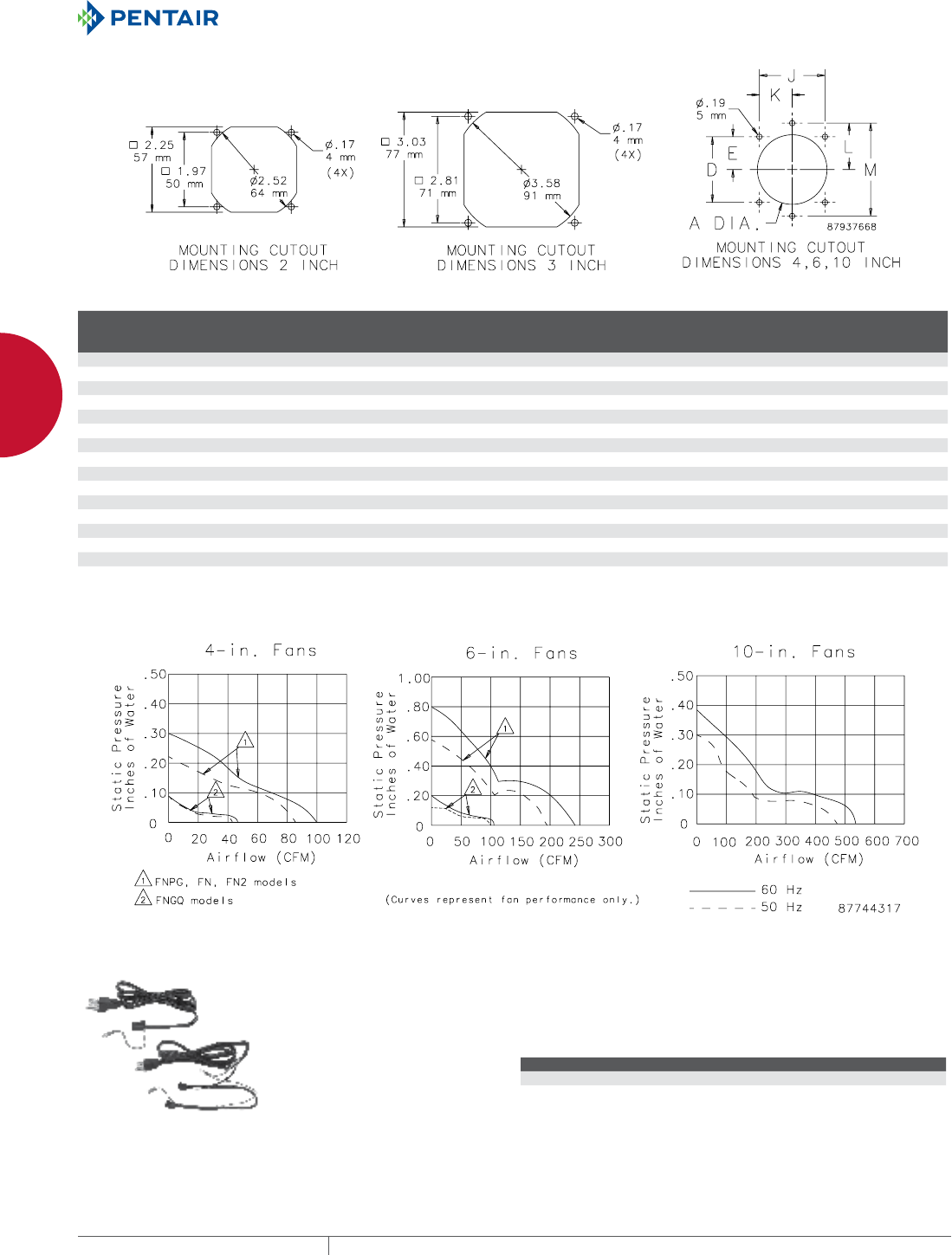
EQUIPMENT PROTECTIONSUBJECT TO CHANGE WITHOUT NOTICENETWORKING216
8
COOLING COMPACT COOLING FANS AND ACCESSORIES
Technical/Performance Data for Compact Cooling Fans
Catalog Number
Nominal
Size
Power
Connection Voltage
A @
50/60 Hz
W @
50/60 Hz
CFM @
50/60 Hz
Fan Size
(in.²) Fan Depth
Max. Motor
Operating RPM @
50/60 Hz Noise SIL (dB)
A2AXFN24 2 Lead wires 24 VDC .09 2.16 21.5 2.36 .98 in. 4550 65
A3AXFN 3 Lead wires 115 VAC .09 7 27 3.15 1.50 in. 2700 40
A3AXFN24 3 Lead wires 24 VDC .14 3.36 40 3.15 .98 in. 3400 35
A4AXFNGQ 4 (Quiet Fan) Power cord 115 VAC .09/.08 6/5 46/49 4.69 1.52 in. 1350/1450 27/28
A4AXFNPG 4 Power cord 115 VAC .26/.21 17/15 85/100 4.69 1.52 in. 2415/2900 37/41
A4AXFN 4 Lead wires 115 VAC .26/.21 17/15 85/100 4.69 1.52 in. 2415/2900 37/41
A4AXFN2 4 Lead wires 230 VAC .14/.11 16/14 85/100 4.69 1.52 in. 2415/2900 37/41
A4AXFN24 4 Lead wires 24 VDC .35 8.4 118 4.69 1.52 in. 3200 46.5
A6AXFNGQ 6 (Quiet Fan) Power cord 115 VAC .16/.19 16/18 85/102 6.77 1.50 in. 1400/1650 35/38
A6AXFNPG 6 Power cord 115 VAC .45/36 36/32 200/240 6.77 1.50 in. 2670/3200 50/56
A6AXFN 6 Lead wires 115 VAC .45/36 36/32 200/240 6.77 1.50 in. 2670/3200 50/56
A6AXFN2 6 Lead wires 230 VAC .23/.18 39/35 200/240 6.77 1.50 in. 2670/3200 50/56
A6AXFN24 6 Lead wires 24 VDC .88 21.1 280 6.77 2.00 in. 3750 62.5
A10AXFNPG 10 Power cord 115 VAC 1.0/.88 36/36 480/560 10.00 3.50 in. 1350/1650 45.8/49
A10AXFN 10 Lead wires 115 VAC 1.0/.88 36/36 480/560 10.00 3.50 in. 1350/1650 45.8/49
A10AXFN2 10 Lead wires 230 VAC .47/.43 36/36 480/560 10.00 3.50 in. 1350/1650 45.8/49
Performance Curves for Compact Axial Fans
FAN CORDS Used to power Compact Cooling Fans when positive ground of
the cabinet case is required. Available with connectors for one or
two fans. Five-foot (1.52-meter) cord with grounded three-prong
plug. Fits A4AXFNPG, A6AXFNPG, A10AXFNPG, A4AXFNGQ and
A10AXFNGQ.
BULLETIN: DTHRM
Catalog Number Description
ACORD1 One connector
ACORD2 Two connectors
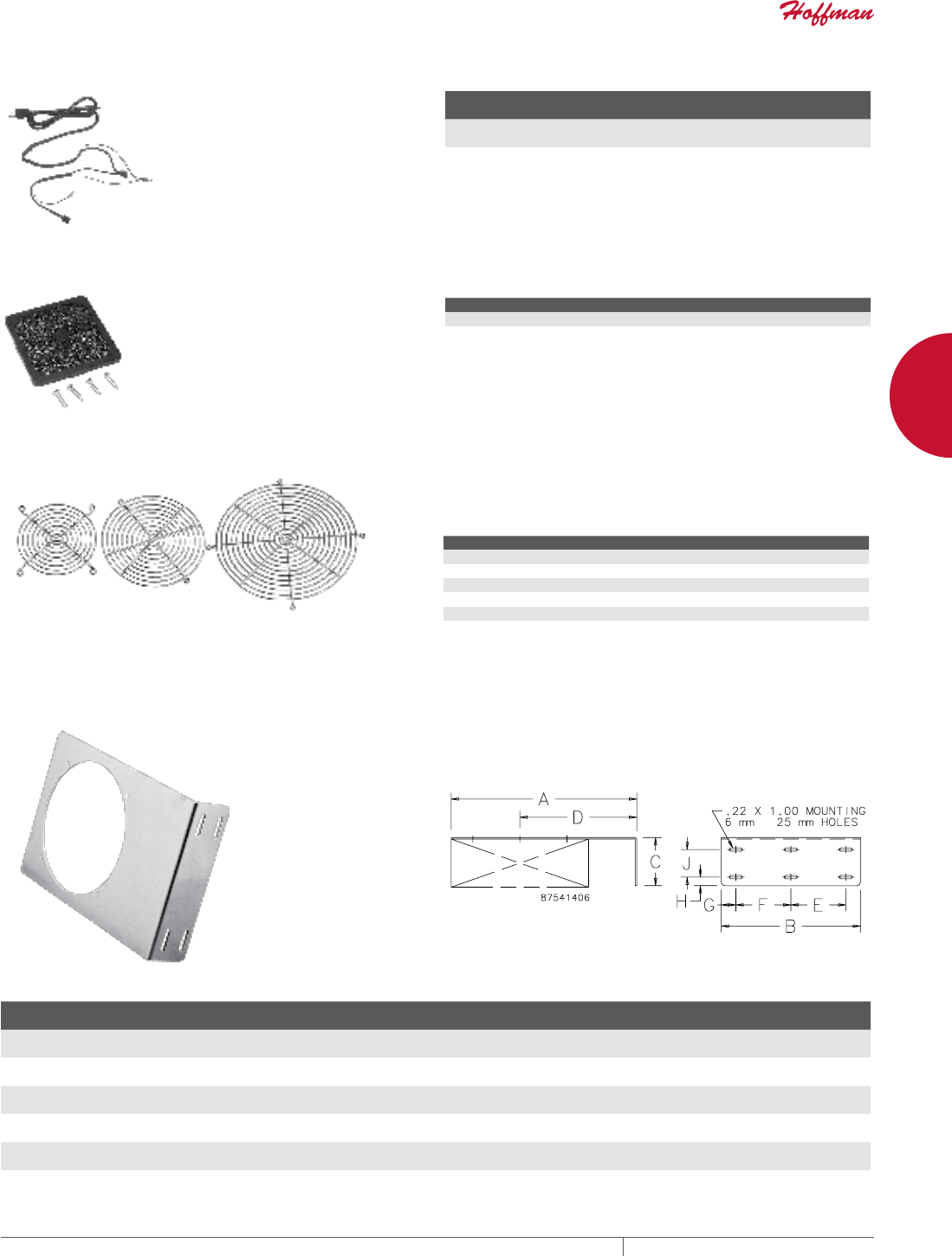
PH 763.422.2661 • FAX 763.422.2588 • PENTAIRPROTECT.COMEQUIPMENT PROTECTION NETWORKING 217
8
COOLING COMPACT COOLING FANS AND ACCESSORIES
FAN CORDS WITH INLINE THERMOSTAT
Use to power 110-120 VAC Compact
Cooling Fans; replaces existing
supplied power cord. Fan cord
includes inline thermostat. The
cord automatically activates up to
two fans. Fan(s) will turn on when
the inline thermostat reaches 85F
(30C). Fan(s) will run only when
temperature is above 85F (30C).
BULLETIN: DTHRM
Catalog Number Description
Fan activation
temperature Voltage Amps
ACORD2T Two-connector fan power cord
with inline thermostat
85 F (30 C) 110-120 VAC 10 amps max.
FAN FILTER AND FINGER GUARD KIT
Low-density filter kit for 4-in.
(102-mm) and 6-in. (152-mm) fans.
Can also be used as vent. Filter
is removable and can be cleaned
and reused. Mounting hardware
included.
BULLETIN: DTHRM, DWS1
Catalog Number Description Fits
AFLTR4LD Fan Filter and Finger Guard Kit 4-in. fans
AFLTR6LD Fan Filter and Finger Guard Kit 6-in. fans
FINGER GUARDS One finger guard is included with each Compact Cooling Fan and
Cooling Fan Package. Additional Finger Guards can be mounted on
either side of the fan for maximum safety. All guards are chrome-
plated and meet UL 507 .25-in. plug gauge test.
BULLETIN: D85
Catalog Number Use on Compact Cooling Fan Catalog Numbers
AGARD2 A2AXFN24
AGARD3 A3AXFN, A3AXFN24
AGARD4 A4AXFNPG, A4XFNGQ, A4AXFN, A4AXFN2
AGARD6 A6AXFNPG, A6AXFNGQ, A6AXFN, A6AXFN2
AGARD10 A10AXFNPG, A10AXFNQR , A10AXFN, A10AXFN2
FAN BRACKETS Designed to provide easy mounting of Hoffman cooling fans on
enclosure panels. Brackets can be used for general air circulation
or to direct air at problem areas. All sizes are .100-in. aluminum.
Package quantity of 1 bracket. Fans must be ordered separately.
BULLETIN: D85
Catalog Number AxBxC in./mm
Used with Fan
Catalog Number
D
in./mm
E
in./mm
F
in./mm
G
in./mm
H
in./mm
J
in./mm
ABRKT2 3.75 x 2.75 x 1.50
95 x 70 x 38
A2AXFN24 2.38
60
—
—
1.75
44
.50
13
.37
9
.62
16
ABRKT3 4.50 x 3.50 x 1.50
114 x 89 x 38
A3AXFN, A3AXFN24 2.75
70
—
—
2.50
64
.50
13
.37
9
.62
16
ABRKT4 6.00 x 5.00 x 1.50
152 x 127 x 38
A4AXFNPG, A4AXFNGQ, A4AXFN, or A4AXFN2 3.50
89
—
—
3.00
76
1.00
25
.38
10
.62
16
ABRKT6 10.00 x 6.88 x 2.00
254 x 175 x 51
A6AXFNPG, A6AXFNGQ, A6AXFN, or A6AXFN2 6.50
51
—
—
5.00
127
.94
24
.38
10
1.00
25
ABRKT10 13.50 x 10.12 x 3.50
343 x 257 x 89
A10AXFNPG, A10AXFNGQ, A10AXFN, or A10AXFN2 8.50
216
4.00
102
4.00
102
1.06
27
.62
16
2.00
51
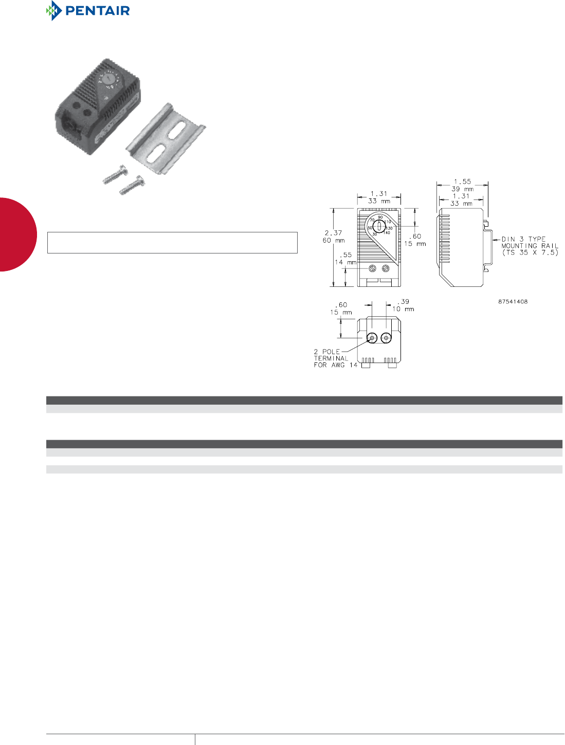
EQUIPMENT PROTECTIONSUBJECT TO CHANGE WITHOUT NOTICENETWORKING218
8
COOLING COMPACT COOLING FANS AND ACCESSORIES
TEMPERATURE CONTROL SWITCHES
INDUSTRY STANDARDS
cURus; File No. E164102
UL94-VO
Protection rating IEC IP30
CSA Certified, File Number 215952
CE
APPLICATION
These easy-to-install thermostats regulate and monitor air
temperature in enclosures that contain heat-emitting equipment.
Thermostats prolong heater and fan life expectancy by controlling
operation time and increase electrical component working
efficiency by exposing them to fewer environmental contaminants.
FEATURES
• Additional label for conversion to Celsius scale and blank label to
cover set point range label when adjustment after initial setting is
not desired are included
• Bimetal temperature sensor
• Plastic housing
• Connections consist of tubular screw terminals for AWG 14
(.04 sq. in.)
• Provision for both panel mounting and DIN rail mounting
FINISH
Molded plastic housing is black
BULLETIN: D85
Standard Product
Catalog Number Contact Type Control Application
ATEMNC NC (normally closed), quick acting Heater
ATEMNO NO (normally open), quick acting Fan
Switching Capacity
Load Amps
Maximum load 15 A resistive / 2 A inductive @ 120 VAC
10 A resistive / 2 A inductive @ 250 VAC
DC 30 W
Minimum load 20 mA (all voltages)
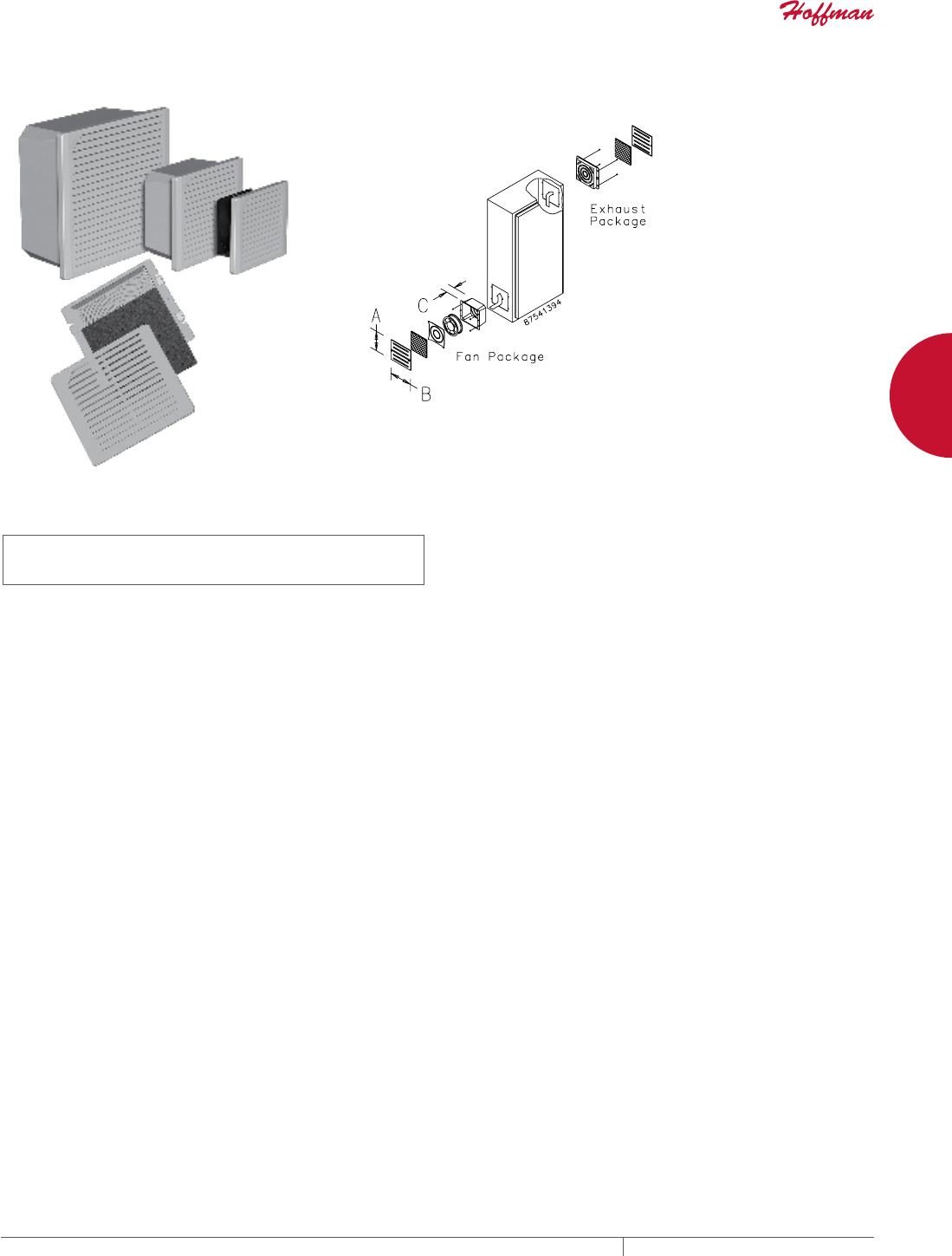
PH 763.422.2661 • FAX 763.422.2588 • PENTAIRPROTECT.COMEQUIPMENT PROTECTION NETWORKING 219
8
COOLING COOLING FAN AND EXHAUST PACKAGES WITH ACCESSORIES
COOLING FAN AN D EXHAUST PACK AGES WITH ACCE SSORIES
TFP SIDEMOUNT
INDUSTRY STANDARDS
UL 508A Component Recognized, File Number E61997
TFP# Models: Type 1
TFP# UL 12 Models: Type 12
CSA certified (fan only)
CE
APPLICATION
Cooling Fan and Exhaust Packages are designed for limited-space
enclosures that require a reliable and filtered airflow. Where
positive airflow is not required, Exhaust Packages can be used on
both the inlet and outlet.
Engineered for 50,000 hours of continuous operation without
lubrication or service. For both Type 1 and Type 12 systems a
monthly maintenance schedule is recommended to ensure optimal
cooling performance.
FEATURES
• Cooling Fan Package includes fan, air filter, composite air
plenum, finger guard and grille
• Exhaust Package includes air filter, filter retainer with integral
finger guard and grille
• EMC Upgrade Kit includes a grille standoff collar and a special
EMC shielding grille
• Washable foam (Type 1) or disposable (Type 12) filter in fan.
Optional washable aluminum air filter is available for Type 1
applications.
• Dynamically-balanced fan impellers molded from polycarbonate
material
• 4-in. fan is thermally protected and uses permanently-lubricated
ball bearings
• 6- and 10-in. fans have ball bearing construction and split-
capacitor motors that are thermally protected to avoid premature
failure
• Fans have leadwires for power connection with ends stripped 1/2
in. (12 mm)
• All mounting hardware and installation instructions are furnished
Filters
Standard Type 1 air filters are washable foam.
Type 12 air filters are not washable.
Installation
Fan and exhaust packages can be installed on any surface of
an enclosure. They are most effective when the fan assembly is
located on a lower panel of the enclosure and the exhaust grille is
positioned near the top of the opposite side. This installation assists
heat transfer by causing slightly more turbulence and also prolongs
the working life of the fan since it is located in the path of the cooler
air entering the enclosure.
The height and width of the cooling fans and exhaust grilles can
be rotated 90 degrees for mounting on narrow enclosures. Allow
adequate clearance for servicing the fan when equipment is
installed inside the enclosure and for replacing filters on both the
fan and the exhaust. Cutout dimensions for both the fan and the
exhaust are shown in the order table. Order the fan and exhaust
packages separately.
FINISH
Stainless steel grilles have brushed finish.
ABS composite grille is black.
ACCESSORIES
Aluminum Type 1 and Hi-Density Type 12 Filters
EMC Upgrade Kit
Grille Options:
Stainless Steel
Black ABS Plastic
BULLETIN: D85
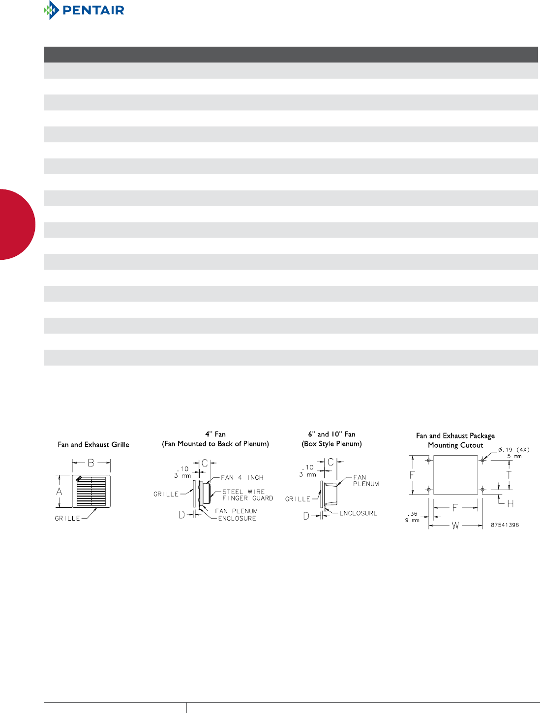
EQUIPMENT PROTECTIONSUBJECT TO CHANGE WITHOUT NOTICENETWORKING220
8
COOLING COOLING FAN AND EXHAUST PACKAGES WITH ACCESSORIES
Standard Product and Cutout Dimensions Cooling Fan and Exhaust Packages
Catalog Number AxBxC in./mm Material and Type
Use with
Exhaust Grille
Nominal
Fan Size
D
in./mm
F
in./mm
H
in./mm
T
in./mm
W
in./mm
TFP424 6.29 x 7.37 x 2.35
160 x 187 x 67
Composite Grille UL 508 Type 1 TEP4 4 0.45
11
5.66
144
0.77
20
4.12
105
6.39
162
TFP41 6.29 x 7.37 x 2.65
160 x 187 x 67
Composite Grille UL 508 Type 1 TEP4 4 0.45
11
5.66
144
0.77
20
4.12
105
6.39
162
TFP41SS 6.29 x 7.37 x 2.65
160 x 187 x 67
Stainless Steel Grille UL 508 Type 1 TEP4SS 4 0.45
11
5.66
144
0.77
20
4.12
105
6.39
162
TFP41UL12 6.29 x 7.37 x 2.65
160 x 187 x 67
Composite Grille UL 508 Type 12 TEP4UL12 4 0.45
11
5.66
144
0.77
20
4.12
105
6.39
162
TFP42 6.29 x 7.37 x 2.65
160 x 187 x 67
Composite Grille UL 508 Type 1 TEP4 4 0.45
11
5.66
144
0.77
20
4.12
105
6.39
162
TFP42SS 6.29 x 7.37 x 2.65
160 x 187 x 67
Stainless Steel Grille UL 508 Type 1 TEP4SS 4 0.45
11
5.66
144
0.77
20
4.12
105
6.39
162
TFP42UL12 6.29 x 7.37 x 2.65
160 x 187 x 67
Composite Grille UL 508 Type 12 TEP4UL12 4 0.45
11
5.66
144
0.77
20
4.12
105
6.39
162
TFP624 7.80 x 8.87 x 3.75
198 x 225 x 95
Composite Grille UL 508 Type 1 TEP6 6 0.49
12
7.16
182
1.33
34
4.50
114
7.89
200
TFP61 7.80 x 8.87 x 3.75
198 x 225 x 95
Composite Grille UL 508 Type 1 TEP6 6 0.49
12
7.16
182
1.33
34
4.50
114
7.89
200
TFP61SS 7.80 x 8.87 x 3.75
198 x 225 x 95
Stainless Steel Grille UL 508 Type 1 TEP6SS 6 0.49
12
7.16
182
1.33
34
4.50
114
7.89
200
TFP61UL12 7.80 x 8.87 x 3.75
198 x 225 x 95
Composite Grille UL 508 Type 12 TEP6UL12 6 0.49
12
7.16
182
1.33
34
4.50
114
7.89
200
TFP62 7.80 x 8.87 x 3.75
198 x 225 x 95
Composite Grille UL 508 Type 1 TEP6 6 0.49
12
7.16
182
1.33
34
4.50
114
7.89
200
TFP62SS 7.80 x 8.87 x 3.75
198 x 225 x 95
Stainless Steel Grille UL 508 Type 1 TEP6SS 6 0.49
12
7.16
182
1.33
34
4.50
114
7.89
200
TFP62UL12 7.80 x 8.87 x 3.75
198 x 225 x 95
Composite Grille UL 508 Type 12 TEP6UL12 6 0.49
12
7.16
182
1.33
34
4.50
114
7.89
200
TFP101 11.81 x 12.99 x 5.25
300 x 330 x 133
Composite Grille UL 508 Type 1 TEP10 10 0.55
14
11.16
283
2.14
54
6.88
175
11.89
302
TFP101SS 11.81 x 12.99 x 5.25
300 x 330 x 133
Stainless Steel Grille UL 508 Type 1 TEP10SS 10 0.55
14
11.16
283
2.14
54
6.88
175
11.89
302
TFP101UL12 11.81 x 12.99 x 5.25
300 x 330 x 133
Composite Grille UL 508 Type 12 TEP10UL12 10 0.55
14
11.16
283
2.14
54
6.88
175
11.89
302
TFP102 11.81 x 12.99 x 5.25
300 x 330 x 133
Composite Grille UL 508 Type 1 TEP10 10 0.55
14
11.16
283
2.14
54
6.88
175
11.89
302
TFP102SS 11.81 x 12.99 x 5.25
300 x 330 x 133
Stainless Steel Grille UL 508 Type 1 TEP10SS 10 0.55
14
11.16
283
2.14
54
6.88
175
11.89
302
TFP102UL12 11.81 x 12.99 x 5.25
300 x 330 x 133
Composite Grille UL 508 Type 12 TEP10UL12 10 0.55
14
11.16
283
2.14
54
6.88
175
11.89
302
An intake grille and filter are included with each Cooling Fan Package. Order at least one Exhaust Package separately for each installation.
Order optional Exhaust Grilles as a separate accessory.
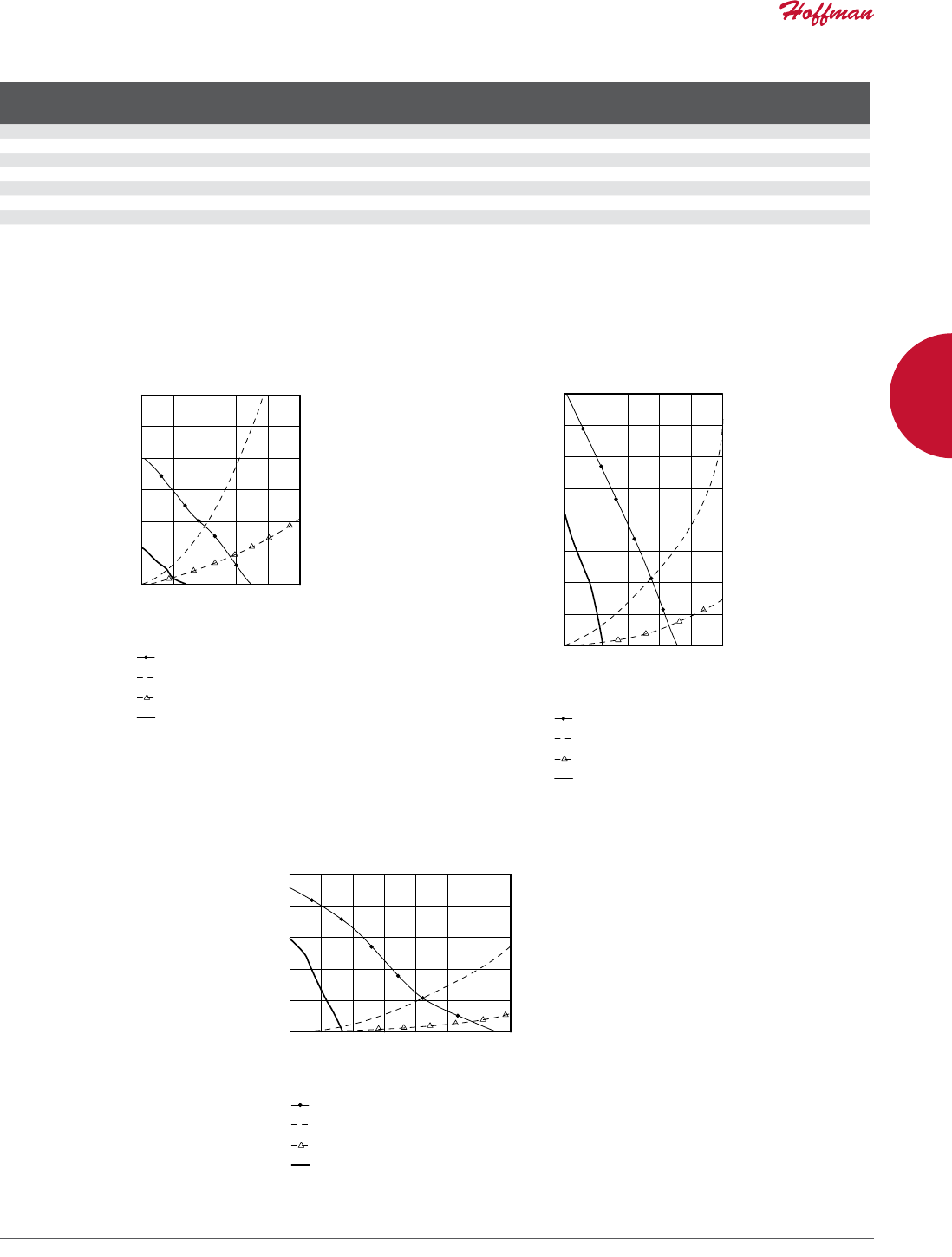
PH 763.422.2661 • FAX 763.422.2588 • PENTAIRPROTECT.COMEQUIPMENT PROTECTION NETWORKING 221
8
COOLING COOLING FAN AND EXHAUST PACKAGES WITH ACCESSORIES
Technical Performance Data for Cooling Fan Packages
Composite
Grille
UL Type 1
Stainless
Grille
UL Type 1
Type 1 CFM
@ 50/60 Hz
Composite
Grille
UL Type 12
Type 12
CFM @ 50/60 Hz
W @
50/60 Hz Voltage
A @
50/60 Hz
Max.
Operating
Temperature (°F)
Max.
Operating
Temperature (°C)
Noise SIL (dB)
@ 50/60 Hz
Weight
(lb.)
Weight
(kg)
TFP424 — 55 — — 8.4 24 VDC .35 158 70 65 4.2 1.90
TFP41 TFP41SS 46/55 TFP41UL12 21/25 17/15 115 VAC .26/.21 158 70 37/41 4.2 1.90
TFP42 TFP42SS 46/55 TFP42UL12 21/25 16/14 230 VAC .14/.11 158 70 37/41 4.3 1.95
TFP624 — 140 — — 21.1 24 VDC .88 158 70 62.5 5.3 2.40
TFP61 TFP61SS 117/140 TFP61UL12 50/60 36/32 115 VAC .45/.36 158 70 50/56 5.3 2.40
TFP62 TFP62SS 117/140 TFP62UL12 50/60 39/35 230 VAC .23/.18 158 70 50/56 5.4 2.45
TFP101 TFP101SS 180/215 TFP101UL12 63/75 64/80 115 VAC .58/.70 167 75 54/61 12.0 2.45
TFP102 TFP102SS 180/215 TFP102UL12 63/75 64/80 230 VAC .29/.35 167 75 54/61 11.4 5.17
CFM with single exhaust grille installed.
Performance Curve for a 4 inch
Cooling Fan Package @ 60 Hz
Performance Curve for a 6 inch
Cooling Fan Package @ 60 Hz
Performance Curve for a 10 inch
Cooling Fan Package @ 60 Hz
Performance Curves for TFP Filter Fans
STATIC PRESSURE (IWC)
STATIC PRESSURE (IWC)
STATIC PRESSURE (IWC)
AIRFLOW (CFM)
AIRFLOW (CFM)
AIRFLOW (CFM)
10 in. Cooling Fan Package
10 in. Exhaust Package
Two 10 in. Exhaust Packages
10 in. Type 12 Cooling Fan Package
4 in. Cooling Fan Package
4 in. Exhaust Package
Two 4 in. Exhaust Packages
4 in. Type 12 Cooling Fan Package 6 in. Cooling Fan Package
6 in. Exhaust Package
Two 6 in. Exhaust Packages
6 in. Type 12 Cooling Fan Pack
age
0
.05
.10
.15
.20
.25
.30
025 50 75 100 125
050 100 150 200 250
050 100 150 200 250 300 350
0
.10
.20
.30
.40
.50
0
.10
.20
.30
.40
.50
.60
.70
.80
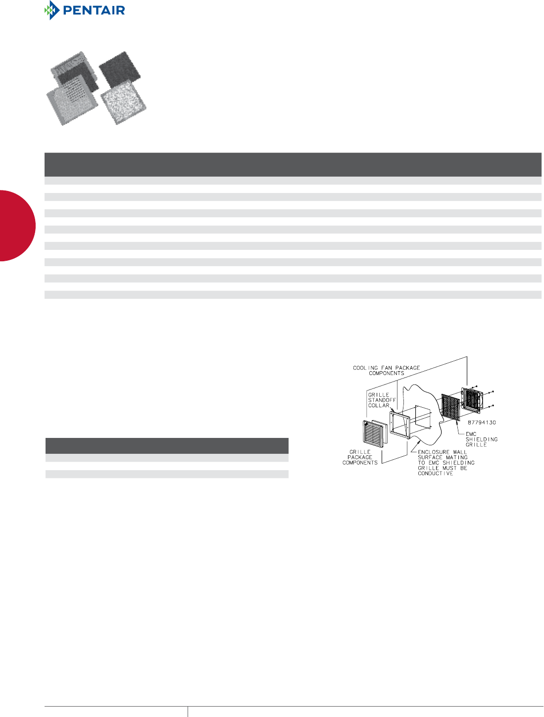
EQUIPMENT PROTECTIONSUBJECT TO CHANGE WITHOUT NOTICENETWORKING222
8
COOLING COOLING FAN AND EXHAUST PACKAGES WITH ACCESSORIES
TFP OPTIONAL GRILLES AND REPLACEMENT FILTERS Optional grilles offer the choice of stainless steel or black
ABS plastic. These grilles replace the standard RAL 7035 gray
composite or stainless steel grilles on both fan and exhaust
packages. Standard replacement filters are washable foam (Type
1) or disposable (Type 12). To maintain UL Type 12 rating on the
enclosure, UL Type 12 filters must be used on the fan package inlet.
Washable aluminum filters are also available. Aluminum filters are
compatible with Type 1 systems only.
Type 12 air filters are not washable.
BULLETIN: D85
Catalog Number Description
Fits Fan
and Exhaust
Nominal Size
Fits Fan
and Exhaust
Grill Size (in.)
Fits Fan
and Exhaust
Grille Size (mm)
TG4SS Brushed stainless steel grille 4 6.29 x 7.31 x .81 (160 x 186 x 21)
TG4B Black ABS plastic grille 4 6.29 x 7.37 x .81 (160 x 187 x 21)
AFLTR4 Type 1 filter replacement (5/package) 4 — —
AFLTR4AL Aluminum filter replacement (5/package) 4 — —
TFLT4UL12 Type 12 filter replacement (5/package) 4 — —
TG6SS Brushed stainless steel grille 6 7.80 x 8.81 x .75 (198 x 224 x 19)
TG6B Black ABS plastic grille 6 7.80 x 8.87 x .49 (198 x 225 x 12)
AFLTR6 Foam filter replacement (5/package) 6 — —
AFLTR6AL Aluminum filter replacement (5/package) 6 — —
TFLT6UL12 UL 12 filter replacement (5/package) 6 — —
TG10SS Brushed stainless steel grille 10 11.81 x 12.92 x .75 (300 x 328 x 19)
TG10B Black ABS plastic grille 10 11.81 x 12.99 x .75 (300 x 330 x 19)
AFLTR10 Foam filter replacement (5/package) 10 — —
AFLTR10AL Aluminum filter replacement (5/package) 10 — —
TFLT10UL12 UL 12 filter replacement (5/package)a 10 — —
Replacement filter for Type 12 fan package only (models TFF__UL12). For Type 12 exhaust package use replacement filter AFLTRX.
Filters fit all fan and exhaust packages according to their size.
TFP EMC UPGRADE KIT
With the addition of this kit, the cooling fan and exhaust packages
are upgraded to provide EMC (electromagnetic compatibility)
protection. Consult Hoffman for shielding effectiveness (dB
attenuation vs. frequency).
Separate kits must be installed on both the inlet and outlet. Cooling fan
and exhaust package must be ordered separately. EMC upgrade kit will
not work with stainless steel grille option.
BULLETIN: D85
Catalog Number
Fits Cooling
Fan Package
Fits Exhaust
Grille
T4EMC TFP41/TFP42 TEP4
T6EMC TFP61/TFP62 TEP6
T10EMC TFP101/TFP102 TEP10
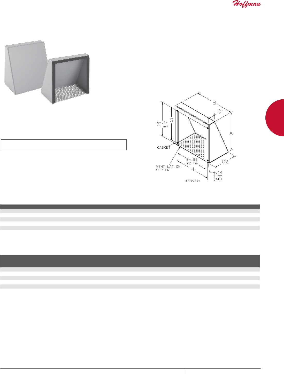
PH 763.422.2661 • FAX 763.422.2588 • PENTAIRPROTECT.COMEQUIPMENT PROTECTION NETWORKING 223
8
COOLING FAN SHROUD KIT
FAN SHROUD KIT
FAN SHROUD KIT, TYPE 3R
INDUSTRY STANDARDS
Maintains UL/cUL Type 3R rating when properly installed on a UL/
cUL Type 3R enclosure.
UL 508A Listed; Type 3R; File No. E61997
cUL Listed per CSA C22.2 No. 94; Type 3R; File No. E61997
NEMA/EEMAC Type 3R
IEC 60529, IP22
APPLICATION
Fan Shroud Kits protect outdoor enclosure openings from rain,
sleet and snow.
FEATURES
• Two fan shrouds per package
• Perforated ventilation screen
• Pressure-sensitive adhesive-backed gasket and mounting
hardware
SPECIFICATIONS
• 16 gauge mild steel or Type 304 stainless steel
FINISH
ANSI 61 gray polyester powder coating over mild steel; smooth #4
brushed finish on stainless steel
BULLETIN: D85
Standard Product
Catalog Number Material A (in.) A (mm) B (in.) B (mm) C1 (in.) C1 (mm) C2 (in.) C2 (mm) G (in.) G (mm) H (in.) H (mm)
T4S3R Steel 6.00 152 6.00 152 1.44 37 4.69 119 4.69 119 5.25 133
T6S3R Steel 8.00 203 8.00 203 1.44 37 4.69 119 6.69 170 7.25 184
T10S3R Steel 12.00 305 12.00 305 1.44 37 4.71 120 10.69 272 11.25 286
T4S3RSS Stainless Steel 6.00 152 6.00 152 1.44 37 4.69 119 4.69 119 5.25 113
T6S3RSS Stainless Steel 8.00 203 8.00 203 1.44 37 4.69 119 6.69 170 7.25 184
T10S3RSS Stainless Steel 12.00 305 12.00 305 1.44 37 4.71 120 10.69 272 11.25 286
Usage Chart
Catalog
Number
Compact Cooling
(muffin) Fans (4 in.)
Compact Cooling
(muffin) Fans (6 in.)
Compact Cooling
(muffin) Fans (10 in.)
Cooling and
Exhaust Fan
Packages (TFP4-)
Cooling and
Exhaust Fan
Packages (TFP6-)
Filter Fan
Packages (SF05-)
Filter Fan
Packages (SF09-)
Filter Fan
Packages (SF10-)
T4S3R •
T6S3R • • •
T10S3R • • • • • • • •
T4S3RSS •
T6S3RSS • • •
T10S3RSS • • • • • • • •

EQUIPMENT PROTECTIONSUBJECT TO CHANGE WITHOUT NOTICENETWORKING224
9
763.422.2661
763.422.2588
NETWORKING
OUTSIDE PL ANT PRODUCTS
Intro Page
CHAPTER 9
OUTSIDE PLANT PRODUCTS
COMLINE™ ENCLOSURES
Enclosing critical telecommunications
equipment in harsh outdoor
environments can be a challenge.
Lightweight, corrosion-resistant
COMLINE™ Wall-Mount Enclosures
provide long-lasting protection for
housing electrical components in
both indoor and extreme outdoor
environments for
rooftop or tower-
mounted applications. FIBER OPTIC
CABINETS
Protect and manage fiber optic cables
for broadband delivery in outdoor
applications with FTTX enclosures.
Welded aluminum and polyester power
paint safeguard components.
FEATURED PRODUCTS

PH 763.422.2661 • FAX 763.422.2588 • PENTAIRPROTECT.COMEQUIPMENT PROTECTION NETWORKING 225
Intro Page CHAPTER CONTENTS
COMLINE™ WALLMOUNT ENCLOSURES AND ACCESSORIES
COMLINE™, Type 4X .........................................226
Mounting Panel. . . . . . . . . . . . . . . . . . . . . . . . . . . . . . . . . . . . . . . . . . . .228
Solar Shield Top ...........................................228
Rack Angles ..............................................229
Door Stop Kit .............................................229
Handle Options ............................................229
Clip Nut Package ..........................................229
Screw Package ............................................229
Pole-Mount Kit ............................................229
COMLINE™ OSP WALLMOUNT CABINET PACKAGE AND
ACCESSORIES
COMLINE™ OSP Package, Type 4X ..............................230
Rack Angles ..............................................233
Vertical Pole-Mount Channel .................................233
Wood Panel ...............................................233
Gland Plate ...............................................233
Plinth Base ...............................................233
Ground Buss ..............................................233
Handle Options ............................................234
Clip Nut Package ..........................................234
Screw Package ............................................234
Mounting Bracket Kits ......................................234
Wall Mounting Bracket ......................................234
COMLINE™ OSP VERTICAL MOUNT CABINET PACKAGE AND
ACCESSORIES
COMLINE™ Vertical Mount Cabinet .............................235
Handle Options ............................................237
Clip Nut Package ..........................................237
Screw Package ............................................237
Mounting Bracket Kits ......................................237
Wall Mounting Bracket ......................................237
Ground Buss ..............................................237
FIBER OPTIC CABINETS
FTTX Fiber Optic Cabinet Package, Type 4X ......................238
Fiber Management Spool ....................................241
Clip Nut Package ..........................................241
Screw Package ............................................241
Fiber Optic Cabinet Pole-Mount Kit ............................241
OSP CABINETS
OPAL Pad-Mount DSL Cabinet .................................242
9
OPAL PADMOUNT
DSL ENCLOSURES
OPAL Cabinets are designed and built
to the outside plant application at hand.
Ideal for broadband voice, data and video
service applications.
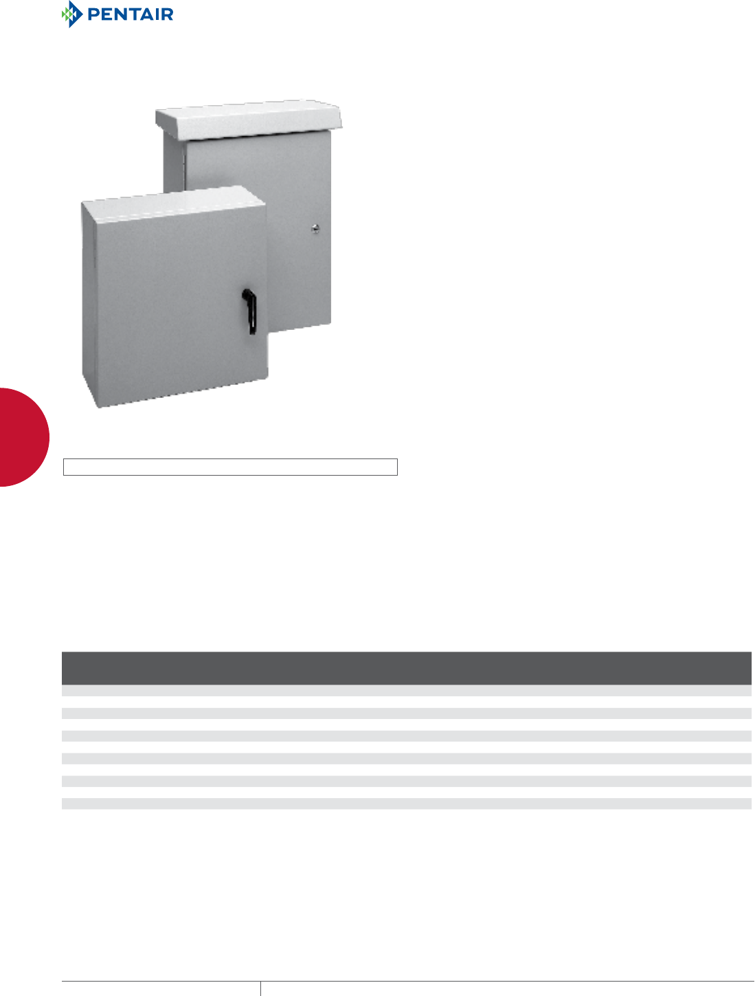
EQUIPMENT PROTECTIONSUBJECT TO CHANGE WITHOUT NOTICENETWORKING226
9
OUTSIDE PLANT PRODUCTS COMLINE™ WALLMOUNT ENCLOSURES AND ACCESSORIES
COMLINE
™
WALL-MOUNT ENCLOS URES AND ACCE SSORIES
COMLINE™, TYPE 4X
INDUSTRY STANDARDS
UL 508A Listed; Type 3, 3R, 4, 4X, 12; File No. E61997
CSA File No. 42186: Type 3, 3R, 4, 4X, 12
NEMA/EEMAC Type 3, 3R, 4, 4X, 12
IEC 60529, IP66
Designed to meet NEBS™ -Telcordia GR487, GR63, IEC 48D
Meets Type 3RX requirements
NEBS is a trademark of Telcordia
APPLICATION
Lightweight, corrosion-resistant COMLINE™ aluminum wall-mount
enclosures provide long-lasting protection for housing electrical
components in extreme outdoor environments. These customizable
enclosures employ a foam-in-place gasket for a tight seal and
are ideal for rooftop or tower-mounted telecommunications
applications.
FEATURES
• Foam-in-place gasket
• 1- or 3-point latching (screwdriver slot), depending on door size
• Optional door stop/wind latch holds door in place during service
• Two door/hinge styles available:
– Easily removable door with hidden hinge and retained
hinge pin. Maximum door load 50 lb. (22.7 kg)
– Heavy-duty continuous hinge door. Maximum door load
150 lb. (68.0 kg)
• Optional solar shield top
SPECIFICATIONS
• Type 5052-H32 aluminum: covers are .080-in. or .100-in. thick
depending on size; bodies are .080-in. thick
• Seams continuously welded and ground smooth for a finished
appearance
• Bonding provision on door; ground stud on body
FINISH
RAL 7035 textured light-gray polyester powder finish inside and out.
ACCESSORIES
See also Accessories chapter.
Door Stop Kit
Handle Options
Mounting Panel
Pole Mounting Kit
Rack Angles
Solar Shield Top
MODIFICATION AND CUSTOMIZATION
Hoffman excels at modifying and customizing products to your
specifications. Contact your local Hoffman sales office or distributor
for complete information.
BULLETIN: DCOM
Standard Product Hidden Hinge
Catalog Number AxBxC mm AxBxC in.
Latch
Points
Door
Thickness
(mm)
Door
Thickness
(in.) Std. Pkg. (lb.)
ECL303015 300 x 300 x 150 11.81 x 11.81 x 5.91 1 2 .08 9.0
ECL403015 400 x 300 x 150 15.75 x 11.81 x 5.91 1 2 .08 10.0
ECL404015 400 x 400 x 150 15.75 x 15.75 x 5.91 1 2 .08 12.0
ECL404020 400 x 400 x 200 15.75 x 15.75 x 7.87 1 2 .08 13.0
ECL504020 500 x 400 x 200 19.69 x 15.75 x 7.87 1 2 .08 15.0
ECL505020 500 x 500 x 200 19.69 x 19.69 x 7.87 1 2 .08 17.0
ECL605020 600 x 500 x 200 23.62 x 19.69 x 7.87 3 2.5 .10 19.0
ECL606020 600 x 600 x 200 23.62 x 23.62 x 7.87 3 2.5 .10 23.0
ECL806020 800 x 600 x 200 31.50 x 23.62 x 7.87 3 2.5 .10 27.0
ECL1006030 1000 x 600 x 300 39.37 x 23.62 x 11.81 3 2.5 .10 35.0
ECL1209030 1200 x 900 x 300 47.24 x 35.43 x 11.81 3 2.5 .10 55.0
ECL1509030 1500 x 900 x 300 59.06 x 35.43 x 11.81 3 2.5 .10 78.0
ECL1209030, ECL1209030CH, ECL1509030 and ECL1509030CH include vertical door stiffener. Additional door stop required to meet NEBS-Telcordia 487 door restrainer requirements.
All the above enclosures must have mounting feet installed to meet UL Type 3, UL Type 4 and UL Type 4X ratings.
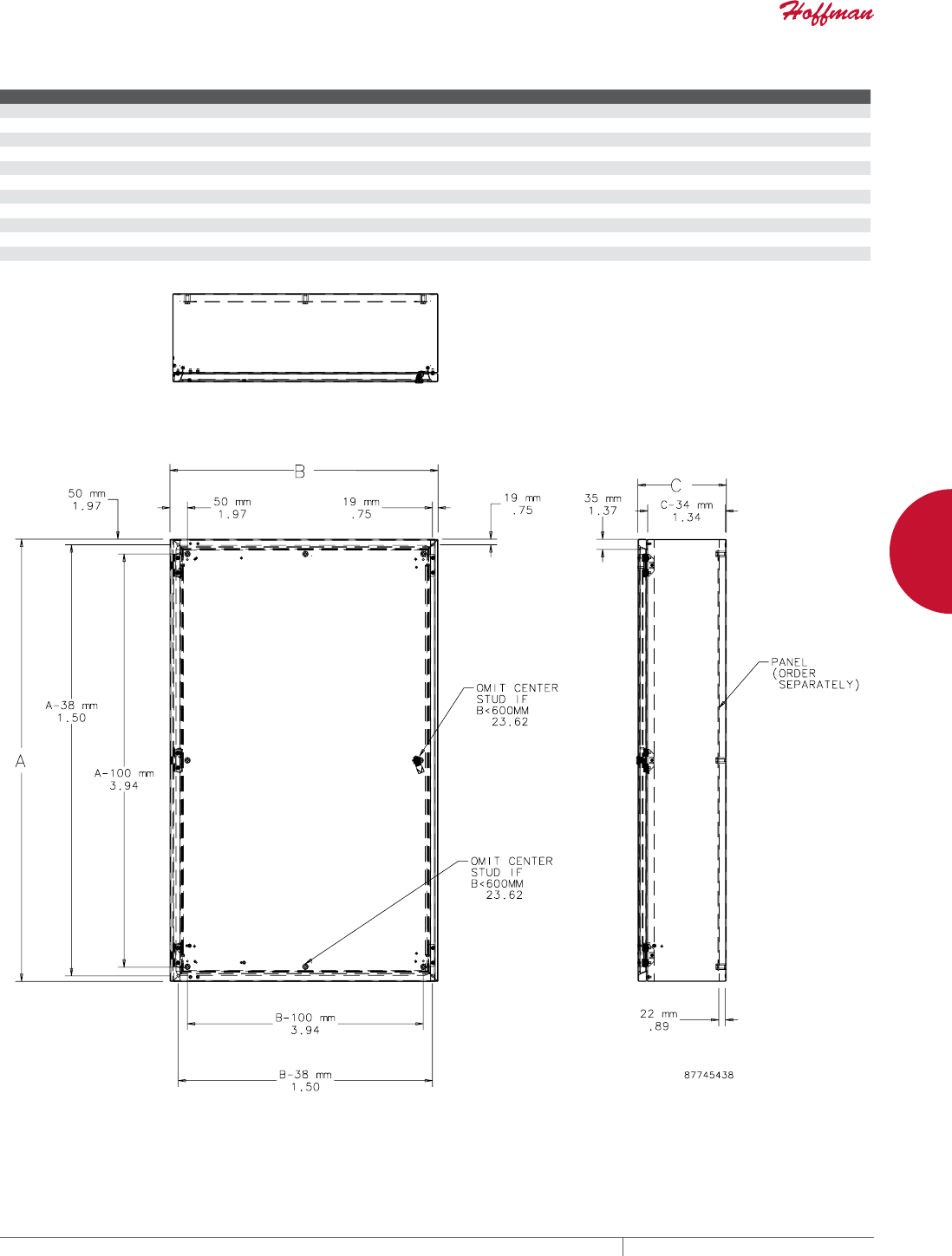
PH 763.422.2661 • FAX 763.422.2588 • PENTAIRPROTECT.COMEQUIPMENT PROTECTION NETWORKING 227
9
OUTSIDE PLANT PRODUCTS COMLINE™ WALLMOUNT ENCLOSURES AND ACCESSORIES
Standard Product Continuous Hinge
Catalog Number AxBxC mm AxBxC in. Latch Points Door Thickness (mm) Door Thickness (in.) Std. Pkg. (lb.)
ECL303015CH 300 x 300 x 150 11.81 x 11.81 x 5.91 1 2 .08 9.0
ECL403015CH 400 x 300 x 150 15.75 x 11.81 x 5.91 1 2 .08 10.0
ECL404015CH 400 x 400 x 150 15.75 x 15.75 x 5.91 1 2 .08 12.0
ECL404020CH 400 x 400 x 200 15.75 x 15.75 x 7.87 1 2 .08 13.0
ECL504020CH 500 x 400 x 200 19.69 x 15.75 x 7.87 1 2 .08 15.0
ECL505020CH 500 x 500 x 200 19.69 x 19.69 x 7.87 1 2 .08 17.0
ECL605020CH 600 x 500 x 200 23.62 x 19.69 x 7.87 3 2.5 .10 19.0
ECL606020CH 600 x 600 x 200 23.62 x 23.62 x 7.87 3 2.5 .10 23.0
ECL806020CH 800 x 600 x 200 31.50 x 23.62 x 7.87 3 2.5 .10 27.0
ECL1006030CH 1000 x 600 x 300 39.37 x 23.62 x 11.81 3 2.5 .10 35.0
ECL1209030CH 1200 x 900 x 300 47.24 x 35.43 x 11.81 3 2.5 .10 55.0
ECL1509030CH 1500 x 900 x 300 59.06 x 35.43 x 11.81 3 2.5 .10 78.0
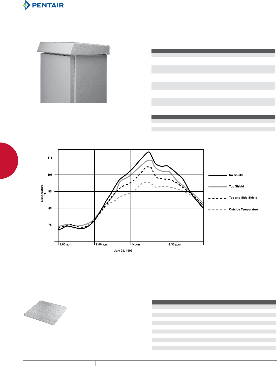
EQUIPMENT PROTECTIONSUBJECT TO CHANGE WITHOUT NOTICENETWORKING228
9
OUTSIDE PLANT PRODUCTS COMLINE™ WALLMOUNT ENCLOSURES AND ACCESSORIES
SOLAR SHIELD TOP
Solar Shield Top provides a vented area on top of the enclosure to
absorb solar heating effects and help keep enclosure cool. Also
provides a drip shield to keep liquids away from the door sealing
surface. Aluminum with RAL 7035 textured light-gray finish inside
and out. Maintains enclosure rating. Includes mounting hardware.
Shielding Effectiveness
Hoffman’s research of the effects of solar radiation on enclosures
has shown the positive benefits of utilizing shielding to decrease
temperature rise. Shielding has been found to be an effective,
low-cost method of reducing solar heat gain in outdoor electrical/
electronic applications.
Test results indicate that a top-mounted solar shield provides a 25
percent reduction in temperature rise due to solar heat load.
BULLETIN: DCOMY
Catalog Number AxB in./mm Fits B x C
ESSH3015 0.00 300 x 150
ESSH4015 15.75 x 5.91
400 x 150
400 x 150
ESSH4020 15.75 x 7.87
400 x 200
400 x 200
ESSH5020 19.69 x 7.87
500 x 200
500 x 200
ESSH6020 23.62 x 7.87
600 x 200
600 x 200
ESSH6030 23.62 x 11.81
600 x 300
600 x 300
ESSH9030 35.43 x 11.81
900 x 300
900 x 300
Unshielded vs. Shielded
Enclosure Type Temperature (ºF) Temp. Reduction (%)
Unshielded 118.6 —
Top shield only 114.0 25
Top and side shields 110.1 46
Air Temperature = 100.2 F
Enclosure color is light-gray (RAL 7035)
7KHUHVXOWVRIWKHWHVWVKRZWKHHQFORVXUHZLWKWRSDQGVLGHVKLHOGVWRKDYHDSSUR[LPDWHO\DUHGXFWLRQ
LQWHPSHUDWXUHFRPSDUHGWRWKHXQVKLHOGHGHQFORVXUH+RIIPDQRIIHUVWRSVKLHOGVDVDQDFFHVVRU\IRU
+RIIPDQ&20/,1(:DOO0RXQW(QFORVXUHV7KHUHGXFWLRQLQWHPSHUDWXUHLVDSSUR[LPDWHO\
ZLWKWKHVRODUVKLHOGWRSRQO\
MOUNTING PANEL
Provides a mounting surface in the
back of the COMLINE™ Enclosure
for surface mount components. Mill
finish aluminum.
BULLETIN: DCOMY
Catalog Number Fits A x B Height (mm) Height (in.) Width (mm) Width (in.)
EP3030AL 300 x 300 226 8.90 226 8.90
EP4030AL 400 x 300 326 12.84 226 8.90
EP4040AL 400 x 400 326 12.84 326 12.94
EP5040AL 500 x 400 426 16.78 326 12.94
EP5050AL 500 x 500 426 16.78 426 16.78
EP6050AL 600 x 500 526 20.71 426 16.78
EP6060AL 600 x 600 526 20.71 526 20.71
EP8060AL 800 x 600 726 28.59 526 20.71
EP10060AL 1000 x 600 926 36.46 526 20.71
EP12090AL 1200 x 900 1126 44.33 826 32.52
EP15090AL 1500 x 900 1426 56.15 826 32.52
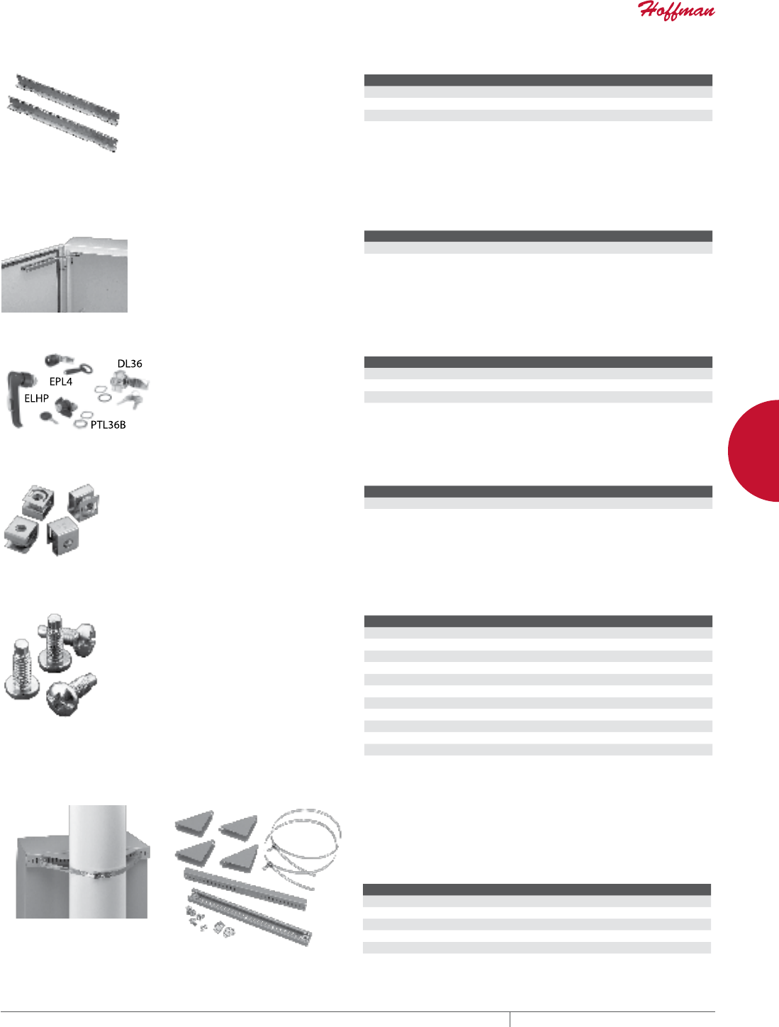
PH 763.422.2661 • FAX 763.422.2588 • PENTAIRPROTECT.COMEQUIPMENT PROTECTION NETWORKING 229
9
OUTSIDE PLANT PRODUCTS COMLINE™ WALLMOUNT ENCLOSURES AND ACCESSORIES
RACK ANGLES
Rack Angles allow for mounting 19-
in. rack equipment in 600-mm wide
enclosures. Plated 14 gauge steel
with .281-in. (7-mm) diameter holes
(through-hole type). Twenty M5
screws and 20 clip nuts included for
mounting rack angles to enclosure
and for mounting equipment to rack
angles.
BULLETIN: DCOMY
Catalog Number Description Fits A (mm) Fits A (in.)
ERA196TH Rack Angles 600 23.62
ERA198TH Rack Angles 800 31.50
ERA1910TH Rack Angles 1000 39.37
DOOR STOP KIT
Self-actuating door stop kit secures
doors in the open position. Mounts to
top or bottom of door. Stainless steel
and aluminum material. Mounting
hardware included.
BULLETIN: DCOMY
Catalog Number Description
EDSK Door Stop Kit
HANDLE OPTIONS
Handle Options can be padlocked for
added security. Kit includes handle
and mounting hardware. Install
using existing enclosure cam.
BULLETIN: A80, DCOMY, DWS12
Catalog Number Description
ELHP Padlocking L-Handle
EPL4 Padlocking quarter-turn with key
DL36 Locking wing nut with 2 keys, silver finish
CLIP NUT PACKAGE
Twenty plated clip nuts fit all
rack-mounting angles with .281-in.
(7-mm) diameter holes (through-
hole type).
BULLETIN: A80
Catalog Number Description Pkg. Qty. Fits
AN1032 Clip Nut 10-32 20 .281-diameter mounting holes
ANM5 Clip Nut M5 (Metric) 20 .281-diameter mounting holes
SCREW PACKAGE
Screws attach rack panels and
rack-mounted equipment to rack-
mounting angles.
BULLETIN: A80, DACCY, X20
Catalog Number Color Description Pkg. Qty.
ES1224 Silver 12-24 x 5/8 in. combo head 20
ES1224250 Silver 12-24 x 5/8 in. combo head 250
ES1224B Black 12-24 x 5/8 in. combo head 20
ES1224B250 Black 12-24 x 5/8 in. combo head 250
ASM5 Silver M5 x 20 mm Combo Head 20
ASM6 Silver M6 x 16 mm combo head 20
ASM5T Silver M5 x 12 mm thread-forming Phillips hex head screws 20
ASM6250 Silver M6 x 16 mm combo head 250
AS1032 Silver 10-32 x 5/8 in. combo head 20
AS1032250 Silver 10-32 x 5/8 in. combo head 250
AS1032B Black 10-32 x 5/8 in. combo head 20
Use ASM5T on PROLINE™ frame or Net Series extruded holes.
POLEMOUNT KIT Use to mount CONCEPT™ , Networking and wall-mount enclosures
to poles of various sizes and shapes. Simply attach the plated steel
channel bar to the mounting holes at the back of the enclosure and
wrap the stainless steel strap around the pole and through the bar.
Kit includes two mounting channels, two straps suitable for 3-in.
(76-mm) to 12-in. (305-mm) diameter pole and mounting hardware.
BULLETIN: CWY
Catalog Number Fits Enclosure (in.) Fits Enclosure (mm)
CPMK12 when B = 12.00 when B = 305
CPMK16 when B = 16.00 when B = 406
CPMK20 when B = 20.00 when B = 508
CPMK24 when B = 24.00 when B = 610
CPMK30 when B = 30.00 when B = 762
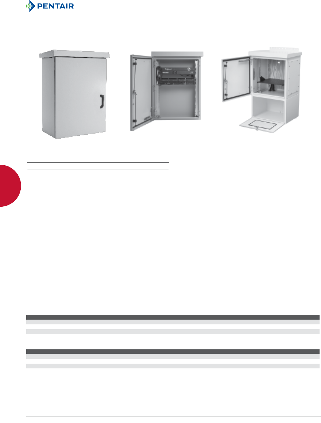
EQUIPMENT PROTECTIONSUBJECT TO CHANGE WITHOUT NOTICENETWORKING230
9
OUTSIDE PLANT PRODUCTS COMLINE™ OSP WALLMOUNT CABINET PACKAGE AND ACCESSORIES
COMLINE
™
OSP WALL-MOUNT CABI NET PACKAGE A ND ACCESSOR IES
COMLINE™ OSP PACKAGE, TYPE 4X
Rack Mount devices
shown not included
Custom cabinet shown
INDUSTRY STANDARDS
UL 508A Listed; Type 3, 3R, 4, 4X, 12; File No. E61997
CSA: Type 3, 3R, 4, 4X, 12
NEMA/EEMAC Type 3, 3R, 4, 4X, 12
EC60529, IP66
Designed to meet Telcordia NEBS™ GR-487, GR-63 and IEC 48D
EIA 310-D with 19 in. spacing for rack equipment
Meets BICSI TDMM, Tenth Edition, Chapter 7, Telecommunication
Enclosures (TE)
Cabinet is RoHS compliant
NEBS is a trademark of Telcordia
APPLICATION
A complete, off-the-shelf package for 19-in. rack equipment,
lightweight COMLINE™ OSP Wall-Mount Cabinets are constructed
of corrosion-resistant aluminum with a foam-in-place gasket that
secures and protects sensitive equipment in outdoor applications.
Available with or without back-up battery compartment.
FEATURES
• Solar shield helps keep enclosure interior cool when cabinet is
installed outdoors and directs liquids away from cabinet opening;
can be removed for indoor installations
• Foam-in-place gasket provides environmental seal
• Padlocking L-Handle provides a tight, secure door seal
• Doorstop holds door in place during service for easier and faster
maintenance
• Heavy-duty hinged door is easily removed to facilitate equipment
installation and removal. Maximum door load 50 lb. (22.7 kg)
• Rack angles adjustable front-to-rear of cabinet
• Gland plates available with cutouts that fit Hoffman T15, T20
and CR23 air conditioners and Hoffman XR20 and XR29 heat
exchangers (Indoor use only)
• Radius corners on cabinet eliminate sharp edges
• Stainless steel fasteners resist corrosion to maintain
professional appearance
• Pole mounting kits available for all sizes
• Pad mounting plinth available for 600mm deep cabinets
• Battery compartment has front vented captivated door.
• Note – SR20 and SR29 are for indoor use only.
SPECIFICATIONS
• Rack angles have EIA universal standard square hole spacing
• Eighth-inch thick, depending on cabinet size
• Seams continuously welded and ground smooth for a finished
appearance
• Body includes studs for ground bar and rear mounting studs for
wood panel
FINISH
RAL 7035 light-textured low-gloss polyester urethane powder
coating over iron-phosphate-treated surface. Custom finishes
available: consult your local Hoffman sales office.
BULLETIN: DCOM
Standard Product COMLINE Wall-Mount Enclosure Packages
Catalog Number AxBxC in. AxBxC mm P ( in.) P (mm) Rack Units
ECL606050P 23.62 x 23.62 x 19.68 600 x 600 x 500 17.47 444 12
ECL906050P 35.43 x 23.62 x 19.68 900 x 600 x 500 30.47 774 18
ECL907060P 35.43 x 27.56 x 23.62 900 x 700 x 600 30.47 774 18
ECL1207060P 47.24 x 27.56 x 23.62 1200 x 700 x 600 30.47 774 25
Standard ProductCOMLINE with Battery Compartment
Catalog Number AxBxC in. AxBxC mm Rack Units
ECL606050PB 38.62 x 23.62 x 19.69 981 x 600 x 500 12
ECL906050PB 50.43 x 23.62 x 19.69 1281 x 600 x 500 18
ECL907060PB 50.43 x 27.56 x 23.62 1281 x 700 x 600 18
ECL1207060PB 62.24 x 27.56 x 23.62 1581 x 700 x 600 25
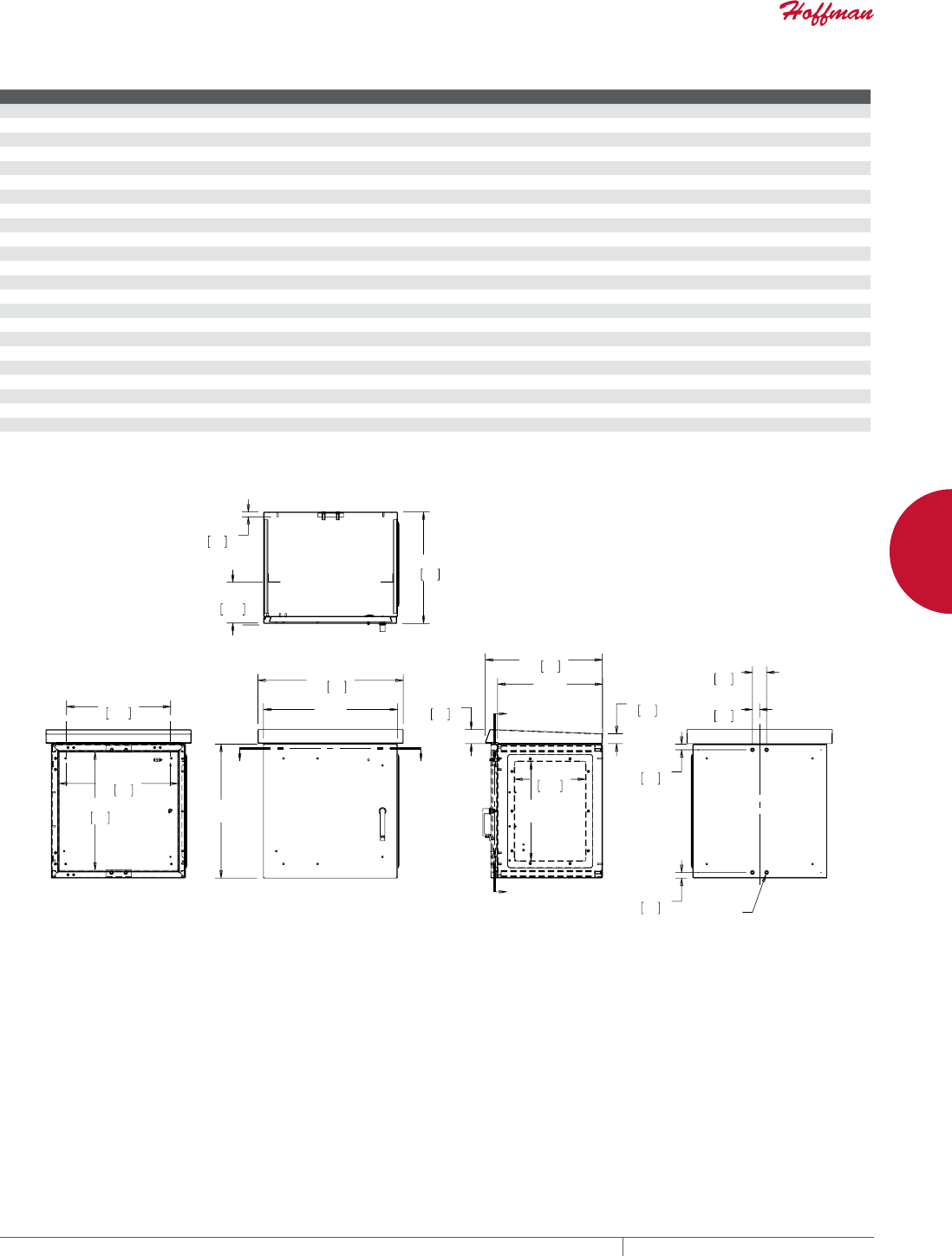
PH 763.422.2661 • FAX 763.422.2588 • PENTAIRPROTECT.COMEQUIPMENT PROTECTION NETWORKING 231
9
OUTSIDE PLANT PRODUCTS COMLINE™ OSP WALLMOUNT CABINET PACKAGE AND ACCESSORIES
Accessory Compatibility
Catalog Numbers ECL606050P/B ECL906050P/B ECL907060P/B ECL1207060P/B
GLAND PLATES
EGPS1 •
EGPS2 • • •
EGPACT15 •
EGPACT20 • • •
EGPACCR15 • • •
EGPHX20 • • •
EGPHX29 • • •
POLE MOUNT CHANNELS
EPMC6 •
EPMC9 • •
EPMC12 •
PLINTH BASE
EPL7060 • •
WOOD PANELS
E60P60W •
E90P60W •
E90P7W •
E120P70W •
RACK ANGLES
ERA196S •
ERA199S •
ERA19239S •
ERA192312S •
%
%
$
<<
3
&
&
=
=
%
$
==
;
&
<<
&20/,1(2633DFNDJH:LWKRXW%DWWHU\&RPSDUWPHQW
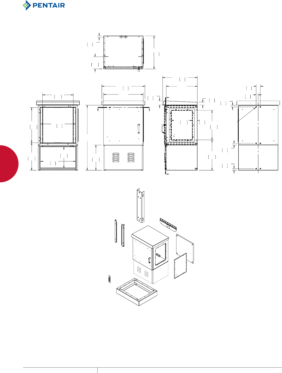
EQUIPMENT PROTECTIONSUBJECT TO CHANGE WITHOUT NOTICENETWORKING232
9
OUTSIDE PLANT PRODUCTS COMLINE™ OSP WALLMOUNT CABINET PACKAGE AND ACCESSORIES
%
$
%
<<
&
&
&
$
=
=
&
<<
$
%
%
==
;
&20/,1(2633DFNDJH:LWK%DWWHU\&RPSDUWPHQW
9HUWLFDO
3ROH
0RXQWLQJ
&KDQQHO
:DOO0RXQWLQJ
%UDFNHW
:RRG
3DQHO
*ODQG
3ODWH
3OLQWK
%DVH
*URXQG
%XVV
5DFN
$QJOHV

PH 763.422.2661 • FAX 763.422.2588 • PENTAIRPROTECT.COMEQUIPMENT PROTECTION NETWORKING 233
9
OUTSIDE PLANT PRODUCTS COMLINE™ OSP WALLMOUNT CABINET PACKAGE AND ACCESSORIES
RACK ANGLES
Rack Angles are made of 12 gauge, self-grounding plated steel
and are grounded to the cabinet body through the mounting bolts.
Square mounting holes meet EIA standard.
Package includes one pair.
BULLETIN: DCOMY
Catalog Number Rack Width Rack Units Use with Cabinet (Height x Width in mm)
ERA196S 19 12 600 x 600
ERA199S 19 18 900 x 600
ERA19239S 19 or 23 18 900 x 700
ERA192312S 19 or 23 25 1200 x 700
VERTICAL POLEMOUNT CHANNEL
Vertical Pole-Mount Channel facilitates pole-mounting the
COMLINE™ package. It includes the bracket and hardware to mount
the channel to the cabinet. No drilling into cabinet required to
install.
BULLETIN: DCOMY
Catalog Number Description Use with Cabinet
EPMC6 Vertical Pole-Mount Channel 600 600-mm tall
EPMC9 Vertical Pole-Mount Channel 900 900-mm tall
EPMC12 Vertical Pole-Mount Channel 1200 1200-mm tall
WOOD PANEL
Wood Panels are made of 3/4-in. plywood, pre-cut and pre-drilled
to install on panel mounting studs in the rear of the cabinet.
BULLETIN: DCOMY
Catalog Number AxB in./mm Height x Width
Use with Cabinet
(Height x Width)
E60P60W 23.62 x 23.62
600 x 600
524 x 524 600 x 600
E90P60W 35.43 x 23.62
900 x 600
824 x 524 900 x 600
E90P70W 35.43 x 27.56
900 x 700
824 x 624 900 x 700
E120P70W 47.24 x 27.56
1200 x 700
1124 x 624 1200 x 700
GLAND PLATE
Gland Plates are made of .100-in.-thick aluminum, finished to match
the cabinet. They include a factory-installed foam-in-place gasket,
stainless steel hardware and grounding provision. The installed
gland plate maintains the cabinet rating.
Package includes solid gland plate.
BULLETIN: DCOMY
Catalog Number Description Nominal Height x Width (P x Q)
EGPS1 Solid small 506 x 381
EGPS2 Solid large 838 x 381
EGPACT15 AC cutout for T15 506 x 381
EGPACT20 AC cutout for T20 838 x 381
EGPACCR23 AC cutout for CR23 838 x 381
EGPHX20 Heat exchanger cutout for XR20 838 x 381
EGPHX29 Heat exchanger cutout for XR29 838 x 381
XR20 and XR29 indoor use only.
PLINTH BASE
The Plinth Base enables pad mounting and provides additional cable
management space. It adds an additional 5.00-in. (127-mm) height
to the cabinet. The base is made of aluminum painted RAL 7035 light
gray.
BULLETIN: DCOMY
Catalog Number AxB in./mm Description
Use with Cabinet
(Width x Depth)
EPL7060 27.56 x 23.62
700 x 600
Plinth base 700 x 600
GROUND BUSS
This copper Ground Buss provides wiring tie points within the
cabinet. Mounts on studs provided on cabinet side. Tie-point spacing
is 3/4-in. pair-to-pair and 5/8-in. across each pair. Ground studs are
1/4-20 x .75-in. on 3/4-in. centers.
BULLETIN: DCOMY
Catalog Number Description
EGBB1 6-position, double-lug buss
EGBB2 12-position, double-lug buss
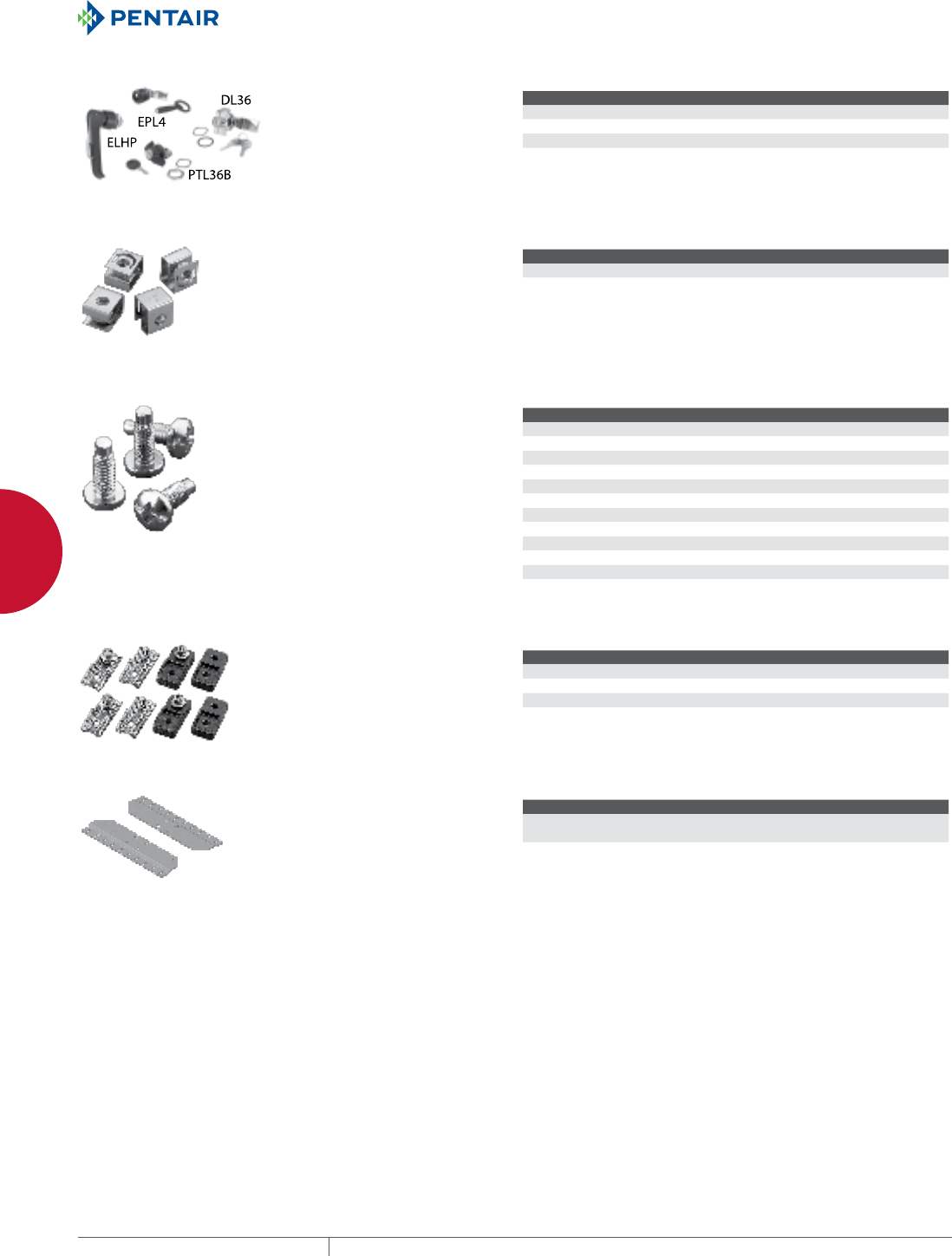
EQUIPMENT PROTECTIONSUBJECT TO CHANGE WITHOUT NOTICENETWORKING234
9
OUTSIDE PLANT PRODUCTS COMLINE™ OSP WALLMOUNT CABINET PACKAGE AND ACCESSORIES
HANDLE OPTIONS
Handle Options can be padlocked for
added security. Kit includes handle
and mounting hardware. Install
using existing enclosure cam.
BULLETIN: A80, DCOMY, DWS12
Catalog Number Description
ELHP Padlocking L-Handle
EPL4 Padlocking quarter-turn with key
DL36 Locking wing nut with 2 keys, silver finish
CLIP NUT PACKAGE
Twenty plated clip nuts fit all
rack-mounting angles with .281-in.
(7-mm) diameter holes (through-
hole type).
BULLETIN: A80
Catalog Number Description Pkg. Qty. Fits
AN1032 Clip Nut 10-32 20 .281-diameter mounting holes
ANM5 Clip Nut M5 (Metric) 20 .281-diameter mounting holes
SCREW PACKAGE
Screws attach rack panels and
rack-mounted equipment to rack-
mounting angles.
BULLETIN: A80, DACCY, X20
Catalog Number Color Description Pkg. Qty.
ES1224 Silver 12-24 x 5/8 in. combo head 20
ES1224250 Silver 12-24 x 5/8 in. combo head 250
ES1224B Black 12-24 x 5/8 in. combo head 20
ES1224B250 Black 12-24 x 5/8 in. combo head 250
ASM5 Silver M5 x 20 mm Combo Head 20
ASM6 Silver M6 x 16 mm combo head 20
ASM5T Silver M5 x 12 mm thread-forming Phillips hex head screws 20
ASM6250 Silver M6 x 16 mm combo head 250
AS1032 Silver 10-32 x 5/8 in. combo head 20
AS1032250 Silver 10-32 x 5/8 in. combo head 250
AS1032B Black 10-32 x 5/8 in. combo head 20
Use ASM5T on PROLINE™ frame or Net Series extruded holes.
MOUNTING BRACKET KITS
Mounting Bracket Kits are available
in stainless steel or composite
material. Kit includes 4 brackets and
mounting hardware.
BULLETIN: A80
Catalog Number Description
CMFK Steel
CMFKSS Stainless Steel
CMTGFT Composite
WALL MOUNTING BRACKET
Wall Mounting Bracket bolts to
enclosure back thread holes and
facilitates easy mounting to walls.
Made of 0.10 aluminum with cabinet
matching RAL 7035 finish.
BULLETIN: DCOMY
Catalog Number AxBxC in./mm Description
EMB1 1.73 x 30.20 x 21.26
44 x 767 x 540
Aluminum
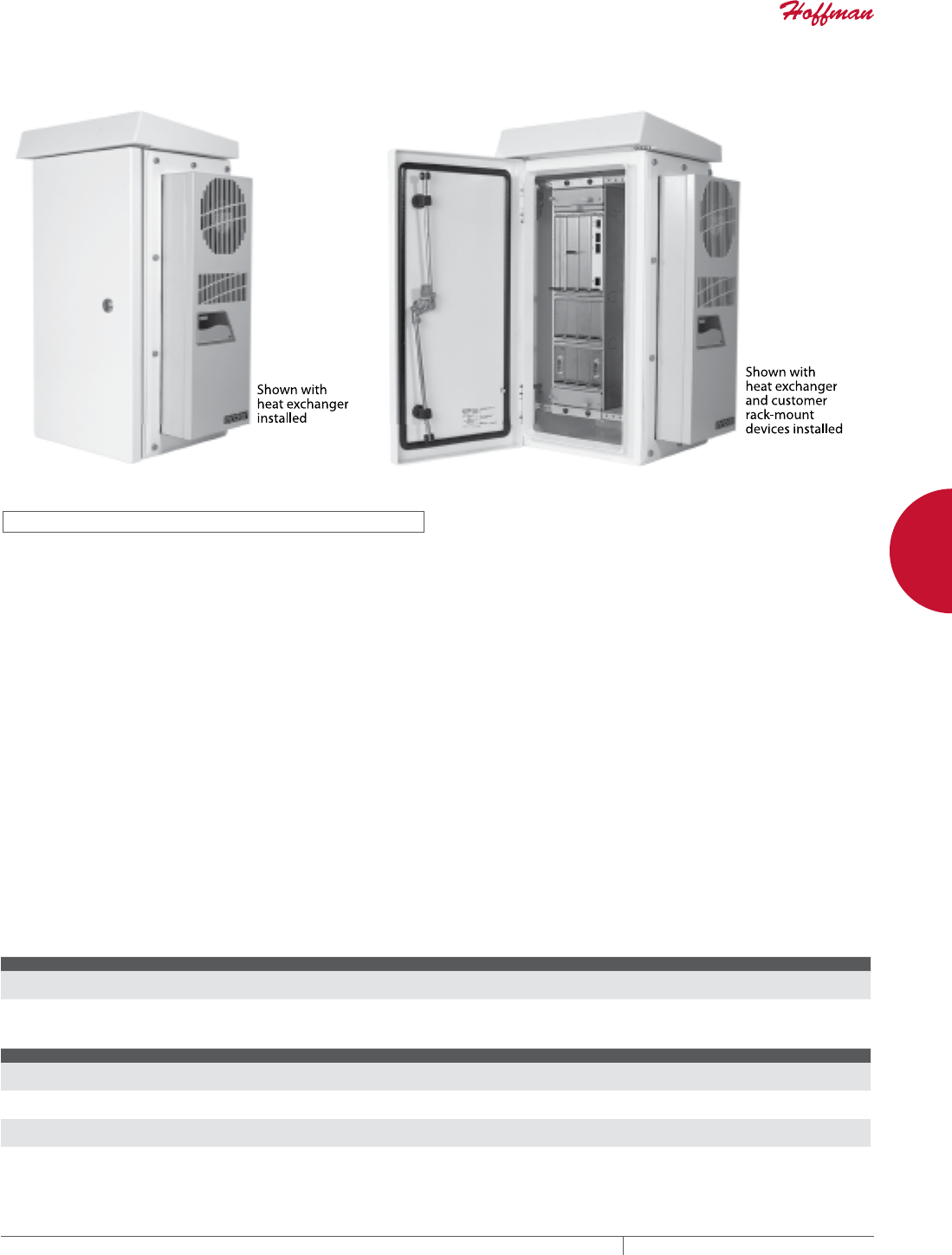
PH 763.422.2661 • FAX 763.422.2588 • PENTAIRPROTECT.COMEQUIPMENT PROTECTION NETWORKING 235
9
OUTSIDE PLANT PRODUCTS COMLINE™ OSP VERTICAL MOUNT CABINET PACKAGE AND ACCESSORIES
COMLINE™ OS P VERTICAL MOU NT CABINET PACK AGE AND ACCE SSORIES
COMLINE™ VERTICAL MOUNT CABINET
INDUSTRY STANDARDS
UL 508A Listed; Type 3, 3R, 4, 4X, 12; File No. E61997
CSA: Type 3, 3R, 4, 4X, 12
NEMA/EEMAC Type 3, 3R, 4, 4X, 12
EC60529, IP66
Designed to meet Telcordia NEBS™ GR-487, GR-63 and IEC 48D
EIA 310-D with 19-in. spacing for rack equipment
Cabinet is RoHS compliant
NEBS™ is a trademark of Telcordia
APPLICATION
COMLINE™ Vertical-Mount Cabinet is ideal for telecommunications
industry applications. The unique vertical orientation of the
19-in. rack equipment makes this cabinet especially suitable
for pole-mount applications. The narrow cabinet width also
makes it very wind resistant. Vertical-Mount Cabinet is ideal for
telecommunications industry applications. The unique vertical
orientation of the 19-in. rack equipment makes this cabinet
especially suitable for pole-mount applications. The narrow cabinet
width also makes it very wind resistant.
FEATURES
• Vertically oriented 19-in. equipment mounting creates a compact,
wind-resistant cabinet
• Integral solar shield reduces solar heat load
• Right-side, solid gland plate can be removed and modified as
needed
• 6 RU Rack has square hole spacing per EIA universal standards;
order cage nuts separately
• Quarter-turn, multi-point, vault-style latching system increases
protection and security
• 160-degree door opening with quick-release, retained hinge pins
• Body and door ground studs for bonding and grounding
• Foam-in-place seamless gasket for superior protection against
dust and liquid ingress
• Back is prepared with mounting provisions for standard panels
• Mounts to poles or walls
Construction
• One set of vertical-mounted 19-in. rack angles made of self-
conducting plated steel have square holes per EIA universal
spacing
• Made using Type 5052-H23 aluminum (door: 2.0 mm; body: 0.8
mm)
• Seams continuously welded and ground smooth
• Solid gland plate made of .125-mm aluminum included with
perimeter flange, seamless gasket, fasteners and mounting
holes. Order pre-cut heat exchanger and air conditioner gland
plates separately.
FINISH
RAL 7035 light-textured, low-gloss polyester powder paint over
pretreated surfaces. Custom finishes available; please contact your
local Hoffman sales office.
BULLETIN: DCOM, DCOMY
Standard ProductCOMLINE Vertical Mount Cabinet
Catalog Number AxBxC in./mm Rack Units Vertical
ECL603537VP 23.62 x 13.78 x 14.76
600 x 350 x 375
5
Standard ProductGland plates for COMLINE Vertical Mount Cabinet
Catalog Number AxBxC in./mm Use with
EGVM 23.23 x 12.68 x 0.35
590 x 322 x 9
Solid
EGVM1 23.23 x 12.68 x 0.35
590 x 322 x 9
XR20 Heat Exchanger
EGVM2 23.23 x 12.68 x 0.35
590 x 322 x 9
T15 AC Unit
EGVM3 23.23 x 12.68 x 0.35
590 x 322 x 9
T20 AC Unit
*Order heat exchanger and air conditioner gland plates separately.
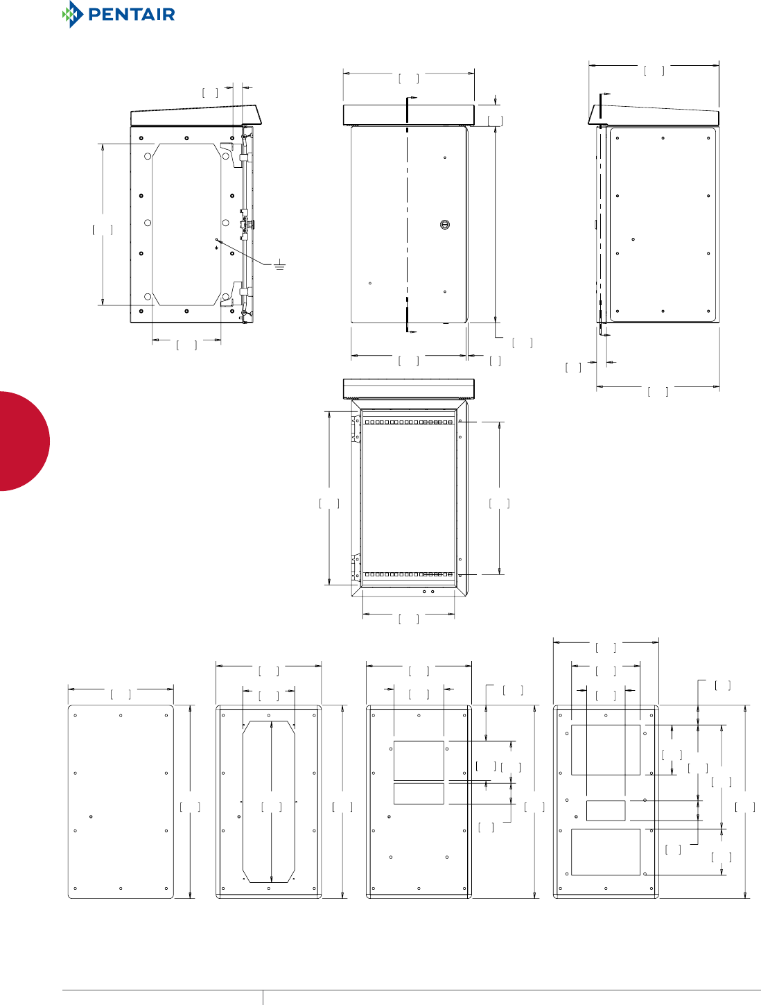
EQUIPMENT PROTECTIONSUBJECT TO CHANGE WITHOUT NOTICENETWORKING236
9
OUTSIDE PLANT PRODUCTS COMLINE™ OSP VERTICAL MOUNT CABINET PACKAGE AND ACCESSORIES
;
;
=
=
==
;;
(*90
;5
(*90
7
(*90
7
(*90
6ROLG
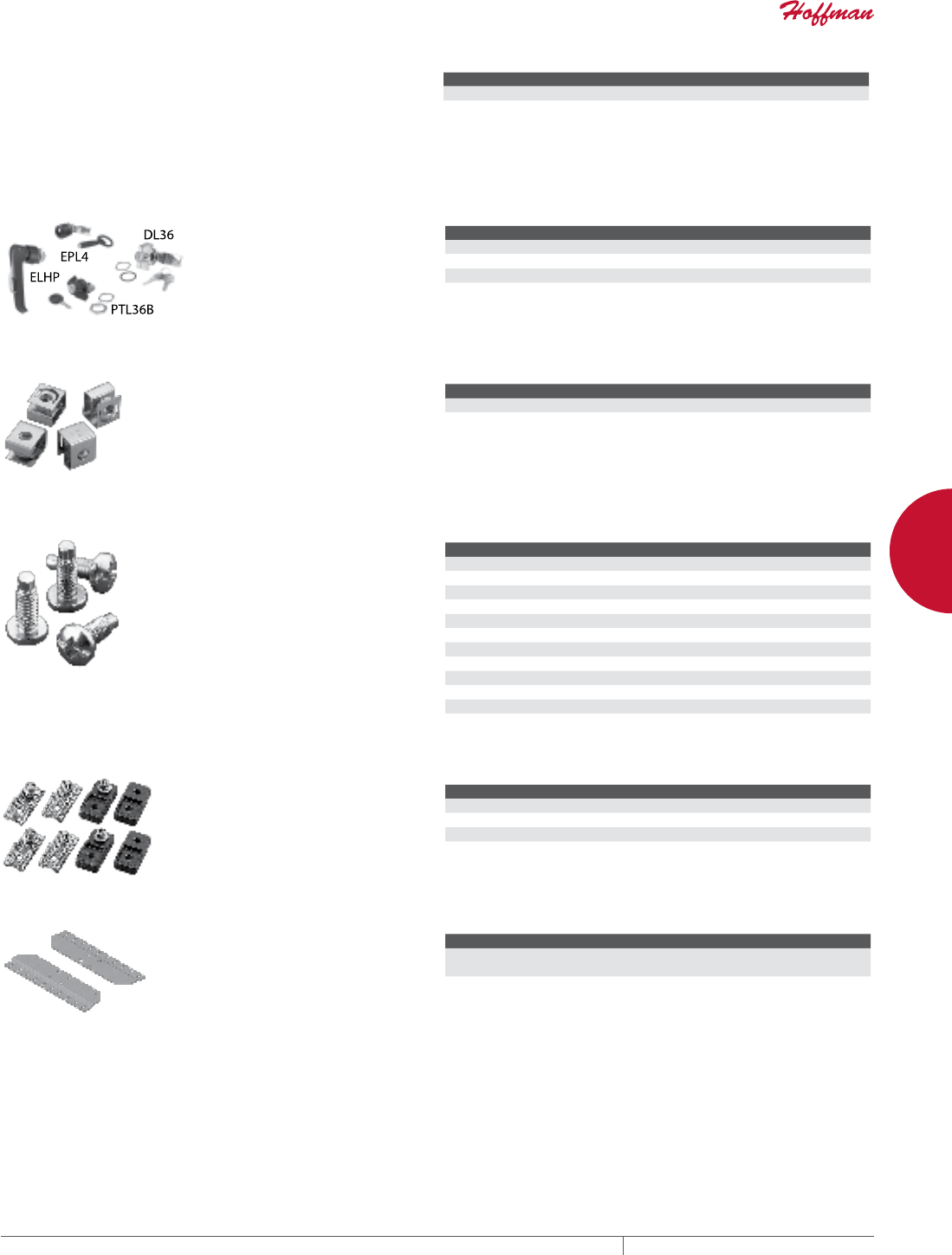
PH 763.422.2661 • FAX 763.422.2588 • PENTAIRPROTECT.COMEQUIPMENT PROTECTION NETWORKING 237
9
OUTSIDE PLANT PRODUCTS COMLINE™ OSP VERTICAL MOUNT CABINET PACKAGE AND ACCESSORIES
GROUND BUSS
This copper Ground Buss provides wiring tie points within the
cabinet. Mounts on studs provided on cabinet side. Tie-point spacing
is 3/4-in. pair-to-pair and 5/8-in. across each pair. Ground studs are
1/4-20 x .75-in. on 3/4-in. centers.
BULLETIN: DCOMY
Catalog Number Description
EGBB1 6-position, double-lug buss
EGBB2 12-position, double-lug buss
HANDLE OPTIONS
Handle Options can be padlocked for
added security. Kit includes handle
and mounting hardware. Install
using existing enclosure cam.
BULLETIN: A80, DCOMY, DWS12
Catalog Number Description
ELHP Padlocking L-Handle
EPL4 Padlocking quarter-turn with key
DL36 Locking wing nut with 2 keys, silver finish
CLIP NUT PACKAGE
Twenty plated clip nuts fit all
rack-mounting angles with .281-in.
(7-mm) diameter holes (through-
hole type).
BULLETIN: A80
Catalog Number Description Pkg. Qty. Fits
AN1032 Clip Nut 10-32 20 .281-diameter mounting holes
ANM5 Clip Nut M5 (Metric) 20 .281-diameter mounting holes
SCREW PACKAGE
Screws attach rack panels and
rack-mounted equipment to rack-
mounting angles.
BULLETIN: A80, DACCY, X20
Catalog Number Color Description Pkg. Qty.
ES1224 Silver 12-24 x 5/8 in. combo head 20
ES1224250 Silver 12-24 x 5/8 in. combo head 250
ES1224B Black 12-24 x 5/8 in. combo head 20
ES1224B250 Black 12-24 x 5/8 in. combo head 250
ASM5 Silver M5 x 20 mm Combo Head 20
ASM6 Silver M6 x 16 mm combo head 20
ASM5T Silver M5 x 12 mm thread-forming Phillips hex head screws 20
ASM6250 Silver M6 x 16 mm combo head 250
AS1032 Silver 10-32 x 5/8 in. combo head 20
AS1032250 Silver 10-32 x 5/8 in. combo head 250
AS1032B Black 10-32 x 5/8 in. combo head 20
Use ASM5T on PROLINE™ frame or Net Series extruded holes.
MOUNTING BRACKET KITS
Mounting Bracket Kits are available
in stainless steel or composite
material. Kit includes 4 brackets and
mounting hardware.
BULLETIN: A80
Catalog Number Description
CMFK Steel
CMFKSS Stainless Steel
CMTGFT Composite
WALL MOUNTING BRACKET
Wall Mounting Bracket bolts to
enclosure back thread holes and
facilitates easy mounting to walls.
Made of 0.10 aluminum with cabinet
matching RAL 7035 finish.
BULLETIN: DCOMY
Catalog Number AxBxC in./mm Description
EMB1 1.73 x 30.20 x 21.26
44 x 767 x 540
Aluminum
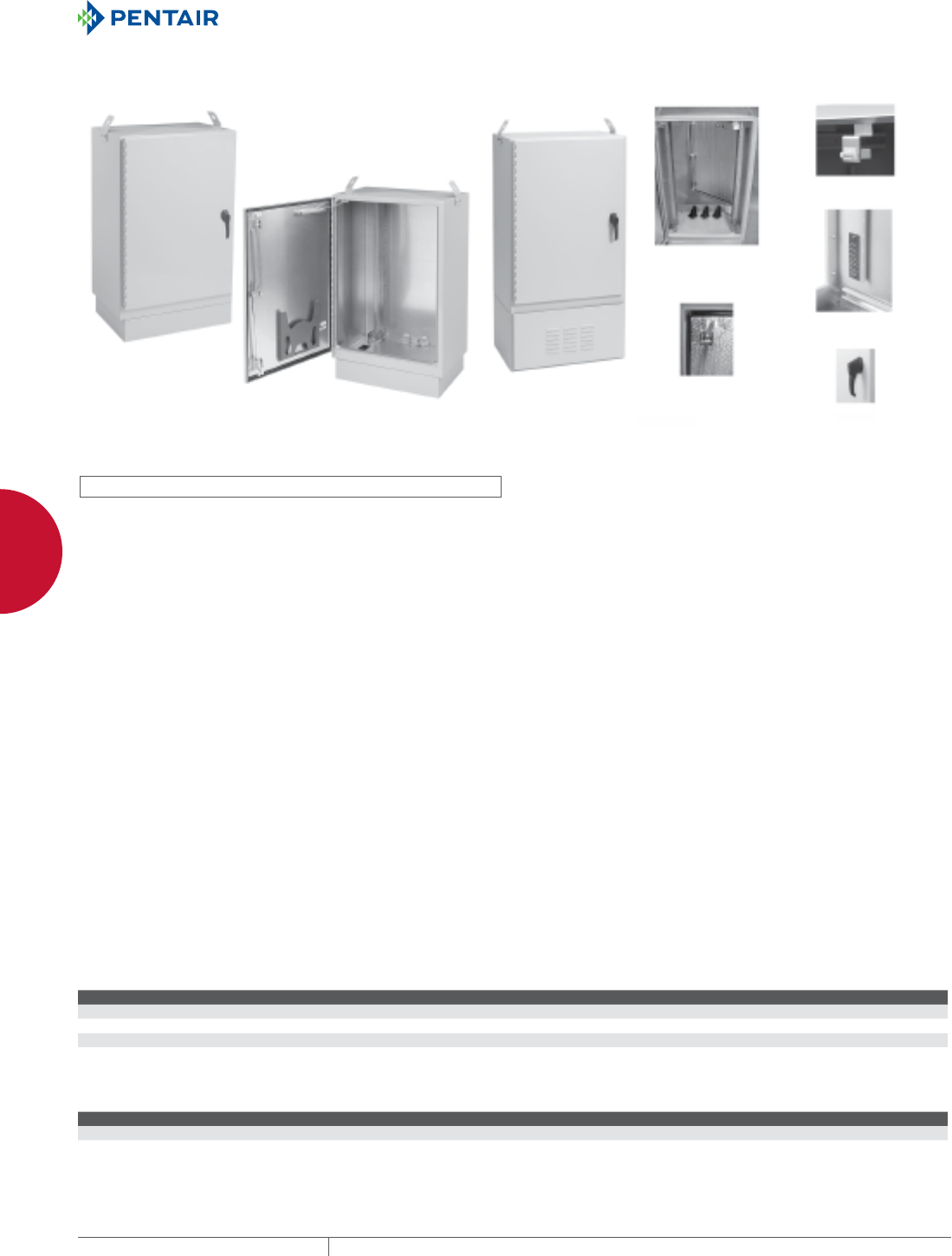
EQUIPMENT PROTECTIONSUBJECT TO CHANGE WITHOUT NOTICENETWORKING238
9
OUTSIDE PLANT PRODUCTS FIBER OPTIC CABINETS
FIBER OPTIC CA BINETS
FTTX FIBER OPTIC CABINET PACKAGE, TYPE 4X
19-or 23-inch rack
mounting including
cabinet entry boots
Door Switch
Handle
Ground Bus Bar
Battery Cabinet Door with foam-in-place
gasketing and optional
insulation
19
-
o
r 2
3
-in
ch
r
ack
mountin
g
includin
g
ca
b
inet entr
y
b
oot
s
D
oo
r
S
wi
tch
H
an
dle
Groun
d
Bus Bar
Battery Ca
b
inet Door with foam-in-plac
e
g
asketin
g
and optiona
l
i
nsulatio
n
INDUSTRY STANDARDS
UL 508A Listed; Type 3, 3R, 4, 4X, 12; File No. E61997
CSA: Type 3, 3R, 4, 4X, 12
NEMA/EEMAC Type 3, 3R, 4, 4X, 12
EC60529, IP66
Designed to meet Telcordia NEBS™ GR-487, GR-63 and IEC 48D
EIA 310-D with 19-in. spacing for rack equipment
Cabinet is RoHS compliant
NEBS™ is a trademark of Telcordia
APPLICATION
Pad-mounted FTTX welded aluminum enclosures provide long-
lasting protection and manage fiber optic cable for broadband
delivery in outdoor applications. Provided with or without back-up
batter compartment.
FEATURES
• Standard pitched roof promotes water runoff
• Available with either single- or dual-access doors on front and
rear for convenient access
• Available with or without battery compartment
• 3-point latching mechanisms and padlocking handles on doors
provide security
• Seamless foam-in-place gasket seals doors against moisture and
dust
• Wind latch mechanisms on doors control door when open for
equipment maintenance
• Removable lifting lugs (2) for easy installation
• Rack angles adjustable for 19-in. or 23-in. spacing without
modifications
• Use clip nuts to mount equipment
• Cabinet top insulation helps prevent the formation of
condensation and reduce solar gain inside cabinet. Cabinet side
insulation is optional.
• Base of cabinet has a 5.00-in. (127-mm) high aluminum mounting
plinth to allow for cable alignment
• Three pyramidal boots provided at base of cabinet for sealing
various sizes of cables
• All fasteners are stainless steel to maintain professional
appearance in severe outdoor climate conditions
• Grounding buss bar provided
SPECIFICATIONS
• Manufactured from Type 5052-H32 .125-in.-thick aluminum
• Seams continuously welded and ground smooth
• Heavy gauge continuous hinge
FINISH
RAL 7035 light textured low gloss polyester powder paint over
pretreated surfaces. Custom finishes available please contact your
local Hoffman sales office.
ACCESSORIES
Fiber Management Spool
Compact Cooling Fans
Temperature Control Switches
Light Package
Screw Packages
Fiber Optic Cabinet Pole-Mount Kit
Compact and Mid-Size Heat Exchangers
Type 3R, 12, 4 T4 Line Indoor/Outdoor Air Conditioners
Electric Heaters
BULLETIN: DTX
Standard ProductFTTX Without Battery Compartment
Catalog Number AxBxC in. AxBxC mm Rack Units Description
T303020FTTX 30.00 x 30.00 x 20.00 762 x 762 x 508 10 Single-Access
T503020FTTX 50.00 x 30.00 x 20.00 1270 x 762 x 508 22 Single-Access
T303020FTTXDA 30.00 x 30.00 x 20.00 762 x 762 x 508 10 Dual-Access
T503020FTTXDA 50.00 x 30.00 x 20.00 1270 x 762 x 508 22 Dual-Access
Standard ProductFTTX With Battery Compartment
Catalog Number AxBxC in. AxBxC mm Rack Units Description
T503020FTTXB 59.49 x 30.00 x 23.27 1511 x 762 x 591 22 Single
T503028FTTXDAB 59.49 x 30.00 x 34.53 1511 x 762 x 877 22 Dual
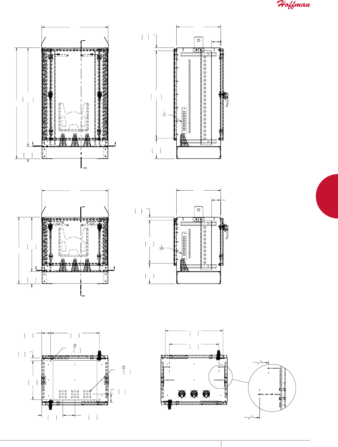
PH 763.422.2661 • FAX 763.422.2588 • PENTAIRPROTECT.COMEQUIPMENT PROTECTION NETWORKING 239
9
OUTSIDE PLANT PRODUCTS FIBER OPTIC CABINETS
%
$
;
;
<<
>@
&
;;
;
;
;
<<
>@
>@
%
$
=
=
<<
>@
&
==
$
>@
$
>@
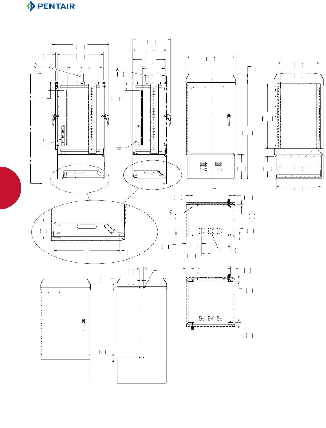
EQUIPMENT PROTECTIONSUBJECT TO CHANGE WITHOUT NOTICENETWORKING240
9
OUTSIDE PLANT PRODUCTS FIBER OPTIC CABINETS
<
<
;
=
=
<<
;
;
;
;
;
;
6
==
;
;;
)77;)LEHU2SWLF&DELQHW:LWK%DWWHU\&RPSDUWPHQW
PH 763.422.2661 • FAX 763.422.2588 • PENTAIRPROTECT.COMEQUIPMENT PROTECTION NETWORKING 241
9
OUTSIDE PLANT PRODUCTS FIBER OPTIC CABINETS
FIBER MANAGEMENT SPOOL
Fiber Management Spools mount
inside the cabinet and help maintain
proper bends when routing cable.
Molded of black plastic. Includes
thread-forming M5 mounting
screws. Slots provided on flange for
VELCRO® cable wrap.
VELCRO is a trademark of Velcro
Industries B.V.
BULLETIN: DTX
Catalog Number Radius (in.) Radius (mm) Pkg. Qty.
TOPTKSPL 1.18 30 4
FIBER OPTIC CABINET POLEMOUNT KIT
The Pole-Mount Kit installs on the rear of the single-access
cabinets using the hardware provided. No drilling or tapping of
the cabinet is required. Installation instructions are provided for
mounting to various types of poles.
BULLETIN: DTX
Catalog Number Kit Includes Use With
T11FTTXPMK Channel and hardware for attaching to cabinet 11U Cabinet
T23FTTXPMK Channel and hardware for attaching to cabinet 23U Cabinet
CLIP NUT PACKAGE
Twenty plated clip nuts fit all
rack-mounting angles with .281-in.
(7-mm) diameter holes (through-
hole type).
BULLETIN: A80
Catalog Number Description Pkg. Qty. Fits
AN1032 Clip Nut 10-32 20 .281-diameter mounting holes
ANM5 Clip Nut M5 (Metric) 20 .281-diameter mounting holes
SCREW PACKAGE
Screws attach rack panels and
rack-mounted equipment to rack-
mounting angles.
BULLETIN: A80, DACCY, X20
Catalog Number Color Description Pkg. Qty.
ES1224 Silver 12-24 x 5/8 in. combo head 20
ES1224250 Silver 12-24 x 5/8 in. combo head 250
ES1224B Black 12-24 x 5/8 in. combo head 20
ES1224B250 Black 12-24 x 5/8 in. combo head 250
ASM5 Silver M5 x 20 mm Combo Head 20
ASM6 Silver M6 x 16 mm combo head 20
ASM5T Silver M5 x 12 mm thread-forming Phillips hex head screws 20
ASM6250 Silver M6 x 16 mm combo head 250
AS1032 Silver 10-32 x 5/8 in. combo head 20
AS1032250 Silver 10-32 x 5/8 in. combo head 250
AS1032B Black 10-32 x 5/8 in. combo head 20
Use ASM5T on PROLINE™ frame or Net Series extruded holes.
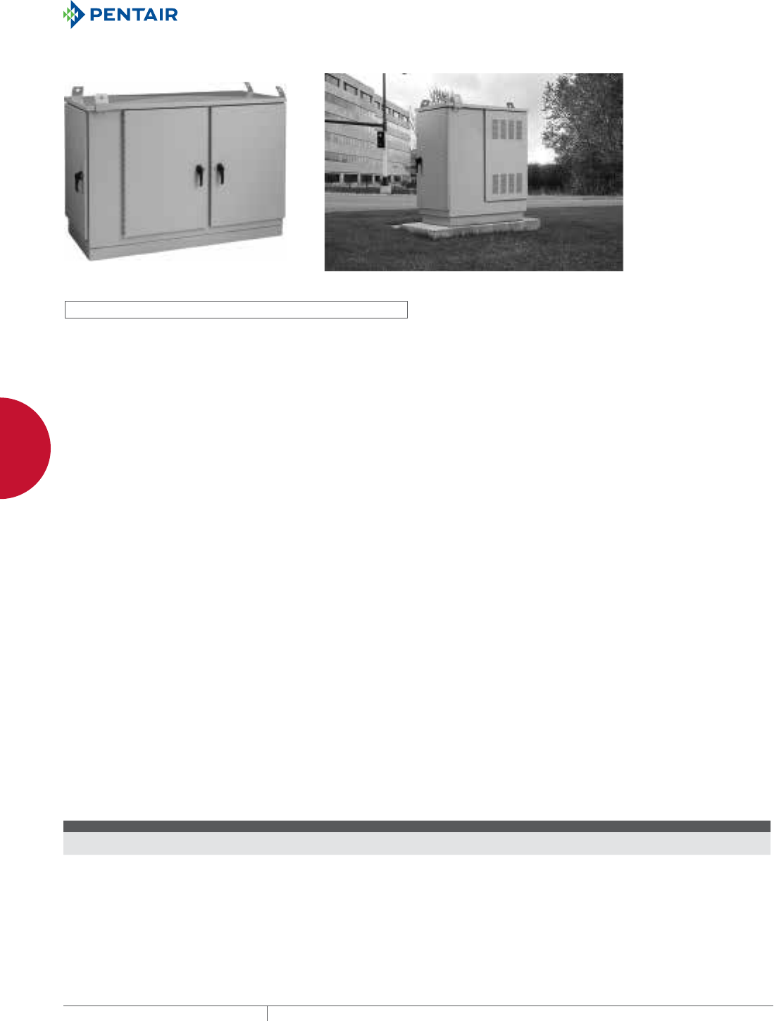
EQUIPMENT PROTECTIONSUBJECT TO CHANGE WITHOUT NOTICENETWORKING242
9
OUTSIDE PLANT PRODUCTS OSP CABINETS
OSP CABINETS
OPAL PADMOUNT DSL CABINET
5-Door Cabinet
C
ustom
Cabinet
Shown
INDUSTRY STANDARDS
UL 508A Listed; Type 3, 3R, 4, 4X, 12; File No. E61997
CSA: Type 3, 3R, 4, 4X, 12
NEMA/EEMAC Type 3, 3R, 4, 4X, 12
EC60529, IP66
Designed to meet Telcordia NEBS™ GR-487, GR-63 and IEC 48D
EIA 310-D with 19-in. spacing for rack equipment
Cabinet is RoHS compliant
NEBS™ is a trademark of Telcordia
APPLICATION
Protect communications equipment from the elements in various
environments with OPAL, an aluminum pad-mounted cabinet. OPAL
is offered in three- and five-door models and is designed to meet
Telcoria NEBS GR-487-CORE requrements.
FEATURES
• Offered with three or five doors mounted for front, rear and side
access to equipment
• Five-door model has two equal compartments and one side
compartment
• Side compartment is ideal for cable entry, power distribution and
load center
• Copper bonding bars included with cabinet
• Rack angles have EIA universal spaced square holes and are
infinitely adjustable front-to-back in compartment
• Rack angles are predrilled for bend radius spools
• Each compartment is capable of either 19- or 23-in. rack angle
positioning
• Top has integral solar shield with formed angles providing a
peaked roof to deflect rain water to the sides of the cabinet
• L-handle is padlockable
• Bottom holes provided for bolting cabinet to concrete pad
• All doors have door switch, door (wind) stops and vault-style
locking system
• Grounding and bonding studs provided on all doors and body
• Three cable entry boots provided in side compartment
• Four cable entry gland plates provided between side and central
compartments
SPECIFICATIONS
• Manufactured from Type 5052-H32 0.125-in. thick aluminum
• Seams continuously welded and ground smooth
• Heavy duty continuous hinge with stainless steel hinge pin on all
doors
• Rack angles made of 12 gauge plated steel
• All doors have with seamless gasket
• Door handles made of die-cast zinc with black polyester powder
finish
FINISH
RAL 7035 light-gray, textured, low-gloss polyester powder paint
over pretreated surfaces. Custom finishes available; please contact
your local Hoffman sales office.
ACCESSORIES
See also Accessories.
Shelves
PDU’s
Cooling
Cable Management Spools
Switches
Lights
Cage Nuts and Screws
MODIFICATION AND CUSTOMIZATION
• Thermal management analysis
• Finish (Graffiti resistant, Local & Regional requirements, Telco
green and beige)
• The addition of Fans, Heat exchangers and Air conditioners
• Cabinet insulation (Recommended for all Air conditioned
applications)
• Holes, cut-outs, finish and size changes
• EMI/RFI shielding
• Level 1- 4 integration
• Additional Battery compartment
• Additional testing (UL, GR-487-CORE, Seismic, Vibration, Load,
etc)
Contact your Hoffman Sales Office for details.
BULLETIN: DPMC
Standard ProductOPAL Outdoor Pad-Mounted Communications Cabinet
Catalog Number AxBxC in./mm Rack Units Per Bay
T504030PM3 48.50 x 43.54 x 30.00
1232 x 1106 x 762
22
T507030PM5 48.50 x 73.54 x 30.00
1232 x 1868 x 762
22
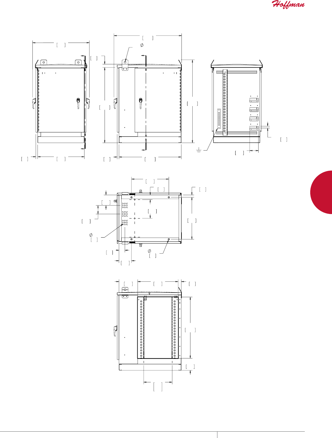
PH 763.422.2661 • FAX 763.422.2588 • PENTAIRPROTECT.COMEQUIPMENT PROTECTION NETWORKING 243
9
OUTSIDE PLANT PRODUCTS OSP CABINETS
>@
;
<
<
=
=
;
;
;
;
;
<<
==
23$/'RRU(QFORVXUH
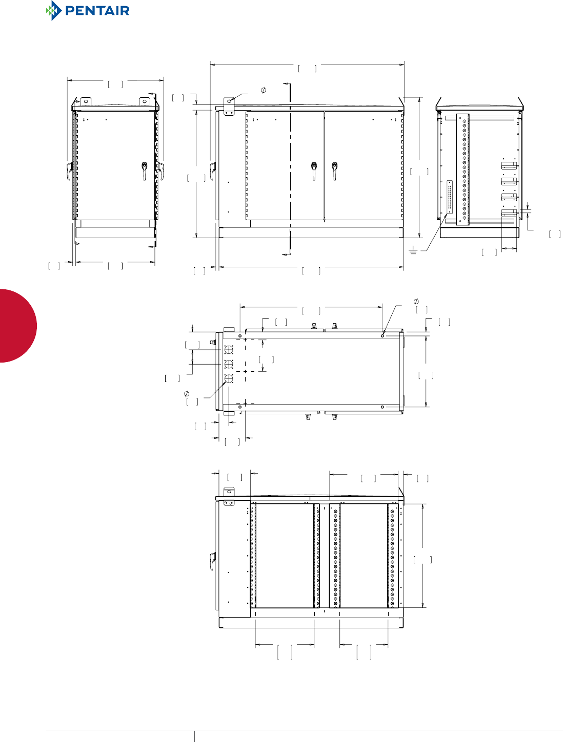
EQUIPMENT PROTECTIONSUBJECT TO CHANGE WITHOUT NOTICENETWORKING244
9
OUTSIDE PLANT PRODUCTS OSP CABINETS
>@
;
<
<
;
;
;
;
=
=
;
==
;
<<
23$/'RRU(QFORVXUH


EQUIPMENT PROTECTIONSUBJECT TO CHANGE WITHOUT NOTICENETWORKING246
10
763.422.2661
763.422.2588
NETWORKING
ACCESSORIES
Intro Page
CHAPTER 10
ACCESSORIES
SHELVES
Ranging from double- and single-sided
shelves to rack-mount and pull-out
options, there are a variety of shelves
available for open frame racks and
cabinets. LIGHTING
LED light kits offer a compact,
energy-efficient and flexible solution
for enclosure-mounted task lighting.
Available in AC and DC powered
models.
FEATURED PRODUCTS

PH 763.422.2661 • FAX 763.422.2588 • PENTAIRPROTECT.COMEQUIPMENT PROTECTION NETWORKING 247
Intro Page CHAPTER CONTENTS
SHELVES FOR OPEN FRAME RACKS AND CABINETS
Double-Sided Solid Aluminum Shelf ............................248
Double-Sided, Solid Aluminum, Heavy Duty Shelf .................248
Single-Sided Solid Aluminum Shelf ............................248
Single-Sided Solid-Steel Shelf ................................248
Single-Sided Steel Vented Shelf ...............................249
Double-Sided Solid-Steel Shelf ...............................249
Double-Sided Steel Vented Shelf ..............................249
Center-Mount Steel Shelves ..................................249
Rack-Mount Steel Shelf .....................................250
Adjustable Steel Vented Shelf ................................250
Pullout Keyboard Tray with Monitor Shelf .......................250
Pivoting Keyboard Shelf with Mouse Tray ........................250
Steel Keyboard/Monitor Shelf ................................251
Pull-Out Shelf for Mini Keyboard ..............................251
Tool-less Shelf ............................................251
Rack-Mount Adjustable Shelf .................................252
Single-Sided Shelf .........................................252
Keyboard Compartment for 19-in. Racks ........................252
Writing Surface for Rack-Angle-Mounted Drawer .................253
Sliding Equipment Shelf .....................................253
Cable Manager Arm for Sliding Equipment Shelf ..................253
Rack-Angle Mounted Drawer .................................254
LIGHTING PACKAGES
PANELITE™ Enclosure Lights Overview .........................255
PANELITE™ LED Enclosure Light ..............................256
PANELITE™ Fluorescent Enclosure Light ........................256
PANELITE™ Power Cords ....................................257
PANELITE™ Power Cable with Leads ...........................257
PANELITE™ Ganging Cables ..................................257
PANELITE™ Door Switch Cable ................................257
230 VAC Fluorescent Enclosure Light ...........................258
PANELITE™ Wiring Options ...................................258
LED Light Kit ..............................................259
LED Light Input Connector/Cable Assembly ......................259
LED Light Extension Connector/Cable Assembly. . . . . . . . . . . . . . . . . . .259
Remote Door Switches ......................................260
LED Puck Light ............................................260
Touch-Safe UL Light Switch ..................................260
Mounting Bracket Kit for Light Package .........................260
MOUNTING HARDWARE
Mounting Foot Kits .........................................261
Screw Packages ...........................................261
Cage Nut Package. . . . . . . . . . . . . . . . . . . . . . . . . . . . . . . . . . . . . . . . . .261
Pole Mounting Kits .........................................261
PROLINE™ Fastener Packages ................................262
VELCRO® Cable Wrap .................................262
HANDLES, LATCHES AND LOCKS
Padlocking L Handle ........................................263
Net Series Combination L-Handle ..............................263
Quick Reference Guide to Networking Handles, Latches and Locks ....263
Padlocking Quarter-Turn Latch ................................264
3-Digit Combination Lock ....................................264
Quarter-Turn Lock ..........................................264
Replacement Keys .........................................264
Keylocking Wing Knob ......................................265
Keylocking Quarter-Turn Wing Knob ............................265
Padlocking Wing Knob, Stainless Steel .........................265
GENERAL ACCESSORIES
19-in. and 23-in. Rack Angles .................................266
Rack Unit Label ...........................................266
Tool-less (Snap-in) Blanking Panels for 19-in. Racks. . . . . . . . . . . . . . .267
Rack Panel for 19-in. Racks ..................................267
Touch-Up Paint ............................................267
10
MOUNTING HARDWARE
Mounting hardware available for
cabinets and rack panels facilitate easy
installation.
HANDLES,
LATCHES AND LOCKS
A wide range of handles,
latches and locks ensure
a secure, yet easy-to-use,
cabinet.
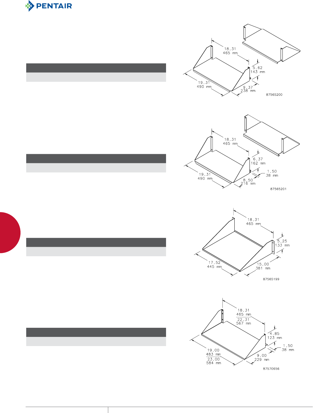
EQUIPMENT PROTECTIONSUBJECT TO CHANGE WITHOUT NOTICENETWORKING248
10
ACCESSORIES SHELVES FOR OPEN FRAME RACKS AND CABINETS
SHELVES FOR OPEN FR AME RACKS AN D CABINETS
DOUBLESIDED SOLID ALUMINUM SHELF
Mounts on 19-in. open frame rack. Two shelves form double-sided
shelf. Uses 4U rack space. Made of 0.090-in. thick aluminum with
brushed finish.
Maximum load rating: 100 lb. (45.4 kg) per side, 200 lb. (90.7 kg)
total
BULLETIN: DACCY
Catalog Number
H x W x D
in./mm Fits Rack Includes Rack Units
ESHDA19 5.62 x 19.31 x 9.37
143 x 490 x 238
19 in. 2 shelves 4
DOUBLESIDED, SOLID ALUMINUM, HEAVY DUTY SHELF
Mounts on open frame rack. Two shelves form double-sided shelf.
Uses 4U rack space. Made of 0.090-in. thick aluminum with brushed
finish.
Maximum Load Rating: 150 lb. (68.0 kg) per side, 300 lb. (136.1 kg)
total
BULLETIN: DACCY
Catalog Number
H x W x D
in./mm Fits Rack Includes Rack Units
ESHDHDA19 6.37 x 19.31 x 10.00
162 x 490 x 254
19 in. 2 shelves 4
SINGLESIDED SOLID ALUMINUM SHELF
Mounts in a cabinet or on a 19-in. open-frame rack and can be wall
mounted. Made of 0.090-in. thick aluminum with brushed finish.
Maximum load rating: 100 lb. (45.4 kg)
BULLETIN: DACCY
Catalog Number
H x W x D
in./mm Fits Rack Rack Units
ESHA19 5.25 x 18.31 x 15.00
133 x 465 x 381
19 in. 3
SINGLESIDED SOLIDSTEEL SHELF
Solid shelf mounts to either front or rear flange of open-frame rack.
Uses 3U of rack space. Steel with textured black finish.
Load rating: 150 lb. (68.0 kg)
BULLETIN: DACCY
Catalog Number
H x W x D
in./mm Fits Rack Rack Units
ESH19S 4.85 x 19.00 x 10.50
123 x 483 x 267
19 in. 3
ESH23S 4.85 x 23.00 x 10.50
123 x 584 x 267
23 in. 3
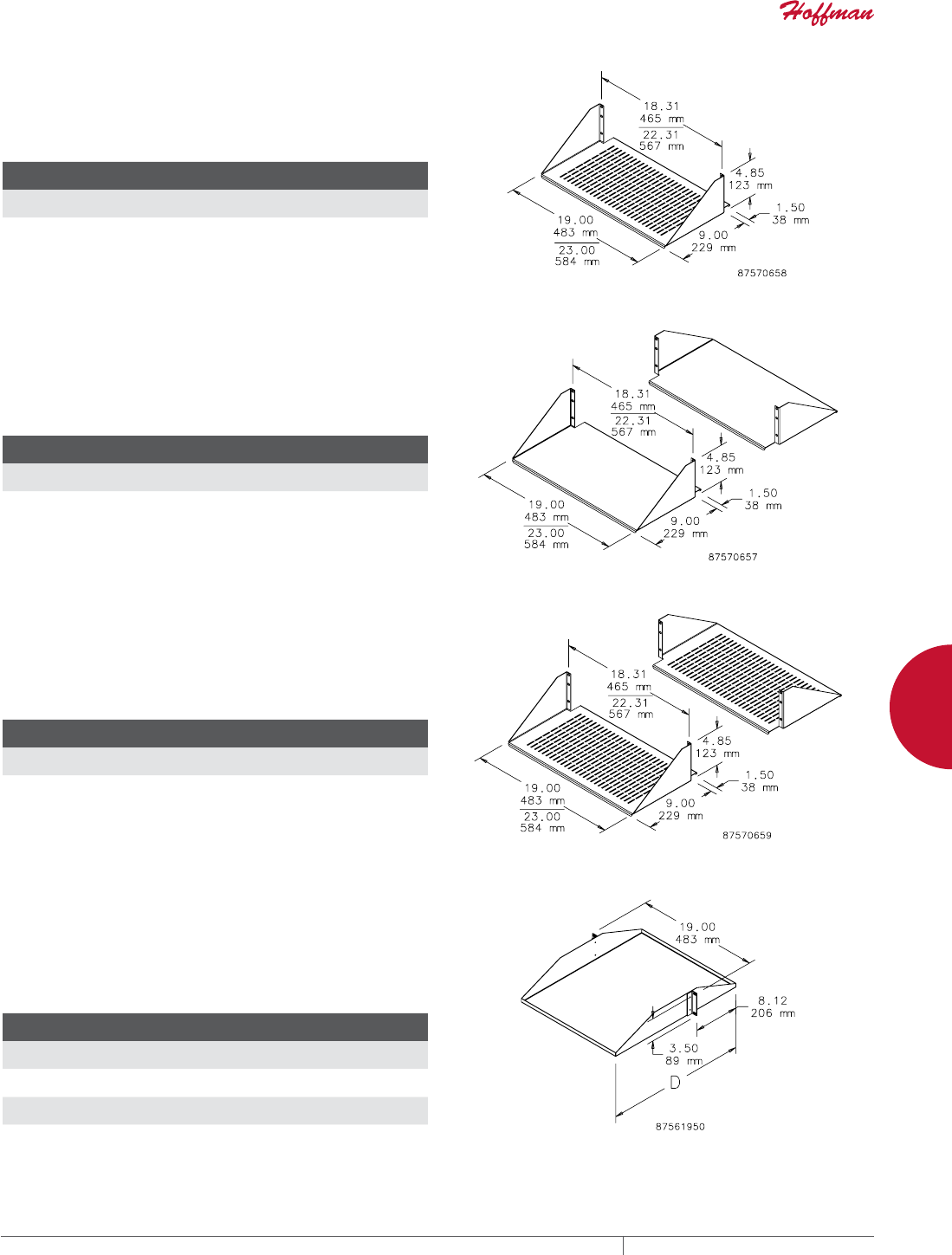
PH 763.422.2661 • FAX 763.422.2588 • PENTAIRPROTECT.COMEQUIPMENT PROTECTION NETWORKING 249
10
ACCESSORIES SHELVES FOR OPEN FRAME RACKS AND CABINETS
SINGLESIDED STEEL VENTED SHELF
Vented shelf mounts to either front or rear flange of open-frame
rack. Steel with textured black polyester powder paint finish.
Load rating: 150 lb. (68.0 kg)
BULLETIN: DACCY
Catalog Number
H x W x D
in./mm Fits Rack Rack Units
ESH19V 4.85 x 19.00 x 10.50
123 x 483 x 267
19 in. 3
ESH23V 4.85 x 23.00 x 10.50
123 x 584 x 267
23 in. 3
DOUBLESIDED SOLIDSTEEL SHELF
Solid double-deep shelf mounts to both front and rear flanges of
open frame rack. Steel with textured black polyester powder paint
finish.
Load rating: 300 lb. (136.1 kg)
BULLETIN: DACCY
Catalog Number
H x W x D
in./mm Fits Rack Rack Units
ESHD19 4.85x 19.00 x 10.50
123 x 483 x 267
19 in. 3
ESHD23 4.85 x 23.00 x 10.50
123 x 584 x 267
23 in. 3
DOUBLESIDED STEEL VENTED SHELF
Vented, double-deep shelf mounts to both front and rear flanges of
open frame rack. Steel with textured black polyester powder paint
finish.
Load rating: 300 lb. (136.1 kg)
BULLETIN: DACCY
Catalog Number
H x W x D
in./mm Fits Rack Rack Units
ESHDV19 4.85 x 19.00 x 10.50
123 x 483 x 267
19 in. 3
ESHDV23 4.85 x 23.00 x 10.50
123 x 584 x 267
23 in. 3
CENTERMOUNT STEEL SHELVES
19-in. shelf mounts to the front of the rack. Ideal for supporting
monitors or computers. Designed to evenly distribute load across
the rack. Manufactured from 16 gauge steel. Black, low-gloss,
light-textured polyester powder paint finish on all surfaces.
Load rating: 100 lb. (45.4 kg)
BULLETIN: DOFRC
Catalog Number
H x W x D
in./mm Style Rack Units
ECMS1918 3.50 x 19.00 x 18.00
89 x 483 x 457
Solid 2
ECMS1922 3.50 x 19.00 x 22.00
89 x 483 x 559
Solid 2
ECMSV1918 3.50 x 19.00 x 18.00
89 x 483 x 457
Vented 2
ECMSV1922 3.50 x 19.00 x 22.00
89 x 483 x 559
Vented 2
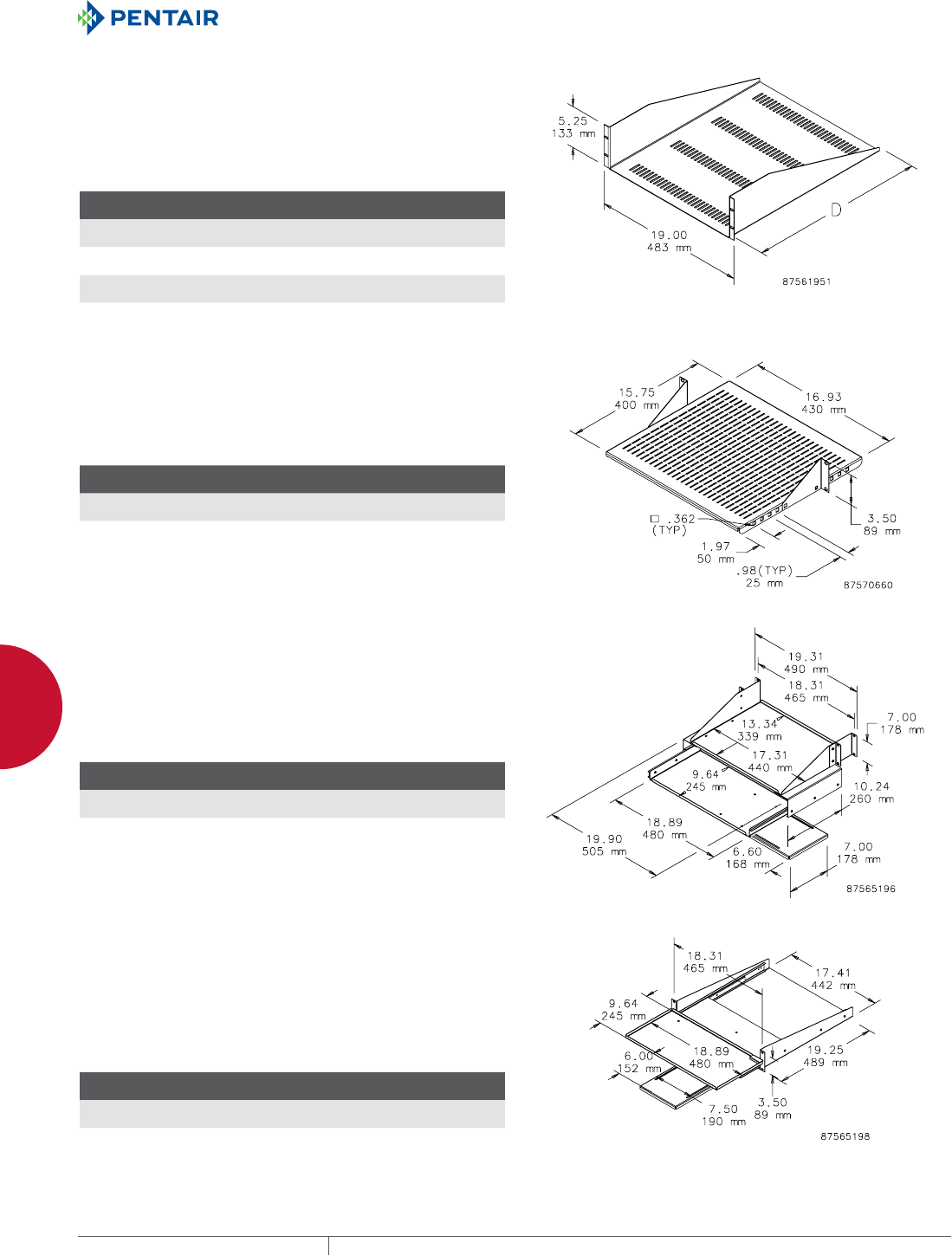
EQUIPMENT PROTECTIONSUBJECT TO CHANGE WITHOUT NOTICENETWORKING250
10
ACCESSORIES SHELVES FOR OPEN FRAME RACKS AND CABINETS
RACKMOUNT STEEL SHELF
19-in. Rack-Mount Shelf mounts to the front of the rack. Ideal for
holding non-19-in. rack-mount equipment. Available with or without
vents. Manufactured from 16 gauge steel. Black, low-gloss, lightly
textured finish on all surfaces.
Load rating: 100 lb. (45.4 kg)
BULLETIN: DOFRC
Catalog Number
H x W x D
in./mm Style Rack Units
EMS1918 5.25 x 19.00 x 18.00
133 x 483 x 457
Solid 3
EMS1922 5.25 x 19.00 x 22.00
133 x 483 x 559
Solid 3
EMSV1918 5.25 x 19.00 x 18.00
133 x 483 x 457
Vented 3
EMSV1922 5.25 x 19.00 x 22.00
133 x 483 x 559
Vented 3
ADJUSTABLE STEEL VENTED SHELF
Vented shelf adjustable front to back in 25-mm increments. Shelf
mounts to either front or rear flange of open frame rack. Steel with
textured black polyester powder paint finish.
Load rating: 60 lb. (27.2 kg)
BULLETIN: DACCY
Catalog Number
H x W x D
in./mm Fits Rack Rack Units
ESHVA19 3.50 x 16.93 x 15.75
89 x 430 x 400
19 in. 2
ESHVA23 3.50 x 19.93 x 15.75
89 x 506 x 400
23 in. 2
PULLOUT KEYBOARD TRAY WITH MONITOR SHELF
Mounts to the front and back surfaces of a standard 3-in. open
frame rack. Fits full-size keyboard. Includes mouse tray. Extends
10.5 in. (267 mm) beyond front of open frame rack. Keyboard tray
slides out an additional 7 in. (178 mm). Uses 4U rack space. 16 gauge
steel with RAL 9005 black polyester powder paint finish.
Monitor shelf load rating: 100 lb. (45.4 kg)
BULLETIN: DACCY
Catalog Number
H x W x D
in./mm Fits Rack Rack Units
E19SKBM 7.00 x 19.90 x 10.24
178 x 505 x 260
19 in. 4
PIVOTING KEYBOARD SHELF WITH MOUSE TRAY
Mounts either in a cabinet or on a 19-in. open-frame rack. Shelf
pulls out and pivots 90 degrees to access full-size keyboard. Shelf
allows keyboard to slide between standard rack angles and includes
mouse tray. 16 gauge steel with RAL 9005 black polyester powder
paint finish. Keyboard tray extends 9.75 in. (248 mm) beyond front of
rack angles or open-frame rack.
BULLETIN: DACCY
Catalog Number
H x W x D
in./mm Fits Rack Rack Units
P19KBPVT 3.50 x 18.89 x 19.25
89 x 480 x 489
19 in. 2
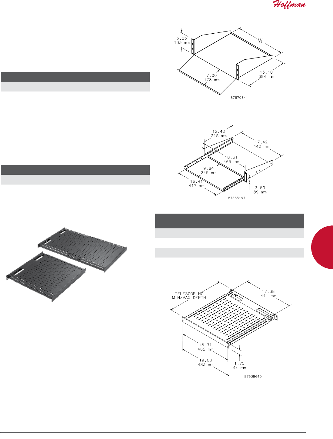
PH 763.422.2661 • FAX 763.422.2588 • PENTAIRPROTECT.COMEQUIPMENT PROTECTION NETWORKING 251
10
ACCESSORIES SHELVES FOR OPEN FRAME RACKS AND CABINETS
STEEL KEYBOARD/MONITOR SHELF
Designed to accommodate a monitor and keyboard in an
ergonomically engineered design. Shelf mounts to front flange of
open-frame rack. Can mount in a cabinet if rack angles are adjusted
back for door clearance. Uses 3U of rack space. 19-in. and 23-in.
rack versions. Steel with textured black finish.
Load rating: 200 lb. (91 kg)
BULLETIN: DACCY
Catalog Number
H x W x D
in./mm Fits Rack Rack Units
ESH19KBM 5.25 x 17.38 x 15.10
133 x 441 x 384
19 3
ESH23KBM 5.25 x 21.38 x 15.10
133 x 543 x 384
23 3
PULLOUT SHELF FOR MINI KEYBOARD
Pull-Out Shelf for Mini Keyboard mounts either in a cabinet or on a
19-in. open-frame rack and fits a 16.25-in. (413-mm) wide keyboard.
When closed, all parts slide between rack angles. Keyboard tray
slides out 8.94 in. (227 mm). 16 gauge steel with RAL 9005 black
polyester powder paint finish.
BULLETIN: DACCY
Catalog Number
H x W x D
in./mm Fits Rack Rack Units
P19KBSM 3.50 x 18.31 x 12.42
89 x 465 x 315
19 in. 2
TOOLLESS SHELF
An easy-to-install tool-less vented 19-in. shelf. Mounts onto
rack angles that have EIA-spaced square holes (.375 in.). Shelf
slides open and provides a variable-sized, continuous surface
for equipment. Back of shelf has oval cutouts for power and data
cables. Accessory hole patterns at back of shelf fit small and large
D-rings to help manage cable. Made of steel with a 150 lb. (68 kg)
static load rating. Available with RAL 9005 black or RAL 7035 gray
polyester powder coat finish.
BULLETIN: DACCY
Catalog Number Description Finish
Minimum
Depth
mm/in.
Maximum
Depth
mm/in.
D19FVT69B Shelf, vented, 19 in. tool-less Black 495
19.50
851
33.50
D19FVT69G Shelf, vented, 19 in. tool-less Gray 495
19.50
851
33.50
D19FVT912B Shelf, vented, 19 in. tool-less Black 792
31.20
1151
45.30
D19FVT912G Shelf, vented, 19 in. tool-less Gray 792
31.20
1151
45.30
Minimum and maximum depth measured from rack angle to rack angle.
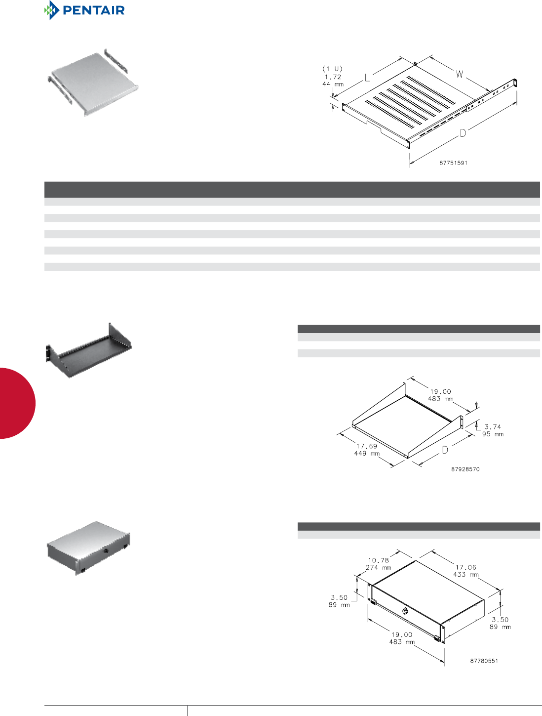
EQUIPMENT PROTECTIONSUBJECT TO CHANGE WITHOUT NOTICENETWORKING252
10
ACCESSORIES SHELVES FOR OPEN FRAME RACKS AND CABINETS
RACKMOUNT ADJUSTABLE SHELF
Mounts to front surface of front
and back rack angles. Shelf is
made of painted 14 gauge steel and
the adjustable support brackets
are clear-plated 12 gauge steel.
Adjustable to fit multiple-depth
enclosures or rack angle placement.
Both solid and vented models
available. Fits 19- or 23-in. rack
spacing. Requires only 1U of rack
space. Shelf has RAL 7035 light-gray
textured or RAL 9005 black textured
polyester powder paint finish.
Load rating: 150 lb. (68 kg)
BULLETIN: DACCY
Catalog Number Type Size Finish L x W (in.) L x W (mm) D max. (in.) D max. (mm)
Fits Enclosure
Depth Up To (in.)
Fits Enclosure
Depth Up To (mm)
P19SH68 Solid 19 in. Gray 19.68 x 17.32 500 x 440 30.71 780 31.50 800
P19SH68B Solid 19 in. Black 19.68 x 17.32 500 x 440 30.71 780 31.50 800
P19VSH68B Vented 19 in. Black 19.68 x 17.32 500 x 440 30.71 780 31.50 800
P19SH810 Solid 19 in. Gray 27.56 x 17.32 700 x 440 38.58 980 39.37 1000
P19SH810B Solid 19 in. Black 27.56 x 17.32 700 x 440 38.58 980 39.37 1000
P19VSH810B Vented 19 in. Black 27.56 x 17.32 700 x 440 38.58 980 39.37 1000
P23SH68B Solid 23 in. Black 19.68 x 21.32 500 x 542 30.71 780 31.50 800
P23VSH68B Vented 23 in. Black 19.68 x 21.32 500 x 542 30.71 780 31.50 800
P23SH810B Solid 23 in. Black 27.56 x 21.32 700 x 542 38.58 980 39.37 1000
P23VSH810B Vented 23 in. Black 27.56 x 21.32 700 x 542 38.58 980 39.37 1000
SINGLESIDED SHELF
Mounts to 19-in. rack angles to
house voice/data networking
equipment. RAL 9005 black finish.
Load rating: 75 lb. (34 kg)
BULLETIN: DACCY
Catalog Number H x W x D (in.) H x W x D (mm) Style Rack Units
ESH198 3.74 x 19.00 x 8.00 95 x 483 x 203 Solid 2
ESH1915 3.74 x 19.00 x 15.00 95 x 483 x 381 Solid 2
ESH1915V 3.74 x 19.00 x 15.00 95 x 483 x 381 Vented 2
ESH1917 3.74 x 19.00 x 17.00 95 x 483 x 432 Solid 2
KEYBOARD COMPARTMENT FOR 19IN. RACKS
Provides a convenient way to
incorporate a keyboard with
other 19-in. rack-mounted
equipment. Uses 2 RU of space.
Made of light-weight aluminum
with brushed finish. Accommodates
keyboard up to 16.50-in. (419-mm)
wide. Mounting hardware included.
BULLETIN: DACCY
Catalog Number Fits rack width Rack Units
A19KBC2B 19 2
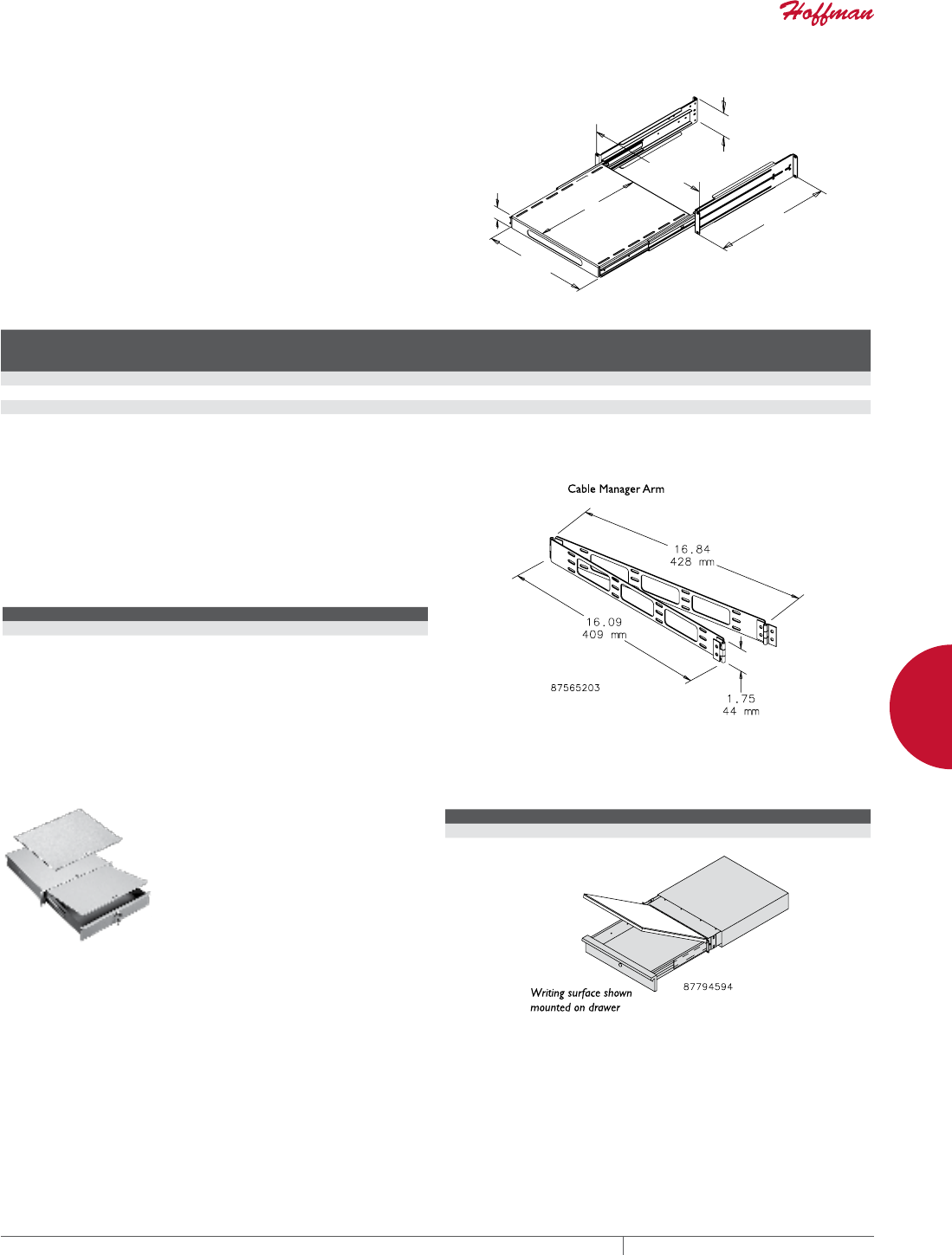
PH 763.422.2661 • FAX 763.422.2588 • PENTAIRPROTECT.COMEQUIPMENT PROTECTION NETWORKING 253
10
ACCESSORIES SHELVES FOR OPEN FRAME RACKS AND CABINETS
SLIDING EQUIPMENT SHELF
Steel Sliding Equipment Shelf mounts to front surface of front and
back rack angles. Models fit 19- or 23-in. rack spacing. Adjusts to
fit multiple-depth enclosures and rack angle placements. Shelf
can be used on 2-post rack or cabinet with front rack angles only by
reversing support bracket. Optional cable manager arm available.
14 gauge steel with 12 gauge supports with RAL 9005 black
polyester powder paint finish. Load rating: 150 lb. (68.0 kg) with four
corner mounting; 75 lb. (34.0 kg) with two-post or front-rack-angle
cabinet mounting.
Optional Cable Manager Arm is recommended to help control cable
movement as shelf slides in and out.
BULLETIN: DACCY
2-ISO2
-
'
>@
>@
>@
/
Catalog Number D Max. (in.) D Max. (mm) L (in.) L (mm) J (in.) J (mm)
Shelf
Pullout
(in.)
Shelf
Pullout
(mm)
Fits
Rack
Rack
Units
P19SHP68B 37.40 950 16.72 425 16.20 412 17.00 432 19 in. 2
P19SHP810B 41.30 1050 24.59 625 16.20 412 19.00 483 19 in. 2
P23SHP68B 37.40 950 16.72 425 20.20 513 17.00 432 23 in. 2
P23SHP810B 41.30 1050 24.59 625 20.20 513 19.00 483 23 in. 2
CABLE MANAGER ARM FOR SLIDING EQUIPMENT
SHELF
Cable Manager Arm mounts to back of sliding equipment shelf on
right or left side. Controls cable movement as shelf slides in and
out. 14 gauge steel with RAL 9005 black polyester powder paint
finish.
BULLETIN: DACCY
Catalog Number Description Use With
PHCB Cable Manager Arm Sliding Equipment Shelf
WRITING SURFACE FOR RACKANGLEMOUNTED DRAWER
Steel cover mounts on top of the
drawer and serves as a writing
surface and drawer cover. Finish
is RAL 7035 light-gray textured
polyester powder paint. Illustration
and one photo show writing surface
mounted on drawer. Order drawer
separately.
BULLETIN: P20
Catalog Number Description Fits
P19WS Steel writing surface and cover Drawer (order separately)
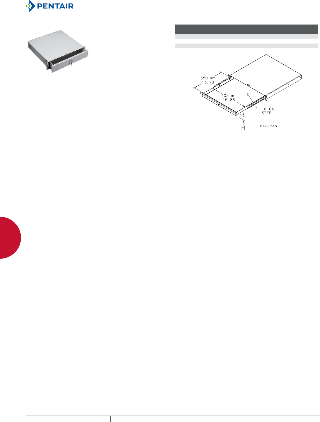
EQUIPMENT PROTECTIONSUBJECT TO CHANGE WITHOUT NOTICENETWORKING254
10
ACCESSORIES SHELVES FOR OPEN FRAME RACKS AND CABINETS
RACKANGLE MOUNTED DRAWER
Steel drawer for 19-in. rack-angle mounting mounts to the front
surface of the rack angles. Integral steel box contains the drawer
and protects surrounding internal equipment. Extends 13 in. (330
mm) on ball bearing slides. Front includes handle and key lock.
Finish is RAL 7035 textured light-gray polyester powder paint.
Mounting hardware is included.
BULLETIN: P20
Catalog Number H (mm) H (in.)
Fits Rack
Width
Rack
Units
P19DR1US 43 1.69 19 in. 1
P19DR2US 88 3.47 19 in. 2
P19DR3US 132 5.20 19 in. 3
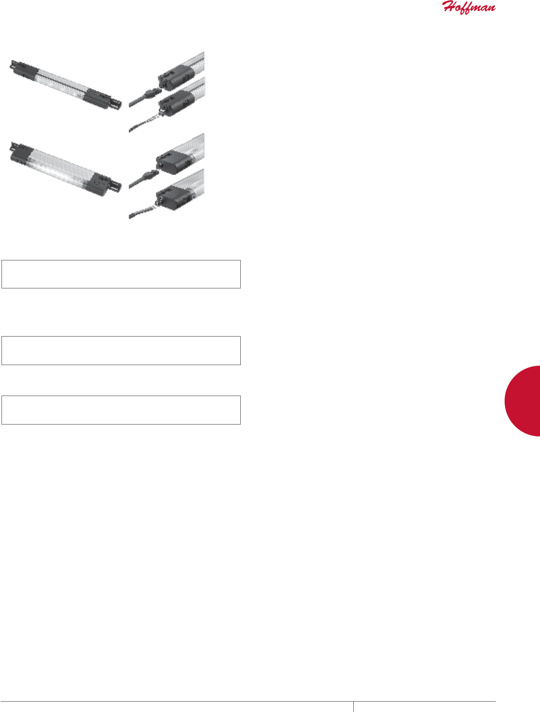
PH 763.422.2661 • FAX 763.422.2588 • PENTAIRPROTECT.COMEQUIPMENT PROTECTION NETWORKING 255
10
ACCESSORIES LIGHTING PACKAGES
LIGHTING PACKAGES
PANELITE™ ENCLOSURE LIGHTS OVERVIEW
INDUSTRY STANDARDS
PANELITE LED and Fluorescent Enclosure Lights
UL 508A Component Recognized; File No. E61997
cUL Component Recognized per CSA C22.2 No 14; File No.
E61997
CSA File No. 42186
Maintains UL/CSA Type 4, 4X and 12 enclosure rating when properly
installed in a Hoffman enclosure.
230 VAC Fluorescent Enclosure Light
UL 508A Component Recognized; File No. E234324
cUL Component Recognized per CSA C22.2 No 14; File No.
E61997
CE
LED Light
UL 508A Component Recognized; File No. E234324
cUL Component Recognized per CSA C22.2 No 14; File No.
E234324
CE
Ingress protection : IP 20
Maintains enclosure type rating up to 4X when installed per instructions
APPLICATION
Versatile, slim-profile LED and fluorescent lights provide mounting
flexibility and are easy to install in any enclosure. Terminal
blocks allow for easy wiring. Accessories include ganging cables,
power cords and door switches, all provided with plug-and-play
connectors for easy connection to the terminal blocks with an
innovative terminal connection system. LED version provides
superior lighting performance with minimal power consumption.
FEATURES
• Slim profile allows light to be tucked up out of the way for easy
panel installation
• Versatile mounting allows the light to be positioned horizontally
or vertically; two-way mounting provides for ideal orientation
• Includes mounting hardware for the following enclosure
installations: PROLINE™ Frame, Enclosure Top, Panel Mount
and Unistrut
• On/off switch incorporated in light; optional remote door switch
accessory available to activate light when enclosure door is
opened (230 VAC Fluorescent Enclosure Light has switch or door-
activated sensor)
PANELITE Only:
• Mounting tabs provide easy access point for attachment
hardware; light does not need to be disassembled for installation
• Up to five lights can be daisy-chained together
• Plug-and-play terminal connection system:
- Pre-wired connection sockets on both ends of light allow use
of Hoffman cable accessories
- Optional terminal blocks snap into the connection sockets
allowing customers to use own wiring methods; two terminal
blocks provided with each light kit
- Power supply can be wired manually with Hoffman PANELITE
Power Cable with Leads or with Hoffman optional PANELITE
Power Cord
- Ganging cables are available in 2-, 4- and 6-ft. lengths to easily
join up to five lights together using one power supply
- Remote door switch for easy door activation eliminates need to
mount light in the exact location required to activate the light
LED Light Only:
• Mechanical screw- or magnetic mount (non-slip rubberized)
• Protection Class II (double insulated)
• Operating temperature -22 F to 140 F (-30 C to 60 C)
• On / Off or motion-sensor activation
• LED lights with 900 LM illumination; 120° angle of illumination
• Low, 5-watt power requirement
• Light-weight, all-composite construction
• Input and output connectors included with light (16 AWG)
SPECIFICATIONS
PANELITE:
• Extruded aluminum center support
• Black composite end caps
• Black composite mounting tabs
• Each light fixture includes two mounting tabs, two pre-wired
connection sockets, two optional terminal blocks that snap into
the connection sockets and enclosure attachment hardware (bulb
not included with fluorescent light)
230 VAC Fluorescent Enclosure Light:
• Light gray composite construction – UL 94V-O material
• Hardware kit provides fasteners to mount to PROLINE, NEMA (4,
4X, 12, and 13), CONCEPT™ , FUSION™ and other cabinets
• Easy-access terminal block that accommodates up to 16 AWG
wires
• Fluorescent light bulb included (2G7 Base)
LED Light:
• LED (Light Emitting Diode) low-power light kit
• Screw mounting using included hardware kit (maintains
enclosure rating up to UL Type 4X)
• No user-serviceable parts
• Life expectancy of 60,000 hours at 68 F (20 C) under specifications
• Operating temperature: -22 to +140 F (-30 to +60 C) under
specifications
• 5-watt power consumption
• Transparent, composite construction
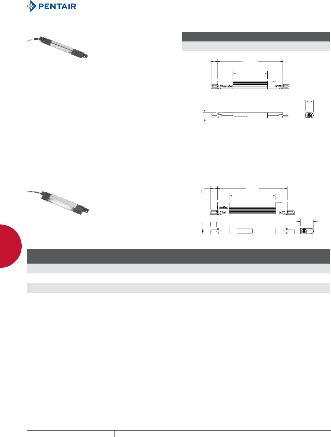
EQUIPMENT PROTECTIONSUBJECT TO CHANGE WITHOUT NOTICENETWORKING256
10
ACCESSORIES LIGHTING PACKAGES
PANELITE™ LED ENCLOSURE LIGHT
• 24 VDC operation for superior
lighting performance with
minimal power consumption
• 140-degree cone angle casts a
broad covering of neutral light
• Center section rotates 120
degrees to re-direct light where
needed
• Long life; 70 percent of initial
luminance at 50,000 hours (at 25
C)
• High power LED emitters produce
470 Lumens for superior lighting
performance; provides up to 50
percent more usable light than
comparable length fluorescent
lights
• Can be wired using optional
PANELITE Cable Accessories or
can be hard-wired with terminal
blocks included in hardware kit
• Up to five lights can be daisy-
chained together using hard-
wired connection to power supply
or catalog number LPC72 power
cable with leads
BULLETIN: A80LT
Catalog Number Description VDC Amps
W
in./mm
X
in./mm
LED24V15 LED Light, 15 in. 24 .5 15.00
381
8.00
203
PP
PP
PP
PP
PP
PANELITE™ FLUORESCENT ENCLOSURE LIGHT
• 120 VAC, 50/60 Hz operation
• Can be wired using optional
PANELITE™ Cable Accessories
or can be hard-wired with
terminal blocks included in
hardware kit
• Available in 15-, 18- and 28-in.
lengths with ability to daisy chain
up to five lights together using
one power supply
• Fluorescent bulb not included
BULLETIN: A80LT
;
:
Catalog Number Description VAC Hz Amps
W
in./mm
X
in./mm
Bulb
(purchase
separately)
Replacement
Lens Cover
LF120V15 Fluorescent Light, 15 in. 120 50/60 .13 14.50
368
9.63
245
F6T5 LFL15
LF120V18 Fluorescent Light, 18 in. 120 50/60 .13 17.50
445
12.63
321
F8T5 LFL18
LF120V28 Fluorescent Light, 28 in. 120 50/60 .26 27.75
705
22.88
581
F14T5 LFL28
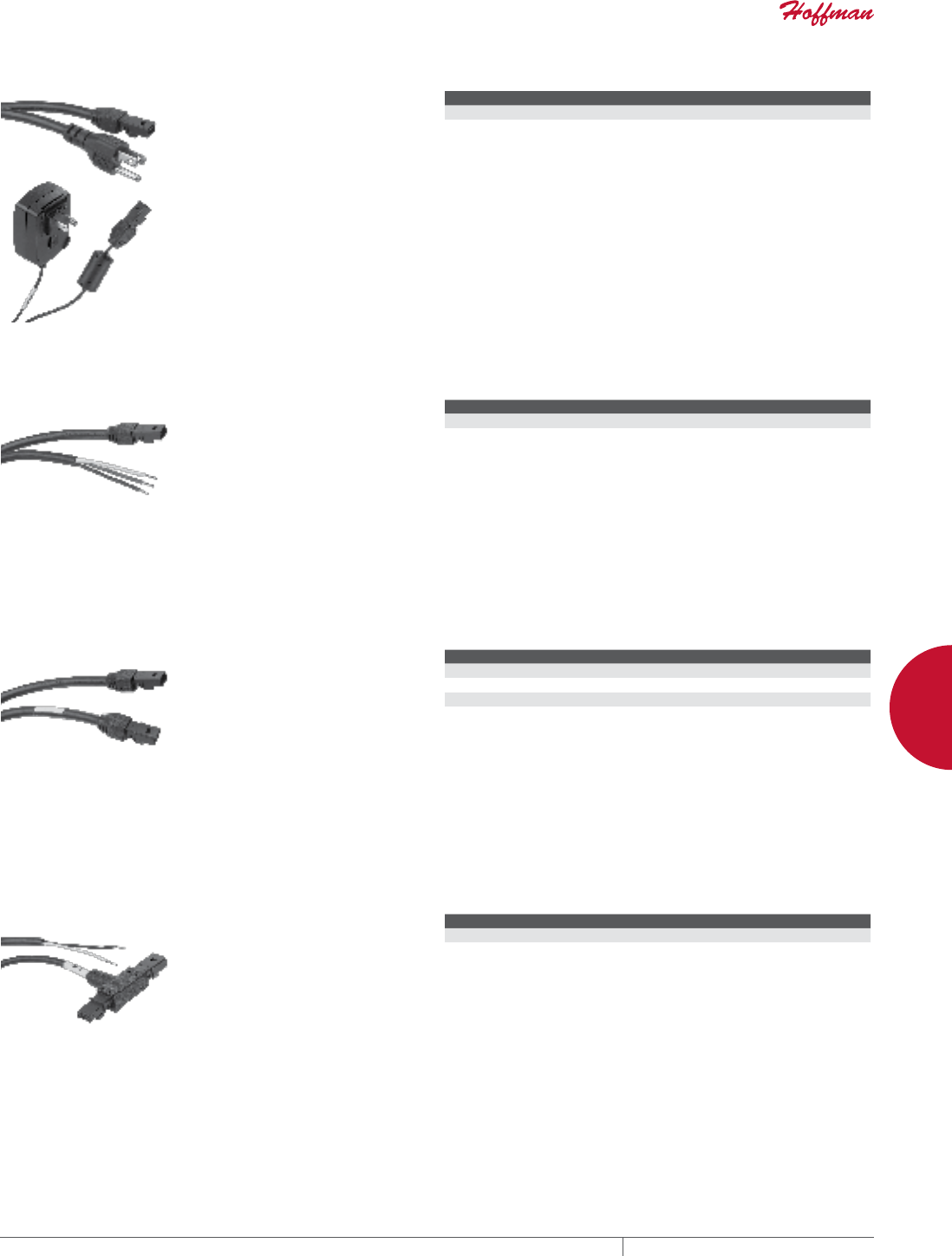
PH 763.422.2661 • FAX 763.422.2588 • PENTAIRPROTECT.COMEQUIPMENT PROTECTION NETWORKING 257
10
ACCESSORIES LIGHTING PACKAGES
PANELITE™ POWER CORDS
• Connects light to standard North
American wall socket
• LF120VCORD is for 120 VAC
Fluorescent lights (up to five
lights can be daisy chained
together using one power cord)
• LED24VCORD is for 24 VDC LED
lights and includes a transformer
to convert 100-240 VAC power
supply (capable of powering only
one LED light)
• Plugs directly into a connection
socket on switch end of the light
• Includes one cable
Power cord not required. Terminal
blocks are provided with each light for
wired connection to electric supply.
BULLETIN: A80LT
Catalog Number Description Length
LF120VCORD Fluorescent Light Power Cord 72 in.
LED24VCORD LED Light Power Cord 60 in.
PANELITE™ POWER CABLE WITH LEADS
• 72-in. power cord provides
convenient connection to an
electrical supply
• Eliminates need to run and tag
individual wires into the light
• Compatible with PANELITE™
LED and Fluorescent lights
• Plugs directly into connection
socket on switch end of the light
• Includes one 16 AWG cable, black
Power Cable not required. Terminal
blocks are provided with each light for
wired connection to electric supply.
BULLETIN: A80LT
Catalog Number Length
LPC72 72 in.
PANELITE™ GANGING CABLES
• Ganging Cables provide
convenient method for joining
up to five lights together while
utilizing one power supply
• Available in 24-, 48- and 72-in.
lengths
• Plugs directly into connection
socket on either end of the light
• Compatible with PANELITE™
LED and Fluorescent lights
• Includes one 16 AWG cable, black
Ganging Cables not required. Terminal
blocks are provided with each light for
hard-wired connections.
BULLETIN: A80LT
Catalog Number Length
LGCABLE24 24 in.
LGCABLE48 48 in.
LGCABLE72 72 in.
PANELITE™ DOOR SWITCH CABLE
• Easily connects PANELITE™ LED
or Fluorescent Light to a Remote
Door Switch
• T-connector allows the Door
Switch Cable to be connected with
a ganging cable or power supply
to the switch end of the light
• Available in 18- and 72-in. lengths
• Includes one 18 AWG cable, black
Door Switch Cables not required.
Terminal blocks are provided with
each light for hard-wired connection to
remote door switch.
BULLETIN: A80LT
Catalog Number Length
LDSWITCH18 18 in.
LDSWITCH72 72 in.
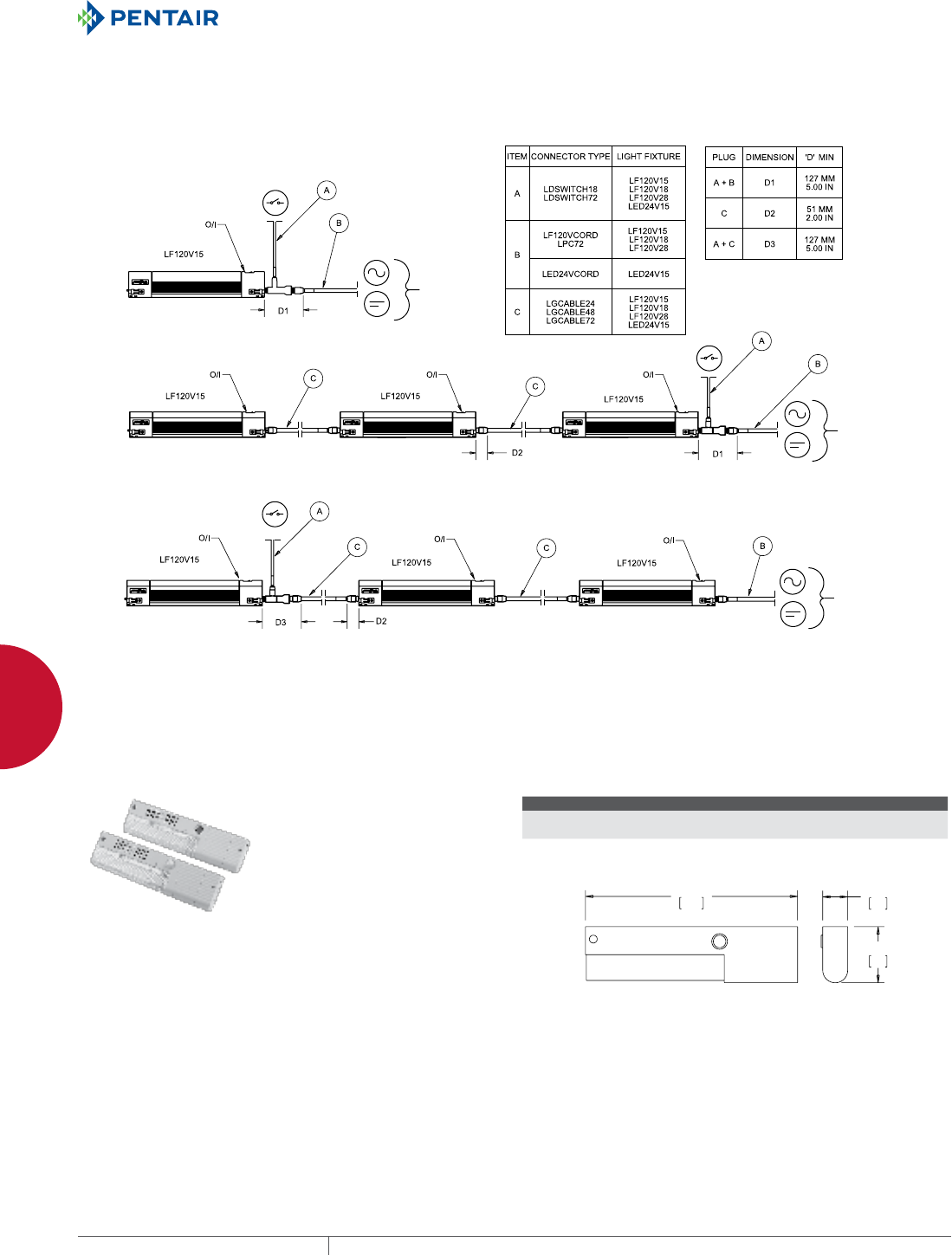
EQUIPMENT PROTECTIONSUBJECT TO CHANGE WITHOUT NOTICENETWORKING258
10
ACCESSORIES LIGHTING PACKAGES
PANELITE™ WIRING OPTIONS
See the table on the drawing for cable clearance dimensions.
2SWLRQ(DFKOLJKWLVFRQWUROOHGE\DUHPRWHGRRUVZLWFK
2SWLRQ$OOOLJKWVDUHFRQWUROOHGE\DVLQJOHUHPRWHGRRUVZLWFK
2SWLRQ7KHODVWOLJKWLVFRQWUROOHGE\DUHPRWHGRRUVZLWFK7KHILUVWWZROLJKWVDUHPDQXDOO\RSHUDWHG
(OHFWULF3RZHU
(OHFWULF3RZHU
(OHFWULF3RZHU
89046495
230 VAC FLUORESCENT ENCLOSURE LIGHT
• 230 VAC, 50/60 Hz operation with
electronic ballast
• Compact light-gray plastic
housing, UL 94V-0
• Easy access to wiring terminals,
integral strain relief, 16 AWG max.
• Versatile mounting to many
enclosure types
• Complete assembly, long-life
fluorescent bulb included,
Luminosity 900 LM
• Switch and Door motion sensor
offering
BULLETIN: A80LT
Catalog Number AxBxC in./mm Description
LF230VM 1.57 x 13.58 x 3.58
40 x 345 x 91
Light Kit, 230VAC, Manual switch
LF230VD 1.57 x 13.58 x 3.58
40 x 345 x 91
Light Kit, 230VAC, IR Motion Sensor
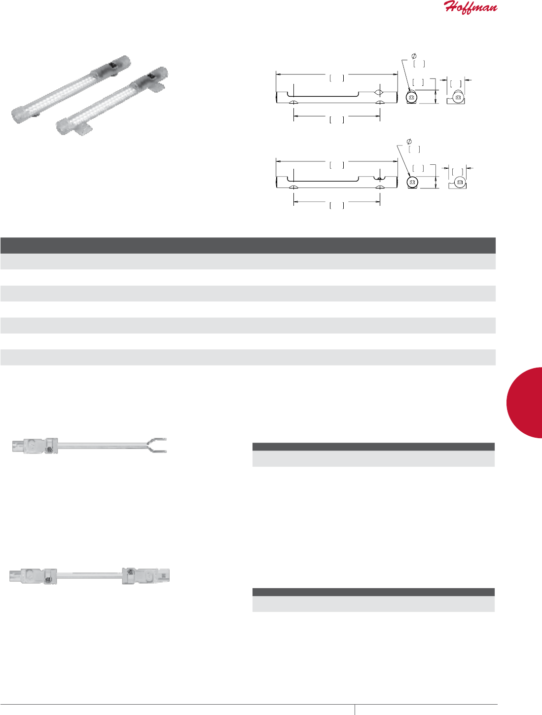
PH 763.422.2661 • FAX 763.422.2588 • PENTAIRPROTECT.COMEQUIPMENT PROTECTION NETWORKING 259
10
ACCESSORIES LIGHTING PACKAGES
LED LIGHT KIT
LED light kits provide interior enclosure lighting. These light kits
are ideal for remote and darkened enclosure applications. The light
can be mechanically fastened with included hardware to maintain
enclosure UL listing (up to Type 4X), or can be magnetically attached
to flat steel surfaces. The lights have auto-sensing circuitry (AC
voltage 90 VAC to 260 VAC and DC voltage 20 VDC to 60 VDC). LED
lights are light-weight and in a small form factor while providing
900 LM of 6500K light. Power consumption for all models is 5 watts.
BULLETIN: A80LT
0DJQHW
0RXQW
0DJQHW
0RXQW
6FUHZ
0RXQW
2Q2II6ZLWFK/LJKW
0RWLRQ6HQVRU/LJKW
6FUHZ
0RXQW
Catalog Number AxBxC in./mm Weight (oz) Weight (gm)
Mounting
Style Power Source Activation Voltage
LEDA1M35 1.34 x 1.26 x 13.82
34 x 32 x 351
4.8 135 Magnetic AC On/off switch 90 VAC-260 VAC
LEDA2M35 1.54 x 1.26 x 13.82
39 x 32 x 351
5.0 140 Magnetic AC IR Motion Sensor 90 VAC-260 VAC
LEDA1S35 1.42 x 2.05 x 13.82
36 x 52 x 351
4.8 135 Screw AC On/off switch 90 VAC-260 VAC
LEDA2S35 1.63 x 2.05 x 13.82
41 x 52 x 351
5.0 140 Screw AC IR Motion Sensor 90 VAC-260 VAC
LEDD1M35 1.34 x 1.26 x 13.82
34 x 32 x 351
4.8 135 Magnetic DC On/off switch 20 VDC-60 VDC
LEDD2M35 1.54 x 1.26 x 13.82
39 x 32 x 351
5.0 140 Magnetic DC IR Motion Sensor 20 VDC-60 VDC
LEDD1S35 1.42 x 2.05 x 13.82
36 x 52 x 351
4.8 135 Screw DC On/off switch 20 VDC-60 VDC
LEDD2S35 1.63 x 2.05 x 13.82
41 x 52 x 351
5.0 140 Screw DC IR Motion Sensor 20 VDC-60 VDC
LED LIGHT INPUT CONNECTOR/CABLE ASSEMBLY
The input connector/cable assembly is used to provide supply power
to the LED light. Pre-assembled connector/cable assembly with
78.7-in. (2000 mm) long cable whip. Cables are constructed of 16
AWG copper wire.
BULLETIN: A80LT
Catalog Number A in./mm Power Source Use with
LEDA20C 78.74
2000
AC AC LED Lights
LEDD20C 78.74
2000
DC DC LED Lights
LED LIGHT EXTENSION CONNECTOR/CABLE ASSEMBLY The extension connector/cable assembly is used to connect
adjacent LED lights (daisy chain). Up to 10 LED lights can be ganged
or connected in series. Pre-assembled connector/cable assembly
with 39.4-in. (1000 mm) long cable between input and output
connectors. Cables are constructed of 16 AWG copper wire.
BULLETIN: A80LT
Catalog Number A in./mm Power Source Use with
LEDA10E 39.37
1000
AC AC LED Lights
LEDD10E 39.37
1000
DC DC LED Lights
EQUIPMENT PROTECTIONSUBJECT TO CHANGE WITHOUT NOTICENETWORKING260
10
ACCESSORIES LIGHTING PACKAGES
REMOTE DOOR SWITCHES
• Remote door switch activates the
light when the enclosure door is
opened
• Mounts on enclosure frame and
includes mounting hardware
• Mounting plate is 14 gauge steel
with a plated finish
• Can be hard-wired to the
PANELITE LED or Fluorescent
light or connected via the
PANELITE Door Switch Cable
BULLETIN: A80LT, P20
Catalog Number Description
ALFSWD Door switch assembly (order connection cable separately)
PLFSWD Door switch assembly for PROLINE™ (order connection cable separately)
TOUCHSAFE UL LIGHT SWITCH
APPLICATION
The Touch-Safe light switch is designed to be used with Hoffman™
light kits (AC and DC). It provides a UL listed touch-safe switch that
can be used on many enclosure types and includes hardware for
most applications. The light switch maintains enclosure overall
rating up to UL 508A Type 4X or 12.
FEATURES
• UL listed for a touch-safe wire connection
• Easily mounted to various enclosure types; common bracket
and hardware included for many enclosure types (NEMA,
CONCEPT™ /FUSION™ G7, PROLINE™ , Freestanding Type 12)
• Cable PG compression hub
• Wide operating temperature range: -49°F to +158°F (-45°C to
70°C)
• Rugged die-cast anodized zinc construction
• Connection 3 cage clamps for solid and stranded wire AWG 20-14
(0.5-2.5mm²)
• Protection class I (grounded)
BULLETIN: A80LT
Catalog Number Max. Cable Dia. Max. Voltage
LDSWITCH .375 in. 250 AC / 48 DC
MOUNTING BRACKET KIT FOR LIGHT PACKAGE
Kit simplifies mounting light package in Hoffman PROLINE™
disconnect enclosures. Includes brackets, all mounting hardware
and complete instructions.
BULLETIN: A80LT
Catalog Number Description
PDLFBRKT Mounting Bracket Kit
Ø.25
[6]
Ø.25
[6]
.88
[22]
1.08
[27]
5.70
[145] 7.25
[184]
87574479
LED PUCK LIGHT
The LED Puck Light is ideal for
remote and darkened applications.
This versatile light provides
mounting flexibility; it can be
magnetically attached to flat steel
surfaces or can be hung with a
swivel hook. This small form factor,
light-weight LED light provides
superior lighting performance with
minimal power consumption. It can
be used as a three-LED flashlight
or as a 24-LED work light with
operating temperature of 40 F to 120
F (4 C to 48 C). An on/off switch is
incorporated in the light and three
AAA batteries are included.
BULLETIN: A80LT
Catalog Number AxBxC in./mm Product Weight
LEDPUCK 2.25 x 3.75 x 1.38
57 x 95 x 35
0.22 lbs.
PH 763.422.2661 • FAX 763.422.2588 • PENTAIRPROTECT.COMEQUIPMENT PROTECTION NETWORKING 261
10
ACCESSORIES MOUNTING HARDWARE
MOUNTING HARDWARE
MOUNTING FOOT KITS
Available in stainless steel or
composite material. Kit includes
four feet and mounting hardware
for all ACCESSPLUS™ , D-BOX™ ,
L-BOX™ and COMLINE™ cabinets.
BULLETIN: A80
Catalog Number Material
CMFK Steel
CMFKSS Stainless Steel
CMTGFT Composite
SCREW PACKAGES
Screw Packages are for mounting
rack panels and equipment to rack
angles.
BULLETIN: A80, DACCY, X20
Catalog Number Color Description Pkg. Qty.
ES1224 Silver 12-24 x 5/8 in. combo head 20
ES1224250 Silver 12-24 x 5/8 in. combo head 250
ES1224B Black 12-24 x 5/8in. combo head 20
ES1224B250 Black 12-24 x 5/8 in. combo head 250
ASM5 Silver M5 x 20 mm Combo Head 20
ASM6 Silver M6 x 16 mm combo head 20
ASM5T Silver M5 x 12 mm thread-forming Phillips hex head screws 20
ASM6250 Silver M6 x 16 mm combo head 250
AS1032 Silver 10-32 x 5/8 in. combo head 20
AS1032250 Silver 10-32 x 5/8 in. combo head 250
AS1032B Black 10-32 x 5/8 in. combo head 20
Use ASM5T on PROLINE ™ frame or Net Series extruded holes.
CAGE NUT PACKAGE
Cage Nut Packages are for use with
square-hole rack angles. Cage nuts
are plated steel.
BULLETIN: DACCY
Catalog Number Color Description Pkg. Qty.
PM5CN Silver M5 cage nut 20
PM6CN Silver M6 cage nut 20
PM6CN250 Silver M6 cage nut 250
P1032CN Silver 10-32 cage nut 20
P1032CN250 Silver 10-32 cage nut 250
P1224CN Silver 12-24 cage nut 20
P1224CN250 Silver 12-24 cage nut 250
POLE MOUNTING KITS Enable COMLINE™ , CONCEPT™ , ACCESSPLUS™ , D-BOX™
and L-BOX™ enclosures to be mounted to poles of various sizes
and shapes. Simply attach the galvanized steel channel bar to
the mounting holes at the back of the enclosure, then wrap the
stainless steel strap around the pole and through the bar. Kit
includes two mounting channels, two straps suitable for up to 12-in.
diameter pole, and mounting hardware.
BULLETIN: CWY
Catalog Number Fits Enclosure
CPMK12 when B = 12.00 (305)
CPMK16 when B = 16.00 (406)
CPMK20 when B = 20.00 (508)
CPMK24 when B = 24.00 (610)
CPMK30 when B = 30.00 (762)
EQUIPMENT PROTECTIONSUBJECT TO CHANGE WITHOUT NOTICENETWORKING262
10
ACCESSORIES MOUNTING HARDWARE
PROLINE™ FASTENER PACKAGES
Use to fasten components to the
grid system. PGF Packages include
20 front-loading clip nuts (M6) and
20 combination-drive washer-head
bolts (M6).
Grounding Package is used with the
rectangular holes in the PROLINE™
frame to provide electrical
continuity between the frame and
the grid system. ASM5T Package is
used with PROLINE frames having
round holes. Package includes 20
M5 self-tapping screws.
BULLETIN: DACCY, P20
Catalog Number Description Use in Pkg. Qty.
ASM5T M5 x 12 mm thread-forming Phillips hex head screws Round holes 20
PGFM6 Standard Package - M6 cage nuts and bolts Rectangular holes 20
PGFGM6 Grounding Package - M6 grounding cage nuts and bolts Tapped holes 20
VELCRO® CABLE WRAP
Securely holds cable to cable manager and unfastens easily for
cable maintenance. VELCRO® is 0.5-in. (12.7-mm) wide. Available
in 8- and 12-in. (203- and 305-mm) lengths in both screw fastener
and wrap styles. M5 self-tapping screw is used on Net Series or
PROLINE™ frames.
VELCRO is a trademark of Velcro Industries B.V.
BULLETIN: DACCY
Catalog Number Description L (in.) L (mm) Color Pkg. Qty.
ECWTD8B Screw fastener style.
Includes M5 mounting screw.
8.00 203 Black 10
ECWTD12B Screw fastener style.
Includes M5 mounting screw.
12.00 305 Black 10
ECW8B Wrap style 8.00 203 Black 10
ECW8R Wrap style 8.00 203 Red 10
ECW8BL Wrap style 8.00 203 Blue 10
ECW8Y Wrap style 8.00 203 Yellow 10
ECW12B Wrap style 12.00 305 Black 10
ECW12R Wrap style 12.00 305 Red 10
ECW12BL Wrap style 12 305 Blue 10
ECW12Y Wrap style 12 305 Yellow 10
PH 763.422.2661 • FAX 763.422.2588 • PENTAIRPROTECT.COMEQUIPMENT PROTECTION NETWORKING 263
10
ACCESSORIES HANDLES, LATCHES AND LOCKS
HANDLES, LATCHES AND LOCKS
QUICK REFERENCE GUIDE TO NETWORKING HANDLES,
LATCHES AND LOCKS
Hoffman offers an array of handles, latches and locks to help make
your cabinet application as secure yet easy to use as possible.
Maintains cabinet rating Type 3R, 4, 12.
Cabinet Std. Key Code
Keylocking Wing Knob
(DL36, PTL36B,PTWK)
Padlocking
L Handle (ELHP)
Padlocking Quarter-Turn
Latch (EPL4)
3-Digit Combination
Locka (PTLCMB3B)
Quarter-Turn
Lock (PSCLO)
Quarter-Turn
Lock
(DKL2233)
Net Series
Combination L-Handle
COMLINE • • • •
ACCESSPLUS 333 • • • • • b
D-BOX 333 • • • •
L-BOX 333 • • • • • b
Net Series side panels 2233 • •
PC Cabinet side panels and keyboard 2233 •
PROLINE side panels 2233 •
PROTEK 333 • • • •
Seismic side panels 2233 •
SOHO side panels 2233 •
aDo not use 3-Digit Combination Lock in severe environments such as corrosive, very wet, salt spray or mist.
b2233 Key Code
PADLOCKING L HANDLE
L Handle easily turns to open and
close cabinet. Padlock can be added
for extra security. Handle has a
black and silver finish. Install using
existing enclosure cam. Maintains
cabinet rating Type 3R, 4, 12.
BULLETIN: DCOMY
Catalog Number Description Use with
ELHP Padlocking L Handle ACCESSPLUS™ II, L-BOX™ , COMLINE™ , PROTEK™
NET SERIES COMBINATION LHANDLE
Combination L-Handle fits Net
Series cabinet doors. The 4-digit
combination lock with master key
override can easily be changed.
Install using existing cam from
standard handle.
BULLETIN: DCY
Catalog
Number AxBxC in./mm Description Use With
NCLH 7.50 x 1.38
x 2.50
191 x 35 x 64
L-Handle with combination lock and master key
override
Net Series
doors
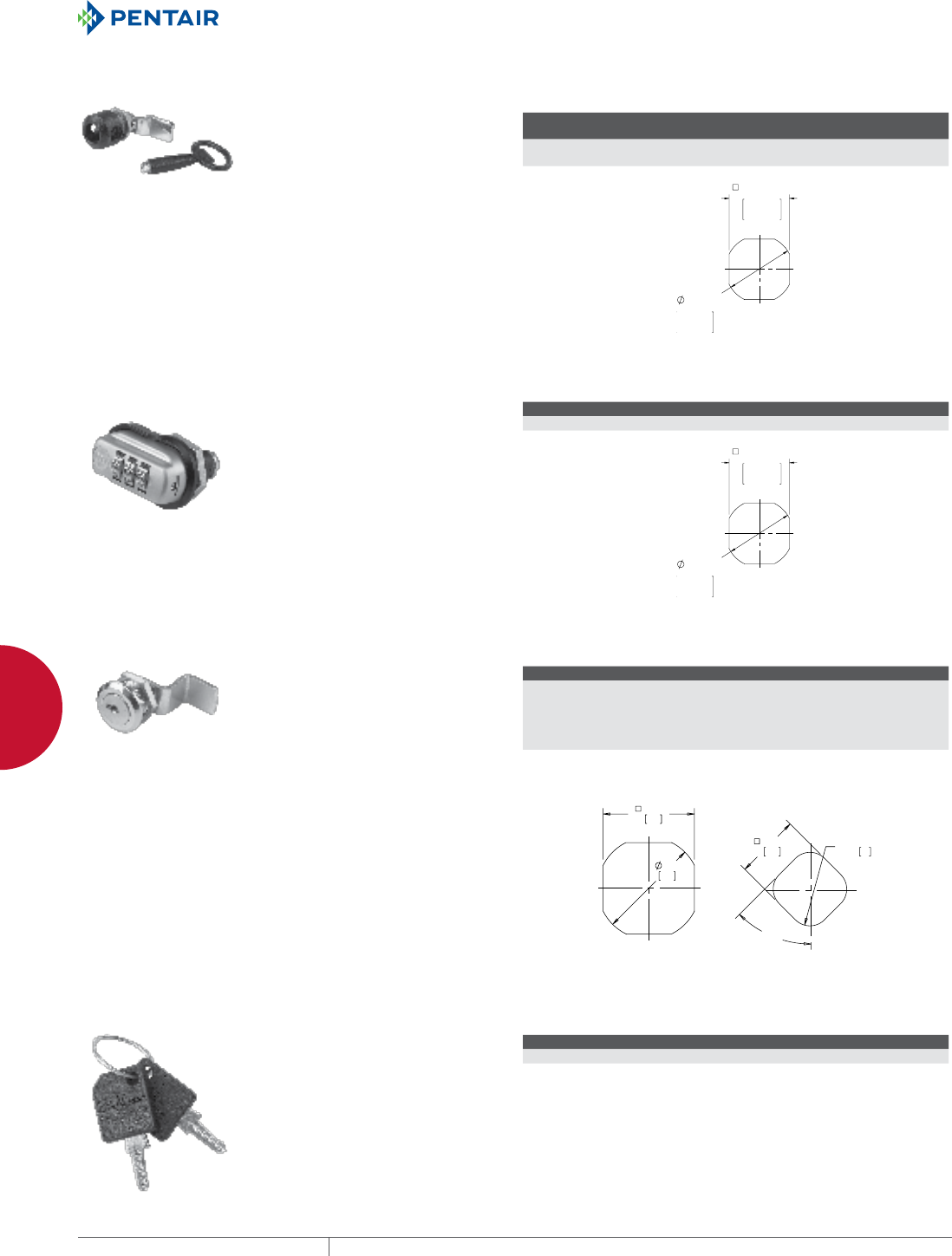
EQUIPMENT PROTECTIONSUBJECT TO CHANGE WITHOUT NOTICENETWORKING264
10
ACCESSORIES HANDLES, LATCHES AND LOCKS
PADLOCKING QUARTERTURN LATCH
Quarter-Turn Latch requires Allen
wrench, included with lock, to open
or close cabinet. Padlock can be
added for extra security. Install
using existing enclosure cam.
Maintains cabinet rating Type 3R,
4, 12.
BULLETIN: DCOMY
Catalog
Number Description Use with
EPL4 Padlocking Quarter-Turn
Latch
ACCESSPLUS™ II, L-BOX™ , D-BOX™ , COMLINE™ ,
PROTEK™
3DIGIT COMBINATION LOCK
3-Digit Combination Lock in handle
eliminates the need to carry around
a key. Combination can easily be
changed. A quarter turn of the
handle opens and closes the cabinet.
Lock has silver and black finish.
Install using existing enclosure cam.
Maintains cabinet rating Type 12.
Do not use in severe environments
such as corrosive, very wet, salt
spray or mist.
BULLETIN: DWS12
Catalog Number Description Use with
PTLCMB3B Combination Lock ACCESSPLUS™ II, L-BOX™ , D-BOX™ , COMLINE™ , PROTEK™
QUARTERTURN LOCK
Quarter-turn keylock includes one
key. Install using existing enclosure
cam on DKL2233.
BULLETIN: DACCY, DPC
Catalog Number Description Use with Hole Size Key Code
PSCLO Quarter-turn
keylock
Side panels on PROLINE™ ,
Net Series, SOHO and
Seismic cabinets;
side panels and keyboard
on PC cabinets
B
(see dimension
drawing)
2233
DKL2233 Quarter-turn
keylock
ACCESSPLUS™ II, L-BOX™ , D-BOX™ A
(see dimension
drawing)
2233
;
5
$%
REPLACEMENT KEYS
Fits PROLINE™ Network Cabinet
and Networking Wall-Mount
Cabinet.
BULLETIN: DACCY
Catalog Number Key Code Includes Use with
E2233KEY 2233 2 Keys PROLINE™ , Net Series, PC Cabinet, SOHO
E333KEY 333 2 Keys ACCESSPLUS™ II, L-BOX™ , D-BOX™
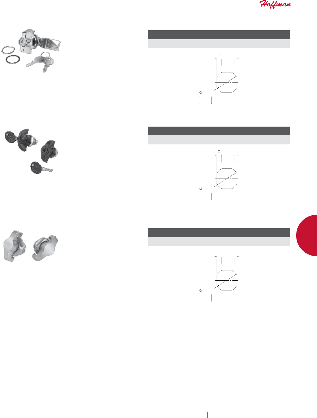
PH 763.422.2661 • FAX 763.422.2588 • PENTAIRPROTECT.COMEQUIPMENT PROTECTION NETWORKING 265
10
ACCESSORIES HANDLES, LATCHES AND LOCKS
KEYLOCKING WING KNOB
Locking wing nut position shows
whether door is locked. Wing nut has
silver finish. Includes 2 keys with
333 key code. Install using existing
enclosure cam. Maintains cabinet
rating Type 12.
BULLETIN: A80, DWS12
Catalog
Number Description Use with
DL36 Chrome Keylocking Wing
Knob
ACCESSPLUS™ II, L-BOX™ , D-BOX™ , COMLINE™ ,
PROTEK™
KEYLOCKING QUARTERTURN WING KNOB
Keylocking quarter-turn wing knob
latch. Black finish. Includes gasket,
mounting nut and one key with
333 key code. Use existing cam for
installation; cam is not included with
wing knob. Can be locked in open or
closed position. Maintains cabinet
rating Type 4, 12.
BULLETIN: DWS12
Catalog
Number Description Use with
PTWK Keylocking wing knob, quarter-
turn
ACCESSPLUS™ , COMLINE™ , PROTEK™ , L-BOX™ ,
D-BOX™
PADLOCKING WING KNOB, STAINLESS STEEL
Padlocking quarter-turn wing knob
is made of Type 304 stainless steel.
When the padlock is in place, the
wing knob cannot be rotated and
the cabinet is secured. The wing
knob has a brushed bright finish.
Maximum padlock diameter is
.31 (8mm). Use existing cam for
installation; cam is not included with
wing knob. It maintains the cabinet
rating Type 3R, 4, 4X, 12.
BULLETIN: DWS12
Catalog
Number Description Use with
PTWPSS Padlocking wing knob, quarter-
turn
ACCESSPLUS™ , COMLINE™ , PROTEK™ , L-BOX™ ,
D-BOX™
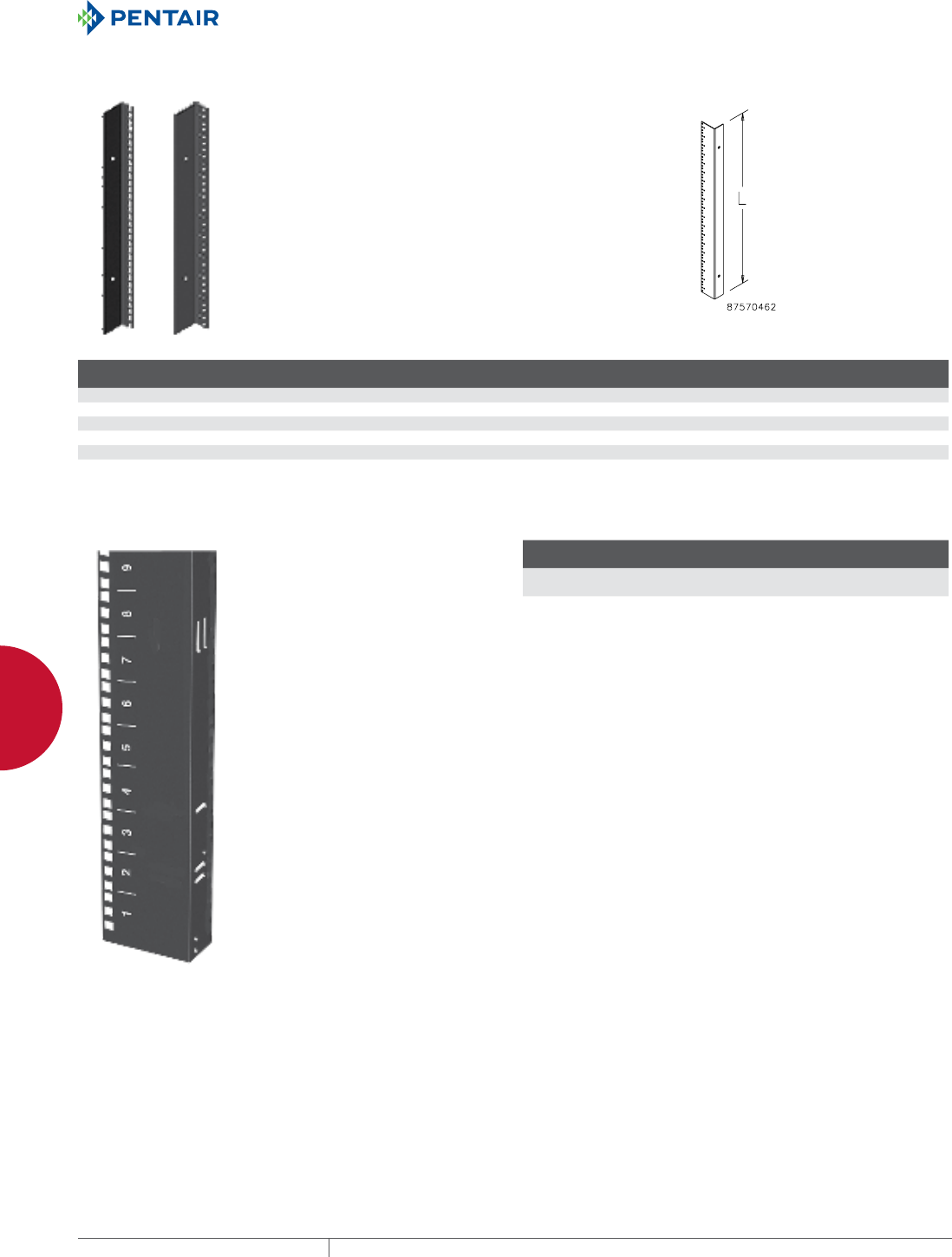
EQUIPMENT PROTECTIONSUBJECT TO CHANGE WITHOUT NOTICENETWORKING266
10
ACCESSORIES GENERAL ACCESSORIES
GENERAL ACCESSORIES
19IN. AND 23IN. RACK ANGLES
Made of 14 gauge steel with square
holes or 12 gauge steel with 10-32
tapped holes. Provides 19- or 23-in.
rack spacing depending on frame
width. Finished with flat black RAL
9005 polyester powder paint or
plated. Furnished in pairs.
BULLETIN: DNCY, DWDH1
Catalog Number Rack Spacing Hole Type Finish Use With
Fits Frame
Height
Fits Frame
Width
Rack
Units L (mm) L (in.)
ERA197THLN 19 in. Square Black Networking Cabinet - SOHO 700mm 600mm 11 492 19.38
ERA197TPLN 19 in. Tapped Black Networking Cabinet - SOHO 700mm 600mm 11 492 19.38
ERA1921TPL 19 in. Tapped Black Seismic Cabinet 2100mm 700mm 45 2003 78.87
ERA192321TPL 19 & 23 in. Tapped Black Seismic Cabinet 2100mm 800mm 45 2003 78.87
ERA1910TPL 19 in. Tapped Black Network PC Cabinet Bottom Section — 19 848 33.37
RACK UNIT LABEL
Self-adhesive clear Mylar™ label
with white numbers enables
numbering along sides of open
frame racks or rack angles.
Numbers spaced one rack unit
apart. Can be used for bottom-up or
top-down numbering of rack units
to simplify equipment installation.
Each label provided in two pieces
(numbers 1-29 and 30-58) for easier
installation. Two labels per catalog
number. Label shown mounted on
rack angle.
Mylar is a registered trademark of
DuPont Tejin Films.
BULLETIN: DOFRY
Catalog Number
Installed Length
in./mm
Width
in./mm
ARULABEL 101.50
2578
.50
13
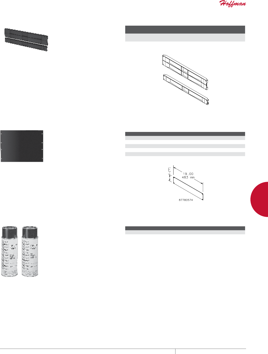
PH 763.422.2661 • FAX 763.422.2588 • PENTAIRPROTECT.COMEQUIPMENT PROTECTION NETWORKING 267
10
ACCESSORIES GENERAL ACCESSORIES
TOOLLESS (SNAPIN) BLANKING PANELS FOR 19IN. RACKS
These Tool-less 19-in. Blanking
Panels provide easy tool-less
installation and ensure proper
airflow to equipment. Made of black
composite material and can be used
with tapped or square EIA universal
spaced rack mounting angles.
BULLETIN: DACCY
Catalog Number Description
Rack
Units Fits
Pkg.
Qty.
D19BPT1RU Blanking Panel, 19 in. 1 19 in., universal rack spacing,
tapped or square holes
10
D19BPT2RU Blanking Panel, 19 in. 2 19 in., universal rack spacing,
tapped or square holes
10
RACK PANEL FOR 19IN. RACKS
Used to cover unused rack space
in cabinets or open frame racks
for a finished appearance. Can
also be used for surface mounting
small devices. Panels are flat with
mounting slots spaced at 19-in. EIA
standard spacing. Made of 12 gauge
steel with RAL 9005 black polyester
powder paint finish. Mounting
hardware sold separately.
BULLETIN: DOFRY
Catalog Number Rack Units E (in.) E (mm)
P19RPP1UB 1 1.75 44
P19RPP2UB 2 3.50 89
P19RPP3UB 3 5.25 133
P19RPP4UB 4 7.00 178
P19RPP5UB 5 8.75 222
P19RPP6UB 6 10.50 267
TOUCHUP PAINT
For repairing the finish of any
painted parts.
BULLETIN: DACCY, P20
Catalog Number Description
ATPG7035 RAL 7035 Gray
ATPB9005 RAL 9005 Black

EQUIPMENT PROTECTIONSUBJECT TO CHANGE WITHOUT NOTICENETWORKING268
11
763.422.2661
763.422.2588
NETWORKING
TECHNICAL INFORMATION
Intro Page
CHAPTER 11
TECHNICAL INFORMATION
COOLING
Effective cooling maximizes the
efficiency and lifecycle of electrical
components. While it is critical to
dissipate and manage heat build-up, it
can also be necessary to add heat.
SOLAR HEAT GAIN
Solar heat gain can affect the cooling
needs of outdoor electrical enclosures.
Factors such as solar exposure,
enclosure color and material type
can impact the enclosure’s internal
temperature.
OVERVIEW

PH 763.422.2661 • FAX 763.422.2588 • PENTAIRPROTECT.COMEQUIPMENT PROTECTION NETWORKING 269
Intro Page CHAPTER CONTENTS
COOLING
How to Dissipate Excess Heat - Understanding T and CFM ..........270
T ......................................................270
CFM ....................................................271
SOLAR HEAT GAIN
Solar Heat Gain ............................................272
Exposure to Solar Radiation ..................................272
Effect of Surrounding Location ................................272
Effect of Enclosure Color and Finish ............................272
Standardized Test Evaluation .................................272
Evaluation of Solar Heat Gain .................................272
The Benefits of Shielding Enclosures ...........................273
STANDARDS
Standards Organization Summary and Directory Overview ...........274
CE ......................................................274
Enclosure Type Rating vs. IP Rating ............................274
NEMA, UL and CSA Ratings ...................................275
IP Rating Descriptions ......................................275
11
STANDARDS
It is important to select an enclosure
that has the appropriate rating for the
specified environment and application.
Rating systems from UL, NEMA, CSA,
IEC and VDE determine an enclosure’s
ability to withstand environmental
conditions.
EQUIPMENT PROTECTIONSUBJECT TO CHANGE WITHOUT NOTICENETWORKING270
11
TECHNICAL INFORMATION COOLING
COOLING
HOW TO DISSIPATE EXCESS HEAT UNDERSTANDING T AND CFM
Factors in this equation will need to be de-rated for high elevations.
Watts = .316 x CFM x 'T
or
CFM = Watts / (.316 x 'T)
or
'T = (.315 x CFM) / Watts
When it comes to cooling a data center, one equation is key
Cooling network equipment requires both cold intake air and airflow (CFM). These two factors work directly to dissipate, or carry away,
the heat that network equipment produces. While increasing either factor will increase the amount of heat that is dissipated, there are
limits to both. Air that is too cold results in cooling expansion and condensation issues. Airflow that is too high results in acoustic and
physical limitations. A cooling system that relies on too much of only one of these factors usually results in higher capital and operating
costs. Finding an ideal balance between cold air and airflow allows optimal heat dissipation, protecting network equipment from the
consequences of overheating.
T
In the above equations, T, measured in degrees Fahrenheit, refers to the difference between the intake air and exhaust air, or the amount
of heat that is carried away by the stream of air exiting the heat load. A greater temperature difference signifies more heat being removed.
While it is difficult to constantly deliver the coldest air to all equipment—in particular, equipment installed in upper rack units—data
centers that maintain a range between 10 and 30 F T carry a high level of confidence that equipment will dissipate the amount of heat that
it produces, staying within its cooling limits.
• The area between 10 and 30 degrees T represents capable cooling in a typical well-designed data center.
• Knowing two of the three quantities allows operators to solve for the third—in this equation, knowing either watts or CFM solves for T.
For example, 9000 W in a data center with a T of 20 degrees requires 1425 CFM.
More than 30 degrees ΔT can cause humidity and condensation issues.
30˚∆T
25,000
20,000
15,000
10,000
5,000
0
Watts = .316 x CFM x ∆T (˚F)
0
200
400
600
800
1,000
1,200
1,400
1,600
1,800
2,000
2,200
2,400
CFM
Watts
10
20
30
10˚∆T
20˚∆T
PH 763.422.2661 • FAX 763.422.2588 • PENTAIRPROTECT.COMEQUIPMENT PROTECTION NETWORKING 271
11
TECHNICAL INFORMATION COOLING
CFM
Another way to increase the amount of heat dissipated or removed from network equipment is by increasing the airflow, expressed in
cubic feet per minute (CFM). An increase of CFM—the amount of airflow across a given area in a given time—results in increased heat
removal.
CFM can be achieved through the use of fans. The larger the fan, the more CFM it provides. An increase in RPM (the speed at which the
fan circulates) as well as the size or quantity of fan blades results in a higher CFM, but as these factors increase, so do several others that
can be detrimental to the equipment in data centers. For example, acoustic noise is one consequence of high levels of CFM. Additionally, at
very high CFM, physical forces also come into play that can cause damage to electrical equipment. Plus the higher the CFM, the higher the
upfront capital costs, as well as ongoing operational expenses.
• Most data centers operate between 10 and 20 T. Using this and the CFM of the fan, the necessary quantity of cooling (watts) can be
determined.
• The same equation also works for equipment outside the data center. Again, the intake air can only be so cold and at a certain CFM
before other issues arise.
• The bigger the fan, the more airflow that moves across equipment. The amount of airflow and the temperature of the air determine the
amount of heat dissipation that can occur.
• CFMin = CFMout on all passive systems.
• Total CFMin = the sum of all equipment (servers) mounted in the cabinet.
An increase in fan size will increase acoustic noise at the same motor RPM.
30˚∆T
10˚∆T
20˚∆T
4" Fan
Quiet
4" Fan
6" Fan
10" Fan
10
20
30
6000
5500
5000
4500
4000
3500
3000
2500
2000
1500
1000
500
0
4", 6", & 10" Cooling Fan Performance
0
25
50
75
100
125
150
175
200
225
250
275
300
325
350
375
400
425
450
475
500
525
550
575
600
CFM
Watts
EQUIPMENT PROTECTIONSUBJECT TO CHANGE WITHOUT NOTICENETWORKING272
11
TECHNICAL INFORMATION SOLAR HEAT GAIN
SOLAR HEAT GAI N
SOLAR HEAT GAIN
When evaluating the cooling needs of outdoor electrical enclosures, solar heat gain must be considered. Variables that affect the
enclosure’s internal temperature rise include the amount of solar exposure, enclosure color and material type, highest sustained
atmospheric temperature, heat build-up from internal components and heat reflectance from the surrounding environment.
EXPOSURE TO SOLAR RADIATION
Over much of the United States, the approximate peak values of solar radiation striking the Earth’s surface is 97 W/ft.2 and the ambient
air temperature can reach 104 F. Altitude, humidity and air pollution have an impact on these values, even more so than the location’s
latitude. In the high, dry climates of the southwest, solar radiation values of 111 W/ft.2 and air temperatures greater than 104 F can be
reached.
The extreme conditions the enclosure will be exposed to should be identified. If the internal enclosure temperature is greater than the
outdoor (ambient) temperature, wind will provide greater heat transfer and thus cool the enclosure. But, because the presence of wind
cannot be guaranteed, it is usually not taken into account when establishing a worst-case evaluation.
EFFECT OF SURROUNDING LOCATION
Reflection of solar energy from the foreground and surrounding surfaces can impact the total amount of radiant exposure by as much as
30 percent.
EFFECT OF ENCLOSURE COLOR AND FINISH
The percent of solar energy absorbed by the enclosure depends on surface color, finish and texture. Absorption values of the finish will
increase with age.
STANDARDIZED TEST EVALUATION
Telcordia NEBS™ GR-487 provides a test procedure for evaluating the solar load on electrical/electronic enclosures. The test is run
with the internal electronics on, in an environmentally controlled room, and three sides of the enclosure are illuminated uniformly with
controlled banks of lights to a measured surface radiant value of 70 W/ft.2 The temperature rise inside the enclosure above ambient is
added to 115 F (46 C). This temperature total must not exceed the lowest-rated component within the enclosure.
EVALUATION OF SOLAR HEAT GAIN
To evaluate the heat load on an enclosure, you must take into
account:
• Total surface area of the enclosure
• Color of the enclosure
• Internal heat load
• Maximum allowable internal temperature
• Maximum ambient temperature
• Solar load
Examples:
1. What amount of heat energy must be removed from a 24
x 20 x 12 (surface area = 14 ft.2) ANSI 61 gray enclosure
located outdoors without any heat dissipated internally, to
maintain the enclosure temperature equal to the ambient
(temperature rise = 0 degrees)? From the chart below, at 0 F
temperature rise we find the solar load is approximately 14
W/ft.2 (14 ft.2 x 14 W/ft.2 = 196 W). This is the heat energy that
must be removed to maintain the enclosure temperature at
ambient.
2. If the same enclosure has internal equipment dissipating
200 W of heat, what is the amount of heat energy that must
be removed to maintain the enclosure at a temperature rise
of 20F above the ambient temperature? From the chart
below, at 20 F temperature rise we find the solar load is
approximately 6 W/ft.2 (14 ft.2 x 6 W/ft.2 = 84 W). All of the
internally dissipated heat of 200 W must also be removed.
84 W + 200 W = 284 W. This is the total amount of heat
energy that must be removed to maintain the enclosure at
20F above the ambient temperature.
3. What is the expected temperature rise above the ambient
temperature due to solar heat gain for an enclosure with
ANSI 61 gray finish? From the chart below, the temperature
rise due to solar heat load can be found by locating the
intersection of the data curve for the given finish and the
0 Solar Generated Heat Load axis. For ANSI 61 Gray, the
temperature rise due to solar heat is about 40 F.
Black
Gray
Light Color
White
Metallic
Solar Load Based on Color and Temperature Rise
0
10
20
30
40
50
∆T (Internal Temp. - Ambient Temp.) °F
Solar Load (watts/ft2)
5 10 20
30
15 25
PH 763.422.2661 • FAX 763.422.2588 • PENTAIRPROTECT.COMEQUIPMENT PROTECTION NETWORKING 273
11
TECHNICAL INFORMATION SOLAR HEAT GAIN
THE BENEFITS OF SHIELDING ENCLOSURES
Hoffman’s research on the effects of solar radiation on enclosures
has shown the positive benefits of utilizing shielding to decrease
temperature rise. Shielding has been found to be an effective, low-
cost method of reducing solar heat gain in outdoor
electrical/electronic applications.
A test to compare the shielding effect on internal temperature rise was
performed on similar enclosures exposed to the sun. The enclosures
are the same color (RAL 7035 light gray) and material. The enclosure on
the left is unshielded; the enclosure on the right is shielded on top and
applicable sides.
The results of the test show the enclosure with top and side shields
to have approximately a 46 percent reduction in temperature
compared to the unshielded enclosure. The reduction in temperature
is approximately 25 percent with the solar top shield only. Hoffman
offers top shields as an accessory for Hoffman COMLINE™ Wall-Mount
Enclosures. Hoffman can provide side shields as a customer-ordered
modification.
Outside Temperature
Top and Side Shield
Shielding Eectiveness
No Shield
Side Shield
75
85
95
105
115
3:00 a.m. 7:00 a.m. Noon 4:30 p.m.
July 29, 1999
Temperature (°F)
Enclosure Type Temperature (F) Temperature (C) Percent Temperature Reduction
Unshielded 119 48 —
Top shield only 114 46 25
Top and side shields 110 43 46

EQUIPMENT PROTECTIONSUBJECT TO CHANGE WITHOUT NOTICENETWORKING274
11
TECHNICAL INFORMATION STANDARDS
STANDARDS
STANDARDS ORGANIZATION SUMMARY AND DIRECTORY OVERVIEW
What’s in a Rating?
As a way of standardizing enclosure performance, organizations
like NEMA, UL, CSA, IEC and VDE use rating systems to identify
an enclosure’s ability to resist external environmental influences.
Resistance to everything from dripping liquid to hose-down to total
submersion is defined by the ratings systems. While these ratings
are all intended to provide information to help you make a safer,
more-informed product choice, there are differences among them.
North American Standards Organizations
In North America, NEMA, UL and CSA are the commonly recognized
standards organizations. Their ratings are based on similar
application descriptions and expected performance. UL and CSA
both require enclosure testing by qualified evaluators in their
certified labs. They also send site inspectors to make sure a
manufacturer adheres to prescribed manufacturing methods and
material specifications. NEMA, on the other hand, does not require
independent testing and leaves compliance completely up to the
manufacturer.
North American enclosure rating systems also include a 4X rating
that indicates corrosion resistance. This rating is based on the
enclosure’s ability to withstand prolonged exposure to salt water
spray.
While a 4X rating is a good indicator that an enclosure can resist
corrosion, it does not provide information on how a specific
corrosive agent will affect a given enclosure material. It is best to
conduct a full analysis of the specific application and environment to
determine the best enclosure choice.
International Standards Organizations
Like NEMA, IEC does not require independent testing and leaves
compliance completely up to the manufacturer. Nevertheless, there
are differences in how enclosure performance is interpreted. For
example, UL and CSA test requirements specify that an enclosure
fails the water-tight test if even a single drop of water enters the
enclosure. In the IEC standards for each level of ingress protection
(IP), a certain amount of water is allowed to enter the enclosure.
IEC 60529 IP ratings do not specify construction requirements
or degrees of protection against corrosive atmospheres, risk of
explosion or conditions such as moisture or corrosive vapors.
NEMA Type ratings, on the other hand, do specify construction and
performance requirements for most environmental conditions.
For this reason, and because the tests and evaluations for other
characteristics are not identical, the IEC enclosure classification
designations cannot be exactly equated with NEMA enclosure Type
numbers.
CE
For industrial control equipment, the CE Mark is not intended to be applied to empty enclosures because such enclosures are inactive
components of a final assembly. The responsibility of ensuring compliance with all applicable EU directives and harmonized standards
belongs with the final equipment manufacturer.
ENCLOSURE TYPE RATING VS. IP RATING
Electrical enclosures are rated by Type (NEMA 250 / UL 50, 50E),
and/or IP rating (IEC 60529) based upon the degree of protection
provided. Type ratings and IP ratings have only the following in
common:
1. A degree of protection for persons from hazardous
components inside the enclosure
2. A degree of protection for equipment inside the enclosure
from ingress of solid foreign objects, including dust
3. A degree of protection for equipment inside the enclosure
from ingress of water
NEMA 250 and UL 50, 50E Type rating documentation defines
additional requirements that a Type-rated enclosure must meet.
These include:
• Mechanical impact on enclosure walls
• Gasket aging and oil resistance
• Corrosion resistance
• Door and cover latching requirements
• Sheet metal gauge construction requirements (UL 50 only)
Electrical enclosures that carry only an IP rating have not been
designed or tested to the additional Type-rating requirements.
For this reason, and because the tests and evaluations for other
characteristics are not identical, the IP ratings cannot be exactly
equated with NEMA enclosure Types.
Electrical enclosures manufactured by Hoffman are tested for and
carry both Type and IP ratings.
Fluid Statics and Dynamic Comparison of Ingress Water Tests
Test Type
Flow Rate
(gal./min.)
Flow Rate
(l/min.)
Nozzle
Diameter
in./mm
Nozzle
Area
(in.2)
Nozzle
Velocity (ft./sec.)
Equivalent
Head (ft.)
Equivalent
Pressure (psi)
Mass
Flow (lb./sec.)
Power
(hp)
Total Force
on Vertical
Plate (lb.)
Type 3 45.00 170 1.0000
25.4
0.7854 18.38 5.25 2.274 6.256 0.060 3.5716
Type 4 65.00 246 1.000
25.4
0.7854 26.55 10.85 4.744 9.037 0.180 7.4516
IPX5 3.30 12.5 0.2480
6.3
0.0483 21.93 7.46 3.235 0.459 0.006 0.3126
IPX6 26.42 100 0.4921
12.5
0.1902 44.55 30.82 13.357 3.672 0.206 5.0815

PH 763.422.2661 • FAX 763.422.2588 • PENTAIRPROTECT.COMEQUIPMENT PROTECTION NETWORKING 275
11
TECHNICAL INFORMATION STANDARDS
NEMA, UL AND CSA RATINGS
Enclosure Type Descriptions for Non-Hazardous Locations
Enclosure
Type NEMA UL CSA
Indoor Type 1 Enclosures are intended for indoor use primarily
to provide a degree of protection against contact
with the enclosed equipment or locations where
unusual service conditions do not exist.
Indoor use primarily to provide protection against
contact with the enclosed equipment and against
a limited amount of falling dirt.
General purpose enclosure. Protects against
accidental contact with live parts.
Indoor Type 12 Enclosures are intended for indoor use primarily to
provide a degree of protection against dust, falling
dirt and dripping noncorrosive liquids.
Indoor use to provide a degree of protection against
dust, dirt, fiber flyings, dripping water and external
condensation of noncorrosive liquids.
Indoor use; provides a degree of protection against circulating
dust, lint, fibers and flyings; dripping and light splashing of
non-corrosive liquids; not provided with knockouts.
Indoor Type 12K Enclosures with knockouts are intended for indoor
use primarily to provide a degree of protection against
dust, falling dirt and dripping noncorrosive liquids.
Indoor use to provide a degree of protection against
dust, dirt, fiber flyings, dripping water and external
condensation of noncorrosive liquids.
Indoor use: provides a degree of protection against circulating
dust, lint, fibers and flyings; dripping and light splashing
of noncorrosive liquids; not provided with knockouts.
Indoor Type 13 Enclosures are intended for indoor use primarily to
provide a degree of protection against dust, spraying
of water, oil and noncorrosive coolant.
Indoor use to provide a degree of protection against
lint, dust seepage, external condensation and
spraying of water, oil and noncorrosive liquids.
Indoor use; provides a degree of protection against circulating
dust, lint, fibers and flyings; seepage and spraying of
non-corrosive liquids, including oils and coolants.
Outdoor Type 3 Enclosures are intended for outdoor use primarily to
provide a degree of protection against windblown dust, rain
and sleet; undamaged by the formation of ice on the enclosure.
Outdoor use to provide a degree of protection against
windblown dust and windblown rain; undamaged by
the formation of ice on the enclosure.
Indoor or outdoor use; provides a degree of protection against
rain, snow and windblown dust; undamaged by the external
formation of ice on the enclosure.
Outdoor Type 3R Enclosures are intended for outdoor use primarily to provide a
degree of protection against falling rain and sleet; undamaged
by the formation of ice on the enclosure.
Outdoor use to provide a degree of protection against
falling rain; undamaged by the formation of ice
on the enclosure.
Indoor or outdoor use; provides a degree of protection against
rain and snow; undamaged by the external formation
of ice on the enclosure.
Outdoor Type 3RX Enclosures are intended for outdoor use primarily to
provide a degree of protection against corrosion, falling rain
and sleet; undamaged by the formation of ice on the enclosure.
Not specifically defined. Not specifically defined.
Outdoor Type 4 Enclosures are intended for indoor or outdoor use primarily
to provide a degree of protection against windblown dust
and rain, splashing water and hose directed water;
undamaged by the formation of ice on the enclosure.
Either indoor or outdoor use to provide a degree
of protection against falling rain, splashing water
and hose-directed water; undamaged by the
formation of ice on the enclosure.
Indoor or outdoor use; provides a degree of protection against
rain, snow, windblown dust, splashing and hose-directed
water; undamaged by the external formation of ice on the
enclosure.
Outdoor Type 4X Enclosures are intended for indoor or outdoor use primarily
to provide a degree of protection against corrosion,
windblown dust and rain, splashing water and hose-directed
water; undamaged by the formation of ice on the enclosure.
Either indoor or outdoor use to provide a degree of
protection against falling rain, splashing water and
hose-directed water; undamaged by the formation
of ice on the enclosure; resists corrosion.
Indoor or outdoor use; provides a degree of protection against rain,
snow, windblown dust, splashing and hose-directed water;
undamaged by the external formation of ice on the enclosure;
resists corrosion.
Outdoor Type 6 Enclosures are intended for use indoors or outdoors where
occasional submersion is encountered; limited depth;
undamaged by the formation of ice on the enclosure.
Indoor or outdoor use to provide a degree of protection
against entry of water during temporary submersion at
a limited depth; undamaged by the external formation
of ice on the enclosure.
Indoor or outdoor use; provides a degree of protection against
the entry of water during temporary submersion at a limited
depth. Undamaged by the external formation of ice on the
enclosure; resists corrosion.
This material is reproduced with permission from NEMA. The preceding descriptions, however, are not intended to be complete representations of National Electrical Manufacturers Association standards
for enclosures nor those of the Electrical and Electronic Manufacturers Association of Canada.
This material is reproduced with permission from Underwriters Laboratories Inc. Enclosures for Electrical Equipment, UL 50, 50E and Industrial Control Panels, UL 508A.
This material is reproduced with permission from the Canadian Standards Association.
Underwriters Laboratories Inc. (UL) shall not be responsible for the use of or reliance upon a UL Standard by anyone. UL shall not incur any obligation or liability for damages, including consequential damages,
arising out of or in connection with the use, interpretation of, or reliance upon a UL Standard.
IP RATING DESCRIPTIONS
Example Rating
If 1st IP number is... and the 2nd ip number is... Then the IP rating is
2 3 IP 2 3
(protection against solid objects) (protection against liquids) An enclosure with this designation provides protection against touch with a finger, penetration of solid objects greater than 12mm, and spraying water.
First Numeral (Solid Objects and Dust)
IP Protection of Persons Protection of Equipment
0No Protection No Protection
1Protected against contact with large areas of the body (back of hand) Protected against objects over 50 mm in diameter
2Protected against contact with fingers Protected against solid objects over 12 mm in diameter
3Protected against tools and wires over 2.5 mm in diameter Protected against solid objects over 2.5 mm in diameter
4Protected against tools and wires over 1 mm in diameter Protected against solid objects over 1 mm in diameter
5Protected against tools and wires over 1 mm in diameter Protected against dust (limited ingress, no harmful deposit)
6Protected against tools and wires over 1 mm in diameter Totally protected against dust
Second Numeral (Liquid)
IP Protection of Equipment
0No Protection
1Protected against vertically falling drops of water, e.g. condensation
2Protected against direct sprays of water up to 15 degrees from vertical
3Protected against sprays to 60 degrees from vertical
4Protected against water sprayed from all directions (limited ingress permitted)
5Protected against low-pressure jets of water from all directions (limited ingress permitted)
6Protected against strong jets of water
7Protected against the effects of immersion between 15 cm and 1 m
8Protected against long periods of immersion under pressure

12
BULLETIN NUMBER INDEX
EQUIPMENT PROTECTIONSUBJECT TO CHANGE WITHOUT NOTICEINDEX276
Bulletin
Number
Catalog
Page
Bulletin
Number
Catalog
Page
Bulletin
Number
Catalog
Page
INDEX
INDEX
B
Bulletin Number Index
A48Y ....................................... 151, 152
A80 ............... 59, 151, 229, 234, 237, 261, 241, 265, 237
A80LT ........................... 256, 257, 258, 259, 260
CWP ........................................... 136
CWY ....................................... 229, 261
D85 ................... 49, 158, 215, 217, 218, 219, 222, 223
DACCY .................... 11, 84, 57, 59, 61, 229, 252, 234,
85, 261, 241, 267, 161, 262, 264, 12, 264, 74, 81, 54, 82, 83, 248,
249, 211, 250, 212, 251, 253, 100, 83, 237, 85, 262, 158
DBG ................................ 184, 195, 196, 197
DC .............................................. 6
DCOM ................................... 226, 230, 235
DCOMY ........... 228, 229, 233, 234, 235, 237, 263, 264, 237
DCR ..................... 179, 180, 181, 182, 183, 184, 185
DCY .................................... 10, 11, 263, 12
DEC1 ............................ 160, 161, 162, 163, 164
DMAX ..................................... 92, 96, 98
DNC ............................................ 71
DNCS .................................. 68, 70, 71, 202
DNCY. . . . . . . . . . . . . . . . . . . . . . . . . . . . . . . . . . . . . 266, 71, 203
DOFR2 ...................................... 183, 92
DOFR4 .......................................... 94
DOFRC ..................................... 249, 250
DOFRS ..................................... 204, 206
DOFRW ................... 168, 169, 170, 171, 172, 173, 185
DOFRY ... 76, 78, 80, 99, 100, 266, 267, 80, 99, 81, 82, 83, 99, 174,
100
DPC ........................ 264, 38, 42, 47, 48, 49, 64, 62
DPMC .......................................... 242
DPS ......................................... 86, 87
DPSR .......................... 18, 20, 22, 28, 38, 42, 46
DPVD ..................................... 24, 30, 32
DPY ... 14, 16, 17, 87, 50, 51, 52, 53, 54, 55, 58, 60, 61, 62, 63, 65,
64, 203
DQT .......................... 186, 188, 189, 190, 191, 192
DTHRM ............. 217, 140, 144, 217, 64, 213, 214, 216, 66
DTX ...................................... 84, 238, 241
DWDH1 .............................. 106, 110, 266, 110
DWDH2 .................................. 120, 132, 136
DWS1 ................ 217, 138, 140, 141, 142, 144, 145, 158
DWS12 229, 112, 234, 264, 265, 128, 146, 150, 237, 152, 153, 155
MCL ............................................ 41
P20 . 253, 260, 262, 267, 56, 57, 58, 59, 60, 61, 62, 63, 65, 67, 254,
65, 66, 67
P20EM ....................................... 56, 66
P9 .............................................. 58
PCRY .................................... 147, 148, 149
PNLJ ........................................... 152
PNLWM ..................................... 152, 155
UX1Y .................................... 155, 156, 157
X20 ....................... 59, 161, 229, 234, 261, 241, 237

12
CATALOG NUMBER INDEX
PH 763.422.2661 • FAX 763.422.2588 • PENTAIRPROTECT.COMEQUIPMENT PROTECTION INDEX 277
Catalog
Number UPC Bulletin
Number
Catalog
Page
Catalog
Number UPC Bulletin
Number
Catalog
Page
Catalog
Number UPC Bulletin
Number
Catalog
Page
C
Catalog Number Index
A10AXFN2 ..........22140 ......D85 .......... 215, 216
A10AXFN ...........22230 ......D85 .......... 215, 216
A10AXFNPG .........50449 ......D85 .......... 215, 216
A10SPK8C ..........34920 ......A48Y ............. 152
A1010PSWPNL.......17103 ......PCRY ............. 148
A108PSWPNL........17102 ......PCRY ............. 148
A12SPK10C .........34930 ......A48Y ............. 152
A1210PSWPNL.......17104 ......PCRY ............. 148
A14SPK12C .........34940 ......A48Y ............. 152
A1412PSWPNL.......17105 ......PCRY ............. 148
A16P14 ............54810 ......PNLJ ............. 152
A16P14WD..........15288 ......DWS12 ........... 152
A16SPK14C .........34950 ......A48Y ............. 152
A1614PSWPNL.......17106 ......PCRY ............. 148
A18P16 ............58480 ......PNLWM ........... 152
A18P16WD..........15291 ......DWS12 ........... 152
A18SPK16C .........34960 ......A48Y ............. 152
A1816PSWPNL.......17107 ......PCRY ............. 148
A19ESOK ...........13763 ......DOFRY ............ 100
A19FANSC ..........14073 ......DTHRM ........... 214
A19FT3B ...........13855 ......DTHRM ........... 213
A19FT6B ...........13856 ......DTHRM ........... 213
A19KBC2B ..........13764 ......DACCY ............ 252
A19MB1000 .........13774 ......DOFRY ............. 99
A19MB600 ..........13772 ......DOFRY ............. 99
A19PSMB...........10244 ......DPS ............... 87
A2AXFN24 ..........17393 ......D85 .......... 215, 216
A24P24 ............23180 ......PNLWM ........... 155
A24P24WD..........15292 ......DWS12 ........... 155
A3AXFN ............17395 ......D85 .......... 215, 216
A3AXFN24 ..........17394 ......D85 .......... 215, 216
A4AXFN2 ...........22120 ......D85 .......... 215, 216
A4AXFN ............22210 ......D85 .......... 215, 216
A4AXFN24 ..........17391 ......D85 .......... 215, 216
A4AXFNGQ ..........13852 ......D85 ....... 158, 215, 216
A4AXFNPG ..........50429 ......D85 ........ 215, 216, 49
A6AXFN2 ...........22130 ......D85 .......... 215, 216
A6AXFN ............22220 ......D85 .......... 215, 216
A6AXFN24 ..........17392 ......D85 .......... 215, 216
A6AXFNGQ ..........13853 ......D85 .......... 215, 216
A6AXFNPG ..........50439 ......D85 .......... 215, 216
A6P6 ..............54760 ......PNLJ ............. 152
A6P6WD............15287 ......DWS12 ........... 152
A6SPK6C ...........34900 ......A48Y ............. 152
A64PSWPNL.........17096 ......PCRY ............. 148
A66PSWPNL.........17097 ......PCRY ............. 148
A8SPK6C ...........34910 ......A48Y ............. 152
A86PSWPNL.........17098 ......PCRY ............. 148
A88PSWPNL.........17101 ......PCRY ............. 148
ABRKT10 ...........71320 ...... D85 .............. 217
ABRKT2 ............17397 ...... D85 .............. 217
ABRKT3 ............17396 ...... D85 .............. 217
ABRKT4 ............71300 ...... D85 .............. 217
ABRKT6 ............71310 ...... D85 .............. 217
ACORD1 ............50499 ......DTHRM ........... 216
ACORD2 ............50509 ......DTHRM ........... 216
ACORD2T ...........23802 ......DTHRM ........... 217
AFANTSC ...........13857 ......DTHRM ........... 214
AFLTR10............21620 ......D85 .............. 222
AFLTR10AL..........51450 ......D85 .............. 222
AFLTR4.............21560 ......D85 .............. 222
AFLTR4AL...........51410 ......D85 .............. 222
AFLTR4LD...........14377 ...... DWS1 ..... 140, 144, 217
AFLTR6.............21570 ......D85 .............. 222
AFLTR6AL...........51420 ......D85 .............. 222
AFLTR6LD...........17424 ...... DTHRM .... 140, 144, 217
AGARD10 . . . . . . . . . . . 22200 ...... D85 .............. 217
AGARD2 ............17398 ...... D85 .............. 217
AGARD3 ............17401 ...... D85 .............. 217
AGARD4 ............22180 ...... D85 ........... 49, 217
AGARD6 ............22190 ...... D85 .............. 217
AHGCLP . . . . . . . . . . . .18702 ......PCRY ............. 149
AL48 ..............29770 ......A48Y ............. 151
ALFSWD............71260 ......A80LT ............ 260
AN1032 ............13090 ......A80 ... 229, 234, 237, 241
ANM5..............47680 ......A80 ... 229, 234, 237, 241
APE050 ............36670 ......A80 .............. 151
APE100 ............36680 ......A80 .............. 151
APNLBLK ...........17094 ......PCRY ............. 147
APOLYFT10..........17127 ......PCRY ............. 148
APOLYFT12..........17128 ......PCRY ............. 148
APOLYFT14..........17131 ......PCRY ............. 148
APOLYFT16..........17132 ......PCRY ............. 148
APOLYFT4...........17095 ......PCRY ............. 148
APOLYFT6...........17125 ......PCRY ............. 148
APOLYFT8...........17126 ......PCRY ............. 148
APSM6CN...........11256 ......DPY ............... 60
AQRLSS6 ...........17134 ...... PCRY ............. 148
ARULABEL ..........13761 ......DOFRY ............ 266
AS1032 ............13080 ...... A80 59, 229, 234, 261, 241,
237
AS1032B ...........15333 ...... DACCY . 59, 229, 234, 261,
241, 237
AS1032250..........10258 ......DACCY . 59, 229, 234, 261,
241, 237
ASM5..............47690 ...... X20 59, 161, 229, 234, 261,
241, 237
ASM5T.............17365 ......DACCY .. 59, 61, 229, 234,
261, 241, 237, 262
ASM6..............10256 ...... DACCY . 59, 229, 234, 261,
241, 237
ASM6250 ...........10257 ...... DACCY . 59, 229, 234, 261,
241, 237
ATEMNC............71160 ......D85 .............. 218
ATEMNO............71170 ......D85 .............. 218
ATPB9005 ..........10274 ......DACCY ............ 267
ATPG7035...........90740 ......P20 .............. 267
CMFK..............62490 ...... A80 ....... 234, 261, 237
CMFKSS............65750 ......A80 ....... 234, 261, 237
CMTGFT ............73370 ......A80 ....... 234, 261, 237
CP2014 ............15633 ......CWP ............. 136
CP2020 ............78550 ......CWP ............. 136
CP2442 ............78590 ......CWP ............. 136
CP3220 ............23782 ......DWDH2 ........... 136
CP4420 ............23783 ......DWDH2 ........... 136
CP5620 ............23784 ......DWDH2 ........... 136
CPMK12............79360 ......CWY ......... 229, 261
CPMK16............79430 ......CWY ......... 229, 261
CPMK20............79440 ......CWY ......... 229, 261
CPMK24............79450 ......CWY ......... 229, 261
CPMK30............79460 ......CWY ......... 229, 261
CR290216G002.......74260 ......MCL .............. 41
CR290226G002.......74270 ......MCL .............. 41
CR290416G002.......75610 ......MCL .............. 41
CR290426G002.......74290 ......MCL .............. 41
D16148CHSCFGP .....14963 ......DWS12 ........... 150
D16148CHSCFGWP....14964 ...... DWS12 ........... 150
D16148WF ..........18705 ......DWS12 ........... 147
D16148WFW ........18706 ......DWS12 ........... 147
D181610CHSCFGP ....14965 ......DWS12 ........... 150
D181610CHSCFGWP...14966 ......DWS12 ........... 150
D19BPT1RU .........16693 ...... DACCY ....... 11, 57, 267
D19BPT2RU .........16694 ...... DACCY ....... 11, 57, 267
D19FVT69B .........16687 ......DACCY ......... 12, 251
D19FVT69G .........16688 ......DACCY ......... 12, 251
D19FVT912B ........16691 ......DACCY ......... 12, 251
D19FVT912G.........16692 ......DACCY ......... 12, 251
D664CHSCFGP .......14961 ......DWS12 ........... 150
D664CHSCFGWP......14962 ...... DWS12 ........... 150
D664WF............18703 ......DWS12 ........... 147
D664WFW ..........18704 ......DWS12 ........... 147
DB24WMTK .........14394 ......DWS1 ........ 141, 145
DBDXK .............14378 ......DWS1 ........ 140, 144
DBERA4U ...........14536 ......DWS1 ............ 144
DBERA6U ...........14537 ......DWS1 ............ 144
DBGRDK............14393 ......DWS1 ........ 140, 144
DBL242412G ........14373 ......DWS1 ............ 138
DBL362412G ........14374 ......DWS1 ............ 138
DBL482412G ........14375 ......DWS1 ............ 138
DBPDLK ............14376 ......DWS1 ............ 144
DBPRA4U...........14538 ...... DWS1 ........ 140, 145
DBS242412G ........14366 ......DWS1 ............ 143
DBS24248G .........14365 ......DWS1 ............ 143
DBS362412G ........14368 ......DWS1 ............ 143
DBS36248G .........14367 ......DWS1 ............ 143
DBS482412G ........14372 ......DWS1 ............ 143
DBS48248G .........14371 ......DWS1 ............ 143
DBSHELF12 .........14535 ......DWS1 ........ 141, 145
DBSHELF8 ..........14534 ......DWS1 ........ 141, 145
DCHB1 .............17244 ......DACCY ............. 83

12
CATALOG NUMBER INDEX
EQUIPMENT PROTECTIONSUBJECT TO CHANGE WITHOUT NOTICEINDEX278
Catalog
Number UPC Bulletin
Number
Catalog
Page
Catalog
Number UPC Bulletin
Number
Catalog
Page
Catalog
Number UPC Bulletin
Number
Catalog
Page
DCHD2.............17243 ...... DACCY ............. 75
DCHS1 .............17241 ......DACCY ............. 75
DCHS2 .............17242 ......DACCY ............. 75
DCHS4 .............26292 ......DACCY ............. 75
DFB410F ...........18707 ......DACCY ........ 210, 211
DFB57F ............18708 ......DACCY ........ 210, 211
DFB66S ............18711 ......DACCY ........ 210, 212
DFBA1024F .........18715 ...... DACCY ........ 210, 212
DG19 ..............17266 ......DBG .............. 196
DG23 ..............17267 ......DBG .............. 196
DG36 ..............17268 ......DBG .............. 196
DG72 ..............17271 ......DBG .............. 196
DGCL201 ...........17256 ......DBG .............. 195
DGCL21 ............17254 ......DBG .............. 195
DGCL22 ............17255 ......DBG .............. 195
DGCL402 ...........17257 ......DBG .............. 195
DGCL61 ............17252 ......DBG .............. 195
DGCL62 ............17253 ......DBG .............. 195
DGJ ...............17272 ...... DBG .......... 184, 197
DGLG . . . . . . . . . . . . . .17251 ......DBG .............. 195
DGP10 . . . . . . . . . . . . .17297 ...... DOFRY ............. 80
DGP12 . . . . . . . . . . . . .17298 ...... DOFRY ............. 80
DGP3 ..............19184 ......DOFRY ............. 80
DGP6 ..............17296 ......DOFRY ............. 80
DGRJ ..............17273 ......DBG .............. 197
DGT1 ..............17258 ......DBG .............. 195
DGT2 ..............17261 ......DBG .............. 195
DGTB212 ...........17262 ......DBG .............. 196
DGTB216 ...........17263 ......DBG .............. 196
DGTB412 ...........17264 ......DBG .............. 196
DGTB420 ...........17265 ......DBG .............. 196
DKL2233 ...........19231 ......DACCY ............ 264
DL36 ..............11890 ......A80 ... 229, 234, 265, 237
DLCASTERS .........13020 ......DNC. . . . . . . . . . . . . . . 71
DP10E .............17314 ......DPS ............... 87
DP1E2663030MT .....17313 ......DPS ............... 87
DP1N120615 ........16873 ......DPS ............... 87
DP1N160620S .......16874 ......DPS ............... 87
DP1N190615 ........16884 ......DPS ............... 86
DP1N191015S .......16887 ......DPS ............... 86
DP1N191020 ........16888 ......DPS ............... 86
DP1N191020S .......16891 ......DPS ............... 86
DP1N191020ST ......16892 ......DPS ............... 86
DP1N191415 ........16885 ......DPS ............... 86
DP1N191415M .......16886 ......DPS ............... 86
DP1N191420 ........16893 ......DPS ............... 86
DP1N481815 ........16875 ......DPS ............... 87
DP1N622040DT ......16883 ......DPS ............... 87
DP1N622415 ........16876 ......DPS ............... 87
DP1N622420 ........16877 ......DPS ............... 87
DP1N622420M .......16881 ......DPS ............... 87
DP1N622420MT ......16882 ......DPS ............... 87
DP1N622420T .......16878 ......DPS ............... 87
DP3E2663635MT .....17317 ......DPS ............... 87
DP5E ..............17315 ......DPS ............... 87
DPCLIP ............17316 ......DPS ............... 87
DU606030P .........14957 ......DWS12 ........... 153
DU606030WP........14958 ......DWS12 ........... 153
DV10D7 ............17277 ...... DOFRY ............. 77
DV10D8 ............17285 ...... DOFRY ............. 77
DV10D9 ............17293 ...... DOFRY ............. 77
DV10DF7 ...........26285 ...... .................. 77
DV10DF8 ...........26288 ...... .................. 77
DV10S7 ............17276 ...... DOFRY ............. 77
DV10S8 ............17284 ...... DOFRY ............. 77
DV10S9 ............17292 ...... DOFRY ............. 77
DV12D7 ............17281 ...... DOFRY ............. 77
DV12D8 ............17287 ...... DOFRY ............. 77
DV12D9 ............17295 ...... DOFRY ............. 77
DV12DF7 ...........26286 ...... .................. 77
DV12DF8 ...........26291 ...... .................. 77
DV12S7 ............17278 ...... DOFRY ............. 77
DV12S8 ............17286 ...... DOFRY ............. 77
DV12S9 ............17294 ...... DOFRY ............. 77
DV6D7 .............17275 ...... DOFRY ............. 77
DV6D8 .............17283 ...... DOFRY ............. 77
DV6D9 .............17291 ...... DOFRY ............. 77
DV6DF7 ............26284 ...... .................. 77
DV6DF8 ............26287 ...... .................. 77
DV6S7 .............17274 ...... DOFRY ............. 77
DV6S8 .............17282 ...... DOFRY ............. 77
DV6S9 .............17288 ...... DOFRY ............. 77
DVR4U .............17905 ...... DWS1 ............ 158
DVR6U .............17906 ...... DWS1 ............ 158
E120P70W ..........17035 ......DCOMY ........... 233
E19BHPM4U12.......11007 ...... DOFRW ........... 173
E19BHPM6U12.......11008 ...... DOFRW ........... 173
E19BHPM8U12.......11011 ...... DOFRW ........... 173
E19C12U ...........26172 ......DOFRW ........... 169
E19C20U ...........26173 ......DOFRW ........... 169
E19C25U ...........26174 ......DOFRW ........... 169
E19FWM12U20.......11012 ......DOFRW ........... 173
E19FWM20U20.......11013 ......DOFRW ........... 173
E19FWM25U20.......11014 ......DOFRW ........... 173
E19FWM32U20.......11015 ......DOFRW ........... 173
E19HPM1U..........11001 ...... DOFRW ........... 172
E19HPM2U..........11002 ...... DOFRW ........... 172
E19HPM4U..........11003 ...... DOFRW ........... 172
E19HPM6U..........11004 ...... DOFRW ........... 172
E19HPM8U..........11005 ...... DOFRW ........... 172
E19SKBM...........10252 ...... DACCY ............ 250
E19SM2U ...........11022 ......DOFRY ............ 174
E19SM4U ...........11023 ......DOFRY ............ 174
E19SWM12U12.......26162 ......DOFRW ........... 168
E19SWM12U24.......26163 ......DOFRW ........... 168
E19SWM20U12.......26164 ......DOFRW ........... 168
E19SWM20U24.......26165 ......DOFRW ........... 168
E19SWM25U12.......26166 ......DOFRW ........... 168
E19SWM25U24.......26167 ......DOFRW ........... 168
E19SWMC12U24......26168 ......DOFRW ........... 170
E19SWMC20U24......26171 ......DOFRW ........... 170
E19T6U ............26176 ......DOFRW ....... 171, 185
E2233KEY...........13864 ...... DACCY ............ 264
E333KEY............17904 ......DACCY ........ 158, 264
E4DR19FM38U .......10007 ......DOFR4 ............. 94
E4DR19FM45U .......10008 ......DOFR4 ............. 94
E4DR19FM51U .......10012 ......DOFR4 ............. 94
E4DRS19FM45U ......12953 ......DOFR4 ............. 94
E4DRS19FM51U ......12954 ......DOFR4 ............. 94
E4FBCM............16043 ......DOFRY ............. 99
E4SDR19FM45U ......14243 ......DOFRS ............ 206
E45RUBKIT..........13863 ...... DOFR2 ............ 183
E60P60W ...........17032 ......DCOMY ........... 233
E90P60W ...........17033 ......DCOMY ........... 233
E90P70W ...........17034 ......DCOMY ........... 233
EC10C7 ............19182 ......DOFRY ............. 80
EC12C7 ............19183 ......DOFRY ............. 80
EC3C7 .............19178 ......DOFRY ............. 80
EC3D7 .............19175 ......DOFRY ............. 78
EC3S7 .............19174 ......DOFRY ............. 78
EC6C7 .............19181 ......DOFRY ............. 80
EC6D7 .............19177 ......DOFRY ............. 78
EC6DF7 ............26283 ......DOFRY ............. 78
EC6S7 .............19176 ......DOFRY ............. 78
ECK19H ............10233 ......DACCY ............. 83
ECK19HV ...........35289 ......DOFRY ............. 83
ECK23HV ...........35299 ......DOFRY ............. 83
ECKCVR19 ..........10234 ......DACCY ............. 83
ECKCVR23 ..........10235 ......DACCY ............. 83
ECL1006030.........37149 ......DCOM ............ 226
ECL1006030CH.......38029 ......DCOM ............ 227
ECL1207060P........17031 ......DCOM ............ 230
ECL1207060PB.......21151 ......DCOM ............ 230
ECL1209030.........37159 ......DCOM ............ 226
ECL1209030CH.......38039 ......DCOM ............ 227
ECL1509030.........37169 ......DCOM ............ 226
ECL1509030CH.......38049 ......DCOM ............ 227
ECL303015..........37059 ......DCOM ............ 226
ECL303015CH........37939 ......DCOM ............ 227
ECL403015..........37069 ......DCOM ............ 226
ECL403015CH........37949 ......DCOM ............ 227
ECL404015..........37079 ......DCOM ............ 226
ECL404015CH........37959 ......DCOM ............ 227
ECL404020..........37089 ......DCOM ............ 226
ECL404020CH........37969 ......DCOM ............ 227
ECL504020..........37099 ......DCOM ............ 226
ECL504020CH........37979 ......DCOM ............ 227
ECL505020..........37109 ......DCOM ............ 226
ECL505020CH........37989 ......DCOM ............ 227

12
CATALOG NUMBER INDEX
PH 763.422.2661 • FAX 763.422.2588 • PENTAIRPROTECT.COMEQUIPMENT PROTECTION INDEX 279
Catalog
Number UPC Bulletin
Number
Catalog
Page
Catalog
Number UPC Bulletin
Number
Catalog
Page
Catalog
Number UPC Bulletin
Number
Catalog
Page
ECL603537VP........21153 ...... DCOM ............ 235
ECL605020..........37119 ......DCOM ............ 226
ECL605020CH........37999 ......DCOM ............ 227
ECL606020..........37129 ......DCOM ............ 226
ECL606020CH........38009 ......DCOM ............ 227
ECL606050P.........17026 ......DCOM ............ 230
ECL606050PB........21146 ......DCOM ............ 230
ECL806020..........37139 ......DCOM ............ 226
ECL806020CH........38019 ......DCOM ............ 227
ECL906050P.........17027 ......DCOM ............ 230
ECL906050PB........21147 ......DCOM ............ 230
ECL907060P.........17028 ......DCOM ............ 230
ECL907060PB........21148 ......DCOM ............ 230
ECM19DR1U.........15153 ......DACCY ............. 81
ECM19DR2U.........15151 ......DACCY ............. 81
ECM19TD2U .........15152 ......DACCY ............. 82
ECM19TP1U .........15254 ......DACCY ............. 81
ECM19TP2U .........15255 ......DACCY ............. 81
ECM2S10 ...........16665 ......DACCY ............. 54
ECM3DR10..........15293 ...... DACCY ............. 84
ECM4S10 ...........16666 ......DACCY ............. 54
ECM6DR10..........15294 ...... DACCY ............. 84
ECMBA4............26175 ...... DOFRW ........... 172
ECMS1918 ..........13272 ......DOFRC ............ 249
ECMS1922 ..........13273 ......DOFRC ............ 249
ECMSV1918 . . . . . . . . . 13274 ...... DOFRC ............ 249
ECMSV1922 . . . . . . . . . 13275 ...... DOFRC ............ 249
ECNSM6............40130 ......DACCY ............ 161
ECT19 .............35359 ......DOFRY ............. 82
ECT23 .............35369 ......DOFRY ............. 82
ECW12B............10987 ......DACCY ......... 85, 262
ECW12BL...........10991 ...... DACCY ......... 85, 262
ECW12R............10988 ...... DACCY ......... 85, 262
ECW12Y ............10992 ......DACCY ......... 85, 262
ECW8B.............10983 ......DACCY ......... 85, 262
ECW8BL............10985 ......DACCY ......... 85, 262
ECW8R.............10984 ......DACCY ......... 85, 262
ECW8Y .............10986 ......DACCY ......... 85, 262
ECWTD12B..........16034 ...... DACCY ......... 85, 262
ECWTD8B...........16033 ......DACCY ......... 85, 262
EDR19FM24U ........21599 ......DOFR2 ............. 92
EDR19FM38U ........21609 ......DOFR2 ............. 92
EDR19FM45U ........21619 ......DOFR2 ............. 92
EDR19FM45U6 .......25324 ......DMAX ............. 92
EDR19FM45UCM1.....14643 ......DOFR2 ............. 92
EDR19FM45UCM2.....14644 ......DOFR2 ............. 92
EDR19FM51U ........21629 ......DOFR2 ............. 92
EDR19FM51U6 .......25325 ......DMAX ............. 92
EDR19FM58U ........35309 ......DOFR2 ............. 92
EDR23FM24U ........21649 ......DOFR2 ............. 92
EDR23FM38U ........21659 ......DOFR2 ............. 92
EDR23FM45U ........21669 ......DOFR2 ............. 92
EDR23FM51U ........21679 ......DOFR2 ............. 92
EDRBK10 ...........16032 ......DACCY ............. 84
EDSK ..............37179 ......DCOMY ........... 229
EDUSTCVR ..........13745 ......DOFRY ............ 100
EEC12U5260.........39510 ......DEC1 ............. 160
EEC3U5250..........39470 ......DEC1 ............. 160
EEC4U5250..........39480 ......DEC1 ............. 160
EEC6U5260..........39490 ......DEC1 ............. 160
EEC9U5260..........39500 ......DEC1 ............. 160
EECCR50 ...........39520 ......DEC1 ............. 161
EECCR60 ...........39530 ......DEC1 ............. 161
EECFTP ............39550 ......DEC1 ............. 161
EGBB1 . . . . . . . . . . . . .17123 ......DCOMY ....... 233, 237
EGBB2 . . . . . . . . . . . . .17124 ......DCOMY ....... 233, 237
EGPACCR23 .........17047 ...... DCOMY ........... 233
EGPACT15 ..........17045 ......DCOMY ........... 233
EGPACT20 ..........17046 ......DCOMY ........... 233
EGPHX20 ...........17048 ......DCOMY ........... 233
EGPHX29 ...........17051 ......DCOMY ........... 233
EGPS1 .............17043 ......DCOMY ........... 233
EGPS2 .............17044 ......DCOMY ........... 233
EGVM1.............21154 ......DCOMY ........... 235
EGVM2.............21155 ......DCOMY ........... 235
EGVM..............21157 ......DCOMY ........... 235
EGVM3.............21156 ......DCOMY ........... 235
EJ2DR .............22059 ......DOFRY ............. 99
ELHP ..............37399 ......DCOMY 229, 234, 263, 237
EMB1..............21152 ......DCOMY ....... 234, 237
EMS1918 . . . . . . . . . . .13266 ......DOFRC ............ 250
EMS1922 . . . . . . . . . . .13267 ......DOFRC ............ 250
EMSV1918 . . . . . . . . . . 13271 ......DOFRC ............ 250
EMSV1922 . . . . . . . . . . 13268 ......DOFRC ............ 250
ENC1776PC .........11223 ......DNCS. . . . . . . . . . . . . . 70
ENC21710S .........14245 ......DNCS. . . . . . . . . . . . . 202
ENC21712S .........14246 ......DNCS. . . . . . . . . . . . . 202
ENC2178S ..........11062 ......DNCS. . . . . . . . . . . . . 202
ENC2189S ..........11063 ......DNCS. . . . . . . . . . . . . 202
ENC766SH ..........11064 ......DNCS. . . . . . . . . . . . . . 68
ENC769SH ..........11065 ......DNCS. . . . . . . . . . . . . . 68
ENCJK .............11057 ......DNCY ............. 203
EP10060AL..........37299 ...... DCOMY ........... 228
EP12090AL..........37309 ...... DCOMY ........... 228
EP15090AL..........37319 ...... DCOMY ........... 228
EP3030AL...........37219 ...... DCOMY ........... 228
EP4030AL...........37229 ...... DCOMY ........... 228
EP4040AL...........37239 ...... DCOMY ........... 228
EP5040AL...........37249 ...... DCOMY ........... 228
EP5050AL...........37259 ...... DCOMY ........... 228
EP6050AL...........37269 ...... DCOMY ........... 228
EP6060AL...........37279 ...... DCOMY ........... 228
EP8060AL...........37289 ...... DCOMY ........... 228
EPCEQS ............12921 ......DNCS. . . . . . . . . . . . . . 71
EPDUBK............16064 ...... DPY ............ 53, 87
EPL4 ..............37409 ......DCOMY 229, 234, 264, 237
EPL7060............17036 ......DCOMY ........... 233
EPMC12............17054 ......DCOMY ........... 233
EPMC6.............17052 ......DCOMY ........... 233
EPMC9.............17053 ......DCOMY ........... 233
ERA1910TH .........37209 ......DCOMY ........... 229
ERA1910TPL.........11236 ......DNCY .......... 266, 71
ERA1921TPL.........11248 ......DNCY ............. 266
ERA192312S.........17042 ......DCOMY ........... 233
ERA192321TPL.......11251 ......DNCY ............. 266
ERA19239S .........17041 ......DCOMY ........... 233
ERA196S ...........17037 ......DCOMY ........... 233
ERA196TH ..........37189 ......DCOMY ........... 229
ERA197THLN ........11254 ......DNCY ............. 266
ERA197TPLN ........11247 ......DNCY ............. 266
ERA198TH ..........37199 ......DCOMY ........... 229
ERA199S ...........17038 ......DCOMY ........... 233
ERB1U2319 .........21939 ......DACCY ............ 100
ERB3U2319 .........21949 ......DACCY ............ 100
ERB5U2319 .........21959 ......DACCY ............ 100
ERC3U4837 .........39560 ......DEC1 ............. 162
ERC4U4843 .........39570 ......DEC1 ............. 162
ERC6U4843 .........39580 ......DEC1 ............. 162
ERCFH3U ...........39630 ......DEC1 ............. 163
ERCFH4U ...........39640 ......DEC1 ............. 163
ERCFH6U ...........39650 ......DEC1 ............. 163
ERCFP3U48 .........39660 ......DEC1 ............. 163
ERCFP4U48 .........39670 ......DEC1 ............. 163
ERCFP6U48 .........39680 ......DEC1 ............. 163
ERCRF48 ...........39720 ......DEC1 ............. 164
ERCRP3U48 .........39690 ......DEC1 ............. 163
ERCRP4U48 .........39700 ......DEC1 ............. 163
ERCRP6U48 .........39710 ......DEC1 ............. 163
ES1224 ............21969 ......DACCY . 59, 229, 234, 261,
241, 237
ES1224B ...........10253 ......DACCY . 59, 229, 234, 261,
241, 237
ES1224B250.........10254 ......DACCY . 59, 229, 234, 261,
241, 237
ES1224250..........10255 ...... DACCY . 59, 229, 234, 261,
241, 237
ESBDK .............14251 ......DACCY ............ 100
ESDR19FM45U.......14241 ......DOFRS ............ 204
ESH19KBM..........35269 ...... DACCY ............ 251
ESH19S ............35249 ......DACCY ............ 248
ESH19V ............35229 ......DACCY ............ 249
ESH1915 ...........17366 ......DACCY ............ 252
ESH1915V ..........17367 ......DACCY ............ 252
ESH1917 ...........35219 ......DACCY ............ 252
ESH198 ............35209 ......DACCY ............ 252
ESH23KBM..........35279 ...... DACCY ............ 251
ESH23S ............35259 ......DACCY ............ 248
ESH23V ............35239 ......DACCY ............ 249
ESHA19 ............10247 ......DACCY ............ 248
ESHD19 ............21869 ......DACCY ............ 249

12
CATALOG NUMBER INDEX
EQUIPMENT PROTECTIONSUBJECT TO CHANGE WITHOUT NOTICEINDEX280
Catalog
Number UPC Bulletin
Number
Catalog
Page
Catalog
Number UPC Bulletin
Number
Catalog
Page
Catalog
Number UPC Bulletin
Number
Catalog
Page
ESHD23 ............21879 ......DACCY ............ 249
ESHDA19 ...........10248 ......DACCY ............ 248
ESHDHDA19 .........10251 ......DACCY ............ 248
ESHDV19 ...........21849 ...... DACCY ............ 249
ESHDV23 ...........21859 ...... DACCY ............ 249
ESHVA19 ...........21829 ......DACCY ............ 250
ESHVA23 ...........21839 ......DACCY ............ 250
ESSH3015 ..........37329 ......DCOMY ........... 228
ESSH4015 ..........37339 ......DCOMY ........... 228
ESSH4020 ..........37349 ......DCOMY ........... 228
ESSH5020 ..........37359 ......DCOMY ........... 228
ESSH6020 ..........37369 ......DCOMY ........... 228
ESSH6030 ..........37379 ......DCOMY ........... 228
ESSH9030 ..........37389 ......DCOMY ........... 228
ETRB8 .............16031 ......DACCY ............. 85
EVR19FM45U ........22019 ......DOFR2 ............. 92
EVR19FM51U ........22029 ......DOFR2 ............. 92
EVR19FM58U ........35319 ......DOFR2 ............. 92
EVR23FM45U ........22039 ......DOFR2 ............. 92
EVR23FM51U ........22049 ......DOFR2 ............. 92
EWFT..............10232 ...... DOFRY ............. 81
EWMC24 ...........17901 ......DWDH1 ........... 110
EWMC36 ...........17902 ......DWDH1 ........... 110
EWMC48 ...........17903 ......DWDH1 ........... 110
EWMF1 ............17907 ......DWDH1 ........... 110
EWMF2 ............17908 ......DWDH1 ........... 110
EWMR24S ..........17894 ......DWDH1 ........... 110
EWMR24T ..........17887 ......DWDH1 ........... 110
EWMR36S ..........17895 ......DWDH1 ........... 110
EWMR36T ..........17888 ......DWDH1 ........... 110
EWMR48S ..........17896 ......DWDH1 ........... 110
EWMR48T ..........17891 ......DWDH1 ........... 110
EWMR60S ..........17897 ......DWDH1 ........... 110
EWMR60T ..........17892 ......DWDH1 ........... 110
EWMR72S ..........17898 ......DWDH1 ........... 110
EWMR72T ..........17893 ......DWDH1 ........... 110
EWMS242418........17873 ......DWDH1 ........... 108
EWMS242425........17876 ......DWDH1 ........... 108
EWMS362418........17874 ......DWDH1 ........... 108
EWMS362425........17877 ......DWDH1 ........... 108
EWMS482418........17875 ......DWDH1 ........... 108
EWMS482425........17878 ......DWDH1 ........... 108
EWMW242418 .......17853 ......DWDH1 ........... 107
EWMW242425 .......17858 ......DWDH1 ........... 107
EWMW242430 .......17865 ......DWDH1 ........... 107
EWMW242825 .......17868 ......DWDH1 ........... 108
EWMW362418 .......17854 ......DWDH1 ........... 107
EWMW362425 .......17861 ......DWDH1 ........... 107
EWMW362430 .......17866 ......DWDH1 ........... 107
EWMW362825 .......17871 ......DWDH1 ........... 108
EWMW482418 .......17855 ......DWDH1 ........... 107
EWMW482425 .......17862 ......DWDH1 ........... 107
EWMW482430 .......17867 ......DWDH1 ........... 107
EWMW482825 .......17872 ......DWDH1 ........... 108
EWMW602418 .......17856 ......DWDH1 ........... 107
EWMW602425 .......17863 ......DWDH1 ........... 107
EWMW722418 .......17857 ......DWDH1 ........... 107
EWMW722425 .......17864 ......DWDH1 ........... 107
EWMWG242418 ......17881 ......DWDH1 ........... 109
EWMWG242425 ......17884 ......DWDH1 ........... 109
EWMWG362418 ......17882 ......DWDH1 ........... 109
EWMWG362425 ......17885 ......DWDH1 ........... 109
EWMWG482418 ......17883 ......DWDH1 ........... 109
EWMWG482425 ......17886 ......DWDH1 ........... 109
EWVC19H...........14248 ...... DACCY ............. 82
L90HB12BLK ........10062 ......DCR .............. 179
L90HB12G ..........10058 ......DCR .............. 179
L90HB12GZ .........10063 ......DCR .............. 179
L90HB18BLK ........10065 ......DCR .............. 179
L90HB18G ..........10064 ......DCR .............. 179
L90HB18GZ .........10066 ......DCR .............. 179
L90HB24BLK ........17338 ......DCR .............. 179
LABSK . . . . . . . . . . . . . 10076 ......DCR .............. 179
LABSKB ............14588 ......DCR .............. 179
LABSKG . . . . . . . . . . . . 14591 ...... DCR .............. 179
LAJSK .............10078 ...... DCR .............. 180
LAJSKB ............14594 ...... DCR .............. 180
LAJSKG ............14595 ......DCR .............. 180
LBSK ..............10075 ......DCR .............. 179
LBSKB . . . . . . . . . . . . .14586 ......DCR .............. 179
LBSKG .............14587 ......DCR .............. 179
LCBK ..............17358 ......DCR .............. 181
LCBKB .............19928 ......DCR .............. 181
LCK ...............10083 ......DCR .............. 181
LCRDSK . . . . . . . . . . . .17362 ...... DCR .............. 184
LCSK12 ............17353 ......DCR .............. 184
LCSK ..............14612 ......DCR .............. 182
LCSK18 ............17354 ......DCR .............. 184
LCSK24 ............17355 ......DCR .............. 184
LCSK6 .............17352 ......DCR .............. 184
LCSKB .............14613 ......DCR .............. 182
LCSKG .............14614 ...... DCR .............. 182
LDSWITCH18 ........19198 ......A80LT ............ 257
LDSWITCH ..........19278 ......A80LT ............ 260
LDSWITCH72 ........19201 ......A80LT ............ 257
LEC ...............10085 ......DCR .............. 183
LED24V15...........19194 ...... A80LT ............ 256
LED24VCORD ........19197 ......A80LT ............ 257
LEDA10E ...........26088 ......A80LT ............ 259
LEDA1M35 ..........26076 ......A80LT ............ 259
LEDA1S35 ..........26078 ......A80LT ............ 259
LEDA20C ...........26086 ......A80LT ............ 259
LEDA2M35 ..........26077 ......A80LT ............ 259
LEDA2S35 ..........26081 ......A80LT ............ 259
LEDD10E ...........26091 ......A80LT ............ 259
LEDD1M35 ..........26082 ......A80LT ............ 259
LEDD1S35 ..........26084 ......A80LT ............ 259
LEDD20C ...........26087 ......A80LT ............ 259
LEDD2M35 ..........26083 ......A80LT ............ 259
LEDD2S35 ..........26085 ......A80LT ............ 259
LEDPUCK . . . . . . . . . . .26476 ......A80LT ............ 260
LEK12 .............19935 ......DCR .............. 183
LEK12B ............19936 ......DCR .............. 183
LEK3 ..............17356 ......DCR .............. 183
LEK3B .............19933 ......DCR .............. 183
LEK6 ..............17357 ......DCR .............. 183
LEK6B .............19934 ......DCR .............. 183
LF120V15...........19191 ...... A80LT ............ 256
LF120V18...........19192 ...... A80LT ............ 256
LF120V28...........19193 ...... A80LT ............ 256
LF120VCORD ........19196 ......A80LT ............ 257
LF230VD ...........24093 ......A80LT ............ 258
LF230VM ...........24094 ......A80LT ............ 258
LFK ...............10082 ......DCR .............. 181
LFKB ..............14598 ......DCR .............. 181
LFKG ..............14601 ......DCR .............. 181
LGCABLE24 .........19202 ......A80LT ............ 257
LGCABLE48 .........19203 ......A80LT ............ 257
LGCABLE72 .........19225 ......A80LT ............ 257
LIB12BLK...........10053 ...... DCR .............. 179
LIB12G.............10052 ...... DCR .............. 179
LIB12GZ ............10054 ......DCR .............. 179
LIB18BLK...........10056 ...... DCR .............. 179
LIB18G.............10055 ...... DCR .............. 179
LIB18GZ ............10057 ......DCR .............. 179
LIB24BLK...........17337 ...... DCR .............. 179
LIB6BLK............10047 ...... DCR .............. 179
LIB6G..............10046 ...... DCR .............. 179
LIB6GZ.............10048 ...... DCR .............. 179
LJBK ..............10081 ......DCR .............. 185
LJBK5 .............19922 ......DCR .............. 185
LJBK6 .............19923 ......DCR .............. 185
LJBK7 .............19924 ......DCR .............. 185
LJSK ..............10077 ......DCR .............. 180
LJSKB .............14592 ......DCR .............. 180
LJSKG .............14593 ......DCR .............. 180
LLB ...............10087 ......DCR .............. 180
LLBB ..............14596 ......DCR .............. 180
LLBG ..............14597 ......DCR .............. 180
LMCM12BLK.........10068 ......DCR .............. 183
LMCM12G ..........10067 ......DCR .............. 183
LMCM12GZ..........10071 ......DCR .............. 183
LMCM18BLK.........10073 ......DCR .............. 183
LMCM18G ..........10072 ......DCR .............. 183
LMCM18GZ..........10074 ......DCR .............. 183
LMCM24BLK.........17348 ......DCR .............. 183
LMTSB12B ..........17382 ......DCR .............. 182
LMTSB18B ..........17383 ......DCR .............. 182
LMTSB24B ..........17345 ......DCR .............. 182

12
CATALOG NUMBER INDEX
PH 763.422.2661 • FAX 763.422.2588 • PENTAIRPROTECT.COMEQUIPMENT PROTECTION INDEX 281
Catalog
Number UPC Bulletin
Number
Catalog
Page
Catalog
Number UPC Bulletin
Number
Catalog
Page
Catalog
Number UPC Bulletin
Number
Catalog
Page
LOB12BLK ..........10038 ......DCR .............. 179
LOB12G ............10037 ......DCR .............. 179
LOB12GZ ...........10042 ......DCR .............. 179
LOB18BLK ..........10044 ......DCR .............. 179
LOB18G ............10043 ......DCR .............. 179
LOB18GZ ...........10045 ......DCR .............. 179
LOB24BLK ..........17336 ......DCR .............. 179
LOB6BLK ...........10035 ......DCR .............. 179
LOB6G .............10034 ......DCR .............. 179
LOB6GZ ............10036 ......DCR .............. 179
LPC72 .............19204 ......A80LT ............ 257
LRD12BLK ..........10095 ......DCR .............. 180
LRD12G ............10094 ......DCR .............. 180
LRD12GZ ...........10096 ......DCR .............. 180
LRD18BLK ..........10098 ......DCR .............. 180
LRD18G ............10097 ......DCR .............. 180
LRD18GZ ...........10101 ......DCR .............. 180
LRD24BLK ..........17341 ......DCR .............. 180
LRD6BLK ...........10092 ......DCR .............. 180
LRD6G .............10091 ......DCR .............. 180
LRD6GZ ............10093 ......DCR .............. 180
LRP . . . . . . . . . . . . . . .10086 ...... DCR .............. 180
LRPB ..............19926 ......DCR .............. 180
LRRMPBLK..........10127 ...... DCR .............. 181
LRRMPBLK18........13471 ......DCR .............. 181
LRRMPBLK24........17344 ......DCR .............. 181
LRRMPG ...........10126 ......DCR .............. 181
LRRMPG18..........13468 ......DCR .............. 181
LRRMPGZ...........10128 ......DCR .............. 181
LRRMPGZ18.........13472 ......DCR .............. 181
LRTK12 ............14604 ......DCR .............. 183
LRTK12B ...........14605 ......DCR .............. 183
LRTK12G ...........14606 ......DCR .............. 183
LRTK18 ............14607 ......DCR .............. 183
LRTK18B ...........14608 ......DCR .............. 183
LRTK18G ...........14611 ......DCR .............. 183
LRTK24B ...........17347 ......DCR .............. 183
LRWBK ............17343 ...... DCR .............. 181
LRWBKB ...........19927 ...... DCR .............. 181
LRWSBK ...........19931 ......DCR .............. 181
LRWSBKB ..........19932 ......DCR .............. 181
LSRDBLK ...........10103 ......DCR .............. 180
LSRDG .............10102 ......DCR .............. 180
LSRDGZ ............10104 ......DCR .............. 180
LSS12BLK ..........10026 ......DCR .............. 179
LSS12G ............10025 ......DCR .............. 179
LSS12GZ ...........10027 ......DCR .............. 179
LSS18BLK ..........10032 ......DCR .............. 179
LSS18G ............10028 ......DCR .............. 179
LSS18GZ ...........10033 ......DCR .............. 179
LSS24BLK ..........17335 ......DCR .............. 179
LSS6BLK ...........10023 ......DCR .............. 179
LSS6G .............10022 ......DCR .............. 179
LSS6GZ ............10024 ......DCR .............. 179
LST12 .............17351 ......DCR .............. 184
LST12B ............19937 ......DCR .............. 184
LTR ...............17342 ......DCR .............. 181
LTSB12BLK..........10106 ......DCR .............. 182
LTSB12G ...........10105 ......DCR .............. 182
LTSB12GZ...........10107 ......DCR .............. 182
LTSB18BLK..........10112 ......DCR .............. 182
LTSB18G ...........10108 ......DCR .............. 182
LTSB18GZ...........10113 ......DCR .............. 182
LTSB24BLK..........19925 ......DCR .............. 182
LVWB..............10084 ......DCR .............. 181
LVWBB.............14602 ......DCR .............. 181
LVWBG.............14603 ...... DCR .............. 181
LWASK12BLK ........10118 ......DCR .............. 182
LWASK12G..........10117 ......DCR .............. 182
LWASK12GZ .........10122 ......DCR .............. 182
LWASK18BLK ........10124 ......DCR .............. 182
LWASK18G..........10123 ......DCR .............. 182
LWASK18GZ .........10125 ......DCR .............. 182
LWASK24BLK ........17346 ......DCR .............. 182
LWASK6BLK.........10115 ......DCR .............. 182
LWASK6G...........10114 ......DCR .............. 182
LWASK6GZ ..........10116 ......DCR .............. 182
M84D12 ............25316 ......DMAX ............. 98
M84D18 ............25317 ......DMAX ............. 98
M8410B45 ..........24288 ......DMAX ............. 96
M8416B45 ..........24292 ......DMAX ............. 96
M8432B45 ..........24293 ......DMAX ............. 96
M846B45 ...........24287 ......DMAX ............. 96
M96D12 ............25318 ......DMAX ............. 98
M96D18 ............25323 ......DMAX ............. 98
M9610B51 ..........24295 ......DMAX ............. 96
M9616B51 ..........24296 ......DMAX ............. 96
M9632B51 ..........24297 ......DMAX ............. 96
M966B51 ...........24294 ......DMAX ............. 96
MDC10.............25368 ......DMAX ............. 98
MDC16.............25371 ......DMAX ............. 98
MDC32.............25372 ......DMAX ............. 98
MDC6..............25367 ......DMAX ............. 98
NC1268 ............16796 ......DC ................. 7
NC21710 ...........16806 ......DC ................. 7
NC2178 ............16804 ......DC ................. 7
NC2178NS . . . . . . . . . .19844 ...... DC ................. 7
NC2179 ............16805 ......DC ................. 7
NC21810 ...........16811 ......DC ................. 7
NC2188 ............16807 ......DC ................. 7
NC2189 ............16808 ......DC ................. 7
NCK...............16818 ...... DCY ............... 10
NCLH ..............19228 ......DCY .............. 263
NCW2168...........17236 ......DC ................. 7
NCW2168NS ........19845 ......DC ................. 7
NCW2178...........17233 ......DC ................. 7
NCW2178NS ........19846 ......DC ................. 7
NCW2188...........17234 ......DC ................. 7
NJK ...............16816 ......DCY ............... 12
NLK ...............16817 ......DCY ............... 10
NRAS126 . . . . . . . . . . . 16813 ...... DCY ............... 10
NRAS216 . . . . . . . . . . . 16815 ...... DCY ............... 10
NRAS217 . . . . . . . . . . . 16902 ...... DCY ............... 10
NRAS218 . . . . . . . . . . . 16903 ...... DCY ............... 10
NRAT126 ...........16812 ......DCY ............... 10
NRAT216 ...........16814 ......DCY ............... 10
NRAT217 ...........16898 ......DCY ............... 10
NRAT218 ...........16901 ......DCY ............... 10
NS12610 ...........16797 ......DC ................. 7
NS21610 ...........16801 ......DC ................. 7
NS21610NS .........19848 ......DC ................. 7
NS21611 ...........16802 ......DC ................. 7
NS21612 ...........16803 ......DC ................. 7
NS2169 ............16798 ......DC ................. 7
NS2169NS . . . . . . . . . .19847 ...... DC ................. 7
NS21711 ...........16904 ......DC ................. 7
NS21811 ...........16905 ......DC ................. 7
NVCMTD12..........16821 ...... DCY ............... 11
NVCMTD21..........16822 ...... DCY ............... 11
P1032CN250 ........10262 ......DACCY ......... 59, 261
P1032CN ...........83280 ......DACCY ......... 59, 261
P1224CN250 ........15637 ......DACCY ......... 59, 261
P1224CN ...........47459 ......DACCY ......... 59, 261
P19DR1US ..........70080 ......P20 .............. 254
P19DR2US ..........70090 ......P20 .............. 254
P19DR3US ..........70640 ......P20 .............. 254
P19KBPVT ..........10246 ......DACCY ............ 250
P19KBSM...........10245 ......DACCY ............ 251
P19RPP1UB .........13753 ......DOFRY ............ 267
P19RPP2UB .........13754 ......DOFRY ............ 267
P19RPP3UB .........13755 ......DOFRY ............ 267
P19RPP4UB .........13756 ......DOFRY ............ 267
P19RPP5UB .........13757 ......DOFRY ............ 267
P19RPP6UB .........13758 ......DOFRY ............ 267
P19SH68 ...........47399 ......DACCY ............ 252
P19SH68B ..........47909 ......DACCY ............ 252
P19SH810 ..........47409 ......DACCY ............ 252
P19SH810B .........47919 ......DACCY ............ 252
P19SHP68B .........10013 ......DACCY ............ 253
P19SHP810B ........10014 ......DACCY ............ 253
P19VSH68B .........11053 ......DACCY ............ 252
P19VSH810B ........11054 ......DACCY ............ 252
P19WS.............70650 ...... P20 .............. 253
P23SH68B ..........12955 ......DACCY ............ 252
P23SH810B .........12956 ......DACCY ............ 252
P23SHP68B .........10015 ......DACCY ............ 253
P23SHP810B ........10016 ......DACCY ............ 253
P23VSH68B .........11055 ......DACCY ............ 252
P23VSH810B ........11056 ......DACCY ............ 252

12
CATALOG NUMBER INDEX
EQUIPMENT PROTECTIONSUBJECT TO CHANGE WITHOUT NOTICEINDEX282
Catalog
Number UPC Bulletin
Number
Catalog
Page
Catalog
Number UPC Bulletin
Number
Catalog
Page
Catalog
Number UPC Bulletin
Number
Catalog
Page
P4SPOOL ...........14247 ......DACCY ............. 85
PB2010B ...........18788 ......DPY ............... 61
PB2011B ...........18791 ......DPY ............... 61
PB2012B ...........18792 ......DPY ............... 61
PB209B ............18787 ......DPY ............... 61
PBARA10B ..........18794 ...... DPY ............... 62
PBARA11B ..........18795 ...... DPY ............... 62
PBARA12B ..........18796 ...... DPY ............... 62
PBARA6 ............34679 ...... P20 ............... 62
PBARA8 ............34689 ...... P20 ............... 62
PBARA9 ............34699 ...... P20 ............... 62
PBARA9B ...........18793 ...... DPY ............... 62
PBCL2010B .........47269 ......DPC ............... 47
PBCL209B ..........47259 ......DPC ............... 47
PBLNKDR6..........50489 ......DTHRM ............ 64
PBMG610B..........15396 ...... DPC ............ 39, 43
PBMG78B...........15395 ...... DPC ............ 39, 43
PC1M12............98160 ......P20 ............... 59
PCAD2 .............19872 ...... DPY ............... 15
PCL2C2069B ........47449 ......DPSR. . . . . . . . . . . . . . 46
PCLC2069B .........47439 ......DPSR. . . . . . . . . . . . . . 46
PCLCMD............47379 ......DPC ............... 48
PCLCMP............47369 ......DPC ............... 48
PCM1..............20786 ......DPY ............... 17
PCM2..............20787 ......DPY ............... 17
PCMFTD10 ..........16667 ......DPY ............... 54
PCP612 ............20768 ......DPY ............... 16
PCP69 .............19867 ......DPY ............... 16
PCP712 ............20771 ......DPY ............... 16
PCP79 .............19868 ......DPY ............... 16
PCP812 ............20772 ......DPY ............... 16
PCP89 .............19871 ......DPY ............... 16
PCPC612 ...........20791 ......DPY ............... 16
PCPC69 ............20788 ......DPY ............... 16
PCPC712 ...........20793 ......DPY ............... 16
PCPC79 ............20792 ......DPY ............... 16
PCPC812 ...........20795 ......DPY ............... 16
PCPC89 ............20794 ......DPY ............... 16
PD206V2B ..........47159 ......DPC ............... 49
PD206V3B ..........47169 ......DPC ............... 49
PD206V4B ..........47179 ......DPC ............... 49
PD206VB ...........47889 ......DPC ............... 49
PDCP2078B12 .......14925 ......DPSR. . . . . . . . . . . . . . 38
PDCP2078BAC .......15343 ......DPSR. . . . . . . . . . . . . . 38
PDCP2078BFP .......15334 ......DPSR. . . . . . . . . . . . . . 42
PDCP2078G12 .......14926 ......DPSR. . . . . . . . . . . . . . 38
PDCP2078GAC .......15342 ......DPSR. . . . . . . . . . . . . . 38
PDCP2078GFP .......15335 ......DPSR. . . . . . . . . . . . . . 42
PDKL . . . . . . . . . . . . . .86940 ......P20 ............... 65
PDKLRKPR..........50249 ...... DPY ............... 65
PDLFBRKT ..........11334 ...... A80LT ............ 260
PDS206B ...........15381 ......DPC ............ 39, 43
PDS206G ...........15567 ......DPC ............ 39, 43
PDS207B ...........15378 ......DPC ............ 39, 43
PDS207G ...........15568 ......DPC ............ 39, 43
PDW206V2B.........47189 ...... DPC ............... 49
PDW206V3B.........47199 ...... DPC ............... 49
PDW206V4B.........47209 ...... DPC ............... 49
PDW206VB..........47899 ...... DPC ............... 49
PDWG206B .........15377 ......DPC ............ 39, 43
PDWG206G .........15565 ......DPC ............ 39, 43
PDWG207B .........15376 ......DPC ............ 39, 43
PDWG207G .........15566 ......DPC ............ 39, 43
PF06021DR6 ........50479 ......DPY ............... 64
PF20610CLB.........47149 ...... DPC ............... 48
PF2069CLB .........47139 ......DPC ............... 48
PFBDR10 . . . . . . . . . . .16013 ......DPY ............... 51
PFBDR11 . . . . . . . . . . .16014 ......DPY ............... 51
PFBDR12 . . . . . . . . . . .16015 ......DPY ............... 51
PFBDR8 ............16011 ......DPY ............... 51
PFBDR9 ............16012 ......DPY ............... 51
PFBK ..............47359 ......DPY ............... 58
PFD20610B .........15373 ......DPC ............ 39, 43
PFD20610G .........15372 ......DPC ............ 39, 43
PFD2078B ..........15375 ......DPC ............ 39, 43
PFD2078G ..........15374 ......DPC ............ 39, 43
PFFM12 ............98170 ......P20 ............... 57
PFHDBL ............95170 ......P20 ............... 65
PFHDF .............91520 ......P20 ............... 65
PFHKBL . . . . . . . . . . . .95150 ......P20 ............... 65
PFHPBL . . . . . . . . . . . .95160 ......P20 ............... 65
PFSHCL610B ........47229 ......DPC ............... 48
PFSHCL69B .........47219 ......DPC ............... 48
PGFGM6............90850 ...... P20 ........... 61, 262
PGFM6.............90840 ......P20 ........... 61, 262
PGH1S10 ...........46869 ......P20 ............... 60
PGH1S11 ...........90500 ......P20 ............... 60
PGH1S13 ...........90520 ......P20 ............... 60
PGH1S17 ...........90530 ......P20 ............... 60
PGH1S5 ............90440 ......P20 ............... 60
PGH1S6 ............90450 ......P20 ............... 60
PGH1S7 ............90460 ......P20 ............... 60
PGH1S8 ............90470 ......P20 ............... 60
PGH1S9 ............90480 ......P20 ............... 60
PGH3S10 ...........46879 ......P20 ............... 60
PGH3S11 ...........90610 ......P20 ............... 60
PGH3S12 ...........16028 ......DPY ............... 60
PGH3S13 ...........90630 ......P20 ............... 60
PGH3S14V ..........90660 ......P20 ............... 61
PGH3S16V ..........90670 ......P20 ............... 61
PGH3S17 ...........90640 ......P20 ............... 60
PGH3S18V ..........90680 ......P20 ............... 61
PGH3S20V ..........90690 ......P20 ............... 61
PGH3S22V ..........90700 ......P20 ............... 61
PGH3S4 ............90540 ......P20 ............... 60
PGH3S5 ............90550 ......P20 ............... 60
PGH3S6 ............90560 ......P20 ............... 60
PGH3S7 ............90570 ......P20 ............... 60
PGH3S8 ............90580 ......P20 ............... 60
PGH3S9 ............90590 ......P20 ............... 60
PGK ...............46389 ......P9 ................ 58
PGS2K .............45979 ......P20 ............... 58
PGS4K .............45989 ......P20 ............... 58
PGS6K .............45999 ......P20 ............... 58
PH180 .............89230 ......P20 ............... 63
PHCB..............10017 ...... DACCY ............ 253
PHCT1 .............10238 ......DPY ............... 54
PHCT2 .............10241 ......DPY ............... 54
PHCT3 .............10242 ......DPY ............... 54
PHCT4 .............10243 ......DPY ............... 54
PJ2F...............96330 ......P20 ............... 56
PJ2FBF.............96940 ...... P20 ............... 56
PJ2FD .............27659 ......P20 ............... 56
PJ2FF..............89200 ......P20 ............... 56
PJ2FHF2............11669 ......P20EM ............. 56
PJB2F .............30829 ......P20 ............... 56
PKODBK3FH.........35009 ......P20 ............... 65
PKOSLFH . . . . . . . . . . .34959 ......P20 ............... 65
PKOSM7FH..........34979 ......P20 ............... 65
PKOTM7FH..........34969 ...... P20 ............... 65
PKOTM8FH..........34989 ...... P20 ............... 65
PLFSWD............26949 ......P20 .............. 260
PLHK ..............95260 ......P20 ............... 65
PLM12 .............98140 ......P20 ............... 57
PM5CN ............83300 ......DACCY ...... 59, 161, 261
PM6CN250..........10261 ...... DACCY ......... 59, 261
PM6CN ............50149 ......DACCY ......... 59, 261
PMB66.............37889 ......P20 ............... 67
PMB69.............37879 ......P20 ............... 67
PMB86.............37869 ......P20 ............... 67
PMB89.............37859 ......P20 ............... 67
PMBLM12 ..........46489 ......P20 ............... 67
PMU10B............50419 ......DPY ............... 60
PMU11B............14401 ......DPY ............... 60
PMU12B............14402 ......DPY ............... 60
PMU8B.............50399 ......DPY ............... 60
PMU9B.............50409 ......DPY ............... 60
PMURB100..........11263 ......DPY ............... 63
PMURB50...........11268 ......DPY ............... 63
PNC20710B .........15614 ......DPVD .............. 30
PNC20710BNS . . . . . . .15618 ......DPVD .............. 30
PNC20711B .........15615 ......DPVD .............. 30
PNC20711BNS . . . . . . .15621 ......DPVD .............. 30
PNC20712B .........15616 ......DPVD .............. 30
PNC20712BNS . . . . . . .15622 ......DPVD .............. 30
PNC2079B ..........15613 ......DPVD .............. 30
PNC2079BNS ........15617 ......DPVD .............. 30
PNC20810B .........16066 ......DPVD .............. 30
PNC20810BNS . . . . . . .16072 ......DPVD .............. 30

12
CATALOG NUMBER INDEX
PH 763.422.2661 • FAX 763.422.2588 • PENTAIRPROTECT.COMEQUIPMENT PROTECTION INDEX 283
Catalog
Number UPC Bulletin
Number
Catalog
Page
Catalog
Number UPC Bulletin
Number
Catalog
Page
Catalog
Number UPC Bulletin
Number
Catalog
Page
PNC20811B .........16067 ......DPVD .............. 30
PNC20811BNS . . . . . . .16073 ......DPVD .............. 30
PNC20812B .........16068 ......DPVD .............. 30
PNC20812BNS . . . . . . .16074 ......DPVD .............. 30
PNC2089B ..........16065 ......DPVD .............. 30
PNC2089BNS ........16071 ......DPVD .............. 30
PNC21810B .........26387 ......DPVD .............. 30
PNC21811B .........26388 ......DPVD .............. 30
PNC21812B .........26391 ......DPVD .............. 30
PNC2189B ..........26386 ......DPVD .............. 30
PNC24810B .........26393 ......DPVD .............. 30
PNC24811B .........26394 ......DPVD .............. 30
PNC24812B .........26395 ......DPVD .............. 30
PNC2489B ..........26392 ......DPVD .............. 30
PNS201012B ........23993 ......DPVD .............. 34
PNS201012BNS ......23995 ......DPVD .............. 34
PNS20810B .........18781 ......DPVD .............. 33
PNS20810BNS . . . . . . .18782 ......DPVD .............. 33
PNS20811B .........18783 ......DPVD .............. 33
PNS20811BNS . . . . . . .18784 ......DPVD .............. 33
PNS20812B .........18785 ......DPVD .............. 33
PNS20812BNS . . . . . . .18786 ......DPVD .............. 33
PNS211012B ........26407 ......DPVD .............. 34
PNS21810B .........26396 ......DPVD .............. 33
PNS21811B .........26397 ......DPVD .............. 33
PNS21812B .........26398 ......DPVD .............. 33
PNS241012B ........26408 ......DPVD .............. 34
PNS24810B .........26404 ......DPVD .............. 33
PNS24811B .........26405 ......DPVD .............. 33
PNS24812B .........26406 ......DPVD .............. 33
PPT1 ..............20459 ......P20 ............... 66
PPT1C .............11095 ......DTHRM ............ 66
PPT2 ..............24169 ......P20 ............... 66
PPTHP1 ............24369 ......P20 ............... 66
PPTHP1C ...........11096 ......DTHRM ............ 66
PPTHP1EMC.........27679 ...... P20EM ............. 66
PPTHP2 ............24379 ......P20 ............... 66
PPTHP2EMC.........27689 ...... P20EM ............. 66
PPTHP610B .........15384 ......DPC ............... 43
PPTHP610G .........15383 ......DPC ............... 43
PPTHP78B ..........15382 ......DPC ............... 43
PPTHP78G ..........15573 ......DPC ............... 43
PRA1912THL1 .......11243 ......DPC ............... 62
PRA1916TPL1........11237 ...... DPC ............... 62
PRA1918THL1 .......11244 ......DPC ............... 62
PRA1918TPL1........11238 ...... DPC ............... 62
PRA1920THL1 .......47279 ......DPC ............ 49, 62
PRA1920THL2 .......47289 ......DPC ............... 49
PRA1920THL3 .......47299 ......DPC ............... 49
PRA1920THL4 .......47309 ......DPC ............... 49
PRA1920TPL1........11241 ...... DPC ............... 62
PRA1921THL1 .......26413 ......DPC ............... 62
PRA1921TPL1........26414 ...... DPC ............... 62
PRA1922THL1 .......11246 ......DPC ............... 62
PRA1922TPL1........11242 ...... DPC ............... 62
PRA192320THL1......50379 ...... DPC ............... 62
PRA192322THL1......50389 ...... DPC ............... 62
PRA1924TPL1........26415 ...... DPC ............... 62
PRB100 ............79560 ......P20 ............... 63
PRB200 ............79570 ......P20 ............... 63
PRB50 .............77280 ......P20 ............... 63
PRBF1210 ..........16006 ......DPY ............... 50
PRBF125 ...........16005 ......DPY ............... 50
PRBF2010 ..........16008 ......DPY ............... 50
PRBF205 ...........16007 ......DPY ............... 50
PRBTD1210 .........16002 ......DPY ............... 51
PRBTD125 ..........16001 ......DPY ............... 51
PRBTD2010 .........16004 ......DPY ............... 51
PRBTD205 ..........16003 ......DPY ............... 51
PS2010VB ..........47479 ......DPC ............... 47
PS209VB ...........47469 ......DPC ............... 47
PSC12610 ..........46499 ......DPSR. . . . . . . . . . . . . . 28
PSC12610B .........48259 ......DPSR. . . . . . . . . . . . . . 28
PSC1269 ...........46509 ......DPSR. . . . . . . . . . . . . . 28
PSC1269B ..........48249 ......DPSR. . . . . . . . . . . . . . 28
PSC20610 ..........38969 ......DPSR. . . . . . . . . . . . . . 28
PSC20610B12 .......14927 ......DPSR. . . . . . . . . . . . . . 38
PSC20610B .........48279 ......DPSR. . . . . . . . . . . . . . 28
PSC20610BAC .......15338 ......DPSR. . . . . . . . . . . . . . 38
PSC20610BFP .......15337 ......DPSR. . . . . . . . . . . . . . 42
PSC20610G12 .......14928 ......DPSR. . . . . . . . . . . . . . 38
PSC20610GAC .......15341 ......DPSR. . . . . . . . . . . . . . 38
PSC20610GFP .......15336 ......DPSR. . . . . . . . . . . . . . 42
PSC20611 ..........14253 ......DPSR. . . . . . . . . . . . . . 28
PSC20611B .........14252 ......DPSR. . . . . . . . . . . . . . 28
PSC20612 ..........14255 ......DPSR. . . . . . . . . . . . . . 28
PSC20612B .........14254 ......DPSR. . . . . . . . . . . . . . 28
PSC2069 ...........35129 ......DPSR. . . . . . . . . . . . . . 28
PSC2069B ..........48269 ......DPSR. . . . . . . . . . . . . . 28
PSCHCA20610B ......15594 ...... DPSR. . . . . . . . . . . . . . 20
PSCHCA20610BNS ....15598 ...... DPSR. . . . . . . . . . . . . . 20
PSCHCA20611B ......15595 ...... DPSR. . . . . . . . . . . . . . 20
PSCHCA20611BNS ....15601 ...... DPSR. . . . . . . . . . . . . . 20
PSCHCA20612B ......15596 ...... DPSR. . . . . . . . . . . . . . 20
PSCHCA20612BNS ....15602 ...... DPSR. . . . . . . . . . . . . . 20
PSCHCA2069B .......15593 ...... DPSR. . . . . . . . . . . . . . 20
PSCHCA2069BNS .....15597 ...... DPSR. . . . . . . . . . . . . . 20
PSCLO .............27669 ......DPC ........... 64, 264
PSCPC20610B .......15604 ......DPSR. . . . . . . . . . . . . . 18
PSCPC20610BNS .....15608 ......DPSR. . . . . . . . . . . . . . 18
PSCPC20611B .......15605 ......DPSR. . . . . . . . . . . . . . 18
PSCPC20611BNS .....15611 ......DPSR. . . . . . . . . . . . . . 18
PSCPC20612B .......15606 ......DPSR. . . . . . . . . . . . . . 18
PSCPC20612BNS .....15612 ......DPSR. . . . . . . . . . . . . . 18
PSCPC2069B ........15603 ......DPSR. . . . . . . . . . . . . . 18
PSCPC2069BNS . . . . . .15607 ......DPSR. . . . . . . . . . . . . . 18
PSCPC21610B .......26377 ......DPSR. . . . . . . . . . . . . . 18
PSCPC21611B .......26378 ......DPSR. . . . . . . . . . . . . . 18
PSCPC21612B .......26381 ......DPSR. . . . . . . . . . . . . . 18
PSCPC2169B ........26376 ......DPSR. . . . . . . . . . . . . . 18
PSCPC24610B .......26383 ......DPSR. . . . . . . . . . . . . . 18
PSCPC24611B .......26384 ......DPSR. . . . . . . . . . . . . . 18
PSCPC24612B .......26385 ......DPSR. . . . . . . . . . . . . . 18
PSCPC2469B ........26382 ......DPSR. . . . . . . . . . . . . . 18
PSFD20610B ........15841 ......DPSR. . . . . . . . . . . . . . 22
PSFD20610BNS ......15845 ......DPSR. . . . . . . . . . . . . . 22
PSFD20611B ........15842 ......DPSR. . . . . . . . . . . . . . 22
PSFD20611BNS ......15846 ......DPSR. . . . . . . . . . . . . . 22
PSFD20612B ........15843 ......DPSR. . . . . . . . . . . . . . 22
PSFD20612BNS ......15847 ......DPSR. . . . . . . . . . . . . . 22
PSFD2069B .........15838 ......DPSR. . . . . . . . . . . . . . 22
PSFD2069BNS .......15844 ......DPSR. . . . . . . . . . . . . . 22
PSPOOL ............11316 ......DACCY ............. 85
PSS2010ACB ........15393 ...... DPC ............... 39
PSS2010ACG ........15394 ...... DPC ............... 39
PSS2010B ..........15368 ......DPC ............... 39
PSS2010FPB ........15387 ......DPC ............... 43
PSS2010FPG ........15388 ......DPC ............... 43
PSS2010G ..........15367 ......DPC ............... 39
PSS208ACB .........15391 ...... DPC ............... 39
PSS208ACG .........15392 ...... DPC ............... 39
PSS208B ...........15371 ......DPC ............... 39
PSS208FPB .........15385 ......DPC ............... 43
PSS208FPG .........15386 ......DPC ............... 43
PSS208G ...........15571 ......DPC ............... 39
PSTD20610BM . . . . . . .18944 ...... DPVD .............. 24
PSTD20610BT........19275 ......DPVD .............. 24
PSTD20611BM . . . . . . .19273 ...... DPVD .............. 24
PSTD20611BT........19276 ......DPVD .............. 24
PSTD20612BM . . . . . . .19274 ...... DPVD .............. 24
PSTD20612BT........19277 ......DPVD .............. 24
PT610B ............15365 ......DPC ............... 39
PT610G ............15364 ......DPC ............... 39
PT78B .............15366 ......DPC ............... 39
PT78G .............15572 ......DPC ............... 39
PTCL610B ..........47249 ......DPC ............... 49
PTCL69B ...........47239 ......DPC ............... 49
PTHS162415G4.......23611 ......DWDH2 ........... 121
PTHS242415G4.......23612 ......DWDH2 ........... 121
PTHS242415X........24063 ...... DWDH2 ........... 123
PTHS242424G3.......23626 ......DWDH2 ........... 133
PTHS242424G4.......23613 ......DWDH2 ........... 121
PTHS242424X........24064 ...... DWDH2 ........... 123
PTHS242428G4A......23631 ...... DWDH2 ........... 124
PTHS242428XA.......24072 ......DWDH2 ........... 126
PTHS242430G4.......23615 ......DWDH2 ........... 121
PTHS242824G4.......23614 ......DWDH2 ........... 121
PTHS362415G4.......23616 ......DWDH2 ........... 121
PTHS362415X........24065 ...... DWDH2 ........... 123

12
CATALOG NUMBER INDEX
EQUIPMENT PROTECTIONSUBJECT TO CHANGE WITHOUT NOTICEINDEX284
Catalog
Number UPC Bulletin
Number
Catalog
Page
Catalog
Number UPC Bulletin
Number
Catalog
Page
Catalog
Number UPC Bulletin
Number
Catalog
Page
PTHS362424G3.......23627 ......DWDH2 ........... 133
PTHS362424G4.......23617 ......DWDH2 ........... 121
PTHS362424X........24066 ...... DWDH2 ........... 123
PTHS362428G4A......23632 ...... DWDH2 ........... 124
PTHS362428XA.......24073 ......DWDH2 ........... 126
PTHS362824G4.......23618 ......DWDH2 ........... 121
PTHS482415G4.......23621 ......DWDH2 ........... 121
PTHS482415X........24067 ...... DWDH2 ........... 123
PTHS482424G3.......23628 ......DWDH2 ........... 133
PTHS482424G4.......23622 ......DWDH2 ........... 121
PTHS482424X........24068 ...... DWDH2 ........... 123
PTHS482428G4A......23633 ...... DWDH2 ........... 124
PTHS482428XA.......24074 ......DWDH2 ........... 126
PTHS482824G4.......23623 ......DWDH2 ........... 121
PTHS602415G4.......23624 ......DWDH2 ........... 121
PTHS602424G4.......23625 ......DWDH2 ........... 121
PTHW162415G2 ......23634 ......DWDH2 ........... 122
PTHW242415G2 ......23635 ......DWDH2 ........... 122
PTHW242424G2 ......23636 ......DWDH2 ........... 122
PTHW242424GF ......23653 ......DWDH2 ........... 134
PTHW242428G2A .....23656 ......DWDH2 ........... 125
PTHW242430G2 ......23638 ......DWDH2 ........... 122
PTHW242824G2 ......23637 ......DWDH2 ........... 122
PTHW362415G2 ......23641 ......DWDH2 ........... 122
PTHW362424G2 ......23642 ......DWDH2 ........... 122
PTHW362424GF ......23654 ......DWDH2 ........... 134
PTHW362428G2A .....23657 ......DWDH2 ........... 125
PTHW362430G2 ......23643 ......DWDH2 ........... 122
PTHW362824G2 ......23644 ......DWDH2 ........... 122
PTHW482415G2 ......23645 ......DWDH2 ........... 122
PTHW482424G2 ......23646 ......DWDH2 ........... 122
PTHW482424GF ......23655 ......DWDH2 ........... 134
PTHW482428G2A .....23658 ......DWDH2 ........... 125
PTHW482430G2 ......23648 ......DWDH2 ........... 122
PTHW482824G2 ......23647 ......DWDH2 ........... 122
PTHW602415G2 ......23651 ......DWDH2 ........... 122
PTHW602424G2 ......23652 ......DWDH2 ........... 122
PTKLDC ............47349 ......DPC ............ 49, 64
PTLCMB3B ..........15666 ...... DWS12 ........... 264
PTRA16S ...........23771 ......DWDH2 ........... 136
PTRA16T ...........23768 ......DWDH2 ........... 136
PTRA24S ...........23773 ......DWDH2 ........... 136
PTRA24T ...........23772 ......DWDH2 ........... 136
PTRA36S ...........23775 ......DWDH2 ........... 136
PTRA36T ...........23774 ......DWDH2 ........... 136
PTRA48S ...........23777 ......DWDH2 ........... 136
PTRA48T ...........23776 ......DWDH2 ........... 136
PTRA60S ...........23781 ......DWDH2 ........... 136
PTRA60T ...........23778 ......DWDH2 ........... 136
PTRS242412G3.......23592 ......DWS12 ........... 129
PTRS242412G4.......23576 ......DWS12 ........... 113
PTRS242412X........24048 ...... DWS12 ........... 115
PTRS242424G3.......23593 ......DWS12 ........... 129
PTRS242424G4.......23577 ......DWS12 ........... 113
PTRS242424G4A......23603 ...... DWS12 ........... 116
PTRS242424X........24052 ...... DWS12 ........... 115
PTRS242424XA.......24057 ......DWS12 ........... 118
PTRS362412G3.......23594 ......DWS12 ........... 129
PTRS362412G4.......23578 ......DWS12 ........... 113
PTRS362412X........24053 ...... DWS12 ........... 115
PTRS362424G3.......23595 ......DWS12 ........... 129
PTRS362424G4.......23581 ......DWS12 ........... 113
PTRS362424G4A......23604 ...... DWS12 ........... 116
PTRS362424X........24054 ...... DWS12 ........... 115
PTRS362424XA.......24058 ......DWS12 ........... 118
PTRS482412G3.......23596 ......DWS12 ........... 129
PTRS482412G4.......23582 ......DWS12 ........... 113
PTRS482412X........24055 ...... DWS12 ........... 115
PTRS482424G3.......23597 ......DWS12 ........... 129
PTRS482424G4.......23583 ......DWS12 ........... 113
PTRS482424G4A......23605 ...... DWS12 ........... 116
PTRS482424X........24056 ...... DWS12 ........... 115
PTRS482424XA.......24062 ......DWS12 ........... 118
PTRW242412G2 ......23584 ......DWS12 ........... 114
PTRW242424G2 ......23585 ......DWS12 ........... 114
PTRW242424G2A .....23606 ......DWS12 ........... 117
PTRW242424GF ......23598 ......DWS12 ........... 130
PTRW362412G2 ......23586 ......DWS12 ........... 114
PTRW362424G2 ......23587 ......DWS12 ........... 114
PTRW362424G2A .....23607 ......DWS12 ........... 117
PTRW362424GF ......23601 ......DWS12 ........... 130
PTRW482412G2 ......23588 ......DWS12 ........... 114
PTRW482424G2 ......23591 ......DWS12 ........... 114
PTRW482424G2A .....23608 ......DWS12 ........... 117
PTRW482424GF ......23602 ......DWS12 ........... 130
PTWK..............24076 ......DWS12 ........... 265
PTWPSS............24077 ...... DWS12 ........... 265
PVCM1.............10236 ......DPY ............... 53
PVCM167...........10973 ......DPY ............... 52
PVCM168...........10977 ......DPY ............... 52
PVCM187...........10974 ......DPY ............... 52
PVCM188...........10978 ......DPY ............... 52
PVCM2.............10237 ......DPY .............. 203
PVCM207...........10975 ......DPY ............... 52
PVCM208...........10981 ......DPY ............... 52
PVCM227...........10976 ......DPY ............... 52
PVCM228...........10982 ......DPY ............... 52
PVCMTD12..........15997 ...... DPY ............... 53
PVCMTD20..........15998 ...... DPY ............... 53
PVCMX127 ..........16016 ...... DPY ............... 52
PVCMX128 ..........16017 ...... DPY ............... 52
PVCMX207 ..........16018 ...... DPY ............... 52
PVCMX208 ..........16021 ...... DPY ............... 52
PVCPM20...........18797 ...... DPY ............... 55
PVF127 ............17684 ......DPY ............... 50
PVF128 ............17685 ......DPY ............... 50
PVF207 ............17686 ......DPY ............... 50
PVF208 ............17687 ......DPY ............... 50
QTP12INST..........23667 ......DQT .............. 192
QTP16INST..........23668 ......DQT .............. 192
QTP18INST..........23671 ......DQT .............. 192
QTP20INST..........23672 ......DQT .............. 192
QTP2X12 ...........21341 ......DQT .............. 186
QTP2X12BLK ........21365 ......DQT .............. 186
QTP2X16 ...........21342 ......DQT .............. 186
QTP2X16BLK ........21374 ......DQT .............. 186
QTP2X18 ...........21343 ......DQT .............. 186
QTP2X18BLK ........21386 ......DQT .............. 186
QTP2X20 ...........21344 ......DQT .............. 186
QTP2X20BLK ........21387 ......DQT .............. 186
QTP2X22 ...........23144 ......DQT .............. 186
QTP2X22BLK ........23145 ......DQT .............. 186
QTP2X24 ...........21346 ......DQT .............. 186
QTP2X24BLK ........21388 ......DQT .............. 187
QTP2X4 ............21336 ......DQT .............. 186
QTP2X4BLK .........21335 ......DQT .............. 186
QTP2X6 ............21337 ......DQT .............. 186
QTP2X6BLK .........21345 ......DQT .............. 186
QTP2X8 ............21338 ......DQT .............. 186
QTP2X8BLK .........21356 ......DQT .............. 186
QTP24INST..........23673 ......DQT .............. 192
QTP4INST...........23664 ......DQT .............. 192
QTP4X12 ...........21352 ......DQT .............. 187
QTP4X12BLK ........21407 ......DQT .............. 187
QTP4X16 ...........21353 ......DQT .............. 187
QTP4X16BLK ........21408 ......DQT .............. 187
QTP4X18 ...........21354 ......DQT .............. 187
QTP4X18BLK ........21412 ......DQT .............. 187
QTP4X20 ...........21355 ......DQT .............. 187
QTP4X20BLK ........21415 ......DQT .............. 187
QTP4X22 ...........23813 ......DQT .............. 187
QTP4X22BLK ........21416 ......DQT .............. 187
QTP4X24 ...........21357 ......DQT .............. 187
QTP4X24BLK ........21417 ......DQT .............. 187
QTP4X4 ............21347 ......DQT .............. 187
QTP4X4BLK .........21391 ......DQT .............. 187
QTP4X6 ............21348 ......DQT .............. 187
QTP4X6BLK .........21392 ......DQT .............. 187
QTP4X8 ............21351 ......DQT .............. 187
QTP4X8BLK .........21393 ......DQT .............. 187
QTP6INST...........23665 ......DQT .............. 192
QTP6X12 ...........21361 ......DQT .............. 187
QTP6X12BLK ........21425 ......DQT .............. 187
QTP6X16 ...........21362 ......DQT .............. 187
QTP6X16BLK ........21426 ......DQT .............. 187
QTP6X18 ...........21363 ......DQT .............. 187
QTP6X18BLK ........23146 ......DQT .............. 187
QTP6X20 ...........21364 ......DQT .............. 187
QTP6X20BLK ........23147 ......DQT .............. 187

12
CATALOG NUMBER INDEX
PH 763.422.2661 • FAX 763.422.2588 • PENTAIRPROTECT.COMEQUIPMENT PROTECTION INDEX 285
Catalog
Number UPC Bulletin
Number
Catalog
Page
Catalog
Number UPC Bulletin
Number
Catalog
Page
Catalog
Number UPC Bulletin
Number
Catalog
Page
QTP6X22 ...........23148 ......DQT .............. 187
QTP6X22BLK ........23151 ......DQT .............. 187
QTP6X24 ...........21366 ......DQT .............. 187
QTP6X24BLK ........23152 ......DQT .............. 187
QTP6X8 ............21358 ......DQT .............. 187
QTP6X8BLK .........21418 ......DQT .............. 187
QTP8INST...........23666 ......DQT .............. 192
QTP90TKIT ..........21367 ......DQT .............. 188
QTP90TKITBLK .......23153 ......DQT .............. 188
QTPBC . . . . . . . . . . . . .21371 ......DQT .............. 191
QTPBNWK ..........21368 ......DQT .............. 188
QTPBNWKBLK .......23154 ......DQT .............. 188
QTPCB12 ...........21375 ......DQT .............. 189
QTPCB12BLK ........21372 ......DQT .............. 189
QTPCB4 ............21376 ......DQT .............. 189
QTPCB4BLK .........21373 ......DQT .............. 189
QTPCB8 ............21377 ......DQT .............. 189
QTPCB8BLK .........23155 ......DQT .............. 189
QTPCH12 ...........21378 ......DQT .............. 189
QTPCH12BLK ........21383 ......DQT .............. 189
QTPCH24 ...........21381 ......DQT .............. 189
QTPCH24BLK ........21411 ......DQT .............. 189
QTPCH4 ............23675 ......DQT .............. 189
QTPCH4BLK .........23674 ......DQT .............. 189
QTPDS2 ............21384 ......DQT .............. 191
QTPDS2BLK .........21431 ......DQT .............. 191
QTPDS4 ............21385 ......DQT .............. 191
QTPDS4BLK .........23156 ......DQT .............. 191
QTPDS6 ............23142 ......DQT .............. 191
QTPDS6BLK .........23716 ......DQT .............. 191
QTPLB12 ...........21394 ......DQT .............. 190
QTPLB12BLK ........23157 ......DQT .............. 190
QTPLB4 ............21395 ......DQT .............. 190
QTPLB4BLK .........23158 ......DQT .............. 190
QTPLB8 ............21396 ......DQT .............. 190
QTPLB8BLK .........23161 ......DQT .............. 190
QTPRWB12..........21398 ...... DQT .............. 190
QTPRWB12BLK.......23162 ......DQT .............. 190
QTPRWB16..........21401 ...... DQT .............. 190
QTPRWB16BLK.......23163 ......DQT .............. 190
QTPRWB18..........23143 ...... DQT .............. 190
QTPRWB18BLK.......23797 ......DQT .............. 190
QTPRWB20..........21402 ...... DQT .............. 190
QTPRWB20BLK.......23164 ......DQT .............. 190
QTPRWB24..........21403 ...... DQT .............. 190
QTPRWB24BLK.......23165 ......DQT .............. 190
QTPRWB4 ..........21404 ......DQT .............. 190
QTPRWB4BLK........23166 ......DQT .............. 190
QTPRWB6 ..........21405 ......DQT .............. 190
QTPRWB6BLK........23167 ......DQT .............. 190
QTPRWB8 ..........21406 ......DQT .............. 190
QTPRWB8BLK........23168 ......DQT .............. 190
QTPSSW3...........21413 ......DQT .............. 188
QTPSSW3BLK........23171 ...... DQT .............. 188
QTPTH .............21414 ......DQT .............. 189
QTPTHBLK ..........23172 ......DQT .............. 189
QTPUS10 ...........21424 ......DQT .............. 188
QTPUS10BLK ........23173 ......DQT .............. 188
QTPVD .............21382 ......DQT .............. 191
QTPVDBLK ..........21428 ......DQT .............. 191
QTPWTB............21427 ......DQT .............. 192
QTPWTBBLK.........23174 ...... DQT .............. 192
T10EMC ............12791 ......D85 .............. 222
T10S3R ............13862 ......D85 .............. 223
T10S3RSS ..........14077 ......D85 .............. 223
T11FTTXPMK ........16925 ......DTX .............. 241
T23FTTXPMK ........16924 ......DTX .............. 241
T303020FTTX ........16921 ......DTX .............. 238
T303020FTTXDA . . . . . .16923 ......DTX .............. 238
T4EMC .............12787 ......D85 .............. 222
T4S3R .............13858 ......D85 .............. 223
T4S3RSS ...........14075 ......D85 .............. 223
T503020FTTX ........16918 ......DTX .............. 238
T503020FTTXB .......21142 ......DTX .............. 238
T503020FTTXDA . . . . . .16922 ......DTX .............. 238
T503028FTTXDAB .....21141 ......DTX .............. 238
T504030PM3 ........21863 ......DPMC ............ 242
T507030PM5 ........21864 ......DPMC ............ 242
T6EMC .............12788 ......D85 .............. 222
T6S3R .............13861 ......D85 .............. 223
T6S3RSS ...........14076 ......D85 .............. 223
TFLT10UL12 .........41339 ......D85 .............. 222
TFLT4UL12 ..........41319 ......D85 .............. 222
TFLT6UL12 ..........41329 ......D85 .............. 222
TFP101 ............41389 ......D85 .............. 220
TFP101SS ..........11233 ......D85 .............. 220
TFP101UL12.........41489 ......D85 .............. 220
TFP102 ............41399 ......D85 .............. 220
TFP102SS ..........11234 ......D85 .............. 220
TFP102UL12.........42679 ......D85 .............. 220
TFP41 .............41349 ......D85 .............. 220
TFP41SS ...........11224 ......D85 .............. 220
TFP41UL12..........41469 ......D85 .............. 220
TFP42 .............41359 ......D85 .............. 220
TFP42SS ...........11225 ......D85 .............. 220
TFP42UL12..........42659 ......D85 .............. 220
TFP424 ............17387 ......D85 .............. 220
TFP61 .............41369 ......D85 .............. 220
TFP61SS ...........11226 ......D85 .............. 220
TFP61UL12..........41479 ......D85 .............. 220
TFP62 .............41379 ......D85 .............. 220
TFP62SS ...........11227 ......D85 .............. 220
TFP62UL12..........42669 ......D85 .............. 220
TFP624 ............17388 ......D85 .............. 220
TG10B .............12786 ......D85 .............. 222
TG10SS ............12792 ......D85 .............. 222
TG4B ..............12784 ......D85 .............. 222
TG4SS .............12782 ......D85 .............. 222
TG6B ..............12785 ......D85 .............. 222
TG6SS .............12783 ......D85 .............. 222
TOPTKSPL ..........16926 ......DTX ........... 84, 241
UU10080SP .........34780 ......UX1Y ............. 156
UU5040SP ..........33740 ......UX1Y ............. 156
UU6050SP ..........34770 ......UX1Y ............. 156
UU6060SF ..........61490 ......UX1Y ............. 155
UU6060SP ..........33750 ......UX1Y ............. 156
UU7560SF ..........61500 ......UX1Y ............. 155
UU7560SP ..........33760 ......UX1Y ............. 156
UUGK..............31390 ...... UX1Y ............. 156
UUHKL .............33780 ......UX1Y ............. 157
UUHPL .............33770 ......UX1Y ............. 157
UUMF..............33800 ......UX1Y ............. 157
UUMH1 ............33810 ......UX1Y ............. 157
UUMH2 ............33820 ......UX1Y ............. 157
UUPB..............33790 ...... UX1Y ............. 155
UURA6060 ..........33850 ......UX1Y ............. 156
UURA7560 ..........33860 ......UX1Y ............. 156

12
PRODUCT INDEX
EQUIPMENT PROTECTIONSUBJECT TO CHANGE WITHOUT NOTICEINDEX286
Product
Description
Catalog
Page
Product
Description
Catalog
Page
Product
Description
Catalog
Page
P
Product Index
1-Piece Flush-Mount Floor Brush Kit with Cover and Two-Stage
Sealing.............................................................................. 211
180-Degree Hinge Kit ............................................................ 63
19-in. and 23-in. Rack Angles ......................................... 266, 62
19-in. Bottom-Hinged Panel ................................................. 173
19-in. Electronic Case, Type 1 ............................................... 160
19-in. Fixed Wall-Mount Rack .............................................. 173
19-in. Hinged Wall-Mount Panel ........................................... 172
19-in. Rack-Mount/Desktop Case, Type 1 .............................. 162
19-in. Side-Mount Cabinet .................................................... 174
2-Piece Flush-Mount Floor Brush Kit with Cover ................... 211
2-Piece Surface-Mount Retrofit Floor Brush Kits ................... 212
2-Post Open Frame Rack ....................................................... 92
230 VAC Fluorescent Enclosure Light .................................... 258
3-Digit Combination Lock ..................................................... 264
4-Post Open Frame Rack ....................................................... 94
4-Post Open Frame Rack Front-to-Back Cable Manager .......... 99
90-Degree Horizontal E-Bend Section (cULus Classified) ........ 179
ACCESSPLUS™ II Double-Hinge, Type 1 ................................. 106
Adjustable Butt-Splice Kit (cULus Classified) ........................ 179
Adjustable Floor Brush Kits .................................................. 212
Adjustable Junction Splice Kit (cULus Classified) .................. 180
Adjustable Panel Block Kit.................................................... 147
Adjustable Rack-Mounting Rails ............................................ 62
Adjustable Steel Vented Shelf ............................................... 250
Air Conditioner Sizing ............................................................ 40
Aluminum Swing-Out Panels ................................................ 148
Bonding and Grounding Kit............................................ 140, 144
Bonding and Grounding Overview .......................................... 194
Butt-Splice Kit (cULus Classified) ......................................... 179
Cable and PDU Manager ........................................................ 55
Cable Manager ...................................................................... 83
Cable Manager Arm for Sliding Equipment Shelf .................... 253
CABLERACK™ ............................................................... 171, 185
CABLERACK™ Cable Bend Radius Accessory.......................... 172
Cable Spools ......................................................................... 85
CABLETEK™-EC Vertical Cable Manager ................................. 78
CABLETEK™ Horizontal Cable Manager ................................... 74
CABLETEK™ Post and Gate Kits .............................................. 80
CABLETEK™ Vertical Cable Manager ...................................... 76
Cable Trough ......................................................................... 82
Cage Nut Package .......................................................... 59, 261
Caster Kit .............................................................................. 59
C-Bracket ............................................................................ 189
CE ........................................................................................ 274
Ceiling Support Kit ............................................................... 181
Center Hangers .................................................................... 189
Center-Mount Steel Shelves ................................................. 249
CFM ..................................................................................... 271
Chimney Ceiling Panel ........................................................... 16
Clip Nut Package ............................................ 229, 234, 237, 241
Colocation Cabinet External Components ............................... 49
Colocation Cabinet Frames .................................................... 48
Colocation Cabinet Internal Components ................................ 49
Colocation Divider Shelf......................................................... 48
Colocation Power Cable and Data Cable Way .......................... 48
COMLINE™ OSP Package, Type 4X ......................................... 230
COMLINE™, Type 4X .............................................................. 226
Compact Axial Fans .............................................................. 215
Compression Lugs ................................................................ 195
Concrete Expansion Bolt Anchor Kit ...................................... 100
Containment System Chimney ............................................... 17
Cooling Performance for Air Conditioner Packages ................. 135
Cooling Product Selection App ............................................... 39
Corner Support Bracket Kit ................................................... 182
CR Mid-Size Air Conditioners ................................................. 41
Data Center Floor Brush Kits ................................................. 210
DataCom Wall-Mount Cabinet with Gland Plate Application ... 111
D-BOX™, Type 1.................................................................... 142
ΔT .............................................................................. 270
DIN Lock Inserts (for DIN Profile Handle Only) ........................ 65
Divider Strip ......................................................................... 191
Door-Mount Fan Tray and Blocking Plate ................................ 64
Door Stop Kit ........................................................................ 229
Double-Sided, Solid Aluminum, Heavy Duty Shelf .................. 248
Double-Sided Solid Aluminum Shelf ...................................... 248
Double-Sided Solid-Steel Shelf ............................................. 249
Double-Sided Steel Vented Shelf .......................................... 249
D-Ring Assembly ................................................................... 81
D-Ring Cable Managers ......................................................... 84
Duplex Outlet Kit .......................................................... 140, 144
Dust Cover ........................................................................... 100
Effect of Enclosure Color and Finish ...................................... 272
Effect of Surrounding Location .............................................. 272
Electrical Isolation Kit .......................................................... 100
Enclosure Type Rating vs. IP Rating ...................................... 274
End Cap Kit .......................................................................... 183
Equipment Rack Angles ........................................................ 144
Evaluation of Solar Heat Gain ................................................ 272
Exposure to Solar Radiation .................................................. 272
Fan Brackets ........................................................................ 217
Fan Cords ............................................................................. 216
Fan Cords With Inline Thermostat ......................................... 217
Fan Filter and Finger Guard Kit............................... 140, 144, 217
Fan Kits ............................................................................... 110
Fan Shroud Kit, Type 3R ....................................................... 223
Fan Speed Controls............................................................... 214
Fiber Management Spool ................................................ 84, 241
Fiber Optic Cabinet Pole-Mount Kit ....................................... 241
Finger Guards ....................................................................... 217
Flush Keylocking Trigger Latch with Random Key Codes ......... 64
Flush Swing Handles ............................................................. 65
Foot Kit ................................................................................ 181
Frame Feet ............................................................................ 57
Frame Joining Kits ................................................................. 56
Frame-Reducing Brackets for Frames or Grid Straps ............... 63
Frame-Reducing Brackets for Frames or Mounting Channel .... 63
Frame Tie-Down Bracket ........................................................ 54
Free-Stand Cabinets Product Selection Guide ........................... 4
Front Handles ....................................................................... 163
Front Panels ......................................................................... 163
Front-to-Back D-Ring Bracket ............................................... 51
FTTX Fiber Optic Cabinet Package, Type 4X ............................ 238
Full-Height Vertical Grid Straps ............................................. 61
Gland Plate .......................................................................... 233
Grid Straps ............................................................................ 60
Ground Buss ................................................................. 233, 237
Grounding Bar System ........................................................... 58
Grounding Device.................................................................. 156
Handle Options ............................................................. 229, 234
Hardware Kits for Electronic Case ......................................... 161
Heavy-Duty C-Taps ............................................................... 195
High-Performance Pagoda Exhaust Vent ................................. 66
Hinge-Cover WiFi, Type 4X .................................................... 150

12
PRODUCT INDEX
PH 763.422.2661 • FAX 763.422.2588 • PENTAIRPROTECT.COMEQUIPMENT PROTECTION INDEX 287
Product
Description
Catalog
Page
Product
Description
Catalog
Page
Product
Description
Catalog
Page
Hinge Retainers .................................................................... 149
Horizontal Cable Management Cover ...................................... 83
Horizontal Cable Manager Bar ................................................ 83
Horizontal Cable Trough ......................................................... 54
Horizontal Ground Bar Kits .................................................... 196
How to Dissipate Excess Heat - Understanding ΔT and CFM .
270
How to Dissipate Excess Heat (Watts) - Understanding ΔT
and CFM ............................................................................. 44
IEC C-13 Retaining Clip .......................................................... 87
IEC Cord Sets ........................................................................ 87
Insulated Ground Jumper Kit ........................................ 184, 197
IP Rating Descriptions .......................................................... 275
J-Bolt Kit ............................................................................. 185
Joining Kit............................................................................. 99
Junction Splice Kit (cULus Classified) ................................... 180
Keyboard Compartment for 19-in. Racks ............................... 252
Keylocking Quarter-Turn Wing Knob ...................................... 265
Keylocking Wing Knob .......................................................... 265
Keylock Kit and Padlock Kit .................................................. 157
Ladder Rack Curved Sections (cULus Classified) .................... 179
Ladder Rack Straight Sections (cULus Classified) .................. 179
Ladder Rack System ............................................................. 178
Lay-In Lug ............................................................................ 195
L-BOX™, Type 1 .................................................................... 138
L-Bracket Kit ........................................................................ 180
L-Brackets ........................................................................... 190
LED Light Extension Connector/Cable Assembly ..................... 259
LED Light Input Connector/Cable Assembly ........................... 259
LED Light Kit ........................................................................ 259
LED Puck Light ..................................................................... 260
Levelers ................................................................................ 57
L Handle ............................................................................... 65
L Joining Bracket .................................................................. 56
MAXRACK™ Air Baffle and Cable Managers for CISCO Switch .. 98
MAXRACK™ Dust Cover ......................................................... 98
MAXRACK™ Open Frame System ............................................ 96
Mobile Base .......................................................................... 67
Mobile Base for Open Frame Racks ........................................ 99
Mobile Base Leveling Kit........................................................ 67
Modular Triangle Support Bracket Kit .................................... 182
Mounting Bracket Kit for Light Package ................................ 260
Mounting Bracket Kits .................................................. 234, 237
Mounting Channel ................................................................. 60
Mounting Foot Kits ............................................................... 261
Mounting Panel .................................................................... 228
Movable Cross Member ........................................................ 183
NEMA, UL and CSA Ratings ................................................... 275
Net Series Caster Kit ............................................................. 10
Net Series Combination L-Handle .......................................... 263
Net Series Communication and Server Cabinet ......................... 6
Net Series Joining Kit ............................................................ 12
Net Series Leveler Kit ............................................................ 10
Net Series Rack Angles ......................................................... 10
Net Series Vertical Tie-Down Cable Manager .......................... 11
Network Cabinet Caster Kit ................................................... 71
Networking PC Cabinet Rack Angle ........................................ 71
Networking PC Cabinet Shelf ................................................ 71
Networking PC Cabinet, Type 1 ............................................... 70
OPAL Pad-Mount DSL Cabinet ............................................... 242
Padlocking L Handle ............................................................. 263
Padlocking Quarter-Turn Latch .............................................. 264
Padlocking Wing Knob, Stainless Steel ................................. 265
Padlock Kit .......................................................................... 144
Pagoda Exhaust Vents ........................................................... 66
Panel Adapter ...................................................................... 100
Panel Bracket Kit ................................................................. 155
PANELITE™ Door Switch Cable .............................................. 257
PANELITE™ Enclosure Lights Overview .................................. 255
PANELITE™ Fluorescent Enclosure Light ............................... 256
PANELITE™ Ganging Cables .................................................. 257
PANELITE™ LED Enclosure Light............................................ 256
PANELITE™ Power Cable with Leads ...................................... 257
PANELITE™ Power Cords ....................................................... 257
PANELITE™ Wiring Options ................................................... 258
Panels for WiFi Cabinets and Small Wall-Mount Enclosures .. 152
Patch Panel Rack Angles .............................................. 140, 145
Pivoting Keyboard Shelf with Mouse Tray ............................... 250
PIVOTRACK™ ........................................................................ 170
Plinth Base .......................................................................... 233
Pole Mounting Kits ............................................................... 261
Pole-Mount Kit ..................................................................... 229
Polyester Mounting Bracket Kits ........................................... 148
Polymer Insert ...................................................................... 192
POLYPRO™ WiFi, Type 4X ...................................................... 146
PROLINE™ CABLETEK™ Reducing Brackets ............................ 50
PROLINE™ CABLETEK™ Vertical Cable Manager ..................... 50
PROLINE™-CL Colocation Server Cabinet ............................... 46
PROLINE™ CONNECTEK™ Communications (Patch) Cabinet .... 30
PROLINE™ Containment System ............................................ 14
PROLINE™ Fastener Packages ........................................ 61, 262
PROLINE™ FLOTEK™ FD (Floor Ducted) Server Cabinet ........... 22
PROLINE™ FLOTEK™ FD (Floor Ducted) Server Cabinet Required
Floor Cutout ....................................................................... 23
PROLINE™ FLOTEK™ HCA (Hot/Cold Aisle) Server Cabinet ....... 20
PROLINE™ FLOTEK™ PC (Passive Cooling) Server Cabinet....... 18
PROLINE™ FLOTEK™ TD (Top Ducted) Server Cabinet .............. 24
PROLINE™ Frame Floor-Mounting Bracket.............................. 58
PROLINE™ Grounding Kit ....................................................... 58
PROLINE™ Network Switch Cabinet........................................ 32
PROLINE™ Server Cabinet ..................................................... 28
PROLINE™ Side Barrier Panels ............................................... 61
PROLINE™ Tie-Down Reducing Bracket .................................. 51
PROLINE™ Voice/Data and Server Cabinets with Fan and Filter
Package, Type 1 .................................................................. 42
PROLINE™ Voice/Data and Server Cabinet, Type 12 ................ 38
PROTEK™ Double-Hinged Fan Packages ................................ 132
PROTEK™ Double-Hinged, UL and NEMA Type 4, 4X or 12 ...... 120
PROTEK™ Rack Angles ......................................................... 136
PROTEK™ Single-Door Fan Packages .................................... 128
PROTEK™ Single-Door, UL and NEMA Type 4, 12 .................... 112
PROTEK™ Wall-Mount Cabinet Accessory Panels .................. 136
Pullout Keyboard Tray with Monitor Shelf .............................. 250
Pull-Out Shelf for Mini Keyboard ........................................... 251
Quarter-Turn Lock ................................................................. 264
Quick Reference Guide to Networking Handles, Latches and Locks
263
Quick-Release Latch Kit........................................................ 151
Rack- and Panel-Mount Power Distribution Units (PDUs) ....... 86
Rack-Angle Mounted Drawer ................................................. 254
Rack Angles .......................................................... 229, 110, 233
Rack Angles (Type RA) .......................................................... 156
Rack Jumper Kit ................................................................... 197
Rack-Mountable 19-in. Fan Tray ............................................ 213
Rack-Mount Adjustable Shelf ............................................... 252
Rack-Mount PDU Bracket ...................................................... 87

12
PRODUCT INDEX
EQUIPMENT PROTECTIONSUBJECT TO CHANGE WITHOUT NOTICEINDEX288
Product
Description
Catalog
Page
Product
Description
Catalog
Page
Product
Description
Catalog
Page
Rack-Mount Steel Shelf........................................................ 250
Rack Panel for 19-in. Racks ................................................. 267
Rack-to-Runway Mounting Plate Kit ..................................... 181
Rack-to-Wall Kit .................................................................. 183
Rack Unit Label .................................................................... 266
Radius Drop Kit .................................................................... 180
Rear Cover ............................................................................ 80
Rear Panels .......................................................................... 163
Reinforced Wall Bracket ....................................................... 190
Remote Door Switches .......................................................... 260
Replacement Keys ................................................................ 264
Retaining Post Kit ................................................................. 180
Runway Center Support Kit ................................................... 184
Runway Elevation Kit ............................................................ 183
Runway Overhead 12-in. Stack Kit......................................... 184
Runway Termination Kit ........................................................ 183
Screw Insert Kit .................................................................... 157
Screw Package ............................................... 229, 234, 237, 241
Screw Packages ............................................................. 59, 261
Security DVR and 19-in. Rack Equipment Cabinet, Type 1 ....... 158
Seismic 2-Post Open Frame Rack.......................................... 204
Seismic 4-Post Open-Frame Rack ......................................... 206
Seismic Cabinet ................................................................... 202
Seismic Cabinet Joining Kit .................................................. 203
Seismic Enclosures Provide an Extra Measure of Protection ... 200
Self-Tapping Screws ............................................................. 157
Shelves ........................................................................ 141, 145
Side-Action Bolt Cutter ......................................................... 191
Side Cover Lock ..................................................................... 64
Sides for Colocation Cabinet Packages ................................... 47
Single-Sided Shelf ............................................................... 252
Single-Sided Solid Aluminum Shelf ....................................... 248
Single-Sided Solid-Steel Shelf .............................................. 248
Single-Sided Steel Vented Shelf ........................................... 249
Slide Rails for Electronic Case .............................................. 161
Sliding Equipment Shelf ....................................................... 253
Smart PDU Component Application ........................................ 88
Smart Power Distribution Unit and Environmental Monitor ...... 88
SOHO Cabinet for Small Office and Home Office ..................... 68
Solar Heat Gain .................................................................... 272
Solar Shield Top ................................................................... 228
Splice Bars ........................................................................... 188
Splice Kit ............................................................................. 188
Splice Washer ...................................................................... 188
Splitter Chassis .................................................................... 241
Spool Divider Kit ................................................................... 184
Stainless Steel Latches (Padlockable) .................................. 148
Standardized Test Evaluation ................................................ 272
Standards Organization Summary and Directory Overview ...... 274
Steel Keyboard/Monitor Shelf ............................................... 251
Straight Section ................................................................... 186
Stringer Radius Drop Kit ....................................................... 180
Strut Cable Rings .................................................................. 54
Strut Wall-Mounting Kit ............................................... 141, 145
Support Rail Kit .................................................................... 164
Swing Frame ........................................................................ 155
Swing-Out Panel .................................................................. 156
Swing-Out Panel Kit ............................................................. 152
Telecommunications Ground Bar Kits .................................... 196
Temperature Control Switches .............................................. 218
TFP EMC Upgrade Kit ............................................................ 222
TFP Optional Grilles and Replacement Filters ........................ 222
TFP Side-Mount ................................................................... 219
The Benefits of Shielding Enclosures .................................... 273
Threaded Panel Extenders ..................................................... 151
Tie-Down Panel ..................................................................... 81
Tie-Down Rack ...................................................................... 82
Tip-Up Foot Kit for Electronic Case ........................................ 161
Tool-less Shelf ............................................................... 12, 251
Tool-less (Snap-in) Blanking Panels for 19-in. Racks . 11, 57, 267
Touch-Safe UL Light Switch .................................................. 260
Touch-Up Paint ..................................................................... 267
Trapeze Hanging Clip ............................................................ 189
Triangle Support Bracket Kit ................................................. 182
ULTRX™ Mounting Bracket Kit .............................................. 157
ULTRX™ Panel ...................................................................... 155
ULTRX™ WiFi, Type 4X .......................................................... 153
Universal D-Ring Bracket ....................................................... 84
Universal Power Strip Bracket ........................................... 53, 87
Universal Transition Bracket .................................................. 85
VELCRO® Cable Wrap.................................................... 85, 262
VERSARACK™ ....................................................................... 168
VERSARACK™ Vertical Cable Manager ................................... 169
Vertical Cable Manager 2 ...................................................... 203
Vertical Cable Manager for 700- and 800-mm Wide Cabinets .. 52
Vertical Cable Manager I ........................................................ 53
Vertical Cable Managers for 28-in.-Wide Cabinet ........... 109, 110
Vertical Down ....................................................................... 191
Vertical Ground Bar Kits........................................................ 196
Vertical Pole-Mount Channel ................................................ 233
Vertical Tie-Down Cable Manager ........................................... 53
Vertical Wall Bracket ............................................................ 181
Wall Angle Support............................................................... 182
Wall-Mount Cabinets Product Selection Guide ...................... 104
Wall Mounting Bracket ................................................. 234, 237
Wall-Termination Bracket ..................................................... 192
Waterfall Top ........................................................................ 81
Window Ceiling Panel ............................................................ 16
Wire Form Cable Manager ...................................................... 82
Wood Panel .......................................................................... 233
Writing Surface for Rack-Angle-Mounted Drawer ................... 253
SAN DIEGO
MEXICO D.F.
REYNOSA
MT. STERLING
MINNEAPOLIS
WARWICK
TORONTO
SĀO PAULO
BETSCHDORF
HEMEL HEMPSTEAD
MOSCOW
WARSAW
PREGNANA MILANESE
SKARPNÄCK
STRAUBENHARDT
BANGALORE
DUBAI SHANGHAI
SHIN-YOKOHAMA
SINGAPORE
BOITUVA
QINGDAO
ISTANBUL
EQUIPMENT PROTECTION
HOFFMAN ENCLOSURES INC.
2100 HOFFMAN WAY, MINNEAPOLIS, MN 55303
All Pentair trademarks and logos are owned by Pentair. All other brand or product names are trademarks or registered marks of their respective owners.
Because we are continuously improving our products and services, Pentair reserves the right to change specifications without prior notice.
Pentair is an equal opportunity employer.
Printed in the USA. © 2004-2014 Pentair. All Rights Reserved. CAT00004 I
FOR MORE INFORMATION AND TO CONTACT US, GO TO: PENTAIRPROTECT.COM
