Product Detail Manual
199493-Catalog 199493-Catalog 199493-Catalog 763474 Batch8 unilog cesco-content
102631-Catalog 1 102631-Catalog_1 102631-Catalog_1 763474 Batch5 unilog cesco-content
203308-Catalog 203308-Catalog 203308-Catalog 763474 Batch5 unilog cesco-content
104910-Catalog 104910-Catalog 104910-Catalog 763474 Batch7 unilog cesco-content
2014-10-17
: Pdf 587639-Attachment 587639-Attachment 763474 Batch10 unilog
Open the PDF directly: View PDF ![]() .
.
Page Count: 139 [warning: Documents this large are best viewed by clicking the View PDF Link!]
2012-2013
PREMISE
CONNECTIVITY
SYSTEMS
TM

Work Area Outley Systems
Category 6A 10G MT-Series Keystone Jacks A1
Category 6A 10G Screened Keystone Jack A1
Category 6 MT-Series Keystone Jacks A2
Category 5e MT-Series Keystone Jacks A2
Voice-Grade MT-Series Keystone Jacks A3
KJMT-8600 Multipair Termination Tool A4
Category 6 and 5e Screened Keystone Jacks A5
Keystone Jack Accessories & Tools A5
Keystone Multimedia Modules A6
Single-Gang Faceplates & Double Gang Faceplates A9
106-Type and Decora-Style Faceplates A14
Telephone & Video Wallplates A15
Surface-Mount Faceplate Boxes A15
Modular Furniture Adapters A15
Surface-Mount Multimedia Boxes A16
International Outlets & Surface-Mount Boxes A16
Multimedia Modular Outlet System A17
Industrial-Grade Jacks A23
Industrial-Grade Faceplates & Surface-Mount Boxes A24
Keystone Jack DIN-Rail Mounting Modules A24
Patch Panels and Cross-Connect Systems
Category 6A 10G Patch Panels B1
Category 6A 10G Screened Patch Panels B3
Category 6A 10G Pre-Terminated Trunk Assemblies B4
Category 6 Patch Panels B5
Category 6 Pre-Terminated Trunk Assemblies B8
Category 5e Patch Panels B9
Category 5e Mini Patch Panels B11
Gigabit Ethernet Modular-Telco Patch Panels B12
Fast Ethernet Modular-Telco Patch Panels B12
Category 3 Modular-110 Patch Panels B13
Category 3 Modular-Telco Patch Panels B13
Category 6 and 5e Feed-Thru Patch Panels B14
F-Type and BNC Feed-Thru Panels B15
Field-Configurable Multimedia Panels B17
Category 6A, 6, and 5e 110 Cross-Connect System B19
66 Blocks and Accessories B24
Patch Cords / Cable / Cable Assemblies
Category 6A 10G Patch Cords C1
Category 6 Patch Cords C2
Category 5e Patch Cords C3
Category 6 and 5e 110 Patch Cords C4
Category 6 and 5e 110 Plugs C4
Category 6 and 5e Crossover Patch Cords C5
Modular Plugs & Strain Relief Boots C5
Modular Crimp Tool C6
Compression Connectors C6
Category 6 and 5e Industrial-Grade Patch Cords C7
Category 5e and 3 25-Pair Telco Cable Assemblies C8
Pre-Terminated Copper Trunk Assemblies C9
Category 6A, 6, and 5e Cable C10
w w w . s i g n a m a x . c o m
Table of Contents
AD
E
F
B
C
Optical Fiber System
Premium Rack-Mount Fiber Enclosures D1
General-Purpose Rack-Mount Fiber Enclosures D3
Pre-Configured Rack-Mount Fiber Enclosures D5
Rack-Mount Fiber Distribution Enclosures D7
Rack-Mount Fiber Splice Enclosures D8
Rack-Mount Slide-Out Fiber Enclosure D9
Wall-Mount Fiber Enclosures D10
Rack-Mount Fiber Panels D11
Splice Trays D12
Fiber Adapter Plates D14
Fiber Adapters D15
Field-Installable Fiber Connectors D16
High-Density Fiber Panels D17
Multimode Fiber Patch Cords D19
Singlemode Fiber Patch Cords D20
10G Multimode Fiber Patch Cords D21
Fiber Pigtails D22
Plug-and-Play Pre-Terminated Fiber Cassettes D23
MTP Optical Fiber Assemblies D24
MTP Fanout Assemblies D24
Racks and Cable Management
Equipment Racks E1
Vertical Cable Management for Equipment Racks E1
Equipment Shelves E2
Wall-Mount Equipment Cabinets E2
Hinged Wall-Mount Brackets E2
Patch Cord and Cable Management Panels E3
Cable Management Ring Brackets E5
Blank Filler Panels E5
Rack-Mounting Hardware E5
Velcro Cable Management Ties E6
Media Converters
10/100BaseT/TX to 100BaseFX F1
10/100BaseT/TX to 100BaseFX Single Fiber F2
100Base FX Singlemode to Multimode F3
10/100/10000BaseT/TX to 1000Base SX/LX F4
10/100/1000 BaseT/TX to 10/1000Base SFP F5
Gigabit Ethernet Converters F6
10/100BaseT/TX Ethernet Extenders F7
16-Bay Rack Mount Chassis F8
12-Channel Rack Mount Converters F9
OAM Converters F10
10/100BaseT/TX to 100BaseFX Mini Converters F11
10/100BaseT/TX to 100BaseFX PCI Converters F12
10/100Base T/TX to 100BaseFX PoE PSE Converters F13
10/100BaseT/TX to 100BaseFX PoE PD Converters F14
10/100BaseT/TX Hardened Converters F15
10/100/1000 to Gigabit SFP Hardened Converters F16

Connected
KEEPING
Y O U R W O R L D
PREMISE AND NETWORK CONNECTIVITY SYSTEMS 800.446.2377 www.signamax.com
TM
ISO 9001 : 2008 Registered
Signamax can provide the scope of network
configurations you will need to support your business.
You’ll find that our products are designed to install
with greater ease, and bring an unparalleled level
of performance and reliability to your network. Our
systems are designed for the most demanding
applications, engineered to meet stringent standards
and specifications, and backed by our comprehensive
Cabling System Warranty Program. Each product is
manufactured to the highest quality standards, and
then tested to ensure that it exceeds the industry
standards, such as ANSI/TIA, ISO/IEC and IEEE.
The strength and integrity of our Premise Connectivity
System is backed by the skills and experience of our
technical staff.
In addition, Signamax Network Connectivity Systems
also provides media conversion products that work in
concert with your cabling system. These products are
optimized for use in either standard commercial or
harsh environment applications. They allow single-
mode or multimode fiber optic cable to augment the
copper-based cabling plant when distances exceed
100 meters, or when high EMI environments exist.
At Signamax, we’re dedicated to making your
business run more efficiently, with network solutions
backed by long-term performance warrantees that
provide the peace of mind you want when selecting
systems to support your network. So, if you want to
keep your world connected, choose the supplier that
can make it happen-Signamax
Connectivity Systems.
In today’s technology-driven environment, staying
connected to staff, customers, suppliers, and the
world at large are key components of your business.
To run a successful enterprise, you need a network
that is fast, reliable, and ready to support the growth
and change your business will experience. The
supplier that can provide you with a network infra-
structure that is up to those challenges is Signamax
Connectivity Systems.
Our mission is to provide for your total network
connectivity needs from end to end — from the server
to the user’s workstation, in any premise and campus
environment from the home, office, the data center,
and the factory floor. While other premise connectivity
systems suppliers promise end-to-end solutions,
Signamax delivers, with both high-performance
network solutions and connectivity systems to make
them run more effectively.
The Signamax Premise Connectivity System enables
you to build a cabling infrastructure engineered to
accommodate any of your information transport
systems, starting from traditional voice and ending
with multi-Gigabit and multimedia applications. Our
system is comprised of cabling solutions for your
distribution cabling, telecommunications spaces,
cross-connects, and work areas, with a wide range
of high-value, high-performance copper and optical
fiber components, all designed to work together as
a system. Whether you are upgrading a category 5e
network, building a category 6 platform, or implement-
ing new category 6A systems, Signamax has a broad
spectrum of solutions. From the smallest project to the
largest, enterprise-wide fiber-to-the-desk installation,
Signamax Category 6A Keystone Jacks exceed TIA Category 6A
performance specifications and feature a metalized plastic cable
retention cap, which eliminates alien crosstalk for maximum per-
formance. The screened connectors are fully shielded to optimize
protection from EMI and feature a toolless termination method.
Category 6A 10G Connectivity System
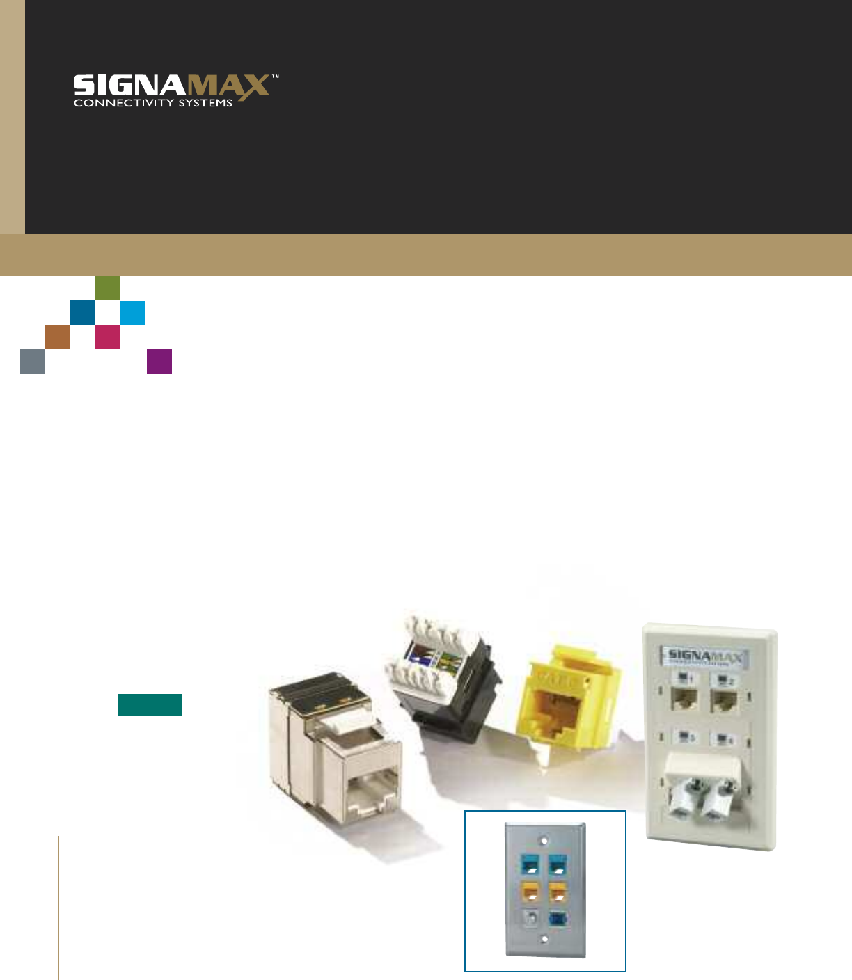
Work Area Outlets
Category 6A
For the highest level cabling system perform-
ance, specify the new Signamax Category 6A
Connectivity System. This ultrahigh-perfor-
mance system has been designed to meet 10
Gigabit IEEE 802.3an transmission require-
ments and is guaranteed to exceed ANSI/TIA-
568-C.2 Category 6A and ISO Class EA
performance requirements.
Designed to support applications from the
data center to the work area, the Signamax
Category 6A System delivers both advanced
performance and reliability for the most
demanding network requirements. The
Signamax Category 6A System is available
in an unscreened and a fully screened
version, both designed to eliminate alien
crosstalk, ensuring the performance of
10GBASE-T network applications. System
components include modular connectors,
patch panels, and patch cords engineered to
deliver guaranteed performance for todayʼs
most demanding applications.
A
Section
6A
CAT
w w w . s i g n a m a x . c o m
In order to provide additional flexibility in cabling
configurations with consolidation points (CP) in an
open office environment, Signamax specifies as a
CP its high-performance Category 6 wiring blocks
having enough transmission performance head-
room to meet Category 6A channel specifications.
Unique design and orientation of connecting block
contacts allow to effectively avoid alien crosstalk,
ensuring stable 10GBASE-T channel performance.
Signamax Category 6A patch cords incorporate a slim-profile
design for use in high-density applications and are designed to
exceed TIA Category 6A performance. Cords are 100% tested
and support Category 6A 100-meter channel
requirements.
Patch Cords
Cross Connect
Category 6A
Category 6A C
B
Section
Section
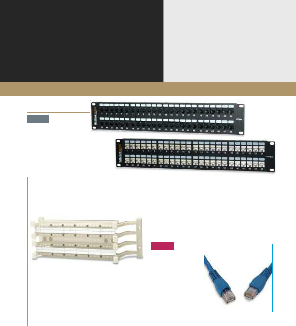
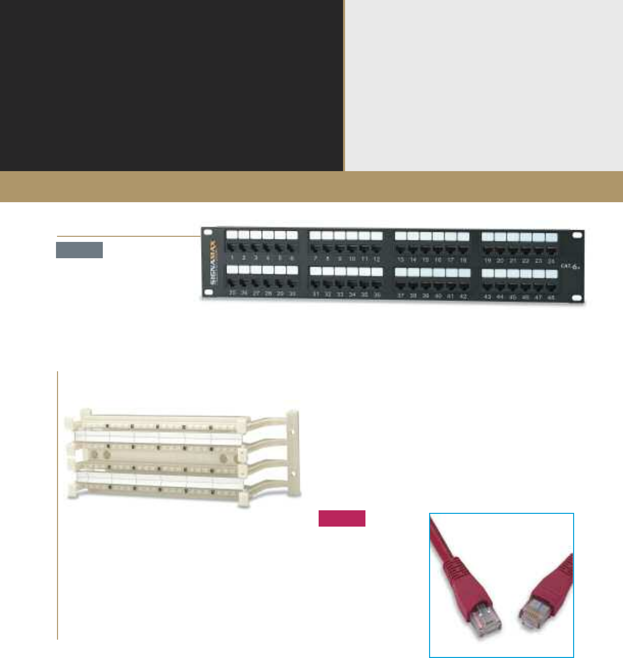
Signamax Category 6A patch panels are designed for high performance, high density
and ease of installation. These high-density panels are available in 24- and 48-port sizes
and are provided with newly designed rear cable management bars. For higher- density
application, a 48-port 1-RMS panel is available.
Patch Panels
Category 6A
A
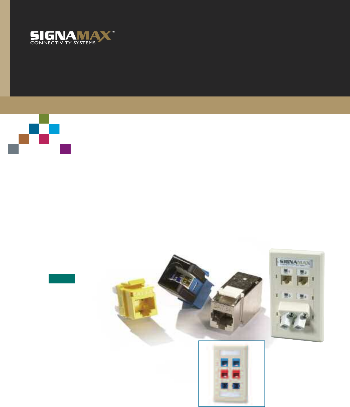
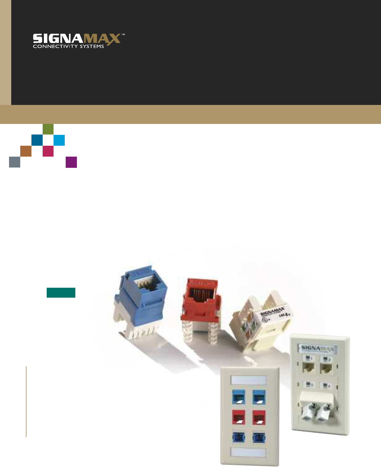
Signamax Category 6 Work Area products offer both performance
and flexibility. The single-and dual-port front-loading Category 6
Connector Modules and Category 6 Keystone Jacks both exceed
ANSI/TIA-568-C.2 performance specifications.
Category 6 Connectivity System
Work Area Outlets
Category 6
Section
The Signamax Category 6 Connectivity
System is designed to exceed TIA Category 6
and ISO Class E performance specifications.
With usable bandwidth beyond 250 MHz, the
Signamax Category 6 Connectivity System
provides a powerful, cost-effective platform
to support the most bandwidth-intensive
applications.
At the heart of the Signamax Category 6 Sys-
tem is the advanced design of our Category 6
connectors. These key system
elements have been designed with a specific
geometry that provides for short transmission
paths between termination points and mating
contacts, as well as a unique pair separation
layout that assures signal integrity. The space-
efficient design of the Signamax modular jack
enables it to be used in the highest-density
applications that you're sure to encounter both
in the telecommunications room and work
areas. Signamax connectors, outlets, patch
panels, connecting blocks, and patch cords are
combined in the Signamax Category 6 System,
to provide an advanced-performance solution
for today's most demanding applications, as
well as to support new, emerging technologies.
6
CAT
w w w . s i g n a m a x . c o m
The Signamax Category 6 Cross-Connect System,
to support high-performance networks, exceeds
Category 6 ANSI/TIA-568-C.2 performance
requirements. Blocks are designed with the same
footprint as standard 50-, 100-, and 300-pair
blocks. Patch cords are available in 110/110
and 110/RJ-45 styles.
Signamax continues to set the standard for high-performance,
high-quality patch cords. These Category 6 cables are
manufactured to the strictest performance requirements,
as specified in ANSI/TIA-568-C.2, using a special, higher-
performance plug design and cable construction. All
Category 6 cords are 100% transmission tested to ensure
superior performance.
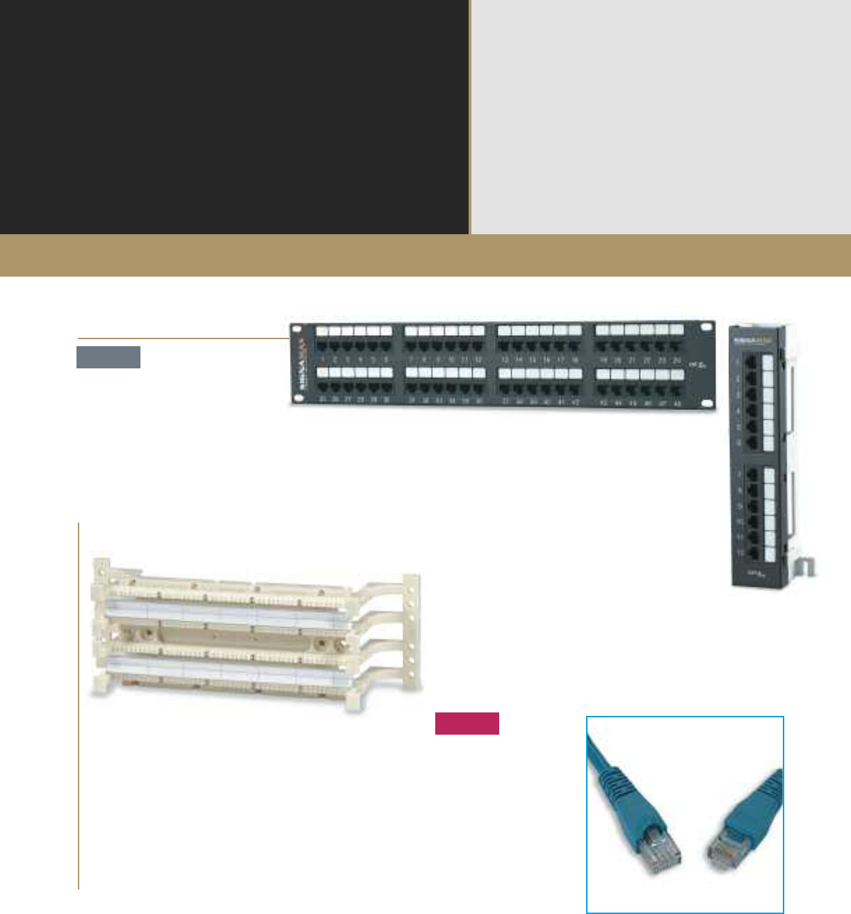
Signamax Category 6 patch panels are designed for high performance, high density, and
ease of installation. Panels are available in a variety of port sizes for both rack
and wall-mount applications. Patch panels exceed Category 6 component performance
as specified in ANSI/TIA-568-C.2.
Patch Cords
Patch Panels
Cross Connect
Category 6
Category 6
Category 6 C
B
Section
Section
A
Offered in both a keystone type and a front-load, front-removable
modular system, Signamax Category 5e Work Area products
offer flexibility and ease of installation for any application. All
connector modules and jacks exceed component performance
standards as defined in ANSI/TIA-568-C.2.
Category 5e Connectivity System
Work Area Outlets
Category 5e
Section
The Signamax Category 5e Connectivity
System provides superior transmission
performance, by combining our Category 5e
patch panels, work area products, patch cords,
and 110 cross-connect products. All Category
5e products are engineered to exceed
ANSI/TIA-568-C.2 specifications to ensure
support for the most demanding network
applications. With usable bandwidth beyond
100 MHz, the Signamax Category 5e system
combines exceptional value, performance, and
reliability for today's mission-critical networks.
Specify the Signamax Category 5e
Cabling System for applications, such as
10/100BASE-T/TX and 1000BASE-T. Use the
appropriate performance-rated jacks, outlet
modules, patch panels, connecting blocks, and
patch cords, with qualified cable, to construct
the Signamax performance-rated Category 5e
Connectivity System. It's that simple.
5e
CAT w w w . s i g n a m a x . c o m
Signamax Category 5e 110 Cross-Connect system
is designed for durability and ease of installation as
well as performance. When used as a consolida-
tion point or as a primary part of your connectivity
system, optimum channel performance is ensured.
Patch cords are available in 110/110
and 110/RJ-45 styles.
Signamax Category 5e patch cords provide an increased
level of channel performance and are available in a variety
of lengths and colors. Category 5e patch cords feature
molded boots for improved reliability and performance.
All cords are 100% transmission tested.
Signamax Category 5e patch panels have been engineered for
high performance, high density, and ease of installation. Panels
are available in a variety of port sizes for both rack- and wall-mount
applications. Panels exceed component performance as specified in
ANSI/TIA-568-C.2.
Patch Cords
Patch Panels
Cross Connect
Category 5e
Category 5e
Category 5e C
B
Section
Section
A
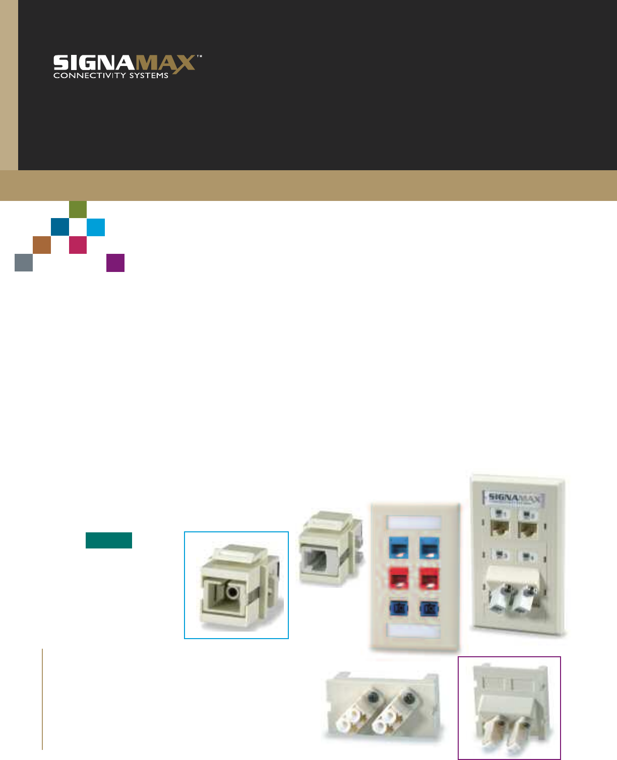
Work-area optical fiber outlets can be addressed in either
single-unit keystone faceplate types, or the Signamax Modular
System, which offers solutions for straight or angled cable exit,
often desired in work area applications. Work area solutions
support all major connector types.
Optical Fiber Systems
Work Area Outlets
Section
Signamax Connectivity Systems offers one of
the broadest array of solutions for Premises
Optical Fiber cabling system designs. From
the work area to the data center, Signamax
has the solution to meet your needs.
Optical Fiber products include rack-mount
distribution enclosures designed to support
up to 288-fibers and feature a slide-out tray
for easy access. Our wall-mount enclosures
support up to 96 fibers and feature front ac-
cess hinged doors; two versions are equipped
with an additional lockable security door. A full
range of optical fiber adapter plates compati-
ble with all Signamax wall- and rack-mount
enclosures is available with fiber counts up to
24 per adapter plate.
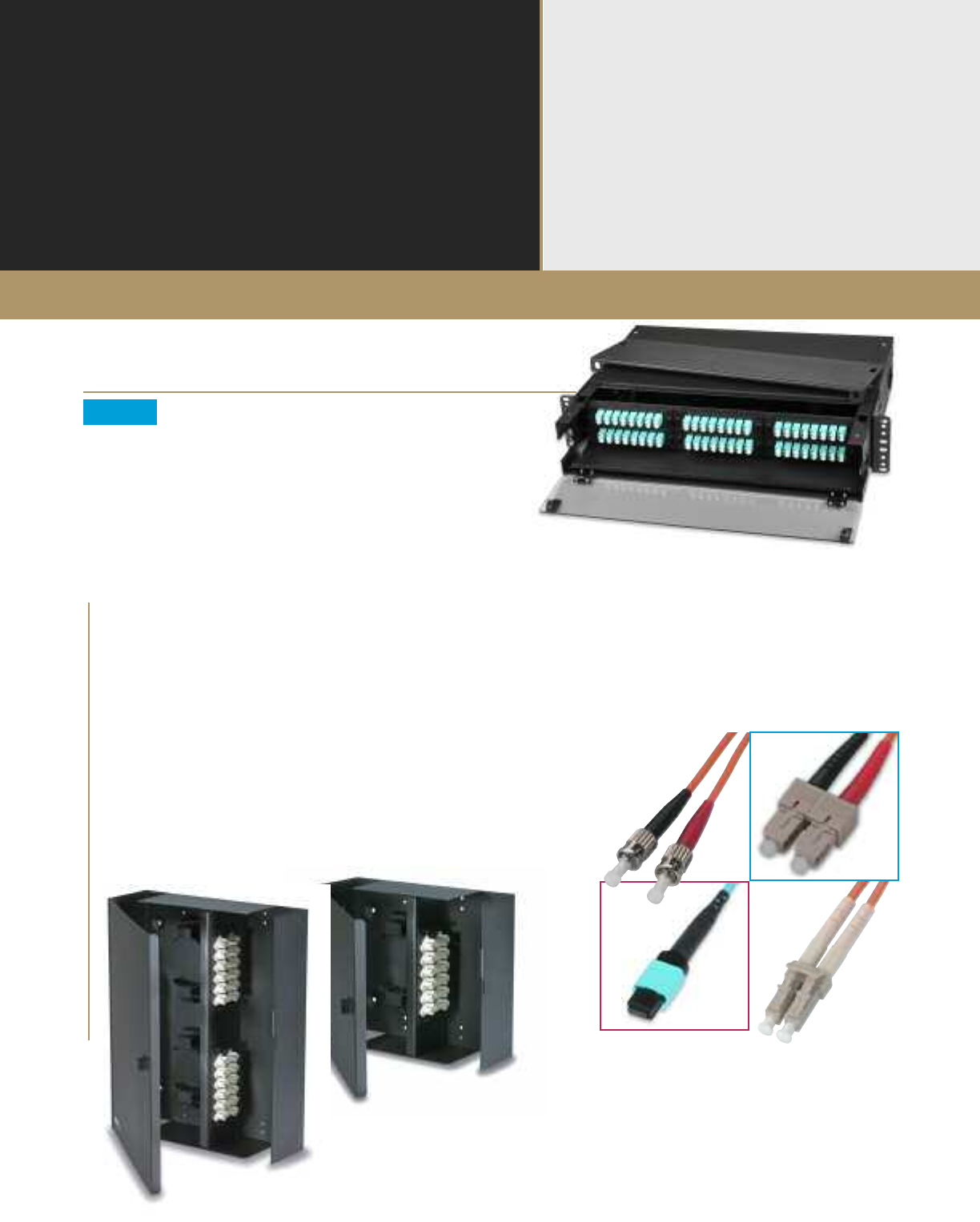
Signamax offers a wide range of optical fiber
patch cords including 62.5- and 50-µm
multimode, singlemode, and 50-µm laser-
optimized (LO) multimode supporting 10-
Gigabit applications. All cords are 100%
factory tested for insertion and return loss to
ensure performance per ANSI/TIA-568-C.3
specifications.
The new Signamax Plug-and-Play
Pre-Terminated Optical Fiber System is
ideal for data center applications and offers
superior performance, high density, and
reduced installation time.
Whether your network is copper-based, or
copper/fiber-based, Signamax can work with
you to develop an integrated solution from
entrance facility to work area, with products
designed for each cable type, yet designed
to work as a system, a capability few
suppliers can offer.
Fiber
OPTICAL
w w w . s i g n a m a x . c o m
Rack-mount enclosures are designed for maximum density, ease of inspection, and main-
tenance convenience. Enclosures are available to accommodate form 12 to 288 fibers
and feature a front slide-out tray for easy access to patch cord connections. A wide range
of fiber adapter plates are available for ST, FC, SC, LC, and MT-RJ coupling types.
Signamax offers a comprehensive line of optical
fiber patch cords for cross-connect or work area
applications. Patch cords are available in simplex
or duplex, multimode (62.5-µm or 50-µm) or single-
mode designs with ST, FC, SC, and small-form-
factor connectors including LC and MT-RJ. Patch
cords are manufactured using riser-rated (OFNR)
cable and are 100% factory tested to ensure
performance to ANSI/TIA-568-C.3 standards.
Wall-mount enclosures enable optical fiber cables to
be easily managed and accessed. These enclosures
provide for cable slack storage and tie-down, in single-
and dual-module styles. Fiber capacity is up to 48 fibers
in the 2-plate enclosure and 96 fibers in the 4-plate
type. Cable entry/exit is enabled from above or below
the enclosure, with cable management provisions for
both cabling options.
Patch Cords
Enclosures
Enclosures
Fiber Optic
Wall-mount
Rack-mount
Section
D
Work Area
O U T L E T
SYSTEMS
CCaatteeggoorryy 66AA 1100GG MMTT--SSeerriieess KKeeyyssttoonnee JJaacckkssAA11
CCaatteeggoorryy 66AA 1100GG SSccrreeeenneedd KKeeyyssttoonnee JJaacckkAA11
CCaatteeggoorryy 66 MMTT--SSeerriieess KKeeyyssttoonnee JJaacckkss AA22
CCaatteeggoorryy 55ee MMTT--SSeerriieess KKeeyyssttoonnee JJaacckkss AA22
VVooiiccee--GGrraaddee MMTT--SSeerriieess KKeeyyssttoonnee JJaacckkss AA33
KKJJMMTT--88660000 MMuullttiippaaiirr TTeerrmmiinnaattiioonn TToooollAA44
CCaatteeggoorryy 66 aanndd 55ee SSccrreeeenneedd KKeeyyssttoonnee JJaacckkss AA55
KKeeyyssttoonnee JJaacckk AAcccceessssoorriieess && TToooollss AA55
KKeeyyssttoonnee MMuullttiimmeeddiiaa MMoodduulleess AA66
SSiinnggllee--GGaanngg FFaacceeppllaatteess AA99
SSiinnggllee--GGaanngg FFaacceeppllaatteess wwiitthh LLaabbeelliinngg AA1100
SSiinnggllee--GGaanngg AAnngglleedd FFaacceeppllaatteess wwiitthh LLaabbeelliinngg AA1100
SSiinnggllee--GGaanngg SSttaaiinnlleessss SStteeeell FFaacceeppllaatteess AA1111
DDoouubbllee--GGaanngg FFaacceeppllaatteess AA1122
DDoouubbllee--GGaanngg FFaacceeppllaatteess wwiitthh LLaabbeelliinngg AA1122
DDoouubbllee--GGaanngg AAnngglleedd FFaacceeppllaatteess wwiitthh LLaabbeelliinngg AA1133
DDoouubbllee--GGaanngg SSttaaiinnlleessss SStteeeell FFaacceeppllaatteess AA1133
110066--TTyyppee aanndd DDeeccoorraa--SSttyyllee FFaacceeppllaatteess AA1144
TTeelleepphhoonnee && VViiddeeoo WWaallllppllaatteessAA1155
SSuurrffaaccee--MMoouunntt FFaacceeppllaattee BBooxxeess AA1155
MMoodduullaarr FFuurrnniittuurree AAddaapptteerrss AA1155
SSuurrffaaccee--MMoouunntt MMuullttiimmeeddiiaa BBooxxeess AA1166
IInntteerrnnaattiioonnaall OOuuttlleettss && SSuurrffaaccee--MMoouunntt BBooxxeessAA1166
MMuullttiimmeeddiiaa MMoodduullaarr OOuuttlleett SSyysstteemm AA1177
IInndduussttrriiaall--GGrraaddee JJaacckkss AA2233
IInndduussttrriiaall--GGrraaddee FFaacceeppllaatteess && SSuurrffaaccee--MMoouunntt BBooxxeess AA2244
KKeeyyssttoonnee JJaacckk DDIINN--RRaaiill MMoouunnttiinngg MMoodduulleess AA2244
w w w . s i g n a m a x . c o m
Work Area
Category 6A 10G MT-Series High-Density Keystone Jacks
Category 6A 10G Screened Toolless Keystone Jack
PART NO. DESCRIPTION
KJS458TL-C6AC Category 6A 10G Screened Toolless Keystone Jack, T568A/B Wiring
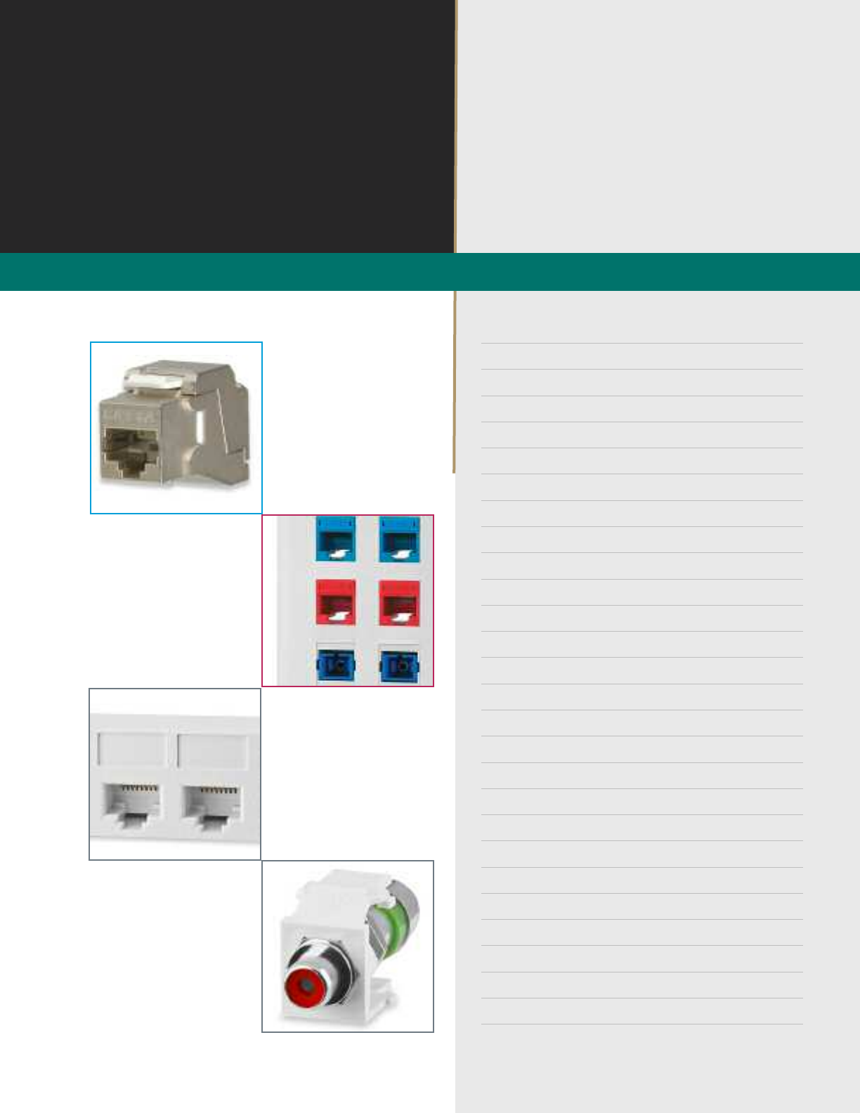
Category 6A 10G Screened Jacks are designed for the same high level of performance standards
as our unscreened jacks. This uniquely designed connector features a toolless termination method
for quick and easy installation. The connectors contact design provides enhanced plug-to-jack
connection integrity and is rated for a minimum of 750 plug insertions providing for the highest level
of reliability. Jacks are fully shielded to optimize protection from EMI including alien crosstalk.
PART NO. DESCRIPTION
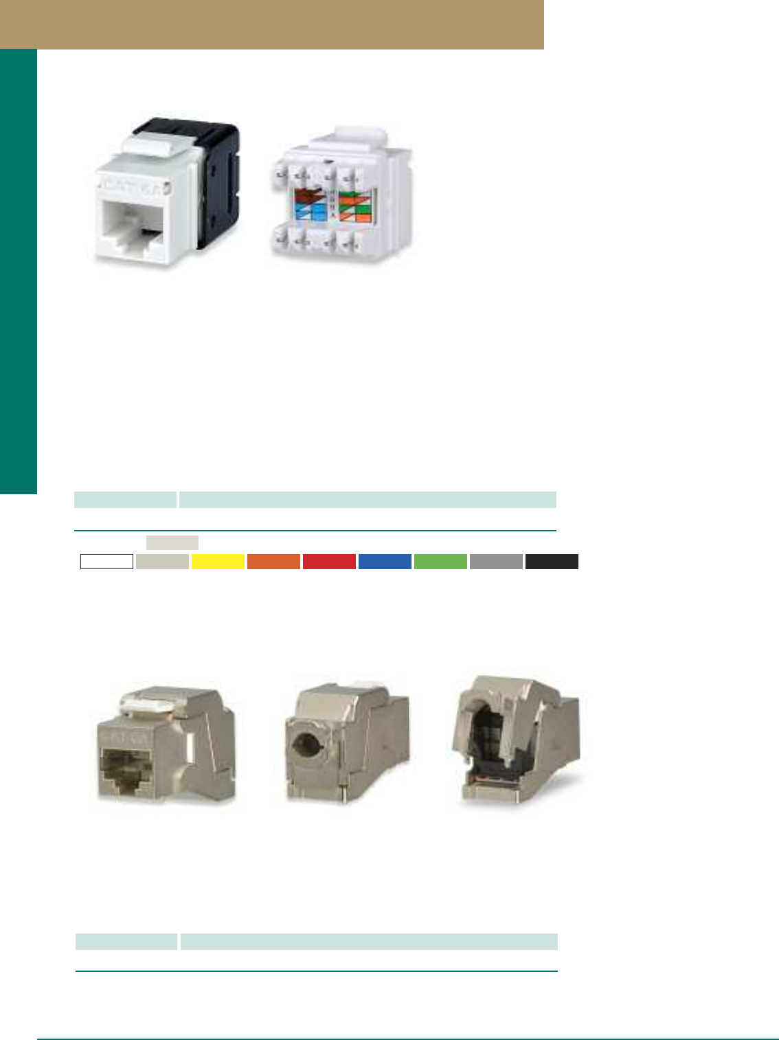
KJ458MT-C6AC Category 6A 10G MT-Series Keystone Jack, T568A/B Wiring, Light Ivory
Signamax Category 6A 10G MT-Series Keystone Jacks have been designed to meet 10 Gigabit Ethernet IEEE 802.3an
transmission reqiurements and are guaranteed to exceed ANSI/TIA-568-C.2 component-level performance specifications.
Category 6A connectors are slim in profile for the highest density applications.
Jacks support both T568A and T568B wiring schemes for maximum flexibility using an easy-to-read color-code wiring label
and can be terminated using standard single-position 110 tool or the new MT-8600 multipair tool to save termination time and
ensure reliable, precise, and consistent terminations. The connectors contact design provides enhanced plug-to-jack connec-
tion integrity, protects against damage caused by insertion of 4- or 6-position plugs, and is rated for a minimum of 750 plug
insertions providing for the highest level of system reliability.
Jacks feature the ability to mount either color-coded icons for service identification or dust covers to protect unused jacks
from dust and other contaminants. Rear 110 contacts provide improved conductor retention and ease of termination.
Jacks are supplied with a metallized plastic cable-retention cap, which eliminates alien crosstalk for maximum performance.
Standard color For other colors add the following to P/N:
Light Ivory
-BK (Black)
-BU (Blue) -GN (Green) -GY (Gray)-OR (Orange) -RD (Red)
-WH (White) -YE (Yellow)
-DI (Ivory)
Part Number Example: KJ458MT-C6AC-BU - Category 6A MT-Series Keystone Jack, Blue
Category 6A 10G MT-Series Keystone Jacks
A 1 PREMISE CONNECTIVITY SYSTEMS 800.446.2377 www.signamax.com
Work Area Outlet Systems
A 2
Category 6 MT-Series High-Density Keystone Jacks
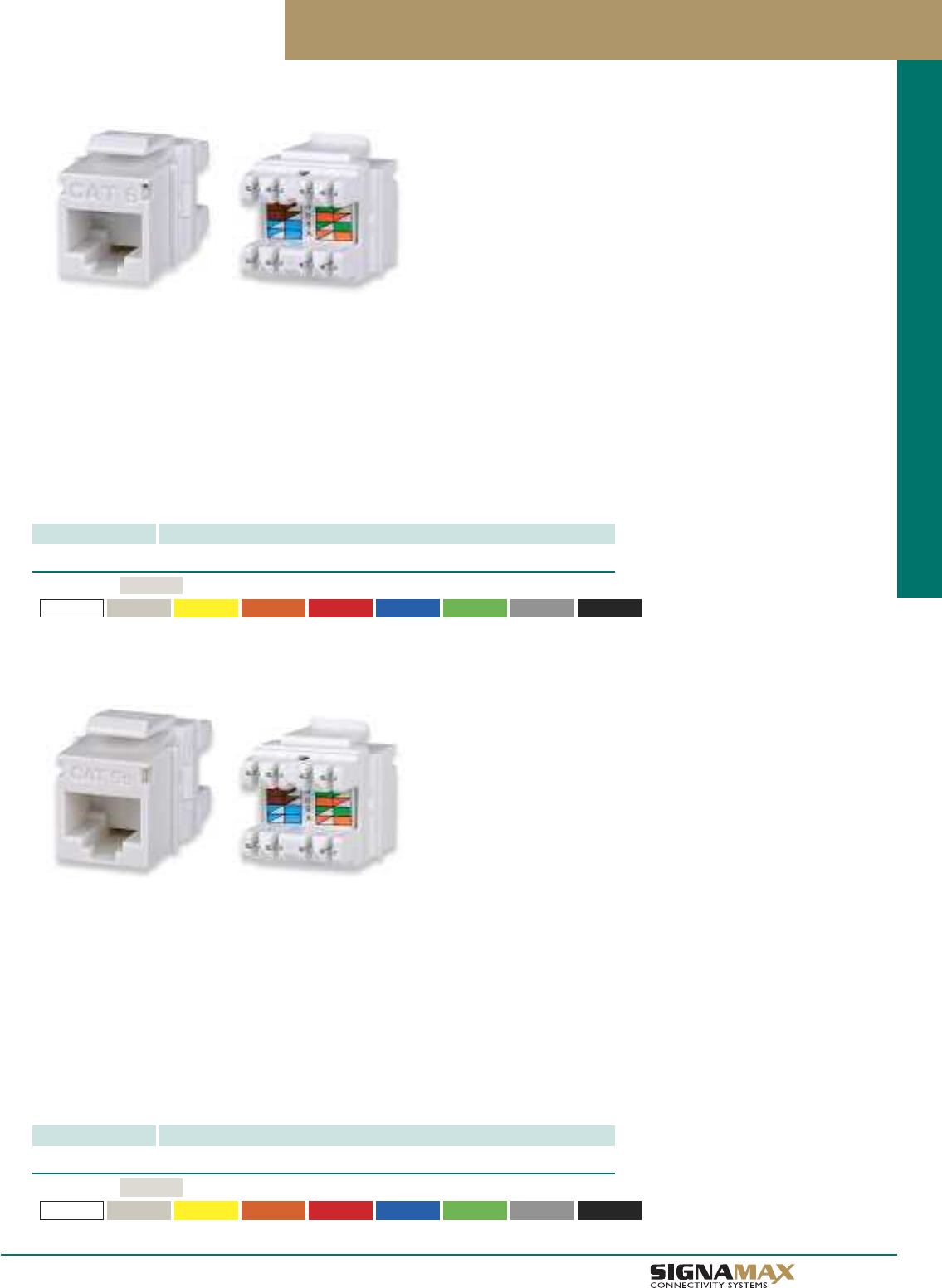
Category 6 Keystone Jacks have been designed to meet the need for today’s high-bandwidth applications. Category 6 connectors
are slim in profile for the highest-density applications, and are engineered to exceed all ANSI/TIA-568-C.2 category 6 requirements.
Jacks support both T568A/B wiring schemes using an easy-to-read color-code wiring label and can be terminated using standard
single-position 110 tools or the new KJMT-8600 multipair tool to save termination time and ensure reliable, precise, and consistent
terminations. The connectors contact design provides enhanced plug-to-jack connection integrity, protects against damage caused
by insertion of 4- or 6-position plugs, and is rated for a minimum of 750 plug insertions providing for the highest level of reliability.
Jacks feature the ability to mount either color-coded icon tabs for service identification or dust covers to protect unused jacks from
dust and other contaminants. Jacks are available in nine colors and are supplied with two color-matched tabs and dust covers with
icons for voice or data identification.
PART NO. DESCRIPTION
KJ458MT-C6C Category 6 MT-Series Keystone Jack, T568A/B Wiring, Light Ivory
Standard color For other colors add the following to P/N:
Light Ivory
-BK (Black)
-BU (Blue) -GN (Green) -GY (Gray)-OR (Orange) -RD (Red)-WH (White) -YE (Yellow)
-DI (Ivory)
Part Number Example: KJ458MT-C6C-BU - Category 6 MT-Series Keystone Jack, Blue
Category 5e MT-Series High-Density Keystone Jacks
Category 5e connectors are engineered to exceed all ANSI/TIA-568-C.2 category 5e requirements and are slim in profile for
the highest-density applications. Jacks support both T568A and T568B wiring schemes using an easy-to-read color-code wiring
label and can be terminated using standard single-position 110 tools or the new KJMT-8600 multipair tool to save termination
time and ensure reliable, precise, and consistent terminations.
The connectors contact design provides enhanced plug-to-jack connection integrity, protects against damage caused by
insertion of 4- or 6-position plugs, and is rated for a minimum of 750 plug insertions providing for the highest level of reliability.
Rear 110-type contacts are designed to provide improved conductor retention and ease of termination.
Jacks feature the ability to mount either color-coded icon tabs for service identification or dust covers to protect unused jacks
from dust and other contaminants. Jacks are available in nine colors and are supplied with two color-matched tabs and dust
covers with icons for voice or data identification.
PART NO. DESCRIPTION
KJ458MT-C5E Category 5e MT-Series Keystone Jack, T568A/B Wiring, Light Ivory
Standard color For other colors add the following to P/N:
Light Ivory
-BK (Black)-BU (Blue) -GN (Green) -GY (Gray)-OR (Orange) -RD (Red)-WH (White) -YE (Yellow)-DI (Ivory)
Part Number Example: KJ458MT-C5E-BU - Category 5e MT-Series Keystone Jack, Blue
Category 6 MT-Series Keystone Jacks
Category 5e MT-Series Keystone Jacks
TM
Work Area Outlet Systems
A 3
Voice-Grade MT-Series High-Density Keystone Jacks
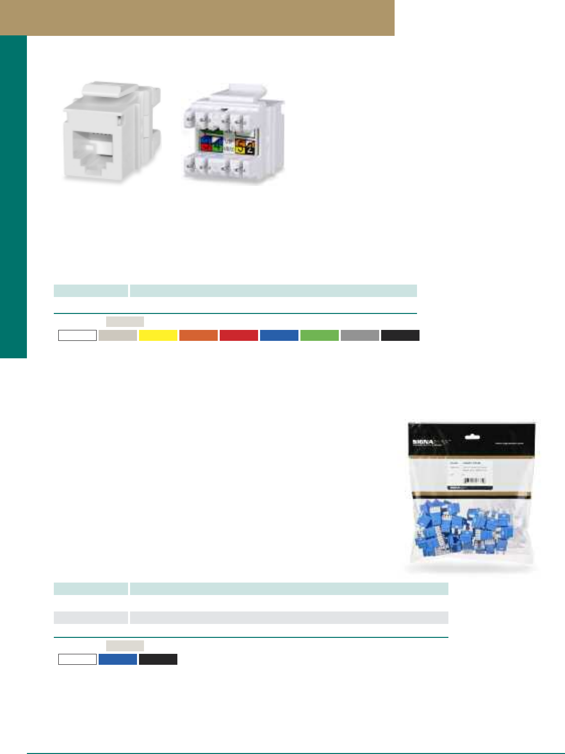
Voice-Grade RJ-12 6-Wire High-Density Jacks are slim in profile for the highest-density applications. Jacks support USOC
wiring using an easy-to-read color-code wiring label and can be terminated using standard single-position 110 tools or the new
KJMT-8600 multipair tool to save termination time and ensure reliable, precise, and consistent terminations. Jacks feature the
ability to mount either color-coded icon tabs for service identification or dust covers to protect unused jacks from dust and other
contaminants. Jacks are available in nine colors and are supplied with color-matched tabs and dust covers with icons for easy
circuit identification.
PART NO. DESCRIPTION
KJ126MT-C3U Voice-Grade RJ-12 6P6C MT-Series Keystone Jack, USOC Wiring, Light Ivory
Standard color For other colors add the following to P/N:
Light Ivory
-BK (Black)
-BU (Blue) -GN (Green) -GY (Gray)-OR (Orange) -RD (Red)
-WH (White) -YE (Yellow)
-DI (Ivory)
Part Number Example: KJ126MT-C3U-BU - Voice-Grade MT-Series Keystone Jack, Blue
Voice-Grade MT-Series High-Density Keystone Jacks
MT-Series Keystone Jacks - Package of 25
PART NO. DESCRIPTION
KJ458MT25-C6C Category 6 MT-Series Keystone Jack, T568A/B Wiring, Light Ivory, 25-Pack
KJ458MT25-C5E Category 5e MT-Series Keystone Jack, T568A/B Wiring, Light Ivory, 25-Pack
KJ126MT25-C3U Voice-Grade RJ-12 6P6C MT-Series Keystone Jack, USOC Wiring, Light Ivory, 25-Pack
Standard color For other colors add the following to P/N:
Light Ivory
-BK (Black)
-BU (Blue)-WH (White)
Part Number Example: KJ458MT25-C6C-BU - Category 6 MT-Series Keystone Jack, Blue, 25-Pack
MT-Series Keystone Jacks - 25 Pack
PREMISE CONNECTIVITY SYSTEMS 800.446.2377 www.signamax.com
Work Area Outlet Systems
Category 6, 5e and Voice-Grade MT-Series Keystone are now available in packages of 25
using a reseal heavy-duty clear package. This packaging saves time and reduces packaging
waste on larger installation. Jacks are available in light ivory, white, blue and black.
A 4
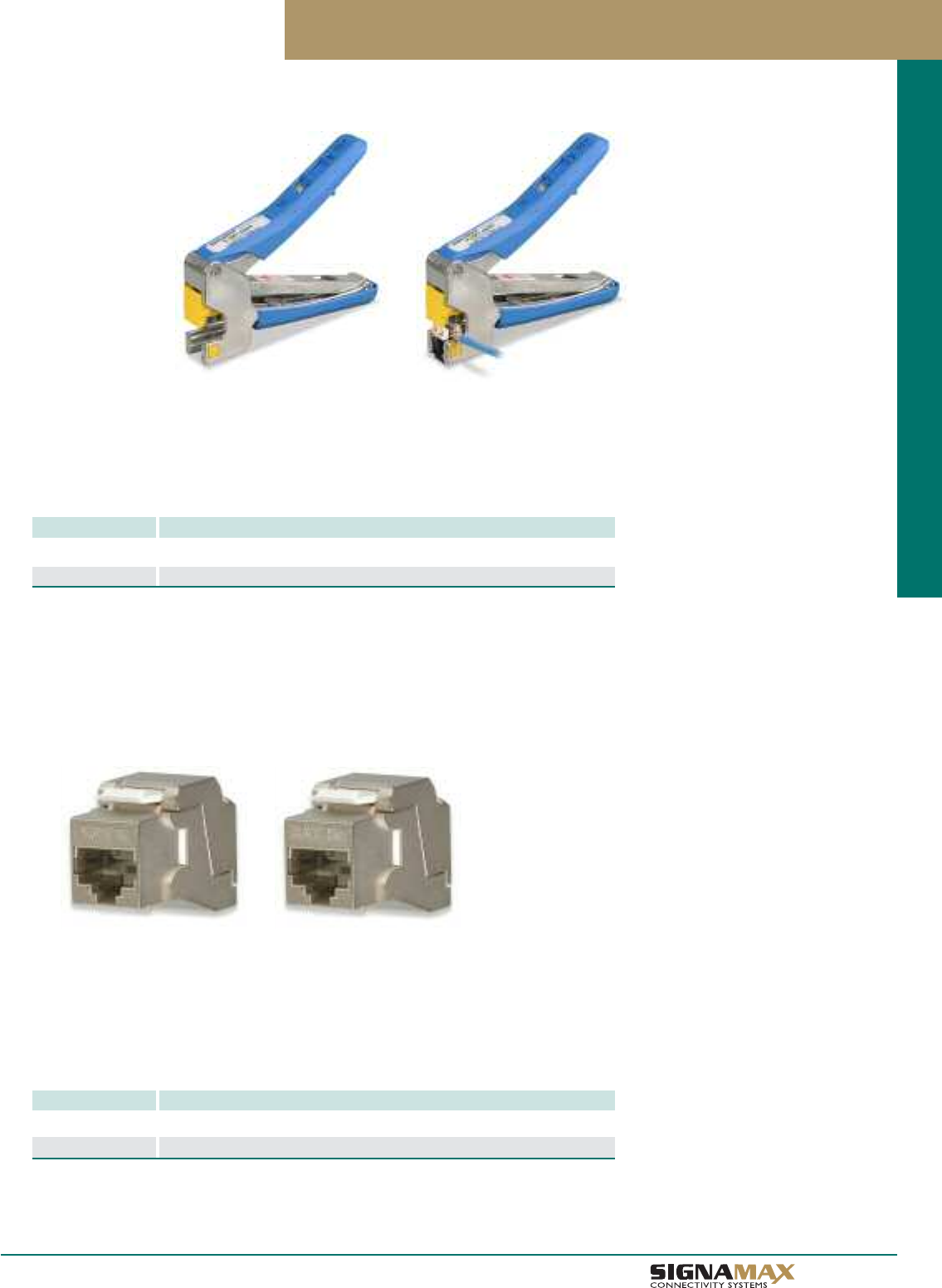
Category 6 and Category 5e Screened Toolless Keystone Jacks
PART NO. DESCRIPTION
KJS458TL-C6C Category 6 Screened Toolless Keystone Jack, T568A/B Wiring
KJS458TL-C5E Category 5e Screened Toolless Keystone Jack, T568A/B Wiring
Screened jacks are designed for the same high level of performance standards as our unscreened
jacks. This slim in profile jack is designed for the highest-density applications, and is engineered to
exceed all ANSI/TIA-568-C.2 category 6 and category 5e requirements. Jacks are fully shielded to
optimize protection from EMI. This uniquely designed connector features a toolless termination
method for quick and easy installation.
4-Pair Termination Tool for MT-Series Keystone Jacks
The new Signamax KJMT-8600 4-Pair Termination Tool is designed to work with all MT-Series Keystone Jacks.
The KJMT-8600 tool simultaneously terminates all eight twisted-pair cable conductors along with trimming of conductor
excess. This innovative tool saves installation time while ensuring precise and consistent termination of all pairs due to the
calibrated die drive mechanism. The tool features a comfortable plastic handle and is lightweight and compact design with
replaceable dies, and can be stored in the closed position using the integrated lock to save space.
4-Pair Termination Tool for MT-Series Keystone Jacks
PART NO. DESCRIPTION
KJMT-8600 4-Pair Termination Tool for MT-Series Keystone Jacks
KJMT-8600-DS Replacement Termination Die for KJMT-8600 Tool
Category 6 and Category 5e Screened Toolless Keystone Jacks
TM
Work Area Outlet Systems
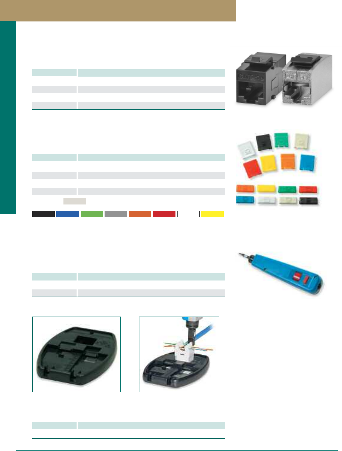
Designation icons and dust covers can be specified for providing both port protection and
color-coding. Icons and dust covers are sold in packages of 50.
Keystone Jack Dust Covers and Icon Tabs
PART NO. DESCRIPTION
DDC-50D-IV Designation Dust Covers, Data, Package of 50, Light Ivory
DDC-50V-IV Designation Dust Covers, Voice, Package of 50, Light Ivory
DIT-50D-IV Designation Icon Tabs, Data, Package of 50, Light Ivory
DIT-50V-IV Designation Icon Tabe, Voice, Package of 50, Light Ivory
Keystone Jack Termination Fixture
PART NO. DESCRIPTION
KJ-TF Keystone Jack Termination Fixture
Standard color
For other colors add the following to P/N
-BK (Black) -BU (Blue) -GN (Green) -GY (Gray) -OR (Orange) -RD (Red) -WH (White) -YE (Yellow)
Light Ivory
The universal termination fixture is compatible with Category 6A, 6, 5e and Voice-Grade
Keystone Kacks. It helps to facilitate wire positioning and termination on-site.
Termination Tools
PART NO. DESCRIPTION
T110 Single-Position 110 Impact Termination Tool
T110BL Single-Position 110 Termination Blade
Signamax single-position termination tool is a versatile impact tool designed to terminate
and cut conductor excess. Our single-position impact tool is available to terminate all
Signamax keystone jacks and is spring-loaded and tension-adjustable.
Category 6 and Category 5e Feed-Thru Couplers
PART NO. DESCRIPTION
KRJ45/6S Category 6 Feed-Thru Coupler
KRJ45/6S-SH Category 6 Screened Feed-Thru Coupler
KRJ45/5S Category 5e Feed-Thru Coupler
KRJ45/5S-SH Category 5e Screened Feed-Thru Coupler
Feed-thru couplers are available in both category 6 and category 5e performance levels
and are compatible with all Signamax faceplates, surface mount multimedia boxes, and
field-configurable patch panels.
A 5 PREMISE CONNECTIVITY SYSTEMS 800.446.2377 www.signamax.com
Work Area Outlet Systems
Keystone Multimedia Modules
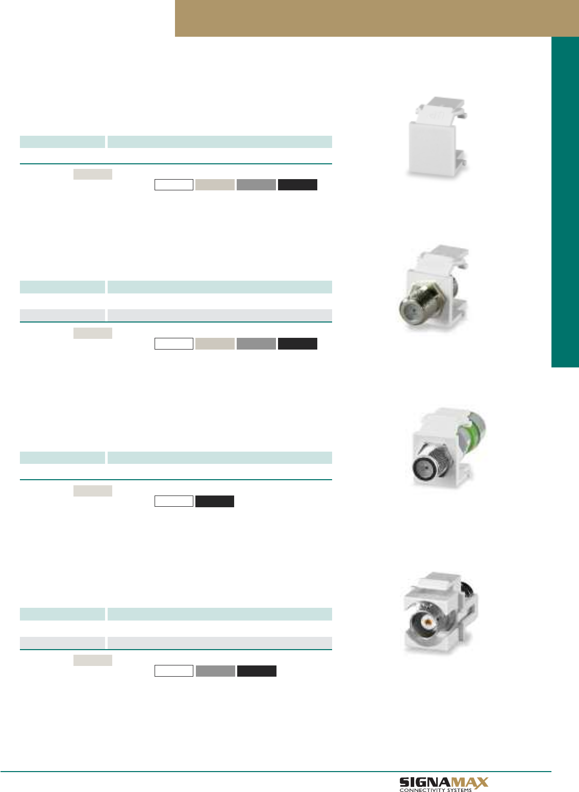
Blank Module
PART NO. DESCRIPTION
CMK-BL Blank Keystone Module
Blank Modules cover up unused port openings on all Signamax keystone faceplates
and surface mount boxes. Blank Modules are sold in packages of 10.
F-Type Connector Modules
F-Type feed-thru modules are compatible with all Signamax keystone faceplates and
surface-mount boxes. Connectors are 75 Ohm and rated for 1- or 3-GHz performance.
BNC Connector Modules
PART NO. DESCRIPTION
CMK-BNC 50-Ohm BNC Keystone Connector Module
CMK-BNC75 75-Ohm BNC Keystone Connector Module
BNC Modules are compatible with all Signamax keystone faceplates and surface-
mount boxes. The BNC modules provide one feed-thru connection.
PART NO. DESCRIPTION
CMK-F F-Type Keystone Connector Module, 1 GHz
CMK-F3 F-Type Keystone Connector Module, 3 GHz
Standard color
For other colors add the following to P/N
Light Ivory
-BK (Black)-GY (Gray)
-WH (White) -DI (Ivory)
Standard color
For other colors add the following to P/N
Light Ivory
-BK (Black)-GY (Gray)
-WH (White)
Standard color
For other colors add the following to P/N
Light Ivory
-BK (Black)-GY (Gray)
-WH (White) -DI (Ivory)
F-Type Compression Connector Modules
F-Type Compression Modules are compatible with all Signamax keystone faceplates
and surface-mount boxes. The connectors are designed for RG6 quad shield coaxial
cable to provide superior video and audio performance.
PART NO. DESCRIPTION
CMK-F-CF F-Type Compression Keystone Connector Module
Standard color
For other colors add the following to P/N
Light Ivory
-BK (Black)
-WH (White)
A 6
TM
Work Area Outlet Systems
Keystone Multimedia Modules
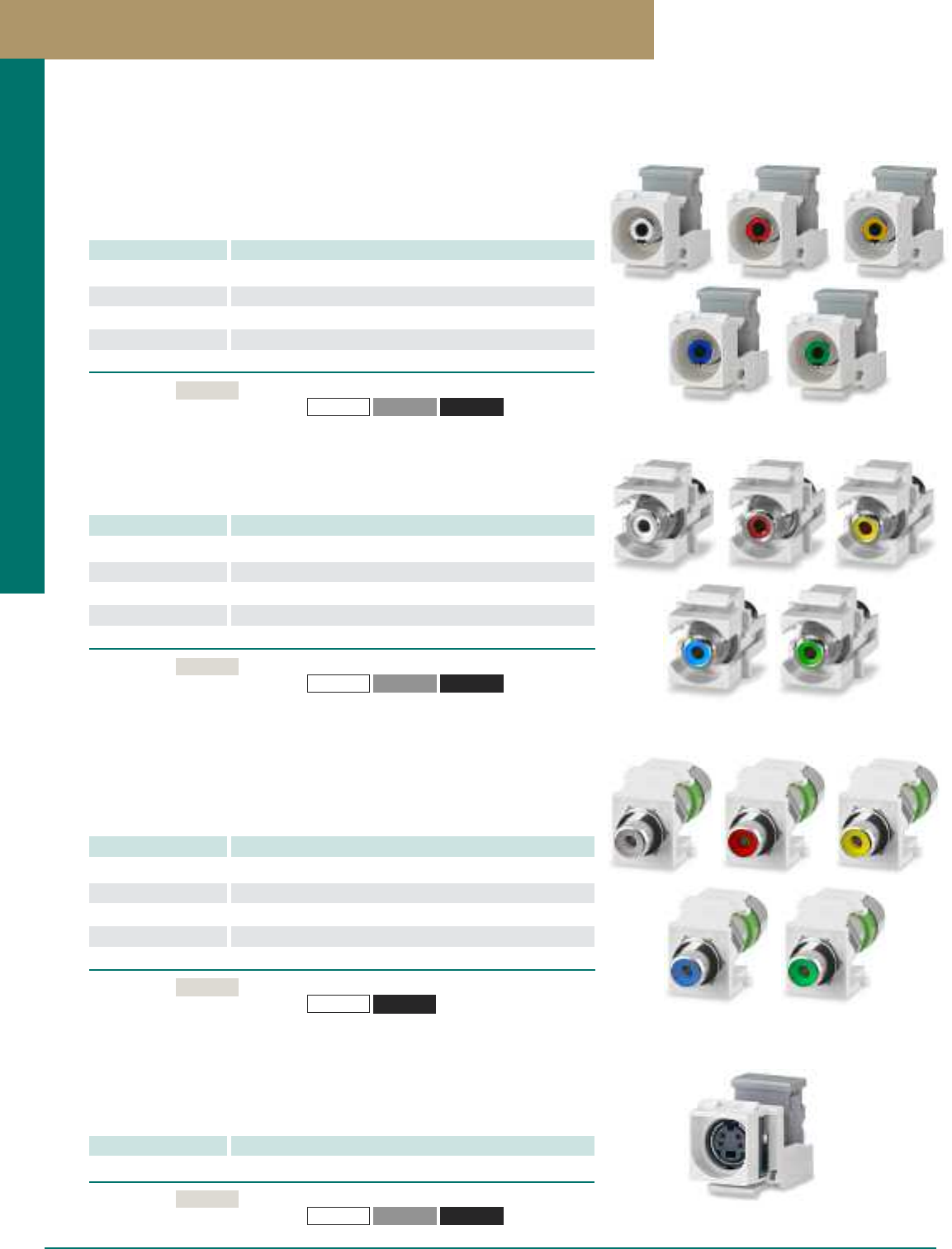
RCA Feed-Thru Connector Modules
PART NO. DESCRIPTION
CMK-RCAW RCA White Feed-Thru Keystone Connector Module
CMK-RCAR RCA Red Feed-Thru Keystone Connector Module
CMK-RCAY RCA Yellow Feed-Thru Keystone Connector Module
CMK-RCAB RCA Blue Feed-Thru Keystone Connector Module
CMK-RCAG RCA Green Feed-Thru Keystone Connector Module
Modules are available with RCA feed-thru (female-to-female) connectors.
RCA modules are offered in five colors to indicate connection type.
SVHS-110 Connector Module
PART NO. DESCRIPTION
CMK-110SVHS SVHS-to-110 Keystone Connector Module
The SVHS-to-110 modules enable connection to your video systems using category
5e or 6 cabling and feature 110-type IDC terminations on rear for quick, easy installa-
tion. These modules provide a cost-effective alternative to running S-Video cabling.
Standard color
For other colors add the following to P/N
Light Ivory
-BK (Black)-GY (Gray)
-WH (White)
Standard color
For other colors add the following to P/N
Light Ivory
-BK (Black)-GY (Gray)
-WH (White)
RCA-110 Connector Modules
PART NO. DESCRIPTION
CMK-110RCAW RCA White-to-110 Keystone Connector Module
CMK-110RCAR RCA Red-to-110 Keystone Connector Module
CMK-110RCAY RCA Yellow-to-110 Keystone Connector Module
CMK-110RCAB RCA Blue-to-110 Keystone Connector Module
CMK-110RCAG RCA Green-to-110 Keystone Connector Module
The RCA-to-110 modules enable transmission of audio/video signals over category
5e or 6 twisted-pair cabling and feature 110-type IDC terminations on rear for quick,
easy installation. RCA modules are offered in five colors to indicate connection type.
Standard color
For other colors add the following to P/N
Light Ivory
-BK (Black)-GY (Gray)
-WH (White)
RCA Compression Connector Modules
PART NO. DESCRIPTION
CMK-RCAW-C RCA White Compresion Keystone Connector Module
CMK-RCAR-C RCA Red Compresion Keystone Connector Module
CMK-RCAY-C RCA Yellow Compresion Keystone Connector Module
CMK-RCAB-C RCA Blue Compresion Keystone Connector Module
CMK-RCAG-C RCA Green Compresion Keystone Connector Module
RCA Female Compression Modules are compatible with all Signamax keystone
faceplates and surface-mount boxes. The connectors are designed for RG6 quad
shield coaxial cable to provide superior video and audio performance. RCA modules
are offered in five colors to indicate connection type.
A 7 PREMISE CONNECTIVITY SYSTEMS 800.446.2377 www.signamax.com
Work Area Outlet Systems
Standard color
For other colors add the following to P/N
Light Ivory
-BK (Black)
-WH (White)
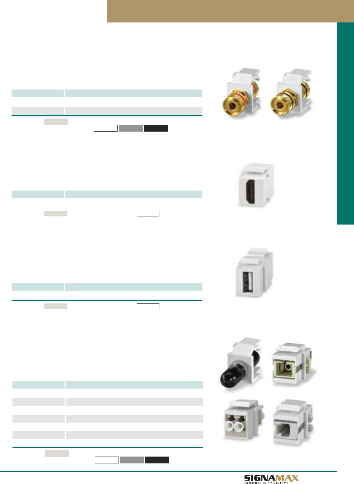
3-Way Binding Post Connector Modules
PART NO. DESCRIPTION
CMK-RA Red 3-Way Binding Post Keystone Connector Module
CMK-BA Black 3-Way Binding Post Keystone Connector Module
3-Way Binding Post Modules provide termination options for banana plugs, speaker
tips, spade tips, or bare wire. Binding post modules are available with red or black
color code.
Standard color
For other colors add the following to P/N
Light Ivory
-BK (Black)-GY (Gray)
-WH (White)
HDMI Feed-Thru Connector Module
PART NO. DESCRIPTION
CMK-HDMI-WH HDMI Feed-Thru Keystone Connector Module
The HDMI Feed-Thru Connector Module is compatible with all Signamax faceplates
and surface mount boxes. The HDMI connector is compatible with Type A plugs and
support all HDMI sources.
Keystone Multimedia Modules
USB Feed-Thru Connector Module
PART NO. DESCRIPTION
CMK-USB-WH USB Feed-Thru Keystone Connector Module
The USB Feed-Thru Connector Module is compatible with all Signamax faceplates
and surface mount boxes. The USB connector accepts Type A plugs and is complient
with USB 2.0 standards.
A 8
TM
Work Area Outlet Systems
Optical Fiber Connector Modules
PART NO. DESCRIPTION
CMK-ST ST MM Keystone Connector Module
CMK-STS ST SM Keystone Connector Module
CMK-SC SC MM Keystone Connector Module
CMK-CSC SC SM Keystone Connector Module
CMK-LC LC MM Keystone Connector Module
CMK-LCS LC SM Keystone Connector Module
CMK-MTRJ MTRJ MM/SM Keystone Connector Module
Optical Fiber Modules bring ST, SC, LC, and MT-RJ fiber connectors to the
workstation. Fiber couplers are provided with phosphor bronze sleeves suitable for
both multimode and singlemode short-range applications. Modules with ceramic
sleeves are available for precision singlemode alignment.
Standard color
For other colors add the following to P/N
Light Ivory
-BK (Black)-GY (Gray)
-WH (White)
Standard color For white add the following to P/N -WH (White)
Light Ivory
Standard color For white add the following to P/N -WH (White)Light Ivory
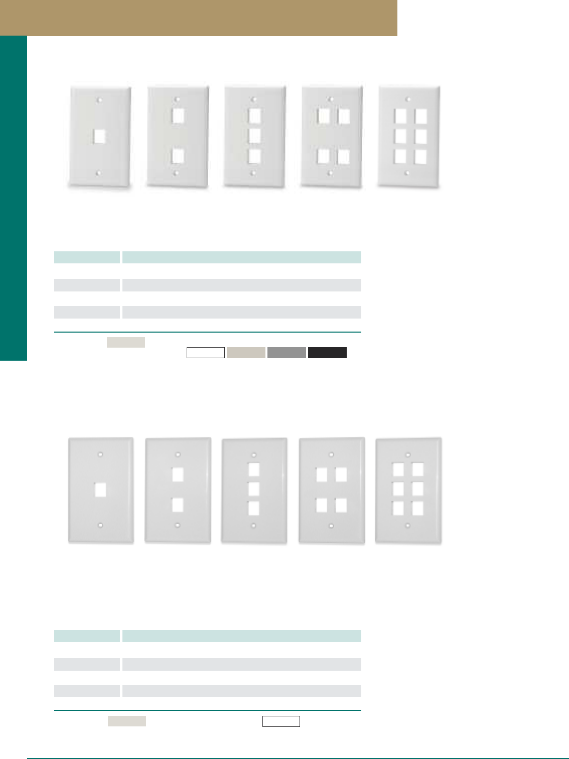
Keystone Faceplates
Single-Gang Faceplates
Single-gang faceplates are available in 1-, 2-, 3-, 4-, or 6-port versions and allow for
mounting any combination of keystone jacks and multimedia modules.
Single-Gang Oversized Faceplates
PART NO. DESCRIPTION
SKFM-1 1-Port Single-Gang Oversized Keystone Faceplate
SKFM-2 2-Port Single-Gang Oversized Keystone Faceplate
SKFM-3 3-Port Single-Gang Oversized Keystone Faceplate
SKFM-4 4-Port Single-Gang Oversized Keystone Faceplate
SKFM-6 6-Port Single-Gang Oversized Keystone Faceplate
Single-gang oversized faceplates are available in 1-, 2-, 3-, 4-, or 6-port versions
and allow for mounting any combination of keystone jacks and multimedia modules.
Oversized faceplates are 4.875” x 3.125” x .375”, provide a designer look and help
hiding irregular drywall cuts and flaws around openings.
Standard color For white add the following to P/N -WH (White)
Light Ivory
PART NO. DESCRIPTION
SKF-1 1-Port Single-Gang Keystone Faceplate
SKF-2 2-Port Single-Gang Keystone Faceplate
SKF-3 3-Port Single-Gang Keystone Faceplate
SKF-4 4-Port Single-Gang Keystone Faceplate
SKF-6 6-Port Single-Gang Keystone Faceplate
Standard color
For other colors add the following to P/N
Light Ivory
-BK (Black)
-GY (Gray)
-WH (White) -DI (Ivory)
A 9 PREMISE CONNECTIVITY SYSTEMS 800.446.2377 www.signamax.com
Work Area Outlet Systems
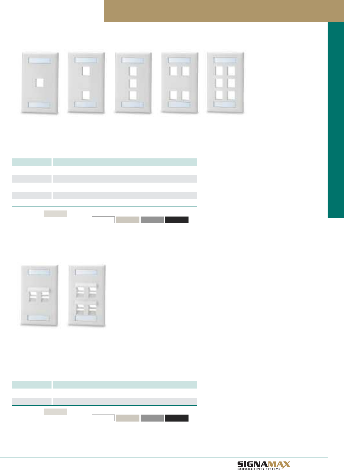
Single-Gang Faceplates with Labeling Windows
PART NO. DESCRIPTION
SKFL-1 1-Port Single-Gang Keystone Faceplate with Labeling Windows
SKFL-2 2-Port Single-Gang Keystone Faceplate with Labeling Windows
SKFL-3 3-Port Single-Gang Keystone Faceplate with Labeling Windows
SKFL-4 4-Port Single-Gang Keystone Faceplate with Labeling Windows
SKFL-6 6-Port Single-Gang Keystone Faceplate with Labeling Windows
Faceplates are available in 1-, 2-, 3-, 4-, or 6-port versions and allow for mounting any
combination of keystone jacks and multimedia modules. These faceplates feature top
and bottom designation labeling windows for convenient faceplate identification.
Keystone Faceplates
Single-Gang Angled Faceplates with Labeling Windows
PART NO. DESCRIPTION
SKFLA-2 2-Port Single-Gang Angled Keystone Faceplate with Labeling
SKFLA-4 4-Port Single-Gang Angled Keystone Faceplate with Labeling
Angled faceplates are available in 2- and 4-port versions. These plates allow an
angled patch cord exit to prevent damage to the connector interface and help maintain
the bend radius of patch cords. Faceplates feature designation labeling windows for
faceplate identification.
A 1 0
TM
Work Area Outlet Systems
Standard color
For other colors add the following to P/N
Light Ivory
-BK (Black)-GY (Gray)
-WH (White) -DI (Ivory)
Standard color
For other colors add the following to P/N
Light Ivory
-BK (Black)-GY (Gray)
-WH (White) -DI (Ivory)
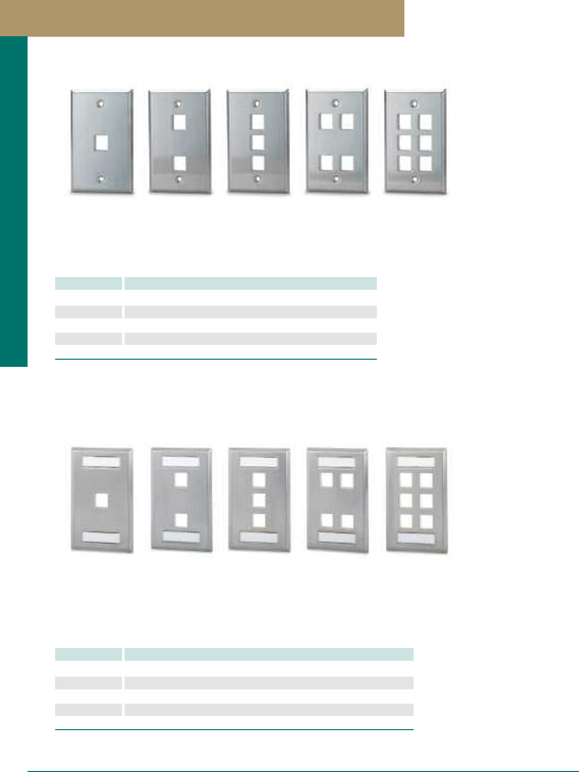
Keystone Faceplates
Single-Gang Stainless Steel Faceplates
PART NO. DESCRIPTION
SSKF-1 1-Port Single-Gang Stainless Steel Keystone Faceplate
SSKF-2 2-Port Single-Gang Stainless Steel Keystone Faceplate
SSKF-3 3-Port Single-Gang Stainless Steel Keystone Faceplate
SSKF-4 4-Port Single-Gang Stainless Steel Keystone Faceplate
SSKF-6 6-Port Single-Gang Stainless Steel Keystone Faceplate
Single-gang brushed stainless steel faceplates allow mounting any combination of
keystone jacks and multimedia modules. These faceplates allow for flush mounting of
jacks and for a clean appearance. Stainless steel faceplates are ideal for use in
environments that require greater durability and a sanitary, easy-to-clean solution.
Single-Gang Stainless Steel Faceplates with Labeling Windows
PART NO. DESCRIPTION
SSKFL-1 1-Port Single-Gang Stainless Steel Keystone Faceplate w/Labeling Windows
SSKFL-2 2-Port Single-Gang Stainless Steel Keystone Faceplate w/Labeling Windows
SSKFL-3 3-Port Single-Gang Stainless Steel Keystone Faceplate w/Labeling Windows
SSKFL-4 4-Port Single-Gang Stainless Steel Keystone Faceplate w/Labeling Windows
SSKFL-6 6-Port Single-Gang Stainless Steel Keystone Faceplate w/Labeling Windows
Single-gang brushed stainless steel faceplates allow mounting any combination of keystone
jacks and multimedia modules. These faceplates allow for flush mounting of jacks and for a clean
appearance. Stainless steel faceplates are ideal for use in environments that require greater
durability and a sanitary, easy-to-clean solution.These faceplates feature top and bottom
designation labeling windows for convenient faceplate identification.
A 11 PREMISE CONNECTIVITY SYSTEMS 800.446.2377 www.signamax.com
Work Area Outlet Systems
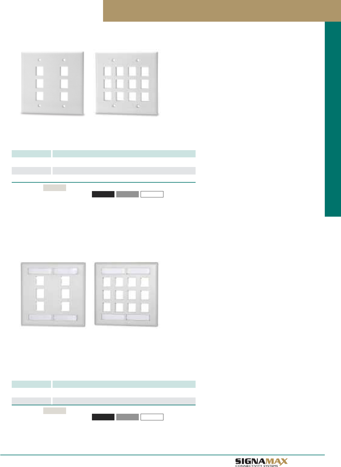
Keystone Faceplates
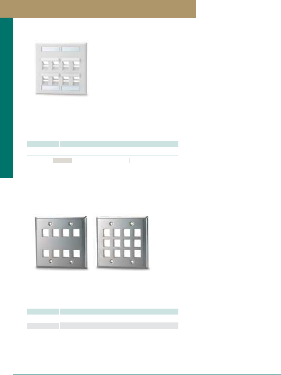
Double-Gang Faceplates
PART NO. DESCRIPTION
DKF-6 6-Port Double-Gang Keystone Faceplate
DKF-8 8-Port Double-Gang Keystone Faceplate
DKF-12 12-Port Double-Gang Keystone Faceplate
Double-gang faceplates are available in 6-, 8-, and 12-port versions and allow for
mounting any combination of keystone jacks and multimedia modules.
Double-Gang Faceplates with Labeling Windows
PART NO. DESCRIPTION
DKFL-6 6-Port Double-Gang Keystone Faceplate with Labeling
DKFL-12 12-Port Double-Gang Keystone Faceplate with Labeling
Double-gang faceplates are available in 8- and 12-port versions and allow for
mounting any combination of keystone jacks and multimedia modules. These
faceplates feature top and bottom designation labeling windows for convenient
faceplate identification. Plates are supplied with label cards and clear labeling
window covers.
Standard color
For other colors add the following to P/N -BK (Black) -GY (Gray) -WH (White)
Light Ivory
Standard color
For other colors add the following to P/N -BK (Black) -GY (Gray) -WH (White)
Light Ivory
A 1 2
TM
Work Area Outlet Systems
Keystone Faceplates
Double-Gang Angled Faceplate with Labeling Windows
PART NO. DESCRIPTION
DKFLA-8 8-Port Double-Gang Angled Keystone Faceplate with Labeling
Angled faceplate is available in an 8-port version. This plate allows an angled patch
cord exit to prevent damage to the connector interface and help maintain the bend
radius of patch cords. Faceplate features top and bottom designation labeling
windows for convenient faceplate identification. Faceplate is supplied with label
cards and clear labeling window covers.
Double-Gang Stainless Steel Faceplates
PART NO. DESCRIPTION
DSKF-8 8-Port Double-Gang Stainless Steel Keystone Faceplate
DSKF-12 12-Port Double-Gang Stainless Steel Keystone Faceplate
Double-gang brushed stainless steel faceplates are available in 8- and 12-port
versions and allow for flush-mounting of jacks and for a clean appearance. Stainless
steel faceplates are ideal for use in environments that require greater durability and a
sanitary, easy-to-clean solution.
A 1 3 PREMISE CONNECTIVITY SYSTEMS 800.446.2377 www.signamax.com
Work Area Outlet Systems
Standard color For white add the following to P/N -WH (White)
Light Ivory
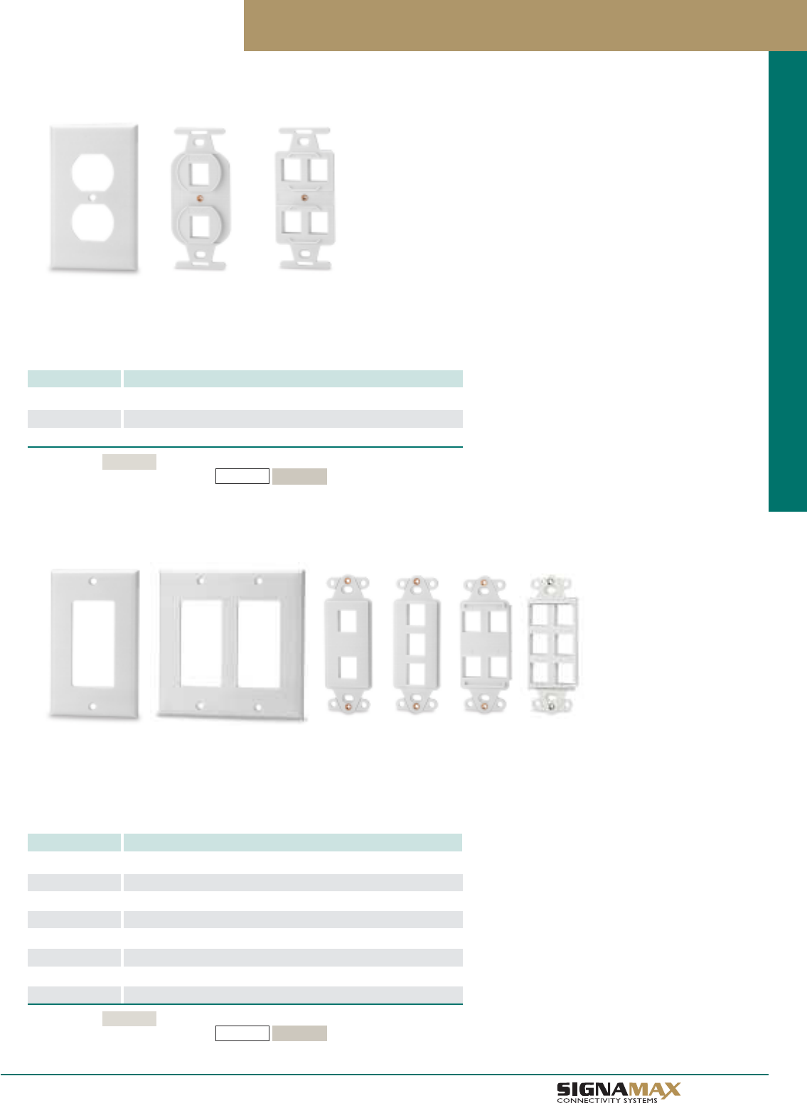
106-Type Faceplates and Keystone Adapters
PART NO. DESCRIPTION
SKF-106 Single-Gang 106-Type Faceplate
106A-2 2-Port 106-Type Faceplate Adapter
106A-4 4-Port 106-Type Faceplate Adapter
The 106-Type Faceplates with 2- and 4-port adapters are compatible with all
Signamax keystone jacks and multimedia modules. The 106-type plates and adapters
are ideal to coordinate electrical wiring devices with telecommunications outlets.
106-Type and Decora Faceplates and Adapters
Decora-Style Faceplates and Keystone Adapters
PART NO. DESCRIPTION
SKFD-1 Single-Gang Decora-Style Faceplate
DKFD-2 Double-Gang Decora-Style Faceplate
DA-BL Blank Decora-Style Adapter
DA-1 1-Port Decora-Style Keystone Adapter
DA-2 2-Port Decora-Style Keystone Adapter
DA-3 3-Port Decora-Style Keystone Adapter
DA-4 4-Port Decora-Style Keystone Adapter
DA-6 6-Port Decora-Style Keystone Adapter
Decora-Style Faceplates and Adapters are compatible with all Signamax keystone
jacks and multimedia modules. Faceplates are available in single- and double-gang
versions. Adapters are available in a variety of port sizes and are ideal for combining
data, voice, audio, and video in one outlet location.
A 1 4
TM
Work Area Outlet Systems
Standard color
For other colors add the following to P/N
Light Ivory
-WH (White) -DI (Ivory)
Standard color
For other colors add the following to P/N
Light Ivory
-WH (White) -DI (Ivory)
A 1 5
Telephone & Video Wallplates / Surface-Mount Faceplate Boxes
Surface-Mount Faceplate Boxes
PART NO. DESCRIPTION
SMB1-SG Single-Gang Surface-Mount Faceplate Box
SMB1-DG Double-Gang Surface-Mount Faceplate Box
Surface-mount faceplate boxes are available to accommodate both single-gang and
double-gang faceplates. Boxes provide knockouts on all sides for easy cable entry
and are supplied with mounting hardware.
Modular Furniture Keystone Adapters
PART NO. DESCRIPTION
FAK-3 3-Port Modular Furniture Adapter
FAK-4 4-Port Modular Furniture Adapter
Modular furniture adapters accept all Signamax jacks and multimedia modules and are
available in 2- and 4-port versions. Adapters fit into standard modular furniture openings.
Standard color
For other colors add the following to P/N -GY (Gray) -WH (White)
Light Ivory
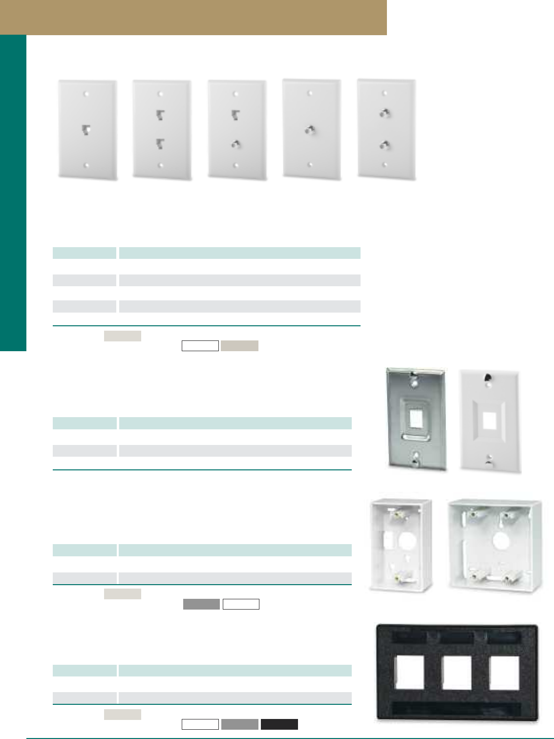
Keystone Wall-Mount Phone Plates
PART NO. DESCRIPTION
SSKF-1P 1-Port Stainless Steel Keystone Wall-Mount Phone Plate
SKF-1P 1-Port Plastic Keystone Wall-Mount Phone Plate, Light Ivory
SKF-1P-WH 1-Port Plastic Keystone Wall-Mount Phone Plate, White
Stainless steel wall-mount phone plate provides a clean, easy-to-install method for
mounting any wall-mountable phone. Plates are standard sized and with durable
mounting posts.
Telephone and Video Wallplates
Faceplates are offered in a number of different types for both telephone and video
applications. The telephone faceplates are offered in a single or dual RJ-11 6P4C
connector with screw terminal termination.
PART NO. DESCRIPTION
SCF-1P46S 1-Port RJ11 6P4C Telephone Faceplate, Light Ivory
SCF-2P46S 2-Port RJ11 6P4C Telephone Faceplate, Light Ivory
SCF-2P46SF 2-Port RJ11 6P4C & F-Type Telephone/Video Faceplate, Light Ivory
SCF-1F 1-Port F-Type Video Faceplate, Light Ivory
SCF-2F 2-Port F-Type Video Faceplate, Light Ivory
Standard color
For other colors add the following to P/N
Light Ivory
-WH (White) -DI (Ivory)
PREMISE CONNECTIVITY SYSTEMS 800.446.2377 www.signamax.com
Work Area Outlet Systems
Standard color
For other colors add the following to P/N
Light Ivory
-BK (Black)-GY (Gray)
-WH (White)
A 1 6
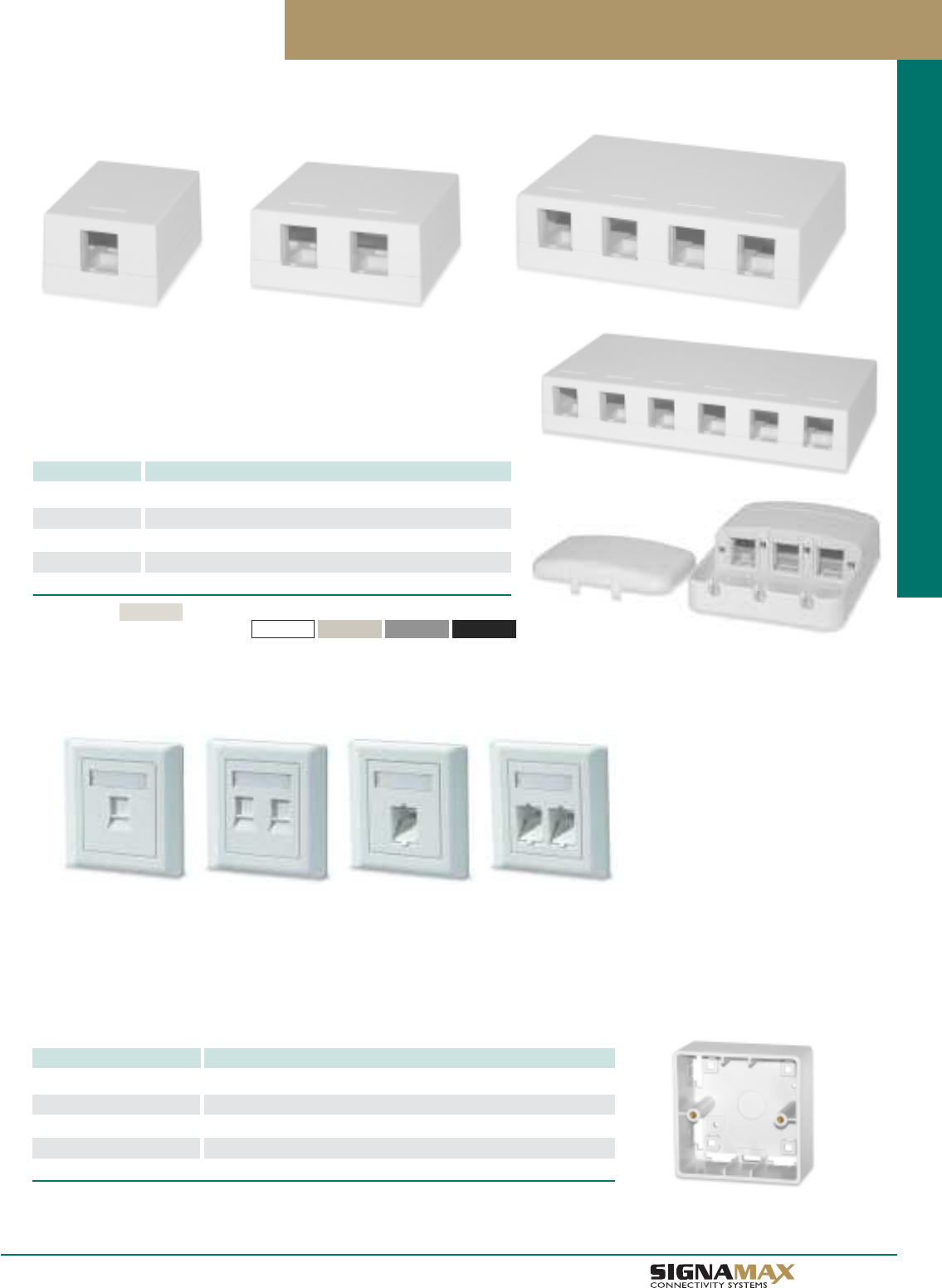
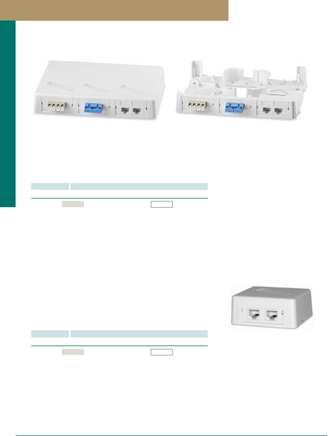
Surface-Mount Multimedia Boxes
PART NO. DESCRIPTION
SMKL-1 1-Port Surface-Mount Multimedia Box
SMKL-2 2-Port Surface-Mount Multimedia Box
SMKL-4 4-Port Surface-Mount Multimedia Box
SMKL-6 6-Port Surface-Mount Multimedia Box
SMKT-3 3-Port Surface-Mount Tamper-Proof Multimedia Box
Surface-mount multimedia boxes are available in a 1-, 2-, 4-, and 6-port versions.
The 3-port tamper-proof surface-mount multimedia box provides protection of
patch cord connection points, which gives the installation an additional flexibility
at such locations as open office environments, warehouses, lobbies/hallways, etc.
Surface-Mount Multimedia Boxes
Single- and Dual-Port Keystone Outlets
PART NO. DESCRIPTION
SKFL-1S-85-WH 1-Port Keystone International Outlet, 85 x 85 mm, White
SKFL-2S-85-WH 2-Port Keystone International Outlet, 85 x 85 mm, White
SKFLA-1S-85-WH 1-Port Angled Keystone International Outlet, 85 x 85 mm, White
SKFLA-2S-85-WH 2-Port Angled Keystone International Outlet, 85 x 85 mm, White
SMB-85-WH Surface-Mount Box for 85 x 85-mm International Outlets, White
International outlets are designed for creating work area connections based on popular European outlet mounting format
(mounting box/faceplate size – 85 x 85 mm). The two-piece design hides slots and screw heads under a decorative faceplate
allowing a clean, elegant solution suitable for any application. Clear plastic label covers provide an easy-to-read labeling solution.
Integrated shutters protect jacks from dust and other solid agents’ penetration in unmated state. Snap-on decorative faceplate
does not require tools for replacement and can be installed after all office fit-out works are finished. Outlets are compatible with
all Signamax twisted-pair and fiber keystone jacks.
International Outlets and Surface-Mount Boxes
TM
Work Area Outlet Systems
Standard color
For other colors add the following to P/N
Light Ivory
-BK (Black)
-GY (Gray)
-WH (White) -DI (Ivory)
A 1 7
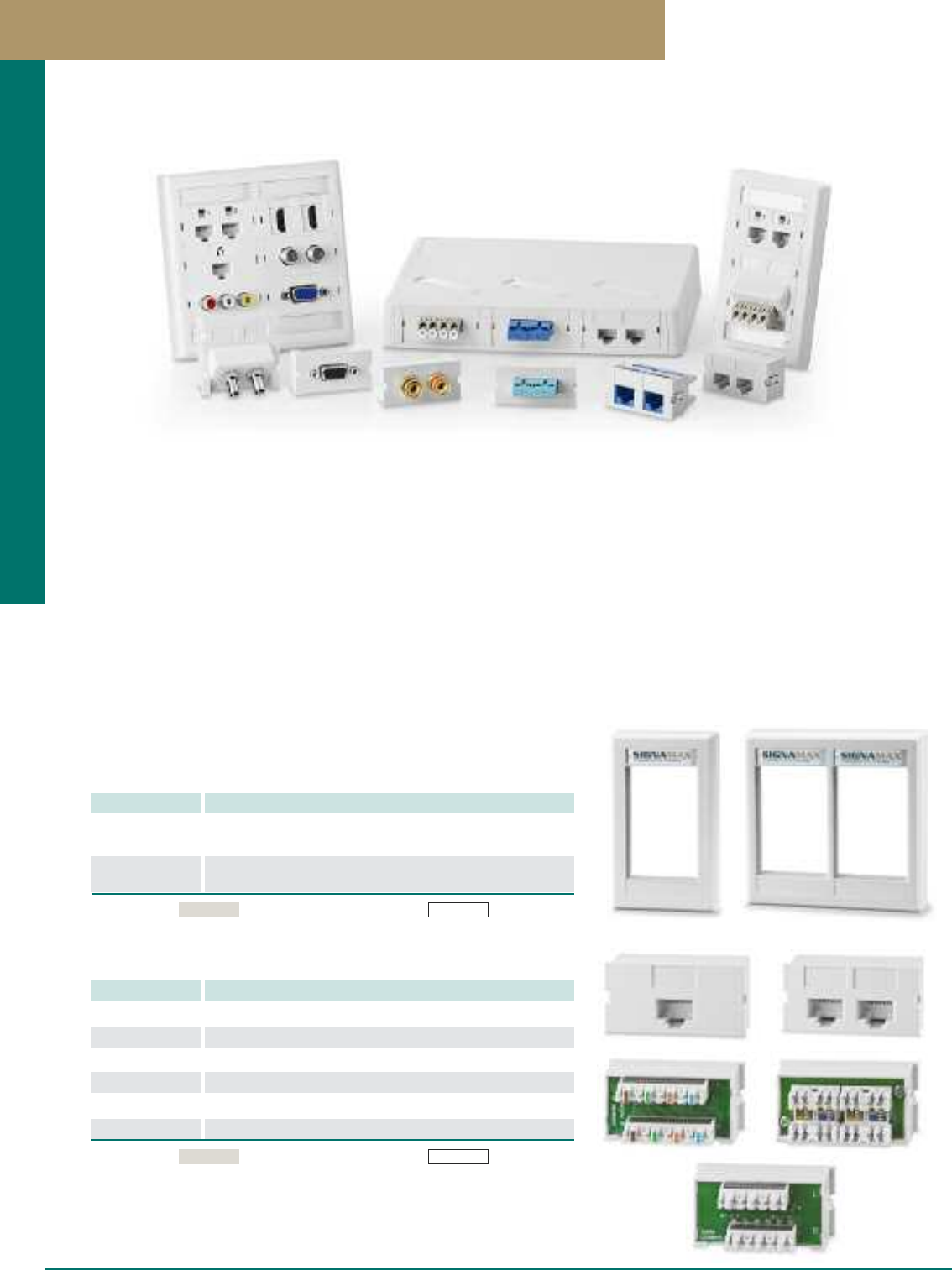
Multimedia Modular Outlet System
Single- and Double-Gang Faceplates
PART NO. DESCRIPTION
SGF-06 Single-Gang Faceplate w/2 ID Labels, 2 Clear ID Covers,
2 Color-Coded Screw Covers
DGF-12 Double-Gang Faceplate w/4 ID Labels, 4 Clear ID Covers,
4 Color-Coded Screw Covers
Category 6, 5e and Voice Grade Connector Modules
PART NO. DESCRIPTION
SCM145-C6C 1-Port Category 6 Connector Module, T568A/B Wiring
SCM245-C6C 2-Port Category 6 Connector Module, T568A/B Wiring
SCM145-C5E 1-Port Category 5e Connector Module, T568A/B Wiring
SCM245-C5E 2-Port Category 5e Connector Module, T568A/B Wiring
SCM112-C3U 1-Port RJ-12 6-Wire Connector Module, USOC Wiring
SCM212-C3U 2-Port RJ-12 6-Wire Connector Module, USOC Wiring
Standard color For white add the following to P/N -WH (White)Light Ivory
The Signamax Multimedia Modular Outlet System offers the versatility to mount a wide variety of copper, fiber and audio/video connector
modules in single- or dual-gang faceplates and surface mount boxes. The system features front-loading of connector modules with a
snap-in process allowing additions or outlet configuration changes to be made quickly. This System is the perfect solution for conference
rooms, classrooms, training rooms and other areas requiring deployment of data, voice, audio and video systems.
Faceplates have both top and bottom labeling windows for station identification and are supplied with white cards and clear label covers.
For installations that require an aesthetically pleasing look, color-coded inserts are provided to replace labels and hide the mounting
screws. The single-gang faceplate can accommodate up to three connector modules for a total of 6 connections. The double-gang plate
provides double the capacity for 12 connections in a single location. The 3-module surface mount box features an integral cable
management spool, port labeling and raceway knockouts.
Connector Modules are available in category 6, 5e and voice-grade performance levels and are designed for ease and reliability of
termination. Fiber modules accommodate feed-thru adapters ranging from ST, SC and LC in multimode, singlemode and multimode
LOF for 10G applications. A wide selection of audio/video modules is available to accommodate applications requiring F-Type, BNC,
RCA connections along with 3-Way Binding Post, S-Video, VGA/SVGA, DVI, HDMI and USB connections.
Standard color For white add the following to P/N -WH (White)Light Ivory
PREMISE CONNECTIVITY SYSTEMS 800.446.2377 www.signamax.com
Work Area Outlet Systems
A 1 8
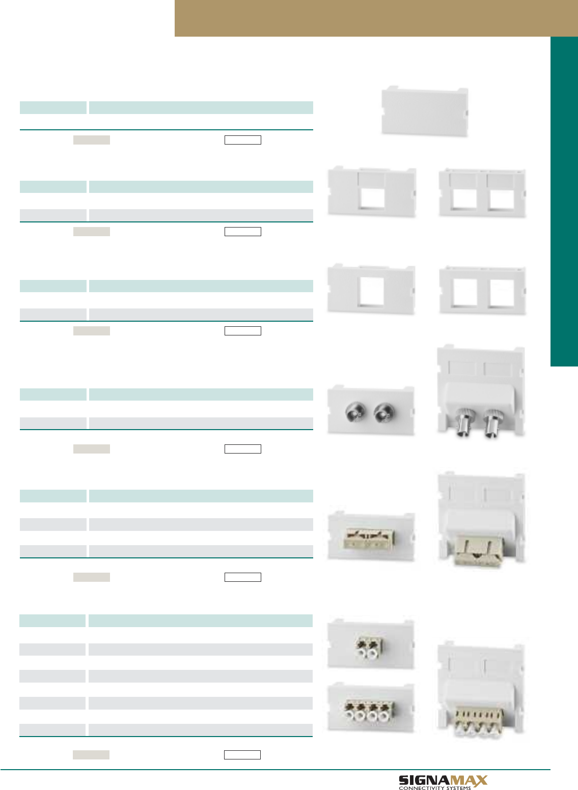
Multimedia Modular Outlet System
ST Fiber Connector Module
PART NO. DESCRIPTION
SCM-2ST 2-Fiber ST MM Connector Module, 180° Exit
SCM-2ST-C 2-Fiber ST SM Connector Module, 180° Exit
For 45° exit add -A to P/N
SC Fiber Connector Module
PART NO. DESCRIPTION
SCM-2SC 2-Fiber SC MM Connector Module, 180° Exit
SCM-2SC-C 2-Fiber SC SM Connector Module, 180° Exit
SCM-2SC-G 2-Fiber SC MM 10G LOF Connector Module, 180° Exit
SCM-2SCA-C 2-Fiber SC APC SM Connector Module, 180° Exit
For 45° exit add -A to P/N
Standard color For white add the following to P/N -WH (White)Light Ivory
LC Fiber Connector Module
PART NO. DESCRIPTION
SCM-1LC 2-Fiber LC MM Connector Module, 180° Exit
SCM-1LC-C 2-Fiber LC SM Connector Module, 180° Exit
SCM-1LC-G 2-Fiber LC MM 10G LOF Connector Module, 180° Exit
SCM-1LCA-C 2-Fiber LC APC SM Connector Module, 180° Exit
SCM-2LC 4-Fiber LC MM Connector Module, 180° Exit
SCM-2LC-C 4-Fiber LC SM Connector Module, 180° Exit
SCM-2LC-G 4-Fiber LC MM 10G LOF Connector Module, 180° Exit
SCM-4LCA-C 4-Fiber LC APC SM Connector Module, 180° Exit
For 45° connector add -A to P/N
Standard color For white add the following to P/N -WH (White)Light Ivory
Blank Module
PART NO. DESCRIPTION
SCM-BL Blank Module
Single- and Dual-Port Keystone Jack Connector Modules
PART NO. DESCRIPTION
SCM-1-KU 1-Port Keystone Jack Connector Module
SCM-2-KU 2-Port Keystone Jack Connector Module
Standard color For white add the following to P/N -WH (White)Light Ivory
Standard color For white add the following to P/N -WH (White)Light Ivory
Standard color For white add the following to P/N
Modules accept only category 6A, 6, 5e and Voice-Grade Keystone Jacks
-WH (White)
Light Ivory
TM
Work Area Outlet Systems
Single- and Dual-Port Multimedia Connector Modules
PART NO. DESCRIPTION
SCM-1-MCU 1-Port Multimedia Connector Module
SCM-2-MCU 2-Port Multimedia Connector Module
Standard color For white add the following to P/N
Modules accept category 6A, 6, 5e and Voice-Grade Keystone Jacks and all CMK Series
Keystone Multimedia Connector Modules
-WH (White)Light Ivory
A 1 9
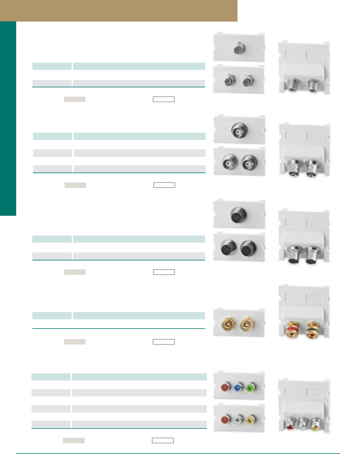
F-Type Connector Module
PART NO. DESCRIPTION
SCM-1F 1-Port F-Type 75 Ohm 3 GHz Connector Module, 180° Exit
SCM-2F 2-Port F-Type 75 Ohm 3 GHz Connector Module, 180° Exit
For 45° exit add -A to P/N
BNC Connector Module
PART NO. DESCRIPTION
SCM-1BNC 1-Port 50 Ohm BNC Connector Module, 180° Exit
SCM-2BNC 2-Port 50 Ohm BNC Connector Module, 180° Exit
SCM-1BNC75 1-Port 75 Ohm BNC Connector Module, 180° Exit
SCM-2BNC75 1-Port 75 Ohm BNC Connector Module, 180° Exit
For 45° exit add -A to P/N
Multimedia Modular Outlet System
RCA Connector Modules
PART NO. DESCRIPTION
SCM-2R-WR 2-Port RCA (White/Red) Feed-Thru Module, 180° Exit
SCM-3R-RWY 3-Port RCA (Red/White/Yellow) Feed-Thru Module, 180° Exit
SCM-3R-RGB 3-Port RCA (Red/Green/Blue) Feed-Thru Module, 180° Exit
SCM-2RS-WR 2-Port RCA (White/Red) Solder Module, 180° Exit
SCM-3RS-RWY 3-Port RCA (Red/White/Yellow) Solder Module, 180° Exit
SCM-3RS-RGB 3-Port RCA (Red/Green/Blue) Solder Module, 180° Exit
For 45° exit add -A to P/N
3-Way Binding Post Connector Module
PART NO. DESCRIPTION
SCM-2RBA 2-Port 3-Way Binding Post Connector Module, 180° Exit
For 45° exit add -A to P/N
Standard color For white add the following to P/N -WH (White)Light Ivory
Standard color For white add the following to P/N -WH (White)
Light Ivory
Standard color For white add the following to P/N -WH (White)Light Ivory
Standard color For white add the following to P/N -WH (White)Light Ivory
S-Video Connector Module
PART NO. DESCRIPTION
SCM-1SV 1-Port S-Video Feed-Thru Connector Module, 180° Exit
SCM-2SV 2-Port S-Video Feed-Thru Connector Module, 180° Exit
For 45° exit add -A to P/N
Standard color For white add the following to P/N -WH (White)Light Ivory
PREMISE CONNECTIVITY SYSTEMS 800.446.2377 www.signamax.com
Work Area Outlet Systems
A 2 0
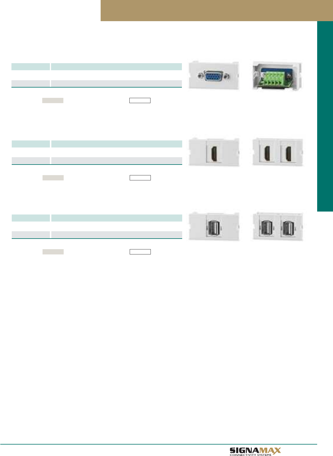
VGA HD-15 Connector Modules
PART NO. DESCRIPTION
SCM-1VGA 1-Port VGA Feed-Thru Connector Module, 180° Exit
SCM-1VGATB 1-Port VGA Female-to-Terminal Block Module, 180° Exit
Available only with 180° exit
Multimedia Modular Outlet System
Standard color For white add the following to P/N -WH (White)Light Ivory
HDMI Connector Modules
PART NO. DESCRIPTION
SCM-1HDMI 1-Port HDMI Feed-Thru Connector Module, 180° Exit
SCM-2HDMI 2-Port HDMI Feed-Thru Connector Module, 180° Exit
Available only with 180° exit
Standard color For white add the following to P/N -WH (White)Light Ivory
USB Connector Modules
PART NO. DESCRIPTION
SCM-1USB 1-Port USB Feed-Thru Connector Module, 180° Exit
SCM-2USB 2-Port USB Feed-Thru Connector Module, 180° Exit
Available only with 180° exit
Standard color For white add the following to P/N -WH (White)Light Ivory
TM
Work Area Outlet Systems
Multimedia Modular Outlet System
One-Module Surface-Mount Multimedia Box
PART NO. DESCRIPTION
SMMB-1 One-Module Surface-Mount Multimedia Box
The One-Module Surface-Mount Multimedia Box is a convenient way to mount
connector modules in the work area, for any cable type. This single-module box
consolidates cabling from behind the wall, on the wall, or from surface raceways.
This box is ideal for mixing cable types, and offers knockouts in the cover that
permit a smooth transition to industry-standard raceways.
Surface-Mount Multimedia Box with Cable Management
PART NO. DESCRIPTION
SMMB-3F 3-Module Surface Mount Box with Cable Management
The three-module surface-mount multimedia box features an integral cable
management spool, for storing cable slack lengths. Port identification can be
accomplished with the use of three labeling windows located on the box cover.
These surface- mount boxes are compatible with all copper, fiber, and multimedia
connector modules with 180° cable exit.
A 2 1 PREMISE CONNECTIVITY SYSTEMS 800.446.2377 www.signamax.com
Work Area Outlet Systems
Standard color For white add the following to P/N -WH (White)
Light Ivory
Standard color For white add the following to P/N -WH (White)
Light Ivory
Multimedia Modular Outlet System
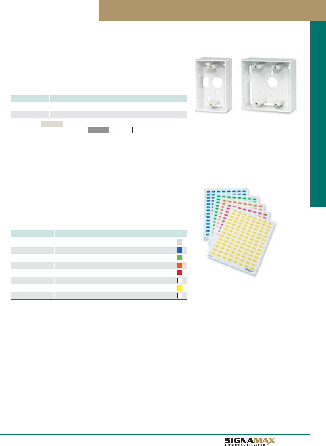
Surface-Mount Faceplate Boxes
PART NO. DESCRIPTION
SMB1-SG Single-Gang Surface-Mount Faceplate Box
SMB1-DG Double-Gang Surface-Mount Faceplate Box
Surface-mount faceplate boxes are available to accommodate both single-gang and
double-gang faceplates. Boxes provide knockouts on all sides for easy cable entry
and are supplied with mounting hardware.
Each connector module port and faceplate can be easily identified using custom
printable label sheets. Label printing is made easy by using the downloadable
template. Connector module features a recessed area above each port to
accommodate a clean, quick labeling. Labels are supplied on an 8.5” x 11”
sheet suitable for printing using most general-purpose office printers.
Printable Port and Faceplate Designation Lables
PART NO. DESCRIPTION
DL-112-IV Port Designation Labels, Sheet of 112 Labels, Light Ivory
DL-112-BU Port Designation Labels, Sheet of 112 Labels, Blue
DL-112-GN Port Designation Labels, Sheet of 112 Labels, Green
DL-112-OR Port Designation Labels, Sheet of 112 Labels, Orange
DL-112-RD Port Designation Labels, Sheet of 112 Labels, Red
DL-112-WH Port Designation Labels, Sheet of 112 Labels, White
DL-112-YE Port Designation Labels, Sheet of 112 Labels, Yellow
FL-100B-WH Faceplate Designation Cards, Sheet of 100, White
A 2 2
TM
Work Area Outlet Systems
Standard color
For other colors add the following to P/N -GY (Gray) -WH (White)
Light Ivory
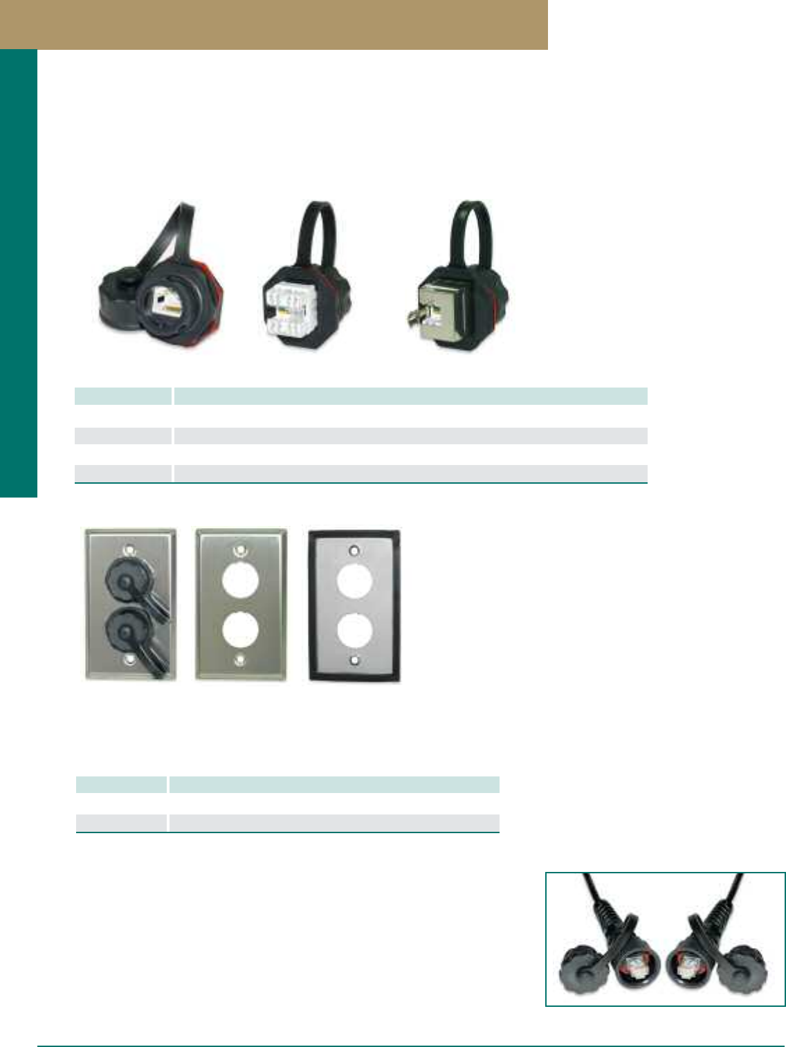
Industrial-Grade Solutions
Signamax industrial-grade jacks provide the same high-level transmission performance as other Signamax twisted-pair
connectors intended for regular commercial applications, but with a robustness capable to withstand harsh environments typical
to factory floors, chemical, food processing plants, etc. Unique IP67-rated jack housing design guarantees superb protection
against liquid and solid agents’ penetration, against vibrations, and for a long-life reliable performance. Jacks are furnished with
dust caps to prevent exposure of unmated connectors and are available in both unscreened and screened versions.
PART NO. DESCRIPTION
KJ458IG-C6C Category 6 Industrial-Grade Jack with Protective Cap, T568A/B Wiring, IP67-Rated
KJS458IG-C6C Category 6 Screened Industrial-Grade Jack with Protective Cap, T568A/B Wiring, IP67-Rated
KJ458IG-C5E Category 5e Industrial-Grade Jack with Protective Cap, T568A/B Wiring, IP67-Rated
KJS458IG-C5E Category 5e Screened Industrial-Grade Jack with Protective Cap, T568A/B Wiring, IP67-Rated
See page C7 for Industrial-Grade Field-Installable Plugs
Category 6 and Category 5e Industrial Grade Jacks
Industrial-Grade Stainless Steel Faceplates
PART NO. DESCRIPTION
SSKFIG-1 1-Port Industrial-Grade Stainless Steel Faceplate
SSKFIG-2 2-Port Industrial-Grade Stainless Steel Faceplate
Single-gang industrial faceplates are available in a 1- or 2-port version and accept
both category 6 and category 5e Industrial Jacks. Faceplates are supplied with a rear
sealing gasket and mounting screws. Faceplates are IP44-rated.
Industrial-Grade Patch Cords
Signamax industrial-grade patch cords provide a robustness capable to withstand harsh
environments typical to factory floors, chemical, food processing plants, etc. Unique IP67-
rated plug housing design along with industrial-grade stranded cable (category 5e only)
guarantee superb protection against liquid and solid agents penetration, against vibrations,
and for a long-life reliable performance. Cords are furnished with dust caps on the
protected ends to prevent exposure of unplugged connectors. (See page C7 for details.)
A 2 3 PREMISE CONNECTIVITY SYSTEMS 800.446.2377 www.signamax.com
Work Area Outlet Systems
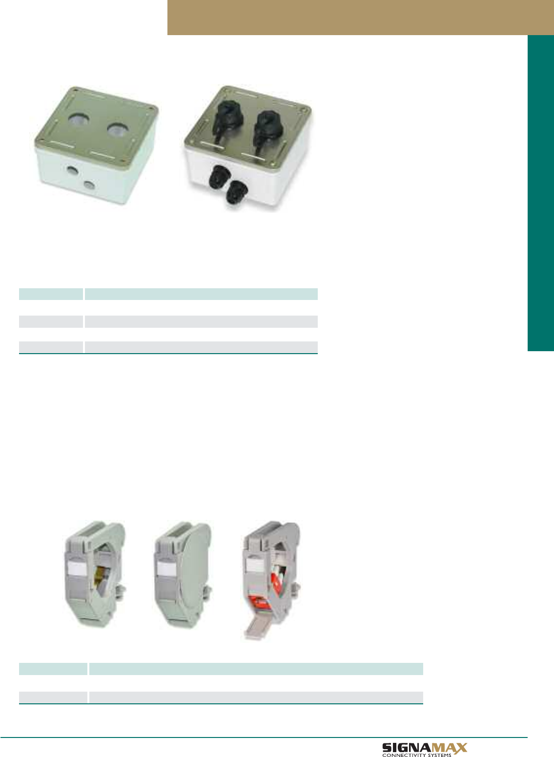
Industrial-Grade Surface-Mount Boxes
PART NO. DESCRIPTION
SMKIG-1 1-Port Industrial-Grade Surface-Mount Box
SMKIG-2 2-Port Industrial-Grade Surface-Mount Box
SMKIG-3 3-Port Industrial-Grade Surface-Mount Box
SMKIG-4 4-Port Industrial-Grade Surface-Mount Box
Harsh Environment / Industrial-Grage Surface-Mount Boxes are available in 1-, 2-, 3-,
and 4-port versions and will accept both category 6 and category 5e Industrial Jacks.
These boxes are designed to mount on any surface and provide IP66/IP67 rating.
Boxes are supplied with cable entry compression fittings and mounting screws.
Industrial-Grade Solutions
Keystone Jack DIN-Rail Mounting Modules
Keystone Jack Industrial DIN-Rail Mounting Modules provide an opportunity to combine advantages of regular keystone jack
design and transmission performance with simplicity and usability of industrial DIN-rail mounting systems. State-of-the-art
module's design provides features usually found in office work area solutions - universal labeling, protection covers, "front
access," "gravity compensation" for patch cords along with important features for the industrial applications aspects such as
toolless mounting and replacement of connector modules, quick access to any part of the assembly. Additionally, modules
allow installing screened jacks without any extra efforts, parts and tools.
PART NO. DESCRIPTION
KI-DIN-RMM-SL Keystone Jack Industrial DIN-Rail Mounting Module with 2 Side Covers
KI-DIN-RMM Keystone Jack Industrial DIN-Rail Mounting Module w/o Side Covers
Keystone Jack Industrial DIN-Rail Mounting Modules
A 2 4
TM
Work Area Outlet Systems
Patch
Panels
Cross-Connect
SYSTEMS
AND
CCaatteeggoorryy 66AA 1100GG PPaattcchh PPaanneellss BB11
CCaatteeggoorryy 66AA 1100GG AAnngglleedd PPaattcchh PPaanneellss BB22
CCaatteeggoorryy 66AA FFiieelldd--CCoonnffiigguurraabbllee PPaattcchh PPaanneellss BB22
CCaatteeggoorryy 66AA 1100GG SSccrreeeenneedd PPaattcchh PPaanneellss BB33
CCaatteeggoorryy 66AA 1100GG PPrree--TTeerrmmiinnaatteedd TTrruunnkk AAsssseemmbblliieess BB44
CCaatteeggoorryy 66 PPaattcchh PPaanneellss BB55
CCaatteeggoorryy 66 AAnngglleedd PPaattcchh PPaanneellss BB66
CCaatteeggoorryy 66 SSccrreeeenneedd PPaattcchh PPaanneell BB77
CCaatteeggoorryy 66 MMiinnii PPaattcchh PPaanneellss BB77
CCaatteeggoorryy 66 PPrree--TTeerrmmiinnaatteedd TTrruunnkk AAsssseemmbblliieess BB88
CCaatteeggoorryy 55ee PPaattcchh PPaanneellss BB99
CCaatteeggoorryy 55ee AAnngglleedd PPaattcchh PPaanneellss BB1100
CCaatteeggoorryy 55ee SSccrreeeenneedd PPaattcchh PPaanneell BB1111
CCaatteeggoorryy 55ee MMiinnii PPaattcchh PPaanneellss BB1111
CCaatteeggoorryy 55ee WWaallll--MMoouunntt JJaacckk PPaanneellss BB1111
GGiiggaabbiitt EEtthheerrnneett MMoodduullaarr--TTeellccoo PPaattcchh PPaanneellss BB1122
FFaasstt EEtthheerrnneett MMoodduullaarr--TTeellccoo PPaattcchh PPaanneellss BB1122
CCaatteeggoorryy 33 MMoodduullaarr--111100 PPaattcchh PPaanneellss BB1133
CCaatteeggoorryy 33 MMoodduullaarr--TTeellccoo PPaattcchh PPaanneellss BB1133
CCaatteeggoorryy 66 aanndd 55ee FFeeeedd--TThhrruu PPaattcchh PPaanneellss BB1144
FF--TTyyppee aanndd BBNNCC FFeeeedd--TThhrruu PPaanneellss BB1155
FFiieelldd--CCoonnffiigguurraabbllee MMuullttiimmeeddiiaa PPaanneellss BB1177
CCaatteeggoorryy 66AA,, 66,, aanndd 55ee 111100 CCrroossss--CCoonnnneecctt SSyysstteemm BB1199
6666 BBlloocckkss aanndd AAcccceessssoorriieess BB2244
w w w . s i g n a m a x . c o m
PREMISE CONNECTIVITY SYSTEMS 800.446.2377 www.signamax.comB 1
Patch Panels and Cross-Connect Systems
Category 6A 10G Patch Panels
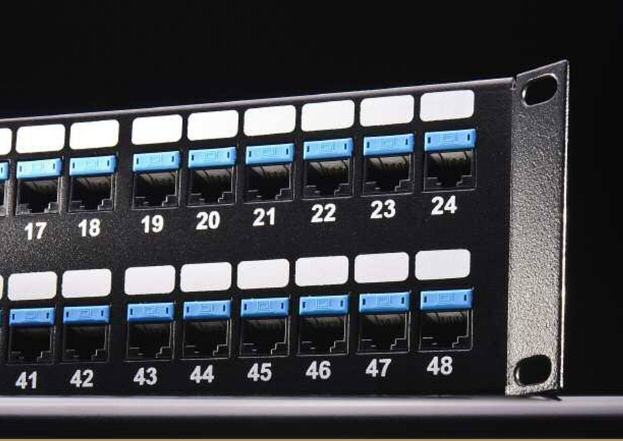
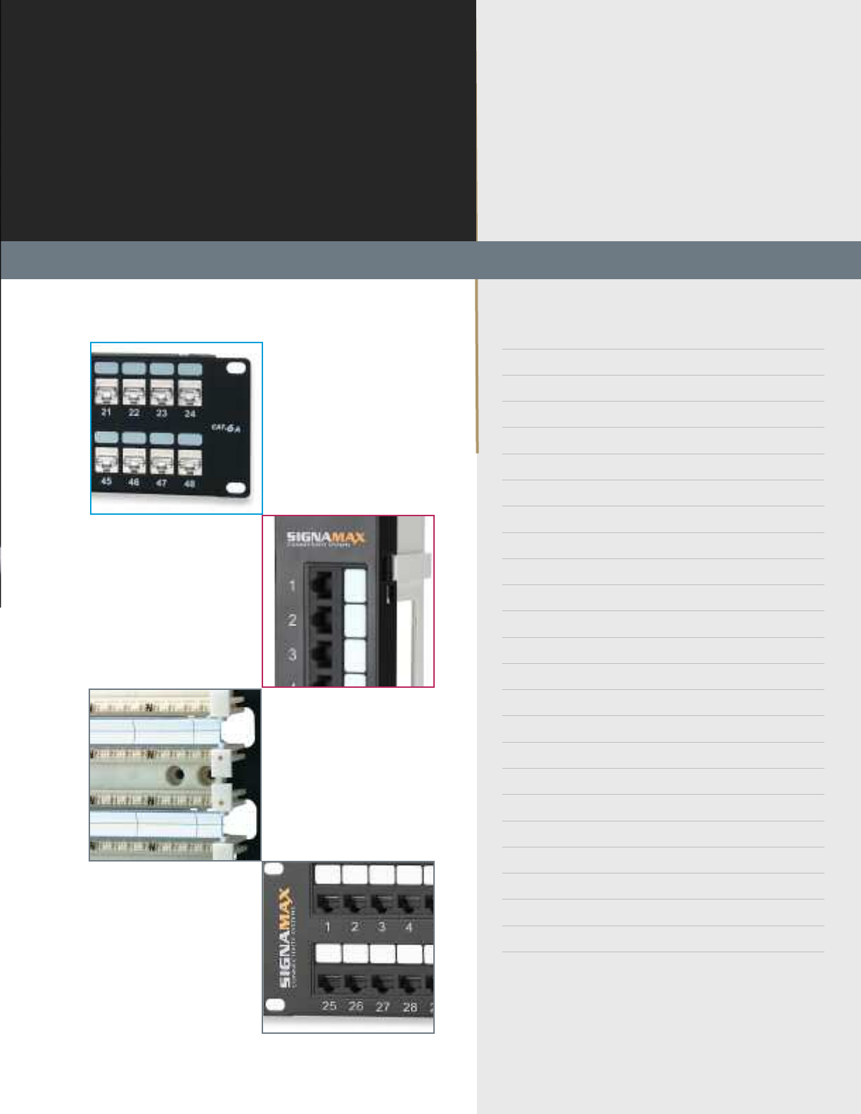
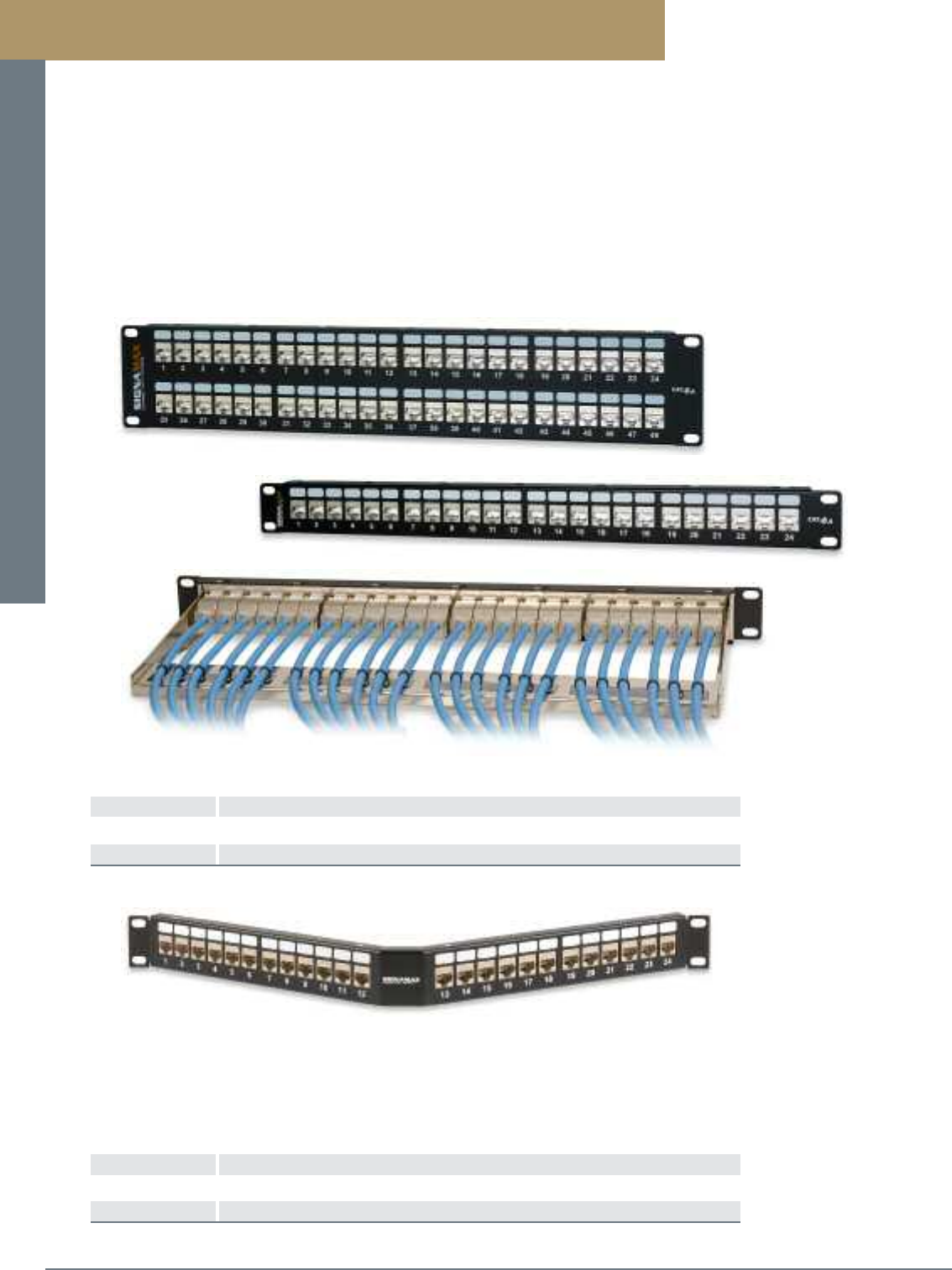
Category 6A 10G Patch Panels
Category 6A Patch Panels are designed to meet 10 Gigabit Ethernet IEEE 802.3an transmission requirements and are guaranteed
to exceed ANSI/TIA-568-C.2 performance specifications. These high-density panels are available in 24- and 48-port versions featuring
a rolled edge steel construction, which provides maximum strength and durability and eliminates panel flex during termination.
Panels feature port labeling areas and port numbering for easy circuit identification.
Panels are supplied with category 6A connectors supporting both T568A and T568B wiring using an easy-to-read color-code labels
and can be terminated using standard single-position 110 termination tool or the KJMT-8600 4-pair termination tool. This new
connector design provides enhanced plug-to-jack connection integrity, protects against damage caused by insertion of 4- or
6-position plugs, and is rated for a minimum of 750 plug insertions providing for the highest level of system reliability.
Jacks feature the ability to mount either color-coded icons for service identification or dust covers to protect unused jacks from dust
and other contaminants. Rear 110 contacts provide improved conductor retention and ease of termination. Jacks are supplied with a
metallized plastic cable protection cap, which eliminates alien crosstalk for maximum performance.
Panels are provided with a newly designed cable management bar that easily mounts to the back of the panel without the need for
mounting screws. This cable management bar features improved cable routing and strain relief.
PART NO. DESCRIPTION
24458-C6A 24-Port Category 6A 10G Patch Panel, T568A/B Wiring, 1.75” High
48458-C6A 48-Port Category 6A 10G Patch Panel, T568A/B Wiring, 3.50” High
Black connectors are standard. For panels with other color connectors contact Customer Service.
B 2
TM
Patch Panels and Cross-Connect Systems
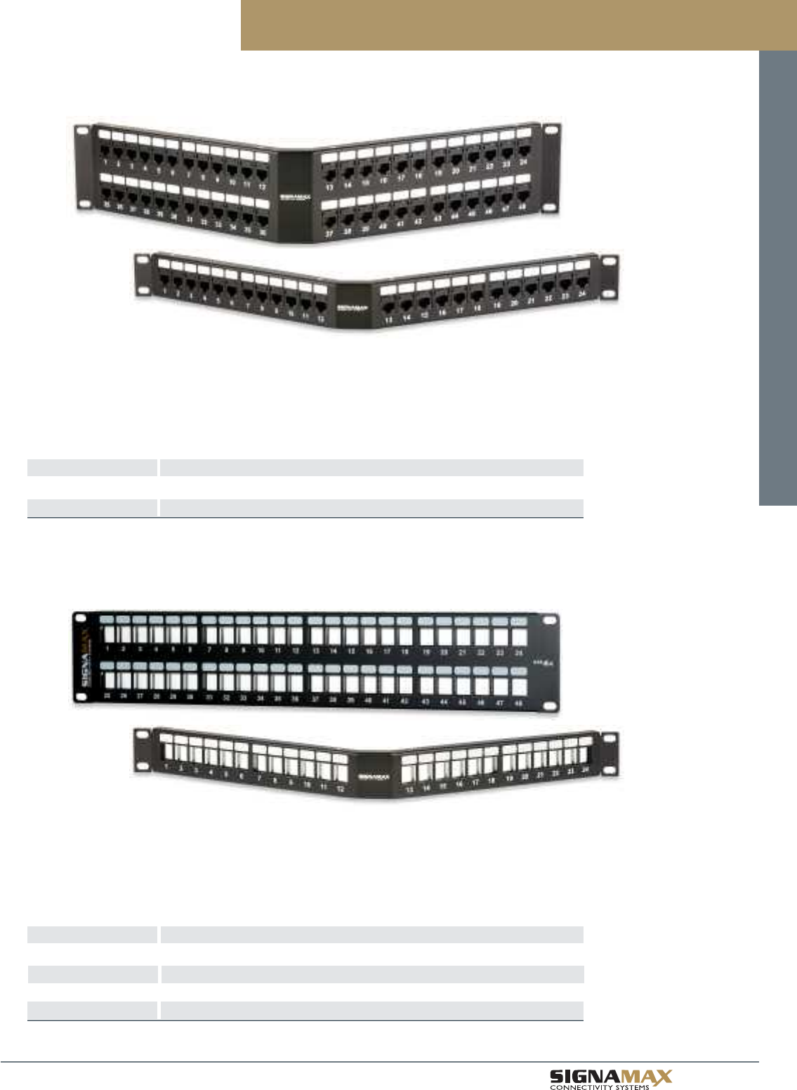
Category 6A Field-Configurable Unloaded Patch Panels
PART NO. DESCRIPTION
24U-HDMMP-C6A 24-Port Category 6A Field-Configurable Unloaded Patch Panel, 1.75” High
48U-HDMMP-C6A 48-Port Category 6A Field-Configurable Unloaded Patch Panel, 3.50” High
24U-HDMMP-A-C6A 24-Port Category 6A Angled Field-Configurable Unloaded Panel, 1.75” High
48U-HDMMP-A-C6A 48-Port Category 6A Angled Field-Configurable Unloaded Panel, 3.50” High
Category 6A unloaded panels are available for field configuration. Panels accept category 6A unscreened or
screened jacks and are supplied with cable management bars. These field-configurable panels provide the
ability to populate only the number of ports that are needed and can be configured with unscreened connectors
of different colors providing additional color-coding capabilities.
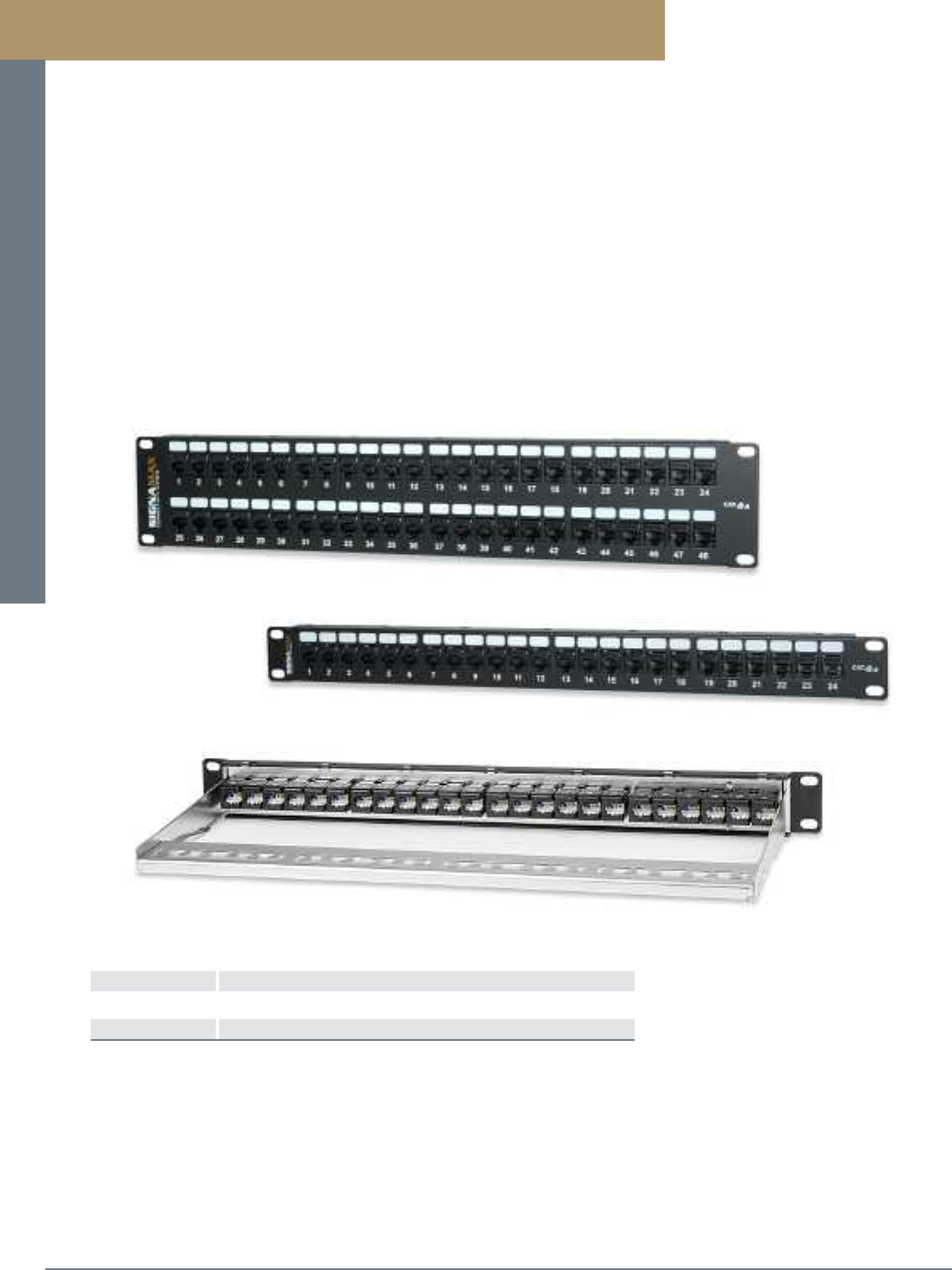
Category 6A 10G Angled Patch Panels
PART NO. DESCRIPTION
24458A-C6A 24-Port Category 6A 10G Angled Patch Panel, T568A/B Wiring 1.75” High
48458A-C6A 48-Port Category 6A 10G Angled Patch Panel, T568A/B Wiring 3.50” High
Black connectors are standard. For panels with other color connectors contact Customer Service.
Category 6A 10G Angled Patch Panels are designed to the same high-level performance as our standard
category 6A patch panels. Angled panels are supplied with black category 6A jacks supporting both T568A and
T568B wiring using an easy-to-read color-code labels. These panels have the added feature of an angled design
to help route patch cords to vertical rack- or cabinet-mounted cable management. This feature eliminates the
need for horizontal management panels, which provides additional rack space in high-density applications.
Category 6A 10G Patch Panels
Patch Panels and Cross-Connect Systems
PREMISE CONNECTIVITY SYSTEMS 800.446.2377 www.signamax.comB 3
Category 6A 10G Screened Patch Panels
Category 6A 10G Screened Patch Panels
PART NO. DESCRIPTION
24458S-C6A 24-Port Category 6A 10G Screened Patch Panel, T568A/B Wiring, 1.75” High
48458S-C6A 48-Port Category 6A 10G Screened Patch Panel, T568A/B Wiring, 3.50” High
Category 6A Screened Patch Panels are designed to meet 10 Gigabit Ethernet IEEE 802.3an ransmission requirements and are
guaranteed to exceed ANSI/TIA-568-C.2 performance specifications. These high-density panels are available in 24- and 48-port
versions featuring port labeling areas and port numbering for easy circuit identification.
Panels are supplied with 10G screened connectors supporting both T568A and T568B wiring using an easy-to-read color-code labels.
This uniquely designed connector features a toolless termination method for quick and easy installation. A new contact design provides
enhanced plug-to-jack connection integrity and is rated for a minimum of 750 plug insertions providing for the highest level of system
reliability. Jacks are fully shielded to optimize protection from EMI including alien crosstalk.
Panels are provided with a newly designed cable management bar that easily mounts to the back of the panel without the need for
mounting screws. This cable management bar features improved cable routing and strain relief.
PART NO. DESCRIPTION
24458SA-C6A 24-Port Category 6A 10G Screened Angled Patch Panel, T568A/B Wiring 1.75” High
48458SA-C6A 48-Port Category 6A 10G Screened Angled Patch Panel, T568A/B Wiring 3.50” High
Category 6A 10G Screened Angled Patch Panels
Category 6A 10G Screened Angled Patch Panels are designed to the same high-level performance as our
standard category 6A screened patch panels. These panels have the added feature of an angled design to help
route patch cords to vertical rack- or cabinet-mounted cable management. This feature eliminates the need for
horizontal management panels, which provides additional rack space in high-density applications.
Patch Panels and Cross-Connect Systems
B 4
TM
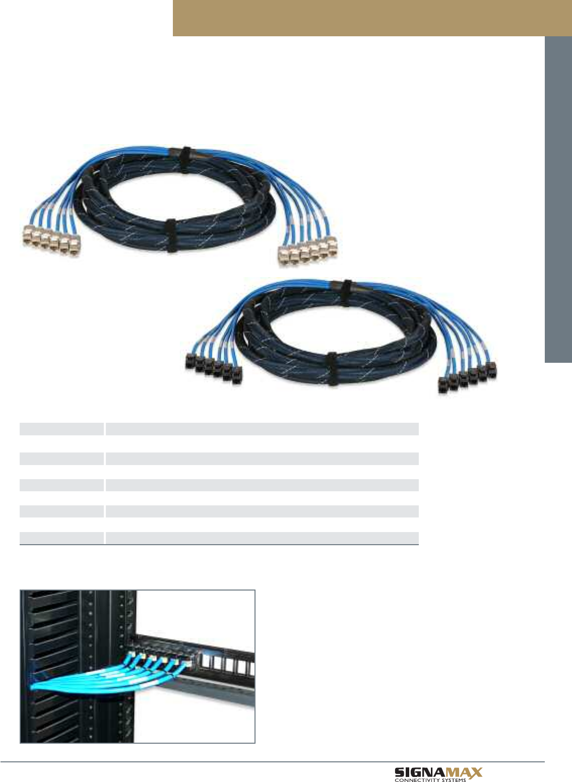
Category 6A 10G Pre-Terminated Trunk Assemblies
Pre-terminated Category 6A Trunk Assemblies help to reduce significantly both time and cost of a category 6A cabling installation.
Terminated and tested in a controlled manufacturing environment, cut to the customer pre-ordered lengths, and ready to install
in a patch panel, trunk assemblies eliminate all these operations in the field making your job easy and efficient. Trunk cables
are available in both unscreened and screened versions in either a jack-to-jack or jack-to-blunt cut configurations.
Trunk cables can be used with any category 6A field-configurable patch panel (see page B2).
Category 6A 10G Pre-Terminated Trunk Assemblies
PART NO. DESCRIPTION
6L-C6A-JJ-P-FXXX Category 6A 10G 6-Leg Trunk Cable, Jack-to-Jack, Unscreened U/UTP Cable, CMP
6L-C6A-JB-P-FXXX Category 6A 10G 6-Leg Trunk Cable, Jack-to-Open, Unscreened U/UTP Cable, CMP
6L-C6AS-JJ-P-FXXX Category 6A 10G 6-Leg Trunk Cable, Jack-to-Jack, Screened F/UTP Cable, CMP
6L-C6AS-JB-P-FXXX Category 6A 10G 6-Leg Trunk Cable, Jack-to-Open, Screened F/UTP Cable, CMP
6L-C6A-JJ-R-FXXX Category 6A 10G 6-Leg Trunk Cable, Jack-to-Jack, Unscreened U/UTP Cable, CMR
6L-C6A-JB-R-FXXX Category 6A 10G 6-Leg Trunk Cable, Jack-to-Open, Unscreened U/UTP Cable, CMR
6L-C6AS-JJ-R-FXXX Category 6A 10G 6-Leg Trunk Cable, Jack-to-Jack, Screened F/UTP Cable, CMR
6L-C6AS-JB-R-FXXX Category 6A 10G 6-Leg Trunk Cable, Jack-to-Open, Screened F/UTP Cable, CMR
For length substitute XXX for length in feet. Minimum length is 10 ft. Maximum length is 295 ft.
Unscreened cable color is blue. Screened cable is gray. Other colors are available.
Standard cable is straight-cut for either left or right cable exit. Staggered-cut cables are available.
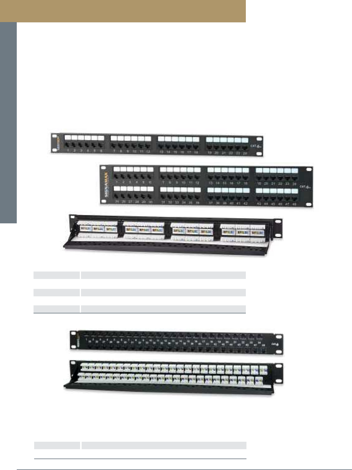
Patch Panels and Cross-Connect Systems
PREMISE CONNECTIVITY SYSTEMS 800.446.2377 www.signamax.comB 5
Category 6 Patch Panels
Category 6 Patch Panels are designed to exceed ANSI/TIA-568-C.2 component performance specifications providing usable band-
width beyond 250 MHz and are backward compatible with lower category cabling systems. These high-density panels are available in
12- through 48-port versions and feature enhanced front and rear labeling features for easy circuit identification. Category 6 panels
support both T568A and T568B wiring schemes using an easy-to-read color-code label.
Panels are constructed for maximum strength and durability and feature a fully enclosed, modular design, which provides flexibility and
protection of printed circuitry during termination. The RJ-45 contact configuration provides enhanced plug-to-jack connection integrity
for superior reliability. The Category 6 panel features standard 4-pair 110 connectors for more reliable termination and improved cable
retention.
Panels include an integrated cable management feature for cable routing and strain relief requirements. An optional cable manage-
ment bar, which mounts easily to the back of the panel without the need for mounting screws, is available for improved cable routing
and strain relief.
Category 6 Patch Panels
PART NO. DESCRIPTION
12458MD-C6C 12-Port Category 6 Patch Panel, T568A/B Wiring, 1.75” High
24458MD-C6C 24-Port Category 6 Patch Panel, T568A/B Wiring, 1.75” High
48458MD-C6C 48-Port Category 6 Patch Panel, T568A/B Wiring. 3.50” High
CMB-250-P Panel-Mount Cable Management Bar, 2.5” Deep
Category 6 High-Density 48-Port Patch Panel
PART NO. DESCRIPTION
48458HD-C6C 48-Port Category 6 High-Density Patch Panel, T568A/B, 1.75” High
Black connectors are standard. For panel kit with other color connectors contact Customer Service.
The Category 6 High-Density Panel supports 48 category 6 connectors in a 1-RMS (1.75”H) panel. This
high-density panel is the ideal solution where rack space is limited. The panel is supplied as a kit, which includes
the panel, 48 category 6 black jacks and a cable management bar. Panel kits can be supplied with category 6 un-
screened jacks of different colors providing additional color-coding capabilities.

Patch Panels and Cross-Connect Systems
B 6
TM
Category 6 Patch Panels
Category 6 Angled Patch Panels
PART NO. DESCRIPTION
24458A-C6C 24-Port Category 6 Angled Patch Panel, T568A/B Wiring, 1.75” High
48458A-C6C 48-Port Category 6 Angled Patch Panel, T568A/B Wiring, 3.50” High
Black connectors are standard. For panels with other color connectors contact Customer Service.
Category 6 Angled Patch Panels are designed to the same high-level performance as our standard category 6
patch panels. Angled panels are supplied with black category 6 jacks supporting both T568A and T568B wiring
using an easy-to-read color-code labels. These panels have the added feature of an angled design to help
route patch cords to vertical rack- or cabinet-mounted cable management. This feature eliminates the need for
horizontal management panels, which provides additional rack space in high-density applications.
Field-Configurable Unloaded Patch Panels
PART NO. DESCRIPTION
24U-HDMMP 24-Port Field-Configurable Unloaded Patch Panel, 1.75” High
48U-HDMMP 48-Port Field-Configurable Unloaded Patch Panel, 3.50” High
24U-HDMMP-A 24-Port Angled Field-Configurable Unloaded Panel, 1.75” High
48U-HDMMP-A 48-Port Angled Field-Configurable Unloaded Panel, 3.50” High
48U-HDMMP-1R 48-Port High-Density Field-Configurable Unloaded Panel, 1.75” High
Unloaded panels are available for field configuration. Panels accept unscreened or screened jacks and are sup-
plied with cable management bars. These field-configurable panels provide the ability to populate only the num-
ber of ports that are needed and can be configured with unscreened connectors of different colors providing
additional color-coding capabilities.
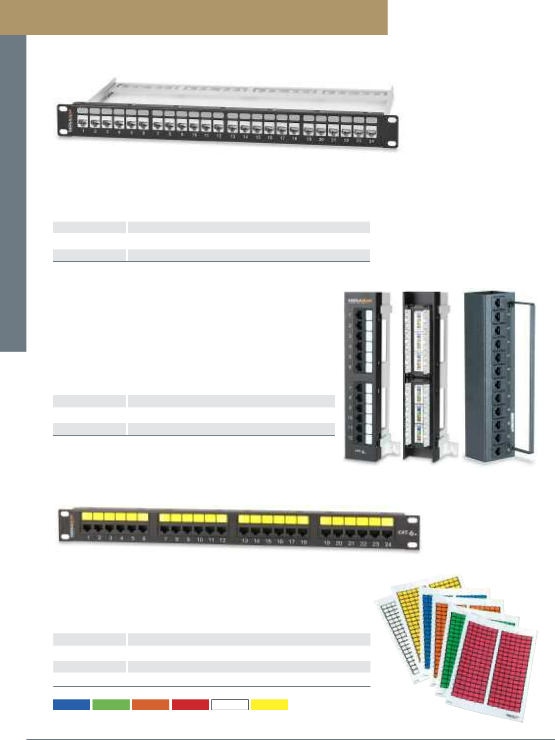
Patch Panels and Cross-Connect Systems
PREMISE CONNECTIVITY SYSTEMS 800.446.2377 www.signamax.comB 7
Category 6 Mini Patch Panels are available in 12-port size and are ideal for
installations where space is at a premium and open bay racks cannot be used.
Panels are provided mounted to either an 89D bracket or in a hinged version,
both of which allow for easy access to the back of the panel for termination to
110 connectors. Panels exceed ANSI/TIA-568-C.2 performance specifications.
Category 6 Wall-Mount Mini Patch Panels
PART NO. DESCRIPTION
12458M-C6C 12-Port Category 6 Mini Panel w/89D Bracket, T568A/B
12458MH-C6C 12-Port Category 6 Hinged Mini Panel, T568A/B
Category 6 Patch Panels
Designation Labeling Sheets
PART NO. DESCRIPTION
DLF6-LC 6-Port Front Panel Designation Label Sheet
DLR6-WH 6-Port Rear Panel 110 Designation Label Sheet, White Only
SPL-648 Sequentially Numbered Port Label Strips, 1 through 648
Category 6 and 5e rack-mount and mini patch panel ports and 110 wiring connectors can be
labeled using color-coded labels. Templates can be downloaded from the Signamax web site,
to help installers to lay out label sheets for custom printing. Labels are supplied on 8.5” x 11”
sheets suitable for printing using most general-purpose office printers. Sequentially
numbered port label strips are also available for numbering ports from 1 to 648.
For label colors substitute LC for color in P/N.
Labels are available for the following panel P/N’s only; 12458MD-C6C, 24458MD-C6C, 48458MD-C6C and 12458M-C6C
12458MD-C5E, 24458MD-C5E, 48458MD-C5E and 12458M-C5E
-BU (Blue) -GN (Green) -OR (Orange) -RD (Red) -WH (White) -YE (Yellow)
Category 6 Screened Patch Panels are available in 24- and 48-port sizes and provide the
ability to terminate fully screened category 6 cable. These panels exceeds ANSI/TIA-568-
C.2 specifications for superior performance. Panels feature front labeling areas and comes
with a rear cable management bar that mounts easily to the back of the panel.
Category 6 Screened Patch Panels
PART NO. DESCRIPTION
24458S-C6C 24-Port Category 6 Screened Patch Panel, T568A/B, 1.75” High
48458S-C6C 48-Port Category 6 Screened Patch Panel, T568A/B, 3.50” High
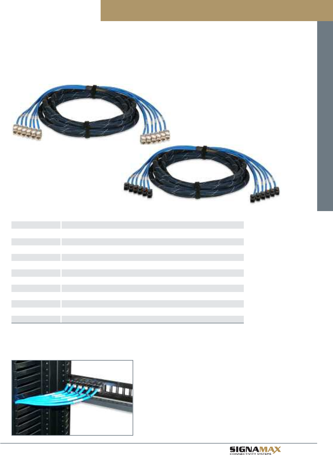
Patch Panels and Cross-Connect Systems
B 8
TM
Pre-Terminated Category 6 Trunk Assemblies
Pre-terminated Category 6 Trunk Assemblies help to reduce significantly both time and cost of a category 6 cabling installation.
Terminated and tested in a controlled manufacturing environment, cut to the customer pre-ordered lengths, and ready to install in
a patch panel, trunk assemblies eliminate all these operations in the field making your job easy and efficient. Trunk cables are
available in both unscreened and screened versions in either a jack-to-jack, jack-to-plug or jack-to-blunt cut configurations.
Trunk cables can be used with any category 6 field-configurable patch panel (see page B6).
Category 6 Pre-Terminated Trunk Assemblies
PART NO. DESCRIPTION
6L-C6-JJ-P-FXXX Category 6 6-Leg Trunk Cable, Jack-to-Jack, Unscreened U/UTP Cable, CMP
6L-C6-JP-P-FXXX Category 6 6-Leg Trunk Cable, Jack-to-Plug, Unscreened U/UTP Cable, CMP
6L-C6-JB-P-FXXX Category 6 6-Leg Trunk Cable, Jack-to-Open, Unscreened U/UTP Cable, CMP
6L-C6S-JJ-P-FXXX Category 6 6-Leg Trunk Cable, Jack-to-Jack, Screened F/UTP Cable, CMP
6L-C6S-JP-P-FXXX Category 6 6-Leg Trunk Cable, Jack-to-Plug, Screened F/UTP Cable, CMP
6L-C6S-JB-P-FXXX Category 6 6-Leg Trunk Cable, Jack-to-Open, Screened F/UTP Cable, CMP
6L-C6-JJ-R-FXXX Category 6 6-Leg Trunk Cable, Jack-to-Jack, Unscreened U/UTP Cable, CMR
6L-C6-JP-R-FXXX Category 6 6-Leg Trunk Cable, Jack-to-Plug, Unscreened U/UTP Cable, CMR
6L-C6-JB-R-FXXX Category 6 6-Leg Trunk Cable, Jack-to-Open, Unscreened U/UTP Cable, CMR
6L-C6S-JJ-R-FXXX Category 6 6-Leg Trunk Cable, Jack-to-Jack, Screened F/UTP Cable, CMR
6L-C6S-JP-R-FXXX Category 6 6-Leg Trunk Cable, Jack-to-Plug, Screened F/UTP Cable, CMR
6L-C6S-JB-R-FXXX Category 6 6-Leg Trunk Cable, Jack-to-Open, Screened F/UTP Cable, CMR
For length substitute XXX for length in feet. Minimum length is 10 ft. Maximum length is 295 ft.
Unscreened cable color is blue. Screened cable is gray. Other colors are available.
Standard cable is straight-cut for either left or right cable exit. Staggered-cut cables are available.
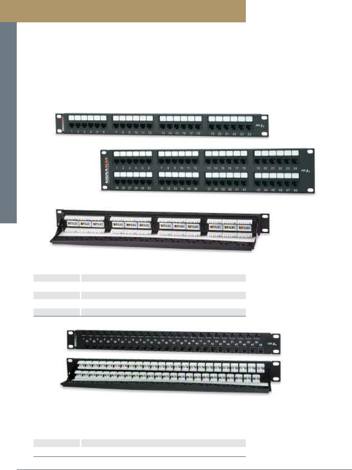
Patch Panels and Cross-Connect Systems
PREMISE CONNECTIVITY SYSTEMS 800.446.2377 www.signamax.comB 9
Category 5e Patch Panels
Category 5e Patch Panels are designed to exceed ANSI/TIA-568-C.2 component performance specifications providing usable
bandwidth beyond 100 MHz. These high-density panels are available in 12- through 48-port versions and feature enhanced front
and rear labeling features for easy circuit identification. Category 5e panels support both T568A and T568B wiring schemes using
an easy-to-read color-code labels.
Panels are constructed for maximum strength and durability and feature a fully enclosed, modular design, which provides flexibility
and protection of printed circuitry during termination. Panels include an integrated cable management feature for cable routing and
strain relief requirements. An optional cable management bar, which mounts easily to the back of the panel without the need for
mounting screws, is available for improved cable routing and strain relief.
Category 5e Patch Panels
PART NO. DESCRIPTION
12458MD-C5E 12-Port Category 5e Patch Panel, T568A/B Wiring, 1.75” High
24458MD-C5E 24-Port Category 5e Patch Panel, T568A/B Wiring, 1.75” High
48458MD-C5E 48-Port Category 5e Patch Panel, T568A/B Wiring, 3.50” High
CMB-250-P Panel-Mount Cable Management Bar, 2.5” Deep
Category 5e High-Density 48-Port Patch Panel
PART NO. DESCRIPTION
48458HD-C5E 48-Port Category 5e High-Density Patch Panel, T568A/B, 1.75” High
Black connectors are standard. For panel kit with other color connectors contact Customer Service.
The Category 5e High-Density Panel supports 48 category 5e connectors in a 1-RMS (1.75”H) panel.
This high-density panel is the ideal solution where rack space is limited. The panel is supplied as a kit, which
includes the panel, 48 category 5e black jacks, and a cable management bar. Panel kits can be supplied with
category 5e unscreened jacks of different colors providing additional color-coding capabilities.
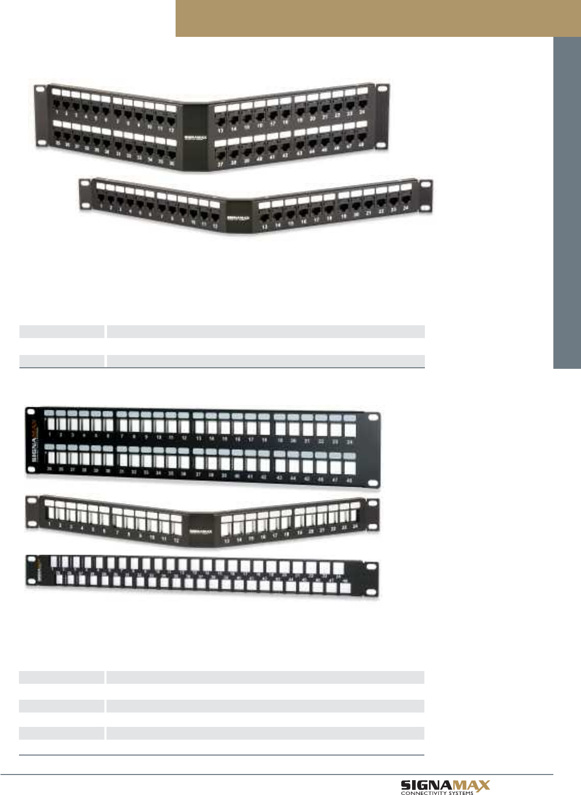
Patch Panels and Cross-Connect Systems
B 1 0
TM
Category 5e Patch Panels
Category 5e Angled Patch Panels
PART NO. DESCRIPTION
24458A-C5E 24-Port Category 5e Angled Patch Panel, T568A/B Wiring, 1.75” High
48458A-C5E 48-Port Category 5e Angled Patch Panel, T568A/B Wiring, 3.50” High
Black connectors are standard. For panels with other color connectors contact Customer Service.
Category 5e Angled Panels are designed to the same high-level performance as our standard category 5e
patch panels. Angled panels are supplied with black category 5e jacks supporting both T568A and T568B wiring
schemes using an easy-to-read color-code labels. These panels have the added feature of an angled design to
help route patch cords to vertical rack- or cabinet-mounted cable management. This feature eliminates the
need for horizontal management panels, which provides additional rack space in high-density applications.
Field-Configurable Unloaded Patch Panels
PART NO. DESCRIPTION
24U-HDMMP 24-Port Field-Configurable Unloaded Patch Panel, 1.75” High
48U-HDMMP 48-Port Field-Configurable Unloaded Patch Panel, 3.50” High
24U-HDMMP-A 24-Port Angled Field-Configurable Unloaded Panel, 1.75” High
48U-HDMMP-A 48-Port Angled Field-Configurable Unloaded Panel, 3.50” High
48U-HDMMP-1R 48-Port High-Density Field-Configurable Unloaded Panel, 1.75” High
Unloaded panels are available for field configuration. Panels accept unscreened or screened jacks and are
supplied with cable management bars. These field-configurable panels provide the ability to populate only the
number of ports that are needed and can be configured with unscreened connectors of different colors providing
additional color-coding capabilities.
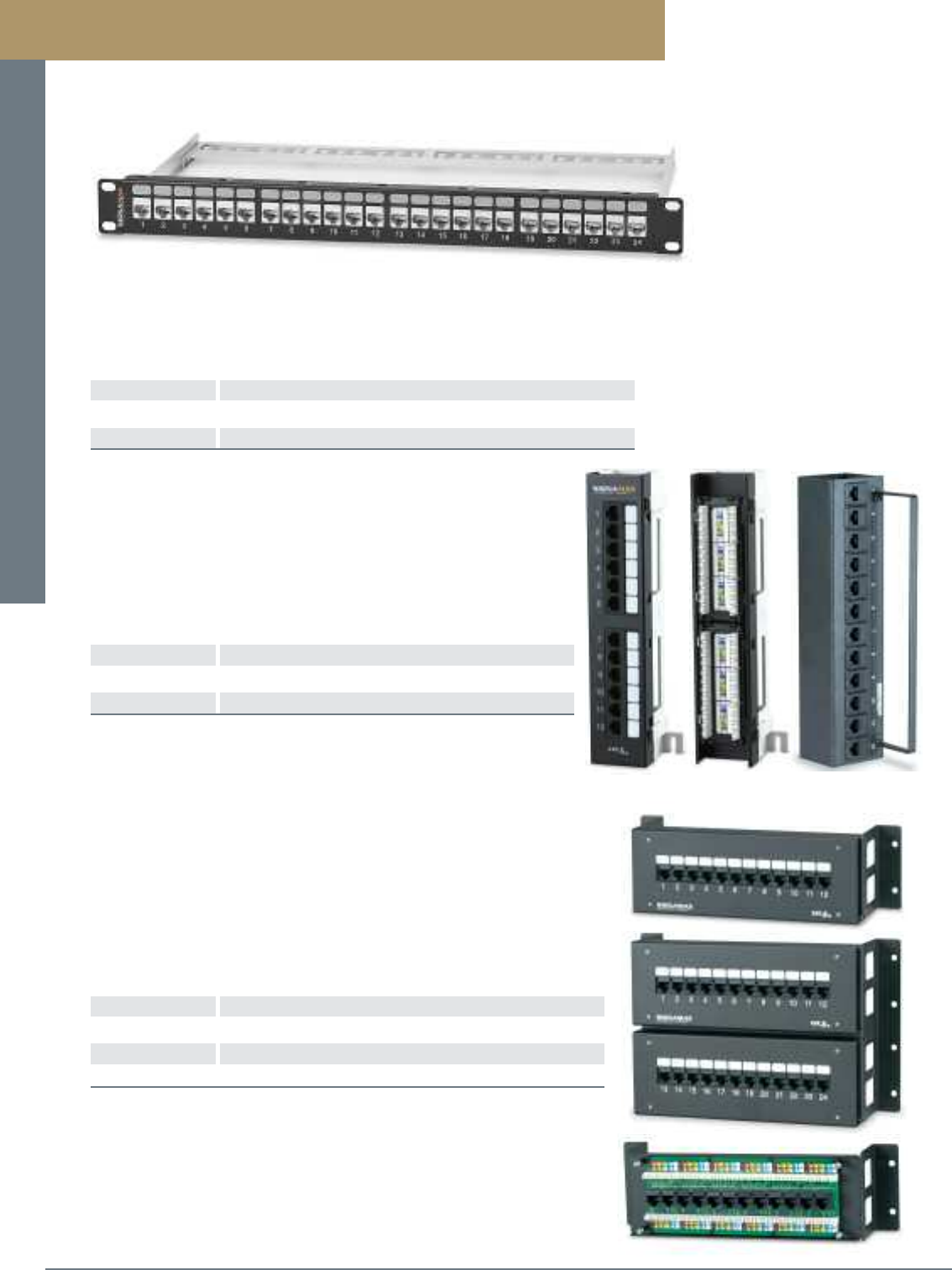
Patch Panels and Cross-Connect Systems
PREMISE CONNECTIVITY SYSTEMS 800.446.2377 www.signamax.comB 11
Category 5e Wall-Mount Mini Patch Panels
PART NO. DESCRIPTION
12458M-C5E 12-Port Category 5e Mini Panel w/89D Bracket, T568A/B
12458MH-C5E 12-Port Category 5e Hinged Mini Panel, T568A/B
Category 5e Mini Patch Panels are available in 12-port size and are ideal for
installations where space is at a premium and open bay racks cannot be used.
Panels are provided mounted to either an 89D bracket or in a hinged version,
both of which allow for easy access to the back of the panel for termination to
110 connectors. Panels exceed ANSI/TIA-568-C.2 performance specifications.
Category 5e Patch Panels
Category 5e Wall-Mount Jack Panels are available in 12-, 24-, and 36-port sizes with
termination points enclosed in a protective housing featuring a removable front cover
for easy access to the front-facing RJ-45 and 110 connectors. Panels are provided
with stand-off legs for routing cables behind the panel and a cable tie-down feature at
the panel entry point. The 12- and 36-port panels have the same footprint as 100- and
300-pair 110-blocks. The jack panels accommodate both T568A and T568B wiring
schemes using an easy-to-read color-code labels.
Category 5e Wall-Mount Jack Panels
PART NO. DESCRIPTION
12458JPL-C5E 12-Port Category 5e Jack Panel, T568A/B Wiring
24458JPL-C5E 24-Port Category 5e Jack Panel, T568A/B Wiring
36458JPL-C5E 36-Port Category 5e Jack Panel, T568A/B Wiring
Category 5e Screened Patch Panels are available in 24- and 48-port sizes and provide the
ability to terminate fully screened category 5e cable. These panels exceeds ANSI/TIA-568-
C.2 specifications for superior performance. Panels feature front labeling areas and comes
with a rear cable management bar that mounts easily to the back of the panel.
Category 5e Screened Patch Panels
PART NO. DESCRIPTION
24458S-C5E 24-Port Category 5e Screened Patch Panel, T568A/B, 1.75” High
48458S-C5E 48-Port Category 5e Screened Patch Panel, T568A/B, 3.50” High
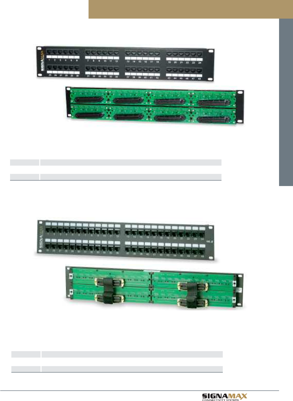
Patch Panels and Cross-Connect Systems
B 1 2
TM
Fast Ethernet Modular-Telco Patch Panels
Fast Ethernet Modular-Telco Patch Panels
PART NO. DESCRIPTION
24454-C5FT 24-Port 10/100T/TX Modular-Telco Patch Panel, Active Pins 1, 2, 3, and 6, Female Telco, 1.75”H
48454-C5FT 48-Port 10/100T/TX Modular-Telco Patch Panel, Active Pins 1, 2, 3, and 6, Female Telco, 3.50”H
For male Telco-style connector substitute M for F in P/N
Fast Ethernet Modular-Telco Patch Panels provide the ability to connect to 10/100BASE-TX switches with Telco-style
or RJ-45 interface connectors, while maintaining performance throughout the cabling system. The panels are
available in 24- and 48-port sizes with RJ-45 connectors (active pins 1, 2, 3, and 6) wired to 50-position (25-pair)
Telco-style connectors using standard pin configuration.
Gigabit Ethernet Modular-Telco Patch Panels
Gigabit Ethernet Modular-Telco Patch Panels
PART NO. DESCRIPTION
24458-C5FB 24-Port Gigabit Modular-Telco Patch Panel, 568B Wiring (Active Pins 1-8) Female Telco, 1.75”H
48458-C5FB 48-Port Gigabit Modular-Telco Patch Panel, 568B Wiring (Active Pins 1-8) Female Telco, 3.50”H
See page C8 for Category 5e 25-Pair Telco Assemblies and Adapter Cables
Gigabit Ethernet Modular-Telco Patch Panels provide the ability to connect to gigabit equipment while maintaining
performance throughout the cabling system. The panels are available in 24- and 48-port sizes with RJ-45 8P8C
connectors wired to 50-position (25-pair) Telco-style connectors using T568B wiring.
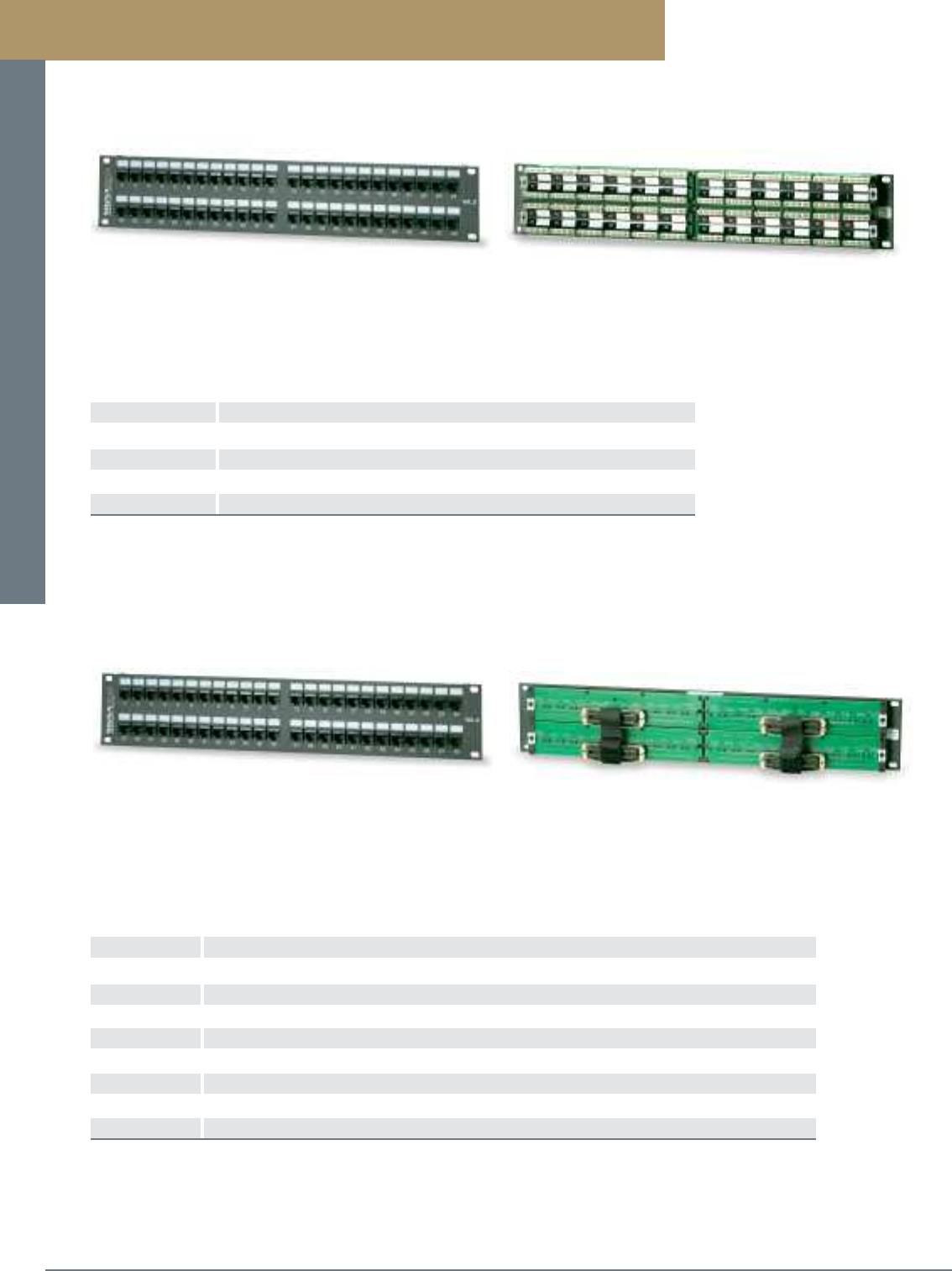
Patch Panels and Cross-Connect Systems
PREMISE CONNECTIVITY SYSTEMS 800.446.2377 www.signamax.comB13
Category 3 Modular-Telco Patch Panels
Category 3 “RJ-11” and “RJ-45” Modular-Telco Patch Panels
PART NO. DESCRIPTION
24112-C3MU 24-Port Category 3 RJ-11 2W Modular-Telco Patch Panel, Active Pins 3-4, USOC, Male, 1.75” High
48112-C3MU 48-Port Category 3 RJ-11 2W Modular-Telco Patch Panel, Active Pins 3-4, USOC, Male, 3.50” High
24114-C3MU 24-Port Category 3 RJ-11 4W Modular-Telco Patch Panel, Active Pins 2-5, USOC, Male, 1.75” High
48114-C3MU 48-Port Category 3 RJ-11 4W Modular-Telco Patch Panel, Active Pins 2-5, USOC, Male, 3.50” High
24452-C3MU 24-Port Category 3 RJ-45 2W Modular-Telco Patch Panel, Active Pins 4-5, USOC, Male, 1.75” High
48452-C3MU 48-Port Category 3 RJ-45 2W Modular-Telco Patch Panel, Active Pins 4-5, USOC, Male, 3.50” High
24454-C3MU 24-Port Category 3 RJ-45 4W Modular-Telco Patch Panel, Active Pins 3-6, USOC, Male, 1.75” High
48454-C3MU 48-Port Category 3 RJ-45 4W Modular-Telco Patch Panel, Active Pins 3-6, USOC, Male, 3.50” High
For female 25-pair Telco connectors substitute F for M in P/N
Category 3 Modular-Telco Patch Panels are available in 24- and 48-port sizes and support 2-wire “RJ-11”, 4-wire “RJ-11”,
2 wire “RJ-45” and 4 wire “RJ-45” USOC wiring schemes. Each 50-position Telco connector is provided with both Velcro
strain relief brackets and hex sockets to secure 25-pair cables with either 90-degree or 180-degree cable exit. Panels
front features a write-on surface to provide port identification. Panels include an integrated cable management/strain relief
system for improved cable routing and strain relief.
Category 3 Modular-110 Patch Panels
PART NO. DESCRIPTION
24116-C4U 24-Port Category 3 RJ-12 6W 110 Patch Panel, USOC Wiring, 1.75” High
48116-C4U 48-Port Category 3 RJ-12 6W 110 Patch Panel, USOC Wiring, 3.50” High
24458-C4U 24-Port Category 3 RJ-45 8W 110 Patch Panel, USOC Wiring, 1.75” High
48458-C4U 48-Port Category 3 RJ-45 8W 110 Patch Panel, USOC Wiring, 3.50” High
Category 3 Modular-110 Patch Panels are available in 24- and 48-port sizes and support 6-wire “RJ-12”
and 8-wire “RJ-45” USOC wiring schemes. Panels are constructed for maximum strength and durability
and can be terminated with either multipair or single-position 110-tool. Panels feature a write-on
surface area to provide port identification on both the front and rear termination areas. Panels include
an integrated cable management/strain relief system for improved cable routing and strain relief.
Category 3 Modular-110 Patch Panels
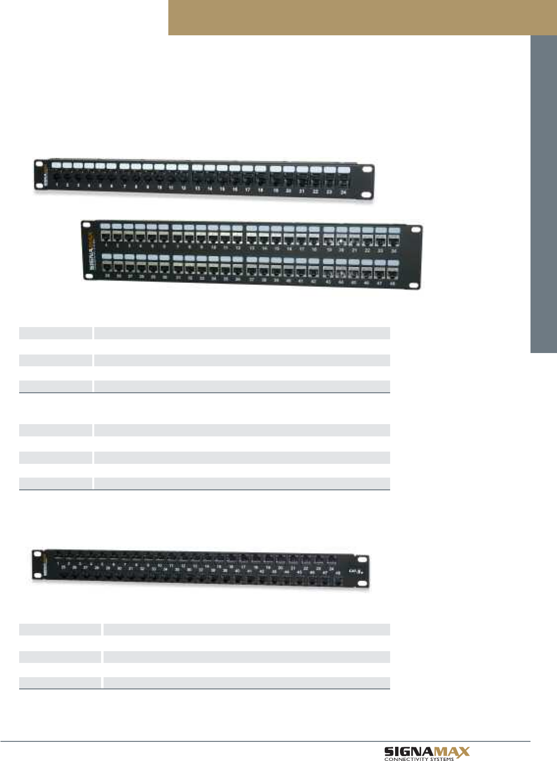
Patch Panels and Cross-Connect Systems
B 1 4
TM
Category 6 and 5e High-Density Feed-Thru Patch Panels
Category 6 High-Density Feed-Thru Patch Panels
PART NO. DESCRIPTION
24458FTHD-C6 24-Port Category 6 High-Density Feed-Thru Patch Panel, 1.75” High
48458FTHD-C6 48-Port Category 6 High-Density Feed-Thru Patch Panel, 3.50” High
24458SFTHD-C6 24-Port Category 6 Screened High-Density Feed-Thru Patch Panel, 1.75” High
48458SFTHD-C6 48-Port Category 6 Screened High-Density Feed-Thru Patch Panel, 3.50” High
Category 5e High-Density Feed-Thru Patch Panels
PART NO. DESCRIPTION
24458FTHD-C5E 24-Port Category 5e High-Density Feed-Thru Patch Panel, 1.75” High
48458FTHD-C5E 48-Port Category 5e High-Density Feed-Thru Patch Panel, 3.50” High
24458SFTHD-C5E 24-Port Category 5e Screened High-Density Feed-Thru Patch Panel, 1.75” High
48458SFTHD-C5E 48-Port Category 5e Screened High-Density Feed-Thru Patch Panel, 3.50” High
Category 6 and 5e High-Density Feed-Thru Panels can be used when connecting active equipment in a telecommunications
room and it is necessary to cross-connect using patch cables, in order to interface to the distribution cabling system. Signamax
High-Density Feed-Thru Patch Panels provide 24 and 48 modular coupling ports, while maintaining category 5e or category 6
performance. Panels are available in either an unscreened or screened version and are provided with a newly designed cable
management bar that easily mounts to the back of the panel without the need for mounting screws. This cable management bar
features improved cable routing and strain relief.
Category 6 and 5e High-Density 48-Port Feed-Thru Patch Panel
PART NO. DESCRIPTION
48458FTHD1-C6 48-Port Category 6 High-Density Feed-Thru Patch Panel, 1.75” High
48458SFTHD1-C6 48-Port Category 6 Screened High-Density Feed-Thru Patch Panel, 1.75” High
48458FTHD1-C5E 48-Port Category 5e High-Density Feed-Thru Patch Panel, 1.75” High
48458SFTHD1-C5E 48-Port Category 5e Screened High-Density Feed-Thru Patch Panel, 1.75” High
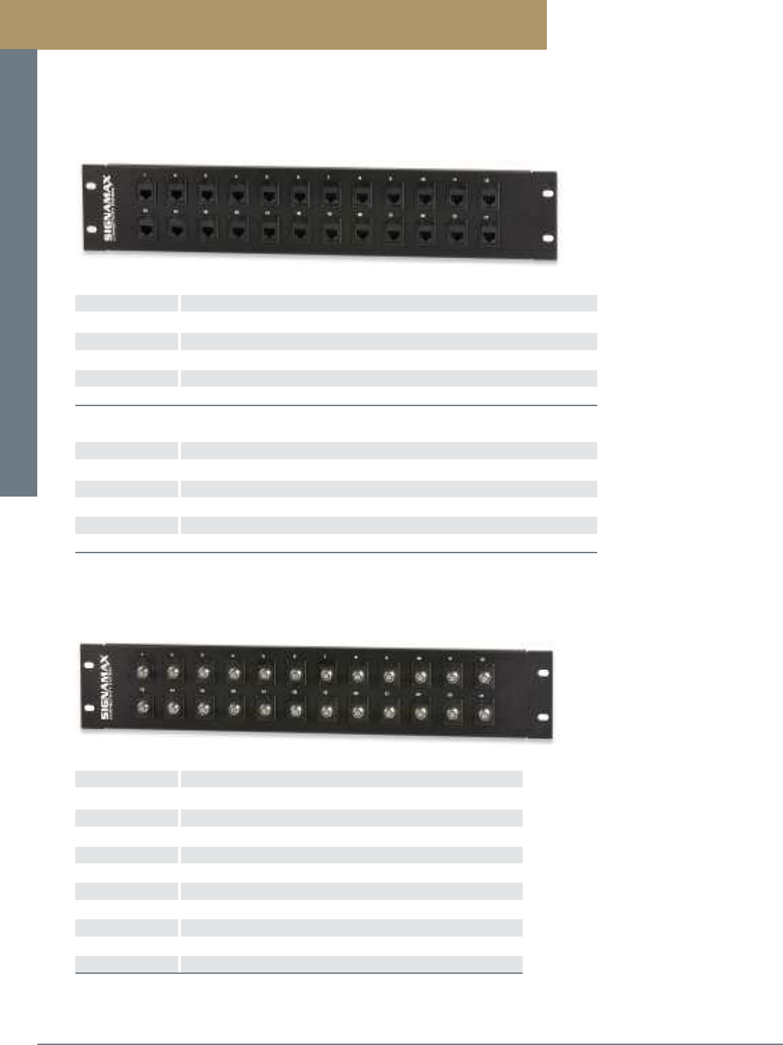
Patch Panels and Cross-Connect Systems
PREMISE CONNECTIVITY SYSTEMS 800.446.2377 www.signamax.comB15
Standard-Density F-Type Feed-Thru Patch Panels
F-Type Connector Feed-Thru Patch Panel
PART NO. DESCRIPTION
12F-FT 12-Port 1-GHz F-Type Feed-Thru Patch Panel, 1.75” High
16F-FT 16-Port 1-GHz F-Type Feed-Thru Patch Panel, 1.75” High
24F-FT 24-Port 1-GHz F-Type Feed-Thru Patch Panel, 3.50” High
32F-FT 32-Port 1-GHz F-Type Feed-Thru Patch Panel, 3.50” High
48F-FT 48-Port 1-GHz F-Type Feed-Thru Patch Panel, 5.25” High
12F3-FT 12-Port 3-GHz F-Type Feed-Thru Patch Panel, 1.75” High
16F3-FT 16-Port 3-GHz F-Type Feed-Thru Patch Panel, 1.75” High
24F3-FT 24-Port 3-GHz F-Type Feed-Thru Patch Panel, 3.50” High
32F3-FT 32-Port 3-GHz F-Type Feed-Thru Patch Panel, 3.50” High
48F3-FT 48-Port 3-GHz F-Type Feed-Thru Patch Panel, 5.25” High
Category 6 Standard-Density Feed-Thru Patch Panels
PART NO. DESCRIPTION
12458FT-C6 12-Port Category 6 Standard-Density Feed-Thru Patch Panel, 1.75” High
16458FT-C6 16-Port Category 6 Standard-Density Feed-Thru Patch Panel, 1.75” High
24458FT-C6 24-Port Category 6 Standard-Density Feed-Thru Patch Panel, 3.50” High
32458FT-C6 32-Port Category 6 Standard-Density Feed-Thru Patch Panel, 3.50” High
48458FT-C6 48-Port Category 6 Standard-Density Feed-Thru Patch Panel, 5.25” High
Category 5e Standard-Density Feed-Thru Patch Panels
PART NO. DESCRIPTION
12458FT-C5E 12-Port Category 5e Standard-Density Feed-Thru Patch Panel, 1.75” High
16458FT-C5E 16-Port Category 5e Standard-Density Feed-Thru Patch Panel, 1.75” High
24458FT-C5E 24-Port Category 5e Standard-Density Feed-Thru Patch Panel, 3.50” High
32458FT-C5E 32-Port Category 5e Standard-Density Feed-Thru Patch Panel, 3.50” High
48458FT-C5E 48-Port Category 5e Standard-Density Feed-Thru Patch Panel, 5.25” High
Category 6 and 5e Standard-Density Feed-Thru Patch Panels
When connecting active equipment in a telecommunications room, it is often necessary to cross-connect using patch
cables, in order to interface to the distribution cabling system. Signamax Standard-Density Feed-Thru Patch Panels
provide 12, 16, 24, 32, and 48 modular coupling ports, while maintaining category 5e or category 6 performance.
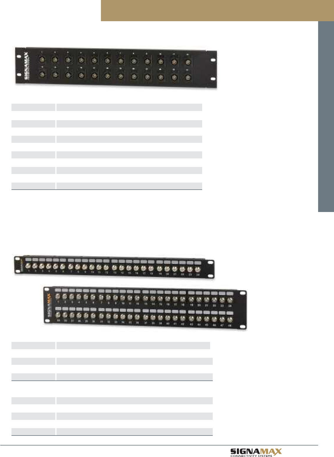
Patch Panels and Cross-Connect Systems
B 1 6
TM
BNC Feed-Thru Patch Panels
PART NO. DESCRIPTION
12BNC-FT 12-Port 50-Ohm BNC Feed-Thru Patch Panel, 1.75” High
16BNC-FT 16-Port 50-Ohm BNC Feed-Thru Patch Panel, 1.75” High
24BNC-FT 24-Port 50-Ohm BNC Feed-Thru Patch Panel, 3.50” High
32BNC-FT 32-Port 50-Ohm BNC Feed-Thru Patch Panel, 3.50” High
48BNC-FT 48-Port 50-Ohm BNC Feed-Thru Patch Panel, 5.25” High
12BNC75-FT 12-Port 75-Ohm BNC Feed-Thru Patch Panel, 1.75” High
16BNC75-FT 16-Port 75-Ohm BNC Feed-Thru Patch Panel, 1.75” High
24BNC75-FT 24-Port 75-Ohm BNC Feed-Thru Patch Panel, 3.50” High
32BNC75-FT 32-Port 75-Ohm BNC Feed-Thru Patch Panel, 3.50” High
48BNC75-FT 48-Port 75-Ohm BNC Feed-Thru Patch Panel, 5.25” High
High-Density F-Type and BNC Feed-Thru Patch Panels
High-Density F-Type Connector Feed-Thru Patch Panel
PART NO. DESCRIPTION
24FHD-FT 24-Port 1-GHz F-Type High-Density Feed-Thru Patch Panel, 1.75” High
48FHD-FT 48-Port 1-GHz F-Type High-Dendity Feed-Thru Patch Panel, 3.50” High
24F3HD-FT 24-Port 3-GHz F-Type High-Density Feed-Thru Patch Panel, 1.75” High
48F3HD-FT 48-Port 3-GHz F-Type High-Density Feed-Thru Patch Panel, 3.50” High
High-Density BNC Feed-Thru Patch Panels
PART NO. DESCRIPTION
24BNCHD-FT 24-Port 50-Ohm BNC High-Density Feed-Thru Patch Panel, 1.75” High
48BNCHD-FT 48-Port 50-Ohm BNC High-Density Feed-Thru Patch Panel, 3.50” High
24BNC75HD-FT 24-Port 75-Ohm BNC High-Density Feed-Thru Patch Panel, 1.75” High
48BNC75HD-FT 48-Port 75-Ohm BNC High-Density Feed-Thru Patch Panel, 3.50” High
Standard-Density BNC Feed-Thru Patch Panels
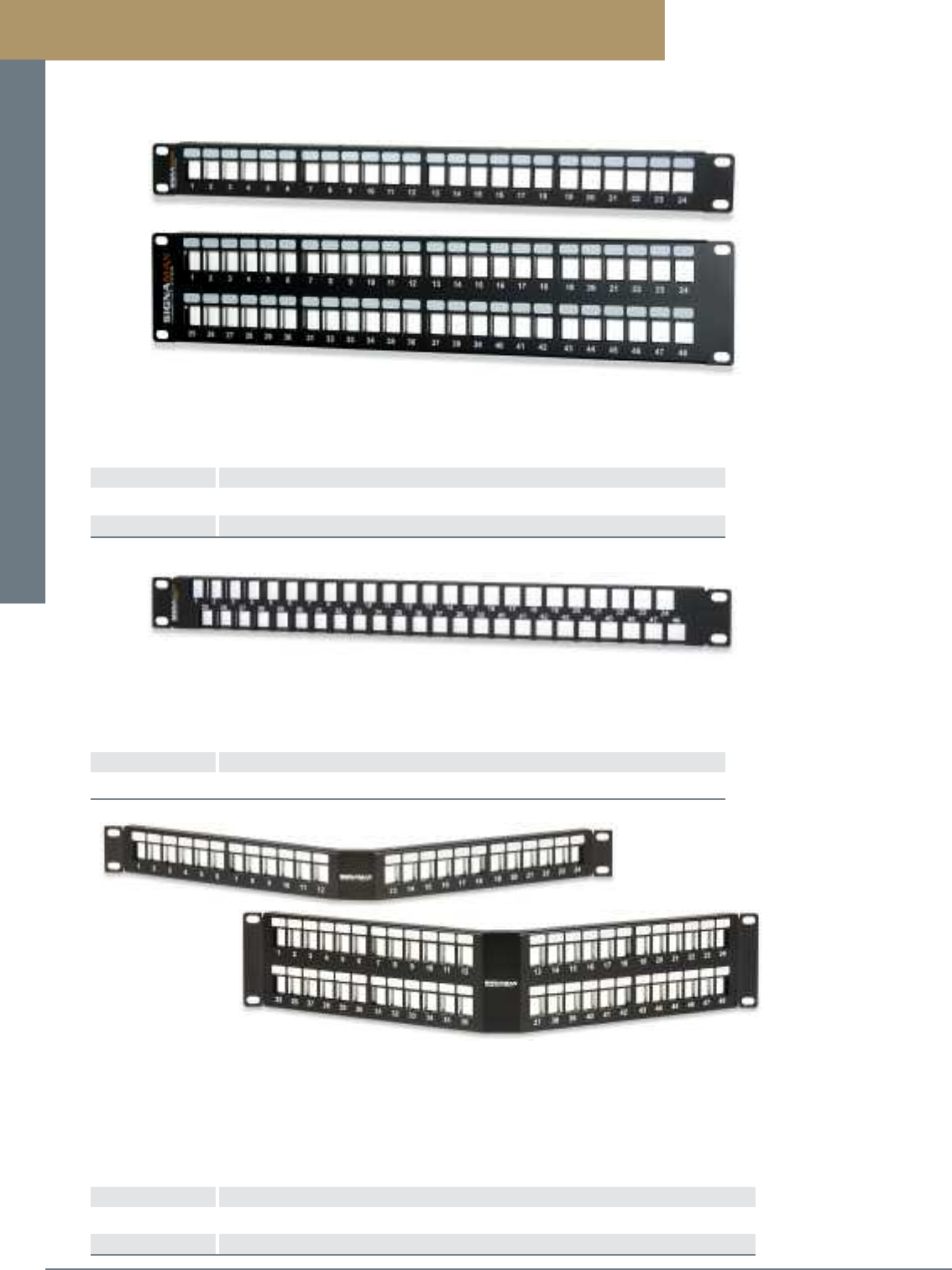
Patch Panels and Cross-Connect Systems
PREMISE CONNECTIVITY SYSTEMS 800.446.2377 www.signamax.comB17
High-density field-configurable panels are available in 24- and 48-port sizes. Panels provide the flexibility
when field configuring using a variety of connectors including category 6A, 6, 5e, and voice-grade
high-density jacks, as well as a wide range of fiber and audio/video multimedia modules.
High-Density Field-Configurable Unloaded Multimedia Panels
PART NO. DESCRIPTION
24U-HDMMP 24-Port High-Density Field-Configurable Unloaded Multimedia Panel, 1.75” High
48U-HDMMP 48-Port High-Density Field-Configurable Unloaded Multimedia Panel, 3.50” High
Field-Configurable Multimedia Patch Panels
High-density field-configurable angled panels has the added feature of angled design to help route patch cords
to vertical rack- or cabinet-mounted cable management. This unique feature eliminates the need for horizontal
management panels providing additional rack space in high-density applications. The panel provides the
flexibility to field configure panels using a variety of connectors including category 6A, 6, 5e, and voice-grade
high-density jacks, as well as a wide range of fiber and audio/video multimedia modules.
High-Density Field-Configurable Angled Unloaded Multimedia Panels
PART NO. DESCRIPTION
24U-HDMMP-A 24-Port High-Density Field-Configurable Unloaded Angled Multimedia Panel, 1.75” High
48U-HDMMP-A 48-Port High-Density Field-Configurable Unloaded Angled Multimedia Panel, 3.50” High
48-Port High-Density Field-Configurable Unloaded Multimedia Patch Panel
PART NO. DESCRIPTION
48U-HDMMP-1R 48-Port High-Density Field-Configurable Unloaded Multimedia Panel, 1.75” High
High-density field-configurable 48-port panel provides 48 ports in a 1-RMS (1.75”H) panel. This high-density panel is
the ideal solution where rack space is limited and supports a variety of connectors including category 6A, 6, 5e, and
voice-grade high-density jacks, as well as a wide range of fiber and audio/video multimedia modules.
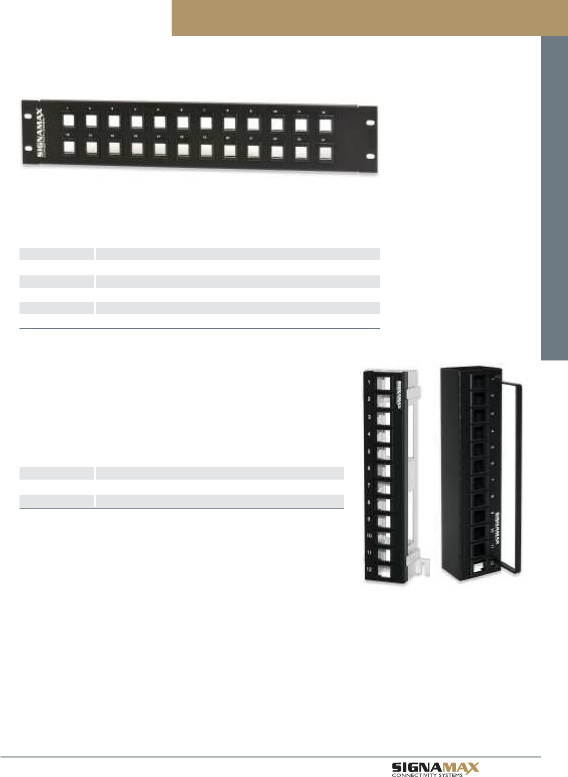
Patch Panels and Cross-Connect Systems
B 1 8
TM
Standard-Density Field-Configurable Multimedia Panels are available in 12-, 16-, 24-, 32-, and 48-port
sizes. Panels provide the ability to field configure port layout using a variety of connectors including
category 6A, category 6, and category 5e jacks, as well as a wide range of multimedia modules.
Standard-Density Field-Configurable Multimedia Panels
PART NO. DESCRIPTION
12U-MMP 12-Port Standard-Density Field-Configurable Multimedia Panel, 1.75” High
16U-MMP 16-Port Standard-Density Field-Configurable Multimedia Panel, 1.75” High
24U-MMP 24-Port Standard-Density Field-Configurable Multimedia Panel, 3.50” High
32U-MMP 32-Port Standard-Density Field-Configurable Multimedia Panel, 3.50” High
48U-MMP 48-Port Standard-Density Field-Configurable Multimedia Panel, 5.25” High
12-Port Field-Configurable Multimedia Wall-Mount Mini Panels are ideal for applications
where space is at a premium. Panels are provided mounted to either an 89D bracket or in
a hinged version, both allow for easy access to the back of the panel. These panels are
designed to accept unscreened category 6A, 6, and 5e high-density jacks.
12-Port Field-Configurable Multimedia Wall-Mount Mini Panels
PART NO. DESCRIPTION
12U-M89 12-Port Field-Configurable Multimedia Panel w/89D Bracket
12U-MH 12-Port Field-Configurable Multimedia Hinged Panel
Field-Configurable Multimedia Patch Panels
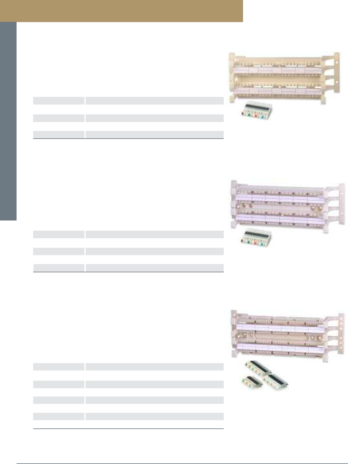
Patch Panels and Cross-Connect Systems
PREMISE CONNECTIVITY SYSTEMS 800.446.2377 www.signamax.comB19
110 Wiring Blocks
Category 6A 110 Wiring Blocks
PART NO. DESCRIPTION
110WB6A-32PR-L Category 6A 32-Pair 110 Wiring Block With Mounting Legs
110WB6A-64PR-L Category 6A 64-Pair 110 Wiring Block With Mounting Leg
110WB6A-192PR-L Category 6A 192-Pair 110 Wiring Block With Mounting Legs
110CB6-4PR 4-Pair 110 IDC Connecting Blocks, Package of 10
For Wiring Blocks w/o Legs delete -L from P/N.
Category 6A Wiring Blocks accommodate a range of solid conductor sizes from 22
to 26 AWG and are designed to support ANSI/TIA-568-C.2 category 6A channel
performance. Blocks are available in 32-, 64-, and 192-pair sizes with mounting legs
for routing cable behind the block. Connecting Blocks are available in a 4-pair size
and color coded for easy conductor placement.
Category 6 110 Wiring Blocks
PART NO. DESCRIPTION
110WB6-48PR-L Category 6 48-Pair 110 Wiring Block With Mounting Legs
110WB6-96PR-L Category 6 96-Pair 110 Wiring Block With Mounting Leg
110WB6-288PR-L Category 6 288-Pair 110 Wiring Block With Mounting Legs
110CB6-4PR Category 6 4-Pair 110 IDC Connecting Blocks, Package of 10
For Wiring Blocks w/o Legs delete -L from P/N.
Category 6 Wiring Blocks accommodate a range of solid conductor sizes from 22 to
26 AWG and are designed to exceed ANSI/TIA-568-C.2 category 6 specifications.
Blocks are available in 48-, 96-, and 288-pair sizes and can be ordered with mounting
legs for routing cable behind the block, or without legs where space is limited.
Category 6 Connecting Blocks are available in a 4-pair size and color coded for
easy conductor placement.
Category 5e 110 Wiring Blocks
PART NO. DESCRIPTION
110WB-50PR-L Category 5e 50-Pair 110 Wiring Block With Mounting Legs
110WB-100PR-L Category 5e 100-Pair 110 Wiring Block With Mounting Legs
110WB-300PR-L Category 5e 300-Pair 110 Wiring Block With Mounting Legs
110CB-3PR Category 5e 3-Pair 110 IDC Connecting Block, Package of 10
110CB-4PR Category 5e 4-Pair 110 IDC Connecting Block, Package of 10
110CB-5PR Category 5e 5-Pair 110 IDC Connecting Block, Package of 10
110-CAP 2-Pair 110 Stuffer Cap
For Wiring Blocks w/o Legs delete -L from P/N.
Wiring Blocks accommodate a range of solid conductor sizes from 22 to 26 AWG and
are designed to exceed category 5e specifications. Blocks are available in 50-, 100-,
and 300-pair sizes and can be ordered with mounting legs for routing cable behind
the block, or without legs where space is limited. Connecting Blocks are available in
3-, 4-, and 5-pair sizes. Each IDC connecting block is color- coded for easy conductor
placement. Connecting blocks are sold in packages of 10.
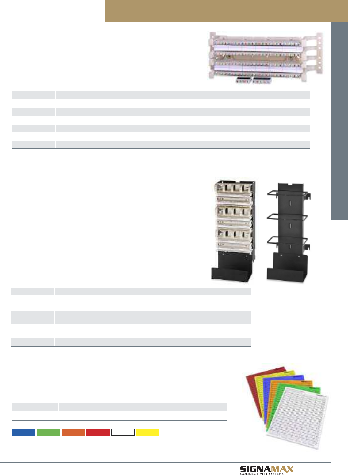
Patch Panels and Cross-Connect Systems
B 2 0
TM
Category 6 and 5e 110 Wiring Block Kits
PART NO. DESCRIPTION
WBK6-48PRL4 Category 6 48-Pair Kit w/Mounting Legs, (12) 4-Pair Connecting Blocks and 1 Label/Clear Holder
WBK6-96PRL4 Category 6 96-Pair Kit w/Mounting Legs, (24) 4-Pair Connecting Blocks and 2 Labels/Clear Holders
WBK6-288PRL4 Category 6 288-Pair Kit w/Mounting Legs, (72) 4-Pair Connecting Blocks and 6 Labels/Clear Holders
WBK-50PRL4 Category 5e 50-Pair Kit w/Mounting Legs, (10) 4-Pair, (2) 5-Pair Connecting Blocks and 1 Label/Clear Holder
WBK-100PRL4 Category 5e 100-Pair Kit w/Mounting Legs, (20) 4-Pair, (4) 5-Pair Connecting Blocks and 2 Labels/Clear Holders
WBK-300PRL4 Category 5e 300-Pair Kit w/Mounting Legs, (60) 4-Pair, (12) 5-Pair Connecting Blocks and 6 Labels/Clear Holders
For Wiring Block Kits w/o Legs delete L from P/N.
Simplified ordering is facilitated by the use of 110 Wiring Block Kits. These kits include
everything needed to assemble a fully configured cross-connect field. Wiring block kits
are available with or without mounting legs and are packaged with the appropriate
number of designation labels and clear label holders.
110 Wiring Block Kits
Wall-Mount 110 Wiring Blocks
Wall-Mount 110 Wiring Block Kits are available in Category 6 and 5e performance
levels. The kits are designed for high-density applications and are supplied with all
components needed to assemble a fully configured cross-connect field. Each kit
includes the mounting frame, bottom cable tray, 3 wiring blocks, 3 cable management
troughs, 6 labels/clear holders and the appropriate number of connecting blocks.
A Wall-Mount Cable Management Tower is available to organize and manage
patch cords.
PART NO. DESCRIPTION
WBWM6-288PR4 Category 6 288-Pair Wall-Mount Kit, (3) 96-Pair Wiring Blocks
(72) 4-Pair Conn. Blocks, 3 Cable Mgmt. Troughs and 6 Label/Clear Holder
WBWM5-300PR5 Category 5e 300-Pair Wall-Mount Kit, (3) 100-Pair Wiring Blocks
(60) 5-Pair Conn. Blocks, 3 Cable Mgmt. Troughs and 6 Label/Clear Holder
WBWM5-300PR4 Category 5e 300-Pair Wall-Mount Kit, (3) 100-Pair Wiring Blocks
(60) 4-Pair, (12) 5-Pair Conn. Blocks, 3 Cable Mgmt. Troughs and 6 Label/Clear Holder
WMCM-300 Wall-Mount Cable Management Tower
Designation Labeling Sheets for 110 Wiring Blocks
PART NO. DESCRIPTION
110WB-LS4PR-LC Label Sheet for 110 Wiring Blocks, 6 x 4 Pairs, 20 50-Pair Labels/Sheet
110 wiring blocks can be labeled using color-coded labels. Templates can be downloaded from the
Signamax web site, to help installers to lay out label sheets for custom printing. Labels are supplied
on 8.5” x 11” sheets suitable for printing using most general-purpose office printers.
For label colors substitute LC for color in P/N.
Labels are available for the following panel P/N’s only;
110WB6-xxxPR 110WB6-xxxPR-L WBK6-xxx-PRL4 RM6xxxPR RWBK6-xxxPR4
110WB-xxxPR 110WB-xxxPR-L WBK-xxx-PRL4 RMxxxPR RWBK-xxxPR4
-BU (Blue) -GN (Green) -OR (Orange) -RD (Red) -WH (White) -YE (Yellow)
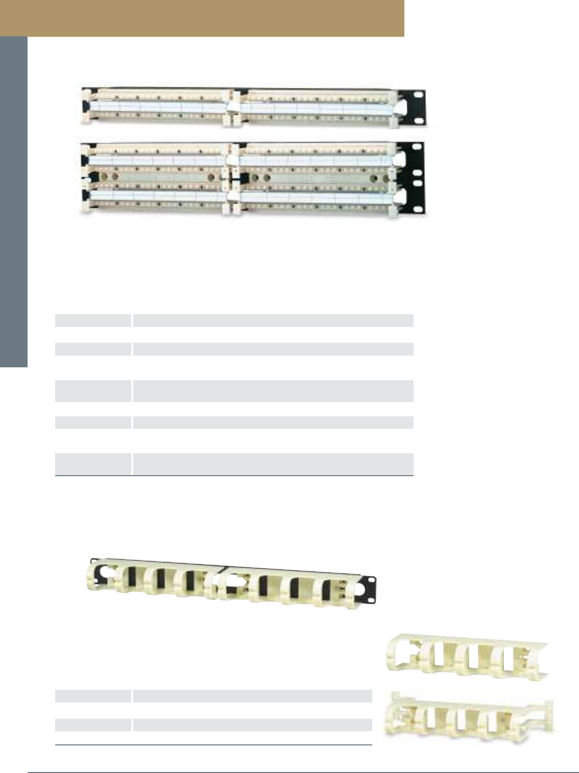
Patch Panels and Cross-Connect Systems
PREMISE CONNECTIVITY SYSTEMS 800.446.2377 www.signamax.comB21
Category 6 and 5e Rack-Mount 110 Wiring Block Kits
PART NO. DESCRIPTION
RM696PR Category 6 96-Pair 110 Rack-Mount Wiring Blocks, 1.75”H x 19”W
RM6192PR Category 6 192-Pair 110 Rack-Mount Wiring Blocks, 3.50”H x 19”W
RWBK6-96PR4 Category 6 96-Pair Rack-Mount Kit w/(24) 4-Pair Connecting Blocks
and 2 Designation Labels/Clear Holders, 1.75”H x 19”W
RWBK6-192PR4 Category 6 192-Pair Rack-Mount Kit w/(48) 4-Pair Connecting Blocks
and 4 Designation Labels/Clear Holders, 3.50”H x 19”W
RM100PR Category 5e 100-Pair 110 Rack-Mount Wiring Blocks, 1.75”H x 19”W
RM200PR Category 5e 200-Pair 110 Rack-Mount Wiring Blocks, 3.50”H x 19”W
RWBK-100PR4 Category 5e 100-Pair Rack-Mount Kit w/(20) 4-Pair, (4) 5-Pair
Connecting Blocks and 2 Designation Labels/Clear Holders, 1.75”H x 19”W
RWBK-200PR4 Category 5e 200-Pair Rack-Mount Kit w/(40) 4-Pair, (8) 5-Pair
Connecting Blocks and 4 Designation Labels/Clear Holders, 3.50”H x 19”W
110 Blocks are available for 19"-rack mounting in both category 6 and 5e versions. Category 5e
panels are available in 100- and 200-pair configurations with or without connecting blocks. The
category 6 panels are available in 96- and 192-pair configurations with or without connecting
blocks. Patch cord management is provided by a rack-mount patch cord and cable management
trough (sold separately).
Rack-Mount Wiring Blocks
Patch Cord and Cable Management Troughs
PART NO. DESCRIPTION
110-CMT-L Patch Cord and Cable Mgmt. Trough with Mounting Legs
110-CMT Patch Cord and Cable Mgmt. Trough without Mounting Legs
110-RMCMT Rack-Mount Patch Cord and Cable Mgt. Trough, 1.75”H
Used between wiring blocks, cable management troughs provide jumper and patch
cord organization. Troughs are available with or without stand-off legs to match
installation requirements. Cable management trough rings feature a split ring design,
which facilitates easy insertion and maximum retention.
110 Wiring Block Accessories
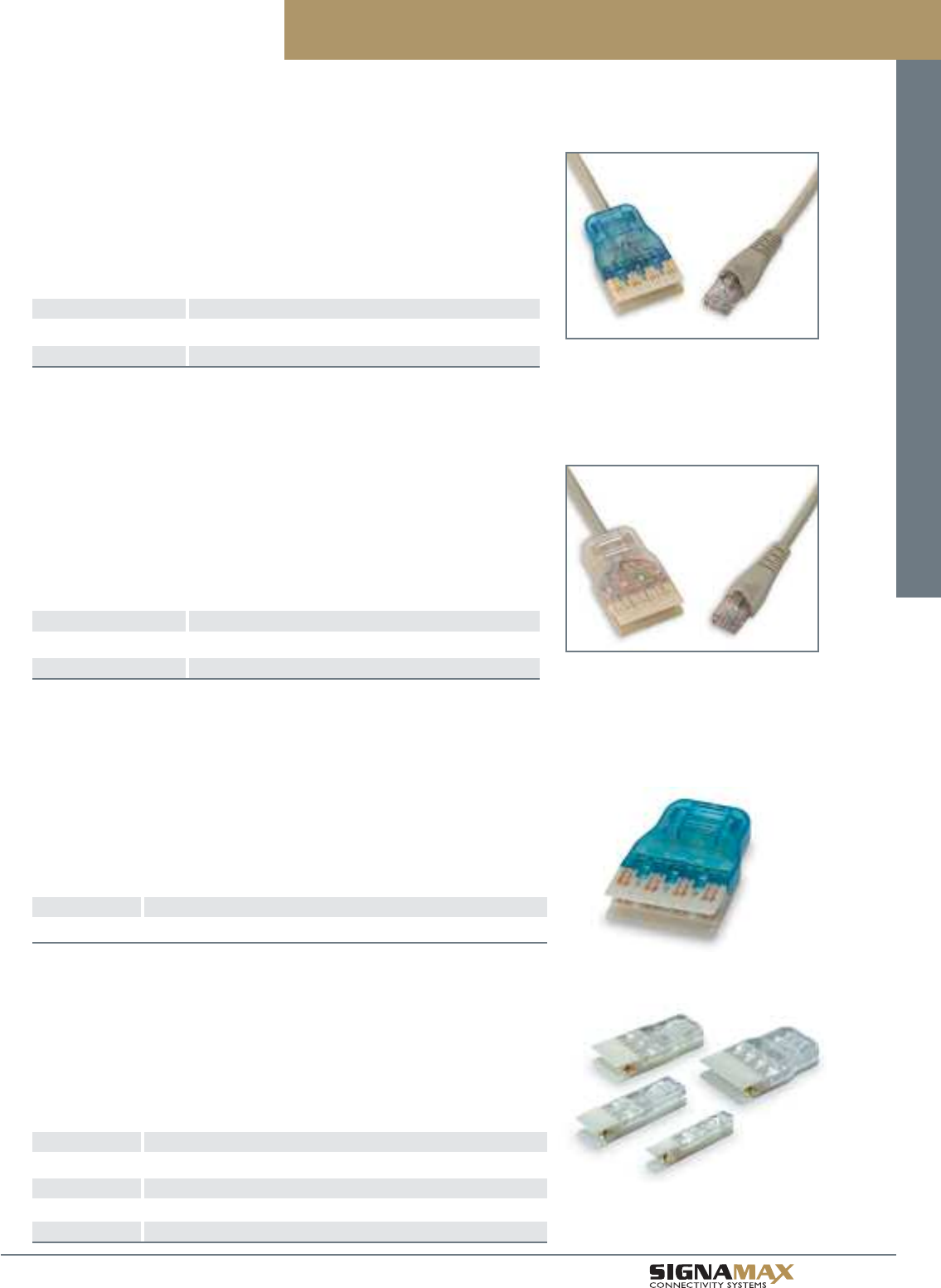
Patch Panels and Cross-Connect Systems
B 2 2
TM
Category 6 and 5e 110 Patch Cords
Category 6 110 Patch Cords
Category 6 110 Patch Cords exceed performance specifications as defined in
ANSI/TIA-568-C.2. Patch cords are available with four-pair 110 plugs and are used
for patching between category 6 110 termination fields. Category 6 RJ-45/110 Patch
Cords are available in four-pair configurations wired to T568B wiring scheme.
RJ-45/110 Patch Cords are used for patching between equipment and category 6
110 termination fields. All cords are 100% performance tested at the factory.
PART NO. DESCRIPTION
C6C-4P-GY-LB Category 6 4-Pair 110-to-110 Patch Cords
C6C-4P-458B-GY-LB Category 6 RJ-45-to-4-Pair 110 Patch Cords
For length substitute L for length in P/N
3=3 ft 5=5 ft 7=7 ft 10=10 ft 15=15 ft 20=20 ft 25=25 ft
Standard cable color is gray. Other colors and lengths are available.
Category 5e 110 Patch Cords
Category 5e 110 Patch Cords are assembled using stranded cable that exceeds
category 5e specifications. Patch cords are available with one-, two-, three-, and four-
pair 110 plugs and are used for patching between 110 termination fields. All cords are
100% factory tested. Category 5e RJ-45/110 Patch Cords are available in four-pair
configurations wired to T568B wiring scheme. RJ-45/110 Patch Cords are used for
patching between equipment and 110 termination fields.
PART NO. DESCRIPTION
C5E-4P-GY-LB Category 5e 4-Pair 110-to-110 Patch Cords
C5E-4P-458B-GY-LB Category 5e RJ-45-to-4-Pair 110 Patch Cords
For length substitute L for length in P/N
3=3 ft 5=5 ft 7=7 ft 10=10 ft 15=15 ft 20=20 ft 25=25 ft
Standard cable color is gray. Other colors and lengths are available.
Patch cords are also available in 1-Pair, 2-Pair, and 3-Pair configurations.
Category 6 Field-Installable 110 Plug
PART NO. DESCRIPTION
1106-4PRP Category 6 4-Pair Field-Installable 110 Plug
Category 6 Field-Installable 110 Plug is available in a 4-pair size and accommodates
24- to 26-AWG stranded conductor. The plug easily assembled in the field to provide
the flexibility and quick termination of any length patch cord. The snap-together
designed plugs are polarized to ensure a proper connection to the connecting blocks.
Category 5e Field-Installable 110 Plugs
PART NO. DESCRIPTION
110-1PRP Category 5e 1-Pair Field-Installable 110 Plug
110-2PRP Category 5e 2-Pair Field-Installable 110 Plug
110-3PRP Category 5e 3-Pair Field-Installable 110 Plug
110-4PRP Category 5e 4-Pair Field-Installable 110 Plug
Category 5e Field-Installable 110 Plugs are available in 1-, 2-, 3-, and 4-pair sizes
and accommodate 24- to 26-AWG stranded conductor. Plugs are easily assembled in
the field to provide the flexibility and quick termination of any length patch cord. The
snap-together designed plugs are polarized to ensure a proper connection to the
connecting blocks.
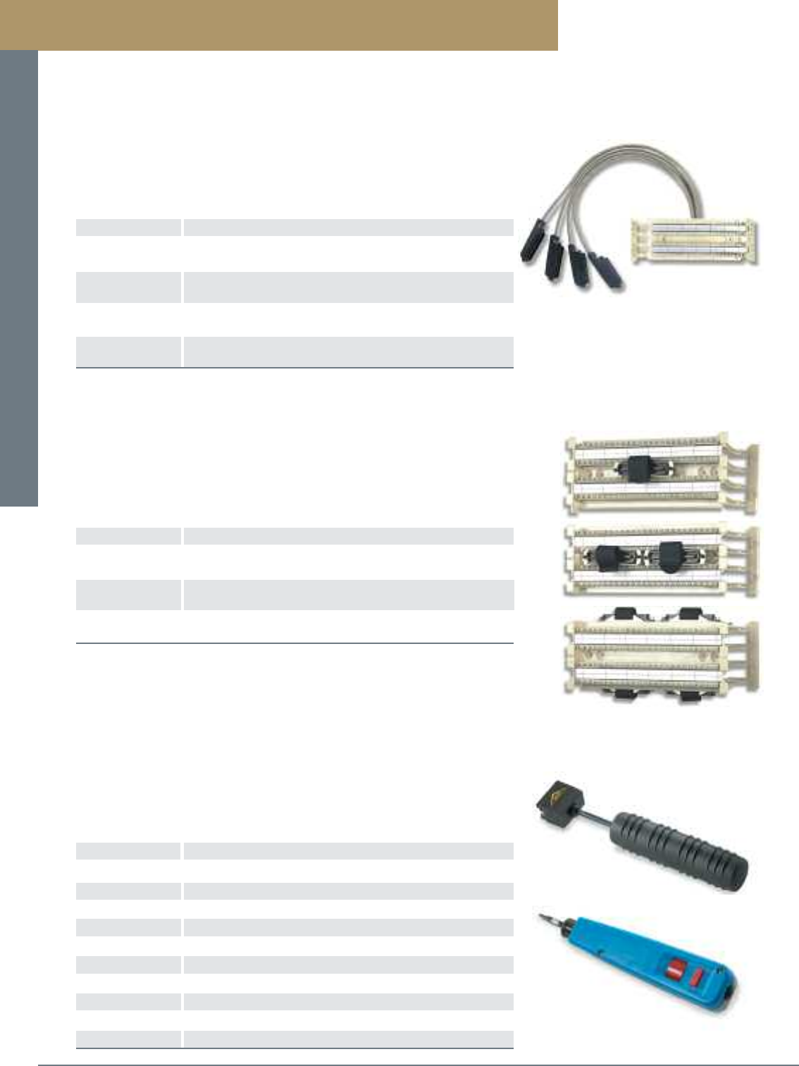
Patch Panels and Cross-Connect Systems
PREMISE CONNECTIVITY SYSTEMS 800.446.2377 www.signamax.comB23
Pre-Connectorized 110 Wall-Mount Wiring Blocks
PART NO. DESCRIPTION
100PR-5MX03 100-Pair Wall-Mount Panel, (20) 5-Pair Connecting Blocks
Wired to (4) Male Telco Connectors
100PR-4MX03 100-Pair Wall-Mount Panel, (20) 4-Pair, (4) 5-Pair Connecting
Blocks Wired to (4) Male Telco Connectors
300PR-5MX03 300-Pair Wall-Mount Panel, (60) 5-Pair Connecting Blocks
Blocks Wired to (12) Male Telco Connectors
300PR-4MX03 100-Pair Wall-Mount Panel, (60) 4-Pair, (12) 5-Pair Connecting
Blocks Wired to (12) Male Telco Connectors
Note: For top entry substitute T for X in P/N. For bottom entry substitute B for X in P/N.
For female Telco substitute F for M in P/N.
For other length cable stubs substitute 03 for desired length in feet.
Wall-Mount Wiring Blocks are available in 100- and 300-pair sizes pre-connectorized
with 3-, 4-, or 5-pair connecting blocks wired to male or female 50-position Telco
connectors. Top or bottom cable entry is available with 3-foot cable stubs as a
standard length. Other lengths are available.
Pre-Connectorized 110 Wall-Mount Wiring Blocks
PART NO. DESCRIPTION
WM25PRL-1M4 25-Pair 110 Block w/(5) 4-Pair, (1) 5-Pair Connecting Blocks
Wired to (1) 25-Pair Male Telco Connector
WM50PRL-2M4 50-Pair 110 Block w/(10) 4-Pair, (2) 5-Pair Connecting Blocks
Wired to (2) 25-Pair Male Telco Connector
WM100PRL-4M4 100-Pair 110 Block w/(20) 4-Pair, (4) 5-Pair Connecting Blocks
Wired to (4) 25-Pair Male Telco Connector
For female 25-pair telco connector substitute F for M in P/N.
For wiring blocks without legs eliminate L in P/N.
Pre-connectorized blocks can also be specified with 3- or 5-pair connecting blocks.
Wall-mount 110 wiring blocks are available in 25-, 50-, and 100-pair sizes and are ideal
for small voice and data cross-connect applications. Blocks are pre-connectorized with
4- and 5-pair connecting blocks wired to male or female 25-pair Telco connectors.
Pre-Connectorized 110 Wiring Blocks
Termination Tools
PART NO. DESCRIPTION
1106-4PRT 4-Pair Impact Tool for Category 6A/6 110 Wiring Blocks
1106-4PRH 4-Pair Replacement Head and Blade for 1106-4PRT Tool
110-4PRT 4-Pair Impact Tool for Category 6/5e 110 Patch Panels
110-4PRH 4-Pair Replacement Head and Blade for 110-4PRT Tool
110-5PRT 5-Pair Impact Tool for Category 5e 110 Wiring Blocks
110-5PRH 5-Pair Replacement Head and Blade for 110-5PRT Tool
T110 1-Position 110 Impact Termination Tool
T110BL 1-Position 110 Termination Blade
T66 1-Position 66 Impact Termination Tool
T66BL 1-Position 66 Termination Blade
Signamax multi-pair termination tool is a versatile impact tool designed to terminate
twisted-pair cable conductors, cut conductor excess and seat connecting blocks.
The tool features an ergonomically designed handle to provide a no-slip grip. Our
single-position impact tool is available to terminate to either 66 or 110 blocks and is
spring-loaded and tension-adjustable. Replacement blades are available.
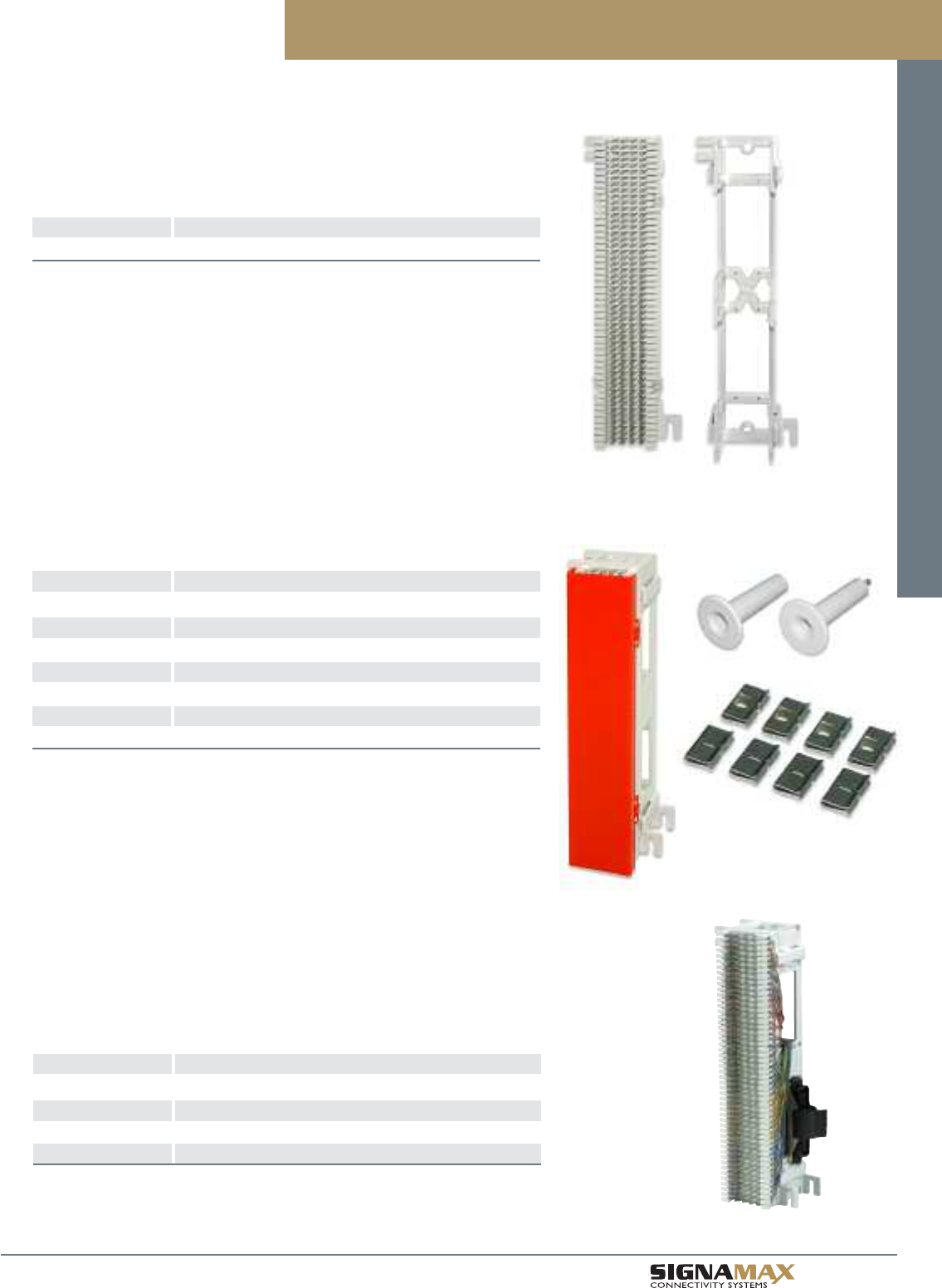
Patch Panels and Cross-Connect Systems
B 2 4
TM
Pre-Connectorized 66 Blocks
PART NO. DESCRIPTION
66M1-25M 66 Block Wired to (1) Male 25-Pair Telco Connector
66M1-25F 66 Block Wired to (1) Female 25-Pair Telco Connector
66M1-50M 66 Block Wired to (2) Male 25-Pair Telco Connectors
66M1-50F 66 Block Wired to (2) Female 25-Pair Telco Connectors
For voice applications 66 Blocks are available pre-wired with one or two 25-pair Telco
connectors. Blocks can be specified with male or female connectors. Blocks are
designed for top cable entry.
66 Blocks and Accessories
66 Blocks
PART NO. DESCRIPTION
SM66M1-50 50-Pair 66 Block
For voice and data applications 66 Blocks are available in a 50-pair type. This block is
designed for category 5e performance to support high-bandwidth applications.
66 Block Accessories
PART NO. DESCRIPTION
SM66M1-89D 89D 66 Block Mounting Bracket
SM66M1-CC Snap-On Clear Cover for 50-Pair 66 Block
SM66M1-OR Orange Hinged Cover for 50-Pair 66 Block
SM66M1-BU Blue Hinged Cover for 50-Pair 66 Block
SM66M1-BC Bridging Clips for 50-Pair 66 Blocks, Package of 100
SM66M1-WMS Wire Management Spool with Screw
SM66M1-WM Wire Management Spool without Screw
Covers of other standard colors are available.
Patch
Cords/Cable/
Cable Assemblies
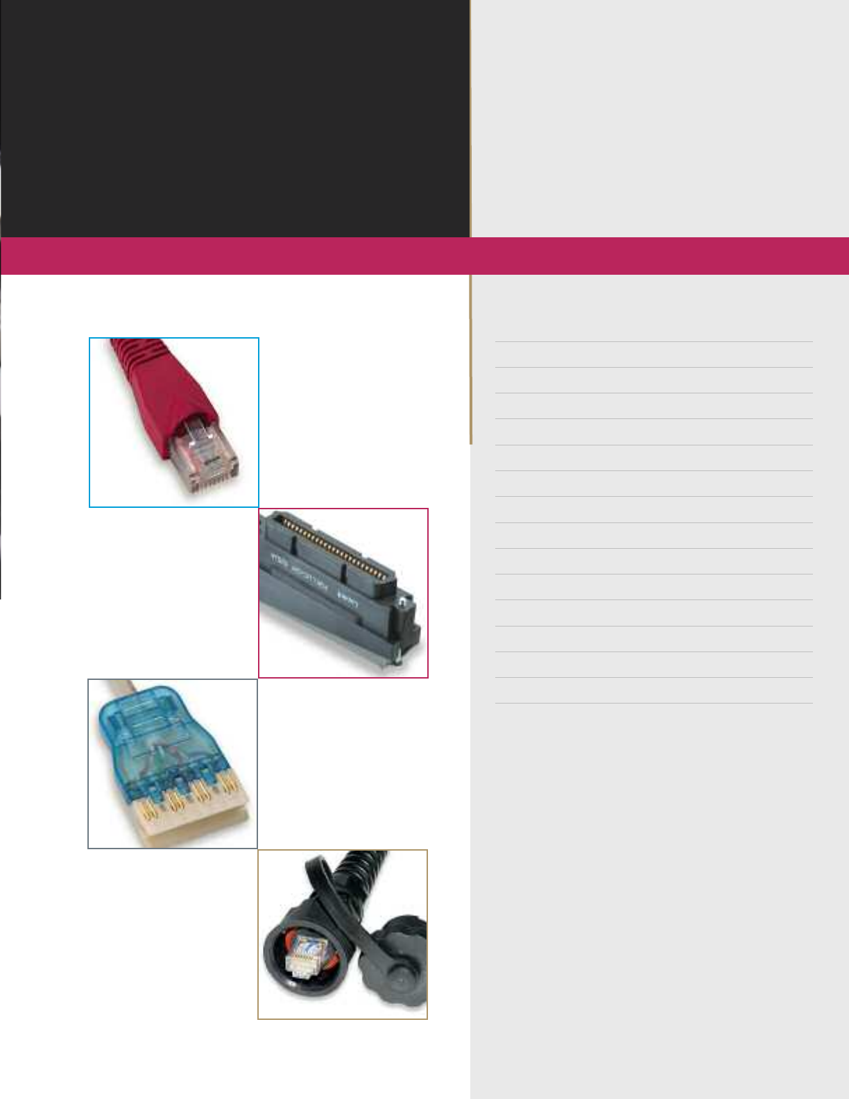
Patch Panels and Cross-
CCaatteeggoorryy 66AA 1100GG PPaattcchh CCoorrddss CC11
CCaatteeggoorryy 66 PPaattcchh CCoorrddss CC22
CCaatteeggoorryy 55ee PPaattcchh CCoorrddss CC33
CCaatteeggoorryy 66 aanndd 55ee 111100 PPaattcchh CCoorrddss CC44
CCaatteeggoorryy 66 aanndd 55ee 111100 PPlluuggss CC44
CCaatteeggoorryy 66 aanndd 55ee CCrroossssoovveerr PPaattcchh CCoorrddss CC55
MMoodduullaarr PPlluuggss && SSttrraaiinn RReelliieeff BBoooottss CC55
MMoodduullaarr CCrriimmpp TTooooll CC66
CCoommpprreessssiioonn CCoonnnneeccttoorrss CC66
CCaatteeggoorryy 66 aanndd 55ee IInndduussttrriiaall--GGrraaddee PPaattcchh CCoorrddss CC77
CCaatteeggoorryy 55ee IInndduussttrriiaall--GGrraaddee PPlluugg AAsssseemmbblliieess CC66
CCaatteeggoorryy 55ee 2255--PPaaiirr TTeellccoo CCaabbllee AAsssseemmbblliieess CC88
CCaatteeggoorryy 33 2255--PPaaiirr TTeellccoo CCaabbllee AAsssseemmbblliieess CC88
PPrree--TTeerrmmiinnaatteedd CCooppppeerr TTrruunnkk AAsssseemmbblliieess CC99
CCaatteeggoorryy 66AA,, 66,, aanndd 55ee CCaabbllee CC1100
w w w . s i g n a m a x . c o m
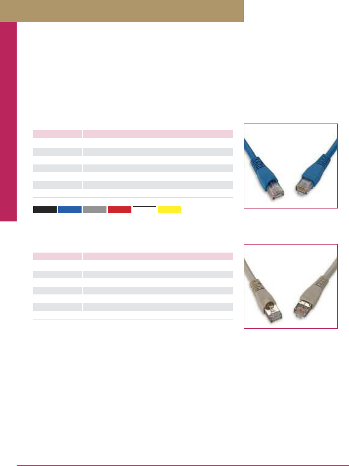
Patch Cords / Cable / Cable Assemblies / Connectors
PREMISE CONNECTIVITY SYSTEMS 800.446.2377 www.signamax.comC 1
Category 6A 10G Patch Cords
Category 6A 10G Patch Cords
PART NO. DESCRIPTION LENGTH
C6A-114CC-3FB Category 6A Patch Cord w/Snag-Proof Boots 3 ft
C6A-114CC-5FB Category 6A Patch Cord w/Snag-Proof Boots 5 ft
C6A-114CC-7FB Category 6A Patch Cord w/Snag-Proof Boots 7 ft
C6A-114CC-10FB Category 6A Patch Cord w/Snag-Proof Boots 10 ft
C6A-114CC-15FB Category 6A Patch Cord w/Snag-Proof Boots 15 ft
C6A-114CC-20FB Category 6A Patch Cord w/Snag-Proof Boots 20 ft
C6A-114CC-25FB Category 6A Patch Cord w/Snag-Proof Boots 25 ft
Signamax Connectivity Systems category 6A patch cords are designed to meet 10 Gigabit Ethernet IEEE 802.3an transmission
requirements, and are guaranteed to support ANSI/TIA-568-C.2 category 6A 100-meter channel performance. Assembled in a
controlled environment using advanced manufacturing techniques and 100% transmission tested to insure consistent quality these
patch cords provide reliable performance when mated with our category 6A connecting hardware and deliver supreme performance
for network cabling systems.
Signamax category 6A patch cords incorporate slim-profile snag-free boots, which protect the plug latch, and a flexible, but durable
cable strain relief, and are compatible with both T568A and T568B wiring schemes. Patch cords are manufactured using ETL-verified
stranded cable designed for greater flexibility and service life.
PART NO. DESCRIPTION LENGTH
C6AS-314GY-3FB Category 6A Screened Patch Cord w/Snag-Proof Boots 3 ft
C6AS-314GY-5FB Category 6A Screened Patch Cord w/Snag-Proof Boots 5 ft
C6AS-314GY-7FB Category 6A Screened Patch Cord w/Snag-Proof Boots 7 ft
C6AS-314GY-10FB Category 6A Screened Patch Cord w/Snag-Proof Boots 10 ft
C6AS-314GY-15FB Category 6A Screened Patch Cord w/Snag-Proof Boots 15 ft
C6AS-314GY-20FB Category 6A Screened Patch Cord w/Snag-Proof Boots 20 ft
C6AS-314GY-25FB Category 6A Screened Patch Cord w/Snag-Proof Boots 25 ft
Standard cable color is gray. Other colors and lengths are available.
For cable color substitute CC for color in P/N. Other lengths are available.
Part Number Example: C6A-114BU-7FB
Category 6A Patch Cord with Snag-Proof Boots, Blue, 7 ft.
-BK (Black) -BU (Blue) -GY (Gray) -RD (Red) -WH (White) -YE (Yellow)
Category 6A 10G Screened Patch Cords
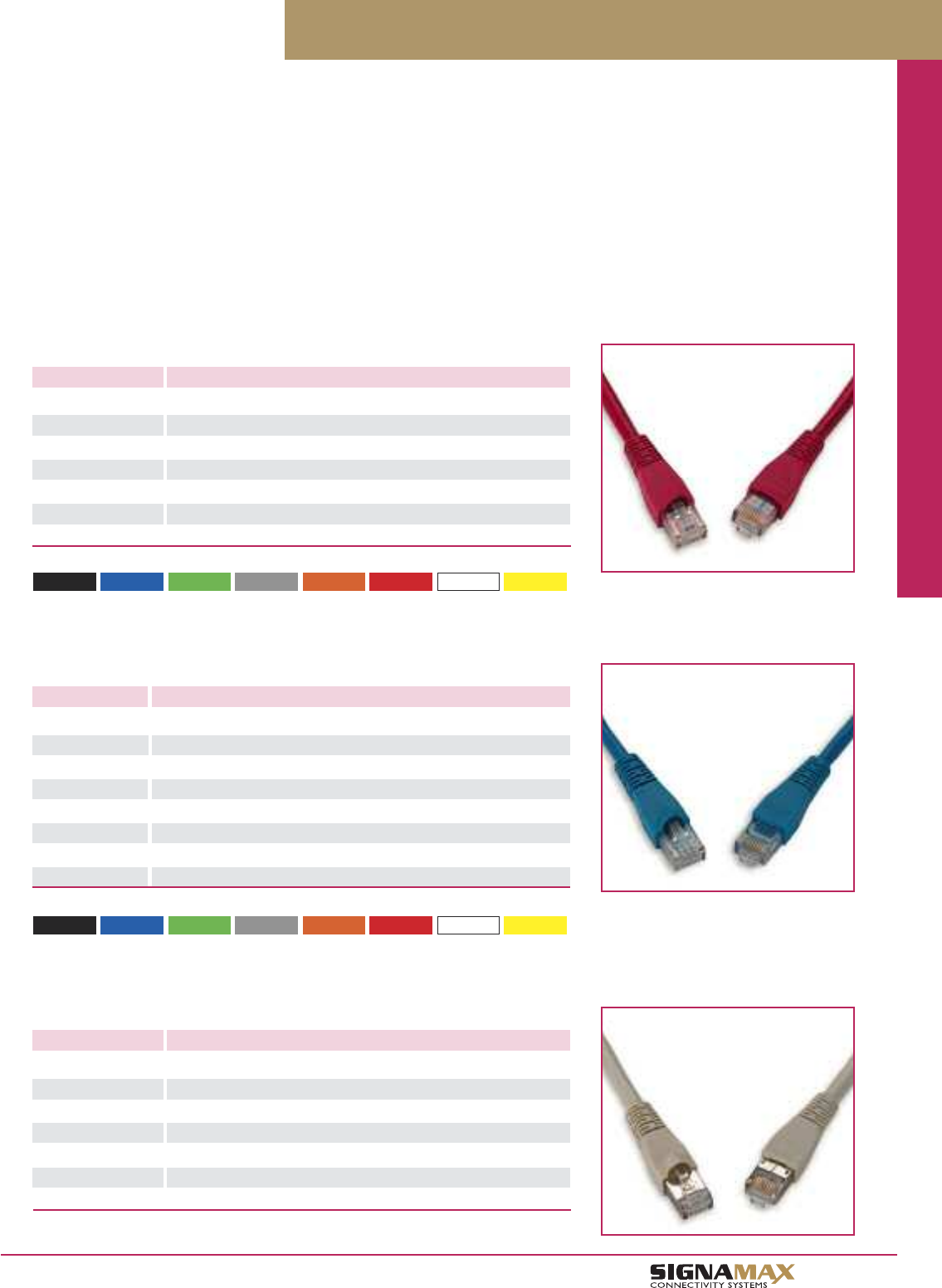
Patch Cords / Cable / Cable Assemblies / Connectors
C 2
TM
Category 6 Patch Cords
Category 6 Patch Cords
PART NO. DESCRIPTION LENGTH
C6C-114CC-3FB Category 6 Patch Cord w/Snag-Proof Boots 3 ft
C6C-114CC-5FB Category 6 Patch Cord w/Snag-Proof Boots 5 ft
C6C-114CC-7FB Category 6 Patch Cord w/Snag-Proof Boots 7 ft
C6C-114CC-10FB Category 6 Patch Cord w/Snag-Proof Boots 10 ft
C6C-114CC-15FB Category 6 Patch Cord w/Snag-Proof Boots 15 ft
C6C-114CC-20FB Category 6 Patch Cord w/Snag-Proof Boots 20 ft
C6C-114CC-25FB Category 6 Patch Cord w/Snag-Proof Boots 25 ft
Category 6 Channel-Level Patch Cords
PART NO. DESCRIPTION LENGTH
C6-115CC-3FB Category 6 Channel-Level Patch Cord w/Snag-Proof Boots 3 ft
C6-115CC-5FB Category 6 Channel-Level Patch Cord w/Snag-Proof Boots 5 ft
C6-115CC-7FB Category 6 Channel-Level Patch Cord w/Snag-Proof Boots 7 ft
C6-115CC-10FB Category 6 Channel-Level Patch Cord w/Snag-Proof Boots 10 ft
C6-115CC-14FB Category 6 Channel-Level Patch Cord w/Snag-Proof Boots 14 ft
C6-115CC-25FB Category 6 Channel-Level Patch Cord w/Snag-Proof Boots 25 ft
C6-115CC-50FB Category 6 Channel-Level Patch Cord w/Snag-Proof Boots 50 ft
C6-115CC-100FB Category 6 Channel-Level Patch Cord w/Snag-Proof Boots 100 ft
Category 6 Screened Patch Cords
PART NO. DESCRIPTION LENGTH
C6CS-314GY-3FB Category 6 Screened Patch Cord w/Snag-Proof Boots 3 ft
C6CS-314GY-5FB Category 6 Screened Patch Cord w/Snag-Proof Boots 5 ft
C6CS-314GY-7FB Category 6 Screened Patch Cord w/Snag-Proof Boots 7 ft
C6CS-314GY-10FB Category 6 Screened Patch Cord w/Snag-Proof Boots 10 ft
C6CS-314GY-15FB Category 6 Screened Patch Cord w/Snag-Proof Boots 15 ft
C6CS-314GY-20FB Category 6 Screened Patch Cord w/Snag-Proof Boots 20 ft
C6CS-314GY-25FB Category 6 Screened Patch Cord w/Snag-Proof Boots 25 ft
Standard cable color is gray. Other colors and lengths are available.
-BK (Black) -BU (Blue) -GN (Green) -GY (Gray) -OR (Orange) -RD (Red) -WH (White) -YE (Yellow)
For cable color substitute CC for color in P/N. Other lengths are available.
Part Number Example: C6-115BU-7FB
Category 6 Channel-Level Patch Cord with Snag-Proof Boots, Blue, 7 ft.
-BK (Black) -BU (Blue) -GN (Green) -GY (Gray) -OR (Orange) -RD (Red) -WH (White) -YE (Yellow)
For cable color substitute CC for color in P/N. Other lengths are available.
Part Number Example: C6C-114BU-7FB
Category 6 Patch Cord with Snag-Proof Boots, Blue, 7 ft.
Signamax continues to set the standard for high-quality, high-performance patch cords with two series of category 6 patch cords.
Our category 6 cords are 100% transmission tested to component performance as specified in ANSI/TIA-568-C.2. Assembled in a
controlled environment using advanced manufacturing techniques to ensure consistent quality, these patch cords provide exceptional
performance when mated with our category 6 connecting hardware.
Our Channel-Level Category 6 cords provide an excellent level of performance and are designed for less demanding applications.
These cords are 100% tested in a 4-connector channel configuration to ensure consistent performance.
Both types of Signamax category 6 patch cords incorporate slim-profile snag-free boots, which protect the plug latch, and a flexible,
but durable cable strain relief and are compatible with both T568A and T568B wiring schemes. Category 6 and Category 6 Channel-
Level patch cords are manufactured using ETL-verified stranded cable designed for greater flexibility and service life and are available
in eight popular colors and a variety of standard lengths.
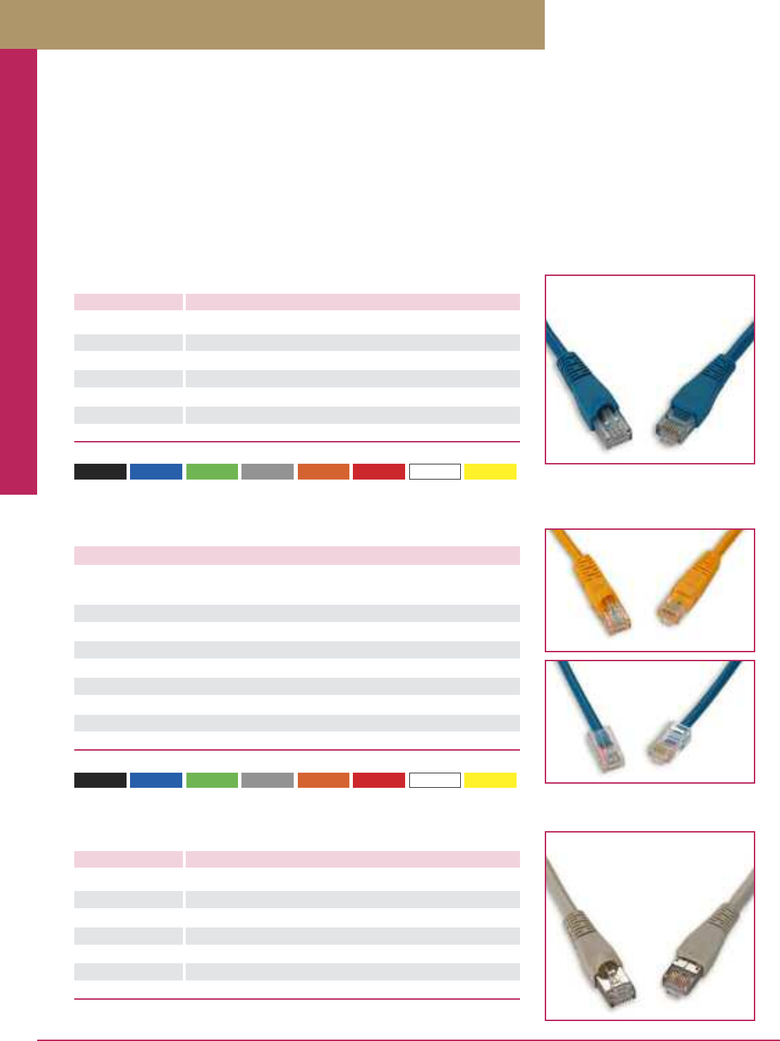
Patch Cords / Cable / Cable Assemblies / Connectors
PREMISE CONNECTIVITY SYSTEMS 800.446.2377 www.signamax.comC 3
Category 5e Patch Cords
Category 5e Patch Cords
PART NO. DESCRIPTION LENGTH
C5EC-114CC-3FB Category 5e Patch Cord w/Snag-Proof Boots 3 ft
C5EC-114CC-5FB Category 5e Patch Cord w/Snag-Proof Boots 5 ft
C5EC-114CC-7FB Category 5e Patch Cord w/Snag-Proof Boots 7 ft
C5EC-114CC-10FB Category 5e Patch Cord w/Snag-Proof Boots 10 ft
C5EC-114CC-15FB Category 5e Patch Cord w/Snag-Proof Boots 15 ft
C5EC-114CC-20FB Category 5e Patch Cord w/Snag-Proof Boots 20 ft
C5EC-114CC-25FB Category 5e Patch Cord w/Snag-Proof Boots 25 ft
Category 5e Screened Patch Cords
PART NO. DESCRIPTION LENGTH
C5ES-314GY-3FB Category 5e Screened Patch Cord w/Snag-Proof Boots 3 ft
C5ES-314GY-5FB Category 5e Screened Patch Cord w/Snag-Proof Boots 5 ft
C5ES-314GY-7FB Category 5e Screened Patch Cord w/Snag-Proof Boots 7 ft
C5ES-314GY-10FB Category 5e Screened Patch Cord w/Snag-Proof Boots 10 ft
C5ES-314GY-15FB Category 5e Screened Patch Cord w/Snag-Proof Boots 15 ft
C5ES-314GY-20FB Category 5e Screened Patch Cord w/Snag-Proof Boots 20 ft
C5ES-314GY-25FB Category 5e Screened Patch Cord w/Snag-Proof Boots 25 ft
Standard cable color is gray. Other colors and lengths are available.
Category 5e Channel-Level Patch Cords
DESCRIPTION PART NO. PART NO.
Snag-Proof Boots No Boots
Category 5e Channel-Level Patch Cord, 1 ft C5E-114CC-1FB C5E-121CC-1FB
Category 5e Channel-Level Patch Cord, 3 ft C5E-114CC-3FB C5E-121CC-3FB
Category 5e Channel-Level Patch Cord, 5 ft C5E-114CC-5FB C5E-121CC-5FB
Category 5e Channel-Level Patch Cord, 7 ft C5E-114CC-7FB C5E-121CC-7FB
Category 5e Channel-Level Patch Cord, 10 ft C5E-114CC-10FB C5E-121CC-10FB
Category 5e Channel-Level Patch Cord, 14 ft C5E-114CC-14FB C5E-121CC-14FB
Category 5e Channel-Level Patch Cord, 25 ft C5E-114CC-25FB C5E-121CC-25FB
Category 5e Channel-Level Patch Cord, 50 ft C5E-114CC-50FB C5E-121CC-50FB
Category 5e Channel-Level Patch Cord, 100 ft C5E-114CC-100FB C5E-121CC-100FB
-BK (Black) -BU (Blue) -GN (Green) -GY (Gray) -OR (Orange) -RD (Red) -WH (White) -YE (Yellow)
For cable color substitute CC for color in P/N. Other lengths are available (C5E-121XX series only).
Part Number Example: C5E-114BU-7FB
Category 5e Channel-Level Patch Cord with Snag-Proof Boots, Blue, 7 ft.
-BK (Black) -BU (Blue) -GN (Green) -GY (Gray) -OR (Orange) -RD (Red) -WH (White) -YE (Yellow)
For cable color substitute CC for color in P/N. Other lengths are available.
Part Number Example: C5EC-114BU-7FB
Category 5e Patch Cord with Snag-Proof Boots, Blue, 7 ft.
Category 5e unscreened and screened cords are 100% transmission tested to component performance as specified in ANSI/TIA-568-C.2.
Assembled in a controlled environment using advanced manufacturing techniques to ensure consistent quality, these patch cords provide
exceptional performance when mated with our category 5e connecting hardware and deliver supreme performance for network cabling
systems. Category 5e patch cords incorporate slim-profile snag-free boots, which protect the plug latch, and a flexible, but durable cable
strain relief and are compatible with both T568A and T568B wiring schemes. Patch cords are manufactured using ETL-verified stranded
cable designed for greater flexibility and service life and are available in eight popular colors and in seven standard lengths.
Signamax category 5e channel-level cords provide an excellent level of channel performance and are designed for less demanding
applications. These cords are 100% tested in a 4-connector channel configuration to ensure consistent performance. Signamax category
5e channel-level patch cords are compatible with both T568A and T568B wiring schemes.
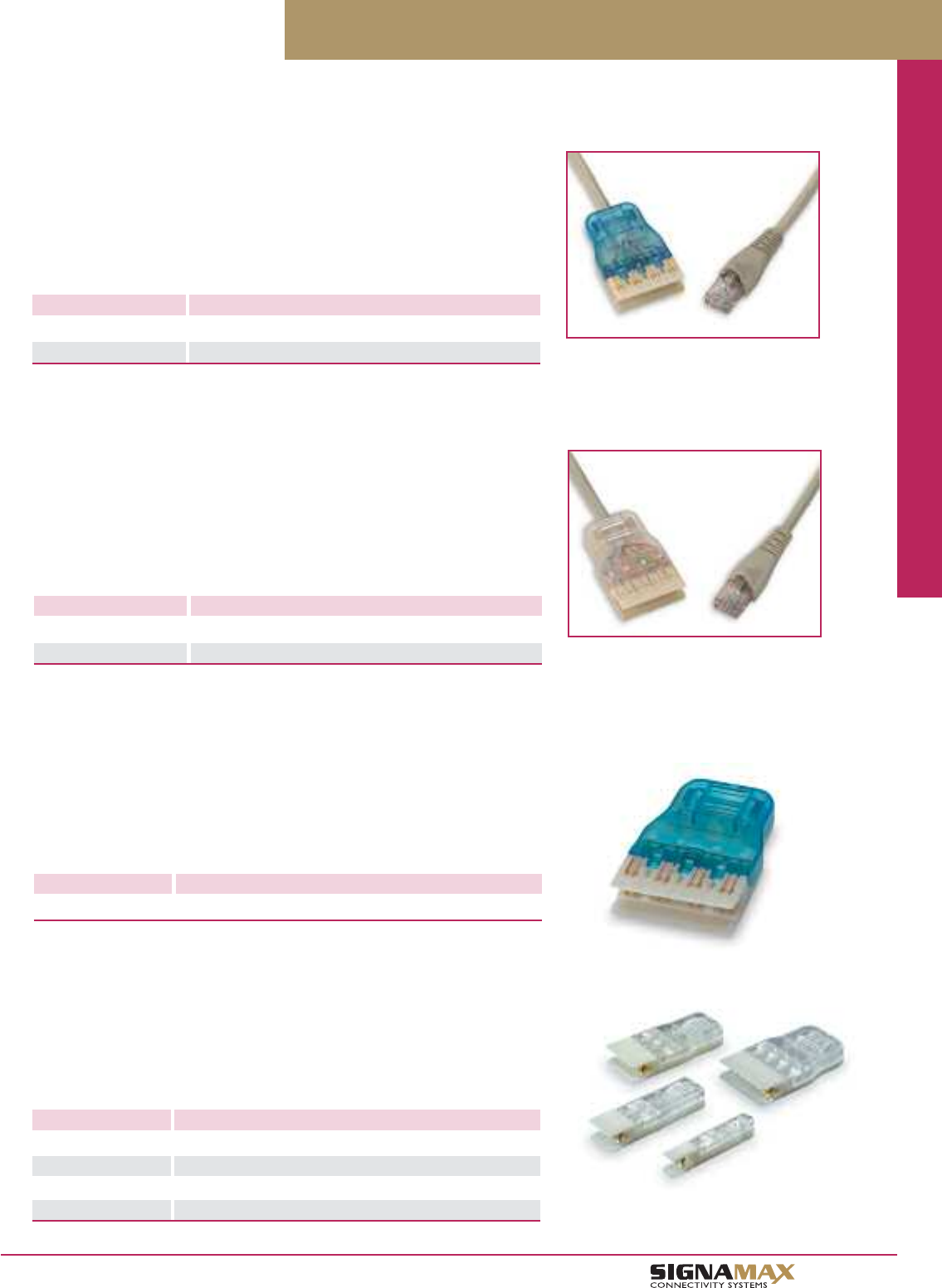
Patch Cords / Cable / Cable Assemblies / Connectors
C 4
TM
Category 6 and 5e 110 Patch Cords
Category 6 110 Patch Cords
Category 6 110 Patch Cords exceed performance specifications as defined in
ANSI/TIA-568-C.2. Patch cords are available with four-pair 110 plugs and are used
for patching between category 6 110 termination fields. Category 6 RJ-45/110 Patch
Cords are available in four-pair configurations wired to T568B wiring scheme.
RJ-45/110 Patch Cords are used for patching between equipment and category 6
110 termination fields. All cords are 100% performance tested at the factory.
PART NO. DESCRIPTION
C6C-4P-GY-LB Category 6 4-Pair 110-to-110 Patch Cords
C6C-4P-458B-GY-LB Category 6 RJ-45-to-4-Pair 110 Patch Cords
For length substitute L for length in P/N
3=3 ft 5=5 ft 7=7 ft 10=10 ft 15=15 ft 20=20 ft 25=25 ft
Standard cable color is gray. Other colors and lengths are available.
Category 5e 110 Patch Cords
Category 5e 110 Patch Cords are assembled using stranded cable that exceeds
category 5e specifications. Patch cords are available with one-, two-, three-, and four-
pair 110 plugs and are used for patching between 110 termination fields. All cords are
100% factory tested. Category 5e RJ-45/110 Patch Cords are available in four-pair
configurations wired to T568B wiring scheme. RJ-45/110 Patch Cords are used for
patching between equipment and 110 termination fields.
PART NO. DESCRIPTION
C5E-4P-GY-LB Category 5e 4-Pair 110-to-110 Patch Cords
C5E-4P-458B-GY-LB Category 5e RJ-45-to-4-Pair 110 Patch Cords
For length substitute L for length in P/N
3=3 ft 5=5 ft 7=7 ft 10=10 ft 15=15 ft 20=20 ft 25=25 ft
Standard cable color is gray. Other colors and lengths are available.
Patch cords are also available in 1-Pair, 2-Pair, and 3-Pair configurations.
Category 6 Field-Installable 110 Plug
PART NO. DESCRIPTION
1106-4PRP Category 6 4-Pair Field-Installable 110 Plug
Category 6 Field-Installable 110 Plug is available in a 4-pair size and accommodates
24- to 26-AWG stranded conductors. The plug is easily assembled in the field to pro-
vide the flexibility and quick termination of any length patch cord. The snap-together
designed plugs are polarized to ensure a proper connection to the connecting blocks.
Category 5e Field-Installable 110 Plugs
PART NO. DESCRIPTION
110-1PRP Category 5e 1-Pair Field-Installable 110 Plug
110-2PRP Category 5e 2-Pair Field-Installable 110 Plug
110-3PRP Category 5e 3-Pair Field-Installable 110 Plug
110-4PRP Category 5e 4-Pair Field-Installable 110 Plug
Category 5e Field-Installable 110 Plugs are available in 1-, 2-, 3-, and 4-pair sizes
and accommodate 24- to 26-AWG stranded conductors. Plugs are easily assembled
in the field to provide the flexibility and quick termination of any length patch cord.
The snap-together designed plugs are polarized to ensure a proper connection to the
connecting blocks.
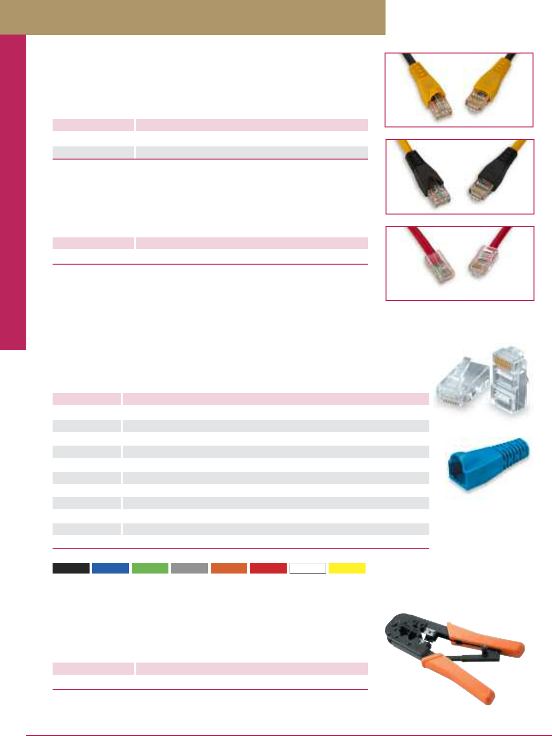
Patch Cords / Cable / Cable Assemblies / Connectors
PREMISE CONNECTIVITY SYSTEMS 800.446.2377 www.signamax.comC 5
Modular Crimp Tool
PART NO. DESCRIPTION
TRJ45P RJ-12/45 Dual Crimp Tool, Ratchet Type
This ratchet-style crimp tool that cuts, strips cable, and crimps modular plugs on both round
or flat cables. The ratchet design maintains accurate alignment with the plug for a precision
crimp. The tool will crimp 4- and 6-position (RJ-12-style) and 8-position (RJ-45-style) plugs.
-BK (Black) -BU (Blue) -GN (Green) -GY (Gray) -OR (Orange) -RD (Red) -WH (White) -YE (Yellow)
For boot color substitute BC for color in P/N.
Crossover Patch Cords
Category 6 and Category 5e Crossover Patch Cords are assembled using stranded cable
that exceeds ANSI/TIA-568-C.2 performance specifications. Crossover Patch Cords are
used for connecting uplink ports on network hubs. All cables are 100% factory tested.
Modular Plugs & Strain Relief Boots
PART NO. DESCRIPTION
KRJ45/5E-100 CAT5E Compatible 8P8C Modular Plug for 24-AWG Unscreened Stranded Cable
KRJ45/5SH-100 CAT5E Compatible 8P8C Modular Plug for 24-26 AWG Screened Stranded Cable
KRJ45/5-100 CAT5E Compatible 8P8C Modular Plug for 24-AWG Unscreened Stranded Cable
KRJ45/5SLD-100 CAT5E Compatible 8P8C Modular Plug for 24-AWG Unscreened Solid Cable
KRJ12-C5/100 Voice-Grade 6P6C Modular Plug for 24-AWG Unscreened Stranded Cable
KRJ11-C5/100 Voice-Grade 6P4C Modular Plug for 24-AWG Unscreened Stranded Cable
KRJ12SLD-100 Voice-Grade 6P6C Modular Plug for 24-AWG Unscreened Solid Cable
KRJ45/100 Voice-Grade 8P8C Modular Plug for 28-AWG Flat Cable
KRJ12/100 Voice-Grade 6P6C Modular Plug for 28-AWG Flat Cable
KRJ11/100 Voice-Grade 6P4C Modular Plug for 28-AWG Flat Cable
S45SP-BC/100 Snag-Proof Strain Relief Boots, Package of 100
Modular Plugs are available for termination of patch cords. All plugs have contacts plated with 50
micro- inches of gold and are designed for termination of stranded or solid cable and sold in packages of
100. Snag-Proof Strain Relief Boots are available in a variety of colors. The boots protect against damage
to the connector latch and help maintain the proper bend radius of the cable to ensure performance.
PART NO. DESCRIPTION
C6XB-112BK-LFB CAT6 Crossover Cord w/Black Cable, Yellow Boots
C5EXB-112YE-LFB CAT5E Crossover Cord w/Yellow Cable, Black Boots
Category 6 and Category 5e Crossover Cords
For length substitute L for length in P/N
3=3 ft 5=5 ft 7=7 ft 10=10 ft 15=15 ft 20=20 ft 25=25 ft
PART NO. DESCRIPTION
C5EX-112RD-LFB CAT5E Crossover Cord w/Red Cable, No Boots
Category 5e Crossover Cords
For length substitute L for length in P/N
3=3 ft 5=5 ft 7=7 ft 10=10 ft 14=14 ft 25=25 ft
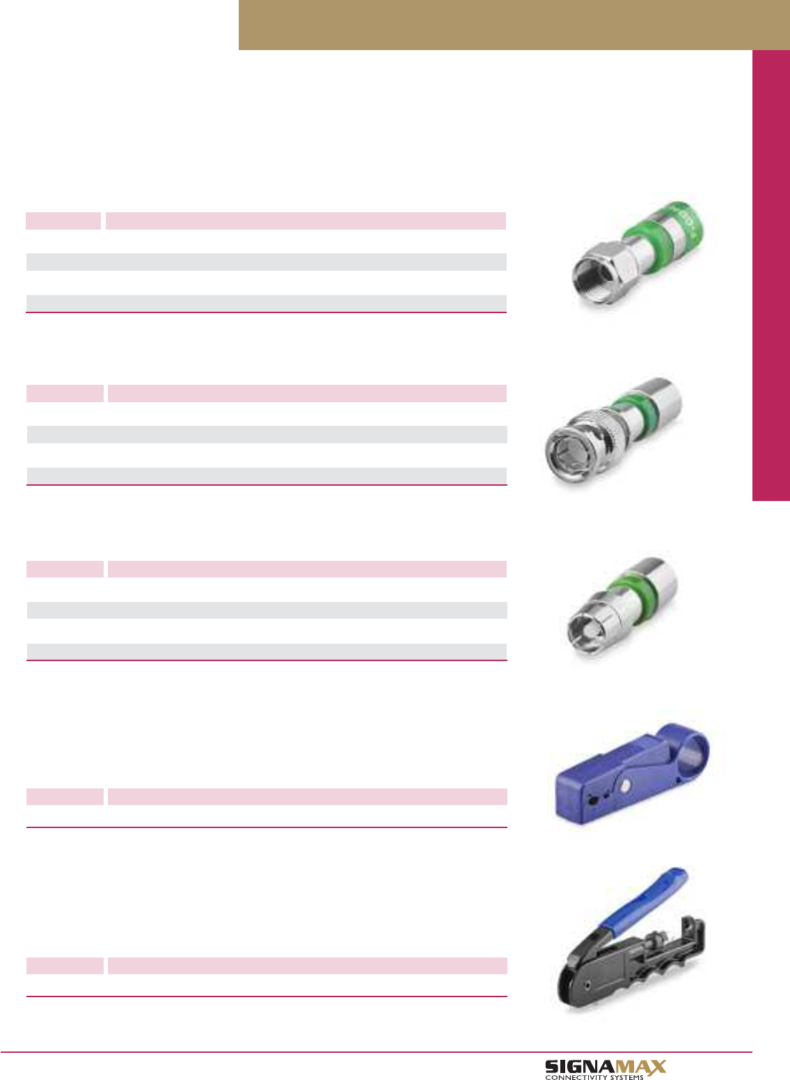
Patch Cords / Cable / Cable Assemblies / Connectors
C 6
TM
Compression Connectors
F-Type Compression Connector
PART NO. DESCRIPTION
CC-F06N F-Type Compression Connector for RG6 & RG6 Quad Shield Cable, Nickel
CC-F59N F-Type Compression Connector for RG59 & RG59 Quad Shield Cable, Nickel
CC-F06G F-Type Compression Connector for RG6 & RG6 Quad Shield Cable, Gold
CC-F59G F-Type Compression Connector for RG59 & RG59 Quad Cable, Glod
BNC Compression Connector
PART NO. DESCRIPTION
CC-BNC06N BNC Compression Connector for RG6 & RG6 Quad Shield Cable, Nickel
CC-BNC59N BNC Compression Connector for RG59 & RG59 Quad Shield Cable, Nickel
CC-BNC06G BNC Compression Connector for RG6 & RG6 Quad Shield Cable, Gold
CC-BNC59G BNC Compression Connector for RG59 & RG59 Quad Shield Cable, Glod
RCA Compression Connector
PART NO. DESCRIPTION
CC-RCA06N RCA Compression Connector for RG6 & RG6 Quad Shield Cable, Nickel
CC-RCA59N RCA Compression Connector for RG59 & RG59 Quad Shield Cable, Nickel
CC-RCA06G RCA Compression Connector for RG6 & RG6 Quad Shield Cable, Gold
CC-RCA59G RCA Compression Connector for RG59 & RG59 Quad Shield Cable, Glod
PART NO. DESCRIPTION
CST-596 Coax Cable Stripping Tool for RG59 and RG6
Compression connectors provide the ideal solution for audio/video applications requiring the highest performance and
reliability. Connectors are available in a variety of types that include F-type, BNC and 360° compression on the cable.
The radial design reduces the possibility of an inpedance problem and can defeat ingress/egress at the connector.
An internal “O” sealing ring prevents moisture, while the large ferrule surface insures proper RF digital interface.
Coax Cable Stripping Tool
The CST Cable Stripping Tool provides a fast, reliable means to prepare cable for termination.
The tools cable stops create a precise 1/4”-1/4” cable preparation. The CST tool includes two
extra blade cartridges.
PART NO. DESCRIPTION
CFT-LC1 Compression Tool for F-Type, BNC and RCA connectors
Compression Tool
The CFT Compression Tool terminates F-Type, BNC and RCA connectors. The tool design
provides a self-adjusting, light-weight, one-step functionality creating a true 360° compression.
The tool is supplied with interchangeable tips allowing compression of a variety of connectors.
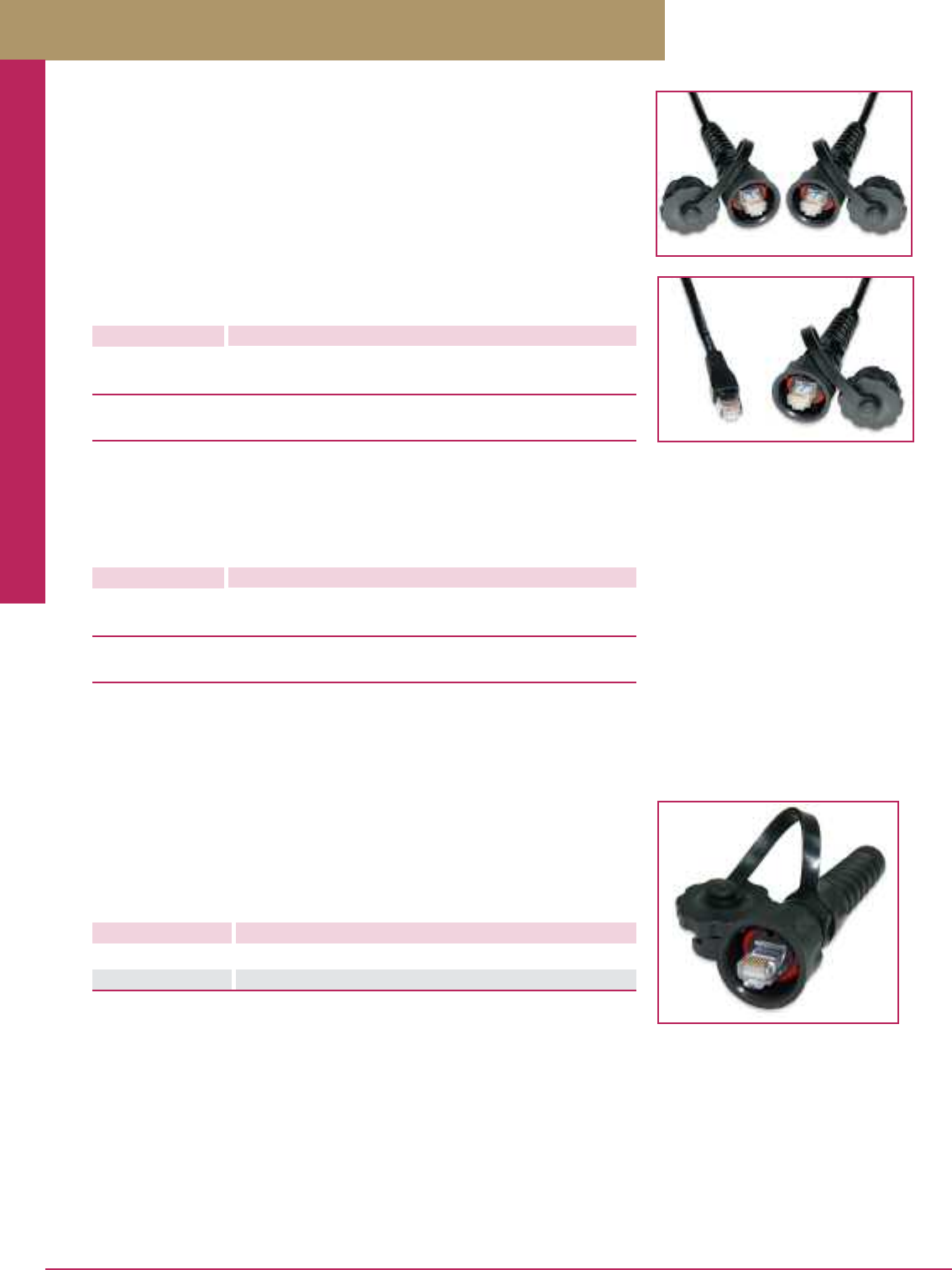
Patch Cords / Cable / Cable Assemblies / Connectors
PREMISE CONNECTIVITY SYSTEMS 800.446.2377 www.signamax.comC 7
Industrial-Grade Patch Cords
Signamax industrial-grade patch cords provide the same high-level transmission
performance as other Signamax cords intended for regular commercial applications,
but with a robustness capable to withstand harsh environments typical to factory floors,
chemical, food processing plants, etc. Unique IP67-rated plug housing design along with
industrial-grade stranded cable (category 5e only) guarantee superb protection against
liquid and solid agents penetration, against vibrations, and for a long-life reliable
performance. Cords are furnished with dust caps on the protected ends to prevent
exposure of unplugged connectors.
Category 6 Industrial-Grade Patch Cords
PART NO. DESCRIPTION
Industrial Plug-to-Industrial Plug
C6-116IG-LFB Category 6 Industrial Plug-to-Industrial Plug
Industrial Plug-to-RJ-45
C6-117IG-LFB Category 6 Industrial Plug-to-RJ-45
For length substitute L for length in P/N
3=3 ft 5=5 ft 7=7 ft 10=10 ft 15=15 ft 20=20 ft 25=25 ft
Standard cable color is black. Other colors and lengths are available.
Category 6 patch cords are manufactured using commercial-grade cable.
Category 5e Industrial-Grade Patch Cords
PART NO. DESCRIPTION
Industrial Plug-to-Industrial Plug
C5E-116IG-LFB Category 5e Industrial Plug-to-Industrial Plug
Industrial Plug-to-RJ-45
C5E-117IG-LFB Category 5e Industrial Plug-to-RJ-45
For length substitute L for length in P/N
3=3 ft 5=5 ft 7=7 ft 10=10 ft 15=15 ft 20=20 ft 25=25 ft
Standard cable color is black. Other colors and lengths are available.
Category 5e patch cords are manufactured using industrial-grade petroleum and UV-resistant cable.
Category 5e Field-Installable Industrial-Grade Plug Assemblies
PART NO. DESCRIPTION
KRJ45IG-C5E Category 5e Unscreened Field-Installable Industrial Plug
KRJS45IG-C5E Category 5e Screened Field-Installable Industrial Plug
Category 5e Industrial-Grade Plug Assemblies are available in an unscreened and
screened versions. These field-installable connectors are supplied with an 8P8C plug,
industrial housing and a protective cap. Plugs are easily assembled in the field and
accommodate 24- to 26-AWG stranded conductors.
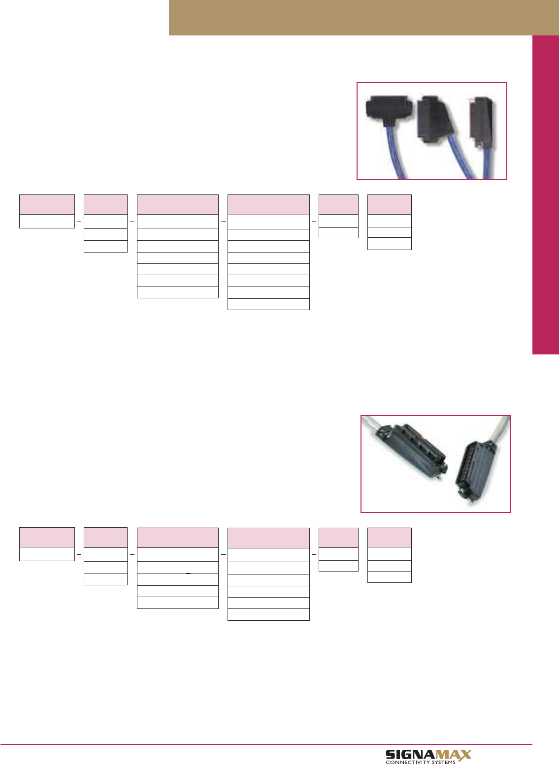
Patch Cords / Cable / Cable Assemblies / Connectors
C 8
TM
Category 5e 25-Pair Cable Assemblies
Category 5e 25-Pair Telco Assemblies are constructed using category 5e compliant
cable in both riser and plenum versions. Cables are available in single-ended male or
female, double-ended male or female, and double-ended male/female configurations.
Telco connector hoods are available in 90-, 110-, or 180-degree cable exit.
25-Pair Telco Cable Assemblies
Category 5e 25-Pair Cable Assembly Configurator
CABLE
TYPE
X
R = Riser
P = Plenum
UNIT OF
MEASURE
X
F = Feet
M = Meters
LENGTH
XXX
001 - 999
CATEGORY 5e
25-PAIR CABLE
C525
CONNECTOR
END ONE
XX
M9 = Male 90° Exit
F9 = Female 90° Exit
M1 = Male 110° Exit
F1 = Female 110° Exit
M8 = Male 180° Exit
F8 = Female 180° Exit
CONNECTOR
END TWO
XX
M9 = Male 90° Exit
F9 = Female 90° Exit
M1 = Male 110° Exit
F1 = Female 110° Exit
M8 = Male 180° Exit
F8 = Female 180° Exit
B = Blunt Cut
Part Number Example: C525-P-F1-F1-025F
25-Pair Cable Assembly, CMP-Rated Cable, Female 110° Exit to Female 110° Exit, 25 Feet
Category 3 25-Pair Cable Assemblies
Assemblies are constructed using category 3 compliant cable in both riser and plenum
versions. Cables are available in single-ended male or female, double-ended male or
female, and double-ended male/female configurations. Telco connector hoods are
available in 90- or 180-degree cable exit.
Category 3 25-Pair Cable Assembly Configurator
CABLE
TYPE
X
R = Riser
P = Plenum
UNIT OF
MEASURE
X
F = Feet
M = Meters
LENGTH
XXX
001 - 999
CATEGORY 3
25-PAIR CABLE
C325
CONNECTOR
END ONE
XX
M9 = Male 90° Exit
F9 = Female 90° Exit
M8 = Male 180° Exit
F8 = Female 180° Exit
CONNECTOR
END TWO
XX
M9 = Male 90° Exit
F9 = Female 90° Exit
M8 = Male 180° Exit
F8 = Female 180° Exit
B = Blunt End
Part Number Example: C325-R-M9-F9-025F
25-Pair Cable Assembly, CMR Riser-Rated Cable, Female 90° Exit to Male 90° Exit, 25 Feet
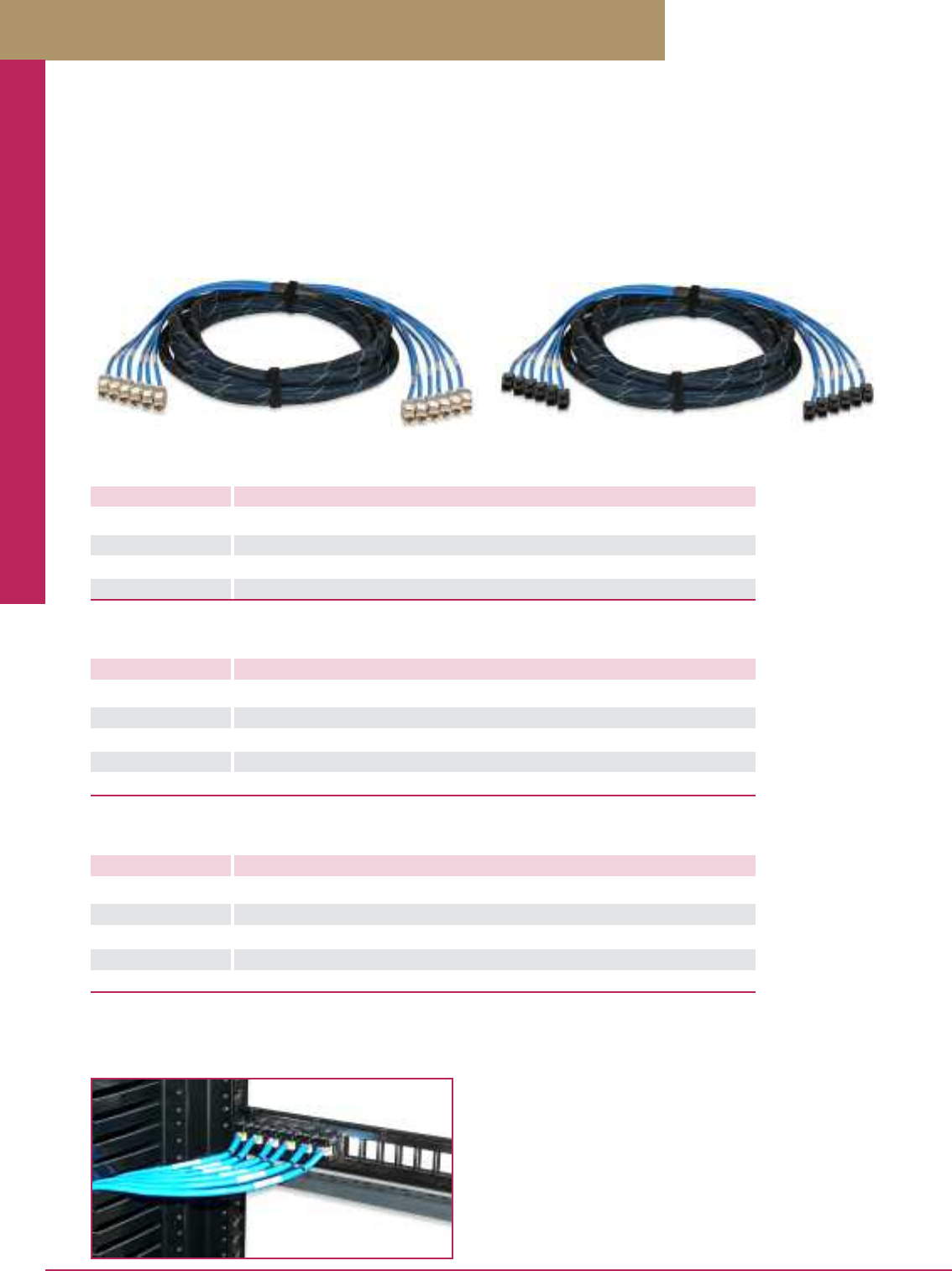
Patch Cords / Cable / Cable Assemblies / Connectors
PREMISE CONNECTIVITY SYSTEMS 800.446.2377 www.signamax.comC 9
Pre-Terminated Copper Trunk Assemblies
Pre-terminated Copper Trunk Assemblies help to reduce significantly both time and cost of a cabling installation. Terminated and
tested in a controlled manufacturing environment, cut to the customer pre-ordered lengths, and ready to install in a patch panel, trunk
assemblies eliminate all these operations in the field making your job easy and efficient. Trunk cables are available in category 6A, 6,
and 5e performance levels. Trunk cable assemblies can be provided in an unscreened and screened versions in either a jack-to-jack,
jack-to-plug or jack-to-blunt cut configurations to support the widest range of applications. Cables can be used with any field-
configurable patch panel.
Category 6A 10G Pre-Treminated Trunk Assemblies
PART NO. DESCRIPTION
6L-C6A-JJ-P-FXXX Category 6A 10G 6-Leg Trunk Cable, Jack-to-Jack, Unscreened U/UTP Cable, CMP
6L-C6A-JB-P-FXXX Category 6A 10G 6-Leg Trunk Cable, Jack-to-Open, Unscreened U/UTP Cable, CMP
6L-C6AS-JJ-P-FXXX Category 6A 10G 6-Leg Trunk Cable, Jack-to-Jack, Screened F/UTP Cable, CMP
6L-C6AS-JB-P-FXXX Category 6A 10G 6-Leg Trunk Cable, Jack-to-Open, Screened F/UTP Cable, CMP
Category 6 Pre-Terminated Trunk Assemblies
PART NO. DESCRIPTION
6L-C6-JJ-P-FXXX Category 6 6-Leg Trunk Cable, Jack-to-Jack, Unscreened U/UTP Cable, CMP
6L-C6-JP-P-FXXX Category 6 6-Leg Trunk Cable, Jack-to-Plug, Unscreened U/UTP Cable, CMP
6L-C6-JB-P-FXXX Category 6 6-Leg Trunk Cable, Jack-to-Open, Unscreened U/UTP Cable, CMP
6L-C6S-JJ-P-FXXX Category 6 6-Leg Trunk Cable, Jack-to-Jack, Screened F/UTP Cable, CMP
6L-C6S-JB-P-FXXX Category 6 6-Leg Trunk Cable, Jack-to-Open, Screened F/UTP Cable, CMP
Category 5e Pre-Terminated Trunk Assemblies
PART NO. DESCRIPTION
6L-C5E-JJ-P-FXXX Category 5e 6-Leg Trunk Cable, Jack-to-Jack, Unscreened U/UTP Cable, CMP
6L-C5E-JP-P-FXXX Category 5e 6-Leg Trunk Cable, Jack-to-Plug, Unscreened U/UTP Cable, CMP
6L-C5E-JB-P-FXXX Category 5e 6-Leg Trunk Cable, Jack-to-Open, Unscreened U/UTP Cable, CMP
6L-C5ES-JJ-P-FXXX Category 5e 6-Leg Trunk Cable, Jack-to-Jack, Screened F/UTP Cable, CMP
6L-C5ES-JB-P-FXXX Category 5e 6-Leg Trunk Cable, Jack-to-Open, Screened F/UTP Cable, CMP
For length substitute XXX for length in feet. Minimum length is 10 ft. Maximum length is 295 ft.
Unscreened cable color is blue. Screened cable is gray. Other colors are available.
Standard cable is straight-cut for either left ot right cable exit. Staggered-cut cables are available.
For riser-rated (CMR) cable substitute R for P in P/N.
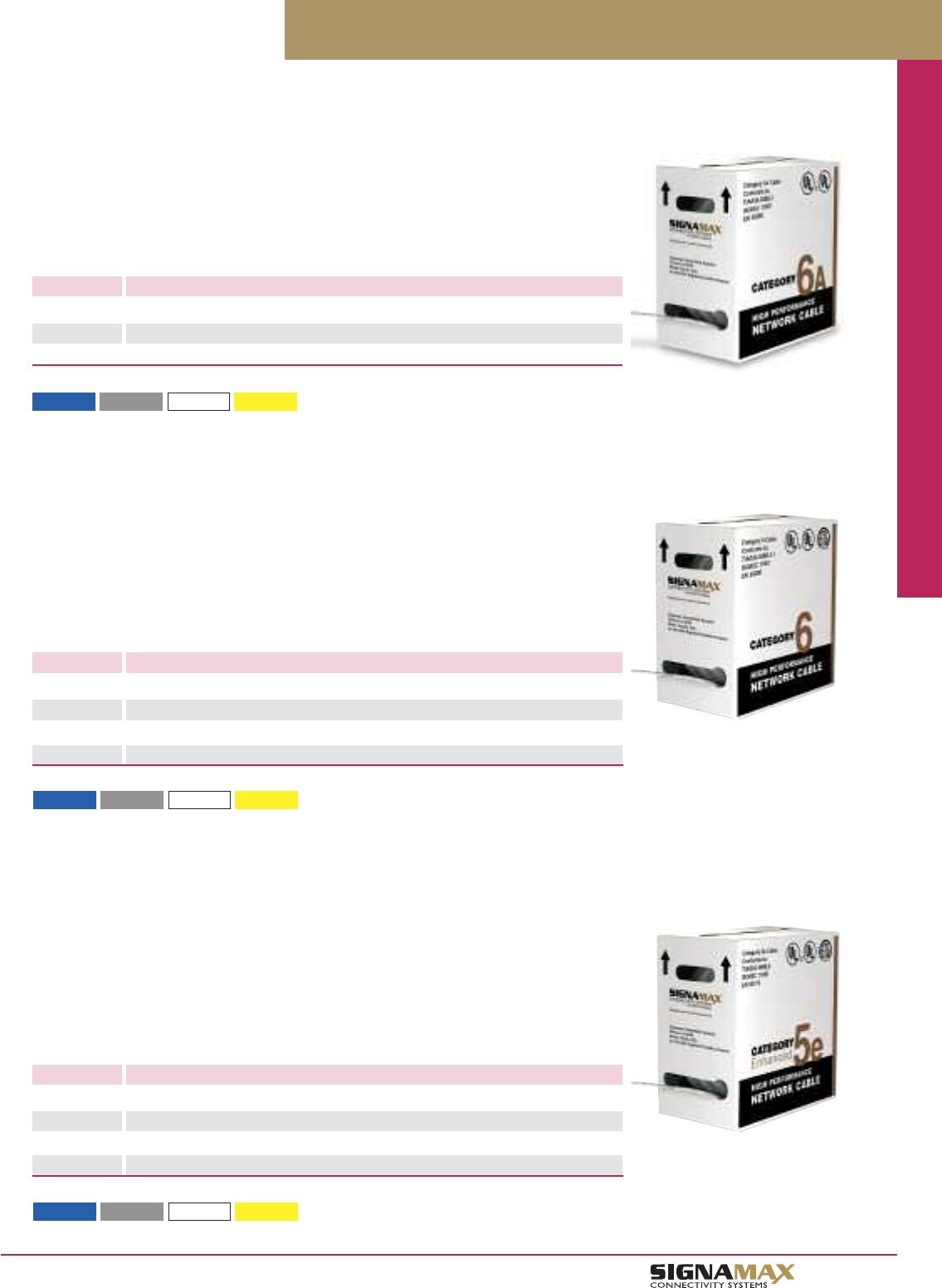
Patch Cords / Cable / Cable Assemblies / Connectors
C 1 0
TM
Cable
Category 6 4-pair solid conductor cable is ETL-verified, manufactured to the highest quality
standards, and exceeds all performance specifications for category 6 as defined in ANSI/TIA-
568-C.2, ISO/IEC 11801 2nd Edition, CENELEC EN 50173-1, and CENELEC EN 50288. Cable is
available in plenum (CMP) and riser (CMR) versions and is supplied in "tangle-free" cartons of
305 m (1,000 ft). Cable is available in a variety of popular colors. Cable is RoHS compliant per
European Union Directive 2002/95/EC.
Category 6A Cable
PART NO. DESCRIPTION
BC6A-4P-CC Category 6A, 4-Pair, 23-AWG Solid Unscreened U/UTP Cable, CMP
BC6A-4CC Category 6A, 4-Pair, 23-AWG Solid Unscreened U/UTP Cable, CMR (PVC)
BC6AM-4CC Category 6A, 4-Pair, 23-AWG Solid Unscreened U/UTP Cable, CM (PVC)
Category 6 Cable
PART NO. DESCRIPTION
BC6-4P-CC Category 6, 4-Pair, 23-AWG Solid Unscreened U/UTP Cable, CMP
BC6-4CC Category 6, 4-Pair, 23-AWG Solid Unscreened U/UTP Cable, CMR (PVC)
BC6M-4CC Category 6, 4-Pair, 23-AWG Solid Unscreened U/UTP Cable, CM (PVC)
BC6-4SH Category 6, 4-Pair, 23-AWG Solid Screened F/UTP Cable, CMR (PVC), Gray Only
-BU (Blue) -GY (Gray) -WH (White) -YE (Yellow)
For cable color substitute CC for color in P/N. Other colors available as a special request.
Category 5e 4-pair solid conductor cable is ETL-verified, manufactured to the highest quality
standards, and exceeds all performance specifications for category 5e as defined in ANSI/TIA-
568-C.2, ISO/IEC 11801 2nd Edition, CENELEC EN 50173-1, and CENELEC EN 50288. Cable is
available in plenum (CMP) and riser (CMR) versions and is supplied in "tangle-free" cartons of
305 m (1,000 ft). Cable is available in a variety of popular colors. Cable is RoHS
compliant per European Union Directive 2002/95/EC.
Category 5e Cable
PART NO. DESCRIPTION
BC5E-4P-CC Category 5e, 4-Pair, 24-AWG Solid Unscreened U/UTP Cable, CMP
BC5E-4CC Category 5e, 4-Pair, 24-AWG Solid Unscreened U/UTP Cable, CMR (PVC)
BC5EM-4CC Category 5e, 4-Pair, 24-AWG Solid Unscreened U/UTP Cable, CM (PVC)
BC5E-4SH Category 5e, 4-Pair, 24-AWG Solid Screened F/UTP Cable, CMR (PVC), Gray Only
-BU (Blue) -GY (Gray) -WH (White) -YE (Yellow)
For cable color substitute CC for color in P/N. Other colors available as a special request.
-BU (Blue) -GY (Gray) -WH (White) -YE (Yellow)
For cable color substitute CC for color in P/N. Other colors available as a special request.
Signamax solid conductor twisted-pair cable is ETL-verified to ANSI/TIA-568-C.2 for category 6A
cable specifications, CMR-rated, manufactured to the highest quality standards, and meets all
applicable performance specifications of category 6A requirements as per ANSI/TIA and ISO/IEC
standards. Flame retardancy is verified according to IEC and UL requirements. RoHS compliance
per European Union Directive 2002/95/EC.
Cable is available for customers outside the U.S. only. Minimum quantity may be required.
Cable is available for customers outside the U.S. only. Minimum quantity may be required.
Cable is available for customers outside the U.S. only. Minimum quantity may be required.
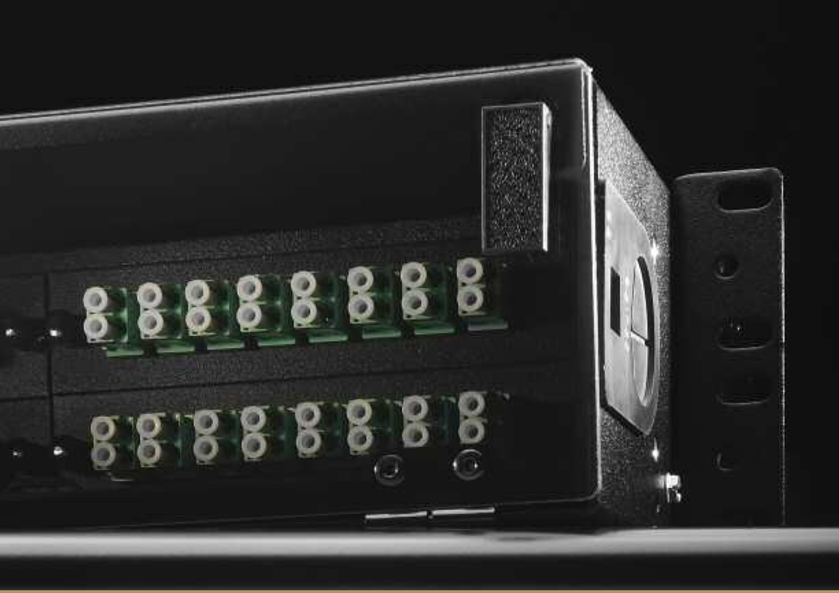
Optical
Fiber
SYSTEMS
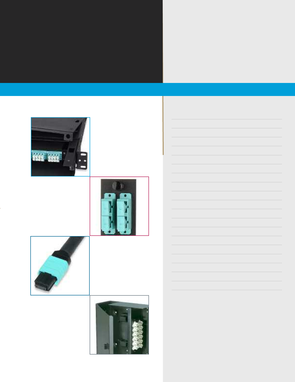
PPrreemmiiuumm RRaacckk--MMoouunntt FFiibbeerr EEnncclloossuurreess DD11
GGeenneerraall--PPuurrppoossee RRaacckk--MMoouunntt FFiibbeerr EEnncclloossuurreessDD33
PPrree--CCoonnffiigguurreedd RRaacckk--MMoouunntt FFiibbeerr EEnncclloossuurreessDD55
RRaacckk--MMoouunntt FFiibbeerr DDiissttrriibbuuttiioonn EEnncclloossuurreess DD77
RRaacckk--MMoouunntt FFiibbeerr SSpplliiccee EEnncclloossuurreess DD88
RRaacckk--MMoouunntt SSlliiddee--OOuutt FFiibbeerr EEnncclloossuurree DD99
WWaallll--MMoouunntt FFiibbeerr EEnncclloossuurreess DD1100
RRaacckk--MMoouunntt FFiibbeerr PPaanneellss DD1111
SSpplliiccee TTrraayyss DD1122
FFiibbeerr AAddaapptteerr PPllaatteess DD1144
FFiibbeerr AAddaapptteerrss DD1155
FFiieelldd--IInnssttaallllaabbllee FFiibbeerr CCoonnnneeccttoorrss DD1166
HHiigghh--DDeennssiittyy FFiibbeerr PPaanneellss DD1177
MMuullttiimmooddee FFiibbeerr PPaattcchh CCoorrddss DD1199
SSiinngglleemmooddee FFiibbeerr PPaattcchh CCoorrddss DD2200
1100GG MMuullttiimmooddee FFiibbeerr PPaattcchh CCoorrddss DD2211
FFiibbeerr PPiiggttaaiillss DD2222
PPlluugg--aanndd--PPllaayy PPrree--TTeerrmmiinnaatteedd FFiibbeerr CCaasssseetttteess DD2233
MMTTPP OOppttiiccaall FFiibbeerr AAsssseemmbblliieess DD2244
MMTTPP FFaannoouutt AAsssseemmbblliieess DD2244
w w w . s i g n a m a x . c o m
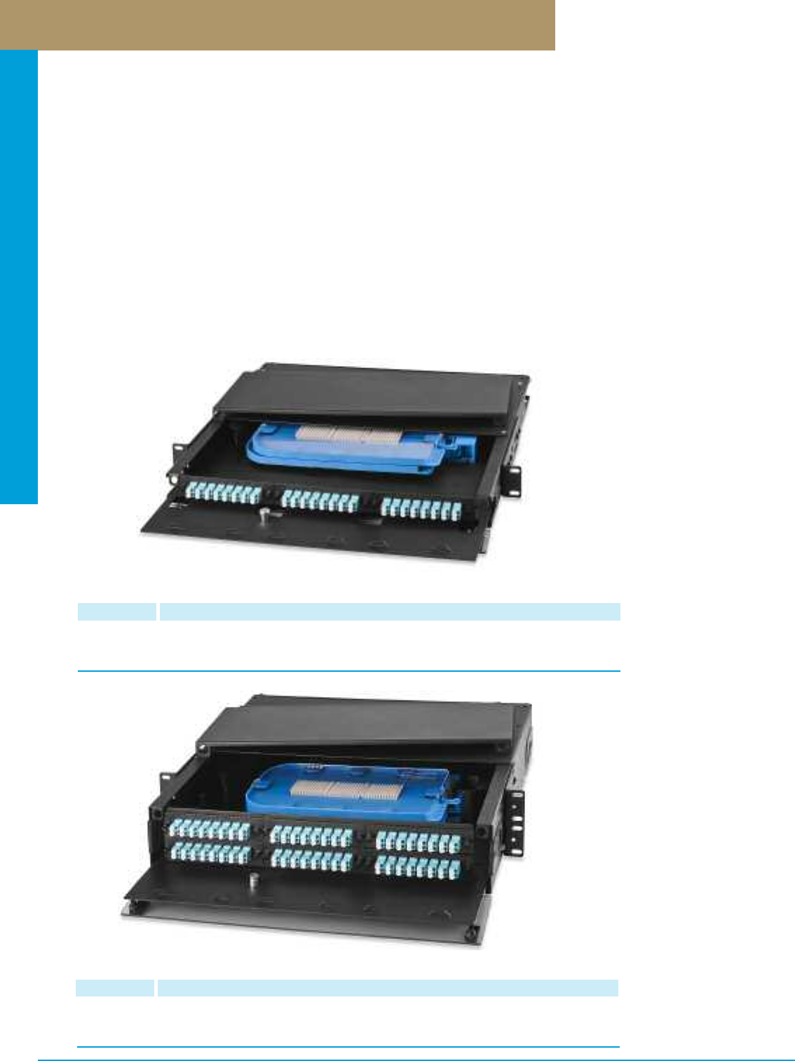
Optical Fiber Systems
PREMISE CONNECTIVITY SYSTEMS 800.446.2377 www.signamax.comD 1
Premium Rack-Mount Optical Fiber Enclosures
18- to 72-Fiber Premium Rack-Mount Optical Fiber Enclosure
PART NO. DESCRIPTION
UFE3HD1-B 18- to 72-Fiber Enclosure w/Locking Slide-Out Support Stage. Accepts 3 Adapter Plates
and 2 FST-24P or FST-36P Splice Trays. Dimensions: 1.75”H x 19”W x 16”D.
Material: Black Powder Coated Steel.
Optical fiber enclosures provide cross- and interconnections in IT cabling systems between optical fiber distribution cables, connecting
hardware and active equipment, and for mechanical protection of such connections. Termination density of Signamax Premium
Rack-Mount Optical Fiber Enclosures ranges between 6 and 288 fiber connections depending on the enclosure size (1, 2, 3, or 4 RMS),
number of adapter plates installed (3, 6, 9, or 12), and types of optical fiber connectors used.
Modular design of Signamax optical fiber adapter plates allows creating flexible connection patterns based on 6-, 8-, 12-, 16- and
24-fiber ST, FC, SC, LC, and MT-RJ adapter plates, which can be arranged in 3- to 12-plate groups in any available connector
combination. Adapter plates mount easily by means of plunger locks (“pushpins”). All enclosures feature front and rear access hinged
panels and sliding-out support stages. The transparent plastic front panel enables visual inspection of the enclosure contents when
closed. Internal cable anchor points and fiber slack management mechanisms ensure reliable cable fixing, safe cable/fiber tension
and bend radii. Cable entry points are equipped with rubber grommets preventing dust penetration when the entry point is not used, and
protecting optical fiber cable from kinks that sharp edges of the enclosure case may cause.
Lightweight aluminum case (three-adapter-plate version has steel case) with increased depth (16 in) and high-impact black epoxy-
powder anticorrosive paint provide excellent protection for optical fiber connections. Optional stackable plastic optical fiber splice cassettes
are available when passive uniform interconnection or transfer from buffered to jacketed fibers are required. Enclosures are supplied with
a complete set of fastening elements and installation guidelines. Adapter plates and splice cassettes are ordered separately.
36- to 144-Fiber Premium Rack-Mount Optical Fiber Enclosure
PART NO. DESCRIPTION
UFE6HD1-B 36- to 144-Fiber Enclosure w/Locking Slide-Out Support Stage. Accepts 6 Adapter Plates
and 4 FST-24P or FST-36P Splice Trays. Dimensions: 3.50”H x 19”W x 16”D
Material: Black Powder Coated Aluminum.
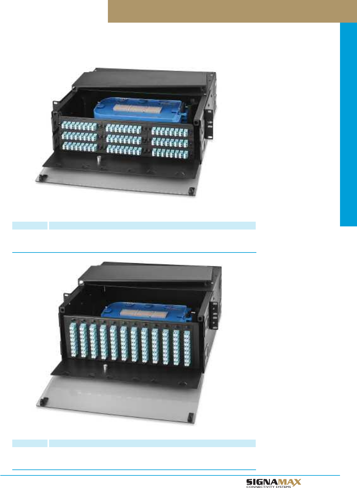
Optical Fiber Systems
D 2
TM
Premium Rack-Mount Optical Fiber Enclosures
54- to 216-Fiber Premium Rack-Mount Optical Fiber Enclosure
PART NO. DESCRIPTION
UFE9HD1-B 54- to 216-Fiber Enclosure w/Locking Slide-Out Support Stage. Accepts 9 Adapter Plates
and 6 FST-24P or FST-36P Splice Trays. Dimensions: 5.35”H x 19”W x 16”D.
Material: Black Powder Coated Aluminum.
72- to 288-Fiber Premium Rack-Mount Optical Fiber Enclosure
PART NO. DESCRIPTION
UFE12HD1-B 72- to 288-Fiber Enclosure w/Locking Slide-Out Support Stage. Accepts 12 Adapter Plates
and 8 FST-24P or FST-36P Splice Trays. Dimensions: 7.00”H x 19”W x 16”D.
Material: Black Powder Coated Aluminum.
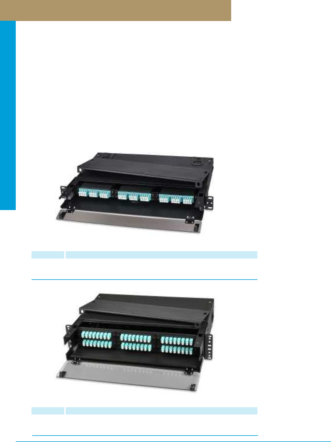
Optical Fiber Systems
PREMISE CONNECTIVITY SYSTEMS 800.446.2377 www.signamax.comD 3
General-Purpose Rack-Mount Optical Fiber Enclosures
18- to 72-Fiber General-Purpose Rack-Mount Optical Fiber Enclosure
PART NO. DESCRIPTION
UFE3HD-B 18- to 72-Fiber Enclosure w/Slide-Out Support Stage. Accepts 3 Adapter Plates
and 1 FST-24A Splice Tray. Dimensions: 1.75”H x 19”W x 14”D.
Material: Black Powder Coated Steel
Optical fiber enclosures provide cross- and interconnections in IT cabling systems between optical fiber distribution cables, connecting
hardware and active equipment, and for mechanical protection of such connections. Termination density of Signamax General-Purpose
Rack-Mount Optical Fiber Enclosures ranges between 6 and 288 fiber connections depending on the enclosure size (1, 2, 3, or 4
RMS), number of adapter plates installed (3, 6, 9, or 12), and types of optical fiber connectors used.
Modular design of Signamax optical fiber adapter plates allows creating flexible connection patterns based on 6-, 8-, 12-, 16- and 24-
fiber ST, FC, SC, LC, and MT-RJ adapter plates, which can be arranged in 3- to 12-plate groups in any available connector combina-
tion. Adapter plates mount easily by means of plunger locks (“pushpins”). All enclosures feature front and rear access hinged panels
and sliding-out support stages. The transparent plastic front panel enables visual inspection of the enclosure contents when closed.
Internal cable anchor points and fiber slack management mechanisms ensure reliable cable fixing, safe cable/fiber tension and bend
radii. Cable entry points are equipped with plastic edge protectors preventing optical fiber cable from kinks that sharp edges of the
enclosure case may cause.
Sixteen-gage steel case and high-impact black epoxy-powder anticorrosive paint provide excellent protection for optical fiber
connections. Optional aluminum optical fiber splice trays are available when passive uniform interconnection or transfer from buffered
to jacketed fibers are required. Enclosures are supplied with a complete set of fastening elements and installation guidelines. Adapter
plates and splice trays are ordered separately.
36- to 144-Fiber General-Purpose Rack-Mount Optical Fiber Enclosure
PART NO. DESCRIPTION
UFE6HD-B 36- to 144-Fiber Enclosure w/Slide-Out Support Stage. Accepts 6 Adapter Plates
and 3 FST-24A Splice Trays. Dimensions: 3.50”H x 19”W x 14”D.
Material: Black Powder Coated Steel
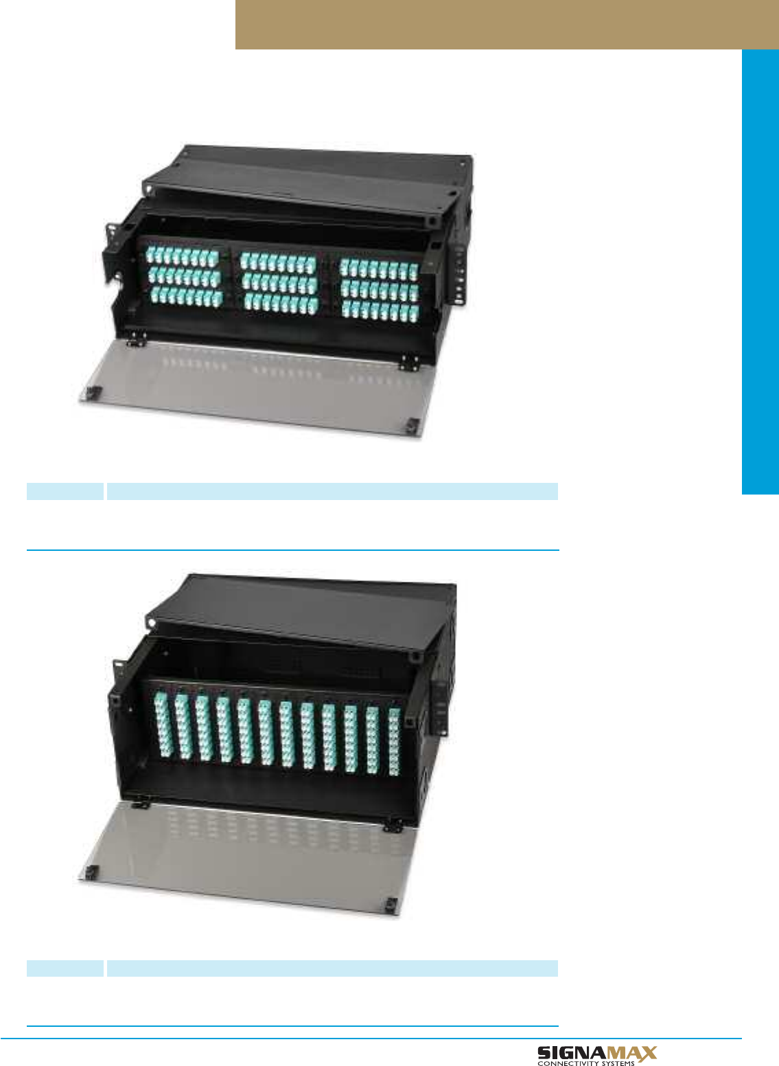
Optical Fiber Systems
D 4
TM
General-Purpose Rack-Mount Optical Fiber Enclosures
54- to 216-Fiber General-Purpose Rack-Mount Optical Fiber Enclosure
PART NO. DESCRIPTION
UFE9HD-B 54- to 216-Fiber Enclosure w/Slide-Out Support Stage. Accepts 9 Adapter Plates
and 5 FST-24A Splice Trays. Dimensions: 5.35”H x 19”W x 14”D.
Material: Black Powder Coated Steel
72- to 288-Fiber General-Purpose Rack-Mount Optical Fiber Enclosure
PART NO. DESCRIPTION
UFE12HD-B 72- to 288-Fiber Enclosure w/Slide-Out Support Stage. Accepts 12 Adapter Plates
and 8 FST-24A Splice Trays. Dimensions: 7.00”H x 19”W x 14”D.
Material: Black Powder Coated Steel
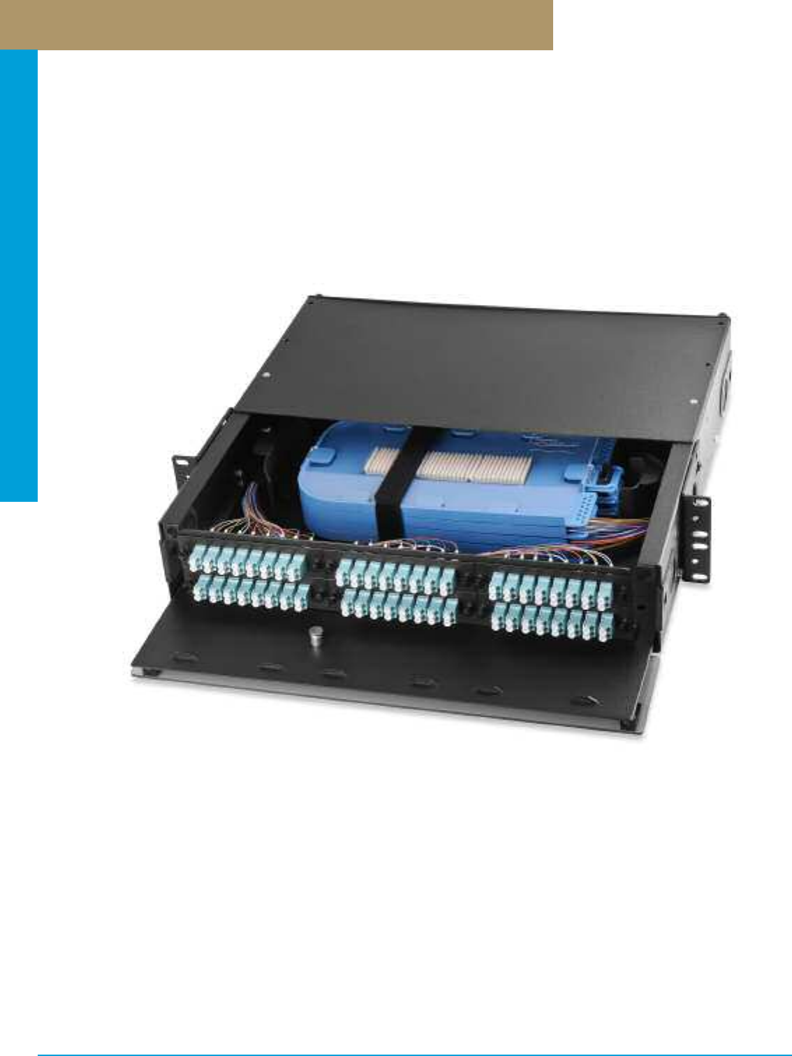
Optical Fiber Systems
PREMISE CONNECTIVITY SYSTEMS 800.446.2377 www.signamax.comD 5
Pre-Configured Rack-Mount Optical Fiber Enclosures
Pre-configured optical fiber enclosures can provide a number of convenient features including but not limited to field-assembly labor
cost savings, compliance with the standard requirements (e.g., fiber bend radii and tension), etc. Signamax pre-configured optical fiber
enclosures can be ordered as a complete set, which includes maximum available number of components in various configurations, or
as a start-up kit with some basic suit of connecting hardware with a view to expanding it in the future. The part number configurator
provided helps to make the right choice of enclosure and its components.
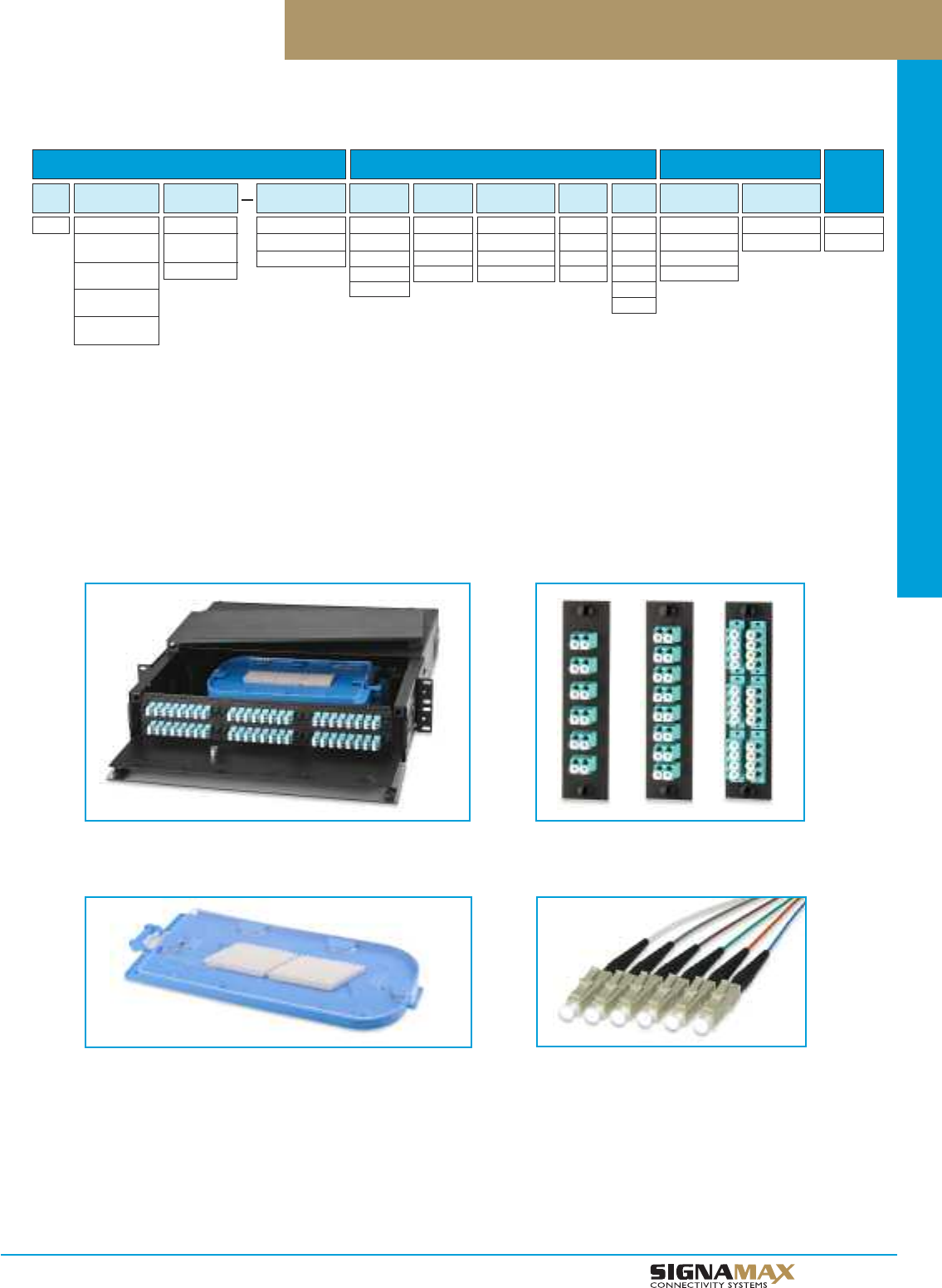
Optical Fiber Systems
D 6
TM
Pre-Configured Rack-Mount Optical Fiber Enclosures
TYPE ADAPTER
PLATE COUNT
XX
3 = 3-Adapter
Plates
6 = 6-Adapter
Plates
9 = 9-Adapter
Plates
12 = 12-Adapter
Plates
SERIES
XX
HD = General
Purpose
HD1 = Premium
CONNECTIVITY
TYPE
XX
P = Adapter Plates
C = MTP Cassette
ADAPTER
TYPE
XX
2 = ST
4 = SC
5 - FC
8 = LC
SX-DX-QX
XX
S = Simplex
D = Duplex
Q = Quad
ADAPTER
COUNT
XX
6 = 6 Adapters
8 = 8 Adapters
12 = 12 Adapters
POLISH
TYPE
XX
P = PC
U = UPC
A = APC
FIBER
TYPE
XX
1 = OM1
2 = OM2
3 = OM3
4 = OM4
S = SM
SPLICE TRAY
TYPE
XX
C = FST-24A
D = FST-24P
E = FST-36P
SPLICE TRAY
COUNT
XX
1 - 8
PIGTAILS
XX
0 - 288
ENCLOSURES ADAPTERS SPLICE TRAYS
UFE
22
1
1. Adapter count depends on the adapter
type slected:
ST: 6, 8, 12
FC: 6, 8, 12
SC Simplex: 6, 8
SC Duplex: 6
LC Duplex: 6, 8
LC Quad: 6
2. Splice tray type and count depend on the enclosure design slected:
UFE3HD-X Type C ( FST-24A); 1 maxumum UFE3HD1-X Type E or D (FST-24P or 36P): 2 maximum
UFE6HD-X Type C ( FST-24A); 3 maxumum UFE6HD1-X Type E or D (FST-24P or 36P): 4 maximum
UFE9HD-X Type C ( FST-24A); 5 maxumum UFE9HD1-X Type E or D (FST-24P or 36P): 6 maximum
UFE12HD-X Type C ( FST-24A); 8 maxumum UFE12HD1-X Type E or D (FST-24P or 36P): 8 maximum
Part Number Example: UFE9HD1-BP9Q06ASE6144
Premium optical fiber enclosure, 9 SM APC LC quad 6-adapter plates (216-fiber), 6 36-fiber splice trays, 144 SM APC LC pigtails.
For Enclosures See Page D1 - D4
For Splice Trays See Page D12
For Adapter Platec See Page D13 - D14
For Pigtail Kits See Page D22
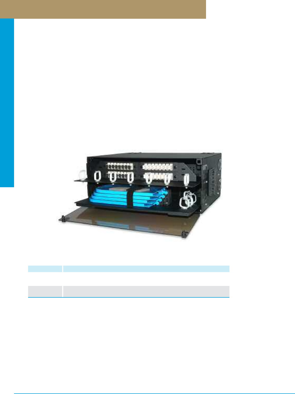
Optical Fiber Systems
PREMISE CONNECTIVITY SYSTEMS 800.446.2377 www.signamax.comD 7
Optical Fiber Distribution Enclosures
Optical fiber distribution enclosures provide flexibility along with a high termination density when cross- or interconnections and splicing
are required together at a single distribution point. Combining features of Signamax rack-mount optical fiber enclosures and rack-mount
optical fiber splice enclosures, fiber distribution enclosures allow to terminate and splice maximum number of optical fibers within one
enclosure.
Signamax rack-mount optical fiber distribution enclosure’s termination density ranges between 24 and 288 fiber connections depending
on the enclosure size (4 or 8 RMS) and optical fiber connectors used. Modular design of Signamax optical fiber adapter plates allows
creating flexible connection patterns based on 6-, 8-, 12-, 16-, and 24-fiber ST-, FC-, SC-, LC- and MT-RJ-adapter plates, which can be
arranged in 4- to 12-plate groups in any available connector combination. Splicing capacity ranges between 24 and 192 splices
depending on the enclosure size and number (up to 8) of 24-fiber splice trays used. Unique splice tray stacking mechanism allows
adding trays and servicing each of them without disassembling the stack.
All enclosures feature front and rear access hinged panels and sliding-out support stages. The transparent plastic front panel enables
visual inspection of the panel contents when closed. Internal cable anchor points and fiber slack management mechanisms ensure
reliable cable fixing, safe cable/fiber tension and bend radii. Cable entry points are equipped with rubber grommets preventing dust
penetration when the entry point is not used, and protecting optical fiber cable from kinks that sharp edges of the enclosure case may
cause. Steel case and high-impact black epoxy-powder anticorrosive paint provide excellent protection of optical fiber connections.
Enclosures are supplied with a complete set of fastening elements and installation guidelines.
Optical Fiber Distribution Enclosures
PART NO. DESCRIPTION
UFD4-B 24- to 96-Fiber Optical Fiber Distribution Enclosure, Accepts 4 Adapter Plates and
4 FST-24P Splice Trays. Dimensions: 7”H x 19”W x 14”D
UFD12-B 72- to 288-Fiber Optical Fiber Distribution Enclosure, Accepts 12 Adapter Plates and
8 FST-24P Splice Trays, Dimensions: 14”H x 19”W x 14”D
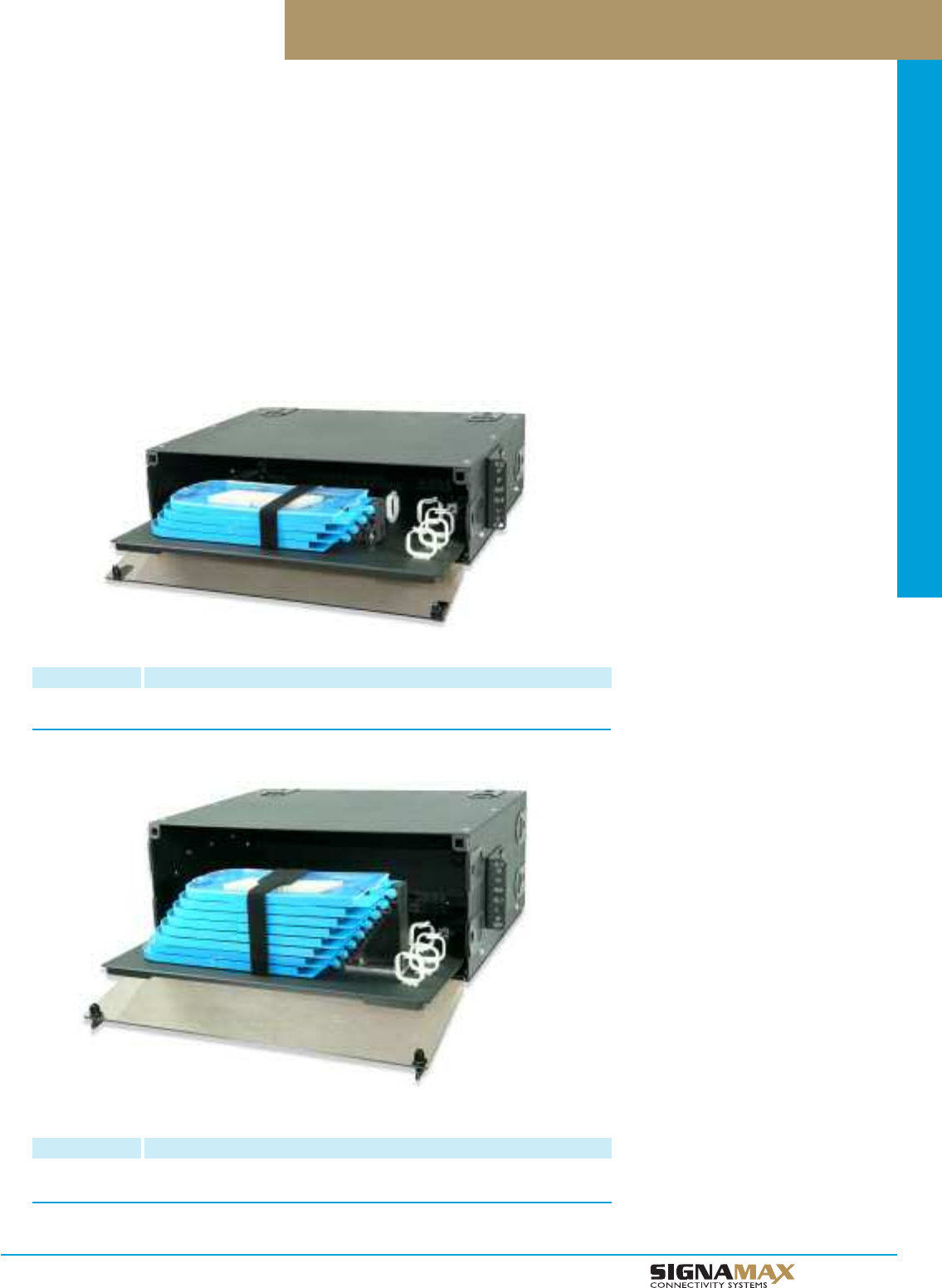
Optical Fiber Systems
D 8
TM
Rack-Mount Optical Fiber Splice Enclosures
96-Fiber Slide-Out Splice Tray Enclosure
PART NO. DESCRIPTION
UFS4-B 96-Fiber Slide-Out Splice Tray Enclosure. Accepts 4 FST-24P Splice Trays
(Includes one FST-24P Splice Tray). Dimensions: 5.25”H x 19”W x 14”D
Optical fiber splice enclosures are inexpendable when interconnection between segments of optical fiber cables is required without
connection of active equipment or creation of cross-connections, providing fast, flexible, and cost-effective solution by means of fusion
or mechanical splices. Physical protection of such connections and storage of fiber slack are also splice enclosure’s major functions.
Rack mount optical fiber splice enclosure’s termination density ranges between 24 and 192 splices depending on the enclosure size
(3 or 4 RMS) and number of 24-fiber splice trays used. Unique splice tray stacking mechanism allows adding trays and servicing each
of them without disassembling the stack. All enclosures feature front and rear access hinged panels and sliding-out support stages.
The transparent plastic front panel enables visual inspection of the enclosure contents when closed. Internal cable anchor points and
fiber slack management mechanisms ensure reliable cable fixing, safe cable/fiber tension and bend radii. Cable entry points are
equipped with rubber grommets preventing dust penetration when the entry point is not used, and protecting optical fiber cable from
kinks that sharp edges of the enclosure case may cause.
Steel case and high-impact black epoxy-powder anticorrosive paint provide excellent protection of optical fiber connections. Enclosures
include one 24-fiber splice tray (P/N FST-24P) and are supplied with a complete set of fastening elements and installation guidelines.
192-Fiber Slide-Out Splice Tray Enclosure
PART NO. DESCRIPTION
UFS8-B 192-Fiber Slide-Out Splice Tray Enclosure. Accepts 8 FST-24P Splice Trays
(Includes one FST-24P splice tray). Dimensions: 7”H x 19”W x 14”D
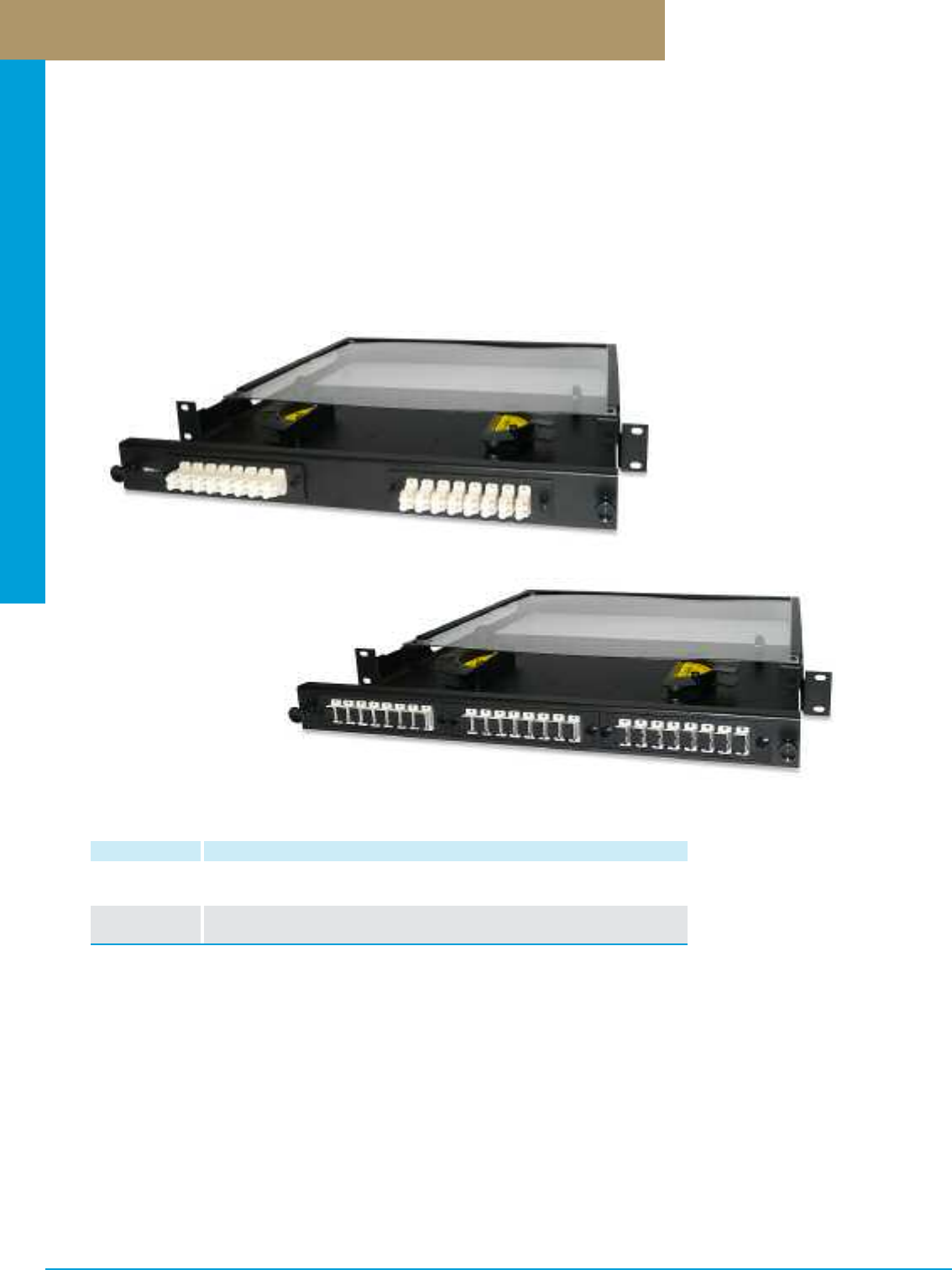
Optical Fiber Systems
PREMISE CONNECTIVITY SYSTEMS 800.446.2377 www.signamax.comD 9
Rack-Mount Slide-Out Optical Fiber Enclosures
Signamax rack mount slide-out enclosures provide a simple, high-density, low-profile solution for easy access and management of
optical fiber terminations in a one-rack-space design. The rack-mount sliding tray enclosures accommodate up to 72 fibers in ST-,
FC-, SC-, MT-RJ- and LC- interfaces. Modular design of Signamax optical fiber adapter plates allows creating flexible connection
patterns based on 6-, 8-, 12-, 16-, and 24-fiber ST-, FC-, SC-, LC- and MT-RJ-adapter plates, which can be arranged in 2- and 3-plate
groups in any available connector combination. Adapter plates mount easily by means of plunger locks (“pushpins”). Internal cable
anchor points and fiber slack management mechanisms ensure reliable cable fixing, safe cable/fiber tension and bend radii.
Steel case and high-impact black epoxy-powder anticorrosive paint provide excellent protection of optical fiber connections. Optional
optical fiber splice trays/cassettes are available when passive uniform interconnection or transfer from buffered to jacketed fibers are
required. All enclosures are supplied with a complete set of fastening elements and installation guidelines.
12- to 72-Fiber Rack-Mount Slide-Out Optical Fiber Enclosures
PART NO. DESCRIPTION
SL2M-B 12- to 48-Fiber Rack-Mount Optical Fiber Enclosure, Accepts 2 Adapter Plates
and 2 FST-2M-B Splice Trays. Dimensions: 1.75”H x 19”W x 14”D
SL3M-B 18- to 72-Fiber Rack-Mount Optical Fiber Enclosure, Accepts 3 Adapter Plates
and 2 FST-2M-B Splice Trays.Dimensions: 1.75”H x 19”W x 14”D
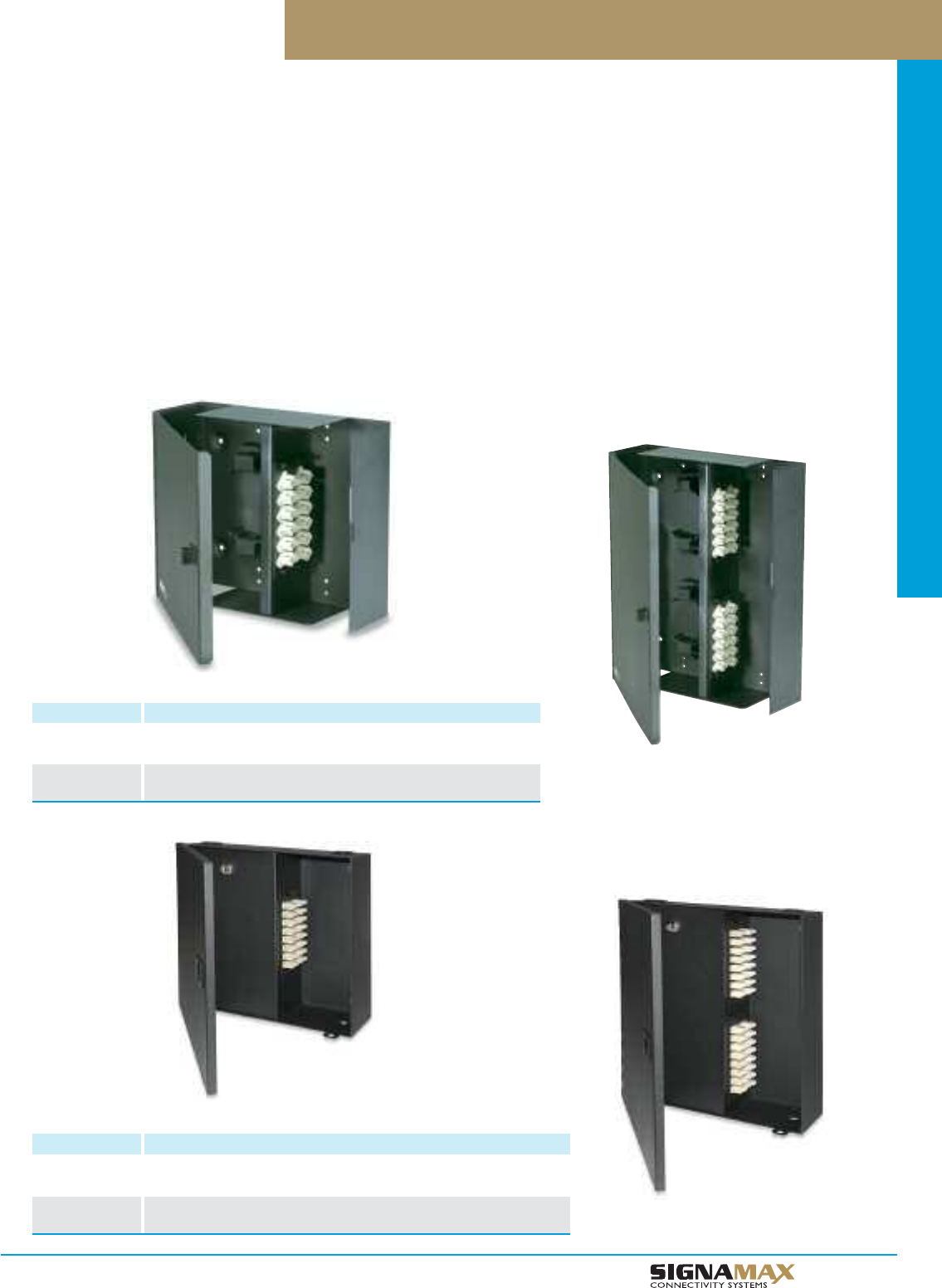
Optical Fiber Systems
D 1 0
TM
Wall-Mount Optical Fiber Enclosures w/Security Door
PART NO. DESCRIPTION
WFE2S-B 12- to 48-Fiber Wall-Mount Optical Fiber Enclosure w/Security Door
Accepts 2 Adapter Plates. Dimensions: 10.2"H x 12"W x 3.5"D
WFE4S-B 24- to 96-Fiber Wall-Mount Optical Fiber Enclosure w/Security Door
Accepts 4 Adapter Plates. Dimensions: 12"H x 12"W x 3.5"D
Wall-Mount Optical Fiber Enclosures
Wall-mount optical fiber enclosures are ideal in small installations and/or where rack or cabinet mounting is not feasible. Most popular
applications include demarcation and consolidation points, horizontal mini cross-connects, centralized optical architecture transition
points, etc. Physical protection of such connections and storage of fiber slack are also wall-mount enclosure’s major functions. Signamax
wall-mount optical fiber enclosure’s termination density ranges between 6 and 96 fiber connections depending on the enclosure capacity
(2 or 4 adapter plates) and optical fiber connectors used.
Modular design of Signamax optical fiber adapter plates allows creating flexible connection patterns based on 6-, 8-, 12-, 16-, and
24-fiber ST-, FC-, SC- and LC-adapter plates, which can be arranged in 2- and 4-plate groups in any available connector combination.
Adapter plates mount easily by means of plunger locks (“pushpins”). All enclosures feature front access hinged doors; two versions are
equipped with additional lockable security doors. Internal cable anchor points and fiber slack management mechanisms ensure reliable
cable fixing, safe cable/fiber tension and bend radii.
Steel case and high-impact black epoxy-powder anticorrosive paint provide excellent protection of optical fiber connections. Optional
optical fiber splice trays/cassettes are available when passive uniform interconnection or transfer from buffered to jacketed fibers are
required. Enclosures are supplied with a complete set of fastening elements and installation guidelines.
Wall-Mount Optical Fiber Enclosures
PART NO. DESCRIPTION
WFE2-B 12- to 48-Fiber Wall-Mount Optical Fiber Enclosure
Accepts 2 Adapter Plates. Dimensions: 9”H x 10”W x 3.50”D
WFE4-B 24- to 96-Fiber Wall-Mount Optical Fiber Enclosure
Accepts 4 Adapter Plates. Dimensions: 15”H x 10”W x 3.50”D
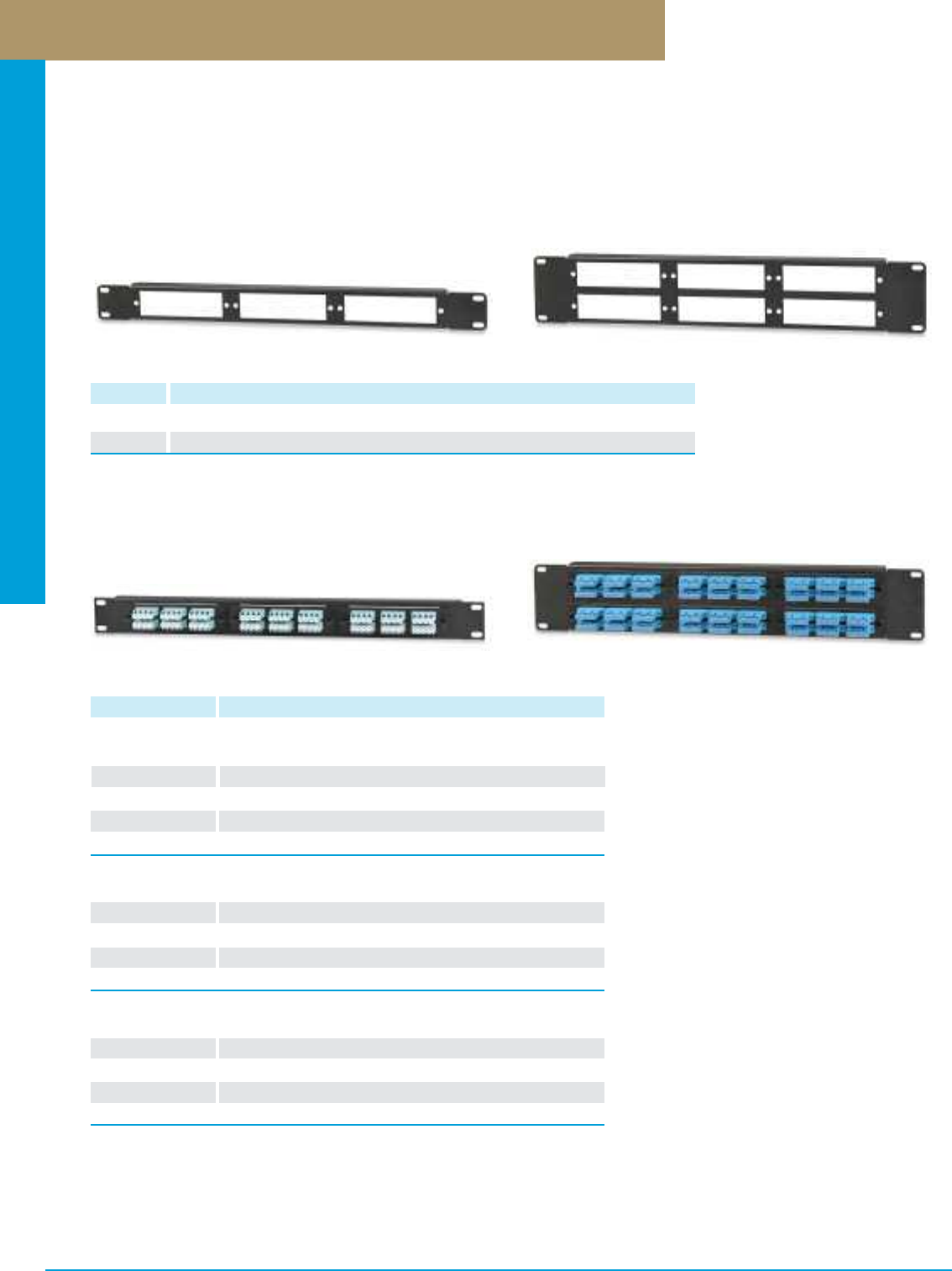
Optical Fiber Systems
PREMISE CONNECTIVITY SYSTEMS 800.446.2377 www.signamax.comD 11
Rack-Mount Optical Fiber Panels
Rack-Mount Optical Fiber Panels
PART NO. DESCRIPTION
RMF3-B 18- to 72-Fiber Rack-Mount Optical Fiber Panel, Accepts 3 Adapter Plates, 1.75”H
RMF6-B 36- to 144-Fiber Rack-Mount Optical Fiber Panel, Accepts 6 Adapter Plates, 3.50”H
Signamax offers a range of economy, high-density optical fiber patch panels accepting variety of our optical fiber adapter plates.
These rack-mount panels are available in 3- and 6-adapter-plate sizes (1 or 2 RMS) and are ideal where space is limited as compared
to the standard-density optical fiber panels or enclosures. These high-density panels provide increased termination density due to
more compact adapter population and can be supplied unloaded for field configuration or pre-loaded with adapters.
Pre-Configured Optical Fiber Panels
PART NO. DESCRIPTION
ST Optical Fiber Panels
16HDST-FT 16-Fiber ST MM Optical Fiber Panel, 1.75” High
24HDST-FT 24-Fiber ST MM Optical Fiber Panel, 1.75” High
36HDST-FT 36-Fiber ST MM Optical Fiber Panel, 1.75” High
48HDST-FT 48-Fiber ST MM Optical Fiber Panel, 3.50” High
72HDST-FT 72-Fiber ST MM Optical Fiber Panel, 3.50” High
SC Optical Fiber Panels
16HDSC-FT 16-Fiber (16-Simplex) SC MM Optical Fiber Panel, 1.75” High
24HDSC-FT 24-Fiber (24-Simplex) SC MM Optical Fiber Panel, 1.75” High
36HDSC-FT 36-Fiber (18-Duplex) SC MM Optical Fiber Panel, 1.75” High
48HDSC-FT 48-Fiber (48-Simplex) SC MM Optical Fiber Panel, 3.50” High
72HDSC-FT 72-Fiber (36-Duplex) SC MM Optical Fiber Panel, 3.50” High
LC Optical Fiber Panels
36HDLC-FT 36-Fiber (18-Duplex) LC MM Optical Fiber Panel, 1.75” High
48HDLC-FT 48-Fiber (24-Duplex) LC MM Optical Fiber Panel, 1.75” High
72HDLC-FT 72-Fiber (18-Quad) LC MM Optical Fiber Panel, 1.75” High
96HDLC-FT 96-Fiber (48-Duplex) LC MM Optical Fiber Panel, 3.50” High
144HDLC-FT 144-Fiber (36-Quad) LC MM Optical Fiber Panel, 3.50” High
For singlemode adapters add -C to P/N. For multimode 10G LOF adapters add -G to P/N
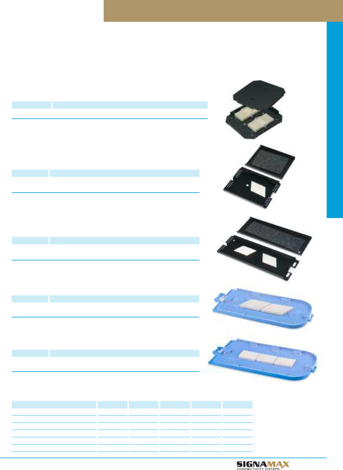
Optical Fiber Systems
D 1 2
TM
Splice Trays for Wall- and Rack-Mount Enclosures
Splice trays are the best solution when interconnection between segments of optical fiber cables is required without connection of
active equipment or creation of cross-connections, providing fast, flexible, and cost-effective solution by means of fusion or mechanical
splices. Signamax splice trays are available in plastic and metal versions with 12- and 24- and 36-fiber capacity. Plastic trays feature
a transparent lid allowing visual inspection of the tray contents without opening it. Splice trays are compliant with Telcordia GR-769.
12A Fiber Splice Tray
PART NO. DESCRIPTION
FST-12A Aluminum Splice Tray. Stores Up To 12 Fusion, 8 Mechanical, or 4
Mass Fusion Splices.
See Splice Tray Guide below for use with Enclosure type.
24A Fiber Splice Tray
PART NO. DESCRIPTION
FST-24A Aluminum Splice Tray. Stores Up To 24 Fusion, 16 Mechanical, or 8
Mass Fusion Splices.
See Splice Tray Guide below for use with Enclosure type.
24P Plastic Fiber Splice Tray
PART NO. DESCRIPTION
FST-24P Plastic Splice Tray. Stores Up To 24 Fusion, 16 Mechanical, or 8
Mass Fusion Splices.
See Splice Tray Guide below for use with Enclosure type.
Splice Tray For SL2M-B and SL3M-B Enclosures
PART NO. DESCRIPTION
FST-2M-B 12-Fiber Splice Tray for SLXM-B (Up to 2 Splice Trays Per Enclosure)
36P Plastic Fiber Splice Tray
PART NO. DESCRIPTION
FST-36P Plastic Splice Tray. Stores Up To 36 Fusion, 24 Mechanical, or 12
Mass Fusion Splices.
See Splice Tray Guide below for use with Enclosure type.
Fiber Splice Tray Guide
OF Enclosure Type
Preminum Enclosures (Page D1)
General-Purpose Enclosures (Page D3)
Distribution Enclosures (Page D7)
Splice Enclosures (Page D8)
Slide-Out Enclosures (Page D11)
Wall-Mount Enclosures (Page D9)
FST-2M-B
X
X
X
X
X
X
FST-12A
X
X
X
X
X
X
FST-24A
X
X
X
X
X
X
FST-24P
X
X
X
X
X
X
FST-36P
X
X
X
X
X
X
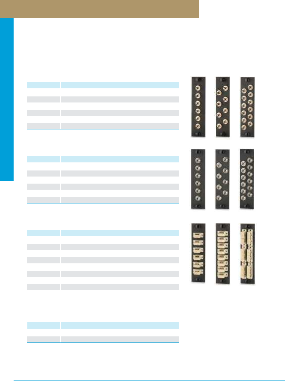
Optical Fiber Systems
PREMISE CONNECTIVITY SYSTEMS 800.446.2377 www.signamax.comD13
Optical Fiber Adapter Plates
MTP Adapter Plates
PART NO. DESCRIPTION
UFE-B-06MTP 6-Port MTP Adapter Plate, Black
UFE-B-08MTP 8-Port MTP Adapter Plate, Black
Specify optical fiber adapter plates for ST-, FC-, SC-, MT-RJ-, or LC-type connections. Adapter plates are compatible with all Signamax
wall- and rack-mount optical fiber enclosures and available in 6 simplex and duplex, 8 simplex and duplex, and 6 quad configurations with
fiber counts of up to 24 per adapter plate. They mount easily by means of plunger locks (“pushpins”). ST-, SC- and LC-adapter plates can
be equipped with 62.5-µm and 50-µm adapters suitable for multimode applications or a singlemode only version is available with adapters
outfitted with zirconia ceramic sleeves. Our SC and LC 10G multimode laser optimized adapter uses zirconia ceramic sleeves.
ST Adapter Plates
PART NO. DESCRIPTION
UFE-B-06ST 6-Fiber (6-Simplex) ST MM Adapter Plate
UFE-B-08ST 8-Fiber (8-Simplex) ST MM Adapter Plate
UFE-B-12ST 12-Fiber (12-Simplex) ST MM Adapter Plate
UFE-B-06ST-C 6-Fiber (6-Simplex) ST SM Adapter Plate
UFE-B-08ST-C 8-Fiber (8-Simplex) ST SM Adapter Plate
UFE-B-12ST-C 12-Fiber (12-Simplex) ST SM Adapter Plate
Multimode adapters use Phosphor Bronze sleeve
Singlemode adapters use Zirconia Ceramic sleeve
SC Adapter Plates
PART NO. DESCRIPTION
UFE-B-06SC 6-Fiber (6-Simplex) SC MM Adapter Plate, Beige Adapters
UFE-B-08SC 8-Fiber (8-Simplex) SC MM Adapter Plate, Beige Adapters
UFE-B-12SC 12-Fiber (6-Duplex) SC MM Adapter Plate, Beige Adapters
UFE-B-06SC-C 6-Fiber (6-Simplex) SC SM Adapter Plate, Blue Adapters
UFE-B-08SC-C 8-Fiber (8-Simplex) SC SM Adapter Plate, Blue Adapters
UFE-B-12SC-C 12-Fiber (6-Duplex) SC SM Adapter Plate, Blue Adapters
UFE-B-06SCA-C 6-Fiber (6-Simplex) SC APC SM Adapter Plate, Green Adapters
UFE-B-08SCA-C 8-Fiber (8-Simplex) SC APC SM Adapter Plate, Green Adapters
UFE-B-12SCA-C 12-Fiber (6-Duplex) SC APC SM Adapter Plate, Green Adapters
Multimode adapters use Phosphor Bronze sleeve
Singlemode adapters use Zirconia Ceramic sleeve
FC Adapter Plates
PART NO. DESCRIPTION
UFE-B-06FC 6-Fiber (6-Simplex) FC MM Adapter Plate
UFE-B-08FC 8-Fiber (8-Simplex) FC MM Adapter Plate
UFE-B-12FC 12-Fiber (12-Simplex) FC MM Adapter Plate
UFE-B-06FC-C 6-Fiber (6-Simplex) FC SM Adapter Plate
UFE-B-08FC-C 8-Fiber (8-Simplex) FC SM Adapter Plate
UFE-B-12FC-C 12-Fiber (12-Simplex) FC SM Adapter Plate
Multimode adapters use Phosphor Bronze sleeve
Singlemode adapters use Zirconia Ceramic sleeve
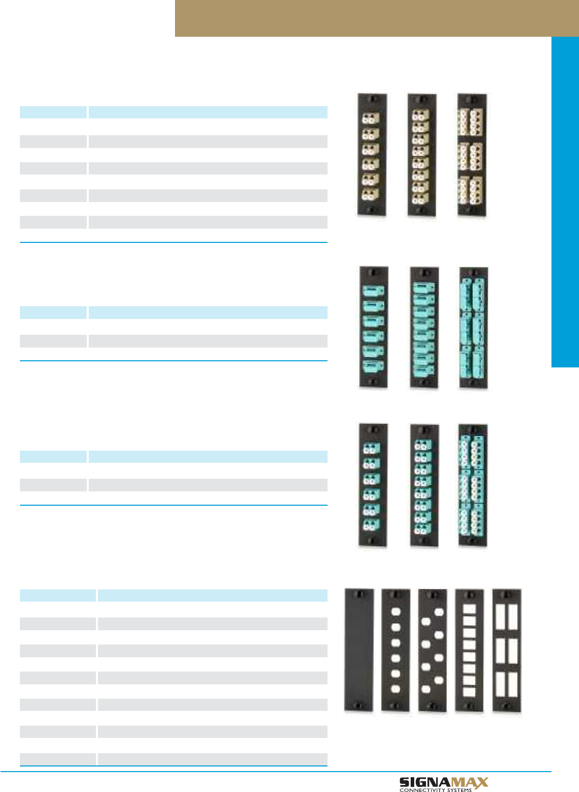
Optical Fiber Systems
D 1 4
TM
Optical Fiber Adapter Plates
Blank Plate
PART NO. DESCRIPTION
UFE-B-BL Blank Filler Plate
UFE-B-06ST-B 6-ST Adapter Plate, No Adapters
UFE-B-08ST-B 8-ST Adapter Plate, No Adapters
UFE-B-12ST-B 12-ST Adapter Plate, No Adapters
UFE-B-06FC-B 6-FC Adapter Plate, No Adapters
UFE-B-08FC-B 8-FC Adapter Plate, No Adapters
UFE-B-12FC-B 12-FC Adapter Plate, No Adapters
UFE-B-06SC-B 6-Simplex-SC or 6-Duplex-LC Adapter Plate, No Adapters
UFE-B-08SC-B 8-Simplex-SC or 8-Duplex-LC Adapter Plate, No Adapters
UFE-B-12SC-B 6-Duplex-SC or 6-Quad-LC Adapter Plates, No Adapters
UFE-B-06MTRJ-B 6-MT-RJ Adapter Plate, No Adapters
UFE-B-08MTRJ-B 8-MT-RJ Adapter Plate, No Adapters
LC Adapter Plates
PART NO. DESCRIPTION
UFE-B-06LC 12-Fiber (6-Duplex) LC MM Adapter Plate, Beige Adapters
UFE-B-08LC 16-Fiber (8-Duplex) LC MMAdapter Plate, Beige Adapters
UFE-B-12LC 24-Fiber (6-Quad) LC MM Adapter Plate, Beige Adapters
UFE-B-06LC-C 12-Fiber (6-Duplex) LC SM Adapter Plate, Blue Adapters
UFE-B-08LC-C 16-Fiber (8-Duplex) LC SM Adapter Plate, Blue Adapters
UFE-B-12LC-C 24-Fiber (6-Quad) LC SM Adapter Plate, Blue Adapters
UFE-B-06LCA-C 12-Fiber (6-Duplex) LC APC SM Adapter Plate, Green Adapters
UFE-B-08LCA-C 16-Fiber (8-Duplex) LC APC SM Adapter Plate, Green Adapters
UFE-B-12LCA-C 24-Fiber (6-Quad) LC APC SM Adapter Plate, Green Adapters
Multimode adapters use Phosphor Bronze sleeve
Singlemode adapters use Zirconia Ceramic sleeve
LC 10G LOF Adapter Plates
PART NO. DESCRIPTION
UFE-B-06LC-G 12-Fiber (6-Duplex) LC MM LOF Adapter Plate, Aqua Adapters
UFE-B-08LC-G 16-Fiber (8-Duplex) LC MM LOF Adapter Plate, Aqua Adapters
UFE-B-12LC-G 24-Fiber (6-Quad) LC MM LOF Adapter Plate, Aqua Adapters
Adapters for multimode laser optimized fiber use Zirconia Ceramic sleeve
SC 10G LOF Adapter Plates
PART NO. DESCRIPTION
UFE-B-06SC-G 6-Fiber (6-Simplex) SC MM LOF Adapter Plate, Aqua Adapters
UFE-B-08SC-G 8-Fiber (8-Simplex) SC MM LOF Adapter Plate, Aqua Adapters
UFE-B-12SC-G 12-Fiber (6-Duplex) SC MM LOF Adapter Plate, Aqua Adapters
Adapters for multimode laser optimized fiber use Zirconia Ceramic sleeve
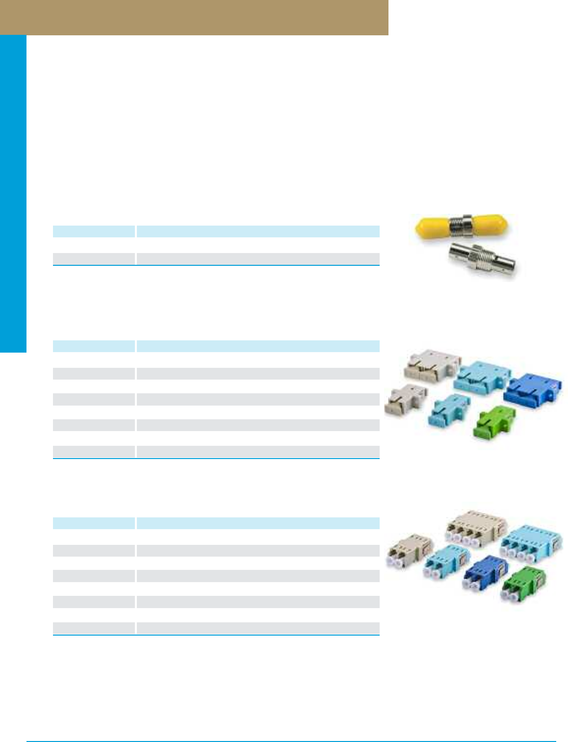
Optical Fiber Systems
PREMISE CONNECTIVITY SYSTEMS 800.446.2377 www.signamax.comD15
Optical Fiber Adapters
Signamax offers a wide variety of optical fiber adapters including ST, SC, LC, and MT-RJ. Our ST and SC simplex and duplex
adapters are available with a phosphor bronze sleeve for multimode applications and zirconia ceramic sleeve for singlemode
requirements. The LC adapter fits the same cutout size as a simplex SC adapter and provides for higher termination densities. It is
available in both multimode and singlemode versions. Our MT-RJ adapter is about 1/3 the size as a duplex SC adapter providing the
same increased density as the LC.
All SC, LC, and MT-RJ adapters are provided with retaining clips for easy, snap-in mounting, and, additionally, with screw-mounting
seats; ST adapters are instrumented with a retainer ring. All adapters with plastic bodies (SC-, LC-, and MT-RJ-type) are color-coded
per ANSI/TIA-568-C.3 - 62.5- and 50-µm multimode adapters are beige in color, 50-µm multimode OM3 and OM4 - aqua, singlemode
PC and UPC - blue, singlemode APC - green.
ST Fiber Adapters
PART NO. DESCRIPTION
FA-ST-SX-PB-NF-RD ST MM Adapter, Phosphor Bronze Sleeve, Red Cap
FA-ST-SX-ZR-NF-YE ST SM Adapter, Zirconia Ceramic Sleeve, Yellow Cap
SC Fiber Adapters
PART NO. DESCRIPTION
FA-SC-SX-PB-MF-BE SC SX MM Adapter w/Flange, Phosphor Bronze Sleeve, Beige
FA-SC-SX-ZR-MF-AQ SC SX MM Adapter w/Flange, Zirconia Ceramic Sleeve, Aqua
FA-SC-SX-ZR-MF-BU SC SX SM Adapter w/Flange, Zirconia Ceramic Sleeve, Blue
FA-SC-SX-ZR-MF-GN SC SX SM APC Adapter w/Flange, Zirconia Ceramic Sleeve, Green
FA-SC-DX-PB-MF-BE SC DX MM Adapter w/Flange, Phosphor Bronze Sleeve, Beige
FA-SC-DX-ZR-MF-AQ SC DX MM Adapter w/Flange, Zirconia Ceramic Sleeve, Aqua
FA-SC-DX-ZR-MF-BU SC DX SM Adapter w/Flange, Zirconia Ceramic Sleeve, Blue
FA-SC-DX-ZR-MF-GN SC DX SM APC Adapter w/Flange, Zirconia Ceramic Sleeve, Green
For adapters without flanges substitute NF for MF in P/N.
LC Fiber Adapters
PART NO. DESCRIPTION
FA-LC-DX-PB-MF-BE LC DX MM Adapter w/Flange, Phosphor Bronze Sleeve, Beige
FA-LC-DX-ZR-MF-AQ LC DX MM Adapter w/Flange, Zirconia Ceramic Sleeve, Aqua
FA-LC-DX-ZR-MF-BU LC DX SM Adapter w/Flange, Zirconia Ceramic Sleeve, Blue
FA-LC-DX-ZR-MF-GN LC DX SM APC Adapter w/Flange, Zirconia Ceramic Sleeve, Green
FA-LC-QX-PB-MF-BE LC QX MM Adapter w/Flange, Phosphor Bronze Sleeve, Beige
FA-LC-QX-ZR-MF-AQ LC QX MM Adapter w/Flange, Zirconia Ceramic Sleeve, Aqua
FA-LC-QX-ZR-MF-BU LC QX SM Adapter w/Flange, Zirconia Ceramic Sleeve, Blue
FA-LC-QX-ZR-MF-GN LC QX SM APC Adapter w/Flange, Zirconia Ceramic Sleeve, Green
For adapters without flanges substitute NF for MF in P/N.
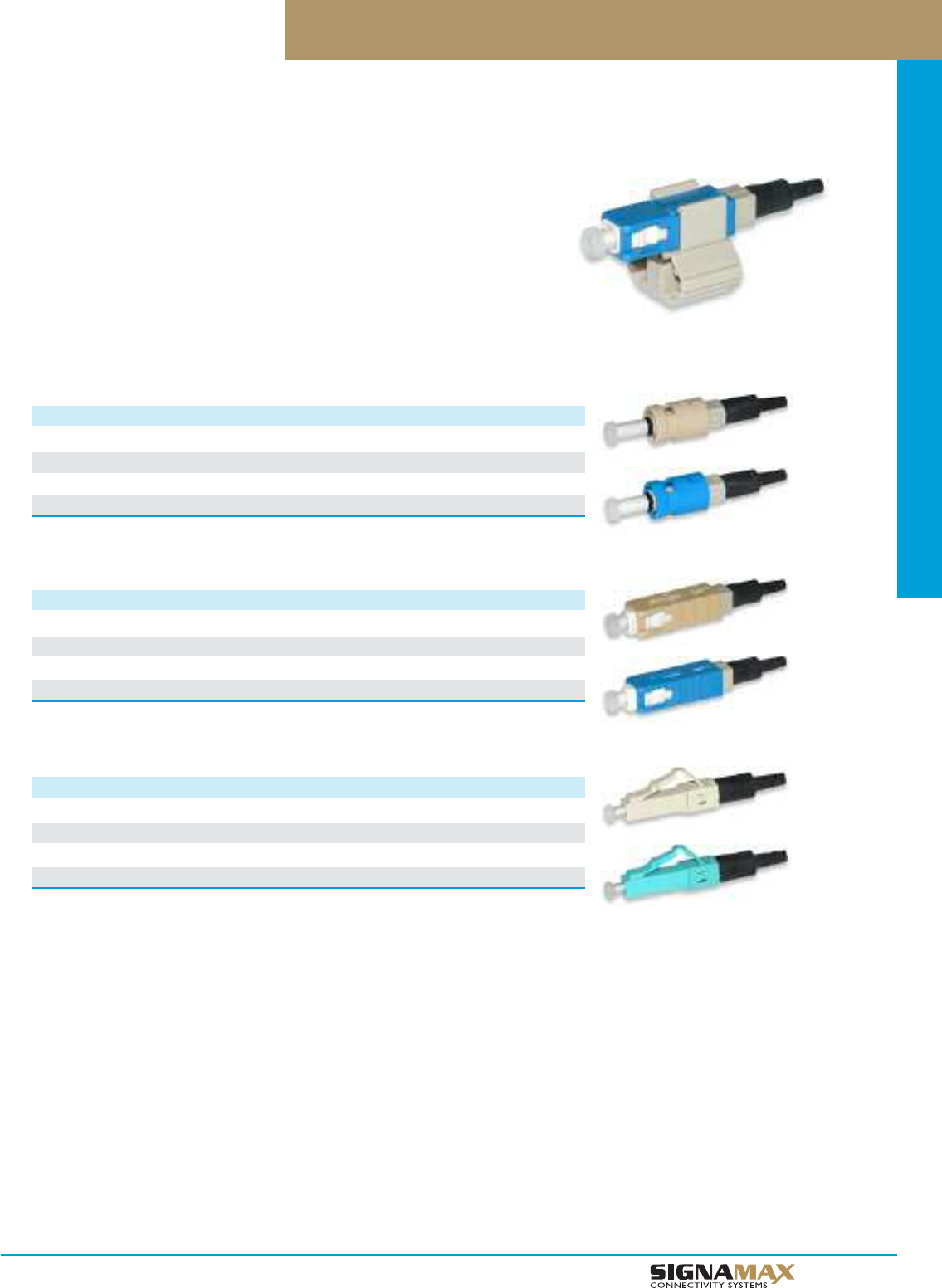
Optical Fiber Systems
D 1 6
TM
Field-Installable Pre-Polished Optical Fiber Connectors
ST Pre-Polished Optical Fiber Connectors
Signamax field-installable pre-polished connectors allow reducing installation time
significantly owing to the absence of need to use adhesives and polishing. This unique
feature makes possible to eliminate field termination errors and to provide equal quality
of connection performed by an experienced installer and apprentice.
Available in multimode (50 µm, 50 µm laser-optimized (LO), and 62.5 µm) and single-
mode ST, SC, and LC versions, field-installable connectors feature a polished ferrule
with a factory installed fiber stub, which splices in the field to distribution cable fibers
using an integrated alignment mechanism and index-matching gel. The alignment
mechanism is activated with the help of a termination clip, which is supplied with each
connector; after successful termination, the clip is removed. Field-installable connectors
are designed to terminate 3- and 2-mm jacketed, 250-µm and 900-µm buffered fibers.
PART NO. FIBER TYPE HOUSING COLOR CABLE SIZE
FPC-LC06 MM 62.5-µm Beige 2-mm, 3-mm, 250-µm, 900-µm
FPC-LC05 MM 50-µm Black 2-mm, 3-mm, 250-µm, 900-µm
FPC-LC51 MM 50-µm LO Aqua 2-mm, 3-mm, 250-µm, 900-µm
FPC-LC09 SM Blue 2-mm, 3-mm, 250-µm, 900-µm
LC Pre-Polished Optical Fiber Connectors
PART NO. FIBER TYPE HOUSING COLOR CABLE SIZE
FPC-SC06 MM 62.5-µm Beige 2-mm, 3-mm, 250-µm, 900-µm
FPC-SC05 MM 50-µm Black 2-mm, 3-mm, 250-µm, 900-µm
FPC-SC51 MM 50-µm LO Aqua 2-mm, 3-mm, 250-µm, 900-µm
FPC-SC09 SM Blue 2-mm, 3-mm, 250-µm, 900-µm
SC Pre-Polished Optical Fiber Connectors
PART NO. FIBER TYPE HOUSING COLOR CABLE SIZE
FPC-ST06 MM 62.5-µm Beige 250-µm, 900-µm
FPC-ST05 MM 50-µm Black 250-µm, 900-µm
FPC-ST51 MM 50-µm LO Aqua 250-µm, 900-µm
FPC-ST09 SM Blue 250-µm, 900-µm
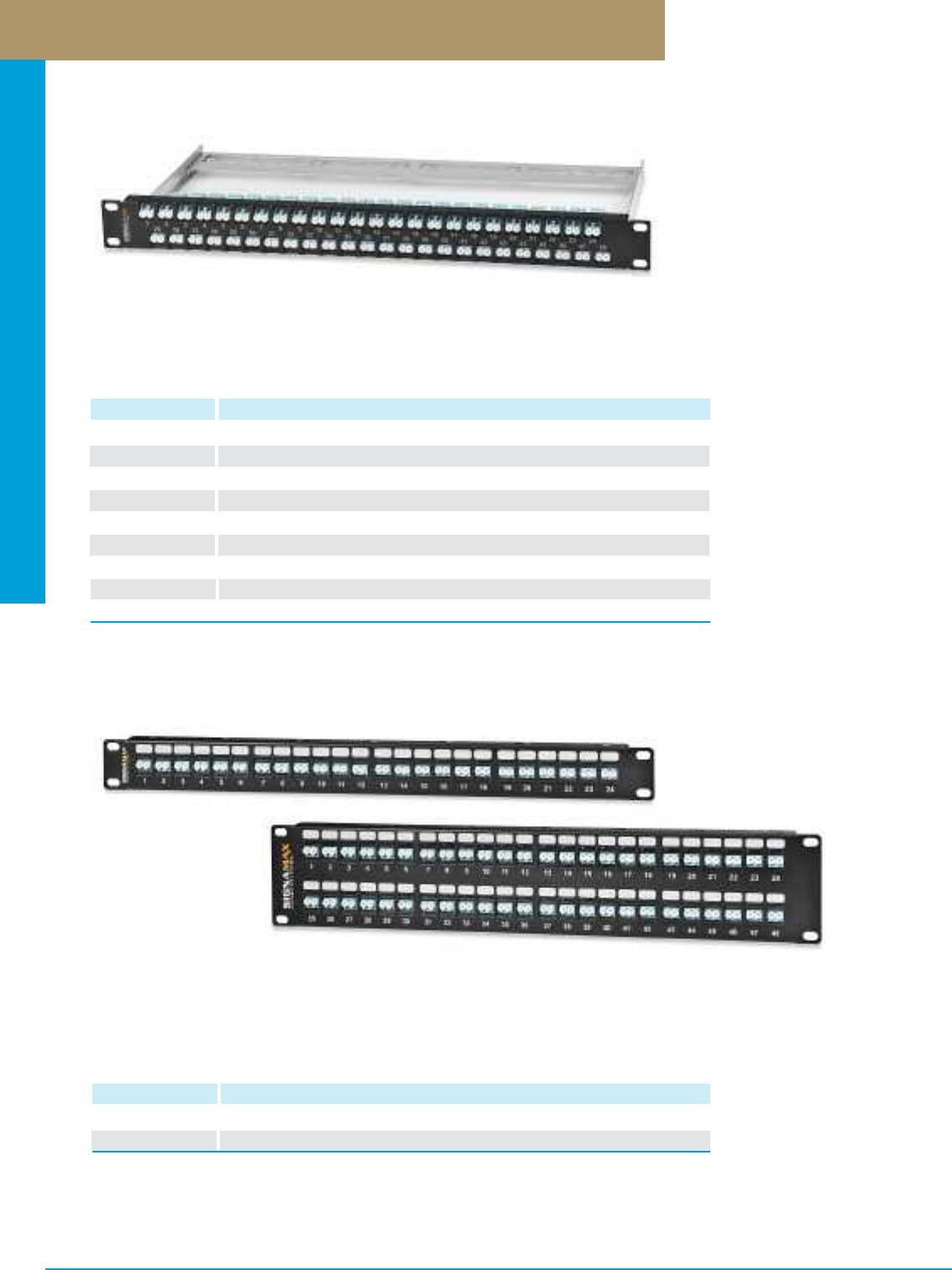
Optical Fiber Systems
PREMISE CONNECTIVITY SYSTEMS 800.446.2377 www.signamax.comD17
Optical Fiber Panels
PART NO. DESCRIPTION
48HD1SC-FT 48-Fiber (48-Simplex) High-Density SC MM Optical Fiber Panel, 1.75”H
48HD1SCS-FT 48-Fiber (48-Simplex) High-Density SC SM Optical Fiber Panel, 1.75”H
48HD1SCA-FT 48-Fiber (48-Simplex) High-Density SC APC SM Optical Fiber Panel, 1.75”H
48HD1SCG-FT 48-Fiber (48-Simplex) High-Density SC 10G LO MM Optical Fiber Panel, 1.75”H
48HD1LC-FT 96-Fiber (48-Duplex) High-Density LC MM Optical Fiber Panel, 1.75”H
48HD1LCS-FT 96-Fiber (48-Duplex) High-Density LC SM Optical Fiber Panel, 1.75”H
48HD1LCA-FT 96-Fiber (48-Duplex) High-Density LC APC SM Optical Fiber Panel, 1.75”H
48HD1LCG-FT 96-Fiber (48-Duplex) High-Density LC 10G LO MM Optical Fiber Panel, 1.75”H
48U-HDMMP-1R 48-Port High-Density Field-Configurable Panel, 1.75”H (Accepts SC and LC only)
High-Density 1-RMS Optical Fiber Panels
High-Density 1-RMS Optical Panels are available in 48- and 96-fiber sizes pre-loaded with SC or LC
adapters. These high-density panels are equiped with a cable management bar when there is a need
to provide support for bulky cables and/or maintain required cable bend radii. This panel is available
unloaded for field configuration.
PART NO. DESCRIPTION
24HDFAT-FT 24-Port High-Density Optical Fiber Panel, 1.75”H
48HDFAT-FT 48-Port High-Density Optical Fiber Panel, 3.50”H
High-Density Optical Fiber Panels
For fiber adapter type substitute FAT in P/N
ST (ST MM) STS (ST SM) FC (FC MM) FCS (FC SM)
SC (SC MM) SCS (SC SM) SCA (SC APC SM) SCG (SC 10G MM LOF)
LC (LC MM) LCS (LC SM) LCA (LC APC SM) LCG (LC 10G MM LOF)
Signamax offers a range of high-density optical fiber patch panels for ST, FC, SC, and LC connections.
These rack-mount panels are available in 24- and 48-port (24-, 48- and 96-fiber) sizes based on standard
Optical Fiber Connector Modules.These high-density panels are equiped with a cable management bar
when there is a need to provide support for bulky cables and/or maintain required cable bend radii.
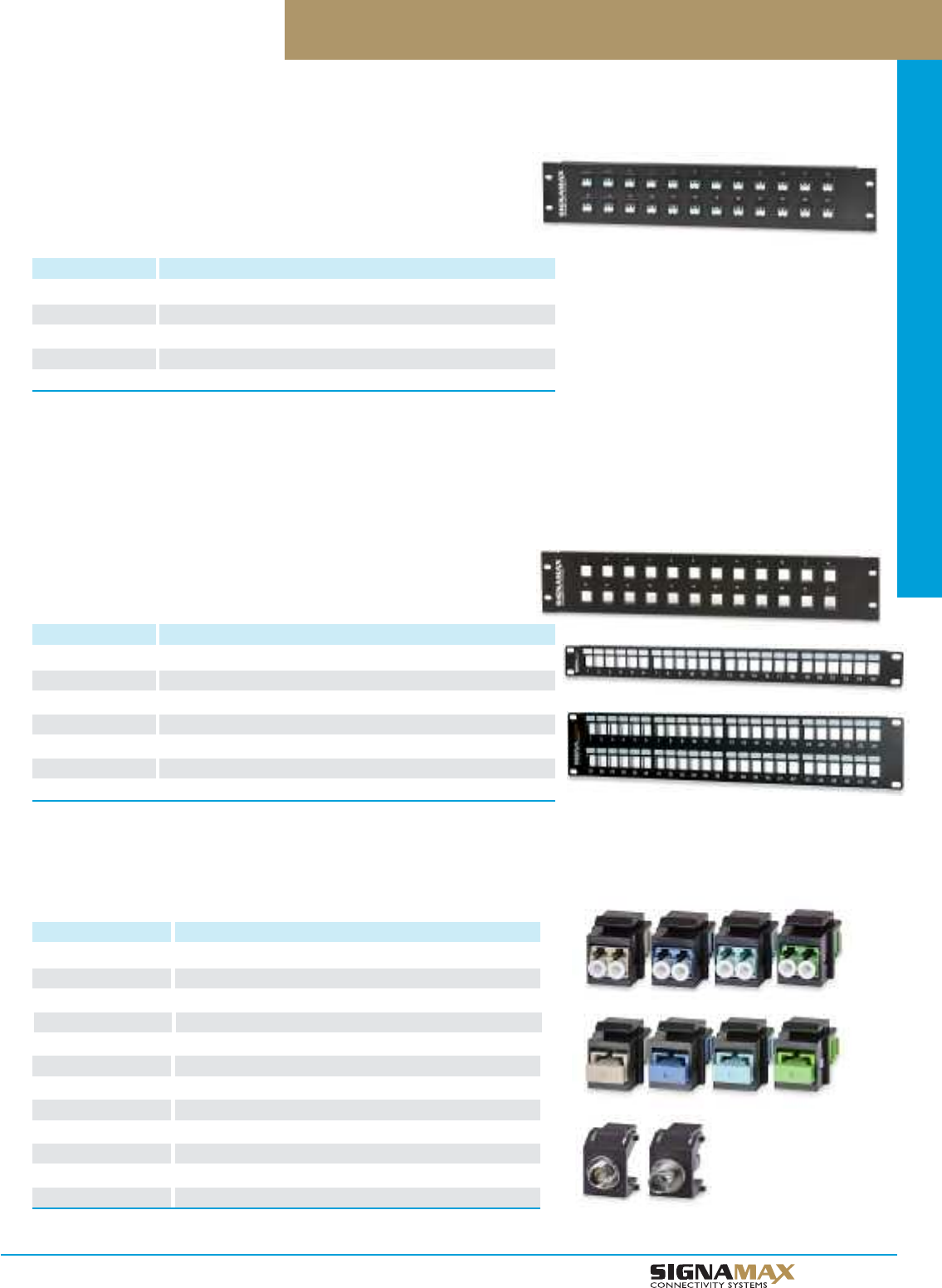
Optical Fiber Systems
D 1 8
TM
Signamax offers a range of economy optical fiber patch panels for ST, FC, SC, and
LC connections. These rack-mount panels are available in 12- thru 48-port (12- thru
96-fiber) sizes based on standard Optical Fiber Connector Modules and are ideal
where extra access space to the connections is required.
Optical Fiber Panels
PART NO. DESCRIPTION
12FAT-FT 12-Port Optical Fiber Panel, 1.75” High
16FAT-FT 16-Port Optical Fiber Panel, 1.75” High
24FAT-FT 24-Port Optical Fiber Panel, 3.50” High
32FAT-FT 32-Port Optical Fiber Panel, 3.50” High
48FAT-FT 48-Port Optical Fiber Panel, 5.25” High
For fiber adapter type substitute FAT in P/N
ST (ST MM) STS (ST SM) FC (FC MM) FCS (FC SM)
SC(SC MM) SCS (SC SM) SCA (SC APC SM) SCG (SC 10G MM LOF)
LC (LC MM) LCS (LC SM) LCA (LC APC SM) LCG (LC 10G MM LOF)
Optical Fiber Panels
Optical Fiber Connector Modules
PART NO. DESCRIPTION
CMK-ST-BK ST MM Keystone Connector Module
CMK-STS-BK ST SM Keystone Connector Module
CMK-FC-BK FC MM Keystone Connector Module
CMK-FCS-BK FC SM Keystone Connector Module
CMK-SC-BK SC Simplex MM Keystone Connector Module
CMK-SCS-BK SC Simplex SM Keystone Connector Module
CMK-SCA-BK SC Simplex APC SM Keystone Connector Module
CMK-SCG-BK SC Simplex 10G LO MM Keystone Connector Module
CMK-LC-BK LC Duplex MM Keystone Connector Module
CMK-LCS-BK LC Duplex SM Keystone Connector Module
CMK-LCA-BK LC Duplex APC SM Keystone Connector Module
CMK-LCG-BK LC Duplex 10G LO MM Keystone Connector Module
Field-Configurable Panels are available in 12- thru 48-port sizes. Panels provide
the ability to field configure ports and support all Optical Fiber Connector Modules.
Field-Configurable Panels
PART NO. DESCRIPTION
12U-MMP 12-Port Field-Configurable Panel, 1.75” High
16U-MMP 16-Port Field-Configurable Panel, 1.75” High
24U-MMP 24-Port Field-Configurable Panel, 3.50” High
32U-MMP 32-Port Field-Configurable Panel, 3.50” High
48U-MMP 48-Port Field-Configurable Panel, 5.25” High
24U-HDMMP 24-Port High-Density Field Configurable Panel, 1.75” High
48U-HDMMP 48-Port High-Density Field Configurable Panel, 3.50” High
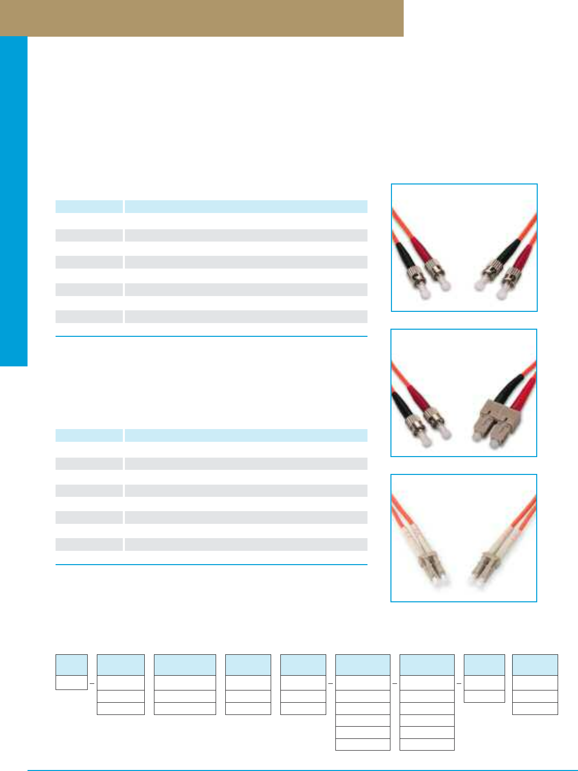
Optical Fiber Systems
PREMISE CONNECTIVITY SYSTEMS 800.446.2377 www.signamax.comD19
Multimode Optical Fiber Patch Cords
Multimode optical fiber patch cords can be used as cross-connect jumpers, equipment and work area cords. All Signamax optical
fiber patch cords are manufactured using riser-rated (OFNR) cable and are 100% factory tested for insertion and return loss to
ensure transmission performance per ANSI/TIA-568-C.3 standard specifications. Patch cords terminated with ST, SC, LC, and MT-RJ
connectors (uniform and hybrid versions) are available in 62.5-µm and 50-µm, in duplex and simplex designs.
Cordage used in multimode fiber cords is color-coded per ANSI/TIA-598-C – 62.5-µm and 50-µm multimode cables are orange in color.
Connectors with plastic bodies (SC and LC) are color-coded – 62.5-µm and 50-µm multimode connectors are beige in color. Marked
clips, color rings, or colored connector boots identify each end of the duplex fiber cord to designate Position A and Position B.
Multimode 62.5-µm Optical Fiber Patch Cords
PART NO. DESCRIPTION
FC-2/2-LM ST-to-ST Duplex Multimode Fiber Patch Cord
FC-4/4-LM SC-to-SC Duplex Multimode Fiber Patch Cord
FC-4/2-LM SC-to-ST Duplex Multimode Fiber Patch Cord
FC-9/9-LM LC-to-LC Duplex Multimode Fiber Patch Cord
FC-9/2-LM LC-to-ST Duplex Multimode Fiber Patch Cord
FC-9/4-LM LC-to-SC Duplex Multimode Fiber Patch Cord
FC-8/8-LM MT-RJ-to-MT-RJ Duplex Multimode Fiber Patch Cord
FC-8/2-LM MT-RJ-to-ST Duplex Multimode Fiber Patch Cord
FC-8/4-LM MT-RJ-to-SC Duplex Multimode Fiber Patch Cord
For length substitute L in P/N. Other lengths are available.
1=1 Meter 2=2 Meters 3=3 Meters 5=5 Meters 7=7 Meters
Cable diameter for ST and SC cords is 3 mm. All other connectors cable diameter is 2 mm.
Insertion Loss: ST, SC, LC, FC: typical - 0.2 dB maximum - 0.3 dB
MT-RJ: typical - 0.3 dB maximum - 0.3 dB
Maximum Return Loss: PC ≤ –30 dB
Multimode 50-µm Optical Fiber Patch Cords
PART NO. DESCRIPTION
FC50-2/2-LM ST-to-ST Duplex Multimode Fiber Patch Cord
FC50-4/4-LM SC-to-SC Duplex Multimode Fiber Patch Cord
FC50-4/2-LM SC-to-ST Duplex Multimode Fiber Patch Cord
FC50-9/9-LM LC-to-LC Duplex Multimode Fiber Patch Cord
FC50-9/2-LM LC-to-ST Duplex Multimode Fiber Patch Cord
FC50-9/4-LM LC-to-SC Duplex Multimode Fiber Patch Cord
FC50-8/8-LM MT-RJ-to-MT-RJ Duplex Multimode Fiber Patch Cord
FC50-8/2-LM MT-RJ-to-ST Duplex Multimode Fiber Patch Cord
FC50-8/4-LM MT-RJ-to-SC Duplex Multimode Fiber Patch Cord
For length substitute L in P/N. Other lengths are available.
1=1 Meter 2=2 Meters 3=3 Meters 5=5 Meters 7=7 Meters
Cable diameter for ST and SC cords is 3 mm. All other connectors cable diameter is 2 mm.
Insertion Loss: ST, SC, LC, FC: typical - 0.2 dB maximum - 0.3 dB
MT-RJ: typical - 0.3 dB maximum - 0.3 dB
Maximum Return Loss: PC: ≤ –30 dB
Multimode Fiber Patch Cord Configurator
CABLE
DIA.
X
1 = 2 MM
3 = 3 MM
JACKET
TYPE
X
R = Riser
P = Plenum
UNIT OF
MEASURE
X
F = Feet
M = Meters
LENGTH
XXX
001 - 999
FIBER
CORD
FC
CABLE
TYPE
X
D = Duplex
S = Simplex
FIBER
TYPE
X
6 = MM 62.5 µm
5 = MM 50 µm
CONNECTOR
END ONE
X
2 = ST
4 = SC
5 = FC
9 = LC
8 = MT-RJ
CONNECTOR
END TWO
X
2 = ST
4 = SC
5 = FC
9 = LC
8 = MT-RJ
Part Number Example: FC-D6R3-4-4-010M
Fiber patch cord, duplex, multimode 62.5/125-µm, riser-rated, 3-mm diameter cable, SC-to-SC, 10-meter length.
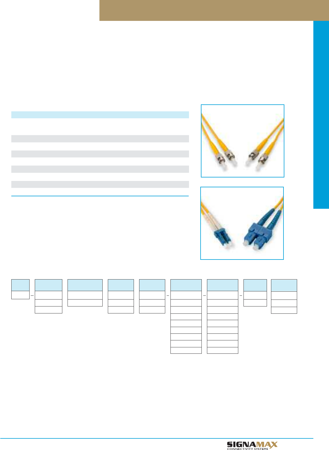
Optical Fiber Systems
D 2 0
TM
Singlemode Fiber Patch Cord Configurator
CABLE
DIA.
X
1 = 2 MM
3 = 3 MM
JACKET
TYPE
X
R = Riser
P = Plenum
UNIT OF
MEASURE
X
F = Feet
M = Meters
LENGTH
XXX
001 - 999
FIBER
CORD
FC
CABLE
TYPE
X
D = Duplex
S = Simplex
FIBER
TYPE
9
9 = SM
CONNECTOR
END ONE
X
2 = ST/UPC
4 = SC/UPC
4A = SC/APC
5 = FC/UPC
5A = FC/APC
9 = LC/UPC
9A = LC/APC
8 = MT-RJ
CONNECTOR
END TWO
X
2 = ST/UPC
4 = SC/UPC
4A = SC/APC
5 = FC/UPC
5A = FC/APC
9 = LC/UPC
9A = LC/APC
8 = MT-RJ
Singlemode Optical Fiber Patch Cords
Singlemode 9-µm Optical Fiber Patch Cords
DESCRIPTION PART NO. PART NO.
Duplex Simplex
ST-to-ST Singlemode Fiber Patch Cord FCS-2/2-LM FC9S-2/2-LM
SC-to-SC Singlemode Fiber Patch Cord FCS-4/4-LM FC9S-4/4-LM
SC-to-ST Singlemode Fiber Patch Cord FCS-4/2-LM FC9S-4/2-LM
LC-to-LC Singlemode Fiber Patch Cord FCS-9/9-LM FC9S-9/9-LM
LC-to-ST Singlemode Fiber Patch Cord FCS-9/2-LM FC9S-9/2-LM
LC-to-SC Singlemode Fiber Patch Cord FCS-9/4-LM FC9S-9/4-LM
MT-RJ-to-MT-RJ Singlemode Fiber Patch Cord FCS-8/8-LM
MT-RJ-to-ST Singlemode Fiber Patch Cord FCS-8/2-LM
MT-RJ-to-SC Singlemode Fiber Patch Cord FCS-8/4-LM
For length substitute L in P/N. Other lengths are available.
1=1 Meter 2=2 Meters 3=3 Meters 5=5 Meters 7=7 Meters
Cable diameter for ST and SC cords is 3 mm. All other connectors cable diameter is 2 mm.
Insertion Loss: ST, SC, LC, FC: typical - 0.15 dB maximum - 0.25 dB
MT-RJ: typical - 0.3 dB maximum - 0.5 dB
Maximum Return Loss: UPC: ≤ –50 dB
APC: ≤ –60 dB
Singlemode optical fiber patch cords can be used as cross-connect jumpers, equipment and work area cords. All Signamax optical
fiber patch cords are manufactured using riser-rated (OFNR) cable and are 100% factory tested for insertion and return loss to ensure
transmission performance per TIA/EIA-568-B.3 standard specifications. Patch cords terminated with ST, SC, LC, and MT-RJ connectors
(uniform and hybrid versions) are available in duplex and simplex designs.
Cordage used in singlemode fiber cords is color-coded per ANSI/TIA-598-C – all singlemode cables are yellow in color. Connectors with
plastic bodies (SC and LC) are color-coded per ANSI/TIA-568-C.3 – singlemode PC and UPC – blue in color, singlemode APC – green.
Marked clips, color rings, or colored connector boots identify each end of the duplex fiber cord to designate Position A and Position B.
Part Number Example: FC-D9R1-9A-9A-015M
Fiber patch cord, duplex, singlemode, riser-rated, 2-mm diameter cable, LC/APC to LC/APC, 15-meter length.
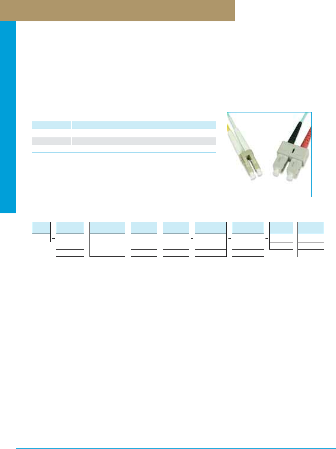
Optical Fiber Systems
PREMISE CONNECTIVITY SYSTEMS 800.446.2377 www.signamax.comD21
10G Multimode Fiber Patch Cord Configurator
10G Laser-Optimized Multimode Optical Fiber Patch Cords
10G laser-optimized optical fiber (LOF) patch cords intended to support high-speed 10-gigabit applications can be used as cross-connect
jumpers, equipment and work area cords. All Signamax LOF patch cords are manufactured using riser-rated (OFNR) cable and are 100%
factory tested for insertion and return loss to ensure transmission performance per ANSI/TIA-568-C.3 standard specifications. Patch cords
terminated with SC and LC connectors (uniform and hybrid versions) are available in duplex and simplex designs.
Cordage used in LOF cords is aqua in color per ANSI/TIA-598-C; connectors are grey in color. Marked clips, color rings, or colored
connector boots identify each end of the duplex optical fiber cord to designate Position A and Position B.
CABLE
DIA.
X
1 = 2 MM
3 = 3 MM
JACKET
TYPE
X
R = Riser
P = Plenum
UNIT OF
MEASURE
X
F = Feet
M = Meters
LENGTH
XXX
001 - 999
FIBER
CORD
FC
CABLE
TYPE
X
D = Duplex
S = Simplex
FIBER
TYPE
51
51 = MM 50 µm
10G LO
CONNECTOR
END ONE
X
4 = SC
9 = LC
CONNECTOR
END TWO
X
4 = SC
9 = LC
10G LO Multimode 50-µm Optical Fiber Patch Cords
PART NO. DESCRIPTION
FC51-4/4-LM SC-to-SC Duplex 10G LO Multimode Fiber Patch Cord
FC51-9/9-LM LC-to-LC Duplex 10G LO Multimode Fiber Patch Cord
FC51-9/4-LM LC-to-SC Duplex 10G LO Multimode Fiber Patch Cord
For length substitute L in P/N. Other lengths are available.
1=1 Meter 2=2 Meters 3=3 Meters 5=5 Meters 7=7 Meters
Cable diameter for ST and SC cords is 3 mm. All other connectors cable diameter is 2 mm.
Insertion Loss: ST, SC, LC, FC: typical - 0.2 dB maximum - 0.3 dB
MT-RJ: typical - 0.3 dB maximum - 0.3 dB
Maximum Return Loss: PC: ≤ –30 dB
Part Number Example: FC-D51P1-9-9-010M
Fiber patch cord, duplex, multimode 50/125-µm, 10G LO, plenum-rated, 2-mm diameter cable, LC-to-LC, 10-meter length.
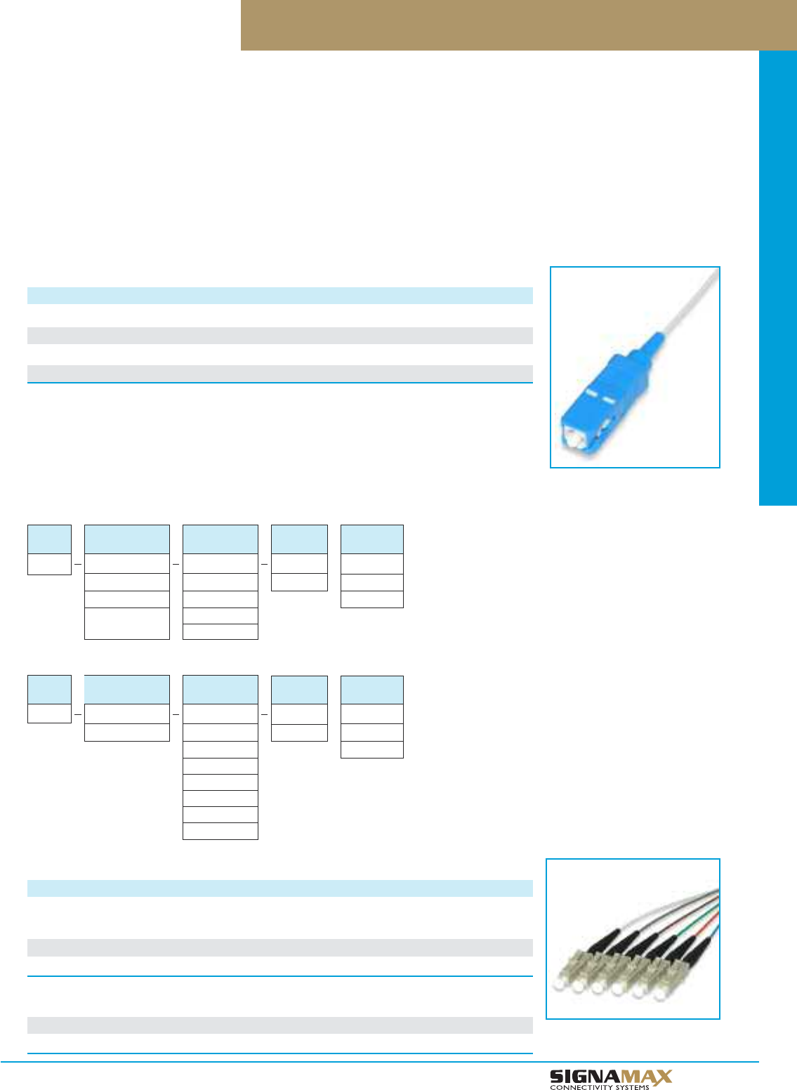
Optical Fiber Systems
D 2 2
TM
Optical Fiber Pigtails
Single-Fiber Pigtails
DESCRIPTION PART NO. PART NO. PART NO PART NO.
62.5-µm MM 50-µm MM SM 50-µm MM 10G
ST Single-Fiber Pigtail, 3 m FP1-6-2-003M FP1-5-2-003M FP1-9-2-003M
SC Single-Fiber Pigtail, 3 m FP1-6-4-003M FP1-5-4-003M FP1-9-4-003M FP1-51-4-003M
LC Single-Fiber Pigtail, 3 m FP1-6-9-003M FP1-5-9-003M FP1-9-9-003M FP1-51-9-003M
Standard length is 3 meters. Cable type is 900-micron buffered white cable. Other connector types are available.
Insertion Loss: Multimode ST, SC, LC, FC: typical - 0.2 dB maximum - 0.3 dB
Multimode MT-RJ: typical - 0.3 dB maximum - 0.3 dB
Singlemode ST, SC, LC, FC: typical - 0.15 dB maximum - 0.25 dB
Singlemode MT-RJ: typical - 0.3 dB maximum - 0.3 dB
Maximum Return Loss: PC: ≤ –30 dB
UPC: ≤ –50 dB
APC: ≤ –60 dB
Multi-Strand Optical Fiber Pigtail Kits
DESCRIPTION PART NO. PART NO. PART NO PART NO.
6-Fiber Pigtail Kits 62.5-µm MM 50-µm MM SM 50-µm MM 10G
ST 6-Fiber Pigtail Kit, 3 m FP6-6-2-003M FP6-5-2-003M FP6-9-2-003M
SC 6-Fiber Pigtail Kit, 3 m FP6-6-4-003M FP6-5-4-003M FP6-9-4-003M FP6-51-4-003M
LC 6-Fiber Pigtail Kit, 3 m FP6-6-9-003M FP6-5-9-003M FP6-9-9-003M FP6-51-9-003M
12-Fiber Pigtail Kits
ST 12-Fiber Pigtail Kit, 3 m FP12-6-2-003M FP12-5-2-003M FP12-9-2-003M
SC 12-Fiber Pigtail Kit, 3 m FP12-6-4-003M FP12-5-4-003M FP12-9-4-003M FP12-51-4-003M
LC 12-Fiber Pigtail Kit, 3 m FP12-6-9-003M FP12-5-9-003M FP12-9-9-003M FP12-51-9-003M
Multimode Single-Fiber Pigtail Configurator
UNIT OF
MEASURE
X
F = Feet
M = Meters
LENGTH
XXX
001 - 999
FIBER
PIGTAIL
FP1
FIBER
TYPE
X
6 = MM 62.5 µm
5 = MM 50 µm
51 = MM 50 µm
10G LO
CONNECTOR
X
2 = ST
4 = SC
5 = FC
9 = LC
Singlemode Single-Fiber Pigtail Configurator
FIBER
PIGTAIL
FP1
FIBER
TYPE
9
9 = SM
CONNECTOR
X
2 = ST/UPC
4 = SC/UPC
4A = SC/APC
5 = FC/UPC
5A = FC/APC
9 = LC/UPC
9A = LC/APC
Optical fiber pigtails are recommended or sometimes required when there is a need to make a transition from thin buffered fibers
(250–900 µm), typical for distribution cables and not suitable for direct optical fiber connector termination, to cross-connection or
equipment connection points. Pigtails mechanically or fusion connected to the distribution cable fibers simplify cabling system installation
and servicing significantly.
Signamax pigtails are manufactured to meet TIA, IEC, and Telcordia standard requirements. Signamax pigtails based on 900-µm
buffered white cable are available in multimode (62.5-µm OM1 and 50-µm OM2, OM3 and OM4 ) and singlemode, simplex and
multistrand, ST, SC, and LC versions.
UNIT OF
MEASURE
X
F = Feet
M = Meters
LENGTH
XXX
001 - 999
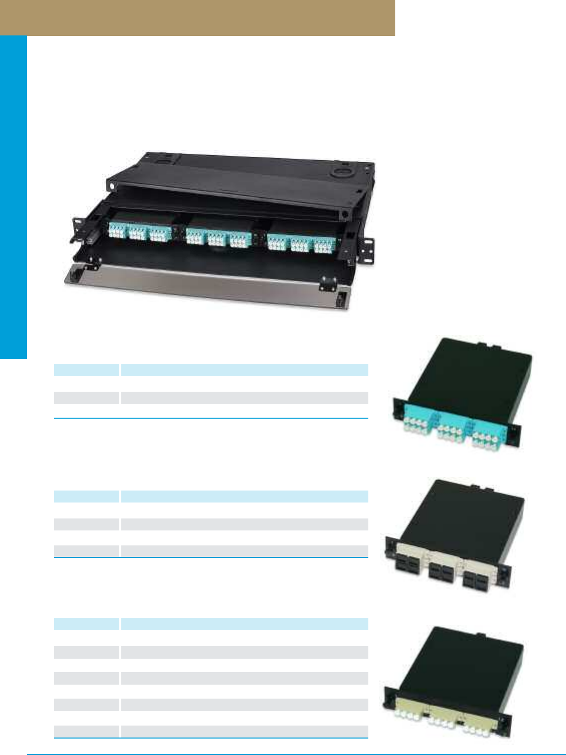
Optical Fiber Systems
PREMISE CONNECTIVITY SYSTEMS 800.446.2377 www.signamax.comD23
Plug-and-Play Pre-Terminated Fiber Cassettes
Plug-and-Play Pre-Terminated Fiber Cassettes featuring one of the most advanced modern optical fiber technologies provide quick
and easy handling of high-density optical fiber connections. Available in multiple configurations MTP cassettes can be used in
telecommunications spaces for cross- and interconnections, for connection of active equipment to the cabling. Simple mounting
mechanism similar to one used in optical fiber adapter plates allows using MTP cassettes almost in every kind of optical fiber
enclosure and panel accepting such plates. Cassette connectors pre-terminated at the factory provide the highest possible level of
transmission parameters corresponding to the connector type used.
SC Plug-and-Play Fiber Cassettes
PART NO. DESCRIPTION
FCM-12SC-6M 12-Fiber (6-Duplex) 62.5-µm MM (OM1) (12)SC-to-(1)MTP(M)
FCM-12SC-5M 12-Fiber (6-Duplex) 50-µm MM (OM2) (12)SC-to-(1)MTP(M)
FCM-12SC-9M 12-Fiber (6-Duplex) SM (12)SC(UPC)-to-(1)MTP(M)
FCM-12SCA-9M 12-Fiber (6-Duplex) SM (12)SC(APC)-to-(1)MTP(M)
LC Plug-and-Play Fiber Cassettes
PART NO. DESCRIPTION
FCM-12LC-6M 12-Fiber (6-Duplex) 62.5-µm MM (OM1) (12)LC-to-(1)MTP(M)
FCM-12LC-5M 12-Fiber (6-Duplex) 50-µm MM (OM2) (12)LC-to-(1)MTP(M)
FCM-12LC-9M 12-Fiber (6-Duplex) SM (12)LC(UPC)-to-(1)MTP(M)
FCM-12LCA-9M 12-Fiber (6-Duplex) SM (12)LC(APC)-to-(1)MTP(M)
FCM-24LC-6M 24-Fiber (6-Quad) 62.5-µm MM (OM1) (24)LC-to-(2)MTP(M)
FCM-24LC-5M 24-Fiber (6-Quad) 50-µm MM (OM2) (24)LC-to-(2)MTP(M)
FCM-24LC-9M 24-Fiber (6-Quad) SM LC(UPC)-to-(2)MTP(M)
FCM-24LCA-9M 24-Fiber (6-Quad) SM LC(APC)-to-(2)MTP(M)
10G Plug-and-Play Fiber Cassettes
PART NO. DESCRIPTION
FCM-12SC-51M 12-Fiber (6-Duplex) 50-µm MM (OM3/OM4) (12)SC-to-(1)MTP(M)
FCM-12LC-51M 12-Fiber (6-Duplex) 50-µm MM (OM3/OM4) (12)LC-to-(1)MTP(M)
FCM-24LC-51M 24-Fiber (6-Quad) 50-µm MM (OM3/OM4) (24)LC-to-(2)MTP(M)
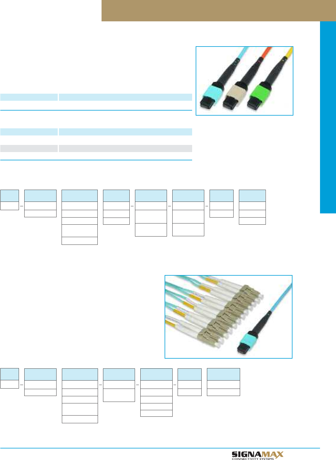
Optical Fiber Systems
D 2 4
TM
12-Fiber MTP Optical Fiber Assemblies
12-Fiber MTP Optical Fiber Assemblies are available in multiple configurations and
designed to be used with Signamax Plug-and-Play Pre-Terminated Fiber Cassettes in
telecommunications spaces for cross- and interconnections, for connection of active
equipment to the cabling. MTP connectors pre-terminated at the factory provide the
highest possible level of transmission performance.
12-Fiber 10G LO Multimode 50-µm MTP-to-MTP Assemblies
PART NO. DESCRIPTION
FMA-1251P-7F-7F-XXXM 12-Fiber MTP (F)-to-MTP (F), 10G LO 50 µm MM, Plenum
12-Fiber 62.5-µm, 50-µm and 9-µm MTP-to-MTP Assemblies
PART NO. DESCRIPTION
FMA-126P-7F-7F-XXXM 12-Fiber MTP (F)-to-MTP (F), 62.5 µm MM, Plenum
FMA-125P-7F-7F-XXXM 12-Fiber MTP (F)-to-MTP (F), 50 µm MM, Plenum
FMA-129P-7F-7F-XXXM 12-Fiber MTP (F)-to-MTP (F), SM, Plenum
For length in meters substitute XXX for length in P/N. Use configurator for other lengths.
005=5 meters 010=10 meters 020=20meters 030=30 meters 050=50 meters
12-Fiber MTP-to-MTP Fiber Assembly Configurator
JACKET
TYPE
X
R = Riser
P = Plenum
UNIT OF
MEASURE
X
F = Feet
M = Meters
LENGTH
XXX
001 - 999
FIBER
CORD
FMA
FIBER
TYPE
X
6 = MM 62.5 µm
5 = MM 50 µm
51 = MM 50 µm
10G LO
9 = SM
CONNECTOR
END ONE
XX
7F = MTP
(Non-Pinned)
7M = MTP
(Pinned)
FIBER
COUNT
12
12 = 12 Fibers
CONNECTOR
END TWO
XX
7F = MTP
(Non-Pinned)
7M = MTP
(Pinned)
12-Fiber MTP Fanout Assemblies
12-Fiber MTP Fan-out Assemblies serve as the most effective and
sometimes the only solution where a transition from MTP to any other
simplex or duplex optical fiber connector is required. Built according to a
customer order, available in various configurations fan-out assemblies
being terminated and tested in a controlled manufacturing environment
not only help to reduce time and cost of installation, but also provide
the highest achievable level of transmission performance eliminating
termination procedures in the field.
12-Fiber MTP Fanout Configurator
FIBER
CORD
FMF
FIBER
COUNT
12
12 = 12 Fibers
FIBER
TYPE
X
6 = MM 62.5 µm
5 = MM 50 µm
51 = MM 50 µm
10G LO
9 = SM
CONNECTOR
END ONE
XX
7M = MTP
(Pinned)
CONNECTOR
END TWO
X
2 = ST
4 = SC
9 = LC
8 = MT-RJ
LENGTH
(Feet)
XX
001 - 020
BREAKOUT
LENGTH (Inches)
XX
012 - 048
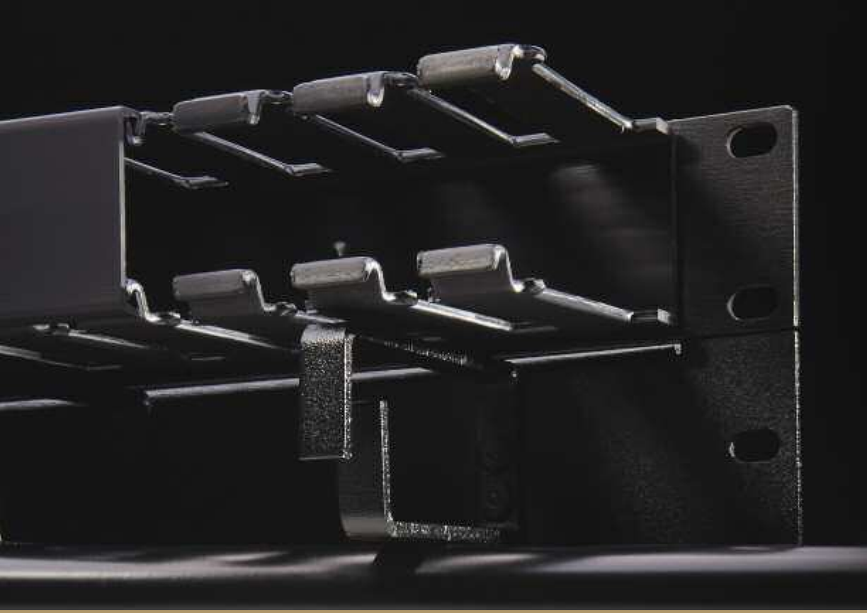
Racks
M A N A G E M E N T
ANDCable
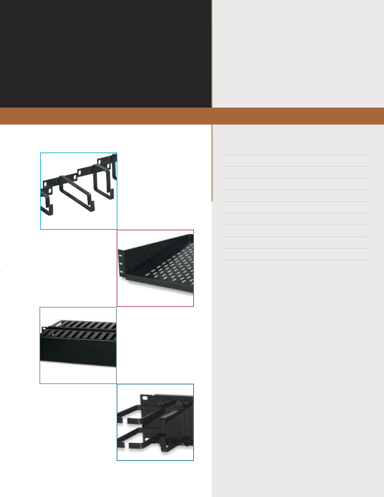
Racks and Cable Manage-
TM
EEqquuiippmmeenntt RRaacckkss EE11
VVeerrttiiccaall CCaabbllee MMaannaaggeemmeenntt ffoorr EEqquuiippmmeenntt RRaacckkss EE11
EEqquuiippmmeenntt SShheellvveess EE22
WWaallll--MMoouunntt EEqquuiippmmeenntt CCaabbiinneettssEE22
HHiinnggeedd WWaallll--MMoouunntt BBrraacckkeettss EE22
PPaattcchh CCoorrdd aanndd CCaabbllee MMaannaaggeemmeenntt PPaanneellss EE33
CCaabbllee MMaannaaggeemmeenntt RRiinngg BBrraacckkeettss EE55
BBllaannkk FFiilllleerr PPaanneellss EE55
RRaacckk--MMoouunnttiinngg HHaarrddwwaarree EE55
VVeellccrroo CCaabbllee MMaannaaggeemmeenntt TTiieess EE66
w w w . s i g n a m a x . c o m
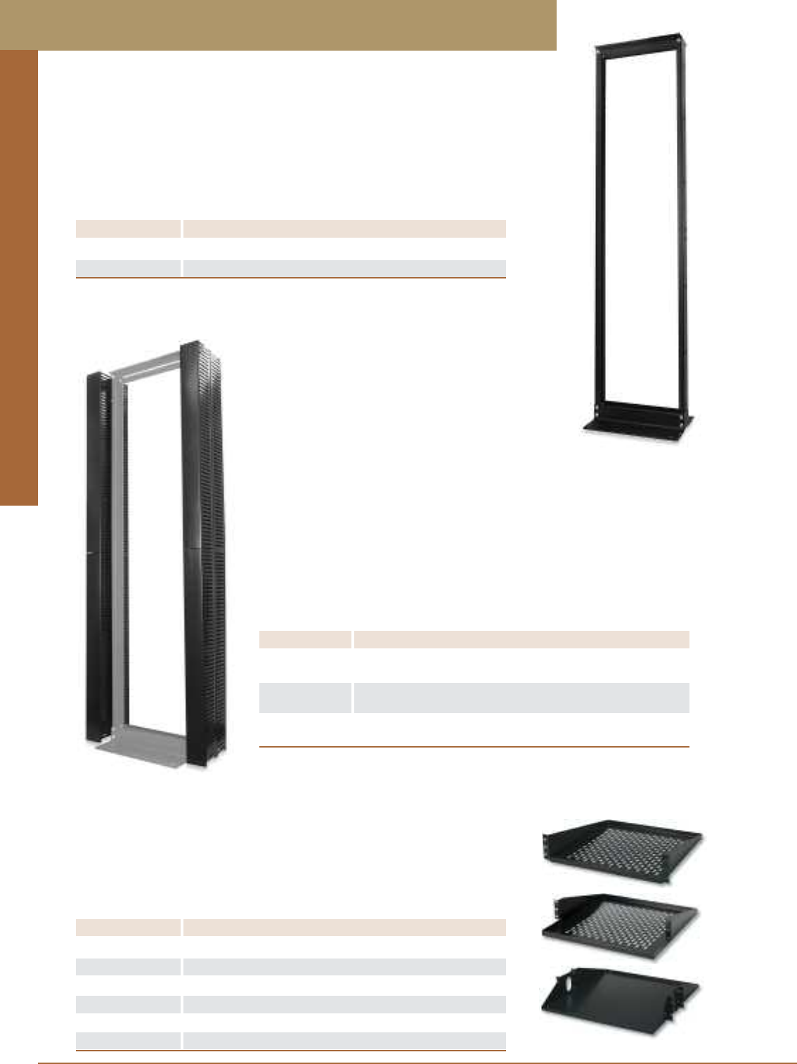
Racks and Cable Management
PREMISE CONNECTIVITY SYSTEMS 800.446.2377 www.signamax.comD 1
Shelves are designed for use in equipment and cable management racks, for locating
keyboards, monitors, or other shelf-located network equipment. Rack-Mount Shelves
are available in either cantilevered or center weight style. Both styles are constructed
from 16-gauge steel with a black polyurethane finish in either solid or louvered
ventilated bottom style. All shelves are rated for a maximum of 50-lbs capacity.
Rack-Mount Shelves
PART NO. DESCRIPTION DIMENSIONS
ERB-14CS Cantilever Solid Bottom, Black 3.5”H x 14”D
ERB-14C Cantilever Vented Bottom, Black 3.5”H x 14”D
ERB-18CS Cantilever Offset Solid Bottom, Black 3.5”H x 18”D
ERB-18C Cantilever Offset Vented Bottom, Black 3.5”H x 18”D
ERB-19C Center Weight Vented Bottom, Black 3.5”H x 19”D
ERB-19CS Center Weight Solid Bottom, Black 3.5”H x 19”D
Equipment racks are designed for 19-inch rack-mount equipment. Racks are con-
structed of aluminum and are available in a variety of standard heights. Each rack is
drilled and tapped on both the front and the rear rails with 10-32 holes on CEA-310-E
spacing. Standard rack finish is black.
Equipment Racks
PART NO. DESCRIPTION RACK SPACES
RR-84B 84” High Equipment Rack, Black Finish 45
RR-48B 48” High Equipment Rack, Black Finish 24
Vertical Cable management for Equipment Racks can be used for handling both
equipment/patch cords and distribution cables providing efficient and inexpensive
means for arranging, routing, and protection of cabling. Easy-to-remove snap-on front
and back panels in combination with routing and retaining slots on the base facilitate
initial cabling installation and routine maintenance procedures. Plastic design of the
management troughs with several mounting brackets evenly located along the base
provides reliable yet lightweight cable management solution suitable for most
telecommunications applications.
Vertical Cable Management for Equipment Racks
PART NO. DESCRIPTION
VCM-84FR-S Vertical Cable Management for 84” High Equipment Rack,
Side-Mount with 4”W x 5”H Wiring Duct on Front and Back
VCM-84FR-C Vertical Cable Management for 84” High Equipment Rack,
Center-Mount with 4”W x 5”H Wiring Duct on Front and Back
VCM-84F-S Vertical Cable Management for 84” High Equipment Rack,
Side-Mount with 4”W x 5”H Wiring Duct on Front Only
Racks and Cable Management
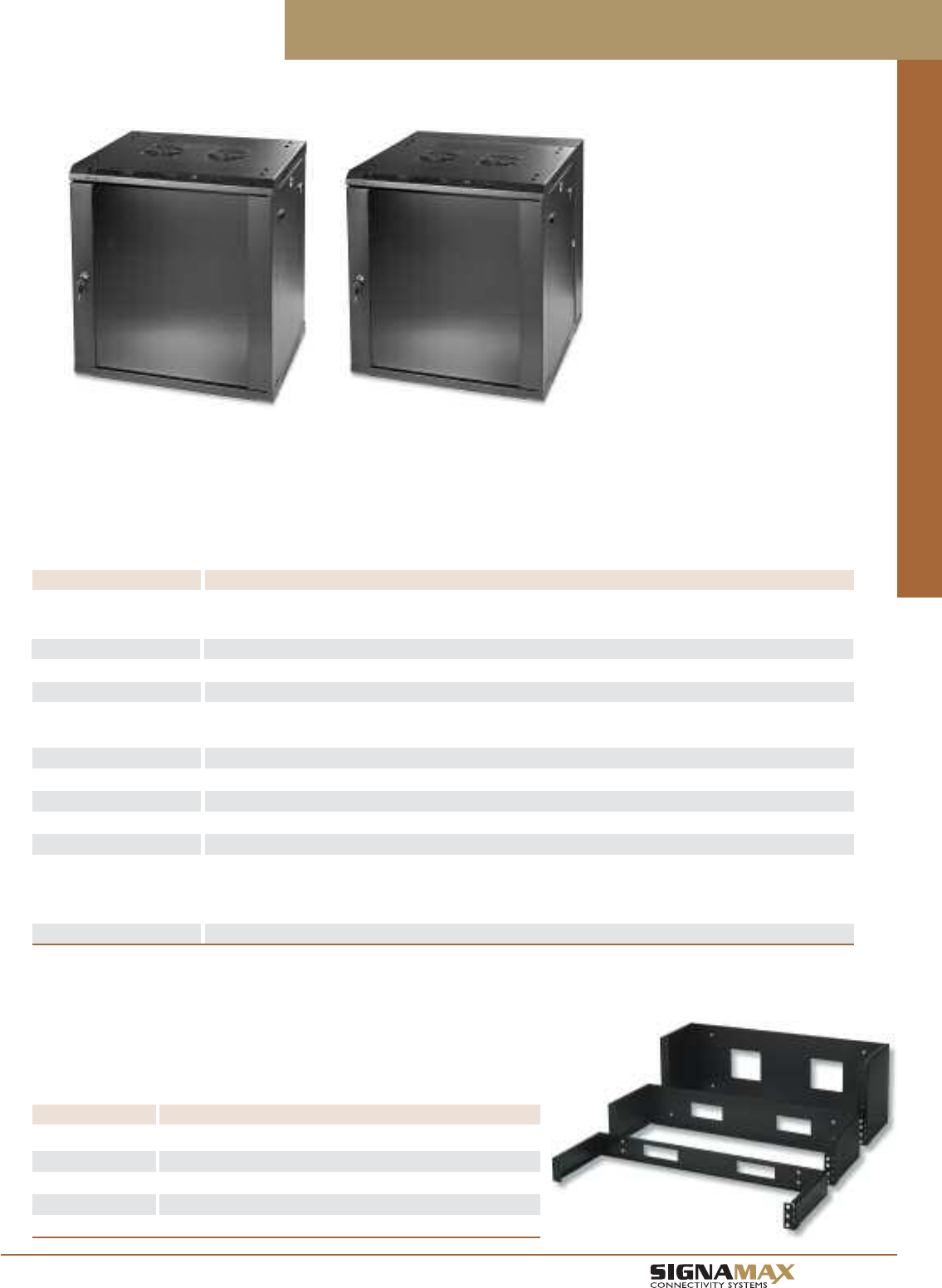
Racks and Cable Management
D 2
TM
Hinged Wall-Mount Brackets are designed for mounting one or more 19-inch panels
and have a 6-inch standoff depth. Brackets are constructed from 16-gauge steel with
a black polyurethane finish. Brackets have cable access holes on both the rear and
sides of the brackets to allow a variety of cable access configurations. Brackets can
be mounted for either right- or left-hand swing.
Hinged Wall-Mount Brackets
PART NO. DESCRIPTION RACK SPACES
HWB-175 Hinged Wall Mount Bracket, 1.75”H x 6”D 1
HWB-350 Hinged Wall Mount Bracket, 3.50”H x 6”D 2
HWB-525 Hinged Wall Mount Bracket, 5.25”H x 6”D 3
HWB-700 Hinged Wall Mount Bracket, 7.00”H x 6”D 4
HWB-875 Hinged Wall Mount Bracket, 8.75”H x 6”D 5
Wall-Mount Equipment Cabinets and Hinged Wall-Mount Brackets
Signamax wall-mount equipment cabinets are a perfect solution for small to medium IT installations, for installations where either space is
limited or security requirements exist. Cabinets may also serve as alternative spaces to the telecommunications room or entrance facility.
Designed to accommodate active and passive telecommunications equipment, these cabinets are supplied in two basic versions – single-
section and dual-section, and a variety of heights – from 6 to 18 rack-mount units. Removable side doors equipped with a lock allows access
to the cabinet contents from left, right or rear. Front door features a lock and toughened glass for easy inspection of cabinet contents and op-
erational status of the installed equipment. An optional set of two fans can be installed to improve active equipment cooling where necessary.
Wall-Mount Equipment Cabinets
PART NO. DESCRIPTION Height, RMU Height, mm (in) Depth, mm (in) Weight, kg (lb)
Single Section Cabinets
WEC-S-06-600/450-BK Single-Section Wall-Mount Cabinet 6 266.7 (10.50) 450.0 (17.72) 28 (62)
WEC-S-09-600/450-BK Single-Section Wall-Mount Cabinet 9 400.1 (15.75) 450.0 (17.72) 29 (64)
WEC-S-12-600/450-BK Single-Section Wall-Mount Cabinet 12 533.4 (21.00) 450.0 (17.72) 30 (66)
WEC-S-15-600/450-BK Single-Section Wall-Mount Cabinet 15 666.8 (26.25) 450.0 (17.72) 31 (68)
Dual Section Cabinets
WEC-D-06-600/550-BK Dual-Section Wall-Mount Cabinet 6 266.7 (10.50) 550.0 (21.65) 30 (66)
WEC-D-09-600/550-BK Dual-Section Wall-Mount Cabinet 9 400.1 (15.75) 550.0 (21.65) 30 (66)
WEC-D-12-600/550-BK Dual-Section Wall-Mount Cabinet 12 533.4 (15.75) 550.0 (21.65) 31 (68)
WEC-D-15-600/550-BK Dual-Section Wall-Mount Cabinet 15 666.8 (26.25) 550.0 (21.65) 34 (75)
WEC-D-15-600/600-BK Dual-Section Wall-Mount Cabinet 15 666.8 (26.25) 600.0 (23.62) 36 (79)
WEC-D-18-600/550-BK Dual-Section Wall-Mount Cabinet 18 800.1 (26.25) 550.0 (21.65) 39 (86)
WEC-D-18-600/600-BK Dual-Section Wall-Mount Cabinet 18 800.1 (26.25) 600.0 (23.62) 40 (88)
Accessories
WEC-CTF-2 Cooling Fans, Set of Two, NEMA 5-15 Plug, 6ft Cord
WEC-MH-CN-50 Mounting Hardware, Package of 50
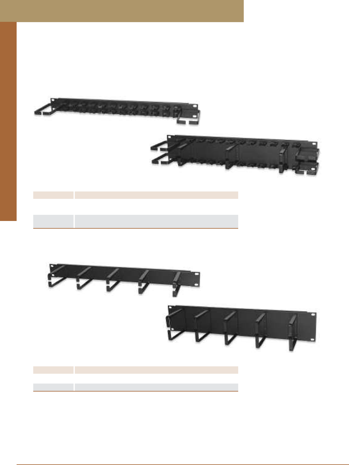
Racks and Cable Management
PREMISE CONNECTIVITY SYSTEMS 800.446.2377 www.signamax.comE 3
Patch Cord and Cable Management Panels
Patch cord and cable management panels provide a simple means of organizing and managing cables, either on the front or rear
of an equipment rack or enclosure. Cable management panels are available in several styles with features such as horizontal and
vertical rings, individual wire saddles, and slotted duct. All panels allow management and routing of both bundled and individual
cables. Cable management panels are available in 1.75” high (1 rack space) and 3.50” high (2 rack spaces) and are supplied with
mounting hardware.
Panels with Distribution Rings and Routing Clips
PART NO. DESCRIPTION RACK SPACES
CMP-175 Panel with (2) 3” x 3” Vertical Distribution Rings 1
and Routing Clips
CMP-350 Panel with (2) 3” x 3” Vertical Distribution Rings, 2
(4) 3” x 3” Horizontal Distribution Rings and Routing Clips
Panels with Distribution Rings
PART NO. DESCRIPTION RACK SPACES
CMP-175-A Panel with (5) 1.75” x 3” Horizontal Distribution Rings 1
CMP-350-A Panel with (5) 3” x 3” Horizontal Distribution Rings 2
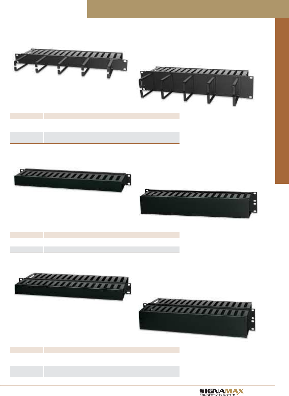
Racks and Cable Management
E 4
TM
Patch Cord and Cable Management Panels
Panels with Distribution Rings and Wiring Duct
PART NO. DESCRIPTION RACK SPACES
CMP-175-AD Panel with (5) 1.75” x 3” Horizontal Distribution Rings 1
and 1.5”H x 4”D Wiring Duct on Back
CMP-350-AD Panel with (5) 3” x 3” Horizontal Distribution Rings 2
and 3”H x 4”D Wiring Duct on Back
Panels with Front Wiring Duct
PART NO. DESCRIPTION RACK SPACES
CDP-175 Panel with 1.5”H x 3”D Wiring Duct on Front 1
CDP-350 Panel with 3”H x 3”D Wiring Duct on Front 2
Panels with Front and Back Wiring Duct
PART NO. DESCRIPTION RACK SPACES
CDP-175-A Panel with 1.5”H x 3”D Wiring Duct on Front and 1
1.5”H x 3.75”D Wiring Duct on Back
CDP-350-A Panel with 3”H x 3”D Wiring Duct on Front and 2
3”H x 3.75”D Wiring Duct on Back
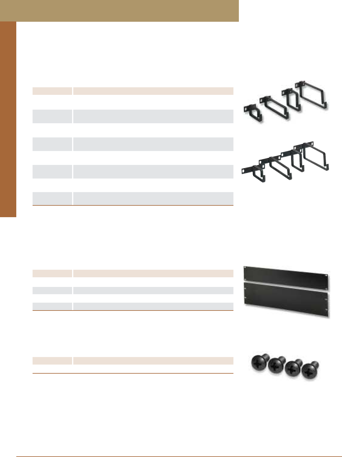
Racks and Cable Management
PREMISE CONNECTIVITY SYSTEMS 800.446.2377 www.signamax.comE 5
PART NO. DESCRIPTION RACK SPACES
CMR-175-A Cable Management Ring Bracket with 1.75”H x 4.00”D 1
Horizontal Ring on 1.75”H Rack-Mount Bracket
CMR-175-B Cable Management Ring Bracket with 2.25”H x 4.00”D 1
Horizontal Ring on 1.75”H Rack-Mount Bracket
CMR-175-C Cable Management Ring Bracket with 1.75”H x 6.125”D 1
Horizontal Ring on 1.75”H Rack-Mount Bracket
CMR-175-D Cable Management Ring Bracket with 2.25”H x 6.125”D 1
Horizontal Ring on 1.75”H Rack-Mount Bracket
CMR-350-A Cable Management Ring Bracket with 1.75”H x 4.00”D 2
Horizontal Ring on 3.50”H Rack-Mount Bracket
CMR-350-B Cable Management Ring Bracket with 2.25”H x 4.00”D 2
Horizontal Ring on 3.50”H Rack-Mount Bracket
CMR-350-C Cable Management Ring Bracket with 1.75”H x 6.125”D 2
Horizontal Ring on 3.50”H Rack-Mount Bracket
CMR-350-D Cable Management Ring Bracket with 2.25”H x 6.125”D 2
Horizontal Ring on 3.50”H Rack-Mount Bracket
Cable Management Ring Brackets can be mounted to the front or rear of a rack to provide both
vertical and horizontal cable management. Brackets can be specified in either one or two rack-
space sizes and are offered in 4” and 6” depths for accommodating various cable bundle sizes.
Cable Management Ring Brackets
Blank Filler Panels
PART NO. DESCRIPTION RACK SPACES
BFP-19175 Blank Filler Panel, 19’W x 1.75”H 1
BFP-19350 Blank Filler Panel, 19’W x 3.50”H 2
BFP-19525 Blank Filler Panel, 19’W x 5,25”H 3
BFP-19700 Blank Filler Panel, 19’W x 7.00”H 4
Mounting Hardware
PART NO. DESCRIPTION
RMH-1032 10-32 Rack Mount Hardware, Package of 100
Cable Management Ring Brackets and Blank Filler Panels
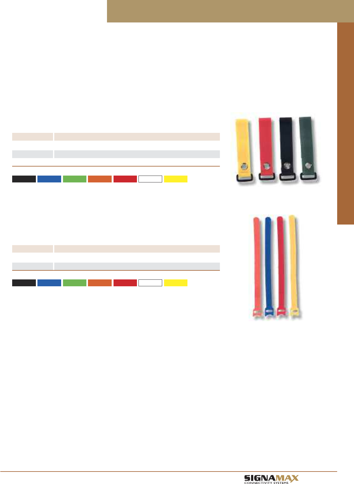
Racks and Cable Management
E 6
TM
Velcro®cable management ties provide the best option for securing or bundling
communications cables. Their design and construction eliminate over-tensioning and jacket
distortion problems, which can degrade transmission performance. Signamax Velcro cable
ties provide a solution for bundling cables in an adjustable range of cable bundle diameters
up to eight inches and can be ordered in a rack-rail mountable version.
Cable Management Ties
Rack-Mountable Velcro®Cable Management Ties
PART NO. DESCRIPTION MAX. BUNDLE DIA.
VCT-08-TC Velcro Cable Management Tie, 8”L x 1”W 2.0”
VCT-12-TC Velcro Cable Management Tie, 12”L x 1”W 3.5”
VCT-20-TC Velcro Cable Management Tie, 20”L x 1”W 6.0”
-BK (Black) -BU (Blue) -GN (Green) -OR (Orange) -RD (Red) -WH (White) -YE (Yellow)
For cable tie color substitute TC for color in P/N. Sold in packages of 5.
Velcro®Cable Management Ties
PART NO. DESCRIPTION MAX. BUNDLE DIA.
VCPT-08-TC Velcro Cable Management Tie, 8”L x 0.5”W 1.60”
VCPT-12-TC Velcro Cable Management Tie, 12”L x 0.5”W 2.75”
-BK (Black) -BU (Blue) -GN (Green) -OR (Orange) -RD (Red) -WH (White) -YE (Yellow)
For cable tie color substitute TC for color in P/N. Sold in packages of 10.
Velcro Cable Management Ties
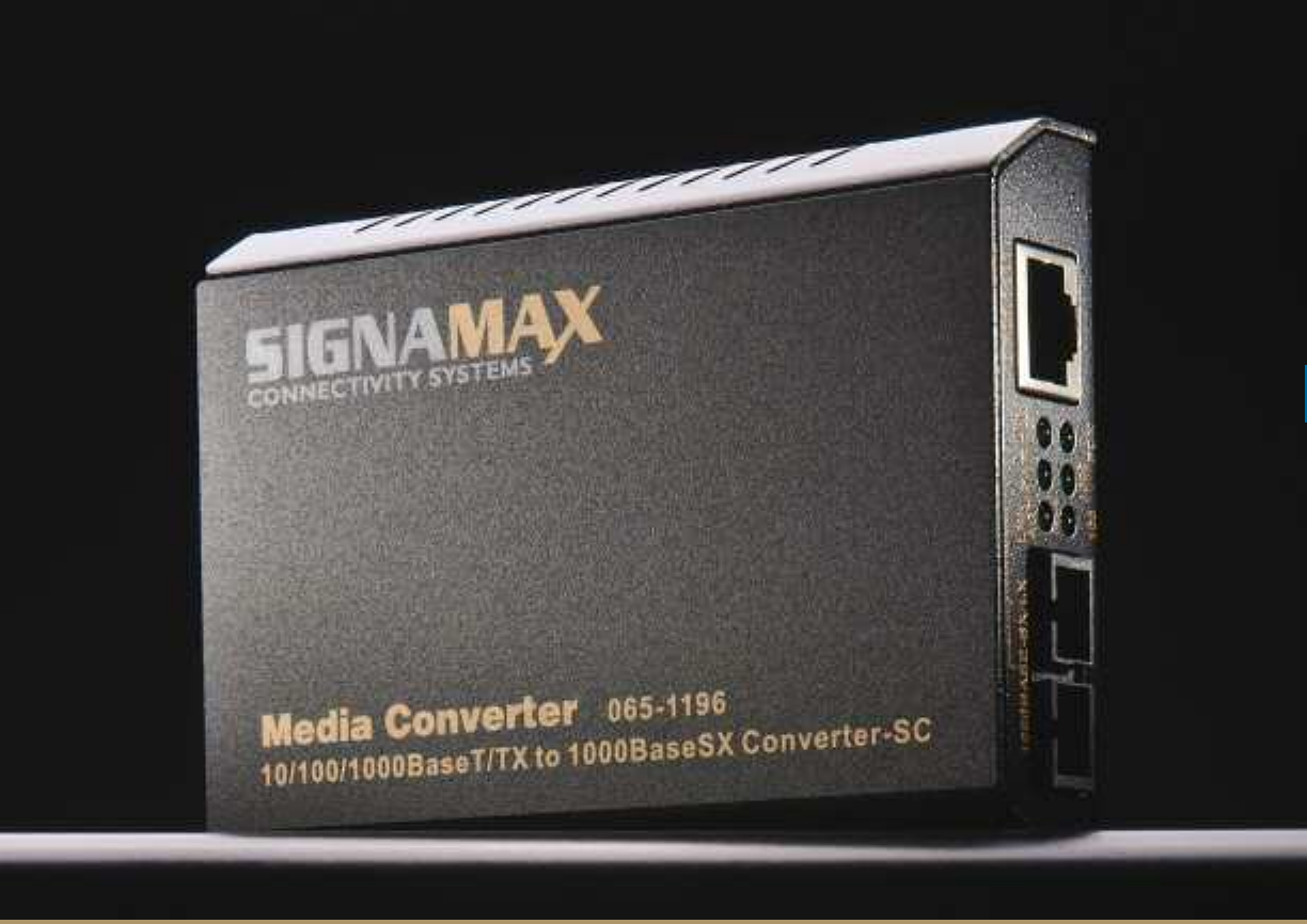
Optical
Fiber
M E D I A C O N V E R T E R S
1100//110000BBaasseeTT//TTXX ttoo 110000BBaasseeFFXX FF11
1100//110000BBaasseeTT//TTXX ttoo 110000BBaasseeFFXX SSiinnggllee FFiibbeerr FF22
110000BBaassee FFXX SSiinngglleemmooddee ttoo MMuullttiimmooddee FF33
1100//110000//1100000000BBaasseeTT//TTXX ttoo 11000000BBaassee SSXX//LLXX FF44
1100//110000//11000000 BBaasseeTT//TTXX ttoo 1100//11000000BBaassee SSFFPP FF55
GGiiggaabbiitt EEtthheerrnneett CCoonnvveerrtteerrss FF66
1100//110000BBaasseeTT//TTXX EEtthheerrnneett EExxtteennddeerrss FF77
1166--BBaayy RRaacckk MMoouunntt CChhaassssiiss FF88
1122--CChhaannnneell RRaacckk MMoouunntt CCoonnvveerrtteerrss FF99
OOAAMM CCoonnvveerrtteerrss FF1100
1100//110000BBaasseeTT//TTXX ttoo 110000BBaasseeFFXX MMiinnii CCoonnvveerrtteerrss FF1111
1100//110000BBaasseeTT//TTXX ttoo 110000BBaasseeFFXX PPCCII CCoonnvveerrtteerrssFF1122
1100//110000BBaassee TT//TTXX ttoo 110000BBaasseeFFXX PPooEE PPSSEE CCoonnvveerrtteerrssFF1133
1100//110000BBaasseeTT//TTXX ttoo 110000BBaasseeFFXX PPooEE PPDD CCoonnvveerrtteerrssFF1144
1100//110000BBaasseeTT//TTXX HHaarrddeenneedd CCoonnvveerrtteerrssFF1155
1100//110000//11000000 ttoo GGiiggaabbiitt SSFFPP HHaarrddeenneedd CCoonnvveerrtteerrssFF1166
w w w . s i g n a m a x . c o m
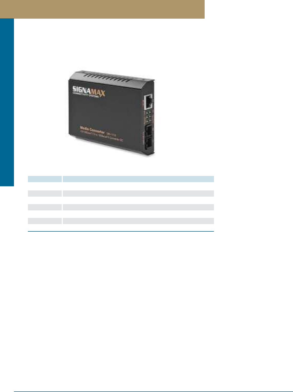
Media Converters
PREMISE CONNECTIVITY SYSTEMS 800.446.2377 www.signamax.comF 1
10/100BaseT/TX to 100BaseFX Fiber Optic Media Converters
Media Converters with Link Fault Signaling (LFS) provide the means for an SNMP-Managed switch to recognize a failure on a fiber
channel or twisted-pair connection, enabling the switch to automatically route to a backup path if the connected switch is equipped with
Spanning Tree Algorithm. This intelligence maximizes the power of managed switches, and enables fail-safe design solutions for complex
networks. These converters also extend the maximum singlemode fiber distance, spanning over 46 miles with P/N 065-1120XLD.
Fixed Ports
Models: 065-1100/1110/1172/1174/1120/1120ES/ 1120XLD
1 Auto-MDIX IEEE 802.3/3u standard 10/100BaseT/TX port, plus 1
fiber optic IEEE 802.3u 100BaseFX standard port; either 62.5/125 or
50/125 micron multimode fiber optic cable, 2,000 meters maximum
distance. 9/125 micron singlemode fiber spanning 15 kilometers
(Model 065-1120), 40 kilometers (Model 065-1120ED), or 75
kilometers (Model 065-1120XLD)
LED Indicators
Per Unit: Power status, RJ-45 port speed
Per Port: LNK/ACT, FDX/COL
Six LEDs total
Performance
Latency: < 4.2 µs (LIFO)
Throughput @ 100Base: 148,809 pps (64-byte packets)
Physical Characteristics
Case dimensions: 4.33"L x 3.19"W x 0.91"H
(110mm x 81mm x 23mm)
Weight: 0.33 pounds (150 grams)
Environmental Characteristics
Operating Temperature: 32°F ~ 104°F (0°C ~ 40°C)
(Models 065-1100E, 065-1110E and 065-1120E)
Storage Temperature: -13°F ~ 158°F (-25°C ~ 70°C)
Relative Humidity: 10 ~ 90%, non-condensing
Power
External power adapter: 12 Volts DC, 600 mA; secondary USB cable
power option available on certain models by special order; please
add “LFS” as a suffix to the part number for this option.
Power Consumption: 5 Watts Maximum
Emissions & Safety
FCC part 15 Class A, CISPR Class A, VCCI Class A, CE Mark
UL Listed
Warranty
Lifetime
Specifications
PART NO. DESCRIPTION
065-1100 10/100BaseT/TX to 100BaseFX Media Converter ST Multimode, 2 km Span
065-1110 10/100BaseT/TX to 100BaseFX Media Converter SC Multimode, 2 km Span
065-1172 10/100BaseT/TX to 100BaseFX Media Converter MT-RJ Multimode, 2 km Span
065-1174 10/100BaseT/TX to 100BaseFX Media Converter LC Multimode, 2 km Span
065-1120 10/100BaseT/TX to 100BaseFX Media Converter SC Singlemode, 15 km Span
065-1120ED 10/100BaseT/TX to 100BaseFX Media Converter SC Singlemode, 40 km Span
065-1120XLD 10/100BaseT/TX to 100BaseFX Media Converter SC Singlemode, 75 km Span
10/100BaseT/TX to 100BaseFX Fiber Optic Media Converters
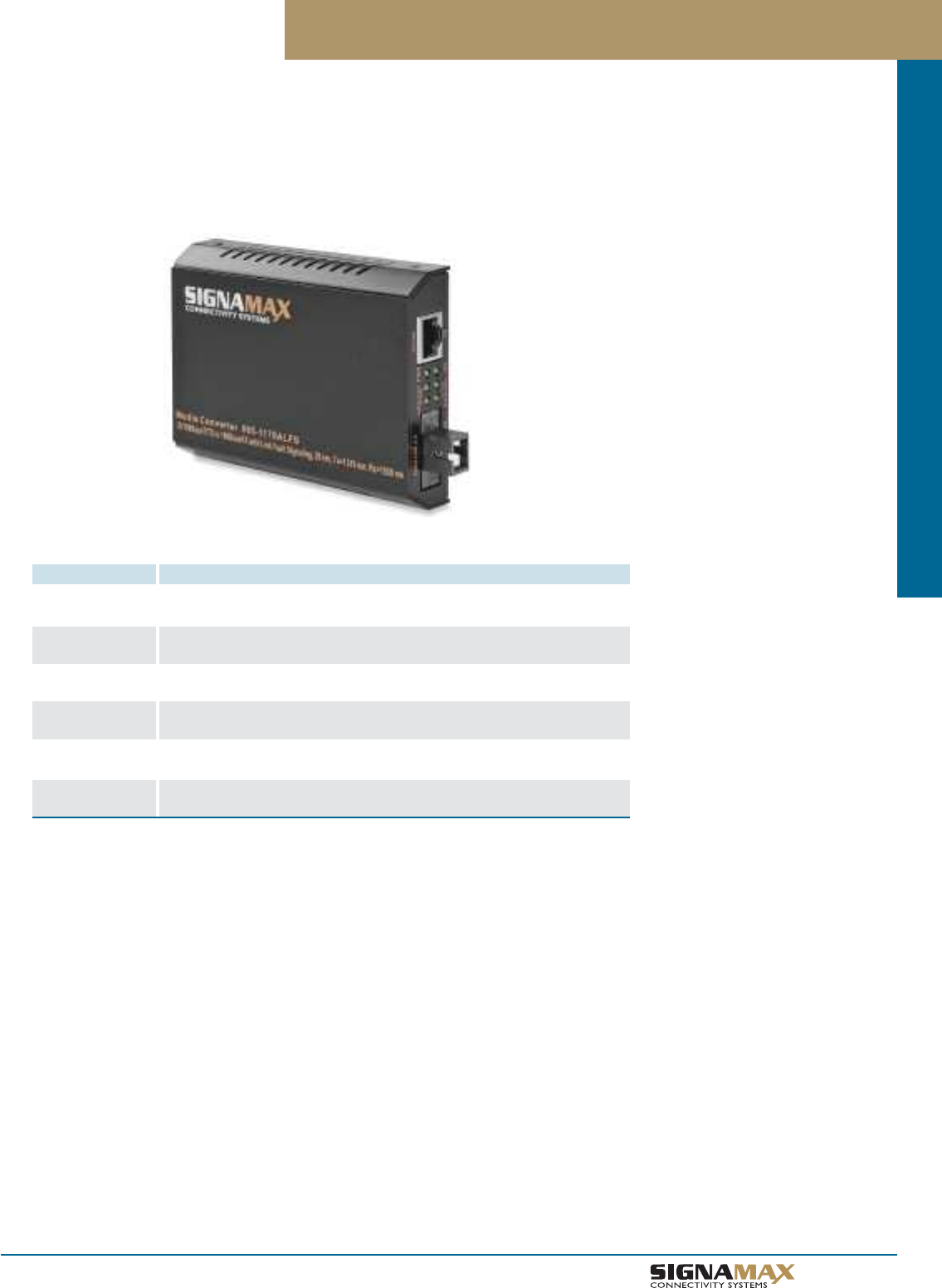
Media Converters
F 2
TM
10/100BaseT/TX to 100BaseFX Single Fiber (WDM) Media Converters
10/100BaseT/TX to 100BaseFX Single Fiber (WDM) Media Converters
PART NO. DESCRIPTION
065-1176ALFS 10/100BaseT/TX to 100BaseFX Single Fiber (WDM) Media Converter
SC Simplex Singlemode, Tx=1310 nm; Rx=1550 nm, 20 km Span
065-1176BLFS 10/100BaseT/TX to 100BaseFX Single Fiber (WDM) Media Converter
SC Simplex Singlemode, Tx=1550 nm; Rx=1310 nm, 20 km Span
065-1176AEDLFS 10/100BaseT/TX to 100BaseFX Single Fiber (WDM) Media Converter
SC Simplex Singlemode, Tx=1310 nm; Rx=1550 nm, 40 km Span
065-1176BEDLFS 10/100BaseT/TX to 100BaseFX Single Fiber Media (WDM) Converter
SC Simplex Singlemode, Tx=1550 nm; Rx=1310 nm, 40 km Span
065-1176ALFSMM 10/100BaseT/TX to 100BaseFX Single Fiber (WDM) Media Converter
SC Simplex Multimode, Tx=1310 nm; Rx=1550 nm, 2 km Span
065-1176BLFSMM 10/100BaseT/TX to 100BaseFX Single Fiber (WDM) Media Converter
SC Simplex Multimode, Tx=1550 nm; Rx=1310 nm, 2 km Span
Single Fiber Wave Division Multiplexing (WDM) Media Converters with Link Fault Signaling allow data normally carried over two strands of
fiber optic cable to be carried over a single strand of fiber optic cable, utilizing two different light spectra to carry signals in both directions
simultaneously. This technology doubles the capacity of a company's fiber optic network, allowing a carrier or an enterprise business to
minimize its operational costs by eliminating or delaying the deployment of additional fiber optic capacity. These converters are available
in singlemode and multimode, and span distances of up to 40 kilometers (24.85 miles) with the 065-1176AEDLFS and 065-1176BEDLFS.
Fixed Ports
1 Auto-MDIX twisted-pair port meeting IEEE 802.3 10BaseT & IEEE
802.3u 100BaseTX standard specifications; Category 5 or better cable,
100 meters maximum distance for 100BaseTX, Category 3 or better
cable, 100 meters maximum distance for 10BaseT
PLUS
1 WDM fiber optic port meeting IEEE 802.3u 100BaseFX standard
specification; 9/125 micron singlemode fiber optic cable, spanning 20
kilometers maximum distance (models 065-1176ALFS and
065-1176BLFS)
OR
1 WDM fiber optic port meeting IEEE 802.3u 100BaseFX standard
specification; 9/125 micron singlemode fiber optic cable, spanning
40 kilometers maximum distance (models 065-1176AEDLFS and
065-065-1176BEDLFS)
OR
1 WDM fiber optic port meeting IEEE 802.3u 100BaseFX standard
specification; 62.5/125 micron or 50/125 micron multimode fiber optic
cable, spanning 2 kilometers maximum distance
(models 065-1176ALFSMM and 065-1176BLFSMM)
LED Indicators
Per unit: Power status, RJ-45 port speed
Per Port: LNK/ACT, FDX/COL
Six LEDs total
Performance
Latency: < 4.2 µs (LIFO)
Throughput @ 100Base: 148,810 pps (64-byte packets)
Physical Characteristics
Case dimensions: 4.33"L x 3.19"W x 0.91"H
(110mm x 81mm x 23mm)
Weight: 150 grams (0.33 pounds)
Environmental Characteristics
Operating Temperature: 32°F ~ 104°F (0°C ~ 40°C)
Storage Temperature: -13°F ~ 158°F (-25°C ~ 70°C)
Relative Humidity: 10 ~ 90%, non-condensing
Power
External power adapter: 12 Volts DC, 600 mA; secondary USB cable
power option is standard on these models.
Power Consumption: 5 Watts Maximum
Emissions & Safety
FCC part 15 Class A, CISPR Class A, VCCI Class A, CE Mark
UL Listed
Warranty
Lifetime
Specifications
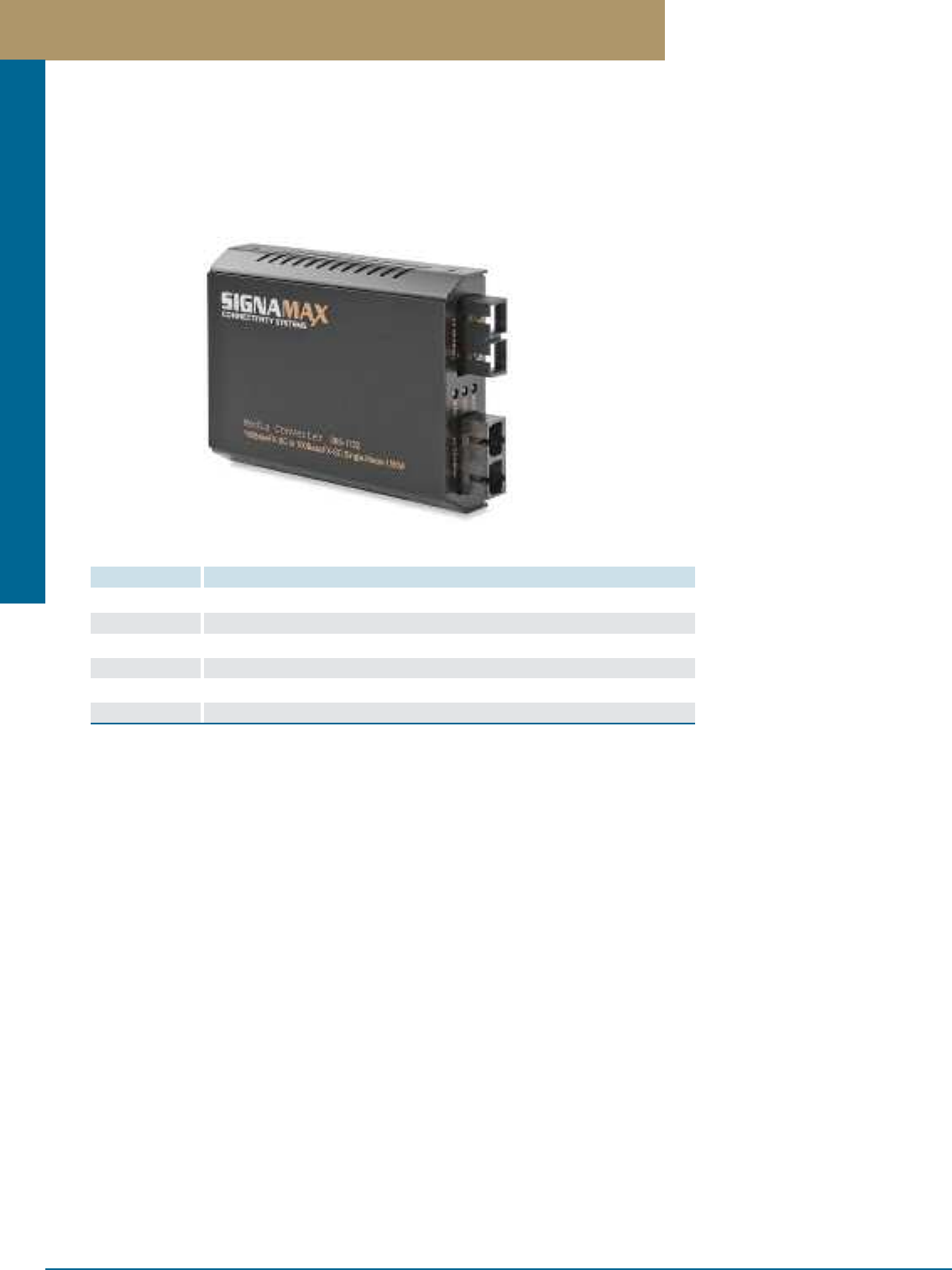
Media Converters
PREMISE CONNECTIVITY SYSTEMS 800.446.2377 www.signamax.comF 3
100BaseFX Singlemode To Multimode Media Converters
100BaseFX Singlemode To Multimode Media Converters
PART NO. DESCRIPTION
065-1130 100BaseFX SC/SM, 15 km Span to 100BaseFX ST/MM, 2 km Span
065-1130ED 100BaseFX SC/SM, 40 km Span to 100BaseFX ST/MM, 2 km Span
065-1130XLD 100BaseFX SC/SM, 75 km Span to 100BaseFX ST/MM, 2 km Span
065-1132 100BaseFX SC/SM, 15 km Span to 100BaseFX SC/MM, 2 km Span
065-1132ED 100BaseFX SC/SM, 40 km Span to 100BaseFX SC/MM, 2 km Span
065-1132XLD 100BaseFX SC/SM, 75 km Span to 100BaseFX SC/MM, 2 km Span
100BaseFX Singlemode to Multimode Converters provide efficient solutions for interconnecting multimode fiber LANs over longer
distances by integrating singlemode fiber optic cable into the LAN. They also enable Ethernet LAN and WAN connectivity, by providing a
multimode interface to singlemode fiber carrier demarcation points. Each Media Converter is enclosed in a compact, strong metal case
and includes an external power supply for stand-alone applications. They can also be installed without modification in the Signamax
065-1185 Rack Mount Chassis system, featuring redundant power supplies for high reliability in multiple converter installations.
Fixed Ports
Models 065-1130/1132/1130ED/1132ED/1130XLD/1132XLD:
1 fiber optic port meeting IEEE 802.3u 100BaseFX standard specifica-
tion; 62.5/125 or 50/125 micron multimode fiber optic cable, 2,000
meters maximum distance plus 1 IEEE 802.3u 100BaseFX standard
fiber optic port supporting 9/125 micron singlemode fiber optic cable,
spanning 15 kilometers (065-1130 & 065-1132) or 40 kilometers
(065-1130ED & 065-1132ED) or 75 kilometers (065-1130XLD
& 065-1132XLD)
LED Indicators
Per Unit: Power status
Per Port: SD (A & B ports) – link and activity
Performance
Latency: < 21 bit times
Throughput @ 100Base: 148,809 pps (64-byte packets)
Speed: 100BaseFX: 100/200 Mbps for half/full duplex
Physical Characteristics
Case dimensions: 4.33"L x 3.19"W x 0.91"H
(110mm x 81mm x 23mm)
Weight: 0.33 pounds (150 grams)
Environmental Characteristics
Operating Temperature: 32°F ~ 104°F (0°C ~ 40°C)
Storage Temperature: -13°F ~ 158°F (-25°C ~ 70°C)
Relative Humidity: 10 ~ 90%, non-condensing
Power
External power adapter: 12 Volts DC; 600 mA
Power Consumption: 5 Watts Maximum
Emissions & Safety
FCC part 15 Class A, CISPR Class A, VCCI Class A, CE Mark
UL Listed
Warranty
Lifetime
Specifications
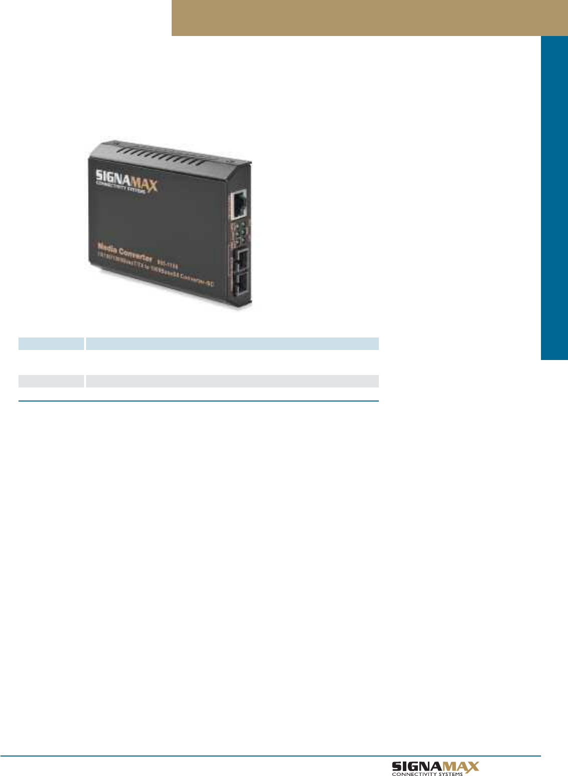
Media Converters
F 4
TM
10/100/1000BaseT/TX to 1000BaseSX/LX Fiber Optic Media Converters
10/100/1000BaseT/TX to 1000BaseSX/LX Fiber Optic Media Converters
PART NO. DESCRIPTION
065-1196 10/100/1000BaseT/TX to 1000BaseSX Media Converter; Fixed SC MM,
220m Span on 62.5µm Fiber / 550m Span on 50µm Fiber
065-1196LX 10/100/1000BaseT/TX to 1000BaseLX Media Converter; Fixed SC SM, 10 km
065-1196LXED 10/100/1000BaseT/TX to 1000BaseLX Media Converter; Fixed SC SM, 20 km
10/100/1000 Switching Media Converters provide an intelligent solution for long distance connections between legacy 10BaseT and
100BaseTX networks and 1000Base Gigabit Ethernet networks. The built-in 10/100/1000 switch enables the fiber cable connection
to operate at 1000 Mbps connected to either a 10BaseT, 100BaseTX, or a 1000BaseT network, while remaining completely
1000BaseSX/LX standard-compliant for the fiber optic connection. Each model 065-1196 series Media Converter provides a
10/100/1000BaseT/TX auto-negotiating RJ-45 twisted-pair connector port featuring store-and-forward switching architecture.
Fixed Ports
1 Auto-MDIX IEEE 802.3ab standard 10/100/1000BaseT/TX port, plus
either 1 fiber optic IEEE 802.3z 1000BaseSX standard port supporting
62.5/125 micron multimode fiber optic cable, 220 meters maximum
distance, or 50/125 micron multimode fiber optic cable, 550 meters
maxi-mum distance (065-1196), 9/125 micron singlemode fiber
spanning 10 kilometers (065-1196LX), 20 kilometers (065-1196LXED).
LED Indicators
Per Unit: Power status, RJ-45 100 port speed, RJ-45 1000 port speed,
RJ-45 FDX indicator
Per Port: LNK/ACT
Six LEDs total
Performance
Latency: < 4.2 µs (LIFO)
Throughput @ 100Base: 148,810 pps (64-byte packets)
Throughput @ 1000Base: 1,488,100 pps (64-byte packets)
Physical Characteristics
Case dimensions: 4.33"L x 3.19"W x 0.91"H
(110mm x 81mm x 23mm)
Weight: 0.33 pounds (150 grams)
Environmental Characteristics
Operating Temperature: 32°F ~ 104°F (0°C ~ 40°C)
Storage Temperature: -13°F ~ 158°F (-25°C ~ 70°C)
Relative Humidity: 10 ~ 90%, non-condensing
Power
External power adapter: 12 Volts DC, 600 mA
Power Consumption: 5 Watts Maximum
Emissions & Safety
FCC part 15 Class A, CISPR Class A, VCCI Class A, CE Mark
UL Listed
Warranty
Lifetime
Specifications
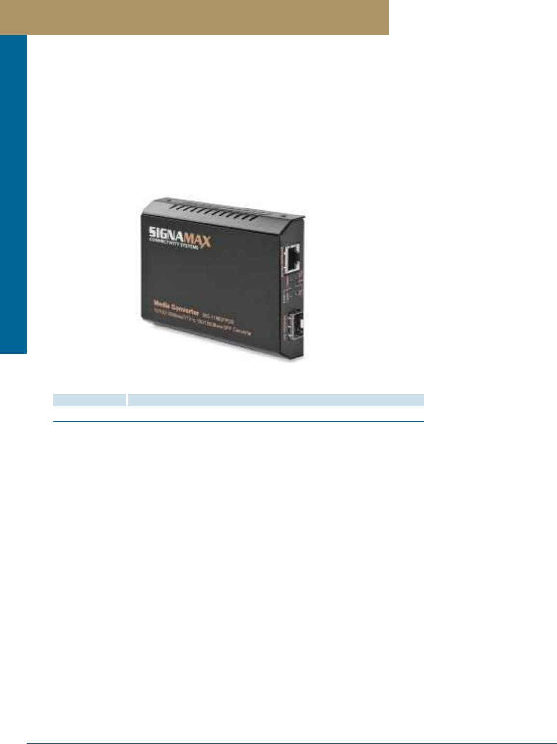
Media Converters
PREMISE CONNECTIVITY SYSTEMS 800.446.2377 www.signamax.comF 5
10/100/1000BaseT/TX to 100/1000Base SFP Fiber Optic Media Converters
10/100/1000BaseT/TX to 100/1000Base SFP Fiber Optic Media Converters
PART NO. DESCRIPTION
065-1196SFPDR 10/100/1000BaseT/TX to Dual-Rate 100Base or 1000Base SFP Media Converter
Fiber types, 100 or 1000Base speed, and distances spanned are SFP module-dependent. Please see our website at
www.signamax.com for 1000Base SFP and 100Base SFP availability and specification in formation.
Signamax Connectivity Systems' new 065-1196SFPDR 10/100/1000BaseT/TX to 100/1000Base SFP Switching Media Converter provides
a flexible and intelligent solution for long distance connections between legacy 10BaseT and 100BaseTX networks and either 1000Base
Gigabit Ethernet fiber or 100Base fiber networks. The built-in 10/100/1000 switch enables the fiber cable connection to operate at 1000
Mbps connected to either a 10BaseT, 100BaseTX, or a 1000BaseT network, while remaining completely 1000BaseSX/LX OR
100BaseFX/BX standard-compliant for the fiber optic connection.
The 065-1196SFPDR dual-rate fiber Media Converter features extremely low latency of ≤1.6 µs, FIFO, worst case; the ability to force
the RJ-45 port to 100Base or 10Base full or half-duplex modes; the ability to provide auto-negotiation on the 1000Base fiber port or forced
full-duplex mode where required; and the enabling or disabling of the Link Fault Signaling feature. Link Fault Signaling provides a means
of propagating a link drop on either port of the media converter to the other port, enabling a connected managed switch to see the link
drop and respond to it using Spanning Tree Protocol or another recovery scheme.
Ports
1 - RJ-45 10/100/1000BaseT/TX port
1 - Dual-rate 1000Base or 100Base SFP receptacle.
LED Indicators
Power; LFS Status; Link Copper; Link Fiber; Copper port speed
(Green = 1000 Mbps, Amber = 100 Mbps, off = 10 Mbps); SFP fiber port
speed indicator.
Six LEDs total.
Performance
Latency: ≤1.6 µs (FIFO).
MTBF: 1,857,775.35 hours (212.07 years), calculated via the Part
Stress Analysis Method.
Throughput, per port: @ 1000Base: 1,488,100 pps (64-byte packets);
@ 100Base: 148,810 pps (64-byte packets)
Switch Fabric Speed: 4.0 Gbps (non-blocking, wire speed
performance)
Frame Buffer: 12K total (Tx buffer = 4K, Rx buffer = 4K,
8051microcontroller use = 4K).
Physical Characteristics
Case dimensions: 4.33"L x 3.19"W x 0.91"H
(110mm x 81mm x 23mm)
Weight: 0.33 pounds (150 grams)
Environmental Characteristics
Operating Temperature: 32°F ~ 122°F (0°C ~ 50°C)
Storage Temperature: -14°F ~ 158°F (-10°C ~ 70°C)
Relative Humidity: 5% ~ 90%, non-condensing
Power
Power Requirement: 12 VDC
Power Supply Provided: Primary: 100 - 240 VAC, 50/60 Hz.
Secondary: 12 VDC, 600 ma, center contact positive.
Power Consumption: 2.76 watts maximum.
Maximum Current Consumption: 0.23A @ 12VDC.
Emissions & Safety
Safety: CE Mark Class A
EMI: FCC Part 15 Class A; VCCI Class A
Warranty
Lifetime
Specifications
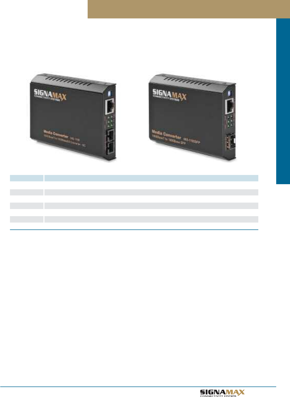
Media Converters
F 6
TM
Gigabit Ethernet Fiber Optic Media Converters
Gigabit Ethernet Fiber Optic Media Converters
PART NO. DESCRIPTION
065-1194 1000BaseLX SC SM, 10 km Span to 1000BaseSX, SC MM, 220m Span on 62.5µ Fiber/550m Span on 50µ Fiber
065-1194ED 1000BaseLX SC SM, 20 km Span to 1000BaseSX, SC MM, 220m Span on 62.5µ Fiber/550m Span on 50µ Fiber
065-1195 1000BaseT to 1000BaseSX, SC MM, 220m Span on 62.5µ Fiber/550m Span on 50µ Fiber
065-1197 1000BaseT to 1000BaseLX Converter, SC MM, 10 km Span
065-1197ED 1000BaseT to 1000BaseLX Converter, SC SM, 20 km Span
065-1198XLD 1000BaseLX SC SM, 20 km Span to 1000BaseLX SC SM, 20 km Span Repeater
065-1195SFP 1000BaseT to 1000Base Media Converter with SFP Slot
Fiber types and distances spanned are SFP module-dependent.
Please see our website at www.signamax.com for SFP availability and specification information.
Gigabit Ethernet Media Converters make it simple to extend distances over multimode or singlemode fiber. They are designed to expand
the scope of your Gigabit Ethernet network applications and are 100% compliant with Ethernet IEEE 802.3ab and 802.3z specifications.
These converters maintain the same form factor as other Signamax media converters, allowing use in the 065-1185 16-Bay Rack Mount
Chassis. Twisted pair to fiber optic converters for multimode, singlemode, and SFP fiber modules are available, plus multimode to
singlemode converters and singlemode to singlemode extenders.
Fixed Ports
1 twisted-pair port meeting IEEE 802.3ab standard specification
and/or 1 fiber optic port meeting IEEE 802.3z standard; 62.5/125
micron multimode fiber optic cable, 220 meters maximum distance or
50/125 micron multimode fiber optic cable, 550 meters maximum
distance (065-1194 & 065-1195) or 1 fiber optic port meeting IEEE
802.3z 1000BaseLX standard specification; 9/125 micron singlemode
fiber optic cable, spanning 10 kilometers maximum distance ( 065-1194
& 065-1197) or 20 kilometers maximum distance (065-1194ED,
065-1197ED, & 065-1198XLD) or 1 fiber optic IEEE 802.3z 1000Base
standard SFP port supporting a variety of 1000Base SFP modules
(model 065-1195SFP).
LED Indicators
Power; TX; RX; FDX/COL; LNKF; LNKC (or LNK1; LNK2,
065-1198XLD)
Performance
Latency: < 4.2 µs (LIFO)
Throughput @ 1000Base: 1,488,100 pps (64-byte packets)
Physical Characteristics
Case dimensions: 4.33"L x 3.19"W x 0.91"H
(110mm x 81mm x 23mm)
Weight: 0.33 pounds (150 grams)
Environmental Characteristics
Operating Temperature: 32°F ~ 104°F (0°C ~ 40°C)
Storage Temperature: -13°F ~ 158°F (-25°C ~ 70°C)
Relative Humidity: 10 ~ 90%, non-condensing
Power
External power adapter: 12 Volts DC, 600 mA
Power Consumption: 5 Watts Maximum
Emissions & Safety
FCC part 15 Class A, CISPR Class A, VCCI Class A, CE Mark
UL Listed
Warranty
Lifetime
Specifications
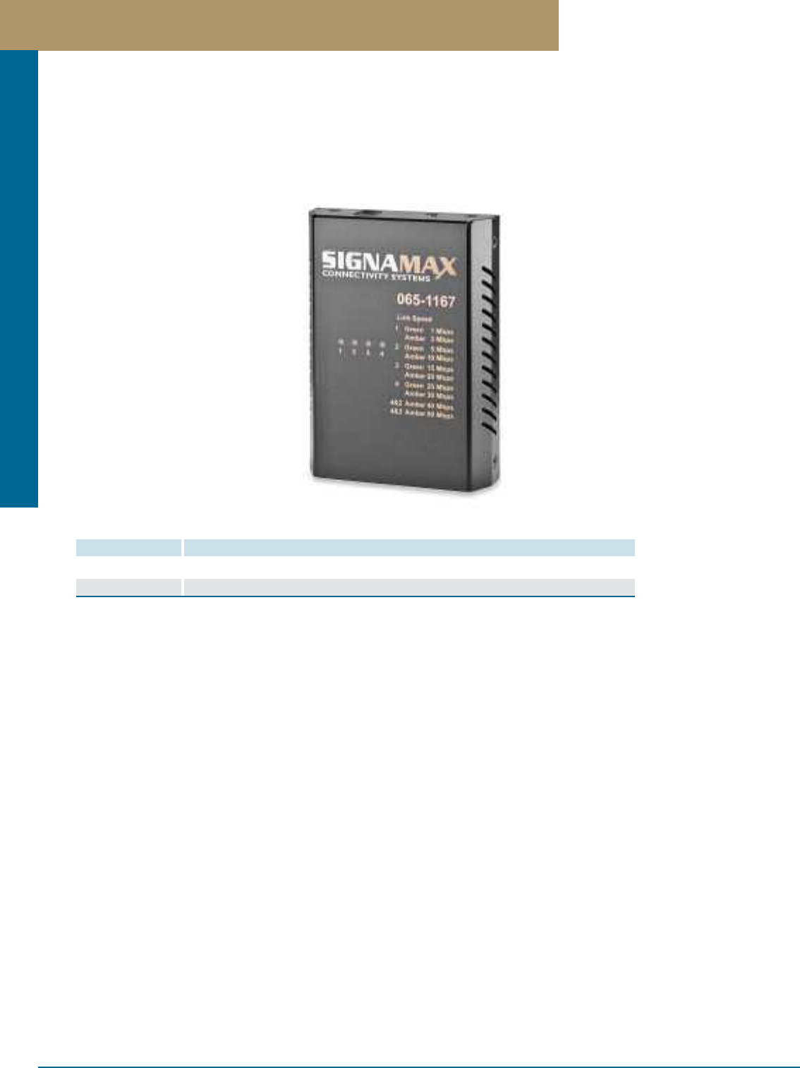
Media Converters
PREMISE CONNECTIVITY SYSTEMS 800.446.2377 www.signamax.comF 7
10/100BaseT/TX Ethernet Extender Media Converter
Signamax Connectivity Systems’ model 065-1167 is a point-to-point Ethernet Extender that efficiently extends 10/100 Ethernet circuits
to over 1,960 feet (600 meters) at 30 Mbps using existing straight pair copper wire. The 065-1167 allows Ethernet connectivity in
existing facilities without pulling extra cable. This is the perfect solution to Ethernet on the factory floor where systems have been
upgraded from slower serial data communication to Ethernet networking. The 065-1167 is used in pairs to extend Ethernet connectivity
over existing voice grade copper wire. Installation is easy; a single switch setting allows each unit to be set either for local operation at
the near side of the circuit, or remote operation when used at the other end of the circuit.
10/100BaseT/TX Ethernet Extender Media Converters
PART NO. DESCRIPTION
065-1167 10/100BaseT/TX Ethernet Extender Media Converter
065-1167DIN 10/100BaseT/TX Ethernet Extender Media Converter with Pre-attached DIN-Rail Mount
Fixed Ports
1- RJ-45 Twisted Pair; 10/100BaseT/TX
1- RJ-11 Ethernet Extender
LED Indicators
End Panel: Per Unit: PWR (green).
10/100BaseT/TX Port (labeled Ethernet): Lnk/Act (green), Fdx (green).
Ethernet Extender Port (labeled Line): Lnk (green); Err (green); Loc
(green); Rmt (green).
Top Panel: Ethernet Extender (Line) Port Speed: LED 1 (green/amber);
LED 2 (green/amber); LED 3 (green/amber); LED 4 (green/amber).
Combination of illuminated LEDs indicates speed achieved.
Data Rates & Distances Spanned
Twisted Pair Ethernet Port: 10 or 100 Mbps; 100 m
Ethernet Extender Port: Up to 30 Mbps @ 1,968 feet (600 meters)
down to 1 Mbps @ 6,233 feet (1,900 meters); supports symmetrical
VDSL operation. Cable: Telephone line 24 AWG (0.5mm diameter, 1-pair
wire) or larger.
Physical Characteristics
Dimensions: 4.30 in. x 3.16 in. x 0.94 in., D x W x H
(109.2 mm x 80.3 mm x 23.8 mm)
Weight: 0.33 lb (150 kg.)
Environmental Characteristics
Operating Temperature: -4°F to 140°F (-20°C to 60°C)
Storage Temperature: -4°F to 158°F (-20°C to 70°C)
Operating and Storage Humidity: 10 to 95% (non-condensing)
Power
Power Supply: 12 Volts DC, 800 mA
Power Consumption: 2.4 Watts Maximum; 200 mA @ 12 Volts DC
Certifications
Safety: UL508, EN60950-1, IEC60950-1; CE Mark
EMI: FCC Part 15 Class A; EN61000-6-3; EN55022;
EN61000-3-2; EN61000-3-3
EMS: ESD Standards (IEC 61000-4-2);
Radiated FRI Standards (IEC 61000-4-3);
Burst Standards (IEC 61000-4-4);
Surge Standards (IEC 61000-4-5);
Induced RFI Standards (IEC 61000-4-6)
Magnetic Field Standards (IEC 61000-4-8);
Voltage Dip Standards (IEC 61000-4-11).
Environmental Test Compliance:
Vibration Resistance: IEC 60068-2-6fc.
Shock: IEC 60068-2-27 Ea.
Free Fall: IEC 60068-2-32 Ed.
Warranty
Lifetime
Specifications
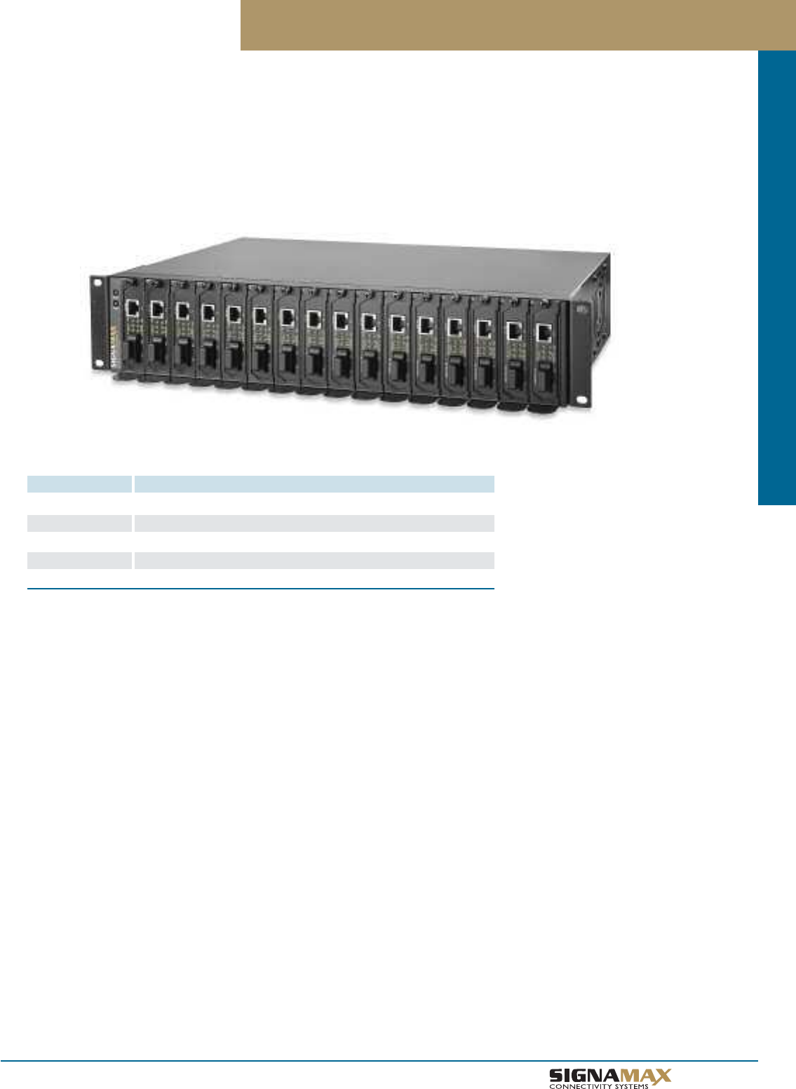
Media Converters
F 8
TM
16-Bay Rack Mount Media Converter Chassis
16-Bay Rack Mount Media Converter Chassis
PART NO. DESCRIPTION
065-1185 16-Bay Rack Mount Media Converter Chassis, AC
065-1185DC 16-Bay Rack Mount Media Converter Chassis, 48V DC
AC-1185 Spare Redundant Power Supply 90 - 240 V AC
DC1185 Spare Redundant Power Supply 48V DC
1185FAN Spare Individual Fan Assembly
The Signamax 065-1185 16-Bay Rack Mount Media Converter Chassis provides higher rack mount media converter density for large
installations that can accommodate rear access to the chassis for power supply maintenance. The 065-1185 provides 16 bays of space
for all 065-11xx series Signamax media converters in a standard two rack unit high enclosure. High port density allows a variety of media
converter solutions to be housed in a minimum amount of rack spaces for enterprise-level businesses and carriers. Redundant, fan-cooled
load-sharing power supplies can be hot-swapped to ensure system uptime. The 065-1185 has a choice of power supply configurations,
supporting AC power for 110 volt or 220 volt power systems or -48 volt DC power for carrier operations.
Capacity
Sixteen bays, for up to sixteen 065-11xx series media converters.
Cooling
Two 42.5 cfm side-mounted fans, plus one fan for each of the two
redundant power supplies.
LED Status Indicators
Power 1/Power 2: Power supply on-line
Physical Characteristics
Dimensions: 17.3" x 10.9" x 3.5" (440mm x 276mm x 90mm);
2 standard rack units
Weight: Approximately 18.7 pounds (8.5 kilograms), fully loaded
Environmental Characteristics
Operating Temperature: 32°F ~ 104°F (0°C ~ 40°C)
Storage Temperature: -13°F ~ 158°F (-25°C ~ 70°C)
Power Supplies
Load-sharing and hot-swappable; 2 supplied as standard equipment.
Power status LED on each power supply, as well as remote status
LEDs on front panel. Specifications, each:
Input: 90-240 Volts AC, 47-63 Hz.
Output: Normal +12 Volts DC (Min. +11.88 Volts, Max. +12.12 Volts,
7.0 Amps)
Total Regulation: +/- 1.0%, Rip. 120 mV, Load 1.0%, Line 0.5%
Overload Protection: All outputs protected against short circuit
conditions; automatic recovery
Over-Voltage Protection: Output level exceeding 13.2 Volts causes
shutdown - automatic recovery
Emissions & Safety
FCC Part 15 Class A, CE Class A, UL 1950 listed
Warranty
Lifetime
Specifications
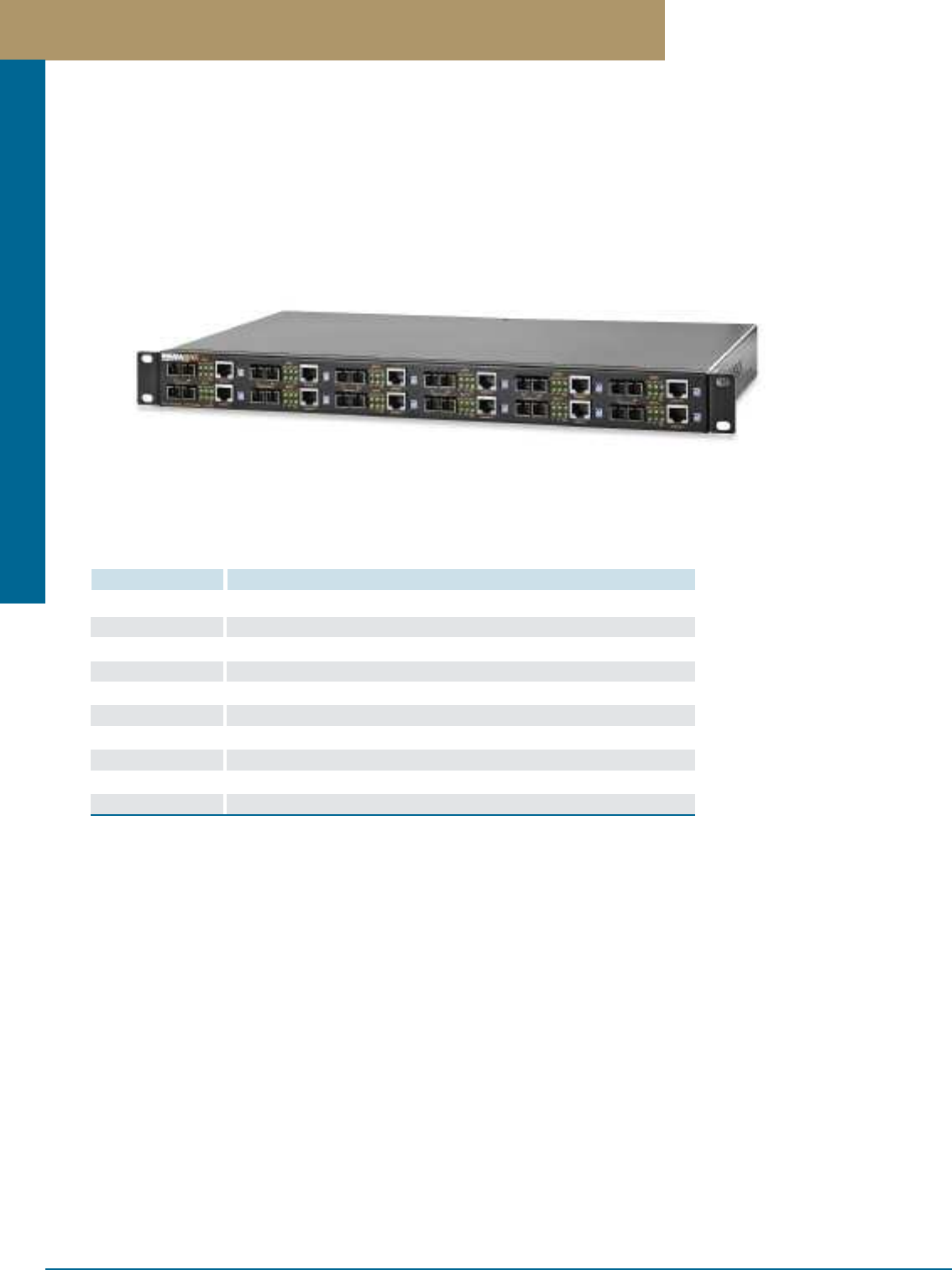
Media Converters
PREMISE CONNECTIVITY SYSTEMS 800.446.2377 www.signamax.comF 9
12-Channel Rack Mount Media Converters
12-Channel Rack Mount Media Converters
PART NO. DESCRIPTION
065-1200ST00 12-Channel 10/100T/TX to 100FX Media Converter, ST/MM, 2 km Span
065-1200SC10 12-Channel 10/100T/TX to 100FX Media Converter, SC/MM, 2 km Span
065-1200MT72 12-Channel 10/100T/TX to 100FX Media Converter, MT-RJ/MM, 2 km Span
065-1200LC74 12-Channel 10/100T/TX to 100FX Media Converter, LC/MM, 2 km Span
065-1200SC20 12-Channel 10/100T/TX to 100FX Media Converter, SC/SM, 15 km Span
065-1200SC20ED 12-Channel 10/100T/TX to 100FX Media Converter, SC/SM, 40 km Span
065-1200SC20XLD 12-Channel 10/100T/TX to 100FX Media Converter, SC/SM, 75 km Span
065-1200SC95 12-Channel 1000T to 1000BaseSX Media Converter, SC/MM, 220/550 m
065-1200SC97 12-Channel 1000T to 1000LX Media Converter, SC/SM, 10 km Span
065-1200SC97ED 12-Channel 1000T to 1000LX Media Converter, SC/SM, 20 km Span
12-Channel Rack Mount Media Converter is a perfect solution for large installations that utilize many of the same type of media
converters. The 065-1200 contains 12 channels of media conversion in a standard rack mountable case only one rack unit high.
This extremely high port density allows the maximum number of media converter channels per rack for enterprise-level businesses
and carriers. Redundant fan-cooled power supplies ensure system uptime.
Fixed Ports
Switched Fast Ethernet Series:
Multimode versions:
10/100BaseT/TX to 100BaseFX, multimode fiber; choice of SC, ST, LC,
or MT-RJ connectors. Maximum distance: 2 km.
Singlemode versions:
10/100BaseT/TX to 100BaseFX, singlemode SC connectors. Maximum
distance: up to 75 km
LED Status Indicators:
Per unit: Power status, Speed (2 LEDs)
Per port: LNK/ACT, FDX/COL (2 LEDs)
Gigabit Ethernet Series:
065-1200SC95 version:
1000BaseT to 1000BaseSX, multimode fiber, SC connectors. Maximum
distance, 1000BaseSX port: 220 meters over 62.5/125 µ multimode
fiber or 550 meters over 50/125 µ multimode fiber (full duplex only)
065-1200SC97 & 065-1200SC97ED versions:
1000BaseT to 1000BaseLX, singlemode fiber, SC connectors.
Maximum distance, 1000BaseLX port: 10 km (Model 065-1200SC97) or
20 km (Model 065-1200SC97ED) (full duplex only)
LED Status Indicators:
Per unit: Power status, FDX/COL, TX, RX (4 LEDs)
Per port: LNKF (fiber port), LNKC (copper port); 1 LED each.
Performance
Latency: < 4.2 µs (LIFO)
Throughput @ 100Base: 148,809 pps (64-byte packets)
Throughput @ 1000Base: 1,488,100 pps (64-byte packets)
Physical Characteristics
Dimensions: 17.3"W x 8.0"D x 1.8"H (440mm x 205mm x 45mm)
Weight: 6.8 lbs. (3.1 kg) maximum
Standard 19-in rack mounting (hardware included)
Environmental Characteristics
Operating Temperature: 0º - 40º C (32º - 140º F)
Relative Humidity: 10 to 90%, non-condensing
Power
Heat Dissipation/Hour: 85 BTU/hr
Maximum Wattage: 52 W. Current: 2.0 A maximum
Emissions & Safety
FCC part 15 Class A, CISPR Class A, VCCI Class A, CE Mark
UL Listed
Warranty
Lifetime
Specifications
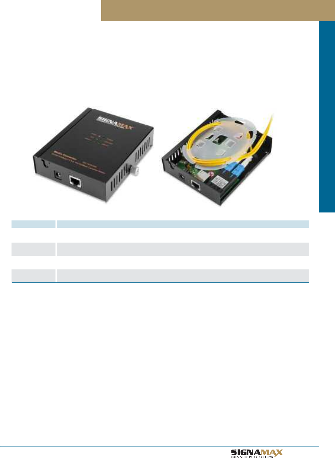
Media Converters
F 1 0
TM
Managed Operations, Administration & Maintenance (OAM) Media Converter
OAM Media Converters
PART NO. DESCRIPTION
065-1610OAM 10/100/1000 to 1000BaseSX/BX or 100BaseFX/BX SC/MM OAM Managed Media Converter
1000BaseSX/BX span: 220m on 62.5µ MM fiber/550 m on 50µ MM fiber. 100BaseFX/BX span: 2 km on 62.5µ MM fiber or 50µ MM fiber
065-1610OAMED 10/100/1000 to 1000BaseSX/BX or 100BaseFX/BX SC/MM OAM Managed Media Converter
1000BaseSX/BX span or 100BaseFX/BX span: 2 km on either 62.5µ or 50µ multimode fiber
065-1620OAM10 10/100/1000 to 1000BaseSX/BX or 100BaseFX/BX SC/MM OAM Managed Media Converter
1000BaseSX/BX span or 100BaseFX/BX span: 10 km on singlemode fiber
065-1620OAM20 10/100/1000 to 1000BaseSX/BX or 100BaseFX/BX SC/MM OAM Managed Media Converter
1000BaseSX/BX span or 100BaseFX/BX span: 20 km on singlemode fiber
Signamax Connectivity Systems’ 065-16xxOAM series Managed Operations, Administration & Maintenance (OAM) Media Converters are
designed to provide Local Exchange Carriers (LECs), Internet Service Providers (ISPs), and large installations such as airports with media
conversion solutions that can provide device information, testing, and integration with standards-based operations systems in a Fiber to the
Premises (FTTP) environment. These converters adhere to the IEEE 802.3ah standard for Link Monitoring, Remote Failure Indication, and
Remote Loopback capabilities. They are equipped with a 10/100/1000BaseT/TX RJ45 port and a fiber interface that supports either
1000Base or 100Base connections. Multimode and singlemode models share the same OAM feature set, so that commercial entities
who utilize multimode fiber for their Local Area Networks (LANs) can get the same advantages of remote fault detection and testing and
controlling unnecessary dispatches as carriers using singlemode fiber for their Wide-Area Networks (WANs).
Ports
1- RJ-45 10/100/1000BaseT/TX ports
1- Dual Rate 100BaseFX/BX or 1000BaseSX/LX/BX port; Multimode
models 065-1610OAM & 065-1610OAMED:
SC multimode connector.
Singlemode models 065-1620OAM10 &065-1610OAM20:
SC singlemode connector.
LED Indicators
Per Media Converter: Power; OAMLOOP
Per Copper RJ-45 Port: Speed, FDX, LNK/ACT
Per Fiber Port: LNK/ACT
Performance
Latency: <4.2 µs (LIFO).
Throughput, per port: 14,880 pps for 10 Mbps; 148,810 pps for 100
Mbps; 1,488,100 pps for 1000 Mbps (64-byte packets)
Switch Fabric Speed: 4.0 Gbps (non-blocking, wire speed)
MAC Address Capacity: 1,024 MAC addresses
Jumbo Frame Support: 9 K packets supported
VLAN Capabilities
IEEE 802.1Q Tag-based VLAN supported; up to 4K active VLANs
possible. Supports Q-in-Q Double Tagged Frame Transparent
Management
Access Methods: Via SNMP agent and Web browser.
Software Upgrade Capability: Via TFTP
SNMP v1 and v2 Network Management supported.
IEEE 802.3ah OAM supported.
Physical Characteristics
Dimensions: 3.94" (W) x 4.8" (D) x 1.28" (H) (100 x 122 x 32.5 mm)
Housing: Metal case, with built-in fiber splice tray.
Weight: 1.1 lbs (0.5 kg)
Environmental Characteristics
Operating Temperature: 23°F to 131°F (-5°C to 55° C).
Storage Temperature: -4°F to 158°F (-20°C to 70° C).
Operating Humidity: 5 to 95% RH, non-condensing.
Power
Power Supply: External power adapter 12 Volts DC, 0.25 Amp
Maximum Power Consumption: 3 Watts.
Emissions & Safety
Safety: CE Mark
EMI: FCC Part 15 Class A; CE Mark Class A; VCCI Class A
Warranty
Lifetime
Specifications
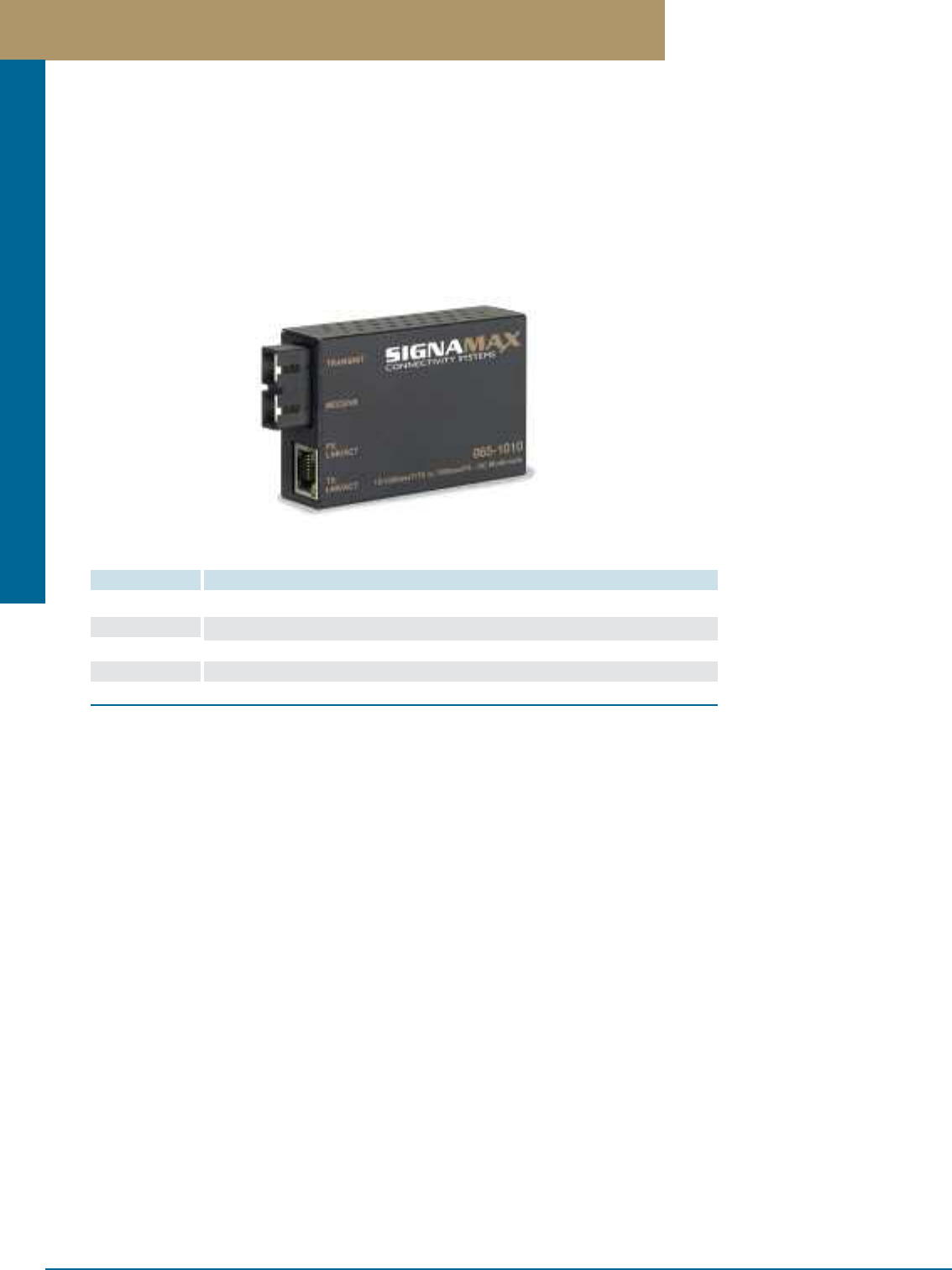
Media Converters
PREMISE CONNECTIVITY SYSTEMS 800.446.2377 www.signamax.comF 11
10/100BaseT/TX to 100BaseFX Mini Fiber Optic Media Converters
Signamax Connectivity Systems’ Switching Mini Fiber Optic Media Converters provide an intelligent solution for fiber optic connectivity
where simplicity, low cost, and minimum footprint are the primary considerations. These converters are designed to handle both legacy
10BaseT and 100BaseTX Fast Ethernet devices on their twisted pair port while maintaining 100BaseFX Fast Ethernet transmission on
the fiber optic port. Plug-and-play simplicity makes connection easy. Each Media Converter provides a 10/100BaseT/TX auto-negotiating
RJ-45 twisted-pair connector port with Auto-MDIX capability for more convenient connection. Built-in 10/100 switch enables the fiber
cable connection to operate at 100 Mbps connected to either a 10BaseT or a 100BaseTX network, while remaining completely
100BaseFX standard-compliant. Fiber connection can also operate in full duplex mode whether the RJ-45 port is connected to a full
duplex switch or a half duplex hub.
Fixed Ports
Models 065-1000/1010/1020/1020ED/1020XLD:
1 - Auto-MDIX twisted-pair port meeting IEEE 802.3 10BaseT & IEEE
802.3u 100BaseTX standard specifications; Category 5 or better cable,
100 meters maximum distance for 100BaseTX, Category 3 or better
cable, 100 meters maximum distance for 10BaseT
plus
1 - fiber optic port meeting IEEE 802.3u 100BaseFX standard specifica-
tion; 62.5/125 or 50/125 micron multimode fiber optic cable, 2,000 meters
maximum distance
or
1 - fiber optic port meeting IEEE 802.3u 100BaseFX standard specifica-
tion; 9/125 micron singlemode fiber optic cable, spanning: 20 km maxi-
mum distance (Model 065-1020)
or
40 km maximum distance (Model 065-1020ED)
or
75 km maximum distance (Model 065-1020XLD)
LED Indicators
Per Port: FX LNK/ACT, TX LNK/ACT
Two LEDs total
Performance
Latency: < 4.2 µs (LIFO)
Throughput @ 100Base: 148,809 pps (64-byte packets)
Switching Method: Store-and-Forward
Physical Characteristics
Case dimensions: 3.15"L x 2.13"W x 0.87"H (80 x 54 x 22 mm)
Weight: 0.27 pounds (122 grams)
Environmental Characteristics
Operating Temperature: 32°F ~ 104°F (0°C ~ 40°C)
Storage Temperature: -13°F ~ 158°F (-25°C ~ 70°C)
Relative Humidity: 10 ~ 90%, non-condensing
Power
External power adapter: 5 Volts DC; 1.0 A
Power Consumption: 5 Watts Maximum
Emissions & Safety
FCC part 15 Class A, CISPR Class A, VCCI Class A, CE Mark
UL Listed
Warranty
Lifetime
Specifications
PART NO. DESCRIPTION
065-1000 10/100BaseT/TX to 100BaseFX Mini Media Converter ST Multimode, 2 km Span
065-1010 10/100BaseT/TX to 100BaseFX Mini Media Converter SC Multimode, 2 km Span
065-1020 10/100BaseT/TX to 100BaseFX Mini Media Converter SC Singlemode, 15 km Span
065-1020ED 10/100BaseT/TX to 100BaseFX Mini Media Converter SC Singlemode, 40 km Span
065-1020XLD 10/100BaseT/TX to 100BaseFX Mini Media Converter SC Singlemode, 75 km Span
10/100BaseT/TX to 100BaseFX Mini Fiber Optic Media Converters

Media Converters
F 1 2
TM
10/100BaseT/TX to 100BaseFX PCI Fiber Optic Media Converters
Signamax Connectivity Systems’ Switching PCI Fiber Optic Media Converters are an excellent solution for fiber-to-the-desktop
installations where the workstation computers have pre-installed Network Interfaces. These media converters are inserted into one of
the PC’s available PCI slots, and a copper patch cable is used to connect the media converter to the existing network interface jack
on the PC’s motherboard or in an adjoining PCI slot. The fiber optic cable then connects to the fiber-based cabling plan for network
connectivity. They avoid the need for fiber NIC driver maintenance in environments where PCs are used in both fiber- and copper–
connected areas. These converters are designed to handle both legacy 10BaseT and 100BaseTX Fast Ethernet devices on their twisted
pair port while maintaining 100BaseFX Fast Ethernet transmission on the fiber optic port. Plug-and-play simplicity makes connection easy,
with Auto-MDIX capability on the twisted-pair port for convenient connection. A built-in 10/100 switch enables the fiber cable connection to
operate at 100 Mbps connected to either a 10BaseT or a 100BaseTX network interface, while remaining completely 100BaseFX
standard-compliant.
Fixed Ports
1 - Auto-MDIX twisted-pair port meeting IEEE 802.3 10BaseT & IEEE
802.3u 100BaseTX standard specifications; Category 5 or better cable,
100 meters maximum distance for 100BaseTX, Category 3 or better
cable, 100 meters maximum distance for 10BaseT
PLUS
1 - fiber optic port with SC (Model 065-1060SC), ST (Model 065-
1060ST), or LC (Model 065-1060LC) meeting IEEE 802.3u 100BaseFX
standard specification; 62.5/125 or 50/125 micron multimode fiber optic
cable, 2,000 meters maximum distance
OR
1 - SC duplex fiber optic port meeting IEEE 802.3u 100BaseFX standard
specification; 9/125 micron singlemode fiber optic cable, spanning: 20
kilometers maximum distance (model 065-1060SM)
OR
40 kilometers maximum distance (model 065-1060SMED)
OR
75 kilometers maximum distance (model 065-1060SMXLD)
LED Indicators
Per Port: FX LNK/ACT, TX LNK/ACT
Two LEDs total
Performance
Latency: < 4.2 µs (LIFO)
Throughput @ 100Base: 148,809 pps (64-byte packets)
Speed: 100BaseTX: 100/200 Mbps for half/full duplex; 10BaseT: 10/20
Mbps for half/full duplex
Switching Method: Store-and-Forward
Architecture
32-Bit PCI Bus Mastering
Power
Via computer’s internal PCI bus; no external power required.
Emissions & Safety
FCC part 15 Class A, CISPR Class A, VCCI Class A, CE Mark
UL Listed
Warranty
Lifetime
Specifications
PART NO. DESCRIPTION
065-1060ST 10/100BaseT/TX to 100BaseFX PCI Media Converter ST Multimode, 2 km Span
065-1060SC 10/100BaseT/TX to 100BaseFX PCI Media Converter SC Multimode, 2 km Span
065-1060LC 10/100BaseT/TX to 100BaseFX PCI Media Converter LC Multimode, 2 km Span
065-1060SM 10/100BaseT/TX to 100BaseFX PCI Media Converter SC Singlemode, 20 km Span
065-1060SMED 10/100BaseT/TX to 100BaseFX PCI Media Converter SC Singlemode, 40 km Span
065-1060SMXLD 10/100BaseT/TX to 100BaseFX PCI Media Converter SC Singlemode, 75 km Span
10/100BaseT/TX to 100BaseFX PCI Fiber Optic Media Converters
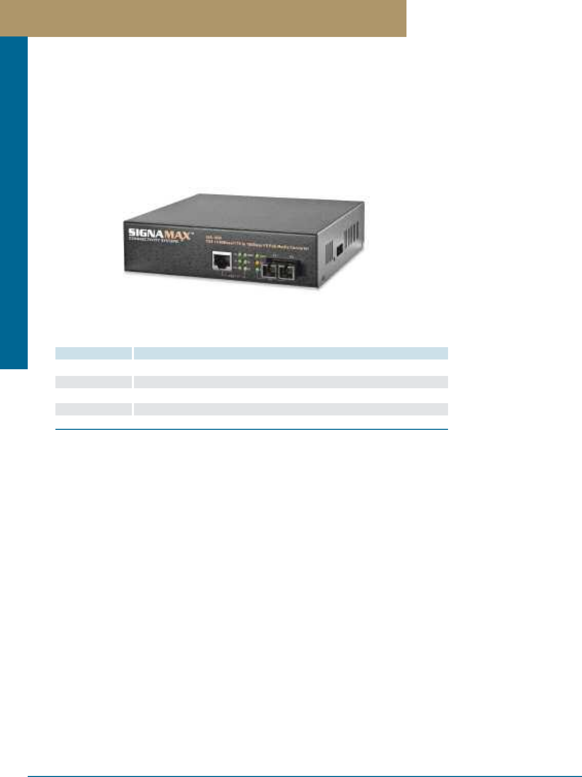
Media Converters
PREMISE CONNECTIVITY SYSTEMS 800.446.2377 www.signamax.comF 1 3
10/100 to 100BaseFX PoE PSE Fiber Optic Media Converters
The Signamax 065-1050 series media converters are 10/100BaseT/TX to 100BaseFX Power over Ethernet (PoE) devices that serve as
Power Sourcing Equipment (PSE), which allows the converter to provide power to IEEE 802.3af PoE standard compliant Powered Devices
(PDs) using the twisted pair connection. This AC-powered PoE media converter combines data received over a fiber optic link with
–48 Volt DC power, which the PD can use in lieu of a separate power connector. The 065-1050 series converters are also equipped
with PD signature-sensing, power monitoring, over-current protection, under-current detection, and input fault protection features.
Their Link Fault Signaling (LFS) and Far End Fault (FEF) detection capabilities maintain link integrity and enable automatic failover
when used with Spanning Tree-equipped switches.
10/100 to 100BaseFX PoE PSE Fiber Optic Media Converters
PART NO. DESCRIPTION
065-1050ST 10/100BaseT/TX to 100BaseFX PoE PSE Media Converter, Multimode/ST, 2 km
065-1050SC 10/100BaseT/TX to 100BaseFX PoE PSE Media Converter, Multimode/SC, 2 km
065-1050SM 10/100BaseT/TX to 100BaseFX PoE PSE Media Converter, Singlemode/SC, 15 km
065-1050SMED 10/100BaseT/TX to 100BaseFX PoE PSE Media Converter, Singlemode/SC, 40 km
065-1050SMXLD 10/100BaseT/TX to 100BaseFX PoE PSE media converter, Singlemode/SC, 75 km
Fixed Ports
1 - Auto-MDIX twisted-pair port meeting IEEE 802.3 10BaseT & IEEE
802.3u 100BaseTX standard specifications; Category 5 or better
cable, 100 meters maximum distance for 100BaseTX, Category 3 or
better cable, 100 meters maximum distance for 10BaseT
PLUS
1 - fiber optic port meeting IEEE 802.3u 100BaseFX standard specifica-
tion; 62.5/125 or 50/125 micron multimode fiber optic cable, 2,000 me-
ters maximum distance (Models 065-1050ST & 065-1050SC)
OR
1 - fiber optic port meeting IEEE 802.3u 100BaseFX standard specifica-
tion; 9/125 micron singlemode fiber optic cable, spanning: 15 kilometers
maximum distance (Model 065-1050SM)
OR
1 - fiber optic port meeting IEEE 802.3u 100BaseFX standard specifica-
tion; 9/125 micron singlemode fiber optic cable, spanning: 40 kilometers
maximum distance (Model 065-1050SMED)
OR
1 - fiber optic port meeting IEEE 802.3u 100BaseFX standard specifica-
tion; 9/125 micron singlemode fiber optic cable, spanning: 75 kilometers
maximum distance (Model 065-1050SMXLD)
DIP Switches for setting PoE configuration
LED Indicators
Models 065-1050ST, 065-1050SC, 065-1050SM, 065-1050SMED,
065-1050SMXLD:
Power, PoE, TP Link/Act, 100, FX Link/Act, FDX/COL, 4W, 7W, 15.4W,
Power Bad
Nine LEDs total
Performance
Latency: < 4.2 µs (LIFO)
Throughput @ 100Base: 148,810 pps (64-byte packets)
Physical Characteristics
Dimensions: 6.22 in. x 5.24 in. x 1.57 in., W x D x H
(158 mm x 133 mm x 40 mm)
Weight: 1.7 lb (0.75 kg.)
Environmental Characteristics
Operating and Storage Temperature: 32°F to 122°F (0°C to 50°C)
Operating and Storage Humidity: 5 to 95% (non-condensing)
Power
Maximum Wattage: 24 Watts
PSE Power Feed Support: “Endpoint” via TP pin 1, 2, 3, 6
Maximum PoE Wattage Deliverable: 15.4 Watts (with a 15.4 Watt PoE
device connected)
AC Input: 100 ~ 240 VAC, 50 ~ 60 Hz internal universal power supply
Emissions & Safety
UL Listed
Warranty
Lifetime
Specifications
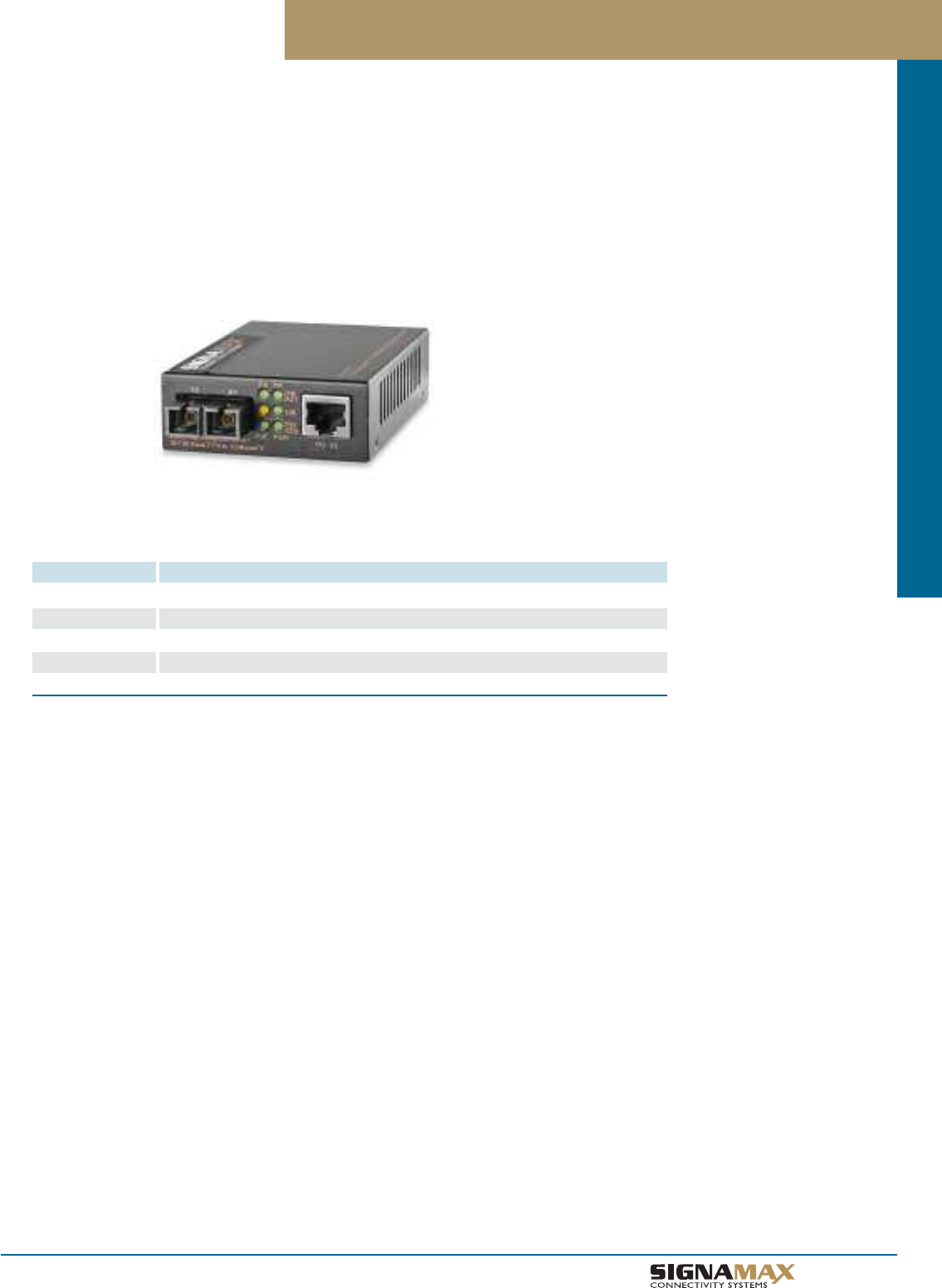
Media Converters
F 1 4
TM
10/100 to 100BaseFX PoE PD Fiber Optic Media Converters
The Signamax 065-1050 series media converters are 10/100BaseT/TX to 100BaseFX Power over Ethernet (PoE) devices that are Powered
Devices (PDs). It receives power over its data connection from a Power over Ethernet Power Sourcing Equipment (PSE), such as a PoE
switch, so that a separate power source for the media converter is not required. The Signamax 065-1052 series media converters are PoE
Powered Devices supporting two types of media, 10/100BaseT/TX and 100BaseFX, for network connection. They are also equipped with
Link Fault Signaling (LFS), to maintain link integrity and enable automatic failover when used with Spanning Tree-equipped switches.
10/100 to 100BaseFX PoE PD Fiber Optic Media Converters
PART NO. DESCRIPTION
065-1052ST 10/100BaseT/TX to 100BaseFX PoE PD Media Converter, Multimode/ST, 2 km
065-1052SC 10/100BaseT/TX to 100BaseFX PoE PD Media Converter, Multimode/SC, 2 km
065-1052SM 10/100BaseT/TX to 100BaseFX PoE PD Media Converter, Singlemode/SC, 15 km
065-1052SMED 10/100BaseT/TX to 100BaseFX PoE PD Media Converter, Singlemode/SC, 40 km
065-1052SMXLD 10/100BaseT/TX to 100BaseFX PoE PD media converter, Singlemode/SC, 75 km
Fixed Ports
1 - Auto-MDIX twisted-pair port meeting IEEE 802.3 10BaseT & IEEE
802.3u 100BaseTX standard specifications; Category 5 or better
cable, 100 meters maximum distance for 100BaseTX, Category 3 or
better cable, 100 meters maximum distance for 10BaseT
PLUS
1 - fiber optic port meeting IEEE 802.3u 100BaseFX standard specifica-
tion; 62.5/125 or 50/125 micron multimode fiber optic cable, 2,000
meters maximum distance (Models 065-1052ST & 065-1052SC)
OR
1 - fiber optic port meeting IEEE 802.3u 100BaseFX standard specifica-
tion; 9/125 micron singlemode fiber optic cable, spanning: 15 kilometers
maximum distance (Model 065-1052SM)
OR
1 - fiber optic port meeting IEEE 802.3u 100BaseFX standard specifica-
tion; 9/125 micron singlemode fiber optic cable, spanning: 40 kilometers
maximum distance (Model 065-1052SMED)
OR
1 - iber optic port meeting IEEE 802.3u 100BaseFX standard specifica-
tion; 9/125 micron singlemode fiber optic cable, spanning: 75 kilometers
maximum distance (Model 065-1052SMXLD)
LED Indicators
FX Link/Act, FX FDX/Col, TX Link/Act, TX 100, PSE Power Good, PSE
Power Bad, Power
Six LEDs total
Performance
Latency: < 4.2 µs (LIFO)
Throughput @ 100Base: 148,810 pps (64-byte packets)
Physical Characteristics
Case dimensions: 3.70"L x 2.77"W x 1.03"H (94mm x 70.3mm x
26.2mm)
Weight: 0.5 pounds (0.23 kilograms)
Environmental Characteristics
Operating Temperature: 32°F to 122°F (0°C to 50° C)
Storage Temperature: -4°F to 158°F (-20°C to 70° C)
Relative Humidity: 5 to 90%, non-condensing
Power
Maximum Wattage: 4.8 Watts
PD Power Reception Support: “Endpoint” via TP pin 1, 2, 3, 6 or
“Midspan” via TP pin 4, 5, 7, 8
Maximum PoE Draw: 100mA @ -48 V DC from IEEE 802.3af PSE or
PoE injector
Power Supply: External, 1 Amp @ +5 V DC (when not powered via
PoE)
Emissions & Safety
UL Listed
Warranty
Lifetime
Specifications
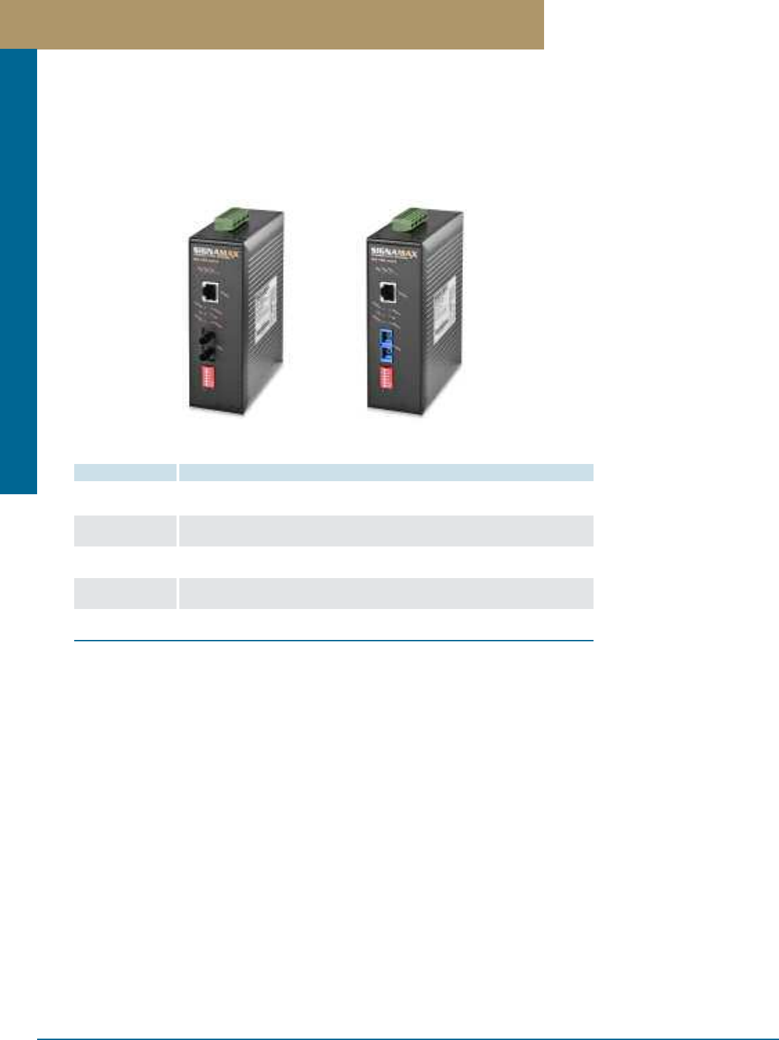
Media Converters
PREMISE CONNECTIVITY SYSTEMS 800.446.2377 www.signamax.comF 1 5
DIN-Rail Mount Industrial Hardened Media Converters
10/100BaseT/TX to 100BaseFX DIN Rail Mount Hardened Media Converters
PART NO. DESCRIPTION
065-1800TB 10/100BaseT/TX to 100BaseFX Industrial Hardened Media Converter,
ST Multimode, 2 km Span, 24 V DC Redundant Power Terminal Block
065-1810TB 10/100BaseT/TX to 100BaseFX Industrial Hardened Media Converter,
SC Multimode, 2 km Span, 24 V DC Redundant Power Terminal Block
065-1820TB 10/100BaseT/TX to 100BaseFX Industrial Hardened Media Converter,
SC Singlemode, 15 km Span, 24 V DC Redundant Power Terminal Block
065-1820EDTB 10/100BaseT/TX to 100BaseFX Industrial Hardened Media Converter,
SC Singlemode, 40 km Span, 24 V DC Redundant Power Terminal Block
065-1820XLDTB 10/100BaseT/TX to 100BaseFX Industrial Hardened Media Converter,
SC Singlemode, 75 km Span, 24 V DC Redundant Power Terminal Block
10/100 to 100BaseFX media converters have been developed to operate in harsh industrial environments that require ruggedized
equipment that can operate in severe temperature extremes. These media converters are an affordable solution for outdoor environments,
transportation roadside systems, shop floors, and other harsh environments where consistent operation at temperature extremes of -40°F
to 176°F (-40°C to 80°C) is necessary. These media converters are compact, plug-and-play devices that do not require complex user
setup, but also have the manual setting features necessary to adjust to unusual operating conditions.
Fixed Ports
1 - twisted-pair port meeting IEEE 802.3 10BaseT & IEEE 802.3u
100BaseTX standard specifications, Auto MDI/MDI-X and Auto-
Negotiation Function supported (all models) PLUS 1 100Base FX port
with ST/MM, 2 km span (065-1800TB) OR 1 100Base FX port
with SC/MM, 2 km span (065-1810TB) OR 1 100Base FX port with
SC/SM, 20 km span (065-1820TB) OR 1 100Base FX port with SC/SM,
40 km span (065-1820EDTB) OR 1 100Base FX with SC/SM, 75 km
span (065-1820XLDTB)
LED Indicators
Per Unit: Power1 (Green), Power2 (Green). Fault, LFS
Per Port: 10/100BaseT/TX port: 100 Mbps Speed, Link/Activity,
FDX/COL
100BaseFX port - Link/Activity, FDX/COL
Performance
Latency: < 4.2 µs (LIFO)
Throughput @ 100Base: 148,810 pps (64-byte packets)
Physical Characteristics
Housing: IP30 protection, metal case
Dimensions: 1.97 in. x 5.35 in. x 4.33 in., W x H x D
(50 mm x 136 mm x 110 mm)
Weight: 1.76 lb (0.8 kg.)
Environmental Characteristics
Operating Temperature: -40°F to 176°F (-40°C to 80°C)
Storage Temperature: -50°F to 200°F (-45°C to 93°C)
Operating Humidity: 10 to 95% (non-condensing)
Power input Requirements
Redundant 12 to 48 Volts DC Terminal Block; optional 24V DC DIN-rail
mount hardened industrial power supplies available, sold separately
Emissions & Safety
FCC: Part 15 Class A
CE: EN55022 (CISR22 Class A), EN55024 (CISPR24 Class A),
CE EN-6100-4-4, CE EN6100-4-5, CE EN6100-4-6
UL 60950, EN 60950, IEC 60950, IEC 61000-6-2
Installation
DIN Rail Kit, or wall mounting ears for 3-way installation
Warranty
Lifetime
Specifications
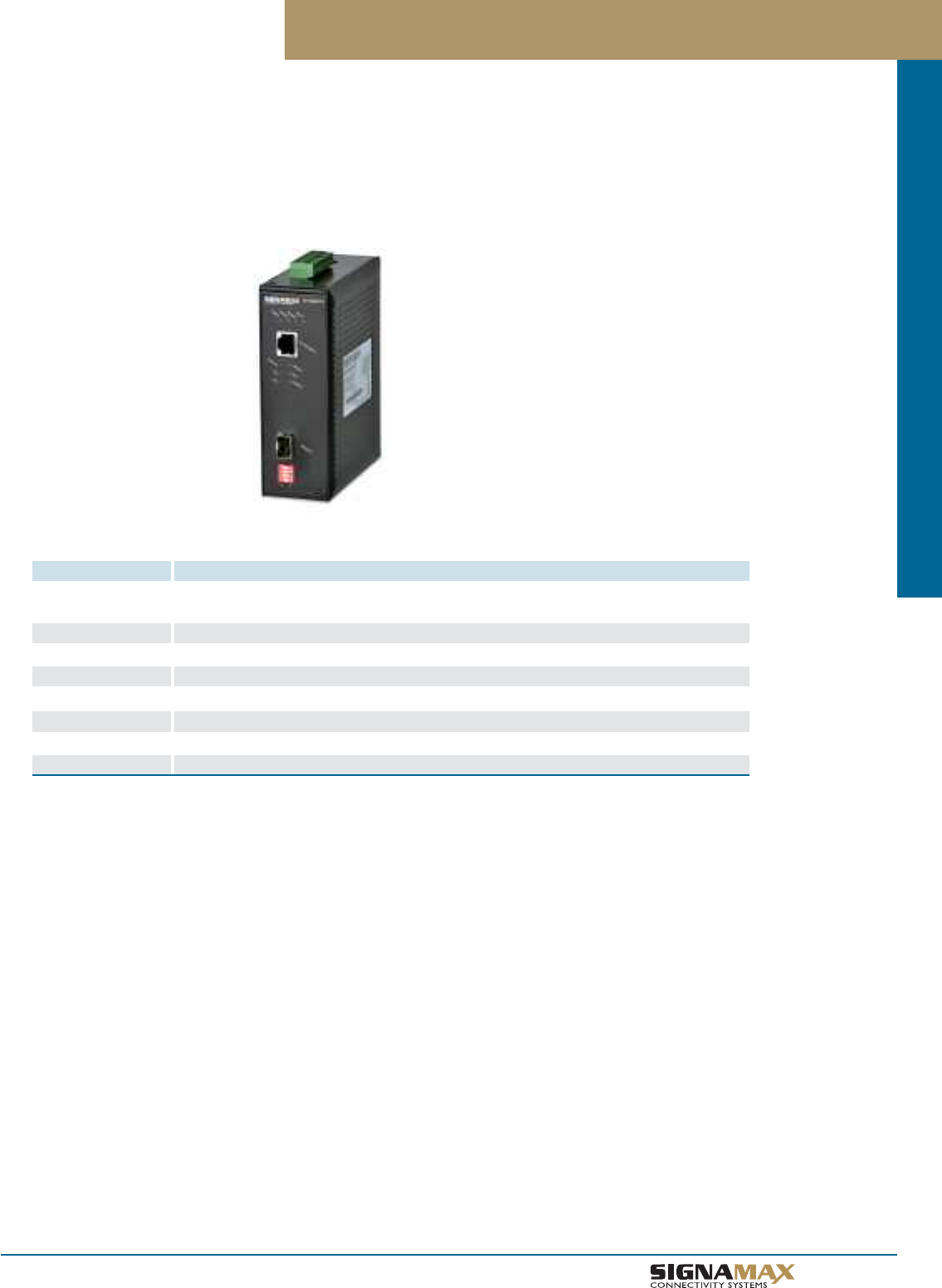
Media Converters
F 1 6
TM
10/100/1000 to Gigabit SFP DIN Rail Mount Industrial Media Converter
10/100/1000BaseT/TX to 1000Base SFP Hardened Media Converters
PART NO. DESCRIPTION
065-1896SFPTB 10/100/1000BaseT/TX to 1000Base SFP Industrial Hardened Media Converter,
24 V DC Redundant Power Terminal Block
065-79SXMG-H 1000BaseSX SFP Module - MM/LC, 220m Span on 62.5µm Fiber / 550m Span on 50µm Fiber
065-79SXEDMG-H 1000BaseSX SFP Module 1310 nm - MM/LC, 2 km
065-79LXMG-H 1000BaseLX SFP Module 1310 nm - SM/LC, 10 km
065-79LXEDMG-H 1000BaseLX SFP Module 1310 nm - SM/LC, 40 km
065-79XDMG-H 1000BaseXD SFP Module 1550 nm - SM/LC, 40 km
065-79ZXMG-H 1000BaseZX SFP Module 1550 nm - SM/LC, 80 km
065-79EZXMG-H 1000BaseEZX SFP Module 1550 nm - SM/LC, 110 km
Signamax Connectivity Systems’ 065-1896SFPTB 10/100/1000BaseT/TX to 1000BaseSFP media converter has been developed to operate
flexibly at Standard Ethernet, Fast Ethernet, or Gigabit Ethernet speeds in harsh industrial environments that require ruggedized equipment
that can operate in severe temperature extremes. This media converter is an affordable solution for outdoor environments, transportation
roadside systems, shop floors, and other harsh environments where consistent operation at temperature extremes of -40°F to 176°F (-40°C
to 80°C) is necessary and varying Ethernet speeds interface to a fiber optic Gigabit Ethernet network.
Fixed Ports
1 - twisted-pair port meeting IEEE 802.3, IEEE 802.3u, or IEEE 802.3ab
standard specifications, Auto MDI/MDI-X and Auto-Negotiation Function
supported.
PLUS
1 - 1000BaseSFP port with SFP receptacle.
LED Indicators
Per Unit: Power1, Power2, Power3 (Green). Fault, LFS
Per Port: 10/100/1000BaseT/TX port: Link/Activity, Speed, Full
Duplex/Collision; 1000BaseSX/LX port – Link F, TX, RX
Performance
Throughput @ 1000BaseT: 1,488,100 pps
Throughput @ 100BaseTX: 148,810 pps
Throughput @ 10BaseT: 14,881 pps
(64-byte packets)
Physical Characteristics
Housing: IP30 protection, metal case
Dimensions: 1.97 in. x 5.35 in. x 4.33 in., W x H x D
(50 mm x 136 mm x 110 mm)
Weight: 1.76 lb (0.8 kg.)
Environmental Characteristics
Operating Temperature: -40°F to 176°F (-40°C to 80°C)
Storage Temperature: -50°F to 200°F (-45°C to 93°C)
Operating Humidity: 10 to 95% (non-condensing)
Power input Requirements
Redundant 12 to 48 Volts DC Terminal Block; optional 24V DC DIN-rail
mount hardened industrial power supplies available, sold separately
Emissions & Safety
FCC: Part 15 Class A
CE: EN55022 (CISR22 Class A), EN55024 (CISPR24 Class A),
CE EN-6100-4-4, CE EN6100-4-5, CE EN6100-4-6
UL 508
Installation
DIN Rail Kit included and pre-installed,
or wall mounting ears for 3-way installation
Warranty
Lifetime
Specifications

Index
PREMISE CONNECTIVITY SYSTEMS 800.446.2377 www.signamax.com
PART NO. PAGE
065-1000 .................................................F11
065-1010 .................................................F11
065-1020 ..................................................F11
065-1020ED .............................................F11
065-1020XLD ...........................................F11
065-1050SC .............................................F13
065-1050SM.............................................F13
065-1050SMED........................................F13
065-1050SMXLD......................................F13
065-1050ST..............................................F13
065-1052SC .............................................F14
065-1052SM.............................................F14
065-1052SMED........................................F14
065-1052SMXLD......................................F14
065-1052ST .............................................F14
065-1060LC..............................................F12
065-1060SC ............................................F12
065-1060SM.............................................F12
065-1060SMED........................................F12
065-1060SMXLD......................................F12
065-1060ST .............................................F12
065-1100 ...................................................F1
065-1110 ....................................................F1
065-1120 ...................................................F1
065-1120ED ..............................................F1
065-1120XLD .............................................F1
065-1130 ...................................................F3
065-1130ED ..............................................F3
065-1130XLD ............................................F3
065-1132 ...................................................F3
065-1132ED ..............................................F3
065-1132XLD .............................................F3
065-1167 ....................................................F7
065-1167DIN ..............................................F7
065-1172 ...................................................F1
065-1174 ...................................................F1
065-1176AEDLFS ......................................F2
065-1176ALFS ..........................................F2
065-1176ALFSMM .....................................F2
065-1176BEDLFS ......................................F2
065-1176BLFS ..........................................F2
065-1176BLFSMM .....................................F2
065-1185 ...................................................F8
065-1185DC ..............................................F8
065-1194 iber .............................................F6
065-1194ED ..............................................F6
065-1195 ....................................................F6
065-1195SFP .............................................F6
065-1196 ....................................................F4
065-1196LX ................................................F4
065-1196LXED ...........................................F4
065-1196SFPDR ........................................F5
065-1197 ....................................................F6
PART NO. PAGE
065-1197ED ...............................................F6
065-1198XLD .............................................F6
065-1200LC74 ...........................................F9
065-1200MT72 ...........................................F9
065-1200SC10 ..........................................F9
065-1200SC20 ..........................................F9
065-1200SC20ED ......................................F9
065-1200SC20XLD ...................................F9
065-1200SC95 ...........................................F9
065-1200SC97 ...........................................F9
065-1200SC97ED ......................................F9
065-1200ST00 ...........................................F9
065-1610OAM ..........................................F10
065-1610OAMED .....................................F10
065-1620OAM10 ......................................F10
065-1620OAM20 ......................................F10
065-1800TB..............................................F15
065-1810TB..............................................F15
065-1820EDTB.........................................F15
065-1820TB..............................................F15
065-1820XLDTB.......................................F15
065-1896SFPTB.......................................F16
065-79EZXMG-H......................................F16
065-79LXEDMG-H ..................................F16
065-79LXMG-H .......................................F16
065-79SXEDMG-H ..................................F16
065-79SXMG-H .......................................F16
065-79XDMG-H .......................................F16
065-79ZXMG-H .......................................F16
100PR-4MX03..........................................B23
100PR-5MX03..........................................B23
106A-2 .....................................................A14
106A-4......................................................A14
110-1PRP .........................................B22, C4
110-2PRP .........................................B22, C4
110-3PRP .........................................B22, C4
110-4PRH ................................................B23
110-4PRP ..........................................B22, C4
110-4PRT ................................................B23
110-5PRH.................................................B23
110-5PRT ................................................B23
1106-4PRH ..............................................B23
1106-4PRP ........................................B22, C4
1106-4PRT ..............................................B23
110-CAP...................................................B19
110CB-3PR .............................................B19
110CB-4PR .............................................B19
110CB-5PR ..............................................B19
110CB6-4PR ............................................B19
110CB6-4PR ............................................B19
110-CMT ..................................................B21
110-CMT-L ...............................................B21
110-RMCMT.............................................B21
PART NO. PAGE
110WB-100PR-L .....................................B19
110WB-300PR-L .....................................B19
110WB-50PR-L .......................................B19
110WB6-288PR-L ...................................B19
110WB6-48PR-L .....................................B19
110WB6-96PR-L .....................................B19
110WB6A-192PR-L .................................B19
110WB6A-32PR-L ...................................B19
110WB6A-64PR-L ...................................B19
110WB-LS4PR-LC ...................................B20
1185FAN.....................................................F8
12458FT-C5E ..........................................B15
12458FT-C6 ............................................B15
12458JPL-C5E ........................................B11
12458M-C5E ............................................B11
12458M-C6C..............................................B7
12458MD-C5E ..........................................B9
12458MD-C6C ..........................................B5
12458MH-C5E..........................................B11
12458MH-C6C ...........................................B7
12BNC75-FT ............................................B16
12BNC-FT ................................................B16
12F3-FT ..................................................B15
12FAT-FT ................................................D18
12F-FT ....................................................B15
12U-M89 .................................................B18
12U-MH....................................................B18
12U-MMP .......................................B18, D18
144HDLC-FT ...........................................D11
16458FT-C5E ..........................................B15
16458FT-C6 ............................................B15
16BNC75-FT ............................................B16
16BNC-FT ...............................................B16
16F3-FT ..................................................B15
16FAT-FT ................................................D18
16F-FT ....................................................B15
16HDSC-FT .............................................D11
16HDST-FT .............................................D11
16U-MMP .......................................B18, D18
24112-C3MU ...........................................B13
24114-C3MU ...........................................B13
24116-C4U ..............................................B13
24452-C3MU ...........................................B13
24454-C3MU ...........................................B13
24454-C5FT ............................................B12
24458A-C5E ............................................B10
24458A-C6A ..............................................B2
24458A-C6C .............................................B6
24458-C4U ..............................................B13
24458-C5FB ............................................B12
24458-C6A .................................................B1
24458FT-C5E ..........................................B15
24458FT-C6 ............................................B15

Index
TM
PART NO. PAGE
24458FTHD-C5E ....................................B14
24458FTHD-C6 .......................................B14
24458JPL-C5E ........................................B11
24458MD-C5E ..........................................B9
24458MD-C6C ...........................................B5
24458SA-C6A ...........................................B3
24458S-C5E ............................................B11
24458S-C6A...............................................B3
24458S-C6C .............................................B7
24458SFTHD-C5E ...................................B14
24458SFTHD-C6 ....................................B14
24BNC75-FT ............................................B16
24BNC75HD-FT.......................................B16
24BNC-FT ...............................................B16
24BNCHD-FT ..........................................B16
24F3-FT ..................................................B15
24F3HD-FT .............................................B16
24FAT-FT ................................................D18
24F-FT .....................................................B15
24FHD-FT ................................................B16
24HDFAT-FT ............................................D17
24HDSC-FT .............................................D11
24HDST-FT .............................................D11
24U-HDMMP ............................B6, B10, B17
24U-HDMMP-A .........................B6, B10, B17
24U-HDMMP-A-C6A ..................................B2
24U-HDMMP-C6A .....................................B2
24U-MMP .......................................B18, D18
300PR-4MX03..........................................B23
300PR-5MX03..........................................B23
32458FT-C5E ..........................................B15
32458FT-C6 ............................................B15
32BNC75-FT ...........................................B16
32BNC-FT ...............................................B16
32F3-FT ..................................................B15
32FAT-FT ................................................D18
32F-FT ....................................................B15
32U-MMP .......................................B18, D18
36458JPL-C5E .........................................B11
36HDLC-FT .............................................D11
36HDSC-FT .............................................D11
36HDST-FT .............................................D11
48112-C3MU ...........................................B13
48114-C3MU ...........................................B13
48116-C4U ..............................................B13
48452-C3MU ...........................................B13
48454-C3MU............................................B13
48454-C5FT .............................................B12
48458A-C5E.............................................B10
48458A-C6A...............................................B2
48458A-C6C ..............................................B6
48458-C4U...............................................B13
48458-C5FB.............................................B12
PART NO. PAGE
48458-C6A .................................................B1
48458FT-C5E...........................................B15
48458FT-C6 .............................................B15
48458FTHD1-C5E ...................................B14
48458FTHD1-C6 .....................................B14
48458FTHD-C5E .....................................B14
48458FTHD-C6........................................B14
48458HD-C5E............................................B9
48458HD-C6C............................................B5
48458MD-C5E ..........................................B9
48458MD-C6C ..........................................B5
48458SA-C6A ............................................B3
48458S-C5E.............................................B11
48458S-C6A...............................................B3
48458S-C6C ..............................................B7
48458SFTHD1-C5E .................................B14
48458SFTHD1-C6 ...................................B14
48458SFTHD-C5E ...................................B14
48458SFTHD-C6 .....................................B14
48BNC75-FT ............................................B16
48BNC75HD-FT ......................................B16
48BNC-FT ...............................................B16
48BNCHD-FT...........................................B16
48F3-FT ...................................................B15
48F3HD-FT ..............................................B16
48FAT-FT .................................................D18
48F-FT ....................................................B15
48FHD-FT ...............................................B16
48HD1LCA-FT ........................................D17
48HD1LC-FT ...........................................D17
48HD1LCG-FT ........................................D17
48HD1LCS-FT ........................................D17
48HD1SCA-FT ........................................D17
48HD1SC-FT ..........................................D17
48HD1SCG-FT .......................................D17
48HD1SCS-FT ........................................D17
48HDFAT-FT ............................................D17
48HDLC-FT .............................................D11
48HDSC-FT .............................................D11
48HDST-FT .............................................D11
48U-HDMMP ............................B6, B10, B17
48U-HDMMP-1R .......................B6, B10, B17
48U-HDMMP-A .........................B6, B10, B17
48U-HDMMP-A-C6A ..................................B2
48U-HDMMP-C6A......................................B2
48U-MMP ........................................B18, D18
66M1-25F.................................................B24
66M1-25M ...............................................B24
66M1-50F.................................................B24
66M1-50M ...............................................B24
6L-C5E-JB-P-FXXX ...................................C9
6L-C5E-JJ-P-FXXX ...................................C9
6L-C5E-JP-P-FXXX ..................................C9
PART NO. PAGE
6L-C5ES-JB-P-FXXX.................................C9
6L-C5ES-JJ-P-FXXX ................................C9
6L-C6A-JB-P-FXXX ............................B4, C9
6L-C6A-JB-R-FXXX.............................B4, C9
6L-C6A-JJ-P-FXXX ............................B4, C9
6L-C6A-JJ-R-FXXX .............................B4, C9
6L-C6AS-JB-P-FXXX ..........................B4, C9
6L-C6AS-JB-R-FXXX ..........................B4, C9
6L-C6AS-JJ-P-FXXX ...........................B4, C9
6L-C6AS-JJ-R-FXXX...........................B4, C9
6L-C6-JB-P-FXXX ..............................B8, C9
6L-C6-JB-R-FXXX ..............................B8, C9
6L-C6-JJ-P-FXXX ...............................B8, C9
6L-C6-JJ-R-FXXX ...............................B8, C9
6L-C6-JP-P-FXXX ..............................B8, C9
6L-C6-JP-R-FXXX ..............................B8, C9
6L-C6S-JB-P-FXXX ............................B8, C9
6L-C6S-JB-R-FXXX.............................B8, C9
6L-C6S-JJ-P-FXXX ............................B8, C9
6L-C6S-JJ-R-FXXX ............................B8, C9
6L-C6S-JP-P-FXXX ............................B8, C9
6L-C6S-JP-R-FXXX ............................B8, C9
72HDLC-FT .............................................D11
72HDSC-FT .............................................D11
72HDST-FT .............................................D11
96HDLC-FT .............................................D11
AC-1185 .....................................................F8
BC5E-4CC ..............................................C10
BC5E-4P-CC ...........................................C10
BC5E-4SH ...............................................C10
BC5EM-4CC ............................................C10
BC6-4CC .................................................C10
BC6-4P-CC .............................................C10
BC6-4SH..................................................C10
BC6A-4CC ..............................................C10
BC6A-4P-CC ...........................................C10
BC6AM-4CC ............................................C10
BC6M-4CC ..............................................C10
BFP-19175 ................................................E5
BFP-19350 ................................................E5
BFP-19525 ................................................E5
BFP-19700 .................................................E5
C325-x-xx-xx-xxx-x ....................................C8
C525-x-xx-xx-xxx-x ....................................C8
C5E-114CC-100FB ...................................C3
C5E-114CC-10FB .....................................C3
C5E-114CC-14FB .....................................C3
C5E-114CC-1FB .......................................C3
C5E-114CC-25FB .....................................C3
C5E-114CC-3FB ........................................C3
C5E-114CC-50FB .....................................C3
C5E-114CC-5FB .......................................C3
C5E-114CC-7FB .......................................C3

Index
PREMISE CONNECTIVITY SYSTEMS 800.446.2377 www.signamax.com
PART NO. PAGE
C5E-116IG-LFB .........................................C7
C5E-117IG-LFB .........................................C7
C5E-121CC-100FB....................................C3
C5E-121CC-10FB......................................C3
C5E-121CC-14FB......................................C3
C5E-121CC-1FB........................................C3
C5E-121CC-25FB......................................C3
C5E-121CC-3FB........................................C3
C5E-121CC-50FB......................................C3
C5E-121CC-5FB........................................C3
C5E-121CC-7FB........................................C3
C5E-4P-458B-GY-LB.........................B22, C4
C5E-4P-GY-LB .................................B22, C4
C5EC-114CC-10FB ..................................C3
C5EC-114CC-15FB ..................................C3
C5EC-114CC-20FB ...................................C3
C5EC-114CC-25FB ...................................C3
C5EC-114CC-3FB ....................................C3
C5EC-114CC-5FB ....................................C3
C5EC-114CC-7FB ....................................C3
C5ES-314GY-10FB ...................................C3
C5ES-314GY-15FB ...................................C3
C5ES-314GY-20FB ...................................C3
C5ES-314GY-25FB....................................C3
C5ES-314GY-3FB .....................................C3
C5ES-314GY-5FB .....................................C3
C5ES-314GY-7FB .....................................C3
C5EX-112RD-LFB......................................C5
C5EXB-112YE-LFB....................................C5
C6-115CC-100FB ......................................C2
C6-115CC-10FB .......................................C2
C6-115CC-14FB .......................................C2
C6-115CC-25FB .......................................C2
C6-115CC-3FB .........................................C2
C6-115CC-50FB .......................................C2
C6-115CC-5FB .........................................C2
C6-115CC-7FB ..........................................C2
C6-116IG-LFB............................................C7
C6-117IG-LFB............................................C7
C6A-114CC-10FB .....................................C1
C6A-114CC-15FB .....................................C1
C6A-114CC-20FB .....................................C1
C6A-114CC-25FB ......................................C1
C6A-114CC-3FB .......................................C1
C6A-114CC-5FB .......................................C1
C6A-114CC-7FB .......................................C1
C6AS-314GY-10FB ...................................C1
C6AS-314GY-15FB ...................................C1
C6AS-314GY-20FB ...................................C1
C6AS-314GY-25FB....................................C1
C6AS-314GY-3FB .....................................C1
C6AS-314GY-5FB .....................................C1
C6AS-314GY-7FB .....................................C1
PART NO. PAGE
C6C-114CC-10FB......................................C2
C6C-114CC-15FB .....................................C2
C6C-114CC-20FB .....................................C2
C6C-114CC-25FB......................................C2
C6C-114CC-3FB .......................................C2
C6C-114CC-5FB .......................................C2
C6C-114CC-7FB .......................................C2
C6C-4P-458B-GY-LB.........................B22, C4
C6C-4P-GY-LB .................................B22, C4
C6CS-314GY-10FB ...................................C2
C6CS-314GY-15FB ...................................C2
C6CS-314GY-20FB ...................................C2
C6CS-314GY-25FB....................................C2
C6CS-314GY-3FB .....................................C2
C6CS-314GY-5FB .....................................C2
C6CS-314GY-7FB .....................................C2
C6XB-112BK-LFB .....................................C5
CDP-175 ....................................................E4
CDP-175-A.................................................E4
CDP-350 ....................................................E4
CDP-350-A.................................................E4
CMB-250-P ................................................B5
CMB-250-P ................................................B9
CMK-110RCAB .........................................A7
CMK-110RCAG..........................................A7
CMK-110RCAR .........................................A7
CMK-110RCAW .........................................A7
CMK-110RCAY ..........................................A7
CMK-110SVHS ..........................................A7
CMK-BA .....................................................A8
CMK-BL......................................................A6
CMK-BNC .................................................A6
CMK-BNC75 ..............................................A6
CMK-F........................................................A6
CMK-F3......................................................A6
CMK-FC-BK ............................................D18
CMK-F-CF..................................................A6
CMK-FCS-BK ..........................................D18
CMK-HDMI.................................................A8
CMK-LC ....................................................A8
CMK-LCA-BK ..........................................D18
CMK-LC-BK ............................................D18
CMK-LCG-BK ..........................................D18
CMK-LCS-BK...........................................D18
CMK-MTRJ ................................................A8
CMK-RA ....................................................A8
CMK-RCAB ...............................................A7
CMK-RCAB-C ...........................................A7
CMK-RCAG................................................A7
CMK-RCAG-C............................................A7
CMK-RCAR ...............................................A7
CMK-RCAR-C ...........................................A7
CMK-RCAW ..............................................A7
PART NO. PAGE
CMK-RCAW-C ..........................................A7
CMK-RCAY ...............................................A7
CMK-RCAY-C ............................................A7
CMK-SC ....................................................A8
CMK-SCA-BK .........................................D18
CMK-SC-BK ............................................D18
CMK-SCG-BK .........................................D18
CMK-SCS-BK ..........................................D18
CMK-ST ....................................................A8
CMK-ST-BK ............................................D18
CMK-STS-BK ..........................................D18
CMK-USB...................................................A8
CMP-175 ....................................................E3
CMP-175-A ................................................E3
CMP-175-AD..............................................E4
CMP-350 ....................................................E3
CMP-350-A ................................................E3
CMP-350-AD..............................................E4
CMR-175-A ...............................................E5
CMR-175-B ...............................................E5
CMR-175-C ...............................................E5
CMR-175-D ...............................................E5
CMR-350-A ...............................................E5
CMR-350-B ...............................................E5
CMR-350-C ...............................................E5
CMR-350-D ................................................E5
DA-1 .........................................................A14
DA-2 ........................................................A14
DA-3 ........................................................A14
DA-4 ........................................................A14
DA-6 ........................................................A14
DA-BL.......................................................A14
DC1185 ......................................................F8
DDC-50D-IV ..............................................A5
DDC-50V-IV ..............................................A5
DGF-12 ....................................................A17
DIT-50D-IV ................................................A5
DIT-50V-IV..................................................A5
DKF-12.....................................................A12
DKF-6.......................................................A12
DKF-8 ......................................................A12
DKFD-2 ...................................................A14
DKFL-12...................................................A12
DKFL-6 ....................................................A12
DKFLA-8 ..................................................A13
DL-112-BU ..............................................A22
DL-112-GN ..............................................A22
DL-112-IV .................................................A22
DL-112-OR ...............................................A22
DL-112-RD ..............................................A22
DL-112-WH ..............................................A22
DL-112-YE................................................A22
DLF6-LC.....................................................B7

Index
TM
PART NO. PAGE
DLR6-WH ..................................................B7
DSKF-12 ..................................................A13
DSKF-8 ....................................................A13
ERB-14C ...................................................E1
ERB-14CS .................................................E1
ERB-18C ...................................................E1
ERB-18CS .................................................E1
ERB-19C ...................................................E1
ERB-19CS..................................................E1
FAK-3 ......................................................A15
FAK-4 .......................................................A15
FA-LC-DX-PB-MF-BE ..............................D15
FA-LC-DX-ZR-MF-AQ .............................D15
FA-LC-DX-ZR-MF-BU ..............................D15
FA-LC-DX-ZR-MF-GN .............................D15
FA-LC-QX-PB-MF-BE ..............................D15
FA-LC-QX-ZR-MF-AQ..............................D15
FA-LC-QX-ZR-MF-BU .............................D15
FA-LC-QX-ZR-MF-GN ............................D15
FA-SC-SX-PB-MF-BE ..............................D15
FA-SC-SX-ZR-MF-AQ..............................D15
FA-SC-SX-ZR-MF-BU .............................D15
FA-SC-SX-ZR-MF-GN ............................D15
FA-SC-DX-PB-MF-BE..............................D15
FA-SC-DX-ZR-MF-AQ .............................D15
FA-SC-DX-ZR-MF-BU..............................D15
FA-SC-DX-ZR-MF-GN .............................D15
FA-ST-SX-PB-NF-RD ..............................D15
FA-ST-SX-ZR-NF-YE ...............................D15
FC-2/2-LM ...............................................D19
FC-4/2-LM ...............................................D19
FC-4/4-LM ...............................................D19
FC50-2/2-LM............................................D19
FC50-4/2-LM ...........................................D19
FC50-4/4-LM ...........................................D19
FC50-8/2-LM ...........................................D19
FC50-8/4-LM............................................D19
FC50-8/8-LM ...........................................D19
FC50-9/2-LM ...........................................D19
FC50-9/4-LM ...........................................D19
FC50-9/9-LM............................................D19
FC51-4/4-LM ...........................................D21
FC51-9/4-LM............................................D21
FC51-9/9-LM ...........................................D21
FC-8/2-LM ...............................................D19
FC-8/4-LM................................................D19
FC-8/8-LM ...............................................D19
FC-9/2-LM ...............................................D19
FC-9/4-LM ...............................................D19
FC-9/9-LM ...............................................D19
FC9S-2/2-LM ...........................................D20
FC9S-4/2-LM ...........................................D20
FC9S-4/4-LM ...........................................D20
PART NO. PAGE
FC9S-9/2-LM ...........................................D20
FC9S-9/4-LM ...........................................D20
FC9S-9/9-LM ...........................................D20
FCM-12LC-51M ......................................D23
FCM-12LC-5M .........................................D23
FCM-12LC-6M ........................................D23
FCM-12LC-9M ........................................D23
FCM-12LCA-9M ......................................D23
FCM-12SC-51M ......................................D23
FCM-12SC-5M ........................................D23
FCM-12SC-6M ........................................D23
FCM-12SC-9M ........................................D23
FCM-12SCA-9M ......................................D23
FCM-24LC-51M .......................................D23
FCM-24LC-5M ........................................D23
FCM-24LC-6M ........................................D23
FCM-24LC-9M .........................................D23
FCM-24LCA-9M.......................................D23
FCS-2/2-LM ............................................D20
FCS-4/2-LM .............................................D20
FCS-4/4-LM ............................................D20
FCS-8/2-LM .............................................D20
FCS-8/4-LM .............................................D20
FCS-8/8-LM .............................................D20
FCS-9/2-LM ............................................D20
FCS-9/4-LM ............................................D20
FCS-9/9-LM ............................................D20
FL-100B-WH ............................................A22
FMA-1251P-7F-7F-XXXM........................D24
FMA-125P-7F-7F-XXXM .........................D24
FMA-126P-7F-7F-XXXM .........................D24
FMA-129P-7F-7F-XXXM..........................D24
FMF-12-X-XX-X-XX .................................D24
FP12-51-4-003M......................................D22
FP12-51-9-003M......................................D22
FP12-5-2-003M........................................D22
FP12-5-4-003M........................................D22
FP12-5-9-003M........................................D22
FP12-6-2-003M........................................D22
FP12-6-4-003M........................................D22
FP12-6-9-003M........................................D22
FP12-9-2-003M........................................D22
FP12-9-4-003M........................................D22
FP12-9-9-003M........................................D22
FP1-51-4-003M........................................D22
FP1-51-9-003M........................................D22
FP1-5-2-003M..........................................D22
FP1-5-4-003M..........................................D22
FP1-5-9-003M..........................................D22
FP1-6-2-003M..........................................D22
FP1-6-4-003M..........................................D22
FP1-6-9-003M..........................................D22
FP1-9-2-003M..........................................D22
PART NO. PAGE
FP1-9-4-003M..........................................D22
FP1-9-9-003M..........................................D22
FP6-51-4-003M........................................D22
FP6-51-9-003M........................................D22
FP6-5-2-003M..........................................D22
FP6-5-4-003M..........................................D22
FP6-5-9-003M..........................................D22
FP6-6-2-003M..........................................D22
FP6-6-4-003M..........................................D22
FP6-6-9-003M..........................................D22
FP6-9-2-003M..........................................D22
FP6-9-4-003M..........................................D22
FP6-9-9-003M..........................................D22
FPC-LC05 ...............................................D16
FPC-LC06 ...............................................D16
FPC-LC09 ................................................D16
FPC-LC51 ................................................D16
FPC-SC05 ...............................................D16
FPC-SC06 ...............................................D16
FPC-SC09................................................D16
FPC-SC51 ...............................................D16
FPC-ST05 ...............................................D16
FPC-ST06 ...............................................D16
FPC-ST09 ................................................D16
FPC-ST51 ...............................................D16
FST-12A...................................................D12
FST-24A...................................................D12
FST-24P...................................................D12
FST-2M-B.................................................D12
FST-36P...................................................D12
HWB-175....................................................E2
HWB-350....................................................E2
HWB-525....................................................E2
HWB-700....................................................E2
HWB-875....................................................E2
KI-DIN-RMM.............................................A24
KI-DIN-RMM-SL .......................................A24
KJ126MT25-C3U .......................................A3
KJ126MT-C3U............................................A3
KJ126MT-C3U-BH .....................................A3
KJ126MT-C3U-BU .....................................A3
KJ126MT-C3U-DI.......................................A3
KJ126MT-C3U-GN .....................................A3
KJ126MT-C3U-GY .....................................A3
KJ126MT-C3U-OR .....................................A3
KJ126MT-C3U-RD .....................................A3
KJ126MT-C3U-WH ....................................A3
KJ126MT-C3U-YE......................................A3
KJ458IG-C5E ..........................................A23
KJ458IG-C6C ..........................................A23
KJ458MT25-C5E .......................................A3
KJ458MT25-C6C ......................................A3
KJ458MT-C5E............................................A2

Index
PREMISE CONNECTIVITY SYSTEMS 800.446.2377 www.signamax.com
PART NO. PAGE
KJ458MT-C5E-BK......................................A2
KJ458MT-C5E-BU......................................A2
KJ458MT-C5E-DI .......................................A2
KJ458MT-C5E-GN .....................................A2
KJ458MT-C5E-GY .....................................A2
KJ458MT-C5E-OR .....................................A2
KJ458MT-C5E-RD .....................................A2
KJ458MT-C5E-WH.....................................A2
KJ458MT-C5E-YE......................................A2
KJ458MT-C6AC .........................................A1
KJ458MT-C6AC-BK ...................................A1
KJ458MT-C6AC-BU ...................................A1
KJ458MT-C6AC-DI ....................................A1
KJ458MT-C6AC-GN...................................A1
KJ458MT-C6AC-GY...................................A1
KJ458MT-C6AC-OR...................................A1
KJ458MT-C6AC-RD...................................A1
KJ458MT-C6AC-WH ..................................A1
KJ458MT-C6AC-YE ...................................A1
KJ458MT-C6C-BK......................................A2
KJ458MT-C6C-BU .....................................A2
KJ458MT-C6C-DI.......................................A2
KJ458MT-C6C-GN .....................................A2
KJ458MT-C6C-GY .....................................A2
KJ458MT-C6C-OR .....................................A2
KJ458MT-C6C-RD .....................................A2
KJ458MT-C6C-WH ....................................A2
KJ458MT-C6C-YE......................................A2
KJMT-8600 ................................................A4
KJMT-8600-DS...........................................A4
KJS458IG-C5E.........................................A23
KJS458IG-C6C .......................................A23
KJS458TL-C5E ..........................................A4
KJS458TL-C6AC........................................A1
KJS458TL-C6C .........................................A4
KJ-TF .........................................................A5
KRJ11/100 ................................................C5
KRJ11-C5/100 ...........................................C5
KRJ12/100 ................................................C5
KRJ12-C5/100 ...........................................C5
KRJ12SLD-100 .........................................C5
KRJ45/100 .................................................C5
KRJ45/5-100 .............................................C5
KRJ45/5E-100 ...........................................C5
KRJ45/5S ..................................................A5
KRJ45/5SH-100 ........................................C5
KRJ45/5SLD-100 .......................................C5
KRJ45/5S-SH ............................................A5
KRJ45/6S ..................................................A5
KRJ45/6S-SH ............................................A5
KRJ45IG-C5E ............................................C7
KRJS45IG-C5E..........................................C7
RM100PR ................................................B21
PART NO. PAGE
RM200PR ................................................B21
RM6192PR...............................................B21
RM696PR ................................................B21
RMF3-B ...................................................D11
RMF6-B....................................................D11
RMH-1032..................................................E5
RR-48.........................................................E1
RR-48B .....................................................E1
RR-84 ........................................................E1
RR-84B .....................................................E1
RWBK-100PR4 .......................................B21
RWBK-200PR4 ........................................B21
RWBK6-192PR4 .....................................B21
RWBK6-96PR4 .......................................B21
S45SP-BC/100 ..........................................C5
SCF-1F ....................................................A15
SCF-1P46S .............................................A15
SCF-2F.....................................................A15
SCF-2P46S .............................................A15
SCF-2P46SF ...........................................A15
SCM112-C3U ...........................................A17
SCM145-C5E ..........................................A17
SCM145-C6C ..........................................A17
SCM-1BNC .............................................A19
SCM-1BNC75 .........................................A19
SCM-1F ...................................................A19
SCM-1HDMI ............................................A20
SCM-1-KU ...............................................A18
SCM-1LC ................................................A18
SCM-1LCA-C ..........................................A18
SCM-1LC-C .............................................A18
SCM-1LC-G ............................................A18
SCM-1-MCU ............................................A18
SCM-1SV ................................................A19
SCM-1USB ..............................................A20
SCM-1VGA ..............................................A20
SCM-1VGATB ..........................................A20
SCM212-C3U...........................................A17
SCM245-C5E ...........................................A17
SCM245-C6C ..........................................A17
SCM-2BNC .............................................A19
SCM-2BNC75 ..........................................A19
SCM-2F....................................................A19
SCM-2HDMI.............................................A20
SCM-2-KU................................................A18
SCM-2LC ................................................A18
SCM-2LC-C .............................................A18
SCM-2LC-G ............................................A18
SCM-2-MCU.............................................A18
SCM-2RBA...............................................A19
SCM-2RS-WR .........................................A19
SCM-2R-WR ...........................................A19
SCM-2SC ................................................A18
PART NO. PAGE
SCM-2SCA-C...........................................A18
SCM-2SC-C ............................................A18
SCM-2SC-G ............................................A18
SCM-2ST ................................................A18
SCM-2ST-C..............................................A18
SCM-2SV .................................................A19
SCM-2USB...............................................A20
SCM-3R-RGB .........................................A19
SCM-3R-RWY .........................................A19
SCM-3RS-RGB ........................................A19
SCM-3RS-RWY .......................................A19
SCM-4LCA-C ...........................................A18
SCM-BL....................................................A18
SGF-06.....................................................A17
SKF-1 ........................................................A9
SKF-106 ..................................................A14
SKF-1P.....................................................A15
SKF-1P-WH .............................................A15
SKF-2 ........................................................A9
SKF-3 ........................................................A9
SKF-4 ........................................................A9
SKF-6 .........................................................A9
SKFD-1 ...................................................A14
SKFL-1 ....................................................A10
SKFL-1S-85-WH .....................................A16
SKFL-2 ....................................................A10
SKFL-2S-85-WH .....................................A16
SKFL-3 ....................................................A10
SKFL-4 ....................................................A10
SKFL-6 .....................................................A10
SKFLA-1S-85-WH ...................................A16
SKFLA-2...................................................A10
SKFLA-2S-85-WH ...................................A16
SKFLA-4...................................................A10
SKFM-1 .....................................................A9
SKFM-2 .....................................................A9
SKFM-3 .....................................................A9
SKFM-4 .....................................................A9
SKFM-6 ......................................................A9
SL2M-B ......................................................D9
SL3M-B ......................................................D9
SM66M1-50..............................................B24
SM66M1-89D ..........................................B24
SM66M1-BC ............................................B24
SM66M1-BU ............................................B24
SM66M1-CC ...........................................B24
SM66M1-OR ...........................................B24
SM66M1-WM ...........................................B24
SM66M1-WMS ........................................B24
SMB1-DG.........................................A15, A22
SMB1-SG ........................................A15, A22
SMB-85-WH .............................................A16
SMKIG-1 ..................................................A24

Index
TM
PART NO. PAGE
SMKIG-2 .................................................A24
SMKIG-3 .................................................A24
SMKIG-4 ..................................................A24
SMKL-1 ....................................................A16
SMKL-2 ...................................................A16
SMKL-4 ...................................................A16
SMKL-6 ...................................................A16
SMKT-3 ....................................................A16
SMMB-1 ...................................................A21
SMMB-3F .................................................A21
SPL-648 .....................................................B7
SSKF-1 ....................................................A11
SSKF-1P .................................................A15
SSKF-2 ....................................................A11
SSKF-3 ....................................................A11
SSKF-4 ....................................................A11
SSKF-6.....................................................A11
SSKFIG-1 ................................................A23
SSKFIG-2.................................................A23
SSKFL-1 ..................................................A11
SSKFL-2 ..................................................A11
SSKFL-3 ..................................................A11
SSKFL-4 ..................................................A11
SSKFL-6...................................................A11
T110 ..........................................................A5
T110 ........................................................B23
T110BL ......................................................A5
T110BL ....................................................B23
T66 ..........................................................B23
T66BL.......................................................B23
TRJ45P ......................................................C5
UFD12-B ....................................................D7
UFD4-B ......................................................D7
UFE12HD1-B .............................................D2
UFE12HD-B ...............................................D4
UFE3HD1-B ...............................................D1
UFE3HD-B .................................................D3
UFE6HD1-B ...............................................D1
UFE6HD-B .................................................D3
UFE9HD1-B ...............................................D2
UFE9HD-B .................................................D4
UFE-B-06FC ...........................................D13
UFE-B-06FC-B ........................................D14
UFE-B-06FC-C .......................................D13
UFE-B-06LC ...........................................D14
UFE-B-06LCA-C .....................................D14
UFE-B-06LC-C ........................................D14
UFE-B-06LC-G .......................................D14
UFE-B-06MTP ........................................D13
UFE-B-06MTRJ-B ...................................D14
UFE-B-06SC ...........................................D13
UFE-B-06SCA-C......................................D13
UFE-B-06SC-B .......................................D14
PART NO. PAGE
UFE-B-06SC-C .......................................D13
UFE-B-06SC-G .......................................D14
UFE-B-06ST ...........................................D13
UFE-B-06ST-B ........................................D14
UFE-B-06ST-C ........................................D13
UFE-B-08FC ...........................................D13
UFE-B-08FC-B ........................................D14
UFE-B-08FC-C .......................................D13
UFE-B-08LC ...........................................D14
UFE-B-08LCA-C .....................................D14
UFE-B-08LC-C ........................................D14
UFE-B-08LC-G .......................................D14
UFE-B-08MTP .........................................D13
UFE-B-08MTRJ-B....................................D14
UFE-B-08SC ...........................................D13
UFE-B-08SCA-C .....................................D13
UFE-B-08SC-B .......................................D14
UFE-B-08SC-C .......................................D13
UFE-B-08SC-G .......................................D14
UFE-B-08ST ...........................................D13
UFE-B-08ST-B ........................................D14
UFE-B-08ST-C ........................................D13
UFE-B-12FC ...........................................D13
UFE-B-12FC-B ........................................D14
UFE-B-12FC-C ........................................D13
UFE-B-12LC ............................................D14
UFE-B-12LCA-C ......................................D14
UFE-B-12LC-C ........................................D14
UFE-B-12LC-G ........................................D14
UFE-B-12SC ...........................................D13
UFE-B-12SCA-C......................................D13
UFE-B-12SC-B .......................................D14
UFE-B-12SC-C ........................................D13
UFE-B-12SC-G ........................................D14
UFE-B-12ST ...........................................D13
UFE-B-12ST-B ........................................D14
UFE-B-12ST-C.........................................D13
UFE-B-BL ................................................D14
UFS4-B ......................................................D8
UFS8-B ......................................................D8
VCM-84FR-C .............................................E1
VCM-84FR-S..............................................E1
VCM-84F-S ................................................E1
VCPT-08-TC ..............................................E6
VCPT-12-TC...............................................E6
VCT-08-TC ................................................E6
VCT-12-TC ................................................E6
VCT-20-TC .................................................E6
WBK-100PRL4 ........................................B20
WBK-300PRL4.........................................B20
WBK-50PRL4 ..........................................B20
WBK6-288PRL4 ......................................B20
WBK6-48PRL4.........................................B20
PART NO. PAGE
WBK6-96PRL4 ........................................B20
WBWM5-300PR4.....................................B20
WBWM5-300PR5.....................................B20
WBWM6-288PR4.....................................B20
WFE2-B ...................................................D10
WFE2S-B .................................................D10
WFE4-B ...................................................D10
WFE4S-B .................................................D10
WM100PRL-4M4......................................B23
WM25PRL-1M4........................................B23
WM50PRL-2M4........................................B23
WMCM-300 ..............................................B20
WWC-D-06-600/550-BK ............................E2
WWC-D-09-600/550-BK ............................E2
WWC-D-12-600/550-BK ............................E2
WWC-D-15-600/550-BK.............................E2
WWC-D-15-600/600-BK.............................E2
WWC-D-18-600/550-BK.............................E2
WWC-D-18-600/600-BK.............................E2
WWC-S-06-600/450-BK ............................E2
WWC-S-09-600/450-BK ............................E2
WWC-S-12-600/450-BK ............................E2
WWC-S-15-600/450-BK ............................E2

Notes
PREMISE CONNECTIVITY SYSTEMS 800.446.2377 www.signamax.com

Notes
TM

Notes
PREMISE CONNECTIVITY SYSTEMS 800.446.2377 www.signamax.com

Notes
TM

Notes
PREMISE CONNECTIVITY SYSTEMS 800.446.2377 www.signamax.com
