Product Detail Manual
2014-10-17
: Pdf 60028-Attachment 60028-Attachment 001077 Batch10 unilog
Open the PDF directly: View PDF ![]() .
.
Page Count: 3
Release date 2012-11-28 13:28 Date of issue 2012-12-17 188369_eng.xml
KFD2-UFC-1.D
Subject to reasonable modifications due to technical advances. Copyright Pepperl+Fuchs, Printed in Germany
Pepperl+Fuchs Group • Tel.: Germany +49-621-776-0 • USA +1-330-4253555 • Singapore +65-67-799091 • Internet www.pepperl-fuchs.com
1
Frequency Converter with Trip Values
KFD2-UFC-1.D
16
17
18
10
11
12
I
II
19+
20-
III
8+
7- IV
24 V DC
23+
24-
Power Rail
24 V DCERR
mA
+
-
+
-
+
-
+
10 k Ω10 k Ω
400 Ω ≤ R ≤ 2 kΩ
-
+
-3
1
2
13+
14-
Zone 2
Div. 2
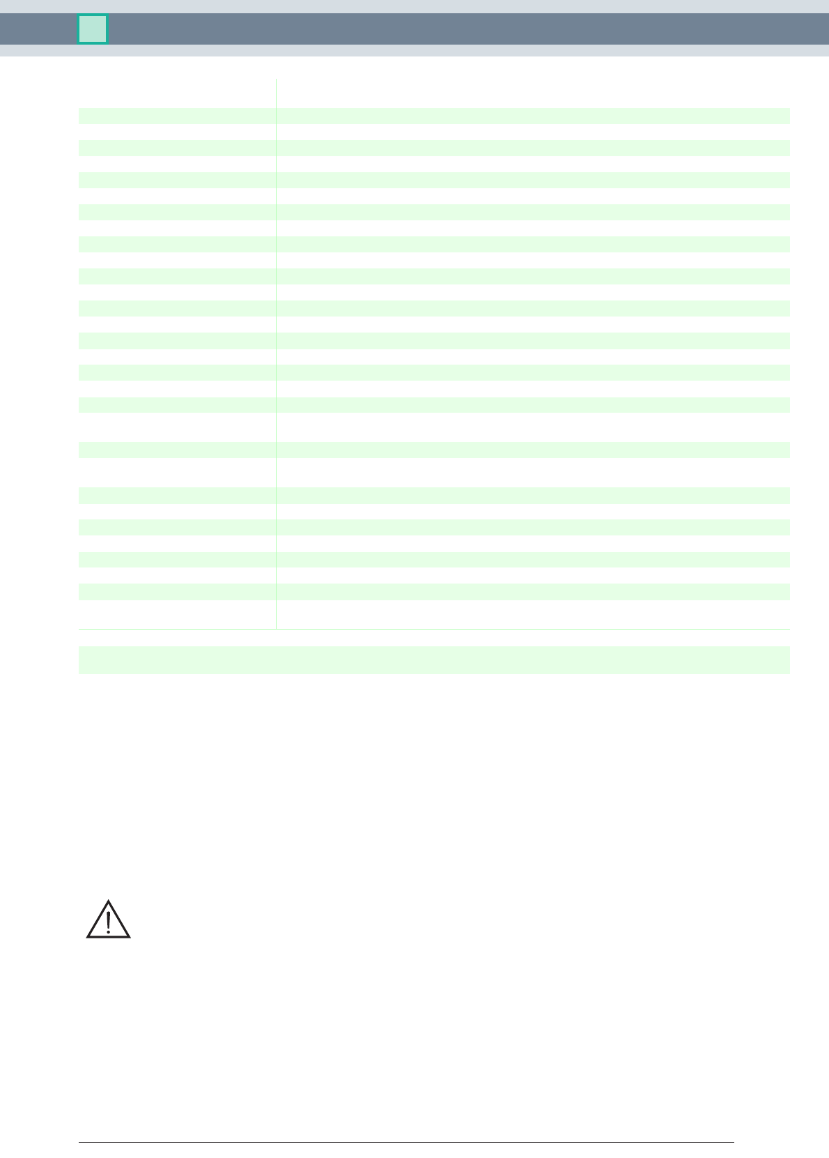
Connection
Assembly
• 1-channel signal conditioner
• 24 V DC supply (Power Rail)
• Input for 2- or 3-wire sensors, NAMUR sensors or dry
contacts
• Input frequency 1 mHz ... 12 kHz
• Current output 0/4 mA ... 20 mA
• Relay and transistor output
• Start-up override
• Line fault detection (LFD)
• Up to SIL2 acc. to IEC 61508
Function
This signal conditioner provides the isolation for non-
intrinsically safe applications.
The device is a universal frequency converter that changes a
digital input signal into a proportional free adjustable
0/4 mA ... 20 mA analog output signal and functions as a
switch amplifier and a trip alarm.
The functions of the switch outputs (2 relay outputs and
1 potential free transistor output) are easily adjustable [trip
value display (min/max alarm), serially switched output, pulse
divider output, error signal output].
The device is easily configured by the use of keypad or with
the PACTware configuration software.
A fault is signalized by LEDs acc. to NAMUR NE44 and a
separate collective error message output.
For additional information, refer to the manual and
www.pepperl-fuchs.com.
Features
19 23
17
11
13
7
24
18
12
22
16
10
20
14
8
21
15
9
1564
23
KFD2-UFC-
1.D
PWR
1
12
IN/
CH K
OUT
ESC
OK
3
RS 232
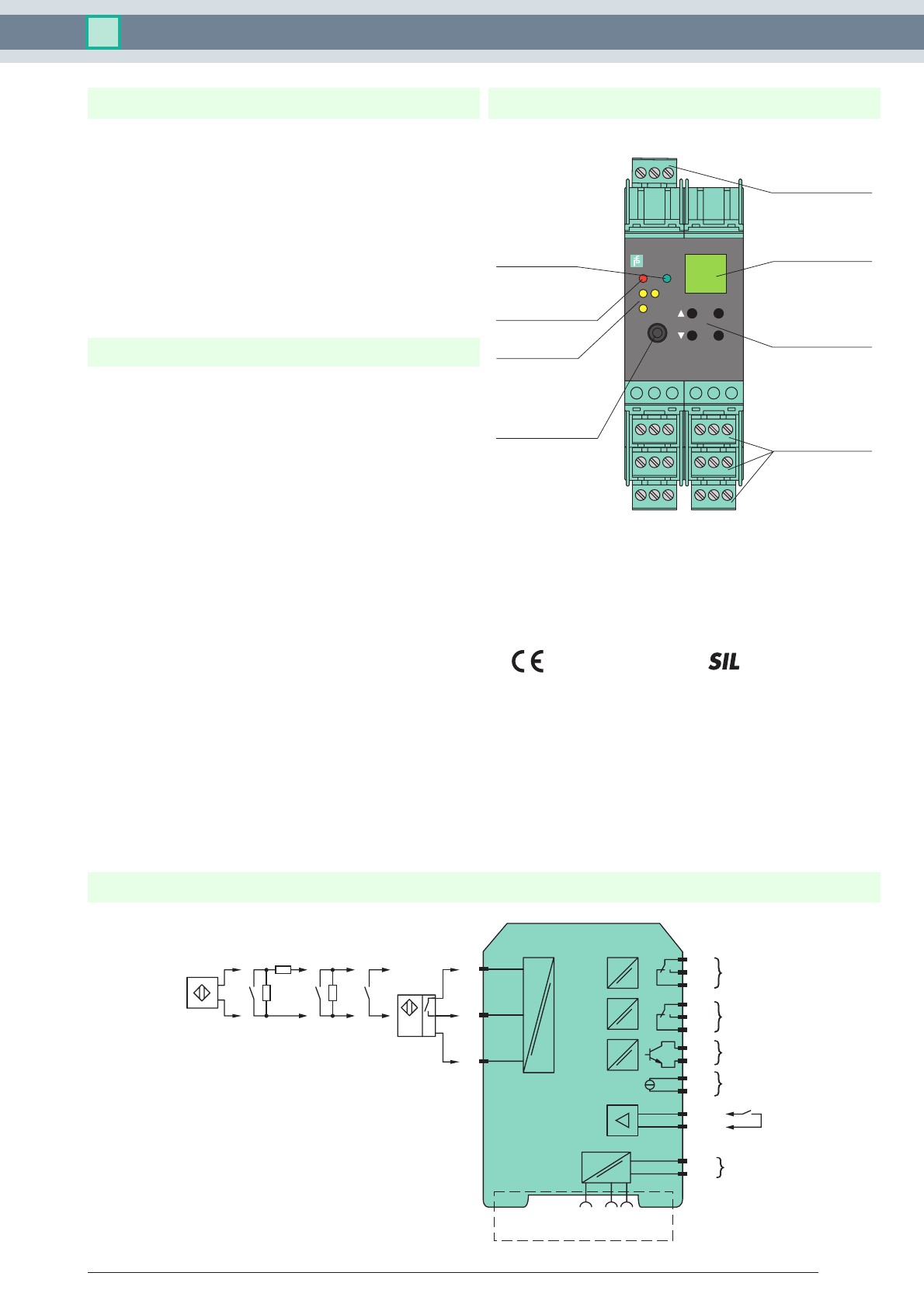
Front view
Removable terminals
green
Removable terminal
green
Keypad
LC display
LED green:
Power supply
LED yellow/red:
Input pulses/
fault signal
LED yellow:
Output I ... III
Programming jack
2

Release date 2012-11-28 13:28 Date of issue 2012-12-17 188369_eng.xml
Technical data KFD2-UFC-1.D
Subject to reasonable modifications due to technical advances. Copyright Pepperl+Fuchs, Printed in Germany
Pepperl+Fuchs Group • Tel.: Germany +49-621-776-0 • USA +1-330-4253555 • Singapore +65-67-799091 • Internet www.pepperl-fuchs.com
2
General specifications
Signal type Digital Input
Supply
Connection terminals 23+, 24- or power feed module/Power Rail
Rated voltage 20 ... 30 V DC
Rated current approx. 100 mA
Power loss/power consumption ≤ 2 W / 2.2 W
Input
Connection Input I: 2-wire sensor: terminals 1+, 3- three wire sensor: terminals 1+, 2- and 3
input II: terminals 13+, 14- start-up override;
Input I 2- or 3-wire sensor, sensor acc. to EN 60947-5-6 (NAMUR) or mechanical contact
Open circuit voltage/short-circuit
current
22 V / 40 mA
Input resistance 4.7 kΩ
Switching point/switching hysteresis logic 1: > 2.5 mA ; logic 0: < 1.9 mA
Pulse duration > 50 µs
Input frequency 0.001 ... 12000 Hz
Lead monitoring breakage I ≤ 0.15 mA; short-circuit I > 4 mA
Input II startup override: 1 ... 1000 s, adjustable in steps of 1 s
Active/Passive I > 4 mA (for min. 100 ms) / I < 1.5 mA
Open circuit voltage/short-circuit
current
18 V / 5 mA
Output
Connection output I: terminals 10, 11, 12
output II: terminals 16, 17, 18
outout III: terminasl 19+, 20-
output IV: terminals 8+, 7-
Output I, II signal, relay
Contact loading 250 V AC / 2 A / cos φ ≥ 0.7 ; 40 V DC / 2 A
Mechanical life 5 x 10⁷ switching cycles
Energized/De-energized delay approx. 20 ms / approx. 20 ms
Output III electronic output, passive
Contact loading 40 V DC
Signal level 1-signal: (L+) -2.5 V (50 mA, short-circuit/overload proof)
0-signal: blocked output (off-state current ≤ 10 µA)
Output IV analog
Current range 0 ... 20 mA or 4 ... 20 mA
Open loop voltage ≤ 24 V DC
Load ≤ 650 Ω
Fault signal downscale I ≤ 3.6 mA , upscale ≥ 21.5 mA (acc. NAMUR NE43)
Collective error message Power Rail
Transfer characteristics
Input I
Measurement range 0.001 ... 12000 Hz
Resolution 0.1 % of the measurement value , ≥ 0.001 Hz
Accuracy 0.1 % of the measurement value , > 0.001 Hz
Measuring time < 100 ms
Influence of ambient temperature 0.003 %/K (30 ppm)
Output I, II
Response delay ≤ 200 ms
Output IV
Resolution < 10 µA
Accuracy < 20 µA
Influence of ambient temperature 0.005 %/K (50 ppm)
Electrical isolation
Input/Other circuits safe electrical isolation acc. to IEC/EN 60079-11, voltage peak value 375 V
Output I, II/other circuits reinforced insulation according to IEC 61140, rated insulation voltage 300 Veff
Mutual output I, II, III reinforced insulation according to IEC 61140, rated insulation voltage 300 Veff
Output III/power supply and collective
error
basic insulation according to IEC 62103, rated insulation voltage 50 Veff
Output III/IV basic insulation according to IEC 62103, rated insulation voltage 50 Veff
Output IV/power supply and collective
error
functional insulation acc. to IEC 62103, rated insulation voltage 50 Veff
Start-up override/power supply and
collective error
functional insulation acc. to IEC 62103, rated insulation voltage 50 Veff
Release date 2012-11-28 13:28 Date of issue 2012-12-17 188369_eng.xml
Technical data KFD2-UFC-1.D
Subject to reasonable modifications due to technical advances. Copyright Pepperl+Fuchs, Printed in Germany
Pepperl+Fuchs Group • Tel.: Germany +49-621-776-0 • USA +1-330-4253555 • Singapore +65-67-799091 • Internet www.pepperl-fuchs.com
3
Interface/power supply and collective
error
functional insulation acc. to IEC 62103, rated insulation voltage 50 Veff
Interface/output III basic insulation according to IEC 62103, rated insulation voltage 50 Veff
Directive conformity
Electromagnetic compatibility
Directive 2004/108/EC EN 61326-1:2006
Low voltage
Directive 2006/95/EC EN 50178:1997
Conformity
Insulation coordination IEC 62103
Electrical isolation IEC 62103
Electromagnetic compatibility NE 21:2006
Protection degree IEC 60529:2001
Protection against electrical shock IEC 61140
Ambient conditions
Ambient temperature -20 ... 60 °C (-4 ... 140 °F)
Mechanical specifications
Protection degree IP20
Mass 300 g
Dimensions 40 x 119 x 115 mm (1.6 x 4.7 x 4.5 in) , housing type C3
Mounting DIN rail mounting
Data for application in connection
with Ex-areas
Statement of conformity Pepperl+Fuchs
Group, category, type of protection,
temperature class
¬ II 3G Ex nA nC IIC T4
Output I, II
Contact loading 50 V AC/2 A/cos φ > 0.7; 40 V DC/1 A resistive load
Ambient conditions
Ambient temperature -20 ... 50 °C (-4 ... 122 °F)
Directive conformity
Directive 94/9/EC EN 60079-0:2006, EN 60079-15:2005
General information
Supplementary information Statement of Conformity, Declaration of Conformity, Attestation of Conformity and instructions have to be
observed where applicable. For information see www.pepperl-fuchs.com.
Power feed module KFD2-EB2
The power feed module is used to supply the devices with 24 V DC via the Power Rail. The fuse-protected power feed module
can supply up to 150 individual devices depending on the power consumption of the devices. A galvanically isolated mechanical
contact uses the Power Rail to transmit collective error messages.
Power Rail UPR-03
The Power Rail UPR-03 is a complete unit consisting of the electrical inset and an aluminium profile rail 35 mm x 15 mm. To make
electrical contact, the devices are simply engaged.
Profile Rail K-DUCT with Power Rail
The profile rail K-DUCT is an aluminum profile rail with Power Rail insert and two integral cable ducts for system and field cables.
Due to this assembly no additional cable guides are necessary.
Power Rail and Profile Rail must not be fed via the device terminals of the individual devices!
PACTware™
Device-specific drivers (DTM)
Adapter K-ADP1
Programming adapter for parameterisation via the serial RS 232 interface of a PC/Notebook
For programming, please use the new version of adapter K-ADP1 (part no. 181953, connector length 14mm). When using the
previous version K-ADP1 (connector length 18 mm) the plug is exposed by approx. 3 mm. The function is not affected.
Adapter K-ADP-USB
Programming adapter for parameterisation via the serial USB interface of a PC/Notebook
Accessories
