2228 Rev A
2014-09-27
: Pdf 60327-Attachment 60327-Attachment 095969 Batch8 unilog
Open the PDF directly: View PDF ![]() .
.
Page Count: 2
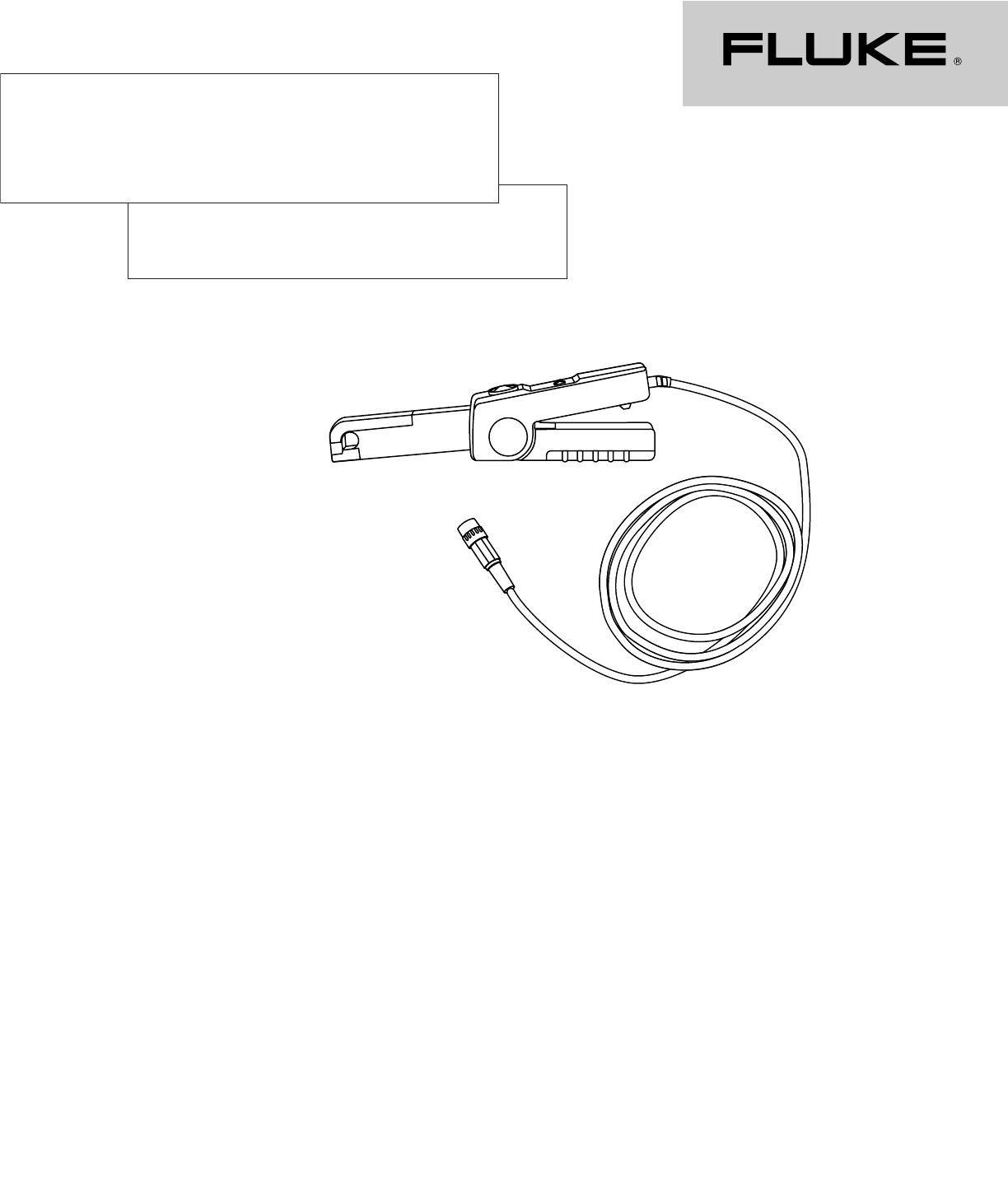
The ideal current probe for
Fluke ScopeMeter®Test Tools
80i-110s AC/DC
Current Probe
Technical Data
Accurate current measurements
become more and more critical
when troubleshooting electric,
electronic, and automotive cir-
cuits. The Fluke 80i-110s AC/DC
Current Probe is designed to
provide you with safe, high
accuracy measurements for a
wide range of applications.
The specially designed built-
in safety features such as the
600 V rms rating at the input
jaws, output cable, and BNC
connector enhance work safety
in industrial and commercial
power distribution systems.
The probe is shielded for
high noise immunity, to prevent
unwanted noise when trou-
bleshooting around noise gen-
erating devices like adjustable
speed motor drives and ignition
systems.
The 80i-110s accurately
reproduces current waveforms
as they occur. Connect the
clamp to a Fluke ScopeMeter
Test Tool or other waveform
recording device like a Fluke
Power Harmonics Analyzer, to
clearly see distorted waveforms
that result from non-linear loads
such as computers, adjustable
speed motor drives, and elec-
tronic ballasts for fluorescent
lighting.
Current clamps, not specifi-
cally designed for oscilloscopes,
may add distortion to the actual
signal present in the system
under test. This makes it diffi-
cult to get an accurate wave-
form measurement.
The wide measurement
range from 50 milliamps to 100
Amps with a high fidelity milli-
volt output gives you full
advantage of the high resolu-
tion oscilloscope displays. This
gives you the true picture of
your current situation, and
allows useful measurements as
low as 10 milliamps.
The broad band frequency
response of the Fluke 80i-110s
AC/DC Current Probe from dc to
100 kHz supports a wide range
of applications where the probe
can be used. The probe can be
used to track down leakage
currents discharging car batter-
ies or to measure dc currents
in an Uninterruptible Power
Supply (UPS), that uses a
battery backup system.
With its narrow jaw design,
the Fluke 80i-110s makes it
easy to take measurements in
tight spots.
Specifications
Electrical specifications
Current ranges:
0 to 10 A dc or ac peak
0 to 100 A dc or ac peak
Output signals:
10 A range: 100 mV/A
100 A range: 10 mV/A
Working voltage
(clamp jaws to ground):
600 V ac rms on Installation
Category II per IEC 1010-1
circuits.
300 V ac rms on Installation
Category III per IEC 1010-1
circuits.
Page 1 of 2, Document #2228
80i-110s AC/DC Current Probe
©2002 Fluke Corporation
Rev. A-9/2002
Fluke Corporation
PO Box 9090, Everett, WA USA 98206
Fluke Europe B.V.
PO Box 1186, 5602 BD
Eindhoven, The Netherlands
For more information call:
In the U.S.A. (800) 443-5853 or
Fax (425) 446-5116
In Europe/M-East/Africa (31 40) 2 675 200 or
Fax (31 40) 2 675 222
In Canada (800)-36-FLUKE or
Fax (905) 890-6866
From other countries +1 (425) 446-5500 or
Fax +1 (425) 446-5116
Web access: http://www.fluke.com/
Fluke. Keeping your world
up and running.
Floating voltage (output
cable and connector to
ground):
600 V ac rms on Installation
Category II per IEC 1010-1
circuits.
300 V ac rms on Installation
Category III per IEC 1010-1
circuits.
Basic accuracy (dc to 1 kHz)
Extended accuracy:
For other frequencies, refer to
the appropriate input current
range and add the error listed
below to the “Basic Accuracy.”
Phase shift, dc to 65 Hz:
10 A range < 1.5 degree
100 A range < 1 degree
Input load impedance
(of host instrument):
> 1 MΩin parallel with up to
100 pF
Useful bandwidth (-3 dB):
0 to 100 kHz
Rise or fall time: < 4 msec
Output noise level:
10 mV/A typ. 480 mV pk-pk
100 mV/A typ. 3 mV pk-pk
Maximum non-destructive
current:
0 to 2 kHz 140 A peak
2 to 10 kHz 110 A peak
10 to 20 kHz 70 A peak
20 to 50 kHz 30 A peak
50 to 100 kHz 20 A peak
Temperature coefficient:
2000 ppm/°C max. for tempera-
ture from 0 °C to 50 °C (32 °F to
132 °F)
All Electrical Specifications are valid at a
temperature of 3 °C to 23 °C (5 °F to 73 °F)
General specifications
Dimensions:
67 x 231 x 36 mm
(2.6 x 9.1 x 1.4 inches)
Weight: 330 g (11.6 oz), battery
included
Output cable:
1.6 meters (63 inches)
Maximum conductor size:
11. 8 mm (.46 inch)
Maximum jaw opening:
12.5 mm (.49 inch)
Temperature:
Operating: 0 °C to 50 °C
(32 °F to 122 °F)
Non-operating: -30 °C to 70 °C
(-22 °F to 158 °F)
Relative humidity (operating):
0 to 85 % (0 °C to 35 °C; 32 °F
to 95 °F)
0 to 45 % (35 °C to 50 °C;
95 °F to 122 °F)
Altitude:
Operating: 0 to 2,000 meters
(0 to 6,560 feet)
Non-operating: 0 to 12,000
meters (0 to 40,000 feet)
Safety specification
Designed to meet the require-
ments of IEC 1010 and CSA-
C22.2 No. 1010.1: Installation
Category II, Working Voltage
600V, Pollution Degree 2.
Installation Category III,
Working Voltage 300V,
Pollution Degree 2.
Installation (Overvoltage)
Category II refers to local
level, appliances, and portable
equipment.
Installation (Overvoltage)
Category III refers to distribu-
tion level and fixed installation
circuits inside a building
electrical service entrance.
Designed to meet the
requirements of UL1244,
Protection Class II Double
Insulation.
Battery information
Battery: 9 volt, IEC 6LR61
Consumption: 8.6 mA typical;
12 mA maximum
Service life:
55 hours typical, when Alkaline
IEC 6LR61 is used
40 hours minimum, when
Alkaline IEC 6LR61 is used
Battery indicator (ON):
Green LED dims when battery
voltage is below 6.5V
Overload indicator (OL):
Red LED indicates that wave-
form or impulse is out of range
Instrument compatibility
The 80i-110s is compatible
with any Fluke ScopeMeter Test
Tool, Power Harmonics
Analyzer, Oscilloscope,
Multimeter, or other voltage
measurement device that has
the following features:
•BNC input connector. A
BNC-to-banana adapter
(order PM 9081/001 from
Fluke) can also be used with
standard inputs on a digital
multimeter (DMM).
•Input accuracy of 2 % or
better to take full advantage
of the accuracy of the probe.
•Input impedance of greater
than or equal to 1 MΩin
parallel with a maximum of
100 pF.
•A passband of more than
four times the frequency
of the waveform to be
measured.
Warranty
One-year warranty
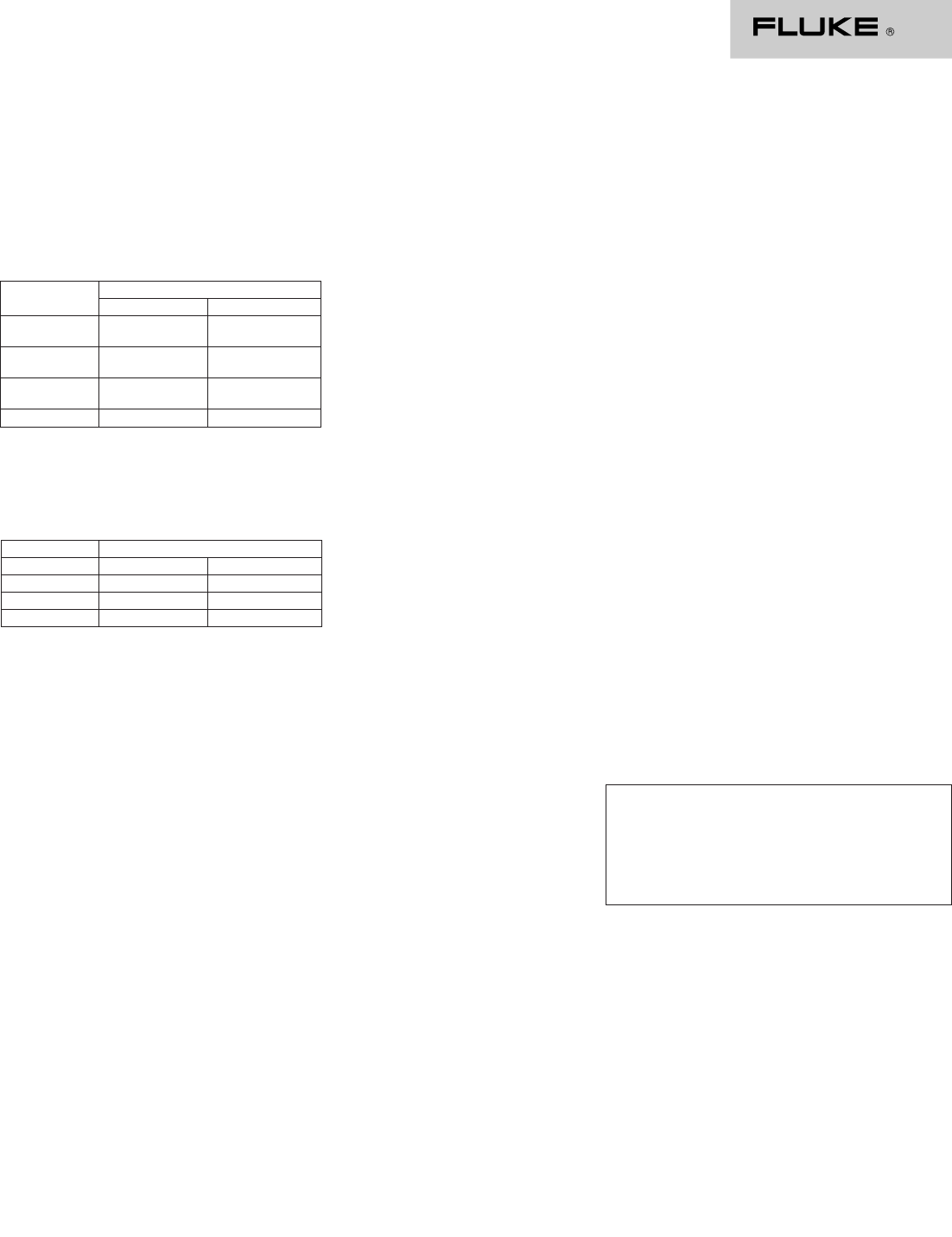
Input current Error (after zero check)
dc or ac peak 100 mV/A 10 mV/A
50 mA to 10 A < 3 % of reading —
+ 50 mA
50 mA to 40 A — < 4 % of reading
+ 50 mA
40 to 80 A — < 12 % of reading
+ 50 mA
80 to 100 A — < 15 % of reading
Additional error
Frequency 100 mV/A 10 mV/A
1 to 5 kHz 3 % 3 %
5 to 20 kHz 12 % 12 %
> 20 kHz Not specified Not specified
Ordering information
Model
80i-110s AC/DC Current Probe
Page 2 of 2, Document #2228
80i-110s AC/DC Current Probe
©2002 Fluke Corporation
Rev. A-9/2002
