Product Detail Manual
2014-11-11
: Pdf 60710-Attachment 60710-Attachment 000334 Batch12 unilog
Open the PDF directly: View PDF ![]() .
.
Page Count: 6
Switches & Pilot LightsSignaling LightsRelays & SocketsTimersContactorsTerminal BlocksCircuit Breakers
RSS Relays & Sockets
822 www.IDEC.com
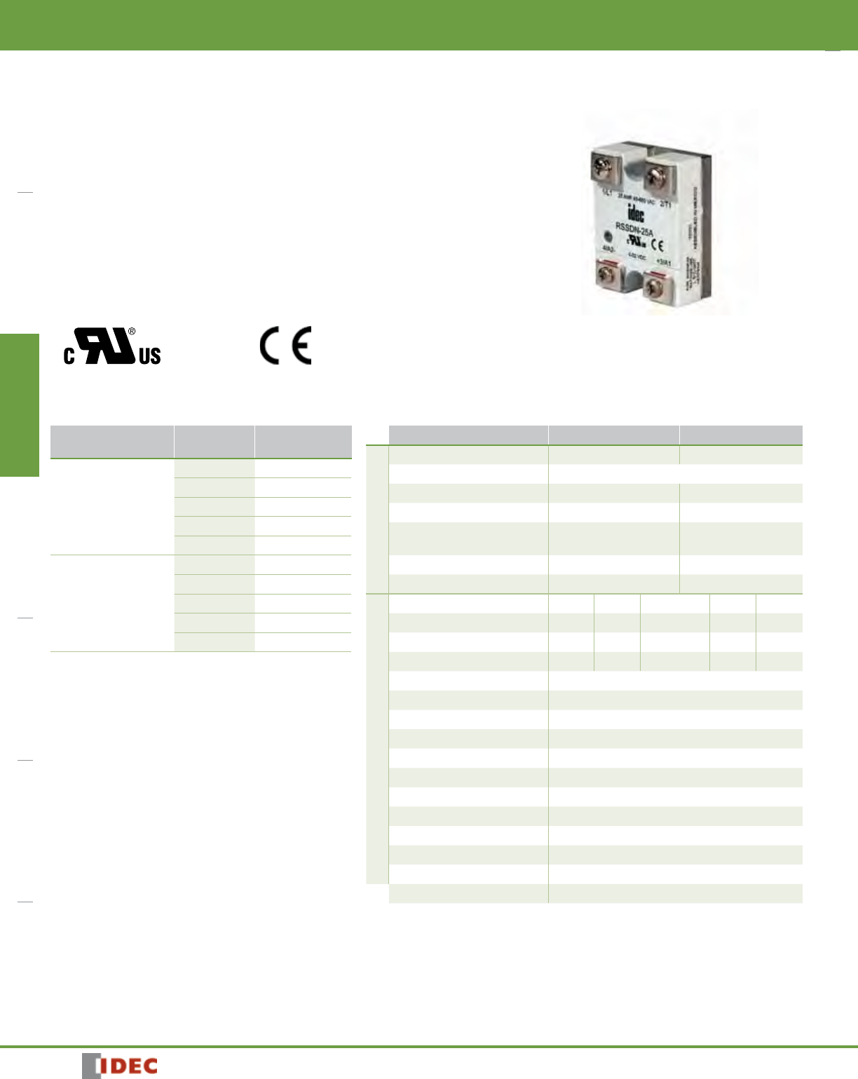
RSS Series Panel Mount Solid State Relays
Key features:
• Input status LED Indicator
• Dual SCR output
• Direct bond copper substrate
• Internal transient protection – built-in snubber
• EMC compliant (level 3)
• Photo isolation
• 1200 Volt blocking voltage
• 4000 Volt optical isolation
• Zero voltage turn-on
• High surge capability
• Optional fingersafe terminal cover (RSS-CVR)
UL Recognized
File No. E194577
Part Number Selection Specifications
Input Continuous
Output Current Part Number
AC Input
90-280V AC
10A RSSAN-10A
25A RSSAN-25A
50A RSSAN-50A
75A RSSAN-75A
90A RSSAN-90A
DC Input
4-32V DC
10A RSSDN-10A
25A RSSDN-25A
50A RSSDN-50A
75A RSSDN-75A
90A RSSDN-90A
Series RSSDN RSSAN
Input Specifications
Voltage Range 4 to 32V DC 90 to 280V AC
Input Current current regulated (10mA)
Pick Up Voltage 4V DC 90V AC
Drop Out Voltage 1V DC 10V AC
Dielectric Strength
(Input-Output-Base) 4000 RMS (min) 4000 RMS (min)
Capacitance (Input to Output) 8pF 8pF
Rev. Voltage Protection Yes (–32VDC) N/A
Output Specifications
Current (continuous) 10A 25A 50A 75A 90A
1-Cycle Surge Current 150A 300A 750A 1000A 1200A
1-Second Surge Current 30A 75A 150A 225A 300A
Minimum Holding Current 50mA 50mA 100mA 100mA 100mA
Voltage Drop at Rated Current 1.6V (maximum)
Voltage Range 48 - 660V AC
Output Dual SCR (N.O.)
Over Voltage Rating 1200 PIV
Frequency Range 47 to 80Hz
Off-State Leakage at Rated Voltage 20mA (maximum)
Turn-On Time 1/2 cycle @ 60Hz
Turn-Off Time 1/2 cycle @ 60Hz
Zero Voltage Switching Yes
Static DV/DT 200V/µsec
Commutating DV/DT Snubbed for 0.5 power factor at rated load
Weight 10g (approx.)
RSS
Switches & Pilot Lights Signaling Lights Relays & Sockets Timers Contactors Terminal Blocks Circuit Breakers
823
800-262-IDEC (4332) • USA & Canada
RSS
Relays & Sockets
Recommended Loads
Transformer Loads
Transformer loads sometimes result in severe inrush current when the transformer saturates during the first cycle. Use a relay rated for this surge, which has a 1/2
cycle surge current greater than the maximum applied line voltage; the transformer’s primary resistance (approximately 10x rated current).
Recommended Loads
SSR Rating at 120V AC at 240V AC
10A 500VA 1KVA
25A 1KVA 2KVA
50A 2KVA 4KVA
Heater Loads
When using solid state relays for driving heaters where the load is switched on and off rapidly and continuously, severe thermal stress will result. In such cases, use
an SSR relay at no more than 75% of the rating.
Recommended Loads
SSR Rating at 120V AC at 240V AC
10A 1KW 2KW
25A 2KW 4KW
50A 3KW 6KW
Solenoid Valves and Contactors
RSS relays use high-noise immunity circuitry with a built-in snubber to handle the electrical noise generated by inductive loads.
Recommended Loads
SSR Rating at 120V AC at 240V AC
10A 900W 1,800W
25A 2,100W 4,200W
50A 3,800W 7,500W
RSS series relays provide a highly reliable means of switching AC loads when applied properly. Read the technical notes on the following page prior to installing
solid state relays.
Switches & Pilot LightsSignaling LightsRelays & SocketsTimersContactorsTerminal BlocksCircuit Breakers
RSS Relays & Sockets
824 www.IDEC.com
UL Motor Load Ratings (HP Ratings)
Part Number 120V 240V 480V
10A 1/2 3/4 3/4
25A 1/2 3/4 3/4
50A 3/4 1 1/2 1 1/2
75A 3/4 5 5
90A 3/4 5 5
Lamp Loads
Zero voltage switching is ideal for driving incandescent lamps, since the cold filament will not be subjected to a large inrush current. Using a zero-switched SSR will
reduce inrush current and prolong lamp life.
Recommended Loads
SSR Rating at 120V AC at 240V AC
10A 1KW 2KW
25A 2KW 4KW
50A 3KW 6KW
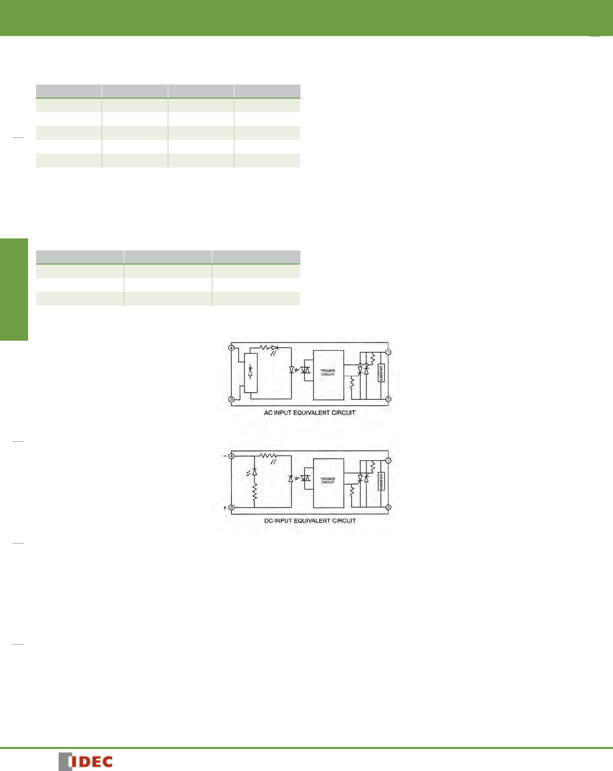
Internal Circuit Block Diagram
Switches & Pilot Lights Signaling Lights Relays & Sockets Timers Contactors Terminal Blocks Circuit Breakers
825
800-262-IDEC (4332) • USA & Canada
RSS
Relays & Sockets
Technical Notes
Environment
Do not install SSRs near sources of excessive heat. Make sure applications are dry and well ventilated.
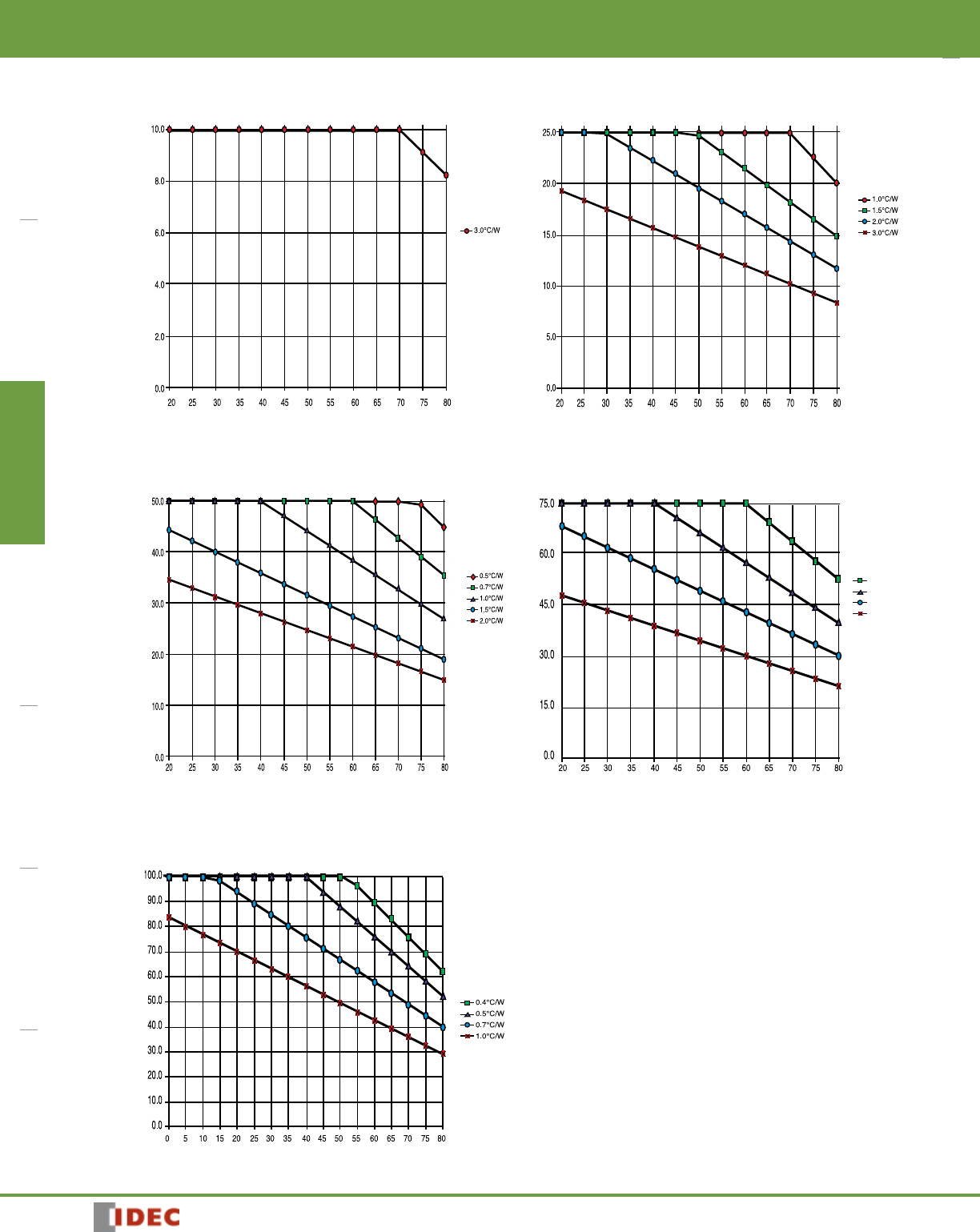
If SSRs must be installed in an environment subject to high temperatures or poor ventilation, or if SSRs are mounted collectively, reduce the load current so that it
does not approach the ambient temperature-load current recommendation. (See the Temperature Derating Curves on the following page.)
When SSRs are used with inductive loads, suppress the inrush current to half of the peak surge current.
Heat Sinks
Heat sinks are recommended for all solid state relays depending on ambient temperature and mounting position. The recommended heat sink dimensions and mate-
rial are shown in the table:
Output Rating Dimensions Material
10A 12” x 12” x 1/8” Aluminum (black anodized)
25A 12” x 12” x 1/8” (DC/AC) Aluminum (black anodized)
25A 15” x 15” x 1/8” (AC/AC) Aluminum (black anodized)
50A 15” x 15” x 1/8” Aluminum (black anodized)
75A 17” x 17” x 1/8” Aluminum (black anodized)
90A 17” x 17” x 1/8” Aluminum (black anodized)
Using a thermal compound between the base of the SSR and the heat sink for heat dissipation is recommended.
Wiring
Locate SSRs as far from motor leads as possible to prevent malfunction from induced current.
Use shielded wires for input leads when they are exposed to a source of induced current.
Mounting
Provide sufficient ventilation.
Use #6 – 32 screws, flat washers, and lock washers to secure mounting on heat sinks.
Vertical mounting is recommended to allow air to flow unimpeded. Horizontal or inverted mounting is possible, but the SSR must be derated according to the derating
curves on the following page.
Additional Information
Do not exceed the load voltage and current specifications.
A small-capacity load may not turn off due to the leakage current present after the SSR has turned off. If this is the case, use a resistor in parallel with the load to
shunt the leakage current.
Observe the polarity of input terminals. Failure to do so may cause damage to the SSR.
When the SSR output is subjected to a higher than rated voltage, a varistor or other element should be connected to the output terminals to absorb the over-voltage.
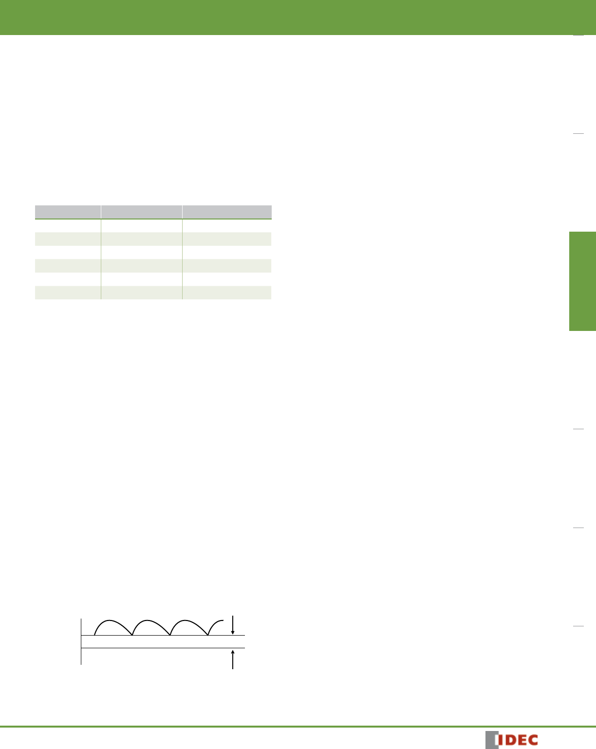
When the input signal contains a ripple voltage, the lowest ripple amplitude should exceed the minimum pick-up voltage of 4V.
Lowest Voltage
Over 4V
0V
Switches & Pilot LightsSignaling LightsRelays & SocketsTimersContactorsTerminal BlocksCircuit Breakers
RSS Relays & Sockets
826 www.IDEC.com
Temperature Derating Curves: RSS Series
1
10 AMP SCR OUTPUT
50 AMP SCR OUTPUT
Ambient Temperature (°C)
Ambient Temperature (°C)
Load Current (Amperes)
75 AMP SCR OUTPUT
Ambient Temperature (°C)
Load Current (Amperes)
Load Current (Amperes)
25 AMP SCR OUTPUT
Ambient Temperature (°C)
Load Current (Amperes)
0.5°C/
W
0.7°C/
W
1.0°C/
W
1.5°C/
W
90 AMP SCR OUTPUT
Ambient Temperature (°C)
Load Current (Amperes)
Switches & Pilot Lights Signaling Lights Relays & Sockets Timers Contactors Terminal Blocks Circuit Breakers
827
800-262-IDEC (4332) • USA & Canada
RSS
Relays & Sockets
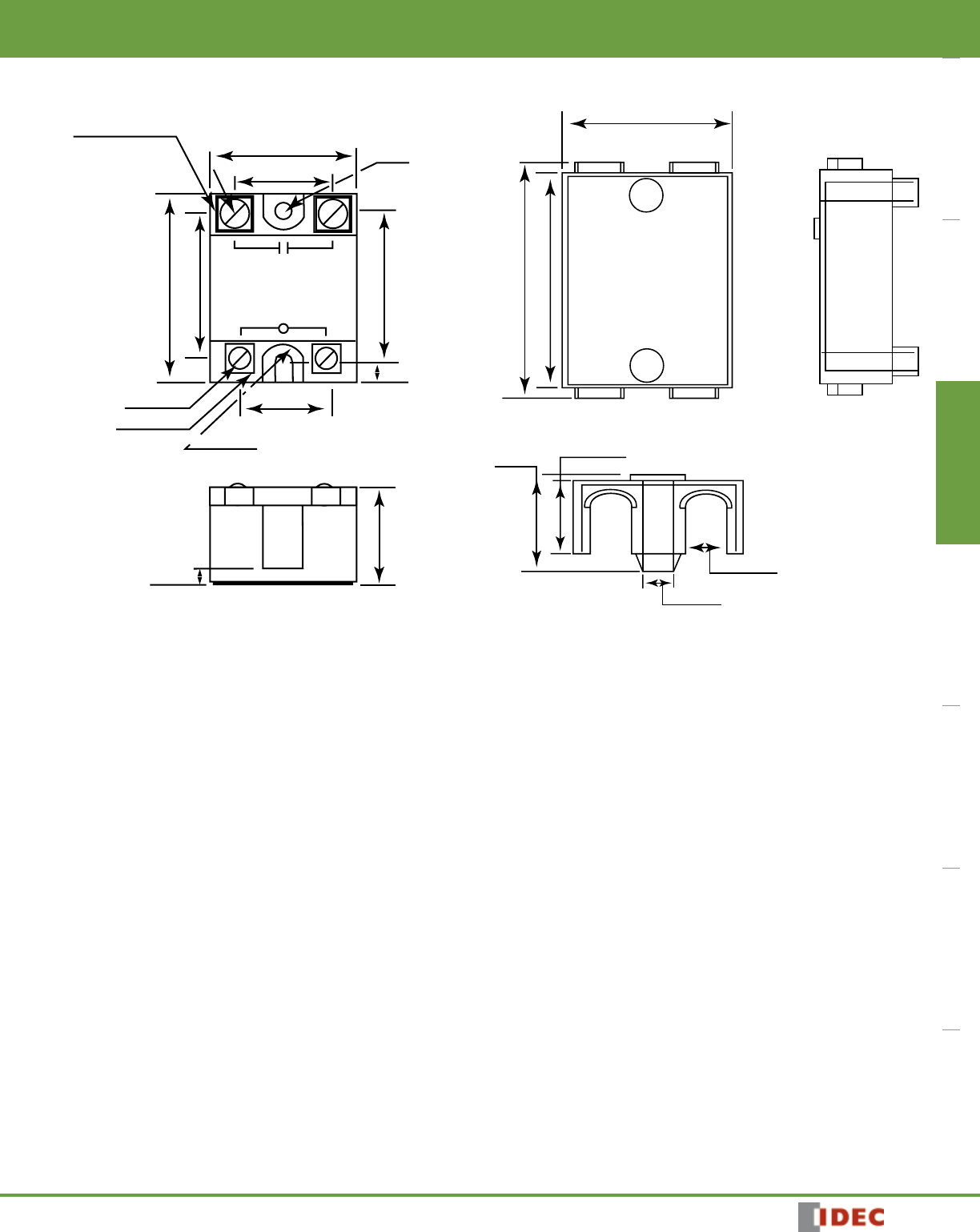
Dimensions (mm)
12
3+
-4
6-32 Pan Head Screw
Small Saddle Clamp
Large Saddle Clamp
1.75" (44.5mm)
1.1" (27.9mm)
0.2"
(4.8mm)
1.88" (47.6mm)
1.0" (25.4mm)
2.25" (57.2mm)
1.7" (43.2mm)
8-32 Pan Head Screw
ø0.187"
(4.5mm)
R 0.265" (6.7mm)
0.09" (2.3mm)
0.95" (24.1mm)
1.9" (48.26mm)
2.4" (6.96mm)
2.65" (67.31mm)
0.5" (12.70mm)
0.37" (9.40mm)
0.79"
(20.07mm)
1.075"
(27.31mm)
RSS-CVR - Optional Fingersafe Cover
