Data Sheet DB EN QUINT UPS/ 1AC/ 1AC/500VA
2014-07-04
: Pdf 611057-Attachment 611057-Attachment 012596 Batch5 unilog
Open the PDF directly: View PDF ![]() .
.
Page Count: 34
- 1 Description
- 2 Table of contents
- 3 Ordering data
- 4 Technical data
- General input data
- Input data (mains operation 230 V AC)
- Input data (mains operation 120 V AC)
- General output data
- Output data (mains operation 230 V AC)
- Output data (mains operation 120 V AC)
- Output data (battery mode 230 V AC)
- Output data (battery mode 120 V AC)
- Power storage device connection
- Device combinations
- Status and diagnostic indicator POWER IN OK
- Status and diagnostic indicators/signal outputs Alarm
- Status and diagnostic indicators/signal outputs Battery Charge
- Status and diagnostic indicators/signal outputs Battery Mode
- Status and diagnostic indicators/signal outputs POWER BOOST
- Remote control
- Battery-operated start (auto start)
- Interfaces
- Housing
- General data
- Input connection data
- Output connection data
- Output connection battery
- Signal connection data
- Ambient conditions
- Standards
- Approvals
- Noise emission according to EN 62040-2 (Class C1)
- 5 Safety regulations and installation notes
- 6 Structure
- 7 Basic circuit diagram
- 8 Installation
- 9 Installation of individual components
- 10 Device connection terminal blocks
- 11 Signaling
- 11.1 LED bar graph display
- 11.2 IQ power storage devices
- 11.3 Standard power storage devices (without IQ technology)
- 11.4 LED indicators
- 11.5 LED bar graph display with communication cable installed between the UPS and the power storage device
- 11.6 LED bar graph display without communication cable between the UPS and the power storage device
- 11.7 Active signal outputs
- 12 Function
- 13 Interfaces
- 14 Derating
- 15 Service mode
- 16 PC mode in UPS-CONF
- 17 Application example
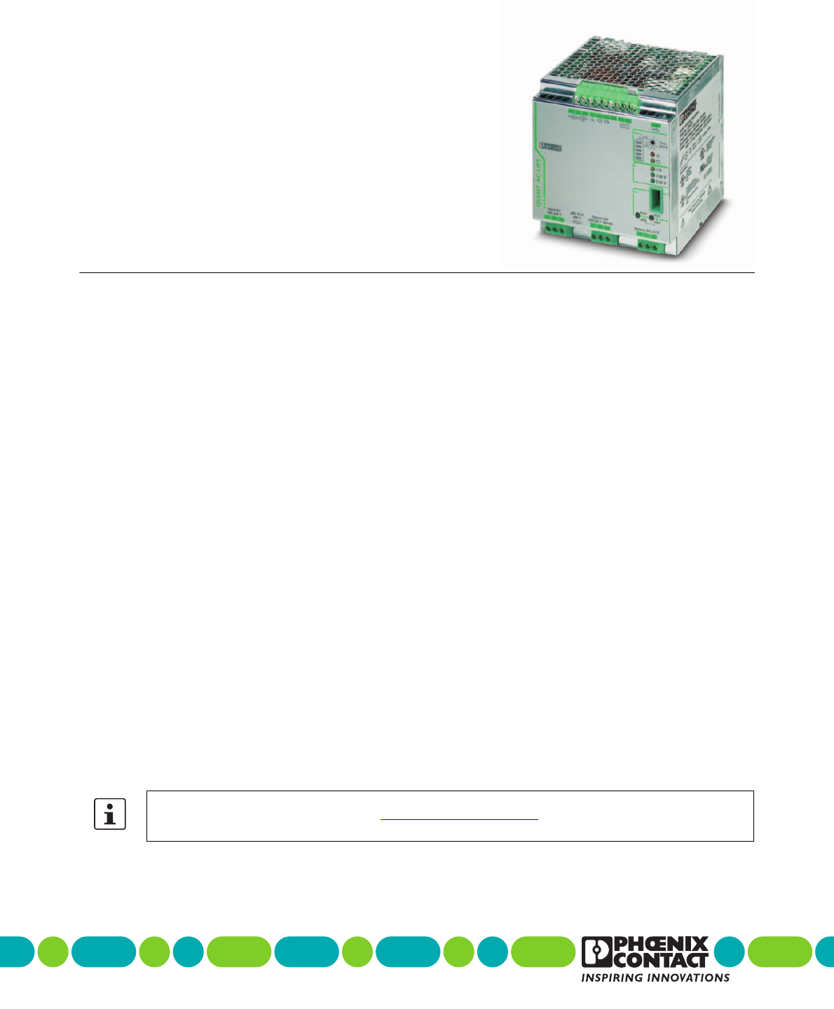
1Description
Uninterruptible power supply
QUINT-UPS/ 1AC/ 1AC/500VA
© PHOENIX CONTACT
Data sheet
The QUINT-UPS uninterruptible power supply (UPS) is
used to ensure that power for critical electrical loads contin-
ues to be supplied in the event of disturbances in the power
supply network, e.g., due to mains breakdown or failure.
In doing so, the UPS switches to battery operation without
interruption so that connected loads continue to be consis-
tently supplied.
When mains power is restored, the UPS automatically re-
turns to normal operation. The connected loads are again
supplied via the power supply network and the battery is
charged.
The product described here is an uninterruptible power sup-
ply (UPS) with integrated power supply unit.
Features
– Offline UPS in line with UPS classification code accord-
ing to IEC 62040-3: VFD-SS-311
–Waveform Type: pure sine
Optimum use of the buffer time and preventive moni-
toring of the power storage device
– Detects the current state of charge (SOC) and the re-
maining runtime of the power storage
– Detects the current state of health (SOH) of the power
storage and warns of failure at an early stage
Worldwide use
– Input voltage from 96 V AC ... 264 V AC
– Storage of the level and frequency of the input voltage,
in the event of mains failure, the output is automatically
supplied with 120 V AC/60 Hz or 230 V AC/50 Hz
Maximum energy efficiency
– Offline operation: 98% efficiency for charged power
storage device
Extensive signaling and parameterization
– Switching outputs, USB interface, data port, parameter-
ization with memory stick
Simplified startup
– The UPS can be switched on without a power supply
network
Make sure you always use the latest documentation.
It can be downloaded from the product at phoenixcontact.net/products.
104661_en_02 2013-08-12

QUINT-UPS/ 1AC/ 1AC/500VA
104661_en_02 PHOENIX CONTACT 2
2Table of contents
1 Description ..................................................................................................................................1
2 Table of contents.........................................................................................................................2
3 Ordering data ..............................................................................................................................4
4 Technical data.............................................................................................................................5
5 Safety regulations and installation notes ...................................................................................10
6 Structure....................................................................................................................................11
7 Basic circuit diagram...........................................................................................................................................12
8 Installation ..............................................................................................................................................................12
8.1 Convection ...................................................................................................................................................12
8.2 Mounting position .........................................................................................................................................13
8.3 Mounting on a DIN rail ..................................................................................................................................13
9 Installation of individual components.........................................................................................14
10 Device connection terminal blocks ............................................................................................15
10.1 AC input........................................................................................................................................................15
10.2 AC output......................................................................................................................................................15
10.3 DC battery ....................................................................................................................................................15
10.4 Remote shutdown R1, R2.............................................................................................................................16
10.5 Remote shutdown is activated......................................................................................................................16
10.6 Setting the buffer time...................................................................................................................................17
10.7 Remote activation of Autonomic Start...........................................................................................................17
11 Signaling ...................................................................................................................................18
11.1 LED bar graph display ..................................................................................................................................18
11.2 IQ power storage devices.............................................................................................................................18
11.3 Standard power storage devices (without IQ technology).............................................................................19
11.4 LED indicators ..............................................................................................................................................20
11.5 LED bar graph display with communication cable installed between the UPS
and the power storage device.......................................................................................................................21
11.6 LED bar graph display without communication cable between the UPS
and the power storage device.......................................................................................................................21
11.7 Active signal outputs.....................................................................................................................................21
12 Function .................................................................................................................................... 22
12.1 SOC application example .............................................................................................................................22
12.2 SOH/SOF application example.....................................................................................................................22
12.3 Charging characteristic.................................................................................................................................22

QUINT-UPS/ 1AC/ 1AC/500VA
104661_en_02 PHOENIX CONTACT 3
Interfaces......................................................................................................................................................................... 23
13.1 Data port ...................................................................................................................................................... 23
13.2 IFS-CONFSTICK-L....................................................................................................................................... 25
13.3 Transfer parameter data from UPS to IFS-CONFSTICK-L ........................................................................... 25
13.4 Transferring IFS-CONFSTICK-L parameters to the UPS.............................................................................. 26
13.5 USB interface MINI type B............................................................................................................................ 27
14 Derating .................................................................................................................................................................. 27
14.1 Temperature-dependent derating................................................................................................................. 27
14.2 Position-dependent derating ........................................................................................................................ 27
15 Service mode.............................................................................................................................31
15.1 Power storage device replacement .............................................................................................................. 31
16 PC mode in UPS-CONF ............................................................................................................33
17 Application example ..................................................................................................................34

QUINT-UPS/ 1AC/ 1AC/500VA
104661_en_02 PHOENIX CONTACT 4
Description Type Order No. Pcs. / Pkt.
Uninterruptible power supply with IQ technology 1AC/1AC/500 VA. For
120 V AC/230 V AC applications. Provides information regarding the
charging state, remaining runtime, and service life of your rechargeable
battery module at all times and thereby increases system availability.
QUINT-UPS/ 1AC/ 1AC/500VA 2320270 1
3Ordering data
Accessories Type Order No. Pcs. / Pkt.
Power storage device, lead AGM, VRLA technology, 24 V DC, 3.4 Ah, tool-
free battery replacement, automatic detection, and communication with
QUINT UPS-IQ
UPS-BAT/VRLA/24DC/ 3.4AH 2320306 1
Power storage device, lead AGM, VRLA technology, 24 V DC, 7.2 Ah, tool-
free battery replacement, automatic detection, and communication with
QUINT UPS-IQ
UPS-BAT/VRLA/24DC/ 7.2AH 2320319 1
Power storage device, lead AGM, VRLA technology, 24 V DC, 12 Ah, tool-
free battery replacement, automatic detection, and communication with
QUINT UPS-IQ
UPS-BAT/VRLA/24DC/12AH 2320322 1
Power storage device, lead AGM, VRLA technology, 24 V DC, 38 Ah, au-
tomatic detection, and communication with QUINT UPS-IQ
UPS-BAT/VRLA/24DC/38AH 2320335 1
Power storage device, LI-ION technology, 24 V DC, 120 Wh, for ambient
temperatures of -20°C ... 58°C, automatic detection and communication
with QUINT UPS-IQ
UPS-BAT/LI-ION/24DC/120WH 2320351 16
Maintenance-free power storage based on double-layer capacitor, 24
VDC, 20 kJ, automatic detection and communication with QUINT UPS-IQ
UPS-CAP/24DC/20A/20KJ 2320380 1
Configuration software for QUINT UPS IQ and TRIO UPS uninterruptible
power supplies.
UPS-CONF 2320403 1
USB connecting cable: USB plug type A to USB plug type Mini-B; length: 3
m
CABLE-USB/MINI-USB-3,0M 2986135 1
Data cable for communication, e.g., between Phoenix Contact type ILC 1xx
Inline controllers and Phoenix Contact devices with the 12-pos. IFS data
port, such as QUINT UPS-IQ UPS or TRIO UPS
IFS-MINI-DIN-DATACABLE 2320487 1
Data cable for communication between devices with a D-SUB 9 RS-232
connection and Phoenix Contact devices with the 12-pos. IFS data port
such as QUINT UPS-IQ or TRIO UPS.
IFS-RS232-DATACABLE 2320490 1
Used for communicating between industrial PCs and Phoenix Contact de-
vices with the 12-pos. IFS data port, such as QUINT UPS or TRIO UPS.
IFS-USB-DATACABLE 2320500 1
Multi-functional memory block with handle for the INTERFACE system; for
easy storage and back up of the configuration.
IFS-CONFSTICK-L 2901103 1
Universal wall adapter UWA 130 2901664 1
Universal wall adapter UWA 182/52 2938235 1
Our range of accessories is being continually extended, our current range can be found in the download area.

QUINT-UPS/ 1AC/ 1AC/500VA
104661_en_02 PHOENIX CONTACT 5
4 Technical data
General input data
Input voltage range 80 V AC ... 264 V AC
Frequency range 45 Hz ... 65 Hz
Activation threshold UN ±10%. Can be configured using UPS-CONF software.
Input data (mains operation 230 V AC)
Nominal input voltage 230 V AC
Nominal input voltage range 180 V AC ... 264 V AC
Nominal frequency 50 Hz
Current consumption mains mode 2.2 A
Max. current consumption (IIN = ICHARGE + IBOOST)3.7 A
No load (ICHARGE = 0, IOUT = 0) 0.18 A
Charging process (ICHARGE = max., IOUT = 0) 0.8 A
Device mains fuse 10 A
Backup fuse B16 230 V AC
Input data (mains operation 120 V AC)
Nominal input voltage 120 V AC
Nominal input voltage range 80 V AC ... 150 V AC
Nominal frequency 60 Hz
Current consumption mains mode 4.3 A
Max. current consumption (IIN = ICHARGE + IBOOST)6.8 A
No load (ICHARGE = 0, IOUT = 0) 0.35 A
Charging process (ICHARGE = max., IOUT = 0) 1.3 A
Backup fuse 20 A 120 V AC, Listed breaker
General output data
Apparent power 500 VA
Nominal power (real power) 400 W
Derating > 50 °C ... 70 °C (2.5%/K)
Switch-over time < 10 ms
UPS classification EN 62040-3
Waveform type pure sine
Output data (mains operation 230 V AC)
Nominal output voltage 230 V AC
Nominal output current IN at 500 VA 2.2 A ( -25 °C ... 70 °C )
POWER BOOST IBOOST (continual) at 625 VA 2.7 A ( -25 °C ... 70 °C )
No load power dissipation (ICHARGE = 0, IOUT = 0) 14 W
Nominal load power dissipation (ICHARGE = 0, IOUT = IN)14 W
Efficiency (ICHARGE = 0, IOUT = IN)> 98 % (Mains operation)

QUINT-UPS/ 1AC/ 1AC/500VA
104661_en_02 PHOENIX CONTACT 6
Output data (mains operation 120 V AC)
Nominal output voltage 120 V AC
Nominal output current IN at 500 VA 4.3 A ( -25 °C ... 70 °C )
POWER BOOST IBOOST (continual) at 625 VA 5.2 A ( -25 °C ... 70 °C )
No load power dissipation (ICHARGE = 0, IOUT = 0) 15 W
Nominal load power dissipation (ICHARGE = 0, IOUT = IN)15 W
Efficiency (ICHARGE = 0, IOUT = IN)> 98 %
Output data (battery mode 230 V AC)
Nominal output voltage 230 V AC
Nominal output current IN at 500 VA 2.2 A ( -25 °C ... 50 °C , Derating >50 °C 2.5%/K )
POWER BOOST IBOOST (5 seconds) at 625 VA 2.7 A ( -25 °C ... 50 °C , Derating >50 °C 2.5%/K )
No load power dissipation (ICHARGE = 0, IOUT = 0) 20 W
Nominal load power dissipation (ICHARGE = 0, IOUT = IN)69 W
Efficiency (ICHARGE = 0, IOUT = IN)> 86 %
Buffer time (IOUT = IN) 400 W/7.2 Ah 10 min
Output data (battery mode 120 V AC)
Nominal output voltage 120 V AC
Nominal output current IN at 500 VA 4.3 A ( -25 °C ... 50 °C , Derating >50 °C 2.5%/K )
POWER BOOST IBOOST (5 seconds) at 625 VA 5.2 A ( -25 °C ... 50 °C , Derating >50 °C 2.5%/K )
No load power dissipation (ICHARGE = 0, IOUT = 0) 20 W
Nominal load power dissipation (ICHARGE = 0, IOUT = IN)69 W
Efficiency (ICHARGE = 0, IOUT = IN)> 86 %
Buffer time (IOUT = IN) 400 W/7.2 Ah 10 min
Power storage device connection
Nominal voltage UN24 V DC
End-of-charge voltage 25 V DC ... 30 V DC (temperature compensated)
Temperature compensation (preset) 42 mV/K
Nominal capacity range 3 Ah ... 200 Ah
Charge current 0.2 A ... 2 A
Battery presence check (cyclic) all 60 s
Device combinations
UPS connection in parallel no
UPS connection in series no
Power storage device connection in parallel yes, 15 (observe line protection)
Power storage device connection in series no
Status and diagnostic indicator POWER IN OK
Status indicator 230 V AC LED green
Status indicator 120 V AC LED green
Status and diagnostic indicators/signal outputs Alarm
Switching output Transistor output, active
Output voltage 24 V (SELV)
Continuous load current ≤ 30 mA
Status display LED ( red )

QUINT-UPS/ 1AC/ 1AC/500VA
104661_en_02 PHOENIX CONTACT 7
Status and diagnostic indicators/signal outputs Battery Charge
Status indication Bar graph ( red/green )
Status and diagnostic indicators/signal outputs Battery Mode
Switching output Transistor output, active
Output voltage 24 V (SELV)
Continuous load current ≤ 30 mA
Status display LED ( yellow )
Status and diagnostic indicators/signal outputs POWER BOOST
Switching output Transistor output, active
Output voltage 24 V (SELV)
Continuous load current ≤ 30 mA
Status display LED ( yellow )
Remote control
Version 1 : Output R1 to input R2 Plug-in bridge (plugged in by default)
Version 2 : Input R2 + 24 V DC
Input current R2 2.8 mA
Battery-operated start (auto start)
230 V AC version: output +24 V DC 30 mA to A2 input Plug-in bridge
120 V AC version: output +24 V DC 30 mA to A1 input Plug-in bridge
Interfaces
Data interface (configuration and communication) IFS (Interface system data port)
USB classification MINI-USB type B
Housing
Degree of protection IP20
Side element version Aluminum
Hood version Galvanized sheet steel, free from chrome (VI)
Dimensions W/H/D (normal mounting position/delivered condition) 125 mm / 130 mm / 125 mm
General data
Weight 2.2 kg
MTBF (According to EN 29500)
Protection class I
Insulation voltage input, output / housing 1.5 kV AC / 2.1 kV DC
Input connection data
Connection method Screw connection
Conductor cross section, solid 1.5 mm² ... 6 mm²
Conductor cross section, stranded 1.5 mm² ... 4 mm²
Conductor cross section AWG/kcmil 18 ... 10
Stripping length 8 mm
Screw thread M4
Tightening torque 0.5 Nm ... 0.6 Nm

QUINT-UPS/ 1AC/ 1AC/500VA
104661_en_02 PHOENIX CONTACT 8
Output connection data
Connection method Screw connection
Conductor cross section, solid 1.5 mm² ... 6 mm²
Conductor cross section, stranded 1.5 mm² ... 4 mm²
Conductor cross section AWG/kcmil 18 ... 10
Connection method 8 mm
Screw thread M4
Tightening torque 0.5 Nm ... 0.6 Nm
Output connection battery
Connection method Screw connection
Conductor cross section, solid 1.5 mm² ... 6 mm²
Conductor cross section, stranded 1.5 mm² ... 4 mm²
Conductor cross section AWG/kcmil 12 ... 10
Stripping length 8 mm
Screw thread M4
Tightening torque 0.5 Nm ... 0.6 Nm
Signal connection data
Connection method Screw connection
Conductor cross section, solid 0.2 mm² ... 2.5 mm²
Conductor cross section, stranded 0.2 mm² ... 2.5 mm²
Conductor cross section AWG/kcmil 24 ... 10
Stripping length 8 mm
Screw thread M4
Tightening torque 0.5 Nm ... 0.6 Nm
Ambient conditions
Ambient temperature (operation) -25 °C ... 70 °C (> 50°C derating)
Ambient temperature (start-up type tested) -40 °C
Ambient temperature (storage/transport) -40 °C ... 85 °C
Max. permissible relative humidity (operation) ≤ 95 % (25°C, no condensation)
Vibration (operation) < 15 Hz, amplitude ±2.5 mm (according to IEC 60068-2-6)
15 Hz ... 150 Hz, 2.3 g tv = 90 min.
Shock 30 g in each direction, according to IEC 60068-2-27
Climatic class 3K3 (in acc. with EN 60721)
Standards
Uninterruptible power supply EN 62040-3
Approvals
UL approvals UL/C-UL Recognized UL 1778
Current approvals/permissions for the product can be found in the download area under phoenixcontact.net/products.

QUINT-UPS/ 1AC/ 1AC/500VA
104661_en_02 PHOENIX CONTACT 9
Conformance with EMC Directive 2004/108/EC
Noise immunity according to EN 62040-2-2006
EN 62040-4 requirement Tested
Electrostatic discharge EN 62040-2
Housing contact discharge 4 kV (Test intensity 2) 8 kV (Test intensity 4)
Housing air discharge 8 kV (Test intensity 3) 15 kV (Test intensity 4)
Comments Criterion B Criterion A
Electromagnetic HF field EN 61000-4-3
Frequency range 80 MHz ... 1 GHz 80 MHz ... 3 GHz
Test field strength 10 V/m 10 V/m
Frequency range 1.4 GHz ... 2 GHz 1 GHz ... 3 GHz
Test field strength 3 V/m 10 V/m
Frequency range 2 GHz ... 2.7 GHz 2 GHz ... 3 GHz
Comments Criterion A Criterion A
Fast transients (burst) EN 61000-4-4
Input 2 kV (Test intensity 3 - asymmetrical) 2 kV (Test intensity 3 - asymmetrical)
Output 2 kV (Test intensity 3 - asymmetrical) 2 kV (Test intensity 3 - asymmetrical)
Signal 1 kV (Test intensity 4 - asymmetrical) 2 kV (Test intensity 4 - asymmetrical)
Comments Criterion B Criterion A
Surge current loads (surge) EN 62040-4
Input 1 kV (Test intensity 2 - symmetrical)
2 kV (Test intensity 3 - asymmetrical)
1 kV (Test intensity 2 - symmetrical)
2 kV (Test intensity 3 - asymmetrical)
Output 1 kV (Test intensity 2 - symmetrical)
1 kV (Test intensity 3 - asymmetrical)
1 kV (Test intensity 2 - symmetrical)
2 kV (Test intensity 3 - asymmetrical)
Signal 1 kV (Test intensity 2 - asymmetrical) 1 kV (Test intensity 2 - asymmetrical)
Comments Criterion B Criterion A
Conducted interference EN 61000-4-6
Input/Output/Signal asymmetrical asymmetrical
Frequency range 0.15 MHz ... 80 MHz 0.15 MHz ... 80 MHz
Voltage 10 V (Test intensity 3) 10 V (Test intensity 3)
Comments Criterion A Criterion A
Noise emission according to EN 62040-2 (Class C1)
Radio interference voltage EN 62040-2 (Class C1)
Limit value for harmonic currents EN 61000-3-2 (Class A)
QUINT-UPS/ 1AC/ 1AC/500VA
104661_en_02 PHOENIX CONTACT 10
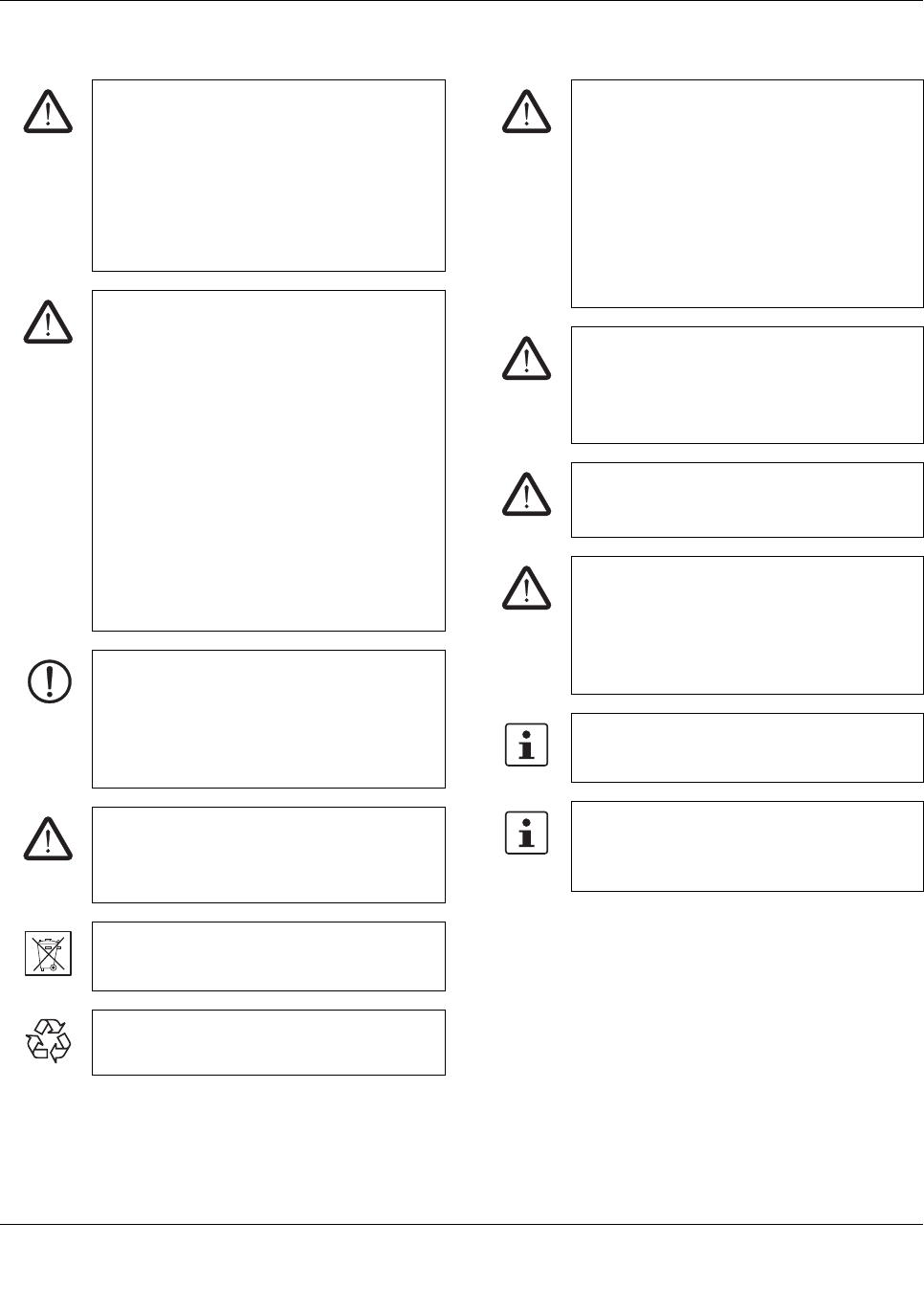
5 Safety regulations and installation notes
EXPLOSION HAZARD!
Only remove equipment when it is discon-
nected and not in the potentially explosive ar-
ea.
DANGER
Never carry out work on live parts!
The housing can become very hot, depending
on the ambient temperature and load!
CAUTION:
Before startup please ensure:
The connection must be carried out by a com-
petent person and protection against electric
shock guaranteed.
It must be possible to switch off power to de-
vice according to EN60950.
All feed lines are sufficiently protected and di-
mensioned!
All output lines are dimensioned according to
the maximum output current of the device or
separately protected!
Sufficient convection must be guaranteed.
Observe mechanical and thermal limits.
NOTE: Danger if used improperly
Uninterruptible power supplies are installable
devices. Installation and startup may only be
carried out by qualified personnel. The rele-
vant country-specific regulations must be ob-
served.
CAUTION: Risk of injury
Cover termination area after installation in or-
der to avoid accidental contact with live parts
(e. g., installation in control cabinet).
Do not dispose of used batteries in the house-
hold waste! Dispose of these according to the
currently valid national regulations.
They can also be returned to Phoenix Contact
or the manufacturer.
CAUTION: Risk of injury
Use the device with the UPS-BAT.... recom-
mended in the table of accessories. When us-
ing power storage devices other than UPS-
BAT..., make sure that the corresponding pa-
rameters for the charging characteristics are
adjusted and adhered to.
Phoenix Contact accepts no liability or re-
sponsibility for possible for any consequential
damage.
CAUTION: Risk of electric shock
This unit receives power from more than one
source - Disconnection of AC source and the
energy storage is required to de-energize this
unit before servicing.
WARNING - Fire hazard
To reduce the risk of fire, replace only with
same type and rating of fuse.
WARNING - Fire hazard
To reduce the risk of fire, connect only to a cir-
cuit provided with the following maximum
branch circuit overcurrent protection in accor-
dance with the National Electric Code, ANSI/
NFPA 70.
The device must be installed in a control cab-
inet that can be locked and only opened by
specialist staff.
Provide a switch/circuit breaker close to the
device at the AC input and at the battery termi-
nals, which are labeled as the disconnecting
device for this device.
QUINT-UPS/ 1AC/ 1AC/500VA
104661_en_02 PHOENIX CONTACT 11
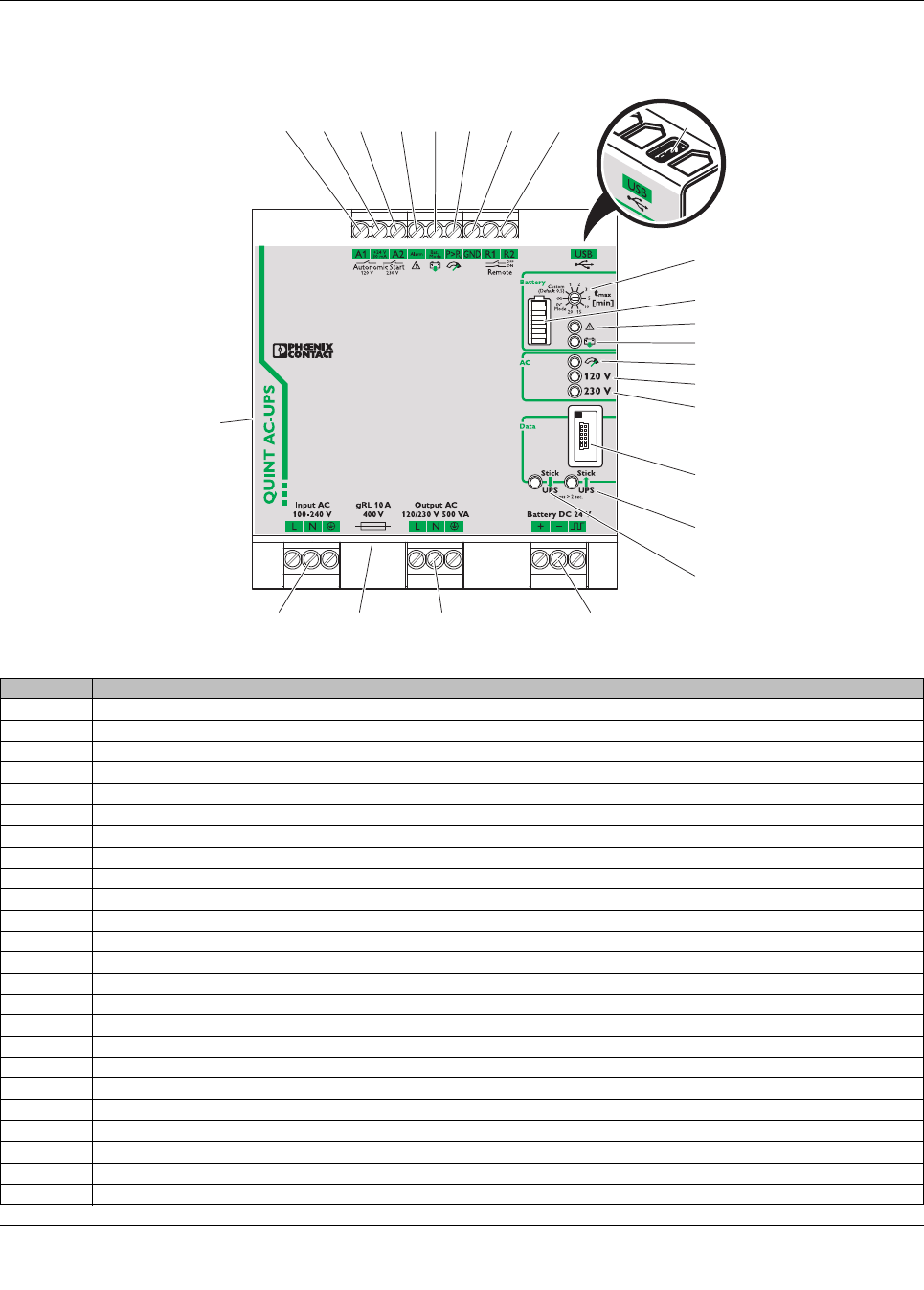
6 Structure
Figure 1 Position of the function elements
1
23 22 21 20
3456
10
8
7
2
11
12
13
14
15
16
17
19
9
18
24
No. Connection terminal blocks and function elements
1UPS battery-operated start (120 V AC/60 Hz)
2Active output for UPS battery-operated start
3UPS battery-operated start (230 V AC/50 Hz)
4Active signal output alarm
5Active signal output battery mode
6Active signal output POWER BOOST
7GND, reference potential
8Battery mode remote shutdown
9USB interface MINI type B
10 Rotary switch for setting the buffer time tmax [min]
11 LED bar graph display
12 Red LED indicator: alarm
13 Yellow LED indicator: battery mode
14 Yellow LED indicator: BOOST mode active
15 Green LED indicator 120 V AC: POWER IN OK (mains operation), supply voltage load (battery mode)
16 Green LED indicator 230 V AC: POWER IN OK (mains operation), supply voltage load (battery mode)
17 Data port
18 Buttons for write function: parameter data from QUINT-UPS -> IFS-CONFSTICK
19 Buttons for write function: parameter data from IFS-CONFSTICK -> QUINT-UPS
20 Power storage device connection terminal blocks (plus/minus/communication cable)
21 Connection terminal blocks for AC outputs
22 Device mains fuse (400 V/10 A)
23 Connection terminal blocks for AC input
24 Universal snap-on foot (rear mounting)
QUINT-UPS/ 1AC/ 1AC/500VA
104661_en_02 PHOENIX CONTACT 12
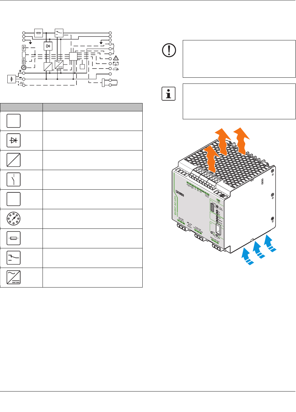
7Basic circuit diagram 8 Installation
8.1 Convection
Figure 2 Convection
Element Meaning
Microprocessor
Decoupling
Charging unit
Switch
Temperature sensor
Selector switch
Fuse
Switch
Inverter
R1
GND
R2
t [min]
max
Alarm
Bat.-Mode
Power-Boost
Remote
Battery
Confirm
Data-Port
USB-Port
Input AC
100..240V
Output AC
120/230V
Autonomic-
Start
24V 0.03A
120V 230V
m
C
J
I
F
S
24VDC
L L
N N
PE PE
µC
J
NOTE: enable convection
To enable sufficient convection, we recom-
mend a minimum vertical gap to other mod-
ules of 50 mm. A horizontal gap of 5 mm is
recommendable.
The device can be snapped onto all DIN rails
in accordance with EN60715 and should be
mounted in the normal mounting position
(connection terminal blocks on top and bot-
tom).
QUINT-UPS/ 1AC/ 1AC/500VA
104661_en_02 PHOENIX CONTACT 13
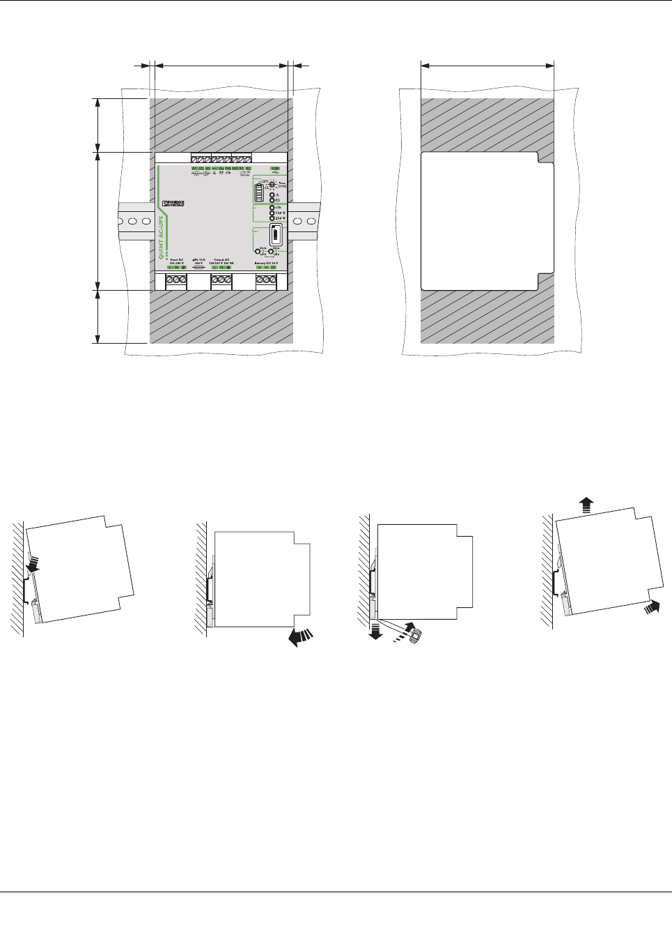
8.2 Mounting position
Figure 3 Installation dimensions and locked areas
8.3 Mounting on a DIN rail
Assembly
Position the module with the DIN rail guide on the upper
edge of the DIN rail, and snap it in with a downward motion.
Figure 4 Assembly
Removing
Pull the snap lever open with the aid of a screwdriver and
slide the module out at the lower edge of the DIN rail.
Figure 5 Removal
125
50
50 130
125
55
AB
B
A
QUINT-UPS/ 1AC/ 1AC/500VA
104661_en_02 PHOENIX CONTACT 14
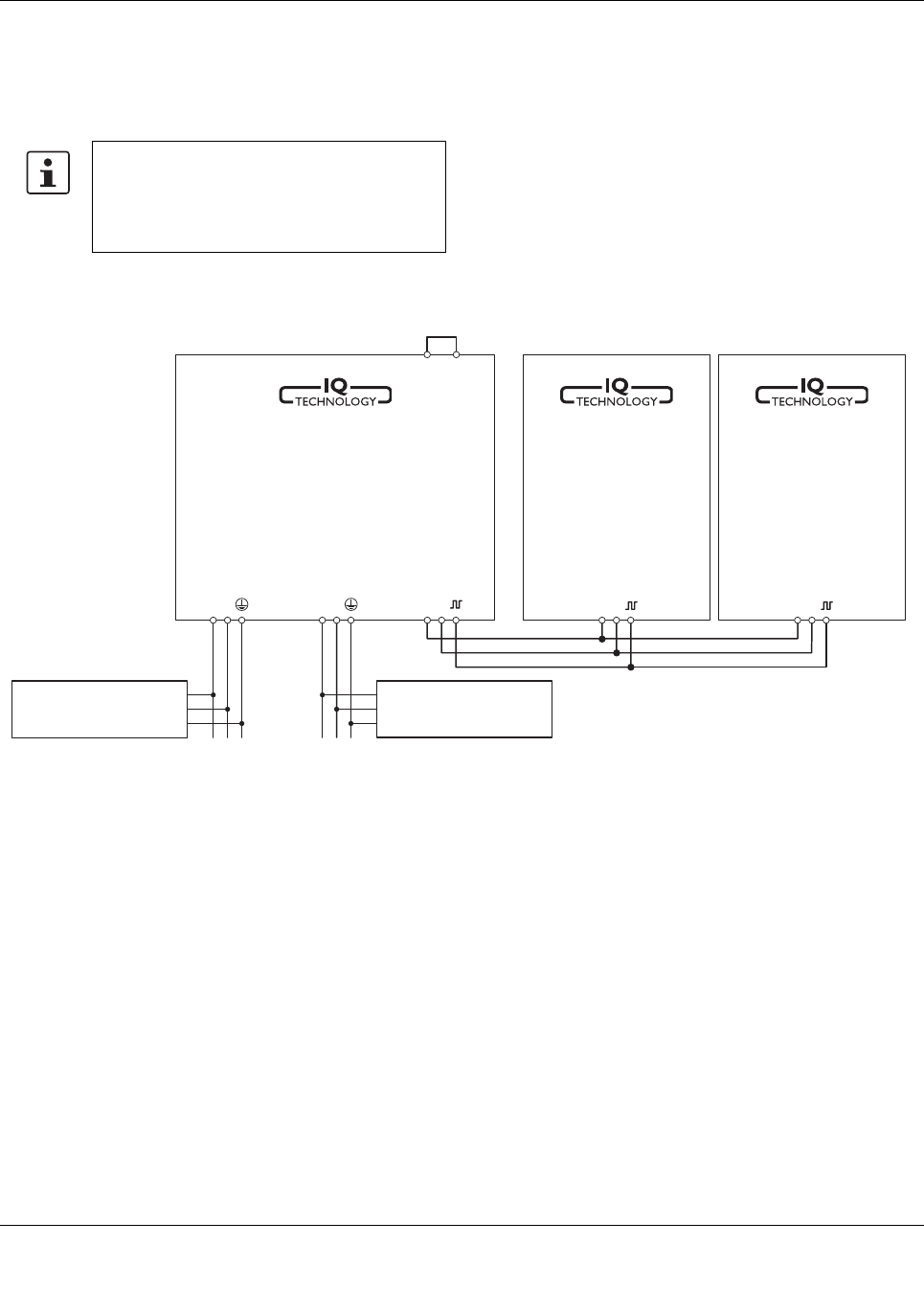
9 Installation of individual components
Installation of uninterruptible power supply units must corre-
spond to EN 60950 regulations.
Figure 6 Schematic design
Provide a switch/circuit breaker close to the
uninterruptible power supply unit at the AC in-
put and at the battery terminals, which are la-
beled as the disconnecting device for these
devices.
+ - + -
R1 R2
L N L N + -
unbuffered
AC-Load
bufferd
AC-Load
Energy-
storage
A
Energy-
storage
B
QUINT
AC UPS
Battery
Output
Input
QUINT-UPS/ 1AC/ 1AC/500VA
104661_en_02 PHOENIX CONTACT 15
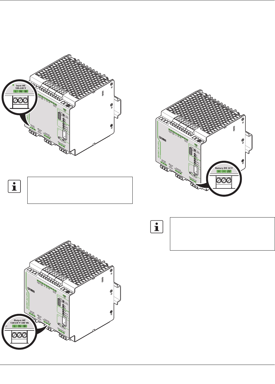
10 Device connection terminal blocks
10.1 AC input
The supply voltage is connected via "Input AC 100 - 240 V"
connection terminal blocks.
Figure 7 Connection terminal block, AC input
10.2 AC output
Buffered output voltage is connected via "Output AC" con-
nection terminal blocks.
Figure 8 Connection terminal block, AC output
10.3 DC battery
The power storage device is connected via the "Battery DC
24 V" connection terminal blocks. In order to use the IQ tech-
nology of the power storage device, a communication cable
should also be connected between the uninterruptible
power supply unit and the power storage device used in IQ
technology. Optimum use of the buffer time and preventive
battery monitoring are ensured by the IQ technology, for ex-
ample.
Figure 9 Connection terminal blocks, DC battery
If loads must not be supplied in the event of a
mains breakdown or failure, they must be con-
nected directly to the input of the power sup-
ply as unbuffered AC load.
Our range of accessories is being continually
extended, our current range of power storage
devices with IQ technology can be found in
the download area at www.phoenixcon-
tact.net/products
QUINT-UPS/ 1AC/ 1AC/500VA
104661_en_02 PHOENIX CONTACT 16
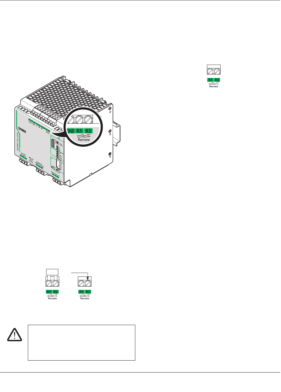
10.4 Remote shutdown R1, R2
The connection terminal blocks are bridged with a plug-in
bridge by default. Remote shutdown of the uninterruptible
power supply units is deactivated. Should the supply voltage
fail or be undershot, the UPS switches over to battery mode.
If the plug-in bridge is not plugged in, the UPS shuts down in
the event of the mains supply voltage failing or being under-
shot.
Figure 10 Connection terminal block R1, R2
Remote shutdown is deactivated
UPS in function (delivery state)
– The "R1" and "R2" terminal points are short circuited
(delivery with plug-in bridge) OR 24 V DC is present at
terminal point "R2".
– In the event of a voltage supply failure, the UPS switch-
es over to battery mode.
Figure 11 Remote shutdown is deactivated
10.5 Remote shutdown is activated
– The "R1" and "R2" terminal points are not short circuit-
ed.
– In the event of a voltage supply failure, the UPS does
not switch over to battery mode. The device switches
off.
Figure 12 Remote shutdown active
Example 1
The remote shutdown can be used to suppress the buffering
of selective machine shutdowns. In doing so, the auxiliary
contact of the main switch is connected to R1 and R2 con-
nection terminal blocks.
Example 2
End the buffering at a specific time (e.g., following shutdown
of another machine part). Remote shutdown can be acti-
vated with a relay (N/C contact).
CAUTION: Risk of electric shock
In the event of a voltage supply failure, the
UPS switches over to battery mode. The load
connected to the AC output is supplied by the
power storage device.
+24 V DC
QUINT-UPS/ 1AC/ 1AC/500VA
104661_en_02 PHOENIX CONTACT 17
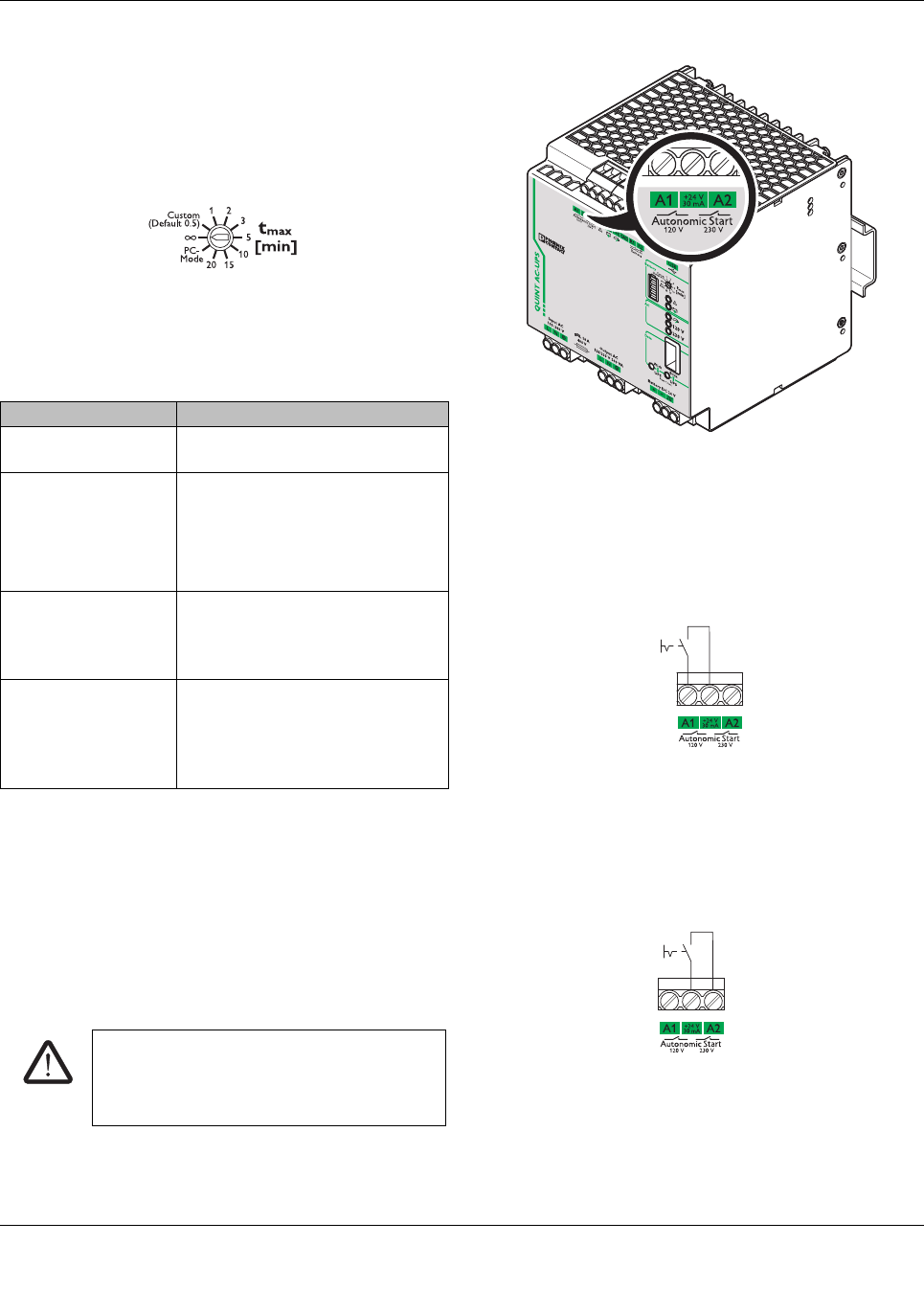
10.6 Setting the buffer time
You can set the time for exiting battery mode via the rotary
selector switch on the front of the device. For this purpose
use a screwdriver.
Figure 13 Buffer time selector switch
10.7 Remote activation of Autonomic Start
Remote activation of Autonomic Start is always used when
primary voltage supply is not available at the AC input termi-
nals of uninterruptible power supply units, but the device
nonetheless needs to be started.
Another application, for example, is when a portable ma-
chine needs to be moved and connection should be estab-
lished by a mains supply that can be used in any location.
Figure 14 Autonomic Start connection terminal blocks
Autonomic Start 120 V
In this operating mode, the output voltage level is set ac-
cording to the preselected value. The output voltage con-
nected to the load is 120 V/60 Hz.
Figure 15 Autonomic Start 120 V
Autonomic Start 230 V
In this operating mode, the output voltage level is set ac-
cording to the preselected value. The output voltage con-
nected to the load is 230 V/50 Hz.
Figure 16 Autonomic Start 230 V
tmax [min] setting Meaning
1, 2, 3, 5, 10, 15, 20 The UPS switches off after the set
buffer time.
Custom (default 0.5) The UPS switches off after the indi-
vidual buffer time set via UPS-
CONF.
If a buffer time is not set, the UPS
shuts down after 30 seconds.
(unlimited, delivery
state)
Buffering with the total stored
power. A warning is generated as
soon as the power storage device
only has 10% charge (default).
PC mode In PC mode, it is possible to con-
tinue working with a PC after a
mains failure, perform a controlled
shutdown and restart automati-
cally.
CAUTION: Risk of electric shock
In this operating mode, the load connected to
the AC output is supplied by the power stor-
age device.
QUINT-UPS/ 1AC/ 1AC/500VA
104661_en_02 PHOENIX CONTACT 18
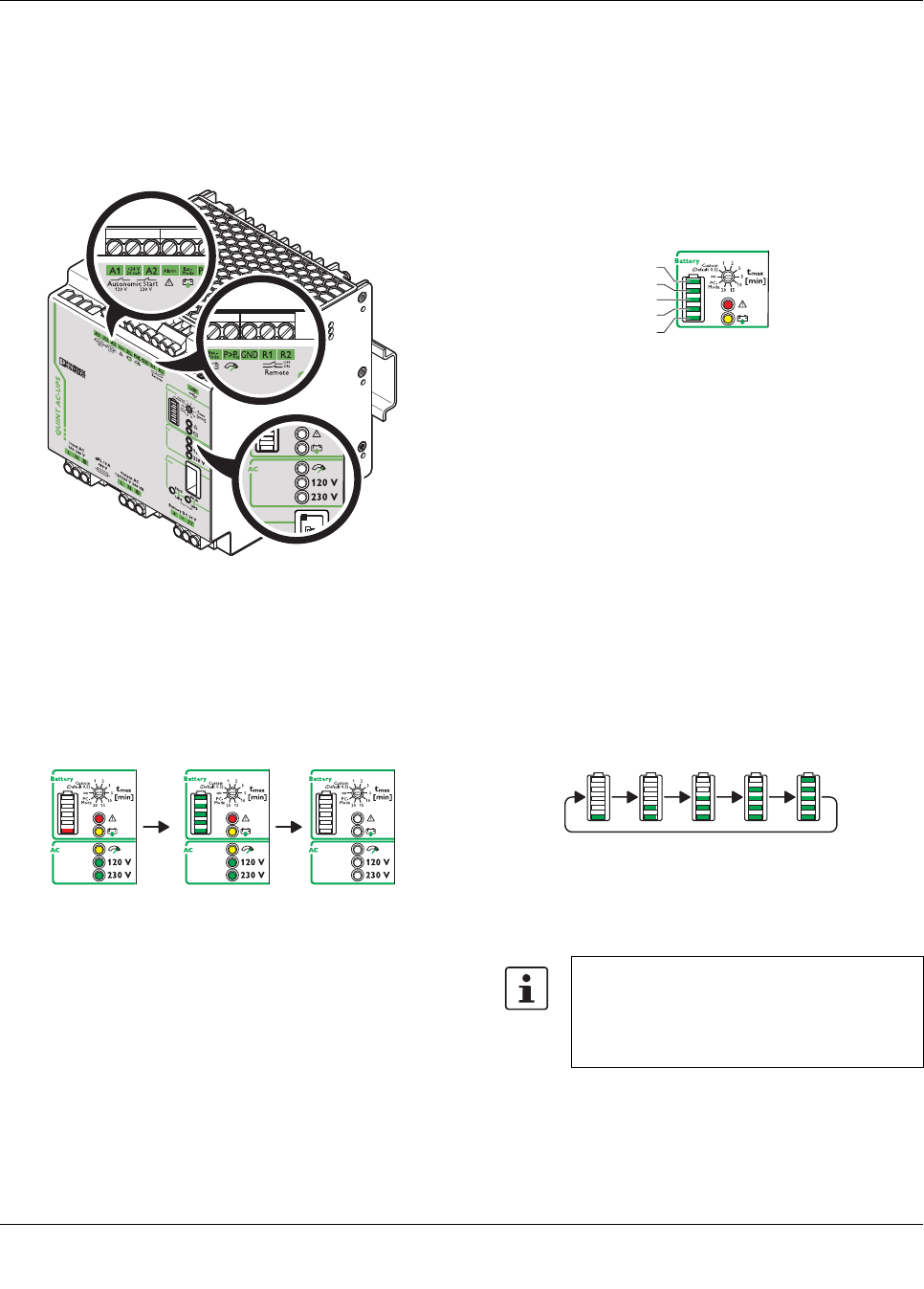
11 Signaling
Various LED indicators are available for visual function mon-
itoring of uninterruptible power supplies. Moreover, active
signal outputs can be used to forward this data to a higher-
level control system.
Figure 17 LED indicators and signal outputs
LED test
When starting the uninterruptible power supply unit for the
first time, a test is automatically performed on the LED indi-
cators and the LED bar graph display.
The LEDs indicate the following states:
Figure 18 LED indicators
Following the LED test, the current device status of the unin-
terruptible power supply unit is displayed.
11.1 LED bar graph display
The LED bar graph display consists of five individual seg-
ments and displays the SOC (state of charge) of the power
storage device. In this case, each segment corresponds to
20% of the total capacity.
Depending on the type of power storage device used, i.e.
whether it is equipped with IQ technology or not, the display
varies according to charging or discharging.
Figure 19 LED bar graph display
11.2 IQ power storage devices
In mains operation of the uninterruptible power supply unit,
supplying the load connected to the AC output of the UPS is
of paramount importance. The power storage device is
charged using the power reserve of the UPS.
Charging a new, unknown IQ power storage device
•As the state of charge (SOC) of the power storage de-
vice is still unknown when installing it for the first time, it
is essential that the device is fully charged once. For ex-
ample, in doing so, the capacity of the power storage
device is determined. The bar graph will exhibit an un-
stable curve until the device has been fully charged for
the first time.
Figure 20 Charging a new IQ power storage device (un-
known SOC)
The charging time of the power storage de-
vice depends on the capacity and energy sup-
plied by the uninterruptible power supply unit.
The maximum charging time can last up to
several hours.
20%
100%
80%
60%
40%
QUINT-UPS/ 1AC/ 1AC/500VA
104661_en_02 PHOENIX CONTACT 19
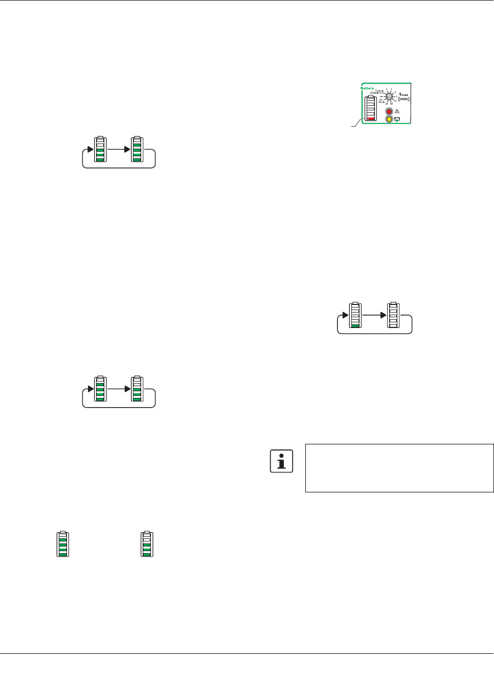
Charging known IQ power storage devices
•The power storage device has already been fully
charged once and its properties have been determined.
The individual segments of the LED bar graph display
are illuminated based on the current state of charge
(SOC) of the power storage device. The current charg-
ing state is indicated by permanently illuminated seg-
ments. The charging process is indicated by the
flashing upper segment.
Figure 21 IQ power storage device is charged (SOC is
known)
Discharging IQ power storage devices
When operating the uninterruptible power supply unit in bat-
tery mode, the load connected to the AC output of the UPS
is supplied by the power stored in the power storage device.
The charging state of the power storage device is indicated
by means of the LED bar graph display. In this case, a dis-
tinction is made between the following states:
•A new power storage device that has not yet been fully
charged. As the power storage device is still unknown
when installing it for the first time, the state of charge
must be determined. As such, it is essential that the
power storage device is fully charged once.
Figure 22 New power storage device (unknown SOC)
•The power storage device has already been fully
charged once and its properties have been determined.
The individual segments of the LED bar graph are con-
trolled based on the current state of charge of the power
storage device.
Figure 23 Power storage device is discharged (SOC is
known)
•Should the capacity of the connected power storage de-
vice drop to below 10% of the determined capacity dur-
ing battery mode discharge, the lower segment of the
LED bar graph display will be illuminated in red.
Figure 24 Power storage device capacity < 10%
11.3 Standard power storage devices (without IQ
technology)
When operating the uninterruptible power supply unit in
mains operation, the load connected to the AC output is sup-
plied by the UPS. In addition, the connected power storage
device is charged by the UPS.
The current charging state of the power storage device is in-
dicated by means of the LED bar graph display. The lower
segment of the LED bar graph display flashes green.
Figure 25 Charge standard power storage device
Discharging power storage devices
When operating the uninterruptible power supply unit in bat-
tery mode, the load connected to the AC output of the UPS
is supplied by the power stored in the power storage device.
= 80 % = 60 %
When the UPS is operated in battery mode
with the power storage device without IQ tech-
nology, the LED bar graph display is not illumi-
nated.
< 10 %
QUINT-UPS/ 1AC/ 1AC/500VA
104661_en_02 PHOENIX CONTACT 20
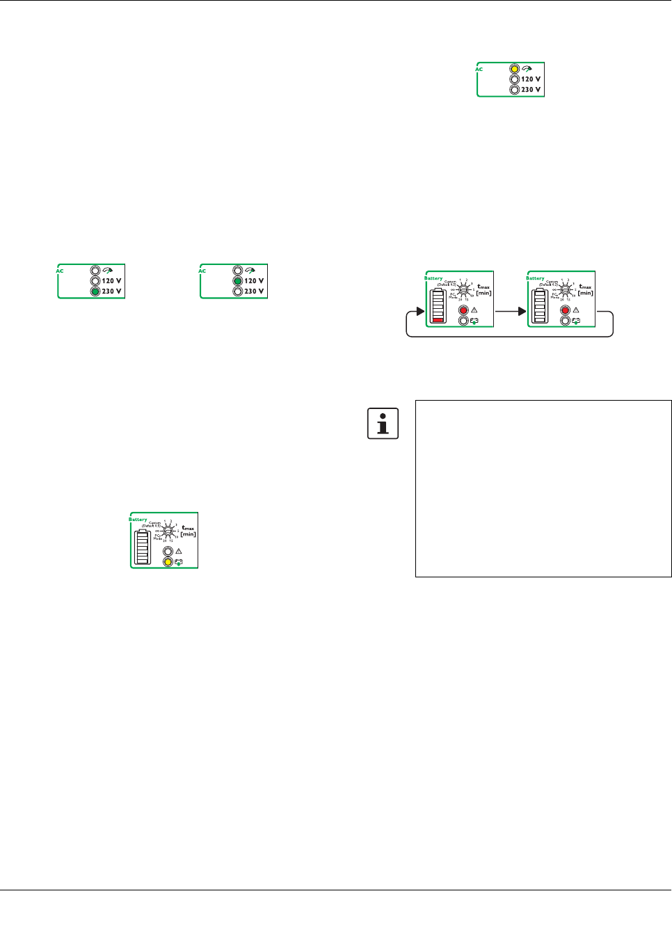
11.4 LED indicators
Mains operation or battery mode
The UPS can be operated with a mains voltage of 120 V AC
or 230 V AC. The permitted mains frequency ranges from 45
Hz to 65 Hz.
In mains operation, the load connected to the output of the
uninterruptible power supply unit is supplied by the mains.
Depending on the input voltage detected and the resulting
output voltage, the corresponding operating LED is acti-
vated at 120 V or 230 V.
Figure 26 LED indicators in mains or battery mode
Battery operation
In battery mode, the load connected to the AC output of the
uninterruptible power supply unit is supplied by the power
storage device. The output voltage is automatically set to
120 V AC or 230 V AC based on the previously detected
input voltage.
In battery mode, the corresponding yellow LED indicator is
activated.
Figure 27 LED indicator battery mode active
P > PN (POWER BOOST)
The load connected to the AC output of the uninterruptible
power supply unit can be operated up to POWER BOOST
static power reserve. The POWER BOOST static power re-
serve depends on the ambient temperature.
– In mains operation, POWER BOOST (IN + 25%) can be
permanently operated
– In battery mode, POWER BOOST (IN + 25%) can be op-
erated for a maximum of five seconds
In POWER BOOST, the corresponding yellow LED indicator
is activated.
Figure 28 LED indicator P > PN active
Alarm (power storage device disrupted in mains oper-
ation)
The LED indicator alarm is permanently illuminated in red. In
addition, the lower segment of the LED bar graph display
flashes red.
Figure 29 LED indicator alarm active
When using the UPS-BAT... power storage device and a
connected communication cable, the current life expec-
tancy (SOH, State of Health) is determined via the IQ tech-
nology. An alarm is signaled in the following cases:
– The adjustable threshold "remaining life expectancy" is
reached.
– Different types of battery technology were connected
that cannot be charged simultaneously, e.g. VRLA and
LI-ION.
– The presence check is negative.
– The quality check is negative.
When using power storage devices other than UPS-BAT...,
an alarm is signaled if it is not present or if the quality of the
power storage device is no longer sufficient for supplying the
load in the event of a mains failure.
If the lower LED bar graph display segment does not flash,
the alarm indicates overload or service mode.
Input AC / Output AC
230 V AC
Input AC / Output AC
120 V AC
Check the connecting cables between the un-
interruptible power supply unit and the power
storage device.
Replace the power storage device while mon-
itoring the polarity. Then perform an initializa-
tion. In doing so, the battery presence check
is automatically performed and the uninter-
ruptible power supply automatically detects
the power storage device used. This function-
ality is only supported by power storage de-
vices with IQ technology.
QUINT-UPS/ 1AC/ 1AC/500VA
104661_en_02 PHOENIX CONTACT 21
11.5 LED bar graph display with communication ca-
ble installed between the UPS and the power
storage device
The current charging state and the remaining runtime of the
power storage device is determined during startup of the
UPS. As such, the LED indicator lights up from bottom to top
during this process (charging the battery in mains operation)
or from top to bottom (discharging the battery in battery
mode).
When the power storage device is fully charged and the
charging state is determined, this is displayed by the bar
graph.
11.6 LED bar graph display without communication
cable between the UPS and the power storage
device
If a communication cable is not connected between the UPS
and the power storage device, the individual segments of
the LED bar graph display will be illuminated as follows dur-
ing startup.
The lower segment of the LED bar graph display is acti-
vated.
– Flashing green: power storage device is being charged
– Permanent red light: battery problem
– Off: power storage device is not being charged
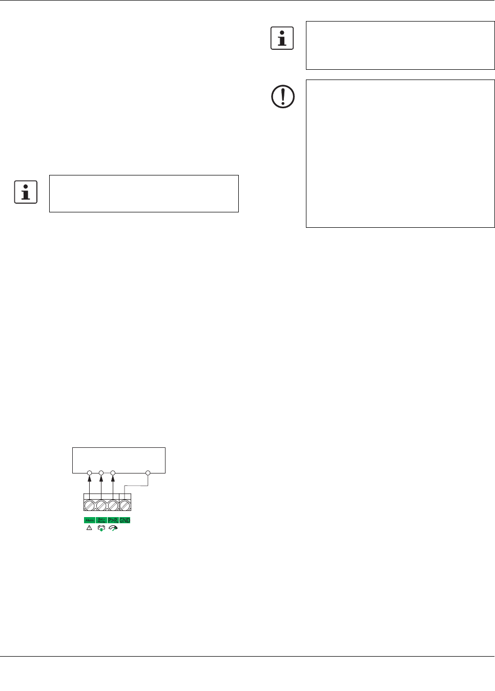
11.7 Active signal outputs
Active signal outputs can be used to forward this data to a
higher-level control system. Each signal output can be
loaded with a maximum of 24 V DC/25 mA.
Figure 30 Active signal outputs
Alarms, warnings and/or operating states can be individually
assigned to the battery mode and battery charge via the
UPS-CONF configuration software. In addition to this, the
current device status can be conveniently displayed on your
PC by using UPS-CONF configuration software combined
with an IFS communication cable.
Depending on the charging state and the size
of the power storage device, charging can
range from a few minutes to hours.
PLC Digital Input
+++
GND
24 V DC
25 mA
The free configuration software, along with
accompanying documentation, can be found
in the device download area at www.phoenix-
contact.net/products
NOTE
Assignment between the LED indicator and
the active signal output is identical in the de-
fault settings. If necessary, the corresponding
signal output can be set in addition to the LED
indicator.
The free UPS-CONF configuration software
can be used to individually change the assign-
ment and control of the active signal output.
When individually parameterizing the signal
outputs, ensure that a logical combination is
used.

QUINT-UPS/ 1AC/ 1AC/500VA
104661_en_02 PHOENIX CONTACT 22
12 Function
In mains mode (AC input voltage present), the output volt-
age corresponds to the applied input voltage. In the event of
a failure of the voltage supply, switching to battery mode
takes place without interruption.
The output voltage is set to 120 V AC or 230 V AC based on
the previously detected input voltage.
Figure 31 LED indicator mains mode
12.1 SOC application example
Task:
An industrial PC must be continuously supplied with 120 V
AC or 230 V AC.
Previous solution:
The UPS is buffered with a 3.4 Ah power storage device and
supplies 120 V AC or 230 V AC and a load of 180 W for ten
minutes under optimum conditions.
Problem:
Can the power storage device actually bridge this time?
Charging state, performance, and remaining runtime of the
battery are unknown.
Solution with IQ technology:
The intelligent UPS determines all relevant battery states.
This ensures the transparency required to guarantee the
stability of the supply and optimum use of the battery at all
times.
The intelligent battery management detects the current
charging state of the connected battery and uses this to cal-
culate the remaining runtime.
The QUINT UPS-IQ also signals whether the buffer time is
actually 10minutes. As soon as an adjustable threshold
value is reached, the active switching output or the configu-
ration software generates a warning message or the indus-
trial PC is shut down. The industrial PC works for as long as
possible and is only shut down if absolutely necessary.
12.2 SOH/SOF application example
Task:
Previous solution:
The user invests in a new battery every two years assuming
that the system is reliably protected by this.
Problem:
Is the power storage device really 100% available for two
years? Could the battery have aged more quickly as a result
of higher ambient temperatures and not be able to deliver
sufficient performance?
Solution with IQ technology:
The remaining life expectancy of the battery is known. This
allows servicing to be planned. If the battery is replaced at
the ideal time, costs are also avoided that would occur by re-
placing the battery too early or after failure. It is particularly
important for applications that are widely separated from
each other to ascertain whether the battery will continue to
work reliably for another two years or only for another two
months.
12.3 Charging characteristic
When the recommended UPS-BAT power storage device is
used, the intelligent battery management of the UPS adapts
itself to the respective connected storage technology such
as lithium or lead (VRLA – Valve Regulated Lead Acid) bat-
teries. Additional charging parameter settings are not nec-
essary due to automatic detection.
The UPS is equipped with an integrated charging unit.
Charging is performed according to the current battery state.
By measuring the current temperature at the battery, tem-
perature-compensated charging takes place.
Intelligent battery management ensures fast availability and
maximum service life of the power storage device.
If the communication cable between the UPS and the power
storage device is interrupted, the temperature detected in
the UPS module is used temporarily to ensure temperature
compensation.
Temperature recording only takes place in the UPS module
when using power storage devices other than the UPS-BAT.
Furthermore, adjustment and adherence to the charging pa-
rameters is necessary.
Input AC / Output AC
230 V AC
Input AC / Output AC
120 V AC
QUINT-UPS/ 1AC/ 1AC/500VA
104661_en_02 PHOENIX CONTACT 23
13 Interfaces
The uninterruptible power supply unit is equipped with two
interfaces for data transmission.
1. Interface: data port
2. Interface: USB interface MINI type B
13.1 Data port
The uninterruptible power supply unit is equipped with a
data port for data transmission. A data cable is required for
communicating with a PC or a higher-level controller.
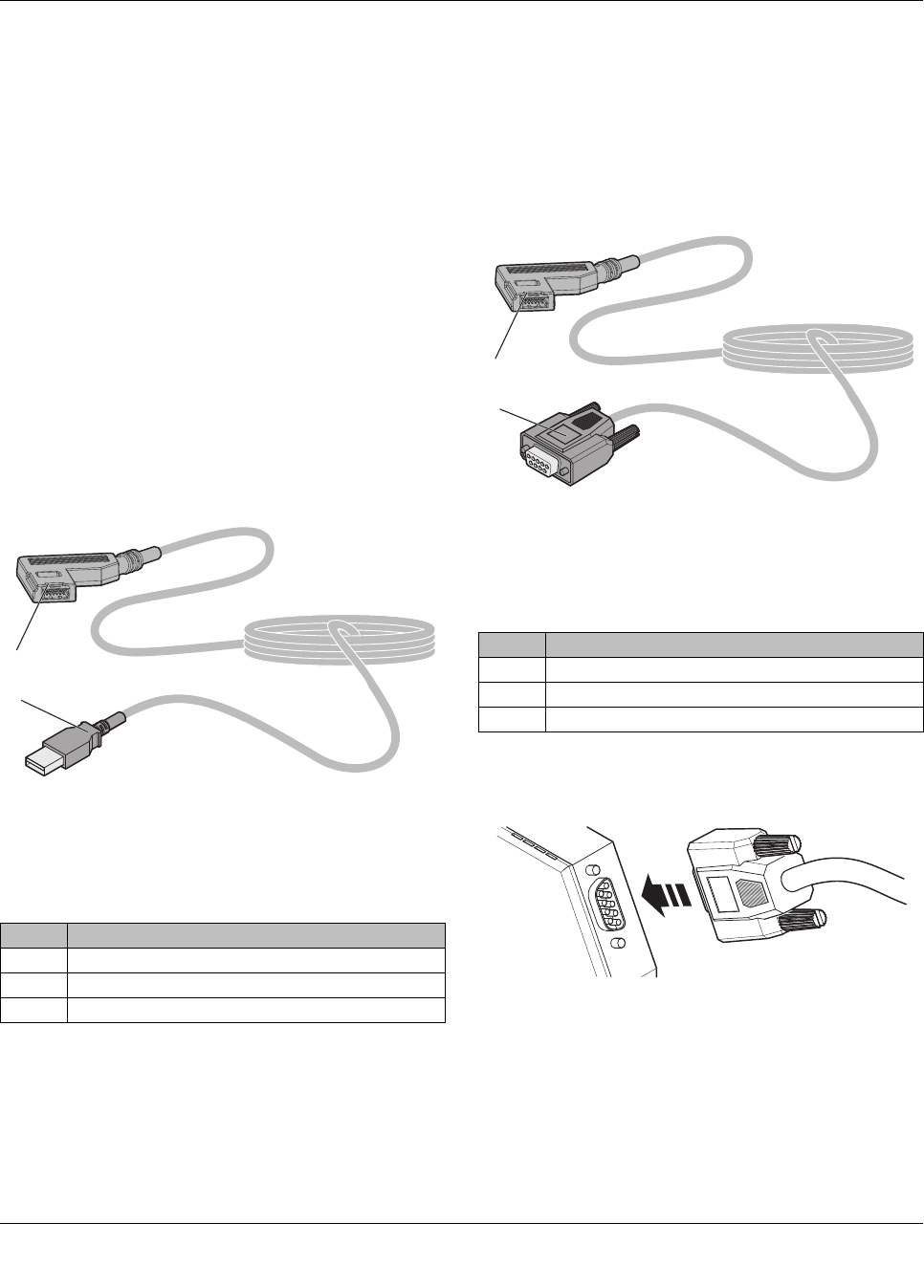
IFS-USB-DATACABLE
The uninterruptible power supply unit is connected to the
USB PC connection with data cable IFS-USB-DATACABLE
(Order No. 2320500) via the data port.
The data cable can be used to parameterize and monitor the
UPS. The data cable is electrically isolated.
Figure 32 IFS-USB-DATACABLE
IFS-RS232-DATACABLE
The uninterruptible power supply unit is connected to the se-
rial RS-232 connection of a data transmission device, such
as a modem, with data cable IFS-RS232-DATACABLE (Or-
der No. 2320490) via the data port.
Figure 33 IFS-RS232-DATACABLE
Ethernet connection is possible by connecting via an FL-
COMSERVER (e.g., Order No. 2313452).
Figure 34 FL COMSERVER connection
The data cable between the modem and the UPS is neces-
sary for parameterization and monitoring. It contains the in-
terface electronics and electrical isolation.
No. Designation
1IFS plug
2 USB plug type A
Cable length: 3 m
2
1
No. Designation
1IFS plug
29-pos. D-SUB plug
Cable length: 2 m
2
1
QUINT-UPS/ 1AC/ 1AC/500VA
104661_en_02 PHOENIX CONTACT 24
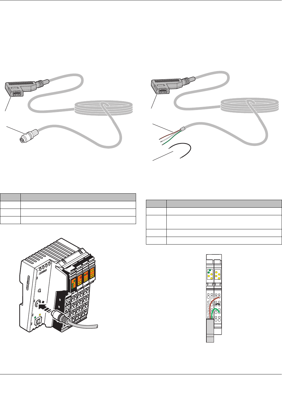
IFS-MINI-DIN-DATACABLE
The uninterruptible power supply is connected, for example,
to Phoenix Contact type ILC 1xx controllers with data cable
IFS-MINI-DIN-DATACABLE (Order No. 2320487) via the
data port.
Figure 35 IFS-MINI-DIN-DATACABLE
Figure 36 Connection to an ILC 1xx controller
IFS-OPEN-END-DATACABLE
The uninterruptible power supply is connected, for example,
to a Phoenix Contact IB IL RS UNI-PAC Inline communica-
tion terminal (Order No. 2700893) with data cable IFS-
OPEN-END-DATACABLE (Order No. 2320450) via the data
port.
Figure 37 IFS-OPEN-END-DATACABLE
Figure 38 Connection to communication terminal IB IL
RS UNI-PAC
No. Designation
1IFS plug
2 6-pos. MINI-DIN plug
Cable length: 2 m
1
2
ILC 151 ETH
Order-No.: 2700974
HW/FW: xx/xxx
MAC Addr.: xx.xx.xx.xx
AUTOMATIONWORX
MRESET
STOP
RUN/PROG
RESET
PRG
ACT
LNK
I6
I5
I8
I7
PF
BSA
RDY FAIL
I1
I3
I2
I4
E
Q2
Q1
Q3 Q4
UL
US
UM
FF
FR
No. Designation
1IFS plug
2 Data cable (open signal lines), ready for connec-
tion, assembled
3 Wire jumper, ready for connection, assembled
Cable length: 2 m
1
3
2
12
1
2
3
4
1
2
3
4
12
1
2
3
4
1
2
3
4
D
TR
CTS
RTS
RxD
TxD
DCD
DSR
DTR
QUINT-UPS/ 1AC/ 1AC/500VA
104661_en_02 PHOENIX CONTACT 25
13.2 IFS-CONFSTICK-L
The IFS-CONFSTICK-L is a multi-functional memory block
for easy storage and backup of configuration and parameter
data. You can copy the parameterization of one UPS to an-
other UPS of the same type using the IFS-CONFSTICK-L.
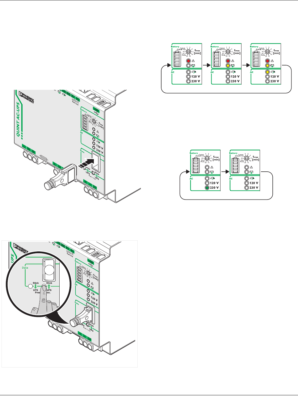
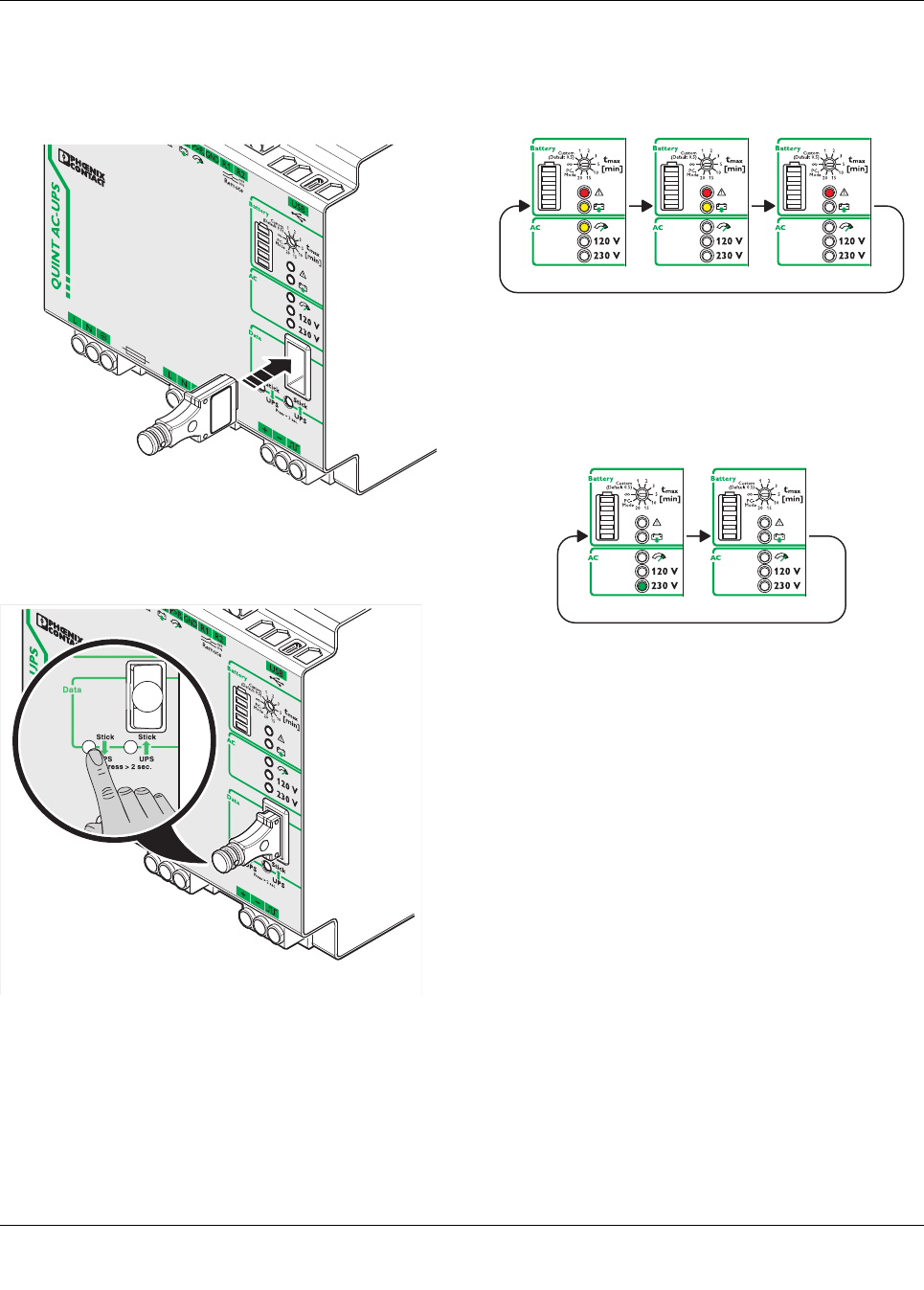
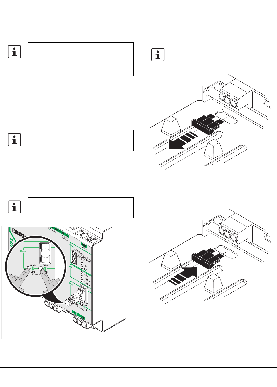
13.3 Transfer parameter data from UPS to IFS-
CONFSTICK
1. Insert the IFS-CONFSTICK-L carefully into the data port
of the UPS while observing the plug-in direction.
Figure 39 Insert IFS-CONFSTICK-L
2. Press the "UPS -> Stick" button and hold for at least 2
seconds.
Figure 40 Transfer parameter data from UPS -> IFS-
CONFSTICK-L
3. The parameter transmission is started. The three LED
indicators will be cyclically illuminated during the trans-
mission.
Figure 41 Write parameter data active
4. An error-free transmission is represented by a flashing
green LED indicator. An inaccurate transmission is rep-
resented by a red LED indicator.
Figure 42 Transmission successful
5. Once the signaling time has elapsed, all LED indicators
are switched off and the current device status is dis-
played.
QUINT-UPS/ 1AC/ 1AC/500VA
104661_en_02 PHOENIX CONTACT 26
13.4 Transferring IFS-CONFSTICK parameters to the
UPS
1. Insert the IFS-CONFSTICK-L carefully into the data port
of the UPS while observing the plug-in direction.
Figure 43 Insert IFS-CONFSTICK-L
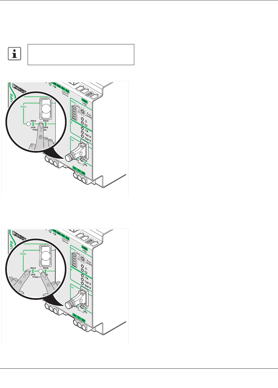
2. Press the “Stick -> UPS” button and hold down for at
least 2 seconds.
Figure 44 Start parameter transmission
3. The parameter transmission is started. The three LED
status indicators will be cyclically illuminated during the
transmission.
Figure 45 Write parameter data active
4. An error-free transmission is represented by a flashing
green LED indicator. An inaccurate transmission is rep-
resented by a red LED indicator.
Figure 46 Transmission successful
5. Once the signaling time has elapsed, all LED indicators
are switched off and the current device status is dis-
played.
QUINT-UPS/ 1AC/ 1AC/500VA
104661_en_02 PHOENIX CONTACT 27
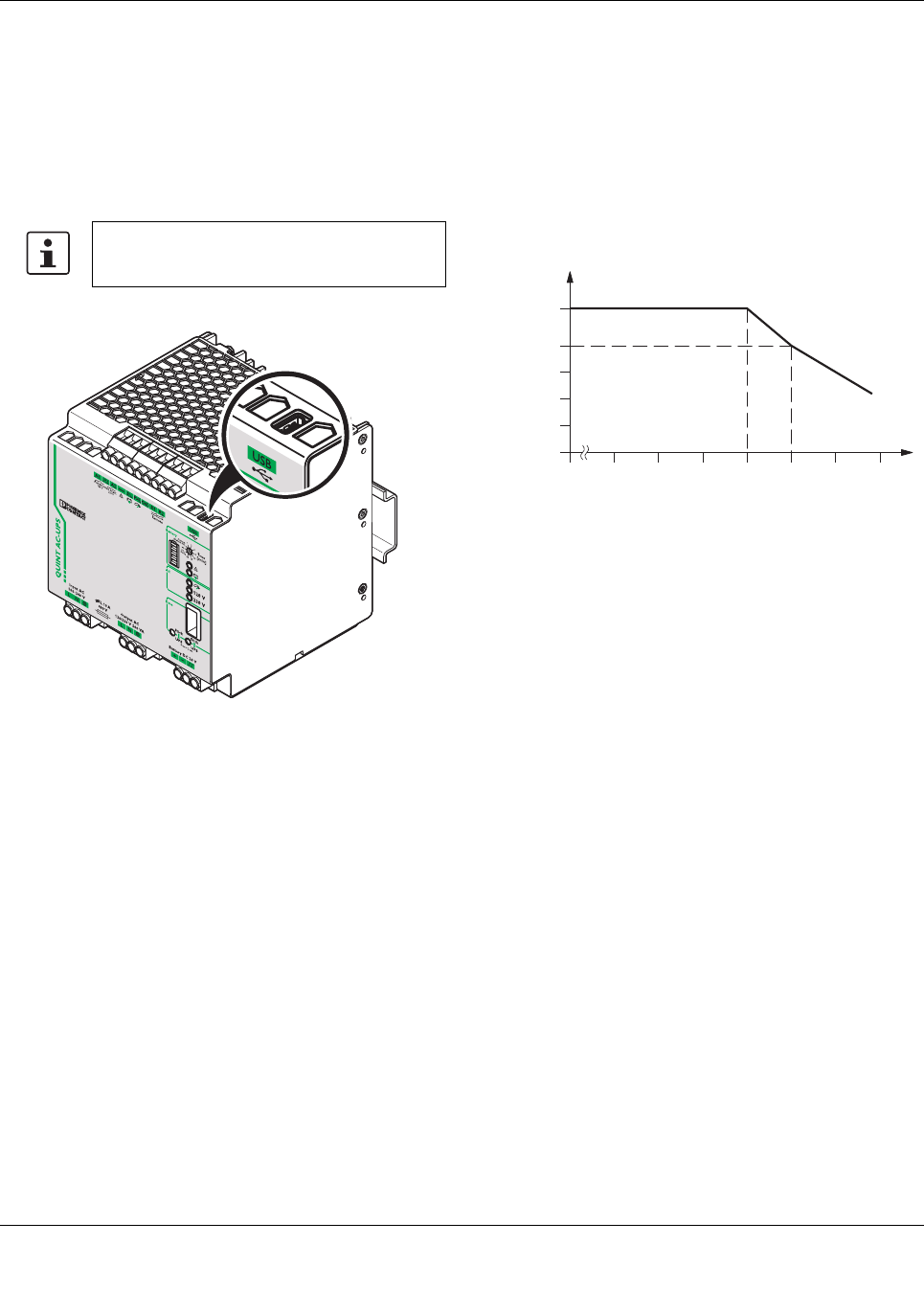
13.5 USB interface MINI type B
The uninterruptible power supply unit is connected to the
USB PC connection with data cable CABLE-USB/MINI-
USB-3.0M (Order No. 2986135) via USB interface mini type
B.
The data cable can be used to parameterize and monitor the
UPS.
Figure 47 USB interface
14 Derating
14.1 Temperature-dependent derating
At an ambient temperature of up to +40°C, the UPS sup-
plies the IBOOST continuous output current in mains opera-
tion. In battery mode and mains operation, the device sup-
plies the IN nominal output current up to an ambient
temperature of +50°C. In the case of ambient temperatures
above +50°C, the output power must be decreased by
2.5% per Kelvin temperature increase.
Figure 48 Derating diagram
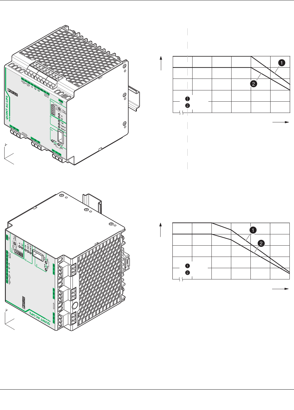
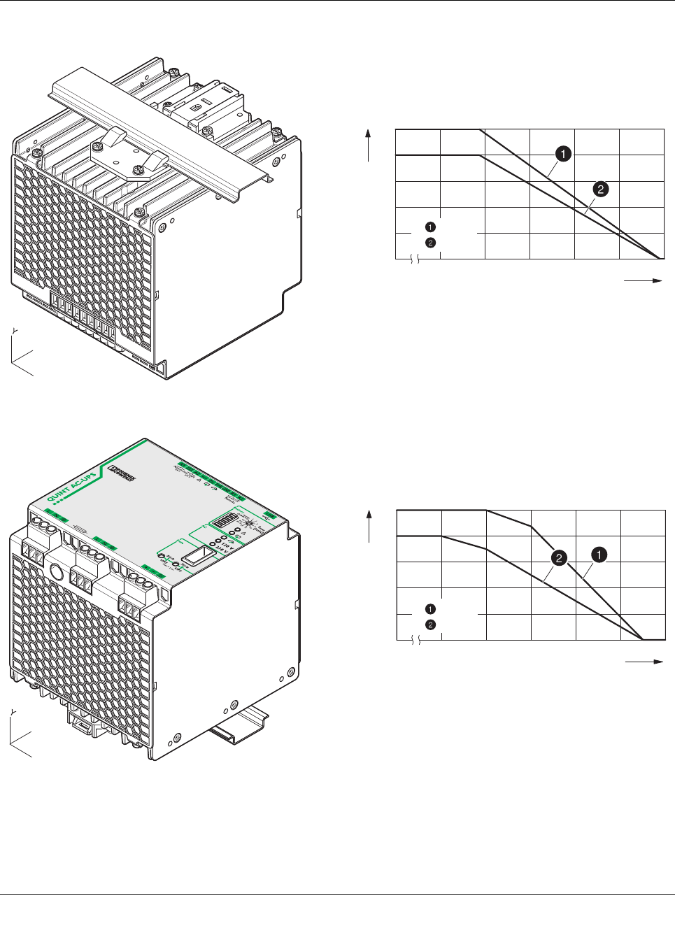
14.2 Position-dependent derating
The uninterruptible power supply unit can be snapped onto
all DIN rails according to EN 60715. It should be mounted
horizontally in the normal mounting position (with the input
terminals facing downward).
When installing in a different mounting position, derating
should be adhered to.
The characteristic curve can be used to determine the max-
imal output power to be drawn for each ambient temperature
for different mounting positions.
Connection via the MINI type B USB interface
is not electrically isolated.
[A]
[°C]
-25
0
40 6020
IBOOST
IN
QUINT-UPS/ 1AC/ 1AC/500VA
104661_en_02 PHOENIX CONTACT 28
Normal mounting position
Rotated mounting position 90° X-axis
[°C]
[W] / [VA]
300
100
020 30 40 50 60 70
400
200
500
-25
= W
= VA
X
Z
[°C]
[W] / [VA]
300
100
020 30 40 50 60 70
400
200
500
-25
= W
= VA
X
Z
QUINT-UPS/ 1AC/ 1AC/500VA
104661_en_02 PHOENIX CONTACT 29
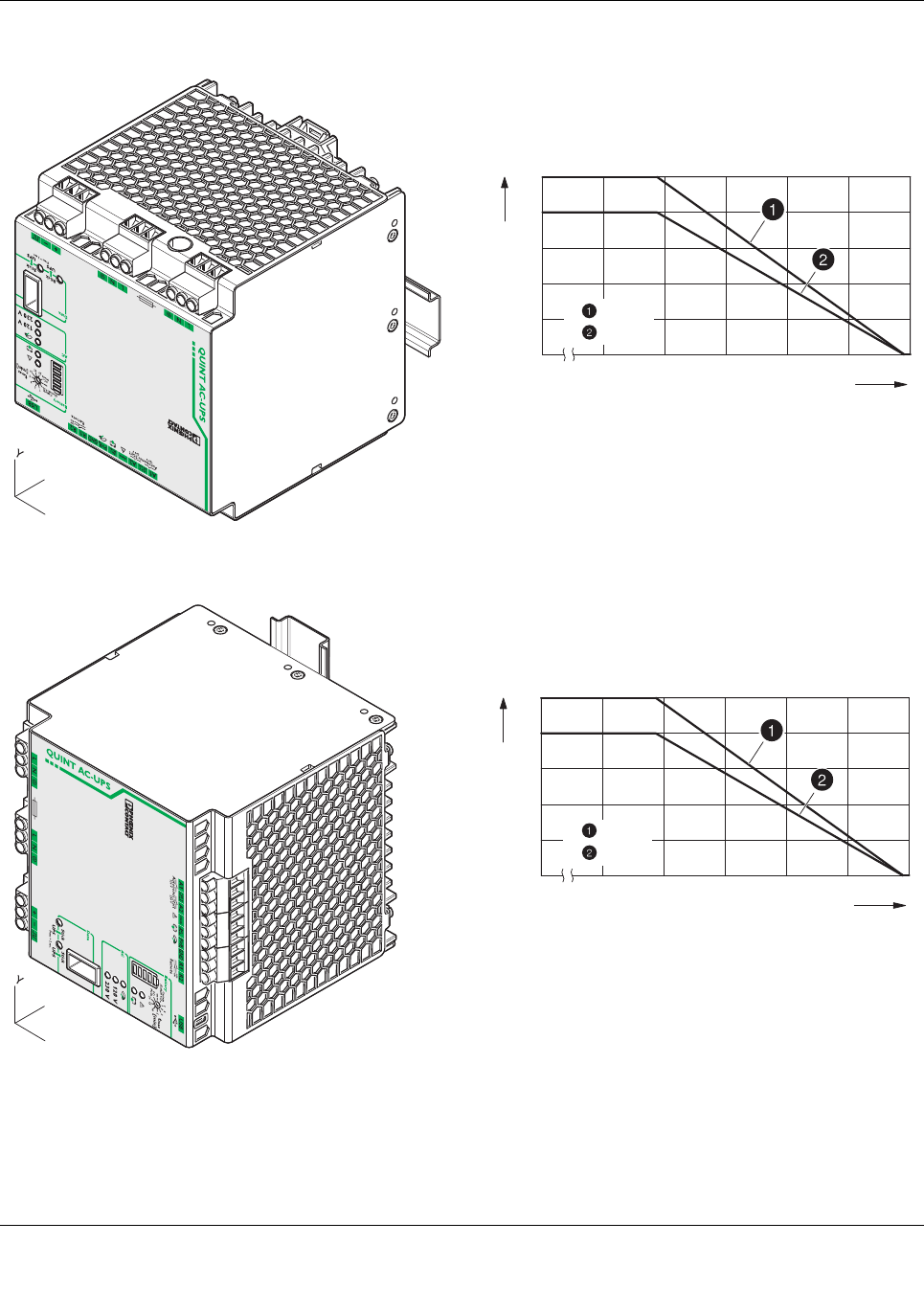
Rotated mounting position 180° X-axis
Rotated mounting position 270° X-axis
[°C]
[W] / [VA]
300
100
020 30 40 50 60 70
400
200
500
-25
= W
= VA
X
Z
X
Z
[°C]
[W] / [VA]
300
100
020 30 40 50 60 70
400
200
500
-25
= W
= VA
QUINT-UPS/ 1AC/ 1AC/500VA
104661_en_02 PHOENIX CONTACT 30
Rotated mounting position 90° Z-axis
Rotated mounting position 270° Z-axis
X
Z
[°C]
[W] / [VA]
300
100
020 30 40 50 60 70
400
200
500
-25
= W
= VA
[°C]
[W] / [VA]
300
100
020 30 40 50 60 70
400
200
500
-25
= W
= VA
X
Z
QUINT-UPS/ 1AC/ 1AC/500VA
104661_en_02 PHOENIX CONTACT 31
15 Service mode
When working in a system, it may be necessary to switch the
uninterruptible power supply unit over to service mode.
The following options are available for switching to service
mode:
– Button on the front of the UPS
–UPS-CONF software
– Service stick (IFS-CONFSTICK-L including service for-
matting, see UPS-CONF user manual)
15.1 Power storage device replacement
To switch to UPS service mode, press and hold the two but-
tons on the front of the UPS for longer than 6seconds.
•The red LED indicator alarm is illuminated
•You may need to remove the existing fuse, depending
on the power storage device used
•Disconnect the connecting cables from the power stor-
age device
•Connect the new power storage device while observing
the polarity.
•Plug in the fuse required, depending on the power stor-
age device used
In this operating mode, DC battery connection
terminal blocks are deactivated using soft-
ware. The active signal output is always acti-
vated when the unit is switched over to
service mode.
Further information can be found in the UPS-
CONF user manual at phoenixcontact.net/
products
The battery charger is deactivated in this op-
erating mode. Charging and buffer operation
are not possible.
Ensure that the power storage device can
continue charging.
QUINT-UPS/ 1AC/ 1AC/500VA
104661_en_02 PHOENIX CONTACT 32
•Press one button on the front of the UPS for longer than
6seconds. The battery presence check is started and
the properties of the new power storage device are de-
termined.
•The LED bar graph display flashes cyclically
•Press and hold down both buttons on the front of the
UPS for longer than 6s to exit the service mode. The
red LED indicator alarm is deactivated.
Power storage device data can only be auto-
matically determined for power storage devic-
es with IQ technology.
QUINT-UPS/ 1AC/ 1AC/500VA
104661_en_02 PHOENIX CONTACT 33
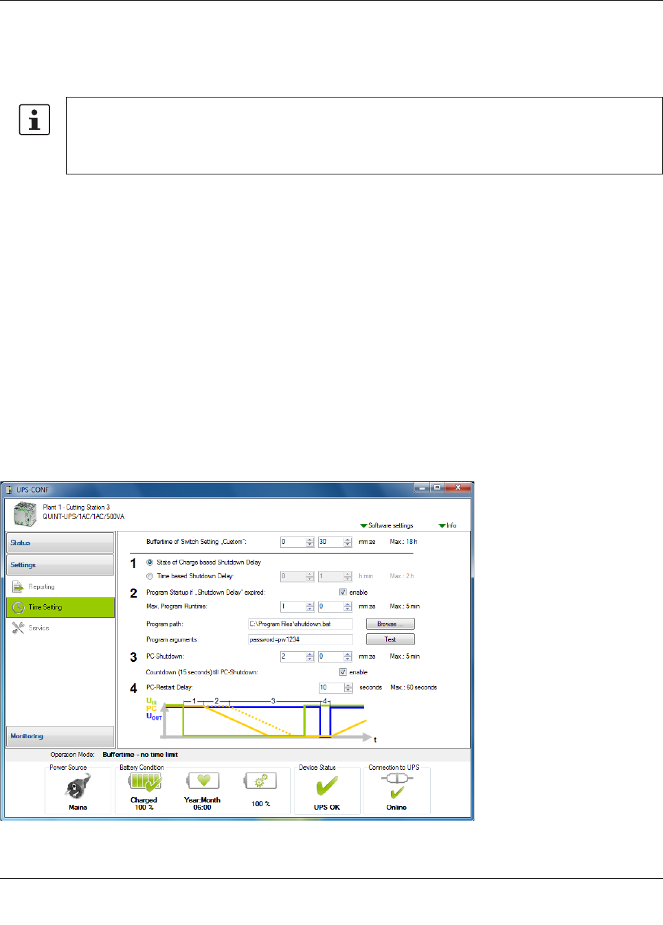
16 PC mode in UPS-CONF
In "PC mode", the UPS function follows a chronological sequence that can be parameterized via UPS-CONF configuration
software. In this way, it can be adjusted to each individual application.
In the event of a mains failure, one PC can continue to work, perform a controlled shutdown, and restart automatically.
1. Delay time
Delay time is calculated automatically from the current re-
maining battery life minus the time required by the PC to shut
Delay time is calculated automatically from the current re-
maining battery life minus the time required by the PC / IPC
to shut-down. Alternatively, a fixed delay time may be cho-
sen.
Example: setting is 10 minutes - if mains power has not re-
turned within 10 minutes, a corresponding alarm is signaled.
2. Program start
After the delay time has expired, it is possible to start a pro-
gram.
Example: a software backup starts which ensures succes-
sive backup of system data.
In the “PC Mode” setting on the UPS rotary selector switch,
the UPS functionality follows a chronological sequence that
can be parameterized via configuration software and is
therefore individually optimized for the respective applica-
tion.
Menu: Settings > Time setting
3. PC shutdown
The time required to shut down the PC or industrial PC is set
here.
4. PC idle time
The output voltage is interrupted during the reset time and
the PC automatically restarted only if the PC is shut down
and the mains returned in the mean time
Figure 49 UPS-CONF user interface
The following components are required for the PC mode function:
Data cable IFS-XXX-DATACABLE (Order No. 2320XXX)
Configuration software UPS-CONF (Order No. 2320403)
Communication cable between the UPS and the power storage device with IQ technology
QUINT-UPS/ 1AC/ 1AC/500VA
104661_en_02 34
PHOENIX CONTACT GmbH & Co. KG • 32823 Blomberg • Germany
phoenixcontact.com
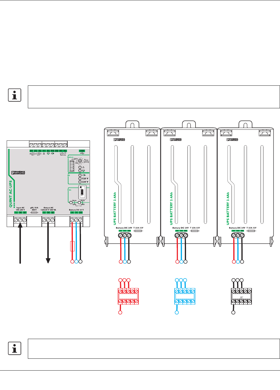
17 Application example
Parallel connection of the power storage devices
To increase the buffer time, a maximum of 15 power storage
devices can be switched in parallel. It is recommended to
keep the number as low as possible and use power storage
devices with a higher capacity if required.
After discharging the power storage, the required recharg-
ing time depends on the maximum charging current that the
uninterruptible power supply can provide.
If possible, install at a cool location e.g., at the bottom of the
control cabinet to ensure optimum function. For this, the fol-
lowing cabling design is advantageous.
Figure 50 Parallel connection of the power storage devices in the control cabinet with modular terminal blocks (example)
Use a suitable fuse.
The required fuse value of the backup fuse must not exceed the nominal fuse value of an individual power stor-
age device.
Battery DC 24 V
+
Battery DC 24 V
-
Battery DC 24 V
456456456
4
1
4
2
4
3
55 6 566
L1, N, PE
INPUT AC
L1, N, PE
OUTPUT AC
123
The power storage device should always be wired with the same cable cross sections and cable lengths.
