615909 Catalog 1
345598-Catalog 345598-Catalog 345598-Catalog 785901 Batch5 unilog cesco-content
2014-07-05
: Pdf 615909-Catalog 1 615909-Catalog_1 785901 Batch5 unilog
Open the PDF directly: View PDF ![]() .
.
Page Count: 204 [warning: Documents this large are best viewed by clicking the View PDF Link!]

Supplemental and Obsolescence
Digest 176
Global Specialist in Energy Management
2012
Process & Machines
Management
Power
Management
Building
Management
Security
Management
IT/Server Room
Management
The only good watt
is a negawatt.
©2011 Schneider Electric. All Rights Reserved. Schneider Electric, EcoStruxure, Active Energy Management Architecture from Power Plant to
Plug, and Efficient Enterprise are trademarks owned by Schneider Electric Industries SAS or its affiliated companies. 35 rue Joseph Monier,
*Source: World Energy Outlook 2009, IEA/OECD
What’s a negawatt? The one you didn’t use.
Energy saved is money saved.
Yes, the smart grid is coming and we are actively implementing intelligence and
innovations to help make it a reality. But we need a solution that will save energy and
drive efficiency today as we are building the smarter grids of tomorrow.
Introducing EcoStruxure: Active Energy Management Architecture from
Power Plant to Plug™.
Right now, EcoStruxure™ solutions from Schneider Electric™ can reduce your energy
is where our focus needs to be! The percentage of revenue spent on energy by
companies could reach 30% by 2020. And there is an urgent need to reduce CO2
emissions, especially as energy demand escalates. Energy management is the key
– the fastest and most effective solution to curb greenhouse gas emissions while
improving business performance. In fact, by 2030, energy efficiency and behavior
change will offset more CO2 than all the new wind, solar, and other alternative energy
generation methods combined.*
EcoStruxure solutions cut energy costs today.
As energy prices continue to climb, every unit
of energy you save matters. One unit saved at
the point of use means three units of primary
energy not consumed. Today, only EcoStruxure
Active Energy Management architecture can
deliver up to 30% energy savings across your
buildings, industrial plants, and data centers.
You deserve an Efficient Enterprise™!
30% 30%30%
Visit www.SEreply.com Key Code b653v
Get smarter about energy
Download this White Paper, “Growing a Green
Corporation,” a $199 value, for FREE.
Mining
Due to intrinsic inefficiencies, 33 units of energy consumed at the point of use
require 100 units of primary energy.
100 energy units 35 energy units 33 energy units
Generation Transmission Point of use

i - 1
© 2012 Schneider Electric All Rights Reserved
www.schneider-electric.us
Table of Contents
01 LOAD CENTERS................................................................................... 1-1
Fusible Pullouts .................................................................................................................. 1-2
Circuit Breaker Covers ....................................................................................................... 1-3
02 SAFETY SWITCHES............................................................................. 2-1
General Duty Safety Switches............................................................................................ 2- 4
Accessories .................................................................................................................. 2-4
Heavy Duty Safety Switches .............................................................................................. 2- 3
Accessories .................................................................................................................. 2-3
Key Interlock Systems ................................................................................................. 2-4
Sample Applications .................................................................................................... 2-4
03 MOLDED CASE CIRCUIT BREAKERS AND ENCLOSURES ............. 3-1
PowerPact™ Circuit Breakers ............................................................................................ 3-3
PowerPact™ H- and J-Frame Circuit Breakers ........................................................... 3-3
PowerPact™ L-Frame Circuit Breakers ....................................................................... 3-4
PowerPact™ D-Frame Circuit Breakers ...................................................................... 3-5
PowerPact™ Automatic Switches ....................................................................................... 3-6
Molded Case Circuit Breakers............................................................................................. 3-7
F-Frame Thermal-Magnetic Circuit Breakers ............................................................... 3-7
K- and Q4-Frame Thermal-Magnetic Circuit Breakers ................................................ 3-9
L-Frame Thermal-Magnetic Circuit Breakers ............................................................. 3-11
L-Frame Micrologic™ Series B Trip Circuit Breakers ................................................ 3-13
Molded Case Circuit Breakers........................................................................................... 3-15
Mag-Gard™ Motor Circuit Protector .......................................................................... 3-15
Molded Case Circuit Breakers........................................................................................... 3-16
GJ-Frame MCP Selection .......................................................................................... 3-16
Special Construction Circuit Breakers............................................................................... 3-17
Special Terminal Connectors and Lugs ..................................................................... 3-17
Special Calibration, Rear-Connected Studs, Visi-Blade,
Moisture/Fungus Treatment, and Short LA/LH Handle .............................................. 3-18
Special Magnetic or Thermal Calibration ................................................................... 3-18
Rear-Connected Studs .............................................................................................. 3-18
Visi-Blade
TM
Circuit Breakers .................................................................................... 3-18
Moisture and Fungus Resistant Treatment for Circuit Breakers ................................ 3-18
Short Handle for LA/LH Circuit Breakers (No Additional Charge) .............................. 3-18
P-Frame Replacement Handles, Key Interlock Adapter Plate and
Exchange Program .................................................................................................... 3-19
Special Terminations ................................................................................................. 3-20
Grounded BØ Systems .............................................................................................. 3-21
Circuit Breakers for Grounded B-Phase (BØ) (Corner-Grounded Delta) Systems
(No Additional Charge) .............................................................................................. 3-21
UL Marine Listed Circuit Breakers ............................................................................. 3-22
UL Naval Listed Circuit Breakers ............................................................................... 3-22
Circuit Breaker Accessories .............................................................................................. 3-23
PowerPact
™
Circuit Breakers Electrical Accessories ................................................ 3-23
Factory-Installed Accessories .................................................................................... 3-24
Factory-Installed Electrical Accessories .................................................................... 3-24
Field-Installable Accessories ..................................................................................... 3-25
Field-Installable Electrical Accessories ...................................................................... 3-25
Electrical Operators, Handle Accessories, Cylinder Locks,
and Walking Beam Mechanical Interlocks ................................................................. 3-26
Locks, Installation Accessories, and Rear Connections ............................................ 3-27
Mechanical Lug Information ....................................................................................... 3-28
Compression Lug and Power Distribution Connectors .............................................. 3-29
PowerPact™ Circuit Breakers Miscellaneous Accessories ....................................... 3-30
Electronic Products ........................................................................................................... 3-31
Neutral Current Transformers and
Micrologic™ Series B Trip Unit Accessories .............................................................. 3-31
Restraint Interface Module ......................................................................................... 3-32
Circuit Breaker Dimensions............................................................................................... 3-33
Enclosures......................................................................................................................... 3-34
Industrial Circuit Breaker Enclosures ......................................................................... 3-34
Enclosures......................................................................................................................... 3-35
Enclosed Switches and Enclosure Dimensions ......................................................... 3-35
Accessories ................................................................................................................ 3-36
Key Interlock Systems—Factory Installed Only ......................................................... 3-37
Special Applications ................................................................................................... 3-38
04 PANELBOARDS ................................................................................... 4-1
Panelboards ........................................................................................................................ 4-2
General Information ..................................................................................................... 4-2
General Instructions ..................................................................................................... 4-2
Pricing Instructions ....................................................................................................... 4-2
Metric Conversion ........................................................................................................ 4-2
I-Line™ Panelboards Factory Assembled Pricing ....................................................... 4-2
Special Features ................................................................................................................. 4-3
Mains and Branches .................................................................................................... 4-3

i - 2
© 2012 Schneider Electric All Rights Reserved
www.schneider-electric.us
Mains ........................................................................................................................... 4-3
Branches ...................................................................................................................... 4-3
Cabinets .......................................................................................................................4-4
Increased Enclosure Depth .......................................................................................... 4-4
Increased Side Gutters
(Type 1 Enclosures Only) ............................................................................................ 4-4
Extended Top and Bottom End Gutters ....................................................................... 4-4
Drip Hoods a ................................................................................................................ 4-4
Special Finishes ........................................................................................................... 4-4
Free-standing Enclosures (welded base channels) c .................................................. 4-4
Special Trims ............................................................................................................... 4-4
Cabinets .......................................................................................................................4-5
Padlock Hasp ............................................................................................................... 4-5
Special Locks ............................................................................................................... 4-5
Multi-Section Panels .................................................................................................... 4-5
Cabinets .......................................................................................................................4-6
Panel Skirt for Standard Width Panelboards a ............................................................ 4-6
Wireway a .................................................................................................................... 4-6
Cabinets .......................................................................................................................4-7
Panels to Fit Existing Enclosures ................................................................................. 4-7
Space Heater ............................................................................................................... 4-7
Cabinets .......................................................................................................................4-8
Special Enclosures a ................................................................................................... 4-8
NQ Main Lug and Main Circuit Breaker Interiors with SPD—240 Vac, 48 Vdc .................. 4-9
Ready-to-Install (RTI) Merchandise .................................................................................. 4-10
Miscellaneous Panelboard Accessories .................................................................... 4-10
Copper Equipment Ground Bars ................................................................................ 4-10
Field Installable I-Line™ Door Kits ............................................................................. 4-10
Type 1 Door-in-Door (Hinged) Trim Fronts ................................................................ 4-10
Replacement Parts for Standard Panelboards.................................................................. 4-11
Trim Clamps and Screws ........................................................................................... 4-11
Locks and Keys .......................................................................................................... 4-12
CTC Cabinets....................................................................................................................4-13
Replacement Parts for Standard Panelboards.................................................................. 4-14
Retrofit Existing Enclosure Data Sheet ...................................................................... 4-14
Data Sheet for Panelboards to Retrofit Existing Enclosures ...................................... 4-14
05 SWITCHBOARDS ..................................................................................5-1
Power-Style™ CMM Switchboards ......................................................................................5-2, 5-3
Replacement Parts ...................................................................................................... 5-2
Meter Sockets, Covers, Hardware Kits ........................................................................ 5-2
Tenant Main Disconnects ............................................................................................ 5-3
Class T Fusible Pullouts, CMM Pullout Heads ............................................................ 5-3
Speed-D
™
Switchboards..................................................................................................... 5-4
Service Selection ......................................................................................................... 5-4
06 TRANSFORMERS .................................................................................6-1
General Purpose Dry Type 600 Volts and Below................................................................ 6-2
Energy Efficient ............................................................................................................ 6-2
K-Rated ........................................................................................................................6-3
EE NL and NLP Series Transformers .......................................................................... 6-3
Drive Isolation Transformers .......................................................................................... 6-4
Open Core and Coil ..................................................................................................... 6-5
Open Core and Coil Transformers Designed for General Applications
for 600 V and Below ..................................................................................................... 6-5
Industrial Control ................................................................................................................. 6-6
Type EO ....................................................................................................................... 6-6
Type T .......................................................................................................................... 6-7
Type T and MultiTap™ Transformers .......................................................................... 6-7
Selection Guide ............................................................................................................ 6-7
Instrument 600 Volt Class .................................................................................................. 6-8
Voltage Transformers .................................................................................................. 6-8
Current Transformers ................................................................................................... 6-8
Current Transformers: Torroidal .................................................................................. 6-9
Torroidal Current Transformers ..........................................................................6-9, 6-10
Current Transformers: Torroidal, Shorting Terminal Blocks ...................................... 6-10
Shorting Terminal Blocks ........................................................................................... 6-10
Current Transformers: Multi-Ratio, Rectangular, Split-Core ...................................... 6-11
Multi-Ratio Current Transformers .............................................................................. 6-11
Rectangular Window Current Transformers .............................................................. 6-11
Split-Core Current Transformers ................................................................................ 6-11
Current Transformers: Bushing, Auxiliary .................................................................. 6-12
Bushing Current Transformers 50–400 Hz ................................................................ 6-12
Auxiliary Current Transformers .................................................................................. 6-12
07 INTERNATIONAL LOAD CENTERS .....................................................7-1
International Miniature Circuit Breakers ............................................................................. 7-2
QO™ Plug-On and Bolt-On Circuit Breakers and Switches ........................................ 7-2
General Description ..................................................................................................... 7-2
Characteristics ............................................................................................................. 7-2
Accessories .................................................................................................................. 7-2
Plug-On QOXD and Bolt-On QOBXD .......................................................................... 7-3
Load Centers....................................................................................................................... 7-4
IEC Certified QO™ Load Centers, Type 1 (Indoor) ..................................................... 7-4
08 INTERNATIONAL SAFETY SWITCHES ...............................................8-1

i - 3
© 2012 Schneider Electric All Rights Reserved
www.schneider-electric.us
General Duty Safety Switches............................................................................................. 8-2
International ................................................................................................................. 8-2
CSA Certified General Duty—Fusible 240 Vac ............................................................ 8-2
Heavy Duty Safety Switches ............................................................................................... 8-3
International ................................................................................................................. 8-3
CSA Certified Heavy Duty—Fusible 240 Vac .............................................................. 8-3
CSA Certified Heavy Duty—Fusible 600 Vac .............................................................. 8-3
CSA Certified Heavy Duty—Non-Fusible 600 Vac ...................................................... 8-4
CSA Certified Heavy Duty—Special Applications ........................................................ 8-4
Double-Throw Safety Switches ........................................................................................... 8-5
International ................................................................................................................. 8-5
CSA Certified Double-Throw ........................................................................................ 8-5
Accessories .................................................................................................................. 8-6
CSA Certified Switch Accessories ............................................................................... 8-6
09 INTERNATIONAL CIRCUIT BREAKERS ............................................. 9-1
Thermal-Magnetic Circuit Breakers..................................................................................... 9-2
SF and SL Circuit Breakers, IEC Rated 415/240 Vac Max. ......................................... 9-2
Electronic Trip Circuit Breakers........................................................................................... 9-3
P-frame, 3P, Micrologic™ Electronic-Trip Unit, IEC Rated .......................................... 9-3
R-frame, 3P, Micrologic™ Electronic-Trip Unit, IEC Rated .......................................... 9-4
P-frame, 4P, Micrologic™ Electronic-Trip Unit, IEC Rated .......................................... 9-5
R-frame, 4P, Micrologic™ Electronic-Trip Unit, IEC Rated .......................................... 9-6
Breaking Capacities ............................................................................................................ 9-7
Circuit Breaker Dimensions................................................................................................. 9-8
10 INTERNATIONAL PANELBOARDS ................................................... 10-1
Factory Assembled Circuit Breaker Panelboard ........................................................ 10-2
11 OBSOLESCENT AND OBSOLETE CIRCUIT BREAKERS ............... 11-1
Obsolescent and Obsolete Types ..................................................................................... 11-2
Circuit Breaker Availability ......................................................................................... 11-2
Pictorial and Dimensions .................................................................................. 11-4, 11-5
Obsolescent Circuit Breakers............................................................................................ 11-6
F-Frame Thermal-Magnetic Circuit Breakers ............................................................. 11-6
K-Frame Thermal-Magnetic Circuit Breakers ............................................................ 11-7
Automatic Molded-Case Switches ............................................................................. 11-8
Automatic Molded Case Switches ............................................................................. 11-8
Mag-Gard™ Motor Circuit Protector ...............................................................11-9, 11-10
UL Listed Marine Circuit Breakers ........................................................................... 11-11
Circuit Breakers for NQO, NQOB and NQOD Panelboards, Branch Circuit Breakers
and Mounting Assemblies for ML Panelboards ................................................................ 11-12
Rating Plugs For Obsolete Electronic Trip Circuit Breakers .................................... 11-13
EH/EHB Circuit Breakers ......................................................................................... 11-14
FJA Thermal-Magnetic Circuit Breakers .................................................................. 11-15
QE Metering Circuit Breakers .................................................................................. 11-16
KD/KG Thermal-Magnetic Circuit Breakers ............................................................. 11-17
NHL Thermal-Magnetic Molded Case Circuit Breaker ............................................. 11-18
SE Circuit Breaker with Full-Function Trip Unit ........................................................ 11-19
SE Circuit Breaker Accessories ............................................................................... 11-20
Molded Case Circuit Breakers......................................................................................... 11-21
M-Frame Thermal-Magnetic Circuit Breakers .......................................................... 11-21
Circuit Breaker Accessories ............................................................................................ 11-22
Field-Installable Accessories ................................................................................... 11-22
Field-Installable Electrical Accessories .................................................................... 11-22
Mechanical Lug Information ..................................................................................... 11-23
Electronic Products ......................................................................................................... 11-24
Micrologic™ Series 2/3/A/B Trip Unit Test Sets ...................................................... 11-24
Ground-Fault Protection .................................................................................................. 11-25
Micrologic™ Add-On Ground-Fault Module (GFM) ................................................. 11-25
Obsolescent Circuit Breakers.......................................................................................... 11-26
Masterpact™ M/MP/MC Circuit Breakers, UL 489/1066 Listed ............................... 11-26
Masterpact™ M/MP/MC Circuit Breaker Control Units ............................................ 11-27
For pricing contact your local Schneider Electric distributor. ................................... 11-27
Masterpact™ M/MP/MC Circuit Breaker Accessories ............................................. 11-28
Masterpact™ M/MP/MC Circuit Breaker Spare Parts .............................................. 11-30
12 OBSOLETE MOTOR CONTROL CENTERS ...................................... 12-1
Model 4 Branch Feeder Units .................................................................................... 12-2
Model 4 Circuit Breaker Type Combination Starters
1B Wiring and 1 N.O. and 1 N.C. Auxiliary Interlock (Standard) ................................ 12-3
Model 4 Fusible Switch Combination Starter Units
1B Wiring and 1 N.O. and 1 N.C. Auxiliary Interlock (Standard) ................................ 12-4
Series 5600 General Information ............................................................................... 12-5
Telemecanique
™
Series 5600 History ....................................................................... 12-5
Transition Sections From Telemecanique Series 5600 To Square D™ Brand Model 6 12-5
Series 5600 Branch Feeder and Circuit Breaker Type
Combination Starter Units .......................................................................................... 12-6
13 OBSOLESCENT PANELBOARDS ..................................................... 13-1
QMB Fusible Panelboards ................................................................................................ 13-2
Ready-to-Install (RTI)—600 Vac, 250 Vdc ................................................................. 13-2
QMB Layout Information ............................................................................................ 13-2
Main Switch Replacement Units ................................................................................ 13-3
Branch Switch Replacement ...................................................................................... 13-4
Obsolescent Branch Switch Replacement Units ........................................................ 13-5

i - 4
© 2012 Schneider Electric All Rights Reserved
www.schneider-electric.us
30–200 A Obsolescent Switch Units—Series D2 ...................................................... 13-5
Series E1 Motor Starter Replacement Units .............................................................. 13-6
Replacement Parts............................................................................................................ 13-7
Trim Clamps and Screws; Circuit I.D. Numbers; Locks ............................................. 13-7
Series Ratings ................................................................................................................... 13-8
NQOD Panelboards ................................................................................................... 13-8
NQOD Panelboards .......................................................................................................... 13-9
Pricing Procedure Examples ...................................................................................... 13-9
NQOD Merchandised Pricing Procedure ................................................................... 13-9
NQOD Merchandised Panelboards................................................................................. 13-10
NQOD 20-inch Wide Enclosures—240 Vac, 48 Vdc ....................................13-10, 13-11
NQOD 14-inch Wide Enclosures—240 Vac, 48 Vdc ............................................... 13-12
For Non-Linear Loads (200% Rated Neutral) .......................................................... 13-13
NQOD Panelboards ........................................................................................................ 13-14
Terminal Data .......................................................................................................... 13-14
14 BUSWAY..............................................................................................14-1
I-Line™ Busway ................................................................................................................ 14-2
Special Purpose Plug-In Units ................................................................................... 14-2
APD and SD Busway Plug-In Units (Not I-Line™ Busway) ....................................... 14-2
Capacitor and Transformer Units ............................................................................... 14-2
Combination Switches and Contactors (For I-Line Busway) ...................................... 14-2
Ground Indicator and Neutralizer Plugs ..................................................................... 14-2
15 LIMIT SWITCHES ................................................................................15-1
Heavy Duty, Industrial Precision and Oiltight .................................................................... 15-1
Type XA ..................................................................................................................... 15-1
Heavy Duty, Industrial Reed Contact ................................................................................ 15-2
Type C ....................................................................................................................... 15-2
16 MEDICAL PRODUCTS ........................................................................16-1
Medical Products............................................................................................................... 16-2
Isolated Power Panels ............................................................................................... 16-2
OR, ICU/CCU, and Controlled Isolation Power Panels—UL Listed ........................... 16-2
Duplex Panels ............................................................................................................ 16-3
Surgical Facility Panels .............................................................................................. 16-4
Dual Output Voltage Panels ....................................................................................... 16-5
Accessories ................................................................................................................ 16-6
17 NEMA CONTACTORS AND STARTERS............................................17-1
IEC Style Disconnect Switches ......................................................................................... 17-2
UL508 Motor Disconnect Switches ................................................................................... 17-8
Vario ........................................................................................................................... 17-8
NEMA Style Disconnect Switches..................................................................................... 17-9
Door-Mounted Operating Mechanisms ........................................................................... 17-10
Approximate Dimensions ................................................................................................ 17-11
Bracket-Mounted Disconnect Devices ............................................................................ 17-13
Flexible Cable Mechanisms ............................................................................................ 17-14
Dual Cable Operating Mechanisms for Square D™ Circuit Breakers ...................... 17-14
Disconnect Switch Accessories....................................................................................... 17-15
Reversing Drum Switches ............................................................................................... 17-17
NEMA Types 1, 3R, 4, and 13 Without Overload .................................................... 17-17
Approximate Dimensions—Class 2601 Reversing Drum Switches ......................... 17-17
Electromechanical Reduced Voltage Starters................................................................. 17-18
Reduced Voltage Starting of Squirrel Cage Motors ................................................. 17-18
Electromechanical Reduced Voltage Starters ......................................................... 17-18
Multispeed Magnetic Starters.......................................................................................... 17-24
Application Data ............................................................................................17-24, 17-25
3-Pole Polyphase, 600 Vac Maximum, 50–60 Hz ..............................17-25, 17-26, 17-27
Two-Speed Combination Starters ............................................................................ 17-26
Reversing Two-Speed Magnetic Starters ................................................................ 17-27
Two-Speed Magnetic Starters ................................................................................. 17-28
Approximate Dimensions ......................................................................................... 17-29
Disconnect Switch or Circuit Breaker Type .............................................................. 17-29
Lighting Contactors ......................................................................................................... 17-30
General Information ................................................................................................. 17-30
Well-Guard™ Pump Panel........................................................................................................ 17-31
Factory Modifications (Forms)......................................................................................... 17-32
Definite Purpose Contactors ........................................................................................... 17-35
Thermal Overload Relays—NEMA Style......................................................................... 17-36
Motor Logic Plus—Class 9065 ................................................................................. 17-36
Example ................................................................................................................... 17-36
SCHNEIDER ELECTRIC CONDITIONS OF SALE ................................... A-1
Coordinated Projects ....................................................................................................A-1
Standard .......................................................................................................................A-3

1-2 © 2012 Schneider Electric
All Rights Reserved
www.schneider-electric.us
1LOAD CENTERS
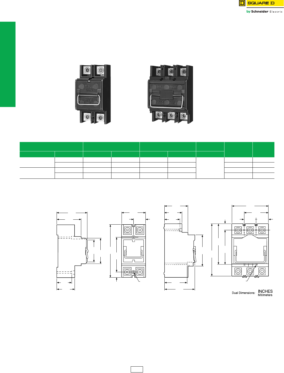
Fusible Pullouts
Refer to Catalog 1100CT0501
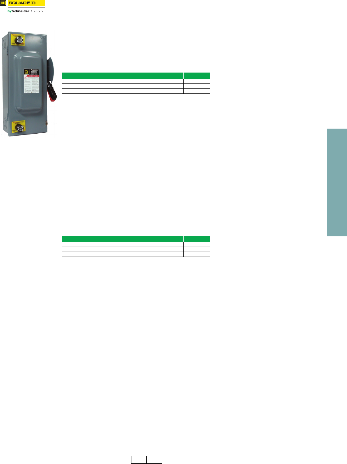
Class T Fusible Pullouts
•2- or 3-pole fusible pullouts
•200 A maximum 300 V Class T fuses (not included)
•1Ø3W 120/240 V
1Ø2W 240 V
•3Ø3W 240 V delta
3Ø4W 240/120 V delta
3Ø4W 208Y/120 V
•UL Listed 100 kA short circuit current rating
Dimensions
FTL2200 FTL3200
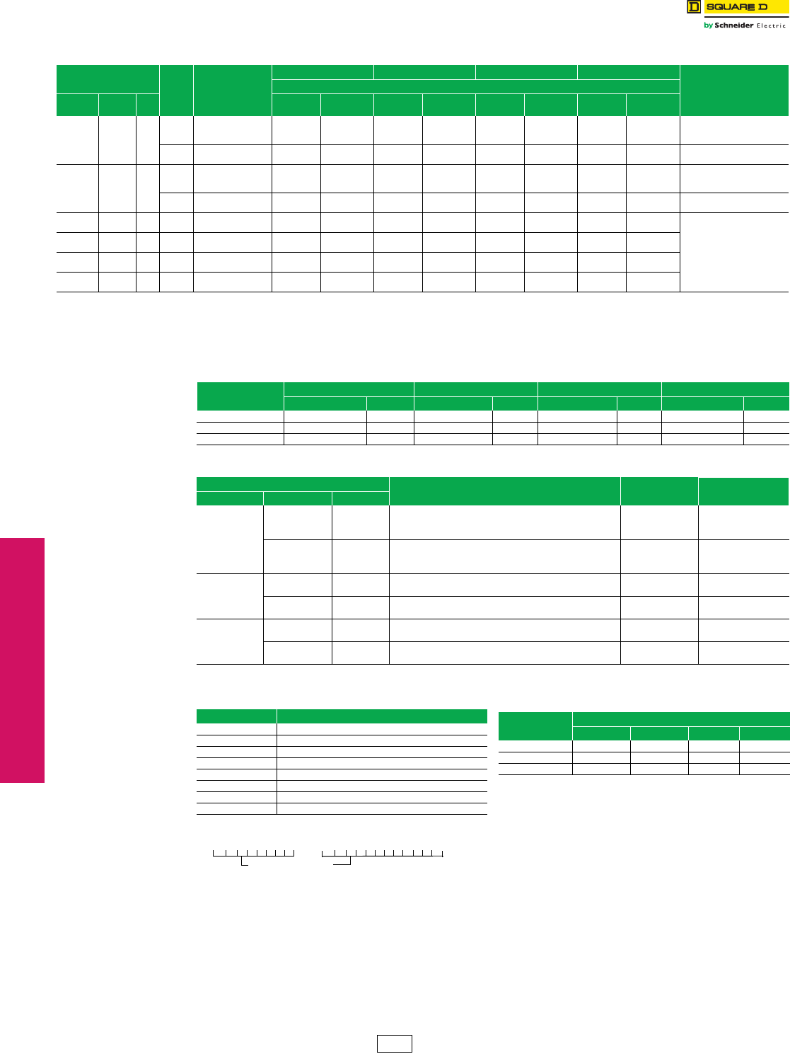
Table 1.1: Fusible Pullouts
Mains Two-pole Three-pole Main Wire Size
AWG/kcmil Fuse Pullout Only $ Price
System Rating Cat. No. $ Price Cat. No. $ Price Al or Cu
1Ø3W 120/240 V
1Ø2W 240 V
100 A FTL2100a380.00 ——
4–250
4050704950a128.00
200 A FTL2200a400.00 —— 4050703850a151.00
3Ø3W 240 V delta
3Ø4W 240/120 V delta
3Ø4W 208Y/120 V
100 A — — FTL3100 1000.00 4050707050a196.00
200 A — — FTL3200 1045.00 4050705950a288.00
aNot stocked in PDS. Order point Lexington.
3.80
97
3.16
80
2.96
75
1.48
38
6.38
162
3.44
87
3.20
81
4.25
108
.63
16
(2) .187 Dia. Hole
.34 Dia. C'bore
1.85
47
2.19
56
2.85
72
3.80
97
3.00
76
2.23
57
1.85
47
Pull
200A
4.00
102
2.98
76
4.46
113
1.48
38
1.50
38
(4) .187 Dia. Mounting Holes
.34 Dia. C'bore, .38 Deep
Pull 200A
6.61
168
.78
20
5.03
128
4.25
108
DE5 Discount
Schedule
www.schneider-electric.us
1LOAD CENTERS
© 2012 Schneider Electric
All Rights Reserved 1-3
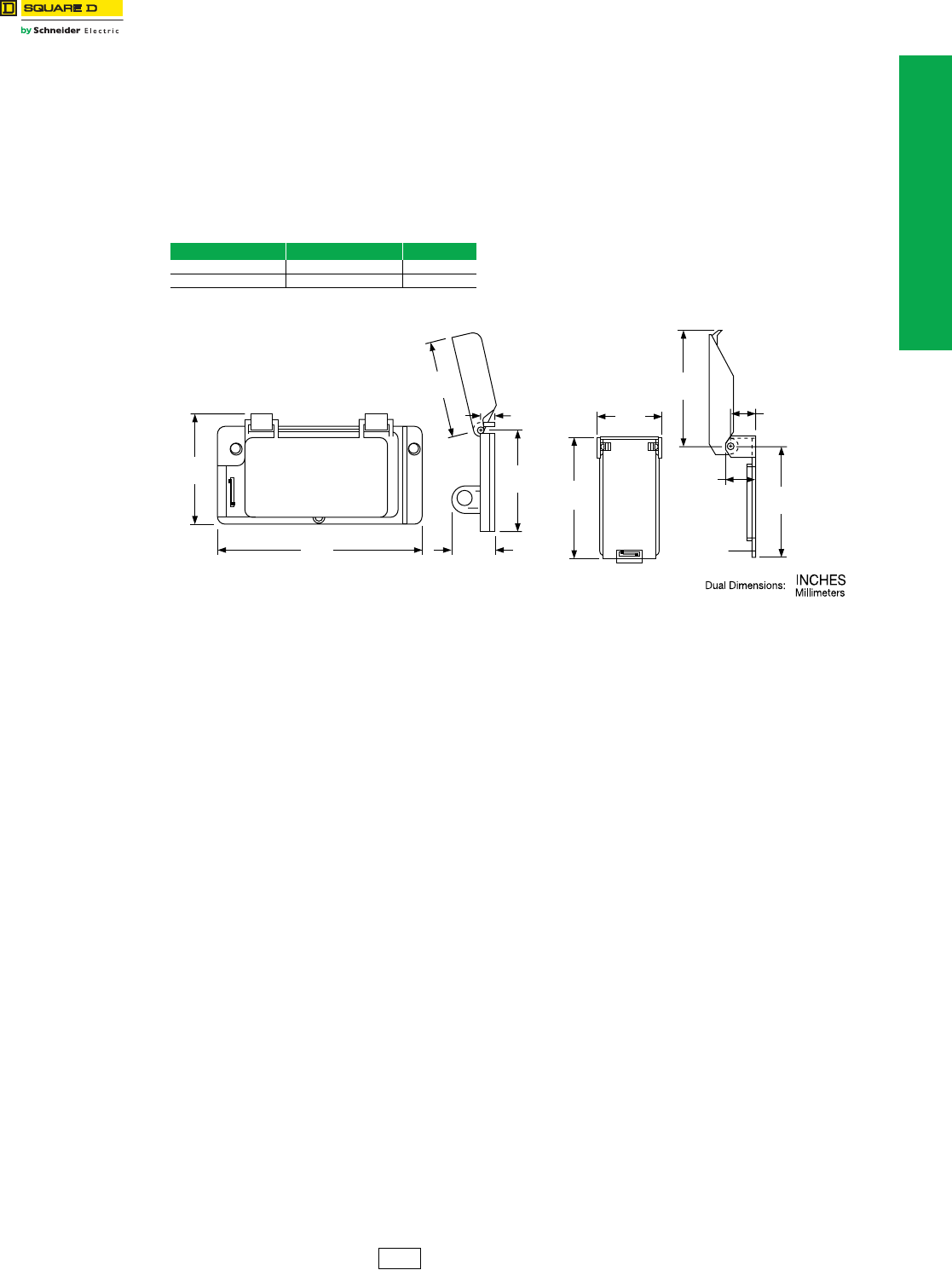
Circuit Breaker Covers
Refer to Catalog 1100CT0501
Circuit Breaker Covers
Available now from Square D™ / Schneider Electric™ are two different versions of rainproof circuit breaker covers
which are UL component recognized as being suitable for use as circuit breaker handle covers.
They are constructed of durable impact-resistant material and are intended for use by OEMs where a rainproof cover is
needed (e.g. on heat pumps and air conditioners with built-in disconnects). Both models have a built-in latch with
padlock provisions.
The BCH covers are for use on a horizontally-mounted circuit breaker and fit over Square D two-pole QO™, QOU, Q2,
EH and three-pole Q2 and EH circuit breakers.
The BCV covers are for use on vertically-mounted circuit breakers and will fit over Square D two- and three-pole QO,
QOU, Q2, EH, FA and KA circuit breakers.
Dimensions
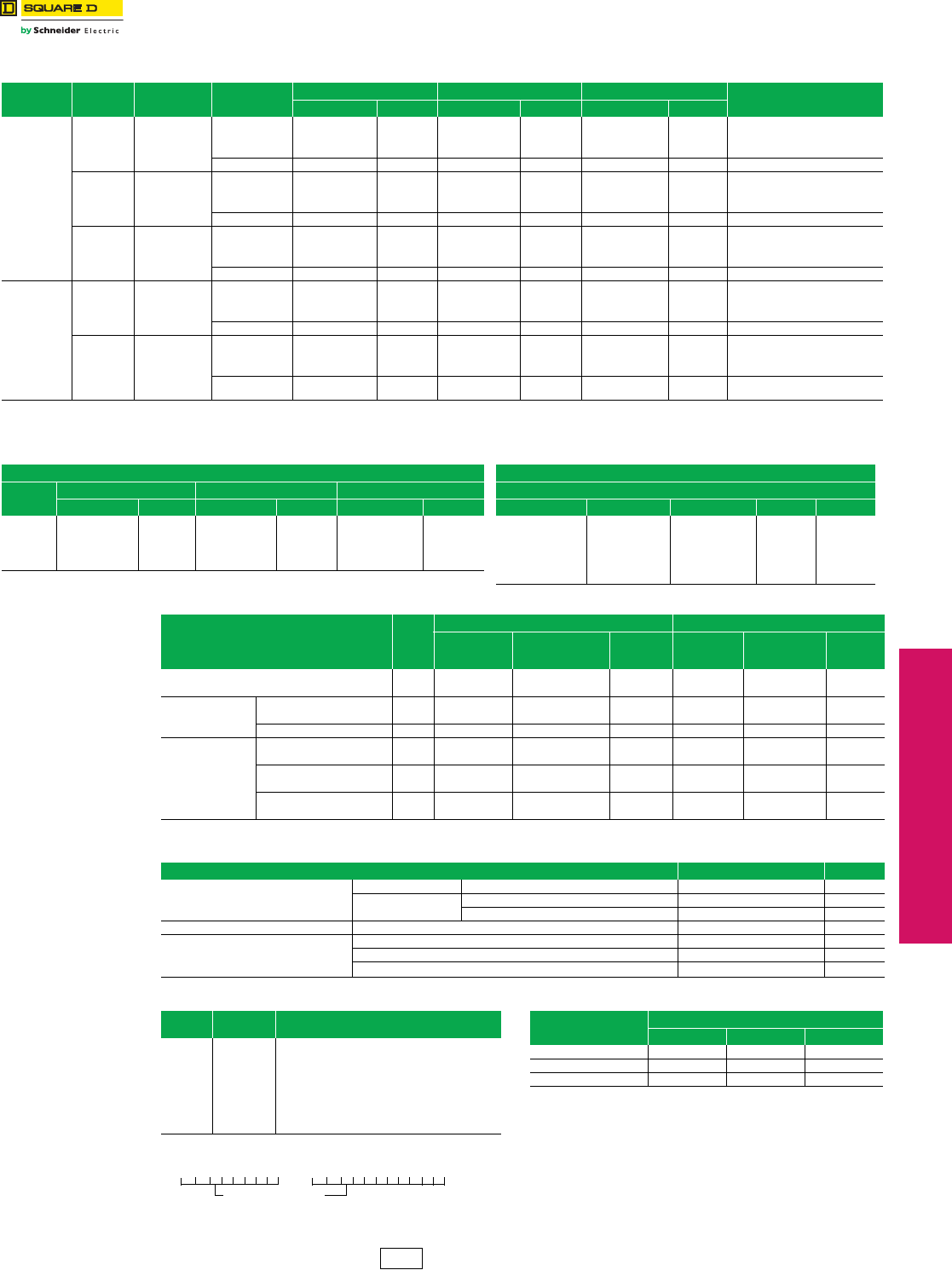
Table 1.2: Covers
Quantity Cat. No. $ Price
1BCH 20.50
1BCV 20.50
4.58
116
1.09
28
1.32
34
4.82
122
4.40
112
BCV
Vertical Cover
3.14
80
.30
8
2.50
64
2.11
54
2.33
59
4.62
117
BCH
Horizontal Cover
1.10
28
DE2E Discount
Schedule

www.schneider-electric.us
1LOAD CENTERS
1-4 © 2012 Schneider Electric
All Rights Reserved

2-1
© 2012 Schneider Electric
All Rights Reserved
2SAFETY SWITCHES
Table of Contents
Section 2
Safety Switches
General Duty Safety Switches
General Duty Safety Switches 2-2
Heavy Duty Safety Switches
Voltage-Indicating Safety Switches 2-3
Push Button—Pilot Light—Selector Switch 2-3
Key Interlock Systems 2-4
Sample Applications 2-4
2SAFETY SWITCHES
2-2 © 2012 Schneider Electric
All Rights Reserved
www.schneider-electric.us
General Duty Safety
Switches
Accessories
Class 3130
Field-Installed Lug Kit
Kit consists of three line, three load, and two neutral lugs as required for a three-pole 400 A or 600 A general duty switch.
Kit can be installed in field on 400 or 600 A General Duty switches.
a400 Amp NEMA 1 Series E03 only. 600 Amp NEMA 1 and 3R Series E01, E02 and E03.
Table 2.1: Lug Kit
Switch Rating
(A)
Lug Kit
Cat. No.
Wire Range/NEC
312.6
AWG/kcmil
Lug Wire Range per Lug
AWG/kcmil $ Price
400 or 600 AaGD4060LK
(1) 1/0–600 or
(2) 1/0–500 or
(4) 1/0–250
(2) 1/0–600 or
(4) 1/0–250 404.00
DE1 DE3A Discount
Schedule
2SAFETY SWITCHES
www.schneider-electric.us
© 2012 Schneider Electric
All Rights Reserved 2-3
Heavy Duty Safety
Switches
Accessories
Class 3130
Voltage-Indicating Safety Switches
Voltage-indicating safety switches indicate when voltage is present, helping to prevent arc-flash hazards and electric
shocks during maintenance work. Voltage indicators are a factory-installed only option. Order the indicators by adding
the appropriate suffix below to the switch catalog number. Not available on the following: NEMA 7 and 9 and NEMA 4 X
Fiberglass and Krydon Enclosures.
Voltage-indicating safety switches can be combined with other safety features such as visible blades, viewing windows
and color-coded handles.
aAdd an additional $120.00 for 30 and 60 A NEMA TYPE 1, 3R and 12 enclosures.
In addition to the suffix in Table 2.2, a 3 must be added to the switch catalog number for all 30 and 60 Amp switches,
i.e. H361AWK becomes H3613AWKLI.
Phenolic Legend Plate
Available engraved and mounted on all heavy duty safety switches, except NEMA 7 and 9. Legend engraved in 1/4 in.
high white letters on black background. Customer must provide legend. UL Listed.
To order, add suffix NP to standard Cat. No.
Example: H363-NP
Price adder per legend plate—$167.00
Push Button—Pilot Light—Selector Switch
Push buttons, pilot lights or selector switches are available factory-installed in the cover of NEMA 1, 3R, (4-4X-5)
stainless steel or NEMA 12 heavy duty non-fusible safety switches and all double throw switches. Wiring to contact
blocks is not available. Customer must furnish catalog number of push button, pilot light or selector switch device
desired. UL Listed.
Contact Schneider Electric for catalog number and availablility prior to quoting a job.
Factory-installed price adder — $584. for Heavy Duty and $1168. for Double Throw Switches. Price does not include
cost of buttons/lights. For enclosure sizing, 30 and 60 Amperes switches will be in 100 Ampere enclosures.
Table 2.2: Voltage Indicators
Suffix Description $ Pricea
SI Line Side Indicator 1208.00
LI Load Side Indicator 1208.00
LI2 Li ne and Load Side Indicators 2416.00
Table 2.3: Electrical Interlock Contact Ratings
Suffix Description $ Pricea
SI Line Side Indicator 1208.00
LI Load Side Indicator 1208.00
LI2 Li ne and Load Side Indicators 2416.00
DE1 DE3A Discount
Schedule
www.schneider-electric.us
2SAFETY SWITCHES
2-4 © 2012 Schneider Electric
All Rights Reserved
Heavy Duty Safety
Switches
Key Interlock Systems
Key Interlock Systems
Factory-installed only on heavy duty and double throw
safety switches.
Interlocks are used to prevent the operator from making
an unauthorized operation. Not available on hazardous
location devices (NEMA 7/9) or fiberglass reinforced
polyester (NEMA 4X).
The key interlock system is a simple and easy method of
applying individual key interlock units and assemblies to
the above equipment so as to require operation in a
predetermined sequence. UL Listed.
Quoting:
Contact Schneider Electric for catalog number, availability
and pricing prior to quoting a job.
Ordering:
Order cannot be released for production until the following
information has been provided:
•End User—Company name, address;
•Function of each lock (e.g., switch to be locked open with key
removed, key held when switch is closed);
•Existing Equipment—if switch is to be interlocked with equipment
already on site, provide brand of existing lock and key number;
•Other New Equipment—if switch is to be interlocked with new
equipment not yet installed at the site, then provide contact
person and phone number so that locks may be coordinated;
•Additional information may be required upon order entry;
•Schneider Electric locks supplied unless otherwise specified.
Use these suffixes on switch catalog numbers:
•KI = 1 lock per switch
•KI2 = 1 lock with 2 cylinders per switch
•KIKI = 2 separate locks per switch
bPrices do not apply when more than three devices are interlocked as these
schemes normally require more than one key assembly per device.
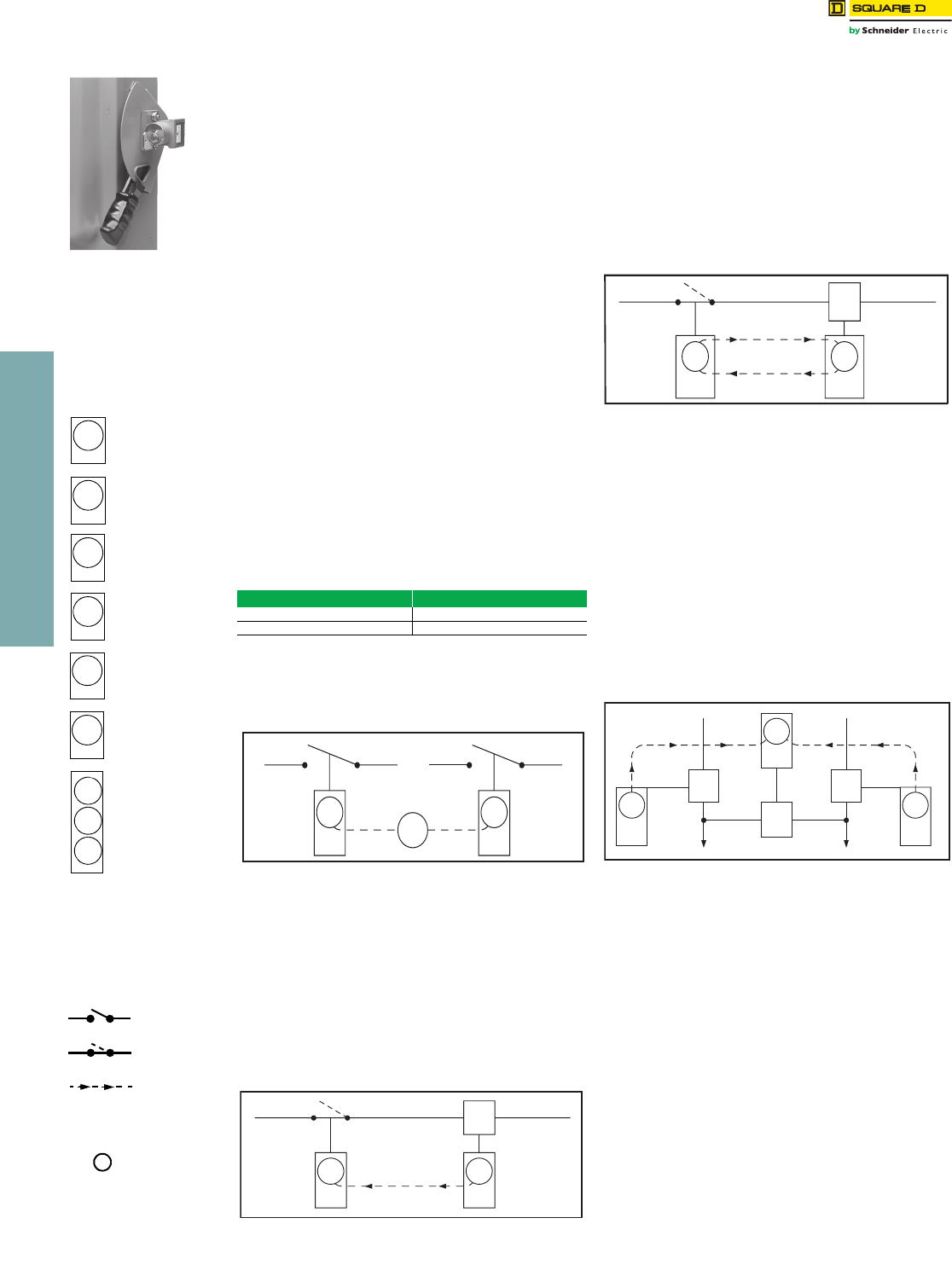
Sample Applications
Sample Application—1
To prevent two devices from being closed simultaneously.
Two devices are shown in Figure 1. In operation they are
not closed at the same time. With the interlocks arranged
as shown only one key is required in the interlocking
system. Both devices are shown open, therefore, the key
is free. To close any one device the key is inserted and
turned in that particular lock, the key is held in this lock
until the device is again locked open. This simple
interlocking sequence lends itself to a multitude of
applications. The procedure is the same for two devices,
neither of which is to be opened at the same time.
Sample Application—2
To prevent opening of switch A when circuit breaker B is
closed.
Switch A and circuit breaker B are in closed position. Key
A-1 is held in circuit breaker B interlock.
1. Open circuit breaker.
2. Turn key A-1 in L-O-R interlock on circuit breaker B to lock
open. Key A-1 is now free.
3. Insert key A-1 in L-C-R interlock on switch A and turn to
unlock.
4. Open switch A. Key A-1 is now held. Reverse sequence to
restore service.
Sample Application—3
To prevent operation of switch A when circuit breaker B is
closed. Permits re-closing of circuit breaker for servicing
when switch is locked open.
Switch A and circuit breaker B are in closed position. Key
A-1 is held in circuit breaker interlock.
5. Open circuit breaker.
6. Turn key A-1 in L-O-R interlock on circuit breaker B to lock
open. Key A-1 is now free.
7. Insert key A-1 in L-O-C-R interlock on switch A and turn to
unlock.
8. Open switch A.
9. Turn key A-1 in L-O-C-R interlock on switch A to lock open.
Key A-1 is now free.
10. Return key A-1 to circuit breaker interlock and unlock for
operation during servicing period.
Reverse sequence to restore service.
Sample Application—4 (Main-Tie-Main)
To prevent paralleling of lines A and B; two loads, fed from
either source.
Circuit breaker A is closed to supply load M. Circuit
breaker B is closed to supply load N. Tie-circuit breaker C
is open. Keys A-1 are held in interlocks on both circuit
breakers A and B. Tie-circuit breaker C cannot be closed
unless either A or B is locked open.
To transfer load N to circuit breaker A, proceed as follows:
1. Open circuit breaker B.
2. Turn key A-1 in L-O-R interlock on circuit breaker B to lock
open. Key A-1 is now free.
3. Insert Key A-1 in L-O-R interlock on tie-circuit breaker C and
turn to unlock. Key A-1 is now held.
4. Close tie-circuit breaker C.
5. Reverse sequence to restore service.
6. Load M can be supplied through circuit breaker B in a similar
manner.
Locking Position—
Designations
L-O-R
L-C-R
L-O-C-R
L-O-H
L-C-H
L-O-C-H
Devices locked open
with key removed
Devices locked closed
with key removed
Devices locked open
or closed with key
removed
Devices locked open
with key held
Devices locked closed
with key held
Devices locked open or
closed with key held
Multi-lock interlock
(More than one key
per lock)
Diagram Symbols
Note:
Device locked open =
switch in OFF (O) position
Device locked closed =
switch in ON (I) position
A-1 A-2 A-3
Device normall
y
open
Device normall
y
closed
Direction of key
transfer
Key
interchange
number
Key
Table 2.4: Price Adder Per Lockb
Switch Type $ Price
30–1200 A Heavy Duty 2055.00
30–600 A Double Throw 1988.00
Figure 1
A-1
A 1
L-O-R L-O-R
AB
A-1
Figure 2
A-1
L-C-R L-O-R
A
B
A 1
Figure 3
A-1
L-O-C-R L-O-R
A
B
A 1
Figure 4
L-O-R
C
L-O-R
A
A
N
M
A 1
L-O-R
A 1
A-1
B
B

3-1
© 2012 Schneider Electric
All Rights Reserved
3MOLDED CASE CIRCUIT
BREAKERS
Table of Contents
Section 3
Molded Case Circuit Breakers and Enclosures
PowerPact™ Circuit Breakers 3-3
PowerPact™ H- and J-Frame Circuit Breakers 3-2–3-3
PowerPact™ L-Frame Circuit Breakers 3-4
PowerPact™ D-Frame Circuit Breakers 3-5
PowerPact™ Automatic Switches 3-6
PowerPact™ D-frame Mission Critical Circuit Breakers 3-6
Molded Case Circuit Breakers 3-7
F-Frame Thermal-Magnetic Circuit Breakers 3-7—3-8
K- and Q4-Frame Thermal-Magnetic Circuit Breakers 3-9—3-10
L-Frame Thermal-Magnetic Circuit Breakers 3-11—3-12
L-Frame Micrologic™ Series B Trip Circuit Breakers 3-13—3-14
Mag-Gard™ Motor Circuit Protector 3-15
GJ-Frame MCP Selection 3-16
Special Construction Circuit Breakers 3-17
Special Terminal Connectors and Lugs 3-17
Special Calibration, Rear-Connected Studs, Visi-Blade,
Moisture/Fungus Treatment, and Short LA/LH Handle
3-18
Special Calibration, Rear-Connected Studs, Visi-Blade,
Moisture/Fungus Treatment, and Short LA/LH Handle
3-18
P-Frame Replacement Handles, Key Interlock Adapter Plate and
Exchange Program
3-19
Special Terminations 3-20
Grounded BØ Systems 3-21
UL Marine Listed Circuit Breakers 3-22
Circuit Breaker Accessories 3-23
PowerPact™ Circuit Breakers Electrical Accessories 3-23
Factory-Installed Accessories 3-24
Field-Installable Accessories 3-25
Electrical Operators, Handle Accessories, Cylinder Locks, and
Walking Beam Mechanical Interlocks
3-26
Locks, Installation Accessories, and Rear Connections 3-27
Mechanical Lug Information 3-28
Compression Lug and Power Distribution Connectors 3-29
PowerPact™ Circuit Breakers Miscellaneous Accessories 3-30
Electronic Products 3-31
Neutral Current Transformers and Micrologic™ Series B Trip Unit
Accessories
3-31
Restraint Interface Module 3-32
Circuit Breaker Dimensions 3-33
Enclosures 3-34
Industrial Circuit Breaker Enclosures 3-34
Enclosed Switches and Enclosure Dimensions 3-35
Accessories 3-36
Key Interlock Systems—Factory Installed Only 3-37
Special Applications 3-38
3-2 © 2012 Schneider Electric
All Rights Reserved
www.schneider-electric.us
3MOLDED CASE CIRCUIT
BREAKERS
PowerPact™ Circuit
Breakers
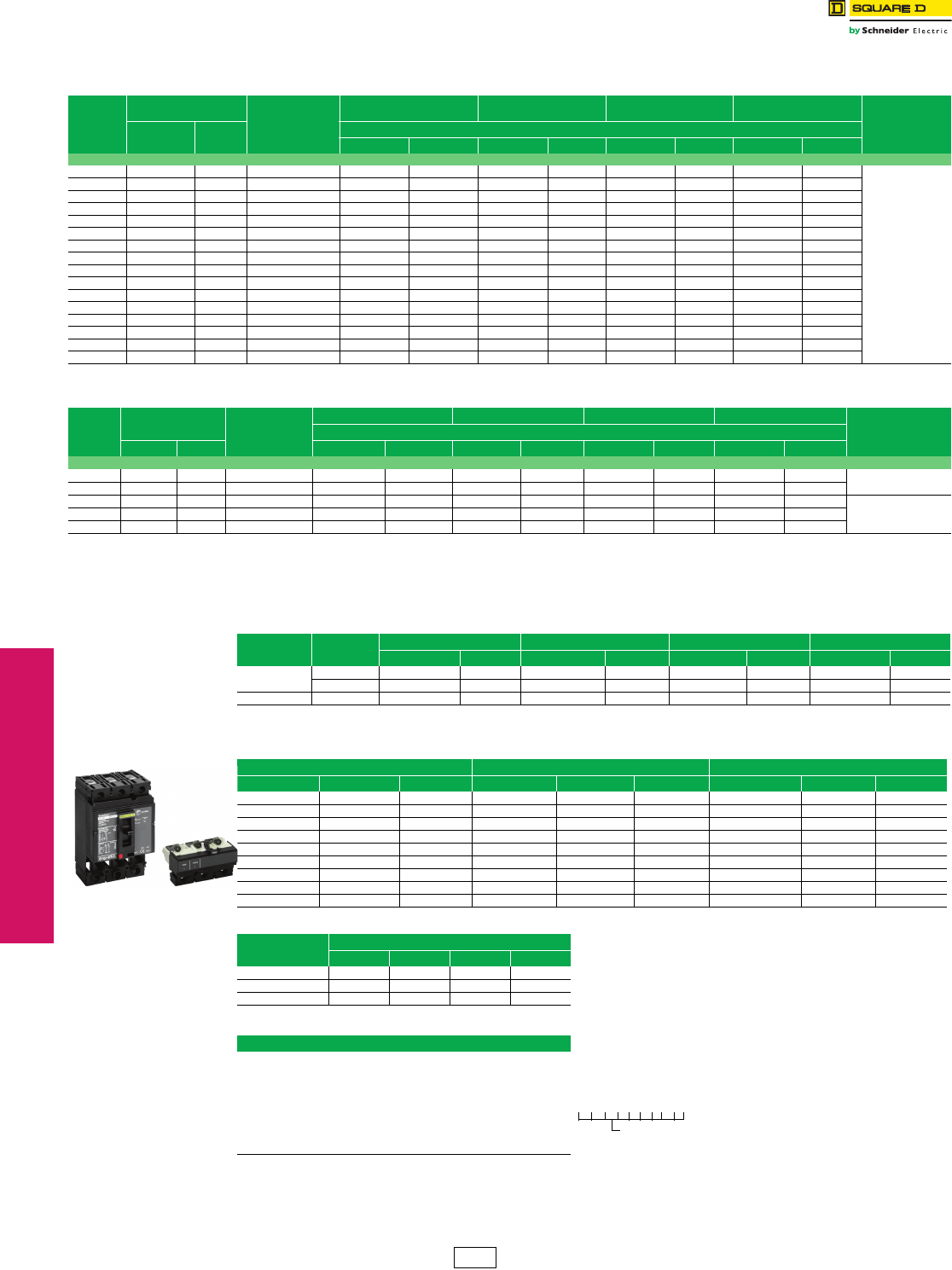
PowerPact™ H- and J-Frame Circuit Breakers
Class 611 / Refer to Catalog 0611CT1001
aTo complete catalog number, replace the blank with the appropriate rating (D, G, J, L)
bFor 80% rated use “T” or for 100% rated Use “R” in the 9th character place (for example, HDL36015T or HDL36015R). 100% rated H- and J-frame circuit
breakers have copper lugs and can only be used with copper wire.
cCircuit breakers will be labeled with Line and Load markings and are not suitable for reverse connections.
Only available on standard (80%) rated 3P unit-mount circuit breakers; not available with I-Line™ or Plug-In constructions.
dSee Digest page 7-39–3-41 for lug and termination kits.
eJ and L interrupts are UL Certified as current limiting.
Accessories . . . . . . . . . . . . . . . . . . . . . . . . . . . . . . . . . . . . . Digest Page 7-35
Optional Lugs . . . . . . . . . . . . . . . . . . . . . . . . . . . . . . . . . . . . Digest Page 7-38
Dimensions . . . . . . . . . . . . . . . . . . . . . . . . . . . . . . . . . . . . . Digest Page 7-53
Enclosures . . . . . . . . . . . . . . . . . . . . . . . . . . . . . . . . . . . . . . Digest Page 7-54
Table 3.1: H-Frame 150 A UL Current-Limitinge Circuit Breaker Frame with Field-Interchangeable
Thermal-Magnetic Trip Unitsc (600 Vac, 250 Vdc)
Ampere
Rating
Fixed AC
Magnetic Trip Cat.
No.b
D Interrupting G Interrupting Je Interrupting Le Interrupting
Terminal
Wire Range
Hold Trip $ Price
80% Rated 100% Rated 80% Rated 100% Rated 80% Rated 100% Rated 80% Rated 100% Rated
3P, 600 Vac 50/60 Hz
15 A 350 A 750 A H(a)L36015( ) 1088.00 1305.00 1493.00 1791.00 1949.00 2339.00 2849.00 3419.00
AL150HD
14–3/0 AWG
Al or Cu
20 A 350 A 750 A H(a)L36020( ) 1088.00 1305.00 1493.00 1791.00 1949.00 2339.00 2849.00 3419.00
25 A 350 A 750 A H(a)L36025( ) 1088.00 1305.00 1493.00 1791.00 1949.00 2339.00 2849.00 3419.00
30 A 350 A 750 A H(a)L36030( ) 1088.00 1305.00 1493.00 1791.00 1949.00 2339.00 2849.00 3419.00
35 A 400 A 850 A H(a)L36035( ) 1088.00 1305.00 1493.00 1791.00 1949.00 2339.00 2849.00 3419.00
40 A 400 A 850 A H(a)L36040( ) 1088.00 1305.00 1493.00 1791.00 1949.00 2339.00 2849.00 3419.00
45 A 400 A 850 A H(a)L36045( ) 1088.00 1305.00 1493.00 1791.00 1949.00 2339.00 2849.00 3419.00
50 A 400 A 850 A H(a)L36050( ) 1088.00 1305.00 1493.00 1791.00 1949.00 2339.00 2849.00 3419.00
60 A 800 A 1450 A H(a)L36060( ) 1088.00 1305.00 1493.00 1791.00 1949.00 2339.00 2849.00 3419.00
70 A 800 A 1450 A H(a)L36070( ) 1328.00 1592.00 1701.00 2042.00 2099.00 2519.00 3149.00 3779.00
80 A 800 A 1450 A H(a)L36080( ) 1328.00 1592.00 1701.00 2042.00 2099.00 2519.00 3149.00 3779.00
90 A 800 A 1450 A H(a)L36090( ) 1328.00 1592.00 1701.00 2042.00 2099.00 2519.00 3149.00 3779.00
100 A 900 A 1700 A H(a)L36100( ) 1328.00 1592.00 1701.00 2042.00 2099.00 2519.00 3149.00 3779.00
110 A 900 A 1700 A H(a)L36110( ) 2600.00 3120.00 3599.00 4319.00 5174.00 6209.00 6749.00 8099.00
125 A 900 A 1700 A H(a)L36125( ) 2600.00 3120.00 3599.00 4319.00 5174.00 6209.00 6749.00 8099.00
150 A 900 A 1700 A H(a)L36150( ) 2600.00 3120.00 3599.00 4319.00 5174.00 6209.00 6749.00 8099.00
Table 3.2: J-Frame 250 A UL Current-Limitinge Circuit Breaker Frame with Field-Interchangeable
Thermal-Magnetic Trip Unitsc (600 Vac, 250 Vdc)
Ampere
Rating
Adjustable AC
Magnetic Trip Cat.
No.b
D Interrupting G Interrupting Je Interrupting Le Interrupting
Terminal
Wire Range
$ Price
Low High 80% Rated 100% Rated 80% Rated 100% Rated 80% Rated 100% Rated 80% Rated 100% Rated
3P, 600 Vac 50/60 Hz
150 A 750 A 1500 A J(a)L36150( ) 2730.00 3276.00 3779.00 4535.00 5432.00 6519.00 7086.00 8504.00 AL175JD
4--4/0 AWG Al or Cu
175 A 875 A 1750 A J(a)L36175( ) 2730.00 3276.00 3779.00 4535.00 5432.00 6519.00 7086.00 8504.00
200 A 1000 A 2000 A J(a)L36200( ) 2730.00 3276.00 3779.00 4535.00 5432.00 6519.00 7086.00 8504.00 AL250JD
3/0 AWG–350 kcmil Al
or Cu
225 A 1125 A 2250 A J(a)L36225( ) 2730.00 3276.00 3779.00 4535.00 5432.00 6519.00 7086.00 8504.00
250 A 1250 A 2500 A J(a)L36250( ) 3749.00 4499.00 5001.00 6002.00 7238.00 8685.00 8993.00 10791.00
Table 3.3: H-Frame 150A and J-Frame 250 A 3P Basic UL Current-Limitinge Circuit Breaker Frame Without
Terminationsd or Trip Unit (600 Vac, 250 Vdc)
Circuit Breaker
Frame
Ampere
Rating
D Interrupting G Interrupting Je Interrupting Le Interrupting
Cat. No. $ Price Cat. No. $ Price Cat. No. $ Price Cat. No. $ Price
H-Frame 15–60 A HDF36000F06 525.00 HGF36000F06 930.00 HJF36000F06 1386.00 HLF36000F06 2286.00
70–150 A HDF36000F15 585.00 HGF36000F15 1574.00 HJF36000F15 3149.00 HLF36000F15 4724.00
J-Frame 150–250 A JDF36000F25 1538.00 JGF36000F25 2790.00 JJF36000F25 5027.00 JLF36000F25 6782.00
Table 3.4: H-Frame and J-Frame 3P Field-Installable Thermal-Magnetic Trip Unit
15–60 A H-Frame 70–150 A H-Frame 150–250 A J-Frame
Amperage Cat. No. $ Price Amperage Cat. No. $ Price Amperage Cat. No. $ Price
15 A HT3015 563.00 70 A HT3070 743.00 150 A JT3150 1193.00
20 A HT3020 563.00 80 A HT3080 743.00 175 A JT3175 1193.00
25 A HT3025 563.00 90 A HT3090 743.00 200 A JT3200 1193.00
30 A HT3030 563.00 100 A HT3100 743.00 225 A JT3225 1193.00
35 A HT3035 563.00 110 A HT3110 2025.00 250 A JT3250 2213.00
40 A HT3040 563.00 125 A HT3125 2025.00 — — —
45 A HT3045 563.00 150 A HT3150 2025.00 — — —
50 A HT3050 563.00 — — — — — —
60 A HT3060 563.00 — — — — — —
Table 3.5: H- and J-Frame Interrupting Ratings
Volt age Interrupting Rating
D G J L
240 Vac 25 KA 65 kA 100 kA 125 kA
480 Vac 18 kA 35 kA 65 kA 100 kA
600 Vac 14 kA 18 kA 25 kA 50 kA
Table 3.6: H- and J-Frame Termination Options
Termination Letter
A - I-Line (See Section 9)
F = No Lugs (includes terminal nut kit on both ends)f
L = Lugs both ends
M = Lugs ON end Terminal Nut Kit OFF end
P = Lugs OFF end Terminal Nut Kit ON end
N = Plug-in g
D = Drawout g
S = Rear Connected g
fAdd TS suffix for circuit breaker without terminal nut kit.
gFor N and D pricing, add termination pricing on Digest page 7-41 to price. For S pricing, add termination pricing
on Digest page 7-37 to price.
H-Frame Trip Unit
H D L 3 6 0 1 5 T
For factory-installed
termination, place termination
letter in the third block of the
circuit breaker catalog number.
Termination Letter
DE2 Discount
Schedule
www.schneider-electric.us
3MOLDED CASE CIRCUIT
BREAKERS
© 2012 Schneider Electric
All Rights Reserved 3-3
PowerPact™ Circuit
Breakers
PowerPact™ H- and J-Frame Circuit Breakers
Class 611 / Refer to Catalog 0611CT1001
fSee Digest page 7-38 for lug and termination kits.
gJ and L interrupts are UL Certified as current limiting.
Accessories . . . . . . . . . . . . . . . . . . . . . . . . . . . . . . . . . . . . . Digest page 7-36
Optional Lugs . . . . . . . . . . . . . . . . . . . . . . . . . . . . . . . . . . . . Digest page 7-39
Dimensions . . . . . . . . . . . . . . . . . . . . . . . . . . . . . . . . . . . . . . Digest page 7-55
Enclosures . . . . . . . . . . . . . . . . . . . . . . . . . . . . . . . . . . . . . . Digest page 7-56
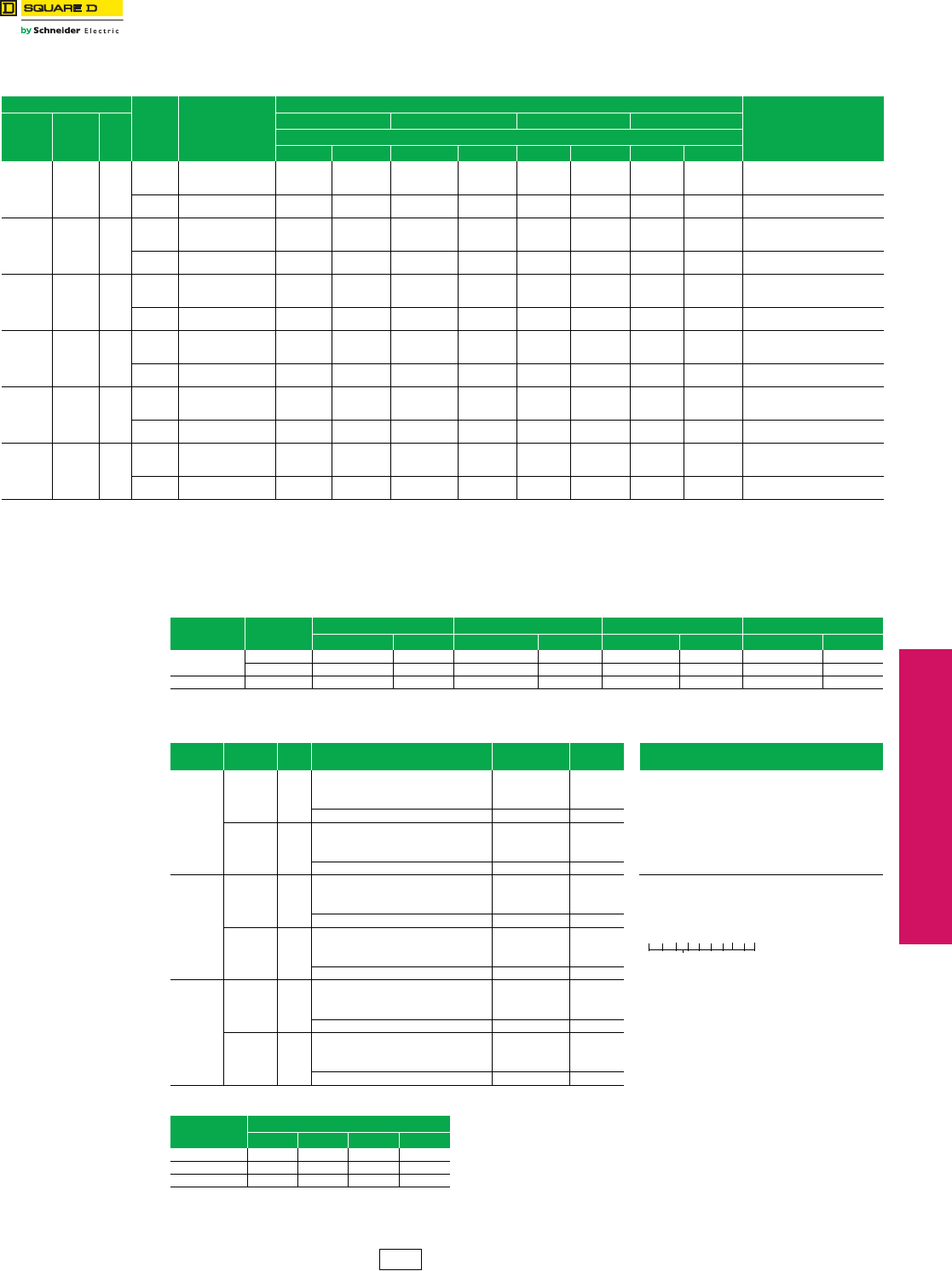
Table 3.7: H-Frame 150 A and J-Frame 250 A Circuit Breakers with Lugs and Field-Interchangeable Electronic Trip Units cd
(600 Vac, 50/60 Hz, 3P) cd
Electronic Trip Unit
Sensor
Rating
Cat.
No.b
Interrupting Rating (2nd Letter of Catalog Number)
Terminal
Wire Range
Type Function Tri p
Unit
D Interrupting G Interrupting J Interrupting L Interrupting
$ Price
80% Rated 100% Rated 80% Rated 100% Rated 80% Rated 100% Rated 80% Rated 100% Rated
Micrologic
Standard LI 3.2
60 A
100 A
150 A
H(a)L36060()U31X
H(a)L36100()U31X
H(a)L36150()U31X
1247.00
1487.00
2759.00
1455.00
1735.00
3220.00
1652.00
1860.00
3758.00
1928.00
2171.00
4386.00
2108.00
2258.00
5333.00
2460.00
2635.00
6224.00
3008.00
3308.00
6908.00
3510.00
3860.00
8062.00
AL150HD
14–3/0 AWG Al or Cu
250 A J(a)L36250()U31X 2957.00 3451.00 4006.00 4675.00 5659.00 6604.00 7313.00 8534.00 AL250JD
3/0 AWG–350 kcmil Al or Cue
Micrologic
Standard LSI 3.2S
60 A
100 A
150 A
H(a)L36060()U33X
H(a)L36100()U33X
H(a)L36150()U33X
1433.00
1673.00
2945.00
1641.00
1921.00
3405.00
1838.00
2046.00
3944.00
2113.00
2356.00
4571.00
2294.00
2444.00
5519.00
2646.00
2821.00
6409.00
3194.00
3494.00
7094.00
3696.00
4046.00
8247.00
AL150HD
14–3/0 AWG Al or Cu
250 A J(a)L36250()U33X 3221.00 3715.00 4270.00 4939.00 5923.00 6868.00 7577.00 8798.00 AL250JD
3/0 AWG–350 kcmil Al or Cue
Micrologic
Ammeter LSI 5.2A
60 A
100 A
150 A
H(a)L36060()U43X
H(a)L36100()U43X
H(a)L36150()U43X
2031.00
2271.00
3543.00
2240.00
2520.00
4004.00
2436.00
2644.00
4542.00
2712.00
2955.00
5170.00
2892.00
3042.00
6117.00
3244.00
3419.00
7008.00
3792.00
4092.00
7692.00
4295.00
4645.00
8846.00
AL150HD
14–3/0 AWG Al or Cu
250 A J(a)L36250()U43X 4075.00 4569.00 5124.00 5793.00 6777.00 7722.00 8431.00 9653.00 AL250JD
3/0 AWG–350 kcmil Al or Cue
Micrologic
Energy LSI 5.2E
60 A
100 A
150 A
H(a)L36060()U53X
H(a)L36100()U53X
H(a)L36150()U53X
2391.00
2631.00
3903.00
2599.00
2879.00
4363.00
2796.00
3004.00
4902.00
3072.00
3314.00
5529.00
3252.00
3402.00
6477.00
3604.00
3779.00
7367.00
4152.00
4458.00
8052.00
4654.00
5004.00
9205.00
AL150HD
14–3/0 AWG Al or Cu
250 A J(a)L36250()U53X 4588.00 5082.00 5637.00 6306.00 7290.00 8235.00 8944.00 10165.00 AL250JD
3/0 AWG–350 kcmil Al or Cue
Micrologic
Ammeter LSIG 6.2A
60 A
100 A
150 A
H(a)L36060()U44X
H(a)L36100()U44X
H(a)L361504()U44X
2751.00
2991.00
4263.00
2960.00
3240.00
4724.00
3156.00
3364.00
5262.00
3432.00
3675.00
5890.00
3612.00
3762.00
6837.00
3964.00
4139.00
7728.00
4512.00
4812.00
8412.00
5015.00
5365.00
9566.00
AL150HD
14–3/0 AWG Al or Cu
250 A J(a)L36250()U44X 5100.00 5594.00 6149.00 6818.00 7802.00 8747.00 9456.00 10678.00 AL250JD
3/0 AWG–350 kcmil Al or Cue
Micrologic
Energy LSIG 6.2E
60 A
100 A
150 A
H(a)L36060()U54X
H(a)L36100()U54X
H(a)L36150()U54X
3111.00
3351.00
4623.00
3319.00
3599.00
5083.00
3516.00
3724.00
5622.00
3792.00
4034.00
6249.00
3972.00
4122.00
7197.00
4324.00
4499.00
8087.00
4872.00
5172.00
8772.00
5374.00
5724.00
9925.00
AL150HD
14–3/0 AWG Al or Cu
250 A J(a)L36250()U54X 5613.00 6107.00 6662.00 7331.00 8315.00 9260.00 9969.00 11190.00 AL250JD
3/0 AWG–350 kcmil Al or Cue
aTo complete catalog number, replace the blank with the appropriate rating (D, G, J, L)
bFor 80% rated use “T” or for 100% rated Use “R” in the 9th character place (for example, HGL36015TU31X or HGL36015RU31X). 100% rated H- and J-frame circuit breakers have copper
lugs and can only be used with copper wire.
cCircuit breakers will be labeled with Line and Load markings and are not suitable for reverse connections.
dOnly available on 3P unit-mount circuit breakers. Not available with I-Line™ or Plug-in constructions.
eFor smaller wire (4–4/0 AWG Al or Cu), replace the lug wire binding screws with longer binding screws provided.
Table 3.8: H-Frame 150A and J-Frame 250 A 3P Basic UL Current-Limitingg Circuit Breaker Frame Without
Terminationsf or Trip Unit (600 Vac, 250 Vdc)
Circuit Breaker
Frame
Ampere
Rating
D Interrupting G Interrupting Jg Interrupting Lg Interrupting
Cat. No. $ Price Cat. No. $ Price Cat. No. $ Price Cat. No. $ Price
H-Frame 15–60 A HDF36000F06 525.00 HGF36000F06 930.00 HJF36000F06 1386.00 HLF36000F06 2286.00
70–150 A HDF36000F15 585.00 HGF36000F15 1574.00 HJF36000F15 3149.00 HLF36000F15 4724.00
J-Frame 150–250 A JDF36000F25 1538.00 JGF36000F25 2790.00 JJF36000F25 5027.00 JLF36000F25 6782.00
Table 3.9: Micrologic Field-Installable Trip Unit
Model Trip
Function
Trip
Unit Contiuous Current Trip Unit
Cat. No. $ Price Termination Letter
Micrologic
Standard
LI 3.2
15-20-25-30-35-40-45-50-60 HE3060U31X 722.00 A - I-Line (See Section 9)
35-40-45-50-60-70-80-90-100 HE3100U31X 902.00 F = No Lugs (includes terminal nut kit on both ends)h
50-60-70-80-90-100-110-125-150 HE3150U31X 2184.00 L = Lugs both ends
70-80-100-125-150-175-200-225-250 JE3250U31X 1216.00 M = Lugs ON end Terminal Nut Kit OFF end
LSI 3.2S
15-20-25-30-35-40-45-50-60 HE3060U33X 908.00 P = Lugs OFF end Terminal Nut Kit ON end
35-40-45-50-60-70-80-90-100 HE3100U33X 1088.00 N = Plug-in i
50-60-70-80-90-100-110-125-150 HE3150U33X 2370.00 D = Drawout i
70-80-100-125-150-175-200-225-250 JE3250U33X 1480.00 S = Rear Connected i
Micrologic
Ammeter
LSI 5.2A
15–60 HE3060U43X 1506.00
35–100 HE3100U43X 1686.00
50–150 HE3150U43X 2968.00
70–250 JE3250U43X 2334.00
LSIG 6.2A
15–60 HE3060U44X 1866.00
35–100 HE3100U44X 2046.00
50–150 HE3150U44X 3318.00 hAdd TS suffix for circuit breaker without
terminal nut kit.
iFor N and D pricing, add termination pricing on
Digest page 7-42 to price. For S pricing, add
termination pricing on Digest page 7-38 to
price.
70–250 JE3250U44X 2847.00
Micrologic
Energy
LSI 5.2E
15–60 HE3060U53X 2226.00
35–100 HE3100U53X 2406.00
50–150 HE3150U53X 4038.00
70–250 JE3250U53X 3359.00
LSIG 6.2E
15–60 HE3060U54X 2586.00
35–100 HE3100U54X 2766.00
50–150 HE3150U54X 4038.00
70–250 JE3250U54X 3872.00
Table 3.10: H- and J-Frame Interrupting Ratings
Voltag e Interrupting Rating
D G J L
240 Vac 25 KA 65 kA 100 kA 125 kA
480 Vac 18 kA 35 kA 65 kA 100 kA
600 Vac 14 kA 18 kA 25 kA 50 kA
H D L 3 6 0 1 5 T
For factory-installed termination, place
termination letter in the third block of the
circuit breaker catalog number.
DE2 Discount
Schedule
www.schneider-electric.us
3-4 © 2012 Schneider Electric
All Rights Reserved
3MOLDED CASE CIRCUIT
BREAKERS
PowerPact™ Circuit
Breakers
PowerPact™ L-Frame Circuit Breakers
Class 612, 615 / Refer to Catalogs: 0612CT0101, 0616CT0801
eFor N, D, and S pricing, add termination pricing to price. See Digest
page 7-42.
Accessories . . . . . . . . . . . . . . . . . . . . . . . . . . . . . . .Digest pages 7-36–7-45
Optional Lugs . . . . . . . . . . . . . . . . . . . . . . . . . . . . . .Digest pages 7-39–7-40
Dimensions. . . . . . . . . . . . . . . . . . . . . . . . . . . . . . . . . . . . . . Digest page 7-55
Table 3.11: L-Frame 3 Pole, 600 A Circuit Breakers with Lugs and Field-Interchangeable Electronic Trip Units (600 Vac, 50/60 Hz)ad
Electronic Trip Unit Sensor
Rating
Cat.
No.b
D Interrupting G Interrupting J Interrupting L Interrupting
Terminal
Wire Range
$ Price
Type Function Trip
Unit 80% Rated 100% Rated 80% Rated 100% Rated 80% Rated 100% Rated 80% Rated 100% Rated
Micrologic
Standard LI 3.3
250 A L(a)L36250( )U31 4287.00 5648.00 5081.00 5945.00 8487.00 9919.00 9918.00 11604.00
AL400L61K3D
(1) 2 AWG–600 kcmil Cu
(1) 2 AWG–500 kcmil Al
400 A
600 A
L(a)L36400( )U31X
L(a)L36600( )U31X
4827.00
7109.00
5648.00
—
5081.00
7484.00
5945.00
—
8487.00
10541.00
9919.00
—
9918.00
11837.00
11604.00
—
AL600S52K3
(2) 2/0 AWG–500 kcmil Al/Cu
Micrologic
Standard LSI 3.3S
250 A L(a)L36250( )U33X 5391.00 6211.00 5674.00 6538.00 9071.00 10513.00 10511.00 12198.00
AL400L61K3D
(1) 2 AWG–600 kcmil Cu
(1) 2 AWG–500 kcmil Al
400 A
600 A
L(a)L36400( )U33X
L(a)L36600( )U33X
5391.00
7673.00
6211.00
—
5674.00
8077.00
6538.00
—
9071.00
11134.00
10513.00
—
10511.00
12430.00
12198.00
—
AL600S52K3
(2) 2/0 AWG–500 kcmil Al/Cu
Micrologic
Ammeter LSI 5.3A 400 A
600 A
L(a)L36400( )U43X
L(a)L36600( )U43X
6253.00
8535.00
7073.00
—
6582.00
8984.00
7445.00
—
9979.00
12041.00
11420.00
—
11419.00
13337.00
13105.00
—
AL600S52K3
(2) 2/0 AWG–500 kcmil Al/Cu
Micrologic
Energy LSI 5.3E 400 A
600 A
L(a)L36400( )U53X
L(a)L36600( )U53X
7200.00
9483.00
8021.00
—
7579.00
9982.00
8443.00
—
10976.00
13039.00
12418.00
—
12416.00
14335.00
14103.00
—
Micrologic
Ammeter LSIG 6.3A 400 A
600 A
L(a)L36400( )U44X
L(a)L36600( )U44X
8149.00
10431.00
8969.00
—
8578.00
10980.00
9441.00
—
11975.00
14037.00
13416.00
—
13415.00
15333.00
15101.00
—
Micrologic
Energy LSIG 6.3E 400 A
600 A
L(a)L36400( )U54X
L(a)L36600( )U54X
9097.00
11379.00
9917.00
—
9575.00
11978.00
10439.00
—
12972.00
15035.00
14414.00
—
14412.00
16331.00
16099.00
—
aTo complete catalog number, replace the blank with the appropriate rating (D, G, J, L)
bFor 80% rated use “T” or for 100% rated Use “R” in the 9th character place (for example, LGL36400TU31X or LGL36400RU31X). 100% rated H- and J-frame circuit breakers have copper
lugs and can only be used with copper wire.
cCircuit breakers will be labeled with Line and Load markings and are not suitable for reverse connections.
dOnly available on 3P unit-mount circuit breakers.
Table 3.12: L-Frame 3 Pole, 600 A Circuit Breaker Breaker Frame without Trip Units (600 Vac, 50/60 Hz)
Ampere
Rating
D Interrupting G Interrupting J Interrupting L Interrupting
Cat. No. $ Price Cat. No. $ Price Cat. No. $ Price Cat. No. $ Price
250 A (70–250 A) LDF36000F25 1328.00 LGF36000F25 1480.00 LJF36000F25 4616.00 LLF36000F25 6069.00
400 A (125–400 A LDF36000F40 2628.00 LGF36000F40 2766.00 LJF36000F40 6164.00 LLF36000F40 7602.00
600 A (200–600 A) LDF36000F60 5199.00 LGF36000F60 5472.00 LJF36000F60 8226.00 LLF36000F60 9522.00
Table 3.13: L-Frame 3P Field-Installable Micrologic Electronic Trip Units
Electronic Trip Unit Continuous Current Trip Unit
Cat. No. $ Price
Type Function Code
Micrologic
Standard
LI 3.3
70-80-100-125-150-175-200-225-250 LE3250U31X 2315.00
125-150-175-200-225-250-300-350-400 LE3400U31X 2315.00
200-225-250-300-350-400-450-500-600 LE3600U31X 2315.00
LSI 3.3S
70-80-100-125-150-175-200-225-250 LE3250U33X 2908.00
125-150-175-200-225-250-300-350-400 LE3400U33X 2908.00
200-225-250-300-350-400-450-500-600 LE3600U33X 2908.00
Micrologic
Ammeter
LSI 5.3A 125–400 LE3400U43X 3816.00
200–600 LE3600U43X 3816.00
LSIG 6.3A 125–400 LE3400U44X 4813.00
200–600 LE3600U44X 4813.00
Micrologic Energy
LSI 5.3E 125–400 LE3400U53X 5812.00
200–600 LE3600U53X 5812.00
LSIG 6.3E 125–400 LE3400U54X 6809.00
200–600 LE3600U54X 6809.00
Table 3.14: Termination Options
Termination Letter Termination Option
A I-Line (See Section 9)
F No lugs (includes terminal nut kit on both ends)
L Lugs both ends
M Lugs ON end, terminal nut kit OFF end
P Lugs OFF end, terminal nut kit ON end
NePlug In
DeDrawout
SeRear Connected
M G L 3 6 4 0 0 or
For factory-installed termination, place termination letter in
the third block of the circuit breaker catalog number.
Termination Letter
L G L 3 6 6 0 0 U 4 4 X
Table 3.15: L-Frame Interrupting Ratings
Voltag e Interrupting Rating
D G J L
240 Vac 25 kA 65 kA 100 kA 125 kA
480 Vac 18 kA 35 kA 65 kA 100 kA
600 Vac 14 kA 18 kA 25 kA 50 kA
DE2 Discount
Schedule
www.schneider-electric.us
© 2012 Schneider Electric
All Rights Reserved 3-5
3MOLDED CASE CIRCUIT
BREAKERS
PowerPact™ Circuit
Breakers
PowerPact™ D-Frame Circuit Breakers
Class 612, 615 / Refer to Catalogs: 0612CT0101, 0616CT0801
aPrice shown is for quantity of 1.
bFor N, D, and S pricing, add termination pricing to price.
Accessories . . . . . . . . . . . . . . . . . . . . . . . . . . . . . . . . . . . . . Page 3-24—3-27
Optional Lugs . . . . . . . . . . . . . . . . . . . . . . . . . . . . . . . . . . . . Page 3-28—3-29
Dimensions . . . . . . . . . . . . . . . . . . . . . . . . . . . . . . . . . . . . . . . . . . . .Page 3-33
Enclosures. . . . . . . . . . . . . . . . . . . . . . . . . . . . . . . . . . . . . . .Digest Page 7-56
Table 3.16: D-Frame (600 A 600 Vac) 3P 50/60 Hz Circuit Breaker with Lugs and Electronic Trip Unitsa
Electronic Trip
Unit Type Trip Function Trip Unit Continuous
Current
G Interrupting J Interrupting L Interrupting Terminal Wire Range
(AWG/kcmil)
Cat. No. $ Price Cat. No. $ Price Cat. No. $ Price
Standard
LS STR23SP
150 A DGL36150E20 5081.00 DJL36150E20 8478.00 DLL36150E20 9918.00
(1) 2–600 Cu or (1) 2–500 Al250 A DGL36250E20 5081.00 DJL36250E20 8478.00 DLL36250E20 9918.00
400 A DGL36400E20 5081.00 DJL36400E20 8478.00 DLL36400E20 9918.00
600 A DGL36600E20 8315.00 DJL36600E20 11712.00 DLL36600E20 13152.00 (2) 2/0–350 Cu or (2) 2/0–500 Al
LSI SR53UP-Fb
150 A DGL36150E53 6200.00 DJL36150E53 9597.00 DLL36150E53 11037.00
(1) 2–600 Cu or (1) 2–500 Al250 A DGL36250E53 6200.00 DJL36250E53 9597.00 DLL36250E53 11037.00
400 A DGL36400E53 6200.00 DJL36400E53 9597.00 DLL36400E53 11037.00
600 A DGL36600E53 9429.00 DJL36600E53 12813.00 DLL36600E53 14721.00 (2) 2/0–350 Cu or (2) 2/0–500 Al
LSIG STR53UP-FTb
150 A DGL36150E54 7527.00 DJL36150E54 10925.00 DLL36150E54 12365.00
(1) 2–600 Cu or (1) 2–500 Al250 A DGL36250E54 7527.00 DJL36250E54 10925.00 DLL36250E54 12365.00
400 A DGL36400E54 7527.00 DJL36400E54 10925.00 DLL36400E54 12365.00
600 A DGL36600E54 10761.00 DJL36600E54 14159.00 DLL36600E54 15599.00 (2) 2/0–350 Cu or (2) 2/0–500 Al
Ammeter
LSI STR53UP-FIb
150 A DGL36150E58 7661.00 DJL36150E58 11058.00 DLL36150E58 12498.00
(1) 2–600 Cu or (1) 2–500 Al250 A DGL36250E58 7661.00 DJL36250E58 11058.00 DLL36250E58 12498.00
400 A DGL36400E58 7661.00 DJL36400E58 11058.00 DLL36400E58 12498.00
600 A DGL36600E58 10895.00 DJL36600E58 14292.00 DLL36600E58 15732.00 (2) 2/0–350 Cu or (2) 2/0–500 Al
LSIG STR53UP-FTIb
150 A DGL36150E59 8990.00 DJL36150E59 12387.00 DLL36150E59 13827.00
(1) 2–600 Cu or (1) 2–500 Al250 A DGL36250E59 8990.00 DJL36250E59 12387.00 DLL36250E59 13827.00
400 A DGL36400E59 8990.00 DJL36400E59 12387.00 DLL36400E59 13827.00
600 A DGL36600E59 9434.00 DJL36600E59 15621.00 DLL36600E59 17061.00 (2) 2/0–350 Cu or (2) 2/0 –
500 Al
aD-frame circuit breakers 400 A and below are 100% rated. 600 A is standard (80%) rated only.
bF = Fault indicator; T = Residual-type ground-fault protection; I = Ammeter
cAvailable with lugs (L) or bus (F) connections only.
Table 3.17: D-Frame 3P 600 A Circuit Breaker, Frame Only, and Field-Installable Trip Units
Basic Frame Only (600 Vac)d Field Installable D-Frame Electronic Trip Unit
Ampere
Rating
G Interrupting J Interrupting L Interrupting Long-time, Short-time and Instantaneous Protection
Cat. No. $ Price Cat. No. $ Price Cat. No. $ Price Description Factory Code Trip Function Cat. No. $ Price
150 A DGL36150F40 2766.00 DJL36150F40 6164.00 DLL36150F40 7602.00 STR23SP E20 LS 36940 2033.00
250 A DGL36250F40 2766.00 DJL36250F40 6164.00 DLL36250F60 7602.00 STR53UP-F E53 LSI 36942 3152.00
400 A DGL36400F40 2766.00 DJL36400F40 6164.00 DLL36400F40 7602.00 STR53UP-FT E54 LSIG 36943 4479.00
600 A DGL36600F60 5904.00 DJL36600F60 9302.00 DLL36600F60 10740.00 STR53UP-FI E58 LSI 36944 4613.00
dAvailable with lugs (L) or bus (F) connections only. STR53UP-FTI E59 LSIG 36945 5942.00
Table 3.18: Plug-In and Drawout Mountings for D-Frame Circuit Breakers
Description Poles
Plug-in Mounting Drawout Mounting
Factory
Installed
Cat. No.
Field-
Installed
Cat. No.
$ Price
Factory
Installed
Cat. No.
Field-
Installed
Cat. No.
$ Price
Kit (stationary and moving parts) 3N 32546 1542.00 D32548 2466.00
4N M32547 2082.00 DM32549 3281.00
Stationary Part Plug-in base 332514 1065.00 32514 1065.00
4M32515 1439.00 M32515 1439.00
Fixed part of chassis 32532 693.00
Moving Part
HJ00 710.00 HJ00 710.00
Moving part of chassis 32533 231.00
Short terminal covers 332562 149.00 32562 149.00
432563 161.00 32563 161.00
Power connections 33x32518a95.00 3x 32518a95.00
44x32518a95.00 4x 32518a95.00
Table 3.19: Plug-In and Drawout Accessories for D-Frame Circuit Breakers
Description Field-Installed Cat. No. $ Price
Secondary Disconnecting Blocks
Fixed Part 9-wire connector 29273 95.00
Moving Part 9-wire connector 32523 60.00
Support for 3 moving connectors 32525 42.60
Shutters Two shutters for plug-in base 32521 81.00
Chassis Accessories
Extended escutcheon for toggle 32534 104.00
Locking device (key lock is not included) 29286 164.00
Two position indicating switches (connected/disconnected) 29287 207.00
Table 3.20: Termination Options
Frame Termination
Letter Termination Option
D-Frame
F No Lugs (Includes terminal nut kit on both ends)
L Lugs both ends
M Lugs ON end Terminal Nut Kit Off end
P Lugs OFF end Terminal Nut Kit On end
N bPlug-in
D bDrawout
S bRear Connected
M G L 3 6 4 0 0 or
For factory-installed termination, place termination letter in
the third block of the circuit breaker catalog number.
Termination Letter
D G L 3 6 4 0 0 E 2 0
Table 3.21: D-Frame Interrupting Ratings
Voltage Interrupting Rating
G J L
240 Vac 65 kA 100 kA 125 kA
480 Vac 35 kA 65 kA 100 kA
600 Vac 18 kA 25 kA 25 kA
DE2 Discount
Schedule
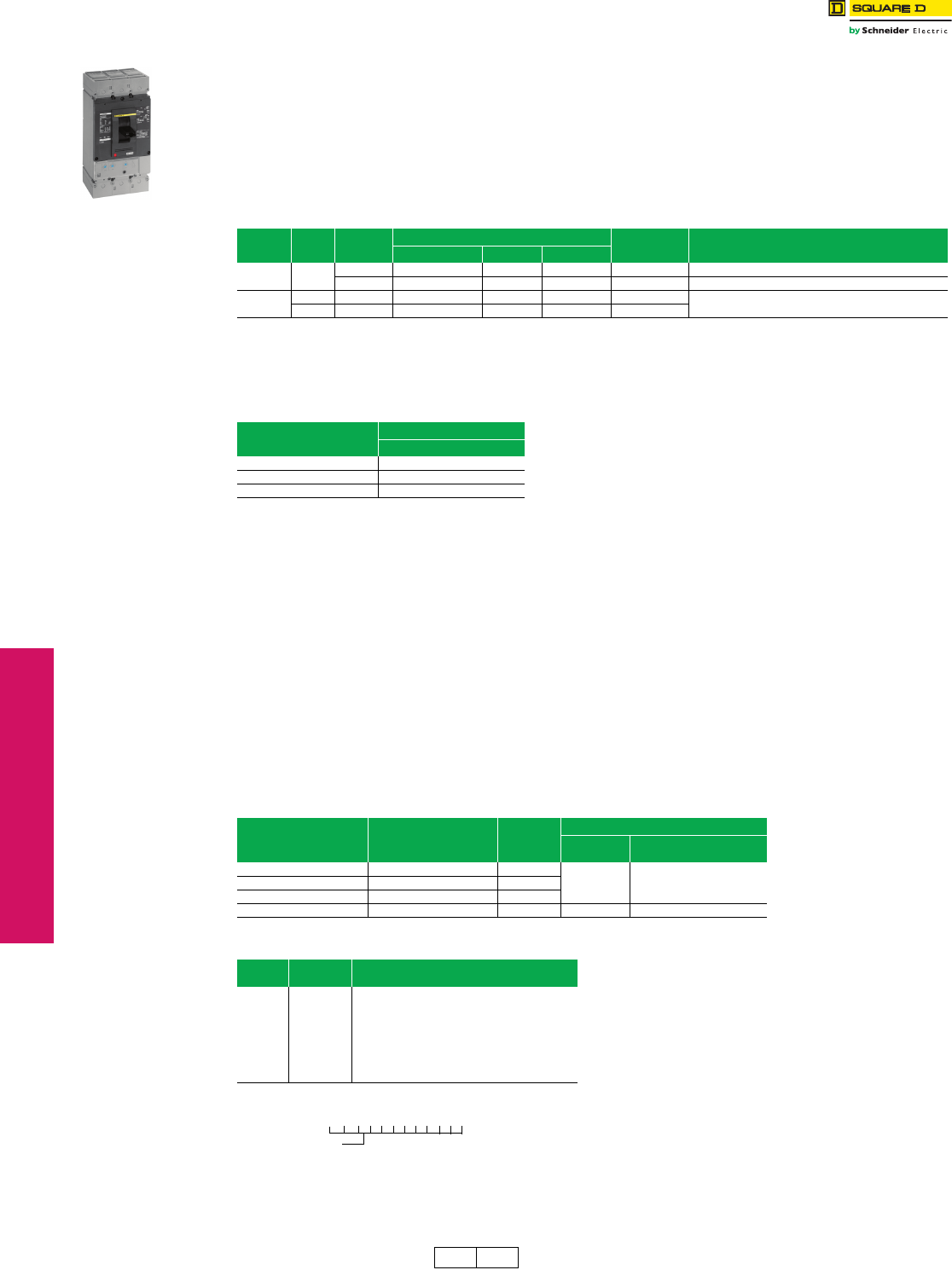
3-6 © 2012 Schneider Electric
All Rights Reserved
www.schneider-electric.us
3MOLDED CASE CIRCUIT
BREAKERS
PowerPact™ Automatic
Switches Class 600 / Refer to Catalog 0612CT0101
Automatic molded case switches open instantaneously at a factory preset magnetic trip point, calibrated to protect only
the molded case switch itself, when it is subjected to high fault currents. The trip point is nonadjustable and provides no
overload or low level fault protection.
Molded case switches open when the handle is switched to the OFF position or in response to an auxiliary tripping
device such as a shunt trip.
All molded case switches will accept the same lugs and accessories as equivalent thermal-magnetic circuit breakers,
with the exception of Q-frame switches which do not have electrical accessories available.
Automatic molded case switches are UL Listed per UL 489 and are CSA Certified.
cWithstand rating of 10 kA at 240 Vac.
dDE2A discount schedule.
eP-frame L-interrupting is available in 480 Vac only.
fUL magnetic trip tolerances are -20% / +30% from the nominal values shown.
gThe withstand rating is the fault current at rated voltage that the molded case switch will withstand without damage when protected by a circuit breaker
with an equal continuous current rating.
PowerPact™ D-frame Mission Critical Circuit Breakers
When the D-frame Mission Critical circuit breaker is used as a main circuit breaker with QO branch circuit breakers, the
D-frame MC will remain closed during any fault that occurs downstream of the QO circuit breaker up to 30kA at
208Y/120 Vac.
Ratings:
•UL 489 Listed
•CSA Certified
•Voltage: 208Y/120 V
•Handle ratings: 60–600 A
•AIR: 65 kA
Available Configurations:
•Four sizes: 150 A, 250 A, 400 A, and 600 A
•Main circuit breaker in NQ panelboards
•Unit mount for OEM users
•Plug-in base for OEM users
•Drawout base for OEM users
aD-Frame circuit breakers 400 A and below are 100% rated.
For N, D, and S pricing, add termination pricing to price. See page 7-45
Accessories . . . . . . . . . . . . . . . . . . . . . . . . . . . . . . . . . . . . Page 3-24—3-27
Optional Lugs . . . . . . . . . . . . . . . . . . . . . . . . . . . . . . . . . . . . Page 3-28—3-29
Dimensions. . . . . . . . . . . . . . . . . . . . . . . . . . . . . . . . . . . . . . . . . . . . Page 3-33
Table 3.22: D-Frame (600 Vac) and Q-Frame (240 Vac) PowerPact™ Automatic Molded Case Switches
Circuit
Breaker Poles Ampere
Rating
J Interrupting Terminal Wire Range
Cat. No. $ Price Trip Point
D-Frame 3 400 A DJL36000S40 4572.00 6000 A S32508 2 AWG–500 kcmil Al or 2 AWG–600 kcmil Cu
600 A DJL36000S60 7484.00 6000 A S32510 (2) 2/0 AWG–500 kcmil Al or (2) 2/0 AWG–350 kcmil Cu
Q-Framec2225 AQBL22000S22d440.00 4500 A 4 AWG–300 kcmil
3225 AQBL32000S22d1193.00 4500 A
Table 3.23: D-Frame Withstand Ratingsg
Voltag e Interrupting
J
240 Vac 150 kA
480 Vac 100 kA
600 Vac 25 kA
Table 3.24: D-Frame Mission Critical Circuit Breakers
Circuit Breaker
Cat. No.a
Continuous Current
Rating $ Price
Terminal
Cat. No. Wire Range
(AWG/kcmil)
DJL32150W 150 A 10317.00
32508 #2-600 Cu or #2-500 AlDJL32250W 250 A 10317.00
DJL32400W 400 A 10317.00
DJL32600W 600 A 13551.00 32510 (2) 2/0-350 Cu or (2) 2/0-500Al
Table 3.25: Termination Options
Frame Termination
Letter Termination Option
D-Frame
F No Lugs (Includes terminal nut kit on both ends)
L Lugs both ends
M Lugs ON end Terminal Nut Kit Off end
P Lugs OFF end Terminal Nut Kit On end
N Plug-in
D Drawout
S Rear Connected
D-Frame Switch
For factory-installed termination, place termination letter in
the third block of the circuit breaker catalog number.
Termination Letter
D G L 3 6 4 0 0 E 2 0
DE2 DE2A Discount
Schedule
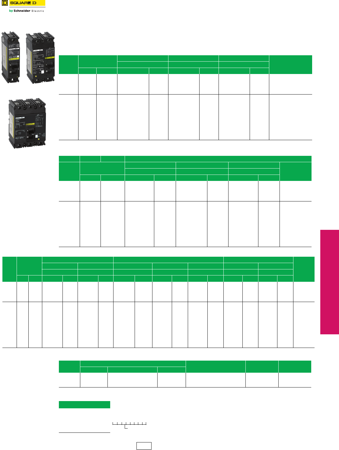
www.schneider-electric.us
© 2012 Schneider Electric
All Rights Reserved 3-7
3MOLDED CASE CIRCUIT
BREAKERS
Molded Case Circuit
Breakers
F-Frame Thermal-Magnetic Circuit Breakers
Class 650
Thermal-magnetic molded case circuit breakers shown on
pages 3-7 through 3-18 are permanent trip UL Listed,
CSA® Certified, IEC rated, and also meet the requirements
of Federal Specification W–C–375B/GEN as indicated on
Digest pages 7-4 through 7-7.
NOTE: Consider using PowerPact™ circuit breakers for
situations requiring circuit breaker accessories.
See Digest Section 7 for more information.
aSee Section 11
Accessories . . . . . . . . . . . . . . . . . . . . . . . . . . . . . . . . . . . . . Page 3-24—3-27
Optional Lugs . . . . . . . . . . . . . . . . . . . . . . . . . . . . . . . . . . . . Page 3-28—3-29
Dimensions . . . . . . . . . . . . . . . . . . . . . . . . . . . . . . . . . . . . . . . . . . . .Page 3-33
Enclosures: see Digest Section 7
FAL 1P
15–100 A
FAL/FHL
2P
15–100 A
FAL/FHL 3P
15–100 A
Table 3.24: F-Frame—100 A, Thermal-Magnetic, Individually-Mounted, Standard Interrupting, 240 Vac
Ampere
Rating
Fixed AC Magnetic
Trip
1 P 2 P 3 P
Terminal Wire Range
(AWG)
120 Vac 240 Vac 240 Vac
Hold Trip Cat. No. $ Price Cat. No. $ Price Cat. No. $ Price
15 A 275 A 600 A FAL12015 198.00 FAL22015 333.00 FAL32015 495.00
AL50FA
14–4 Cu or 12–4 Al
20 A 275 A 600 A FAL12020 198.00 FAL22020 333.00 FAL32020 495.00
25 A 275 A 600 A FAL12025 198.00 FAL22025 333.00 FAL32025 495.00
30 A 275 A 600 A FAL12030 198.00 FAL22030 333.00 FAL32030 495.00
35 A 400 A 850 A FAL12035 198.00 FAL22035 333.00 FAL32035 495.00
AL100FA
14–1/0 Cu or 12–1/0 Al
40 A 400 A 850 A FAL12040 198.00 FAL22040 333.00 FAL32040 495.00
45 A 400 A 850 A FAL12045 198.00 FAL22045 333.00 FAL32045 495.00
50 A 400 A 850 A FAL12050 198.00 FAL22050 333.00 FAL32050 495.00
60 A 800 A 1450 A FAL12060 198.00 FAL22060 333.00 FAL32060 495.00
70 A 800 A 1450 A FAL12070 261.00 FAL22070 543.00 FAL32070 704.00
80 A 800 A 1450 A FAL12080 261.00 FAL22080 543.00 FAL32080 704.00
90 A 900 A 1700 A FAL12090 261.00 FAL22090 543.00 FAL32090 704.00
100 A 900 A 1700 A FAL12100 261.00 FAL22100 543.00 FAL32100 704.00
Table 3.25: F-Frame—100 A, Thermal-Magnetic, Individually-Mounted, 480 Vac
Standard Interrupting
Ampere
Rating
Fixed AC Magnetic
Trip
1P 2P 3P Terminal
Wire Range
(AWG)
277 Vac, 125 Vdc 480 Vac, 250 Vdc 480 Vac, 250 Vdc
Hold Trip Cat. No. $ Price Cat. No. $ Price Cat. No. $ Price
15 A 275 A 600 A FAL14015 251.00 FAL24015 609.00 FAL34015 782.00
AL50FA
(1) 14–4 Cu or
(1) 12–4 Al
20 A 275 A 600 A FAL14020 251.00 FAL24020 609.00 FAL34020 782.00
25 A 275 A 600 A FAL14025 251.00 FAL24025 609.00 FAL34025 782.00
30 A 275 A 600 A FAL14030 251.00 FAL24030 609.00 FAL34030 782.00
35 A 400 A 850 A FAL14035 251.00 FAL24035 609.00 FAL34035 782.00
AL100FA
(1) 14–1/0 Cu
or (1) 12–1/0 Al
40 A 400 A 850 A FAL14040 251.00 FAL24040 609.00 FAL34040 782.00
45 A 400 A 850 A FAL14045 251.00 FAL24045 609.00 FAL34045 782.00
50 A 400 A 850 A FAL14050 251.00 FAL24050 609.00 FAL34050 782.00
60 A 800 A 1450 A FAL14060 251.00 FAL24060 609.00 FAL34060 782.00
70 A 800 A 1450 A FAL14070 312.00 FAL24070 788.00 FAL34070 924.00
80 A 800 A 1450 A FAL14080 312.00 FAL24080 788.00 FAL34080 924.00
90 A 900 A 1700 A FAL14090 312.00 FAL24090 788.00 FAL34090 924.00
100 A 900 A 1700 A FAL14100 312.00 FAL24100 788.00 FAL34100 924.00
Table 3.26: F-Frame—100 A, Thermal-Magnetic, Individually-Mounted, 600 Vac
Ampere
Rating
Fixed AC
Magnetic
Trip
Standard Interrupting High Interrupting Current Limiting
Terminal
Wire Range
(AWG)
2P 3P 1P 2P 3P 2P 3P
600 Vac, 250 Vdc 600 Vac, 250 Vdc 277 Vac, 125 Vdc 600 Vac, 250 Vdc 600 Vac, 250 Vdc 600 Vac, 250 Vdc 600 Vac, 250 Vdc
Hold Trip Cat. No. $ Price Cat. No. $ Price Cat. No. $ Price Cat. No. $ Price Cat. No. $ Price Cat. No. $ Price Cat. No. $ Price
15 A 275 A 600 A FAL26015 704.00 FAL36015 906.00 FHL16015 452.00 FHL26015 1163.00 FHL36015 1358.00 ——
AL50FA
14–4 Cu or
12–4 Al
20 A 275 A 600 A FAL26020 704.00 FAL36020 906.00 FHL16020 452.00 FHL26020 1163.00 FHL36020 1358.00 FIL26020 2633.00 FIL36020 3296.00
25 A 275 A 600 A FAL26025 704.00 FAL36025 906.00 FHL16025 452.00 FHL26025 1163.00 FHL36025 1358.00 FIL26025 2633.00 FIL36025 3296.00
30 A 275 A 600 A FAL26030 704.00 FAL36030 906.00 FHL16030 452.00 FHL26030 1163.00 FHL36030 1358.00 FIL26030 2633.00 FIL36030 3296.00
35 A 400 A 850 A FAL26035 704.00 FAL36035 906.00 FHL16035 452.00 FHL26035 1163.00 FHL36035 1358.00 FIL26035 2633.00 FIL36035 3296.00
AL100FA
14–1/0 Cu
or 12–1/0 Al
40 A 400 A 850 A FAL26040 704.00 FAL36040 906.00 FHL16040 452.00 FHL26040 1163.00 FHL36040 1358.00 FIL26040 2633.00 FIL36040 3296.00
45 A 400 A 850 A FAL26045 704.00 FAL36045 906.00 FHL16045 452.00 FHL26045 1163.00 FHL36045 1358.00 FIL26045 2633.00 FIL36045 3296.00
50 A 400 A 850 A FAL26050 704.00 FAL36050 906.00 FHL16050 452.00 FHL26050 1163.00 FHL36050 1358.00 FIL26050 2633.00 FIL36050 3296.00
60 A 800 A 1450 A FAL26060 704.00 FAL36060 906.00 FHL16060 452.00 FHL26060 1163.00 FHL36060 1358.00 FIL26060 2633.00 FIL36060 3296.00
70 A 800 A 1450 A FAL26070 890.00 FAL36070 1115.00 FHL16070 509.00 FHL26070 1353.00 FHL36070 1541.00 FIL26070 2633.00 FIL36070 3296.00
80 A 800 A 1450 A FAL26080 890.00 FAL36080 1115.00 FHL16080 509.00 FHL26080 1353.00 FHL36080 1541.00 FIL26080 2633.00 FIL36080 3296.00
90 A 900 A 1700 A FAL26090 890.00 FAL36090 1115.00 FHL16090 509.00 FHL26090 1353.00 FHL36090 1541.00 FIL26090 2633.00 FIL36090 3296.00
100 A 900 A 1700 A FAL26100 890.00 FAL36100 1115.00 FHL16100 509.00 FHL26100 1353.00 FHL36100 1541.00 FIL26100 2633.00 FIL36100 3296.00
Table 3.27: Interrupting Ratings
Volt age FAL FHL FCLa FIL
240 Vac 480 Vac 600 Vac
240 Vac 10 kA 18 kA (1P), 25 kA (2P, 3P) 25 kA 25 kA (1P) 65 kA (2P, 3P) 100 kA 200 kA
480 Vac — 18 kA 18 kA 25 kA (2P, 3P) 65 kA 200 kA
600 Vac — — 14 kA 18 kA (2P, 3P) — 100 kA
Table 3.28: Termination Option
Termination Letter
F = No Lugs
L = Lugs both ends
P with MT Suffix = Lugs ON end
P = Lugs OFF end
F A L 3 6 1 0 0
For factory-installed termination, place
termination letter in the third block of the
circuit breaker catalog number.
Termination Letter
DE2 Discount
Schedule
www.schneider-electric.us
3-8 © 2012 Schneider Electric
All Rights Reserved
3MOLDED CASE CIRCUIT
BREAKERS
Molded Case Circuit
Breakers
F-Frame Thermal-Magnetic Circuit Breakers
Class 650
NOTE: Consider using PowerPact™ circuit breakers for situations requiring circuit breaker
accessories. See Digest Section 7 for more information.
.
eSee Section 11.
Accessories . . . . . . . . . . . . . . . . . . . . . . . . . . . . . . . . . . . . .Page 3-24—3-27
Optional Lugs. . . . . . . . . . . . . . . . . . . . . . . . . . . . . . . . . . . . .Page 3-28—3-29
Dimensions. . . . . . . . . . . . . . . . . . . . . . . . . . . . . . . . . . . . . . . . . . . . Page 3-33
Enclosures: see Digest Section 7
Table 3.29: F-Frame—100 A, Thermal-Magnetic, I-Line™ Construction, 240 Vac,
Standard Interrupting
Ampere
Rating
Fixed AC Magnetic
Trip
2 Pa3 P Terminal
Wire Range
(AWG)
240 Vac 240 Vac
Hold Trip Cat. No. $ Price Cat. No. $ Price
15 A 275 A 600 A FA22015( ) 398.00 FA32015 572.00
AL50FA
14–4 Cu or
12–4 Al
20 A 275 A 600 A FA22020( ) 398.00 FA32020 572.00
25 A 275 A 600 A FA22025( ) 398.00 FA32025 572.00
30 A 275 A 600 A FA22030( ) 398.00 FA32030 572.00
35 A 400 A 850 A FA22035( ) 398.00 FA32035 572.00
AL100FA
14–1/0 Cu
or 12–1/0 Al
40 A 400 A 850 A FA22040( ) 398.00 FA32040 572.00
45 A 400 A 850 A FA22045( ) 398.00 FA32045 572.00
50 A 400 A 850 A FA22050( ) 398.00 FA32050 572.00
60 A 800 A 1450 A FA22060( ) 398.00 FA32060 572.00
70 A 800 A 1450 A FA22070( ) 617.00 FA32070 780.00
80 A 800 A 1450 A FA22080( ) 617.00 FA32080) 780.00
90 A 900 A 1700 A FA22090( ) 617.00 FA32090 780.00
100 A 900 A 1700 A FA22100( ) 617.00 FA32100 780.00
Table 3.30: F-Frame—100 A, Thermal-Magnetic, I-Line™ Construction, 480 Vac
Ampere
Rating
Fixed AC Magnetic
Trip
Standard Interrupting
1Pad 2Pa3P Terminal
Wire Range
(AWG)
277 Vac, 125 Vdc 480 Vac, 250 Vdc 480 Vac, 250 Vdc
Hold Trip Cat. No. $ Price Cat. No. $ Price Cat. No. $ Price
15 A 275 A 600 A — — FA24015( ) 651.00 FA34015 833.00
AL50FA
(1) 14–4 Cu or
(1) 12–4 Al
20 A 275 A 600 A — — FA24020( ) 651.00 FA34020 833.00
25 A 275 A 600 A — — FA24025( ) 651.00 FA34025 833.00
30 A 275 A 600 A — — FA24030( ) 651.00 FA34030 833.00
35 A 400 A 850 A FA14035( ) 302.00 FA24035( ) 651.00 FA34035 833.00
AL100FA
(1) 14–1/0 Cu
or (1) 12–1/0 Al
40 A 400 A 850 A FA14040( ) 302.00 FA24040( ) 651.00 FA34040 833.00
45 A 400 A 850 A FA14045( ) 302.00 FA24045( ) 651.00 FA34045 833.00
50 A 400 A 850 A FA14050( ) 302.00 FA24050( ) 651.00 FA34050 833.00
60 A 800 A 1450 A FA14060( ) 302.00 FA24060( ) 651.00 FA34060 833.00
70 A 800 A 1450 A FA14070( ) 332.00 FA24070( ) 833.00 FA34070 996.00
80 A 800 A 1450 A FA14080( ) 332.00 FA24080( ) 833.00 FA34080 996.00
90 A 900 A 1700 A FA14090( ) 332.00 FA24090( ) 833.00 FA34090 996.00
100 A 900 A 1700 A FA14100( ) 332.00 FA24100( ) 833.00 FA34100 996.00
FA 1P
1.5 in. (38 mm)
Mounting Height
FA 2P
3 in. (76 mm)
Mounting Height
FA 3P
4.5 in. (114 mm)
Mounting Height
Table 3.31: F-Frame—100 A, Thermal-Magnetic, I-Line™ Construction, 600 Vac
Ampere
Rating
Fixed AC
Magnetic
Trip
Standard Interrupting High Interrupting Current Limiting
2Pa3 P 1Pad 2Pa3P 2Pa3P Terminal
Wire Range
(AWG)
600 Vac. 250 Vdc 600 Vac. 250 Vdc 277 Vac, 125 Vdc 600 Vac. 250 Vdc 600 Vac. 250 Vdc 600 Vac. 250 Vdc 600 Vac. 250 Vdc
Hold Trip Cat. No. $ Price Cat. No. $ Price Cat. No. $ Price Cat. No. $ Price Cat. No. $ Price Cat. No. $ Price Cat. No. $ Price
15 A 275 A 600 A FA26015( ) 780.00 FA36015 971.00 FH16015( ) 507.00 FH26015( ) 1214.00 FH36015 1446.00 ————
AL50FA
14–4 Cu or
12–4 Al
20 A 275 A 600 A FA26020( ) 780.00 FA36020 971.00 FH16020( ) 507.00 FH26020( ) 1214.00 FH36020 1446.00 FI26020( ) 2763.00 FI36020 3296.00
25 A 275 A 600 A FA26025( ) 780.00 FA36025 971.00 FH16025( ) 507.00 FH26025( ) 1214.00 FH36025 1446.00 ————
30 A 275 A 600 A FA26030( ) 780.00 FA36030 971.00 FH16030( ) 507.00 FH26030( ) 1214.00 FH36030 1446.00 FI26030( ) 2763.00 FI36030 3296.00
35 A 400 A 850 A FA26035( ) 780.00 FA36035 971.00 FH16035( ) 507.00 FH26035( ) 1214.00 FH36035 1446.00 ————
AL100FA
14–1/0 Cu
or 12–1/0 Al
40 A 400 A 850 A FA26040( ) 780.00 FA36040 971.00 FH16040( ) 507.00 FH26040( ) 1214.00 FH36040 1446.00 FI26040( ) 2763.00 FI36040 3296.00
45 A 400 A 850 A FA26045( ) 780.00 FA36045 971.00 FH16045( ) 507.00 FH26045( ) 1214.00 FH36045 1446.00 ————
50 A 400 A 850 A FA26050( ) 780.00 FA36050 971.00 FH16050( ) 507.00 FH26050( ) 1214.00 FH36050 1446.00 FI26050( ) 2763.00 FI36050 3296.00
60 A 800 A 1450 A FA26060( ) 780.00 FA36060 971.00 FH16060( ) 507.00 FH26060( ) 1214.00 FH36060 1446.00 FI26060( ) 2763.00 FI36060 3296.00
70 A 800 A 1450 A FA26070( ) 947.00 FA36070 1163.00 FH16070( ) 563.00 FH26070( ) 1452.00 FH36070 1632.00 FI26070( ) 2763.00 FI36070 3296.00
80 A 800 A 1450 A FA26080( ) 947.00 FA36080 1163.00 FH16080( ) 563.00 FH26080( ) 1452.00 FH36080 1632.00 FI26080( ) 2763.00 FI36080 3296.00
90 A 900 A 1700 A FA26090( ) 947.00 FA36090 1163.00 FH16090( ) 563.00 FH26090( ) 1452.00 FH36090 1632.00 FI26090( ) 2763.00 FI36090 3296.00
100 A 900 A 1700 A FA26100( ) 947.00 FAL6100 1163.00 FH16100( ) 563.00 FH26100( ) 1452.00 FH36100 1632.00 FI26100( ) 2763.00 FI36100 3296.00
a1P and 2P circuit breaker catalog numbers are completed by adding the required phase connection letters as a suffix. See Phase Option Table.
bFCL 2P circuit breakers are built using 3P module.
cFCL circuit breakers are not rated for 250 Vdc.
dRated 277 Vac, 125 Vdc. 15–30 A circuit breaker suitable for use with 60°C or 75 °C conductors. 35–100 A circuit breakers are suitable for use with 75°C conductors.
Table 3.32: Phase Options
Phase Option
Letter 1P 2P 3P
A
B
C
FA14035A
FA14035B
FA14035C
AB
AC
BC
FA24030AB
FA24030AC
FA24030BC
ABC
CBA
FA34030
FA34030CBA
Table 3.33: Interrupting Ratings
Voltage FA FH FCeFI
240 Vac 480 Vac 600 Vac
240 Vac 10 kA 18 kA (1P), 25 kA (2P, 3P) 25 kA 25 kA (1P) 65 kA (2P, 3P) 100 kA 200 kA
277 Vac — 18 kA — — 65 kA —
480 Vac — 18 kA 18 kA 25 kA (2P, 3P) 65 kA 200 kA
600 Vac — — 14 kA 18 kA (2P, 3P) — 100 kA
DE2 Discount
Schedule
www.schneider-electric.us
3MOLDED CASE CIRCUIT
BREAKERS
© 2012 Schneider Electric
All Rights Reserved 3-9
Molded Case Circuit
Breakers
K- and Q4-Frame Thermal-Magnetic Circuit Breakers
Class 655, 825, 660
NOTE: Consider using PowerPact™ circuit breakers for situations requiring circuit breaker accessories. See Digest
Section 7 for more information.
aUL magnetic trip setting tolerances are ±25% for low and ±20% for high from nominal value shown.
bKC circuit breakers are 480 Vac
Accessories . . . . . . . . . . . . . . . . . . . . . . . . . . . . . . . . . . . . . . . . . . Page 3-25
Optional Lugs . . . . . . . . . . . . . . . . . . . . . . . . . . . . . . . . . . . . . . . . . Page 3-28
Dimensions . . . . . . . . . . . . . . . . . . . . . . . . . . . . . . . . . . . . . . . . . . . Page 3-33
Enclosures: see Digest Section 7
Table 3.34: K-Frame—250 A, Thermal-Magnetic, Individually-Mounted, 600 Vac
Ampere
Rating
Adjustable AC Magnetic TripaCurrent Limiting Terminal
Wire Range
Low High Cat. No. $ Price
2P, 600 Vac, 250 Vdc
110 550 A 1100 A KIL26110 6177.00
AL250KA
(1) 4 AWG–350 kcmil Al
125 625 A 1250 A KIL26125 6177.00
150 750 A 1500 A KIL26150 6177.00
175 875 A 1750 A KIL26175 6177.00
200 1000 A 2000 A KIL26200 6177.00 AL250KI
(1) 1/0 AWG–350 kcmil Al
225 1125 A 2250 A KIL26225 6177.00
250 1250 A 2500 A KIL26250 7223.00
3P, 600 Vac, 250 Vdc
110 550 A 1100 A KIL36110 7754.00
AL250KA
(1) 4 AWG–350 kcmil Al
125 625 A 1250 A KIL36125 7754.00
150 750 A 1500 A KIL36150 7754.00
175 875 A 1750 A KIL36175 7754.00
200 1000 A 2000 A KIL36200 7754.00 AL250KI
(1) 1/0 AWG–350 kcmil Al
225 1125 A 2250 A KIL36225 7754.00
250 1250 A 2500 A KIL36250 9081.00
Table 3.35: Q4-Frame—400 A, Thermal-Magnetic, Individually-Mounted, 240 Vac
Ampere
Rating
Adjustable AC Magnetic TripaStandard Interrupting Terminal
Wire Range
Low High Cat. No. $ Price
2P, 240 Vac
250 1250 A 2500 A Q4L2250 3171.00 AL400LA
(1) 1 AWG–600 kcmil Al
or
(2) 1 AWG–250 kcmil Al
300 1500 A 3000 A Q4L2300 3171.00
350 1750 A 3500 A Q4L2350 3171.00
400 2000 A 4000 A Q4L2400 3171.00
3P, 240 Vac
250 1250 A 2500 A Q4L3250 3831.00 AL400LA
(1) 1 AWG–600 kcmil Al
or
(2) 1 AWG–250 kcmil Al
300 1500 A 3000 A Q4L3300 3831.00
350 1750 A 3500 A Q4L3350 3831.00
400 2000 A 4000 A Q4L3400 3831.00
Table 3.36: Interrupting Ratings
Volt age KIL Q4
240 Vac 200 kA 25 kA
480 Vac 200 kA —
600 Vac 100 kA —
KAL/KHL
2P and 3P
70–250 A
KIL36250
Q4L
2P and 3P
250–400 A
DE2 Discount
Schedule
3-10 © 2012 Schneider Electric
All Rights Reserved
www.schneider-electric.us
3MOLDED CASE CIRCUIT
BREAKERS
Molded Case Circuit
Breakers
K- and Q4-Frame Thermal-Magnetic Circuit Breakers
Class 655, 825, 660
NOTE: Consider using PowerPact™ circuit breakers for situations requiring circuit breaker accessories. See Digest
Section 7 for more information.
aUL magnetic trip setting tolerances are ±25% for low and ±20% for high from nominal value shown.
bKC circuit breakers are 480 Vac
c2P and 3P circuit breaker catalog numbers are completed by adding the required phase connection letters as a suffix. See Phase Option Table.
Accessories . . . . . . . . . . . . . . . . . . . . . . . . . . . . . . . . . . . . . . . . . . Page 3-25
Optional Lugs . . . . . . . . . . . . . . . . . . . . . . . . . . . . . . . . . . . . . . . . . . Page 3-28
Dimensions. . . . . . . . . . . . . . . . . . . . . . . . . . . . . . . . . . . . . . . . . . . . Page 3-33
Enclosures: see Digest Section 7
Table 3.37: K-Frame—250A, Thermal-Magnetic, I-Line™ Construction, 600 Vac
Ampere
Rating
Adjustable AC Magnetic TripaCurrent
Limiting Terminal
Wire Range
Low High Cat. No. $ Price
2P, 600 Vac, 250 Vdcc
110 550 A 1100 A KI26110( ) 6633.00
AL250KA
(1) 4 AWG–350 kcmil Al
125 625 A 1250 A KI26125( ) 6633.00
150 750 A 1500 A KI26150( ) 6633.00
175 875 A 1750 A KI26175( ) 6633.00
200 1000 A 2000 A KI26200( ) 6633.00 AL250KI
(1) 1/0 AWG–350 kcmil Al
225 1125 A 2250 A KI26225( ) 6633.00
250 1250 A 2500 A KI26250( ) 7704.00
3P, 600 Vac, 250 Vdc
110 550 A 1100 A KI36110 8375.00
AL250KA
(1) 4 AWG–350 kcmil Al
125 625 A 1250 A KI36125 8375.00
150 750 A 1500 A KI36150 8375.00
175 875 A 1750 A KI36175 8375.00
200 1000 A 2000 A KI36200 8375.00 AL250KI
(1) 1/0 AWG–350 kcmil Al
225 1125 A 2250 A KI36225 8375.00
250 1250 A 2500 A KI36250 9267.00
Table 3.38: Q4-Frame—400 A, Thermal-Magnetic, I-Line™ Construction, 240 Vac
Ampere
Rating
Adjustable AC Magnetic TripaStandard Interrupting Terminal
Wire Range
Low High Cat. No. $ Price
2P, 240 Vacc
250 1250 A 2500 A Q422250( ) 3435.00 AL400LA
(1) 1 AWG–600 kcmil Al
or
(2) 1 AWG–250 kcmil Al
300 1500 A 3000 A Q422300( ) 3435.00
350 1750 A 3500 A Q422350( ) 3435.00
400 2000 A 4000 A Q422400( ) 3435.00
3P, 240 Vac
250 1250 A 2500 A Q43250 4313.00 AL400LA
(1) 1 AWG–600 kcmil Al
or
(2) 1 AWG–250 kcmil Al
300 1500 A 3000 A Q43300 4313.00
350 1750 A 3500 A Q43350 4313.00
400 2000 A 4000 A Q43400 4313.00
Table 3.39: Interrupting Ratings
Voltage KI Q4
240 Vac 200 kA 25 kA
480 Vac 200 kA —
600 Vac 100 kA —
Table 3.40: Phase Options
Phase Option Letter 2P 3P
AB
AC
BC
KA26250AB
KA26250AC
KA26250BC
ABC
CBA
KA36250
KA36250CBA
Q4 2P and 3P
6 in. (152 mm)
Mounting Height
KI 2P and 3P
4.5 in. (114 mm)
Mounting Height
DE2 Discount
Schedule
www.schneider-electric.us
3MOLDED CASE CIRCUIT
BREAKERS
© 2012 Schneider Electric
All Rights Reserved 3-11
Molded Case Circuit
Breakers
L-Frame Thermal-Magnetic Circuit Breakers
Class 600, 665, 736, 830
NOTE: Consider using PowerPact™ circuit breakers for situations requiring circuit breaker accessories. See Digest
Section 7 for more information.
aAC magnetic setting tolerances are +0–25% from max. value shown.
Accessories . . . . . . . . . . . . . . . . . . . . . . . . . . . . . . . . . . . . . Page 3-24—3-27
Optional Lugs . . . . . . . . . . . . . . . . . . . . . . . . . . . . . . . . . . . . Page 3-28—3-29
Dimensions . . . . . . . . . . . . . . . . . . . . . . . . . . . . . . . . . . . . . . . . . . . Page 3-33
Enclosures: see Digest Section 7
Table 3.41: L-Frame—400 A, Thermal-Magnetic, Individually-Mounted, High Magnetic Withstand Circuit
Breakers For Mission Critical Loads
Ampere
Rating
AC Magnetic Level
Factory Seta
Standard Interrupting High Interrupting Terminal
Wire Range
Cat. No. $ Price Cat. No. $ Price
LA/LH MC Circuit Breaker, 3P, 480 Vac
200 A 4000 A LAL34200MC 4962.00 LHL34200MC 7941.00 AL250LA
(1) 4 AWG–350 kcmil Al
225 A 4500 A LAL34225MC 4962.00 LHL34225MC 7941.00
250 A 5000 A LAL34250MC 5355.00 LHL34250MC 8336.00
400 A 8000 A LAL34400MC 6615.00 LHL34400MC 9596.00
AL400LA
(1) 1 AWG–600 kcmil Al or
(2) 1 AWG–250 kcmil Al
Table 3.42: L-Frame—600 A, Thermal-Magnetic, Individually-Mounted Circuit Breakers, 600 Vac
Ampere
Rating
Adjustable AC
Magnetic Trip Standard Interrupting High Interrupting Terminal
Wire Range
Low High Cat. No. $ Price Cat. No. $ Price
2P, 600 Vac, 250 Vdc
125 A
150 A
175 A
200 A
225 A
250 A
625 A
750 A
875 A
1000 A
1125 A
1250 A
1250 A
1500 A
1750 A
2000 A
2250 A
2500 A
LAL26125
LAL26150
LAL26175
LAL26200
LAL26225
LAL26250
3807.00
3807.00
3807.00
3807.00
3807.00
3807.00
LHL26125
LHL26150
LHL26175
LHL26200
LHL26225
LHL26250
6362.00
6362.00
6362.00
6362.00
6362.00
6362.00
AL400LA
(1) 1 AWG–600 kcmil Al
or
(2) 1 AWG–250 kcmil Al
300 A
350 A
400 A
1500 A
1750 A
2000 A
3000 A
3500 A
4000 A
LAL26300
LAL26350
LAL26400
3807.00
3807.00
3807.00
LHL26300
LHL26350
LHL26400
6362.00
6362.00
6362.00
3P, 600 Vac, 250 Vdc
125 A
150 A
175 A
200 A
225 A
250 A
625 A
750 A
875 A
1000 A
1125 A
1250 A
1250 A
1500 A
1750 A
2000 A
2250 A
2500 A
LAL36125
LAL36150
LAL36175
LAL36200
LAL36225
LAL36250
4619.00
4619.00
4619.00
4619.00
4619.00
4619.00
LHL36125
LHL36150
LHL36175
LHL36200
LHL36225
LHL36250
7598.00
7598.00
7598.00
7598.00
7598.00
7598.00
AL400LA
(1) 1 AWG–600 kcmil Al
or
(2) 1 AWG–250 kcmil Al
300 A
350 A
400 A
1500 A
1750 A
2000 A
3000 A
3500 A
4000 A
LAL36300
LAL36350
LAL36400
4619.00
4619.00
4619.00
LHL36300
LHL36350
LHL36400
7598.00
7598.00
7598.00
Table 3.43: L-Frame—600 A, Current-Limiting, Individually-Mounted Circuit Breakers, 600 Vac
Ampere
Rating
Adjustable AC
Magnetic Trip Extra-High Interrupting Current Limiting Terminal
Wire Range
Low High Cat. No. $ Price Cat. No. $ Price
2P, 600 Vac
300 A
350 A
400 A
1500 A
1750 A
2000 A
3200 A
3200 A
3200 A
LCL26300
LCL26350
LCL26400
7479.00
7479.00
7479.00
LIL26300
LIL26350
LIL26400
8604.00
8604.00
8604.00 AL600LI5
(2) 4/0 AWG–500 kcmil Al
450 A
500 A
600 A
2250 A
2500 A
3000 A
4200 A
4200 A
4200 A
LCL26450
LCL26500
LCL26600
7823.00
7823.00
7823.00
LIL26450
LIL26500
LIL26600
12551.00
12551.00
12551.00
3P, 600 Vac
300 A
350 A
400 A
1500 A
1750 A
2000 A
3200 A
3200 A
3200 A
LCL36300
LCL36350
LCL36400
8312.00
8312.00
8312.00
LIL36300
LIL36350
LIL36400
9563.00
9563.00
9563.00 AL600LI5
(2) 4/0 AWG–500 kcmil Al
450 A
500 A
600 A
2250 A
2500 A
3000 A
4200 A
4200 A
4200 A
LCL36450
LCL36500
LCL36600
8691.00
8691.00
8691.00
LIL36450
LIL36500
LIL36600
13949.00
13949.00
13949.00
Table 3.44: Interrupting Ratings
Voltage LAL LHL LCL LIL
240 Vac 42 kA 65 kA 100 kA 200 kA
480 Vac 30 kA 35 kA 65 kA 200 kA
600 Vac 22 kA 25 kA 35 kA 100 kA
LAL/LHL MC
For Mission Critical
Power Loads
available in 200, 225, 250,
and 400 A @ 480 Vac
LIL36600
2P and 3P 300–600 A
LAL/LHL
2P and 3P
125–400 A
DE2 Discount
Schedule
3-12 © 2012 Schneider Electric
All Rights Reserved
www.schneider-electric.us
3MOLDED CASE CIRCUIT
BREAKERS
Molded Case Circuit
Breakers
L-Frame Thermal-Magnetic Circuit Breakers
Class 600, 665, 736, 830
NOTE: Consider using PowerPact™ circuit breakers for situations requiring circuit breaker accessories. See Digest
Section 7 for more information.
aFactory set AC magnetic setting tolerances are +0–25% from max. value shown.
a2P and 3P circuit breaker catalog numbers are completed by adding the required phase connection letters as a suffix. See Phase Option Table.
bUL magnetic trip setting tolerances are ±25% for low and ±20% for high from nominal value.
ccessories . . . . . . . . . . . . . . . . . . . . . . . . . . . . . . . . . . . . . . Page 3-24—3-27
Optional Lugs . . . . . . . . . . . . . . . . . . . . . . . . . . . . . . . . . . . . Page 3-28—3-29
Dimensions. . . . . . . . . . . . . . . . . . . . . . . . . . . . . . . . . . . . . . . . . . . . Page 3-33
Enclosures: see Digest Section 7
Table 3.45: L-Frame—400 A, Thermal-Magnetic, I-Line™ Construction, High Magnetic Withstand Circuit
Breakers For Mission Critical Loads
Ampere
Rating
AC Magnetic Level
Factory Seta
Standard Interrupting High Interrupting Terminal
Wire Range
Cat. No. $ Price Cat. No. $ Price
LA/LH MC Circuit Breaker, 3P, 480 Vac
200 A 4000 A LA34200MC 5571.00 LH34200MC 8771.00 AL250LA
(1) 4 AWG–350 kcmil Al
225 A 4500 A LA34225MC 5571.00 LH34225MC 8771.00
250 A 5000 A LA34250MC 5681.00 LH34250MC 8882.00
400 A 8000 A LA34400MC 7241.00 LH34400MC 10142.00
AL400LA
(1) 1 AWG–600 kcmil Al or
(2) 1 AWG–250 kcmil Al
Table 3.46: L-Frame—600 A, Thermal-Magnetic I-Line™ Construction Circuit Breakers, 600 Vac
Ampere
Rating
Adjustable AC
Magnetic TripbStandard Interrupting High Interrupting Terminal
Wire Range
Low High Cat. No. $ Price Cat. No. $ Price
2P, 600 Vac, 250 Vdca
125 A
150 A
175 A
200 A
225 A
250 A
625 A
750 A
875 A
1000 A
1125 A
1250 A
1250 A
1500 A
1750 A
2000 A
2250 A
2500 A
LA26125( )
LA26150( )
LA26175( )
LA26200( )
LA26225( )
LA26250( )
4053.00
4053.00
4053.00
4053.00
4053.00
4053.00
LH26125( )
LH26150( )
LH26175( )
LH26200( )
LH26225( )
LH26250( )
6762.00
6762.00
6762.00
6762.00
6762.00
6762.00
AL400LA
(1) 1 AWG–600 kcmil Al
or
(2) 1 AWG–250 kcmil Al
300 A
350 A
400 A
1500 A
1750 A
2000 A
3000 A
3500 A
4000 A
LA26300( )
LA26350( )
LA26400( )
4053.00
4053.00
4053.00
LH26300( )
LH26350( )
LH26400( )
6762.00
6762.00
6762.00
3P, 600 Vac, 250 Vdc
125 A
150 A
175 A
200 A
225 A
250 A
625 A
750 A
875 A
1000 A
1125 A
1250 A
1250 A
1500 A
1750 A
2000 A
2250 A
2500 A
LA36125
LA36150
LA36175
LA36200
LA36225
LA36250
4944.00
4944.00
4944.00
4944.00
4944.00
4944.00
LH36125
LH36150
LH36175
LH36200
LH26225
LH36250
8145.00
8145.00
8145.00
8145.00
8145.00
8145.00
AL400LA
(1) 1 AWG–600 kcmil Al
or
(2) 1 AWG–250 kcmil Al
300 A
350 A
400 A
1500 A
1750 A
2000 A
3000 A
3500 A
4000 A
LA36300
LA36350
LA36400
4944.00
4944.00
4944.00
LH36300
LH36350
LH36400
8145.00
8145.00
8145.00
Table 3.47: L-Frame—600 A, Current-Limiting, I-Line™ Construction, Circuit Breakers, 600 Vac
Ampere
Rating
Adjustable AC
Magnetic TripbExtra-High Interrupting Current Limiting Terminal
Wire Range
Low High Cat. No. $ Price Cat. No. $ Price
2P, 600 Vaca
300 A
350 A
400 A
1500 A
1750 A
2000 A
3200 A
3200 A
3200 A
LC26300( )
LC26350( )
LC26400( )
8312.00
8312.00
8312.00
LI26300( )
LI26350( )
LI26400( )
9563.00
9563.00
9563.00 AL600LI5
(2) 4/0 AWG–500 kcmil Al
450 A
500 A
600 A
2250 A
2500 A
3000 A
4200 A
4200 A
4200 A
LC26450( )
LC26500( )
LC26600( )
8691.00
8691.00
8691.00
LI26450( )
LI26500( )
LI26600( )
13949.00
13949.00
13949.00
3P, 600 Vac
300 A
350 A
400 A
1500 A
1750 A
2000 A
3200 A
3200 A
3200 A
LC36300
LC36350
LC36400
9234.00
9234.00
9234.00
LI36300
LI36350
LI36400
10673.00
10673.00
10673.00 AL600LI5
(2) 4/0 AWG–500 kcmil Al
450 A
500 A
600 A
2250 A
2500 A
3000 A
4200 A
4200 A
4200 A
LC36450
LC36500
LC36600
9657.00
9657.00
9657.00
LI36450
LI36500
LI36600
15498.00
15498.00
15498.00
Table 3.48: Interrupting Ratings
Voltage LA LH LC LI
240 Vac 42 kA 65 kA 100 kA 200 kA
480 Vac 30 kA 35 kA 65 kA 200 kA
600 Vac 22 kA 25 kA 35 kA 100 kA
Table 3.49: Phase Options
Phase Option Letter 2P 3P
AB
AC
BC
LA26400AB
LA26400AC
LA26400BC
ABC
CBA
LA36400
LA36400CBA
LA / LH 2P and 3P
6 in. (152 mm)
Mounting Height
LC 2P and 3P
7.5 in. (190 mm)
Mounting Height
LI 2P and 3P
7.5 in. (190 mm)
Mounting Height
DE2 Discount
Schedule
www.schneider-electric.us
© 2012 Schneider Electric
All Rights Reserved 3-13
3MOLDED CASE CIRCUIT
BREAKERS
Molded Case Circuit
Breakers
L-Frame Micrologic™ Series B Trip Circuit Breakers
NOTE: Consider using PowerPact™ circuit breakers for situations
requiring circuit breaker accessories. See Digest Section 7 for
more information.
Standard-Function Features:
•80% rated
•True RMS sensing
•Interchangeable rating plugs
•LSI, LS(I)G, trip configurations
•Short-time delay = I2t IN and ground-fault delay = I2t OUT
•Integral ground-fault testing
•LED long-time pickup indication
•Thermal & magnetic backup protection
•Long-time & ground-fault memory
•Optional local trip indicators—overload, short circuit, ground-fault
•Optional local ammeter/trip indicator
•Universal test set available
•Optional I-Line™ mounting (LX, LXI)
•Optional neutral current transformer for 4-wire systems
Full-Function Features:
•100% rated (600 sensor LE/LEL) circuit breakers are 80% rated)
•True RMS sensing
•Interchangeable rating plugs
•PowerLogic™ compatible
•LI, LIG, LS(I), LS(I)G (instantaneous OFF) configurations
•Short-time delay = I2t IN & I2t OUT and ground-fault delay = I2t IN & I2t OUT
•Short-time withstand rating
•Integral ground-fault testing
•Optional ground-fault alarm (no trip) (Requires CIM3F with PowerLogic, see
Bulletin 0502DB0001.)
•LED long-time pickup indication
•Zone-selective interlocking (short-time & ground-fault)
•Long-time & ground-fault memory
•Local Trip Indicators—overload, short circuit, ground-fault
•Local ammeter/trip indicator
•Universal test set available
•Optional I-Line™ mounting (LE)
•Optional neutral current transformer for 4-wire systems
Table 3.50: L-Frame—600 A, Micrologic Series B Trip System, Individually-Mounted, 3P, 600 Vac
Sensor
Size
Ampere
Rating
Trip
Function
Standard Function Standard Function
Current Limiting
100% Rated
Full FunctionbInstalled
Rating
Plug
Terminal
Wire Range
Cat. No. $ Price Cat. No. $ Price Cat. No. $ Price
250
100
LI — — — — LEL36100LI 7692.00
ARP040
AL600LI35
(2) 1 AWG–350 kcmil
Al/Cu
LSI LXL36100 5616.00 LXIL36100 11262.00 LEL36100LS 13035.00
LIG — — — — LEL36100LIG 9768.00
LSIG LXL36100G 7692.00 LXIL36100G 13338.00 LEL36100LSG 15111.00
125
LI — — — — LEL36125LI 7692.00
ARP050
LSI LXL36125 5616.00 LXIL36125 11262.00 LEL36125LS 13035.00
LIG — — — — LEL36125LIG 9768.00
LSIG LXL36125G 7692.00 LXIL36125G 13338.00 LEL36125LSG 15111.00
150
LI — — — — LEL36150LI 7692.00
ARP060
LSI LXL36150 5616.00 LXIL36150 11262.00 LEL36150LS 13035.00
LIG — — — — LEL36150LIG 9768.00
LSIG LXL36150G 7692.00 LXIL36150G 13338.00 LEL36150LSG 15111.00
175
LI — — — — LEL36175LI 7692.00
ARP070
LSI LXL36175 5616.00 LXIL36175 11262.00 LEL36175LS 13035.00
LIG — — — — LEL36175LIG 9768.00
LSIG LXL36175G 7692.00 LXIL36175G 13338.00 LEL36175LSG 15111.00
200
LI — — — — LEL36200LI 7692.00
ARP080
LSI LXL36200 5616.00 LXIL36200 11262.00 LEL36200LS 13035.00
LIG — — — — LEL36200LIG 9768.00
LSIG LXL36200G 7692.00 LXIL36200G 13338.00 LEL36200LSG 15111.00
225
LI — — — — LEL36225LI 7692.00
ARP090
LSI LXL36225 5616.00 LXIL36225 11262.00 LEL36225LS 13035.00
LIG — — — — LEL36225LIG 9768.00
LSIG LXL36225G 7692.00 LXIL36225G 13338.00 LEL36225LSG 15111.00
250
LI — — — — LEL36250LI 7692.00
ARP100
LSI LXL36250 5616.00 LXIL36250 11262.00 LEL36250LS 13035.00
LIG — — — — LEL36250LIG 9768.00
LSIG LXL36250G 7692.00 LXIL36250G 13338.00 LEL36250LSG 15111.00
400
300
LI — — — — LEL36300LI 10691.00
ARP075
AL600LI5
(2) 4/0 AWG– 500 kcmil
Al/Cu
LSI LXL36300 8618.00 LXIL36300 16400.00 LEL36300LS 16034.00
LIG — — — — LEL36300LIG 12767.00
LSIG LXL36300G 10694.00 LXIL36300G 18476.00 LEL36300LSG 18110.00
350
LI — — — — LEL36350LI 10691.00
ARP088
LSI LXL36350 8618.00 LXIL36350 16400.00 LEL36350LS 16034.00
LIG — — — — LEL36350LIG 12767.00
LSIG LXL36350G 10694.00 LXIL36350G 18476.00 LEL36350LSG 18110.00
400
LI — — — — LEL36400LI 10691.00
ARP100
LSI LXL36400 8618.00 LXIL36400 16400.00 LEL36400LS 16034.00
LIG — — — — LEL36400LIG 12767.00
LSIG LXL36400G 10694.00 LXIL36400G 18476.00 LEL36400LSG 18110.00
600
450
LI — — — — LEL36450LI 14688.00
ARP075
LSI LXL36450 12611.00 LXIL36450 23250.00 LEL36450LS 20031.00
LIG — — — — LEL36450LIG 16764.00
LSIG LXL36450G 14687.00 LXIL36450G 25326.00 LEL36450LSG 22107.00
500
LI — — — — LEL36500LI 14688.00
ARP083
LSI LXL36500 12611.00 LXIL36500 23250.00 LEL36500LS 20031.00
LIG — — — — LEL36500LIG 16764.00
LSIG LXL36500G 14687.00 LXIL36500G 25326.00 LEL36500LSG 22107.00
600
LI — — — — LEL36600LI 14688.00
ARP100
LSI LXL36600 12611.00 LXIL36600 23250.00 LEL36600LS 20031.00
LIG — — — — LEL36600LIG 16764.00
LSIG LXL36600G 14687.00 LXIL36600G 25326.00 LEL36600LSG 22107.00
a600 A sensor is 80% rated
bSubstitute (A) in place of (G) for ground-fault alarm (pickup indication only).
Requires CIM3F and Powerlogic, or see Data Bulletin 0502DB0001. No
instantaneous OFF position for LI or LIG trip function type circuit breakers.
NOTE: Consider using PowerPact™ circuit breakers for situations
requiring circuit breaker accessories.
Table 3.51: Interrupting Ratings
Voltage LXL LEL LXIL
240 V 100 kA 100 kA 200 kA Accessories . . . . . . . . . . . . . . . . . . . . . . . . . . . . . . . . . . . . . Page 3-24—3-27
Optional Lugs . . . . . . . . . . . . . . . . . . . . . . . . . . . . . . . . . . . . Page 3-28—3-29
Dimensions . . . . . . . . . . . . . . . . . . . . . . . . . . . . . . . . . . . . . . . . . . . .Page 3-33
480 V 65 kA 65 kA 200 kA
600 V 35 kA 35 kA 100 kA
DE2 Discount
Schedule
Micrologic Standard-Function
Trip Systems (LXL, LXIL)
Micrologic Full-Function Trip
Systems (LEL)
3-14 © 2012 Schneider Electric
All Rights Reserved
www.schneider-electric.us
3MOLDED CASE CIRCUIT
BREAKERS
Molded Case Circuit
Breakers
L-Frame Micrologic™ Series B Trip Circuit Breakers
NOTE: Consider using PowerPact™ circuit breakers for situations requiring circuit breaker accessories. See Digest
Section 7 for more information.
Accessories . . . . . . . . . . . . . . . . . . . . . . . . . . . . . . . . . . . . . . . . . . Page 3-25
Optional Lugs . . . . . . . . . . . . . . . . . . . . . . . . . . . . . . . . . . . . . . . . . . Page 3-28
Dimensions. . . . . . . . . . . . . . . . . . . . . . . . . . . . . . . . . . . . . . . . . . . . Page 3-33
Enclosures . . . . . . . . . . . . . . . . . . . . . . . . . . . . . . . . . . . . . Digest Page 7-56
Table 3.52: L-Frame—600 A, Micrologic Series B Trip System, I-Line™ Construction, 3P, 600 Vacc
Ampere
Rating
Trip
Function
Standard Function Standard Function Current
Limiting
100% Rated
Full FunctionbInstalled
Rating
Plug
Terminal
Wire Range
Cat. No. $ Price Catalog No. $ Price Cat. No. $ Price
100
LI — — — —LE36100LI 8078.00
ARP040
AL600LI35
(2) 1 AWG–350 kcmil
Al/Cu
LSI LX36100 5898.00 LXI36100 11825. LE36100LS 13421.00
LIG — — — —LE36100LIG 10154.00
LSIG LX36100G 7974.00 LXI36100G 13901. LE36100LSG 15497.00
125
LI — — — —LE36125LI 8078.00
ARP050
LSI LX36125 5898.00 LXI36125 11825. LE36125LS 13421.00
LIG — — — —LE36125LIG 10154.00
LSIG LX36125G 7974.00 LXI36125G 13901. LE36125LSG 15497.00
150
LI — — — —LE36150LI 8078.00
ARP060
LSI LX36150 5898.00 LXI36150 11825. LE36150LS 13421.00
LIG — — — —LE36150LIG 10154.00
LSIG LX36150G 7974.00 LXI36150G 13901. LE36150LSG 15497.00
175
LI — — — —LE36175LI 8078.00
ARP070
LSI LX36175 5898.00 LXI36175 11825. LE36175LS 13421.00
LIG — — — —LE36175LIG 10154.00
LSIG LXL36175G 7974.00 LXI36175G 13901. LE36175LSG 15497.00
200
LI — — — —LE36200LI 8078.00
ARP080
LSI LX36200 5898.00 LXI36200 11825. LE36200LS 13421.00
LIG — — — —LE36200LIG 10154.00
LSIG LX36200G 7974.00 LXI36200G 13901. LE36200LSG 15497.00
225
LI — — — —LE36225LI 8078.00
ARP090
LSI LX36225 5898.00 LXI36225 11825. LE36225LS 13421.00
LIG — — — —LE36225LIG 10154.00
LSIG LX36225G 7974.00 LXI36225G 13901. LE36225LSG 15497.00
250
LI — — — —LE36250LI 8078.00
ARP100
LSI LX36250 5898.00 LXI36250 11825. LE36250LS 13421.00
LIG — — — —LE36250LIG 10154.00
LSIG LX36250G 7974.00 LXI36250G 13901. LE36250LSG 15497.00
300
LI — — — —LE36300LI 11223.00
ARP075
AL600LI5
(2) 4/0 AWG– 500 kcmil
Al/Cu
LSI LX36300 9047.00 LXI36300 17222. LE36300LS 16566.00
LIG — — — —LE36300LIG 13299.00
LSIG LX36300G 11123.00 LXI36300G 19298. LE36300LSG 18642.00
350
LI — — — —LE36350LI 11223.00
ARP088
LSI LX36350 9047.00 LXI36350 17222. LE36350LS 16566.00
LIG — — — —LE36350LIG 13299.00
LSIG LX36350G 11123.00 LXI36350G 19298. LE36350LSG 18642.00
400
LI — — — —LE36400LI 11223.00
ARP100
LSI LX36400 9047.00 LXI36400 17222. LE36400LS 16566.00
LIG — — — —LE36400LIG 13299.00
LSIG LX36400G 11123.00 LXI36400G 19298. LE36400LSG 18642.00
450
LI — — — —LE36450LI 15422.00
ARP075
LSI LX36450 13241.00 LXI36450 24413. LE36450LS 20765.00
LIG — — — —LE36450LIG 17498.00
LSIG LX36450G 15317.00 LXI36450G 26489. LE36450LSG 22841.00
500
LI — — — —LE36500LI 15422.00
ARP083
LSI LX36500 13241.00 LXI36500 9413. LE36500LS 20765.00
LIG — — — —LE36500LIG 17498.00
LSIG LX36500G 15317.00 LXI36500G 26489. LE36500LSG 22841.00
600a
LI — — — —LE36600LI 15422.00
ARP100
LSI LX36600 13241.00 LXI36600 24413. LE36600LS 20765.00
LIG — — — —LE36600LIG 17498.00
LSIG LX36600G 15317.00 LXI36600G 26489. LE36600LSG 22841.00
a600 A Sensor is 80% rated.
bSubstitute (A) in place of (G) for ground-fault alarm (pickup indication only). Requires CIM3F and Powerlogic, or see Data Bulletin 0502DB0001. No
instantaneous OFF position for LI or LIG trip function type circuti breakers.
cType LX, LXI and LE circuit breakers are NOT recommended for use on single motor branch circuits.
Table 3.53: Interrupting Ratings
Voltage LX LE LXI
240 Vac 100 kA 100 kA 200 kA
480 Vac 65 kA 65 kA 200 kA
600 Vac 35 kA 35 kA 100 kA
DE2 Discount
Schedule
www.schneider-electric.us
3MOLDED CASE CIRCUIT
BREAKERS
© 2012 Schneider Electric
All Rights Reserved 3-15
Molded Case Circuit
Breakers
Mag-Gard™ Motor Circuit Protector
Class 680, 685
Mag-Gard™ Motor Circuit Protector
Instantaneous trip magnetic only circuit breakers have a single adjustment which simultaneously sets the magnetic trip
level of each individual pole. Mag-Gard circuit breakers comply with NEC® requirements for providing motor circuit
protection when installed as part of a UL Listed combination controller having motor overload protection. Interrupting
ratings are established for these UL Recognized Components only when they are used in combination with motor
starters with properly sized overload relays and contactors.
Mag-Gard circuit breakers will accept the same lugs and accessories as equivalent thermal-magnetic circuit breakers.
aUL magnetic trip setting tolerances are -20%/+30% from the nominal values shown.
bNo GJL I-Line available.
c250 Vdc ratings are available . No UL component recognition.
dEach ampere rating can be ordered with any designated trip range for the frame by adding the proper suffix to the catalog numbers.
eHold and Trip indicate fixed magnetic trip levels
fLow and High refer to adjustable mag level setting.
Accessories . . . . . . . . . . . . . . . . . . . . . . . . . . . . . . . . . . . . . . . . . Page 11-30
Optional Lugs . . . . . . . . . . . . . . . . . . . . . . . . . . . . . . . . . . . . . . . . Page 11-25
Dimensions . . . . . . . . . . . . . . . . . . . . . . . . . . . . . . . . . . . . . . . . . . . Page 11-4
Table 3.54: Magnetic Only LAL Mag-Gard, 400 A,
600 Vac, 50/60 Hzc
Ampere
Rating
Adjustablea
Trip Range
3P only
Cat. No. $ Price
GJLb
3
7
15
30
50
75
9–33 A
21–77 A
45–165 A
90–330 A
150–550 A
225–825 A
GJL36003M01
GJL36007M02
GJL36015M03
GJL36030M04
GJL36050M05
GJL36075M06
1089.00
1089.00
1089.00
1089.00
1380.00
1643.00
Table 3.55: Special Magnetic Trip Settings for PowerPact H- and J-Frame Thermal Magnetic Circuit Breakers
Amps Special Low Mags Ii on
Label Mag Suffix
Interrupting Rating
D G J L
HoldeTripeCat. No. $ Price Cat. No. $ Price Cat. No. $ Price Cat. No. $ Price
70 400 850 625 H83 HDL36070H83 1594.00 HGL36070H83 2041.00 HJL36070H83 2519.00 HLL36070H83 3779.00
80 400 850 625 H83 HDL36080H83 1594.00 HGL36080H83 2041.00 HJL36080H83 2519.00 HLL36080H83 3779.00
90 400 850 625 H83 HDL36090H83 1594.00 HGL36090H83 2041.00 HJL36090H83 2519.00 HLL36090H83 3779.00
100 400 850 625 H83 HDL36100H83 1594.00 HGL36100H83 2041.00 HJL36100H83 2519.00 HLL36100H83 3779.00
110 400 850 625 H83 HDL36110H83 3120.00 HGL36110H83 4319.00 HJL36110H83 6209.00 HLL36110H83 8099.00
125 800 1450 1125 H84 HDL36125H84 3120.00 HGL36125H84 4319.00 HJL36125H84 6209.00 HLL36125H84 8099.00
Amps Special High Mags Ii on
Label Mag Suffix D G J L
HoldeTripeCat. No. $ Price Cat. No. $ Price Cat. No. $ Price Cat. No. $ Price
90 900 1700 1300 H85 HDL36090H85 1594.00 HGL36090H85 2041.00 HJL36090H85 2519.00 HLL36090H85 3779.00
Amps Special Low Mags Ii on
Label Mag Suffix D G J L
LowfHighfCat. No. $ Price Cat. No. $ Price Cat. No. $ Price Cat. No. $ Price
150 875L 1750H H29 JDL36150H29 3276.00 JGL36150H29 4535.00 JJL36150H29 6518.00 JLL36150H29 8503.00
200 1250L 2500H H32 JDL36200H32 3276.00 JGL36200H32 4535.00 JJL36200H32 6518.00 JLL36200H32 8503.00
Table 3.56: H- and J-Frame Interrupting Ratings
Volt age Interrupting Rating
D G J L
240 Vac 25 KA 65 kA 100 kA 125 kA
480 Vac 18 kA 35 kA 65 kA 100 kA
600 Vac 14 kA 18 kA 25 kA 50 kA
DE2 Discount
Schedule
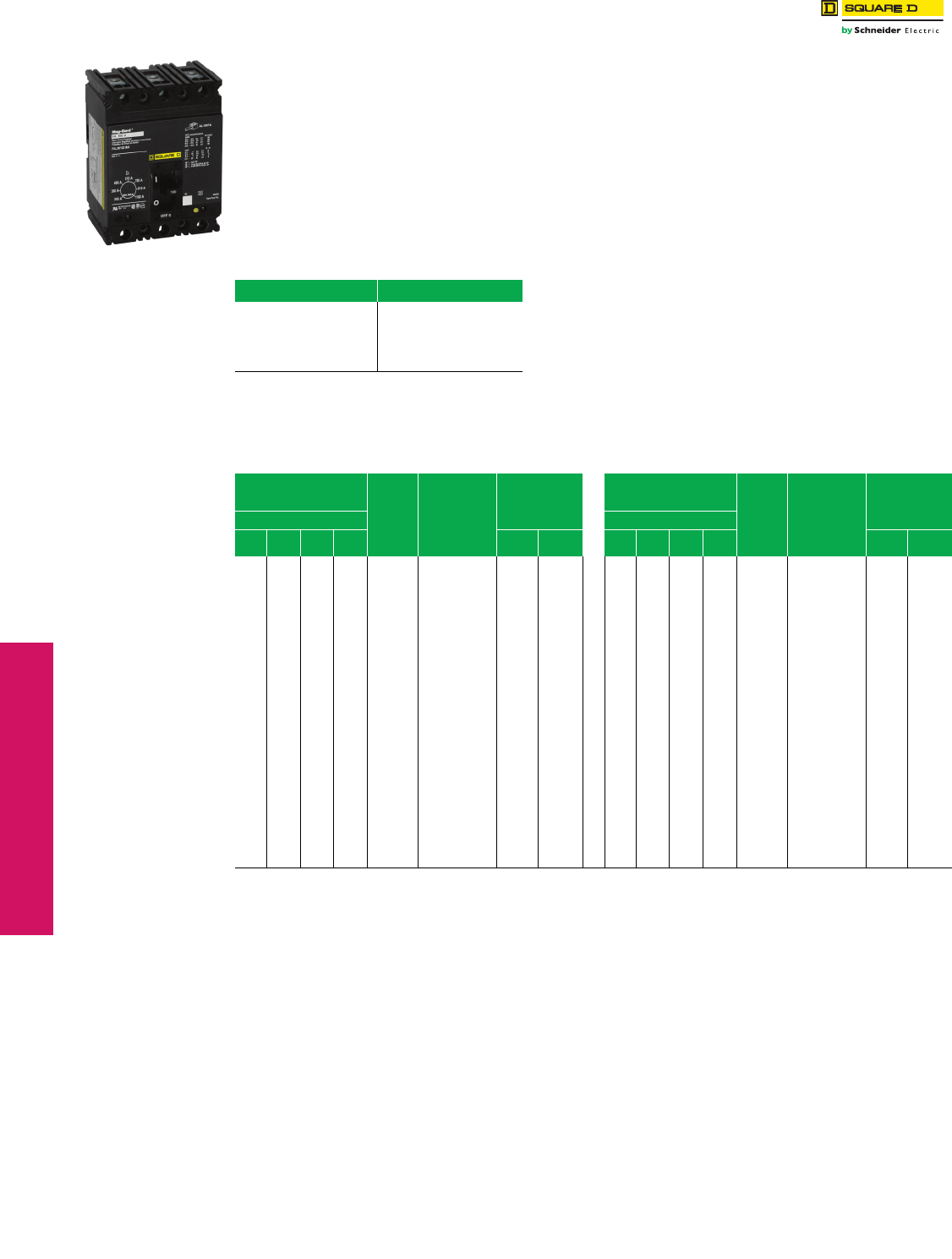
www.schneider-electric.us
3-16 © 2012 Schneider Electric
All Rights Reserved
3MOLDED CASE CIRCUIT
BREAKERS
Molded Case Circuit
Breakers
GJ-Frame MCP Selection
Class 680
Adjustable instantaneous-trip circuit breakers are intended
for use in combination with motor starters with overload
relays for the protection of motor circuits from short circuits.
Other specific applications include rectifiers and resistance
welders. These circuit breakers contain a magnetic trip
element in each pole with the trip point adjustable from the
front. Interrupting ratings are determined by testing the
instantaneous-trip circuit breakers in combination with a
contactor and overload relay.
Select instantaneous-trip circuit breakers as follows:
This selection table is suitable for motors, other than
NEMA Design E, with locked-rotor indicating code letters
per NEC® Table 430.7 (b) as follows:
1. For other motors order a special thermal-magnetic circuit
breaker with magnetic trip settings for the specific motor—
specify motor horsepower, voltage, frequency, full-load
current and code letter or locked rotor current.
2. Determine motor hp rating from the motor nameplate.
3. Refer to the tables and select an instantaneous-trip circuit
breaker with an ampere rating recommended for the hp and
voltage involved.
4. Select an adjustable trip setting of at least 800%, not to
exceed 1300%, of the motor full-load amperes (FLA) for other
than Design E motors. For Design E motors, select an
adjustable trip setting of at least 1100% not to exceed 1700%
of FLA.
5. The NEC 1300% maximum setting may be inadequate for
instantaneous-trip circuit breakers to withstand current surges
typical of the magnetization current of autotransformer type
reduced voltage starters, or open transition wye-delta starters
during transfer from “start” to “run,” constant hp multi-speed
motors, and motors labeled “high efficiency.” Select thermal-
magnetic circuit breakers from Digest page 7-32 for those
applications.
6. Part-winding motors, per NEC 430.3, should have two circuit
breakers selected from the above at not more than one half
the allowable trip setting for the horsepower rating. The two
circuit breakers should operate simultaneously as a
disconnecting means per NEC 430.103.
7. Based on NEC 430.52 and NEC Table 430.150. See
Digest page 7-30 for a available Adjustable Instantaneous-
Trip Circuit Breakers.
Table 3.57: Locked-Rotor Indicating Codes
Horsepower Motor Code letter
1/2 or less
3/4 to 1-1/2
2 to 3
5 to 25
30 to 125
150 or more
A–L
A–K
A–J
A–H
A–G
A–F
Table 3.58: GJL Adjustable Instantaneous-Trip Circuit Breakers for Single Motor Circuit Protection
Hp Ratings of Induction Type
Squirrel-Cage and
Wound Rotor Motors Full
Load
Amperesa
GJL Family
Mag-Gard
Circuit Breaker
Cat. No.
Magnetic Trip
Settingsb
Hp Ratings of Induction Type
Squirrel-Cage and
Wound Rotor Motors Full
Load
Amperesa
GJL Family
Mag-Gard
Circuit Breaker
Cat. No.
Magnetic Trip
Settingsb
3Ø 60 Hz 3Ø 60 Hz
200
Vac
230
Vac
460
Vac
575
Vac MIN MAX 200
Vac
230
Vac
460
Vac
575
Vac MIN MAX
1/2 0.8 GJL36003M01c1100% 4100% 7-1/2 9 GJL36015M03 500% 1800%
1/2 1 GJL36003M01c900% 3300% 3 9.6 GJL36015M03 500% 1700%
3/4 1.1 GJL36003M01c800% 3000% 3 7-1/2 10 11 GJL36015M03 400% 1500%
3/4 1.4 GJL36003M01 600% 2400% 10 14 GJL36030M04 600% 2400%
1 1.8 GJL36003M01 500% 1800% 5 15.2 GJL36030M04 600% 2200%
1/2 2 GJL36003M01 500% 1700% 15 17 GJL36030M04 500% 1900%
1-1/2 2.1 GJL36003M01 400% 1600% 5 17.5 GJL36030M04 500% 1900%
1/2 2.3 GJL36003M01 400% 1400% 15 21 GJL36030M04 400% 1600%
1-1/2 2.6 GJL36003M01 300% 1300% 7-1/2 20 22 GJL36030M04 400% 1500%
2 2.7 GJL36003M01d300% 1200% 7-1/2 25.3 GJL36030M04 400% 1300%
3/4 2.8 GJL36003M01d300% 1200% 20 25 27 GJL36050M05 600% 2000%
3/4 3.2 GJL36007M02 700% 2400% 10 28 GJL36050M05 500% 2000%
2 3.4 GJL36007M02 600% 2300% 30 32 GJL36050M05 500% 1700%
1 3.6 GJL36007M02 600% 2100% 10 32.2 GJL36050M05 500% 1700%
3 3.9 GJL36007M02 500% 2000% 25 34 GJL36050M05 400% 1600%
1 4.1 GJL36007M02 500% 1900% 30 40 GJL36050M05 400% 1400%
3 4.8 GJL36007M02 400% 1600% 40 41 GJL36050M05 400% 1300%
1-1/2 5.2 GJL36007M02 400% 1500% 15 42 GJL36075M06 400% 1300%
1-1/2 6 GJL36007M02 400% 1300% 15 48.3 GJL36075M06 500% 1700%
5 6.1 GJL36015M03 700% 2700% 40 50 52 GJL36075M06 400% 1600%
2 6.8 GJL36015M03 700% 2400% 20 54 GJL36075M06 400% 1500%
5 7.6 GJL36015M03 600% 2200% 20 60 62 GJL36075M06 400% 1300%
2 7.8 GJL36015M03 600% 2100% 50 65 GJL36075M06 300% 1300%
aMotor full-load currents are taken from NEC Table 430.150. Select wire and circuit breakers on basis of horsepower rather than nameplate full-load current
per NEC 430.6 (A) for general motor applications. Do not use these values to select overload relay thermal units. See Digest pages 14-129–14-152 for
selection of thermal units when actual full load current is not known. The voltages listed are rated motor voltages. Corresponding nominal system voltages
are 200–208, 220–240, 440–480 and 550–600 V.
bOnly MIN and MAX settings are shown, intermediate settings are available on all circuit breakers.
cSee NEC 430.52(A) for circuit breaker settings above 800%.
dIf due to motor starting characteristics, trip settings at the 1300% maximum permitted level are needed, the next size Mag-Gard circuit breaker should be
chosen.
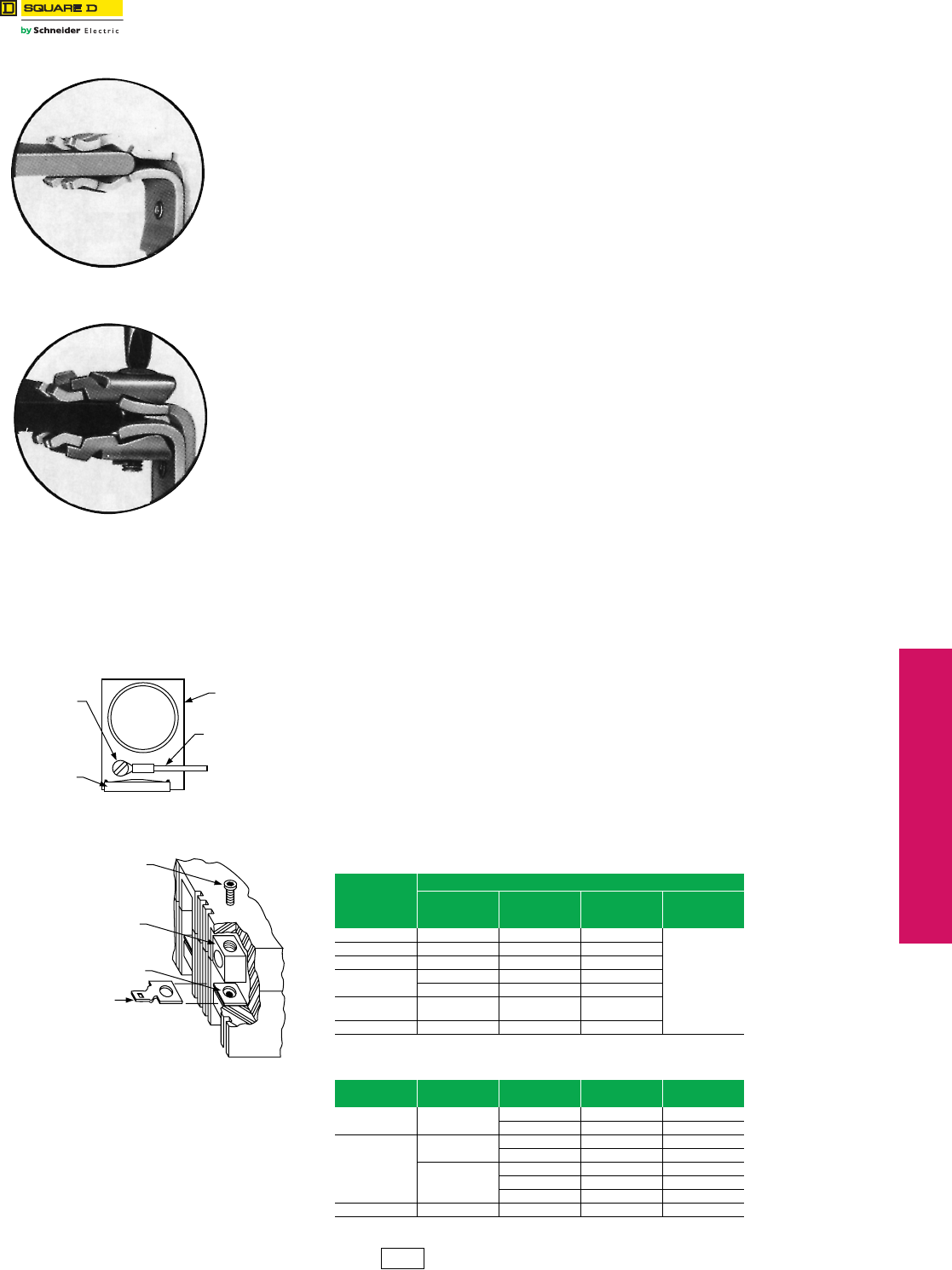
www.schneider-electric.us
© 2012 Schneider Electric
All Rights Reserved 3-17
3MOLDED CASE CIRCUIT
BREAKERS
Special Construction
Circuit Breakers
Special Terminal Connectors and Lugs
Class 600
Bolt-On I-Line™
(20% Price Adder)
The standard I-Line circuit breaker is designed to provide a high quality, secure connection
between the distribution bus and circuit breaker. I-Line circuit breakers use plug-on type
line-side connectors. The parallel line-side connectors “clamp’’ around the bus bars. In case
of a short circuit, the increased magnetic flux causes the connectors to grasp the bus bars
even tighter. I-Line circuit breakers with bolted connections have clamp-on jaws that are
bolted around the main bus, as shown. The bolt-on I-Line design is offered as an alternative
in order to meet specifications requiring a bolted connection. Bolt-on I-Line construction is
available on FY, QB, QD, QG, QJ, Q4, FA, FH, FI, KI, LA, and LH frame circuit breakers
and molded case switches, and SL100, SL225 and SL400 sub-feed lugs.
To order on all products except QB, QD, QG and QJ, simply add the letter “B’’ in the catalog
number prefix of the circuit breaker, e.g., FA36100 becomes FAB36100. For QB, QD, QG
and QJ, insert the letter “E” in the third position, e.g., QBE, QDE, etc.
NOTE: Not available on Powerpact™ circuit breakers.
Top-Feed I-Line
(No Additional Charge)
I-Line panelboards may require the use of a top-feed I-Line circuit breaker in applications
where a top-feed main circuit breaker is required. This involves having the I-Line jaw
connectors on the OFF end of the circuit breaker, as opposed to the standard location on
the ON end of the circuit breaker. To designate this construction, simply place the suffix
“MT” at the end of the circuit breaker catalog number, e.g., FA36100 becomes FA36100MT.
On LA or LH top-feed I-Line circuit breakers, accessories must be factory installed. This
option is available in PowerPact™ H and J-frame by placing a “K” in the 4th position
(termination indicator) of the circuit breaker catalog number, e.g., HGA36125 becomes
HGK36125. This option is not available on L-frame (600 A only), M-frame,
N-Frame or Powerpact M-, P- and R-frame.
“CBA” I-Line Jaw Configuration (Non-PowerPact Circuit Breaker)
(No Additional Charge)
Standard 1-pole and 2-pole I-Line circuit breakers are ordered by designating the required
phase connection letters as a suffix to the circuit breaker catalog number. 3-pole circuit
breakers do not require this phase designation and are supplied with an “ABC” phase jaw
configuration as standard. In most applications this is acceptable since the phase loading is
evenly distributed. In applications where the phases must be reversed it is possible to order
a “CBA” jaw configuration by simply placing the letters “CBA” at the end of the standard
catalog number, e.g., FA36100 becomes FA36100CBA.
Control Wire Tap Lugs
(No Additional Charge if Field Installed; 20% Price Adder if Factory Installed)
Control wire tap lugs are used in applications requiring connection to a small wire (22-14
AWG) for control circuits. This is accomplished by crimping the wire to a standard wire
crimp terminal (not included) and fastening the terminal to the circuit breaker lug. On LA
lugs, the lug is drilled to accept a 6-32 screw (included) to secure the crimp connector. On
FA lugs, a flat slip-on crimp connector is used to attach to a shim-like connector placed
under the circuit breaker lug.
Note: To order as a factory-installed device on FA, FH, FI, KI, Q4, LA, LH, LC, LI, LXI, LX or
LC circuit breakers, add suffix number 8041 to circuit breaker catalog number, e.g.,
KIL362258041. To order as a factory-installed device on MG, MJ, PG, PJ, PL RG, RJ and
RL use the product selector or the respective PowerPact catalog. Tapped lugs will be
installed on the “ON” and “OFF” ends of the circuit breaker.
aUse fully-insulated 0.250 in slip-on connectors.
bI-Line Only.
Table 3.59: Control Wire Terminations for Circuit Breakers
Circuit Breaker
Control Wire Termination Kits
Cat. No.
Standard
Package
Quantity
$ Price
Per Lug
Factory
Installed $ Price
(Suffix 8041)
FA, FH, FI FATa18.40
Add 20%
to price of
circuit breaker
KI AL250KIT 1113.00
Q4, LA, LH AL400LAT 140.80
LC, LI, LXI,
LX, LE
AL600LI35T 153.00
AL600LI5T 144.60
MA, MH, MX, ME AL900MAT 1111.00
AL1000MAT 1111.00
NA, NC, NX, NE AL1200NE6T 1228.00
Table 3.60: Tapped Lugs for PowerPact™ Circuit Breakers
Circuit Breaker Amperes
Max. Kit Cat. No. Standard
Package Qty. $ Price Per Kit
MG, MJ,
PG, PJ, PL 800 A AL800M23TK 3312.00
AL800P6TK 3458.00
PG, PJ, PL
800 A AL800M23TK4 4414.00
AL800P6TK4 4608.00
1200 A
AL1200P24TK 1138.00
AL1200P25TK 3416.00
AL1200P25TK4 4555.00
RG, RJ, RL 1200 A AL1200R53TKb1237.00
Plug-on
C
onnector
Bolted Connector
Control Wire
Mounting Screw
Circuit Breaker
Terminal
Control Wire
AL250KAT Lug
ASKC 809
Lug
BSKC 394
Lug Mounting Screw
Circuit Breaker Lug
Circuit Breaker Terminal
Control Wire Terminal
(Catalog Number FAT)
DE2 Discount
Schedule
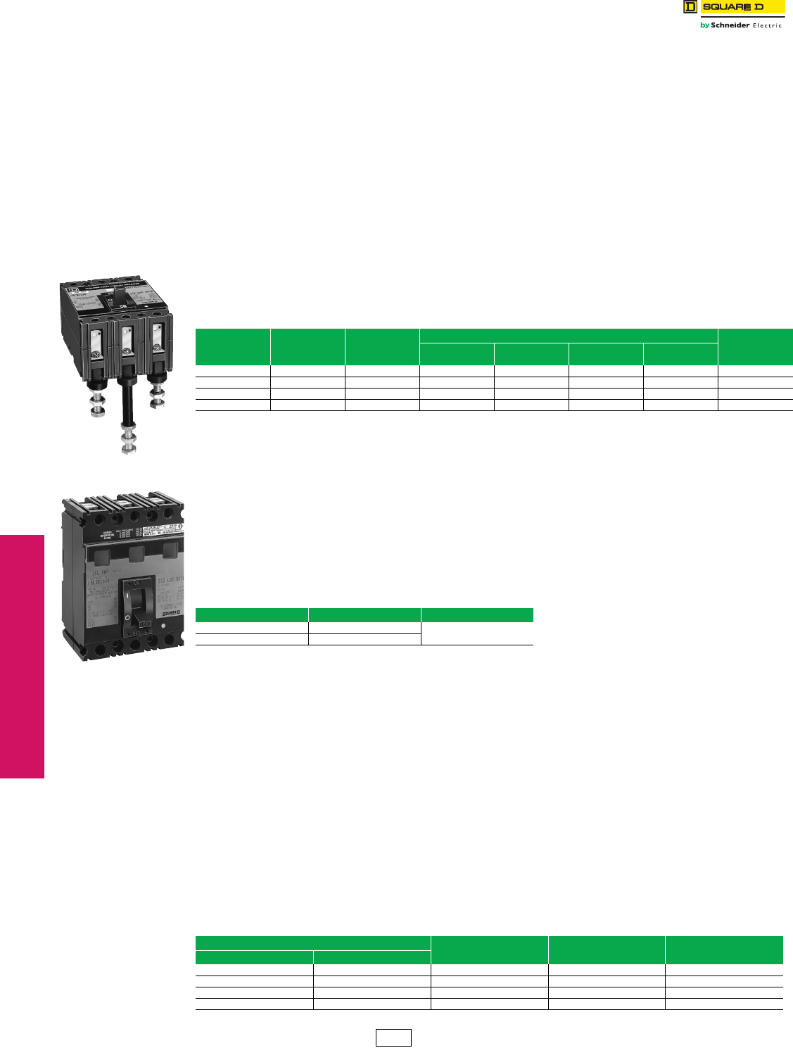
3-18 © 2012 Schneider Electric
All Rights Reserved
www.schneider-electric.us
3MOLDED CASE CIRCUIT
BREAKERS
Special Construction
Circuit Breakers
Special Calibration, Rear-Connected Studs, Visi-Blade,
Moisture/Fungus Treatment, and Short LA/LH Handle
Special Magnetic or Thermal Calibration
(20% Price Adder)
Magnetic
The magnetic trip ranges for standard circuit breakers are listed in the Square D Digest. Requirements outside this
range are best accommodated by selecting another standard circuit breaker. In some cases where this is not practical,
a circuit breaker may be ordered with special magnetic calibration. Special magnetic calibration is not possible in all
cases. Circuit breakers with special magnetic calibration and an adjustable magnetic trip range are not UL Listed;
those with a fixed magnetic trip setting are UL Listed. Consult Schneider Electric local sales office for more information.
50 Degrees C
UL 489 Listed molded case circuit breakers are calibrated for 40 degree C ambient temperature. To meet requirements
of higher ambient conditions, circuit breakers can be factory calibrated for a 50 degree C ambient temperature. Circuit
breakers with special thermal calibration are not UL Listed. To order 50° calibration, add “35” suffix to FA/FH/LA/LH or
CA to H or J thermal magnetic breakers and add 20% to the List price of the breaker. Consult local sales office for more
information.
Rear-Connected Studs
Rear-connected studs are designed to allow rear termination in applications such as control panels where wire gutter
space may be limited. The studs may be bolted directly to the bus or lugs may be attached to the studs.
NOTE: Long and short studs must be alternated on adjacent poles to assure proper electrical clearance
Note: Use alternate size studs on adjacent poles to obtain proper electrical clearance.
Visi-BladeTM Circuit Breakers
(20% Price Adder)
Visi-blade construction is a modification to the cover of a thermal-magnetic circuit breaker, a molded case switch, or a
Mag-Gard™ circuit breaker which provides a “window” through which the position of the movable contacts can be
verified. Luminescent paint is applied to the movable contact arms to clearly indicate their position. Gases produced
during high level interruption may cause clouding of the Visi-blade window. Visi-Blade circuit breakers listed below are
UL Listed except for FH circuit breakers. Visi-Blade construction is not available on circuit breakers not included in table
below.
Add suffix letter “V” to the circuit breaker catalog number, i.e., FAL 36100V.
aFH circuit breaker is not UL Listed.
bNot available on 1P FA/FH circuit breakers.
Moisture and Fungus Resistant Treatment for Circuit Breakers
(20% Price Adder)
This treatment covers the application of moisture and fungus resistant varnish to circuit breakers and molded case
switches.
•The varnish meets Military Specification MIL-V-173C VARNISH, MOISTURE AND FUNGUS RESISTANT.
•The treatment meets military Specification MIL-T-152E TREATMENT, MOISTURE AND FUNGUS-RESISTANT,
OF COMMUNICATIONS, ELECTRONIC, AND ASSOCIATED ELECTRICAL EQUIPMENT.
The treatment of circuit breakers in accordance with said specifications is intended to protect them against the moisture
and fungus condition encountered in service by retarding the absorption of moisture and inhibiting the growth of fungi.
To order for F- and L-frame circuit breakers, place the suffix “FT” at the end of the circuit breaker catalog number, e.g.,
FAL36100 becomes FAL36100FT. To order for QB, QD, and QG circuit breakers, place the suffix “YF” at the end of the
circuit breaker catalog number, e.g., QDL32150 becomes QDL32150YF. ED, EG, EF, GJL, PowerPact™ D-, H-, J-, M-
, P- and R-frame circuit breakers are inherently fungus resistant and need no further treatment.
Short Handle for LA/LH Circuit Breakers (No Additional Charge)
Certain applications of the LA/LH circuit breakers (as mains in particular panelboards) require the use of a slightly
shorter operating handle. For ordering information refer to the chart below.
Rear- Connected Studs
Table 3.61: Rear-Connected Studs—Not UL Listed
Circuit Breaker
Cat. No.
Prefix
Ampere
Ratings
Stud
Cat. No.
Dimensions
$ Price Per Stud
Overall
Length
To Back of
Circuit Breaker Diameter Threads/Inch
FAL, FHL 15–100 A FAS20 2-1/4 in. 2 in. 3/8 in. 16 70.00
FAL, FHL 15–100 A FAS42 4-7/8 in. 4-1/4 in. 3/8 in. 16 92.00
LAL, LHL 125–400 A LAS54 6-3/16 in. 5-1/2 in. 3/4 in. 16 243.00
LAL, LHL 125–400 A LAS114 12-3/16 in. 11-1/2 in. 3/4 in. 16 360.00
V
isi-Blade Circuit Breaker
Table 3.62: Available Visi-Blade Circuit Breakers
Circuit Breaker Prefix Amperes $ Price
FA, FHab 15–100 A 20% Price Adder
LA, LH 125–400 A
Table 3.63: Catalog Numbers for Short Handle LA/LH CIrcuit Breakers
Lug Configuration Desired Catalog
“Prefix Indication”
Catalog
“Suffix Indication”
Circuit Breaker
Cat. No.
ON End OFF End
Lugs Lugs “L” “MB” LAL36400MB
No Lugs Lugs “P” “MB” LAP36400MB
Lugs No Lugs “P” “MT” LAP36400MT
No Lugs No Lugs “F” “MB” LAF36400MB
DE2 Discount
Schedule
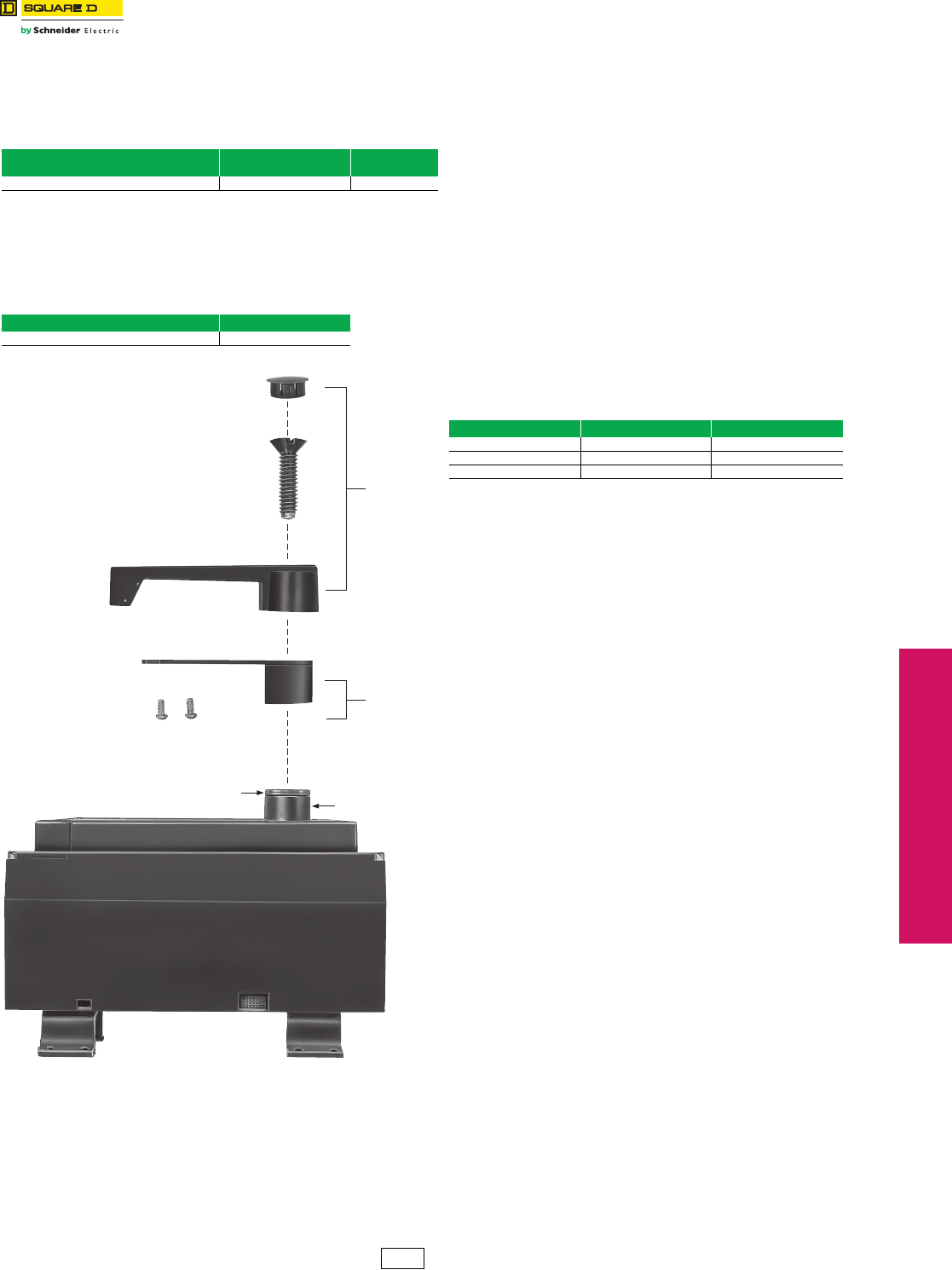
www.schneider-electric.us
© 2012 Schneider Electric
All Rights Reserved 3-19
3MOLDED CASE CIRCUIT
BREAKERS
Special Construction
Circuit Breakers
P-Frame Replacement Handles, Key Interlock Adapter Plate
and Exchange Program
P-Frame Replacement Handle
Replacement handle assemblies for PA, PC, PE, PX and PH circuit
breakers (produced after March 1975) are available.
Exchange Guarantee Prices, Permanent Trip Molded
Case Circuit Breakers
When a Square D permanent trip circuit breaker is supplied to
meet a specification requiring an interchangeable trip unit, it may
be exchanged for another circuit breaker of the same type with a
different trip setting.
When entering an order for the replacement circuit breaker:
1. Reference “Exchange Price Guarantee” as a line item marking on the
replacement order. The replacement order will be billed at normal
authorized selling net price.
2. Request Return Material Authorization referencing “Exchange Price
Guarantee” and the replacement exchange price guarantee invoice
number.
When the circuit breaker is returned to Cedar Rapids, credit will
be issued for the difference between the replacement net price
billed and the exchange list price (from the table below) times the
same multiplier used on the replacement order. The list price
used to determine credit will be based on the highest trip setting
of the circuit breakers involved in the exchange.
Only those circuit breaker types below are eligible for this
exchange guarantee program.
Table 3.64: P-Frame Replacement Handle
Circuit Breaker
Cat. No. Prefix
Replacement Handle
Cat. No. $ Price
PAF, PAE, PHF, PHE, PCF, PEC, PEF, PXF HRPA 111.00
P-Frame Key Interlock Adapter Plate
PAKK Kit – An adapter plate that is added under the circuit breaker
handle to allow mechanical interlocking with a key interlock (not
included). The kit includes all the necessary hardware to mount onto the
circuit breaker handle.
Table 3.65: P-Frame Key Interlock Adapter Plate
Cat. No. $ Price
PAKK 185.00
Table 3.66: Exchange Guarantee Circuit Breakers
Circuit Breaker Type Trip Range Exchange List $ Price
LA All 2465.00
LH All 4055.00
LC All 4434.00
Replacement
Handle
Assembly
Optional
PAKK
Assembly
Circuit Breaker with Handle Removed
Hub q
Washers are to remain with Circuit Breaker
aThe “hub” under normal conditions is insulated. When the phenolic handle is removed,
a label is exposed warning of the hub being energized. That can only happen if a short
circuit or severe overload occurs. The ionized gasses inside the circuit breaker could
momentarily (1-2 cycles) put a high voltage potential on the hub.
DE2 Discount
Schedule
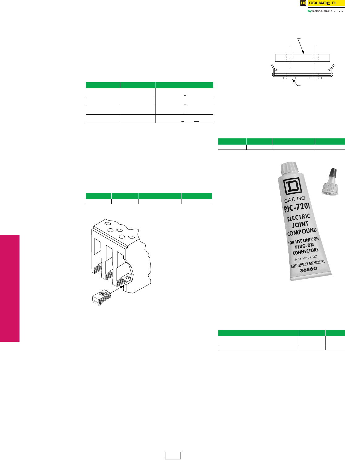
www.schneider-electric.us
3-20 © 2012 Schneider Electric
All Rights Reserved
3MOLDED CASE CIRCUIT
BREAKERS
Special Construction
Circuit Breakers
Special Terminations
Class 690
Lug Deletion (No Additional Charge)
In some applications, the circuit breaker does not require
lugs on one or both ends. To meet this requirement, the
circuit breaker should be ordered with the desired lug
configuration as indicated below. If necessary, lugs may
be removed in the field. However, if lugs are removed in
the field, circuit breaker Types FH, FC, Q4 LA and LH
must be secured with pan-mounting screws, or have “P”
screws (cover screws and nuts) installed securing the
base to the cover.
Termination Insert Kits
The standard lugs supplied with EDB, EGB, EJB, and FJA
circuit breakers and molded case switches are secured by
means of a screw fastened through the circuit breaker
terminal into the lug body. If the standard lug is removed
and a bolted connection to the circuit breaker terminal pad
is desired, a threaded insert kit is required. The insert is
installed below the terminal pad. For ordering information
see chart below.
LC, LI, LE, LX and LXI Circuit Breaker
Termination Clip Kit
The standard
lugs supplied
with LC, LI, LE,
LX and LXI
circuit breakers
are secured by
means of a
screw fastened
through the
circuit breaker
terminal into the
lug body. If the
standard lug is
removed and a
bolted
connection to the circuit breaker terminal is desired, the
AL600IN threaded terminal clip kit is required to make this
connection. The AL600IN clip snaps onto the bottom of
the terminal. For ordering information, see chart below.
Electric Joint Compound
I-Line™ circuit
breakers, I-Line
busway plug-on units,
I-Line panelboards
and switchboards,
QMB plug-on switches
and motor control
center plug-on units
are supplied with
factory applied joint
compound on the
plug-on connectors.
The compound should
not be removed
because it contributes
to the overall
performance of the
connection.
Whenever one of
these units is removed
and reinstalled, the
joint compound should
be reapplied. Catalog
number PJC 7201 is a
two-ounce container of
compound specially formulated for the I-Line, QMB and
motor control center connections.
No other type of commercially available joint compound
should be used.
Table 3.67: Lug Configurationa
ON End OFF End Circuit Breaker Prefix – Suffix
Lugs Lugs “L”
(e.g., FAL36100)
No Lugs No Lugs “F”
(e.g., FAF36100)
No Lugs Lugs “P”
(e.g., FAP36100)
Lugs No Lugs “P – MT”b
(e.g., FAP36100MT)
aSee information on termination kits below
bMT suffix also required (except for PowerPact™).
Table 3.68: Termination Kit Inserts
Kit Cat. No. Inserts Per Kit Circuit Breakers $ Price Per Kit
TIKFD 3 EDB, EGB, EJB, FJA 17.40
EDB, EGB, EJB,
FJA
Table 3.69: Termination Clip Kit
Kit Cat. No. Clips Per Kit Circuit Breakers $ Price Per Kit
AL600IN 3 LC, LI, LE, LX, LXI 65.00
Table 3.70: Electric Joint Compound
Use With Cat. No. $ Price
I-Line Circuit Breakers, QMB Plug-On Units, or
Model-V MCC Units PJC7201 19.80
SED Drawout Circuit Breakers PJC8311 42.80
Terminal Clip
LC, LI, LE, LX and LXI Circuit Breakers
Terminal
DE2 Discount
Schedule
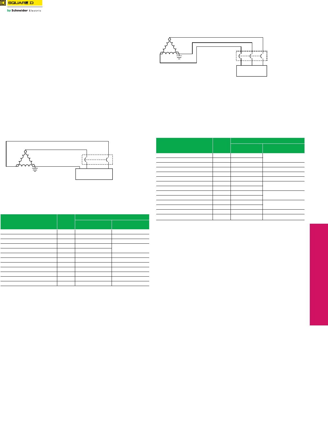
www.schneider-electric.us
© 2012 Schneider Electric
All Rights Reserved 3-21
3MOLDED CASE CIRCUIT
BREAKERS
Special Construction
Circuit Breakers
Grounded BØ Systems
Class 600
Circuit Breakers for Grounded B-Phase (BØ)
(Corner-Grounded Delta) Systems (No Additional
Charge)
Ordering Information For Grounded BØ Circuit Breakers
1. There is no additional charge for grounded BØ circuit breakers.
2. For use on 480 V systems, FH and LH type circuit breakers must be ordered
as 600 V versions and with a 5861 suffiix (i.e. FHL361005861).
3. For use on 240 V systems, FH type circuit breakers may be ordered as 480 V
versions with a 5861 suffix (i.e. FHL341005861).
4. FA and LA type circuit breakers are not available with grounded B phase
markings.
5. Two-pole 240 V grounded B-phase circuit breakers (except EDB, EGB, EJB,
QB, QD, QG, and QJ) will be built using three-pole modules.
6. Two-pole grounded BØ circuit breakers will be labeled with 240 Vac
interrupting ratings.
7. No self-certification is available for interrupting ratings greater than shown in
the tables below.
NOTE: Three-pole circuit breakers must be used on three-phase
480 V corner-grounded delta systems. The outside poles
are to be connected to the ungrounded phase and the
grounded conductor connected to the center pole.
Connecting the circuit breaker in a manner other than that
described or shown may result in an unsafe application of
the circuit breaker.
Table 3.71: 480 Vac 3Ø Corner-Grounded Delta System
Cat. No. Prefix Polesc
UL Listed Interrupting Ratingc
Ampere Rating 480 Vac Interrupting
Rating
HD, HG, HJ, HL 3 15–150 A 18 kA, 35 kA, 65 kA, 100 kA
JD, JG, JJ, JL 3 150–250 A
FH, FHL 3 15–100 A 10 kA
LH, LHL 3 125–400 A 14 kA
LD, LG, LJ, LL Electronic Trip Unit 3 250–600 A 18 kA, 35 kA, 65 kA, 100 kA
MG, MJ Electronic Trip Unit 3d300–800 A 35 kA
PG, PK Electronic Trip Unit 3d600–1200 A 35 kA, 50 kA
PG, PK Micrologic Trip Unit 3d250–1200 A
PJ, PL Electronic Trip Unit 3d600–1200 A 65 kA, 100 kA
PJ, PL Micrologic Trip Unit 3d250–1200 A
RG, RJ, RK RL Electronic Trip Unit 3d1200–2500 A 35 kA, 65 kA, 65 kA,100 kA
Table 3.72: Application Data for 240 Vac 3Ø Corner-Grounded
Delta System RG, RJ, RK, RL Micrologic Trip Unit 3d600–2500 A
NT 3 800–1200 100 kA
Cat. No. Prefix Poles
UL Listed Interrupting Rating NW 3 800–6000 150 kA
Ampere Rating 240 Vac Interrupting
Rating
cThe grounded phase should be connected through the center pole only.
dElectronic = ET1.0 Electronic Trip System
Micrologic = 3.0, 5.0, 3.0A, 5.0A, 6.0A, 5.0P, 6.0P, 5.0H and 6.0 H Micrologic Trip
System.
QO-H, QOB-H 2 15–100 A 5 kA
QB, QD, QG, QJ 2a70–250 A 10 kA
EDB, EGB, EJB 2a15–125 A 18 kA, 35 kA, 65 kA
HD, HG, HJ, HL 2a15–150 A 42 kA, 42 kA,
65 kA, 100 kA
JD, JG, JJ, JL 2b150–250 A
FH, FHL 2b15–100 A 42 kA
LH, LHL 2b125–400 A 30 kA
MG, MJ Electronic Trip Unit 2cb 300–800 A 65 kA
PG, PJ, PK, PL Electronic Trip Unit 2bc 600–1200 A 65 kA
RG, RK Electronic Trip Unit 2bc 1200–2500 A 35 kA, 65 kA
RJ Electronic Trip Unit 2bc 1200–2500 A 100 kA
RL Electronic Trip Unit 2bc 1200–2500 A 125 kA
aStandard labeling includes grounded B phase.
bBuilt using 3P module.
cElectronic = ET1.0 Electronic Trip System
Micrologic = 3.0, 5.0, 3.0A, 5.0A, 6.0A, 5.0P, 6.0P, 5.0H and 6.0 H Micrologic Trip
System.
Load
2-pole
Circuit Breaker
3Ø 240 Vac Corner-Grounded Delta System
Load
3-pole
Circuit Breake
r
3Ø 480 Vac Corner-Grounded Delta System
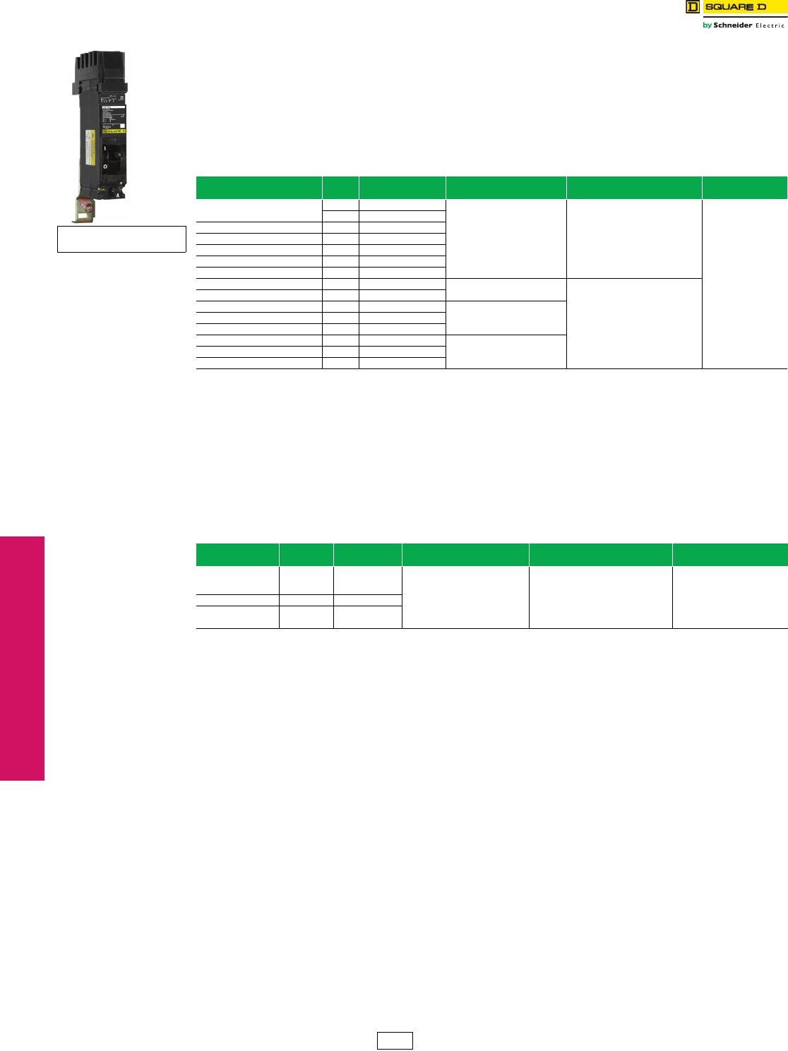
3-22 © 2012 Schneider Electric
All Rights Reserved
www.schneider-electric.us
3MOLDED CASE CIRCUIT
BREAKERS
Special Construction
Circuit Breakers
UL Marine Listed Circuit Breakers
Class 600
UL Marine Listed/CSA Certified Circuit Breakers (UL 489 Supplement SA)
PowerPact H and J circuit breakers with thermal magnetic trip units meet the UL 489 SA requirements on vessels of
any length under or over 65 ft. (19.8m). PowerPact H, J, and L circuit breakers with Micrologic trip units meet the
UL 489 Supplement SA requirements for use on vessels over 65 ft. (19.8m) in length. Marine circuit breakers must not
use aluminum or aluminum alloys for terminal connections and must be calibrated at an ambient temperature of 104°F
(40°C). Standard circuit breakers should not be specified or used in place of marine rated circuit breakers.
Circuit breakers can be ordered with the Marine SA listing by adding the suffixes of “LC” (copper lugs) and “YA”
(marine) to the catalog number.
aThermal-Magnetic trip units only.
bMicrologic trip units only.
UL Naval Listed/CSA Certified Circuit Breakers (UL 489 Supplement SB)
PowerPact H, J, and L circuit breakers with Micrologic trip units meet the UL 489 Supplement SB requirements for
naval vessels. These circuit breakers are subject to various vibration testing as described in UL 489 Supplement SB.
Naval circuit breakers must not use aluminum or aluminum alloys for terminal connections and are calibrated at an
ambient temperature of 122°F (50°C). Standard circuit breakers should not be specified or used in the place of naval
rated circuit breakers.
Circuit breakers can be ordered with the Naval SB listing by adding the suffixes of “LC” (copper lugs) and “YA1” (naval)
to the catalog number.
aWith Micrologic trip units only thermal-magnetic breakers not approved.
Table 3.73: Circuit Breakers for Marine Applications
Cat. No. Prefix Poles Ampere
Rating Application Cat. No. $ Price
FA, FAL 2 15–100 A
For use only on
vessels over 65 feet
(19.8 m) in length.
Add the number “9’’ after the catalog
number prefix of the standard circuit
breaker catalog number.
Example:
Standard FAL36100
Marine FAL936100
There is a 20%
adder to the price of
the equivalent standard
circuit breaker. All
marine
circuit breakers are
supplied with copper
lugs.
3 15–100 A
FH, FHL 2, 3 15–100 A
FI, FIL 2, 3 20–100 A
KI, KIL 2, 3 110–250 A
LA, LAL 2, 3 125–400 A
LH, LHL 2, 3 125–400 A
PowerPact™ HD, HG, HJ, HLa2, 3 15–150 A For use on vessels over and under
65 feet (19.8 m) in length. Add suffix for Copper Lugs (LC) and
“YA’’ after the standard circuit
breaker catalog number.
Example:
Standard HGL36100
Marine HGL36100LCYA
PowerPact JD, JG, JJ, JLa2, 3 150–250 A
PowerPact HD, HG, HJ, HL, HRb2, 3 15–150 A For use on vessels over 65 feet
(19.8m) in length.
PowerPact JD, JG, JJ, JL, JRb2, 3 150–250 A
PowerPact LD, LG, LJ, LL, LR 3, 4 250–600 A
PowerPact MG, MJ 2, 3 300–800 A For use only on
vessels over 65 feet
(19.8 m) in length.
PowerPact PG, PJ, PL 2, 3, 4 100–1200 A
PowerPact RG, RJ, RL 2, 3, 4 600–2500 A
Table 3.74: Circuit Breakers for Navel Applications
Cat. No. Prefix Poles Ampere
Rating Application Cat. No. $ Price
HD, HG, HJ, HLa2, 3 15–150 A
For use on non-combat and
auxiliary naval
ships of any length.
Add suffix for Copper Lugs (LC) and
“YA1’’ after the standard circuit
breaker catalog number.
Example:
Standard HGL36100
Marine HGL36100LCYA1
There is a 20%
adder to the price of
the equivalent standard
circuit breaker. All marine
circuit breakers are
supplied with copper lugs.
JD, JG, JJ, JLa2, 3 150–250 A
LD, LG, LH, LL 3,4 250–600 A
For use on vessels over 65 ft.
(19,8 m) in length
DE2 Discount
Schedule
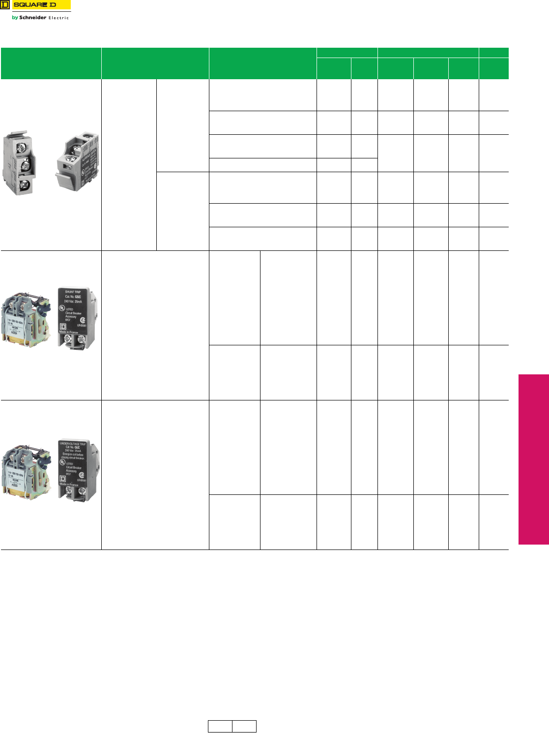
www.schneider-electric.us
3MOLDED CASE CIRCUIT
BREAKERS
© 2012 Schneider Electric
All Rights Reserved 3-23
Circuit Breaker
Accessories
PowerPact™ Circuit Breakers Electrical Accessories
Class 612 / Refer to Catalog 0616CT0801
Table 3.75: Electrical Accessories
Accessory Description Rated Voltage
G-Frame D-Frame
Field-
Installable
Cat. No.
$ Price
Factory-
Installed
Cat. Suffix
Field-
Installable
Cat. No.
$ Price $ Price
Auxiliary and Alarm Switches
(OF, SD, SDE)
Provides circuit
breaker contact
status.
Note: The location of
the accessory in the
circuit breaker
determines its
function.
Standard Min
Load =
10mA with 24V
1 auxiliary switch (OF) 1a1b AAC 297.00 AA S29450 297.00 297.00
2 auxiliary switch (OF) 2a2b — — AB 2x S29450 594.00 594.00
3 auxiliary switch (OF) 3a3b — — AC 3x S29450 891.00 891.00
Alarm Switch (SD) 1a1b AAC 297.00 BC S29450 297.00 297.00
Overcurrent trip switch (SDE) 1a1b — — BD S29450 297.00 297.00
Consisting of: OF Switch — — — — — —
SDE Adapter — — — — — —
Alarm switch and Overcurrent trip switch — — BE 2x S29450 594.00 594.00
Consisting of: OF Switch — — — — — —
SDE Adapter — — — — — —
Auxiliary Switch/Alarm Switch/Adapter
(OF/SD/SDE) Kit —— — ——297.00
Low Level
Min Load =
1mA with 24V
One auxiliary switch (OF) 1a1b — — AE S29452 372.00 372.00
Two auxiliary switches (OF) 2a2b — — AF 2x S29452 744.00 744.00
3 auxiliary switches (OF) 3a3b — — AG 3x S29452 1116.00 1116.00
Alarm Switch (SD) 1a1b — — BH S29452 372.00 372.00
Overcurrent trip switch (SDE) 1a1b — — BJ S29452 372.00 372.00
Consisting of: OF Switch — — — — — —
SDE Adapter — — — — — —
Alarm switch and Overcurrent trip switch — — BK 2x S29452 744.00 744.00
Consisting of: OF Switch — — — — — —
SDE Adapterd—— — ———
Shunt Trip (MX)
Trips the circuit breaker from a remote
location by means of a trip coil energized
from a separate supply voltage circuit.
AC
24 —
717.00
SK S29384
717.00 755.00
48 — SL S29385
120 GSA ——
110/130 — SA S29386
208 GSB ——
240 GSC ——
200/250 — — —
277 GSD ——
208/277 — SD S29387
480 GSH ——
380/480 — SH S29388
525/600 — SJ S29389
DC
12 —
717.00
SN S29382
717.00 755.00
24 GSO SO S29390
30 — SU S29391
48 GSP SP S29392
60 — SV S29383
125 GSR SR S29393
250 GSS SS S29394
Undervoltage Trip
Instantaneously opens the circuit breaker
when the under-voltage trip supply voltage
drops to a value between 35% and 70% of
its rated voltage. Closing is allowed when
the supply voltage of the undervoltage trip
reaches 85% of rated voltage.
AC
24 —
717.00
UK S29404
717.00 755.00
48 — UL S29405
120 GUA ——
110/130 — UA S29406
208 GUB ——
240 GUC ——
200/250 — — —
277 GUD ——
208/277 — UD S29407
480 GUH ——
380/480 — UH S29408
525/600 — UJ S29409
DC
12 —
717.00
UN S29402
717.00 755.00
24 GUO UO S29410
30 — UU S29411
48 GUP UP S29412
60 — UV S29403
125 GUR UR S29413
250 GUS US S29414
aField-installable kit includes time delay module only. Order undervoltage trip separately.
bDiscount schedule DE2F.
cP-frame drawout circuit breaker only.
dSDE Adapter used for H- and J-frame only.
G-Frame
D-Frame
G-Frame
D-Frame
G-Frame
D-Frame
DE2 DE2F Discount
Schedule
3-24 © 2012 Schneider Electric
All Rights Reserved
www.schneider-electric.us
3MOLDED CASE CIRCUIT
BREAKERS
Circuit Breaker
Accessories
Factory-Installed Accessories
Factory-Installed Electrical Accessories
Electrical accessories are available on all molded case circuit breakers except FY and QOM1 circuit breakers.
•Alarm switch is the only accessory available for the 1-pole FA circuit breaker.
•Combination accessories may be ordered by description, i.e., 1021 and 1212.
•All AC electrical accessories shown below are rated for 50/60 Hz.
•Add 20% to accessory price for each field-installable accessory that is factory-installed.
•See page 3-25 for field-installable accessories. See Digest page 7-35 for PowerPact™ circuit breaker accessories.
Table 3.76: Factory-Installed Accessories for Thermal-Magnetic Circuit Breakers
Accessory Description Rated
Voltag e
Coil
BurdenaSuffix $ Price
Adder
Shunt Trip
Trips the circuit breaker from a remote location by means of a trip coil energized from a separate circuit.
A 120 V shunt trip will operate at 55% or more of rated voltage. All other shunt trips will operate at 75%
or more of rated voltage.
Application
•For use with momentary or maintained push button.
•Sure Trip Capacitor Unit requires 48 Vdc shunt trip.
•Leads: (2) Black.18 AWG Cu.
24 Vac 21 VA -1042b755.00
120 Vac 24 VA -1021c755.00
208 Vac 107 VA -1021 755.00
240 Vac 154 VA -1021 755.00
277 Vac 14 VA -1037b755.00
480 Vac 45 VA -1037b755.00
24 Vdc 36 VA -1027 755.00
48 Vdc 36 VA -1028 755.00
125 Vdc 44 VA -1029 755.00
250 Vdc 15 VA -1030d755.00
Ground-
Fault
Shunt Trip
Trips the circuit breaker electrically using the signal from a Micrologic™ Ground-Fault Module.
Application
•For use only with obsolete GP Ground-Censor™ system or add on ground-fault module.
•Leads: (2) Orange 18 AWG Cu.
——-Gd755.00
Undervoltage
Tr ip ( UV R )
Trips the circuit breaker electrically when a control circuit falls below 35 to 70% of nominal (not field
adjustable). Picks up at 35–85% of nominal voltage.
Application
•UVR must be energized in order to close the circuit breaker.
•Leads: (2) Brown 18 AWG Cu leads.
24 Vac
120 Vac
240 Vac
24 Vdc
48 Vdc
5 VA
8 VA
8 VA
2 VA
3 VA
-1143d
-1121
-1124
-1127
-1128
755.00
755.00
755.00
755.00
755.00
Time Delay
Unit
Provides adjustable time delay for UVR of 0.1 to 0.6 second before circuit breaker trips.
Application
•For use only with -1121 UV trip.
•Adjustable time delay (0.1 to 0.6 second).
•I-Line unit requires 1.5 in. (38 mm) of mounting space.
•Leads: (2) Brown 18 AWG Cu and (2) Black/White 18 AWG Cu.
120 Vac
Cat. No.
Unit Mt. I-Line™
690UVTD 690UVTDI 1941.00
Auxiliary
Switches
Monitors circuit breaker contact status and provides a remote signal indicating
the circuit breaker contacts are OPEN or CLOSED.
Application
•Max. Load = FA, FH, FI, LC, LE, LI, LX, LXI.
10 A @ 125–250 Vac, ¼ hp @ 125–250 Vac, 5 A @ 30 Vdc
•Leads: Yellow for “A’’, Blue for “B’’, Striped for common 18 AWG Cu.
See load
info. in
App. text
at left
See load
info. in
App. text
at left
1A/1B -1212 312.00
2A/2B -1352 623.00
3A/3B -1364e800.00
Alarm
Switches
Used with control circuits and actuated only when the circuit breaker has tripped.
Standard construction includes a normally-open contact.
Application
•Max. Load = 10 A @ 125–250 Vac
•Max. Load = 15 A @ 30 Vdc
•Leads: (2) Red 18 AWG Cu.
1A
1A
1B
1B
250 Vac
28 Vdc
250 Vac
48 Vdc
See
load
info. in
App.
text
at left
-2100
-2100
-2103
-2103
312.00
312.00
312.00
312.00
aCoil burden values do not apply to LC, LE, LI, LX and LXI. Consult Field Sales office for more information.
bNot available on FI or KI circuit breakers.
cLC, LE, LI, LX, and LXI circuit breakers operate at 75% or more of rated voltage.
dNot available on LC, LE, LI, LX, LXI circuit breakers.
eNot available in FA, FC, FH, FI and KI circuit breakers.
Circuit Breaker Open or Closed
1A Alarm Switch
Configuration
Color Code: Red Leads
Circuit Breaker Tripped
Circuit Breaker Tripped
1B Alarm Switch
Configuration
Color Code: Red Leads
Circuit Breaker Open or Closed
1A/1B
Circuit Breaker Closed
AB
Circuit Breaker Open or Tripped
AB
Auxiliary Switch
Contact Configuration
Color Code:
"A" Contact - Yellow Leads
"B" Contact - Blue Leads
Common-Striped Leads
Undervoltage Trip
Wiring Diagram
Brown
Brown
Brown Wires To Be
Connected To
Control Power
UVR
Shunt Trip
Wiring Diagram
Black
Black
Black Wires To Be
Connected To
Control Power
Shunt
Tr i p
690UVTD Wiring Diagram
DE2 Discount
Schedule
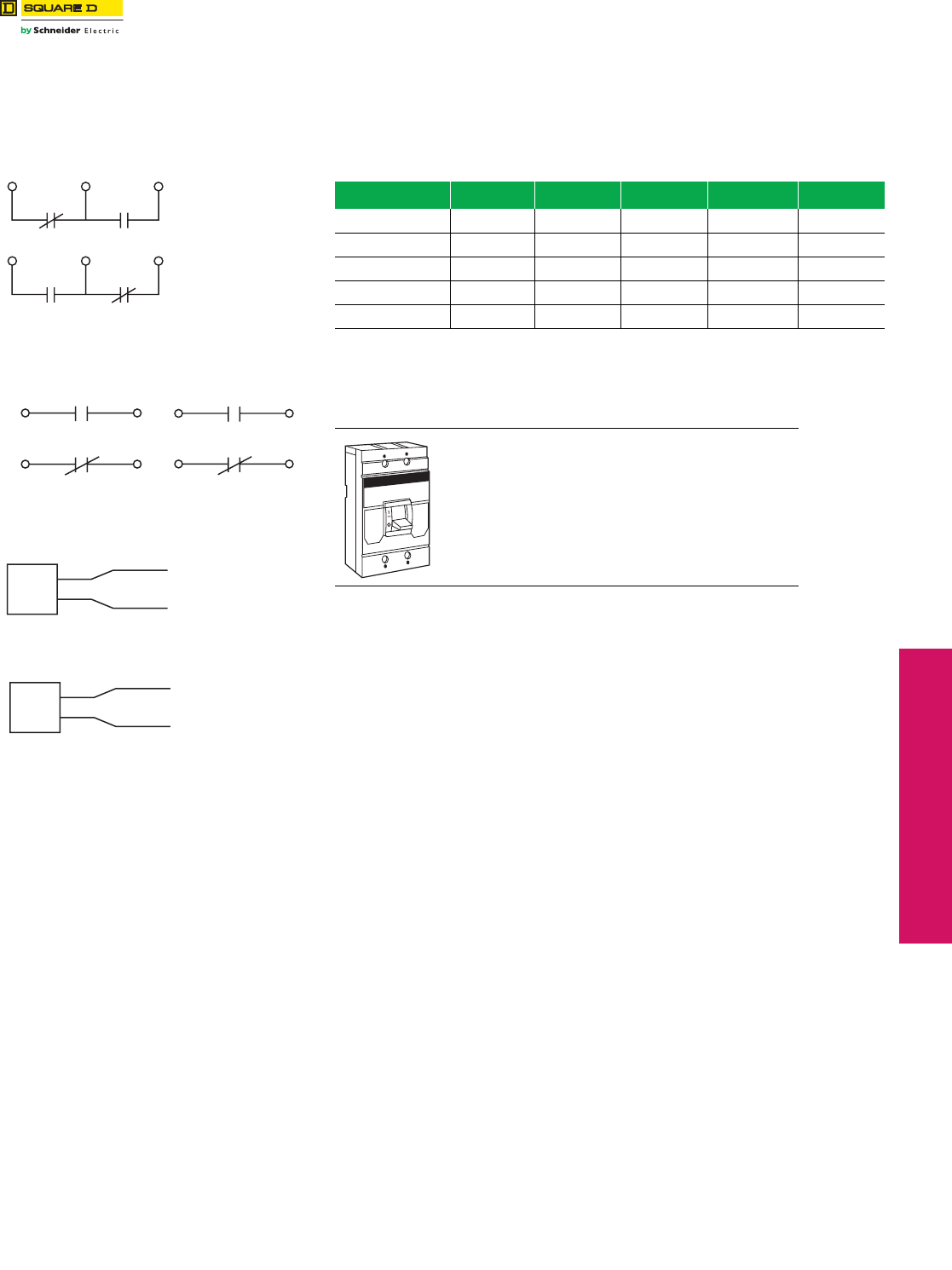
www.schneider-electric.us
© 2012 Schneider Electric
All Rights Reserved 3-25
3MOLDED CASE CIRCUIT
BREAKERS
Circuit Breaker
Accessories
Field-Installable Accessories
Field-Installable Electrical Accessories
Complete field-installable accessory catalog number by inserting suffix from 3-24 between
the parentheses in the catalog numbers shown in the table below. (Example: LA11212) See
3-24 for accessory pricing; add 20% to factory-install field-installable devices.
Table 3.77: Field-Installable Accessories for Thermal-Magnetic and Electronic Trip
Circuit Breakers
Circuit Breaker Shunt Trip Ground-Fault
Shunt TripaUndervoltage Trip Auxiliary Switches Alarm Switch
Miniature Circuit Breakers,
EH and EH-PL
Factory-Installed
Only Not Available Not Available Factory-Installed
Only
Factory-Installed
Only
FA, FH, FI, KI Factory-Installed
Only
Factory-Installed
Only
Factory-Installed
Only
Factory-Installed
Only
Factory-Installed
Only
LA, LH
Series 4bLA1( ) LA1G LA1 ( ) LA1( ) Factory-Installed
Only Right Pole
Q4 LA1( ) LA1G LA1 ( ) LA1( ) Factory-Installed
Only Right Pole
LC, LE, LI, LX, LXI LC1( ) LC1G LC1 ( ) LC1( ) Factory-Installed
Only
aUsed with obsolete GP Ground-Censor™ system or add-on ground-fault modules.
bWith LA and LH top-feed circuit breakers (suffix MT, I-Line jaws on OFF end) all accessories must be factory
installed.
Table 3.78: Accessory Mounting Locations
LA, LH, Q4 Series 4 circuit breakers or newer =
Field-installable accessories
LC, LI, LX, LXI circuit breakers = Field-installable
accessories
Both accessory ports will accept shunt trips, UVRs
and auxiliary switches. Alarm switches are factory
installable only (right pole). Maximum of one device
per port.
1A/1B
Circuit Breaker Closed
AB
Circuit Breaker Open or Tripped
AB
Auxiliary Switch
Contact Configuration
Color Code:
"A" Contact - Yellow Leads
"B" Contact - Blue Leads
Common-Striped Leads
Circuit Breaker Open or Closed
1A Alarm Switch
Configuration
Color Code: Red Leads
Circuit Breaker Tripped
Circuit Breaker Tripped
1B Alarm Switch
Configuration
Color Code: Red Leads
Circuit Breaker Open or Closed
Undervoltage Trip
Wiring Diagram
Brown
Brown
Brown Wires To Be
Connected To
Control Power
UVR
Shunt Trip
Wiring Diagram
Black
Black
Black Wires To Be
Connected To
Control Power
Shunt
Tr i p
L
R
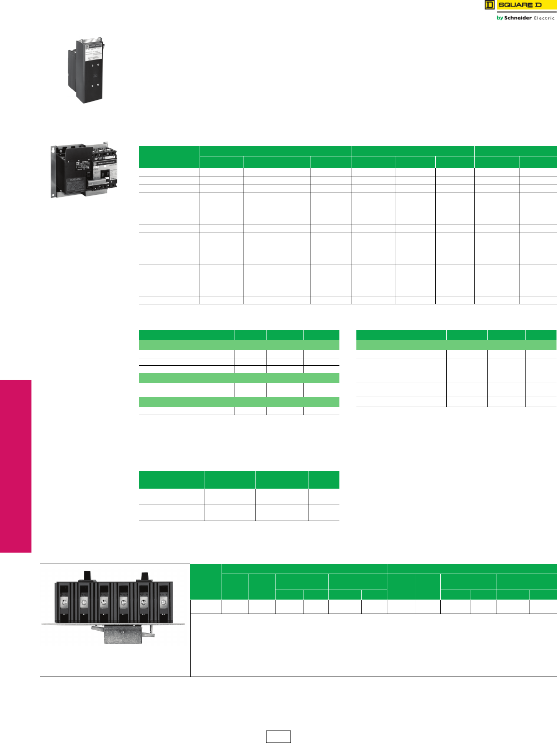
3-26 © 2012 Schneider Electric
All Rights Reserved
www.schneider-electric.us
3MOLDED CASE CIRCUIT
BREAKERS
Circuit Breaker
Accessories
Electrical Operators, Handle Accessories, Cylinder Locks, and
Walking Beam Mechanical Interlocks
Electrical Operators
Provides remote ON, OFF/RESET control of molded case circuit breakers.
•A complete line of field-installable electrical operators.
•Not applicable on LC/LI/LE/LX/LXI circuit breakers.
•Installing side mounted motor operators on non I-Line™ circuit breakers requires the use of a separate mounting pan.
•Side mounted electrical operators require an additional 4-1/2 in. (114 mm) of mounting space in I-Line installations.
When remote indication of circuit breaker status is required, order circuit breaker with 1A-1B auxilliary switch for ON-
OFF Indication and alarm switch for TRIP Indication. Electrical operators require SPDT maintained contact switch.
Refer to Class 9001 control unit listing for operators and pilot lights.
NOTE: Not available on Mag-Gard™ circuit breakers and molded case switches.
Handle Accessories
aLocks OFF only.
Cylinder Lock
Used to lock the circuit breaker in the OFF position. Circuit breaker cannot be reset when locked OFF.
Interlocks
Table 3.79: Electrical Operators
Circuit
Breaker
Prefix
Top Mount Side Mount Mounting Pan
Voltag e Cat. No. $ Price Voltag e Cat. No. $ Price Cat. No. $ Price
FA, FH — — — 120 Vac FAMO1 1304.00 ——
FAL, FHL — — — 120 Vac FAMO1 1304.00 FAMOP 108.00
FI, KI — — — 120 Vac KAMO1 3506.00 ——
FIL, KIL
120 Vac KAMO2120AC 3642.00
120 Vac KAMO1 3506.00 KAMOP 134.00
240 Vac KAMO2240AC 3642.00
24 Vdc KAMO224DC 3642.00
125 Vdc KAMO2125DC 3642.00
LA, LH, Q4 — — — 120 Vac LAMO1 4518.00 ——
LAL, LHL,
Q4L
120 Vac LAMO2120AC 4704.00
120 Vac LAMO1 4518.00 LAMOP 185.00
240 Vac LAMO2240AC 4704.00
24 Vdc LAMO224DC 4704.00
125 Vdc LAMO2125DC 4704.00
MAL, MHL
120 Vac MAMO2120AC 4704.00
120 Vac MAMO1 4518.00 MAMOP 1856.00
240 Vac MAMO2240AC 4704.00
24 Vdc MAMO224DC 4704.00
125 Vdc MAMO2125DC 4704.00
PA, PH, PC, PE, PX 120 Vac PA M O2 5544.00 —————
Table 3.80: Handle Accessories
Circuit Breaker Prefix Poles Cat. No. $ Price Circuit Breaker Prefix Poles Cat. No. $ Price
Handle Tie Handle Padlock Attachment (locks ON or OFF)
(2)FA 3 FKHT 215.00 FY Series 1 1 HPAFYQ 19.80
(2)FI,(2)KI, or (1)FI + (1)KI 2,3 FKHT 215.00 FA, FH, FC, FI 1,2,3 HPAFK 24.20
(2)LA or (2)Q4 2,3 LAHT 497.00 FY Series 2, 2,3 HPAFK 24.20
California Title 24 Comb. Handle Tie and Lock Off KI 2,3 HPAFKFa32.60
FY
FA
(3)1P
(3)1P
FY3HT
FA3HT
53.00
53.00 LA, LH, Q4 2,3 HPALM
HPAXLM
26.00
27.60
Handle Extension LC, LE, LI, LX, LXI 2,3 AHPALI 25.20
LA, LH, LE, LI, LX, LXI, Q4 2,3 AHEXLI 95.00
Table 3.81: Cylinder Lock
Circuit Breaker
Prefix
Factory Installed
Suffix
Field Installable
Cat. No. $ Price
FA, FAL, FH, FHLb—CL Factory-installed
only 315.00
LA, LAL, LH, LHL, Q4 Field-installable
only LA1CL 315.00
bNot available on Mag-Gard circuit breakers and molded case
switches.
KAMO2120AC
With KAL Circuit Breaker
FAMO1 and FAMOP
With FAL Circuit Breaker
Table 3.82: Walking Beam Mechanical Interlock Componentsc
Circuit
Breaker
Prefix
Manually Operated Electrically Operated
Operator
Suffix
$ Price
Adder
Walking Beam
Ass'y. Mounting Pan Operator
Suffix
$ Price
Adder
Walking Beam
Ass'y. Mounting Pan
Cat. No. $ Price Cat. No. $ Price Cat. No. $ Price Cat. No. $ Price
FAL, FHL
LAL, LHL
WB
WB
246.00
246.00
FA4WB
LA6WB
134.00
179.00
FAWBP4
LAWBP6
177.00
242.00
WBMO
WBMO
246.00
246.00
FA9WB
LA10WB
200.00
213.00
FAWBP9
LAWBP10
242.00
309.00
cFully enclosed interlocked units are available in Type 1 and Type 3R enclosures, with two neutrals provided in each enclosure. The
completely enclosed assembly is not UL Listed. Please consult your nearest Schneider Electric local sales office for more information.
Walking Beam Mechanical Interlock
Requires 2 circuit breakers with WB suffix,
1 walking beam assembly and 1 mounting pan.
DE2 Discount
Schedule
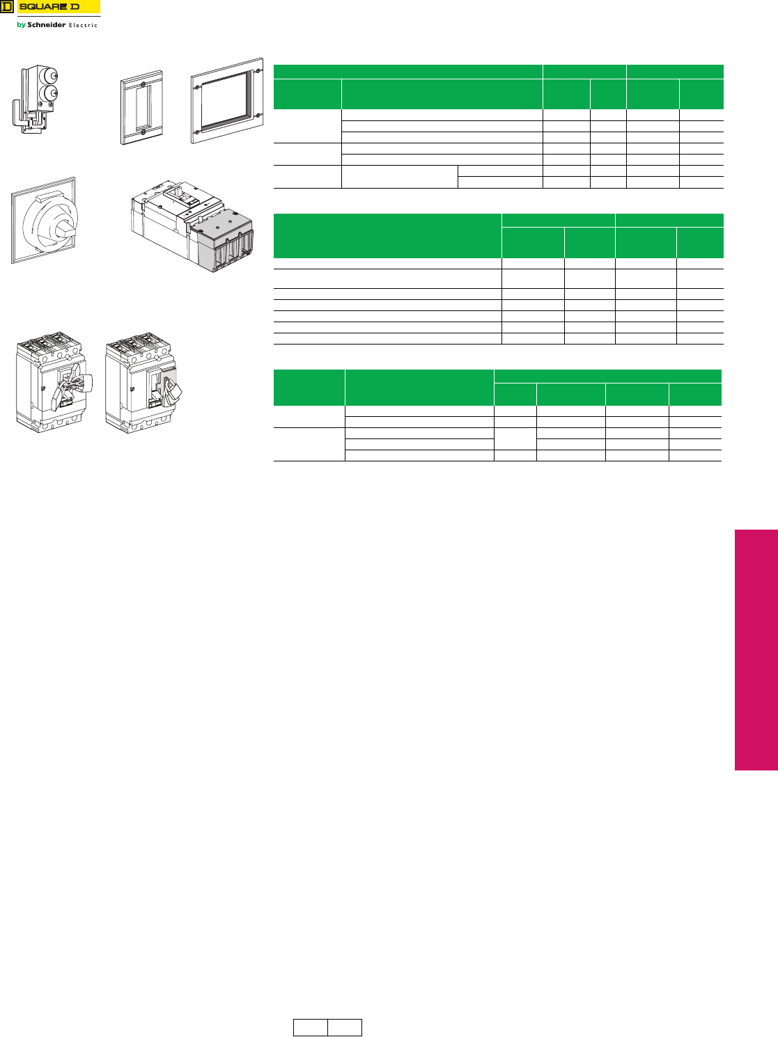
www.schneider-electric.us
© 2012 Schneider Electric
All Rights Reserved 3-27
3MOLDED CASE CIRCUIT
BREAKERS
Circuit Breaker
Accessories
Locks, Installation Accessories, and Rear Connections
Class 612 / Refer to Catalog 0612CT0101
Table 3.83: Locks, Interlocking
G-Frame D-Frame
Device Description
Field-
Installed
Cat. No.
$ Price
Field-
Installed
Cat. No.
$ Price
Handle
Padlocking
Device
Removable (lock OFF only) AHP 19.70 S29370 50.00
Fixed (lock OFF or ON) — — S32631 122.00
Fixed (lock OFF only) — — NJPAF 122.00
Interlocking
(Not UL listed)
Mechanical for circuit breakers with rotary handles — — 32621 494.00
Mechanical for circuit breakers with toggles — — 32614 494.00
Key Locking Provision and 2 locks keyed
alike
Ronis — — 41950 183.00
Profalux — — 42878 183.00
Table 3.84: Installation Accessories for G- and D-Frame Circuit Breakers
Description
G-Frame D-Frame
Field-
Installed
Cat. No.
$ Price
Field-
Installed
Cat. No.
$ Price
Front Panel Escutcheon for Toggle Breakers — — 32556 55.00
Front Panel Escutcheon for Rotary Handle, Motor Operator, or
extended escutcheon ——32558 74.00
Phase Barriers (set of 6) — — 32570 72.00
Handle Rubber Boot — — 32560 171.00
Sealing Accessories ACS 18.50 29375 42.00
DIN rail adapter GYR 93.00 — —
Toggle Extensions (set of 10) — — 32553 33.20
Table 3.85: Rear Connections
Device Description
D-Frame
Poles Factory-Installed
Termination No.
Field-Installed
Cat. No. $ Price
Mixed Rear
Connection Kit
3S 32477 848.00
4S 32478 1122.00
Consisting of:
Short rear connections (set of 2) 3—2x32475d219.00
Long rear connections (set of 2) — 32476 261.00
Short terminal cover (3P) 3 — 32562 149.00
dPrice shown is for quantity one.
Handle Rubber Boot
Door Escutcheon
Terminal Covers
Removable Padlock
Attachment
Fixed Padlock
Attachment
Key Locking
DE2 DE2F Discount
Schedule
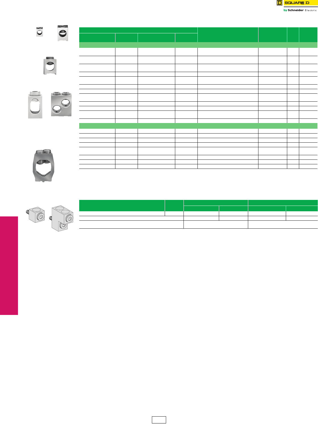
3-28 © 2012 Schneider Electric
All Rights Reserved
www.schneider-electric.us
3MOLDED CASE CIRCUIT
BREAKERS
Circuit Breaker
Accessories
Mechanical Lug Information
aUnless otherwise specified, wire sizes apply to both aluminum and copper conductors.
bFor use in the OFF end only, when the OFF end is the load end.
cUse suffix 8002 for factory-installed Cu lugs. (20% adder.)
Table 3.86: Mechanical Lug Kit Information
Circuit Breaker Application (Number of Wires Per Lug )
Wire RangeaCat. No.
Lugs
Per
Kit
$ Price
Per Kit
Standard Ampere
Rating Optional Ampere
Rating
Al Lugs for Use with Al or Cu Wire
FA, FH
FI 15–30 A FA, FH
FI 35–100 A (1) 14–4 AWG Cu or
(1) 12–4 AWG Al AL50FA 337.20
FC 35–100 A FC 15–30 A (1) 14–3 AWG Cu or
(1) 12–1 AWG Al AL100FA4 337.20
FA, FH
FI 35–100 A FA, FH
FI 15–30 A (1) 14–1/0 AWG Cu or
(1) 12–1/0 AWG Al AL100FA 337.20
— — FA, FH, FC 15–100 A (1) 12–3 AWG Cu AL100TFb337.20
——FA 150 A
(only) (1) 2–3/0 AWG AL150FA 337.20
KI 110–175 A — — (1) 4 AWG–350 kcmil AL250KA 3113.00
KI 200–250 A KI 110–175 A (1) 1/0 AWG–350 kcmil AL250KI 3107.00
Q4, LA, LH 125–400 A — — (1) 1 AWG–600 kcmil or
(2) 1 AWG–250 kcmil AL400LA 135.70
— — Q4, LA, LH 125–400 A (1) 350–750 kcmil AL400LH7 147.10
LE, LX, LXI 100–250 A LC, LI, LE, LX, LXI 300–600 A (2) 1 AWG–350 kcmil AL600LI35 149.60
LI, LE,
LX, LXI 300–600 A LE, LX, LXI 100–250 A (2) 4/0 AWG–500 kcmil AL600LI5 147.10
— — LC, LI, LE, LX, LXI — (1) 500–750 kcmil AL600LI7 153.00
Cu Lugs for Use with Cu Wire Only c
FC 15–30 A — — (1) 14–10 AWG Cu CU30FA4 337.20
— — FA, FH, FC, FI 15–100 A (1) 14–1 AWG Cu CU100FA 337.20
— — FA, FH, FC 15–100 A (1) 12–3 AWG Cu CU100TFb362.00
— — KI 110–250 A (1) 4 AWG–250 kcmil Cu CU250KA 3113.00
— — Q4, LA, LH 125–400 A (1) 1 AWG–600 kcmil Cu or
(2) 1 AWG–250 kcmil Cu CU400LA 170.00
— — LI, LE, LX, LXI — (2) 1 AWG–350 kcmil Cu CU600LI35 1230.00
— — LI, LE, LX, LXI — (2) .4/0 AWG–500 kcmil Cu CU600LI5 1230.00
— — LI, LE, LX, LXI — (1) 500–750 kcmil Cu CU600LI7 1230.00
Table 3.87: Mechanical Lug Kits for D-Frame Circuit Breakers
Description Poles 400 A Lugs 600 A Lugs
Cat. No. $ Price Cat. No. $ Price
Field-Installable Lug Kit, Terminal Cover Included 3 32508 191.00 32510 347.00
Voltage Takeoffs (set of two) 29348 28.40 29348 28.40
Wire Range (1) 2 AWG-600 kcmil stranded CU cable
(1) 2 AWG-500 kcmil stranded AL cable
(2) 2/0 AWG-350 kcmil stranded CU cable
(2) 2/0 AWG-500 kcmil stranded AL cable
AL50FA
AL250KI
AL250KA
AL100FA
AL400LA AL600LI5
AL400LH7
D-Frame Lugs
DE2 Discount
Schedule
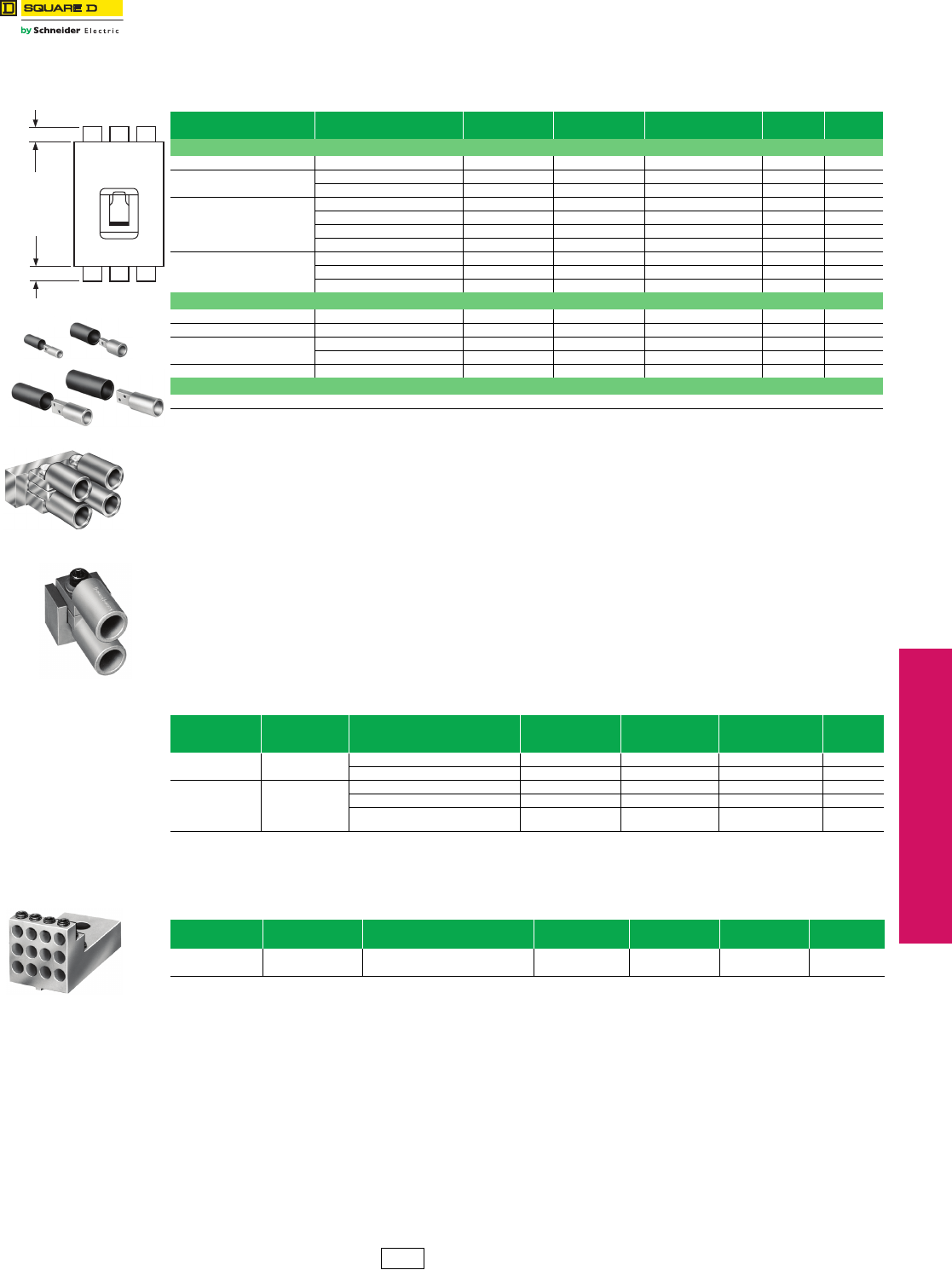
www.schneider-electric.us
3MOLDED CASE CIRCUIT
BREAKERS
© 2012 Schneider Electric
All Rights Reserved 3-29
Circuit Breaker
Accessories
Compression Lug and Power Distribution Connectors
Compression Lug Kits
aSee instruction bulletins for recommended tools.
bThese lug kits cannot be used on I-Line™ circuit breakers.
cUnless otherwise specified, wire sizes apply to both aluminum and copper conductors.
dAll P-frame circuit breakers require terminal pads for mounting lugs of any type.
Power Distribution Connectors (PDC) for Circuit Breakers—for Field Replacement of Mechanical
Lugs
Can be used for multiple load connections on one circuit breaker. Use in place of standard distribution blocks to save
space and time.
Field-installable kits, including tin-plated aluminum connectors and all necessary mounting hardware are available for
Square D FA, LA and Q4-frame molded case circuit breakers.
Connectors are UL Listed:
•For use on load end of circuit breaker only
•For use in UL508 Industrial Control applications only
•For use in UL 1995/CSA C22.2 No. 236 heating and cooling equipment
•For copper wire only
eNot for use with I-Line circuit breakers.
fWhen using fine stranded wire, increased cross sectional area may cause maximum wire size to be reduced.
gOFF end only when OFF end is the load end.
hKit includes long terminal shield, which adds 1.65 inches to standard lug with short terminal shield.
Table 3.88: Field-installable Compression Lug Kitsa
Circuit Breaker
Type Wire RangecDimension A
(In)
Max. Lugs
Per Terminal Cat. No. Lug Qty.
Per Kit
$ Price Per
Kit
Aluminum Compression Lug Kits
FA, FH, FC, FI 8–1/0 AWG 1.3 1 VC100FA 3175.00
KI 4 AWG–300 kcmil 1.5 1 VC250KA3 3255.00
250–350 kcmil 1.5 1 VC250KA35 3194.00
LA, LH, Q4
250–350 kcmil 1.25 2 VC400LA35 2194.00
4 AWG–300 kcmil 1.0 2 VC400LA3 2202.00
2/0 AWG–500 kcmil 2.2 1 VC400LA5 1166.00
500–750 kcmil 2.5 1 VC400LA7 1198.00
LI, LE, LX, LXI b
4 AWG–300 kcmil 1.05 2 VC600LI3 2295.00
2/0 AWG–500 kcmil 3.20 2 VC600LI5 2308.00
500–750 kcmil 3.45 1 VC600LI7 1311.00
Copper Compression Lug Kits
FA, FH, FC, FI 6–1/0 AWG Cu 1.4 1 CVC100FA 3156.00
KI 2/0 AWG–300 kcmil Cu 1.5 1 CVC250KA3 3301.00
LA, LH, Q4 2/0 AWG–300 kcmil Cu 1.3 2 CVC400LA3 2271.00
250–500 kcmil Cu 2.3 1 CVC400LA5 1118.00
LI, LE, LX, LXI b250–500 kcmil Cu 3.20 2 CVC600LI5 2491.00
Compression Lug Kits for D-Frame Circuit Breakers
Not Available
Table 3.89: PDC Lugs
Use With Circuit
Breakere
Circuit Breaker
Ampere Rating
Wires Per Terminal
& Wire Rangef
Cu
Cat. No. Lug Quantity Per Kit Dimension
A (i.)
$ Price Per
Kit
FAL, FHL, FCLg15–100 A (6) 14–6 AWG PDC6FA6 31.092.00
(3) 14–2 AWG PDC3FA2 31.292.00
LAL, LHL, Q4L 125–400 A
(6) 12–2/0 AWG PDC6LA20 12.25182.00
(12) 14–4 AWG PDC12LA4 11.25129.00
(3) 14–2 AWG
(1) 2 AWG–250 kcmil PDC4LA250 12.0129.00
Table 3.90: Power Distribution Connectors for D-Frame Circuit Breakers
Use with Circuit
Breaker Type
Circuit Breaker
Ampere Rating
Wires Per Terminal &
Wire Range Dimension A (in.) Cat. No. Quantity Per Kit $ Price Per Kit
DG, DJ, DL 150–600 (3) 14–2 AWG and (2) 14–2/0 AWG 1.28hPDC5DG20 3387.00
150–600 (12) 14–4 AWG 1.31hPDC12DG4 3387.00
Extremity
of
Molded Case
w/Mechanical
Lugs
“A” See Table
Crimp lug or
power distribution connectors
extension past end of
circuit breaker “A” See Table
CVC100FA VC250KA3
VC400LA7
VC1200NE5
VC400LA7
CVC600MA5
PDC12LA4
DE2 Discount
Schedule
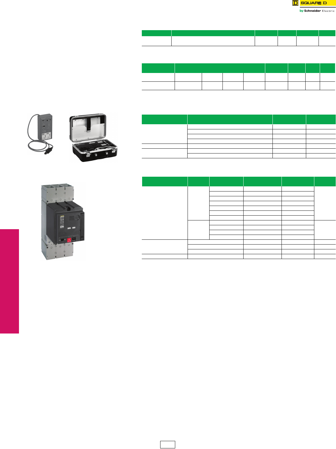
www.schneider-electric.us
3-30 © 2012 Schneider Electric
All Rights Reserved
3MOLDED CASE CIRCUIT
BREAKERS
Circuit Breaker
Accessories
PowerPact™ Circuit Breakers Miscellaneous Accessories
Class 612 / Refer to Catalog 0612CT0101
aShort lug shields provide IP20 protection for mechanical lugs and are compatible with control wire terminals.
bJ-frame terminal shield is not compatible with the YA250J35 compression terminal.
cDE5A Discount Schedule
Table 3.91: Bus Bar Connections Hardware for D-Frame Circuit Breakers
Frame Description Term. No. Poles Cat. No. $ Price
D-Frame Set of 3 terminal screws and washers for one side F336966 23.70
Set of 4 terminal screws and washers for one side 4 36967 31.50
Table 3.92: Terminal Shields and Phase Barriers
Used With Description Dimension B
(in.) Cat. No. Qty Per
Kit $ Price
G-Frame Terminal Shield
(3P) —— — GYT 175.00
D-Frame Terminal Shield
(3P)
PDC5DG2
PDC12DG2 —— 36965 1108.00
Table 3.93: Miscellaneous D-Frame Circuit Breaker Accessories
Accessory Description Field-Installed
Cat. No, $ Price
External Neutral Sensor
150 A Neutral Sensor 36950 806.00
250 A Neutral Sensor 36951 806.00
400 A Neutral Sensor 36952 806.00
600 A Neutral Sensor 36953 806.00
Spare Parts 100 Identification Labels 29314 119.00
Te st K it s Mini test kit (battery not included) 43362 884.00
Portable test kit 55391c16365.00
Table 3.94: Motor Operators for D-Frame Circuit Breakers
Description Rated
Voltag e
Factory Installed
Cat. No. Suffix
Field-Installed
Cat. No, $ Price
Standard motor for
electrically-operated circuit
breakers
AC
48/60 ML 32839
3395.00
110/130 MA 32840
208/277 MD 22841
220/240 MC —
380/415 MF 32842
380/485 MH —
440/480 MH 32847
DC
24/30 MO 32843
3545.00
48/60 MP 32844
110/130 MR 32845
250 MS 32846
Locking Device
Mounting Hardware — 32649 58.00
Ronis lock — 41940 146.00
Profalux lock — 42888 146.00
Operations Counter — 32648 225.00
Mini Test Kit Portable Test Kit
Motor Operator
DE2 Discount
Schedule
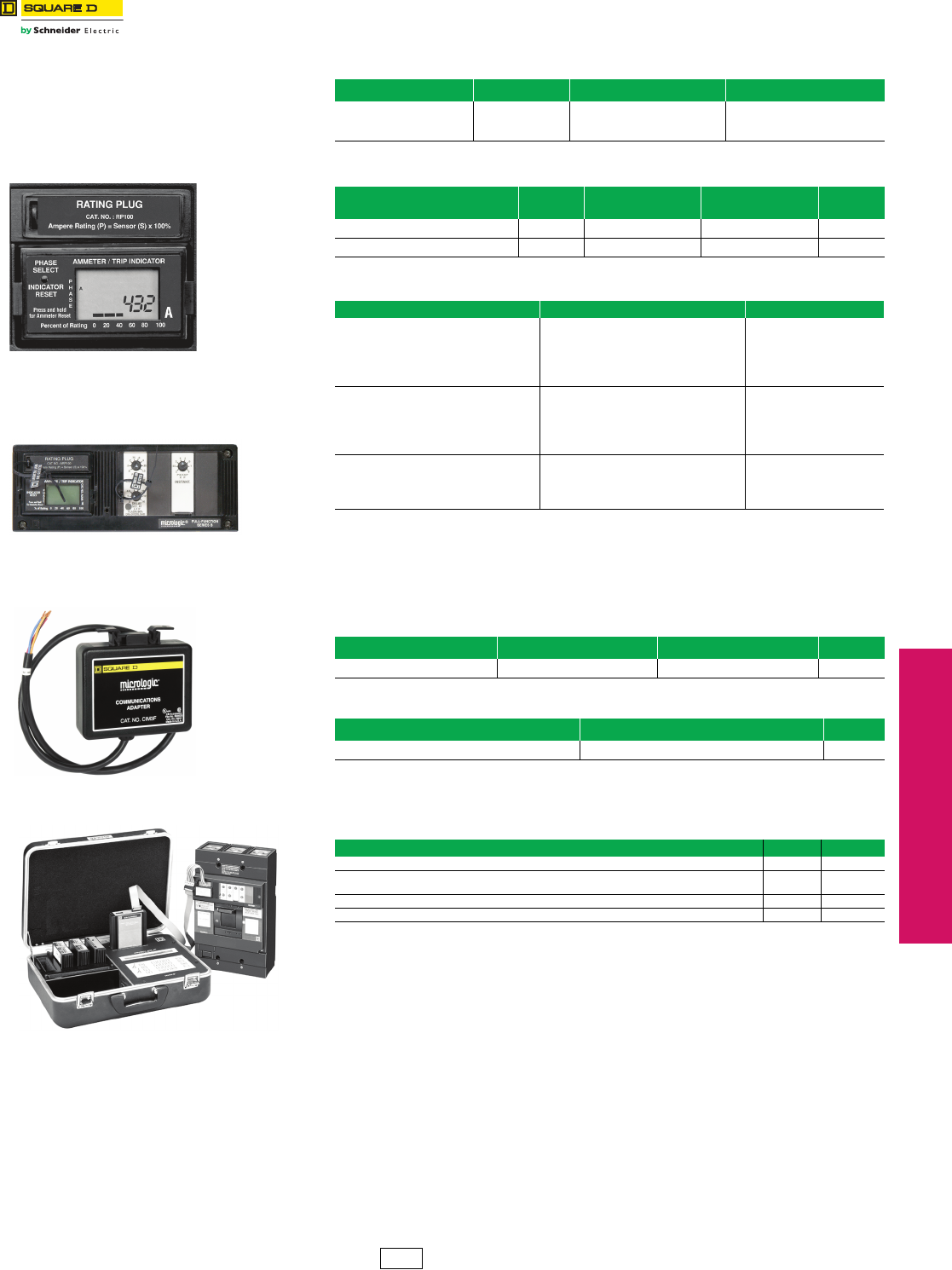
www.schneider-electric.us
© 2012 Schneider Electric
All Rights Reserved 3-31
3MOLDED CASE CIRCUIT
BREAKERS
Electronic Products Neutral Current Transformers and
Micrologic™ Series B Trip Unit Accessories
Complying with NEC®
The National Electrical Code, Section 240-6(c) exception allows conductor ampere ratings
equal to the selected long-time pick-up setting. Square D offers the seals below to restrict
access to trip unit once settings are selected.
aRequired for Micrologic to communicate with PowerLogic™ system.
Table 3.95: Neutral Current Transformers
Cat. No. $ Price Sensor Where Used
LE25CT2
LE4CT2
LE6CT2
588.00
588.00
588.00
250 A
400 A
600 A
LXL, LEL, LXIL
Table 3.96: Electronic Trip Indicator and Current Meter Field-installable Kits
Device Cat. No. Included With
Circuit Breaker Optional $ Price
Local Trip Indicator Kit ALTI —LXL, LXIL1461.00
Local Current Meter Kit/Trip Indicator ALAM LEL LXL, LXIL 2286.00
Table 3.97: Interchangeable Rating Plug Kits for all Circuit Breakers with
Micrologic Series B Trip System
Cat. No. Sensor Multiplier Value $ Price
ARP040 0.400 297.00
ARP050 0.500 297.00
ARP056 0.563 297.00
ARP058 0.583 297.00
ARP060 0.600 297.00
ARP063 0.625 297.00
ARP067 0.667 297.00
ARP070 0.700 297.00
ARP075 0.750 297.00
ARP080 0.800 297.00
ARP083 0.833 297.00
ARP088 0.875 297.00
ARP090 0.900 297.00
ARP100 1.000 297.00
Table 3.98: Trip Unit Seals
Description Cat. No. Package Quantity $ Price
Trip Unit Seal TUSEAL 100 102.00
Table 3.99: Communication Adapter
Description Cat. No. $ Price
Communication Adapter CIM3Fa465.00
Table 3.100: Test Equipment for Circuit Breakers with Micrologic Series B Trip
Systems
Description Cat. No. $ Price
Universal Test Set (includes test module for Full-function and Standard-function LEL, LXL, LXIL) UTS3 14022.00
Test Module for Full-function and Standard-function LEL, LXL, LXIL. (For use with existing CBTU1
or UTS3 test set.) CBTMB 2349.00
Replacement ribbon cable and rating plug adapter for CBTMB CBTMBRK 627.00
Long-time and ground-fault Memory Reset Module (Series B Electronics) MTMB 381.00
C
ombination Local Current Meter
and Trip Indicator
Electronic Trip Unit with Seals Installed
to Restrict Access
CIM3F Communication Adapter
Universal Test Set
DE2 Discount
Schedule
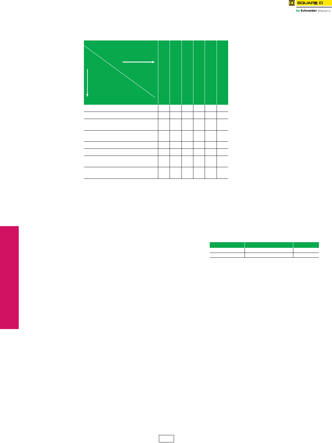
www.schneider-electric.us
3-32 © 2012 Schneider Electric
All Rights Reserved
3MOLDED CASE CIRCUIT
BREAKERS
Electronic Products Restraint Interface Module
S48890 and S48895 Restraint Interface Modules
The Restraint Interface Module (RIM) is used to allow
zone-selective Interlocking communications between
circuit breakers with Micrologic™ Series B trip units or
Micrologic™ #.Ox trip units, Compact™ STR53 trip units,
Masterpact™ STR58 trip units, Federal Pioneer USRC
and USRCM trip units, and Square D GC series ground-
fault relays.
Upstream circuit breakers with Micrologic 3.0A, 5.0A 5.0P,
5.0H, 6.0A, 6.0P, and 6.0H trip units can receive up to 15
input signals without requiring a restraint interface
module. If the number of input signals exceeds 15, then a
RIM is required. Contact your local Sales Office for RIM
requirements.
The restraint interface module operates on either 120
Vac/24 Vdc, or 240 Vac/24 Vdc, 50/50 Hz.
NOTE: The maximum distance between devices is
1000 ft. (305 m)
Table 3.101: RIM Requirements
Note: R=RIM module is required to restrain any devices.
Numerical References=Maximum number of upstream circuit breakers which can be
restrained without requiring a RIM module.
Micrologic
#.0x Trip Units
Square D Micrologic
Series B Trip Units
Square D GC-100 Ground-Fault
Relay for Equipment Protection
Square DGC-200 Ground-Fault
Relay for Equipment Protection
Merin Gerin
STR58 Trip Units
Federal Pioneer
USRC and USRCM Trip Units
Micrologic #.0x Trip Units 15 R R 15 15 R
Square D Micrologic Series B Trip Units R26R R R15
Square D GC-100 Ground-Fault
Relay for Equipment Protection RR7RRR
Square D GC-200 Ground-Fault
Relay for Equipment Protection 15 R R 15 15 R
Merlin Gerin STR58 Trip Units 15 R R 15 15 R
Merlin Gerin STR53 Trip Units 15 R R 15 15 R
Federal Pioneer USRC
and USRCM Trip Units R15R R R15
Square D Add-on Ground-Fault Module
for Equipment Protection R5RRRR
Upstream Device
(receives input
from RIM)
Downstream Device
(sends output to RIM))
Table 3.102: Restrain Interface Module (RIM)
Cat. No. Voltage $ Price
S48890 120 Vac/24 Vdc 1860.00
S48895 240 Vac/24 Vdc 1860.00
DE2 Discount
Schedule
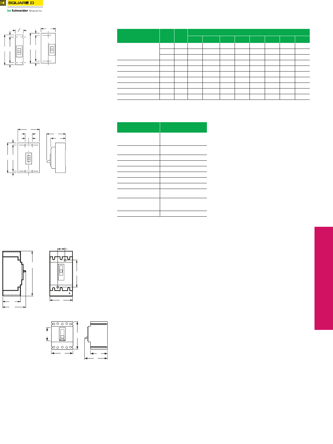
www.schneider-electric.us
© 2012 Schneider Electric
All Rights Reserved 3-33
3MOLDED CASE CIRCUIT
BREAKERS
Circuit Breaker
Dimensions
Table 3.103: Circuit Breakers Dimensions
Circuit Breaker
Catalog No.
Prefix
No.
Poles
Fig.
No.
Dimensions—Inches
A B C D E F G H
FAL, FHL
1 21 6.00 1.50 3.16 4.13 0.44 5.13 1.50 —
2 22 6.00 3.00 3.16 4.13 0.44 5.13 — —
3 23 6.00 4.50 3.16 4.13 0.44 5.13 1.50 0.75
KAL, KCL, KHL 2 & 3 23 8.00 4.50 3.66 4.75 0.44 7.13 1.50 0.75
FIL, KIL 2 & 3 23 8.00 4.50 3.66 4.75 0.44 7.13 1.50 0.75
GJ 3 32 3.54 4.72 2.76 3.94 2.20 — — —
DG, DJ, DL 3 28 13.38 5.51 3.75 6.61 2.22 8.93 1.77 —
LC, LI, LE, LX, LXI 2 & 3 23 11.86 7.50 5.48 6.74 0.55 10.75 2.50 —
Q4L, LAL, LHL 2 & 3 23 11.00 6.00 4.06 5.84 0.88 9.25 2.00 1.00
MAL, MHL 2 & 3 23 14.00 9.00 4.53 6.50 1.66 10.69 3.00 1.50
Table 3.104: Shipping Weights
Frame Size Approx. Shipping Weight
(Lbs.)
FAL
FHL 2-pole
FCL
3
FAL
FHL 3-pole 5
FIL 8
KAL, KHL 7
KIL 9
Q4L 15
DG, DJ, DL 14
GJ 3
LAL
LHL 15
LXL
LEL
LIL
25
MAL, MHL 34
Figure 21
A
G
B
E
F
E
C/L
Figure 22
B
E
E
FA
Figure 23
C/L
B
D
C
G
HH
E
E
FA
Figure 32
A
EB
C
D
A
C
D
B
G
F
Figure 28
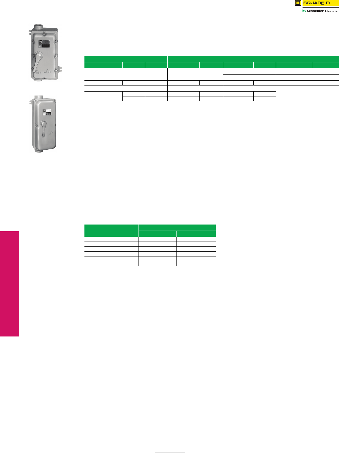
3-34 © 2012 Schneider Electric
All Rights Reserved
www.schneider-electric.us
3MOLDED CASE CIRCUIT
BREAKERS
Enclosures Industrial Circuit Breaker Enclosures
Class 610
Circuit breaker enclosures are UL Listed, CSA Certified and are suitable for use as service equipment except as
footnoted.
•The short circuit rating of an enclosed circuit breaker is equal to the rating of the circuit breaker installed, except as footnoted.
•Circuit breakers are ordered and shipped separately for field installation.
•For enclosure accessories refer to page 3-36 . For enclosure dimensions refer to page 3-35.
aEnclosures with NRB or RB suffix have provisions for 3/4 in. through 2-1/2 in. bolt-on hubs in top endwall. Enclosures with R suffix have blank endwalls
and require field cut opening. For details and hub catalog numbers see Digest Section 3.
bNot CSA Certified.
cNEMA 7—Indoor Hazardous Locations—Division 1 and 2, Class I, Groups C and D; Class II, Groups E, F and G; Class III.
dSuitable for rainproof NEMA 3R application by removing drain screw from bottom endwall.
eShort circuit rating is 100 k AIR at 480 Vac maximum.
fNEMA 9—Indoor Hazardous Locations–Division 1 and 2, Class II, Groups E, F and G; Class III
gUse 75oC Copper conductors only.
hSuitable for rainproof applications—includes PKDB1 breather and drain kit.
Enclosed Motor-Operated Molded Case Circuit Breakers
NOTE: Contact local Field Office for catalog number prior to quoting or placing an order.
Motor-operated enclosed circuit breakers are utilized whenever it is desired to control the operation of an individually
mounted circuit breaker from a remote location. Enclosed motor operated circuit breakers are available in either NEMA
1 or 3R construction. 120 Vac control circuit required for operation of motor operator. Sufficient space is included for
field-installation of a terminal block for convenient end-user control circuit wiring. Not UL Listed.
Enclosed motor-operated circuit breaker with neutral
•Specify circuit breaker catalog number (ex: FAL36060)
•Specify side mounted operator only.
•Specify enclosure type (ex: NEMA 1, 3R, 12)
•Specify if neutrals are required (Same price)
aPrice includes 3P circuit breaker, motor operator, and neutral assembly
factory assembled in specified enclosure.
Table 3.105: Circuit Breaker Enclosures
Circuit Breaker Enclosure
Cat. No. Prefix Rating Poles Cat. No. $ Price Cat. No. $ Price Cat. No. $ Price
NEMA 4, 4X, 5, 3, 3R Stainless
Steel (Hubs—See page 3-9)
NEMA 12/3R, 12K (Hubs—See page 3-9)
With Knockouts (NEMA 12K) Without Knockoutsd (NEMA 12/3R, 5)
KILe110–250 A 2, 3 IK250DS 5238.00 ——IK250AWK 878.00
NEMA 7c Cast Aluminum NEMA 9f Cast Aluminum
FALg15–60 A 1, 2, 3 FA060Xh1620.00 FA060Yb1227.00
15–100 A 1, 2, 3 FA100Xh2006.00 FA100Yb1389.00
Table 3.106: Enclosed Motor-Operated Circuit Breakers
Circuit Breaker Type $ Price a
NEMA 1 NEMA 3R
FAL—240 V 2915.00 3149.00
FAL—480 V 3131.00 3369.00
FAL—600 V 3308.00 3525.00
FHL—600 V 3725.00 3950.00
LAL—600 V 11187.00 11477.00
LHL—600 V 14147.00 14429.00
FA100X
FA100Y
DE1 DE2A Discount
Schedule
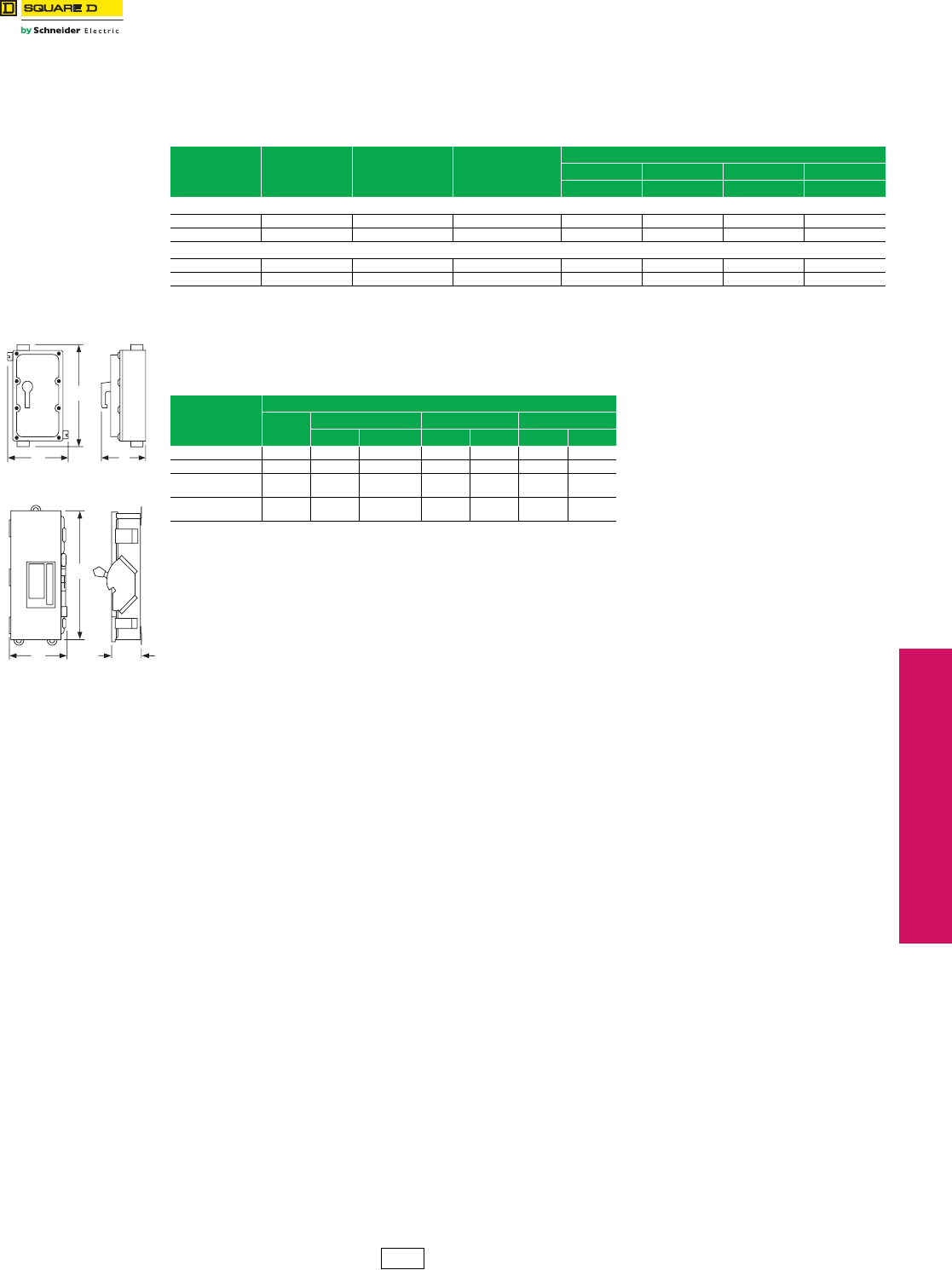
www.schneider-electric.us
3MOLDED CASE CIRCUIT
BREAKERS
© 2012 Schneider Electric
All Rights Reserved 3-35
Enclosures Enclosed Switches and Enclosure Dimensions
Class 610
Enclosed Molded Case Switches
Enclosed molded case switches are UL Listed devices supplied with factory-installed automatic molded case switch.
Use the Cat. No. listed below and add the enclosure style suffix. An insulated groundable neutral, if required, must be
ordered separately from Digest page 7-58. Enclosed molded case switches are manufactured on order only.
aFHE and KHE devices accept bolt-on hubs and have a suffix RB. LHE, MHE and NCE devices have blank endwalls and have a suffix R. For details and
hub catalog numbers see page 3-9.
Dimensions: Refer to enclosed circuit breaker dimensions by NEMA type.
Table 3.107: Enclosed Molded Case Switches
System Ampere
Rating
Cat. No.
Add Suffix
600 Vac
Short Circuit
Withstand Ratings
$ Price
NEMA 1 NEMA 3RaNEMA 4,4X,5 NEMA 12
(F) or (S) (RB) or (R) (DS) (AWK)
FH—100 A Frame, 3P, 600 Vac Max.
2P 100 FHE26000( ) 18 kA 963.00 1277.00 2273.00 1083.00
3P 100 FHE36000( ) 18 kA 1187.00 1499.00 2432.00 1310.00
LH—400 A Frame, 3P, 600 Vac Max.
2P 400 LHE26000( ) 25 kA 3915.00 5174.00 9264.00 4497.00
3P 400 LHE36000( ) 25 kA 4653.00 5982.00 9999.00 5232.00
Table 3.108: Enclosure Dimensions
Cat. No.
Approximate Dimension
Series H W D
in. mm in. mm in. mm
FA060XaE1 16.00 406 9.88 251 7.00 178
FA060YaE1 16.00 406 9.88 251 7.00 178
FA100Xa
FA100Ya
E1
E1
16.00
16.00
406
406
9.88
9.88
251
251
7.00
7.00
178
178
IK250DS
IK250AWK
E2
E2
42.25
42.25
1073
1073
13.88
13.88
353
353
7.50
7.50
191
191
aTapped conduit opening, top and bottom endwall: FA060X/Y– 3/4", FA100X/Y–1-1/4"
W
H
D
Enclosures FA060X, FA100X,
FA060Y and FA100Y
Enclosures for IK250DS
and IK250AWK
W
H
D
DE1 Discount
Schedule
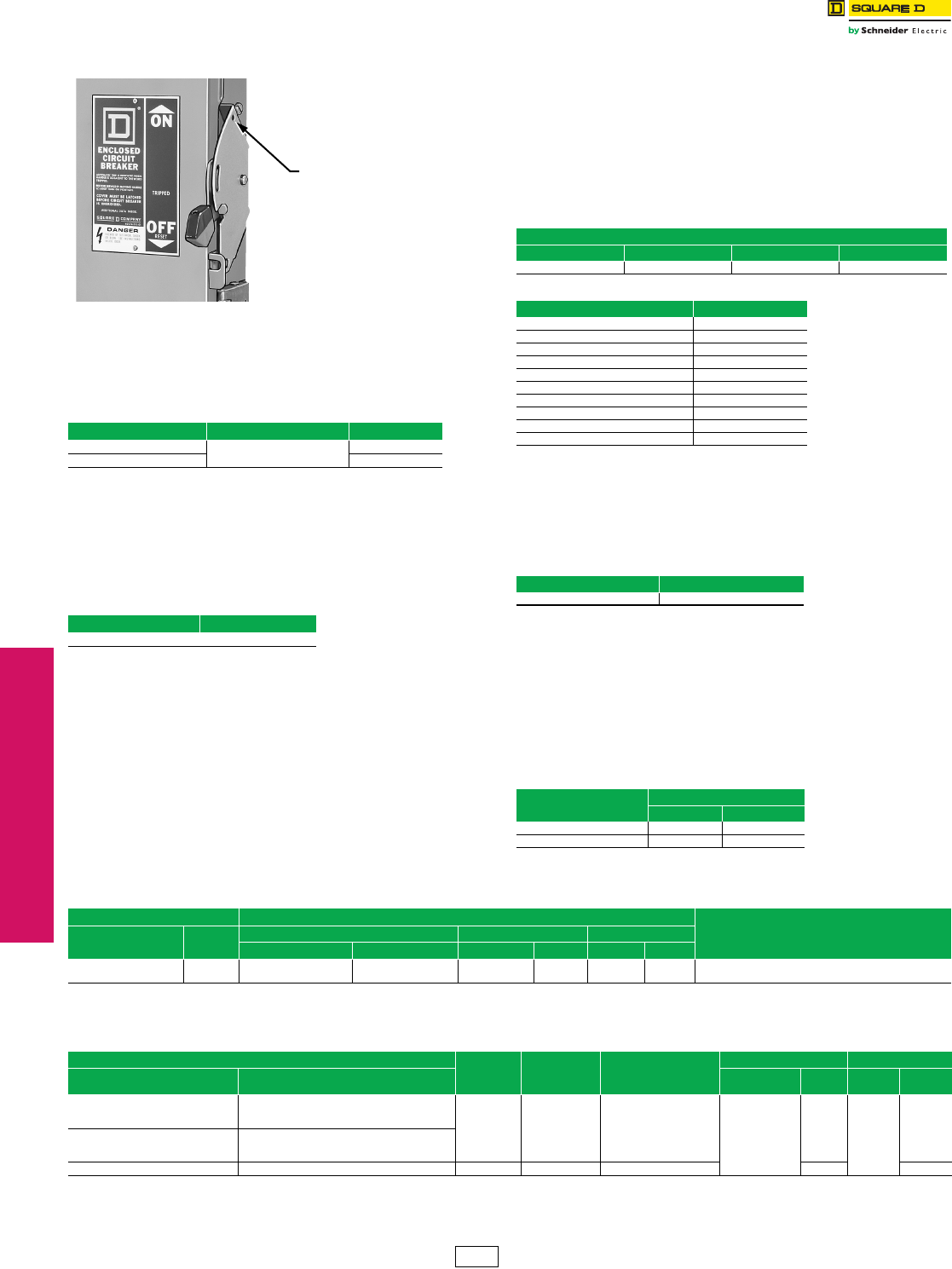
www.schneider-electric.us
3-36 © 2012 Schneider Electric
All Rights Reserved
3MOLDED CASE CIRCUIT
BREAKERS
Enclosures
Accessories
Lock-On Provisions
Lock-off provisions are standard on all NEMA Type 4-4X-5 stainless steel
and NEMA Type 12, 12K circuit breaker enclosures. Provision for one inch
hasp padlock is available factory installed. This modification will allow the
circuit breaker to be locked in the ON position. When locked in the ON
position, the external operator will not indicate if circuit breaker is tripped. UL
Listed.
Pilot Light—Selector Switch—Push Button
Pilot lights, push buttons or selector switches are available factory
installed in the cover of NEMA Type 3R, (4-4X-5) stainless steel or 12
enclosures. Wiring to contact blocks is not available. Customer must
furnish catalog number of device desired. Price = circuit breaker +
enclosure + neutral + ground + pilot light, push button and/or selector
switch + factory-installed adder. Order by description. Not UL Listed.
Phenolic Legend Plate
Available engraved and mounted on most circuit breaker enclosures.
Legend engraved in 1/4-inch high white letters on black background.
Customer must provide legend. UL Listed. Not available on NEMA Type
7 or 9 enclosures.
To order, add suffix NP to standard catalog number (i.e. LA400SNP).
Price adder per legend plate: $167.00
Special Paint
UL Listed circuit breaker enclosures are available painted with special
safety colors. To order safety colored enclosures add suffixes as noted
in Table 3.112 to the standard enclosure commercial reference number.
All colors comply with OSHA Standard 1910.144 and ANSI Specification
Z535.1 for marking physical hazards.
A minimum quantity of ten is required. Order by description. Not
available for NEMA Type 7/9 or stainless steel enclosures.
Shipment: 6 weeks
aStandard Square D ANSI 49 grey paint, when selecting this suffix, switches will receive
additional coat of paint.
Stainless Steel Front
The FA100F NEMA Type 1, flush-mount circuit breaker enclosure is
available with a stainless steel front. This modification is desirable in
food handling areas such as cafeterias and restaurants.
Enclosed Ground-Fault Modules (GFM)
Ground-fault modules (GFM) can be factory installed on FAL and FHL
circuit breakers and enclosed in the next larger size NEMA 1 or 3R
enclosure.
Enclosed circuit breaker with ground-fault module
•Specify circuit breaker catalog number
•Specify enclosure type (NEMA 1 or 3R)
•Ground-fault modules are available factory installed. See table below for
pricing and availability.
bPrice includes 3P circuit breaker, GFM, neutral assembly and neutral CT factory
assembled in specified enclosure
cNot UL Listed
Equipment Ground Kit
Price adder includes price of ground bar kit.
Table 3.109: Price Adder Each Enclosure
Enclosure Prefix Suffix for Lock-On Provision $ Price
FA, J SPLO 155.00
LA, M, P 234.00
Table 3.110: Price Adder
Quantity $ Price Adder
For Each Device Installed 297.00
Lock-on Provision
Table 3.111: Price Adder Each Enclosure
Enclosure Prefix
FA $ Price J $ Price LA $ Price P $ Price
113.00 180.00 327.00 513.00
Table 3.112: Safety Colors
Safety Color Suffix
Black SP0
Red SP2
Orange SP3
Yellow SP4
Green SP5
Blue SP6
Purple SP7
Gray SP8
Gray ANSI61 SP861a
White SP9
Table 3.113: Price Each Enclosure
Cat. No. $ Price
FA100FSS 1659.00
Table 3.114: Enclosed Circuit Breaker with Ground Fault Modulec
Circuit Breaker
Prefix
$ Price b
NEMA 1 NEMA 3R
FAL, 600 V, 15–60 A 6585.00 7091.00
FAL, 600 V, 70–100 A 6797.00 7307.00
Table 3.115: Insulated Groundable Neutral Assembly
Circuit Breaker Neutral Assembly For Use With Terminal Lug Data—Total Available
(Line plus Load)
AWG/kcmil
Cat. No. Prefix Ampere
Rating
NEMA 1 & 3R NEMA 4, 4X, 5, 12 & 12K NEMA 7 & 9
Cat. No. $ Price Cat. No. Price Cat. No. $ Price
KIL
KIL
225
250
—
—
—
—
SN225KA
SN400LA
201.00
251.00
—
—
—
—
(2) 4–300 Al/Cu, plus (2) 14–1/0 Al/Cu
(2) 1–600 or (4) 1–250 Al/Cu, plus (2) 4–300 Al/Cu
Table 3.116: Ground Kit Price Adder
Enclosure Number of
Terminals per
Kit
Conductors
Per Terminal
Wire Range
AWG/kcmil
Field-Installable Factory-Installedd
Enclosure Type Circuit Breaker Cat. No. Prefix Ground Bar
Kit Cat. No. $ Price Suffix $ Price
NEMA Type 1 and 3R
FAL, FHL, FIL
KIL
LAL, LHL 21 10–2/0 Cu or
6–2/0 Al PKOGTA2f263.00 GL 191.00
NEMA Type 4-4X-5 stainless steel
and NEMA Type 12
FAL, FHL, FIL
KIL
LAL, LHL, Q4L
M, Pe2 1 10–2/0 Cu or 6–2/0 Al 263.00 263.00
dFor factory installation of equipment ground lugs in these or any other enclosures, add suffix GL.
eUse of PKOGTA2 with M, and P enclosure prefix not UL Listed
fQuantity (2) may be required for some wire installation.
DE1 Discount
Schedule
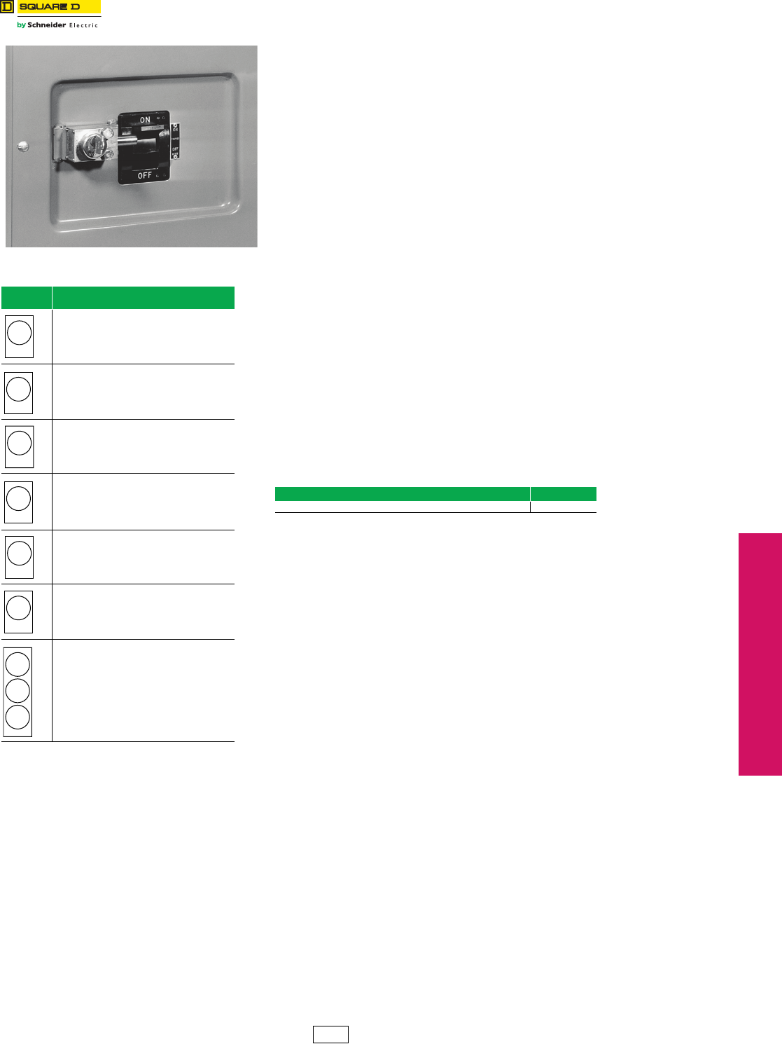
www.schneider-electric.us
© 2012 Schneider Electric
All Rights Reserved 3-37
3MOLDED CASE CIRCUIT
BREAKERS
Enclosures Key Interlock Systems—Factory Installed Only
Class 736, 1130
Key Interlock Systems
(Factory installed only)
Interlocks are used to prevent the authorized operator from making an unauthorized
operation. Not available on hazardous location devices (NEMA 7/9.)
The key interlock system is a simple and easy method of applying individual key interlock
units and assemblies to the above equipment so as to require operation in a predetermined
sequence. UL Listed.
Quoting:
Contact local Field Sales office for catalog number, availability and pricing prior to quoting a
job.
Ordering:
•Order cannot be released for production until the following information has been provided.
•End User—Company name, address
•Function of each lock (e.g., circuit breaker to be locked open with key removed, key held when
circuit breaker is closed)
•Existing Equipment—if circuit breaker is to be interlocked with equipment already on site, provide
brand of existing lock and key number
•Other New Equipment—if circuit breaker is to be interlocked with new equipment not yet installed at
the site, then provide contact person and phone number so that locks may be coordinated
•Additional information may be required upon order entry
•Federal Pioneer locks supplied unless otherwise specified
aPrices do not apply when more than three devices are interlocked as these schemes
normally require more than one key assembly per device.
Table 3.117: Locking Position Designations
Locking
Position Designation
Device locked open with key removed.
Device locked closed with key removed.
Device locked open or closed with key removed.
Device locked open with key held.
Device locked closed with key held.
Device locked open or closed with key held.
Multi-lock interlock.
(More than one key per lock.)
NOTE: 1. Device locked open (circuit
breaker in OFF position).
2. Device locked closed (circuit
breaker in ON position).
L-O-R
L-C-R
L-O-C-R
L-O-H
L-C-H
L-O-C-H
Table 3.118: Price Adder Per Lock, Each Complete Enclosed Devicea
Device $ Price
Enclosed industrial circuit breaker 2055.00
DE1 Discount
Schedule
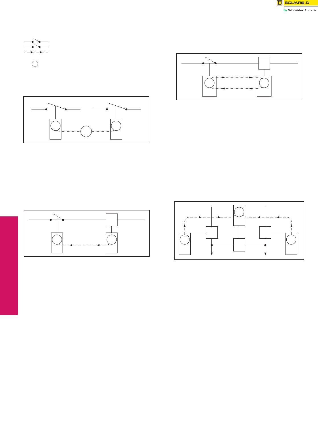
www.schneider-electric.us
3-38 © 2012 Schneider Electric
All Rights Reserved
3MOLDED CASE CIRCUIT
BREAKERS
Enclosures Special Applications
Class 610
Sample Application—1
To prevent two devices from being closed simultaneously.
Two devices are shown in Figure 1. In operation they are not closed at
the same time. With the interlocks arranged as shown only one key is
required in the interlocking system. Both devices are shown open,
therefore, the key is free. To close any one device the key is inserted
and turned in that particular lock, the key is held in this lock until the
device is again locked open. This simple interlocking sequence lends
itself to a multitude of applications. The procedure is the same for two
devices, neither of which is to be opened at the same time.
Sample Application—2
To prevent opening of switch A when circuit breaker B is closed.
Switch A and circuit breaker B are in closed position. Key A-1 is held in
circuit breaker B interlock.
1. Open circuit breaker.
2. Turn key A-1 in L-O-R interlock on circuit breaker B to lock open. Key A-1 is
now free.
3. Insert key A-1 in L-C-R interlock on switch A and turn to unlock.
4. Open switch A. Key A-1 is now held. Reverse sequence to restore service.
Sample Application—3
To prevent operation of switch A when circuit breaker B is closed.
Permits reclosing of circuit breaker for servicing when switch is locked
open.
Switch A and circuit breaker B are in closed position. Key A-1 is held in
circuit breaker interlock.
1. Open circuit breaker.
2. Turn key A-1 in L-O-R interlock on circuit breaker B to lock open. Key A-1 is
now free.
3. Insert key A-1 in L-O-C-R interlock on switch A and turn to unlock.
4. Open switch A.
5. Turn key A-1 in L-O-C-R interlock on switch A to lock open. Key A-1 is now
free.
6. Return key A-1 to circuit breaker interlock and unlock for operation during
servicing period.
Reverse sequence to restore service.
Sample Application—4 (Main-Tie-Main)
To prevent paralleling of lines A and B.—Two loads, fed from either
source.
Circuit breaker A is closed to supply load M. Circuit breaker B is closed
to supply load N. Tie-circuit breaker C is open. Keys A-1 are held in
interlocks on both circuit breakers A and B. Tie-circuit breaker C cannot
be closed unless either A or B is locked open.
To transfer load N to circuit breaker A, proceed as follows:
1. Open circuit breaker B.
2. Turn key A-1 in L-O-R interlock on circuit breaker B to lock open. Key A-1 is
now free.
3. Insert Key A-1 in L-O-R interlock on tie-circuit breaker C and turn to unlock.
Key A-1 is now held.
4. Close tie-circuit breaker C.
Reverse sequence to restore service.
Load M can be supplied through circuit breaker B in a similar manner.
. . . . . . . . Device normally open
. . . . . . . . Device normally closed
. . . . . . . . Direction of key transfer
. . . . . . . . Key interchange numbe
r
. . . . . . . . Key
Diagram Symbols
A-1 A-2 A-3
Figure 1
A-1
A 1
L-O-R L-O-R
AB
A-1
Figure 2
A-1
L-C-R L-O-R
A
B
A 1
Figure 3
A-1
L-O-C-R L-O-R
A
B
A 1
Figure 4
L-O-R
C
L-O-R
A
A
NM
A 1
L-O-R
A 1
A-1
B
B
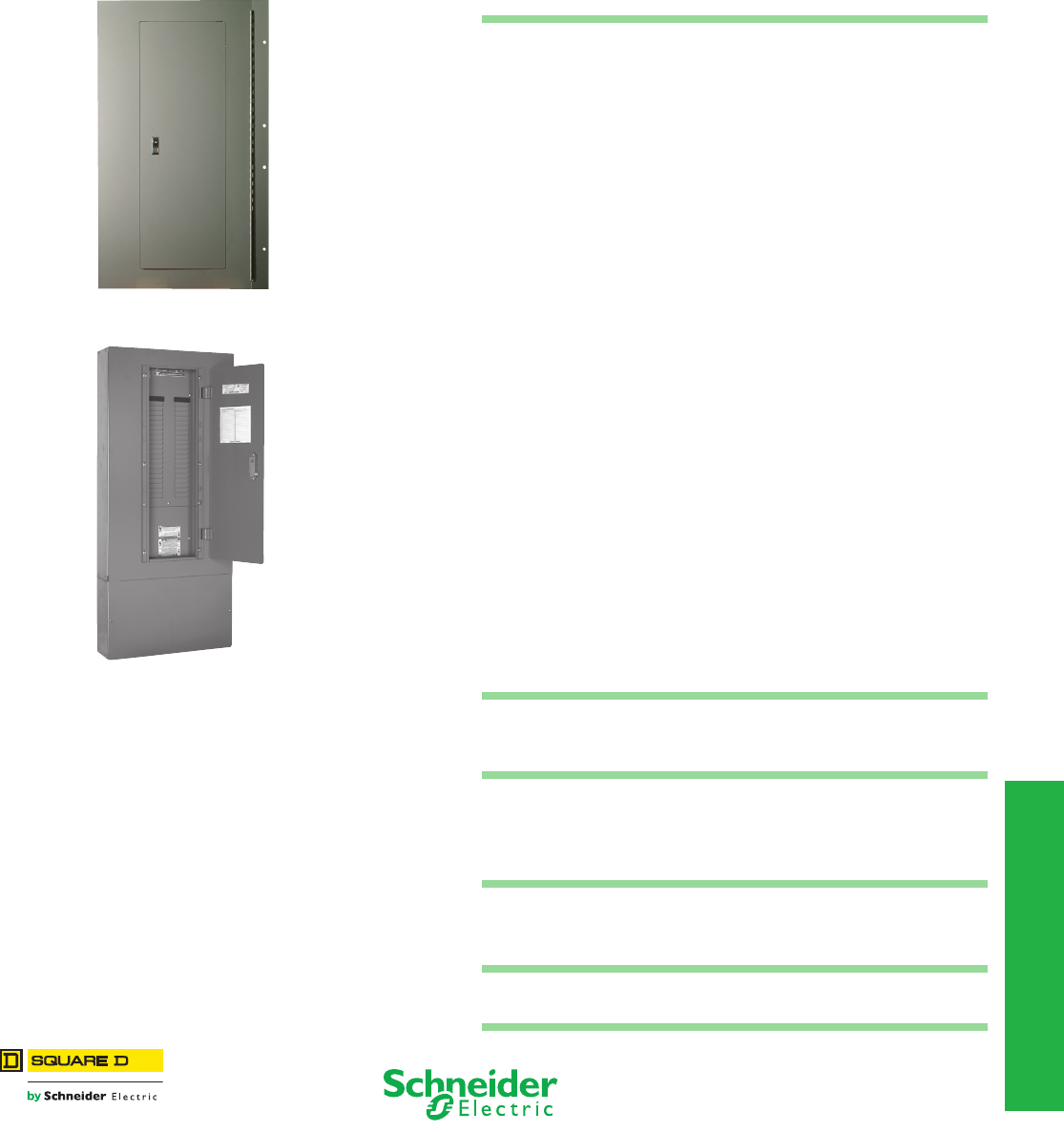
4-1
© 2012 Schneider Electric
All Rights Reserved
4PANELBOARDS
Table of Contents
Section 4
Panelboards
NQ Panelboard with
Door-in-Door (Hinged) Trim
MH38 Enclosure with 12-inch Wireway and
Mono-Flat™ Trim with 12-inch Wireway Cover
Factory Assembled Panelboard Special Features
General Instructions 4-2
Pricing Instructions 4-2
Metric Conversion 4-2
I-Line Panelboards Factory Assembled Pricing 4-2
Metering 4-3
Current Transformers 4-3
Customer Equipment Space 4-3
Keyed Interlocks 4-3
Motor Operators 4-3
Increased Enclosure Depth 4-4
Increased Side Gutters 4-4
Extended Top and Bottom End Gutters 4-4
Drip Hoods 4-4
Special Finishes
(non-standard paint color, painted enclosures, etc.)
4-4
Free Standing Enclosures 4-4
Special Trims (hinged, stainless steel, etc.) 4-4
Padlock Hasp 4-5
Special Locks 4-5
Multi-section Panels
(equal-height enclosures, common trims, etc.)
4-5
Panel Skirts 4-6
Wireway 4-6
Panels to Fit Existing Enclosures 4-7
Space Heater 4-7
Special Enclosures
(Type 1, 3R-12, 4, 4X, etc.)
4-8
NQ Merchandised Panelboards
NQ Main Lug and Main Circuit Breaker Panelboard
with SPD
4-9
Ready-to-Install (RTI) Merchandise
Copper Equipment Ground Bars 4-10
Field Installable I-Line™ Door Kits 4-10
Type 1 Door-in-Door (Hinged) Trim Fronts 4-10
Replacement Parts for Standard Panelboards
Trim Clamps and Screws 4-11
Locks and Keys 4-12
CTC Cabinets 4-13
Datasheet for the Retrofit of an Existing
Enclosure
4-14
4-2 © 2012 Schneider Electric
All Rights Reserved
www.schneider-electric.us
4PANELBOARDS
Panelboards General Information
cRefer to Table 4.3 for LE, LX and LXI Micrologic Trip Unit price adders.
General Instructions
The special feature options covered in this Panelboard estimating
procedure are applicable to factory-assembled panelboards only. Do
not apply this pricing to ready-to-assemble panelboards.
Special features are listed in three major categories:
• Mains
• Branches
• Cabinets
Pricing Instructions
All special feature entry prices are list prices.
Price the panelboard in the standard manner, then add for any special
features required to obtain the total price.
Certain features already appear in the Q2C or EQM panelboard
quotation system. For those features not listed in the quotation system,
enter the information as it appears in this publication with the
appropriate price in the “Other Special Features” screen in Q2C or
EQM. Follow the example below:
Metric Conversion
Inches (in.) x 25.4 = millimeters (mm).
I-Line™ Panelboards Factory Assembled Pricing
Table 4.1: Basic $ Price – Main Circuit Breaker
Panel Type No.
Poles
Main Circuit Breakera
400 A 600 A
LXbLEbLXIbLXbLEbLXIb
HCP, HCP-SU 210976.00 15232.00 19944.00 14312.00 17078.00 29878.00
312132.00 17944.00 22734.00 17822.00 20590.00 33390.
aWhen required, add the $ Price of a solid neutral from Digest Table 9.125.
bStd. construction back-fed main.
Quantity Description $ Price
1 Corbin Locks 704.00
Table 4.2: Micrologic LE, LX and LXI Branch Circuit Breakers (See Digest pages 7-7 for interrupting rating,
voltage rating, Fed. Specs. etc.)
Circuit
Breaker
Ampere
Circuit
Breaker
3 pole 2 pole 1 pole
240 V 480 Vac
250 Vdc 600 V Space
only H240 V 480 Vac
250 Vdc
480 Vac
250 Vdc
Space
only H120 V 277 V 277 Vac
125 Vdc
Space
only H
Micrologic™ Circuit Breakers (% Rated)
100–250 A
LX (80%)c
— — 10100.00
456.00 7.5
— — 7580.00
456.00 7.5
——— ——
300–400 A — — 10400.00 — — 9240.00 — — — — —
450–600 A — — 15566.00 — — 12056.00 — — — — —
100–250 A
LXI (80%)c
— — 16556.00
456.00 7.5
— — 13666.00
456.00 7.5
——— ——
300–400 A — — 21002.00 — — 18212.00 — — — — —
450–600 A — — 31134.00 — — 27622.00 — — — — —
100–250 A LE
(100%)c
— — 14544.00 456.00 7.5 — — 10740.00 456.00 7.5 ——— ——
300–400 A — — 16212.00 — — 13500.00 — — — — —
450–600 A LE (80%)c— — 18334.00 456.00 7.5 — — 14820.00 456.00 7.5 ——— ——
Table 4.3: LE, LX & LXI Micrologic Trip Units
LE LX and LXI
LI - Std —
LSI - $4670.00 Standard
LIG - $4670.00 —
LSIG - $9340.00 $12,880.00
Table 4.4: D-Frame (600 A 480 Vac) 3P 50/60 Hz circuit Breaker with Electronic Trip Units
Electronic
Trip Unit
Type
Trip
Function Trip Unit Continuous
Currenta
G Interrupting J Interrupting L Interrupting
Terminal Wire Ratings
Catalog No. $ Price Catalog No. $ Price Catalog No. $ Price
Standard
LS STR23SP
150 A DGA34150E20
5631.00
DJA34150E20
9028.00
DLA34150E20
10468.00 (1) 2–600 Cu or (1) 2– 500 Al250 A DGA34250E20 DJA34250E20 DLA34250E20
400 A DGA34400E20 DJA34400E20 DLA34400E20
600 A DGA34600E20 8865.00 DJA34600E20 12262.00 DLA34600E20 13702.00 (2) 2/0–350 Cu or (2) 2/0–500 Al
LSI STR53UP-b
150 A DGA34150E53
6750.00
DJA34150E53
10147.00
DLA34150E53
11587.00 (1) 2–600 Cu or (1) 2– 500 Al250 A DGA34250E53 DJA34250E53 DLA34250E53
400 A DGA34400E53 DJA34400E53 DLA34400E53
600 A DGA34600E53 9984.00 DJA34600E53 13381.00 DLA34600E53 14821.00 (2) 2/0–350 Cu or (2) 2/0–500 Al
Ammeter LSI STR53-UPFIb
150 A DGA34150E58
8211.00
DJA34150E58
11608.00
DLA34150E58
13048.00 (1) 2–600 Cu or (1) 2– 500 Al250 A DGA34250E58 DJA34250E58 DLA34250E58
400 A DGA34400E58 DJA34400E58 DLA34400E58
600 A DGA34600E58 114445.00 DJA34600E58 14842.00 DLA34600E58 16282.00 (2) 2/0–350 Cu or (2) 2/0–500 Al
aD-frame circuit breakers 400 A and below are 100% rated, 600 A is standard (80%) rated only
bF = Fault Indicator, I = Ammeter
Table 4.5: DG, DJ, DL Electronic Trip Units
Standard Ammeter
LS Standard —
LSI 1130.00 1476.00
LSIG — —
PE1 Discount
Schedule
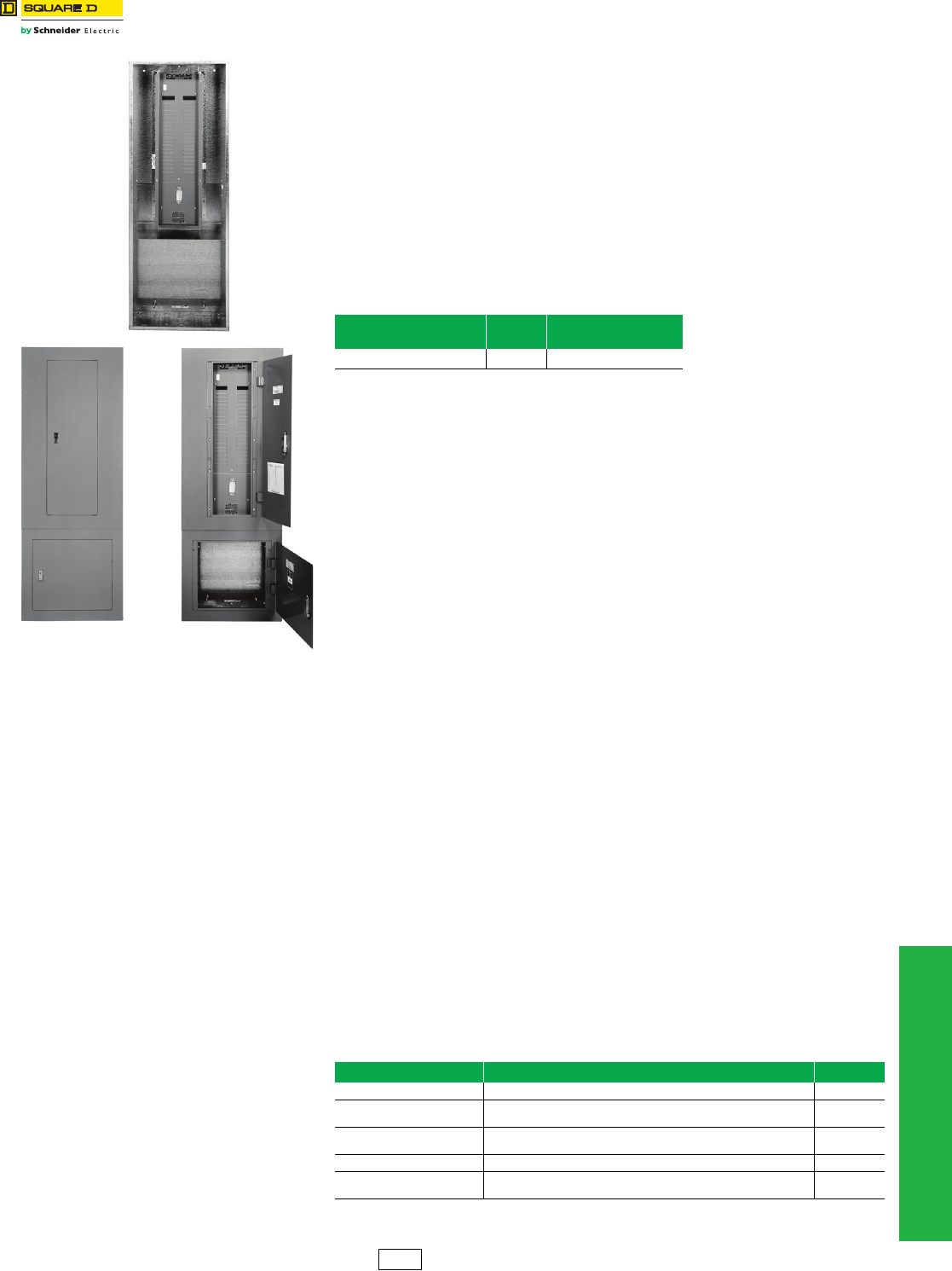
www.schneider-electric.us
© 2012 Schneider Electric
All Rights Reserved 4-3
4PANELBOARDS
Special Features Mains and Branches
Mains
Metering—Type 1 Enclosures Only (1200 A Maximum)
Enclosures and Interiors are shipped fully assembled.
NQ, NF and Powerlink™ require a 7-inch left side gutter extension and a 6-inch main end
extension for PowerLogic Power Meter applications.
7-inch side gutter extension, add . . . . . . . . . . . . . . . . . . . . . . . . . . . . $960.00
6-inch main end extension, add . . . . . . . . . . . . . . . . . . . . . . . . . . . . . . 428.00
I-Line™ and QMB require a 14-inch side gutter extension for PowerLogic Circuit Monitor
and Power Meter applications.
Current Transformers In Mains (ac only and line side only)a
Prices listed are based on transformers having a 5 A secondary and mounted under a
separate cover. Apply appropriate charge from the table below
Customer Equipment Spacea
NOTE: End user must specify end use equipment to be installed.
Available with NQ, and NF lighting panelboards only. Must be opposite the mains end, both
main breaker and main lug, to prevent interference with incoming cables. Customer
equipment space is not available with thru-feed lugs or sub-feed breakers.
18-inch space only with separate door, add. . . . . . . . . . . . . . . . . . . . . 992.00
A barrier exists between the equipment space and the panelboard compartment; a separate
door is provided as standard (requires 18-inch additional enclosure height).
NOTE: A separate door is not supplied in NEMA 3R/12 construction.
aFeature supported by product selectors in Q2C and EQM.
bFor NQ, and NF panelboards.
Branches
Keyed Interlocks
NOTE: Not available for use in NQ, NF or I-Line™ HCN panelboards with door. Not
available on I-Line™ with door when key interlocked MG/MJ/P/R frame branch-
mounted circuit breakers are installed. Must use 4-piece trim or NEMA 3R/12.
Keyed mechanical interlocking of two or more circuits is available on request. Individual
locks are furnished for each circuit. All locks operate by one key, which can be removed
only when the circuit is locked in the desired position.
I-Line Circuit Breakers—A 3-inch filler adjacent to the circuit is necessary for mounting the
interlock; contact your nearest Schneider Electric sales office for assistance with power
distribution panelboards with doors. Feature not available on vertically mounted main circuit
breaker.
To the standard panelboard pricing, per interlock, add . . . . . . . . . . $1940.00
QMB Fusible Switches—Available on 100 A singles (100 A single QMB requires 9 inches of
mounting space) through 800 A switches plus LA circuit breaker adapters. Requires
3 inches of branch mounting space per switch for interlock installation.
Per interlock, add. . . . . . . . . . . . . . . . . . . . . . . . . . . . . . . . . . . . . . . . . 1940.00
Motor Operators—I-Line Circuit Breakers Only
Motor operators provide remote open, close, and reset control of molded case circuit
breakers. Price panelboard from the latest Digest, and, for each motor operator, add per
table below. In I-Line panelboards, motor operators require 4.5 inches of circuit breaker
mounting space. This can be provided on I-Line main circuit breaker only when the main is
branch-mounted and back-fed.
NOTE: Not available in I-Line HCN Panelboards
Table 4.6: Current Transformers
Primary Amperes
(5 A—Secondary)
$ Price Per
C/T
Additional Enclosure
Height Required b
100–1200 1804.00 6 inches
Table 4.7: Motor Operators
Circuit Breaker Type Motor Operator Voltage $ Price Each
F--frame 120 Vac 1198.00
H-frame (3P modules only) 48/60, 110/130, 208/277, 380/480 Vac;
24/30, 48/60, 110/130, 250 Vdc 1198.00
J-frame 48/60, 110/130, 208/277, 380/480 Vac;
24/30, 48/60, 110/130, 250 Vdc 2975.00
LA, LH 120 Vac 3908.00
PG, PJ, PL 48, 110/130, 220/240, 380/480 Vac;
24/30, 48/60, 110/130, 200/250 Vdc 4450.00
NOTE: If the customer is not supplying the motor operator voltage, a control transformer
can be supplied (priced separately)
PE1 Discount
Schedule
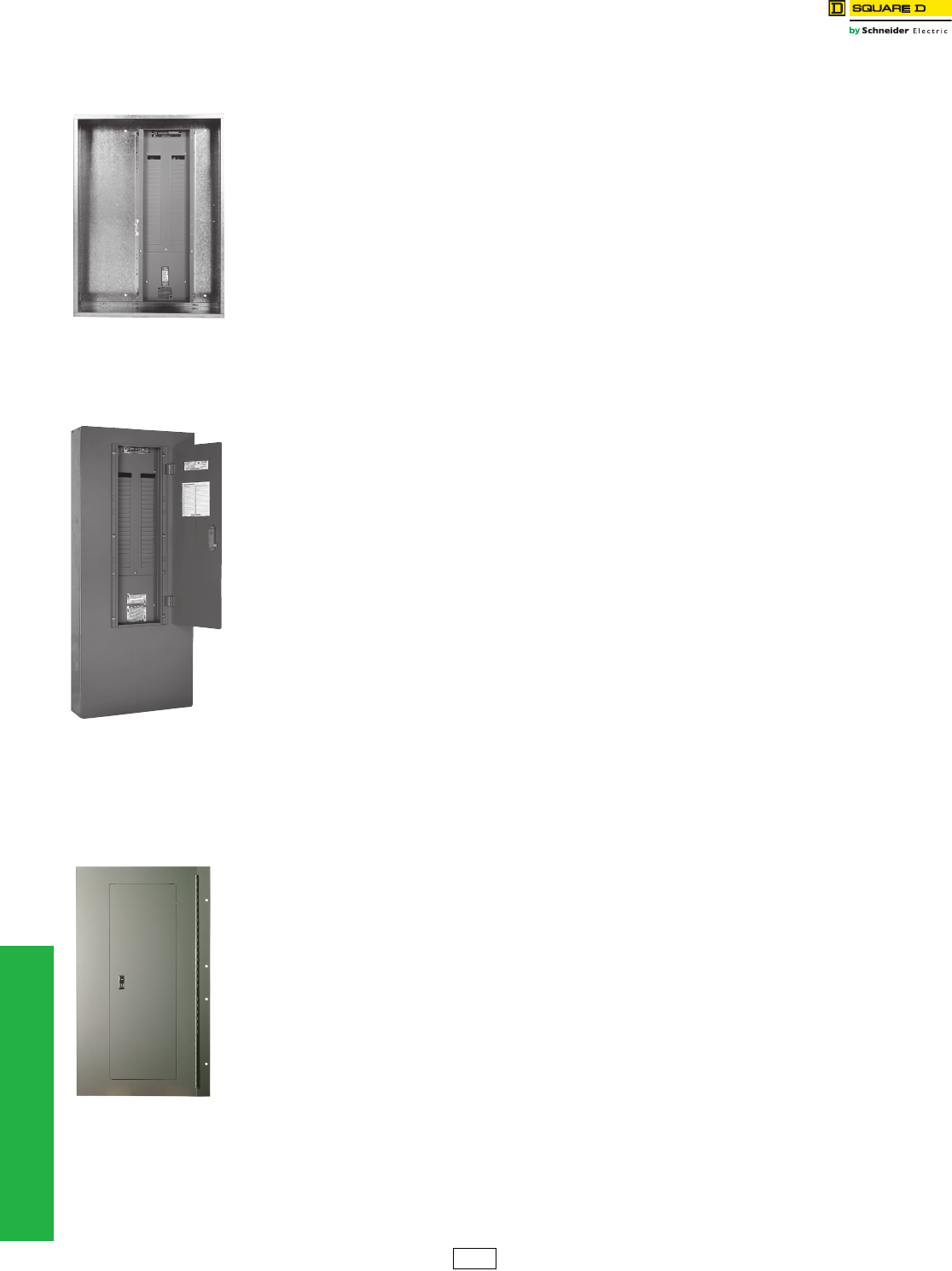
www.schneider-electric.us
4-4 © 2012 Schneider Electric
All Rights Reserved
4PANELBOARDS
Special Features Cabinets
Increased Enclosure Depth
Type 1 Enclosure a
For 8-inch depth (HC26), add . . . . . . . . . . . . . . . . . . . . . . . . . . . . . . . $640.00
For 12-inch depth (HC32, 42, 44—12-inch only), add . . . . . . . . . . . . . 640.00
Type 3R, 5, or 12 Enclosure a
For 8-inch or 12-inch depth, add . . . . . . . . . . . . . . . . . . . . . . . . . . . . . . 690.00
NOTE: No other depths are available.
Increased Side Gutters
(Type 1 Enclosures Only)
NOTE: Available on MH enclosures (right or left) in 3,
6 and 12-inch added widths, 26-inch wide HC
enclosures up to a maximum of 14 additional
inches and 32-inch wide HC enclosures up to
a maximum of 10 additional inches.
Not available on 42-inch wide HC enclosures.
No barrier will be supplied unless specified.
Includes one-piece trim.
Provide extended side gutters.
Add per panelboard . . . . . . . . . . . . . . . . . . . . . . . . . . . . . . . . . . . . . . . 1508.00
Steel Barrier in Enclosure
Add . . . . . . . . . . . . . . . . . . . . . . . . . . . . . . . . . . . . . . . . . . . . . . . . . . . . . 410.00
NOTE: The enclosure will be extended on one side
only. If extension is required on both sides,
contact your nearest Schneider Electric sales
office for assistance.
Extended Top and Bottom End Gutters
NOTE: Available for Type 1 enclosures only
Type MH Enclosures
6-inch, 12-inch, 18-inch or 24-inch extension. Includes
one-piece trim.
Add per panelboard . . . . . . . . . . . . . . . . . . . . . . . . . . . . . . . . . . . . . . . 1214.00
Type HCN, HCM Enclosures
9-inch extension. Includes standard panel trim and
enclosure extension cover.
Add per panelboard . . . . . . . . . . . . . . . . . . . . . . . . . . . . . . . . . . . . . . . 1214.00
Type HCP, HCR-U Enclosures
12-inch extension. Includes standard panel trim and
enclosure extension cover.
Add per panelboard . . . . . . . . . . . . . . . . . . . . . . . . . . . . . . . . . . . . . . . 1214.00
Type QMB Enclosures
38-inch W x 11.5-inch D may have a 6-inch maximum
increased end gutter. This is the only QMB enclosure with
an increased end gutter option. Available only with a
four-piece trim.
Add per panelboard . . . . . . . . . . . . . . . . . . . . . . . . . . . . . . . . . . . . . . . 1214.00
For lengths other than those listed above, refer to the
Wireway section on page 4-8.
Drip Hoods a
For each surface-mounted-only panelboard, add . . . . . . . . . . . . . . . .$294.00
Special Finishes
NOTE: The standard finish of the enclosure fronts is
ANSI 49. The enclosures are galvanized steel.
ANSI 49 Enclosure a
Add . . . . . . . . . . . . . . . . . . . . . . . . . . . . . . . . . . . . . . . . . . . . . . . . . . . . . 584.00
ANSI 61 Front or Enclosure a
Add . . . . . . . . . . . . . . . . . . . . . . . . . . . . . . . . . . . . . . . . . . . . . . . . . . . . . 700.00
Front and Enclosure with Polyester Acrylic
Powder Paint Finish
Provides increased salt spray performance in coastal
areas and increased resistance to UV fading.
Add . . . . . . . . . . . . . . . . . . . . . . . . . . . . . . . . . . . . . . . . . . . . . . . . . . . . 1350.00
Special or Custom Paint for Trim and/or
Enclosure
Add . . . . . . . . . . . . . . . . . . . . . . . . . . . . . . . . . . . . . . . . . . . . . . . . . . . . 4400.00
Free-standing Enclosures (welded base
channels) c
Supports extending out front and back, welded to bottom
of enclosure
Add . . . . . . . . . . . . . . . . . . . . . . . . . . . . . . . . . . . . . . . . . . . . . . . . . . . . . 876.00
Special Trims
Hinged Trim a
Add . . . . . . . . . . . . . . . . . . . . . . . . . . . . . . . . . . . . . . . . . . . . . . . . . . . . . 646.00
Hinged Trim with Outer Door Lock
Add . . . . . . . . . . . . . . . . . . . . . . . . . . . . . . . . . . . . . . . . . . . . . . . . . . 846.00 b
NOTE: Outer door lock, must be priced with hinged
trim.
For door-in-door trim, use hinged trim with
outer door lock.
Stainless Steel Trim Fronts a
NQ 20-inch-wide flush and surface, add . . . . . . . . . . . . . . . . . . . . . . .4200.00
NF flush and surface, add . . . . . . . . . . . . . . . . . . . . . . . . . . . . . . . . . . 4200.00
I-Line™ HCN—Standard trim with door, add . . . . . . . . . . . . . . . . . . 14800.00
I-Line HCM—Standard trim with door, add . . . . . . . . . . . . . . . . . . . . 14800.00
I-Line HCP—Standard trim with door, add . . . . . . . . . . . . . . . . . . . . 15400.00
aFeature supported by Product Selectors in Q2C and EQM.
b$846.00 price includes a hinged trim with an integrated outer door lock.
cNot available on NEMA 3R/12 I-Line™ and QMB.
MH38 Enclosure
with 6-inch Increased
Left-side Gutter
MH38 Enclosure with
12-inch Extended
Bottom End Gutter
and One-Piece Trim
Hinged Trim
PE1 Discount
Schedule
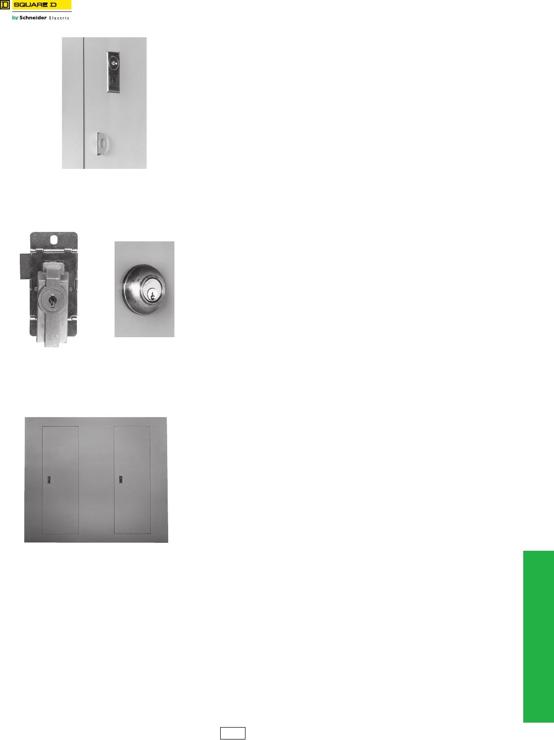
www.schneider-electric.us
© 2012 Schneider Electric
All Rights Reserved 4-5
4PANELBOARDS
Special Features Cabinets
Padlock Hasp
For hasp, staple and standard lock (padlock not included)
Add . . . . . . . . . . . . . . . . . . . . . . . . . . . . . . . . . . . . . . . . . . . . . . . . . . . $600.00
Special Locks
On trim with a 3-point latch, special locks will be installed as a secondary latch. Special
locks include Corbin 60, Corbin 15767, GE 75, Yale® 511S and Best 5L7RL2-626. For all
other locks, contact your nearest Schneider Electric sales office for assistance.
Standard key change, Corbin 60, Corbin 15767 or GE 75, adda. . . . 704.00
Standard key change, Yale 511S, adda . . . . . . . . . . . . . . . . . . . . . . 1700.00
Standard key change, Best 5L7RL2-626, adda . . . . . . . . . . . . . . . . 1500.00
Quarter turn fasteners
Add . . . . . . . . . . . . . . . . . . . . . . . . . . . . . . . . . . . . . . . . . . . . . . . . . . . . 584.00
NOTE: Special locks for all HC trims and NF panelboards with three-point latches, will
be installed as secondary locks. Special locks are not available on I-Line™
42-inch and 44-inch wide panelboards or QMB type panelboards.
NOTE: Many key configurations can be accommodated with our standard Square D™
brand lock. Contact your nearest Schneider Electric sales office for assistance.
aFeature supported by Product Selectors in Q2C and EQM.
Multi-Section Panels
Equal-Height Enclosuresa
NQ, and NF, add per panel . . . . . . . . . . . . . . . . . . . . . . . . . . . . . . . . 1688.00
I-Line or QMB, add per panel . . . . . . . . . . . . . . . . . . . . . . . . . . . . . . 2198.00
Common Trim in Place of Two Individual Fronts a
Used to cover two equal-height enclosures mounted side-by-side.
Add . . . . . . . . . . . . . . . . . . . . . . . . . . . . . . . . . . . . . . . . . . . . . . . . . . . 2334.00
Sheared on Inside Edges
Allows enclosures to be butted together.
Add per panel . . . . . . . . . . . . . . . . . . . . . . . . . . . . . . . . . . . . . . . . . . . 1644.00
aFeature supported by Product Selectors in Q2C and EQM.
NC38S with
Padlock Hasp
NC38S with
Yale Lock Installed
Corbin 15767 Lock
Common Trim Front for Use with Multiple-Section
Panelboards Mounted Side-By-Side
PE1 Discount
Schedule
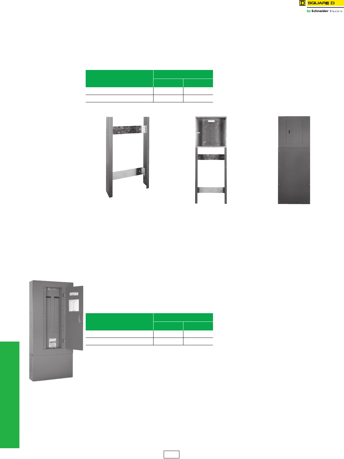
4-6 © 2012 Schneider Electric
All Rights Reserved
www.schneider-electric.us
4PANELBOARDS
Special Features Cabinets
Panel Skirt for Standard Width Panelboards a
Panel skirts are intended for cosmetic purposes only; they are meant to hide cables which are enclosed in conduit.
Do not use a panel skirt as a wireway; see the Wireway section below.
NOTE: Panel skirts are for Type 1 surface-mounted applications with standard depth and width,
Square D™ brand enclosures only.
aFeature supported by Product Selectors in Q2C and EQM.
Wireway a
Allows for terminating conduit in the wireway endwall. Only the cable passes through the wireway into the panelboard
enclosure. Includes trim and wireway cover.
NOTE: Wireway is for Type 1, surface-mounted applications with standard depth
and width, Square D™ brand enclosures only.
aFeature supported by Product Selectors in Q2C and EQM.
Table 4.8: Panel Skirts
Skirt Length
$ Price
NQ, NF I-Line™, QMB
4–60 inches 912.00 1298.00
61–92 inches 1142.00 1908.00
Table 4.9: Wireway
Wireway Length
$ Price
NQ, NF I-Line™, QMB
4–60 inches 1014.00 1482.00
61–92 inches 1264.00 2160.00
Panel skirt framework
to be bolted to the wall. Panel skirt bolted
in place below
an MH26 enclosure.
Panel skirt
completely
installed.
MH38 enclosure with
12-inch wireway and
Mono-Flat™ trim with
12-inch wireway cover.
PE1 Discount
Schedule
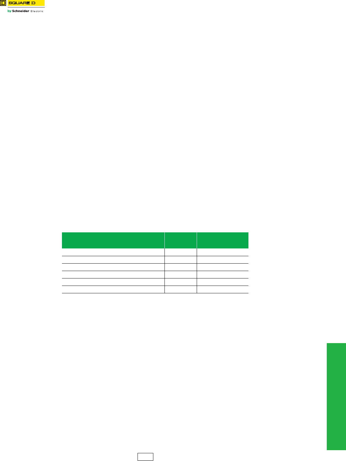
www.schneider-electric.us
4PANELBOARDS
© 2012 Schneider Electric
All Rights Reserved 4-7
Special Features Cabinets
Panels to Fit Existing Enclosures
Panelboard interiors and special fronts can be furnished to fit existing enclosures. First, price the complete panel along
with the appropriate price adder from below. Next, photocopy the Retrofit Existing Enclosure data sheet found on
page 4-14, record the required dimensions on the photocopy and forward it with your order to the nearest Schneider
Electric sales office. For interiors requiring vented enclosures, contact your nearest Schneider Electric sales office for
assistance.
NOTE: Existing enclosure depth on flush installations must be measured from inside surface of enclosure to outer
wall or plaster surface.
Special Fronts
Existing enclosure the same depth as or deeper than our standard.
Add. . . . . . . . . . . . . . . . . . . . . . . . . . . . . . . . . . . . . . . . . . . . . . . . . . . $1040.00
NOTE: Elevating brackets to be supplied by customer for existing enclosures deeper than our standard.
Existing enclosure shallower than our standard. Requires an enclosure extension (surface applications) or
a formed front (flush applications). A hinged trim front option is not available for these applications.
Add. . . . . . . . . . . . . . . . . . . . . . . . . . . . . . . . . . . . . . . . . . . . . . . . . . . . 2080.00
NOTE: A formed front is available on NQ (225 A max.) and, NF (250 A max.). When a flush front is required for an
existing enclosure that is shallower than our standard, be sure to indicate the position of the enclosure with
respect to the wall in which it is mounted. This is required in order to determine whether an enclosure
extension with a flat front should be supplied, or whether a flush formed front is more applicable. The
interior must be centered in the enclosure and, if the enclosure is deeper than our standard, the interior
must be leveled within the enclosure. The existing enclosure for NQ and, NF panels cannot be more than
3.0 inches shorter than the standard enclosure. Minimum width is 17 inches. Special trims that are
manufactured to fit an existing enclosure will be within ± 0.25 inches of the specification. Refer to the table
below for standard enclosure depths and for the maximum depth for which no special mounting brackets
are required.
Space Heater
NOTE: Enclosure, interior and trim ship fully assembled. 120 V is standard. Top feed applications only.
NQ and NF require 18 inches equipment space in NEMA 3R/12 constructions.
NQ and NF require 6 inch bottom end gutter in NEMA 1 construction.
Unwired (provisions for wiring to external source), add . . . . . . . . . . . . 800.00
Wired (with overcurrent device, thermostat), add. . . . . . . . . . . . . . . . 1570.00
Table 4.10: Panelboard Enclosure Depths
Panelboard Type Standard
Enclosure Depth
Maximum Enclosure Depth
for which No Special
Mounting Brackets Required
NQ standard width—main lugs only 5.75 inches 5.75 inches
NQ standard width—main circuit breaker 5.75 inches 5.75 inches
NF 5.75 inches 5.75 inches
I-Line™—Maximum F, H or Q-frame branch circuit breaker 6.5 inches 7.25 inches
I-Line—Maximum J-frame branch circuit breaker 8.25 inches 9.0 inches
I-Line—Maximum P or R-frame branch circuit breaker 9.25 inches 10.25 inches
PE1 Discount
Schedule
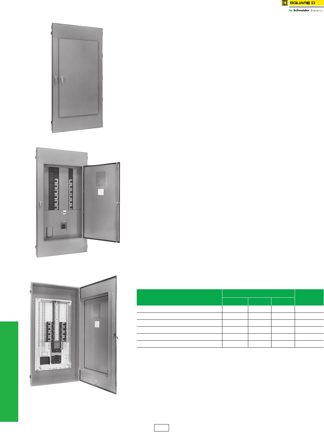
www.schneider-electric.us
4-8 © 2012 Schneider Electric
All Rights Reserved
4PANELBOARDS
Special Features Cabinets
Special Enclosures a
Type 1 Gasketed Enclosure (gasketing between front and enclosure)
20-inch maximum panel width. . . . . . . . . . . . . . . . . . . . . . . . . . . . . . . $494.00
Over 20-inch panel width . . . . . . . . . . . . . . . . . . . . . . . . . . . . . . . . . . . . 716.00
NOTE: For 250 A and below enclosures only.
aFeature supported by Product Selectors in Q2C and EQM.
Stainless Steel Enclosure (Type 3R, 4, 4X, 5 and 12; UL Listed)
NOTE: For #316 stainless steel, add 15% to the prices shown below.
NQ, and NF
For panelboard heights up to 41inches, add. . . . . . . . . . . . . . . . . . . 13564.00
For panelboard heights of 44–56 inches, add. . . . . . . . . . . . . . . . . . 17564.00
For panelboard heights of 59–80 inches, add. . . . . . . . . . . . . . . . . . 21076.00
I-Line™
HCN and HCM, add. . . . . . . . . . . . . . . . . . . . . . . . . . . . . . . . . . . . . . 36190.00
HCP, add . . . . . . . . . . . . . . . . . . . . . . . . . . . . . . . . . . . . . . . . . . . . . . 42482.00
NOTE: 304 stainless, standard
QMB b
Add . . . . . . . . . . . . . . . . . . . . . . . . . . . . . . . . . . . . . . . . . . . . . . . . . . . 47978.00
bNot available for QMB interiors over 800 A.
Fiberglass Enclosures (Type 4X, Non-Vented; UL Listed)
NQ, and NF
28-inch height, add . . . . . . . . . . . . . . . . . . . . . . . . . . . . . . . . . . . . . . . 6780.00
33-inch, 40-inch and 50-inch height, add . . . . . . . . . . . . . . . . . . . . . 11482.00
I-Line and QMB
Add . . . . . . . . . . . . . . . . . . . . . . . . . . . . . . . . . . . . . . . . . . . . . . . Not Available
Type 12 Door-In-Door Enclosures
Table 4.11: Available Enclosures
Interior Type
Enclosure Size $ Price
Adder
Height Width Depth
NQ a56 inches 20 inches 6.5 inches 3826.00
NF b56 inches 20 inches 6.5 inches 3826.00
I-Line (HCN) 92 inches 26 inches 9.5 inches 7278.00
I-Line (HCM) 91 inches 32 inches 11.5 inches 7854.00
I-Line (HCP) 68 inches 42 inches 12.7 inches 9788.00
I-Line (HCP) 86 inches 42 inches 12.7 inches 9788.00
aNot available for NQ interiors over 225 A.
bNot available for NF interiors over 250 A.
I-Line Door-in-Door Enclosure
Access to Circuit Breaker Handles
Access to Wiring Gutters
PE1 Discount
Schedule
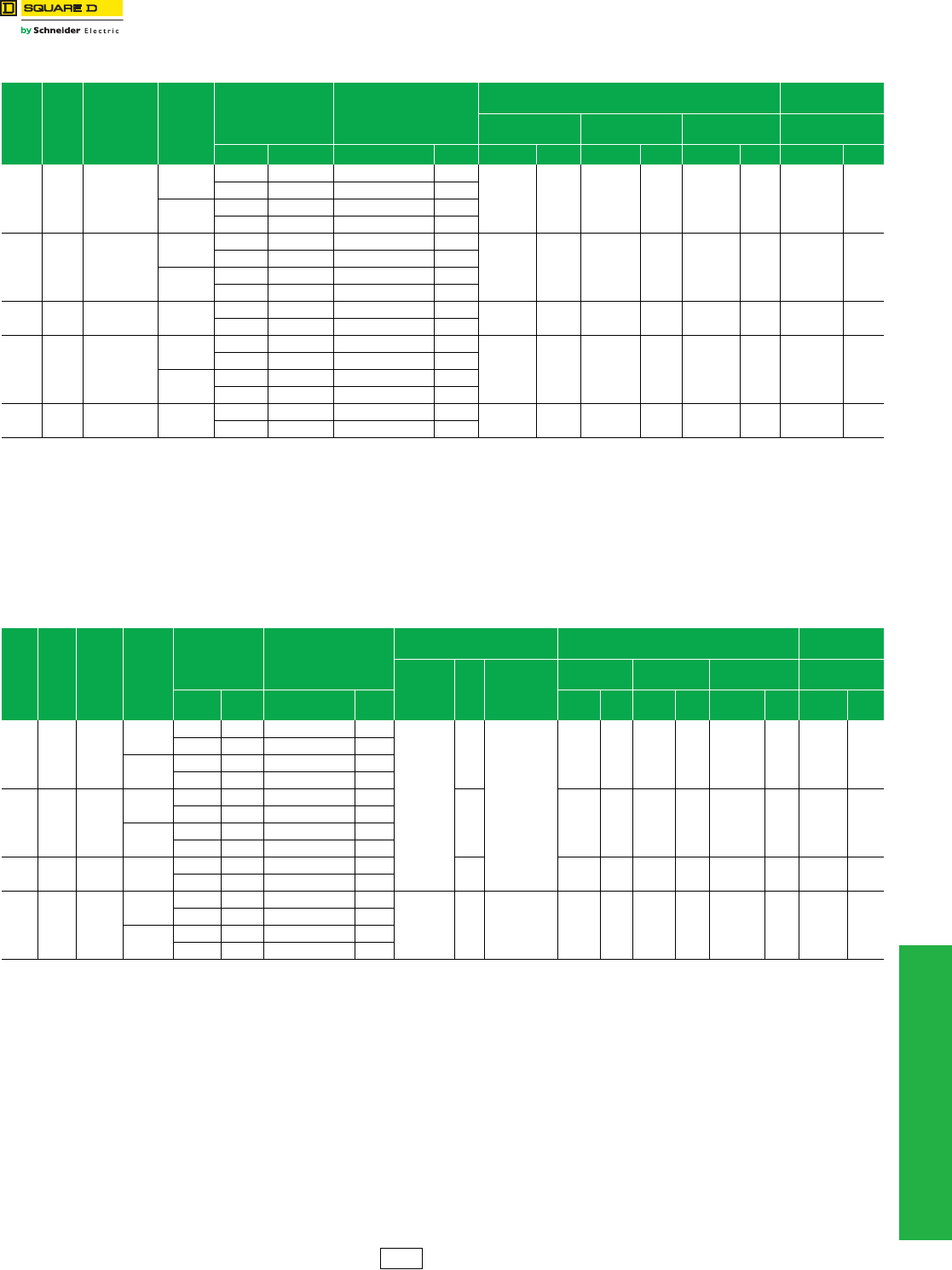
www.schneider-electric.us
© 2012 Schneider Electric
All Rights Reserved 4-9
4PANELBOARDS
NQ Merchandised
Panelboards
NQ Main Lug and Main Circuit Breaker Interiors with SPD—240 Vac, 48 Vdc
Class 1640 / Refer to Catalog 1640CT0801
Table 4.12: Main Lug Interiors with SPD
Mains
Rating
Pole
Spaces Voltage Surge
Rating
Total Price Interior, Front,
Box and Adapter Kit
Interior Only (Order Branch
Circuit Breakers Separately)
Type 1 Enclosure Type 3R/5/12
Enclosure e
Box
20 in. W x 5.75 in. D bMono-Flat™ Front Hinged Fronts 20 in. W x 6.5 in. D
Type 1 Type 3R, 5, 12 Catalog Number a$ Price Cat. No. $ Price Cat. No. c$ Price Cat. No. $ Price Cat. No. $ Price
225 A 30 208Y/120 Vac
120,000 A 19269. 20686. NQ430L2TVS212 18594.
MH50 113. NC50( ) 729. NC50( )HR 912. MH50WP 2609.
19331. 20748. NQ430L2TVS212C 18655.
160,000 A 20909. 22222. NQ430L2TVS216 20283.
20966. 22278. NQ430L2TVS216C 20340.
225 A 42 208Y/120 Vac
120,000 A 19524. 20930. NQ442L2TVS212 18803.
MH56 113. NC56( ) 786. NC56( )HR 983. MH56WP 2652.
19584. 20990. NQ442L2TVS212C 18863.
160,000 A 21145. 22448. NQ442L2TVS216 20477.
21201. 22503. NQ442L2TVS216C 20533.
225 A 72d208Y/120 Vac 120,000 A 20451. 21802. NQ472L2TVS212 19649. MH62 113. NC62( ) 887. NC62( )HR 1109. MH62WP 2685.
20554. 21906. NQ472L2TVS212C 19752.
400 A 42 208Y/120 Vac
120,000 A 20084. 21432. NQ442L4TVS212 19233.
MH68 113. NC68V( ) 948. NC68V( )HR 1185. MH68WP 2742.
20181. 21529. NQ442L4TVS212C 19330.
160,000 A 21663. 22912. NQ442L4TVS216 20875.
21754. 23003. NQ442L4TVS216C 20965.
400 A 72d208Y/120 Vac 120,000 A 21279. 22659. NQ472L4TVS212 20385. MH80 113. NC80V( ) 1001. NC80V( )HR 1245. MH80WP 2835.
21445. 22826. NQ472L4TVS212C 20552.
a“C’’ suffix indicates copper bussing.
bEmbossed mounting holes add a .25 inch standoff to back of MH box.
cAdd “F’’ for flush, “S’’ for surface.
dUse only if the Local Jurisdiction where this panelboard interior is being applied has adopted the 2008 NEC, which allows single panelboard interiors greater than 42 circuits.
eEnclosure includes trim kit.
Table 4.13: Main Circuit Breaker Interiors with SPD
Mains
Rating
Pole
Spaces Voltage Surge
Rating
Total Price Interior,
Front, Box and
Adapter Kit a
Interior Only (Order Main
Circuit Breaker, Kit and
Branches Separately)
Main Circuit Breaker Adapter Kit Type 1 Enclosure Type 3R/5/12
Enclosure e
Kit Catalog
No. a
$
Price
Main Circuit
Breaker Frame
Box 20 in. W x
5.75 in. D c
Mono-Flat™
Front dHinged Fronts 20 in. W x
6.5 in.D
Type 1 Type
3R, 5, 12 Catalog Number b$ Price Cat. No. $Price Cat. No. $Price Cat. No. $Price Cat. No. $Price
225 A 30 208Y/120
Vac
120,000 A 18548. 19800. NQ430L2TVS212 17226.
NQMB2HJ
or
NQMB2Q
or
NQMB2KI
780.
HD/HG/HJ/HL
QB/QD/QG/QJ
KI
MH62 113. NC62( ) 887. NC62( )HR 1109. MH62WP 2685.
18605. 19857. NQ430L2TVS212C 17283.
160,000 A 23321. 24668. NQ430L2TVS216 21894.
23382. 24734. NQ430L2TVS216C 21955.
225 A 42 208Y/120
Vac
120,000 A 18787. 20036. NQ442L2TVS212 17420.
780. MH68 113. NC68( ) 948. NC68( )HR 1185. MH68WP 2742.
18843. 20092. NQ442L2TVS212C 17475.
160,000 A 23580. 24928. NQ442L2TVS216 22103.
23640. 24988. NQ442L2TVS216C 22163.
225 A 72f208Y/120
Vac 120,000 A 19589. 20831. NQ472L2TVS212 18204. 780. MH74 113. NC74( ) 972. NC74( )HR 1215. MH74WP 2757.
19685. 20927. NQ472L2TVS212C 18299.
400 A 42 208Y/120
Vac
120,000 A 19225. 20504. NQ442L4TVS212 17818.
NQMB4LA 780. LA/LH
(LC is F/A only) MH80 113. NC80V( ) 1001. NC80V( )HR 1245. MH80WP 2835.
19315. 20594. NQ442L4TVS212C 17908.
160,000 A 24051. 25431. NQ442L4TVS216 22532.
24149. 25529. NQ442L4TVS216C 22630.
aSelect the appropriate main circuit breaker from tables starting on page 7-22 and add the circuit breaker price to the total price of the panelboard.
b“C’’ suffix indicates copper bussing.
cEmbossed mounting holes add a .25 inch standoff to back of MH box.
dAdd “F’’ for flush, “S’’ for surface.
eEnclosure includes trim kit.
fUse only if the Local Jurisdiction where this panelboard interior is being applied has adopted the 2008 NEC, which allows single panelboard interiors greater than 42 circuits.
PE1A Discount
Schedule
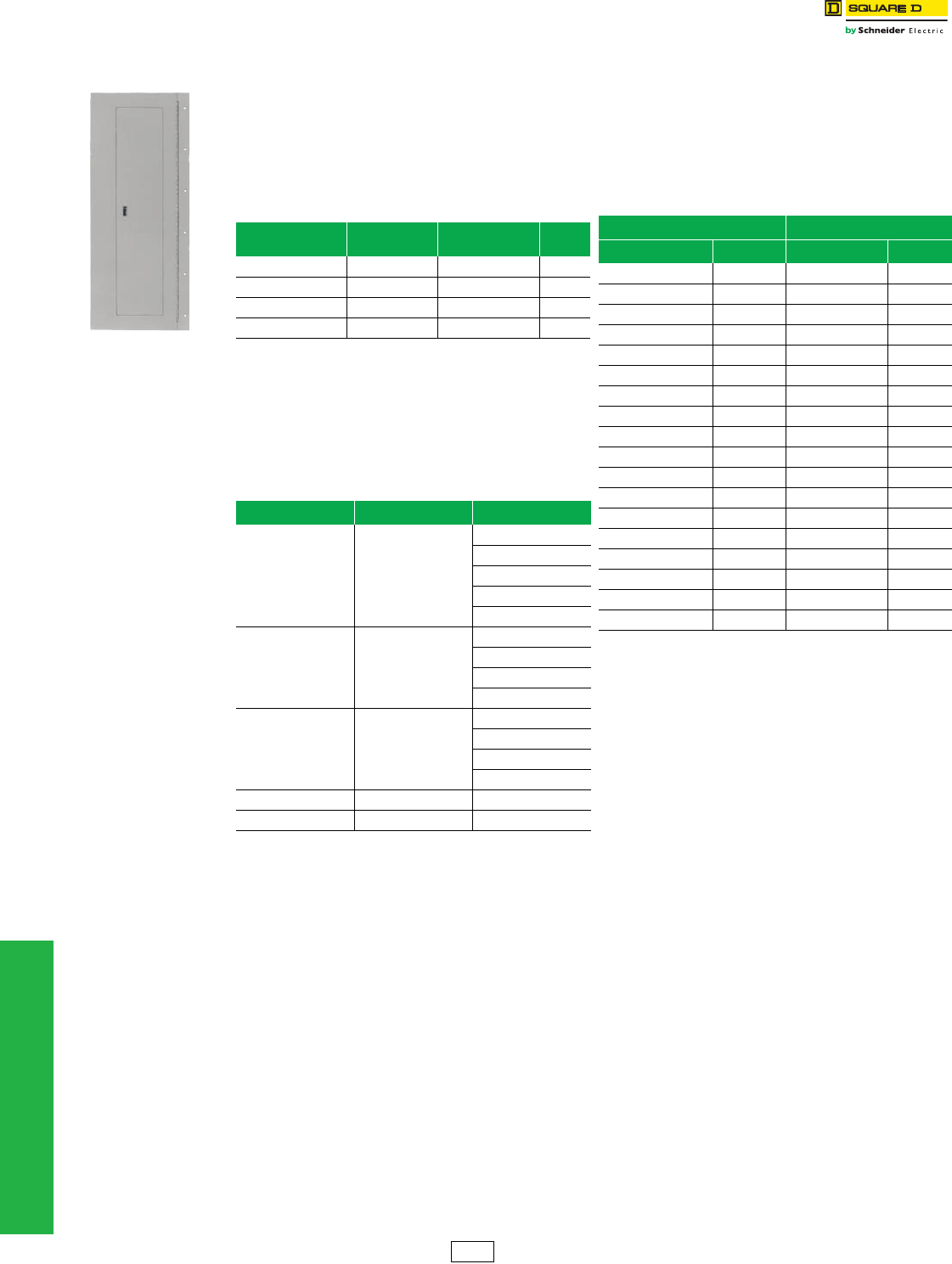
www.schneider-electric.us
4-10 © 2012 Schneider Electric
All Rights Reserved
4PANELBOARDS
Ready-to-Install (RTI)
Merchandise
Miscellaneous Panelboard Accessories
Class 1630, 1640, 1660, 2110, 2120
Copper Equipment Ground Bars
Copper equivalents of our aluminum PK–GTA equipment
ground bars are available. These copper ground bars
accept #14–4 Cu only.
Field Installable I-Line™ Door Kits
Type 1 Door-in-Door (Hinged) Trim Fronts
Features
•Meets door-in-door specifications
•Provides continuous piano hinge
•Permits one-person maintenance
Table 4.14: Copper Ground Bars for NQOD and NF
Panelboards (see the Digest, Section 9
for NQ copper ground bar kits)
Maximum Number
of Circuits
Maximum
Ampere Rating Catalog No. $ Price
12 225 8010302651 35.00
18 225 8010302652 41.00
23 225 8010302653 57.00
27 400/600 PK27GTACU 75.00
Table 4.15: I-Line Door Kits
Panel Type Catalog No. a$ Price
HCN
HCN52D( ) 77.00
HCN65D ( ) 90.00
HCN74D ( ) 122.00
HCN83D ( ) 137.00
HCN92D ( ) 155.00
HCM
HCM48D ( ) 227.00
HCM64D ( ) 254.00
HCM73D ( ) 333.00
HCM91D ( ) 390.00
HCP
HCW50D 323.00
HCW59D 351.00
HCW68D 422.00
HCW86D 467.00
HCRU HCW86D 467.00
HCN/HCM Latch Bracket 80104-908-50 —
aAdd “S” for surface or “F” for flush in place of the parentheses.
NOTE: HCRU door covers circuit breakers only, not entire box
Table 4.16: Hinged Trim
I-Line Fronts NQ and NF Fronts
Catalog No. a$ Price Catalog No. ab $ Price
HC2652T( )HR 720.00 NC26( )HR 620.00
HC2665T( )HR 926.00 NC32( )HR 657.00
HC2674T( )HR 1254.00 NC38( )HR 687.00
HC2683T( )HR 1557.00 NC44( )HR 830.00
HC2692T( )HR 1751.00 NC50( )HR 912.00
HC3248T( )HR 846.00 NC56( )HR 983.00
HC3264T( )HR 1109.00 NC62( )HR 1109.00
HC3273T( )HR 1514.00 NC68( )HR 1185.00
HC3291T( )HR 2129.00 NC74( )HR 1215.00
HC4250T( )HR 1298.00 NC80( )HR 1245.00
HC4259T( )HR 1448.00 NC86( )HR 1430.00
HC4268T( )HR 1841.00 NC50V( )HR 912.00
HC4286T( )HR 2351.00 NC56V( )HR 983.00
HC4486T( )HR 2351.00 NC62V( )HR 1109.00
——NC68V( )HR 1185.00
——NC74V( )HR 1215.00
——NC80V( )HR 1245.00
——NC86V( )HR 1430.00
aAdd “S” for surface or “F” for flush in place of the parentheses.
bFor welded metal directory, add “WMD” suffix to the end of the catalog
number and add $75.00 to the price.
Catalog No.
NC44SHR
PE1A Discount
Schedule
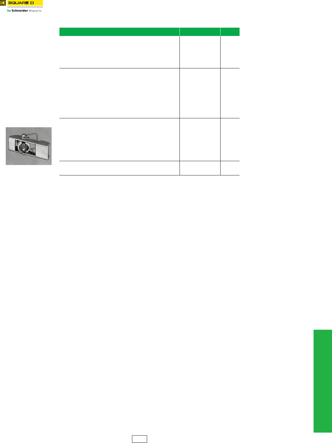
www.schneider-electric.us
4PANELBOARDS
© 2012 Schneider Electric
All Rights Reserved 4-11
Replacement Parts for
Standard Panelboards
Trim Clamps and Screws
Class 1600
Table 4.17: Trim Clamps and Screws
Application Catalog No. $ Price
NQOD Panelboards:
Series E1 a 400 A and 600 A fronts
NEHB Panelboards:
Series E1 a 600 A fronts
I-Line Panelboards:
All Series E1 a fronts
LP9501 36.00
NQOD Panelboards:
All Series E1 a vented fronts and hinged fronts manufactured after July 1994.
NF Panelboards:
All vented fronts and hinged fronts.
NEHB Panelboards:
All Series E1 a hinged fronts manufactured after
July 1994.
I-Line and QMB Panelboards:
I-Line front with door manufactured after July 1994 but before August 1997; and
I-Line hinged fronts and QMB front with door manufactured after July 1994.
LP9502
(includes 8 trim screws
and captive hardware)
15.00
NQ and NQOD Panelboards:
Screws for all fronts through 225 A.
NF Panelboards:
Screws for all fronts through 250 A.
I-Line Panelboards:
4-piece trim and trim with door manufactured after July 1997.
QMB Panelboards:
Screws for 4-piece covers.
4020513001K
(package of 10) 3.80
I-Line Panelboards:
Panelboard deadfront screws for 4-piece trim manufactured after July 1994 but
before August 1997.
8002506701 0.72
aPanelboards that meet 1984 NEC® Wire Bending Space are Series E1.
Catalog No.
LP9501
PE1A Discount
Schedule
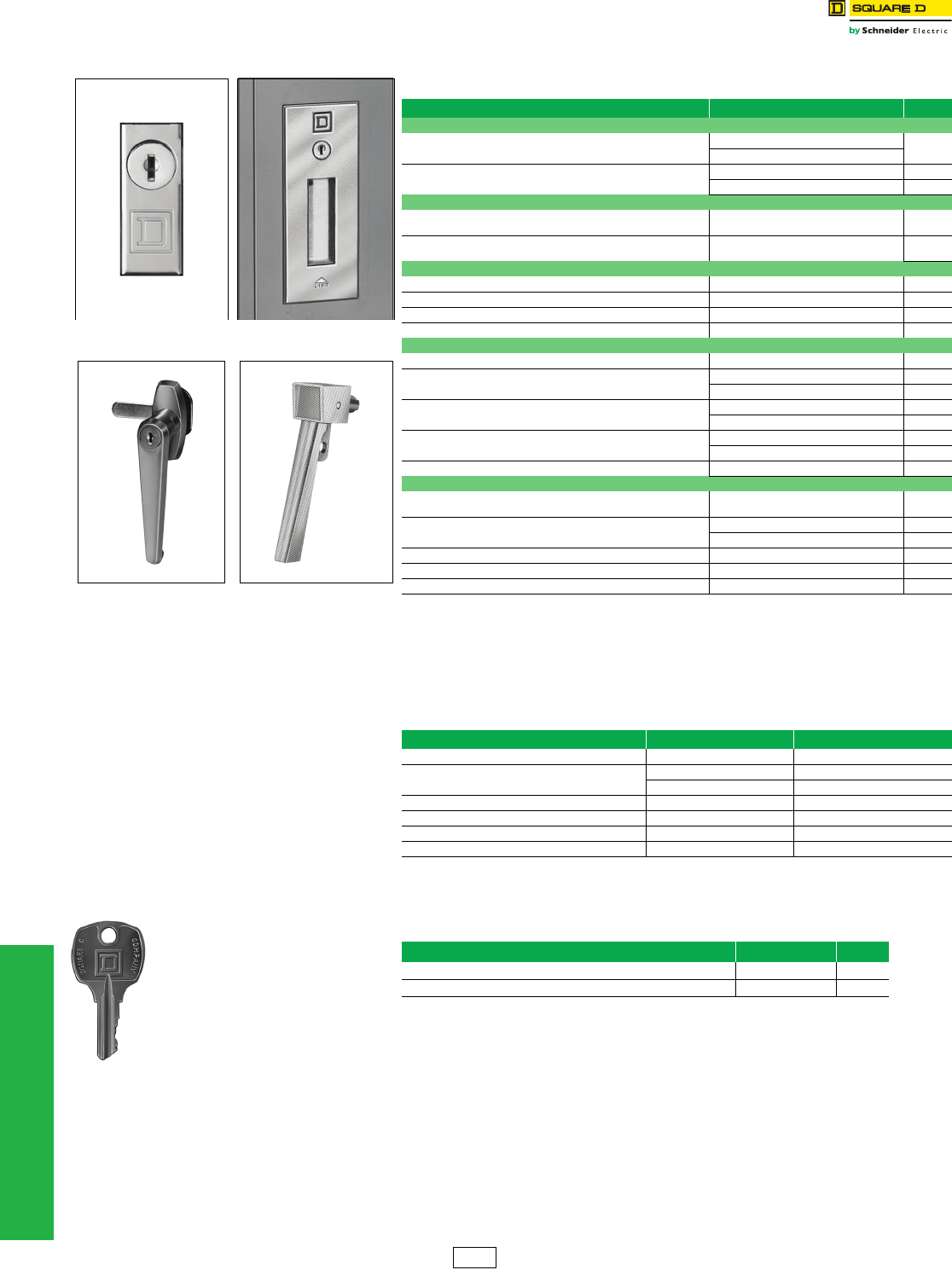
www.schneider-electric.us
4-12 © 2012 Schneider Electric
All Rights Reserved
4PANELBOARDS
Replacement Parts for
Standard Panelboards
Locks and Keys
Class 1600
Locks a
Keys
Table 4.18: Locks—Type 1 Enclosures
Application Catalog No. $ Price
NQOD, NQO, and NQOB Panelboards
All fronts on enclosures up to and including 50-inch high and 53-inch
through 68-inch high vented trims
PK4FL (Before 01/06/97) 90.00
PK22FL (After 01/06/97 NQ or NQOD only)
All fronts on enclosures 56 inches high or higher, excluding 53-inch
through 68-inch high vented fronts
PK5FL (Before 11/01/99) 165.00
PK22FL (After 11/01/99 NQOD only) 90.00
NQ and NF Panelboards
All frontsc d with the exception of those for use on panels
using LC or LI main circuit breakers PK22FL 90.00
Fronts on enclosures 68 inches high or higher for panels using LC or LI
main circuit breakers PK5FL 165.00
I-Line Panelboards
HCN: Series 1 and 2 fronts on enclosures up to 54 inches high PK4FL 90.00
HCN: Series 1 and 2 fronts on enclosures 63 inches high or higher PK5FL 165.00
HCM: Series 1 and 2 fronts on 38-inch high enclosures PK4FL 90.00
HCM: Series 1 and 2 fronts on enclosures 47 inches high or higher PK5FL 165.00
I-Line Panelboards
HCW, HCWM: Series 1 and 2 fronts PK5FL 165.00
HCN: Series E1afronts on enclosures up to and including 74-inches
high
PK4FL (Before 11/14/97) 90.00
PK22FL (After 11/14/97) 90.00
HCN: Series E1a fronts on enclosures 83 inches high or higher PK5FL (Before 04/05/02) 165.00
PK22FL (After 04/05/02) b90.00
HCM: Series E1a fronts on enclosures 64 inches high or higher PK5FL (Before 11/14/97) 165.00
PK22FL (After 11/14/97) b90.00
HCW, HCWM, HCWM-U, HCR-U: Series E1aFront PK5FL 165.00
I-Line Panelboards (4-piece trim with door kit)
HCN: Series E1a fronts on enclosures up to and including 74 inches
high PK22FL 90.00
HCN: Series E1a fronts on enclosures 83 inches high or higher PK5FL (Before 02/22/02) 90.00
PK22FL (After 02/22/02) b90.00
HCM: Series E1a fronts on enclosures 73 inches high or higher PK22FL 90.00
HCP, HCR-U: Series E1a Front PK5FL 165.00
HCP-SU: Series E1a Front and HCP-SU Hinged Front PK22FL b90.00
aPanelboards that meet 1984 NEC® Wire Bending Space are Series E1.
bFronts require two locks.
cFronts 56 inches or higher on 250 A maximum interior require two locks.
dFront 74 inches or higher on 600 A maximum interior require two locks.
eOne NSR-251 key is included with each lock.
Table 4.19: Locks—Type 3R/12 Enclosures
Application Catalog No. $ Price
NQOD, NQO, NQOB, NF all enclosures Series E1 PK4NVL 167.00
NQ, NQOD, NF Series E2 8011604350 (one handle) 90.00
8011604351 (two handles) 159.00
I-Line and QMB Series E1 PK4NVL 167.00
I-Line and QMB Series E2 8012106350 75.00
I-Line—Handle for padlocking Series 1 and 2 3000711851 Order from the Raleigh, NC plant.
Stainless steel enclosures HSEM-3PLH 952.00
Catalog No. PK4FL and
PD22FL
Catalog No. PK5FL
Catalog No. PK4NVL Catalog No. 30007 11851
Catalog No.
LP9618
Table 4.20: Replacement Keys
Application Catalog No. $ Price
For use on all locks except those on stainless steel enclosures LP9618 28.80
Locks on stainless steel enclosures 80106-456-01 22.50
PE1A Discount
Schedule
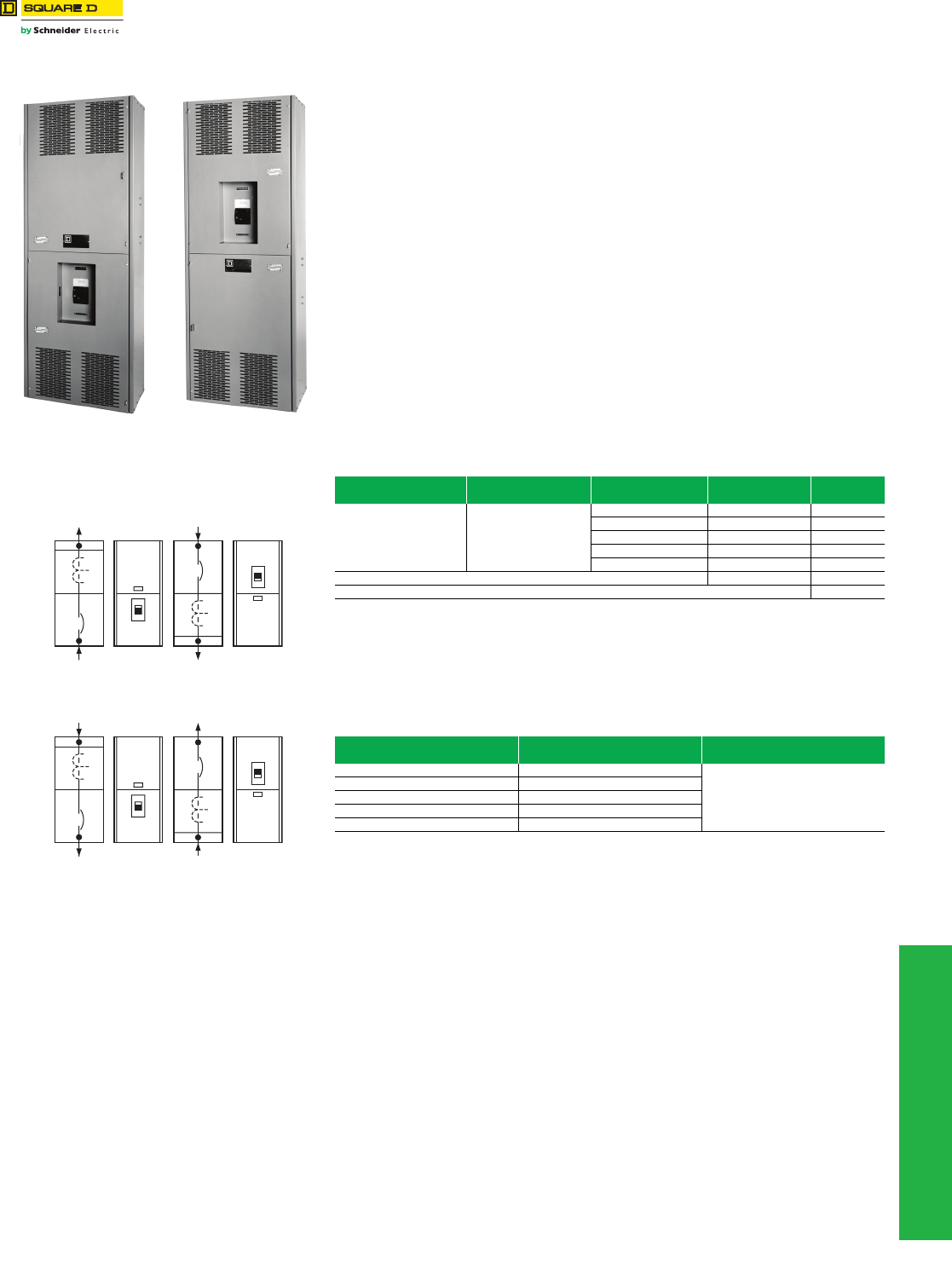
www.schneider-electric.us
© 2012 Schneider Electric
All Rights Reserved 4-13
4PANELBOARDS
CTC Cabinets Wall Mounted Metering Equipment
Class 2730 / Refer to Handout 2730HO9401
Main Circuit Breaker and Current Transformer Compartment
Service Entrance Equipment Hot or Cold Sequence Metering, Top or Bottom Feed,
Indoor Construction at 600 Volts
General: Suitable for use as service entrance equipment on AC systems. Listed by
Underwriters’ Laboratories.
Service: 1Ø3W, 3Ø3W, 3Ø4W, rated up to 600 Vac maximum.
Metering: a Current transformer compartment with provisions for installing bar type current
transformers. For window type current transformers, order bus link kit from Table 4.21.
Standard unit is factory assembled for bottom feed cold sequence or top feed hot sequence
metering applications. The unit is field convertible for bottom feed hot sequence or top feed
cold sequence metering. Refer to instruction bulletin 80105-113-0x, CTC Wall-Mounted
Metering Equipment, for field conversion details.
Mains: Main disconnects provided. 400-800 A: MJP. 1000-1200 A: PJP. Handle lock-off
attachment provided for main circuit breaker as standard.
Refer to Digest pages 7-36—7-42 for field installable accessories.
Enclosure: Front accessible, totally enclosed, gray baked enamel finish. Available as
indoor construction only. Dimensions—78 in. H x 26 in. W x 14.3 in. D.
aField conversion is the customer’s responsibility, only the standard configuration is built by the factory.
Note: Not EUSERC approved. For EUSERC approved Speed-D switchboards, see Digest pages 11-4 and 11-5.
Standard Unit Inverted Unit
Service Applications
Cold Sequence Metering
Standard Unit Inverted Unit
Bottom Feed Top Feed
Hot Sequence Metering
Standard Unit Inverted Unit
Top Feed Bottom Feed
Table 4.21: Product Selection Table
System Service
Voltage (AC)
Ampere Rating
of Main Catalog Number $ Price
1Ø3W, 3Ø3W, 3Ø4W 600 V Max.
400 A CTC364CU 4680.
600 A CTC366CU 5870.
800 A CTC368CU 7603.
1000 A CTC3610CU 9730.
1200 A CTC3612CU 10944.
Bus link kit—used when installing window-type current transformers bSS4BLC 152.
Ground fault protection—factory-installed onlyc3145.
bKits required per 3Ø application:
400–600 A—Order one kit
800–1200 A—Order two kits
cMust specify feed (top or bottom) and sequence (hot or cold) at the time of order.
Ground fault protection—consists of ground fault relay, ground fault sensor, and display. Available only on 1000 A
and 1200 A units. The ground fault option adds 8 in. of height to the enclosure, making the total 86 in.
Table 4.22: Lug Table
Ampere
Rating
Main Circuit Breaker Lug
Wire RangedGround Lug
400 A (3) 3/0–500 kcmil Al or Cu
#6 AWG–300 kcmil Al or Cu
600 A (3) 3/0–500 kcmil Al or Cu
800 A (3) 3/0–500 kcmil Al or Cu
1000 A (4) 3/0–500 kcmil Al or Cu
1200 A (4) 3/0–500 kcmil Al or Cu
dCT bus lugs and neutral lugs are identical to the main circuit breaker lugs.
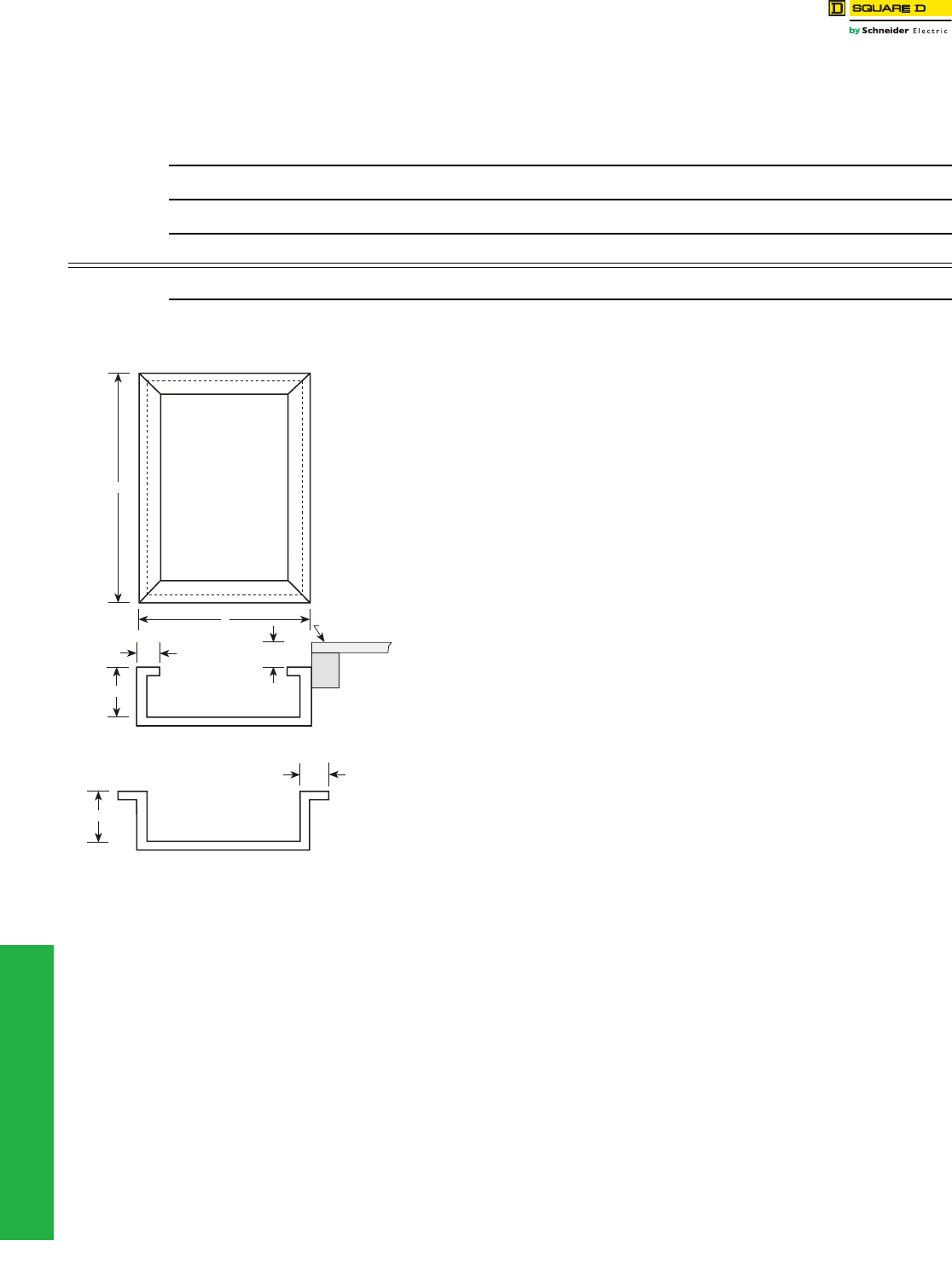
www.schneider-electric.us
4-14 © 2012 Schneider Electric
All Rights Reserved
4PANELBOARDS
Replacement Parts for Standard
Panelboards
Retrofit Existing Enclosure Data Sheet
The following dimensions are necessary for quotation and production of a panel to fit an
existing enclosure. Provide dimensions in inches only.
Existing Flush-Mounted Enclosures
•Height dimension “A”:
•Width dimension “B”:
•Depth dimension “C”:
•Flange width dimension “D”:
•If enclosure is not flush with Plaster Line, dimension “E”:
Existing Surface-Mounted Enclosures
•Height dimension “A”:
•Width dimension “B”:
•Depth dimension “C”:
•Flange dimension may be either dimension “D” or “F”
(select one)
— Dimension “D”:
— Dimension “F”:
NOTE: Trims are furnished so that the interior must be centered within the enclosure.
If the enclosure is deeper than the standard panelboard enclosure for the
required type of panelboard, customer-supplied mounting brackets may be
necessary to bring the interior out to the front of the enclosure.
If interior requires a vented enclosure, contact your nearest Schneider Electric
sales office for assistance.
This data sheet is also available on-line.
1. Go to http://intranet.us.schneider-electric.com
2. Click on U.S. Business, then select Sales & Marketing Home from the pulldown menu
3. On the Sales & Marketing page, select Support and Resources
4. On the Support and Resources page, select Mentor from the Tools options
5. On the Mentor page, select Mentor Order Quality from the Mentor Application options
6. When the Mentor order page appears, type in a project name in the Project Name: field, an
8-character number in the Q2C # field and your name in the Prepared by: field. Click on the box
next to Panelboards, and then click on the Next---> button at the top of the page.
7. On the Panelboards Mentor page, click on the box next to Trims to Fit, and then click on the
Next---> button at the top of the page.
8. When the File Download window appears, click on the Open option.
9. When the Mentor document opens, click on the Trims to Fit Data Sheet link at the bottom of the
page.
10. When the File Download window appears, click on the Open option to display the data sheet, or
click the Save option to save the data sheet to your hard drive.
Data Sheet for Panelboards to Retrofit Existing Enclosures
Distributor:
Job Name:
Contractor:
Panel Marking:
E
D
C
C
B
F
Top View
Top View
Front View
Plaster Line
A
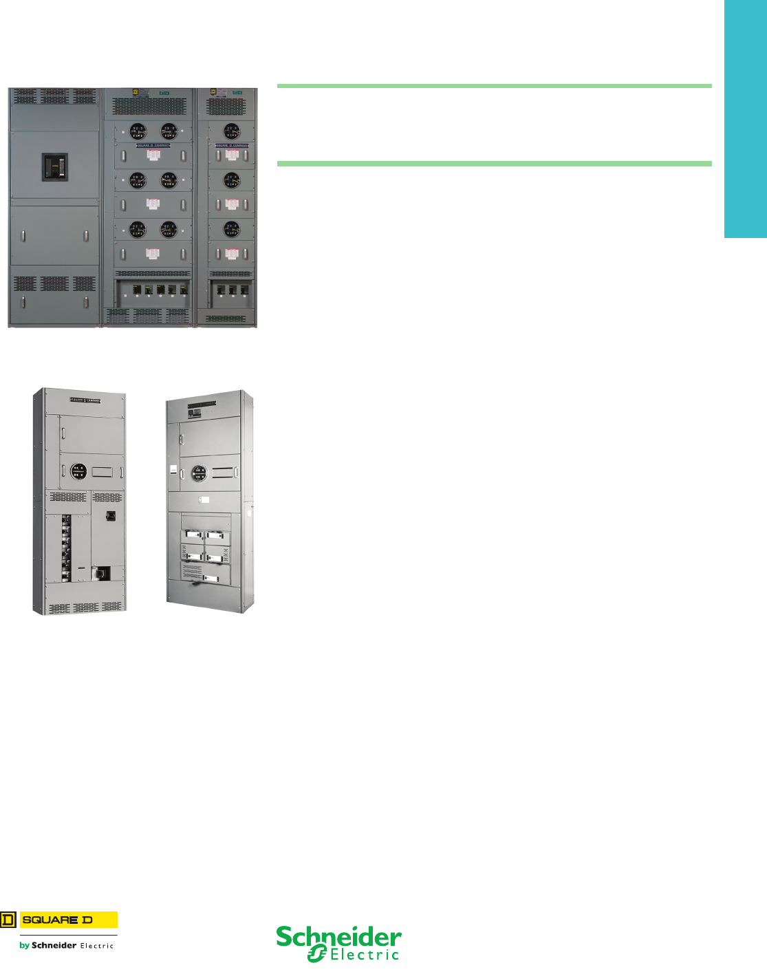
5-1
© 2012 Schneider Electric
All Rights Reserved
5SWITCHBOARDS
Table of Contents
Section 5
Switchboards
Power-Style™ Commercial Multi-Metering
Switchboard Lineup
Speed-D™ Switchboards
EUSERC UCT,
Single Main Circuit Breaker with
I-Line Distribution Panel
EUSERC UCT,
Fusible Multiple Mains
Power-Style™ Commercial Multi-Metering (CMM) Switchboards
Meter Sockets, Covers, Hardware Kits 5-2
Tenant Main Disconnects 5-3
Class T Fusible Pullouts, CMM Pullout Heads 5-3
Speed-D™ Switchboards
Subfeed Circuit Breakers 5-4
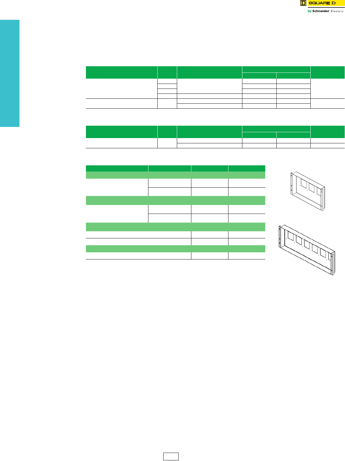
5-2 © 2012 Schneider Electric
All Rights Reserved
www.schneider-electric.us
5SWITCHBOARDS
Power-Style™ CMM
Switchboards
Replacement Parts
Class 2755, 2756 / Refer to Catalog 2755CT9501, 2756CT9601
Meter Sockets, Covers, Hardware Kits
Meter socket kits include meter socket (ringless type or ring type—see tables below) and instruction bulletin. The
connection cables from the line bus to the meter socket and from the meter socket to the tenant main disconnect are
not included. These should be provided by the contractor.
For additional information or for custom applications, please contact your local Schneider Electric
representative. Or, visit us on the web at www.schneider-electric.us.
Table 5.1: EUSERC Meter Socket with Test Block Kit (Ring Type; Class 2756)
Voltage System Poles Description Catalog No. $ Price
Single-Phase 3-Phase
120/240 V, 208Y/120 V, or 240/120 V Delta
AB
Old design: plug on to line side bus
CM522ABE —
1087.00
AC CM522ACE —
BC CM522BCE —
AC New design: lugs on line side CMLL522E —
208Y/120 V, 240/120 V Delta, or 480Y/277 V ABC Old design: plug on to line side bus — CM732E 1349.00
New design: lugs on line side — CMLL732E
Table 5.2: Lever Bypass Meter Socket (Ringless Type; Class 2755)
Voltage System Poles Description Catalog No. $ Price
Single-Phase 3-Phase
480Y/277 V ABC Old design: plug on to line side bus — 8024878850 2434.00
New design: lugs on line side — CMLL732 1349.00
Table 5.3: Cover and Hardware Kits
Description Tenant Main Structure Catalog No. $ Price
CMM Circuit Breaker Cover Kit a
Allows PowerPact™ H, J, and Q circuit
breakers to be installed in legacy
design CMM structures.
3-Socket CM3BKRCVR 137.00
6-Socket CM6BKRCVR 173.00
CMM Meter Cover Kit for EUSERC Applications
Includes meter cover, test block cover,
and hardware.
3-Socket CM7CR20ER 373.00
6-Socket CM7CR32ER 536.00
CMM Meter Cover Kit for Lever Bypass Applications
Meter socket cover CM7CR20Rb419.00
Blank cover CM20BLK b353.00
CMM Universal Hardware Kit
Required to add any tenant main disconnect. CMUHWKIT 58.00
aA new circuit breaker cover is required when adding a PowerPact Q, H, or J circuit breaker to a legacy
design tenant metering structure. The new cover has larger openings to accommodate the padlock
attachment for these circuit breakers.
bOrder point: PDS.
CM3BKRCVR
CM6BKRCVR
PE1A Discount
Schedule
www.schneider-electric.us
5SWITCHBOARDS
© 2012 Schneider Electric
All Rights Reserved 5-3
Power-Style™ CMM
Switchboards
Replacement Parts
Class 2755, 2756 / Refer to Catalog 2755CT9501, 2756CT9601
Tenant Main Disconnects
aTo complete the catalog number for these PowerPact F-frame circuit breakers, replace xxx with the required ampacity (070, 080, 090, or 100).
bA shunt trip is not available on PowerPact Q–frame circuit breakers.
cA new circuit breaker cover is required when adding a PowerPact Q-, H-, or J-frame circuit breaker to an old–design tenant metering structure. This new
cover has larger openings to accommodate the padlock attachment for these circuit breakers. See page 5-2 for ordering information.
dTo complete the catalog number for PowerPact Q-frame circuit breakers, replace xxx with the required ampacity (110, 125, 150, 175, or 200).
eTo complete the catalog number for PowerPact H-frame circuit breakers, replace xxx with the required ampacity (070, 080, 090, 100, 110, 125, or 150).
fTo complete the catalog number for PowerPact J-frame circuit breakers, replace xxx with the required ampacity (175 or 200).
Class T Fusible Pullouts, CMM Pullout Heads
a240 V fusible pullouts cannot be used on a Lever Bypass CMM. Only 480 V pullouts can be used.
bDiscount schedules: FTL3100 and FTL3200 = DE5; FTL43060, FTL43100, and FTL43200 = PE1A.
cDiscount schedule: DE5.
dOrder point: Lexington, KY.
Table 5.4: Circuit Breakers
(Universal Hardware Kit CMUHWKIT required; see page 5-2 for ordering information.)
Ampacity Catalog No. SCCR $ Price Load Lug Information
240 V 480 V
100 A F-frame Circuit Breaker
60 A FAL34060 25 kA 18 kA 521.00
#12 - 1/0 AWG Al or Cu
70–100 A FAL34xxx a616.00
60 A FHL36060 65 kA 25 kA 905.00
70–100 A FHL36xxx a1027.00
Padlock Attachment HPAFK —— 16.10 —
PowerPact™ Q-frame 250 A Circuit Breaker (240 Vac) b c
110–200 A QDL32xxx d25 kA N/A 1189.00
#4 - 300 kcmil Al or Cu 110–200 A QGL32xxx d65 kA N/A 1628.00
110–200 A QJL32xxx d100 kA N/A 1864.00
Padlock Attachment QBPAF —— 51.50 —
PowerPact H-frame 150 A Circuit Breaker (600 Vac, 250 Vdc)
60 A HDL36060
25 kA 18 kA
725.00
#4 - 3/0 kcmil Al or Cu
70–100 A HDL36xxx e885.00
110–150 A 1733.00
60 A HGL36060
65 kA 35 kA
995.00
70–100 A HGL36xxx e1134.00
110–150 A 2399.00
60 A HJL36060
100 kA 65 kA
1299.00
70–100 A HJL36xxx e1399.00
110–150 A 3449.00
60 A HLL36060
100 kA 100 kA
1899.00
70–100 A HLL36xxx e2099.00
110–150 A 4499.00
Padlock Attachment S37422 —— 51.00 —
PowerPact J-frame 250 A Circuit Breaker (600 Vac, 250 Vdc)
175–200 A JDL36xxx f25 kA 18 kA 1820.00
#4 - 300 kcmil Al or Cu
175–200 A JGL36xxx f65 kA 35 kA 2519.00
175–200 A JJL36xxx f100 kA 65 kA 3621.00
175–200 A JLL36xxx f100 kA 100 kA 4724.00
Padlock Attachment S37422 —— 51.00 —
Table 5.5: Class T Fusible Pullouts (Universal Hardware Kit CMUHWKIT Required)
(Universal Hardware Kit CMUHWKIT required; see page 5-2 for ordering information.)
Ampacity Catalog No. SCCR $ Price bWire Size Al or Cu
240 V a480 V
100 A FTL3100 100 kA N/A 1000.00 #14 - 1/0 AWG
200 A FTL3200 100 kA N/A 1045.00 #4 - 250 kcmil
60 A FTL43060 N/A 100 kA 839.00 #14 - #2
100 A FTL43100 N/A 100 kA 840.00 #14 - 1/0 AWG
200 A FTL43200 N/A 100 kA 1877.00 1/0 AWG - 300 kcmil
Table 5.6: CMM Pullout Heads
Mains Pullout Head
(No Base)
Catalog No.
$ Price c
Voltage System Rating (A) Poles
1Ø3W 120/240 V
3Ø4W 240/120 V Delta
3Ø4W 208Y/120 V
100 3 4050707050 d196.00
200 3 4050705950 d288.00
3Ø4W 480Y/277 V
60 3 — —
100 3 — —
200 3 — —
DE5 PE1A Discount
Schedule
www.schneider-electric.us
5-4 © 2012 Schneider Electric
All Rights Reserved
5SWITCHBOARDS
Speed-D™ Switchboards Service Selection
Class 2710 / Refer to Catalog 2700CT1101
Merchandised Speed-D Switchboards
Table 5.7: Subfeed Circuit Breakers ab
Description
Ratin
g
(A)
2-Polec
$ Price
3-Pole
$ PriceCatalog No. Catalog No.
Left Right Left Right
Subfeed Circuit Breaker Kit—
Price includes circuit breaker,
connectors and mounting hardware.
The complete kit, mounting
hardware, circuit breaker and
connectors will be shipped direct
from plant.
100 SASFB100L( )SASFB100R( ) 1148.00 SASFB100L SASFB100R 2055.00
110 SASFB110L( )SASFB110R( ) 1148.00 SASFB110L SASFB110R 2055.00
125 SASFB125L( )SASFB100R( ) 1148.00 SASFB125L SASFB125R 2055.00
150 SASFB150L( )SASFB150R( ) 1148.00 SASFB150L SASFB150R 2055.00
175 SASFB175L( )SASFB175R( ) 1148.00 SASFB175L SASFB175R 2055.00
200 SASFB200L( )SASFB200R( ) 1148.00 SASFB200L SASFB200R 2055.00
225 SASFB225L( )SASFB225R( ) 1148.00 SASFB225L SASFB225R 2055.00
aCannot use subfeed circuit breaker kit with multiple mains service section switchboards.
bFor use on all Speed-D switchboards except Series E4.
cTwo pole circuit breaker catalog numbers are completed by adding required phase connection letters as suffix (e.g.
SASFB100LAC).
PE1A Discount
Schedule
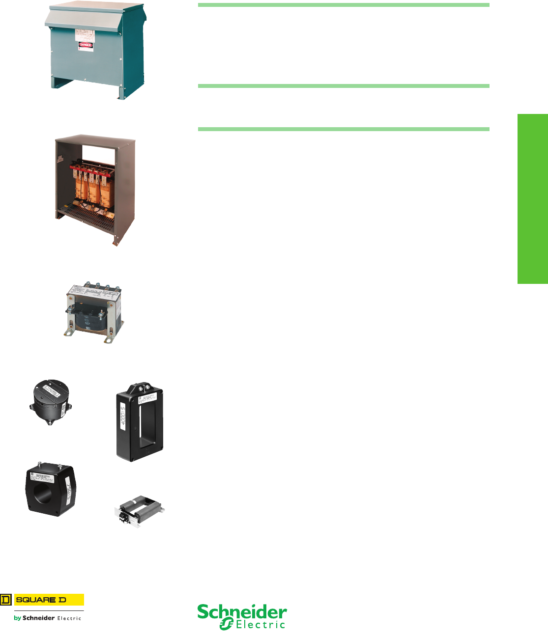
6-1
© 2012 Schneider Electric
All Rights Reserved
6TRANSFORMERS
Table of Contents
Section 6
Transformers
Dry Type, General Purpose
see page 6-2
K-Rated
see page 6-3
Type EO
see page 6-6
460R Voltage Transformer
see page 6-8
270R Split-Core
Current Transformer
see page 6-11
66R Current Transformer
see page 6-8
260R Rectangular Window
Current Transformer
see page 6-11
General Purpose, Dry Type, 600 Volts and Below
Three-Phase, Energy Efficient Transformers 6-2
Single-Phase, Energy Efficient Transformers 6-2
K-Rated Transformers 6-3
Drive Isolation Transformers 6-4
Open Core and Coil 6-5
Industrial Control
Typ e EO Tran sfo r m e rs 6-6
Type T and MultiTap™ Transformers 6-7
Instrument, 600 Volt Class
Voltage and Current Transformers 6-8
Torroidal Current Transformers 6-9
Shorting Terminal Blocks 6-10
Multi-Ratio Current Transformers 6-11
Rectangular Window Current Transformers 6-11
Split Core Current Transformers 6-11
Bushing Current Transformers 6-12
Auxiliary Current Transformers 6-12
www.schneider-electric.us
6TRANSFORMERS
6-2 © 2012 Schneider Electric
All Rights Reserved
General Purpose Dry
Type 600 Volts and Below
Energy Efficient
Class 7400
Schneider Electric offers Assembled in the U.S., energy efficient, low voltage transformers that are ideal for American
Reinvestment and Recovery Act (ARRA) applications.
aNot for construction. Contact your nearest Schneider Electric sales
office for certified prints.
bFor enclosure styles, see the dimensions table in Digest Section 14.
cContact the factory.
dWhen 240 V tap is used, there will be 3–5% taps: 1 above and 2 below.
Table 6.1: Three Phase
kVA Catalog No. $ Price
Full
Capacity
Taps
Degree
C Temp.
Rise
Weight
(lbs) a
Enclosure ab
480 V Delta Primary, 208Y/120 V Secondary, 60 Hz, cULus Listed,
Aluminum Windings
15 EE15T3HDM 5,044.00 6–2.5%2+4– 150 220 17D
30 EE30T3HDM 6,632.00 6–2.5%2+4– 150 260 17D
45 EE45T3HDM 7,980.00 6–2.5%2+4– 150 368 18D
75 EE75T3HDM 12,023.00 6–2.5%2+4– 150 585 20D
112.5 EE112T3HDM 16,017.00 6–2.5%2+4– 150 620 21D
150 EE150T3HDM 20,908.00 6–2.5%2+4– 150 835 22D
225 EE225T3HDM 27,873.00 6–2.5%2+4– 150 1110 24D
300 EE300T3HDM 35,743.00 6–2.5%2+4– 150 1350 25D
500 EE500T68HDM 49,987.00 4–2.5%2+2– 150 1875 30D
750 EE750T68HDM 96,660.00 4–2.5%2+2– 150 2965 31D
1000 EE1000T77HDM 155,217.00 2–5%1+1– 150 5200 c
480 V Delta Primary, 208Y/120 V Secondary, 60 Hz, cULus Listed,
Copper Windings
15 EE15T3HCUDM 8,072.00 6–2.5%2+4– 150 310 17D
30 EE30T3HCUDM 10,611.00 6–2.5%2+4– 150 340 17D
45 EE45T3HCUDM 12,767.00 6–2.5%2+4– 150 418 18D
75 EE75T3HCUDM 19,237.00 6–2.5%2+4– 150 642 20D
112.5 EE112T3HCUDM 25,627.00 6–2.5%2+4– 150 725 21D
150 EE150T3HCUDM 33,452.00 6–2.5%2+4– 150 915 22D
225 EE225T3HCUDM 44,598.00 6–2.5%2+4– 150 1125 24D
300 EE300T3HCUDM 57,189.00 6–2.5%2+4– 150 1535 25D
500 EE500T68HCUDM 79,978.00 4–2.5%2+2– 150 2350 30D
750 EE750T68HCUDM 154,657.00 4–2.5%2+2– 150 3485 31D
480 V Delta Primary, 208Y/120 V Secondary, 60 Hz, cULus Listed,
Aluminum Windings
15 EE15T3HFDM 6,222.00 6–2.5%2+4– 115 220 17D
30 EE30T3HFDM 9,334.00 6–2.5%2+4– 115 368 18D
45 EE45T3HFDM 11,235.00 6–2.5%2+4– 115 585 20D
75 EE75T3HFDM 16,924.00 6–2.5%2+4– 115 620 21D
112.5 EE112T3HFDM 22,546.00 6–2.5%2+4– 115 835 22D
150 EE150T3HFDM 29,431.00 6–2.5%2+4– 115 980 24D
225 EE225T3HFDM 39,235.00 6–2.5%2+4– 115 1349 25D
300 EE300T68HFDM 50,040.00 6–2.5%2+4– 115 2050 30D
500 EE500T68HFDM 69,981.00 6–2.5%2+2– 115 2330 30D
480 V Delta Primary, 208Y/120 V Secondary, 60 Hz, cULus Listed,
Copper Windings
15 EE15T3HFCUDM 9,956.00 6–2.5%2+4– 115 260 17D
30 EE30T3HFCUDM 14,934.00 6–2.5%2+4– 115 420 18D
45 EE45T3HFCUDM 17,975.00 6–2.5%2+4– 115 642 20D
75 EE75T3HFCUDM 27,078.00 6–2.5%2+4– 115 675 20D
112.5 EE112T3HFCUDM 36,073.00 6–2.5%2+4– 115 741 21D
150 EE150T3HFCUDM 47,090.00 6–2.5%2+4– 115 1050 22D
225 EE225T3HFCUDM 62,775.00 6–2.5%2+4– 115 1220 24D
300 EE300T68HFCUDM 80,065.00 6–2.5%2+4– 115 2300 30D
500 EE500T68HFCUDM 111,971.00 6–2.5%2+2– 115 2409 30D
Table 6.1: Three Phase
kVA Catalog No. $ Price
Full
Capacity
Taps
Degree
C
Temp.
Rise
Weight
(lbs) a
Enclosure ab
480 V Delta Primary, 208Y/120 V Secondary, 60 Hz, cULus Listed,
Aluminum Windings
15 EE15T3HBDM 6,789.00 6–2.5%2+4– 80 220 17D
30 EE30T3HBDM 10,184.00 6–2.5%2+4– 80 368 18D
45 EE45T3HBDM 12,255.00 6–2.5%2+4– 80 585 20D
75 EE75T3HBDM 18,463.00 6–2.5%2+4– 80 620 21D
112.5 EE112T3HBDM 24,595.00 6–2.5%2+4– 80 835 22D
150 EE150T3HBDM 31,540.00 6–2.5%2+4– 80 980 24D
225 EE225T3HBDM 42,801.00 6–2.5%2+4– 80 1349 25D
300 EE300T68HBDM 55,401.00 6–2.5%2+4– 80 2400 30D
500 EE500T68HBDM 77,480.00 6–2.5%2+2– 80 2964 31D
480 V Delta Primary, 208Y/120 V Secondary, 60 Hz, cULus Listed,
Copper Windings
15 EE15T3HBCUDM 10,862.00 6–2.5%2+4– 80 260 17D
30 EE30T3HBCUDM 16,294.00 6–2.5%2+4– 80 418 18D
45 EE45T3HBCUDM 19,607.00 6–2.5%2+4– 80 642 20D
75 EE75T3HBCUDM 29,540.00 6–2.5%2+4– 80 725 21D
112.5 EE112T3HBCUDM 39,352.00 6–2.5%2+4– 80 910 21D
150 EE150T3HBCUDM 50,465.00 6–2.5%2+4– 80 1125 24D
225 EE225T3HBCUDM 68,481.00 6–2.5%2+4– 80 1425 24D
300 EE300T68HBCUDM 88,641.00 6–2.5%2+4– 80 2400 30D
500 EE500T68HBCUDM 123,968.00 6–2.5%2+2– 80 2578 30D
Table 6.2: Single Phase
kVA Catalog No. $ Price Full Capacity
Taps d
Degree
C Temp.
Rise
Weig
ht
(lbs)
a
Enclosure ab
240 X 480 V Primary, 120/240 V Secondary, 60 Hz, cULus Listed
through 167 kVA
15 EE15S3HDM 3,932.00 6–2.5%2+4– 150 215 17D
25 EE25S3HDM 5,313.00 6–2.5%2+4– 150 275 17H
37.5 EE37S3HDM 7,084.00 6–2.5%2+4– 150 340 18H
50 EE50S3HDM 8,616.00 6–2.5%2+4– 150 395 18H
75 EE75S3HDM 11,684.00 6–2.5%2+4– 150 619 21D
100 EE100S3HDM 19,316.00 6–2.5%2+4– 150 682 22D
167 EE167S3HDM 22,186.00 6–2.5%2+4– 150 982 24D
250 EE250S3HDM 45,871.00 6–2.5%2+4– 150 1060 25D
333 EE333S3HDM 57,070.00 6–2.5%2+4– 150 1854 31D
PE2E Discount
Schedule
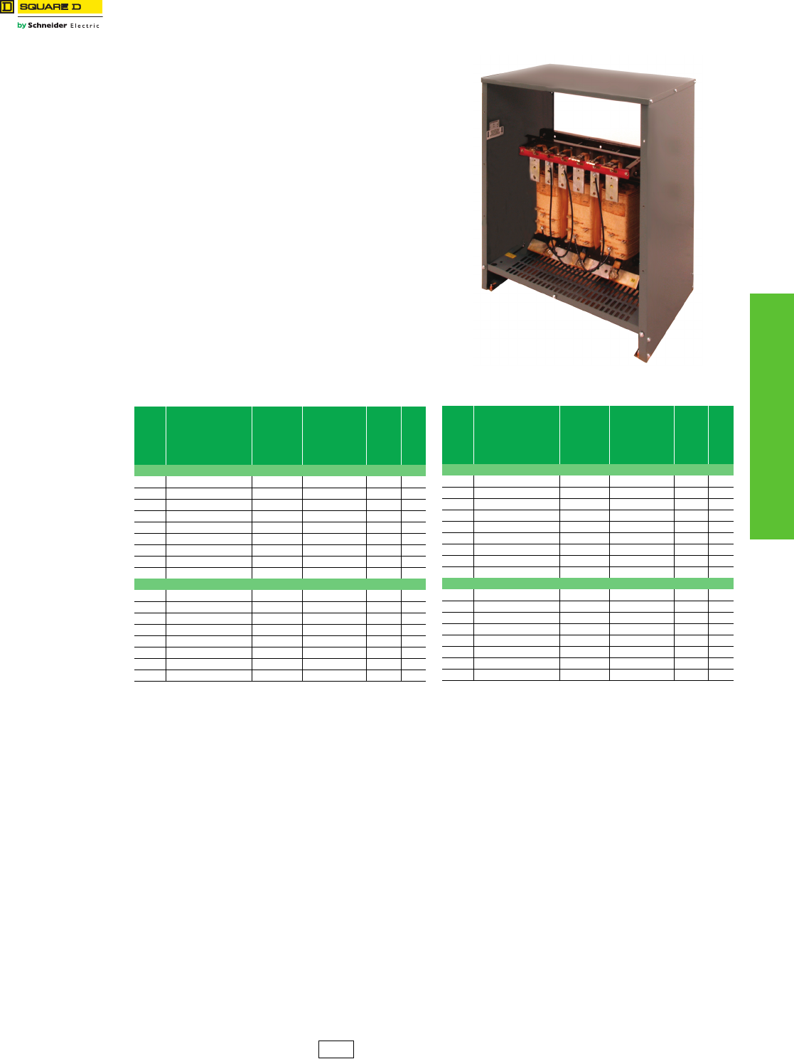
www.schneider-electric.us
6TRANSFORMERS
© 2012 Schneider Electric
All Rights Reserved 6-3
General Purpose Dry
Type 600 Volts and Below
K-Rated
Class 7400
EE NL and NLP Series Transformers
•Three-phase dry type transformers,
480 Delta—208Y/120
•Aluminum or copper windings
•Electrostatic shield
•Class 220 insulation
•Double size neutral terminal for additional
customer neutral cables
•Additional coil capacity to compensate
for higher non-linear load loss
•cULus Listed
aNot for construction. Contact your nearest Schneider Electric sales
office for certified prints.
bFor enclosure styles, see the dimensions table in Digest Section 14.
NOTE: Available with other temperature rises via the Schneider Electric
Product Selector.
Lugs are furnished by customer.
Table 6.3: NL Series for Typical Non-Linear Load
Service—K-4 Rated; 150 °C Rise
kVA Catalog
No. $ Price Taps
Weight
(lbs)
a
Enclosure ab
Aluminum Windings
15 EE15T3HISNL 5,253.00 6–2.5% 2+4– 266 17D
30 EE30T3HISNL 7,880.00 6–2.5% 2+4– 360 18D
45 EE45T3HISNL 9,484.00 6–2.5% 2+4– 515 20D
75 EE75T3HISNL 14,287.00 6–2.5% 2+4– 560 21D
112.5 EE112T3HISNL 19,033.00 6–2.5% 2+4– 800 22D
150 EE150T3HISNL 24,845.00 6–2.5% 2+4– 1150 24D
225 EE225T3HISNL 34,567.00 6–2.5% 2+4– 1349 25D
300 EE300T68HISNL 47,885.00 4–2.5% 2+2– 2125 30D
500 EE500T68HISNL 66,168.00 4–2.5% 2+2– 2595 31D
Copper Windings
15 EE15T3HISCUNL 8,405.00 6–2.5% 2+4– 260 17D
30 EE30T3HISCUNL 12,608.00 6–2.5% 2+4– 395 18D
45 EE45T3HISCUNL 15,174.00 6–2.5% 2+4– 730 20D
75 EE75T3HISCUNL 22,859.00 6–2.5% 2+4– 640 20D
112.5 EE112T3HISCUNL 30,453.00 6–2.5% 2+4– 935 22D
150 EE150T3HISCUNL 39,752.00 6–2.5% 2+4– 1300 24D
225 EE225T3HISCUNL 55,307.00 6–2.5% 2+4– 1450 24D
300 EE300T68HISCUNL 76,616.00 4–2.5% 2+2– 2450 25D
Table 6.4: NLP Series for More Severe Non-Linear
Load Service—K-13 Rated; 150 °C Rise
kVA Catalog
No. $ Price Taps
Weight
(lbs)
a
Enclosure ab
Aluminum Windings
15 EE15T3HISNLP 5,976.00 6–2.5% 2+4– 261 17D
30 EE30T3HISNLP 8,963.00 6–2.5% 2+4– 365 18D
45 EE45T3HISNLP 10,789.00 6–2.5% 2+4– 415 20D
75 EE75T3HISNLP 17,876.00 6–2.5% 2+4– 535 21D
112.5 EE112T3HISNLP 21,650.00 6–2.5% 2+4– 750 22D
150 EE150T3HISNLP 28,261.00 6–2.5% 2+4– 755 24D
225 EE225T3HISNLP 38,507.00 6–2.5% 2+4– 775 25D
300 EE300T68HISNLP 51,295.00 4–2.5% 2+2– 2350 30D
500 EE500T68HISNLP 71,277.00 4–2.5% 2+2– 3150 31D
Copper Windings
15 EE15T3HISCUNLP 9,562.00 6–2.5% 2+4– 260 17D
30 EE30T3HISCUNLP 14,341.00 6–2.5% 2+4– 430 18D
45 EE45T3HISCUNLP 17,262.00 6–2.5% 2+4– 730 20D
75 EE75T3HISCUNLP 28,602.00 6–2.5% 2+4– 640 20D
112.5 EE112T3HISCUNLP 34,640.00 6–2.5% 2+4– 985 22D
150 EE150T3HISCUNLP 45,218.00 6–2.5% 2+4– 1135 24D
225 EE225T3HISCUNLP 61,611.00 6–2.5% 2+4– 1477 25D
300 EE300T68HISCUNLP 82,072.00 4–2.5% 2+2– 2650 30D
PE2E Discount
Schedule
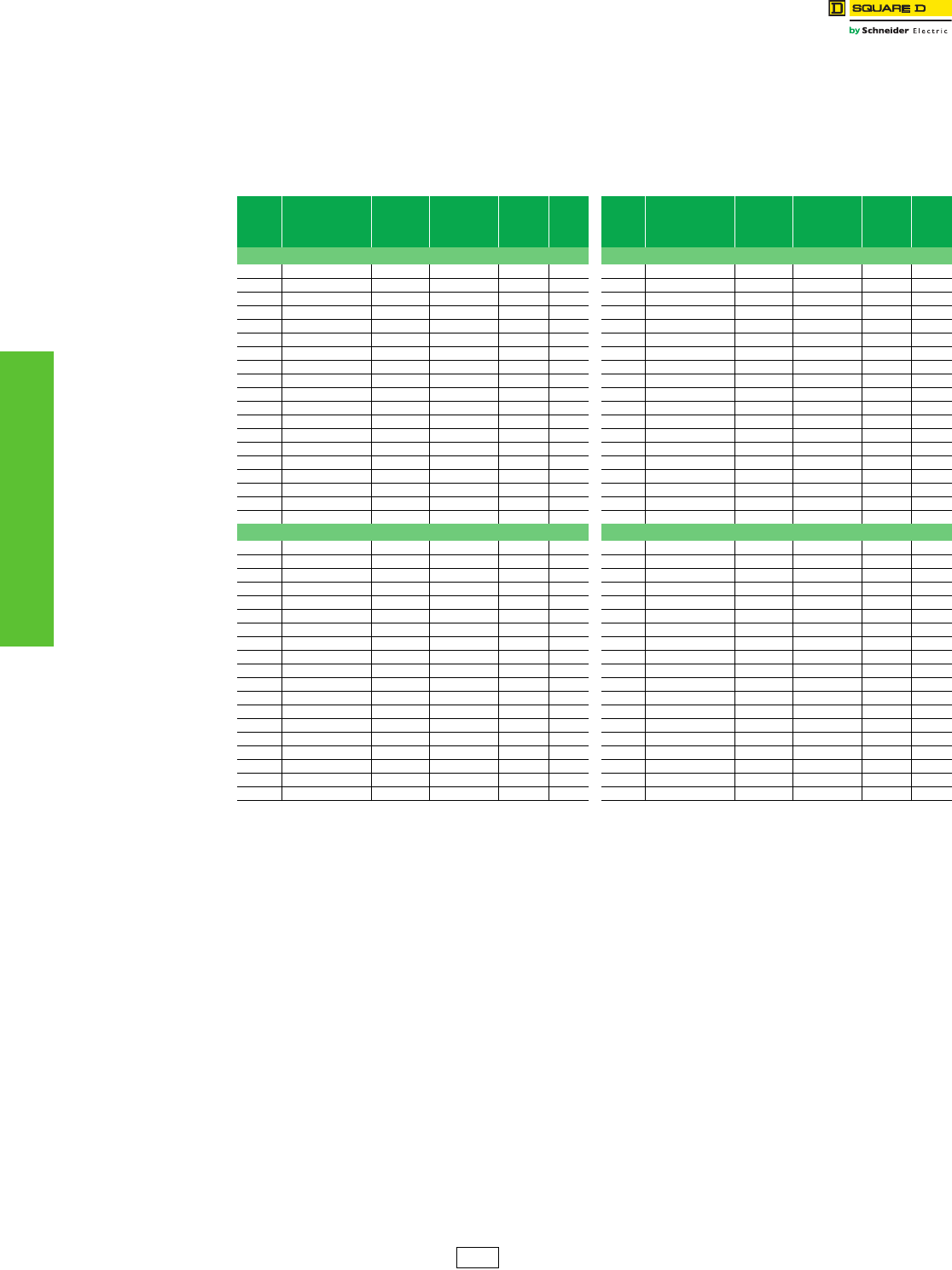
www.schneider-electric.us
6-4 © 2012 Schneider Electric
All Rights Reserved
6TRANSFORMERS
General Purpose Dry
Type 600 Volts and Below
Drive Isolation
Class 7400
Drive Isolation Transformers
Special design considerations must be made for the requirements of both adjustable frequency and dc motor drive
power isolation. Allowance for high surge, harmonic and offset currents are taken into account in the design of
Square D™ brand drive isolation transformers. Drive isolation transformers are not shielded isolation transformers, but
act to lessen transient generation into the supply power and act as a buffer for SCR current surges.
aNot for construction. Contact your nearest Schneider Electric sales
office for certified prints.
bFor enclosure styles, see the dimensions table in Digest Section 14.
NOTE: Lugs are furnished by customer.
Table 6.5: Three-Phase 60 Hz; Class B
(IEEE Standard 597-1983);
460 V Delta Primary
kVA Catalog
No. $ Price Full Capacity
Taps
Weight
(lbs) a
Enclosure
ab
460 V Delta Primary, 460Y/265 V Secondary, 150 °C Rise
7.5 7T145HDIT 4,464.00 2–5%1 + 1– 180 17D
11 11T145HDIT 5,302.00 2–5%1 + 1– 180 17D
15 15T145HDIT 5,464.00 2–5%1 + 1– 190 17D
20 20T145HDIT 6,550.00 2–5%1 + 1– 210 17D
27 27T145HDIT 6,722.00 2–5%1 + 1– 250 17D
34 34T145HDIT 7,392.00 2–5%1 + 1– 295 18D
40 40T145HDIT 8,406.00 2–5%1 + 1– 350 18D
51 51T145HDIT 9,830.00 2–5%1 + 1– 445 20D
63 63T145HDIT 10,694.00 2–5%1 + 1– 465 20D
75 75T145HDIT 12,500.00 2–5%1 + 1– 550 20D
93 93T145HDIT 16,026.00 2–5%1 + 1– 845 22D
118 118T145HDIT 17,848.00 2–5%1 + 1– 920 22D
145 145T145HDIT 20,014.00 2–5%1 + 1– 1025 22D
175 175T145HDIT 23,096.00 2–5%1 + 1– 1120 25D
220 220T145HDIT 28,228.00 2–5%1 + 1– 1200 25D
275 275T145HDIT 37,720.00 2–5%1 + 1– 1500 25D
330 330T145HDIT 39,694.00 2–5%1 + 1– 1390 25D
440 440T145HDIT 48,660.00 2–5%1 + 1– 2700 30D
550 550T145HDIT 60,456.00 2–5%1 + 1– 3800 30D
460 V Delta Primary, 230Y/132 V Secondary, 150 °C Rise
7.5 7T144HDIT 4,464.00 2–5%1 + 1– 180 17D
11 11T144HDIT 5,302.00 2–5%1 + 1– 180 17D
15 15T144HDIT 5,464.00 2–5%1 + 1– 190 17D
20 20T144HDIT 6,550.00 2–5%1 + 1– 210 17D
27 27T144HDIT 6,722.00 2–5%1 + 1– 250 17D
34 34T144HDIT 7,392.00 2–5%1 + 1– 295 18D
40 40T144HDIT 8,406.00 2–5%1 + 1– 350 18D
51 51T144HDIT 9,830.00 2–5%1 + 1– 445 20D
63 63T144HDIT 10,694.00 2–5%1 + 1– 465 20D
75 75T144HDIT 12,500.00 2–5%1 + 1– 550 20D
93 93T144HDIT 16,026.00 2–5%1 + 1– 845 22D
118 118T144HDIT 17,848.00 2–5%1 + 1– 920 22D
145 145T144HDIT 20,014.00 2–5%1 + 1– 1025 22D
175 175T144HDIT 23,096.00 2–5%1 + 1– 1120 25D
220 220T144HDIT 28,228.00 2–5%1 + 1– 1200 25D
275 275T144HDIT 37,720.00 2–5%1 + 1– 1500 25D
330 330T144HDIT 39,694.00 2–5%1 + 1– 1390 25D
440 440T144HDIT 48,660.00 2–5%1 + 1– 2700 30D
550 550T144HDIT 60,456.00 2–5%1 + 1– 3800 30D
Table 6.6: Three-Phase 60 Hz; Class B
(IEEE Standard 597-1983);
230 V Delta Primary
kVA Catalog
No. $ Price Full Capacity
Taps
Weight
(lbs) a
Enclosure
ab
230 V Delta Primary, 460Y/265 V Secondary, 150 °C Rise
7.5 7T143HDIT 4,464.00 2–5%1 + 1– 180 17D
11 11T143HDIT 5,302.00 2–5%1 + 1– 180 17D
15 15T143HDIT 5,464.00 2–5%1 + 1– 190 17D
20 20T143HDIT 6,550.00 2–5%1 + 1– 210 17D
27 27T143HDIT 6,722.00 2–5%1 + 1– 250 17D
34 34T143HDIT 7,392.00 2–5%1 + 1– 295 18D
40 40T143HDIT 8,406.00 2–5%1 + 1– 350 18D
51 51T143HDIT 9,830.00 2–5%1 + 1– 445 20D
63 63T143HDIT 10,694.00 2–5%1 + 1– 465 20D
75 75T143HDIT 12,500.00 2–5%1 + 1– 550 20D
93 93T143HDIT 16,026.00 2–5%1 + 1– 845 22D
118 118T143HDIT 17,848.00 2–5%1 + 1– 920 22D
145 145T143HDIT 20,014.00 2–5%1 + 1– 1025 22D
175 175T143HDIT 23,096.00 2–5%1 + 1– 1120 25D
220 220T143HDIT 28,228.00 2–5%1 + 1– 1200 25D
275 275T143HDIT 37,720.00 2–5%1 + 1– 1500 25D
330 330T143HDIT 39,694.00 2–5%1 + 1– 1390 25D
440 440T143HDIT 48,660.00 2–5%1 + 1– 2700 30D
550 550T143HDIT 60,456.00 2–5%1 + 1– 3800 30D
230 V Delta Primary, 230Y/132 V Secondary, 150 °C Rise
7.5 7T142HDIT 4,464.00 2–5%1 + 1– 180 17D
11 11T142HDIT 5,302.00 2–5%1 + 1– 180 17D
15 15T142HDIT 5,464.00 2–5%1 + 1– 190 17D
20 20T142HDIT 6,550.00 2–5%1 + 1– 210 17D
27 27T142HDIT 6,722.00 2–5%1 + 1– 250 17D
34 34T142HDIT 7,392.00 2–5%1 + 1– 295 18D
40 40T142HDIT 8,406.00 2–5%1 + 1– 350 18D
51 51T142HDIT 9,830.00 2–5%1 + 1– 445 20D
63 63T142HDIT 10,694.00 2–5%1 + 1– 465 20D
75 75T142HDIT 12,500.00 2–5%1 + 1– 550 20D
93 93T142HDIT 16,026.00 2–5%1 + 1– 845 22D
118 118T142HDIT 17,848.00 2–5%1 + 1– 920 22D
145 145T142HDIT 20,014.00 2–5%1 + 1– 1025 22D
175 175T142HDIT 23,096.00 2–5%1 + 1– 1120 25D
220 220T142HDIT 28,228.00 2–5%1 + 1– 1200 25D
275 275T142HDIT 37,720.00 2–5%1 + 1– 1500 25D
330 330T142HDIT 39,694.00 2–5%1 + 1– 1390 25D
440 440T142HDIT 48,660.00 2–5%1 + 1– 2700 30D
550 550T142HDIT 60,456.00 2–5%1 + 1– 3800 30D
PE2 Discount
Schedule
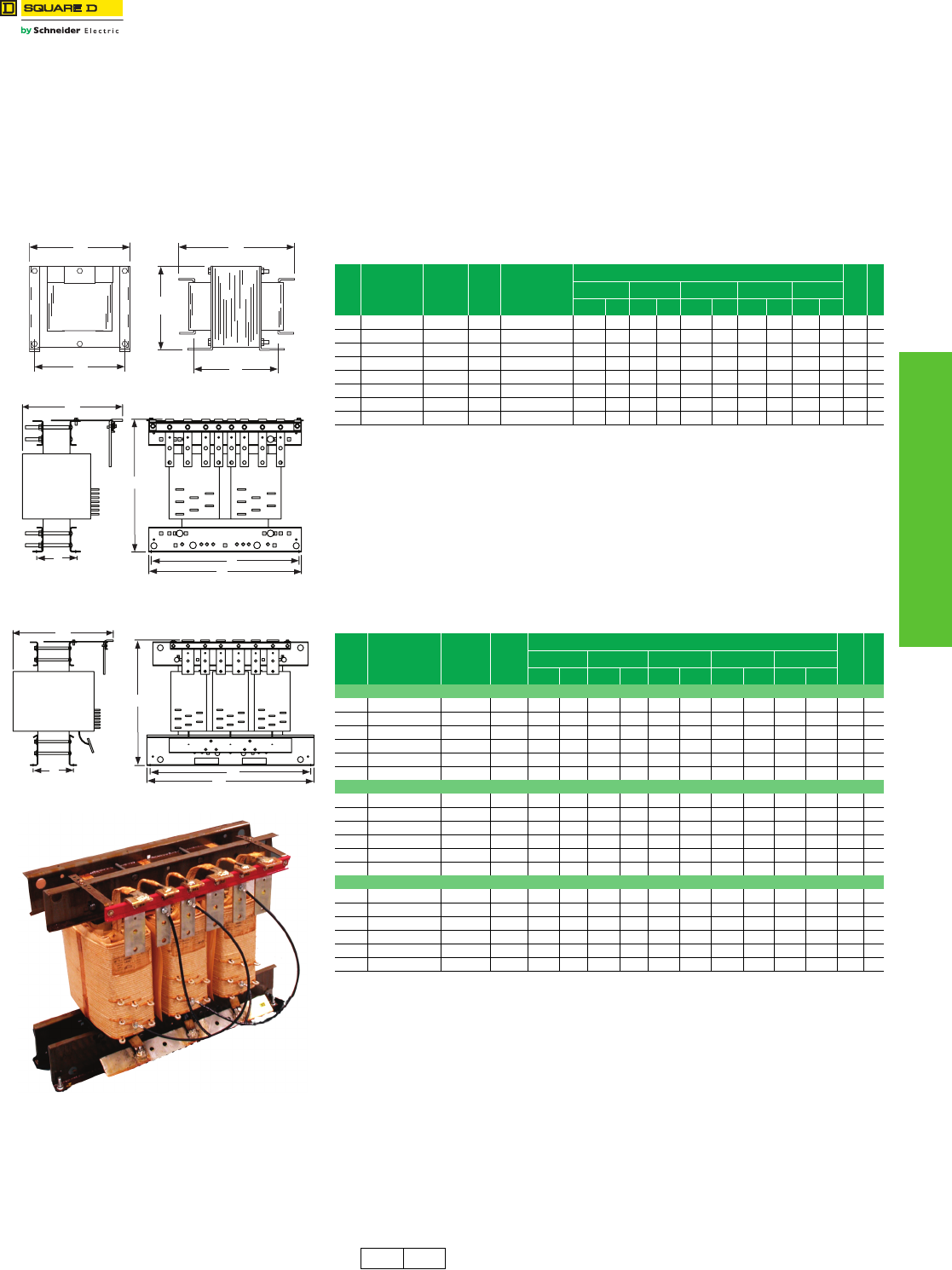
www.schneider-electric.us
6TRANSFORMERS
© 2012 Schneider Electric
All Rights Reserved 6-5
General Purpose Dry
Type 600 Volts and Below
Open Core and Coil
Class 7400 / Refer to Catalog 7400CT9601
Open Core and Coil Transformers Designed for General
Applications for 600 V and Below
Units are designed with 220 °C insulation, aluminum windings, top terminations, compact
design to save space, and are UL component recognized for:
•Non-energy efficiency (less than 15 kVA)
Single-phase 5–10 VA
Three-phase 3–9 VA
•Energy efficiency (meets Table 4-2 of NEMA TP1–2002)
Single-phase 15–75 kVA
Three-phase 15–112.5 kVA
aNot for construction. Contact your local Schneider Electric sales office for certified prints.
bWhen 240 V tap is used, there will be 3–5% taps, 1 above and 2 below.
cNot for construction. Contact your local Schneider Electric sales office for certified prints.
dDimensions may vary due to manufacturing process.
B
D
C
A
E
E
A
B
D
C
Figure 1
Figure 2
Table 6.7: Single-Phase Open Core and Coil Transformers—240 X 480 V Primary,
120/240 V Secondary, 60 Hz
kVA Catalog
No. $ Price
Deg.
C
Temp.
Rise
Full Capacity
Taps
Dimensions a
Weight
(lbs)
Figure
A B C D Ed
in mm in mm in mm in mm in mm
55S1HFOC 2868.00 115 — 8.00 203 9.00 229 11.00 279 8.00 203 8.00 203 66 1
7.5 7S1HFOC 3062.00 115 — 8.00 203 9.00 229 14.25 362 8.00 203 8.50 216 80 1
10 10S1HFOC 3396.00 115 — 20.50 521 18.5 470 14.00 356 17.0 432 4.25 108 140 2
15 EE15S3HOC 3072.00 150 6–2.5% 2+4–d20.50 521 18.5 470 14.00 356 17.0 432 4.25 108 140 2
25 EE25S3HOC 4151.00 150 6–2.5% 2+4–b20.25 514 18.5 470 14.00 356 17.0 432 5.00 127 200 2
37.5 EE37S3HOC 5534.00 150 6–2.5% 2+4–b22.00 559 18.5 470 18.00 457 17.0 432 5.50 140 255 2
50 EE50S3HOC 6731.00 150 6–2.5% 2+4–b22.00 559 18.5 470 18.00 457 17.0 432 6.50 165 310 2
75 EE75S3HOC 9128.00 150 6–2.5% 2+4–b22.25 565 28.0 711 22.00 559 27.0 686 8.50 216 460 2
C
E
BD
A
Figure 3
Table 6.8: Three Phase Open Core and Coil Transformers
kVA Catalog
No. $ Price
Degree
C
Temp.
Rise
Dimensions c
Weight
(lbs)
Figure
A B C D Ed
in mm in mm in mm in mm in mm
480 V to 208Y/120
99T3HFOC 3424.00 115 14.75 375 18.50 470 14.00 356 17.00 432 5.13 130 145 3
15 EE15T3HOC 4532.00 150 14.75 375 18.50 470 14.00 356 17.00 432 5.13 130 145 3
30 EE30T3HOC 6799.00 150 16.50 419 18.50 470 14.00 356 17.00 432 5.88 149 185 3
45 EE45T3HOC 6234.00 150 17.25 438 18.50 470 18.00 457 17.00 432 6.50 165 285 3
75 EE75T3HOC 9393.00 150 21.00 533 28.00 711 18.00 457 26.94 684 6.75 171 450 3
112.5 EE112T3HOC 12513.00 150 21.75 552 28.00 711 22.00 559 26.94 684 6.75 171 460 3
240 V to 208Y/120
99T67HFOC 3424.00 115 14.75 375 18.50 470 14.00 356 17.00 432 5.13 130 165 3
15 EE15T67HOC 4434.00 150 14.75 375 18.50 470 14.00 356 17.00 432 5.13 130 165 3
30 EE30T67HOC 5828.00 150 16.50 419 18.50 470 14.00 356 17.00 432 5.88 149 185 3
45 EE45T67HOC 7013.00 150 17.25 438 18.50 470 18.00 457 17.00 432 6.50 165 295 3
75 EE75T67HOC 10567.00 150 21.00 533 28.00 711 18.00 457 27.00 686 6.38 162 450 3
112.5 EE112T67HOC 14077.00 150 21.75 552 28.00 711 22.00 559 27.00 686 6.38 162 460 3
600 V to 208Y/120
99T65HFOC 3424.00 115 14.75 375 18.50 470 14.00 356 17.00 432 5.13 130 165 3
15 EE15T65HOC 5122.00 150 14.75 375 18.50 470 14.00 356 17.00 432 5.13 130 165 3
30 EE30T65HOC 7683.00 150 16.50 419 18.50 470 14.00 356 17.00 432 5.88 149 215 3
45 EE45T65HOC 7013.00 150 17.25 438 18.50 470 18.00 457 17.00 432 6.50 165 290 3
75 EE75T65HOC 10567.00 150 21.00 533 28.00 711 18.00 457 27.00 686 6.75 171 445 3
112.5 EE112T65HOC 14077.00 150 21.75 552 28.00 711 22.00 559 27.00 686 6.75 171 450 3
PE2E PE2 Discount
Schedule
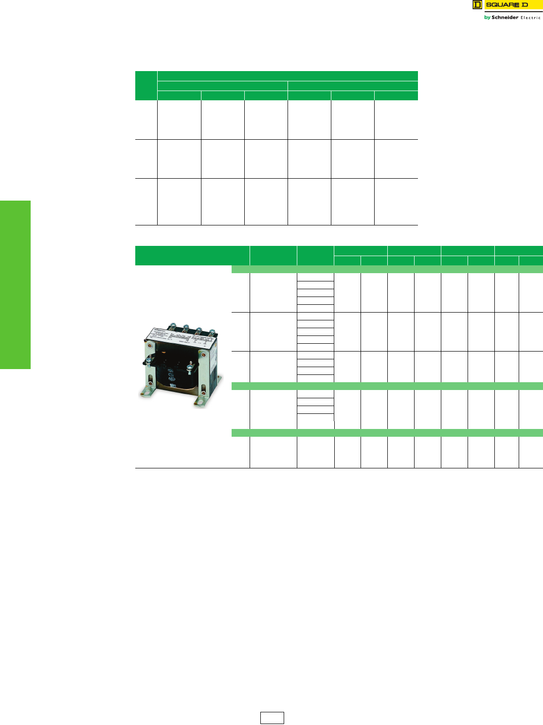
6-6 © 2012 Schneider Electric
All Rights Reserved
www.schneider-electric.us
6TRANSFORMERS
Industrial Control Type EO
Class 9070 / Refer to Catalog 9070CT9901
Type EO units are designed with exceptional voltage regulation. These control transformers are constructed using
traditional materials and manufacturing techniques, and are designed for 25–5000 VA with a 55 °C temperature rise.
When exceptional regulation and very low temperature rise are an absolute necessity, choose Type EO units.
Table 6.9: Regulation Chart for Type EO Transformers
VA
(60 Hz)
Secondary Voltage
Inrush UL VA at 20% Power Factor Inrush UL VA at 40% Power Factor
95% 90% 85% 95% 90% 85%
25 95 — 146 60 — 119
50 164 213 277 123 168 225
75 387 487 622 284 375 798
100 479 606 770 346 463 613
150 755 1177 1532 567 930 1252
200 1260 1883 2419 910 1462 1950
250 1530 2327 2995 1115 1811 2419
300 2030 2981 3800 1455 2290 3038
350 2920 4586 5981 2180 3637 4903
500 4230 5984 7707 3120 4661 6229
750 7430 11460 14736 5380 8907 11891
1000 10300 16873 21734 7450 13145 17571
1500 19200 30042 39217 14500 23859 32179
2000 27750 45194 60022 21750 36901 50994
3000 31800 82333 108205 26750 66072 89509
5000 86100 148768 202077 72600 126887 175552
Table 6.10: Type EO Transformer Dimensions
VA
(60 Hz)
Catalog Number
Class 9070 $ Price A B C Weight
IN mm IN mm IN mm lbs kg
220x440 V Primary, 110 V Secondary; 230x460 V Primary, 115 V Secondary; or 240x480 V Primary, 120 V Secondary
25 9070EO17D1 79.00 3.31 84 3.00 76 2.50 64 1.9 0.9
50 9070EO1D1 99.00 3.31 84 3.00 76 2.50 64 2.2 1.0
75 9070EO18D1 114.00 3.78 96 3.38 86 2.81 71 3.5 1.6
100 9070EO2D1 136.00 3.78 96 3.38 86 2.81 71 3.8 1.7
150 9070EO3D1 153.00 4.441133.75953.13806.02.7
200 9070EO19D1 214.00 4.81 122 4.50 114 3.75 95 10.5 4.8
250 9070EO15D1 250.00 5.19 132 4.50 114 3.75 95 13.2 6.0
300 9070EO04D1 300.00 5.56 141 4.50 114 3.75 95 17.2 7.8
500 9070EO51D1 333.00 6.56 167 5.25 133 4.38 111 24.5 11.1
750 9070EO61D1 473.00 7.94 202 5.25 133 4.38 111 30.5 13.8
1000 9070EO71D1 543.00 7.94 202 6.00 152 5.00 127 45.0 20.4
1500 9070EO81D1 831.00 8.59 218 7.06 179 6.03 153 56.0 25.4
2000 9070EO91D1 1007.00 9.22 234 7.06 179 6.03 153 72.0 32.7
3000 9070EO10D1 1365.00 9.44 239 9.00 229 7.50 191 115.0 52.2
240x480 V Primary, 24 V Secondary
25 9070EO17D2 79.00 3.31 84 3.00 76 2.50 64 1.9 0.9
50 9070EO10D2 99.00 3.31 84 3.00 76 2.50 64 2.2 1.0
75 9070EO18D2 114.00 3.78 96 3.38 86 2.81 71 3.5 1.6
100 9070EO2D2 136.00 3.78 96 3.38 86 2.81 71 3.8 1.7
250 9070EO16D2 295.00 6.19 157 4.50 114 3.75 95 13.2 6.0
550 V Primary, 110 V Secondary; 575 V Primary, 115 V Secondary; or 600 V Primary, 120 V Secondary
200 9070EO19D5 214.00 5.56 4.81 122 4.50 114 3.75 10.5 4.8
300 9070EO04D5 276.00 5.56 141 4.50 114 3.75 95 17.2 7.8
500 9070EO51D5 333.00 6.56 167 5.25 133 4.38 111 24.5 11.1
750 9070EO61D5 473.00 7.94 202 5.25 133 4.38 111 30.5 13.8
CP8 Discount
Schedule
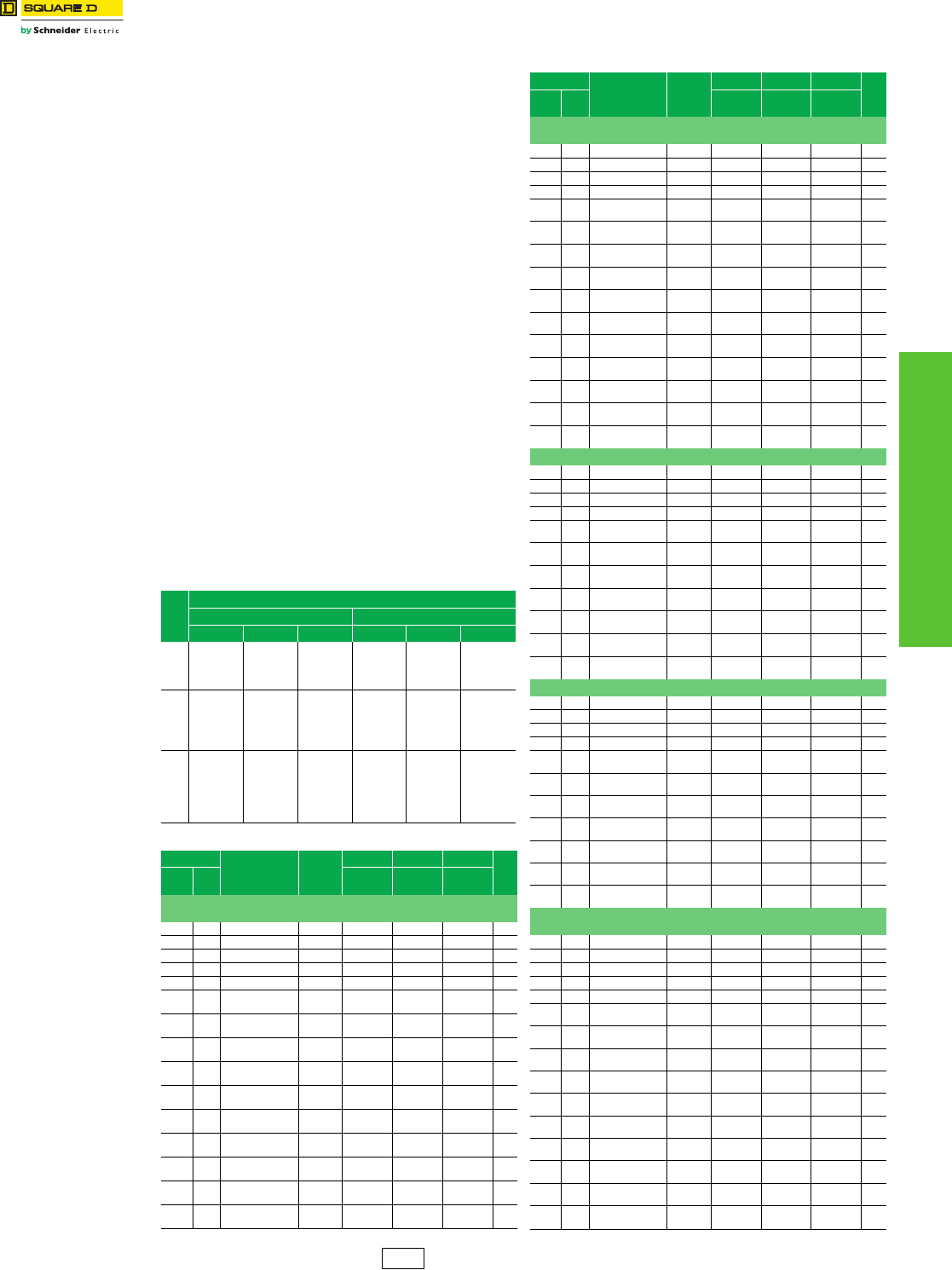
www.schneider-electric.us
6TRANSFORMERS
© 2012 Schneider Electric
All Rights Reserved 6-7
Industrial Control Type T
Class 9070 / Refer to Catalogs 9070CT9901, 7400CT9601
Type T and MultiTap™ Transformers
Type T transformers are designed with low impedance
windings for excellent voltage regulation and can
accommodate the high inrush current associated with
contactors, starters, solenoids, and relays. As the most
popular and complete line of control transformers with
unmatched design innovations for top performance, Type Ts
are manufactured using the most advanced insulating
materials and are the best choice if size and cost are of
concern. It is available in the MultiTap version, designed to
respond to the increased need for voltage and stock flexibility.
It combines multiple primary voltages with one or more
secondary voltages, all in a single transformer.
Selection Guide
1. Determine the inrush and sealed VA of each coil in the control
circuit, and the VA of all other components.
2. Total the sealed VA of all operating coils and the VA of all other
loads. (This determines the minimal VA size required for the
circuit.)
3. Total the inrush VA of all coils that are starting at the same
time, and all loads and coils that are running. (Use the
regulation chart to give possible units to be used.)
4. Taking the VA size from step 2, go to the standard VA size in
the chart. Make sure the inrush VA from the chart is greater
than the total VA from step 3. (If not, go to the next larger VA
size and repeat.)
If your supply voltage is stable and fluctuates less than 5%,
we recommend you use the 90% secondary voltage
column. If your supply voltage is not stable and fluctuates
more than 10%, we recommend you use the 95%
secondary voltage column. We recommend that you never
use the 85% secondary voltage column since magnetic
devices lose life expectancy if they are continuously
started at 85% of rated voltage.
Table 6.11: Regulation Chart for Type T Transformers
VA
(60 Hz)
Secondary Voltage
Inrush UL VA at 20% Power Factor Inrush UL VA at 40% Power Factor
95% 90% 85% 95% 90% 85%
50 193 266 339 151 215 282
75 271 396 20 210 318 430
100 339 499 659 266 404 549
150 666 893 1120 529 731 942
200 588 815 1041 459 659 866
250 1416 1910 2388 1057 1494 1936
300 1634 2184 2709 1194 1681 2169
350 1894 2592 3261 1392 2005 621
500 3197 4104 4981 2374 3195 4019
750 3770 5515 7231 2887 4391 5945
1000 6587 9079 11430 4706 6886 9051
1500 19324 23983 28607 15066 19361 23756
2000 31384 38777 6161 24794 31630 38667
3000 26539 39934 52713 19355 30721 42216
5000 53111 85265 116277 39368 66309 93882
Table 6.12: Type T Transformer Selection
VA Catalog
No. $ Price
H W D
Weight
(lbs)
UL/
CSA/
NOM
CE in (mm) in (mm) in (mm)
120 V Primary, 120 V Secondary; 115 V Primary, 115 V Secondary; or
110 V Primary, 110 V Secondary
50 50 9070T50D24 468.00 2.58 (65.5) 3.00 (76.2) 3.09 (78.5) 2.5
75 75 9070T75D24 486.00 2.89 (73.4) 3.38 (85.8) 3.34 (84.8) 3.8
100 100 9070T100D24 489.00 2.89 (73.4) 3.38 (85.8) 3.34 (84.8) 3.8
150 150 9070T150D24 522.00 3.20 (81.3) 3.75 (95.3) 3.59 (91.2) 5.5
200 200 9070T200D24 713.00 3.20 (81.3) 3.75 (95.3) 3.59 (91.2) 5.5
250 160 9070T250D24 716.00 3.25
(82.6)
3.75
(95.3)
5.25
(133.4) 7.1
300 200 9070T300D24 722.00 3.80
(96.5)
4.50
(114.3)
4.70
(119.4) 8.5
350 250 9070T350D24 725.00 3.80
(96.5)
4.50
(114.3)
5.09
(129.3) 10.5
500 300 9070T500D24 747.00 3.80
(96.5)
4.50
(114.3)
5.46
(138.7) 11.9
750 500 9070T750D24 840.00 4.43
(112.5)
5.25
(133.4)
5.66
(143.8) 11.0
1000 630 9070T1000D24 891.00 4.43
(112.5)
5.25
(133.4)
6.04
(153.4) 20.6
1500 1000 9070T1500D24 1076.00 6.16
(156.5)
7.06
(179.3)
5.81
(147.6) 34.0
2000 1500 9070T2000D24 1394.00 6.16
(156.5)
7.06
(179.3)
7.04
(178.8) 47.0
3000 2000 9070T3000D24 2195.00 8.46
(214.9)
9.00
(228.6)
6.86
(174.2) 60.0
5000 3000 9070T5000D24 3015.00 8.46
(214.9)
9.00
(228.6)
8.73
(221.7) 89.0
120 V x 240 V Primary, 120/240 V Secondary; 115 V x 230 V Primary,
115/230 V Secondary; or 110 V x 220 V Primary, 110/220 V Secondary
50 50 9070T50D55 468.00 2.58 (65.5) 3.00 (76.2) 3.09 (78.5) 2.5
75 75 9070T75D55 486.00 2.89 (73.4) 3.38 (85.8) 3.34 (84.8) 3.8
100 100 9070T100D55 489.00 2.89 (73.4) 3.38 (85.8) 3.34 (84.8) 3.8
150 150 9070T150D55 522.00 3.20 (81.3) 3.75 (95.3) 3.59 (91.2) 5.5
200 200 9070T200D55 713.00 3.20
(81.3)
3.75
(95.3)
3.59
(91.20) 5.5
250 160 9070T250D55 716.00 3.25
(82.6)
3.75
(95.3)
5.25
(133.4) 7.1
300 200 9070T300D55 722.00 3.80
(96.5)
4.50
(114.3)
4.70
(119.4) 8.5
350 250 9070T350D55 725.00 3.80
(96.5)
4.50
(114.3)
5.09
(129.3) 10.5
500 300 9070T500D55 747.00 3.80
(96.5)
4.50
(114.3)
5.46
(138.7) 11.9
750 500 9070T750D55 840.00 4.43
(112.5)
5.25
(133.4)
5.66
(143.8) 11.0
1000 630 9070T1000D55 891.00 4.43
(112.5)
5.25
(133.4)
6.04
(153.4) 20.6
1500 1000 9070T1500D55 1284.00 6.16
(156.5)
7.06
(179.3)
5.81
(147.6) 34.0
2000 1500 9070T2000D55 1394.00 6.16
(156.5)
7.06
(179.3)
7.04
(178.8) 47.0
3000 2000 9070T3000D55 2382.00 8.46
(214.9)
9.00
(228.6)
6.86
(174.2) 60.0
5000 3000 9070T50000D55 3015.00 8.46
(214.9)
9.00
(228.6)
8.73
(221.7) 89.0
277 V Primary, 24 V Secondary
50 50 9070T50D25 468.00 2.58 (65.5) 3.00 (76.2) 3.09 (78.5) 2.5
75 75 9070T75D25 486.00 2.89 (73.4) 3.38 (85.8) 3.34 (84.8) 3.8
100 100 9070T100D25 489.00 2.89 (73.4) 3.38 (85.8) 3.34 (84.8) 3.8
150 150 9070T150D25 522.00 3.20 (81.3) 3.75 (95.3) 3.59 (91.2) 5.5
200 200 9070T200D25 713.00 3.20
(81.3)
3.75
(95.3)
3.59
(91.20) 5.5
250 160 9070T250D25 716.00 3.25
(82.6)
3.75
(95.3)
5.25
(133.4) 7.1
300 200 9070T300D25 722.00 3.80
(96.5)
4.50
(114.3)
4.70
(119.4) 8.5
350 250 9070T350D25 725.00 3.80
(96.5)
4.50
(114.3)
5.09
(129.3) 10.5
500 300 9070T500D25 747.00 3.80
(96.5)
4.50
(114.3)
5.46
(138.7) 11.9
750 500 9070T750D25 840.00 4.43
(112.5)
5.25
(133.4)
5.66
(143.8) 11.0
1000 630 9070T1000D25 891.00 4.43
(112.5)
5.25
(133.4)
6.04
(153.4) 20.6
600 V Primary, 12/24 V Secondary
50 50 9070T50D36 468.00 2.58 (65.5) 3.00 (76.2) 3.09 (78.5) 2.5
75 75 9070T75D36 486.00 2.89 (73.4) 3.38 (85.8) 3.34 (84.8) 3.8
100 100 9070T100D36 489.00 2.89 (73.4) 3.38 (85.8) 3.34 (84.8) 3.8
150 150 9070T150D36 522.00 3.20 (81.3) 3.75 (95.3) 3.59 (91.2) 5.5
200 200 9070T200D36 713.00 3.20
(81.3)
3.75
(95.3)
3.59
(91.20) 5.5
250 160 9070T250D36 716.00 3.25
(82.6)
3.75
(95.3)
5.25
(133.4) 7.1
300 200 9070T300D36 722.00 3.80
(96.5)
4.50
(114.3)
4.70
(119.4) 8.5
350 250 9070T350D36 725.00 3.80
(96.5)
4.50
(114.3)
5.09
(129.3) 10.5
500 300 9070T500D36 747.00 3.80
(96.5)
4.50
(114.3)
5.46
(138.7) 11.9
750 500 9070T750D36 840.00 4.43
(112.5)
5.25
(133.4)
5.66
(143.8) 11.0
1000 630 9070T1000D36 891.00 4.43
(112.5)
5.25
(133.4)
6.04
(153.4) 20.6
480 V Primary, 240 V Secondary; 460 V Primary, 230 V Secondary; or
440 V Primary, 220 V Secondary
50 50 9070T50D12 468.00 2.58 (65.5) 3.00 (76.2) 3.09 (78.5) 2.5
75 75 9070T75D12 486.00 2.89 (73.4) 3.38 (85.8) 3.34 (84.8) 3.8
100 100 9070T100D12 489.00 2.89 (73.4) 3.38 (85.8) 3.34 (84.8) 3.8
150 150 9070T150D12 522.00 3.20 (81.3) 3.75 (95.3) 3.59 (91.2) 5.5
200 200 9070T200D12 713.00 3.20 (81.3) 3.75 (95.3) 3.59 (91.2) 5.5
250 160 9070T250D12 716.00 3.25
(82.6)
3.75
(95.3)
5.25
(133.4) 7.1
300 200 9070T300D12 722.00 3.80
(96.5)
4.50
(114.3)
4.70
(119.4) 8.5
350 250 9070T350D12 725.00 3.80
(96.5)
4.50
(114.3)
5.09
(129.3) 10.5
500 300 9070T500D12 747.00 3.80
(96.5)
4.50
(114.3)
5.46
(138.7) 11.9
750 500 9070T750D12 840.00 4.43
(112.5)
5.25
(133.4)
5.66
(143.8) 11.0
1000 630 9070T1000D12 891.00 4.43
(112.5)
5.25
(133.4)
6.04
(153.4) 20.6
1500 1000 9070T1500D12 1294.00 6.16
(156.5)
7.06
(179.3)
5.81
(147.6) 34.0
2000 1500 9070T2000D12 1394.00 6.16
(156.5)
7.06
(179.3)
7.04
(178.8) 47.0
3000 2000 9070T3000D12 2382.00 8.46
(214.9)
9.00
(228.6)
6.86
(174.2) 60.0
5000 3000 9070T5000D12 3015.00 8.46
(214.9)
9.00
(228.6)
8.73
(221.7) 89.0
Table 6.12: Type T Transformer Selection
VA Catalog
No. $ Price
H W D
Weight
(lbs)
UL/
CSA/
NOM
CE in (mm) in (mm) in (mm)
CP8 Discount
Schedule
www.schneider-electric.us
6-8 © 2012 Schneider Electric
All Rights Reserved
6TRANSFORMERS
Instrument
600 Volt Class
Voltage Transformers, Current Transformers
Class 4210 / Refer to Catalog 4210CT9701
Voltage Transformers
These voltage transformers are designed for line-to-line or line-to-ground connection on the
primary voltage indicated. See Table 6.13 to determine the applicable configuration for
proper system voltage indication.
•Model 450R—designed for switchboard use. This model features high accuracy and burden
capacity for excellent performance in metering and indication.
•Model 460R—a compact, lightweight design, providing exceptional performance in indicating
applications.
•Model 470R—a compact, low cost design optimized for maximum accuracy and performace when used
with Powerlogic™ circuit monitors.
aFor use on 277/480 Wye systems.
bFor use on 480 V Delta systems.
Current Transformers
cFor mounting brackets, see Supplemental Digest page 6-12.
Model 450R
Model 460R
Model 470R
Model Dimensions (inches)
A B C
450R
460R
470R
6
4-3/4
4-3/4
7-1/8
4-1/2
4-1/2
5-7/8
3-7/8
3-7/8
B
A
C
Table 6.13: Voltage Transformers, UR/cUR Recognized, 60 Hz
Model 450R
Thermal Rating:
500 VA @ 30 oC;
300 VA @ 55 oC.
Accuracy 0.3W. X.M & Y: 1.2 Z
Model 460R
Thermal Rating:
150 VA @ 30 oC;
100 VA @ 55 oC.
Accuracy 0.6W: 1.2 X
Model 470R
Thermal Rating:
150 VA @ 30 oC;
100 VA @ 55 oC.
Accuracy 0.3W: 1.2 X
System
Voltage
Winding
Ratio
Catalog Number $ Price Each Catalog Number $ Price Each Catalog Number $ Price Each
450R069
450R120
450R208
450R240
450R288
1097.00
1053.00
1053.00
1053.00
1053.00
460R069
460R120
460R208
460R240
460R288
759.00
786.00
786.00
786.00
786.00
470R069
470R120
470R208
470R240
470R288
558.00
578.00
578.00
578.00
578.00
69/120Y
120/208Y
120/208Y
240/416Y
288/500Ya
0.58:1
1:1
1.73:1
2:1
2.4:1
450R300
450R380
450R480
450R600
1097.00
1398.00
1097.00
1097.00
460R300
460R380
460R480
460R600
810.00
861.00
810.00
810.00
470R300
470R380
470R480
470R600
596.00
635.00
596.00
596.00
300/520Y
220/380Y
480/480Yb
600/600Y
2.5:1
3.17:1
4:1
5:1
Model 54R
ACEB
H1
0.20 Dia.
Mtg. Hole
(2)
D
.
Model Dimensions (inches)
ABCDE
2NR
5NR
54R
7RL
1.13
1.56
1.56
2.25
2.38
3.50
3.50
4.38
—
—
4.56
—
.94
1.06
1.06
1.38
—
—
4.00
—
Table 6.14: General Purpose Compact Units, UR/cUR Recognized
Window Size
(inches)
Catalog Number
(without brackets)c
Current Rating
(Amperes) VA 60 Hz VA 400 Hz Accuracy
(At Rated Current)
Rating
Factor
30 oC Ambient
$ Price
Each
1-1/8
2NR500
2NR600
2NR750
2NR800
2NR101
2NR121
2NR1250
2NR151
2NR201
2NR251
2NR301
50:5
60:5
75:5
80:5
100:5
120:5
125:5
150:5
200:5
250:5
300:5
1.0
1.0
1.5
1.5
2.0
2.5
2.5
2.5
2.5
2.5
2.5
2.0
2.0
3.0
3.0
4.0
5.0
5.0
5.0
5.0
5.0
5.0
= 2%
= 2%
= 2%
= 2%
= 1%
= 1%
= 1%
= 1%
= 1%
= 1%
= 1%
1.0
1.0
1.0
1.0
1.0
1.0
1.0
1.0
1.0
1.0
1.0
96.00
96.00
96.00
96.00
96.00
96.00
96.00
96.00
96.00
96.00
96.00
1-9/16
5NR101
5NR151
5NR201
5NR251
5NR301
5NR401
5NR501
5NR601
100:5
150:5
200:5
250:5
300:5
400:5
500:5
600:5
2.0
2.5
5.0
5.0
5.0
12.5
12.5
25.0
4.0
5.0
12.5
12.5
12.5
25.0
25.0
50.0
= 1%
= 1%
= 1%
= 1%
= 1%
= 1%
= 1%
= 1%
1.0
1.0
1.0
1.0
1.0
1.0
1.0
1.0
114.00
114.00
114.00
114.00
114.00
123.00
123.00
123.00
1-9/16
54R101
54R151
54R201
54R251
54R301
54R401
54R501
54R601
100:5
150:5
200:5
250:5
300:5
400:5
500:5
600:5
2.0
2.5
5.0
5.0
5.0
12.5
12.5
25.0
4.0
5.0
12.5
12.5
12.5
25.0
25.0
50.0
= 1%
= 1%
= 1%
= 1%
= 1%
= 1%
= 1%
= 1%
1.0
1.0
1.0
1.0
1.0
1.0
1.0
1.0
120.00
120.00
120.00
120.00
120.00
134.00
134.00
134.00
2-1/4
7RL500
7RL101
7RL151
7RL201
7RL251
7RL301
7RL401
7RL501
7RL601
7RL751
7RL801
7RL102
7RL122
7RL152
50:5
100:5
150:5
200:5
250:5
300:5
400:5
500:5
600:5
750:5
800:5
1000:5
1200:5
1500:5
2.5
2.5
2.5
5.0
5.0
5.0
12.5
12.5
12.5
12.5
12.5
25.0
25.0
25.0
5.0
5.0
5.0
10.0
10.0
10.0
25.0
25.0
25.0
25.0
25.0
50.0
50.0
50.0
= 1%
= 1%
= 1%
= 1%
= 1%
= 1%
= 1%
= 1%
= 1%
= 1%
= 1%
= 1%
= 1%
= 1%
1.5
1.5
1.5
1.5
1.5
1.5
1.5
1.5
1.5
1.5
1.5
1.5
1.5
1.5
137.00
137.00
137.00
137.00
137.00
137.00
137.00
137.00
137.00
137.00
137.00
158.00
158.00
158.00
PA1 Discount
Schedule
www.schneider-electric.us
6TRANSFORMERS
© 2012 Schneider Electric
All Rights Reserved 6-9
Instrument
600 Volt Class
Current Transformers: Torroidal
Class 4210 / Refer to Catalog 4210CT9701
Torroidal Current Transformers
aFor mounting brackets, see Supplemental Digest page 6-12.
Models 64R, 74R
Models 66R, 76R
Models 100R, 110R, 120R, 140R
CB
AB
Model Dimensions (inches)
A B C
64R
66R
74R
76R
100R
110R
120R
140R
1-15/16
1-15/16
2-11/32
2-11/32
4
4
5-3/4
8-1/8
4-3/16
4-3/16
4-11/16
4-11/16
7
7
8-1/2
11
1-1/2
31/16
1-5/8
3-1/4
2-1/8
2-7/8
2-1/8
3
Table 6.15: Torroidal Current Transformers, UR/cUR Recognized, 25–400 Hz
Window
Size
(inches)
Catalog
Number
(without
brackets)a
Current
Rating
(Amperes)
Relay
Class
ANSI Accuracy Classification—60 Hz
Metering Class
Rating
Factor
30 oC
Ambient
$ Price
B-0.1 B-0.2 B-0.5 B-0.9 B-1.8
1-15/16
64R101
64R151
64R201
64R251
64R301
64R401
64R501
64R601
64R751
100:5
150:0
200:5
250:5
300:5
400:5
500:5
600:5
750:5
—
—
—
—
—
—
—
—
—
1.2
1.2
1.2
0.6
0.6
0.3
0.3
0.3
0.3
2.4
1.2
1.2
0.6
0.6
0.6
0.3
0.3
0.3
—
—
2.4
1.2
1.2
0.6
0.6
0.3
0.3
—
—
—
—
2.4
1.2
0.6
0.6
0.6
—
—
—
—
—
—
—
1.2
0.6
1.33
1.33
1.33
1.33
1.33
1.33
1.33
1.33
1.33
140.00
140.00
140.00
140.00
140.00
164.00
164.00
189.00
192.00
1-15/16
66R101
66R151
66R201
66R251
66R301
66R401
66R501
66R601
66R751
100:5
150:0
200:5
250:5
300:5
400:5
500:5
600:5
750:5
—
—
C10
C10
C10
C10
C20
C20
C20
1.2
0.6
0.6
0.3
0.3
0.3
0.3
0.3
0.3
2.4
1.2
0.6
0.6
0.3
0.3
0.3
0.3
0.3
—
2.4
1.2
0.6
0.6
0.3
0.3
0.3
0.3
—
2.4
2.4
1.2
1.2
0.6
0.6
0.3
0.3
—
—
—
2.4
2.4
1.2
0.6
0.6
0.3
1.33
1.33
1.33
1.33
1.33
1.33
1.33
1.33
1.33
264.00
264.00
264.00
264.00
264.00
297.00
297.00
327.00
337.50
2-11/32
74R201
74R251
74R301
74R401
74R501
74R601
74R751
74R801
74R102
74R122
74R152
200:5
250:5
300:5
400:5
500:5
600:5
750:5
800:5
1000:5
1200:5
1500:5
—
—
—
—
—
—
—
—
—
—
—
1.2
1.2
0.6
0.3
0.3
0.3
0.3
0.3
0.3
0.3
0.3
1.2
1.2
0.6
0.3
0.3
0.3
0.3
0.3
0.3
0.3
0.3
0.6
0.6
1.2
0.6
0.6
0.3
0.6
0.3
0.3
0.3
0.3
—
1.2
2.4
1.2
0.6
0.6
0.6
0.6
0.3
0.3
0.3
—
—
—
—
1.2
1.2
1.2
1.2
0.6
0.6
0.6
1.33
1.33
1.33
1.33
1.33
1.33
1.33
1.33
1.33
1.33
1.00
192.00
192.00
192.00
192.00
192.00
192.00
192.00
206.00
203.00
219.00
243.00
2-11/32
76R201
76R251
76R301
76R401
76R501
76R601
76R751
76R801
76R102
76R122
76R152
200:5
250:5
300:5
400:5
500:5
600:5
750:5
800:5
1000:5
1200:5
1500:5
C10
C10
C10
C10
C10
C20
C20
C20
C20
C20
C20
0.6
0.3
0.3
0.3
0.3
0.3
0.3
0.3
0.3
0.3
0.3
0.6
0.6
0.3
0.3
0.3
0.3
0.3
0.3
0.3
0.3
0.3
1.2
1.2
0.6
0.3
0.3
0.3
0.3
0.3
0.3
0.3
0.3
2.4
1.2
1.2
0.6
0.3
0.3
0.3
0.3
0.3
0.3
0.3
2.4
2.4
1.2
1.2
0.6
0.6
0.6
0.3
0.3
0.3
0.3
1.33
1.33
1.33
1.33
1.33
1.33
1.33
1.33
1.33
1.33
1.00
260.00
297.00
297.00
297.00
297.00
297.00
297.00
297.00
378.00
392.00
459.00
4
100R201
100R301
100R401
100R501
100R601
100R801
100R102
100R122
100R152
100R162
100R202
200:5
300:5
400:5
500:5
600:5
800:5
1000:5
1200:5
1500:5
1600:5
2000:5
C10
C10
C20
C20
C20
C20
C50
C50
C50
C50
C50
0.6
0.3
0.3
0.3
0.3
0.3
0.3
0.3
0.3
0.3
0.3
1.2
0.6
0.3
0.3
0.3
0.3
0.3
0.3
0.3
0.3
0.3
2.4
1.2
0.6
0.6
0.3
0.3
0.3
0.3
0.3
0.3
0.3
—
1.2
1.2
0.6
0.6
0.3
0.3
0.3
0.3
0.3
0.3
—
2.4
1.2
1.2
0.6
0.6
0.3
0.3
0.3
0.3
0.3
1.33
1.33
1.33
1.33
1.33
1.33
1.33
1.33
1.33
1.33
1.33
386.00
386.00
386.00
386.00
386.00
386.00
480.00
480.00
561.00
561.00
561.00
4
110R201
110R301
110R401
110R501
110R601
110R801
110R102
110R122
110R152
110R162
110R202
200:5
300:5
400:5
500:5
600:5
800:5
1000:5
1200:5
1500:5
1600:5
2000:5
C20
C20
C20
C50
C50
C50
C100
C100
C100
C100
C100
0.6
0.3
0.3
0.3
0.3
0.3
0.3
0.3
0.3
0.3
0.3
0.6
0.3
0.3
0.3
0.3
0.3
0.3
0.3
0.3
0.3
0.3
1.2
0.6
0.3
0.3
0.3
0.3
0.3
0.3
0.3
0.3
0.3
2.4
1.2
0.6
0.6
0.3
0.3
0.3
0.3
0.3
0.3
0.3
—
2.4
1.2
0.6
0.6
0.3
0.3
0.3
0.3
0.3
0.3
1.33
1.33
1.33
1.33
1.33
1.33
1.33
1.33
1.33
1.33
1.33
543.00
543.00
543.00
543.00
543.00
618.00
672.00
672.00
723.00
723.00
723.00
5-3/4
120R201
120R301
120R401
120R501
120R601
120R801
120R102
120R122
120R152
120R162
120R202
120R252
120R302
120R402
200:5
300:5
400:5
500:5
600:5
800:5
1000:5
1200:5
1500:5
1600:5
2000:5
2500:5
3000:5
4000:5
C10
C10
C20
C20
C20
C20
C50
C50
C50
C50
C50
C50
C50
—
1.2
0.6
0.3
0.3
0.3
0.3
0.3
0.3
0.3
0.3
0.3
0.3
0.3
0.3
2.4
1.2
0.6
0.3
0.3
0.3
0.3
0.3
0.3
0.3
0.3
0.3
0.3
0.3
2.4
2.4
1.2
0.6
0.6
0.3
0.3
0.3
0.3
0.3
0.3
0.3
0.3
0.3
—
2.4
1.2
1.2
0.6
0.6
0.3
0.3
0.3
0.3
0.3
0.3
0.3
0.3
—
—
2.4
2.4
1.2
0.6
0.6
0.3
0.3
0.3
0.3
0.3
0.3
0.3
1.33
1.33
1.33
1.33
1.33
1.33
1.33
1.33
1.33
1.33
1.33
1.33
1.33
1.00
426.00
426.00
426.00
426.00
426.00
443.00
486.00
486.00
524.00
524.00
524.00
618.00
618.00
780.00
8-1/8
140R500 50:5 — For Ground Fault Sensing — — 1.33 894.00
140R101 100:5 — — — 1.33 894.00
140R401
140R501
140R601
140R801
140R102
140R122
140R152
140R202
140R252
140R302
140R402
140R502
140R602
400:5
500:5
600:5
800:5
1000:5
1200:5
1500:5
2000:5
2500:5
3000:5
4000:5
5000:5
6000:5
C20
C20
C20
C50
C50
C100
C100
C100
C100
C100
C100
C100
C100
0.6
0.3
0.3
0.3
0.3
0.3
0.3
0.3
0.3
0.3
0.3
0.3
0.3
0.6
0.3
0.3
0.3
0.3
0.3
0.3
0.3
0.3
0.3
0.3
0.3
0.3
1.2
0.6
0.6
0.3
0.3
0.3
0.3
0.3
0.3
0.3
0.3
0.3
0.3
1.2
1.2
0.6
0.6
0.3
0.3
0.3
0.3
0.3
0.3
0.3
0.3
0.3
2.4
1.2
1.2
0.6
0.6
0.3
0.3
0.3
0.3
0.3
0.3
0.3
0.3
1.33
1.33
1.33
1.33
1.33
1.33
1.33
1.33
1.33
1.33
1.33
1.00
1.00
894.00
894.00
894.00
894.00
962.00
962.00
1131.00
1131.00
1131.00
1131.00
1202.00
1418.00
1691.00
PA1 Discount
Schedule
www.schneider-electric.us
6TRANSFORMERS
6-10 © 2012 Schneider Electric
All Rights Reserved
Instrument
600 Volt Class
Current Transformers: Torroidal, Shorting Terminal Blocks
Class 4210 / Refer to Catalog 4210CT9701
Torroidal Current Transformers
Models 152R, 170R, 180R, 210R
Model Dimensions (inches)
A B C
152R
170R
180R
210R
6.88
4.25
2.50
6.25
12.25
6.75
4.50
9.50
4.12
1.31
2.12
2.87
Models 200R, 201R, 202R, 203R
ModelbDimension A (Inches)
200R
201R
202R
203R
2.50
3.50
4.50
5.25
Shorting Terminal Blocks
Catalog No. Description $ Price
3090TB4 Shorting terminal block (4-pole) 75.00
3090TB6 Shorting terminal block (6-pole) 86.00
aFor mounting brackets, see Supplemental Digest
page 6-12.
bBase is included.
HI
X1
A
B
C
L
C
L
B
C
8.50
8.50
3.25
X1
4.62
HI
A
C
L
C
L
1. 0 1. 0
Table 6.16: Torroidal Current Transformers, UR/cUR Recognized, 25–400 Hz
Window
Size
(inches)
Catalog
Number
(without
brackets)a
Current
Rating
(Amperes)
Relay
Class
ANSI Accuracy Classification—60 Hz
Metering Class
Rating
Factor
30 oC
Ambient
$ Price
B-0.1 B-0.2 B-0.5 B-0.9 B-1.8
6-7/8
152R500
152R101
152R151
152R201
50:5
100:5
150:5
200:5
C10
C20
C50
C50
1.2
1.2
0.6
0.6
—
2.4
1.2
0.6
—
—
2.4
1.2
—
—
—
2.4
—
—
—
2.4
1.33
1.33
1.33
1.33
1461.00
1601.00
1722.00
1799.00
152R251
152R301
152R401
152R501
250:5
300:5
400:5
500:5
C50
C100
C100
C100
0.3
0.3
0.3
0.3
0.6
0.3
0.3
0.3
0.6
0.6
0.3
0.3
1.2
1.2
0.6
0.3
2.4
1.2
1.2
0.6
1.33
1.33
1.33
1.33
1857.00
1917.00
2019.00
2087.00
152R601
152R801
152R102
152R122
600:5
800:5
1000:5
1200:5
C200
C200
C200
C400
0.3
0.3
0.3
0.3
0.3
0.3
0.3
0.3
0.3
0.3
0.3
0.3
0.3
0.3
0.3
0.3
0.6
0.3
0.3
0.3
1.33
1.33
1.33
1.33
2163.00
2265.00
2373.00
2441.00
152R152
152R162
152R202
152R252
1500:5
1600:5
2000:5
2500:5
C400
C400
C400
C400
0.3
0.3
0.3
0.3
0.3
0.3
0.3
0.3
0.3
0.3
0.3
0.3
0.3
0.3
0.3
0.3
0.3
0.3
0.3
0.3
1.33
1.33
1.33
1.33
2528.00
2576.00
2660.00
2765.00
152R302
152R402
3000:5
4000:5
C400
C800
0.3
0.3
0.3
0.3
0.3
0.3
0.3
0.3
0.3
0.3
1.33
1.33
2862.00
3000.00
4-1/4
170R201
170R251
170R301
200:5
250:5
300:5
—
—
—
1.2
0.6
0.6
0.6
0.6
0.6
2.4
2.4
1.2
—
—
2.4
—
—
—
1.33
1.33
1.33
294.00
294.00
294.00
170R401
170R501
170R601
400:5
500:5
600:5
—
—
—
0.6
0.3
0.3
0.6
0.6
0.3
0.6
0.6
0.6
1.2
1.2
1.2
—
—
2.4
1.33
1.33
1.33
294.00
294.00
294.00
170R751
170R801
170R102
750:5
800:5
1000:5
C10
C10
C10
0.3
0.3
0.3
0.3
0.3
0.3
0.6
0.3
0.3
0.6
0.6
0.3
1.2
1.2
0.6
1.33
1.33
1.33
308.00
308.00
402.00
170R122
170R152
170R162
170R202
170R252
1200:5
1500:5
1600:5
2000:5
2500:5
C10
—
—
—
—
0.3
0.3
0.3
0.3
0.3
0.3
0.3
0.3
0.3
0.3
0.3
0.3
0.3
0.3
0.3
0.3
0.3
0.3
0.3
0.3
0.6
0.6
0.6
0.3
0.3
1.33
1.33
1.33
1.33
1.33
402.00
500.00
500.00
500.00
500.00
2-1/2
180R101
180R151
180R201
100:5
150:5
200:5
—
—
—
2.4
1.2
1.2
2.4
2.4
1.2
—
—
2.4
—
—
—
—
—
—
1.33
1.33
1.33
227.00
227.00
227.00
180R251
180R301
180R401
250:5
300:5
400:5
—
—
—
0.6
0.6
0.3
1.2
0.6
0.3
2.4
1.2
0.6
2.4
2.4
1.2
—
—
2.4
1.33
1.33
1.33
227.00
227.00
227.00
180R501
180R601
180R751
500:5
600:5
750:5
—
—
—
0.3
0.3
0.3
0.3
0.3
0.3
0.6
0.3
0.3
0.6
0.6
0.3
1.2
1.2
0.6
1.33
1.33
1.33
227.00
227.00
246.00
180R801
180R102
180R122
180R152
800:5
1000:5
1200:5
1500:5
—
—
—
—
0.3
0.3
0.3
0.3
0.3
0.3
0.3
0.3
0.3
0.3
0.3
0.3
0.6
0.6
0.3
0.3
1.2
0.6
0.6
0.3
1.33
1.33
1.33
1.33
246.00
318.00
318.00
338.00
2-1/2
210R122
210R162
210R202
210R252
210R302
210R402
1200:5
1600:5
2000:5
2500:5
3000:5
4000:5
C100
C100
C100
C200
C200
C200
0.3
0.3
0.3
0.3
0.3
0.3
0.3
0.3
0.3
0.3
0.3
0.3
0.3
0.3
0.3
0.3
0.3
0.3
0.3
0.3
0.3
0.3
0.3
0.3
0.3
0.3
0.3
0.3
0.3
0.3
1.33
1.33
1.33
1.33
1.0
1.0
1131.00
1131.00
1131.00
1286.00
1286.00
1434.00
2-1/2
200R101
200R151
200R201
200R251
100:5
150:0
200:5
250:5
C50
C50
C100
C100
0.6
0.3
0.3
0.3
1.2
0.6
0.3
0.3
1.2
0.6
0.6
0.3
—
1.2
1.2
0.6
—
2.4
1.2
1.2
1.5
1.5
1.5
1.5
1493.00
1493.00
1493.00
1493.00
200R301
200R401
200R501
200R601
300:5
400:5
500:5
600:5
C100
C200
C200
C200
0.3
0.3
0.3
0.3
0.3
0.3
0.3
0.3
0.3
0.3
0.3
0.3
0.3
0.3
0.3
0.3
0.6
0.3
0.3
0.3
1.5
1.5
1.5
1.5
1493.00
1493.00
1493.00
1493.00
3-1/2
201R101
201R151
201R201
100:5
150:5
200:5
C20
C50
C50
1.2
0.3
0.3
1.2
0.6
0.3
2.4
1.2
0.6
2.4
2.4
1.2
—
2.4
2.4
1.5
1.5
1.5
1218.00
1218.00
1218.00
201R251
201R301
201R401
201R501
250:5
300:5
400:5
500:5
C100
C100
C100
C200
0.3
0.3
0.3
0.3
0.3
0.3
0.3
0.3
0.6
0.3
0.3
0.3
1.2
0.6
0.3
0.3
1.2
1.2
0.6
0.3
1.5
1.5
1.5
1.5
1218.00
1218.00
1256.00
1256.00
201R601
201R751
201R801
600:5
750:5
800:5
C200
C200
C200
0.3
0.3
0.3
0.3
0.3
0.3
0.3
0.3
0.3
0.3
0.3
0.3
0.3
0.3
0.3
1.5
1.5
1.5
1256.00
1293.00
1361.00
4-1/2
202R101
202R151
202R201
100:5
150:5
200:5
C20
C20
C50
1.2
1.2
0.3
2.4
1.2
0.6
2.4
2.4
1.2
—
2.4
1.2
—
—
2.4
1.5
1.5
1.5
1064.00
1064.00
1064.00
202R251
202R301
202R401
202R501
250:5
300:5
400:5
500:5
C50
C50
C100
C100
0.3
0.3
0.3
0.3
0.3
0.3
0.3
0.3
0.6
0.6
0.3
0.3
1.2
0.6
0.3
0.3
1.2
1.2
0.6
0.8
1.5
1.5
1.5
1.5
1094.00
1094.00
1115.00
1115.00
202R601
202R751
202R801
202R102
600:5
750:5
800:5
1000:5
C100
C200
C200
C200
0.3
0.3
0.3
0.3
0.3
0.3
0.3
0.3
0.3
0.3
0.3
0.3
0.3
0.3
0.3
0.3
0.3
0.3
0.3
0.3
1.5
1.5
1.5
1.5
1128.00
1128.00
1155.00
1277.00
5-1/4
203R101
203R151
203R201
100:5
150:5
200:5
C20
C20
C20
1.2
0.6
0.3
2.4
1.2
0.6
—
2.4
1.2
—
2.4
2.4
—
—
2.4
1.5
1.5
1.5
939.00
939.00
939.00
203R251
203R301
203R401
250:5
300:5
400:5
C20
C50
C50
0.3
0.3
0.3
0.6
0.3
0.3
1.2
0.6
0.6
1.2
1.2
0.6
2.4
1.2
1.2
1.5
1.5
1.5
939.00
939.00
939.00
203R501
203R601
203R751
203R801
500:5
600:5
750:5
800:5
C100
C100
C100
C100
0.3
0.3
0.3
0.3
0.3
0.3
0.3
0.3
0.3
0.3
0.3
0.3
0.3
0.3
0.3
0.3
0.6
0.6
0.3
0.3
1.5
1.5
1.5
1.5
939.00
939.00
962.00
962.00
203R102
203R122
203R152
203R162
1000:5
1200:5
1500:5
1600:5
C200
C200
C200
C200
0.3
0.3
0.3
0.3
0.3
0.3
0.3
0.3
0.3
0.3
0.3
0.3
0.3
0.3
0.3
0.3
0.3
0.3
0.3
0.3
1.5
1.5
1.5
1.33
962.00
962.00
1002.00
1002.00
203R202
203R252
203R302
2000:5
2500:5
3000:5
C200
C200
C200
0.3
0.3
0.3
0.3
0.3
0.3
0.3
0.3
0.3
0.3
0.3
0.3
0.3
0.3
0.3
1.33
1.33
1.33
1002.00
1002.00
1002.00
PA1 Discount
Schedule
www.schneider-electric.us
6TRANSFORMERS
© 2012 Schneider Electric
All Rights Reserved 6-11
Instrument
600 Volt Class
Current Transformers: Multi-Ratio, Rectangular, Split-Core
Class 4210 / Refer to Catalog 4210CT9701
Multi-Ratio Current Transformers
Rectangular Window Current Transformers
Split-Core Current Transformers
aFor mounting brackets, see Supplemental Digest page 6-12.
bSee chart at left for multi-ratio (MR) taps.
cRelay class applies to nominal ratio only.
Models 151R, 312R
Model Dimensions (inches)
A B C
151R
312R
6.88
4.50
12.25
11.00
4.12
2.38
Multi-Ratio Taps
(Models 151R, 312R, 781R, 786R)
Nominal
Ratio
Current Ratioc
(Amperes)
600:5
1200:5
2000:5
3000:5
4000:5
600/500/450/400/300/250/200/150/100/50:5
1200/1000/900/800/600/500/400/300/200/100:5
2000/1600/1500/1200/1100/800/500/400/300:5
3000/2500/2200/2000/1500/1200/1000/800/500/300:5
4000/3500/3000/2500/2000/1500/1000/500
cTaps in accordance with ANSI C57.13 and NEMA SG-4.
Model Dimensions (inches)
A B C D E
260R
270R
273
560R
2.13
3.56
3.50
3.75
4.25
8.81
6.25
7.45
2.12
3.00
3.27
1.13
4.88
9.25
9.25
5.53
7.25
13.06
11.28
11.19
X5 X4 X3 X2 X1
HI
C
L
C
L
A
C
B
B
A C
D
BE
Table 6.17: Multi-Ratio Transformers, UR/cUR Recognized
60 Hz-Model 312R, 25–400 Hz-Model 151R
Window
Size
(inches)
Catalog
Number
(without
brackets)a
Currentb
Rating
(Amperes)
Relay
Class
c
ANSI Accuracy Classification – 60 Hz
Metering Class
Rating
Factor
30 oC
Ambient
$ Price
B-0.1 B-0.2 B-0.5 B-0.9 B-1.8
4-1•2
312R601
312R122
312R202
312R302
312R402
600:5MR
1200:5MR
2000:5MR
3000:5MR
4000:5MR
C100
C200
C400
C400
C400
—
—
—
—
—
—
—
—
—
—
—
—
—
—
—
—
—
—
—
—
—
—
—
—
—
1.5
1.5
1.5
1.5
1.33
1628.00
1863.00
2123.00
2282.00
2420.00
6-7•8
151R601
151R122
151R202
151R302
151R402
600:5MR
1200:5MR
2000:5MR
3000:5MR
4000:5MR
C200
C400
C400
C400
C800
—
—
—
—
—
—
—
—
—
—
—
—
—
—
—
—
—
—
—
—
—
—
—
—
—
1.33
1.33
1.33
1.33
1.33
2697.00
3149.00
3396.00
3534.00
3635.00
Table 6.18: Rectangular Window Transformers, UR/cUR Recognized, 50–400 Hz
Window
Size
(inches)
Catalog
Number
(without
brackets)a
Current
Rating
(Amperes)
ANSI Accuracy Classification—60 Hz
Metering Class
Rating
Factor
30 oC
Ambient
$ Price
B-0.1 B-0.2 B-0.5 B-0.9 B-1.8
2-1/8
x
4-1/4
260R101
260R151
260R201
100:5
150:5
200:5
1.2
1.2
1.2
2.4
2.4
1.2
—
—
—
—
—
—
—
—
—
1.33
1.33
1.33
621.00
621.00
621.00
260R301
260R401
260R601
300:5
400:5
600:5
0.6
0.6
0.3
0.6
0.6
0.3
—
—
—
—
—
—
—
—
—
1.33
1.33
1.33
621.00
621.00
621.00
260R801
260R122
260R162
800:5
1200:5
1600:5
0.3
0.3
0.3
0.3
0.3
0.3
—
—
—
—
—
—
—
—
—
1.33
1.33
1.33
713.00
821.00
821.00
260R202
260R252
260R302
260R402
2000:5
2500:5
3000:5
4000:5
0.3
0.3
0.3
0.3
0.3
0.3
0.3
0.3
—
—
—
—
—
—
—
—
—
—
—
—
1.33
1.0
1.0
1.0
894.00
894.00
894.00
1040.00
3-3/4
x
7-7/16
560R401
560R501
560R601
560R751
560R801
400:5
500:5
600:5
750:5
800:5
1.2
0.6
0.6
0.6
0.6
1.2
1.2
0.6
0.6
0.6
2.4
2.4
1.2
1.2
1.2
—
—
2.4
1.2
1.2
—
—
2.4
2.4
2.4
1.33
1.33
1.33
1.33
1.33
500.00
500.00
500.00
500.00
500.00
560R102
560R122
560R152
560R162
560R202
1000:5
1200:5
1500:5
1600:5
2000:5
0.3
0.3
0.3
0.3
0.3
0.3
0.3
0.3
0.3
0.3
0.6
0.6
0.3
0.3
0.3
1.2
0.6
0.6
0.6
0.6
1.2
1.2
0.6
0.6
0.6
1.33
1.33
1.33
1.33
1.33
507.00
507.00
507.00
507.00
524.00
560R252
560R302
560R322
560R402
560R502
2500:5
3000:5
3200:5
4000:5
5000:5
0.3
0.3
0.3
0.3
0.3
0.3
0.3
0.3
0.3
0.3
0.3
0.3
0.3
0.3
0.3
0.3
0.3
0.3
0.3
0.3
0.6
0.6
0.6
0.6
0.6
1.33
1.33
1.33
1.33
1.33
524.00
524.00
561.00
561.00
611.00
Table 6.19: Split-Core Transformers, Model 270R is UR/cUR Recognized, 60 Hz
Window
Size
(inches)
Catalog
Number
(without
brackets)a
Current
Rating
(Amperes)
ANSI Accuracy Classification — 60 Hz
Metering Class
Rating
Factor
30 oC
Ambient
$ Price
B-0.1 B-0.2 B-0.5 B-0.9 B-1.8
3-9/16
x
8-3/16
270R401
270R501
270R601
400:5
500:5
600:5
—
—
—
—
—
—
—
—
—
—
—
—
—
—
—
1.33
1.33
1.33
1563.00
1563.00
1563.00
3-9/16
x
8-3/16
270R801
270R102
270R122
270R152
270R162
800:5
1000:5
1200:5
1500:5
1600:5
1.2
1.2
1.2
1.2
1.2
2.4
1.2
1.2
1.2
1.2
—
2.4
2.4
2.4
2.4
—
—
—
—
—
—
—
—
—
—
1.33
1.33
1.33
1.33
1.33
1353.00
1493.00
1493.00
1493.00
1493.00
270R202
270R252
270R302
270R402
270R502
2000:5
2500:5
3000:5
4000:5
5000:5
1.2
1.2
1.2
1.2
1.2
1.2
1.2
1.2
1.2
1.2
1.2
1.2
1.2
1.2
1.2
2.4
2.4
1.2
1.2
1.2
—
—
2.4
1.2
1.2
1.33
1.33
1.0
1.0
1.0
1596.00
1596.00
1674.00
1772.00
1971.00
3-1/2
x
6-1/4
273201
273251
273301
273401
273501
200:5
250:5
300:5
400:5
500:5
—
—
2.4
2.4
2.4
—
—
—
—
—
—
—
—
—
—
—
—
—
—
—
—
—
—
—
—
1.33
1.33
1.33
1.33
1.33
1245.00
1245.00
1245.00
1245.00
1245.00
273601
273801
273102
273122
273162
600:5
800:5
1000:5
1200:5
1600:5
2.4
1.2
1.2
1.2
1.2
2.4
2.4
1.2
1.2
1.2
—
—
2.4
2.4
2.4
—
—
—
—
—
—
—
—
—
—
1.33
1.33
1.33
1.33
1.33
1509.00
1245.00
1245.00
1245.00
1245.00
273202
273252
273302
273402
2000:5
2500:5
3000:5
4000:5
1.2
1.2
1.2
1.2
1.2
1.2
1.2
1.2
1.2
1.2
1.2
1.2
2.4
2.4
1.2
1.2
—
—
2.4
1.2
1.33
1.33
1.00
1.00
1425.00
1425.00
1425.00
1604.00
PA1 Discount
Schedule
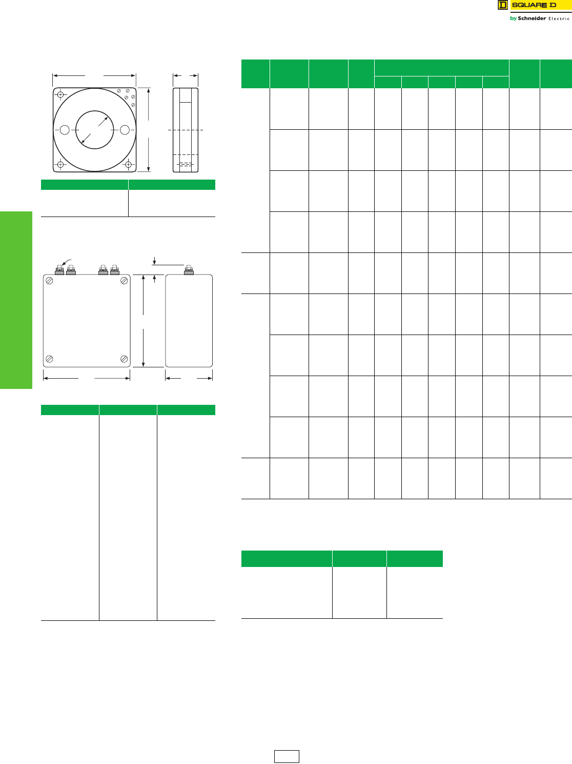
www.schneider-electric.us
6TRANSFORMERS
6-12 © 2012 Schneider Electric
All Rights Reserved
Instrument
600 Volt Class
Current Transformers: Bushing, Auxiliary
Class 4210 / Refer to Catalog 4210CT9701
Bushing Current Transformers 50–400 Hz
aSee chart on 6-11 for multi-ratio (MR) taps.
Auxiliary Current Transformers
NOTE: Model 81X Accuracy 0.3B0.1, B0.2, B0.5@60 Hz, RF=1.5@30 oC
Models 780R, 781R, 785R, 786R
Model T (inches)
780R
781R
785R
786R
3.38
3.38
6.75
6.75
Model 81X
Table 6.20: Mounting Brackets
Model Bracket $ Price
2NR MB1 9.00
5NR MB1
MB7
9.00
7RL 11.70
54R Included —
64R MB10 9.00
66R MB12 13.10
74R MB16 13.10
76R MB18 13.10
81X MB81 27.20
100R MB31 27.20
110R MB32 27.20
120R MB31 27.20
140R MB32 27.20
151R MB30 27.20
152R MB30 27.20
170R MB30 27.20
180R MB9 16.40
200R Included —
201R Included —
202R Included —
203R Included —
210R MB32 27.20
260R Not Available —
270R Not Available —
273 Not Available —
H2 H1
9.88
251
9.88
251
6.5
T
5.88
149 3.25
83
6.38
162
.75
19
10-32 Studs
Table 6.21: Bushing Current Transformers
Window
Size
(inches)
Catalog
Number
Current a
Rating
(Amperes)
Relay
Class
ANSI Accuracy Classification—60 Hz
Metering Class
Rating
Factor
30oC
Ambient
$ Price
B-0.1 B-0.2 B-0.5 B-0.9 B-1.8
6-1•2
780R500 50:5 ——————2.0723.00
780R750 75:5 C10 1.2 2.4 — — — 2.0 723.00
780R101 100:5 C10 2.4 2.4 — — — 2.0 723.00
780R151 150:5 C20 0.6 1.2 — — — 2.0 723.00
780R201 200:5 C20 0.6 1.2 2.4 — — 2.0 723.00
780R251 250:5 C20 0.6 0.6 1.2 2.4 — 2.0 723.00
780R301 300:5 C50 0.3 0.6 1.2 1.2 2.4 2.0 723.00
780R401 400:5 C50 0.3 0.3 0.6 1.2 1.2 2.0 723.00
780R501 500:5 C50 0.3 0.3 0.6 0.6 1.2 2.0 723.00
780R601 600:5 C100 0.3 0.3 0.3 0.6 0.6 2.0 723.00
780R751 750:5 C100 0.3 0.3 0.3 0.3 0.6 2.0 780.00
780R801 800:5 C100 0.3 0.3 0.3 0.3 0.6 2.0 780.00
780R102 1000:5 C100 0.3 0.3 0.3 0.3 0.3 2.0 780.00
780R122 1200:5 C200 0.3 0.3 0.3 0.3 0.3 2.0 780.00
780R152 1500:5 C200 0.3 0.3 0.3 0.3 0.3 2.0 780.00
780R162 1600:5 C200 0.3 0.3 0.3 0.3 0.3 2.0 813.00
780R202 2000:5 C200 0.3 0.3 0.3 0.3 0.3 2.0 813.00
780R252 2500:5 C200 0.3 0.3 0.3 0.3 0.3 2.0 813.00
780R302 3000:5 C200 0.3 0.3 0.3 0.3 0.3 2.0 813.00
780R402 4000:5 C200 0.3 0.3 0.3 0.3 0.3 1.5 867.00
6-1•2
781R601 600:5 MR C100 0.3 0.3 0.3 0.6 0.6 2.0 972.00
781R122 1200:5 MR C200 0.3 0.3 0.3 0.3 0.3 2.0 1023.00
781R202 2000:5 MR C200 0.3 0.3 0.3 0.3 0.3 2.0 1064.00
781R302 3000:5 MR C200 0.3 0.3 0.3 0.3 0.3 2.0 1083.00
781R402 4000:5 MR C200 0.3 0.3 0.3 0.3 0.3 1.5 1118.00
6-1•2
785R500 50:5 C10 2.4 2.4 — — — 2.0 1317.00
785R750 75:5 C20 1.2 1.2 — — — 2.0 1317.00
785R101 100:5 C20 1.2 1.2 2.4 — — 2.0 1317.00
785R151 150:5 C50 0.6 0.6 1.2 2.4 _ 2.0 1317.00
785R201 200:5 C50 0.6 0.6 1.2 2.4 2.4 2.0 1317.00
785R251 250:5 C50 0.3 0.6 1.2 1.2 2.4 2.0 1317.00
785R301 300:5 C100 0.3 0.3 0.6 0.6 1.2 2.0 1317.00
785R401 400:5 C100 0.3 0.3 0.3 0.6 1.2 2.0 1317.00
785R501 500:5 C100 0.3 0.3 0.3 0.6 0.6 2.0 1317.00
785R601 600:5 C200 0.3 0.3 0.3 0.3 0.6 2.0 1317.00
785R751 750:5 C200 0.3 0.3 0.3 0.3 0.3 2.0 1317.00
785R801 800:5 C200 0.3 0.3 0.3 0.3 0.3 2.0 1415.00
785R102 1000:5 C200 0.3 0.3 0.3 0.3 0.3 2.0 1415.00
785R122 1200:5 C400 0.3 0.3 0.3 0.3 0.3 2.0 1415.00
785R152 1500:5 C400 0.3 0.3 0.3 0.3 0.3 2.0 1415.00
785R162 1600:5 C400 0.3 0.3 0.3 0.3 0.3 2.0 1479.00
785R202 2000:5 C400 0.3 0.3 0.3 0.3 0.3 2.0 1479.00
785R252 2500:5 C400 0.3 0.3 0.3 0.3 0.3 2.0 1479.00
785R302 3000:5 C400 0.3 0.3 0.3 0.3 0.3 2.0 1479.00
785R402 4000:5 C400 0.3 0.3 0.3 0.3 0.3 1.5 1577.00
6-1•2
786R601 600:5 MR C200 0.3 0.3 0.3 0.3 0.3 2.0 1566.00
786R122 1200:5 MR C400 0.3 0.3 0.3 0.3 0.3 2.0 1664.00
786R202 2000:5 MR C400 0.3 0.3 0.3 0.3 0.3 2.0 1722.00
786R302 3000:5 MR C400 0.3 0.3 0.3 0.3 0.3 2.0 1749.00
786R402 4000:5 MR C400 0.3 0.3 0.3 0.3 0.3 1.5 1823.00
Table 6.22: Auxiliary Current Transformers
Catalog Number
(without brackets) Ratio $ Price
81X05000100
81X05000200
81X05000250
81X05000500
81X07500500
81X10000500
81X12500500
81X15000500
5:1
5:2
5:2.5
5:5
7.5:5
10:5
12.5:5
15:5
990.00
990.00
990.00
990.00
990.00
990.00
990.00
990.00
PA1 Discount
Schedule

7-1
© 2012 Schneider Electric
All Rights Reserved
7INTERNATIONAL LOAD
CENTERS
Table of Contents
Section 7
International Load Centers
Circuit Breaker Load Centers
International Miniature Circuit Breakers
QO™ Plug-On and Bolt-On Circuit Breakers and Switches 7-2
Plug-On QOXD and Bolt-On QOBXD 7-3
Load Centers
IEC Certified QO™ Load Centers, Type 1 (Indoor) 7-4
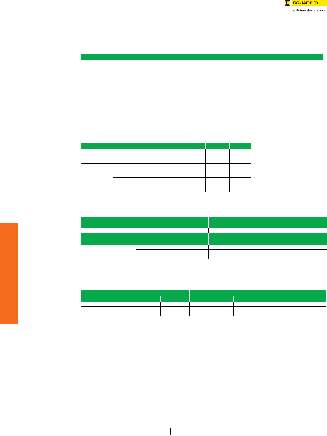
7-2 © 2012 Schneider Electric
All Rights Reserved
www.schneider-electric.us
7INTERNATIONAL LOAD
CENTERS
International Miniature
Circuit Breakers
QO™ Plug-On and Bolt-On Circuit Breakers and Switches
General Description
In 1955 Square D Company introduced the QO™ Plug-on System and revolutionized the way electrical contractors
install miniature circuit breakers in the United States. Today as part of Schneider Electric™ we offer the same Plug-on
System technology around the world. IEC certified QO products are available for residential, commercial and industrial
applications.
Characteristics
•Circuit breakers are rated 240 Vac single phase and 415 Vac three phase, 50/60 Hz.
•Circuit breakers are available in 1-, 2- or 3-pole construction.
•Thermal trip elements are factory calibrated to 40°C (IEC 947-2) and 30°C (IEC 898) ambient temperature.
•Trip-free handle ensures tripping even when the circuit breaker is held or locked in the ON position.
•Circuit breakers are in compliance with international standards set by the International Electrotechnical Commission (IEC).
•The CE marking is located on each circuit breaker in accordance with the low voltage directive of the European Union.
•The entire QO circuit breaker family provides the advantage of a plug-on connection. (Bolt-on connections also available)
Accessories
Circuit Breaker Operating Characteristics
Main Switches
Table 7.1: International Miniature Circuit Breaker Description
Circuit Breaker Description 1Ø Consumer Units 3Ø Distribution Boards
QOXD Branch circuit breaker X X
Table 7.2: Accessories
Accessory Description Cat. No. QOXD
Handle Tie Ties two 1P circuit breakers together QO1HT X
Handle Lock-Off
(Clamp)
Attaches to 1P circuit breaker handles QO1LO X
Attaches to 1P, 2P, 3P circuit breaker handles HLO1 X
Handle Padlock
Attachment
Attaches to 1P, 2P, 3P circuit breaker handles QOEPLA —
Attaches to 1P circuit breaker handles QOE1PL —
Attaches to 1P circuit breaker escutcheon (fixed) QO1PA X
Attaches to 1P circuit breaker handles (removable) QOHPL X
Attaches to 2P, 3P circuit breaker handles (removable) QO1HPL X
Attaches to 2P circuit breaker handles (removable) GFI2PA —
Table 7.3: Branch Circuit Breakers
Cat. No. Prefix Number of Poles Continuous
Ampere Rating
IEC 898 Service Rating Icn Tripping Characteristics
Plug-on Bolt-on 240 V 415 V
QOXD QOBXD 1, 2, 3 10–32 A 3000 3000 Type D (10–20 In)
Cat. No. Prefix Number of Poles Continuous
Ampere Rating
IEC 947-2 Service Rating Icu (Ics) —
Plug-on Bolt-on 240 V 415 V —
QOXD QOBXD
1, 2, 3 10–32 A 3000 (100%) 3000 (100%) —
1 40–63 A 3000 (50%) — —
2, 3 40–100 A — 3000 (50%) —
Table 7.4: QO-M Plug-On Main Incomer Switch
240 V Certified to IEC 947-3
Ampere Rating 1P 2P 3P and 4P
Cat. No. $ Price Cat. No. $ Price Cat. No. $ Price
100 A N/A — N/A — N/A —
125 A N/A — N/A — QO3100M 116.00
125 A–4P N/A — N/A — QO4100M 200.00
DE2A Discount
Schedule
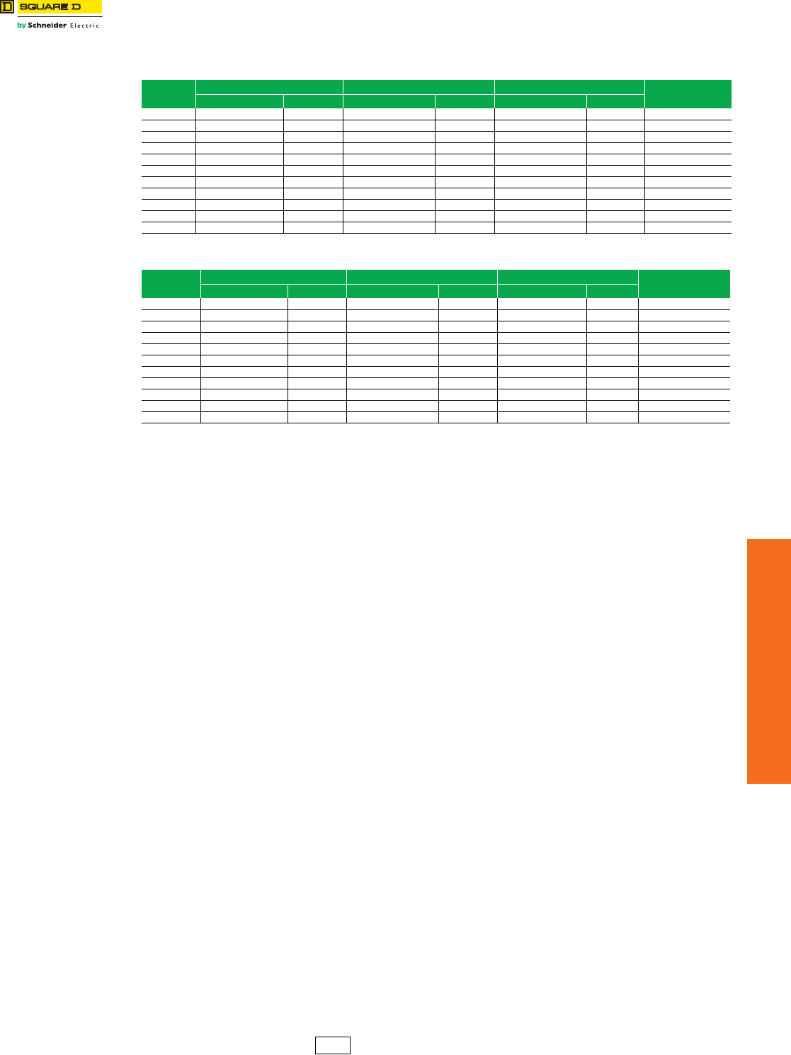
www.schneider-electric.us
© 2012 Schneider Electric
All Rights Reserved 7-3
7INTERNATIONAL LOAD
CENTERS
International Miniature
Circuit Breakers
Plug-On QOXD and Bolt-On QOBXD
Class 738, 739
Short circuit ratings . . . . . . . . . . . . . . . . . . . . . . . . . . . . . . . . . . . . . . .Page 7-2
Accessories . . . . . . . . . . . . . . . . . . . . . . . . . . . . . . . . . . . . . . . . . . . . .Page 7-2
Table 7.5: QOXD Thermal-Magnetic, Plug-On Miniature Circuit Breakers
240/415 V 10–32 A Certified to IEC 898 at 3 kA, 40–100 A Certified to IEC 947-2 at 3 kA
Ampere
Rating
1P 2P 3P Terminal Capacity
Range
Cat. No. $ Price Cat. No. $ Price Cat. No. $ Price
10 A QOXD110 20.40 QOXD210 46.90 QOXD310 165.00 2.5–6 mm2
16 A QOXD116 20.40 QOXD216 46.90 QOXD316 165.00 2.5–6 mm2
20 A QOXD120 20.40 QOXD220 46.90 QOXD320 165.00 2.5–6 mm2
25 A QOXD125 20.40 QOXD225 46.90 QOXD325 165.00 2.5–6 mm2
32 A QOXD132 20.40 QOXD232 46.90 QOXD332 165.00 2.5–6 mm2
40 A QOXD140 20.40 QOXD240 46.90 QOXD340 165.00 10–25 mm2
45 A QOXD145 20.40 QOXD245 46.90 QOXD345 165.00 10–25 mm2
50 A QOXD150 20.40 QOXD250 46.90 QOXD350 165.00 10–25 mm2
63 A QOXD163 20.40 QOXD263 46.90 QOXD363 165.00 10–25 mm2
80 A N/A — QOXD280 132.00 QOXD380 244.00 25–50 mm2
100 A N/A — QOXD2100 132.00 QOXD3100 244.00 25–50 mm2
Table 7.6: QOBXD Thermal-Magnetic, Bolt-On Miniature Circuit Breakers
240/415 V 10–32 A Certified to IEC 898 at 3 kA, 40–100 A Certified to IEC 947-2 at 3 kA
Ampere Rating 1P 2P 3P Terminal Capacity
Range
Cat. No. $ Price Cat. No. $ Price Cat. No. $ Price
10 A QOBXD110 26.50 QOBXD210 59.00 QOBXD310 195.00 2.5–6 mm2
16 A QOBXD116 26.50 QOBXD216 59.00 QOBXD316 195.00 2.5–6 mm2
20 A QOBXD120 26.50 QOBXD220 59.00 QOBXD320 195.00 2.5–6 mm2
25 A QOBXD125 26.50 QOBXD225 59.00 QOBXD325 195.00 2.5–6 mm2
32 A QOBXD132 26.50 QOBXD232 59.00 QOBXD332 195.00 2.5–6 mm2
40 A QOBXD140 26.50 QOBXD240 59.00 QOBXD340 195.00 10–25 mm2
45 A QOBXD145 26.50 QOBXD245 59.00 QOBXD345 195.00 1–25 mm2
50 A QOBXD150 26.50 QOBXD250 59.00 QOBXD350 195.00 10–25 mm2
63 A QOBXD163 26.50 QOBXD263 59.00 QOBXD363 195.00 10–25 mm2
80 A N/A — QOBXD280 160.00 QOBXD380 279.00 25–50 mm2
100 A N/A — QOBXD2100 160.00 QOBXD3100 279.00 25–50 mm2
DE2A Discount
Schedule
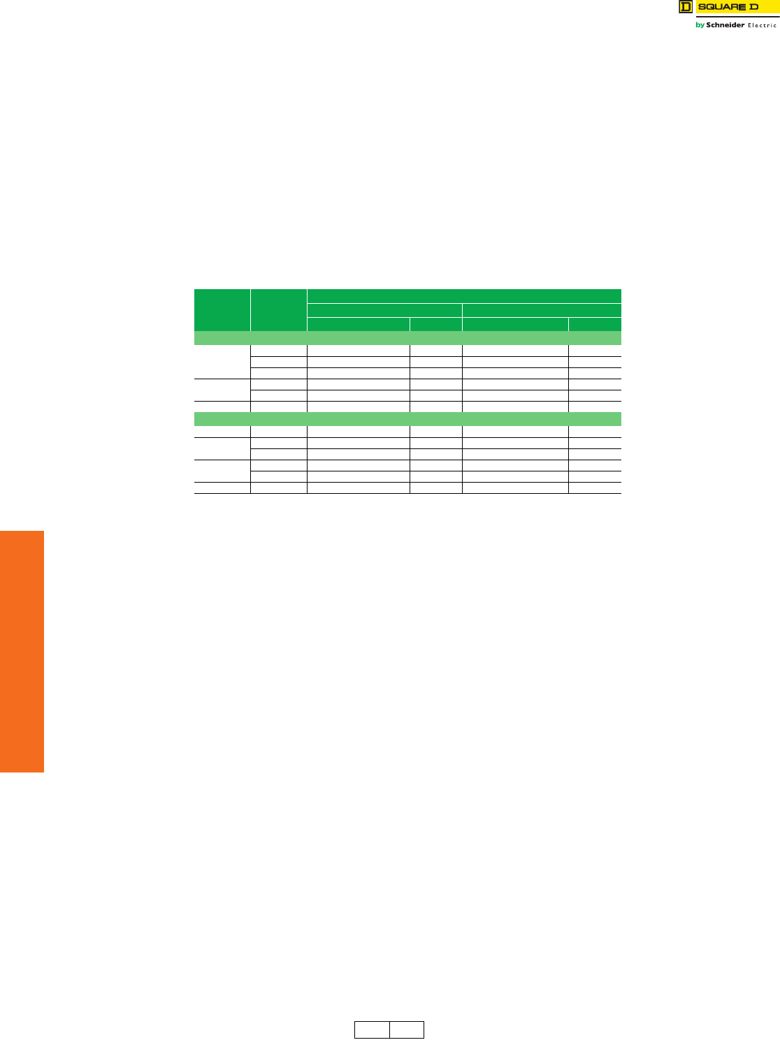
7-4 © 2012 Schneider Electric
All Rights Reserved
www.schneider-electric.us
7INTERNATIONAL LOAD
CENTERS
Load Centers IEC Certified QO™ Load Centers, Type 1 (Indoor)
Application Data
Square D™ QO™ Three-Phase Circuit Breaker Load Centers can be certified to IEC 60439-1 and 60439-3. Contact
your local Field Sales office for more information. They are designed to meet residential, commercial, and industrial
requirements to protect electrical systems and equipment.
Features
•Three phase construction
•100, 125, 150, 200 and 225 A mains ratings with main lugs or main circuit breaker
•12-42 circuit indoor version
•Flush or surface mounting
•Straight-in wiring to minimize service cable installation
•Top or bottom feed
•Automatic flush adjustment cover to speed installation
•Covers sold separately
•Products are stocked in USA
•Bus on 12-42 circuit load centers is one piece, solid copper
•Order entry point is Lexington
•For more information, contact your local Field Sales office.
aF/S at end of catalog number indicates to order F for flush device or S for surface device.
bDiscount Schedule DE3A
Table 7.7: Load Centers
Mains Rating
Ampere
Spaces/
Max. Poles
Type 1
Box and Interior Cover With Door
Cat. No. $ Price Cat. No.a$ Price
Main Lugs 240/415 Vac 3Ø4W
125 A
12 QO312L125G 221.00 QOC16UF/Sb25.10
20 QO320L125G 314.00 QOC24UF/Sb25.10
24 QO324L125G 360.00 QOC24UF/Sb25.10
200 18 QO318L200G 295.00 QOC30UF/Sb58.00
30 QO330L200G 413.00 QOC30UF/Sb58.00
225 42 QO342L225G 561.00 QOC42UF/Sb74.00
Main Circuit Breaker 240/415 Vac 3Ø4W
125 30 QO330MQ125 1226.00 QOC342MQF/S 61.00
150 30 QO330MQ150 1226.00 QOC342MQF/S 61.00
42 QO342MQ150 1351.00 QOC342MQF/S 61.00
200 30 QO330MQ200 1226.00 QOC342MQF/S 61.00
42 QO342MQ200 1351.00 QOC342MQF/S 61.00
225 42 QO342MQ225 1351.00 QOC342MQF/S 61.00
DE3 DE3A Discount
Schedule

8-1
© 2012 Schneider Electric
All Rights Reserved
8INTERNATIONAL SAFETY
SWITCHES
Table of Contents
Section 8
International Safety Switches
General Duty Safety Switches
CSA Certified General Duty—Fusible 240 Vac 8-2
Heavy Duty Safety Switches
CSA Certified Heavy Duty—Fusible 240 Vac 8-3
CSA Certified Heavy Duty—Fusible 600 Vac 8-3
CSA Certified Heavy Duty—Non-Fusible 600 Vac 8-4
CSA Certified Heavy Duty—Special Applications 8-4
Double-Throw Safety Switches
CSA Certified Double-Throw 8-5
Accessories
CSA Certified Switch Accessories 8-6
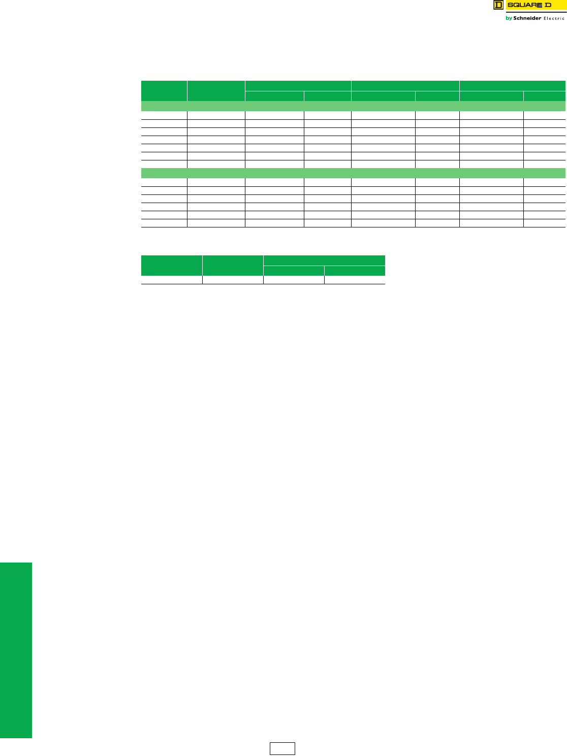
8-2 © 2012 Schneider Electric
All Rights Reserved
www.schneider-electric.us
8INTERNATIONAL SAFETY
SWITCHES
General Duty Safety
Switches
International
Class 736, 1130
CSA Certified General Duty—Fusible 240 Vac
•Switches have factory-installed ground bars.
•Optional accessories are listed on page 8-6.
aNot suitable for use as service entrance equipment.
bNot suitable for use as service equipment.
Table 8.1: General Duty Single-Throw 120/240 Vac (Plug); 240 Vac (Cartridge)
Ampere Fuse Type 1 Type 3R Field Installable Class R Fuse Kits
Cat. No. $ Price Cat. No. $ Price Cat. No. $ Price
2-Pole + S/N (2 Blades and Fuseholders, 1 S/N)—Suitable For Service Entrance Use
30 Plug CD211Na104.00 ————
30 Cartridge CD221Na137.00 ——DRK30 25.70
60 — CD222N 221.00 CD222NRB 339.00 RFK03H 25.50
100 — CD223N 485.00 CD223NRB 543.00 RFK10 47.70
200 — CD224N 947.00 CD224NRB 1200.00 HRK1020 47.70
400 — CD225N 2610.00 CD225NR —DRK40 111.00
600 — CD226N 5166.00 CD226NR —DRK600 111.00
3-Pole + S/N (3 Blades and Fuseholders, 1 S/N)—Suitable For Service Entrance Use
30 Cartridge CD321Na146.00 CD321NRB 494.00 DRK30 25.70
60 — CD322N 366.00 CD322NRB 743.00 RFK03H 25.50
100 — CD323N 485.00 CD323NRB 1371.00 RFK10 47.70
200 — CD324N 2019.00 CD324NRB 2454.00 HRK1020 47.70
400 — CD325N 3113.00 CD325NR —DRK40 111.00
600 — CD326N 5823.00 CD326NR —DRK600 111.00
Table 8.2: Light Duty Single-Throw 120 Vac Plug
Ampere Fuse Type 1
Cat. No. $ Price
30 Plug L111Nb54.00
DE1A Discount
Schedule
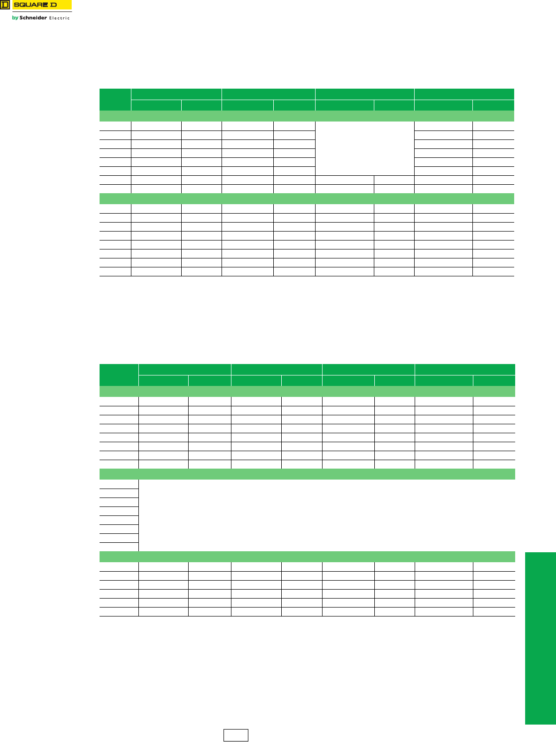
www.schneider-electric.us
8INTERNATIONAL SAFETY
SWITCHES
© 2012 Schneider Electric
All Rights Reserved 8-3
Heavy Duty Safety
Switches
International
Class 736, 1130
CSA Certified Heavy Duty—Fusible 240 Vac
•Switches have factory-installed ground bars.
•Switches 30–200 A Type 4/4X and 3R/12 have viewing windows.
•Optional accessories are listed on page 8-6.
aDual UL Listed and CSA Certified device.
CSA Certified Heavy Duty—Fusible 600 Vac
•Switches have factory-installed ground bars.
•Switches 30–200 A Type 4/4X and 3R/12 have viewing windows.
•Optional accessories are listed on page 8-6.
aDual UL Listed and CSA Certified device.
Table 8.3: Single-Throw 240 Vac, 250 Vdc
Ampere Type 1 Type 3R Type 4/4X Type 12
Cat. No. Price Cat. No. $ Price Cat. No. $ Price Cat. No. $ Price
2P + S/N (2 Blades and Fuseholders, 1 S/N)—Suitable For Service Entrance Use
30 A CH221N 251.00 CH221NRB 480.00
Use 3P devices
listed below.
CH221NAWK 620.00
60 A CH222N 504.00 CH222NRB 893.00 CH222NAWK 791.00
100 A CH223N 807.00 CH223NRB 1196.00 CH223NAWK 1250.00
200 A CH224N 1409.00 CH224NRB 1695.00 CH224NAWK 1964.00
400 A CH225N 3246.00 CH225NR 4568.00 CH225NAWK 4409.00
600 A CH226N 6219.00 CH226NR 8061.00 CH226NAWK 6936.00
800 A H227Na10067.00 H227NRa12216.00 ——H227NAWKa12338.00
1200 A H228Na12422.00 H228NRa16665.00 ——H228NAWKa17184.00
3P + S/N (3 Blades and Fuseholders, 1 S/N)—Suitable For Service Entrance Use
30 A CH321N 339.00 CH321NRB 596.00 CH321NDS 2201.00 CH321NAWK 750.00
60 A CH322N 569.00 CH322NRB 947.00 CH322NDS 2687.00 CH322NAWK 1007.00
100 A CH323N 941.00 CH323NRB 1398.00 CH323NDS 5651.00 CH323NAWK 1625.00
200 A CH324N 1580.00 CH324NRB 1896.00 CH324NDS 7836.00 CH324NAWK 2249.00
400 A CH325N 3977.00 CH325NR 4650.00 CH325NDS 15321.00 CH325NAWK 4737.00
600 A CH326N 6845.00 CH326NR 9164.00 CH326NDS 21759.00 CH326NAWK 7863.00
800 A H327Na12189.00 H327NRa15563.00 ——H327NAWKa15879.00
1200 A H328Na15314.00 H328NRa19709.00 ——H328NAWKa20015.00
Table 8.4: Single-Throw 600 Vac, 600 Vdc
Ampere Type 1 Type 3R Type 4/4X Type 12
Cat. No. $ Price Cat. No. $ Price Cat. No. $ Price Cat. No. $ Price
3-Pole (3 Blades and Fuseholders)
30 A CH361 379.00 CH361RB 636.00 CH361DS 1714.00 CH361AWK 667.00
60 A CH362 453.00 CH362RB 744.00 CH362DS 1881.00 CH362AWK 686.00
100 A CH363 868.00 CH363RB 1191.00 CH363DS 3729.00 CH363AWK 1079.00
200 A CH364 1233.00 CH364RB 1620.00 CH364DS 5184.00 CH364AWK 1649.00
400 A CH365 3186.00 CH365R 3872.00 CH365DS 10214.00 CH365AWK 3641.00
600 A CH366 5354.00 CH366R 7703.00 CH366DS 14601.0 CH366AWK 6135.00
800 A H367a8879.00 H367Ra11000.00 ——H367AWKa10901.00
1200 A H368a11671.00 H368Ra13339.00 ——H368AWKa13137.00
3-Pole + S/N (3 Blades and Fuseholders, 1 S/N)—Suitable For Service Entrance Use
30 A
For 3 pole switches 30 A–1200 A with solid neutral
attachment, select switch from 3-Pole table
above and add the Solid Neutral Assembly Kit
from the Accessories -page 8-6
60 A
100 A
200 A
400 A
600 A
800 A
1200 A
4-Pole (4 Blades and Fuseholders)—Not Suitable For Service Entrance Use
30 A H461a609.00 ————H461AWKa743.00
60 A H462a710.00 ————H462AWKa838.00
100 A H463a1185.00 ————H463AWKa1288.00
200 A H464a2008.00 ————H464AWKa2218.00
400 A CH465 4140.00 ————CH465AWK 4538.00
600 A CH466 6736.00 ——————
DE1 Discount
Schedule
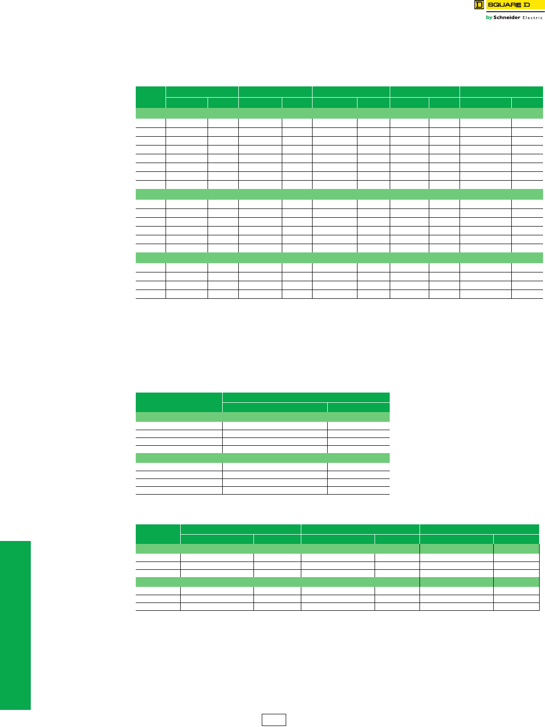
8-4 © 2012 Schneider Electric
All Rights Reserved
www.schneider-electric.us
8INTERNATIONAL SAFETY
SWITCHES
Heavy Duty Safety
Switches
International
Class 736, 1130
CSA Certified Heavy Duty—Non-Fusible 600 Vac
•Switches have factory-installed ground bars.
•Switches 30–200 A Type 4/4X and 3R/12 have viewing windows.
•Optional accessories are listed on page 8-6.
aDual UL Listed and CSA Certified devices.
bF Series devices.
CSA Certified Heavy Duty—Special Applications
•Switches have factory-installed ground bars.
•Optional accessories are listed on page 8-6.
aF Series devices.
bDual UL Listed and CSA Listed device.
Table 8.5: Single-Throw 600 Vac, 600 Vdc
Ampere Type 1 Type 3R Type 4/4X Type 7/9 Type 3R/12
Cat. No. $ Price Cat. No. $ Price Cat. No. $ Price Cat. No. $ Price Cat. No. $ Price
3P
30 A CHU361 305.00 CHU361RB 530.00 CHU361DS 2184.00 ——CHU361AWK 692.00
60 A CHU362 530.00 CHU362RB 932.00 CHU362DS 2568.00 H60XFAa2571.00 CHU362AWK 873.00
100 A CHU363 878.00 CHU363RB 1343.00 CHU363DS 5199.00 H100XFAa3045.00 CHU363AWK 1281.00
200 A CHU364 1325.00 CHU364RB 1616.00 CHU364DS 7055.00 ——CHU364AWK 1686.00
400 A CHU365 3054.00 CHU365RB 6216.00 CHU365DS 14397.00 ——CHU365AWK 4127.00
600 A CHU366 5352.00 CHU366R 8180.00 CHU366DS 19358.00 ——CHU366AWK 6816.00
800 A HU367a9978.00 HU367Ra13050.00 ————HU367AWKa13097.00
1200 A HU368a13421.00 HU368Ra17867.00 ————HU368AWKa17940.00
4P, 600 Vac, 600 Vdc
30 A HU461ab 827.00 —— — ———HU461AWKab 915.00
60 A HU462ab 914.00 —— — ———HU462AWKab 1008.00
100 A HU463ab 1647.00 —— — ———HU463AWKab 1791.00
200 A HU464a2454.00 —— — ———HU464AWK 2937.00
400 A CHU465 5201.00 —— — ———CHU465AWK 5775.00
600 A CHU466 9072.00 —— — ———CHU466AWK —
6P, 600 Vac
30 A — — — — — — — — HU661AWKa3357.00
60 A — — — — — — — — HU662AWKa3884.00
100 A — — — — — — — — HU663AWKa4793.00
200 A — — — — — — — — HU664AWK 10571.00
Table 8.6: Fiberglass Reinforced Polyester NEMA 4X Enclosures
Single-Throw 600 Vac, 600 Vdc
Amperes Type 4X
Cat. No. $ Price
3P Fusible
30 A H361DFba 3570.00
60 A H362DFba 3968.00
100 A H363DFba 7613.00
200 A H364DFb9729.00
3P Non-Fusible
30 A HU361DFba 3402.00
60 A HU362DFba 3782.00
100 A HU363DFba 7241.00
200 A HU364DFb9695.00
Table 8.7: Receptacle Switches—Single-Throw 600 Vac
Ampere Stainless Steel Type 4/4X Type 12 Use With Plug
Cat. No. $ Price Cat. No. $ Price Cat. No. $ Price
3P Fusible
30 A CH361DSWC 4322.00 CH361AWC 2243.00 APJ3485 1235.00
60 A CH362DSWC 4581.00 CH362AWC 2459.00 APJ6485 1295.00
100 A CH363DSWC 8309.00 CH363AWC 3689.00 APJ10487 1928.00
3P Non-Fusible
30 A CHU361DSWC 3927.00 CHU361AWC 2058.00 APJ3485 1235.00
60 A CHU362DSWC 4325.00 CHU362AWC 2310.00 APJ6485 1295.00
100 A CHU363DSWC 7863.00 CHU363AWC 3282.00 APJ10487 1928.00
DE1 Discount
Schedule
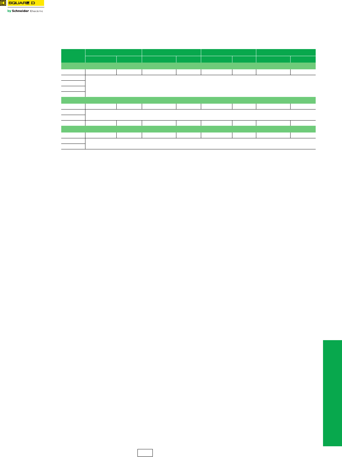
www.schneider-electric.us
8INTERNATIONAL SAFETY
SWITCHES
© 2012 Schneider Electric
All Rights Reserved 8-5
Double-Throw Safety
Switches
International
Class 736, 1130
CSA Certified Double-Throw
•Switches have factory-installed ground bars.
•Optional accessories are listed on page 8-6.
a240 Vac Maximum
bFor isolation only, not Load-Make/Load-Break.
Table 8.8: Double-Throw
Ampere Type 1 Type 3R Type 4/4X Type 12
Cat. No. $ Price Cat. No. $ Price Cat. No. $ Price Cat. No. $ Price
2P 240 Vac—250 Vdc
30 A C92251 615.00 ——————
60 A
For 2P switch applications, select
3P switch 60–600 A from 3P table below.
100 A
200 A
400 A
3P 600 Vac—250 Vdc
30 A C92351a716.00 ——————
60 A For 60–100 A, use US devices.
100 A
200 A C82344b2813.00 C82344RBb5898.00 C82344DSb11444.00 CH82344b7532.00
4P 600 Vac
30 A C92451a981.00 ——————
60 A For 60–100 A, use US devices.
100 A
DE1 Discount
Schedule
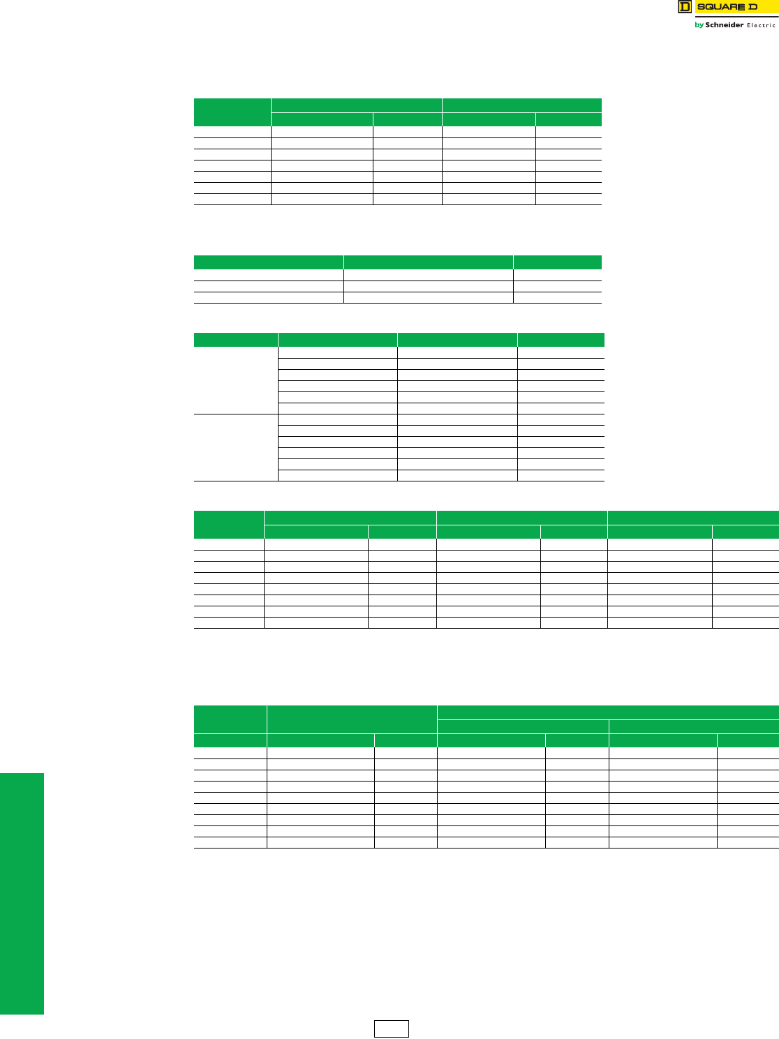
8-6 © 2012 Schneider Electric
All Rights Reserved
www.schneider-electric.us
8INTERNATIONAL SAFETY
SWITCHES
Double-Throw Safety
Switch
Accessories
Class 736, 1130
CSA Certified Switch Accessories
•Optional
aNot for C92251, C92351, C92451.
bE-series uses EK1020-1 or -2. Requires 2
cC92251, C92351, C92451 uses DT30SN.
dNot Stocked—Order Only.
•Optional
Table 8.9: Electrical Interlock Kits
Ampere Single-Throw Double-Throw Type 1 Only
Cat. No. $ Price Cat. No. $ Price
30–100 A EIK-1 or -2 311.00 EIK-1 or -2a311.00
200 A-3P EIK-1 or -2b311.00 EK200DTU2 389.00
200 A-4P EIK-1 or -2b311.00 EK100DTU2 389.00
400 A EIK4060-1 or -2 533.00 EK400DTU2 389.00
600 A EIK4060-1 or -2 533.00 ——
800 A EIK4060-1 or -2 533.00 ——
1200 A EIK4060-1 or -2 533.00 ——
Table 8.10: Fuse Puller Kitsd
Ampere Cat. No. $ Price
30 A FPK03 30.20
60 A FPK0610 42.60
100 A FPK0610 42.60
Table 8.11: Class R Fuse Kits
Voltage Ampere Cat. No. $ Price
240 Vac
30 A RFK03L 25.50
60 A RFK03H 25.50
100 A RFK10 47.70
200 A HRK1020 47.70
400 A HRK4060 111.00
600 A HRK4060 111.00
600 Vac
30 A RFK03H 25.50
60 A RFK06H 25.50
100 A RFK10 47.70
200 A HRK1020 47.70
400 A HRK4060 111.00
600 A HRK4060 111.00
Table 8.12: Solid Neutral Assembly Kitsd
Ampere Single-Throw Type 1, 3R Single-Throw (Copper) Type 4, 4X Double-Throw Type 1
Cat. No. $ Price Cat. No. $ Price Cat. No. $ Price
30 A CSN03 83.00 CSN03C 102.00 SN0310c114.00
60 A CSN0610 107.00 CSN0610C 114.00 SN0310 114.00
100 A CSN0610 107.00 CSN0610C 114.00 SN0310 114.00
200 A CSN20 200.00 CSN20C 252.00 225SNA 198.00
400 A CH600SN 327.00 CH600SNC 453.00 DT400N 458.00
600 A CH600SN 327.00 CH600SNC 453.00 ——
800 A H800SNE4 753.00 ————
1200 A H1200SNE4 1034.00 ————
Table 8.13: Hubs
Size Type 3R Type 4/4X/12
Standard Zinc Chrome Plated Zinc
Inches Cat. No. $ Price Cat. No. $ Price Cat. No. $ Price
0.50 — — H050 31.10 H050CP 40.70
0.75 B075 35.00 H075 45.00 H075CP 57.00
1.00 B100 35.00 H100 47.10 H100CP 65.00
1.25 B125 35.00 H125 54.00 H125CP 67.00
1.50 B150 35.00 H150 83.00 H150CP 96.00
2.00 B200 65.00 H200 120.00 H200CP 137.00
2.50 B250 107.00 H250 138.00 ——
3.00 — — H300 177.00 ——
CAP BCAP 3.80 ————
DE1 Discount
Schedule

9-1
© 2012 Schneider Electric
All Rights Reserved
9INTERNATONAL CIRCUIT
BREAKERS
Table of Contents
Section 9
International Circuit Breakers
Thermal-Magnetic Circuit Breakers
SF and SL Circuit Breakers, IEC Rated 415/240 Vac Max. 9-2
Electronic Trip Circuit Breakers
P-frame, 3P, Micrologic™ Electronic-Trip Unit, IEC Rated 9-3
R-frame, 3P, Micrologic™ Electronic-Trip Unit, IEC Rated 9-4
P-frame, 4P, Micrologic™ Electronic-Trip Unit, IEC Rated 9-5
R-frame, 4P, Micrologic™ Electronic-Trip Unit, IEC Rated 9-6
Breaking Capacities 9-7
Circuit Breaker Dimensions 9-8
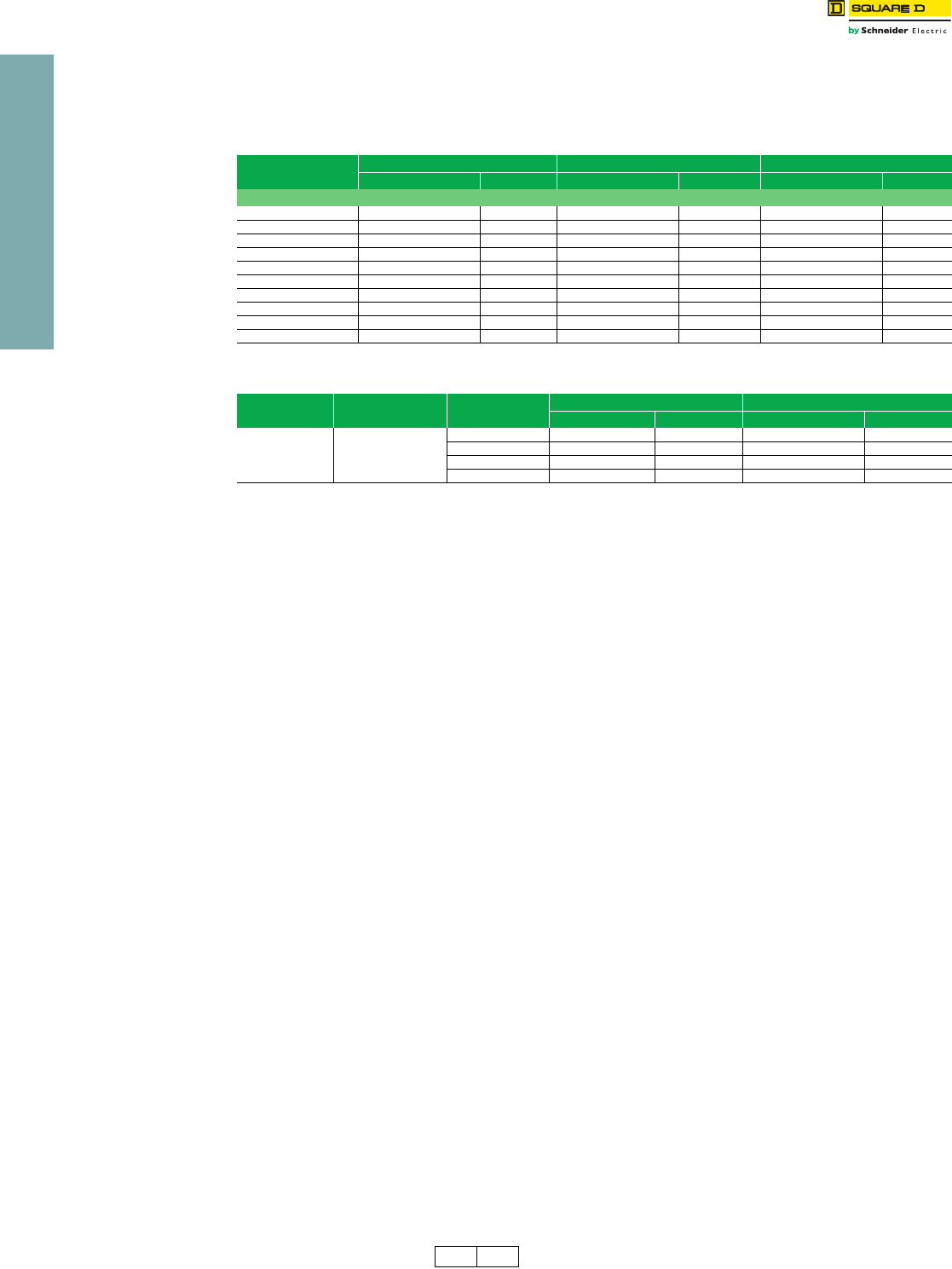
9-2 © 2012 Schneider Electric
All Rights Reserved
www.schneider-electric.us
9INTERNATONAL CIRCUIT
BREAKERS
Thermal-Magnetic
Circuit Breakers
SF and SL Circuit Breakers, IEC Rated 415/240 Vac Max.
Class 600
•CE marking.
•S-frame circuit breakers are CCC Certified.
•International products—for export use only.
•MCCBs in I-Line™ plug-on construction and a complete line of accessories are available. Contact your local Field Sales office.
•Order entry point is Cedar Rapids, Iowa.
aDE2A Discount Schedule
bAdd suffix K for CCC label
Table 9.1: SFAL, Individually-Mounted, IEC Rated Circuit Breakers, 415/240 Vac Max., 50/60 Hz, 1P, 2P, and 3P
Ampere Rating 1P 2P 3P
Cat. No. $ Price Cat. No. $ Price Cat. No. $ Price
SFALb
16 A SFAL1016 450.00 SFAL2016 704.00 SFAL3016 906.00
20 A SFAL1020 450.00 SFAL2020 704.00 SFAL3020 906.00
32 A SFAL1032 450.00 SFAL2032 704.00 SFAL3032 906.00
40 A SFAL1040 450.00 SFAL2040 704.00 SFAL3040 906.00
50 A SFAL1050 450.00 SFAL2050 704.00 SFAL3050 906.00
63 A SFAL1063 450.00 SFAL2063 704.00 SFAL3063 906.00
80 A SFAL1080 510.00 SFAL2080 890.00 SFAL3080 1115.00
100 A SFAL1100 510.00 SFAL2100 890.00 SFAL3100 1115.00
125 A — — SFAL2125 1076.00 SFAL3125 1262.00
160 A — — SFAL2160 1259.00 SFAL3160 1449.00
Table 9.2: SLAL Individually-Mounted, IEC Rated Circuit Breakers, 415/240 Vac Max., 50/60 Hz, 2P and 3P
Frame Size Circuit Breaker Type Ampere
Rating
2P 3P
Cat. No. $ Price Cat. No. $ Price
400 A SLALb
250 A SLAL2250 3807.00 SLAL3250 4619.00
300 A SLAL2300 3807.00 SLAL3300 4619.00
350 A SLAL2350 3807.00 SLAL3350 4619.00
400 A SLAL2400 3807.00 SLAL3400 4619.00
DE2 DE2A Discount
Schedule
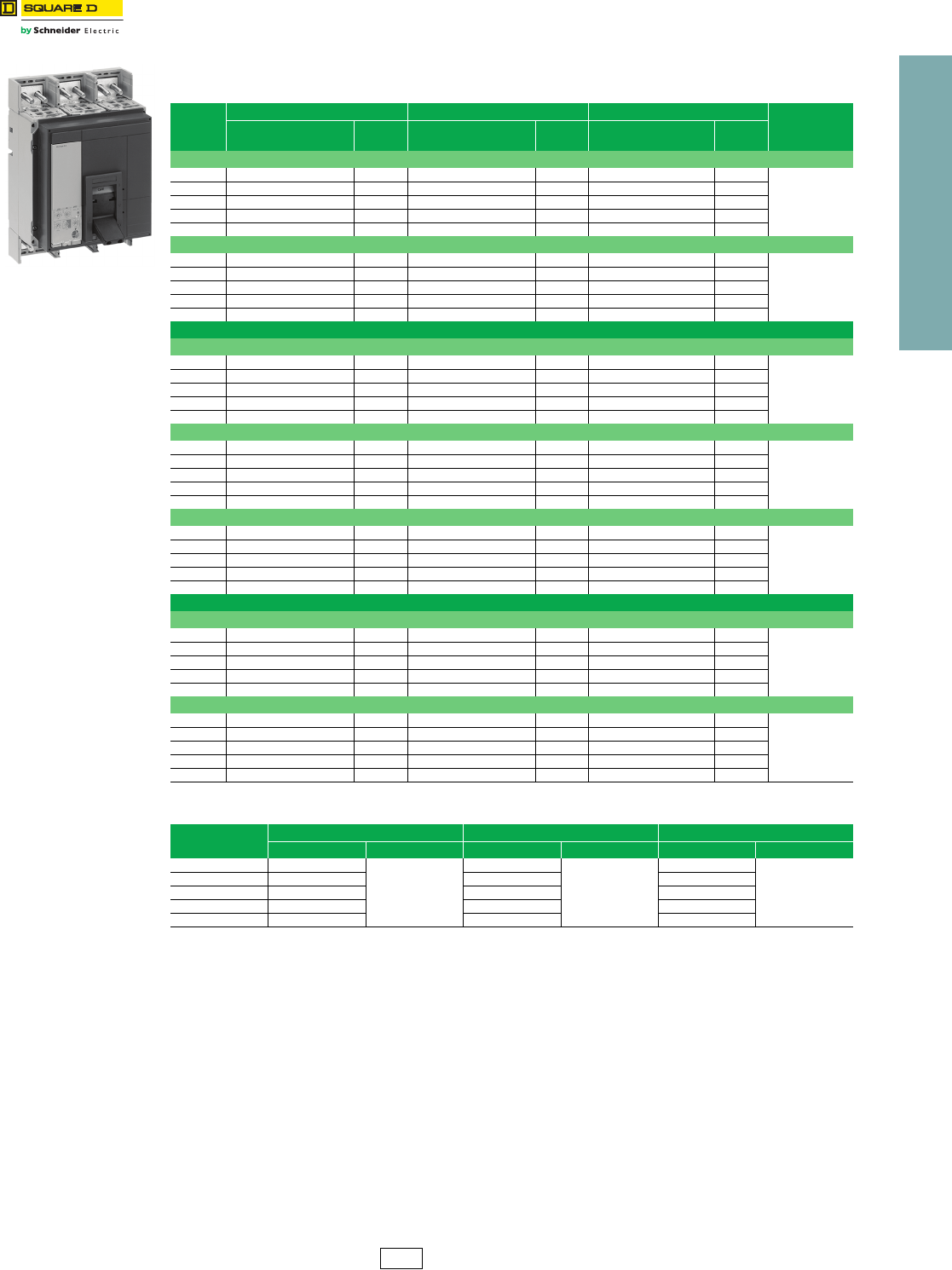
www.schneider-electric.us
9INTERNATONAL CIRCUIT
BREAKERS
© 2012 Schneider Electric
All Rights Reserved 9-3
Electronic Trip Circuit
Breakers
P-frame, 3P, Micrologic™ Electronic-Trip Unit, IEC Rated
Class 612
Note: See Digest for accessories and other information.
Table 9.3: P-frame—1600 A, Individually-Mounted, Micrologic™ Electronic Trip Unit,
IEC Rated
Sensor
Rating
N Interrupting H Interrupting L Interrupting Terminal
Wire
Range
(AWG–kcmil)
Cat. No. $ Price Cat. No. $ Price Cat. No. $ Price
3P, 690 Vac 50/60 Hz with LS0 Trip Functions
630 A PNLE36063U32R 13958.00 PHLE36063U32R 14792.00 PLLE36063U32R 15626.00
(4) 3/0–500
Al/Cu
800 A PNLE36080U32R 13958.00 PHLE36080U32R 14792.00 PLLE36080U32R 15626.00
1000 A PNLE36100U32R 18843.00 PHLE36100U32R 19985.00 PLLE36100U32R 21128.00
1250 A PNLE36125U32R 18843.00 PHLE36125U32R 19985.00 ——
1600 A PNLE36160U32R 20163.00 PHLE36160U32R 21384.00 ——
3P, 690 Vac 50/60 Hz with LSI Trip Functions
630 A PNLE36063U33R 14280.00 PHLE36063U33R 15114.00 PLLE36063U33R 15947.00
(4) 3/0–500
Al/Cu
800 A PNLE36080U33R 14280.00 PHLE36080U33R 15114.00 PLLE36080U33R 15947.00
1000 A PNLE36100U33R 19166.00 PHLE36100U33R 20309.00 PLLE36100U33R 21450.00
1250A PNLE36125U33R 19166.00 PHLE36125U33R 20309.00 ——
1600A PNLE36160U33R 20508.00 PHLE36160U33R 21731.00 ——
Micrologic Ammeter Trip Unit
3P, 690 Vac 50/60 Hz with LS0 Trip Functions
630 A PNLE36063U42R 14768.00 PHLE36063U42R 15600.00 PLLE36063U42R 16434.00
(4) 3/0–500
Al/Cu
800 A PNLE36080U42R 14768.00 PHLE36080U42R 15600.00 PLLE36080U42R 16434.00
1000 A PNLE36100U42R 19653.00 PHLE36100U42R 20795.00 PLLE36100U42R 21936.00
1250 A PNLE36125U42R 19653.00 PHLE36125U42R 20795.00 ——
1600 A PNLE36160U42R 21030.00 PHLE36160U42R 22250.00 ——
3P, 690 Vac 50/60 Hz with LSI Trip Functions
630 A PNLE36063U43R 16191.00 PHLE36063U43R 17024.00 PLLE36063U43R 17858.00
(4) 3/0–500
Al/Cu
800 A PNLE36080U43R 16191.00 PHLE36080U43R 17024.00 PLLE36080U43R 17858.00
1000 A PNLE36100U43R 21077.00 PHLE36100U43R 22218.00 PLLE36100U43R 23360.00
1250 A PNLE36125U43R 21077.00 PHLE36125U43R 22218.00 ——
1600 A PNLE36160U43R 22551.00 PHLE36160U43R 23774.00 ——
3P, 690 Vac 50/60 Hz with LSIG Trip Functions
630 A PNLE36063U44R 17964.00 PHLE36063U44R 18798.00 PLLE36063U44R 19631.00
(4) 3/0–500
Al/Cu
800 A PNLE36080U44R 17964.00 PHLE36080U44R 18798.00 PLLE36080U44R 19631.00
1000 A PNLE36100U44R 22850.00 PHLE36100U44R 23993.00 PLLE36100U44R 25134.00
1250 A PNLE36125U44R 22850.00 PHLE36125U44R 23993.00 ——
1600 A PNLE36160U44R 24450.00 PHLE36160U44R 25671.00 ——
Micrologic Power Trip Unit
3P, 690 Vac 50/60 Hz with LSI Trip Functions
630 A PNLE36063U63RE1 20382.00 PHLE36063U63RE1 21216.00 PLLE36063U63RE1 22049.00
(4) 3/0–500
Al/Cu
800 A PNLE36080U63RE1 20382.00 PHLE36080U63RE1 21216.00 PLLE36080U63RE1 22049.00
1000 A PNLE36100U63RE1 25268.00 PHLE36100U63RE1 26409.00 PLLE36100U63RE1 27552.00
1250 A PNLE36125U63RE1 25268.00 PHLE36125U63RE1 26409.00 ——
1600 A PNLE36160U63RE1 27036.00 PHLE36160U63RE1 28257.00 ——
3P, 690 Vac 50/60 Hz with LSIG Trip Functions
630 A PNLE36063U64RE1 21410.00 PHLE36063U64RE1 22244.00 PLLE36063U64RE1 23078.00
(4) 3/0–500
Al/Cu
800 A PNLE36080U64RE1 21410.00 PHLE36080U64RE1 22244.00 PLLE36080U64RE1 23078.00
1000 A PNLE36100U64RE1 26297.00 PHLE36100U64RE1 27437.00 PLLE36100U64RE1 28578.00
1250 A PNLE36125U64RE1 26297.00 PHLE36125U64RE1 27437.00 ——
1600 A PNLE36160U64RE1 28136.00 PHLE36160U64RE1 29358.00 ——
Table 9.4: Interrupting Ratings
N H L
Icu Ics (%Icu) Icu Ics (%Icu) Icu Ics (%Icu)
220/240 V 50 kA
75%
70 kA
50%
150 kA
100%
380/415 V 50 kA 70 kA 150 kA
440 V 50 kA 65 kA 130 kA
500/525 V 40 kA 50 kA 100 kA
660/690 V 30 kA 42 kA 25 kA
DE2 Discount
Schedule
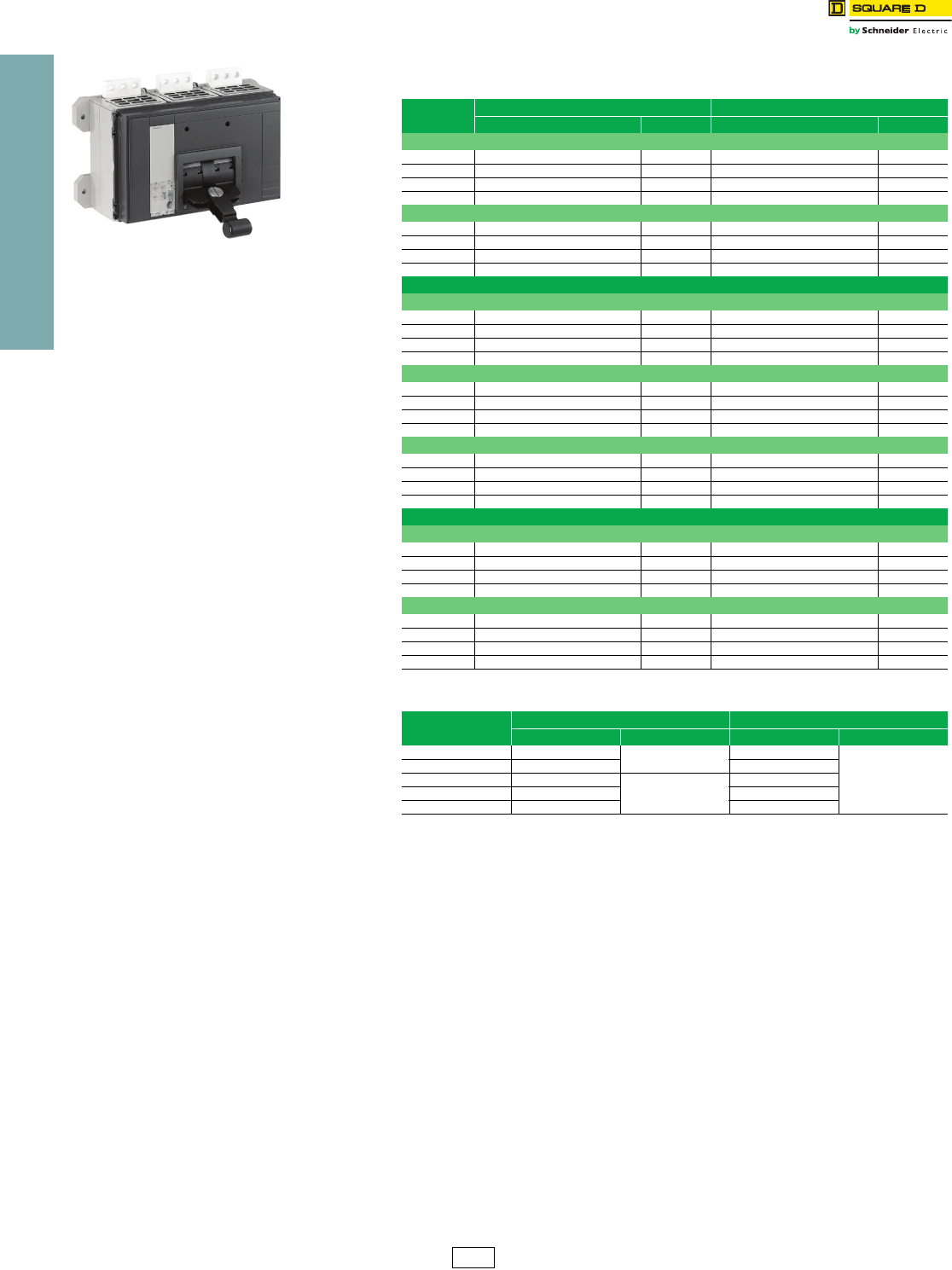
www.schneider-electric.us
9INTERNATONAL CIRCUIT
BREAKERS
9-4 © 2012 Schneider Electric
All Rights Reserved
Electronic Trip Circuit
Breakers
R-frame, 3P, Micrologic™ Electronic-Trip Unit, IEC Rated
Class 612
Note: See Digest for accessories and other information.
Table 9.5: R-frame—3200 A, Individually-Mounted, Micrologic™ Electronic Trip
Unit, IEC Rated
Sensor
Rating
N Interrupting H Interrupting
Cat. No. $ Price Cat. No. $ Price
3P, 690 Vac 50/60 Hz with LS0 Trip Functions
1600 A RNFE36160U32R 22004.00 RHFE34160U32R 23120.00
2000 A RNFE36200U32R 22004.00 RHFE34200U32R 23120.00
2500 A RNFE36250U32R 34607.00 RHFE34250U32R 36384.00
3200 A RNFE36320U32R 34607.00 RHFE34320U32R 36384.00
3P, 690 Vac 50/60 Hz with LSI Trip Functions
1600 A RNFE36160U33R 22326.00 RHFE34160U33R 23441.00
2000 A RNFE36200U33R 22326.00 RHFE34200U33R 23441.00
2500 A RNFE36250U33R 34929.00 RHFE34250U33R 36707.00
3200 A RNFE36320U33R 34929.00 RHFE34320U33R 36707.00
Micrologic Ammeter Trip Unit
3P, 690 Vac 50/60 Hz with LS0 Trip Functions
1600 A RNFE36160U42R 22812.00 RHFE34160U42R 23928.00
2000 A RNFE36200U42R 22812.00 RHFE34200U42R 23928.00
2500 A RNFE36250U42R 35414.00 RHFE34250U42R 37194.00
3200 A RNFE36320U42R 35414.00 RHFE34320U42R 37194.00
3P, 690 Vac 50/60 Hz with LSI Trip Functions
1600 A RNFE36160U43R 24234.00 RHFE34160U43R 25352.00
2000 A RNFE36200U43R 24234.00 RHFE34300U43R 25352.00
2500 A RNFE36250U43R 36837.00 RHFE34350U43R 38618.00
3200 A RNFE36320U43R 36837.00 RHFE34320U43R 38618.00
3P, 690 Vac 50/60 Hz with LSIG Trip Functions
1600 A RNFE36160U44R 26010.00 RHFE34160U44R 27126.00
2000 A RNFE36200U44R 26010.00 RHFE34200U44R 27126.00
2500 A RNFE36250U44R 38612.00 RHFE34250U44R 41199.00
3200 A RNFE36320U44R 38612.00 RHFE34320U44R 41199.00
Micrologic Power Trip Unit
3P, 690 Vac 50/60 Hz with LSI Trip Functions
1600 A RNFE36160U63RE1 28425.00 RHFE34160U63RE1 29543.00
2000 A RNFE36200U63RE1 28425.00 RHFE34200U63RE1 29543.00
2500 A RNFE36250U63RE1 41030.00 RHFE34250U63RE1 42809.00
3200 A RNFE36320U63RE1 41030.00 RHFE34320U63RE1 42809.00
3P, 690 Vac 50/60 Hz with LSIG Trip Functions
1600 A RNFE36160U64RE1 29454.00 RHFE34160U64RE1 30572.00
2000 A RNFE36200U64RE1 29454.00 RHFE34200U64RE1 30572.00
2500 A RNFE36250U64RE1 42057.00 RHFE34250U64RE1 43836.00
3200 A RNFE36320U64RE1 42057.00 RHFE34320U64RE1 48386.00
Table 9.6: Interrupting Ratings
N H
Icu Ics Icu Ics (%Icu)
220/240 V 85 kA 75% 125 kA
75%
380/415 V 70 kA 85 kA
440 V 65 kA
100%
85 kA
500/525 V 65 kA —
660/690 V 65 kA —
DE2 Discount
Schedule
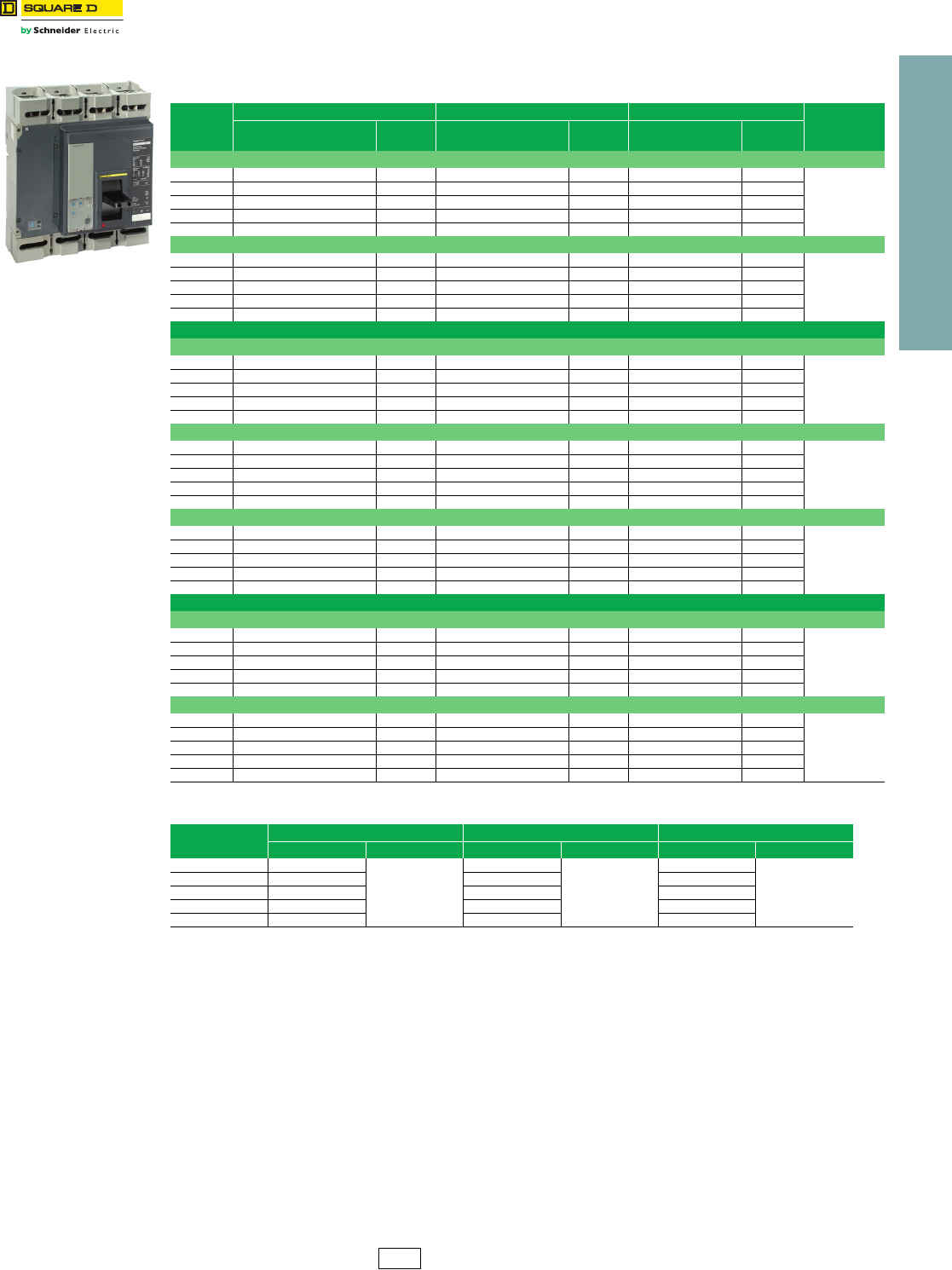
www.schneider-electric.us
9INTERNATONAL CIRCUIT
BREAKERS
© 2012 Schneider Electric
All Rights Reserved 9-5
Electronic Trip Circuit
Breakers
P-frame, 4P, Micrologic™ Electronic-Trip Unit, IEC Rated
Class 612
Note: See Digest for accessories and other information.
Table 9.7: P-frame—1600 A, Individually-Mounted, Micrologic™ Electronic Trip Unit,
IEC Rated
Sensor
Rating
N Interrupting H Interrupting L Interrupting Terminal
Wire
Range
(AWG–kcmil)
Cat. No. $ Price Cat. No. $ Price Cat. No. $ Price
4P, 690 Vac 50/60 Hz with LS0 Trip Functions
630 A PNLE46063U32R 17307.00 PHLE46063U32R 18341.00 PLLE46063U32R 19376.00
(4) 3/0–500
Al/Cu
800 A PNLE46080U32R 17307.00 PHLE46080U32R 18341.00 PLLE46080U32R 19376.00
1000 A PNLE46100U32R 23367.00 PHLE46100U32R 24783.00 PLLE46100U32R 26198.00
1250 A PNLE46125U32R 23367.00 PHLE46125U32R 24783.00 ——
1600 A PNLE46160U32R 25002.00 PHLE46160U32R 26517.00 ——
4P, 690 Vac 50/60 Hz with LSI Trip Functions
630 A PNLE46063U33R 17708.00 PHLE46063U33R 18741.00 PLLE46063U33R 19776.00
(4) 3/0–500
Al/Cu
800 A PNLE46080U33R 17708.00 PHLE46080U33R 18741.00 PLLE46080U33R 19776.00
1000 A PNLE46100U33R 23768.00 PHLE46100U33R 25182.00 PLLE46100U33R 26598.00
1250 A PNLE46125U33R 23768.00 PHLE46125U33R 25182.00 ——
1600 A PNLE46160U33R 25430.00 PHLE46160U33R 26945.00 ——
Micrologic Ammeter Trip Unit
4P, 690 Vac 50/60 Hz with LS0 Trip Functions
630 A PNLE46063U42R 18311.00 PHLE46063U42R 19344.00 PLLE46063U42R 20378.00
(4) 3/0–500
Al/Cu
800 A PNLE46080U42R 18311.00 PHLE46080U42R 19344.00 PLLE46080U42R 20378.00
1000 A PNLE46100U42R 24371.00 PHLE46100U42R 25787.00 PLLE46100U42R 27201.00
1250 A PNLE46125U42R 24371.00 PHLE46125U42R 25787.00 ——
1600 A PNLE46160U42R 26076.00 PHLE46160U42R 27591.00 ——
4P, 690 Vac 50/60 Hz with LSI Trip Functions
630 A PNLE46063U43R 20076.00 PHLE46063U43R 21110.00 PLLE46063U43R 22143.00
(4) 3/0–500
Al/Cu
800 A PNLE46080U43R 20076.00 PHLE46080U43R 21110.00 PLLE46080U43R 22143.00
1000 A PNLE46100U43R 26135.00 PHLE46100U43R 27551.00 PLLE46100U43R 28967.00
1250 A PNLE46125U43R 26135.00 PHLE46125U43R 27551.00 ——
1600 A PNLE46160U43R 27964.00 PHLE46160U43R 29480.00 ——
4P, 690 Vac 50/60 Hz with LSIG Trip Functions
630 A PNLE46063U44R 22277.00 PHLE46063U44R 23310.00 PLLE46063U44R 24344.00
(4) 3/0–500
Al/Cu
800 A PNLE46080U44R 22277.00 PHLE46080U44R 23310.00 PLLE46080U44R 24344.00
1000 A PNLE46100U44R 28335.00 PHLE46100U44R 29750.00 PLLE46100U44R 31166.00
1250 A PNLE46125U44R 28335.00 PHLE46125U44R 29750.00 ——
1600 A PNLE46160U44R 30317.00 PHLE46160U44R 31833.00 ——
Micrologic Power Trip Unit
4P, 690 Vac 50/60 Hz with LSI Trip Functions
630 A PNLE46063U63RE1 25274.00 PHLE46063U63RE1 26307.00 PLLE46063U63RE1 27341.00
(4) 3/0–500
Al/Cu
800 A PNLE46080U63RE1 25274.00 PHLE46080U63RE1 26307.00 PLLE46080U63RE1 27341.00
1000 A PNLE46100U63RE1 31332.00 PHLE46100U63RE1 32748.00 PLLE46100U63RE1 34164.00
1250 A PNLE46125U63RE1 31332.00 PHLE46125U63RE1 32748.00 ——
1600 A PNLE46160U63RE1 33525.00 PHLE46160U63RE1 35039.00 ——
4P, 690 Vac 50/60 Hz with LSIG Trip Functions
630 A PNLE46063U64RE1 26549.00 PHLE46063U64RE1 27582.00 PLLE46063U64RE1 28614.00
(4) 3/0–500
Al/Cu
800 A PNLE46080U64RE1 26549.00 PHLE46080U64RE1 27582.00 PLLE46080U64RE1 28614.00
1000 A PNLE46100U64RE1 32606.00 PHLE46100U64RE1 34022.00 PLLE46100U64RE1 35438.00
1250 A PNLE46125U64RE1 32606.00 PHLE46125U64RE1 34022.00 ——
1600 A PNLE46160U64RE1 34890.00 PHLE46160U64RE1 36404.00 ——
Table 9.8: Interrupting Ratings
N H L
Icu Ics (%Icu) Icu Ics (%Icu) Icu Ics (%Icu)
220/240 V 50 kA
75%
70 kA
50%
150 kA
100%
380/415 V 50 kA 70 kA 150 kA
440 V 50 kA 65 kA 130 kA
500/525 V 40 kA 50 kA 100 kA
660/690 V 30 kA 42 kA 25 kA
DE2 Discount
Schedule
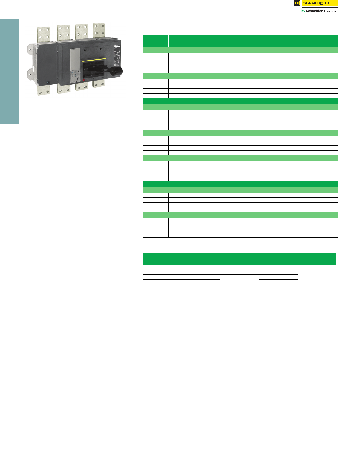
www.schneider-electric.us
9INTERNATONAL CIRCUIT
BREAKERS
9-6 © 2012 Schneider Electric
All Rights Reserved
Electronic Trip Circuit
Breakers
R-frame, 4P, Micrologic™ Electronic-Trip Unit, IEC Rated
Class 612
Note: See Digest for accessories and other information.
Table 9.9: R-frame—3200 A, Individually-Mounted, Micrologic™ Electronic Trip
Unit, IEC Rated
Sensor
Rating
N Interrupting H Interrupting
Cat. No. $ Price Cat. No. $ Price
4P, 690 Vac 50/60 Hz with LS0 Trip Functions
1600 A RNFE46160U32R 27284.00 RHFE44160U32R 28667.00
2000 A RNFE46200U32R 27284.00 RHFE44200U32R 28667.00
2500 A RNFE46250U32R 42911.00 RHFE44250U32R 45117.00
3200 A RNFE46320U32R 42911.00 RHFE44320U32R 45117.00
4P, 690 Vac 50/60 Hz with LSI Trip Functions
1600 A RNFE46160U33R 27684.00 RHFE44160U33R 29067.00
2000 A RNFE46200U33R 27684.00 RHFE44200U33R 29067.00
2500 A RNFE46250U33R 43311.00 RHFE44250U33R 45518.00
3200 A RNFE46320U33R 43311.00 RHFE44320U33R 45518.00
Micrologic Ammeter Trip Unit
4P, 690 Vac 50/60 Hz with LS0 Trip Functions
1600 A RNFE46160U42R 28287.00 RHFE44160U42R 29670.00
2000 A RNFE46200U42R 28287.00 RHFE44200U42R 29670.00
2500 A RNFE46250U42R 43914.00 RHFE44250U42R 46119.00
3200A RNFE46320U42R 43914.00 RHFE44320U42R 46119.00
4P, 690 Vac 50/60 Hz with LSI Trip Functions
1600 A RNFE46160U43R 30051.00 RHFE44160U43R 31436.00
2000 A RNFE46200U43R 30051.00 RHFE44300U43R 31436.00
2500 A RNFE46250U43R 45678.00 RHFE44350U43R 47885.00
3200 A RNFE46320U43R 45678.00 RHFE44320U43R 47885.00
4P, 690 Vac 50/60 Hz with LSIG Trip Functions
1600 A RNFE46160U44R 32252.00 RHFE44160U44R 33636.00
2000 A RNFE46200U44R 32252.00 RHFE44200U44R 33636.00
2500 A RNFE46250U44R 47879.00 RHFE44250U44R 51087.00
3200 A RNFE46320U44R 47879.00 RHFE44320U44R 51087.00
Micrologic Power Trip Unit
4P, 690 Vac 50/60 Hz with LSI Trip Functions
1600 A RNFE46160U63RE1 35249.00 RHFE44160U63RE1 36633.00
2000 A RNFE46200U63RE1 35249.00 RHFE44200U63RE1 36633.00
2500 A RNFE46250U63RE1 50876.00 RHFE44250U63RE1 53082.00
3200 A RNFE46320U63RE1 50876.00 RHFE44320U63RE1 53082.00
4P, 690 Vac 50/60 Hz with LSIG Trip Functions
1600 A RNFE46160U64RE1 36522.00 RHFE44160U64RE1 37907.00
2000 A RNFE46200U64RE1 36522.00 RHFE44200U64RE1 37907.00
2500 A RNFE46250U64RE1 52152.00 RHFE44250U64RE1 54357.00
3200 A RNFE46320U64RE1 52152.00 RHFE44320U64RE1 54357.00
Table 9.10: Interrupting Ratings
N H
Icu Ics Icu Ics (%Icu)
220/240 V 85 kA 75% 125 kA
75%
380/415 V 70 kA 85 kA
440 V 65 kA
100%
85 kA
500/525 V 65 kA —
660/690 V 65 kA —
DE2 Discount
Schedule
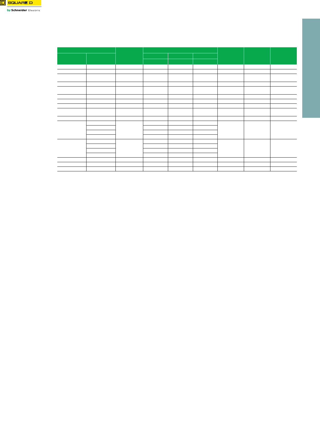
www.schneider-electric.us
9INTERNATONAL CIRCUIT
BREAKERS
© 2012 Schneider Electric
All Rights Reserved 9-7
Breaking Capacities
•CE Marking
•International products—IEC 60947-2 rated. North American products are dual rated, UL 489 and IEC 60947-2.
•MCCBs in I-Line™ plug-on construction and a complete line of accessories are available. Contact your nearest Field Sales office.
•Order entry point is Cedar Rapids, Iowa.
aSingle pole ratings are 240 V.
bSFA 2 & 3 pole marked Line and Load.
cIEC rating 415Y/240 Vac; NEMA/UL rating 240 Vac.
d250 A lugs are suitable for copper conductors only.
Table 9.11: Circuit Breaker Breaking Capacities
Circuit Breaker Cat. Prefix
Current Rating
(Amps)
Short-circuit Ratings (415 Vac)
Isolator Rating Impulse Rating
Uimp (kV)
Insulation
Rating Ui (Vac)
International North America Ultimate Service Withstand
lcu Ics Icw
— FA, FH 15–100 A 10 kA 2.5 kA N/A Yes 6 750
— FA, FH (1 pole)a15–100 A 18 kA 9 kA N/A Yes 6 750
SFA (1 pole)a
SFAb—16–100 A
16–160 A
25 kA
25 kA
12.5 kA
12.5 kA
N/A
N/A
Ye s
Ye s
6
6
750
750
— FC 15–100 A 10 kA 2.5 kA N/A Yes 6 750
SFH — 16–63 A
80–100 A
65 kA
65 kA
50 kA
33 kA
N/A
N/A
Ye s
Ye s
6
6
750
750
—QBc70–250 Ad10 kA 5 kA N/A Yes 6 750
— LA 125–400 A 20 kA 5 kA N/A Yes 6 750
SLA — 250–400 A 36 kA 18 kA N/A Yes 6 750
LC LC 300–400 A
450–630 A
65 kA
65 kA
65 kA
50 kA
N/A
N/A
Ye s
Ye s
6
6
750
750
— LH 125–400 A 20 kA 5 kA N/A Yes 6 750
—
PG
250–1200 A
35 kA 17.5 kA 25 kA
Ye s 6 7 5 0
PJ 50 kA 25 kA 10 kA
PL 85 kA 42.5 kA 10 kA
PK 50 kA 25 kA 25 kA
—
RG
600–2500 A
35 kA 17.5 kA 32 kA
Ye s 6 7 5 0
RJ 50 kA 25 kA 32 kA
RL 85 kA 42.5 kA 32 kA
RK 70 kA 52.5 kA 32 kA
— PA 600–2000 A 50 kA 38 kA N/A No 6 750
— PC, PH 600–2500 A 70 kA 53 kA N/A No 6 750
PE, PX PE, PX 600–2500 A 70 kA 53 kA 12.5 No 6 750
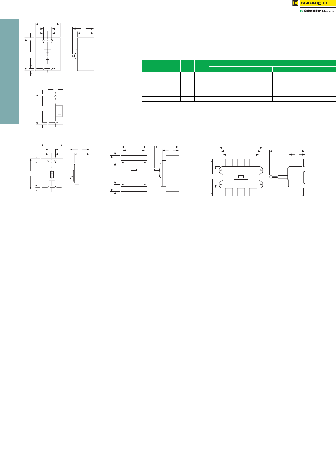
www.schneider-electric.us
9INTERNATONAL CIRCUIT
BREAKERS
9-8 © 2012 Schneider Electric
All Rights Reserved
Circuit Breaker
Dimensions
•CE Marking
•International products—IEC 60947-2 rated. North American products are dual rated, UL 489 and
IEC 60947-2.
•MCCBs in I-Line™ plug-on construction and a complete line of accessories are available. Contact
your nearest Field Sales office.
•Order entry point is Cedar Rapids, Iowa.
aDimensions E are 40 mm at ON end and 16 mm at OFF end.
Table 9.12: Dimensions
Circuit
Breaker
No.
Poles
Fig.
No.
Dimensions – mm
A B C D E F G H
SFA, SFH/FS, FH 3 1 152 114 80 105 11 130 38 19
SLA/LA, LH 3 1 279 152 103 148 22 235 51 25
QB 2 2 164 76 77 100 a108 —
3 3 164 114 77 100 a1083819
PG, PJ, PL 2, 3 4 414 210 140 204 106 200 200 —
RG, RJ, RL 2, 3 5 381 420 160 365 222 362 390 —
B
D
C
F
E
E
C/L
A
G
HH
Figure 1
C/L
Figure 2
B
E
E
FA
Figure 3
C/L
B
D
C
G
HH
E
E
FA
G
B
F
EA
DC
Figure 5
F
E
E
A
DC
G
B
Figure 4
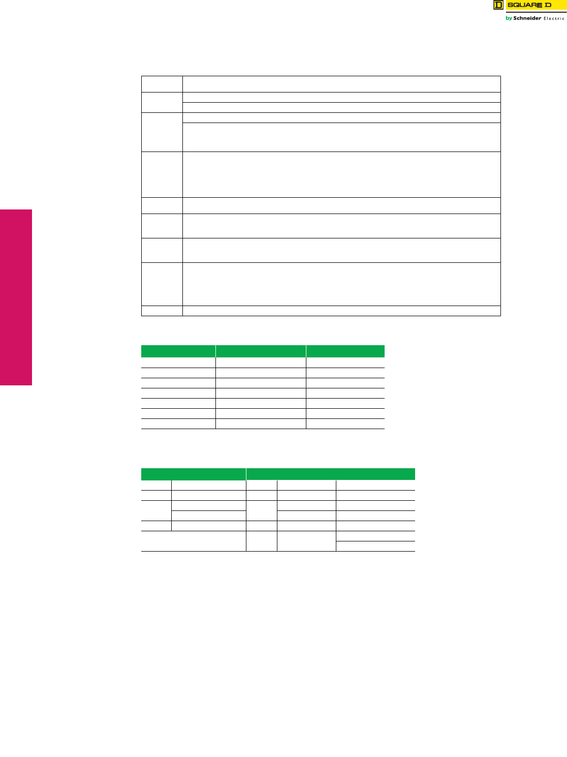
10-2 © 2011 Schneider Electric
All Rights Reserved
www.schneider-electric.us
10 INTERNATIONAL PANELBOARDS
NQX Panelboards Factory Assembled Circuit Breaker Panelboard
NOTE: For export application only. Not UL Listed
Panelboard Information
Service 1Ø3W 110/220, 127/220, 115/230/ Vac 50 Hz, 60 Hz
3Ø4W 220/110, 220/127, 230/115, 380/220, 415Y/240, 400/230 Vac 50 Hz, 60 Hz
Branches Plug-on QOXD and Bolt-on QOBXD
10–100 A QOXD and QOBXD 1-, 2-, and 3-pole (3000 AIR)
Boxes
Galvanized steel with removable endwalls with knockouts on one end.
Two sizes:
•NQB — 14 in. W x 5.75 in. D — 225 A interior maximum (availability to be announced)
•MH — 20 in. W x 5.75 in. D — 600 A main lug interior maximum
Fronts
•Gray baked enamel finish (ANSI49)
•Door with flush lock
•Mono-Flat™ fronts on 100–225 A. Front mounts to the interior with trim screws.
(Both trim screws and door hinges are concealed.)
•Fronts for 400A–600 A interiors are louvered and mount to the enclosure with trim screws.
(Door hinges are concealed.)
Common
Features Sub-Feed Lugs, Sub-Feed Circuit Breaker, Split Bus, Feed-Through Lugs
Bus Bars
•Aluminum bus, standard — 100 A, 225 A, and 400 A interiors
•Copper bus, optional — 100 A, 225 A, and 400 A interiors
•Copper bus, standard — 600 A interiors
Neutrals
•100% Aluminum neutral, standard
•100% Copper neutral, optional
•200% Neutral, optional
Enclosures
•Type 1, standard
•Type 3R, 5, and 12, optional
•Type 3R, 4, 4X, and 12 Stainless Steel, optional
NOTE: Price factory assembled NQX panelboard in the Quote to Cash Product Selector.
Select "NQ" panelboard, then select the appropriate "International Voltage".
Order Point Peru, IN
Figure 10.1: Mains
Mains Rating Main Lugs Main Circuit Breaker
70 A — QOBXDa, QB, HD
100 A Yes QOBXDa, QB, HD
150 A — QB, HD
225 A Yes QB
250 A — JD
400 A Yes LA
600 A Yes —
aAvailable at 240 Vac maximum.
Figure 10.2: Distributed Phase Bussing
Main Lugs Main Circuit Breaker
100 A (1) #6-2/0 Al or Cu 100 A QOXD/QOBXD (1) #4-2/0 Al or Cu
225 A (1) #6-350 kcmil Al or Cu 150 A HD (1) #14-3/0 Al or Cu
400 A (1) 1/0-750 kcmil, or 225 A QB (1) #4-300 kcmil Al or Cu, or
(2) 1/0-350 kcmil Al or Cu JD (1) #3/0-350 kcmil Al or Cu
600 A (2) 1/0-750 kcmil Al or Cu 250 A JD (1) #3/0-350 kcmil Al or Cu
400 A LA (1) #1-600 kcmil, or
(2) #1-250 kcmil Al or Cu

11-1
© 2012 Schneider Electric
All Rights Reserved
11 OBSOLETE CIRCUIT BREAKERS
Table of Contents
Section 11
Obsolescent and Obsolete Circuit Breakers
Obsolescent and Obsolete Types
Circuit Breaker Availability 11-2
Pictorial and Dimensions 11-4—11-5
Obsolescent Circuit Breakers
F-Frame Thermal-Magnetic Circuit Breakers 11-6
K-Frame Thermal-Magnetic Circuit Breakers 11-7
Automatic Molded-Case Switches 11-8
Mag-Gard™ Motor Circuit Protector 11-9—11-10
UL Listed Marine Circuit Breakers 11-11
Circuit Breakers for NQO, NQOB and NQOD Panelboards, Branch
Circuit Breakers and Mounting Assemblies for ML Panelboards
11-12
Rating Plugs For Obsolete Electronic Trip Circuit Breakers 11-13
EH/EHB Circuit Breakers 11-14
FJA Thermal-Magnetic Circuit Breakers 11-15
QE Metering Circuit Breakers 11-16
KD/KG Thermal-Magnetic Circuit Breakers 11-17
NHL Thermal-Magnetic Molded Case Circuit Breaker 11-18
SE Circuit Breaker with Full-Function Trip Unit 11-19
SE Circuit Breaker Accessories 11-20
M-frame Thermal-Magnetic Circuit Breakers 11-21
Field-Installable Accessories 11-22
Mechanical Lug Information 11-23
Micrologic™ Series 2/3/A/B Trip Unit Test Sets 11-24
Micrologic™ Add-On Ground-Fault Module (GFM) 11-25
Masterpact™ M/MP/MC Circuit Breakers, UL 489/1066 Listed 11-26
Masterpact™ M/MP/MC Circuit Breaker Control Units 11-27
Masterpact™ M/MP/MC Circuit Breaker Accessories 11-28—11-29
Masterpact™ M/MP/MC Circuit Breaker Spare Parts 11-30

11-2 © 2012 Schneider Electric
All Rights Reserved
www.schneider-electric.us
11 OBSOLETE CIRCUIT BREAKERS
Obsolescent and
Obsolete Types
Circuit Breaker Availability
Class 600
Contact your local Sales Office for availability.
Table 11.1: Circuit Breaker Availability
Series of
Cat. No. Frame Size Volts Poles Amperes Availability
Obsolete No Longer Available Obsolescent
115A–130A MO-1 (Add-on) 120 Vac 1 15–30 X
215A–250A MO-2 (Add-on) 120/240 Vac 2 15–50 X
215B–250B MO-2B (Add-on) 120/240 Vac 2 S.P. 15–50 X
70000 Multi-Breaker 120 Vac 4 S.P. 15–50 X
111600 MO-2 120/240 Vac 2 15–30 X
131600 MO-2 120/240 Vac 2 15–30 X
151101 MO-1 120 Vac 1 15–30 X
151600 MO-2 120/240 Vac 2 15–30 X
161101 MO-1 120 Vac 1 With SN 15–30 X
161600 MO-2 120/240 Vac 2 With SN 15–30 X
161700 MO-2 120/240 Vac 2 S.P. 15–30 X
260000 MB (Left-hand) 120 Vac 4 S.P. 15–50 X
270000 MB (Right-hand) 120 Vac 4 S.P. 15–50 X
460000 MO-8 120/240 Vac 4 S.P. 15–50 X
470000 MO-4 120/240 Vac 4 S.P. 15–40 X
480000 MO-4 (Plug-in) 120/240 Vac 4 S.P. 15–50 X
940000 LM 600 Vac 2-3 125–800 X
950000 50 A Form W 250 Vac 1, 2, 3 15–50 X
951000 50 A Form W 250 Vac 2, 3 15–50 X
952000 50 A Form W 250 Vac 2, 3 15–50 X
953000 Flip-on Form W 230 Vac 1, 2, 3 15–50 X
954000 100 A Form W (Trip Unit) 250 Vac 2, 3 50–100 X
955000 100 A Form W 250 Vac 2, 3 50–100 X
956000 225 A Form W 250 Vac 2, 3 70–225 X
957000 400 A (KL) Form W 250 Vac 2, 3 125–400 X
958000 600 A (WL) Form W 250 Vac 2, 3 225–600 X
959000 KL Frame Only 600 Vac 2, 3 125–400 X
961000 50 A Form W 600 Vac 2, 3 15–50 X
962000 50 A Form W 600 Vac 2, 3 15–50 X
964000 100 A Form W 600 Vac 2, 3 50–100 X
965000 100 A Form W 600 Vac 2, 3 50–100 X
966000 225 A Form W 600 Vac 2, 3 70–225 X
967000 400 A (KL) Form W 600 Vac 2, 3 125–400 X
968000 600 A (WL) Form W 600 Vac 2, 3 225–600 X
970000 Type L Form W 240 Vac 1, 2, 3 10–50 X
971000 Type L Form W (Flip-on) 240 Vac 1, 2, 3 10–50 X
972000 M1 (Bolt-on) 240 Vac 2, 3 15–70 X
973000 M2 (Bolt-on) 240 Vac 2, 3 50–100 X
974000 MM (M) (Bolt-on) 120/240 Vac 2 S.P. 15–50 X
975000 100 A Trip Unit 250 Vac 2, 3 50–100 X
976000 225 A Trip Unit 250 Vac 2, 3 70–225 X
977000 KL Trip Unit 600 Vac 2, 3 125–400 X
978000 LM Trip Unit 600 Vac 2, 3 225–800 X
979000 WL Frame 600 Vac 2, 3 225–600 X
982000 50 A Form W (Flip-on) 125/250 Vac 1, 2, 3 15–50 X
984000 ML-2 250 Vac 2, 3 50–100 X
985000 100 A (G) Form W 600 Vac 2, 3 50–100 X
986000 100 A (F) Form W 600 Vac 2, 3 10–100 X
987000 ML-3 250 Vac 2, 3 125–225 X
988000 ML-1 250 Vac 2, 3 15–100 X
989000 ML-1 480 Vac 2, 3 15–100 X
991000 QB 120/240 Vac 1 15–50 X
992000 ML 120/240 Vac 1, 2, 3 10–50 X
992900 ML Form Y 277 Vac 1 10–20 X
994000 ML-2 600 Vac 2, 3 15–100 X
995000 100 A (G) Form W 600 Vac 2, 3 15–100 X
996000 100 A (F) Form W 600 Vac 2, 3 15–100 X
997000 ML-3 600 Vac 2, 3 50–225 X
998000 ML-1 600 Vac 2, 3 15–100 X
999000 ML-1 600 Vac 2, 3 15–100 X
A1B 100 A 120/240 Vac 1, 2, 3 15–100 X
EH, EHB 100 A 480Y/277 Vac 1, 2, 3 15–100 EH See page 11-14
FC 100 A 480 Vac 2, 3 15–100 FC See page 11-5
FD, FG, FJ 100 A 480Y/277 Vac 1, 2, 3 15–100 X
GJL / NENL 100 A 480 Vac 3 15–100 X
KA, KH, KC 250 A 480 Vac 2, 3 70–250 X See pgs. 11-6–11-8

www.schneider-electric.us
11 OBSOLETE CIRCUIT BREAKERS
© 2012 Schneider Electric
All Rights Reserved 11-3
Obsolescent and
Obsolete Types
Circuit Breaker Availability
Class 600
Contact your local Sales Office for availability.
Table 11.2: Circuit Breaker Availability. Continued
Series of
Cat. No. Frame Size Volts Poles Amperes Availability
Obsolete No Longer Available Obsolescent
FI, FIL 100 A 480 Vac 2, 3 20–100 X
KI, KIL 225 A 480 Vac 2, 3 110–225 X
LI, LIL 400 A 480 Vac 2, 3 300–400 X
KD, KG 250 A 240 Vac 2, 3 100–250 KG See page 11-17
LA(JKL) 0000 400 A 600 Vac 2, 3 125–400 X
MA-0000 1000 A 600 Vac 2, 3 125–1000 X
Masterpact M/MP/MC 6300 A 600 Vac 3, 4 800–6300 See pgs. 11-27–11-30
MEC 225 A 600 Vac 2, 3 100–225 X
MEC 400 A 600 Vac 2, 3 250–400 X
MEC 800 A 600 Vac 2, 3 400–800 X
MHAB, BC, CA MM (Plug-on) 120/240 Vac 2 S.P. 15–50 X
MHAB, BC, CA M1 (Plug-on) 120/240 Vac 2, 3 15–70 X
MHAB, BC, CA M2 (Plug-on) 120/240 Vac 2, 3 70–100 X
NHL 1200 A 480 Vac 2, 3 800–1200 See page 11-18
PEC 1200 A 600 Vac 2, 3 600–1200 X
PEC 1600 A 600 Vac 2, 3 1000–1600 X
PEC 2000 A 600 Vac 2, 3 1000–2000 X
QOT Series 1 120/240 Vac 1, 2 30 X
Q1, Q1B 150 A 120/240 Vac 1, 2 15–100 X
Q1, Q1B 150 A 240 Vac 3 15–100 X
Q1-H, Q1B-H 100 A 240 Vac 2 15–100 X
Q1-VH, Q1B-VH 125 A 120/240 Vac 2 15–30 X
Q1-VH, Q1B-VH 100 A 240 Vac 3 15–30 X
Q2, Q2-H, Q2H 225 A 240 Vac 2, 3 100–225 X
QE 200 A 120/240 Vac 2, 3 70–200 See page 11-16
SE 4000 A 600 Vac 3 200–4000 See pgs. 11-20
CK 1200 A 480 Vac 3 400–1200 X
CM 2000 A 480 Vac 3 1250–2000 X
XO 50 A 120/240 Vac 1, 2 15–50 X
Y1B 100 A 277 Vac 1 15–100 X
ME, MEL 250 A, 400 A, 800 A 600 Vac 3 100–800 X
MX, MXL 250 A, 400 A, 800 A 600 Vac 3 100–800 X
NA, NAL 1200 A 600 Vac 3 600–1200 X
NC, NCL 1200 A 600 Vac 3 600–1200 X
NX, NXL 1200 A 600 Vac 3 600–1200 X
NE, NEL 1200 A 600 Vac 3 600–1200 X
PAF 2000 A 600 Vac 3 600–2000 X
PHF 2000 A 600 Vac 2, 3 600–2000 X
PCF 2500 A 600 Vac 2, 3 1600–2500 X
PXF 2500 A 600 Vac 2, 3 600–2500 X
PEF 2500 A 600 Vac 3 600–2500 X
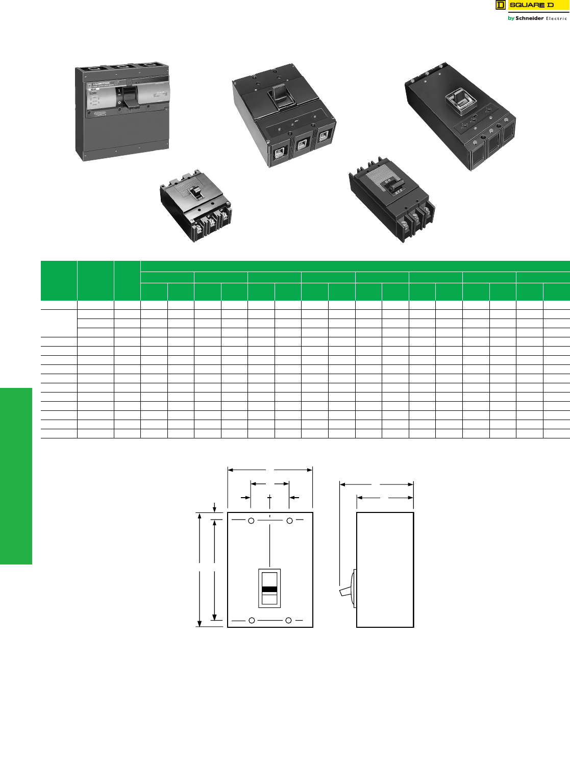
11-4 © 2012 Schneider Electric
All Rights Reserved
www.schneider-electric.us
11 OBSOLETE CIRCUIT BREAKERS
Obsolescent and
Obsolete Types
Pictorial and Dimensions
Class 600
Table 11.3: Circuit Breaker Dimensions
Circuit
Breaker
Type
Cat. No.
Prefix
Number
Poles
Dimensions
A B C D E F G H
in. mm in. mm in. mm in. mm in. mm in. m
min. mm in. mm
QB 991 13.75951.00252.50633.0678————————
ML
992 1 6.00 152 1.00 25 3.09 78 3.91 99 .88 22 4.25 108 — — .33 8
992 2 6.00 152 2.00 51 3.09 78 3.91 99 .88 22 4.25 108 — — .19 5
992 3 6.00 152 3.00 76 3.09 78 3.91 99 .88 22 4.25 108 — — 1.83 46
ML-1 999 2 & 3 6.50 165 4.47 113 3.06 78 3.94 100 .94 24 4.25 108 1.50 38 .75 19
ML-2 994 2 & 3 9.56 243 4.47 113 3.75 95 4.88 124 1.69 43 6.50 165 1.50 38 .75 19
ML-3 997 2 & 3 10.38 264 5.97 152 3.88 98 5.31 135 1.69 43 6.63 168 2.00 51 1.00 25
LA (W) LA 2 & 3 10.75 273 8.25 209 4.31 109 5.50 140 .63 16 9.50 241 2.75 70 1.38 35
MA (W) MA 2 & 3 16.00 406 8.25 209 4.06 103 6.06 154 .88 22 14.25 362 2.75 70 1.38 35
KL 967 2 & 3 22.00 559 8.25 209 5.50 140 7.00 178 .63 16 20.75 527 2.75 70 1.38 35
LM 940 2 & 3 22.00 559 8.25 209 5.50 140 7.00 178 .63 16 20.75 527 2.75 70 1.38 35
FIL (4) IFL 2 & 3 8.29 210 4.46 113 3.67 93 4.70 119 .44 11 7.41 188 1.50 38 .75 19
KIL (4) IKL 2 & 3 11.00 279 6.00 152 4.02 102 5.51 140 .88 22 9.25 235 2.00 51 1.00 25
LIL ILL 2 & 3 11.00 279 12.00 305 4.05 103 6.11 155 .88 22 9.25 235 4.00 102 2.00 51
NHL NHL 2 & 3 20.00 508 12.00 305 5.75 146 8.12 206 5.87 149 7.76 197 4.00 102 2.00 51
LIL
ML-1
LA (W) MA (W)
ML-2
G
AF
E
D
C
HH
B
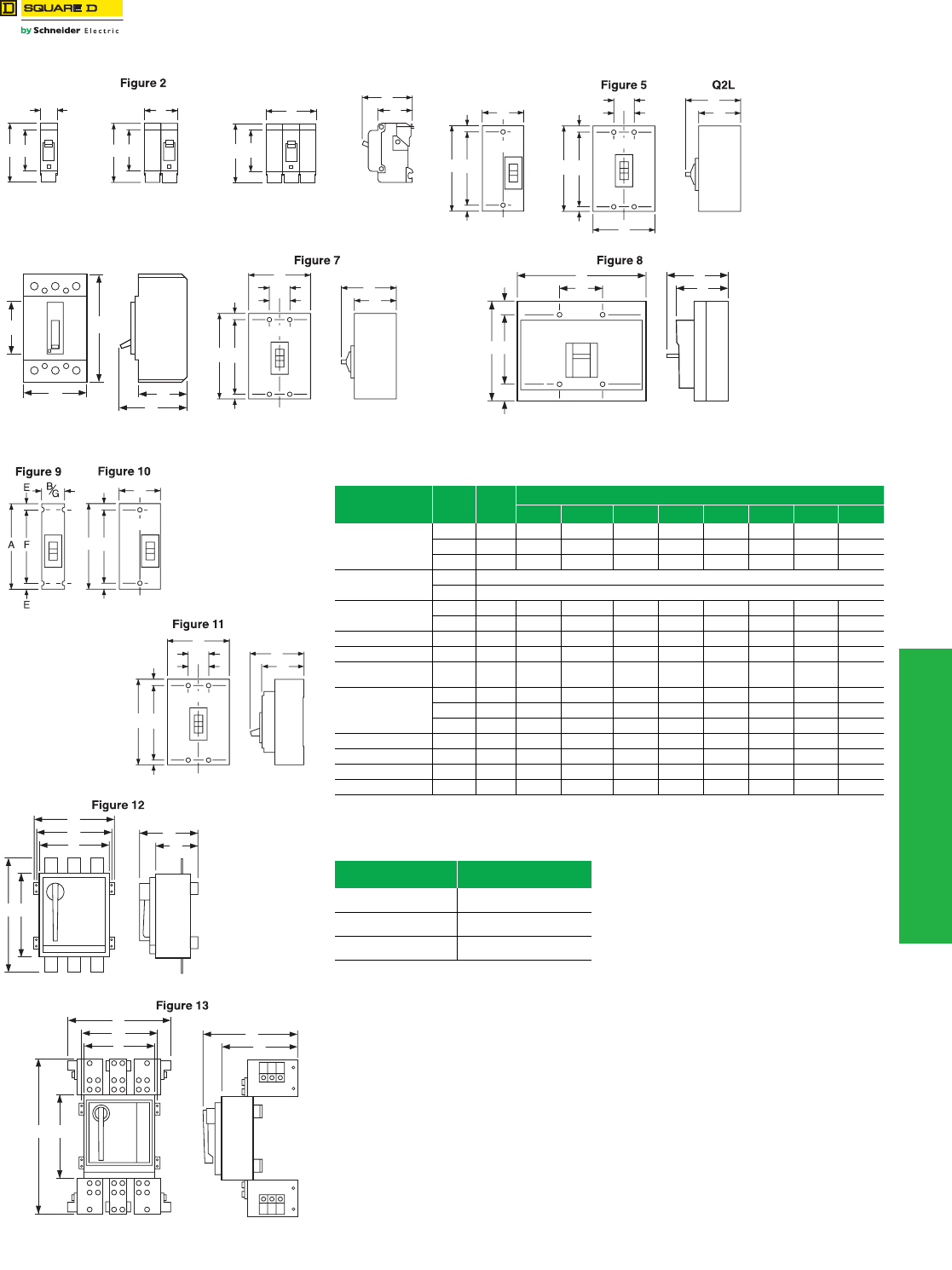
www.schneider-electric.us
11 OBSOLETE CIRCUIT BREAKERS
© 2012 Schneider Electric
All Rights Reserved 11-5
Obsolescent and
Obsolete Types
Pictorial and Dimensions
Class 600
a70–100 A is 4.00 in.
bDimensions E are 1.59 in at ON end and 0.63 in at OFF end.
cFCL 2-pole circuit breaker dimension B is 4.50 as in Fig. 23.
Figure 1
A
BE BE
A
Figure 3
BE
A
EH, EHB
D
C
C/L
Figure 4
B
E
E
FA
C/L
B
D
C
G
HH
E
E
FA
B
G
E
E
FA
D
C
Figure 6
A
D
C
EBC/L
B
D
C
G
HH
E
E
FA
Table 11.4: Circuit Breaker Dimensions
Circuit Breaker
Cat. No. Prefix
No.
Poles
Fig.
No.
Dimensions—In.
A B C D E F G H
EH, EHB
1 1 1.00 3.50 2.00 2.97 2.44 — — —
2 2 2.00 3.50a2.00 2.97 2.44 — — —
3 3 3.00 3.50a2.00 2.97 2.44 — — —
FDA, FGA, FJA 1 Width 1.50
2, 3 Width 3.00
Q2L, Q2L-H 2 4 6.44 3.00 3.16 3.92 b4.25 — —
3 5 6.44 4.50 3.16 3.92 b4.25 1.50 0.75
KD, KG 2, 3 6 4.12 7.35 3.20 4.17 3.34 — — —
MXL, MEL 2 & 3 7 14.75 9.00 4.37 6.50 1.66 11.43 3.00 1.50
NAL, NCL,
NEL, NXL 2 & 3 8 12.12 14.98 6.40 8.07 1.69 8.75 5.00 —
FCL
1 9 6.00 1.50 3.16 4.13 0.44 5.13 1.50 —
2106.003.00c3.16 4.13 0.44 5.13 — —
3 11 6.00 4.50 3.16 4.13 0.44 5.13 1.50 0.75
MAL, MHL 2 & 3 8 14.00 9.00 4.53 6.50 1.66 10.69 3.00 1.50
NA, NC, NX, NE 2 & 3 8 12.12 14.98 6.40 8.07 1.69 8.75 5.0 —
PA, PH, PX, PE 2 & 3 12 20.06 13.70 7.25 10.47 14.00 12.00 12.75 —
PC, PX-25, PE-20-25 2 & 3 13 26.10 23.30 13.33 16.55 14.10 12.00 — —
Table 11.5:
Frame Size Approx. Shipping Weight
(Lbs.)
MAL
MHL 34
PAF
PHF 69
PXF
PEF 80
C/L
B
E
E
FA
C/L
B
D
C
G
HH
E
E
FA
B
G
AE
D
C
F
D
C
G
A
B
F
E
11-6 © 2012 Schneider Electric
All Rights Reserved
www.schneider-electric.us
11 OBSOLETE CIRCUIT BREAKERS
Obsolescent Circuit
Breakers
F-Frame Thermal-Magnetic Circuit Breakers
Class 650
Thermal-magnetic molded case circuit breakers shown on page 11-6 are permanent trip UL Listed, CSA® Certified, IEC
rated, and also meet the requirements of Federal Specification W–C–375B/GEN as indicated on Digest pages 7-4
through 7-7.
NOTE: Consider using PowerPact™ circuit breakers for situations requiring circuit breaker accessories. See Digest
Section 7 for more information.
a1P and 2P circuit breaker catalog numbers are completed by adding the required phase connection letters as a suffix. See Phase Option Table.
bFCL 2P circuit breakers are built using 3P module.
cFCL circuit breakers are not rated for 250 Vdc.
Accessories . . . . . . . . . . . . . . . . . . . . . . . . . . . . . . . . . . . . . . . . . Page 11-28
OptionalLugs . . . . . . . . . . . . . . . . . . . . . . . . . . . . . . . . . . . . . . . . . Page 11-23
Dimensions. . . . . . . . . . . . . . . . . . . . . . . . . . . . . . . . . . . . . . . . . . . . Page 11-5
Enclosures: see Digest Section 7
FC circuit breakers are obsolete. Please refer to Digest 176 for PowerPact™ molded case circuit breakers for new installations or
replacement.
Table 11.6: F-Frame—100 A, Thermal-Magnetic, Individually-Mounted, 480 Vac
Extra-High Interrupting
Ampere
Rating
Fixed AC Magnetic
Trip
2P 3P Terminal
Wire Range
(AWG)
480 Vac, 250 Vdc 480 Vac, 250 Vdc
Hold Trip Cat. No. Cat. No.
15 A 275 A 600 A — FCL34015
CU30FA4
(1) 14–10 Cu
20 A 275 A 600 A — FCL34020
25 A 275 A 600 A — FCL34025
30 A 275 A 600 A — FCL34030
35 A 400 A 850 A — FCL34035
AL100FA4
(1) 14–3 Cu
or (2) 12–1 Al
40 A 400 A 850 A — FCL34040
45 A 400 A 850 A — FCL34045
50 A 400 A 850 A FCL24050 FCL34050
60 A 800 A 1450 A FCL24060 FCL34060
70 A 800 A 1450 A FCL24070 FCL34070
80 A 800 A 1450 A FCL24080 FCL34080
90 A 900 A 1700 A FCL24090 FCL34090
100 A 900 A 1700 A FCL24100 FCL34100
Table 11.7: Interrupting Ratings
Volt age FAL FHL FCL FIL
240 Vac 480 Vac 600 Vac
240 Vac 10 kA 18 kA (1P), 25 kA (2P, 3P) 25 kA 25 kA (1P) 65 kA (2P, 3P) 100 kA 200 kA
480 Vac — 18 kA 18 kA 25 kA (2P, 3P) 65 kA 200 kA
600 Vac — — 14 kA 18 kA (2P, 3P) — 100 kA
Termination Option
Termination Letter
F = No Lugs
L = Lugs both ends
P with MT Suffix = Lugs ON end
P = Lugs OFF end
Table 11.8: F-Frame—100 A, Thermal-Magnetic, I-Line™ Construction, 480 Vac
Ampere
Rating
Fixed AC Magnetic
Trip
Extra-High Interruptingc
2Pa3P Terminal
Wire Range
(AWG)
480 Vac, 250 Vdcb480 Vac, 250 Vdcc
Hold Trip Cat. No. Cat. No.
15 A 275 A 600 A — FC34015
CU30FA4
(1) 14–10 Cu
20 A 275 A 600 A — FC34020
25 A 275 A 600 A — FC34025
30 A 275 A 600 A — FC34030
35 A 400 A 850 A — FC34035
AL100FA4
(1) 14–3 Cu
or (1) 12–1 Al
40 A 400 A 850 A — FC34040
45 A 400 A 850 A — FC34045
50 A 400 A 850 A FC24050( ) FC34050
60 A 800 A 1450 A FC24060( ) FC34060
70 A 800 A 1450 A FC24070( ) FC34070
80 A 800 A 1450 A FC24080( ) FC34080
90 A 900 A 1700 A FC24090( ) FC34090
100 A 900 A 1700 A FC24100( ) FC34100
FAL/FHL 2P
15–100 A
FAL/FHL 3P
15–100 A
FA 2P
3 in. (76 mm)
Mounting Height
FA 3P
4.5 in. (114 mm)
Mounting Height
F A L 3 6 1 0 0
For factory-installed termination, place
termination letter in the third block of the
circuit breaker catalog number.
Termination Letter
Table 11.9: Phase Options Table 11.10: Interrupting Ratings
Phase Option
Letter 1P 2P 3P Volt age FA FH FC FI
240 Vac 480 Vac 600 Vac
A
B
C
FA14035A
FA14035B
FA14035C
240 Vac 10 kA 18 kA (1P), 25 kA (2P, 3P) 25 kA 25 kA (1P) 65 kA (2P, 3P) 100 kA 200 kA
277 Vac — 18 kA — — 65 kA —
480 Vac — 18 kA 18 kA 25 kA (2P, 3P) 65 kA 200 kA
AB
AC
BC
FA24030AB
FA24030AC
FA24030BC
600 Vac — — 14 kA 18 kA (2P, 3P) — 100 kA
ABC
CBA
FA34030
FA34030CBA
DE2 Discount
Schedule
www.schneider-electric.us
11 OBSOLETE CIRCUIT BREAKERS
© 2012 Schneider Electric
All Rights Reserved 11-7
Obsolescent Circuit
Breakers
K-Frame Thermal-Magnetic Circuit Breakers
Class 655, 825, 660
aUL magnetic trip setting tolerances are ±25% for low and ±20% for high from nominal value shown.
bKC circuit breakers are 480 Vac
c2P and 3P circuit breaker catalog numbers are completed by adding the required phase connection letters as a suffix. See Phase Option Table.
Accessories . . . . . . . . . . . . . . . . . . . . . . . . . . . . . . . . . . . . . . . . . Page 11-28
OptionalLugs . . . . . . . . . . . . . . . . . . . . . . . . . . . . . . . . . . . . . . . . . Page 11-23
Dimensions . . . . . . . . . . . . . . . . . . . . . . . . . . . . . . . . . . . . . . . . . . . Page 11-5
Enclosures: see Digest Section 7
K-frame circuit breakers are obsolete. Please refer to Digest 176 for PowerPact™ molded case circuit breakers for new installations or
replacement.
Table 11.11: K-Frame—250 A, Thermal-Magnetic, Individually-Mounted, 600 Vac
Ampere
Rating
Adjustable AC Magnetic TripaStandard
Interrupting
Cat. No.
High
Interrupting
Cat. No.
Extra-High
Interruptingb
Cat. No.
Terminal
Wire Range
Low High
2P, 600 Vac, 250 Vdc
70 350 A 700 A KAL26070 KHL26070 —
AL250KA
(1) 4 AWG–350 kcmil Al
80 400 A 800 A KAL26080 KHL26080 —
90 450 A 900 A KAL26090 KHL26090 —
100 500 A 1000 A KAL26100 KHL26100 —
110 550 A 1100 A KAL26110 KHL26110 KCL24110
125 625 A 1250 A KAL26125 KHL26125 KCL24125
150 750 A 1500 A KAL26150 KHL26150 KCL24150
175 875 A 1750 A KAL26175 KHL26175 KCL24175
200 1000 A 2000 A KAL26200 KHL26200 KCL24200
225 1125 A 2250 A KAL26225 KHL26225 KCL24225
250 1250 A 2500 A KAL26250 KHL26250 KCL24250
3P, 600 Vac, 250 Vdc
70 350 A 700 A KAL36070 KHL36070 —
AL250KA
(1) 4 AWG–350 kcmil Al
80 400 A 800 A KAL36080 KHL36080 —
90 450 A 900 A KAL36090 KHL36090 —
100 500 A 1000 A KAL36100 KHL36100 —
110 550 A 1100 A KAL36110 KHL36110 KCL34110
125 625 A 1250 A KAL36125 KHL36125 KCL34125
150 750 A 1500 A KAL36150 KHL36150 KCL34150
175 875 A 1750 A KAL36175 KHL36175 KCL34175
200 1000 A 2000 A KAL36200 KHL36200 KCL34200
225 1125 A 2250 A KAL36225 KHL36225 KCL34225
250 1250 A 2500 A KAL36250 KHL36250 KCL34250
Table 11.12: K-Frame—250A, Thermal-Magnetic, I-Line™ Construction, 600 Vac
Ampere
Rating
Adjustable AC Magnetic TripaStandard
Interrupting
Cat. No.
High
Interrupting
Cat. No.
Extra-High
Interruptingb
Cat. No.
Terminal
Wire Range
Low High
2P, 600 Vac, 250 Vdcc
70 350 A 700 A KA26070( ) KH26070( ) —
AL250KA
(1) 4 AWG–350 kcmil Al
80 400 A 800 A KA26080( ) KH26080( ) —
90 450 A 900 A KA26090( ) KH26090( ) —
100 500 A 1000 A KA26100( ) KH26100( ) —
110 550 A 1100 A KA26110( ) KH26110( ) KC24110( )
125 625 A 1250 A KA26125( ) KH26125( ) KC24125( )
150 750 A 1500 A KA26150( ) KH26150( ) KC24150( )
175 875 A 1750 A KA26175( ) KH26175( ) KC24175( )
200 1000 A 2000 A KA26200( ) KH26200( ) KC24200( )
225 1125 A 2250 A KA26225( ) KH26225( ) KC24225( )
250 1250 A 2500 A KA26250( ) KH26250( ) KC24250( )
3P, 600 Vac, 250 Vdc
70 350 A 700 A KA36070 KH36070 —
AL250KA
(1) 4 AWG–350 kcmil Al
80 400 A 800 A KA36080 KH36080 —
90 450 A 900 A KA36090 KH36090 —
100 500 A 1000 A KA36100 KH36100 —
110 550 A 1100 A KA36110 KH36110 KC34110
125 625 A 1250 A KA36125 KH36125 KC34125
150 750 A 1500 A KA36150 KH36150 KH34150
175 875 A 1750 A KA36175 KH36175 KC34175
200 1000 A 2000 A KA36200 KH36200 KC34200
225 1125 A 2250 A KA36225 KH36225 KC34225
250 1250 A 2500 A KA36250 KH36250 KC34250
Table 11.13: Interrupting Ratings Table 11.14: Phase Options
Voltag e KA, KAL KH, KHL KC, KCL KI, KIL Phase Option Letter 2P 3P
240 Vac 42 kA 65 kA 100 kA 200 kA AB
AC
BC
KA26250AB
KA26250AC
KA26250BC
480 Vac 25 kA 35 kA 65 kA 200 kA
600 Vac 22 kA 25 kA — 100 kA
ABC
CBA
KA36250
KA36250CBA
K
A/KH/KC 2P and 3P
4.5 in. (114 mm)
Mounting Height
Table 11.15: Walking Beam Mechanical Interlock Componentse
Circuit
Breaker
Prefix
Manually Operated Electrically Operated
Operator
Suffix
Walking Beam
Ass'y. Cat. No.
Mounting Pan Cat.
No.
Operator
Suffix
Walking Beam
Ass'y. Cat. No. Mounting Pan Cat. No.
KAL WB KA4WB KAWBP4 WBMO KA9WB KAWBP9
dWalking Beam Mechanical Interlock requires 2 circuit breakers with WB suffix, 1 walking beam assembly and 1 mounting pan.
eFully enclosed interlocked units are available in Type 1 and Type 3R enclosures, with two neutrals provided in each enclosure. The
completely enclosed assembly is not UL Listed. Consult your nearest Schneider Electric local sales office for more information.
DE2 Discount
Schedule
11-8 © 2012 Schneider Electric
All Rights Reserved
www.schneider-electric.us
11 OBSOLETE CIRCUIT BREAKERS
Obsolescent Circuit
Breakers
Automatic Molded-Case Switches
Class 680, 685
Automatic Molded Case Switches
Automatic molded case switches open instantaneously at a factory preset magnetic trip point, calibrated to protect only
the molded case switch itself, when it is subjected to high fault currents. The trip point is nonadjustable and provides no
overload or low level fault protection.
Molded case switches open when the handle is switched to the OFF position or in response to an auxiliary tripping
device such as a shunt trip.
Automatic switches will accept the same lugs and accessories as equivalent thermal-magnetic circuit breakers.
Automatic molded case switches are UL Listed per UL 489 and are CSA® Certified.
aUL magnetic trip tolerances are -20% / +30% from the nominal values shown.
bFHL and KHL automatic switches will not accept cylinder lock attachments.
cThe withstand rating is the fault current at rated voltage that the molded case switch will withstand without damage when protected by a circuit breaker
with an equal continuous current rating.
dThe short circuit current rating is the fault current, at rated voltage, that the molded case switch will withstand without damage when protected by a circuit
breaker with an equal continuous current rating.
Accessories . . . . . . . . . . . . . . . . . . . . . . . . . . . . . . . . . . . . . . . . . Page 11-28
OptionalLugs . . . . . . . . . . . . . . . . . . . . . . . . . . . . . . . . . . . . . . . . . Page 11-23
Dimensions. . . . . . . . . . . . . . . . . . . . . . . . . . . . . . . . . . . . . . . . . . . . Page 11-5
These automatic molded case switches are in obsolescence. Do not use on new applications. Limited service stock is available for
replacement or fill purposes. Contact your local Sales Office for product availability.
Table 11.16: Automatic Molded Case Switches, 600 Vac
Ampere
Rating
2P 3P Withstand Ratingdc Trip Point (A)aLug Kit
Installed
Cat. No. Availability Cat. No. Availability 240 Vac 480 Vac 600 Vac 250 Vdc AC DC
100 FHL26000MbFHL36000Mb65k 25k 18k 10k 1500 1725 AL100FA
150 — FHL3600015Mb65k 25k 18k — 2500 — AL150FA
400 LHL26000M LHL36000M 65k 35k 25k 10k 8000 9600 AL400LA
250 KHL26000MbNot Available KHL36000MbNot Available 65k 35k 25k 10k 4500 5175 AL250KA
600 MHL260006M Not Available MHL360006M 65k 65k 25k 10k 9000 9900 AL900MA
800 MHL260008M Not Available MHL360008M 65k 65k 25k 10k 9000 9900 AL900MA
DE2 Discount
Schedule
www.schneider-electric.us
11 OBSOLETE CIRCUIT BREAKERS
© 2012 Schneider Electric
All Rights Reserved 11-9
Obsolescent Circuit
Breakers
Mag-Gard™ Motor Circuit Protector
Class 680, 685
Mag-Gard™ Motor Circuit Protector
Instantaneous trip magnetic only circuit breakers have a single adjustment which simultaneously sets the magnetic trip
level of each individual pole. Mag-Gard circuit breakers comply with NEC® requirements for providing motor circuit
protection when installed as part of a UL Listed combination controller having motor overload protection. Interrupting
ratings are established for these UL Recognized Components only when they are used in combination with motor
starters with properly sized overload relays and contactors.
Mag-Gard circuit breakers will accept the same lugs and accessories as equivalent thermal-magnetic circuit breakers.
Mag-Gard circuit breakers are available with I-Line construction. H-construction Mag-Gard circuit breakers are also available.
aUL magnetic trip setting tolerances are -20%/+30% from the nominal values shown.
Adjustable instantaneous-trip circuit breakers are intended for use in combination with motor starters with overload
relays for the protection of motor circuits from short circuits. Other specific applications include rectifiers and resistance
welders. These circuit breakers contain a magnetic trip element in each pole with the trip point adjustable from the
front. Interrupting ratings are determined by testing the instantaneous-trip circuit breakers in combination with a
contactor and overload relay.
Select instantaneous-trip circuit breakers as follows:
1. Use selection table for motors, other than NEMA Design E, with locked-rotor indicating code letters per NEC® Table 430.7 (b) as
follows:
For other motors order a special thermal-magnetic circuit breaker with magnetic trip settings for the specific motor— specify motor
horsepower, voltage, frequency, full-load current and code letter or locked rotor current.
2. Determine motor hp rating from the motor nameplate.
3. Refer to the table at right and select an instantaneous-trip circuit breaker with an Ampere rating recommended for the hp and
voltage involved.
4. Select an adjustable trip setting of at least 800%, not to exceed 1300%, of the motor full-load Amperes. (FLA) for other than Design
E motors. For Design E motors, select an adjustable trip setting of at least 1100% not to exceed 1700% of FLA.
5. The NEC 1300% maximum setting may be inadequate for instantaneous-trip circuit breakers to withstand current surges typical of
the magnetization current of autotransformer type reduced voltage starters, or open transition wye-delta starters during transfer
from “start” to “run,” constant hp multi-speed motors, and motors labeled “high efficiency.” Select thermal-magnetic circuit breakers
from Digest page 7-32 for those applications.
6. Part-winding motors, per NEC® 430.3, should have two circuit breakers selected from the above at not more than one half the
allowable trip setting for the horsepower rating. The two circuit breakers should operate simultaneously as a disconnecting means
per NEC 430.103.
Accessories . . . . . . . . . . . . . . . . . . . . . . . . . . . . . . . . . . . . . . . . . Page 11-28
OptionalLugs . . . . . . . . . . . . . . . . . . . . . . . . . . . . . . . . . . . . . . . . . Page 11-23
Dimensions . . . . . . . . . . . . . . . . . . . . . . . . . . . . . . . . . . . . . . . . . . . Page 11-5
These Mag-Gard™ motor circuit protectors are obsolete. Please refer to Digest 176 for PowerPact™ molded case circuit breakers for
new installations or replacement.
Table 11.17: Magnetic Only 3–1200 A 600 Vac, 50/60 Hz
Ampere
Rating
Adjustablea
Trip Range
Cat. No.
3P only
KAL
150 A 750–1500 A KAL3615026M
250 A
400–800 A
750–1500 A
1000–2000 A
1125–2250 A
1250–2500 A
KAL3625021M
KAL3625026M
KAL3625030M
KAL3625031M
KAL3625032M
FAL
3 A
7 A
15 A
30 A
30 A
50 A
100 A
100 A
8–28 A
18–70 A
50–180 A
50–180 A
150–580 A
150–580 A
300–1100 A
FAL3600311M
FAL3600712M
FAL3601513M
FAL3603013M
FAL3603015M
FAL3605016M
FAL3610016M
FAL3610018M
Horsepower Motor Code Letters
1/2 or less A–L
3/4 to 1-1/2 A–K
2 to 3 A–J
5 to 25 A–H
30 to 125 A–G
150 or more A–F
DE2 Discount
Schedule
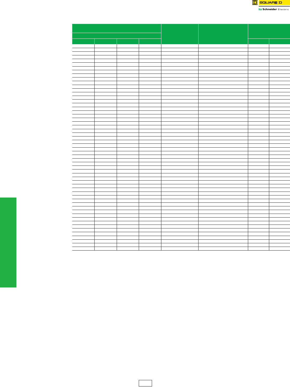
11-10 © 2012 Schneider Electric
All Rights Reserved
www.schneider-electric.us
11 OBSOLETE CIRCUIT BREAKERS
Obsolescent Circuit
Breakers
Mag-Gard™ Motor Circuit Protector
Class 680, 685
aMotor full-load currents are taken from NEC Table 430.150. Select wire and circuit breakers on basis of horsepower rather than nameplate full-load
current per NEC 430.6 (A) for general motor applications. Do not use these values to select overload relay thermal units. See Digest Section 15 for
selection of thermal units when actual full load current is not known. The voltages listed are rated motor voltages. Corresponding nominal system
voltages are 200 to 208, 220 to 240, 440 to 480 and 550 to 600 volts.
bOnly MIN and MAX settings are shown, intermediate settings are available on all circuit breakers.
Accessories . . . . . . . . . . . . . . . . . . . . . . . . . . . . . . . . . . . . . . . . . Page 11-28
OptionalLugs . . . . . . . . . . . . . . . . . . . . . . . . . . . . . . . . . . . . . . . . . Page 11-23
Dimensions. . . . . . . . . . . . . . . . . . . . . . . . . . . . . . . . . . . . . . . . . . . . Page 11-5
Table 11.18: Adjustable Instantaneous-Trip Circuit Breakers for Single Motor Circuit Protection
Hp Ratings of Induction Type
Squirrel-Cage and Wound Rotor Motors Full Load
Amperesa
Mag-Gard
Circuit Breaker
Cat. No.
Magnetic Trip
Settings b
3Ø 60 Hz ac
200 V 230 V 460 V 575 V MIN MAX
1/2 0.8 FAL3600311Ma1000% 3500%
1/2 1 FAL3600311Ma800% 2800%
3/4 1.1 FAL3600311M 700% 2500%
3/4 1 1.4 FAL3600311M 600% 2000%
1 1.8 FAL3600311M 400% 1600%
1/2 2 FAL3600311M 400% 1400%
1-1/2 2.1 FAL3600311M 400% 1300%
1/2 2.3 FAL3600311M 300% 1200%
1-1/2 2.6 FAL3600712M 700% 2700%
2 2.7 FAL3600712M 700% 2600%
3/4 2.8 FAL3600712M 600% 2500%
3/4 3.2 FAL3600712M 600% 2200%
2 3.4 FAL3600712M 500% 2100%
1 3.6 FAL3600712M 500% 1900%
3 3.9 FAL3600712M 500% 1800%
1 4.1 FAL3600712M 400% 1700%
3 4.8 FAL3600712M 400% 1500%
1-1/2 5.2 FAL3600712M 300% 1300%
1-1/2 6 FAL3600712M 300% 1200%
5 6.1 FAL3600712M 300% 1100%
2 6.8 FAL3601513M 700% 2600%
5 7.6 FAL3601513M 700% 2400%
2 7.8 FAL3601513M 600% 2300%
7-1/2 9 FAL3601513M 600% 2000%
3 9.6 FAL3601513M 500% 1900%
3 7-1/2 10 11 FAL3601513M 500% 1600%
10 14 FAL3603015M 700% 2500%
5 15.2 FAL3603015M 700% 2300%
15 17 FAL3603015M 600% 2100%
5 17.5 FAL3603015M 600% 2000%
15 21 FAL3603015M 500% 1700%
7-1/2 20 22 FAL3605016M 700% 2600%
7-1/2 25.3 FAL3605016M 600% 2300%
20 25 27 FAL3605016M 600% 2100%
10 28 FAL3605016M 500% 2100%
30 32 FAL3605016M 500% 1800%
10 32.2 FAL3605016M 500% 1800%
25 34 FAL3605016M 400% 1700%
30 40 FAL3605016M 400% 1500%
40 41 FAL3610018M 700% 2700%
15 42 FAL3610018M 700% 2600%
15 48.3 FAL3610018M 600% 2300%
40 50 52 FAL3610018M 600% 2100%
20 54 FAL3610018M 600% 2000%
20 60 62 FAL3610018M 500% 1800%
50 65 FAL3610018M 500% 1700%
25 68 FAL3610018M 400% 1600%
30 92 KAL3625025M 700% 1400%
40 104 KAL3625026M 700% 1400%
150 144 KAL3625030M 700% 1400%
50 150 KAL3625030M 700% 1300%
60 154 KAL3625031M 700% 1500%
125 156 KAL3625031M 700% 1400%
60 177.1 KAL3625032M 700% 1400%
150 180 KAL3625032M 700% 1400%
75 200 192 KAL3625032M 700% 1300%
DE2 Discount
Schedule
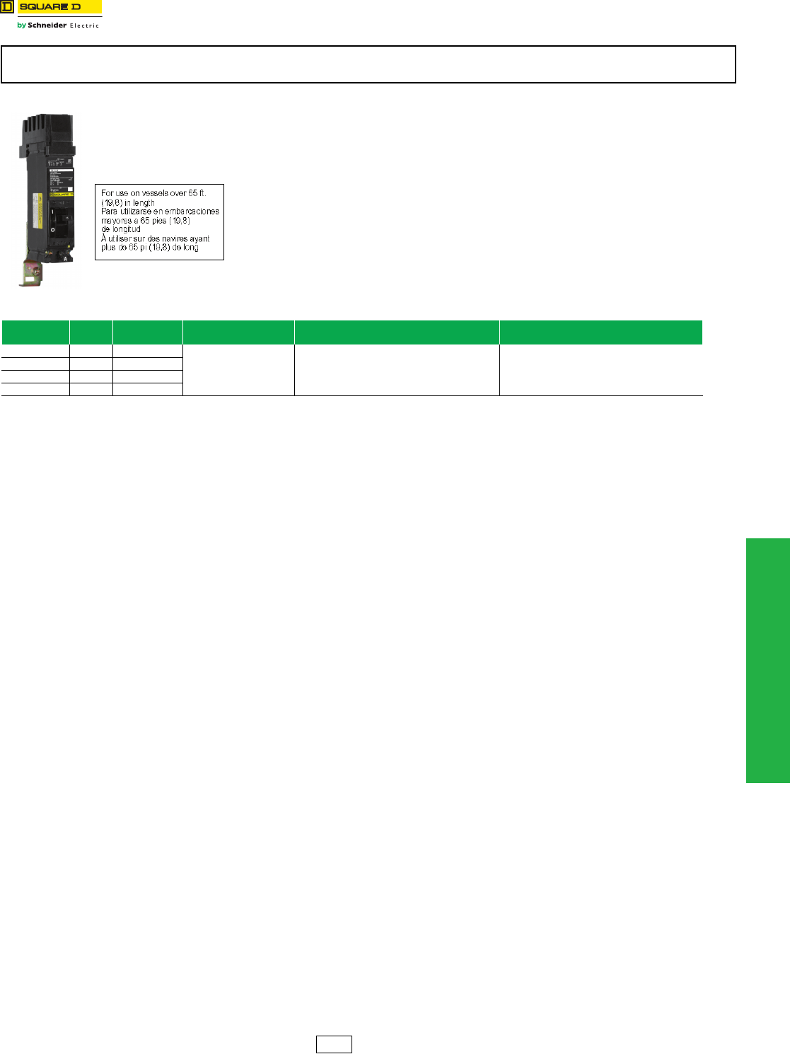
www.schneider-electric.us
11 OBSOLETE CIRCUIT BREAKERS
© 2012 Schneider Electric
All Rights Reserved 11-11
Obsolescent Circuit
Breakers
UL Listed Marine Circuit Breakers
Class 600
A standard for molded case circuit breakers which are intended to be installed and used
aboard a boat or vessel is included in Supplement SA to UL 489, “Standard for Molded
Case Circuit Breakers and Circuit Breaker Enclosures’’ (also referred to as UL product
category DKTY). This UL Standard was established in accordance with U.S. Coast Guard
regulations, applicable American Boat and Yacht Council Inc. publications, and NFPA® 302
“Standard for Motor Craft (Pleasure and Commercial)’’. In order to be UL Listed for marine
use, circuit breakers must not use aluminum or aluminum alloys for terminal connections
and must be calibrated at an ambient temperature of 40 oC. Standard circuit breakers
should not be specified or used in place of marine circuit breakers.
The following table lists those circuit breakers which are UL Marine Listed for use on
vessels over 65 ft. (19.8 m) in length. (PowerPact H and J-frame circuit breakers can also
be used in vessels under 65 ft. [19.8 m] in length.)
These marine circuit breakers are obsolete. Please refer to Digest 176 for PowerPact™ molded case circuit breakers for new
installations or replacement.
Table 11.19: CIrcuit Breakers for Marine Applications
Cat. No. Prefix Poles Ampere
Rating Application Cat. No. $ Price
FC, FCL 2, 3 15–100 A
For use only on vessels over
65 feet (19.8 m) in length.
Add the number “9’’ after the catalog number prefix
of the standard circuit breaker catalog number.
Example:
Standard FAL36100
Marine FAL936100
There is a 20% adder to the price of the equivalent
standard circuit breaker.
All marine circuit breakers are supplied
with copper lugs.
KA, KAL 2, 3 70–250 A
KH, KHL 2, 3 70–250 A
KC, KCL 2, 3 110–250 A
DE2 Discount
Schedule
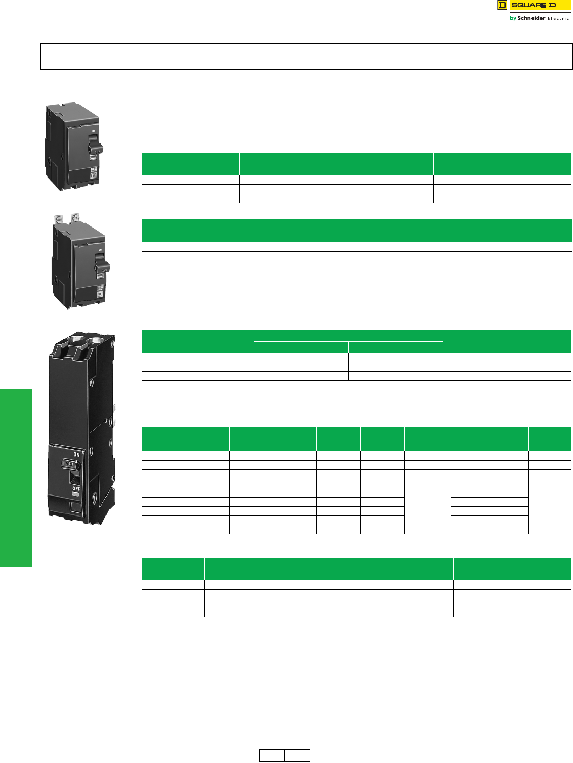
11-12 © 2012 Schneider Electric
All Rights Reserved
www.schneider-electric.us
11 OBSOLETE CIRCUIT BREAKERS
Obsolescent Circuit
Breakers
Circuit Breakers for NQO, NQOB and NQOD Panelboards, Branch
Circuit Breakers and Mounting Assemblies for ML Panelboards
Replacing Obsolescent Q1 and Q1B Circuit Breakers In NQO, NQOB and NQOD Panelboards
Q1 and Q1B circuit breakers have been replaced by QO and QOB circuit breakers.
Table 1 below is used for replacing 1P, 2P or 3P Q1 and Q1B circuit breakers with QO and QOB branch circuit
breakers in NQO, NQOB and NQOD panelboards.
Table 2 below is used for replacing Q1 and Q1B main circuit breakers in NQO and NQOB panelboards.
aMounting assembly SK5669 is used to mount both Q1 and QO circuit breakers. Not required for replacement purposes.
b225 A maximum. For 400–600 ampere circuit breaker mounting assembly, see Class 1630 Service Bulletin.
cDiscount Schedule PE1A.
Branch Circuit Breakers and Mounting Assemblies for ML Panelboards
Replacement circuit breakers for ML panelboards are determined by the manufacture date of the panel and the panel
depth. (See chart below)
The tables below are used for replacing or adding circuit breakers to 10-5/8 inch deep ML panelboards manufactured
from 1962–1968 and for switchboards manufactured from 1962–1968.
dMounting assemblies for twin-mounted circuit breakers will only accept the same family and configuration of circuit breakers, i.e., FAL and FAL.
NQO, NQOB, and NQOD circuit breakers and panelboards are obsolete. Do not use on new applications. Limited service stock is
available for replacement or fill purposes. Contact your local Sales Office for product availability.
2P QO
2P QOB
2P Q1
Table 11.20: Replacing Q1 and Q1B Circuit Breakers with QO and QOB Branch Circuit Breakers
Panelboard
Type
Branch Circuit Breaker Mounting Assembly
Requiredc
Obsolete Available
NQOB Q1B QOB SK5668
NQOD QO SKNQOD225b
NQOD QOB SKNQOD225b
Table 11.21: Replacing Q1 and Q1B Main Circuit Breakers in NQO and NQOB Panelboards
Panelboard
Type
Main Circuit Breaker Mounting Assembly
Requiredc
Retaining Kit
Required
Obsolete Available
NQOB Q1B QOB SK5668 —
Table 11.22: Replacement Circuit Breakers in ML Panelboards
Manufacture Date Panel Depth Availability of Replacement Circuit Breakers
in. mm
1948–1956 8.63 219 No Replacements Available
1958–1961 10.00 254 No Replacements Available
1962–1968 10.63 270 Refer to Tables Below
Table 11.23: Replacement of Existing Circuit Breakers
Existing
Circuit
Breaker
Ampere
Rating
Mounting Height Cat. No.
Prefix
Replacement
Circuit
Breaker
Mounting
Assembly
Required
Poles
Required
Single or Twin
(Mounting
Assembly)
Availability
in. mm
ML-1 15–100 A 4.50 114 989 or 999 FAL SK4515d3P Twin
ML-3 100–225 A 6.00 152 997 KAL SK4516d3P Twin
LA (W) 225–400 8.25 210 LA LAL SK4517 3P Single
MA (W) 125–1000 A 8.25 210 MA MAL SK4578 3P Single
FAL 15–100 A 4.50 114 FAL FAL No
Mounting
Assembly
Required
3P Twin
Not Available
KAL 70–250 A 4.50 114 KAL KAL 3P Twin
LAL 125–400 A 6.00 152 LAL LAL 3P Single
MAL 300–1000 A 9.00 229 MAL MAL 3P Single
MAL 125–250 A 9.00 229 MAL LAL SK4517 3P Single
Table 11.24: Adding New Circuit Breakers
Cat. No.
Prefix Ampere Rating Mounting Assembly
Required
Mounting Height Poles
Required
Single or Twin
(Mounting Assembly)
in. mm
FAL 15–100 A SK4515 4.50 114 3P Twin
KAL 70–250 A SK4516 4.50 114 3P Twin
LAL 125–400 A SK4517 6.00 152 3P Single
MAL 300–1000 A SK4578 9.00 229 3P Single
DE5A PE1A Discount
Schedule
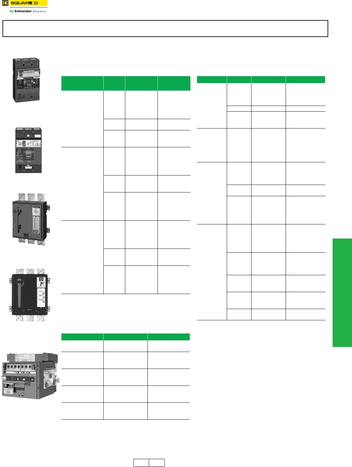
www.schneider-electric.us
11 OBSOLETE CIRCUIT BREAKERS
© 2012 Schneider Electric
All Rights Reserved 11-13
Obsolescent Circuit
Breakers
Rating Plugs For Obsolete Electronic Trip Circuit Breakers
Class 666, 671, 677
Replacement rating plugs for circuit breakers
manufactured before Micrologic™.
eContact your nearest local sales office for availability.
These rating plugs are for electronic circuit breakers which are obsolete. Please refer to Digest 176 for PowerPact™ circuit breakers
for new installations or replacement.
Table 11.25: Replacement Rating Plugs for Pre-
Micrologic Circuit Breakers
Circuit Breakers
Manufactured
Before Micrologic
Frame
Size
Ampere
Rating Cat. No.
ME
225 A
100 A ME2100
110 A ME2110
125 A ME2125
150 A ME2150
175 A ME2175
400 A 250 A ME4250
350 A ME4350
800 A
450 A ME8450
500 A ME8500
700 A ME8700
PE-G/PEC-G
Built before
June 1, 1982
and all PE/PEC
1200 A
600 A PE120600
700 A PE120700
800 A PE120800
900 A PE120900
1200 A PE121200
1600 A
1000 A PE161000
1200 A PE161200
1400 A PE161400
2000 A
1000 A PE161000
1200 A PE161200
1400 A PE161400
1800 A PE201800
2000 A PE202000
PE-G/PEC-G
Built after
June 1, 1982
1200 A
600 A PEG120600
700 A PEG120700
800 A PEG120800
1000 A PEG121000
1200 A PEG121200
1600 A
1000 A PEG161000
1200 A PEG161200
1400 A PEG161400
2000 A
1000 A PEG161000
1200 A PEG161200
1400 A PEG161400
1800 A PEG201800
2000 A PEG202000
Table 11.26: Interchangeable Rating Plug Kits for ME,
NE, PE and SE Circuit Breakers with
Full-Function Micrologic Trip System
Manufactured Between December 1989
and September 1992
Old Cat. No. New Cat. No. Multiplier Value
RP040 ARP040 0.400
RP050 ARP050 0.500
RP056 ARP056 0.563
RP058 ARP058 0.583
RP060 ARP060 0.600
RP063 ARP063 0.625
RP067 ARP067 0.667
RP070 ARP070 0.700
RP075 ARP075 0.750
RP080 ARP080 0.800
RP083 ARP083 0.833
RP088 ARP088 0.875
RP090 ARP090 0.900
RP100 ARP100 1.000
ME Micrologic
Circuit Breakers
ME Circuit Breakers
Manufactured
before Micrologic
PE Micrologic
Circuit Breakers
PE Circuit Breakers
Manufactured
before Micrologic
SE Micrologic
Circuit Breakers
Table 11.27: Replacement Rating Plugs for
Micrologic Circuit Breakers
Circuit Breaker Frame Size Ampere Rating Cat. No.e
Micrologic
ME Series 3
225 A
100 A ME2100RP
110 A ME2110RP
150 A ME2150RP
175 A ME2175RP
400 A 250 A ME4250RP
800 A
450 A ME8450RP
500 A ME8500RP
700 A ME8700RP
Micrologic
NE Series 1 1200 A
600 A NE120600RP
630 A NE120630RP
700 A NE120700RP
800 A NE120800RP
900 A NE120900RP
1000 A NE121000RP
Micrologic
PE Series 4
1200 A
600 A PE120600RP
700 A PE120700RP
1000 A PE121000RP
1200 A PE121200RP
1600 A 1000 A PE161000RP
1200 A PE161200RP
2000 A
1000 A PE201000RP
1200 A PE201200RP
1400 A PE201400RP
1600 A PE201600RP
1800 A PE201800RP
Micrologic
SE Series 2
200 A
100 A S9020100RP
125 A S9020125RP
150 A S9020150RP
175 A S9020175RP
200 A S9020200RP
400 A
200 A S9040200RP
250 A S9040250RP
300A S9040300RP
350 A S9040350RP
800 A
450 A S9080450RP
500 A S9080500RP
700 A S9080700RP
1200 A
800 A S9120800RP
1000 A S9121000RP
1200 A S9121200RP
1600 A 1600 A S9161600RP
2000 A 2000 A S9202000RP
DE5A DE2 Discount
Schedule
11-14 © 2012 Schneider Electric
All Rights Reserved
www.schneider-electric.us
11 OBSOLETE CIRCUIT BREAKERS
Obsolescent Circuit
Breakers
EH/EHB Circuit Breakers
Class 590, 652
aUL Listed as SWD (switching duty) rated.
bFor use only in Series 3 or Series E1 panelboards. Contact your nearest local sales office for use in earlier series panelboards
EH/EHB circuit breakers are obsolete. Do not use on new applications. Limited service stock is available for replacement or fill
purposes. Contact your local Sales Office for product availability.
Table 11.28: E Frame—100 A, Thermal Magnetic (480Y/277 Vac)
Amp
Rating
1P
277 Vac—14 kA
120 Vac—65 kA
2P
480Y/277 Vac—14 kA
120/240 Vac—65 kA
3P
480Y/277 Vac—14 kA
240 Vac—65 kA
Wire Size
(AWG) Wire
Temp.
Plug-On Bolt-On Bolt-On Bolt-On
Cat. No. Availability Cat. No. Availability Cat. No. Availability Cat. No. Availability Al Cu
EH/EHB Circuit Breakers
15 A
Not Available Not Available EHB14015 aEHB24015 EHB34015 — (2) 14–10 60/75 oC
— — — — — — EHB340151042 — (2) 14–10 60/75 oC
— — EHB140151082 — — EHB340151082 — (2) 14–10 60/75 oC
20 A
Not Available Not Available EHB14020 aNot Available Not Available EHB34020 — (2) 14–10 60/75 oC
— — — — — — EHB340201042 — (2) 14–10 60/75 oC
— — Not Available Not Available Not Available Not Available EHB340201082 — (2) 14–10 60/75 oC
— — — — Not Available Not Available EHB340201212 — (2) 14–10 60/75 oC
25 A Not Available Not Available Not Available Not Available Not Available Not Available Not Available Not Available 12–8 14–8 60/75 oC
30 A
Not Available Not Available Not Available Not Available Not Available Not Available EHB34030 12–8 14–8 60/75 oC
— — EHB140301082 EHB240301042 EHB340301082 12–8 14–8 60/75 oC
— — — — EHB240301082 EHB340301212 12–8 14–8 60/75 oC
— — — — — — EHB3403035 12–8 14–8 60/75 oC
35 A Not Available Not Available Not Available Not Available Not Available Not Available EHB34035 12–2 14–2 75 oC
40 A
Not Available Not Available Not Available Not Available Not Available Not Available Not Available Not Available 12–2 14–2 75 oC
— — — — — — Not Available Not Available 12–2 14–2 75 oC
— — — — — — EHB340401212 12–2 14–2 75 oC
45 A Not Available Not Available Not Available Not Available Not Available Not Available Not Available Not Available 12–2 14–2 75 oC
50 A
Not Available Not Available Not Available Not Available EHB24050 Not Available Not Available 12–2 14–2 75 oC
— — — — — — EHB340501042 12–2 14–2 75 oC
— — — — — — EHB340501082 12–2 14–2 75 oC
— — — — — — Not Available Not Available 12–2 14–2 75 oC
60 A
Not Available Not Available Not Available Not Available EHB24060 Not Available Not Available 12–2 14–2 75 oC
— — — — — — Not Available Not Available 12–2 14–2 75 oC
— — — — — — Not Available Not Available 12–2 14–2 75 oC
70 A — — — — Not Available Not Available Not Available Not Available 4–2/0 4–2/0 75 oC
80 A — — — — Not Available Not Available Not Available Not Available 4–2/0 4–2/0 75 oC
90 A — — — — Not Available Not Available Not Available Not Available 4–2/0 4–2/0 75 oC
100 A — — — — EHB24100bNot Available Not Available 4–2/0 4–2/0 75 oC
100 A — — — — EHB241001082 Not Available Not Available 4–2/0 4–2/0 75 oC
EH/EHB HID Circuit Breakers — For Use on High Intensity Discharge Lighting Systems
15 A Not Available Not Available Not Available Not Available EHB24015HID Not Available Not Available — (2) 14–10 60/75 oC
20 A Not Available Not Available EHB14020HIDaNot Available Not Available EHB34020HID — (2) 14–10 60/75 oC
25 A Not Available Not Available Not Available Not Available Not Available Not Available Not Available Not Available 12–8 14–8 60/75 oC
30 A Not Available Not Available Not Available Not Available Not Available Not Available EHB34030HID 12–8 14–8 60/75 oC
Requires
1 Space
Requires
1 Space Requires
2 Spaces
Requires
3 Spaces
DE5A Discount
Schedule

www.schneider-electric.us
11 OBSOLETE CIRCUIT BREAKERS
© 2012 Schneider Electric
All Rights Reserved 11-15
Obsolescent Circuit
Breakers
FJA Thermal-Magnetic Circuit Breakers
FJ 3-pole circuit breakers are obsolete. Please refer to Digest 176 for PowerPact™ molded case circuit breakers for new installations
or replacement.
Table 11.29: Mechanical Lug Kit Information
Circuit Breaker Application Number of Wires
Per Lug and
Wire Range
Kit
Cat. No.
Lugs
Per
Kit
Standard Ampere
Rating Optional Ampere
Rating
Al Lugs for Use with Al or Cu Wire
FJ 35–125 A FJ 15–30 A (1) 12–2/0 AWG Al or
(1) 14–2/0 AWG Cu AL100FD 3
Table 11.30: Handle Accessories
Circuit Breaker Type No. of Poles Cat. No.
Handle Padlock Attachment (locks ON or OFF)
FJ 1, 2 or 3 HPAFD
DE2 Discount
Schedule
www.schneider-electric.us
11 OBSOLETE CIRCUIT BREAKERS
11-16 © 2012 Schneider Electric
All Rights Reserved
Obsolescent Circuit
Breakers
QE Metering Circuit Breakers
QE circuit breakers are obsolete. Please refer to Digest 176 for PowerPact™ molded case circuit breakers for new installations or
replacement.
Table 11.31: Branch Circuit Breakers
Branch Device
System
Type
Branch Circuit Breaker
Ampere
Rating Cat. No. Availability
1Ø IN – 1Ø OUT
or
3Ø IN – 1Ø3W OUT
200 A Max.
70 A QE270VH
80 A QE280VH
90 A QE290VH
100 A QE2100VH
125 A QE2125VH Not Available
150 A QE2150VH
175 A QE2175VH Not Available
200 A QE2200VH Not Available
3Ø IN 3Ø OUT
200 A Max.
70 A QE370VH
80 A QE380VH Not Available
90 A QE390VH Not Available
100 A QE3100VH Not Available
125 A QE3125VH Not Available
150 A QE3150VH Not Available
175 A QE3175VH Not Available
200 A QE3200VH Not Available
Table 11.31: Branch Circuit Breakers
Branch Device
System
Type
Branch Circuit Breaker
Ampere
Rating Cat. No. Availability
DE5A Discount
Schedule
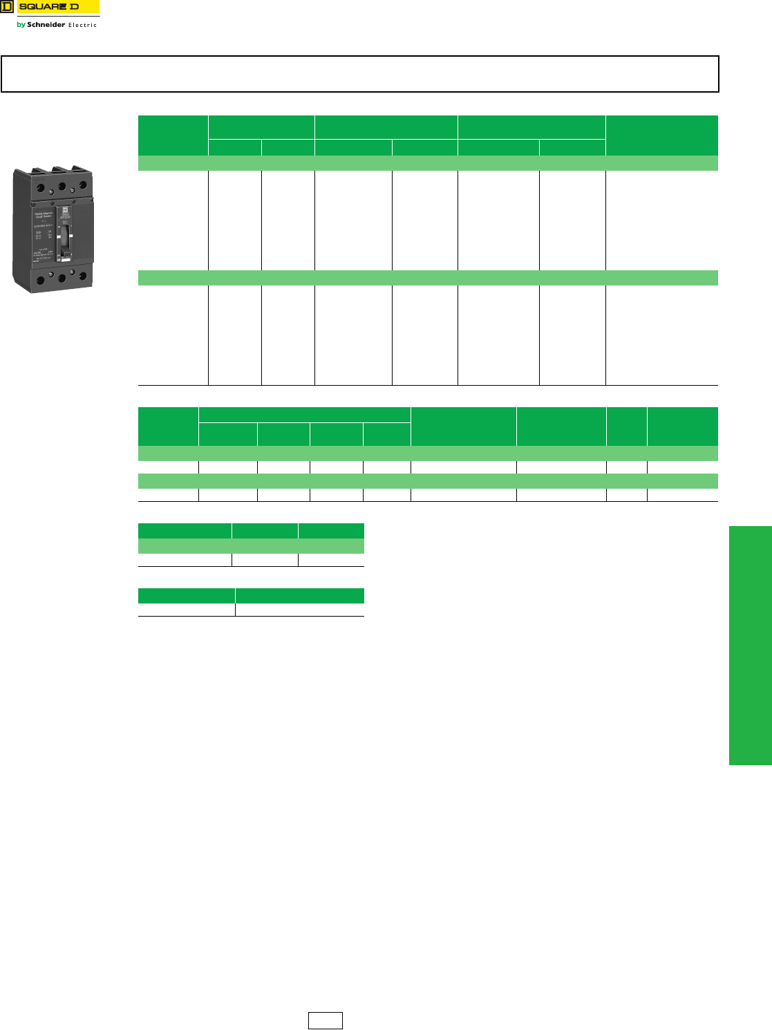
www.schneider-electric.us
11 OBSOLETE CIRCUIT BREAKERS
© 2012 Schneider Electric
All Rights Reserved 11-17
Obsolescent Circuit
Breakers
KD/KG Thermal-Magnetic Circuit Breakers
Class 540
KD and KG circuit breakers are obsolete. Please refer to Digest 176 for PowerPact™ molded case circuit breakers for new installations
or replacement.
Table 11.32: PowerPact™ K Frame—250 A, Thermal-Magnetic (240 Vac)
Continuous
Current
Rating
@ 40o C
AC Magnetic
Trip Settings D Interrupting Level G Interrupting Level Terminal
Wire
Range
Hold Trip Cat. No. Availability Cat. No. Availability
2P, 240 Vac
100 A 1100 A 1700 A KDL22100 Not Available KGL22100 Not Available
AL250KD
6 AWG–350 kcmil
Al or Cu
110 A 1100 A 1700 A KDL22110 Not Available KGL22110 Not Available
125 A 1100 A 1700 A KDL22125 Not Available KGL22125 Not Available
150 A 1100 A 1700 A KDL22150 Not Available KGL22150 Not Available
175 A 1400 A 2400 A KDL22175 Not Available KGL22175 Not Available
200 A 1400 A 2400 A KDL22200 Not Available KGL22200 Not Available
225 A 1400 A 2400 A KDL22225 Not Available KGL22225 Not Available
250 A 1400 A 2400 A KDL22250 Not Available KGL22250 Not Available
3P, 240 Vac
100 A 1100 A 1700 A KDL32100 KGL32100 Not Available
AL250KD
6 AWG–350 kcmil
Al or Cu
110 A 1100 A 1700 A KDL32110 Not Available KGL32110 Not Available
125 A 1100 A 1700 A KDL32125 KGL32125 Not Available
150 A 1100 A 1700 A KDL32150 KGL32150 Not Available
175 A 1400 A 2400 A KDL32175 Not Available KGL32175 Not Available
200 A 1400 A 2400 A KDL32200 Not Available KGL32200 Not Available
225 A 1400 A 2400 A KDL32225 KGL32225 Not Available
250 A 1400 A 2400 A KDL32250 Not Available KGL32250 Not Available
Table 11.33: Mechanical Lug Kit Information
Kit Catalog
Number
Circuit Breaker Application Number of Wires Per Lug
and Wire Range Torque Lugs
Per Kit Availability
Standard Ampere
Rating Optional Ampere
Rating
Al Lugs for Use with Al or Cu Wire
AL250KD KDL, KGL 100–250 A — — (1) 6 AWG–350 kcmil 300 lb-in (34 N•m) 3 Not Available
Cu Lugs for Use with Cu Wire Only
CU250KD — — KDL, KGL 100–250 (1) 6 AWG–350 kcmil 300 lb-in (34 N•m) 3
Table 11.34: Handle Accessories
Circuit Breaker Type Cat. No. Availability
Handle Padlock Attachment (locks ON or OFF)
KDL, KGL HPAKD Not Available
Table 11.35: Interrupting Ratings (kA)
KDL
240 V 25
KDL and KGL
Circuit Breaker
3P
100–250 A
DE5A Discount
Schedule
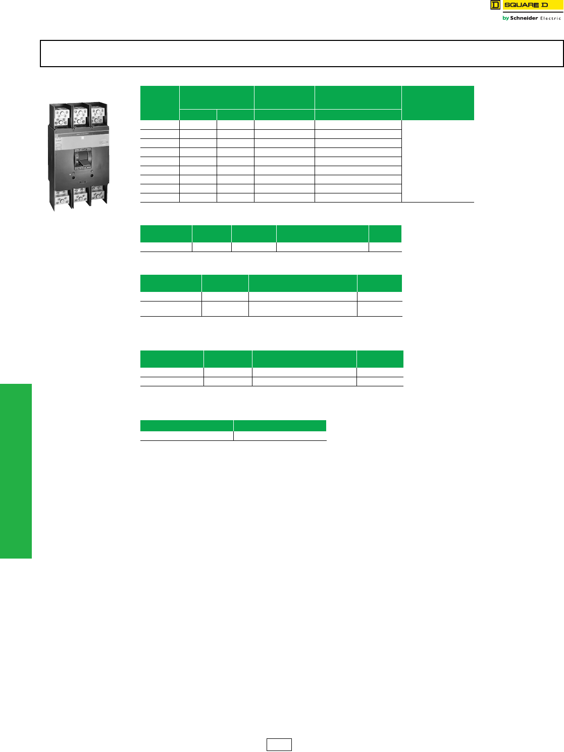
11-18 © 2012 Schneider Electric
All Rights Reserved
www.schneider-electric.us
11 OBSOLETE CIRCUIT BREAKERS
Obsolescent Circuit
Breakers
NHL Thermal-Magnetic Molded Case Circuit Breaker
Class 670
aUnless otherwise specified, wire sizes apply to both aluminum and copper conductors.
bUse with NAHEX handle extension.
NHL circuit breakers and related accessory products are obsolete. Please refer to Digest 176 for PowerPact™ molded case circuit
breakers for new installations or replacement.
NHL Circuit Breaker
800–1200 A
Table 11.36: NHL Circuit Breaker (1200 A, 480 Vac)
Ampere
Rating
AC Magnetic Trip
Settings
Amperes
2P 3P Standard Lug Kit Wire
Range
Low High Cat. No. Cat. No.
800 A 4000 A 8000 A — NHF368001021
AL1200NA
(4) 350–750-kcmil
1000 A 5000 A 10000 A — NHF3610001021
1200 A 5000 A 10000 A — NHF361200
1200 A 5000 A 10000 A — NHF3612001021
800 A 4000 A 8000 A — NHL36800
1000 A 5000 A 10000 A NHL261000 NHL361000
1000 A 5000 A 10000 A — NHL3610001021
1200 A 5000 A 10000 A NHL261200 NHL361200
1200 A 5000 A 10000 A — NHL3612001021
Table 11.37: Mechanical Lug Kit
Kit Cat. No. Circuit
Breaker
Ampere
Rating
Number of Wires Per
Lug and Wire Rangea
Lugs
Per Kit
AL1200NA NH 600–1200 (4) 350–750 kcmil 1
Table 11.38: Compression Lug Kit
Kit Cat. No. Circuit
Breaker
Number of Lugs
Per Terminal and Wire Rangea
Lugs
Per Kit
VC1200NA5 NH (1) 2/0 AWG–500 kcmil 1
VC1200NA7 NH (1) 500–750 kcmil Al or
500 kcmil Cu 1
Table 11.39: Mechanical Accessories
Cat. No. Circuit
Breaker Description No. of
Poles
HPANAbNH Handle Padlock Attachment 2, 3
NAHEX NH Handle Extension 2, 3
Table 11.40: Control Wire Terminations
Cat. No. Standard Package Quantity
AL1200NAT 1
DE5A Discount
Schedule
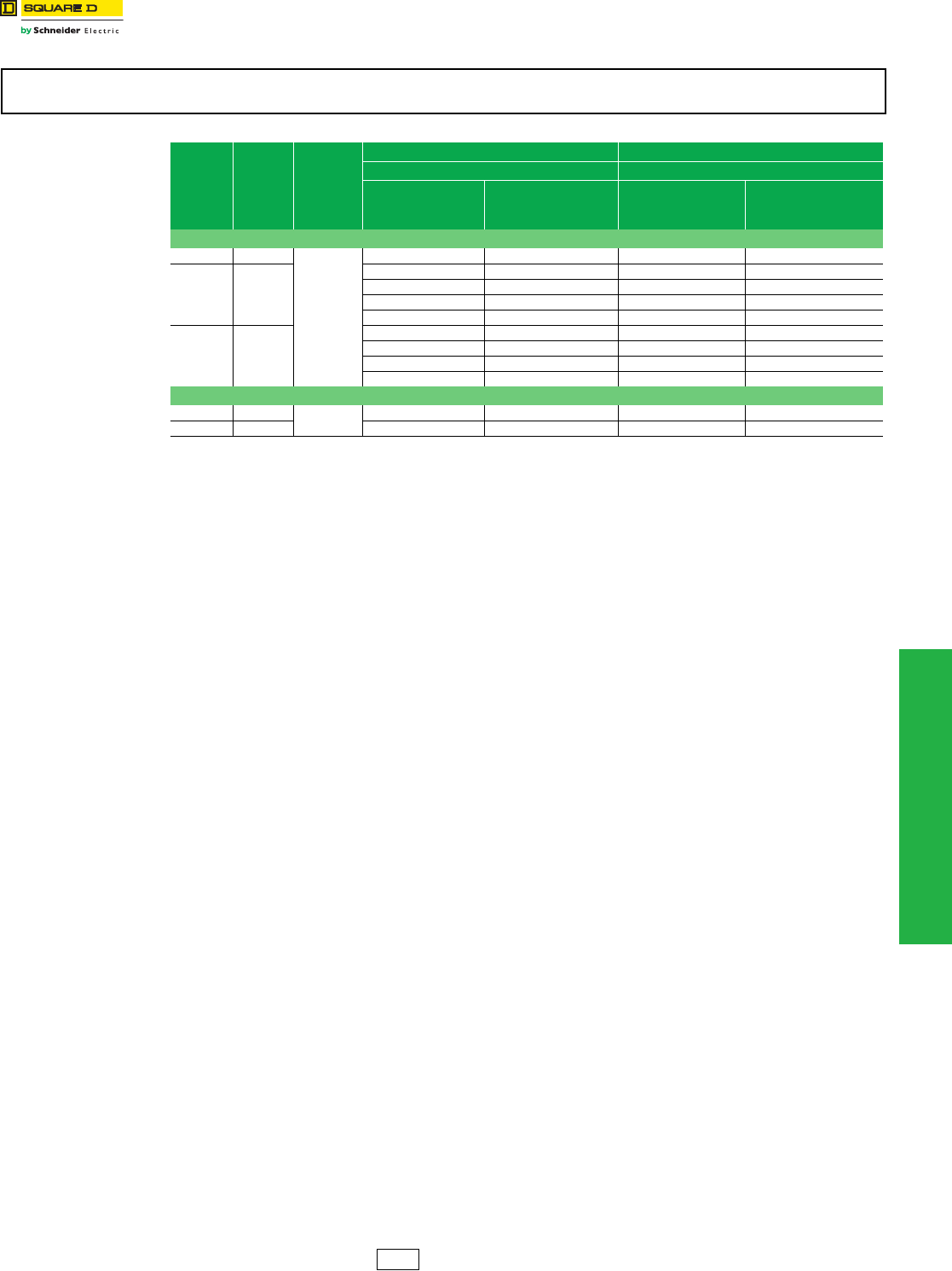
www.schneider-electric.us
11 OBSOLETE CIRCUIT BREAKERS
© 2012 Schneider Electric
All Rights Reserved 11-19
Obsolescent Circuit
Breakers
SE Circuit Breaker with Full-Function Trip Unit
Class 678
a“MR” (Motor Ready) indicates 120 Vac spring charging motor only already installed. Does not include shunt close or shunt trip option.
b“Z” indicates circuit breaker supplied without terminal connector kit.
cSubstitute (A) in place of (G) for ground-fault alarm (pick-up indication only).
SE circuit breakers and related accessories are obsolete. Please refer to Digest 176 for PowerPact™ molded case circuit breakers for
new installations or replacement.
Table 11.41: SE Circuit Breaker
Sensor Size Ampere
Rating
Rating
Plug
Installed
Fixed-Mounted Circuit Breaker Drawout Circuit Breaker
Cat. No.ab Cat. No.ab
Long-Time
Short-Time
Instantaneous
Long-Time
Short-Time
Instantaneous
w/Ground Faultc
Long-Time
Short-Time
Instantaneous
Long-Time
Short-Time
Instantaneous
w/Ground Faultc
Standard Interrupting Rating
1200 A 1200 A
ARP100
SEF361200LSMR — — —
3000 A 3000 A
SEF363000LS — SED363000LS —
— SEF363000LSG — SED363000LSG
SEF363000LSMR — SED363000LSMR —
— SEF363000LSGMR — SED363000LSGMR
4000 A 4000 A
SEF364000LSZ — — —
SEF364000LSMRZ —
— SEF364000LSGMRZ — SED364000LSGMR
— SEF364000LSAMRZ — —
High Interrupting Rating
1200 A 1200 A ARP100 — SEHF361200LSGMR — —
3000 A 3000 A SEHF363000LSMR — — —
DE5A Discount
Schedule
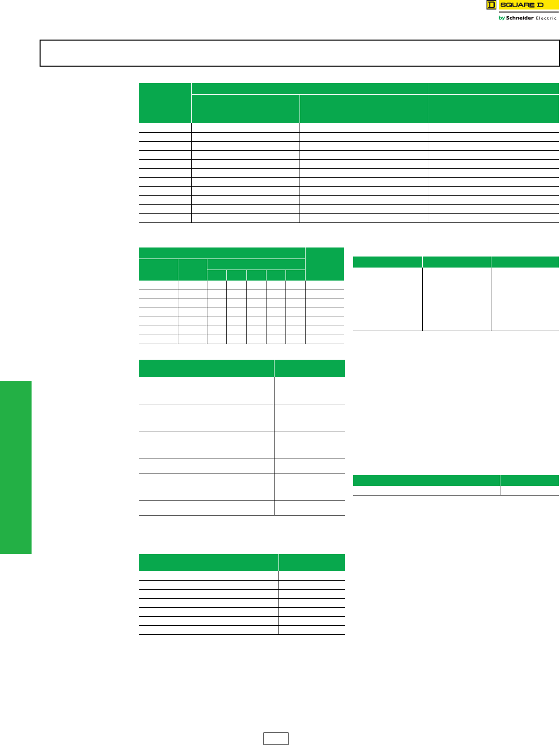
www.schneider-electric.us
11 OBSOLETE CIRCUIT BREAKERS
11-20 © 2012 Schneider Electric
All Rights Reserved
Obsolescent Circuit
Breakers
SE Circuit Breaker Accessories
Class 678
aUsed only with SE circuit breaker Series 3B.
bAlso field-installable on Series 3 and newer, and for Series 2 ground
fault circuit breakers.
cFixed-mounted circuit breakers only. Does not include key interlock.
Electric Joint Compound
SE drawout circuit breakers are supplied with factory-
applied joint compound on the plug-on connectors. The
compound should not be removed because it contributes
to the overall performance of the connection.
Whenever one of these units is removed and reinstalled,
the joint compound should be reapplied.
PJC 8311 is a two-ounce container of compound specially
formulated for the SE drawout connections. This
compound MUST BE USED ON SE DRAWOUT
CONNECTIONS. No other type of commercially available
joint compound should be used.
SE circuit breakers and related accessories are obsolete. Please refer to Digest 176 for PowerPact™ molded case circuit breakers for
new installations or replacement.
Table 11.42: Field-Replaceable Electronic Trip Unit Kits (Replaceable by Field Services Only)a
Ampere Rating
Trip Unit Function Cat. No.
Long-Time
Short-Time
Instantaneous
Long-Time
Short-Time
Instantaneous with
Ground Fault
Long-Time
Short-Time
Instantaneous with
Ground Fault Alarm
400 A — SETU400LSGB —
800 A SETU800LSB — —
800 A — SETU800LSGB —
1200 A SETU1200LSB — —
1200 A — SETU1200LSGB —
1600 A — SETU1600LSGB SETU1600LSAB
2500 A — SETU2500LSGB —
3000 A SETU3000LSB — —
3000 A — SETU3000LSGB SETU3000LSAB
4000 A SETU4000LSB — —
4000 A — SETU4000LSGB —
Table 11.43: SE Drawout Cell Keying Kit
Cell Key Positions Table
Availability
Cell Keying
Kit Cat. No.
Frame
Size
Drawout Carriage Cell Key Position
A B C D E
SECK0400 400 A X X Not Available
SECK0800 800 A X X Not Available
SECK1200 1200 A X X
SECK1600 1600 A X X
SECK2000 2000 A X X
SECK2500 2500 A X X
SECK3000 3000 A X X
Table 11.44: Field-Replaceable Accessory Kits
Description Kit
Cat. No.
Spring Charging Motor
Replacement Kit
120 Vac
24 Vdc
48 Vdc
125 Vdc
S3MOT120AC2
—
—
S3MOT125DC2
Shunt Close
Replacement Kit
120 Vac
24 Vdc
48 Vdc
125 Vdc
S3SC120AC2
S3SC024DC2
S3SC048DC2
S3SC125DC2
Shunt Tripb
Replacement Kit
120 Vac
24 Vdc
48 Vdc
125 Vdc
S3ST120AC2
S3ST024DC2
S3ST048DC2
S3ST125DC2
Undervoltage Tripb
Replacement Kit 120 Vac —
Auxiliary Switchb
Replacement Kit
4 ac/dc
4 ac/dc add on
4 ac only
8 ac only
S34DCB2
S34DCT2
S34AC2
S38AC2
Alarm Switchb
Replacement Kit 2 ac only S3AS2
Table 11.45: Field-Installable External Accessory
Kits
Description Kit
Cat. No.
Padlock Attachment SE2PA
Close Button Cover SE1CBC
Key Interlock Bracketc SE1KI
Series 1 Primary Injection Test Plug SEPITK1
Series 2 Primary Injection Test Plug SEPITK2
SE Drawout Crank SEDC
Fan Monitoring Switch Kit SE40FAN
Table 11.46: Neutral Current Transformers
Cat. No. Sensor Where Used
SE12NCT 800 SE, SEH
SE12NCT 1200 SE, SEH
SE30NCT 1600 SE, SEH
SE30NCT 2000 SE, SEH
SE30NCT 2500 SE, SEH
SE30NCT 3000 SE, SEH
SE40NCT 4000 SE, SEH
Table 11.47: Electric Joint Compound
Used With Cat. No.
SED Drawout Circuit Breakers PJC8311
DE5A Discount
Schedule
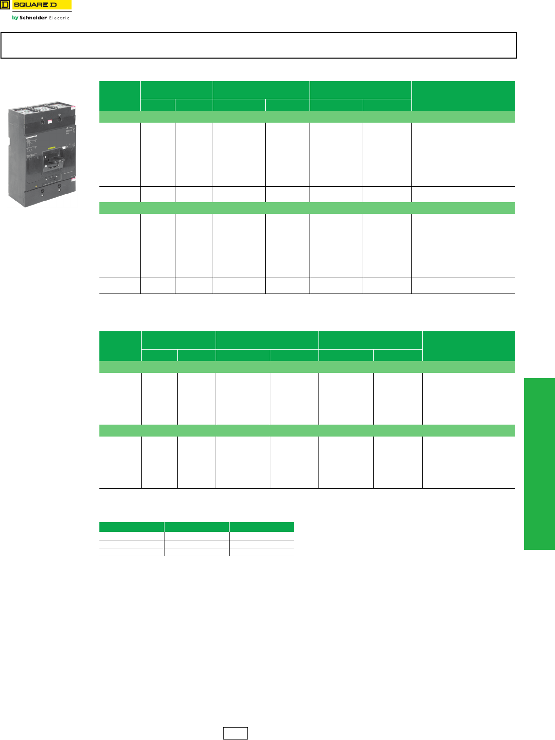
www.schneider-electric.us
11 OBSOLETE CIRCUIT BREAKERS
© 2012 Schneider Electric
All Rights Reserved 11-21
Molded Case Circuit
Breakers
M-Frame Thermal-Magnetic Circuit Breakers
.
Accessories . . . . . . . . . . . . . . . . . . . . . . . . . . . . . . . . . . . . . . . . . Page 11-28
OptionalLugs . . . . . . . . . . . . . . . . . . . . . . . . . . . . . . . . . . . . . . . . . Page 11-23
Dimensions . . . . . . . . . . . . . . . . . . . . . . . . . . . . . . . . . . . . . . . . . . . Page 11-5
Enclosures: see Digest Section 7
M-frame thermal-magnetic circuit breakers are obsolete. Please refer to Digest 176 for PowerPact™ molded case circuit breakers for
new installations or replacement.
Table 11.48: M-Frame—Thermal-Magnetic, Individually-Mounted Circuit Breakers, 600 Vac
Ampere
Rating
AC Magnetic
Trip SettingsaStandard Interrupting High Interrupting Terminal
Wire
Range
Low High Cat. No. Availability Cat. No. Availability
2P, 600 Vac, 250 Vdc
300 A
350 A
400 A
450 A
500 A
600 A
700 A
800 A
900 A
1000 A
1500 A
1750 A
2000 A
2250 A
2500 A
3000 A
3500 A
4000 A
4500 A
5000 A
3000 A
3500 A
4000 A
4500 A
5000 A
6000 A
7000 A
8000 A
9000 A
10000 A
MAL26300
MAL26350
MAL26400
MAL26450
MAL26500
MAL26600
MAL26700
MAL26800
MAL26900
MAL261000
Not Available
Not Available
Not Available
Not Available
Not Available
Not Available
Not Available
Not Available
Not Available
Not Available
MHL26300
MHL26350
MHL26400
MHL26450
MHL26500
MHL26600
MHL26700
MHL26800
MHL26900
MHL261000
Not Available
Not Available
Not Available
Not Available
Not Available
Not Available
Not Available
Not Available
AL900MA
(3) 3/0 AWG–500 kcmil
1200 A 5000 A 10000 A MAL261200 Not Available MHL261200 Not Available AL1000MAb
(4) 1/0 AWG–350 kcmil
3P, 600 Vac, 250 Vdc
300 A
350 A
400 A
450 A
500 A
600 A
700 A
800 A
900 A
1000 A
1500 A
1750 A
2000 A
2250 A
2500 A
3000 A
3500 A
4000 A
4500 A
5000 A
3000 A
3500 A
4000 A
4500 A
5000 A
6000 A
7000 A
8000 A
9000 A
10000 A
MAL36300
MAL36350
MAL36400
MAL36450
MAL36500
MAL36600
MAL36700
MAL36800
MAL36900
MAL361000
Not Available
Not Available
Not Available
Not Available
Not Available
Not Available
Not Available
Not Available
Not Available
Not Available
MHL36300
MHL36350
MHL36400
MHL36450
MHL36500
MHL36600
MHL36700
MHL36800
MHL36900
MHL361000
Not Available
Not Available
Not Available
Not Available
AL900MA
(3) 3/0 AWG–500 kcmil
1200 A 5000 A 10000 A MAL361200 Not Available MHL361200 AL1000MAb
(4) 1/0 AWG–350 kcmil
aUL magnetic trip setting tolerances are ±25% for low and ±20% for high from nominal values shown.
bThe AL100MA lug is the only lug available for the 1200 A MA and MH circuit breakers.
Table 11.49: M-Frame—Thermal-Magnetic, I-Line™ Construction Circuit Breakers, 600 Vac
Ampere
Rating
AC Magnetic
Trip SettingscStandard Interrupting High Interrupting Terminal
Wire
Range
Low High Cat. No. Availability Cat. No. Availability
2P, 600 Vac, 250 Vdcd
300 A
350 A
400 A
450 A
500 A
600 A
700 A
800 A
1500 A
1750 A
2000 A
2250 A
2500 A
3000 A
3500 A
4000 A
3000 A
3500 A
4000 A
4500 A
5000 A
6000 A
7000 A
8000 A
MA26300( )
MA26350( )
MA26400( )
MA26450( )
MA26500( )
MA26600( )
MA26700( )
MA26800( )
Not Available
Not Available
Not Available
Not Available
Not Available
Not Available
Not Available
Not Available
MH26300( )
MH26350( )
MH26400( )
MH26450( )
MH26500( )
MH26600( )
MH26700( )
MH26800( )
Not Available
Not Available
Not Available
Not Available
Not Available
Not Available
Not Available
Not Available
AL900MA
(3) 3/0 AWG–500 kcmil
3P, 600 Vac, 250 Vdc
300 A
350 A
400 A
450 A
500 A
600 A
700 A
800 A
1500 A
1750 A
2000 A
2250 A
2500 A
3000 A
3500 A
4000 A
3000 A
3500 A
4000 A
4500 A
5000 A
6000 A
7000 A
8000 A
MA36300
MA36350
MA36400
MA36450
MA36500
MA36600
MA36700
MA36800
Not Available
Not Available
Not Available
Not Available
Not Available
MH36300
MH36350
MH36400
MH36450
MH36500
MH36600
MH36700
MH36800
Not Available
Not Available
Not Available
Not Available
Not Available
AL900MA
(3) 3/0 AWG–500 kcmil
cUL magnetic trip setting tolerances are ±25% for low and ±20% for high from nominal values shown.
d2P circuit breaker catalog numbers are completed by adding required phase connection letters as suffix to catalog numbers. See Phase Options table.
Table 11.50: Interrupting Ratings
Volt age MA/MAL MH/MHL
240 Vac 42 kA 65 kA
480 Vac 30 kA 65 kA
600 Vac 22 kA 25 kA
MAL/MHL 2P and 3p
300–1000 A
DE2 Discount
Schedule
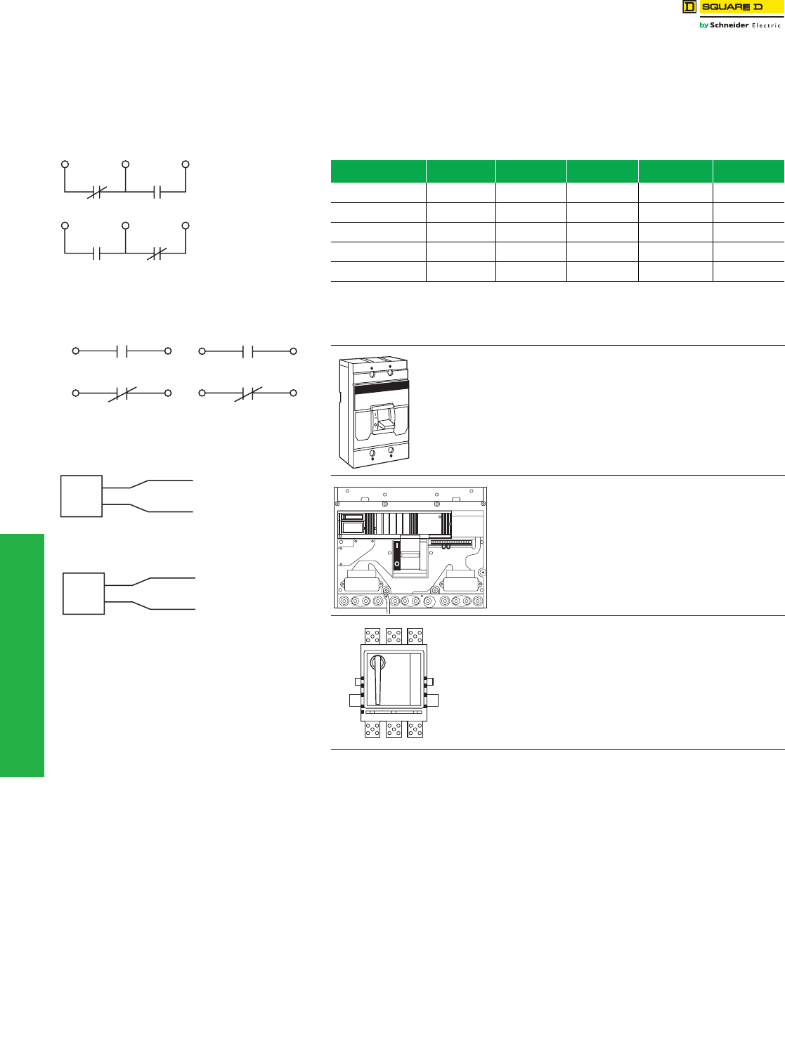
11-22 © 2012 Schneider Electric
All Rights Reserved
www.schneider-electric.us
11 OBSOLETE CIRCUIT BREAKERS
Circuit Breaker
Accessories
Field-Installable Accessories
Field-Installable Electrical Accessories
Complete field-installable accessory catalog number by inserting suffix from Digest page 7-
36 between the parentheses in the catalog numbers shown in the table below. (Example:
LA11212) See Digest page 7-36 for accessory pricing; add 20% to factory-install field-
installable devices.
Table 11.51: Field-Installable Accessories for Thermal-Magnetic and Electronic Trip
Circuit Breakers
Circuit Breaker Shunt Trip Ground-Fault
Shunt TripaUndervoltage Trip Auxiliary Switches Alarm Switch
MA, MH
Series 2 MA1( ) MA1G MA1 ( ) MA1( ) Factory-Installed
Only Center Pole
ME, MX Factory-Installed
Only
Factory-Installed
Only
Factory-Installed
Only
Factory-Installed
Only
Factory-Installed
Only
NA, NC, NE, NX
Series 1, 2, 3 NA1( ) NA1( ) NA1( ) NA1( ) NA1( )
PA, P H, PC
Series 4 PA1 ( ) Factory-Installed
Only PA11121 PA1( ) Factory-Installed
Only
PE, PX
Series 4, 5, 6 PA 1( ) Factory-Installed
Only
PA11121 PA1( ) Factory-Installed
Only
aUsed with obsolete GP Ground-Censor™ system or add-on ground-fault modules.
Table 11.52: Accessory Mounting Locations
MA, MH Series 2 circuit breakers or newer = Field-
installable accessories
ME/MX circuit breakers = Not field-installable accessories
NA, NC, NE, NX circuit breakers - FIeld-installable
accessories
“L” port and “R” port will accept shunt trips, alarm switches
and UVRs; “R2” port will accept auxiliary switches.
Maximum of one device per port.
PA, PH, PC, PE, PX Series 4 circuit breakers or newer = FIield-installable
accessories.
“L1” a
nd “L2” or “R1” and “R2” port combinations are required
to mount a single shunt trip. Both “L2” and “R2” ports will
accept a UVR. Both “L1” and R1” ports will accept
auxiliary switches. If alarm switch is factory installed in PA
or PC circuit breaker, it will be installed in “R2” port. For a
PE or PX circuit breaker, the alarm switch will be factory
installed in “L2” port.
1A/1B
Circuit Breaker Closed
AB
Circuit Breaker Open or Tripped
AB
Auxiliary Switch
Contact Configuration
Color Code:
"A" Contact - Yellow Leads
"B" Contact - Blue Leads
Common-Striped Leads
Circuit Breaker Open or Closed
1A Alarm Switch
Configuration
Color Code: Red Leads
Circuit Breaker Tripped
Circuit Breaker Tripped
1B Alarm Switch
Configuration
Color Code: Red Leads
Circuit Breaker Open or Closed
Undervoltage Trip
Wiring Diagram
Brown
Brown
Brown Wires To Be
Connected To
Control Power
UVR
Shunt Trip
Wiring Diagram
Black
Black
Black Wires To Be
Connected To
Control Power
Shunt
Tr i p
L
R
LR1
R2
L1
L2
R1
R2
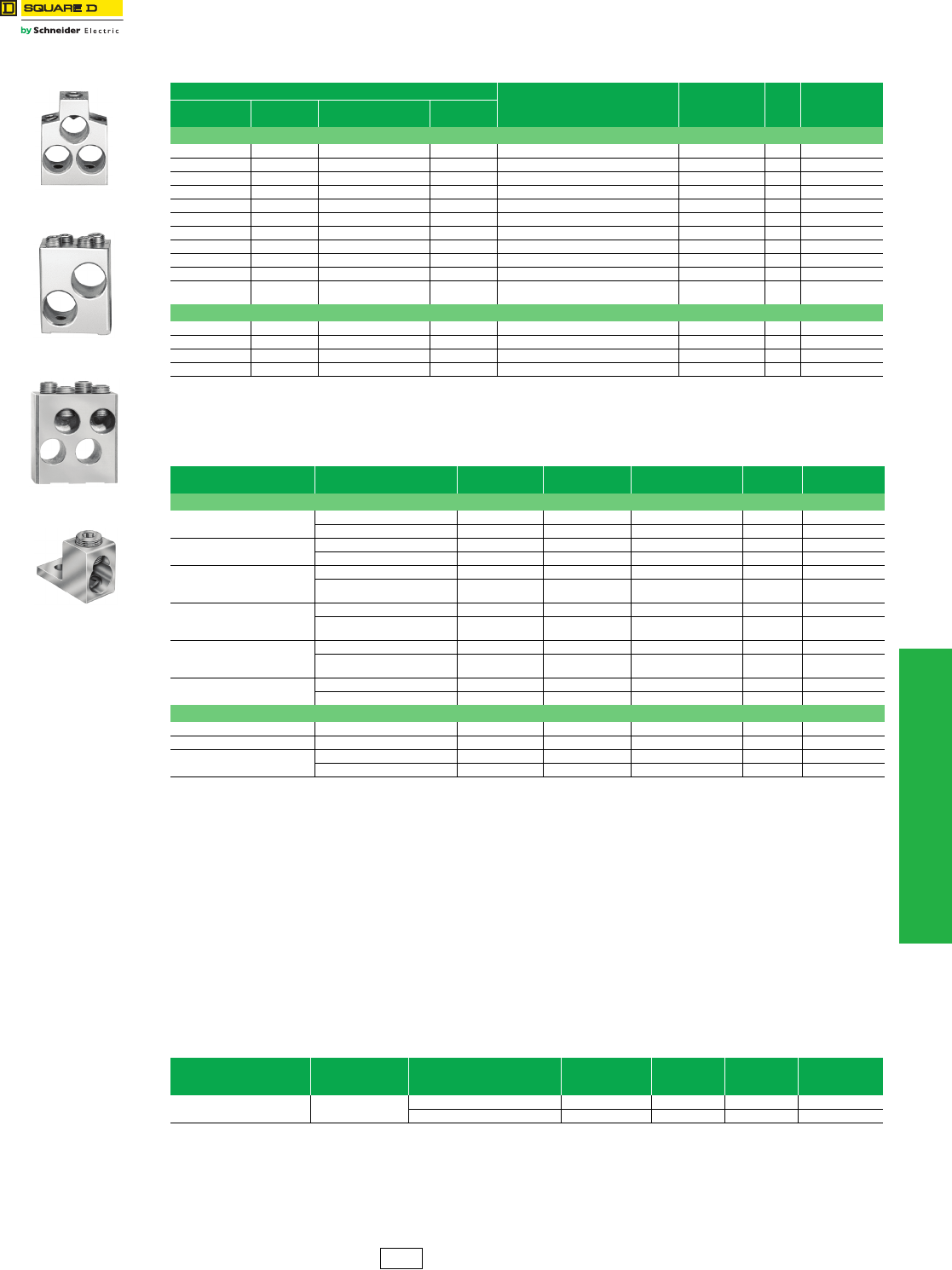
www.schneider-electric.us
11 OBSOLETE CIRCUIT BREAKERS
© 2012 Schneider Electric
All Rights Reserved 11-23
Circuit Breaker
Accessories
Mechanical Lug Information
aUnless otherwise specified, wire sizes apply to both aluminum and copper conductors.
bFor use in the OFF end only, when the OFF end is the load end.
cUse suffix 8002 for factory-installed Cu lugs. (20% adder.)
Compression Lug Kits
aSee instruction bulletins for recommended tools.
bUnless otherwise specified, wire sizes apply to both aluminum and copper conductors.
cAll P-frame circuit breakers require terminal pads for mounting lugs of any type.
Power Distribution Connectors (PDC) for Circuit Breakers—for Field Replacement of Mechanical
Lugs
Can be used for multiple load connections on one circuit breaker. Use in place of standard distribution blocks to save
space and time.
Field-installable kits, including tin-plated aluminum connectors and all necessary mounting hardware are available for
Square D FA, LA and Q4-frame molded case circuit breakers.
Connectors are UL Listed:
•For use on load end of circuit breaker only
•For use in UL508 Industrial Control applications only
•For use in UL 1995/CSA C22.2 No. 236 heating and cooling equipment
•For copper wire only
dNot for use with I-Line circuit breakers.
eWhen using fine stranded wire, increased cross sectional area may cause maximum wire size to be reduced.
fOFF end only when OFF end is the load end.
Table 11.53: Mechanical Lug Kit Information
Circuit Breaker Application (Number of Wires Per Lug )
Wire RangeaCat. No.
Lugs
Per
Kit
Availability
Per Kit
Standard Ampere
Rating Optional Ampere
Rating
Al Lugs for Use with Al or Cu Wire
— — LC, LI, LE, LX, LXI — (1) 500–750 kcmil AL600LI7 1
MA, MH 300–1000 A — — (3) 3/0 AWG–500 kcmil AL900MA 1
— — MA, MH 300–1000 A (2) 500–750 kcmil AL800MA7 1
— — MA, MH 300–1200 A (4) 1/0 AWG–350 kcmil AL1000MA 1
ME, MX 100–250 A — — (1) 6 AWG–350 kcmil AL250ME 3 Not Available
— — ME, MX 250–400 A (1) 350–750 kcmil AL400ME7 1 Not Available
— — ME, MX 100–800 A (2) 500–750 kcmil AL800MA7 1
ME, MX 300–800 A ME, MX 100–250 A (3) 3/0 AWG–500 kcmil AL900MA 1
— — ME, MX 300–1200 A (4) 1/0 AWG–350 kcmil AL1000MA 1
NA, NC, NE, NX 600–1200 A — — (4) 3/0 AWG–600 kcmil AL1200NE6 1 Not Available
——
PAF, PHF, PEF, PXF,
PCF 600–2500 A (1) 1/0 AWG–750 kcmil AL2500PA 2
Cu Lugs for Use with Cu Wire Only c
— — MA, MH 300–1000 A (3) 3/0 AWG–500 kcmil Cu CU1000MA 1
— — ME, MX 125–250 A (1) 4 AWG–250 kcmil Cu CU250ME 3 Not Available
— — ME, MX 100–800 A (3) 3/0 AWG–500 kcmil Cu CU1000MA 1
— — NA, NC, NE, NX 600–1200 A (4) 3/0 AWG–600 kcmil Cu CU1200NE6 1 Not Available
Table 11.54: Field-installable Compression Lug Kitsa
Circuit Breaker
Type Wire RangebDimension A
(In)
Max. Lugs
Per Terminal Cat. No. Lug Qty.
Per Kit Availability
Aluminum Compression Lug Kits
MA, MH 2/0 AWG–500 kcmil 1.9 2 VC600MA5 2 Not Available
500–750 kcmil 2.1 2 VC800MA7 2 Not Available
ME2, MX2 4 AWG–300 kcmil 1.5 1 VC250ME3 3 Not Available
250–350 kcmil 1.5 1 VC250ME35 3 Not Available
ME4, MX4
2/0 AWG–500 kcmil 2.2 1 VC400ME5 1 Not Available
500–750 kcmil Al
or 500 kcmil Cu 2.5 1 VC400ME7 1 Not Available
ME, MX, MA, MH
2/0 AWG–500 kcmil 1.9 2 VC600MA5 2 Not Available
500–750 kcmil Al
or 500 kcmil Cu 2.1 2 VC800MA7 2 Not Available
NA, NC, NE, NX
2/0 AWG–500 kcmil 3.3 4 VC1200NE5 4 Not Available
500–750 kcmil Al
or 500 kcmil Cu 3.6 4 VC1200NE7 4 Not Available
PA F, PH F, P C F, P E F 2/0 AWG–500 kcmil c6–8 VC2000PA5 4 Not Available
2/0 AWG–500 kcmil c6–8 VC2500PA7 4 Not Available
Copper Compression Lug KitsNot Available
ME4, MX4 250–500 kcmil Cu 2.6 1 CVC400ME5 1 Not Available
ME, MX 250–500 kcmil Cu 2.4 2 CVC600MA5 2 Not Available
NA, NC, NE, NX 250–500 kcmil Cu 3.3 4 CVC1200NE5 4 Not Available
500–750 kcmil Cu 3.6 4 CVC1200NE7 4 Not Available
Table 11.55: PDC Lugs
Use With Circuit BreakerdCicuit Breaker
Ampere Rating
Wires Per Terminal
& Wire Rangee
Cu
Cat. No. Lug Quantity
Per Kit
Dimension
A (i.) Availability
MAL, MHL, MEL, MXL 125–1000 A (6) 12–2/0 AWG Cu PDC6MA20 1 0.0 Not Available
(12) 14–4 AWG Cu PDC12MA4 1 0.0
AL900MA
AL1000MA
AL800MA7
AL2500PA
DE2 Discount
Schedule
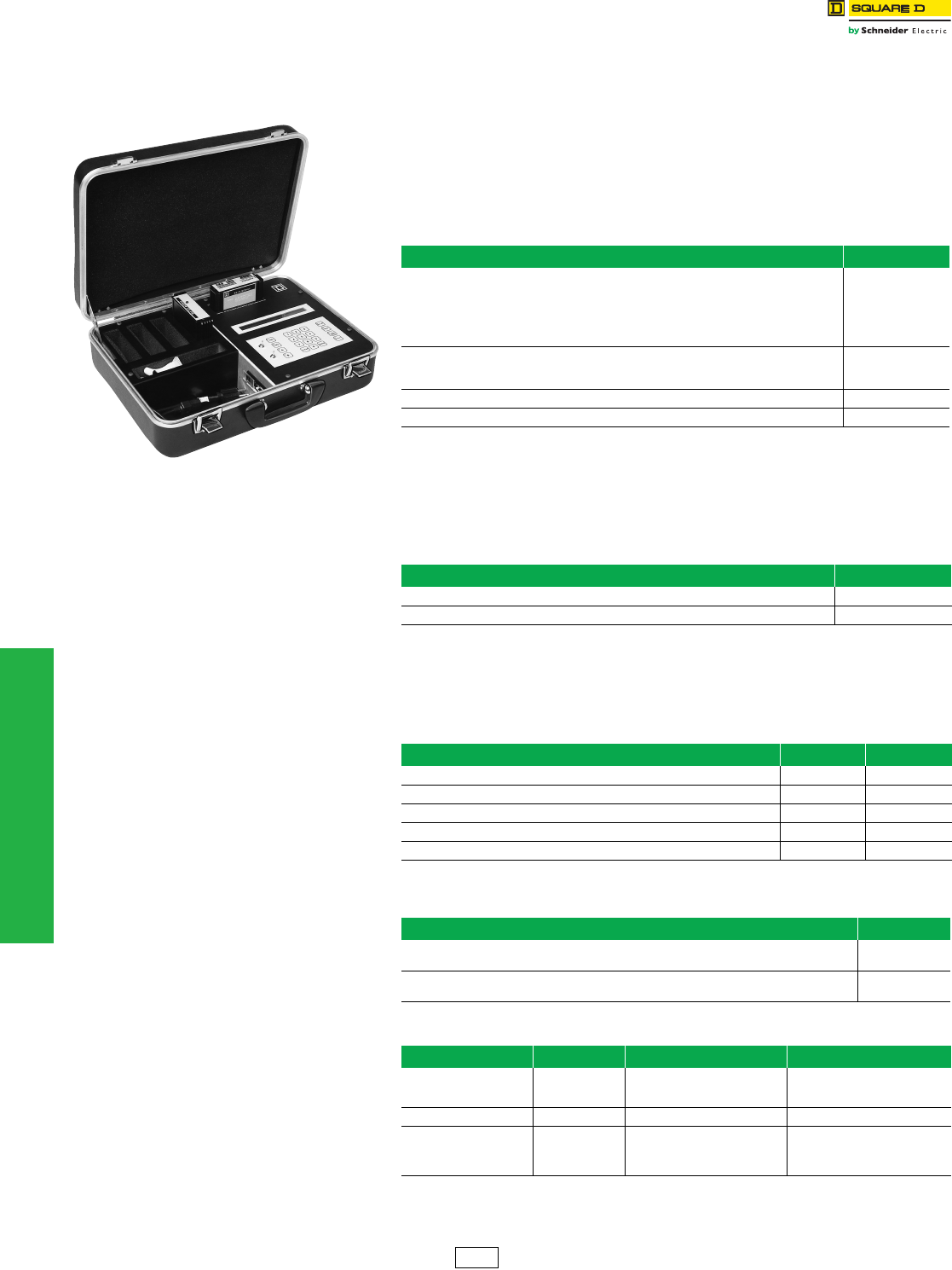
11-24 © 2012 Schneider Electric
All Rights Reserved
www.schneider-electric.us
11 OBSOLETE CIRCUIT BREAKERS
Electronic Products Micrologic™ Series 2/3/A/B Trip Unit Test Sets
Class 690
NOTE: Listed below are the catalog numbers and the components required for testing
the entire family of Micrologic trip systems. The listing includes obsolete series
trip systems.
Micrologic Series B Trip Systems
Identified by label on front of trip unit
(LE/LX/LXI, ME/MX, NE/NX and PE/PX circuit breaker 9/92 to present)
(SE circuit breaker 10/92 to present)
This is the latest series of standard (LX/LXI, MX, NX and PX) and full-function (LE, ME, NE,
PE and SE) Micrologic trip systems.
Micrologic Series 3 and Series A Trip Systems
Identified by two rows of rotary switches
(ME/MX, NE/NX and PE/PX circuit breakers 11/89 to 9/92)
(SE circuit breakers 5/90 to 10/92)
For those customers who already own the Universal Test Set (CBTU1 or UTS3) and want
to test these earlier series Micrologic trip systems, see the following chart.
Micrologic Series 2 Trip Systems
Identified by only one row of rotary switches
Micrologic Series 2 Test Modules are obsolete and no longer available.
Note: For trip systems of this type that require testing, contact Technical Services toll free at 1-800-634-2003.
Table 11.56: Universal Test Set
Description Cat. No.
Universal Test Set includes the following:
1. Self-test module (CBTMT)
2. Standard and full-function Micrologic Series B module (CBTMB) includes rating plug adapter
3. Power cord
4. Ribbon cable for making the connection from the test set to the rating plug adapter
5. Instruction manual
UTS3
For those customers who already own the Universal Test Set and want to test the latest standard and
full-function (Series B) trip systems, all that is needed is Micrologic Series B module (CBTMB). Included
is the rating plug adapter and instruction manual.
CBTMB
Replacement ribbon cable and rating plug adapter for CBTMB CBTMBRK
Long-time and ground-fault memory reset module (Series B Electronics) MTMB
Table 11.57: Micrologic Series 3 and Series A Circuit Breaker Test Module
Circuit Breaker Test Module Cat. No.
Includes rating plug adapter and instruction manual CBTM4A
Replacement ribbon cable and rating plug adapter for CBTM4A CBTM4RK
Table 11.58: Micrologic Series 2 Circuit Breaker Test Module
Circuit Breaker Test Modules Cat. No. Availability
SE (5/85-5/90) includes rating plug adapter and instruction pages CBTM1 Not Available
Replacement ribbon cable and rating plug for CBTM1 CBTM1A Not Available
ME, PE (4/85-11/89) CBTM2 obsolete, no longer available CBTM2 Not Available
ME, NE, PE (10/86-11/89) includes rating plug adapter and instruction manual CBTM3 Not Available
Replacement ribbon cable and rating plug for CBTM3 CBTM3A Not Available
Table 11.59: Micrologic Series 1 Trip Systems for Circuit Breakers Manufactured
Before Micrologic
Trip System Test Set
ME/PE (8/78-4/85) Identified by slide type switches instead of rotary switches.
The very first series ME and PE electronic trip circuit breakers offered by Square D.
Test Set
Not Available
SE (7/83-5/85) The very first series of SE electronic trip circuit breakers had rotary switches and can be
identified by a three-digit serial number.
Test Set
Not Available
Table 11.60: Neutral Current Transformers
Cat. No. Availability Sensor Where Used
ME25CT2
ME4CT2
ME8CT2
Not Available
Not Available
Not Available
250 A
400 A
800 A
MXL,MEL
NE12CT2 1200 A NXL,NEL
PE12CT2
PE16CT2
PE20CT2
PE25CT2
Not Available
Not Available
Not Available
Not Available
1200 A
1600 A
2000 A
2500 A
PXF, PEF
DE2 Discount
Schedule
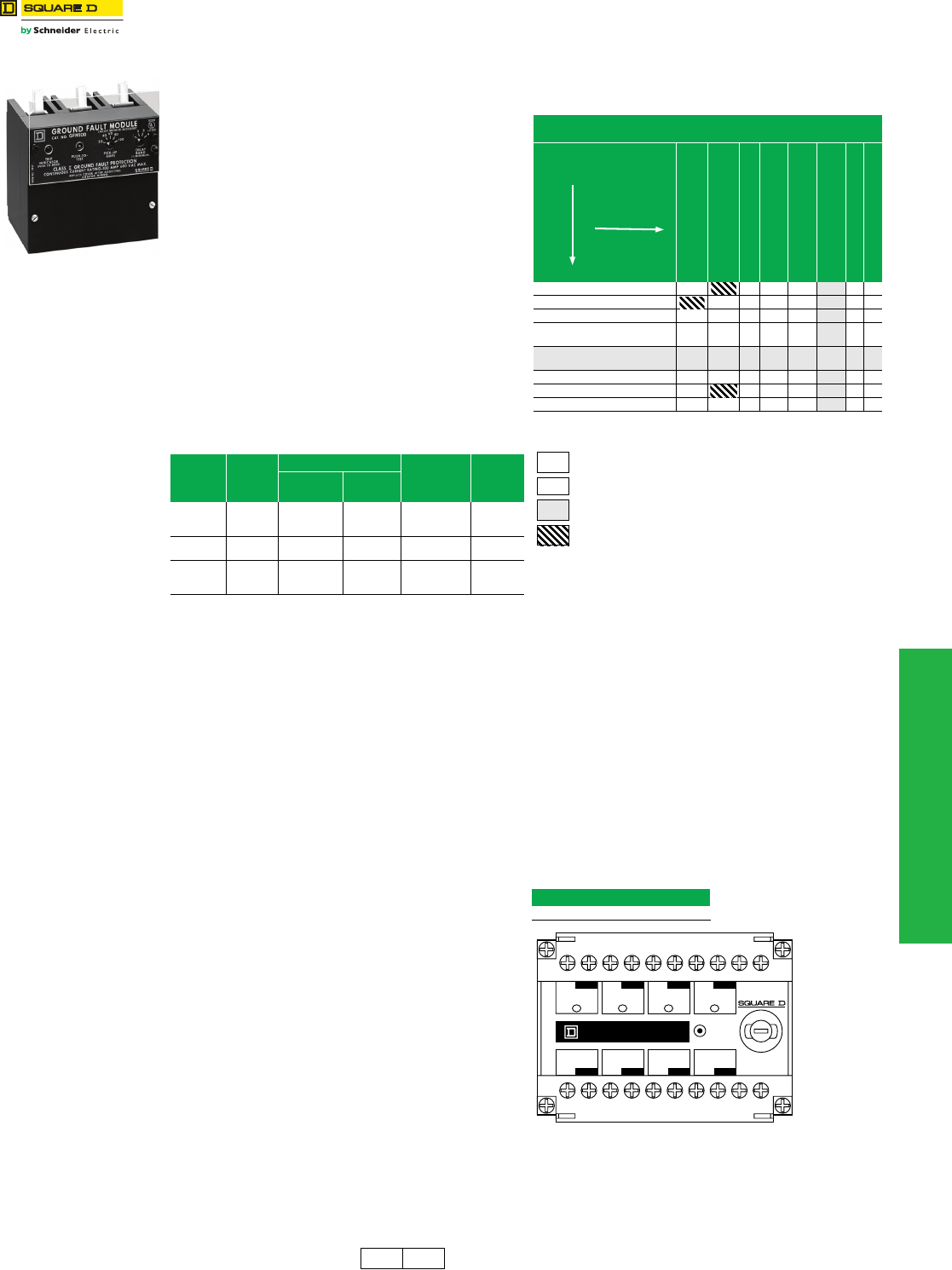
www.schneider-electric.us
11 OBSOLETE CIRCUIT BREAKERS
© 2012 Schneider Electric
All Rights Reserved 11-25
Ground-Fault Protection Micrologic™ Add-On Ground-Fault Module (GFM)
Class 931, 940, 960
The Micrologic ground-fault module (GFM) is a UL Listed
circuit breaker accessory for equipment protection. It is a
combination ground-fault relay and ground-fault sensing
device.
Micrologic Add-On Ground-Fault Module Features:
•Used in combination with the FA, KA, FC, KC, FI, and KI type
circuit breakers with a ground-fault shunt trip factory installed
(add the suffix “G” to the circuit breaker)
•Adjustable ground-fault pickup levels
•Adjustable ground-fault time delays
•Integral ground fault push-to-test feature and ground-fault
indicator
•All GFMs supplied for I-Line™ mounting, easily convertible to
unit mount by removing the
I-Line brackets
•Neutral current transformer is supplied for 3-phase 4-wire
applications. Refer to instructions for proper installation
•Zone-selective interlocking capability is standard with
upstream Micrologic trip system circuit breakers. The GFM
can also be zone interlocked with the GC ground-fault system
by using a restraint interface module.See Supplementary
Digest
•120 Vac control power is required for integral test feature.
Meets NEC 230-95(c)
NOTE: Ground-fault modules cannot be reverse fed.
aUse NEMA 1 or 3R enclosures only. See page 11-5 for dimensions.
RIM32 Restraint Interface Module
The RIM32 Restraint Interface Module is used to interface
the restraint signals between various Square D
Micrologic™ circuit breakers, Micrologic ground-fault
modules, and GC-100 ground-fault protection systems.
The restraint interface module operates on either 120 or
240 Vac, 50/60 Hz. The module is protected by a 1/4 A
fuse.
Allowable ZSI combinations are shown in Table 11.62.
(Series numbers for current design circuit breakers end in
B, for example NE Series 3B.) For double-ended or larger
systems, or systems which contain devices from different
columns in Table 11.62, contact your local Sales Office for
combination information.
If more inputs or outputs are needed, another restraint
interface module is necessary. Contact your local Sales
Office for information on multiple module installations.
NOTE: The maximum distance between
devices is 1000 ft. (305 m).
Table 11.61: Module/Enclosure Selection Chart
Companion
Circuit
Breaker
Prefix
Cat. No.
Enclosure Space Required Ground-Fault
Pickup
Adjustment
Range
Availability
I-Line
Switchboard
Individual
Enclosure a
FAL, FHL,
FCL, FA,
FH, FC
GFM100FA LA KA 20–100 A
FI GFM100FI LA — 20–100 A Not
Available
KAL, KHL,
KI, KA,
KH, KC
GFM250 LA LA 40–200 A
GFM250
Table 11.62: ZSI Combinations
Table 11.63: RIM32
Cat. No.
RIM32
aGFM is an output device only.
ZSI Combinations
(Where All Inputs Driven Are Same Column)
SE 2 (Ground Fault)
SE 2 (Short Time)
ME 3, NE1, PE 4
ME 4 & 5, NE 2 & 3
PE 5 & 6, SE 3
ME 5A, NE 3A,
PE 6A, SE 3A
LE 1B, ME 5B, NE 3B,
PE 6B, SE 3B
GC100
RIM 32
SE 2 (Ground Fault) 50 R R R RR50
SE 2 (Short Time) 1 R R R RR50
ME 3, NE1, PE 4 50 R 15 2 13 47 R 50
ME 4, 5 & 5A, NE 2, 3 & 3A, PE
5, 6 & 6A, SE 3, 3A 50 R R 1 1 7R14
LE 1B, ME 5B, NE 3B, PE 6B,
SE 3B 50 R10 1 R 26 R44
GC 100 R R R R R R750
GFMa50 2 1 1 5R10
RIM32 50 6 50 7 37 50 15 50
# Maximum inputs without RIM32. Self-restraint counts as one input.
R RIM32(s) required to restrain any devices.
Note:Note: Present design.
Invalid combination.
Inputs
Output
Circuit Breaker Series
GND
OUT
No. 4
Ground Fault
Restraint
GND
OUT
No. 5
Short Time
Restraint
GND
OUT
No. 6
Restraint
GND
OUT
GC-100
Ground Fault
Restraint
GND
IN
No. 1
Ground Fault
Restraint
GND
IN
No. 2
Short Time
Restraint
GND
IN
No. 3
Restraint
GND
IN
GC-100
Ground Fault
Restraint
PUSH
TO TEST
OUTPUTS
INPUTS
CAT. NO. RIM32
COM 240
Vac
COM
120
Vac
1/4 AMPERE
DE2 DE5A Discount
Schedule
11-26 © 2012 Schneider Electric
All Rights Reserved
www.schneider-electric.us
11 OBSOLETE CIRCUIT BREAKERS
Obsolescent Circuit
Breakers
Masterpact™ M/MP/MC Circuit Breakers, UL 489/1066 Listed
To order a complete circuit breaker, order:
1. Circuit breaker fixed or drawout frame..........................page 11-26
or cradle only................................................................page 11-32
or circuit breaker without cradle....................................page 11-26
2. Connections..................................................................page 11-23
3. Control unit....................................................................page 11-27
4. Rating plug....................................................................page 11-27
5. Accessories...................................................................page 11-28
Fixed and Drawout breakers listed below are complete with STR58U Trip unit which includes Long time, short time,
instantaneous and ground fault as well as options T (residual) and I (ammeter).
bNot UL Listed
Additional information: Catalog 0631CT9501, Data Sheet 0631HO9701
Masterpact™ M/MP/MC circuit breakers and related accessories are obsolete. Use Masterpact NT/NW for new applications. See DIgest
176. Limited service stock is available for replacement or fill purposes. Contact your local sales office for product availability.
Table 11.64: UL Listed Masterpact MP Circuit Breaker Frame
Rating AIR/
480 V
Fixed
3P
Drawout without Cradle
3P
Cradle Only
3P $ Price
MP16 to MP30—
UL 489/NEMA AB1
Standards
High Interrupting (H2)
Contact Schneider Electric Cedar Rapids
Plant Customer Service Group for current
pricing and availability.
MP16H2 1600 A 100 kA MP100135 MP100136 MP100141
MP20H2 2000 A 100 kA MP100137 MP100138 MP100133
MP30H2 3000 A 100 kA MP100139 MP100140 MP100132
DE2G Discount
Schedule
www.schneider-electric.us
11 OBSOLETE CIRCUIT BREAKERS
© 2012 Schneider Electric
All Rights Reserved 11-27
Obsolescent Circuit
Breakers
Masterpact™ M/MP/MC Circuit Breaker Control Units
aExternal neutral sensor not included.
bExternal AD module (see page 11-28) is required if load is below 20% or if setting is red zone.
NOTE: Mandatory for UL Listed Masterpact MP circuit breakers with STR 28D, STR 38S and STR 58U control
units. Not required on IEC Rated Masterpact circuit breakers.
Masterpact™ M/MP/MC circuit breakers and related accessories are obsolete. Use Masterpact NT/NW for new applications. See DIgest 176. Limited
service stock is available for replacement or fill purposes. Contact your local sales office for product availability.
Table 11.65: Control Units
Control Unit Ground-Fault ProtectionaWithout Ground-Fault Protectiona
STR 58U (long-time, short-time and instantaneous protection)
STR58U (long-time = 0.4x1 sensor rating) Includes Residual Type T — and Ammeter — I
External neutral sensor (TCE) b– see page 11-28
M1008H2 M1008H2NG
M10H2 M10H2NG
M1612H2 M1612H2NG
M16H2 M16H2NG
M20H2 M20H2NG
M25H2 M25H2NG
M3230H2 M3230H2NG
M32H2 M32H2NG
M6340H2 M6340H2NG
M6350H2 M6350H2NG
M63H2 M63H2NG
Table 11.66: Rating Plug (RL)
Sensor Rating Plug Rating Cat. No.
250 A
150 A 54732
200 A 54733
250 A 54734
400 A
200 A 54735
250 A 54736
300 A 54737
400 A 54738
600 A
300 A 54739
400 A 54740
500 A 54741
600 A 54742
800 A
400 A 54743
500 A 54744
600 A 54745
800 A 54746
1200 A
600 A 54747
800 A 54748
1200 A 54750
2500 A 1200 A 54759
5000 A
3000 A 54772
4000 A 54773
5000 A 54774
DE2G Discount
Schedule
For pricing contact your local
Schneider Electric distributor.
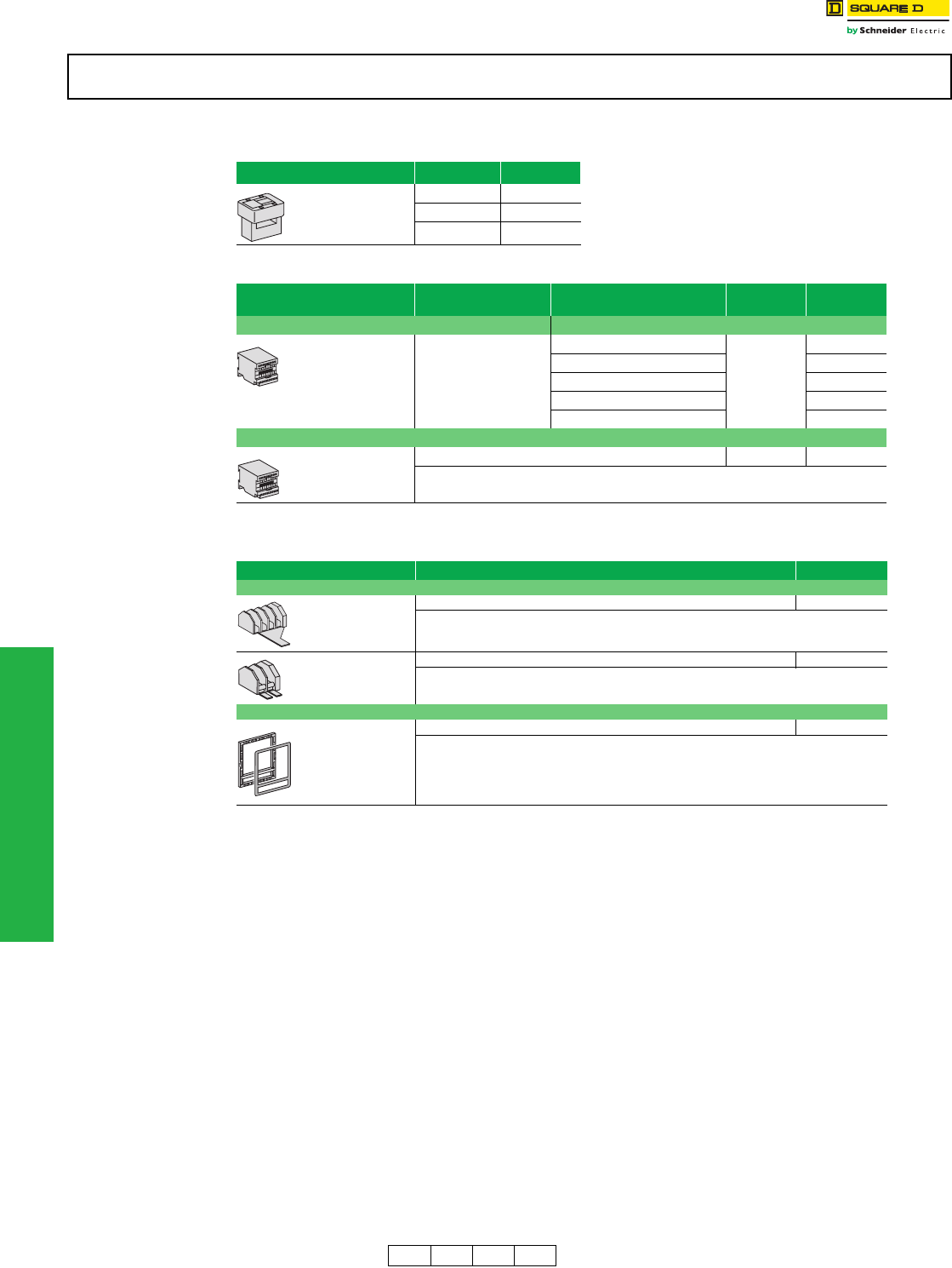
11-28 © 2012 Schneider Electric
All Rights Reserved
www.schneider-electric.us
11 OBSOLETE CIRCUIT BREAKERS
Obsolescent Circuit
Breakers
Masterpact™ M/MP/MC Circuit Breaker Accessories
aDiscount Schedule DE2G.
bDiscount Schedule DE2F
Masterpact™ M/MP/MC circuit breakers and related accessories are obsolete. Use Masterpact NT/NW for new applications. See DIgest
175. Limited service stock is available for replacement or fill purposes. Contact your local sales office for product availability.
Table 11.67: Neutral Sensor for 3ØH4W Systems (TCE)
NOTE: External neutral transformer (TCE) must have the same rating
as the circuit breaker current sensor.
Rating Cat. No.
800 A 54422
1250 A 54426
2000 A 54427
Table 11.68: Accessories (Must be ordered as separate items)
Accessory Description Discount
Schedule Cat. No.
Power Supply Module (AD) Input voltage
For STR 18M to STR 58U
control units
Output voltage: 24 Vdc
24/30 Vdc
DE2F
54440
48/60 Vdc 54441
10 Vac 50/60 Hz 54443
220 Vac 50/60 Hz 54444
380 Vac 50/60 Hz 54446
Battery Module (BAT)
Battery back-up power supply for AD module DE2F 54446
Table 11.69: Accessories for Cradle
Accessory Cat. No.
Position Switches
Four SPDT connected position switches (CE) 54590
Two SPDT disconnected position switches (CD) 54591
Door Escutcheon
Can be used with fixed or drawout circuit breakers 54594b
DE2F DE2G DE2 DE5A Discount
Schedule
For pricing contact your local
Schneider Electric distributor.
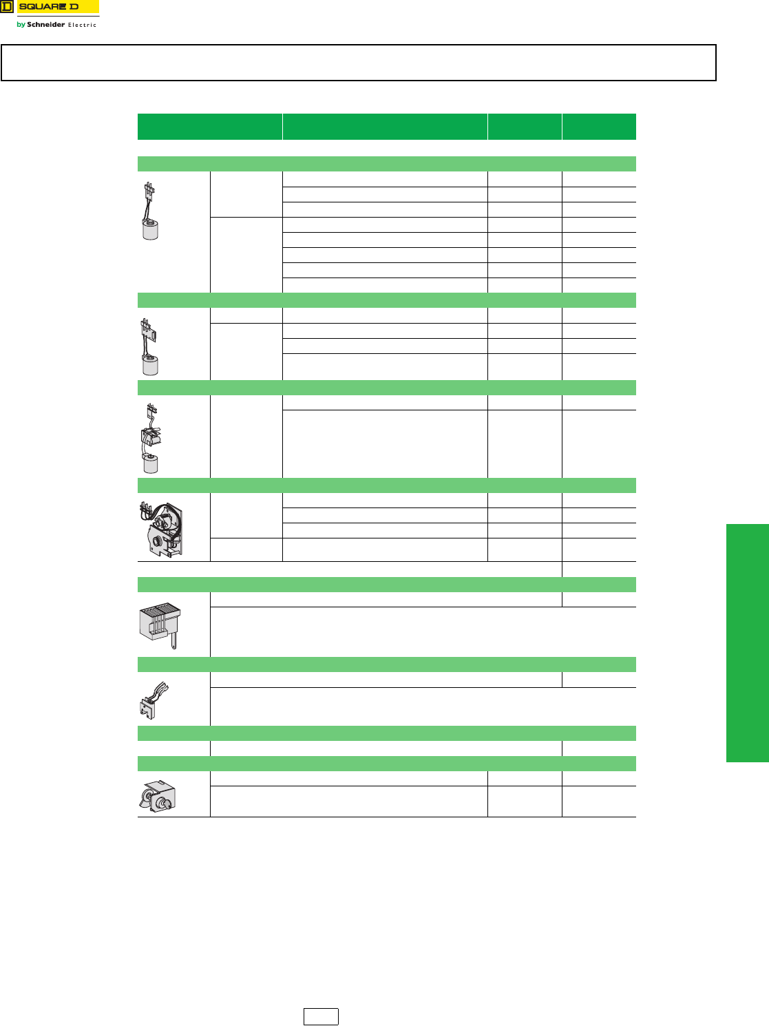
www.schneider-electric.us
11 OBSOLETE CIRCUIT BREAKERS
© 2012 Schneider Electric
All Rights Reserved 11-29
Obsolescent Circuit
Breakers
Masterpact™ M/MP/MC Circuit Breaker Accessories
aNot UL Listed.
Masterpact™ M/MP/MC circuit breakers and related accessories are obsolete. Use Masterpact NT/NW for new applications. See DIgest
175. Limited service stock is available for replacement or fill purposes. Contact your local sales office for product availability.
Table 11.70: Accessories for Circuit Breaker Frame
Volt s (V ) Cat. No.
(XF)
Cat. No.
(MX)
•Maximum 2 shunt trips or 1 shunt trip + 1 undervoltage trip.
Closing Coil (XF)/Shunt Trip (MX)
AC 50/60 Hz
110/127 54449 54449
220/250 54503 54503
277 a54504 54504
DC
24 54495 54495
48 54497 54497
100/110 a54449 54449
200/220 a54503 54503
250 54504a54504
Undervoltage Trip (MN)
AC 50/60 Hz 440/480 54481
DC
24 54470
100/110 a54474
200/220a54478
Time Delayed Undervoltage Trip (MNR) – Not UL Listed
AC 50/60 Hz
110/127 54486
220/250 54488
Spring Charging Motor (MCH)—Includes Spring Charged Switch
AC 50/60 Hz
100/127 54512
200/240 54513
480a54518
DC 48/60 54511
Two Standard (2a+2b) Auxiliary Switches Standard
Four Auxiliary Switches (OF)
Four changeovers (SPDT) 54525
One Ready to Close Switch (PF)
One ready to close switch 54528
One Overcurrent Trip Switch (SDE)
Not available on switch version Standard
“OFF” Position Lock by Key Lock
Provision for KIRK key lock VKA 54536
Ronis (1 key lock) with provision VSRA1 54533
For pricing contact your local
Schneider Electric distributor.
DE2G Discount
Schedule
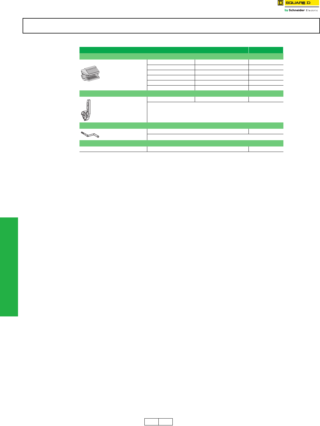
11-30 © 2012 Schneider Electric
All Rights Reserved
www.schneider-electric.us
11 OBSOLETE CIRCUIT BREAKERS
Obsolescent Circuit
Breakers
Masterpact™ M/MP/MC Circuit Breaker Spare Parts
Masterpact™ M/MP/MC circuit breakers and related accessories are obsolete. Use Masterpact NT/NW for new applications. See DIgest
175. Limited service stock is available for replacement or fill purposes. Contact your local sales office for product availability.
Table 11.71: Spare Parts
Spare Parts Cat. No.
Clusters for Cradle (Set of 2)
MP25–MP30 3P M20–M25L 3P 54063 (3)
MP25–MP30 4P M20–M25L 4P 54063 (4)
M32H 3P 54063 (3)
M32H 4P 54063 (4)
MP40–MP50 3P M50H 3P 54063 (6)
M50H 4P 54063 (7)
Charging Handle
One piece 685713
Racking Handle
One piece 685631
Vertical UL 489—UL 1066 Connectors
MP25–MP30 3P (set of three top or bottom connectors) 54107 (2)
For pricing contact your local
Schneider Electric distributor.
DE2F DE2 Discount
Schedule

12-1
© 2012 Schneider Electric
All Rights Reserved
12 OBSOLETE MOTOR CONTROL
CENTERS
Table of Contents
Section 12
Obsolete Motor Control Centers
Model 4
Branch Feeder Units 12-2
Circuit Breaker Type Combination Starter Units 12-3
Fusible Switch Type Combination Starter Units 12-4
Series 5600
General Information 12-5
Branch Feeder Units 12-6
Circuit Breaker Type Combination Starter Units 12-6
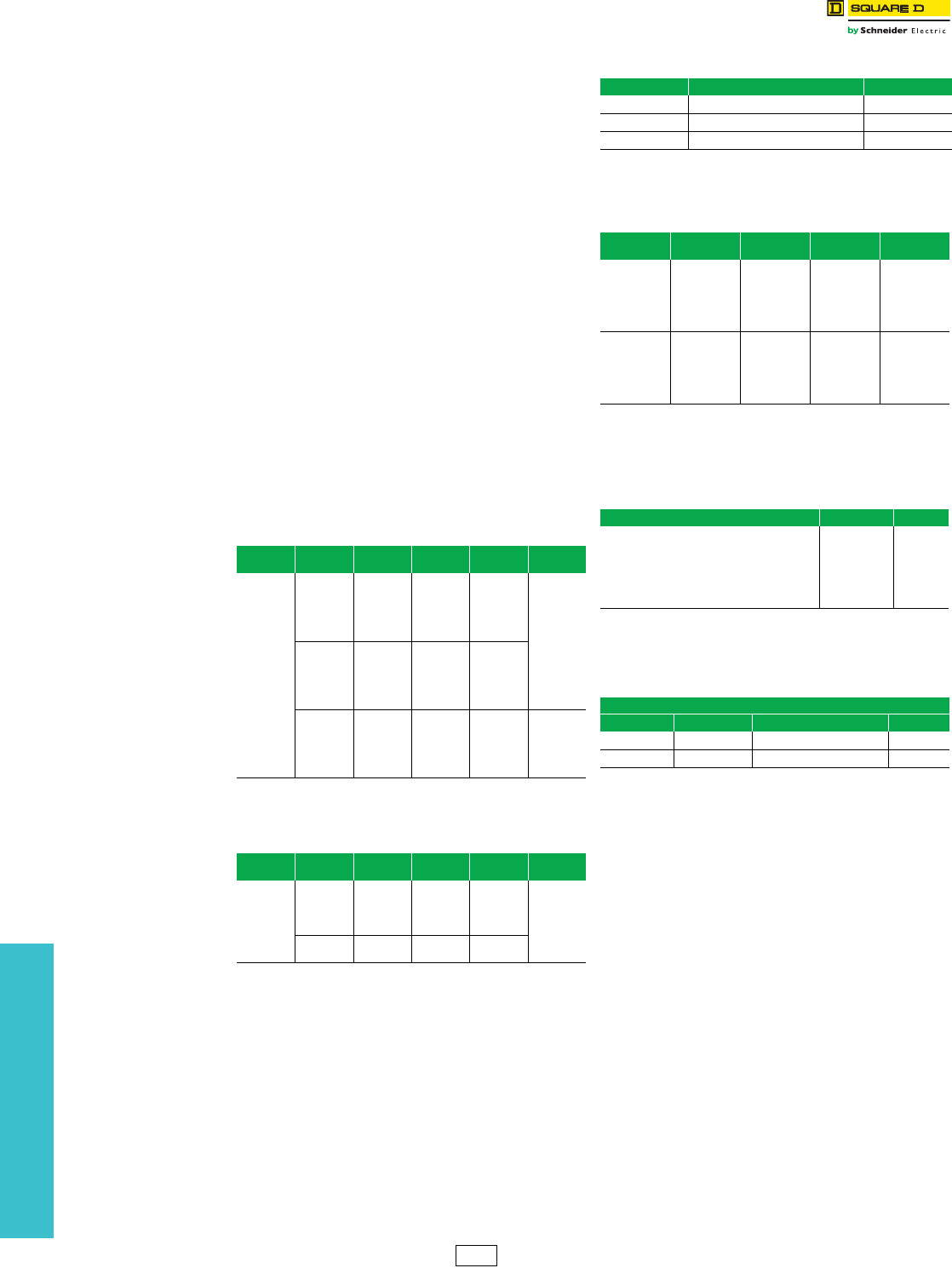
www.schneider-electric.us
12 OBSOLETE MOTOR CONTROL
CENTERS
12-2 © 2012 Schneider Electric
All Rights Reserved
Obsolete Motor Control
Centers
Model 4 Branch Feeder Units
Class 8998
This section covers Model 4 Motor Control Center (MCC)
unit availability during product obsolescence. All Model 4
orders can be completely defined by price, catalog type,
and modifications. Layout sheets and data sheets are not
required for order entry.
All unit prices are shown as NEMA 1. If a NEMA 12 unit is
required, multiply the base price by 1.06. Note the
standard features of the unit. Please refer to footnotes for
important information.
Model 4 structures are no longer available. Transition
sections can be provided to match an existing Model 4
MCC to a Model 6 MCC.
Model 4 to Model 6 Transition
Provides transition from a Model 4 to a Model 6 MCC. The
transition requires a 12-inch extension on the first section
of the Model 6 lineup. The transition section must be
ordered with at least one Model 6 section and cannot ship
separately. THE MODEL 6 BUS MUST BE OF EQUAL
OR GREATER AMPACITY THAN THE MODEL 4 BUS.
The transition section includes all required splice bars.
(Reference the Model 6 Motor Control Center Pricing
Guide.)
Please supply original Model 4 factory order number,
basic configuration, and Model 4 bus amperage, material,
and plating at time of order.
Compatible structure depths include:
•15-inch deep Model 6 to 14-inch deep Model 4
•20-inch deep Model 6 to 20-inch deep Model 4
Branch Feeder Units and Modifications
aAll branch circuit breakers are thermal magnetic with high interrupting
Form Y532.
bUnit support pan included.
NOTE: Fusible branch feeders 30-200 amp using Class H fuse clips have a
short circuit rating of 10,000 AIR @ 600 V. If Class R fuse clips are
required, order field installabe kit from Digest.
cFuses not included.
dFull Voltage Non-Reversing units only.
eReversing units only.
fTwo-Speed units only.
gDimensions are in inches — Depth from door to panel is 7.50 inches.
Table 12.1: Circuit Breaker Branch Feeder Units a
No. of Poles Trip Rating Breaker
Frame Type
Unit Type
No. $ Price Space
Factor
3
15
FH
BW423
2150.00
1
20 BW424
30 BW425
40 BW429
50 BW428
60
FH
BW426
2376.00
70 BW450
80 BW451
90 BW452
100 BW427
125
KH
BY405
6336.00 1-1/2
150 BY406
175 BY409
200 BY407
225 BY408
Table 12.2: Dual Mounted Units
No. of Poles Trip Rating Breaker
Frame Type
Unit Type
No. $ Price Space
Factor
3
15/15
FH/FH
BW453
3908.00
1-1/2
20/20 BW454
30/30 BW455
50/50 BW456
60/60 FH/FH BW457 3988.00
100/100 BW458
Table 12.3: Miscellaneous Items
Unit Description Price
K401b1/2 S.F. Blank Plate $ 68.00
K402b1 S.F. Blank Plate 68.00
K404b2 S.F. Blank Plate 106.00
Table 12.4: Fusible Switch Branch Feeder Units—
3-pole c
Volt age Max. Fuse Size Unit Type No. $ Price Space
Factor
250
30 KW408 1214.00 1
60 KX409 1214.00 1
100 KY409 1714.00 1
200 KZ409 2046.00 2-1/2
600
30 KW409 1214.00 1
60 KX410 1214.00 1
100 KY410 1714.00 1
200 KZ410 2046.00 2-1/2
Table 12.5: Starter Unit Options
Description Form No. Price
Start-Stop PB with 1 Pilot light — Red (On)dAP $284.00
Forward-Reverse-Stop PB with 2 Pilot LightseA1PP 616.00
High-Low-Stop PB with 2 Pilot LightsfA2PP 616.00
Hand-Off-Auto SS with 1 Pilot Light — Red (On)dCP 284.00
1 Pilot Light only — Red (On)dP151.00
2 Pilot Lights — Red (On)ePP 384.00
Table 12.6: Miscellaneous Units
MT Units (Undrilled Panel and Hinged Door)
Unit Type No. Space Factors Panel DimensionsgPrice
MT414 1 11-3/4 in. H x 13-5/8 in. W$450.00
MT415 2 22-1/3 in. H x 13-5/8 in. W908.00
PE4 Discount
Schedule
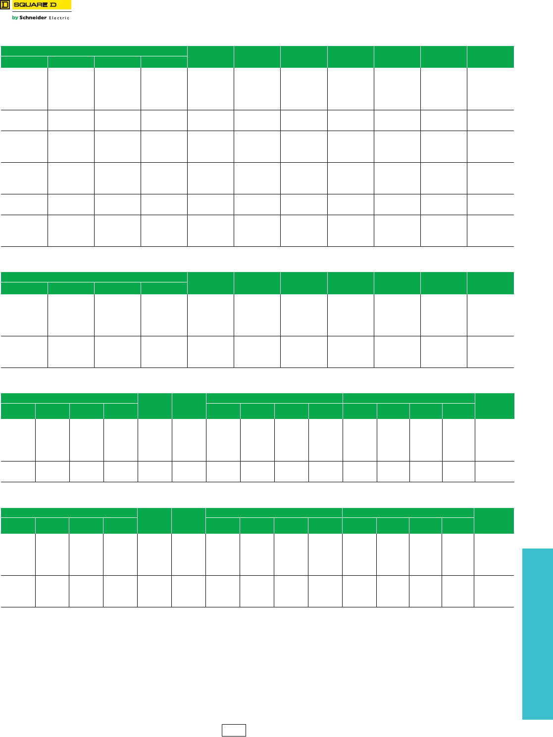
www.schneider-electric.us
12 OBSOLETE MOTOR CONTROL
CENTERS
© 2012 Schneider Electric
All Rights Reserved
12-3
Obsolete Motor Control
Centers
Model 4 Circuit Breaker Type Combination Starters
1B Wiring and 1 N.O. and 1 N.C. Auxiliary Interlock (Standard)
aUnits are wired for 480 V unless 240 V is stated on order. The 480 V contol circuit transformer is reconnectable for 240 V. For other voltages, form SY74
must be used.
bIncludes extra 1/2 space factor (additional space only).
cMelting alloy overload relay included; thermal units must be priced and ordered separately. If ambient compensated bimetallic overload is required add
form B to unit, price adder is 170.00
NOTE: To get NEMA 12, multiply base price by 1.06 and add form N12 to unit.
Mag-Gard™ circuit breaker combination starter units through Size 4 are UL Listed for 22,000 AIR @ 600 V. Exception: NEMA Size 3 and 4 when
bimetallic overloads are used are UL Listed for 10,000 AIR @ 600 V.
Table 12.7: Full Voltage Non-Reversing
Maximum Horsepower At NEMA
Starter Size C/B Amp Unit Type
No.
Space
Factor
$ Price With
FTa
$ Price With
SY74
No. of
Thermal Units
Requiredc
208 V 240 V 480 V 600 V
1/4–1/3 1/3 1 1/4–1
1
3EC403
13480.00 3190.00 3
1/2–1 1 3 1-1/2–3 7 EC404
1-1/2–3 3 7-1/2 5–10 15 EC405
57-1/210 — 30EC406
1-1/2–3 3 7-1/2 5–10 115 EC409 1-1/2b4772.00 4475.00 3
57-1/210 — 30EC410
5 7-1/2 15 15–20
2
30 ED402
14695.00 4297.00 37-1/2–10 10 25 25 50 ED403
—15—— 100ED404
5 7-1/2 15 15–20
2
30 ED405
1-1/2b5718.00 4884.00 37-1/2–10 10 25 25 50 ED406
—15—— 100ED407
10 10 25 25–30 350 EE404 1-1/2 6490.00 5884.00 3
15–25 30 50 40–50 100 EE405
30 40 — —
4
225 EF406
211615.00 10798.00 340 — 75 100 225 EF407
— 50 100 — 225 EF408
Table 12.8: Full Voltage Reversing
Maximum Horsepower At NEMA
Starter Size C/B Amp Unit Type
No.
Space
Factor
$ Price With
FTa
$ Price With
SY74
No. of
Thermal Units
Requiredc
208 V 240 V 480 V 600 V
1/4–1/3 1/3 1 1/4–1
1
3FC408
1-1/2 4877.00 4480.00 3
1/2–1 1 3 1-1/2–3 7 FC409
1-1/2–3 3 7-1/2 5–10 15 FC410
57-1/210 — 30FC411
5 7-1/2 15 15–20
2
30 FD402
26251.00 5851.00 37-1/2–10 10 25 25 50 FD403
—15—— 100FD404
Table 12.9: Two-Speed, Constant Hp, Full Voltage Non-Reversing
Maximum Horsepower At NEMA
Starter
Size
C/B
Amp
One Winding (Consequent Pole) Two Winding (Separate Winding) No. of Thermal
Units
Requiredc
208 V 240 V 480 V 600 V Unit Type
No.
Space
Factor
$ Price
w/ Ta
$ Price
w/ SY74
Unit Type
No.
Space
Factor
$ Price
w/ FTa
$ Price
w/ SY74
— — 1/2 1/4–3/4
1
3 HC415
24301.00 3846.00
HC419
27068.00 6240.00 6
1/4–3/4 3/4 2 1–2 7 HC416 HC420
1–2 2 5 3–5 15 HC417 HC421
3–5 5 7-1/2 7-1/2 30 HC418 HC422
— — 10 10–15 230 HC411 25947.00 5309.00 HD413 29489.00 8328.00 6
7-1/2 10 20 20 50 HC412 HD414
Table 12.10: Two-Speed, Constant or Variable Torque, Full Voltage Non-Reversing
Maximum Horsepower At NEMA
Starter
Size
C/B
Amp
One Winding (Consequent Pole) Two Winding (Separate Winding) No. of Thermal
Units
Requiredc
208 V 240 V 480 V 600 V Unit Type
No.
Space
Factor
$ Price
w/ FTa
$ Price
w/ SY74
Unit Type
No.
Space
Factor
$ Price
w/ FTa
$ Price
w/ SY74
1/4–1/3 1/3 1 1/4–1
1
3 HC407
24301.00 3846.00
HC411
27068.00 6240.00 6
1/2–1 1 3 1-1/2–3 7 HC408 HC412
1-1/2–3 3 7-1/2 5–10 15 HC409 HC413
5 7-1/2 10 — 30 HC410 HC414
5 7-1/2 15 15–20
2
30 HD405
25947.00 5309.00
HD408
29489.00 8328.00 67-1/2–10 10 25 25 50 HD406 HD409
— 15 — — 100 HD407 HD410
PE4 Discount
Schedule
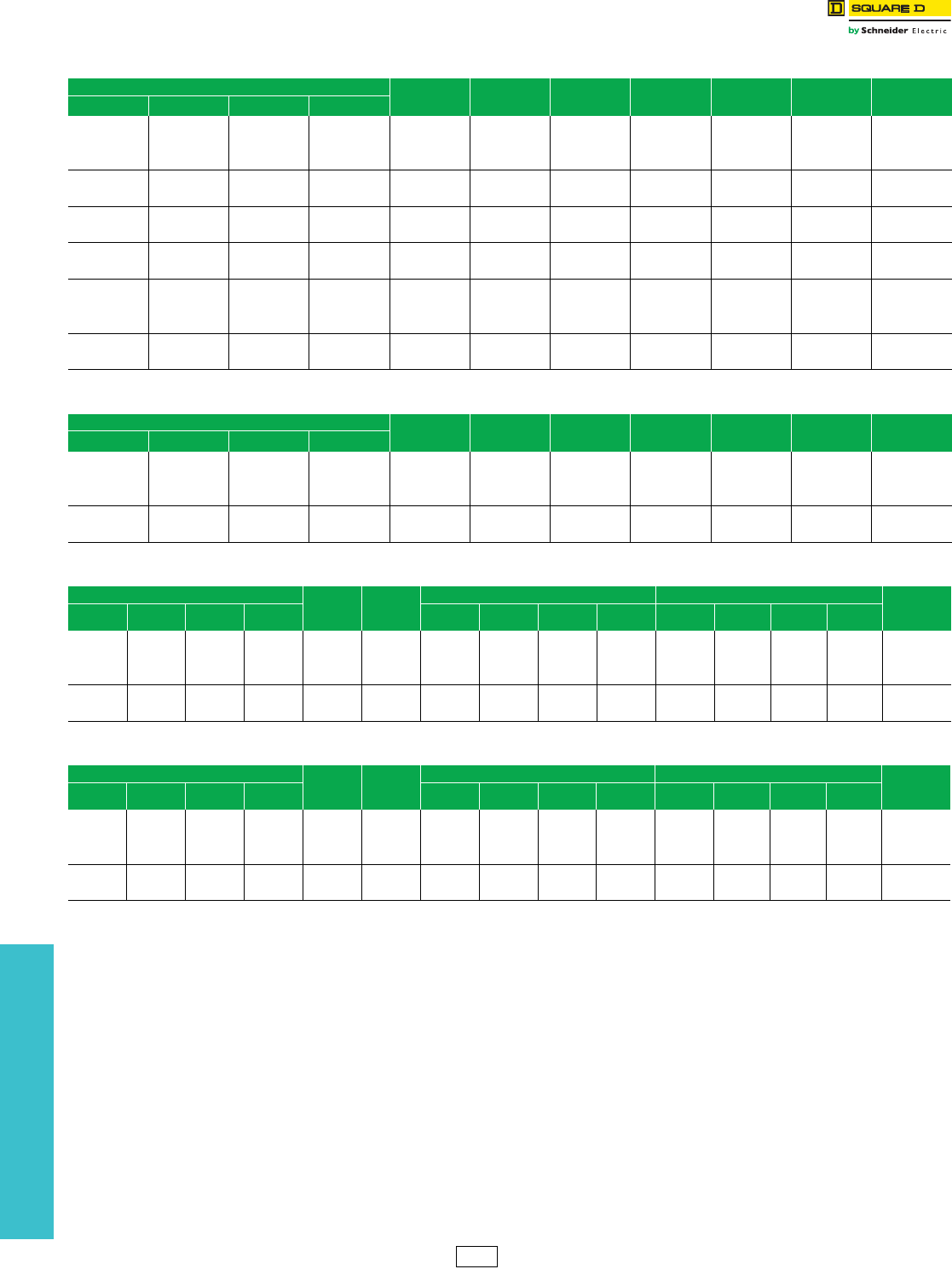
12-4 © 2012 Schneider Electric
All Rights Reserved
www.schneider-electric.us
12 OBSOLETE MOTOR CONTROL
CENTERS
Obsolete Motor Control
Centers
Model 4 Fusible Switch Combination Starter Units
1B Wiring and 1 N.O. and 1 N.C. Auxiliary Interlock (Standard)
aUnits are wired for 480 V unless 240 V is stated on order. The 480 V control circuit transformer is reconnectable for 240 V. For other voltages, form SY74
must be used.
bIncludes extra 1/2 space factor (additional spaces only).
cMelting alloy overload relay included; thermal units must be priced and ordered separately. If ambient compensated bimetallic overload is required add
form B to unit, price adder is 170.00
NOTE: Refer to catalog to get NEMA 12, multiply base price by 1.06 and add form N12 to unit.
Fusible starters Sizes 1–3 using Class H fuse clips have a short circuit rating of 5,000 AIR @ 600 V. Size 4 starters using Class H are rated 10 kAIR @
600 V. If Class R fuse clips are required, order field installable kit from Digest. Fuses are not included.
Table 12.11: Full Voltage Non-Reversing
Maximum Horsepower At NEMA
Starter Size
Switch
Amp Rating
Unit Type
No.
Space
Factor
$ Price With
FTa
$ Price With
SY74
No. of
Thermal Units
Requiredc
208 V 240 V 480 V 600 V
55——
1
30 NC413
13345.00 3055.00 3— — 10 10 30 NC414
7-1/2 7-1/2 — — 60 NC415
7-1/2 7-1/2 — — 160 NC416 1-1/2b4479.00 4029.00 3
— — 10 10 30 NC417
10 15 — — 260 ND411 14509.00 4102.00 3
— — 25 25 60 ND412
10 15 — — 260 ND413 1-1/2b5197.00 4715.00 3
— — 25 25 60 ND414
20 25 — —
3
100 NE416 1-1/2
6228.00 5618.00 325 30 — — 200 NE417 3
— — 50 50 100 NE418 1-1/2
40 50 — — 4200 NF409 3-1/2 10192.00 9369.00 3
— — 100 100 200 NF410
Table 12.12: Full Voltage Reversing
Maximum Horsepower At NEMA
Starter Size
Switch
Ampere
Rating
Unit Type
No.
Space
Factor
$ Price With
FTa
$ Price With
SY74
No. of
Thermal Units
Requiredc
208 V 240 V 480 V 600 V
55——
1
30 OC417
1-1/2 4744.00 4349.00 37-1/2 7-1/2 — — 60 OC418
— — 10 10 30 OC419
10 10 — — 260 OD409 26069.00 5669.00 3
— — 25 25 60 OD410
Table 12.13: Two-Speed, Constant Hp, Full Voltage Non-Reversing
Maximum Horsepower At NEMA
Starter
Size
Switch
Amp
Rating
One Winding (Consequent Pole) Two Winding (Separate Winding) No. of Thermal
Units
Requiredc
208 V 240 V 480 V 600 V Unit Type
No.
Space
Factor
$ Price
w/ FTa
$ Price
w/ SY74
Unit Type
No.
Space
Factor
$ Price
w/ FTa
$ Price
w/ SY74
55——
1
30 QC447
24016.00 3559.00
QC450
26541.00 5712.00 65 5 — — 60 QC448 QC450
— — 7-1/2 7-1/2 30 QC449 QC452
7-1/2 10 — — 260 QD437 25712.00 5074.00 QD439 29016.00 7849.00 6
— — 20 20 60 QD438 QD440
Table 12.14: Two-Speed, Constant or Variable Torque, Full Voltage Non-Reversing
Maximum Horsepower At NEMA
Starter
Size
Switch
Amp
Rating
One Winding (Consequent Pole) Two Winding (Separate Winding) No. of Thermal
Units
Requiredc
208 V 240 V 480 V 600 V Unit Type
No.
Space
Factor
$ Price
w/ FTa
$ Price
w/ SY74
Unit Type
No.
Space
Factor
$ Price
w/ FTa
$ Price
w/ SY74
7-1/2 7-1/2 — —
1
30 QC441
24016.00 3559.00
QC444
26541.00 5712.00 67-1/2 7-1/2 — — 60 QC442 QC445
— — 10 10 30 QC443 QC446
10 15 — — 260 QD433 25712.00 5074.00 QD435 29016.00 8749.00 6
— — 25 25 60 QD434 QD436
PE4 Discount
Schedule

www.schneider-electric.us
12 OBSOLETE MOTOR CONTROL
CENTERS
© 2012 Schneider Electric
All Rights Reserved
12-5
Obsolete Motor Control
Centers
Series 5600 General Information
This section covers Series 5600 Motor Control Center availability during product obsolescence. All Series 5600 orders
can be completely defined by price, catalog type, and modifications. Layout sheets and data sheets are not required for
order entry.
All unit prices are shown as NEMA 1. Note the standard features of the unit. Please refer to footnotes for important
information.
Notes:
1. All units are circuit breaker type.
2. All starter units use Square D™ brand Type S starters and contactors.
Telemecanique™ Series 5600 History
The Series 5600 MCC was in production for more than 20 years. In 1970 it was first sold under the ITE Circuit
Breaker/ITE Imperial name. In 1976 ITE Imperial merged with Gould Inc. The MCC was then sold with the Gould ITE
name and later the Gould name. In 1985 the Industrial Controls Division of Gould Inc. was sold to Telemecanique Inc.,
and the MCC was renamed the Telemecanique Series 5600 MCC. Telemecanique, Inc., was acquired by Groupe
Schneider in 1988, and in 1991 Square D Company was purchased by Groupe Schneider.
Transition Sections From Telemecanique Series 5600 To Square D™ Brand Model 6
Provides transition from Telemecanique Series 5600 MCC to Square D™ brand Model 6 MCC. The transition requires
an extension on the first section of the Model 6 lineup. The transition section must be ordered with at least one Model 6
section, and cannot ship separately. The ampacity of the Model 6 bus will be equal to or greater than that of the
Series 5600 bus. 20 in. deep Model 6 can be spliced to 20 in. deep Series 5600. 15 in. deep Model 6 can be spliced to
15 in. deep Series 5600. 20 in. deep Model 6 can be spliced to 20 in. deep back-to-back Series 5600 (units mounted
both front and back), with front only unit mounting on the Model 6 section(s). The transition section includes all required
splice bars. (Reference Model 6 Motor Control Center Pricing Guide.)
NOTE: Not Available In NEMA Type 3R Construction.
The Model 6 to Series 5600 transition section is available in two basic configurations:
1. Model 6 on right spliced to Series 5600 on left
2. Model 6 on left spliced to Series 5600 on right
The following information must be provided when ordering a Model 6 to Series 5600 transition section:
1. Basic configuration (Model 6 Right/Series 5600 Left or Model 6 Left/Series 5600 Right)
2. Series 5600 bus amperage, material, plating, and dimensions
3. Model 6 bus amperage, material, and plating
4. Original Series 5600 factory order number
Please contact your local Schneider Electric sales office for price and availability of transition sections.
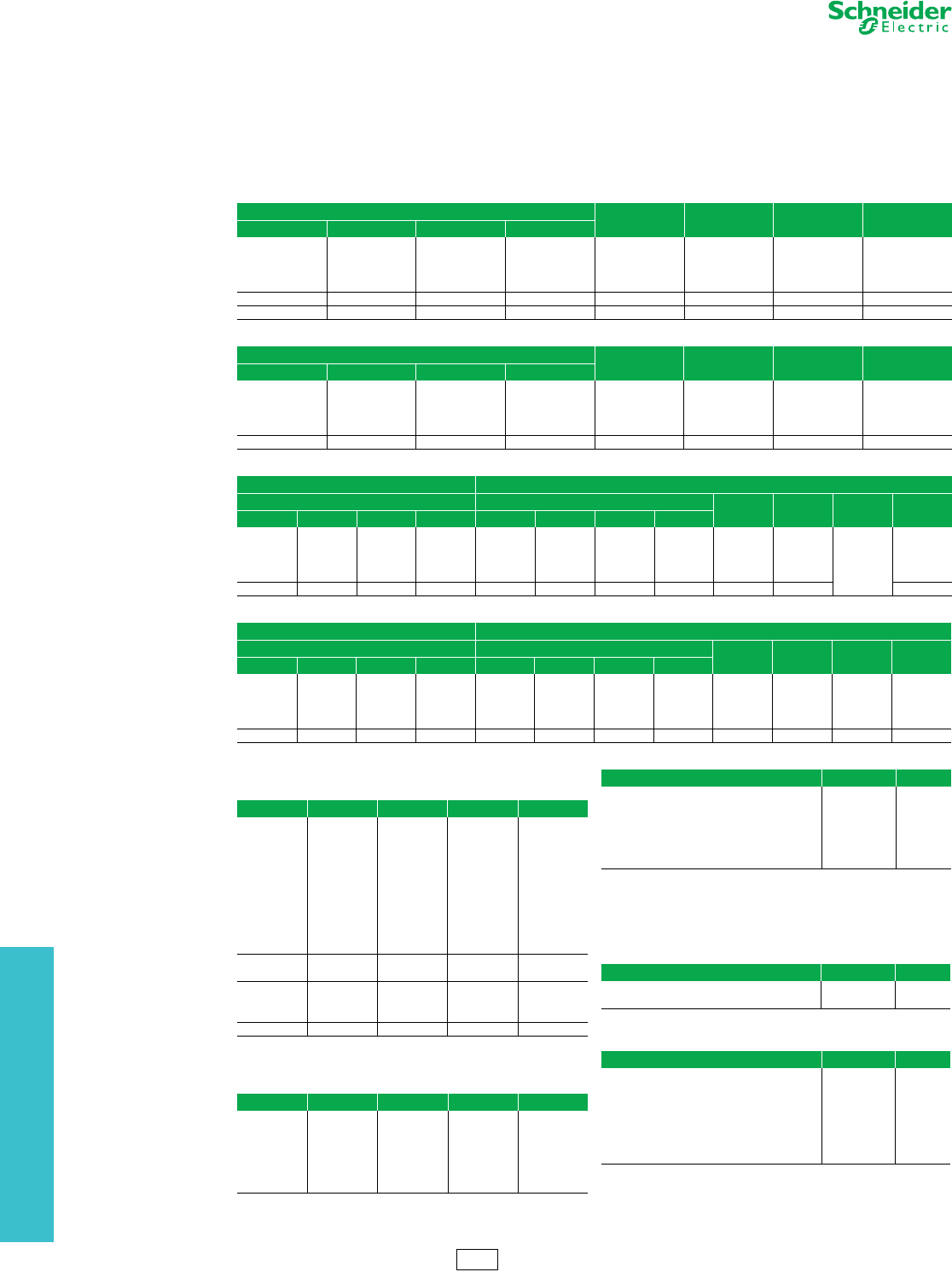
12 OBSOLETE MOTOR CONTROL
CENTERS
12-6 © 2012 Schneider Electric
All Rights Reserved
www.schneider-electric.us
Obsolete Motor Control
Centers
Series 5600 Branch Feeder and Circuit Breaker Type
Combination Starter Units
Notes:
1. Bimetallic overload relay included; thermal units
must be priced and ordered separately for NEMA
Sizes 1 and 2.
2. On starter units, the last digits of the unit catalog
number represent the horsepower.
3. All units are NEMA 1 enclosure.
4. All units include a control power transformer and are
wired for 120 V control.
5. All starter units are rated for 100 k AIR at 480 V.
6. All starter units are supplied with 1B wiring, 1 N.O.
auxiliary interlock, and 1 N.C. auxiliary interlock.
NOTE: All circuit breaker branch feeder units are rated for 25 k AIR at 480 V.
aTo order a unit with any of the options listed, add the form number as
a suffix to the unit type number. Only listed combinations of options are
available. Choose only one form number option per starter unit.
bFull Voltage Non-Reversing units only.
cReversing units only.
dTwo-speed units only.
NOTE: (Undrilled Panel and Hinged Door)
NOTE:
•All units are NEMA 1 enclosure.
•All operators and pilot lights are 22 mm.
•1 space factor = 12 inches
•The ground stab kit is field installed and available for all units.
Table 12.15: Full Voltage Non-Reversing Starters
Unit Catalog No. NEMA Size C/B Amps $ Price Space Factor
208 V 240 V 480 V 600 V
1TA.33 2TA.33 TA1 6TA1
1
3
3600.00 1
1TA1 2TA1 TA3 6TA3 7
1TA3 2TA3 TA7.5 6TA10 15
1TA5 2TA7.5 TA10 —30
1TA10 2TA10 TA25 6TA25 250 4326.00 1
1TA25 2TA30 TA50 6TA50 3100 5632.00 2
Table 12.16: Full Voltage Reversing Starters
Unit Catalog No. NEMA Size C/B Amps $ Price Space Factor
208 V 240 V 480 V 600 V
1TC.33 2TC.33 TC1 6TC1
1
3
4816.00 1.5
1TC1 2TC1 TC3 6TC3 7
1TC3 2TC3 TC7.5 6TC7.5 15
1TC5 2TC7.5 TC10 6TC10 30
1TC10 2TC10 TC25 6TC25 250 5796.00 1.5
Table 12.17: 2 Speed 1 Winding Starters
Constant Hp Constant or Variable Torque
Unit Catalog No. Unit Catalog No. NEMA
Size C/B Amps $ Price Space
Factor
208 V 240 V 480 V 600 V 208 V 240 V 480 V 600 V
——TH.5 6TH.75 1TE.33 2TE.33 TE1 6TE1
1
3
6572. 2
1TH.75 2TH.75 TH2 6TH2 1TE1 2TE1 TE3 6TE3 7
1TH2 2TH2 TH5 6TH5 1TE3 2TE3 TE7.5 6TE7.5 15
1TH5 2TH5 TH7.5 6TH7.5 1TE5 2TE7.5 TE10 6TE10 30
1TH7.5 2TH10 TH20 6TH20 1TE10 2TE10 TE25 6TE25 250 2
Table 12.18: 2 Speed 2 Winding Starters
Constant Hp Constant or Variable Torque
Unit Catalog No. Unit Catalog No. NEMA
Size C/B Amps $ Price Space
Factor
208 V 240 V 480 V 600 V 208 V 240 V 480 V 600 V
——TI.5 6TI.75 1TG.33 2TG.33 TG1 6TG1
1
3
6082.00 2
1TI.75 2TI.75 TI2 6TI2 1TG1 2TG1 TG3 6TG3 7
1TI2 2TI2 TI5 6TI5 1TG3 2TG3 TG7.5 6TG7.5 15
1TI5 2TI5 TI7.5 6TI7.5 1TG5 2TG7.5 TG10 6TG10 30
1TI7.5 2TI10 TI20 6TI20 1TG10 2TG10 TG25 6TG25 2507510.00 2
Table 12.19: Single Branch Circuit Breaker
Feeder Units
NOTE: All units are 3 Phase, 3 Wire
Unit Type Trip Rating Frame Type $ Price Space Factor
TW15 15
FD 2934.00 1
TW20 20
TW30 30
TW40 40
TW50 50
TW60 60
TW70 70
TW80 80
TW90 90
TW100 100
TW125 125 FD 6040.00 1.5
TW150 150
TW175 175
JD 6408.00 1.5TW200 200
TW225 225
TW250 250 JD 8102.00 1.5
Table 12.20: Dual Mounted Branch Circuit Breaker
Feeder Units
NOTE: All units are 3 Phase, 3 Wire
Unit Type Trip Rating Frame Type List $ Price Space Factor
TW415 15/15
FD/FD 5310.00 1
TW420 20/20
TW430 30/30
TW450 50/50
TW460 60/60
TW4100 100/100
Table 12.21: Starter Unit Options
DescriptionaForm No. List $ Price
bStart-Stop PB with 1 Pilot Light—Red (On) AP 540.
cForward-Reverse-Stop PB with 2 Pilot Lights A1PP 1164.
dHigh-Low-Stop PB with 2 Pilot Lights A2PP 1164.
bHand-Off-Auto SS with 1 Pilot Light—Red (On) CP 540.
b1 Pilot Light Only—Red (On) P 286.
cd2 Pilot Lights—Red (On) PP 722.
Table 12.22: Misc. Units—Empty Mounting Units
Description Unit Type $ Price
1 Space Factor TMT1 702.00
2 Space Factor TMT2 1020.00
Table 12.23: Miscellaneous Items
Description Unit Type $ Price
1•
2 Space Factor Blank Door TBD.5 282.00
1 Space Factor Blank Door TBD1 302.00
2 Space Factor Blank Door TBD2 502.00
Ground Stab Kit TGSK 152.00
1 Space Factor Unit Gasketing Kit TGAS12 50.00
1.5 Space Factor Unit Gasketing Kit TGAS18 76.00
2 Space Factor Unit Gasketing Kit TGAS24 100.00
PE4 Discount
Schedule

13-1
© 2012 Schneider Electric
All Rights Reserved
13 OBSOLESCENT PANELBOARDS
Table of Contents
Section 13
Obsolescent Panelboards
QMB Fusible Panelboards
Ready-to-Install (RTI)—600 Vac, 250 Vdc 13-2
Main Switch Replacement Units 13-3
Branch Switch Replacement 13-4
Obsolescent Branch Switch Replacement Units 13-5
Series E1 Motor Starter Replacement Units 13-6
Replacement Parts
Trim Clamps and Screws 13-7
Circuit ID Numbers 13-7
Locks 13-7
NQOD Lighting and Appliance Panelboards
Series Rated/Fully Rated Tables 13-8
Lighting and Appliance Panelboard Pricing Procedures 13-9
Merchandised 20-Inch Wide Main Lugs Only Panelboards 13-10
Merchandised Accessories 13-11
Merchandised 20-Inch Wide Main Circuit Breaker Panelboards 13-11
NQOD 14-Inch Wide Enclosures 13-12
Merchandised Non-Linear Panel (200% rated neutral) 13-13
Te r m i n a l D a ta 13-14
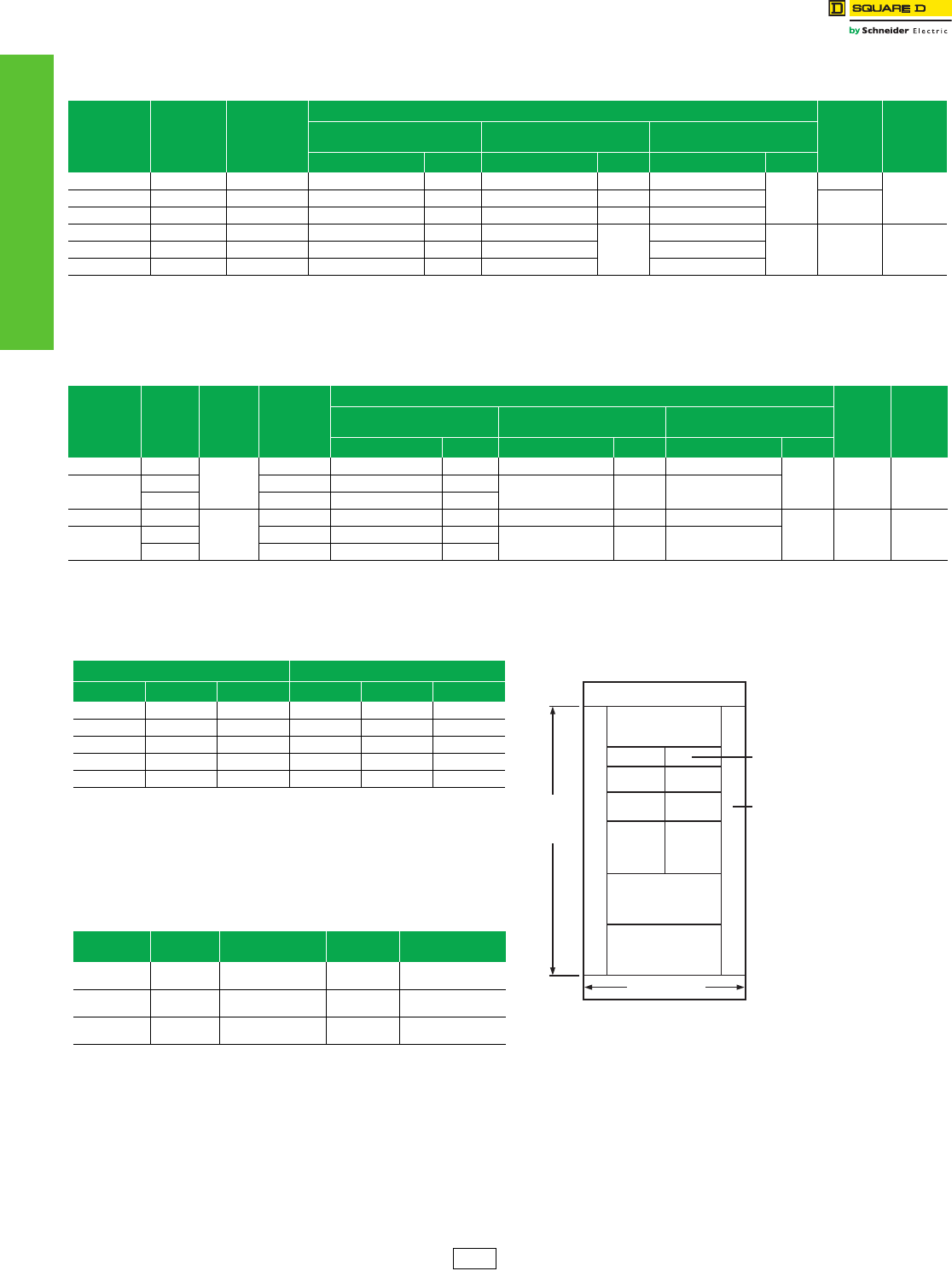
www.schneider-electric.us
13 OBSOLESCENT PANELBOARDS
13-2 © 2012 Schneider Electric
All Rights Reserved
QMB Fusible Panelboards Ready-to-Install (RTI)—600 Vac, 250 Vdc
Class 4620
0
QMB Layout Information
Table 13.1: QMB Main Lugs Interiors, Boxes and Fronts
Total Branch Unit
Mounting
Space (Inches)
Ampere
Rating
of Mains
$ Price
Interior, Front
and Box
(less units)
Component Selection
Box Height
(inches)
Box Width
(inches)
Interior Assembly—3-pole with Main
Lugs Front (4-piece Standard) Box
Catalog No. $ Price Catalog No. $ Price Catalog No. $ Price
60 225 3478.00 QMB60902 2631.00 QM38902TS 590.00 QM3890B
257.00
90
3845 400 3954.00 QMB45754 2894.00 QM38756TS 803.00 QM3875B 75
45 600 4484.00 QMB45756 3540.00 QM38756TS 687.00 QM3875B
45 800 5448.00 QMB45908 4304.00 QM38908TS
887.00
QM3890B
257.00 90 3845 1200 6313.00 QMB459012 5169.00 QM389012TS QM3890B
60 600 6093.00 QMB60906 4949.00 QM38906TS QM3890B
Table 13.2: QMB Main Switch Interiors, Boxes and Fronts
Total Branch
Unit Mounting
Space
(inches)
Ampere
Rating of
Mains
Maximum
Voltage (ac)
$ Price
Interior, Front
and Box
(less units)
Component Selection
Box Height
(inches)
Box Width
(inches)
Interior Assembly—3-pole with Main
Switch Front (4-Piece Standard) Box
Catalog No. $ Price Catalog No. $ Price Catalog No. $ Price
51 200
240
4551.00 QMB5190324M 3704.00 QM38902TS 590.00 QM3890B
257.00 90 38
45 400 10173.00 QMB4590325M 9029.00 QM38906TS 887.00 QM3890B
600 12118.00 QMB4590326M 10974.00
51 200
600
5332.00 QMB5190364M 4485.00 QM38902TS 590.00 QM3890B
257.00 90 38
45 400 10834.00 QMB4590365M 9690.00 QM38906TS 887.00 QM3890B
600 12940.00 QMB4590366M 11796.00
Table 13.3: Accessories
Blanks Solid Neutral Assembly
Height Catalog No. $ Price Ampere Rating Catalog No. $ Price
1.5 QMB1BLW 75.00 225 QMB2SN 380.00
3QMB3BLW 80.00 400 QMB4SN 477.00
6QMB6BLW 87.00 600 QMB6SN 599.00
15 QMB15BLW 120.00 800 QMB8SN 969.00
—— —1200 QMB12SN 1545.00
Note: Equipment Ground Bar—PK32DGTA, price: $104.00
Table 13.4: QMB Branch Circuit Breaker Units
600 Vac
Unit Ampere
Rating
Unit Height
(Inches) Catalog No. $ Price Description
15–150 6 QMBHW ab 1965.00 Mounts (1) or (2) 3-pole
HDL circuit breakers
150 –225 6 QMBJW ac 2099.00 Mounts (1) 3-Pole JDL
circuit breaker
400 7.5 QMB3400LAW d5445.00 Includes (1) 3-Pole LAL
circuit breaker
aCircuit breakers not included. Order HDL or JDL circuit breakers from Digest page 7-22.
bOrder one catalog number S37444 for each circuit breaker.
cOrder catalog number S37445 with QMBJW.
dFor trip ratings other than 400 A, contact the nearest Schneider Electric sales office.
Branch
Unit
Mounting
Space
100 A twin QMB
6 in. H @ 240 V
60 A twin QMB
6 in. H @ 600 V
100 A twin QMJ
6 in. H @ 600 V
100 A twin QMB
7.5 in. H @ 600 V
200 A QMB
9 in. mounting height,
200 A twin QMJ
7.5 in. mounting height
38 in.
30/30 @ 240 V or 600 V
or 60/60 @ 240 V
are 4.5 in. high
Wiring Gutter
400 A QMJ 9 in. H,
400 A Class T 9 in. H,
400, 600 or 800 A
QMB all require 15 in. H
PE1A Discount
Schedule
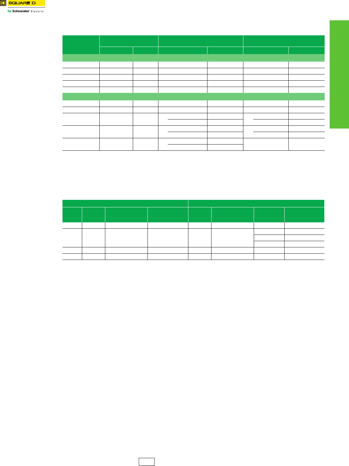
www.schneider-electric.us
13 OBSOLESCENT PANELBOARDS
© 2012 Schneider Electric
All Rights Reserved
13-3
QMB Fusible Panelboards Main Switch Replacement Units
Class 4620
Table 13.5: Main Switch Replacement Units (Replaces Series E1)
Ampere Rating
Standard—Class H, R, K Fuse
Spacing Class T Fuse Spacing Class J Fuse Spacing
Catalog No. $ Price Catalog No. $ Price Catalog No. $ Price
3-Pole, 240 Vac
100 QMB323MW 2208.00 ————
200 QMB324MW 2208.00 ————
400 QMB325MW 6923.00 ————
600 QMB326MW 8561.00 ————
800 — —————
3-Pole, 600 Vac
100 QMB363MW 2891.00 ————
200 QMB364MW 2891.00 ————
400 QMB365MW 7616.00 QMB365MWa7616. QMB365MWa7616.00
QMB400T6 275. QMB400J 530.00
600 QMB366MW 9417.00 QMB366MWa9416. QMB366MWa9416.00
QMB600T6 291. QMB600J 591.00
800 QMB367MW 16974.00 QMB367MWa16974. ——
QMB800T6 701.
aBoth catalog numbers are required for a complete device.
Example: QMB365MW
QMB400T6 constitutes a complete device.
Table 13.6: Main Switch Interior Lug Data
Mechanical Lugs VCEL Compression Lugs
Mains
Ampere
Rating
Conductors
Per
Phase
Wire Range
Wire Bending Space per
NEC Table 373-6
Lug Wire Range
Conductors
Per
Phase
Wire Range
Wire Bending Space per
NEC Table 373-6
Catalog No. Lug Wire Range
200 (1) #6–300 kcmil Al or Cu #6–300 kcmil Al or Cu (1) #4–300 kcmil Al or Cu VCEL030516H1 #4–300 kcmil Al or Cu
400 (2) 3/0–500 kcmil Al or Cu 3/0–600 kcmil Al or Cu (2) 2/0–600 kcmil Al or Cu
VCEL05012H1 2/0–500 kcmil Al or Cu
VCEL06012H1 400–600 kcmil Al or Cu
VCEL07512H1 500–750 kcmil Al
600 (2) 3/0–500 kcmil Al or Cu 3/0–600 kcmil Al or Cu (2) 2/0–500 kcmil Al or Cu VCEL05012H1 3/0–500 kcmil Al or Cu
800b(3) 3/0–500 kcmil Al or Cu 3/0–600 kcmil Al or Cu (3) 2/0–500 kcmil Al or Cu VCEL05012H1 3/0–500 kcmil Al or Cu
bFactory assembled only.
{{
{
{
{
{
PE1A Discount
Schedule
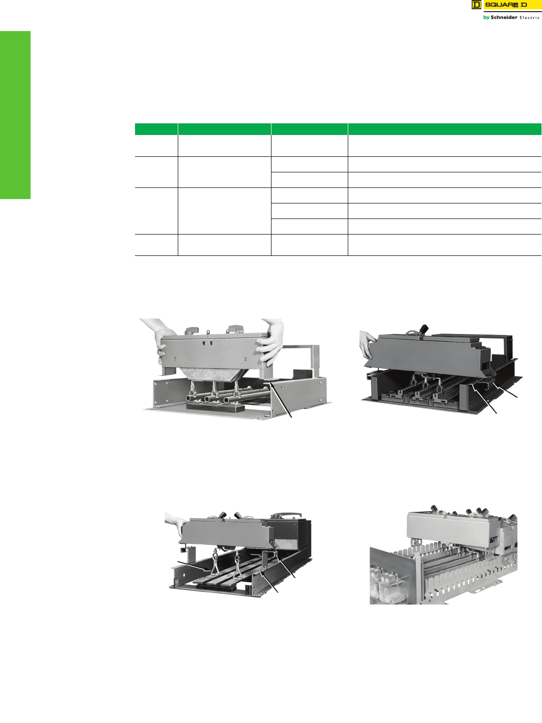
13-4 © 2012 Schneider Electric
All Rights Reserved
www.schneider-electric.us
13 OBSOLESCENT PANELBOARDS
QMB Fusible Panelboards Branch Switch Replacement
Class 4620
Guidelines
STEP 1: Determine the panelboard interior type. If the date of manufacture is not known, compare your switch with the
pictures below to determine the mounting rail direction. Only mounting rails that face outward will accept the Series D2
switch and its required mounting rail extension bracket.
STEP 2: Order a replacement switch from page 13-5.
Table 13.7: Panelboard Interiors
Illustration No. Interior Catalog No. Prefix Designed For Switch Type Switch Availability/Order Information
1. Type QM
in 31-inch wide box
built before 1961.
Series 1-4
30–200 A Maximum
NOT AVAILABLE
Series D2 switches are not compatible replacements for this application.
2. Type QM
in 31-inch wide box
built after 1961
and before 1984.
Series 1-4
30–200 A Maximum
NOT AVAILABLE
Order Series D2 switch from page 13-5.
Series D2
30–200 A Maximum Order Series D2 switch from page 13-5. (Many still stocked in DS.)
3.
Type QW
in 38-inch wide box
built before 1984.
Series 1-4
30–200 A Maximum
NOT AVAILABLE
Order Series D2 switch and plug-on extension assembly from page 13-5.
Series 1-4
400–600 A
NOT AVAILABLE
QMB3400LA available order only from Lexington.
Series D2
30–200 A Maximum Order Series D2 switch and plug-on extension assembly from page 13-5.
4. Type QM B
in 35-inch or 38-inch wide box
built after 1984.
Series E1 or E2
30–800 A Order from Digest page 9-34.
Type QM (31-inch Wide)
Manufactured Before 1961
Panelboards manufactured before 1961 have the interior mounting
rails facing inward (toward the bus). Switches and circuit breakers that
fit in this interior type are obsolete.
Type QM (31-inch Wide)
Manufactured After 1961 But Before October 1984
Panelboards manufactured after 1961 have the interior mounting rails
facing outward (away from the bus). This interior accepts Series 1-4
switches and Series D2 switches (shown above with required rail
extensions). Order the Series D2 switch (includes mounting rail
extensions) from page 13-5.
Type QW (38-inch Wide)
Manufactured Before 1984
Type QW panelboards were built to accept bolt-on 400 A and 600 A
Series 1-4 switches. 30-200 A Series D2 switches may be installed as
shown using the plug-on extension assembly from page 13-5.
Type QMB
Manufactured After October 1984
Series E1 panelboards will accept only Series E1 or E2 switches. Order
from Digest page 9-34.
Mounting rail
Rail
extension
Mounting rail
Rail
extension
Mounting rail
Plug-on
extension
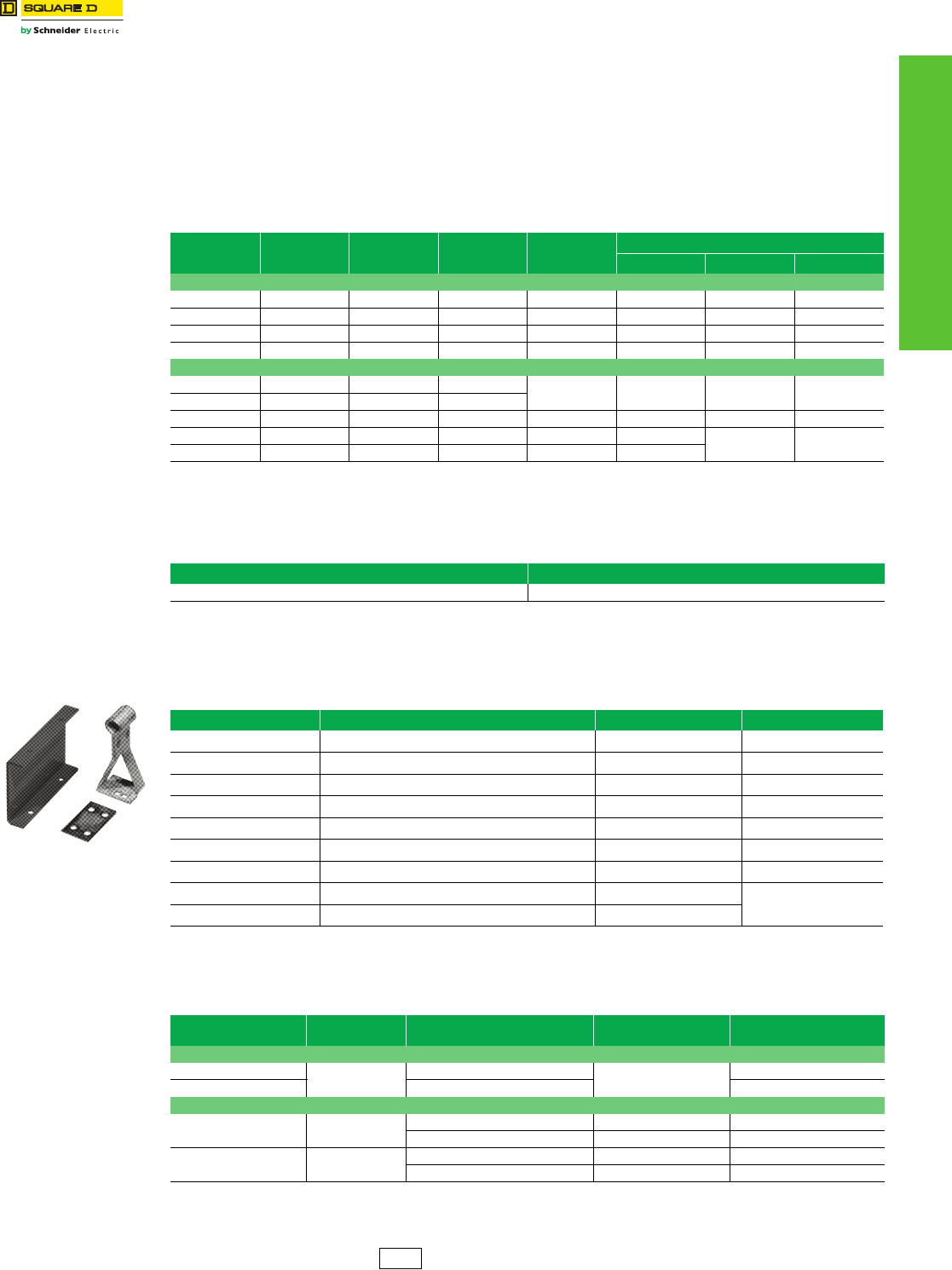
www.schneider-electric.us
13 OBSOLESCENT PANELBOARDS
© 2012 Schneider Electric
All Rights Reserved
13-5
QMB Fusible Panelboards Obsolescent Branch Switch Replacement Units
Class 4620
30–200 A Obsolescent Switch Units—Series D2
Available In DS Stock, except where noted.
All Series D2 switches require that rail extension assemblies be attached to the interior side rails in order to mount the
switch. These rail extension assemblies are packaged with every Series D2 switch. If a rail extension is lost or missing,
contact the nearest Schneider Electric™ sales office to order a replacement.
Plug-on extension assemblies must also be ordered when installing 30–200 A plug-on units in blank spaces of a QW
interior in the 38-inch wide box. These plug-on extension assemblies (which extend the bus) are NOT the same as the
rail extension assemblies packaged with every Series D2 switch (which extend only the mounting rails).
Table 13.8: Branch Units—Three Pole
Ampere
Rating
Unit Height
(inches)
Obsolescent a
Series 1–4
Catalog No.
Replaced By
Series D2
Catalog No.
$ Price
Class R Fuse Kits
No. Kits Req’d. Catalog No. $ Price
240 Vac
30-30 4.50 QMB3203T QMB321Tb1139.00 2HRK30 26.00
60-60 4.50 QMB306T QMB322TD 1187.00 1QMB36R 49.00
100-100 6.00 QMB310T QMB323TD 1808.00 1QMB100R 95.00
200 9.00 QMB3220 QMB324 2393.00 1HRK1020 48.00
600 Vac
30-30 4.50 QMB3603T QMB361Tb
1763.00 1QMB36R 49.00
30-30 6.00 QMB362T1
60-60 6.00 QMB3606T QMB362T 1763.00 1QMB60R 49.00
100-100 7.50 QMB3610T QMB363T 2795.00 2HRK1020 48.00
200 9.00 QMB3620 QMB364 3297.00 1
aThese switch units are no longer available; the catalog number is provided only for cross referencing to Series D2 units.
bWhen this Series D2 switch is used as a replacement for a Series 1-4 3-inch switch, a blank filler plate is also required. Purchase the blank filler plate
from a local sheet-metal fabricator.
Table 13.9: Obsolescent Circuit Breaker Units a
Catalog No. $ Price
QMB3400LAb7097.00
aCircuit breaker units are designed for use in all QMB interior types manufactured between 1961 and October 1984.
bIncludes a 3-pole, LA type circuit breaker. For other ampere ratings, contact the Schneider Electric Customer Information Center.
Table 13.10: Plug-On Extension Assemblies a
Ampere Rating Switch Mounting Height (inches) Catalog No. $ Price
30-30 Switch 3 QMB303LEX 203.00
30-30 Switch 4.5 QMB306LEX 207.00
30-30 Switch 6 QMB306EX 239.00
60-60 Switch 4.5 QMB306LEX 207.00
60-60 Switch 6 QMB306EX 239.00
100-100 Switch 6 QMB310LEX 239.00
100-100 Switch 7.5 QMB310EX 567.00
200 Switch 9 QMB320EX
567.00
LA Circuit Breaker 7.5 QMB310EX
aBus extensions are required on all 30–200 A switches. They are also required on all circuit breaker units used in switchboards or in QW type panelboards
with a 38-inch wide box.
Table 13.11: Obsolescent Main Switch Units a
Ampere Rating Unit Height
(inches) Catalog No. $ Price Replaces Series 4
Unit Catalog No.
3-pole 240 Vac
100 9QMB323Mb
2303.00 QMB3210M
200 QMB324M QMB3220M
3-pole 600 Vac
100 9 QMB363Mb3017.00 QMB3610M
QMB363MJb3213.00 QMB3610MJ
200 9 QMB364M 3792.00 QMB3620M
QMB364MJb4038.00 QMB3620MJ
aReplace Series 4 Units
bOrder only from the Lexington plant.
Plug-On Extension
Assembly
PE1A Discount
Schedule
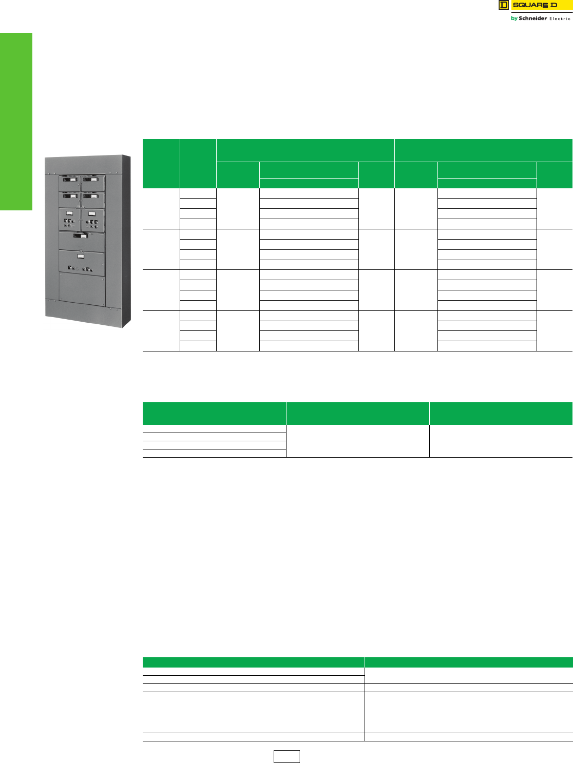
13-6 © 2012 Schneider Electric
All Rights Reserved
www.schneider-electric.us
13 OBSOLESCENT PANELBOARDS
QMB Fusible Panelboards Series E1 Motor Starter Replacement Units
Class 2320
Application
For use on three-phase ac systems—208, 240, or 480 volts. UL® Listed.
Starters
Line Voltage Type
•Non-Reversing—Twin Units
— Sizes 0 through 3—Class 8536, Types SB, SC, SD and SE.
•Reversing—Single Units
— Sizes 0 through 3—Class 8736, Types SB, SC, SD and SE.
Selection of Components
1. List required motor starter units (reversing or non-reversing) from the tables above.
2. Specify the HP, voltage, phase, frequency and full load current rating of the motor.
3. Specify the unit mounting space.
4. Determine the circuit breaker or fusible switch rating for motor branch circuits from the selection tables on Digest page 9-34.
5. For motor starter voltages other than standard voltages of 120, 208, 240 and 480 volts, contact the nearest Schneider Electric sales
office.
Starter Data
•Line voltage coils are furnished as standard on all starters.
•Twistouts are provided in starter covers for start-stop push buttons, selector switches and pilot lights. See accessories table below.
•Starter door interlocks are furnished with motor starter enclosures.
•Type S starter enclosures include drillings for the next smaller size.
•All Type S starters have provisions for three overload relay thermal units, as required by NEC® Table 430.37 for three phase ac
motor circuits.
Accessories
Accessories listed below are available for field installation on all units. Go to the sections shown for prices.
QMB Motor Starter
Panelboard
Table 13.12: Starter Units—Not stocked in DS. Order only from the Peru plant.
NEMA
Size
Coil
Voltage c
Class 8536—Types SB, SC, SD and SEq
Type S—Non-Reversing
(see Digest page 16-16)
Class 8736—Types SB, SC, SD and SE a
Reversing
(see Digest page 16-51
Unit
Height
(Inches)
Twin-Starter Unit
(Two Non-Reversing Starters) $ Price b
Unit
Height
(Inches)
Single-Starter Unit
(One Reversing Starter) $ Price b
Catalog No. Catalog No.
0
120
9
QMBS8536100120W
1931.00 9
QMBS873610120W
2115.00
208 QMBS8536100208W QMBS873610208W
240 QMBS8536100240W QMBS873610240W
480 QMBS8536100480W QMBS873610480W
1
120
9
QMBS8536111120W
2435.00 9
QMBS873611120W
2295.00
208 QMBS8536111208W QMBS873611208W
240 QMBS8536111240W QMBS873611240W
480 QMBS8536111480W QMBS873611480W
2
120
10-1/2
QMBS8536222120W
3813.00 10-1/2
QMBS873622120W
3732.00
208 QMBS8536222208W QMBS873622208W
240 QMBS8536222240W QMBS873622240W
480 QMBS8536222480W QMBS873622480W
3
120
18
QMBS8536333120W
5930.00 18
QMBS873633120W
6797.00
208 QMBS8536333208W QMBS873633208W
240 QMBS8536333240W QMBS873633240W
480 QMBS8536333480W QMBS873633480W
aSpace and drilling are provided for field addition of control voltage transformer and fuse base.
bPrices include starters, but do not include overload relay thermal units. See Digest page 16-129 for selection procedure (ac magnetic starters—small
enclosure), and order thermal units separately.
cSee Digest page 16-21 for maximum motor starter ratings.
Table 13.13: UL Listed Short Circuit Ratings @ 600 V Maximum
Starter Size
Fusible Switch
(with Class R or J fuse)
RMS Sym. Amperes
Thermal-Magnetic
Circuit Breaker
RMS Sym. Amperes
0
100,000 5,000
1
2
3
Table 13.14: Field Installable Accessories
Description Digest Section
Push Buttons and Selector Switches: Class 9001, Type K Pushbuttons and Operator Interface
Pilot Lights: Class 9001, Type KP
Electrical Interlocks: Class 9999, Types SX6, SX7 NEMA-Definite Purpose Type Contactors and Starters
Industrial Control Transformers: Class 9070
Supplemental Digest, Transformers
Type EO1; Starter Size: 0 and 1, Non-Reversing
Type EO2; Starter Size: 0, 1 and 2, Reversing
Type EO3; Starter Size: 3
Type EO4; Starter Size: 4
Control Circuit Fuse Block: Class 9080, Type PF1 Terminal Blocks
PE1A Discount
Schedule
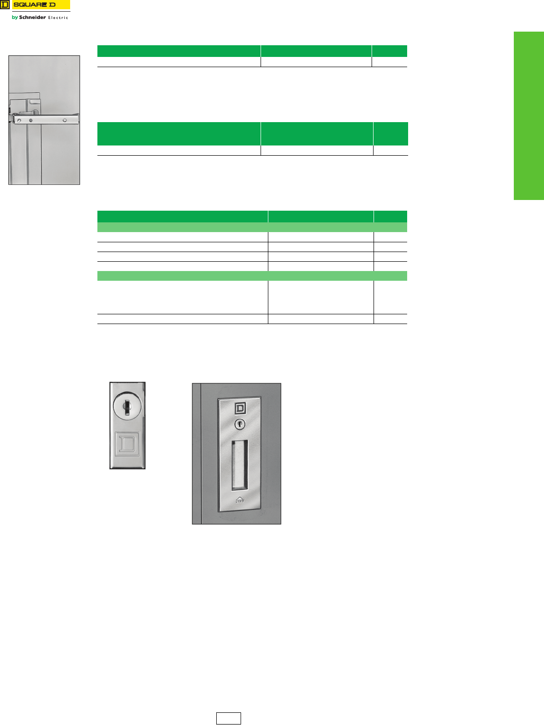
www.schneider-electric.us
13 OBSOLESCENT PANELBOARDS
© 2012 Schneider Electric
All Rights Reserved
13-7
Replacement Parts Trim Clamps and Screws; Circuit I.D. Numbers; Locks
Class 1600
Catalog No.
PK3TC
Table 13.15: Trim Clamps and Screws
Application Catalog No. $ Price
NEHB Panelboards: All fronts up through 400 A PK3TC 44.00
Table 13.16: Circuit I.D. Numbers
Circuit Number Description
NEHB and NEHB
Column Width
Catalog No.
$ Price
1 through 54 8004332501 14.00
Table 13.17: Locks—Type 1 Enclosures
Application Catalog No. $ Price
NEHB Panelboards
All main lug fronts and all main circuit breaker fronts up to 225 A
Lock only PK4FL 90.00
Complete assembly PK7FL 90.00
All 400 A main circuit breaker fronts PK5FL 165.00
Telephone Cabinets
Fronts on boxes up to 30 inches wide
PK4FL
(Before November 1997)
PK22FL
(After November 1997)
90.00
Fronts on boxes 36 inches or wider PK5FL 165.00
Catalog No.
PK4FL
Catalog No.
PK5FL
PE1A Discount
Schedule
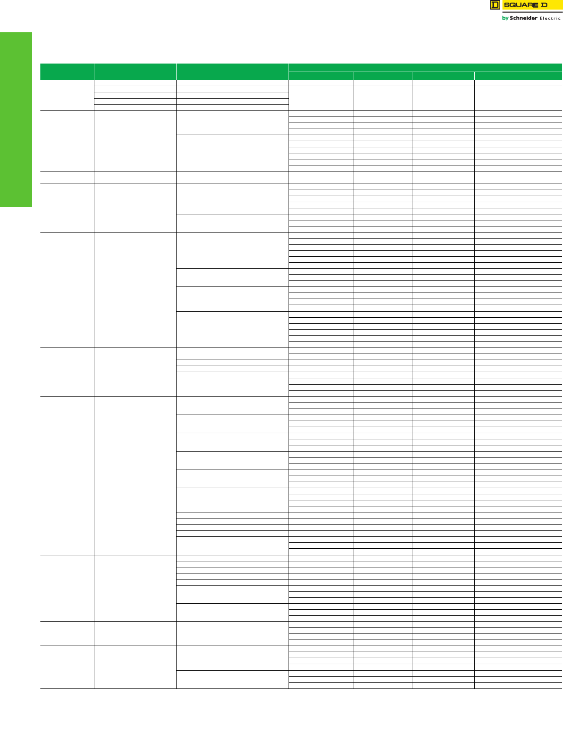
www.schneider-electric.us
13 OBSOLESCENT PANELBOARDS
13-8 © 2012 Schneider Electric
All Rights Reserved
Series Ratings NQOD Panelboards
Class 1630 / Refer to Catalog 1630CT9701
This page contains UL Tested and Certified series combination ratings for
panelboards. These ratings apply to either an integral main located in the same
enclosure or a remote main located in a separate enclosure. NOTE: Where QO(B)
GFI circuit breakers are shown above, QO (B) EPD circuit breakers may also be used.
Table 13.18: NQOD Series Ratings
Maximum System
Voltag e AC c
Maximum Short Circuit
Current Rating (RMS Sym.)
Integral or Remote Main Circuit Breakers
and Remote Main Fuses
Branch Circuit Breaker Designations and Allowable Ampere Ranges ab
Type 1-pole 2-pole 3-pole
120/240 1Ø
22k MG QO (B) 15–30 A — —
42k HD, JD
QO (B) PL 15–30 A 15–60 A 15–30 A
65k HG, JG
100k HJ, JJ
125k HL, JL
120/240 1Ø
208Y/120 100k
DJ 400 A
QO (B) 15–70 A 15–125 A —
QO (B) GFI 15–30 A 40–60 A —
QO (B) VH — 150 A 15–150 A
QO (B) AFI 15–20 A — —
QJ
QO (B) 15–70 A 15–125 A 15–30 A
QO (B) AS 15–30 A 15–30 A 15–30 A
QO (B) GFI 15–30 A 15–60 A —
QO (B) PL 15–30 A 15–60 A 15–30 A
QO (B) VH — 150 A 35–150 A
QO (B) AFI 15–20 A — —
208Y/120 18k LA/LH (L) 34200MC, LA/LH (L) 34225MC,
LA/LH (L) 34250MC, LA/LH (L) 34400MC QO (B) 15–30 A 15–30 A 15–30 A
240 22k
QO (B) VH
QO (B) 15–70 A 15–125 A 15–100 A
QO (B) AS 15–30 A 15–30 A 15–30 A
QO (B) GFI 15–30 A 15–60 A —
QO (B) PL 15–30 A 15–30 A —
QO (B) AFI 15–20 A — —
Q2-Hf
QO (B) 15–70 A 15–100 A 15–30 A
QO (B) GFI 15–30 A 15–30 A —
QO (B) AFI 15–20 A — —
240 25k
QD
QO (B) 15–70 A 15–125 A 15–30 A
QO (B) AS 15–30 A 15–30 A 15–30 A
QO (B) GFI 15–30 A 15–60 A —
QO (B) PL 15–30 A 15–60 A 15–30 A
QO (B) VH — 150 A 35–150 A
QO (B) AFI 15–20 A — —
ED, FDf
QO (B) 15–70 A 15–125 A 15–100 A
QO (B) GFI 15–30 A 15–60 A —
QO (B) AFI 15–20 A — —
KDf
QO (B) 15–70 A 15–125 A 15–100 A
QO (B) AS 15–30 A 15–30 A 15–30 A
QO (B) GFI 15–30 A 15–60 A —
QO (B) AFI 15–20 A — —
HD, JD
QO (B) 15–70 A 15–125 A 15–100 A
QO (B) VH — — 35–150 A
QO (B) GFI 15–30 A 15–60 A —
QO (B) AFI 15–20 A — —
QO (B) H — 15–100 A —
QOB2150VH — 150 A —
240 42k
LA, MA Q2L-Hf— 110–225 A 110–225 A
QDL — 70–225 A 70–225 A
MG QO (B) VH 15–30 A 15–30 A 15–30 A
HD, JD QO (B) PL 15–30 A 15–60 A 15–30 A
LC
600 A Maximum
QO (B) 15–70 Ad——
QO (B) VH 15–30 A 15–125 A 15–100 A (3P 208 V Max.)
QO (B) GFI 15–30 Ae15–60 A —
QO (B) AFI 15–20 A — —
240 65k
LC
600 A Maximum
QO (B) VH 15–30 A 15–125 A 15–100 A (3P 208 V Max.)
QO (B) GFI 15–30 Ae——
QO (B) AFI 15–20 A — —
DJ 400 A
QO (B) 15–70 A 15–125 A —
QO (B) VH — 150 A 15–150 A
QO (B) H — 15–100 A —
EG, FGf, KGf
QO (B) 15–70 A 15–125 A 15–100 A
QO (B) GFI 15–30 A 15–60 A —
QO (B) AFI 15–20 A — —
QG
QO (B) 15–70 A 15–125 A 15–30 A
QO (B) AS 15–30 A 15–30 A 15–30 A
QO (B) VH — — 35–150 A
QG, HG, JG
QO (B) GFI 15–30 A 15–60 A —
QO (B) PL 15–30 A 15–60 A 15–30 A
QO (B) AFI 15–30 A — —
HG, JG
QO (B) 15–70 A 15–125 A 15–100 A
QO (B) VH — — 35–150 A
QO (B) H — 15–100 A —
QOB2150VH — 150 A —
FC22__ QO (B) 15–70 A 15–100 A 15–100 A
KC22__ QO (B) AS 15–30 A 15–30 A 15–30 A
FC32__ QO (B) GFI 15–30 A 15–30 A —
KC32__ QO (B) AFI 15–20 A — —
400 A Max. Class J or T6 Fuses
QO (B) VH 15–30 A 15–125 A 15–100 A
QOB-VH — 150 A —
QO (B) AFI 15–20 A — —
240 100k
FC24__ QO (B) 15–70 A 15–100 A 15–100 A
KC24__ QO (B) AS 15–30 A 15–30 A 15–30 A
FC34__ QO (B) GFI 15–30 A 15–30 A —
KC34__ QO (B) AFI 15–20 A — —
200 A Max. Class T3 Fuses QO (B) AFI 15–20 A — —
EJ, FJf
QO (B) 15–70 A 15–125 A 15–100 A
QO (B) GFI 15–30 A 15–60 A —
QO (B) AFI 15–20 A — —
HJ, JJ QO (B) 15–70 A 15–125 A 15–100 A
QO (B) VH — — 35–150 A
QO (B) GFI 15–30 A 15–60 A —
240 125k HL. JL
QO (B) PL 15–30 A 15–60 A 15–30 A
QO (B) AFI 15–20 A — —
QO (B) H — 15–100 A —
QOB2150VH — 150 A —
240 200k
FI, KI
QO (B) 15–70 A 15–125 A 15–100 A
QO (B) AS 15–30 A 15–30 A 15–30 A
QO (B) GFI 15–30 A 15–60 A —
QO (B) AFI 15–20 A — —
Maximum Fuses 200 A
Class J or T6 400 A Class T3
QO (B) 15–70 A 15–125 A 15–100 A
QO (B) AS 15–30 A 15–30 A 15–30 A
QO (B) GFI 15–30 A 15–60 A —
aSuffixes HID, SWD and SWN may also be applied to the applicable branch circuit breakers shown above, except suffix SWN may NOT be applied in combination with LC main circuit breakers.
bWhere QO (B) circuit breakers are shown above, QO (B) H, QO (B) VH, and QH (B) circuit breakers may also be used.
cFor shown circuit breakers rated less than this maximum voltage, the indicated short circuit current rating also applies, but at the voltage rating of the circuit breaker.
dOnly 15–30 A circuit breakers may be used when the LC circuit breaker is rated 450, 500 or 600 A.
eCircuit breakers may not be used when the LC circuit breaker is rated 450, 500 or 600 A.
fObsolescent. Contact the Schneider Electric local Field Sales Office for the replacement circuit breaker. One-pole FJ circuit breakers are still available.
www.schneider-electric.us
13 OBSOLESCENT PANELBOARDS
© 2012 Schneider Electric
All Rights Reserved
13-9
NQOD Panelboards Pricing Procedure Examples
Class 1630 Refer to Catalog 1630CT0701
NQOD Merchandised Pricing Procedure
1. List circuit breakers required, either plug-on or bolt-on. See appropriate pages for catalog numbers.
2. Determine equivalent number of pole spaces required.
3. Select proper main lugs interior or main lugs interior and main circuit breaker adapter kit based on equivalent number of poles and
ampere rating from appropriate page. Interiors include solid neutral and are field convertible to top feed.
4. Select enclosure from appropriate page.
Type 1—Select box and front catalog number corresponding to interior catalog number. Types 3R, 5, 12—Select enclosure, front
included.
5. For complete price, add the component prices. Include panelboard accessories.
6. Apply appropriate discount schedule.
NQOD Merchandised Example:
Table 13.19: 208Y/120 Vac, 3Ø4W, 10 kAIR, 225 A, MLO, Type 1 surface mount, bolt-on branch circuit
breakers, main sub-feed lugs. a
Branches Page No. Catalog Number Spaces $ Price
225 A MLO Interior 13-10 NQOD430L225CU 30 1292.00
Box 13-10 MH32 — 113.00
Cover 13-10 MHC32S — 497.00
Main Sub-Feed Lugs 13-10 NQOD225SFL — 203.00
Total Price 2105.00
aPrice branch circuit breakers from page 9-10 of the current Digest.
Example pricing only Discount
Schedule
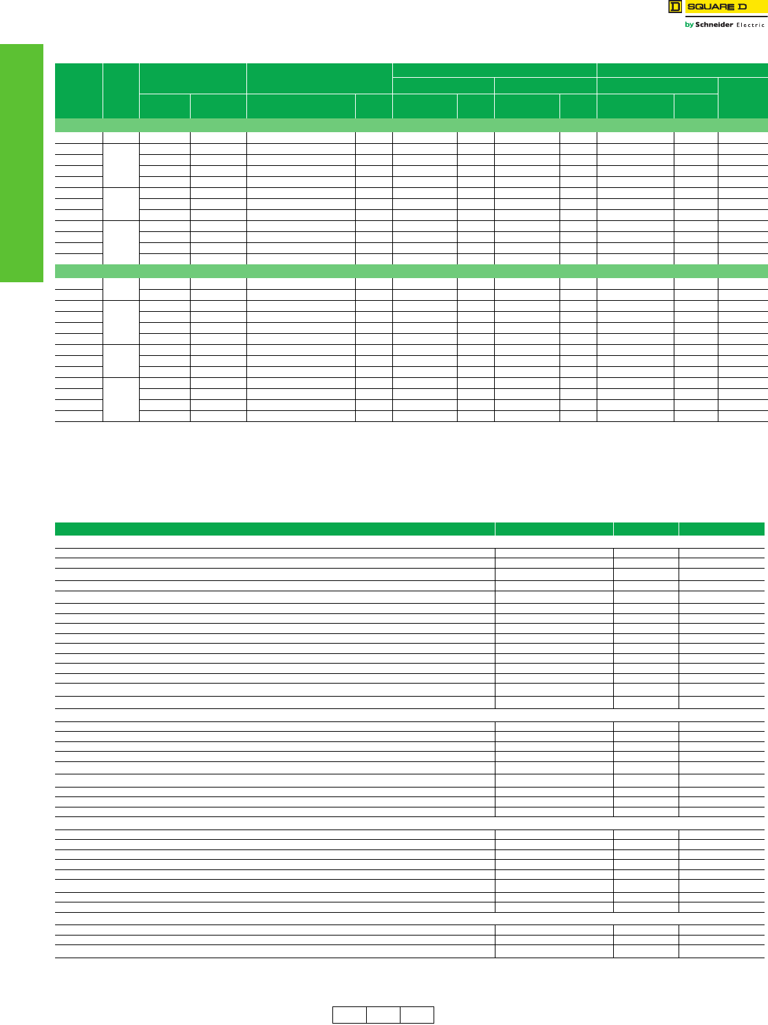
www.schneider-electric.us
13 OBSOLESCENT PANELBOARDS
13-10 © 2012 Schneider Electric
All Rights Reserved
NQOD Merchandised
Panelboards
NQOD 20-inch Wide Enclosures—240 Vac, 48 Vdc
Class 1630 / Refer to Catalog 1630CT0701
Table 13.20: Main Lug Interiors—Accepts plug-on and bolt-on circuit breakers
Max.
No. of
Single Pole
QO™/QOB
Circuit
Breakers
Mains
Rating
Total Price
Interior
Front and Enclosure
Interior Only
(Order Branch Circuit
Breakers Separately)
Type 1 Enclosure Types 3R, 5, 12 Enclosures
Box 20"W x 5.75"DbMono-Flat™ FrontbEnclosure 20"W x 6.5"D
Height
(In.)
Type 1 Types 3R,
5, 12 Catalog No.aPrice Catalog No. Price Catalog No. Price Catalog No. Price
20" Wide Cabinet—Single Phase 3-Wire
20 100 1417.00 3050.00 NQOD20L100CU 864.00 MH23 113.00 MHC23 ( ) 440.00 MH23WP 2186.00 23
30
225
1789.00 3383.00 NQOD30L225CU 1179.00 MH32 113.00 MHC32 ( ) 497.00 MH32WP 2204.00 32
42 2037.00 3623.00 NQOD42L225CU 1418.00 MH35 113.00 MHC35 ( ) 506.00 MH35WP 2205.00 35
42 2464.00 4021.00 NQOD42L225CUTFe1799.00 MH41 113.00 MHC41 ( ) 552.00 MH41WP 2222.00 41
54 2278.00 3835.00 NQOD54L225CU 1613.00 MH41 113.00 MHC41 ( ) 552.00 MH41WP 2222.00 41
30
400
2483.00 4346.00 NQOD30L400CU 1737.00 MH50 113.00 MHC50V ( ) 633.00 MH50WP 2609.00 50
42 2671.00 4512.00 NQOD42L400CU 1896.00 MH53 113.00 MHC53V ( ) 662.00 MH53WP 2616.00 53
54 2894.00 4737.00 NQOD54L400CU 2085.00 MH59 113.00 MHC59V ( ) 696.00 MH59WP 2652.00 59
30
600d
2638.00 4605.00 NQOD30L600 1863.00 MH53 113.00 MHC53V ( ) 662.00 MH656WP 2742.00 53/65
42 2807.00 4767.00 NQOD42L600 2019.00 MH56 113.00 MHC56V ( ) 675.00 MH686WP 2748.00 56/68
42 3768.00 5699.00 NQOD42L600TFLe2942.00 MH62 113.00 MHC62V ( ) 713.00 MH746WP 2757.00 62/74
54 2991.00 4922.00 NQOD54L600 2165.00 MH62 113.00 MHC62V ( ) 713.00 MH746WP 2757.00 62/74
20" Wide Cabinet —Three Phase 4-Wire
24 100 1615.00 3248.00 NQOD424L100CU 1062.00 MH23 113.00 MHC23 ( ) 440.00 MH23WP 2186.00 23
30 1769.00 3383.00 NQOD430L100CU 1191.00 MH26 113.00 MHC26 ( ) 465.00 MH26WP 2192.00 26
30
225
1902.00 3496.00 NQOD430L225CU 1292.00 MH23 113.00 MHC32 ( ) 497.00 MH32WP 2204.00 32
42 2170.00 3756.00 NQOD442L225CU 1551.00 MH35 113.00 MHC35 ( ) 506.00 MH35WP 2205.00 35
42 2567.00 4124.00 NQOD442L225CUTFe1902.00 MH41 113.00 MHC41 ( ) 552.00 MH41WP 2222.00 41
54 2378.00 3935.00 NQOD454L225CU 1713.00 MH41 113.00 MHC41 ( ) 552.00 MH41WP 2222.00 41
30
400
2726.00 4589.00 NQOD430L400CU 1980.00 MH50 113.00 MHC50V ( ) 633.00 MH50WP 2609.00 50
42 2908.00 4749.00 NQOD442L400CU 2133.00 MH53 113.00 MHC53V ( ) 662.00 MH53WP 2616.00 53
54 3091.00 4934.00 NQOD454L400CU 2282.00 MH59 113.00 MHC59V ( ) 696.00 MH59WP 2652.00 59
30
600d
2916.00 4883.00 NQOD430L600 2141.00 MH53 113.00 MHC53V ( ) 662.00 MH656WP 2742.00 53/65
42 3062.00 5022.00 NQOD442L600 2274.00 MH56 113.00 MHC56V ( ) 675.00 MH686WP 2748.00 56/68
42 4050.00 5981.00 NQOD442L600TFLe3224.00 MH62 113.00 MHC62V ( ) 713.00 MH746WP 2757.00 62/74
54 3279.00 5210.00 NQOD454L600 2453.00 MH62 113.00 MHC62V ( ) 713.00 MH746WP 2757.00 62/74
a“CU” suffix indicates copper bussing. NQOD RTI interiors with aluminum bus are no longer available. Order the copper bussed equivalent with a “CU” suffix when ordering a replacement interior.
bEmbossed mounting holes add a 0.25 inch standoff to back of MH box.
cAdd “F” for flush, “S” for surface.
dCopper bus standard on 600 A interiors.
eFeed-thru lug interior.
fEnclosure includes trim kit.
g42 circuit MLO panelboard requires MH38 box, 54 circuit panelboard requires MH44 box.
Table 13.21: NQOD Accessories
Description Catalog No. $ Price Schedule
Sub-feed lug kits—main lugs only—1Ø or 3Øg
•100 A NQOD100SFL 155.00 PE1A
•225 A NQOD225SFL 203.00 PE1A
Sub-feed: Bolt-on: 2-pole QOB2125SL 176.00 DE2
•3-pole QOB3125SL 176.00 DE2
Equipment ground bars: 12 circuit 225 A max. PK9GTA 13.00 DE3A
•20 circuit 225 A max. PK12GTA 16.00 DE3A
•24 circuit 225 A max. PK15GTA 17.00 DE3A
•30 circuit 225 A max. PK18GTA 19.00 DE3A
•54 circuit 225 A max. PK23GTA 21.00 DE3A
•54 circuit 600 A max. PK27GTA 34.00 DE3A
•PK15GTA with #1 to 4/0 Al/Cu lug PK15GTAL 35.00 DE3A
•PK18GTA with #1 to 4/0 Al/Cu lug PK18GTAL 38.00 DE3A
•PK23GTA with #1 to 4/0 Al/Cu lug PK23GTAL 41.00 DE3A
Ground bar insulator kit PKGTAB 44.00 DE3A
Filler plate QOFP 3.60 DE2A
Circuit I.D. number strips
1-102 odd/even (left side numbered 1,3,5 ...101) NQ102OE 8.00 PE1A
103-204 odd/even (left side numbered 103,105,107 ... 203) NQ204OE 8.00 PE1A
1-102 sequential (left side numbered 1,2,3 ... 102) NQ102S 8.00 PE1A
103-204 sequential (left side numbered 103,104,105 ... 204) NQ204S 8.00 PE1A
Directory cards 8003115801 5.00 PE1A
Plastic stick-on directory pouch 8003115901 14.00 PE1A
Lock - for Mono-Flat fronts PK22FL 93.00 PE1A
Key—NSR-251 (for all locks) LP9618 29.00 PE1A
Touch-up paint USAS #49 Gray (Aerosol can) PK49SP 39.00 DE1
Handle attachments—branch circuit breakers:
•Handle lock-off HLO1 9.90 DE2E
•Handle tie - (QO and QOB only) QO1HT 3.80 DE2E
•Handle padlock attachment - 1-pole QO1PA 10.70 DE2E
•2- and 3-pole QO1PL 10.70 DE2E
•Combination handle tie and lock-off for three 1-pole (QO, QOB) QO3HT 13.40 DE2E
Neutral or Ground Lugs: #10 to #2 Al or #14 to #4 Cu QO70AN 9.90 DE2E
•#4 to #1/0 Al/Cu Q1100AN 11.10 DE2E
•#1 to #4/0 Al/Cu Q1150AN 32.40 DE2E
Endwalls for MH Boxes
•Blank 8011010501 41.00 PE1A
•With Knockouts 8011010401 41.00 PE1A
Elevating Nuts (4 required) 2322000003 1.30 PE1A
NOTE: For Door-in-door (hinged) trim see the Supplemental & Obsolescence Digest, Section 4.
PE1A DE2A DE3A Discount
Schedule
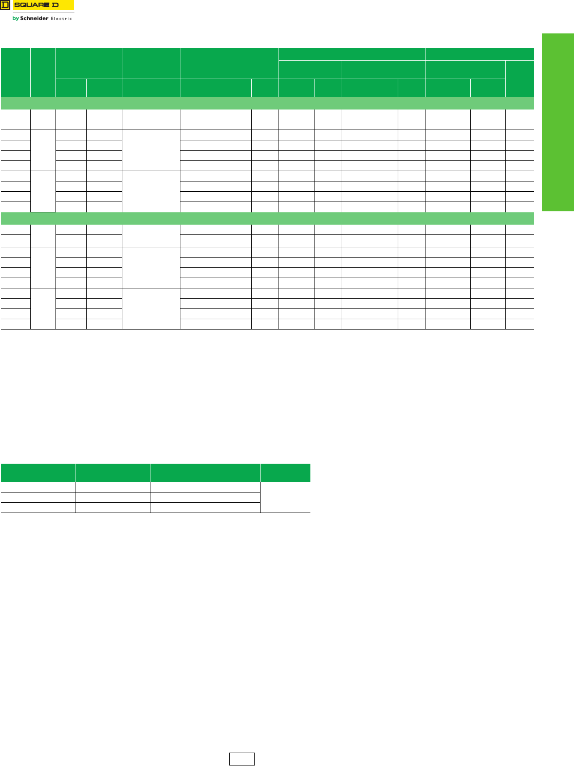
www.schneider-electric.us
13 OBSOLESCENT PANELBOARDS
© 2012 Schneider Electric
All Rights Reserved
13-11
NQOD Merchandised
Panelboards
NQOD 20-inch Wide Enclosures—240 Vac, 48 Vdc
Class 1630 / Refer to Catalog 1630CT0701
Table 13.22: Main Circuit Breaker Interiors—Accepts plug-on and bolt-on circuit breakers
Max.
No. of
One-pole
QO™/
QOB
Circuit
Breakers
Mains
Rating
Total Price
Interior, Front, Box
and Adapter Kit
Main
Circuit Breaker
Adapter Kit
Interior Only
(Order Branch
Circuit Breakers Separately)
Type 1 Enclosure Types 3R, 5, 12 Enclosures d
Box
20"W x 5.75"D b
Mono-Flat™
Front b
Enclosure
20"W x 6.5"D Height
(In.)
Type 1 Types 3R, 5,
12
Catalog No.
Price Catalog No. aPrice Catalog
No. $ Price Catalog
No. Price Catalog
No. $ Price
20" Wide Cabinet—Single Phase 3-Wire
20 100 2024.00 3638.00 Factory Installed
Backfed QOB Main
Circuit Breaker
NQOD20M100CU 1446.00 MH26 113.00 MHC26 ( ) 465.00 MH26WP 2192.00 26
30
225
2662.00 4562.00
NQODQBe
or
NQODJKe
$780.
NQOD30L225CU 1179.00 MH44 113.00 MHC44 ( ) 590.00 MH44WP 2603.00 44
42 2944.00 4807.00 NQOD42L225CU 1418.00 MH50 113.00 MHC50 ( ) 633.00 MH50WP 2609.00 50
42 3367.00 5231.00 NQOD42L225CUTFf1799.00 MH56 113.00 MHC56 ( ) 675.00 MH56WP 2652.00 56
54 3181.00 5045.00 NQOD54L225CU 1613.00 MH56 113.00 MHC56 ( ) 675.00 MH56WP 2652.00 56
30
400
3362.00 5259.00
NQOD4e
$780.
NQOD30L400CU 1737.00 MH65 113.00 MHC65V ( ) 732.00 MH65WP 2742.00 65
42 3545.00 5418.00 NQOD42L400CU 1896.00 MH68 113.00 MHC68V ( ) 756.00 MH68WP 2742.00 68
42 4612.00 6479.00 NQOD42L600TFLf2942.00 MH77 113.00 MHC77V ( ) 777.00 MH77WP 2757.00 77
54 3746.00 5622.00 NQOD54L400CU 2085.00 MH74 113.00 MHC74V ( ) 768.00 MH74WP 2757.00 74
20" Wide Cabinet—Three Phase 4-Wire
24
100
2437.00 4051.00 Factory Installed
Backfed QOB Main
Circuit Breaker
NQOD424M100CU 1859.00 MH26 113.00 MHC26 ( ) 465.00 MH26WP 2192.00 26
30 2575.00 4178.00 NQOD430M100CU 1985.00 MH29 113.00 MHC29 ( ) 477.00 MH29WP 2193.00 29
30
225
2775.00 4675.00
NQODQBe
or
NQODJKe
$780.
NQOD430L225CU 1292.00 MH44 113.00 MHC44 ( ) 590.00 MH44WP 2603.00 44
42 3077.00 4940.00 NQOD442L225CU 1551.00 MH50 113.00 MHC50 ( ) 633.00 MH50WP 2609.00 50
42 3470.00 5334.00 NQOD442L225CUTFf1902.00 MH56 113.00 MHC56 ( ) 675.00 MH56WP 2652.00 56
54 3281.00 5145.00 NQOD454L225CU 1713.00 MH56 113.00 MHC56 ( ) 675.00 MH56WP 2652.00 56
30
400
3605.00 5502.00
NQOD4e
$780.
NQOD430L400CU 1980.00 MH65 113.00 MHC65V ( ) 732.00 MH65WP 2742.00 65
42 3782.00 5655.00 NQOD442L400CU 2133.00 MH68 113.00 MHC68V ( ) 756.00 MH68WP 2742.00 68
42 4894.00 6761.00 NQOD442L600TFLf3224.00 MH77 113.00 MHC77V ( ) 777.00 MH77WP 2757.00 77
54 3943.00 5819.00 NQOD454L400CU 2282.00 MH74 113.00 MHC74V ( ) 768.00 MH74WP 2757.00 74
a“CU” suffix indicates copper bussing. NQOD RTI interiors with aluminum bus are no longer available. Order the copper bussed equivalent with a “CU” suffix when ordering a replacement interior.
bEmbossed mounting holes add a 0.25 inch standoff to back of MH box.
cAdd “F” for flush, “S” for surface.
dEnclosure includes trim kit.
eSelect the appropriate main circuit breaker from tables starting on Digest page 7-22 and add the circuit breaker price to the total price of the panelboard.
fFeed-thru lug interior.
Table 13.23: Main Circuit Breaker Adapter Kits (Less Circuit Breaker) a
Amperes Catalog Number Circuit
Breaker Frameb$ Price
225 NQODQB QBL, QDL, QGL, QJL
780.00225 NQODJK JDL, JGL, JJL, JLL, KIL
400 NQOD4 LAL, LHL, Q4L
aSelect the appropriate main circuit breaker from tables starting on Digest page 7-22 and add the circuit
breaker price to the total price of the panelboard.
bCircuit breaker interrupting ratings, see tables starting on Digest page 7-22.
PE1A Discount
Schedule
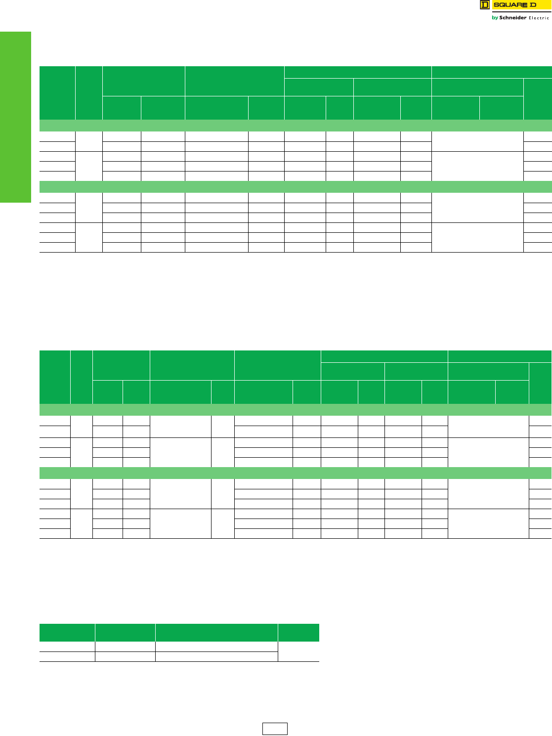
13-12 © 2012 Schneider Electric
All Rights Reserved
www.schneider-electric.us
13 OBSOLESCENT PANELBOARDS
NQOD Merchandised
Panelboards
NQOD 14-inch Wide Enclosures—240 Vac, 48 Vdc
Class 1630 / Refer to Catalog 1630CT0701
Table 13.24: Main Lug Interiors—Accepts plug-on and bolt-on circuit breakers
Max.
No. of
Single
Pole
QO™/QOB
Circuit
Breakers
Mains
Rating
Total $ Price
Interior, Front
and Enclosure
Interior Only
(Order Branch Circuit
Breakers Separately)
Type 1 Enclosure Types 3R, 5, 12 Enclosures
Box
14 in. W x 5.75 in. Db
Mono-Flat™
Front c
Enclosure
20 in. W x 6.5 in. D
Height
(In.)
NEMA
Type 1
NEMA
Types
3R, 5, 12
Catalog No. a$ Price Catalog No. $ Price Catalog No. $ Price Catalog No. $ Price
14-inch Wide Cabinet—Single Phase 3-Wire
12 100 1132.00 — NQOD12L100CU 734.00 NQB520 117.00 NQC20 ( ) 281.00 Use 20-inch Wide Enclosure
for Types 3R, 5, 12
20
20 1271.00 — NQOD20L100CU 864.00 NQB523 117.00 NQC23 ( ) 290.00 23
30
225
1634.00 — NQOD30L225CU 1179.00 NQB532 117.00 NQC32 ( ) 338.00
Use 20-inch Wide Enclosure
for Types 3R, 5, 12
32
42 1882.00 — NQOD42L225CU 1418.00 NQB535 117.00 NQC35 ( ) 347.00 35
54 2099.00 — NQOD54L225CU 1613.00 NQB541 117.00 NQC41 ( ) 369.00 41
14-inch Wide Cabinet—Three Phase 4-Wire
12
100
1267.00 — NQOD412L100CU 869.00 NQB520 117.00 NQC20 ( ) 281.00
Use 20-inch Wide Enclosure
for Types 3R, 5, 12
20
24 1469.00 — NQOD424L100CU 1062.00 NQB523 117.00 NQC23 ( ) 290.00 23
30 1616.00 — NQOD430L100CU 1191.00 NQB526 117.00 NQC26 ( ) 308.00 26
30
225
1747.00 — NQOD430L225CU 1292.00 NQB532 117.00 NQC32 ( ) 338.00
Use 20-inch Wide Enclosure
for Types 3R, 5, 12
32
42 2015.00 — NQOD442L225CU 1551.00 NQB535 117.00 NQC35 ( ) 347.00 35
54 2199.00 — NQOD454L225CU 1713.00 NQB541 117.00 NQC41 ( ) 369.00 41
a“CU” suffix indicates copper bussing. NQOD RTI interiors with aluminum bus are no longer available. Order the copper bussed equivalent with a “CU” suffix when ordering a replacement interior.
b14-inch wide cabinets accept 100 A max. branch circuit breakers. Through feed lugs are not available in 14-in. wide enclosures.
cAdd “F” for flush, “S” for surface.
Table 13.25: Main Circuit Breaker Interiors—Accepts Plug-On and Bolt-On Circuit Breakers
Max.
No. of
One
Pole
QO
QOB
Circuit
Breakers
Mains
Rating
Total $ Price
Interior, Front, Box
and Adapter Kit
Main Circuit Breaker
Adapter Kit
Interior Only
(Order Branch Circuit
Breakers Separately)
Type 1 Enclosure Types 3R, 5, 12 Enclosure
Box
14 in. W x 5.75 in. Dd
Mono-Flat
Front b
Enclosure
20 in. W x 6.5 in. D
Height
(In.)
NEMA
Type 1
NEMA
Types
3R, 5, 12
Catalog No. $ Price Catalog No. a$ Price Catalog No. $ Price Catalog No. $ Price Catalog No. $ Price
14-inch Wide Cabinet—Single Phase 3-Wire
12
100
1688.00 — Factory Installed
QOB
Main Circuit Breaker
—
NQOD12M100CU 1281.00 NQB523 117.00 NQC23 ( ) 290.00 Use 20-inch Wide Enclosure
for Types 3R, 5, 12
23
20 1871.00 — NQOD20M100CU 1446.00 NQB526 117.00 NQC26 ( ) 308.00 26
30
225
2481.00 NQODJKc
or
NQODQBc
780.00
NQOD30L225CU 1179.00 NQB544 117.00 NQC44 ( ) 405.00
Use 20-inch Wide Enclosure
for Types 3R, 5, 12
44
42 2734.00 — NQOD42L225CU 1418.00 NQB550 117.00 NQC50 ( ) 419.00 50
54 2984.00 — NQOD54L225CU 1613.00 NQB556 117.00 NQC56 ( ) 474.00 56
14-inch Wide Cabinet—Three Phase 4-Wire
12
100
2032.00 — Factory Installed
QOB
Main Circuit Breaker
—
NQOD412M100CU 1625.00 NQB523 117.00 NQC23 ( ) 290.00
Use 20-inch Wide Enclosure
for Types 3R, 5, 12
23
24 2284.00 — NQOD424M100CU 1859.00 NQB526 117.00 NQC26 ( ) 308.00 26
30 2431.00 — NQOD430M100CU 1985.00 NQB529 117.00 NQC29 ( ) 329.00 29
30
225
2594.00 — NQODJKc
or
NQODQBc
780.00
NQOD430L225CU 1292.00 NQB544 117.00 NQC44 ( ) 405.00
Use 20-inch Wide Enclosure
for Types 3R, 5, 12
44
42 2867.00 — NQOD442L225CU 1551.00 NQB550 117.00 NQC50 ( ) 419.00 50
54 3084.00 — NQOD454L225CU 1713.00 NQB556 117.00 NQC56 ( ) 474.00 56
a“CU” suffix indicates copper bussing. NQOD RTI interiors with aluminum bus are no longer available. Order the copper bussed equivalent with a “CU” suffix when ordering a replacement interior.
bAdd “F” for flush, “S” for surface.
cSelect the appropriate main circuit breaker from pages 7-24, 7-31, 7-48 and 7-49, and add the circuit breaker price to the total price of the panelboard.
d14-inch wide cabinets accept 100 A max. branch circuit breakers.
Table 13.26: Main Circuit Breaker Adapter Kits (Less Circuit Breaker a)
Amperes Catalog No. Circuit
Breaker Frame b$ Price
225 NQODQB QBL, QDL, QGL, QJL 780.00
225 NQODJK JDL, JGL, JJL, JLL, KIL
aSelect the appropriate main circuit breaker from pages 7-24, 7-31, 7-48 and 7-49, and add the circuit
breaker price to the total price of the panelboard.
bCircuit breaker interrupting ratings, see pages 7-2 through 7-9.
PE1A Discount
Schedule
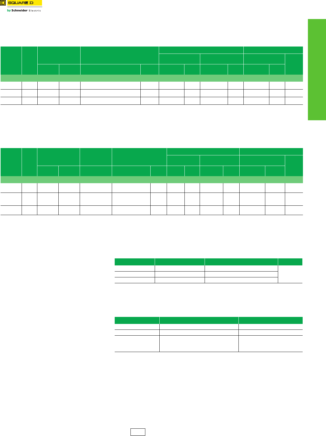
www.schneider-electric.us
13 OBSOLESCENT PANELBOARDS
© 2012 Schneider Electric
All Rights Reserved
13-13
NQOD Merchandised
Panelboards
For Non-Linear Loads (200% Rated Neutral)
Class 1630 / Refer to Catalog 1630CT0701
NQOD 240 Vac Max.
Table 13.27: Main Lug Interiors—Accepts plug-on and bolt-on circuit breakers
Max.
No. of
Single Pole
QO/QOB
Circuit
Breakers
Mains
Rating
Total Price
Interior,
Front and Enclosure
Main Lugs Interior Only
(Order Branch Circuit Breakers Separately)
Type 1 Enclosure Types 3R, 5, 12 Enclosures d
Box 20"W x 5.75"D bMONO-FLAT® Front cEnclosure
20"W x 6.5"D Height
(In.)
Type 1 Types
3R, 5, 12 Catalog No. a$ Price Catalog No. $ Price Catalog No. $ Price Catalog No. $ Price
20" Wide Cabinet—3 Phase 4-Wire
30 100 2096.00 3699.00 NQOD430L100CUNL 1506.00 MH29 113.00 MHC29 ( ) 477.00 MH29WP 2193.00 29
42 225 2620.00 4193.00 NQOD442L225CUNL 1977.00 MH38 113.00 MHC38 ( ) 530.00 MH38WP 2216.00 38
42 400 3547.00 5388.00 NQOD442L400CUNL 2772.00 MH53 113.00 MHC53V ( ) 662.00 MH53WP 2616.00 53
a“CU” suffix indicates copper bussing. NQOD RTI interiors with aluminum bus are no longer available. Order the copper bussed equivalent with a “CU” suffix when ordering a replacement interior.
bEmbossed mounting holes add a 0.25 inch standoff to back of MH box.
cAdd “F” for flush, “S” for surface.
dEnclosure includes trim kit.
Table 13.28: Main Circuit Breaker Interiors
Max.
No. of
Single Pole
QO/QOB
Circuit
Breakers
Mains
Rating
Total Price
Interior, Front, Box and
Adapter Kit
Main Circuit
Breaker
Adapter Kit a
Main Lugs Interior Only
(Order Branch Circuit
Breakers Separately)
Type 1 Enclosure Types 3R, 5, 12 Enclosures d
Box
20"W x 5.75"D MONO-FLAT Front cEnclosure
20"W x 6.5"D Height
(In.)
Type 1 Types 3R, 5,
12
Catalog No.
$ Price Catalog No. b$ Price Catalog
No. $ Price Catalog No. $ Price Catalog No. $ Price
20" Wide Cabinet—3 Phase 4-Wire
30 100 2877.00 4471.00 QOB Main Circuit
Breaker NQOD430M100CUNL 2267.00 MH32 113.00 MHC32 ( ) 497.00 MH32WP 2204.00 32
42 225 3503.00 5366.00
NQODJK
NQODQB
780.00
NQOD442L225CUNL 1977.00 MH50 113.00 MHC50 ( ) 633.00 MH50WP 2609.00 50
42 400 4421.00 6294.00 NQOD4
780.00 NQOD442L400CUNL 2772.00 MH68 113.00 MHC68V ( ) 756.00 MH68WP 2742.00 68
aOrder main circuit breaker separately
b“CU” suffix indicates copper bussing. NQOD RTI interiors with aluminum bus are no longer available. Order the copper bussed equivalent with a “CU” suffix when ordering a replacement interior.
cAdd “F” for flush, “S” for surface.
dEnclosure includes trim kit.
Table 13.29: Main Circuit Breaker Adapter Kits (Less Circuit Breaker) a
Amperes Catalog Number Circuit Breaker Frame b$ Price
225 NQODQB QBL, QDL, QGL, QJL
780. 00225 NQODJK JDL, JGL, JJL, JLL, KIL
400 NQOD4 LAL, LHL
aOrder main circuit breaker separately
bMain neutral conductors must be copper or aluminum conductors of minimum size and quantity shown to maintain
Table 13.30: NQOD Main Neutral Conductors—Required Size and Quantity a
Panelboard Ampacity Neutral Conductors RequiredbActual Lug Wire Range
100/125 (2) 1/0 Cu or Al (2) #4–300 kcmil
225 (2) 4/0 Cu or (2) 300 kcmil Al (2) #4–300 kcmil
400
(4) 3/0 Cu or
(4) 250 kcmil Al
(2) 600 kcmil Cu
(2) 750 kcmil Al
(2) 1/0–300 kcmil or
(1) 750 kcmil
aNeutral conductors must be of size and quantity per table above.
bMain neutral conductors must be copper or aluminum conductors of minimum size and quantity shown to maintain
UL Listing. Requirement is based on heat rise testing.
PE1A Discount
Schedule
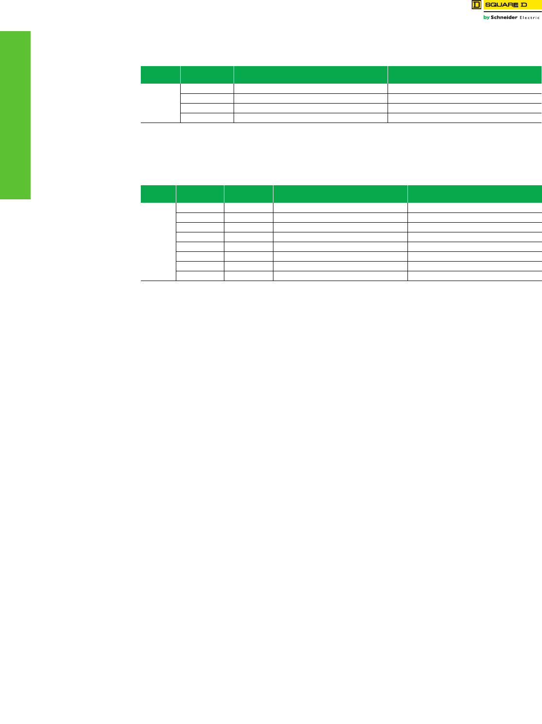
www.schneider-electric.us
13 OBSOLESCENT PANELBOARDS
13-14 © 2012 Schneider Electric
All Rights Reserved
NQOD Panelboards Terminal Data
Class 1630 / Refer to Catalog 1630CT0701
Table 13.31: Standard Mechanical Lugs—Main Lugs
Panel Type Ampere Rating Lug Wire RangeaWire Range
Wire Bending Space per NEC Table 373-6a
NQOD
100 (1) #10–#2/0 Cu or (1) #6–#2/0 Al (1) #10–#1 Cu or (1) #6–#1 Al
225 (1) #6–300 kcmil Al/Cu (1) #6–300 kcmil Al/Cu
400 (2) #1/0–300 kcmil Al/Cu or (1) #1/0–750 kcmil Al/Cu (2) #1/0–300 kcmil Al/Cu or (1) #1/0–750 kcmil Al/Cu
600 (2) #4-600 kcmil (2) #4-500 kcmil
a(#) = Number of conductors per phase.
Table 13.32: Standard Mechanical Lugs—Main Circuit Breaker
Panel Type Ampere Rating Circuit Breaker
Type Lug Wire RangebWire Range
Wire Bending Space per NEC Table 373-6b
NQOD
100 QOB (1) #4–#2/0 Al/Cu (1) #4–#1 Al/Cu
100 FA, FH, FI (1) #14–#1/0 Al/Cu (1) #14–#1 Al/Cu
150 HD, HG, HJ, HL (1) #14–#3/0 Al/Cu (1) #14–#3/0 Al/Cu
225 QB, QD, QG, QJ (1) #4–300 kcmil Al/Cu (1) #4–300 kcmil Al/Cu
225 KI (1) #6–350 kcmil Al/Cu (1) #4–300 kcmil Al/Cu
250 JD, JG, JJ, JL (1) #1/0–#4/0 Al/Cu or (1) #3/0–350 kcmil Al/Cu (1) #1/0–300 kcmil Al/Cu
400 LA, LH (1) #1–600 kcmil Al/Cu or (2) #1–250 kcmil Al/Cu (1) #4–500 kcmil Al/Cu or (2) #1–250 kcmil Al/Cu
600 MA (3) #3/0–500 kcmil (3) #3/0–500 kcmil
b(#) = Number of conductors per phase.
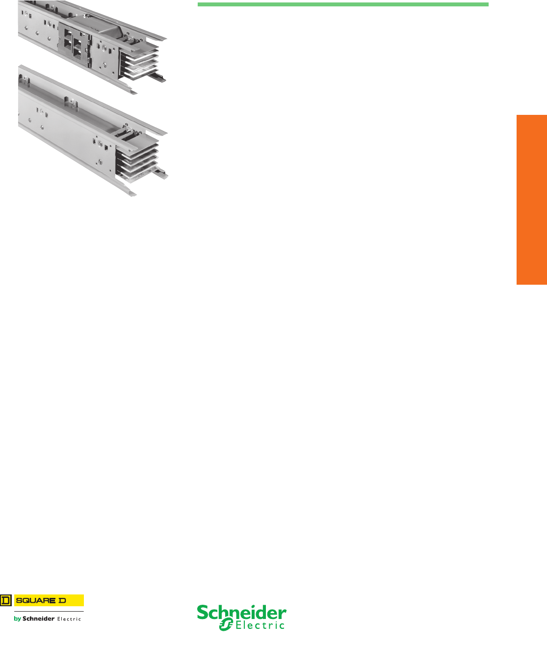
14-1
© 2012 Schneider Electric
All Rights Reserved
14 BUSWAY
Table of Contents
Section 14
Busway
I-Line II Busway 800–5000 A pp. 14-2
Feeder Style
Plug-In Style
Busway Special Purpose Plug-In Units
APD and SD Busway Plug-In Units (Not I-Line™ Busway) 14-2
Capacitor and Transformer Units 14-2
Combination Switches and Contactors (For I-Line™ Busway) 14-2
Ground Indicator and Neutralizer Plugs 14-2
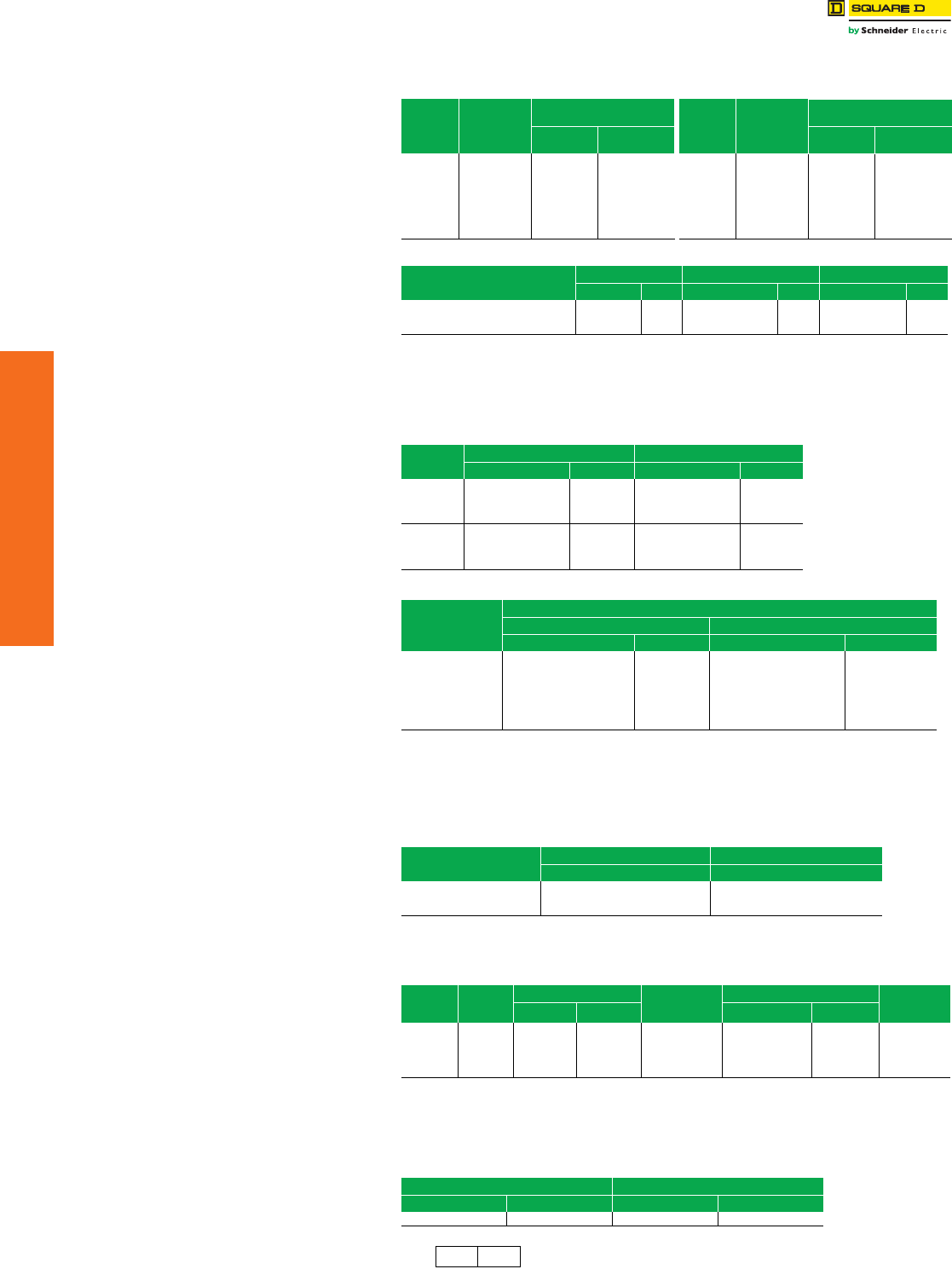
www.schneider-electric.us
14-2 © 2012 Schneider Electric
All Rights Reserved
14 BUSWAY
I-Line™ Busway Special Purpose Plug-In Units
Class 5600
APD and SD Busway Plug-In Units (Not I-Line™ Busway)
aWith PIN-QO, use circuit breakers QO215H, QO220H, and QO230H. For higher ratings, use FA enclosures and
circuit breakers.
bEnclosure with space for three QO circuit breaker poles and provisions for three duplex receptacles.
cDiscount Schedule PE8
Capacitor and Transformer Units
Combination Switches and Contactors (For I-Line Busway)
Ground Indicator and Neutralizer Plugs
Table 14.1: Circuit Breaker Plug-In Units
Breaker
Frame
Trip Rating
Amps
600 Vac 3Ø4W for use on both
3-Pole and 3Ø4W Busway Breaker
Frame
Trip Rating
Amps
600 Vac 3Ø4W for use on both
3-Pole and 3Ø4W Busway
Catalog
Number $ Price Catalog
Number $ Price
FA
15
20
30
40
50
60
70
100
SD75415
SD75420
SD75430
SD75440
SD75450
SD75460
SD75470
SD75416
2966.00
2966.00
2966.00
2966.00
2966.00
2966.00
3186.00
3186.00
LA
250
300
350
400
SD67428
SD67436
SD67438
SD67446
13846.00
13846.00
13846.00
13846.00
Table 14.2: 100 A Busway Plug-In Unit Circuit Breaker Enclosures and Accessories
Enclosure Only
(Price Circuit Breaker Separately)
1Ø3W & 3Ø4W aGround Kit Floor Operator Attachment
Catalog No. $ PricecCatalog No. $ PricecCatalog No. $ Pricec
QO Breaker–70 A Enclosure
QO Breaker/Recpt.–70 A Enclosureb
FA Breaker–15-100 A Enclosure
PINQO
PINQOR
PIN100FA
208.00
324.00
690.00
PGKQO2
PGKQOR
PGKFA2
66.00
66.00
66.00
PI1QO
PI1QO
PI1FA
144.00
144.00
144.00
Table 14.3: 3Ø Capacitor Units (Order plug-in units separately)
3Ø
kVAR
240 Vac 480 Vac
Catalog Number $ Price Catalog Number $ Price
2.5
5
7.5
10
—
PC3205
PC3207
PC3210
—
5804.00
7276.00
8470.00
PC3402
PC3405
PC3407
PC3410
2510.00
3752.00
4566.00
5080.00
15
20
25
30
PC3215
—
—
—
10328.00
—
—
—
PC3415
PC3420
PC3425
PC3430
6098.00
7620.00
9478.00
11206.00
Table 14.4: 1Ø Transformer Units (Order plug-in units separately)
1Ø kVA
Primary Voltage
240 Vac 480 Vac
Catalog Number $ Price Catalog Number $ Price
1
1.5
2
PT2200
PT2201
PT2202
2394.00
2574.00
2796.00
PT2400
PT2401
PT2402
2394.00
2574.00
2796.00
3
5
7.5
10
PT2203
PT2205
PT2207
PT2210
3312.00
4590.00
5528.00
6370.00
PT2403
PT2405
PT2407
PT2410
3312.00
4590.00
5528.00
6370.00
Note: Transformer units do not plug into busway and must be used with plug-in switch, circuit breaker or cable tap box.
Standard secondary voltage terminals are provided for 120 V or 240 V 1Ø2W, or 120/240, 1Ø3W connection.
Specify secondary voltage if other than standard.
Note: Capacitor units do not plug into busway and must be used with plug-in switch or circuit breaker.
Table 14.5: Combination Fusible Switch (3Ø4W) and Lighting Contactord
Ampere
Ratinge
Electrically Held — 240 V Mechanically Held — 80 V
$ Price $ Price
30 2802.00 3014.00
60 3564.00 4252.00
100 4990.00 5840.00
dOrder this device by description.
eLighting contactors do not include holding circuit interlock.
Table 14.6: Combination Starter/Contactor—Line Voltage—Single Speed—
Non-Reversinga
NEMA
Size
Ampere
Rating
Fusible Switch (3-Pole) + G Rating
Amperes
Trip
Circuit Breaker (3-Pole) + G Add for
Control
Transformer
StarterbContactor Starter bContactor
1302872.00 2778.00 15–20 2950.00 2854.00 448.00
0303042.00 —— — — 448.00
160 —2950.00 15–20 3060.00 2968.00 448.00
2603828.00 —— — — 636.00
2100 —3640.00 35–80 4396.00 4088.00 636.00
aOrder this device by description. Special control features also available. Consult your nearest Schneider Electric
sales office.
bPrice does not include overload relay thermal units.
Table 14.7: Ground Indicator and Neutralizer Plugs
240 Vac—3-Pole 600 Vac—3-Pole
Catalog Number $ Price Catalog Number $ Price
PGD3200G 1566.00 PGD3600G 1566.00
PE8 PE7 Discount
Schedule
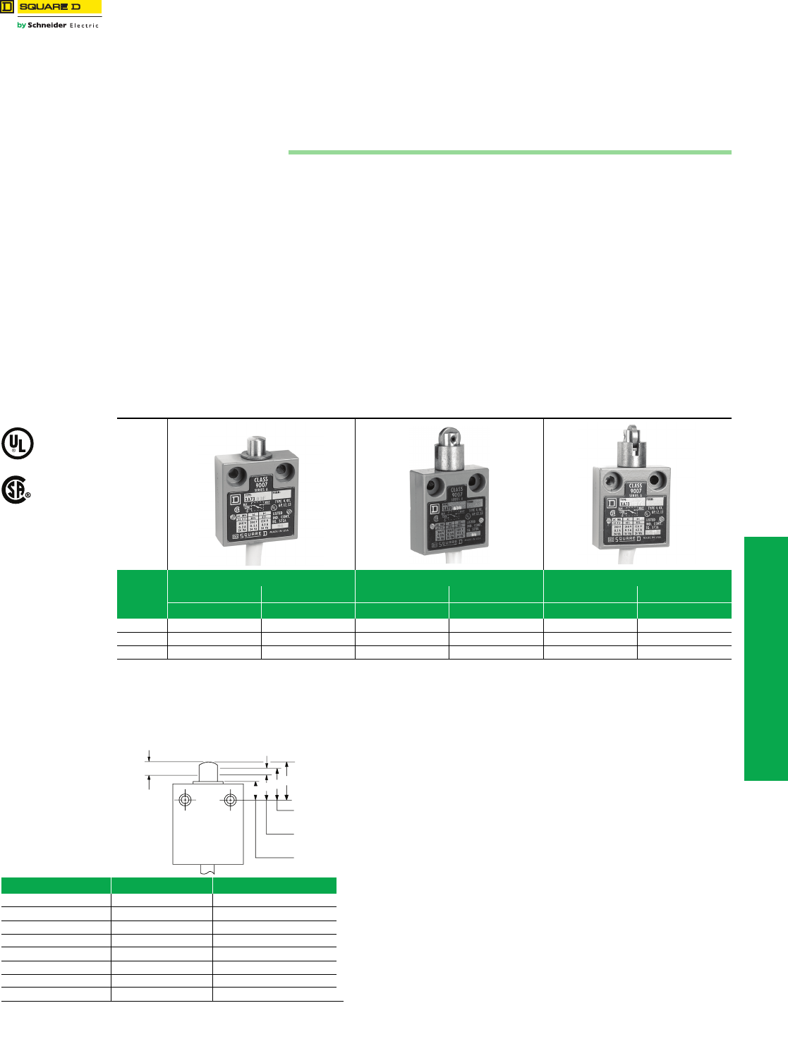
www.schneider-electric.us
© 2012 Schneider Electric
All Rights Reserved 15-1
15 LIMIT SWITCHES
Table of Contents
Section 15
Limit Switches
Miniature Enclosed Reed
Type XA is designed for use in applications where contact reliability, environmental immunity, small size, or low cost are
required. Sealed construction keeps contaminants out of the contact area, making it the ideal choice for low voltage, low
current circuits such as Programmable Controllers. a
NOTE: Because reed switches are magnet operated, they should not be installed where strong magnetic fields may be
present. The devices should always be checked for proper operation after installation.
aSee the current ratings table in Section 21 of Digest 176 for contact specifications.
bOther cable lengths are available. Order by changing the last two digits of the type number to the length desired.
Example: An XA7303E with 15 ft of cable would become an XA7315E.
Operating Data
Obsolete Reed Limit Switches
Miniature Enclosed Reed 9007XA 15-1
Heavy Duty, Industrial Reed Contact 9007C 15-2
Heavy Duty, Industrial
Precision and Oiltight
Type XA
Class 9007 / Refer to Catalog 9006CT1007
Table 15.1: Class 9007 Type XA
Cable
Lengthb
Straight Plunger Roller Plunger Cross Roller Plunger
N.O. N.C. N.O. N.C. N.O. N.C.
Type Type Type Type Type Type
3 ft XA7303E XA7503E XA7303D XA7503D XA7303DC XA7503DC
6 ft XA7306E XA7506E XA7306D XA7506D XA7306DC XA7506DC
9 ft XA7309E XA7509E XA7309D XA7509D XA7309DC XA7509DC
File 42259
CCN NKCR
File LR25490
Class 3211 03
Contacts: The contact is a fully encapsulated hermetically sealed reed,
suitable for controlling solid state loads as well as industrial relays. Switches
can also be used as inputs to intrinsically safe systems. Use of a transient
suppressor will extend life of the switch when using on heavy electrical loads.
Type XA cannot be used in Division 2 locations as the Type C Reed
switches can, since the National Electrical Code (NEC) requires provisions for
conduit connection. The Type C Reed switches have this provision for conduit
and the Type XA does not.
Enclosure Construction: Die cast zinc-baked gray enamel finish.
Meets NEMA Type 2, 4, 4X, 6P, 12 and 13 requirements.
Oiltight, dusttight, watertight, and submersible.
Cable: SJTOWA jacketed cable with 18 gauge wire.
Ambient Temperature Range: –20 to + 140 °F (–28.9 to 60 °C).
NOTE: The XA switch is available with 3 ft of cable and 3 pin Brad
Harrison male connector No. 40904 (or equivalent): Form Y190.
Top Push Rod (Type E) Roller Plunger (Types D, DC)
Initial position (D) 0.690 in. 1.190 in.
Trip position (B) 0.620 in. 1.120 in.
Pretravel (E) 0.07 in. 0.07 in.
Reset position (C) max. 0.655 in. 1.155 in.
Differential (F) 0.015 in. 0.015 in.
Final position (A) 0.492 in. 0.992 in.
Total stroke 0.198 in. 0.198 in.
Operating force (max.) 2.75 lb 2.75 lb
ABCD
E (Pretravel)
Initial
Position
Contacts
Reset
Contacts
Trip
Final
Position
F (Differential)
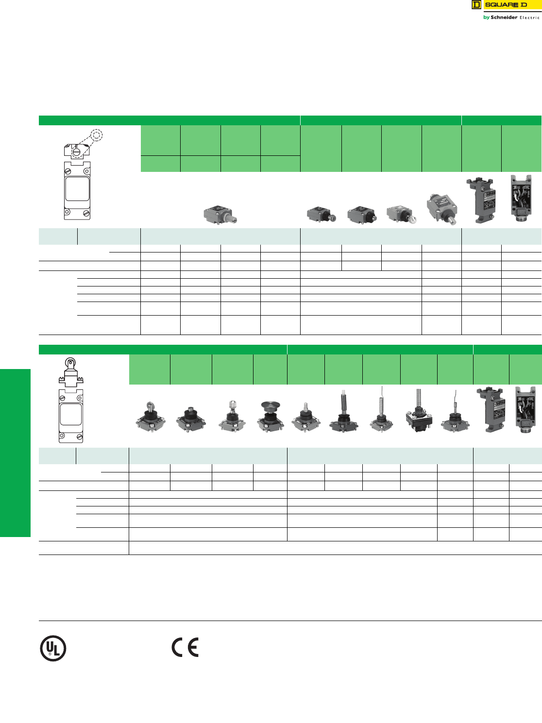
www.schneider-electric.us
15-2 © 2012 Schneider Electric
All Rights Reserved
15 LIMIT SWITCHES
Heavy Duty, Industrial
Reed Contact
Type C
Class 9007/ Refer to Catalog 9006CT1007
Heavy Duty Precision Turret Head Type
These switches can be used with standard industrial relays and starters.
UL Listed for Class I, II and III Division 2 Groups B, C, D, F and G hazardous locations.
They can also be used as inputs to intrinsically safe systems.
NOTE: Because reed switches are operated by a magnet, they should not be installed in areas where strong
magnetic fields may be present. The devices should always be checked for proper operation after
installation.
Table 15.2: All 9007C Switches Are Rated NEMA 6P and UL Type 6P
Lever Arm Type Side Plunger Type Plug-in
Standard
Pre-travel
Spring Return
Low
Differential
Spring Return
Extra Light
Operating
Torque
Spring Return
Maintained
Contact
Side Roller-
Plunger
Spring Return
Vertical b
Roller Type
Side Push-
Rod Plunger
Spring Return
Side Push-
Rod Plunger
Adjustabled
Spring Return
Side Push-
Rod Plunger
Maintained
Contact
Plug-in Unit
without Head
Plug-in
Receptacle
Only
CW &
CCWa
CW &
CCWa
CW &
CCWa
CW (Trip)
CCW (Reset)
Select Basic
Switch Contacts Type Type Type
Standard
Box Plug-in Reed 1 N.O. C84B2 C84A2 C84N2 C84C C84F C84G C84GD C84H eCT54 f
1 N.C. C86B2 C86A2 C86N2 C86C C86F C86G C86GD C86H eCT54 f
Head Only f BANC FGGDH——
Nominal
Operating
Data
Pre-travel 13° 7° 13° 45° 0.110" (2.8 mm) 0.14" (3.6 mm) — —
Total Travel 90° 90° 90° 90° 0.25" (6.3 mm) 0.25" (6.3 mm) — —
Differential 7° 4° 7° — 0.07" (1.8 mm) — — —
Reverse Overtravel 90° 90° 90° — — — — —
Operating Torque/Force 4 lb-in
(0.45 N•m)
4 lb-in
(0.45 N•m)
25 in-oz
(0.08 N•m)
3 lb-in
(0.34 N•m) 4 lb (0.45 N•m) 7 lb
(0.80 N•m) ——
Repeat Accuracy—
Linear travel of cam
1-1/2" (38 mm) lever arm
± 0.006"
(0.15 mm)
± 0.003"
(0.07 mm)
± 0.006"
(0.15 mm)
± 0.006"
(0.15 mm) ± 0.003" (0.07 mm) — — —
Select
Turret
Head
Top Plunger Type Wobble Stick Type
Top Roller-
Plunger
Spring Return
Top Push-Rod
Plunger
Spring Return
Top Push-Rod
Plunger
Adjustable d
Spring Return
Palm
OperatedcUniversal g
Wobble Stick
DELRIN
Extensiong
Wobble Stick
Wire
Extensiong
Wobble
Stick Coil
Spring
Extensiong
Cat
Whisker
Plug-in Unit
without
Head
Plug-in
Receptacle
Only
Select Basic
Switch Contacts Type Type Type
Standard
Box Plug-in Reed 1 N.O. C84D C84E C84ED C84RcC84JKC C84J C84K C84KC C84L eCT54 f
1 N.C. C86D C86E C86ED C86RcC86JKC C86J C86K C86KC C86L eCT54 f
Head Only f DEEDR cJKC J K KC L — —
Nominal
Operating
Data
Pre-travel 0.100" (2.5 mm) 13° (Any Direction) 25° — —
Total Travel 0.25" (6.3 mm) 90° 90° — —
Differential 0.05" (1.3 mm) 11° 18° — —
Operating
Torque/Force 4 lb 3 lb-in 7 in-oz — —
Repeat Accuracy—
Linear travel of cam ± 0.003" — — — —
ePlug-in Replacement Units To order basic switch and head less the plug-in receptacle base, substitute the letters “CO” for the first “C” in the type number.
Example: Open type replacement for Type C84B2 is Type CO84B2.
aThese devices are factory set to operate the contacts in both the CW and CCW directions. Mode of operation is field convertible to CW only or CCW only.
To order factory converted devices—for CCW only operation, change the “2” at the end of the type number to “1” (Example: C84B2 becomes C84B1);
for CW only operation, delete the “2” at the end of the type number (Example: C84B2 becomes C84B).
bCan be converted to horizontal roller type in the field. To order horizontal roller version, add the letter “H” at the end of the equivalent vertical roller version type number
(Example: C84F would become C84FH).
cPrice does not include mushroom button. Must be ordered separately from Section 21 of Digest 176.
dTo lock the nut in the desired position, crimp the slot near the bottom of the nut.
ePlug-in units less head are not available as separate units. Order complete plug-in replacement units instead. Plug-in replacement units include the plug-in unit and head.
fThese products are currently available.
gWobble stick extensions are available separately for the universal head or as replacements for complete devices. See Section 21 of Digest 176.
File
CCN
E10054
NOIV
Acceptable Wire Sizes: 12–22 AWG
Recommended Terminal Clamp Torque: 7 lb-in (0.80 N•m)
Select
Turret
Head
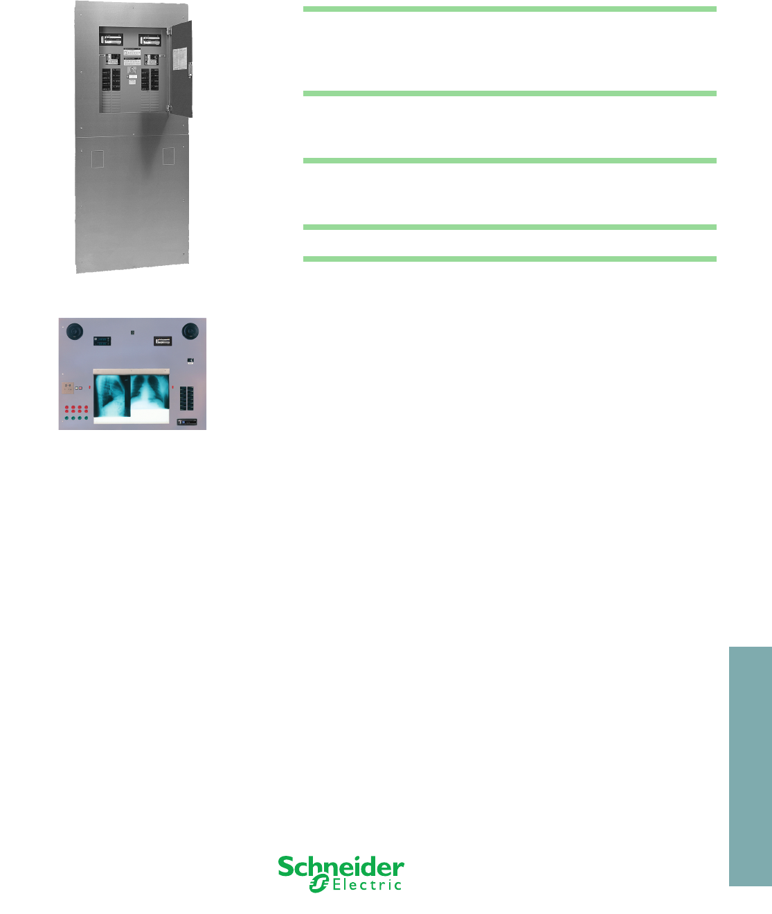
16-1
© 2012 Schneider Electric
All Rights Reserved
16 MEDICAL PRODUCTS
Table of Contents
Section 16
Medical Products
All Square D™ brand Isolation Power Panels meet or exceed UL 1022 and 1047 and are
cUL Listed.
All products listed in this section are available through standard ordering procedures from
authorized Schneider Electric distributors. For more information, contact your nearest
Schneider Electric sales office or distributor. Call 1-888-Square D (778-2733) or visit
www.schneider-electric.us.
NOTE: The National Electrical Code® (NEC®) requires audible and visual alarm
indication where isolation power is used (NEC 517-160).
Duplex Isolation Power Panel, see page 16-3
Surgical Facility Panel, see page 16-4
Isolated Power Panels 16-2
Operating Room Panels 16-2
ICU/CCU Panels 16-2
Controlled Isolation Power Panels (For X-ray and Laser Receptacles) 16-2
Duplex Panels 16-3
Duplex Power Panels 16-3
Power/Ground Modules 16-3
Surgical Facility Panels 16-4
Surgical Facility Panels 16-4
Isolation Transformers 16-4
Dual Output Voltage Panels 16-5
Accessories 16-6
Accessories Panels 16-6
X-ray and Laser Receptacles 16-6
Supervisory Modules 16-6
Nurses’ Station Indicator-Alarm Annunciator 16-6
Digital Clock/Timers 16-6
Remote Alarm Indicators 16-6
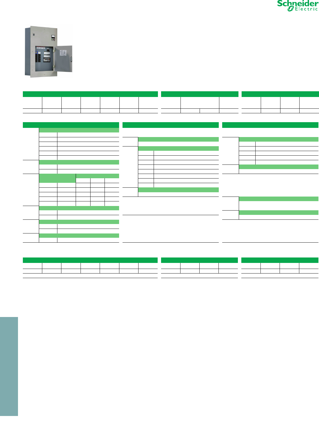
16-2 © 2012 Schneider Electric
All Rights Reserved
www.schneider-electric.us
16 MEDICAL PRODUCTS
Medical Products Isolated Power Panels
Class 4800 / Refer to Catalog 4800CT0301
OR, ICU/CCU, and Controlled Isolation Power Panels—UL Listed
NOTE: The NEC requires audible and visual alarm indication where isolation power is used (NEC 517-160).
The catalog number creates all components needed for a complete panel including eight circuits. All standard panels
are field expandable to 16 circuits for the OR and ICU panels by adding QO™ circuit breakers. All panels come with a
main circuit breaker. All panels are 5 mA and field adjustable. All panels include a remote alarm indicator for panel or
wall mounting. A backbox (single gang) is provided by others. Other options are available for each design. Six-inch
panels are not available for all kVA ratings.
For more information, contact your nearest Schneider Electric sales office or distributor.
Table 16.1: Catalog Number Matrix (refer to Table 16.2 for the available options for each field)
Basic OR Panel ICU/CCU Panels Controlled Panels
Transformer
kVA
Panel
Mounting
Primary
Voltage
Secondary
Voltage
Panel
Ty p e
Circuit
Breaker
Type
Tot al
No. of
Circuits
No. of 120 V
Receptacles
Type of 120 V
Receptacles
No. of
Ground
Jacks
Type of
Control
No. of Total
Circuits
No. of 'ON'
Circuits
Output
Amperes
1234567 891011 891011
Table 16.2: Options
Basic OR Panel ICU/CCU Panels Controlled Panels
1
Transformer kVA Add these options to the basic OR panel
for power / ground outputs. Add these Control options to the basic OR panel.
3 3 (maximum 277 volt primary)
55
8Number of 120 volt receptacles
8
Type of control
7 7.5 8 maximum M Mechanical interlock
10 10
9-10
Type of 120 volt receptacles P PLC interlock
15 15 DR Duplex red K Interposing contact (limit of four circuits)
25 25 DW Duplex white N Non-interposing contact
2
Panel mounting DI Duplex ivory D No controls or contactors
F Flush SR Single red 9Total number of circuits in the panel
S Surface SW Single white Enter 1 thru 8
3-4
Primary and
secondary voltage
Main circuit breaker SI Single ivory
Schneider Electric has a variety of designs for Controlled Panels
with more than 8 circuits. For more information, contact your
nearest Schneider Electric sales office.
5 kVA 7.5 kVA 10 kVA HR Hospital-only (Hubbell 23000)
1 120 60 A 80 A 100 A TL L5-20 twist lock
2 208 30 A 45 A 60 A 11 Number of ground jacks
3 240 30 A 40 A 60 A 6 Maximum
4 277 25 A 35 A 45 A Options for this section include a Music Center. The Music
Center consists of an AM/FM radio with cassette, CD single
player, or CD changer. Contact your nearest Schneider Electric
sales office for this option.
10
Total number of circuits HOT at one time
5 480 15 A 20 A 30 A 1 Minimum
Note: Recommended four maximum
5
Type of panel
A Low profile transformer (6 in.) 11 Output ampere
T Standard transformer (8 in. or 12 in.)
For Chicago-code ground for ALL panels, add “C” as the
Catalog No. suffix.
20 to 60 A maximum
6
Type of panel circuit breakers
International and special voltage codes available. For other
options including “IN USE” Light Control Panels, contact your
nearest Schneider Electric sales office.
S Plug-in QO
B Bolt-on QOB
7Total number of circuits
# 8 standard—16 maximum
Table 16.3: Catalog Numbering Example
Basic Panel ICU/CCU Options Controlled Panel Options
1234567 891011 891011
5F21TS12 4DR4 P8430
5 kVA flush-mount, 208 V primary, 120 V secondary, standard transformer, snap-in, 12 circuits 4 duplex red receptacles, 4 grounds PLC, 8 circuit, 4 of 8 active, 30 A
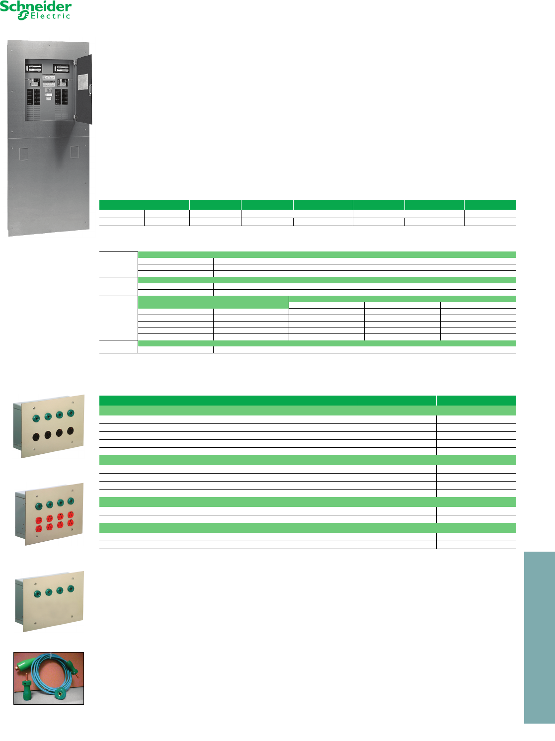
© 2012 Schneider Electric
All Rights Reserved
16-3
16 MEDICAL PRODUCTS
www.schneider-electric.us
Medical Products Duplex Panels
Class 4800 / Refer to Catalog 4800CT0301
The Duplex Isolation Power Panel is a single enclosure containing two complete 120 V secondary hospital isolation
systems. A divider in the unit’s backbox separates the systems from top-to-bottom and front-to-back.
Each system has its own set of equipment:
•Primary circuit breaker
•Square D™ brand isolation transformer
•Reference ground bus bar
•Square D brand Iso-Gard™ line isolation monitor (LIM)
•Load center
Duplex Power Panel—UL Listed
NOTE: The NEC requires audible and visual alarm indication where isolation power is used (NEC 517-160).
The catalog number creates all components needed for a complete panel, including 8 circuits. All OR panels can be
field expanded to 16 circuits by adding QO circuit breakers. All panels include a main circuit breaker. All panels are
5 mA and field adjustable. All panels include a remote alarm indicator for panel or wall mounting. Single-gang
backboxes can be provided by others. Other options are available for each design.
For more information, contact your nearest Schneider Electric sales office or distributor.
Power/Ground Modulea—UL Listed
aSchneider Electric Medical Products offers many options for power/ground modules. Contact your nearest Schneider Electric sales office.
Table 16.4: Catalog Number Matrix (refer to Table 16.5 for the available options for each field)
Transformer kVA Panel Mounting Primary Voltage Secondary Voltage Primary Voltage Secondary Voltage Chicago Ground
Left Side Right Side Left Side Right Side
12345678
Table 16.5: Options
1 & 2
Transformer kVA
55
77.5
10 10
3Panel mounting
FFlush
SSurface
4, 5, 6, & 7
Primary and secondary voltage Main circuit breaker
5 kVA 7.5 kVA 10 kVA
1 120 60 A 80 A 100 A
2 208 30 A 45 A 60 A
3 240 30 A 40 A 60 A
4 277 25 A 35 A 45 A
5 480 15 A 20 A 30 A
8Chicago-type ground
C Leave blank for standard ground
Table 16.6: Ordering Information
Description Dimensions Catalog No.
16 gauge stainless steel trim
4 “Powerlock” / 4 ground receptacle Trim 9.5 in. x 13.5 in. RM1204NI
4 ivory duplex / 4 ground receptacle Trim 9.5 in. x 13.5 in. RMDI1204NI
4 red duplex / 4 ground receptacle Trim 9.5 in. x 13.5 in. RMDR1204NI
4 ground receptacle Trim 9.5 in. x 13.5 in. GS1204NI
Backbox 8 in. H x 12 in. W x 4 in. D 53007BB
8 gang stainless steel trim—box not provided
4 “Hubbellock” / 4 ground receptacle Trim 4.5 in. x 15.43 in. RM504NI
4 ivory duplex / 4 ground receptacle Trim 4.5 in. x 15.43 in. RMDI504NI
4 red duplex / 4 ground receptacle Trim 4.5 in. x 15.43 in. RMDR504NI
4 ground receptacle (4-gang outlet box) Trim 4.5 in. x 8.19 in. GS504NI
Master ground module18-point ground bus—16 gauge stainless steel trim
18-point terminal bus Trim 9.5 in. x 13 in. GS1200I
Backbox 8 in. H x 12 in. W x 4 in. D 53007BB
Ground cord assembly for power/ground modules
15 ft. w/ lug — P751N
15 ft. w/ insulated clip — P753N
Powerlock/Ground
Module RM1204NI
Ground Cord
Assembly P753N
Ground Module
GS1204NI
Duplex/Ground Module
RMDR1204NI
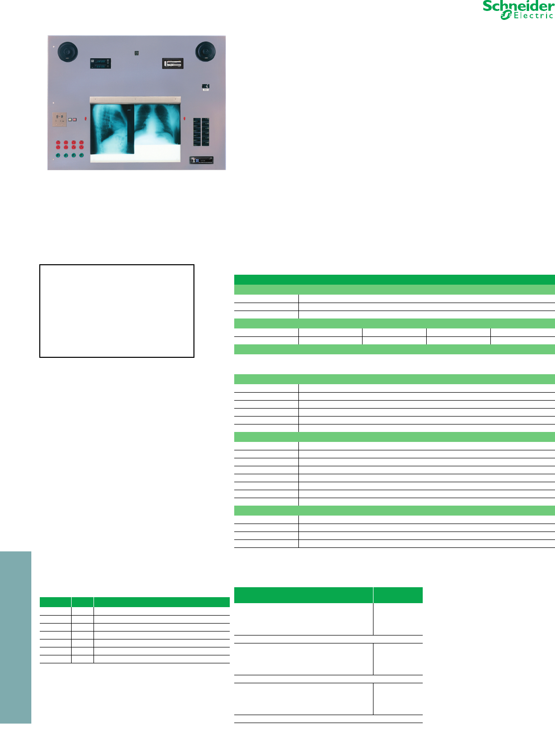
16-4 © 2012 Schneider Electric
All Rights Reserved
16 MEDICAL PRODUCTS
www.schneider-electric.us
Medical Products Surgical Facility Panels
Class 4800 / Refer to Catalog 4800CT0301
Square D™ brand surgical facility panels combine several required operating room
components in an economical, UL Listed package. Isolated power centers, power outlets,
time clocks and controls, and X-ray film viewers are grouped together in one enclosure that
can be easily installed and maintained. When installed separately, these items require
expensive labor and take up valuable surgical suite space.
Standard Equipment
•Square D brand Iso-Gard™ line isolation monitor (LIM)
•Primary main circuit breaker
•Secondary branch circuit breakers—(16) 20 A, 2-pole
•Ground bar
Optional Equipment
•5 kVA, 7.5 kVA, or 10 kVA isolation transformer
•AM/FM/cassette stereo system
•AM/FM/CD (single or multi-play) stereo system
•Twin X-ray film illuminator
•Portable X-ray film illuminator
•Portable X-ray receptacle
•Digital or dial clocks and timers
•Power receptacles–single, duplex, or locking type “Hospital Use Only”
•Ground jacks
Surgical Facility Panel—UL Listed
NOTE: The NEC requires audible and visual alarm indication where isolation power is
used (NEC 517-160).
aContact your nearest Schneider Electric sales office for international and special voltage codes.
b“n” indicates number of devices. Maximum of six receptacles and ground jacks (depending on available space).
Typical Surgical Facility Panel
Some items CANNOT be sold
separately. Surgical facility panels
are priced, ordered, and shipped as
three separate parts: the front cover,
the isolation transformer, and the
backbox. Contact your nearest
Schneider Electric sales office for
custom pricing.
Table 16.7: Ordering Information
Description
Electrical system—Position #1
SF5 5.0 kVA isolation transformer provision (specify primary voltage)
SF7 7.5 kVA isolation transformer provision (specify primary voltage)
SF10 10.0 kVA isolation transformer provision (specify primary voltage)
Primary and secondary voltage codes a
12345
120 208 240 277 480
Electrical components
Base Price includes Electrical System, Transformer, Backbox, and Remote Alarm Indicator with
PUSH-TO-TEST LIM, Trim, Main Circuit Breaker, 16 (QO220) Secondary Breakers, Ground Bus, and all mounting
provisions for mounting transformer.
Receptacles and switches—Position #2
SnbSingle 20 A, hospital grade; specify color when ordering (each)
DnbDuplex, 20 A, hospital grade; specify color when ordering (each)
PnbPower-Lock 20 A, hospital-only, available in black only (each)
HnbX-ray (Hubbell IN16494) 60 A, with LIM indicator/alarm
GnbGround Jacks 30 A (each)
TnbToggle Switch 20 A, 2-pole, specify color when ordering (each)
Clocks, clock/timers—Position #3
1 MCT12B dual display digital clock/timer
2 MCTCT remote control for MCT12B, includes battery pack
3 MCT14B surgical chronometer
4 MCT4RC remote control for MCT14B, includes battery pack
5 Dial type elapsed time indicator and control
6 Dial type clock, manual adjustment
7 Simplex Celestra digital elapsed time indicator and control—2 in. high digits
8 Simplex Celestra digital clock
Miscellaneous components—Position #4
DX Double size film illuminator—for x-ray viewing
CA AM/FM/cassette stereo with speakers—antenna not supplied
CD AM/FM/single play CD stereo with speakers—antenna not supplied
MP AM/FM/cassette/multi-play CD stereo with speakers—antenna not supplied
Table 16.8: Catalog Numbering Example
SF521 D4G4 12 DXCD c
Position Qty. Description
1 1 5XR21 isolation transformer (5.0 kVA, 208–120 V)
2 4 Duplex receptacles (specify color when ordering)
2 4 Ground jacks
3 1 MCT12B dual display digital clock/timer
3 1 MCTCT remote control
4 1 Double size film illuminator
4 1 AM/FM/CD single player
cNote use of spacing and position numbering to complete the
catalog number.
Table 16.9: Isolation Transformers
Description Main
Circuit Breaker
5XR11, 5.0 kVA, 120–120 V 60 A
5XR21, 5.0 kVA, 208–120 V 30 A
5XR31, 5.0 kVA, 240–120 V 30 A
5XR41, 5.0 kVA, 277–120 V 25 A
5XR51, 5.0 kVA, 480–120 V 15 A
53040BB Backbox (42 in. H x 56 in. W x 8 in. D)
7XR11, 7.5 kVA, 120–120 V 80 A
7XR21, 7.5 kVA, 208–120 V 45 A
7XR31, 7.5 kVA, 240–120 V 40 A
7XR41, 7.5 kVA, 277–120 V 35 A
7XR51, 7.5 kVA, 480–120 V 20 A
53032BB Backbox (42 in. H x 56 in. W x 12 in. D)
10XR11, 10.0 kVA, 120–120 V 100 A
10XR21, 10.0 kVA, 208–120 V 60 A
10XR31, 10.0 kVA, 240–120 V 60 A
10XR41, 10.0 kVA, 277–120 V 45 A
10XR51, 10.0 kVA, 480–120 V 30 A
53059BB Backbox (42 in. H x 56 in. W x 12 in. D)
© 2012 Schneider Electric
All Rights Reserved 16-5
16 MEDICAL PRODUCTS
www.schneider-electric.us
Medical Products Dual Output Voltage Panels
Class 4800 / Refer to Catalog 4800CT0301
a120 V section of panel interior will be factory loaded with 8-20/2 branch
breakers. This panel section is field expandable to 16 branch breakers
by ordering additional circuit breaker catalog numbers QO220.
b208 V or 240 V section of panel interior will be factory loaded with the
correct circuit breaker to match the selected receptacle. If no receptacle
is selected, this section of the panel interior is field expandable to 2
branch breakers by ordering catalog number QO220 through QO260.
Note: Total transformer kVA rating is the sum of the 120 V winding and the 208
V (or 240 V) winding.
Catalog Numbering System Notes and Pricing
Catalog # DVP (1)(2)(3)(4)(5)(6)(7)(8)
Fill-in parenthesis from selections listed above.
NOTE: The NEC requires audible and visual alarm
indication where isolation power is used
(NEC 517-160).
The dual output voltage hospital isolation panel is a single
ungrounded hospital isolation panel that can supply two different
output voltages simultaneously. Similar to a standard distribution
panel or load center, it can supply either 208/120 or 240/120 volts
of ungrounded, isolated,
single phase power using only one isolation transformer.
Other hospital isolation panels can supply only one output
voltage. The panel is ideally suited for renovation or
surgical center projects.
Table 16.10: Interior
Description
(1) Primary voltage
2 = 208 V
3 = 240 V
4 = 277 V
5 = 480 V
(2) Output voltage
A = 120/208 V
B = 120/240 V
(3) Size rating of 120 V secondary winding (kVA)a
5 = 5.0 kVA
7 = 7.5 kVA
1 = 10.0 kVA
(4) Number of 30 A green ground receptacles
0 = None
1 = One
2 = Two
3 = Three
4 = Four
5 = Five
6 = Six
(5) Number of 120 V power receptacles
0 = None
1 = One
2 = Two
3 = Three
4 = Four
5 = Five
6 = Six
(6) Type of 120 V power receptacles
0 = No 120 V receptacles
R = 20 A, red hospital grade duplex
I = 20 A, ivory hospital grade duplex
B = 20 A, black hospital grade duplex
T = 20 A, brown hospital grade duplex
L = 20 A, black hospital-only locking type receptacle
(Hubbell #23000HG or equivalent)
(7) Configuration of 208 or 240 V receptacle #1b
0 = No 208 or 240 V receptacle
X = Hubbell #IN16 494 (equivalent to Hubbell #25603)
A = NEMA Type #6-15R
B = NEMA Type #6-20R
C = NEMA Type #6-30R
D = NEMA Type #6-50R
E = NEMA Type #L6-15R
F = NEMA Type #L6-20R
G = NEMA Type #L6-30R
(8) Configuration of 208 or 240 V receptacle #2b
0 = No 208 or 240 V receptacle
X = Hubbell #IN16494 (equivalent to Hubbell #25603)
A = NEMA Type #6-15R
B = NEMA Type #6-20R
C = NEMA Type #6-30R
D = NEMA Type #6-50R
E = NEMA Type #L6-15R
F = NEMA Type #L6-20R
G = NEMA Type #L6-30R
Interior Code Numbers (1) (2) (3) (4) (5) (6) (7) (8)
Interior Catalog Number DVP 2 B 7 6 6 R X D
208/240 V receptacle #2 is
NEMA Type 6-50R
208/240 V receptacle #1 is
Hubbell IN16494
120 V power receptacles are
red in color
Six 120 V power receptacles
Six 30 A green ground
receptacles
Size rating of 120 V
transformer secondary is 7.5
Output voltage is 120 V and
240 V
Primary voltage is 208 V
Table 16.11: Transformer
120 V Winding
Rating (kVA)
Primary
Voltage
Secondary
Volt age s
Catalog
No.
5.0 208 208/120 DVT522
5.0 208 240/120 DVT523
5.0 240 208/120 DVT532
5.0 240 240/120 DVT533
5.0 277 208/120 DVT542
5.0 277 240/120 DVT543
5.0 480 208/120 DVT552
5.0 480 240/120 DVT553
7.5 208 208/120 DVT722
7.5 208 240/120 DVT723
7.5 240 208/120 DVT732
7.5 240 240/120 DVT733
7.5 277 208/120 DVT742
7.5 277 240/120 DVT743
7.5 480 208/120 DVT752
7.5 480 240/120 DVT753
10.0 208 208/120 DVT122
10.0 208 240/120 DVT123
10.0 240 208/120 DVT132
10.0 240 240/120 DVT133
10.0 277 208/120 DVT142
10.0 277 240/120 DVT143
10.0 480 208/120 DVT152
10.0 480 240/120 DVT153
Table 16.12: Trim
Catalog No.
DVC
Table 16.13: Backbox
Catalog No. Description Dimensions
DVBF flush mount 62 in. H x 34 in. W x 12 in. D
DVBS surface mount 64 in. H x 36 in. W x 12 in. D
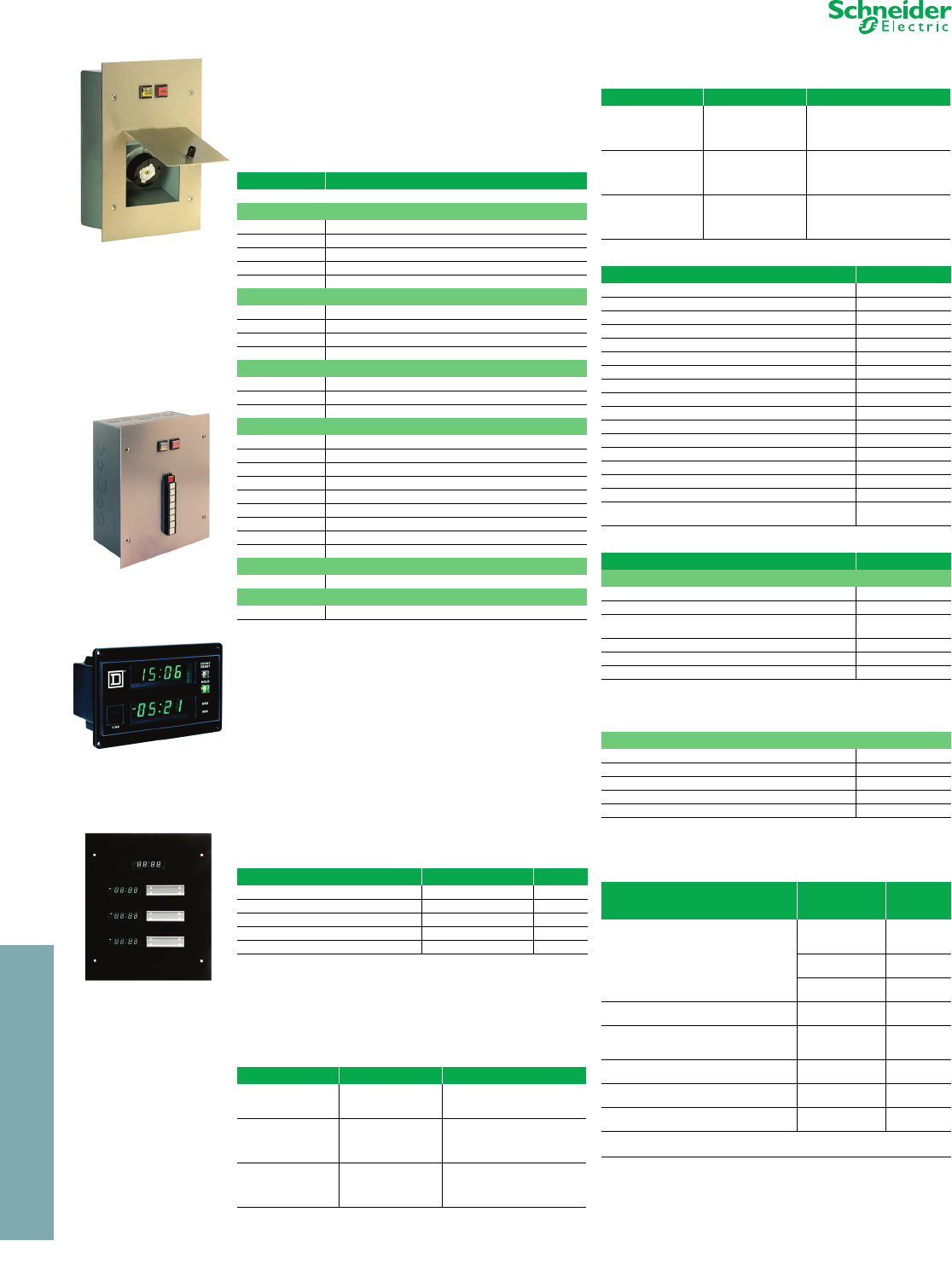
16-6 © 2012 Schneider Electric
All Rights Reserved
16 MEDICAL PRODUCTS
www.schneider-electric.us
Medical Products Accessories
Class 4800 / Refer to Catalog 4800CT0301
Accessories Panel
The Accessories Panel accommodates options typically
found in the operating room environment, including
receptacles, clock/timers, and music centers. Other
options include relays for controlling “IN USE” lights for
laser and X-ray.
Instructions: Combine the unit part numbers to build the
desired panel. The catalog number must begin with “AP”
and corresponding number to follow. For example,
APCTCRMARMA4N4 will produce a panel containing a
MCT12B clock/timer with a MCTCT remote control, a
M5IAI remote alarm indicator, a AM/FM/CD multi-play
music center, four HBL8310R receptacles, and four SLR3
ground jacks.
The purchase price includes the appropriate backbox.
Some components may not be able to be installed with
others, and may be considered as special items. Contact
your nearest Schneider Electric sales office for all special
item pricing.
Receptacles quoted include a Hubbell 50/60 A, X-ray type
25000. For other receptacles, indicate the NEMA
configuration after the Catalog Number. For example,
XRIADINEMAL630R
cIncludes meter for 5 mA LIM. For 2 mA LIM applications, change to
catalog number ORICAC. 2 mA analog meter available. Contact
Schneider Electric.
Table 16.14: Ordering Information
Unit Part Number Component Number
Base Price Catalog Number AP
Clock/timer
CT MCT12B
CR MCTCT
CB MCTBP
ST MCT14B
SR MCT4RC
Remote alarm indicator
IA IA1C
MA M5IAI
MM MMIAI
RA RA1
Music center
RC AM/FM cassette
RP AM/FM/CD single play CD player
RM AM/FM/CD multi-play CD player
Receptacles (Maximum of 8)
A-# 5–20R (duplex red)
B-# 5–20R (single red)
C-# 6–20R
D-# L6–20R
E-# 6–30R
F-# L6–30R
G-# Hubbellock
X-# X-ray
S-# Special
Ground jacks
N-# 1–8
Relay (For use with controlled power panels only)
R-# Ice cube relay (1–16)
Table 16.15: X-ray Indicator/Receptacle Module
Supervisory Module for Controlled
Panels
Description Dimensions Catalog No.
Receptacle & indicator module 13 in. H x 9.5 in. W Trim XRIAI
Receptacle & indicator module w/ switch 13 in. H x 9.5 in. W Trim XRIADI
Backbox 12 in. H x 8 in. W x 4 in. D 53007BB
Remote push button station and alarm c13 in. H x 11 in. W Trim 8CIIAI
Backbox 12 in. H x 10 in. W x 6 in. D 53004BB
Table 16.16: Nurses’ Station Indicator/Alarm
Annunciator
Catalog No. Backbox Application Backbox Dimensions
IA2CI
IA3CI
IA4CI
53008BB 12 in. H X 4 in. W X 4 in. D
IA5CI
IA6CI
IA7CI
IA8CI
53007BB 12 in. H X 8 in. W X 4 in. D
IA9CI
IA10CI
IA11CI
IA12CI
53005BB 12 in. H X 12 in. W X 4 in. D
Receptacle and Indicator
Module XRIAI–XRIADI
Remote Push Button
Station and Alarm 8CIIAI
Dual Display Digital
Clock Timer MCT12B
Surgical Chronometer
MCT14B
IA13C
IA14CI
IA15CI
IA16CI
53006BB 15 in. H X 12 in. W X 4 in. D
IA17CI
IA18CI
IA19CI
IA20CI
53021BB 18 in. H X 4 in. W X 6 in. D
IA21CI
IA22CI
IA23CI
IA24CI
53011BB 12 in. H X 20 in. W X 6 in. D
Table 16.17: Accessories and Replacement Parts
Description Catalog No.
1/4 A fuse (Wickman TR5T) TR5
2 mA meter 6301002350
5 mA meter 6301060250
Fuseholder/cap (black) 2549909510
1/4 A fuse (glass fuse) 4319900406
Green LED GLED
Red LED RLED
Yellow LED YLED
Interior only for 1A-1C (no trim) IANC
SAFE/SILENCE assembly for remote alarm SSPB
HAZARD/PUSH-TO-TEST assembly for remote alarm HPPB
HAZARD assembly for remote alarm HPB
SAFE/SILENCE replacement lens SSLEN
HAZARD/PUSH-TO-TEST replacement lens HPLEN
HAZARD replacement lens HLEN
Buzzer only for remote alarm 4319950001
Accessory –E booster power supply for three or more
remote indicator alarms. EXR
Table 16.18: Digital Clock/Timers—UL Listed
Description Catalog No.
Dual display clock/timer
Clock/timer with separate displays MCT12B
Rechargeable battery pack for MCT12B (Optional) MCTBP
Remote control unit w/ rechargeable battery pack for
MCT12B (Optional) MCTCT
Stainless steel trim plate MCTS95135
Backbox to be used with MCT95135 53007BB
Clock/timer complete with backbox and trim MCT12BC
Note: A complete clock/timer can be ordered using the catalog number
MCT12BC. This includes the clock/timer, stainless steel trim and
backbox. Remote control or battery pack must be ordered separately.
Note: The battery pack and remote control do not work together.
Surgical Chronometer
Clock and three timers MCT14B
Backbox 53006BB
Auxiliary control MCT4RC
Backbox 53008BB
Chronometer complete MCT14BC
Note: A complete surgical chronometer can be ordered using catalog number
MCT14BC. This includes the chronometer, Remote control and both
backboxes. All of these items are required for one complete unit.
Table 16.19: Remote Alarm Indicators
Description
Where Remote
Alarm is
REQUIRED
Catalog No.
Single gang remote with meter display
Included with all new panels
Panel- or wall-
mounted; no face
plate
RA1
Panel-mounted;
includes face plate RA1PM
Wall-mounted;
includes face plate RA1WM
Green, amber, and red indicating lights
and audible alarm mounted on front trim
Panel-mounted
in the room ORICA
Green, amber, and red indicating lights,
PUSH-TO-TEST button, audible alarm, and
milliammeter mounted on front trim c
Panel-mounted
in the room ORICA5C
Wall-mounted backbox not supplied.
Fits standard 2 gang box (3.5 in. deep)
Panel-mounted
outside the room IA1C
Wall-mounted 53008BB backbox required
(backbox 4 in. H x 12 in. W x 4 in. D) c
Panel-mounted
outside the room M5IAI
Wall mounted backbox not supplied.
Fits standard 4 gang box (3.5 in. deep) c
Panel-mounted
outside the room M5IAI50
Note: PUSH-TO-TEST option for any of the above remotes—add PTT after
the catalog number.
Table 16.16: Nurses’ Station Indicator/Alarm
Annunciator (continued)
Catalog No. Backbox Application Backbox Dimensions
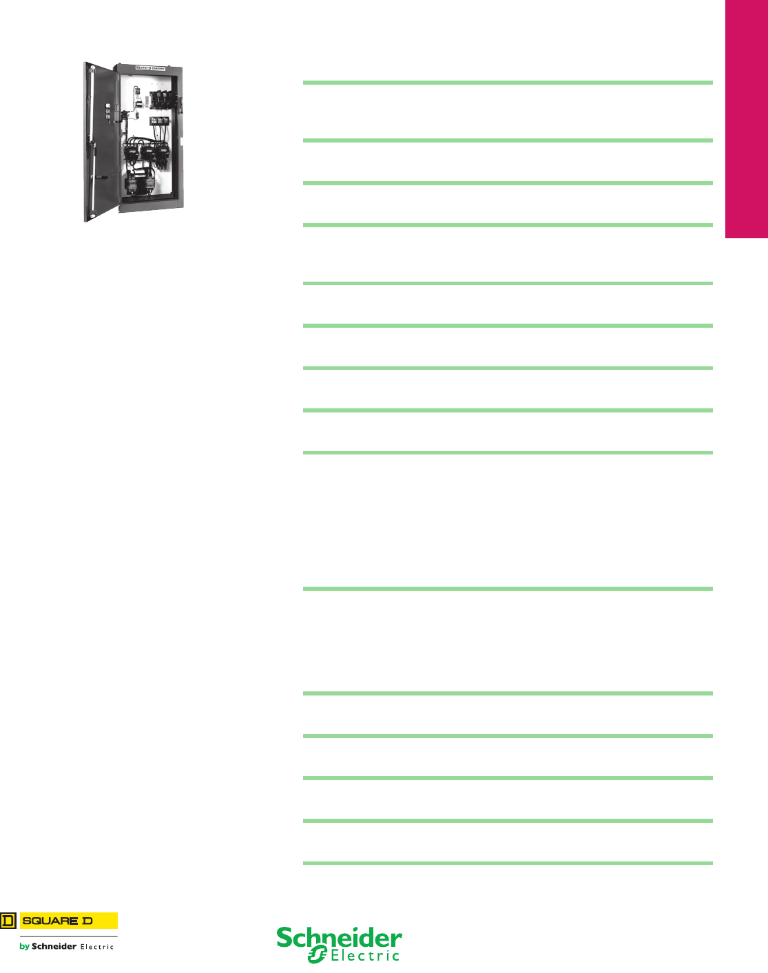
17-1
17 NEMA/DEFINITE PURPOSE TYPE
CONTACTORS AND STARTERS
© 2012 Schneider Electric
All Rights Reserved
Table of Contents
Section 17
NEMA Contactors and Starters
Electromechanical
Reduced Voltage Starter (p. 17-18)
IEC Style Disconnect Switches
GS1 Fusible and LK3 Nonfusible, UL98 Tested 17-2
GS1 Fusible and LK3 Nonfusible, Dimensions 17-5
UL508 Motor Disconnect Switches
Mini-Vario and Vario™ Switches 17-8
NEMA Style Disconnect Switches
NEMA Style Door-Mounted Disconnect Switches 17-9
Door-Mounted Operating Mechanisms
For Square D™ Circuit Breakers 17-10
Approximate Dimensions 17-12
Bracket-Mounted Disconnect Devices
Type T Disconnect Switches 17-13
Flexible Cable Mechanisms
For Circuit Breakers 17-14
Disconnect Switch Accessories
Flange Mounted, Variable Depth 17-15
Reversing Drum Switches
Type A and B 17-17
Electromechanical Reduced Voltage Starters
Description of All Types 17-18
How to Order 17-18
Autotransformer Starters 17-19
Wye-Delta Starters (Open Transition) 17-20
Wye-Delta Starters (Closed Transition) 17-21
Part Winding Starters 17-22
Approximate Dimensions 17-23
Multispeed Magnetic Starters
Application Data 17-24
Two-Speed Combination Starters 17-26
Reversing Two-Speed Magnetic Starters 17-27
Two-Speed Magnetic Starters 17-28
Approximate Dimensions 17-29
Lighting Contactors
Panelboard Lighting Contactors, Type PB 17-30
Well-Guard™ Pump Panel
Reduced Voltage Type 17-31
Factory Modifications (Forms)
Reduced Voltage Starters 17-32
Definite Purpose Contactors
Reversing/Hoist, Type R 17-35
Thermal Overload Relays—NEMA Style
Solid-State Overload Relay, Motor Logic™ Plus 17-36
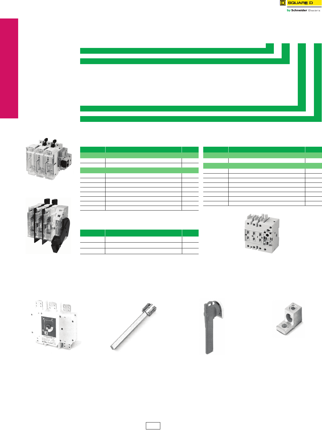
www.schneider-electric.us
17-2 © 2012 Schneider Electric
All Rights Reserved
17 NEMA DEFINITE PURPOSE TYPE
CONTACTORS AND STARTERS
IEC Style Disconnect
Switches
GS1 Fusible and LK3 Nonfusible, UL98 Tested
Class 9421 / Refer to Catalog 9421CT0301
The GS1 part numbers can be identified as follows.
See Catalog 9421CT0301 for specific applications.
aShipped with line side terminal shrouds; for additional shrouds,
see page 17-4.
bTerminal lug must be ordered separately—see page 17-4.
Table 17.1: Identification System
GS1 D U 3
Model GS1 Fusible (Class J fuse unless noted), LK3 Nonfusible
Current Range, Operator Type (front operator unless noted), Accessory Type
D30 A front and side operation T800 A (Class L if fused)
DD 30 A Class CC front and side operation U1000 A
E30 A W1200 A
EE 30 A Class CC AH handle
G60 A AHT handle with test
J100 A AE extension shaft
M200 A AD auxiliary contact holder
Q400 A AM auxiliary contact
S600 A
UL Certification
Poles—Number of Poles, 2 or 3
Note: All fusible switches through 400 A and nonfused switches through 200 A are equipped with a feature to test optional auxiliary contacts without energizing
the load when the appropriate GS1AHT•••• handle is used.
Table 17.2: Fusible Switches
Catalog No. Description $ Price
Compact GS1 Fusible IEC Style Disconnect Switches
GS1DDU3 30 A, 3-pole, Class CC, use 5x5 shaft 237.00
GS1DU3 30 A, 3-pole, Class J, use 5x5 shaft 260.00
GS1 Fusible IEC Style Disconnect Switches
GS1EEU3 30 A, 3-pole, Class CC , use 10x10 shaft 237.00
GS1EU3 30 A, 3-pole, Class J, use 10x10 shaft 260.00
GS1GU3 60 A, 3-pole, Class J, use 10x10 shaft 336.00
GS1JU3ab 100 A, 3-pole, Class J, use 10x10 shaft 536.00
GS1MU3ab 200 A, 3-pole, Class J, use 10x10 shaft 1181.00
GS1QU3ab 400 A, 3-pole, Class J, use 10x10 shaft 2252.00
GS1SU3ab 600 A, 3-pole, Class J, use 15x15 shaft 3377.00
GS1TU3ab 800 A, 3-pole, Class L, use 15x15 shaft 5061.00
Table 17.3: Fusible Switches with
Direct Mount Side Handle
Catalog No. Description $ Price
GS1EERU20 30 A, 2-pole, Class CC 204.00
GS1EERU30 30 A, 3-pole, Class CC 242.00
GS1AH01 Right side handle for GS1EERU20 & GS1EERU30 46.40
200 A Switch
GS1MU3
30 A Side Handle
GS1EERU30
Table 17.4: Nonfusible Switches
Catalog No. Description $ Price
Compact LK3 Nonfusible IEC Style Disconnect Switches
LK3DU3 30 A, 3-pole, 5x5 shaft 218.00
LK3 Nonfusible IEC Style Disconnect Switches
LK3GU3 60 A, 3-pole, use 10x10 shaft 263.00
LK3JU3 100 A, 3-pole, use 10x10 shaft 458.00
LK3MU3ab 200 A, 3-pole, use 10x10 shaft 1010.00
LK3QU3ab 400 A, 3-pole, use 15x15 shaft 1910.00
LK3SU3ab 600 A, 3-pole, use 15x15 shaft 2873.00
LK3TU3ab 800 A, 3-pole, use 15x15 shaft 4301.00
LK3UU3ab 1000 A, 3-pole, use 15x15 shaft 5372.00
LK3WU3ab 1200 A, 3-pole, use 15x15 shaft 6450.00
Compact 30 A Switch
LK3DU3
Example of the parts to order to build a complete GS or LK switch:
Choose a Switch + Shaft + Handle Assembly + Lugs, if needed
600 A, LK3SU3 Shaft 200 mm, GS1AE6 Black Handle, LK3AH150 Lugs Kit, GS1AW503
For example:
LK3SU3 (600 A nonfusible switch, use 15x15 shaft) + GS1AE6 (15x15 200 mm Type H shaft) + LK3AH150 (black/black, lockable)
To add auxiliary contacts:
For front-mounted contacts order GS1AD30 (front-mounted auxiliary contact holder) + GS1AM110 (NO contact for GS1AD10, 20, and 30)
CP1 Discount
Schedule
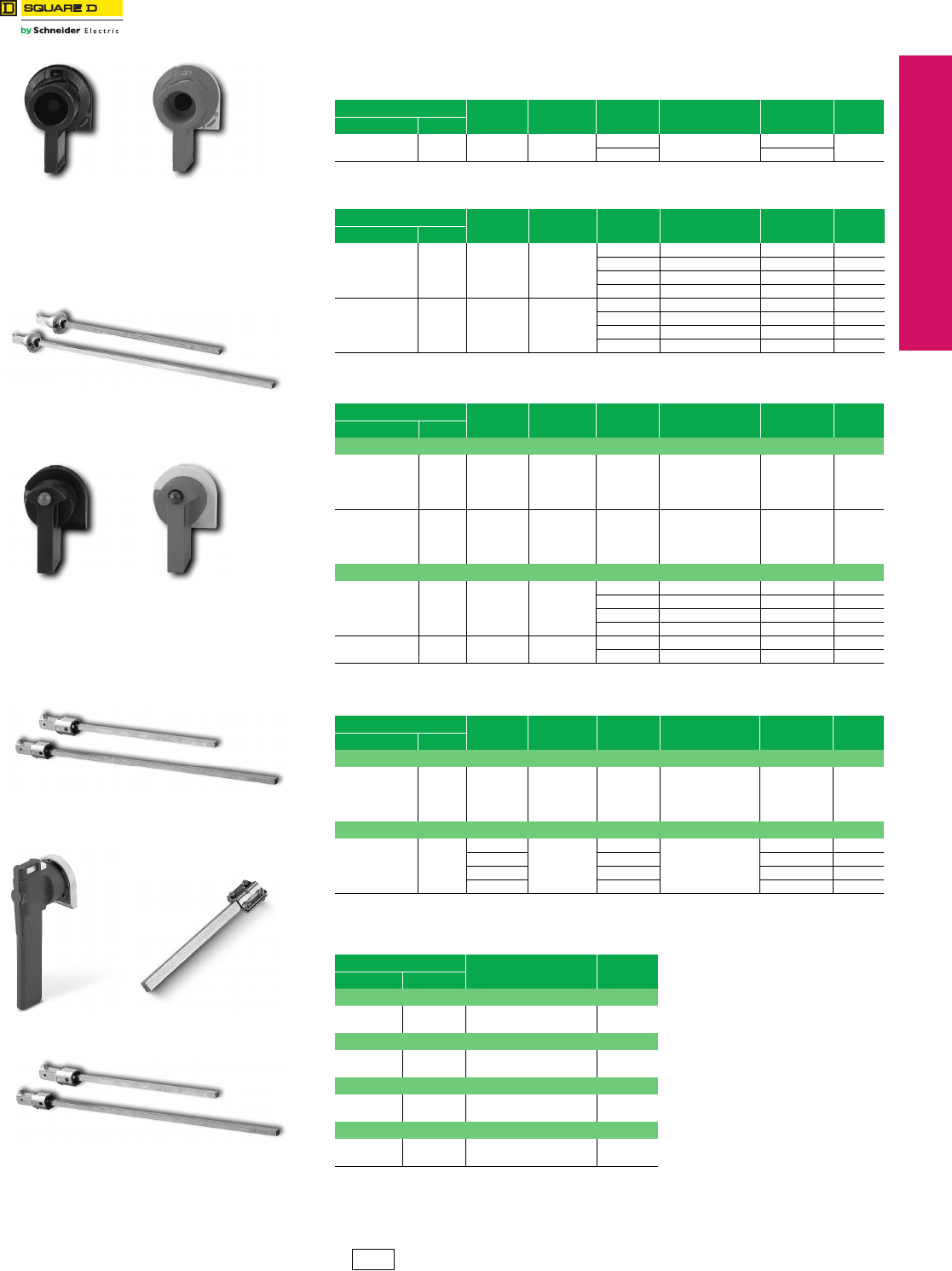
www.schneider-electric.us
© 2012 Schneider Electric
All Rights Reserved 17-3
17 NEMA/DEFINITE PURPOSE TYPE
CONTACTORS AND STARTERS
CP1 Discount
Schedule
IEC Style Disconnect
Switches
GS1 Fusible and LK3 Nonfusible, UL98 Tested
Class 9421 / Refer to Catalog 9421CT0301
Handles
Note: Now UL approved for indoor or outdoor applications.
Table 17.5: Pistol Handles for Compact GS1 and LK3 for Use with Shaft Type D
Type Defeatable Padlockable Color Operation Catalog
Number $ Price
NEMA/UL IEC
1, 12 IP54 Yes Yes Black Off/On (O/I) GS1AH101 51.00
Red/Yellow GS1AH102
Table 17.6: Pistol Handles for Compact GS1 and LK3 for Use with Shaft Type G
Type Defeatable Padlockable Color Operation Catalog
Number $ Price
NEMA/UL IEC
1, 3R, 12 IP54 Yes Yes
Black Off/On (O/I) GS1AH110 62.00
Red/Yellow Off/On (O/I) GS1AH120 62.00
Black Test/Off/On (T/O/I) GS1AHT110 117.00
Red/Yellow Test/Off/On (T/O/I) GS1AHT120 117.00
1, 3R, 4, 4X, 12 IP65 Yes Yes
Black Off/On (O/I) GS1AH410 46.60
Red/Yellow Off/On (O/I) GS1AH420 46.60
Black Test/Off/On (T/O/I) GS1AHT410 78.00
Red/Yellow Test/Off/On (T/O/I) GS1AHT420 78.00
Table 17.7: Pistol Handles for Standard GS1 and LK3
Type Defeatable Padlockable Color Operation Catalog
Number $ Price
NEMA/UL IEC
GS1 30–100 A and LK3 60–100 A (3 in. handles)
1, 3R, 12 IP54 Yes Yes
Black Off/On (O/I) GS1AH110 62.00
Red/Yellow Off/On (O/I) GS1AH120 62.00
Black Test/Off/On (T/O/I) GS1AHT110 117.00
Red/Yellow Test/Off/On (T/O/I) GS1AHT120 117.00
1, 3R, 4, 4X, 12 IP65 Yes Yes
Black Off/On (O/I) GS1AH410 70.00
Red/Yellow Off/On (O/I) GS1AH420 70.00
Black Test/Off/On (T/O/I) GS1AHT410 117.00
Red/Yellow Test/Off/On (T/O/I) GS1AHT420 117.00
GS1 200–400 A and LK3 200 A (5 in. handles)
1, 3R, 12 IP54 Yes Yes
Black Off/On (O/I) GS1AH130 70.00
Red/Yellow Off/On (O/I) GS1AH140 70.00
Black Test/Off/On (T/O/I) GS1AHT130 125.00
Red/Yellow Test/Off/On (T/O/I) GS1AHT140 125.00
1, 3R, 4, 4X, 12 IP65 Yes Yes Black Off/On (O/I) GS1AH430 78.00
Red/Yellow Off/On (O/I) GS1AH440 78.00
Table 17.8: Pistol Handles for Use with Shaft Type H
Type Defeatable Padlockable Color Operation Catalog
Number $ Price
NEMA/UL IEC
For LK3 400–1200 A
1, 3R, 4, 4X, 12 IP65
No
Ye s
Black
Off/On (O/I)
LK3AH150 233.00
No Red/Yellow LK3AH160 233.00
Ye s B l a c k LK3AH170 386.00
Yes Red/Yellow LK3AH180 386.00
For GS1 600–800 A
1, 3R, 4, 4X, 12 IP65
No
Ye s
Black
Off/On (O/I)
LK3AH150 233.00
No Red/Yellow LK3AH160 233.00
Ye s B l a c k GS1AH170 386.00
Yes Red/Yellow GS1AH180 386.00
Table 17.9: Shafts
Length Catalog No. $ Price
in. mm
Shaft 5 mm x 5 mm—For use with Pistol Handles, Type D
12.6 320 GS1AE7 18.60
15.7 400 GS1AE71 23.30
Shaft 5 mm x 5 mm—For use with Pistol Handles, Type G
12.6 320 GS1AE8 18.60
15.7 400 GS1AE81 23.30
Shaft 10 mm x 10 mm—For Standard GS1 and LK3
12.6 320 GS1AE2 20.30
15.7 400 GS1AE21 24.90
Shaft 15 mm x 15 mm—For use with Pistol Handles, Type H
7.9 200 GS1AE6 32.60
15.7 400 GS1AE61 40.40
Type D—alternate handles
for compact switches only
Compact Shaft Kits
GS1AH101 GS1AH102
GS1AE7/AE71 Shafts
5 mm x 5 mm
Type G—Standard Handle Design
Use these shaft kits when
using compact switches:
GS1AE8/AE81 Shafts
5 mm x 5 mm
GS1AH110 GS1AH120
LK3AH160 GS1AE6
GS1AE2/AE21 Shafts
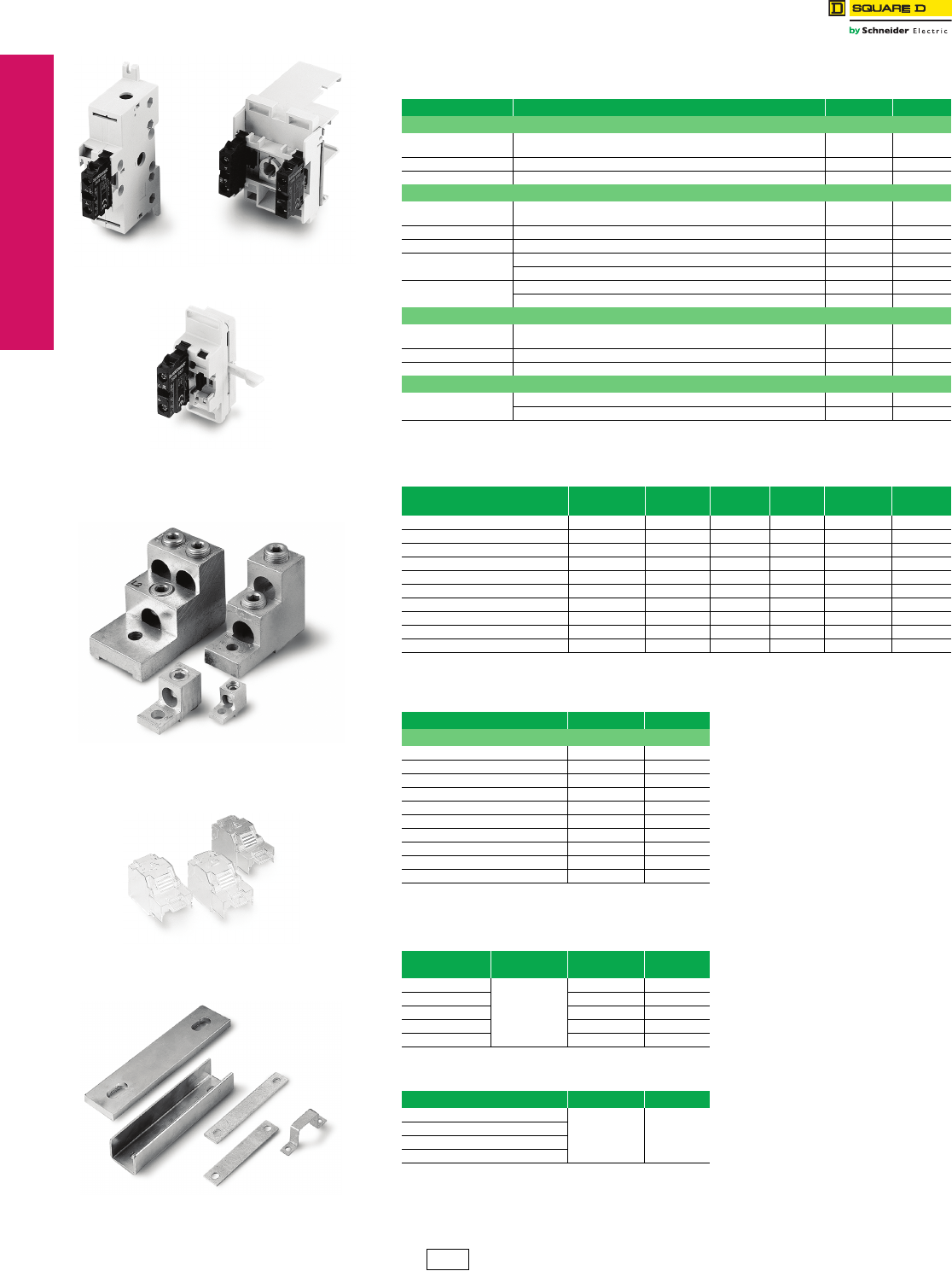
www.schneider-electric.us
17-4 © 2012 Schneider Electric
All Rights Reserved
17 NEMA DEFINITE PURPOSE TYPE
CONTACTORS AND STARTERS
CP1 Discount
Schedule
IEC Style Disconnect
Switches
GS1 Fusible and LK3 Nonfusible, UL98 Tested
Class 9421 / Refer to Catalog 9421CT0301
Accessories
aCannot be mixed. A single switch must use all GS1AN11/GS1AN22 contact blocks or all GS1ANT11/GS1ANT22
contact blocks. A GS1AN• • contact block may not be used on the same switch as a GS1ANT• •.
bGS1 600–800 A and LK3 800–1250 A can receive 1 lug for 3 cables per terminal or 2 lugs for 2 cables per terminal.
cAll GS1 and LK3 switches supplied with line side shrouding.
dThree-piece kit for either line or load side.
Table 17.10: Auxiliary Contacts
Type Description Catalog No. $ Price
For Compact LK3 / GS1
U = Upper or
Top mounted
Standard products allow up to 4 auxiliary contacts without any extra
contact holders. Contact holder (for 5 to 8 auxiliary contacts) GS1AD10 46.70
10 A 1 N.O. Contact Block GS1AM110 14.70
600 Vac 1 N.C. Contact Block GS1AM101 14.70
For LK3 60–200 A, GS1 30–400 A
U = Upper or
Top mounted Contact holder required (for 1 to 8 upper auxiliary contacts) GS1AD20 46.70
10 A 1 N.O. Contact Block GS1AM110 14.70
600 Vac 1 N.C. Contact Block GS1AM101 14.70
S = Side mounted a1 N.O. & N.C. Contact Block (max of two blocks—any mix) GS1AN11 78.00
2 N.O. & N.C. Contact Block (max of two blocks—any mix) GS1AN22 140.00
S = Side mounted a1 N.O. & N.C. Contact Block w/ Test (max of two blocks—any mix) GS1ANT11 93.00
2 N.O. & N.C. Contact Block w/ Test (max of two blocks—any mix) GS1ANT22 156.00
For LK3 400–1200 A
U = Upper or
Top mounted Contact holder (for 1 to 4 auxiliary contacts) LK3AD30 46.70
10 A 1 N.O. Contact Block GS1AM110 14.70
600 Vac 1 N.C. Contact Block GS1AM101 14.70
For GS1 600–800 A
Micro-switch
(top mounted)
1 N.O./N.C. Contact GS1AMU3 57.00
2 N.O./N.C. Contact GS1AMU4 83.00
Table 17.11: Terminal Lugs
For Use On Wire Size # of Wires
per Lug Wire Type Lugs
per Kit Catalog No. $ Price
Compact GS1/LK3 #14–#10 1 Cu — Standard —
GS1 30 A CC #14–#10 1 Cu — Standard —
GS1 30 A J #14–#10 1 Cu — Standard —
GS1/LK3 60 A J #10–#3 1 Cu — Standard —
LK3 100 A #14–#2/0 1 Cu — Standard —
GS1 100 A #14–2/0 1 Cu/Al 6 GS1AW303 59.00
GS1/LK3 200 A #6–3/0 1 Cu/Al 6 GS1AW403 98.00
GS1/LK3 400–600 A b2 x 2–2 x 600 2 Cu/Al 6 GS1AW503 197.00
GS1/LK3 800 A / LK3 1000 A b3 x 2–3 x 600 3 Cu/Al 6 GS1AW803 246.00
LK3 1250 A b4 x 2–4 x 600 2 Cu/Al 12 GS1AW903 395.00
Table 17.12: Terminal Shrouds
For Use On Catalog No. $ Price
For Line or Load Side c
Compact GS1/LK3 Standard —
All GS1/LK3 30 A Standard —
All GS1/LK3 60 A Standard —
LK3 100 A Standard —
GS1 100 A dGS1AP33 101.00
GS1/LK3 200 A dGS1AP43 132.00
GS1 400 A GS1AP63 213.00
LK3 400–600 A LK3AP63 86.00
GS1 600–800 A GS1AP83 140.00
LK3 800–1250 A LK3AP83 101.00
Table 17.13: Shorting Links
For Use On Shorting Links
per Kit Catalog No. $ Price
GS1 60 A
3
GS1AU203 29.60
GS1 100 A GS1AU303 41.90
GS1 200 A GS1AU403 62.10
GS1 400 A GS1AU503 93.00
GS1 600–800 A GS1AU803 156.00
Table 17.14: Shaft Padlocking Kit
For Use On Catalog No. $ Price
Compact GS1/LK3
Standard —
LK3 60–200 A
GS1 30–400 A
LK3 400–1250 A
GS1AD10 +
GS1AM110
GS1AD20 +
GS1AM110
GS1AD30 +
GS1AM110
Terminal Lugs
Terminal Shrouds
Shorting Links
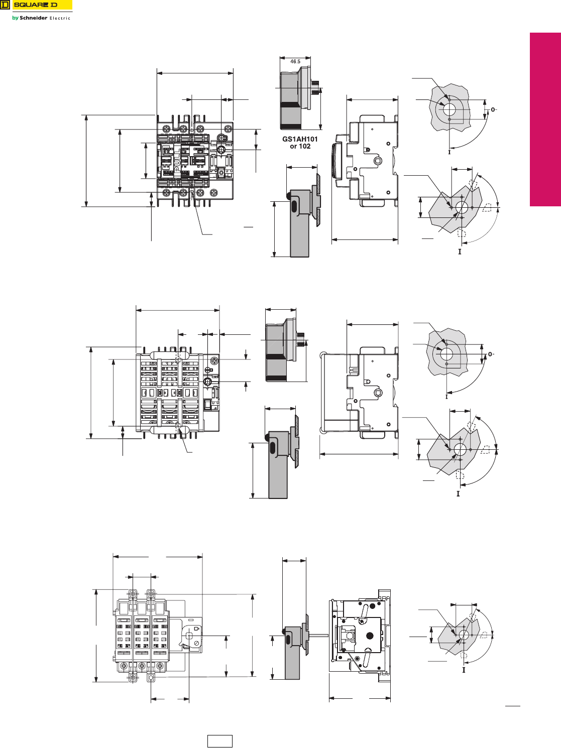
www.schneider-electric.us
© 2012 Schneider Electric
All Rights Reserved 17-5
17 NEMA/DEFINITE PURPOSE TYPE
CONTACTORS AND STARTERS
CP1 Discount
Schedule
IEC Style Disconnect
Switches
GS1 Fusible and LK3 Nonfusible, Dimensions
Class 9421 / Refer to Catalog 9421CT0301
Dimensions
25.6
1
37.3
FIX
15
116
79.5
96.5
45
18.3
M 5
FIX
3
16
ø
2
ø 4.5
ø 31
50
90°
2
-OFF
-ON
Door Drilling
83.8
3.25
65
2.5
63
2.48
1.83
2.75
70
76.2
3.0
50
90°
65°
o
2.0
50
2.0
ø 31
1.25
4 ø 4.5
0.13
-ON
-OFF
GS1AH/AHT110, 120, 410, or 420
0.125
1.25
3.75
0.59
1.47
3.125
4.56
1.78
0.72
Test Position
GS1DDU3
Compact CC
30 A
GS1AH110 or 120
2.75
70
65°
o
GS1AH/AHT110, 120, 410, or 420
4.13
105.5
1.47
37.3
0.059
15
4.56
116
3.38
84
0.63
15.8
1.0
28
3.0
7.62
2.48
63
2.0
50
2.0
50
FIX
FIX ø 0.19
1.83
46.5
2.5
65
3.88
99
OFF
0.13
2 ø 4.5
ø 31
1.25
90°
-ON
0.13
2 ø 4.5
ø 31
1.25
2.0
50
-OFF
90°
-ON
Door Drilling
Test Position
GS1DU3
Compact J
30 A
GS1EEU3,
GS1
CC
30 A 1.13 Fix
29
90°
65°
Test Position
-ON
5.69
144
5.88
149
2.00
50
2.00
50
2.75
70
3.00
76.2
3.88
99
2.44
62
2.63
67 1.25
Ø 31
0.13
4 Ø 4.5
0-OFF
Fix 5.25
133
Door Drilling
Dimensions: in.
mm
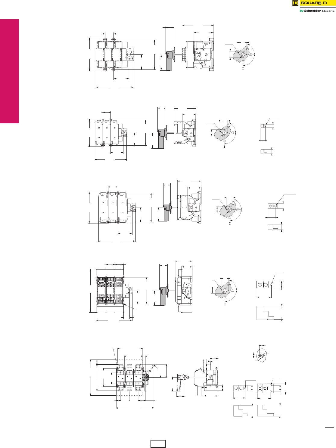
17-6 © 2012 Schneider Electric
All Rights Reserved
www.schneider-electric.us
17 NEMA DEFINITE PURPOSE TYPE
CONTACTORS AND STARTERS
CP1 Discount
Schedule
IEC Style Disconnect
Switches
GS1 Fusible and LK3 Nonfusible, Dimensions
Class 9421 / Refer to Catalog 9421CT0301
90°
65°
Test Position
-ON
Door Drilling
2.00
50
2.00
50
1.25
Ø 31
.13
4 Ø 4.5
0-OFF
1.50
38
5.88
149
2.75
70
6.75
171
2.63
67
2.75
70
3.00
76.2
Fix
5.25
133
5.63
143
3.50
89
Mounting Hole
Dimension:
0.19 in. (4.8 mm)
GS1EU3/GS1GU3,
GS1
30 A/60 A J
Terminal Lugs 2/0 Max.
90°
65°
Test Position
-ON
Door Drilling
2.00
50
2.00
50
1.25
Ø 31
Ø6.9
.75
19
.63
16
.88
22
0.13
4 Ø 4.5
0-OFF
2.06
52
7.19
183
8.25
210
3.31
84
3.31
84
2.75
70
3.00
76.2
Fix 6.56
167
5.63
1433.44
87.25
GS1JU3,
GS1
100 A J
Mounting Hole
Dimension:
0.19 in. (4.8 mm)
Terminal Lugs 3/0 Max.
90°
65°
Test Position
-ON
Door Drilling
2.00
50
1.00
25
1.13
29
1.50
38
2.00
50
.44
11Ø1 1.6
.13
4 Ø 4.5
1.25
Ø 31
0-OFF
Fix 2.44
62
8.13
207
9.44
240
3.69
94
3.75
95
Fix 7.50
191
2.75
70
6.00
152 3.44
87
5.00
127
GS1MU3,
GS1
200 A J
Mounting Hole
Dimension:
0.19 in. (4.8 mm)
GS1QU3,
GS1
400 A J
Mounting Hole
Dimension:
0.25 in. (6.3 mm)
90°
65°
Test Position
-ON
Door Drilling
Terminal Lugs
2 x 600 MCM Max.
2.00
50
1.50
38
3.13
80
2.88
73
2.00
50
0.13
4 Ø 4.5
1.25
Ø 31
0-OFF
.38
10
Ø 10.2
Fix 2.81
72
Fix 8.81
224
2.81
72
14.31
363
11.94
303
2.06
52
4.44
112
2.75
70
5.00
127
5.56
141 3.44
87
Ø .25
6
Dimensions: in.
mm
Door Drilling
Terminal Lugs
2X600 MCM Max. 3X600 MCM Max.
2.50
64
19.38
492 6.00
152
2.38
59 4.75
120 4.75
120 4.00
100
3.88
98
7.50
190
7.50
190
4.13
106
3.13
80
2.75
69
3.13
803.56
91 1.56
40
2.50
64
2.88
733.00
76
1.50
38
.50
13
.25
7
9.88
250
14.25
362
20.38
517
1.50
38 7.13
181
Ø 9.38 Fix 13.63
346
Fix 9.88
251
Locking
55˚
Ø .38
10
Ø 44
11
Ø 1.25
31
2.00
51
2.00
51
0.13
Ø 4.5
GS1SU3/GS1TU3,
GS1
600 A J
and 800 A L
Mounting Hole
Dimension:
0.38 in. (9.6 mm)
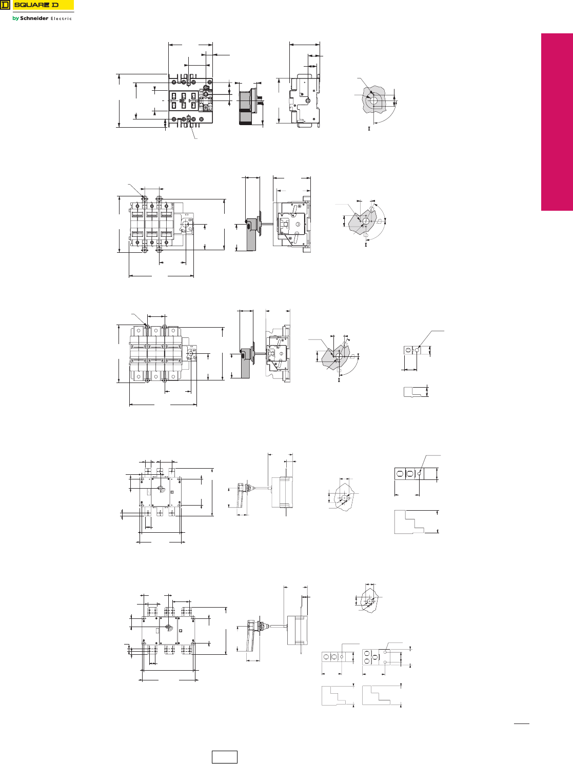
www.schneider-electric.us
© 2012 Schneider Electric
All Rights Reserved 17-7
17 NEMA/DEFINITE PURPOSE TYPE
CONTACTORS AND STARTERS
CP1 Discount
Schedule
IEC Style Disconnect
Switches
GS1 Fusible and LK3 Nonfusible, Dimensions
Class 9421 / Refer to Catalog 9421CT0301
90°
Door Drilling
4.56
116
3.78
96
1.94
37
0.59
15
1.00
25
1.00
25
2.00
51
0.75
19
1.83
46
2.59
66
2.48
63
3.84
98
1.78
45
0.72
18
0.56
14
Fix
3.13
80
Fix
Ø .19
M5
-ON
0-OFF
1.25
Ø 31
0.13
2 Ø 4.5
Mounting Hole
Dimension:
0.19 in. (4.8 mm)
LK3DU3,
Compact LK3
30 A
ø 0.19
5FIX 1.50
38
5.88
149
70
170
6.69
2.75
FIX 5.25
133
67
2.63 76.2
3.00
70
2.75 99
3.88
89
3.50
90°
65°
Test Position
-ON
Door Drilling
2.00
50
2.00
50
.13
4 Ø 4.5
1.25
Ø 31
0-OFF
LK3GU3/LK3JU3,
LK3
60 A/100 A
Mounting Hole
Dimension:
0.19 in. (4.8 mm)
Terminal Lugs 3/0 Max.
90°
65°
Test Position
-ON
Door Drilling
2.00
50
1.00
25
1.13
1.50
38
2.00
50
.44
11
Ø11.6
0.13
4 Ø 4.5
1.25
Ø 31
0-OFF
8.13
206
2.44
62
9.50
241
3.69
94
3.75
95
2.75
70
3.44
87
5.00
127
Ø
.19
5
Fix
7.50
191
29
LK3MU3,
LK3
200 A
Mounting Hole
Dimension:
0.19 in. (4.8 mm)
Door Drilling
Terminal Lugs
2 x 600 MCM Max.
1.50
38
3.13
80
2.88
73
.38
10
Ø 10.2
.13
4 Ø 4.5
1.25
Ø 31
2.00
51
2.00
51
0.81
20
11.00
279
0.56
14
7.50
191
3.88
98
6.56
166 1.63
41
2.31
59
5.00
127
1.56
40 3.13
80
Fix 10.06
255
Fix 6.88
175
Fix 12.63
320
LK3QU3/LK3SU3,
LK3
400 A/600 A
Mounting Hole
Dimension:
0.25 in. (6.3 mm)
Dimensions: in.
mm
Door Drilling
Terminal Lugs
2X600 MCM Max. 3X600 MCM Max.
3.13
803.56
91 1.56
40
2.50
64
2.88
733.00
76
1.50
38
Ø .38
10
Ø 44
11
Ø 1.25
31
2.00
51
6.56
166 1.56
40
2.00
51
0.13
Ø 4.5
0.81
20
0.81
20
2.31
59
1.56
40
14.63
372
6.81
1734.75
121
13.00
330
7.50
191
3.88
98
2.50
64
Fix 6.88
175
Fix 13.69
347
LK3TU3/LK3UU3/
LK3WU3,
LK3
800 A/1000 A/1250 A
Mounting Hole
Dimension:
0.38 in. (9.6 mm)
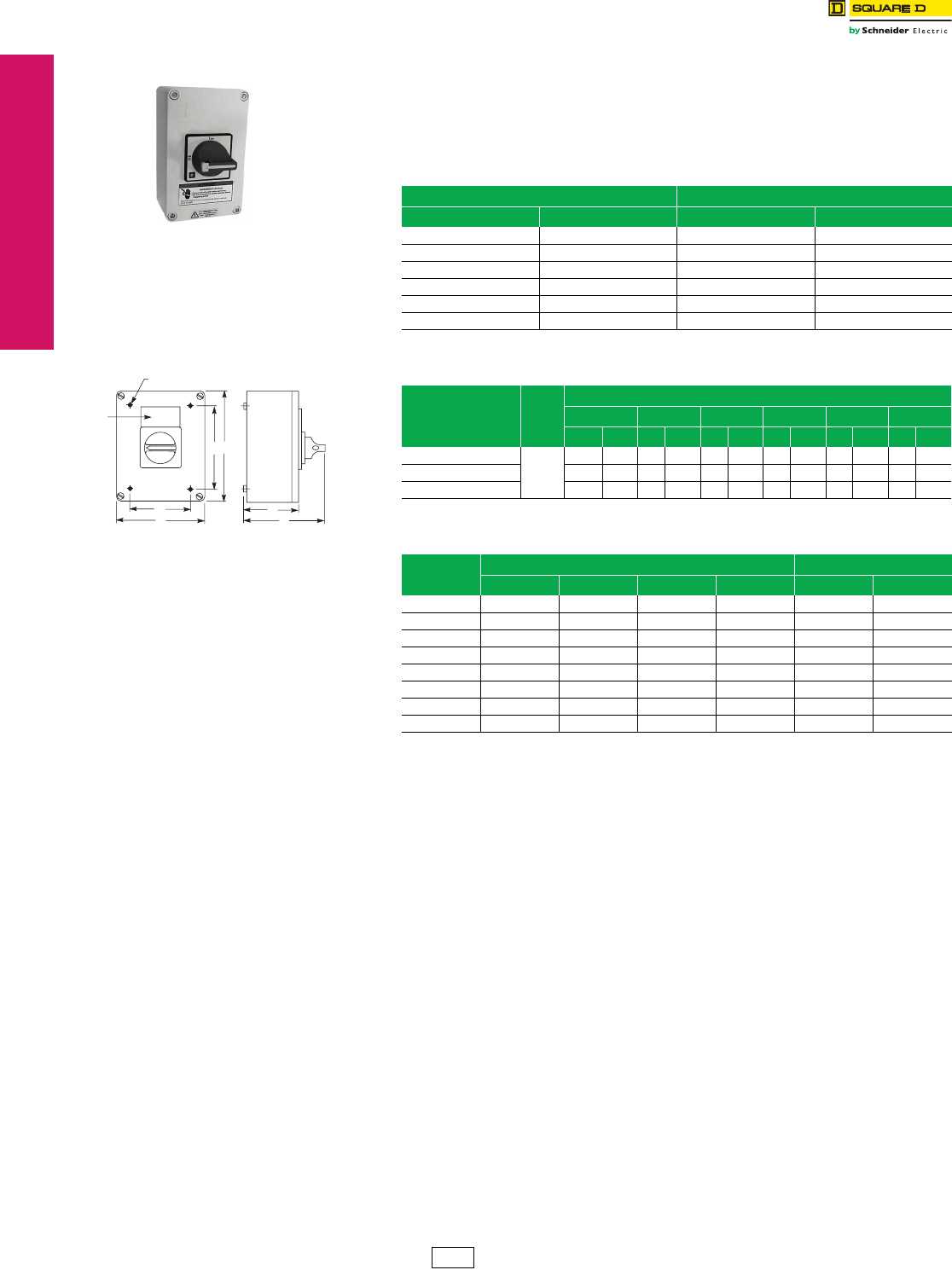
www.schneider-electric.us
17-8 © 2012 Schneider Electric
All Rights Reserved
17 NEMA DEFINITE PURPOSE TYPE
CONTACTORS AND STARTERS
UL508 Motor Disconnect
Switches
Mini-Vario and Vario™ Switches
Refer to Catalog 9421CT0301
Vario
The Vario Motor Disconnect Switch is also offered as an enclosed switch made of corrosion
resistant material. The 3-pole version makes the Vario switch ideal for manual motor control
applications. The switches are compact, easy to wire and connect, and come undrilled to
allow variable cable entry positions.
NOTE: VCGUN enclosures are UL approved.
aAssembled, includes switches mounted in enclosure with handle.
aUL Rated, NEMA Type 1, 12, IP55.
Table 17.15: Non-Metallic Enclosed Switches a
Ampere Size IP55-PVC 3-Pole, NEMA Type 1 & 12
UL IEC Catalog No. $ Price
20 32 VC1GUN 239.00
25 40 VC2GUN 287.00
45 63 VC3GUN 345.00
63 80 VC4GUN 381.00
100 125 VC5GUN 548.00
115 175 VC6GUN 845.00
Table 17.16: Non-Metallic Enclosed Switch Dimensions a
Catalog No. a
No.
of
Poles
Dimensions
a b c d e f
in. mm in. mm in. mm in. mm in. mm in. mm
VC1GU–VC2GU
3
6.7 170 4.1 105 3.2 82 4.8 122 2.1 53 5.0 128
VC3GU–VC4GU 6.7 170 5.3 135 3.3 85 5.1 130 3.7 95 5.2 131
VC5GU–VC6GU 11.0 280 8.6 220 5.0 126 7.9 201 7.5 190 8.6 203
Table 17.17: Vario Manual Motor Control Switches, IEC
Rating (A)
IEC
kW Rating 3-Pole Switch Body
230 V 240 V 400 V 415 V 500 V 690 V
20 4 4 5.5 5.5 7.5 11
25 5.5 5.5 7.5 7.5 11 15
32 5.5 5.5 11 11 11 15
40 7.5 7.5 15 15 18.5 15
63 15 15 22 22 30 22
80 18.5 18.5 30 30 37 30
125222237374537
175303045455545
Non-Metallic Enclosure
Ø 6.2
.25
e
b
da
c
f
Legend
Plate
Holder
VC1GU–VC6GU
CP1 Discount
Schedule
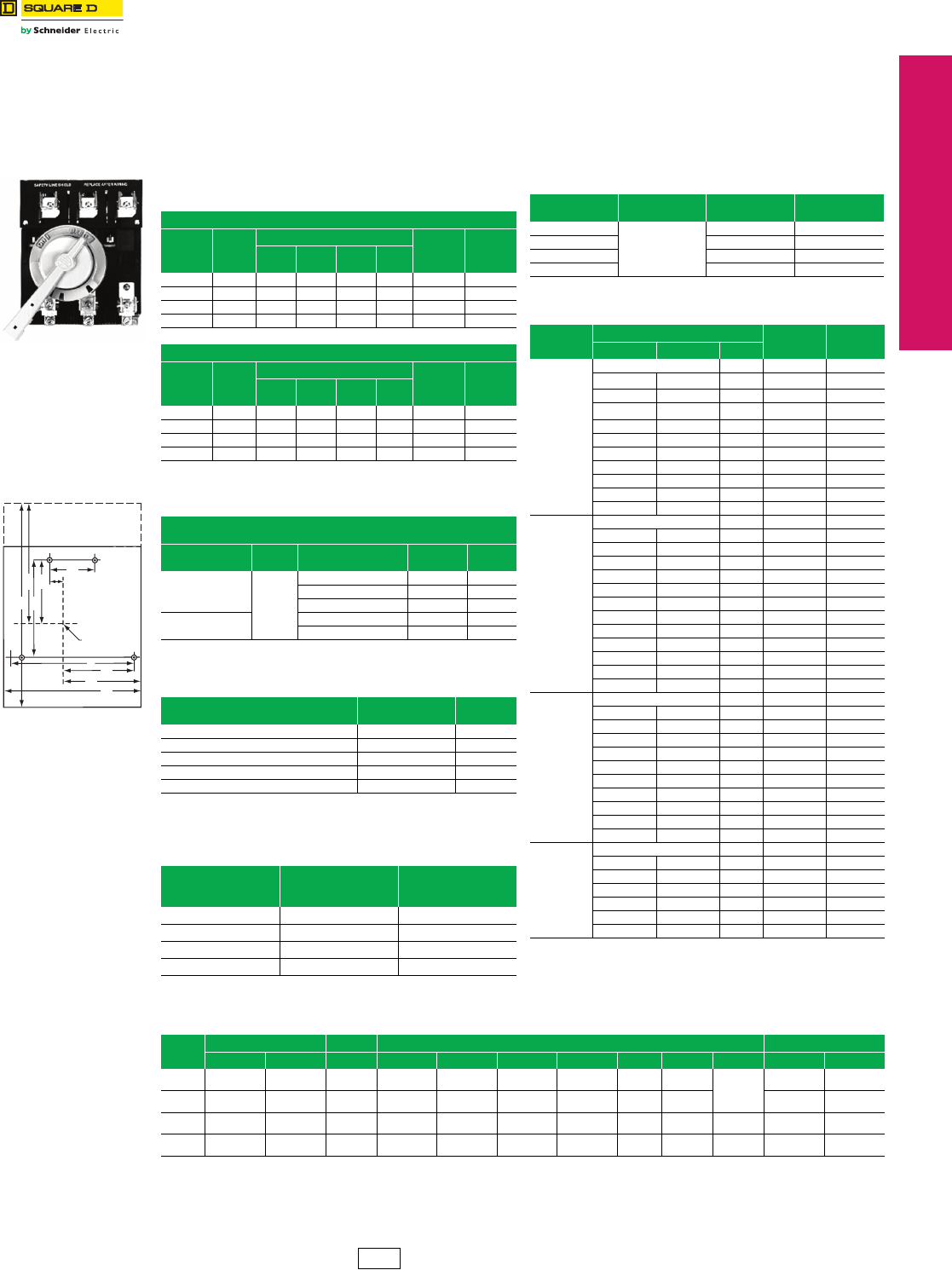
www.schneider-electric.us
© 2012 Schneider Electric
All Rights Reserved 17-9
17 NEMA DEFINITE PURPOSE TYPE
CONTACTORS AND STARTERS
NEMA Style Disconnect
Switches
NEMA Style Door-Mounted Disconnect Switches
Refer to Catalog 9420CT9701
aNonfused ratings.
aOne block per switch.
Note: These switches are for motor circuit applications.
aOne conductor per lug.
aContinuous current should not exceed switch rating (size).
Fuse clip kits should be sized to accommodate inrush.
File D10
The D10 disconnect switch features high I2T rating, longer contact life, visible contact indication, fuse-mounting flexibility, dead-front construction,
and auxiliary interlocks.
A complete installation includes a D10 disconnect switch, D11 handle operator, and D12 fuse clip kit. The D10 accepts Class H, K, J, or R fuses, or
can be used for nonfusible applications. The D10 disconnect switch is operated by a cast metal handle operator that is lockable in the “Off” position
and defeatable in the “On” position.
Table 17.18: Disconnect Switches
(without fuse clips or shorting straps)
600 V—Without Service Entrance Rating
Starter
NEMA
Size
Rating
(A)
Max. Horsepower Ratinga
Catalog
Number $ Price
120 V 200–
240 V 480 V 600 V
0–1 30 5 10 20 25 D10S1 270.00
26010204050D10S2 292.00
3 100 15 30 60 75 D10S3 452.00
4 200 25 50 100 100 D10S4 860.00
600 V—With Service Entrance Rating
Starter
NEMA
Size
Rating
(A)
Max. Horsepower Rating a
Catalog
Number $ Price
120 V 200–
240 V 480 V 600 V
0–1 30 5 10 20 25 D10S1H 320.00
26010204050D10S2H 352.00
3 100 15 30 60 75 D10S3H 544.00
4 200 25 50 100 100 D10S4H 1154.00
Table 17.19: Rotary Handle Operator Kits and Shafts
Kits include: Handle, Shaft, and Actuator
NEMA Type 1, 3, 3R, 4, and 12
Description Rating
(A)
Enclosure Interior
Depth—Inches
Catalog
Number $ Price
Complete Kit with
Handle, Shaft, and
Actuator
30,
60,
100,
200
5–6 D11SF4 106.00
6–10 D11SF10 118.00
10–16 D11SF16 130.00
Shaft only 6D11SH10 26.20
12 D11SH16 32.80
Table 17.20: Auxiliary Electrical Interlock
(for mounting on 30–200 A disconnect switch a)
Block Description
(with switch contacts open)
Catalog
Number $ Price
1 N.O. D11N0 79.00
1 N.C. D11NC 79.00
1 N.O. and 1 N.C. D11N0C 116.00
2 N.O. D11N00 116.00
2 N.O. and 2 N.C. D11N0C2 130.00
Table 17.21: Interrupting and Withstandability
Ratings
Rating
(A)
Interrupting Rating
Amperes Symmetrical
600 Vac, 3Ø
Withstandability I2T
(Amperes2 seconds)
30 1,200 0.38 x 10⁶
60 1,800 1.28 x 10⁶
100 2.000 2.62 x 10⁶
200 3,600 5.25 x 10⁶
Line Shield
Centerline
of Switch
Operating
Shaft
IJ
D
A
B
E
FH
C
G
Table 17.22: Lug Data
Rating (A) Number
Per Pole Wire Range aWire Type
30
1
#14–#8 Cu
60 #14–#4 Cu
100 #14–#1/0 Al–Cu
200 #6–250 kcmil Al–Cu
Table 17.23: Fuse Clip Kits
D10
Switch Size
Fuse Clip Rating aCatalog
Number $ Price
Amperes AC Volts Type
30 A
No Fuse D12C01 8.30
0–30 250 H, K D12C21 16.30
0–30 250 R D12CR21 65.00
0–30 600 H, K D12C61 24.50
0–30 600 R D12CR61 65.00
0–30 600 J D12CJ1 49.30
31–60 250 H, K D12C22 24.50
31–60 600 H, K D12C62 49.30
31–60 600 R D12CR62 82.50
31–60 600 J D12CJ2 57.50
61–100 250 H, K D12C23 65.00
60 A
No Fuse D12D02 24.50
0–30 250 R D12DR21 65.00
0–30 600 H, K D12D61 24.50
0–30 600 R D12DR61 65.00
31–60 250 H, K D12D22 23.80
31–60 250 R D12DR22 82.50
31–60 600 H, K D12D62 41.00
31–60 600 R D12DR62 82.50
31–60 600 J D12DJ2 57.50
61–100 250 H, K D12D23 65.00
61–100 600 H, K D12D63 115.00
61–100 600 J D12DJ3 106.30
61–100 600 R D12DR63 113.80
100 A
No Fuse D12E03 49.30
31–60 250 H, K D12E22 41.00
31–60 600 H, K D12E62 41.00
61–100 250 H, K D12E23 32.50
61–100 250 R D12ER23 115.00
61–100 600 H, K D12F63 90.00
61–100 600 R D12FR63 115.00
61–100 600 J D12EJ3 115.00
101–200 250 H, K D12F24 106.30
101–200 600 H, K D12F64 122.50
101–200 600 J D12FJ4 140.00
200 A
No Fuse D12F04 82.50
61–100 600 H, K D12F63 90.00
101–200 250 H, K D12F24 106.30
101–200 250 R D12FR24 140.00
101–200 600 H, K D12F64 122.50
101–200 600 R D12FR64 135.00
101–200 600 J D12FJ4 140.00
Table 17.24: Switch Dimensions (in inches)
Rating
(A)
Length Width Mounting Hole Dimensions Depth
A B C D E F G H I J Kalb
30 7-5/16 4-15/32 5-7/8 3-15/32 6 3-15/32 1-7/8 13/32 5-7/16 3-1/4 4-3/32 4-11/32
60 7-5/16 4-15/32 5-7/8 3-15/32 6 3-15/32 1-7/8 13/32 5-7/16 3-1/4 4-11/32 4-11/32
100 9-27/32 5-11/32 8-3/16 4-5/8 5-13/16 3-13/16 2-11/16 51/64 7-5/16 4-3/16 5-23/32 4-27/32
200 12-3/16 7-7/32 8-3/16 4-5/8 5-13/16 3-13/16 2-11/16 51/64 7-5/16 4-3/16 5-23/32 4-27/32
aMaximum depth with largest fuse.
bDepth including insulating barrier on service entrance switches.
CP1 Discount
Schedule
17-10 © 2012 Schneider Electric
All Rights Reserved
www.schneider-electric.us
17 NEMA DEFINITE PURPOSE TYPE
CONTACTORS AND STARTERS
Door-Mounted Operating
Mechanisms
For Square D™ Circuit Breakers
Class 9421 / Refer to Catalog 9420CT9701
Type L Circuit Breaker Mechanisms
Type L door-mounted, variable-depth operating mechanisms feature heavy duty, all metal construction with trip
indication. All can be padlocked in the “Off” position when the enclosure door is open. Further, the handle assemblies
can be locked “Off” with up to three padlocks, which also locks the enclosure when the door is closed. (The 3” handle
accepts one padlock.) Complete kits are rated for NEMA Type 1, 3R, and 12 enclosures. They include a handle
assembly, operating mechanism, and shaft assembly.
aContains support bracket.
aOptional accessory for use with 9421L operating mechanisms. Not used with GJL, NAL,
NCL, NEL, NXL, NSF, NSJ, PowerPact™ C, D, H, and J circuit breakers; use field-installed
circuit breaker interlocks instead.
Table 17.25: Complete Kits
Complete Kit
Does Not Include Circuit Breaker
Includes:
Operating Mechanism
Standard 6 in. Handle
Standard Shaft Kit
Includes:
Operating Mechanism
Standard 6 in. Handle
Long Shaft Kit
Includes:
Operating Mechanism
Short 3 in. Handle
Long Shaft Kit
Use With
Circuit Breaker or
Interrupter Type
No.
of
Poles
Frame
Size
(A)
Type $ Price
Mounting
Depth a
Min. – Max.
Type $ Price
Mounting
Depth a
Min. – Max.
Type $ Price
Mounting
Depth a
Min. – Max.
GJL 3 75, 100 LG1 140.00 5-1/2–10-1/4 LG4 158.00 5-1/2–20-7/8 LG3 198.00 5-1/2–20-7/8
FAL, FCL, FHL 2–3 100 LN1 140.00 5-1/2–10-7/16 LN4 158.00 5-1/2–21 LN3 198.00 5-1/2–21
KAL, KCL, KHL 2–3 250 LP1 171.00 6-1/4–11-3/16 LP4 189.00 6-1/4–21-3/4 LP3 230.00 6-1/4–21-3/4
LALc, LHLc, Q4L 2–3 400 LR1 242.00 6-5/16–10-7/8 LR4 255.00 6-5/16–21-1/2 LJ3 230.00 5-1/2–21-3/8
MEL, MXL 2–3 800 LT1 b242.00 7-3/16–11-5/8 LT4b255.00 7-3/16–22-1/4
3 in. handles are not recommended
for use with these circuit breakers.
MAL, MHL 2–3 1200 LT1b242.00 7-3/16–11-5/8 LT4b255.00 7-3/16–22-1/4
NAL, NCL, NEL, NXL 2–3 1200 LX1b242.00 8-1/4–12-3/4 LX4b255.00 8-1/4–23-3/8
Table 17.26: Component Parts
Use With
3 in. Handle
Assemblies
Type 1, 3R, 12
Standard
Handle
Assemblies
Type 1, 3R, 12
Operating
Mechanism
(Lockout
Included)
Standard Shaft
(Support Bracket
Not Required)
Long Shaft
(Support Bracket
Included)
Circuit Breaker or
Interrupter Type
No.
of
Poles
Frame
Size
(A)
Type $ Price Type $ Price Type $ Price
Mounting
Depth a
Min. – Max.
Type $ Price
Mounting
Depth a
Min. – Max.
Type $ Price
GJL 3 75, 100 LH3 90.00 LH6 50.00 LG7 68.00 5-1/2–10-7/16 LS8 21.50 5-1/2–21 LS13 35.60
FAL, FCL, FHL 2–3 100 LH3 90.00 LH6 50.00 LF1 71.00 5-1/2–10-7/16 LS8 21.50 5-1/2–21 LS12 35.60
KAL, KCL, KHL 2–3 250 LH3 90.00 LH6 50.00 LK1 105.00 6-1/4–11-3/16 LS8 21.50 6-1/4–21-3/4 LS12 35.60
LALc, LHLc, Q4L 2–3 400 3 in. handles
are not
recommended
for use with
these circuit
breakers.
LH6 50.00 LL1 170.00 6-5/16–10-7/8 LS8 21.50 6-5/16–21-1/2 LS10 35.60
MEL, MXL 2–3 800 LH8 50.00 LM1 170.00 7-3/16–11-5/8 LS8 21.50 7-3/16–22-1/4 LS10 35.60
MAL, MHL 2–3 1200 LH8 50.00 LM1 170.00 7-3/16–11-5/8 LS8 21.50 7-3/16–22-1/4 LS10 35.60
NAL, NCL, NEL, NXL 2–3 1200 LH8 50.00 LX7 170.00 8-1/4–12-3/4 LS8 21.50 8-1/4–23-3/8 LS10 35.60
aMounting depth in inches, measured from circuit breaker mounting surface (control panel) to outside of enclosure door.
bTypes LT1, LT4, LX1, and LX4 include an 8 in. handle rather than a 6 in. handle.
cThese operating mechanisms cannot be used with any LA/LH circuit breaker with an MB or MT suffix.
Table 17.27: NEMA Type 4 and 4X Handle Assemblies a
Use With Standard Handle Assemblies 3 in. Handle Version
Circuit Breaker or
Interrupter Type
No.
of
Poles
Frame
Size
(A)
NEMA Type 1, 3R,
4, 12
(Painted)
NEMA Type 1, 3R,
4, 4X, 12
(Chrome Plated)
NEMA Type 1, 3R,
4, 12
(Painted)
NEMA Type 1, 3R,
4, 4X, 12
(Chrome Plated)
Type $ Price Type $ Price Type $ Price Type $ Price
GJL 3 75 LH46 90.00 LC46 149.00 LH43 165.00 LC43 233.00
FAL, FCL, FHL 2–3 100 LH46 90.00 LC46 149.00 LH43 165.00 LC43 233.00
KAL, KCL, KHL 2–3 250 LH46 90.00 LC46 149.00 LH43 165.00 LC43 233.00
LAL, LHL, Q4L 2–3 400 LH46 90.00 LC46 149.00
3 in. handles are not recommended
for use with these circuit breakers.
MEL, MXL 2–3 800 LH48 90.00 LC48 149.00
MAL, MHL 2–3 1000 LH48 90.00 LC48 149.00
NAL, NCL, NEL, NXL 2–3 1200 LH48 90.00 LC48 149.00
aDue to gasketing, NEMA Type 3 and 4 handle assemblies are not trip indicating.
Table 17.28: IEC Style Operating Mechanisms
Circuit Breaker or
Interrupter Type
Type 1, 4, 4X, 12 Operating Mechanism
(Lockout Included)
Extension Shafts
Mounting Depth Type $ Price
Color Type $ Price Type $ Price Min. Max.
GJL Red/Yellow NW3 90.00 LG8 71.00 6-1/8 10-3/4 NS16 28.70
Black NW3B 90.00 6-1/8 17-7/8 NS336a35.60
Table 17.29: Electrical Interlock Kits—Class 9999 a
Description Class Type $ Price
Single-Pole, Double-Throw 9999 R47 131.00
Double-Pole, Double-Throw 9999 R48 221.00
Operating
Mechanism
3 in. Handle
Assembly
Standard
Handle
Assembly
CP1 Discount
Schedule
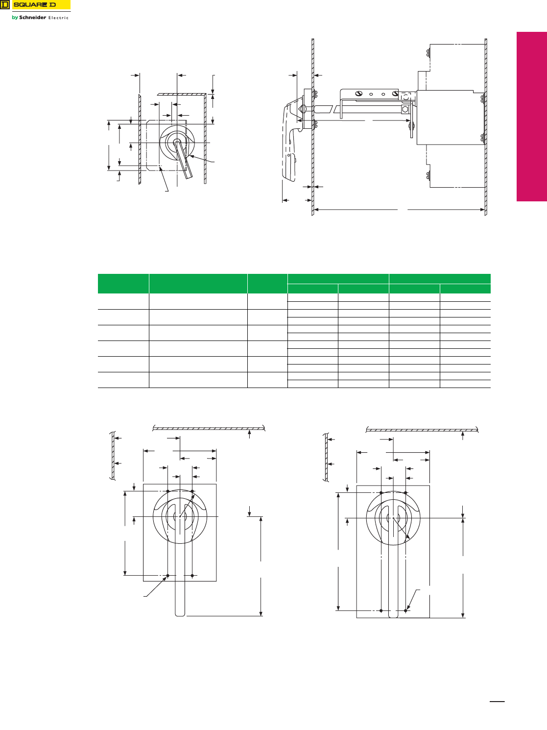
www.schneider-electric.us
© 2012 Schneider Electric
All Rights Reserved 17-11
17 NEMA DEFINITE PURPOSE TYPE
CONTACTORS AND STARTERS
Approximate
Dimensions
Door-Mounted Operating Mechanisms
Class 9421 / Refer to Catalog 9420CT9701
aMounting depth measured from circuit breaker mounting surface (control panel) to outside of enclosure door.
Table 17.30: Shaft Cutting Dimensions
Class Type Shaft Length
Formula
H = Standard Shaft H = Long Shaft
Min. Max. Min. Max.
9421 LG7, LG1, LG4, LG3 L = H–2.50 5.50 10.25 5.50 20.85
64 140 260 140 530
9421 LF1, LN1, LN3, LN4 L = H–2.88 5.50 10.44 5.50 21.00
73 140 265 140 533
9421 LK1, LP1, LP3, LP4 L = H–3.63 6.25 11.19 6.25 21.75
92 159 284 159 552
9421 LL1, LR1, LR4 L= H–3.13 6.31 10.88 6.31 21.50
79 160 276 160 546
9421 LM1, LT1, LT4 L= H–4.00 7.18 11.63 7.18 22.25
102 182 295 182 565
9421 LX7, LX1, LX4 L= H–5.17 8.25 12.75 8.25 23.38
131 210 324 210 594
Handle Mechanism
Handle
Mechanism
(2) #8-32 Tap
2.38
60
L
H
Mounting Depth
.28
Maximum
7 Door Thickness
L = Overall shaft length
H = Distance from inside of enclosure door to circuit
breaker mounting surface
1.38
35
3.50
Min.
45
1.18
30
.50
13
.45
12
4.72
120
1.77
45
3.94
100
Screw Driver
Interlock Pin
Location
CL
CL
X
Refer to NEC
Article 430-10
for minimum
dimension from
top mounting hole
to wall or barrier
to ensure adequate
wire bending space.
Panel drilling for GJL circuit breaker
and operating mechanism
a
2.25
57
1.50
38
7.00
178
1.6 3
41
6.00
152
R
5.13
130
(4) #8-32 Tap
1.56
40
.75
19
4.50
114
Hinge
Point of
Door
C
L Handle
Mechanism
C
L Handle & Ckt. Bkr. Toggle
Minimum to wall or
barrier to ensure
adequate wire bending
space to lug surface
when maximum wire
size is used with
standard lugs.
Refer to NEC Article
430-10.
3.25
Minimum
83 (Both Sides)
Panel drilling for FAL, FCL, and FHL
circuit breakers and operating mechanisms
3.25 Minimum
83 (Both Sides)
2.25
57
1.50
38
13.50
343
1.6 3
41
6.00
152
R
7.13
181
(4) #10-24 Tap
C30080-120
1.81
46
.75
19
4.50
114
Hinge
Point of
Door
C
L Handle & Ckt. Bkr. Toggle
Minimum to wall or
barrier to ensure
adequate wire bending
space to lug surface
when maximum wire
size is used with
standard lugs.
Refer to NEC Article
430-10.
Dimensions: in.
mm
Panel drilling for KAL, KCL, and KHL
circuit breakers and operating mechanisms
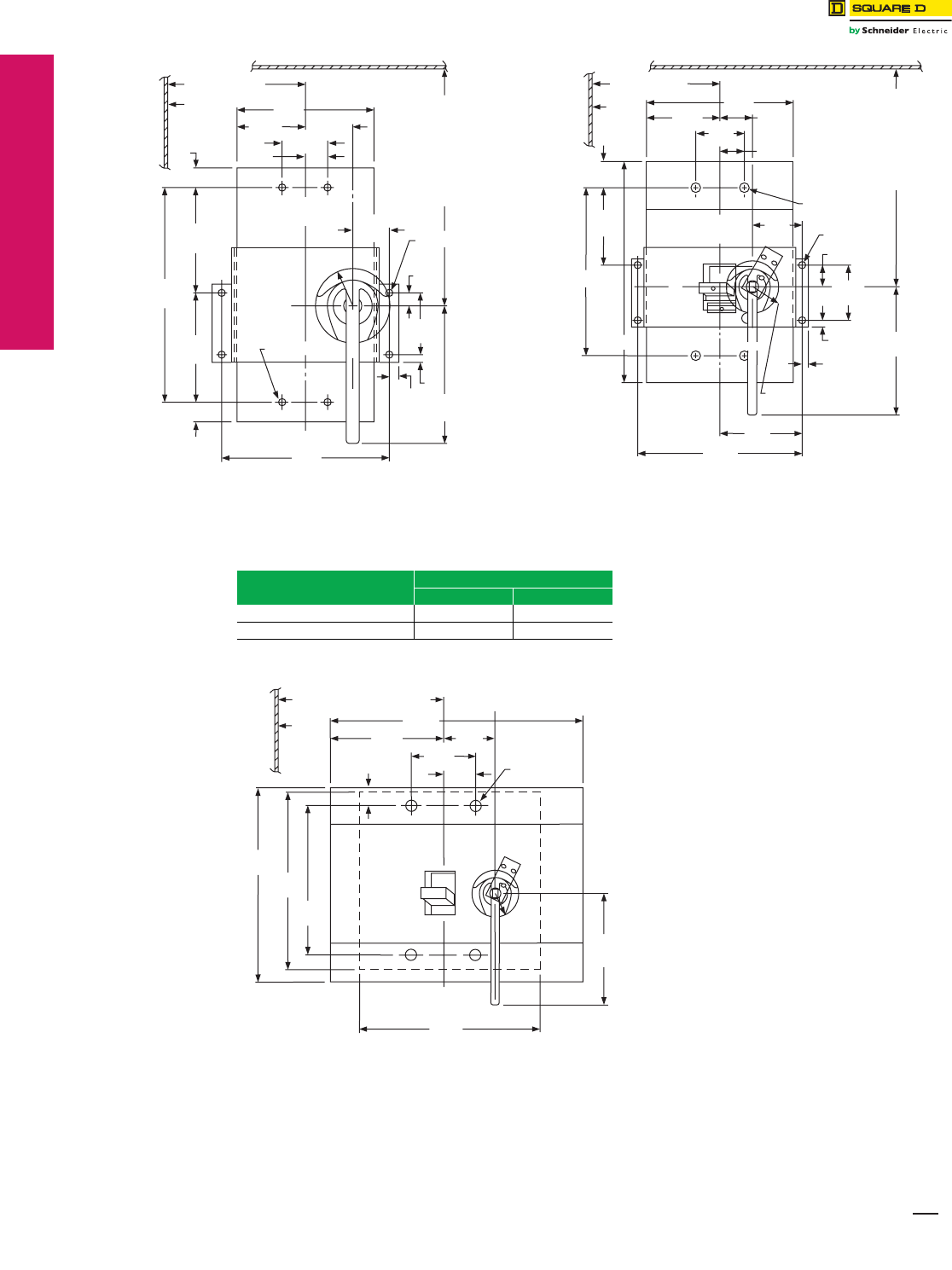
17-12 © 2012 Schneider Electric
All Rights Reserved
www.schneider-electric.us
17 NEMA DEFINITE PURPOSE TYPE
CONTACTORS AND STARTERS
Approximate
Dimensions
Door-Mounted Operating Mechanisms
Class 9421 / Refer to Catalog 9420CT9701
(4) 1/4-20 Tap
C
L Handle
C
L
Circuit Breaker
C
L Handle
9.25
235
4.57
116
6.00
152
19.19
487
.88
22
.88
22
6.00
Minimum
152 (Both Sides)
Hinge
Point
of Door Minimum to wall or barrier
to ensure adequate wire
bending space to lug surface
when maximum wire size is
used with standard lugs.
Refer to NEC Article 430-10.
4.68
119
7.19
183
(4) #12-24 Tap
2.68
68
.56
14
6.00
152
.44
11
.38
10
3.00
76
2.00
51
1.00
25
1.59
40
1.63
R
41
2.00
51
C
L
Circuit Breaker
4.50
114 3.00
76
3.09
79
3.50
89
1.66
42
A
B
4.937
125
8.00
203
.38
10
.44
11
1.63R
41
1.03
26
(4) 5/16-18 Tap
(4) 1/4-20 Tap
Minimum to wall or
barrier to ensure
adequate wire bending
space to lug surface
when maximum wire
size is used. Refer to
NEC Article 430-10.
2.00
51
1.50
38
9.00
229
Hinge
Point
of
Door
5.09
129
10.19
259
X
8.00 Minimum
203 (Both Sides)
C
L
Handle
C
L
Handle
Panel drilling for LAL, LHL, and Q4L
circuit breakers and operating mechanisms
Panel drilling for MAL, MEL, MHL, and MXL
circuit breakers and operating mechanisms
Circuit Breaker Type Dimensions = in. (mm)
A B
MAL, MHL 10.69 (272) 14.00 (356)
MEL, MXL 11.47 (291) 14.75 (375)
Panel drilling for NAL, NCL, NEL, and NXL
circuit breakers and operating mechanisms
9.00 Minimum (Both Sides)
229
7.50
191
8.50
216
8.00
203
12.13
308
9.50
241
8.75
222 1.6 3R
41
1.66
42
5.00
127
3.16
80
2.50
64
(4) 1/4-20 Tap
15.00
381
Hinge
Point
of Door
C
L Handle
Mechanism
C
L
Circuit Breaker
C
L
Handle Mechanism
Dimensions: in.
mm
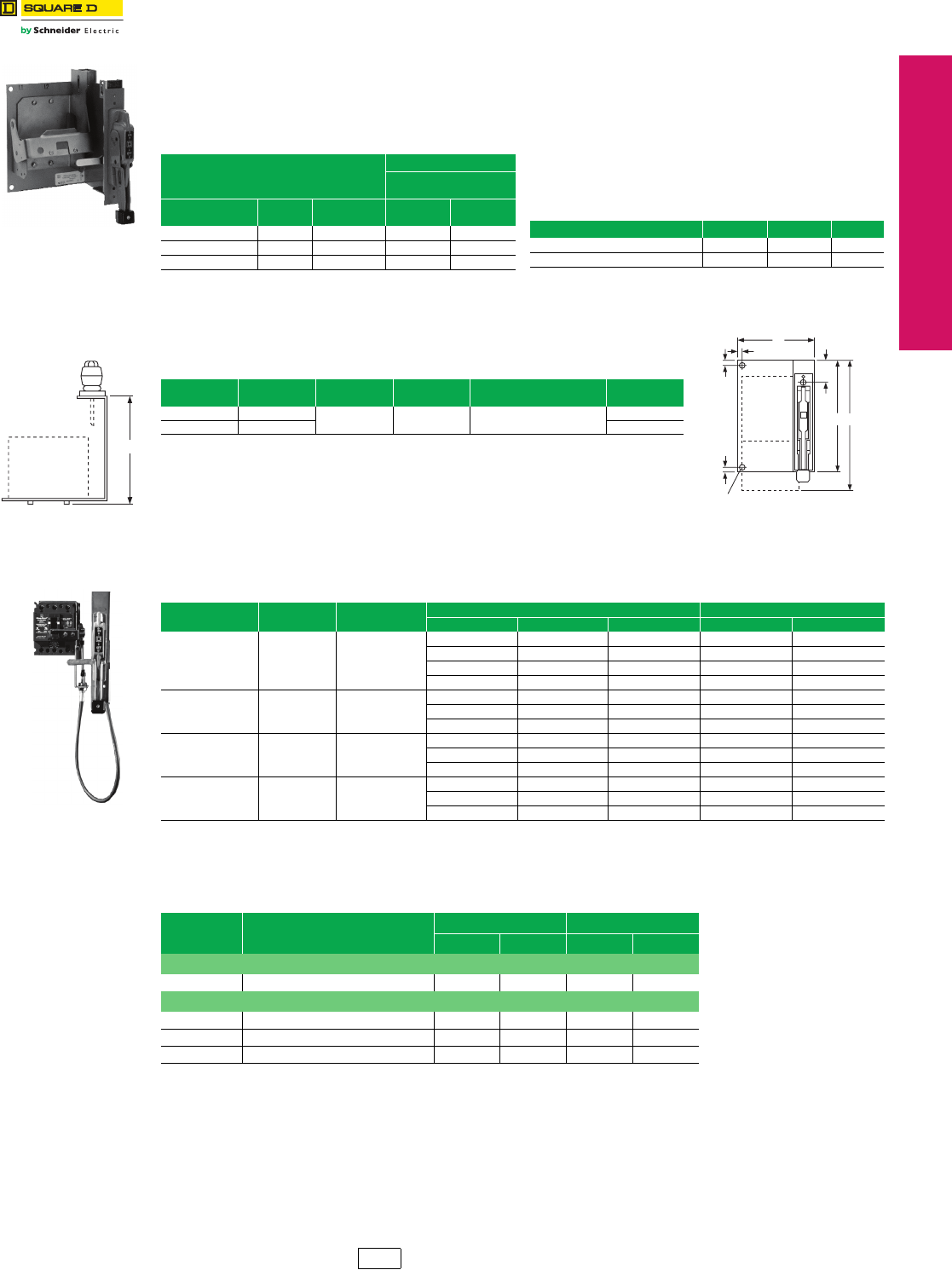
www.schneider-electric.us
© 2012 Schneider Electric
All Rights Reserved 17-13
17 NEMA DEFINITE PURPOSE TYPE
CONTACTORS AND STARTERS
Bracket-Mounted
Disconnect Devices
Type T Disconnect Switches
Class 9422 / Refer to Catalog 9420CT9701
aThese operating mechanisms cannot be used with any LA/LH circuit
breaker with an MB or MT suffix.
Note: Some enclosures may not accept the listed bracket-mounted
operating mechanisms; contact the enclosure manufacturer.
Table 17.32: Electrical Interlock Kits—Class 9999
Optional accessory for use with circuit breaker operating
mechanisms listed to the left and the flexible cable
mechanisms listed below, except GJL.
Note: Not used with GJL; use field installed circuit breaker interlocks.
Table 17.31: Bracket-Mounted Operating Mechanisms for Use With Square D™ Circuit Breakers
The circuit breaker operating mechanisms listed below are shipped with the external operating handle assembled to a
bracket. Circuit breakers are not included and must be ordered separately. A trim plate is provided with each kit to
prevent any mounting screws from being accessible from the front and also to provide an attractive installation.The
operating handle is Type A1. These switches can be used with Class 9423 door closing mechanisms.
Use With
Operating Mechanism
Right Hand
Flange Mounting
Circuit Breaker or
Interrupter Type
No. of
Poles
Frame Size
(A) Cat. No. $ Price
FAL, FHL 2–3 100 BN1 257.00
KAL, KHL 2–3 250 BP1 270.00
LALa, LHLa, Q4L 2–3 400 BR1 543.00
Description Class Type $ Price
Single Pole, Double Throw 9999 R26 131.00
Double Pole, Double Throw 9999 R27 243.00
D
Disconnect
Device
Table 17.33: Dimensions
Type A
in. (mm)
C
in. (mm)
D
in. (mm)
Min. Enclosure Deptha
in. (mm)
F
in. (mm)
BG1, BN1 8.75 (222) 1.13 (29) 6.50 (165) 8.00 (203) 7.13 (181)
BP1 9.13 (232) 7.38 (187)
aThe minimum enclosure depth is greater than Dimension D since additional space is needed when mounting
the mechanism.
Note: Back panel support is recommended for Types TFB1, 2, and 3. Other devices may also require support if the
flange is not sufficiently rigid.
ON
OFF
0.38
10
0.38
10
F
C
AE
0.38
10
Fused
Non Fused
and Circuit
Breaker
Disconnect
Device
(2) 0.38 Dia. Mounting Holes
10
(For back panel support if necessary.)
For use with Square D circuit breakers and Class 9422 A handle operators. Especially designed for tall, deep
enclosures where placement flexibility is required. See Digest 176 page 8-24 for dimensions.
Table 17.34: Class 9422—Flexible Cable Mechanisms for Use With Square D Circuit Breakers
Circuit Breaker
Type
No. of
Poles
Frame Size
(A)
Cable Mechanism Cable Mechanisms with A1 Handle
Cable Length Catalog No. $ Price Catalog No. $ Price
GJL 3 100
36 in. CGJ30 273.00 CGJ31 417.00
48 in. CGJ40 291.00 CGJ41 432.00
60 in. CGJ50 291.00 CGJ51 432.00
120 in. CGJ10 333.00 CGJ11 476.00
FAL, FHL 2, 3 100
36 in. CFA30 273.00 CFA31 417.00
60 in. CFA50 291.00 CFA51 432.00
120 in. CFA10 333.00 CFA11 476.00
KAL, KHL 2, 3 250
36 in. CKA30 288.00 CKA31 431.00
60 in. CKA50 305.00 CKA51 446.00
120 in. CKA10 347.00 CKA11 489.00
LALa, LHLa, Q4L 2, 3 400
36 in. CLA30 486.00 CLA31 630.00
60 in. CLA50 504.00 CLA51 647.00
120 in. CLA10 548.00 CLA11 689.00
aThese operating mechanisms cannot be used with any LA/LH circuit breaker with an MB or MT suffix.
Table 17.35: Class 9999 Auxiliary Contact Kits for Disconnect Switches and
Circuit Breakers
Class Type
SPDT DPDT
Type $ Price Type $ Price
Disconnect Switches
9422 TF R8 87.00 R9 243.00
Circuit Breaker Operating Mechanisms
9421 LF, LK, LL, LM, LN, LP, LR, LT R47 131.00 R48 221.00
9422 RM, RN, RP, RR, RT R26 131.00 R27 243.00
9422 CFA, CKA, CLA, CSF R26 131.00 R27 243.00
Note: No external auxiliary contacts are available for the following circuit breakers:
GJL circuit breakers must use internal auxiliary contacts, catalog number AAC.
PowerPact D circuit breakers must use internal auxiliary contacts, catalog number AAC.
Note: For additional variations, contact the Customer Care Center (CCC) at 1-888-778-2733.
CP1 Discount
Schedule
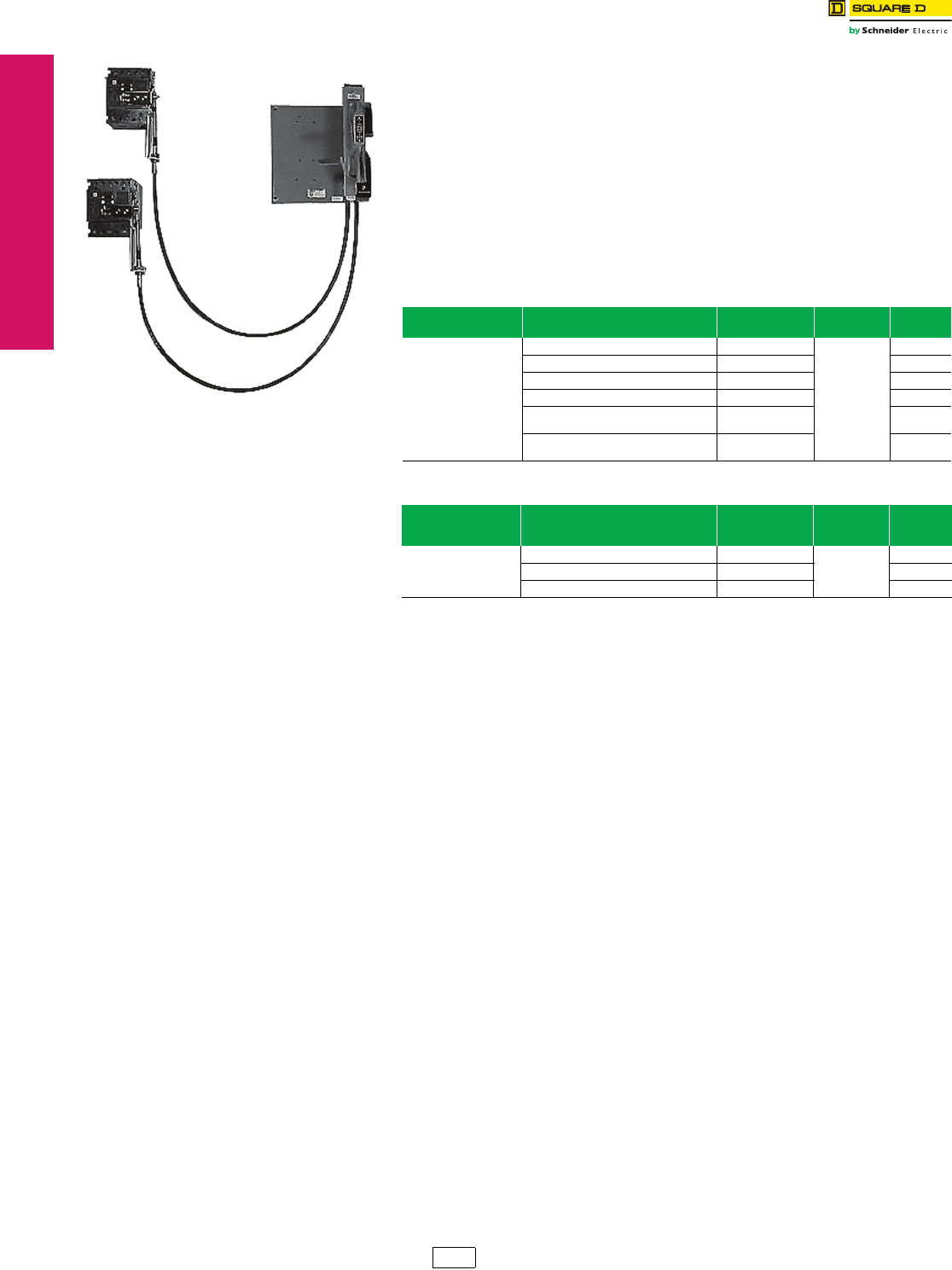
www.schneider-electric.us
17-14 © 2012 Schneider Electric
All Rights Reserved
17 NEMA DEFINITE PURPOSE TYPE
CONTACTORS AND STARTERS
Flexible Cable
Mechanisms
For Circuit Breakers
Class 9422 / Refer to Catalog 9420CT9701
Dual Cable Operating Mechanisms for Square D™ Circuit Breakers
Dual cable operator mechanisms are designed for use with Square D GJL circuit breakers.
The cable mechanisms allow for a single handle operator, Class 9422A1, to operate both
circuit breakers. The cable mechanism is designed especially for tall, deep enclosures
where placement flexibility is required. There are numerous cable arrangements to choose
from to accommodate many applications.
Features
•Separate cables for each circuit breaker
•Rugged metal flange handle operator
•Maximized flexibility of circuit breaker placement for existing and new applications
•Control panel can be fed from two separate supply voltages (if required)
•Dual mechanism allows both separate supply voltages to be controlled by a single
handle to improve security features
Table 17.36: Dual Cable Operating Mechanisms Selection
Circuit Breaker Type Cable Length
in. / mm (quantity)
Catalog
Number
Frame Size
(max.) $ Price
GJL
36 in. / 914 mm (2) 9422CGJD3
100 A
585.00
48 in. / 1219 mm (2) 9422CGJD4 608.00
60 in. / 1524 mm (2) 9422CGJD5 675.00
120 in. / 3048 mm (2) 9422CGJD1 788.00
36 in. / 914 mm (1)
60 in. / 1524 mm (1) 9422CGJD8 642.00
60 in. / 1524 mm (1)
120 in. / 3048 mm (1) 9422CGJD9 720.00
Table 17.37: Special Left-hand Mounted Single Cable Operating Mechanisms
Circuit Breaker Type
Cable Length
in. / mm
(quantity)
Catalog
Number
Frame Size
(max.) $ Price
FAL
120 in. / 3048 mm (1) 9422CFAL10
100 A
350.00
36 in. / 914 mm (1) 9422CFAL30 287.00
60 in. / 1524 mm (1) 9422CFAL50 318.00
CP1 Discount
Schedule
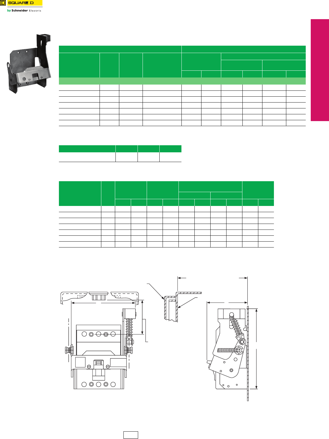
www.schneider-electric.us
© 2012 Schneider Electric
All Rights Reserved 17-15
17 NEMA/DEFINITE PURPOSE TYPE
CONTACTORS AND STARTERS
Disconnect Switch
Accessories
Flange Mounted, Variable Depth
Class 9422 / Refer to Catalog 9420CT9701
Designed for installation in custom built control enclosures where main or branch circuit protective devices are required. All
circuit breaker operating mechanisms are suitable for either right- or left-hand flange mounting, convertible on the job.
aClass 9422 Type R2 will extend mounting depth 7 in.
aNot for use with the GJL operating mechanism.
Table 17.38: Variable-Depth Mechanisms for Use with Square D™ Circuit Breakers and Schneider Electric™
(formerly Merlin Gerin™) Circuit Breakers
Use With Operating Mechanism
Circuit Breaker
Frame Size
No. of
Poles
Frame Size
A
Variable-Depth Mtg.
Range Min.-Max.a
(Inches)
Operating Mechanism
Only—Does Not Include
Handle Mechanism
Operating Mechanism and Handle Mechanism
Includes Type A1
Handle Mechanism
Includes Type A2
Handle Mechanism
Type $ Price Type $ Price Type $ Price
Square D Circuit Breakers
GJL 3 100 6.00–17.75 RG1 116.00 ARG11 257.00 ARG21 372.00
FAL, FHL 2–3 100 5.38–17.75 RN1 116.00 ARN11 257.00 ARN21 372.00
KAL, KHL 2–3 250 6.38–17.88 RP1 129.00 ARP11 270.00 ARP21 386.00
LALc, LHLc, Q4L 2–3 400 7.44–18.25 RR1 329.00 ARR11 471.00 ARR21 585.00
MEL, MXL 2–3 800 9.00–18.38 RT1 449.00 ART11 593.00 ART21 705.00
MAL, MHL 2–3 1200 9.00–18.38 RT1 449.00 ART11 593.00 ART21 705.00
NAL, NCL, NEL, NXL 2–3 1200 11.00–18.37 RX1 513.00 ——— —
Table 17.39: Electrical Interlocks—Class 9999
Description Class Type $ Price
Single Pole, Double Throw
Double Pole, Double Throw
9999
9999
R26a
R27a
131.00
243.00
Table 17.40: Dimensions
Circuit Breaker
Frame Size Type
Width
(A)
Height
(B)
Distance to Enclosure Flangea
(C) Bracket Depth
(D)
Minimum Maximum
in. mm in. mm in. mm in. mm in. mm
GJL RG1 5.00 127 4.75 121 6.00 152 17.75 451 4.00 102
FAL, FHL RN1 6.75 171 8.50 216 5.51 140 17.75 451 4.26 108
KAL, KHL RP1 7.13 181 10.13 257 6.51 165 17.88 454 4.94 125
LALc, LHLc, Q4L RR1 10.19 259 11.00 279 7.44 189 18.25 464 6.00 152
MEL, MXL RT1 13.38 340 14.00 356 9.00 229 18.38 467 9.69 246
MAL, MHLbRT1 13.38 340 14.00 356 9.00 229 18.38 467 9.69 246
NAL, NCL, NEL, NXL RX1 19.63 499 13.50 343 11.00 279 18.37 467 9.00 229
a9422R2 will extend the dimension by 7 in. Two required.
bMinimum mounting depth when using MAL or MHL circuit breakers can be decreased to 7.63 inches by using the
Class 9422 Type RT1B conversion kit. $23.00
cWarning: These operating mechanisms cannot be used with any LA / LH circuit breaker with an MB or MT suffix.
Minimum to wall or barrier.
Right- or left-hand mounting
to ensure adequate wire
bending space to lug
surface when maximum
wire size is used.
Refer to NEC Article 430-10.
C
L
R.H. Handle
C
L L.H. Handle
A
B
D
C = Distance from Outside of
Flange to Circuit Breaker
Mounting Surface
Enclosure Flange
Enclosure Door
CP1 Discount
Schedule
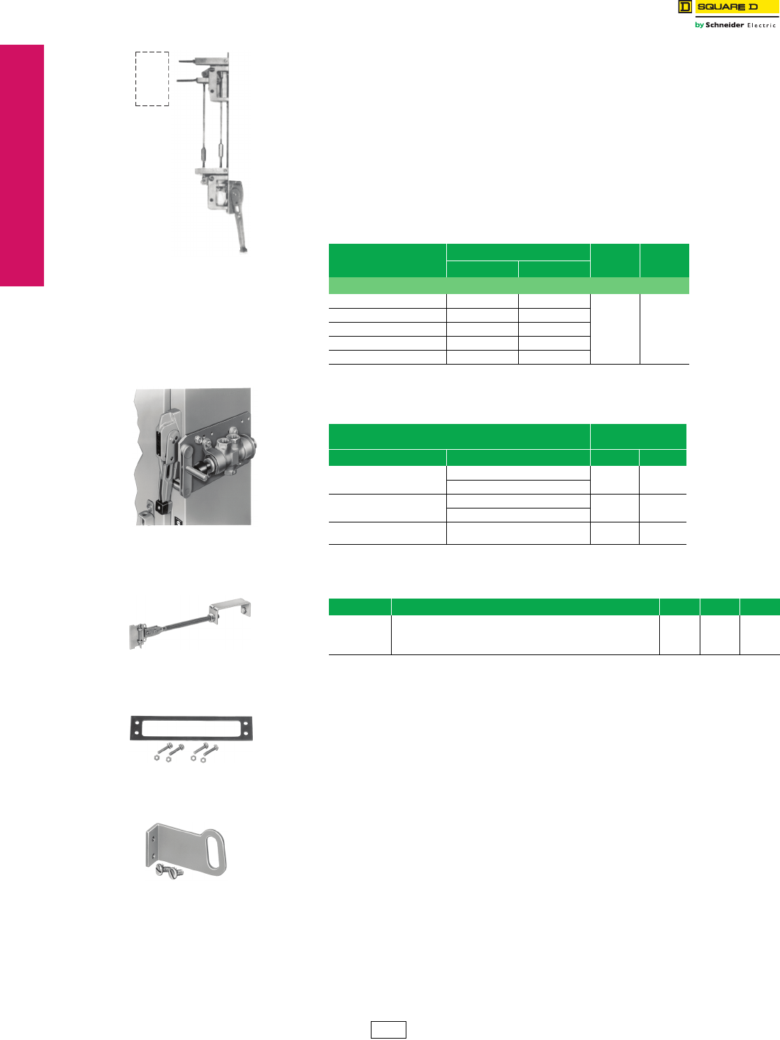
www.schneider-electric.us
17-16 © 2012 Schneider Electric
All Rights Reserved
17 NEMA DEFINITE PURPOSE TYPE
CONTACTORS AND STARTERS
Disconnect Switch
Accessories
Flange Mounted, Variable Depth
Class 9422 / Refer to Catalog 9420CT9701
Remote or Dual Adapter Kit
For the remote or dual operation of GJL, FAL, FHL, KAL, KHL, LAL, LHL, Q4L, MAL, MHL,
MEL, and MXL circuit breakers.
Remote Operation—permits mounting the Class 9422 Type A9 or A10 handle mechanism
at a lower level than the disconnect device it controls. This arrangement is often required
where the disconnect device is mounted too high for personnel to easily reach a
conventional operator.
Dual Operation—permits controlling two disconnect devices, one in line with, and one
remote from, a single Class 9422 Type A9 or A10 handle mechanism.
NOTE: A Class 9422 Type A9 or A10 handle (see Digest 176 page 8-15) and the
preferred mounting method must be used.
aPrices do not include air valves or handle mechanism. For more information on the
air valves listed above, contact Parker at c-parker@parker.com, or call 1-800-272-7537.
Table 17.41: Disconnect Device
Disconnect Device
Enclosure Mounting Depth
Type $ Price
Min. Max.
Circuit Breaker
GJL 10.50 19.50
D2 251.00
FAL, FHL 10.66 19.50
KAL, KHL 11.13 19.50
LAL, LHL, Q4L 12.13 19.88
MAL, MHL,MEL, MXL 13.75 20.25
Table 17.42: Air Valve Interlock
Note: Air valve interlocks only accept the specific three-way air valves, manufactured by Parker,
listed in the table below.
Parker Valve Model NumberaClass 9422
Air Valve Interlock
Air Valve Size Knob Operated Type $ Price
0.50 NPT
13
M04841885 G1 513.00
M08541848
0.75 NPT
19
M04861885 G2 513.00
M08561848
1.00 NPT
25 M00080004 G1 513.00
Table 17.43: Other Accessories
Accessory Description Class Type $ Price
Channel/Flange
Support Kit
Auxiliary kit recommended for use with 30 A and 60 A disconnect switches
and FAL, FCL, FHL, KAL KHL, NSF, and NSJ circuit breaker mechanisms
when these devices are to be mounted on the center channel of a multi-door
enclosure or when extra rigidity for the flange is required. Supplied as
9422 C1 42.80
Switch
or
Breaker
Remote operation shown
(handle mechanism not
included in kit)
Air valve interlock
mounted on enclosure
Alternate Mounting Kit
Channel/Flange
Support Kit
Auxiliary Lock Plate
CP1 Discount
Schedule
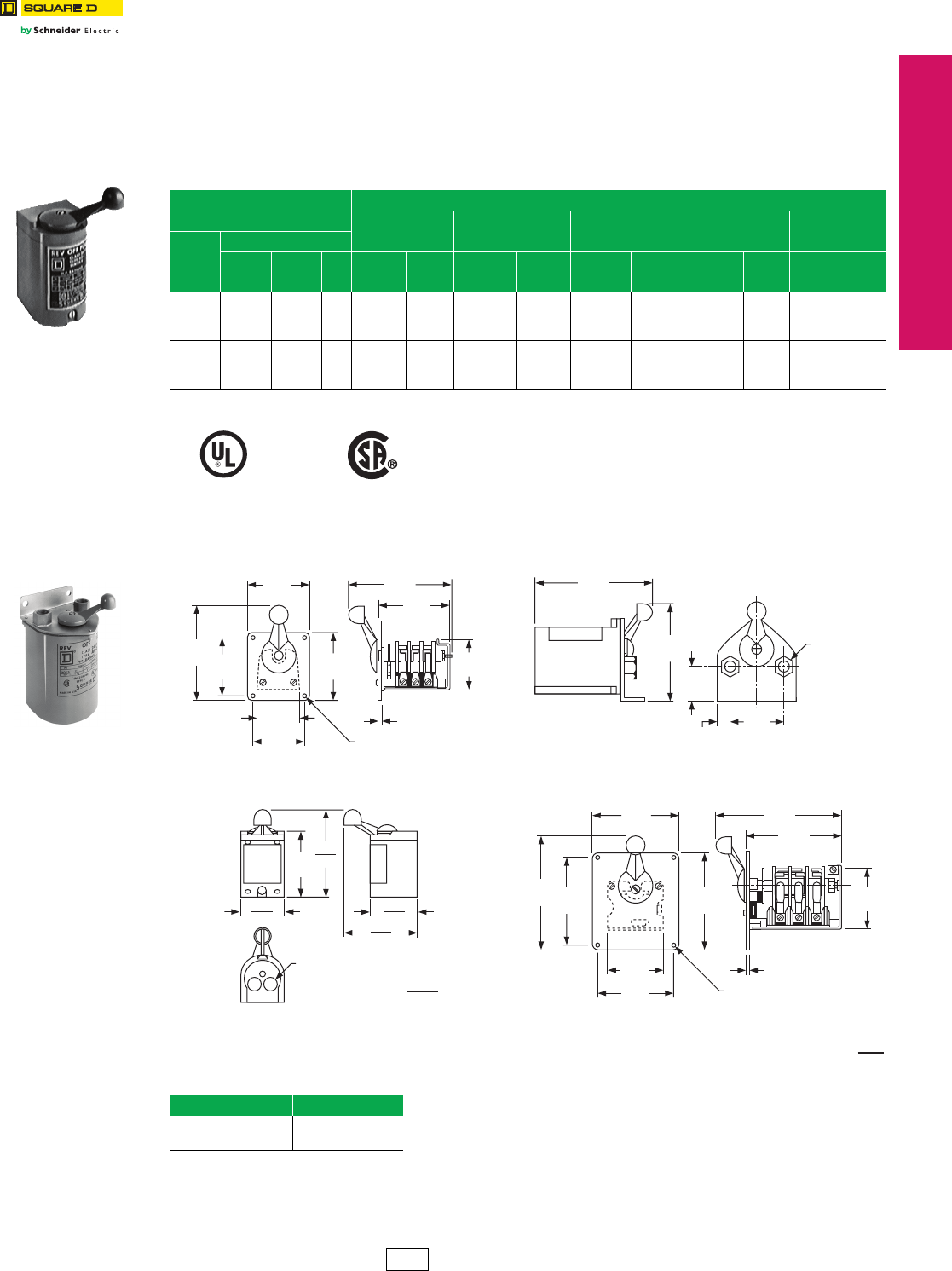
www.schneider-electric.us
© 2012 Schneider Electric
All Rights Reserved 17-17
17 NEMA DEFINITE PURPOSE TYPE
CONTACTORS AND STARTERS
Reversing Drum Switches Type A and B
Class 2601 / Refer to Catalog 2510CT9701
NEMA Types 1, 3R, 4, and 13 Without Overload
Class 2601 reversing drum switches may be used for across-the-line starting and reversing of AC polyphase, AC single
phase or DC motors, where overload protection is not required or is provided separately. They are compact and
inexpensive but ruggedly constructed. Drum switches are field convertible from maintained-only to momentary-only
operation. This conversion consists of removing the handle screw and handle, turning the shaft 180 degrees, then
replacing the handle and handle screw.
aMaintained – “Forward”; Momentary – “Reverse”; (not field convertible)
Approximate Dimensions—Class 2601 Reversing Drum Switches
Table 17.44: Reversing Drum Switches
600 Vac Maximum Class 2601 360 Vdc Maximum
Ratings NEMA Type 1
General Purpose
Enclosure
NEMA Type 4
Watertight and
Dusttight Enclosure
NEMA Type 3R
Rainproof
Outdoor Enclosure
NEMA Type 1
Maintained &
Momentary a
NEMA Type 13
Oiltight
Flush Mounting
Volt age
Maximum Horsepower
AC
Single
Phase
AC
Poly-
Phase
DC Type $ Price Type $ Price Type $ Price Type $ Price Type $ Price
115-
200/230
230
460/575
1-1/2
—
2
—
—
2
—
2
1/4
—
1/4
—
AG2 158.00 AW2 428.00 AH2 207.00 AG2S2 158.00 AF2 131.00
115-
200/230
230
460/575
1-1/2
—
3
5
—
5
—
7-1/2
2
—
2
—
BG1 428.00 BW1 590.00 N/A — BG1S4 428.00 BF1 356.00
File
CCN
E42243
NLRV
File
Class
LR25490
3211-05
Table 17.45: How to Order
To Order Specify: Catalog Number
•Class Number
•Type Number
Class Type
2601 AG2
Type AG2
3.38
86
5.20
132
3.19
81
3.70
94
.20
5
2.38
60
2.87
73
2.77
70
3.81
97
5.58
142
(4) .17 Mounting Holes
Type AF2 Types AW and BW
(2) 1/2" NPT
Pipe Thread
.60
15
1.82
46
5.50
140
6.89
175
3.20
81
4.00
5.18
2.68
3.26
5.38
6.62
dimensions (inches) =
4.61
4.86
AG/AH
BG
(2) K.O. For 1/ 2" Conduits
2.91
3.53
Types AG, AH, BG
4.50
114
4.50
114
2.94
75
4.00
102 (4) .218 Mounting Holes
.20
5
5.12
130
3.25
83
6.54
166
4.82
122
5.95
151
Dimensions: in.
mm
Type BF1
Type AW2
CP1 Discount
Schedule
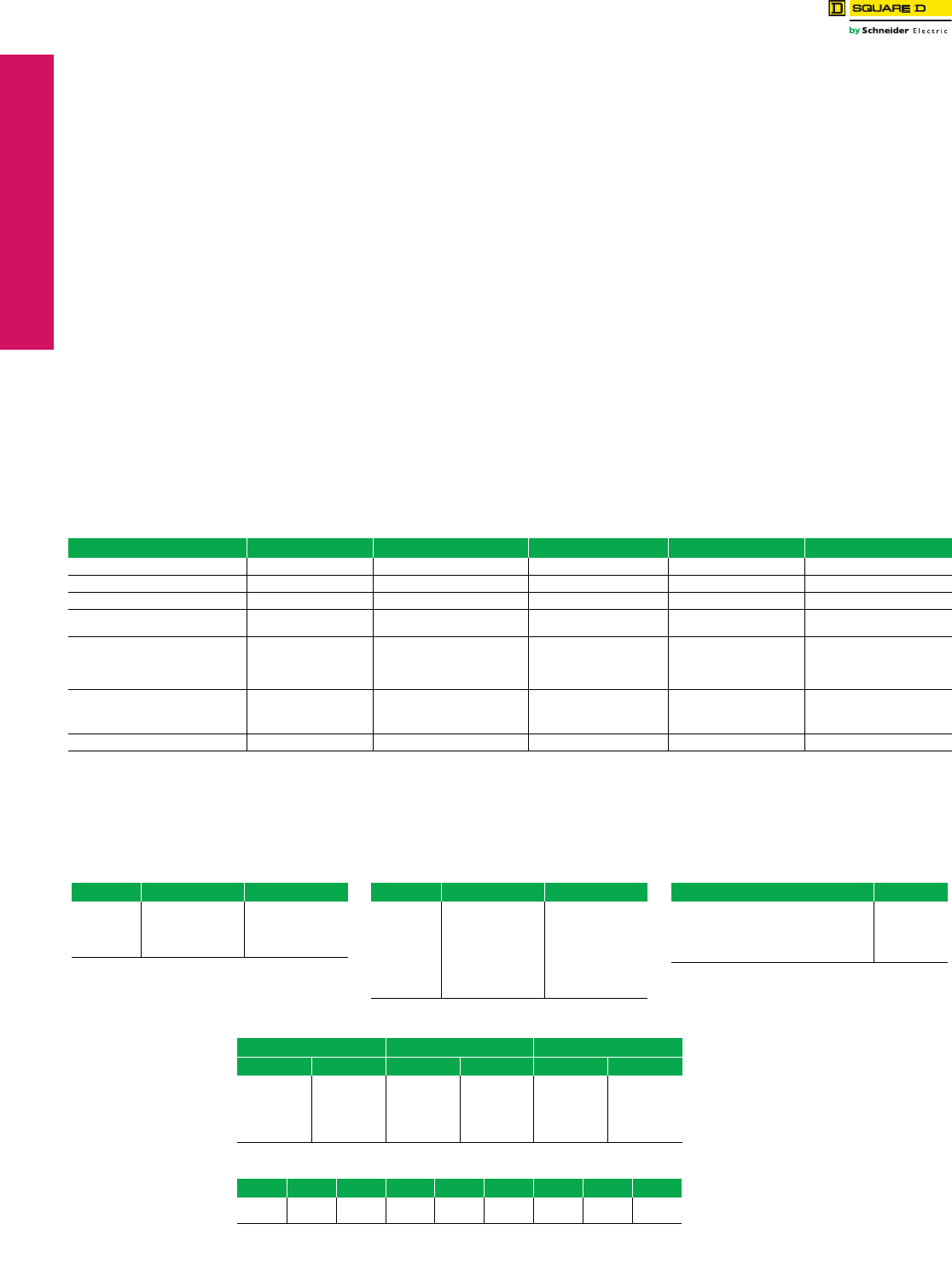
www.schneider-electric.us
17-18 © 2012 Schneider Electric
All Rights Reserved
17 NEMA DEFINITE PURPOSE TYPE
CONTACTORS AND STARTERS
Electromechanical
Reduced Voltage Starters
Description of All Types
Class 8600 / Refer to Catalog 8600CT9601
A squirrel cage motor draws high starting current (inrush) and produces high starting torque when started at full voltage.
While these values differ for different motor designs, for a typical NEMA design B motor, the inrush will be approximately
600% of the motor full load amperage (FLA) rating, and the starting torque will be approximately 150% of full load torque at
full voltage. High current inrush and starting torque can cause problems in the electrical and mechanical systems, or may
even damage the materials being processed.
When a motor is started at reduced voltage, the current at the motor terminals is reduced in direct proportion to the voltage
reduction, while the torque is reduced by the square of the voltage reduction. If the “typical” NEMA B motor is started at 70%
of line voltage, the starting current would be 70% of the full voltage value (that is, 0.70 x 600% = 420% FLA). The torque
would then be (0.70)2 or 49% of the normal starting torque (that is, 0.49 x 150% = 74% full load torque). Therefore, reduced
voltage starting provides an effective means of reducing both inrush current and starting torque.
If the motor has a high inertia or if the motor rating is marginal for the applied load, reducing the starting torque may prevent
the motor from reaching full speed before the thermal overload relays trip. Applications that require high starting torque
should be reviewed to determine if reduced voltage starting is suitable.
Square D™ offers several types of electromechanical as well as solid-state reduced voltage starters that provide different
starting characteristics. The following describes the 8600 series of reduced voltage starters.
Class 8606—Autotransformer Starter: Autotransformer starters provide reduced voltage to the motor terminals
during starting through the use of a tapped, three phase autotransformer. Taps on the autotransformer allow for
selection of the motor with 50%, 65%, or 80% of line voltage values supplying 50%, 65%, or 80% of the current inrush
seen during a full voltage start. The resulting starting torque will be 25%, 42%, or 64% of full voltage values, as will be
the current draw on the line. Thus, the autotransformer provides the maximum torque with minimum line current.
Class 8630—Wye-Delta Starter: Wye-delta starters can only be used on wye-delta motors which have six leads that
allow for motor winding to be connected in either a wye or delta configuration. During start up, the windings are
connected in the wye, resulting in 58% of line voltage applied across two windings. This reduces both inrush and
starting torque to 33% of the delta connected values. After a set time delay, the motor leads are switched to the delta
connection. The wye-delta starter is available in both open and closed transition configurations. Closed transition
starters are supplied with an additional contactor and resistor bank used to keep the motor windings energized for a
few cycles until the transition from wye to delta is complete.
Class 8640—Part Winding Starter: Part winding starters can be used only with part winding motors. During a part winding
start, only one winding is energized, reducing the inrush current to 60–70% (depending on the motor design) and starting
torque to 50% of normal starting values with both windings energized. Most (but not all) dual voltage 230/460 volt motors are
suitable for part winding starts at 230 volts.
1. Specify the Class Number and the Type Number.
2. If all coils are at the line voltage, and not Sizes 6 or 7, select the voltage code from Table 17.47 (Sizes 6 and 7 are supplied with a
fused transformer with 120 Vac as standard).
3. If the coils are at a different voltage than line supply, or Size 6 or 7, select a voltage code from Table 17.48 and also select a Form
code from Table 17.49 (note that a Form code may be used with any voltage code, except as noted).
Table 17.46: Starter Characteristics
Characteristic Full Voltage Autotransformer, Class 8606 Wye-Delta Class, 8630 Part Winding, Class 8640 Solid-State ATS46
Voltage at Motor 100% 50% / 65% / 80% (tap setting) 100% 100% Ramped Up
Line Current (% Full Load Current) 600% 150% / 250% / 380% 200% 390% 150% to 700% (adjustable)
Starting Torque (% Rated Torque) 150% 40% / 60% / 100% 50% 70% 0% to 100% (adjustable)
Start Time (Factory Setting) — 6–7 seconds 10 seconds / 15 seconds
(open/closed transition)
1–1.5 seconds 10 seconds
(adjustable 1–60 seconds)
Advantages •Simple
•Economical
•High Starting Torque
•High torque/amperage
•High inertial loads
•Flexibility
•High inertial loads
•Long acceleration loads
•Good torque/amperage
•Simple
•Small size
•Greatest flexibility
•Smooth ramp
•Solid-state overload relay
•Diagnostics
Disadvantages •Abrupt starts
•Large current inrush
•Large size •Low torque
•No flexibility
Not suitable for:
•High inertial loads
•Frequent starting
•SCR heat dissipation
•Ambient limitations
Motor Standard Standard Special Special Standard
bSee Table 17.50 for sizing of 380 V starters.
c24 V coils are not available on Sizes 4–7.
Table 17.47: Line Voltage Codes
Line Control Code
208
240
380
480
600
208
240
380
480
600
V08
V03
V05
V06
V07
Table 17.48: Coil Voltage Codes
Line Control Code
208
240
240
480
480
480
600
380
other
120
24
120
24
120
240
120
110/50
specify
V84
V82
V80
V83
V81
V87
V86
V95
V99
Table 17.49: Form Codes
Form Description Form Code
Fused CPT for timing relay only F4T
Fused CPT for all coils F4T40
Separate control of timing relay only S
Separate control for all coils Y195
Table 17.50: 380 Vac, 50 Hz Starters, Maxiumum Horsepower Rating
Autotransformer, Class 8606 Wye-Delta, Class 8630 Part Winding, Class 8640
Max. hp NEMA Size Max. hp NEMA Size Max. hp NEMA Size
—
25
50
75
150
300
—
2
3
4
5
6
15
40
75
150
250
500
1YD
2YD
3YD
4YD
5YD
6YD
15
40
75
125
250
500
1PW
2PW
3PW
4PW
5PW
6PW
Table 17.51: Coil Voltages
Hz Voltag e Code Voltage Code Volt age Code Vol tage Code
60
50
120
110 V02 240
220 V03 480
440 V06 600
550 V07
Reduced Voltage
Starting of Squirrel
Cage Motors
Electromechanical
Reduced Voltage
Starters
How to Order
Note: Tables 17.47 and 17.48 are
for 60 Hz; see Table 17.51
for 50 Hz codes.
380 Vac, 50 Hz
Starters The Class 8600 starters are available for 380 Vac,
50 Hz applications. Table 17.50 provides maximum
horsepower ratings. To determine the Type Number,
select the second digit based on NEMA size. Select the
fifth digit based on the horsepower requirement. Specify
V05 voltage code. List prices for the same NEMA size
starter apply.
The starters in this section can also be operated at
50 Hz at the coil voltages listed in Table 17.51.
For additional coil voltage availability, contact the
Customer Care Center (CCC) at 1-888-778-2733.
50 Hz Control
Voltage
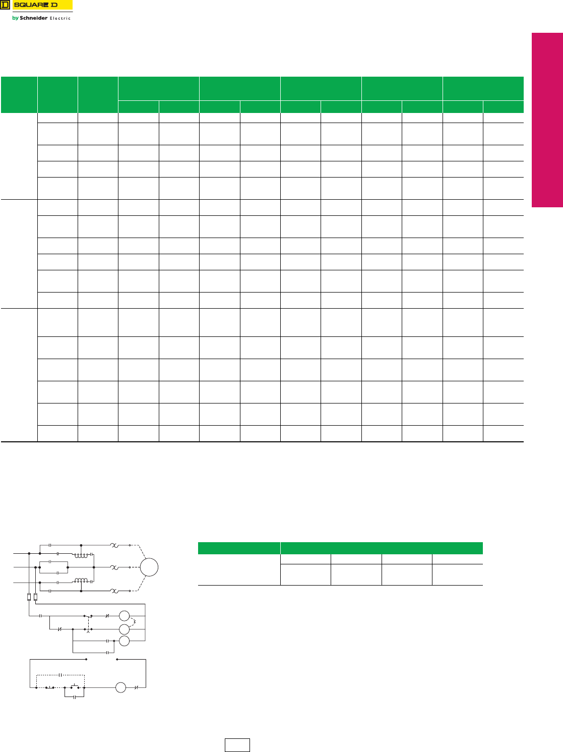
www.schneider-electric.us
17 NEMA DEFINITE PURPOSE TYPE
CONTACTORS AND STARTERS
© 2012 Schneider Electric
All Rights Reserved 17-19
Electromechanical
Reduced Voltage Starters
Autotransformer Starters
Class 8606 / Refer to Catalog 8600CT9601
NOTE: Prices shown do not include thermal units. Devices require 3 thermal units
(Sizes 00–6). Standard trip thermal units are $21.50 each. See Digest 176
page 16-116 for selection information.
eForms need to be specified only if any of the coils are at a different voltage than line supply (V8•).
See page 17-18 for a fuller explanation of how to order; this page also provides the necessary
coil voltage and Form codes as well as codes for 380 V starters and 50 Hz applications.
Table 17.52: 3-Pole Polyphase, 600 Vac Maximum, 50–60 Hz
Motor
Voltag e
(Starter
Volt age )
Max.
HP
NEMA
Size
NEMA Type 1
General Purpose
Enclosure
NEMA Type 4a
Watertight and
Dusttight Enclosure
NEMA Type 12/3Rd
Dusttight & Driptight
Industrial Use Enclosure
Open Type O.E.M. Kit c
Typeb$ Price Typeb$ Price Typeb$ Price Typeb$ Price Typeb$ Price
200
(208)
10 2 SDG1C 8076.00 SDW1C 12491.00 SDA1C 10641.00 SDO1C 7734.00 SDK1C 6786.00
15
20
25
3
SEG1D
SEG1E
SEG1F
9500.00
SEW1D
SEW1E
SEW1F
13914.00
SEA1D
SEA1E
SEA1F
13707.00
SEO1D
SEO1E
SEO1F
8418.00
SEK1D
SEK1E
SEK1F
7493.00
30
40 4SFG1G
SFG1H 18417.00 SFW1G
SFW1H 26535.00 SFA1G
SFA1H 21834.00 SFO1G
SFO1H 16848.00 SFK1G
SFK1H 13181.00
50
75 5SGG1J
SGG1L 30330.00 SGW1J
SGW1L 38448.00 SGA1J
SGA1L 34176.00 SGO1J
SGO1L 27167.00 SGK1J
SGK1L 23223.00
100
125
150
6
SHG1M
SHG1N
SHG1P
56507.00
SHW1M
SHW1N
SHW1P
67190.00
SHA1M
SHA1N
SHA1P
61848.00
SHO1M
SHO1N
SHO1P
51438.00
SHK1M
SHK1N
SHK1P
41481.00
230
(240)
10
15 2SDG1C
SDG1D 8076.00 SDW1C
SDW1D 12491.00 SDA1C
SDA1D 10641.00 SDO1C
SDO1D 7734.00 SDK1C
SDK1D 6786.00
20
25
30
3
SEG1E
SEG1F
SEG1G
9500.00
SEW1E
SEW1F
SEW1G
13914.00
SEA1E
SEA1F
SEA1G
12207.00
SEO1E
SEO1F
SEO1G
8418.00
SEK1E
SEK1F
SEK1G
7493.00
40
50 4SFG1H
SFG1J 18417.00 SFW1H
SFW1J 26535.00 SFA1H
SFA1J 21834.00 SFO1H
SFO1J 16848.00 SFK1H
SFK1J 13181.00
75
100 5SGG1L
SGG1M 30330.00 SGW1L
SGW1M 38448.00 SGA1L
SGA1M 34176.00 SGO1L
SGO1M 27167.00 SGK1L
SGK1M 23223.00
125
150
200
6
SHG1N
SHG1P
SHG1Q
56507.00
SHW1N
SHW1P
SHW1Q
67190.00
SHA1N
SHA1P
SHA1Q
61848.00
SHO1N
SHO1P
SHO1Q
51438.00
SHK1N
SHK1P
SHK1Q
41481.00
250
300 7SJG1R
SJG1S 96786.00 SJW1R
SJW1S 107468.00 SJA1R
SJA1S 102126.00 ——— —
460
(480)
/
575
(600)
10
15
20
25
2
SDG1C
SDG1D
SDG1E
SDG1F
8076.00
SDW1C
SDW1D
SDW1E
SDW1F
12491.00
SDA1C
SDA1D
SDA1E
SDA1F
10641.00
SDO1C
SDO1D
SDO1E
SDO1F
7734.00
SDK1C
SDK1D
SDK1E
SDK1F
6786.00
30
40
50
3
SEG1G
SEG1H
SEG1J
9500.00
SEW1G
SEW1H
SEW1J
13914.00
SEA1G
SEA1H
SEA1J
12207.00
SEO1G
SEO1H
SEO1J
8418.00
SEK1G
SEK1H
SEK1J
7493.00
60
75
100
4
SFG1K
SFG1L
SFG1M
18417.00
SFW1K
SFW1L
SFW1M
26535.00
SFA1K
SFA1L
SFA1M
21834.00
SFO1K
SFO1L
SFO1M
16848.00
SFK1K
SFK1L
SFK1M
13181.00
125
150
200
5
SGG1N
SGG1P
SGG1Q
30330.00
SGW1N
SGW1P
SGW1Q
38448.00
SGA1N
SGA1P
SGA1Q
34176.00
SGO1N
SGO1P
SGO1Q
27167.00
SGK1N
SGK1P
SGK1Q
23223.00
250
300
400
6
SHG1R
SHG1S
SHG1T
56507.00
SHW1R
SHW1S
SHW1T
67190.00
SHA1R
SHA1S
SHA1T
61848.00
SHO1R
SHO1S
SHO1T
51438.00
SHK1R
SHK1S
SHK1T
41481.00
500
600 7SJG1U
SJG1W 96786.00 SJW1U
SJW1W 107468.00 SJA1U
SJA1W 102126.00 SJO1W 88250.00 ——
aNEMA Type 4 enclosures are painted sheet steel. Where required, stainless steel enclosures are available at extra cost.Specify as Form G17. See “Modifications & Forms” for price adder.
bBoth line and control voltage must be specified to order this product. See page 17-18 for the necessary codes and instructions for ordering.
cNo factory modifications (Forms) are available with O.E.M. Kit.
dNEMA Type 12 enclosures can be field modified for outdoor non-corrosive and non-service entrance rated applications.
Note: Class 8606 starters are supplied with a NEMA style medium duty autotransformer.
Medium duty service includes applications to motors which drive loads such as fans, pumps, compressors, and line shafts.
NEMA Sizes 2–5: Autotransformer is rated for fifteen 15-second starts per hour.
NEMA Sizes 6–7: Autotransformer is rated for three 30-second starts per hour.
Contact the Customer Care Center (CCC) at 1-888-778-2733 for applications which require frequent starting or jogging, or have extremely high inertia.
Table 17.53: How to Order
To Order Specify: Catalog Number
•Class Number
•Type Number
•Voltage Code
•Form(s)e
Class Type Voltage Code Form(s)
8606 SFG1M V81 S
Description: 100 hp, 480 V line, 120 V separate control, 60 Hz
ROL
L2
L3
L1
T1
OL T2
2S 1S
1S
R
R
2S
OL T3
TR
1S
2S
Motor
2S
10 0
80
65
50
0
10 0
80
65
50
0
R
1S
2S
TR
TR 1S
R
OL
To
Separate
Control
TR
1Stop Start
23
2 Wire Control
Device (If used)
Typical Autotransformer Starter
Sizes 2–5
Separate Control (Form S)
CP1 Discount
Schedule
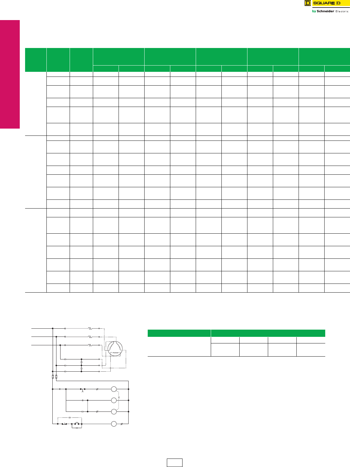
www.schneider-electric.us
17 NEMA DEFINITE PURPOSE TYPE
CONTACTORS AND STARTERS
17-20 © 2012 Schneider Electric
All Rights Reserved
Electromechanical
Reduced Voltage Starters
Wye-Delta Starters (Open Transition)
Class 8630 / Refer to Catalog 8600CT9601
NOTE: Prices shown do not include thermal units. Devices require 3 thermal units
(Sizes 00–6). Standard trip thermal units are $21.50 each. See Digest 176 page
16-116 for selection information.
eForms need to be specified only if any of the coils are at a different voltage than line supply (V8•).
See page 17-18 for a fuller explanation of how to order; this page also provides the necessary
coil voltage and Form codes as well as codes for 380 V starters and 50 Hz applications.
Refer to page 17-32 for other factory modifications (Forms).
Table 17.54: 3-Pole Polyphase, 600 Vac Maximum, 50–60 Hz
Motor
Volt age
(Starter
Voltage )
Max.
HP
NEMA
Size
NEMA Type 1
General Purpose
Enclosure
NEMA Type 4a
Watertight and
Dusttight Enclosure
(Stainless Steel 1YD-4YD)
NEMA Type 12/3Rd
Dusttight & Driptight
Industrial Use Enclosure
Open Type O.E.M. Kit c
Typeb$ Price Typeb$ Price Typeb$ Price Typeb$ Price Typeb$ Price
200
(208)
10 1YD SCG1C 4892.00 SCW1C 6602.00 SCA1C 6317.00 SCO1C 4806.00 ——
15
20 2YD SDG1D
SDG1E 5790.00 SDW1D
SDW1E 7713.00 SDA1D
SDA1E 7569.00 SDO1D
SDO1E 5562.00 ——
25
30
40
3YD
SEG1F
SEG1G
SEG1H
8424.00
SEW1F
SEW1G
SEW1H
11204.00
SEA1F
SEA1G
SEA1H
10562.00
SEO1F
SEO1G
SEO1H
7542.00
SEK1F
SEK1G
SEK1H
6596.00
50
60 4YD SFG1J
SFG1K 17568.00 SFW1J
SFW1K 21941.00 SFA1J
SFA1K 20417.00 SFO1J
SFO1K 15987.00 SFK1J
SFK1K 9300.00
75
100
125
150
5YD
SGG1L
SGG1M
SGG1N
SGG1P
31584.00
SGW1L
SGW1M
SGW1N
SGW1P
39702.00
SGA1L
SGA1M
SGA1N
SGA1P
35429.00
SGO1L
SGO1M
SGO1N
SGO1P
28422.00
SGK1L
SGK1M
SGK1N
SGK1P
18530.00
200
250
300
6YD
SHG1Q
SHG1R
SHG1S
67589.00
SHW1Q
SHW1R
SHW1S
78272.00
SHA1Q
SHA1R
SHA1S
72930.00
SHO1Q
SHO1R
SHO1S
62519.00
SHK1Q
SHK1R
SHK1S
39347.00
230
(240)
10 1YD SCG1C 4892.00 SCW1C 6602.00 SCA1C 6317.00 SCO1C 4806.00 ——
15
20
25
2YD
SDG1D
SDG1E
SDG1F
5790.00
SDW1D
SDW1E
SDW1F
7713.00
SDA1D
SDA1E
SDA1F
7569.00
SDO1D
SDO1E
SDO1F
5562.00 ——
30
40
50
3YD
SEG1G
SEG1H
SEG1J
8424.00
SEW1G
SEW1H
SEW1J
11204.00
SEA1G
SEA1H
SEA1J
10562.00
SEO1G
SEO1H
SEO1J
7542.00
SEK1G
SEK1H
SEK1J
6596.00
60
75 4YD SFG1K
SFG1L 17568.00 SFW1K
SFW1L 21941.00 SFA1K
SFA1L 20417.00 SFO1K
SFO1L 15987.00 SFK1K
SFK1L 9300.00
100
125
150
5YD
SGG1M
SGG1N
SGG1P
31584.00
SGW1M
SGW1N
SGW1P
39702.00
SGA1M
SGA1N
SGA1P
35429.00
SGO1M
SGO1N
SGO1P
28422.00
SGK1M
SGK1N
SGK1P
18530.00
200
250
300
6YD
SHG1Q
SHG1R
SHG1S
67589.00
SHW1Q
SHW1R
SHW1S
78272.00
SHA1Q
SHA1R
SHA1S
72930.00
SHO1Q
SHO1R
SHO1S
62519.00
SHK1Q
SHK1R
SHK1S
39347.00
400
500 7YD SJG1T
SJG1U 91160.00 SJW1T
SJW1U 101843.00 SJA1T
SJA1U 96501.00 SJO1T
SJO1U 86090.00 ——
460
(480)
/
575
(600)
10
15 1YD SCG1C
SCG1D 4892.00 SCW1C
SCW1D 6602.00 SCA1C
SCA1D 6317.00 SCO1C
SCO1D 4806.00 ——
20
25
30
40
2YD
SDG1E
SDG1F
SDG1G
SDG1H
5790.00
SDW1E
SDW1F
SDW1G
SDW1H
7713.00
SDA1E
SDA1F
SDA1G
SDA1H
7569.00
SDO1E
SDO1F
SDO1G
SDO1H
5562.00 ——
50
60
75
3YD
SEG1J
SEG1K
SEG1L
8424.00
SEW1J
SEW1K
SEW1L
11204.00
SEA1J
SEA1K
SEA1L
10562.00
SEO1J
SEO1K
SEO1L
7542.00
SEK1J
SEK1K
SEK1L
6596.00
100
125
150
4YD
SFG1M
SFG1N
SFG1P
17568.00
SFW1M
SFW1N
SFW1P
21941.00
SFA1M
SFA1N
SFA1P
20417.00
SFO1M
SFO1N
SFO1P
15987.00
SFK1M
SFK1N
SFK1P
9300.00
200
250
300
5YD
SGG1Q
SGG1R
SGG1S
31584.00
SGW1Q
SGW1R
SGW1S
39702.00
SGA1Q
SGA1R
SGA1S
35429.00
SGO1Q
SGO1R
SGO1S
28422.00
SGK1Q
SGK1R
SGK1S
18530.00
400
500
600
6YD
SHG1T
SHG1U
SHG1W
67589.00
SHW1T
SHW1U
SHW1W
78272.00
SHA1T
SHA1U
SHA1W
72930.00
SHO1T
SHO1U
SHO1W
62519.00
SHK1T
SHK1U
SHK1W
39347.00
800
1000 7YD SJG1Y
SJG1Z 91160.00 SJW1Y
SJW1Z 101843.00 SJA1Y
SJA1Z 96501.00 SJO1Y
SJO1Z 86090.00 ——
aNEMA Type 4 enclosures are painted sheet steel. Where required, stainless steel enclosures are available at extra cost. Specify as Form G17. See page 17-32 for price adder.
bBoth line and control voltage must be specified to order this product. See page 17-18 for the necessary codes and instructions for ordering.
cNo Factory Modifications (Forms) available with O.E.M. Kit.
dNEMA Type 12 enclosures may be field modified for outdoor non-corrosive and non-service entrance rated applications. See Digest 176 page 16-95 for more information.
Table 17.55: How to Order
To Order Specify: Catalog Number
•Class Number
•Type Number
•Voltage Code
•Form(s)e
Class Type Voltage Code Form(s)
8630 SFG1M V06
Description: 100 hp, 480 V line, 480 V common control, 60 Hz
T4 T2
T1 T5
T6 T3
T2
T3
T5
T4
T6
T1
S
S
1M
1M
1M
OL
OL
OL
L1
L2
L3
2M
2M
2M
TR
3
1Stop Start
2
TR
TR
S
1M S
2M
2M
1M
S
TR OL
Moto
r
2 Wire Control Device (If used)
Typical Wye-Delta Starter Sizes 1–4 (Open Transition)
Common Control (Standard)
CP1 Discount
Schedule
www.schneider-electric.us
17 NEMA DEFINITE PURPOSE TYPE
CONTACTORS AND STARTERS
© 2012 Schneider Electric
All Rights Reserved 17-21
Electromechanical
Reduced Voltage Starters
Wye-Delta Starters (Closed Transition)
Class 8630 / Refer to Catalog 8600CT9601
NOTE: Prices shown do not include thermal units. Devices require 3 thermal units
(Sizes 00–6). Standard trip thermal units are $21.50 each. See Digest 176 page
16-116 for selection information.
eForms need to be specified only if any of the coils are at a different voltage than line supply (V8 •).
See page 17-18 for a fuller explanation of how to order; this page also provides the necessary
coil voltage and Form codes as well as codes for 380 V starters and 50 Hz applications.
Refer to page 17-32 for other factory modifications (Forms).
Table 17.56: 3-Pole Polyphase, 600 Vac Maximum, 50–60 Hz
Motor
Voltag e
(Starter
Volt age )
Max.
HP
NEMA
Size
NEMA Type 1
General Purpose
Enclosure
NEMA Type 4d
Watertight and
Dusttight Enclosure
(Stainless Steel 1YD-4YD)
NEMA Type 12/3Rc
Dusttight & Driptight
Industrial Use Enclosure
Open Type O.E.M. Kit b
Typea$ Price Typea$ Price Typea$ Price Typea$ Price Typea$ Price
200
(208)
10 1YD SCG2C 7470.00 SCW2C 9180.00 SCA2C 8895.00 SCO2C 7385.00 ——
15
20 2YD SDG2D
SDG2E 8454.00 SDW2D
SDW2E 10376.00 SDA2D
SDA2E 10233.00 SDO2D
SDO2E 8226.00 ——
25
30
40
3YD
SEG2F
SEG2G
SEG2H
11672.00
SEW2F
SEW2G
SEW2H
14450.00
SEA2F
SEA2G
SEA2H
13809.00
SEO2F
SEO2G
SEO2H
10790.00
SEK2F
SEK2G
SEK2H
10142.00
50
60 4YD SFG2J
SFG2K 22995.00 SFW2J
SFW2K 27368.00 SFA2J
SFA2K 25844.00 SFO2J
SFO2K 21414.00 SFK2J
SFK2K 13931.00
75
100
125
150
5YD
SGG2L
SGG2M
SGG2N
SGG2P
38363.00
SGW2L
SGW2M
SGW2N
SGW2P
46481.00
SGA2L
SGA2M
SGA2N
SGA2P
42209.00
SGO2L
SGO2M
SGO2N
SGO2P
35202.00
SGK2L
SGK2M
SGK2N
SGK2P
25181.00
200
250
300
6YD
SHG2Q
SHG2R
SHG2S
85022.00
SHW2Q
SHW2R
SHW2S
95702.00
SHA2Q
SHA2R
SHA2S
90363.00
SHO2Q
SHO2R
SHO2S
79950.00
SHK2Q
SHK2R
SHK2S
50319.00
230
(240)
10 1YD SCG2C 7470.00 SCW2C 9180.00 SCA2C 8895.00 SCO2C 7385.00 ——
15
20
25
2YD
SDG2D
SDG2E
SDG2F
8454.00
SDW2D
SDW2E
SDW2F
10376.00
SDA2D
SDA2E
SDA2F
10233.00
SDO2D
SDO2E
SDO2F
8226.00
—
—
—
—
30
40
50
3YD
SEG2G
SEG2H
SEG2J
11672.00
SEW2G
SEW2H
SEW2J
14450.00
SEA2G
SEA2H
SEA2J
13809.00
SEO2G
SEO2H
SEO2J
10790.00
SEK2G
SEK2H
SEK2J
10142.00
60
75 4YD SFG2K
SFG2L 22995.00 SFW2K
SFW2L 27368.00 SFA2K
SFA2L 25844.00 SFO2K
SFO2L 21414.00 SFK2K
SFK2L 13931.00
100
125
150
5YD
SGG2M
SGG2N
SGG2P
38363.00
SGW2M
SGW2N
SGW2P
46481.00
SGA2M
SGA2N
SGA2P
42209.00
SGO2M
SGO2N
SGO2P
35202.00
SGK2M
SGK2N
SGK2P
25181.00
200
250
300
6YD
SHG2Q
SHG2R
SHG2S
85022.00
SHW2Q
SHW2R
SHW2S
95702.00
SHA2Q
SHA2R
SHA2S
90363.00
SHO2Q
SHO2R
SHO2S
79950.00
SHK2Q
SHK2R
SHK2S
50319.00
400
500 7YD SJG2T
SJG2U 118206.00 SJW2T
SJW2U 128888.00 SJA2T
SJA2U 123548.00 SJO2T
SJO2U 113135.00 —
——
460
(480)
/
575
(600)
10
15 1YD SCG2C
SCG2D 7470.00 SCW2C
SCW2D 9180.00 SCA2C
SCA2D 8895.00 SCO2C
SCO2D 7385.00 —
——
20
25
30
40
2YD
SDG2E
SDG2F
SDG2G
SDG2H
8454.00
SDW2E
SDW2F
SDW2G
SDW2H
10376.00
SDA2E
SDA2F
SDA2G
SDA2H
10233.00
SDO2E
SDO2F
SDO2G
SDO2H
8226.00
—
—
—
—
—
50
60
75
3YD
SEG2J
SEG2K
SEG2L
11672.00
SEW2J
SEW2K
SEW2L
14450.00
SEA2J
SEA2K
SEA2L
13809.00
SEO2J
SEO2K
SEO2L
10790.00
SEK2J
SEK2K
SEK2L
10142.00
100
125
150
4YD
SFG2M
SFG2N
SFG2P
22995.00
SFW2M
SFW2N
SFW2P
27368.00
SFA2M
SFA2N
SFA2P
25844.00
SFO2M
SFO2N
SFO2P
21414.00
SFK2M
SFK2N
SFK2P
13931.00
200
250
300
5YD
SGG2Q
SGG2R
SGG2S
38363.00
SGW2Q
SGW2R
SGW2S
46481.00
SGA2Q
SGA2R
SGA2S
42209.00
SGO2Q
SGO2R
SGO2S
35202.00
SGK2Q
SGK2R
SGK2S
25181.00
400
500
700
6YD
SHG2T
SHG2U
SHG2W
85022.00
SHW2T
SHW2U
SHW2W
95702.00
SHA2T
SHA2U
SHA2W
90363.00
SHO2T
SHO2U
SHO2W
79950.00
SHK2T
SHK2U
SHK2W
50319.00
800
1000 7YD SJG2Y
SJG2Z 118206.00 SJW2Y
SJW2Z 128888.00 SJA2Y
SJA2Z 123548.00 SJO2Y
SJO2Z 113135.00 —
——
aBoth line and control voltage must be specified to order this product. See page 17-18 for the necessary codes and instructions for ordering.
bNo Factory Modifications (Forms) available with O.E.M. Kit.
cNEMA Type 12 enclosures may be field modified for outdoor non-corrosive and non-service entrance rated applications. See Digest 176 page 16-95 for more information.
dNEMA Type 4 enclosures are painted sheet steel. Where required, stainless steel enclosures are available at extra cost. Specify as Form G17. See page 17-32 for price adder.
Table 17.57: How to Order
To Order Specify: Catalog Number
•Class Number
•Type Number
•Voltage Code
•Form(s)e
Class Type Voltage Code Form(s)
8630 SFG1M V81 F4T40
Description: 100 hp, 480 V line, 120 V separate control, 60 Hz
OL T1
T1
OL T2
T2
OL T3
T3
T6 T6
T4
T4
T5
T5
1M
2S
2S
2S
1S
1S
1M
1M
2M
2M
2M
L1
L2
L3
OL
2S
1S
1S
1M
2M
TR
TR
TR
(HI) PRI
SEC(X1) (X2)
GND (If used)
PT
TR
1S
2S
1M
2M
23
1Stop Start
2 Wire Control
Device (If used)
R
E
S
R
E
S
R
E
S
Motor
Typical Wye-Delta Starter
Sizes 1–4 (Closed Transition)
Fused Control Transformer (Form F4T40)
CP1 Discount
Schedule
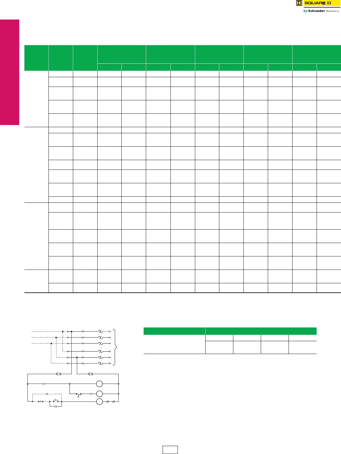
www.schneider-electric.us
17 NEMA DEFINITE PURPOSE TYPE
CONTACTORS AND STARTERS
17-22 © 2012 Schneider Electric
All Rights Reserved
Electromechanical
Reduced Voltage Starters
Part Winding Starters
Class 8640 / Refer to Catalog 8600CT9601
NOTE: Prices shown do not include thermal units. Devices require 6 thermal units
(Sizes 00–6). Standard trip thermal units are $21.50 each. See Digest 176
page 16-116 for selection information.
eForms need to be specified only if any of the coils are at a different voltage than line supply (V8•).
See page 17-18 for a fuller explanation of how to order; this page also provides the necessary
coil voltage and Form codes as well as codes for 380 V starters and 50 Hz applications.
Refer to page 17-32 for other factory modifications (Forms).
Table 17.58: 3-Pole Polyphase—600 Vac Maximum—50–60 Hz
Motor
Voltag e
(Starter
Volt age )
Max.
HP
NEMA
Size
NEMA Type 1
General Purpose
Enclosure
NEMA Type 4a
Watertight and
Dusttight Enclosure
(Stainless Steel 1PW–4PW)
NEMA Type 12/3Rd
Dusttight & Driptight
Industrial Use Enclosure
Open Type O.E.M. Kit c
Typeb$ Price Typeb$ Price Typeb$ Price Typeb$ Price Typeb$ Price
200
(208)
10 1PW SCG1C 3119.00 SCW1C 4829.00 SCA1C 4544.00 SCO1C 3033.00 ——
15
20 2PW SDG1D
SDG1E 4445.00 SDW1D
SDW1E 6368.00 SDA1D
SDA1E 6224.00 SDO1D
SDO1E 4217.00 SDK1D
SDK1E 2685.00
25
30
40
3PW
SEG1F
SEG1G
SEG1H
6267.00
SEW1F
SEW1G
SEW1H
9045.00
SEA1F
SEA1G
SEA1H
8405.00
SEO1F
SEO1G
SEO1H
5868.00
SEK1F
SEK1G
SEK1H
4359.00
50
60
75
4PW
SFG1J
SFG1K
SFG1L
13404.00
SFW1J
SFW1K
SFW1L
17775.00
SFA1J
SFA1K
SFA1L
16253.00
SFO1J
SFO1K
SFO1L
12662.00
SFK1J
SFK1K
SFK1L
8217.00
100
125
150
5PW
SGG1M
SGG1N
SGG1P
28071.00
SGW1M
SGW1N
SGW1P
36192.00
SGA1M
SGA1N
SGA1P
31919.00
SGO1M
SGO1N
SGO1P
26505.00
SGK1M
SGK1N
SGK1P
18621.00
230
(240)
10 1PW SCG1C 3119.00 SCW1C 4829.00 SCA1C 4544.00 SCO1C 3033.00 ——
15
20
25
2PW
SDG1D
SDG1E
SDG1F
4445.00
SDW1D
SDW1E
SDW1F
6368.00
SDA1D
SDA1E
SDA1F
6224.00
SDO1D
SDO1E
SDO1F
4217.00
SDK1D
SDK1E
SDK1F
2685.00
30
40
50
3PW
SEG1G
SEG1H
SEG1J
6267.00
SEW1G
SEW1H
SEW1J
9045.00
SEA1G
SEA1H
SEA1J
8405.00
SEO1G
SEO1H
SEO1J
5868.00
SEK1G
SEK1H
SEK1J
4359.00
60
75 4PW SFG1K
SFG1L 13404.00 SFW1K
SFW1L 17775.00 SFA1K
SFA1L 16253.00 SFO1K
SFO1L 12662.00 SFK1K
SFK1L 8217.00
100
125
150
5PW
SGG1M
SGG1N
SGG1P
28071.00
SGW1M
SGW1N
SGW1P
36192.00
SGA1M
SGA1N
SGA1P
31919.00
SGO1M
SGO1N
SGO1P
26505.00
SGK1M
SGK1N
SGK1P
18621.00
200
250
300
6PW
SHG1Q
SHG1R
SHG1S
58694.00
SHW1Q
SHW1R
SHW1S
67338.00
SHA1Q
SHA1R
SHA1S
65816.00
SHO1Q
SHO1R
SHO1S
53622.00 ——
400 7PW SJG1T 89672.00 SJW1T 98865.00 SJA1T 98217.00 SJO1T 80699.00 ——
460
(480)
/
575
(600)
10
15 1PW SCG1C
SCG1D 3119.00 SCW1C
SCW1D 4829.00 SCA1C
SCA1D 4544.00 SCO1C
SCO1D 3033.00 —
——
20
25
30
40
2PW
SDG1E
SDG1F
SDG1G
SDG1H
4445.00
SDW1E
SDW1F
SDW1G
SDW1H
6368.00
SDA1E
SDA1F
SDA1G
SDA1H
6224.00
SDO1E
SDO1F
SDO1G
SDO1H
4217.00
SDK1E
SDK1F
SDK1G
SDK1H
2685.00
50
60
75
3PW
SEG1J
SEG1K
SEG1L
6267.00
SEW1J
SEW1K
SEW1L
9045.00
SEA1J
SEA1K
SEA1L
8405.00
SEO1J
SEO1K
SEO1L
5868.00
SEK1J
SEK1K
SEK1L
4359.00
100
125
150
4PW
SFG1M
SFG1N
SFG1P
13404.00
SFW1M
SFW1N
SFW1P
17775.00
SFA1M
SFA1N
SFA1P
16253.00
SFO1M
SFO1N
SFO1P
12662.00
SFK1M
SFK1N
SFK1P
8217.00
200
250
350
5PW
SGG1Q
SGG1R
SGG1S
28071.00
SGW1Q
SGW1R
SGW1S
36192.00
SGA1Q
SGA1R
SGA1S
31919.00
SGO1Q
SGO1R
SGO1S
26505.00
SGK1Q
SGK1R
SGK1S
18621.00
460
(480)
/
575
(600)
400
500
600
6PW
SHG1T
SHG1U
SHG1W
58694.00
SHW1T
SHW1U
SHW1W
67338.00
SHA1T
SHA1U
SHA1W
65816.00
SHO1T
SHO1U
SHO1W
53622.00 ——
700
800 7PW SJG1X
SJG1Y 89672.00 SJW1X
SJW1Y 98865.00 SJA1X
SJA1Y 98217.00 SJO1X
SJO1Y 80699.00 —
——
aNEMA Type 4 enclosures are painted sheet steel. Where required, stainless steel enclosures are available at extra cost. Specifiy as Form G17. See page 17-32 for price adder.
bBoth line and control voltage must be specified to order this product. See page 17-18 for the necessary codes and instructions for ordering.
cNo Factory Modifications (Forms) available with O.E.M. Kit.
dNEMA Type 12 enclosures may be field modified for outdoor non-corrosive and non-service entrance rated applications. See Digest 176 page 16-95 for more information.
OL1 OL2
S
S
R
TR
TR
TR
TR
1Stop Start
23
L1
L2
L3
R
R
S
S
S
SOL2
OL1
OL1
OL1
OL2
OL2 A
B
C
D
E
F
To Motor
2 Wire Control
Device (If used)
Typical Part Winding
Sizes 1–4
Common Control (Standard)
Table 17.59: How to Order
To Order Specify: Catalog Number
•Class Number
•Type Number
•Voltage Code
•Form(s)e
Class Type Voltage Code Form(s)
8640 SFG1M V06 C
Description: 100 hp, 480 V line, 480 V common control, 60 Hz
CP1 Discount
Schedule
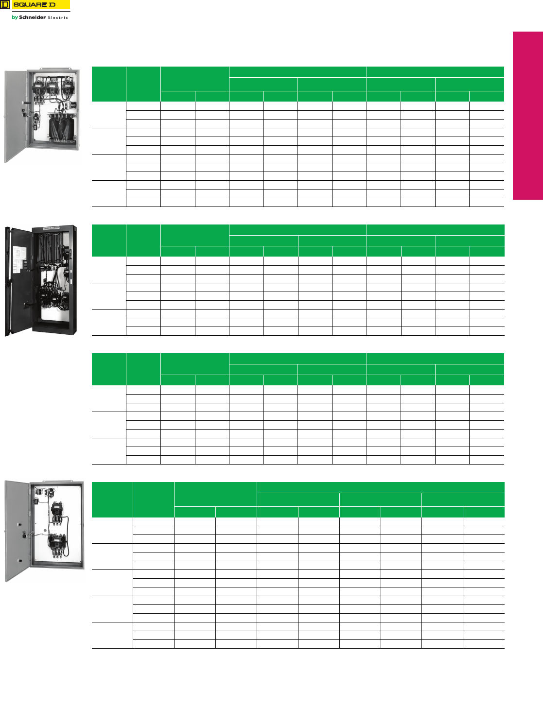
www.schneider-electric.us
© 2012 Schneider Electric
All Rights Reserved 17-23
17 NEMA DEFINITE PURPOSE TYPE
CONTACTORS AND STARTERS
Electromechanical
Reduced Voltage Starters
Approximate Dimensions
Class 8606, 8630, 8640 / Refer to Catalog 8600CT9601
Approximate Dimensions—Not for Construction
Note: H = Height, W = Width, D = Depth
aSubtract 8 in. from height for Type 1 or 12 enclosure.
bFree standing enclosure. Combination Starter Form Reference
Circuit Breaker: Y791, Y7911
Nonfusible Disconnect Switch: Y792, Y7910
Fusible Disconnect Switch: Y793-Y799
Refer to page 17-32 for a complete listing of Forms for combination devices.
Class 8606
Autotransformer
Table 17.60: Class 8606—Autotransformer
NEMA
Size Dim. Open
NEMA Type 1 / 12 Enclosure NEMA Type 4 Enclosure
Non-Combo or Combo
with Circuit Breaker
Combo
with Disconnect Switch
Non-Combo or Combo
with Circuit Breaker
Combo
with Disconnect Switch
in. mm in. mm in. mm in. mm in. mm
2
H 43 1092 52 1320 52 1320 52 1320 52 1320
W 22 559 25 635 25 635 25 635 25 635
D 8 203 10 254 10 254 10 254 10 254
3 or 4
H63160070b1778 70b1778 75b1778 75b1778
W 28 711 32 813 32 813 32 813 32 813
D 9 229 16 406 16 406 16 406 16 406
5
H63160070b1778 90b2286 75b1778 95b 2413
W 28 711 32 813 36 914 32 813 36 914
D 9 229 16 406 16 406 16 406 16 406
6
H56142290b2286 90b2286 98b2489 98b2489
W 30 762 34 864 64 1626 34 864 64 1626
D 14 354 20 508 24 610 20 508 24 610
Class 8630
Wye-Delta
Table 17.61: Class 8630—Wye-Delta, Open Transition
NEMA
Size Dim. Open NEMA Type 1 / 12 Enclosure NEMA Type 4 Enclosure
Non-Combo Combo Non-Combo Combo
in. mm in. mm in. mm in. mm in. mm
1YD
or
2YD
H 21 553 25 635 25 635 25 635 — —
W 21 553 23 584 23 584 23 584 — —
D 7 178 8 203 8 203 8 203 — —
3YD
or
4YD
H 42 1067 48 1219 49 1245 48 1219 49 1245
W 25 635 28 712 30 762 28 712 30 762
D 7 178 8 203 11 279 8 203 11 279
5YD
or
6YD
H62157690b2286 90b2286 98b2489 98b2489
W 29 737 36 914 36 914 36 914 36 914
D 10 254 16 406 16 406 16 406 16 406
Table 17.62: Class 8630—Wye-Delta, Closed Transition
NEMA
Size Dim. Open NEMA Type 1 / 12 Enclosure NEMA Type 4 Enclosure
Non-Combo Combo Non-Combo Combo
in. mm in. mm in. mm in. mm in. mm
1YD
or
2YD
H 21 553 25 635 25 635 25 635 — —
W 21 553 23 584 23 584 23 584 — —
D 14 354 16 406 16 406 16 406 — —
3YD
or
4YD
H 42 1067 48 1219 49 1245 48 1219 49 1245
W 25 635 28 712 30 762 28 712 30 762
D 14 354 16 406 18 457 16 406 18 457
5YD
or
6YD
H80203290b2286 90b2286 98b2489 98b2489
W 30 762 36 914 36 914 36 914 36 914
D 12 305 16 406 16 406 16 406 16 406
Class 8640
Part Winding
Table 17.63: Class 8640—Part Winding
NEMA
Size Dim. Open
Enclosed—NEMA Type 1 / 4 / 12
Non-Combo Combo with Circuit Breaker Combo with Disconnect
Switch
in. mm in. mm in. mm in. mm
1PW
or
2PW
H 21 553 25 635 34 853 25 635
W 21 553 23 584 19 483 23 584
D 6 152 8 203 11 279 8 203
3PW
H 42 1067 48 1219 44 1118 52 1321
W 26 660 28 712 30 762 25 635
D 7 178 8 203 12 305 11 279
4PW
H 42 1067 48 1219 44 1118 78b1981
W 26 660 28 712 30 762 32 813
D 7 178 8 203 12 305 16 406
5PW
H 35 889 44 1118 78ba 1981 78ba 1981
W 22 559 24 610 36 914 36 914
D 10 254 12 305 16 406 16 406
6PW
H 49 1245 64 1626 — — 90b2286
W 24 610 28 712 — — 64 1626
D 11 279 16 406 — — 24 406
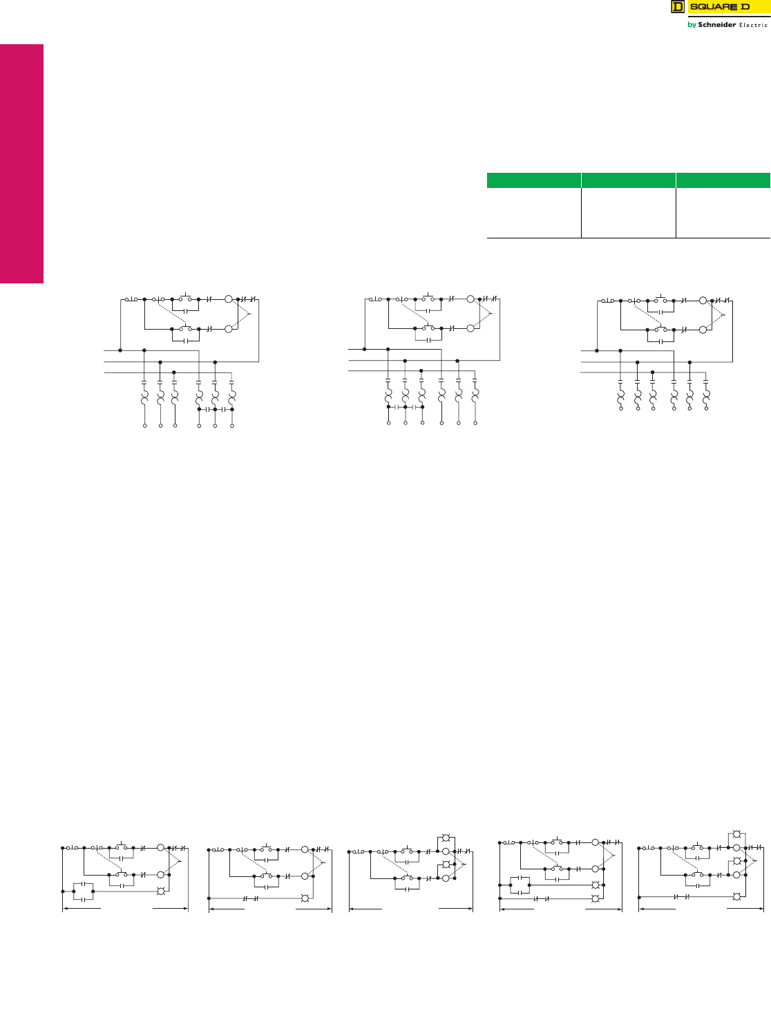
www.schneider-electric.us
17-24 © 2012 Schneider Electric
All Rights Reserved
17 NEMA DEFINITE PURPOSE TYPE
CONTACTORS AND STARTERS
Multispeed Magnetic
Starters
Application Data
Class 8810 / Refer to Catalog 8502CT9701
Multispeed motors are available in two basic versions:
1) separate winding, and 2) consequent pole. A separate
winding motor has a winding for each speed while a
consequent pole motor has a winding for every two speeds
(three-speed motors have two windings). The motor
connections (and thus the types of controllers) for two
speed starters are exemplified by the schematic diagrams
shown below. Note that consequent pole two-speed
controllers involve a 5-pole and a 3-pole starter, while
separate winding controllers have two 3-pole starters.
Verify the type of motor before ordering. Field
modification of starters to match the motor may not
be possible.
Separate winding motors are usually chosen when
flexibility is important, since the speeds of a consequent
pole motor are usually limited to a 2/1 ratio; a broad range
of speeds can be obtained on a separate winding motor.
Both separate winding and consequent pole motors are
available in three types: 1) constant horsepower,
2) constant torque, and 3) variable torque. Table 17.64
shows typical applications for these different types of
motors.
NOTE: For detailed information involving the technical
aspects of flexibility of the starters used in the
multispeed controllers, see Classes 8702,
8736, and 8810 application data.
Additional Features—Special Relays for
Non-Reversing and Reversing Multispeed
Starters
General. Some applications require special relays to
control the speed change and/or starting of the motor.
The descriptions that follow cover the four common relay
schemes for these applications.
Form R1 Compelling Relay. This relay requires the
motor to be started at low speed before any higher speed
can be selected. This arrangement ensures that the motor
will always start the load at low speed. The stop button
must be pressed before it is possible to change from a
higher to a lower speed. (Not available with Form R2.)
Form R2 Accelerating Relay/Timer. With Form R2
accelerating relays, the ultimate speed is determined by
the button which is pressed, but the starter will start the
motor at low speed and automatically accelerate it through
successive steps until the selected speed is reached.
Definite time intervals must elapse between each speed
change. Individual adjustable timing relays are provided
for each interval.
The stop button must be pressed before it is possible to
change from a higher to a lower speed.
(Not available with Form R1.)
Form R3 Decelerating Relay/Timer. This is similar in
action to Form R2 accelerating relays, except that they
function to prevent immediate transfer from a higher to a
lower speed. A definite time interval, preset on the timer,
must elapse between each speed change.
Form R10 Antiplugging Relays/Timers. This Form
imposes a time delay when transferring from the forward
to the reverse direction or reverse to forward, for
reversing multispeed starters. This provides up to a
60 second delay in the transfer of the direction of the
motor, and can help prevent damage which could result
from plugging.
Form Y81 (Low Speed) Overload Relay Modification.
For NEMA size 3 and 4, when the low speed full load
current does not appear on the appropriate thermal unit
selection tables, include Form Y81 (low speed) (no charge
for this Form). This Form modifies the overload relay block
to accept Type B thermal units. For assistance on thermal
unit selection, contact the Customer Care Center (CCC) at
1-888-778-2733.
Table 17.64: Typical Applications
Constant HP Constant Torque Variable Torque
A. Spindles A. Conveyors A. Fans
B. Cutting Tools B. Mills B. Centrifugal Pumps
1. Lathes C. Dough Mixers
2. Saws D. Reciprocating Pumps
Table 17.65: Typical Schematic Diagrams
STOP HIGH 4LOW 5H
HIGH
L
2
H
3L
LL
LLL
L1
L2
L3
LOL OL
H
H
H
H
OL OL OL OL OL OL
T1 T2 T3 T6 T4 T5
1
2-Speed
Consequent Pole
Constant Horsepower
NEMA Size 0–4
Sizes 5, 6, & 7 Use Special Circuitry
STOP HIGH 4LOW 5H
HIGH
L
2
H
3L
LLL
L1
L2
L3
LOL OL
H
H
H
H
HH
OL OL OL OL OL OL
T1 T2 T3 T6 T4 T5
1
2-Speed
Consequent Pole
Constant or Variable Torque
NEMA Size 0–4
Sizes 5, 6, & 7 Use Special Circuitry
STOP HIGH4
LOW
5H
HIGH
L
2
H
3L
LLL
L1
L2
L3
LOLOL
H
H
H
H
OL OL OL OL OL OL
T1 T2 T3 T11 T12 T13
1
2-Speed
Separate Winding
Constant HP, Constant Torque
and Variable Torque
NEMA Size 0–4
Sizes 5, 6, & 7 Use Special Circuitry
Table 17.66: Special Pilot Lighting
STOP HIGH 4LOW 5H
HIGH
L
2
H
L
H
3L
L OL OL
H
ON
To Power Circuit
1
One pilot light “On”
STOP HIGH 4LOW 5H
HIGH
L
2
H
LH
3L
LOL OL
H
OFF
To Power Circuit
1
One pilot light “Off”
STOP HIGH 4LOW 5H
HIGH
L
2
H
3L
L
L
OL OL
H
H
To Power Circuit
1
Two pilot lights
“L” and “H'”
STOP HIGH 4LOW 5H
HIGH
L
2
H
L
H
3L
LOL OL
H
ON
To Power Circuit
OFF
1
LH
Two pilot lights
“On” and “Off”
STOP HIGH 4LOW 5H
HIGH
L
2
H
3L
L
L
OL OL
H
H
To Power Circuit
OFF
1
HL
Three pilot lights
“L”, “H”, and “Off”
“L”, “H” and “Off”
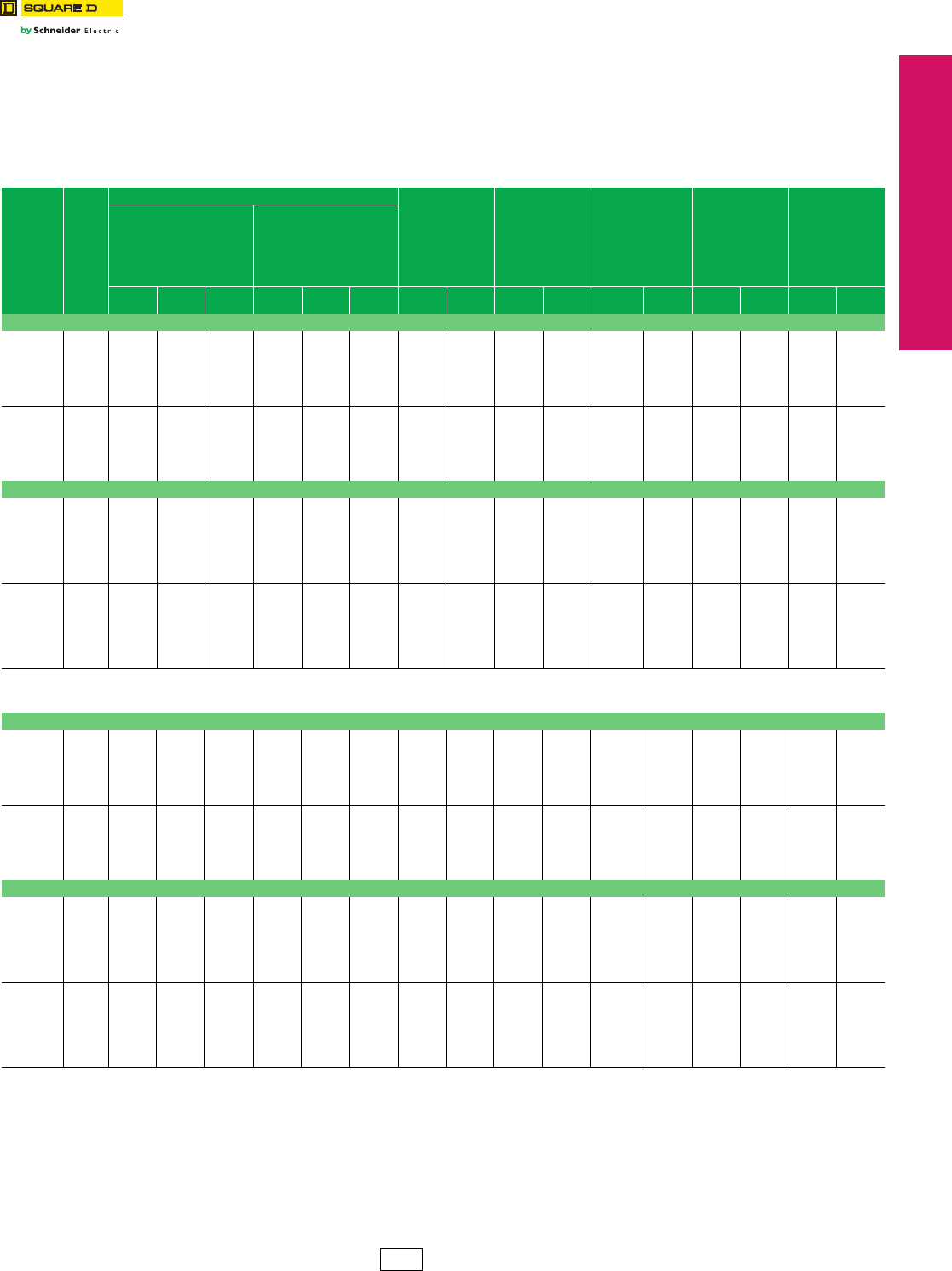
www.schneider-electric.us
© 2012 Schneider Electric
All Rights Reserved 17-25
17 NEMA DEFINITE PURPOSE TYPE
CONTACTORS AND STARTERS
Multispeed Magnetic
Starters
Application Data
Class 8810 / Refer to Catalog 8502CT9701
Multispeed motors are available in two basic versions: 1) consequent pole, and 2) separate winding. A separate
winding motor has a winding for each speed while a consequent pole motor has a winding for every two speeds
(three-speed motors have two windings).
3-Pole Polyphase, 600 Vac Maximum, 50–60 Hz
Note that the prices shown do not include thermal units. Devices require 6 thermal units (Sizes 0–6). Standard trip
thermal units are $21.50 each. See Digest 176 page 16-116 for selection information.
aThe NEC 1300% maximum setting for instantaneous trip circuit breakers may be inadequate for multispeed motors.
bPrices and type numbers shown for three phase, separate-winding motor starters apply only when motor windings are wye connected.
When motor windings are connected open delta, use the prices shown for three phase consequent pole motor starters.
cVoltage code must be specified to order this product. Refer to standard voltage codes shown on page 17-18.
dNEMA Type 4X hubs are included with each starter at no additional cost.
eNot available in Mag-Gard versions.
fNEMA Type 12 enclosures may be field modified for outdoor non-corrosive and non-service entrance rated applications.
See Digest 176 page 16-95 for more information.
Table 17.67: Class 8810—Non-Combination Type
Type of
Motor
NEMA
Size
Maximum Polyphase Horsepower Ratings
NEMA Type 1
General
Purpose
Enclosure
NEMA Type 4 & 4X
Watertight and
Dusttight
Enclosure
(Stainless Steel)
(304)
(Sizes 0—5)
Sheet Steel
(Size 6)
NEMA Type 4Xd
Watertight,
Dusttight
and Corrosion
Resistant
Enclosure
NEMA Type 12/3Rf
Dusttight and
Driptight
Industrial Use
Enclosure
Open Type
Constant
Horsepower
Motors
Constant Torque
or Variable
Torque Motors
200 V 230 V 460–
575 V 200 V 230 V 460–
575 V Type $ Price Type $ Price Type $ Price Type $ Price Type $ Price
Single Winding (Consequent Pole) 5-Pole–3-Pole
Constant
HP
0
1
2
3
4
5
6
2
5
7-1/2
20
30
60
100
2
5
10
25
40
75
150
3
7-1/2
20
40
75
150
300
—
—
—
—
—
—
—
—
—
—
—
—
—
—
—
—
—
—
—
—
—
SBG1c
SCG1c
SDG1c
SEG1c
SFG1c
SGG1c
SHG1c
2199.
2370.
4307.
6501.
17352.
34286.
77286.
SBW1c
SCW1c
SDW1c
SEW1c
SFW1c
SGW1c
SHW1c
3567.
3708.
5958.
8837.
22365.
46008.
93308.
SBW51c
SCW51c
SDW51c
—
—
—
—
4100.
4278.
6557.
—
—
—
—
SBA1c
SCA1c
SDA1c
SEA1c
SFA1c
SGA1c
SHA1c
2640.
2811.
4932.
7925.
20172.
46008.
83753.
SBO1c
SCO1c
SDO1c
SEO1c
SFO1c
SGO1c
SHO1c
2142.
2285.
4050.
6101.
15786.
31197.
70799.
Constant
To r q u e
or
Variable
To r q u e
0
1
2
3
4
5
6
—
—
—
—
—
—
—
—
—
—
—
—
—
—
—
—
—
—
—
—
—
3
7-1/2
10
25
40
75
150
3
7-1/2
15
30
50
100
200
5
10
25
50
100
200
400
SBG2c
SCG2c
SDG2c
SEG2c
SFG2c
SGG2c
SHG2c
2199.
2370.
4307.
6501.
17352.
34286.
77286.
SBW2c
SCW2c
SDW2c
SEW2c
SFW2c
SGW2c
SHW2c
3567.
3708.
5958.
8837.
22365.
46008.
93308.
SBW52c
SCW52c
SDW52c
—
—
—
—
4100.
4278.
6557.
—
—
—
—
SBA2c
SCA2c
SDA2c
SEA2c
SFA2c
SGA2c
SHA2c
2640.
2811.
4932.
7925.
20172.
46008.
83753.
SBO2c
SCO2c
SDO2c
SEO2c
SFO2c
SGO2c
SHO2c
2142.
2285.
4050.
6101.
15786.
31197.
70799.
Two Winding (Separate Winding) 3-Pole–3-Poleb
Constant
HP
b
0
1
2
3
4
5
6
7
2
5
7-1/2
20
30
60
100
—
2
5
10
25
40
75
150
225
3
7-1/2
20
40
75
150
300
450
—
—
—
—
—
—
—
—
—
—
—
—
—
—
—
—
—
—
—
—
—
—
—
—
SBG3c
SCG3c
SDG3c
SEG3c
SFG3c
SGG3c
SHG3c
SJG3c
1571.
1772.
3167.
4962.
12168.
28718.
58755.
76032.
SBW3c
SCW3c
SDW3c
SEW3c
SFW3c
SGW3c
SHW3c
—
2939.
3110.
3231.
7412.
17181.
40440.
66090.
—
SBW53c
SCW53c
SDW53c
—
—
—
—
—
3384.
3567.
3564.
—
—
—
—
—
SBA3c
SCA3c
SDA3c
SEA3c
SFA3c
SGA3c
SHA3c
SJA3c
2015.
2213.
2529.
6386.
14988.
40440.
65195.
82826.
SBO3c
SCO3c
SDO3c
SEO3c
SFO3c
SGO3c
SHO3c
SJO3c
1515.
1686.
1956.
4590.
11429.
26994.
51848.
69195.
Constant
To r q u e
or
Variable
To r q u e
b
0
1
2
3
4
5
6
7
—
—
—
—
—
—
—
—
—
—
—
—
—
—
—
—
—
—
—
—
—
—
—
—
3
7-1/2
10
25
40
75
150
—
3
7-1/2
15
30
50
100
200
300
5
10
25
50
100
200
400
600
SBG4c
SCG4c
SDG4c
SEG4c
SFG4c
SGG4c
SHG4c
SJG4c
1571.
1772.
3167.
4962.
12168.
28718.
58755.
76032.
SBW4c
SCW4c
SDW4c
SEW4c
SFW4c
SGW4c
SHW4c
—
2939.
3110.
3231.
7412.
17181.
40440.
66090.
—
SBW54c
SCW54c
SDW54c
—
—
—
—
—
3384.
3567.
3564.
—
—
—
—
—
SBA4c
SCA4c
SDA4c
SEA4c
SFA4c
SGA4c
SHA4c
SJA4c
2015.
2213.
2529.
6386.
14988.
40440.
65195.
82826.
SBO4c
SCO4c
SDO4c
SEO4c
SFO4c
SGO4c
SHO4c
SJO4c
1515.
1686.
1956.
4590.
11429.
26994.
51848.
69195.
Table 17.68: Class 8810—Combination Circuit Breaker Type (Thermal Magnetic Circuit Breakers)ae
Single Winding (Consequent Pole) 5-Pole–3-Pole
Constant
HP
0
1
2
3
4
5
6
2
5
7-1/2
20
30
60
100
2
5
10
25
40
75
150
3
7-1/2
20
40
75
150
300
—
—
—
—
—
—
—
—
—
—
—
—
—
—
—
—
—
—
—
—
—
CBG1c
CCG1c
CDG1c
CEG1c
CFG1c
CGG1c
CHG1c
4206.
4377.
6758.
9162.
22224.
43758.
91229.
CBW1c
CCW1c
CDW1c
CEW1c
CFW1c
CGW1c
CHW1c
6429.
6566.
10089.
13836.
29460.
57816.
68843.
CBW51c
CCW51c
CDW51c
—
—
—
—
6962.
7140.
10089.
—
—
—
—
CBA1c
CCA1c
CDA1c
CEA1c
CFA1c
CGA1c
CHA1c
4676.
4867.
7497.
10787.
26753.
56847.
65841.
—
—
—
—
—
—
—
—
—
—
—
—
—
—
Constant
To r q u e
or
Variable
To r q u e
0
1
2
3
4
5
6
—
—
—
—
—
—
—
—
—
—
—
—
—
—
—
—
—
—
—
—
—
3
7-1/2
10
25
40
75
150
3
7-1/2
15
30
50
100
200
5
10
25
50
100
200
400
CBG2c
CCG2c
CDG2c
CEG2c
CFG2c
CGG2c
CHG2c
4206.
4377.
6758.
9162.
22224.
43758.
91229.
CBW2c
CCW2c
CDW2c
CEW2c
CFW2c
CGW2c
CHW2c
6429.
6566.
10089.
13836.
29460.
57816.
68843.
CBW52c
CCW52c
CDW52c
—
—
—
—
6962.
7140.
10089.
—
—
—
—
CBA2c
CCA2c
CDA2c
CEA2c
CFA2c
CGA2c
CHA2c
4676.
4867.
7497.
10787.
26753.
56847.
65841.
—
—
—
—
—
—
—
—
—
—
—
—
—
—
Two Winding (Separate Winding) 3-Pole–3-Poleb
Constant
HP
b
0
1
2
3
4
5
6
7
2
5
7-1/2
20
30
60
100
—
2
5
10
25
40
75
150
225
3
7-1/2
20
40
75
150
300
450
—
—
—
—
—
—
—
—
—
—
—
—
—
—
—
—
—
—
—
—
—
—
—
—
CBG3c
CCG3c
CDG3c
CEG3c
CFG3c
CGG3c
CHG3c
CJG3c
3581.
3780.
5616.
7626.
17040.
38190.
72629.
95358.
CBW3c
CCW3c
CDW3c
CEW3c
CFW3c
CGW3c
CHW3c
—
5801.
5972.
8379.
12297.
16182.
52248.
84306.
—
CBW53c
CCW53c
CDW53c
—
—
—
—
—
6251.
6429.
8879.
—
—
—
—
—
CBA3c
CCA3c
CDA3c
CEA3c
CFA3c
CGA3c
CHA3c
CJA3c
4050.
4248.
6357.
9248.
14379.
51278.
80199.
103217.
—
—
—
—
—
—
—
—
—
—
—
—
—
—
Constant
To r q u e
or
Variable
To r q u e
b
0
1
2
3
4
5
6
7
—
—
—
—
—
—
—
—
—
—
—
—
—
—
—
—
—
—
—
—
—
—
—
—
3
7-1/2
10
25
40
75
150
—
3
7-1/2
15
30
50
100
200
300
5
10
25
50
100
200
400
600
CBG4c
CCG4c
CDG4c
CEG4c
CFG4c
CGG4c
CHG4c
CJG4c
3581.
3780.
5616.
7626.
17040.
38190.
72629.
95358.
CBW4c
CCW4c
CDW4c
CEW4c
CFW4c
CGW4c
CHW4c
—
5801.
5972.
8379.
12297.
16182.
52248.
84306.
—
CBW54c
CCW54c
CDW54c
—
—
—
—
—
6251.
6429.
8879.
—
—
—
—
—
CBA4c
CCA4c
CDA4c
CEA4c
CFA4c
CGA4c
CHA4c
CJA4c
4050.
4248.
6357.
9248.
14379.
51278.
80199.
103217.
—
—
—
—
—
—
—
—
—
—
—
—
—
—
CP1 Discount
Schedule
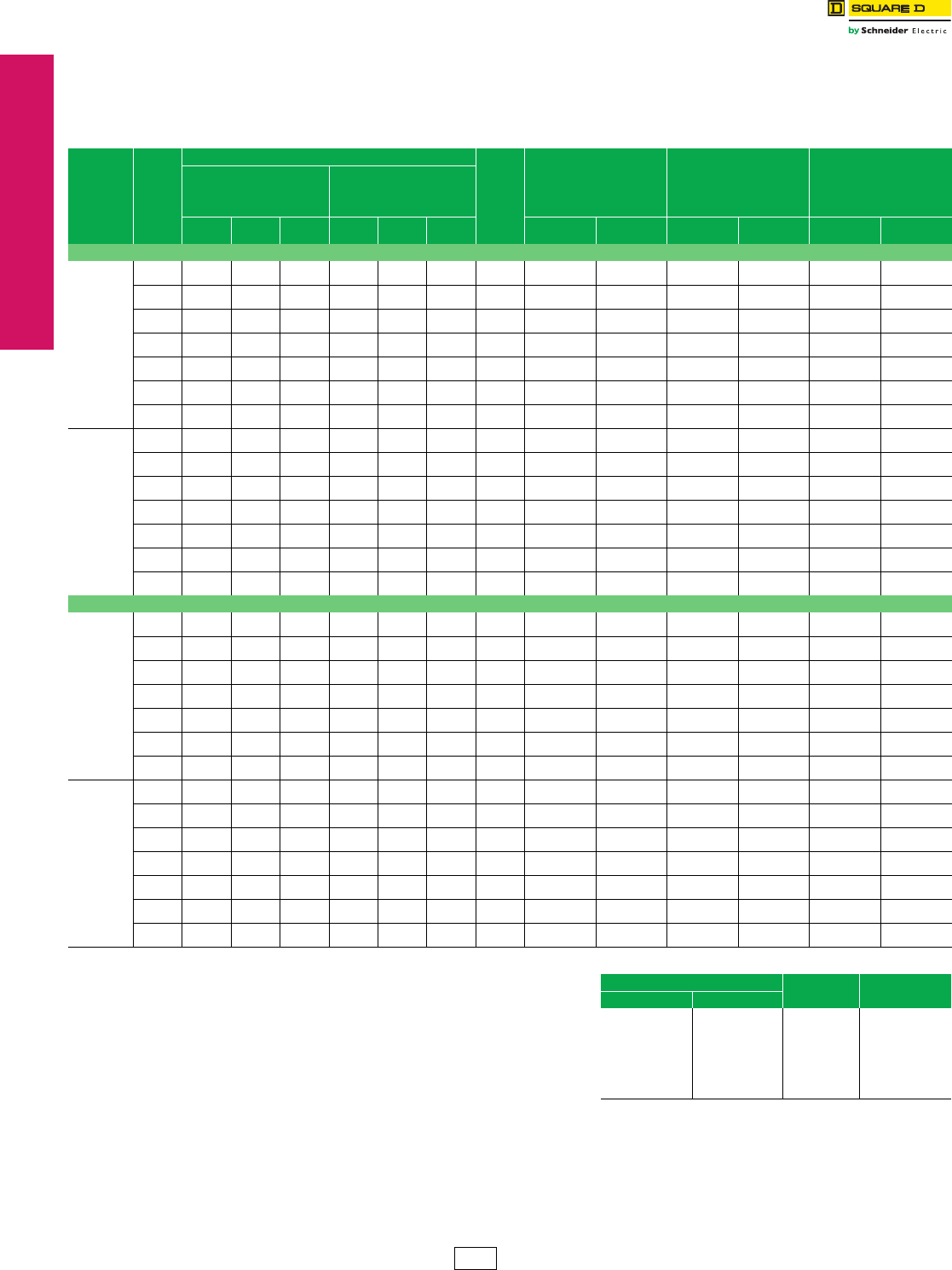
www.schneider-electric.us
17-26 © 2012 Schneider Electric
All Rights Reserved
17 NEMA DEFINITE PURPOSE TYPE
CONTACTORS AND STARTERS
Multispeed Magnetic
Starters
Two-Speed Combination Starters
Class 8810 / Refer to Catalog 8502CT9701
3-Pole Polyphase, 600 Vac Max., 50–60 Hz
Note that the prices shown do not include thermal units.
Devices require 6 thermal units (Sizes 0–6).
Standard trip thermal units are $21.50 each.
See Digest 176 page 16-116 for selection information.
aPrices and type numbers shown for three phase, separate-winding
motor starters apply only when motor windings are wye connected.
When motor windings are connected open delta, use the prices shown
for three phase consequent pole motor starters.
bVoltage code must be specified to order this product. Refer to standard
voltage codes shown below.
cNEMA Type 12 enclosures may be field modified for outdoor
non-corrosive and non-service entrance rated applications. See
Digest 176 page 16-95 for more information.
dWhen separate control is specified, use V8x (see page 32) voltage
codes to specify motor and control voltages.
Dimensions. . . . . . . . . . . . . . . . . . . . . . . . . . . . . . . . . . . . . . . . . . . page 17-28
Refer to the following Digest 176 pages for:
Factory Modifications (Forms) . . . . . . . . . . . . . . . . . . . . . . . . . . . page 16-100
Replacement Parts (Class 9998). . . . . . . . . . . . . . . . . . . . . . . . . page 16-105
Type S Accessories (Class 9999) . . . . . . . . . . . . . . . . . . . . . . . . page 16-109
e24 V coils are not available on Sizes 4–7. On Sizes 00–3, where 24 V
coils are available, Form S (separate control) must be specified (for
example, order as 8810UBG1V01S).
fThese voltage codes must include Form S (supplied at no charge)
(for example, order as 8810UCG1V02S).
Note: For voltage codes used with control transformers, see page 17-32.
Form S (separate control) is used when a separate source of power is
available for the control (coil) voltage. Form S is supplied at no charge.
Table 17.69: Class 8810—Combination Disconnect Switch Type (Class H Fuse Clips)
Type of
Motor
NEMA
Size
Maximum Polyphase Horsepower Ratings
Fuse
Clip
Size
A
NEMA Type 1
General
Purpose
Enclosure
NEMA Type 4 & 4X
Watertight
and Dusttight Enclosure
Stainless Steel (304)
(Sizes 0–5)
Sheet Steel (Size 6 not 4X)
NEMA Type 12/3Rc
Dusttight and
Driptight
Industrial Use
Enclosure
Constant
Horsepower
Motors
Constant Torque
or Variable
Torque Motors
200 V 230 V 460–
575 V 200 V 230 V 460–
575 V Type $ Price Type $ Price Type $ Price
Single Winding (Consequent Pole) 5-Pole–3-Pole
Constant
Horsepower
0 223———
None
30d
UBG1b
DBG1b
3537.00
3765.00
UBW1b
DBW1b
5759.00
5988.00
UBA1b
DBA1b
4008.00
4235.00
1 5 57-1/2———
None
30d
UCG1b
DCG1b
3708.00
3936.00
UCW1b
DCW1b
5903.00
6129.00
UCA1b
DCA1b
4179.00
4406.00
2 7-1/2 10 20 — — — None
60
UDG1b
DDG1b
6015.00
6129.00
UDW1b
DDW1b
8751.00
8864.00
UDA1b
DDA1b
6758.00
6870.00
3 202540———
None
100
UEG1b
DEG1b
8666.00
8837.00
UEW1b
DEW1b
13337.00
13508.00
UEA1b
DEA1b
10287.00
10458.00
4 304075———
None
200
UFG1b
DFG1b
19517.00
20970.00
UFW1b
DFW1b
27693.00
25964.00
UFA1b
DFA1b
24987.00
22500.00
5 6075150———
None
400
UGG1b
DGG1b
39644.00
40154.00
UGW1b
DGW1b
35799.00
54212.00
UGA1b
DGA1b
34622.00
52446.00
6 100 150 300 — — — None
600
UHG1b
DHG1b
87789.00
91085.00
UHW1b
DHW1b
99824.00
103121.00
UHA1b
DHA1b
95324.00
98621.00
Constant
To r q u e
or
Variable
To r q u e
0 ——— 3 3 5
None
30d
UBG2b
DBG2b
3537.00
3765.00
UBW2b
DBW2b
5759.00
5988.00
UBA2b
DBA2b
4008.00
4235.00
1 — — — 7-1/2 7-1/2 10 None
30d
UCG2b
DCG2b
3708.00
3936.00
UCW2b
DCW2b
5903.00
6129.00
UCA2b
DCA2b
4179.00
4406.00
2 — — — 10 15 25 None
60
UDG2b
DDG2b
6015.00
6129.00
UDW2b
DDW2b
8751.00
8864.00
UDA2b
DDA2b
6758.00
6870.00
3 — — — 25 30 50 None
100
UEG2b
DEG2b
8666.00
8837.00
UEW2b
DEW2b
13337.00
13508.00
UEA2b
DEA2b
10287.00
10458.00
4 — — — 40 50 100 None
200
UFG2b
DFG2b
19517.00
20970.00
UFW2b
DFW2b
27693.00
25964.00
UFA2b
DFA2b
24987.00
22500.00
5 — — — 75 100 200 None
400
UGG2b
DGG2b
39644.00
40154.00
UGW2b
DGW2b
35799.00
54212.00
UGA2b
DGA2b
34622.00
52446.00
6 — — — 150 200 400 None
600
UHG2b
DHG2b
87789.00
91085.00
UHW2b
DHW2b
99824.00
103121.00
UHA2b
DHA2b
95324.00
98621.00
Two Winding (Separate Winding) 3-Pole–3-Pole
Constant
Horsepower
a
0 223———
None
30d
UBG3b
DBG3b
2910.00
3140.00
UBW3b
DBW3b
5133.00
5360.00
UBA3b
DBA3b
3380.00
3609.00
1 5 57-1/2———
None
30d
UCG3b
DCG3b
3110.00
3338.00
UCW3b
DCW3b
5304.00
5531.00
UCA3b
DCA3b
3581.00
3807.00
2 7-1/2 10 20 — — — None
60
UDG3b
DDG3b
4877.00
4991.00
UDW3b
DDW3b
7640.00
7754.00
UDA3b
DDA3b
5616.00
5732.00
3 202540———
None
100
UEG3b
DEG3b
7127.00
7866.00
UEW3b
DEW3b
11798.00
11969.00
UEA3b
DEA3b
8751.00
9491.00
4 304075———
None
200
UFG3b
DFG3b
15159.00
17324.00
UFW3b
DFW3b
22509.00
23021.00
UFA3b
DFA3b
19803.00
21852.00
5 6075150———
None
400
UGG3b
DGG3b
34073.00
34586.00
UGW3b
DGW3b
48131.00
48644.00
UGA3b
DGA3b
50439.00
50952.00
6 100 150 300 — — — None
600
UHG3b
DHG3b
69188.00
72485.00
UHW3b
DHW3b
80868.00
84164.00
UHA3b
DHA3b
76766.00
80063.00
Constant
To r q u e
or
Variable
To r q u e
a
0 ——— 3 3 5
None
30d
UBG4b
DBG4b
2910.00
3140.00
UBW4b
DBW4b
5133.00
5360.00
UBA4b
DBA4b
3380.00
3609.00
1 — — — 7-1/2 7-1/2 10 None
30d
UCG4b
DCG4b
3110.00
3338.00
UCW4b
DCW4b
5304.00
5531.00
UCA4b
DCA4b
3581.00
3807.00
2 — — — 10 15 25 None
60
UDG4b
DDG4b
4877.00
4991.00
UDW4b
DDW4b
7640.00
7754.00
UDA4b
DDA4b
5616.00
5732.00
3 — — — 25 30 50 None
100
UEG4b
DEG4b
7127.00
7866.00
UEW4b
DEW4b
11798.00
11969.00
UEA4b
DEA4b
8751.00
9491.00
4 — — — 40 50 100 None
200
UFG4b
DFG4b
15159.00
17324.00
UFW4b
DFW4b
22509.00
23021.00
UFA4b
DFA4b
19803.00
21852.00
5 — — — 75 100 200 None
400
UGG4b
DGG4b
34073.00
34586.00
UGW4b
DGW4b
48131.00
48644.00
UGA4b
DGA4b
50439.00
50952.00
6 — — — 150 200 400 None
600
UHG4b
DHG4b
69188.00
72485.00
UHW4b
DHW4b
80868.00
84164.00
UHA4b
DHA4b
76766.00
80063.00
Table 17.70: Coil Voltage Codes
Volt age Code $ Price Adder
60 Hz 50 Hz
24fe
120f
208
240
—
480
600
Specify
—
110
—
220
380
440
550
Specify
V01
V02
V08
V03
V05
V06
V07
V99
No Charge
No Charge
No Charge
No Charge
No Charge
No Charge
No Charge
35.60
CP1 Discount
Schedule
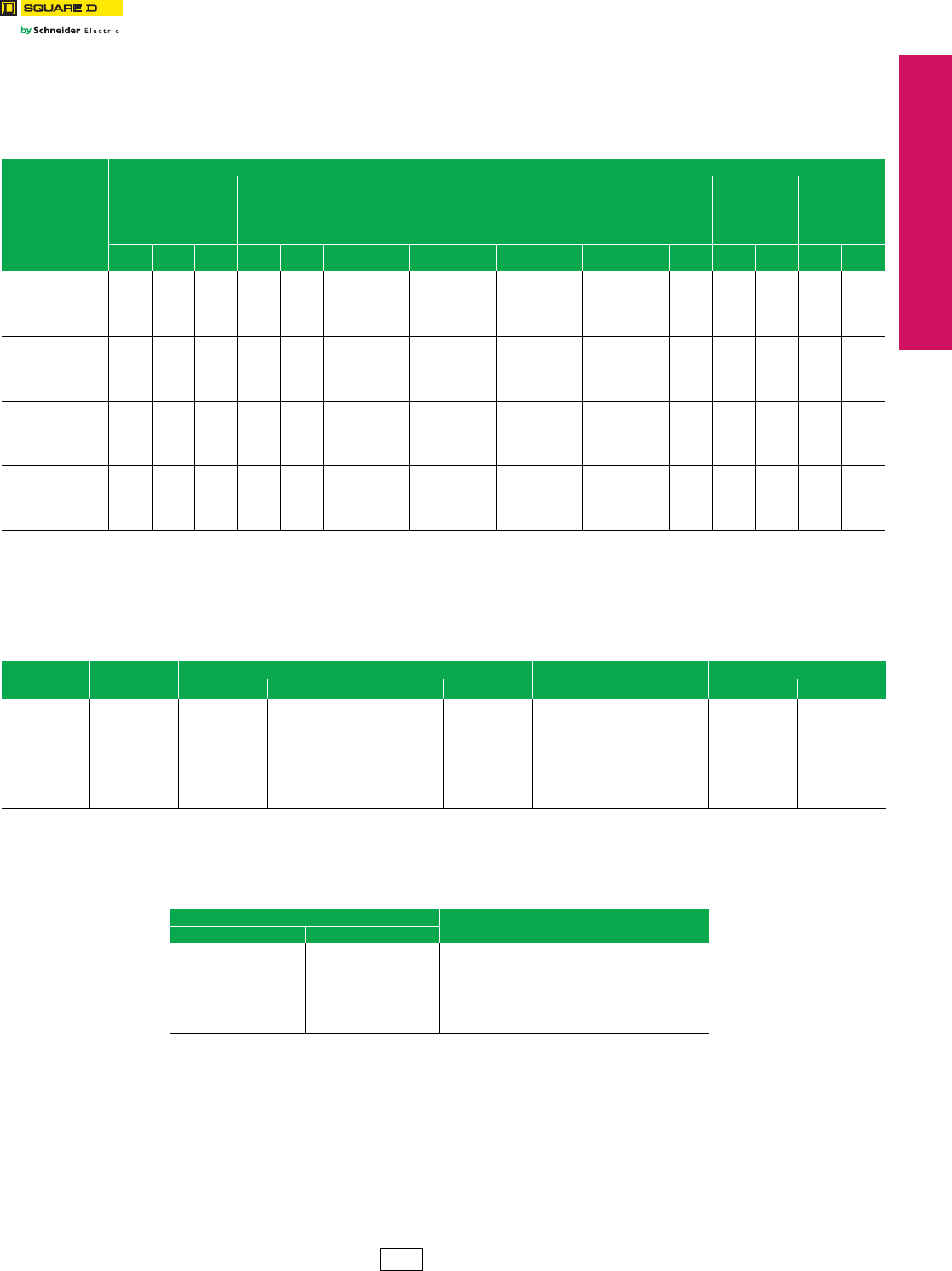
www.schneider-electric.us
© 2012 Schneider Electric
All Rights Reserved 17-27
17 NEMA DEFINITE PURPOSE TYPE
CONTACTORS AND STARTERS
Multispeed Magnetic
Starters
Reversing Two-Speed Magnetic Starters
Class 8810 / Refer to Catalog 8502CT9701
3-Pole Polyphase, 600 Vac Max., 50–60 Hz
Note that the prices shown do not include thermal units. Devices require 6 thermal units (Sizes 0–6).
Standard trip thermal units are $21.50 each. See Digest 176 page 16-116 for selection information.
3-Pole Polyphase, 600 Vac Max., 50–60 Hz
Note that the prices shown do not include thermal units. Devices require 6 thermal units (Sizes 0–6). Standard trip
thermal units are $21.50 each. See Digest 176 page 16-116 for selection information.
aPrices and type numbers shown for three phase, separate winding motor starters apply only when motor windings are wye connected. When motor
windings are connected open delta, use the prices shown for consequent pole motor starters.
bSpecify the speed which requires reversing by adding an L (low) or an H (high) after the type number, e.g., a Class 8810 Type SBG21 with reversing in
low only would be ordered as a Class 8810 Type SBG21L.
cVoltage codes must be specified to order this product. Refer to standard voltage codes listed below.
d24 V coils are not available on Sizes 4–7. On Sizes 00–3, where 24 V coils are available,
Form S (separate control) must be specified (for example, order as 8810SCG21V01S).
eThese voltage codes must include Form S (supplied at no charge) (for example, order as 8810SDG21V02S).
fNEMA Type 12 enclosures may be field modified for outdoor non-corrosive and non-service entrance rated
applications. See Digest 176 page 16-95 for more information.
Note: For voltage codes used with control transformers, see page 17-18.
Form S (separate control) is used when a separate source of power is available for the control (coil) voltage.
Form S is supplied at no charge.
Dimensions . . . . . . . . . . . . . . . . . . . . . . . . . . . . . . . . . . . . . . . page 17-28
Refer to the following Digest 176 pages for:
Factory Modifications (Forms) . . . . . . . . . . . . . . . . . . . . . . . page 16-100
Replacement Parts (Class 9998) . . . . . . . . . . . . . . . . . . . . . page 16-105
Type S Accessories (Class 9999). . . . . . . . . . . . . . . . . . . . . page 16-109
Table 17.71: Class 8810—Reversing
Type of
Motor
NEMA
Size
Maximum Polyphase Ratings Reversing In One Speed Only (Specify High or Low)bReversing In Both Speeds
Constant
Horsepower
Motors
Constant Torque
or Variable
Torque Motors
NEMA Type 1
General
Purpose
Enclosure
NEMA Type 12
Dusttight
and Driptight
Industrial Use
Enclosure
Open
Type
NEMA Type 1
General
Purpose
Enclosure
NEMA Type
12/3Rf
Dusttight
and Driptight
Industrial Use
Enclosure
Open
Type
200 V 230 V 460–
575 V 200 V 230 V 460–
575 V Type $ Price Type $ Price Type $ Price Type $ Price Type $ Price Type $ Price
Single
Winding
Constant
Horsepower
0
1
2
3
4
5
2
5
7-1/2
20
30
60
2
5
10
25
40
75
3
7-1/2
20
40
75
150
—
—
—
—
—
—
—
—
—
—
—
—
—
—
—
—
—
—
SBG21c
SCG21c
SDG21c
SEG21c
SFG21c
SGG21c
3936.
4248.
6984.
10260.
20457.
46449.
SBA21c
SCA21c
SDA21c
SEA21c
SFA21c
SGA21c
5261.
5574.
8522.
13892.
28290.
58172.
SBO21c
SCO21c
SDO21c
SEO21c
SFO21c
SGO21c
3851.
4121.
6501.
9662.
19718.
42164.
SBG31c
SCG31c
SDG31c
SEG31c
SFG31c
SGG31c
4563.
4926.
8522.
13508.
26810.
56946.
SBA31c
SCA31c
SDA31c
SEA31c
SFA31c
SGA31c
6330.
6728.
10517.
17139.
33390.
68679.
SBO31c
SCO31c
SDO31c
SEO31c
SFO31c
SGO31c
4449.
4791.
8010.
11997.
24930.
52659.
Single
Winding
Constant
Torque or
Variable
To r q u e
0
1
2
3
4
5
—
—
—
—
—
—
—
—
—
—
—
—
—
—
—
—
—
—
3
7-1/2
10
25
40
75
3
7-1/2
15
30
50
100
5
10
25
50
100
200
SBG22c
SCG22c
SDG22c
SEG22c
SFG22c
SGG22c
3936.
4248.
6984.
10260.
20457.
46449.
SBA22c
SCA22c
SDA22c
SEA22c
SFA22c
SGA22c
5261.
5574.
8522.
13892.
28290.
58172.
SBO22c
SCO22c
SDO22c
SEO22c
SFO22c
SGO22c
3851.
4121.
6501.
9662.
19718.
42164.
SBG32c
SCG32c
SDG32c
SEG32c
SFG32c
SGG32c
4563.
4926.
8522.
13508.
26810.
56946.
SBA32c
SCA32c
SDA32c
SEA32c
SFA32c
SGA32c
6330.
6728.
10517.
17139.
33390.
68679.
SBO32c
SCO32c
SDO32c
SEO32c
SFO32c
SGO32c
4449.
4791.
8010.
11997.
24930.
52659.
Two Winding
Constanta
Horsepower
0
1
2
3
4
5
2
5
7-1/2
20
30
60
2
5
10
25
40
75
3
7-1/2
20
40
75
150
—
—
—
—
—
—
—
—
—
—
—
—
—
—
—
—
—
—
SBG23c
SCG23c
SDG23c
SEG23c
SFG23c
SGG23c
3252.
3452.
5817.
9005.
15929.
37335.
SBA23c
SCA23c
SDA23c
SEA23c
SFA23c
SGA23c
4577.
4778.
7353.
12639.
22338.
49058.
SBO23c
SCO23c
SDO23c
SEO23c
SFO23c
SGO23c
3167.
3324.
5432.
8267.
15188.
33048.
SBG33c
SCG33c
SDG33c
SEG33c
SFG33c
SGG33c
4193.
4620.
8067.
12027.
21284.
49455.
SBA33c
SCA33c
SDA33c
SEA33c
SFA33c
SGA33c
5958.
6386.
10061.
15885.
27693.
59396.
SBO33c
SCO33c
SDO33c
SEO33c
SFO33c
SGO33c
4077.
4449.
7554.
11228.
20487.
43388.
Two Winding
Constanta
To r q u e
or
Variable
To r q u e
0
1
2
3
4
5
—
—
—
—
—
—
—
—
—
—
—
—
—
—
—
—
—
—
3
7-1/2
10
25
40
75
3
7-1/2
15
30
50
100
5
10
25
50
100
200
SBG24c
SCG24c
SDG24c
SEG24c
SFG24c
SGG24c
3252.
3452.
5817.
9005.
15929.
37335.
SBA24c
SCA24c
SDA24c
SEA24c
SFA24c
SGA24c
4577.
4778.
7353.
12639.
22338.
49058.
SBO24c
SCO24c
SDO24c
SEO24c
SFO24c
SGO24c
3167.
3324.
5432.
8267.
15188.
33048.
SBG34c
SCG34c
SDG34c
SEG34c
SFG34c
SGG34c
4193.
4620.
8067.
12027.
21284.
49455.
SBA34c
SCA34c
SDA34c
SEA34c
SFA34c
SGA34c
5958.
6386.
10061.
15885.
27693.
59396.
SBO34c
SCO34c
SDO34c
SEO34c
SFO34c
SGO34c
4077.
4449.
7554.
11228.
20487.
43388.
Table 17.72: Class 8810—Non-Reversing, Vertically Arranged, Open Type, Two-Speed Starters
Type
of
Motor
NEMA
Size
Maximum HP Ratings For Consequent Pole Motors For Separate Winding Motors
200 V 230 V 380 V 460-575 V Type $ Price Type $ Price
Constant
Horsepower
0
1
2
3
4
2
5
7-1/2
20
30
2
5
10
25
40
3
7-1/2
20
40
60
3
7-1/2
20
40
75
SBO11c
SCO11c
SDO11c
SEO11c
SFO11c
2142.00
2282.00
4050.00
6101.00
15786.00
SBO13c
SCO13c
SDO13c
SEO13c
SFO13c
1515.00
1686.00
2939.00
4563.00
11429.00
Constant
To r q u e
or
Variable
To r q u e
0
1
2
3
4
3
7-1/2
10
25
40
3
7-1/2
15
30
50
5
10
25
50
75
5
10
25
50
100
SBO12c
SCO12c
SDO12c
SEO12c
SFO12c
2142.00
2282.00
4050.00
6101.00
15786.00
SBO14c
SCO14c
SDO14c
SEO14c
SFO14c
1515.00
1686.00
2939.00
4563.00
11429.00
Table 17.73: Coil Voltage Codes
Voltag e Code $ Price Adder
60 Hz 50 Hz
24ed
120e
208
240
—
480
600
Specify
—
110
—
220
380
440
550
Specify
V01
V02
V08
V03
V05
V06
V07
V99
No Charge
No Charge
No Charge
No Charge
No Charge
No Charge
No Charge
35.60
CP1 Discount
Schedule
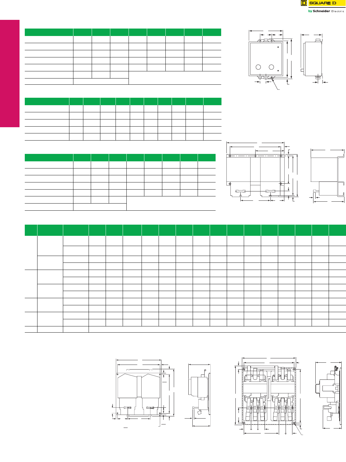
www.schneider-electric.us
17-28 © 2012 Schneider Electric
All Rights Reserved
17 NEMA DEFINITE PURPOSE TYPE
CONTACTORS AND STARTERS
Multispeed Magnetic
Starters
Two-Speed Magnetic Starters
Class 8810 / Refer to Catalog 8502CT9701
aConsequent pole type starters consist of two 3-pole starters as pictured in Figure 4 and an additional 2-pole shorting contactor (not shown),
all on a common baseplate, horizontally mounted.
bCurrent transformers used with Size 1 overload relay blocks.
cSolid-state overload relays and special current transformers.
Table 17.74: NEMA Type 1 Enclosure (see Figure 1)
Type A B C D E F G H
SBG and SCG 11-7/8 11-7/8 7-17/32 9-3/4 1-1/16 1-1/16 9-3/4 5/16
SDG 14-7/8 14-1/8 7-21/32 12-3/4 1-1/16 1-1/16 12 5/16
SEG3 & 4 and SFG3 & 4 18-5/32 29-5/32 9-15/64 15-1/2 1-11/32 1-11/32 26-1/2 7/16
SEG1 & 2 and SFG1 & 2 22-5/32 39-5/32 10-15/64 19-1/2 1-11/32 1-11/32 36-1/2 7/16
SGG1, 2, 3, 4 20-7/32 65-3/4 16-29/64 31 2-1/8 2-1/8 42 9/16
SHG1, 2, 3, 4 36-7/32 62-7/32 19-15/32 Floor Mount
SJG3 & 4 Consult Square D
(4) H Dia. Mtg. Holes
G
DE
A
B
F
C
JI
RESET RESET
Figure 1:
NEMA Type 1, 4, and 12 Enclosures
Table 17.75: NEMA Type 4 Enclosure (see Figure 1)
Type A B C D E F G H I J
SBW and SCW 12-5/8 14-11/16 7-13/16 4-1/4 4-3/16 19/32 13-1/2 5/16 1-21/32 2-5/16
SDW 14-7/8 15-3/4 8-1/4 4-1/4 5-5/16 3/8 15 5/16 2-1/32 2-5/8
SEW3 & 4 and SFW3 & 4 18-5/32 32-7/32 8-19/64 12 3-5/64 55/64 30-1/2 7/16 2-37/64 3-3/16
SEW1 & 2 and SFW1 & 2 22-5/32 42-7/32 9-49/64 16 3-5/64 55/64 40-1/2 7/16 2-21/64 2-57/64
SGW1, 2, 3, 4 35-7/32 49-7/32 12-1/8 27 4-3/32 39/64 48 9/16 2-63/64 3-1/2
Table 17.76: NEMA Type 12/3R Enclosure (see Figure 1)
Type A B C D E F G H
SBA and SCA 11-7/8 13-1/2 7-3/4 4-1/4 3-13/16 3/8 12-3/4 5/16
SDA 14-7/8 15-3/4 7-7/8 4-1/4 5-5/16 3/8 15 5/16
SEA3 & 4 and SFA3 & 4 18-5/32 31-1/2 9-19/32 16 3-3/32 1/2 30-1/2 7/16
SEA1 & 2 and SFA1 & 2 22-5/3 41-1/2 10-19/32 16 3-3/32 1/2 40-1/2 7/16
SGA1, 2, 3, 4 35-7/32 49 13-7/64 27 4-7/64 1/2 48 9/16
SHA1, 2, 3, 4 36-7/32 62-7/32 19-15/32 Floor Mount
SJA3 & 4 Consult Square D
RESET RESET
A
DF
EG
I
HB
N
J
L
K
C
P
M
Tra ve l
Figure 2:
Class 8810 NEMA Sizes 0, 1, and 2
Table 17.77: Non-Reversing, Open Type
Fig.
No.
NEMA
Size Type Mtg.
Holes A B C D E F G H I J K L M N
2
0 and 1
SBO1, 2
SCO1, 2 4 9-5/8 7-11/32 5-5/16 8 5/8 — 7/32 6-29/32 — 7/32 4-3/4 2-1/4 5-1/16 19/32
SBO3, 4
SCO3, 4 3 7-1/8 6-29/32 5-5/16 — — 3-13/32 15/32 6-7/32 — 7/32 3-9/16 1-5/8 5-1/16 19/32
2SDO1, 2 6 12-1/32 8-17/32 6-1/32 10-3/8 1/2 — 1/4 8-1/8 6-1/4 5/32 5-3/4 2-13/16 5-5/32 25/32
SDO3, 4 3 9 8-1/16 6-1/32 — — 4-1/2 3/8 7-1/2 — 3/16 4-11/32 2-5/32 5-5/32 25/32
3
3SEO1, 2 4 18 14-7/16 17 12-1/4 1-1/2 11/16 1/2 6-7/16 7-3/8 1-21/32 2-5/32 — — —
SEO3, 4 4 12-3/4 12-9/32 11-3/4 10-3/4 1-1/32 1/2 1/2 2-1/2 6-3/4 1-5/32 1-5/32 — — —
4SFO1, 2 4 18-5/8 15-19/32 17 12-1/4 1-27/32 1-1/2 1-1/8 6-7/16 7-21/32 1-21/32 1-21/32 — — —
SFO3, 4 4 14-1/4 14-19/32 13-1/4 12-1/4 1-27/32 1/2 1/2 2-15/16 7-3/8 1-21/32 1-21/32 — — —
45
SGO1, 2a4 29-9/32 20-9/32 9-3/8 5-13/32 1-9/32 28 5/8 12-9/16 19 5/8 22-17/32 1/2 2-13/32 6-5/8
SGO3, 4 4 19-9/32 20-9/32 9-3/8 5-13/32 1-9/32 18 5/8 2-5/8 19 5/8 12-17/32 1/2 2-13/32 6-5/8
46bSHO1, 2a4 29-17/32 22-7/16 9-17/32 6-31/32 3-13/16 28 3/4 11-5/8 21-3/16 5/8 9-7/8 9/16 3-1/32 9-5/16
SHO3, 4 4 19-17/32 22-7/16 9-17/32 6-31/32 3-13/16 18 3/4 21-3/16 1-11/16 5/8 9-7/8 9/16 3-1/32 9-5/16
—7cSJO3, 4 Consult the Customer Care Center (CCC) at 1-888-778-2733.
RESET
RESET
J
GHI
DB
K
F
Prov. for (4) .31 Dia. Mtg. Screws
8
.50
13
.50
13
.50
13
C
A
E
.56
14 6.25
159
Reset
Tra ve l
7.00
178
Figure 3: Class 8810 NEMA Sizes 3 and 4
G
F
A
E
B
D
MM
M
H M
K
J
(4) L Dia. Mtg. Holes
C
I
N
Figure 4: Class 8810 NEMA Size 5 and 6
NOTE: Illustrations are intended for
dimensional information only
and may not represent the
actual enclosure. Dimensions
are shown in inches.
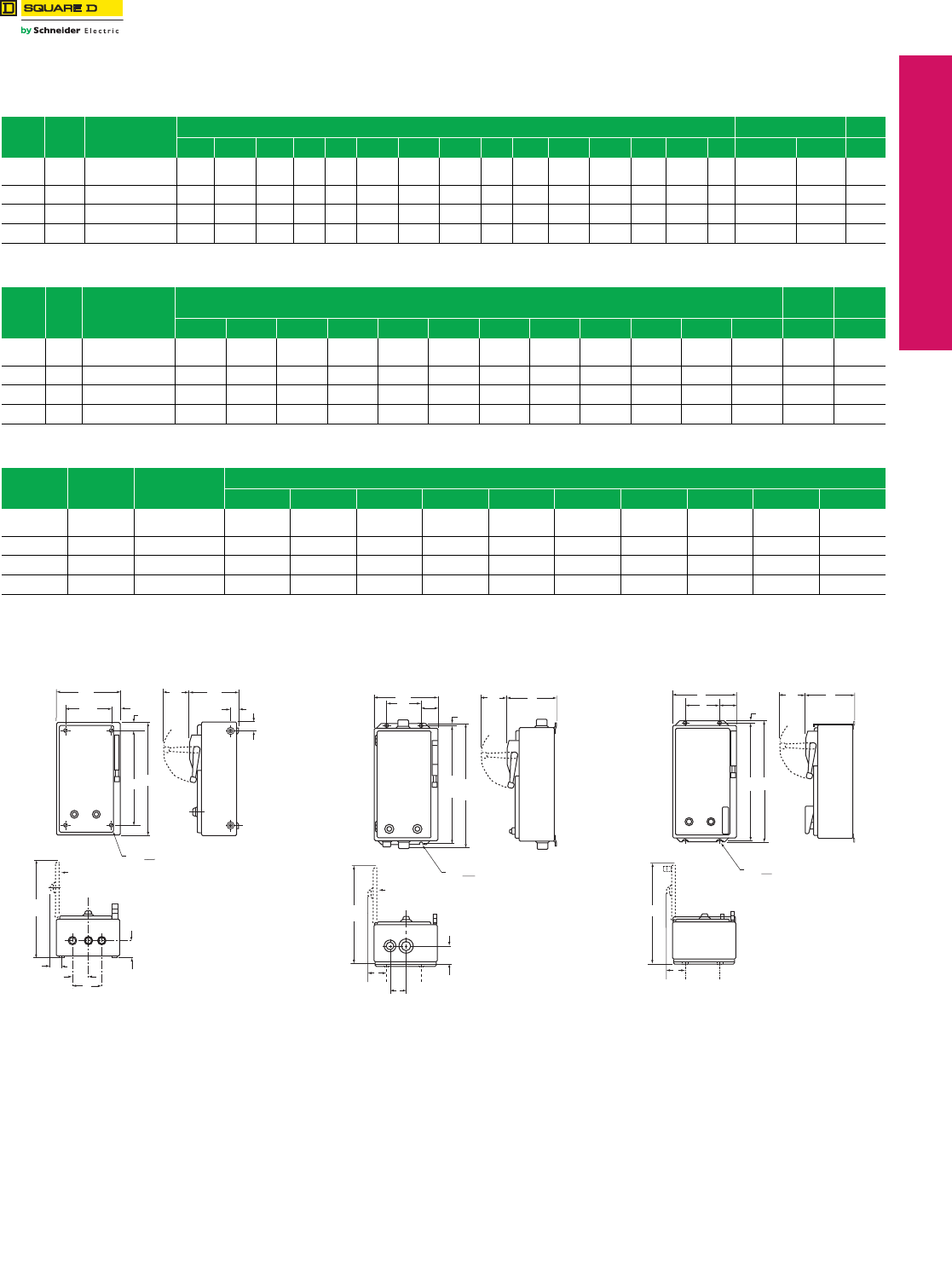
www.schneider-electric.us
© 2012 Schneider Electric
All Rights Reserved 17-29
17 NEMA DEFINITE PURPOSE TYPE
CONTACTORS AND STARTERS
Multispeed Magnetic
Starters
Approximate Dimensions
Class 8810 / Refer to Catalog 8502CT9701
Disconnect Switch or Circuit Breaker Type
aSize 3 (5-Pole–3-Pole) with FA, KA circuit breaker or 100 A disconnect switch.
Size 4 (5-Pole–3-Pole) with KA circuit breaker or 200 A disconnect switch. Size 3 & 4 (3-Pole–3-Pole) enclosures may be smaller.
Consult the Customer Care Center (CCC) at 1-888-778-2733 for additional dimensional information.
Table 17.78: NEMA Type 1 Enclosure, Figure 1
NEMA
Size Class Type
Dimensions (in inches)—see Figure 1 Top & Bottom Sides
A B C D E F G H I J K L M N O W X Y
0–1 8810 CBG UBG DBG
CCG UCG DCG 13-7/8 23-1/8 8-1/4 10-5/8 21 19-9/32 1-7/8 1-7/8 3-3/4 2-5/16 1-1/16 3-19/64 2-3/16 1-1/4 7/8 1/2–3/4–1 1/2–3/4–1 1/2
2 8810 CDG UDG DDG 15-5/32 28-29/32 9-9/16 11-5/8 26-1/4 21-13/16 2-3/16 2 4 2-5/8 1-21/64 3-19/64 2-7/32 1-17/64 29/32 1–1-1/4 1/2–3/4 1/2
3a8810 CEG UEG DEG 22-1/8 42-5/8 10-1/8 18-5/8 40 29-1/8 2-11/32 2-1/8 4-1/4 2-5/8 1-1/4 3-19/64 2-1/4 7/8 3/4 1–1-1/4–1-1/2 1/2–3/4 1/2
4a8810 CFG UFG DFG 22-1/8 50-1/8 10-3/16 18-5/8 47-1/2 29-3/16 2-29/32 2-11/16 5-3/8 2-5/8 1-5/16 3-19/64 2-1/4 7/8 3/4 2-1/2 1/2–3/4 1/2
Table 17.79: NEMA Type 4 Enclosure, Figure 2
NEMA
Size Class Type
Dimensions (in inches)—see Figure 2 Bottom Top &
Bottom
A B C D E F G H I J K L W X
0–1 8810 CBW UBW DBW
CCW UCW DCW 13-7/8 8-21/64 25-3/16 3-19/64 2-9/16 8-3/4 24 19/32 3-61/64 1-5/8 2-5/16 18-17/32 3/4 Hub 1 Hub
2 8810 CDW UDW DDW 15-1/8 9-37/64 30-15/16 3-19/64 2-9/16 10 29-3/4 19/32 3-61/64 2 2-5/8 21-11/32 3/4 Hub 1-1/2 Hub
3a8810 CEW UEW DEW 22-1/8 10-1/8 46-1/4 3-19/64 3 16 44 5/8 3-15/16 1-3/4 2-5/8 29-1/8 3/4 Hub 2 Hub
4a8810 CFW UFW DFW 22-1/8 10-3/16 53-3/4 3-19/64 3 16 51-1/2 5/8 3-15/16 2-9/32 3-3/16 29-3/16 3/4 Hub 2-1/2 Hub
Table 17.80: NEMA Type 12 Enclosure, Figure 3
NEMA
Size Class Type
Dimensions (in inches)—see Figure 3
A B C D E F G H I J
0–1 8810 CBA UBA DBA
CCA UCA DCA 13-7/8 10-3/32 24-3/4 3-19/64 2-9/16 8-3/4 24 3/8 3-61/64 20-9/32
2 8810 CDA UDA DDA 15-5/32 10-31/32 31-1/4 3-19/64 3-5/64 9 30-1/4 1/2 4-53/64 23-7/16
3a8810 CEA UEA DEA 22-1/8 10-1/8 45 3-19/64 3 16 44 5/8 3-15/16 29-1/8
4a8810 CFA UFA DFA 22-1/8 10-3/16 52-1/2 3-19/64 3 16 51-1/2 5/8 3-15/16 29-3/16
O
N
C
HANDLE
SWING
EB
K
M
D
A
Y
(4) .31 DIA. MTG.HOLES
(for Size 0, 1, & 2)
8
F
WXW
G
J
H
I
COVER OPEN 90°
L
Y
Figure 1:
NEMA Type 1 Enclosure
B
HANDLE
SWING
C
F
A
(4) .31 DIA. MTG.HOLES
(for Size 0, 1, & 2)
8
L
WX
I
COVER OPEN 90°
D
E
K
J
G
H
Figure 2:
NEMA Type 4 Enclosure
B
HANDLE
SWING
C
F
A
(4) .31 DIA. MTG.HOLES
(for Size 0, 1, & 2)
8
J
I
D
E
G
H
Figure 3:
NEMA Type 12 Enclosure
NOTE: Illustrations are intended for dimensional
information only and may not represent the
actual enclosure. Dimensions are shown
in inches.
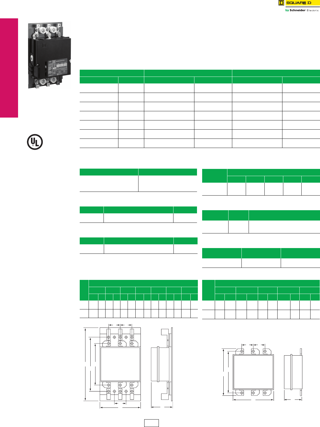
www.schneider-electric.us
17-30 © 2012 Schneider Electric
All Rights Reserved
17 NEMA DEFINITE PURPOSE TYPE
CONTACTORS AND STARTERS
Lighting Contactors Panelboard Lighting Contactors, Type PB
Class 8903 / Refer to Catalog 8903CT9701
General Information
Panelboard lighting contactors, sometimes called remote
control switches, are designed for use with lighting
panelboards and motor control centers where either panel
or bus mounting is desired. Type PB lighting contactors
can be used in a retrofit or new project without increasing
the panelboard depth. They can be used to directly
replace many inoperative existing switches.
The features include: mechanically held; compatible with
Square D panelboards; short-circuit ratings to 100 kA;
compact arc suppression; bus or panel mounted; fits in
standard-depth lighting panelboards; easy manual
operation; standard coil clearing contacts; and operates in
any position.
aVoltage code must be specified to order this product. Refer to standard
voltage codes listed below.
bSlotted mounting holes suitable for 2.88–3.19 in. mounting centers.
Panel Mount
Table 17.81: Class 8903 Type PB Lighting Contactors
Description Bus Mount Panel Mount (Includes Lugs)
Size (A) Poles Type $ Price Type $ Price
30 2
3
PBM 10Ba
PBM 11Ba
2129.00
2403.00
PBM 10a
PBM 11a
2640.00
2973.00
60 2
3
PBP 10Ba
PBP 11Ba
2237.00
2573.00
PBP 10a
PBP 11a
2762.00
3185.00
75 2
3
PBN 10Ba
PBN 11Ba
2237.00
2573.00
PBN 10a
PBN 11a
2762.00
3185.00
100 2
3
PBQ 10Ba
PBQ 11Ba
2541.00
2978.00
PBQ 10a
PBQ 11a
3119.00
3546.00
150 2
3
PBR 10Ba
PBR 11Ba
3162.00
4055.00
PBR 10a
PBR 11a
3897.00
4787.00
200 2
3
PBV 10Ba
PBV 11Ba
3551.00
4496.00
PBV 10a
PBV 11a
4409.00
5360.00
225 2
3
PBW 10Ba
PBW 11Ba
3909.00
4958.00
PBW 10a
PBW 11a
4964.00
5990.00
Table 17.82: AC Coil Voltage Codes
60 Hz Voltage Code
120
208
240/277
480
V02
V08
V39
V28
Table 17.83: Class 8903—Auxiliary Contacts
Type Description $ Price
PBX1
PBX2
(1) Auxiliary Contact SPDT
(2) Auxiliary Contacts SPDT
243.00
485.00
Table 17.84: Factory Modifications
Form Description $ Price
X11
X22
(1) Auxiliary Contact SPDT
(2) Auxiliary Contacts SPDT
158.00
314.00
Table 17.85: Dimensions (Panel Mount)
Amperes
Dimensions
H W D A B C E
in. mm in. mm in. mm in. mm in. mm in. mm in. mm
30–
100 11.75 298 7.50 191 3.88 98 2.25 57 7.38 187 2.25 57 9.25 235
150–
225 14.50 368 7.50 191 3.88 98 2.88 73 8.50 216 3.00 76 10.50 267
File E78427
CCN NRNT
B
C
A A
WD
E
H
Table 17.86: Control Distance
Wire Gauge
AWG
Maximum Distance (feet)
120 V 208 V 240 V 277 V 480 V
#14
#12
#10
550
900
1425
1650
2700
4275
2200
3600
5700
2925
4700
7550
8800
14400
22800
Table 17.87: Short-Circuit Ratings
RMS Sym.
Current (A) Max. Volts Short Circuit
Protection Device Recommended
100,000
22,000
65,000
600
600
240
Class J Fuses
Circuit Breaker—Square D—Type LHL
Circuit Breaker—Square D—Type LHL
Table 17.88: Maximum Wire Size (AWG)
Current Range Power Wire
(Cu/Al)
Control Wire
(Cu Only)
30–100 A
150–225 A
#1/0 Max.
350 MCM Max.
#18–#10
#18–#10
Table 17.89: Dimensions (Bus Mount)
Amperes
Dimensions
H W D A B
in. mm in. mm in. mm in. mm in. mm
30–
100 8.31 211 7.50 191 3.38 86 2.25 57 7.38 187
150–
225 9.50 241 7.50 191 3.38 86 2.88b73 8.50 216
B
A A
WD
H
CP1 Discount
Schedule
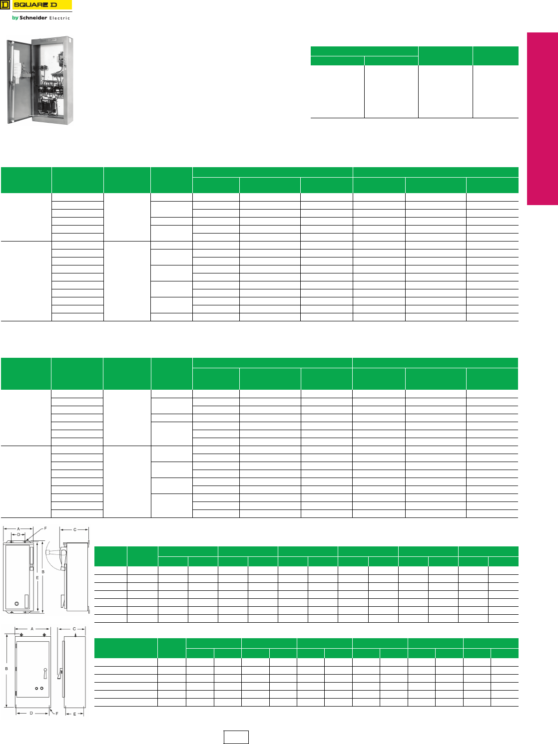
www.schneider-electric.us
© 2012 Schneider Electric
All Rights Reserved 17-31
17 NEMA/DEFINITE PURPOSE TYPE
CONTACTORS AND STARTERS
Well-Guard™ Pump Panel Reduced Voltage Type
Class 8940 / Refer to Catalog 8940CT9701
Class 8940 reduced voltage panels in NEMA 3R
enclosures are specifically designed for pumping
applications. Extra space is provided for field installation of
auxiliary equipment.
•Type S contactors/starters provided as standard
•All devices are UL Listed, and marked “SUITABLE
ONLY FOR USE AS SERVICE EQUIPMENT”
•Price includes Hand-Off-Auto selector switch and Start
push button
For How to Order Information, see Digest 176 page 16-12
and Digest 176 page 16-125 for selection information.
c24 V coils are not available on Sizes 4–7. On Sizes 2–3, where 24 V
coils are available, Form S (separate control) must be specified.
dThis voltage code must include Form S (no charge).
aFuse clips are sized for use with dual-element time-delay fuses. bCoil voltage code must be specified to order this product. Refer to
standard voltage codes shown in Table 17.90.
cFuse clips are sized for use with dual-element time-delay fuses. dCoil voltage code must be specified to order this product. Refer to
standard voltage codes shown in Table 17.90.
aCabinet has double doors. NOTE: Illustrations may not represent the actual enclosure; they are
intended for dimensional information only.
Table 17.90: Coil Voltage Codes
Voltag e Code $ Price Adder
60 Hz 50 Hz
24c
120d
208
240
—
480
600
Specify
—
110
—
220
380
440
550
Specify
V01
V02
V08
V03
V05
V06
V07
V99
No Charge
No Charge
No Charge
No Charge
No Charge
No Charge
No Charge
35.60
Table 17.91: Closed Transition Autotransformer Type, 3-Pole Polyphase—480 Vac Maximum (50–60 Hz)
Note: The prices shown do not include thermal units. Overload relays are ambient temperature compensated. Devices require 3 thermal units (Sizes 2–6). Standard trip thermal units are $21.50 each.
Motor
(Starter)
Volts
Max. HP
Polyphase
Coil
Voltag e
NEMA
Size
Fusible Disconnect Type Circuit Breaker Type
Fuse Clip
AmperesaTypeb$ Price Circuit Breaker Typeb$ Price
230
(240)
15
240@ 60 Hz
220@ 50 Hz
260RD4DV03 11928.00 FAL36080 VD1DV03 11928.00
25 3100 RE4FV03 17055.00 FAL36100 VE1FV03 17055.00
30 200 RE1GV03 17342.00 KAL36100 VE2GV03 17342.00
50 4 200 RF4JV03 26657.00 KAL36200 VF1JV03 28107.00
75 5400 RG1LV03 43946.00 LAL36250 VG2LV03 43946.00
100 400 RG1MV03 46083.00 LAL36350 VG2MV03 46083.00
460
(480)
25
480 @ 60 Hz
440 @ 50 Hz
260RD2FV06 12555.00 FAL36070 VD1FV06 12555.00
30 3100 RE2GV06 17085.00 FAL36080 VE1GV06 17085.00
50 100 RE2JV06 18197.00 FAL36100 VE1JV06 18197.00
75 4 200 RF2LV06 26657.00 KAL36125 VF1LV06 27872.00
100 200 RF2MV06 28278.00 KAL36200 VF1MV06 28278.00
150 5 400 RG3PV06 42735.00 LAL36250 VG4PV06 46340.00
200 400 RG3QV06 48860.00 LAL36350 VG4QV06 51237.00
300 6 —— —MAL36600 VH1SV06 79338.00
400 — — —MAL36900 VH2TV06 79338.00
600 7 — — —MAL361000 VJ1WV06 123134.00
Type VG4V06K15
Table 17.92: Part Winding Type, 3-Pole Polyphase—480 Vac Maximum (50–60 Hz)
Note: The prices shown do not include thermal units. Overload relays are ambient temperature compensated. Devices require 6 thermal units (Sizes 2–6). Standard trip thermal units are $21.50 each.
Motor
(Starter)
Voltag e
Max. HP
Polyphase
Coil
Voltag e
NEMA
Size
Combination Fusible Disconnect Type Combination Circuit Breaker Type
Fuse Clip
(2 Sets)
(A)c
Typed$ Price
Circuit Breaker
(2 Bkrs.)
Frame Size
Typed$ Price
230
(240)
25
240 @ 60 Hz
220 @ 50 Hz
2PW 60 MD4FV03 7536.00 FAL36070 PD1FV03 7923.00
30 3PW 60 ME5GV03 11609.00 FAL36080 PE3GV03 11322.00
50 100 ME6JV03 11609.00 FAL36100 PE3JV03 11322.00
75 4PW 200 MF1LV03 21821.00 KAL36150 PF3LV03 23400.00
100
5PW
200 MG3MV03 43326.00 KAL36175 PG2MV03 43326.00
125 400 MG1NV03 43326.00 LAL36250 PG3NV03 43326.00
150 400 MG1PV03 43326.00 LAL36250 PG3PV03 43326.00
460
(480)
30
480 @ 60 Hz
440 @ 50 Hz
2PW 30 MD5GV06 7536.00 FAL36040 PD1GV06 7293.00
40 60 MD2HV06 7536.00 FAL36050 PD1HV06 7293.00
60 3PW 60 ME7KV06 11609.00 FAL36070 PE3KV06 12822.00
75 100 ME3LV06 11609.00 FAL36090 PE3LV06 11322.00
100 4PW 200 MF3MV06 23400.00 FAL36100 PF2MV06 23400.00
150 200 MF3PV06 23400.00 KAL36125 PF3PV06 23400.00
200
5PW
200 MG4QV06 43326.00 KAL36175 PG2QV06 43326.00
250 200 MG4RV06 43326.00 KAL36225 PG3RV06 43326.00
350 400 MG2TV06 43326.00 LAL36300 PG3TV06 43326.00
Table 17.93: Part Winding—Reduced Voltage Type
Type Figure A B C D E F
in. mm in. mm in. mm in. mm in. mm in. mm
PD 3 19.00 483 34.50 876 12.25 311 13.00 330 33.50 851 0.44 11
MD 3 23.00 584 25.50 648 10.60 269 17.00 432 24.50 622 0.44 11
PE, PF 3 30.00 762 47.00 1194 13.25 337 22.00 559 46.00 1168 0.56 14
ME 3 25.00 635 52.50 1334 12.13 308 19.00 483 51.50 1308 0.44 11
MF 4 36.00 914 93.00 2362 19.25 489 33.75 857 12.50 318 0.69 18
PG, MG 4 36.00 914 73.00 1854 19.25 489 33.75 857 12.50 318 0.69 18
PH 4 38.00 965 93.00 2362 19.25 489 35.75 908 12.50 318 0.69 18
Table 17.94: Autotransformer—Reduced Voltage Type
Type Figure A B C D E F
in. mm in. mm in. mm in. mm in. mm in. mm
RD, VD 3 25.00 635 52.50 1334 11.13 283 19.00 483 51.50 1308 0.44 11
RE, VE, RF, VF 4 32.00 813 72.50 1842 19.25 489 29.75 756 12.50 318 0.68 17
RG 4 36.00 914 93.00 2362 19.25 489 33.75 857 12.50 318 0.69 17
VG 4 32.00 813 72.50 1842 19.25 489 29.75 756 12.50 318 0.68 17
VH 4 34.00 864 93.00 2362 23.25 591 31.75 806 16.50 419 0.69 17
VJa4 64.00 1626 93.00 2362 27.25 692 61.75 1568 17.25 438 0.81 21
CP1 Discount
Schedule
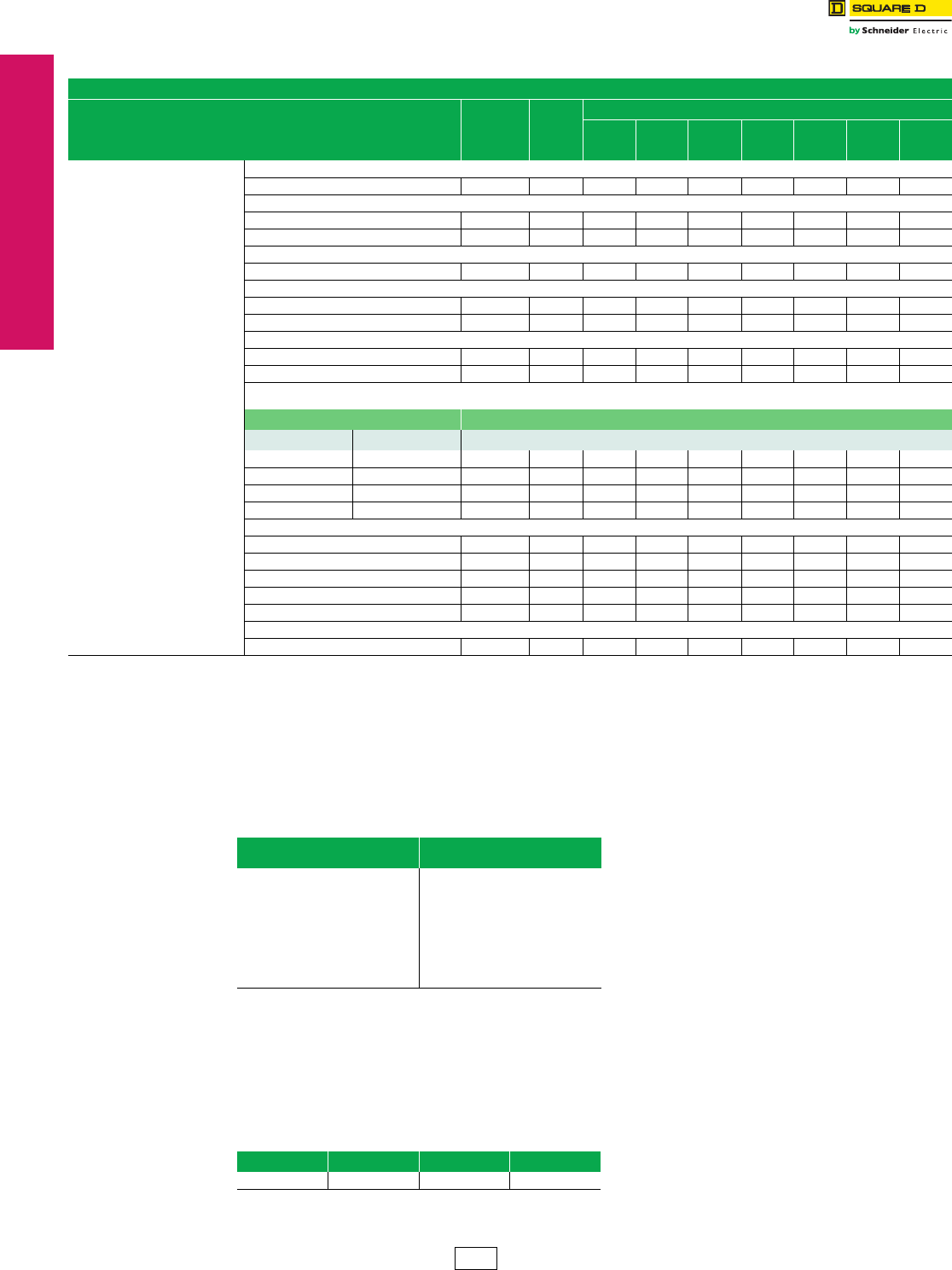
17-32 © 2012 Schneider Electric
All Rights Reserved
www.schneider-electric.us
17 NEMA DEFINITE PURPOSE TYPE
CONTACTORS AND STARTERS
Factory Modifications
(Forms)
Reduced Voltage Starters
Classs 8606, 8630, 8640
aAll push buttons are momentary contact.
bFor pilot light details, refer to the pilot light table in Digest 176 page 16-100.
cSee Table 17.96 below.
dAs standard, Reduced Voltage Controllers are supplied with common control. If Form S or T is specified, only the TR coil will be at control voltage.
Specify Form Y195 or T40 (Ex. Form F4T40) if all coils must be at control voltage. Refer to page 17-18 for control circuit arrangements.
eReduced Voltage Controllers are supplied with two control circuit fuses for conductors at line voltage. Additional fusing may be supplied if a fused control
circuit transformer or separate control is specified.
fMust be used with Form specifying separate control (Ex. Form FS).
gAdd Form letters and price to that of standard control transformer. (Example: For Size 1, Form F4T, plus 100 VA becomes F4T11, $984.00
Form F4T40 plus 100 VA becomes F4T41, $807.00).
hSize 6 and 7 controllers come with Form F4T as standard.
iMust be used in conjunction with a variation of Form of F4T. (Ex. Standard capacity transformer required, 208–24 V. Order as Form F4TT1, 208–24 V.)
The standard primary and secondary voltages for control circuit transformers are indicated in Table 17.96.
To order, select the desired device with the appropriate transformer Form designation. Then convert the previously
selected voltage code (V••) to reflect the desired primary/secondary voltage for the transformer. The secondary voltage
should equal the previously selected coil voltage of the device. (24 Vac coils for NEMA Sizes 4–7 are not available).
Example:
You previously selected a Class 8606SDG1V02S. The designation V02S means that you need a coil voltage of
120-60/110-50 wired for separate control. You would like to add Form FF4T with the transformer voltages being 480
volt primary, 120 volt secondary. The new, complete Class, Type, Voltage Code, and Form are:
jForm numbers should always be shown in alphabetical order.
Table 17.95: Reduced Voltage Controllers Only
Classes 8606, 8630, 8640
Factory Modifications Enclosure
Type Form
NEMA Size
1
1PW
1 YD
2
2 PW
2 YD
3
3 PW
3 YD
4
4 PW
4 YD
5
5 PW
5 YD
6
6 PW
6 YD
7
7 PW
7 YD
Pilot Devices in Cover and
Control Circuit
Reduced Voltage
Controllers Only
Classes
8606
8630
8640
8647
8650
Push Buttonsa
Start-Stop 1, 4, 12 A 336.00 336.00 336.00 33600 336.00 336.00 336.00
Selector Switches
Hand-Off-Auto 1, 4, 12 C 336.00 336.00 336.00 336.00 336.00 336.00 336.00
On-Off 1, 4, 12 C6 336.00 336.00 336.00 336.00 336.00 336.00 336.00
Pilot Lights (specify color)b
One light On 1, 4, 12 P 336.00 336.00 336.00 336.00 336.00 336.00 336.00
Separate Control Circuitde
TR coil only (at control voltage) 1, 4, 12 S N/C N/C N/C N/C N/C N/C N/C
All coils (at control voltage) 1, 4, 12 Y195 N/C N/C N/C N/C N/C N/C N/C
Fused Control Circuitcdef
One fuse 1, 4, 12 F 314.00 314.00 314.00 314.00 314.00 N/ChN/Ch
Two fuses 1, 4, 12 F4 314.00 314.00 314.00 314.00 314.00 N/ChN/Ch
Control Circuit Transformercde
Standard Capacity (50 or 60 Hz)
Fuses
Primary Secondary
2— 0— 1, 4, 12 F4T 684.00 882.00 1112.00 1254.00 1395.00 N/ChN/Ch
2.. 1— 1, 4, 12 FF4T 1026.00 1197.00 1425.00 1566.00 1710.00 314.00 314.00
2— 0— 1, 4, 12 F4T40 912.00 1182.00 1938.00 2079.00 3803.00 3803.00 3803.00
2— 1— 1, 4, 12 FF4T40 1224.00 1497.00 2250.00 2393.00 4116.00 4116.00 4116.00
Additional capacity (50 or 60 Hz)g
100 VA additional capacity 1, 4, 12 T11 300.00 300.00 300.00 300.00 300.00 300.00 300.00
200 VA additional capacity 1, 4, 12 T12 570.00 570.00 570.00 570.00 570.00 570.00 570.00
300 VA additional capacity 1, 4, 12 T13 1139.00 1139.00 1139.00 1139.00 1139.00 1139.00 1139.00
400 VA additional capacity 1, 4, 12 T14 2421.00 2421.00 2421.00 2421.00 2421.00 2421.00 2421.00
500 VA additional capacity 1, 4, 12 T15 2721.00 2721.00 2721.00 2721.00 2721.00 2721.00 2721.00
Substitute nonstandard single primary and/or single secondary
Voltage rating on the control transformerc1, 4, 12 T1i71.00 71.00 71.00 71.00 71.00 ——
Table 17.96: Selection of Control Circuit Transformers
Volt age
60 Hz (Primary–Secondary) Code
120–12
120–24
208–120
240–24
240–120
277–120
480–24
480–120
480–240
600–120
Specify
V88
V89
V84
V82
V80
V85
V83
V81
V87
V86
V99
Class Type Voltage Code Formj
8606 SDG1 V81 FF4T
CP1 Discount
Schedule
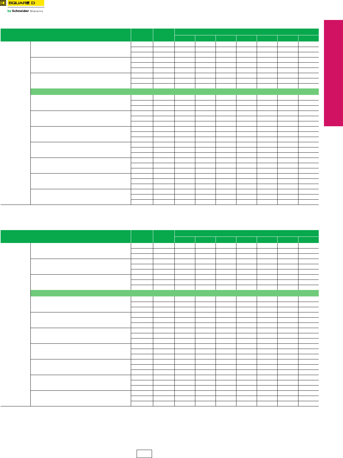
www.schneider-electric.us
17 NEMA DEFINITE PURPOSE TYPE
CONTACTORS AND STARTERS
© 2012 Schneider Electric
All Rights Reserved 17-33
Factory Modifications
(Forms)
Reduced Voltage Starters
Class 8606, 8630
Table 17.97: Class 8606 Reduced Voltage Starters Only
Factory Modifications Enclosure
Type Form NEMA Size
1 2 3 4 5 6 7
Circuit
Breaker
or
Disconnect
Switch
Molded case thermal magnetic circuit breaker b
1Y7912010.00 2451.00 2664.00 4872.00 9471.00 13944.00 18320.00
4Y7912862.00 3533.00 4886.00 7092.00 11808.00 18216.00 23601.00
12 Y791 2037.00 2564.00 2862.00 6579.00 10839.00 15012.00 20397.00
Nonfusible disconnect switch
1Y7921340.00 1710.00 2165.00 2991.00 5355.00 — —
4Y7922195.00 2793.00 4388.00 5327.00 7691.00 — —
12 Y792 1368.00 1823.00 2366.00 4815.00 5925.00 — —
Atuomatic molded case switch
1 Y7910 — — — — — 12293.00 13004.00
4 Y7910 — — — — — 16565.00 17276.00
12 Y7910 — — — — — 13361.00 14072.00
Fusible Disconnect Switch with Fuse Clips a
30 A clips
1 Y7931566.00 1566.00 — — — — —
4Y7932421.00 2124.00 — — — — —
12 Y793 1596.00 1596.00 — — — — —
60 A clips
1Y7941566.00 1823.00 2066.00 — — — —
4Y7942421.00 2885.00 3609.00 — — — —
12 Y794 1596.00 1938.00 2280.00 — — — —
100 A clips
1Y795 — — 2336.00 2574.00 — — —
4Y795 — — 4559.00 5021.00 — — —
12 Y795 — — 2537.00 2943.00 — — —
200 A clips
1Y796 — — 2885.00 3596.00 — — —
4Y796 — — 5129.00 4340.00 — — —
12 Y796 — — 3105.00 5327.00 — — —
400 A clips
1Y797 — — — — 5868.00 11039.00 —
4Y797 — — — — 8190.00 15354.00 —
12 Y797 — — — — 6438.00 12861.00 —
Automatic Molded Case Switch
with 600 A fuse clips
1Y798 — — — — — 13802.00 —
4Y798 — — — — — 18075.00 —
12 Y798 — — — — — 14871.00 —
Automatic Molded Case Switch
with fuse clips 1200 A or less
1Y799 ——————15425.00
4Y799 ——————19697.00
12 Y799 ——————17562.00
aFuses not included.
bMag-Gard™ circuit breakers are not supplied nor recommended.
Table 17.98: Class 8630 Reduced Voltage Controllers Onlyd
Factory Modifications Enclosure
Type Form NEMA Size
1 YD 2 YD 3 YD 4 YD 5 YD 6 YD 7 YD
Circuit
Breaker
or
Disconnect
Switch
Molded case thermal magnetic circuit breaker e
1Y7912451.00 2664.00 4872.00 9471.00 13944.00 18320.00 32759.00
4Y7913533.00 4886.00 7092.00 11808.00 18216.00 23601.00 37031.00
12 Y791 2564.00 2856.00 6579.00 10839.00 15012.00 20397.00 33827.00
Nonfusible disconnect switch
1Y7921710.00 2165.00 2991.00 5355.00 — — —
4Y7922793.00 4388.00 5327.00 7691.00 — — —
12 Y792 1823.00 2366.00 4815.00 5925.00 — — —
Atuomatic molded case switch
1 Y7910 — — — — 12293.00 13004.00 29483.00
4 Y7910 — — — — 16565.00 17276.00 33755.00
12 Y7910 — — — — 13361.00 14072.00 30551.00
Fusible Disconnect Switch with Fuse Clipsc
30 A clips
1 Y7931823.00 1823.00 — — — — —
4Y7932421.00 3771.00 — — — — —
12 Y793 1938.00 1938.00 — — — — —
60 A clips
1Y7941823.00 2066.00 — — — — —
4Y7942421.00 3609.00 — — — — —
12 Y794 1938.00 2280.00 — — — — —
100 A clips
1Y795 — 2336.00 2574.00 — — — —
4Y795 — 4559.00 5021.00 — — — —
12 Y795 — 2537.00 2943.00 — — — —
200 A clips
1Y796 — — 2885.00 3596.00 — — —
4Y796 — — 5129.00 5840.00 — — —
12 Y796 — — 3105.00 5327.00 — — —
400 A clips
1Y797 — — — 6510.00 11039.00 — —
4Y797 — — — 8204.00 15354.00 — —
12 Y797 — — — 6438.00 12861.00 — —
Automatic Molded Case Switch
with 600 A fuse clips
1Y798 — — — — 13802.00 14513.00 —
4Y798 — — — — 18075.00 18786.00 —
12 Y798 — — — — 14871.00 15227.00 —
Automatic Molded Case Switch
with fuse clips 1200 A or less
1Y799 — — — — — 15425.00 30195.00
4Y799 — — — — — 19697.00 34704.00
12 Y799 — — — — — 17562.00 31095.00
cFuses not included.
dWye-Delta motor starters typically have higher current ratings per NEMA Size than full voltage motor starters. Care must be taken in selecting the appropriate short circuit protection.
The table on Digest 176 page 7-33 will assist in selecting proper protection based on motor full-load current.
eMag-Gard™ circuit breakers are not supplied nor recommended.
CP1 Discount
Schedule
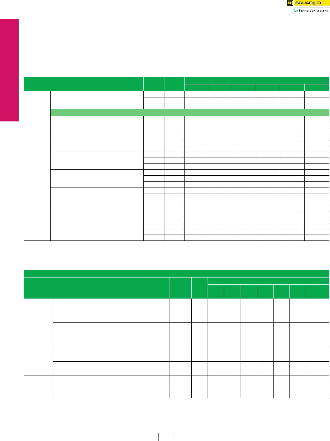
www.schneider-electric.us
17 NEMA DEFINITE PURPOSE TYPE
CONTACTORS AND STARTERS
17-34 © 2012 Schneider Electric
All Rights Reserved
Factory Modifications
(Forms)
Reduced Voltage Starters
Class 8640, 8606, 8630
NOTE: To comply with Section 430-3 of the National Electrical Code®, combination part-winding starters are
provided as follows:
1. Circuit breaker: two thermal-magnetic, adjustable-trip circuit breakers—one for each motor winding. In the smaller controllers that
use the FA and KA frames, a single external operating mechanism operates the two circuit breakers simultaneously. In the larger
controllers that use the KA and LA frames, each circuit breaker has its own operating mechanism.
2. Nonfusible disconnect switch: a single 3-pole unfused disconnect switch of the proper rating for both windings. The user must
provide proper short-circuit protection external to the starter, using only Class J fuses.
3. Fusible disconnect switch: a single unfused disconnect switch with two sets of fuse clips (each set of the rating indicated) to provide
short-circuit protection for each winding.
Table 17.99: Class 8640 Reduced Voltage Starters Only
Factory Modifications Enclosure
Type Form
NEMA Size
1 PW 2 PW 3 PW 4 PW 5 PW 6 PW
Circuit
Breaker
or
Disconnect
Switch
Molded case thermal magnetic circuit breaker b
1 Y7911 3014.00 3675.00 3996.00 7307.00 14207.00 —
4 Y7911 4293.00 5300.00 7329.00 10641.00 17711.00 —
12 Y7911 3056.00 3846.00 4293.00 9872.00 16259.00 —
Fusible Disconnect Switch with Fuse Clips a
30 A clips (two sets)
1 Y79312006.00 2006.00 — — — —
4 Y7931 2664.00 2664.00 — — — —
12 Y7931 2132.00 2132.00 — — — —
60 A clips (two sets)
1 Y7941 — 2273.00 2570.00 — — —
4 Y7941 — 3969.00 5013.00 — — —
12 Y7941 — 2507.00 2790.00 — — —
100 A clips (two sets)
1 Y7951 — 2570.00 2831.00 3176.00 — —
4 Y7951 — 5013.00 5525.00 5642.00 — —
12 Y7951 — 2790.00 3239.00 3416.00 — —
200 A clips (two sets)
1 Y7961 — — 3176.00 3959.00 6456.00 —
4 Y7961 — — 5642.00 6425.00 9026.00 —
12 Y7961 — — 3416.00 5859.00 7082.00 —
400 A clips (two sets)
1 Y7971 — — — 6456.00 15182.00 c15596.00 c
4 Y7971 — — — 9026.00 19881.00 c20082.00 c
12 Y7971 — — — 7082.00 16356.00 c16592.00 c
Automatic molded case switch
with 600 A fuse clips (two sets)
1 Y7920 — — — — — 15965.00
4 Y7920 — — — — — 20664.00
12 Y7920 — — — — — 16748.00
Automatic molded case switch
with fuse clips 601–1200 A or less (two sets)
1 Y7921 — — — — — 16968.00
4 Y7921 — — — — — 21668.00
12 Y7921 — — — — — 19319.00
aFuses not included.
bMag-Gard™ circuit breakers are not supplied nor recommended.
cConsists of automatic molded case switch with two sets of 400 A fuse clips.
Table 17.100: Reduced Voltage Controllers Onlyc
Classes 8606, 8630, 8640
Factory Modifications Enclosure
Type Form
NEMA Size
1
1PW
1 YD
2
2 PW
2 YD
3
3 PW
3 YD
4
4 PW
4 YD
5
5 PW
5 YD
6
6 PW
6 YD
7
7 PW
7 YD
Overload
Relays
Non-Compensated Bimetallic Overload Relays
Three Element
Types SC-SD (Sizes 1 & 2)
Types SE-SG (Sizes 3–5)
Type SH (Size 6)
Any
Any
Any
B2
B5
B2
57.00
—
—
57.00
—
—
—
57.00
—
—
57.00
—
—
57.00
—
—
—
57.00
—
—
—b
Ambient Compensated Bimetallic Overload Relays
Three Element
Types SC-SD (Sizes 1 & 2)
Types SE-SF (Sizes 3 & 4)
Types SG-SH (Sizes 5–6)
1, 4, 12
Any
Any
B
Y59
B
86.00
—
—
86.00
—
—
—
107.00
—
—
107.00
—
—
—
86.00
—
—
86.00
—
—
—b
Overload Relays General
Substitute 9999SO4 isolated alarm contact on melting alloy overload relay
Substitute 9999SO5 isolated alarm contact on melting alloy overload relay
Any
Any
Y342
Y344
179.00
179.00
179.00
179.00
179.00
179.00
179.00
179.00
179.00
179.00
179.00
179.00
—
—
b
b
Motor Logic™ Overload Relaysde Any
Any
H10
H20
122.00
122.00
122.00
122.00
122.00
122.00
122.00
122.00
122.00
122.00
57.00
57.00
57.00
57.00
Miscellaneous
Add for thermal protector Class 8606
Coil transient suppressor per coil
Addition of terminal blocks (specify wired or unwired).
Wired, per terminal, each
Unwired, per terminal, each
1, 4, 12
Any
1, 4, 12
1, 4, 12
Y116
Y145
G56a
G50a
—
158.00
116.00
57.00
570.00
158.00
116.00
57.00
570.00
158.00
116.00
57.00
570.00
158.00
116.00
57.00
570.00
158.00
116.00
57.00
570.00
—
116.00
57.00
—
—
116.00
57.00
aAddition of terminal block 9080CA or 9080GR6 only. The number of circuits is the same as the ending of the Form number. (Example: G505 is 5 wire terminal block.) Available in groups
of 5 only. Order in increments of 5. The number of circuits is the same as the ending of the Form number. (Example: G505 = 5 unwired terminals, G510 is 10 unwired terminals.)
bSize 7 uses a solid-state overload relay. See Class 8536 for complete details.
cNEMA Type 7 and 9 enclosures not available with Class 8600 devices.
dMotor Logic overload relays are not available on Class 8640 Size 1PW to 4PW starters.
eSee Motor Logic overload relays in the Full Voltage section on the bottom of Digest 176 page 16-83 for additional Form options of Motor Logic overload relays.
CP1 Discount
Schedule
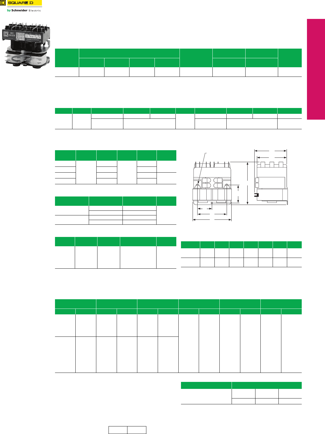
www.schneider-electric.us
© 2012 Schneider Electric
All Rights Reserved 17-35
17 NEMA DEFINITE PURPOSE TYPE
CONTACTORS AND STARTERS
Definite Purpose
Contactors
Reversing/Hoist, Type R
Class 8965 / Refer to Catalog 8910CT9301
Class 8965 reversing hoist contactors meet the small
space requirements found in electrical hoists, light duty
cranes, door operators, and related products. They are
designed to perform in the short periods of jogging
experienced in hoist service. Note that these contactors
must be mounted upright on the vertical plane; the
contactors will not operate properly when mounted in any
other position.
fCP10 Discount Schedule.
gTape wound coils, 2 per package.
hMolded coil, 1 per package.
iSuitable for 440 V 50 Hz applications.
Type RO10V02
Table 17.101: AC Reversing/Hoist Contactors—600 Vac Maximum
No. of
Poles
Horsepower Ratings Power
Terminals
Witha
Jumper Straps
Withouta
Jumper Straps $ Price
115 V
1 Ø
230 V
1 Ø
230 V
3 Ø
460/575 V
3 Ø Open Type Open Type
3-Pole
Polyphase 11-1/23 3
Quick Connect RO10cRO11c998.00
Pressure WirebRO12cRO13c
aJumper straps connect the line side power terminals of the same phase between the forward (up) and reverse (down) contactors in common;
i.e., L1 to L1, L2 to L2, and L3 to L3.
bCoils rated 120 Vac or less are supplied with quick connect terminals only.
cVoltage code must be specified to order this product. Refer to standard voltage codes shown in Table 17.105.
Table 17.102: Miscellaneous Hoist Contactor Kits For Use With Class 8965
Type Series Description Class Type Series Description Class Type $ Priced
RO10
RO11
RO12
RO13
A & B
Armature Kit 9998 RP1e
C
Armature Kit 9998 RP2e29.40
Contact
Carrier
Order as Part Number
3100206050
Contact
Carrier
Order as Part Number
3100208150 39.40
dCP10 discount schedule.
eOne armature per kit.
Table 17.103: Class 8965 Replacement Contact Kits
Device
Type
Device
Series
Class 9998
Kit Type
Device
Series
Class 9998
Kit Type $ Price
RO10
A & B
RA10
C
RA14 202.00
RO11 RA11 RA15
RO12 RA12 RA16 236.00
RO13 RA13 RA17
Table 17.104: Auxiliary Contacts Separate Module
Description Terminals Class 9999
Type $ Price
1 N.O.
Each Side
Quick Connect R10
50.00
Screw R12
1 N.C.
Each Side
Quick Connect R11
Screw R13
Table 17.105: Coil Table
Volt age
60 Hz
Voltag e
50 Hz
Voltage
Code
Replacement
Part Number $ Pricef
24
120
208/220
240
480
600
—
110
—
220
440
550
V01
V02
V21
V03
V06
V07
3100240319g
3100240340g
3100240047h
3100240049h
3100240058hi
3100240060h
119.00
119.00
114.00
114.00
114.00
83.00
Table 17.106: Approximate Dimensions
(3 Poles per Contactor)
Type A B C D E F G
RO10, 11 3.31
84
3.31
84
3.03
77
2.69
68
1.34
34
1.56
40
2.66
68
RO12, 13 3.31
84
3.69
94
2.69
68
2.69
68
1.34
34
1.56
40
2.66
68
A
D
E
F
B
G
C
Provisions for
(3) #8 Mounting Screws
Table 17.107: Cross Reference—Obsolete Devices
Obsolete
Device
Replacement
Device
Auxiliary Contact
Required
Obsolete
Device
Replacement
Device
Auxiliary Contact
Required
Class Type Class Type Class Type Class Type Class Type Class Type
8702
or
8965
HO3
HO4
HO5
HO6
HO7
HO8
8965
RO12
RO12
RO12
RO12
RO12
RO12
—
9999
9999
—
9999
9999
—
R12
R13
—
R12
R13
8965
RO2
RO2S1
RO2S2
RO3
RO3S1
RO3S2
RO3S3
RO4
RO4S1
RO5
RO5S1
RO5S2
RO6
RO6S1
RO6S2
8965
RO10
RO11
RO10
RO10
RO11
RO10
RO10
RO12
RO13
RO12
RO13
RO12
RO12
RO13
RO12
9999
9999
9999
9999
9999
9999
9999
—
—
9999
9999
9999
9999
9999
9999
R10
R10
R10
R11
R11
R11
R11
—
—
R12
R12
R12
R13
R13
R13
8965
RG2S1
RG5S1
RG5S2
RO1
RO1S1
RO1S2
RO1S3
RO1S4
RO1S5
RO1S6
8965
RO10
RO12
RO12
RO10
RO11
RO10
RO11
RO10
RO10
RO10
9999
9999
9999
—
—
—
—
—
—
—
R10
R12
R12
—
—
—
—
—
—
—
Application Data
Coils Duty: Hoist Duty—H4 Intermittent
Voltage Range: AC coils only; +10%, –15% of nominal
Burden Inrush 76 VA, Sealed 27 VA
Approvals
UL Component Recognized: File E78351, CCN NLDX2
CSA Certified: File LR60905, Class 3211 04
Table 17.108: How to Order
To Order Specify: Catalog Number
•Class Number
•Type Number
•Voltage and Frequency
Class Type Voltage and
Frequency
8695 RO10 V02
CP1 CP10 Discount
Schedule
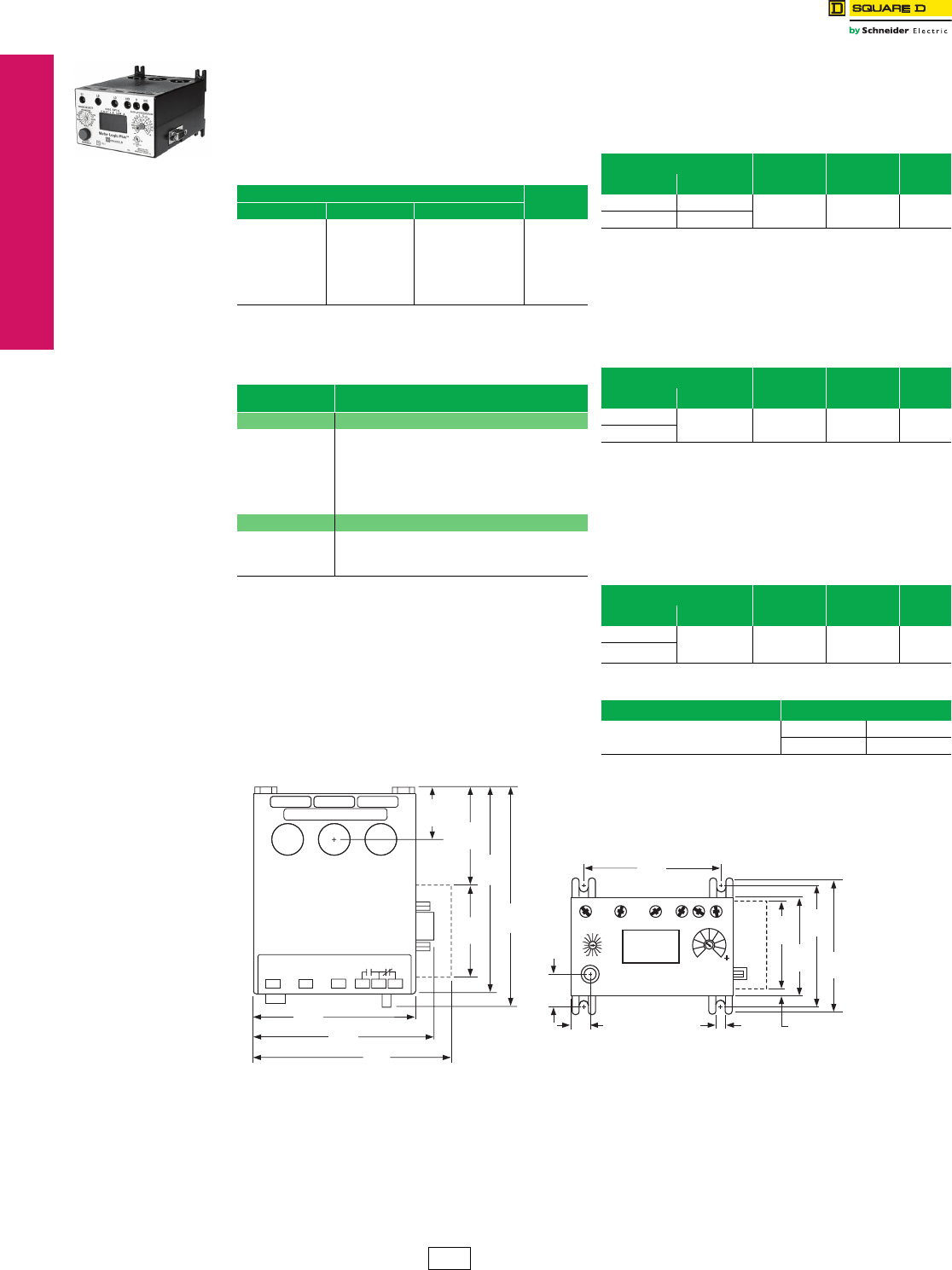
www.schneider-electric.us
17-36 © 2012 Schneider Electric
All Rights Reserved
17 NEMA DEFINITE PURPOSE TYPE
CONTACTORS AND STARTERS
Thermal Overload
Relays—NEMA Style
Solid-State Overload Relay, Motor Logic™ Plus
Class 9065 / Refer to Catalog 9065CT9701
Motor Logic Plus—Class 9065
The Motor Logic Plus solid-state overload relay is
separately powered and fully programmable. It is designed
to protect 3-phase AC motor applications, 200–480 Vac or
600 Vac. The SSOLR has one Form C relay output rated
for 300 Vac maximum.
jMust use 150:5 external current transformer, purchased separately.
kMust use 300:5 external current transformer, purchased separately.
lMust use 600:5 external current transformer, purchased separately.
Example
Form B 4 2
Motor Logic Plus overload relay with a current range of
6–27 A and modifications to add communication module
for an open style starter package.
Lug-Lug Kit
This kit can be field installed on separately mounted
Motor Logic Plus overload relays.
Software Kit
Solutions software program allows an IBM PC compatible
computer (with Windows 95 or greater) to communicate
with a Motor Logic Plus overload relay connected to an
RS-485 network using Modbus protocol.
Communication Module
This module allows the Motor Logic Plus overload relay to
support RS-485 electrical communications standards. Up
to 99 Motor Logic Plus overload relays can be controlled
and monitored from one remote personal computer.
Motor Logic Plus Table 17.109: Motor Logic Plus
Class 9065 SP Solid-State Overload Relay $ Price
200 to 480 V 600 V Current Range
SPB4
SPC4
SP14
SP24
SP34
SP44j
SP54k
SP64l
SPB6
SPC6
SP16
SP26
SP36
SP46j
SP56k
SP66l
0.5–2.3 A
2.0–9.0 A
6.0–27.0 A
10.0–45.0 A
20.0–90.0 A
60.0–135.0 A
120.0–270.0 A
240.0–540.0 A
957.00
Table 17.110: Forms for factory addition to 8536
Open Style only
Alpha Character
BMotor Logic Plus Overload Relay
First Digit Current Ranges
2
3
4
5
6
7
8
9
0.5–2.3 A
2.0–9.0 A
6.0–27.0 A
10.0–45.0 A
20.0–90.0 A
60.0–135.0 A
120.0–270.0 A
240.0–540.0 A
Second Digit Modifications
0
2
4
6
No modification for 200–480 V
Add communication module for 200–480 V
No modification for 600 V
Add communication module for 600 V
Table 17.111: Lug-Lug Kit
For Use With Parts Kit
Description
Class 9999
Type $ Price
Class & Type NEMA Size
8536 SA-SH 1–6 Lug-Lug Kit MLPL 80.00
9065 SP 1–6
Table 17.112: Software Kit
For Use With Parts Kit
Description
Class 9999
Type $ Price
Class & Type NEMA Size
8536 SA–SH 1–6 Software Kit MLPS 1295.00
9065 SP
Table 17.113: Communication Module
For Use With Parts Kit
Description
Class 9999
Type $ Price
Class & Type NEMA Size
8536 SA-SH
1–6
Modbus
Communication
Module
MB22 171.00
9065 SP
Table 17.114: How to Order
To Order Specify: Catalog Number
•Class Number
•Type Number
Class Type
9999 AC04
1.20
30
2.20
56
2.14
54
3.10
79
2.03
52
2.28
58
2.65
67
3.05
77
.70
18
.25
6
3.60
91
3.85
984.37
111
4.70
119
5.05
128
.20
5.34
9
Motor Logic Plus Solid-State Overload Relay
CP1 Discount
Schedule

© 2011 Schneider Electric
All Rights Reserved A-1
Schneider Electric Conditions of Sale
Coordinated Projects
NOTE:The following Conditions of Sale are subject to change. All transactions for all products sold by Schneider Electric USA
("Schneider Electric") including all Schneider Electric brand products, such as Square D and Telemecanique brand
products, are subject to the latest published Conditions of Sale of Schneider Electric and to any Special Conditions of
Sale which may be contained in applicable Schneider Electric quotations and acknowledgments.
Schneider Electric Standard conditions of Sale will apply in all transactions between
customers and Schneider Electric, unless Schneider Electric elects to use the Standard
Coordinated Project Conditions of Sale. The Coordinated Project Conditions of Sale
will be used on appropriate project jobs only.
GOVERNING PROVISIONS AND ACCEPTANCE: All quotations are subject to these
conditions of sale. Acceptance of an order by Schneider Electric shall be expressly
conditioned on Purchaser's assent to these conditions. Purchaser's direction to
proceed with engineering, manufacture or shipment by Schneider Electric shall be
deemed evidence of this assent. No modified or other conditions will be applicable
unless those conditions are so stated in Schneider Electric's proposal or are specifically
agreed to in writing and signed by an authorized official of Schneider Electric. Failure to
object to provisions contained in any Purchase Order or other communication from the
Purchaser (including, without limitation, penalty clauses of any kind) shall not be
construed as a waiver of these Conditions nor an acceptance of any other provisions.
These terms are a complete statement of the parties' agreement and may only be
modified in writing signed by both parties. These terms may not be modified by course
of dealing, course of performance or usage of trade. These terms supersede all
previous written or oral quotations, statements or agreements. Any contract for sale by
and between the parties shall be governed by and construed according to the laws of
the State of Illinois without regard to its rules on the conflict of laws. The Convention on
the International Sale of Goods is expressly excluded.
QUOTATIONS: Quotations shall be valid for no more than thirty (30) days from their
date, unless otherwise stated in the quotation. All quotations are subject to change by
Schneider Electric Company at any time upon notice to Purchaser. Quotations are
made based on Schneider Electric's interpretation of the plans and specifications
submitted to Schneider Electric by the Purchaser. It is Purchaser's obligation to review
the quotation carefully and to immediately advise Schneider Electric of any differing
interpretation Purchaser has so any necessary change can be made.
ORDER ENTRY: A complete, signed purchase order must be received before entry of
an order into Schneider Electric's system. Considerable detail is involved in the
manufacture of power equipment. To facilitate timely shipment, complete details and
information, including Purchaser's requested on-site dates must be provided at the time
of order entry. Shipment dates are approximate and are based upon timely receipt of all
necessary information from the Purchaser. Lack of complete information may result in
delays of drawings or manufacture. Such delays shall relieve Schneider Electric from
compliance with the quoted delivery dates and may lead to price escalation. Failure to
provide a complete signed purchase order within twenty (20) days of notification of
award may result in renegotiation of price or shipment dates.
APPROVAL DRAWINGS: When required by a specific Purchase Order, drawings will
be submitted for approval per agreed upon schedules to assure Schneider Electric has
designed the equipment as described in Purchaser's specifications, as modified by
Schneider Electric's quotation. If at time of drawing approval Schneider Electric has not
designed the equipment to meet the specifications, as modified by Schneider Electric's
quotation, Schneider Electric will make the appropriate changes at no charge to
Purchaser. Where the Purchaser's specification is not definitive, Schneider Electric
shall have the right to design the product in line with good commercial practice, without
further obligation to Purchaser. If at drawing approval, Purchaser makes changes
outside the design as stated in the specifications, such changes shall be treated as a
change order as provided below.
PRICE POLICY: Quoted prices are firm provided: A) The order is received with
complete engineering details and is released for manufacture within thirty (30) calendar
days from the originally anticipated release date. B) All required approval drawings are
returned and equipment released by Purchaser no later than thirty (30) calendar days
from the original date of mailing of approval drawings by Schneider Electric. The
returned drawings must be released for manufacture for shipment on the agreed date.
Drawing re-submittals which are required for any reason other than to correct
Schneider Electric errors will not extend the thirty (30) day deadline. If the Purchaser
causes delay of shipment in any way or returns approval drawings beyond the time
stated above, Purchaser may be subject to charges which shall not exceed 1% of the
purchase order price for each full month or fraction thereof that shipment is delayed, as
compensation to Schneider Electric for expenses created by such delay and not as a
penalty. If shipment is delayed through the fault of Purchaser for more than 12 months
from the originally anticipated release date, the price must be renegotiated.
PRICING-PURCHASER CHANGES: All prices cover a bill of material as described in
Schneider Electric specifications or quotations to be designed and manufactured to
Schneider Electric standard designs, unless otherwise agreed in writing between the
parties. Purchaser may make minor changes not affecting the time or cost of
performance without charge prior to the start of manufacture. If any changes are
requested by the Purchaser after submission of the original Purchase Order which
affect the cost or time of performance, additional billing will be made with the amount of
price adder dependent on the change and status of the order when the change is
made. Changes may also result in an extension of time for shipment. All changes will
be agreed to by the parties, in writing, prior to implementation. Purchaser's
rescheduling shipment will be considered a change. All expenses incurred by
Schneider Electric in connection with the storage of equipment, including demurrage,
packing, storage charges, insurance and handling charges by Schneider Electric will
be paid by the Purchaser upon submission of invoices by Schneider Electric.
Schneider Electric will issue price changes for any change requested by the Purchaser
that affects modification of equipment, changes the bills of material, engineering or
drawings or delivery schedule as follows: A) If Purchaser makes a change to an order
prior to being released to engineering, the net price will be adjusted by re-pricing the
equipment with prices in effect at the time of the change. A commensurate delay in the
shipping date will be based on the changes involved. B) For changes made after the
order is released to engineering, the net price and ship date will be adjusted as
described in paragraph A above. An additional charge based on Schneider Electric
standard engineering billing charges and cost of parts ($250 minimum) will be made to
cover any extra engineering and drafting, scrap or rework of parts, or cost of
modification. C) If during the drawing approval process, the Purchaser makes changes
outside the design covered by the specifications, Schneider Electric will be reimbursed
as described in paragraph A and B above, plus any additional charges for any extra
cost incurred as a direct result of the changes and allowed a commensurate delay in
shipping date based on the changes involved. Changes to the order can not be
processed until a formal change order is received from the Purchaser.
SUBSTITUTION: Schneider Electric may furnish suitable substitutes for material
unobtainable because of priorities or regulations established by governmental authority
or non-availability of materials from suppliers, provided such substitutions do not
adversely affect the technical soundness of the equipment. Schneider Electric
assumes no liability for deviation from published dimensions and descriptive
information not essential to proper performance of the product.
TAXES: Any manufacturer's tax, retailer's tax, occupation tax, use tax, sales tax,
excise tax, (except federal excise tax on vehicles), duty, customs, inspecting or testing
fee, or other tax, fee or charge of any nature whatsoever, imposed by any
governmental authority or measured by any transaction between Schneider Electric
and Purchaser, shall be paid by the Purchaser in addition to the prices quoted or
invoiced, and such charges will appear as a separate line item on the invoice. In the
event Schneider Electric will be required to pay any such tax, fee, or charge, Purchaser
shall reimburse Schneider Electric or, in lieu of such payment, Purchaser shall supply
Schneider Electric at the time the order is submitted with an exemption certificate or
other document acceptable to the tax authority. Purchase Orders must state the
existence and amount of any such tax, fee or charge for which Purchaser claims an
exemption.
TERMS OF PAYMENT: Acceptance of all Purchase Orders is subject to Purchaser
meeting Schneider Electric credit standards. Terms are subject to change for failure to
meet such standards. Terms are net thirty (30) days from date of invoice of each
shipment, unless otherwise stated in Schneider Electric's quotation. For an authorized
distributor or authorized reseller order, applicable terms of payment are stated in the
quotation or applicable discount schedule. Schneider Electric reserves the right at any
time to demand full or partial payment before proceeding with a contract of sale if, in its
sole judgment, as a result of changes in the financial condition of the Purchaser the
terms of payment originally specified are no longer justified.
PAYMENTS: If delivery is delayed or deferred by the Purchaser beyond the scheduled
date, payment shall be due in full when Schneider Electric is prepared to ship. The
equipment may be stored at the risk and expense of the Purchaser. If the Purchaser
defaults when any payment is due, then the whole contract price shall become due and
payable upon demand, or Schneider Electric at its option, without prejudice to other
lawful remedies, may defer delivery or cancel the contract for sale. If Purchaser
become insolvent, or bankrupt or in the event any proceeding is brought against the
Purchaser, voluntarily or involuntarily under the bankruptcy or any insolvency law,
Schneider Electric may cancel any order then outstanding at any time and recover its
proper cancellation charges from the Purchaser or the Purchaser's estate.
DELIVERY:
F.O.B. POINT OF SHIPMENT: When the Schneider Electric quotation is based on
delivery F.O.B. point of shipment, freight prepaid and allowed for delivery within the
continental United States, Product is sold F.O.B. point of shipment, freight prepaid and
allowed for orders over $2000 net. Delivery by Schneider Electric to the point of
shipment constitutes delivery to the Purchaser; and title and all risk of loss or damage
in transit shall pass to the Purchaser at time of delivery at the F.O.B. point. Schneider
Electric is not responsible for breakage or delays by carrier after having received "in
good order" receipts from the carrier. Purchaser is responsible for pursuing any
damage claims with the carrier. For orders under $2000 net the above terms apply
except freight is prepaid not allowed. No allowance will be made in lieu of transportation
if the Purchaser accepts shipment at factory, warehouse or freight station or otherwise
supplies its own transportation. Freight prepaid is defined as: a) Shipments to
destinations within the continental United States to the accessible common carrier point
nearest the first destination. b) Shipments to U.S. destinations outside the continental
United States shall be to the common carrier free delivery point in the United States
nearest the original port of embarkation. All charges associated with F.A.S., C.I.F., or
other charges such as pier transfer, lift, ocean freight, and marine or war insurance
shall be paid by the Purchaser, unless otherwise specifically agreed in a specific
Purchase Order. In no event will Schneider Electric be responsible for demurrage or
detention charges.
DELIVERY: F.O.B. DESTINATION: When the Schneider Electric quotation is based
on delivery F.O.B. Destination, for shipments for delivery within the continental United
States, Schneider Electric will retain title and all risk of loss or damage in transit to the
common carrier free delivery point in the United States nearest the first destination for a
price addition of 2% of the net price. If the Purchaser elects this Option, Purchaser's
obligations shall be as follows: a) Purchaser shall have the responsibility of inspecting
the equipment for apparent loss or damage immediately upon its arrival at the free
delivery point. b) In the event of apparent shipping loss or damage, Purchaser shall
make written notation of the loss on the carrier's delivery receipt and, within 72 hours of
delivery shall notify the Schneider Electric Customer Information Center. Purchaser
shall not remove product from the point of examination and shall retain the shipping
container and packing material. Purchaser shall request the carrier to make an
inspection and send Schneider Electric a copy of the carrier's inspection report. c) In
the event of concealed damage which occurred during transit and is discovered by the
Purchaser after delivery, Purchaser shall report such damage immediately, but in no
event later than 15 days after delivery, to the delivering carrier, and within 72 hours of
discovery, shall notify the local Schneider Electric field office. If such notification is not
made, Schneider Electric shall not be liable for loss or damage in transit.
SHIPMENT AND ROUTING: Square D shall select the point of origin of shipment, the
method of transportation and the routing of the shipment. Purchasers that request
expedited or special modes of transportation or routing involving air, premium or any
other non-standard Square D shipping shall be assessed additional charges for
shipping, handling, freight and expediting. Any rebates, allowances, discounts, or
incentives received by Square D from its carriers shall be retained by Square D. All
prices include domestic packaging only. When other than domestic packaging is
required, contact your local Square D field office. Purchaser specified packaging and
marking may be subject to additional charges.

© 2011 Schneider Electric
All Rights Reserved
A-2
Schneider Electric Conditions of Sale
Coordinated Projects
SHORTAGES: Claims for shortages or errors must be submitted to Schneider Electric
within 30 days after invoice date, and failure to give such notice shall constitute
unqualified acceptance and a waiver of all such claims by the Purchaser.
INSTALLMENTS: Schneider Electric reserves the right to make shipments in
installments, unless otherwise expressly stipulated in a specific Purchase Order; and all
such installments when separately invoiced shall be paid for when due per invoice
without regard to subsequent shipments. Delay in shipment of any installment shall not
relieve Purchaser of its obligation to accept remaining shipments.
FORCE MAJEURE: Schneider Electric shall not be liable for any damages as a result
of any delays due to any causes beyond Schneider Electric's control, including, without
limitation, an act of God; act of Purchaser or Schneider Electric supplier; embargo or
other governmental act, regulation or request; fire; accident; strike; slowdown; flood;
fuel or energy shortage; sabotage; war; riot; delay in transportation and inability to
obtain necessary labor, materials or manufacturing facilities from usual sources. In the
event of any such delay, the date of delivery shall be extended for a period of time
reasonably necessary to overcome the effect of such delay.
STANDARD WARRANTY: Schneider Electric warrants equipment manufactured by it
and sold through authorized sales channels to be free from defects in materials and
workmanship for eighteen (18) months from date of invoice by Schneider Electric or its
authorized sales channel. If within such period, any such equipment shall be proved to
Schneider Electric's satisfaction to be non-conforming, such equipment shall be
repaired or replaced at Schneider Electric's option. This warranty shall not apply (a) to
equipment not manufactured by Schneider Electric, (b) to equipment that has been
repaired or altered by other than Schneider Electric so as, in its judgment, to affect the
same adversely, or (c) to equipment that has been subjected to negligence, accident,
or damage by circumstances beyond Schneider Electric's control, or improper
operation, maintenance or storage, or to other than normal use or service. With respect
to equipment not manufactured by Schneider Electric, the warranty obligations of
Schneider Electric shall in all respects conform and be limited to the warranty actually
extended to Schneider Electric by its supplier. Non-conforming products must be
returned at Schneider Electric's expense for evaluation unless this is waived in writing.
Replacement products may be new or reconditioned. The foregoing warranties do not
cover reimbursement for labor, transportation, removal, installation, temporary power,
or any other expenses that may be incurred in connection with repair or replacement.
OPTIONAL WARRANTIES: (Only available on equipment to be located in the U.S.)
Option 1 - Extended-2 to 5 years from Shipment. If requested by the Purchaser and
specifically accepted in writing by Schneider Electric, the standard warranty will be
extended to two (2) years from date of invoice for a price addition of 1% of the net face
value of the Purchase Order, will be extended to three (3) years from date of invoice for
a price addition of 3% of the net face value of the Purchase Order, will be extended to
four (4) years from date of invoice for a price addition of 5% of the net face value of the
Purchase Order, or will be extended to five (5) years from date of invoice for a price
addition of 7% of the net face value of the Purchase Order. Option 2-Special Warranty:
If requested by the Purchaser and specifically accepted in writing by Schneider Electric,
the standard warranty will be extended, for a price addition of 3% of the net face value
of the Purchase Order, to cover reimbursement of the direct costs of: a) Removal of
non-conforming equipment or part thereof; b) Transporting equipment or parts to and
from the place of repair; c) Off-loading of truck and reinstallation at the original site.
Such special warranty, which may be chosen to cover a period not exceeding that of
the standard or extended warranty (see above) selected, will not include the cost of
providing temporary power or removing or replacing other apparatus or structures, or
costs of transportation beyond a common carrier free delivery point in the continental
United States. Further, the obligation of Schneider Electric for expenses and costs
arising under this special warranty coverage will not exceed 50% of the net invoice
price on the equipment being repaired. This warranty does not change or affect the
allocation of risk or loss during shipment. Option 3-Extended Warranty-Preventative
Maintenance Agreements: If requested by the Purchaser, and specifically accepted by
Schneider Electric, a Preventative Maintenance Agreement is available to provide
preventative maintenance on equipment covered by the agreement. Terms of the
preventative maintenance agreement shall be as defined in a separate Services
Agreement agreed to by the parties.
SOFTWARE: Any software or computer information, in whatever form, provided with
equipment manufactured by Schneider Electric is licensed to Purchaser solely
pursuant to standard licenses of Schneider Electric or its supplier of such software or
computer information, which licenses are, hereby incorporated by reference. Schneider
Electric does not warrant that such software or computer information will operate error
free or without interruption, and warrants only that during the warranty period applicable
to the equipment that the software will perform its essential functions. If such software
or computer information fails to conform to such warranty, Schneider Electric will, at its
option, provide an update to correct the non-conformance or replace the software or
computer information with the latest available version containing a correction.
Schneider Electric shall have no other obligation to provide updates or revisions.
LIMITATIONS: These disclaimers and limitations of remedies apply to all warranties
offered to Purchaser and to all Purchase Orders. THE WARRANTIES SET FORTH
ABOVE ARE EXCLUSIVE AND IN LIEU OF ALL OTHER EXPRESS OR IMPLIED
WARRANTIES (EXCEPT WARRANTIES OF TITLE), INCLUDING, BUT
NOTLIMITED TO IMPLIED WARRANTIES OF MERCHANTABILITY AND FITNESS
FOR A PARTICULAR PURPOSE. Except as may be expressly provided in an
authorized writing by Schneider Electric, Schneider Electric shall not be subject to any
other obligations or liabilities whatsoever other than as stated above with respect to
equipment sold or services rendered by Schneider Electric. Notwithstanding anything
to the contrary herein contained SCHNEIDER ELECTRIC, ITS CONTRACTORS AND
SUPPLIERS OF ANY TIER, SHALL NOT BE LIABLE IN CONTRACT, IN TORT
(INCLUDING NEGLIGENCE OR STRICT LIABILITY) OR OTHERWISE FOR LOST
TIME, LOST PROFITS, OR SPECIAL, INDIRECT, INCIDENTAL OR
CONSEQUENTIAL DAMAGES OF ANY KIND WHATSOEVER. The remedies of the
Purchaser are exclusive and the total cumulative liability of Schneider Electric, its
contractors and suppliers of any tier, with respect to this contract or anything done in
connection therewith, such as the use of any product covered by or furnished under the
contract, whether in contract, in tort (including negligence or strict liability) or otherwise,
shall not exceed the price of the product, part, or service on which such liability is
based.
INTELLECTUAL PROPERTY: As to equipment proposed and furnished by Schneider
Electric, Schneider Electric shall defend any suit or proceeding brought against
Purchaser so far as based on a claim that such equipment constitutes an infringement
of any copyright, trademark or patent of the United States.
This obligation shall be effective only if Purchaser shall have made all payments then
due hereunder and if Schneider Electric is notified promptly in writing and given
authority, information, and assistance at Schneider Electric's expense for the defense
of the same. In the event the use of such equipment by Purchaser is enjoined in such a
suit, Schneider Electric shall, at its expense, and at its sole option, either (a) procure for
the Purchaser the right to continue using such equipment (b) modify such equipment to
render it non-infringing (c) replace such equipment with non-infringing equipment, or (d)
refund the purchase price (less depreciation) and the transportation and installation
costs of such equipment. Schneider Electric will not be responsible for any compromise
or settlement made without its written consent. The foregoing states the entire liability of
Schneider Electric for patent, trademark or copyright infringement, and in no event shall
Schneider Electric be liable if any infringement charge is based on the use of Schneider
Electric equipment for a purpose other than that for which it was sold by Schneider
Electric. As to any equipment furnished by Schneider Electric to Purchaser and
manufactured in accordance with designs proposed by Purchaser, the Purchaser shall
indemnify Schneider Electric against any award made against Schneider Electric for
patent, trademark, or copyright infringements.
WITNESS OF TESTS AND FACTORY INSPECTIONS: Normal production schedules
do not provide the opportunity for Purchaser to witness routine factory tests on
equipment or make factory inspections. Witnessing of tests or factory inspections by
the Purchaser may result in delays of production for which Schneider Electric will not be
responsible. Witness testing and factory inspections must be requested at time of
quotation and confirmed at order entry. Standard Schneider Electric factory testing and
inspection will apply. Schneider Electric will notify Purchaser fourteen (14) calendar
days prior to scheduled witness testing or inspection. In the event Purchaser is unable
to attend, the Parties may mutually agree on a rescheduled date. However, Schneider
Electric, at its sole option, may consider the witness tests and/or inspection waived, and
ship and invoice the Products. Purchaser will be responsible for paying for all
scheduled witness testing, whether or not Purchaser attends.
RETURN OF EQUIPMENT: NO EQUIPMENT MAY BE RETURNED WITHOUT
FIRST OBTAINING SCHNEIDER ELECTRIC'S WRITTEN PERMISSION AND A
RETURNED MATERIAL IDENTIFICATION TAG. Returned equipment must be of
current manufacture, in the original packaging, unused, undamaged and in saleable
condition, securely packed to reach Schneider Electric without damage and labeled
with the return authorization number. Any cost incurred by Schneider Electric to put
equipment in first class condition will be charged to the Purchaser. Returns will be
credited at price invoiced by Schneider Electric less a restocking fee of 25% invoice
price. Special Order and Custom equipment is not returnable. Schneider Electric shall
bear the cost of returns resulting from Schneider Electric error, and method and route
of return will be at the discretion of Schneider Electric. Costs incurred by failure to follow
Schneider Electric direction will be borne by the Purchaser.
NUCLEAR APPLICATIONS TERMS AND CONDITIONS: Unless otherwise agreed
in writing by a duly authorized representative of Schneider Electric, products sold
hereunder are not intended for use in or in connection with any nuclear facility or
activity. If so used, Schneider Electric disclaims all liability for any damage, injury or
contamination; and Purchaser shall indemnify Schneider Electric against any such
liability, whether arising as a result of breach of contract, warranty or tort (including
negligence) or otherwise.
PATTERNS AND TOOLS: Notice will be given if special patterns or tools are required
to complete any order. Charges for such patterns or tools do not convey title thereto or
the right to remove them from Schneider Electric's plant. If patterns or tools are not
used for a period of two years, Schneider Electric shall have the right to scrap them
without notice.
PRODUCT NOTICES: Purchaser shall promptly supply the user (including its
employees) of the product with all Schneider Electric supplied product notices,
warnings, instructions, recommendations and similar materials.
ERRORS: Schneider Electric reserves the right to correct errors or omissions in
quotations, acknowledgments, invoices, or other documents.
OSHA COMPLIANCE: Compliance with OSHA or similar federal, state or local laws
during the operation or use of the product(s) is the sole responsibility of the Purchaser.
TERMINATION: Any order may be terminated by the Purchaser only upon written
notice to Schneider Electric and upon payment of reasonable and proper termination
charges based on the price of the terminated order and reimbursement of all direct
costs and expenses associated with the order caused by such termination and shall
include a reasonable profit. Special or custom ordered equipment is not cancelable
after commencement of manufacturing.
CANCELLATION: Schneider Electric shall have the right to cancel any order or
contract at any time by written notice for any material breach of the contract by the
Purchaser, including material delays in releasing equipment for manufacture or
approval drawings and excessive changes to specifications or drawings.
0100PL0043R11/11 November 30, 2011

© 2011 Schneider Electric
All Rights Reserved A-3
Schneider Electric Conditions of Sale
Standard
NOTE:The following Conditions of Sale are subject to change. All transactions for all products sold by Schneider Electric USA
("Schneider Electric") including all Schneider Electric brand products, such as Square D and Telemecanique brand
products, are subject to the latest published Conditions of Sale of Schneider Electric and to any Special Conditions of
Sale which may be contained in applicable Schneider Electric quotations and acknowledgments.
1. GOVERNING PROVISIONS AND ACCEPTANCE: All quotations are
subject to these conditions of sale. Acceptance of an order by Schneider
Electric shall be expressly conditioned on Purchaser's assent to these
conditions. Purchaser's direction to proceed with engineering, manufacture
or shipmen by Schneider Electric shall be deemed evidence of this assent.
No modified or other conditions will be applicable unless those conditions
are so stated in Schneider Electric's proposal or are specifically agreed to in
writing and signed by an authorized official of Schneider Electric. Failure to
object to provisions contained in any Purchase Order or other
communication from the Purchaser (including, without limitation, penalty
clauses of any kind) shall not be construed as a waiver of these Conditions
nor an acceptance of any other provisions. These terms are a complete
statement of the parties' agreement and may only be modified in writing
signed by both parties. These terms may not be modified by course of
dealing, course of performance or usage of trade. These terms supersede all
previous written or oral quotations, statements or agreements. Any contract
for sale by and between the parties shall be governed by and construed
according to the laws of the State of Illinois without regard to its rules on the
conflict of laws. The Convention on the International Sale of Goods is
expressly excluded.
2. QUOTATIONS: Quotations shall be valid for no more than thirty (30) days
from their date, unless otherwise stated in the quotation. All quotations are
subject to change by Schneider Electric Company at any time upon notice to
Purchaser. It is Purchaser's obligation to review the quotation carefully and
to immediately advise Schneider Electric of any differing interpretation
Purchaser has so any necessary change can be made.
3. PRICE POLICY: All prices are subject to change without notice. In the event
of a net price change and unless otherwise agreed to in writing, prices for
orders scheduled for immediate release shall be those in effect at time of
order entry. Prices for orders placed for future shipment without an agreed
price and ship date will be billed at the pricing in effect as of the shipment
date. All clerical errors are subject to correction.
4. SUBSTITUTION: Schneider Electric may furnish suitable substitutes for
material unobtainable because of priorities or regulations established by
governmental authority or non-availability of materials from suppliers,
provided such substitutions do not adversely affect the technical soundness
of the equipment. Schneider Electric assumes no liability for deviation from
published dimensions and descriptive information not essential to proper
performance of the product.
5. TAXES: Any manufacturer's tax, retailer's tax, occupation tax, use tax, sales
tax, excise tax, (except federal excise tax on vehicles), duty, customs,
inspecting or testing fee, or other tax, fee or charge of any nature
whatsoever, imposed by any governmental authority or measured by any
transaction between Schneider Electric and Purchaser, shall be paid by the
Purchaser in addition to the prices quoted or invoiced, and such charges will
appear as a separate line item on the invoice. In the event Schneider Electric
will be required to pay any such tax, fee, or charge, Purchaser shall
reimburse Schneider Electric or, in lieu of such payment, Purchaser shall
supply Schneider Electric at the time the order is submitted with an
exemption certificate or other document acceptable to the tax authority.
Purchase Orders must state the existence and amount of any such tax, fee
or charge for which Purchaser claims an exemption.
6. TERMS OF PAYMENT: Acceptance of all Purchase Orders is subject to
Purchaser meeting Schneider Electric credit standards. Terms are subject to
change for failure to meet such standards. Terms are net thirty (30) days
from date of invoice of each shipment, unless otherwise stated in Schneider
Electric's quotation. For an authorized distributor or authorized reseller
order, applicable terms of payment are stated in the quotation or applicable
discount schedule. Schneider Electric reserves the right at any time to
demand full or partial payment before proceeding with a contract of sale if, in
its sole judgment, as a result of changes in the financial condition of the
Purchaser the terms of payment originally specified are no longer justified.
7. PAYMENTS: If delivery is delayed or deferred by the Purchaser beyond the
scheduled date, payment shall be due in full when Schneider Electric is
prepared to ship. The equipment may be stored at the risk and expense of
the Purchaser. If the Purchaser defaults when any payment is due, then the
whole contract price shall become due and payable upon demand, or
Schneider Electric at its option, without prejudice to other lawful remedies,
may defer delivery or cancel the contract for sale. If Purchaser becomes
insolvent, or bankrupt or in the event any proceeding is brought against the
Purchaser, voluntarily or involuntarily under the bankruptcy or any
insolvency law, Schneider Electric may cancel any order outstanding at any
time and recover its applicable cancellation charges from the Purchaser or
the Purchaser's estate.
8. DELIVERY:
A: F.O.B. POINT OF SHIPMENT: When the Schneider Electric quotation is
based on delivery F.O.B. point of shipment, freight prepaid and allowed for
delivery within the continental United States, product is sold F.O.B. point of
shipment, freight prepaid and allowed. A shipping and handling charge of fifty
dollars ($50) will be added to all orders having a total net invoice price of less than
one thousand dollars ($1,000). Delivery by Schneider Electric to the point of
shipment constitutes delivery to the Purchaser; and title and all risk of loss or
damage in shall pass to the Purchaser at time of delivery at the F.O.B. point
Schneider Electric is not responsible for breakage after having received "in good
order" receipts from the carrier. Purchaser is responsible for pursuing any damage
claims with the carrier. No allowance will be made in lieu of transportation if the
Purchaser accepts shipment at factory, warehouse or freight station or otherwise
supplies its own transportation. Freight prepaid is defined as: A) Shipments to
destinations within the continental United States to the accessible common carrier
point nearest the first destination. B) Shipments to U.S. destinations outside the
continental United States shall be to the common carrier free delivery point in the
United States nearest the original port of embarkation. All charges associated with
F.A.S., C.I.F., or other charges such as pier transfer, lift, ocean freight, and marine
or war insurance shall be paid by the Purchaser, unless otherwise specifically
agreed in a specific Purchase Order. In no event will Schneider Electric be
responsible for demurrage or detention charges.
B: DELIVERY: F.O.B. DESTINATION: When the Schneider Electric quotation is
based on delivery F.O.B. Destination, for shipments for delivery within the
continental United States, Schneider Electric will retain title and all risk of loss or
damage in transit to the common carrier free delivery point in the United States
nearest the first destination for a price addition of 2% of the net price. If the
Purchaser elects this option, Purchaser's obligations shall be as follows: A)
Purchaser shall have the responsibility of inspecting the equipment for apparent
loss or damage immediately upon its arrival at the free delivery point. B) In the
event of apparent shipping loss or damage, Purchaser shall make written notation
of the loss on the carrier's delivery receipt and, within 72 hours of delivery shall
notify the Schneider Electric Customer Information Center. Purchaser shall not
remove product from the point of examination and shall retain the shipping
container and packing material. Purchaser shall request the carrier to make an
inspection and send Schneider Electric a copy of the carrier's inspection report. C)
In the event of concealed damage which occurred during transit and is discovered
by the Purchaser after delivery, Purchaser shall report such damage immediately,
but in no event later than 15 days after delivery, to the delivering carrier, and within
72 hours of discovery, shall notify the local Schneider Electric field office. If such
notification is not made, Schneider Electric shall not be liable for loss or damage in
transit.
C: SHIPMENT AND ROUTING: Schneider Electric shall select the point of origin
of shipment, the method of transportation and the routing of the shipment.
Purchasers that request expedited or special modes of transportation or routing
involving air, premium or any other non-standard Schneider Electric shipping shall
be assessed additional charges for shipping, handling, freight and expediting. Any
rebates, allowances, discounts or incentives received by Schneider Electric from
its carriers shall be retained by Schneider Electric. All prices include domestic
packaging only. When other than domestic packaging is required, contact your
local Schneider Electric field office. Purchaser specified packaging and marking
may be subject to additional charges.
9. SHORTAGES: Claims for shortages or errors must be submitted to
Schneider Electric within 30 days after invoice date, and failure to give such
notice shall constitute unqualified acceptance and a waiver of all such claims
by the Purchaser.
10. INSTALLMENTS: Schneider Electric reserves the right to make shipments
in installments, unless otherwise expressly stipulated in a specific Purchase
Order; and all such installments when separately invoiced shall be paid for
when due per invoice without regard to subsequent shipments. Delay in
shipment of any installment shall not relieve Purchaser of its obligation to
accept remaining shipments.
11. FORCE MAJEURE: Schneider Electric shall not be liable for any damages
as a result of any delays due to any causes beyond Schneider Electric's
control, including, without limitation, an act of God; act of Purchaser or
Schneider Electric supplier; embargo or other governmental act; regulation
or request; fire; accident; strike; slowdown; flood; fuel or energy shortage;
sabotage; war; riot; delay in transportation and inability to obtain necessary
labor, materials or manufacturing facilities from usual sources. In the event
of any such delay, the date of delivery shall be extended for a period of time
reasonably necessary to overcome the effect of such delay.
12. STANDARD WARRANTY: Schneider Electric warrants equipment
manufactured by it and sold through authorized sales channels to be free
from defects in materials and workmanship for eighteen (18) months from
date of invoice by Schneider Electric or its authorized sales channel. If within
such period any such equipment shall be proved to Schneider Electric's
satisfaction to be non-conforming, such equipment shall be repaired or
replaced at Schneider Electric's option. This warranty shall not apply (a) to
equipment not manufactured by Schneider Electric, (b) to equipment that
has been repaired or altered by other than Schneider Electric so as, in its
judgment, to affect the same adversely, or (c) to equipment that has been
subjected to negligence, accident, or damage by circumstances beyond
Schneider Electric's control, or improper operation, maintenance or storage,
or to other than normal use or service. With respect to equipment not
manufactured by Schneider Electric, the warranty obligations of Schneider
Electric shall in all respects conform and be limited to the warranty actually
extended to Schneider Electric by its supplier. Non-conforming products
must be returned at Schneider Electric's expense for evaluation unless this
is waived in writing. Replacement products may be new or reconditioned.

© 2011 Schneider Electric
All Rights Reserved
A-4
Schneider Electric Conditions of Sale
Standard
The foregoing warranties do not cover reimbursement for labor, transportation,
removal, installation, temporary power, or any other expenses that may be
incurred in connection with repair or replacement.
13. OPTIONAL WARRANTIES: (Only available on equipment to be located in
the U.S.) Option 1 - Extended-2 to 5 years from Shipment. If requested by
the Purchaser and specifically accepted in writing by Schneider Electric, the
standard warranty will be extended to two (2) years from date of invoice for a
price addition of 1% of the net face value of the Purchase Order, will be
extended to three (3) years from date of invoice for a price addition of 3% of
the net face value of the Purchase Order, will be extended to four (4) years
from date of invoice for a price addition of 5% of the net face value of the
Purchase Order, or will be extended to five (5) years from date of invoice for
a price addition of 7% of the net face value of the Purchase Order. Option 2 -
Special Warranty: If requested by the Purchaser and specifically accepted in
writing by Schneider Electric, the standard warranty will be extended, for a
price addition of 3% of the net face value of the Purchase Order, to cover
reimbursement of the direct costs of: A) Removal of non-conforming
equipment or part thereof; B) Transporting equipment or parts to and from
the place of repair; C) Off-loading of truck and reinstallation at the original
site. Such special warranty, which may be chosen to cover a period not
exceeding that of the standard or extended warranty (see above) selected,
will not include the cost of providing temporary power or removing or
replacing other apparatus or structures, or costs of transportation beyond a
common carrier free delivery point in the continental United States. Further,
the obligation of Schneider Electric for expenses and costs arising under this
special warranty coverage will not exceed 50% of the net invoice price on
the equipment being repaired. This warranty does not change or affect the
allocation of risk or loss during shipment. Option 3 - Extended Warranty -
Preventative Maintenance Agreements: If requested by the Purchaser, and
specifically accepted by Schneider Electric, a Preventative Maintenance
Agreement is available to provide preventative maintenance on equipment
covered by the agreement. Terms of the Preventative Maintenance
Agreement shall be as defined in a separate Services Agreement agreed to
by the parties.
14. RETURN OF EQUIPMENT: NO EQUIPMENT MAY BE RETURNED
WITHOUT FIRST OBTAINING SCHNEIDER ELECTRIC'S WRITTEN
PERMISSION AND A RETURNED MATERIAL IDENTIFICATION TAG.
Returned equipment must be of current manufacture, in the original
packaging, unused, undamaged and in saleable condition. Returned
equipment must be securely packed to reach Schneider Electric without
damage and labeled with the return authorization number. Any cost incurred
by Schneider Electric to put equipment in first class condition will be charged
to the Purchaser. Returns must originate from the original purchaser account
number. Returns will be credited at the original price paid as indicated on the
invoice or purchase order associated to the equipment being returned as
provided by the Purchaser. If no invoice number or purchase order number
is provided, then credit will be issued based on the into stock price in effect
12 months prior to date of return authorization and will also have an
additional 25% processing fee applied.
Schneider Electric stocked equipment (which is defined as equipment
stocked within Schneider Electric's Distribution Center) and non-stocked
equipment, which are listed in the current product list as returnable and
which are accepted for credit, not involving a Schneider Electric error, shall
be assessed a restocking fee of 25% of the invoice price.
NOTE: Special Order and Custom equipment is not returnable.
Each line item returned must have an extended line item value of $25.00 or
greater. Schneider Electric shall bear the cost of returns resulting from Schneider
Electric error, and method and route of return will be at the discretion of Schneider
Electric. Costs incurred by failure to follow Schneider Electric direction will be
borne by the Purchaser.
15. SOFTWARE: Any software or computer information, in whatever form that is
provided with equipment manufactured by Schneider Electric, is licensed to
Purchaser solely pursuant to standard licenses of Schneider Electric or its
supplier of such software or computer information which licenses are hereby
incorporated by reference. Schneider Electric does not warrant that such
software or computer information will operate error free or without
interruption, and warrants only that during the warranty period applicable to
the equipment that the software will perform its essential functions. If such
software or computer information fails to conform to such warranty,
Schneider Electric will, at its option, provide an update to correct the non-
conformance or replace the software or computer information with the latest
available version containing a correction. Schneider Electric shall have no
other obligation to provide updates or revisions.
16. LIMITATIONS: These disclaimers and limitations of remedies apply to all
warranties offered to Purchaser and to all Purchase Orders. THE
WARRANTIES SET FORTH ABOVE ARE EXCLUSIVE AND IN LIEU OF
ALL OTHER EXPRESSED OR IMPLIED WARRANTIES (EXCEPT
WARRANTIES OF TITLE), INCLUDING, BUT NOT LIMITED TO IMPLIED
WARRANTIES OF MERCHANTABILITY AND FITNESS FOR A
PARTICULAR PURPOSE. Except as may be expressly provided in an
authorized writing by Schneider Electric, Schneider Electric shall not be
subject to any other obligations or liabilities whatsoever, other than as stated
above with respect to equipment sold or services rendered by Schneider
Electric. Notwithstanding anything to the contrary herein contained
SCHNEIDER ELECTRIC COMPANY, ITS CONTRACTORS AND
SUPPLIERS OF ANY TIER, SHALL NOT BE LIABLE IN CONTRACT, IN
TORT (INCLUDING NEGLIGENCE OR STRICT LIABILITY) OR
OTHERWISE FOR LOST TIME, LOST PROFITS, OR SPECIAL, INDIRECT,
INCIDENTAL OR CONSEQUENTIAL DAMAGES OF ANY KIND
WHATSOEVER. The remedies of the Purchaser are exclusive and the total
cumulative liability of Schneider Electric, its contractors and suppliers of any
tier, with respect to this contract or anything done in connection therewith,
such as the use of any product covered by or furnished under the contract,
whether in contract, in tort (including negligence or strict liability) or
otherwise, shall not exceed the price of the product, part, or service on which
such liability is based.
17. INTELLECTUAL PROPERTY: As to equipment proposed and furnished by
Schneider Electric, Schneider Electric shall defend any suit or proceeding
brought against Purchaser so far as based on a claim that such equipment
constitutes an infringement of any copyright, trademark or patent of the
United States. This obligation shall be effective only if Purchaser shall have
made all payments then due hereunder and if Schneider Electric is notified
promptly in writing and given authority, information, and assistance at
Schneider Electric's expense for the defense of the same. In the event the
use of such equipment by Purchaser is enjoined in such a suit, Schneider
Electric shall, at its expense, and at its sole option, either (a) procure for the
Purchaser the right to continue using such equipment (b) modify such
equipment to render it non-infringing (c) replace such equipment with non-
infringing equipment, or (d) refund the purchase price (less depreciation) and
the transportation and installation costs of such equipment. Schneider
Electric will not be responsible for any compromise or settlement made
without its written consent. The foregoing states the entire liability of
Schneider Electric for patent, trademark or copyright infringement, and in no
event shall Schneider Electric be liable if any infringement charge is based
on the use of Schneider Electric equipment for a purpose other than that for
which it was sold by Schneider Electric. As to any equipment furnished by
Schneider Electric to Purchaser and manufactured in accordance with
designs proposed by Purchaser, the Purchaser shall indemnify Schneider
Electric against any award made against Schneider Electric for patent,
trademark, or copyright infringements.
18. WITNESS OF TESTS AND FACTORY INSPECTIONS: Normal production
schedules do not provide the opportunity for Purchaser to witness routine
factory tests on equipment or make factory inspections. Witnessing of tests
or factory inspections by the Purchaser may result in delays of production for
which Schneider Electric will not be responsible. Witness testing and factory
inspections must be requested at time of quotation, are subject to additional
costs and must be confirmed at order entry. Standard Schneider Electric
factory testing and inspection will apply. Schneider Electric will notify
Purchaser fourteen (14) calendar days prior to scheduled witness testing or
inspection. In the event Purchaser is unable to attend, the Parties may
mutually agree on a rescheduled date. However, Schneider Electric, at its
sole option, may consider the witness tests and/or inspection waived, and
ship and invoice the Products and the witness testing charges. Purchaser
will be responsible for paying for all scheduled witness testing, whether or
not Purchaser attends.
19. NUCLEAR APPLICATIONS TERMS AND CONDITIONS: Unless otherwise
agreed in writing by a duly authorized representative of Schneider Electric,
products sold hereunder are not intended for use in or in connection with any
nuclear facility or activity. If so used, Schneider Electric disclaims all liability
for any damage, injury or contamination; and Purchaser shall indemnify
Schneider Electric against any such liability, whether arising as a result of
breach of contract, warranty or tort (including negligence) or otherwise.
20. PATTERNS AND TOOLS: Notice will be given if special patterns or tools
are required to complete any order. Charges for such patterns or tools do not
convey title thereto or the right to remove them from Schneider Electric's
plant. If patterns or tools are not used for a period of two years, Schneider
Electric shall have the right to scrap them without notice.
21. PRODUCT NOTICES: Purchaser shall promptly supply the user (including
its employees) of the product with all Schneider Electric supplied product
notices, warnings, instructions, recommendations and similar materials.
22. ERRORS: Schneider Electric reserves the right to correct errors or
omissions in quotations, acknowledgments, invoices, or other documents.
23. OSHA COMPLIANCE: Compliance with OSHA or similar federal, state or
local laws during the operation or use of the product(s) is the sole
responsibility of the Purchaser.
24. TERMINATION: Any order may be terminated by the Purchaser only upon
notice to Schneider Electric and upon payment of reasonable and proper
termination charges based on the price of the terminated order and
reimbursement of all direct costs and expenses associated with the order
caused by such termination and shall include a reasonable profit. Special or
custom ordered equipment is not cancelable after final acceptance of
approval drawings for the commencement of manufacturing.
25. CANCELLATION: Schneider Electric shall have the right to cancel any
order or contract at any time by written notice for any material breach of the
contract by the Purchaser, including material delays in releasing equipment
for manufacture or approval drawings and excessive changes to
specifications or drawings.
0100PL0041R11/11 November 30, 2011
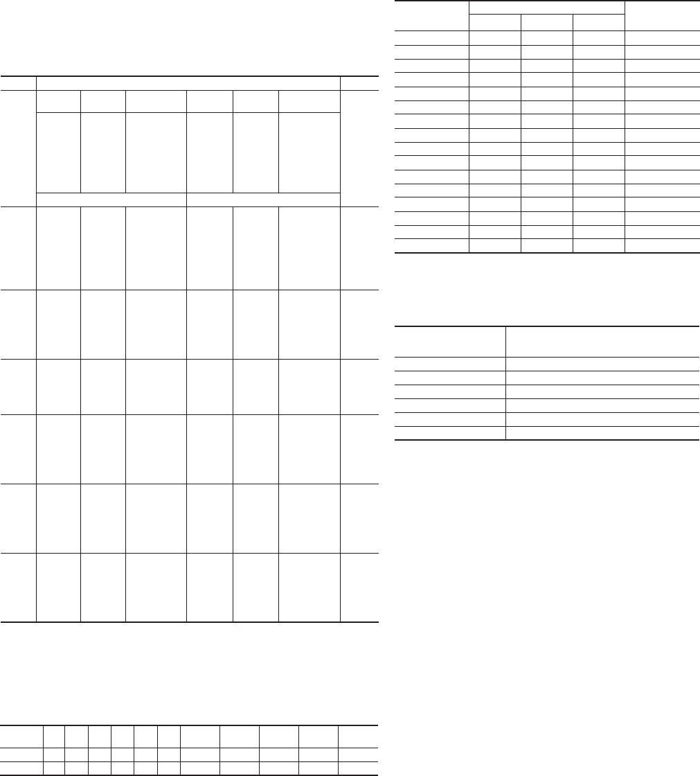
© 2012 Schneider Electric
All Rights Reserved
Ratings for 120/240 volts, 3-Wire, Single-Phase Dwelling
Services— See NEC Table 310.15 (B)(7)
These are permitted ratings for Dwelling Unit service and feeder conductors
which carry the total load of the dwelling.
NEC 210.19 Conductors — Minimum Ampacity and Size
(A) Branch Circuit Not More Than 600 Volts.
(1) General. Branch-circuit conductors shall have an ampacity not less than the
maximum load to be served. Where a branch circuit supplies continuous loads or
any combination of continuous and noncontinuous loads, the minimum branch-
circuit conductor size, before the application of any adjustment or correction
factors, shall have an allowable ampacity not less than the noncontinuous load
plus 125 percent of the continuous load.
Rating
(amps) 100 110 125 150 175 200 225 250 300 350 400
Copper 4 3 2 1 1/0 2/0 3/0 4/0 250 kcmil 350 kcmil 400 kcmil
Aluminum 2 1 1/0 2/0 3/0 4/0 250 kcmil 300 kcmil 350 kcmil 500 kcmil 600 kcmil
Conductor Ampacity Based on the 2011 National Electrical Code®
Ampacity based on NEC Table 310.15(B)(16) (Formerly Table 310.16) –
Allowable Ampacities of Insulated Conductors Rated Up to and Including
2000 Volts, 60° Through 90°C (140° Through 194°F), Not More Than Three
Current-Carrying Conductors in Raceway, Cable, or Earth (Directly Buried),
Based on Ambient Temperature of 30°C (86°F)*
For conduit fill see 2011 NEC Annex C.
For Information on Temperature Ratings of Terminations to Equipment
See NEC 110 .14(C).
* Refer to 310.15(B)(2)(a) for the ampacity correction factors where the ambient temperature is other than
30°C (86°F).
** See Section 240.4 (D) for conductor overcurrent protection limitations.
Size Temperature Rating of Conductor. [See Table 310.104(A).] Size
AWG or
kcmil
60°C
(140°F)
75°C
(167°F)
90°C
(194°F)
60°C
(140°F)
75°C
(167°F)
90°C
(194°F)
AWG
or kcmil
Type s T W,
UF
Ty p e s
RHW,
THHW,
THW,
THWN,
XHHW,
USE, ZW
Ty pe s
TBS, SA, SIS,
FEP, FEPB, MI,
RHH, RHW-2,
THHN,
THHW, THW-2,
THWN-2, USE-
2, XHH, XHHW,
XHHW-2, ZW-2
Ty p e s
TW, UF
Ty p es
RH, RHW,
THHW,
THW,
THWN,
XHHW,
USE
Ty pe s
TBS, SA, SIS,
THHN, THHW,
THW-2,
THWN-2, RHH,
RHW-2, USE-2,
XHH, XHHW,
XHHW-2,
ZW-2
Copper Aluminum or Copper-Clad Aluminum
18 — — 14 — — — —
16 — — 18 — — — —
14** 15 20 25 — — — —
12** 20 25 30 15 20 25 12**
10** 30 35 40 25 30 35 10**
8405055354045 8
6556575405055 6
4708595556575 4
3 85 100 115 65 75 85 3
2 95 115 130 75 90 100 2
1 110 130 145 85 100 115 1
1/0 125 150 170 100 120 135 1/0
2/0 145 175 195 115 135 150 2/0
3/0 165 200 225 130 155 175 3/0
4/0 195 230 260 150 180 205 4/0
250 215 255 290 170 205 230 250
300 240 285 320 195 230 260 300
350 260 310 350 210 250 280 350
400 280 335 380 225 270 305 400
500 320 380 430 260 310 350 500
600 350 420 475 285 340 385 600
700 385 460 520 315 375 425 700
750 400 475 535 320 385 435 750
800 410 490 555 330 395 445 800
900 435 520 585 355 425 480 900
1000 455 545 615 375 445 500 1000
1250 495 590 665 405 485 545 1250
1500 525 625 705 435 520 585 1500
1750 545 650 735 455 545 615 1750
2000 555 655 750 470 560 630 2000
Correction Factors
Based on NEC Table 310.15(B)(2)(a)[Formerly Table 310(16)]
– Ambient Temperature Correction Factors Based on 30°C
(86°F)
Adjustment Factors – See NEC Table 310.15 (B)(3)(a)
Where the number of current-carrying conductors in a
raceway or cable exceeds three, the allowable ampacities
shall be reduced as shown in the following table:
*** Number of conductors is the total number of conductor in the raceway or cable
adjusted in accordance with 310.15 (B)(5) and (6).
NEC 210.20(A) Continuous and Noncontinuous
Loads
Where a branch-circuit supplies continuous loads or any
combination of continuous and noncontinuous loads, the
rating of the overcurrent device shall not be less than the
noncontinuous load plus 125 percent of the continuous load.
NEC 240.4 Protection of Conductors
Conductors, other than flexible cords, flexible cables, and
fixture wires, shall be protected against overcurrent in
accordance with their ampacities specified in 310.15, unless
otherwise permitted or required in 240.4(A) through (G).
NEC 240.4 (D) Small Conductors
Unless specifically permitted in 240.4(E) or (G), the
overcurrent protection shall not exceed that required by (D)(1)
through (D)(7) after any correction factors for ambient
temperature and number of conductors have been applied.
NEC 430.22(A) Direct-Current Motor-Rectifier
Supplied.
For dc motors operating from a rectified power supply, the
conductor ampacity on the input of the rectifier shall not be
less than 125 percent of the rated input current to the rectifier.
For dc motors operating from a rectified single-phase power
supply, the conductors between the field wiring output
terminals of the rectifier and the motor shall have an ampacity
of not less than the following percentages of the motor full-
load current rating:
(1) Where a rectifier bridge of the single-phase, half-wave type
is used, 190 percent.
(2) Where a rectifier bridge of the single-phase, full-wave type
is used, 150 percent.
Ambient
Temperature
(°C)
Temperature Rating of Conductor Ambient
Temperature
(°F)
60°C 75°C 90°C
10 or less 1.29 1.20 1.15 50 or less
11–15 1.22 1.15 1.12 51–59
16–20 1.15 1.11 1.08 60–68
21–25 1.08 1.05 1.04 69–77
26–30 1.00 1.00 1.00 78–86
31–35 0.91 0.94 0.96 87–95
36–40 0.82 0.88 0.91 96–104
41–45 0.71 0.82 0.87 105–113
46–50 0.58 0.75 0.82 114–122
51–55 0.41 0.67 0.76 123–131
56–60 — 0.58 0.71 132–140
61–65 — 0.47 0.65 141–149
66–70 — 0.33 0.58 150–158
71–75 — — 0.50 159–167
76–80 — — 0.41 168–176
81–85 — — 0.29 177–185
Number of
Conductors***
Percent of Values in Table 310.15(B)(16) through
Table 310.15(B)(19) as Adjusted
for Ambient Temperature if Necessary
4 through 6 80
7 through 9 70
10 through 20 50
21 through 30 45
31 through 40 40
41 and Above 35

Document Number 0100PL1202
Have questions? Need technical
support or on-site service?
Now there’s one toll-free number to get all the
information you need.
1-888-778-2733
Customer Care Center
Schneider Electric Services
Schneider Electric USA, Inc.
This document has been
printed on recycled paper
www.schneider-electric.us
