6.58.0 Cannulated Screw System Surgical Technique 1
2016-05-20
: Pdf 6.58.0 Cannulated Screw System Surgical Technique 1 6.58.0_Cannulated_Screw_System_Surgical_Technique_1 5 2016 pdf
Open the PDF directly: View PDF ![]() .
.
Page Count: 24
Biomet 6.5/8.0 mm
Cannulated Screw System
Surgical Technique
Over 1 million times per year, Biomet helps one surgeon
provide personalized care to one patient.
The science and art of medical care is to provide the right
solution for each individual patient. This requires clinical
mastery, a human connection between the surgeon and the
patient, and the right tools for each situation.
At Biomet, we strive to view our work through the eyes of
one surgeon and one patient. We treat every solution we
provide as if it’s meant for a family member.
Our approach to innovation creates real solutions that assist
each surgeon in the delivery of durable personalized care
to each patient, whether that solution requires a minimally
invasive surgical technique, advanced biomaterials or a
patient-matched implant.
When one surgeon connects with one patient to provide
personalized care, the promise of medicine is fullled.
One Surgeon. One Patient.

3
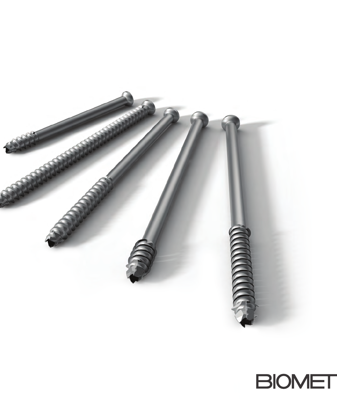
Biomet 6.5/8.0 mm
Cannulated Screw System
The Biomet 6.5/8.0 mm Cannulated Screw System is
part of a series of systems developed by Biomet for
cannulated screws ranging from 4.0 to 8.0 mm.
Matching a combination of screw options with necessary
instrumentation, the systems provide convenience
and exibility for the orthopaedic surgeon and the OR
sta. Consistent with all Biomet Trauma implants, the
screws oer TiMAX benets of increased fatigue strength
compared to unanodized Ti and 316L stainless steel.1
Guide wire diameters have also been reduced allowing
screw purchase. The stiness of the guide wire has not
been compromised because they are manufactured out
of cobalt chrome. These systems are truly designed with
the surgeon in mind.
6.5/8.0 mm Cannulated Screw System
4
6.5/8.0 mm Cannulated Screw System
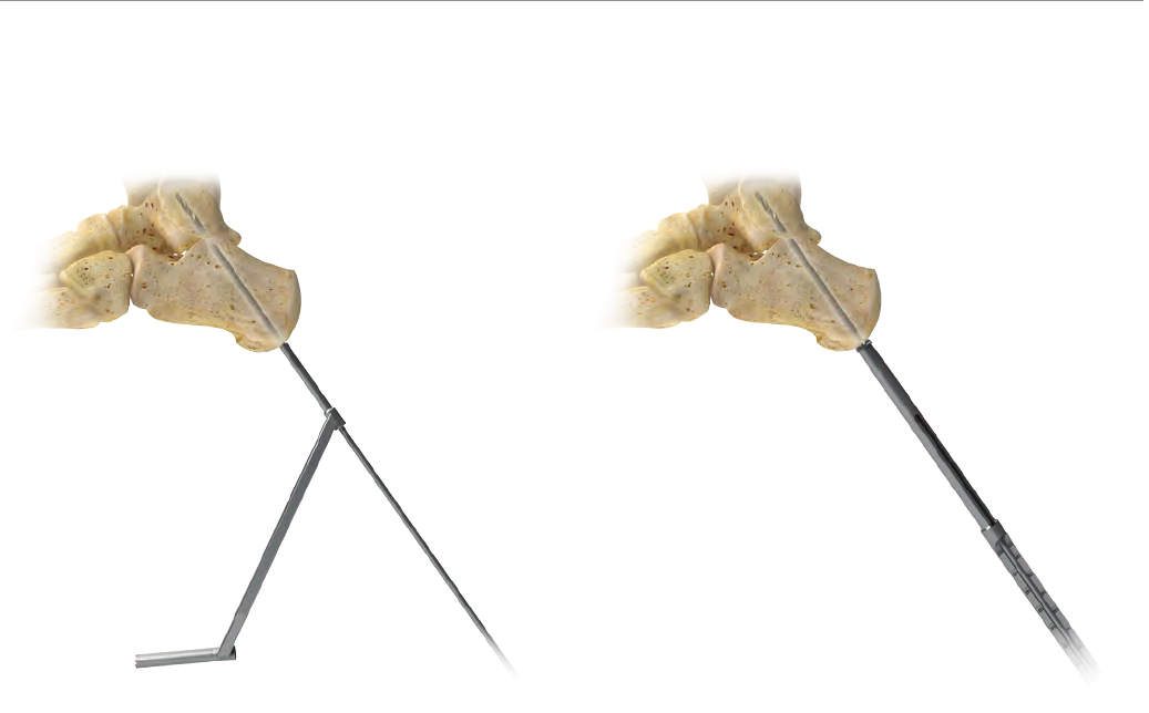
Figure 1 Figure 2
Guide Wire Insertion
Position the guide wire end of the 2.8 /4.8 mm Drill Guide
(Cat. No. 110008428) at the entry point and insert a 2.8 mm
Guide Wire (Cat. No. 110008397) to the desired depth and
verify with uoroscopy (Figure 1). The drill end of the drill
guide can be positioned over the entry point if the drill will
be utilized through the drill guide.
Countersinking and Measurement
Remove the drill guide and insert the 6.5/8.0 mm Depth
Gauge with Countersink (Cat. No. 110008465) over the
inserted guide wire. Using the handle, rotate the depth
gauge back and forth until sucient countersinking has
been achieved, and note the screw length measurement
on the calibrated gauge (Figure 2).
Note: To prevent excessive bone removal, countersinking
under power is not recommended.
Subtalar Arthrodesis: 6.5 mm Cannulated Screw Surgical Technique
5
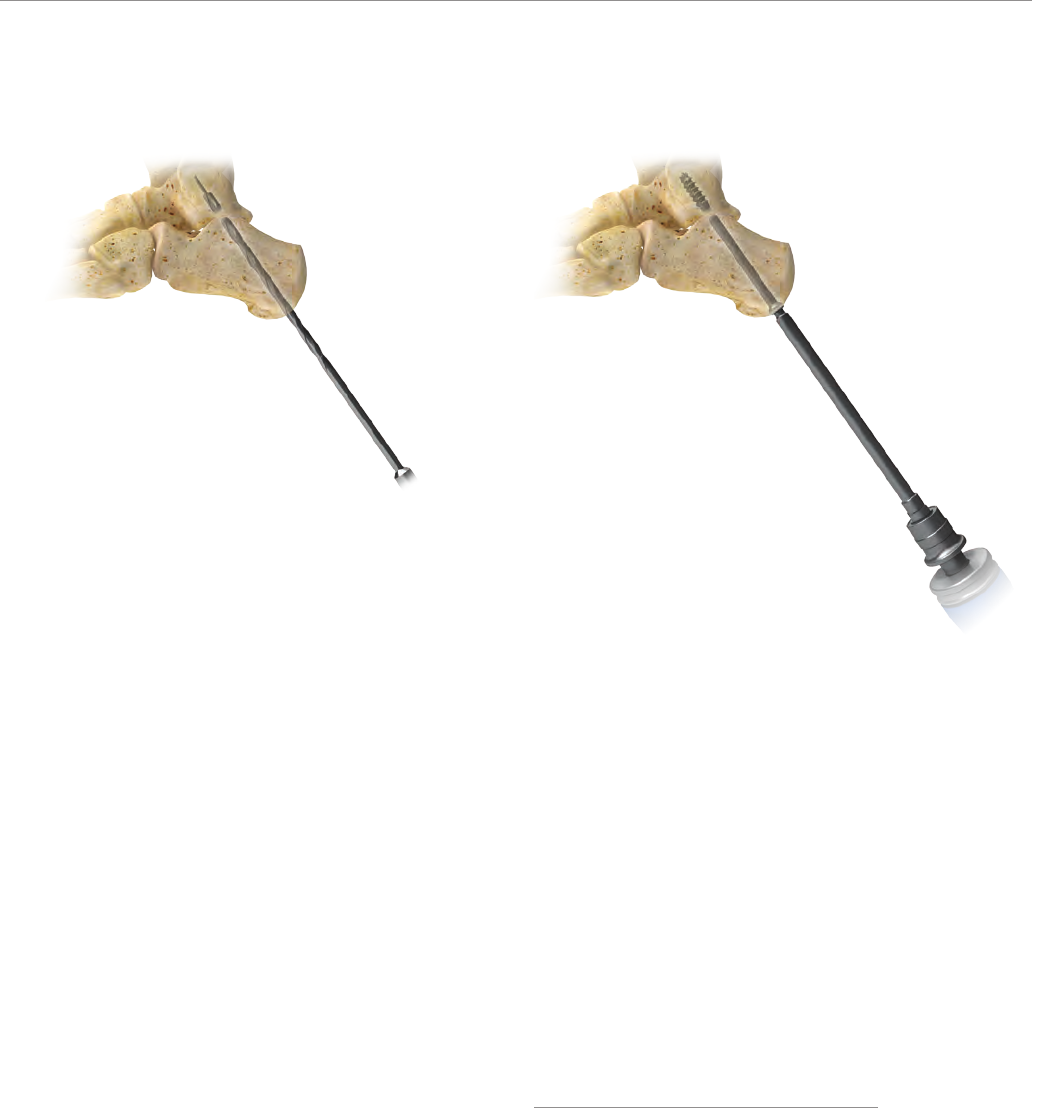
Figure 3 Figure 4
Pre-Drilling
Connect the 4.8 mm Cannulated Drill (Cat. No. 110008408)
to a power adapter and slide the drill over the guide wire.
Drill to appropriate depth and remove drill, leaving the
guide wire in place (Figure 3).
Screw Insertion
Advance the selected 6.5 mm screw over the guide wire
using the BT30 Cannulated Hexolobular Screwdriver
(Cat. No. 110008455) attached to the Screwdriver Handle
(Cat. No. 110017412) until the head of the screw is completely
seated in the bone (Figure 4).
A at washer may be used in conjunction with the same
screw diameter size for osteoporotic bone or where the
cortex is thin, increasing the surface area of the screw head.
6.5 mm Flat Washer (Cat. No. 110008351)
8.0 mm Flat Washer (Cat. No. 110008353)
Note: Screw removal or additional adjustment when not
using a guide wire in the cannulation of the screw can
be achieved by utilizing the BT30 SOLID Hexolobular
Screwdriver (Cat. No. 110009967).
6
6.5/8.0 mm Cannulated Screw System
Open Technique for Hip Fracture
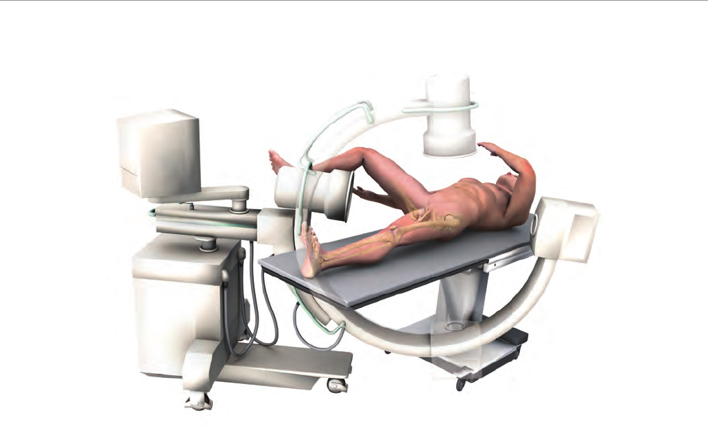
Figure 1
Note: For the purposes of this technique, we will discuss
only the technique and instrumentation as it relates to the
8.0 mm cannulated screw. However, the 6.5 mm cannulated
screw may also be used in hip fracture applications.
Patient Preparation
The patient is placed in the supine position on a standard
fracture table (Figure 1). The patient may be given a
general or spinal anesthetic prior to fracture reduction.
The fracture is reduced by gentle traction with the leg
slightly rotated externally. The leg is then gently rotated
at the knee approximately 45-60° internally. AP and lateral
projections on image intensication should be used to
ensure accurate reduction of the fracture. On reduction
there should be no varus angulation, no more than 15°
valgus angulation and no more than 10° of anterior or
posterior angulation.
Once reduction is achieved the lateral aspect of the hip
is prepared and draped in the usual manner using sterile
technique.
7
Figure 2 Figure 3
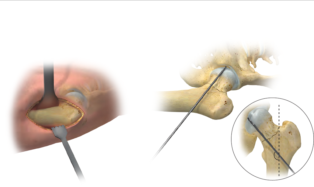
Surgical Exposure
A guide pin placed externally on the anterior surface
of the hip may be used as a template to determine the
appropriate location for the incision. When viewed under
image intensication this “template” guide pin should
lay adjacent to the inferior aspect of the femoral neck
advancing into the femoral head.
A 5 cm incision is made over the lateral aspect of the hip
extending from the are of the greater trochanter distally.
The incision is carried sharply down through the skin and
subcutaneous tissue to the vastus lateralis. The vastus
lateralis is retracted laterally and split. Muscle tissue is
stripped free from the femur and a Bennett retractor is
placed around the femoral shaft exposing its lateral aspect
(Figure 2).
Placement of the Guide Pins
A guide pin is placed on the anterior aspect of the femoral
neck to act as a template. Image intensication is used to
verify its correct orientation adjacent to the inferior cortex
at an angle of 135° to the femoral shaft (Figure 3).
A 2.8 mm Guide Wire (Cat. No. 110008397 or 110008399)
is drilled under power into the lateral cortex in the mid
shaft of the femur parallel to the template guide pin. The
guide wire is advanced adjacent to the inferior cortex at
an angle of 135° to the femoral shaft. The 2.8 mm Parallel
Wire Guide (Cat. No. 110008441) can be used through the
Outer Sheath with Handle (Cat. No. 110008434) as a guide
through soft tissue if needed.
135°
8
6.5/8.0 mm Cannulated Screw System
Figure 5Figure 4
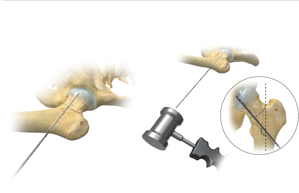
Placement of the Guide Pins (cont.)
The correct position of the guide wire is conrmed under
image intensication. Both AP and lateral images should
be used to conrm that the guide wire is advancing
towards the center of the femoral head. Once this has been
determined, the guide wire is passed across the fracture
site into the femoral head to within 1 cm of subchondral
bone (Figure 4).
The guide pin should be tapped into its nal position at
an angle of 135° to the femoral shaft, adjacent to the
inferior cortex of the femoral neck with its tip within 5 mm
of subchondral bone (Figure 5).
135°
9
Figure 6 Figure 7
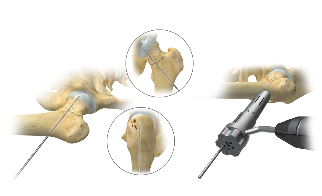
Both AP and lateral images should be used to conrm that
the guide pin is appropriately placed and has not been
bent during insertion (Figure 6).
Note: The position of the rst guide pin adjacent to the
inferior cortex is important as the cannulated screw that
is placed in this position acts as a buttress to support the
femoral head, reducing the potential for varus deformity.
The Parallel Drill Guide (Cat. No. 110008441) is positioned
on the femoral shaft by sliding the most distal hole over
the rst guide pin. The drill guide conrms the angle of
the rst guide pin and facilitates parallel placement of
the following guide pins (Figure 7).
10
6.5/8.0 mm Cannulated Screw System
Figure 9Figure 8
Figure 8a
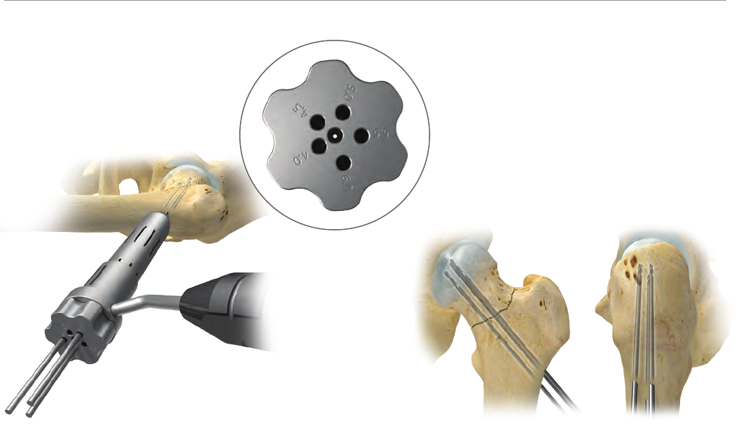
Placement of the Guide Pins (cont.)
The anterior and posterior guide pins are positioned in
the appropriate holes in the drill guide and advanced into
the femoral head to within 5 mm of subchondral bone
(Figure 8).
Note: If three screws are indicated, only an outer three
hole triangle pattern may be used with the parallel drill
guide due to the large diameter of this screw (Figure 8a).
When all of the guide pins are placed, the inferior pin
should lay adjacent to the inferior cortex and the tips of
the other pin(s) should be within 5 mm of subchondral
bone (Figure 9).
Under image intensication the guide pins should not
appear bent nor be in contact with one another.
Caution: Perforation of the femoral head with a guide pin
must be avoided. Once a guide pin penetrates the joint
space and a cannulated screw is inserted over the guide
pin, there is a possibility that the cannulated screw will
follow the path of the original guide pin and penetrate
the joint space. A guide pin that has penetrated the joint
space must be removed completely and be reinserted in
a dierent position.
11
Figure 10 Figure 11
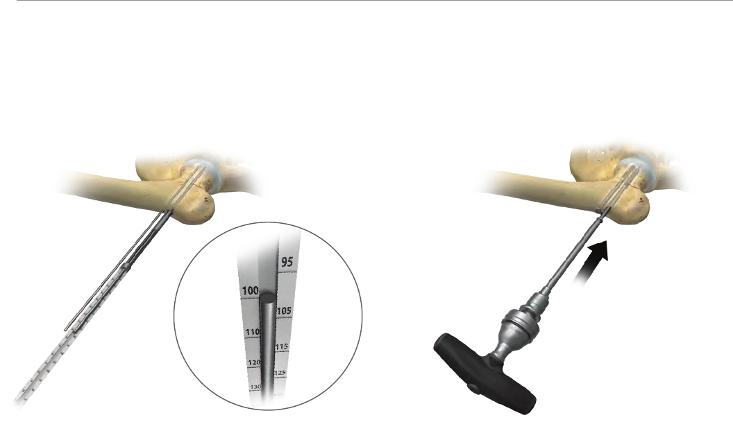
Measurement
After correct placement of the guide pins within 5 mm
of subchondral bone, the drill guide is removed and
the guide pin Depth Gauge with Countersink (Cat. No.
110008465) is placed over each guide pin and advanced to
the femoral cortex. If countersinking is desired, the depth
gauge may be turned back and forth until the bone has
been suciently countersunk. The length of the screw is
then read directly o the gauge at the end of the guide
wire (Figure 10).
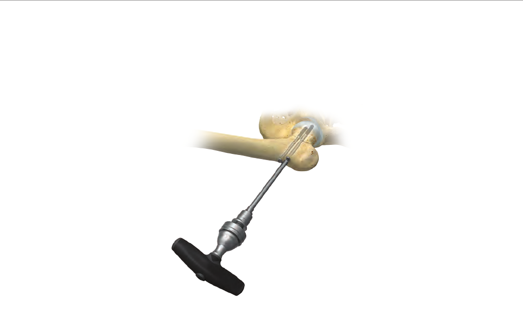
Cannulated Screw Insertion
The appropriate length cannulated screw is placed over
the guide wire and inserted either with power using the
screwdriver shank (Cat. No. 110008455) attached to a
power adapter, or manually with the screwdriver shank
attached to the Screwdriver Handle (Cat. No. 110017412).
The T-Handle (Cat. No. 14-451560) can be used for
additional torque if needed (Figure 11).
Note: The position of the guide wire must be frequently
checked under image during screw insertion to ensure
that the guide pin is not advancing with the screw.
The inferior screw adjacent to the inferior cortex is
advanced rst until the head of the screw is within 1 cm
of the lateral cortex. The remaining screw(s) are then also
inserted and advanced to within 1 cm of the lateral cortex.
12
6.5/8.0 mm Cannulated Screw System
Figure 12
Final Tightening
In order to prevent varus angulation, the anterior and
posterior screws should be tightened before the inferior
screw. The screws should be advanced alternately several
turns at a time until they are completely seated tight. The
inferior screw is then tightened.
Final seating of the screw should always be performed
manually, one half turn at a time, alternating sequentially
between each of the three until the head of each screw
has made solid contact with the lateral cortex (Figure 12).
Once correct placement of the screws and reduction of the
fracture has been conrmed under image intensication,
traction is released and the hip is rotated through the
full range of motion. This is performed while viewing the
AP and lateral image to assure that there has been no
penetration of the joint space.
The wound is then thoroughly irrigated and closed in the
usual manner.
13
Figure 13
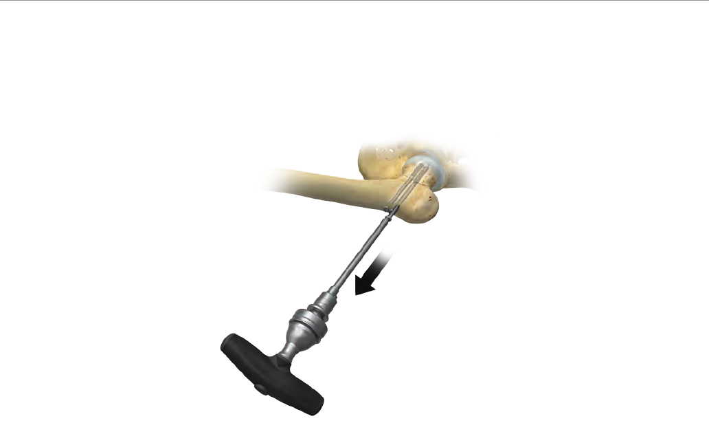
Screw Removal
Screw removal should always be started manually. Once
started, screws may be removed either with power using
the BT30 Solid Screwdriver shank (Cat. No. 110009967)
attached to the power adapter, or manually with the
screwdriver shank attached to the screwdriver handle, or
the T-Handle.
Caution: Under no circumstances should pliers or similar
devices be used to grip the screw head as this will damage
the screw and could lead to breakage.
If the cannulated screw becomes damaged or removal
becomes dicult, the Easy Out (Cat. No. 110008495)
should be used for screw extraction. The Easy Out must
be used manually in conjunction with the T-Handle. The
tip of the Easy Out is inserted through the head and
down the center of the cannulated screw. The Easy Out
is turned counter-clockwise while applying rm forward
pressure. The Easy Out cuts into the cannula of the screw
shaft to facilitate removal. The Easy Out extractor may be
used even if the head or shaft of the screw is not intact
(Figure 13).

14
6.5/8.0 mm Cannulated Screw System
Ancillary Components
Washers are available for use in osteoporotic bone.
SCREW WASHER NONSTERILE STERILE
6.5 mm 6.5 mm 110008351 110008363
8.0 mm 8.0 mm 110008353 110008364
Equipment Maintenance
Special care should be exercised during the cleaning of
cannulated instrumentation to ensure that all foreign
material is removed from the inside of the instrument.
Regular inspection and careful maintenance will increase
the useful life of all instrumentation.
Caution
Guide wires should be replaced after each surgery. Use of
scored or bent guide wires increases the risk of unwanted
guide wire advancement or breakage during screw
insertion.
During cannulated screw insertion the surgeon must
periodically check for undesired advancement of the
guide wire.
The text and schematic drawings included in this
protocol are general instructions for the use of Biomet
instrumentation only. Placement of screws and plates for
the stabilization of specic fractures must be determined
using the best judgment of the surgeon.

15
Implants
6.5 mm Cannulated Screws (16 mm thread)
NONSTERILE NO. STERILE NO. DESCRIPTION RECOMMENDED QTY
110007733 110009929 Cann Screw 6.5 x 30 mm 16 mm Thd 2
110007735 110009930 Cann Screw 6.5 x 35 mm 16 mm Thd 2
110007737 110009931 Cann Screw 6.5 x 40 mm 16 mm Thd 2
110007739 110009932 Cann Screw 6.5 x 45 mm 16 mm Thd 2
110007741 110009933 Cann Screw 6.5 x 50 mm 16 mm Thd 2
110007743 110009934 Cann Screw 6.5 x 55 mm 16 mm Thd 2
110007745 110009935 Cann Screw 6.5 x 60 mm 16 mm Thd 2
110007747 110009936 Cann Screw 6.5 x 65 mm 16 mm Thd 2
110007749 110009937 Cann Screw 6.5 x 70 mm 16 mm Thd 3
110007751 110009938 Cann Screw 6.5 x 75 mm 16 mm Thd 3
110007753 110009939 Cann Screw 6.5 x 80 mm 16 mm Thd 3
110007755 110009940 Cann Screw 6.5 x 85 mm 16 mm Thd 3
110007757 110009941 Cann Screw 6.5 x 90 mm 16 mm Thd 3
110007759 110009942 Cann Screw 6.5 x 95 mm 16 mm Thd 3
110007761 110009943 Cann Screw 6.5 x 100 mm 16 mm Thd 3
110007763 110009944 Cann Screw 6.5 x 105 mm 16 mm Thd 2
110007765 110009945 Cann Screw 6.5 x 110 mm 16 mm Thd 2
110007767 110009946 Cann Screw 6.5 x 115 mm 16 mm Thd 2
110007769 110009947 Cann Screw 6.5 x 120 mm 16 mm Thd 2
110007771 110009948 Cann Screw 6.5 x 125 mm 16 mm Thd 2
110007773 110009949 Cann Screw 6.5 x 130 mm 16 mm Thd 2
–110009950 Cann Screw 6.5 x 135 mm 16 mm Thd 0
–110007775 Cann Screw 6.5 x 140 mm 16 mm Thd 0
–110009952 Cann Screw 6.5 x 145 mm 16 mm Thd 0
–110007777 Cann Screw 6.5 x 150 mm 16 mm Thd 0
–110009954 Cann Screw 6.5 x 155 mm 16 mm Thd 0
–110007779 Cann Screw 6.5 x 160 mm 16 mm Thd 0
–110009956 Cann Screw 6.5 x 165 mm 16 mm Thd 0
–110007781 Cann Screw 6.5 x 170 mm 16 mm Thd 0
–110009958 Cann Screw 6.5 x 175 mm 16 mm Thd 0
–110007783 Cann Screw 6.5 x 180 mm 16 mm Thd 0
Reference IFU 01-50-4048 for screw and washer product information.

16
6.5/8.0 mm Cannulated Screw System
6.5 mm Cannulated Screws (40 mm thread)
NONSTERILE NO. STERILE NO. DESCRIPTION RECOMMENDED QTY
110007803 110009969 Cann Screw 6.5 x 70 mm 40 mm Thd 2
110007805 110009970 Cann Screw 6.5 x 75 mm 40 mm Thd 2
110007807 110009971 Cann Screw 6.5 x 80 mm 40 mm Thd 2
110007809 110009972 Cann Screw 6.5 x 85 mm 40 mm Thd 2
110 0 07811 110009973 Cann Screw 6.5 x 90 mm 40 mm Thd 2
110007813 110009974 Cann Screw 6.5 x 95 mm 40 mm Thd 2
110007815 110009975 Cann Screw 6.5 x 100 mm 40 mm Thd 2
110007817 110009976 Cann Screw 6.5 x 105 mm 40 mm Thd 2
110007819 110009977 Cann Screw 6.5 x 110 mm 40 mm Thd 2
110007821 110009978 Cann Screw 6.5 x 115 mm 40 mm Thd 2
110007823 110009979 Cann Screw 6.5 x 120 mm 40 mm Thd 2
110007825 110009980 Cann Screw 6.5 x 125 mm 40 mm Thd 2
110007827 110009981 Cann Screw 6.5 x 130 mm 40 mm Thd 2
–110009982 Cann Screw 6.5 x 135 mm 40 mm Thd 0
–110007829 Cann Screw 6.5 x 140 mm 40 mm Thd 0
–110009984 Cann Screw 6.5 x 145 mm 40 mm Thd 0
–110007831 Cann Screw 6.5 x 150 mm 40 mm Thd 0
–110009986 Cann Screw 6.5 x 155 mm 40 mm Thd 0
–110007833 Cann Screw 6.5 x 160 mm 40 mm Thd 0
–110009988 Cann Screw 6.5 x 165 mm 40 mm Thd 0
–110007835 Cann Screw 6.5 x 170 mm 40 mm Thd 0
–110009990 Cann Screw 6.5 x 175 mm 40 mm Thd 0
–110007837 Cann Screw 6.5 x 180 mm 40 mm Thd 0
Reference IFU 01-50-4048 for screw and washer product information.

17
6.5 mm Cannulated Screws (full thread)
NONSTERILE NO. STERILE NO. DESCRIPTION RECOMMENDED QTY
110007841 110009993 Cann Screw 6.5 x 30 mm Full Thd 2
110007843 110009994 Cann Screw 6.5 x 35 mm Full Thd 2
110007845 110009995 Cann Screw 6.5 x 40 mm Full Thd 2
110007847 110009996 Cann Screw 6.5 x 45 mm Full Thd 2
110007849 110009997 Cann Screw 6.5 x 50 mm Full Thd 2
110007851 110009998 Cann Screw 6.5 x 55 mm Full Thd 2
110007853 110009999 Cann Screw 6.5 x 60 mm Full Thd 2
110007855 110010000 Cann Screw 6.5 x 65 mm Full Thd 2
110007857 110010001 Cann Screw 6.5 x 70 mm Full Thd 2
110007859 110010002 Cann Screw 6.5 x 75 mm Full Thd 2
110007861 110010003 Cann Screw 6.5 x 80 mm Full Thd 2
110007863 110010004 Cann Screw 6.5 x 85 mm Full Thd 2
110007865 110010005 Cann Screw 6.5 x 90 mm Full Thd 2
110007867 110010006 Cann Screw 6.5 x 95 mm Full Thd 2
110007869 110010007 Cann Screw 6.5 x 100 mm Full Thd 2
110007871 110010008 Cann Screw 6.5 x 105 mm Full Thd 2
110007873 110010009 Cann Screw 6.5 x 110 mm Full Thd 2
110007875 110010010 Cann Screw 6.5 x 115 mm Full Thd 2
110007877 110010011 Cann Screw 6.5 x 120 mm Full Thd 2
110007879 110010012 Cann Screw 6.5 x 125 mm Full Thd 2
110007881 110010013 Cann Screw 6.5 x 130 mm Full Thd 2
–110010014 Cann Screw 6.5 x 135 mm Full Thd 0
–110007883 Cann Screw 6.5 x 140 mm Full Thd 0
–110010016 Cann Screw 6.5 x 145 mm Full Thd 0
–110007885 Cann Screw 6.5 x 150 mm Full Thd 0
–110010018 Cann Screw 6.5 x 155 mm Full Thd 0
–110007887 Cann Screw 6.5 x 160 mm Full Thd 0
–110010020 Cann Screw 6.5 x 165 mm Full Thd 0
–110007889 Cann Screw 6.5 x 170 mm Full Thd 0
–110010022 Cann Screw 6.5 x 175 mm Full Thd 0
–110007891 Cann Screw 6.5 x 180 mm Full Thd 0
Reference IFU 01-50-4048 for screw and washer product information.

18
6.5/8.0 mm Cannulated Screw System
8.0 mm Cannulated Screws (16 mm thread)
NONSTERILE NO. STERILE NO. DESCRIPTION RECOMMENDED QTY
110007894 110010025 Cann Screw 8.0 x 30 mm 16 mm Thd 0
110007896 110010026 Cann Screw 8.0 x 35 mm 16 mm Thd 0
110007898 110010027 Cann Screw 8.0 x 40 mm 16 mm Thd 2
110007900 110010028 Cann Screw 8.0 x 45 mm 16 mm Thd 2
110007902 110010029 Cann Screw 8.0 x 50 mm 16 mm Thd 2
110007904 110010030 Cann Screw 8.0 x 55 mm 16 mm Thd 2
110007906 110010031 Cann Screw 8.0 x 60 mm 16 mm Thd 2
110007908 110010032 Cann Screw 8.0 x 65 mm 16 mm Thd 2
110007910 110010033 Cann Screw 8.0 x 70 mm 16 mm Thd 3
110007912 110010034 Cann Screw 8.0 x 75 mm 16 mm Thd 3
110007914 110010035 Cann Screw 8.0 x 80 mm 16 mm Thd 3
110007916 110010036 Cann Screw 8.0 x 85 mm 16 mm Thd 3
110007918 110010037 Cann Screw 8.0 x 90 mm 16 mm Thd 3
110007920 110010038 Cann Screw 8.0 x 95 mm 16 mm Thd 3
110007922 110010039 Cann Screw 8.0 x 100 mm 16 mm Thd 3
110007924 110010040 Cann Screw 8.0 x 105 mm 16 mm Thd 2
110007926 110010041 Cann Screw 8.0 x 110 mm 16 mm Thd 2
110007928 110010042 Cann Screw 8.0 x 115 mm 16 mm Thd 2
110007930 110010043 Cann Screw 8.0 x 120 mm 16 mm Thd 2
110007932 110010044 Cann Screw 8.0 x 125 mm 16 mm Thd 2
110007934 110010045 Cann Screw 8.0 x 130 mm 16 mm Thd 2
–110010046 Cann Screw 8.0 x 135 mm 16 mm Thd 0
–110007936 Cann Screw 8.0 x 140 mm 16 mm Thd 0
–110010048 Cann Screw 8.0 x 145 mm 16 mm Thd 0
–110007938 Cann Screw 8.0 x 150 mm 16 mm Thd 0
–110010050 Cann Screw 8.0 x 155 mm 16 mm Thd 0
–110007940 Cann Screw 8.0 x 160 mm 16 mm Thd 0
–110010052 Cann Screw 8.0 x 165 mm 16 mm Thd 0
–110007942 Cann Screw 8.0 x 170 mm 16 mm Thd 0
–110010054 Cann Screw 8.0 x 175 mm 16 mm Thd 0
–110007944 Cann Screw 8.0 x 180 mm 16 mm Thd 0
Reference IFU 01-50-4048 for screw and washer product information.

19
8.0 mm Cannulated Screws (40 mm thread)
NONSTERILE NO. STERILE NO. DESCRIPTION RECOMMENDED QTY
110007962 110010065 Cann Screw 8.0 x 70 mm 40 mm Thd 0
110007964 110010066 Cann Screw 8.0 x 75 mm 40 mm Thd 0
110007966 110010067 Cann Screw 8.0 x 80 mm 40 mm Thd 0
110007968 110010068 Cann Screw 8.0 x 85 mm 40 mm Thd 0
110007970 110010069 Cann Screw 8.0 x 90 mm 40 mm Thd 0
110007972 110010070 Cann Screw 8.0 x 95 mm 40 mm Thd 0
110007974 110010071 Cann Screw 8.0 x 100 mm 40 mm Thd 0
110007976 110010072 Cann Screw 8.0 x 105 mm 40 mm Thd 0
110007978 110010073 Cann Screw 8.0 x 110 mm 40 mm Thd 0
110007980 110010074 Cann Screw 8.0 x 115 mm 40 mm Thd 0
110007982 110010075 Cann Screw 8.0 x 120 mm 40 mm Thd 0
110007984 110010076 Cann Screw 8.0 x 125 mm 40 mm Thd 0
110007986 110010077 Cann Screw 8.0 x 130 mm 40 mm Thd 0
–110010078 Cann Screw 8.0 x 135 mm 40 mm Thd 0
–110007988 Cann Screw 8.0 x 140 mm 40 mm Thd 0
–110010080 Cann Screw 8.0 x 145 mm 40 mm Thd 0
–110007990 Cann Screw 8.0 x 150 mm 40 mm Thd 0
–110010082 Cann Screw 8.0 x 155 mm 40 mm Thd 0
–110007992 Cann Screw 8.0 x 160 mm 40 mm Thd 0
–110010084 Cann Screw 8.0 x 165 mm 40 mm Thd 0
–110007994 Cann Screw 8.0 x 170 mm 40 mm Thd 0
–110010086 Cann Screw 8.0 x 175 mm 40 mm Thd 0
–110007996 Cann Screw 8.0 x 180 mm 40 mm Thd 0
Reference IFU 01-50-4048 for screw and washer product information.

20
6.5/8.0 mm Cannulated Screw System
8.0 mm Cannulated Screws (full thread)
NONSTERILE NO. STERILE NO. DESCRIPTION RECOMMENDED QTY
110007998 110010089 Cann Screw 8.0 x 30 mm Full Thd 0
110008000 110010090 Cann Screw 8.0 x 35 mm Full Thd 0
110008002 110010091 Cann Screw 8.0 x 40 mm Full Thd 2
110008004 110010092 Cann Screw 8.0 x 45 mm Full Thd 2
110008006 110010093 Cann Screw 8.0 x 50 mm Full Thd 2
110008008 110010094 Cann Screw 8.0 x 55 mm Full Thd 2
110008010 110010095 Cann Screw 8.0 x 60 mm Full Thd 2
110008012 110010096 Cann Screw 8.0 x 65 mm Full Thd 2
110008014 110010097 Cann Screw 8.0 x 70 mm Full Thd 2
110008016 110010098 Cann Screw 8.0 x 75 mm Full Thd 2
110008018 110010099 Cann Screw 8.0 x 80 mm Full Thd 2
110008020 110010100 Cann Screw 8.0 x 85 mm Full Thd 2
110008022 110010101 Cann Screw 8.0 x 90 mm Full Thd 2
110008024 110010102 Cann Screw 8.0 x 95 mm Full Thd 2
110008026 110010103 Cann Screw 8.0 x 100 mm Full Thd 2
110008028 110010104 Cann Screw 8.0 x 105 mm Full Thd 2
110008030 110010105 Cann Screw 8.0 x 110 mm Full Thd 2
110008032 110010106 Cann Screw 8.0 x 115 mm Full Thd 2
110008034 110010107 Cann Screw 8.0 x 120 mm Full Thd 2
110008036 110010108 Cann Screw 8.0 x 125 mm Full Thd 2
110008038 110010109 Cann Screw 8.0 x 130 mm Full Thd 2
–110010110 Cann Screw 8.0 x 135 mm Full Thd 0
–110008040 Cann Screw 8.0 x 140 mm Full Thd 0
–110 010112 Cann Screw 8.0 x 145 mm Full Thd 0
–110008042 Cann Screw 8.0 x 150 mm Full Thd 0
–110 010114 Cann Screw 8.0 x 155 mm Full Thd 0
–110008044 Cann Screw 8.0 x 160 mm Full Thd 0
–110 010116 Cann Screw 8.0 x 165 mm Full Thd 0
–110008046 Cann Screw 8.0 x 170 mm Full Thd 0
–110 010118 Cann Screw 8.0 x 175 mm Full Thd 0
–110008048 Cann Screw 8.0 x 180 mm Full Thd 0
Washers
NONSTERILE NO. STERILE NO. DESCRIPTION RECOMMENDED QTY
110008351 110008363 Flat Washer 6.5 mm 3
110008353 110008364 Flat Washer 8.0 mm 3
Reference IFU 01-50-4048 for screw and washer product information.

21
Disposables
NONSTERILE NO. STERILE NO. DESCRIPTION RECOMMENDED QTY
–110008397 2.8 x 300 mm Guide Pin Drill Tip 2
–110008399 2.8 x 450 mm Guide Pin Drill Tip 1
–110008408 4.8 x 200 mm Cann Drill w/ ZH 2
–110008410 4.8 x 300 mm Cann Drill w/ ZH 2
Instruments
NONSTERILE NO. STERILE NO. DESCRIPTION RECOMMENDED QTY
110008428 –2.8 / 4.8 mm Drill Guide 1
110008455 –BT30 Cann Hexalobular Driver ZH 2
110009967 –BT30 Solid Hexalobular Driver ZH 1
110008465 –6.5 / 8.0 mm Depth Gauge w/ Countersink 1
110008434 –Outer Sheath w/ Handle 1
110008441 –Parallel Wire Guide 2.8 mm 1
110008484 –Oset Delta Wire Guide 2.8 mm 1
110017410 –Standard Ratchet Handle ZH 1
110 017412 –T Ratchet Handle ZH 1
14-451560 –Guide Wire Pusher 2.8 mm 1
13571 –Screw Forceps 1
110008496 –Easy Out Small Tip 1
Case/Tray
NONSTERILE NO. STERILE NO. DESCRIPTION RECOMMENDED QTY
110008481 –Cann Screw Case 6.5 / 8.0 mm 1
Reference IFU 01-50-4202 for sterilization parameters of the Cannulated Screw instrument cases and contents.

22
6.5/8.0 mm Cannulated Screw System
Indications & Contraindications
INDICATIONS
Large Cannulated Screws (5 mm and larger in diameter)
are intended for use in:
1. Fixation of fractures in long bones and long bone
fragments.
2. Long bone osteotomies (femur, tibia, foot, ankle,
olecranon).
3. Arthrodesis, and fracture xation of the foot and ankle,
such as Jones fractures of the fth metatarsal, and
Calcaneal fractures.
Large Cannulated Screws (6.5 mm and larger in diameter)
are intended for use in:
1. Slipped capital femoral epiphysis
2. Pediatric femoral neck fractures
3. Tibial plateau fractures
4. SI joint disruptions
5. Intercondylar femur fractures
6. Subtalar arthrodesis
7. Fixation of pelvis and iliosacral joint.
CONTRAINDICATIONS
1. Infections.
2. Patient conditions including blood supply limitations,
insucient quantity or quality of bone.
3. Patients with mental or neurologic conditions who are
unwilling or incapable of following postoperative care
instructions.
4. Foreign body sensitivity where material sensitivity is
suspected or unknown, testing is to be completed
prior to implantation of the device.

This material is intended for health care professionals and the Biomet sales
force only. Distribution to any other recipient is prohibited. All content herein is
protected by copyright, trademarks and other intellectual property rights owned
by or licensed to Biomet Inc. or its aliates unless otherwise indicated. This material
must not be redistributed, duplicated or disclosed, in whole or in part, without the
express written consent of Biomet.
Check for country product clearances and reference product specic instructions
for use. For complete product information, including indications, contraindications,
warnings, precautions, and potential adverse eects, see the package insert and
Biomet’s website.
This technique was prepared in conjunction with a licensed health care professional.
Biomet does not practice medicine and does not recommend any particular
orthopedic implant or surgical technique for use on a specic patient. The surgeon
is responsible for determining the appropriate device(s) and technique(s) for each
individual patient.
Not for distribution in France.
©2014 Biomet Trauma • Form No. BMET1050.0 • REV1014
References
1. Data on le at Biomet. Test# DVA-107504-DVER.
Mechanical testing not necessarily indicative of clinical performance.
Authorised Representative
Biomet UK Ltd.
Waterton Industrial Estate
Bridgend, South Wales
CF31 3XA
UK
0086
Legal Manufacturer
Biomet Trauma
56 East Bell Drive
P.O. Box 587
Warsaw, Indiana 46581
USA
www.biomet.com
