MN03901003E Installation Directions
66286-Installationsheet 66286-InstallationSheet 66286-InstallationSheet Batch10 unilog cesco-content
2014-10-17
: Pdf 66286-Installationsheet 66286-InstallationSheet 786685 Batch10 unilog
Open the PDF directly: View PDF ![]() .
.
Page Count: 16
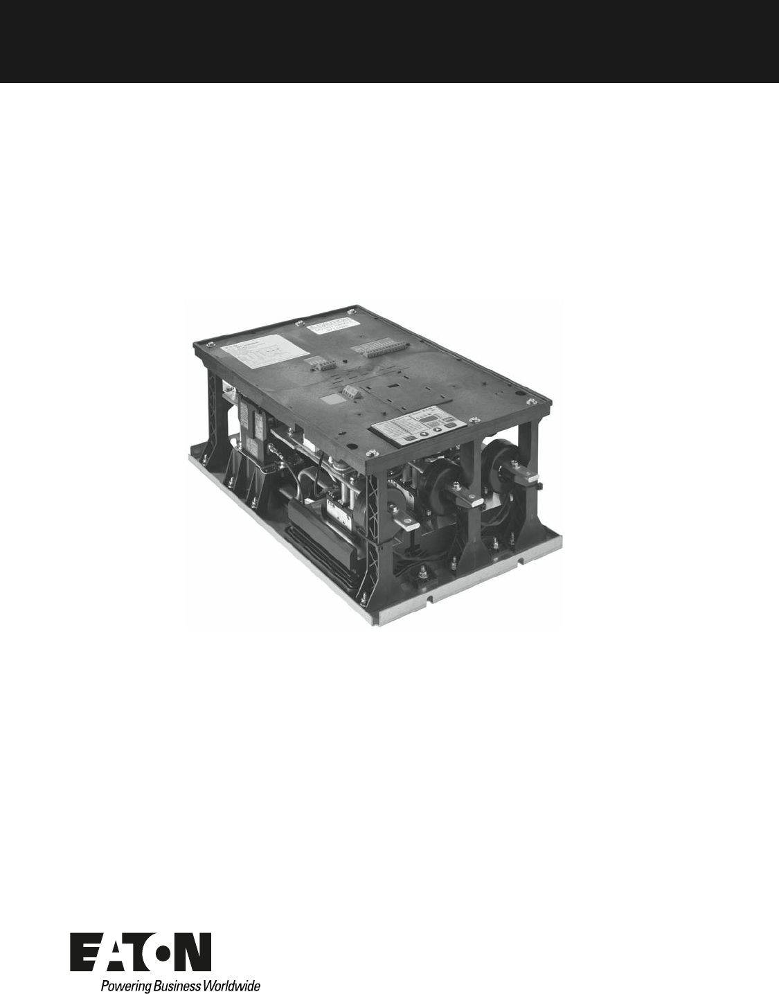
S611 Soft Starter
Quick Start Installation Guide
Effective January 2012
Supersedes June 2011
S611 Soft Starter
S611 Soft Starter MN03901003E—January 2012 www.eaton.com i
Disclaimer of Warranties and Limitation of Liability
The information, recommendations, descriptions and safety notations in this document are
based on Eaton Corporation’s (“Eaton”) experience and judgment and may not cover all
contingencies. If further information is required, an Eaton sales office should be consulted.
Sale of the product shown in this literature is subject to the terms and conditions outlined in
appropriate Eaton selling policies or other contractual agreement between Eaton and the
purchaser.
THERE ARE NO UNDERSTANDINGS, AGREEMENTS, WARRANTIES, EXPRESSED OR
IMPLIED, INCLUDING WARRANTIES OF FITNESS FOR A PARTICULAR PURPOSE OR
MERCHANTABILITY, OTHER THAN THOSE SPECIFICALLY SET OUT IN ANY EXISTING
CONTRACT BETWEEN THE PARTIES. ANY SUCH CONTRACT STATES THE ENTIRE
OBLIGATION OF EATON. THE CONTENTS OF THIS DOCUMENT SHALL NOT BECOME
PART OF OR MODIFY ANY CONTRACT BETWEEN THE PARTIES.
In no event will Eaton be responsible to the purchaser or user in contract, in tort (including
negligence), strict liability or otherwise for any special, indirect, incidental or consequential
damage or loss whatsoever, including but not limited to damage or loss of use of equipment,
plant or power system, cost of capital, loss of power, additional expenses in the use of
existing power facilities, or claims against the purchaser or user by its customers resulting
from the use of the information, recommendations and descriptions contained herein. The
information contained in this manual is subject to change without notice.
Cover Photo: S611 Soft Starter
S611 Soft Starter
ii S611 Soft Starter MN03901003E—January 2012 www.eaton.com
Support Services
The goal of Eaton is to ensure your greatest possible satisfaction with the operation of our
products. We are dedicated to providing fast, friendly, and accurate assistance. That is why
we offer you so many ways to get the support you need. Whether it’s by phone, fax, or
e-mail, you can access Eaton’s support information 24 hours a day, seven days a week.
Our wide range of services is listed below.
You should contact your local distributor for product pricing, availability, ordering, expediting,
and repairs.
Web Site
Use the Eaton web site to find product information. You can also find information on local
distributors or Eaton’s sales offices.
Web Site Address
www.eaton.com/electrical
EatonCare Customer Support Center
Call the EatonCare Support Center if you need assistance with placing an order, stock
availability or proof of shipment, expediting an existing order, emergency shipments, product
price information, returns other than warranty returns, and information on local distributors or
sales offices.
Voice: 877-ETN-CARE (386-2273) (8:00 a.m.–6:00 p.m. EST)
FAX: 800-752-8602
After-Hours Emergency: 800-543-7038
(6:00 p.m.–8:00 a.m. EST)
If you are in the U.S. or Canada, and have OI or PLC questions, you can take advantage of our
toll-free line for technical assistance with hardware and software product selection, system
design and installation, and system debugging and diagnostics. Technical support engineers
are available for calls during regular business hours.
Technical Resource Center
Voice: 877-ETN-CARE (386-2273) (8:00 a.m.–5:00 p.m. EST)
FAX: 828-651-0549
e-mail: TRC@Eaton.com
European PanelMate Support Center
This engineering company, located in Zurich, Switzerland, provides high-level quality
support and repair assistance for your PanelMate products. You will receive technical
and application support.
For Customers in Europe, contact:
BFA Solutions, Ltd.
Voice: +41 1 806.64.44 (9:00 a.m.–5:00 p.m. CET)
e-mail: gk@bfa.ch
www.bfa.ch
Repair and Upgrade Service
Additional support is also available from our well-equipped Repair and Upgrade Service
department. If you have questions regarding the repair or upgrade of an OI product, contact
your local distributor.
Repair and Upgrade Service (support for OI)
Voice:
877-ETN-CARE (877-386-2273) (8:00 a.m.–5:00 p.m. EST)
414-449-7100 (8:00 a.m.–5:00 p.m. EST)
FAX: 614-882-3414
e-mail: TRC@eaton.com
Installation
S611 Soft Starter MN03901003E—January 2012 www.eaton.com 1
Installation
For detailed information please refer to the User Manual
(publication no. MN03902011E) at www.eaton.com/
softstarters.
Mounting
Required mounting hardware is Grade 5, 3/8-16, quantity four
minimum (two upper and two lower).
Unit Weight
Power Wiring
WARNING
Hazardous voltage can cause electric shock and burns.
To avoid shock hazard, disconnect all power to the
controller, motor or other control devices before any
work is performed on this equipment. Failure to do so
will result in personal injury, death or substantial
property damage.
Do not apply a disconnect device on the output of the
S611 soft starter unless a means to turn off the soft
starter when disconnect switch is open is used. Opening
disconnect while the soft starter is operating may cause
a malfunction. Closing disconnect switch while the soft
starter is operating will result in a soft starter failure and
potential equipment damage and personnel hazard.
Note: Short circuit protection must be applied on the line
side of the soft starter.
Do not attempt to lift the soft starter by the cover
only.
Lug Installation
Install the lugs below the bus bar to assure anti-rotation.
Refer to figure “Lug and Bolt Torque Support” on this page.
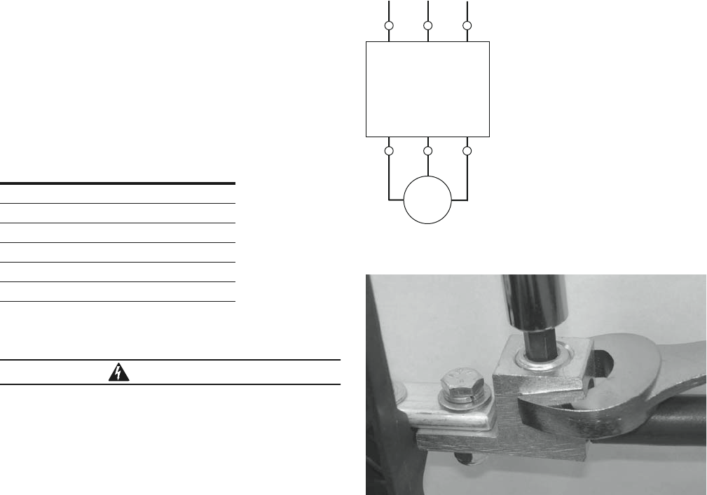
Power Wiring Diagram
Lug Bolt Torque Support
Note: When securing the lugs onto the bus bars of the soft
starters, use a suitable tool such as another wrench to
counteract the bolt torque and prevent excessive side
loads being placed on the supports. Refer to figure “Lug
and Bolt Torque Support” above.
Remove the tie wraps for CTs on Frames C, D, E, and
F. Move each CT to the load cables during assembly
as shown in the figure “CT Location” on Page 2. Each
CT should be properly supported with tie wraps
ensuring that the CT is not supported by the leads.
Properly secure CT leads.
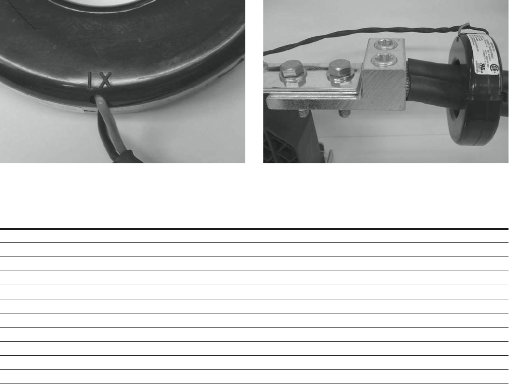
When securing the Current Transformers (CTs) onto
the T1, T2, and T3 bus bars of the soft starter, correct
orientation of the CT must be observed to ensure
proper operation of the soft starter. Each CT is marked
with a symbol “IX” adjacent to the leads. This symbol
shown in the figure “CT Polarity Identification” on
Page 2 indicates the line side (or voltage source side)
of the device.
Frame Size
Weight of Unit
Lbs (kg)
A 24 (11)
B 24 (11)
C 33 (15)
D 38 (17)
E 86 (39)
F 102 (46)
1L1 3L2
S611
5L3
2 T1 4 T2 6 T3
M
3˜
Installation
2 S611 Soft Starter MN03901003E—January 2012 www.eaton.com
CT Polarity Identification CT Location
Line and Load Power Wiring
Notes
Additional lug selection may be found in Appendix D of the User Manual, Publication No. MN03902011E.
Each lug kit consists of three lugs. Two kits are required for both line and load connections.
Wire size based on 125% of UL 508 Table 43.2.
Short-Circuit Rating
Suitable for use on a circuit capable of delivering not more than 100,000 rms
symmetrical amperes, 600 volts maximum when protected by Class RK5 fuses or a
circuit breaker having an interrupting rating not less than 65,000 rms symmetrical
amperes, 480 volts maximum.
Current
Rating
Conductor
Size
Number of
Conductors
Mechanical Lug—
Ilsco Part Number
Torque
lb-in
Mechanical
Lug Range
Soft Starter
Catalog Number
Mechanical Lug—
Eaton Catalog Number
52A 6 AWG 1 TA-2/0 120 14 AWG–2/0 S611A052XXX S611-LUG-MO1
65A 4 AWG 1 TA-2/0 120 14 AWG–2/0 S611A065XXX S611-LUG-MO1
77A 3 AWG 1 TA-2/0 120 14 AWG–2/0 S611A072XXX S611-LUG-MO1
99A 1/0 AWG 1 TA-300 275 14 AWG–2/0 S611B099XXX S611-LUG-MO2
125A 2/0 AWG 1 TA-300 275 2 AWG–600 kcmil S611B125XXX S611-LUG-MO2
156A 3/0 AWG 1 TA-600 500 2 AWG–600 kcmil S611C156XXX S611-LUG-MO3
180A 4/0 AWG 1 TA-600 500 2 AWG–600 kcmil S611C180XXX S611-LUG-MO3
242A 350 kcmil 1 TA-600 500 2 AWG–600 kcmil S611D242XXX S611-LUG-MO3
302A 3/0 AWG 2 AU-600-2NS 500 2 AWG–600 kcmil S611E302XXX S611-LUG-MO4
361A 4/0 AWG 2 AU-600-2NS 500 2 AWG–600 kcmil S611E361XXX S611-LUG-MO4
414A 300 kcmil 2 AU-600-2NS 500 300–800 kcmil S611F414XXX S611-LUG-MO4
Installation
S611 Soft Starter MN03901003E—January 2012 www.eaton.com 3
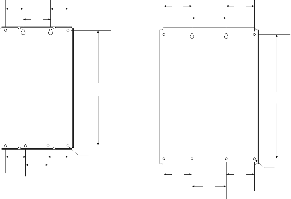
Mounting Hole Dimensions
Approximate Dimensions in mm [Inches]
Frames A through D Frames E and F
70.0
[2.76]
464.7
[18.30]
110.0
[4.33]
10.0
[0.39]
Ø
70.0
[2.76]
80.0
[3.15] 90.0
[3.54]
80.0
[3.15]
155.0
[6.10]
562.0
[22.13]
10.0
[0.39]
Ø
127,0
[5.00]
127,0
[5.00]
155.0
[6.10]
127,0
[5.00]
127,0
[5.00]
Installation
4 S611 Soft Starter MN03901003E—January 2012 www.eaton.com
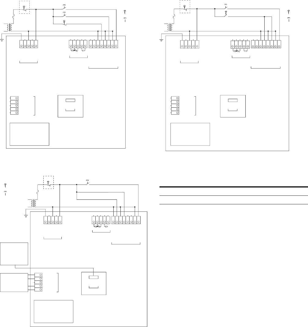
Typical Control Wiring Diagrams
For a single conductor, a minimum wire of 14 AWG (2.5 mm2) should be used between the
control power transformer and the supply terminals.
Basic Connection Diagram for 120 Vac Three-Wire
Pushbutton
Basic Connection Diagram for 120 Vac Network Control
Basic Connection Diagram for 120 Vac Two-Wire
Pushbutton
Terminal Block Wiring Capacity
Reset
E-Stop
Maintained
Momentary
Ground
+24V
D0
D1
Common
N–Tap
Neutral
L–Tap
Line
Start
Stop
TB1
120 Vac
Supply
User Interface
Module
TB4
Comms Port A
98 97 96 13 14
Comms Port B
TB5 (Connector)
TB2
Relays
TB3
120 Vac
Control
Relay 2 Relay 1
N–Network
L–Network
N–Permissive
L–Permissive
N–Start
L–Start
N–Reset
L–Reset
Reset
E-Stop
Maintained
Momentary
Comms Adapter
Comms
Modbus
TB4
DeviceNet
Modbus
PROFIBUS
TB5 (Module)
Ground
+24V
D0
D1
Common
N–Tap
Neutral
L–Tap
Line
Run Enable
Network
TB1
120 Vac
Supply
User Interface
Module
Comms Port B
TB5 (Connector)
TB4
Comms Port A
TB2
Relays
TB3
120 Vac
Control
98 97 96 13 14
N–Network
L–Network
N–Permissive
L–Permissive
L–Start
N–Startl
N–Reset
L–Reset
Relay 2 Relay 1
Wire Size
Number of
Conductors
Torque
Requirements
22–16 AWG (0.33–2.5 mm2) 2 3.5 lb-in (0.4 Nm)
14–12 AWG (4.0 mm2) 1 3.5 lb-in (0.4 Nm)
Maintained
Momentary
Reset
E-Stop
Start/Run
98 97 96 13 14
Ground
+24V
D0
D1
Common
N–Tap
Neutral
L–Tap
Line
TB1
120 Vac
Supply
User Interface
Module
TB4
Comms Port A
Comms Port B
TB5 (Connector)
TB2
Relays
TB3
120 Vac
Control
Relay 2 Relay 1
N–Network
L–Network
N–Permissive
L–Permissive
N–Start
L–Start
N–Reset
L–Reset
User Interface
S611 Soft Starter MN03901003E—January 2012 www.eaton.com 5
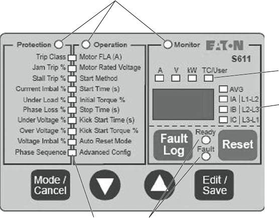
User Interface
User Interface Module (UI)
●Mode/Cancel
●Navigate the Protection, Operation, and Monitor modes
●Exits parameter editing mode without saving value
●Up/Down Arrow
●Navigate Protection/Operation LED list
●Navigates through display parameter list in Monitor mode
●Edit/Save
●Selects/Saves parameter values in Protection/Operation modes
●Selects Advanced Config. Menu parameters
●Selects/Saves parameter values in Advanced Config. Parameters
●No function in Monitor mode
●Fault Log
●View 10 most recent fault codes
●Reset
●Trip reset button if no active faults are present
Status LEDsProtection/
Operation LEDs
Mode LEDs
Phase LEDs
Unit LEDs

Setup and Starting—Initial Configuration
6 S611 Soft Starter MN03901003E—January 2012 www.eaton.com
Setup and Starting—Initial Configuration
1. The S611 Operation and Protection parameters may be
edited when 120 Vac control power is applied to 120 Vac
supply (TB1). Mains power is not required to edit and
save Operation and/or Protection parameters.
2. If any 120 Vac power source other than the normal system
control power source is used to power the control circuit to
edit parameters, connections must be made in compliance
with all local, state, and national electrical codes.
3. To setup the S611 Operating parameters (Operation
mode), perform the following steps:
a. Enter motor FLA.
b. Enter motor rated voltage.
c. Select start method if required (default = voltage
ramp, or pump start).
d. Enter Start time from table on Page 7 (default =
20 seconds).
e. Enter initial torque from table on Page 7 (default =
45%).
f. Enter Stop time, Kick Start time, and Kick Start
torque if desired (default = 0).
4. Application Notes
Adjust Initial Torque for smooth start, motor rotation
should begin within 2 seconds.
If Stall Faults occur at the end of the ramp time, increase
Initial Torque, Kick Start Torque and Time and/or Soft
Start Time to achieve bypass before the Soft Start time
elapses. Verify that the motor is not overloaded.
After suitable performance has been achieved with either
method, determine the starting time to bypass and set
Soft Start Time at 1.25 times this time. For example, if it
takes 10 seconds to accelerate the motor and go into
bypass, set the Soft Start Time for 12.5 seconds.
5. In the Protection Mode, set the Protection parameters
to the desired values. Refer to table on Page 7.
6. For optional advanced configuration parameters refer to
the user manual.
Operating Parameters
Notes
For the device with pump option, the default value is 2 for pump start.
Operating Parameter Units Min Max Default Notes
Motor FLA Amps Motor FLA parameter must be set to
motor nameplate FLA to achieve
proper overload protection
Frame Size A–52 26 52 26
Frame Size A–65 32.5 65 32.5
Frame Size A–77 38.5 77 38.5
Frame Size B–99 48 99 48
Frame Size B–125 62.5 125 62.5
Frame Size C–156 78 156 78
Frame Size C–180 90 180 90
Frame Size D–242 120 242 120
Frame Size E–302 151 302 151
Frame Size E–361 180.5 361 180.5
Frame Size F–414 207 414 207
Motor rated voltage Volts 200 600 480 —
Start method — 0 2 0 0 = Voltage ramp
1 = Current limit
2 = Pump start (option)
Start time Seconds 0.5 180 20 —
Initial torque % 0 100 45 —
Stop time Seconds 0 60 0 —
Kick start time Seconds 0 2 0 —
Kick start torque % 0 100 0 —
Auto reset mode — 0 1 0 0 = Manual
1 = Auto
Advanced config — — — — Refer to User Manual, Publication No.
MN03902011E

Setup and Starting—Initial Configuration
S611 Soft Starter MN03901003E—January 2012 www.eaton.com 7
Protection Parameters
Note: Editing the Trip Class parameter to “OFF” will disable
overload protection.
Torque Settings and Corresponding Current Values
Start Parameter Values for Various Applications
Protection Parameter Units Min Max Default
Trip class — Off, 5 30 20
Jam trip % Off, 150 400 300
Start stall trip % Off, 150 400 200
Current imbalance % Off, 1 100 20
Under load % Off, 1 50 6
Phase loss % Off, 1 100 40
Under voltage % Off, 1 99 90
Over voltage % Off, 101 120 110
Voltage imbalance % Off, 1 20 6
Phase sequence — Off, ABC ACB ABC
Torque
Setting
Current as %
Locked Rotor Initial Motor Torque
85% 92% Maximum
71% 84% —
56% 75% —
45% 67% Default value
36% 60% —
33% 57% Wye-delta equivalent
27% 52% —
19% 44% Minimum for current limit
14% 37% —
9% 30% —
1% 10% Minimum
Application t-Start t-Stop u-Start
Breakaway
Torque Remarks
Crusher, empty at start 20s — 56% 75% Possible high inertia
Conveyor, horizontal, loaded 25s 30s 76% 150% —
Conveyor, horizontal, unloaded 25s 30s 48% 50% —
Chiller 5s — 37% 25% —
Piston compressor, unloaded 10s — 64% 100% —
Circular saw 20s — 48% 50% Possible high inertia
Ball mill 20s — 48% 50% Eccentric load
Mixer, liquids 10s — 37% 40% —
Mixer, dry materials 15s — 56% 75% —
Pump, piston 25s 30s 82% 175% Possible high starting torque
Pump, centrifugal 10s 30s 37% 25% —
Escalator 10s — 48% 50% —
Rotary compressor, unloaded 20s — 42% 35% —
Agitator 15s — 42% 35% —
Feed screw 20s — 82% 175% Possible high starting torque
Press, flywheel 25s — 76% 150% Possible high starting torque
Drier, rotating 20s — 64% 100% —
Blower, axial fan, flaps open 30s — 37% 25% —
Blower, centrifugal fan, valve open 30s — 35% 20% —

Troubleshooting
8 S611 Soft Starter MN03901003E—January 2012 www.eaton.com
Troubleshooting
S611 Fault Codes
Code Fault Condition Solution
3Watchdog • Firmware fault —
5Internal Memory • Internal FRam memory error • Component failure on printed circuit board
• Contact EatonCare for service
6User Interface Communications
Failure
• Communications to UI have been
interrupted
• Possible hardware failure
• Firmware is not communicating internally
• Cycle 120 Vac control voltage power to attempt to
clear problem
7Internal Program Memory • Corrupted firmware or memory
• Flash CRC
• Cycle 120 Vac control power to the S611
• Contact EatonCare for service
8Voltage Zero Cross Lost • Mains voltage lost
• Phase L1 or L3 lost
• Load disconnected
• Restore mains or lost phases
• Verify that the load is connected and any disconnect
devices are properly engaged
• Contact EatonCare for service
9Communications Loss Port A • Communications to a remote network
controller was lost during run cycle
• Device disconnected
• Connection lost
• Reattach network controller, verify that the unit is
recognized by the system controller
10 Communications Loss Port B • Communications to a remote network
controller was lost during run cycle
• Device disconnected
• Connection lost
• Reattach network controller, verify that the unit is
recognized by the system controller
• Comms Port B adapter module failed or disconnected
15 Power Pole Over Temperature • SCR temperature is above limits
• Operating environment above specified
maximum temperature
• Ventilation holes blocked
• Fans are not operational
• Starts/hour exceed specifications
• Sensor failure on power pole
• Bypass contactor(s) failed to close
• Ventilate to specified maximum temperatures
• Clear obstructions
• Verify fans are operational
• Verify system is not exceeding the specified
maximum starts per hour
• Verify bypass contacts are closing at the end of ramp
time
• Reduce excessive cabinet temperature
16 Bypass Failure • Internal bypass contactor(s) not closed
and/or electrically sealed after ramp time
• Contactor(s) opened in bypass
• Verify all bypass contactor(s) close (audible noise)
• Verify all bypass contactor(s) not opening during run
cycle due to excessive vibration and/or shock
Reduce levels of vibration and/or shock
• Verify control power and wire size meet
specifications
• Verify that the control power supply meets the
120 Vac voltage and current requirements of the
IT. soft starter
17 SCR Not Firing • SCR is not conducting when gated
Incoming phase lost
• Special application—undersized or high
impedance motor
• Load disconnected
• SCR failure
• Re-apply lost phase
• Review S611 application
• Circuitry damaged by megger testing
• Contact EatonCare for service

Troubleshooting
S611 Soft Starter MN03901003E—January 2012 www.eaton.com 9
S611 Fault Codes, continued
Note
Shorted SCRs are the most common mode of SCR failure. With power completely removed from the unit, measure the resistance of each pole, line to load.
If the resistance is near zero (less than 5 ohms), it is most likely that the SCR is shorted. Resistance of a serviceable SCR is approximately 10k ohms.
Resistance typically moves to a lower value as the SCR ages. This feature may be disabled (not recommended).
Code Fault Condition Solution
18 Shorted SCR • SCR is shorted
• Internal bypass contactor welded shut
• No load on the SCRs when START
command is issued
• Test resistance of each phase
• Contact EatonCare for service
19 Instantaneous Overcurrent • Excessive starting current
• Excessive load
• Reduce starting load
• Increase soft starter capacity (be sure model ratings
can handle current demands)
20 Overload • Motor overloaded for an extended
period of time
• Thermal memory is over 100%
• Reduce the motor’s load
• Verify the Overld Trip FLA and/or Ovrld Trip Class for
proper adjustment
•Note: Exceeding nameplate ratings will shorten
equipment life
• Fault during motor start: Verify system is not
exceeding the specified maximum starts per hour
• Increase the initial torque and/or reduce ramp time
to bring the motor up to speed faster
• Increase Trip Class setting (5–30 maximum) and/or
reduce ramp time setting
21 Mains AC Voltage Loss • Fuses or breaker open
• Disconnect open
• Replace fuses, close disconnect, or reset breaker
22 Under Voltage • Incoming AC line voltage below trip
threshold
• Incorrect mains supply voltage
• Connect to correct supply voltage
• Verify that mains voltage is within acceptable values
• Verify Motor Rated Voltage in the Operation mode is
set to the correct value
23 Over Voltage • Incoming AC line voltage above trip
threshold
• Incorrect mains supply voltage
• Connect to correct supply voltage
• Verify Motor Rated Voltage in the Operation mode is
set to correct value
24 Phase Reversal • Incoming line phase rotation sequence
opposite of device setting
• Single-phase missing and/or open fuse
or breaker
• Set Phase Sequence to match incoming sequence OR
• Exchange two incoming mains phases
• Verify that all circuit breakers are closed or fuses are
serviceable
25 Start Stall • Motor not at rated RPM at end of start
ramp time and/or current is in excess of
trip threshold
• Bypass contactors not closed at the end
of the start time (start current low/ramp
time short)
• Lengthen Soft Start Time and/or increase Initial
Torque in the Operations mode
• Increase trip threshold
• Loads that are heavily loaded (high inertia) during a
start such as fans will often need an initial torque
setting much greater than the factory default
• Set Kick Start parameters
27 SCR Overcurrent • Excessive SCR current during the start
ramp
• Only active when Stall Fault is disabled
• Increase Soft Start Time and/or Initial Torque
parameters in Operation mode
• Reduce starting load
• Verify S611 is properly rated for current
28 Under Load • Loss of motor load
• Trip threshold set too high
• Excessive current fluctuation during
operation
• Inspect for failed motor coupling or pump cavitation
• Reduce trip threshold
• Increase trip delay time to ride through transient load
changes

Troubleshooting
10 S611 Soft Starter MN03901003E—January 2012 www.eaton.com
S611 Fault Codes, continued
Note: All mains and control power connections must be completed and voltage applied prior
to a START command. Failure to make all connections will result in one or more faults.
All isolation and/or reversing contactors must be staged prior to any START commands.
Manipulating contactors after the START command will result in one or more faults.
Code Fault Condition Solution
29 Current Unbalance • The current imbalance of the incoming
phases exceeds the trip threshold
• Correct imbalance problem with mains
• Increase the Current Imbalance parameters
• Disable the fault if the other issues cannot be
resolved
30 Current Phase Loss • Incoming phase disconnected
• Open fuse or breaker
• Phase imbalance exceeds specifications
or trip parameter
• Severe voltage phase imbalance
• Repair broken connection
• Replace fuse
• Inspect system for phase imbalance conditions
31 Voltage Phase Imbalance • The voltage imbalance of the incoming
phases exceeds the trip threshold
• Correct imbalance problem with mains
• Increase the Voltage Fault Imbalance parameters
• Disable the fault if the other issues cannot be resolved
33 Jam • Soft starter in bypass: Motor below rated
RPM and/or current exceeds 3 x motor
FLA
• Remove obstruction
• Verify proper FLA setting in Operation mode
• Jam fault can be disabled if trips occur during normal
operation (Overcurrent fault will provide protection at
a higher current threshold of 4 x catalog FLA)
34 Contactor Overcurrent • Only active in bypass if the jam fault is
disabled
• Current exceeds the fault threshold of
4 x catalog FLA
• Remove obstruction in motor drive train
• Verify S611 is properly sized for the application
35 Missing Temp Sensor • Temperature sensor failure
• Internal connection failure
• Internal hardware failure (sensor and/or cable)
•Note: Disabling this feature (Temp Sense fault in
Protection menu) will remove protection from
excessive temperature exposure (not recommended)
• Not field repairable, contact Eaton Support
*Cannot RESET fault • Fault condition still exists
• Soft starter has not received RESET
signal
• Troubleshoot fault and correct defective condition
• Attempt alternate methods of RESET
NC No communication • Firmware not programmed, firmware
corrupted
• Contact EatonCare for service

Eaton is a registered trademark
of Eaton Corporation.
All other trademarks are property
of their respective owners.
Eaton Corporation
Electrical Sector
1111
Superior Ave.
Cleveland, OH
44114
United States
Eaton.com
© 2012 Eaton Corporation
All Rights Reserved
Printed in USA
Publication No. MN03901003E / Z11687
January 2012
Eaton is dedicated to ensuring that reliable, efficient and safe
power is available when it’s needed most. With unparalleled
knowledge of el
ectrical power management across industries,
experts at Eaton deliver customized, integrated solutions to
solve our customers’ most critical challenges.
Our focus is on delivering the right solution for the application.
But, de
cision makers demand more than just innovative products.
They turn to Eaton for an unwavering commitment to personal
support that makes customer success a top priority. For more
information,
visit www.eaton.com/electrical.
