Product Detail Manual
114406-Attachment 114406-Attachment 114406-Attachment 781087 Batch7 unilog cesco-content
2014-07-05
: Pdf 6675-Attachment 6675-Attachment 781087 Batch5 unilog
Open the PDF directly: View PDF ![]() .
.
Page Count: 312 [warning: Documents this large are best viewed by clicking the View PDF Link!]

Lighting Electronics Atlas 2010-2011
Philips Lighting Electronics N.A.
10275 W. Higgins Road
Rosemont, IL 60018
Tel: 800-322-2086 Fax: 888-423-1882
Customer Support/Technical Service: 800-372-3331
OEM Support: 866-915-5886
www.philips.com/advance
© 2010 Philips Lighting Electronics N.A.
All rights reserved. Reproduction in whole or part is prohibited without the prior written consent of
the copyright owner. The information presented in this document, is believed to be accurate and
reliable and may be changed without notice. No liability will be accepted by the publisher for any
consequences of its use. Publication thereof does not convey nor imply any license under patent or
other industrial or intellectual property rights.
Form No. CO-7044-B 4/10
Printed in USA 4/10
®
®
Lighting Electronics Atlas
Full Line Catalog 2010-2011

Contents
Electronic Fluorescent Ballasts 1-1 to 1-69
Electronic Fluorescent Controllable Ballasts 2-1 to 2-25
Electromagnetic Fluorescent Ballasts 3-1 to 3-25
Electronic HID Ballasts 4-1 to 4-15
High Intensity Discharge Ballasts 5-1 to 5-57
Specialty Products 6-1 to 6-11
Xitanium® LED Electronic Drivers 7-1 to 7-5
Controls 8-1 to 8-21
Additional Information
Advance Warranty 9-ii
Industry Terms 9-1 to 9-3
Ballast Specifications 9-4 to 9-23
Fixed Light Output Electronic 9-5 to 9-14
Controlled Light Output Electronic 9-15 to 9-19
Magnetic HID 9-20
Electronic HID [Metal Halide] 9-21 to 9-22
Xitanium LED Drivers 9-23
Ballast Catalog Number to Page Number 9-24 to 9-30
Fluorescent 9-24 to 9-28
HID 9-29 to 9-30
eHID & Ignitors 9-30
Discontinued Ballasts – Replacements 9-31 to 9-39
Electromagnetic Fluorescent 9-31 to 9-32
High Frequency Electronic Fluorescent 9-33 to 9-34
HID 9-35 to 9-39
Lamp Index 9-40 to 9-44
Fluorescent 9-40 to 9-43
HID 9-44
Compact Fluorescent Lamp Reference Guide 9-45
Lighting Electronics Atlas
Full Line Catalog 2010-2011
Visit our on-line product catalog at www.philips.com/advance for the latest updates on all Philips Advance products.
Lighting Electronics Atlas 2010-2011
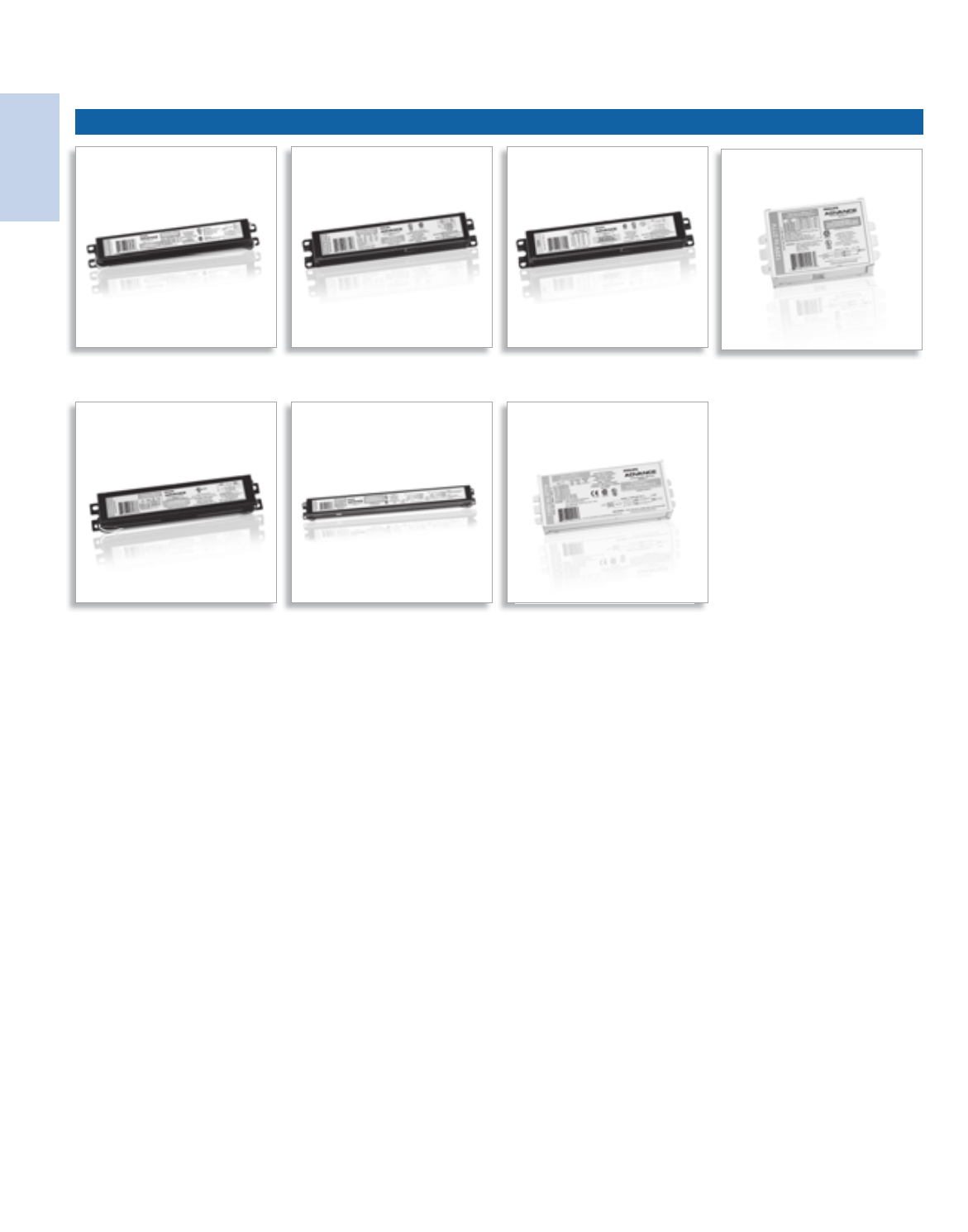
ELECTRONIC FLUORESCENT BALLASTS
1
Electronic
Fluorescent Ballasts
Centium® Optanium® AmbiStar™ SmartMate®
Standard T5HO PureVOLT™

Lighting Electronics Atlas 2010-2011
ELECTRONIC FLUORESCENT BALLASTS
Electronic
Fluorescent Ballasts
1-1
Visit our web site at www.philips.com/advance
Contents
General Information ______________________________1-2 to 1-21
Compact Fluorescent Lamps _______________________1-22 to 1-35
CFL _______________________________________1-22 to 1-28
PLH _____________________________________________ 1-29
Long Twin Tubes _____________________________1-30 to 1-33
2D ________________________________________1-34 to 1-35
Linear Fluorescent Lamps _________________________1-36 to 1-68
T5 ________________________________________1-36 to 1-37
T5 and T5HO Circline ______________________________ 1-38
T5HO _____________________________________1-39 to 1-40
T8 ________________________________________1-41 to 1-62
T8 Slimline ________________________________________ 1-63
T8HO _____________________________________1-64 to 1-65
T12 _____________________________________________ 1-66
T12 Slimline _______________________________________ 1-67
T12HO __________________________________________ 1-68
Note:
Refer to page 9-5 to 9-14 for Ballast Specifications
Customer Support/Technical Service
(800) 372-3331 • (+) 1 847 390-5000 (International)
Corporate Offices
(800) 322-2086

Lighting Electronics Atlas 2010-2011
ELECTRONIC FLUORESCENT BALLASTS
1-2
Electronic
Fluorescent Ballasts
Reliable and energy-efficient, Philips Lighting
Electronics broad line of standard electronic ballasts
for T12 fluorescent lamps offers performance and
fast payback of investment based on the up to
30% energy savings they drive relative to standard
magnetic ballast models. A widely popular product
that also qualifies for rebates by a host of utility
demand-side management programs nationwide,
the Philips Advance line of standard electronic
ballasts are ideal for a broad range of commercial
retrofit and new construction applications.
These ballasts are ideal for general office applications
as well as conference, meeting, and board rooms.
* Based on input watts of Philips Advance’s REL-1S40-SC (35W) and R-140-TP
(50W) both operating a 40W lamp. (50W - 35W = 15) (15 / 50 = .3 or 30%)
Fluorescent Ballasts - Electronic - Standard Electronic
For T12 Fluorescent Lamps
Features
Benefits
Improved efficiency over magnetic counterparts
Potential Savings of up to 30% over magnetic ballasts*
2-lamp 34/40W versions are now available with IntelliVolt®
Stock 1 ballast for 4-foot, 2-lamp fixtures
High frequency operation
Delivers flicker-free operation
Fits the exact footprint of the magnetic ballasts they replace
Enhances ease of installation in retrofit applications
1-3
Lighting Electronics Atlas 2010-2011
ELECTRONIC FLUORESCENT BALLASTS
Electronic
Fluorescent Ballasts
Fluorescent Ballasts - Electronic - Centium®
Electronics Ballasts for T5, T8, T12 and Long Twin Tube Fluorescent Lamps
Reliable and energy-efficient, Philips Advance broad
line of Centium high frequency electronic ballasts
offer all of the energy-saving properties of our
standard electronic line plus the added benefits
of lamp striation reduction technology making the
T8 ballasts compatible with all energy saving T8 lamps.
This provides your customers with a more sustainable
lighting solution over standard T8 fixtures.
Our Centium ballasts are an optimal choice for a
broad range of new construction and retrofit
applications within the commercial sector including
general office lighting, conference, meeting, and board
room applications, indirect and decorative lighting,
and new fixture designs requiring smaller ballasts.
Benefits
Setting Industry Standards for Ballast Efficiency
The National Electrical Manufacturers Association (NEMA)
has created this program to help lighting professionals
and end users recognize the market’s highest-performing
ballast products. A selection of Centium ballasts meet
these requirements. For more information on which
products comply with this program, visit www.philips.com/
advance and click on the “Sustainability” tab.
Lamp Striation Reduction Technology
Reduces the likelihood of striation often associated with
energy-saving lamps, for consistent light output
IntelliVolt® Technology
Enhances accuracy and ease of ordering while reducing
stocking requirement
Cold temperature lamp ignition down to -20 degrees F
Brings energy-efficient T5 and T8 performance to a variety
of new applications such as parking garages, warehouses,
and cold storage areas
The following ballasts are NEMA Premium®:
ICN2P32N
ICN3P32SC
ICN4P32SC
ICN2P32LWSC
ICN3P32LWSC
ICN4P32LWSC
As a licensee in the NEMA Premium Ballast Program, Philips Lighting Electronics has determined that these
products meet the NEMA Premium specification for premium energy efficiency.
Lighting Electronics Atlas 2010-2011
ELECTRONIC FLUORESCENT BALLASTS
1-4
Electronic
Fluorescent Ballasts
Fluorescent Ballasts - Electronic - Optanium®
High-efficiency electronic ballasts for a broad range of T5 and T8 lamps
Optanium ballasts for T5 and T8 lamps are part of
our effort to promote environmental responsibility
through Smart Solutions™ - energy efficient products,
lighting systems, services and expertise through Philips
Advance branded products. They are also one of
the charter products of the NEMA Premium® Ballast
Program. All of this makes these ballasts part of an
overall high-efficiency lighting system that may help
you achieve LEED certification, meet ASHRAE
standards, become compliant with California Title 24
Energy Efficiency Standards, or any other local energy
code you or your customers need to be in compliance.
Optanium ballasts will help you and your customers
meet a variety of application challenges including
luminaire design, installation, maintenance, and
evolving lamp technology. Optanium ballasts are
available in a standard light output, low-watt, and a
high light output design. Also these ballasts come in
options with cold-starting capability down to -20°F
(with standard fluorescent lamps). These two features
combined make it ideal for just about any T5 or
T8 fixture design and application. These ballasts are
available in either instant start or programmed start
ignition for extended lamp life in frequent switching
applications such as those where occupancy sensors
or motion detectors are being used. Optanium ballasts
are also available in program start with parallel wiring.
Setting Industry Standards for Ballast Efficiency
As a charter product in the NEMA Premium®
Ballast Program, Optanium ballasts are recognized as
supporting energy-efficient lighting objectives. The National
Electrical Manufacturers Association (NEMA) has created
this program to help lighting professionals and end users
recognize the market’s highest-performing ballast
products. For more information on the NEMA Premium
Ballast Program, visit www.philips.com/advance and click
on the “Sustainability” tab.
Striation-reduction technology
Reduces the likelihood of striation often associated with
energy-saving lamps, for consistent light output
Cold temperature lamp ignition down to -20°F for instant
or program start ballasts
Brings energy-efficient T5 and T8 performance to a variety
of new applications such as parking garages, warehouses, and
cold storage areas
Arc-reduction technology — UL Type CC
UL Type CC* (on certain ballasts)
Program start parallel (PSP)
Program start ballasts with parallel wiring delivers
independent lamp operation preventing premature lamp
shut down ultimately reducing maintenance
High efficiency design
Maximize energy savings with improved ballast efficiency
The following ballasts are NEMA Premium®:
IOP-1P32-SC
IOP-1P32-LW-SC
IOP-2P32-SC
IOP-2P32-LW-SC
IOP-2P32-HL-SC
IOP-3P32-SC
IOP-3P32-LW-SC
As a licensee in the NEMA Premium Ballast Program, Philips Lighting Electronics has determined that these
products meet the NEMA Premium specification for premium energy efficiency.
IOP-3P32-HL-90C-SC
IOP-4P32-SC
IOP-4P32-LW-SC
IOP-4P32-HL-90C-G
IOPA-1P32-SC
IOPA-1P32-LW-SC
IOPA-2P32-SC
IOPA-2P32-LW-SC
IOPA-2P32-HL-SC
IOPA-3P32-SC
IOPA-3P32-LW-SC
IOPA-3P32-HL-SC
IOPA-4P32-SC
IOPA-4P32-LW-SC
IOPA-4P32-HL

1-5
Lighting Electronics Atlas 2010-2011
ELECTRONIC FLUORESCENT BALLASTS
Electronic
Fluorescent Ballasts
Fluorescent Ballasts - Electronic - SmartMate®
Electronic Ballasts for 4-Pin Compact Fluorescent Lamps
Offering maximum versatility, the Philips Advance
family of SmartMate electronic ballasts for 4-pin
compact fluorescent lamps drive a broad range of
quad and triple-tube, circline, 2D, and long twin-tube
lamps. Representing an innovative breakthrough in
CFL ballast technology, SmartMate Ballasts’ energy-
efficient design, compact and lightweight housing, and
user-friendly features make SmartMate Ballasts an ideal
choice for fixture manufacturers, retrofitters, and MRO
replacement.
SmartMate Ballasts are ideal in such applications as
restaurants, reception areas, conference and meeting
rooms, hotel and convention center ballrooms, and
houses of worship, as well as in place of incandescent
down-lighting systems.
We also offer our distribution partners a way to
eliminate the need to stock loose components with
SmartMate® Ballast Replacement Kits
Conveniently-packaged these kits come complete
with a Philips Advance SmartMate Ballast, a mounting
plate adaptor, lead wire, and a wire extraction tool for
the ultimate in ease and versatility. See page 1-21 for
details on kits.
Dual-entry connector
Reduces SKU requirements and inventory costs, as unit can
be used with side or bottom exit leads
Color-coded, poke-in terminals
Enhances wiring accuracy and ease of assembly/installation
Operation between 42kHz and 52kHz
Eliminates interference with infrared systems, anti-theft
devices, or other electronic equipment
Lamp End-Of-Life (EOL) Protection Circuit
Removes power to lamps upon lamp failure

Lighting Electronics Atlas 2010-2011
ELECTRONIC FLUORESCENT BALLASTS
1-6
Electronic
Fluorescent Ballasts
NOTE: AmbiStar ballasts meet the ballast-controlled performance requirements in the ENERGY STAR
Program Requirements for Residential Light Fixtures. The most current list of ballasts can be found
at www.philips.com/advance in the file “ENERGY STAR Ballast Matrix”.
Fluorescent Ballasts - Electronic - AmbiStar™
Residential Ballasts for 4-pin CFL, T5, T8 or T12 Lamps
Today’s fixed and dimmable fluorescent fixtures offer
greater flexibility and energy savings for residential and
hospitality settings than ever before, thanks to Philips
Advance AmbiStar™ electronic ballasts. No matter
what type of fluorescent lighting you’re considering,
these ballasts help create warm, inviting interiors while
providing Class B FCC EMI Rating - a requirement for
the EPA ENERGY STAR® residential lighting fixtures
-at a very competitive price.
AmbiStar ballasts feature sleek, compact designs
to fit in today’s stylish fixtures. AmbiStar ballasts
deliver quiet, flicker-free performance, which
makes them perfect for any residential or hospitality
setting. Fluorescent lighting isn’t just for garages
and basements anymore.
AmbiStar dimming ballasts are designed to work with
most incandescent dimmers, so they are easy to install
with new or existing dimming systems. Now you can
create any ambiance with dimmable lighting and still
enjoy the energysaving benefits of fluorescent lighting.
Class B FCC EMI Rating
Requirement for the EPA ENERGY STAR Residential
Lighting Fixtures
Title 24 Energy Efficiency Requirements
Enables California’s Title 24 Residential Lighting Energy
Efficiency standards with applicable luminaire design
Electronic circuitry
Enable ballast to run cooler and operate quieter than many
magnetic ballast alternatives.
Fast Start Times
Flicker free ignition starts in less than 1.0 second to meet EPA
ENERGY STAR Requirements for Residential Lighting Fixtures

1-7
Lighting Electronics Atlas 2010-2011
ELECTRONIC FLUORESCENT BALLASTS
Electronic
Fluorescent Ballasts
Electronic Ballast Fundamentals
The job of a ballast
In all fluorescent lighting systems, the ballast’s basic tasks include:
• Providing the proper voltage to establish an arc
between the two electrodes.
• Regulating the electric current flowing through the
lamp to stabilize light output.
In some fluorescent lighting systems, the ballast also provides a
controlled amount of electrical energy to preheat or maintain
the temperature of the lamp electrodes at levels specified by
the manufacturer. This is required to prevent electrode filaments
deteriorating prematurely and shortening the lamp life.
Starting Methods
For many years there were only three types of lighting systems:
preheat, rapid start and slimline instant start. With the introduction
of electronic ballasts, two additional types of lighting system circuits
have been added: instant start for T8 lamps and programmed start.
Each requires a special ballast design to operate the lamps in the
circuit properly.
Instant start electronic ballasts start lamps without delay (<0.1
seconds) or flicker by providing a starting voltage that is sufficiently
high to start a discharge through the lamps without the need for
heating lamp electrodes. For F32T8 systems, the starting voltage is
about 600V. The elimination of electrode heating maximizes energy
savings — typically saving 2W per lamp compared to rapid start
ballasts. Instant start ballasts are best suited for applications with
limited switches each day. Lamps operated by instant start ballasts
typically operate 10,000 to 15,000 switch cycles before failure.
Rapid start electronic ballasts start lamps quickly (0.5 — 1.0 seconds)
without flicker by heating the lamp electrodes and simultaneously
applying a starting voltage. The starting voltage of about 500V for
F32T8 systems is sufficient to start a discharge through the lamps
when the electrodes have reached an adequate temperature.
Electrode heating continues during operation and typically consumes
2W per lamp. Lamps operated by rapid start ballasts typically
operate 15,000 to 20,000 switch cycles before failure.
Programmed start electronic ballasts also start lamps quickly
(1.0 -1.5 seconds) without flicker. Programmed start ballasts
are designed to maximize lamp life in frequent lamp starting
applications such as in areas where occupancy sensor controls
are used. Programmed start electronic ballasts precisely heat the
lamp electrodes, tightly controlling the preheat duration before
applying the starting voltage. This enhancement over rapid start
ballasts minimizes electrode stress and depletion of emitter material,
thereby maximizing lamp life. Lamps operated by programmed start
ballasts typically operate up to 50,000 switch cycles before failure.
Circuits
Series vs. Parallel. Lighting systems are typically wired in a series or
parallel circuit. When a ballast is operating multiple lamps in a series
circuit, if one lamp fails, the circuit is opened and all the lamps will
extinguish. When a ballast operates multiple lamps in a parallel
circuit, the lamps operate independently of each other so, if one
lamp fails, the others can keep operating as the circuit between
them and the ballast remains unbroken.
As a general rule, rapid start ballasts are wired with the lamps in
series. Programmed start ballasts are also typically wired with lamps
in series. However, some three- and four-lamp ballasts feature
series-parallel operation; so that when a single lamp in one branch
fails, the lamp(s) in the parallel branch will continue to operate.
Instant start ballasts are typically wired with the lamps in parallel.
The Language of Ballasts
Input Voltage (dedicated vs. multi). Most ballasts are designed to
operate at specific voltages. Newer electronic ballasts, including Philips
Advance models that use IntelliVolt® technology, offer much greater
flexibility and other advantages such as inventory reduction. Today’s
increasing demands on electrical utilities can cause wide voltage
variations during load demand changes which in turn cause light
output from lamps operated on dedicated electronic and
electromagnetic ballasts to vary with the input voltage changes.
With IntelliVolt technology, many Philips Advance ballasts maintain
constant light output through nominal input voltage ranges of 120
to 277 volts, thereby compensating for any change in input voltage.
Some ballasts operate from 277 to 480 volts or 347 to 480 volts.
Input Watts/ANSI Watts. Input watts published by ballast
manufacturers are the total watts consumed by both the ballast
and the lamps it operates. ANSI watts are the rating given for a
ballast measured under the strict testing procedures specified by
ANSI standards and are a dependable measure of this lamp/ballast
performance. Energy savings can be determined by comparing the
input watts of different lighting systems.
Input watts may be affected by tolerance build-up from the ballast,
lamp, input voltage and ambient temperature. The input watts
published in this catalog are for nominal conditions only.
Ballast Factor (BF) is the ratio of light output from a lamp operated
on a commercial ballast to the light output of that same lamp
operated on a “reference ballast” as specified by ANSI standards.
Light output ratings published by lamp manufacturers, are based on
this “reference ballast”.
BF is a measure of light output best thought of as a ‘multiplier’.
Multiplying the BF times rated lumens will determine actual light
output of a given system operated on commercial ballasts.
Ballast Efficacy Factor (BEF) is the ratio of ballast factor to input
watts. This measurement is generally used to compare the efficiency
of various lighting systems — higher numbers being more efficient.
This comparison is only valid, however, for ballasts operating the
same number and type of lamps. In order to compare different
types of lighting systems, the lumen output of the lamps must also
be used.
Ballast Efficacy Factor = Ballast Factor x 100
Input Watts
BF =
light output of lamp operated on commercial ballast
light output of lamp operated on reference ballast
Lighting Electronics Atlas 2010-2011
ELECTRONIC FLUORESCENT BALLASTS
1-8
Electronic
Fluorescent Ballasts
Power Factor (PF) is the measurement of how effectively a
ballast converts the voltage and current supplied by the power source
into watts of usable power delivered to the ballast and lamps. Perfect
power utilization would result in a power factor of one.
Power factor measurements pertain only to the effective use of
power supplied to the ballast. They are not an indication of the
ballast’s ability to supply light through the lamps. Because low power
factor ballasts require about twice the current needed by high power
factor ballasts, they allow fewer fixtures per circuit and create added
wiring costs. High power factor ballasts are generally specified for all
commercial lighting applications.
EMI/RFI. Because they operate at high frequency, electronic ballasts
may produce electromagnetic interference (EMI) or radio frequency
interference (RFI). RFI frequencies are a subset of EMI frequencies.
EMI issues cover all possible operating frequencies while RFI is only
concerned with radio and television frequencies. This interference
could affect the operation of sensitive electrical equipment, such
as radios, televisions or medical equipment. All Philips Advance
electronic ballasts incorporate features necessary to afford maximum
protection for the operating environment and operate well within
regulatory limits.
Ballast Noise. The slight “humming” sound associated with
fluorescent lighting systems results from vibration caused by the
inherent electromagnetic action in the core-and-coil assembly of the
ballasts. All electromagnetic and some electronic ballasts make this
sound. Ballasts are assigned a sound rating, “A” through “F”, based
on the amount of sound produced, with “A” being the
quietest. Generally, the larger the lamp and ballast, the higher the
sound level and the sound rating will be. Because electronic
ballasts have smaller components, they have the lowest sound
rating. Some electronic ballasts make almost no sound. There is no
ANSI standard for this rating and it is left up to the manufacturer to
rate their ballasts.
Inrush Current. All electrical devices including ballasts have
an initial current surge that is greater than their steady-state
operating current. A standard published by the National Electrical
Manufacturers Association (NEMA) — NEMA 410 — Performance
Testing for Lighting Controls and Switching Devices with Electronic
Fluorescent Ballasts — covers worst-case ballast inrush currents. All
circuit breakers and light switches are designed for inrush currents.
The electrical system should be designed with this issue in mind.
Total Harmonic Distortion (THD). Harmonic distortion occurs when
the wave-shape of current or voltage varies from a pure sine wave.
Except for a simple resistor, all electronic devices, including electro-
magnetic and electronic ballasts, contribute to power-line distortion.
For ballasts, THD is generally considered the percent of harmonic
current the ballast adds to the power distribution system. The ANSI
standard for electronic ballasts specifies a maximum THD of 32% for
commercial applications.. However, most electric utilities now require
that the THD of electronic ballasts be 20% or less. Almost all Philips
Advance electronic ballasts are rated for either less than 20% THD or
less than 10% THD.
Indicates ballast is listed with Underwriters Laboratories,
Inc. and complies with UL935 Standard for Fluorescent
Lamp Ballasts (File No. E14927).
Visit www.ul.com to find a current listing of Philips Advance
ballasts under File No. E14927.
Indicates ballast is certified by Canadian Standards
Association and complies with CSA C22.2 No. 74
Standard for Fluorescent Lamp Ballasts (File No.
007310)
Visit www.csa.ca to find current listing of Philips Advance ballasts
under File No. 007310.
Actual Waveform
Third Harmonic
(180Hz)
60 Hz Sine
Wave
Phase A
Phase B
Low Current
Neutral Wire If low Third Harmonic
on balanced system
Phase C
Phase A
Phase B
100% Plus Current
Neutral Wire
(Overheated)
Third
Harmonic
Phase C
PF =
Input Watts
Input Current x Input Voltage
High Power Factor (HPF) 0.90 or greater
Power Factor Corrected (PFC) 0.80 to 0.89
Normal (Low) Power Factor (NPF) 0.79 or less
A ballast’s power factor may be classified under any one of the
following categories:
Normal Input
Voltage
Catalog Number
Prefix Code
Label Color
Coding
120V R Yellow
277V V Red
347V G Grey
120V to 277V I Blue
277V to 480V J Brown
347V to 480V H Purple
1-9
Lighting Electronics Atlas 2010-2011
ELECTRONIC FLUORESCENT BALLASTS
Electronic
Fluorescent Ballasts
Total Harmonic Current
Non-Dimming Applications
When selecting a ballast for a lighting application, the Total
Harmonic Current (THC) rating of the ballast is more significant
than Total Harmonic Distortion (THD). This is because the
absolute value of harmonic current, not the percentage, affects
the electrical power distribution system. As can been seen in the
table below, the THC rating of our Standard 2-lamp electronic
T8 lamp ballast (REL-2P32-SC) is well below that of both the
conventional (RQM-2S40-TP) and energy-saving magnetic T12
lamp ballasts (R-2S40-TP) it replaces. Moreover, the THC rating
of our Centium electronic ballast is even lower.
Dimming Applications
Mark 7® 0-10V and ROVRTM
Traditional low voltage controlled ballasts and ROVR typically
produce less than 10% THD at full light output and less than
20% THD throughout the entire dimming range, but require extra
wires for the control circuit. THC is always lower than that of the
conventional or energy-saving magnetic system.
Mark 10® Powerline
Mark 10 Powerline electronic dimming ballasts are controlled
by 2-wire modified powerline phase-cut style line voltage
dimmers. Whenever the ballast is dimmed, the input voltage
is cut or “chopped”, causing the THD to increase and the Power
Factor to decrease.
Mark 10 Powerline electronic dimming systems (ballast and controller)
have similar THD and Power Factor levels as the conventional
lighting systems they replace. Since a much smaller load is required
by the Mark 10 Powerline electronic dimming system to achieve the
same illumination level as a magnetic ballast system (20-30% less), the
total input current will be considerably less. As a result, the magnitude
of the total harmonic current will be less.
For example, a typical Mark 10 Powerline electronic ballast and
dimmer control might draw a line current of 0.58A at 15% THD at
full light output. If the light level is reduced to 5% of the maximum,
the input power is decreased to 0.19A at 95% THD. While the
THD level may seem high at the 5% maximum light output
setting, the total harmonic current is still lower (0.13A) than
the conventional T12 magnetic system (0.20A). Moreover,
the overall heating effect on the wires and the distribution
transformer is never higher than the existing conventional or
energy saving T12 magnetic systems.1
Conclusions
A simple ballast retrofit to electronic ballasts should not cause
harmonic problems if none existed before the retrofit. Also, in
new fixture applications, total harmonic distortion should not be a
concern when specifying electronic ballasts. Finally, it is important
to remember that electronic ballasts are not the greatest source of
THD in an electrical distribution system. Other electronic devices
such as computers, laser printers, and other electronic equipment
can draw current with more than 100% THD in some cases.
Philips Advance
Part No.
Ballast
Type
Light Output
Setting
Lamp
Type
Input
Current % THD THC2
RQM-2S40-TP Conventional
Magnetic
100% (Ballast
Factor is 0.98) (2) F40T12 0.84A <25% 0.20A
R2S40-TP Energy Saving
Magnetic
100% (Ballast
Factor is 0.95) (2) F34T12 0.63A <20% 0.12A
REL-2P32-SC Standard
Electronic
100% (Ballast
Factor is 0.88) (2) F32T8 0.49A <20% 0.10A
ICN-2P32-N Centium
Electronic
100% (Ballast
Factor is 0.88) (2) F32T8 0.49A <10% 0.05A
IZT-2S32-SC +
Dimming Contro l
Mark 7 0-10V
Electronic
100% (Ballast
Factor is 1.0) (2) F32T8 0.57A <10% 0.05A
IZT-2S32-SC +
Dimming Control
Mark 7 0-10V
Electronic
5% (Ballast
Factor is 0.05) (2) F32T8 0.12A <20% 0.02A
REZ-2S32-SC
(Ballast Only)
Mark 10 Powerline
Electronic
100% (Ballast
Factor is 1.0) (2) F32T8 0.58A <10% 0.06A
REZ-2S32-SC +
Dimming Control
Mark 10 Powerline
Ballast + Dimmer
100% (Ballast
Factor is 1.0) (2) F32T8 0.58A <15% 0.09A
REZ-2S32-SC +
Dimming Control
Mark 10 Powerline
Ballast + Dimmer
5% (Ballast
Factor is 0.05) (2) F32T8 0.19A <95% 0.13A
Ballast Input Current
Square Root of (1 + 1/THD2)
1 For a more technical study comparing the a Mark 10 Powerline electronic dimming system
to an energy saving magnetic system that it replaces, see the article THD in Philips Advance Mark
10 Powerline Electronic Dimming Systems by O.C. Morse.
2 The Total Harmonic Current (THC) of a ballast is calculated by the following equation:
An approximation of THC may be obtained by simply multiplying the ballast input current by %THD.
Table 1: Comparison of THD and THC Levels
Lighting Electronics Atlas 2010-2011
ELECTRONIC FLUORESCENT BALLASTS
1-10
Electronic
Fluorescent Ballasts
Ballast Life
Philips Advance fluorescent electronic and magnetic ballasts are
designed and manufactured to engineering standards correlating to
an average life expectancy of 50,000 hours of operation at maximum
rated case temperature. Since Philips Advance ballasts operate below
their maximum case temperature in the majority of applications,
increased ballast life can be expected. As a rule of thumb, ballast
life may be doubled for every 10°C reduction in ballast case
operating temperature. However, there are many variables,
such as input voltage, ambient temperature, etc. which affect
ballast operating temperatures, and therefore ballast life.
Lamp Operating Frequency
Electromagnetic ballasts and the lamps connected to them operate
at an input voltage frequency of 60 Hertz (Hz), 60 cycles per
second — which is the standard alternating voltage/current frequency
provided in North America. Electronic ballasts, on the other hand,
convert this 60 Hz input to operate lamps at much higher
frequencies above 20 Kilohertz (kHz), 20,000 cycles per second.
Philips Advance ballasts operate above 20 kHz, but avoid certain
ranges such as 30-40 kHz (infrared) and 54-62 kHz (theft deterrent
systems) due to interference issues.
Because electronic ballasts function at high frequency, the fluorescent
lighting systems that they operate can convert power to light more
efficiently than systems operated by electromagnetic ballasts (See
chart below). For example, lamps operated on electronic ballasts
can produce over 10 percent more light then if operated on electro-
magnetic ballasts at the same power levels. In effect, today’s electronic
ballasts provide additional energy savings by matching the light output
from electromagnetic ballasts while operating the lamps at lower
power. This is the main reason why electronic ballast systems are
more efficient than magnetic ballast system.
Crest Factor
Lamp manufacturers use crest factor to determine ballast
performance as it relates to lamp life. Lamp Current Crest Factor
is a measurement of current supplied by a ballast to start and
operate the lamp. It is basically the ratio of peak current to RMS
(average) current. High crest factor currents may cause the lamp
electrodes to wear out faster, reducing lamp life. Crest factor
requirements are regulated by ANSI (American National Standards
Institute) standards and specified by lamp manufacturers. For rapid
start and instant start T8 lamps
the ratio is 1.7 maximum, and for
instant start slimline lamps, it is 1
.85 maximum.
Weight and Size Advantages
Since electronic components in electronic ballasts are smaller and
lighter than the core-and-coil assembly in electromagnetic ballasts,
electronic ballasts can weigh less than half as much as comparable
electromagnetic models. Almost all Philips Advance electronic
ballasts have a smaller cross-section than electromagnetic ballasts
but maintain the same mounting dimensions. This means that they
can fit into all new fixture designs and can be easily retrofitted into
existing fluorescent lighting systems.
Controllability
The ability of a building’s occupants to control how they light their
space is becoming an increasingly important factor for organizations
in determining what real estate they will lease, buy or invest in.
The ability to dim the lights or easily shut them off completely is a
trend fueled not just by a desire to help the environment, but also
by significant economic benefits. These benefits include greater
energy efficiency — in terms of reduced HVAC costs as well as
energy savings for lighting — more comfortable and productive
working environments, and compliance with ever tighter energy
efficiency regulations. Philips Advance offers three families of
electronic controllable ballasts — ROVR, Mark 7 0-10V and
Mark 10 Powerline.
Compatibility With Powerline Carrier Systems
A powerline carrier system (PLC) uses electronic wiring devices to
send information via a high frequency signal over the 120V or 277V
electrical power distribution system of a building. For example, PLC
systems are used in automatic clock systems (master time systems)
to synchronize all of the clocks in a building or reset the time after a
power outage. They eliminate the need for maintenance personnel
to reset hundreds of clocks throughout a facility.
In a PLC system, a generator is used to impose a 1 to 4V high fre-
quency signal on top of the existing voltage sine wave (60 Hz). This
signal is generally in the 2500 to 9500Hz range, with some older
systems operating at 19,500Hz or higher. Some electronic ballasts
which are capacitive can absorb the signal from a PLC system. As a
result, the signal becomes too weak to be “heard” by the receiver
(like a timeclock) connected to the powerline.
Instant Start vs. Rapid Start Sockets for Dimming
When using dimming ballasts in fixtures, sockets must be of the
Rapid Start type. Many fixtures with T-8 Instant Start electronic
ballasts use jumpered or “shunted” Instant Start sockets. Controllable
ballasts require two distinctly separate wires for each lamp socket. If
you encounter shunted or jumpered sockets in a retrofit application,
they must be removed and replaced with Rapid Start sockets.
Fluorescent Lamp Burn-In
Today, most lamp manufacturers do not require the burn-in of
linear fluorescent lamps prior to dimming in order to attain rated
lamp life and stable electrical measurements. However, some
manufacturers compact fluorescent lamp sources do require a
100 hour burn-in prior to dimming. Consult your lamp manufacturer
for their latest requirements.
Peak
I
R.M.S.
I
Crest Factor =
R.M.S.
I
Peak
I
Improper socket application will damage the ballast and void the ballast warranty.
Refer to ballast wiring diagram for proper installation.

1-11
Lighting Electronics Atlas 2010-2011
ELECTRONIC FLUORESCENT BALLASTS
Electronic
Fluorescent Ballasts
Ordering Information
How to Order
Philips Lighting Electronics has developed the industry’s broadest distribution system for electronic ballasts. More than 3000 stocking
distributors nationwide. For information on the distributor best able to serve your needs, please call 800-372-3331.
• Plan your lighting installation carefully; consider
using the services of a qualified lighting designer
• Consult your local electric utility regarding demand
side management rebate programs.
• Select the Philips Advance electronic ballast which
best matches the requirements of your application.
The technical specifications in this catalog (located
on pages 9-5 to 9-14) will be useful in obtaining
bids from electrical contractors.
• Contact your local Philips Lighting Electronics
distributor. You will find them to be a helpful
supplier of both products and information.
* Many current and all future electronic ballast part numbers will not use the “RH-TP” suffixes even though these ballasts will be thermally protected.
** Parallel Wiring Configuration. However, if one lamp fails, all other lamps in the circuit will extinguish.
Electronic Ballast Part Number Breakdown
CFL Mounting/Connector Options
BL = Bottom leads
BLS = Bottom leads with mounting studs
BS = Bottom mounting studs with single entry color coded connectors
EL = End leads
ELS = End leads with mounting studs
LD = Length mounting feet with SmartMate® dual entry color coded connectors
LS = Length mounting feet with single entry color coded connectors
QS = QuikStart
Linear Fluorescent Mounting/Connector Options
TP* = Thermal Protected
2LS = 2 Level Switching
I CF – – –
2 S 26 H1 LD
Input Voltage
G = 347V
H = IntelliVolt 347V to 480V 50/60 Hz
I = IntelliVolt 120V to 277V 50/60 Hz
J = IntelliVolt 277V to 480V 50/60 Hz
R = 120V
V = 277V
Family Name
CF = Compact Fluorescent CN = Centium
DA = ROVR DL = ROVR
EB = AmbiStar ELB = AmbiStar
EL = Standard EZ = Mark 10® Powerline
IC = Mark 5® LV = Low Cost 0-10V
MB = AmbiStar OP = Optanium
ZT = Mark 7® 0-10V
Maximum Number of Lamps
Wiring Configuration
D = 2D, series
M = Modified parallel**
P = Parallel
PSP = Programmed Start Parallel
Q = Quad CFL, series
S = Series
T = Triple CFL, series
TTS = Long twin tube, series
TTP = Long twin tube, parallel
Lamp Watts (Primary lamp)
CFL Can Desription
H1 = Hybrid metal / plastic case, size 1
L2 = Linear
M1 = Metal case, size 1
M2 = Metal case, size 2
M3 = Metal case, size 3
M4 = Metal case, size 4
M5 = Metal case, size 5
M6 = Metal case, size 6
N = “N” can
S1 = Square, style 1
S2 = Square, style 2
Linear Fluorescent Can Desription
90C = 90°C maximum case temperature rating
A = “A” can
D = ‘D’ can
G = ‘G’ can
HL = High light output
L = “L” can
LW = Low watt
MC = Micro can
RH* = Reduced harmonics
S = Slimline
SC = Small can
Visit our web site at
www.philips.com/advance
Customer Support/Technical Service
(800) 372-3331
(+) 1 847 390-5000 (International)
Corporate Offices
(800) 322-2086
Lighting Electronics Atlas 2010-2011
ELECTRONIC FLUORESCENT BALLASTS
1-12
Electronic
Fluorescent Ballasts
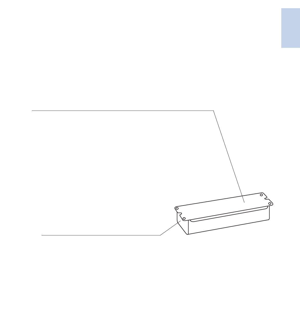
Remote Wiring
LAMP
BALLAST FOR A
SINGLE LUMINAIRE
OUTPUT LEADS IN CONDUIT
Luminaire may contain
various lamp quantities,
but is operated by
one remote ballast
LAMP
LAMP
Remote, Tandem or Through Wiring Distances
Remote Mounting of Electronic Ballasts
Unlike magnetic ballasts, electronic ballasts are limited in remote
mounting distance from the lamps they operate. The factors
limiting the distance from the electronic ballasts to the lamps are:
open circuit voltage as opposed to operating voltage, operating
frequency and the lamp operating current.
As the distance from the high frequency electronic ballasts to the
lamp increases, so does the capacitance across the lead wire to the
lamp. This increase in capacitance is important for two reasons.
First, if the capacitance is too high, there will not be sufficient open
circuit voltage across the lamp for proper lamp ignition.
Second, if the lamp is capable of ignition, the increased capacitance
will cause a loss in the current to the lamp. The added capacitance
creates what is known as a “shunt” around the lamp; in other words
the current will leak from the red wire (or blue) to the yellow,
completely bypassing the lamp. The current through the lamp will be
reduced, resulting in lower lumens, with the possibility that the lamp
will not be capable of sustained operation.
The Mark 7 0-10V, Mark 10 Powerline, and ROVR dimming ballasts
are particularly sensitive to high capacitance associated with long lead
wires. The dimming ballast is capable of very low dim levels because
constant filament heat is provided to the lamp. If there is any loss of
current, the filament current will be reduced and the lamp will begin
to flicker, or it will be completely extinguished. It is also important
that the red and blue leads not be twisted together. Twisting the red
and blue leads will add capacitance, causing the lamp to flicker at the
lower dimming levels.
Open circuit voltage is a function of input voltage in some ballast
designs, particularly for dedicated voltage ballasts. Cold temperature
starting is a function of open circuit voltage. The lead length
recommendations in the following table are for normal rated input
voltages (120V, 277V, 347V) at 25°C ambient temperature.
In summary, there is a wide range and varying types of electronic
ballast architectures that are capable of being remote mounted
for an equally wide range of distances. If you are uncertain of the
remote mounting restrictions for a particular electronic ballast
please consult Philips Lighting Electronics Customer Care
(Warranty/Technical Service)
1-13
Lighting Electronics Atlas 2010-2011
ELECTRONIC FLUORESCENT BALLASTS
Electronic
Fluorescent Ballasts
Tandem Wiring
LAMP A1
LAMP A2
LAMP B1
LAMP A3
LAMP A4
LAMP B2
Conduit for
running output lead wire
to adjacent luminaire
Conduit for
running output lead wire
to adjacent luminaire
4-lamp ballast
operating ‘A’ l amps
2-lamp ballast
operating ‘B’ l amps
LAMP C1 LAMP C2
2-lamp ballast
operating ‘C’ l amps
2 BALLAST EXAMPLE
1 BALLAST EXAMPLE
BALLAST ‘A’ OPERATES OUTBOARD LAMPS
BALLAST ‘B’ OPERATES INBOARD LAMPS
Through Wiring
LAMP
4 - LAMP BALLAST
3 - LAMP BALLAST
2 - LAMP BALLAST
LAMP LAMP LAMP
LAMP LAMP LAMP
LAMP LAMP
Fixture is the wireway.
Output leads are not run in conduit.
Fixture is the wireway.
Output leads are not run in conduit.
Fixture is the wireway.
Output leads are not run in conduit.
Diagrams are also aplicable for multiple lamp
cross-section luminaires. For example,
an 8-foot luminaire with two lamps in cross section
and a single 4-lamp ballast.
Note: Ballast should be mounted
at center of fixture to minimize
lead lengths.
Lighting Electronics Atlas 2010-2011
ELECTRONIC FLUORESCENT BALLASTS
1-14
Electronic
Fluorescent Ballasts
8’ Yes Yes 8’ 8’ 1
8’ Yes Yes 8’ 8’ 1
8’ Yes Yes 8’ 8’ 1
8’ Yes Yes 8’ 8’ 1
8’ Yes Yes 8’ 8’ 1
8’ Yes Yes 8’ 8’ 1
8’ Yes Yes 8’ 8’ 8’ 1
8’ Yes Yes 8’ 8’ 8’ 1
20’ Yes Yes 20’ 4’ 20’ 3
20’ Yes Yes 20’ 4’ 4’ 20’ 20’ 20’ 7
15’ NA NA 4
2-Lamp 6’ Yes Yes 2’ 6’ 6’ 2
1-Lamp 15’ NA NA 4
1-Lamp 15’ NA NA 4
1-Lamp 15’ NA NA 4
1-Lamp 15’ NA NA 4
1-Lamp 15’ NA NA 4
6’ Yes Yes 2’ 6’ 6’ 2
20’ NA NA 4
20’ NA NA 4
20’ NA NA 4
20’ NA NA 4
20’ Yes Yes 20’ 20’ 1
20’ Yes Yes 20’
20’ 1e
20’ Yes Yes 20’
20’ 1
20’ Yes Yes 20’ 4’ 20’ 3
8’ Yes Yes 8’ 4’ 8’ 3
10’ Yes Yes 10’ 10’ 10’ 3
20’ Yes Yes 20’ 4’ 20’ 3
20’ Yes Yes 4’
10’ 10’ 2
20’ Yes Yes 20’ 4’ 20’ 3
20’ Yes Yes 20’ 4’ 20’ 3
20’ Yes Yes 20’ 4’ 20’ 3
20’ Yes Yes 20’ 4’ 20’ 3
20’ Yes Yes 20’ 4’ 20’ 3
12’ Yes Yes 12’ 4’ 12’ 3
20’ Yes Yes 4’ 20’ 20’ 2
20’ Yes Yes 20’ 20’ 1
20’ Yes Yes 20’ 20’ 1e
No No No 5
20’ Yes Yes 20’ 20’ 1
20’ Yes Yes 20’ 20’ 20’ 1e
GOPA-1P32-LW-SC (c)
GOPA-1P32-SC (c)
GOPA-2P32-LW-SC (c)
GOPA-2P32-SC (c)
GOPA-3P32-LW-SC (c)
GOPA-3P32-SC (c)
GOPA-4P32-LW-SC (c)
GOPA-4P32-SC (c)
HCN-2S54-90C-WL
HCN-4S54-90C-2LS-G
ICF-1D38-H1-LD
ICF-1H120-M4-LD
ICF-2S13-H1-LD
ICF-2S13-M1-BS
ICF-2S18-H1-LD
ICF-2S18-M1-BS
ICF-2S26-H1-LD
ICF-2S26-M1-BS
ICF-2S42-M2-BS
ICF-2S42-M2-LD
ICF-2S42-90C-M2-BS
ICF-2S42-90C-M2-LD
ICF-2S70-M4-LD
ICN-132-MC
ICN-1P32-N
ICN-1S80
ICN-1TTP40-SC
ICN-2M32-MC
ICN-2P32-N
ICN-2P60-SC
ICN-2S24
ICN-2S28
ICN-2S28-N
ICN-2S39
ICN-2S40-N
ICN-2S54
ICN-2S54-WL
ICN-2S54-90C
ICN-2S54-90C-SC
ICN-2S54-90C-WL
ICN-2S86 (b)
ICN-2S110-SC
ICN-2TTP40-SC
ICN-3P32-SC
ICN-3S14-D
ICN-3TTP40-SC
ICN-4P32-SC
Maximum Lead Length (Feet) for Tandem or Through Wiring
(Total length of all wires between ballast and lamp sockets)
Application
Note
Remote
(max length)
Tandem Through Blue Red Yellow
Blue/White
Brown Orange
Allowed Wiring Configuration
For nominal input voltage and 25°C ambient temperature. See all notes on page 1-19.

1-15
Lighting Electronics Atlas 2010-2011
ELECTRONIC FLUORESCENT BALLASTS
Electronic
Fluorescent Ballasts
For nominal input voltage and 25°C ambient temperature. See all notes on page 1-19.
ICN-4S54-90C-2LS-G
IDA-132-SC
IDA-154
IDA-2S32-SC
IDA-2S54
IDA-3S32-G
IDA-4S32
IDL-2S26-M5-BS
IDL-2S26-M5-LD
IDL-2T42-M5-BS
IDL-2T42-M5-LD
IEZ-2S24-D
ILV-2S32-SC
ILV-4S32-G
IOP-1P32-LW-SC (c)
IOP-1P32-SC (c)
IOP-1S32-LW-SC (c)
IOP-1S32-SC (c)
IOP-2P32HL-SC (c)
IOP-2P32-LW-SC (c)
IOP-2P32-SC (c)
IOP-2P59-SC
IOP-2PSP32-LW-SC
IOP-2PSP32-SC
IOP-2PSP54-SC
IOP-2S28-95-SC-SD
IOP-2S28-115-SC-SD
IOP-2S28-95-SC
IOP-2S28-115-SC
IOP-2S32-LW-SC (d)
IOP-2S32-SC (d)
IOP-3P32-HL-90C-SC
(c)
IOP-3P32-LW-SC
(c)
IOP-3P32-SC
(c)
IOP-3PSP32-LW-SC
IOP-3PSP32-SC
IOP-3S32-LW-SC (d)
IOP-3S32-SC (d)
IOP-4PSP54-2LS-G
(
c
)
IOP-4P32-LW-SC
(
c
)
IOP-4P32-SC
(
c
)
IOP-4PSP32-LW-SC
IOP-4PSP32-SC
IOP-4PSP54-90C-G
IOP-4S32-LW-SC (d)
IOP-4S32-SC (d)
20’ Yes Yes 20’ 4’ 4’ 20’ 20’ 20’ 7
No NA NA 5
No NA NA 5
No No Yes 5’ 4’ 4’ 3
No No Yes 5’ 4’ 4’ 3
No No No 5
No No Yes-8’
1’ 1.25’ 5.2’ 1.25’ 4.2’
3
No No No 5
No No No 5
No No Yes 3’ 2’ 2’ 3
6’ Yes Yes 6’ 6’ 6’ 1
No No Yes
-8’
1’ 1.25’ 5.2’ 1.25’ 4.2’ 3
20’
NA NA 1e
20’
NA NA 1e
10’ NA NA 4
10’ NA NA 4
20’ Yes Yes 20’ 20’ 1e
20’ Yes Yes 20’ 20’ 1e
20’ Yes Yes 20’ 20’ 1e
20’ Yes Yes 20’ 20’ 1e
20’
Yes Yes
20’
20’
18’ 1e
20’
Yes Yes
20’
20’
18’ 1e
20’
Yes Yes
20’
20’ 15’ 1e
7’ Yes Yes 7’ 7’ 7’ 1
7’ Yes Yes 7’ 7’ 7’ 1
20’ Yes Yes 20’ 20’ 20’ 1
20’ Yes Yes 20’ 20’ 20’ 1
10’ Yes Yes 4’ 10’ 10’ 2
10’ Yes Yes 4’ 10’ 10’ 2
20’ Yes Yes 20’ 20’
1e
20’ Yes Yes 20’ 20’
1e
20’ Yes Yes 20’ 20’
1e
20’
Yes Yes
20’
20’
1
8’
1
8’
1e
20’
Yes Yes
20’
20’
1
8’
1
8’
1e
10’ Yes Yes 10’ 4’ 4’ 10’ 7
10’ Yes Yes 10’ 4’ 4’ 10’ 7
20’ Yes Yes 20’ 20’ 8’
1e
20’ Yes Yes 20’ 20’ 8’
1e
20’ Yes Yes 20’ 20’ 8’
1e
20’
Yes Yes
20’
20’
1
8’
1
8’
1
8’
1e
20’
Yes Yes
20’
20’
1
8’
1
8’
1
8’
1e
20’
Yes Yes
20’
20’
15’ 15’ 15’ 1e
10’ Yes Yes 10’ 4’ 4’ 10’ 10’ 7
10’ Yes Yes 10’ 4’ 4’ 10’ 10’ 7
Maximum Lead Length (Feet) for Tandem or Through Wiring
(Total length of all wires between ballast and lamp sockets)
Application
Note
Remote
(max length)
Tandem Through Blue Red Yellow
Blue/White
Brown Orange
Allowed Wiring Configuration
Lighting Electronics Atlas 2010-2011
ELECTRONIC FLUORESCENT BALLASTS
1-16
Electronic
Fluorescent Ballasts
20’ Yes Yes 20’ 20’
1e
20’ Yes Yes 20’ 20’
1e
20’ Yes Yes 20’ 20’
1e
20’ Yes Yes 20’ 20’’
1e
20’ Yes Yes 20’ 20’
1e
20’’ Yes Yes 20’ 20’’
1e
20’’ Yes Yes 20’ 20’’
1e
20’ Yes Yes 20’ 20’
1e
20’’ Yes Yes 20’ 20’’
1e
20’’ Yes Yes 20’ 20’
8’
1e
20’ Yes Yes 20’ 20’
8’
1e
20’ Yes Yes 20’ 20’
8’
1e
6’ NA NA 4
No No No 5
6’ Yes Yes 6’ 6’ 6’ 1
No No No 5
No No No 5
6’ No No 4
No No No 5
No No Yes-8’ 1’ 1.25’ 5.2’ 1.25’ 4.2’ 3
20’ Yes Yes 4’ 20’ 20’ 2
1-Lamp 15’ No No 4
2-Lamp 6’ Yes Yes 2’ 6’ 6’ 2
1-Lamp 15’ No No 4
2-Lamp 6’ Yes Yes 2’ 6’ 6’ 2
1-Lamp 15’ No No 4
2-Lamp 6’ Yes Yes 2’ 6’ 6’ 2
20” NA NA 4
No Yes Yes 20’ 4’ 20’ 3
No Yes Yes 4’ 4’ 20’ 20’ 6
No Yes Yes 4’ 4’ 20’ 20’ 20’ 6
No No No 5
No No No 5
No No No 5
No No No 5
No No No 5
No No No 5
20” Yes Yes 20’ 20’ 1
20” No No 4
No Yes Yes 12’ 2’ 12’ 3
20” Yes Yes 20’ 20’ 20’ 1
No No No 5
No No No 5
No No No 5
No No No 5
No No No 5
No No No 5
REB-2S26-M1-LD-DIM
IOPA-1P32-HL-SC
(c)
IOPA-1P32-LW-SC
(c)
IOPA-1P32-SC
(c)
IOPA-2P32-HL-SC
(c)
IOPA-2P32-LW-SC
(c)
IOPA-2P32-SC
(c)
IOPA-3P32-HL-SC
(c)
IOPA-3P32-LW-SC
(c)
IOPA-3P32-SC
(c)
IOPA-4P32-HL
(c)
IOPA-4P32-LW-SC
(c)
IOPA-4P32-SC
(c)
IZT-132-SC
IZT-2S26-M5-BS
IZT-2S26-M5-LD
IZT-2S32-SC
IZT-2T42-M3-BS
IZT-2T42-M3-LD
IZT-2T42-M5-BS
IZT-2T42-M5-LD
IZT-2TTS40-SC
IZT-3S32-SC
IZT-4S32
JOP-2S84-G
RCF-2S13-H1-LD
RCF-2S13-M1-BS
RCF-2S18-H1-LD
RCF-2S18-M1-BS
RCF-2S26-H1-LD
RCF-2S26-M1-BS
RCN-1S32-SC
RCN-2S32-SC (d)
RCN-3S32-SC (d)
RCN-4S32-SC (d)
REB-113-M6-BLS
REB-113-M6-EL
REB-118-M6-BLS
REB-118-M6-EL
REB-126-M6-BLS
REB-126-M6-EL
REB-2P32-SC
1-LAMP
2-LAMP
REB-4P32-SC
REB-2S13-M6-EL
REB-2S13-M6-BL
REB-2S18-M6-EL
REB-2S18-M6-BL
REB-2S26-M6-EL
REB-2S26-M6-BL
Maximum Lead Length (Feet) for Tandem or Through Wiring
(Total length of all wires between ballast and lamp sockets)
Application
Note
Remote
(max length)
Tandem Through Blue Red Yellow
Blue/White
Brown Orange
Allowed Wiring Configuration
For nominal input voltage and 25°C ambient temperature. See all notes on page 1-19.
Lighting Electronics Atlas 2010-2011
ELECTRONIC FLUORESCENT BALLASTS
Electronic
Fluorescent Ballasts
1-17
RELB-1S40-SC
RELB-2S40-SC
REZ-132-SC
REZ-154
REZ-132-SC
REZ-154
REZ-1Q18-M2-BS
REZ-1Q18-M2-LD
REZ-1T42-M2-BS
REZ-1T42-M2-LD
REZ-1TTS40-SC
REZ-2Q18-M2-BS
REZ-2Q18-M2-LD
REZ-2Q26-M2-BS
REZ-2Q26-M2-LD
REZ-2S32-SC
REZ-2S54
REZ-2T42-M3-BS
REZ-2T42-M3-LD
REZ-2TTS40-SC
REZ-3S32-SC
RK-132-TP (a)
RK-2S32-TP (a)
RMB-1P13-S1
RMB-1P26-S2
RMB-2P13-S2
RZT-154
RZT-2S54
VCN-1S32-SC
VCN-2S32-SC (d)
VCN-3S32-SC (d)
VCN-4S32-SC (d)
VEL-1S40-SC
VEZ-132-SC
VEZ-154
VEZ-1Q18-M2-BS
VEZ-1Q18-M2-LD
VEZ-1T42-M2-BS
VEZ-1T42-M2-LD
VEZ-1TTS40-SC
VEZ-2Q18-M2-BS
VEZ-2Q18-M2-LD
VEZ-2Q26-M2-BS
VEZ-2Q26-M2-LD
VEZ-2S32-SC
VEZ-2S54
20’ NA NA 4
20” Yes Yes 4’ 10’ 10’ 2
6’ NA NA 4
No NA NA 5
6’ NA NA 4
No NA NA 5
No NA NA 5
No NA NA 5
6’ NA NA 4
No No No 5
No No No 5
6’ Yes Yes 6’ 6’ 6’ 1
No No Yes 5’ 4’ 4’ 3
No No No 5
6’ No No 5
No No No 5
20’ No No 4
20’ Yes Yes 4’ 20’ 20’ 2
20’ NA NA 4
20’ NA NA 4
20’ Yes Yes 20’ 20’ 20’ 1
No NA NA 5
No No Yes 5’ 4’ 4’ 3
20” No No 4
No Yes Yes 20’ 4’ 20’ 3
No Yes Yes 4’ 4’ 20’ 20’ 6
No Yes Yes 4’ 4’ 20’ 20’ 20’ 6
20’ NA NA 4
6’ NA NA 4
No NA NA 5
No NA NA 5
No NA NA 5
6’ NA NA 4
No No No 5
No No No 5
6’ Yes No 6’ 6’ 6’ 1
No No Yes 5’ 4’ 4’ 5
Maximum Lead Length (Feet) for Tandem or Through Wiring
(Total length of all wires between ballast and lamp sockets)
Application
Note
Remote
(max length)
Tandem Through Blue Red Yellow
Blue/White
Brown Orange
Allowed Wiring Configuration
For nominal input voltage and 25°C ambient temperature. See all notes on page 1-19.
Lighting Electronics Atlas 2010-2011
ELECTRONIC FLUORESCENT BALLASTS
1-18
Electronic
Fluorescent Ballasts
For nominal input voltage and 25°C ambient temperature.
Notes:
1. For Tandem or Through wiring, any lamp can be remote mounted.
2. For Tandem or Through wiring, BLUE lamp must be in same fixture as ballast.
3. For Tandem or Through wiring, RED lamp must be in same fixture as ballast.
4. No Tandem or Through wiring allowed.
5. No Remote, Tandem or Through wiring allowed.
6. For Tandem or Through wiring, RED lamp and BLUE lamp must be in same fixture as ballast.
7. For Tandem or Through wiring, RED lamp and YELLOW lamp must be in same fixture as ballast.
(a) Ballast can be Remote, Tandem or Through wired farther than 20’. Consult factory.
(b) Ballast can be Remote, Tandem or Through wired to a maximum 12 feet between ballast and lampholder for (2)F96T8/HO lamps or 20 feet for all other T8/HO lamps.
(c) Ballast can be Remote, Tandem or Through wired to a maximum 6 feet between ballast and lampholder for energy-saving lamps or 8 feet for standard lamps.
(d) For tandem wiring, lamp leads from multiple ballast cannot be run in same conduit. Separate conduit must be used for each ballast.
(e) Ballast can be Remote, Tandem, or Through wired to a maximum of 20’ for standard lamps and 6’ for energy-saving lamps
Use 18 AWG wire or larger
VEZ-2T42-M3-BS
VEZ-2T42-M3-LD
VEZ-2TTS40-SC
VEZ-3S32-SC
VK-132-TP (a)
VK-2S32-TP (a)
VZT-154
VZT-180
VZT-1TTS40
VZT-2S54
VZT-4S32-HL
VZT-4PSP32-G
VZT-4S32-G
No No No 5
6’ No No 4
No No No 5
20’ NA NA 4
20’ Yes Yes 4’ 20’ 20’ 2
No NA NA 5
No NA NA 5
6’ NA NA 4
No No Yes 5’ 4’ 4’ 3
No No Yes-8’ 1’ 1.25’ 5.2’ 1.25’ 4.2’ 3
No No Yes-8’ 5’ 5’ 1’ 5’ R/W=5’ 3
No No Yes-8’ 1’ 1.25’ 5.2’ 1.25’ 4.2’ 3
Maximum Lead Length (Feet) for Tandem or Through Wiring
(Total length of all wires between ballast and lamp sockets)
Application
Note
Remote
(max length)
Tandem Through Blue Red Yellow
Blue/White
Brown Orange
Allowed Wiring Configuration
1-19
Lighting Electronics Atlas 2010-2011
ELECTRONIC FLUORESCENT BALLASTS
Electronic
Fluorescent Ballasts
Reading Date Codes for Warranty Date on Electronic Ballasts
Most date codes are stamped on the back of the ballast (opposite the label side). The date code is part of a larger group
of numbers and letters, which call out the various codes for the factory where the ballast was manufactured. Depending upon
which Philips Lighting Electronics factory manufactured the ballast, the date stamp can vary slightly, in terms of its position on
the ballast and the number sequence.
Some electronic ballasts manufactured from 1988 to 1991 may have the date code in ink stamped on the ballast label.
Some ballasts have the manufacturing code printed in ink on the end of the ballast.
A typical date code for an electronic ballast will have the week and the year the ballast was manufactured. Some ballasts
will have the day of the week included too.
Some examples of these different date codes that you may find are:
937N1B
B41893
The date code is the 18th week of 1993, stamped one line over the other.
937N1J
P23292
The date code is the 32nd week of 1992, stamped one line over the other.
16
93
973N20P3
The date code is the 16th week of 1993, stamped at the end of the ear on the back.
892P
259P
24
94
The date code is the 4th week of 1994, stamped on four separate lines.
91405BB0291N
The date code is the 2nd week of 1991, stamped on one line.
9716T032HD
120432IS24
The date code is the 16th week of 1997, stamped in ink on the end of the ballast.
The above examples are for ballasts that are already out of warranty. The next two examples are for ballasts that may still be covered
under warranty. In 2006 the date code configuration was switched to the bottom example.
693P0MMA
53301707
The date code is the 5th day, of the 33rd week of 2001, stamped on the back of the ballast.
06127M50
F2104571
The date code is the 127th day of 2006 stamped on the back of the ballast.
For Assistance in Determining a Date Code – Call Customer Care (Technical Services /Warranty) at 1-800-372-3331
Lighting Electronics Atlas 2010-2011
ELECTRONIC FLUORESCENT BALLASTS
1-20
Electronic
Fluorescent Ballasts
Key BenefitsKit Contents and Key Features
SmartMate or Mark 10 Powerline ballast
• Intellivolt Technology
• Dual-entry color-coded connectors
• Multi-Lamp Capability
Mounting Plate Adapter
• Multiple lead wire cutouts, including center hole
• Integral mounting studs
Lead Wire
• Color-coded
• Pre-stripped 3/8” on one end — 5/8” on the other
Wire Extraction Tool
Individually Shrink-Wrapped Kits
Makes ballast selection and installation a breeze
• Provides full range input voltage from 120V to 277V
• Adds to application versatility; simplifies wiring
• Encompasses a wide variety of applications, including
• quads, triple tubes, circline, 2D and long twin-tube lamps
Takes the guess-work out of mounting
• Allows wiring and mounting to existing fixture’s mounting plate
• Eliminates need to stock units with and without studs
Allows installer to pre-wire
• Ensures wiring accuracy
• Meets UL poke-in connector requirements and facilitates
• final connection
Makes for quick disconnections if necessary
SmartMate and Mark 10 Powerline Ballast Kits
• Ideally suited for replacement of expired electronic ballasts, regardless of brand or mounting configuration.
• Dramatically simplifies the upgrading of incandescent fixtures to energy-saving CFL.
• Compatible with most J-Box covers
ICF-2S13-H1-LD-K* REZ-2Q26-M2-LD-K* *
ICF-2S18-H1-LD-K* VEZ-2Q26-M2-LD-K*
ICF-2S26-H1-LD-K* REZ-1T42-M2-LD-K*
ICF-2S42-M2-LD-K* VEZ-1T42-M2-LD-K*
Kits contain the standard ballasts.
For lamp and operational data consult
pages 1-23 through 1-35 and 2-9

Lighting Electronics Atlas 2010-2011
ELECTRONIC FLUORESCENT BALLASTS
Electronic
Fluorescent Ballasts
1-21
Notes
Lighting Electronics Atlas 2010-2011
1-22
ELECTRONIC FLUORESCENT BALLASTS
Electronic
Fluorescent Ballasts
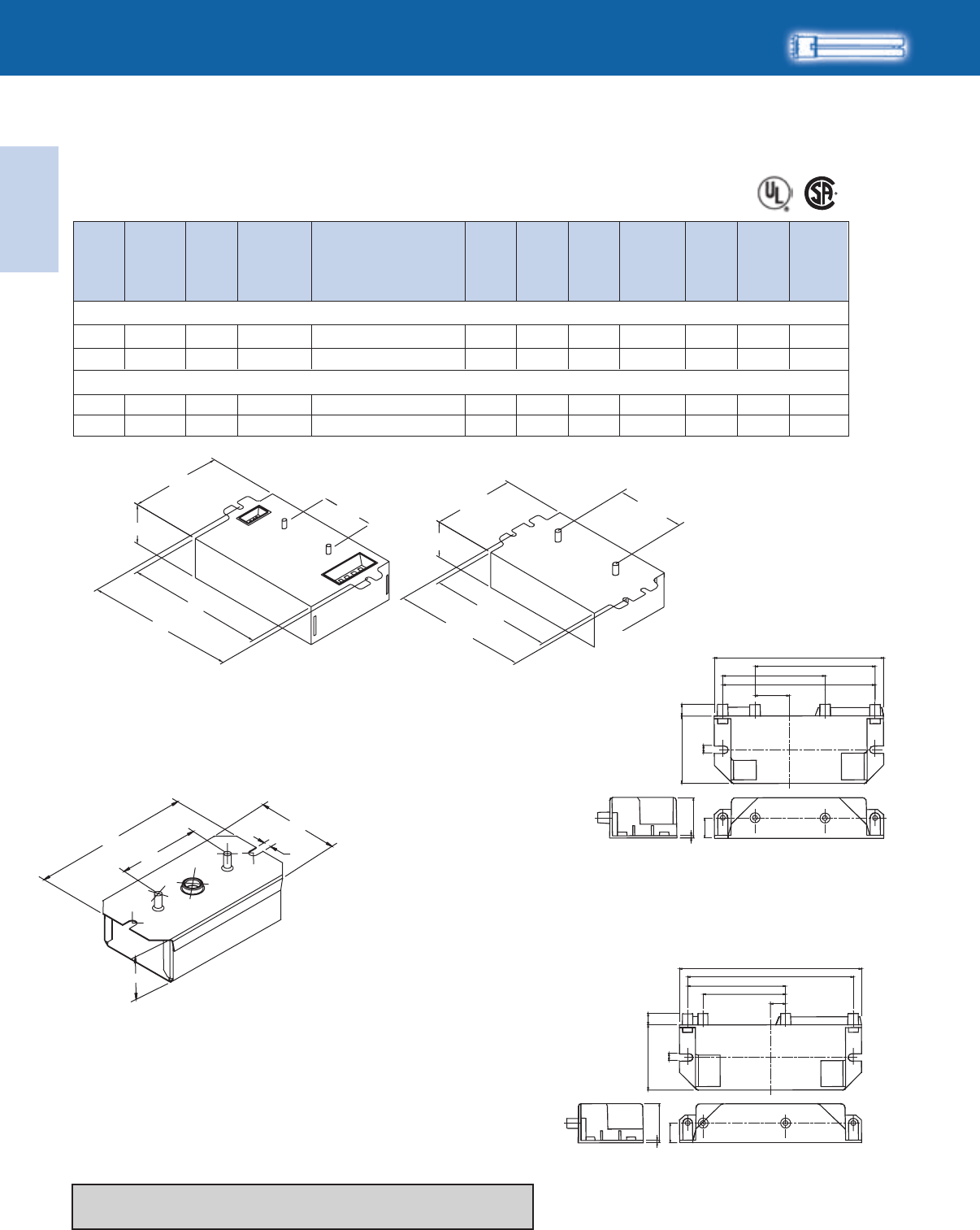
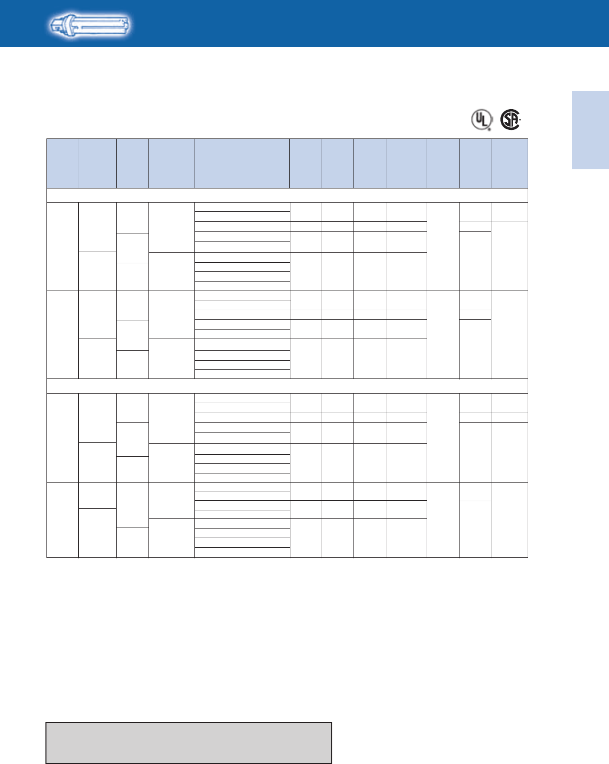
HIGH POWER FACTOR SOUND RATED A
No. of
Lamps Dim. Wiring
Dia.
CFT7W/2G7 - 7W CFL Twin Tube Lamp (CF7DS/E)
1 160
S1
2 159
S2
CFT9W/2G7 - 9W CFL Twin Tube Lamp (CF9DS/E)
1 160
S1
2
Min.
Starting
Temp.
(°F/°C)
0/-18
0/-18
0/-18
0/-18
Input
Volts
120
120
120
120
Ballast
Family
AmbiStar
AmbiStar
AmbiStar
AmbiStar
Lamp
Starting
Method
IS
IS
IS
IS 159
S2
Catalog Number
RMB-1P13-S1*
RMB-2P13-S2*
RMB-1P13-S1*
RMB-2P13-S2*
Line
Current
(Amps)
0.13
0.24
0.16
0.29
Input
Power
ANSI
(Watts)
8
16
10
20
Ballast
Factor
1.00
1.10
1.10
1.10
Max.
THD
%
150
150
150
125
2.00"
2.00"
3.85"
0.20"
1.12"
STUDS FOR BLS MODELS ONLY
BOTTOM LEADS FOR BL AND BLS MODELS ONLY
T4
For 7-9W Lamps
* Normal Power Factor
Refer to page 1-24 for wiring diagrams
Refer to pages 9-24 to 9-28 for lead lengths and shipping data
4.60"
4.20"
0.98"
2.40"
2.00"
STUDS FOR -BS MODELS ONLY
-LD MODELS DO NOT HA
VE MOUNTING STUDS
4.55"
4.20"
1.29"
3.00" 2.00"
STUDS FOR -BS MODELS ONLY
-LD MODELS DO NOT HAVE MOUNTING STUDS
Size 2 Enclosure
Size 6 Enclosure
Size 1 Enclosure
1 LAMP RECTANGULAR BALLAST, PLASTIC ENCLOSURE
INPUT SIDE OUTPUT SIDE
#6 - 20 THREAD FORMING
.25” LONG SCREWS
0.116” HOLES
3.54"
2.38"
0.80"
.28"1.57"
.17"
.47"
.94"
.06"
2.0"
3.15"
2 LAMP RECTANGULAR BALLAST, PLASTIC ENCLOSURE
INPUT SIDE OUTPUT SIDE
#6 - 20 THREAD FORMING
.25” LONG SCREWS
0.116” HOLES
4.41"
4.01"
2.38"
.28"1.57"
.17"
.47"
.94"
.06"
2.0"
3.6"
S2 Model
S1 Model
Electronic
Fluorescent Ballasts
ELECTRONIC FLUORESCENT BALLASTS
1-23
Lighting Electronics Atlas 2010-2011
REB-113-M6-BLS*
CFQ13W/G24q - 13W CFL Quad Tube Lamp (PL-C13W/4P, F13DBX/4P, CF13DD/E)
10/-18
120
IS
AmbiStar
0.23
13 1.00 150
160A
Size 6
REB-113-M6-EL*
HIGH POWER FACTOR SOUND RATED A
* Normal Power Factor
❿
Replacement/Retrofit ballast kits indicated with suffix K are available to distributors. Refer to page 1-21 for details.
REB-118-M6-EL*
CFQ18W/G24q - 18W CFL Quad Tube Lamp (PL-C18W/4 P, F18DBX/4P, CF18DD/E)
10/-18
120
IS
REB-118-M6-BLS*
AmbiStar
0.2918 1.00 150 160A
Size 6
0.2014 1.00 150
160
RMB-1P13-S1* S1
SmartMate
RS
0.1316 1.00 10
Size 1
RCF-2S13-H1-LD-QS
RCF-2S13-M1-BS-QS
120-277
ICF-2S13-M1-BS-QS
ICF-2S13-H1-LD
ICF-2S13-H1-LD-K ❿
PS 0.13-0.06
16 1.00 10
ICF-2S13-M1-BS
20/-18
120 AmbiStar
IS
0.35
0.42
25
27
0.95
0.88
125
135
159
RMB-2P13-S2*
REB-2S13-M6-EL*
S2
Size 6
REB-2S13-M6-BL*
RCF-2S13-H1-LD-QS
RS 0.2529 1.00 10
Size 1
RCF-2S13-M1-BS-QS
120-277
ICF-2S13-M1-BS-QS
ICF-2S13-H1-LD
ICF-2S13-H1-LD-K ❿
PS 0.25-0.1129 1.00 10
ICF-2S13-M1-BS
SmartMate
RCF-2S18-H1-LD-QS
REB-2S18-M6-EL* Size 6
0.2616 0.80 150 *159
RMB-2P13-S2* S2
RCF-2S18-H1-LD-QS
SmartMate
RS
0.1619 1.00 10
Size 1 160
RCF-2S18-M1-BS-QS
120-277
ICF-2S18-M1-BS-QS
ICF-2S18-H1-LD
ICF-2S18-H1-LD-K ❿
PS
0.16-0.0719 1.00 10
ICF-2S18-M1-BS
20/-18
120
SmartMate
AmbiStar
RS
0.55
0.30
37
35
0.90
0.95
135
10
Size 1 159
REB-2S18-M6-BL*
120-277
RCF-2S18-M1-BS-QS
ICF-2S18-M1-BS-QS
ICF-2S18-H1-LD
ICF-2S18-H1-LD-K ❿
PS 0.30-0.1335 0.95 10
ICF-2S18-M1-BS
For 13-18W Quad Lamps
No. of
Lamps Dim. Wiring
Dia.
Min.
Starting
Temp.
(°F/°C)
Input
Volts
Ballast
Family
Lamp
Starting
Method
Catalog Number
Line
Current
(Amps)
Input
Power
ANSI
(Watts)
Ballast
Factor
Max.
THD
%
Refer to page 1-22 for dimensions
Refer to page 1-24 for wiring diagrams
Refer to pages 9-24 to 9-28 for lead lengths and shipping data
T4
Lighting Electronics Atlas 2010-2011
1-24
ELECTRONIC FLUORESCENT BALLASTS
Electronic
Fluorescent Ballasts
No. of
Lamps
WIRING: (2) LAMP
LINE
BLACK
WHITE
GREEN
GREEN TERMINAL MUST BE GROUNDED
BLUE
RED
YELLOW
BALLAST
10/-18
120
IS
CFQR26W/G24q - 26W CFL Quad Tube Lamp (PL-C26W/4P, F26DBX/4P, CF26DD/E)
REB-126-M6-BLS*
AmbiStar
REB-126-M6-EL*
RMB-1P26-S2*
RS
0.3826 0.95 125 S2
Size 6
160
RCF-2S26-H1-LD-QS
SmartMate
QS
0.2327 1.00 10
Size 1
RCF-2S26-M1-BS-QS
120-277
ICF-2S26-M1-BS-QS
ICF-2S26-H1-LD
ICF-2S26-H1-LD-K ❿
PS 0.23-0.1027 1.00 10
ICF-2S26-M1-BS
20/-18
120 RCF-2S26-H1-LD-QS
REB-2S26-M6-EL*
AmbiStar
SmartMate
RS
0.43
0.77
51
52
1.00
0.88
10
135
Size 1
159
RCF-2S26-M1-BS-QS
REB-2S26-M6-BL*
120-277
ICF-2S26-M1-BS-QS
ICF-2S26-H1-LD
ICF-2S26-H1-LD-K ❿
PS
0.43-0.19
51 1.00 10
ICF-2S26-M1-BS
ICF-2S42-M2-BS
0.43-0.1952 1.00 10
Size 2
ICF-2S42-M2-LD
ICF-2S42-M2-LD-K ❿
ICF-2S42-90C-M2-BS 0.43-0.1952 1.00 10
ICF-2S42-90C-M2-LD
0.3825 1.00 150 Size 6 160A
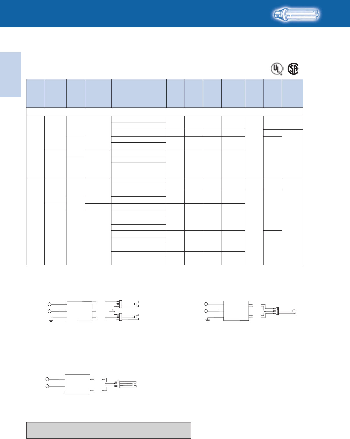
WIRING: (1) LAMP
LINE
BLACK
WHITE
BLUE
RED
BALLAST
HIGH POWER FACTOR SOUND RATED A
Dim. Wiring
Dia.
Min.
Starting
Temp.
(°F/°C)
Input
Volts
Ballast
Family
Lamp
Starting
Method
Catalog Number
Line
Current
(Amps)
Input
Power
ANSI
(Watts)
Ballast
Factor
Max.
THD
%
T4
For 26W Quad Lamps
* Normal Power Factor
❿
Replacement/Retrofit ballast kits indicated with suffix K are available to distributors. Refer to page 1-21 for details.
Diag. 160A
Diag. 159
Note: For AmbiStar 1-lamp operation on 2-lamp
ballast, use red and blue connectors
Diag. 160
Refer to page 1-22 for dimensions
Refer to pages 9-24 to 9-28 for lead lengths and shipping data
WIRING: (1) LAMP
LINE
BLACK
WHITE
GREEN
GREEN TERMINAL MUST BE GROUNDED
BLUE
RED
BALLAST
Electronic
Fluorescent Ballasts
ELECTRONIC FLUORESCENT BALLASTS
1-25
Lighting Electronics Atlas 2010-2011
0/-18
Size 6 160A
0.2313 1.00 150
CFTR13W/GX24q - 13W CFL Triple Tube Lamp (F13TBX/4P, CF13DT/E)
1
120
IS
REB-113-M6-BLS*
AmbiStar
REB-113-M6-EL*
0.2014 1.00 150
160
RMB-1P13-S1* S1
RCF-2S13-H1-LD-QS
SmartMate
RS 0.1316 1.00 10
Size 1
RCF-2S13-M1-BS-QS
120-277
ICF-2S13-M1-BS-QS
ICF-2S13-H1-LD
ICF-2S13-H1-LD-K ❿
PS 0.13-0.0616 1.00 10
ICF-2S13-M1-BS
20/-18
120
REB-2S13-M6-EL*
AmbiStar
IS
0.35
0.42
25
27
0.95
0.88
125
135 Size 6
159
RMB-2P13-S2*
REB-2S13-M6-BL*
S2
RCF-2S13-H1-LD-QS
SmartMate
RS 0.2529 1.00 10
Size 1
RCF-2S13-M1-BS-QS
120-277
ICF-2S13-M1-BS-QS
ICF-2S13-H1-LD
ICF-2S13-H1-LD-K ❿
PS 0.25-0.1129 1.00 10
ICF-2S13-M1-BS
* Normal Power Factor
❿
Replacement/Retrofit ballast kits indicated with suffix K are available to distributors. Refer to page 1-21 for details.
HIGH POWER FACTOR SOUND RATED A
T4
For 13W Triple Lamps
No. of
Lamps Dim. Wiring
Dia.
Min.
Starting
Temp.
(°F/°C)
Input
Volts
Ballast
Family
Lamp
Starting
Method
Catalog Number
Line
Current
(Amps)
Input
Power
ANSI
(Watts)
Ballast
Factor
Max.
THD
%
Refer to page 1-22 for dimensions
Refer to pages 9-24 to 9-28 for lead lengths and shipping data
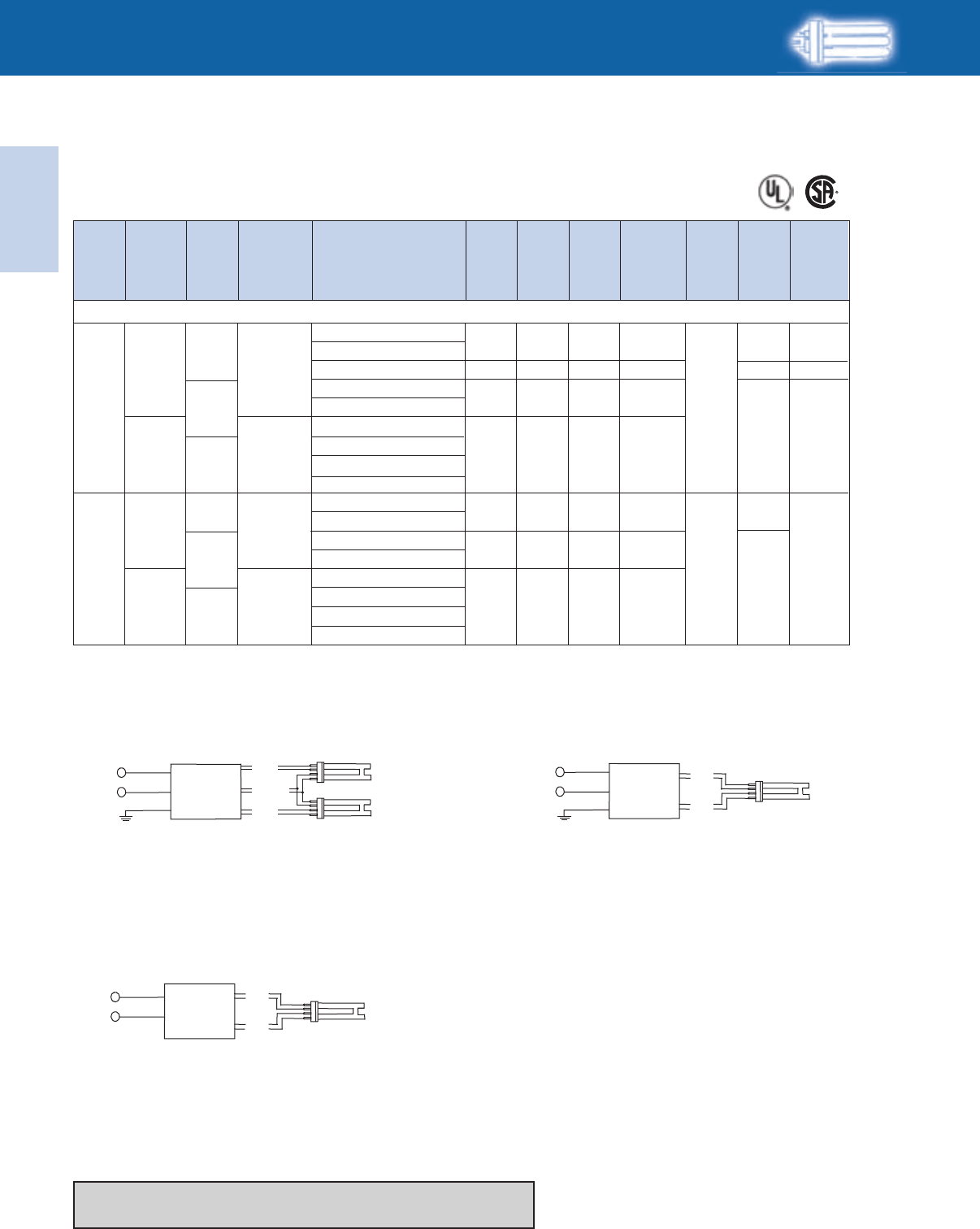
WIRING: (2) LAMP
LINE
BLACK
WHITE
GREEN
GREEN TERMINAL MUST BE GROUNDED
BLUE
RED
YELLOW
BALLAST
WIRING: (1) LAMP
LINE
BLACK
WHITE
BLUE
RED
BALLAST
Diag. 160A
Diag. 159
Note: For AmbiStar 1-lamp operation on 2-lamp
ballast, use red and blue connectors
Diag. 160
WIRING: (1) LAMP
LINE
BLACK
WHITE
GREEN
GREEN TERMINAL MUST BE GROUNDED
BLUE
RED
BALLAST
Lighting Electronics Atlas 2010-2011
1-26
ELECTRONIC FLUORESCENT BALLASTS
Electronic
Fluorescent Ballasts
* Normal Power Factor
❿
Replacement/Retrofit ballast kits indicated with suffix K are available to distributors. Refer to page 1-21 for details.
CFTR18W/GX24q - 18W CFL Triple Tube Lamp (PL-T18W, F18TBX/4P, CF18DT/E)
10/-18
120
IS
REB-1S18-M6-BLS*
AmbiStar
REB-1S18-M6-EL*
RCF-2S18-M1-BS-QS
IS
0.2616 0.80 150 *159
RMB-2P13-S2* S2
Size 6
RCF-2S18-H1-LD-QS
RS 0.1720 1.05 10
Size 1 160
120-277
ICF-2S18-M1-BS-QS
ICF-2S18-H1-LD
ICF-2S18-H1-LD-K ❿
PS 0.17-0.0820 1.05 10
ICF-2S18-M1-BS
2 0/-18
120 RCF-2S18-H1-LD-QS
AmbiStar
SmartMate
SmartMate
RS 0.33
0.55
39
37
1.05
0.90
10
135
Size 1
159
RCF-2S18-M1-BS-QS
REB-2S18-M6-EL*
REB-2S18-M6-BL*
120-277
ICF-2S18-M1-BS-QS
ICF-2S18-H1-LD
ICF-2S18-H1-LD-K ❿
PS 0.33-0.1439 1.05 10
ICF-2S18-M1-BS
0.2918 1.00 150 Size 6 160A
No. of
Lamps
HIGH POWER FACTOR SOUND RATED A
Dim. Wiring
Dia.
Min.
Starting
Temp.
(°F/°C)
Input
Volts
Ballast
Family
Lamp
Starting
Method
Catalog Number
Line
Current
(Amps)
Input
Power
ANSI
(Watts)
Ballast
Factor
Max.
THD
%
T4
For 18W Triple Lamps
Refer to page 1-22 for dimensions
Refer to pages 9-24 to 9-28 for lead lengths and shipping data
WIRING: (2) LAMP
LINE
BLACK
WHITE
GREEN
GREEN TERMINAL MUST BE GROUNDED
BLUE
RED
YELLOW
BALLAST
WIRING: (1) LAMP
LINE
BLACK
WHITE
BLUE
RED
BALLAST
Diag. 160A
Diag. 159
Note: For AmbiStar 1-lamp operation on 2-lamp
ballast, use red and blue connectors
Diag. 160
WIRING: (1) LAMP
LINE
BLACK
WHITE
GREEN
GREEN TERMINAL MUST BE GROUNDED
BLUE
RED
BALLAST
Electronic
Fluorescent Ballasts
ELECTRONIC FLUORESCENT BALLASTS
1-27
Lighting Electronics Atlas 2010-2011
No. of
Lamps Dim. Wiring
Dia.
Min.
Starting
Temp.
(°F/°C)
Input
Volts
Ballast
Family
Lamp
Starting
Method
Catalog Number
Line
Current
(Amps)
Input
Power
ANSI
(Watts)
Ballast
Factor
Max.
THD
%
CFTR26W/GX24q - 26W CFL Triple Tube Lamp (PL-T26W, F26TBX/4P, CF26DT/E)
10/-18
120
IS
Size 1
Size 2
RS
160
159
36
68
0.98
0.98
10
10
PS
PS
1
2
0/-18
0/-18
AmbiStar
SmartMate
SmartMate
120
120-277
120-277
RCF-2S26-H1-LD-QS
RCF-2S26-M1-BS-QS
ICF-2S26-M1-BS-QS
ICF-2S26-H1-LD
ICF-2S26-H1-LD-K
❿
ICF-2S26-M1-BS
ICF-2S42-M2-BS
ICF-2S42-M2-LD
ICF-2S42-M2-LD-K
❿
ICF-2S42-90C-M2-BS
ICF-2S42-90C-M2-LD
CFTR32W/GX24q - 32W CFL Triple Tube Lamp (PL-T32W, F32TBX/4P, CF32DT/E)
36 0.98 10 0.31
0.31-0.13
0.57-0.25
REB-126-M6-BLS
*
AmbiStar
REB-126-M6-EL
*
0.3825 1.00 150 160A
Size 6
RMB-1P26-S2* 0.3826 0.95 125 S2
Size 6
RCF-2S26-H1-LD-QS
Size 1
Size 1
Size 2
RCF-2S26-M1-BS-QS 0.2429 1.10 10
RS
RS
160
159
ICF-2S26-M1-BS-QS
ICF-2S26-H1-LD
ICF-2S26-H1-LD-K
❿
120-277
ICF-2S26-M1-BS
0.24-0.11
0.45
0.55
0.45-0.20
0.46-0.21
29
54
52
54
55
1.10
1.00
0.88
1.00
1.00
10
10
135
10
10
PS
IS
PS
RCF-2S26-H1-LD-QS
REB-2S26-M6-EL*
RCF-2S26-M1-BS-QS
REB-2S26-M6-BL*
20/-18
SmartMate
AmbiStar
SmartMate
ICF-2S26-M1-BS-QS
ICF-2S26-H1-LD
ICF-2S26-H1-LD-K
❿
120
120-277
ICF-2S26-M1-BS
ICF-2S42-M2-BS
ICF-2S42-M2-LD
ICF-2S42-M2-LD-K
❿
ICF-2S42-90C-M2-BS
ICF-2S42-90C-M2-LD
HIGH POWER FACTOR SOUND RATED A
T4
For 26-32W Triple Lamps
* Normal Power Factor
❿
Replacement/Retrofit ballast kits indicated with suffix K are available to distributors. Refer to page 1-21 for details.
Refer to page 1-22 for dimensions
Refer to page 1-24 for wiring diagrams
Refer to pages 9-24 to 9-28 for lead lengths and shipping data

Lighting Electronics Atlas 2010-2011
1-28
ELECTRONIC FLUORESCENT BALLASTS
Electronic
Fluorescent Ballasts
No. of
Lamps Dim. Wiring
Dia.
Min.
Starting
Temp.
(°F/°C)
Input
Volts
Ballast
Family
Lamp
Starting
Method
Catalog Number
Line
Current
(Amps)
Input
Power
ANSI
(Watts)
Ballast
Factor
Max.
THD
%
RCF-2S26-H1-LD-QS
RCF-2S26-M1-BS-QS
ICF-2S26-M1-BS-QS
ICF-2S26-H1-LD
ICF-2S26-H1-LD-K ❿
ICF-2S26-M1-BS
ICF-2S42-M2-BS
ICF-2S42-M2-LD
ICF-2S42-M2-LD-K ❿
ICF-2S42-90C-M2-BS
ICF-2S42-90C-M2-LD
10/-18
AmbiStar
SmartMate
Size 1 160
Size 2 159
RS 0.3846 0.98 10
PS
0.78-0.3393 0.97 10
0.38-0.1746 0.98 10
120
120-277
120-277 0/-18SmartMatePS2
ICF-2S42-M2-BS
ICF-2S42-M2-LD
ICF-2S42-M2-LD-K ❿
ICF-2S42-90C-M2-BS
ICF-2S42-90C-M2-LD
Size 1 1600.50-0.2159 0.94 10120-277 14/-10SmartMatePS1
ICF-2S70-M4-LD
SmartMatePS 1.07-0.46128-126 1.00 10 Size 4 1592 0/-18120-277
ICF-2S42-M2-BS
ICF-2S42-M2-LD
ICF-2S42-M2-LD-K ❿
ICF-2S42-90C-M2-BS
ICF-2S42-90C-M2-LD
ICF-2S70-M4-LD
Size 2 1600.63-0.2775 0.96 10120-277 14/-10SmartMate
SmartMatePS 1.30-0.56156-152 1.00 10 Size 4 159
PS1
2 0/-18120-277
CFTR42W/GX24q - 42W CFL Triple Tube Lamp (PL-T42W, F42TBX/4P, CF42DT/E)
CFTR57W/GX24q - 57W CFL Lamp (PL-T57W, F57QBX/4P, F57DT/E)
CFTR70W/GX24q - 70W CFL Lamp (F70QBX/4P, CF70DT/E)
❿
Replacement/Retrofit ballast kits indicated with suffix K are available to distributors. Refer to page 1-21 for details.
HIGH POWER FACTOR SOUND RATED A
T4
For 42-70W Triple Lamps
Refer to page 1-29 for dimensions and wiring diagrams
Refer to pages 9-24 to 9-28 for lead lengths and shipping data
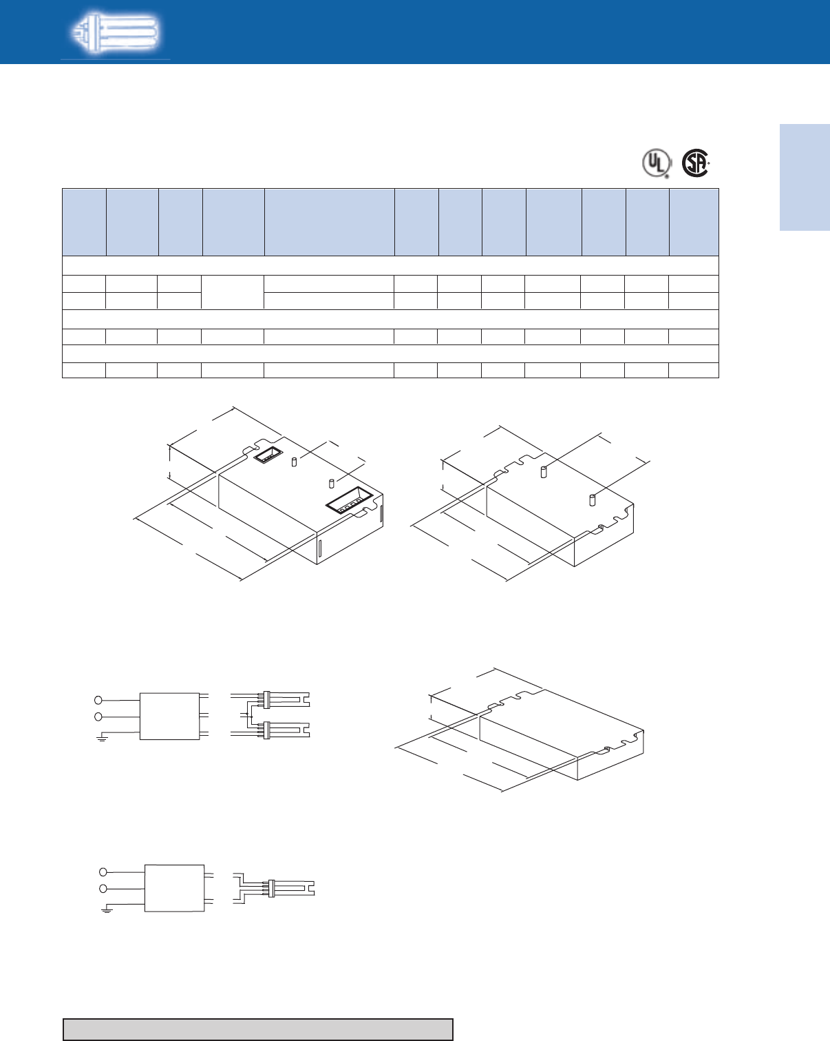
Electronic
Fluorescent Ballasts
ELECTRONIC FLUORESCENT BALLASTS
1-29
Lighting Electronics Atlas 2010-2011
HIGH POWER FACTOR SOUND RATED A
T4
For 60-120W Lamps
No. of
Lamps Dim. Wiring
Dia.
Min.
Starting
Temp.
(°F/°C)
Input
Volts
Ballast
Family
Lamp
Starting
Method
Catalog Number
Line
Current
(Amps)
Input
Power
ANSI
(Watts)
Ballast
Factor
Max.
THD
%
1
2
1
1
-22/-30
-22/-30
-22/-30
-22/-30
SmartMate
SmartMate
SmartMate
Size 4
Size 4
Size 4
Size 4
160
159
160
160
PS
PS
PS
PS
0.59-0.26
1.16-0.50
0.82-0.36
1.16-0.50
70
139-136
98-97
139-136
1.00
1.00
1.00
1.00
15
10
10
10
120-277
120-277
120-277
120-277
60W PLH (PL-H60W/4P)
85W PLH (PL-H85W/4P)
120W PLH (PL-H120W/4P)
ICF-1H120-M4-LD
ICF-1H120-M4-LD
ICF-1H120-M4-LD
ICF-1H120-M4-LD
4.60"
4.20"
0.98"
2.40"
2.00"
STUDS FOR -BS MODELS ONLY
-LD MODELS DO NOT HA
VE MOUNTING STUDS
4.55"
4.20"
1.29"
3.00" 2.00"
STUDS FOR -BS MODELS ONLY
-LD MODELS DO NOT HAVE MOUNTING STUDS
7.50"
7.00"
1.29"
3.00"
Refer to pages 9-24 to 9-28 for lead lengths and shipping data
WIRING: (2) LAMP
LINE
BLACK
WHITE
GREEN
GREEN TERMINAL MUST BE GROUNDED
BLUE
RED
YELLOW
BALLAST
Diag. 159
Note: For AmbiStar 1-lamp operation on 2-lamp
ballast, use red and blue connectors
Diag. 160
WIRING: (1) LAMP
LINE
BLACK
WHITE
GREEN
GREEN TERMINAL MUST BE GROUNDED
BLUE
RED
BALLAST
Size 2 Enclosure
Size 4 Enclosure
Size 1 Enclosure
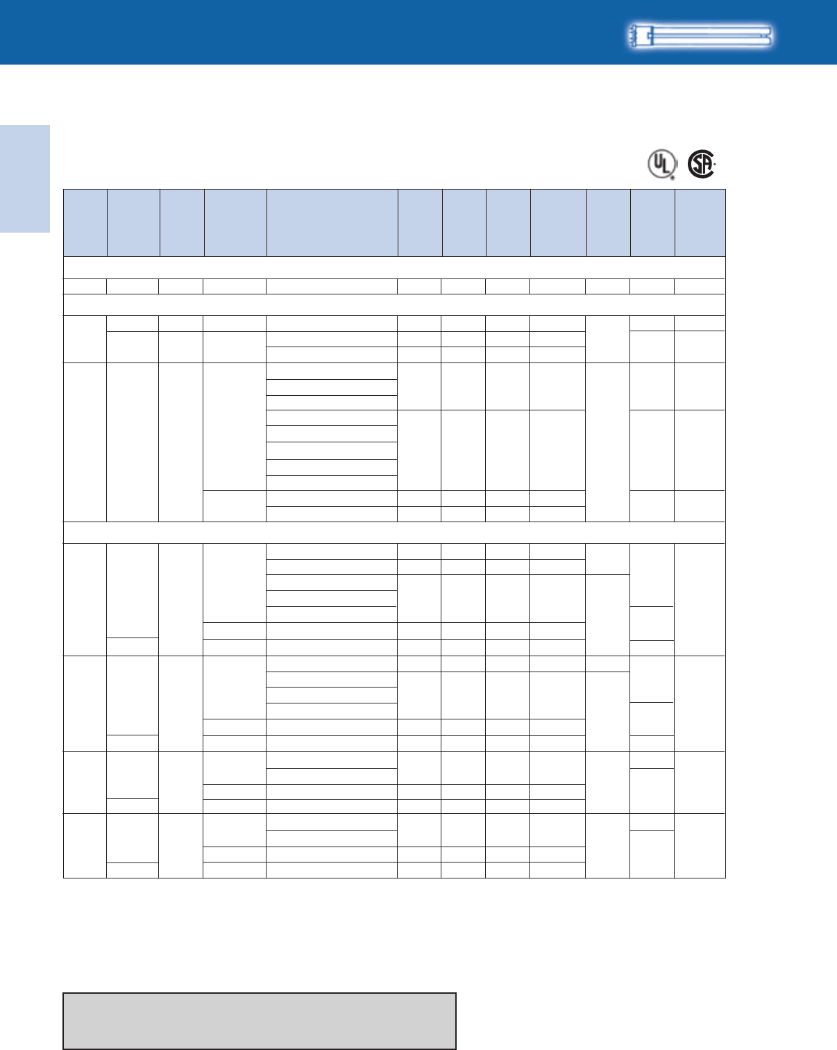
Lighting Electronics Atlas 2010-2011
1-30
ELECTRONIC FLUORESCENT BALLASTS
Electronic
Fluorescent Ballasts
HCN-2S54-90C-WL
No. of
Lamps Dim. Wiring
Dia.
Min.
Starting
Temp.
(°F/°C)
Input
Volts
Ballast
Family
Lamp
Starting
Method
Catalog Number
Line
Current
(Amps)
Input
Power
ANSI
(Watts)
Ballast
Factor
Max.
THD
%
HIGH POWER FACTOR SOUND RATED A
FT5
For 18-36W Lamps
RMB-1P26-S2*1 0/-18 S2 160IS AmbiStar 0.3723 1.00 150120
FT18W/2G11/RS - 18W (F18BX/RS, FT18DL/RS)
FT24W/2G11 - 24/27W (PL-L24W, F27BX/RS, FT24DL)
FT36W/2G11 - 36/39W (PL-L36W, F39BX/RS, FT36DL)
RMB-1P26-S2*
ICN-2S24+
ICN-2S39
ICF-2S26-H1-LD
ICF-2S26-H1-LD-K ❿
ICF-2S26-M1-BS
ICF-2S42-M2-BS
ICF-2S42-M2-LD
ICF-2S42-M2-LD-K ❿
ICF-2S42-90C-M2-BS
ICF-2S42-90C-M2-LD
ICN-2S24+
ICN-2S39
ICN-2S24+
ICN-2S39
ICN-2S54+
ICN-2S54-90C+
ICN-2S54-90C-SC
IOP-2PSP54-SC
1
2
1
0/-18
0/-18
0/-18
120-277
120
120-277
120-277
AmbiStar
Centium
Centium
PS
Centium
SmartMate
IS
PS
PS
0.40
0.23-0.10
0.24-0.12
0.44-0.19
0.46-0.20
0.29-0.13
0.30-0.13
26
27
29
52
54
34
36
0.95
1.02
1.12
1.00
1.10
0.90
0.96
150
10
15
0.41-0.1848 0.93 10
0.40-0.1848 0.93 15
10
10
10
15
0.39-0.1846 1.22 20
0.39-0.1846 1.20 10
0.73-0.3188-85 1.20 10
1.07-0.31128-127 1.20 10
1.42-0.61170-167 1.20 10
S2
D
Size 1
Size 2
D
B
D
160
73
160
159
74A
73
-20/-29
ICN-2S39
ICN-2S54+
ICN-2S54-90C+
ICN-2S54-90C-SC
IOP-2PSP54-SC
2
0/-18
120-277
347-480 Centium
Centium
Centium
Centium
Optanium
Optanium
Optanium
Optanium
PS
Centium
0.13-0.10
0.59-0.25
46
69
1.22
0.94
15
10
0.75-0.3289-86 1.20 10
D
74A
-20/-29
HCN-2S54-90C-WL L
ICN-4S54-90C-2LS-G
IOP-4P2P54-2LS-G
347-480 0.26-0.1989 1.20 10
ICN-4S54-90C-2LS
ICN-4S54-90C-2LS-G
IOP-4P2P54-2LS-G
HCN-4S54-90C-2LS-G
ICN-4S54-90C-2LS
HCN-4S54-90C-2LS-G
3 -20/-29
120-277
347-480
120-277
347-480
PS
Centium
0.40-0.29
0.53-0.38
137-135
182-180
1.20
1.20
1.11-0.49133-132 1.20 10
10
1.47-0.64176-173 1.20 10
10
E
G
E
G
75A
-20/-29
4PS
Centium
75
L
* Normal Power Factor.
+ Also available with leads (ICN-2S24-WL, ICN-2S54-WL, or ICN-2S54-90C-WL)
❿
Replacement/Retrofit ballast kits indicated with suffix K are available to distributors. Refer to page 1-21 for details.
Refer to pages 1-31 and 1-32 for dimensions
Refer to page 1-33 for wiring diagrams
Refer to pages 9-24 to 9-28 for lead lengths and shipping data
B
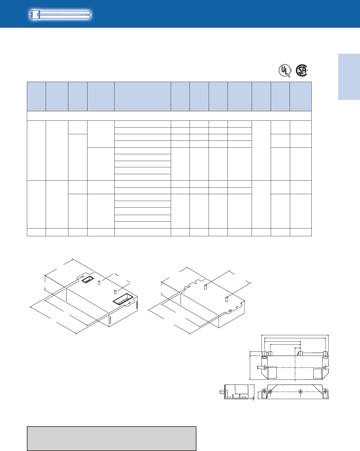
Electronic
Fluorescent Ballasts
ELECTRONIC FLUORESCENT BALLASTS
1-31
Lighting Electronics Atlas 2010-2011
FT40W/2G11/RS - 40W (PL-L40W, F40BX, FT40DL/RS)
HIGH POWER FACTOR SOUND RATED A
FT5
For 40W Lamps
No. of
Lamps Dim. Wiring
Dia.
Min.
Starting
Temp.
(°F/°C)
Input
Volts
Ballast
Family
Lamp
Starting
Method
Catalog Number
Line
Current
(Amps)
Input
Power
ANSI
(Watts)
Ballast
Factor
Max.
THD
%
ICN-1TTP40-SC
ICN-2TTP40-SC
ICN-2S24*+
ICN-2S39
ICF-2S42-M2-BS
ICF-2S42-M2-LD
ICF-2S42-M2-LD-K ❿
ICF-2S42-90C-M2-BS
ICF-2S42-90C-M2-LD
ICN-2TTP40-SC
ICN-3TTP40-SC
ICF-2S42-M2-BS
ICF-2S42-M2-LD
ICF-2S42-M2-LD-K ❿
ICF-2S42-90C-M2-BS
ICF-2S42-90C-M2-LD
ICN-3TTP40-SC
1
2
3
0/-18
0/-18
0/-18
B
D
Size 2
B
Size 2
B
IS
PS
IS
PS
IS
Centium
SmartMate
Centium
SmartMate
Centium
0.33-0.14
0.35-0.15
0.40-0.17
0.42-0.19
0.37-0.16
0.57-0.25
0.61-0.27
0.83-0.35
39
41
47
50
44
67
72
99
0.90
1.00
1.00
1.10
0.95
0.88
0.96
0.88
10
10
10
10
10
10
10
0.66-0.28
78 0.95 10
10
120-277
120-277
120-277
70
73
160
71
159
72
2 LAMP RECTANGULAR BALLAST, PLASTIC ENCLOSURE
INPUT SIDE OUTPUT SIDE
#6 - 20 THREAD FORMING
.25” LONG SCREWS
0.116” HOLES
4.41"
4.01"
2.38"
.28"1.57"
.17"
.47"
.94"
.06"
2.0"
3.6"
Refer to page 1-32 for additional dimensions
Refer to page 1-33 for wiring diagrams
Refer to pages 9-24 to 9-28 for lead lengths and shipping data
4.60"
4.20"
0.98"
2.40"
2.00"
STUDS FOR -BS MODELS ONLY
-LD MODELS DO NOT HA
VE MOUNTING STUDS
4.55"
4.20"
1.29"
3.00" 2.00"
STUDS FOR -BS MODELS ONLY
-LD MODELS DO NOT HAVE MOUNTING STUDS
Size 2 Enclosure
S2 Model
Size 1 Enclosure
* Normal Power Factor.
+ Also available with leads (ICN-2S24-WL, ICN-2S54-WL, or ICN-2S54-90C-WL)
❿
Replacement/Retrofit ballast kits indicated with suffix K are available to distributors. Refer to page 1-21 for details.
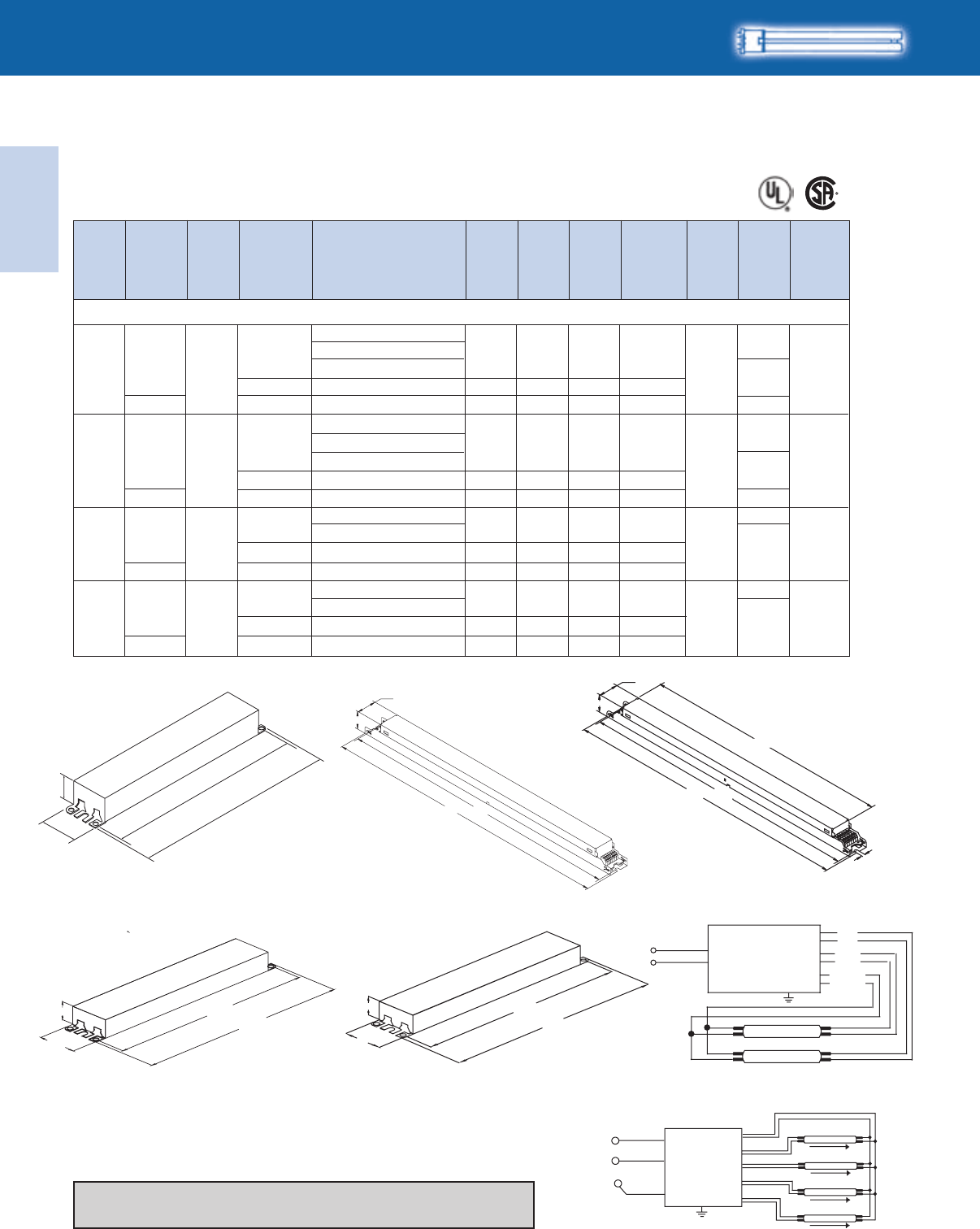
Lighting Electronics Atlas 2010-2011
1-32
ELECTRONIC FLUORESCENT BALLASTS
Electronic
Fluorescent Ballasts
IOP-2PSP54-90C-SC
8.90"
9.5"
1.18"
1.7"
1.18"
1.00"
16.70" 16.34"
.31"
24.0" 23.64"
1.0"
1.18"
21.3" 4 LAMP T5HO BALLAST
16.34"
16.70"
1.18"
1.00"
LAMP
LAMP
BALLAST
BLUE
RED
YELLOW
BLACK
WHITE
LAMP
LAMP
LAMP
LAMP
BALLAST
BLUE
BLUE/WHITE
RED
YEL/BLU
BROWN
GREY/RED
BLACK
WHITE
No. of
Lamps Dim. Wiring
Dia.
Min.
Starting
Temp.
(°F/°C)
Input
Volts
Ballast
Family
Lamp
Starting
Method
Catalog Number
Line
Current
(Amps)
Input
Power
ANSI
(Watts)
Ballast
Factor
Max.
THD
%
HIGH POWER FACTOR SOUND RATED A
FT5
For 50W Lamps
ICN-2S54+
ICN-2S54-90C+
ICN-2S54-90C-SC
1-20/-29
D
D
B
B
PS
Centium 0.51-0.2361 1.12 15
120-277
FT50W/2G11/RS - 50W (PL-L50W, F50BX/RS)
73
Fig. B Fig. D
Includes connectors with no leads
Fig. E
16.34"
16.70"
1.18"
1.70"
Refer to page 1-33 for wiring diagrams
Refer to pages 9-24 to 9-28 for lead lengths and shipping data
Fig. G Fig. L Diag. 78
Diag. 79
+Also available with leads (ICN-2S24-WL, ICN-2S54-WL, or ICN-2S54-90C-WL)
ICN-2S54+
ICN-2S54-90C+
ICN-2S54-90C-SC
IOP-2PSP54-SC
2-20/-29
PS
Centium 0.99-0.43118-115 1.10 10
120-277 74A
0.18-0.1361 1.12 10
347-480 HCN-2S54-90C-WL L
0.34-0.25118 1.10 10
347-480
ICN-4S54-90C-2LS
ICN-4S54-90C-2LS-G
IOP-4PSP54-2LS-G
3-20/-29
E
G
PS
Centium 1.49-0.65178-175 1.10 10
120-277 75A
HCN-4S54-90C-2LS-G
ICN-4S54-90C-2LS
ICN-4S54-90C-2LS-G
IOP-4PSP54-2LS-G -20/-29
E
G
4 PS
Centium
0.54-0.39
1.96-0.84
185-183
235-230
1.10
1.10
10
10
347-480
120-277 75
HCN-4S54-90C-2LS-G 0.68-0.49236-234 1.10 10
347-480
HCN-2S54-90C-WL L
1.90-0.81228-223 1.10 10
1.44-0.62172-169 1.10 10
0.97-0.42117-114 1.10 10
0.51-0.2361 1.10 10
Centium
Centium
Centium
Centium
Optanium
Optanium
Optanium
Optanium
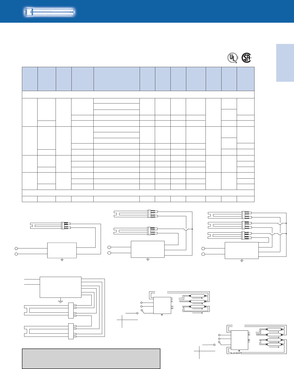
Electronic
Fluorescent Ballasts
ELECTRONIC FLUORESCENT BALLASTS
1-33
Lighting Electronics Atlas 2010-2011
ICN-2S54-90C-SC
IOP-2PSP54-90C-SC
ICN-2S54-90C-SC
IOP-2PSP54-90C-SC
FT55W/2G11 - 55W (PL-L55W, F55BX, FT55DL)
ICN-2S54-90C+
HIGH POWER FACTOR SOUND RATED A
FT5
For 55-80W Lamps
No. of
Lamps Dim. Wiring
Dia.
Min.
Starting
Temp.
(°F/°C)
Input
Volts
Ballast
Family
Lamp
Starting
Method
Catalog Number
Line
Current
(Amps)
Input
Power
ANSI
(Watts)
Ballast
Factor
Max.
THD
%
ICN-2S54+
1-20/-29
PS
Centium 0.49-0.2258 0.92 15
120-277 73
D
L
78
78
79
79
74A
73
ICN-2S54+
ICN-2S54-90C+
2-20/-29
PS
Centium
0.17-0.1358 0.92 10
0.94-0.41112-109 0.90 10
347-480
120-277 74A
HCN-2S54-90C-WL
D
HCN-4S54-90C-2LS-G
ICN-4S54-90C-2LS-G
IOP-4PSP54-2LS-G
4 -20/-29 G
PS
Centium
0.52-0.37
1.86-0.80
178-176
222-217
0.90
0.90
10
10
347-480
120-277
HCN-4S54-90C-2LS-G
ICN-1S801 0/-18 DPS Centium
0.66-0.47228-226
91-89
0.90
1.00
10
10
347-480
120-277
FT80W/2G11 - 80W (PL-L80W, FT80DL)
73
0.76-0.33
0.33-0.24112 0.90 10
347-480
ICN-4S54-90C-2LS-G
3-20/-29 G
PS
Centium 1.41-0.61169-166 0.90 10
120-277 75A
75
75A
75
IOP-4PSP54-2LS-G
HCN-2S54-90C-WL L
B
B
WHITE
BLACK
BALLAST BLUE
BLUE
RED WHITE
BLACK
BALLAST BLUE
BLUE
BLUE
RED
WHITE
BLACK
LINE
BALLAST
BLUE
BLUE
YELLOW
YELLOW
RED
RED
250V,
1mA
BLACK
WHITE
GREY/RED
NUETRAL OR
(ANY HOT)
BALLAST
RED
ORANGE
BLUE
BROWN
YELLOW
LAMP
LAMP
LAMP
LAMPS
S
S
ON
OFF
3 LAMPS ON
3-LAMP
2 LAMPS ON
WHITE
BLACK/WHITE
BALLAST
BLUE
RED
Diag. 74A
BLACK
WHITE
GREY/RED
BALLAST
ORANGE
RED
BLUE
BROWN
YELLOW
250V,
1mA
S
4-LAMP
NUETRAL OR
(ANY HOT)
LAMPS
S
ON
OFF
4 LAMPS ON
2 LAMPS ON
LAMP
LAMP
LAMP
LAMP
Diag. 75A
Diag. 75
Refer to page 1-32 for dimensions
Refer to page 1-37 for diagram 73 and page 1-32 for diagrams 78 and 79.
Refer to pages 9-24 to 9-28 for lead lengths and shipping data
Diag. 70 Diag. 71 Diag. 72
+ Also available with leads (ICN-2S24-WL, ICN-2S54-WL, or ICN-2S54-90C-WL)
217-212 0.90 10 1.81-0.77
1.37-0.59164-161 0.90 10
0.92-0.40110-108 0.90 10
0.49-0.2258 0.90 10
Centium
Centium
Centium
Centium
Optanium
Optanium
Optanium
Optanium
Lighting Electronics Atlas 2010-2011
1-34
ELECTRONIC FLUORESCENT BALLASTS
Electronic
Fluorescent Ballasts
ICF-2S13-H1-LD
ICF-2S13-H1-LD-K ❿
ICF-2S13-M1-BS
ICF-2S13-H1-LD
ICF-2S13-H1-LD-K ❿
ICF-2S13-M1-BS
2
1
2
1
2
0/-18
0/-18
0/-18
0/-18
0/-18
Size 1
Size 1
Size 1
Size 1
Size 1
PS
PS
PS
PS
PS
SmartMate
SmartMate
SmartMate
SmartMate
SmartMate
0.19-0.09
0.14-0.06
0.31-0.13
0.16-0.07
0.33-0.14
0.42-0.18
23
17
37
20
40
51
0.95
1.00
1.00
0.90
0.91
1.12
15
15
10
15
10
10
120-277
120-277
120-277
120-277
120-277
CFS10W/GR10q - 10W 2D Lamp (F10 2D/4P)
CFS16W/GR10q - 16W 2D Lamp (F16 2D/4P)
CFS21W/GR10q - 21W 2D Lamp (F21 2D/4P)
10/-18 Size 1
PS SmartMate 0.11-0.05
13 1.05 15
120-277 160
159
160
159
160
159
ICF-2S13-H1-LD
ICF-2S13-H1-LD-K ❿
ICF-2S13-M1-BS
ICF-2S18-H1-LD
ICF-2S18-H1-LD-K ❿
ICF-2S18-M1-BS
ICF-2S18-H1-LD
ICF-2S18-H1-LD-K ❿
ICF-2S18-M1-BS
ICF-2S18-H1-LD
ICF-2S18-H1-LD-K ❿
ICF-2S18-M1-BS
ICF-2S26-H1-LD
ICF-2S26-H1-LD-K ❿
ICF-2S26-M1-BS
No. of
Lamps Dim. Wiring
Dia.
Min.
Starting
Temp.
(°F/°C)
Input
Volts
Ballast
Family
Lamp
Starting
Method
Catalog Number
Line
Current
(Amps)
Input
Power
ANSI
(Watts)
Ballast
Factor
Max.
THD
%
HIGH POWER FACTOR SOUND RATED A
2D
For 10-21W Lamps
❿
Replacement/Retrofit ballast kits indicated with suffix K are available to distributors. Refer to page 1-21 for details.
Refer to pages 9-24 to 9-28 for lead lengths and shipping data
WIRING: (2) LAMP
LINE
BLACK
WHITE
GREEN
GREEN TERMINAL MUST BE GROUNDED
BLUE
RED
YELLOW
BALLAST
Diag. 159
Note: For AmbiStar 1-lamp operation on 2-lamp
ballast, use red and blue connectors
Diag. 160
WIRING: (1) LAMP
LINE
BLACK
WHITE
GREEN
GREEN TERMINAL MUST BE GROUNDED
BLUE
RED
BALLAST
4.60"
4.20"
0.98"
2.40"
2.00"
STUDS FOR -BS MODELS ONLY
-LD MODELS DO NOT HA
VE MOUNTING STUDS
4.55"
4.20"
1.29"
3.00" 2.00"
STUDS FOR -BS MODELS ONLY
-LD MODELS DO NOT HAVE MOUNTING STUDS
Size 2 Enclosure
Size 1 Enclosure
Electronic
Fluorescent Ballasts
ELECTRONIC FLUORESCENT BALLASTS
1-35
Lighting Electronics Atlas 2010-2011
ICF-1D38-H1-LD
ICF-2S42-M2-BS
ICF-2S42-M2-LD
ICF-2S42-M2-LD-K ❿
ICF-2S42-90C-M2-BS
ICF-2S42-90C-M2-LD
1
2
0/-18
0/-18
Size 1
Size 2
Size 1
Size 2
PS
PS
SmartMate
SmartMate
PS
PS
SmartMate
SmartMate
0.23-0.10
0.48-0.21
0.26-0.11
0.55-0.23
27
57
31
62
1.00
1.00
0.85
0.80
10
10
10
10
120-277
120-277
1
2
0/-18
0/-18
120-277
120-277
CFS28W/GR10q - 28W 2D Lamp (PL-Q 28W/4P, F28 2D/4P)
CFS38W/GR10q - 38W 2D Lamp (PL-Q 38W/4P, F38 2D/4P)
160
159
160
159
ICF-1D38-H1-LD
ICF-2S42-M2-BS
ICF-2S42-M2-LD
ICF-2S42-M2-LD-K ❿
ICF-2S42-90C-M2-BS
ICF-2S42-90C-M2-LD
HIGH POWER FACTOR SOUND RATED A
2D
For 28-38W Lamps
No. of
Lamps Dim. Wiring
Dia.
Min.
Starting
Temp.
(°F/°C)
Input
Volts
Ballast
Family
Lamp
Starting
Method
Catalog Number
Line
Current
(Amps)
Input
Power
ANSI
(Watts)
Ballast
Factor
Max.
THD
%
❿
Replacement/Retrofit ballast kits indicated with suffix K are available to distributors. Refer to page 1-21 for details.
Refer to page 1-34 for dimensions
Refer to pages 9-24 to 9-28 for lead lengths and shipping data
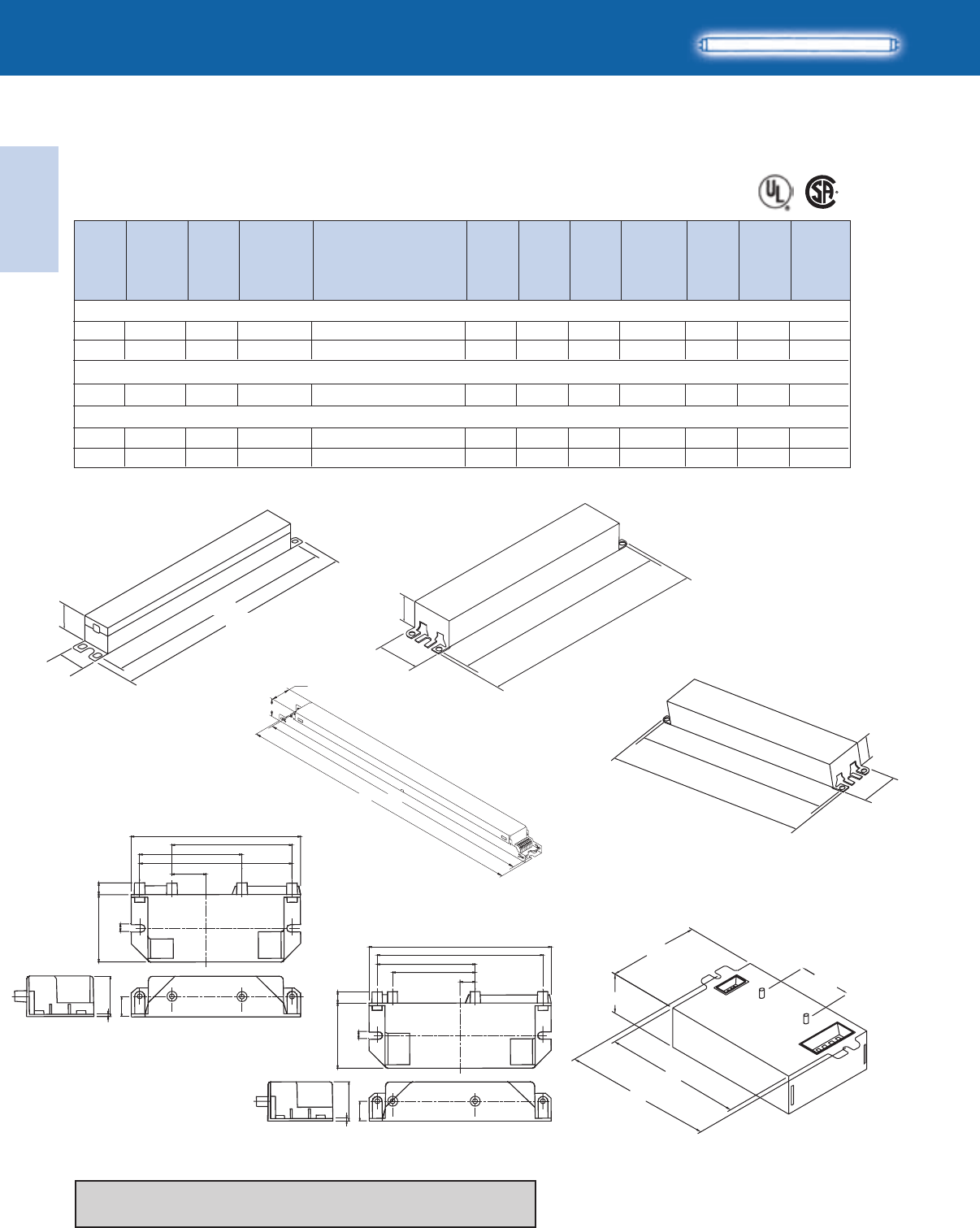
Lighting Electronics Atlas 2010-2011
1-36
ELECTRONIC FLUORESCENT BALLASTS
Electronic
Fluorescent Ballasts
No. of
Lamps Dim. Wiring
Dia.
Min.
Starting
Temp.
(°F/°C)
Input
Volts
Ballast
Family
Lamp
Starting
Method
Catalog Number
Line
Current
(Amps)
Input
Power
ANSI
(Watts)
Ballast
Factor
Max.
THD
%
HIGH POWER FACTOR SOUND RATED A
T5
For 8-13W Lamps
1 LAMP RECTANGULAR BALLAST, PLASTIC ENCLOSURE
INPUT SIDE OUTPUT SIDE
#6 - 20 THREAD FORMING
.25” LONG SCREWS
0.116” HOLES
3.54"
2.38"
0.80"
.28"1.57"
.17"
.47"
.94"
.06"
2.0"
3.15"
1 0/-18 S1
S2
IS
IS
AmbiStar
AmbiStar
0.16
0.27
10
19
1.30
1.30
150
125
120
20/-18
120
10/-18
120
F8T5 (8W)
(1) F8T5 & (1) F13T5 {(1) 8W & (1) 13W}
F13T5 (13W)
1 0/-18120
2 0/-18120
163
162
S1
S2
IS
IS
AmbiStar
AmbiStar
0.21
0.38
14
27
1.00
0.95
150
125
163
162
S1
IS AmbiStar 0.3323 1.10 125 162
RMB-1P13-S1*
RMB-2P13-S2*
RMB-2P13-S2*
RMB-1P13-S1*
RMB-2P13-S2*
* Normal Power Factor
Refer to page 1-37 for wiring diagrams
Refer to pages 9-24 to 9-28 for lead lengths and shipping data
8.90"
9.5"
1.18"
1.7"
1.08"
1.05" 8.91"
9.50"
1.18"
1.00"
16.70" 16.34"
1.0”
1.3”
9.5”
8.9”
Fig. BFig. A2
Fig. D Fig. N
4.60"
4.20"
0.98"
2.40"
2.00"
STUDS FOR -BS MODELS ONLY
-LD MODELS DO NOT HA
VE MOUNTING STUDS
2 LAMP RECTANGULAR BALLAST, PLASTIC ENCLOSURE
INPUT SIDE OUTPUT SIDE
#6 - 20 THREAD FORMING
.25” LONG SCREWS
0.116” HOLES
4.41"
4.01"
2.38"
.28"1.57"
.17"
.47"
.94"
.06"
2.0"
3.6"
S2 Model Size 1 Enclosure
S1 Model
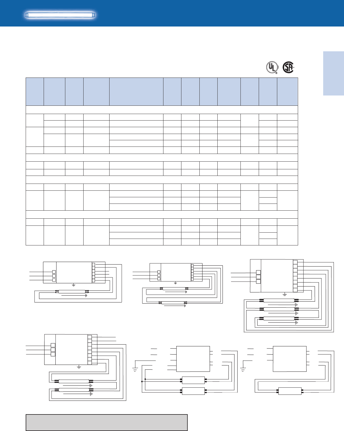
Electronic
Fluorescent Ballasts
ELECTRONIC FLUORESCENT BALLASTS
1-37
Lighting Electronics Atlas 2010-2011
HIGH POWER FACTOR SOUND RATED A
No. of
Lamps Dim. Wiring
Dia.
F14T5 (14W)
Min.
Starting
Temp.
(°F/°C)
Input
Volts
Ballast
Family
Lamp
Starting
Method
Catalog Number
Line
Current
(Amps)
Input
Power
ANSI
(Watts)
Ballast
Factor
Max.
THD
%
T5
For 14-35W Lamps
* Normal Power Factor.
RMB-1P13-S1*
ICN-2S28-N
RMB-2P13-S2*
ICN-2S28-N
ICN-3S14-D
ICN-3S14-D
10/-18 S1
IS
PS
AmbiStar
Centium
0.2114 0.95 150
0.14-0.0717 1.07 10
120
120-277
2
3
0/-18
0/-18
0/-18
120
120-277
120-277
163
73
L2
N
D
IS
PS
PS
AmbiStar
Centium
Centium
0.40
0.28-0.13
0.31-0.13
0.42-0.18
27
33
36
50
0.90
1.04
1.10
1.00
125
10
10
10
162
74
172
171
N
D
10/-18
120-277
20/-18
120-277
F21T5 (21W)
Centium
Centium
N0.22-0.1025 1.06 10 73
N0.43-0.1949 1.02 10 74
ICN-2S28-N
ICN-2S28-N
PS
PS
Refer to page 1-36 for dimensions
Refer to pages 9-24 to 9-28 for lead lengths and shipping data
0/-18
F28T5 (28W)
N0.29-0.1231 1.05 10 73
ICN-2S28-N
1 120-277 CentiumPS
0/-18 B
N
B
0.55-0.22
0.59-0.23
0.60-0.26
59-58
62-61
71-69
0.95
1.00
1.15
10
10
10
74
IOP-2S28-95-SC
ICN-2S28-N
IOP-2S28-115-SC
2 120-277 Centium
PS
0/-18
0/-18
F28T5 (25W)
N0.25-0.1130 1.05 10 73
B
N
B
0.45
0.49-0.21
0.53-0.23
54
58-57
63
0.95
1.00
1.15
10
10
10
74
ICN-2S28-N
IOP-2S28-95-SC
ICN-2S28-N
IOP-2S28-115-SC
1 120-277 CentiumPS
2 120-277 Centium
PS
WHITE
LAMP
RED
RED
YELLOW
YELLOW
BLUE
BLUE
FOR 1 LAMP OPERATION, DO NOT USE YELLOW LEADS
BLACK
GREEN BALLAST
LAMP
LAMP
RED
RED
YELLOW
YELLOW
BLUE
BLUE
WHITE
BLACK
GREEN BALLAST
LAMP
LAMP
LAMP
RED
RED
YELLOW
YELLOW
BLUE
BLUE
BLUE/WHT
BLUE/WHT
WHITE
BLACK
GREEN
3-LAMP
BALLAST
Diag. 73 Diag. 74
Diag. 171
LAMP
LAMP
RED
RED
YELLOW
YELLOW
BLUE
BLUE
BLUE/WHT
BLUE/WHT
WHITE
BLACK
GREEN
2-LAMP
BALLAST BLACK
WHITE
GREEN
YELLOW
GREEN TERMINAL MUST BE GROUNDED
BLUE
RED
LAMP
LAMP
BALLAST
BLACK
WHITE
GREEN
GREEN TERMINAL MUST BE GROUNDED
BLUE
RED
LAMP
BALLAST
Diag. 172 Diag. 162 Diag. 163
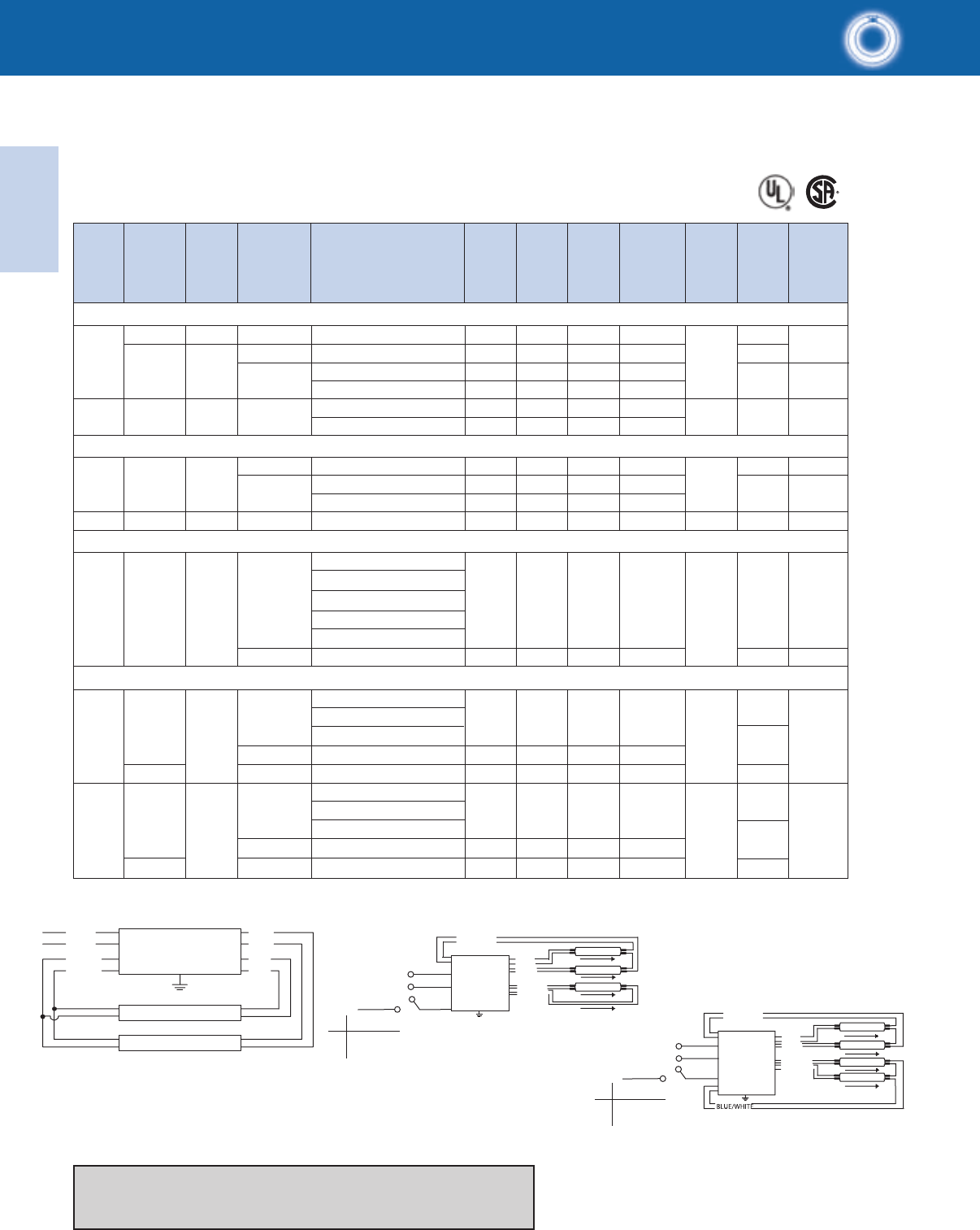
Lighting Electronics Atlas 2010-2011
1-38
ELECTRONIC FLUORESCENT BALLASTS
Electronic
Fluorescent Ballasts
55
HIGH POWER FACTOR SOUND RATED A
* Normal Power Factor.
+ Also available with leads (ICN-2S24-WL, ICN-2S54-WL, or ICN-2S54-90C-WL)
T5 & T5HO
For 22-55W Lamps
No. of
Lamps Dim. Wiring
Dia.
Min.
Starting
Temp.
(°F/°C)
Input
Volts
Ballast
Family
Lamp
Starting
Method
Catalog Number
Line
Current
(Amps)
Input
Power
ANSI
(Watts)
Ballast
Factor
Max.
THD
%
RMB-1P26-S2*
ICF-1D38-H1-LD
ICN-2S24+
ICN-2S39
ICN-2S24+
ICN-2S39
1
2
1
1&1
1
2
0/-18
0/-18
0/-18
0/-18
0/-18
0/-18
S2
Size 1
D
D
Size 1
D
Size 2
D
L
L
B
B
D
IS
PS
PS
PS
PS
PS
PS
AmbiStar
SmartMate
Centium
SmartMate
Centium
SmartMate
Centium
Centium
Centium
0.39
0.21-0.09
0.23-0.10
0.24-0.12
25
25
27
29
1.00
1.00
1.02
1.12
150
15
10
15
0.44-0.19
0.46-0.20
52
54
1.00
1.10
10
10
120
120-277
120-277
120-277
120-277
120-277
120-277
FC9T5 (22W Circline)
FC12T5 (40W Circline)
(1) FC9T5 & (1) FC12T5 {(1) 22W & (1) 40W Circline}
FC12T5/HO (55W Circline)
163
73
74
163
73
162
74
74
ICF-1D38-H1-LD
ICN-2S24+
ICN-2S39
ICN-2S39
0.32-0.14
0.34-0.15
0.35-0.16
0.68-0.29
38
40
0.95
0.84
0.92
0.90
42
80
10
10
10
10
ICF-2S42-M2-BS
ICF-2S42-M2-LD
ICF-2S42-M2-LD-K ❿
ICN-2S39
ICF-2S42-90C-M2-BS
ICF-2S42-90C-M2-LD
0.51-0.22
0.58-0.25
61
68
0.85
1.00
10
10
ICN-2S54*+
ICN-2S54-90C*+
ICN-2S54-90C-SC
IOP-2PSP54-90C-SC
Centium 0.46-0.2155 0.87 15 D
D
73
0/-18 74
2 PS
347-480
120-277
HCN-2S54-90C-WL
ICN-2S54*+
ICN-2S54-90C*+
ICN-2S54-90C-SC
IOP-2PSP54-90C-SC
Centium
0.16-0.120.87 10
0.89-0.38106-103 0.85 10
347-480 HCN-2S54-90C-WL 0.31-0.22106 0.85 10
Refer to page 1-36 for dimensions
Refer to page 1-37 for diagrams 73, 74, 162 and 163
Refer to pages 9-24 to 9-28 for lead lengths and shipping data
BLACK
WHITE
GREY/RED
BALLAST
ORANGE
RED
BLUE
BROWN
YELLOW
250V,
1mA
S
4-LAMP
NUETRAL OR
(ANY HOT)
LAMPS
S
ON
OFF
4 LAMPS ON
2 LAMPS ON
LAMP
LAMP
LAMP
LAMP
WHITE
YELLOW
YELLOW
BLACK
LINE
BALLAST
LAMP
LAMP
BLUE
BLUE
RED
RED
Diag. 75A
Diag. 21
250V,
1mA
BLACK
WHITE
GREY/RED
NUETRAL OR
(ANY HOT)
BALLAST
RED
ORANGE
BLUE
BROWN
YELLOW
LAMP
LAMP
LAMP
LAMPS
S
S
ON
OFF
3 LAMPS ON
3-LAMP
2 LAMPS ON
Diag. 75
0.4453 0.85 10
0.86-0.36103-100 0.85 10
Centium
Centium
Optanium
Optanium
Electronic
Fluorescent Ballasts
ELECTRONIC FLUORESCENT BALLASTS
1-39
Lighting Electronics Atlas 2010-2011
Optanium
75
75A
G
G
HCN-2S54-90C-WL
ICN-2S54-90C-SC
ICN-2S54+
ICN-2S54-90C+0.93-0.40112-109 1.00 10
-20/-29PS
Centium
120-277
F54T5/HO (49W)
73
ICN-2S54+
ICN-2S54-90C+
1
0.49-0.2158 1.02 10 D
IOP-2PSP54-SC B
75
75A
0.35-0.25112-109 1.00 10 74
74
L
E
E
347-480
-20/-29
-20/-29
-20/-29
79
79
PS
PS
Centium
Centium
347-480
120-277
120-277
120-277
347-480
347-480
73
78
78
ICN-4S54-90C-2LS
ICN-4S54-90C-2LS
ICN-4S54-90C-2LS-G
ICN-4S54-90C-2LS-G
IOP-4PSP54-2LS-G
IOP-4PSP54-2LS-G
HCN-4S54-90C-2LS-G
HCN-4S54-90C-2LS-G
PS
Centium
2
3
4
0.18-0.13
1.35-0.58
1.79-0.76
0.54-0.39
0.69-0.50
58
162-159
224-208
175-172
223-221
1.02
1.00
1.00
1.00
1.00
10
1.52-0.66168-165 1.00 10
2.00-0.86222-216 1.00 10
10
10
10
10
ICN-2S54-90C-SC
IOP-2PSP54-SC
HCN-2S54-90C-WL
B
L
D
No. of
Lamps
HIGH POWER FACTOR SOUND RATED A
Dim. Wiring
Dia.
Min.
Starting
Temp.
(°F/°C)
Input
Volts
Ballast
Family
Lamp
Starting
Method
Catalog Number
Line
Current
(Amps)
Input
Power
ANSI
(Watts)
Ballast
Factor
Max.
THD
%
For 24-54W Lamps
T5HO
ICN-2S24+
ICN-2S39
ICN-2S24+
ICN-2S39
1
2
1
2
0/-18
0/-18
0/-18
0/-18
D
D
D
D
PS
PS
PS
PS
Centium
Centium
Centium
Centium
0.23-0.10
0.25-0.12
0.44-0.19
0.47-0.21
27
29
52
55
1.02
1.12
1.00
1.10
10
15
10
10
120-277
120-277
120-277
120-277
F24T5/HO (24W)
F39T5/HO (39W)
73
74
73
74
ICN-2S24+
ICN-2S39
ICN-2S39
0.34-0.15
0.36-0.16
0.73-0.31
40
43
87-85
0.90
1.02
1.00
10
10
10
Refer to pages 1-37 and 1-38 for wiring diagrams
Refer to page 1-40 for dimensions B, D, G, L, and E
Refer to pages 9-24 to 9-28 for lead lengths and shipping data
4.60"
4.20"
0.98"
2.40"
2.00"
STUDS FOR -BS MODELS ONLY
-LD MODELS DO NOT HA
VE MOUNTING STUDS
Size 1 Enclosure
+ Also available with leads (ICN-2S24-WL, ICN-2S54-WL, or ICN-2S54-90C-WL)
0.47-0.2157 1.00 10
0.91-0.38109-105 1.00 10
Centium
Centium
Centium
Centium
Optanium
Optanium
Optanium
LAMP
LAMP
BALLAST
BLUE
RED
YELLOW
BLACK
WHITE
LAMP
LAMP
LAMP
LAMP
BALLAST
BLUE
BLUE/WHITE
RED
YEL/BLU
BROWN
GREY/RED
BLACK
WHITE
Diag. 78 Diag. 79
Lighting Electronics Atlas 2010-2011
1-40
ELECTRONIC FLUORESCENT BALLASTS
Electronic
Fluorescent Ballasts
HIGH POWER FACTOR SOUND RATED A
T5HO
For 54-80W Lamps
No. of
Lamps Dim. Wiring
Dia.
Min.
Starting
Temp.
(°F/°C)
Input
Volts
Ballast
Family
Lamp
Starting
Method
Catalog Number
Line
Current
(Amps)
Input
Power
ANSI
(Watts)
Ballast
Factor
Max.
THD
%
Refer to page 1-37 and 1-38 for wiring diagrams
Refer to pages 9-24 to 9-28 for lead lengths and shipping data
8.90"
9.5"
1.18"
1.7"
1.18"
1.00"
16.70" 16.34"
16.34"
16.70"
1.18"
1.00"
Fig. B Fig. D
Includes connectors with no leads
16.34"
16.70"
1.18"
1.70"
Fig. G Fig. L
75A
75
75
75
B
0.35-0.25120-119 1.00 10 74
74
ICN-2S54+
ICN-2S54-90C+
ICN-2S54-90C-SC
HCN-2S54-90C-WL L
347-480
-20/-29
-20/-29
-20/-29
-20/-29
TBD
TBD
E
E
TBD
TBD
G
G
PS
PS
PS
PS
Centium
Centium
Centium
Centium
120-277
347-480
120-277
120-277
120-277
F54T5/HO (54W)
73
73
ICN-2S54+
ICN-2S54-90C+
ICN-2S54-90C-SC
ICN-4S54-90C-2LS
ICN-4S54-90C-2LS
ICN-4S54-90C-2LS-G
ICN-4S54-90C-2LS-G
IOP-4PSP54-2LS-G
IOP-4PSP54-2LS-G
1
2
3
4
0.18-0.1362 1.02
0.52-0.2362 1.02 10
10
1.00-0.43120-117 1.00 10
1.52-0.66182-179 1.00 10
2.00-0.86240-234 1.00 10
347-480 HCN-4S54-90C-2LS-G 0.54-0.39188-186 1.04 10
347-480 HCN-4S54-90C-2LS-G 0.69-0.50239-237 1.00 10
IOP-2PSP54-SC
HCN-2S54-90C-WL
D
B
L
D
0/-18PS Centium120-277 731
F80T5/HO (80W)
ICN-1S80 0.76-0.3391-89 1.00 10 D
+ Also available with leads (ICN-2S24-WL, ICN-2S54-WL, or ICN-2S54-90C-WL)
Optanium 0.50 - 0.2260 1.00 10
Centium
Optanium 0.98 - 0.41117-114 1.00 10
Centium
Optanium 1.47-0.83176-174 1.00 10
Centium
Optanium 1.96-0.83235-229 1.00 10
Centium
IOP-2PSP54-SC
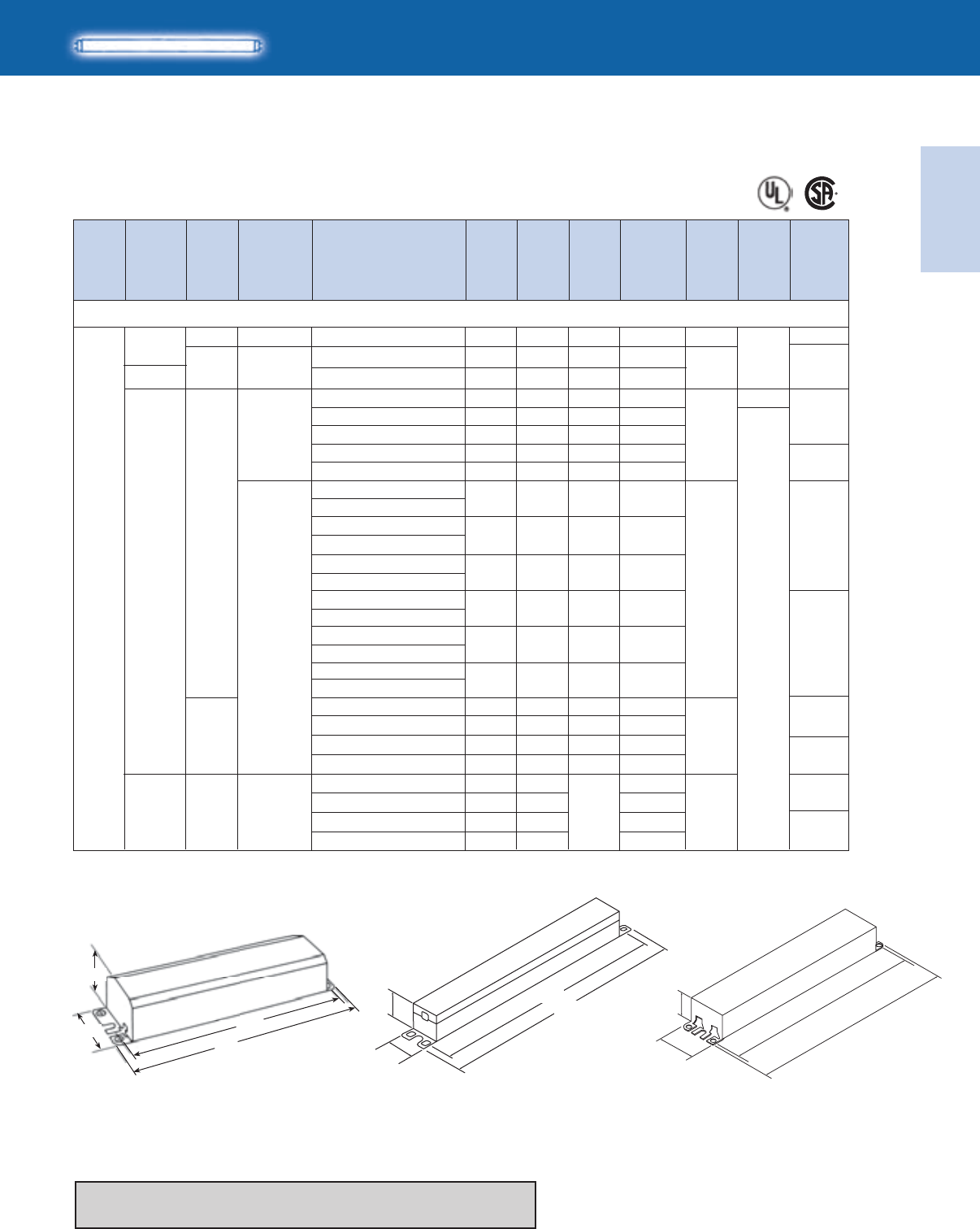
Electronic
Fluorescent Ballasts
ELECTRONIC FLUORESCENT BALLASTS
1-41
Lighting Electronics Atlas 2010-2011
Optanium
IOP-1S32-LW-SC
IOP-1S32-SC
IOP-2S32-LW-SC
IOP-2S32-SC
0/-18
0.12-0.0615 0.78 15
IOP-2P32-HL-SC
IOPA-2P32-HL-SC
‡ The above AmbiStar ballasts are normal power factor and labeled ‘For Residential Use Only’
No. of
Lamps
HIGH POWER FACTOR SOUND RATED A
Dim. Wiring
Dia.
Min.
Starting
Temp.
(°F/°C)
Input
Volts
Ballast
Family
Lamp
Starting
Method
Catalog Number
Line
Current
(Amps)
Input
Power
ANSI
(Watts)
Ballast
Factor
Max.
THD
%
T8
For 17W Lamps
REB-2P32-SC
RCN-1S32-SC
ICN-132-MC
ICN-1P32-LW-SC
ICN-1P32-N
ICN-2P32-LW-SC
ICN-2P32-N
IOP-1P32-LW-SC
IOPA-1P32-LW-SC
1
0/-18
32/0
0/-18
B
A2
B
IS
PS
IS
PS
AmbiStar‡
Centium
Centium
0.19
0.14-0.06
0.13-0.06
0.16-0.07
0.16-0.07
0.18-0.09
0.13-0.06
22
17
16
19
19
22
15
1.00
0.88
0.80
0.93
0.90
1.07
0.80
0.3019 1.02 150
10
20
10
15
20
15
10
120
277
120-277
F17T8, FBO16T8 (17W)
*64
20
63
*64
63
VCN-1S32-SC 0.0822 1.00 10
IOP-1P32-SC
IOPA-1P32-SC 0.14-0.0716 0.90 10
-20/-29
IOP-2P32-LW-SC
IOPA-2P32-LW-SC
IOP-2P32-SC
IOPA-2P32-SC
0.15-0.07
0.17-0.08
18
19
0.90
1.06
20
15
IOP-1P32-HL-SC
IOPA-1P32-HL-SC 0.19-0.0822 1.23 15
*64
2.375"
1.50"
8.91"
9.50"
0.21-0.1025 1.42 20
0.12-0.05
0.14-0.07
14
16
0.79
0.97
10
10 20
39
0.14-0.0717 0.97 15
GOPA-1P32-LW-SC
GOPA-1P32-SC
GOPA-2P32-LW-SC
GOPA-2P32-SC
-20/-29
0.0617 0.89
IS Optanium347
*64
63
0.05
0.06
15
16
0.80
0.93 10
0.0620 1.07
8.90"
9.5"
1.18"
1.7"
Fig. B
1.08"
1.05" 8.91"
9.50"
Fig. A2Fig. A
Refer to page 1-43 and 1-44 for wiring diagrams
Refer to pages 9-24 to 9-28 for lead lengths and shipping data
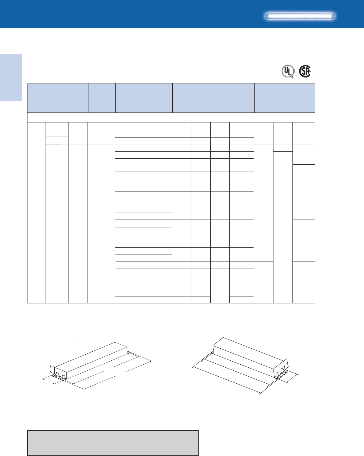
Lighting Electronics Atlas 2010-2011
1-42
ELECTRONIC FLUORESCENT BALLASTS
Electronic
Fluorescent Ballasts
0.26-0.11
0.23-0.10
0.28-0.13
0.27-0.18
ICN-2M32-MC
ICN-2P32-LW-SC
ICN-2P32-N
ICN-3P32-LW-SC
ICN-3P32-SC
IOP-3P32-SC
IOPA-3P32-SC
IOPA-2P32-HL-SC
IOP-3P32-LW-SC
IOPA-3P32-LW-SC
IOP-3P32-HL-90C-SC
IOPA-3P32-HL-SC
IOP-2S32-LW-SC
IOP-2S32-SC
0.26-0.12
0.30-0.14
0.39-0.20
0.21-0.09
0.24-0.11
31
35
47
25
29
0.87
1.01
1.37
0.73
0.90
20
15
10-30
10
15
*65
21
0/-18
No. of
Lamps Dim. Wiring
Dia.
Min.
Starting
Temp.
(°F/°C)
Input
Volts
Ballast
Family
Lamp
Starting
Method
Catalog Number
Line
Current
(Amps)
Input
Power
ANSI
(Watts)
Ballast
Factor
Max.
THD
%
HIGH POWER FACTOR SOUND RATED A
T8
For 17W Lamps
REB-2P32-SC
RCN-2S32-SC
VCN-2S32-SC
IOP-2P32-LW-SC
IOPA-2P32-LW-SC
IOP-2P32-SC
IOPA-2P32-SC
IOP-2P32-HL-SC
2
0/-18
120
277
120-277
32/0
-20/-29
B
A2
B
IS
PS
IS
AmbiStar‡
Centium
Optanium
0.45
0.33
0.15
0.32-0.14
0.23-0.10
0.26-0.11
31
39
39
31
28
33
32
38
27
31
0.91
1.00
1.00
0.88
0.79
0.93
0.88
1.07
0.80
0.90
140
10
10
10
20
15
20
15
10
10
0.34-0.15
41 1.23 15
F17T8, FBO16T8 (17W)
64
21
64
*65
64
Centium 0/-18
‡ The above AmbiStar ballasts are normal power factor and labeled ‘For Residential Use Only’
Refer to page 1-41 for additional dimensions
Refer to page 1-43 and 1-44 for wiring diagrams
Refer to pages 9-24 to 9-28 for lead lengths and shipping data
PS
B
GOPA-2P32-LW-SC
GOPA-2P32-SC -20/-29
0.08
27
30
0.78
0.88 10
64
0.09
0.10
GOPA-3P32-LW-SC
GOPA-3P32-SC
0.09
30
34
0.87
1.01 *65
347 IS Optanium
16.34"
16.70"
1.18"
1.70"
Fig. G
1.0”
1.3”
9.5”
8.9”
Fig. N
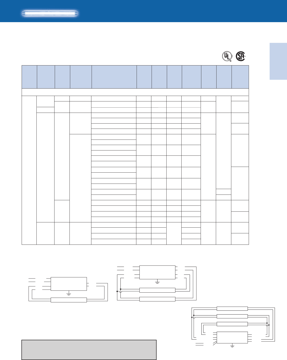
Electronic
Fluorescent Ballasts
ELECTRONIC FLUORESCENT BALLASTS
1-43
Lighting Electronics Atlas 2010-2011
‡ The above AmbiStar ballasts are normal power factor and labeled ‘For Residential Use Only’
44 0.92 0.13
*66
B
GOPA-3P32-LW-SC
GOPA-3P32-SC
347 -20/-29
IS Optanium
0.12
39 0.81
10
65
0.13
0.15
GOPA-4P32-LW-SC
GOPA-4P32-SC
45
50
0.82
1.00
30
IOP-3PSP32-LW-SC TBD TBD
TBD 0.71 10
IOP-3PSP-SC
No. of
Lamps Dim. Wiring
Dia.
Min.
Starting
Temp.
(°F/°C)
Input
Volts
Ballast
Family
Lamp
Starting
Method
Catalog Number
Line
Current
(Amps)
Input
Power
ANSI
(Watts)
Ballast
Factor
Max.
THD
%
HIGH POWER FACTOR SOUND RATED A
T8
For 17W Lamps
REB-4P32-SC
RCN-3S32-SC
VCN-3S32-SC
ICN-3P32-LW-SC
ICN-3P32-SC
ICN-4P32-LW-SC
ICN-4P32-SC
IOP-3P32-LW-SC
IOPA-3P32-LW-SC
3
0/-18
120
277
120-277
32/0
-20/-29
B
B
IS
PS
IS
AmbiStar‡
Centium
Optanium
0.87
0.51
0.22
0.35-0.16
0.39-0.17
0.36-0.16
0.45-0.20
0.34-0.15
44
61
61
42
48
43
53
40
0.81
1.00
1.00
0.80
0.92
0.85
1.04
0.81
135
10
10
15
15
15
15
10
F17T8, FBO16T8 (17W)
*66
30
65
*66
65
Centium
IOP-3P32-SC
IOPA-3P32-SC 0.38-0.1745 0.90 10
IOP-3P32-HL-90C-SC
IOPA-3P32-HL-SC 0.49-0.2259 1.22 10-15
IOP-4P32-LW-SC
IOPA-4P32-LW-SC 0.36-0.1743 0.85 20
*66
IOP-4P32-SC
IOPA-4P32-SC 0.41-0.1849 1.00 15
IOP-4P32-HL-90C-G
IOPA-4P32-HL
G
A
0.58-0.2669 1.28 10-15
0/-18
B
PS 0.39-0.1747 0.90 10
IOP-3S32-SC 0.36-0.1643 0.89 10
IOP-3S32-LW-SC 0.31-0.1437 0.72 10 0/-18
Refer to page 1-41 and 1-42 for dimensions
Refer to page 1-44 for additional wiring diagrams
Refer to pages 9-24 to 9-28 for lead lengths and shipping data
WHITE
YELLOW
YELLOW
BLACK
LINE
BALLAST
LAMP
LAMP
BLUE
BLUE
RED
RED
WHITE
BLUE
BLUE
BLK/WHT
LINE
BALLAST
DIAG. 20
LAMP
RED
RED
Diag. 20 Diag. 21
Diag. 30
WHITE
YELLOW
YELLOW
BLACK
BLUE/WHITE
BLUE/WHITE
LINE
BALLAST
LAMP
LAMP
LAMP
BLUE
BLUE
RED
RED
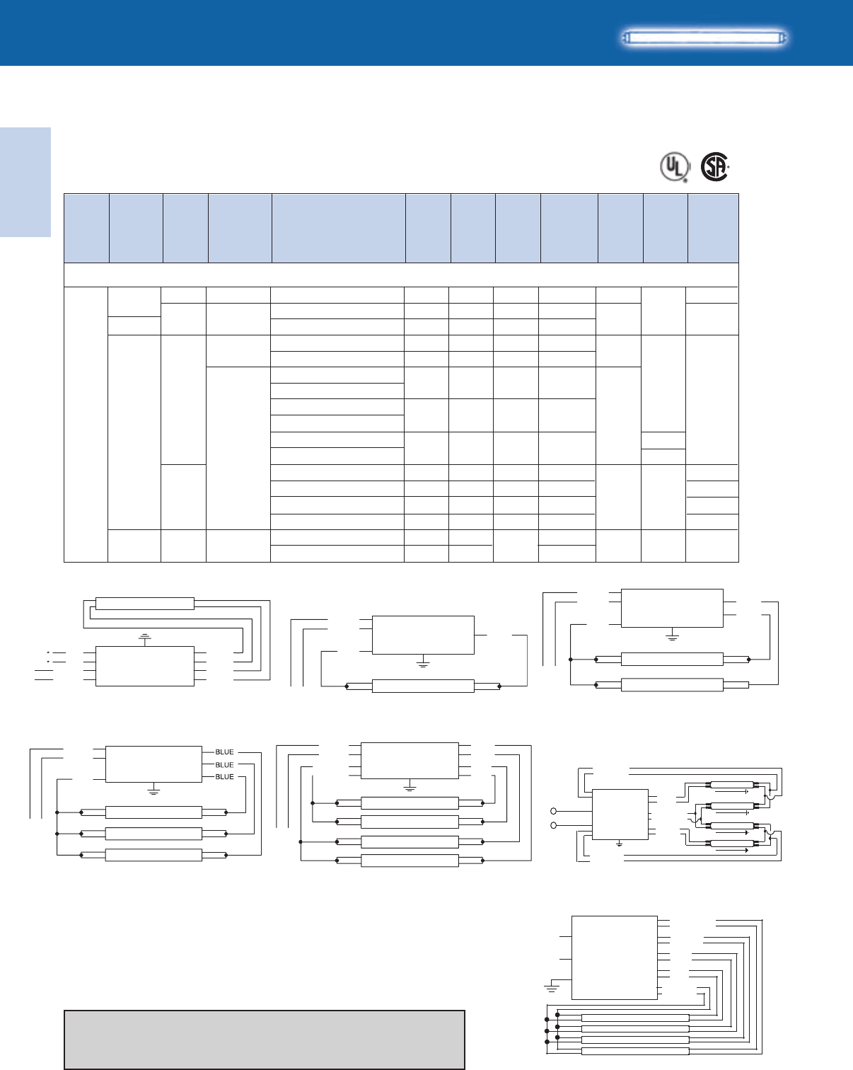
Lighting Electronics Atlas 2010-2011
1-44
ELECTRONIC FLUORESCENT BALLASTS
Electronic
Fluorescent Ballasts
IOP-4PSP32-LW-SC
IOP-4S32-LW-SC
66
WHITE
BLACK
LINE LAMP
BLUE
RED
BALLAST
LAMP
LAMP
LAMP
LAMP
LINE
WHITE
BLACK
YELLOW
YELLOW
RED
BLUE
BLUE
RED
*FOR THREE LAMP OPERATION,
INSULATE UNUSED BLUE LEADS INDIVIDUALLY FOR 600V
BALLAST
WHITE
YEL
YEL
BLACK
*FOR SINGLE LAMP OPERATION,
INSULATE YELLOW LEADS INDIVIDUALLY FOR 600V
LINE BALLAST
LAMP
BLUE
BLUE
RED
RED
BALLAST
LAMP
LAMP
LAMP
LINE
WHITE
BLACK
RED
*FOR TWO LAMP OPERATION,
INSULATE UNUSED BLUE LEADS INDIVIDUALLY FOR 600V
IOP-4P32-SC
IOPA-4P32-SC
HIGH POWER FACTOR SOUND RATED A
T8
For 17W Lamps
No. of
Lamps Dim. Wiring
Dia.
Min.
Starting
Temp.
(°F/°C)
Input
Volts
Ballast
Family
Lamp
Starting
Method
Catalog Number
Line
Current
(Amps)
Input
Power
ANSI
(Watts)
Ballast
Factor
Max.
THD
%
REB-4P32-SC
RCN-4S32-SC
VCN-4S32-SC
ICN-4P32-LW-SC
ICN-4P32-SC
IOP-4P32-LW-SC
IOPA-4P32-LW-SC
4
0/-18
32/0
-20/-29
120
277
120-277
B
B
IS
PS
IS
AmbiStar‡
Centium
Centium
Optanium
1.00
0.67
0.29
0.44-0.19
0.54-0.23
0.45-0.20
52
79
79
53
64
53
0.82
1.00
1.00
0.79
0.93
0.81
135
10
10
15
10
10
F17T8, FBO16T8 (17W)
66
138
66
0.49-0.22
58 0.90 10
IOP-4P32-HL-90C-G
IOPA-4P32-HL
G
0.66-0.2979 1.22 10-15
0/-18
IOP-4PSP32-SC
IOP-4S32-SC
B
PS
TBD
0.40-0.18
0.50-0.22
0.47-0.21
TBD
48
60
57
0.71
0.72
0.90
0.89
10
10
10
10
177
138
177
138
0/-18
‡ The above AmbiStar ballasts are normal power factor and labeled ‘For Residential Use Only’
Diag. 39
Diag. 65
Diag. 63
Diag. 66
Diag. 64
Diag. 138
Diag. 177
LINE
BALLAST
LAMP
LAMP
BLUE
BLUE
WHITE
BLACK
RED
*FOR SINGLE LAMP OPERATION,
INSULATE UNUSED BLUE LEAD FOR 600V
YELLOW
WHITE
BLACK
BROWN
LINE BALLAST
LAMP
LAMP
LAMP
LAMP
BLUE
BLUE/WHT
RED
BLUE/WHITE
BROWN
BLUE
RED
YELLOW
WHITE
BLACK
LINE
BALLAST
LAMP
LAMP
LAMP
LAMP
B
GOPA-4P32-LW-SC
GOPA-4P32-SC -20/-29
347 IS Optanium 0.16
53
60
0.79
0.93 10 0.17
A
Refer to page 1-41 and 1-42 for dimensions
Refer to page 1-43 for additional wiring diagrams
Refer to pages 9-24 to 9-28 for lead lengths and shipping data
Electronic
Fluorescent Ballasts
ELECTRONIC FLUORESCENT BALLASTS
1-45
Lighting Electronics Atlas 2010-2011
IOP-1S32-LW-SC
IOP-1S32-SC
IOP-2S32-LW-SC
IOP-2S32-SC
PS
IOP-2P32-HL-SC
IOPA-2P32-HL-SC
IOP-2P32-LW-SC
IOPA-2P32-LW-SC
IOP-1P32-HL-SC
IOPA-1P32-HL-SC
No. of
Lamps Dim. Wiring
Dia.
Min.
Starting
Temp.
(°F/°C)
Input
Volts
Ballast
Family
Lamp
Starting
Method
Catalog Number
Line
Current
(Amps)
Input
Power
ANSI
(Watts)
Ballast
Factor
Max.
THD
%
HIGH POWER FACTOR SOUND RATED A
T8
For 25W-36" Lamps
‡ The above AmbiStar ballasts are normal power factor and labeled ‘For Residential Use Only’
RCN-1S32-SC
VCN-1S32-SC
ICN-132-MC
ICN-1P32-LW-SC
ICN-1P32-N
ICN-2P32-LW-SC
ICN-2P32-N
IOP-1P32-LW-SC
IOPA-1P32-LW-SC
0/-18
32/0
-20/-29
B
A2
B
IS
IS
AmbiStar‡
Centium
Centium
Optanium
0.39
0.24
0.10
0.19-0.09
0.18-0.08
0.22-0.10
0.21-0.10
0.24-0.11
0.17-0.08
26
28
28
23
22
26
25
29
21
1.00
0.95
0.95
0.88
0.80
0.91
0.88
1.06
0.78
150
10
10
15
15
10
20
15
10
120
277
120-277
F25T8, FBO24T8 (25W - 36”)
*64
20
*64
63
63
REB-2P32-SC
IOP-1P32-SC
IOPA-1P32-SC 0.20-0.0923 0.88 10
0.26-0.1130 1.22 10
0.20-0.0924 0.90 10
*64
IOP-2P32-SC
IOPA-2P32-SC 0.23-0.1028 1.05 10
0.29-0.1335 1.40 20
0/-18
PS
0.16-0.0720 0.74 10 20
0.19-0.0822 0.92 10
0.17-0.0820 0.73 15 39
0.19-0.0923 0.90 15
0/-18
1
Refer to page 1-41 and 1-42 for dimensions
Refer to pages 1-47 & 1-48 for wiring diagrams
Refer to pages 9-24 to 9-28 for lead lengths and shipping data
GOPA-1P32-LW-SC
GOPA-1P32-SC
GOPA-2P32-LW-SC
GOPA-2P32-SC
-20/-29
0.08
0.08
24 0.88
IS Optanium347
63
*64
0.07
0.07
20
22
0.80
0.91 10
27 1.05
Lighting Electronics Atlas 2010-2011
1-46
ELECTRONIC FLUORESCENT BALLASTS
Electronic
Fluorescent Ballasts
REB-2P32-SC
RCN-2S32-SC
VCN-2S32-SC
ICN-2M32-MC
ICN-2P32-LW-SC
ICN-2P32-N
ICN-3P32-LW-SC
ICN-3P32-SC
IOP-2P32-LW-SC
IOPA-2P32-LW-SC
IOP-2P32-SC
IOPA-2P32-SC
IOP-2P32-HL-SC
IOPA-2P32-HL-SC
IOP-3P32-LW-SC
IOPA-3P32-LW-SC
IOP-3P32-SC
IOPA-3P32-SC
IOP-3P32-HL-90C-SC
IOPA-3P32-HL-SC
IOP-2S32-LW-SC
IOP-2S32-SC
43 0.89 130
53 0.95 10
53 0.95 10
44 0.88 15
40 0.77 15
48 0.91 10
44 0.85 15
51 1.03 15
39 0.78 10
43 0.88 10
57 1.20 10
43 0.86 10
49 1.00 10
64 1.32 10-15
36 0.71 10
43 0.89 10
PS
*65
21
0/-18
120
277
T8
HIGH POWER FACTOR SOUND RATED A
For 25W-36” Lamps
No. of
Lamps Dim. Wiring
Dia.
Min.
Starting
Temp.
(°F/°C)
Input
Volts
Ballast
Family
Lamp
Starting
Method
Catalog Number
Line
Current
(Amps)
Input
Power
ANSI
(Watts)
Ballast
Factor
Max.
THD
%
‡ The above AmbiStar ballasts are normal power factor and labeled ‘For Residential Use Only’
2
0/-18
32/0
-20/-29
B
A2
B
IS
PS
IS
AmbiStar‡
Centium
Centium
Optanium
120-277
F25T8, FBO24T8 (25W - 36")
64
21
64
*65
0.61
0.45
0.20
0.37-0.16
0.34-0.14
0.40-0.18
0.37-0.16
0.43-0.19
0.32-0.14
0.37-0.16
0.48-0.21
0.36-0.16
0.42-0.18
0.54-0.24
0.30-0.13
0.36-0.16
64
0/-18
Refer to page 1-41 and 1-42 for dimensions
Refer to pages 1-47 and 1-48 for wiring diagrams
Refer to pages 9-24 to 9-28 for lead lengths and shipping data
*65
B
347 -20/-29
IS Optanium
0.12
38
44
0.78
0.88 10
64
0.12
0.14
0.13
42
48
0.85
1.01
GOPA-2P32-LW-SC
GOPA-2P32-SC
GOPA-3P32-LW-SC
GOPA-3P32-SC

Electronic
Fluorescent Ballasts
ELECTRONIC FLUORESCENT BALLASTS
1-47
Lighting Electronics Atlas 2010-2011
30
120
T8
No. of
Lamps Dim. Wiring
Dia.
Min.
Starting
Temp.
(°F/°C)
Input
Volts
Ballast
Family
Lamp
Starting
Method
Catalog Number
Line
Current
(Amps)
Input
Power
ANSI
(Watts)
Ballast
Factor
Max.
THD
%
HIGH POWER FACTOR SOUND RATED A
For 25W-36" Lamps
‡ The above AmbiStar ballasts are normal power factor and labeled ‘For Residential Use Only’
F25T8, FBO24T8 (25W - 36")
3
0/-18
32/0
0/-18
-20/-29
B
G
A
B
B
IS
PS
IS
AmbiStar‡
Centium
Centium
Optanium
277
120-277
*66
30
65
*66
65
*66
REB-4P32-SC
RCN-3S32-SC
VCN-3S32-SC
ICN-3P32-LW-SC
ICN-3P32-SC
ICN-4P32-LW-SC
ICN-4P32-SC
IOP-3P32-LW-SC
IOPA-3P32-LW-SC
IOP-3P32-SC
IOPA-3P32-SC
IOP-3P32-HL-90C-SC
IOPA-3P32-HL-SC
IOP-4P32-LW-SC
IOPA-4P32-LW-SC
IOP-4P32-SC
IOPA-4P32-SC
IOP-4P32-HL-90C-G
IOPA-4P32-HL-G
IOP-3PSP32-LW-SC
IOP-3PSP32-SC
IOP-3S32-LW-SC
IOP-3S32-SC
63 0.86 125
77 0.95 10
77 0.95 10
58 0.79 15
67 0.90 10
62 0.85 10
74 1.01 10
57 0.79 10
64 0.88 10
84 1.20 10
62 0.85 10
71 0.97 10
94 1.28 10
TBD 0.71 10
66 0.89 10
54 0.71 10
64 0.88 10
1.14
0.65
0.28
0.49-0.21
0.56-0.24
0.52-0.22
0.62-0.27
0.48-0.21
0.54-0.24
0.70-0.31
0.52-0.22
0.59-0.26
0.80-0.35
TBD
0.55-0.24
0.45-0.20
0.53-0.23
0/-18
TBD
PS
*66
B
GOPA-3P32-LW-SC
GOPA-3P32-SC
347 -20/-29
IS Optanium
0.16
56
63
0.77
0.90 10
65
0.18
0.20
GOPA-4P32-LW-SC
GOPA-4P32-SC
0.18
62
70
0.81
0.96
WHITE
YELLOW
YELLOW
BLACK
LINE
BALLAST
LAMP
LAMP
BLUE
BLUE
RED
RED
WHITE
BLUE
BLUE
BLK/WHT
LINE
BALLAST
DIAG. 20
LAMP
RED
RED
Diag. 20 Diag. 21
Diag. 30
WHITE
YELLOW
YELLOW
BLACK
BLUE/WHITE
BLUE/WHITE
LINE
BALLAST
LAMP
LAMP
LAMP
BLUE
BLUE
RED
RED
Refer to page 1-41 and 1-42 for dimensions
Refer to page 1-48 for additional wiring diagrams
Refer to pages 9-24 to 9-28 for lead lengths and shipping data

Lighting Electronics Atlas 2010-2011
1-48
ELECTRONIC FLUORESCENT BALLASTS
Electronic
Fluorescent Ballasts
T8
HIGH POWER FACTOR SOUND RATED A
For 25W-36" Lamps
No. of
Lamps Dim. Wiring
Dia.
Min.
Starting
Temp.
(°F/°C)
Input
Volts
Ballast
Family
Lamp
Starting
Method
Catalog Number
Line
Current
(Amps)
Input
Power
ANSI
(Watts)
Ballast
Factor
Max.
THD
%
‡ The above AmbiStar ballasts are normal power factor and labeled ‘For Residential Use Only’
F25T8, FBO24T8 (25W - 36")
4
0/-18
32/0
-20/-29
B
B
IS
PS
IS
PS
AmbiStar‡
Centium
Optanium
Centium
120
277
120-277
66
138
66
REB-4P32-SC
RCN-4S32-SC
VCN-4S32-SC
ICN-4P32-LW-SC
ICN-4P32-SC
IOP-4P32-LW-SC
IOPA-4P32-LW-SC
IOP-4P32-SC
IOPA-4P32-SC
IOP-4P32-HL-90C-G
IOPA-4P32-HL-G
IOP-4PSP32-LW-SC
IOP-4S32-LW-SC
IOP-4PSP32-SC
IOP-4S32-SC
77 0.81 125
101 0.95 10
101 0.95 10
75 0.79 10
89 0.91 10
76 0.79 10
85 0.88 10
113 1.20 10
TBD 0.71 10
69 0.72 10
85 0.90 10
85 0.88 10
1.31
0.84
0.36
0.63-0.27
0.74-0.32
0.64-0.27
0.72-0.31
0.96-0.41
TBD
0.58-0.25
0.71-0.31
0.72-0.31
0/-18
G
A
B
177
138
177
138
0/-18
B
GOPA-4P32-LW-SC
GOPA-4P32-SC -20/-29
347 IS Optanium 0.22
74
86
0.79
0.91 10 66
0.25
WHITE
BLACK
LINE LAMP
BLUE
RED
BALLAST
LAMP
LAMP
LAMP
LAMP
LINE
WHITE
BLACK
YELLOW
YELLOW
RED
BLUE
BLUE
RED
*FOR THREE LAMP OPERATION,
INSULATE UNUSED BLUE LEADS INDIVIDUALLY FOR 600V
BALLAST
WHITE
YEL
YEL
BLACK
*FOR SINGLE LAMP OPERATION,
INSULATE YELLOW LEADS INDIVIDUALLY FOR 600V
LINE BALLAST
LAMP
BLUE
BLUE
RED
RED
BALLAST
LAMP
LAMP
LAMP
LINE
WHITE
BLACK
RED
*FOR TWO LAMP OPERATION,
INSULATE UNUSED BLUE LEADS INDIVIDUALLY FOR 600V
Diag. 39
Diag. 65
Diag. 63
Diag. 66
Diag. 64
Diag. 138
Diag. 177
LINE
BALLAST
LAMP
LAMP
BLUE
BLUE
WHITE
BLACK
RED
*FOR SINGLE LAMP OPERATION,
INSULATE UNUSED BLUE LEAD FOR 600V
YELLOW
WHITE
BLACK
BROWN
LINE BALLAST
LAMP
LAMP
LAMP
LAMP
BLUE
BLUE/WHT
RED
BLUE/WHITE
BROWN
BLUE
RED
YELLOW
WHITE
BLACK
LINE
BALLAST
LAMP
LAMP
LAMP
LAMP
Refer to page 1-41 and 1-42 for dimensions
Refer to page 1-47 for additional wiring diagrams
Refer to pages 9-24 to 9-28 for lead lengths and shipping data
Electronic
Fluorescent Ballasts
ELECTRONIC FLUORESCENT BALLASTS
1-49
Lighting Electronics Atlas 2010-2011
*64
F32T8/ES (25W - 48")
No. of
Lamps Dim. Wiring
Dia.
Min.
Starting
Temp.
(°F/°C)
Input
Volts
Ballast
Family
Lamp
Starting
Method
Catalog Number
Line
Current
(Amps)
Input
Power
ANSI
(Watts)
Ballast
Factor
Max.
THD
%
HIGH POWER FACTOR SOUND RATED A
For 25W-48" Lamps
T8/ES
160/16
120-277
B
IS
PS
Optanium
63
*64
20
39
IOP-1P32-LW-SC
IOPA-1P32-LW-SC
IOP-1P32-SC
IOPA-1P32-SC
IOP-1P32-HL-SC
IOPA-1P32-HL-SC
IOP-2P32-LW-SC
IOPA-2P32-LW-SC
IOP-2P32-SC
IOPA-2P32-SC
IOP-2P32-HL-SC
IOPA-2P32-HL-SC
IOP-1S32-LW-SC
IOP-1S32-SC
IOP-2S32-LW-SC
IOP-2S32-SC
GOPA-1P32-LW-SC
GOPA-1P32-SC
GOPA-2P32-LW-SC
GOPA-2P32-SC
IOP-2P32-LW-SC
IOPA-2P32-LW-SC
IOP-2P32-SC
IOPA-2P32-SC
IOP-2P32-HL-SC
IOPA-2P32-HL-SC
IOP-3P32-LW-SC
IOPA-3P32-LW-SC
IOP-3P32-SC
IOPA-3P32-SC
IOP-3P32-HL-90C-SC
IOPA-3P32-HL-SC
IOP-2S32-LW-SC
IOP-2S32-SC
21 0.77 10
23 0.87 10
32 1.21 10
24 0.90 10
27 1.05 10
37 1.40 15
21 0.72 10
24 0.88 10
21 0.73 10
24 0.89 10-15
38 0.77 10
44-43 0.87 10
60 1.19 10
43 0.86 10
49 1.00 10
70 1.32 10-20
39-38 0.71 10
45-44 0.88 10
0.17-0.07
0.20-0.09
0.26-0.12
0.20-0.09
0.23-0.10
0.31-0.14
0.17-0.07
0.20-0.08
0.17-0.08
0.20-0.09
0.32-0.14
0.37-0.06
0.50-0.22
0.36-0.16
0.42-0.18
0.59-0.27
0.32-0.14
0.38-0.16
60/16 B
64
*65
21
2
120-277
IS
PS
Optanium
Refer to page 1-41 and 1-42 for dimensions
Refer to page 1-47 and 1-48 for wiring diagrams
Refer to pages 9-24 to 9-28 for lead lengths and shipping data
0.07
25 0.88
IS Optanium347 63
*64
0.06
0.06
21
23
0.77
0.88 10
0.0927 1.04
GOPA-2P32-LW-SC
GOPA-2P32-SC
347 IS Optanium
0.12
39
44
0.78
0.88 10
63
0.13
0.14
GOPA-3P32-LW-SC
GOPA-3P32-SC
0.13
43
48
0.86
1.00

Lighting Electronics Atlas 2010-2011
1-50
ELECTRONIC FLUORESCENT BALLASTS
Electronic
Fluorescent Ballasts
IOP-3P32-LW-SC
IOPA-3P32-LW-SC
IOP-3P32-SC
IOPA-3P32-SC
IOP-3P32-HL-90C-SC
IOPA-3P32-HL-SC
IOP-4P32-LW-SC
IOPA-4P32-LW-SC
IOP-4P32-SC
IOPA-4P32-SC
IOP-4P32-HL-90C-G
IOPA-4P32-HL
IOP-3PSP32-LW-SC
IOP-3PSP32-SC
IOP-3S32-LW-SC
IOP-3S32-SC
IOP-4P32-LW-SC
IOPA-4P32-LW-SC
IOP-4P32-SC
IOPA-4P32-SC
IOP-4P32-HL-90C-G
IOPA-4P32-HL
IOP-4PSP32-LW-SC
IOP-4S32-LW-SC
IOP-4PSP32-SC
IOP-4S32-SC
4
66
65
*66
G
A
120-277 Optanium 60/16
B
B
66
177
138
177
138
IS
PS
B
GOPA-3P32-LW-SC
GOPA-3P32-SC
347 60/16
IS Optanium
0.17
58
64
0.77
0.88 10 0.19
0.21
GOPA-4P32-LW-SC
GOPA-4P32-SC
0.19
65
74
0.81
0.95
B
GOPA-4P32-LW-SC
GOPA-4P32-SC 60/16
347 IS Optanium 0.22
78
89
0.78
0.88 10 0.26
G
A
3
120-277 60/16
B
IS
Optanium
F32T8/ES (25W - 48")
65
*66
B
TBD
30
58-57 0.77 10
65-64 0.87 10
95-93 1.20 10
62-61 0.85 10
70-69 0.97 10
101-100 1.27 10
TBD 0.71 10
70 0.88 10
57-56 0.71 10
67-66 0.89 10
77-75 0.77 10
87-85 0.87 10
124-122 1.19 10
TBD 0.71 10
74-73 0.71 10
90 0.88 10
87-85 0.87 10
0.49-0.21
0.55-0.24
0.79-0.35
0.52-0.22
0.59-0.26
0.85-0.37
TBD
0.59-0.26
0.48-0.21
0.56-0.25
0.65-0.28
0.73-0.31
1.05-0.45
TBD
0.62-0.27
0.75-0.33
0.73-0.31
PS
T8/ES
HIGH POWER FACTOR SOUND RATED A
No. of
Lamps Dim. Wiring
Dia.
Min.
Starting
Temp.
(°F/°C)
Input
Volts
Ballast
Family
Lamp
Starting
Method
Catalog Number
Line
Current
(Amps)
Input
Power
ANSI
(Watts)
Ballast
Factor
Max.
THD
%
For 25W-48" Lamps
Refer to page 1-41 and 1-42 for dimensions
Refer to page 1-47 and 1-48 for wiring diagrams
Refer to pages 9-24 to 9-28 for lead lengths and shipping data
Electronic
Fluorescent Ballasts
ELECTRONIC FLUORESCENT BALLASTS
1-51
Lighting Electronics Atlas 2010-2011
*65
10
IOP-1P32-LW-SC
IOPA-1P32-LW-SC
IOP-1P32-SC
IOPA-1P32-SC
IOP-1P32-HL-SC
IOPA-1P32-HL-SC
IOP-2P32-LW-SC
IOPA-2P32-LW-SC
IOP-2P32-SC
IOPA-2P32-SC
IOP-2P32-HL-SC
IOPA-2P32-HL-SC
IOP-1S32-LW-SC
IOP-1S32-SC
IOP-2S32-LW-SC
IOP-2S32-SC
GOPA-1P32-LW-SC
GOPA-1P32-SC
GOPA-2P32-LW-SC
GOPA-2P32-SC
IOP-2P32-LW-SC
IOPA-2P32-LW-SC
IOP-2P32-SC
IOPA-2P32-SC
IOP-2P32-HL-SC
IOPA-2P32-HL-SC
IOP-3P32-LW-SC
IOPA-3P32-LW-SC
IOP-3P32-SC
IOPA-3P32-SC
IOP-3P32-HL-90C-SC
IOPA-3P32-HL-SC
IOP-2S32-LW-SC
IOP-2S32-SC
No. of
Lamps Dim. Wiring
Dia.
Min.
Starting
Temp.
(°F/°C)
Input
Volts
Ballast
Family
Lamp
Starting
Method
Catalog Number
Line
Current
(Amps)
Input
Power
ANSI
(Watts)
Ballast
Factor
Max.
THD
%
HIGH POWER FACTOR SOUND RATED A
For 28W-48" Lamps
T8/ES
F32T8/ES (28W - 48")
60/16
B
IS
PS
1
120-277 Optanium
63
*64
39
20
22 0.77 10
25 0.87 10
33 1.21 10
26 0.90 10
31 1.05 10
39 1.38 10
21 0.72 10
25 0.88 10
22 0.73 10
26 0.88 10-15
42 0.77 10
48-47 0.87 10
65-64 1.19 10
47 0.86 10
55-54 1.00 10
74-73 1.31 10-15
41-40 0.71 10
49-48 0.88 10
0.19-0.08
0.22-0.10
0.28-0.12
0.22-0.10
0.26-0.11
0.33-0.15
0.18-0.07
0.20-0.09
0.18-0.08
0.21-0.09
0.35-0.15
0.41-0.18
0.55-0.24
0.40-0.18
0.46-0.20
0.62-0.27
0.34-0.15
0.41-0.18
60/16 B
IS
PS
2
120-277 Optanium
64
*65
21
Refer to page 1-41 and 1-42 for dimensions
Refer to page 1-47 and 1-48 for wiring diagrams
Refer to pages 9-24 to 9-28 for lead lengths and shipping data
60/16
0.08
26 0.88
IS Optanium347
63
*64
0.07
0.07
22
25
0.77
0.88
0.09
29 1.04
B
GOPA-2P32-LW-SC
GOPA-2P32-SC
347 60/16
IS Optanium
0.12
42
47
0.78
0.88 10
64
0.13
0.16
GOPA-3P32-LW-SC
GOPA-3P32-SC
0.14
46
52
0.77
1.00
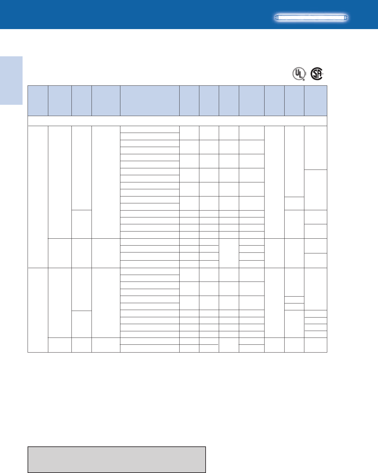
Lighting Electronics Atlas 2010-2011
1-52
ELECTRONIC FLUORESCENT BALLASTS
Electronic
Fluorescent Ballasts
No. of
Lamps Dim. Wiring
Dia.
Min.
Starting
Temp.
(°F/°C)
Input
Volts
Ballast
Family
Lamp
Starting
Method
Catalog Number
Line
Current
(Amps)
Input
Power
ANSI
(Watts)
Ballast
Factor
Max.
THD
%
HIGH POWER FACTOR SOUND RATED A
For 28W-48" Lamps
T8/ES
F32T8/ES (28W - 48")
IOP-3P32-LW-SC
IOPA-3P32-LW-SC
IOP-3P32-SC
IOPA-3P32-SC
IOP-3P32-HL-90C-SC
IOPA-3P32-HL-SC
IOP-4P32-LW-SC
IOPA-4P32-LW-SC
IOP-4P32-SC
IOPA-4P32-SC
IOP-4P32-HL-90C-G
IOPA-4P32-HL
IOP-3PSP32-LW-SC
IOP-3PSP32-SC
IOP-3S32-LW-SC
IOP-3S32-SC
IOP-4P32-LW-SC
IOPA-4P32-LW-SC
IOP-4P32-SC
IOPA-4P32-SC
IOP-4P32-HL-90C-G
IOPA-4P32-HL
IOP-4PSP32-LW-SC
IOP-4S32-LW-SC
IOP-4PSP32-SC
IOP-4S32-SC
64-63 0.77 10
72-71 0.87 10
99-97 1.20 10
69-68 0.85 10
79-78 0.97 10
107-106 1.24 10
TBD 0.71 10
75 0.88 10
62-61 0.71 10
72-71 0.89 10
84-82 0.77 10
96-94 0.87 10
130-129 1.19 10
TBD 0.71 10
80-79 0.71 10
97 0.88 10
97-96 0.88 10
0.54-0.23
0.61-0.26
0.83-0.36
0.58-0.25
0.66-0.28
0.90-0.39
TBD
0.62-0.27
0.51-0.22
0.60-0.26
0.71-0.30
0.81-0.35
1.10-0.47
TBD
0.67-0.29
0.81-0.35
0.82-0.35
60/16
B
G
B
IS
PS
3
120-277 Optanium
65
*66
TBD
30
Refer to page 1-41 and 1-42 for dimensions
Refer to page 1-47 and 1-48 for wiring diagrams
Refer to pages 9-24 to 9-28 for lead lengths and shipping data
4
120-277 60/16
B
G
A
B
IS
PS
Optanium
66
177
138
177
138
B
GOPA-3P32-LW-SC
GOPA-3P32-SC
347 60/16
IS Optanium
0.18
62
70
0.77
0.88 10
65
0.20
0.23
GOPA-4P32-LW-SC
GOPA-4P32-SC
0.20
70
79
0.81
0.97 *66
B
GOPA-4P32-LW-SC
GOPA-4P32-SC 60/16
347 IS Optanium 0.24
84
96
0.78
0.88 10 66
0.28
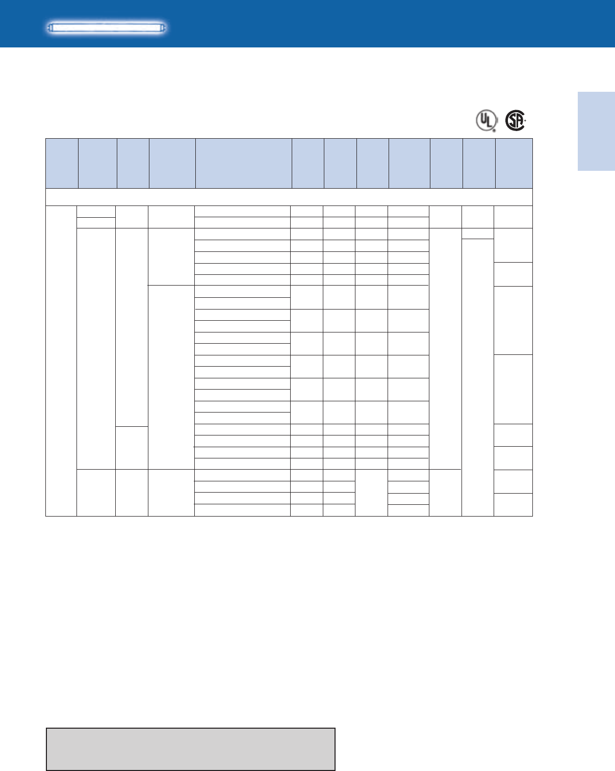
Electronic
Fluorescent Ballasts
ELECTRONIC FLUORESCENT BALLASTS
1-53
Lighting Electronics Atlas 2010-2011
No. of
Lamps Dim. Wiring
Dia.
Min.
Starting
Temp.
(°F/°C)
Input
Volts
Ballast
Family
Lamp
Starting
Method
Catalog Number
Line
Current
(Amps)
Input
Power
ANSI
(Watts)
Ballast
Factor
Max.
THD
%
HIGH POWER FACTOR SOUND RATED A
For 30W-48" Lamps
T8/ES
F32T8/ES (30W - 48")
60/16
60/16
120
277
120-277
B
A2
B
IS
PS
PS Centium
Centium
Optanium
20
63
*64
63
*64
20
39
1
RCN-1S32-SC
VCN-1S32-SC
ICN-132-MC
ICN-1P32-LW-SC
ICN-1P32-N
ICN-2P32-LW-SC
ICN-2P32-N
IOP-1P32-LW-SC
IOPA-1P32-LW-SC
IOP-1P32-SC
IOPA-1P32-SC
IOP-1P32-HL-SC
IOPA-1P32-HL-SC
IOP-2P32-LW-SC
IOPA-2P32-LW-SC
IOP-2P32-SC
IOPA-2P32-SC
IOP-2P32-HL-SC
IOPA-2P32-HL-SC
IOP-1S32-LW-SC
IOP-1S32-SC
IOP-2S32-LW-SC
IOP-2S32-SC
32 0.90 10
32 0.90 10
27 0.88 10
25 0.77 10
29 0.90 10
29-28 0.85 15-20
33 1.03 10
24 0.77 10
27 0.87 10
37-36 1.20 10
28 0.90 10
33 1.05 10
42 1.38 10
23 0.72 10
27 0.88 10
24-23 0.73 10
27 0.90 10
0.27
0.12
0.23-0.10
0.21-0.09
0.24-0.11
0.24-0.11
0.28-0.12
0.20-0.09
0.23-0.10
0.31-0.13
0.24-0.10
0.28-0.12
0.35-0.16
0.19-0.08
0.22-0.10
0.20-0.09
0.23-0.10
Refer to page 1-41 and 1-42 for dimensions
Refer to page 1-55 and 1-56 for wiring diagrams
Refer to pages 9-24 to 9-28 for lead lengths and shipping data
10 60/16
0.0828 0.88
IS Optanium347
63
*64
0.07
0.08
24
27
0.77
0.88
0.1032 1.04
GOPA-1P32-LW-SC
GOPA-1P32-SC
GOPA-2P32-LW-SC
GOPA-2P32-SC

Lighting Electronics Atlas 2010-2011
1-54
ELECTRONIC FLUORESCENT BALLASTS
Electronic
Fluorescent Ballasts
HIGH POWER FACTOR SOUND RATED A
For 30W-48" Lamps
T8/ES
No. of
Lamps Dim. Wiring
Dia.
Min.
Starting
Temp.
(°F/°C)
Input
Volts
Ballast
Family
Lamp
Starting
Method
Catalog Number
Line
Current
(Amps)
Input
Power
ANSI
(Watts)
Ballast
Factor
Max.
THD
%
F32T8/ES (30W - 48")
60/16
60/16
120
277
120-277
B
A2
B
PS
IS
PS
Centium
Centium
Optanium
21
64
*65
64
*65
21
2
RCN-2S32-SC
VCN-2S32-SC
ICN-2M32-MC
ICN-2P32-LW-SC
ICN-2P32-N
ICN-3P32-LW-SC
ICN-3P32-SC
IOP-2P32-LW-SC
IOPA-2P32-LW-SC
IOP-2P32-SC
IOPA-2P32-SC
IOP-2P32-HL-SC
IOPA-2P32-HL-SC
IOP-3P32-LW-SC
IOPA-3P32-LW-SC
IOP-3P32-SC
IOPA-3P32-SC
IOP-3P32-HL-90C-SC
IOPA-3P32-HL-SC
IOP-2S32-LW-SC
IOP-2S32-SC
60 0.88 10
60 0.88 10
54 0.88 10
47-46 0.77 10
54 0.88 10
52 0.83 10
61 1.01 10
45 0.77 10
52-51 0.87 10
72-70 1.19 10
51 0.85 10
59-58 1.00 10
78-77 1.31 10
44-43 0.71 10
52 0.88 10
0.51
0.22
0.45-0.20
0.39-0.17
0.45-0.20
0.44-0.19
0.51-0.22
0.38-0.17
0.44-0.19
0.60-0.26
0.43-0.19
0.50-0.21
0.65-0.29
0.36-0.16
0.44-0.19
Refer to page 1-41 and 1-42 for dimensions
Refer to page 1-55 and 1-56 for wiring diagrams
Refer to pages 9-24 to 9-28 for lead lengths and shipping data
*65
B
GOPA-2P32-LW-SC
GOPA-2P32-SC
347 60/16
IS Optanium
0.13
46
51
0.78
0.88 10
64
0.15
0.17
GOPA-3P32-LW-SC
GOPA-3P32-SC
0.15
50
57
0.86
1.00
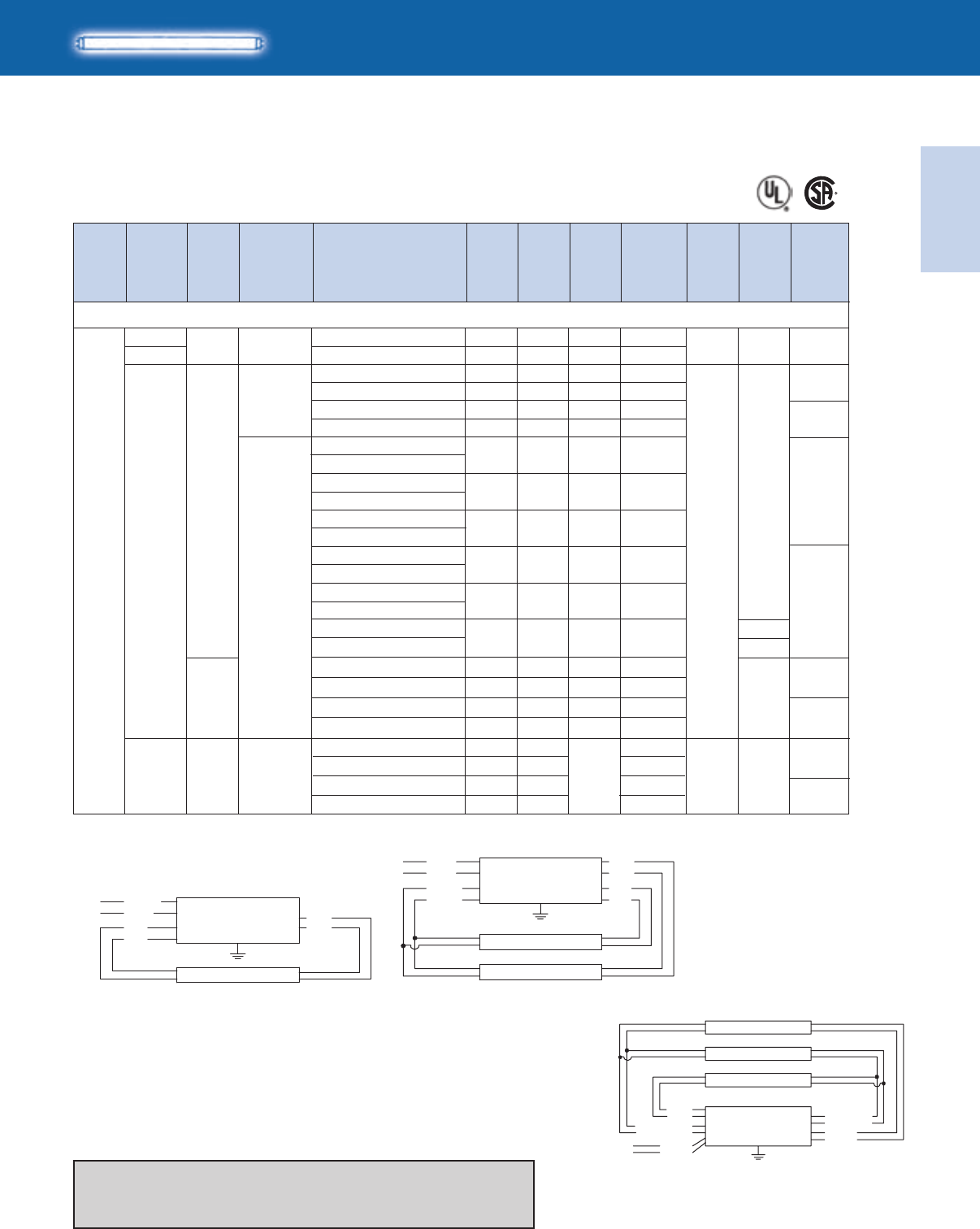
Electronic
Fluorescent Ballasts
ELECTRONIC FLUORESCENT BALLASTS
1-55
Lighting Electronics Atlas 2010-2011
B
IOPA-3P32-HL-SC
HIGH POWER FACTOR SOUND RATED A
For 30W-48" Lamps
No. of
Lamps Dim. Wiring
Dia.
Min.
Starting
Temp.
(°F/°C)
Input
Volts
Ballast
Family
Lamp
Starting
Method
Catalog Number
Line
Current
(Amps)
Input
Power
ANSI
(Watts)
Ballast
Factor
Max.
THD
%
T8/ES
IOP-3PSP32-SC 0.66-0.2979 0.88 10
RCN-3S32-SC
VCN-3S32-SC
ICN-3P32-LW-SC
ICN-3P32-SC
ICN-4P32-LW-SC
ICN-4P32-SC
IOP-3P32-LW-SC
IOPA-3P32-LW-SC
3
60/16
60/16
B
B
PS
IS
Centium
Centium
Optanium
0.72
0.31
0.57-0.25
0.66-0.29
0.62-0.27
0.73-0.32
0.57-0.25
22
85
69-68
79
75-74
87
68-67
0.88
0.88
0.77
0.88
0.80
1.00
0.77
10
10
10
10
10
10
10
120
277
120-277
F32T8/ES (30W - 48")
30
65
*66
65
IOP-3P32-SC
IOPA-3P32-SC 0.65-0.2877-76 0.87 10
0.63-0.2775-74 0.84 10
*66
IOP-4P32-SC 0.70-0.3084-82 0.97 10
1.24 10 G
A
IOP-3PSP32-LW-SC TBDTBD 0.71 10 TBD
30
0.88-0.38106-104 1.20 10
IOP-3S32-SC 0.64-0.2877-76 0.88 10
IOP-3S32-LW-SC 0.55-0.2466-65 0.71 10
Refer to page 1-41 and 1-42 for dimensions
Refer to page 1-56 for additional wiring diagrams
Refer to pages 9-24 to 9-28 for lead lengths and shipping data
PS
IOP-3P32-HL-90C-SC
IOPA-4P32-LW-SC
IOP-4P32-LW-SC
IOPA-4P32-SC
0.97-0.42
IOP-4P32-HL-90C-G
IOPA-4P32-HL 115-114
*66
B
GOPA-3P32-LW-SC
GOPA-3P32-SC
347 60/16
IS Optanium
0.19
67
76
0.77
0.88 10
65
0.22
0.25
GOPA-4P32-LW-SC
GOPA-4P32-SC
0.22
74
84
0.81
0.95
WHITE
YELLOW
YELLOW
BLACK
LINE
BALLAST
LAMP
LAMP
BLUE
BLUE
RED
RED
WHITE
BLUE
BLUE
BLK/WHT
LINE
BALLAST
DIAG. 20
LAMP
RED
RED
Diag. 20 Diag. 21
Diag. 30
WHITE
YELLOW
YELLOW
BLACK
BLUE/WHITE
BLUE/WHITE
LINE
BALLAST
LAMP
LAMP
LAMP
BLUE
BLUE
RED
RED
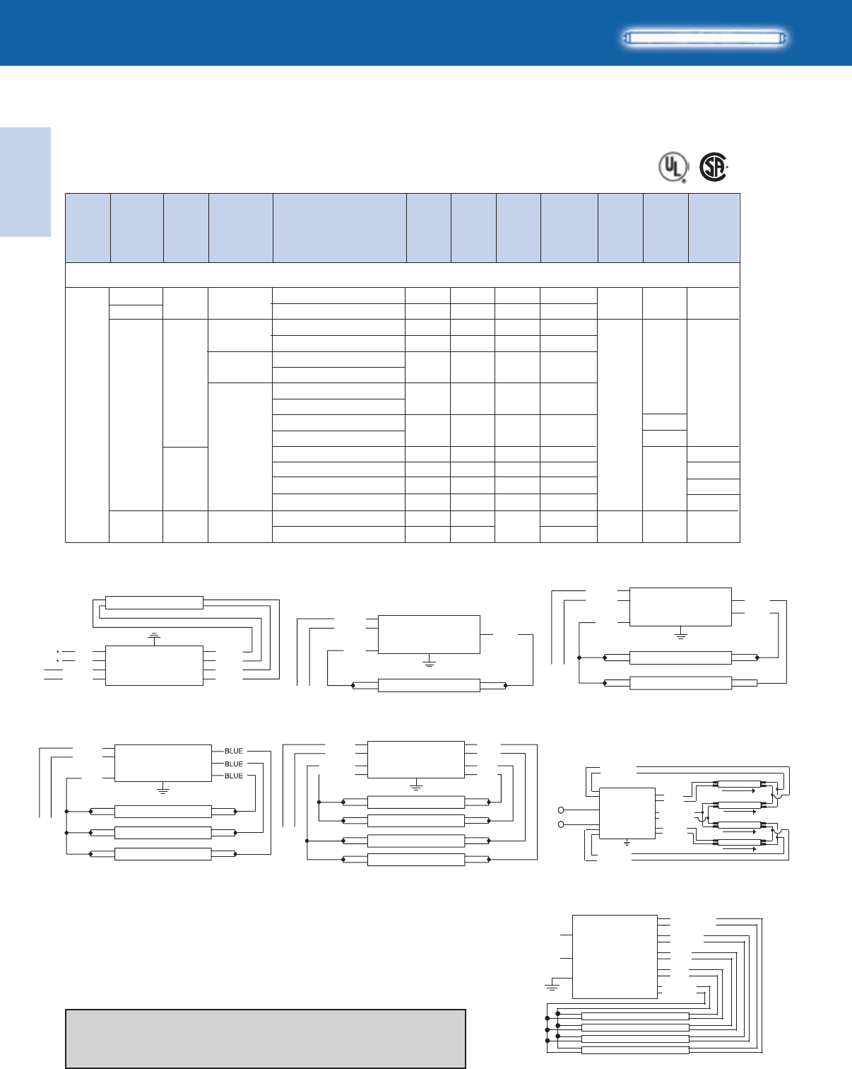
Lighting Electronics Atlas 2010-2011
1-56
ELECTRONIC FLUORESCENT BALLASTS
Electronic
Fluorescent Ballasts
BLUE/WHITE
BROWN
BLUE
RED
YELLOW
WHITE
BLACK
LINE
BALLAST
LAMP
LAMP
LAMP
LAMP
HIGH POWER FACTOR SOUND RATED A
For 30W-48" Lamps
T8/ES
No. of
Lamps Dim. Wiring
Dia.
Min.
Starting
Temp.
(°F/°C)
Input
Volts
Ballast
Family
Lamp
Starting
Method
Catalog Number
Line
Current
(Amps)
Input
Power
ANSI
(Watts)
Ballast
Factor
Max.
THD
%
F32T8/ES (30W - 48")
60/16
60/16
120
277
120-277
B
B
PS
PS
Centium
Centium
Centium
Optanium
138
66
4
RCN-4S32-SC
VCN-4S32-SC
ICN-4P32-LW-SC
ICN-4P32-SC
IOP-4P32-LW-SC
IOPA-4P32-LW-SC
IOP-4P32-SC
IOPA-4P32-SC
IOP-4P32-HL-90C-G
IOPA-4P32-HL-G
IOP-4PSP32-LW-SC
IOP-4S32-LW-SC
IOP-4PSP32-SC
IOP-4S32-SC
114 0.88 10
114 0.88 10
91-89 0.77 10
105 0.88 10
90-88 0.77 10
102-100 0.87 10
143-140 1.18 10
TBD 0.71 10
86-84 0.71 10
103 0.88 10
102-100 0.88 10
0.97
0.42
0.76-0.32
0.88-0.38
0.76-0.33
0.86-0.37
1.21-0.51
TBD
0.71-0.31
0.86-0.37
0.86-0.37
G
A
B
177
138
177
138
GOPA-4P32-LW-SC
GOPA-4P32-SC
347 IS
IS
Optanium 0.26
89
102
0.78
0.88 10 B
60/16 66
0.30
WHITE
BLACK
LINE LAMP
BLUE
RED
BALLAST
LAMP
LAMP
LAMP
LAMP
LINE
WHITE
BLACK
YELLOW
YELLOW
RED
BLUE
BLUE
RED
*FOR THREE LAMP OPERATION,
INSULATE UNUSED BLUE LEADS INDIVIDUALLY FOR 600V
BALLAST
WHITE
YEL
YEL
BLACK
*FOR SINGLE LAMP OPERATION,
INSULATE YELLOW LEADS INDIVIDUALLY FOR 600V
LINE BALLAST
LAMP
BLUE
BLUE
RED
RED
BALLAST
LAMP
LAMP
LAMP
LINE
WHITE
BLACK
RED
*FOR TWO LAMP OPERATION,
INSULATE UNUSED BLUE LEADS INDIVIDUALLY FOR 600V
Diag. 39
Diag. 65
Diag. 63
Diag. 66
Diag. 64
Diag. 138
Diag. 177
LINE
BALLAST
LAMP
LAMP
BLUE
BLUE
WHITE
BLACK
RED
*FOR SINGLE LAMP OPERATION,
INSULATE UNUSED BLUE LEAD FOR 600V
YELLOW
WHITE
BLACK
BROWN
LINE BALLAST
LAMP
LAMP
LAMP
LAMP
BLUE
BLUE/WHT
RED
Refer to page 1-41 and 1-42 for dimensions
Refer to page 1-55 for additional wiring diagrams
Refer to pages 9-24 to 9-28 for lead lengths and shipping data
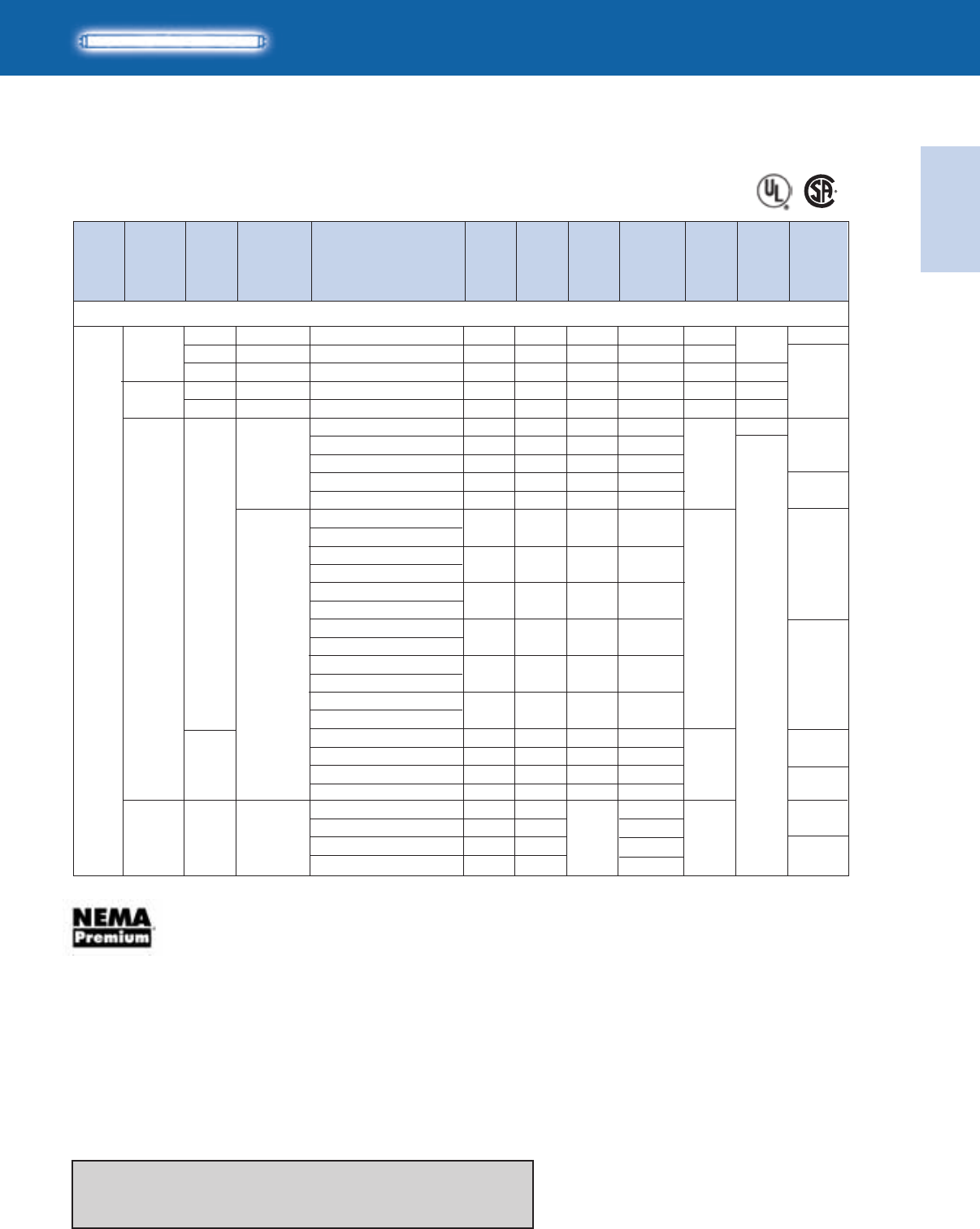
Electronic
Fluorescent Ballasts
ELECTRONIC FLUORESCENT BALLASTS
1-57
Lighting Electronics Atlas 2010-2011
HIGH POWER FACTOR SOUND RATED A
No. of
Lamps Dim. Wiring
Dia.
Min.
Starting
Temp.
(°F/°C)
Input
Volts
Ballast
Family
Lamp
Starting
Method
Catalog Number
Line
Current
(Amps)
Input
Power
ANSI
(Watts)
Ballast
Factor
Max.
THD
%
T8
For 32W Lamps
‡ The above AmbiStar ballasts are normal power factor and labeled ‘For Residential Use Only’
See pages 1-3 and 1-4 for specific SKU’s that meet the NEMA Premium Standard
1
0/-18
32/0
50/10
32/0
50/10
0/-18
-20/-29
0/-18
120
277
120-277
B
B
A
B
A
A2
IS
PS
RS
PS
RS
IS
PS
AmbiStar‡
Centium
PowrKut
Centium
PowrKut
Centium
Optanium
F32T8, FBO31T8, F32T8/U6 (32W)
20
63
*64
63
*64
39
20
REB-2P32-SC
RCN-1S32-SC
RK-132-TP
VCN-1S32-SC
VK-132-TP
ICN-132-MC
ICN-1P32-LW-SC
ICN-1P32-N
ICN-2P32-LW-SC
ICN-2P32-N
IOP-1P32-LW-SC
IOPA-1P32-LW-SC
IOP-1P32-SC
IOPA-1P32-SC
IOP-1P32-HL-SC
IOPA-1P32-HL-SC
IOP-2P32-LW-SC
IOPA-2P32-LW-SC
IOP-2P32-SC
IOPA-2P32-SC
IOP-2P32-HL-SC
IOPA-2P32-HL-SC
IOP-1S32-LW-SC
IOP-1S32-SC
IOP-2S32-LW-SC
IOP-2S32-SC
33 1.00 140
34 0.90 10
34 0.85 20
34 0.90 10
34 0.85 20
30 0.88 10
27 0.77 10
31 0.90 10
32 0.85 15-20
36 1.03 15
25 0.77 10
28 0.87 10
39-38 1.18 10
31 0.90 10
35 1.05 10
45 1.37 10
25 0.72 10
28 0.88 10
25 0.73 10
29 0.90 10
0.48
0.29
0.31
0.13
0.13
0.25-0.11
0.22-0.10
0.26-0.12
0.27-0.12
0.30-0.14
0.22-0.10
0.25-0.11
0.33-0.14
0.26-0.11
0.30-0.13
0.37-0.17
0.20-0.09
0.24-0.10
0.20-0.09
0.24-0.11
*64
Refer to page 1-41 and 1-42 for dimensions
Refer to page 1-59 and 1-60 for wiring diagrams
Refer to pages 9-24 to 9-28 for lead lengths and shipping data
-20/29
10 0.09
31 0.88
IS Optanium347
63
*64
0.08
0.09
26
30
0.77
0.88
1.0334 1.03
GOPA-1P32-LW-SC
GOPA-1P32-SC
GOPA-2P32-LW-SC
GOPA-2P32-SC
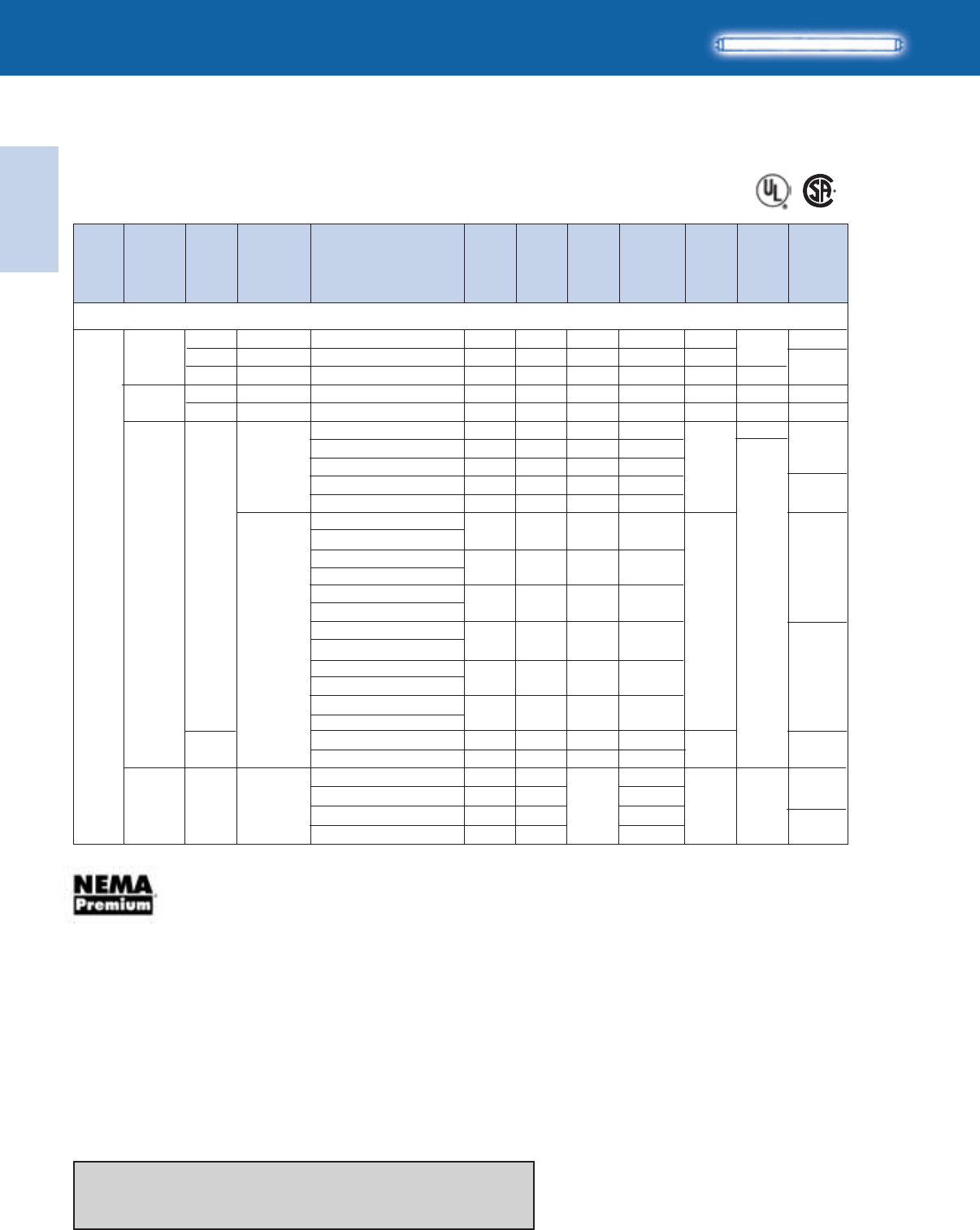
Lighting Electronics Atlas 2010-2011
1-58
ELECTRONIC FLUORESCENT BALLASTS
Electronic
Fluorescent Ballasts
64
*65
0/-18
HIGH POWER FACTOR SOUND RATED A
For 32W Lamps
No. of
Lamps Dim. Wiring
Dia.
Min.
Starting
Temp.
(°F/°C)
Input
Volts
Ballast
Family
Lamp
Starting
Method
Catalog Number
Line
Current
(Amps)
Input
Power
ANSI
(Watts)
Ballast
Factor
Max.
THD
%
T8
2
0/-18
32/0
50/10
32/0
50/10
-20/-29
0/-18
120
277
120-277
B
A
B
A
A2
B
IS
PS
RS
PS
RS
IS
PS
AmbiStar‡
Centium
PowrKut
Centium
PowrKut
Centium
Optanium
F32T8, FBO31T8, F32T8/U6 (32W)
64
*65
21
21
64
*65
21
REB-2P32-SC
RCN-2S32-SC
RK-2S32-TP
VCN-2S32-SC
VK-2S32-TP
ICN-2M32-MC
ICN-2P32-LW-SC
ICN-2P32-N
ICN-3P32-LW-SC
ICN-3P32-SC
IOP-2P32-LW-SC
IOPA-2P32-LW-SC
IOP-2P32-SC
IOPA-2P32-SC
IOP-2P32-HL-SC
IOPA-2P32-HL-SC
IOP-3P32-LW-SC
IOPA-3P32-LW-SC
IOP-3P32-SC
IOPA-3P32-SC
IOP-3P32-HL-90C-SC
IOPA-3P32-HL-SC
IOP-2S32-LW-SC
IOP-2S32-SC
56 0.88 120
63 0.88 10
66 0.86 15
63 0.88 10
66 0.85 15
59 0.88 10
50-49 0.77 10
59 0.88 10
57-56 0.86 10
65 1.01 10
48 0.77 10
55-54 0.87 10
74-72 1.18 10
55-54 0.85 10
63-62 1.00 10
80-79 1.38 10
47-46 0.71 10
56-55 0.88 10
0.80
0.53
0.60
0.23
0.26
0.50-0.21
0.42-0.12
0.49-0.22
0.48-0.21
0.54-0.24
0.41-0.17
0.47-0.20
0.62-0.26
0.46-0.20
0.53-0.23
0.67-0.29
0.38-0.17
0.47-0.20
‡ The above AmbiStar ballasts are normal power factor and labeled ‘For Residential Use Only’
Refer to page 1-41 and 1-42 for dimensions
Refer to page 1-59 and 1-60 for wiring diagrams
Refer to pages 9-24 to 9-28 for lead lengths and shipping data
*65
B
GOPA-2P32-LW-SC
GOPA-2P32-SC
347 -20/-29
IS Optanium
0.14
48
54
0.78
0.88 10
64
0.16
0.18
GOPA-3P32-LW-SC
GOPA-3P32-SC
0.16
55
63
0.86
1.00
See pages 1-3 and 1-4 for specific SKU’s that meet the NEMA Premium Standard
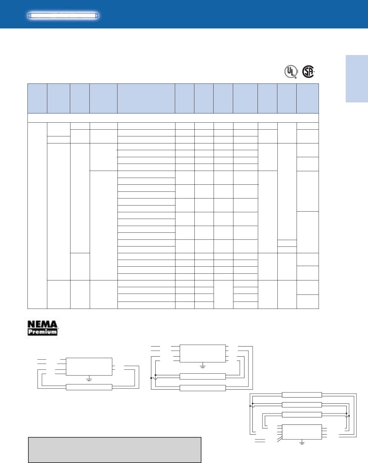
Electronic
Fluorescent Ballasts
ELECTRONIC FLUORESCENT BALLASTS
1-59
Lighting Electronics Atlas 2010-2011
G
A
F32T8, FBO31T8, F32T8/U6 (32W)
For 32W Lamps
No. of
Lamps
HIGH POWER FACTOR SOUND RATED A
Dim. Wiring
Dia.
Min.
Starting
Temp.
(°F/°C)
Input
Volts
Ballast
Family
Lamp
Starting
Method
Catalog Number
Line
Current
(Amps)
Input
Power
ANSI
(Watts)
Ballast
Factor
Max.
THD
%
T8
3
0/-18
32/0
0/-18
-20/-29
120
277
120-277
B
B
IS
PS
IS
AmbiStar‡
Centium
Centium
Optanium
*66
30
65
*66
65
*66
REB-4P32-SC
RCN-3S32-SC
VCN-3S32-SC
ICN-3P32-LW-SC
ICN-3P32-SC
ICN-4P32-LW-SC
ICN-4P32-SC
IOP-3P32-LW-SC
IOPA-3P32-LW-SC
IOP-3P32-SC
IOPA-3P32-SC
IOP-3P32-HL-90C-SC
IOPA-3P32-HL-SC
IOP-4P32-LW-SC
IOPA-4P32-LW-SC
IOP-4P32-SC
IOPA-4P32-SC
IOP-4P32-HL-90C-G
IOPA-4P32-HL
IOP-3PSP32-LW-SC
IOP-3PSP32-SC
IOP-3S32-LW-SC
IOP-3S32-SC
80 0.84 125
91 0.88 10
91 0.88 10
74-73 0.77 10
85 0.88 10
80-79 0.82 10
93 1.00 10
73-71 0.77 10
82-80 0.87 10
110-107 1.18 10
80-79 0.84 10
90-88 0.97 10
120-119 1.26 10
TBD 0.71 10
85 0.88 10
71-70 0.71 10
83-81 0.88 10
1.36
0.78
0.34
0.62-0.27
0.71-0.31
0.67-0.29
0.78-0.33
0.62-0.27
0.70-0.30
0.91-0.39
0.67-0.29
0.75-0.32
1.02-0.44
TBD
0.71-0.31
0.59-0.21
0.70-0.30
0/-18 B
TBD
30
Refer to page 1-41 for dimensions
Refer to page 1-60 for additional wiring diagrams
Refer to pages 9-24 to 9-28 for lead lengths and shipping data
PS
‡ The above AmbiStar ballasts are normal power factor and labeled ‘For Residential Use Only’
B
GOPA-3P32-LW-SC
GOPA-3P32-SC
347 -20/-29
IS Optanium
0.21
74
84
0.77
0.88 10 0.23
0.26
GOPA-4P32-LW-SC
GOPA-4P32-SC
0.24
77
89
0.81
0.96 *66
65
WHITE
YELLOW
YELLOW
BLACK
LINE
BALLAST
LAMP
LAMP
BLUE
BLUE
RED
RED
WHITE
BLUE
BLUE
BLK/WHT
LINE
BALLAST
DIAG. 20
LAMP
RED
RED
Diag. 20 Diag. 21
Diag. 30
WHITE
YELLOW
YELLOW
BLACK
BLUE/WHITE
BLUE/WHITE
LINE
BALLAST
LAMP
LAMP
LAMP
BLUE
BLUE
RED
RED
See pages 1-3 and 1-4 for specific SKU’s that meet the NEMA Premium Standard
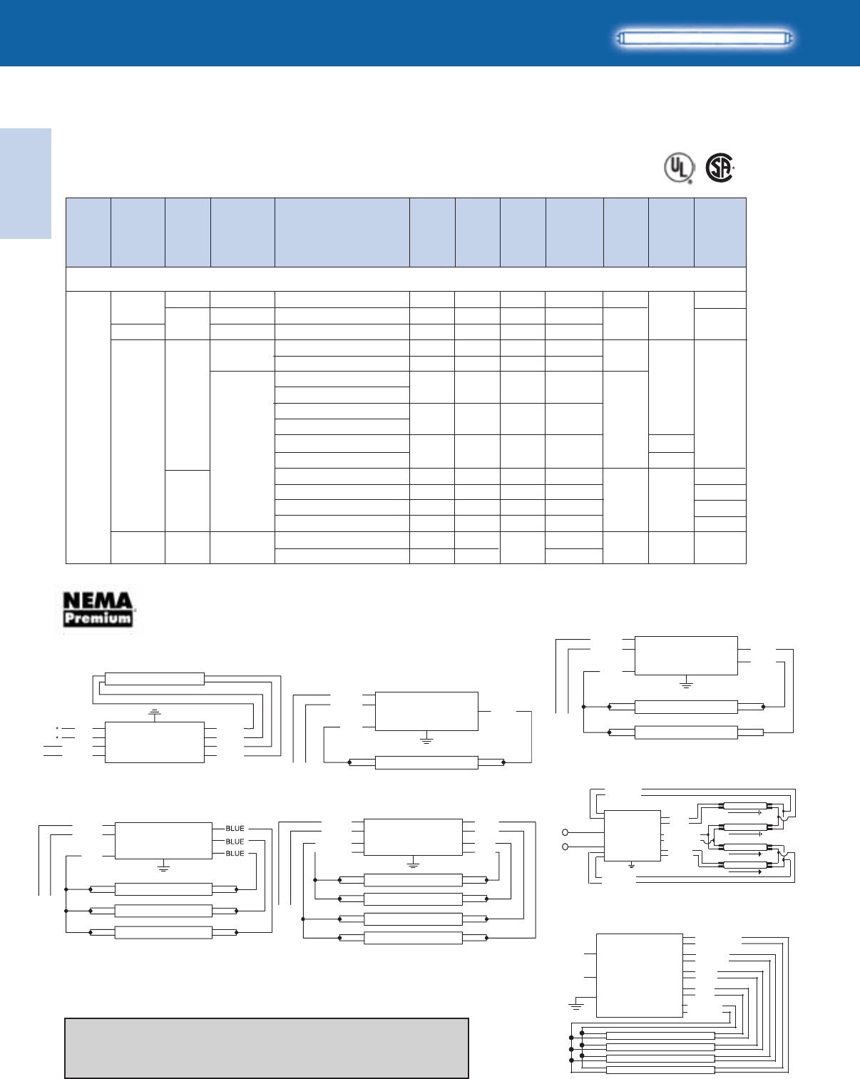
Lighting Electronics Atlas 2010-2011
1-60
ELECTRONIC FLUORESCENT BALLASTS
Electronic
Fluorescent Ballasts
HIGH POWER FACTOR SOUND RATED A
T8
For 32W Lamps
No. of
Lamps Dim. Wiring
Dia.
Min.
Starting
Temp.
(°F/°C)
Input
Volts
Ballast
Family
Lamp
Starting
Method
Catalog Number
Line
Current
(Amps)
Input
Power
ANSI
(Watts)
Ballast
Factor
Max.
THD
%
F32T8, FBO31T8, F32T8/U6 (32W)
4
0/-18
32/0
0/-18
0/-18
-20/-29
120
277
120-277
B
B
G
A
IS
PS
IS
PS
Standard
AmbiStar‡
Centium
Centium
Optanium
66
138
66
B
177
177
138
138
REB-4P32-SC
RCN-4S32-SC
VCN-4S32-SC
ICN-4P32-LW-SC
ICN-4P32-SC
IOP-4P32-LW-SC
IOPA-4P32-LW-SC
IOP-4P32-SC
IOPA-4P32-SC
IOP-4P32-HL-90C-G
IOPA-4P32-HL
IOP-4PSP-LW-SC
IOP-4S32-LW-SC
IOP-4PSP32-SC
IOP-4S32-SC
103 0.81 125
121 0.88 10
121 0.88 10
97-95 0.77 10
112 0.88 10
96-94 0.77 10
109-106 0.87 10
146-143 1.18 10
TBD 0.71 10
93-91 0.71 10
110 0.88 10
110 0.88 10
1.57
1.03
0.45
0.81-0.34
0.94-0.41
0.81-0.35
0.92-0.39
1.23-0.53
TBD
0.77-0.33
0.93-0.40
0.92-0.40
66
‡ The above AmbiStar ballasts are normal power factor and labeled ‘For Residential Use Only’
B
GOPA-4P32-LW-SC
GOPA-4P32-SC -20/-29
347 IS Optanium 0.27
92
107
0.78
0.88 10 0.31
WHITE
BLACK
LINE LAMP
BLUE
RED
BALLAST
LAMP
LAMP
LAMP
LAMP
LINE
WHITE
BLACK
YELLOW
YELLOW
RED
BLUE
BLUE
RED
*FOR THREE LAMP OPERATION,
INSULATE UNUSED BLUE LEADS INDIVIDUALLY FOR 600V
BALLAST
WHITE
YEL
YEL
BLACK
*FOR SINGLE LAMP OPERATION,
INSULATE YELLOW LEADS INDIVIDUALLY FOR 600V
LINE BALLAST
LAMP
BLUE
BLUE
RED
RED
BALLAST
LAMP
LAMP
LAMP
LINE
WHITE
BLACK
RED
*FOR TWO LAMP OPERATION,
INSULATE UNUSED BLUE LEADS INDIVIDUALLY FOR 600V
Diag. 39
Diag. 65
Diag. 63
Diag. 66
Diag. 64
Diag. 138
Diag. 177
LINE
BALLAST
LAMP
LAMP
BLUE
BLUE
WHITE
BLACK
RED
*FOR SINGLE LAMP OPERATION,
INSULATE UNUSED BLUE LEAD FOR 600V
YELLOW
WHITE
BLACK
BROWN
LINE BALLAST
LAMP
LAMP
LAMP
LAMP
BLUE
BLUE/WHT
RED
BLUE/WHITE
BROWN
BLUE
RED
YELLOW
WHITE
BLACK
LINE
BALLAST
LAMP
LAMP
LAMP
LAMP
Refer to page 1-62 for dimensions
Refer to page 1-59 for additional wiring diagrams
Refer to pages 9-24 to 9-28 for lead lengths and shipping data
See pages 1-3 and 1-4 for specific SKU’s that meet the NEMA Premium Standard
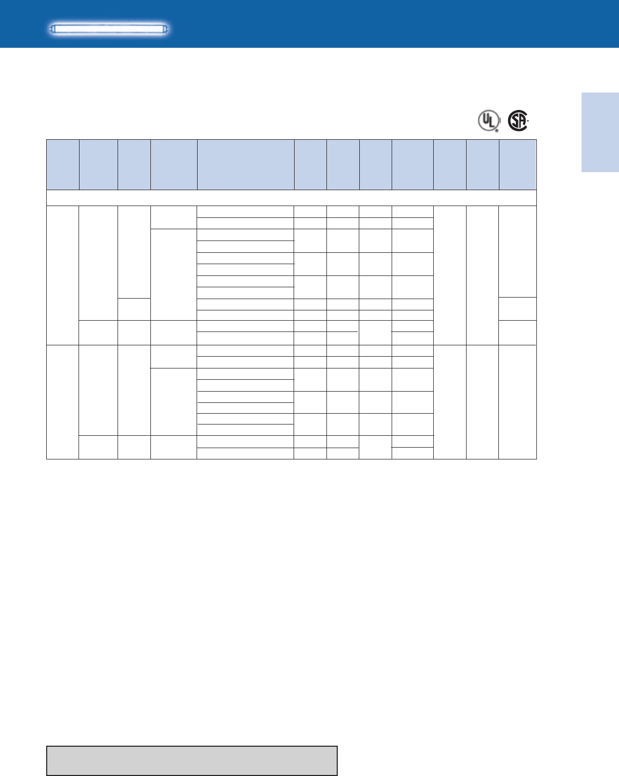
Electronic
Fluorescent Ballasts
ELECTRONIC FLUORESCENT BALLASTS
1-61
Lighting Electronics Atlas 2010-2011
*64
No. of
Lamps
HIGH POWER FACTOR SOUND RATED A
Dim. Wiring
Dia.
Min.
Starting
Temp.
(°F/°C)
Input
Volts
Ballast
Family
Lamp
Starting
Method
Catalog Number
Line
Current
(Amps)
Input
Power
ANSI
(Watts)
Ballast
Factor
Max.
THD
%
T8
For 40W Lamps
1
2
120-277
120-277
32/0 B
IS
PS
IS
Optanium
Centium
Optanium
Centium
F40T8 (40W)
39
32/0 B*65
ICN-2P32-LW-SC
ICN-2P32-N
IOP-2P32-LW-SC
IOPA-2P32-LW-SC
IOP-2P32-SC
IOPA-2P32-SC
IOP-2P32-HL-SC
IOPA-2P32-HL-SC
IOP-2S32-LW-SC
IOP-2S32-SC
ICN-3P32-LW-SC
ICN-3P32-SC
IOP-3P32-LW-SC
IOPA-3P32-LW-SC
IOP-3P32-SC
IOPA-3P32-SC
IOP-3P32-HL-90C-SC
IOPA-3P32-HL-SC
37 0.86 10-15
42 1.00 10
35 0.87 10
41 1.01 10
55-54 1.35 10
31-30 0.73 10
36 0.90 10
69-67 0.83 10
77 1.00 10
67-66 0.85 10
74-72 1.01 10
102-100 1.30 10
0.31-0.14
0.35-0.15
0.29-0.13
0.35-0.15
0.46-0.20
0.73-0.11
0.30-0.13
0.58-0.25
0.65-0.28
0.58-0.25
0.64-0.27
0.85-0.37
*64
Refer to page 1-62 for wiring diagrams and dimensions
Refer to pages 9-24 to 9-28 for lead lengths and shipping data
GOPA-2P32-LW-SC
GOPA-2P32-SC
347 IS Optanium 0.11
37
42
0.86
1.02 10 0.12
GOPA-3P32-LW-SC
GOPA-3P32-SC
347 IS Optanium 0.19
65
75
0.85
1.00 10 0.22
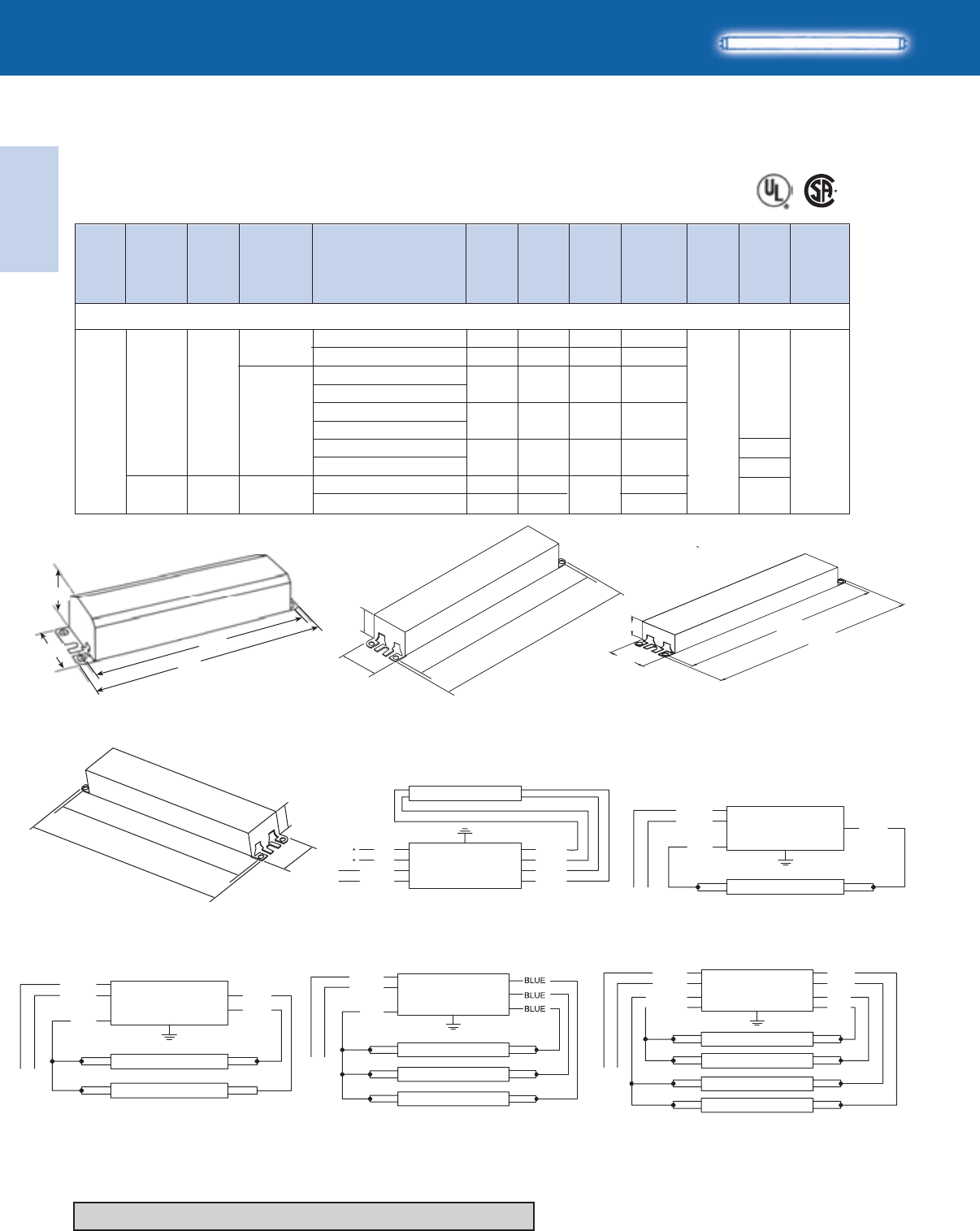
Lighting Electronics Atlas 2010-2011
1-62
ELECTRONIC FLUORESCENT BALLASTS
Electronic
Fluorescent Ballasts
16.34"
16.70"
1.18"
1.70"
No. of
Lamps Dim. Wiring
Dia.
Min.
Starting
Temp.
(°F/°C)
Input
Volts
Ballast
Family
Lamp
Starting
Method
Catalog Number
Line
Current
(Amps)
Input
Power
ANSI
(Watts)
Ballast
Factor
Max.
THD
%
HIGH POWER FACTOR SOUND RATED A
T8
For 40W Lamps
332/0
B
G
A
120-277 IS
Optanium
Centium
F40T8 (40W)
*66
ICN-4P32-LW-SC
ICN-4P32-SC
IOP-4P32-LW-SC
IOPA-4P32-LW-SC
IOP-4P32-SC
IOPA-4P32-SC
IOP-4P32-HL-90C-G
IOPA-4P32-HL
97-95 0.82 10
112 0.97 10
98-96 0.84 10
110-107 0.93 10
150-147 1.25 10
0.81-0.34
0.94-0.40
0.82-0.35
0.92-0.38
1.27-0.54
Refer to pages 9-24 to 9-28 for lead lengths and shipping data
WHITE
BLACK
LINE LAMP
BLUE
RED
BALLAST
LAMP
LAMP
LAMP
LAMP
LINE
WHITE
BLACK
YELLOW
YELLOW
RED
BLUE
BLUE
RED
*FOR THREE LAMP OPERATION,
INSULATE UNUSED BLUE LEADS INDIVIDUALLY FOR 600V
BALLAST
WHITE
YEL
YEL
BLACK
*FOR SINGLE LAMP OPERATION,
INSULATE YELLOW LEADS INDIVIDUALLY FOR 600V
LINE BALLAST
LAMP
BLUE
BLUE
RED
RED
BALLAST
LAMP
LAMP
LAMP
LINE
WHITE
BLACK
RED
*FOR TWO LAMP OPERATION,
INSULATE UNUSED BLUE LEADS INDIVIDUALLY FOR 600V
Fig. N
Diag. 64 Diag. 65
Diag. 39
Diag. 66
Diag. 63
LINE
BALLAST
LAMP
LAMP
BLUE
BLUE
WHITE
BLACK
RED
*FOR SINGLE LAMP OPERATION,
INSULATE UNUSED BLUE LEAD FOR 600V
B
GOPA-4P32-LW-SC
GOPA-4P32-SC
347 IS Optanium 0.28
97
113
0.84
0.93 10 0.28
2.375"
1.50"
8.91"
9.50"
8.90"
9.5"
1.18"
1.7"
1.0”
1.3”
9.5”
8.9”
Fig. G
Fig. BFig. A
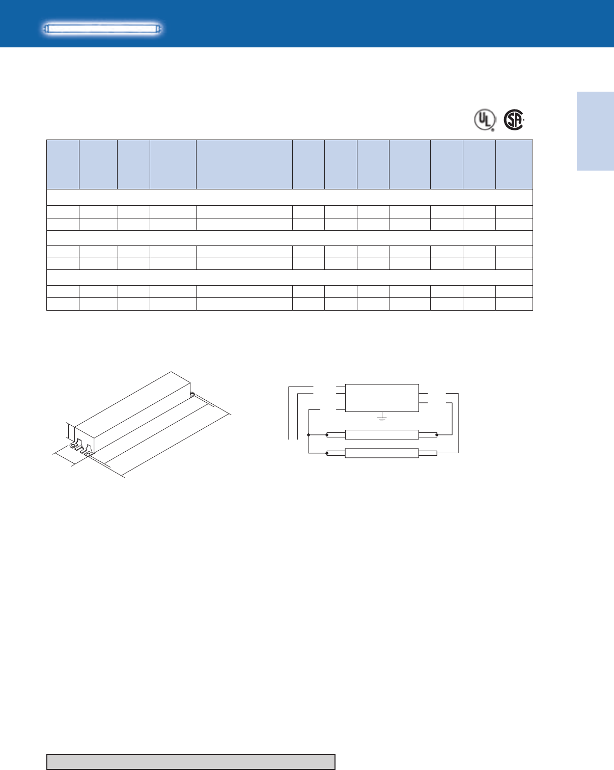
Electronic
Fluorescent Ballasts
ELECTRONIC FLUORESCENT BALLASTS
1-63
Lighting Electronics Atlas 2010-2011
No. of
Lamps Dim. Wiring
Dia.
Min.
Starting
Temp.
(°F/°C)
Input
Volts
Ballast
Family
Lamp
Starting
Method
Catalog Number
Line
Current
(Amps)
Input
Power
ANSI
(Watts)
Ballast
Factor
Max.
THD
%
HIGH POWER FACTOR SOUND RATED A
T8 Slimline
For 46-59W Lamps
1
2
32/0
32/0
120-277
120-277 B
B
IS
IS
54
88 0.92
1.09 10
10
Optanium
Optanium
F72T8 (46W)
*64A
64A
IOP-2P59-SC
IOP-2P59-SC
0.46-0.20
0.74-0.32
64 1.05 10 0.56-0.25
1
2
120-277
120-277
IS
IS
Optanium
Optanium
F96T8/ES (57W)
60/16
60/16
B
B
*64A
64A
IOP-2P59-SC
IOP-2P59-SC 103 0.87 10 0.86-0.37
1
2
120-277
120-277
IS
IS
Optanium
Optanium
F96T8 (59W)
32/0
32/0
B
B
*64A
64A
IOP-2P59-SC
IOP-2P59-SC
67 1.05 10 0.56-0.25
107 0.87 10 0.91-0.39
Refer to pages 9-24 to 9-28 for lead lengths and shipping data
Diag. 64A
LINE
BALLAST
LAMP
LAMP
BLUE
BLUE
WHITE
BLACK
RED
*FOR SINGLE LAMP OPERATION,
INSULATE UNUSED BLUE LEAD FOR 1000V
8.90"
9.5"
1.18"
1.7"
Fig. B
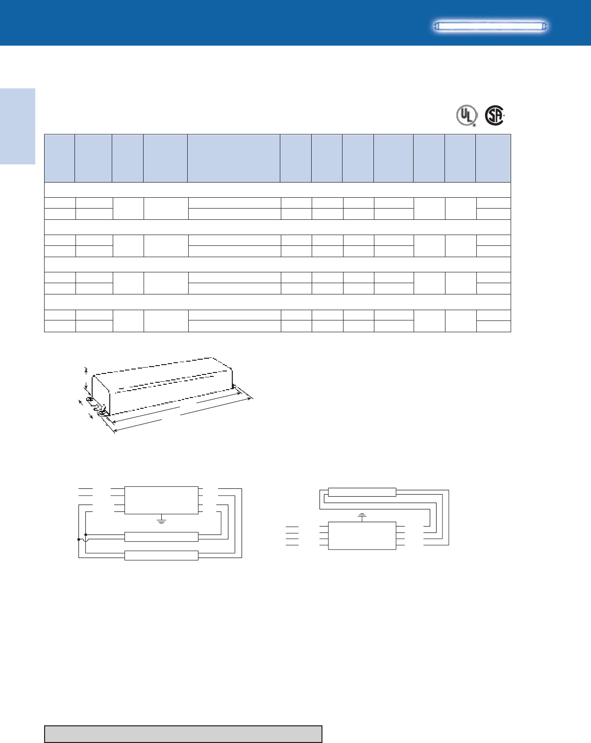
Lighting Electronics Atlas 2010-2011
1-64
ELECTRONIC FLUORESCENT BALLASTS
Electronic
Fluorescent Ballasts
HIGH POWER FACTOR SOUND RATED A
T8HO
For 44-86W Lamps
No. of
Lamps Dim. Wiring
Dia.
Min.
Starting
Temp.
(°F/°C)
Input
Volts
Ballast
Family
Lamp
Starting
Method
Catalog Number
Line
Current
(Amps)
Input
Power
ANSI
(Watts)
Ballast
Factor
Max.
THD
%
Fig C
11 "
34
/
11 "
964
/
2"
78
/
1"
25 32
/
1
2-20/-29
120-277
120-277 C
PS Centium
F48T8/HO (44W)
F60T8/HO (55W)
F72T8/HO (65W)
39A
21
ICN-2S86
ICN-2S86
59 1.02 20
98 0.95 10
0.50-0.23
0.84-0.36
1
2-20/-29
120-277
120-277 C
PS Centium 39A
21
ICN-2S86
ICN-2S86
70 1.00 20
118 0.92 10
0.58-0.26
1.04-0.45
1
2-20/-29
120-277
120-277 C
PS 0.68-0.30
1.21-0.54
81
140
1.00
0.94
15
10
Centium 39A
21
ICN-2S86
ICN-2S86
F96T8/HO (86W)
1
2-20/-29
120-277
120-277 C
PS 0.84-0.36
1.57-0.68
100
185
1.00
0.95
10
10
Centium 39A
21
ICN-2S86
ICN-2S86
Refer to pages 9-24 to 9-28 for lead lengths and shipping data
YELLOW
YELLOW
WHITE
BLACK
*FOR SINGLE LAMP OPERATION,
INSULATE YELLOW LEADS INDIVIDUALLY FOR 1000V
LINE BALLAST
DIAG. 39A
LAMP
BLUE
BLUE
RED
RED
Diag. 39ADiag. 21
WHITE
YELLOW
YELLOW
BLACK
LINE
BALLAST
LAMP
LAMP
BLUE
BLUE
RED
RED
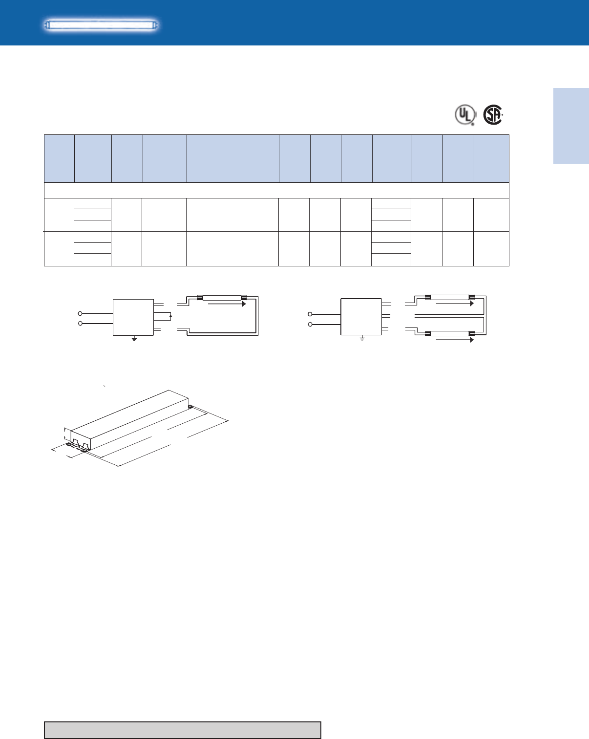
Electronic
Fluorescent Ballasts
ELECTRONIC FLUORESCENT BALLASTS
1-65
Lighting Electronics Atlas 2010-2011
T8VHO
HIGH POWER FACTOR SOUND RATED A
For 55 - 75W Lamps
No. of
Lamps Dim. Wiring
Dia.
Min.
Starting
Temp.
(°F/°C)
Input
Volts
Ballast
Family
Lamp
Starting
Method
Catalog Number
Line
Current
(Amps)
Input
Power
ANSI
(Watts)
Ballast
Factor
Max.
THD
%
BLK/WHT
BLK/ORG
(HOT)
(NEUTRAL)
BLK/WHT
BLK/ORG
(HOT)
(NEUTRAL)
BALLAST
BALLAST
LAMP
LAMP
LAMP
BLUE
BLUE
YELLOW
YELLOW
YELLOW LEADS MUST BE CONNECTED FOR (1) LAMP OPERAT ION
RED
RED
BLK/WHT
BLK/ORG
(HOT)
(NEUTRAL)
BLK/WHT
BLK/ORG
(HOT)
(NEUTRAL)
BALLAST
BALLAST
LAMP
LAMP
LAMP
BLUE
BLUE
YELLOW
YELLOW
YELLOW LEADS MUST BE CONNECTED FOR (1) LAMP OPERAT ION
RED
RED
F48T8/VHO (84W)
1 -20/-29
277
347
480
G
PS Optanium 7097
JOP-2S84-G
0.35
1.05 10 0.28
0.21
2 -20/-29
277
347
480
G
PS Optanium 71185
JOP-2S84-G
0.67
1.00 10 0.53
0.38
Diag. 70 Diag. 71
Refer to pages 9-24 to 9-28 for lead lengths and shipping data
16.34"
16.70"
1.18"
1.70"
Fig. G
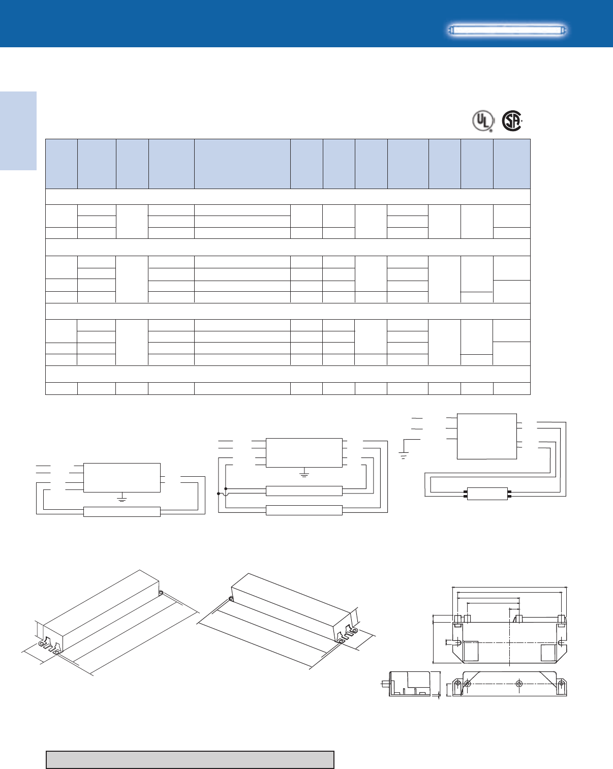
Lighting Electronics Atlas 2010-2011
1-66
ELECTRONIC FLUORESCENT BALLASTS
Electronic
Fluorescent Ballasts
No. of
Lamps Dim. Wiring
Dia.
Min.
Starting
Temp.
(°F/°C)
Input
Volts
Ballast
Family
Lamp
Starting
Method
Catalog Number
Line
Current
(Amps)
Input
Power
ANSI
(Watts)
Ballast
Factor
Max.
THD
%
HIGH POWER FACTOR SOUND RATED A
T12
For 22-40W Lamps
1
2
50/10
120
277
120-277
B
RS 20
21
30
58
RELB-1S40-SC
VEL-1S40-SC
ICN-2S40-N
0.27
0.12
0.48-0.20
0.98
0.93
20
F30T12 (30W - 36")
Diag. 163
1
2
2
2
50/10
120
277
120
120-277
120-277
B
RS AmbiStar
Centium
Centium
Centium
Standard
Standard
F34T12, F34T12/U (34W)
20
21
N
N
31
62
62
72
RELB-1S40-SC
VEL-1S40-SC
RELB-2S40-SC
ICN-2S40-N
0.88
0.85
0.85
0.85
20
10
10
AmbiStar
AmbiStar
35 0.92 0.29
0.12
0.53
0.53-0.23
F40T12, F40T12/U (40W)
1
250/10
120
277
120
B
RS AmbiStar
20
21
35
72
RELB-1S40-SC
VEL-1S40-SC
RELB-2S40-SC
ICN-2S40-N
0.31
0.13
0.62
0.62-0.26
0.85
0.85
20
AmbiStar
Standard
38 0.88
1 0/-18120 RMB-1P26-S2* S2
IS 0.35
AmbiStar 16322 0.95 150
FC8T9 (22W Circline)
* Normal Power Factor
Refer to pages 9-24 to 9-28 for lead lengths and shipping data
S2 Model
WHITE
YELLOW
YELLOW
BLACK
LINE
BALLAST
LAMP
LAMP
BLUE
BLUE
RED
RED
WHITE
BLUE
BLUE
BLK/WHT
LINE
BALLAST
DIAG. 20
LAMP
RED
RED
Diag. 20 Diag. 21
BLACK
WHITE
GREEN
GREEN TERMINAL MUST BE GROUNDED
BLUE
RED
LAMP
BALLAST
Fig. N
8.90"
9.5"
1.18"
1.7"
1.0”
1.3”
9.5”
8.9”
Fig. B
2 LAMP RECTANGULAR BALLAST, PLASTIC ENCLOSURE
INPUT SIDE OUTPUT SIDE
#6 - 20 THREAD FORMING
.25” LONG SCREWS
0.116” HOLES
4.41"
4.01"
2.38"
.28"1.57"
.17"
.47"
.94"
.06"
2.0"
3.6"
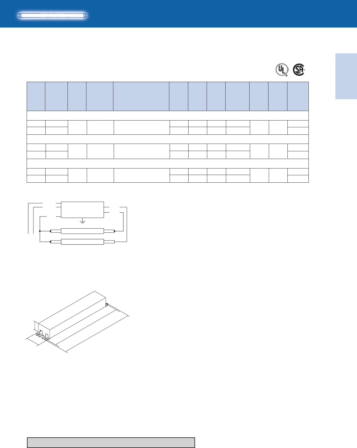
Electronic
Fluorescent Ballasts
ELECTRONIC FLUORESCENT BALLASTS
1-67
Lighting Electronics Atlas 2010-2011
IS
IS
IS
120-277
120-277
120-277
HIGH POWER FACTOR SOUND RATED A
For 55-75W Lamps
No. of
Lamps Dim. Wiring
Dia.
Min.
Starting
Temp.
(°F/°C)
Input
Volts
Ballast
Family
Lamp
Starting
Method
Catalog Number
Line
Current
(Amps)
Input
Power
ANSI
(Watts)
Ballast
Factor
Max.
THD
%
Diag. 64A
1
1
1
0/-18
0/-18
60/16
120-277
120-277
120-277
B
B
B
Centium
Centium
Centium
F72T12 (55W)
F96T12/ES (60W)
68-67
84-82
70-68
ICN-2P60-SC
ICN-2P60-SC
ICN-2P60-SC
0.70-0.31
0.55-0.25
0.53-0.24
1.05
1.04
1.04
10
10
10
108-107
137-135
0.91-0.40
0.92
0.90
10
10 1.17-0.50
105-103 0.89 10 0.88-0.38
2
2
2
F96T12 (75W)
T12 Slimline
Refer to pages 9-24 to 9-28 for lead lengths and shipping data
8.90"
9.5"
1.18"
1.7"
Fig. B
LINE
BALLAST
LAMP
LAMP
BLUE
BLUE
WHITE
BLACK
RED
*FOR SINGLE LAMP OPERATION,
INSULATE UNUSED BLUE LEAD FOR 1000V
*64A
64A
*64A
64A
*64A
64A
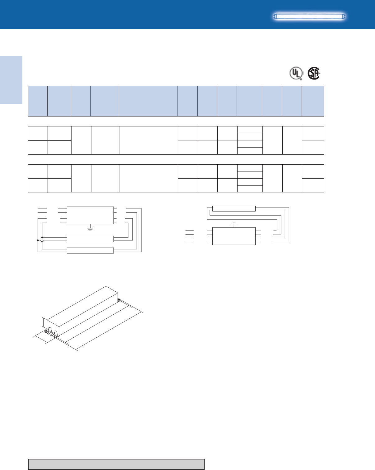
Lighting Electronics Atlas 2010-2011
1-68
ELECTRONIC FLUORESCENT BALLASTS
Electronic
Fluorescent Ballasts
T12/HO
HIGH POWER FACTOR SOUND RATED A
For 95 - 110W Lamps
No. of
Lamps Dim. Wiring
Dia.
Min.
Starting
Temp.
(°F/°C)
Input
Volts
Ballast
Family
Lamp
Starting
Method
Catalog Number
Line
Current
(Amps)
Input
Power
ANSI
(Watts)
Ballast
Factor
Max.
THD
%
Refer to pages 9-24 to 9-28 for lead lengths and shipping data
WHITE
YELLOW
YELLOW
BLACK
LINE
BALLAST
LAMP
LAMP
BLUE
BLUE
RED
RED
YELLOW
YELLOW
WHITE
BLACK
*FOR SINGLE LAMP OPERATION,
INSULATE YELLOW LEADS INDIVIDUALLY FOR 1000V
LINE BALLAST
DIAG. 39A
LAMP
BLUE
BLUE
RED
RED
Diag. 39ADiag. 21
1
1
2
2
60/16
-20/-29
120-277
120-277
120-277
120-277
C
C
RS
RS
Standard
Standard
F96T12/HO (95W)
F96T12/HO (110W)
39A
39A
21
21
78-77
100-92
154-151
194-190
ICN-2S110-SC
ICN-2S110-SC
0.65-0.31
1.28-0.57
1.10
0.48
0.84-0.58
1.60-0.89
1.74
0.76
0.91
0.91
0.89
0.89
10
10
10
10
8.90"
9.5"
1.18"
1.7"
Fig. B

Electronic
Fluorescent Ballasts
ELECTRONIC FLUORESCENT BALLASTS
1-69
Lighting Electronics Atlas 2010-2011
Notes
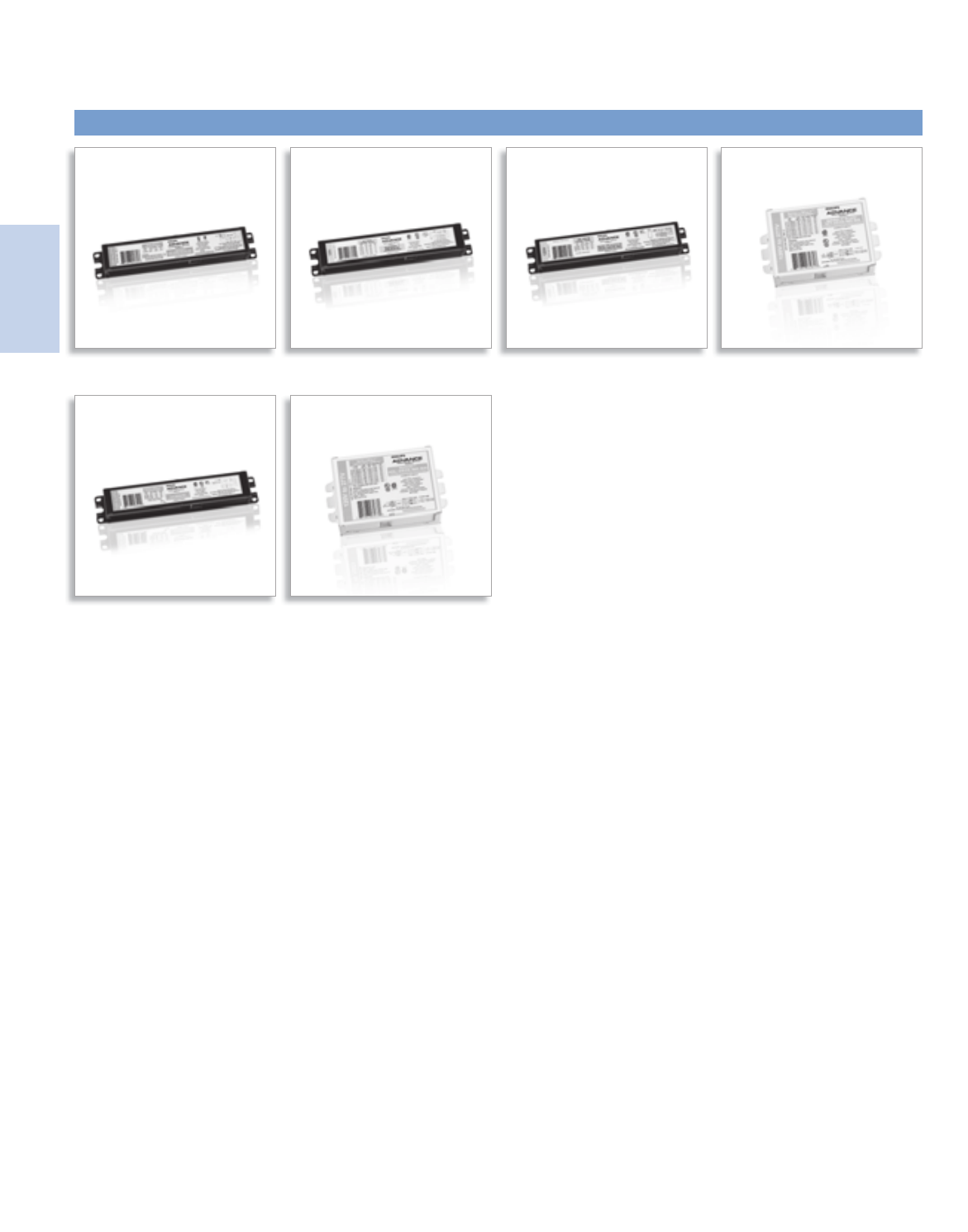
Lighting Electronics Atlas 2010-2011
ELECTRONIC FLUORESCENT CONTROLLABLE BALLASTS
1
Electronic Fluorescent
Controllable Ballasts
Optanium® Step Dim AmbiStar™ Mark 10® Powerline Mark 7® 0-10V
EssentiLine™ 0-10V ROVR™

2-1
Lighting Electronics Atlas 2010-2011
ELECTRONIC FLUORESCENT CONTROLLABLE BALLASTS
Electronic Fluorescent
Controllable Ballasts
Contents
Optanium® Step-Dim 2-2 to 2-3
AmbiStar™ 2-4 to 2-5
EssentiaLine™ 2-6 to 2-7
Mark 10® Powerline 2-8 to 2-12
Mark 7® 0-10V 2-13 to 2-18
ROVR™ 2-19 to 2-23
Compatible Controls 2-24 to 2-25
Select the control you need for your application from a list of
manufacturers that offer compatible controls for the Mark 7 0-10V and
Mark 10 Powerline electronic dimming ballasts, as well as, ROVR digital
addressable ballasts. The manufacturers that offer Mark 10 Powerline
controls have built the control according to our specifications to assure
the system is compatible. Part numbers and/or brands are listed along
with the manufacturer’s phone number.
Note: Refer to pages 9-15 to 9-19 for ballast specifications.
Visit our web site at www.philips.com/advance
Customer Support/Technical Service
(800) 372-3331 • (+) 1 847 390-5000 (International)
Corporate Offices
(800) 322-2086
Controlable
New

Lighting Electronics Atlas 2010-2011
ELECTRONIC FLUORESCENT CONTROLLABLE BALLASTS
2-2
Electronic Fluorescent
Controllable Ballasts
Philips Advance Optanium ballasts with step-dim
capability for T5 fluorescent lamps represent an
affordable, energy-efficient, and versatile lighting
solution designed to meet California’s Title 24
requirements by allowing the end-user the option
to dim the lights by up to 50%, thus reducing power
consumption by up to 50%.
Operating from any line voltage switching device,
the ballast’s programmed-start circuitry provides
extended lamp life in frequent switching applications
like those associated with the use of occupancy
sensors making this product the sustainable choice
for many commercial applications.
Fluorescent Ballasts - Electronic - Optanium® Step-Dim
High Efficiency Electronic Ballast with Step-Dim Capability for T5 Fluorescent Lamps.
Features
Title 24 Energy Efficiency Standards for Residential
and Non-residential Buildings
Meets California’s Title 24 by allowing the end-user
the option to dim the lights by 50%
Light levels are adjustable — 100% power, 50% power,
and off
Dims all the lamps together providing equal burn hours
on all lamps reducing uneven lifetimes as experienced with
on-off switching systems
IntelliVolt multiple-voltage technology enables
operation from 120 to 277V, 50/60 Hz
Allows for greater design flexibility while reducing
SKU requirements
Lamp End-Of-Life (EOL) protection circuit
Removes power to the lamps upon lamp failure
Optanium
Step-Dim
Controllable
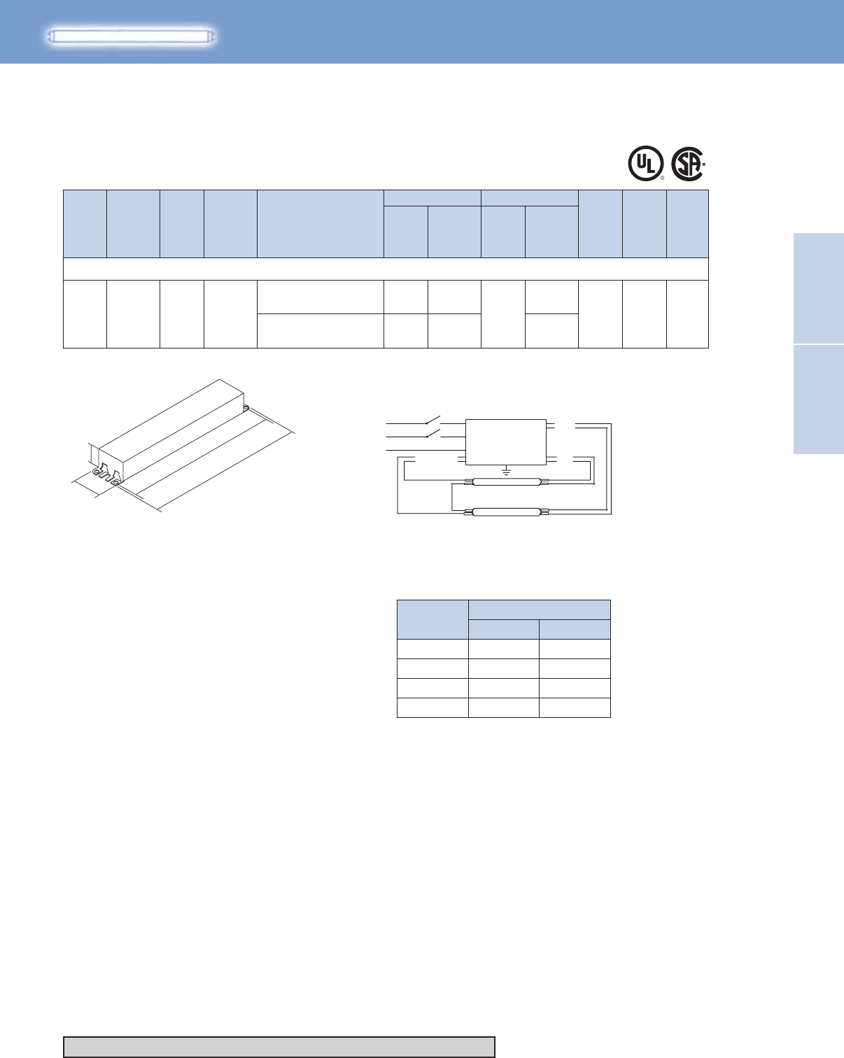
2-3
Lighting Electronics Atlas 2010-2011
Electronic Fluorescent
Controllable Ballasts
ELECTRONIC FLUORESCENT
CONTROLLABLE BALLASTS
HIGH POWER FACTOR SOUND RATED A
Optanium Step-Dim Ballast
IOP-2S28-115-SC-SD
F28T5 (28W)
2 120-277 PS Optanium
58/28 0.50
0.60
0.95/0.35
1.15/0.48
10 32/0 B 173
71/35
IOP-2S28-95-SC-SD
No. of
Lamps
Input
Volts
Lamp
Starting
Method
Ballast
Family Catalog Number Input
Power
ANSI
(Watts)
THD %
Ballast
Factor
Line
Current
(Amps)
Max/Min Min.
Starting
Temp.
(°F/°C)
Dim. Wiring
Dia.
Full Light Output
BLACK S1
BLACK S2
WHITE
YELLOW
LINE
BALLAST
RED
BLUE
LAMP
LAMP
For 28W Lamps
T5
Fig. B
Diag. 173
Line (black) inputs must be connected to
the same phase of the line voltage
8.90"
9.5"
1.18"
1.7"
Power
Output
Position
S1 S2
100% On On
50% On Off
50% Off On
0% Off Off
Optanium
Step-Dim
Controllable
Refer to pages 9-24 to 9-28 for lead lengths and shipping data
For fixed output version see page 1-37

Lighting Electronics Atlas 2010-2011
ELECTRONIC FLUORESCENT CONTROLLABLE BALLASTS
2-4
Electronic Fluorescent
Controllable Ballasts
Today’s fluorescent fixtures offer the opportunity for
greater flexibility and energy savings for residential
and hospitality settings than ever before by using
Philips Advance AmbiStar electronic ballasts. These
electronic ballasts for dimmable compact fluorescent
lamps deliver warm, comfortable, and cost-effective
solutions for such applications as downlighting, task,
ambient, hallway, and staircase lighting.
AmbiStar dimming ballasts are designed to
work with most incandescent dimmers,* so they
are easy to install with new or existing dimming
systems. Now you can create any ambiance
with dimmable lighting and still enjoy the energy
saving benefits of fluorescent lighting.
A single model operates one and two-lamp 26W
models, one-lamp 32W models, and one-lamp 42W
4-pin compact fluorescent lamps.
* Consult control manufacturer for compatibility
Electronic Fluorescent Ballasts - Dimming - AmbiStar™
Controllable Electronic Ballasts for 4-pin Compact Fluorescent Lamps
Class B FCC EMI Rating
Requirement for EPA ENERGY STAR residential
lighting fixtures
Title 24 Energy Efficiency Standards for Residential
and Non-residential Buildings
For use in high frequency residential fixtures as stated
in California’s Title 24 requirements
Electronic circuitry
Enables ballasts to run cooler and operate quieter
than magnetic alternatives
Dimming from 100% down to 15% of relative light output
Offers a large variety of end-user options
Ambistar Controllable
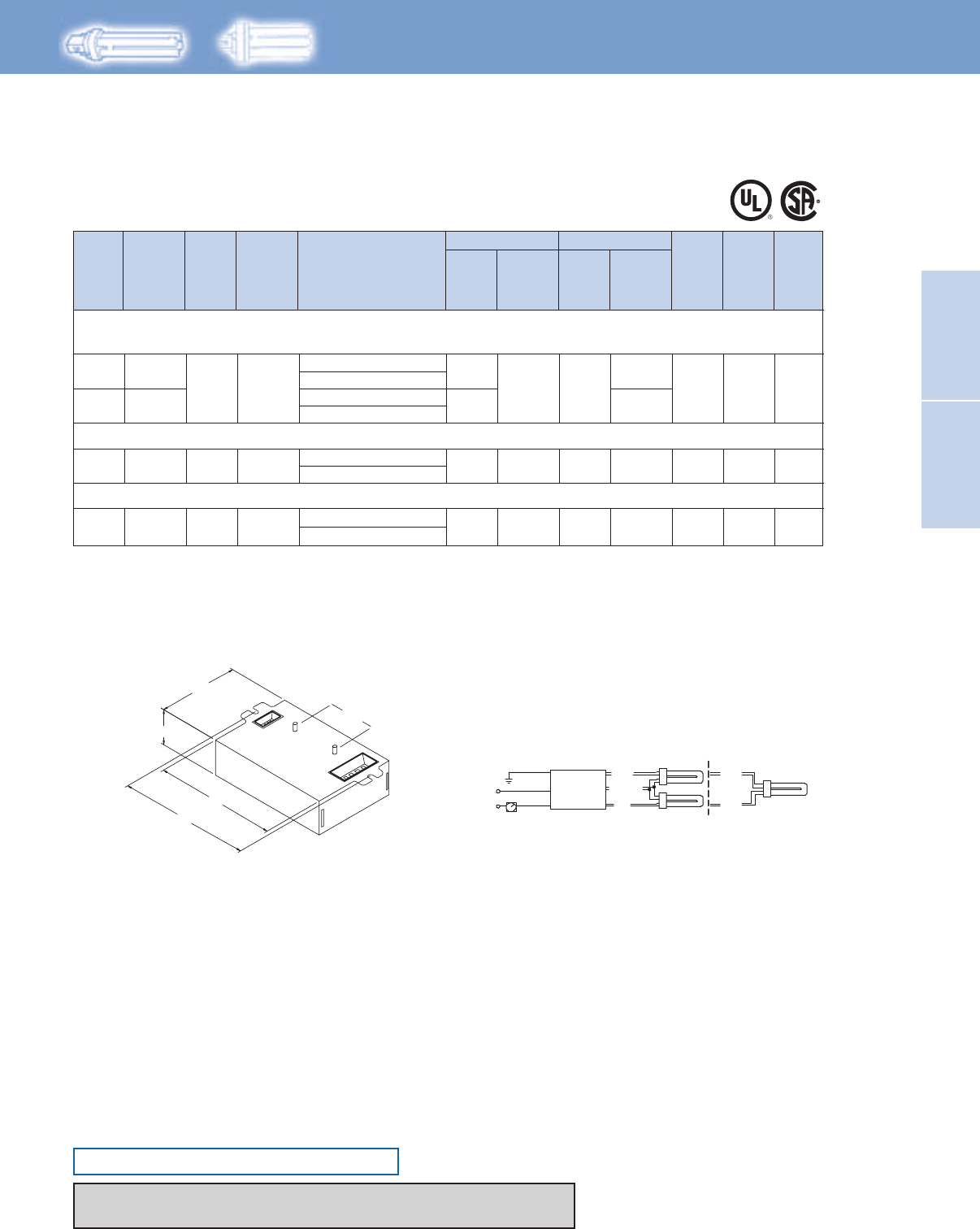
2-5
Lighting Electronics Atlas 2010-2011
Electronic Fluorescent
Controllable Ballasts
ELECTRONIC FLUORESCENT
CONTROLLABLE BALLASTS
HIGH POWER FACTOR SOUND RATED A
AmbiStar Electronic Dimming Ballast
No. of
Lamps
Input
Volts
Lamp
Starting
Method
Ballast
Family Catalog Number Input
Power
ANSI
(Watts)
THD %
Ballast
Factor
Line
Current
(Amps)
Max/Min Min.
Starting
Temp.
(°F/°C)
Dim. Wiring
Dia.
Full Light Output
138
138
120
120
120
REB-2S26-M1-BS-DIM
REB-2S26-M1-LS-DIM
REB-2S26-M1-BS-DIM
REB-2S26-M1-LS-DIM
REB-2S26-M1-BS-DIM
REB-2S26-M1-LS-DIM
0.23
0.45
CFQ26W/G24q - 26W CFL Quad Tube Lamp (PL-C26W/4P, F26DBX/4P, CF26DD/E)
CFTR26W/GX24q - 26W CFL Triple Tube Lamp (PL-T26W, F26TBX/4P, CF26DT/E)
1
2
RS AmbiStar
27/9
0.85/0.15 150 50/10 Size 1
52/17
1 RS AmbiStar 35/10 0.85/0.15 150 0.30 50/10 Size 1
CFTR32W/GX24q - 32W CFL Triple Tube Lamp (PL-T32W, F32TBX/4P, CF32DT/E)
138120 REB-2S26-M1-BS-DIM
REB-2S26-M1-LS-DIM
1 RS AmbiStar 47/11 0.85/0.15 150 0.40 50/10 Size 1
CFTR42W/GX24q - 42W CFL Triple Tube Lamp (PL-T42W, F42TBX/4P, CF42DT/E)
Some lamp manufacturers recommend burning in new lamps 100 hours at full light output before dimming. Consult lamp manufacturer.
Ballasts utilizing poke-in connectors can accept wire gauges from AWG 16 - 20.
Ballast dimmable from many incandescent or Mark 10 Powerline dimmers. Consult control manufacturer for compatibility.
RED
Diag. 138
YELLOW
BLACK
WHITE
GREEN BLUE BLUE
RED
WIRING: (2) QUAD/TRIPLE LAMPS (1) QUAD/TRIPLE LAMP
GREEN TERMINAL MUST BE GROUNDED
DIMMER
LINE BALLAST
4.20"
2.40"
4.60"
0.98"
2.00"
Diag. 138Size 1 Enclosure
Studs for -BS models only
T4
For 18 - 42W Lamps
Ambistar Controllable
ONLY USE 4-PIN RAPID-START SOCKETS
Refer to pages 1-13 & 1-14 for information on remote/tandem wiring and lead length extension
Refer to pages 9-24 to 9-28 for lead lengths and shipping data
Lighting Electronics Atlas 2010-2011
ELECTRONIC FLUORESCENT CONTROLLABLE BALLASTS
2-6
Electronic Fluorescent
Controllable Ballasts
The Philips Advance EssentiaLine 0-10V dimmable
ballasts are an alternative-feature set ballast for 0-10V
dimming systems. With lower up-front costs than
other 0-10V systems, it provides the same energy
savings as these solutions over the life of the system.
These ballasts optimize the benefits of such popular
sustainable lighting techniques as daylight harvesting,
occupancy sensors, and load shedding to satisfy the
need for a more affordable and flexible controllable
lighting solution.
These ballasts offer separate control leads for
use with a wide array of controllers, including
occupancy sensors, daylight harvesting controls,
and building management systems from more
than 30 control manufacturers. In addition, the
0 -10V operation of the ballast reduces the number
of controls required and allows for a single control
to operate across multiple branch circuits.
These ballasts are ideal to optimize energy savings
in such applications as offices, conference rooms,
educational facilities, hotels, and retail as well as
other new construction or retrofit installations.
For a complete list of compatible controls, visit
www.philips.com/advance.
Fluorescent Ballasts – Electronic - EssentiaLine™
EssentiaLine Electronic Dimming Ballasts for Linear Fluorescent T8 Lamps
Meets NEMA Premium® and CSA Energy Efficiency requirements
Helps your efforts to create a more sustainable workplace
Continuous dimming range from 100% light output down to 20%
Provides task appropriate comfort only where necessary
to increase potential energy savings while supporting LEED
performance standards
Programmed start operation
Potentially extends lamp life in frequent switching
applications such as occupancy sensors and daylight
EssentiaLine Controllable
The following ballasts meet NEMA Premium®:
ILV-2S32-SC, ILV-4S32-G
As a licensee in the NEMA Premium Ballast Program, Philips Lighting Electronics has determined that these
products meet the NEMA Premium specification for premium energy efficiency.
Note: Easy way to test dimming functionality is to ‘short’
together the violet and grey control wires. If the lamps go
to full dim, then the ballast is dimming fine.
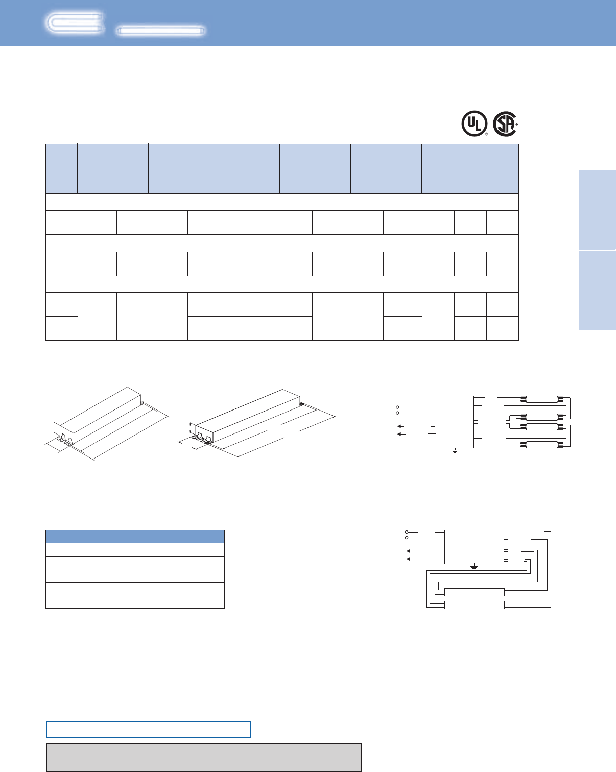
2-7
Lighting Electronics Atlas 2010-2011
Electronic Fluorescent
Controllable Ballasts
ELECTRONIC FLUORESCENT
CONTROLLABLE BALLASTS
F17T8, FBO16T8 (17W)
F25T8, FBO24T8 (25W)
F32T8, FBO31T8, F32T8/U6 (32W)
2
2
32/13
44/15
0.25 - 0.11
0.37 - 0.16
175A
175A
175A
176
0.50 - 0.21
1.00 - 0.43
0.88/0.20
0.88/0.20
50/10
50/10
B
B
B
G
0.88/0.20 20 50/10
59/18
116/40
120-277
120-277
PS
PS
EssentiaLine
EssentiaLine
2
4
PS120-277 EssentiaLine
ILV-2S32-SC
ILV-2S32-SC
ILV-2S32-SC
ILV-4S32-G
Some lamp manufacturers recommend burning in new lamps 100 hours at full light output before dimming. Consult lamp manufacturer.
No. of
Lamps
Input
Volts
Lamp
Starting
Method
Ballast
Family Catalog Number Input
Power
ANSI
(Watts)
THD %
Ballast
Factor
Line
Current
(Amps)
Max/Min Min.
Starting
Temp.
(°F/°C)
Dim. Wiring
Dia.
Full Light Output
For 17 - 32W Lamps
EssentiaLine Electronic Dimming Ballast
EssentiaLine Ballast 0-10V DC Control Wiring (Grey and Violet)
Wire Size Maximum Length (Ft.)
AWG-16 800
AWG-18
AWG-22
500
200
AWG-20
AWG-24
320
120
8.90"
9.5"
1.18"
1.7"
Fig. B Fig. G
16.34"
16.70"
1.18"
1.70"
EssentiaLine Controllable
T8
BALLAST
LAMP
LAMP
Diag. 175A
RED
YELLOW / BLUE
BLUE
BLACK
WHITE
LINE
CLASS 1 OR 2
CIRCUIT
10 V, 0. 5 mA
VIOLET (+)
{GREY (–)
YELLOW
Diag. 176
Diag. 175A
BALLAST
LAMP
RED
YELLOW/
BLUE
BLUE/ WHITE
ORANGE
BLUE
DIAG. 176
LAMP
LAMP
LAMP
YELLOW
ORANGE / BLACK
BLACK
WHITE
LINE
CLASS 1 OR 2
CIRCUIT
10 V, 0. 5 mA
VIOLET (+)
{GREY (–)
20
20
ONLY USE RAPID-START SOCKETS
Refer to pages 1-13 & 1-14 for information on remote/tandem wiring and lead length extension
Refer to pages 9-24 to 9-28 for lead lengths and shipping data
Lighting Electronics Atlas 2010-2011
ELECTRONIC FLUORESCENT CONTROLLABLE BALLASTS
2-8
Electronic Fluorescent
Controllable Ballasts
For companies looking to make their fixed-output
linear T8, 4-pin CFL, and T5/HO fluorescent
systems more cost effective and sustainable, Mark 10
Powerline ballasts provide an easy solution without
the need for additional control leads. Simply, replace
the ballast, replace the switch, dim the lights, that is
all it takes.
It’s that easy to bring the convenience and flexibility
of fluorescent dimming to conference rooms, private
offices, auditoriums, architectural cove lighting –
anywhere dimming is required.
Input voltage to
dimmer
Control Voltage to Ballast (from Dimmer)
Max Light Output Min Light Output
120V 120V 56V
277V 277V 129V
The following ballasts meet NEMA Premium®:
REZ-132-SC, REZ-2S32-SC, REZ-3S32-SC,
VEZ-132-SC, VEZ-2S32-SC, VEZ-3S32-SC
As a licensee in the NEMA Premium Ballast Program, Philips Lighting Electronics has determined that these
products meet the NEMA Premium specification for premium energy efficiency.
Fluorescent Ballasts - Dimming - Mark 10® Powerline
Mark 10®Powerline Electronic Dimming Ballasts for Linear Fluorescent and 4-Pin Compact Fluorescent Lamps
Available in linear T8, 4-pin CFL, and T5/HO models
Making this ideal for a variety of applications
Full range continuous dimming (100% light output down
to 5% - T5/HO to 1%)
Provides task appropriate comfort only where necessary
to increase potential energy savings while supporting LEED
performance standards
Programmed start operation
Potentially extends lamp life in frequent switching applications
such as occupancy sensors and daylight harvesting
Mark 10 Powerline Controllable
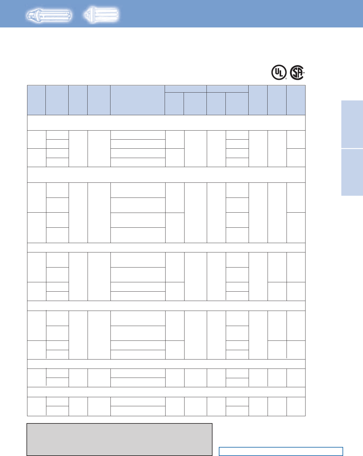
2-9
Lighting Electronics Atlas 2010-2011
Electronic Fluorescent
Controllable Ballasts
ELECTRONIC FLUORESCENT
CONTROLLABLE BALLASTS
HIGH POWER FACTOR SOUND RATED A
Note: Replacement/Retrofit Ballast Kits indicated by Bold Type with suffix -K are
available to distributors only. Refer to page1-21 for details.
Some lamp manufacturers recommend burning in new lamps 100 hours at full light
output before dimming. Consult lamp manufacturer.
Ballasts utilizing poke-in connectors can accept wire gauges from AWG 16 - 20.
CFQ18W/G24q - 18W CFL Quad Tube Lamp (PL-C18W/4P, F18DBX/4P, CF18DD/E)
CFTR18W/GX24q - 18W CFL Triple Tube Lamp (PL-T18W, F18TBX/4P, CF18DT/E)
1
2
PS Mark 10
Powerline
22/7
1.00/0.05 10
0.18
0.07 50/10 Size 2
138
138
0.36
0.16
43/14
120
277
120
277
REZ-1Q18-M2-BS
REZ-1Q18-M2-LD
REZ-2Q18-M2-BS
REZ-2Q18-M2-LD
VEZ-2Q18-M2-BS
VEZ-2Q18-M2-LD
VEZ-1Q18-M2-BS
VEZ-1Q18-M2-LD
CFQ26W/G24q - 26W CFL Quad Tube Lamp (PL-C26W/4P, F26DBX/4P, CF26DD/E)
CFTR26W/GX24q - 26W CFL Triple Tube Lamp (PL-T26W, F26TBX/4P, CF26DT/E)
1
2
PS Mark 10
Powerline
31/8
1.00/0.05 10
0.26
0.11
50/10 Size 2
138
138
0.48
0.21
58/16
120
277
120
277
REZ-1T42-M2-BS
REZ-1T42-M2-LD
REZ-1T42-M2-LD-K
REZ-2Q26-M2-BS
REZ-2Q26-M2-LD
REZ-2Q26-M2-LD-K
VEZ-2Q26-M2-BS
VEZ-2Q26-M2-LD
VEZ-2Q26-M2-LD-K
VEZ-1T42-M2-BS
VEZ-1T42-M2-LD
VEZ-1T42-M2-LD-K
277
CFTR32W/GX24q - 32W CFL Triple Tube Lamp (PL-T32W, F32TBX/4P, CF32DT/E)
1
2
PS Mark 10
Powerline
38/9
1.00/0.05 10
0.32
0.14 50/10
Size 2
Size 3
138
138
0.64
0.28
76/20
120
277
120 REZ-2T42-M3-BS
REZ-2T42-M3-LD
REZ-1T42-M2-BS
REZ-1T42-M2-LD
REZ-1T42-M2-LD-K
VEZ-1T42-M2-BS
VEZ-1T42-M2-LD
VEZ-1T42-M2-LD-K
VEZ-2T42-M3-BS
VEZ-2T42-M3-LD
CFTR42W/GX24q - 42W CFL Triple Tube Lamp (PL-T42W, F42TBX/4P, CF42DT/E)
1
2
PS Mark 10
Powerline
49/10
1.00/0.05 10
0.41
0.18 50/10
Size 2
Size 3
138
138
0.82
0.36
98/20
120
277
120
277
REZ-2T42-M3-BS
REZ-2T42-M3-LD
REZ-1T42-M2-BS
REZ-1T42-M2-LD
REZ-1T42-M2-LD-K
VEZ-1T42-M2-BS
VEZ-1T42-M2-LD
VEZ-1T42-M2-LD-K
VEZ-2T42-M3-BS
VEZ-2T42-M3-LD
CFTR57W/GX24q - 57W CFL Triple Tube Lamp (PL-T57W, F57QBX/4P, CF57DT/E)
1PS Mark 10
Powerline 66/18 1.00/0.05 10 0.55
0.24
50/10 Size 3 138
120
277
REZ-2T42-M3-BS
REZ-2T42-M3-LD
VEZ-2T42-M3-BS
VEZ-2T42-M3-LD
CFTR70W/GX24q - 70W CFL Triple Tube Lamp (F70QBX/4P, CF70DT/E)
1PS Mark 10
Powerline 80/18 1.00/0.05 10 0.67
0.29 50/10 Size 3 138
120
277
REZ-2T42-M3-BS
REZ-2T42-M3-LD
VEZ-2T42-M3-BS
VEZ-2T42-M3-LD
No. of
Lamps
Input
Volts
Lamp
Starting
Method
Ballast
Family Catalog Number Input
Power
ANSI
(Watts)
THD %
Ballast
Factor
Line
Current
(Amps)
Max/Min Min.
Starting
Temp.
(°F/°C)
Dim. Wiring
Dia.
Full Light Output
T4
For 18 - 70W Lamps
Mark 10 Powerline Electronic Dimming Ballast
ONLY USE 4-PIN RAPID-START SOCKETS
Refer to pages 1-13 & 1-14 for information on remote/tandem wiring and lead length extension
Refer to pages 2-10 for ballast dimensions and wiring diagram
Refer to pages 2-24 & 2-25 for compatible Mark 10 Powerline controls
Refer to pages 9-24 to 9-28 for lead lengths and shipping data
Mark 10 Powerline Controllable
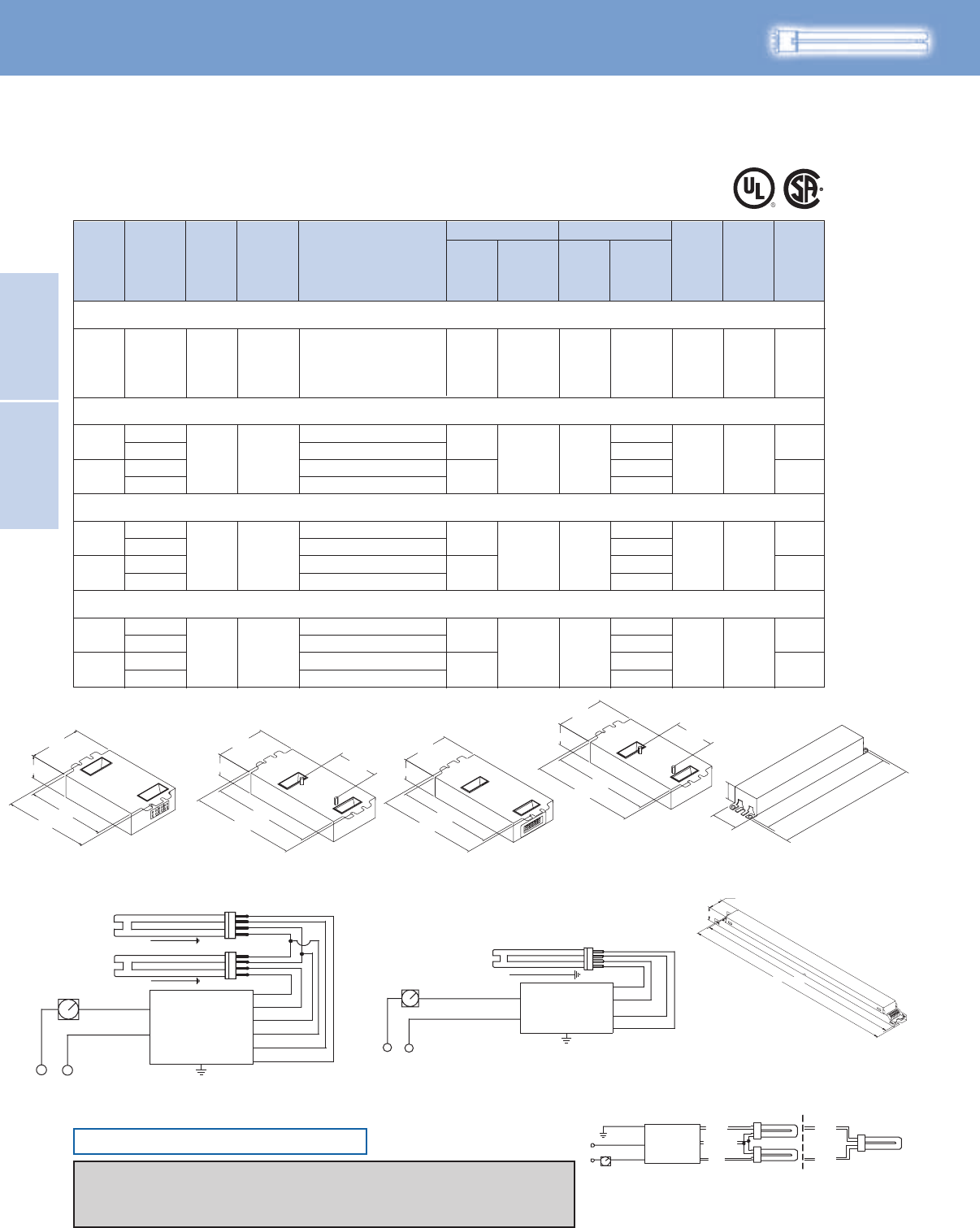
Lighting Electronics Atlas 2010-2011
2-10
Electronic Fluorescent
Controllable Ballasts
ELECTRONIC FLUORESCENT
CONTROLLABLE BALLASTS
HIGH POWER FACTOR SOUND RATED A
FT36W/2G11 - 36/39W Long Twin Tube Lamp (PL-L36W, F39BX/RS, FT36DL)
1
2
PS Mark 10
Powerline
38/9
1.00/0.05 10
0.32
0.14
0.64
0.27
50/10 B
134
13275/16
120
277
120
277
REZ-1TTS40-SC
VEZ-1TTS40-SC
REZ-2TTS40-SC
VEZ-2TTS40-SC
0.30
277 VEZ-2TTS40-SC
FT40W/2G11/RS - 40W Long Twin Tube Lamp (PL-L40W, F40BX, FT40DL/RS)
FT55W/2G11 - 55W Long Twin Tube Lamp (PL-L55W, F55BX, FT55DL)
1
2
PS Mark 10
Powerline
41/10
80/17
1.00/0.05 10
0.32
0.15
0.68 50/10 B
134
132
120
277
120
REZ-1TTS40-SC
VEZ-1TTS40-SC
REZ-2TTS40-SC
0.42
277 VEZ-2S54
1
2
PS Mark 10
Powerline
59/13
114/24
0.90/0.05 10
0.50
0.22
0.96 50/10 D
134
132
120
277
120
REZ-154
VEZ-154
REZ-2S54
FT24W/2G11 - 24/27W Long Twin Tube Lamp (PL-L24W, F27BX/RS, FT24DL)
2 PS Mark 10
Powerline 57/16 1.00/0.05 10 0.48-0.21 50/10 D 132120-277 IEZ-2S24-D
Burn in new lamps 100 hours at full light before dimming.
Ballasts utilizing poke-in connectors can accept wire gauge AWG 16-20.
ONLY USE RAPID-START SOCKETS
BALLAST
BLACK
WHITE
DIMMER
LINE
BLUE
BLUE
YELLOW
YELLOW
RED
RED BALLAST
BLACK/WHITE
WHITE
DIMMER
LINE
BLUE
BLUE
RED
RED
RED
Diag. 138
YELLOW
BLACK
WHITE
GREEN BLUE BLUE
RED
WIRING: (2) QUAD/TRIPLE LAMPS (1) QUAD/TRIPLE LAMP
GREEN TERMINAL MUST BE GROUNDED
DIMMER
LINE BALLAST
No. of
Lamps
Input
Volts
Lamp
Starting
Method
Ballast
Family Catalog Number Input
Power
ANSI
(Watts)
THD %
Ballast
Factor
Line
Current
(Amps)
Max/Min Min.
Starting
Temp.
(°F/°C)
Dim. Wiring
Dia.
Full Light Output
For 24 - 55W Lamps
FT5
Mark 10 Powerline Electronic Dimming Ballast
Diag. 132
Diag. 134
Diag. 138
Fig. B
8.90"
9.5"
1.18"
1.7"
Fig. D
Includes connectors with no leads
1.18"
1.00"
16.70" 16.34"
Size 2 Enclosure
4.20"
3.00"
4.60"
1.29" 2.00"
4.20"
3.00"
4.60"
1.29"
Size 3 Enclosure
Dual connector for input only
5.5"
3.00"
2.00"
6.0"
1.29"
5.5"
3.00"
6.0"
1.29"
Mark 10 Powerline Controllable
Refer to pages 1-13 & 1-14 for information on remote/tandem wiring and lead length extension
Refer to pages 2-24 & 2-25 for compatible Mark 10 Powerline controls
Refer to pages 9-24 to 9-28 for lead lengths and shipping data
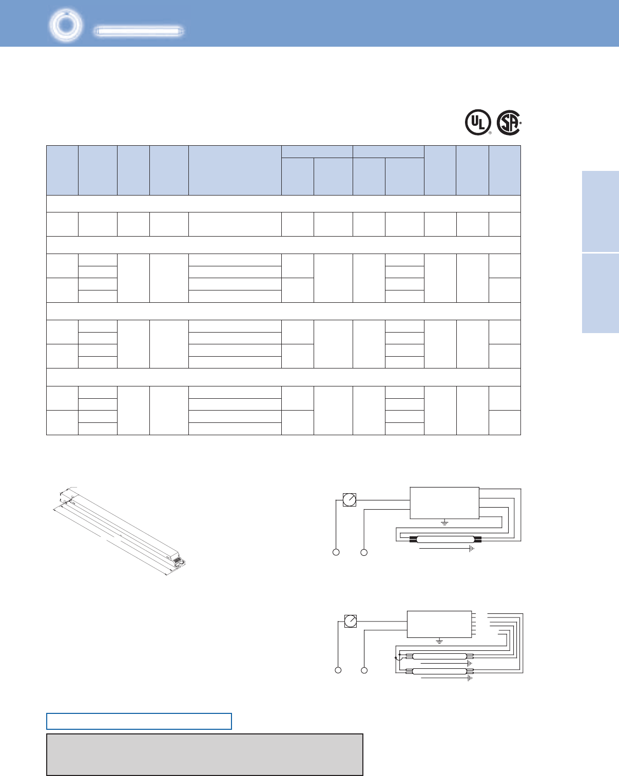
2-11
Lighting Electronics Atlas 2010-2011
Electronic Fluorescent
Controllable Ballasts
ELECTRONIC FLUORESCENT
CONTROLLABLE BALLASTS
HIGH POWER FACTOR SOUND RATED A
No. of
Lamps
Input
Volts
Lamp
Starting
Method
Ballast
Family Catalog Number Input
Power
ANSI
(Watts)
THD %
Ballast
Factor
Line
Current
(Amps)
Max/Min Min.
Starting
Temp.
(°F/°C)
Dim. Wiring
Dia.
Full Light Output
T5/HO
For 24 - 55W Lamps
Mark 10 Powerline Electronic Dimming Ballast
F24T5/HO (24W)
F54T5/HO (54W)
F54T5/HO/ES (49W)
2
1
1
2
2
PS
PS
FC12T5/HO (55W)
1
2
153
152
153
152
152
153
153
0.48-0.21
0.50
0.22
0.96
0.42
0.53
0.49
0.23
0.21
1.05
0.98
0.45
0.42
10
10
10
10
50/10
50/10
50/10
50/10
D
D
D
D
63/13
59/13
125/24
117/24
1.00/0.03
1.00/0.03
0.90/0.03
PS Mark 10
Powerline
Mark 10
Powerline
Mark 10
Powerline
Mark 10
Powerline
120-277
120
277
120
277
120
120
277
277
120
120
277
277
IEZ-2S24-D 1.00/0.05
57/16
59/13
114/24
REZ-154
REZ-154
VEZ-154
VEZ-154
REZ-2S54
REZ-2S54
VEZ-2S54
VEZ-2S54
REZ-154
VEZ-154
REZ-2S54
VEZ-2S54
PS
Some lamp manufacturers recommend burning in new lamps 100 hours at full light output before dimming. Consult lamp manufacturer.
Ballasts utilizing poke-in connectors can accept wire gauge AWG 16-20.
Fig. D
Includes connectors with no leads
Diag. 152
Diag. 153
1.18"
1.00"
16.70" 16.34"
BALLAST
DIMMER
LINE
LAMP
RED
BLACK/WHITE
WHITE
RED
BLUE
BLUE
BALLAST
BLACK
WHITE
DIMMER
LINE
LAMP
LAMP
RED
BLUE
YELLOW
Mark 10 Powerline Controllable
ONLY USE RAPID-START SOCKETS
Refer to pages 1-13 & 1-14 for information on remote/tandem wiring and lead length extension
Refer to pages 2-24 & 2-25 for compatible Mark 10 Powerline controls
Refer to pages 9-24 to 9-28 for lead lengths and shipping data
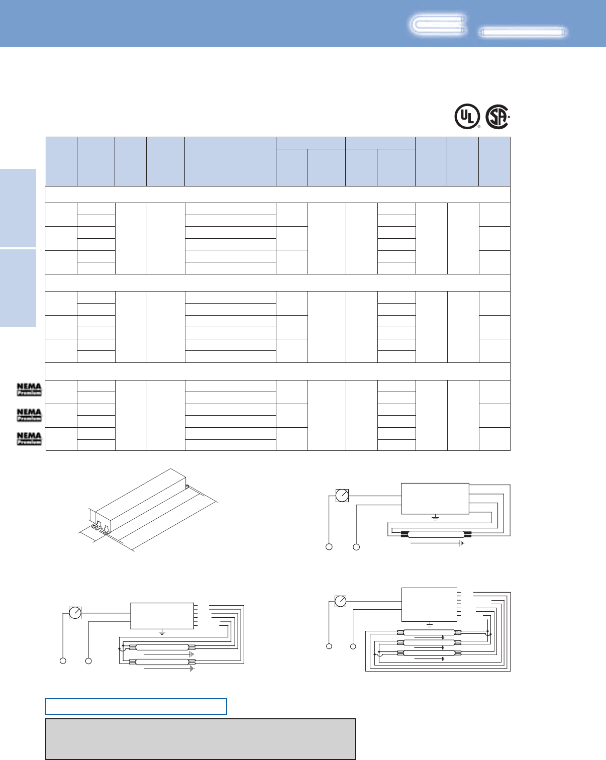
Lighting Electronics Atlas 2010-2011
2-12
Electronic Fluorescent
Controllable Ballasts
ELECTRONIC FLUORESCENT
CONTROLLABLE BALLASTS
Some lamp manufacturers recommend burning in new lamps 100 hours at full light output before dimming. Consult lamp manufacturer.
F17T8, FBO16T8 (17W)
F25T8, FBO24T8 (25W)
1
2
3
1
2
3
120
277
120
277
120
152
153
155
0.26
0.11
0.46
0.20
0.66
0.29
1.05/0.05 10 50/10 B
30/7
55/13
79/19
120
PS
277
120
277
120
277
277
PS Mark 10
Powerline
Mark 10
Powerline
24/7 152
153
155
1.05/0.05 10 50/10 B
38/13
56/18
REZ-132-SC 0.20
0.09
0.32
0.14
0.47
0.21
VEZ-132-SC
REZ-2S32-SC
VEZ-2S32-SC
REZ-3S32-SC
VEZ-3S32-SC
REZ-132-SC
VEZ-132-SC
REZ-2S32-SC
VEZ-2S32-SC
REZ-3S32-SC
VEZ-3S32-SC
F32T8, FBO31T8, F32T8/U6 (32W)
1
2
3
120
PS
277
120
277
120
277
Mark 10
Powerline
35/9 152
153
155
1.00/0.05 10 50/10 B68/15
100/20
REZ-132-SC 0.29
0.13
0.57
0.25
0.86
0.37
VEZ-132-SC
REZ-2S32-SC
VEZ-2S32-SC
REZ-3S32-SC
VEZ-3S32-SC
No. of
Lamps
Input
Volts
Lamp
Starting
Method
Ballast
Family Catalog Number Input
Power
ANSI
(Watts)
THD %
Ballast
Factor
Line
Current
(Amps)
Max/Min Min.
Starting
Temp.
(°F/°C)
Dim. Wiring
Dia.
Full Light Output
For 17 - 32W Lamps
T8
HIGH POWER FACTOR SOUND RATED A
Mark 10 Powerline Electronic Dimming Ballast
8.90"
9.5"
1.18"
1.7"
Fig. B
BALLAST
DIMMER
LINE
LAMP
RED
BLACK/WHITE
WHITE
RED
BLUE
BLUE
BALLAST
BLACK
WHITE
DIMMER
LINE
LAMP
LAMP
RED
BLUE
YELLOW
BLACK
WHITE
DIMMER
LINE
RED
BLUE/WHITE
BLUE
YELLOW
BALLAST
LAMP
LAMP
LAMP
Mark 10 Powerline Controllable
Diag. 152
Diag. 153 Diag. 155
ONLY USE RAPID-START SOCKETS
Refer to pages 1-13 & 1-14 for information on remote/tandem wiring and lead length extension
Refer to pages 2-24 & 2-25 for compatible Mark 10 Powerline controls
Refer to pages 9-24 to 9-28 for lead lengths and shipping data

2-13
Lighting Electronics Atlas 2010-2011
ELECTRONIC FLUORESCENT CONTROLLABLE BALLASTS
Electronic Fluorescent
Controllable Ballasts
The Mark 7 0–10V series of dimmable electronic
ballasts offer maximum versatility by incorporating
separate control leads for use with a wide array of
controllers, including occupancy sensors, daylight
harvesting controls, and building management systems
from more than 30 manufacturers.
When paired with linear fluorescent and 4-pin
compact fluorescent lamps, Mark 7 0–10V ballasts
optimize the benefits of such popular sustainable
lighting techniques as daylight harvesting, occupancy
sensors, and load shedding to satisfy the need for
an affordable, flexible and versatile controllable
lighting solution
Fluorescent Ballasts - Dimming - Mark 7® 0-10 V
0-10V Electronic Dimming Ballasts for Linear Fluorescent and 4-Pin Compact Fluorescent Lamps
Features
Available in linear fluorescent and 4-pin compact
fluorescent models
Making this ideal for a variety of applications
Full range continuous dimming (100% light output down
to 5% - T5/HO to 1%)
Provides task appropriate comfort only where necessary
to increase potential energy savings while supporting LEED
performance standards
Programmed start operation
Potentially extends lamp life in frequent switching applications
such as occupancy sensors and daylight harvesting
IntelliVolt® technology (120 - 277V, 50/60Hz)
Enhances accuracy and ease of ordering while reducing
stocking/SKU requirements
Mark 7 0-10V Controllable
The following ballasts meet NEMA Premium®:
IZT-132-SC, IZT-2S32-SC, IZT-3S32-SC,
IZT-4S32, VZT-4S32-HL, VZT-4S32-G, VZT-4PSP32-G
As a licensee in the NEMA Premium Ballast Program, Philips Lighting Electronics has determined that these
products meet the NEMA Premium specification for premium energy efficiency.
Note: Easy way to test dimming functionality is to ‘short’
together the violet and grey control wires. If the lamps go
to full dim, then the ballast is dimming fine.
Lighting Electronics Atlas 2010-2011
2-14
Electronic Fluorescent
Controllable Ballasts
ELECTRONIC FLUORESCENT
CONTROLLABLE BALLASTS
HIGH POWER FACTOR SOUND RATED A
CFTR42W/GX24q - 42W CFL Triple Tube Lamp (PL-T42W, F42TBX/4P, CF42DT/E)
CFTR57W/GX24q - 57W CFL Triple Tube Lamp (PL-T57W, F57QBX/4P, CF57DT/E)
CFTR70W/GX24q - 70W CFL Triple Tube Lamp (F70QBX/4P, CF70DT/E)
1
2
PS Mark 7
0-10V
47/9
1.00/0.03 10
0.39-0.17
50/10 Size 5
166
1660.82-0.36
98/18
120-277
IZT-2S26-M5-BS
IZT-2S26-M5-LD
IZT-2T42-M5-BS
IZT-2T42-M5-LD
1PS Mark 7
0-10V 65/16 1.00/0.03 10 0.55-0.24 50/10 Size 5 166
120-277 IZT-2T42-M5-BS
IZT-2T42-M5-LD
1PS Mark 7
0-10V 75/16 1.00/0.03 10 0.63-0.27 50/10 Size 5 166
120-277 IZT-2T42-M5-BS
IZT-2T42-M5-LD
Some lamp manufacturers recommend burning in new lamps 100 hours at full light output before dimming. Consult lamp manufacturer.
Ballasts utilizing poke-in connectors can accept wire gauges from AWG 16 - 20.
Mark 7 0-10V Control Wiring (Grey and Violet)
Wire Size Maximum Length (Ft.)
AWG-16 800
AWG-18 500
AWG-20 320
No. of
Lamps
Input
Volts
Lamp
Starting
Method
Ballast
Family Catalog Number Input
Power
ANSI
(Watts)
THD %
Ballast
Factor
Line
Current
(Amps)
Max/Min Min.
Starting
Temp.
(°F/°C)
Dim. Wiring
Dia.
Full Light Output
T4
For 13 - 70W Lamps
Mark 7 0-10V Electronic Dimming Ballast
CFQ13W/G24q - 13W CFL Quad Tube Lamp (PL-C13W/4P, F13DBX/4P, CF13DD/E)
CFTR13W/GX24q - 13W CFL Triple Tube Lamp (F13TBX/4P, CF13DT/E)
CFQ18W/G24q - 18W CFL Quad Tube Lamp (PL-C18W/4P, F18DBX/4P, CF18DD/E)
CFTR18W/GX24q - 18W CFL Triple Tube Lamp (PL-T18W, F18TBX/4P, CF18DT/E)
CFQ26W/G24q - 26W CFL Quad Tube Lamp (PL-C26W/4P, F26DBX/4P, CF26DD/E)
CFTR26W/GX24q - 26W CFL Triple Tube Lamp (PL-T26W, F26TBX/4P, CF26DT/E)
CFTR32W/GX24q - 32W CFL Triple Tube Lamp (PL-T32W, F32TBX/4P, CF32DT/E)
1
2
PS Mark 7
0-10V
18/6
1.00/0.03 10
0.15-0.07
50/10 Size 5
166
1660.28-0.12
33/19
120-277
IZT-2S26-M5-BS
IZT-2S26-M5-LD
IZT-2S26-M5-BS
IZT-2S26-M5-LD
1
2
PS Mark 7
0-10V
23/7
1.00/0.03 10
0.19-0.09
50/10 Size 5
166
1660.34-0.15
41/11
120-277
IZT-2S26-M5-BS
IZT-2S26-M5-LD
IZT-2S26-M5-BS
IZT-2S26-M5-LD
1
2
PS Mark 7
0-10V
30/8
1.00/0.03 10
0.25-0.11
50/10 Size 5
166
1660.46-0.20
55/13
120-277
IZT-2S26-M5-BS
IZT-2S26-M5-LD
IZT-2S26-M5-BS
IZT-2S26-M5-LD
1
2
PS Mark 7
0-10V
36/9
1.00/0.03 10
0.30-0.13
50/10 Size 5
166
166
0.63-0.21
75/19
120-277
IZT-2S26-M5-BS
IZT-2S26-M5-LD
IZT-2T42-M5-BS
IZT-2T42-M5-LD
ONLY USE 4-PIN RAPID-START SOCKETS
Mark 7 0-10V Controllable
Refer to pages 1-13 & 1-14 for information on remote/tandem wiring and lead length extension
Refer to pages 2-15 for wiring diagrams
Refer to pages 9-24 to 9-28 for lead lengths and shipping data
Size 5 Enclosure
4.20" (106.7)
3.00" (76.4)
4.55" (116.6)
-BS-LD
1.18" (30.0)
4.20" (106.7)
3.00" (76.4)
4.55" (116.6)
1.18" (30.0)
2.00" (50.8)
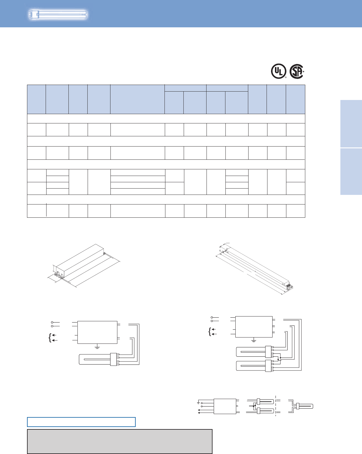
2-15
Lighting Electronics Atlas 2010-2011
Electronic Fluorescent
Controllable Ballasts
ELECTRONIC FLUORESCENT
CONTROLLABLE BALLASTS
HIGH POWER FACTOR SOUND RATED A
RED
Diag. 166
YELLOW
BLACK
WHITE
VIOLET (+)
GREY (-)
GREEN BLUE
{
Class 1 or
Class 2 Circuit
10V, 0.5 mA
BLUE
RED
WIRING: (2) QUAD/TRIPLE LAMPS (1) QUAD/TRIPLE LAMP
Green Te rminal Must Be Grounded
BALLAST
GREEN TERMINAL MUST BE GROUNDED
FT55W/2G11 - 55W Long Twin Tube Lamp (PL-L55W, F55BX, FT55DL)
No. of
Lamps
Input
Volts
Lamp
Starting
Method
Ballast
Family Catalog Number Input
Power
ANSI
(Watts)
THD %
Ballast
Factor
Line
Current
(Amps)
Max/Min Min.
Starting
Temp.
(°F/°C)
Dim. Wiring
Dia.
Full Light Output
FT5
For 36 - 80W Lamps
Mark 7 0-10V Electronic Dimming Ballast
FT36W/2G11 - 36/39W Long Twin Tube Lamp (PL-L36W, F39BX/RS, FT36DL)
FT40W/2G11/RS - 40W Long Twin Tube Lamp (PL-L40W, F40BX, FT40DL/RS)
2PS Mark 7
0-10V 10 0.64-0.28 50/10 B 59A76/16120-277 IZT-2TTS40-SC
2 PS Mark 7
0-10V 75/16 1.00/0.03 10 0.64-0.27 50/10 B 59A120-277 IZT-2TTS40-SC
1
2
PS Mark 7
0-10V
59/13
114/24
0.90/0.03 10
0.50
0.22
0.96
0.42
50/10 D
58A
59A
120
277
120
277
RZT-154
VZT-154
RZT-2S54
VZT-2S54
FT80W/2G11 - 80W Long Twin Tube Lamp (PL-L80W, FT80DL)
1PS Mark 7
0-10V 94/16 1.00/0.03 10 0.34 50/10 D 58A277 VZT-180
Burn in new lamps 100 hours at full light output before dimming.
Ballasts utilizing poke-in connectors can accept wire gauge AWG 16-20.
1.00/0.03
8.90"
9.5"
1.18"
1.7"
Fig. B Fig. D
Includes connectors with no leads
Diag. 166
1.18"
1.00"
16.70" 16.34"
Diag. 58A Diag. 59A
BALLAST
BLUE
RED
LINE BLACK
WHITE
CLASS 1 OR 2
CIRCUIT
10V, 0.5MA
VIOLET (+)
GREY (–)
BALLAST
LINE
BLUE
YELLOW
RED
BLACK
CLASS 1 OR 2
CIRCUIT
10V, 0.5MA
WHITE
VIOLET (+)
GREY (–)
Mark 7 0-10V Controllable
ONLY USE RAPID-START SOCKETS
Refer to pages 1-13 & 1-14 for information on remote/tandem wiring and lead length extension
Refer to pages 2-24 & 2-25 for compatible Mark 10 Powerline controls
Refer to pages 9-24 to 9-28 for lead lengths and shipping data
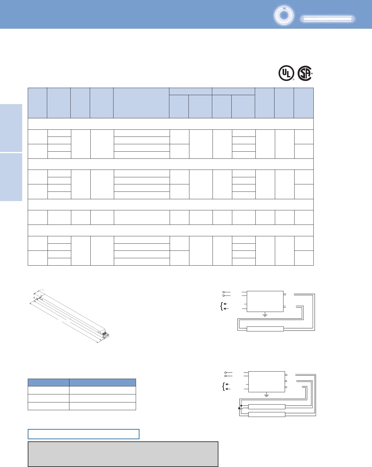
Lighting Electronics Atlas 2010-2011
2-16
Electronic Fluorescent
Controllable Ballasts
ELECTRONIC FLUORESCENT
CONTROLLABLE BALLASTS
Wiring
Dia.
T5/HO
Mark 7 0-10V Control Wiring (Grey and Violet)
Wire Size Maximum Length (Ft.)
AWG-16 800
AWG-18 500
AWG-20 320
No. of
Lamps
Input
Volts
Lamp
Starting
Method
Ballast
Family Catalog Number Input
Power
ANSI
(Watts)
THD %
Ballast
Factor
Line
Current
(Amps)
Max/Min Min.
Starting
Temp.
(°F/°C)
Dim.
Full Light Output
HIGH POWER FACTOR SOUND RATED A
For 49 - 80W Lamps
Mark 7 0-10V Electronic Dimming Ballast
F54T5/HO/ES (49W)
1
2
55A
56A
0.49
0.21
0.98
0.42
10 50/10 DPS Mark 7
0-10V
120
277
120
277
RZT-154
VZT-154
RZT-2S54
59/13
1.00/0.03
117/24
VZT-2S54
F54T5/HO (54W)
F80T5/HO (80W)
1
2
1 277 PS
FC12T5/HO (55W)
1
2
55A
56A
55A
56A
55A
0.53
0.23
1.05
0.45
0.50
0.22
0.96
0.42
0.34
10
10
10
50/10
50/10
50/10
D
D
D
94/18 1.00/0.03
0.90/0.03
PS Mark 7
0-10V
Mark 7
0-10V
Mark 7
0-10V
120
277
120
277
120
277
120
277
RZT-154
VZT-154
RZT-2S54
63/13
1.00/0.03
125/24
59/13
114/24
VZT-2S54
RZT-154
VZT-154
RZT-2S54
VZT-2S54
VZT-180
PS
Some lamp manufacturers recommend burning in new lamps 100 hours at full light output before dimming. Consult lamp manufacturer.
Ballasts utilizing poke-in connectors can accept wire gauges from AWG 16 - 20.
Fig. D
Includes connectors with no leads
Diag. 55A
Diag. 56A
1.18"
1.00"
16.70" 16.34"
BALLAST
BLUE
RED
LAMP
LINE BLACK
WHITE
CLASS 1 OR 2
CIRCUIT
10V, 0.5MA
VIOLET (+)
GREY (–)
BALLAST BLUE
YELLOW
RED
LAMP
LAMP
LINE BLACK
WHITE
CLASS 1 OR 2
CIRCUIT
10V, 0.5MA
VIOLET (+)
GREY (–)
Mark 7 0-10V Controllable
ONLY USE RAPID-START SOCKETS
Refer to pages 1-13 & 1-14 for information on remote/tandem wiring and lead length extension
Refer to pages 2-24 & 2-25 for compatible Mark 10 Powerline controls
Refer to pages 9-24 to 9-28 for lead lengths and shipping data
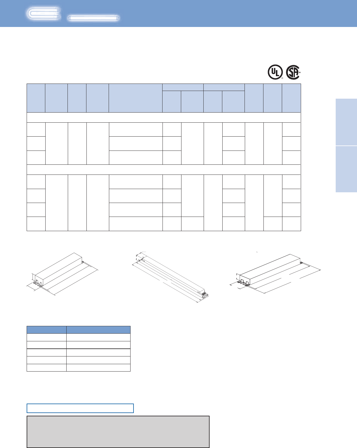
2-17
Lighting Electronics Atlas 2010-2011
Electronic Fluorescent
Controllable Ballasts
ELECTRONIC FLUORESCENT
CONTROLLABLE BALLASTS
F17T8, FBO16T8 (17W)
F25T8, FBO24T8 (25W)
1 20/7 0.16-0.07 55A
56A
57A
55A
56A
57A
16A
0.30-0.13
0.46-0.20
0.24-0.11
0.43-0.19
0.65-0.28
0.77-0.35
1.00/0.03 10 50/10 B
36/11
56/18
1.00/0.03
0.88/0.03
10 50/10
B
D
28/8
52/12
79/19
96/22
120-277 PS Mark 7
0-10V
2
3
1
2
3
4
PS120-277 Mark 7
0-10V
IZT-132-SC
IZT-2S32-SC
IZT-3S32-SC
IZT-132-SC
IZT-2S32-SC
IZT-3S32-SC
IZT-4S32
Some lamp manufacturers recommend burning in new lamps 100 hours at full light output before dimming. Consult lamp manufacturer.
Ballasts utilizing poke-in connectors can accept wire gauges from AWG 16 - 20.
No. of
Lamps
Input
Volts
Lamp
Starting
Method
Ballast
Family Catalog Number Input
Power
ANSI
(Watts)
THD %
Ballast
Factor
Line
Current
(Amps)
Max/Min Min.
Starting
Temp.
(°F/°C)
Dim. Wiring
Dia.
Full Light Output
For 17 - 25W Lamps
Mark 7 0-10V Electronic Dimming Ballast
Mark 7 0-10V Control Wiring (Grey and Violet)
Wire Size Maximum Length (Ft.)
AWG-16 800
AWG-18
AWG-22
500
200
AWG-20
AWG-24
320
120
8.90"
9.5"
1.18"
1.7"
Fig. B Fig. D
Includes connectors with no leads
Fig. G
1.18"
1.00"
16.70" 16.34"
16.34"
16.70"
1.18"
1.70"
Mark 7 0-10V Controllable
ONLY USE RAPID-START SOCKETS
Refer to pages 1-13 & 1-14 for information on remote/tandem wiring and lead length extension
Refer to pages 2-18 for wiring diagrams
Refer to pages 2-24 & 2-25 for compatible low voltage controls
Refer to pages 9-24 to 9-28 for lead lengths and shipping data
T8
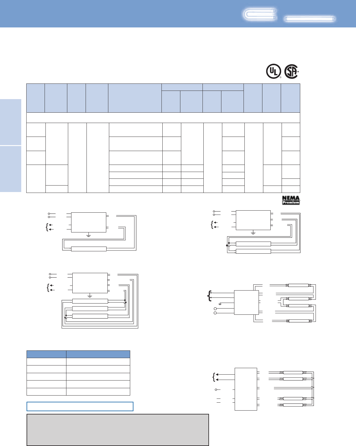
Lighting Electronics Atlas 2010-2011
2-18
Electronic Fluorescent
Controllable Ballasts
ELECTRONIC FLUORESCENT
CONTROLLABLE BALLASTS
VZT-4PSP32-G 0.410.88/0.10112/27
10
LINE BLACK
GREEN
WHITE
CLASS 1 OR 2
CIRCUIT
10V, 0.5MA
GROUND RING
TERMINAL
GREY
VIOLET
LAMP
LAMP
LAMP
LAMP
BLUE/WHITE
RED/WHITE
YELLOW
BLUE
RED
BALLAST
Mark 7 0-10V Control Wiring (Grey and Violet)
Wire Size Maximum Length (Ft.)
AWG-16 800
AWG-18
AWG-22
500
200
AWG-20
AWG-24
320
120
No. of
Lamps
Input
Volts
Lamp
Starting
Method
Ballast
Family Catalog Number Input
Power
ANSI
(Watts)
THD %
Ballast
Factor
Line
Current
(Amps)
Max/Min Min.
Starting
Temp.
(°F/°C)
Dim. Wiring
Dia.
Full Light Output
HIGH POWER FACTOR SOUND RATED A
T8
For 32W Lamps
Mark 7 0-10V Electronic Dimming Ballast
277 0.541.18/0.05149/27
F32T8, FBO31T8, F32T8/U6 (32W)
1
120-277
120-277
PS Mark 7
0-10V
2
3
4
35/8 0.30-0.13
0.57-0.24
0.86-0.37
0.42
0.98-0.42
55A
56A
57A
16A
16A
174
1.00/0.03
0.88/0.05
0.88/0.03
50/10
B
G
D
68/14
100/20
116/25
116/25
IZT-132-SC
IZT-2S32-SC
IZT-3S32-SC
VZT-4S32-G
IZT-4S32
Some lamp manufacturers recommend burning in new lamps 100 hours at full light output before dimming. Consult lamp manufacturer.
Ballasts utilizing poke-in connectors can accept wire gauges from AWG 16 - 20.
VZT-4S32-HL
Diag. 55A
Diag. 57A Diag. 16A
Diag. 174
Diag. 56A
BALLAST
BLUE
RED
LAMP
LINE BLACK
WHITE
CLASS 1 OR 2
CIRCUIT
10V, 0.5MA
VIOLET (+)
GREY (–)
BLUE
RED
YELLOW
BLUE/WHITE
BROWN
LAMP
LAMP
LAMP
LAMP
LINE
BLACK
GREEN
WHITE
CLASS 1 OR 2
CIRCUIT
10V, 0.5MA
VIOLET (+)
GREY (–)
BALLAST
BALLAST BLUE
YELLOW
RED
LAMP
LAMP
LINE BLACK
WHITE
CLASS 1 OR 2
CIRCUIT
10V, 0.5MA
VIOLET (+)
GREY (–)
BALLAST BLUE
BLUE/WHITE
YELLOW
RED
LAMP
LAMP
LAMP
LINE BLACK
WHITE
CLASS 1 OR 2
CIRCUIT
10V, 0.5MA
VIOLET (+)
GREY (–)
Mark 7 0-10V Controllable
ONLY USE RAPID-START SOCKETS
Refer to pages 1-13 & 1-14 for information on remote/tandem wiring and lead length extension
Refer to pages 2-17 for ballast dimensions
Refer to pages 2-24 & 2-25 for compatible low voltage controls
Refer to pages 9-24 to 9-28 for lead lengths and shipping data
2-19
Lighting Electronics Atlas 2010-2011
ELECTRONIC FLUORESCENT CONTROLLABLE BALLASTS
Electronic Fluorescent
Controllable Ballasts
Philips Advance ROVR ballasts reflect the latest
approach to controlling fluorescent lighting.
Rather than simply responding to instructions
from control components, ROVR ballasts enable
two-way communication, allowing for virtually
unlimited design flexibility.
This two-way communication is made possible
through the industry-standard digital communication
protocol known as DALI (Digital Addressable
Lighting Interface).
This protocol allows ROVR ballasts to provide users
with operational data while controlling the output
of individual luminaires. This fully supports sustainable
design principles such as daylight harvesting and
occupancy sensors while enabling a proactive
response to maintenance concerns.
Fluorescent Ballasts - Dimming - ROVR™
Digital Addressable Ballasts for Linear Fluorescent and 4-Pin Compact Fluorescent Lamps
Features
Available in linear fluorescent and 4-pin compact
fluorescent models
Making this ideal for a variety of applications
Full range continuous dimming (100% light output down to
3% - T5/HO to 1%)
Provides task appropriate comfort only where necessary
to increase potential energy savings while supporting LEED
performance standards
Programmed start operation
Potentially extends lamp life in frequent switching
applications such as occupancy sensors and daylight
IntelliVolt Technology (120-277V, 50/60Hz)
Enhances accuracy and ease of ordering while reducing
stocking/SKU requirements
ROVR Controllable
The following ballasts meet NEMA Premium®:
IDA-132-SC, IDA-2S32-SC, IDA-3S32-SC, IDA-4S32
As a licensee in the NEMA Premium Ballast Program, Philips Lighting Electronics has determined that these
products meet the NEMA Premium specification for premium energy efficiency.
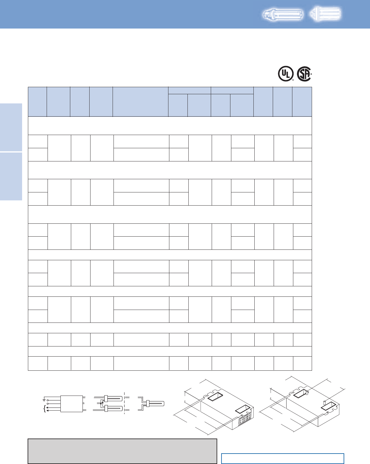
Lighting Electronics Atlas 2010-2011
2-20
Electronic Fluorescent
Controllable Ballasts
ELECTRONIC FLUORESCENT
CONTROLLABLE BALLASTS
CFQ13W/G24q - 13W CFL Quad Tube Lamp (PL-C13W/4P, F13DBX/4P, CF13DD/E)
CFTR13W/GX24q - 13W CFL Triple Tube Lamp (F13TBX/4P, CF13DT/E)
CFQ18W/G24q - 18W CFL Quad Tube Lamp (PL-C18W/4P, F18DBX/4P, CF18DD/E)
CFTR18W/GX24q - 18W CFL Triple Tube Lamp (PL-T18W, F18TBX/4P, CF18DT/E)
CFQ26W/G24q - 26W CFL Quad Tube Lamp (PL-C26W/4P, F26DBX/4P, CF26DD/E)
CFTR26W/GX24q - 26W CFL Triple Tube Lamp (PL-T26W, F26TBX/4P, CF26DT/E)
CFTR32W/GX24q - 32W CFL Triple Tube Lamp (PL-T32W, F32TBX/4P, CF32DT/E)
CFTR42W/GX24q - 42W CFL Triple Tube Lamp (PL-T42W, F42TBX/4P, CF42DT/E)
CFTR57W/GX24q - 57W CFL Triple Tube Lamp (PL-T57W, F57QBX/4P, CF57DT/E)
CFTR70W/GX24q - 70W CFL Triple Tube Lamp (F70QBX/4P, CF70DT/E)
1
2
PS ROVR
18/6
1.00/0.03 10
0.15-0.07
50/10 Size 5
165
1650.28-0.12
33/19
120-277
IDL-2S26-M5-BS
IDL-2S26-M5-LD
IDL-2S26-M5-BS
IDL-2S26-M5-LD
1
2
PS ROVR
23/7
1.00/0.03 10
0.19-0.09
50/10 Size 5
165
1650.34-0.15
41/11
120-277
IDL-2S26-M5-BS
IDL-2S26-M5-LD
IDL-2S26-M5-BS
IDL-2S26-M5-LD
1
2
PS ROVR
30/8
1.00/0.03 10
0.25-0.11
50/10 Size 5
165
1650.46-0.20
55/13
120-277
IDL-2S26-M5-BS
IDL-2S26-M5-LD
IDL-2S26-M5-BS
IDL-2S26-M5-LD
1
2
PS ROVR
36/9
1.00/0.03 10
0.30-0.13
50/10 Size 5
165
1650.63-0.21
75/19
120-277
IDL-2S26-M5-BS
IDL-2S26-M5-LD
IDL-2T42-M5-BS
IDL-2T42-M5-LD
1
2
PS ROVR
47/9
1.00/0.03 10
0.39-0.17
50/10 Size 5
165
1650.82-0.36
98/18
120-277
IDL-2S26-M5-BS
IDL-2S26-M5-LD
IDL-2T42-M5-BS
IDL-2T42-M5-LD
1PS ROVR 65/16 1.00/0.03 10 0.55-0.24 50/10 Size 5 165
120-277 IDL-2T42-M5-BS
IDL-2T42-M5-LD
1PS ROVR 75/16 1.00/0.03 10 0.63-0.27 50/10 Size 5 165
120-277 IDL-2T42-M5-BS
IDL-2T42-M5-LD
No. of
Lamps
Input
Volts
Lamp
Starting
Method
Ballast
Family Catalog Number Input
Power
ANSI
(Watts)
THD %
Ballast
Factor
Line
Current
(Amps)
Max/Min Min.
Starting
Temp.
(°F/°C)
Dim. Wiring
Dia.
Full Light Output
HIGH POWER FACTOR SOUND RATED A
T4
For 13 - 70W Lamps
ROVR Digital Addressable Ballast
ONLY USE 4-PIN RAPID-START SOCKETS
ROVR Controllable
Size 5
4.20" (106.7)
3.00" (76.4)
4.55" (116.6)
-BS
-LD
1.18" (30.0)
4.20" (106.7)
3.00" (76.4)
4.55" (116.6)
1.18" (30.0)
2.00" (50.8)
4.20" (106.7)
3.00" (76.4)
4.55" (116.6)
-BS
-LD
1.18" (30.0)
4.20" (106.7)
3.00" (76.4)
4.55" (116.6)
1.18" (30.0)
2.00" (50.8)
RED
Diag. 165
YELLOW
BLACK
WHITE
GREEN BLUE BLUE
RED
WIRING: (2) QUAD/TRIPLE LAMPS (1) QUAD/TRIPLE LAMP
Green Te rminal Must Be Grounded
DALI
CLASS 1 OR 2
CIRCUIT
PURPLE
PURPLE
BALLAST
GREEN TERMINAL MUST BE GROUNDED
Diag. 165
Some lamp manufacturers recommend burning in new lamps 100 hours at full light output before dimming. Consult lamp manufacturer.
Ballasts utilizing poke-in connectors can accept wire gauges from AWG 16 - 20.
Refer to pages 1-13 & 1-14 for information on remote/tandem wiring and lead length extension
Refer to pages 2-24 & 2-25 for compatible Mark 10 Powerline controls
Refer to pages 9-24 to 9-28 for lead lengths and shipping data
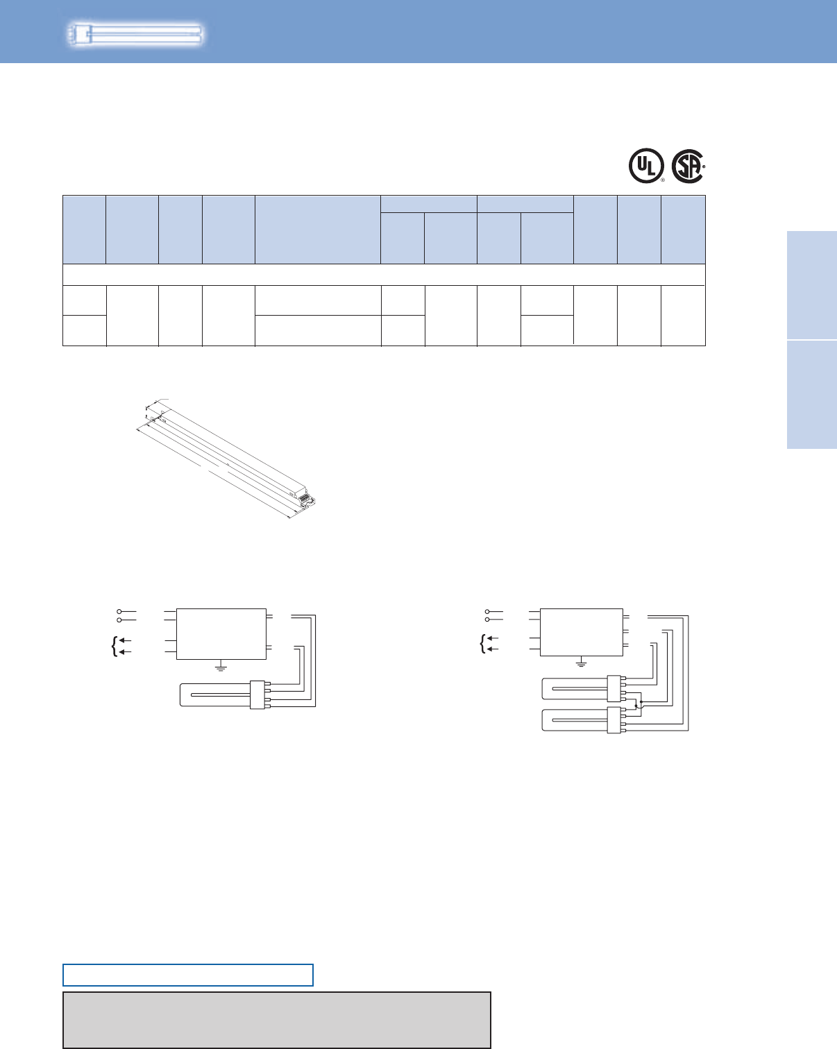
2-21
Lighting Electronics Atlas 2010-2011
Electronic Fluorescent
Controllable Ballasts
ELECTRONIC FLUORESCENT
CONTROLLABLE BALLASTS
FT55W/2G11 - 55W Long Twin Tube Lamp (PL-L55W, F55BX, FT55DL)
1
2
PS ROVR
59/13
114/24
0.90/0.03 10
0.50-0.22
0.96-0.42
50/10 D 165120-277
IDA-154
IDA-2S54
No. of
Lamps
Input
Volts
Lamp
Starting
Method
Ballast
Family Catalog Number Input
Power
ANSI
(Watts)
THD %
Ballast
Factor
Line
Current
(Amps)
Max/Min Min.
Starting
Temp.
(°F/°C)
Dim. Wiring
Dia.
Full Light Output
HIGH POWER FACTOR SOUND RATED A
FT5
For 55W Lamps
ROVR Digital Addressable Ballast
Fig. D
Includes connectors with no leads
Diag. 59BDiag. 58B
1.18"
1.00"
16.70" 16.34"
BALLAST
LINE
BLUE
YELLOW
RED
BLACK
DALI
CLASS 1 OR 2
CIRCUIT
WHITE
PURPLE
PURPLE
BALLAST
BLUE
RED
LINE BLACK
WHITE
DALI
CLASS 1 OR 2
CIRCUIT
PURPLE
PURPLE
ROVR Controllable
Some lamp manufacturers recommend burning in new lamps 100 hours at full light output before dimming. Consult lamp manufacturer.
Ballasts utilizing poke-in connectors can accept wire gauges from AWG 16 - 20.
ONLY USE RAPID-START SOCKETS
Refer to pages 1-13 & 1-14 for information on remote/tandem wiring and lead length extension
Refer to pages 2-24 & 2-25 for compatible Mark 10 Powerline controls
Refer to pages 9-24 to 9-28 for lead lengths and shipping data
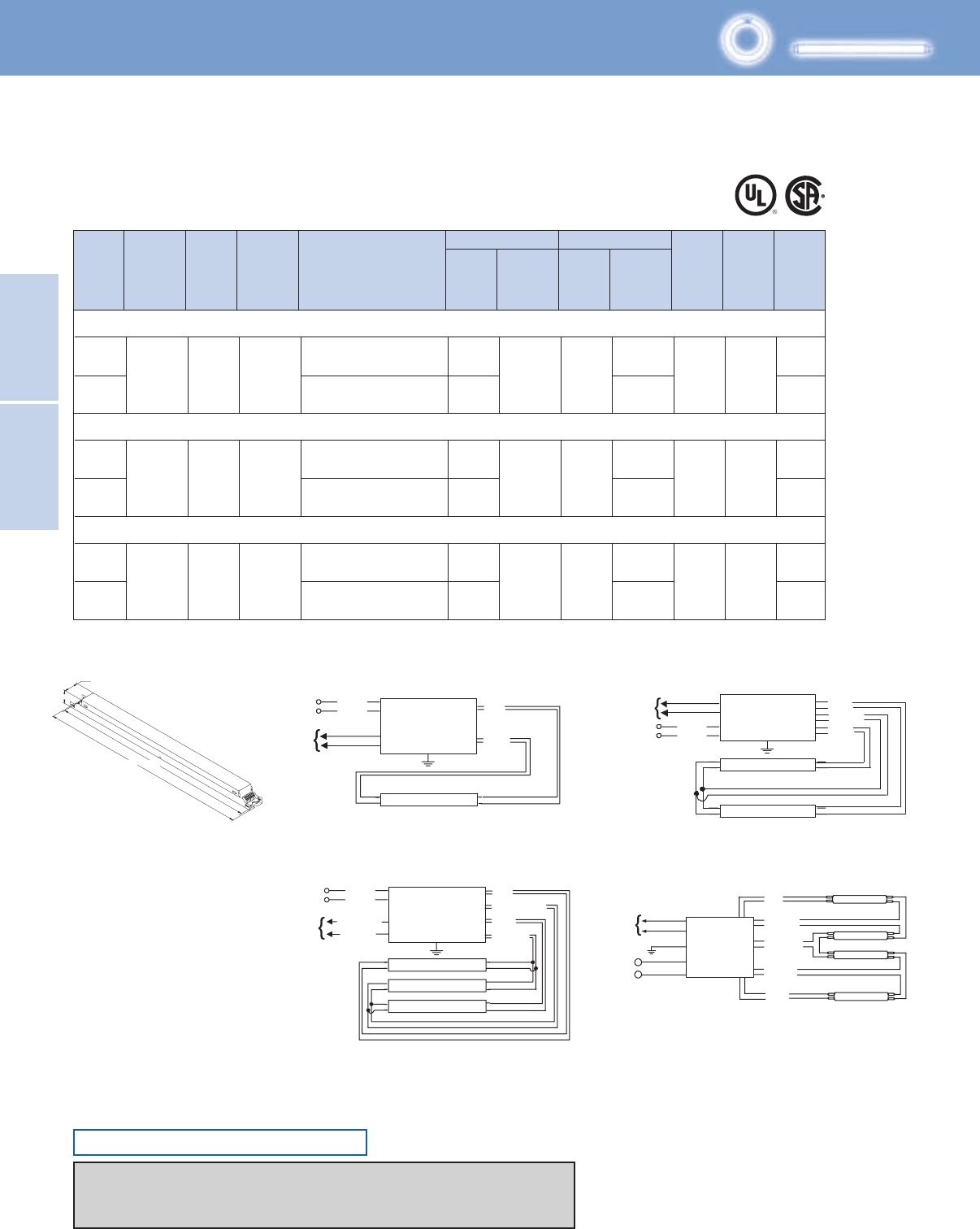
Lighting Electronics Atlas 2010-2011
2-22
Electronic Fluorescent
Controllable Ballasts
ELECTRONIC FLUORESCENT
CONTROLLABLE BALLASTS
BLUE
BLUE/WHITE
YELLOW
RED
LAMP
LAMP
LAMP
LINE BLACK
WHITE
CLASS 1 OR 2
CIRCUIT
10V, 0.5MA
VIOLET (+)
GREY (–)
BALLAST
BALLAST
BLUE
RED
YELLOW
BLUE/WHITE
BROWN
LAMP
LAMP
LAMP
LAMP
LINE
PURPLE
PURPLE
BLACK
WHITE
GREEN
DALI
CLASS 1 OR 2
CIRCUIT
Diag. 167
BALLAST
BLUE
RED
LAMP
LINE
BLACK
WHITE
PURPLE
PURPLE
DALI
CLASS 1 OR 2
CIRCUIT
BLUE
YELLOW
RED
LAMP
LAMP
LINE BLACK
WHITE
PURPLE
PURPLE
DALI
CLASS 1 OR 2
CIRCUIT BALLAST
Max/Min Full Light Output
T5/HO
No. of
Lamps
Input
Volts
Lamp
Starting
Method
Ballast
Family Catalog Number Input
Power
ANSI
(Watts)
THD %
Ballast
Factor
Line
Current
(Amps)
Max/Min Min.
Starting
Temp.
(°F/°C)
Dim. Wiring
Dia.
Full Light Output
HIGH POWER FACTOR SOUND RATED A
For 49 - 55W Lamps
ROVR Digital Addressable Ballast
Diag. 55B Diag. 56B
Fig. D
Includes connectors with no leads
Diag. 167Diag. 57B
1.18"
1.00"
16.70" 16.34"
F54T5/HO (54W)
F54T5/HO/ES (49W)
FC12T5/HO (55W)
1
1
2
2
1
2
PS
55B
55B
56B
56B
55B
56B
0.53-0.23
0.49-0.21
1.05-0.45
0.98-0.42
0.50-0.22
0.96-0.42
10
10
10
50/10
50/10
50/10
D
D
D
59/13
114/24
0.90/0.03
PS
PS
ROVR
ROVR
ROVR
120-277
120-277
120-277
IDA-154
IDA-154
IDA-2S54
IDA-2S54
IDA-154
IDA-2S54
63/13
59/13
1.00/0.03
1.00/0.03
125/24
117/24
Some lamp manufacturers recommend burning in new lamps 100 hours at full light output before dimming. Consult lamp manufacturer.
Ballasts utilizing poke-in connectors can accept wire gauges from AWG 16 - 20.
ROVR Controllable
ONLY USE RAPID-START SOCKETS
Refer to pages 1-13 & 1-14 for information on remote/tandem wiring and lead length extension
Refer to pages 2-24 & 2-25 for compatible Mark 10 Powerline controls
Refer to pages 9-24 to 9-28 for lead lengths and shipping data

2-23
Lighting Electronics Atlas 2010-2011
Electronic Fluorescent
Controllable Ballasts
ELECTRONIC FLUORESCENT
CONTROLLABLE BALLASTS
116/25
55B
56B
55B
56B
57B
167
0.16-0.07
0.30-0.13
0.24-0.11
0.43-0.19
0.65-0.28
0.77-0.35
1.00/0.03
1.00/0.03
0.88/0.03
10
10
50/10
50/10
B
B
G
D
0.30-0.13
0.58-0.25
0.86-0.37
0.98-0.42
55B
56B
57B
167
1.00/0.03
0.88/0.03
10 50/10
B
G
D
F17T8, FBO16T8 (17W)
F25T8, FBO24T8 (25W)
1
2
1
2
3
4
F32T8, FBO31T8, F32T8/U6 (32W)
1
2
3
4
20/7
36/11
28/8
52/12
79/19
96/22
120-277 PS ROVR
PS120-277 ROVR
IDA-132-SC
IDA-2S32-SC
IDA-132-SC
IDA-2S32-SC
IDA-3S32-G
IDA-4S32
35/8
68/14
100/20
120-277 PS ROVR
IDA-132-SC
IDA-2S32-SC
IDA-3S32-G
IDA-4S32
ONLY USE RAPID-START SOCKETS
No. of
Lamps
Input
Volts
Lamp
Starting
Method
Ballast
Family Catalog Number Input
Power
ANSI
(Watts)
THD %
Ballast
Factor
Line
Current
(Amps)
Max/Min Min.
Starting
Temp.
(°F/°C)
Dim. Wiring
Dia.
Full Light Output
For 17 - 32W Lamps
ROVR Digital Addressable Ballast
8.90"
9.5"
1.18"
1.7"
Fig. B Fig. D
Includes connectors with no leads
Fig. G
1.18"
1.00"
16.70" 16.34"
16.34"
16.70"
1.18"
1.70"
T8
HIGH POWER FACTOR SOUND RATED A
Controllable ROVR
Refer to pages 1-13 & 1-14 for information on remote/tandem wiring and lead length extension
Refer to pages 2-22 for wiring diagrams and ballast dimensions
Refer to pages 2-24 & 2-25 for compatible ROVR controls
Refer to pages 9-24 to 9-28 for lead lengths and shipping data
Some lamp manufacturers recommend burning in new lamps 100 hours at full light output before dimming. Consult lamp manufacturer.
Ballasts utilizing poke-in connectors can accept wire gauges from AWG 16 - 20.

Lighting Electronics Atlas 2010-2011
ELECTRONIC FLUORESCENT CONTROLLABLE BALLASTS
2-24
Electronic Fluorescent
Controllable Ballasts
Control Manufacturers who have products compatible with Philips Advance Mark 7 0-10V Electronic Dimming
Ballasts, Mark 10 Powerline Electronic Dimming Ballasts and ROVR Digital Addressable Ballasts as of February 2010
For a more detailed listing please visit http://www.advance.philips.com/documents/uploads/literature/EL-2100-AB-R03.pdf
The listed manufacturers have indicated that they manufacture products that are compatible with the Philips Advance Mark 7 0-10V electronic dimming ballasts, Philips Advance Mark 10 Powerline electronic
dimming ballasts, or Philips Advance ROVR digital addressable ballasts. Philips Lighting Electronics provides this list as a service to our customers and control manufacturers. Philips Lighting Electronics does not
support or recommend one manufacturer over another. Please refer to each manufacturer’s catalog for a complete product description and performance specifications.
MANUFACTURER PHONE MARK 7 0-10V (4-Wire Low Voltage) MARK 10 Powerline (2-Wire Line Voltage) ROVR (DALI)
Compatible Control Controllable
AMX Corporation 800-222-0193 Radia RDM-DC, RDM-2DC and Radia RE-DM4 and RE-DM6
RDM-3DC RDM-INC, RDM-2INC and RDM-INC50
Anigmo 800-749-0518 SEM & SEZ ST2-600LVE
Automated Logic Corp. 770-429-3000 S Line, M Line S Line, M Line
Avab America 415-505-5515 PWR Series PWR Series
CentraLite System, Inc. 877-466-5483 StarLite, Elegance, LiteJet
Colortran, Inc. 503-682-1941 Digital Ballast Controller ENR, I Series, I Series E, and
I Series Quad
Cooper Controls 800-553-3879 Greengate, iLumin Greengate, iLumin iLumin
Cooper Wiring Devices 866-853-4293 SF8AP, DF8AP, 9568 Aspire
Crestron Electronics 201-767-3400 CresLite™ Lighting System CresLite™ Lighting System
Digital Lighting Systems 305-969-8442 Protocol Protocol
DimOnOff 418-682-3636 Distributed Lighting Controls Distributed Lighting Controls
Douglas Lighting Controls 604-873-2797 MC6000, Dilor ALC3, WPC, MC6000, Dilor ALC3, ALC-DCM-12
WPN, WBC, WSP
Eaton 877-386-2273 POW-R-Command System
ETC 608-831-4116 Unison Paradigm, Unison DRd, Unison Paradigm, Unison DRd, Unison
(Electronic Theatre Controls) SmartLink SmartPack, Sensor, SmartLink Paradigm,
Unison DRd,
SmartLink
Electronics Diversified, Inc. 503-645-5533 MVP System, Versa-Pak System, MVP System, Versa-Pak System,
Mark 10 System Rack Mark 10 System Rack
Encelium 888-ENCELIUM Encelium ECS Control System,
DSC-500, MYC-RS-500
Entertainment Technologies 800-223-9477 Tap Glide, IPS, Capio Plus, Oasis Intelli Set Plus, Tap Glide, U-Set, IPS,
Capio Plus
Exergy 562-981-2127 XRG-200,
XRG-300,
XRG-400,
XRG-1000
Hubbell Building Automation 888-698-3242 DLC-7, OMNI, Light Owl, OMNI, Light Owl, Light Hawk,
Light Hawk, UVPP WASP High Bay Sensor, LX Networked
Lighting Controls, UVPP
Hunt Dimming 970-484-9048 PS, FD and SSD Simplicity Series PS, SC, FD and SSD Simplicity Series PS Series
Intelligent Lighting Controls 800-922-8004 Light Master
Johnson Controls 414-274-4000 Application Specific
Leax Controls 970-927-4845 Consult Factory Consult Factory
Legrand/Pass and Seymour 315-468-6211 Slide-to-Off Titan, Preset Titan Scene Director, Harmony,
Slide-to-Off Titan, Preset Titan, LightSense
Lehigh Electric Products Co. 610-395-3386 Sentry, Solitaire, DX2, Solitaire, DX2, SlimDim
Sunburst, ALX and DX with Sunburst, ALX and DX with
DCFL Interface ACFL Interface
Leprecon 810-231-9546 VX Series, MX Series, Lightscape
2-25
Lighting Electronics Atlas 2010-2011
ELECTRONIC FLUORESCENT CONTROLLABLE BALLASTS
Electronic Fluorescent
Controllable Ballasts
Leviton Lighting Control Div. 800-824-3005
Centura, Wallbox: IllumaTech,
Wallbox Dimmers: Monet, Renoir, Mural, CD100
PE300-D (Slave Pack).
TouchPoint, IllumaTech, SureSlide. CD250
Occupancy Sensors: Multi-Tech,
Occupancy Sensors: Multi-Tech, Wide
Wide View, High Bay, Ultrasonic.
View, High Bay, Ultrasonic, PIR.
Systems: a-2000, MDS, D3200
Systems: a-2000, I series e, MDS,
MiniZ Daylight Control System Power Master Station, Dimensions D3200,
MZD Series, Power Extenders PE Power Extenders PE Series, Z-MAX
Series, Z-MAX Relay System Relay System
Lighting Control and Design 323-226-0000 GR4000 GR4000
(an Acuity Brands Controls company)
Lightolier Controls 800-526-2731 Sunrise Preset, Momentum Preset, MultiSet Pro, Sunrise Preset,
Vega Slider, Lytemode module Momentum Preset, Onset, Vega Slider,
Lytemode module
Lutron 800-523-9466 See www.lutron.com/advance See www.lutron.com/advance
Marlin Controls 800-788-5750 HERCULES, MATRIX, SMP, MXI, Starbright Dimming System, HERCULES, Stellar
MXII, MXIV, EFD, Stellar MATRIX, SMP, MXI, MXII, MXIV, Stellar
NexLight 218-828-3700 WR, WRT, Glacier Series 5600 WR, WRT EZ-DALI
Novar Controls 216-682-1600
FDI (Fluorescent Dimming Interface)
Payne Sparkman Mfg., Inc. 812-944-4893 LTRD/4W Series LTRD/2W Series
PDM Electrical Products 514-342-6581 MC6000, Dilor ALC3, WPC, WPN, MC6000, Dilor ALC3 , ALC-DCM-12
WBC, WSP
PLC Multipoint 425-353-7552 EDSAB and RCD Dial EDSPR
Philips Dynalite 800-372-3331 Dynet Load Controller Dynet Load Controller Dynet Load
Controller
Philips Teletrol 603-645-6061 eBuilding eBuilding eBuilding
Sensor Switch, Inc. 800-727-7483 WV16/WVR16, WVPDT16/WVR, WV16/WVR16, WVPDT16/WVR,
(an Acuity Brands Controls company) CM9/CMR9, CMPDT9/CMRPDT9, CM9/CMR9, CMPDT9/CMRPDT9,
CM10/CMR10, CMPDT10/CMRPDT10, CM10/CMR10, CMPDT10/CMRPDT10,
CMRB6, WSD/WSDPDT, CMADC, CMRB6
nLight Control System
Starfield Controls 303-427-1661 TR217, CoreNet Digital Lighting TR217,
Control System CoreNet
Digital Lighting
Control System,
Sterner Controls 320-543-3595 BPM-SFL, BPM-DFL series BPM-SN, BPM-DN series
Strand Lighting 714-230-8200
Vision.net, Light Palette,
Vision.net, Light Palette, Environ3
A21 Dimming Series C21 Dimming Series (120V),
A21 Dimming Series (120/277V)
Synergy Lighting Controls 800-533-2719 Synergy, Sequel, ISD DSD, Synergy, Sequel, ISD Synergy
(an Acuity Brands Controls company)
Touch-Plate Lighting 260-426-1565 CPD-8000D & MCP Series MCD-4000 & CPD-4000
Vantage Lighting Control 801-229-2800 SD4008-120, SD9008-277, LVOS SD4008-120, SD9008-277, Scenepoint,
Radiolink Scenepoint, Powerstation 110V,
Powerstation 277V
Watt Stopper, Inc. 408-988-5331 LS, IRT, W, WT, CI, CX, DT, IRC, WD 170, WD 180, WD270, and ezDALI
LIGHTSAVER, PW,UW,DW,TS, WD 280
CB,UT
MANUFACTURER PHONE MARK 7 0-10V (4-Wire Low Voltage) MARK 10 Powerline (2-Wire Line Voltage) ROVR (DALI)
Controllable Compatible Control
Control Manufacturers who have products compatible with Philips Advance Mark 7 0-10V Electronic Dimming
Ballasts, Mark 10 Powerline Electronic Dimming Ballasts and ROVR Digital Addressable Ballasts as of February 2010
For a more detailed listing please visit http://www.advance.philips.com/documents/uploads/literature/EL-2100-AB-R03.pdf
The listed manufacturers have indicated that they manufacture products that are compatible with the Philips Advance Mark 7 0-10V electronic dimming ballasts, Philips Advance Mark 10 Powerline electronic
dimming ballasts, or Philips Advance ROVR digital addressable ballasts. Philips Lighting Electronics provides this list as a service to our customers and control manufacturers. Philips Lighting Electronics does not
support or recommend one manufacturer over another. Please refer to each manufacturer’s catalog for a complete product description and performance specifications.
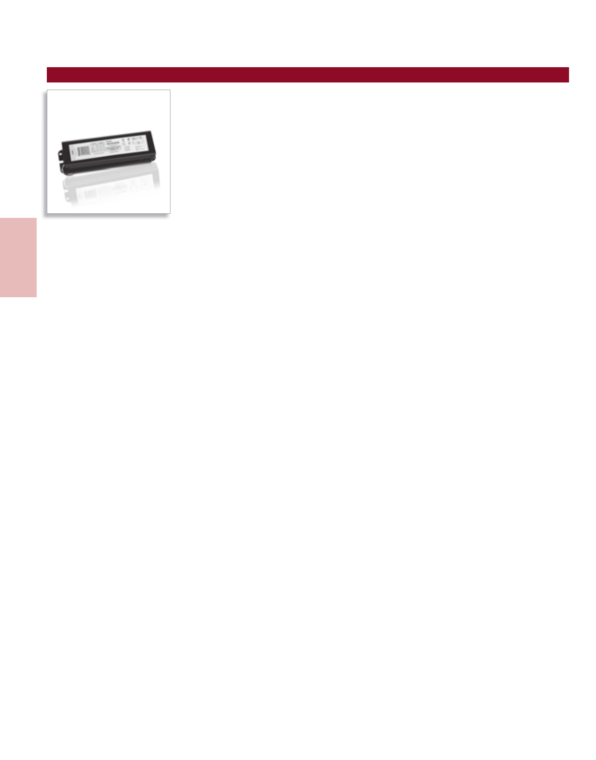
Lighting Electronics Atlas 2010-2011
ELECTROMAGNETIC FLUORESCENT BALLASTS
1
Electromagnetic
Fluorescent Ballasts
Mark III®

3-1
Lighting Electronics Atlas 2010-2011
ELECTROMAGNETIC FLUORESCENT BALLASTS
Electromagnetic
Fluorescent Ballasts
Contents
General Ballast Information 3-2 to 3-4
Rapid Start Ballasts for Linear Fluorescent Lamps
T8 Straight & U-Shaped 3-5
T12 Straight & U-Shaped 3-6
High Output Ballasts for Linear Fluorescent Lamps
T12 High Output (HO) 3-7 to 3-11
Very High Output Ballasts for Linear Fluorescent Lamps
T10 & T12 Very High Output (VHO) 3-12 to 3-13
Slimline Ballasts for Linear Fluorescent Lamps
T12 Slimline 3-14 to 3-15
Preheat Ballasts for Linear Fluorescent Lamps
T5, T8 & T12 Preheat 3-16 to 3-17
Trigger Start Ballasts for Linear Fluorescent Lamps
T8 & T12 Preheat 3-18
Ballasts for Circline Lamps 3-19
Ballasts for Compact Fluorescent Lamps
2-Pin Compact Lamps 3-20 to 3-21
Dimming Ballasts for Rapid Start Lamps 3-22
Radio Interference Filter 3-22
Weatherproof Ballasts 3-23
Sign Ballasts 3-24 to 3-25
Visit our web site at www.philips.com/advance
Customer Support/Technical Service
(800) 372-3331 • (+) 1 847 390-5000 (International)
Corporate Offices
(800) 322-2086
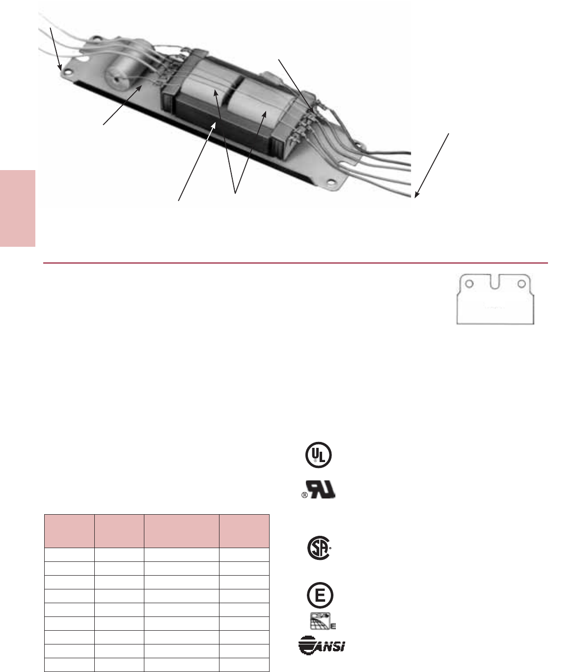
Lighting Electronics Atlas 2010-2011
ELECTROMAGNETIC FLUORESCENT BALLASTS
3-2
Electromagnetic
Fluorescent Ballasts
Case - rugged steel ballast case Thermal Protector - automatic reclosing
protective device affords Class P thermal
protection on all Philips Advance fluorescent
lamp ballasts ordered with”TP” suffix.
Compound - special thermal-pliable
compound containing a high percentage
of silica allows for rapid heat conductivity.
Dampens vibration and ballast hum.
Careful filling excludes moisture, increases
insulation resistance.
Dry Capacitor - is used for power factor
correction and phase displacement, capacitors
(used only on high power factor ballast) are
of highest quality. Rigid inspection and tests
assure uninterrupted, dependable service.
Laminations - laminations are constructed
of high-grade steel, annealed and treated
to assure lowest wattage losses. They are
precision stamped with carbide steel dies for
positive, tight stacking to provide consistent
electrical characteristics.
Coils - highest quality annealed wire is
used in the precision winding of all coils.
Uniform, firmly wound coils assure
consistent operating characteristics.
Complete core & coil assembly is
vacuum impregnated with an exclusive
Philips Advance asphalt-wax impregnant.
Lead Wire - PVC covered solid lead wire
is firmly anchored to the coils to facilitate
positive and permanent connections.
Supply Voltage and Frequency
Each ballast is designed to operate at the nominal voltage
shown on the Philips Advance ballast label. Abnormal
deviation from these values will result in damage to either
the ballast or lamp or both. It is therefore necessary that the
voltage applied to ballasts be maintained within the respective
limits shown in the adjoining table.
A ballast subjected to higher than nominal voltages will
operate at increased temperatures. This will result in reduced
ballast life. Low voltage can cause premature lamp failures as
well as unreliable lamp starting.
All ballasts are designed for single frequency operation.
Therefore, best results will be obtained when that ballast is
used on the frequency shown on the ballast label. Frequency
limitations are as follows:
Nominal Frequency Limits
60HZ 57.5 to 62.5
50HZ 47.5 to 52.5
Ballast Date Codes
Philips Advance electromagnetic
fluorescent lamp ballasts are date
stamped on the ballast cover to
designate month and year of
manufacture. The month is indicated first, followed by the year.
In the example shown 0100, the manufacturing date is January,
2000. In 2006 a new date stamp was implemented. The year
is indicated first, followed by the calendar day of year and
closes with an internal number (06 300 ###). For warranty
information go to www.philips.com/advancewarranty.
See catalog table of contents for important change Certifications
Indicates ballast is listed with Underwriters Laboratories, Inc.
and complies with UL935 Standard for Fluorescent -Lamp
Ballasts (File No. E14927).
Indicates ballast is component recognized with
UL. and complies with UL935 Standard for Fluorescent -Lamp
Ballasts (File No. E14927).
Visit www.ul.com to find a current listing of Philips Advance
ballasts under File No. E14927.
Indicates ballast is certified by Canadian Standards Association
and complies with CSA-22.2 File No. 74for Fluorescent-Lamp
Ballasts (File No. 007310).
Visit www.csa.ca to find a current listing of Philips Advance
ballasts under File No. 007310
Indicates ballast complies with U.S. Energy Standards.
Indicates ballast complies with Canadian
Energy Standards.
Philips Advance fluorescent ballasts are designed and
manufactured in accordance with the American National
Standards Institute standard for fluorescent ballasts,
ANSI C82.1.
U.L. RECOGNIZED
06300###
0100
Prefix
Code
Letters
Normal
Voltage
Applied Voltage
Limits
Color Label
Identification
H 120 112-127 Yellow
R 120 112-127 Yellow
L 120 112-127 Yellow
S 120 112-127 Yellow
X 220 210-230 Green
M 220/250 210-230 / 235-260 –
Y 240 225-250 Orange
V 277 255-290 Red
G 347 322-365 Gray
OR

3-3
Lighting Electronics Atlas 2010-2011
ELECTROMAGNETIC FLUORESCENT BALLASTS
Electromagnetic
Fluorescent Ballasts
Class P Ballasts
Section 410-73(e) of the National Electrical Code (NEC)
requires that all indoor fluorescent fixtures shall incorporate
ballast protection. Those fixtures employing a simple reactive
type ballast are exempted.
The protector is located within the ballast case to prevent
physical damage and tampering.
Philips Advance electromagnetic ballasts ordered with
Class P ballast protection (TP suffix) are equipped with a
thermally actuated automatic reclosing protective device.
This revolutionary development was originally designed
and introduced by Philips Lighting Electronics, and today
this Class P device is a requirement of the National
Electrical Code in all indoor lighting installations.
Safety
The National Electrical Code requires grounding of
fluorescent fixtures. The fluorescent ballast case must be
grounded either to the fluorescent fixture or, if remote
mounted, by other means such as a wire from the ballast
case to ground. Without proper fixture and ballast
grounding, a shock hazard may exist due to the fluorescent
fixture becoming energized by an internal ballast failure to
case. Also, all ballasts have normal leakage current. When
the ballast is properly grounded, the leakage current does
not constitute a hazard.
Starting
The metal of a fluorescent fixture is a starting aid when properly
grounded. T12 fluorescent lamps rated at 40W or less used
for rapid or trigger start operation must be mounted within
1/2” of a grounded metal surface. T8 lamps must be mounted
within 3/4” of a grounded metal surface. All other lamps must
be mounted within 1” of a grounded metal surface.
An important additional factor for proper lamps starting is
polarity. The white ballast lead must be connected to the
ground of the power supply (neutral) and the black lead to
the hot line wire. A reversal of polarity may result in lamp
damage or improper lamp starting.
Cold Weather Operation
Lumen ratings of fluorescent lamps apply for operation in
still air at a temperature of 77°F. While many fluorescent
lamps and fluorescent lamp ballasts are designed to give their
best performance at 77°F, they will provide reasonably good
light output down to 50°F. Further decreases in ambient
temperature will result in decreased light output.
Variables such as humidity, line voltage, fixture design and
variations within the particular design of the lamp and the
fluorescent lamp ballast play an important part in determining
the low temperature starting limit.
These are the two considerations for low temperature application:
1. Starting of the lamps
Low temperatures change the electrical starting characteristics
of a fluorescent lamp. As the fluorescent lamp becomes
colder, it becomes more difficult to start. Therefore,
a fluorescent ballast must have a higher starting voltage.
Ballasts designed for low temperature use ensure reliable
starting only and not the light output.
2. Operating the Lamps
The light output of any fluorescent lamp depends on the
mercury vapor pressure within the lamp. Maximum light
output for most fluorescent lamps occurs when the bulb
temperature is about 100°F. As bulb wall temperature
goes above 100°F the mercury vapor pressure within the
tube increases and the light output decreases.
Interestingly enough, at lower bulb-wall temperatures,
the mercury condenses on the tube, pressure drops and
the light output again decreases. This is inherent in all
fluorescent lamps. In order to prevent reduction in light
output at low temperatures the lamp should be enclosed
so it has a chance to overcome the low bulb-wall
temperature by the heat generated by the lamp.
In general, outdoor lighting installations have tended toward
800 and 1500mA lamps since the additional heat generated
by these lamps will provide better illumination in cold
weather than can be obtained with 430mA lamps.
The 430mA lamps are not recommended by the lamp
manufacturer for starting conditions below 0°F. Above this
temperature, shielding is required to a greater degree than
with the more heavily loaded lamps. Special low temperature
lamps, which may be purchased with shields, are available for
1500mA operation.
Lighting Electronics Atlas 2010-2011
ELECTROMAGNETIC FLUORESCENT BALLASTS
3-4
Electromagnetic
Fluorescent Ballasts
Ballast Sound
The slight hum present in fluorescent lighting installations
originates from the inherent magnetic action in the core &
coil assembly of the ballasts. This hum may be amplified by
the method of mounting the ballast in the fixture...the fixture
design...and, more often than not, this hum is amplified by
the resonant qualities of the ceiling, walls, floors and furniture.
In planning a lighting installation, careful consideration must
be given to the selection of the fluorescent lamp ballast, the
lighting fixture and room components. These precautions will
helped to achieve the quietest installation possible.
The choice of fluorescent lamp ballast should be made on the
basis of selecting the one rated quietest for a specific location
or interior as some ballast have a more discernable hum due
to basic construction features and electrical ratings.
Temperature and Ventilation
Underwriters’ Laboratories, Inc. stipulates that the
temperature limitation of a fluorescent lamp ballast using
Class A insulation at normal operation should have a
maximum ballast coil temperature of 105°C (221°F) and
maximum ballast case temperature of 90°C (194°F) at its
hottest spot. Ballast life will be reduced if it is operated
at a temperature above these limits.
A fluorescent lamp ballast, like other electrical equipment,
generates heat during normal operation. If not maintained
within prescribed limits, this heat will become the primary
cause of reduced ballast life. Heat generated in the
conventional ballast is transferred to the case through
a silica compound which totally surrounds the internal
components and is then dissipated to the surrounding air
or mounting surface by conduction, convection or radiation.
It is therefore essential that a ballast which is placed in an
enclosure be suitably ventilated. Where more than one ballast
is installed in an enclosure, the ballast should be positioned far
enough apart to provide adequate heat dissipation.
To assist in limiting the temperature rise of ballasts, the
following procedures are recommended:
• Mount ballast with maximum number of sides in direct
contact with the metal channel of fixture. Radiators are
an excellent way of dissipating heat.
• Providefixtureventilation.
• Paint the unpainted fixture channels with a non-metallic
finish to increase radiation.
• Placeballastinacoolerlocationoutsidethefixture.
• Place fixture to attain maximum dissipation of heat by
conduction, convection or radiation.
Ballast Type
Standard Magnetic – Electromagnetic core & coil
construction continues to provide reliable service and
economy over a wide variety of lighting system applications.
Operates lamps at 60 Hz.
Mark III® – Energy-saving electromagnetic ballast designed
to provide 10% energy savings over corresponding standard
magnetic units while maintaining equivalent full light output.
Operates lamps at 60 Hz. (e.g. RQM-2S40-TP vs R-2S40-TP).
E-PAK® – Energy-saving electromagnetic ballast specifically
optimized for energy saving lamps to provide 17% energy
savings over corresponding standard magnetic units while
maintaining equivalent light output. Operates lamps at 60 Hz
(e.g. RQM-2S40-TP vs R-2S34-TP).
The Federal Ballast Law prohibits the manufacture
of the following ballasts starting on July 1, 2010
R-140-TP V-140-TP
R-2S34-TP V-2S34-TP
R-2S40-TP V-2S40-TP
R-2E60-S-TP V-2E60-S-TP
R-2E75-S-TP V-2E-75-S-TP
See pages 1-66 to 1-68 for electronic
replacement ballasts
* These sound ratings are based on measurements of Average Ambient noise levels during con-
ditions of normal occupancy. Audible ballast hum may appear amplified during exceptionally
quiet periods and at times when area is unoccupied.
For Any Installation in:
AverageAmbient
NoiseLevel
Of Interior
Sound
Level
Rating*
TV or Radio Station, Library,
Reception or Reading Room,
Church, School Study Hall
20-24
Decibels A
Residence, Quiet Office,
Night School Classroom
25-30
Decibels B
General Office Area,
Commercial Building, Storeroom
31-36
Decibels C
Manufacturing Facility,
Retail Store,Noisy Office
37-42
Decibels D
Sound Ratings
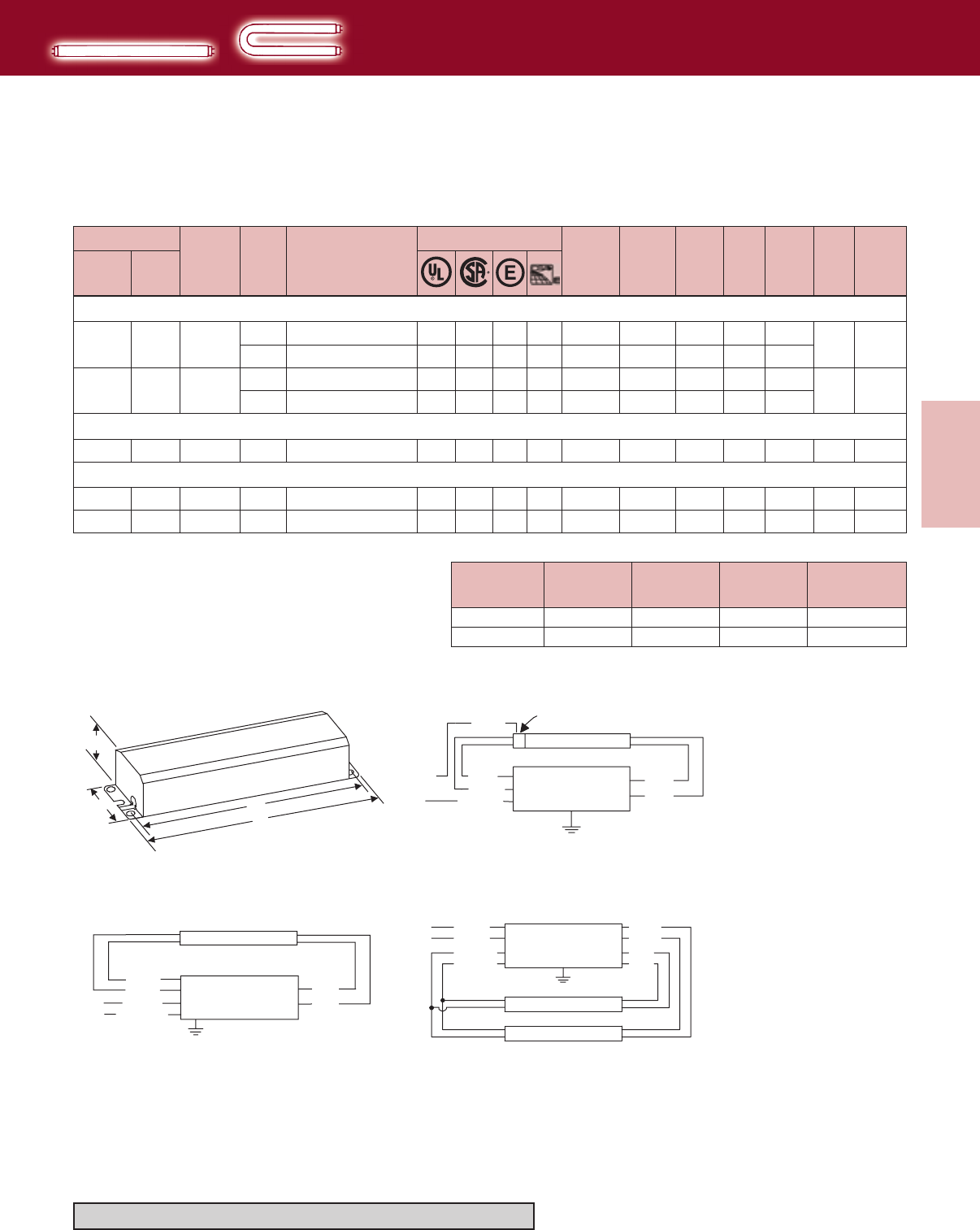
3-5
Lighting Electronics Atlas 2010-2011
ELECTROMAGNETIC
FLUORESCENT BALLASTS
Electromagnetic
Fluorescent Ballasts
Lamp Data Min.
Starting
Temp.
(F)
Input
Volts
Catalog
Number
Certifications Line
Current
(Amps)
Input
Power
ANSI
(Watts)
Ballast
Factor
THD
%
Power
Factor Dim. Wiring
Dia.
Number
Watts
F32T8, FBO32T8, F32T8/U (265mA)
1 32 50 120 R-1P32-TP Mark III ✓ ✓ 0.32 35 0.95 <15 0.91 T-2 20
277 V-1P32-TP Mark III ✓ ✓ 0.16 41 0.98 <15 0.93
2 32 50 120 R-2P32-TP Mark III ✓ ✓ ✓ 0.61 71 0.99 <10 0.97 T-2 21
277 V-2P32-TP Mark III ✓ ✓ ✓ 0.29 76 0.95 <10 0.95
F25T12 (455mA)
2 25 60 120 RM-2SP30-TP ✓ ✓ 0.58 70 0.90 <10 0.99 T-2 21
F30T12 (430mA)
1 30 50 120 RL-140-TP ❉❖ ✓ ✓ 0.60 33 0.71 <10 0.46 R-4 16
2 30 50 120 RM-2SP30-TP ✓ ✓ 0.66 79 0.97 <10 0.99 T-2 21
Designation Length (L)
(inches)
Width (W)
(inches)
Height (H)
(inches)
Mounting(M)
(inches)
T-2
R-4
9½
6½
2³/8
115/16
1½
1³/8
829/32
6+
DIMENSIONS
BLUE RED
RED
WHITE
BLK/WHT
WHITE
LINE
LAMP
CIRCUIT INTERRUPTING
LAMPHOLDER
BALLAST
BALLAST
BLUE
BLUE RED
RED
WHITE
BLK/WHT
LINE
LAMP
BLUE
BLUE
RED
RED
YELLOW
YELLOW
BLACK
WHITE
LINE
LAMP
LAMP
BALLAST
HIGH POWER FACTOR SOUND RATED A
Straight & U-Shaped
T8 & T12
Rapid Start Lamps
❉ Normal Power Factor
❖ Requires Circuit-Interrupting Lamp Holders
+ Mounting dimensions refer to slots only
Diag. 16
Case T
Diag. 20 Diag. 21
H
WM
L
CASE "T"
Refer to pages 9-24 to 9-28 for lead lengths and shipping data
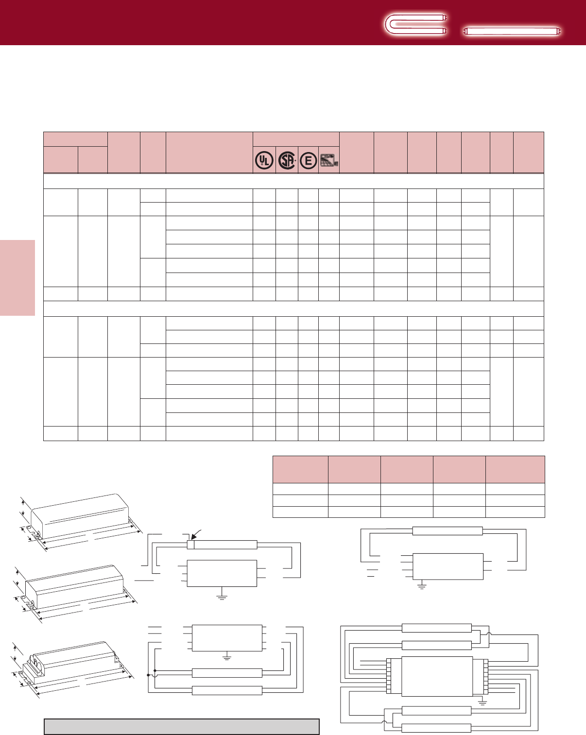
Lighting Electronics Atlas 2010-2011
3-6
ELECTROMAGNETIC
FLUORESCENT BALLASTS
Electromagnetic
Fluorescent Ballasts
Lamp Data Min.
Starting
Temp.
(F)
Input
Volts
Catalog
Number
Certifications Line
Current
(Amps)
Input
Power
ANSI
(Watts)
Ballast
Factor
THD
%
Power
Factor Dim. Wiring
Dia.
Number
Watts
F34T12 (430mA)
1 34 60 120 R-140-TP Mark III R✓ ✓ ✓ ✓ 0.38 43 0.88 <15 0.94 T-2 20
277 V-140-TP Mark III R✓ ✓ ✓ ✓ 0.16 43 0.88 <10 0.94
2 34 60
120
RM-2S35-TP ✪ ❉ ✓0.61 60 0.66 <20 0.82
T-2 21
R-2S34-TP E-PAK R✓ ✓ ✓ ✓ 0.57 68 0.87 <15 0.99
R-2S40-TP Mark III R✓ ✓ ✓ ✓ 0.63 72 0.88 <15 0.95
277 V-2S34-TP E-PAK R✓ ✓ ✓ ✓ 0.25 68 0.87 <15 0.98
V-2S40-TP Mark III R✓ ✓ ✓ ✓ 0.27 72 0.88 <20 0.96
4 34 60 120 R-4S40-A-TP-AC Mark III ✓ ✓ ✓ ✓ 1.26 144 0.88 <20 0/95 D-2 25
F40T12 (430mA)
1 40 50 120 R-140-TP Mark III R✓ ✓ ✓ ✓ 0.43 50 0.95 <10 0.97 T-2 20
RL-140-TP ✪ ❖ ❉ ✓ ✓ 0.53 32 0.63 <15 0.50 R-4 16
277 V-140-TP Mark III R✓ ✓ ✓ ✓ 0.19 50 0.95 <10 0.95 T-2 20
2 40 50
120
RM-2S35-TP ✪ ❉ ✓ 0.72 70 0.68 <20 0.81
T-2 21
R-2S34-TP E-Pak R✓ ✓ ✓ ✓ 0.67 79 0.86 <15 0.98
R-2S40-TP Mark III R✓ ✓ ✓ ✓ 0.73 86 0.95 <15 0.98
277 V-2S34-TP E-Pak R✓ ✓ ✓ ✓ 0.30 79 0.86 <15 0.95
V-2S40-TP Mark III R✓ ✓ ✓ ✓ 0.32 86 0.95 <20 0.97
4 40 50 120 R-4S40-A-TP-AC Mark III ✓ ✓ ✓ ✓ 1.46 172 0.95 <20 0.98 D-2 25
Designation Length (L)
(inches)
Width (W)
(inches)
Height (H)
(inches)
Mounting(M)
(inches)
D-2
T-2
R-4
17
9½
6½
2³/8
2³/8
115/16
1½
1½
1³/8
165/16
829/32
6+
DIMENSIONS
HIGH POWER FACTOR SOUND RATED A
Straight & U-Shaped
Rapid Start Lamps
Note: 2-Lamp Ballasts will also operate U-Shaped Lamps
❉ Normal Power Factor
✪ For Residential Use Only
❖ Requires Circuit-Interrupting Lamp Holders
R For Replacement Use Only - not available after July 1, 2010
+ Mounting dimensions refer to slots only
H
WM
L
CASE "R"
H
WM
L
CASE "D-2"
Case T
Case D2
Case R
Refer to pages 9-24 to 9-28 for lead lengths and shipping data
BLUE RED
RED
WHITE
BLK/WHT
WHITE
LINE
LAMP
CIRCUIT INTERRUPTING
LAMPHOLDER
BALLAST
BALLAST
BLUE
BLUE RED
RED
WHITE
BLK/WHT
LINE
LAMP
BLUE
BLUE
RED
RED
YELLOW
YELLOW
BLACK
WHITE
LINE
LAMP
LAMP
BALLAST
BALLAST
RED
YEL
YEL
RED
BLU
BLU
BLK/WHT
WHT/BLU
1
2
3
4
5
6
7
8
16
15
14
13
12
11
10
9
BLU
BLK
WHT
BLU
RED
RED
YEL
YEL
RED
RED
LAMP
LAMP
LAMP
LAMP
OUTBOARD LAMPS
INBOARD LAMPS
Diag. 16 Diag. 20
Diag. 21
Diag. 25
H
WM
L
CASE "T"
T12
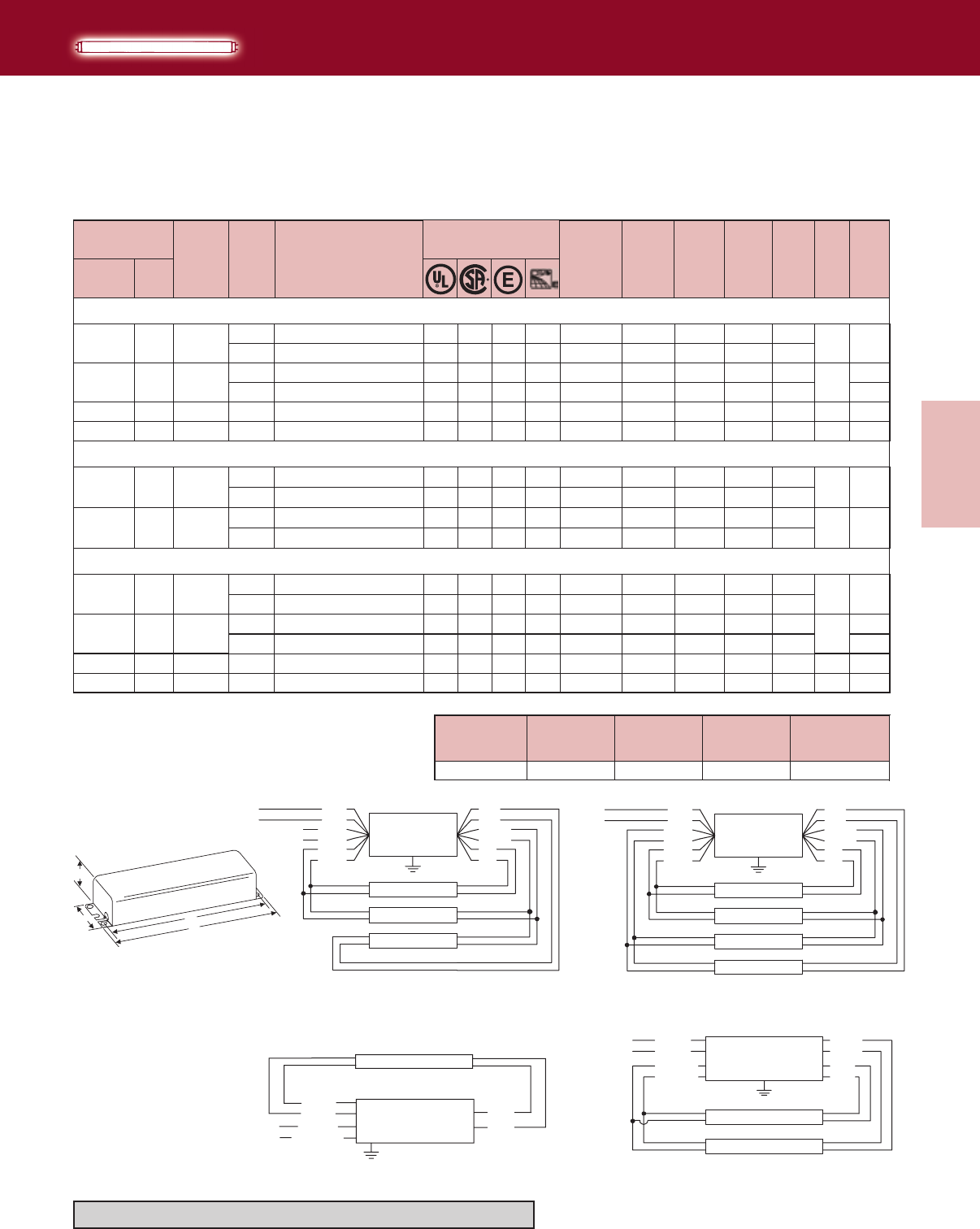
3-7
Lighting Electronics Atlas 2010-2011
ELECTROMAGNETIC
FLUORESCENT BALLASTS
Electromagnetic
Fluorescent Ballasts
Number
Min.
Starting
Temp.
(F)
Input
Volts
Catalog
Number
Certifications Line
Current
(Amps)
Input
Power
ANSI
(Watts)
Ballast
Factor
THD
%
Power
Factor Dim. Wiring
Dia.
Watts
Lamp Data
RS-110-TP ●✓ ✓ 0.58 63 0.93 R-9
VS-110-TP ●✓ ✓ 0.30 66 0.93
120 R-9
F24T12/HO (800mA)
1 35 <50
<50
-20
-20
120
352
277
RC-2S85-TP ✓ ✓ 1.01 95 0.80 <45
0.90
0.80
0.78
20
21
277 VC-2S85-TP ✓ ✓ 0.47 105 0.82 <35
3 50 120-20 RC-4S60-TP ■✓ ✓ 1.60 166 0.93 <30 R-9
4 50 120-20 RC-4S60-TP ■✓ ✓ 1.90 212 0.98 <20 R-9
0.80
0.86
0.93
21
8
13
● Sound Rated B
■ Sound Rated D
3 35 120-20 RC-4S60-TP ■✓ ✓ 1.60 148 0.94 <35 R-9
4 35 120-20 RC-4S60-TP ■✓ ✓ 1.80 183 1.00 <30 R-9
F36T12/HO (800mA)
1 50 120
-20 RS-110-TP ●✓ ✓ 0.62 71 0.94 <40 R-9
277 VS-110-TP ●✓ ✓ 0.31 74 0.94 <45
2 50 120
-20 RC-2S85-TP ✓ ✓ 1.00 107 0.82 <35 R-9
0.77
0.85
0.95
0.86
0.90
277 VC-2S85-TP ✓ ✓ 0.48 94 0.80 <50 0.71 21
8
13
20
21
F30T12/HO (800mA)
1 50 120
-20 RS-110-TP ●✓ ✓ 0.61 67 0.93 <45 R-9
277 VS-110-TP ●✓ ✓ 0.30 70 0.93 <45
0.91
0.84 20
2 50 120
-20 RC-2S85-TP ✓ ✓ 0.96 98 0.80 <35 R-9
277 VC-2S85-TP ✓ ✓ 0.45 96 0.80 <35
0.85
0.77 21
BALLAST
RED
RED
BLUE
BLUE-WH
BLUE-WH
BLUE
LINE BLACK
WHITE
BROWN
BROWN
YELLOW
YELLOW
LAMP 1
LAMP 2
LAMP 3
LAMP 4
RED
RED
BLUE
BLUE-WH
BLUE-WH
BLUE
LINE BLACK
WHITE
BROWN
BROWN
YELLOW
YELLOW
LAMP 1
LAMP 2
LAMP 3
BALLAST
Diag. 13Diag. 8
Note: Insulate unused leads individually as shown on a ballast label
Case R
Designation Length (L)
(inches)
Width (W)
(inches)
Height (H)
(inches)
Mounting(M)
(inches)
R-9 11¾ 33/16 25/8119/64
DIMENSIONS
HIGH POWER FACTOR SOUND RATED C
High Output
T12/HO
Rapid Start Lamps
Refer to pages 9-24 to 9-28 for lead lengths and shipping data
BALLAST
BLUE
BLUE RED
RED
WHITE
BLK/WHT
LINE
LAMP
BLUE
BLUE
RED
RED
YELLOW
YELLOW
BLACK
WHITE
LINE
LAMP
LAMP
BALLAST
Diag. 20 Diag. 21
H
WM
L
CASE "R"
Lighting Electronics Atlas 2010-2011
3-8
ELECTROMAGNETIC
FLUORESCENT BALLASTS
Electromagnetic
Fluorescent Ballasts
F42T12/HO (800mA)
R-9
2 55 120
-20 RC-2S85-TP ✓ ✓ 1.12 126 0.85 <30 0.94 21
RS-110-TP ●✓ ✓ 0.72 84 0.94 <35
R-9
RC-2S85-TP ✓ ✓ 0.91 79 0.78 <50
0.97
0.72
F48T12/HO (800mA)
1 60
120
-20
20
39
VS-110-TP ●✓ ✓ 0.34 86 0.96 <35
VC-2S85-TP ✓ ✓ 0.46 80 0.78 <50
-20 RC-2S85-TP ✓ ✓ 1.16 133 0.85 <20 R-9
0.91
0.63
0.96
2 60
277
120
20
39
21
VC-2S85-TP ✓ ✓ 0.53 131 0.85 <20
-20 RC-4S60-TP ■✓ ✓ 1.90 217 0.92 <20 R-9
RC-4S85-TP ■✓ ✓ 1.70 190 0.86 <10 R-11
-20 RC-4S60-TP ■✓ ✓ 2.40 288 0.92 <15
RC-4S85-TP ■✓ ✓ 1.99 237 0.81 <15
0.90
0.95
0.93
0.99
0.99
R-9
R-11
3
4
60
60
277
120
120
21
8
9
13
13
277 VC-2S85-TP ✓ ✓ 0.51 124 0.85 <30 0.88 21
1 55 120
-20 RS-110-TP ●✓ ✓ 0.69 80 0.96 <40 R-9
277 VS-110-TP ●✓ ✓ 0.33 81 0.96 <40
0.97
0.88 20
HIGH POWER FACTOR SOUND RATED C
High Output
T12/HO
Rapid Start Lamps
● Sound Rated B
■ Sound Rated D
WHITE
YEL
YEL
BLACK
LINE RED
RED
BLUE
BLUE
LAMP
BALLAST
Diag. 39
Note: For a single lamp, insulate yellow leads individually for 600V
Refer to pages 3-9 for ballast dimensions
Refer to pages 9-24 to 9-28 for lead lengths and shipping data
BALLAST
RED
RED
BLUE
BLUE-WH
BLUE-WH
BLUE
LINE BLACK
WHITE
BROWN
BROWN
YELLOW
YELLOW
LAMP 1
LAMP 2
LAMP 3
LAMP 4
RED
RED
BLUE
BLUE-WH
BLUE-WH
BLUE
LINE BLACK
WHITE
BROWN
BROWN
YELLOW
YELLOW
LAMP 1
LAMP 2
LAMP 3
BALLAST
Diag. 13
Diag. 8
Note: Insulate unused leads individually as shown on a ballast label
Diag. 9
Note: Insulate unused leads individually as shown on a ballast label
BALLAST
BLUE
BLUE RED
RED
WHITE
BLK/WHT
LINE
LAMP
BLUE
BLUE
RED
RED
YELLOW
YELLOW
BLACK
WHITE
LINE
LAMP
LAMP
BALLAST
Diag. 20
Diag. 21
BALLAST
RED
RED
BLUE
BLUE-WH
BLUE-WH
BLUE
LINE BLACK
WHITE
BROWN
BROWN
YELLOW
YELLOW
LAMP 2
LAMP 3
LAMP 4
Number
Min.
Starting
Temp.
(F)
Input
Volts
Catalog
Number
Certifications Line
Current
(Amps)
Input
Power
ANSI
(Watts)
Ballast
Factor
THD
%
Power
Factor Dim. Wiring
Dia.
Watts
Lamp Data
3-9
Lighting Electronics Atlas 2010-2011
ELECTROMAGNETIC
FLUORESCENT BALLASTS
Electromagnetic
Fluorescent Ballasts
F60T12/HO (800mA)
VS-110-TP ●✓ ✓ 0.38 98 0.96 <35
VC-2S85-TP ✓ ✓ 0.48 87 0.80 <40
120 RC-2S85-TP ✓ ✓ 1.50 178 0.90 <15
275
277
-20 R-9
0.93
0.66
0.99
39
20
21
277 VC-2S85-TP ✓ ✓ 0.65 170 0.86 <20
3 75 120 RC-4S85-TP ■✓ ✓ 1.90 223 0.83 <20 R-11 9
4 75 120 RC-4S85-TP ■✓ ✓ 2.35 278 0.80 <15 R-11 13
0.94
0.98
0.99
F64T12/HO (800mA)
21
-20
-20
2 80
277
-20 R-9
VS-110-TP ●✓ ✓ 0.42 106 0.96 <35
VC-2S85-TP ✓ ✓ 0.47 95 0.78 <40
120 RC-2S85-TP ✓ ✓ 1.50 178 0.90 <15
0.91
0.73
0.99 21
39
20
277 VC-2S85-TP ✓ ✓ 0.65 170 0.86 <20
3 80 120 RC-4S85-TP ■✓ ✓ 2.09 246 0.84 <15 R-11 9
4 80 120 RC-4S85-TP ■✓ ✓ 2.64 312 0.78 <10
0.94
0.98
0.98 R-11 13
21
-20
-20
-20
RS-110-TP ●✓ ✓ 0.88 104 0.96 <35
RC-2S85-TP ✓ ✓ 0.94 90 0.77 <40
1 80
120
R-9
0.98
0.80
20
39
-20
RS-110-TP ●✓ ✓ 0.83 97 0.93 <35
RC-2S85-TP ✓ ✓ 0.94 90 0.77 <40
175
120
R-9
0.97
0.80
20
39
HIGH POWER FACTOR SOUND RATED C
High Output
T12/HO
Rapid Start Lamps
119/64
13¾
Designation Length (L)
(inches)
Width (W)
(inches)
Height (H)
(inches)
Mounting(M)
(inches)
R-9
R-11
11¾
145/16
33/16
33/16
25/8
25/8
DIMENSIONS
● Sound Rated B
■ Sound Rated D
Case R
Refer to pages 3-8 for wiring diagrams
Refer to pages 9-24 to 9-28 for lead lengths and shipping data
Number
Min.
Starting
Temp.
(F)
Input
Volts
Catalog
Number
Certifications Line
Current
(Amps)
Input
Power
ANSI
(Watts)
Ballast
Factor
THD
%
Power
Factor Dim. Wiring
Dia.
Watts
Lamp Data
H
WM
L
CASE "R"
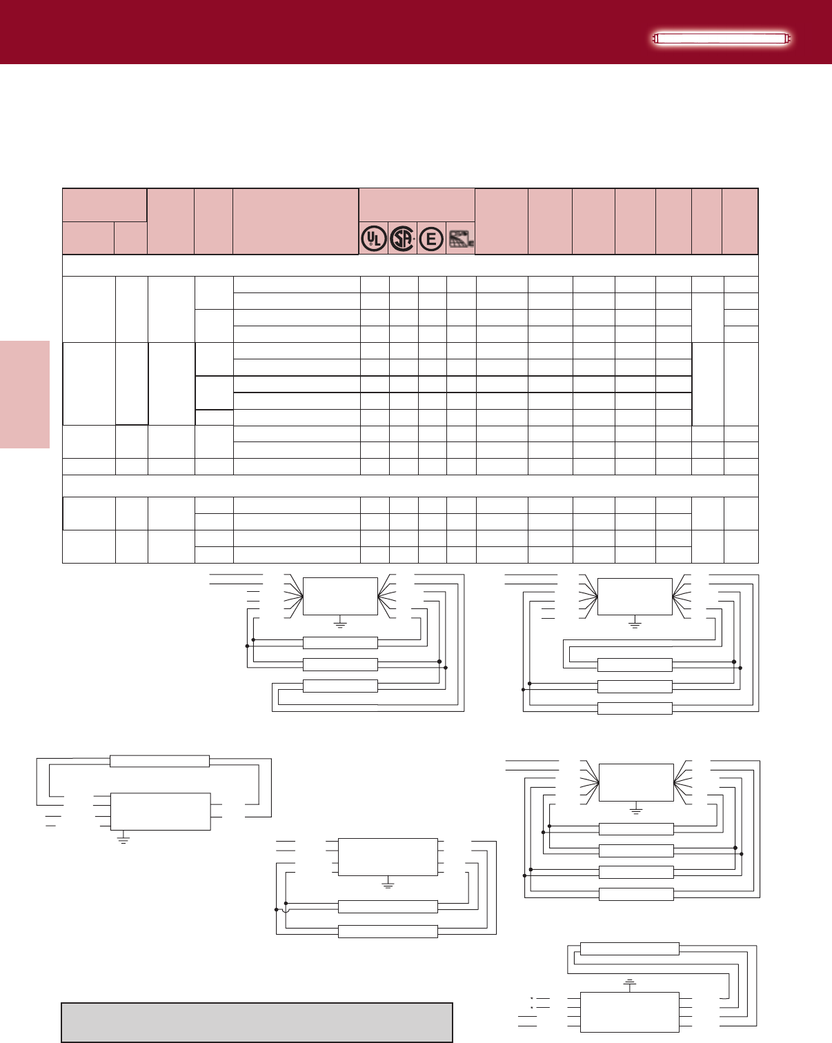
Lighting Electronics Atlas 2010-2011
3-10
ELECTROMAGNETIC
FLUORESCENT BALLASTS
Electromagnetic
Fluorescent Ballasts
Number
Min.
Starting
Temp.
(F)
Input
Volts
Catalog
Number
Certifications Line
Current
(Amps)
Input
Power
ANSI
(Watts)
Ballast
Factor
THD
%
Power
Factor Dim. Wiring
Dia.
Watts
Lamp Data
R-9
R-9
HIGH POWER FACTOR SOUND RATED C
High Output
T12/HO
Rapid Start Lamps
● Sound Rated B
■ Sound Rated D
RC-2S85-TP ✓ ✓ 0.98 100 0.82 <35
RS-110-TP ●✓ ✓ 0.96 113 0.98 <30
39
20
F72T12/HO (800mA)
120
1 85 -20
0.85
0.98
VC-2S85-TP ✓ ✓ 0.47 99 0.81 <35
VS-110-TP ●✓ ✓ 0.44 116 0.99 <30
39
20
RC-2S85-TP ✓ ✓ 1.54 184 0.91 <15
R-2S110-TP Mark III ✓ ✓ 1.60 193 0.95 <15
277
21
0.76
0.95
0.99
0.99
285 -20
120
VC-2S85-TP ✓ ✓ 0.67 180 0.90 <20
V-2S110-TP Mark III ✓ ✓ 0.75 201 0.98 <20
RC-4S60-TP ■✓ ✓ 2.40 291 0.90 <15
RC-4S85-TP ■✓ ✓ 2.17 256 0.81 R-11
R-9 8
9
4 85 120-20 RC-4S85-TP ■✓ ✓ 2.73 323 0.75 <10 R-11 13
RC-2S85-TP ✓ ✓ 1.03 113 0.83 <30
VC-2S85-TP ✓ ✓ 0.47 0.81 <35
RC-2S85-TP ✓ ✓ 1.76 209 0.90 <15
VC-2S85-TP ✓ ✓ 0.73 0.89 <20
3
1
2
85
100
100
120
120
120
-20
-20 R-9 39
F84T12/HO (800mA)
G-2S110-TP Mark III ✓0.57 193 0.94 <20
277
277
50
104
198
<15
0.97
0.97
0.99
0.99
0.91
0.80
0.99
0.98
0.98
R-9 21
0.98
277
347
Refer to pages 3-11 for dimensions
Refer to pages 9-24 to 9-28 for lead lengths and shipping data
BALLAST
RED
RED
BLUE
BLUE-WH
BLUE-WH
BLUE
LINE BLACK
WHITE
BROWN
BROWN
YELLOW
YELLOW
LAMP 2
LAMP 3
LAMP 4
WHITE
YEL
YEL
BLACK
LINE RED
RED
BLUE
BLUE
LAMP
BALLAST
Diag. 39
Note: For a single lamp, insulate yellow leads individually for 600V
BALLAST
RED
RED
BLUE
BLUE-WH
BLUE-WH
BLUE
LINE BLACK
WHITE
BROWN
BROWN
YELLOW
YELLOW
LAMP 1
LAMP 2
LAMP 3
LAMP 4
RED
RED
BLUE
BLUE-WH
BLUE-WH
BLUE
LINE BLACK
WHITE
BROWN
BROWN
YELLOW
YELLOW
LAMP 1
LAMP 2
LAMP 3
BALLAST
Diag. 13
Diag. 8
Note: Insulate unused leads individually as shown on a ballast label
Diag. 9
Note: Insulate unused leads individually as shown on a ballast label
BLUE
BLUE
RED
RED
YELLOW
YELLOW
BLACK
WHITE
LINE
LAMP
LAMP
BALLAST
Diag. 21
BALLAST
BLUE
BLUE RED
RED
WHITE
BLK/WHT
LINE
LAMP
Diag. 20
3-11
Lighting Electronics Atlas 2010-2011
ELECTROMAGNETIC
FLUORESCENT BALLASTS
Electromagnetic
Fluorescent Ballasts
R-9
R-11
Number
Min.
Starting
Temp.
(F)
Input
Volts
Catalog
Number
Certifications
Line
Current
(Amps)
Input
Power
ANSI
(Watts)
Ballast
Factor
THD
%
Power
Factor Dim. Wiring
Dia.
Watts
Lamp Data
HIGH POWER FACTOR SOUND RATED C
High Output
T12/HO
Rapid Start Lamps
120 RS-110-TP ●✓ ✓ 1.00 121 0.94
277
120
VS-110-TP ●✓ ✓ 0.47 125 0.95
R-2S110-TP Mark III ✓ ✓ ✓ ✓ 1.70 203
1 95 60 R-9 20
<35
0.91 <20
<35
0.99
0.99
0.96
V-2S110-TP Mark III ✓ ✓ ✓ ✓ 0.79 210 0.93 <25 0.96
277
F96T12/HOEnergySaver(840mA)
26095 R-9 21
RC-2S85-TP ✓ ✓ 1.07 121 0.84 <25
RS-110-TP ●✓ ✓ 1.20 140 0.98 <35
1 110
120 0.94
0.97
39
20
-20 VC-2S85-TP ✓ ✓ 0.48 114 0.83 <30
VS-110-TP ●✓ ✓ 0.54 145 1.00 <30
R-2S110-TP Mark III ✓ ✓ ✓ ✓ 2.00 237 0.95
120
277
<15
0.85
0.97
0.99
20
39
2110 ✓ ✓ ✓ 0.90 245 0.98 <20 0.98
V-2S110-TP Mark III
277
-20
3 110 120 RC-4S85-TP ■✓✓
✓
2.50 292 0.75 <15 R-11
0.97 9
-20
R-9 21
119/64
13¾
Designation Length (L)
(inches)
Width (W)
(inches)
Height (H)
(inches)
Mounting(M)
(inches)
R-9 11¾
145/16
33/16
33/16
25/8
25/8
DIMENSIONS
● Sound Rated B
■ Sound Rated D
Case R
Refer to pages 3-10 for wiring diagrams
Refer to pages 9-24 to 9-28 for lead lengths and shipping data
F96T12/HO (800mA)
H
WM
L
CASE "R"
Lighting Electronics Atlas 2010-2011
3-12
ELECTROMAGNETIC
FLUORESCENT BALLASTS
Electromagnetic
Fluorescent Ballasts
Number
Min.
Starting
Temp.
(F)
Input
Volts
Catalog
Number
Certifications Line
Current
(Amps)
Input
Power
ANSI
(Watts)
Ballast
Factor
THD
%
Power
Factor Dim. Wiring
Dia.
Watts
Lamp Data
HIGH POWER FACTOR SOUND RATED D
Very High Output
T10 & T12/VHO
VHO & Powergroove Rapid Start Lamps
BLUE
BLUE
RED
RED
YELLOW
YELLOW
BLACK
WHITE
LINE
LAMP
LAMP
BALLAST
WHITE
YEL
YEL
BLACK
LINE RED
RED
BLUE
BLUE
LAMP
BALLAST
Diag. 21 Diag. 39
Note: For a single lamp, insulate yellow leads individually for 600V
13¾
Designation Length (L)
(inches)
Width (W)
(inches)
Height (H)
(inches)
Mounting(M)
(inches)
R-11 145/16 33/16 25/8
DIMENSIONS
Case R
120 RC-2S102-TP ✓ ✓ 1.70 130 0.87 <30
277 VC-2S102-TP ✓ ✓ 0.59 137 0.85 <35
120 RC-2S102-TP ✓ ✓ 2.20 230 0.89 <35
277 ✓ ✓ 0.94 241 0.87 <35
120 RC-2S102-TP ✓ ✓ 1.75 140 0.90 <30
277 VC-2S102-TP ✓ ✓ 0.65 157 0.86 <35
2 138 120-20 RC-2S200-TP ✓ ✓ 2.34 241 0.90 <20 R-11
1
2
1
116
116
138
R-11
R-11
39
21
R-11
21
39
F48T10/VHO (1500mA), F48T12/VHO (1500mA), F48PG17/VHO (1500mA)
F60T10/VHO (1500mA), F60T12/VHO (1500mA)
-20
-20
-20
RC-2S102-TP
277 VC-2S102-TP ✓ ✓
RC-2S200-TP ✓ ✓
RS-2S200-TP
F72T10/VHO (1500mA), F72T12/VHO (1500mA), F72PG17/VHO (1500mA)
1
2
168
168
120
120
277
-20
-20
0.64
0.84
0.87
0.93
0.67
0.87
0.86
✓ ✓ 1.90 173 0.87 <30
0.69 168 0.87
2.51 270 0.89 <20
✓ ✓ 2.90 314 0.85
R-11
R-11
39
21
<35
<15
0.76
0.90
0.88
0.90
VS-2S200-TP ✓ ✓ 1.40 376 0.99 <15 0.97
VC-2S102-TP
Refer to pages 9-24 to 9-28 for lead lengths and shipping data
H
WM
L
CASE "R"
3-13
Lighting Electronics Atlas 2010-2011
ELECTROMAGNETIC
FLUORESCENT BALLASTS
Electromagnetic
Fluorescent Ballasts
F96T10/VHO (1500mA), F96T12/VHO (1500mA), F96PG17/VHO (1500mA)
Number
Min.
Starting
Temp.
(F)
Input
Volts
Catalog
Number
Certifications Line
Current
(Amps)
Input
Power
ANSI
(Watts)
Ballast
Factor
THD
%
Power
Factor Dim. Wiring
Dia.
Watts
Lamp Data
HIGH POWER FACTOR SOUND RATED D
Very High Output
T10 & T12/VHO
VHO & Powergroove Rapid Start Lamps
1
2
185
185
120
120
277
60 R-11
60 RC-2S102-TP ✓ ✓ 2.00 198 0.87 <35
<35
<15
R-11
21
39
<15
277 VC-2S102-TP ✓ ✓ 0.73 190 0.83
RC-2S200-TP ✓ ✓ 2.67 304 0.85 <15
0.83
0.94
0.90
0.95
RS-2S200-TP ✓ ✓ 2.95 320 0.80
<15 0.96VS-2S200-TP ✓ ✓ 1.50 398 0.96
F96T12/VHOEnergySaver(1580mA),F96PG17/VHOEnergySaver(1580mA)
0RC-2S102-TP ✓ ✓ 2.10 213 0.87 <35
RC-2S200-TP ✓ ✓ 2.03 170 0.78
277 VC-2S102-TP ✓ ✓ 0.89 216 0.88
RC-2S200-TP ✓ ✓ 2.72 320 0.80 <15
RS-2S200-TP ✓ ✓ 3.31 358 0.85
1
2
215
215
120
120
277
-20
R-11
R-11
<35
<25
<10
39
21
0.85
0.98
0.88
0.70
0.90
VS-2S200-TP ✓ ✓ 1.65 442 0.90 <15 0.97
-20
0
Refer to pages 9-24 to 9-28 for lead lengths and shipping data
BLUE
BLUE
RED
RED
YELLOW
YELLOW
BLACK
WHITE
LINE
LAMP
LAMP
BALLAST
WHITE
YEL
YEL
BLACK
LINE RED
RED
BLUE
BLUE
LAMP
BALLAST
Diag. 21 Diag. 39
Note: For a single lamp, insulate yellow leads individually for 600V
13¾
Designation Length (L)
(inches)
Width (W)
(inches)
Height (H)
(inches)
Mounting(M)
(inches)
R-11 145/16 33/16 25/8
DIMENSIONS
Case R
H
WM
L
CASE "R"
Lighting Electronics Atlas 2010-2011
3-14
ELECTROMAGNETIC
FLUORESCENT BALLASTS
Electromagnetic
Fluorescent Ballasts
Number
Min.
Starting
Temp.
(F)
Input
Volts
Catalog
Number
Certifications Line
Current
(Amps)
Input
Power
ANSI
(Watts)
Ballast
Factor
THD
%
Power
Factor Dim. Wiring
Dia.
Watts
Lamp Data
HIGH POWER FACTOR SOUND RATED C
Slimline
T12
Instant Start Lamps
● Sound Rated B
R For Replacement Use Only - not available after July 1, 2010
1 20 1200 SM-140-S-TP ✓ ✓ 0.45 45 0.93 R-8
2 20 1200 SM-2E40-S-TP ●✓ ✓ 0.68 65 0.99 R-6
1 30 1200 SM-140-S-TP ✓ ✓ 0.50 57 0.92 R-8
0SM-2E40-S-TP ●✓ ✓ 0.73 83 0.97 R-6
1 35 120
277
0SM-140-S-TP ✓ ✓ 0.51 57 0.90 R-8
0SM-2E4O-S-TP ●✓ ✓ 0.74 87 0.95 R-6
VSM-2E40-S-TP ●✓ ✓ 0.34 91 0.93 R-6
1 40 1200 SM-140-S-TP ✓ ✓ 0.54 62 0.90 R-8
0SM-2E40-S-TP ●✓ ✓ 0.82 96 0.90 R-6
277 VSM-2E40-S-TP ●✓ ✓ 0.36 98 0.96 R-6
F24T12 (425mA)
<35
F36T12 (425mA)
2 30 120
<35
2 35 120
<35
F42T12 (425mA)
F48T12 (425mA)
2 40 120
<30
<30
<30
<25
<25
<25
<30
F48T12/ES (440mA)
2 30 120 <35
<30
0.90
0.95
0.93
0.96
0.80
0.95
0.98
0.97
0.98
0.98
0.93
0.93
60 SM-2E40-S-TP ●✓ ✓ 0.72 80 0.90 R-6
VSM-2E40-S-TP ●✓ ✓ 0.33 85 0.85 R-6
10
12
10
12
10
12
36
10
12
36
12
36277
120
0RSM-175-S-TP ✓ ✓ 0.74 73 0.93
277 VSM-175-S-TP ✓ ✓ 0.31 72 0.93
R-2E75-S-TP Mark III R✓ ✓ 1.03 111 0.94
1 50
02 50 120
<50
<30
R-6
R-8
F60T12 (425mA)
F64T12 (425mA)
<50 10
0.90
0.90
0.90
V-2E75-S-TP Mark III R✓ ✓ 0.47 118 0.93 <30
277 0.91
R-6
<50120
0RSM-175-S-TP ✓ ✓ 0.72 74 0.94
52 277 VSM-175-S-TP ✓ ✓ 0.31 74 0.93
1
<30
120
2 52 0 R-2E75-S-TP Mark III R✓ ✓ 1.07 117 0.95
<50 10
0.90
0.91
0.90
R-8
277 V-2E75-S-TP Mark III R✓ ✓ 0.47 120 0.93 <30 0.92
120
0RSM-175-S-TP ✓ ✓ 0.73 80 0.95
277 VSM-175-S-TP ✓ ✓ 0.32 81 0.94
R-2E75-S-TP Mark III R✓ ✓ 1.18 132 0.94
F72T12 (425mA)
1 57
120
<35
<30
R-6
<35 10
0.91
0.93
0.91
2 57 0 R-8
V-2E75-S-TP Mark III R✓ ✓ 0.51 132 0.94 <25 0.93
277
50 R-2E75-S-TP Mark III R✓ ✓ 1.28 147 0.95
F84T12 (425mA)
2 65 120 <30 12
0.96 R-8 36
12
36
12
36
12
36
V-2E75-S-TP Mark III R✓ ✓ 0.57 151 0.94 <25 0.96
277
Refer to pages 3-15 for wiring diagrams and dimensions
Refer to pages 9-24 to 9-28 for lead lengths and shipping data
3-15
Lighting Electronics Atlas 2010-2011
ELECTROMAGNETIC
FLUORESCENT BALLASTS
Electromagnetic
Fluorescent Ballasts
Number
Min.
Starting
Temp.
(F)
Input
Volts
Catalog
Number
Certifications Line
Current
(Amps)
Input
Power
ANSI
(Watts)
Ballast
Factor
THD
%
Power
Factor Dim. Wiring
Dia.
Watts
Lamp Data
HIGH POWER FACTOR SOUND RATED C
Slimline
T12
Instant Start Lamps
WHITE
BLK/WHT
LINE BLUE
LAMP
CUTOUT LAMPHOLDER
BALLAST
BLACK
WHITE
LINE
RED
BLUE
LAMP
LAMP
CUTOUT LAMPHOLDER
CUTOUT LAMPHOLDER
BALLAST
BALLAST
Diag. 36
LINE
LAMP
LAMP
CUTOUT LAMPHOLDER
CUTOUT LAMPHOLDER
RED
BLUE
YELLOW
YELLOW
BLACK
BROWN,
WHITE or
YEL-BLUE
R For Replacement Use Only - not available after July 1, 2010
Designation Length (L)
(inches)
Width (W)
(inches)
Height (H)
(inches)
Mounting (M)
(inches)
R-6 9½ 37/64 125/32 829/32
R-8 11¾ 37/64 125/32 119/64
DIMENSIONS
Case R
Diag. 12
Diag. 36
Diag. 10
120 RSM-175-S-TP ✓ ✓ 0.68
277 VSM-175-S-TP ✓ ✓ 0.30
120 R-2E60-S-TP E-Pak R✓ ✓ ✓ ✓ 1.03
R-8
F96T12EnergySaver(440mA)
1 60 60 74
112
0.88 <35 R-6
0.88 <35
76
126 0.88
R-2E75-S-TP Mark III R✓ ✓ ✓ ✓ 1.10
0.88 <35
<35
0.91
0.91
0.91
126 0.88
V-2E75-S-TP Mark III R✓ ✓ ✓ ✓ 0.47 <25
112 0.88
277 V-2E60-S-TP E-Pak R✓ ✓ ✓ ✓ 0.44 <35
0.97
0.92
0.95 12
36
10
120 RSM-175-S-TP ✓ ✓ 0.82 0.94
277 VSM-175-S-TP ✓ ✓ 0.35 0.94
R-2E60-S-TP E-Pak R✓ ✓ ✓ ✓ 1.24 144 0.86
F96T12 (425mA)
175
2 75
120
092 <25 R-6
<30
94
R-2E75-S-TP Mark III R✓ ✓ ✓ ✓ 1.35 158 0.94 R-8
<25
<30
0.93
0.98
V-2E75-S-TP Mark III R✓ ✓ ✓ ✓ 0.60 158 0.94
277 <25
V-2E60-S-TP E-Pak R✓ ✓ ✓ ✓ 0.54 144 0.86 <30
0.95
0.96
0.97
0.98 12
10
36
50
2 60 60
Refer to pages 9-24 to 9-28 for lead lengths and shipping data
H
WM
L
CASE "R"
Lighting Electronics Atlas 2010-2011
3-16
ELECTROMAGNETIC
FLUORESCENT BALLASTS
Electromagnetic
Fluorescent Ballasts
Number
Min.
Starting
Temp.
(F)
Input
Volts
Catalog
Number
Certifications Line
Current
(Amps)
Input
Power
ANSI
(Watts)
Ballast
Factor
THD
%
Power
Factor Dim. Wiring
Dia.
Watts
Lamp Data
CLASS B INSULATION NORMAL POWER FACTOR SOUND RATED A
Preheat Lamps
T5 & T8
Preheat Ballasts (Starter Required) ✩
LPL-5-9 ✖✓ ✓ 0.19 1.01
LC-4-9-C ★✖ ✓ ✓ 0.20 1.07
X-1
C-2
LPL-5-9 ✖✓ ✓ 0.17 1.02
LC-4-9-C ★✖ ✓ ✓ 0.19 1.07
X-1
C-2
LPL-5-9 ✖✓ ✓ 0.14 1.00 X-1
F4T5
1
F6T5
1
F8T5
1
4
6
8
120
120
120
50
50
50
9
9
9
<10
<10
<10
9 <10
10 <10
0.39
0.44
0.54
0.38
0.44
116
116
116
116
116
LC-4-9-C ★✖ ✓ ✓ 0.17 1.08 C-211 <10 0.54 116
Designation Length (L)
(inches)
Width (W) (inches) Height (H)
(inches)
Mounting (M)
(inches)
C-2 31/16 13/8113/16 2¾
Standard With TP
119/32
X-1 23/811/813/8213/8
X-3 31/16 1¼ 113/16 2¾17/16
R-4 6½ – 13/86+115/16
DIMENSIONS
✖ Available with Class P Thermal Protection–
Add Suffix -TP to Catalog Number.
★ Core & Coil with Cover, painted white
✩ Ballast Includes Built-in Starter.
✝ Class A Insulation
+ Mounting dimensions refer to slots only
LO-13-22 ✖✓ ✓ 0.32 18 0.90
LC-14-20-C ★✖ ✓ ✓ 0.37 20 0.97
X-3
C-2
LO-13-22 ✖✓ ✓ 18 0.96
LC-14-20-C ★✖ ✓ ✓ 20 1.08
F13T8
1 14 12050
1 15 12050 0.29 <10
<20
0.34
<10
<10
X-3
C-2
1 13 12050 LO-13-22 ✖✓ ✓ 0.34 17 0.91 <10
0.52
0.47
0.45
0.49
0.42
F15T8
X-3
116
116
LO-13-22 ✖✓ ✓ 0.29 17 0.80
LC-14-20-C ★✖ ✓ ✓ 0.33 20 0.92
X-3
C-2
LO-13-22 ✖✓ ✓ 0.28 17 0.90
LC-14-20-C ★✖ ✓ ✓ 0.33 20 0.92
X-3
C-2
L-140F-TP ✝✓ ✓ 0.96 R-4
LX-140F-TP ✩✝ ✓ ✓ 1.00 R-4
F18T8
1 18 12050
F19T8
1 19 12050
<15
<15
F30T8
1 30 12050 0.67 40 <15
0.64 40
<10
<15
<10
0.49
0.51
0.50
0.51
0.51
0.52
116
116
116
116
4
2
116
116
116
F14T8
Refer to pages 3-17 for wiring and dimension diagrams
Refer to pages 9-24 to 9-28 for lead lengths and shipping data
3-17
Lighting Electronics Atlas 2010-2011
ELECTROMAGNETIC
FLUORESCENT BALLASTS
Electromagnetic
Fluorescent Ballasts
Number
Min.
Starting
Temp.
(F)
Input
Volts
Catalog
Number
Certifications Line
Current
(Amps)
Input
Power
ANSI
(Watts)
Ballast
Factor
THD
%
Power
Factor Dim. Wiring
Dia.
Watts
Lamp Data
CLASS B INSULATION NORMAL POWER FACTOR SOUND RATED A
Preheat Lamps
T12
Preheat Ballasts (Starter Required) ✩
✖ Available with Class P Thermal Protection–
Add Suffix -TP to Catalog Number.
★ Core & Coil with Cover, painted white
✩ Ballast Includes Built-in Starter.
✝ Class A Insulation
+ Mounting dimensions refer to slots only
LO-13-22 ✖✓ ✓ 0.34 18 0.92 <10
LC-14-20-C ✖★ ✓ ✓ 0.39 21 1.01
X-3
C-2
LO-13-22 ✖✓ ✓ 18 0.97
LC-14-20-C ✖★ ✓ ✓ 1.10
X-3
C-2
LO-13-22 ✖✓ ✓ 0.28 18 0.77
LC-14-20-C ✖★ ✓ ✓ 0.33 0.93
X-3
C-2
L-140F-TP ✝✓ ✓ 0.95 R-4
LX-140F-TP ✝✩ ✓ ✓ 0.95 R-4
F14T12
1 14 12050
F15T12
1 15 12050 21
0.32
1 20 12050 21
F30T12
1 30 12050 0.73 41
<10
<10
<10
F40T12
1 40 12050 0.65 41 <15
L-140F-TP ✝✓ ✓ 0.79 R-4
LX-140F-TP ✝✩ ✓ ✓ 0.83 R-4
1 25 12050 LC-25-TP ★✓ ✓ 0.36 24 0.90 <10 C-2
116
116
116
116
116
116
2
4
2
4
116
F25T12
<10
0.38
0.73 40
0.63 40
<15
<10
<10
<10
0.44
0.47
0.54
0.47
0.53
0.56
0.45
0.46
0.53
0.46
0.53
F20T12
BLUE
WHITE
BLK/WHT
LINE BALLAST
LAMP
S
WHITE
RED/WHITE BLUE/WHITE
BLUE
BLK/WHT
LINE
BALLAST
LAMP
BLAC
KB
LACK
LINE BALLAST
LAMP
S
Diag. 4
Diag. 2
Diag. 116
M
L
W
H
M
L
Case "C"
3/16" SLO
TS
Case C Case R
H
M
L
W
Fig. X-1, X-2
3/16" HOLES
H
M
L
W
Fig. X-3 through X-8
Case X-1 Case X-3,
X-5, X-8
Refer to pages 3-16 for dimensions
Refer to pages 9-24 to 9-28 for lead lengths and shipping data
H
WM
L
CASE "R"
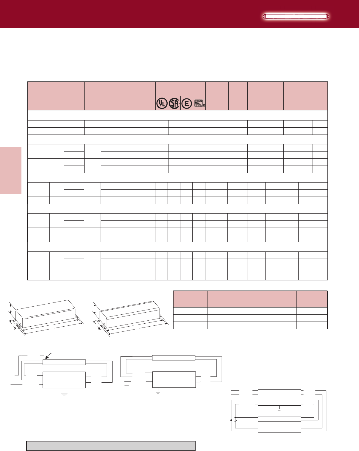
Lighting Electronics Atlas 2010-2011
3-18
ELECTROMAGNETIC
FLUORESCENT BALLASTS
Electromagnetic
Fluorescent Ballasts
Number
Min.
Starting
Temp.
(F)
Input
Volts
Catalog
Number
Certifications Line
Current
(Amps)
Input
Power
ANSI
(Watts)
Ballast
Factor
THD
%
Power
Factor Dim. Wiring
Dia.
Watts
Lamp Data
HIGH POWER FACTOR SOUND RATED A
Preheat Lamps
T8 & T12
Trigger Start Ballasts
RLQ-120-TP ❖❉ ✓ ✓ 0.56 28 1.01 <10 R-4
HM-1P20-TP ✓ ✓ 0.24 27 0.90 <15 T-2
50 RL-2SP20-TP❉✓ ✓ 0.51 36 0.78 <15
20 HM-2SP20-TP ✓ ✓ 0.47 51 0.99 <20
T-1
T-2
F15T8
1 15 120
50
2 15 120
F13T8
1 13 12020 RLQ-120-TP ❖❉ ✓ ✓ 0.54 23 1.00 <10 R-4
2 13 12030 RL-2SP20-TP❉✓ ✓ 0.58 36 1.00 <10
0.42
0.94
0.59
0.90
0.35
0.52 T-1
0
16
20
21
21
16
21
50 RLQ-120-TP ❖❉ ✓ ✓ 0.58 0.92 <10 R-4
HM-1P20-TP ✓ ✓ 0.21 0.82 <10 T-2
120 HM-2SP20-TP ✓ ✓ 0.43 46 0.85 <10
120 RLQ-120-TP ❖❉ ✓ ✓ 0.58 0.99 <10 R-4
HM-1P20-TP ✓ ✓ 0.23 0.89 <15
120
50 RL-2SP20-TP ❉✓ ✓ 0.57 41 0.83 <10
HM-2SP20-TP ✓ ✓ 0.44 47 0.92 <15
F14T12
1 14 120 28
2 14 0T-2
F15T12
1 15 2950
T-2
2 15 10
T-1
T-2
F20T12
1 20 2850
T-2
120 RLQ-120-TP ❖❉ ✓ ✓ 0.55 0.83 <10 R-4
HM-1P20-TP ✓ ✓ 0.24 0.83 <20
2 20 10 120
50 RL-2SP20-TP ❉✓ ✓ 0.49 36 0.61 <15
T-2
T-1
HM-2SP20-TP ✓ ✓ 0.48 53 0.90 <20
0.40
0.95
0.90
0.42
0.98
0.60
0.90
0.42
0.99
0.61
0.92
16
20
16
21
20
21
21
20
16
21
21
24
27
29
0
0
0
❖ Requires Circuit-Interrupting Lamp Holders
❉ Normal Power Factor
+ Mounting dimensions refer to slots only
H
WM
L
CASE "T"
Case R Case T
Designation Length (L)
(inches)
Width (W)
(inches)
Height (H)
(inches)
Mounting (M)
(inches)
R-4 6½ 115/16 13/86+
T-1 6½ 23/81½ 6+
T-2 9½ 6½ 829/32
DIMENSIONS
BLUE RED
RED
WHITE
BLK/WHT
WHITE
LINE
LAMP
CIRCUIT INTERRUPTING
LAMPHOLDER
BALLAST
Refer to pages 9-24 to 9-28 for lead lengths and shipping data
BLUE
BLUE
RED
RED
YELLOW
YELLOW
BLACK
WHITE
LINE
LAMP
LAMP
BALLAST
Diag. 21
BALLAST
BLUE
BLUE RED
RED
WHITE
BLK/WHT
LINE
LAMP
Diag. 20Diag. 16
H
WM
L
CASE "R"
23/8
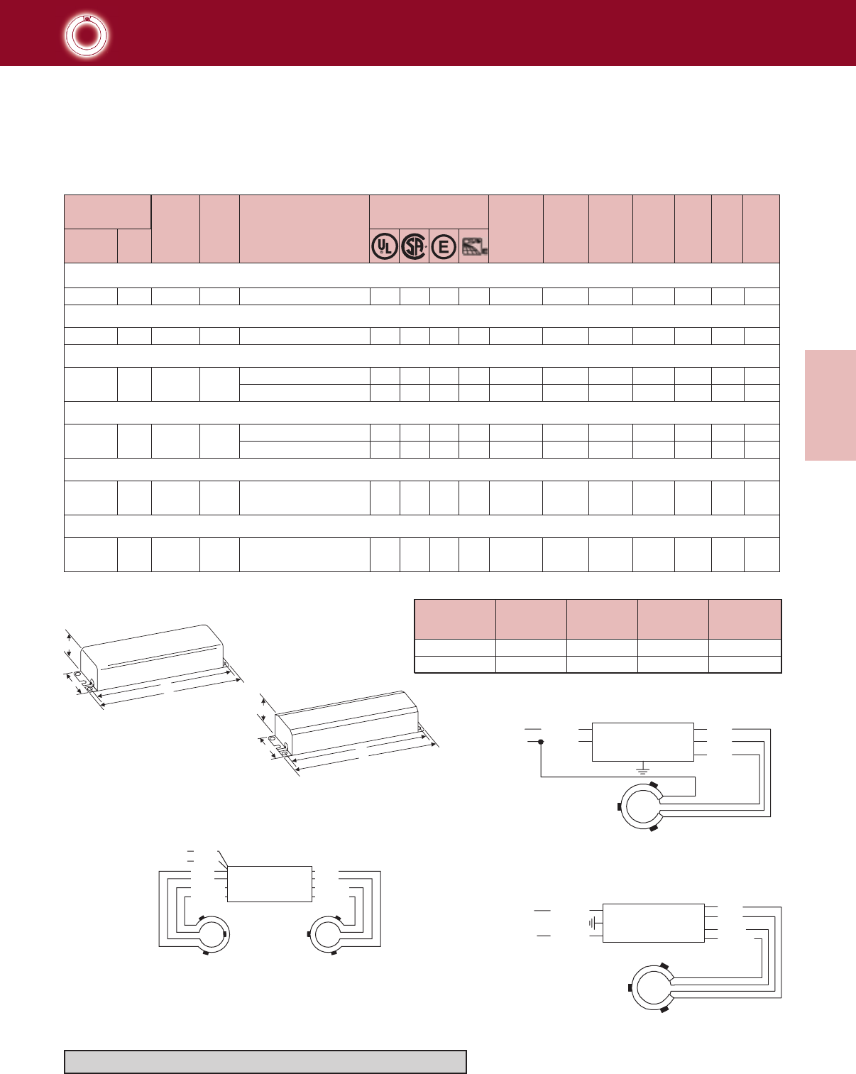
3-19
Lighting Electronics Atlas 2010-2011
ELECTROMAGNETIC
FLUORESCENT BALLASTS
Electromagnetic
Fluorescent Ballasts
Number
Min.
Starting
Temp.
(F)
Input
Volts
Catalog
Number
Certifications Line
Current
(Amps)
Input
Power
ANSI
(Watts)
Ballast
Factor
THD
%
Power
Factor Dim. Wiring
Dia.
Watts
Lamp Data
NORMAL POWER FACTOR SOUND RATED A
Circline Lamps
T9
Rapid Start Ballasts
BLK/WHT
BLUE
RED
RED
WHITE
Diag. 31
LINE
FOR POSITIVE
STARTING, SPACE
3 METAL CLIPS
12O ° APART AS
ILLUSTRATED
BALLAST
BLK/WHT
BLUE
RED
RED
WHITE
Diag. 32
LINE
FOR POSITIVE
STARTING, SPACE
3 METAL CLIPS
12O ° APART AS
ILLUSTRATED
WHITE
BALLAST
Diag. 32
Diag. 31
Diag. 105
+ Mounting dimensions refer to slots only
Note: All Ballasts supplied with Circline sockets in white can except RL-140-TP
Designation Length (L)
(inches)
Width (W)
(inches)
Height (H)
(inches)
Mounting (M)
(inches)
R-4 6½ 115/16 13/86+
T-1 6½ 23/81½ 6+
DIMENSIONS
RLQS-122-TP-W ✓ ✓ 0.76 <10 R-4
RL-140-TP ✓ ✓ 0.68 <15 R-4
RLCS-140-TP-W ✓ ✓ 0.63 <10 R-4
RS-22-32-TP-W ✓ ✓ 0.70 <15 T-1
RS-32-40-TP-W ✓ ✓ 0.60 <20 T-1
FC6T9 (20W Circline)
1 20 0.56 24
1 32 0.59 32
FC12T9 (32W Circline)
222 &
32 0.40 46
(1)FC12T9 & (1)FC16T9 ((1)32W & (1)40W Circline)
232 &
40 0.76 56
(1)FC8T9 & (1)FC12T9 ((1)22W & (1)32W Circline)
FC8T9 (22W Circline)
1 22 0.53 25
RLQS-122-TP-W ✓ ✓ 0.75 <10 R-4
1 40
120
120
120
120
120
120
50
50
50
50
50
50 0.46 29
RL-140-TP ✓ ✓ 0.55 <15 R-4
RLCS-140-TP-W ✓ ✓ 0.50 <15
0.36
0.45
0.45
0.96
0.61
0.39
0.53
0.53 R-4
32
31
32
105
105
32
31
32
FC16T9 (40W Circline)
0.57 31
0.44 28
DIAG. 105
LINE
FOR POITIVE STARTING,
SPACE 3 METAL
CLIPS 120” APART
AS ILLUSTRATED
(HIGHER WATTAGE LAMP IS AT RIGHT)
RED
RED
YELLOW
YELLOW
BLACK
WHITE
BLUE
BLUE
YELLOW
YELLOW BALLAST
Refer to pages 9-24 to 9-28 for lead lengths and shipping data
H
WM
L
CASE "T"
Case R
Case T
H
WM
L
CASE "R"
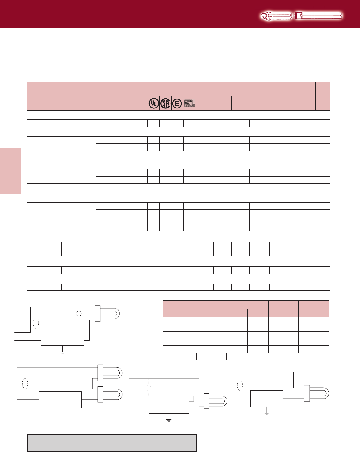
Lighting Electronics Atlas 2010-2011
3-20
ELECTROMAGNETIC
FLUORESCENT BALLASTS
Electromagnetic
Fluorescent Ballasts
★ Core & Coil with Cover, painted white
ƒ For Outdoor Use Only
CLASS B INSULATION NORMAL POWER FACTOR SOUND RATED A
2-Pin Compact & 4-Pin Long Twin Tube Lamps
T4 & T5
Preheat Ballasts
Designation Length (L)
(inches)
Width (W) (inches) Height (H)
(inches)
Mounting (M)
(inches)
C-2 31/16 13/8113/16 2¾
Standard With TP
119/32
X-1 23/811/813/8213/8
X-3 31/16 1¼ 113/16 2¾17/16
X-5 3¼ 1½ 2 23/16
1¾
X-6 31/16 1½ 113/16 2¾–
X-8 4 19/16 2¼ 3½113/16
DIMENSIONS (refer to page 3-17 for dimension diagrams)
CFT5W/G23 - 5W Twin Tube Lamp (PL-S5W, F5BX, CF5DS)
1 5 0 LPL-5-9-TP ✓ ✓ 0.19 0.19 –9 <10 X-1
CFT7W/G23 - 7W Twin Tube Lamp (PL-S7W, F7BX, CF7DS)
1 7 0 LPL-5-9-TP ✓ ✓ 0.17 0.19 – 9 <10
LC-4-9-C-TP ★✓ ✓ 0.19 0.20 – <10
X-1
C-2
CFT9W/G23 - 9W Twin Tube Lamp (PL-S9W, F9BX, CF9DS)
CFQ9W/G23 - 9W Quad Tube Lamp (F9DBX23T4, CF9DD)
1 9 25 LPL-5-9-TP ✓ ✓ 0.14 0.19 – 10 <10
LC-4-9-C-TP ★✓ ✓ 0.16 0.20 – <10
X-1
C-2
1 13 32
LC-13-TP ★✓ ✓ 0.27 0.37 – 16 <15
LO-13-22-TP ✓ ✓ 0.29 0.44 – 17 <15
VLO-13-TP ✓ ✓ 0.30 0.35 – 22 <10
C-2
X-3
X-5
2 13 32 VLO-2S13-TP ✓0.31 0.38 – 34 X-8
140
140
140
140
140
140
140
140
46
10
11
1.06
0.96
0.89
0.93
1.00
1.00
0.95
1.06
1.00
120
120
120
120
277
277 <15
CFT13W/GX23 - 13W Twin Tube Lamp (PL-S13W, F13BX, CF13DS)
CFQ13W/GX23 - 13W Quad Tube Lamp (PL-C13W/USA, F13DBX23T4, CF13DD)
FT18W/2G11 - 18W Long Twin Tube Lamp (PL-L18, F18BX, FT18DL) - Separate Starter Required
1 18 12050 LC-25-TP ★✓ ✓ 0.39 0.59 – 22 1.05 <15
LO-13-22-TP ✓ ✓ 0.21 0.44 – 16 0.89 <20
C-2
X-3
CFQ26W/G24d - 26W Quad Tube Lamp (PL-C26W, F26DBXT4, CF26DD)
1 26 27750 VLO-13-TP ✓ ✓ 0.27 0.35 – 29 0.80 <10 X-5
CFQ27W/GX32d - 28W Quad Tube Lamp (PL-C 15mm/28W, FDL-28)
1 28 120-20 LOS-1Q28 ƒ ✓ ✓ 0.61 0.74 – 32 0.97 <15 X-6
44
44
140
107
BALLAST
Diag. 46
LINE CAP
OPTIONAL
BLACK
WHITE
BLUE
Diag. 46 Diag. 140
BALLAST
Diag. 42
LINE LAMP
CAP
OPTIONAL
BLACK
WHITE
BLUE
Diag. 44
BALLAST
Diag. 44
LINE
S
CAP
OPTIONAL
BLACK
WHITE BLUE
BALLAST
LINE CAP
OPTIONAL
BLACK
BLACK
WHITE
Diag. 107
Refer to page 3-17 for dimension diagrams.
Refer to pages 9-24 to 9-28 for lead lengths and shipping data
Min.
Starting
Temp.
(F)
Input
Volts
Catalog
Number
Certifications Line Current (Amps) Input
Power
ANSI
(Watts)
Ballast
Factor
THD
%Dim. Wiring
Dia.
Watts
Number
Lamp Data
Operating Starting Open
Circuit
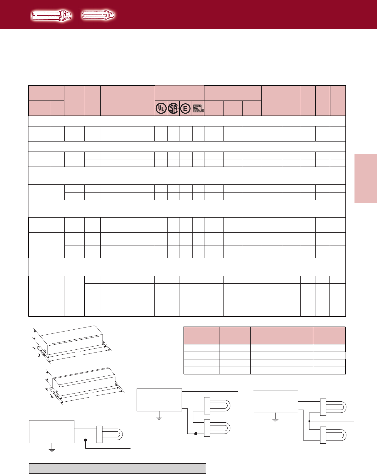
3-21
Lighting Electronics Atlas 2010-2011
ELECTROMAGNETIC
FLUORESCENT BALLASTS
Electromagnetic
Fluorescent Ballasts
Min.
Starting
Temp.
(F)
Input
Volts
Catalog
Number
Certifications Line Current (Amps) Input
Power
ANSI
(Watts)
Ballast
Factor
THD
%Dim. Wiring
Dia.
Watts
Number
Lamp Data
Operating Starting Open
Circuit
HIGH POWER FACTOR SOUND RATED A
2-Pin Compact Lamps
T4
Preheat Ballasts
CFT5W/G23 - 5W Twin Tube Lamp (PL-S5W, F5BX, CF5DS)
1 5 120
25 H-1B9-TP-W ✓ ✓ 0.10 0.20 0.13 11 R-1
CFT7W/G23 - 7W Twin Tube Lamp (PL-S7W, F7BX, CF7DS)
1 7 120
0H-1B9-TP-W ✓ ✓ 0.10 0.20 0.13 11 R-1
277 VH-1B9-TP-W ✓ ✓ 0.05 0.18 0.17 R-2
CFT9W/G23 - 9W Twin Tube Lamp (PL-S9W, F9BX, CF9DS)
CFQ9W/G23 - 9W Quad Tube Lamp (F9DBX23T4, CF9DD)
47
47
47
1 9 12025 H-1B9-TP-W ✓ ✓ 0.10 0.20 0.13 11 0.92 R-1<20 47
2770 VH-1B9-TP-W ✓ ✓ 0.05 0.18 0.17 13 0.95 <35 R-2 47
12
1.06 <20
2770 VH-1B9-TP-W ✓ ✓ 0.05 0.18 0.17 11 R-2 470.95 <35
1.00
0.93 <30
<20
CFT13W/GX23 - 13W Twin Tube Lamp (PL-S13W, F13BX, CF13DS)
CFQ13W/GX23 - 13W Quad Tube Lamp (PL-C13W/USA, F13DBX23T4, CF13DD)
1 13 12032 H-1B13-TP-W ✓ ✓ 0.14 0.36 0.22 0.90 <25 R-1 47
213
12032 H-2B13-TP-BLS
H-2B13-TP-W ✓ ✓ 0.30 0.44 – 35 1.02 <30 T-1
VH-2B13-TP-BLS
VH-2B13-TP-W
51
2770 ✓ ✓ 0.10 0.35 0.21 27 0.92 <30 R-2 50
16
2770 VH-1B13-TP-W ✓ ✓ 0.10 0.30 0.26 0.99 <30 R-2 4724
Diag. 50
Diag. 47 Diag. 51
CFQ26W/G24d - 26W Quad Tube Lamp (PL-C26W, F26DBXT4, CF26DD)
CFTR26W/GX24d - 26W Triple Tube Lamp (CF26DT)
1 26 120
50 H-1Q26-TP-W ✓ ✓ 0.24 0.33 0.41 28 T-1 470.83 <20
277 VH-1Q26-TP-W ✓ ✓ 0.11 0.38 0.24 R-2 4732 0.90 <20
2 26 50
120 H-2Q26-TP-BLS
H-2Q26-TP-W ✓ ✓ 0.42 0.34 – 50 0.82 R-5 50<15
277 VH-2Q26-TP-BLS
VH-2Q26-TP-W ✓ ✓ 0.21 0.32 – R-5 51
58 0.87 <25
H
WM
L
CASE "R"
H
WM
L
CASE "T"
Case R
Case T
Designation Length (L)
(inches)
Width (W)
(inches)
Height (H)
(inches)
Mounting (M)
(inches)
R-1
R-5
4¼
9½
2
23/8
17/16
111/16
39/16
829/32
R-2
T-1
4¾
6½
27/32
23/8
15/6
1½
43/8+
6+
DIMENSIONS
BALLAST
Diag. 47
LINE
WHITE
WHITE
BLK/WHT
BLUE
BALLAST
Diag. 50
LINE
WHITE
BLACK
BLUE
WHITE
BALLAST
Diag. 51
LINE
WHITE
BLACK
BLUE
RED
Refer to pages 9-24 to 9-28 for lead lengths and shipping data
+ Mounting dimensions refer to slots only
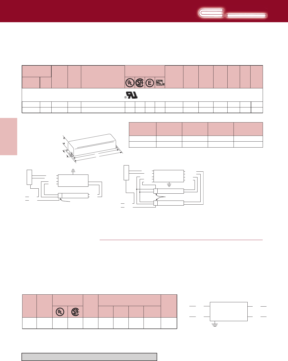
Lighting Electronics Atlas 2010-2011
3-22
ELECTROMAGNETIC
FLUORESCENT BALLASTS
Electromagnetic
Fluorescent Ballasts
H
WM
L
CASE "R"
Number
Min.
Starting
Temp.
(F)
Input
Volts
Catalog
Number
Certifications Line
Current
(Amps)
Input
Power
ANSI
(Watts)
Ballast
Factor
THD
%
Power
Factor Dim. Wiring
Dia.
Watts
Lamp Data
HIGH POWER FACTOR SOUND RATED A
Straight & U-Shaped Lamps
T12
Dimming Ballasts
Radio Interference Filter
Radio interface is caused by the action of the arc at the lamp
electrodes which creates a series of radio waves. This energy may
interfere with radio reception by:
1. Direct radiation from the fluorescent lamp to the aerial circuit.
2. Line feedback from the lamp through the power line to the radio.
3. Direct radiation from the electrical supply line to the aerial circuit.
To correct the first cause, it is recommended the radio and aerial
circuit be separated at least 10 feet from the fluorescent lamp and
the radio provided with a positive ground.
The second and third causes can generally be corrected by the
addition of an external capacitor-reactor filter. It is also desirable
that the radio and fluorescent lamp fixture be provided a supply
voltage from separate branch circuits.
Designation Length (L)
(inches)
Width (W)
(inches)
Height (H)
(inches)
Mounting (M)
(inches)
R-5 9½ 23/8111/16 829/32
R-12 15¾ 23/81½ 147/16
DIMENSIONS
Data listed is for full light output
Line Current Controlled by Control Setting
Dimming Range-100%–5%
All Require Circuit Interrupting Lampholders
Note:WillNOTOperate34WEnergySaverLamps
Input
Volts
Catalog
Number
Line
Current
(Amps)
120-277 RIF-1 4.25
max.
Certifications
✓ ✓
Wiring
Diagram
1184¾
Dimensions (inches)
27/32 15/843/8
Length Width Height Mounting
For bottom leads with studs, add suffix -BLS
SOUND RATED A
DIM-140-H-TP ✓0.52 58 1.00 R-5
DIM-240-H-TP ✓0.94 103 0.92 R-12
17
84
1 40 120
120
50
50
<15
<15
0.93
0.912 40
✓
✓
NOTE: YELLOW/BLACK lead from ballast connects to control lead on dimmer and BLACK lead from ballast connects to switched-hot lead on dimmer.
Case R
LINE
BALLAST
LAMP
CONTROL
SWITCHED
HOT
CIRCUIT INTERRUPTING
LAMPHOLDERS
DIMMER
BLACK
BLUE
YEL/BLU
RED
RED
WHITE
BLK/WHT
WHITE
DIAG. 17
FILTER
BLACK
WHITE WHITE
RED
LINE
Diag. 17
Diag. 118
LINE
BALLAST
DIAG. 84
LAMP
CONTROL
SWITCHED
HOT
CIRCUIT INTERRUPTING
LAMPHOLDERS
DIMMER
LAMP
BLACK
BLACK
WHITE
BLUE
BLU/WHT
YEL/BLU
RED
RED
YELLOW
YELLOW
WHITE
Refer to pages 9-24 to 9-28 for lead lengths and shipping data
F40T12 (430mA)
F40T12/U (430mA)
Diag. 84
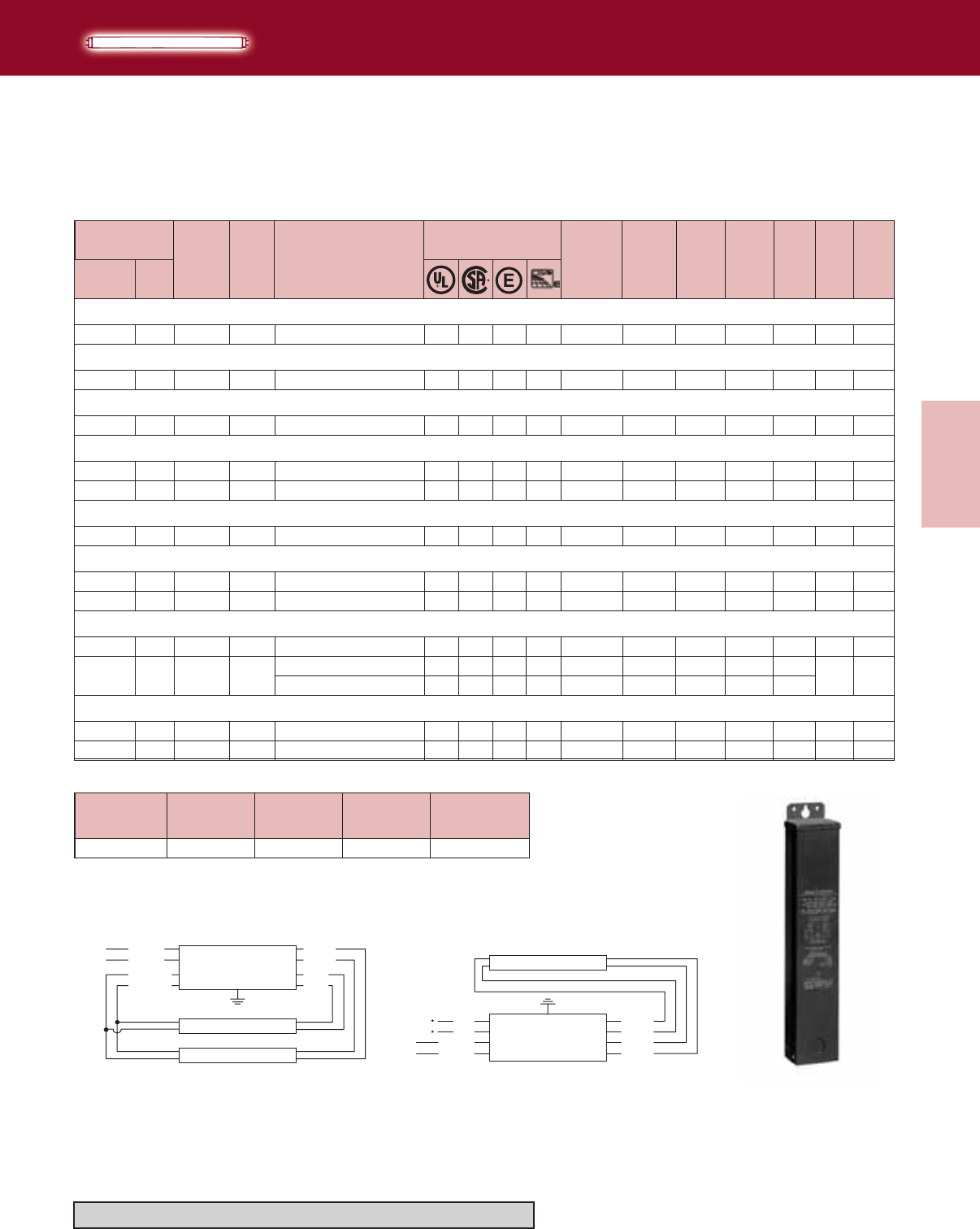
3-23
Lighting Electronics Atlas 2010-2011
ELECTROMAGNETIC
FLUORESCENT BALLASTS
Electromagnetic
Fluorescent Ballasts
Designation Length (L)
(inches)
Width (W)
(inches)
Height (H)
(inches)
Mounting(M)
(inches)
FO 211/16 3¾ 3 205/16
DIMENSIONS
BLUE
BLUE
RED
RED
YELLOW
YELLOW
BLACK
WHITE
LINE
LAMP
LAMP
BALLAST
WHITE
YEL
YEL
BLACK
LINE RED
RED
BLUE
BLUE
LAMP
BALLAST
Note: Can must be mounted vertically
Diag. 21 Diag. 39 Rectangular Can
(FO)
RC-2S85-FO ✓1.01 95 0.78 0.80 FO
RC-2S85-FO ✓1.00 107 0.82 FO
RC-2S85-FO ✓1.10 126 0.82 0.95 FO
F24T12/HO (800mA)
F42T12/HO (800mA)
2
F36T12/HO (800mA)
2
50
35 <45
<35 0.90
<35552
F48T12/HO (800mA)
1 60 RC-2S85-FO ✓0.91 79 0.78 <50 0.75 FO
2RC-2S85-FO ✓1.16 133 0.85 <20 0.95 FO
F60T12/HO (800mA)
1 75 RC-2S85-FO ✓0.94 90 0.77 <40 0.80 FO
F64T12/HO (800mA)
1 80 RC-2S85-FO ✓0.99 99 0.82 <40 0.85 FO
2RC-2S85-FO ✓1.50 178 0.92 <15 0.99 FO
F72T12/HO (800mA)
1 85 RC-2S85-FO ✓0.98 100 0.82 <35 0.85 FO
2RC-2S85-FO ✓1.54 184 0.91 <15 0.99 FO
RC-2S110-FO ✓1.80 203 0.99 <20 0.94
F96T12/HO (800mA)
1 110 RC-2S85-FO ✓1.07 121 0.84 <25 0.94 FO
2RC-2S110-FO ✓2.10 248 0.98 <15 0.98 FO
21
21
21
39
21
39
39
21
39
21
39
21
-20
-20
-20
-20
-20
-20
-20
-20
-20
-20
-20
-20
60
80
85
120
120
120
120
120
120
120
120
120
120
120
120
110
Min.
Starting
Temp.
(F)
Input
Volts
Catalog
Number
Certifications Line
Current
(Amps)
Input
Power
ANSI
(Watts)
Ballast
Factor
THD
%
Power
Factor Dim. Wiring
Dia.
WattsNumber
Lamp Data
T12/HO
HIGH POWER FACTOR SOUND RATED C
High Output Lamps
Weatherproof Ballasts
Refer to pages 9-24 to 9-28 for lead lengths and shipping data
Lighting Electronics Atlas 2010-2011
3-24
ELECTROMAGNETIC
FLUORESCENT BALLASTS
Electromagnetic
Fluorescent Ballasts
T12/HO (800mA)
● Total lamp length of each circuit (A) and (B) must not be less than 10 ft. nor more than 20 ft. Circuit (A) is comprised of lamps 1,2. Circuit (B) is comprised of lamps 3,4. (See wiring diagrams).
▼ Total lamp length of each circuit (A) and (B) must not be less than 6 ft. nor more than 20 ft. Circuit (A) is comprised of lamps 1,2,3. Circuit (B) is comprised of lamps 4,5,6. (See wiring diagrams).
■ Total lamp length of each circuit (A) and (B) must not be less than 12 ft. nor more than 24 ft. Circuit (A) is comprised of lamps 1,2,3. Circuit (B) is comprised of lamps 4,5,6. (See wiring diagrams).
-20°F
120
277
120
277
120
277
120
277
120
277
120
277
1,2
2, 3, 4
2, 3, 4
2, 3, 4
3, 4
4, 5, 6
4, 5, 6
4
6
12
20•
24
12▼
24■
12
20
24
40•
32
40▼
48■
175
304
312
472
370
462
604
480
720
785
720
975
720
720
BL-1
BL-1
BL-2
BL-3
BL-4
BL-3
BL-3
21, 39
5, 8, 13
7, 9, 13
5, 9, 13
8, 13
14, 15, 19
14, 15, 19
120
ASB-1240-46-BL-TP
VSB-1240-46-BL-TP
ASB-2448-46-BL-TP
VSB-2448-46-BL-TP
Lamp Data
Lamp Footage
Catalog
Number
No. of
Lamps Min Max
Certifications Max.Line
Current
(Amps)
Max.Input
Power
(Watts)
Open
Circuit
Volts
Dim. Wiring
Dia.
✓ ✓
✓ ✓
✓ ✓
✓ ✓
✓ ✓
✓ ✓
Input
Volts
Min.
Starting
Temp.
(F)
ASB-0412-12-BL-TP
VSB-0412-12-BL-TP
ASB-0620-24-BL-TP
VSB-0620-24-BL-TP
ASB-1224-24-BL-TP
VSB-1224-24-BL-TP
ASB-2040-24-BL-TP
VSB-2040-24-BL-TP
ASB-2432-34-BL-TP
✓✓
✓ ✓
✓ ✓
✓ ✓
✓ ✓
✓ ✓
✓ ✓
3.90
1.70
5.19
2.25
1.48
0.65
2.56
1.12
2.70
1.15
4.00
1.75
3.30
RED
RED
BLUE
BLUE
LINE
BLUE-WH
BLUE-WH
BLACK
WHITE
BROWN
BROWN
YELLOW
YELLOW
BALLAST
LAMP 3
LAMP 2
BALLAST
RED
RED
BLUE
BLUE-WH
BLUE-WH
BLUE
LINE BLACK
WHITE
BROWN
BROWN
YELLOW
YELLOW
LAMP 2
LAMP 3
LAMP 4
Diag. 7
Note: Insulate unused leads individually as shown
on a ballast label
LINE BALLAST
DIAG. 5
LAMP 2
LAMP 3
BROWN
BROWN
WHITE
BLACK
RED
RED
BLUE
BLUE
BLUE-WH
BLUE-WH
YELLOW
YELLOW
RED
RED
BLUE
BLUE-WH
BLUE-WH
BLUE
LINE BLACK
WHITE
BROWN
BROWN
YELLOW
YELLOW
LAMP 1
LAMP 2
LAMP 3
BALLAST
Diag. 5
Note: Insulate unused leads individually as
shown on a ballast label
Diag. 8
Note: Insulate unused leads individually as
shown on a ballast label
RED
RED
BLUE
OR-BLK
OR-BLK
ORANGE
ORANGE
BLUE
LINE BLACK
WHITE
BLUE-WH
BLUE-WH
BROWN
BROWN
YELLOW
YELLOW
BALLAST
LAMP 1
LAMP 6
LAMP 3
LAMP 4
Diag. 14
Note: Insulate unused leads individually as shown
on a ballast label
BALLAST
RED
RED
BLUE
BLUE-WH
BLUE-WH
BLUE
LINE BLACK
WHITE
BROWN
BROWN
YELLOW
YELLOW
LAMP 1
LAMP 2
LAMP 3
LAMP 4
Diag. 13Diag. 9
Note: Insulate unused leads individually as shown
on a ballast label
CLASS P BALLAST IN WHITE CAN
High Output Lamps
T12/HO
Sign Ballasts
Wiring diagrams continued on page 3-25
Refer to pages 9-24 to 9-28 for lead lengths and shipping data
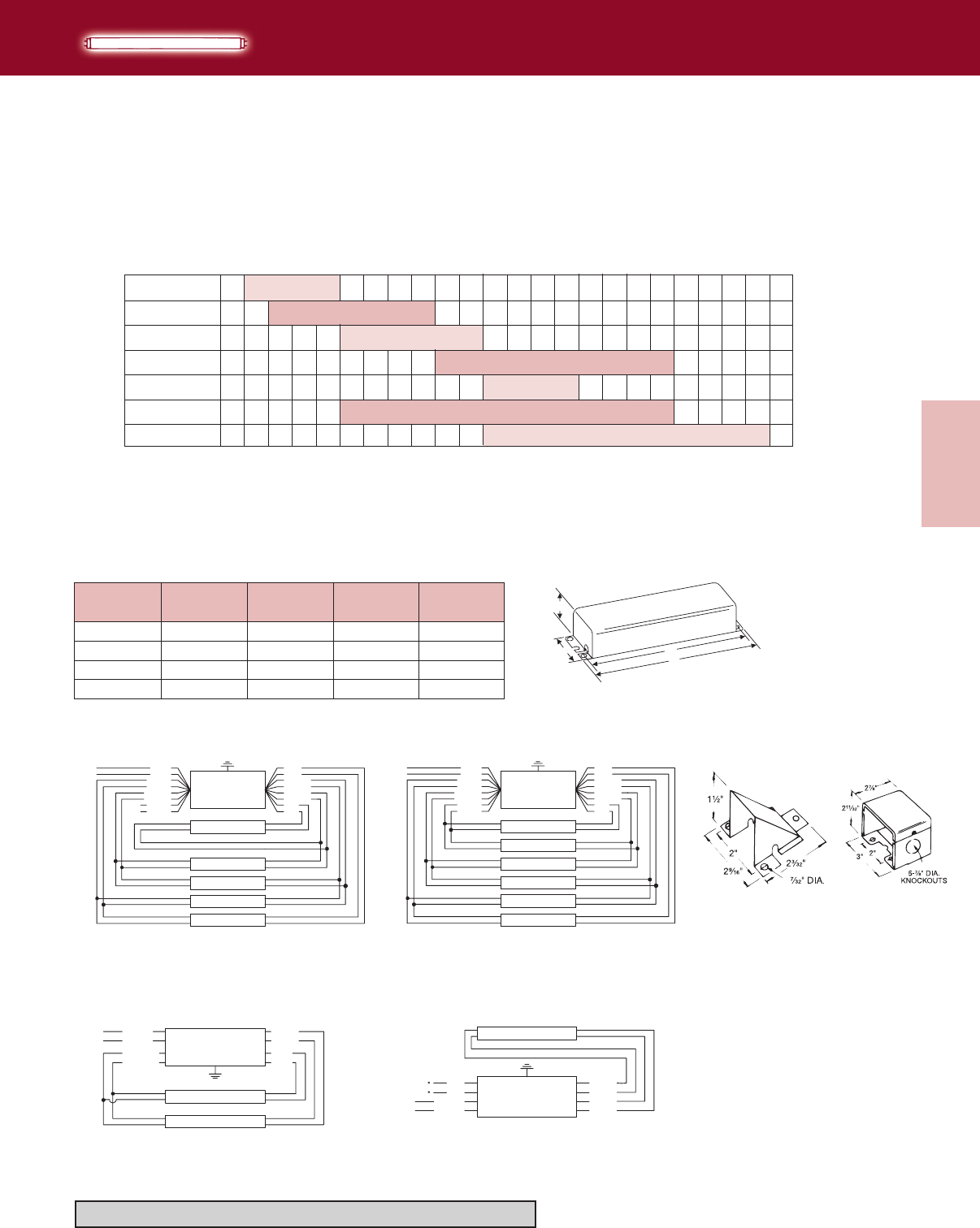
3-25
Lighting Electronics Atlas 2010-2011
ELECTROMAGNETIC
FLUORESCENT BALLASTS
Electromagnetic
Fluorescent Ballasts
ASB-2448-46-BL-TP
VSB-2448-46-BL-TP
ASB-2432-34-BL-TP
T12/HO
CLASS P BALLAST IN WHITE CAN
High Output Lamps
Sign Ballasts
ASB-1240-46-BL-TP
VSB-1240-46-BL-TP
Number of Lamps
per Ballast
ASB-0620-24-BL-TP
VSB-0620-24-BL-TP
ASB-0412-12-BL-TP
VSB-0412-12-BL-TP
ASB-2040-24-BL-TP
VSB-2040-24-BL-TP
Designation Length (L)
(inches)
Width (W)
(inches)
Height (H)
(inches)
Mounting (M)
(inches)
BL-1 11¾ 33/16 25/8119/64
BL-2 145/16 33/16 25/813¾
BL-3 193/16 33/16 211/16 185/8
DIMENSIONS
BL-4 1611/16 33/16 25/8169/64
ASB-1224-24-BL-TP
VSB-1224-24-BL-TP
PC-857WPC-161W
Refer to pages 9-24 to 9-28 for lead lengths and shipping data
BLUE
BLUE
RED
RED
YELLOW
YELLOW
BLACK
WHITE
LINE
LAMP
LAMP
BALLAST
WHITE
YEL
YEL
BLACK
LINE RED
RED
BLUE
BLUE
LAMP
BALLAST
Diag. 21
Diag. 19
Diag. 39
RED
RED
BLUE
OR-BLK
OR-BLK
ORANGE
ORANGE
BLUE
LINE BLACK
WHITE
BLUE-WH
BLUE-WH
BROWN
BROWN
YELLOW
YELLOW
BALLAST
LAMP 1
LAMP 6
LAMP 5
LAMP 3
LAMP 2
LAMP 4
RED
RED
BLUE
OR-BLK
OR-BLK
ORANGE
ORANGE
BLUE
LINE BLACK
WHITE
BLUE-WH
BLUE-WH
BROWN
BROWN
YELLOW
YELLOW
BALLAST
LAMP 1
LAMP 6
LAMP 5
LAMP 3
LAMP 4
Diag. 15
Note: Insulate unused leads individually as shown
on a ballast label
To select the ballast for your particular plastic sign application:
1) Determine the total number of lamp feet required (from 4 to 48 feet) and read down to select the proper Philips Lighting Electronics
Catalog Number. Note that the first ballast you come to, reading down the chart, will be the most economical for your application.
2) The number of lamps per ballast is shown in the left column.
H
WM
L
CASE "R"
Case BL-1, BL-2,
BL-3, BL-4
Total Lamp Feet
2 4 6 8 10 12 14 16 18 20 22 24 26 28 30 32 34 36 38 40 42 44 46 48 50
1,2
2,3,4
2,3,4
2,3,4
3,4
4,5,6
4,5,6
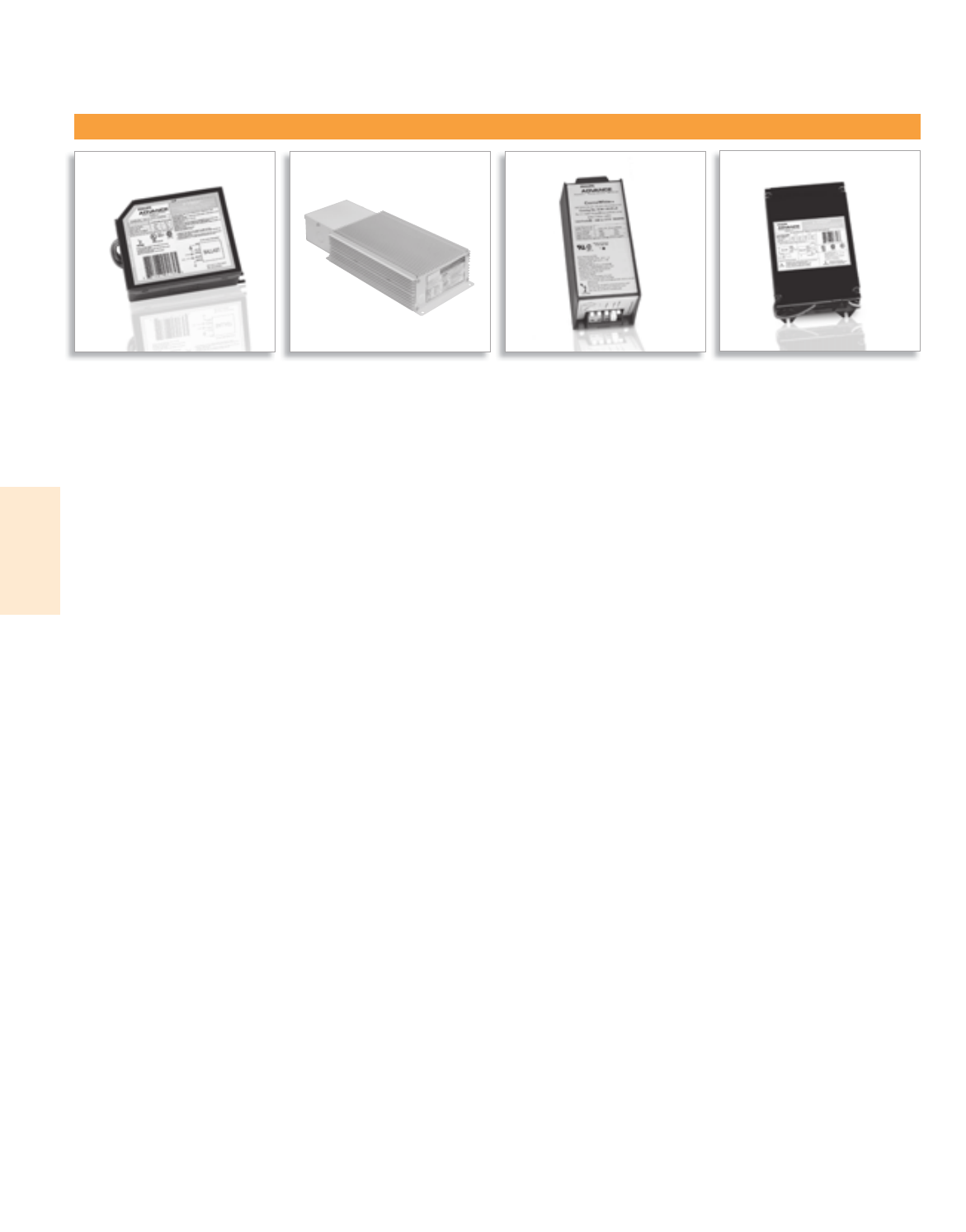
Lighting Electronics Atlas 2010-2011
ELECTRONIC HID BALLASTS
1
Electronic HID
e-Vision® DynaVision® CosmoPolis™ MasterColor CDM™ Elite MV

4-1
Lighting Electronics Atlas 2010-2011
ELECTRONIC HID BALLASTS
Electronic HID
Contents
General Information 4-2
e-Vision® 4-3 to 4-10
DynaVision® 4-11 to 4-13
CosmoPolis™ 4-14
MasterColor CDM™ Elite MW 4-15
Visit our web site at www.philips.com/advance
Customer Support/Technical Service
(800) 372-3331 • (+) 1 847 390-5000 (International)
Corporate Offices
(800) 322-2086

Lighting Electronics Atlas 2010-2011
ELECTRONIC HID BALLASTS
4-2
Electronic HID
Electronic HID Overview
Just as electronic ballast technology enhanced fluorescent
lighting systems, electronic HID ballasts bring significant
performance improvements to HID lighting systems:
• Higher efficiency • Greater lumen maintenance
• Longer lamp life • Enhanced color control
e-Vision®
Low frequency electronic ballasts are recommended
by lamp manufacturers to drive the new generation of
ceramic, low wattage metal halide lamps. These ceramic
lamps have superior color rendition and can potentially
maintain that color over the life of the lamps when
operated with electronic ballasts. Since color is dependent
on proper lamp wattage, the electronic ballast must be
able to maintain lamp wattage precisely at its rated point
throughout the rated average life of the lamp. Low
frequency electronic HID ballasts such as the Philips
Advance e-Vision® line constantly measure and adjust
the wattage, optimizing delivery of the ceramic lamps’
superior color properties. This makes metal ceramic halide
operated by e-vision ballasts the premier choice for many
applications previously lit by either tungsten halogen or
incandescent sources, such as retail lighting.
Operational improvements are gained as greater efficiency
and cooler running electronic ballasts lead to energy
savings. In addition, ballasts run quieter, weigh less and
have compact footprints.
DynaVision®
Improved lumen maintenance — the lamp/ballast system’s
ability to minimize light output depreciation over the life of
the lamp — is the most fundamental and significant benefit
of electronic HID ballasts, especially medium wattage, high
frequency ballasts such as the Philips Advance DynaVision®
ballast. DynaVision delivers a 30-50% improvement in lumen
maintenance over conventional HID systems (magnetic
ballasts driving probe-start metal halide lamps) and a
19% improvement over pulse-start systems. Conventional
HID systems typically experience a 50-60% fall-off in light
output over the published life of the lamp. By maintaining
higher light levels across the rated average life of
the lamp, electronic HID ballasts reduce the need for
frequent re-lamping.
With more maintained lumens the overall fixture count can
be significantly reduced. For example, a 400W DynaVision
system produces up to 56% more mean lumens over a 400W
probe-start system with magnetic ballasts. Taking advantage of
this performance benefit, the fixture count can be reduced by
up to 36% without sacrificing light levels. Fewer fixtures also
lead to much lower operating costs in terms of both energy
savings and maintenance.
The DynaVision ballast provides dimming (to 50% power)
using lighting controls such as relays, occupancy sensors, building
management systems (BMS) and, other 0-10V controls. Also
included is a 120V output for quartz auxiliary lighting during
restrike. The microprocessor-based technology incorporated in
this ballast provides comprehensive lamp and ballast parameter
control and is a solid platform for the future.
CosmoPolis™
CosmoPolis presents a major step forward in outdoor lighting
and was developed specifically to meet the challenges of the 21st
century. The CosmoPolis system simplifies outdoor lighting with
the combination of a compact lamp and an optimized, rugged
electronic ballast system. This highly efficient system provides
end users the ability to convert to a warm white light without
sacrificing color rendering or system lifetime.
MasterColor Elite
The MasterColor CDM Elite MW system offers an unrivalled
level of light quality and performance. The lamp’s sparkling white
light creates a natural ambiance and brings out the best in all
different types of colors. The high efficiency of the lamp and
ballast together means reduced energy use and a lower cost
of ownership compared to traditional 400W Metal Halide HID
systems. This new system is ideal for indoor lighting in both
high-bay and recessed applications, as well as outdoor lighting
for street and area installations.
ELECTRONIC HID BALLASTS
4-3
Lighting Electronics Atlas 2010-2011
Electronic HID
• Fewer SKUs required in inventory
• Broadens the range of applications
• Compact electronic HID footprints
• Provides greater design flexibility
• Energy Savings; Lower cost of ownership
• Prevents acoustic resonance in the lamp arc tube
• Recommended by lamp manufacturers
• Maximizes lamp life
• Enhanced safeguard
• Shuts system down upon
abnormal failure or conditions
Better light quality
• Optimizes lamp color stability over rated
average life
• Reduces lamp-to-lamp color variations
both initially and during lamp life
• Provides enhanced capability for high ambient
temperatures by transferring heat away from
sensitive internal components
• Lamp produces maximum light output over its
rated average life.
IntelliVolt®
• Operates on either 120 or 277V, or any
voltage in between, 50 or 60Hz
Smaller and lighter weight than magnetic HID
F-Can ballasts
Reduced input watts compared to magnetic systems
Low frequency lamp operation
Square wave output waveform
Lamp EOL detection; Shuts down system at lamp
end of life
Thermally protected, internally fused, and output
short circuit protected
Excellent lamp wattage regulation
• Lamp wattage will change less than .5% with a
+/-10% change in line voltage
Metallic enclosure
1.0 Ballast Factor
Key Benefits
Key Features
E-HID Lead Wire Information
Black
White
Black/White
Red
Blue
Wire Color
Green
Orange
Brown
Yellow
Gray with Red Stripe
Input Power
Input Power
Lamp Power Selection (IMH50A and IMH175C models only)
Lamp Base
Lamp Screwshell
Function
Ground
Lamp Base
Lamp Screwshell
Output for 120V Self Heating Thermal protector
Output for 120V Self Heating Thermal protector
11.0” +/- 1.0” 9.0” +3.0”/-2.0”
11.0” +/- 1.0” 9.0” +3.0”/-2.0”
11.0” +/- 1.0” 9.0” +3.0”/-2.0”
11.0” +/- 1.0” 9.0” +3.0”/-2.0”
11.0” +/- 1.0” 9.0” +3.0”/-2.0”
Lengths Lead
(-LF model)
Lengths
(-BLS model)
11.0” +/- 1.0” 9.0” +3.0”/-2.0”
11.0” +/- 1.0” 9.0” +3.0”/-2.0”
11.0” +/- 1.0” 9.0” +3.0”/-2.0”
N/A 9.0” +3.0”/-2.0”
N/A 9.0” +3.0”/-2.0”
0.5”
0.5”
0.5”
0.5”
0.5”
Length Strip
0.5”
0.5”
0.5”
0.5”
0.5”
e-Vision® Low Frequency Electronic HID Ballasts
For Low Wattage HID Lamps
e-Vision®
Lighting Electronics Atlas 2010-2011
4-4
Electronic HID
ELECTRONIC HID BALLASTS
MH _
——
I100 BLSA
Input Voltage:
I = Intellivolt (accepts input of 120 thru 277V, 50/60 Hz nominal) R = 120V, 50/60 Hz nominal)
Primary Lamp Type:
MH = Metal Halide
WSN = Mini white SON (100 W Only)
SN = High Pressure Sodium
CW = CosmoWhite
Max Lamp Wattage:
G20 = 20W Lamp
20= 22 W Lamp^
39 = 39 W Lamp
:
70 = 70W Lamp
90 = 90W CW Lamp
100 = 100W Lamp
P39 = 39W Lamp+
50 = 50W Lamp
60 = 60W CW Lamp
140 = 140W CW Lamp
150 = 150W Lamp
175 = 175W Lamp
210315 = 210 W/315W MCE
Can Material / Size: (Dimensions include mounting feet)
A/B = Metal case with dim. 5.5” L x 3.6” W x 1.5” H
C = Metal case with dim. 8.0” L x 3.6” W x 1.5” H
D = Metal case with dim. 5.0” L x 3.0” W x 1.5” H
E = Metal case with dim. 5.5” L x 1.75” W x 1.2” H
G = Metal case with dim. 3.9” L x 3.0” W x 1.2” H
H = Metal case with dim. 6.4” L x 3.7” W x 1.5” H
K = Metal case with dim. 4.75” L x 1.3” W x 1.2” H
M = Plastic case with dim. 5.9” L x 2.6” W x 2.6” H
N = Plastic case with dim. 5.3” L x 2.6” W x 2.6” H
R = Metal case with dim. 8.2” L x 4.9” W x 2.2” H
T = Plastic case with dim. 6.3” L x 3.9” W x 2.4” H
Lead Exit / Mounting Options:
BLS = Bottom Leads with Studs
LF = Leads (side exit) with mounting Feet
LFS = Leads (side exit, lead exit from same end) with mounting Feet (RMH-G20-K, RMH-20-K and RMH-39-K Only)
LS = Connector (side exit) with mounting Feet
ZT
—
Dimming Scheme: Blank = Fixed Light Output ZT = 0-10V Dimming L = LumiStep
—
Number of Lamps: Blank = 1 Lamp Operation 2 = (2) Lamp Operation
—
ID Additional Options:
Blank = None 6 = 6 hours* 8 = 8 hours* 10 = 10 hours*
ID = Integral 120V output to supply power to a Self Heating Thermal Protector (39W, 70W, 100W)
Catalog Number Explanation
^ Philips 20W MiniMaster Color Lamp
+ Philips 39W MiniMaster Color Lamp
* Dimming time with LumiStep
e-Vision®

ELECTRONIC HID BALLASTS
4-5
Lighting Electronics Atlas 2010-2011
Electronic HID
Section 1 - Physical Characteristics
1.0 The electronic ballast shall be furnished with integral, color-
coded leads.
Section II - Performance Requirements
2.0 The electronic ballast shall be IntelliVolt® and operate from
a nominal line voltage range of 120-27V, +/-10%, 50/60Hz
unless stated otherwise.
2.1 The electronic ballast input current shall have Total Harmonic
Distortion (THD) of less than 15%.
2.2 The electronic ballast shall have a Power Factor greater than 90%.
2.3 The electronic ballast shall have a lamp end-of-life detection
and shutdown circuit.
2.4 The electronic ballast shall be Sound Rated A.
2.5 The electronic ballast output frequency to the lamps shall be
less than 200Hz to prevent acoustic resonance inside the lamp
arc tube and to minimize visible flicker.
2.6 The electronic ballast shall provide a “Lamp Current Crest
Factor” of less than 1.5.
2.7 The electronic ballast shall be thermally protected to shut off
when operating temperatures reach unacceptable levels.
Section III - Regulatory Requirements
3.0 The electronic ballast shall meet the requirements of the
Federal Communications Commission rules and regulations,
Title 47 CFR part 18, for Non-Consumer equipment.
3.1 The electronic ballast shall be Underwriters Laboratories (UL)
Listed and CSA Certified where applicable.
Section IV - Other
4.0 The electronic ballast shall not contain Polychlorinated
Biphenyl (PCB’s).
4.1 The electronic ballast shall carry a three-year limited warranty
from the date of manufacture for operation at marked
maximum case temperature or less (See www.philips.com/
advancewarranty for futher information).
4.2 The manufacturer shall have a twenty-five year history of
producing HID lamp ballasts for the North American market.
4.3 The electronic ballast shall be produced in a factory certified
to ISO 9002 Quality System Standards
Installation Notes
1. Red lead must be connected to center terminal of lamp (for Edison,
screw base lamps). Do not connect red or blue lead to neutral
or ground.
2. Use appropriately rated lampholder.
3. Maximum ballast-to-lamp distance is 5ft. using typical wiring methods
and materials. Additional distance up to 15ft. may be possible using
wire between lamp and ballast with a total measured capacitance
of 100 picofarads or less. Consult Philips Lighting Electronics for
application assistance.
4. Power mains must be cycled off and then on to reset ballast after
failed lamps are replaced.
Ballast Hot Spot Location
Hot spot locations differ with each ballast model and are designated on
the individual ballast labels. Consult ballast labels and ballast specification
sheets for Hot Spot locations.
e-Vision® Electronic Ballast Specifications
e-Vision®
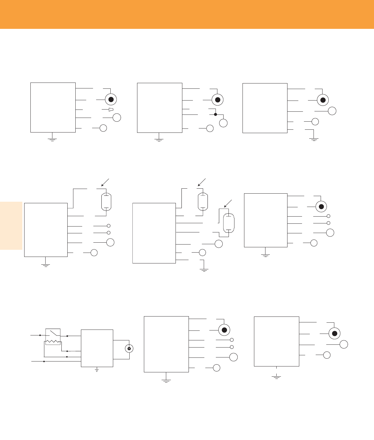
Lighting Electronics Atlas 2010-2011
4-6
Electronic HID
ELECTRONIC HID BALLASTS
BALLAST CASE
MUST BE GROUNDED
WIRING DIAGRAM 1
RED
LAMP
COM
CAP OFF
120V - 277V
BLUE
WHITE
BLACK
WHITE/BLACK
BALLAST
COM
120-277V
WHITE
BLACK PHILIPS
ADVANCE
120-277V
BALLAST
WITH
ID OUTPUT
YELLOW
GRAY W/RED
SELF HEATING
THERMAL PROTECTOR
RED
BLUE
BALLAST CASE MUST
BE GROUNDED
kV
WIRING DIAGRAM 4
DIM –
GRAY
DIM +
VIOLET
BALLAST CASE
MUST BE GOUNDED
COM
120V
RED
LAMP
BLUE
WHITE
BLACK
BALLAST
BALLAST CASE
MUST BE GROUNDED
Wiring Diagram 2
WIRING DIAGRAM 2
RED
LAMP
COM
120V - 277V
BLUE
WHITE
BLACK
WHITE/BLACK
BALLAST
DIM –
GRAY
DIM +
VIOLET
BALLAST CASE
MUST BE GOUNDED
WIRING DIAGRAM 9
RED
LAMP
COM
208V - 277V
BLUE
WHITE
BLACK
BALLAST
kV
kV
WIRING DIAGRAM 5
GREEN
BALLAST CASE
MUST BE GOUNDED
COM
120V - 277V
RED
LAMP 1
LAMP 2
BLUE
WHITE
BLACK
BALLAST
ORANGE
BROWN
BALLAST CASE
MUST BE GROUNDED
WIRING DIAGRAM 3
RED
LAMP
COM
120V - 277V
BLUE
WHITE
BLACK
GREEN
BALLAST
FUNCTIONAL
GROUND
WIRING DIAGRAM 10
GRAY
LAMP
COM
208V - 277V
MAGENTA
GRAY
WHITE
BLACK
BALLAST
WIRING DIAGRAM 6
DIM –
GRAY
DIM +
VIOLET
BALLAST CASE
MUST BE GOUNDED
RED
LAMP
COM
120V - 277V
BLUE
WHITE
BLACK
BALLAST
Wiring Diag. 1
Wiring Diag. 4
Wiring Diag. 8
Wiring Diag. 2
Wiring Diag. 5
Wiring Diag. 9
Wiring Diag. 3
Wiring Diag. 6
Wiring Diag. 10
Enclosure Dimensions, Lead Lengths and Wiring Diagrams
e-Vision®
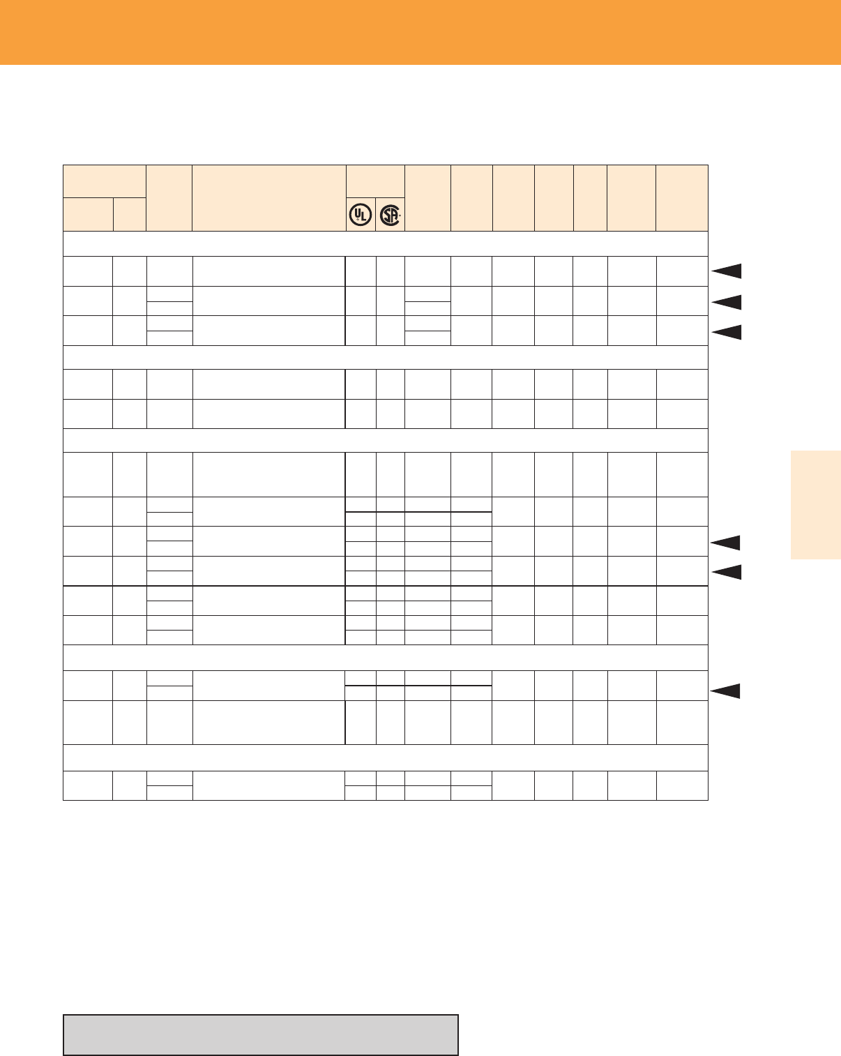
ELECTRONIC HID BALLASTS
4-7
Lighting Electronics Atlas 2010-2011
Electronic HID
20W Lamp, ANSI Code M156 Minimum Starting Temp -20°C/-4°F
Input
Volts
Catalog Number*
Note 1
Certifications Line
Current
(Amps)
Input
Power
ANSI
(Watts)
Max.
Case
Temp.
Note 5
Wiring
Diag. Fig. Weight
(lb)
Watts
Number
Lamp Data
IMH-G20-G-LF
IMH-G20-G-BLS
IMH-G20-E-LF
✓
✓
✓
✓
0.2
0.09
0.21
0.09
3
3
1
1
20
20
120
277
120
277
24
24
90°C
90°C
G
E
0.9
0.55
Max.
Distance to
Lamp (ft)
5
5
1. All ballasts are sound rated A, and feature high power factor (>0.9, a ballast factor of 1.0
resettable thermal protection, and a maximum Harmonic Distortion of 15%.
2. For RMH-39-K-LF, RMH-20-K-LF and RMH-G20-KLF input and output lead wires exit
on opposite sides of ballast. For RMH-39-K-LFS, RMH-20-K-LFS and RMH-G20-KLFS all
lead wires exit the same side of the ballast.
3. A dual-wattage ballast for 39W or 50W MH
4. A dual-wattage ballast for 150W or 175W MH
5. Maximum case temperature should not be exceeded in the application, as life will be affected
and the integral re-settable thermal protector may activate. A lower maximum temperature
rating does not imply lesser thermal performance, and can be indicative of a cooler running
ballast design. Consult factory for further application assistance.
6. Also operates (1) 150W HPS S56 (100V) Lamp
7. Also operates the ES16 and ES36 SLi Brightspot lamps
8. Also operates the 39W Philips miniMastercolor lamp (ANSI Code C179)
* Ordering information:
—LF Side exit leads with mounting feet
—BLS Bottom exit leads with mounting studs
x Use with any Self Heating Thermal Protector (Insulation Detector)
having equivalent resistive value 5k to 25k ohm (4 wire versions only)
RMH-G20-K-LF
RMH-G20-K-LFS Note 2 ✓ ✓ 0.23 4
1 20 120 26 90°C K 0.4 6
22W Lamp, Philips Mini MasterColor, ANSI Code M175, Minimum Starting Temp. -20°C/-4°F
RMH-20-E-LF
RMH-20-E-BLS ✓ ✓ 0.23 4
1 22 120 26 70°C E 0.4
39W Lamp, ANSI Code M130/C130, Minimum Starting Temp. -20°C/-4°F
39W Mini MasterColor Lamp, CDM-Tm 35W/930, ANSI Code M179 Minimum Starting Temp -20°C/-4°F
RMH-39-K-LF,
RMH-39-K-BLS or
RMH-39-K-LFS Note 2,7,8
✓ ✓ 0.40 41 39 120 45 90°C K 0.5
6
6
RMH-39-K-LF,
RMH-39-K-BLS or
RMH-39-K-LFS Note 2,7,8
✓ ✓ 0.40 41 39 120 45 90°C K 0.5 6
IMH-39-G-LF or
IMH-39-G-BLS
✓ ✓
✓ ✓
139 120
277
0.39 3
0.18
46 90°C
45 G 0.9 5
IMH-P39-G-LF
IMH-P39-G-BLS
✓ ✓
✓ ✓
139 120
277
0.39 3
0.17
46 90°C
45 G 0.9 5
IMH-39-E-LF ✓ ✓
✓ ✓
139 120
277
0.39 3
0.18
46 90°C
45 E 0.6 5
IMH-39-A-BLS-IDx✓ ✓
✓ ✓
139 120
277
0.45 8
0.18
48 90°C
47 A 1.5 5
IMH-50-A-LF or
IMH-50-A-BLS Note 3
✓ ✓
✓ ✓
139 120
277
0.38 1
0.16
45 85°C
44 A 1.4 5
IMH-239-A-LF or
IMH-239-A-BLS
✓ ✓
✓ ✓
239 120
277
0.74 5
0.31
89 85°C
89 A 1.7 6
50W Lamp, ANSI Code M110 or M148, Minimum Starting Temp. -20°C/-4°F
IMH-50-A-LF or
IMH-50-A-BLS Note 3
✓✓
✓ ✓
1 50 120
277
0.47 2
0.20
56 85°C
55 A 1.4 5
RMH-20-K-LF or
RMH-20-K-LFS Note 2,7 ✓ ✓ 0.23 4
1 22 120 26 90°C K 0.5 6
Refer to pages 4-9 for ballast dimensions
Refer to pages 4-3 for lead wire information
Metal Halide and High Pressure Sodium
New
New
New
New
New
New
e-Vision®
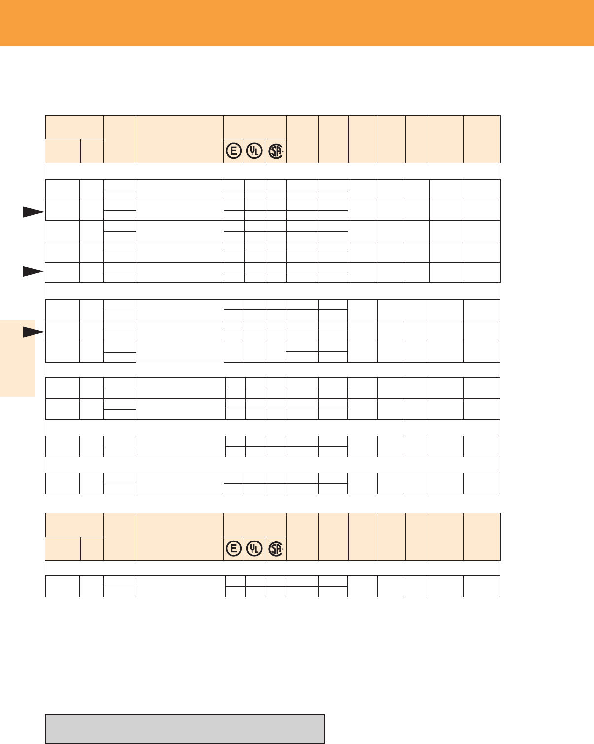
Lighting Electronics Atlas 2010-2011
4-8
Electronic HID
ELECTRONIC HID BALLASTS
Refer to pages 4-9 for ballast dimensions
Refer to pages 4-3 for lead wire information
Input
Volts
Catalog Number*
Note 1
Certifications Line
Current
(Amps)
Input
Power
ANSI
(Watts)
Max.
Case
Temp.
Note 5
Wiring
Diag. Fig. Weight
(lb)
Watts
Number
Lamp Data Max.
Distance to
Lamp (ft)
Metal Halide and High Pressure Sodium
IMH-100-D-LF or
IMH-100-D-BLS
✓ ✓
✓ ✓
1 100 120
277
0.92 3
0.40
110 85°C
109 D 1.6 5
IMH-100-B-LF ✓ ✓
✓ ✓
1 100 120
277
0.92 3
0.40
110 85°C
109 A/B 1.5 5
150W Lamp, ANSI Code M102 or M142, Minimum Starting Temp. -20°C/-4°F
IMH-150-H-LF or
IMH-150-H-BLS Note 9
✓ ✓✓
✓ ✓✓
1 150 120
277
1.4 3
0.6
165 85°C
161 H1.9 5
IMH-175-C-LF or
IMH-175-C-BLS Note 5,6,9
✓ ✓✓
✓ ✓✓
1 150 120
277
1.4 1
0.6
169 85°C
166 C 2.5 5
1. All ballasts are sound rated A, and feature high power factor (>0.9, a ballast factor of 1.0
resettable thermal protection, and a maximum Harmonic Distortion of 15%.
2. For RMH-39-K-LF and RMH-20-K-LF input and output lead wires exit on opposite sides of
ballast. For RMH-39-K-LFS and RMH-20-K-LFS all lead wires exit the same side of the ballast.
3. A dual-wattage ballast for 39W or 50W MH
4. A dual-wattage ballast for 150W or 175W MH
5. Maximum case temperature should not be exceeded in the application, as life will be affected
and the integral re-settable thermal protector may activate. A lower maximum temperature
rating does not imply lesser thermal performance, and can be indicative of a cooler running
ballast design. Consult factory for further application assistance.
6. Also operates (1) 150W HPS S56 (100V) Lamp
7. Also operates the ES16 and ES36 SLi Brightspot lamps
8. Also operates the 39W Philips miniMastercolor lamp (ANSI Code C179)
9. “Circle E” denotes EISA compliance
* Ordering information:
—LF Side exit leads with mounting feet
—BLS Bottom exit leads with mounting studs
x Use with any Self Heating Thermal Protector (Insulation Detector)
having equivalent resistive value 5k to 25k ohm (4 wire versions only)
175W Pulse Start Lamp, ANSI Code M137 or M152 (Pulse Start), Minimum Starting Temp. -20°C/-4°F
IMH-175-C-LF or
IMH-175-C-BLS Note 4,9
✓ ✓✓
✓ ✓✓
1 175 120
277
1.7 2
0.7
194 85°C
191 C 2.5 5
100W Lamp, Philips Mini whiteSON (SDW-TG), ANSI Code S167 (Pulse Start), Min. Starting Temp. -20°C/-4°F
IWSN-100-C-LF ✓ ✓
✓ ✓
1 100 120
277
0.9 3
0.5
165 85°C
161 C1.9 5
IMH-100-A-BLS-IDx✓ ✓
1 100 120
277
0.96 8
0.42
115 90°C
113 A 1.4 6
100W Lamp, ANSI Code M90 or M140, Minimum Starting Temp. -20°C/-4°F
New
70W Lamp, ANSI Code M98 or M143 or M139, Minimum Starting Temp. -20°C/-4°F
IMH-70-G-LF or
IMH-70-G-BLS
✓ ✓
✓ ✓
1 70 120
277
0.67 3
0.30
80 90°C
79 G 0.9 5
IMH-70-E-LF ✓ ✓
✓ ✓
1 70 120
277
0.67 3
0.30
80 90°C
79 E 0.6 5
IMH-70-D-LF or
IMH-70-D-BLS
✓ ✓
✓ ✓
1 70 120
277
0.67 3
0.29
80 85°C
79 D 1.6 5
IMH-70-A-LF ✓ ✓
✓ ✓
1 70 120
277
0.67 3
0.29
80 85°C
79 A 1.5 5
IMH-70-A-BLS-IDx✓ ✓
✓ ✓
1 70 120
277
0.72 8
0.31
86 90°C
84 A 1.6 6
New
New
e-Vision®
Input
Volts
Catalog Number*
Note 1
Certifications Line
Current
(Amps)
Input
Power
ANSI
(Watts)
Max.
Case
Temp.
Note 5
Wiring
Diag. Fig. Weight
(lb)
Watts
Number
Lamp Data Max.
Distance to
Lamp (ft)
150W Lamp, ANSI Code M102 or M142, Minimum Starting Temp. -20°C/-4°F
Controllable Ballasts with 0-10V Dimming Interface
IZTMH-150C-LF Note 9 ✓ ✓✓
✓ ✓✓
1 150 120
277
1.4 6
0.6
169 85°C
166 C 2.5 5
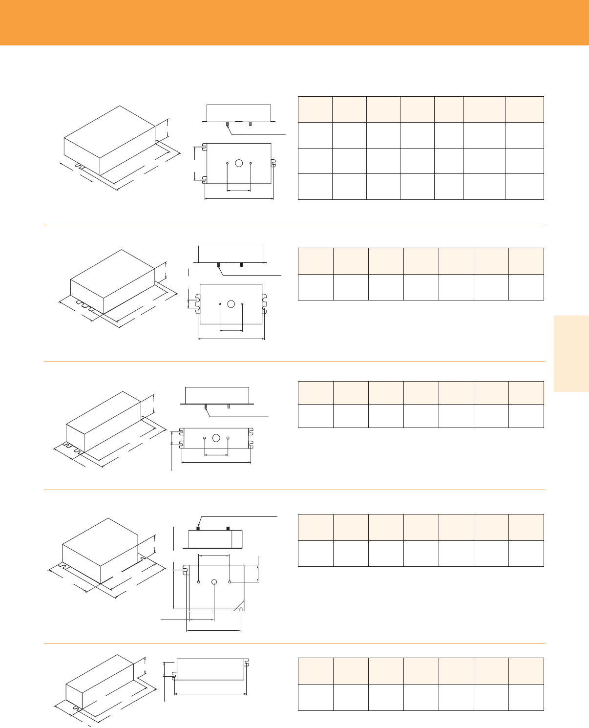
ELECTRONIC HID BALLASTS
4-9
Lighting Electronics Atlas 2010-2011
Electronic HID
CASE LENGTH
HEIGHT
CASE WIDTH
MOUNTING
WIDTH
MOUNTING LENGTH
2.0" (50.8)
8-32 X ¼" MOUNTING STUDS
OVERALL LENGTH
CASE LENGTH
HEIGHT
CASE WIDTH
MOUNTING
WIDTH
MOUNTING LENGTH
2.0" (50.8)
8-32 X ¼" MOUNTING STUDS
OVERALL LENGTH
CASE LENGTH
HEIGHT
CASE WIDTH MOUNTING
WIDTH
MOUNTING LENGTH
2.0" (50.8)
8-32 X ¼" MOUNTING STUDS
Only applies to RMH-20-E
OVERALL LENGTH
CASE LENGTH
CASE WIDTH
MOUNTING LENGTH
2.0" (50.8)
2.0" (50.8)
1.625" (40)
8-32 X ¼" MOUNTING STUDS
8-32 X ¼" MOUNTING STUDS
OVERALL LENGTH
1.125" (27.5)
MOUNTING
WIDTH
HEIGHT
CASE LENGTH
HEIGHT
CASE WIDTH
MOUNTING
WIDTH
MOUNTING LENGTH
OVERALL LENGTH
Case
Figure
Overall
Length
Case
Length
Case
Width Height Mounting
Length
Mounting
Width
A/B 140mm
[5.5”]
120mm
[4.7”]
92mm
[3.6”]
38mm
[1.5”]
132mm
[5.2”]
73mm
[2.9”]
C204mm
[8.0”]
184mm
[7.2”]
92mm
[3.6”]
38mm
[1.5”]
195mm
[7.7”]
73mm
[2.9”]
H161mm
[6.3”]
144mm
[5.7”]
92mm
[3.6”]
38mm
[1.5”]
152mm
[6.0”]
73mm
[2.9”]
Case
Figure
Overall
Length
Case
Length
Case
Width Height Mounting
Length
Mounting
Width
D128mm
[5.0”]
108mm
[4.3”]
77mm
[3.0”]
38mm
[1.5”]
118mm
[4.6”]
19mm
[0.7”]
Case
Figure
Overall
Length
Case
Length
Case
Width Height Mounting
Length
Mounting
Width
E140mm
[5.5”]
127mm
[5.0”]
44mm
[1.7”]
30mm
[1.2”]
135mm
[5.3”]
26mm
[1.0”]
Case
Figure
Overall
Length
Case
Length
Case
Width Height Mounting
Length
Mounting
Width
G97mm
[3.8”]
90mm
[3.5”]
77mm
[3.0”]
30mm
[1.2”]
87mm
[3.4”]
67mm
[2.6”]
Case
Figure
Overall
Length
Case
Length
Case
Width Height Mounting
Length
Mounting
Width
K119mm
[4.4”]
104mm
[4.1”]
33mm
[1.1”]
30mm
[1.2”]
114mm
[4.5”]
13.5mm
[0.5”]
e-Vision®
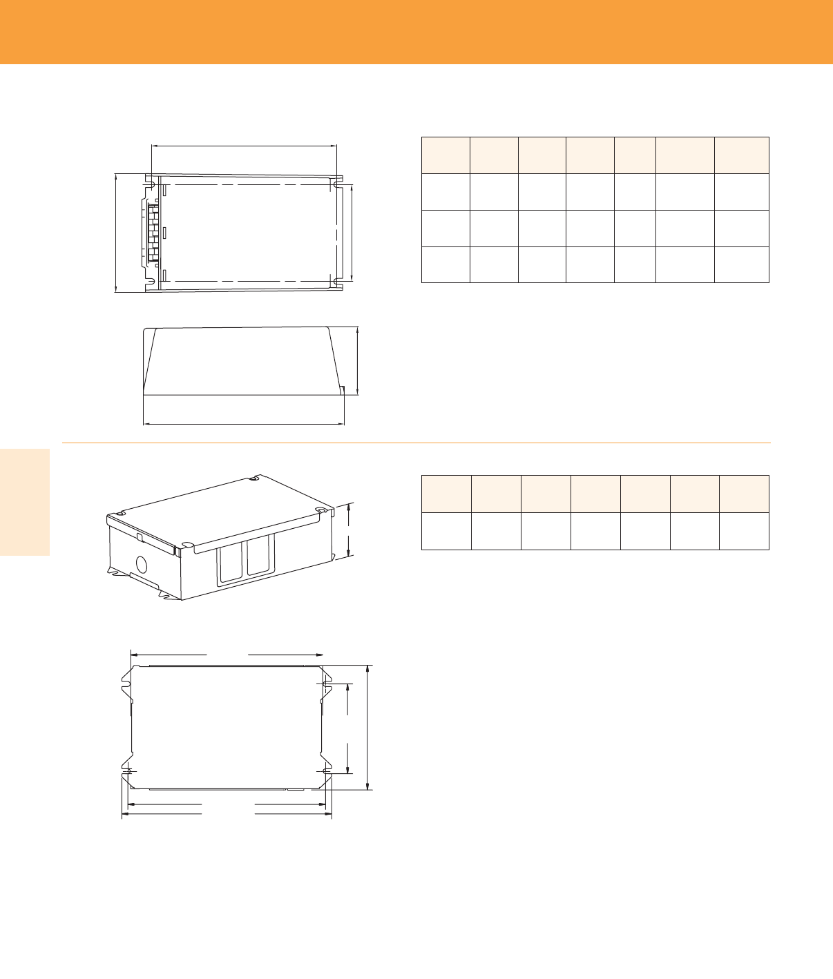
Lighting Electronics Atlas 2010-2011
4-10
Electronic HID
ELECTRONIC HID BALLASTS
Case
Figure
Overall
Length
Case
Length
Case
Width Height Mounting
Length
Mounting
Width
M150mm
[5.9”]
150mm
[5.9”]
65mm
[2.6”]
65mm
[2.6”]
136mm
[5.4”]
47mm
[1.8”]
N135mm
[5.3”]
135mm
[5.3”]
65mm
[2.6”]
65mm
[2.6”]
126mm
[4.9”]
47mm
[1.8”]
T166mm
[6.3”]
166mm
[6.3”]
100mm
[3.9”]
60mm
[2.4”]
156mm
[6.1”]
81.5mm
[3.2”]
Case
Figure
Overall
Length
Case
Length
Case
Width Height Mounting
Length
Mounting
Width
R208mm
[8.2”]
191mm
[7.5”]
124mm
[4.9”]
56mm
[2.2”]
192mm
[7.6”]
86.5mm
[3.4”]
Mounting Length
Mounting
Width
Case
Width
Height
Overall Length / Case Length
Mounting Length
Mounting
Width
Case
Width
Height
Overall Length / Case Length
e-Vision®
Mounting Length
Mounting
Width
Case
Width
Height
Case Length
Overall Length
4-11
Lighting Electronics Atlas 2010-2011
ELECTRONIC HID BALLASTS
Electronic HID
DynaVision extends the key benefits
of magnetic pulse-start metal halide
systems – energy efficiency and white
light. With its very-high frequency
operation, as well as its on-board
microprocessor and standard features,
DynaVision provides numerous
additional benefits and advantages.
More about...
Microprocessor technology Lower operating and maintenance costs
High frequency operation Fewer fixtures
True constant wattage Energy savings
320/350/400 Tri-Wattage Fewer SKU’s
Less chance for ordering error
IntelliVolt 200-277V 50/60 Hz Ease of change over
to different wattage lamps
Standby-lighting ready
Integral 120V quartz tap No special orders
and relay, 250W No special relay or control required
0-10V dimming with automatic Continuous dimming down to 50% power
15-minute warm up Additional energy savings through
daylight harvesting and occupancy sensing
0º to 55ºC ambient rating standard Greater reliability, flexibility and
-30º to +40ºC ambient rating optional and applications opportunities
Lamp End-of-Life Protection (EOL) Safeguard
DynaVision’s 120V output is designed
to operate one quartz (incandescent)
standby lamp up to 250W. The quartz
lamp on or off modes are determined
by the HID lamp’s specific operating
conditions. Once the HID lamp strikes,
the quartz lamp automatically switches off
when the HID lamp reaches 50% power.
DynaVision is dimmable — down to 50% of nominal
lamp power, with no noticeable loss in color charac-
teristics. With 0-10V dimming, and compatible with
a host of products from most control manufacturers,
DynaVision brings new flexibility and energy-saving
strategies, such as daylight harvesting and occupancy
sensing, to applications in the industrial, educational,
government, hospitality, commercial and retail sectors.
DynaVision™ Electronic Ballast Catalog
Number Breakdown
IZTEMH4003PS - XJ
Basic Model Number
Options
I = IntelliVolt (200-277 50/60 Hz)
ZT = Zero-to-ten volt dimming
E = Electronic
MH = Metal Halide
400 = 400W maximum
3 = 3 wattage capability (320/350/400W)
PS = Pulse-Start
-XJ = Without junction box
(i.e. junction box is included if this suffix is omitted).
-XJF = Low temperature, without junction box
9.2˝ bracket end-to-end length
Optional
junction box
Fully closed
extruded aluminum
housing with white finish
8.8˝ mounting
dimensions
4.4˝ mounting
dimensions
DIP switch access
for lamp wattage selection
5mm mounting
holes (4) for
#10 screws
Integral mounting brackets
Hot spot measurement
location at screw
4.0˝
2.3˝
3.7˝
8.0˝
2.6˝
5.0˝
Physical Characteristics
DynaVision Feature Benefits and Advantages
Standby Lighting Versatility Controllability

Lighting Electronics Atlas 2010-2011
4-12
Electronic HID
ELECTRONIC HID BALLASTS
1. Red lead must be connected to center terminal of lamp.
Do not connect red or blue lead to line neutral.
2. Setting precaution with triple-wattage feature: Do not operate
lower wattage lamp on a ballast which has been set for operation
of higher wattage lamp. Short lamp life may result.
3. Ballast output will shut off after 40 minutes maximum if lamp
does not successfully ignite. Replace lamp and cycle mains to restore
output.
4. Use appropriately rated lampholder.
5. Connect red lamp lead to 600Vrms, 3.5kV or UL style 1452 wire.
6. Remote mounting distances not exceeding 15ft. are possible
with normal wiring methods. For distances greater than 15ft.,
power losses in the wire can result in appreciable decline in
actual lamp operating power. Consult Philips Lighting Electronics
for application assistance.
7. Power mains must be cycled off and then on to reset ballast after
failed lamps are replaced.
8. Ballast output exceeds 100kHz. Suitable test equipment is required
for measurement.
9. Ballast is suitable for recessed use. Do not install insulation above or
within 3” of ballast sides.
Where to Measure the Ballast Hot Spot
Section I — Physical Characteristics
1.1 The electronic ballast shall be fully enclosed in an aluminum
housing painted white.
1.2 The aluminum housing shall include a divided wiring compart-
ment to separate the power leads from the control leads. All
leads to be color-coded.
Section II — Performance Requirements
2.1 The electronic ballast shall be multivoltage capable and operate
from a line voltage range of 180 — 305V, 50/60 Hz.
2.2 The electronic ballast shall incorporate a microprocessor con-
troller to provide for optimum starting and operation of the
HID lamp.
2.3 The electronic ballast input current shall have Total Harmonic
Distortion (THD) of less than 15% when operated at nominal
line voltage (200V, 208V, 230V, 240V, 277V).
2.4 The ballast shall incorporate a 0-10V dimming interface and
control the dimming function such that the HID lamp is allowed
to warm up for fifteen minutes at full power before the lamp
will be allowed to dim, regardless of the level of the 0-10V sig-
nal. 10V applied to the dimming control leads, shall result in full
light output. 0V applied, or shorting the control leads together,
shall result in dimming to 50% of nominal lamp power.
2.5 The ballast shall include a 120V/250W auxiliary output for stand-
by incandescent lighting that shall include an integral control
to turn the auxiliary lamp on and off. The integral control shall
include a time-delay feature to keep the auxiliary lamp on until
the HID lamp reaches 50% power.
2.6 The electronic ballast shall have a Power Factor greater
than 90%.
2.7 The electronic ballast shall have a lamp end-of-life detection
and shutdown circuit.
2.8 The electronic ballast shall be Sound Rated A.
2.9 The electronic ballast output frequency to the lamps shall be
higher than 100 kHz to prevent acoustic resonance inside the
lamp arc tube and to minimize visible flicker.
2.10 The electronic ballast shall be thermally protected to shut off
when operating temperatures reach unacceptable levels.
Section III — Regulatory Requirements
3.1 The electronic ballast shall meet the requirements of the
Federal Communications Commission rules and regulations,
Title 47 CFR part 18, for Non-Consumer equipment.
3.2 The electronic ballast shall be Underwriters Laboratories (UL)
Listed and CSA Certified where applicable.
Section VI — Other
4.1 The electronic ballast shall not contain Polychlorinated Biphenyl
(PCB’s).
4.2 The electronic ballast shall carry a three-year warranty from the
date of manufacture for operation at an ambient temperature
of 55° C or less and when operated as a stand alone product
(i.e.remotely from a lighting fixture housing). When operated
within a lighting fixture housing, the same three-year warranty
shall apply for a maximum ballast case hot spot temperature of
76° C or less.
4.3 The manufacturer shall have a twenty-five year history of
producing HID lamp ballasts for the North American market.
4.4 The electronic ballast shall be produced in a factory certified to
ISO 9002 Quality System Standards.
Installation and Application Notes
HOT SPOT AT FORWARD SCREW LOCATION
SIDE VIEW
OPTIONAL
JUNCTION BOX
DynaVision Electronic Ballast Specification
DynaVision™
ELECTRONIC HID BALLASTS
4-13
Lighting Electronics Atlas 2010-2011
Electronic HID
Min Input
Lamp Data Start Input Catalog Line Power Ballast Max. Min. DIP
Temp. Volts Number Listings Current ANSI Factor THD PF Switch
No. Watts (F/C) (A) (W) % % Settings
320W Lamp, ANSI Code M132/M154
1 320 32/0 200 to IZTEMH4003PS 1.8 @ 200V 345 1.0 15 90
-20/-30 277 IZTEMH4003PS-F 1.3 @ 277V
350W Lamp, ANSI Code M131
1 350 32/0 200 to IZTEMH4003PS 1.9 @ 200V 375 1.0 15 90
-20/-30 277 IZTEM4003PS-F 1.4 @ 277V
400W Lamp, ANSI Code M135/M155
1 400 32/0 200 to IZTEMH4003PS 2.2 @ 200V 430 1.0 15 90
-20/-30 277 IZTEM4003PS-F 1.6 @ 277V
All lead lengths are
11” +/- 1”. The black
& white (input power),
green (ground), and
red & blue (lamp) leads
are pre-stripped 1/2”.
The two yellow 120v
(output) and violet &
grey (dimming control)
leads have insulated ends.
Preset at Factory
DIP switches are “on”
in the down position
ON
ON
ON
NOTE: These specifications apply to operation of pulse-start metal halide lamps with quartz arc-tube construction only. For operating
compatibility with ceramic arc-tube lamps, consult Phililps Lighting Electronics.
Dimming Feature
With an integral, industry-standard 0-10V interface, the
DynaVision electronic ballasts offer the capability to dim
the lamp by lowering the wattage lamp, reducing energy
consumption of the light fixture by up to 50%. Access to
this interface is via the violet (+) and grey (-) dimming
control leads. These leads can be connected to either
a 0-10V dimming control, (DynaVision ballast are
compatible with standard 0-10V control devices available
from many manufacturers) a 0-10V DC power supply,
or with a switch. An open switch provides full lamp
power, and a closed switch, short-circuiting the 0-10V
wires, yields 50% lamp power. Control devices such as
relays and occupancy sensors may also be used.
A potentiometer may also be used. However,
the value of the potentiometer is dependent on
the number of ballasts connected. Consult Philips
Lighting Electronics for guidance.
In accordance with the requirements of the
HID lamp manufacturers and NEMA, the dimming
feature includes a time delay to allow the HID lamp
to warm up for 15 minutes at full power before the
lamps will be allowed to dim, regardless of the level
of the 0-10V signal.
0-10V
INTERFACE
WIRES
0-10V
DIMMING
CONTROL
OR OR
VIOLET (+)
GREY (-)
BALLAST
POTENTIOMETER SWITCH
Lead Wire Information
Pulse-Start Metal Halide
Input Power
White Input Power
Green Ground
Yellow (2) 120V Lamp Output
Red Lamp Eyelet
Violet (+) 0-10V Dimming
Blue Lamp Eyelet
Grey 0-10V Dimming (–)
Wire Color Function
Breaks New Ground in HID Performance
Application Specifications
Black
1
1
1
320
350
430
345
375
430
1.0
1.0
1.0
15
15
15
90
90
90
DynaVision™
Listings
Line
Current
(A)
Max.
THD
%
Max.
PF
%
DIP
Switch
Settings
32/0
-20/-30
32/0
-20/-30
32/0
-20/-30
IZTEMH4003PS
IZTEMH4003PS-F
IZTEMH4003PS
IZTEMH4003PS-F
IZTEMH4003PS
IZTEMH4003PS-F
Lighting Electronics Atlas 2010-2011
4-14
Electronic HID
ELECTRONIC HID BALLASTS
The invention of the low-pressure sodium lamp and
linear fluorescent lamp in the 1930s created a foundation
for today’s outdoor lighting. Then, in the 1960s, the
light sources of choice became high pressure sodium
and mercury vapor.
With CosmoPolis, Philips presents to you another
major step forward in urban outdoor lighting, developed
specifically to meet the challenges you face in the 21st
century. The CosmoPolis system simplifies outdoor lighting
with the combination of a miniature lamp and an optimized
electronic ballast system.
The Six Performance Features of the
CosmoPolis System are Impressive:
1. Quality of Light 4. Dependable Service
2. System Efficiency 5. Compact System
3. Optical Efficiency 6. Sustainability
With CosmoPolis, the benefits you experience from
using Philips advanced outdoor HID lamps are more
impressive than ever.
CosmoPolis is not a retrofit for existing lamps, but
offers you impressive benefits for new or renewed
installations. Consider:
• CosmoWhite 60W instead of HPS 70W, MV/QMH 100W
• CosmoWhite 90W instead of HPS 100W, MV/QMH 175W.
• CosmoWhite 140W instead of HPS 150W, MV/QMH 250W.
LumiStep
The CosmoPolis system offers a step dimming capability with
three possible dimming times of 6, 8 or 10 hours with the
LumiStep feature. The ballast will dim the 60W lamp to 75% of
lamp power and the 90 and 140W lamps to 60% lamp power.
The ballast calculates the mid-point of the evening, which is the
starting point for 6 hour LumiStep and will dim the lamp for 6
hours before returning to full light output. The 8 and 10 hour
LumiStep models will begin their dimming at 2 and 4 hours
before the mid-point respectively.
Applications
• Outdoor: Architectural façade lighting, illumination of roads
and pedestrian areas, public spaces, and parking garages
LAMP
POWER
RUSH HOURS 100%
NIGHT MODE 60%
1. SWITCH ON
POINT
1. SWITCH OFF
POINT
ENERGY
SAVING
DIM PERIOD
10 HR
MIDPOINT
8 HR
6 HR
60W Cosmo White Lamp, ANSI Code TBD Minimum Starting Temp -30°C/-20°F
90W Cosmo White Lamp, ANSI Code TBD Minimum Starting Temp -30°C/-20°F
140W Cosmo White Lamp, ANSI Code TBD Minimum Starting Temp -30°C/-20°F
Input
Volts Catalog Number
Certifications Input
Power
ANSI
(Watts)
Max.
Case
Temp.
Wiring
Diag. Fig. Weight
(lb)
Watts
Number
Lamp Data
RCW-60-M-LS
RLCW-60-M-LS, -6, -8, 102
RCW-90-T-LS
RLCW-90-T-LS, -6, -8, 102
RCW-140-T-LS
RLCW-140-T-LS, -6, -8, 102
✓
✓
✓
✓
✓
✓
0.58
0.83
1.3
0.33
0.24
0.49
0.37
0.75
0.57
67
67
99
99
153
153
68
99
154
10
10
10
1
1
1
60
90
140
80°C
70°C
70°C
M
T
T
2.1
3.1
3.1
Max.
Distance to
Lamp (ft)
30
30
30
ICW-60-N-LS1
ILCW-60-N-LS, -6, 8, 102
ICW-90-M-LS1
ILCW-90-M-LS, -6, 8, 102
ICW-140-M-LS1
ILCW-140-M-LS, -6, 8, 102
✓
✓
✓
✓
✓
✓
10
10
10
1
1
1
60
90
140
120
120
120
80°C
80°C
80°C
N
M
M
1.9
2.1
2.1
30
30
30
New
New
New
New
New
New
208
277
208
277
208
277
1 208-277V
2 ILCW and RLCW indicate LumiStep ballasts
Fixed Output and LumiStep™
Line
Current
(Amps)
CosmoPolis™
ELECTRONIC HID BALLASTS
4-15
Lighting Electronics Atlas 2010-2011
Electronic HID
Certifications
The Philips MasterColor Elite MW system offers an
unrivalled level of light quality and performance. The
lamp’s sparkling white light creates a natural ambiance
and brings out the best in all different types of colors.
Additionally the high efficiency of the lamp and ballast
together means reduced energy use and a lower cost of
ownership compared to a 400W Metal Halide HID system.
Philips “Green Flagship Product”
• Low mercury, no lead
• Up to 120 lm/W
• 92% ballast efficacy
Light quality
• Excellent color rendering of CRI 90+
• Crisp, white light in 3000K and 4200K CCT
• Stable color performance over the rated average
life of the lamp
• New socket design enhances higher optical efficiency
Product Benefits
• Significant upgrade opportunity over traditional HID systems.
• Viable alternative to fluorescent options.
• Excellent color quality and consistent light output from
beginning to end.
• Being 50% smaller than traditional metal halide lamps
gives freedom in optic and luminaire design.
• Greater harmony in lighting design due to availability of
Elite lamps in various wattages and two color temperatures.
• Sparkling properties of white light create a more natural
and inviting ambience.
• High system energy efficacy: sound TCO.
• A Green Flagship product to minimize environmental
impact and CO2 emission.
• Long life for low maintenance cost.
• True universal operation with no effect on life and color.
Applications
• Outdoor: Architectural façade lighting, illumination of roads
and pedestrian areas, public spaces, and parking garages
• Indoor: High-Bay retail, Grocery stores, warehouses,
manufacturing facilities
Input
Volts Catalog Number
Line
Current
(Amps)
Input
Power
ANSI
(Watts)
Max.
Case
Temp.
Wiring
Diag. Fig. Weight
(lb)
Watts
Number
Lamp Data
1.2
0.82
1.8
1.25
229
227
343
341
Max.
Distance to
Lamp (ft)
Dip
Switch
Settings
✓
✓
✓
✓
9
9
1
1
210
315
85°C
85°C
R
R
4.5
4.5
30
30
New
New
200
277
200
277
IZTMH-210315-R-LF1
IZTMH-210315-R-LF1
210W MasterColor CDM Elite MW Lamp, ANSI Code C183 Minimum Starting Temp -20°C/-4°F
315W MasterColor CDM Elite MW Lamp, ANSI Code C182 Minimum Starting Temp -20°C/-4°F
1 200-277V
✓
✓
Preset at Factory
ON
ON
DIP switches are “on”
in the down position
MasterColor™ Elite MW
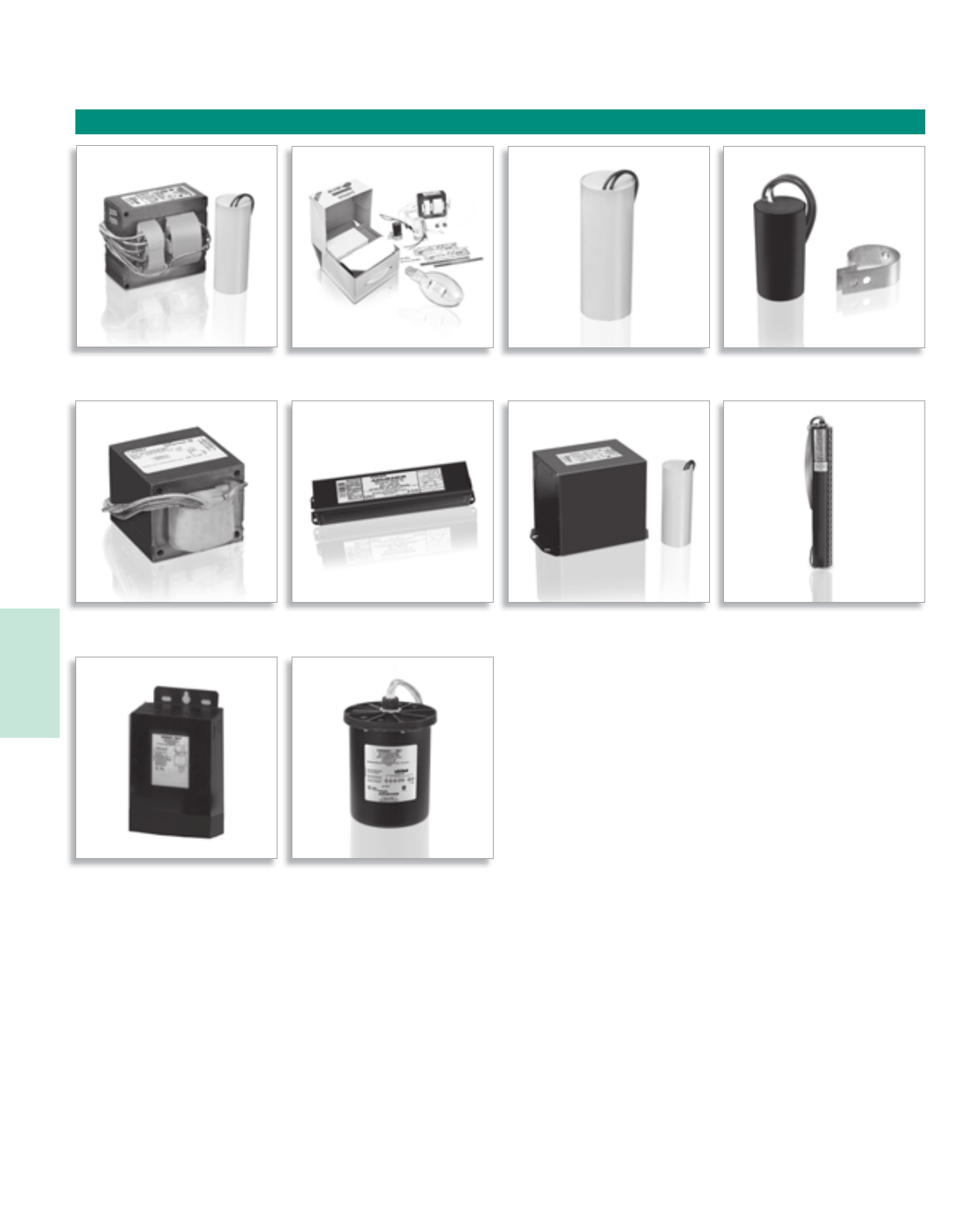
Lighting Electronics Atlas 2010-2011
HIGH INTENSITY DISCHARGE BALLASTS
1
Core & Coil Val-U-Pak Plus Capacitors Ignitors
Transformers F-Can Ballasts Encapsulated Core & Coil Postline
Indoor Enclosed OutDoor Weatherproof
HID

5-1
Lighting Electronics Atlas 2010-2011
HIGH INTENSITY DISCHARGE BALLASTS
Contents
General Information 5-2 to 5-4
Replacement Core & Coil Ballast Kits - U.S. Voltages 5-5 to 5-8
Replacement Core & Coil Ballast Kits - Canadian Voltages 5-9
Val-U-Pak Plus Ballast/Lamp Replacement Kits 5-10
Core & Coil Ballasts (71A Series)
Metal Halide 5-12 to 5-25
High Pressure Sodium 5-26 to 5-35
Low Pressure Sodium 5-36 to 5-37
Capacitors for Bi-Level Operation 5-38 to 5-39
Ballast to Lamp Remote Mounting Distances 5-40
Ignitors 5-41 to 5-44
Transformers & Autotransformers 5-45
F-Can Ballasts (72C Series) 5-46 to 5-48
Metal Halide – High Pressure Sodium
Encapsulated Core & Coil Ballasts (73B Series) 5-49 to 5-51
Metal Halide – High Pressure Sodium
Postline Ballasts (74P Series) 5-52 to 5-53
Metal Halide – High Pressure Sodium
Indoor Enclosed Ballasts (78E Series) 5-54 to 5-55
Metal Halide – High Pressure Sodium
Outdoor Weatherproof Ballasts (79W Series) 5-56 to 5-57
Metal Halide – High Pressure Sodium
Note:
For International HID Ballasts (50Hz and 60Hz),
See International Section, pages 6-14 to 6-19
For Electronic HID Ballasts, See Section 4
Visit our web site at www.philips.com/advance
Customer Support/Technical Service
(800) 372-3331 • (+) 1 847 390-5000 (International)
Corporate Offices
(800) 322-2086
HID
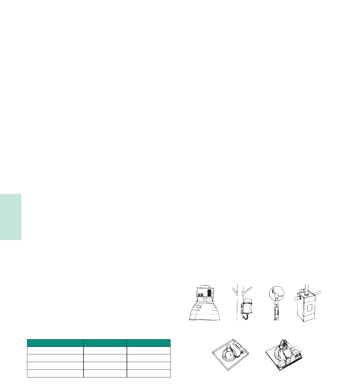
Lighting Electronics Atlas 2010-2011
HIGH INTENSITY DISCHARGE BALLASTS
5-2
Philips Advance HID ballasts are available to operate the wide variety
of metal halide, high pressure sodium and low pressure sodium lamps
available in today’s marketplace.
Like fluorescent, HID lamps are gas discharge lamps. Light is
produced by an arc discharge between two electrodes located at
opposite ends of an arc tube within the lamp’s outer glass envelope.
The ballast is the lamp’s power supply; its purpose is to provide
proper starting and operating voltage and current to initiate and
sustain this arc.
Lamp Starting
Probe-Start Metal Halide Lamps
The “traditional” probe-start metal halide lamps (175 through
1500W) have an additional electrode located at one end of the arc
tube to assist in lamp starting. These types of lamps require an open
circuit voltage (OCV) approximately two times the lamp’s operating
voltage to initiate the arc.
High Pressure Sodium and Pulse-Start Metal Halide Lamps
High pressure sodium and modern metal halide lamps which include
existing lamps, 150W and less, as well as the new generation of
pulse-start metal halide lamps, 150W and greater, have no starting
electrodes. In addition to an OCV of approximately two times the
lamp voltage, these lamps utilize an “ignitor” to provide a high voltage
starting pulse directly across the main electrodes. Once the lamp’s arc
is established, the ignitor automatically stops delivering pulses, and the
lamp comes up to full brightness on its own.
Low Pressure Sodium
Because they have neither a starting electrode nor an ignitor, low
pressure sodium lamps require an open circuit voltage approximately
three to seven times the lamp voltage to start and sustain the lamp.
Lamp Operations
Gas discharge lamps have a negative resistance characteristic which
causes them to draw an increasing amount of current leading to
immediate lamp failure if operated directly from the power line. The
ballast, therefore, is utilized to limit the current to the correct level
for proper operation of the lamp.
Ballast factor is defined as the ratio of light output produced by a
lamp operating on a commercial ballast versus the lamp’s rated light
output. Philips Advance HID ballasts have a nominal ballast factor of
1.0, thus providing full light output.
HID lamps take several minutes to warm-up and reach full lumen
output. Additionally, an interruption in the input power or a sudden
voltage drop may cause the arc to extinguish. A lamp that is hot
will not restart immediately. Before the lamp will relight, it must
cool sufficiently to reduce the vapor pressure within the arc tube to
a point where the arc will restrike. The approximate warmup and
restriking times of the HID lamp groups are as follows:
Ballast Input Voltages
Unlike fluorescent lighting which is operated on either 120V or 277V
circuits, power for HID lighting in the U.S. is delivered at any one
of five voltages: 120V, 208V, 240V, 277V or 480V. While 120V and
277V are the most popular, because of the heavier loads and some-
times longer runs associated with HID lighting (such as shopping mall
parking lots), 208V and 240V power is often used instead of 120V,
and 480V instead of 277V.
To address this multiplicity of voltages, the HID ballast industry offers
ballasts with multiple input voltage taps on the primary coil. Our 4-tap
design is called a Quadri-Volt® ballast and operates on either 120V,
208V, 240V or 277V line voltage. There is a Philips Advance Quadri-Volt
ballast for virtually every HID lamp on the market. New 5-TAP designs,
which feature the same input voltages as Quadri-Volt ballasts plus
480V, are available for 250W, 400W, and 1000W metal halide and
high pressure sodium applications.
Luminaires Fusing
Many HID lighting luminaires are sold with protective fuses. The
purpose of the fuse is to isolate a luminaire from the lighting circuit
in the event of excessive current draw, such as might be caused by
a failed ballast. Unfortunately, the fuse will not protect the ballast
from failure.
With many luminaires the fuse is physically located in the ballast
compartment of the luminaire. The air temperature within this
compartment can easily reach 80°C and still be within the design
limitations of the luminaire.
Many fuses are temperature sensitive, meaning that the current rating
goes down as the ambient temperature goes up. Fuse current ratings
are based on the fuse’s performance in a 25°C ambient (77°F). In an
80°C ambient, some fuses will open at half their rating.
As a result, the fuse rating shown in the HID ballast tables is calculated
at 2½ to 3 times the highest current draw of the ballast: lamp operating,
starting or open circuit conditions. Fast-blow fuses should be used. It is
not necessary to use current limiting fuses.
Ballast Design Applications
HID lamp ballasts are available in a variety of shapes and sizes
for the most popular lighting applications. Six basic designs are
in widest use today.
Fluorescent Can
(72C Series) Encapsulated Core & Coil
(73B Series)
Indoor Enclosed
Rectangular Can
(78E Series)
Postline
(74P Series)
Outdoor Weatherproof
(79W Series)
Cove & Coil
(71A Series)
Light Source Warm-Up Time Restrike Time
High Pressure Sodium 3-4 minutes ½-1 minute
Metal Halide (Probe-Start)
Low Pressure Sodium
5-4 minutes
7-10 minutes
10-20 minutes
3-12 seconds
Metal Halide (Pulse-Start) 2 minutes 3-4 minutes
HID

5-3
Lighting Electronics Atlas 2010-2011
HIGH INTENSITY DISCHARGE BALLASTS
Core & Coil
The basic ballast is the open core & coil which is most often used as a
component within a lighting luminaire. The core & coil also forms the
nucleus of the five other ballast configurations detailed in this section.
It consists of either one or two copper coils on a core (or “stack”) of
electrical-grade steel laminations. The coils are assembled to core
sections which are then surface-welded together. At Philips Lighting
Electronics the assembled ballast is vacuum-pressure impregnated with
a silica-filled polyester varnish to re-enforce the electrical insulation,
preclude moisture, inhibit noise, and dissipate heat. Most other HID
ballast manufacturers apply varnish via a preheat-and-dip process which
only puts a thin coat of varnish on the outer surface of the ballast. Philips
Advance Core & Coil ballasts feature as standard an insulation system
rated class H (180°C maximum coil hot spot temp.) for ballasts below
600W, and Class N (200°C maximum coil hot spot temp.) for ballasts
600W and higher. When performing in-fixture testing, the maximum
allowable average coil temperature (measured by the rise-of-resistance
method) is 165°C for class H ballasts or 185°C for Class N ballasts.
The maximum allowable coil face or lead wire temperature (measured
by thermocouple) is 150°C for both class H and Philips Advance
Class N ballasts.
Encapsulated Core & Coil
Where quiet performance is required, the standard open core & coil
ballasts are encapsulated (potted) in a cube-shaped steel can utilizing
Class H (180°C) polyester compound. These ballasts carry a Class A
noise rating up through 175W and Class B for 250 and 400W. As with
the open core & coil, the capacitor (and ignitor where included) are
mounted separately within the fixture.
Ballasts with Aluminum Secondary Coil
Philips Lighting Electronics offers a wide range of ballasts that have
primary coil made out of copper and secondary coil made out of
aluminum. All Philips Advance ballasts including ballasts with aluminum
secondary coil adhere to ANSI specifications and are certified by
respective agencies (UL, CSA, etc.). Aluminum ballasts are designated
by -A after ballast Catalog number and/or “AL” on wiring diagram.
Fluorescent Can (F-Can)
For indoor commercial applications of HID lighting such as offices,
schools and retail stores, ballast noise must be minimized. Ballasts for
these luminaires are most often encased and potted in fluorescent
ballast type cans and utilize Class A (90°C) asphalt insulating materials
(the same as used in fluorescent lamp ballasts).
The Philips Advance line of F-can ballasts comes in two dual-voltage
configurations: 120/277V for the US market, and 120/347V for the
Canadian market. Each unit has built-in, automatically resetting, thermal
protectors which disconnect the ballast from the power line in the
event of overheating. All units are high power factor and include the
capacitor within the can. All models for high pressure sodium, low-
wattage metal halide, and pulse-start metal halide lamps also include the
ignitor in the can.
Spacing between ballasts and the mounting surface must be considered
when the ballasts are remote-mounted. Twelve inches between ballasts
must be maintained and if multiple rows vertically are used, there should
be at least 12 inches between rows. In addition to ballast and row
spacing, the ballast must not be directly mounted to a non-metallic
surface. They must be spaced with mounting brackets (available from
Philips Lighting Electronics) to allow airflow under the ballast base.
Indoor Enclosed
These units are designed for use indoors where the ballast must be
mounted remotely from the luminaire. They are most typically used
in factories where the luminaire may be mounted in a high-bay where
very high ambient temperatures may be experienced. In these instances,
the remotely-mounted ballast operates cooler, subsequently providing
longer life because it is away from both the heat of the ceiling ambient
and lamp heat within the fixture.
The case contains the core & coil potted in a Class H (180°C)
heat-dissipating resin. The capacitor(s) and ignitor are contained
within a separate compartment. Knockouts in both ends of the case
facilitate hook-up in the most convenient manner. Wall mounting
is accomplished through flanges on the top and bottom of the case.
The ballast is a UL Listed product.
Outdoor Weatherproof
Weatherproof ballasts are designed for remote, pole-mounting outdoor
applications under all weather conditions. They may also be placed inside
of a transformer pole base, but care must be taken to avoid areas prone
to flooding because weatherproof ballasts are not water-submersible.
The core & coil with its capacitor and ignitor (where required) are firmly
mounted to the heat-sink base. An aluminum cover is placed over the
core-&-coil assembly and is bolted with a weather-tight gasket to the
base. An integral 1” threaded nipple with locknut facilities hook-up to
electrical conduit or to the mounting bracket when used on a pole. The
weatherproof ballast may also be placed nipple-up, with a drip loop in
the leads, inside a pole base.
Postline
Lantern-type fixtures mounted on slender poles often require ballasts
which will fit into these poles. Special, elongated core & coil ballasts are
potted in resin in cylindrical cans having a 2.55” outside diameter. All
include leads necessary for direct connection to a photocell.
The capacitor and ignitor (where required) are included within this can.
A ½” threaded nipple is used for vertical mounting, and leads extend
from both ends of the can for ease of installation. The input leads to
the ballast also provide for proper connection to the photocell if such is
included within the luminaire.
To help prevent overheating, one to three feet of air space should
be allowed in the pole above the ballast, and the ballast should be
positioned against the post interior wall to provide a heat-sink. All
units rated 100W and above now include a mounting kit consisting
of an 18” chain to hang the ballast within the pole and a spring clip to
force the ballast’s cylindrical can to make line contact with the pole’s
interior surface to maximize heat transfer, thus prolonging the ballast life.
HID
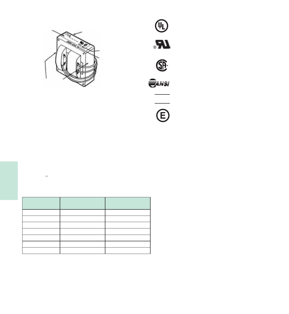
Lighting Electronics Atlas 2010-2011
HIGH INTENSITY DISCHARGE BALLASTS
5-4
Ballast Date and Tempterature Codes
Philips Advance HID Core & Coil ballasts are date stamped on either
the top surface or the side surface of the ballast core. The four-digit
number represents the week and year of manufacture. The first two
numbers indicate the week and the last two indicate the year the ballast
was manufactured. The example shows a ballast manufactured during the
36th week of 1989. The three letters are a Philips Lighting Electronics.
factory code.
The ballast’s UL Bench Top Rise Temperature Code is shown on the
label (see below).
UL Bench Top Rise Temperature Code
To facilitate UL inspection, each ballast’s UL Bench Top Rise
Temperature Code is shown on the Philips Advance Core & Coil ballast
label as 1029X, where 1029 is the UL Standard for HID Ballasts, and
the X is the temperature code: A, B, C, etc. If a fixture is UL listed for
1029C, then automatically, all ballasts with an A, B, or C temperature
classification are acceptable for use within that same fixture.
Certifications
Indicates ballast is listed by Underwriters Laboratories, Inc. in
accordance with UL 1029 Standard for HID Ballasts. Each ballast
is marked appropriately.
Indicates ballast is component recognized by Underwriters
Laboratories, Inc. in accordance with UL 1029 Standard for HID
Ballasts. Each ballast is marked appropriately.
Indicates ballast is certified by Canadian Standards Association in
accordance with CAN/CSA-22.2 No. 74-92. Each ballast is marked
appropriately.
All HID Ballasts are designed and manufactured in accordance
with the American National Standards Institute Standard for HID
Ballasts, ANSI C82.4.
Indicates ballast is certified and compliant with “Norma Obligatorio
Mexicana” (NOM) requiements
Indicates ballast meets the 88% efficiency requirements of EISA
(Energy Independence and Security Act of 2007).
EISA requires all 150W-500W metal halide luminaires
manufactured on or after January 1, 2009, to contain
a ballast meeting the following levels of efficiency:
• 88% for magnetic or electronic pulse start ballasts
• 94% for magnetic probe start ballasts
• 92% for non-pulse start electronic ballasts for wattages
greater than 250W, and
• 90% for non-pulse start electronic ballasts for wattages
up to 250W
Please refer to the EISA brochure found on the
www.philips.com/advance website for additional info
on EISA-Compliant Pulse Start ballasts.
NOM
Ballast Label Catalog Number
Temperature
Code
Date Code
Stamp
Alternate Positions for
Date Stamp Code
See catalog table of contents for
important change
UL Bench Top Rise
Letter Code
Temperature Range for
Class H (180°C) Ballasts
Temperature Range for
Class N (200°C) Ballasts
A
D
F
less than 75°C
85°C < 90°C
95°C < 100°C
less than 95°C
105°C < 110°C
115°C < 120°C
B
E
etc.
75°C < 80°C
90°C < 95°C
etc.
95°C < 100°C
110°C < 115°C
etc.
C80°C < 85°C 100°C < 105°C
HID
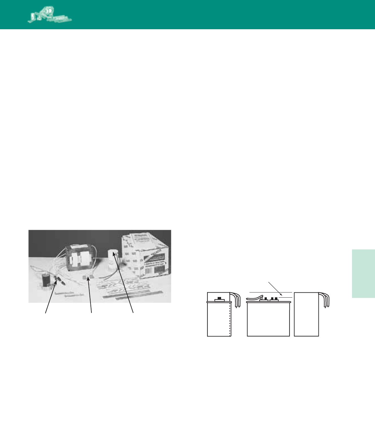
5-5
Lighting Electronics Atlas 2010-2011
HIGH INTENSITY DISCHARGE BALLASTS
Philips Lighting Electronics furnishes 120/208/240/277
Quadri-Volt® core & coil ballasts to allow the stocking
distributor to conveniently meet the replacement and retrofit
needs of customers. In addition, Philips Lighting Electronics now
offers 120/208/240/277/480V 5-TAP™ core & coil ballasts
for the most popular applications. 5-TAP ballasts add the
480V input lead to the Quadri-Volt designs. A Quadri-Volt
or 5-TAP core & coil, along with the appropriate capacitor,
ignitor (where required), mounting bracket & hardware and
installation instructions are packed in a space-saving shipping
carton. These “kits” eliminate the need for distributors or end-
users to stock loose components of single voltage ballasts for
120, 208, 240, 277, and even some 480V applications, though
single voltage kits for 480V applications will also be available.
Ignitors are also packaged in individual cartons for replacement
needs. There are several different ignitors to meet the needs
of the many different lamps. The appropriate ignitor for each
ballast is shown in the far right column on the page in this
Atlas where the ballast is listed. Additionally, this information
is summarized in the tables on pages 5-40 through 5-44.
HID
REPLACEMENT KITS
Dry Capacitors
We have extended the operating voltage range of our dry capacitors
from 330 to 400V. This means that our most popular HID replacement
kits for 175, 250, and 400W metal halide lamps now contain dry capacitors
and offer the additional benefits available only with a dry capacitor.
Those benefits are:
• Dry capacitors are typically 25 to 50% smaller than their oil-filled
counterparts, assuring that the Philips Advance ballast kit will fit
existing fixtures.
• Dry capacitors are rated 105°C, 15°C higher than 90°C oil-filled
capacitors, thus providing longer component life.
• Dry capacitors are built using a thermoplastic case, thus eliminating
the need for grounding and insuring a faster, easier replacement.
• Unlike oil-filled capacitors with exposed tab terminals, dry capacitors
have no exposed live parts and thus protect end-users from
hazardous voltages.
The bottom line is that our expanded use of dry capacitors makes
the contractor’s job faster and easier. Look for the “D” at the end of
our catalog number, it identifies the ballast kit as one that contains a
dry capacitor.
Capacitor Size Comparison
Oil-Filled vs. Advance Dry Type
5/8” required clearance for terminals
Pre-attached
Connectors for
Capacitor
Pre-wired
Ignitor
Dry Capacitor
Now Rated 105°C
end comparison side-by-side comparison
oil
cap
dry cap
with
lead
wires
oil cap
HID
Core & Coil Replacement Kits
Distributor Kits and Replacement Ignitors
HID
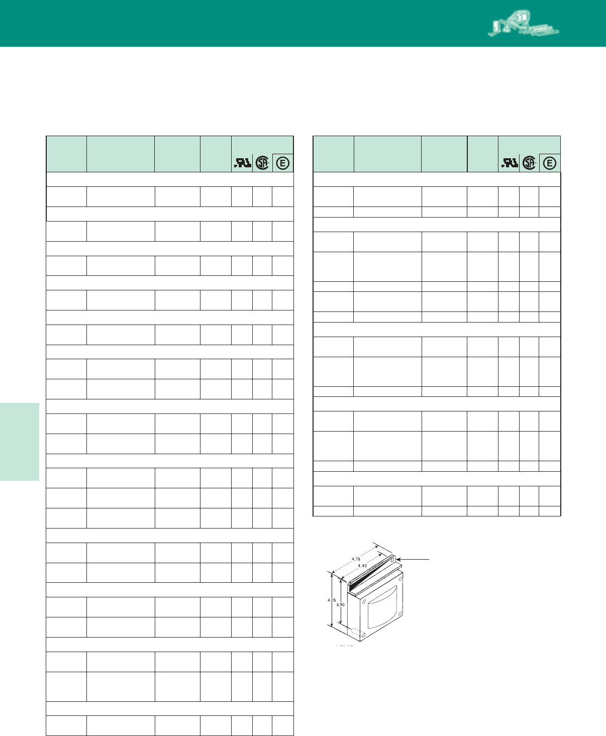
Lighting Electronics Atlas 2010-2011
5-6
HIGH INTENSITY DISCHARGE BALLASTS
Input
Volts
Input
Volts
Catalog
Number
Catalog
Number
Circuit
Type
Circuit
Type
Total
Weight
(Lbs)
Total
Weight
(Lbs)
Certifications Certifications
Core & Coil Replacement Kits
Pulse Start Metal Halide Metal Halide
HID
50W Lamp, ANSI Code M110 or M148 (Pulse-Start)
120/208/
240/277 71A5191-001D HX-HPF 4.0 ✓ ✓
70W Lamp, ANSI Code M110 or M148 (Pulse-Start)
120/208/
240/277 71A5292-001D HX-HPF 5.0 ✓ ✓
100W Lamp, ANSI Code M110 or M148 (Pulse-Start)
120/208/
240/277 71A5390-001D HX-HPF 5.5 ✓ ✓
150W Lamp, ANSI Code M102 or M142 (Pulse-Start)
120/208/
240/277 71A5492-001D HX-HPF 7.0 ✓ ✓
175W Lamp, ANSI Code M137 or M152 (Pulse-Start)
120/208/
240/277 71A5593-001D Super
CWA 7.0 ✓ ✓
200W Lamp, ANSI Code M136 (Pulse-Start)
277 71A5637-001DEE* Linear
Reactor HPF 6.0 ✓ ✓ ✓
120/208/
240/277 71A5692-001D Super
CWA 8.0 ✓ ✓
250W Lamp, ANSI Code M138 or M153 (Pulse-Start)
277 71A5737-001DEE* Linear
Reactor HPF 8.0 ✓ ✓ ✓
120/208/
240/277 71A5792-001D Super
CWA 9.5 ✓ ✓
320W Lamp, ANSI Code M132, M154 or M170 (Pulse-Start)
277 71A5837-001DEE* Linear
Reactor HPF 9.5 ✓ ✓ ✓
120/208/
240/277 71A5892-001D Super
CWA 11.0 ✓ ✓
480/120T 71A5842-001DT Super
CWA 11.0 ✓ ✓
350W Lamp, ANSI Code M131 or M171 (Pulse-Start)
277 71A5937-001DEE* Linear
Reactor HPF 10.0 ✓ ✓ ✓
120/208/
240/277 71A5993-001D Super
CWA 11.0 ✓ ✓
400W Lamp, ANSI Code M135 or M155 or M172 (Pulse-Start)
277 71A6137-001DEE* Linear
Reactor HPF 9.0 ✓ ✓
120/208/
240/277 71A6092-001D Super
CWA 11.0 ✓ ✓
750W Lamp, ANSI Code M149 (Pulse-Start)
277/ 347/
480/120T 71A64F2-001D Super
CWA 17.0 ✓ ✓
120/208/
240/277/
480
71A6452-001D Super
CWA 19.5 ✓ ✓
1000W Lamp, ANSI Code M141 (Pulse-Start)
120/208/
240/277 71A6593-001 Super
CWA 21.0 ✓
175/150W Lamp, ANSI Code M57/M107
120/208/
240/277 71A5570-001D CWA 6.8 ✓ ✓
480/120T 71A5540-001D CWA 8.5 ✓ ✓
250W Lamp, ANSI Code M58
120/208/
240/277 71A5770-001D CWA 4x 4
Core 9.0 ✓ ✓
120/208/
240/277/
480
71A5750-001D 10.0 ✓ ✓
480/120T 71A5740-001D 10.0 ✓ ✓
120/208/
240/277 71A5771-001D CWA 3x 3
Core 9.0 ✓ ✓
480/120T 71A5741-001D 9.0 ✓ ✓
400W Lamp, ANSI Code M59
120/208/
240/277 71A6071-001D CWA 11.5 ✓ ✓
120/208/
240/277/
480
71A6051-001D CWA 14.0 ✓ ✓
480/120T 71A6041-001D CWA 12.0 ✓ ✓
1000W Lamp, ANSI Code M47
120/208/
240/277 71A6572-001 CWA 21.0 ✓ ✓
120/208/
240/277/
480
71A6552-001 CWA 22.0 ✓ ✓
480/120T 71A6542-001 CWA 21.0 ✓ ✓
1500W Lamp, ANSI Code M48
120/208/
240/277 71A6772-001 CWA 30.0 ✓ ✓
480/120T 71A6742-001 CWA 31.0 ✓ ✓
* Includes -540 bracket.
HID
Replacement Kits
-540 Bracket Detail
Suffix -540D denotes a welded
angle bracket to allow linear
reactors to mount in 400W
fixtures designed for standard CWA
ballasts without brackets. This
bracket is standard on -001DEE.
5-7
Lighting Electronics Atlas 2010-2011
HIGH INTENSITY DISCHARGE BALLASTS
PC-848: To order individual packaged kits, specify
PKG 848 (1 brackets with thru bolts).
PC-849: To order individual packaged kits, specify
PKG 849-2 (2 brackets with thru bolts).
PC-848S: Bracket and thru bolts are included in
120V HPS Reactor Kits.
HPS Kits with Plug-In Ignitors
“C” Suffix (p.5-8) denotes standard HPS kit except with plug-in ignitor.
A mating receptacle is attached to the core and coil lead wires, ready
for immediate connection.
HPS Kit Options
In addition to the standard kits, this and the following page include
two HPS kits with special features:
HPS Reactor Kits with Integral Ignitors
“B” Suffix denotes 120V reactor circuit kits featuring single-coil reactor
ballasts with integral ignitors. The kit includes a mounting bracket
(PC848S) sized specifically for the small reactor ballasts.
Compact Reactor
Core and Bracket
Connectorized ignitor
and mating receptable
Input
Volts
Catalog
Number
Circuit
Type
Total
Weight
(Lbs)
Certifications
Core & Coil Replacement Kits
High Pressure Sodium
50W Lamp, ANSI Code S68
70W Lamp, ANSI Code S62
100W Lamp, ANSI Code S54
150W Lamp, ANSI Code S55
120/208/
240/277 71A7971-001D HX-HPF 5.5 ✓ ✓
120/208/
240/277 71A8071-001D HX-HPF 7.3 ✓ ✓
120/208/
240/277 71A8091-001DC HX-HPF 7.3 ✓ ✓
480 7.0HX-HPF71A8041-001D ✓ ✓
120/208/
240/277 71A8172-001D HX-HPF 8.0 ✓ ✓
120/208/
240/277 71A8192-001DC HX-HPF 8.0 ✓ ✓
150W Lamp, ANSI Code S56
120/208/
240/277 71A8176-001D CWA 8.5
480 71A8146-001D CWA 8.5
✓
✓
✓
✓
120 1.9R-HPF71A7807-001DB ✓ ✓
✓
480 71A8142-001D HX-HPF 9.5 ✓
35W Lamp, ANSI Code S76
120 1.5R-HPF71A7707-001DB ✓ ✓
120/277 3.5HX-HPF71A7801-001D ✓ ✓
120 2.5R-HPF71A7907-001DB ✓ ✓
120 3.1R-HPF71A8007-001DB ✓ ✓
120 4.0R-HPF71A8107-001DB ✓ ✓
Core & Coil Mounting Brackets
Included with all Replacement Kits
4.00
1.34
3.00
0.55
2.19
PC-848 Mounting bracket
for Fig. 1, 6, 7 & 9
PC-848S Mounting bracket
for Fig. 9.
PC-849 Mounting bracket
for Fig. 2, 3, 8, 8a &10.
PC-909 Mounting bracket
for Fig. 2, 3 & 8 when used with
power-door roadway fixtures
HID
Replacement Kits
HID
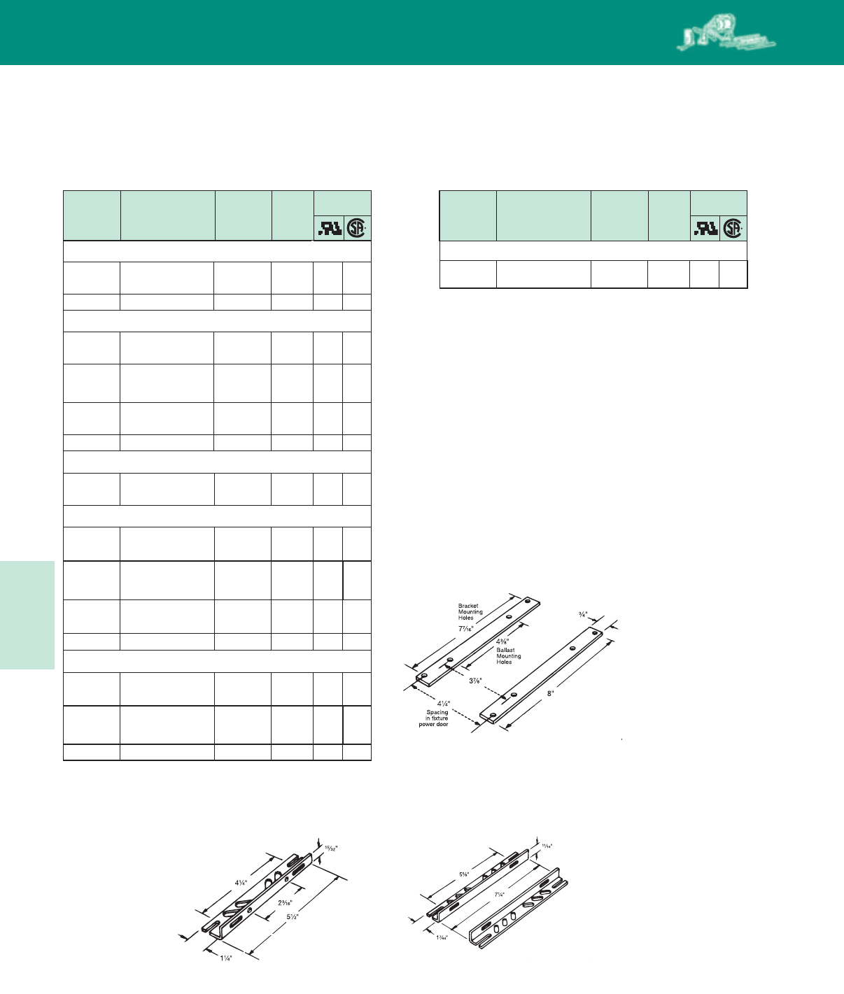
Lighting Electronics Atlas 2010-2011
5-8
HIGH INTENSITY DISCHARGE BALLASTS
35 or 55W Lamp, ANSI Code L70 or L71
120/208/
240/277 71A0490-001D HX-PFC 7.5 ✓ ✓
Input
Volts
Input
Volts
Catalog
Number
Catalog
Number
Circuit
Type
Circuit
Type
Total
Weight
(Lbs)
Total
Weight
(Lbs)
Certifications Certifications
Core & Coil Replacement Kits
High Pressure Sodium Low Pressure Sodium
250W Lamp, ANSI Code S50
480 71A8241-001D CWA 11.0 ✓ ✓
120/208/
240/277 71A8271-001D CWA 11.5 ✓ ✓
120/208/
240/277 71A8291-001DC CWA 11.5 ✓ ✓
200W Lamp, ANSI Code S66
120/208/
240/277 71A8970-001D CWA 8.5
480 71A8940-001D CWA 8.5
✓
✓
✓
✓
120/208/
240/277/
480
71A8251-001D CWA 12.0 ✓ ✓
400W Lamp, ANSI Code S51
120/208/
240/277 71A8473-001D CWA 15.0
1000W Lamp, ANSI Code S52
120/208/
240/277 71A8773-001 CWA 31.0
✓
✓
✓
480 71A8443-001D CWA 15.5 ✓ ✓
120/208/
240/277 71A8493-001DC CWA 15.0 ✓ ✓
✓
480 71A8743-001 CWA 31.0 ✓ ✓
310W Lamp, ANSI Code S67
120/208/
240/277 71A8371-001D CWA 13.8 ✓ ✓
120/208/
240/277/
480
71A8753-001 CWA 29.0 ✓ ✓
120/208/
240/277/
480
71A8453-001D CWA 16.0 ✓ ✓
Core & Coil Mounting Brackets
Included with all Replacement Kits
(See Page 5-7 for addional bracket diagram)
PC-848: To order individual packaged kits, specify PKG 848 (1 brackets with thru bolts).
PC-849: To order individual packaged kits, specify PKG 849-2 (2 brackets with thru bolts).
PC-848S: Bracket and thru bolts are included in 120V HPS Reactor Kits.
PC-848 Mounting bracket
for Fig. 1, 6, 7 & 9
PC-909 Mounting bracket
for Fig. 2, 3 & 8 when used with
power-door roadway fixtures
PC-849 Mounting bracket
for Fig. 2, 3, 8, 8a &10.
HID
HID
Replacement Kits
5-9
Lighting Electronics Atlas 2010-2011
HIGH INTENSITY DISCHARGE BALLASTS
70W Lamp, ANSI Code S62
120/
277/347 71A79A1-001D HX-HPF 5.5
100W Lamp, ANSI Code S54
120/
277/347 71A80A1-001D HX-HPF 7.5
150W Lamp, ANSI Code S55
120/
277/347 71A81A2-001D HX-HPF 7.5
250W Lamp, ANSI Code S50
120/
277/347 71A82A1-001D CWA 11.5
400W Lamp, ANSI Code S51
120/
277/347 71A84A3-001D CWA 13.5
1000W Lamp, ANSI Code S52
120/
277/347 71A87A3-001 CWA 28.0
✓
✓
✓
✓
✓
✓
✓
✓
✓
✓
✓
✓
Input
Volts
Input
Volts
Input
Volts
Catalog
Number
Catalog
Number
Catalog
Number
Circuit
Type
Circuit
Type
Circuit
Type
Total
Weight
(Lbs)
Total
Weight
(Lbs)
Total
Weight
(Lbs)
Certifications
Certifications
Certifications
Tri-Tap Replacement Core & Coil Kits for Canada
Metal Halide
Pulse Start Metal Halide
High Pressure Sodium
70W Lamp, ANSI Code M98
120/
277/347 71A52A2-001D HX-HPF 5.0
100W Lamp, ANSI Code M90
120/
277/347 71A53A0-001D HX-HPF 5.5
175/150W Lamp, ANSI Code M57/M107
120/
277/347 71A55A0-001D CWA 7.0
250W Lamp, ANSI Code M58
120/
277/347 71A57A0-001D CWA 10.0
400W Lamp, ANSI Code M59
120/
277/347 71A60A1-001D CWA 12.0
1000W Lamp, ANSI Code M47
120/
277/347 71A65A2-001 CWA 21.0
✓
✓
✓
✓
✓
✓
✓
✓
✓
✓
✓
✓
1500W Lamp, ANSI Code M48
✓ ✓
120/
277/347 71A67A2-001 CWA 30.0
250W Lamp, ANSI Code M138 or M153 (Pulse-Start)
120/
277/347 71A57A2-001D Super
CWA 9.5
320W Lamp, ANSI Code M132, M154 or M170 (Pulse-Start)
120/
277/347 71A58A2-001D Super
CWA 11.0
400W Lamp, ANSI Code M135, M155 or M172 (Pulse-Start)
120/
277/347 71A60A2-001D Super
CWA 11.0
✓
✓
✓
✓
✓
✓
HID Replacement
Kits
HID
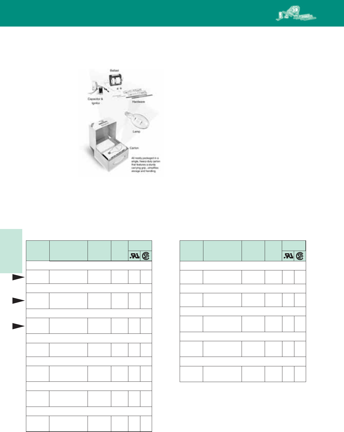
Lighting Electronics Atlas 2010-2011
5-10
HIGH INTENSITY DISCHARGE BALLASTS
Features of Val-U-Pak Plus:
• AddedVersatility– 5-Tap core and coil ballast for the
six most popular applications
*Adds the 480V input lead to the Quadri-Volt design
• AllInclusive– Premium grade clear lamp supplied in kit
*Manufactured by major lamp company and
*warranteed by Philips Lighting Electronics
• HigherWattageOptions– Philips Advance Class N (200°C)
insulation system on 1000W units provides an additional
20°C margin for high ambient applications
HID VAL-U-PAK Plus kits are available for the
12 most popular applications
HID installations just
got simpler, more con-
venient - and
significantly faster,
with the new Val-U-Pak
Plus kits from Philips
Lighting Electronics.
Why Should You
Change All the
Components?
HID fixtures are
generally difficult to
reach and to service.
Subsequently, the cost
of labor can often
exceed the cost of the ballast and/or lamp. When the ballast,
capacitor or ignitor reach end-of-life, it is recommended that all
of these components in the fixture be replaced at the same time.
It is equally suggested that the lamp also be replaced, assuring
optimal performance of the system and eliminating the need to
re-service the fixture during the entire life-cycle of the lamp.
HID Val-U-Pak™ Plus Replacement Kits
Val-U Pak Plus
Input
Volts
Input
Volts
Catalog
Number
Catalog
Number
Circuit
Type
Circuit
Type
Total
Weight
(Lbs)
Total
Weight
(Lbs)
Certifications Certifications
Metal Halide High Pressure Sodium
100W Lamp, ANSI Code S54
120/208/
240/277 77L8071-001D-MED HX-HPF 8.5
150W Lamp, ANSI Code S55
120/208/
240/277
77L8172-001D-
MOG HX-HPF 9.5
250W Lamp, ANSI Code S50
120/208/
240/277/
480
77L8251-001D CWA 15.0
400W Lamp, ANSI Code S51
120/208/
240/277/
480
77L8453-001D CWA 16.0
✓
✓
✓
✓
✓
✓
✓
✓
120/208/
240/277/
480
77L8753-001 CWA 31.0 ✓ ✓
70W Lamp, ANSI Code M98 (Med) or M143 (Pulse-Start)
175/150W Lamp, ANSI Code M57/M107
120/208/
240/277 77L5570-001D CWA 9.5 ✓ ✓
250W Lamp, ANSI Code M58
120/208/
240/277/
480
77L5750-001D CWA 14.0 ✓ ✓
400W Lamp, ANSI Code M59
120/208/
240/277/
480
77L6051-001D CWA 17.0 ✓ ✓
1000W Lamp, ANSI Code M47
120/208/
240/277/
480
77L6552-001 CWA 29.0 ✓ ✓
120/208/
240/277 77L5292-001D HX-HPF 5.0 ✓ ✓
100W Lamp, ANSI Code M90 or M140 (Pulse-Start)
120/208/
240/277 77L5390-001D HX-HPF 5.5 ✓ ✓
150W Lamp, ANSI Code M102 or M142 (Pulse-Start)
120/208/
240/277 77L5492-001D HX-HPF 7.0 ✓ ✓
New
New
New
1000W Lamp, ANSI Code S52
HID Val-U-Pak Plus
Replacement Kits
HID

5-11
Lighting Electronics Atlas 2010-2011
HIGH INTENSITY DISCHARGE BALLASTS
6071A 9-500DAEE
2
Philips Lighting Electronics has developed the industry’s broadest selection of HID ballasts. More than 3000 stocking distributors nationwide. For
information on the distributor best able to serve your needs, please call 800-372-3331.
Ordering Information
Philips Advance HID Ballast Part Number Explanation
50 Hz Voltages
M = 100/200V
N = 120/220-240V
R = 220/240V
60 Hz Voltages
Lamp Type/Wattage/Ballast Circuit Code
0 = 120V A = 120/277/347V
1 = 208V B = 347V
2 = 240V C = 120/347V
3 = 277V D = 120/240/347V
4 = 480V E = 120/208/240V or 208/240V
5 = 120/240V or F = 277/480V, 277/347V, 277/347/480V or
120/208/240/277/480V 347/480V
6 = 240/480V H = 127/220V
7 = 120/208/240/277V J = 220V or 220/240V
8 = 120/277V Y = 100V or 100/200V
9 = 120/208/240/277V
71A = Core and Coil Ballast
72C = F-Can Ballast
73B = Encapsulated Core and Coil Ballast
74P = Postline Ballast
77L = Val-U-Pak Plus Replacement Ballast kit (includes lamp)
78E = Indoor Enclosed Ballast
79W = Outdoor Weatherproof Ballast
Ballast
Type
Input
Voltage
Code
Design Code
Suffix Code*
(as applicable)
-001DB ballast replacement kit with dry capacitor and integral ignitor
-001D ballast replacement kit with dry film capacitor
-001 ballast replacement kit with oil filled capacitor
-500D core & coil ballast with dry film capacitor
-500 core & coil ballast with oil filled capacitor
-510D core & coil ballast with welded bracket and dry film capacitor
-510 core & coil ballast with welded bracket and oil filled capacitor
-540D core & coil ballast with welded angle bracket and dry film capacitor
-600 core & coil ballast (no capacitor)
-610 core & coil ballast with welded bracket (no capacitor)
* Add additional feature codes to the end of suffix where applicable.
i.e. -B = Integral Ignitor, -P = Thermally Protected, -J = J-Box Mounting,
-A = Aluminum Coil, -M = “NOM” (with capacitor), -T = 120V Tap
-EE = EISA Compliant Ballast
HID
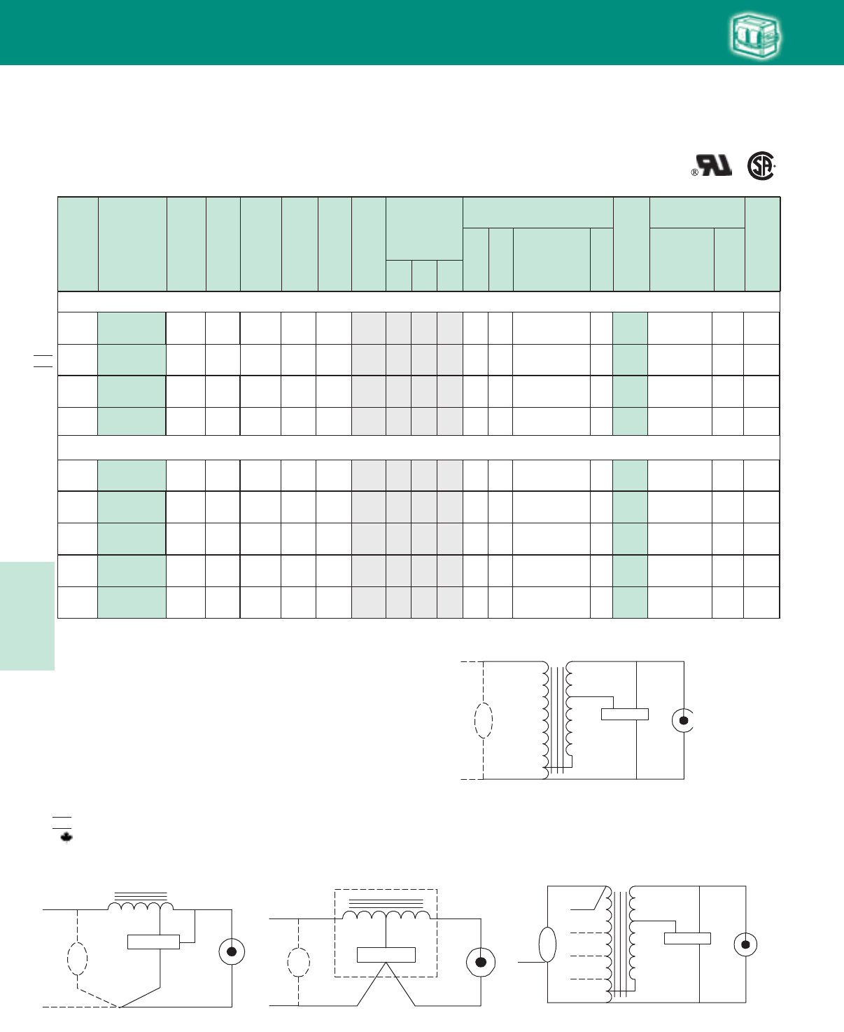
Lighting Electronics Atlas 2010-2011
5-12
HIGH INTENSITY DISCHARGE BALLASTS
R-HPF277 71A5137-510DP 62 .6 277 2 9 1.1 2.2 5 280 7C050L30A D 2.2 LI533-H4 2 AG
R-HPF277 71A5137-500DBP 62 .6 277 2 9 1.1 2.2 5 280 7C050L30A D 2.2 Integral Ignitor 2 AH
Cap Catalog
Number
Dry
or
Oil
Input
Volts
Catalog
Number
Circuit
Type
Input
Watts
Max
Input
Current
Nom
Open
Circuit
Voltage
Fuse
Rating
(Amps)
Fig
Dimensions
Non-PCB Capacitor
(Page 5-38 & 5-39)
Mfd Min
Volt
Total
Weight
(lbs)
Ignitor ✝✝
(Page 5-40 to 5-44)
Part
Number
Max
Dist
To
Lamp
(ft)
U.L.
Bench
Top
Rise
Code
1029
(pg 5-4)
A B
✝
•
Wiring
Dia
Fig. G
COM
LAMP
CAP
(OPTIONAL)
IGNITOR
LAMP
X3
X1
X2
LINE V
120 71A5005-500DP HX-HPF 55 1.1 230 3 6 .9 1.8 28 120 7C280M12RA D 2.2 LI533-H4 15 A
35/39W Lamp, ANSI Code M130 (Pulse-Start)
120/277 B/A15D LI533-H47C050L30A 3.528052.1.813/1230.9/.4HX-HPF
71A5081-500D
F
277 71A5037-500DP HX-HPF 48 .6 277 2 9 .8 1.9 5 280 7C050L30A D 1.8 LI533-H4 7 AG
277 71A5037-500DBP R-HPF 48 .6 277 2 9 1.0 2.7 5 280 7C050L30A D 1.9 Integral Ignitor 2 AH
K
Fig. K
LAMP
CAPLAMP
COM COM
LINE V
LINE V
COM
LINE V
CAP
LINE V
IGNITOR
X1X3
X2
56
Fig. H
COM
LAMP
CAP
IGNITOR
LAMP
LINE V
INTEGRATED
IGNITOR BALLAST
60 Hz Core & Coil Ballasts
Metal Halide
HX-NPF
HX-PFC
120 71A5105-600P
71A5105-500DP 69 2.0
1.1 260 5
36 1.0 1.9 28 120 7C280M12RA D 2.1
2.3 LI533-H4 15 AF
120/277 71A5181-001D HX-HPF 72 1.0/.5 260 3/2 1 1.2 2.1 6 280 7C060L30RA D 4.0 LI533-H4 10 A/AK
120/208/
240/277
71A5191-500D
71A5191-001D HX-HPF 67 1.2/.68/
.59/.51 254 3/3/
2/2 1 1.2 2.3 6 280 7C060L30RA D 4.0 LI533-H4 10 A/A
A/A
K
NOM
✥
✥
✥
✥
✥
✥
Fig. G Fig. H Fig. K
HID
Fig. F
Fig. F
LAMP
CAP
LAMP
COM COM
120 V
IGNITOR
X1X3
X2
✝ Ordering information:
Replacement/retrofit ballast kits – indicated by bold type and -001D or -001 suffix.
Refer to pages 5-5 to 5-9 for more information on replacement kits.
Originalequipmentballasts– typically ordered with capacitor (as shown).
-500D includes core & coil with dry-film capacitor.
-500 includes core & coil with oil-filled capacitor (required for higher wattage ballasts).
May also be available with welded bracket, and/or without capacitor:
-510D includes core & coil with welded bracket and dry-film capacitor.
-510 includes core & coil with welded bracket and oil-filled capacitor.
-600 core & coil only (no capacitor).
-610 core & coil with welded bracket (no capacitor).
✝✝ Each ballast requiring an ignitor is furnished standard with a short-range ignitor model
shown for use within fixtures. long-range ignitors are available separately if required.
See pages 5-xx to 5-yy for additional information.
• MaximumInputCurrent– For HX and R circuits, value is the highest of starting, operating
or open circuit current. For CWA, SCWA and CWI circuits, value is the operating current.
Certified ballast available for Mexican market. Add “M” to suffix (example: -500DM).
Canadian replacement/retrofit ballast kit indicated by bold type. Refer to page 5-9.
✥ Includes auto-reset thermal protection.
NOM
50W Lamp, ANSI Code M110 or M148 (Pulse-Start)
HID•Core&Coil
Metal Halide
5-13
Lighting Electronics Atlas 2010-2011
HIGH INTENSITY DISCHARGE BALLASTS
70W Lamp, ANSI Code M98 (Medium Base) or M143 (Pulse-Start)
120 71A5205-600P
71A5205-500DP
HX-NPF
HX-PFC 94 2.6
1.4 255 6
46 1.6 2.7 36 120 D 3.5
3.7 LI533-H4 10 B
127/220 71A52H2-500DM HX-HPF 90 1.9/.9 255 4/2 1 1.5 2.8 8 280 7C080L30RA D 5.0 LI533-H4 15 A/A
71A5292-500D
71A5292-001D HX-HPF 90 1.9/1.0/
.9/.8 255 4/3/
2/2 1 1.5 2.8 8 280 7C080L30RA D 5.0 LI533-H4 15 A/A/
A/A
F
K
K
120/
277/347
277
277
71A52A2-500D
71A52A2-001D
71A5237-500DP
71A5237-500DBP
HX-HPF
R-HPF
R-HPF
90
85
85
1.9/
.8/.7
.8
.8
255
277
277
4/
2/2
2
2
1
9
9
1.5
1.6
1.5
2.8
2.7
2.9
8
8
8
280
280
280
7C080L30RA
7C080L30RA
7C080L30RA
D
D
D
5.0
2.9
2.9
LI533-H4
LI533-H4
Integral Ignitor
15
10
2
A/
A/A
A
A
K
G
H
120/208/
240/277
7C360M12RA
Cap Catalog
Number
Dry
or
Oil
Input
Volts
Catalog
Number
Circuit
Type
Input
Watts
Max
Input
Current
Nom
Open
Circuit
Voltage
Fuse
Rating
(Amps)
Fig
Dimensions
Non-PCB Capacitor
(Page 5-38 & 5-39)
Mfd Min
Volt
Total
Weight
(lbs)
Ignitor ✝✝
(Page 5-40 to 5-44)
Part
Number
Max
Dist
To
Lamp
(ft)
U.L.
Bench
Top
Rise
Code
1029
(pg 5-4)
A B
✝
•
Wiring
Dia
60 Hz Core & Coil Ballasts
Metal Halide
NOM
NOM
Fig. 1
(3" x 4" Core)
Fig. 6
(2" x 4" Core)
Fig. 9
(25/8" x 23/16" Reactor Core)
WELDED BRACKET DIMENSIONS
W
++
BRACKET
M
L
S
70W Double-ended Lamp, ANSI Code M85 (OSI Briteline/HQI, GE MQI ARC70/TD, Philips MHN70/TD) (Pulse-Start)
70W Lamp, ANSI Code M139 (Philips CDM70/T6, CDM70/TD) (Pulse-Start)
K
71A5280-500D HX-HPF 94 1.6/.7 245 4/2 1 1.5 2.7 8 280 7C080L30RA D 5.5 LI522-H5 30 A/A
71A52A1-500D HX-HPF 94 1.9/
.8/.65 255 4/
2/2 1 1.5 2.8 8 280 7C080L30RA D 5.0 LI533-H4 5 A/
A/A
K
120/
277/347
120/277
213/16"
31/2"315/16"
27/16"
B
MAX.
A
Fig. 1
(3" x 4" core)
4 Holes cleared for
#10 thru-bolts
25/32"
43/32"
B
MAX.
A
Fig. 6
(2 " x 4" core)
23/16"
23/16"
25/8"
13/4"
B
MAX.
A
Fig. 9
(2 5/8" x 2 3/1 6 Reactor Core)
4 Holes cleared for
#6 thru-bolts
Ballast
Dimensions Fig L W M S
1, 6 5.1 1.00 4.50 0.25
9 4.0 0.75 3.50 0.28
HID
✥
✥
✥
HID•Core&Coil
Metal Halide
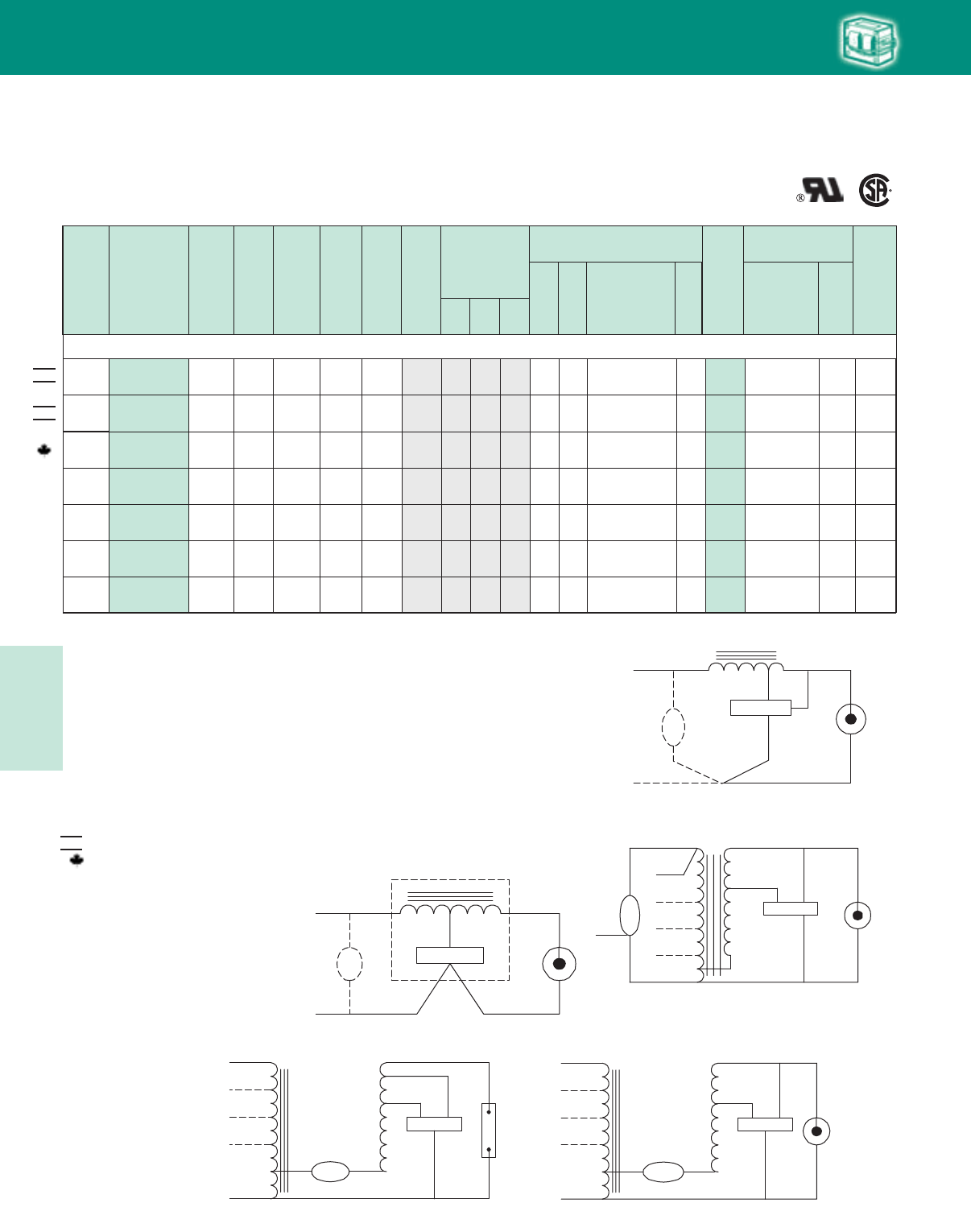
Lighting Electronics Atlas 2010-2011
5-14
HIGH INTENSITY DISCHARGE BALLASTS
Cap Catalog
Number
Dry
or
Oil
Input
Volts
Catalog
Number
Circuit
Type
Input
Watts
Max
Input
Current
Nom
Open
Circuit
Voltage
Fuse
Rating
(Amps)
Fig
Dimensions
Non-PCB Capacitor
(Page 5-38 & 5-39)
Mfd Min
Volt
Total
Weight
(lbs)
Ignitor ✝✝
(Page 5-40 to 5-44)
Part
Number
Max
Dist
To
Lamp
(ft)
U.L.
Bench
Top
Rise
Code
1029
(pg 5-4)
A B
✝
•
Wiring
Dia
60 Hz Core & Coil Ballasts
Metal Halide
NOM
NOM
480/
120T 71A5340-500DT HX-HPF 132 .6 260 2 1 1.7 2.9 10 300 7C100M33-R D 5.5 LI533-H4 25 CK
120/277 71A5383-500D SUPER
CWA 128 1.1/.5 222 3/2 1 1.6 2.8 10 330 7C100M40R D 5.5 LI533-H4 2 C/CM
127/220 71A53H0-500D HX-HPF 129 2.2/1.3 280 5/3 1 1.7 2.9 12 280 7C120M30RA D A/B
120/
277/347
120/208
240/347
71A53A0-500D
71A53A0-001D
HX-HPF 129 2.6/
1.2/1.0 280 6/
3/2 1 1.7 2.9 12 280 7C120M30RA D B/
B/B
100W Lamp, ANSI Code M90 or M140 (Pulse-Start)
5.5 LI533-H4 20
71A5390-500D
71A5390-001D
HX-HPF 129 2.3/1.4/
1.2/1.0 265 6/4/
3/3 1 1.5 2.8 12 280 7C120M30RA D B/C/
A/A
5.5
5.5
LI533-H4
LI533-H4
25
20K
K
K
HID
✥
✥
Fig. L Fig. M
Fig. M
LAMP
CAP
LAMP
COM COM
LINE V
LINE V
LINE V
IGNITOR
X1X3
X2
LINE V
CAPCAP
Fig. L
LAMP
CAP
LAMP
COM
IGNITOR
X1X3
X2
LINE V
CAPCAP
LINE V
LINE V
LINE V
Fig. G
COM
LAMP
CAP
(OPTIONAL)
IGNITOR
LAMP
X3
X1
X2
LINE V
Fig. H
COM
LAMP
CAP
IGNITOR
LAMP
LINE V
INTEGRATED
IGNITOR BALLAST
Fig. G
Fig. H
Fig. K
Fig. K
LAMP
CAPLAMP
COM COM
LINE V
LINE V
COM
LINE V
CAP
LINE V
IGNITOR
X1X3
X2
✝ Ordering information:
Replacement/retrofit ballast kits – indicated by bold type and -001D or -001 suffix.
Refer to pages 5-5 to 5-9 for more information on replacement kits.
Originalequipmentballasts– typically ordered with capacitor (as shown).
-500D includes core & coil with dry-film capacitor.
-500 includes core & coil with oil-filled capacitor (required for higher wattage ballasts).
May also be available with welded bracket, and/or without capacitor:
-510D includes core & coil with welded bracket and dry-film capacitor.
-510 includes core & coil with welded bracket and oil-filled capacitor.
-600 core & coil only (no capacitor).
-610 core & coil with welded bracket (no capacitor).
✝✝ Each ballast requiring an ignitor is furnished standard with a short-range ignitor model
shown for use within fixtures. long-range ignitors are available separately if required.
See pages 5-xx to 5-yy for additional information.
• MaximumInputCurrent– For HX and R circuits, value is the highest of starting, operating
or open circuit current. For CWA, SCWA and CWI circuits, value is the operating current.
Certified ballast available for Mexican market. Add “M” to suffix (example: -500DM).
Canadian replacement/retrofit ballast kit indicated by bold type. Refer to page 5-9.
✥ Includes auto-reset thermal protection.
NOM
277 71A5337-500DP R-HPF 118 1.1 277 3 9 1.7 2.8 10 280 7C100M33-R D 3.2 LI533-H4 2 AG
277 71A5337-500DBP R-HPF 118 1.1 277 3 9 1.8 3.1 10 280 7C100M33-R D 3.2 Integral Ignitor 2 AH
HID•Core&Coil
Metal Halide
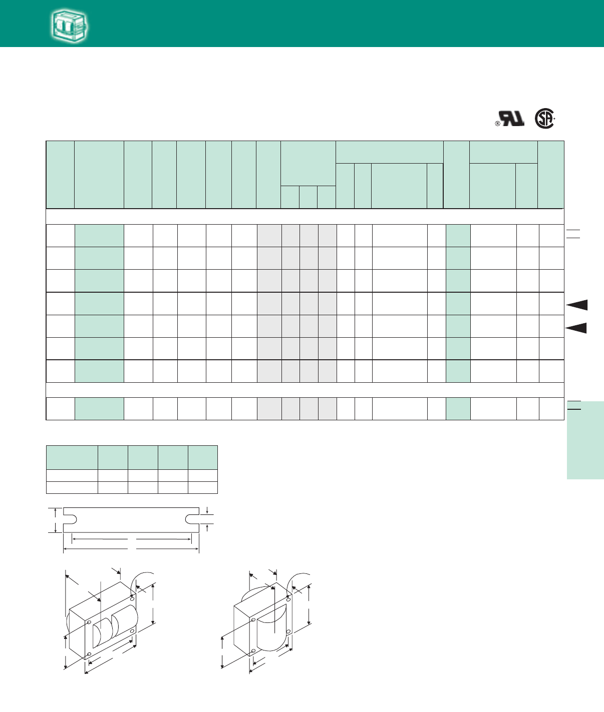
5-15
Lighting Electronics Atlas 2010-2011
HIGH INTENSITY DISCHARGE BALLASTS
120/208
240/277
Cap Catalog
Number
Dry
or
Oil
Input
Volts
Catalog
Number
Circuit
Type
Input
Watts
Max
Input
Current
Nom
Open
Circuit
Voltage
Fuse
Rating
(Amps)
Fig
Dimensions
Non-PCB Capacitor
(Page 5-38 & 5-39)
Mfd Min
Volt
Total
Weight
(lbs)
Ignitor ✝✝
(Page 5-40 to 5-44)
Part
Number
Max
Dist
To
Lamp
(ft)
U.L.
Bench
Top
Rise
Code
1029
(pg 5-4)
A B
✝
•
Wiring
Dia
60 Hz Core & Coil Ballasts
Metal Halide
NOM
Fig. 1
(3" x 4" Core)
Fig. 9
(25/8” x 23/16” Reactor Core)
150W Lamp, ANSI Code M102 or M142 (Pulse-Start)
71A5492-500D
71A5492-001D HX-HPF 185
3.7/2.1/
1.8/1.6
265 10/5/
5/4 1 2.3 3.9 16 280 7C160M30RA D 7.0 LI533-H4 10K
120/
277/347 71A54A2-500D HX-HPF 185 3.7/
1.6/1.3
265 10/
4/3 1 2.3 3.9 16 280 7C160M30RA D 7.0 LI533-H4 10 E/
E/E
K
480/
120T 71A5443-500DT Super
CWA 185 0.4 215 5 1 2.4 3.75 16 300 7C160M30RA D 7.5 LI501-J4 5 CM
C/C/
C/C
480/
120T 71A5442-500DT HX-HPF 185
.9
270 3 1 2.8 4.0 16 280 7C160M30RA D 9.0 LI533-H4 10K B
HID
213/16"
31/2"315/16"
27/16"
B
MAX.
A
Fig. 1
(3" x 4" core)
4 Holes cleared for
#10 thru-bolts
23/16"
23/16"
25/8"
13/4"
B
MAX.
A
Fig. 9
(2 5/8" x 2 3/1 6 Reactor Core)
4 Holes cleared for
#6 thru-bolts
NOM
WELDED BRACKET DIMENSIONS
Ballast
Dimensions Fig L W M S
1 5.1 1.00 4.50 0.25
9 4.0 0.75 3.50 0.28
120/208
240/277 71A5493-500D Super
CWA 190 1.9/1/
.95/.8 215 5/2.5/
2/2 1 2.4 3.75 16 300 7C160M30RA D 8.3 LI501-J4 5 D/C/
C/C
M
150W Lamp, ANSI Code M81 (OSI Briteline/HQI, GE Arcstream MQI, Philips MHN-TD) (Pulse-Start)
120/208/
240/277 71A5490-500D HX-HPF 185
3.6/2.1/
1.8/1.6
240 9/6/
5/4 1 2.5 3.8 16 300 7C160M30RA D 8.5 LI522-H5 20 C/C/
A/A
K
277 71A5437-500DBP
Linear
Reactor
HPF
173 1.5 277 4 9 2.5 4.0 14 280 7C140M30RA D 4.2 Integral Ignitor 2 BH
120/
277/347 71A54A3-500D Super
CWA 189 1.7/
.8/.7
187 5/
2/2 1 2.7 4.0 22 240 7C220M24-RA D 9.0 LI501-J4 15 C/
B/A
L
New
New
W
++
BRACKET
M
L
S
✥
HID•Core&Coil
Metal Halide
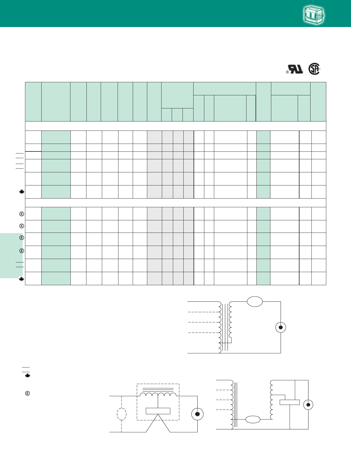
Lighting Electronics Atlas 2010-2011
5-16
HIGH INTENSITY DISCHARGE BALLASTS
Fig. H
COM
LAMP
CAP
IGNITOR
LAMP
LINE V
INTEGRATED
IGNITOR BALLAST
Input
Volts Cap Catalog
Number
Dry
or
Oil
Catalog
Number
Circuit
Type
Input
Watts
Max
Input
Current
Nom
Open
Circuit
Voltage
Fuse
Rating
(Amps)
Fig
Dimensions
Non-PCB Capacitor
(Page 5-38 & 5-39)
Mfd Min
Volt
Total
Weight
(lbs)
Ignitor ✝✝
(Page 5-40 to 5-44)
Part
Number
Max
Dist
To
Lamp
(ft)
U.L.
Bench
Top
Rise
Code
1029
(pg 5-4)
A B
✝
•
Wiring
Dia
60 Hz Core & Coil Ballasts
Metal Halide
NOM
NOM
Fig. H Fig. M
Fig. A
Fig. A
LAMP
LAMP
LINE V
COM COM
LINE V
LINE V
LINE V
CAP
CAP
175W Lamp, ANSI Code M57 or 150 Watt Lamp, ANSI Code M107
71A5590-500D
120/208
240/277
120/208
240/277
127/220 71A55H0-500D
71A5570-001D
480/120T 71A5540-001D
–
– B/B
D
CWA 210 1.8/1.1/
.9/.8 305 5/3/
3/2 2.5 3.7 10 400 7C100M40R D 6.8 –
CWA 210 1.8/1.1 305 5/3 2.5 3.8 10 400 7C100M40R D 6.8 –
CWA 210 1.8/1.1/
.9/.8 305 5/3/
3/2 2.5 3.7 10 400 7C100M40R D 6.8 – – C/D/
D/D
CWA 210 0.5 305 2 2.5 4.0 10 400 7C100M40R D 8.5 – –
A
A
A
A
480/120T 71A5540-500DT DCWA 210 0.5 305 2 2.8 4.0 10 400 7C100M40R D 8.5 – –A
C/D/
D/D
175W Lamp, ANSI Code M137 or M152 (Pulse-Start)
120/
277/347
71A55A0-500D
71A55A0-001D CWA 210 1.8/
.8/.7 305 5/
2/2
1
1
1
1
1
1 2.5 3.7 10 400 7C100M40R D 7.0 – – C/
C/D
A
HID
71A5541-500DTEE
480/120T
71A5591-500DEE
120/208
240/277
71A5543-500DTEE
480/120T
71A5593-500DEE
Super
CWA 198
.04
285 2 1.8 3.4 11 370 7C110M40 D 10.0 LI533-H4 2 AM
Super
CWA 198
1.7/1.0/
.8/.7
285 5/3/
3/2 1.7 3.3 11 370 7C110M40 D 10.5 LI533-H4 2 A/A/
A/A
M
Super
CWA 198
.04
278 2 3.1 4.2 11 370 7C110M40 D 9.4 LI533-H4 2 AM
Super
CWA 198
1.7/1.0/
.9/.8
285 5/3/
3/2 3.2 4.4 11 370 7C110M40 D 9.7 LI533-H4 2 A/A/
A/A
M
120/208
240/277
Fig. M
LAMP
CAP
LAMP
COM COM
LINE V
LINE V
LINE V
IGNITOR
X1X3
X2
LINE V
CAPCAP
NOM 71A5593-001D
120/
277/347
120/208
240/277
71A55A3-500D
Super
CWA 208
1.9/1.1/
.9/.8
275 5/3/
3/3 2.3 3.5 11 370 7C110M40 D 7.0 LI533-H4 2 C/C/
C/C
M
Super
CWA 208
1.9/
.9/.7
275 5/
3/2
2
2
1
1
1
1 2.3 3.5 11 370 7C110M40 D 7.0 LI533-H4 2 C/
C/C
M
◆
◆
✝ Ordering information:
Replacement/retrofit ballast kits – indicated by bold type and -001D or -001 suffix.
Refer to pages 5-5 to 5-9 for more information on replacement kits.
Originalequipmentballasts– typically ordered with capacitor (as shown).
-500D includes core & coil with dry-film capacitor.
-500 includes core & coil with oil-filled capacitor (required for higher wattage ballasts).
May also be available with welded bracket, and/or without capacitor:
-510D includes core & coil with welded bracket and dry-film capacitor.
-510 includes core & coil with welded bracket and oil-filled capacitor.
-600 core & coil only (no capacitor).
-610 core & coil with welded bracket (no capacitor).
✝✝ Each ballast requiring an ignitor is furnished standard with a short-range ignitor model
shown for use within fixtures. long-range ignitors are available separately if required.
See pages 5-xx to 5-yy for additional information.
• MaximumInputCurrent– For HX and R circuits, value is the highest of starting, operating
or open circuit current. For CWA, SCWA and CWI circuits, value is the operating current.
Certified ballast available for Mexican market. Add “M” to suffix (example: -500DM).
Canadian replacement/retrofit ballast kit indicated by bold type. Refer to page 5-9.
✥ Includes auto-reset thermal protection.
◆ Compact 3 x 4 core design
Meets EISA 88% efficiency requirements.
NOM
HID•Core&Coil
Metal Halide
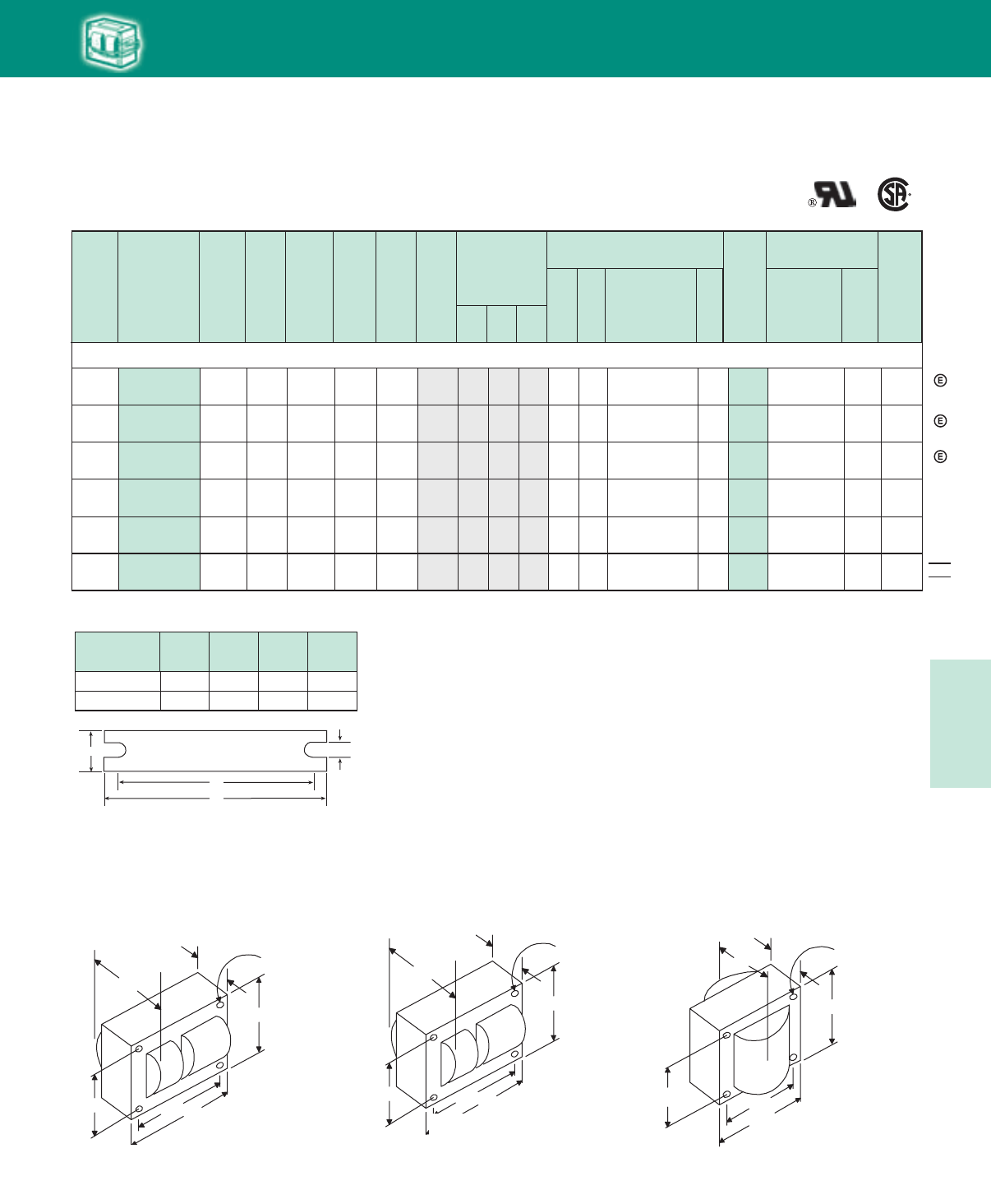
5-17
Lighting Electronics Atlas 2010-2011
HIGH INTENSITY DISCHARGE BALLASTS
41/4"
43/8 "43/4"
37/8"
B
MAX.
A
Fig. 2
(41
/4" x 43
/4" core)
4 Holes cleared for
#10 thru-bolts
Cap Catalog
Number
Dry
or
Oil
Input
Volts
Catalog
Number
Circuit
Type
Input
Watts
Max
Input
Current
Nom
Open
Circuit
Voltage
Fuse
Rating
(Amps)
Fig
Dimensions
Non-PCB Capacitor
(Page 5-38 & 5-39)
Mfd Min
Volt
Total
Weight
(lbs)
Ignitor ✝✝
(Page 5-40 to 5-44)
Part
Number
Max
Dist
To
Lamp
(ft)
U.L.
Bench
Top
Rise
Code
1029
(pg 5-4)
A B
✝
•
Wiring
Dia
60 Hz Core & Coil Ballasts
Metal Halide
NOM
WELDED BRACKET DIMENSIONS
Ballast
Dimensions Fig L W M S
200W Lamp, ANSI Code M136 (Pulse-Start)
277 71A5637-500DBPEE
71A5637-001DEE
Linear
Reactor
HPF
218 1.3 277 4 10 1.0 3.1 12 280 7C120M30RA D 6.0 Integral
Ignitor 2 AH
480/
120T 71A5642-500DTEE Super
CWA 227 0.5 242 2 M 1 2.9 4.2 15 330 7C150M33 D8.7 LI533-H4 2 A
M
120/208/
240/277 71A5692-001D Super
CWA 232 2.0/1.2/
1.0/.9 240 6/4/
3/3 1 2.5 3.6 15 330 7C150M33 D 8.0 LI533-H4 2 A/B/
A/A
120/
277/347 71A56A2-500D Super
CWA 232 2.1/
.9/.7 235 6/
3/2 M 1 2.5 3.6 15 330 7C150M33 D8.0 LI533-H4 2 C/
A/A
120/208/
240/277 71A5692-500DEE Super
CWA 227 2.2/1.3/
1.1/1.0 242 6/4/
3/3 M 1 3.0 4.2 15 33 7C150M33 D8.8 LI533-H4 2 A/A/
A/A
1 5.1 1.00 4.50 0.25
2, 10 6.5 1.25 5.75 0.28
Fig. 2
(4¼" x 4¾" Core)
Fig. 10
(4½” x 3¾” Reactor Core)
HID
W
++
BRACKET
M
L
S
213/16"
31/2"315/16"
27/16"
B
MAX.
A
Fig. 1
(3" x 4" core)
4 Holes cleared for
#10 thru-bolts
3¾
4
3
4½
B
MAX.
A
Fig. 10
(41
/2" x 33
/4 Reactor Core )
4 Holes cleared for
#6 thru-bolts
1/
16 "
5/
16 "
"
Fig. 1
(3" x 4" Core)
6/4/
3/3
120/208/
240/277 71A5693-500DM Super
CWA 240 2.1/1.2/
1.1/.9 252 M 2 1.4 3.0 15 330 D8.5 LI533-H4 2 A/A/
A/A
7C150M33
◆
◆
◆
◆
✥
HID•Core&Coil
Metal Halide
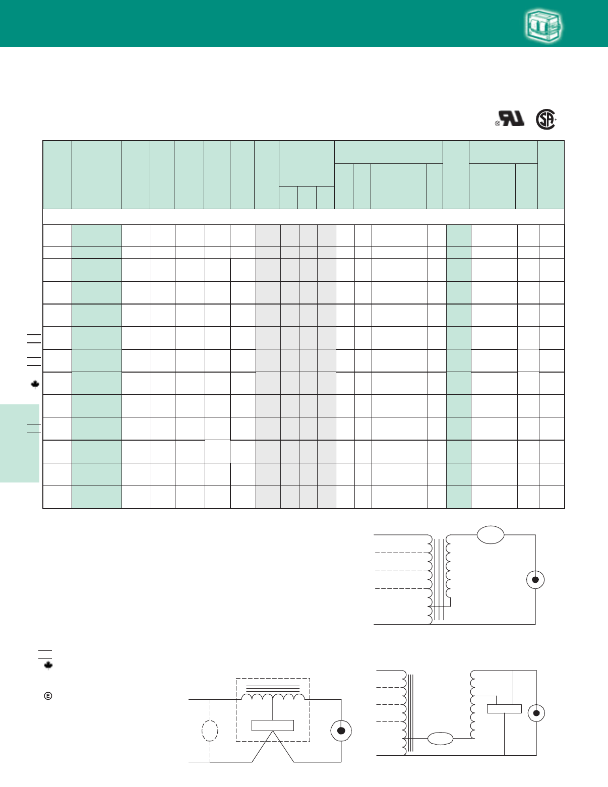
Lighting Electronics Atlas 2010-2011
5-18
HIGH INTENSITY DISCHARGE BALLASTS
250W Lamp, ANSI Code M58
120/208
240/277 –
71A5770-001 CWA 295 2.5/1.4
1.3/1.1 300 8/5/
5/3 2 1.5 3.0 15 400 7C150P40R D 9.0 – A/A
B/A
A
120/208
240/277
NOM 71A5790-500DM CWA 295 2.5/1.4
1.3/1.1 300 8/5/
5/3 2 1.5 3.0 15 400 7C150P40R D 9.0 – A/A/
B/A
–A
120/208
240/277
NOM 71A5790-500DA CWA 298 2.5/1.5
1.3/1.1 300 8/5/
5/3 2 1.5 3.15 15 400 7C150P40R D 8.0 – B/B/
B/B
–A
Cap Catalog
Number
Dry
or
Oil
Input
Volts
Catalog
Number
Circuit
Type
Input
Watts
Max
Input
Current
Nom
Open
Circuit
Voltage
Fuse
Rating
(Amps)
Fig
Dimensions
Non-PCB Capacitor
(Page 5-38 & 5-39)
Mfd Min
Volt
Total
Weight
(lbs)
Ignitor ✝✝
(Page 5-40 to 5-44)
Part
Number
Max
Dist
To
Lamp
(ft)
U.L.
Bench
Top
Rise
Code
1029
(pg 5-4)
A B
✝
•
Wiring
Dia
60 Hz Core & Coil Ballasts
Metal Halide
Fig. A
Fig. H
–
120/208/
240/277/
480
71A5750-001D CWA 290
2.6/1.5/
1.4/1.1/
.7
315 8/5/
5/3/
22 1.6 3.1 15 400 7C150P40R D 10.0 – A/A/
B/A/
B
A
–
120/208/
240/277/
480
71A5750-500DA CWA 290
2.6/1.5/
1.4/1.1/
.7
310 8/5/
5/3/
22 1.6 3.1 15 400 7C150P40R D 9.0 – A/A/
B/A/
B
A
120/208
240/277
120/208
240/277
NOM –127/220
480/120T
480/120T
71A57H0-500DM CWA 295 2.6/1.5 300 8/5 2 1.5 3.0 15 400 7C150P40R D 9.0 – A/BA
71A5771-001D CWA 294 2.6/1.5/
1.3/1.1 300 8/5/
5/3 1 3.0 4.2 15 400 7C150P40R D 9.0 – – C/C/
D/D
A
480/120T 71A5741-500DT
71A5741-OO1D CWA 298 .7 300 2 1 3.0 4.2 15 400 7C150P40R D 9.0 – – HA
71A5791-500D CWA 294 2.6/1.5/
1.3/1.1 300 8/5/
5/3 1 3.0 4.2 15 400 7C150P40R D 9.0 – – C/C/
D/D
A
120/
277/347
71A57A0-500D
71A57A0-001D CWA 295 2.5/
1.1/.9 315 8/
3/3 2 1.7 3.1 15 400 7C150P40R D 10.0 – A/
A/A
–A
120/
277/347 71A57A0-500DA CWA 295 2.5/
1.1/.9 315 8/
3/3 2 1.7 3.1 15 400 7C150P40R D 9.0 – A/A
A/A
–A
71A5740-001D CWA
CWA
295
295
.7
.7
315
315
2
2
2
2
1.7
1.7
3.1
3.1
15
15
400
400
7C150P40R
7C150P40R
D
D
10.0
10.0
–
–
B
B
A
A
–
–
71A5740-500DT
HID
Fig. A
LAMP
LAMP
LINE V
COM COM
LINE V
LINE V
LINE V
CAP
CAP
Fig. H
COM
LAMP
CAP
IGNITOR
LAMP
LINE V
INTEGRATED
IGNITOR BALLAST
◆
◆
◆
✝ Ordering information:
Replacement/retrofit ballast kits – indicated by bold type and -001D or -001 suffix.
Refer to pages 5-5 to 5-9 for more information on replacement kits.
Originalequipmentballasts– typically ordered with capacitor (as shown).
-500D includes core & coil with dry-film capacitor.
-500 includes core & coil with oil-filled capacitor (required for higher wattage ballasts).
May also be available with welded bracket, and/or without capacitor:
-510D includes core & coil with welded bracket and dry-film capacitor.
-510 includes core & coil with welded bracket and oil-filled capacitor.
-600 core & coil only (no capacitor).
-610 core & coil with welded bracket (no capacitor).
✝✝ Each ballast requiring an ignitor is furnished standard with a short-range ignitor model
shown for use within fixtures. long-range ignitors are available separately if required.
See pages 5-xx to 5-yy for additional information.
• MaximumInputCurrent– For HX and R circuits, value is the highest of starting, operating
or open circuit current. For CWA, SCWA and CWI circuits, value is the operating current.
Certified ballast available for Mexican market. Add “M” to suffix (example: -500DM).
Canadian replacement/retrofit ballast kit indicated by bold type. Refer to page 5-9.
✥ Includes auto-reset thermal protection.
◆ Compact 3 x 4 core design
Meets EISA 88% efficiency requirements.
NOM
HID•Core&Coil
Metal Halide
Fig. M
Fig. M
LAMP
CAP
LAMP
COM COM
LINE V
LINE V
LINE V
IGNITOR
X1X3
X2
LINE V
CAPCAP
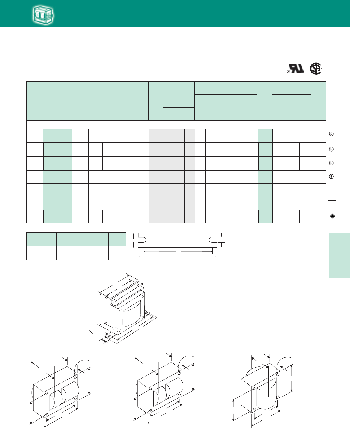
5-19
Lighting Electronics Atlas 2010-2011
HIGH INTENSITY DISCHARGE BALLASTS
Cap Catalog
Number
Dry
or
Oil
Input
Volts
Catalog
Number
Circuit
Type
Input
Watts
Max
Input
Current
Nom
Open
Circuit
Voltage
Fuse
Rating
(Amps)
Fig
Dimensions
Non-PCB Capacitor
(Page 5-38 & 5-39)
Mfd Min
Volt
Total
Weight
(lbs)
Ignitor ✝✝
(Page 5-40 to 5-44)
Part
Number
Max
Dist
To
Lamp
(ft)
U.L.
Bench
Top
Rise
Code
1029
(pg 5-4)
A B
✝
•
Wiring
Dia
60 Hz Core & Coil Ballasts
Metal Halide
NOM
250W Lamp, ANSI Code M138 or M153 (Pulse Start)
277 71A5737-500DBPEE
71A5737-001DEE
Linear
Reactor
HPF 272 1.5 277 4 10 1.3 3.2 14 280 7C140M30RA D 6.5 Integral
Ignitor 5 AH
120/208/
240/277 71A5792-500DEE
Super
CWA
283 2.6/1.5/
1.3/1.1 280 8/5/
5/3 M 2 1.7 3.4 17 340 7C170P40R D 9.5 LI533-H4 2 A/A/
A/A
120/208/
240/277
71A5792-500DA
71A5792-001D
Super
CWA
291 2.5/1.4/
1.3/1.1 275 8/5/
5/3 M 2 1.5 3.1 17 340 7C170P40R D 9.5 LI533-H4 5 A/A/
A/B
120/208/
240/278 71A5792-500DMA
Super
CWA
291 2.5/1.5/
1.3/1.1 275 8/5/
5/3 M 2 1.5 3.1 17 340 7C170P40R D 9.5 LI533-H4 2 A/A/
A/B
120/
277/347
71A57A2-500D
71A57A2-001D
Super
CWA
291 2.5/
1.1/.9 272 8/
3/3 M 2 1.5 3.1 17 340 7C170P40R D 9.5 LI533-H4 5 A/
A/A
480/
120T 71A5742-500DTEE
Super
CWA
283 0.7 290 2 M 2 2.2 4.0 17 340 7C170P40R D 11.0 LI533-H4 2 A
120/208/
240/277/
480
71A5752-500DAEE
Super
CWA
275
2.4/1.4/
1.2/1.1/
0.6
280
8/5/
5/3/
2
M 2 2.2 4.0 17 340 7C170P40R D 11.5 LI533-H4 2
A/A/
A/A
A
Ballast
Dimensions Fig L W M S
1 5.1 1.00 4.50 0.25
2, 10 6.5 1.25 5.75 0.28
WELDED BRACKET DIMENSIONS
HID
41/4"
43/8 "43/4"
37/8"
B
MAX.
A
Fig. 2
(41
/4" x 43
/4" core)
4 Holes cleared for
#10 thru-bolts
Fig. 2
(4¼" x 4¾" Core)
Fig. 10
(4½” x 3¾” Reactor Core)
W
++
BRACKET
M
L
S
213/16"
31/2"315/16"
27/16"
B
MAX.
A
Fig. 1
(3" x 4" core)
4 Holes cleared for
#10 thru-bolts
3¾
4
3
4½
B
MAX.
A
Fig. 10
(41
/2" x 33
/4 Reactor Core )
4 Holes cleared for
#6 thru-bolts
1/
16 "
5/
16 "
"
Fig. 1
(3" x 4" Core)
✥
HID•Core&Coil
Metal Halide
W
M
4.75
4.40
4.25 3.90
L
-540 Bracket Detail
Suffix -540D denotes a welded
angle bracket to allow linear
reactors to mount in 400W
fixtures designed for standard CWA
ballasts without brackets. This
bracket is standard on -001DEE.
Suffix -510 provides
welded-on mounting foot
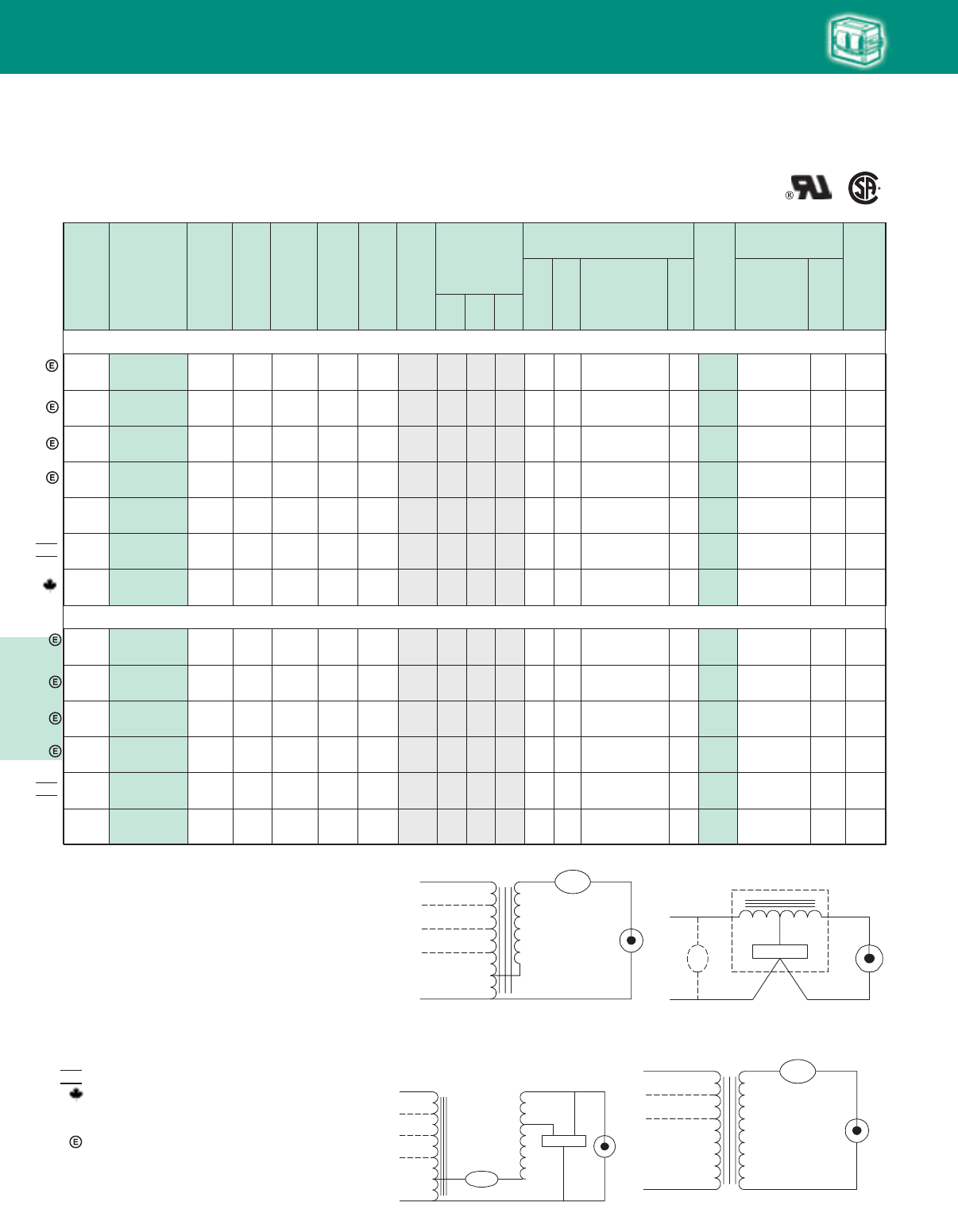
Lighting Electronics Atlas 2010-2011
5-20
HIGH INTENSITY DISCHARGE BALLASTS
320W Lamp, ANSI Code M132 or M154 or M170 (Pulse-Start)
U.L.
Bench
Top
Rise
Code
1029
(pg 5-4)
Cap Catalog
Number
Dry
or
Oil
Input
Volts
Catalog
Number
Circuit
Type
Input
Watts
Max
Input
Current
Nom
Open
Circuit
Voltage
Fuse
Rating
(Amps)
Fig
Dimensions
Non-PCB Capacitor
(Page 5-38 & 5-39)
Mfd Min
Volt
Total
Weight
(lbs)
Ignitor ✝✝
(Page 5-40 to 5-44)
Part
Number
Max
Dist
To
Lamp
(ft)
A B
✝
•
Wiring
Dia
60 Hz Core & Coil Ballasts
Metal Halide
NOM
NOM
277
277
71A5837-500DBPEE
71A5837-001DEE
71A5937-500DBPEE
71A5937-001DEE
Linear
Reactor
HPF
Linear
Reactor
HPF
342
375
1.9
2.1
277
277
5
5
H
H
10
10
1.7
1.9
3.8
4.0
17.5
20
300
280
7C175M30RA
7C200P30RA
D
D
9.5
10.0
Integral
Ignitor
Integral
Ignitor
15
2
A
A
480/
120T
480/
120T
480/
120T
71A5842-500DTAEE
71A5942-500DTAEE
71A5842-001DT
Super
CWA
Super
CWA
Super
CWA
363
397
368
0.8
0.9
0.8
275
280
270
5
3
5
M
M
M
2
2
2
2.2
2.2
1.8
4.0
4.1
3.7
21
22.5
21
345
345
345
7C210P40R
7C225P40
7C210P40R
D
D
D
11.0
11.0
11.0
LI533-H4
LI533-H4
LI533-H4
2
2
2
D
B
D
120/208/
240/277
71A5892-500DMA
71A5892-001D
Super
CWA
368 3.3/1.9/
1.7/1.4 270 8/6/
5/3 M 2 1.8 3.7 21 345 7C210P40R D 11.0 LI533-H4
120/
277/347 71A58A2-500DA
Super
CWA
368 3.3/
1.4/1.1 280 8/
4/3 M 2 1.8 3.7 21 345 7C210P40R D 10.0 LI533-H4 2
2B/B/
B/B
C/
C/C
120/208/
240/277
71A5993-500DMA
71A5993-001D
Super
CWA
400 3.4/2.0/
1.7/1.5 270 10/7/
5/5 M 2 1.8 3.7 22.5 345 7C225P40 D 11.0 LI533-H4
120/
277/347 71A59A3-500D
Super
CWA
400 3.4/
1.5/1.2 280 10/
5/3 M 2 1.8 3.7 22.5 345 7C225P40 D 10.5 LI533-H4 2
2D/C/
C/C
D/
C/C
350W Lamp, ANSI Code M131 or M171 (Pulse-Start)
120/208/
240/277/
480
120/208/
240/277/
480
71A5852-500DAEE
71A5953-500DAEE
Super
CWA
Super
CWA
363
397
3.3/1.9/
1.7/1.4/
0.8
3.4/2.0/
1.7/1.5/
0.9
290
285
10/7/
5/5/
5
10/7/
5/5/
5
M
M
2
2
2.2
2.2
4.2
4.1
21
22.5
345
345
7C210P40R
7C225P40
D
D
11.8
11.2
LI533-H4
LI533-H4
15
2
A/B/
A/A/
A
B/C/
B/B/
B
120/208/
240/277
120/208/
240/277
71A5892-500DAEE
71A5993-500DAEE
Super
CWA
Super
CWA
363
397
3.3/1.9/
1.7/1.4
3.4/2.0/
1.7/1.5
285
270
8/6/
5/3
10/7/
5/5
M
M
2
2
2.2
2.2
4.2
4.1
21
22.5
345
345
7C210P40R
7C225P40
D
D
11.0
11.6
LI533-H4
LI533-H4
2
2
A/A/
A/A
D/C/
C/C
HID
Fig. P
Fig. A Fig. H
Fig. M
✝ Ordering information:
Replacement/retrofit ballast kits – indicated by bold type and -001D or -001 suffix.
Refer to pages 5-5 to 5-9 for more information on replacement kits.
Originalequipmentballasts– typically ordered with capacitor (as shown).
-500D includes core & coil with dry-film capacitor.
-500 includes core & coil with oil-filled capacitor (required for higher wattage ballasts).
May also be available with welded bracket, and/or without capacitor:
-510D includes core & coil with welded bracket and dry-film capacitor.
-510 includes core & coil with welded bracket and oil-filled capacitor.
-600 core & coil only (no capacitor).
-610 core & coil with welded bracket (no capacitor).
✝✝ Each ballast requiring an ignitor is furnished standard with a short-range ignitor model
shown for use within fixtures. long-range ignitors are available separately if required.
See pages 5-xx to 5-yy for additional information.
• MaximumInputCurrent– For HX and R circuits, value is the highest of starting, operating
or open circuit current. For CWA, SCWA and CWI circuits, value is the operating current.
Certified ballast available for Mexican market. Add “M” to suffix (example: -500DM).
Canadian replacement/retrofit ballast kit indicated by bold type. Refer to page 5-9.
✥ Includes auto-reset thermal protection.
◆ Compact 3 x 4 core design
Meets EISA 88% efficiency requirements.
NOM
✥
✥
Fig. A
LAMP
LAMP
LINE V
COM COM
LINE V
LINE V
LINE V
CAP
CAP
Fig. H
COM
LAMP
CAP
IGNITOR
LAMP
LINE V
INTEGRATED
IGNITOR BALLAST
Fig. M
LAMP
CAP
LAMP
COM COM
LINE V
LINE V
LINE V
IGNITOR
X1X3
X2
LINE V
CAPCAP
Fig. P
LAMP 1
LAMP
LINE V
COM
LINE V
LINE V
CAP
CAP
LAMP 2
HID•Core&Coil
Metal Halide
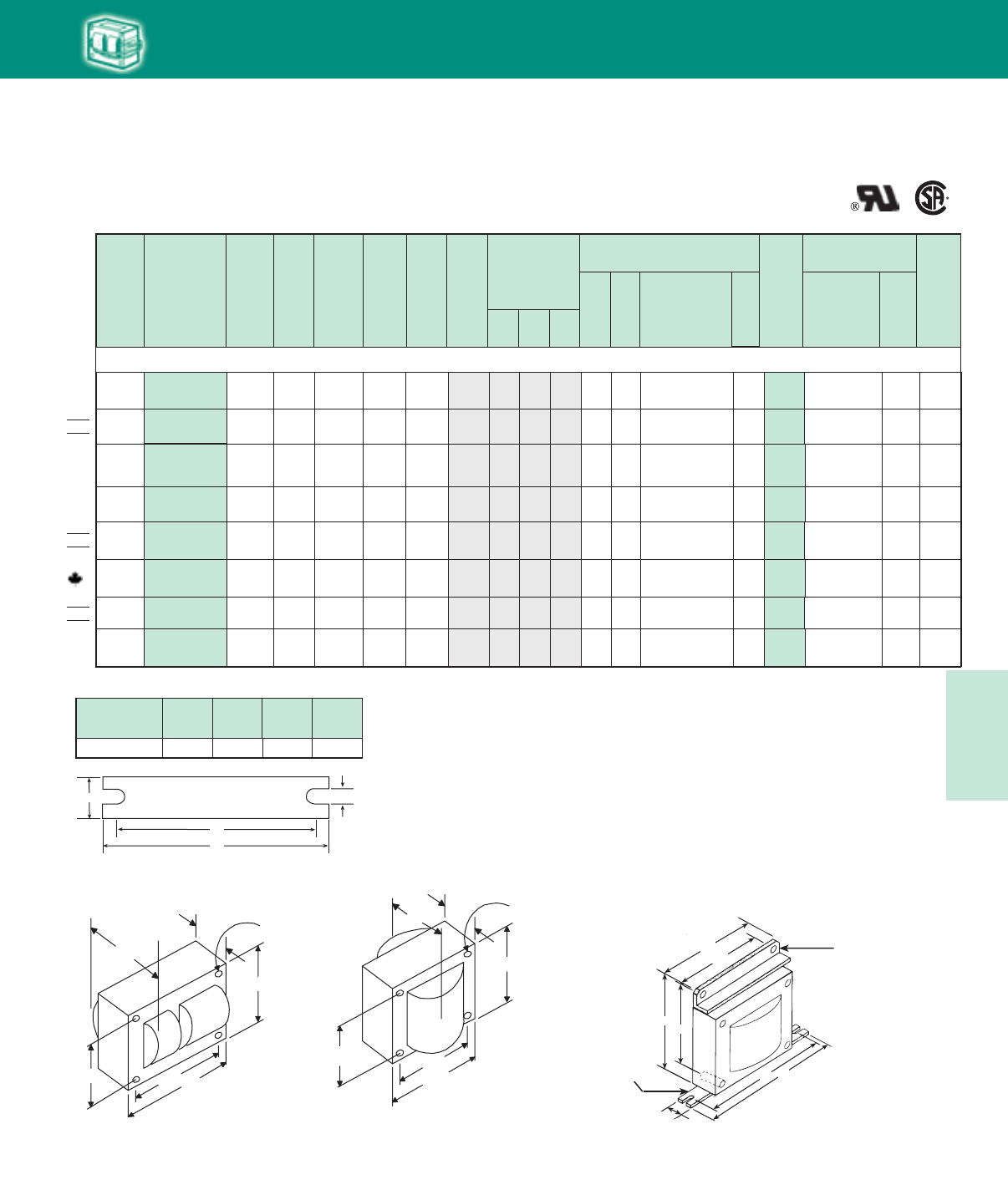
5-21
Lighting Electronics Atlas 2010-2011
HIGH INTENSITY DISCHARGE BALLASTS
Cap Catalog
Number
Dry
or
Oil
Input
Volts
Catalog
Number
Circuit
Type
Input
Watts
Max
Input
Current
Nom
Open
Circuit
Voltage
Fuse
Rating
(Amps)
Fig
Dimensions
Non-PCB Capacitor
(Page 5-38 & 5-39)
Mfd Min
Volt
Total
Weight
(lbs)
Ignitor ✝✝
(Page 5-40 to 5-44)
Part
Number
Max
Dist
To
Lamp
(ft)
U.L.
Bench
Top
Rise
Code
1029
(pg 5-4)
A B
✝
•
Wiring
Dia
HID
60 Hz Core & Coil Ballasts
Metal Halide
NOM
NOM
NOM
400W Lamp, ANSI Code M59
71A6041-500DT
71A6041-500DT
71A6041-500DTA
480/120T
CWA 462 1.0 300 4 2 4.0 24 400 7C240P40R D – –
A
480/120T
CWA 462 1.0 300 4 2 4.0 24 400 7C240P40R D – –
A
127/220 71A60H1-500DM CWA 458 3.9/2.2 300 10/7 2 2.0 3.8 24 400 7C240P40R D 11.5 – – D/DA
120/208/
240/277 71A6091-500DA CWA 458 4.0/2.3/
2.0/1.7 300 10/7/
5/5 2 2.0
2.0
2.0
2.2
3.9 24 400 7C240P40R D 11.5
12.0
12.0
11.0
– – D/E/
D/E
E
E
E
A
120/208/
240/277 71A6071-001D CWA 458 4.0/2.3/
2.0/1.7 300 10/7/
5/5 2 2.2 4.0 24 400 7C240P40R D 11.5 – – D/E/
D/E
A
120/208/
240/277/
480
71A6051-001D CWA 460
4.1/2.3/
2.0/1.7/
1.0
300 10/7/
5/5/
32 2.3 4.0 24 400 7C240P40R D 14.0 – – D/C/
D/C/
D
A
120/
208/240 71A60E6-500DM CWI 465
4.2/
2.5/2.1
320 10/
7/5 2 2.4 4.0 20 425 MD2006-100 O 14.0 – – E/
D/D
P
120/
277/347
71A60A1-500D
71A60A1-001D CWA 460 4.0/
1.7/1.4 300 10/
5/4 2 2.0 4.0 24 400 7C240P40R D 12.0 – – D/
D/D
A
Fig. 10
(4½” x 3¾” Reactor Core)
Ballast
Dimensions Fig L W M S
2, 10 6.5 1.25 5.75 0.28
WELDED BRACKET DIMENSIONS
W
++
BRACKET
M
L
S
3¾
4
3
4½
B
MAX.
A
Fig. 10
(41
/2" x 33
/4 Reactor Core )
4 Holes cleared for
#6 thru-bolts
1/
16 "
5/
16 "
"
Fig. 2
(4¼" x 4¾" Core)
41/4"
43/8 "43/4"
37/8"
B
MAX.
A
Fig. 2
(41
/4" x 43
/4" core)
4 Holes cleared for
#10 thru-bolts
HID • Core & Coil
Metal Halide
W
M
4.75
4.40
4.25 3.90
L
-540 Bracket Detail
Suffix -540D denotes a welded
angle bracket to allow linear
reactors to mount in 400W
fixtures designed for standard CWA
ballasts without brackets. This
bracket is standard on -001DEE.
Suffix -510 provides
welded-on mounting foot
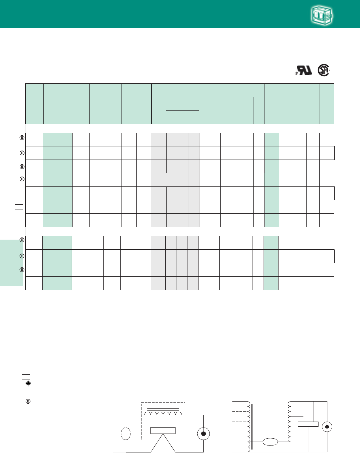
Lighting Electronics Atlas 2010-2011
5-22
HIGH INTENSITY DISCHARGE BALLASTS
U.L.
Bench
Top
Rise
Code
1029
(pg 5-4)
Input
Volts
Catalog
Number
Circuit
Type
✝
•
Cap Catalog
Number
Dry
or
Oil
Input
Watts
Max
Input
Current
Nom
Open
Circuit
Voltage
Fuse
Rating
(Amps)
Fig
Dimensions
Non-PCB Capacitor
(Page 5-38 & 5-39)
Mfd Min
Volt
Total
Weight
(lbs)
Ignitor ✝✝
(Page 5-40 to 5-44)
Part
Number
Max
Dist
To
Lamp
(ft)
A B
Wiring
Dia
60 Hz Core & Coil Ballasts
Metal Halide
400W Lamp, ANSI Code M135 or M155 or M172 (Pulse-Start)
480/
120T 71A6042-500DTAEE Super
CWA 452 1.0 270 3 2 2.1 3.9 26 330 7C260P33R D14.5 LI533-H4 10 DM
120/208/
240/277/
480
71A6052-500DAEE Super
CWA 454
3.8/2.2/
1.9/1.7/
1.0
275
10/7/
5/5/
3
2 2.2 4.3 26 330 7C260P33R D14.0 LI533-H4 10
B/D/
D/B/
D
M
480/
120T 71A6042-001D Super
CWA 452 1.0 270 3 2 2.1 3.9 26 330 7C260P33R D14.5 LI533-H4 10 DM
120/208/
240/277
71A6092-500DM
71A6092-001D
Super
CWA 452 3.8/2.2/
1.9/1.7 265 10/7/
5/5 2 1.8 3.7 26 330 7C260P33R D11.0 LI533-H4 10 D/C/
D/D
M
120/208/
240/277
71A6092-500DAEE
71A6092-001DEE
Super
CWA 452 3.8/2.2/
1.9/1.7 270 10/7/
5/5 2 2.1 4.1 26 330 7C260P33R D13.2 LI533-H4 10 C/D/
D/D
M
277 71A6037-500DBPEE✥
71A6137-001DEE✥
Linear
Reactor
HPF 425 2.1 277 5 10 1.6 3.8 20 280 7C200P30RA D9.0 Integral
Ignitor 2 AH
120/
277/347 71A60A2-500DA Super
CWA 450 3.8/
1.7/1.4 270 10/
5/4 2 1.8 3.7 26 330 7C260P33R D11.0 LI533-H4 10 C/
C/C
M
277 71A6337-500DBPEE
Linear
Reactor
HPF
480 10 1.9 4.0 22.5 280 7C225P30RA D 9.5 Integral
Ignitor 2 A
480/
120T 71A6343-500DTEE Super
CWA 514 2 2.4 4.2 26.5 360 7C265P40R D 14.0 LI533-H4 5 D
H
M
120/208/
240/277 71A6393-500DEE Super
CWA 508 2 2.3 3.9 26.5 360 7C265P40R D 13.5 LI533-H4 5 C/C/
C/C
M
M
120/
277/347 71A63A3-500D Super
CWA 505 2 2.4 4.2 26.5 360 7C265P40R D 14.0 LI533-H4 5 D/
D/D
72772.4
32671.1
10/8/
5/5
257
4.3/2.5/
2.2/1.9
10/
5/4
268
4.3/
1.9/1.5
450W Lamp, ANSI Code M144 (Pulse-Start)
NOM
HID
Fig. H
Fig. H
COM
LAMP
CAP
IGNITOR
LAMP
LINE V
INTEGRATED
IGNITOR BALLAST
Fig. M
Fig. M
LAMP
CAP
LAMP
COM COM
LINE V
LINE V
LINE V
IGNITOR
X1X3
X2
LINE V
CAPCAP
✝ Ordering information:
Replacement/retrofit ballast kits – indicated by bold type and -001D or -001 suffix.
Refer to pages 5-5 to 5-9 for more information on replacement kits.
Original equipment ballasts – typically ordered with capacitor (as shown).
-500D includes core & coil with dry-film capacitor.
-500 includes core & coil with oil-filled capacitor (required for higher wattage ballasts).
May also be available with welded bracket, and/or without capacitor:
-510D includes core & coil with welded bracket and dry-film capacitor.
-510 includes core & coil with welded bracket and oil-filled capacitor.
-600 core & coil only (no capacitor).
-610 core & coil with welded bracket (no capacitor).
✝✝ Each ballast requiring an ignitor is furnished standard with a short-range ignitor model
shown for use within fixtures. long-range ignitors are available separately if required.
See pages 5-xx to 5-yy for additional information.
• Maximum Input Current – For HX and R circuits, value is the highest of starting, operating
or open circuit current. For CWA, SCWA and CWI circuits, value is the operating current.
Certified ballast available for Mexican market. Add “M” to suffix (example: -500DM).
Canadian replacement/retrofit ballast kit indicated by bold type. Refer to page 5-9.
✥ Includes auto-reset thermal protection.
◆ Compact 3 x 4 core design
Meets EISA 88% efficiency requirements.
NOM
✥
✥
HID • Core & Coil
Metal Halide
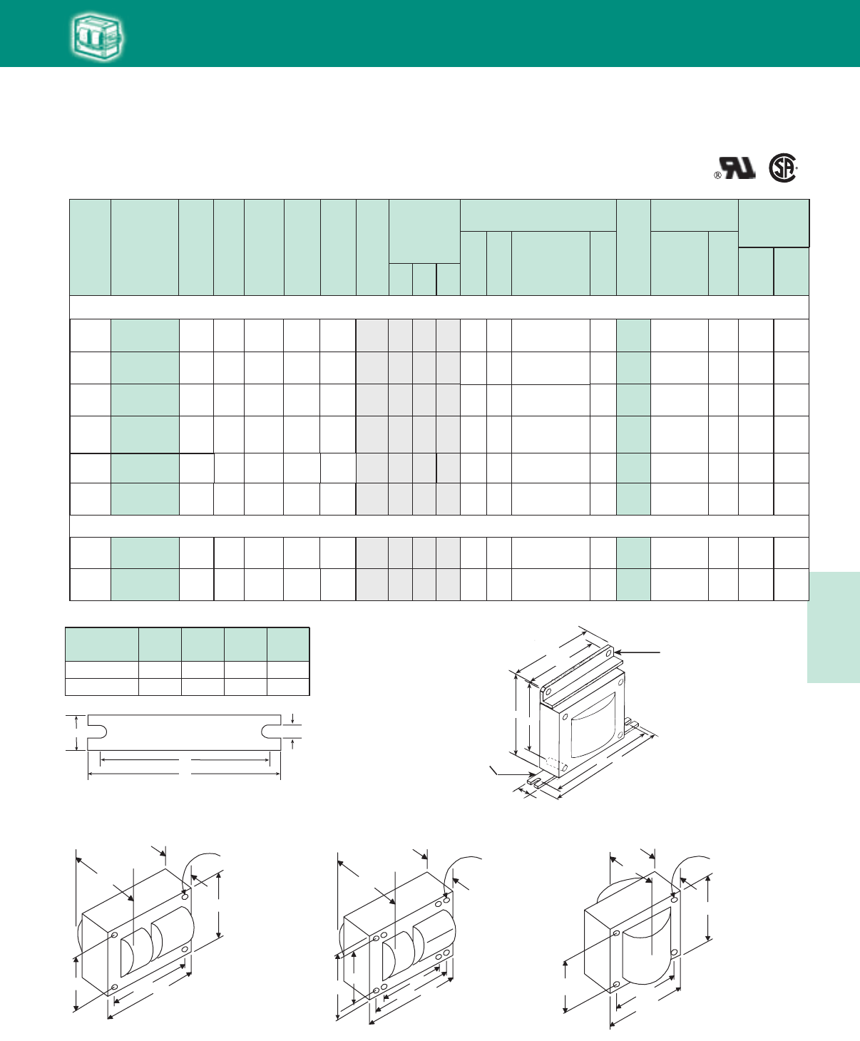
5-23
Lighting Electronics Atlas 2010-2011
HIGH INTENSITY DISCHARGE BALLASTS
41/4"43/8"
6 "
37/8"
B
MAX.
A
Fig. 8
(4 1/4" x 6" core)
8 Holes cleared for
#10 thru-bolts
53/8"
HID
60 Hz Core & Coil Ballasts
Metal Halide
WELDED BRACKET DIMENSIONS
Ballast
Dimensions Fig L W M S
2, 10 6.5 1.25 5.75 0.28
8 7.8 2.75 6.13 0.25
750W Lamp, ANSI Code M149 (Pulse-Start)
A/
A/A
277/
347/480
120/208/
240/277
71A64F2-001D Super
CWA M
818 D 17.0 LI573-H5 15 E/
E/E
8 2.3 4.3
355
3.0/
2.5/1.7
8/
7/5 28 400 7C280S40
A/
A/A
M
120/
208/240 71A64E2-500D Super
CWA 812 8 2.2 4.3 D 17.0 LI573-H5 15 D/
C/D
355
7.0/
4.0/3.5
20/
10/10 28 400 7C280S40
A/A/
A/A/
A
M
120/208/
240/277/
480
71A6452-001D Super
CWA 818 8 2.4 4.3 D 18.0 LI573-H5 15
D/C/
D/D/
C
355
7/4/
3.5/3/
2
20/10/
10/8/
5
28 400 7C280S40
A/A/
A
277/347/
480/120T 71A64F2-500DT Super
CWA M
818 D 17.0 LI573-H5 15 E/
E/E
8 2.3 4.3355
3.0/2.5/
1.7
8/7/
528 400 7C280S40
A/A
A/A
71A6490-500D Super
CWA M820 D 17.5 LI573-H5 10 D/D/
D/D
23.0 4.9
340
7.0/4.0/
3.5/3.0
20/10/
10/10 28 400 7C280S40
A/A
M
71A64F0-600T Super
CWA 820 D 17.5 LI573-H5 10 E/E
2 3.0 4.93402.5/1.7 7/5 28 400 7C280S40
A/A
347/480/
120T 21 480 MD2100-030
M
71A64F8-500T Super
CWA 945 2 3.0 5.0 O 17.5 LI572-H5★5 E/E
M
120/208/
240/277 71A6498-500 Super
CWA 940 2 3.0 5.0415
7.8/4.3
3.9/3.4
20/10/
10/8
7/54152.8/2.0
17.5 A/A/
A/A
OLI572-H5★5E/E/
E/E
21 480 MD2100-030
347/480/
120T
W
++
BRACKET
M
L
S
41/4"
43/8 "43/4"
37/8"
B
MAX.
A
Fig. 2
(41
/4" x 43
/4" core)
4 Holes cleared for
#10 thru-bolts
Fig. 2
(4¼" x 4¾" Core)
Fig. 10
(4½” x 3¾” Reactor Core)
3¾
4
3
4½
B
MAX.
A
Fig. 10
(41
/2" x 33
/4 Reactor Core )
4 Holes cleared for
#6 thru-bolts
1/
16 "
5/
16 "
"
Fig. 8, 8A
(4¼" x 6" Core)
Cap Catalog
Number
Dry
or
Oil
U.L. Bench Top
Rise Code 1029
(Pg 5-4)
Class H
(180°C)
Philips
Advance
Class N
(200°C)
Input
Volts
Catalog
Number
Circuit
Type
Input
Watts
Max
Input
Current
Nom
Open
Circuit
Voltage
Fuse
Rating
(Amps)
Fig
Dimensions
Non-PCB Capacitor
(Page 5-38 & 5-39)
Min
Volt
Total
Weight
(Ibs)
Ignitor ✝✝
(Page 5-40 to 5-44)
Part
Number
Max
Dist
To
Lamp
(ft)
A B
✝Wiring
Dia Mfd
•
◆
◆
◆
◆
HID • Core & Coil
Metal Halide
W
M
4.75
4.40
4.25 3.90
L
-540 Bracket Detail
Suffix -540D denotes a welded
angle bracket to allow linear
reactors to mount in 400W
fixtures designed for standard CWA
ballasts without brackets. This
bracket is standard on -001DEE.
Suffix -510 provides
welded-on mounting foot
875W Lamp, ANSI Code M166 (Pulse-Start)
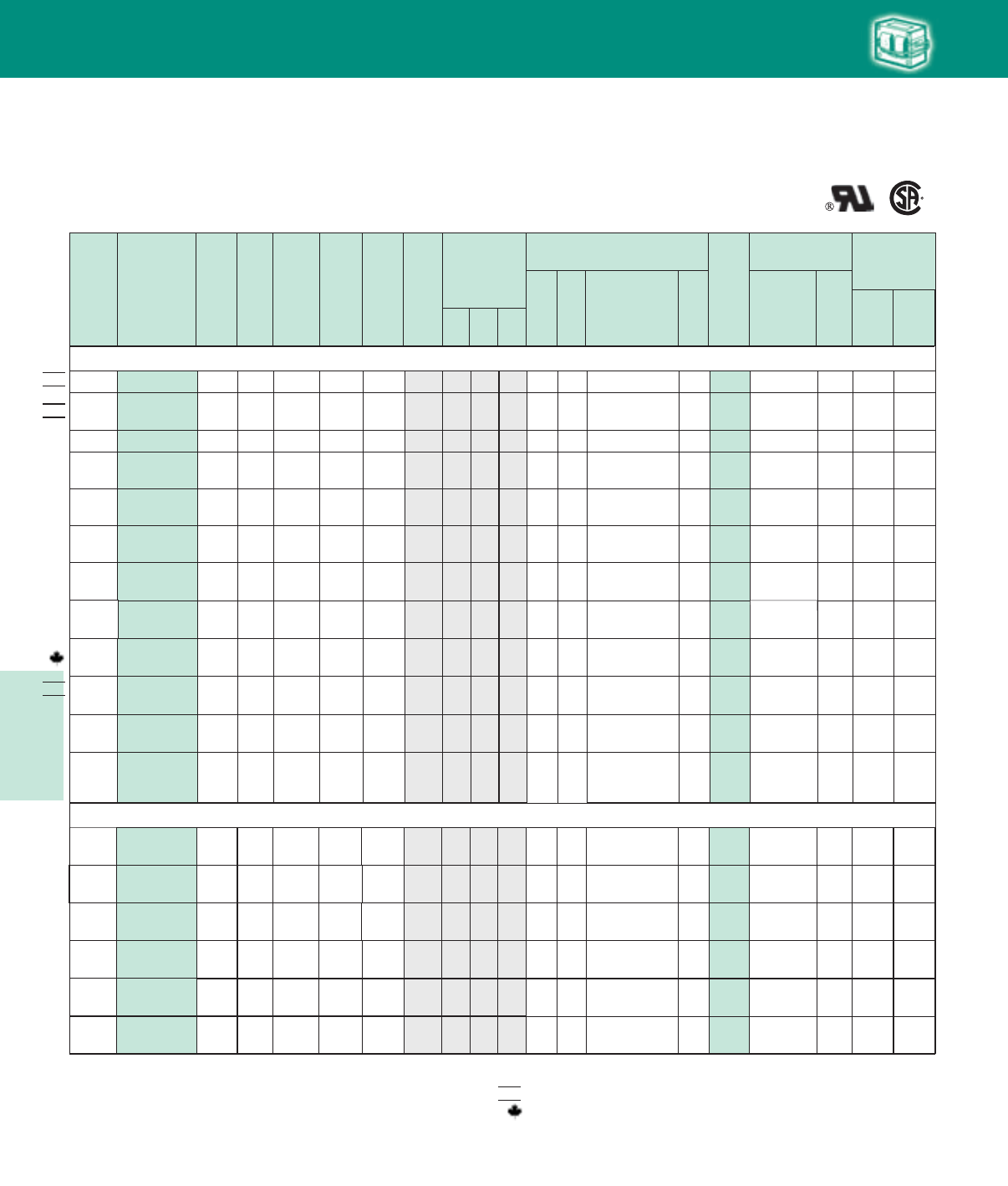
Lighting Electronics Atlas 2010-2011
5-24
HIGH INTENSITY DISCHARGE BALLASTS
60 Hz Core & Coil Ballasts
Metal Halide
1000W Lamp, ANSI Code M47
A241080 4.9 430 12 8 480 MD2409-100 O – –A 21.0
2.6 4.5 B
71A65J2-500M
220
CWA
NOM
NOM
HID
Cap Catalog
Number
Dry
or
Oil
U.L. Bench Top
Rise Code 1029
(Pg 5-4)
Class H
(180°C)
Philips
Advance
Class N
(200°C)
Input
Volts
Catalog
Number
Circuit
Type
Input
Watts
Max
Input
Current
Nom
Open
Circuit
Voltage
Fuse
Rating
(Amps)
Fig
Dimensions
Non-PCB Capacitor
(Page 5-38 & 5-39)
Min
Volt
Total
Weight
(Ibs)
Ignitor ✝✝
(Page 5-40 to 5-44)
Part
Number
Max
Dist
To
Lamp
(ft)
A B
✝•Wiring
Dia Mfd
A
71A6542-001 CWA 1080 2.2 430 6 8 2.6 4.5 24 480 MD2409-100 O 21.0 – – DA
480/120T
NOM
A/A
208/240
120T 71A65E6-500DT CWI 1080 5.3/4.8 440 15/12 8 3.5 5.3 D 25.0 – – C/DP 7C400P30-R
(Two in Series)
20 560
347/480/
120T
347/480/
120T
1000W Lamp, ANSI Code M141 (Pulse-Start)
A/A
24 440 MD2409-000
M
71A65F3-500T Super
CWA 1075 8 2.8 4.5 O 21.0 LI571-H5★5 D/D
8/64303.2/2.4
A/A/
A/A
M
120/208/
240/277
71A6593-500
71A6593-001
Super
CWA 1080 8 2.8 4.5 O 21.0 LI571-H5★5D/B/
B/B
430
9.0/5.2/
4.5/3.9
20/15/
10/10 24 480 MD2409-000
A/A/
A/A
A
A
24 480 MD2409-000
M
71A6553-500 Super
CWA 1080 8 3.0 4.7 O 22.0 LI572-H5★5
D/B/
B/B
B
M
480 71A6543-500A Super
CWA 1080 8 3.1 5.0 O 21.0 LI572-H5★5 D
4302.3 6
22/15/
12/10/
6
430
9.1/5.6/
4.7/4.1/
2.4
24 480 MD2409-000
A/A/
A/A
24 480 MD2409-000
M
71A6591-500 Super
CWA 1070 2 3.4 5.3 O19.0 LI572-H5★5D/D/
D/D
120/208/
240/277
20/15/
10/10
415
9.0/5.2/
4.5/3.9
A/A
24 480 MD2409-000
M
71A65F1-500T Super
CWA 1070 2 3.4 5.3 O19.0 LI572-H5★5 D/D
8/6
415
3.1/2.2
120/208/
240/277/
480
A241080 2.2 430 6 8 480 MD2409-100 O – –A 21.0
2.6 4.5 D
71A6542-500T
480/120T
CWA
A
71A6542-500TA CWA 1080 2.3 430 6 8 3.1 5.0 24 480 MD2409-100 O 21.0 – – DA
480/120T
A/A/
A/A
71A6592-500 CWA 1080 9.0/5.2/
4.5/3.9 430 20/15/
10/10 8 2.6 4.5 24 480 MD2409-100 O 21.0 – – D/B/
B/B
A
120/208
240/277
A/A/
A/A
71A6592-500A CWA 1080 9.0/5.2/
4.5/3.9 430 20/15/
10/10 8 3.1 5.0 24 480 MD2409-100 O 20.0 – – D/B/
B/B
A
120/208
240/277
A/A/
A/A
71A6572-001 CWA 1080 9.0/5.2/
4.5/3.9 430 20/15/
10/10 8 2.6 4.5 24 480 MD2409-100 O 21.0 – – D/B/
B/B
A
A/A/
A/A
A
120/208/
240/277/
480
71A6552-500
71A6552-001 CWA 1080
9.0/5.6/
4.7/4.1/
2.4 430
22/15/
12/10/
683.0 4.7 24 480 MD2409-100 O 22.0
–
–
D/D/
D/C
C
A
120/208
240/277
A/
A/A
A/A/
A/A
120/
277/347
71A65A2-500
71A65A2-001 CWA 1080 9.0/
3.9/3.2 430 20/
10/8 8 2.8 4.5 24 480 MD2409-100 O 21.0 – – D/
C/C
A
71A6590-500 CWA 1070 9.0/5.2/
4.5/3.9 415 20/15/
10/10 23.4 5.3 24 480 MD2409-100 O19.0 – – D/D/
D/D
A
A/A
347/480/
120T 71A65F0-600T CWA 1070 3.1/2.2 415 8/6 2 3.4 5.3 24 480 MD2409-100 O 19.0 – – D/DA
120/208
240/277
✝ Ordering information:
Replacement/retrofit ballast kits – indicated by bold type and -001D or -001 suffix.
Refer to pages 5-5 to 5-9 for more information on replacement kits.
Original equipment ballasts – typically ordered with capacitor (as shown).
-500D includes core & coil with dry-film capacitor.
-500 includes core & coil with oil-filled capacitor (required for higher wattage ballasts).
May also be available with welded bracket, and/or without capacitor:
-510D includes core & coil with welded bracket and dry-film capacitor.
-510 includes core & coil with welded bracket and oil-filled capacitor.
-600 core & coil only (no capacitor).
-610 core & coil with welded bracket (no capacitor).
✝✝ Each ballast requiring an ignitor is furnished standard with a short-range ignitor model
shown for use within fixtures. long-range ignitors are available separately if required.
See pages 5-xx to 5-yy for additional information.
• Maximum Input Current – For HX and R circuits, value is the highest of starting, operating
or open circuit current. For CWA, SCWA and CWI circuits, value is the operating current.
Certified ballast available for Mexican market. Add “M” to suffix (example: -500DM).
Canadian replacement/retrofit ballast kit indicated by bold type. Refer to page 5-9.
◆ Special compact 4¼ x 4¾ core design
◆
◆
◆
◆
NOM
HID • Core & Coil
Metal Halide
5-25
Lighting Electronics Atlas 2010-2011
HIGH INTENSITY DISCHARGE BALLASTS
Cap Catalog
Number
Dry
or
Oil
U.L. Bench Top
Rise Code 1029
(Pg 5-4)
Class H
(180°C)
Philips
Advance
Class N
(200°C)
Input
Volts
Catalog
Number
Circuit
Type
Input
Watts
Max
Input
Current
Nom
Open
Circuit
Voltage
Fuse
Rating
(Amps)
Fig
Dimensions
Non-PCB Capacitor
(Page 5-38 & 5-39)
Min
Volt
Total
Weight
(Ibs)
Ignitor ✝✝
(Page 5-40 to 5-44)
Part
Number
Max
Dist
To
Lamp
(ft)
A B
✝•Wiring
Dia Mfd
HID
60 Hz Core & Coil Ballasts
Metal Halide
Fig. 8, 8A
(4¼" x 6" Core)
41/4"43/8"
6 "
37/8"
B
MAX.
A
Fig. 8
(4 1/4" x 6" core)
8 Holes cleared for
#10 thru-bolts
53/8"
1500W Lamp, ANSI Code M48
A480 71A6742-610
71A6742-001 CWA 1625 3.4 450 10 8a 4.2 6.2 32 525 MD3202-100 O 31.0 – –EA
A
480/120T 71A6742-500A CWA 1610 3.5 460 10 8a 4.7 6.7 32 525 MD3202-100 O 30.0 – – EA
C/A/
A/C
71A6792-500 CWA 1605 13.5/7.8/
6.8/5.9 450 30/25/
20/15 8a 4.1 32 525 MD3202-100 O 30.0 – – G/E/
E/G
120/208
240/277 A 6.1
C/A/
A/C
71A6792-500A CWA 1610 13.5/7.8/
6.8/5.9 460 30/25/
20/15 8a 4.7 32 525 MD3202-100 O 30.0 – – G/E/
E/G
120/208
240/277 A 6.7
NOM C/A/
A/C
120/208
240/277 71A6772-001 CWA 1605 13.5/7.8/
6.8/5.9 450 30/25/
20/15 8a 4.1 32 525 MD3202-100 O 30.0 – – G/E/
E/G
A 6.1
41/4"
43/8 "43/4"
37/8"
B
MAX.
A
Fig. 2
(41
/4" x 43
/4" core)
4 Holes cleared for
#10 thru-bolts
Fig. 2
(4¼" x 4¾" Core)
1650W Lamp, ANSI Code M112
O
C/
C/C
120/
277/347
71A67A2-600
71A67A2-001 CWA 1615 13.5/
5.9/4.8 450 30/
15/15 8a 4.1 32 525 MD3202-100 O 30.0 – – G/
G/G
A 6.1
E/F347/480 71A68F0-600 CWA 1770 5.5/4.0 465 15/10 8a 4.4 – – I/JA 32.06.5 34 550
2 Capacitor Set:
MD1701-200
(2) 17 MFD Caps
Connected in Parallel
[ ]
WELDED BRACKET DIMENSIONS
Ballast
Dimensions Fig L W M S
2 6.5 1.25 5.75 0.28
8 7.8 2.75 6.13 0.25
8a 7.8 4.50 6.75 0.31
W
++
BRACKET
M
L
S
Fig. M Fig. P
Fig. A
Fig. A
LAMP
LAMP
LINE V
COM COM
LINE V
LINE V
LINE V
CAP
CAP
Fig. M
LAMP
CAP
LAMP
COM COM
LINE V
LINE V
LINE V
IGNITOR
X1X3
X2
LINE V
CAPCAP
Fig. P
LAMP 1
LAMP
LINE V
COM
LINE V
LINE V
CAP
CAP
LAMP 2
HID • Core & Coil
Metal Halide
Lighting Electronics Atlas 2010-2011
5-26
HIGH INTENSITY DISCHARGE BALLASTS
Cap Catalog
Number
Dry
or
Oil
Input
Volts
Catalog
Number
Circuit
Type
Input
Watts
Max
Input
Current
Nom
Open
Circuit
Voltage
Fuse
Rating
(Amps)
Fig
Dimensions
Non-PCB Capacitor
(Page 5-38 & 5-39)
Mfd Min
Volt
Total
Weight
(lbs)
Ignitor ✝✝
(Page 5-40 to 5-44)
Part
Number
Max
Dist
To
Lamp
(ft)
U.L.
Bench
Top
Rise
Code
1029
(pg 5-4)
A B
✝
•
Wiring
Dia
HID
60 Hz Core & Coil Ballasts
High Pressure Sodium
35W Lamp, ANSI Code S76
120 71A7707-600
71A7707-500D
R-NPF
R-HPF 46 1.4
.8 120 3
29 .7 1.8 –
14
–
120
––––—
7C140L12RA
–
D
1.3
1.5 LI551-H4 2 A
120 71A7707-600B
71A7707-001DB
R-NPF
R-HPF 46 1.4
.8 120 3
29 .7 2.2 –
14 –120 ––––—
7C140L12RA
–
D
1.3
1.5
Integral
Ignitor 2 A
G
H
Fig. G
COM
LAMP
CAP
(OPTIONAL)
IGNITOR
LAMP
X3
X1
X2
LINE V
Fig. H
COM
LAMP
CAP
IGNITOR
LAMP
LINE V
INTEGRATED
IGNITOR BALLAST
Fig. G
Fig. H Fig. K
Fig. K
LAMP
CAPLAMP
COM COM
LINE V
LINE V
COM
LINE V
CAP
LINE V
IGNITOR
X1X3
X2
✝ Ordering information:
Replacement/retrofit ballast kits – indicated by bold type and -001D or -001 suffix.
Refer to pages 5-5 to 5-9 for more information on replacement kits.
Original equipment ballasts – typically ordered with capacitor (as shown).
-500D includes core & coil with dry-film capacitor.
-500 includes core & coil with oil-filled capacitor (required for higher wattage ballasts).
May also be available with welded bracket, and/or without capacitor:
-510D includes core & coil with welded bracket and dry-film capacitor.
-510 includes core & coil with welded bracket and oil-filled capacitor.
-600 core & coil only (no capacitor).
-610 core & coil with welded bracket (no capacitor).
✝✝ Each ballast requiring an ignitor is furnished standard with a short-range ignitor model
shown for use within fixtures. long-range ignitors are available separately if required.
See pages 5-xx to 5-yy for additional information.
• Maximum Input Current – For HX and R circuits, value is the highest of starting, operating
or open circuit current. For CWA, SCWA and CWI circuits, value is the operating current.
Certified ballast available for Mexican market. Add “M” to suffix (example: -500DM).
Canadian replacement/retrofit ballast kit indicated by bold type. Refer to page 5-9.
NOM
HID • Core & Coil
HPS
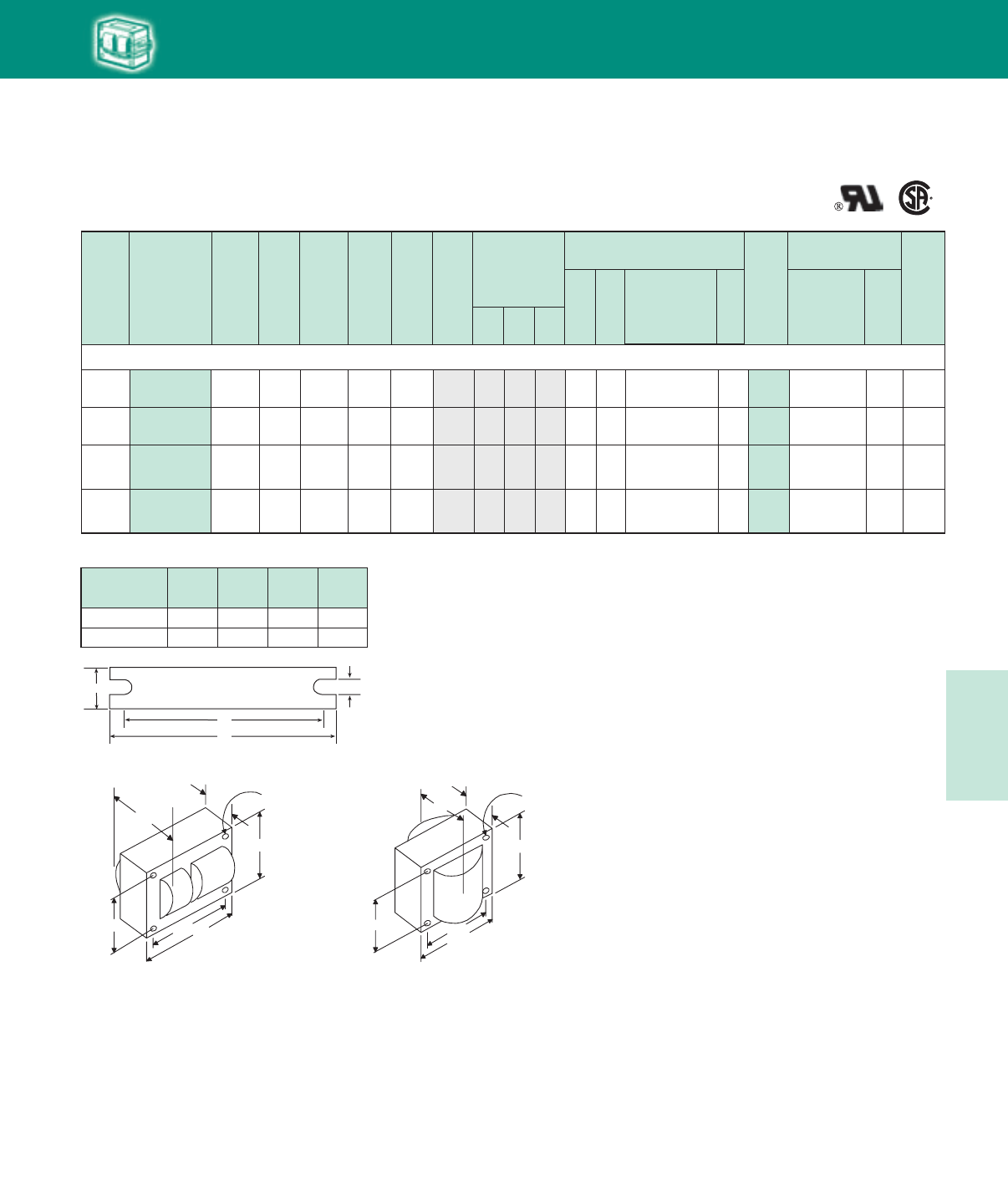
5-27
Lighting Electronics Atlas 2010-2011
HIGH INTENSITY DISCHARGE BALLASTS
Cap Catalog
Number
Dry
or
Oil
Input
Volts
Catalog
Number
Circuit
Type
Input
Watts
Max
Input
Current
Nom
Open
Circuit
Voltage
Fuse
Rating
(Amps)
Fig
Dimensions
Non-PCB Capacitor
(Page 5-38 & 5-39)
Mfd Min
Volt
Total
Weight
(lbs)
Ignitor ✝✝
(Page 5-40 to 5-44)
Part
Number
Max
Dist
To
Lamp
(ft)
U.L.
Bench
Top
Rise
Code
1029
(pg 5-4)
A B
✝
•
Wiring
Dia
HID
60 Hz Core & Coil Ballasts
High Pressure Sodium
WELDED BRACKET DIMENSIONS
Ballast
Dimensions Fig L W M S
1 5.1 1.00 4.50 0.25
9 4.0 0.75 3.50 0.28
120 71A7807-610
71A7807-500D
R-NPF
R-HPF 62 1.8
1.0 120 5
39 1.0 2.3 –
20 –
120
––––—
7C200M12RA
–
D
1.8
2.0 LI551-H4 2 A
120 71A7807-600B
71A7807-001DB
R-NPF
R-HPF 62 1.8
1.0 120 5
39 1.0 2.7 –
20
–
120
––––—
7C200M12RA
–
D
1.8
2.0 Integral Ignitor 2 A
50W Lamp, ANSI Code S68
120/277 71A7801-500D
71A7801-001D HX-HPF 66 1.0/.5 125 3/1 1 1.0 2.2 5 300 7C050L33RA D 3.5 LI551-H4 2 A/AK
G
H
120/208/
240/277
71A7891-500D
71A7891-001D HX-HPF 66 1.0/.57/
.5/.45 125 3/2/
2/1 1 1.0 2.2 5 300 7C050L33RA D 3.5 LI551-H4 2 A/A
A/A
K
Fig. 1
(3" x 4" Core)
Fig. 9
(25/8” x 23/16” Reactor Core)
W
++
BRACKET
M
L
S
213/16"
31/2"315/16"
27/16"
B
MAX.
A
Fig. 1
(3" x 4" core)
4 Holes cleared for
#10 thru-bolts
23/16"
23/16"
25/8"
13/4"
B
MAX.
A
Fig. 9
(2 5/8" x 2 3/1 6 Reactor Core)
4 Holes cleared for
#6 thru-bolts
HID • Core & Coil
HPS
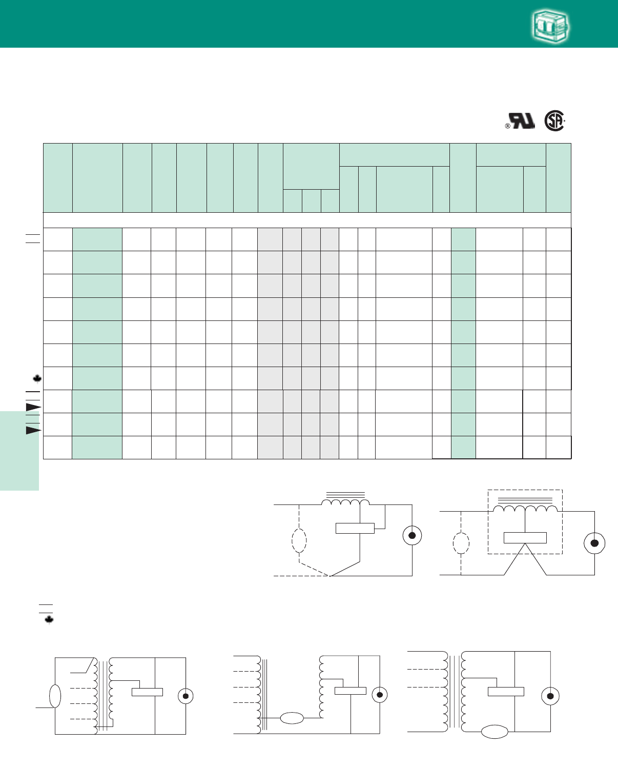
Lighting Electronics Atlas 2010-2011
5-28
HIGH INTENSITY DISCHARGE BALLASTS
Cap Catalog
Number
Dry
or
Oil
Input
Volts
Catalog
Number
Circuit
Type
Input
Watts
Max
Input
Current
Nom
Open
Circuit
Voltage
Fuse
Rating
(Amps)
Fig
Dimensions
Non-PCB Capacitor
(Page 5-38 & 5-39)
Mfd Min
Volt
Total
Weight
(lbs)
Ignitor ✝✝
(Page 5-40 to 5-44)
Part
Number
Max
Dist
To
Lamp
(ft)
U.L.
Bench
Top
Rise
Code
1029
(pg 5-4)
A B
✝
•
Wiring
Dia
HID
60 Hz Core & Coil Ballasts
High Pressure Sodium
NOM
70W Lamp, ANSI Code S62
120 71A7907-600
71A7907-500D
R-NPF
R-HPF 86 2.1
1.3 120 8
39 1.3 2.5 –
28
–
120
––––—
7C280M12RA
–
D2.0 LI551-H4 2 A
120 71A7907-600B
71A7907-001DB
R-NPF
R-HPF 86 2.1
1.3 120 8
39 1.3 2.9 –
28
–
120
––––—
7C280M12RA
–
D2.0 Integral
Ignitor 2 A
G
H
220 71A79J1-500D HX-HPF 91 .8 120 2 1 1.5 2.8 7 300 7C070L30RA D 5.5 LI551-H4 2 AK
480 71A7941-500D HX-HPF 93 .4 120 2 1 1.9 3.2 7 300 7C070L30RA D 6.5 LI551-H4 2 AK
71A7991-500D HX-HPF 91 1.4/.9
.8/.7 120 5/3/
2/2 1 1.5 3.1 7 300 7C070L30RA D 5.5 B/C/
B/C
LI551-H4 2
LI551-H4 2
71A7971-001D
HX-HPF 91 1.4/.9
.8/.7 120 5/3/
2/2 1 1.5 3.1 7 300 7C070L30RA D 5.5 B/C/
B/C
LI551-H4 2
120/
277/347
71A79A1-500D
71A79A1-001D HX-HPF 93 1.4/
.7/.6 120 5/
2/2 1 1.5 3.1 7 300 7C070L30RA D 5.5 A/
B/A
K
K
K
120/208
240/277
120/208
240/277
120/
208/240 71A79E6-500D CWI 95 .9/
.5/.5 110 3/
2/2 1 1.6 2.9 24 300 7C240P30RA D 5.8 LI551-J4 2 C/
C/D
V
NOM LI551-J4 2
127/220 71A79H8-500DMA CWA 95 .8/.5 105 2/2 1 1.9 3.2 32.5 300 7C325P30-RA D 5.5 A/D
M
New
NOM LI551-J4 2
120/277 71A7988-500D CWA 95 .9/.4 105 3/1 1 1.9 3.2 32.5 300 7C325P30-RA D 5.5 A/D
M
New
Fig. V
LAMP 1
CAP
LAMP
COM
LINE V
LINE V
LINE V
IGNITOR
X1X3
X2
LAMP 2CAP
Fig. G
COM
LAMP
CAP
(OPTIONAL)
IGNITOR
LAMP
X3
X1
X2
LINE V
Fig. K
LAMP
CAPLAMP
COM COM
LINE V
LINE V
COM
LINE V
CAP
LINE V
IGNITOR
X1X3
X2
Fig. H
COM
LAMP
CAP
IGNITOR
LAMP
LINE V
INTEGRATED
IGNITOR BALLAST
Fig. G
Fig. K
Fig. H
Fig. M Fig. V
Fig. M
LAMP
CAP
LAMP
COM COM
LINE V
LINE V
LINE V
IGNITOR
X1X3
X2
LINE V
CAPCAP
✝ Ordering information:
Replacement/retrofit ballast kits – indicated by bold type and -001D or -001 suffix.
Refer to pages 5-5 to 5-9 for more information on replacement kits.
Original equipment ballasts – typically ordered with capacitor (as shown).
-500D includes core & coil with dry-film capacitor.
-500 includes core & coil with oil-filled capacitor (required for higher wattage ballasts).
May also be available with welded bracket, and/or without capacitor:
-510D includes core & coil with welded bracket and dry-film capacitor.
-510 includes core & coil with welded bracket and oil-filled capacitor.
-600 core & coil only (no capacitor).
-610 core & coil with welded bracket (no capacitor).
✝✝ Each ballast requiring an ignitor is furnished standard with a short-range ignitor model
shown for use within fixtures. long-range ignitors are available separately if required.
See pages 5-xx to 5-yy for additional information.
• Maximum Input Current – For HX and R circuits, value is the highest of starting, operating
or open circuit current. For CWA, SCWA and CWI circuits, value is the operating current.
Certified ballast available for Mexican market. Add “M” to suffix (example: -500DM).
Canadian replacement/retrofit ballast kit indicated by bold type. Refer to page 5-9.
NOM
HID • Core & Coil
HPS
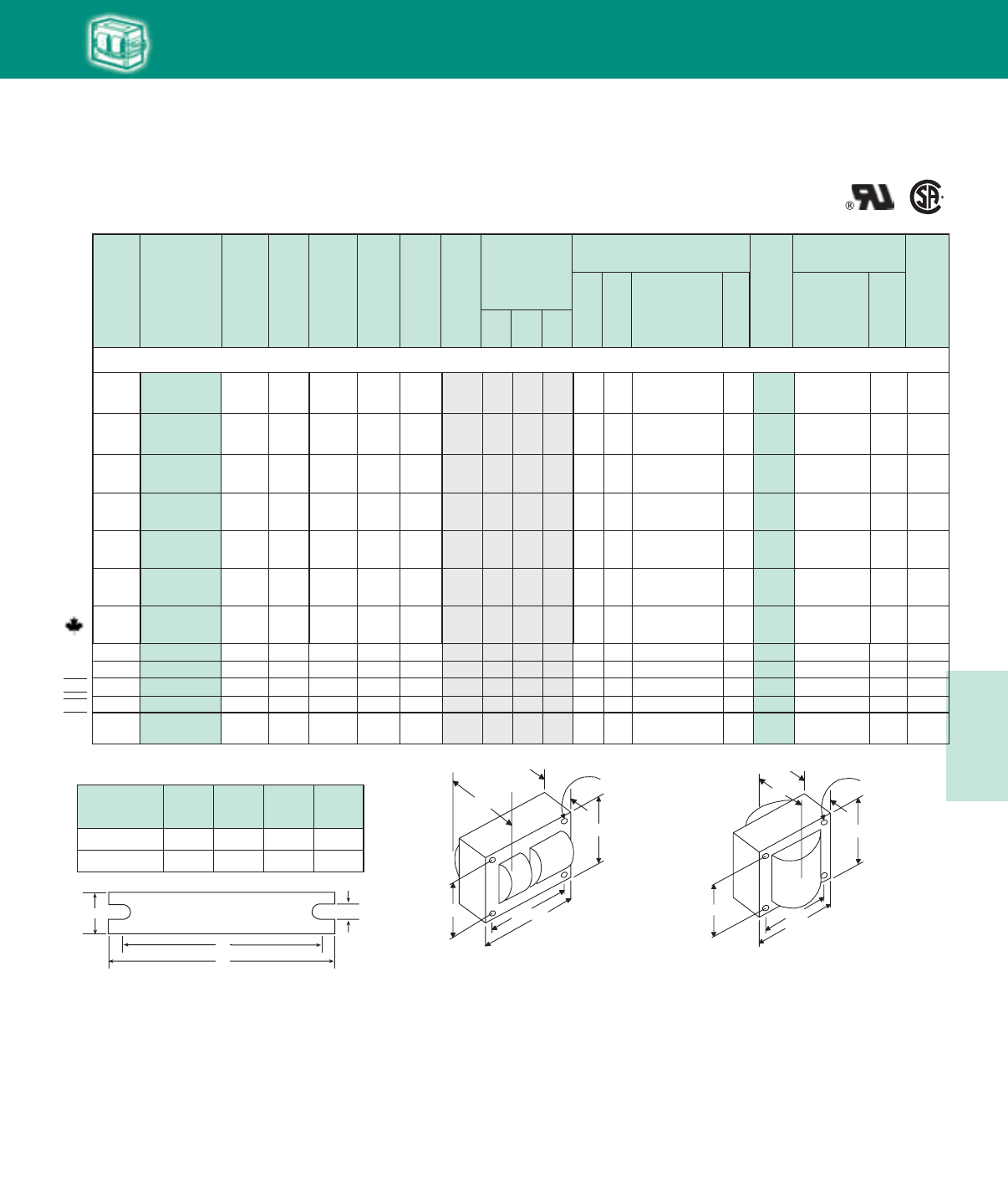
5-29
Lighting Electronics Atlas 2010-2011
HIGH INTENSITY DISCHARGE BALLASTS
127/220 71A80H8-500DMA CWA 138 1.1/.7 115 3/2 M1 2.4 3.7 34 170 7C340P24RA D LI551-J4 5 E/D
230 71A80J8-500DM CWA 136 0.7 118 2 M12.0 3.3 34 D LI551-J4 5 E170 7C350P24RA
NOM
120/208/
240/277 71A8091-500D HX-HPF 130 2.2/1.3/
1.1/.9 120 7/5/
3/3 1 2.0 3.6 10 280 7C100M30RA D 7.2 LI551-H4 2 D/F/
D/D
120/208/
240/277 71A8071-001D HX-HPF 130 2.2/1.3/
1.1/.9 120 7/5/
3/3 1 2.0 3.6 10 280 7C100M30RA D 7.2 LI551-H4 2 D/F/
D/D
480 71A8041-500D
71A8041-001D HX-HPF 130 .6 120 3 1 2.3 3.6 10 280 7C100M30RA D 7.5 LI551-H4 2 EK
K
K
Cap Catalog
Number
Dry
or
Oil
Input
Volts
Catalog
Number
Circuit
Type
Input
Watts
Max
Input
Current
Nom
Open
Circuit
Voltage
Fuse
Rating
(Amps)
Fig
Dimensions
Non-PCB Capacitor
(Page 5-38 & 5-39)
Mfd Min
Volt
Total
Weight
(lbs)
Ignitor ✝✝
(Page 5-40 to 5-44)
Part
Number
Max
Dist
To
Lamp
(ft)
U.L.
Bench
Top
Rise
Code
1029
(pg 5-4)
A B
✝
•
Wiring
Dia
HID
60 Hz Core & Coil Ballasts
High Pressure Sodium
120 71A8007-500D R-HPF 115 1.8 120 5 9 1.5 2.7 36 120 7C360M12RA D 2.8 LI551-H4 2 AG
220 71A80J1-500D HX-HPF 130 1.2 120 3 1 2.0 3.3 10 280 7C100M30RA D 7.2 LI551-H4 2 BK
120 71A8007-500DB
71A8007-001DB R-HPF 115 1.8 120 5 9 1.5 2.7 36 120 7C360M12RA D 2.8 Integral
Ignitor 2 AH
120/
208/240 71A80E6-500D CWI 130 1.2/
.7/.6 110 3/
2/2 V 1 2.1 3.4 35 D LI551-J4 2 C/
C/B
170 7C350P24RA
NOM
120/
277/347
71A80A1-500D
71A80A1-001D HX-HPF 130 2.2/
.9/.7 120 7/
3/3 1 2.3 3.6 10 280 7C100M30RA D 7.5 LI551-H4 2 C/
C/D
K
480/120T 71A8048-500DT CWA 138 0.3 115 1 M1 2.0 3.3 34 170 7C340P24RA D
7.5
7.5
6.8
120/277 71A8088-500D CWA 138 1.2/.5 115 3/2 M1 2.0 3.3 34 170 7C340P24RA D LI551-J4 5 F/F
7.5
7.5 LI551-J4 5 E
100W Lamp, ANSI Code S54
Fig. 1
(3" x 4" Core)
Fig. 9
(25/8” x 23/16” Reactor Core)
213/16"
31/2"315/16"
27/16"
B
MAX.
A
Fig. 1
(3" x 4" core)
4 Holes cleared for
#10 thru-bolts
23/16"
23/16"
25/8"
13/4"
B
MAX.
A
Fig. 9
(2 5/8" x 2 3/1 6 Reactor Core)
4 Holes cleared for
#6 thru-bolts
WELDED BRACKET DIMENSIONS
Ballast
Dimensions Fig L W M S
1 5.1 1.00 4.50 0.25
9 4.0 0.75 3.50 0.28
W
++
BRACKET
M
L
S
HID • Core & Coil
HPS
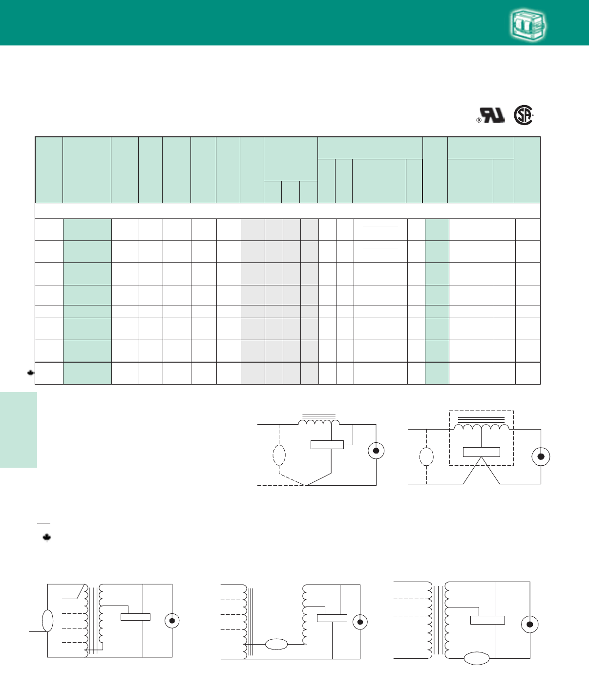
Lighting Electronics Atlas 2010-2011
5-30
HIGH INTENSITY DISCHARGE BALLASTS
Cap Catalog
Number
Dry
or
Oil
Input
Volts
Catalog
Number
Circuit
Type
Input
Watts
Max
Input
Current
Nom
Open
Circuit
Voltage
Fuse
Rating
(Amps)
Fig
Dimensions
Non-PCB Capacitor
(Page 5-38 & 5-39)
Mfd Min
Volt
Total
Weight
(lbs)
Ignitor ✝✝
(Page 5-40 to 5-44)
Part
Number
Max
Dist
To
Lamp
(ft)
U.L.
Bench
Top
Rise
Code
1029
(pg 5-4)
A B
✝
•
Wiring
Dia
HID
60 Hz Core & Coil Ballasts
High Pressure Sodium
150W Lamp, ANSI Code S55 (55V Arc Tube)
220 71A81J2-500D HX-HPF 188 1.5 120 4 1 2.6 3.8 14 280 7C140M30RA D 7.5 LI551-H4 2 CK
120
71A8107-600
71A8107-500D
R-NPF
R-HPF 170 4.5
2.4 120 15
89 2.0 3.3 –
55
–
120
7C550P12RA
–
D
3.5
4.0 LI551-H4 2 AG
120 71A8107-600B
71A8107-001DB
R-NPF
R-HPF 170 4.5
2.4 120 15
89 2.0 3.6 –
55
–
120
7C550P12RA
–
D
3.5
4.0 Integral Ignitor 2 AH
120/208/
240/277 71A8192-500D HX-HPF 188 2.8/1.6/
1.4/1.3 120 10/5/
5/4 1 2.6 3.8 14 280 7C140M30RA D 7.5 LI551-H4 2 E/D/
E/D
120/208/
240/277
71A8172-001D
HX-HPF 188 2.8/1.6/
1.4/1.3 120 10/5/
5/5 1 2.6 3.8 14 280 7C140M30RA D 7.5 LI551-H4 2 E/D/
E/D
480
480/120T
71A8142-510D
71A8142-001D
71A8142-500DT
HX-HPF
HX-HPF
188
188
0.7
0.7
120
120
2
2
1
1
3.0
3.0
4.3
4.3
14
14
280
280
7C140M30RA
7C140M30RA
D
D
9.0
9.0
LI551-H4
LI551-H4
2
2
E
E
K
K
K
K
120/
277/347
71A81A2-500D
71A81A2-001D
HX-HPF 188
2.8/
1.3/.9
120 10/
4/3 1 2.6 3.8 14 280 7C140M30RA D 7.5 LI551-H4 2 D/
D/D
K
Fig. G
COM
LAMP
CAP
(OPTIONAL)
IGNITOR
LAMP
X3
X1
X2
LINE V
Fig. K
LAMP
CAPLAMP
COM COM
LINE V
LINE V
COM
LINE V
CAP
LINE V
IGNITOR
X1X3
X2
Fig. H
COM
LAMP
CAP
IGNITOR
LAMP
LINE V
INTEGRATED
IGNITOR BALLAST
Fig. G Fig. H
Fig. K
✝ Ordering information:
Replacement/retrofit ballast kits – indicated by bold type and -001D or -001 suffix.
Refer to pages 5-5 to 5-9 for more information on replacement kits.
Original equipment ballasts – typically ordered with capacitor (as shown).
-500D includes core & coil with dry-film capacitor.
-500 includes core & coil with oil-filled capacitor (required for higher wattage ballasts).
May also be available with welded bracket, and/or without capacitor:
-510D includes core & coil with welded bracket and dry-film capacitor.
-510 includes core & coil with welded bracket and oil-filled capacitor.
-600 core & coil only (no capacitor).
-610 core & coil with welded bracket (no capacitor).
✝✝ Each ballast requiring an ignitor is furnished standard with a short-range ignitor model
shown for use within fixtures. long-range ignitors are available separately if required.
See pages 5-xx to 5-yy for additional information.
• Maximum Input Current – For HX and R circuits, value is the highest of starting, operating
or open circuit current. For CWA, SCWA and CWI circuits, value is the operating current.
Certified ballast available for Mexican market. Add “M” to suffix (example: -500DM).
Canadian replacement/retrofit ballast kit indicated by bold type. Refer to page 5-9.
LL Special high efficiency/ low-loss ballast
NOM
Fig. M Fig. V
Fig. M
LAMP
CAP
LAMP
COM COM
LINE V
LINE V
LINE V
IGNITOR
X1X3
X2
LINE V
CAPCAP
Fig. V
LAMP 1
CAP
LAMP
COM
LINE V
LINE V
LINE V
IGNITOR
X1X3
X2
LAMP 2CAP
HID • Core & Coil
HPS
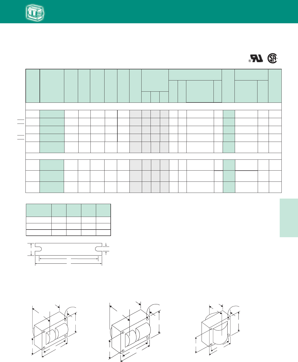
5-31
Lighting Electronics Atlas 2010-2011
HIGH INTENSITY DISCHARGE BALLASTS
Cap Catalog
Number
Dry
or
Oil
Input
Volts
Catalog
Number
Circuit
Type
Input
Watts
Max
Input
Current
Nom
Open
Circuit
Voltage
Fuse
Rating
(Amps)
Fig
Dimensions
Non-PCB Capacitor
(Page 5-38 & 5-39)
Mfd Min
Volt
Total
Weight
(lbs)
Ignitor ✝✝
(Page 5-40 to 5-44)
Part
Number
Max
Dist
To
Lamp
(ft)
U.L.
Bench
Top
Rise
Code
1029
(pg 5-4)
A B
✝
•
Wiring
Dia
60 Hz Core & Coil Ballasts
High Pressure Sodium
NOM
LL
150W Lamp, ANSI Code S55 (55V Arc Tube)
LI551-J4 10120/277 71A8188-500D CWA 190 1.7/.7 110 5/3 1 2.8 4.1 55 170 7C550P24RA D 8.5 E/DM
LI551-J4 10127/220 71A81H8-500DMA CWA 190
1.6/.9
110 4/2 1 3.0 4.3 55 170 7C550P24RA D 8.5 D/CM
LI551-J4 10480 71A8148-500D CWA 190
.5
110 11 2.5 3.8 55 170 7C550P24RA D 8.0 EM
NOM LI551-J4 2220/240 71A81J9-500DM CWA 170 0.8/0.7 111 2/2 2 2.5 3.8 60 240 7C600P24RA D 13.5 A/AM
120/
208/240 71A81E6-500D CWI 190 1.7/
1.1/.8 105 5/
3/3 1 2.6 4.0 52 240 7C520P24RA D 8.5 LI551-J4 2V
150W Lamp, ANSI Code S56 (100V Arc Tube)
LI501-H4 2
480 71A8146-500D
71A8146-001D CWA 188 0.5 180 21 2.5 3.8 20 280 7C200P30RA D 8.5 B
M
71A8196-500D CWA 188 1.7/1.0
.9/.8 180 5/3/
3/3 1 2.5 4.1 20 280 7C200P30RA D 8.5 E/D/
C/C
LI501-H4 2
LI501-H4 2
71A8176-001D CWA 188 1.7/1.0
.9/.8 180 5/3/
3/3 1 2.5 4.1 20 280 7C200P30RA D 8.5 E/D/
C/C
M
M
E/
E/D
120/208
240/277
120/208
240/277
HID
Fig. 2
(4¼” x 4¾” Core)
Fig. 1
(3" x 4" Core)
Fig. 9
(25/8” x 23/16” Reactor Core)
WELDED BRACKET DIMENSIONS
Ballast
Dimensions Fig L W M S
1 5.1 1.00 4.50 0.25
2 6.5 1.25 5.75 0.28
9 4.0 0.75 3.50 0.28
W
++
BRACKET
M
L
S
213/16"
31/2"315/16"
27/16"
B
MAX.
A
Fig. 1
(3" x 4" core)
4 Holes cleared for
#10 thru-bolts
23/16"
23/16"
25/8"
13/4"
B
MAX.
A
Fig. 9
(2 5/8" x 2 3/1 6 Reactor Core)
4 Holes cleared for
#6 thru-bolts
41/4"
43/8 "43/4"
37/8"
B
MAX.
A
Fig. 2
(41
/4" x 43
/4" core)
4 Holes cleared for
#10 thru-bolts
HID • Core & Coil
HPS
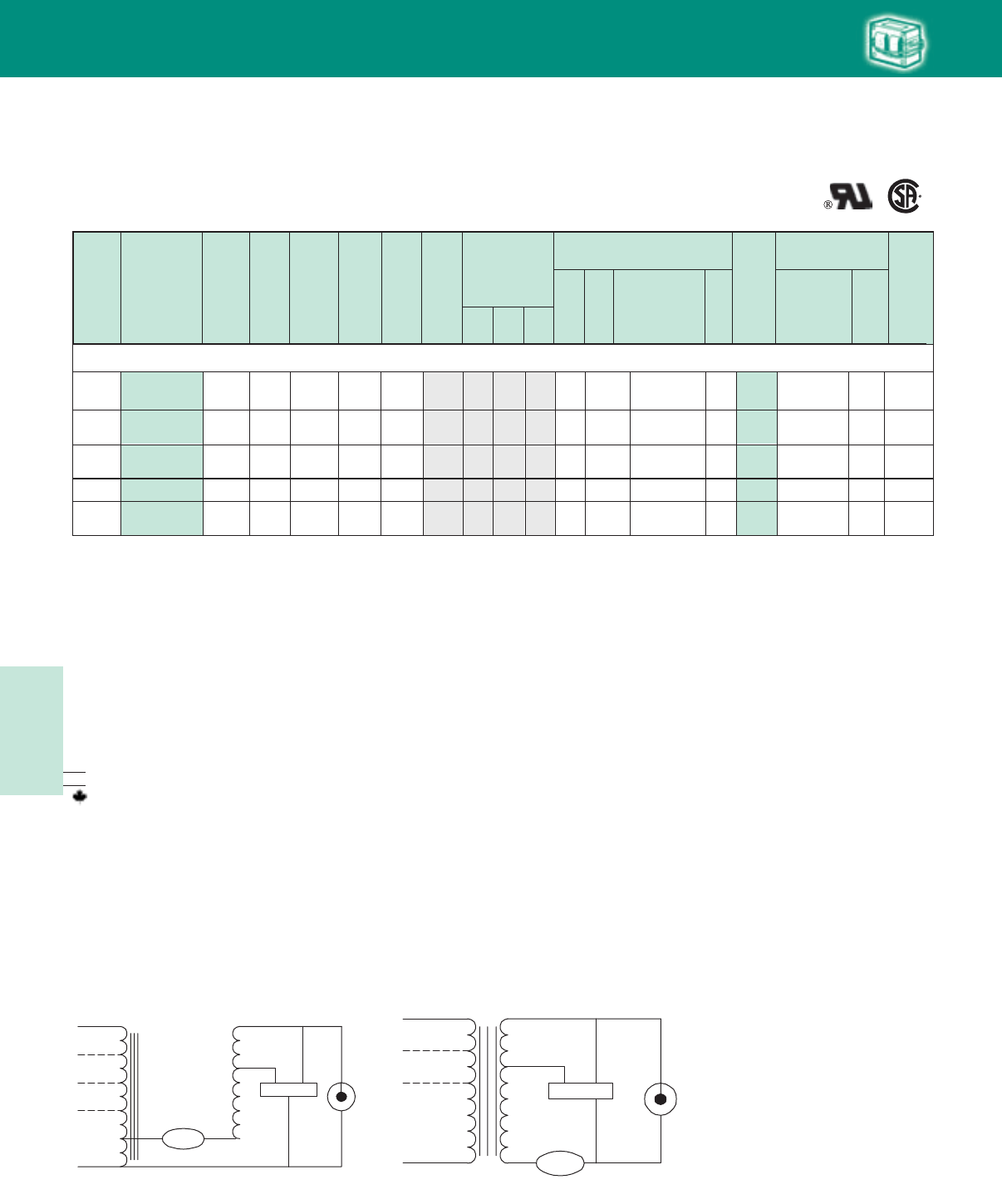
Lighting Electronics Atlas 2010-2011
5-32
HIGH INTENSITY DISCHARGE BALLASTS
200W Lamp, ANSI Code S66
480 CWA 240 .6 185 2 M 2 1.2 3.0 28 280 7C280P30-RA DLI501-H4 2 C
120/208/
240/277 CWA 240 2.2/1.3
1.1/1.0 185 6/4/
3/3 M 2 1.2 3.0 28 280 7C280P30-RA DLI501-H4 2E/D/
D/C
120/208/
240/277 CWA 240 2.2/1.3
1.1/1.0 185 6/4/
3/3 M 2 1.2 3.0 28 280 7C280P30-RA DLI501-H4 2E/D/
D/C
480 CWA 250 .6 195 2 M 1 3.0 4.2 24 280 7C240P30RA DLI501-H4 2 J
120/208/
240/277
71A8940-001D
71A8990-500D
71A8970-001D
71A8941-500D
71A8991-500D CWA 250 2.4/1.4
1.2/1.0 195 8/5/
5/3 M 1 3.0 4.2 24 280 7C240P30RA D
8.5
8.5
8.5
8.5
8.5 LI501-H4 2H/G/
H/I
Cap Catalog
Number
Dry
or
Oil
Input
Volts
Catalog
Number
Circuit
Type
Input
Watts
Max
Input
Current
Nom
Open
Circuit
Voltage
Fuse
Rating
(Amps)
Fig
Dimensions
Non-PCB Capacitor
(Page 5-38 & 5-39)
Mfd Min
Volt
Total
Weight
(lbs)
Ignitor ✝✝
(Page 5-40 to 5-44)
Part
Number
Max
Dist
To
Lamp
(ft)
U.L.
Bench
Top
Rise
Code
1029
(pg 5-4)
A B
✝
•
Wiring
Dia
60 Hz Core & Coil Ballasts
High Pressure Sodium
HID
Fig. M Fig. V
Fig. M
LAMP
CAP
LAMP
COM COM
LINE V
LINE V
LINE V
IGNITOR
X1X3
X2
LINE V
CAPCAP
Fig. V
LAMP 1
CAP
LAMP
COM
LINE V
LINE V
LINE V
IGNITOR
X1X3
X2
LAMP 2CAP
✝ Ordering information:
Replacement/retrofit ballast kits – indicated by bold type and -001D or -001 suffix.
Refer to pages 5-5 to 5-9 for more information on replacement kits.
Original equipment ballasts – typically ordered with capacitor (as shown).
-500D includes core & coil with dry-film capacitor.
-500 includes core & coil with oil-filled capacitor (required for higher wattage ballasts).
May also be available with welded bracket, and/or without capacitor:
-510D includes core & coil with welded bracket and dry-film capacitor.
-510 includes core & coil with welded bracket and oil-filled capacitor.
-600 core & coil only (no capacitor).
-610 core & coil with welded bracket (no capacitor).
✝✝ Each ballast requiring an ignitor is furnished standard with a short-range ignitor model
shown for use within fixtures. long-range ignitors are available separately if required.
See pages 5-xx to 5-yy for additional information.
• Maximum Input Current – For HX and R circuits, value is the highest of starting, operating
or open circuit current. For CWA, SCWA and CWI circuits, value is the operating current.
Certified ballast available for Mexican market. Add “M” to suffix (example: -500DM).
Canadian replacement/retrofit ballast kit indicated by bold type. Refer to page 5-9.
LL Special high efficiency/ low-loss ballast
NOM
◆
◆
HID • Core & Coil
HPS
5-33
Lighting Electronics Atlas 2010-2011
HIGH INTENSITY DISCHARGE BALLASTS
LI501-H47C350P24RA
HID
Cap Catalog
Number
Dry
or
Oil
Input
Volts
Catalog
Number
Circuit
Type
Input
Watts
Max
Input
Current
Nom
Open
Circuit
Voltage
Fuse
Rating
(Amps)
Fig
Dimensions
Non-PCB Capacitor
(Page 5-38 & 5-39)
Mfd Min
Volt
Total
Weight
(lbs)
Ignitor ✝✝
(Page 5-40 to 5-44)
Part
Number
Max
Dist
To
Lamp
(ft)
U.L.
Bench
Top
Rise
Code
1029
(pg 5-4)
A B
✝•Wiring
Dia
60 Hz Core & Coil Ballasts
High Pressure Sodium
NOM
250W Lamp, ANSI Code S50 or M168
127/220 71A82H1-500DM CWA 295 185 7/4 2 1.8 3.5 35 240M2.5/1.5 D 11.0 D/C2
Fig. 2
(4¼” x 4¾” Core)
Fig. 1
(3" x 4" Core)
213/16"
31/2"315/16"
27/16"
B
MAX.
A
Fig. 1
(3" x 4" core)
4 Holes cleared for
#10 thru-bolts
41/4"
43/8 "43/4"
37/8"
B
MAX.
A
Fig. 2
(41
/4" x 43
/4" core)
4 Holes cleared for
#10 thru-bolts
WELDED BRACKET DIMENSIONS
Ballast
Dimensions Fig L W M S
1 5.1 1.00 4.50 0.25
2 6.5 1.25 5.75 0.28
W
++
BRACKET
M
L
S
LI501-H4
LI501-H4
LI501-H4
LI501-H4
LI501-H4
7C350P24RA
7C350P24RA
7C350P24RA
7C350P24RA
7C350P24RA
NOM
120/208/
240/277/
480
71A8251-500DA
71A8251-001D
71A8241-500DA
CWA 300 185
10/4/
4/3/
2
2 2.0 3.6 35 240M
120/208/
240/277 71A8291-500DA
71A8241-500DT
71A8241-001D
CWA 295 185 7/4/
4/3 2 1.8 3.5 35 240
120/208/
240/277 71A8271-001D CWA 295 185 7/4/
4/3 2 1.8 3.5 35 240
480
480/120T
CWA
CWA
310
310
185
185
2
2
2
2
1.8
1.8
3.5
3.5
35
35
240
240
M
M
M
M
2.6/1.5/
1.3/1.2/
.7
2.5/1.5/
1.3/1.1
2.5/1.5/
1.3/1.1
.7
.7
D
D
D
D
D
12.0
11.0
11.0
11.0
11.0
B/B/
B/B/
B
2
2B/A/
B/B
2B/A/
B/B
2
2
B
B
LI501-H47C350P24RA
120/
277/347
71A82A1-500D
71A82A1-001D CWA 295 185 7/
3/2 2 2.0 3.6 35 240M
2.7/
1.2/.9
D 11.5 2 C/
C/B
LI501-H4
LI501-J4
7C340P24RA
7C280P30-RA
NOM
LL
220/240 71A82J9-500DM CWA 285 188 4/4 2 1.8 3.4 34 240M
120/
208/240 71A82E6-500D CWI 300
1.4/1.3
2.8/
1.6/1.4 190 8/
5/5 2 1.9 3.8 28 300
D
D
11.0
11.0
5 A/A
2D/
C/C
V
HID • Core & Coil
HPS
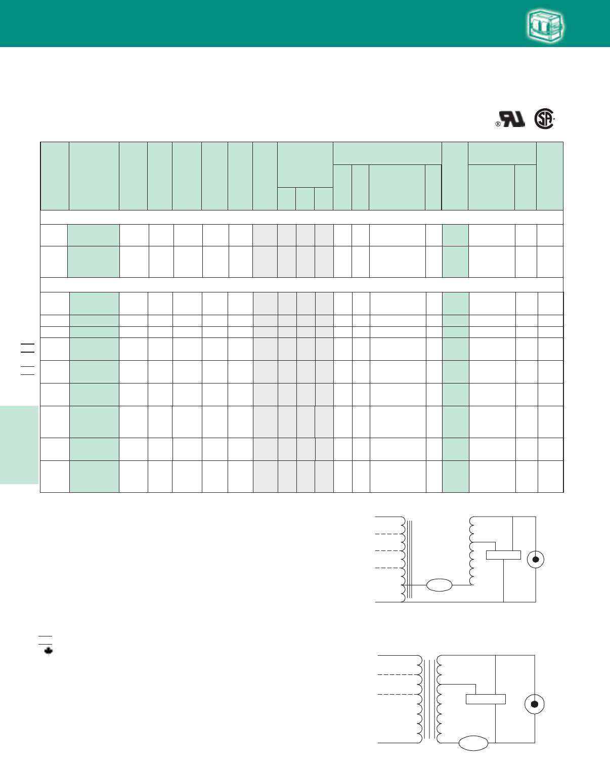
Lighting Electronics Atlas 2010-2011
5-34
HIGH INTENSITY DISCHARGE BALLASTS
310W Lamp, ANSI Code S67
71A8371-001D CWA 365 3.4/1.9/
1.7/1.4
3.2/1.7/
1.6/1.4/
.8
120/208/
240/277
120/208/
240/277/
480
175 8/5/
5/5 M2 2.2 4.1 45 280 7C450P30-RA D 13.5 LI501-H4 2 D/C/
D/B
71A8351-500D CWA 367 183
8/5/
4/4/
2
M 2 2.5 4.1 45 280 7C450P30-RA D 14.0 LI501-H4 2
C/A/
B/B/
B
HID
Cap Catalog
Number
Dry
or
Oil
Input
Volts
Catalog
Number
Circuit
Type
Input
Watts
Max
Input
Current
Nom
Open
Circuit
Voltage
Fuse
Rating
(Amps)
Fig
Dimensions
Non-PCB Capacitor
(Page 5-38 & 5-39)
Mfd Min
Volt
Total
Weight
(lbs)
Ignitor ✝✝
(Page 5-40 to 5-44)
Part
Number
Max
Dist
To
Lamp
(ft)
U.L.
Bench
Top
Rise
Code
1029
(pg 5-4)
A B
✝•
Wiring
Dia
60 Hz Core & Coil Ballasts
High Pressure Sodium
400W Lamp, ANSI Code S51 or M169
D480 71A8443-510D
71A8443-001D CWA 464 1.0 190 3 2 2.6 4.3 55 240 7C550P24RA LI501-H4 2M D
D480/120T 71A8443-500DT CWA 464 1.0 190 3 2 2.3 4.0 55 240 7C550P24RA LI501-H4 2M D 15.0
D480/120T 71A8443-500DTA CWA 464 1.0 190 3 2 2.8 4.3 55 240 7C550P24RA LI501-H4 2M D 16.0
15.0
120/208/
240/277/
480
71A8453-500D
71A8453-001D CWA 465
3.9/2.2/
1.9/1.7/
1.0
195
10/6/
5/5/
3
2 2.7 4.4 55 240 7C550P24RA LI501-H4 2
C/C/
D/D/
C
M
D/D/
D/D
120/208/
240/277 71A8473-001D CWA 464 3.8/2.2/
1.9/1.7 190 10/8/
5/5 2 2.1 4.0 55 240 7C550P24RA LI501-H4 2M
D
D
16.0
13.5
120/
208/240 71A84E6-500D CWI 465 4.2/
2.4/2.1 190 10/
7/5 2 2.7 4.4 48 300 7C480S30RA LI501-J4 2 E/
E/E
V
D/
D/D
M
120/
277/347
71A84A3-500D
71A84A3-001D CWA 464 3.8/
1.7/1.3 190 10/
5/5 2 2.3 4.0 55 240 7C550P24RA
D
D
15.5
13.5 LI501-H4 2
D/D/
D/D
120/208/
240/277 71A8493-500D CWA 464 3.8/2.2/
1.9/1.7 190 10/8/
5/5 2 2.1 4.0 55 240 7C550P24RA LI501-H4 2M D 13.5
NOM
D/D/
D/D
120/208/
240/277 71A8493-500DA CWA 464 3.8/2.2/
1.9/1.7 190 10/8/
5/5 2 2.6 4.3 55 240 7C550P24RA LI501-H4 2M D 16.0
NOM
Fig. M
Fig. V
Fig. M
LAMP
CAP
LAMP
COM COM
LINE V
LINE V
LINE V
IGNITOR
X1X3
X2
LINE V
CAPCAP
Fig. V
LAMP 1
CAP
LAMP
COM
LINE V
LINE V
LINE V
IGNITOR
X1X3
X2
LAMP 2CAP
✝ Ordering information:
Replacement/retrofit ballast kits – indicated by bold type and -001D or -001 suffix.
Refer to pages 5-5 to 5-9 for more information on replacement kits.
Original equipment ballasts – typically ordered with capacitor (as shown).
-500D includes core & coil with dry-film capacitor.
-500 includes core & coil with oil-filled capacitor (required for higher wattage ballasts).
May also be available with welded bracket, and/or without capacitor:
-510D includes core & coil with welded bracket and dry-film capacitor.
-510 includes core & coil with welded bracket and oil-filled capacitor.
-600 core & coil only (no capacitor).
-610 core & coil with welded bracket (no capacitor).
✝✝ Each ballast requiring an ignitor is furnished standard with a short-range ignitor model
shown for use within fixtures. long-range ignitors are available separately if required.
See pages 5-xx to 5-yy for additional information.
• Maximum Input Current – For HX and R circuits, value is the highest of starting, operating
or open circuit current. For CWA, SCWA and CWI circuits, value is the operating current.
Certified ballast available for Mexican market. Add “M” to suffix (example: -500DM).
Canadian replacement/retrofit ballast kit indicated by bold type. Refer to page 5-9.
NOM
HID • Core & Coil
HPS
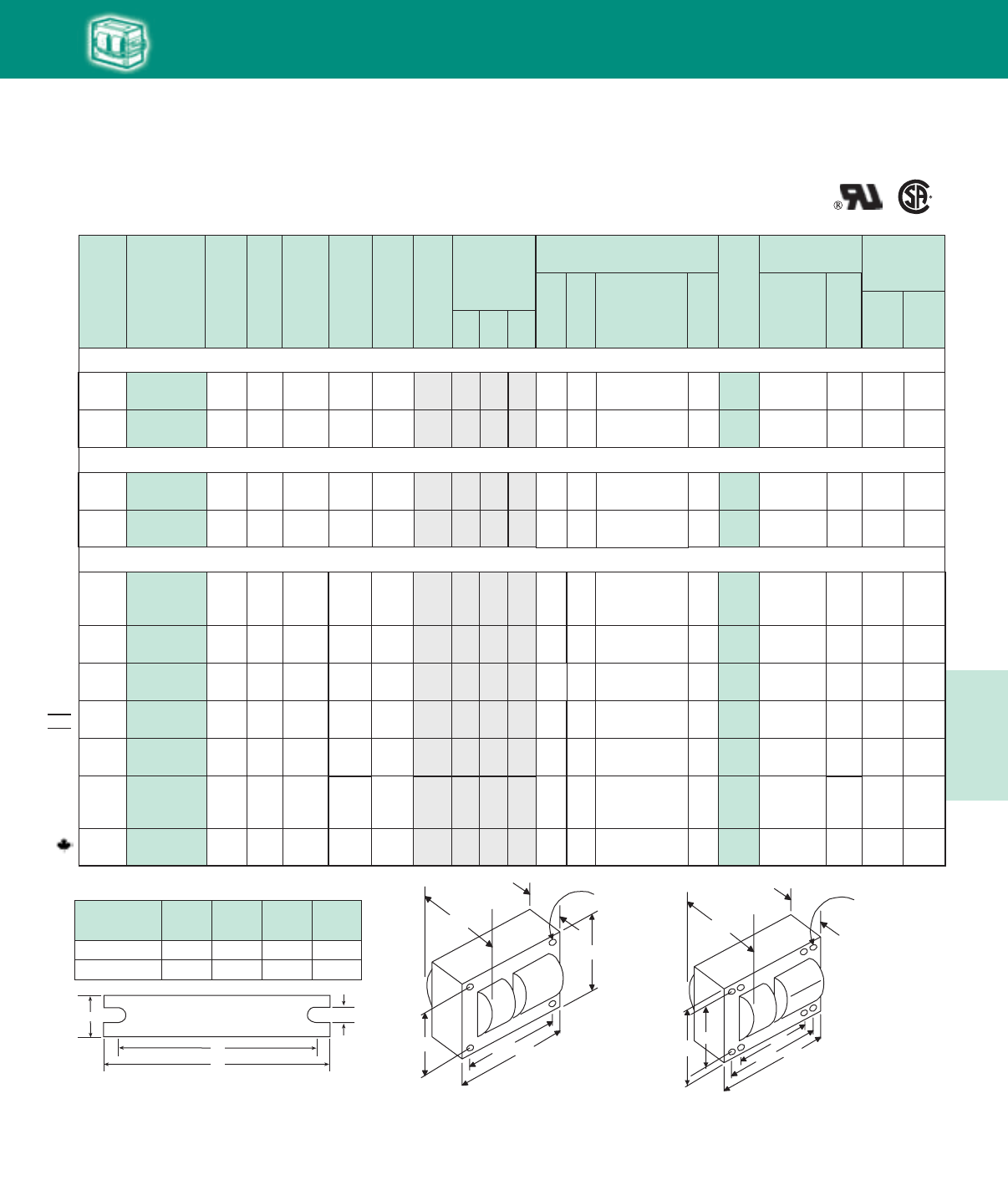
5-35
Lighting Electronics Atlas 2010-2011
HIGH INTENSITY DISCHARGE BALLASTS
Cap Catalog
Number
Dry
or
Oil
U.L. Bench Top
Rise Code 1029
(Pg 5-4)
Class H
(180°C)
Philips
Advance
Class N
(200°C)
Input
Volts
Catalog
Number
Circuit
Type
Input
Watts
Max
Input
Current
Nom
Open
Circuit
Voltage
Fuse
Rating
(Amps)
Fig
Dimensions
Non-PCB Capacitor
(Page 5-38 & 5-39)
Min
Volt
Total
Weight
(Ibs)
Ignitor ✝✝
(Page 5-40 to 5-44)
Part
Number
Max
Dist
To
Lamp
(ft)
A B
✝•Wiring
Dia Mfd
HID
60 Hz Core & Coil Ballasts
High Pressure Sodium
A/
A/A
A/
A/A
600W Lamp, ANSI Code S106
120/
208/240 71A85E5-500D CWA 670 5.5/
3.3/2.9 220 15/
9/8 8a 3.2 5.1 D 22.5 LI561-H5 2 A/
A/B
277/
347/480 71A85F5-500D 2.5/
2.0/1.4
A/
A/A
CWA 665 230 7/
5/4 8a 3.2 5.1 D 23.0 LI561-H5 5M
M
64 7C640S28-RA280
64 7C640S28-RA280
75 7C750S28-RA280
A/
A/A
A/
A/A
750W Lamp, ANSI Code S111
120/
208/240 71A86E5-500D CWA 840 6.8/
4.0/3.5 220 20/
10/10 8a 3.2 5.1 D 22.5 LI561-H5 5 D/
E/E
277/
347/480 71A86F5-500D CWA 840 3.1/
2.5/1.8 225 10/
10/5 8a 3.2 5.1 D 23.0 E/
D/D
LI561-H5 5
M
M
75 7C750S28-RA280
WELDED BRACKET DIMENSIONS
Ballast
Dimensions Fig L W M S
2 6.5 1.25 5.75 0.28
8a 7.8 4.50 6.75 0.31
W
++
BRACKET
M
L
S
Fig. 8, 8A
(4¼" x 6" Core)
41/4"43/8"
6 "
37/8"
B
MAX.
A
Fig. 8
(4 1/4" x 6" core)
8 Holes cleared for
#10 thru-bolts
53/8"
Fig. 2
(4¼” x 4¾” Core)
41/4"
43/8 "43/4"
37/8"
B
MAX.
A
Fig. 2
(41
/4" x 43
/4" core)
4 Holes cleared for
#10 thru-bolts
1000W Lamp, ANSI Code S52
71A87J3-500 CWA 1100 5.0 435 15 M 8a 3.8 5.8 26 525 MD2602-030 O 28.0 LI571-H5★15
C 220
480 71A8743-500
71A8743-001 CWA 1100 2.3 435 6 8a 3.9 5.8 26 525 MD2602-030 O 28.0 LI571-H5★15 CM
480/120T 71A8743-500T CWA 1100 2.3 435 6 8a 3.9 5.8 26 525 MD2602-030 O 28.0 LI571-H5★15 CM
NOM
C/B/
C/C
71A8793-500 CWA 1100
9.5/5.5/
4.8/4.2
435 25/15/
10/10 8a 3.8 5.8 26 525 MD2602-030 O 28.0 C/B/
C/C
120/208
240/277/
480
120/208
240/277
120/208
240/277
LI571-H5★15
LI571-H5★15
71A8773-001 CWA 1100
9.5/5.5/
4.8/4.2
435 25/15/
10/10 8a 3.8 5.8 26 525 MD2602-030 O 28.0M
M
C/C/
C/C/
C
LI571-H5★15
71A8753-600
71A8753-001 CWA 1100
9.3/5.3/
4.7/4.1/
2.3
437
25/15/
12/10/
6
26 525 MD2602-030 O 29.0
8a 4.0 6.0M
A
A
A
A/A/
A/A
A/A/
A/A
A/A/
A/A/
A
A/
A/A
LI571-H5★15M
120/
277/347
71A87A3-500
71A87A3-001 CWA 1100 9.5/
4.2/3.3 435 25/
15/10 8a 3.9 5.9 26 525 MD2602-030 O 28.0 C/
C/C
HID • Core & Coil
HPS
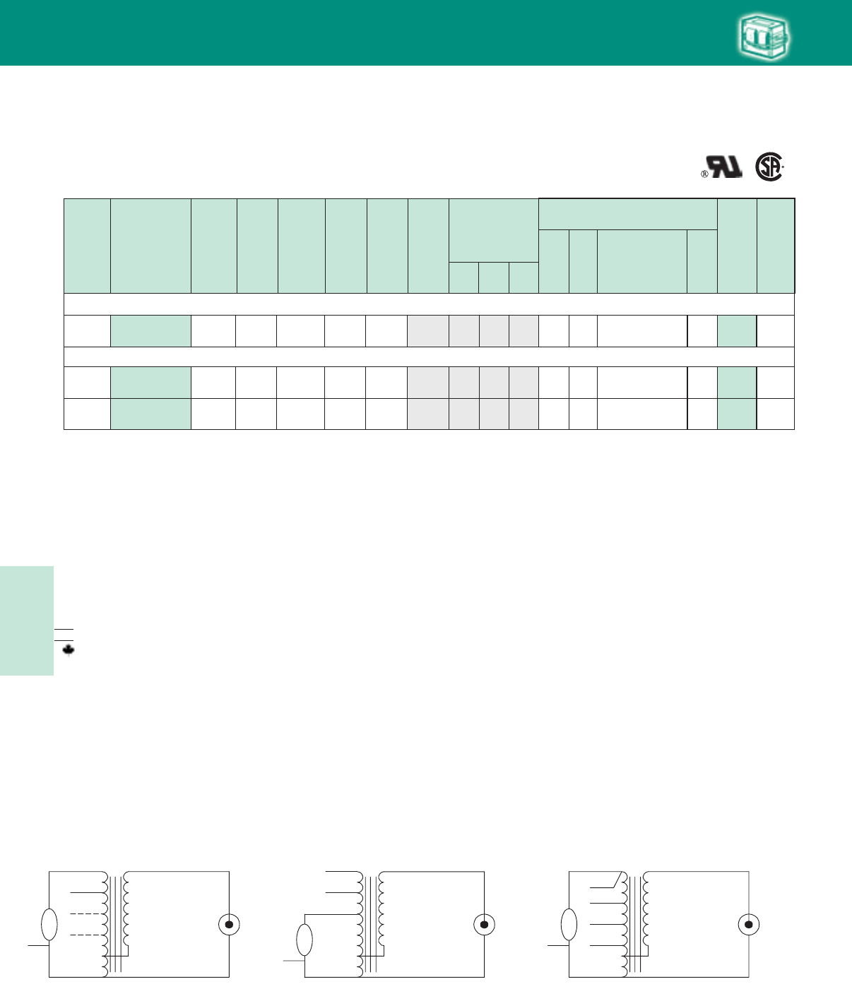
Lighting Electronics Atlas 2010-2011
5-36
HIGH INTENSITY DISCHARGE BALLASTS
1
Fig. Q
LAMP
CAP
LAMP
COM COM
LINE V
LINE V
COM
LINE V
CAPLAMP
LAMP
COM COM
LINE V
LINE V
CAP
COM
CAP
Fig. Q2
HID
Cap Catalog
Number
Dry
or
Oil
18W Lamp, ANSI Code L69
120/277 71A0280-500D HX-PFC 30 1.0/.5 315 3/2 1 1.0 2.4 5 250 7C050L30RA D 4.5 A/A
35W Lamp, ANSI Code L70 or 55W Lamp, ANSI Code L71
Q
Input
Volts
Catalog
Number
Circuit
Type
Input
Watts
Max
Input
Current
Nom
Open
Circuit
Voltage
Fuse
Rating
(Amps)
Fig
Dimensions
Non-PCB Capacitor
(Page 5-38 & 5-39)
Mfd Min
Volt
Total
Weight
(Ibs)
U.L.
Bench
Top Rise
Code
1029
(pg 5-4)
A B
•
✝Wiring
Dia
60 Hz Core & Coil Ballasts
Low Pressure Sodium
Fig. Q Fig. Q2
120/208/
240/277
71A0490-500D
71A0490-001D
HX-HPF/
HX-PFC 60 or 80 480 6/4/
3/3 2.3 3.5 14 240 7C140M30RA D 8.0 A/A/
A/A
71A04F0-500D
2.4/1.4/
1.2/1.0
18.0
347/480 HX-HPF 60 or 80 0.79/0.58 480 2/2 14 240 7C140M30RA D A/A
Q
2.3 3.5
Q2
LAMP
CAP
LAMP
COM COM
LINE V
LINE V
COM
LINE V
LINE V
CAP
Fig. Q4
Fig. Q4
✝ Ordering information:
Replacement/retrofit ballast kits – indicated by bold type and -001D or -001 suffix.
Refer to pages 5-5 to 5-9 for more information on replacement kits.
Original equipment ballasts – typically ordered with capacitor (as shown).
-500D includes core & coil with dry-film capacitor.
-500 includes core & coil with oil-filled capacitor (required for higher wattage ballasts).
May also be available with welded bracket, and/or without capacitor:
-510D includes core & coil with welded bracket and dry-film capacitor.
-510 includes core & coil with welded bracket and oil-filled capacitor.
-600 core & coil only (no capacitor).
-610 core & coil with welded bracket (no capacitor).
✝✝ Each ballast requiring an ignitor is furnished standard with a short-range ignitor model
shown for use within fixtures. long-range ignitors are available separately if required.
See pages 5-xx to 5-yy for additional information.
• Maximum Input Current – For HX and R circuits, value is the highest of starting, operating
or open circuit current. For CWA, SCWA and CWI circuits, value is the operating current.
Certified ballast available for Mexican market. Add “M” to suffix (example: -500DM).
Canadian replacement/retrofit ballast kit indicated by bold type. Refer to page 5-9.
NOM
HID • Core & Coil
LPS
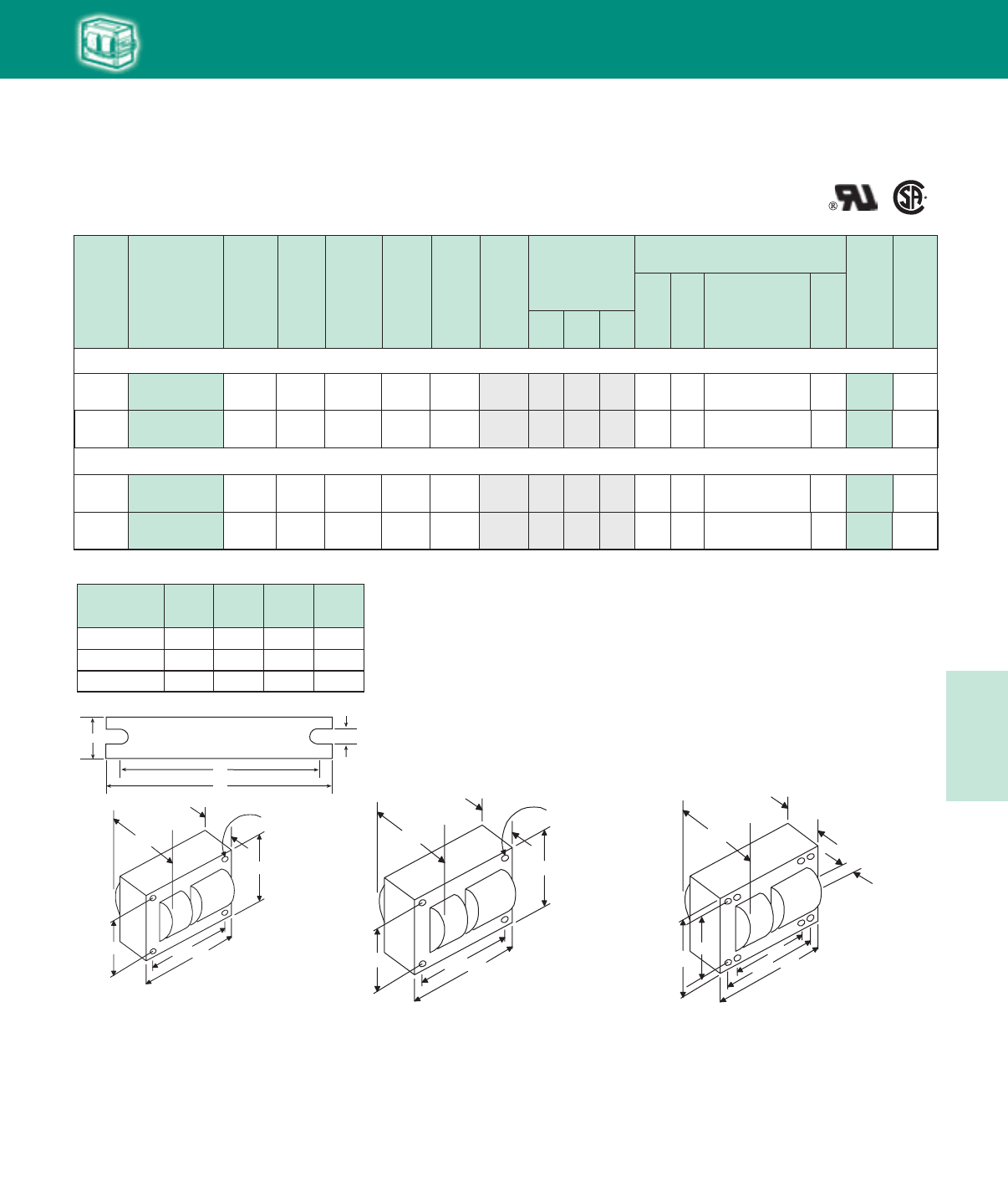
5-37
Lighting Electronics Atlas 2010-2011
HIGH INTENSITY DISCHARGE BALLASTS
90W Lamp, ANSI Code L72
HID
Cap Catalog
Number
Dry
or
Oil
Input
Volts
Catalog
Number
Circuit
Type
Input
Watts
Max
Input
Current
Nom
Open
Circuit
Voltage
Fuse
Rating
(Amps)
Fig
Dimensions
Non-PCB Capacitor
(Page 5-38 & 5-39)
Mfd Min
Volt
Total
Weight
(Ibs)
U.L.
Bench
Top Rise
Code
1029
(pg 5-4)
A B
•
✝Wiring
Dia
60 Hz Core & Coil Ballasts
Low Pressure Sodium
120/208/
240/277 71A0590-500D HX-HPF 125 4.1/2.3/
2.0/1.75 515 11/6/
5/5 2 1.8 3.3 17.5 330 7C175M33-R A/A/
A/A
135W Lamp, ANSI Code L73 or 180W Lamp, ANSI Code L74
Q4 D 10.0
120/208/
240/277 71A0790-500D HX-HPF 180 or
208 695 15/7/
7/6 3a 2.4 4.0 16 330 7C160M33 A/A/
A/A
Q D 15.3
15.0Q2 D347/480 71A07F0-500D HX-HPF 182 or
213 1.82/1.33
5.28/2.82/
2.62/2.25
690 5/4 3a 2.4 4.0 16 330 7C160M33 A/A
10.2Q2 D347/480 71A05F0-500D HX-HPF 125 1.35/0.95 520 4/3 2 1.8 3.4 16.0 330 7C160M33 A/A
WELDED BRACKET DIMENSIONS
Ballast
Dimensions Fig L W M S
1 5.1 1.00 4.50 0.25
2 6.5 1.25 5.75 0.28
3a 7.8 2.75 6.13 0.25
W
++
BRACKET
M
L
S
41/4"43/8"
53/4"
37/8"
B
MAX.
A
Fig. 3a
(4 1/4" x 5 3/4" core)
11/4"
53/8"
Fig. 2
(4¼” x 4¾” Core)
Fig. 3a
(4¼" x 5¾" Core)
41/4"
43/8 "43/4"
37/8"
B
MAX.
A
Fig. 2
(41
/4" x 43
/4" core)
4 Holes cleared for
#10 thru-bolts
Fig. 1
(3" x 4" Core)
213/16"
31/2"315/16"
27/16"
B
MAX.
A
Fig. 1
(3" x 4" core)
4 Holes cleared for
#10 thru-bolts
HID • Core & Coil
LPS
Lighting Electronics Atlas 2010-2011
5-38
HIGH INTENSITY DISCHARGE BALLASTS HID
RW33CC200
Mounting Clip
For 2.00 in. diameter Round Case.
Mount in the middle of can.
3/16” Dia.
2 1/8”
RW33CC175
Mounting Clip
For 1.25 thru 1.75 in. diameter
Round Case (Furnished as standard
with -001 and -001 D suffix ballasts).
RW33CC1252
Mounting Clip
For 1.18 thru 1.25
in diameter, Round Case
Advance
Ballast Family
Nominal
Lamp Watts
ANSI
Code
Lamp Watts
at Low Light
Full Light
Capacitance Mfd.
Low Light
Capacitance Mfd.
Primary
Capacitor
Secondary
Capacitor
Capacitor
Connection
Metal Halide 60Hz CWA/SuperCWA Ballasts
71A54A3 150
Pulse-Start 90 22.0 15.0 22.0 mfd, 240V
(7C220M24RA)
48.0 mfd, 300V
(7C480S30RA) Series
71A53_3 100
Pulse-Start M90/140 55 10.0 7.8 10.0 mfd 330V
(7C100M30RA)
35.0 mfd 300V
(7C350P30RA) Series
Capacitor Specifications
Recommended Capacitors for Bi-level Ballast Operation
Max Case
Temp 90°C
Dry-Film Capacitors
Thermal Plastic Case
Dry-film capacitors contain no oil; are
furnished with 8” leads and include integral
resistor where required.
Oil-Filled Capacitor
Furnished with appropriate leads and/or resistors
where required. Case must be grounded.
Note: Capacitor boots available, order catalog
number CB-100.
Diameter
Height
Dry Film Capacitors
Thermal Plastic Case
Dry-Film capacitors contain
no oil, are furnished with 9"
leads and include integral
resistor where required.
Max
Case
Temp
105°C
Dry-Film Capacitors
Dimensions (in)
Letter Diameter Height
L 1.18 2.2 or 2.7
M 1.58 2.7 or 3.7
P 1.77 3.7 or 4.9
S 1.97 5.0
Oil-Filled Capacitors
Dimensions (in)
Oval A B Height
1.25 1.30 2.15
As Shown
in Tables
1.25 1.55 2.70
1.75 1.90 2.90
2.00 1.95 3.65
M102/
142
71A5493 150
Pulse-Start 90 16.0 9.6 16.0 mfd, 280V
(72160M30RA)
24.0 mfd, 120V
(7C240P30RA) Series
M102/
142
71A55_0 175 M57 122 10.0 8.0 10 mfd, 400V
(7C100M40-R)
40 mfd, 300V
(7C400P30-R) Series
71A55_3 175
Pulse-Start
M137 or
M152 102 11.0 7.7 11 mfd, 400V
(7C110M40)
26 mfd, 330V
(7C260:33-R) Series
71A56_2 or
71A56_3
200
Pulse-Start M136 102 15.0 9.3 15 mfd, 330V
(7C150M33)
24 mfd, 300V
(7C240P30) Series
71A57_0 or
71A57_1 250 M58 127 15.0 9.0 15 mfd, 400V
(7C150P40-R)
22.5 mfd, 300V
(7C225P30-R) Series
71A57_2 250
Pulse-Start
M138 or
M153 133 17.0 10.8 17 mfd, 330V
(7C170P33)
30 mfd, 345V
(7C300S34) Series
71A58_2 320
Pulse-Start
M132 or
M154 149 21.0 13.1 21 mfd, 345V
(7C210P34-R)
35 mfd, 300V
(7C350P30-R) Series
71A59_3 350
Pulse-Start M131 163 22.5 14.4 22.5 mfd, 345V
(7C225P34)
40 mfd, 300V
(7C400 P30-R) Series
71A60_1 400 M59 192 24.0 15.0 24 mfd, 400V
(7C240P40-R)
40 mfd, 300V
(7C400P30-R) Series
71A60_2 400
Pulse-Start
M135 or
M155 210 26.0 18.5 18.5 mfd, 330V
(7C185P33-R)
7.5 mfd, 400V
(7C075M40) Parallel
71A63_3 450
Pulse-Start M144 212 26.5 16.7 26.5 mfd, 400V
(7C265P40-R)
45.0 mfd, 120V
(7C450P12) Series
71A64_2 750
Pulse-Start M149 380 28.0 18.0 18 mfd, 400V
(7C180P40-R)
10 mfd, 400V
(7C100M40-R) Parallel
71A65_0, 71A65_1,
71A65_2, or 71A65_3
1000 Probe or
Pulse-Start
M47 or
M141 571 24.0 15.0 24 mfd, 480V
(MD2409-100)
40 mfd, 300V
(7C400P30-R) Series
71A80_8 100 S54 52 34.0 26.0 26.0 mfd, 330V
(7C260P33-R)
8.0 mfd, 330V
(7C080L33-R) Parallel
71A81_8 150 S55 66 55.0 40.0 40 mfd, 300V
(7C400P30-R)
15 mfd, 330V
(7C150M33) Parallel
71A82_1 250 S50 144 35.0 28.0 28 mfd, 300V
(7C280P30-R)
7 mfd, 330V
(7C070L33-R) Parallel
71A84_3 400 S51 189 55.0 40.0 40 mfd, 300V
(7C400P30-R)
15 mfd, 330V
(7C150M33) Parallel
71A86_5 750 S111 356 75.0 55.0
35 mfd, 300V (7C350P30-R)
in parallel with 20 mfd, 300V
(7C200P33-R)
20 mfd, 330V
(7C200P33-R) Parallel
71A87_3 1000 S52 406 26.0 17.7 26 mfd, 525V
(MD2602-030)
55 mfd, 240V
(7C550P24) Series
71A64_8 875
Pulse-Start M166 440 21.0 13.1 21 mfd 480V
(MD2100-030)
35 mfd 170V
(7C350P24RA) Series
71A64_8 875
Pulse-Start M166 440 21.0 13.1 13 mfd 480V
(MD1300-100) 8 mfd 480V Parallel
71A89_1 200 S66 130 24.0 18.0 24 mfd 280V
(7C240P30RA)
72 mfd 120V
(7C720P12RA) Series
71A89_1 200 S66 130 24.0 18.0 18 mfd 280V 6 mfd 280V
(7C060L30RA) Parallel
High Pressure Sodium 60Hz CWA Ballasts
HID • Capacitors
5-39
Lighting Electronics Atlas 2010-2011
HIGH INTENSITY DISCHARGE BALLASTS
2.25
2.75
2.75
2.90
2.75
2.90
2.75
3.75
3.75
2.75
2.90
3.90
2.25
2.75
2.75
3.75
2.75
3.75
3.90
3.90
3.75
3.90
3.90
3.75
3.75
3.75
2.75
3.75
3.90
4.80
3.90
2.75
3.75
3.75
3.75
4.80
3.90
3.90
4.80
4.80
4.80
5.30
5.30
4.80
3.75
2.75
3.75
4.80
3.90
4.80
3.75
3.75
3.90
3.75
4.75
2.75
4.75
2.75
4.75
5.00
3.75
4.00
3.75
3.75
3.75
3.75
5.00
5.00
5.00
71A02x0, 5037, 5081, 5137, 78x1 (60 Hz)
71A5181, 78R1
71A1580, 50x7 (50 Hz. only), 79x1 (60 Hz)
Bi-Level, 71A5283
71A20x0, 52x0, 52x2 (60 Hz. only), 5237, 5281
71A79x1 (50 Hz)
71A25x1 (60 Hz), 50Y1, 52Y1, 52Y2, 5337, 5340-T, 5383, 53Y3, 80x1 (60 Hz)
71A55x0 (60 Hz)
71A55x3
71A25x1 (50 Hz), 29D1, 50x1 (50 Hz), 53x0 (60Hz, except 5340-T), 5637, 80x1 (50 Hz)
71A55x0 (50 Hz)
71A57E6
71A7707
71A04x0, 29R0, 52x1 (50 Hz), 52x2 (50 Hz), 5437, 5737, 81x2 (60 Hz)
71A56x2, 56x3
71A57x0 (60 Hz), 57x1
71A05F0, 54x0, 54x2, 80x0
71A81x0, 07x0
71A57x4, 82x0
71A43x0
71A55x4, 5634, 57x2
71A83x0
71A69x0 (Use one 17 mfd-550V and one 26 mfd-540V in parallel)
71A0590, 30x2, 53N0, 5837, 81x2 (50 Hz)
56x3 (50 Hz), 71A57x0 (50 Hz), 89x4
60x2 Bi-Level
71A0201, 7705, 7807
71A57x2 (50 Hz), 53MO, 5880, 5937, 6037, 6137, 79xO, 81R6, 8146, 8176, 8196
71A60x6
71A58x2 (60 Hz)
71A59x4, 60x4 (60 Hz), 6334, 64x8
71A54A3
71A35x2 (60 Hz), 5486, 6337
71A59x3
71A79x6, 89x1
71A58x2 (50 Hz), 60x1 (60 Hz), 63x2
71A84x0, 65x3 (60 Hz), 65x1
71A50x0, 60N1, 65x2 (60 Hz), 65x0
71A59x3 (50 Hz)
71A60x2 (60 Hz), 61E6
Alternative to 7C260P33R
71A69x0 (Uses one 17 mfd-540V and one 26 mfd-540V capacitor in parallel), 87x3 (60 Hz)
71A60M2, 65x2 (50 Hz), 65x3 (50 Hz only)
71A63x3 (60 Hz)
71A79J9
71A5005, 5105, 7805, 7907
71A35R2, 54x2 (50 Hz), 79x8, 82x6, 89x0
71A64x0, 64x2 (60 Hz)
71A87x3 (50 Hz only, uses two 14mfd-580 volt capacitors in parallel)
71A60N2
71A67x2 (60 Hz)
71A80x8
71A68x0 (Uses two 17mfd-550 volt capacitors in parallel)
71A54M2, 80x6, 82x1 (60 Hz)
71A40x1 (60 Hz)
71A5205, 8007, 50Y5
71A40R1, 65E6 (two in series), 82x1 (50 Hz only), 65Y6 (two in series)
71A8005
71A65M6, 83x1
71A84x6, 85x6
71A8156, 81E6
Bi-Level
71A8107
71A81x8, 84x3 (60 Hz)
71A8593
71A99x2, 71A9968
71A84x3 (50 Hz), 85x5
71A9942, 71A9943
71A86x5
1.25
1.25
1.25
1.50
1.25
1.25
1.65
1.40
1.65
1.65
1.75
1.75
1.25
1.65
1.65
1.75
1.65
1.75
1.75
1.75
1.75
1.75
1.75
1.65
1.75
1.65
1.25
1.75
1.75
1.75
1.75
1.65
1.65
1.75
1.65
1.75
1.75
1.75
1.75
1.75
2.00
1.75
1.75
1.75
1.75
1.65
1.75
2.00
1.50
1.75
2.00
1.65
1.75
1.65
1.65
1.65
1.75
1.65
1.75
2.00
1.75
2.00
1.65
1.75
1.75
1.75
2.00
2.00
2.00
Dia/Oval Height Ballast family where used
5
6
7
7.5
8
8.4
10
10
11
12
12
13
14
14
15
15
16
16
16
16
17
17
17
17.5
18
18.5
20
20
20
21
21
22
22.5
22.5
24
24
24
24
25.5
26
26
26
26
26.5
27.5
28
28
28
28
30
32
34
34
35
35
36
40
45
45
48
52
52
55
55
58
60
64
66
75
300
300
300
400
300
300
300
400
400
300
450
525
120
300
300
400
300
400
525
525
400
550
550
300
400
330
120
330
450
400
525
240
300
345
300
400
480
480
400
330
330
540
540
400
240
120
300
400
580
345
525
240
550
240
300
120
300
120
300
300
240
280
120
240
240
240
280
280
280
7C050L30RA
7C060L30RA
7C070L30RA
7C075M40
7C080L30RA
7C084L33R
7C100M30RA
7C100M40RA
7C110M40RA
7C120M30RA
MD1204100
MD1300-100
7C140L12RA
7C140M30RA
7C150M30RA
7C150P40RA
7C160M30RA
7C160P40
MD1606-000
MD1606-100
7C170P40RA
MD1701-000
MD1701-100
7C175M30RA
7C180P40RA
7C185M33R
7C200M12RA
7C200P33R
MD2006-100
7C210P40RA
MD2100-030
7C220M24RA
7C225P30RA
7C225P34
7C240P30RA
7C240P40RA
MD2409-000
MD2409-100
7C225P40
7C260P33R
7C260S33R
MD2602-030
MD2602-100
7C265P40R
7C275P24RAT1
7C280M120RA
7C280P30RA
7C280S40R
MD1408-230
7C300S34
MD3202100
7C340P24RA
MD1701-200
7C350P24RA
7C350P30RA
7C360M12RA
7C400P30RA
7C450P12RA
7C450P30RA
7C480S30RA
7C520P24RA
7C520S28RA
7C550P12RA
7C550P24RA
7C580P24RA
7C600P24RA
7C640S28RA
7C660S28RA
7C750S28RA
HID
Capacitor Specifications HID Non-PCB Capacitors
Mfd. Voltage Capacitor
Part Number
1,2
1. “R” suffix denotes capacitors with a discharge resistor where required by UL.
2. MD_ denotes 90° Oil Filled, 7C_ denotes 105° Dry Film with leads.
HID • Capacitors
Lighting Electronics Atlas 2010-2011
5-40
HIGH INTENSITY DISCHARGE BALLASTS HID
Ballasts-to-Lamp Remote Mounting Distances
Ballasts that include an ignitor to start the HID lamp are limited
in the distance which they may be mounted remotely from the
lamp because the ignitor pulse attenuates as the wire length
between the ballast and lamp increases. All Philips Advance open
core & coil ballasts listed in this Atlas include a standard ignitor
that provides the proper electrical pulse to start lamps when
the ballast is mounted within the lighting fixture. For most of
these ballast/ignitor combinations, the maximum ballast-to-lamp
distance is listed as 2 feet. For ballast-to-lamp distances greater
than the capability of the standard ignitor, a long range ignitor
is required.
Use the tables on the following pages to find the proper long
range ignitor for various metal halide and high pressure sodium
ballasts. Not all ballasts listed in the Atlas have long range
ignitor options. It may be necessary to use a ballast employing
a different circuit to achieve the needed ballast-to-lamp distance.
Whichever ignitor is used, it must be installed with and adjacent
to the core & coil, as the two components work together to
deliver the proper pulse to the lamp. Do not install ignitors
next to a remote lamp because the electrical pulse will be
further attenuated as it first has to travel from the ignitor to
the core & coil and then back to the lamp, thus doubling the
actual ballast-to-lamp distance.
Metal Halide Ballasts
The distances at which most Metal Halide ballasts can be located
from their respective lamps are limited by the ballast-to-lamp wire
size. The exceptions being the ballasts for the new, lamps which
require an ignitor for starting. The mounting distances for these are
limited by the ignitor as shown on the following page.
Use this chart to determine the minimum wire size required for the
Metal Halide (not requiring an ignitor) lamps shown:
Lamp
Wattage
Maximum One-Way
Length of Wire between
Lamp and Ballast (ft)
(Voltage Drop Limited to
1% of Lamp Voltage)
Metal
Halide #10 #12 #14 #16 #18
175
250
1-400 or
2-400
M57 425 265 165 105 65
M58 300 190 120 75 45
M59 200 125 75 50 30
1000
1500
M47 325 205 125 80 50
M48 225 140 85 55 35
Ignitors
HID • Ignitors
BTL
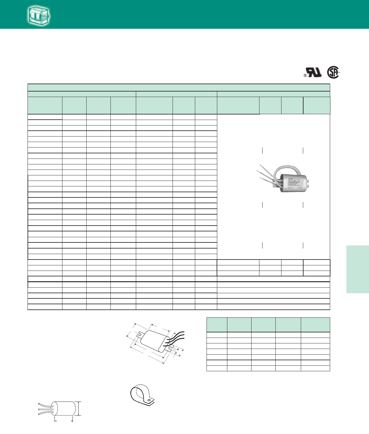
5-41
Lighting Electronics Atlas 2010-2011
HIGH INTENSITY DISCHARGE BALLASTS
HID
Ignitor Specifications (Case Temperature Rating 105°C)
Metal Halide
★ Equipped with an auto-rest thermal protector to help prevent
ignitor from overheating in the event of lamp failure
RW33CC1252
MOUNTING CLIP for Round Case
(Furnished as standard with -001 suffix ballasts and
all -IC suffix replacement ignitors.
RED (X1)
WHITE (X2)
BLUE (X3)
Round Case
LI551-H4 = 2"
All Others= 2 1/2"
Max. case temp. 90 oC
11/4" DIAMETER
Round Case
LI551-H4
= 21/8”
All others 21/2”
71A5105 50 M110/148 HX LI533-H4-IC 15 Round
71A51_1 50 M110/148 HX LI533-H4-IC 10 Round
71A5137 50 M110/148 R LI533-H4-IC 2 Round
71A5205 70 M98/143 HX LI533-H4-IC 25 Round
71A52_2 70 M98/143 HX LI533-H4-IC 15 Round
71A5237 70 M98/143 R LI533-H4-IC 10 Round
71A52_1 70 M139 HX LI533-H4-IC 10 Round
71A53_0 100 M90/140 HX LI533-H4-IC 20 Round
Metal Halide
Long Range IgnitorBallast Data Standard Ignitor
Philips Advance
Ballast Family
Lamp
Watts
ANSI
Code
Ballast
Circuit
Type
Catalog
Number
Max.
Dist. (ft.)
To Lamp
Case
Type
Catalog
Number
Max.
Dist. (ft)
To Lamp
Min.
Dist. (ft)
To Lamp
Case
Type
LI533-LR1 0 - 50 ft Oval
LI533-LR3★ 0 - 50 ft Oval
71A50_5 35 M130 HX LI533-H4-IC 15 Round
71A5081 35 M130 HX LI533-H4-IC 15 Round
71A5037 35 M130 R LI533-H4-IC 10 Round
71A54A3 150 M102/142 SuperCWA LI501-J4-IC★15 Round
71A64_2 750 M149 SuperCWA LI573-H5-IC 15 Oval
71A64_0 750 M149 SuperCWA LI573-H5 15 Oval
71A65_3 1000 M141 SuperCWA LI571-H5-IC★5 Oval
71A52_0 70 M85 HX LI522-H5-IC★30 Oval
71A54_0 150 M81 HX LI522-H5-IC★20 Oval
71A5486 150 M81 CWA LI523-H5-IC★2 Oval
71A5880 250 M80 HX LI522-H5-IC★5 Oval
71A86_5 750 ** CWA LI561-H5-IC★5 Oval
Not Available
Not Available
Not Available
Not Available
Not Available
Not Available
LI561-H5★15 50 Oval
LI561-H5★15 50 Oval
LI561-H5★10 50 Oval
71A64_8 875 M-166 SuperCWA LI572-H5-IC★10 Oval
71A65_1 1000 M141 SuperCWA LI572-H5-IC★10 Oval
71A5383 100 M90/140 CWA LI533-H4-IC 2 Round
71A5337 100 M90/140 R LI533-H4-IC 2 Round
71A54_2 150 M102/142 HX LI533-H4-IC 10 Round
71A5437 150 M102/142 R LI533-H4-IC 2 Round
71A55_3 175 M137/152 SuperCWA LI533-H4-IC 2 Oval
71A56_2 200 M136 SuperCWA LI533-H4-IC 2 Round
71A57_2 250 M138/153 SuperCWA LI533-H4-IC 5 Round
71A58_2 320 M132/154 SuperCWA LI533-H4-IC 2 Round
71A59_3 350 M131 SuperCWA LI533-H4-IC 2 Round
71A60_2 400 M135/155 SuperCWA LI533-H4-IC 10 Round
71A61E6 400 M135/155 SuperCWI LI533-H4-IC 2 Round
71A63_3 450 M144 Super CWA LI533-H4-IC 5 Round
71A56_3 200 M136 SuperCWA LI533-H4-IC 5 Round
RED (X1)
WHITE (X2)
BLUE (X3)
1"
1/4" SLOT
43/4"
41/4"
25/32"3"
15/16 "
Max.
case temp. 90 oC
Case must be grounded
Oval Ignitor
Case
35 M130 71A5005
35 M130 71A5081
70 M98/143 71A5205
70 M98/143 71A5292
70 M98/143 71A52A2
100 M90/140 71A5383
100 M90/140 71A5390
-900D
-900D
-900D
-900D
-910DP
-910DP
-910D
-910D
Lamp
Watts
ANSI
Code
Ballast
Number
No
Bracket
With Welded
Bracket
XTENZA Ordering Information
To order in bulk, specify item no. LI533-LR,
LI533-LR1 or LI533-LR3. For individual carton,
add -IC to item no.
XTENZA is also available packaged with the ballasts
shown at right.
LI533-LR 0 - 50 ft Oval
XTENZA® Long-Range Ignitor
- Meets ANSI pulse requirements for all ballast to lamp
distances from 0 to 50 ft.
- Features 105°C case temperature rating
- See Ordering Information Below
}
}
}
Oval Case
HID • Ignitors
Metal Halide
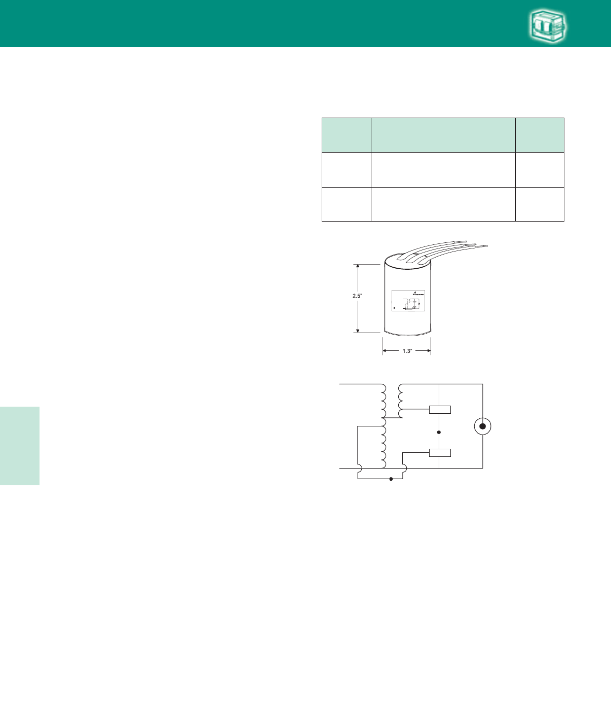
Lighting Electronics Atlas 2010-2011
5-42
HIGH INTENSITY DISCHARGE BALLASTS
LISOD™
HID
The Philips Advance shut-off device (LISODTM) enhances the
reliability of High Intensity Discharge (HID) lighting systems where
ignitors are utilized to start the HID lamps. This includes all high
pressure sodium lamps as well as all low, medium, and high wattage
pulse-start metal halide lamps. The LISOD shut-off device is used in
addition to a standard ignitor.
The LISOD shut-off device increases the life of the ignitor by
disabling it from the circuit and eliminating any concern over
long-term ballast reliability due to continuously pulsing ignitors
when a lamp is burned out. The LISOD provides a simple solution
to eliminate lamp cycling typically associated with lamps that have
reached their end of life. The LISOD disables the ignitor after 15
minutes of pulsing in cases when lamp is taken out of socket or
lamp fails to ignite.
• CompatiblewithanyPhilipsAdvanceReactor(R),
High-Reactance (HX), and Constant Wattage Autotransformer
(CWA) ballast and ignitor circuit that includes a 120V input tap.
• Integraltimerautomaticallydisablesignitorfromballastcircuit
15-minutes after power is applied to the ballast
• Extendsignitorlife,whichistypicallyratedfor10,000hoursof
continuous pulsing
• Protectsballastcoilinsulationfrompotentialdamageduetoa
continuously pulsing ignitor
• Preventscyclingofend-of-lifelampsmakingidentificationfor
lamp replacement easy
• Automaticallyresets/restartsitselfafter0.6secondofpower
interruption (voltage dropout)
LAMP
LISOD
IGNITOR
COM COM (WHITE)
X2 COM (WHITE)
X2 COM
X1 LAMP
X3
COM
120V
120V (RED)
VLINE
Catalog
Number Description Quantity
Per Carton
LISOD1-IC
Ignitor shut-off device for HID CWA, HX,
and R ballasts with ignitors.
Individual carton packaging
1
LISOD1
Ignitor shut-off device for HID CWA, HX
and R ballasts with ignitors.
Bulk packaging
50
Lead Lengths are 12”
HID • Ignitors
Shut-off Device
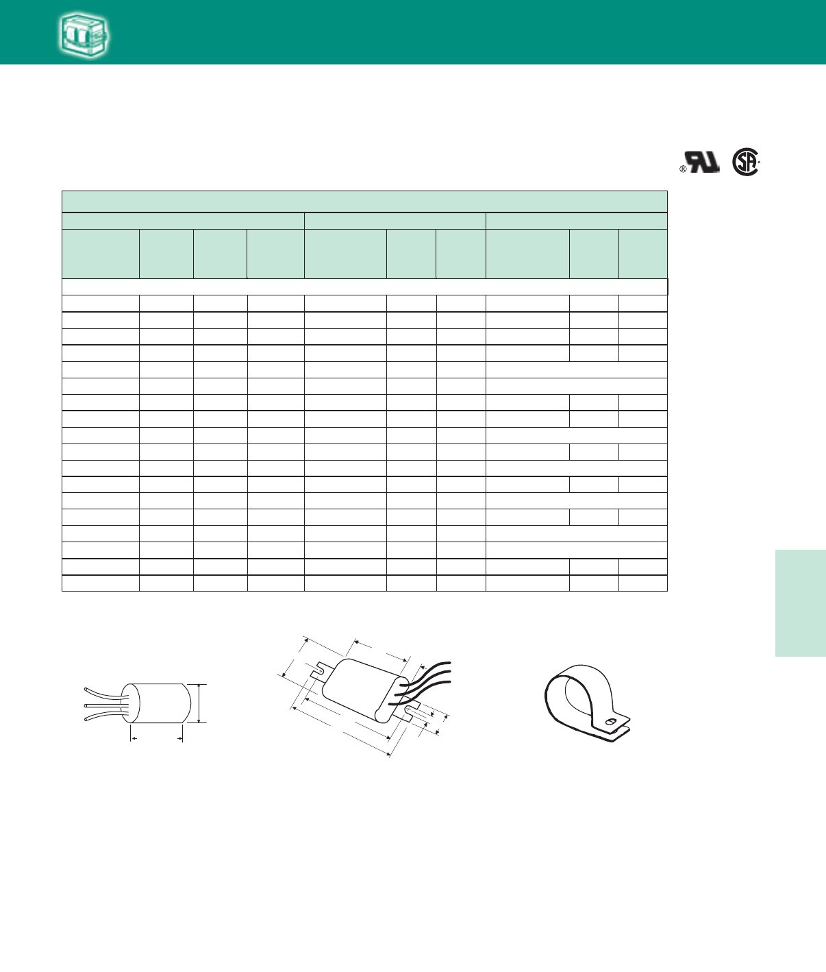
5-43
Lighting Electronics Atlas 2010-2011
HIGH INTENSITY DISCHARGE BALLASTS
Ignitor Specifications (Case Temperature Rating 105°C)
HID
71A7707 35 S76 R LI551-H4-IC 2 Round LI551-J4-IC 15 Round
71A7801 50 S68 HX LI551-H4-IC 2 Round LI551-J4-IC
71A7807 50 S68 R LI551-H4-IC 2 Round LI551-J4-IC 15 Round
Round35
71A81_2 150 S55 HX LI551-H4-IC 2 Round LI551-J4-IC
71A81_8 150 S55 CWA LI551-J4-IC 10 Round Not Available
71A8107 150 S55 R LI551-H4-IC 2 Round LI551-J4-IC
71A8156 150 S55 CWI LI551-J4-IC 2 Round Not Available
71A85_5 150 S55 CWI LI551-J4-IC 2 Round Not Available
Round35
Round15
71A81_6 150 S56 CWA LI501-H4-IC 2 Round LI501-J4-IC Round 50
71A86_7 150 S56 R LI501-H4-IC 2 Round LI501-J4-IC Round50
71A79_1 70 S62 HX LI551-H4-IC 2 Round LI551-J4-IC
71A79_6 70 S62 CWI LI551-J4-IC 2 Round Not Available
71A79_8 70 S62 CWA LI551-J4-IC 5 Round Not Available
71A7907 70 S62 R LI551-H4-IC 2 Round LI551-J4-IC
Round35
Round15
71A80_1 100 S54 HX LI551-H4-IC 2 Round LI551-J4-IC
71A80_8 100 S54 CWA LI551-J4-IC 5 Round Not Available
71A8007 100 S54 R LI551-H4-IC 2 Round LI551-J4-IC
71A80_6 100 S54 CWI LI551-J4-IC 2 Round Not Available
Round35
Round15
High Pressure Sodium
Long Range Ignitor
Phililps Advance
Ballast Family
Ballast Data
Lamp
Watts
ANSI
Code
Ballast
Circuit
Type
Catalog
Number
Standard Ignitor
Max.
Dist. (ft.)
To Lamp
Case
Type
Catalog
Number
Max.
Dist. (ft.)
To Lamp
Case
Type
RW33CC1252
Mounting Clip for Round Case
(Furnished as standard with -001 suffix ballasts and
all -IC suffix replacement ignitors.
Round Case
RED (X1)
WHITE (X2)
BLUE (X3)
Round Case
LI551-H4 = 2"
All Others= 2 1/2"
Max. case temp. 90 oC
11/4" DIAMETER
RED (X1)
WHITE (X2)
BLUE (X3)
1"
1/4" SLOT
43/4"
41/4"
25/32"3"
15/16 "
Max.
case temp. 90 oC
Case must be grounded
Oval Ignitor
Case
Oval Case
High Pressure Sodium
HID • Ignitors
HPS
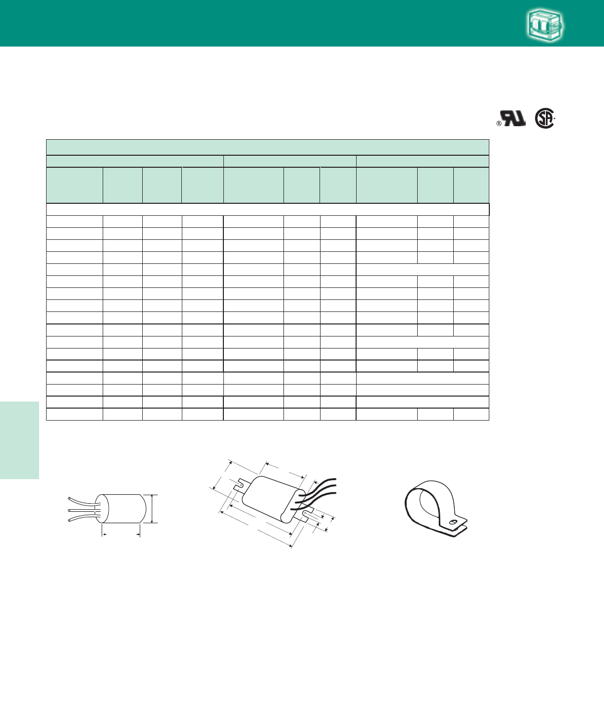
Lighting Electronics Atlas 2010-2011
5-44
HIGH INTENSITY DISCHARGE BALLASTS
Ignitor Specifications (Case Temperature Rating 105°C)
High Pressure Sodium
Long Range Ignitor
Phililps Advance
Ballast Family
Ballast Data
Lamp
Watts
ANSI
Code
Ballast
Circuit
Type
Catalog
Number
Standard Ignitor
Max.
Dist. (ft.)
To Lamp
Case
Type
Catalog
Number
Max.
Dist. (ft.)
To Lamp
Case
Type
High Pressure Sodium
★ Equipped with an auto-rest thermal protector to help prevent
ignitor from overheating in the event of lamp failure.
71A89_1 200 S66 CWA LI501-H4-IC 2 Round LI501-J4-IC Round50
71A89_7 200 S66 R LI501-H4-IC 2 Round LI501-J4-IC Round50
71A89_0 200 S66 CWA LI501-H4-IC 2 Round LI501-J4-IC Round50
71A82_1 250 S50 CWA LI501-H4-IC 2 Round LI501-J4-IC
71A82_6 250 S50 CWI LI501-J4-IC 2 Round Not Available
71A82_7 250 S50 R LI501-H4-IC 2 Round LI501-J4-IC
71A8392 250 S50 CWA LI501-H4-IC 2 Round LI501-J4-IC
Round
Round
Round
50
50
50
71A84_3 400 S51 CWA LI501-H4-IC 2 Round LI501-J4-IC
71A84_6 400 S51 CWI LI501-J4-IC 2 Round Not Available
71A84_7 400 S51 R LI501-H4-IC 2 Round LI501-J4-IC
71A85_6 430 n/a CWI LI501-H4-IC 15 Round LI501-J4-IC
Round
Round
50
50
71A85_5 600 S106 CWA LI561-H5-IC 5 Oval Not Available
Round35
71A86_5 750 S111 CWA LI561-H5-IC 5 Oval Not Available
71A87_3 1000 S52 CWA LI571-H5-IC★15 Oval LI571-J5-IC★Oval75
71A85_8 600 S106 CWI LI561-H5-IC 2 Oval Not Available
71A83_1 310 S67 CWA LI501-H4-IC 2 Round LI501-J4-IC
71A83_7 310 S67 R LI501-H4-IC 2 Round LI501-J4-IC
Round
Round
50
50
RW33CC1252
Mounting Clip for Round Case
(Furnished as standard with -001 suffix ballasts and
all -IC suffix replacement ignitors.
Round Case
RED (X1)
WHITE (X2)
BLUE (X3)
Round Case
LI551-H4 = 2"
All Others= 2 1/2"
Max. case temp. 90 oC
11/4" DIAMETER
RED (X1)
WHITE (X2)
BLUE (X3)
1"
1/4" SLOT
43/4"
41/4"
25/32"3"
15/16 "
Max.
case temp. 90 oC
Case must be grounded
Oval Ignitor
Case
Oval Case
HID
HID • Ignitors
HPS
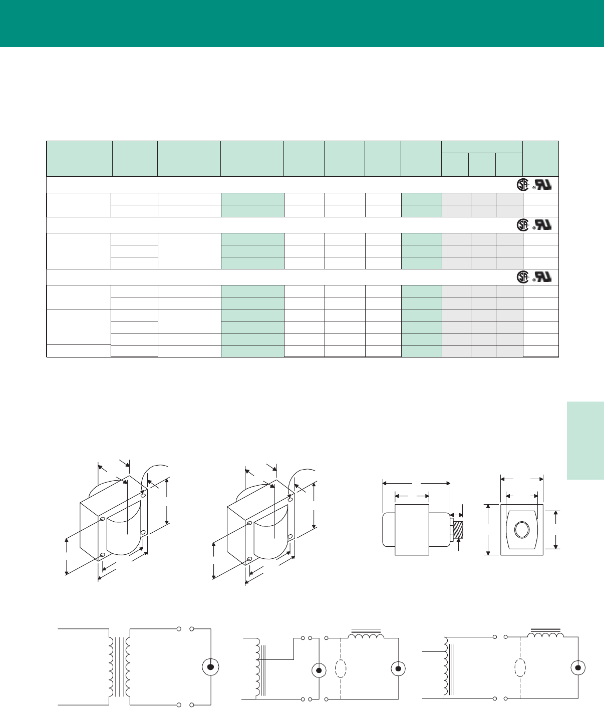
5-45
Lighting Electronics Atlas 2010-2011
HIGH INTENSITY DISCHARGE BALLASTS
Dimensions
Transformers & Autotransformers
Stepdown Transformers and Autotransformers
✝ Ordering information:
Add proper suffix to catalog number:
-600 includes core and coil only
-J (available where shown) includes J-Box cover
and auto-reset thermal protection. Refer to Figure 11.
* For use with Intellivolt LED Drivers.
OUTPUT V
OUTPUT VLINE V
LINE V
Fig. T- 1
INCANDESCENT
LAMP
Fig. T- 4
OUTPUT V
COM
VOLT
SL
AMP
COM COM
CAP
REACTO R
BALLAST
(OPTIONAL) HID
LAMP
LINE V
COM
LINE V
Fig. T- 2
INCANDESCENT
LAMP
COM
OUTPUT V
COM
VOLT
SL
AMP
COM COM
CAP
REACTO R
BALLAST
(OPTIONAL) HID
LAMP
Lamp Type Lamp
Watts
Input: Output
(Volts)
Catalog ✝
Number
Max.
Input
Current
Max.
Input
Watts
Max.
V.A.
Load
Wiring
Diagram
Weight
(lbs)
Fig A B
Stepdown Transformers for 6 and 12V Halogen Lighting
Halogen 120:11.5
277:120
100 71A9876-600 (-J) .9 125 265 T-2 4 (11) 1.9 2.6(3.9) 6.5(6.8)
Metal Halide 120:277
High Pressure
Sodium
75 71A9743-600C .8 81 75 T-1 9 1.5 2.8 2.5
50/75 277:11.8 71A9833-600C .3/.4 60/86 75 T-1 9 1.5 2.8 2.5
Stepdown Autotransformers for 120V Incandescent Lighting
Incandescent
150
277:115
71A9749-600 .6 150 150 T-2 9 1.5 2.7 2.3
200 71A9839-600 (-J) .8 199 200 T-2 9 (11) 2.2 3.8(4.2) 3.8(4.1)
300 71A9741-600 (-J) 1.1 300 300 T-2 9 (11) 2.0 3.5(4.0) 3.5(3.8)
Stepdown & Step-up Autotransformers for use with HID Reactor Ballasts
100/150 71A9862-600 1.7 200 395 T-2 9 2.7 3.9 4.5347:120/277
LED* 150 71A9843-600 0.65 100 300 T-2 9 2.4 3.8 3.7
480:270 or 347:190
70 71A9900-600 2.5 85 250 T-4 9 1.9 3.4 3.3
100/150 71A9741-600 (-J) 2.4 125 300 T-4 9 (11) 2.0 3.5(4.0) 3.5(3.8)
50/100/150 347:120/277 71A9862-600 (-J) 1.7 200 395 T-2 9 (11) 2.7 3.9(4.7) 4.5(4.8)
Fig 11
(J-Box Ballast)
Fig 9
(25/8" x 23/16" Reactor Core)
Fig 4
(23/16" x 33/8" Reactor Core)
Fig T-1 Fig T-2 Fig T-4
23/16"
23/16"
25/8"
13/4"
B
MAX.
A
Fig. 9
(2 5/8" x 23/1 6 Reactor Core)
4 Holes cleared for
#6 thru-bolts
23/16"
213/16"
33/8"
21/4"
BA
Fig. 9
(2 3/8" x 3
13/1 6 Reactor Core)
4 Holes cleared for
#10 thru-bolts
Fig. 11
J-Box Ballast
A
B
1/2"
1/2"-14
STRAIGHT PIPETHREAD
113 /16 "
23/16 "
127 /32 "
25/8"
Transformers
Autotransformers
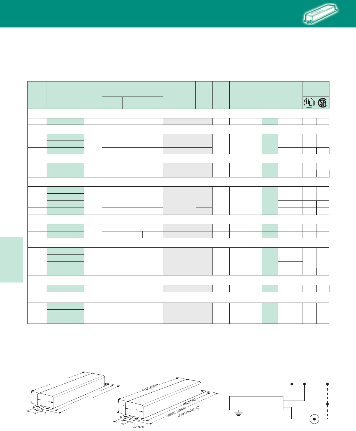
Lighting Electronics Atlas 2010-2011
5-46
HIGH INTENSITY DISCHARGE BALLASTS
F-Can Ballast
MOUNTING
3³⁄₁₆"
⁵⁄₁₆" Slots
OVERALL LENGTH
CASE LENGTH
LEAD LENGTHS
12"
2 ⁵⁄₈"
2"
111/16
23/8
111/16
Mtg.
Dim.
35/39W Lamp, ANSI Code M130 (Pulse-Start) SOUND RATING B
60 Hz F-Can Ballasts, (Indoor, Outdoor Type 1)
Metal Halide
120/277 HX-HPF .9/.4 1.0/.5 1.7/.8 94 240 5/2 11.75 10.50 11.13 8.5 10 ✓ ✓
HX-HPF
120/277 .9/.4 1.0/.5 1.7/.8 94 240 5/2 11.75 10.50 11.13 8.5 ✓ ✓
Input
Voltage
Catalog
Number
Circuit
Type
Input Amps Input
Watts
Nom.
Open
Circuit
Voltage
Fuse
Rating
Amps
Total
Wt.
(lbs)
Max.
Ballast
to Lamp
Distance (ft)
Case
Length
Over-all
Length
Starting Open
Circuit
Operating
Certifications
120/277 72C5181-NP
72C5181-NP-001 HX-HPF .7/.3 .8/.4 1.2/.5 72 254 3/2 11.75 10.50 11.13 9.0 25
20 20 20
50W Lamp, ANSI Code M110 or M148 (Pulse-Start) SOUND RATING B
✓✓
✓
120/277 72C5081-NP HX-HPF .6/.3 .6/.3 1.0/.4 56 255 3/1 11.75 10.50 11.13 9.0 10 ✓ ✓
120/347 72C51C1-NP .6/.2 .5/.2 1.6/.6 67 277 4/2
Dimensions Dimensions
(72C5005-NP)
Wiring Diagram
All lead lengths 12”
72C5280-NP-001
35 ✓
120/347 72C52C0-NP .8/.3 1.0/.4 1.7/.6
120/277
72C5282-NP
72C5282-NP-001 HX-HPF .9/.4 1.3/.6 1.6/.8 94 255 4/2 11.75 10.50 11.13 8.5
10
72C5282-NP-900•✓
✓✓
70W Lamp, ANSI Code M139 (Pulse-Start) SOUND RATING B
120/347 72C52C2-NP .9/.3 1.2/.4 1.7/.7 5/2 ✓
50
20
72C5281-NP-900•50
72C5381-NP-900•
100W Lamp, ANSI Code M90 or M140 (Pulse-Start) SOUND RATING B
120/277
72C5381-NP
72C5381-NP-001 HX-HPF 1.1/.5 2.2/1.0 2.4/1.1 125 277 6/3 11.75 10.50 11.13 11.0
5✓ ✓
150W Lamp, ANSI Code M81 (Double-ended lamp) (Pulse-Start) SOUND RATING B
120/277 72C5481-NP HX-HPF 1.6/.7 1.7/.8 3.7/1.6 180 240 10/4 14.30 13.13 13.75 13.0 10 ✓ ✓
120/347 72C52C1-NP-900•.8/.3 1.0/.4 1.7/.6 94 255 5/2 11.75 10.50 11.13 8.5 50 ✓ ✓
120/347 72C53C1-NP 1.1/.4 2.2/.8 2.4/.9 6/2 ✓
50
15
72C5482-NP-900•
72C5482-NP
150W Lamp, ANSI Code M102 or M142 (Pulse-Start) SOUND RATING B
120/277 HX-HPF 1.6/.7 1.5/.8 3.7/1.6 180 277 10/4 14.30 13.13 13.75 13.0 5✓ ✓
50
120/347 72C54C2-NP-900•1.6/.6 1.7/.6 3.7/1.3 180 240 10/4 14.30 13.13 13.75 13.0 50 ✓
All Philips Advance dual-volt, F-can ballasts include auto-reset thermal protection for both taps.
Replacement ballasts in individual cartons indicated by bold type with suffix -001.
• Ballasts with suffix -900 include integral XTENXA® Long-Range Ignitor for 50ft. max. ballast to lamp distance. Also suitable for shorter distances.
˚ All 150W thru 400W F-Can Ballasts are not EISA compliant.
HID
BALLAST
GROUND CASE
LAMP
RED
WHITE
COMMON120V
277V
OR
347V
BLK
YELLOW/BLUE
70W Lamp, ANSI Code M85 (Double-ended lamp) (Pulse-Start) SOUND RATING B
70W Lamp, ANSI Code M98 or M143 (Pulse-Start) SOUND RATING B
HID • F-Can
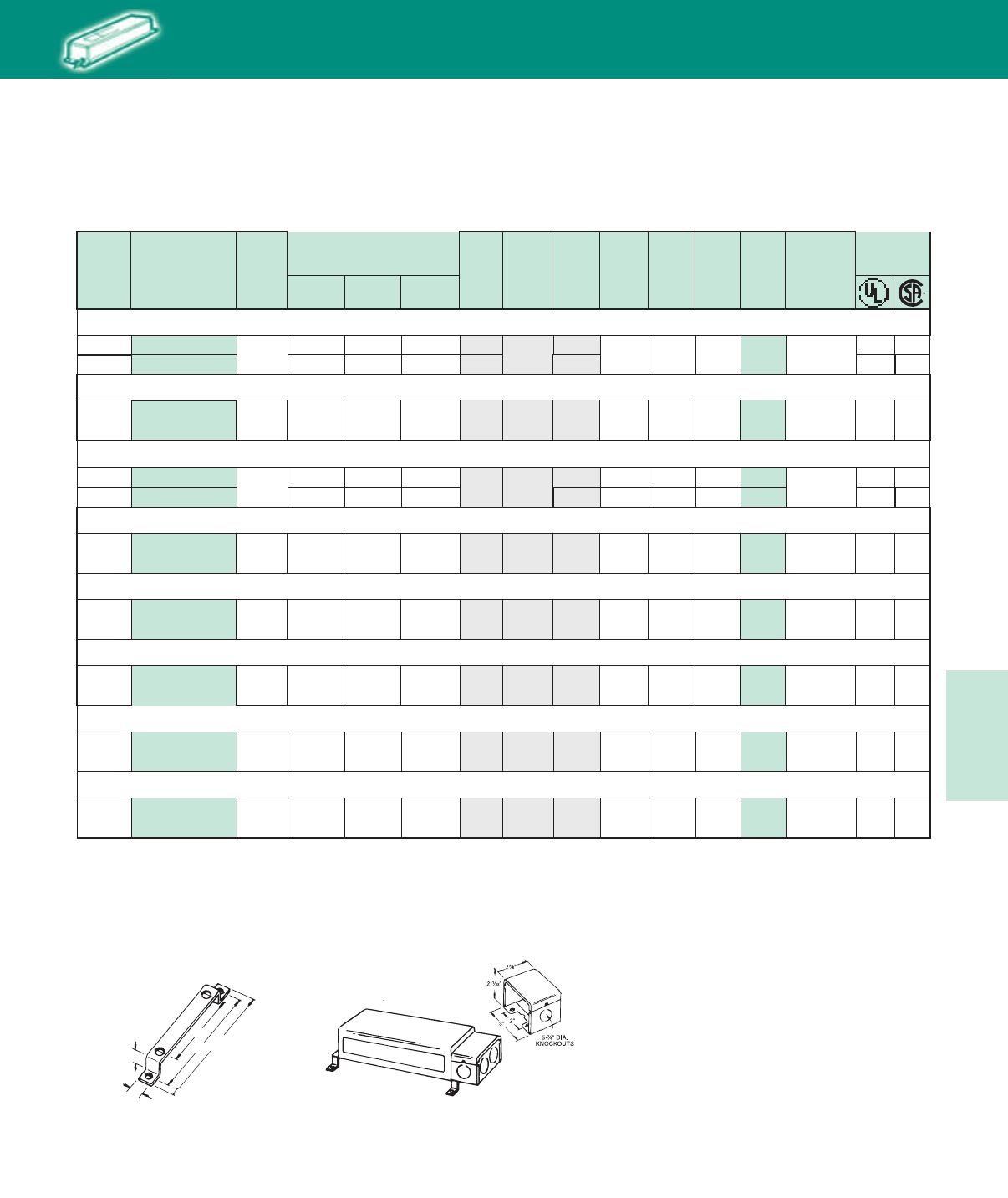
5-47
Lighting Electronics Atlas 2010-2011
HIGH INTENSITY DISCHARGE BALLASTS
Accessories
(PC-625 Mounting Bracket Kit)
⁵⁄₈
"
2"
4¹⁄₂"
4"
³⁄₈"
Includes (2) mounting brackets
and (4) #10-32 screws with nuts
and washers
Mtg.
Dim.
60 Hz F-Can Ballasts, (Indoor, Outdoor Type 1)
Metal Halide
Input
Voltage
Catalog
Number
Circuit
Type
Input Amps Input
Watts
Nom.
Open
Circuit
Voltage
Fuse
Rating
Amps
Total
Wt.
(lbs)
Max.
Ballast
to Lamp
Distance (ft)
Case
Length
Over-all
Length
Starting Open
Circuit
Operating
Certifications
All Philips Advance dual-volt, F-can ballasts include auto-reset thermal protection for both taps..
✪ Ballast to lamp distance is only limited by the size of the conductor between the ballast and the lamp. For proper wire size, see table on page 5-46 of this catalog.
Replacement ballasts in individual cartons indicated by bold type with suffix -001.
˚ All 150W thru 400W F-Can Ballasts are not EISA compliant.
HID
16.0
120/277 72C5782-NP-001 CWA 2.6/1.1 2.1/.9 2.1/.9 290 300 8/4 16.70 15.50 16.13
120/347 72C57C2-NP 2.5/.9 2.0/.7 2.0/.7 7/3 14.30 13.13 13.75 14.0 ✓
✓ ✓
✪✓
120/277 CWA 2.0/.9 2.0/.9 1.4/.7 205 300 5/3 11.75 10.50 11.13 12.0 ✓
✓
72C5581-NP-001
120/347 72C55C1-NP 1.9/.7 1.9/.7 1.7/.5 208 5/2
Accessories
PKG-625
Mounting Bracket Kit
Includes (2) mounting brackets and (4) #10-32
screws with nuts and washers.
PC-857
Wiring Compartment
For end mounting, includes
(5) M\,” dia. knockouts. May be used
with or without PC-625 Mtg. Brkt. Kit
120/277 Super
CWA 1.7/.8 .9/.4 2.2/.9 205 300 5/3 14.30 13.13 13.75 15.5 50 ✓ ✓
72C5582-NP
✪
72C6082-NP-001 3.9/1.7 3.3/1.4 3.9/1.7 460 310 10/5 19.20 18.00 18.63 22.5 ✪ ✓ ✓
120/277 Super
CWA 2.8/1.2 2.5/1.1 1.9/.8 290 300 8/3 16.70 15.50 16.13 18.0 50 ✓ ✓
72C5783-NP
120/277 Super
CWA 3.4/1.5 2.8/1.2 1.6/.7 370 270 8/3 19.20 18.00 18.63 21.0 50 ✓ ✓
72C5882-NP
120/277 Super
CWA 3.7/1.7 2.5/1.2 3.9/1.7 410 310 10/4 19.20 18.00 18.63 24.0 50 ✓ ✓
72C5983-NP
120/277
120/277 72C6182-NP-001 4.1/1.8 2.9/1.3 3.9/1.7 465 310 10/4 19.20 18.00 18.63 24.0 50 ✓ ✓
CWA
Super
CWA
250W Lamp, ANSI Code M58 SOUND RATING C
175W Lamp, ANSI Code M137 or M152 (Pulse-Start) SOUND RATING B
400W Lamp, ANSI Code M59 SOUND RATING C
250W Lamp, ANSI Code M138 or M153 (Pulse-Start) SOUND RATING B
320W Lamp, ANSI Code M132 or M154 (Pulse-Start) SOUND RATING C
350W Lamp, ANSI Code M131 (Pulse-Start) SOUND RATING C
400W Lamp, ANSI Code M135 or M155 (Pulse-Start) SOUND RATING C
175/150W Lamp, ANSI Code M57 or M107 SOUND RATING C
HID • F-Can

Lighting Electronics Atlas 2010-2011
5-48
HIGH INTENSITY DISCHARGE BALLASTS
72C8084-NP-001
72C7884-NP-001
Mtg.
Dim.
60 Hz F-Can Ballasts, (Indoor, Outdoor Type 1)
High Pressure Sodium
Input
Voltage
Catalog
Number
Circuit
Type
Input Amps Input
Watts
Nom.
Open
Circuit
Voltage
Fuse
Rating
Amps
Total
Wt.
(lbs)
Max.
Ballast
to Lamp
Distance (ft)
Case
Length
Over-all
Length
Starting Open
Circuit
Operating
Certifications
HID
HX-HPF .7/.3 .7/.4 1.4/.7 65 120 4/2 11.75 10.50 11.13 11.0 15 ✓ ✓
120/277 72C8084-NP HX-HPF 1.1/.5 1.5/.7 1.9/.8 125 120 6/3 11.75 10.50 11.13 11.0 15 ✓✓
120/277 72C7984-NP
72C7984-NP-001 HX-HPF .9/.4 1.0/.5 1.4/.7 90 120 5/2 11.75 10.50 11.13 10.0 7
120/347 72C79C4-NP .8/.3 .9/.3 1.4/.5 94 4/2 ✓
✓ ✓
120/277
All Philips Advance dual-volt, F-can ballasts include auto-reset thermal protection for both taps.
Replacement ballasts in individual cartons indicated by bold type with suffix -001.
Accessories
(PC-625 Mounting Bracket Kit)
⁵⁄₈
"
2"
4¹⁄₂"
4"
³⁄₈"
Includes (2) mounting brackets
and (4) #10-32 screws with nuts
and washers
Accessories
PKG-625
Mounting Bracket Kit
Includes (2) mounting brackets and (4) #10-32
screws with nuts and washers.
PC-857
Wiring Compartment
For end mounting, includes
(5) M\,” dia. knockouts. May be used
with or without PC-625 Mtg. Brkt. Kit
111/16
23/8
111/16
Wiring Diagram
All lead lengths 12”
Dimensions
BALLAST
GROUND CASE
LAMP
RED
WHITE
COMMON120V
277V
OR
347V
BLK
YELLOW/BLUE
120/277 72C8185-NP HX-HPF 1.7/.7 2.6/1.2 2.2/1.0 185 120 8/4 14.30 13.13 13.75 14.0 5 ✓ ✓
50W Lamp, ANSI Code S68 SOUND RATING B
100W Lamp, ANSI Code S54
SOUND RATING B
70W Lamp, ANSI Code S62
SOUND RATING B
150W Lamp, ANSI Code S55 (55V Arc Tube)
SOUND RATING B
HID • F-Can
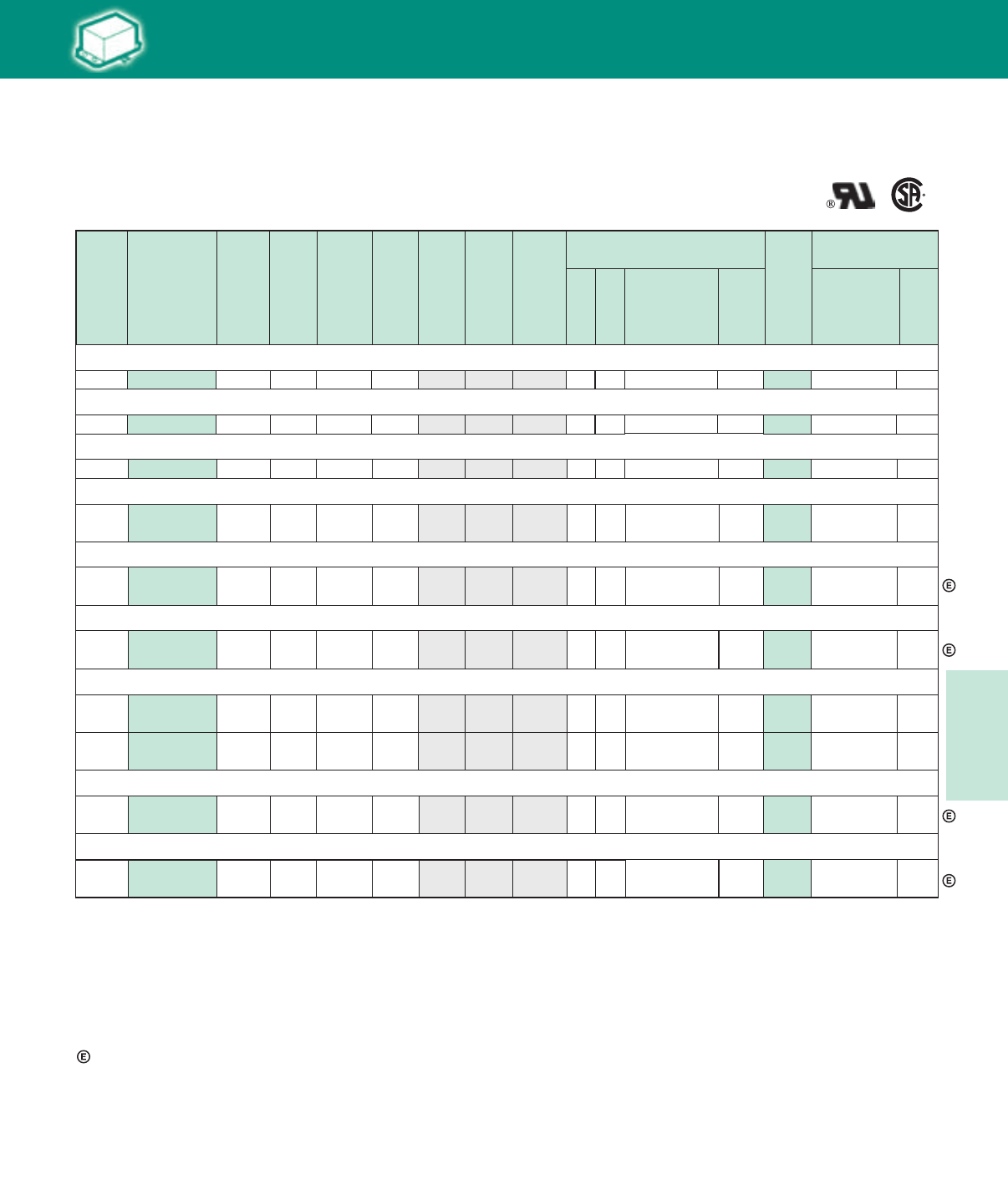
5-49
Lighting Electronics Atlas 2010-2011
HIGH INTENSITY DISCHARGE BALLASTS
60 Hz Encapsulated Core & Coil Ballasts
Metal Halide
✝ Ordering information:
Original equipment ballasts – typically ordered with capacitor (as shown)
-500D includes core & coil with dry-film capacitor
May also be available without capacitor:
-600 core & coil only (no capacitor)
• ForCWA,figureisoperatingcurrent.ForHXcircuits,figureishighestofstarting,operating
or open circuit currents
✝✝ Each ballast requiring an ignitor is furnished standard with the short-range ignitor model shown
for use within fixtures. Long-range ignitors are available separately, if required.
See pages 5-40 to 5-44 for additional information.
Indicates the ballast meets the 88% efficiency requirements of EISA
(Energy Independence and Security Act of 2007)
HID
Dry
or
Oil
Cap Catalog
Number
7C080L30RA
Catalog
Number
Circuit
Type
Input
Watts
Max
Input
Current
Nom
Open
Circuit
Voltage
Wiring
Dia
Non-PCB Capacitor
(Page 5-38 & 5-39)
Min
Volt
Ignitor ✝✝
(Page 5-40 to 5-44)
Part
Number
Max
Dist
To
Lamp
(ft)
70W Lamp, ANSI Code M98 Medium Base (Pulse-Start) SOUND RATING A
120/277 73B5282-500D HX-HPF 90 1.9/.8 255 K 280
7C100M30RA
D
D
9.0 LI533-H4 15
100W Lamp, ANSI Code M90 or M140 (Pulse-Start) SOUND RATING A
120/277 10.0
Total
Weight
(lbs)
✝
•
4/2
73B5383-500D CWA 128 1.1/.5 222 M 330 LI533-H4 23/2
Fuse
Rating
(Amps)
Input
Volts Mfd
8
10
Case
Style
PC709-4
7C100M40-R D
7C160M33-R D
150W Lamp, ANSI Code M102 (Medium Base) or M142 (Pulse-Start) SOUND RATING A
120/277 73B5482-500D HX-HPF 185 3.7/1.6 265 K 280 11.0 LI533-H4 10
175W Lamp, ANSI Code M57 SOUND RATING A
10/4
120/208/
240/277 73B5590-500D CWA 210 1.8/1.1/
.9/.8 305 A 12.0 – –
5/3/
3/2 400
16
10
PC709-4
PC709-4
PC709-2
7C110M40 D
175W Lamp, ANSI Code M137 or M152 (Pulse-Start) SOUND RATING A
120/208/
240/277 73B5591-500DEE Super
CWA 198 1.7/1.0/
.8/.7 285 M 15.0 LI533-H4 2
5/3/
3/2 37011 PC767-1
7C170P40 D
120/208/
240/277 73B5792-500DAEE Super
CWA 283 2.5/1.5/
1.3/1.1 275 M 16.0 LI533-H4 2
8/5
5/3 35017PC767-1
7C150P40-R
7C150P40-R
D
D
D
250W Lamp, ANSI Code M58 SOUND RATING B
120/208/
240/277 73B-5790-500DA CWA 295 2.5/1.4/
1.3/1.1 300 A 15.0
18.0
18.0
– –
8/5/
5/3
120/
277/347 73B57A0-500D CWA 295 2.5/
1.1/.9 315 A 15.2 – –
8/
3/3
400
400
15
15
PC767-1
PC767-1
7C225P40 D
7C210P40R
120/208/
240/277 73B5892-500DAEE Super
CWA 361 3.3/1.9/
1.7/1.4 270 M 345 LI533-H4 2
8/6/
5/3
120/208/
240/277 73B5993-500DAEE Super
CWA 397 3.4/2.0/
1.7/1.5 270 M
21
22.5 345 LI533-H4 2
10/7/
5/5
PC768-1
PC767-3
250W Lamp, ANSI Code M138 or M153 (Pulse-Start) SOUND RATING B
320W Lamp, ANSI Code M132 or M154 (Pulse-Start) SOUND RATING B
350W Lamp, ANSI Code M131 (Pulse-Start) SOUND RATING B
HID • Encapsulated
Core & Coil
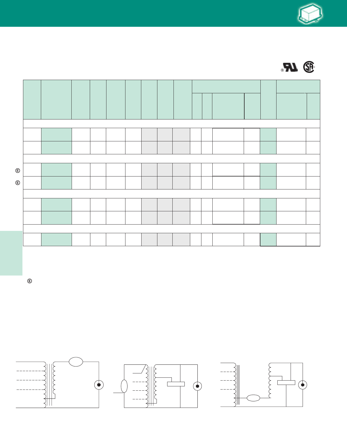
Lighting Electronics Atlas 2010-2011
5-50
HIGH INTENSITY DISCHARGE BALLASTS
60 Hz Encapsulated Core & Coil Ballasts
Metal Halide
✝ Ordering information:
Original equipment ballasts - add proper suffix to catalog number:
-500D includes core & coil with dry-film capacitor
-500 includes core & coil with oil-filled capacitor
-600 core & coil only (no capacitor)
• ForCWA,figureisoperatingcurrent.
Indicates the ballast meets the 88% efficiency requirements of EISA
(Energy Independence and Security Act of 2007)
Dry
or
Oil
Cap Catalog
Number
Catalog
Number
Circuit
Type
Input
Watts
Max
Input
Current
Nom
Open
Circuit
Voltage
Wiring
Dia
Non-PCB Capacitor
(Page 5-38 & 5-39)
Min
Volt
Ignitor ✝✝
(Page 5-40 to 5-44)
Part
Number
Max
Dist
To
Lamp
(ft)
Total
Weight
(lbs)
✝
• Fuse
Rating
(Amps)
Input
Volts Mfd
Case
Style
HID
400W Lamp, ANSI Code M59 SOUND RATING B
Fig. M
Fig. A
Fig. A
LAMP
LAMP
LINE V
COM COM
LINE V
LINE V
LINE V
CAP
CAP
Fig. M
LAMP
CAP
LAMP
COM COM
LINE V
LINE V
LINE V
IGNITOR
X1X3
X2
LINE V
CAPCAP
Fig. K
Fig. K
LAMP
CAPLAMP
COM COM
LINE V
LINE V
COM
LINE V
CAP
LINE V
IGNITOR
X1X3
X2
D
D
D
7C240P40-R
D
7C240P40-R
120/208/
240/277 73B6091-500DA CWA 458 4.0/2.3/
2.0/1.7 300 A PC-767-3 24 400 20.0 – –
10/7/
5/5
120/
277/347 73B60A1-500D CWA 460 4.0/
1.7/1.4 300 A PC-767-3 24 400 20.2 – –
10/
5/4
400W Lamp, ANSI Code M135 or M155 (Pulse-Start) SOUND RATING B
120/208/
240/277
120/208/
240/277
480
73B6092-500DAEE
73B6052-500DAEE
Super
CWA
Super
CWA
454
454
3.8/2.2/
1.9/1.7
3.8/2.2/
1.9/1.7/
1
270
275
M
M
PC-767-3
PC-767-3
26
26
330
330
15.0
17.0
LI533-H4
LI533-H4
10
2
10/7/
5/5
10/7/
5/5/
3
7C260P33R
7C260P33R
O
MD2409-100
120/208/
240/277 73B6590-500 CWA 1070 9.0/5.2
4.5/3.9 415 A PC-768-2 24 480 28.0 – –
20/15
10/10
O
MD2409-100
120/
277/347 73B65A2-500 CWA 1080 9.0/
3.9/3.2 430 A PC-768-1 24 480 28.0 – –
20/
10/8
O
MD2409-000
120/208/
240/277 73B6593-500 Super
CWA 1080 9/5.3/
4.5/3.9 430 M PC-768-1 24 480 29.0 L1571-H5 5
20/15
10/10
1000W Lamp, ANSI Code M141 (Pulse-Start) SOUND RATING C
1000W Lamp, ANSI Code M47 SOUND RATING C
HID • Encapsulated
Core & Coil
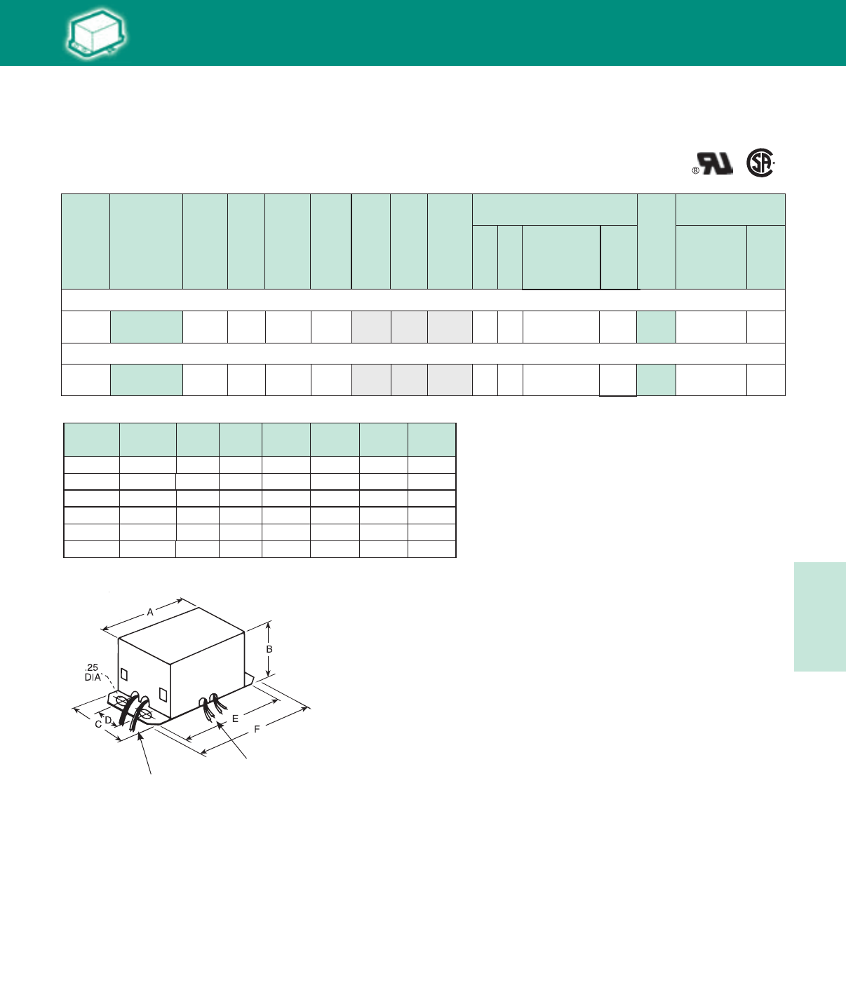
5-51
Lighting Electronics Atlas 2010-2011
HIGH INTENSITY DISCHARGE BALLASTS
HID
60 Hz Encapsulated Core & Coil Ballasts
Metal Halide
Dry
or
Oil
Cap Catalog
Number
Catalog
Number
Circuit
Type
Input
Watts
Max
Input
Current
Nom
Open
Circuit
Voltage
Wiring
Dia
Non-PCB Capacitor
(Page 5-38 & 5-39)
Min
Volt
Ignitor ✝✝
(Page 5-40 to 5-44)
Part
Number
Max
Dist
To
Lamp
(ft)
Total
Weight
(lbs)
✝
• Fuse
Rating
(Amps)
Input
Volts Mfd
Case
Style
D
250W Lamp, ANSI Code S50 SOUND RATING B
120/208/
240/277 73B8291-500DA CWA 295 2.5/1.5/
1.3/1.1 187 7/4/
4/3 15.4 LI501-H4 2
400W Lamp, ANSI Code S51 SOUND RATING B
120/208/
240/277 73B8493-500D CWA 460 3.8/2.2/
1.9/1.7 190 10/8/
5/5
PC-767-3
PC-767-3
35 240
55 240 21.0 LI501-H4 2
M
M
7C350P24RA
D
7C550P24RA
Side Lead Exit
End Lead Exit
DIMENSIONS
Case
Style
Lead
Exit A B C D E
PC709-4 Side 4.6 4.4 3.6 2.0 5.25 6.0
F
2.0PC709-2 Side 4.6 3.4 3.6 5.25 6.0
PC767-1 Side 5.4 5.0 3.8 2.0 6.0 6.75
PC767-3 Side 5.4 5.0 4.3 2.0 6.0 6.75
PC768-1 Side 6.5 5.0 5.2 2.0 7.0 7.75
PC768-2 Side 6.3 4.9 5.9 2.0 7.0 7.75
HID • Encapsulated
Core & Coil
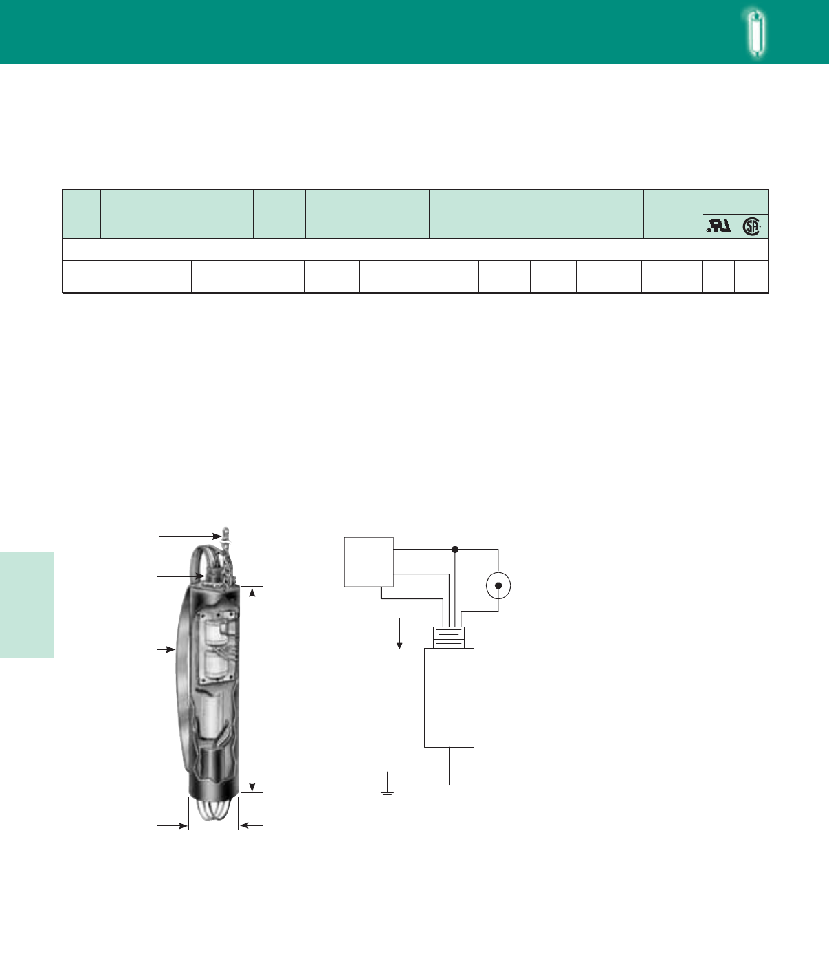
Lighting Electronics Atlas 2010-2011
5-52
HIGH INTENSITY DISCHARGE BALLASTS
Metal Halide
Input
Volts
Catalog Number
(P=Thermally
Protected)
Circuit
Type
Input
Watts
Max
Input
Current
Nom. Open
Circuit
Voltage
Fuse
(amps)
Weight
(lbs)
Max Dist
To Lamp
(ft)
Spring Clip
& Support
Chain Kit
Certifications
✝• Length
(in)
HID
60 Hz Postline Ballasts
HID•POSTLINE
✝ Ordering information:
Order catalog number indicated. If spring clip and support chain kit is desired,
order separately.
• ForHXandRcircuits,figureishighestofstarting,operatingoropencircuitcurrent.
PL-1 and PL-2 - Spring Clip and Support Chain Kits
Included pre-assembled with all postline ballasts rated 100 watts and
above. Support chain lowers ballast 18” down post while 6” or 10”
spring clip forces ballast against post’s inner wall to assure proper
heat dissipation away from ballast’s internal components. Also includes
factory-connected ground wire to provide for proper grounding of
ballast case and fixture housing. Kits include instruction sheet and may
be ordered separately to retrofit existing installations.
Postline Wiring Diagram
L
2.55" dia.
18" Chain &
Ground Wire
½" NPT – 14 Nipple
Spring Clip:
PL-1 6" for 7.0" long
ballasts
PL-2 10" for 12.0",
17.6", 21.0"
long ballasts
50W Lamp, ANSI Code M110
120 74P5104-011P HX-PFC 69 1.1 260 3 6.0 PL-2
(Optional) 2012.0 ✓ ✓
GREEN
WHITE
COM
BLACK
INPUT
VOLTS
TO
FIXTURE
FRAME
GREEN
LAMP
WHITE
BLUE
PHOTO
CONTROL RED
BLACK
Note: If Photo Control
is not used, connect
Red and Black leads together
Postline Wiring Diagram
HID • Postline
Metal Halide
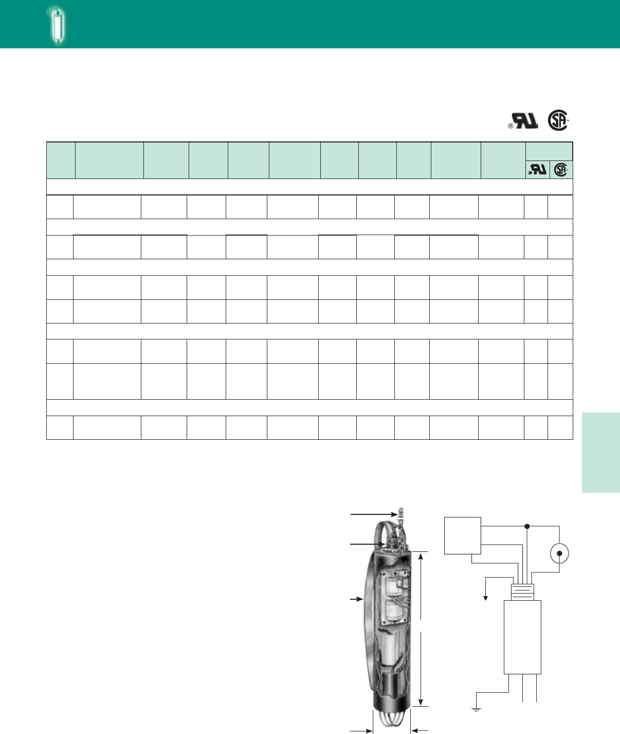
5-53
Lighting Electronics Atlas 2010-2011
HIGH INTENSITY DISCHARGE BALLASTS
120 74P7703-011P R-HPF 43 .8 120 2 3.5
120 61 120
PL-1
(Optional)
10
10
10
120 84 120
10
7.0
74P7803-011P R-HPF 1.3 4 4.8 PL-2
(Optional)
12.0
74P7903-011P R-PFC 1.6 4 5.0 PL-2
(Optional)
12.0
✓
✓
✓
✓
✓
277 74P7933-011P HX-HPF 97 .7 277 2 8.5 PL-2*
(Included) 1017.6 ✓
✓
✓
✓
HID
60 Hz Postline Ballasts
High Pressure Sodium
Input
Volts
Catalog Number
(P=Thermally
Protected)
Circuit
Type
Input
Watts
Max
Input
Current
Nom. Open
Circuit
Voltage
Fuse
(amps)
Weight
(lbs)
Max Dist
To Lamp
(ft)
Spring Clip
& Support
Chain Kit
Certifications
Length
(in)
HID•POSTLINE
✝ Ordering information:
Order catalog number indicated. Ballasts rated 100W and above include pre-assembled spring clip and support
chain kit. For ballasts rated less than 100W, if spring clip and support chain kit is desired, order separately.
* 70W High Pressure Sodium ballasts with 208, 240, or 277V inputs will always be supplied with the spring clip
and chain kit.
PL-1 and PL-2 - Spring Clip and Support Chain Kits
Included pre-assembled with all postline ballasts rated 100 watts and
above. Support chain lowers ballast 18” down post while 6” or 10”
spring clip forces ballast against post’s inner wall to assure proper
heat dissipation away from ballast’s internal components. Also includes
factory-connected ground wire to provide for proper grounding of
ballast case and fixture housing. Kits include instruction sheet and may
be ordered separately to retrofit existing installations.
L
2.55" dia.
18" Chain &
Ground Wire
½" NPT – 14 Nipple
Spring Clip:
PL-1 6" for 7.0" long
ballasts
PL-2 10" for 12.0",
17.6", 21.0"
long ballasts
Postline Wiring Diagram
✝
208
240
277
74P8013-011P
74P8023-011P
74P8033-011P
HX-HPF 136
1.1
1.0
.9
208
240
277
3
3
3
12.7 PL-2
(Included) 5
50W Lamp, ANSI Code S68
35W Lamp, ANSI Code S76
70W Lamp, ANSI Code S62
100W Lamp, ANSI Code S54
150W Lamp, ANSI Code S55 (55V Arc Tube)
120 74P8104-011P R-HPF 178 3.6 120 9 7.8 PL-2
(Included) 5
120 74P8003-011P R-HPF 122 2.5 120 7 7.3 PL-2
(Included) 517.6
17.6
21.0
✓
✓
✓
✓
✓
✓
✓
GREEN
WHITE
COM
BLACK
INPUT
VOLTS
TO
FIXTURE
FRAME
GREEN
LAMP
WHITE
BLUE
PHOTO
CONTROL RED
BLACK
Note: If Photo Control
is not used, connect
Red and Black leads together
Postline Wiring Diagram
HID • Postline
HPS
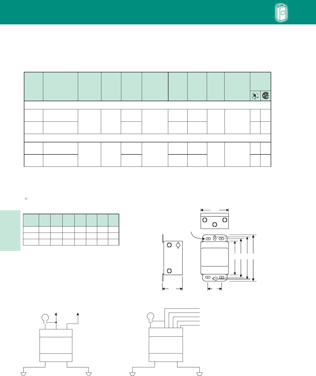
Lighting Electronics Atlas 2010-2011
5-54
HIGH INTENSITY DISCHARGE BALLASTS HID
60 Hz Indoor Enclosed Ballasts
High Pressure Sodium
Note: Ballasts must be mounted at least 12" apart. All indoor enclosed high pressure sodium and pulse-start metal
halide lamp ballasts are furnished with an Philips Advance long range ignitor built into the ballast enclosure. Maximum
lamp-to-ballast distance is 50 ft. (Except 1000 watt ballasts which are 75 ft). For ballasts not requiring ignitors,
see page 5-44 for remote mounting considerations.
• For CWA circuits, figure is operating current.
★ Equipped with an auto-reset thermal protector to prevent ignitor from overheating in the event of lamp failure.
White can typically used for indoor tennis courts.
DIMENSIONS
Case
Style A B C D
PC-723 11³/8
121/16
12
1211/16
12¾
137/16
13¾
147/16
PC-724
PC-746 17³/818 18¾ 19¾ 35/16
35/16
35/16
E
69/16
711/16
711/16
F
5¾
5¾
4¾
G
G
FTop view
3 double
7/8" and 1
1/8"
knockouts
3/8" Oval Slots
E
AB
CD
78E
INDOOR ENCLOSED
DIMENSIONS
Certification
Input
Volts
Catalog
Number
Circuit
Type
Maximum
Ambient
Temp.
Input
Watts
Max
Input
Current
Nom. Open
Circuit
Voltage
Fuse
(amps)
Case
Style
Weight
(lbs)
Wiring
Dia.
120/208/
240/277 38
78E8493-001 CWA
(40°C) 464
3.8/2.2/
1.9/1.7 190
10/8/
5/5 PC-724
IE-2 ✓ ✓
480 78E8493-001 1.0 3 IE-1 ✓
120/208/
240/277 60
78E8793-001 CWA★
(40°C) 1100
9.5/5.5/
4.8/4.2 435
25/15/
10/10 PC-746
IE-2 ✓ ✓
480 78E8743-001 2.3 6 IE-1 ✓
400W Lamp, ANSI Code S51
1000W Lamp, ANSI Code S52
)(
•
Fig IE-1
LAMP
LAMP COM
COM LINE V
TO LINE
TOP
INSULATE UNUSED
LAMP LEADS
INDIVIDUALLY FOR 600V
Fig. IE-1
Fig IE-2
LAMP
LAMP COM
COM
TOP
INSULATE UNUSED
LAMP LEADS
INDIVIDUALLY FOR 600V
Fig. IE-2
120 V
208 V
240 V
277 V
COM
HID
Indoor Enclosed
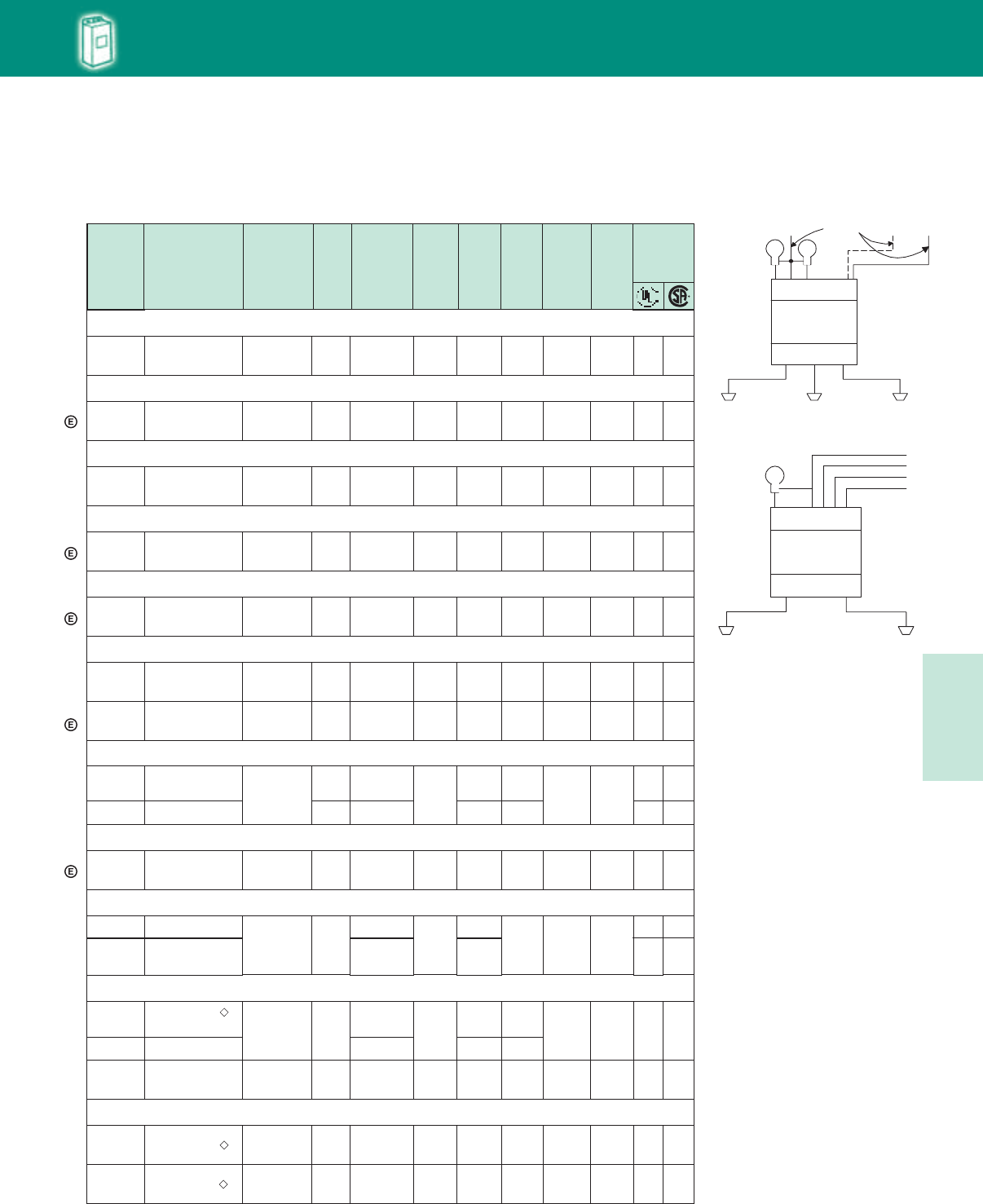
5-55
Lighting Electronics Atlas 2010-2011
HIGH INTENSITY DISCHARGE BALLASTS
120/208/
240/277
78E6592-WC1
78E6592-001
9.0/5.2/
4.5/3.9
20/15/
10/10 IE-2
480 78E6542-001 2.3 6 IE-1
HID
60 Hz Indoor Enclosed Ballasts
Metal Halide
Input
Volts
Catalog
Number
Circuit
Type
Maximum
Ambient
Temperature
Input
Watts
Max
Input
Current
Nom
Open
Circuit
Voltage
Weight
(Ibs)
Fuse
(amps)
Case
Style
• Wiring
Dia.
Certification
175/150W Lamp, ANSI Code M57/M107
120/208/
240/277 78E5590-001 CWA
(65°C) 210 1.8/1.1/
0.9/.8 305 5/3/
3/2 PC-723 22IE-2 ✓ ✓
175/150W Lamp, ANSI Code M137/M152 (Pulse Start)
120/208/
240/277 78E5591-001EE Super CWA
(65°C) 198 1.7/1.0/
.8/.7 285 5/3/
3/2 PC-723 22IE-2 ✓ ✓
250W Lamp, ANSI Code M58
120/208/
240/277 78E5790-001 CWA
(65°C) 285 2.5/1.5/
1.3/1.1 310 8/5/
5/3 PC-723 24IE-2 ✓ ✓
250W Lamp, ANSI Code M138/M153 (Pulse Start)
120/208/
240/277/
480
78E5752-001EE Super CWA
(55°C) 284 2.4/1.4/
1.2/1.1
.6 280 8/5/
5/3/
2PC-723 23IE-2 ✓ ✓
320W Lamp, ANSI Code M132/M155/M170 (Pulse Start)
120/208/
240/277/
480
78E5852-001EE Super CWA
(55°C) 363 3.3/1.9/
1.7/1.4/
0.6 275 10/7/
5/5/
5 PC-724 30IE-2 ✓ ✓
400W Lamp, ANSI Code M59
480 78E6041-001
CWA
(55°C) 462 1.0
300
3
PC-724 32
IE-1 ✓
400W Lamp, ANSI Code M135 (Pulse-Start)
120/208/
240/277/
480
78E6052-001EE Super CWA
(55°C) 454 265 10/7/
5/5
3PC-724 32.8IE-2 ✓✓
Two 400W Lamps, ANSI Code M59
CWA-ILO
(40°C) 890 330 PC-746 58IE-3
120/240 78E6351-001 8.4/4.2 20/10 ✓
350W Lamp, ANSI Code M131 (Pulse-Start)
120/208/
240/277 78E5993-001 Super CWA
(55°C) 400 3.4/2.0/
1.7/1.51 270 10/7/
5/5 PC-724 31.25IE-2 ✓ ✓
120/208/
240/277/
480
78E5953-001EE Super CWA
(55°C) 397 3.4/2.0/
1.7/1.5/
.9
3.8/2.3/
1.9/1.7/
1
285 10/7/
5/5/
5 PC-724 31.5IE-2 ✓ ✓
1000W Lamp, ANSI Code M47
CWA
(55°C) 1080 430 PC-724 42
✓
✓
✓
✓
✓
1000W Lamp, ANSI Code M141 (Pulse-Start)
120/208
240/277 78E6593-WC1 Super CWA
(50°C) 1080 9.0/5.2/
4.5/3.2 430 20/15/
10/10 PC-724 43.2IE-2 ✓
277/
347/480 78E65F3-WC1 Super CWA
(40°C) 1075 3.8/
3.2/2.4 430 10/
8/5 PC-724 42IE-2 ✓
120/
277/347 78E65A2-001 CWA
(55°C) 1080 9.0/
3.9/3.2 430 20/
10/8 PC-724 42.2IE-4 ✓
)(
✓
✓
✓
120/208/
240/277 78E6091-001 458 4.0/2.3/
2.0/1.8
10/7/
5/5 IE-2 ✓✓
120/277/
480
78E6381-001
78E6341-001
8.4/3.6
2.1
20/10
5
✓
✓
Fig IE-3
Fig. IE-3
LAMP 1
LAMP 1
LAMP 2
LAMP 2
COM
COM LINE VLINE VTO LINE
INSULATE UNUSED
LAMP LEADS
INDIVIDUALLY FOR 600 V
TOP
Fig IE-4
LAMP
LAMP COM
COM
COM
LINE V
LINE V
LINE V
INSULATE UNUSED
LAMP LEAD
FOR 600 V
TOP
HID
Indoor Enclosed
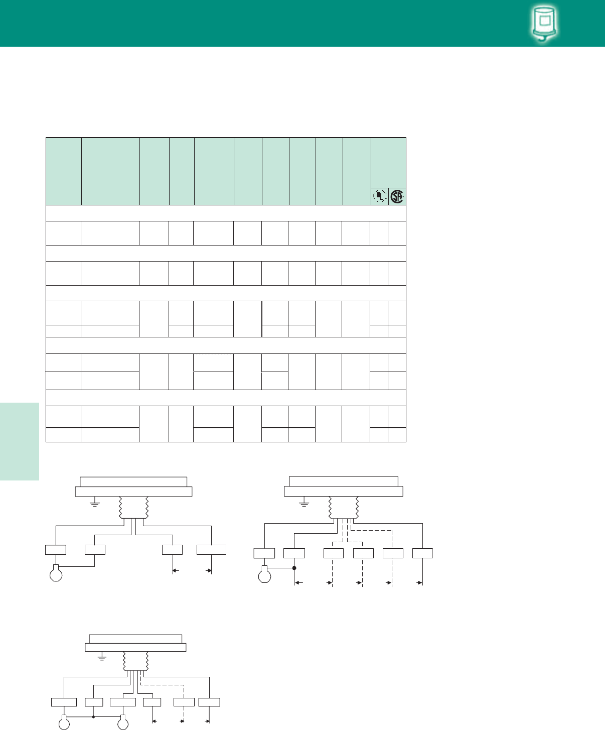
Lighting Electronics Atlas 2010-2011
5-56
HIGH INTENSITY DISCHARGE BALLASTS
480 79W6542-001 2.3 6 OW-1 ✓ ✓
LAMP COM CO
ML
INE V
TO LINE
Fig. OW-1
LAMP COM
TO LINE
Fig. OW-2
120 V 208 V 240 V 277 V
HID
60 Hz Outdoor Weatherproof Ballasts
Metal Halide
• For CWA circuits, figure is operating current.
Input
Volts
Catalog
Number
Circuit
Type
Input
Watts
Max
Input
Current
Nom
Open
Circuit
Voltage
Weight
(Ibs)
Fuse
(amps)
Height
(in)
• Wiring
Dia.
Certification
175/150W Lamp, ANSI Code M57/M107
120/208/
240/277 79W5590-001 CWA 210 1.8/1.1/
.9/.8 305 5/3/
3/2 6.6 15
250W Lamp, ANSI Code M58
120/208/
240/277 79W5790-001 CWA 285 2.5/1.5/
1.3/1.1 310 8/5/
5/3 8.6 18
400W Lamp, ANSI Code M59
Two 400W Lamps, ANSI Code M59
120/240 79W6351-001 CWA
(ILO) 890
8.4/4.2
330
25/15
13.8 43
1000W Lamp, ANSI Code M47
CWA 1080 430 11.3 33
OW-2
OW-2
OW-3
✓
✓
✓
✓
✓
120/208/
240/277
480
79W6091-001
79W6341-001
CWA 458
462
4.0/2.3/
2.0/1.8
1.0
300
10/7/
5/5
4
8.6 21
OW-2
OW-1
✓
✓
✓
✓
120/208/
240/277 79W6592-001 9.0/5.2/
4.5/3.9
20/15/
10/10 OW-2 ✓ ✓
480 79W6341-001 2.1 7 ✓ ✓
Fig OW-1 Fig OW-2
Fig OW-3
TO LINE
Fig. OW-4
INSULATE UNUSED
ALTERNAT E LAMP
LEADS INDIVIDUALLY
FOR 600V
LAMP 1COM CO
ML
INE V LAMP
2L
INE V
HID • Outdoor
Weatherproof
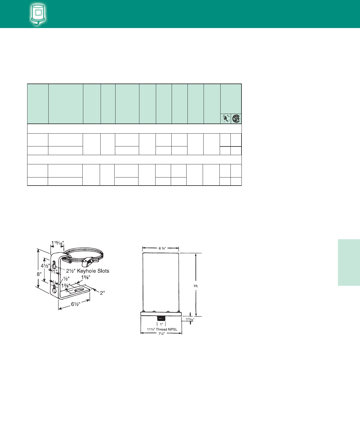
5-57
Lighting Electronics Atlas 2010-2011
HIGH INTENSITY DISCHARGE BALLASTS
HID
60 Hz Outdoor Weatherproof Ballasts
High Pressure Sodium
All weatherproof high pressure sodium lamp ballasts are furnished with an Philips Advance long range ignitor built into the ballast enclosure.
Maximum lamp-to-ballast distance is 50 ft. (except 1000W ballasts which are 75 ft.)
• For CWA circuits, figure is operating current. For HX circuits, figure is highest of starting, operating or open circuit current.
★ Equipped with an auto-reset thermal protector to prevent ignitor from overheating in the event of lamp failure.
400W Lamp, ANSI Code S51
1000W Lamp, ANSI Code S52
120/208/
240//277
480
79W8793-001
79W8743-001
CWA 1100
9.5/5.5/
4.8/4.2
2.3
435
25/15/
10/10
6
13.8 34
OW-2
OW-1
✓
✓
✓
Input
Volts
Catalog
Number
Circuit
Type
Watts
Input
Max
Input
Current
Nom
Open
Circuit
Voltage
Weight
(Ibs)
Fuse
(amps)
Height
(in)
• Wiring
Dia.
Certification
★
SH-1 Mounting Bracket
(RW4759007 and RW4777010)
HID • Outdoor
Weatherproof
480 79W8443-001 1.0 3 OW-1 ✓
CWA 464 430 11.3 20
120/208/
240/277 79W8493-001 3.8/2.2
1.9/1.7
10/8/
5/5 OW-2 ✓ ✓
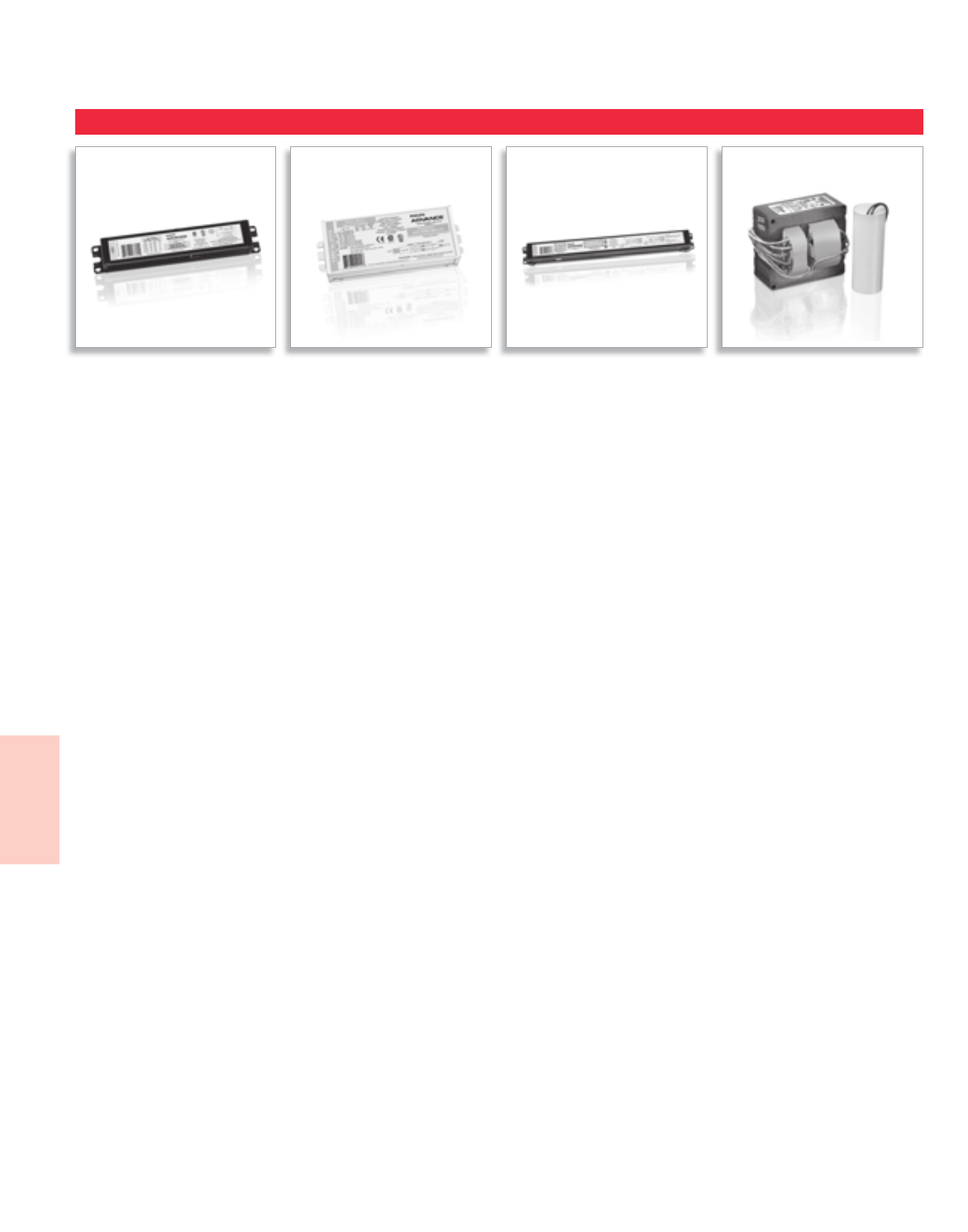
Lighting Electronics Atlas 2010-2011
SPECIALTY PRODUCTS
1
Specialty / International
Ballasts
AmbiStar™ PureVOLT™ Centium® Core & Coil

6-1
Lighting Electronics Atlas 2010-2011
SPECIALTY PRODUCTS
Specialty / International
Ballasts
Contents
Specialty Fluorescent and HID Ballasts
Residential Lighting 6-2
Ballasts that meet FCC Consumer limits and can be used in
Energy Star Fixtures
UV Disinfection 6-5
Ballast for Germicidal/UV lamps
Refrigeration 6-6
Ballasts for T8
International HID Ballasts (Locations other than North America)
General Information 6-7
50 Hz Core & Coil Ballasts 6-8 to 6-10
Mercury - Metal Halide - High Pressure Sodium lamps
Visit our web site at www.philips.com/advance
Customer Support/Technical Service
(800) 372-3331 • (+) 1 847 390-5000 (International)
Corporate Offices
(800) 322-2086

Lighting Electronics Atlas 2010-2011
SPECIALTY PRODUCTS
6-2
Specialty / International
Ballasts
Today’s fluorescent fixtures offer greater flexibility
and energy savings for residential and hospitality
settings than ever before, thanks to Philips Advance
AmbiStar electronic ballasts. No matter what
type of fluorescent lighting you’re considering, these
ballasts help create warm, inviting interiors while
providing Class B FCC EMI Rating – a requirement
for the EPA ENERGY STAR® residential lighting
fixtures – at a very competitive price.
AmbiStar fixed ballasts feature sleek, compact designs
to fit in today’s stylish fixtures. They deliver quiet,
flicker-free performance, which makes them perfect
for any residential or hospitality setting. Fluorescent
lighting isn’t just for garages and basements anymore.
AmbiStar dimming ballasts are designed to work
with most incandescent dimmers, so they are easy
to install with new or existing dimming systems.
Now you can create any ambiance with dimmable
lighting and still enjoy the energysaving benefits of
fluorescent lighting.
Fluorescent Ballasts - Electronic - AmbiStar™
Residential Ballasts for 4-pin CFL, T5, T8 or T12 Lamps
Features
Class B FCC EMI Rating
Requirement for EPA ENERGY STAR Residential
Lighting Fixtures
Title 24 Energy Efficiency Requirements
For use in high efficiency residential fixtures as stated
in applicable California’s Title 24 requirements
Electronic circuitry
Reduces energy used when compared to magnetic alternatives
RESIDENTIAL BALLASTS

6-3
Lighting Electronics Atlas 2010-2011
SPECIALTY PRODUCTS
Specialty / International
Ballasts
Features
In support of the growing popularity of High Output
(HO) germicidal UV-C lamps – which have been
effective at improving indoor air quality in low
temperature environments such as HVAC systems
– Philips Advance PureVOLT electronic UV ballast is
specially designed to operate a variety of 800mA HO
UV lamps. PureVOLT is ideal in such applications as
hospitals, food processing facilities, schools, office
buildings, recreational facilities, and residences.
Fluorescent Ballasts - Electronic - PureVOLT™
Electronic Ballasts for High Output (HO) Germicidal Ultraviolet (UV) Lamps
Features
Microprocessor-controlled design
Enables one UV ballast to operate multiple lamps
IntelliVolt® multiple-voltage technology enables operation
from 120 to 277V, 50/60 Hz
Enhances accuracy of ordering and reduces
SKU requirements
Lamp End-Of-Life (EOL) Protection Circuit
Removes power to the lamp upon lamp failure
Auto-restart
Eliminates the need to reset power mains after
lamp replacement
Programmed-start technology
Provides extended lamp life in frequent switching applications
UV DISINFECTION BALLASTS
Lighting Electronics Atlas 2010-2011
6-4
Specialty / International
Ballasts
Above ballasts comply with the requirements of the Federal Communications Commission (FCC) rules and requlations Title 47 CFR Part 18, Consumer (Class B) for EMI/RFI (conducted and radiated).
Above ballasts meet the ballast-controlled performance requirements in the ENERGY STAR Program Requirements for Residential Lite Fixtures
The most current list of ballasts can be found at www.philips.com/advance in the file “ENERGY STAR Ballast Matrix”
1 or 2 120 AmbiStarIS 1-41, 1-42, 1-45
1-46, 1-57, 1-58
REB-2P32-SC
3 or 4 120 AmbiStarIS 1-43, 1-44, 1-47
1-48, 1-59, 1-60
REB-4P32-SC
(1) or (2) F17T8, F25T8, F32T8 Linear
(3) or (4) F17T8, F25T8, F32T8 Linear
Linear T12 Lamps
1 120 AmbiStarRS 1-66
RELB-1S40-SC (1) F34T12, F40T12 Linear
2 120 AmbiStarRS 1-66 RELB-2S40-SC (2) F34T12, F40T12 Linear
Linear T8 Lamps
1 or 2 120 REB-2S26-M1-BS-DIM
AmbiStarRS REB-2S26-M1-LS-DIM
(1) or (2) 26W CFL
(1) 32W, 42W CFL 2-5
2 120 REB-2S13-M6-EL
AmbiStarIS REB-2S13-M6-BL (2) 13W CFL 1-23, 1-25
2 120 REB-2S18-M6-EL
AmbiStarIS REB-2S18-M6-BL (2) 18W CFL 1-23, 1-26
2 120 REB-2S26-M6-EL
AmbiStarIS REB-2S26-M6-BL (2) 26W CFL 1-24, 1-27
1 120 AmbiStarIS
(1) 26W CFL
(1) 18W, 24W Long Twin Tube or (1) 22W
Circline
1-24, 1-27, 1-30
1-38, 1-66
RMB-1P26-S2
1120 AmbiStarIS RMB-1P13-S1 1-22, 1-23, 1-25
1-36, 1-37
1 or 2 120 AmbiStar
IS RMB-2P13-S2 1-22, 1-23, 1-25
1-26, 1-36, 1-37
( 1 ) 7 W , 9 W , 1 3 W C F L
(1) F8T5, F13T5, F14T5 Linear
( 1 ) 1 8 W o r ( 2 ) 7 W , 9 W , 1 3 W C F L
(1) F8T5 & (1) F13T5 or (2) F8T5, F13T5, F14T5
Linear
REB-126-M6-BLS
SOUND RATED A
CFL Lamps
1 or 2 120 RCF-2S13-H1-LD-QS
AmbiStarRS RCF-2S13-M1-BS-QS
No. of
Lamps
Input
Volts Catalog Number
Ballast
Family
Lamp
Starting
Method
UL Listed Lamp Types Page No.
(1) or (2) 13W CFL 1-23, 1-25
1 or 2 120 RCF-2S18-H1-LD-QS
AmbiStarRS
RCF-2S18-M1-BS-QS
(1) or (2) 18W CFL 1-23, 1-26
1 or 2 120 RCF-2S26-H1-LD-QS
AmbiStarRS RCF-2S26-M1-BS-QS
(1) or (2) 26W CFL
(1) 32W, 42W CFL 1-24, 1-27, 1-28
REB-113-M6-BLS
1 120 AmbiStarIS REB-113-M6-EL (1) 13W CFL 1-23, 1-25
RESIDENTIAL LIGHTING
For 7 - 42W Lamps
T4, T5, T8 & T12
REB-118-M6-BLS
1 120 AmbiStarIS REB-118-M6-EL (1) 18W CFL 1-23
1 120 AmbiStarIS REB-126-M6-EL (1) 26W CFL 1-24, 1-27
CFL & Linear T5 Lamps
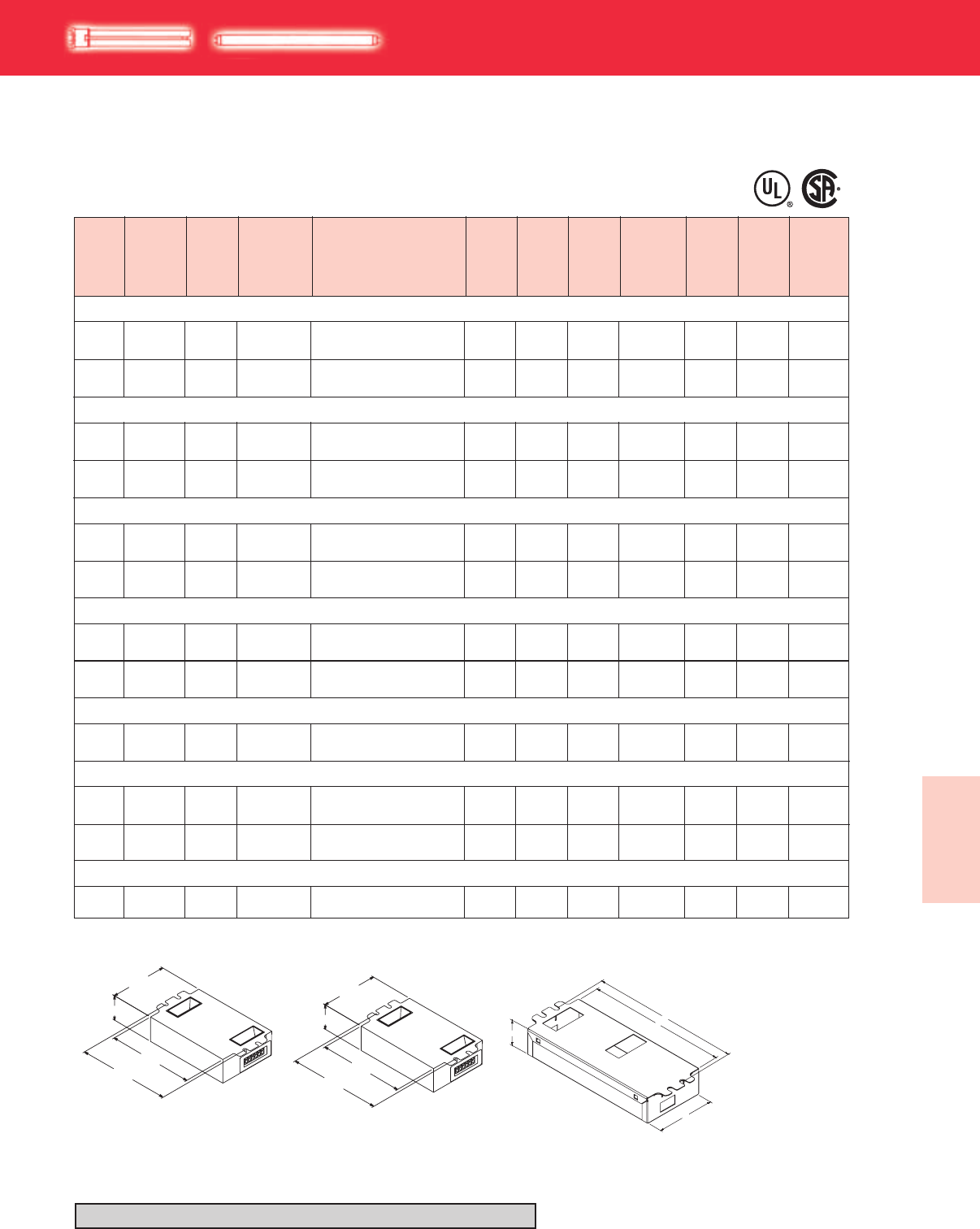
6-5
Lighting Electronics Atlas 2010-2011
Specialty / International
Ballasts
1 0/-18120 - 277 IUV-2S18-H1-LDPureVOLTPS 0.26 - 0.1130 290 10 Size 1 160
For 18 - 145W Lamps
PL-L18W/TUV (18W)
No. of
Lamps
Min.
Starting
Temp.
(°F/°C)
Input
Volts Catalog Number
Ballast
Family
Lamp
Starting
Method
Line
Current
(Amps)
Input
Power
ANSI
(Watts)
Lamp
Current
(mAmps)
Max.
THD
%
Dim. Wiring
Dia.
2 0/-18120 - 277 IUV-2S18-H1-LDPureVOLTPS 0.47 - 0.2055 280 10 Size 1 159
PL-L36W/TUV (36W)
PL-L35WHO/TUV (35W)
PL-L60WHO/TUV (60W)
PL-L95WHO/TUV (95W)
TUV 36T5/HO (75W)
TUV 64T5/HO (145W)
UV DISINFECTION
PL-L & T5/HO
HIGH POWER FACTOR SOUND RATED A
1 0/-18120 - 277 IUV-2S36-M2-LDPureVOLTPS 0.44 - 0.1951 330 10 Size 2 160
2 0/-18120 - 277 IUV-2S36-M2-LDPureVOLTPS 0.78 - 0.3390 285 10 Size 2 159
1 0/-18120 - 277 PureVOLTPS 0.35 - 0.1540 850 10 Size 4 160IUV-2S60-M4-LD
2 0/-18120 - 277 PureVOLTPS 0.68 - 0.2978 850 10 Size 4 159IUV-2S60-M4-LD
1 0/-18120 - 277 PureVOLTPS 0.60 - 0.2670 850 10 Size 4 160
IUV-2S60-M4-LD
2 0/-18120 - 277 PureVOLTPS 1.20 - 0.52138 850 10 Size 4 159
IUV-2S60-M4-LD
1 0/-18120 - 277 PureVOLTPS 0.87 - 0.37100 800 10 Size 4 160
IUV-2S60-M4-LD
1 0/-18120 - 277 PureVOLTPS 0.69 - 0.3080 800 10 Size 4 160
2 0/-18120 - 277 PureVOLTPS 1.30 - 0.56155 800 10 Size 4 159
IUV-2S60-M4-LD
IUV-2S60-M4-LD
1 0/-18120 - 277 PureVOLTPS 1.30 - 0.56155 800 10 Size 4 160
IUV-2S60-M4-LD
Refer to pages 6-6 for wiring diagrams
7.00"
7.50"
1.29"
3.00"
4.20"
4.60"
-LD
1.29"
3.00"
4.20"
4.60"
-LD
0.98"
2.40"
4.20"
4.60"
-LD
1.29"
3.00"
4.20"
4.60"
-LD
0.98"
2.40"
Size 1 Size 2 Size 4
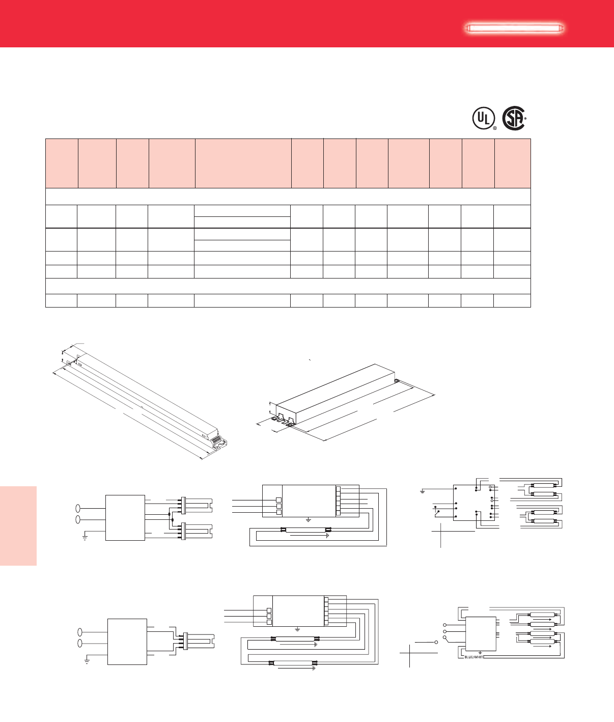
Lighting Electronics Atlas 2010-2011
6-6
Specialty / International
Ballasts
No. of
Lamps
Min.
Starting
Temp.
(°F/°C)
Input
Volts Catalog Number
Ballast
Family
Lamp
Starting
Method
Line
Current
(Amps)
Input
Power
ANSI
(Watts)
Ballast
Factor
Max.
THD
%
Dim. Wiring
Dia.
HIGH POWER FACTOR SOUND RATED A
1 -20/-18120 - 277 ICN-2S54
CentiumPS 0.49 - 0.2258 1.00 10 D 73
ICN-2S54-90C
F58T8 (58W)
2 -20/-18120 - 277 ICN-2S54
CentiumPS 0.97 - 0.42116 1.00 10 D74
ICN-2S54-90C
3 -20/-18120 - 277 CentiumPS 1.43 - 0.62171 1.00 10 *75
ICN-4S54-90C-2LS-G
4-20/-18120 - 277 CentiumPS 1.88 - 0.81225 1.00 10 75
ICN-4S54-90C-2LS-G
G
G
1 -20/-18120 - 277 ICN-1S80
CentiumPS 0.62 - 0.2673 0.77 10 D 73
REFRIGERATION T8
For 58 - 70W Lamps
1.18"
1.00"
16.70" 16.34"
Fig. D Fig. G
WIRING: 1-LAMP
Diag. 160
Green Te rminal must be Grounded
Diag. 159
Green Te rminal must be Grounded
Diag. 163
Green Te rminal must be Grounded
Diag. 162
Green Te rminal must be Grounded
RED
GREEN
BLACK
WHITE BALLAST
LINE
BLUE
WIRING: 2-LAMP
YELLOW
GREEN
BLACK
WHITE BALLAST
LINE
BLUE
RED
YELLOW
GREEN
BLACK
WHITE
BALLAST
BLUE
LAMP
LAMP
RED
GREEN
BLACK
WHITE
BALLAST
BLUE
LAMP
RED
Diag. 159
Green Terminal must be Grounded
Diag. 160
Green Terminal must be Grounded
Diag. 74
Diag. 75
Diag. *75
WIRING: 1-LAMP
Diag. 160
Green Te rminal must be Grounded
Diag. 159
Green Te rminal must be Grounded
Diag. 163
Green Te rminal must be Grounded
Diag. 162
Green Te rminal must be Grounded
RED
GREEN
BLACK
WHITE BALLAST
LINE
BLUE
WIRING: 2-LAMP
YELLOW
GREEN
BLACK
WHITE BALLAST
LINE
BLUE
RED
YELLOW
GREEN
BLACK
WHITE
BALLAST
BLUE
LAMP
LAMP
RED
GREEN
BLACK
WHITE
BALLAST
BLUE
LAMP
RED
GREEN
BLACK
WHITE
GREY
LINE (HOT)
LINE (NEU) S
BALLAST
RED
ORANGE
BLUE
BROWN
BLU/WHT
YELLOW
LAMP
LAMP
LAMP
LAMP
LAMPS
S
ON
OFF
4 LAMPS ON
2 LAMPS ON
Diag. 73
For 1 lamp operation, do not use yellow leads
LAMP
LAMP
RED
RED
GREEN
BLACK
WHITE
BALLAST
BLUE
BLUE
YELLOW
YELLOW
For 1 lamp operation, do not use yellow leads
LAMP
RED
RED
GREEN
BLACK
WHITE
BALLAST BLUE
BLUE
YELLOW
YELLOW
16.34"
16.70"
1.18"
1.70"
F70T8 (70W)
BLACK
WHITE
GREY/RED
BALLAST
ORANGE
RED
BLUE
BROWN
YELLOW
250V,
1mA
S
4-LAMP
NUETRAL OR
(ANY HOT)
LAMPS
S
ON
OFF
4 LAMPS ON
2 LAMPS ON
LAMP
LAMP
LAMP
LAMP
6-7
Lighting Electronics Atlas 2010-2011
SPECIALTY PRODUCTS
Specialty / International
Ballasts
Philips Lighting Electronics offers an extensive range of High Intensity Discharge ballasts to run ANSI
specification (U.S. style) lamps. These ballasts are suitable for International markets and range in voltage
from 120 through 240V, 50 Hz.
Philips Advance HID Ballasts are available to operate
the wide variety of mercury, metal halide, high pressure
sodium and low pressure sodium lamps available in
today’s marketplace.
Like fluorescent, HID lamps are electric discharge lamps.
Light is produced by an arc discharge between two
electrodes located at opposite ends of an arc tube within
the lamp’s outer glass envelope. The ballast is the lamp’s
power supply; its purpose is to provide proper starting
and operating voltage and current to initiate and sustain
this arc.
Core & Coil
The basic ballast is the open core & coil which is most
often used as a component within a lighting fixture. The
core & coil also forms the nucleus of the five other ballast
configurations detailed in this section. It consists of either
one, two or three copper coils on a core (or “stack”) of
electrical-grade steel laminations. The coils are assembled
to core sections which are then surface-welded together.
At Philips Lighting Electronics the assembled ballast is
vacuum impregnated with a silica-filled polyester varnish
to re-enforce the electrical insulation, preclude moisture,
inhibit noise, and dissipate heat. Some HID ballast
manufacturers apply varnish via a preheat-and-dip process
which only puts a thin coat of varnish on the outer surface
of the ballast.
Encapsulated Core & Coil
Where quiet performance is required, the standard
open core & coil ballasts are encapsulated (potted) in a
cube-shaped steel can utilizing Class H (180°C) polyester
compound. These ballasts carry a Class A noise rating up
through 175W and Class B for 250 and 400W. As with
the open core & coil, the capacitor (and ignitor where
included) are mounted separately within the fixture.
EPAct 2005
The Energy Policy Act of 2005 (EPACT 2005) requires
that mercury vapor lamp ballasts shall not be manufactured
in or imported into the United States after January 1, 2008.
With regard to imported ballasts, the standard applies to
both the importing of ballasts as well as the importing
of mercury vapor lamp luminaires with ballasts, since
importing a mercury vapor lamp luminaire with a mercury
vapor lamp ballast would be the same as importing a
mercury vapor lamp ballast. Therefore, as of January 1,
2008, luminaires cannot be imported with mercury vapor
lamp ballasts.
Replacements
For capacitors, see pages 5-38 & 5-39
For ignitors, see pages 5-40 & 5-41
Special Voltages
For voltage and frequencies not shown in the charts of
the following pages, please contact your Philips Lighting
Electronics Sales Representative.
CERTIFICATIONS
Indicates ballast is listed by Underwriters
Laboratories, Inc. in accordance with UL 1029
Standard for HID Ballasts. Each ballast is marked
appropriately.
All HID Ballasts are designed and manufactured
in accordance with the American National
Standards Institute Standard for HID Ballasts,
ANSI C82.4.
Norma Obligatorio Mexicana.
(contact your local salesperson for availability)
NOM
INTERNATIONAL ELECTROMAGNETIC HID BALLASTS
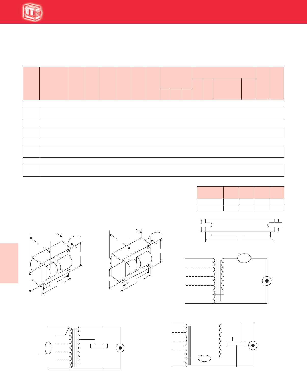
Lighting Electronics Atlas 2010-2011
6-8
Specialty / International
Ballasts
International HID
Dry
or
Oil
Cap Catalog
Number
Input
Volts
Catalog
Number
Circuit
Type
Watts
Input
Max
Input
Current
Nom
Open
Circuit
Voltage
Fuse
Rating
(Amps)
Fig
Dimensions
Non-PCB Capacitor
(Page 5-38 & 5-39)
Mfd Min
Volt
Total
Weight
(Ibs)
U.L.
Bench
Top Rise
Code
1029
(Pg 5-4)
A B
•
✝Wiring
Dia
HIGH INTENSITY DISCHARGE BALLAST
HID
50 HZ Core & Coil Ballasts
Mercury These products are for use outside the USA ONLY
175W Lamp, ANSI Code H39
120/
220/240 See 175W Metal Halide CWA 71A55N0-500D (page 6-9)
250W Lamp, ANSI Code H37
400W Lamp, ANSI Code H33
1000W Lamp, ANSI Code H36
120/
220/240 See 1000W Metal Halide CWA 71A65N2-500 (page 6-9)
120/
220/240 See 250W Metal Halide CWA 71A57N0-500D (page 6-9)
120/
220/240 See 400W Metal Halide CWA 71A60N1-500 (page 6-9)
WELDED BRACKET DIMENSIONS
Ballast
Dimensions Fig L W M S
1 5.1 1.00 4.50 0.25
2 6.5 1.25 5.75 0.28
✝ Ordering information:
Original equipment ballasts - add proper suffix to catalog number:
-500D includes core & coil with dry-film capacitor
-510D includes core & coil with welded bracket and dry-film capacitor
-600 core & coil only (no capacitor)
• For CWA circuits, figure is operating current.
41/4"
43/8 "43/4"
37/8"
B
MAX.
A
Fig. 2
(41
/4" x 43
/4" core)
4 Holes cleared for
#10 thru-bolts
Fig. 2
(4¼" x 4¾" Core)
W
++
BRACKET
M
L
S
213/16"
31/2"315/16"
27/16"
B
MAX.
A
Fig. 1
(3" x 4" core)
4 Holes cleared for
#10 thru-bolts
Fig. 1
(3" x 4" Core)
Fig. M
Fig. A
Fig. A
LAMP
LAMP
LINE V
COM COM
LINE V
LINE V
LINE V
CAP
CAP
Fig. M
LAMP
CAP
LAMP
COM COM
LINE V
LINE V
LINE V
IGNITOR
X1X3
X2
LINE V
CAPCAP
Fig. K
Fig. K
LAMP
CAPLAMP
COM COM
LINE V
LINE V
COM
LINE V
CAP
LINE V
IGNITOR
X1X3
X2
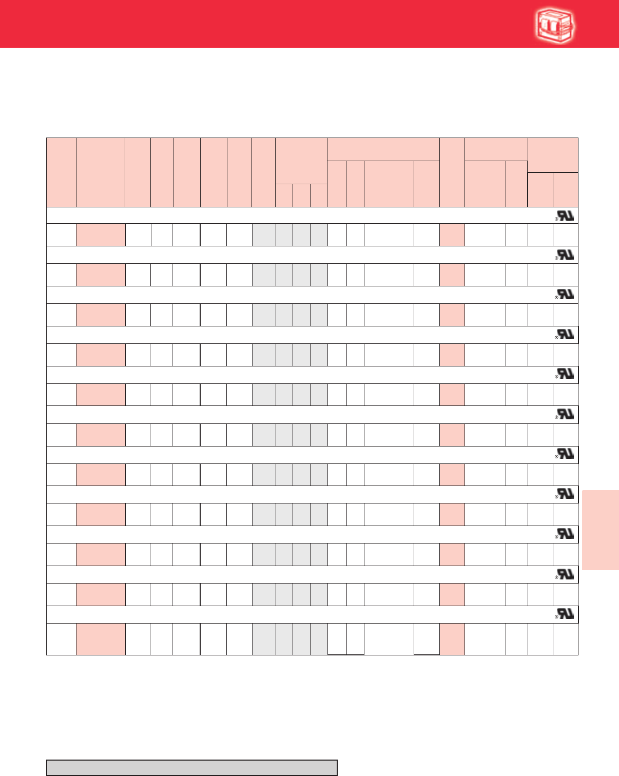
6-9
Lighting Electronics Atlas 2010-2011
Specialty / International
Ballasts
A
International HID
HIGH INTENSITY DISCHARGE BALLASTS HID
Metal Halide These products are for use outside the USA ONLY
50 HZ Core & Coil Ballasts
54036 O
D7C140M30RA
D7C175M30RA
120/
220/240 71A52N2-500D HX-HPF
HX-HPF
HX-HPF
95 1.7/
1.0/.9 256 5/
3/3 1 1.5 2.8 14 280 LI533-H4
120/
220-240 71A55N0-500 CWA 210 2.0/
1.0 310 5/
31 2.8 4.0 12 450 –
120/
220-240 71A57N0-500D CWA 290 2.5/
1.3 315 7/
4
454 3.9/
2.0 270 10/
5
365 3.1/
1.6 280 10/
5
21.9 3.4 18 400 –
120/
220-240 71A60N1-500 CWA 462 4.1/
2.1 320 10/
62 2.2 3.7 24 450 –
120/
220/240 71A65N2-500 CWA 1090 9.3/
5.0/4.5 450 24/
13/13 8 3.0 5.0 26 525 –
220/240 71A67R2-510 CWA 1605 7.5/6.9 450 20/20 8a 4.4 6.4 –
K
A
A
A
A
B/
A/B
E/E
C/
C
D/
A
D/
D
D/
C/C
120/
220-240 71A58N2-500D Super
CWA 2 2.1 3.8 24 400 LI533-H4 A/
A
M
120/
220-240 71A60N2-500D Super
CWA 2 2.1 3.8 30 345 LI533-H4 C/
E
M
2
15
–
–
–
2
–
–
12.5
5.0
32.0
9.0
11.5
12.3
14.0
23.0
A/A
120/
220/240
71A53N0-500D
129 2.2/
1.2/1.1 266 6/
3/3 11.9 3.2 17.5 300 LI533-H4KA/
A/A
156.0 –
–
–
–
A/
A/A
–
–
120/
220/240
71A54N2-500D
187 3.7/
2.0/1.8 248 10/
5/5 1 2.5 4.1 28 240 LI533-H4KC/
C/D
57.5 –
120/
220-240 71A57N2-500D Super
CWA
2.6/
1.4 280 6/
32 1.8 3.3 20 330 LI533-H4
MC/
C
511.5 –
294
D7C280P30RA
OMD1204-100
D7C180P40-R
D7C200P33-R
D7C240P40-R
OMD2409-100
D7C300S34
OMD2602-100
2 Capacitor Set:
MD1802-200
(2) 18mFd Caps
Connected in Parallel
[ ]
Dry
or
Oil
Cap Catalog
Number
U.L. Bench Top
Rise Code 1029
(Pg 5-4)
Class H
(180°C)
Philips
Advance
Class N
(200ºC)
Input
Volts
Catalog
Number
Circuit
Type
Max
Input
Current
Fuse
Rating
(Amps)
Fig
Dimensions
Non-PCB Capacitor
(Page 5-38 & 5-39)
Min
Volt
Total
Weight
(Ibs)
Ignitor ✝✝
(Page 5-40 to 5-44)
Part
Number
Max
Dist
To
Lamp
(ft)
A B
✝•Wiring
Dia Mfd
Nom
Open
Circuit
Voltage
Watts
Input
Refer to pages 6-8 for ballast dimensions and wiring diagrams
70W Lamp, ANSI Code M98 or M143 (Pulse-Start)
250W Lamp, ANSI Code M58 or H37
400W Lamp, ANSI Code M59 or H33
1000W Lamp, ANSI Code M47 or H36
320W Lamp, ANSI Code M132 or M154 (Pulse-Start)
400W Lamp, ANSI Code M135 or M155 (Pulse-Start)
–
150W Lamp, ANSI Code M102 or M142 (Pulse-Start)
100W Lamp, ANSI Code M90 or M140 (Pulse-Start)
250W Lamp, ANSI Code M138 or M153 (Pulse-Start)
175W Lamp, ANSI Code M57 or H39; or 150 Watt Lamp, ANSI Code M107
1500W Lamp, ANSI Code M48
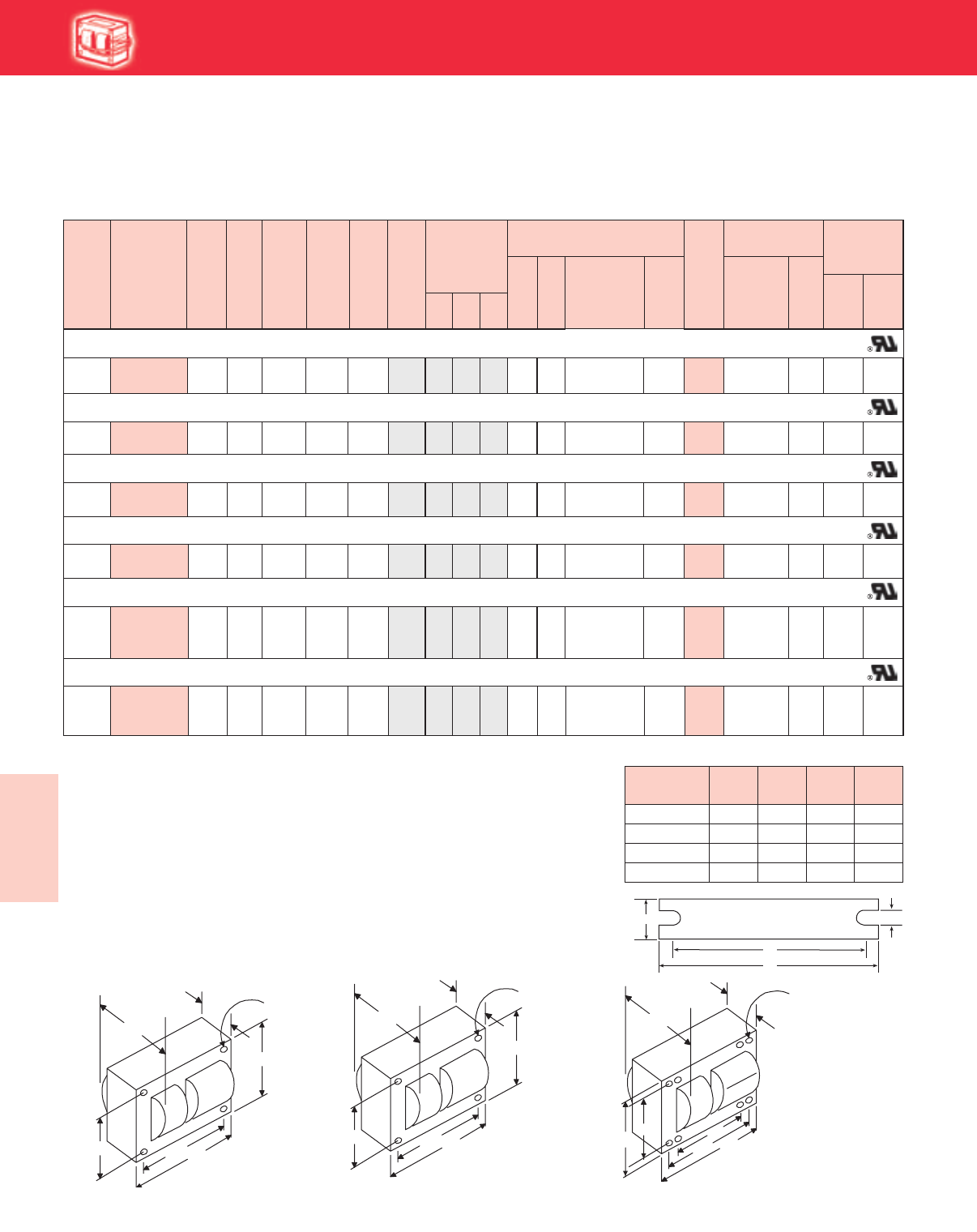
Lighting Electronics Atlas 2010-2011
6-10
Specialty / International
Ballasts
WELDED BRACKET DIMENSIONS
Ballast
Dimensions Fig L W M S
1 5.1 1.00 4.50 0.25
2 6.5 1.25 5.75 0.28
8 7.8 2.75 6.13 0.25
8a 7.8 4.50 6.75 0.31
✝ Ordering information:
Original equipment ballasts - add proper suffix to catalog number:
-500D includes core & coil with dry-film capacitor
-510D includes core & coil with welded bracket and dry-film capacitor
-500 includes core & coil with oil-filled capacitor
-510 includes core & coil with welded bracket and oil-filled capacitor
-600 core & coil only (no capacitor)
✝✝ Each ballast requiring an ignitor is furnished as standard with the Short Range
ignitor model shown for use within fixtures. If a Long Range ignitor is required
for remote mounting, specify on order. See pages 5-40 to 5-44 for additional information.
• For HX and R circuits, figure is highest of starting, operating or open circuit current.
For CWA circuits, figure is operating current.
★ Equipped with an auto-reset thermal protector to prevent ignitor from overheating in
the event of lamp failure.
International HID
HIGH INTENSITY DISCHARGE BALLAST
HID
50 HZ Core & Coil Ballasts
High Pressure Sodium These products are for use outside the USA ONLY
Dry
or
Oil
Cap Catalog
Number
U.L. Bench Top
Rise Code 1029
(Pg 5-4)
Class H
(180°C)
Philips
Advance
Class N
(200ºC)
Input
Volts
Catalog
Number
Max
Input
Current
Fuse
Rating
(Amps)
Fig
Dimensions
Non-PCB Capacitor
(Page 5-38 & 5-39)
Min
Volt
Total
Weight
(Ibs)
Ignitor ✝✝
(Page 5-40 to 5-44)
Part
Number
Max
Dist
To
Lamp
(ft)
A B
✝•Wiring
Dia Mfd
Nom
Open
Circuit
Voltage
2 Capacitor Set:
MD1408-230
(2) 14mFd Caps
Connected in Parallel
[ ]
58028 O
D7C640S28-RA
D7C400P30-RA
D7C175M30RA
D7C120M30RA
D7C084L30RA
120/
220/240 71A79N1-500D 94 1.4/
0.8/.7 125 4/
2/2 11.9 3.1 8.4 280 LI551-H4 2
120/
220/240 71A80N1-500D 130 2.4/
1.3/1.2 120 6/
4/4 12.4 3.7 12 280 LI551-H4 2
120/
220/240 71A81N2-500D 188 3.0/
1.7/1.6 120 8/
5/4 1 3.0 4.2 17.5 260 LI551-H4 2
120/
220-240 71A82N1-500D CWA 300 2.8/
1.4 190 7/
42 2.1 3.7 40 240 LI501-H4 2
220/240 71A87R3-500 CWA 1100 6.0/5.6 435 15/15 8a 4.3 6.3 LI571-H5★2
K
M
K
K
M
120/
220-240 4.12.52M
10/
6
190
4.0/
2.0
465
71A84N3-500D
A/
A/A
A/
A/A
C/
B/B
D/
C
E/E
D/
D
2LI501-H415.0
6.0
8.0
7.5
12.0
CWA 64 280
35.5
–
–
–
–
A/A
–
HX-HPF
HX-HPF
HX-HPF
41/4"
43/8 "43/4"
37/8"
B
MAX.
A
Fig. 2
(41
/4" x 43
/4" core)
4 Holes cleared for
#10 thru-bolts
41/4"43/8"
6 "
37/8"
B
MAX.
A
Fig. 8
(4 1/4" x 6" core)
8 Holes cleared for
#10 thru-bolts
53/8"
Fig. 2
(4¼" x 4¾" Core)
Fig. 8 and 8a
(4 ¼" x 6" core)
W
++
BRACKET
M
L
S
213/16"
31/2"315/16"
27/16"
B
MAX.
A
Fig. 1
(3" x 4" core)
4 Holes cleared for
#10 thru-bolts
Fig. 1
(3" x 4" Core)
Circuit
Type
Watts
Input
70W Lamp, ANSI Code S62
100W Lamp, ANSI Code S54
150W Lamp, ANSI Code S55
250W Lamp, ANSI Code S50
400W Lamp, ANSI Code S51
1000W Lamp, ANSI Code S52

6-11
Lighting Electronics Atlas 2010-2011
Specialty / International
Ballasts
Notes
HIGH INTENSITY DISCHARGE BALLASTS HID
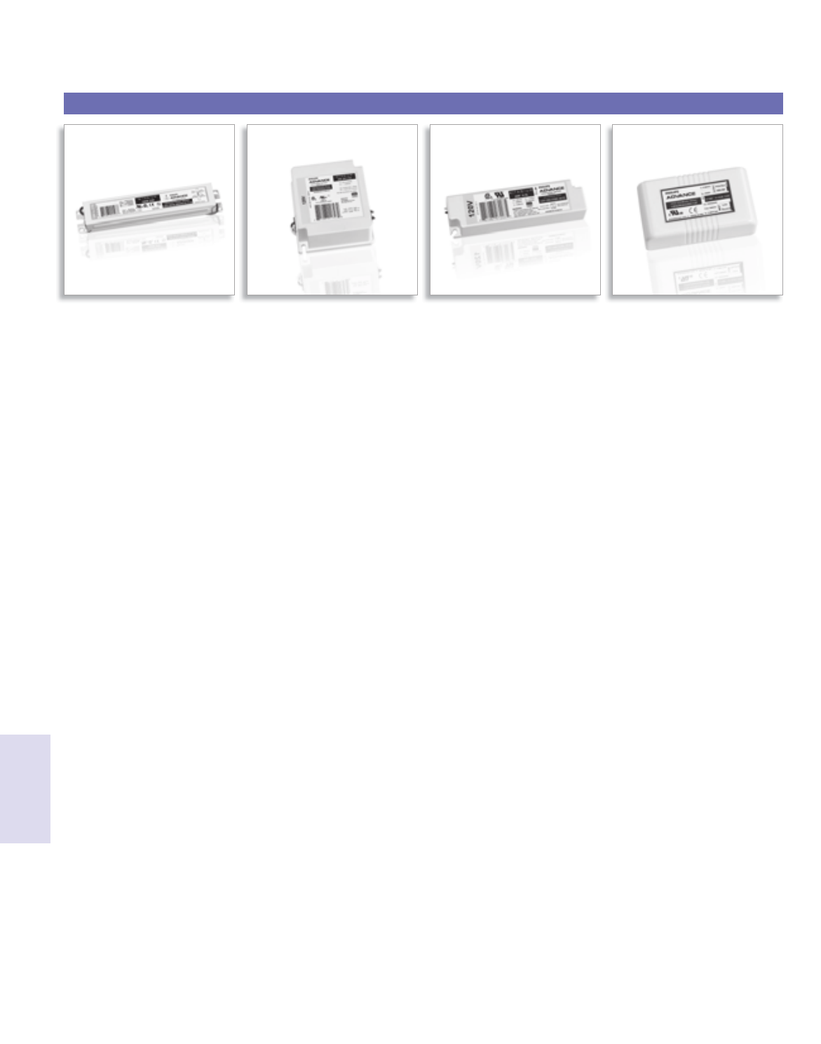
Lighting Electronics Atlas 2010-2011
Xitanium LED ELECTRONIC DRIVERS
1
LED Drivers
Xitanium®
LED Drivers for 12vdc LED Drivers for LED Dimming Controller for LED Drivers for 350mA
and 24vdc LED Systems Luxeon Brand LEDs 12vdc and 24vdc LED Systems and 700mA LEDs

7-1
Lighting Electronics Atlas 2010-2011
Xitanium LED ELECTRONIC DRIVERS
Dimming Ballasts LED Drivers
Xitanium®
Contents
Driver Specifications 7-2
Visit our web site at www.philips.com/advance
Customer Support/Technical Service
(800) 372-3331 • (+) 1 847 390-5000 (International)
Corporate Offices
(800) 322-2086
®
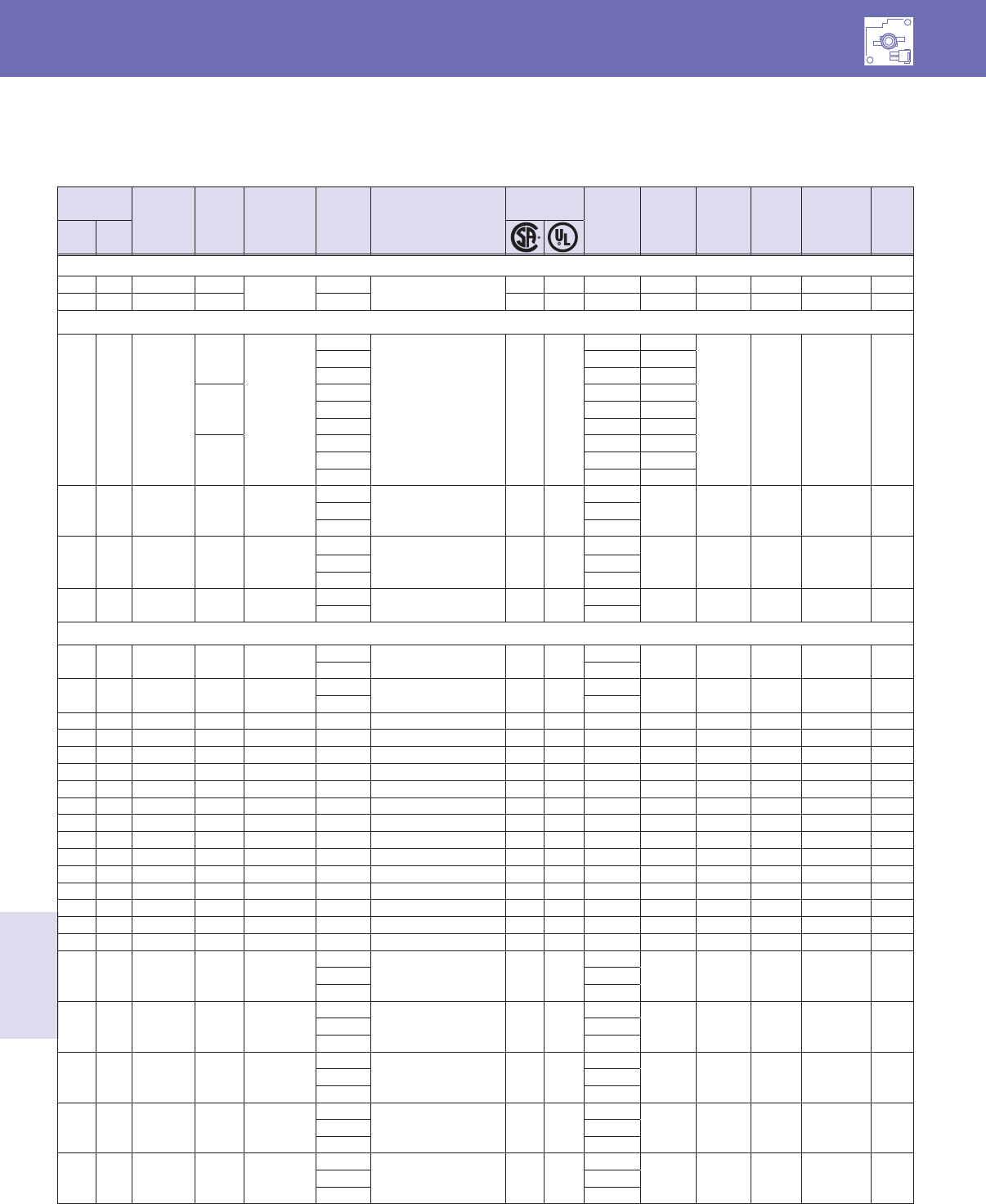
Lighting Electronics Atlas 2010-2011
7-2
Xitanium® LED ELECTRONIC DRIVERS
LED Drivers
Xitanium®
LED
Output
Power (W) Output
Voltage
(V)
Output
Current
(Amps)
Min/Max
Ambient
Temp (C/F)
Input
Volts Catalog #
Certifcations Input
Current
Max (A)
Input
Power
Max
(W)
Max.
THD %
Power
Factor Env. Rating
Dim./
Wiring
Dia.
Max Min
DC/DC Dimming Controller
60 0 12 5.000 -40C / 60C 12VDC 913710830902 ✓ ✓ 5.00 60 N/A N/A Dry, Damp C/4
100 0 24 4.100 24VDC ✓ ✓ 4.10 100 N/A N/A Dry, Damp C/4
UL Class 1 Drivers
100 21 60 ~ 140
0.350
-40C / 60C
120
LEDINTA700C140F3O ✓ ✓
0.53 64
20 0.9 Dry, Damp F/5
230 0.29 67
277 0.25 69
0.525
120 0.78 94
230 0.41 94
277 0.35 97
0.700
120 1.04 125
230 0.55 127
277 0.46 127
150 42 120 ~ 425 0.350 -40C / 60C
120
LEDINTA0350C425FO ✓ ✓
1.40
165 20 0.9 Dry, Damp F/1230 0.72
277 0.60
150 42 60 ~ 210 0.700 -40C / 60C
120
LEDINTA0700C210FO ✓ ✓
1.40
165 20 0.9 Dry, Damp F/1
230 0.72
277 0.60
150 42 60 ~ 210 0.700 -40C / 60C 347 LEDINTA0700C210DN ✓ ✓ 0.48 165 20 0.9 Dry, Damp F/2
480 0.34
Luxeon Drivers
4 2 2.8 ~ 12 0.350 -10C / 40C 120 LEDUNIA0350C12F ✓0.07 8.5 20 0.5 Dry G/3
230 0.04
8 2 2.8 ~ 12 0.700 -10C / 40C 120 LEDUNIA0700C12F ✓0.15 18.5 20 0.5 Dry G/3
230 0.08
12 2 2.8 ~ 33 0.350 -40C / 60C 120 LED120A0350C33F ✓ ✓ 0.13 15 20 0.9 Dry A/6
12 2 2.8 ~ 28 0.350 -40C / 60C 120 LED120A0350C28FO ✓ ✓ 0.10 12.5 20 0.9 Dry, Damp C/1
12 2 2.8 ~ 12 1.000 -40C / 60C 120 LED120A0012V10F ✓ ✓ 0.13 15 20 0.9 Dry, Damp C/1
17 2 2.8 ~ 24 0.700 -40C / 60C 120 LED120A0700C24F ✓ ✓ 0.18 21.6 20 0.9 Dry A/6
17 2 2.8 ~ 24 0.700 -40C / 60C 120 LED120A0700C24FO ✓ ✓ 0.18 21.6 20 0.9 Dry, Damp C/1
20 2 2.8 ~ 28 0.700 -40C / 60C 120 LED120A0700C28FO ✓ ✓ 0.20 24 20 0.9 Dry, Damp C/1
20 2 10 ~ 28 0.700 -40C / 60C 277 LED277A0700C28FO ✓ ✓ 0.09 24 20 0.9 Dry, Damp C/1
25 3 2.8 ~ 12 2.100 -40C / 60C 120 LED120A0012V21F ✓ ✓ 0.25 30.4 20 0.9 Dry B/8
25 3 2.8 ~ 24 1.050 -40C / 60C 120 LED120A0024V10F ✓ ✓ 0.25 30.4 20 0.9 Dry B/8
34 5 3.6 ~ 24 1.400 -40C / 60C 120 LED120A1400C24F ✓ ✓ 0.33 40 20 0.9 Dry B/8
34 5 3.6 ~ 24 1.400 -40C / 60C 120 LED120A0024V14FO ✓ ✓ 0.33 40 20 0.9 Dry, Damp E/7
40 5 2.8 ~ 24 1.750 -40C / 60C 120 LED120A0024V18F ✓ ✓ 0.42 50 20 0.9 Dry B/8
40 5 2.8 ~ 24 1.750 -40C / 60C 120 LED120A0024V18FO ✓ ✓ 0.42 50 20 0.9 Dry, Damp E/7
40 5 2.8 ~ 24 1.750 -40C / 60C 277 LED277A0024V18F ✓ ✓ 0.18 50 20 0.9 Dry B/8
48 4 2 ~ 24 2.000 -40C / 60C
120
LEDINTA0024V20FLO ✓ ✓
0.47
56 20 0.9 Dry, Damp F/1230 0.24
277 0.20
67 6 2 ~ 24 2.800 -40C / 60C
120
LEDINTA0024V28FO ✓ ✓
0.65
78 20 0.9 Dry, Damp D/1230 0.34
277 0.28
72 6 2 ~ 24 3.000 -40C / 60C
120
LEDINTA0024V30FLO ✓ ✓
0.70
84 20 0.9 Dry, Damp F/1230 0.37
277 0.30
100 8 2 ~ 24 4.160 -40C / 55C
120
LEDINTA0024V41FLO ✓ ✓
1.00
117 20 0.9 Dry, Damp F/1230 0.51
277 0.42
100 8 2 ~ 24 4.160 -40C / 55C
120
LEDINTA0024V41FO ✓ ✓
1.00
117 20 0.9 Dry, Damp D/1230 0.51
277 0.42
Xitanium LED Electronic Drivers
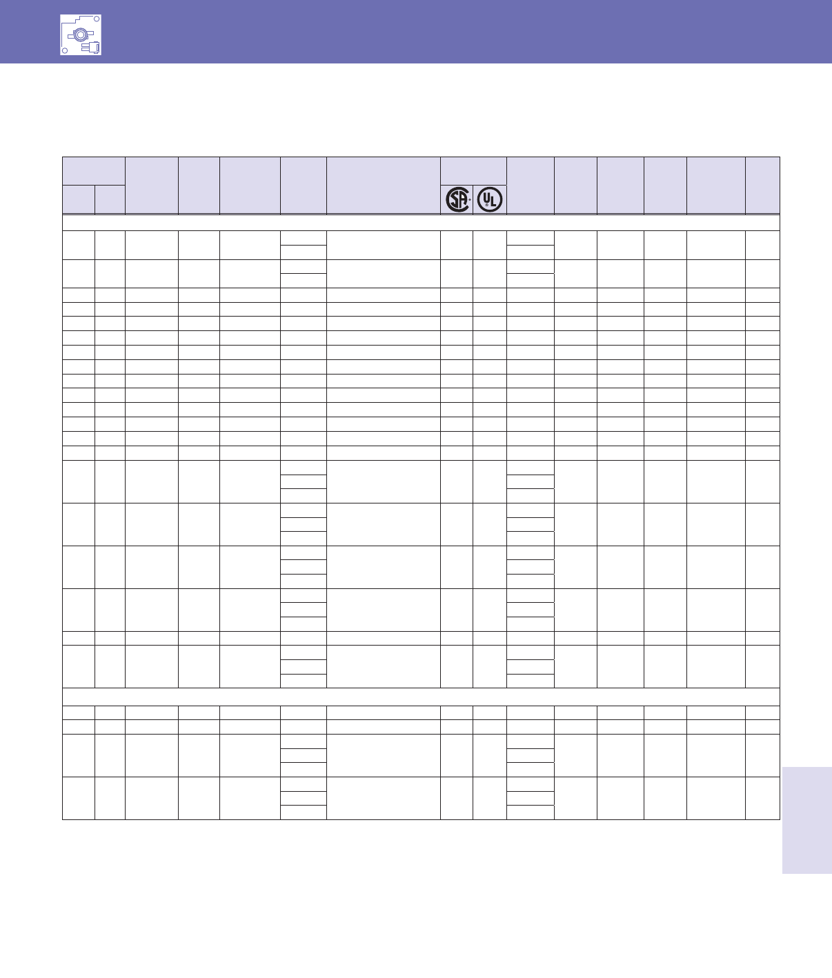
7-3
Lighting Electronics Atlas 2010-2011
Xitanium LED ELECTRONIC DRIVERS
LED Drivers
Xitanium®
LED
Output
Power (W) Output
Voltage
(V)
Output
Current
(Amps)
Min/Max
Ambient
Temp (C/F)
Input
Volts Catalog #
Certifcations Input
Current
Max (A)
Input
Power
Max
(W)
Max.
THD %
Power
Factor Env. Rating
Dim./
Wiring
Dia.
Max Min
12VDC & 24VDC LED Drivers
4 2 12 - -10C / 40C 120 LEDUNIA0350C12F ✓0.07 8.5 20 0.5 Dry G/3
230 0.04
8 2 12 - -10C / 40C 120 LEDUNIA0700C12F ✓0.15 18.5 20 0.5 Dry G/3
230 0.08
12 2 12 - -40C / 60C 120 LED120A0012V10F ✓ ✓ 0.13 15 20 0.9 Dry, Damp C/1
17 2 24 - -40C / 60C 120 LED120A0700C24F ✓ ✓ 0.18 21.6 20 0.9 Dry A/6
17 2 24 - -40C / 60C 120 LED120A0700C24FO ✓ ✓ 0.18 21.6 20 0.9 Dry, Damp C/1
25 3 12 - -40C / 60C 120 LED120A0012V21F ✓ ✓ 0.25 30.4 20 0.9 Dry B/8
25 3 24 - -40C / 60C 120 LED120A0024V10F ✓ ✓ 0.25 30.4 20 0.9 Dry B/8
25 3 24 - -40C / 60C 120 LED120A0024V10D ✓ ✓ 0.25 30.4 20 0.9 Dry B/9
34 5 24 - -40C / 60C 120 LED120A1400C24F ✓ ✓ 0.33 40 20 0.9 Dry B/8
34 5 24 - -40C / 60C 120 LED120A0024V14FO ✓ ✓ 0.33 40 20 0.9 Dry, Damp E/7
40 5 24 - -40C / 60C 120 LED120A0024V18F ✓ ✓ 0.42 50 20 0.9 Dry B/8
40 5 24 - -40C / 60C 120 LED120A0024V18FO ✓ ✓ 0.42 50 20 0.9 Dry, Damp E/7
40 5 24 - -40C / 60C 277 LED277A0024V18F ✓ ✓ 0.18 50 20 0.9 Dry B/8
60 10 12 - -40C / 60C 120 LED120A0012V50F ✓ ✓ 0.63 75 20 0.9 Dry, Damp D/1
48 2 24 - -40C / 60C
120
LEDINTA0024V20FLO ✓ ✓
0.47
56 20 0.9 Dry, Damp F/1230 0.24
277 0.20
60 2 12 - -40C / 60C
120
LEDINTA0012V50FO ✓ ✓
0.58
70 20 0.9 Dry, Damp D/1230 0.30
277 0.25
67 2 24 - -40C / 60C
120
LEDINTA0024V28FO ✓ ✓
0.65
78 20 0.9 Dry, Damp D/1230 0.34
277 0.28
72 2 24 - -40C / 60C
120
LEDINTA0024V30FLO ✓ ✓
0.70
84 20 0.9 Dry, Damp F/1230 0.37
277 0.30
80 10 24 - -40C / 60C 120 LED120A0024V33F ✓ ✓ 0.80 95 20 0.9 Dry, Damp D/1
100 2 24 - -40C / 55C
120
LEDINTA0024V41FO ✓ ✓
1.00
117 20 0.9 Dry, Damp D/1230 0.51
277 0.42
Dimming Drivers (0-10V Dimming)
20 2 2.8 ~ 28 0.700 -40C / 60C 120 LED120A0700C28DO ✓ ✓ 0.20 24 20 0.9 Dry, Damp C/2
25 3 14 ~ 24 1.050 -40C / 60C 120 LED120A0024V10D ✓ ✓ 0.25 30.4 20 0.9 Dry B/9
100 62 15 ~ 24 4.160 -40C / 55C
120
LEDINTA0024V41DLO ✓ ✓
1.00
117 20 0.9 Dry, Damp F/2230 0.51
277 0.42
150 42 210 0.700 -40C / 60C
120
LEDINTA0700C210DN ✓ ✓
1.40
165 20 0.9 Dry F/2230 0.72
277 0.60
Xitanium LED Electronic Drivers
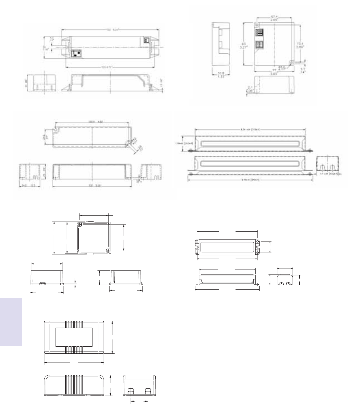
Lighting Electronics Atlas 2010-2011
Xitanium LED ELECTRONIC DRIVERS
7-4
LED Drivers
Xitanium®
66.2
36.2
22.9
19.1
Fig. A Fig. B
Fig. C Fig. D
Fig. E Fig. F
Fig. G
70.0 mm [2.76 in]
76.0 mm [2.99 in]
89.0 mm [3.50 in]
83.6 mm [3.29 in]
38.0 mm [1.49 in]
87.0 mm [3.43 in]
82.8 mm [3.26 in]
87.0 mm [3.43 in]
5.0 mm [0.20 in]
226.2 mm
[8.91 in]
211.1 mm
[8.31 in]
39.7 mm [1.56 in]
37.7 mm [1.49 in]
42.9 mm [1.69 in]
224.6 mm
[8.84 in]
240.5 mm
[9.47 in]
59.1 mm [2.33 in]
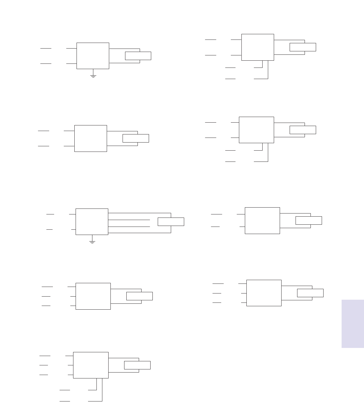
7-5
Lighting Electronics Atlas 2010-2011
Xitanium LED ELECTRONIC DRIVERS
Dimming Ballasts LED Drivers
Xitanium®
Diag. 1
Diag. 3
Diag. 5
Diag. 7
Diag. 9
Diag. 2
Diag. 4
Diag. 6
Diag. 8
BLUE (NEGATIVE)
RED (POSITIVE)
OUTPUTINPUT
BLACK
(LINE)
WHITE
(NEUTRAL)
LED
DRIVER LED ARRAY
BLACK (NEGATIVE)
RED (POSITIVE)
OUTPUTINPUT
BLACK
(LINE)
BLACK
(NEUTRAL)
LED
DRIVER LED ARRAY
BLACK
(LINE)
WHITE
(NEUTRAL) BLUE (NEG. 700mA)
RED (POSITIVE)
OUTPUTINPUT
LED
DRIVER LED ARRAY
ORANGE (NEG. 350mA)
YELLOW (NEG. 525mA)
BLUE (NEGATIVE)
RED (POSITIVE)
OUTPUTINPUT
BLACK
(LINE)
GREEN
(GROUND)
WHITE
(NEUTRAL)
LED
DRIVER LED ARRAY
BLUE (NEGATIVE)
WAGO CONNECTOR
WAGO CONNECTOR
RED (POSITIVE)
OUTPUTINPUT
BLACK
(LINE)
GREEN
(GROUND)
WHITE
(NEUTRAL)
LED
DRIVER
0-10V DIMMING
LED ARRAY
VIOLET
(POSITIVE)
GRAY
(NEGATIVE)
BLUE (NEGATIVE)
RED (POSITIVE)
OUTPUTINPUT
BLACK
(LINE)
WHITE
(NEUTRAL)
LED
DRIVER
0-10V DIMMING
LED ARRAY
VIOLET
(POSITIVE)
GRAY
(NEGATIVE)
WHITE (NEGATIVE)
RED (POSITIVE)
OUTPUTINPUT
RED
(POSITIVE)
BLUE
(NEGATIVE)
DC/DC
LED DIMMING
CONTROLLER
0-10V DIMMING
LED ARRAY
VIOLET
(POSITIVE)
GRAY
(NEGATIVE)
(NEGATIVE)
TYCO CONNECTOR
WAGO CONNECTOR
(POSITIVE)
OUTPUTINPUT
BLACK
(LINE)
WHITE
(NEUTRAL)
LED
DRIVER LED ARRAY
BLUE (NEGATIVE)
WAGO CONNECTOR
WAGO CONNECTOR
RED (POSITIVE)
OUTPUTINPUT
BLACK
(LINE)
GREEN
(GROUND)
WHITE
(NEUTRAL)
LED
DRIVER LED ARRAY
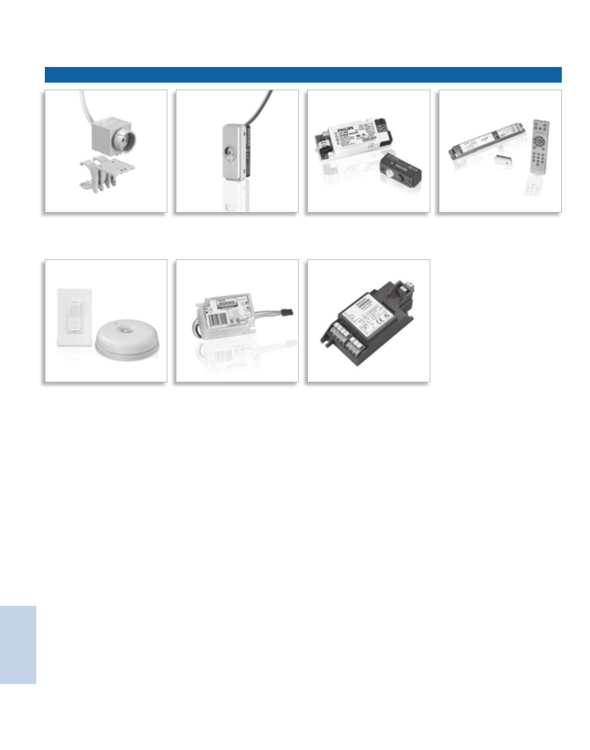
Lighting Electronics Atlas 2010-2011
CONTROLS
1
Controls
LuxSense™ MicroLuxSense™ ActiLume™ ActiLume™ Color
OccuSwitch™ Wireless Dynadimmer™ Chronosense™

8-1
Lighting Electronics Atlas 2010-2011
CONTROLS
Controls
Visit our web site at www.philips.com/advance
Contents
Indoor Controls
Luminaire based
LuxSense™ 8-2 to 8-4
MicroLuxSense™ 8-5 to 8-7
ActiLume™ 8-8 to 8-11
ActiLume™ Color 8-12 to 8-15
Stand Alone
OccuSwitch™ Wireless 8-16 to 8-18
Outdoor Controls
DynaDimmer™ 8-19
ChronoSense™ 8-20
Customer Support/Technical Service
(800) 372-3331 • (+) 1 847 390-5000 (International)
Corporate Offices
(800) 322-2086

Lighting Electronics Atlas 2010-2011
CONTROLS
8-2
Controls
Philips LuxSense is a daylight sensor that can control up
to 20 fixtures equipped with Philips Advance Mark 7
0-10V or EssentiaLine 0-10V ballasts. The sensor
measures the reflected light coming from the
designated surface below, such as a desk or tabletop.
It dims the lamp output when the light level exceeds
the required level defined by the LuxSense sensor.
The light level is easily adjusted via a simple dial.
Luxsense provides the benefit of a comfortable and
controllable level of illumination throughout the
working day. More importantly it can provide energy
savings when installed near windows where natural
illumination is usually greatest.
It is also designed to save energy by reducing excess
light output that occurs from design factors of lumen
depreciation. Lamps are dimmed slightly when new, but
the light levels will then be raised over time to
compensate for depreciation of lamp output that
occurs in normal lamp aging.
* Galasiu, A.D. “Energy saving lighting control systems for open-plan offices: a field study,”
National Research Council Canada, v4 no1, July 2007 pg. 7-29
** External installation of class 2 wiring where allowed by local codes.
LuxSense™
Provides daylight regulation via a single miniature sensor
Features
State-of-the-art daylight sensor
Provides a potential energy savings of up to 32%
without sacrificing visual comfort*
Simple to use lighting control system
No specific lighting control training is needed to
commission or adjust light levels or operation modes
Flexibility in design
LuxSense can be incorporated directly into a fixture
or alternatively clipped to a T5 lamp.**

8-3
Lighting Electronics Atlas 2010-2011
CONTROLS
Controls
Installation of LuxSense into existing fixtures
Connecting diagram of the sensor to the ballast
The maximum fixture temperature should always remain below
70˚C. The sensitivity opening angle should never be obscured by
the optics or any other part of the fixture. Metal optics should be
properly grounded.
Mounting LuxSense on the Lamp
LuxSense mounted with a lamp clip (For use with T5 lamps only).
Not for use with T5/HO lamps.
Position LuxSense 3 inches away from the end cap on the
(electrical) “cold” side of the lamp. This is the side of the lamp
that is connected to the terminals of the ballast that allows
for the longest wiring to the lamp.
Installation of fixtures that include LuxSense
Interconnecting LuxSense Master fixtures (M) to Satellite fixtures (S)
Interconnecting LuxSense Master fixture (M) to Satellite fixture (S).
Up to 19 satellite fixtures can be looped through to I Master
fixture, if all of them are equipped with Philips Advance
Mark 7® 0-10V or EssentiaLine 0-10V ballasts.
Satellite fixture should have similar daylight conditions to the master.
Connect 0-10V “+ to +” and “– to –”. (See diagram above)
Never loop through 2 Master fixtures!
White -
White/gray +
min. 5 ft
Install fixtures
LuxSense
LRL1220TL5

Lighting Electronics Atlas 2010-2011
CONTROLS
8-4
Controls
Dimensions in mm
Warning: the required light level should be no more than 30% lower
than the average installed light level, without daylight contribution
(e.g. 55 footcandles installed, adjustment down to 39 foot candles is
possible).
Please note that LuxSense is not designed for maintaining
a constant light level.
Measure the light level
under each LuxSense
sensor with no or negligible
daylight contribution.
If needed, turn the diaphragm
until the required light level is
reached (with no or negligible
daylight contribution).
See diagram on the left to
manually adjust the light levels.
You can easily copy the new
set point to other rooms
when similar daylight and
reflector conditions exist.
Technical data
Operation conditions
Ambient temperature 5°C to 55°C
Rel. humidity 15% to 90%, no condensation
Max. temperature of clip to
lamp contact surface 70°C
Storage conditions
Ambient temperature -25°C to 70°C
Rel. humidity 5% to 95% at 25°C
Connection 20 AWG, flying leads,
length 27 inches.
Color coding of cable: white/grey +
white –
Connecting the wires in the reverse
will result in minimum light output.
Housing
Material ASA
Color light grey (similar to RAL 7035)
Weight/dimensions Approx. 20 grams, 25x21x19mm.
Control signal input - operating voltage: 1.5 - 10VDC
- operating current sink 100µA-3mA
(sufficient for 20 0-10VDC ballasts)
- control voltage variation: < 0.5V
over current and temperature range
- max. input voltage
(maximum rating): 15 Vdc
- max. current sink
(maximum rating): 50 mA
Optical characteristics It is assumed that the reflection in
a room is such that a light level of
45 fc on a table (2.6 ft. in height)
will result in 2.3 fc seen by the
controller at ceiling height (8 ft.)
under a viewing angle of 45°
- The opening angle can be adapted
by the diaphram control, realizing an
adjustment factor between 1/3 and 3.
Controls characteristics LuxSense compensates approximately
for 50% of the added light (simulated
and measured with a fluorescent light
source). See graph below. In case of a
natural light source, the light compensation
is higher than 50%.
0 30 60 90 120 150 180
225
180
135
90
45
0
LuxSense controls characteristics
LuxSense
LRL1220TL5
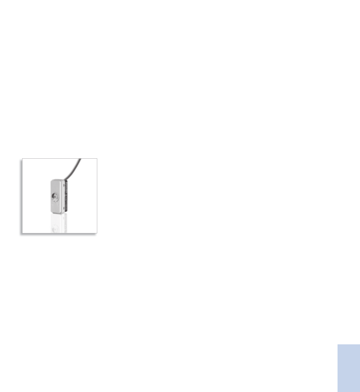
8-5
Lighting Electronics Atlas 2010-2011
CONTROLS
Controls
MicroLuxSense is a DayLight Regulation option (DLR)
for luminaires equipped with a Philips Advance Mark 7
0-10V or EssentiaLine 0-10V ballasts. The sensor
measures the reflected light coming from the surface
below. It dims down the lamp output when the light
level exceeds the required light level defined by the
light sensor set point.
MicroLuxSense can be installed in the luminaire
either mounted between the louvers or recessed
in the housing.
MicroLuxSense™
Provides daylight regulation via a single miniature sensor
Connect to the 0-10VDC control input of the Mark 7
or EssentiaLine ballast
Provides a potential energy savings of up to 32% without
sacrificing visual comfort*
Maximize visual comfort
Automated regulation of artificial lighting allows for task
illumination to be maintained.
Arrives from the factory in a standard preset configuration
No need for complex commissioning. Field adjustment possible
if needed.
Regulate up to 20 luminaires
Utilize one sensor for continuous rows or multiple sensors
with single luminaires
Uses common sensor footprint with ActiLume and
ActiLume Color
One luminaire design now has the capability to provide
various control options
* Galasiu, A.D. “Energy saving lighting control systems for open-plan offices: a field study,”
National Research Council Canada, v4 no1, July 2007 pg. 7-29

Lighting Electronics Atlas 2010-2011
CONTROLS
8-6
Controls
M S
M S
MicroLuxsense
SS
Luxmeter
= 500 Lux
500 Lux
Luxmeter
500 lux
Installation
Mount the luminaire with
MicroLuxSense daylight
Regulation option.
Interconnecting MicroLuxSense Master fixture (M) to Satellite fixture (S).
Up to 19 satellite fixtures can be looped through to I Master
fixture, if all of them are equipped with Philips Advance
Mark 7® 0-10V or EssentiaLine 0-10V ballasts.
Satellite fixture should have similar daylight conditions to the master.
Connect 0-10V “+ to +” and “– to –”. (See diagram above)
Never loop through 2 Master fixtures!
MicroLuxSense
LRL1222
Slotted head
screwdriver
No.0
Phillips head
screwdriver No.1
Warning: the required light level should be no more than 30% lower
than the average installed light level, without daylight contribution
(e.g. 55 footcandles installed, adjustment down to 39 foot candles
is possible).
Please note that MicroLuxSense is not designed for
maintaining a constant light level.
Measure the light level
under each MicroLuxSense
sensor with no or negligible
daylight contribution.
If needed, turn the diaphragm
until the required light level is
reached (with no or negligible
daylight contribution).
The setpoint of the sensor
can be changed manually
by using a screwdriver to
turn the control ring on the
front, which influences the
diaphragm. The housing is
equipped with an indication
of the default setting.
You can easily copy the new
set point to other rooms
when similar daylight and
reflector conditions exist.

8-7
Lighting Electronics Atlas 2010-2011
CONTROLS
Controls
MicroLuxSense
LRL1222
Technical data
Operation conditions
Ambient temperature 5°C to 55°C
Rel. humidity 5% to 90%, no condensation
Max. allowed temperature 55°C
Anywhere on the sensor housing
Storage conditions
Ambient temperature -25°C to 70°C
Rel. humidity 5% to 95% at 25°C
Connection 20 AWG, flying leads,
length 27 inches.
Color coding of cable white/grey +, white –.
Connecting the wires in the
reverse will result in minimum
light output.
Housing material Polycarbonate UL94 V-0
Color bottom part Ultra Dark Grey
(similar to RAL 7024)
Color cover part Light Grey (similar to RAL 7035)
Weight/dimensions Approx. 25 grams, 47x19x19 mm
Control signal input
operating voltage +1.5 - +10Vdc
operating current sink 100µA-3mA (sufficient for 20
Philips Advance Mark 7 0-10V or
EssentiaLine 0-10V ballasts)
control voltage variation < 0.7V
over current and temp. range
max. input voltage 15 Vdc (maximum rating)
max. current sink 50 mA (maximum rating)
Optical characteristics - It is assumed that the reflection
in a room is such that a light
level of 45 fc on a table (2.6 ft.
in height) will result in 2.3 fc
seen by the controller at ceiling
height (8 ft.) under a viewing
angle of 45°
- The opening angle can be
adapted by the diaphram
control, realizing an attenuation
factor between 1/3 and 3.
MicroLuxSense control characteristics
The control characteristics are described in the graph. The light sensor
roughly compensates for 50% of the ingressing daylight by dimming
the artificial light output, until the minimum output is reached.
General Specifications
45
47
12
32
19 7
44
17
3
17
0 30 60 90 120 150 180
225
180
135
90
45
0
Dimensions in mm
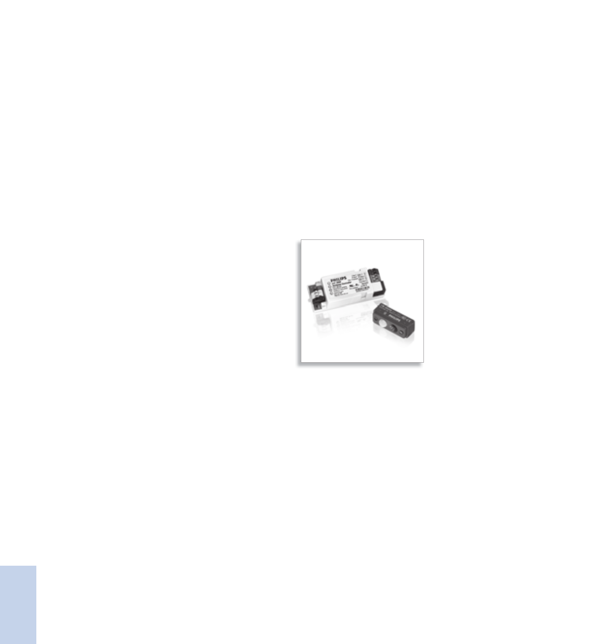
Lighting Electronics Atlas 2010-2011
CONTROLS
8-8
Controls
ActiLume is a revolutionary new plug-and-play
daylight/occupancy lighting system that virtually
eliminates any worries of complicated programming
procedures. Commissioning is easily achieved by
pushing a button on the sensor that calibrates the
light level and switches the controller between
open plan and private office modes.
Actilume consists of a ready to use sensor and
control unit to be built directly into a luminaire.
This system is designed to deliver maximum visual
comfort and potential energy savings of up to 65%*
to the commercial sector.
The relative light output of the luminaire is defined
by its placement within the space (window or
corridor side of the office). The controller switches
the lamps in a fixture automatically on and off
based on occupancy and regulates the light output
according to the amount of daylight entering the
space. The system is operated with Philips Advance
ROVR™ electronic ballasts.
* Galasiu, A.D. “Energy saving lighting control systems for open-plan offices: a field study,”
National Research Council Canada, v4 no1, July 2007 pg. 7-29
ActiLume™
An easy to use and install lighting control system
Features
State-of-the-art daylight/occupancy sensor
Provides a potential energy savings of up to 65%
without sacrificing visual comfort*
Simple to use lighting control system
No specific lighting control training is needed to
commission or adjust light levels or operation modes
Two pre-programmed application modes
Private or open plan modes can be selected via a
simple push of the service button

8-9
Lighting Electronics Atlas 2010-2011
CONTROLS
Controls
RJ10
4P4C
R=8'
R=6.5'
General Specifications Controller / Sensor Specifications
Plug & Play control models
• Mode 1, Private Office: Lights switch off after 15 minutes,
saving energy in a private office situation.
• Mode 2, Open Office: Lights dim after 15 minutes, but are
not switched off until unoccupied for 2 additional hours.
This avoids dark areas in an open plan office.
Technical data for installation, mains operation
Rated mains voltage 120-277 V
Voltage tolerance: +/- 10% 108-305 V
Mains frequency 50/60 Hz
Input power (system) <2W
Maximum number of ballasts 9
Maximum number of
extension sensors 2
Technical data for design and mounting in fixtures
Operating conditions
Ambient temperature 0 ºC to 55 ºC
Sensor and controller
Relative humidity 20% to 85%,
no condensation
Storage Conditions
Ambient temperature -25 ºC to +85 ºC
Relative humidity 10% to 95%
Sensor LRI 1653
Connection RJ-10 4-Pole
Fixed to LRI1653 3 ft. cable
Housing (casing)
Material Polycarbonate UL94 V-0
Mounting 1. Latching tabs on the back
The sensor housing has two of the sensor
mechanisms that may be used 2. Four small ridges, two on
for mounting:
each long side of the sensor
Safety, basic insulation > 1500 V
When placed at a height of 9 ft.
the following values are valid:
Infrared receiver Signal Range
Light sensor Monitoring range of 2.5 to
35 foot-candles at sensor
Monitoring area
Movement detector Passive Infra Red (PIR)
Detection area at 9 ft. height:
• 13x13 ft. (sensitive for small
movements)
• 20x16 ft. (sensitive for larg
movements)
19'
16'
Sensor Orientation
Y
X
Maximum height PIR: 11 ft.
X-angle PIR: 100˚
Y-angle PIR: 82˚
ActiLume
Controller LLC 1654
Sensor LRI 1653

Lighting Electronics Atlas 2010-2011
CONTROLS
8-10
Controls
Lighting Controls ActiLume / Sensor
Set the reference light level adjustment:
Pressing the service button (>3 seconds) until the lamp gives a light
flash (wink) will start the automatic calibration procedure for light
level adjustment. Step aside or remove stepladder, if used.
The light output of the luminaires connected to window row is
set to 80%. The light output of the luminaires connected to a
corridor row is set to 100%.
After 30 seconds the ActiLume controller is saving the actual light
level as new reference light level (indicated by a second flash).
This 30 seconds time delay is required to have sufficient time to
step aside or remove a stepladder.
Select the user mode (application):
The user mode can be toggled between mode 1 and 2 by means
of a short push on the service button (<3 seconds). [Fig. A]
After the service button has been released the lamp will flash to
indicate the selected user mode: 1 flash = User mode 1 (Private
office application) 2 flashes = User mode 2 (Open plan office
application). The flash count begins after the lamp has been dimmed.
Count only the short lamp pulses and not the final lamp level.
Controller unit LLC 1654
Window and In user mode 1 and user mode 2
corridor output the system is programmed as one
channel with two zones. When
enough daylight enters the room,
the amount of artificial light will be
automatically reduced on the
window row and the amount of
light on the corridor row will be
offset with 30% more light.
Safety, basic insulation > 1500 V
Material Polycarbonate UL94 V-0
Mounting The controller housing contains
snap-in pins for quick fixation.
The diameter of the fixation holes
should be maximum 4.5 mm.
The snap-in pins are designed for a
metal thickness of maximum 0.8 mm.
The maximum distance between
the fixation holes is 78 mm.
Connector type
Connection wiring is greatly simplified through use of
POKE-IN connectors.
Wire cross-section
22 AWG - 18 AWG solid or stranded with tinned ends
Strip length 3 8 "
B1
A1
C1
B1
A1
C1
Dimensions in inches
Controller LLC1654
Controller LLC1654
Sensor LRI1653
Sensor LRI1653
B1
A1
C1
B1
A1
C1
Dimensions in inches
Controller LLC1654
Controller LLC1654
Sensor LRI1653
Sensor LRI1653
A1 B1 C1
Sensor LRI 1653 1 ¾ 5 85 8
Controller LLC 1654 3 1 81 3 16 7 8
Dimensions in inches
ActiLume
Controller LLC 1654
Sensor LRI 1653
Service
button
Fig. A
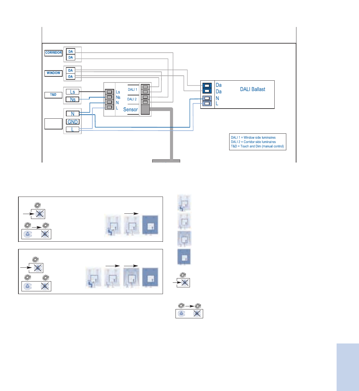
8-11
Lighting Electronics Atlas 2010-2011
CONTROLS
Controls
ActiLume / Sensor
120 or
277VAC
ActiLume Modes
Besides the private office and open plan office modes, in the future it will be possible to recall additional (yet to be determined) application modes.
This will make the ActiLume system very flexible for all different kinds of applications. An advanced remote control will be added in the future to
allow users to select and store other specific modes to meet the space needs.
Mode 1: Private office
15 min
Mode 2: Open plan office
15 min
15 min
120 min
15 min
Presence - Area is occupied.
Absence - Light stays on. (internal timer is activated to clock
absence time)
Absence - Light dims down to a background level (internal timer
is activated to clock absence time) or surrounding light at 100%.
Absence - Light switched off.
When enough daylight is detected, the lights will
NOT be switched on automatically when someone
enters the room.
When enough daylight is detected (measured
over 15 minutes), the lights will automatically be
switched off.
Mode 1: Private office
15 min
Mode 2: Open plan office
15 min
15 min
120 min
15 min
Mode 1: Private office
15 min
Mode 2: Open plan office
15 min
15 min
120 min
15 min
Mode 1: Private office
15 min
Mode 2: Open plan office
15 min
15 min
120 min
15 min
ActiLume
Controller LLC 1654
Sensor LRI 1653

Lighting Electronics Atlas 2010-2011
CONTROLS
8-12
Controls
Philips ActiLume Color is a stand-alone, lighting
control designed for dynamic and static color effects
in small, medium and large sized applications. This
plug and play color system makes commissioning
easy; simply wire the system and you can start color
changing with the infrared remote control. With no
specific training needed, the operator can quickly
recall ten pre-programmed dynamic color changing
sequences and ten pre-programmed static scenes.
This system has been designed for all indoor
applications within retail, hospitality, and other
public spaces, to attract people to specific areas
and to enhance areas with color for scene setting.
In addition, for maximum flexibility it is compatible
with many light sources including LEDs and
fluorescent lamps.
A maximum of 10 color luminaires can be
controlled per ActiLume Color controller via
the DALI broadcast output ports. You can also
synchronize up to 60 ActiLume Color controllers
(or 600 RGB fixtures) simultaneously. This system
can also be operated in larger and existing DALI
or DMX backbone based networks.
The ActiLume Color system is available with
the ActiLume Color Programming Kit. Included in
the kit is an easy to use software called ActiLume
Color Studio, that allows you to create your own
static colors or dynamic color sequences off-site
and then upload them to the color controller
during on-site commissioning.
ActiLume™ Color
A true plug and play color management system for the retail, hospitality, and architectural markets
Features
Easy to use color management system
Plug and Play controller requires no specific lighting
controls training
State-of-the-art controller
Provides the functionality of all input lighting control
signals from various input devices (remote control,
DALI interface, etc).
Design flexibility
Can be used in one fixture or up to 10 interconnected
fixtures as well as the ability to be networked with up
to 60 other controllers
8-13
Lighting Electronics Atlas 2010-2011
CONTROLS
Controls
ActiLume Color System
• It can be used for both dynamic sequences from very fast
to very slow (24 hr cycle), and static colors that are selected
to support many applications including seasonal fashion,
merchandise change, a specific atmosphere in a bar or
restaurant or to enhance an architectural design.
• It offers 10 pre-programmed sequences corresponding
with seasons (Christmas, autumn) and daily ambiance
(nature, sunset).
Plug and Play control
• Simple systems with one ActiLume Color controller
can be operated by DALI push button controls or remote
control. The Philips Advance ROVR ballasts are directly
connected to the Red, Green, and Blue outputs without
any commissioning.
9.92
9.69
1.25
0.18
0.85
0.75
Technical data for installation
Mains operation Rated mains voltage 120-277 V
With tolerances for operation +/- 10%
Mains frequency 50/60 Hz
Output power (system)
R output Maximum 10 DALI loads (20 mA)
G output Maximum 10 DALI loads (20 mA)
B output Maximum 10 DALI loads (20 mA)
Ext output Maximum 40 DALI loads (80 mA)
DMX 64 mA
Sensor 5 mA
Technical data for design and mounting in fixtures
Operating conditions Ambient temperature +5 … 50 ºC
Controller and sensor
Rel. humidity operating 20% … 85%, no condensation
Tcase 75 ºC
Storage Conditions -25 … +70 ºC
Rel. humidity storage 10% … 95%
Lifetime 10% failure rate at 50k hrs with
Tcase of 75 ºC
DMX operation
Operating temperature +5 … 55ºC
Protocol standards ANSI 1.11-2004 (USITT DMX512-A)
ANSI 1.20-2006 (RDM)
Connector 8-position modular connector (RJ45)
Transient/Burst Immunity
and Surge IEC 61000-4-4/5, level 2 on IO: 0.5kV
UL840: over voltage category II (<50 V):
0.5 kV
Network requirements According to EIA-485-A specification
Technical data
Compliances and approvals
Safety Standards NEMA 410
UL935
Quality standard ISO 9001
Environmental standard ISO 14001
Approval marks ENEC:
72/23/EEC (low voltage)
89/336/EEC
(electromagnetic compatibility)
CSA
UL-recognized (UL1310 for class
II power supplies)
CE marking
ActiLume Color
LLC 1670
Dimensions in inches
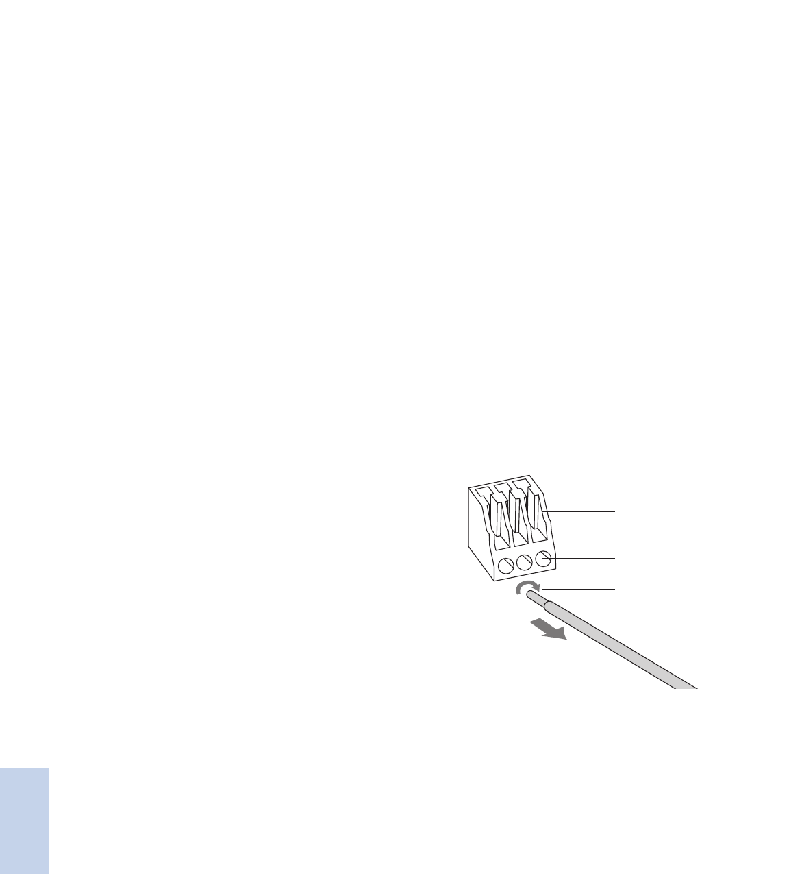
Lighting Electronics Atlas 2010-2011
CONTROLS
8-14
Controls
ActiLume Color Controller unit LLC1670
In standard operation and based on the pre-programmed colors,
ActiLume Color calculates the different dim levels for the Red, Green
and Blue lamps, and the fading (dim levels) in between two color
points. On the extended output, additional ActiLume colors can be
operated within the same sequences or scenes.
In DMX operation, the real time DMX commands are directly
translated into DALI commands on the output side.
ActiLume Color Inputs/Outputs
4x DALI current limited outputs DALI-R: 10 DALI loads max
DALI-G: 10 DALI loads max
DALI-B: 10 DALI loads max
DALI-EXT: 40 DALI loads max
(mentioned as group RGBE_DA)
1x ActiLume Multi-Sensor input, labeled SENSOR
1x RS-485 connection, based on DMX (RDM)
The controller only supports the RDM address setting. The
RDM requires bidirectional RS-485 (half duplex) and a factory
programmed device unique ID.
Transmission load 32 devices, with
terminators
Transmission level range 0 ≤V≤+6 with respect to
common
Transmission frequency 250 kBit/s ± 2%
Reception level range +12/-7 with respect to
common
Reception frequency 250 kBit/s ± 2,5%
Turn around time of
DMX transceiver 176 µs after transmission
of the last stop bits.
When a DMX-RDM
controller expects a
response, the device must
place its transmitter in high
impedance state within
88 µs after transmission
of the last stop-bit (of the
last transmitted byte). Time
between slots (data-bytes)
may not exceed 76 µs
IDC Connection
ADS/Manual connection
Release: Rotate and pull
Remark: Release all wires one by one
IDC Connection 20 AWG solid /18 AWG stranded
ADS or manual push 20 AWG - 18 AWG solid wire
Strip length 0.32 inches – 0.35 inches
1x DALI passive input, (DALI GP)
Transmit:
Short circuit current Max 250 mA
High-level range 11.5 … 20.5 V
Low-level range –4.5 … 4.5 V
Rise/fall time 10 …50 μs
Transmission frequency 1200 Hz +/- 5%
Receive:
High-level range 9.5 … 300 V
Low-level range –6.5 … 6.5 V
Rise/fall time 10 …50 ms (mains),
0 …100 μs (DALI)
Reception frequency 50/60 Hz (mains),
1200 Hz +/- 10% (DALI)
1x Universal mains input
Glow wire test 850 ºC / 5 s
Safety, basic insulation < 2000 V
Material Polycarbonate + ABS Bay blend
KU-2 1514
UL94 V-0
Housing color Dark gray
Mounting The minimum distance between
the fixation holes is 9.29 inches.
User interfaces
Remote control IRT1670 needs to be pointed to the
sensor (IRR1654, or IRR8125) for
starting dynamic sequences or static scenes.
Philips DALI Broadcast commands will start
pre-programmed sequences/static colors
Connections for DALI and mains
ActiLume Color
LLC 1670

8-15
Lighting Electronics Atlas 2010-2011
CONTROLS
Controls
IRR 1654 with cap
IRR 8125 invisible
Connection RJ-10 4-Pole 100 cm cable
Housing (casing)
Material Polycarbonate UL94 V-0
Glow wire test 950 ºC / 5 s
Safety, basic insulation < 2000 V
Infrared receiver RC5 signal
Minimum range 20 m2
Cap material IRR1654 Polycarbonate, RAL7035
Advanced color selection remote control IRT1670
This remote control can be used
for selecting pre-programmed color
sequences and static colors. These
programmed dynamic sequences can
be played faster (in half of the time),
or slower (factor 3 or 6 slower). Static
colors can be selected in hue and dim
level and stored into the controller.
Batteries are included.
ActiLume Color Programming Kit LCK1671
Consists of:
A. ActiLume Color Studio.
An intuitive software for
programming sequences into
the ActiLume Color controller
allowing for direct preview,
light plan overview,
and grouping.
B. RS232 gateway the RS232-DALI
gateway translates all
communication between the
personal computer and the
DALI network. The connection
between PC and the DALI
network is only necessary
when the sequences are
uploaded into the ActiLume
Color Controller. The gateway
requires a 24V power supply,
not provided.
C. Interconnecting cable for
the PC/Gateway.
To Lamps
Red, green and blue lamp ballasts
Remote control receiver
Master Controller
Wiring scheme
Ordering and Packing data
Type Description Packaging
(PCS)
LLCI670 Controller 24
IRR1654 IR Sensor with cap 24
IRR8125 IR Sensor invisable 1
IRT1670 Remote Control 18
LCK1671 Programming Kit 1
ActiLume Color
LLC 1670
IRR 8125
IRR 1654

Lighting Electronics Atlas 2010-2011
CONTROLS
8-16
Controls
The Philips OccuSwitch Wireless Occupancy Sensor
is an advanced wireless system that automatically
turns lights off when a workspace is unoccupied,
saving energy and helping to create a more
sustainable work environment. The system consists
of a wireless battery-powered ceiling mounted sensor
that communicates to a wall switch. Multiple sensors
and switches can be used for additional coverage.
Using a combination of passive infrared (PIR)
technology and advanced logic for detecting major
and minor motion, the sensor recognizes when
the room is occupied (or unoccupied), helping to
eliminate false triggers. The system adapts to
accommodate varying user patterns with built-in
intelligence to automatically adjust the shut off
time delay.
The Philips OccuSwitch Wireless Control System
is a unique indoor plug and play system perfect
for retrofits and new installations in commercial
applications including private offices, conference
rooms, restrooms, breakrooms, copyrooms, storage
areas, and lobby areas. Uncompromising on style,
the functional design allows for easy setup and
adjustments to system settings via front
accessible buttons.
* Product has a 2-year limited warranty. See page 8-18 for more details.
OccuSwitch™ Wireless
A simple, easy, and effortless way to create a more sustainable work environment
Features
Easy-to-install retrofit
Wireless controls means no sensor wiring providing quick
set-up times, minimizing disruptions
Advanced occupancy sensing
Helps eliminate false triggers which optimizes energy savings
Sleek Low Profile Design
Stylish low-profile design easily blends into existing and
current office designs
10-year battery life design*
Provides worry free maintenance, just install and leave for
long lasting performance
Manual-On/Auto-Off Capability
Compliant with applicable California Title 24 energy efficiency
code requirements

8-17
Lighting Electronics Atlas 2010-2011
CONTROLS
Controls
Wireless Occupancy Sensor Specifications
Detection Technology
Passive Infrared (PIR)
Mounting Height
Can be installed for up to 12ft ceiling height
Detection Area
Will vary based on ceiling height.
For a typical ceiling height of 8 ft (2.4m):
Major motion coverage 17.7 x 23.6ft (5.40m x 7.20m)
Minor motion coverage 11.8 x 17.7ft (3.60m x 5.40m)
Larger areas will require multiple sensors.
23.6ft (7.2m)
17.7ft (5.4m)
17.7ft (5.4m)
11.8ft (3.6m)
h= 8ft (2.4m)
Large movements
Small movements
h
The orientation of the window arrow on the mounting plate aligns the
direction of the rectangular detection area.
Rotating Shield
During installation the retractable sensor shield can be rotated to partially
mask the sensor’s field of view and prevent unwanted movement detection.
Wireless Network Protocol ZigBee Pro 2.4GHz
Universal license free band
Wireless Compatibility
Can be connected with multiple OccuSwitch Wireless Wall Switches.
Up to 10 sensors and switches can be networked together.
Wireless Range
Switch to Sensor: 50ft (17m)
Switch to Switch (same plane): 18ft (6m)
Switch to Switch (line of sight): 50ft (17m)
Battery
Standard AA size 3.6V DC Lithium-thionyl chloride (Included)
10-year battery life design.
Actual battery lifetime will vary based on
application and occupancy activity.
Intelligent Delay Timer
The switch-off delay can be manually set between 1 and 30 minutes
using the dial on the sensor. Once system is operational, the initial
setting is automatically adjusted to the user’s occupancy pattern
USB Port
Incorporates ability for future field firmware upgrades
Dimensions
Diameter 3.3 inches (84mm)
Height (with ceiling plate) 0.98 inches (25mm)
Operating Conditions
Temperature 41°F – 104°F (5°C – 40°C)
For Indoor use only.
Humidity 20% – 85%, non-condensing
Environmental Compliance RoHS
Regulatory Compliance UL, CSA, FCC, California Title 24
Energy Efficient Standards
Intelligent Delay
Timer
Battery
USB port
OccuSwitch Wireless
Occupancy Sensor LRM 1742
Switch LRM 1720
Lighting Electronics Atlas 2010-2011
CONTROLS
8-18
Controls
Wireless Wall Switch Specifications
Operating Voltage Universal Input
120V AC or 277V AC, 60 Hz
Load Rating
Electronic Fluorescent Ballast: 120V / 1300VA
277V / 1300VA
Electromagnetic Fluorescent Ballast: 120V / 1300VA
277V / 1300VA
Incandescent lamps 120V / 800W
Motor load 120V / 0.25HP
Wireless Network Protocol ZigBee Pro 2.4GHz
Universal license free band
Wireless Compatibility
Can be connected to multiple OccuSwitch Wireless Sensors
and Switches. Up to 10 sensors and switches can be
networked together.
Stand alone or 3-way switching
Each Wireless Switch can be configured to operate as a standalone
switch or a 3-way switch.
By default the switch will act as a stand-alone switch: the switch only
controls the load that is connected to it.
When configured as a 3-way switch, all loads are controlled from
any switch.
USB Port
Incorporates ability for future field firmware upgrades
Color White
Almond
Dimensions
length x width x depth 4.13 x 2.56 x 1.79 inches
(105 x 65 x 45mm)
Designed to fit in a standard single-gang wall box.
Can also be installed in a multi-gang configuration.
Operating Conditions
Temperature 41°F – 104°F (5°C – 40°C)
For Indoor use only.
Humidity 20% – 85%, non-condensing
Environmental Compliance RoHS
Regulatory Compliance UL, CSA, FCC, California Title 24
Energy Efficient Standards
Type Description Quantity
LRM 1742/00 OccuSwitch Wireless occupancy sensor 1
LRA 1720/00 OccuSwitch Wireless wall switch (White color) 1
LRA 1720/01 OccuSwitch Wireless wall switch (Almond color) 1
Product Warranty
2-year limited warranty. Go to our website for up-to-date warranty
information on this product: www.philips.com/advancewarranty.
For complete ordering information, contact your local sales representative.
OccuSwitch Wireless
Occupancy Sensor LRM 1742
Switch LRM 1720

8-19
Lighting Electronics Atlas 2010-2011
CONTROLS
Controls
The Dynadimmer is a stand-alone dimming
control with a 0-10 volt dimming output that can
be used in combination with a compatible dimmable
electronic driver. Easy to install into a luminaire
or pole without any need for external control
components or additional signal wiring, it is fully
flexible and can be reprogrammed at any time to
fit new lighting demands if changes are needed.
The Dynadimmer can be configured to dim to any
level that the end-user wishes at set periods, with
a maximum of five set periods. Both the levels and
the time period are configured with an easy-to-use
software tool, which also calculates and displays the
energy savings that may be obtained from a particular
dimming schedule.
The designed configuration is then loaded into a
standard personal computer that will be used later
to program the Dynadimmer via a USB cable. This
configuration can be modified at any time by down-
loading a new dimming schedule to adapt the lighting
to a new situation or simply fine-tune the savings.
The five time periods and five dim levels guarantee
an optimal schedule whether the application is an
industrial area, parking lot, residential area or road.
The Dynadimmer can help to meet certain road/
area-lighting requirements and standards, which
entail the introduction of illumination levels that take
account of road use and/or traffic flows.
Dynadimmer™
A simple, easy to install outdoor controller for electronic lighting systems
Features
Energy savings and reduced light nuisance through dimming
Small size that can fit within almost any luminaire
Easy-to-use software that can provide a forecast of
energy savings
Energy savings may be are maximized with the Dynadimmer.
The fact that any level can be configured at any time makes
very low levels late at night possible, high levels at peak times
(though not necessarily 100%) and medium levels during
the transitional periods. For example, a dimming schedule
like the one shown in the picture projects an overall yearly
energy saving of 40%.
Avaialble in Q2, 2010 – Contact your local sales rep or agent
for more details.
12:00
0%
20%
40%
60%
80%
100%
12:0014:00
T1
D1
D2
D3
D4
D5
T2 T3 T4 T5
16:00 18:00 20:00
23:00 5:00 6:0015:00
10:0022:00 00:00 2:00 4:00 6:00 8:00
Lighting Electronics Atlas 2010-2011
CONTROLS
8-20
Controls
The Chronosense is a stand-alone dimming control
with a 1-step dim control output that can be used in
combination with one multi-wattage electro-magnetic
ballast or additional dim ballast. Easy to install into a
luminaire or pole without any need for external con-
trol components or additional signal wiring, it is fully
flexible and can be reprogrammed at any time to fit
new lighting demands if changes are needed.
The time period for which the Chronosense applies
the 1-step dimming can easily be changed by means
of dipswitches in the unit and can be modified at any
time in the future. To calculate the hours for which
it should operate, Chronosense counts the time that
the lights were turned on and determines a mid-
point, which is used as an intelligent reference point.
The Chronosense comes ready to operate with a
factory pre-set value of a 6-hour dimming period.
The six-position dipswitch sets both mode of
operation (test/normal) and the appropriate dimming
period. Switches 1-3 set the dim hours before the
midpoint of the night, switches 4-5 the dim hours
after and the sixth sets the mode of operation.
The Chronosense is suitable for new installations
as well as retrofit solutions for electro-magnetic
controlled luminaires. The flexible dipswitch
settings guarantee an optimal schedule whether
the application is an industrial area, parking lot or
residential area. The Chronosense can help to meet
certain Outdoor lighting requirements and standards,
which entail the introduction of illumination levels
that take account of use and/or traffic flows.
Chronosense™
A simple, easy to install outdoor controller for magnetic lighting systems
Features
Energy savings and reduced light nuisance through dimming
Easy to install and flexible to reprogram
Suitable for new installations as well as retrofit
The energy savings with Chronosense are determined by the
ballast combination used. A typical configuration with a
multi-wattage 100/150W ballast projects an overall yearly
energy saving of 20%. The ballast determines the dim
level, but using the combination with the multi-wattage
100/150W it is usually about 65% of full power (as shown
in the picture).
Avaialble in Q2, 2010 – Contact your local sales rep or agent.
12:00
0%
20%
40%
60%
80%
100%
12:0014:00 16:00 18:00 20:00
22:00 10:005:0015:00
10:0022:00 00:00 2:00 4:00 6:00 8:00
ON OFF

8-21
Lighting Electronics Atlas 2010-2011
CONTROLS
Controls
Notes

Lighting Electronics Atlas 2010-2011
CONTROLS
1
Controls
LuxSense™ MicroLuxSense™ ActiLume™ ActiLume™ Color
OccuSwitch™ Wireless Dynadimmer™ Chronosense™

8-1
Lighting Electronics Atlas 2010-2011
CONTROLS
Controls
Visit our web site at www.philips.com/advance
Contents
Indoor Controls
Luminaire based
LuxSense™ 8-2 to 8-4
MicroLuxSense™ 8-5 to 8-7
ActiLume™ 8-8 to 8-11
ActiLume™ Color 8-12 to 8-15
Stand Alone
OccuSwitch™ Wireless 8-16 to 8-18
Outdoor Controls
DynaDimmer™ 8-19
ChronoSense™ 8-20
Customer Support/Technical Service
(800) 372-3331 • (+) 1 847 390-5000 (International)
Corporate Offices
(800) 322-2086

Lighting Electronics Atlas 2010-2011
CONTROLS
8-2
Controls
Philips LuxSense is a daylight sensor that can control up
to 20 fixtures equipped with Philips Advance Mark 7
0-10V or EssentiaLine 0-10V ballasts. The sensor
measures the reflected light coming from the
designated surface below, such as a desk or tabletop.
It dims the lamp output when the light level exceeds
the required level defined by the LuxSense sensor.
The light level is easily adjusted via a simple dial.
Luxsense provides the benefit of a comfortable and
controllable level of illumination throughout the
working day. More importantly it can provide energy
savings when installed near windows where natural
illumination is usually greatest.
It is also designed to save energy by reducing excess
light output that occurs from design factors of lumen
depreciation. Lamps are dimmed slightly when new, but
the light levels will then be raised over time to
compensate for depreciation of lamp output that
occurs in normal lamp aging.
* Galasiu, A.D. “Energy saving lighting control systems for open-plan offices: a field study,”
National Research Council Canada, v4 no1, July 2007 pg. 7-29
** External installation of class 2 wiring where allowed by local codes.
LuxSense™
Provides daylight regulation via a single miniature sensor
Features
State-of-the-art daylight sensor
Provides a potential energy savings of up to 32%
without sacrificing visual comfort*
Simple to use lighting control system
No specific lighting control training is needed to
commission or adjust light levels or operation modes
Flexibility in design
LuxSense can be incorporated directly into a fixture
or alternatively clipped to a T5 lamp.**
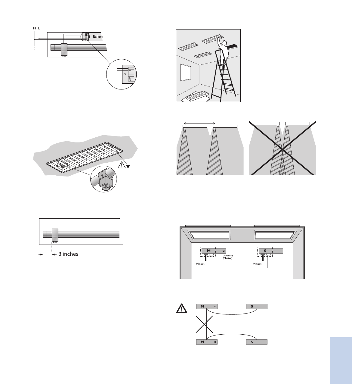
8-3
Lighting Electronics Atlas 2010-2011
CONTROLS
Controls
Installation of LuxSense into existing fixtures
Connecting diagram of the sensor to the ballast
The maximum fixture temperature should always remain below
70˚C. The sensitivity opening angle should never be obscured by
the optics or any other part of the fixture. Metal optics should be
properly grounded.
Mounting LuxSense on the Lamp
LuxSense mounted with a lamp clip (For use with T5 lamps only).
Not for use with T5/HO lamps.
Position LuxSense 3 inches away from the end cap on the
(electrical) “cold” side of the lamp. This is the side of the lamp
that is connected to the terminals of the ballast that allows
for the longest wiring to the lamp.
Installation of fixtures that include LuxSense
Interconnecting LuxSense Master fixtures (M) to Satellite fixtures (S)
Interconnecting LuxSense Master fixture (M) to Satellite fixture (S).
Up to 19 satellite fixtures can be looped through to I Master
fixture, if all of them are equipped with Philips Advance
Mark 7® 0-10V or EssentiaLine 0-10V ballasts.
Satellite fixture should have similar daylight conditions to the master.
Connect 0-10V “+ to +” and “– to –”. (See diagram above)
Never loop through 2 Master fixtures!
White -
White/gray +
min. 5 ft
Install fixtures
LuxSense
LRL1220TL5
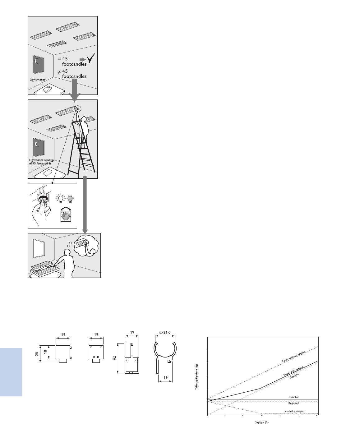
Lighting Electronics Atlas 2010-2011
CONTROLS
8-4
Controls
Dimensions in mm
Warning: the required light level should be no more than 30% lower
than the average installed light level, without daylight contribution
(e.g. 55 footcandles installed, adjustment down to 39 foot candles is
possible).
Please note that LuxSense is not designed for maintaining
a constant light level.
Measure the light level
under each LuxSense
sensor with no or negligible
daylight contribution.
If needed, turn the diaphragm
until the required light level is
reached (with no or negligible
daylight contribution).
See diagram on the left to
manually adjust the light levels.
You can easily copy the new
set point to other rooms
when similar daylight and
reflector conditions exist.
Technical data
Operation conditions
Ambient temperature 5°C to 55°C
Rel. humidity 15% to 90%, no condensation
Max. temperature of clip to
lamp contact surface 70°C
Storage conditions
Ambient temperature -25°C to 70°C
Rel. humidity 5% to 95% at 25°C
Connection 20 AWG, flying leads,
length 27 inches.
Color coding of cable: white/grey +
white –
Connecting the wires in the reverse
will result in minimum light output.
Housing
Material ASA
Color light grey (similar to RAL 7035)
Weight/dimensions Approx. 20 grams, 25x21x19mm.
Control signal input - operating voltage: 1.5 - 10VDC
- operating current sink 100µA-3mA
(sufficient for 20 0-10VDC ballasts)
- control voltage variation: < 0.5V
over current and temperature range
- max. input voltage
(maximum rating): 15 Vdc
- max. current sink
(maximum rating): 50 mA
Optical characteristics It is assumed that the reflection in
a room is such that a light level of
45 fc on a table (2.6 ft. in height)
will result in 2.3 fc seen by the
controller at ceiling height (8 ft.)
under a viewing angle of 45°
- The opening angle can be adapted
by the diaphram control, realizing an
adjustment factor between 1/3 and 3.
Controls characteristics LuxSense compensates approximately
for 50% of the added light (simulated
and measured with a fluorescent light
source). See graph below. In case of a
natural light source, the light compensation
is higher than 50%.
0 30 60 90 120 150 180
225
180
135
90
45
0
LuxSense controls characteristics
LuxSense
LRL1220TL5

8-5
Lighting Electronics Atlas 2010-2011
CONTROLS
Controls
MicroLuxSense is a DayLight Regulation option (DLR)
for luminaires equipped with a Philips Advance Mark 7
0-10V or EssentiaLine 0-10V ballasts. The sensor
measures the reflected light coming from the surface
below. It dims down the lamp output when the light
level exceeds the required light level defined by the
light sensor set point.
MicroLuxSense can be installed in the luminaire
either mounted between the louvers or recessed
in the housing.
MicroLuxSense™
Provides daylight regulation via a single miniature sensor
Connect to the 0-10VDC control input of the Mark 7
or EssentiaLine ballast
Provides a potential energy savings of up to 32% without
sacrificing visual comfort*
Maximize visual comfort
Automated regulation of artificial lighting allows for task
illumination to be maintained.
Arrives from the factory in a standard preset configuration
No need for complex commissioning. Field adjustment possible
if needed.
Regulate up to 20 luminaires
Utilize one sensor for continuous rows or multiple sensors
with single luminaires
Uses common sensor footprint with ActiLume and
ActiLume Color
One luminaire design now has the capability to provide
various control options
* Galasiu, A.D. “Energy saving lighting control systems for open-plan offices: a field study,”
National Research Council Canada, v4 no1, July 2007 pg. 7-29
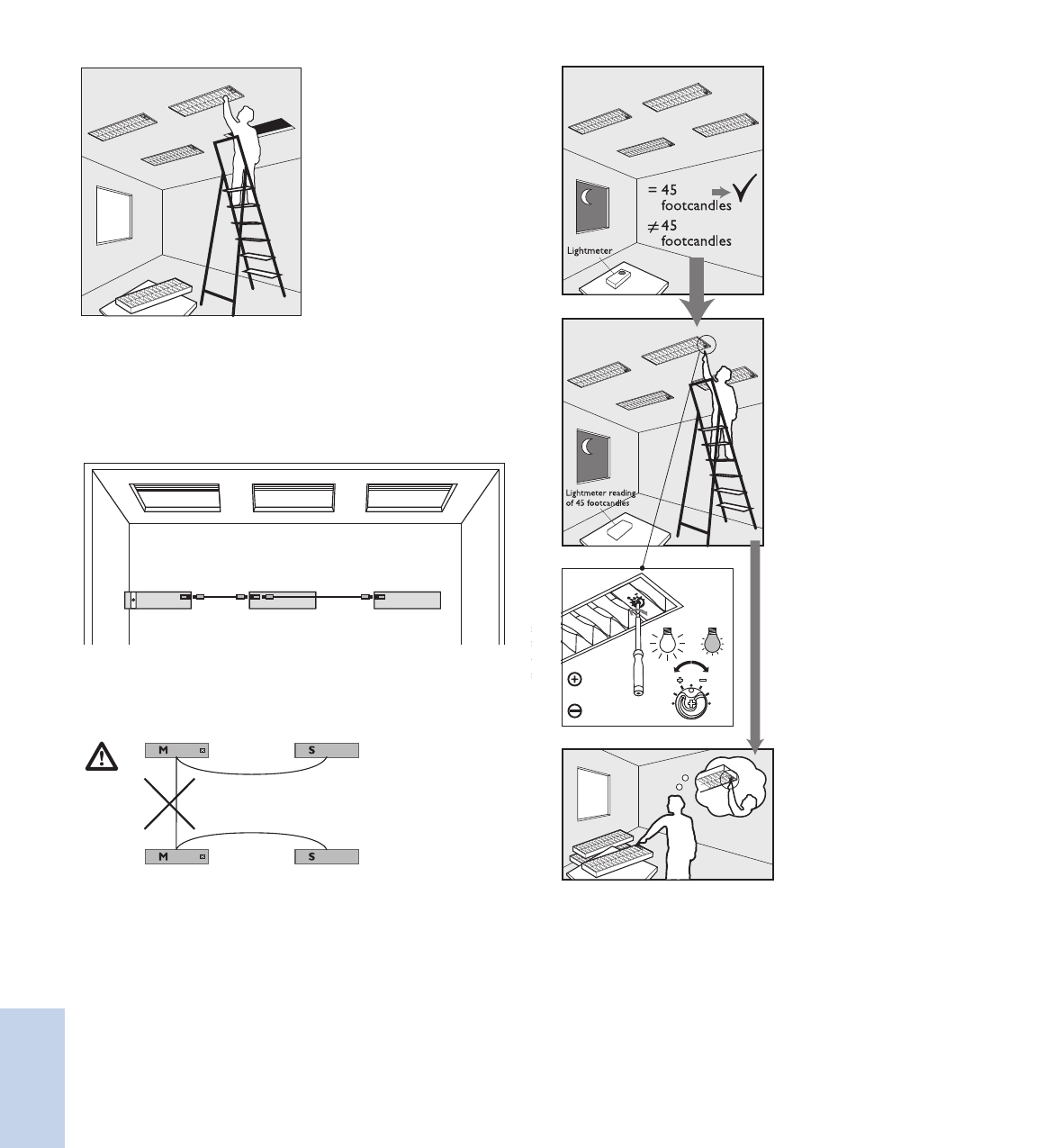
Lighting Electronics Atlas 2010-2011
CONTROLS
8-6
Controls
M S
M S
MicroLuxsense
SS
Luxmeter
= 500 Lux
500 Lux
Luxmeter
500 lux
Installation
Mount the luminaire with
MicroLuxSense daylight
Regulation option.
Interconnecting MicroLuxSense Master fixture (M) to Satellite fixture (S).
Up to 19 satellite fixtures can be looped through to I Master
fixture, if all of them are equipped with Philips Advance
Mark 7® 0-10V or EssentiaLine 0-10V ballasts.
Satellite fixture should have similar daylight conditions to the master.
Connect 0-10V “+ to +” and “– to –”. (See diagram above)
Never loop through 2 Master fixtures!
MicroLuxSense
LRL1222
Slotted head
screwdriver
No.0
Phillips head
screwdriver No.1
Warning: the required light level should be no more than 30% lower
than the average installed light level, without daylight contribution
(e.g. 55 footcandles installed, adjustment down to 39 foot candles
is possible).
Please note that MicroLuxSense is not designed for
maintaining a constant light level.
Measure the light level
under each MicroLuxSense
sensor with no or negligible
daylight contribution.
If needed, turn the diaphragm
until the required light level is
reached (with no or negligible
daylight contribution).
The setpoint of the sensor
can be changed manually
by using a screwdriver to
turn the control ring on the
front, which influences the
diaphragm. The housing is
equipped with an indication
of the default setting.
You can easily copy the new
set point to other rooms
when similar daylight and
reflector conditions exist.
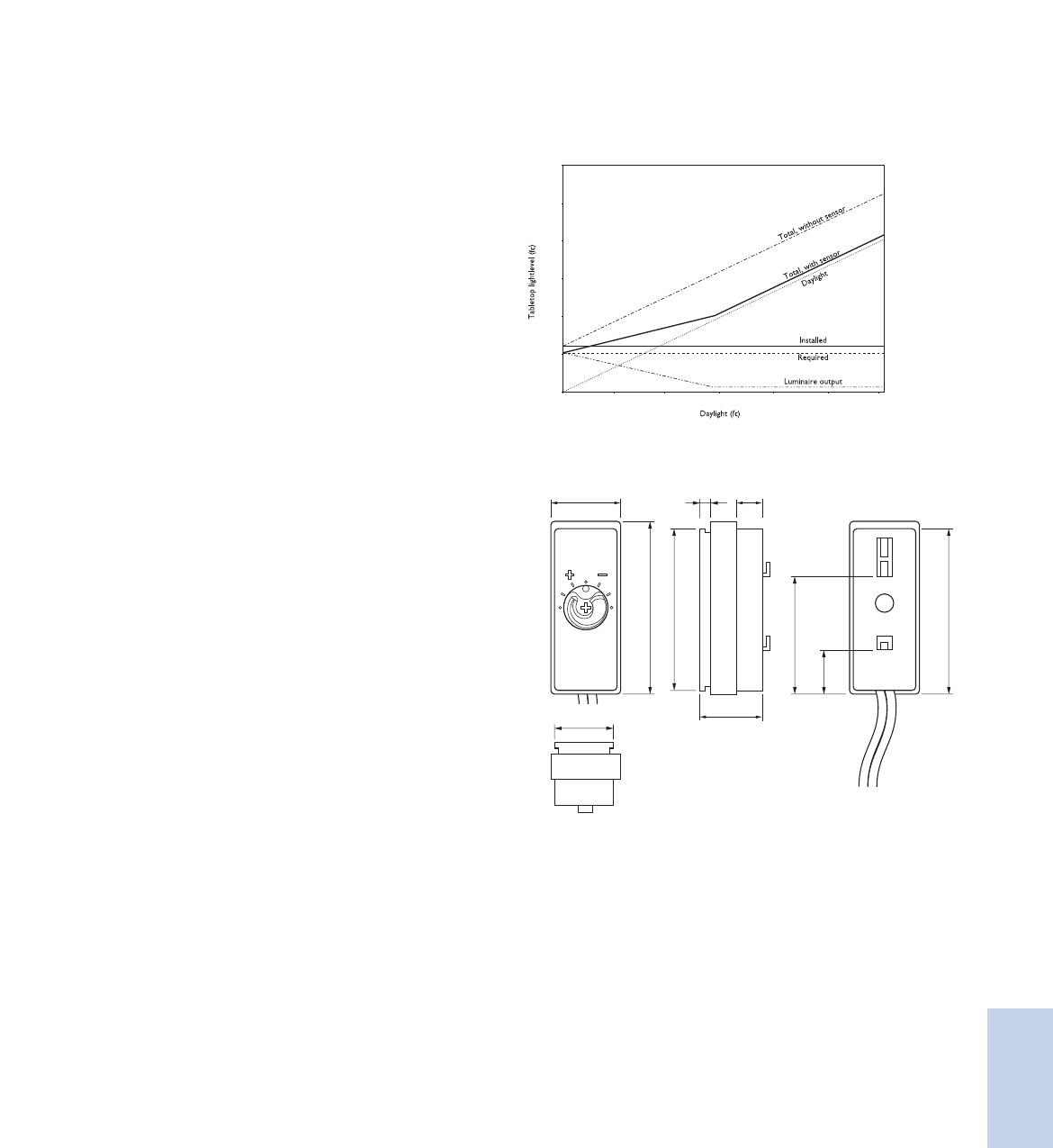
8-7
Lighting Electronics Atlas 2010-2011
CONTROLS
Controls
MicroLuxSense
LRL1222
Technical data
Operation conditions
Ambient temperature 5°C to 55°C
Rel. humidity 5% to 90%, no condensation
Max. allowed temperature 55°C
Anywhere on the sensor housing
Storage conditions
Ambient temperature -25°C to 70°C
Rel. humidity 5% to 95% at 25°C
Connection 20 AWG, flying leads,
length 27 inches.
Color coding of cable white/grey +, white –.
Connecting the wires in the
reverse will result in minimum
light output.
Housing material Polycarbonate UL94 V-0
Color bottom part Ultra Dark Grey
(similar to RAL 7024)
Color cover part Light Grey (similar to RAL 7035)
Weight/dimensions Approx. 25 grams, 47x19x19 mm
Control signal input
operating voltage +1.5 - +10Vdc
operating current sink 100µA-3mA (sufficient for 20
Philips Advance Mark 7 0-10V or
EssentiaLine 0-10V ballasts)
control voltage variation < 0.7V
over current and temp. range
max. input voltage 15 Vdc (maximum rating)
max. current sink 50 mA (maximum rating)
Optical characteristics - It is assumed that the reflection
in a room is such that a light
level of 45 fc on a table (2.6 ft.
in height) will result in 2.3 fc
seen by the controller at ceiling
height (8 ft.) under a viewing
angle of 45°
- The opening angle can be
adapted by the diaphram
control, realizing an attenuation
factor between 1/3 and 3.
MicroLuxSense control characteristics
The control characteristics are described in the graph. The light sensor
roughly compensates for 50% of the ingressing daylight by dimming
the artificial light output, until the minimum output is reached.
General Specifications
45
47
12
32
19 7
44
17
3
17
0 30 60 90 120 150 180
225
180
135
90
45
0
Dimensions in mm

Lighting Electronics Atlas 2010-2011
CONTROLS
8-8
Controls
ActiLume is a revolutionary new plug-and-play
daylight/occupancy lighting system that virtually
eliminates any worries of complicated programming
procedures. Commissioning is easily achieved by
pushing a button on the sensor that calibrates the
light level and switches the controller between
open plan and private office modes.
Actilume consists of a ready to use sensor and
control unit to be built directly into a luminaire.
This system is designed to deliver maximum visual
comfort and potential energy savings of up to 65%*
to the commercial sector.
The relative light output of the luminaire is defined
by its placement within the space (window or
corridor side of the office). The controller switches
the lamps in a fixture automatically on and off
based on occupancy and regulates the light output
according to the amount of daylight entering the
space. The system is operated with Philips Advance
ROVR™ electronic ballasts.
* Galasiu, A.D. “Energy saving lighting control systems for open-plan offices: a field study,”
National Research Council Canada, v4 no1, July 2007 pg. 7-29
ActiLume™
An easy to use and install lighting control system
Features
State-of-the-art daylight/occupancy sensor
Provides a potential energy savings of up to 65%
without sacrificing visual comfort*
Simple to use lighting control system
No specific lighting control training is needed to
commission or adjust light levels or operation modes
Two pre-programmed application modes
Private or open plan modes can be selected via a
simple push of the service button
8-9
Lighting Electronics Atlas 2010-2011
CONTROLS
Controls
RJ10
4P4C
R=8'
R=6.5'
General Specifications Controller / Sensor Specifications
Plug & Play control models
• Mode 1, Private Office: Lights switch off after 15 minutes,
saving energy in a private office situation.
• Mode 2, Open Office: Lights dim after 15 minutes, but are
not switched off until unoccupied for 2 additional hours.
This avoids dark areas in an open plan office.
Technical data for installation, mains operation
Rated mains voltage 120-277 V
Voltage tolerance: +/- 10% 108-305 V
Mains frequency 50/60 Hz
Input power (system) <2W
Maximum number of ballasts 9
Maximum number of
extension sensors 2
Technical data for design and mounting in fixtures
Operating conditions
Ambient temperature 0 ºC to 55 ºC
Sensor and controller
Relative humidity 20% to 85%,
no condensation
Storage Conditions
Ambient temperature -25 ºC to +85 ºC
Relative humidity 10% to 95%
Sensor LRI 1653
Connection RJ-10 4-Pole
Fixed to LRI1653 3 ft. cable
Housing (casing)
Material Polycarbonate UL94 V-0
Mounting 1. Latching tabs on the back
The sensor housing has two of the sensor
mechanisms that may be used 2. Four small ridges, two on
for mounting:
each long side of the sensor
Safety, basic insulation > 1500 V
When placed at a height of 9 ft.
the following values are valid:
Infrared receiver Signal Range
Light sensor Monitoring range of 2.5 to
35 foot-candles at sensor
Monitoring area
Movement detector Passive Infra Red (PIR)
Detection area at 9 ft. height:
• 13x13 ft. (sensitive for small
movements)
• 20x16 ft. (sensitive for larg
movements)
19'
16'
Sensor Orientation
Y
X
Maximum height PIR: 11 ft.
X-angle PIR: 100˚
Y-angle PIR: 82˚
ActiLume
Controller LLC 1654
Sensor LRI 1653
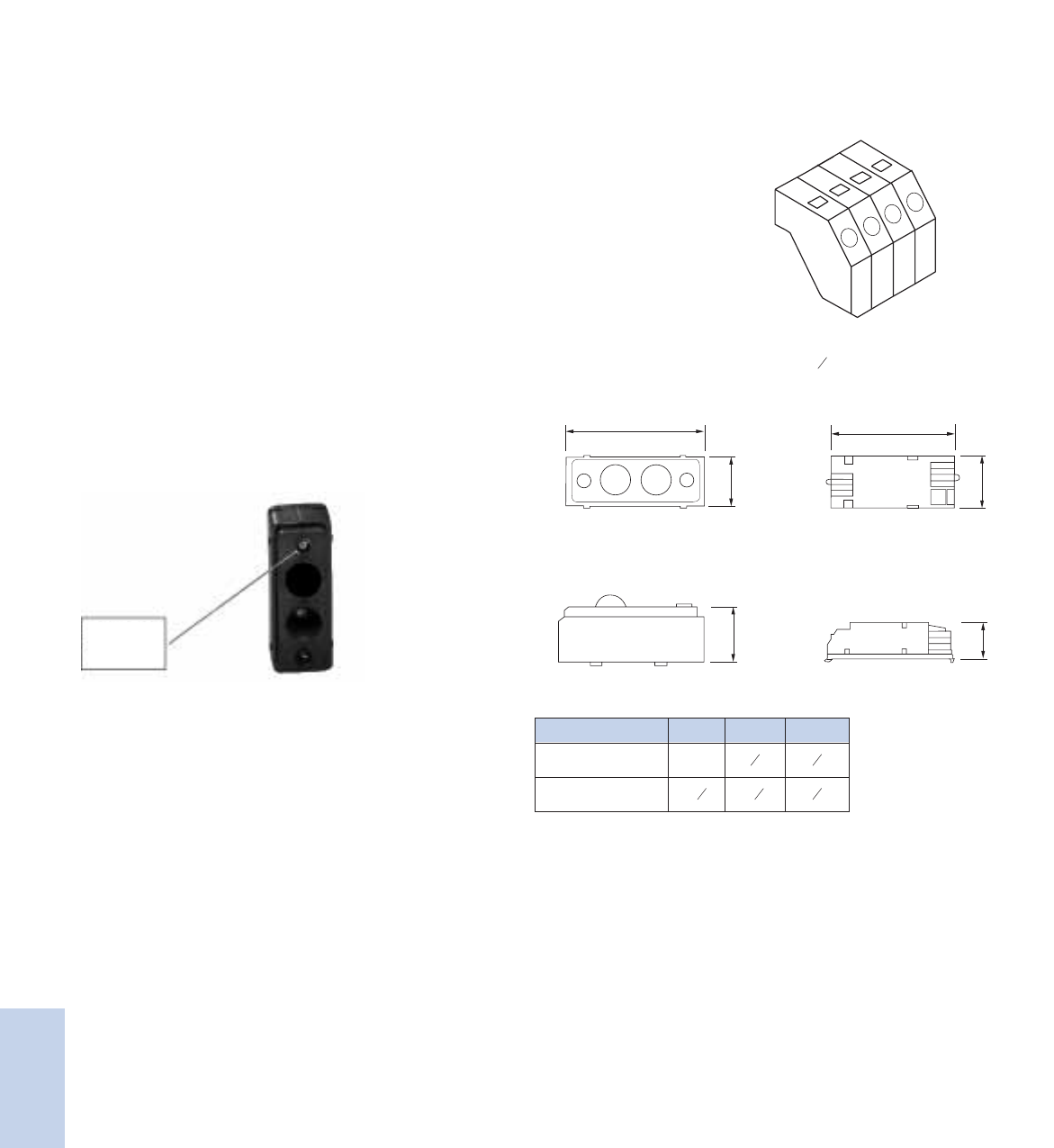
Lighting Electronics Atlas 2010-2011
CONTROLS
8-10
Controls
Lighting Controls ActiLume / Sensor
Set the reference light level adjustment:
Pressing the service button (>3 seconds) until the lamp gives a light
flash (wink) will start the automatic calibration procedure for light
level adjustment. Step aside or remove stepladder, if used.
The light output of the luminaires connected to window row is
set to 80%. The light output of the luminaires connected to a
corridor row is set to 100%.
After 30 seconds the ActiLume controller is saving the actual light
level as new reference light level (indicated by a second flash).
This 30 seconds time delay is required to have sufficient time to
step aside or remove a stepladder.
Select the user mode (application):
The user mode can be toggled between mode 1 and 2 by means
of a short push on the service button (<3 seconds). [Fig. A]
After the service button has been released the lamp will flash to
indicate the selected user mode: 1 flash = User mode 1 (Private
office application) 2 flashes = User mode 2 (Open plan office
application). The flash count begins after the lamp has been dimmed.
Count only the short lamp pulses and not the final lamp level.
Controller unit LLC 1654
Window and In user mode 1 and user mode 2
corridor output the system is programmed as one
channel with two zones. When
enough daylight enters the room,
the amount of artificial light will be
automatically reduced on the
window row and the amount of
light on the corridor row will be
offset with 30% more light.
Safety, basic insulation > 1500 V
Material Polycarbonate UL94 V-0
Mounting The controller housing contains
snap-in pins for quick fixation.
The diameter of the fixation holes
should be maximum 4.5 mm.
The snap-in pins are designed for a
metal thickness of maximum 0.8 mm.
The maximum distance between
the fixation holes is 78 mm.
Connector type
Connection wiring is greatly simplified through use of
POKE-IN connectors.
Wire cross-section
22 AWG - 18 AWG solid or stranded with tinned ends
Strip length 3 8 "
B1
A1
C1
B1
A1
C1
Dimensions in inches
Controller LLC1654
Controller LLC1654
Sensor LRI1653
Sensor LRI1653
B1
A1
C1
B1
A1
C1
Dimensions in inches
Controller LLC1654
Controller LLC1654
Sensor LRI1653
Sensor LRI1653
A1 B1 C1
Sensor LRI 1653 1 ¾ 5 85 8
Controller LLC 1654 3 1 81 3 16 7 8
Dimensions in inches
ActiLume
Controller LLC 1654
Sensor LRI 1653
Service
button
Fig. A

8-11
Lighting Electronics Atlas 2010-2011
CONTROLS
Controls
ActiLume / Sensor
120 or
277VAC
ActiLume Modes
Besides the private office and open plan office modes, in the future it will be possible to recall additional (yet to be determined) application modes.
This will make the ActiLume system very flexible for all different kinds of applications. An advanced remote control will be added in the future to
allow users to select and store other specific modes to meet the space needs.
Mode 1: Private office
15 min
Mode 2: Open plan office
15 min
15 min
120 min
15 min
Presence - Area is occupied.
Absence - Light stays on. (internal timer is activated to clock
absence time)
Absence - Light dims down to a background level (internal timer
is activated to clock absence time) or surrounding light at 100%.
Absence - Light switched off.
When enough daylight is detected, the lights will
NOT be switched on automatically when someone
enters the room.
When enough daylight is detected (measured
over 15 minutes), the lights will automatically be
switched off.
Mode 1: Private office
15 min
Mode 2: Open plan office
15 min
15 min
120 min
15 min
Mode 1: Private office
15 min
Mode 2: Open plan office
15 min
15 min
120 min
15 min
Mode 1: Private office
15 min
Mode 2: Open plan office
15 min
15 min
120 min
15 min
ActiLume
Controller LLC 1654
Sensor LRI 1653
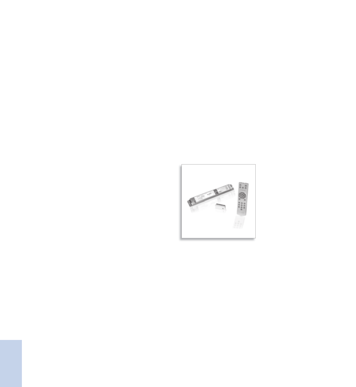
Lighting Electronics Atlas 2010-2011
CONTROLS
8-12
Controls
Philips ActiLume Color is a stand-alone, lighting
control designed for dynamic and static color effects
in small, medium and large sized applications. This
plug and play color system makes commissioning
easy; simply wire the system and you can start color
changing with the infrared remote control. With no
specific training needed, the operator can quickly
recall ten pre-programmed dynamic color changing
sequences and ten pre-programmed static scenes.
This system has been designed for all indoor
applications within retail, hospitality, and other
public spaces, to attract people to specific areas
and to enhance areas with color for scene setting.
In addition, for maximum flexibility it is compatible
with many light sources including LEDs and
fluorescent lamps.
A maximum of 10 color luminaires can be
controlled per ActiLume Color controller via
the DALI broadcast output ports. You can also
synchronize up to 60 ActiLume Color controllers
(or 600 RGB fixtures) simultaneously. This system
can also be operated in larger and existing DALI
or DMX backbone based networks.
The ActiLume Color system is available with
the ActiLume Color Programming Kit. Included in
the kit is an easy to use software called ActiLume
Color Studio, that allows you to create your own
static colors or dynamic color sequences off-site
and then upload them to the color controller
during on-site commissioning.
ActiLume™ Color
A true plug and play color management system for the retail, hospitality, and architectural markets
Features
Easy to use color management system
Plug and Play controller requires no specific lighting
controls training
State-of-the-art controller
Provides the functionality of all input lighting control
signals from various input devices (remote control,
DALI interface, etc).
Design flexibility
Can be used in one fixture or up to 10 interconnected
fixtures as well as the ability to be networked with up
to 60 other controllers

8-13
Lighting Electronics Atlas 2010-2011
CONTROLS
Controls
ActiLume Color System
• It can be used for both dynamic sequences from very fast
to very slow (24 hr cycle), and static colors that are selected
to support many applications including seasonal fashion,
merchandise change, a specific atmosphere in a bar or
restaurant or to enhance an architectural design.
• It offers 10 pre-programmed sequences corresponding
with seasons (Christmas, autumn) and daily ambiance
(nature, sunset).
Plug and Play control
• Simple systems with one ActiLume Color controller
can be operated by DALI push button controls or remote
control. The Philips Advance ROVR ballasts are directly
connected to the Red, Green, and Blue outputs without
any commissioning.
9.92
9.69
1.25
0.18
0.85
0.75
Technical data for installation
Mains operation Rated mains voltage 120-277 V
With tolerances for operation +/- 10%
Mains frequency 50/60 Hz
Output power (system)
R output Maximum 10 DALI loads (20 mA)
G output Maximum 10 DALI loads (20 mA)
B output Maximum 10 DALI loads (20 mA)
Ext output Maximum 40 DALI loads (80 mA)
DMX 64 mA
Sensor 5 mA
Technical data for design and mounting in fixtures
Operating conditions Ambient temperature +5 … 50 ºC
Controller and sensor
Rel. humidity operating 20% … 85%, no condensation
Tcase 75 ºC
Storage Conditions -25 … +70 ºC
Rel. humidity storage 10% … 95%
Lifetime 10% failure rate at 50k hrs with
Tcase of 75 ºC
DMX operation
Operating temperature +5 … 55ºC
Protocol standards ANSI 1.11-2004 (USITT DMX512-A)
ANSI 1.20-2006 (RDM)
Connector 8-position modular connector (RJ45)
Transient/Burst Immunity
and Surge IEC 61000-4-4/5, level 2 on IO: 0.5kV
UL840: over voltage category II (<50 V):
0.5 kV
Network requirements According to EIA-485-A specification
Technical data
Compliances and approvals
Safety Standards NEMA 410
UL935
Quality standard ISO 9001
Environmental standard ISO 14001
Approval marks ENEC:
72/23/EEC (low voltage)
89/336/EEC
(electromagnetic compatibility)
CSA
UL-recognized (UL1310 for class
II power supplies)
CE marking
ActiLume Color
LLC 1670
Dimensions in inches

Lighting Electronics Atlas 2010-2011
CONTROLS
8-14
Controls
ActiLume Color Controller unit LLC1670
In standard operation and based on the pre-programmed colors,
ActiLume Color calculates the different dim levels for the Red, Green
and Blue lamps, and the fading (dim levels) in between two color
points. On the extended output, additional ActiLume colors can be
operated within the same sequences or scenes.
In DMX operation, the real time DMX commands are directly
translated into DALI commands on the output side.
ActiLume Color Inputs/Outputs
4x DALI current limited outputs DALI-R: 10 DALI loads max
DALI-G: 10 DALI loads max
DALI-B: 10 DALI loads max
DALI-EXT: 40 DALI loads max
(mentioned as group RGBE_DA)
1x ActiLume Multi-Sensor input, labeled SENSOR
1x RS-485 connection, based on DMX (RDM)
The controller only supports the RDM address setting. The
RDM requires bidirectional RS-485 (half duplex) and a factory
programmed device unique ID.
Transmission load 32 devices, with
terminators
Transmission level range 0 ≤V≤+6 with respect to
common
Transmission frequency 250 kBit/s ± 2%
Reception level range +12/-7 with respect to
common
Reception frequency 250 kBit/s ± 2,5%
Turn around time of
DMX transceiver 176 µs after transmission
of the last stop bits.
When a DMX-RDM
controller expects a
response, the device must
place its transmitter in high
impedance state within
88 µs after transmission
of the last stop-bit (of the
last transmitted byte). Time
between slots (data-bytes)
may not exceed 76 µs
IDC Connection
ADS/Manual connection
Release: Rotate and pull
Remark: Release all wires one by one
IDC Connection 20 AWG solid /18 AWG stranded
ADS or manual push 20 AWG - 18 AWG solid wire
Strip length 0.32 inches – 0.35 inches
1x DALI passive input, (DALI GP)
Transmit:
Short circuit current Max 250 mA
High-level range 11.5 … 20.5 V
Low-level range –4.5 … 4.5 V
Rise/fall time 10 …50 μs
Transmission frequency 1200 Hz +/- 5%
Receive:
High-level range 9.5 … 300 V
Low-level range –6.5 … 6.5 V
Rise/fall time 10 …50 ms (mains),
0 …100 μs (DALI)
Reception frequency 50/60 Hz (mains),
1200 Hz +/- 10% (DALI)
1x Universal mains input
Glow wire test 850 ºC / 5 s
Safety, basic insulation < 2000 V
Material Polycarbonate + ABS Bay blend
KU-2 1514
UL94 V-0
Housing color Dark gray
Mounting The minimum distance between
the fixation holes is 9.29 inches.
User interfaces
Remote control IRT1670 needs to be pointed to the
sensor (IRR1654, or IRR8125) for
starting dynamic sequences or static scenes.
Philips DALI Broadcast commands will start
pre-programmed sequences/static colors
Connections for DALI and mains
ActiLume Color
LLC 1670
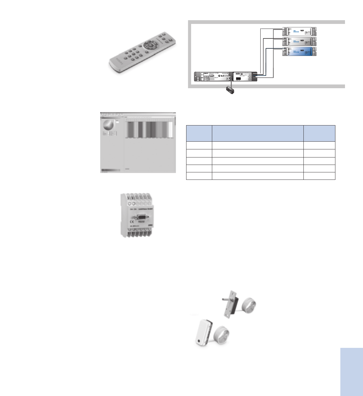
8-15
Lighting Electronics Atlas 2010-2011
CONTROLS
Controls
IRR 1654 with cap
IRR 8125 invisible
Connection RJ-10 4-Pole 100 cm cable
Housing (casing)
Material Polycarbonate UL94 V-0
Glow wire test 950 ºC / 5 s
Safety, basic insulation < 2000 V
Infrared receiver RC5 signal
Minimum range 20 m2
Cap material IRR1654 Polycarbonate, RAL7035
Advanced color selection remote control IRT1670
This remote control can be used
for selecting pre-programmed color
sequences and static colors. These
programmed dynamic sequences can
be played faster (in half of the time),
or slower (factor 3 or 6 slower). Static
colors can be selected in hue and dim
level and stored into the controller.
Batteries are included.
ActiLume Color Programming Kit LCK1671
Consists of:
A. ActiLume Color Studio.
An intuitive software for
programming sequences into
the ActiLume Color controller
allowing for direct preview,
light plan overview,
and grouping.
B. RS232 gateway the RS232-DALI
gateway translates all
communication between the
personal computer and the
DALI network. The connection
between PC and the DALI
network is only necessary
when the sequences are
uploaded into the ActiLume
Color Controller. The gateway
requires a 24V power supply,
not provided.
C. Interconnecting cable for
the PC/Gateway.
To Lamps
Red, green and blue lamp ballasts
Remote control receiver
Master Controller
Wiring scheme
Ordering and Packing data
Type Description Packaging
(PCS)
LLCI670 Controller 24
IRR1654 IR Sensor with cap 24
IRR8125 IR Sensor invisable 1
IRT1670 Remote Control 18
LCK1671 Programming Kit 1
ActiLume Color
LLC 1670
IRR 8125
IRR 1654
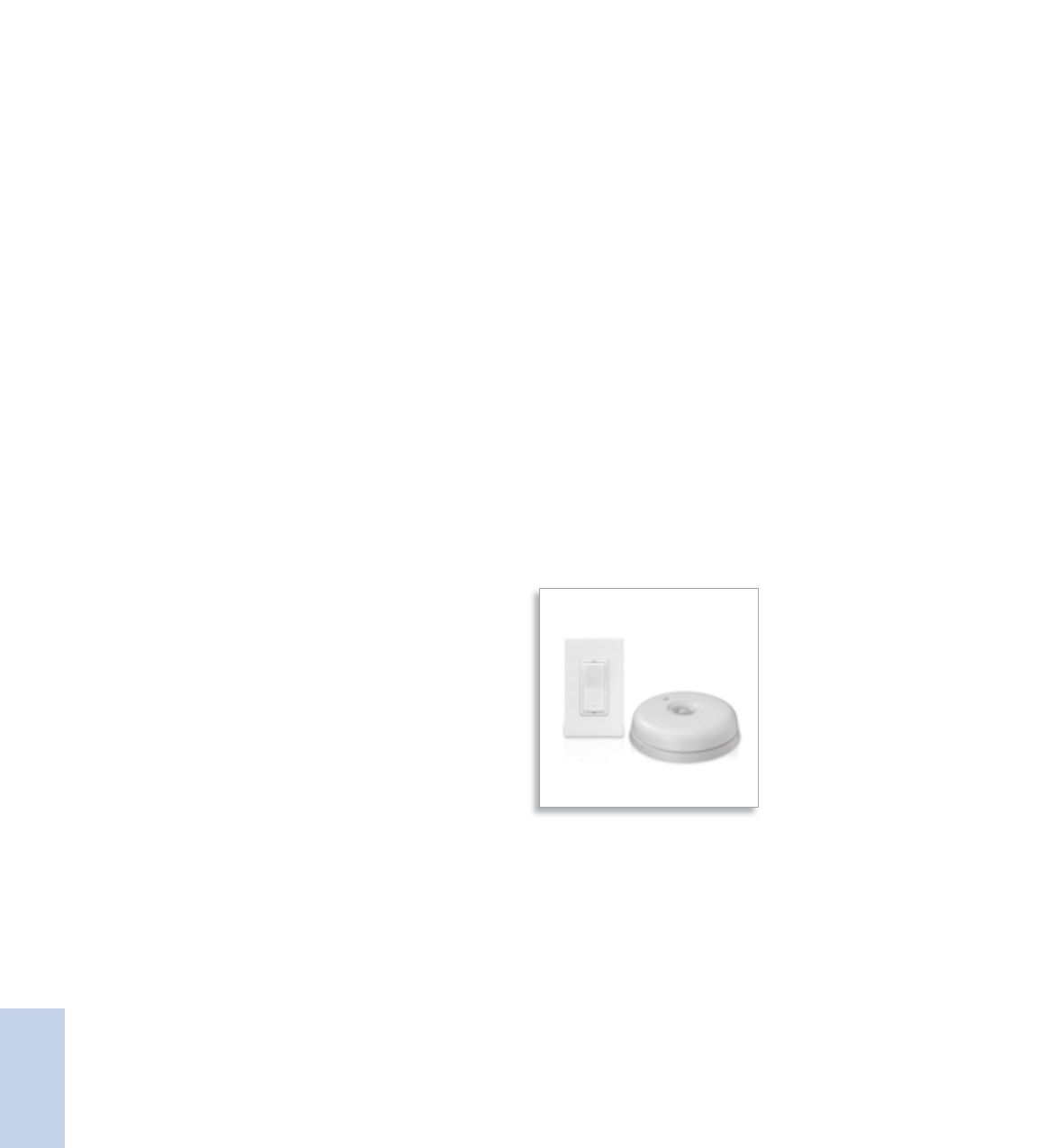
Lighting Electronics Atlas 2010-2011
CONTROLS
8-16
Controls
The Philips OccuSwitch Wireless Occupancy Sensor
is an advanced wireless system that automatically
turns lights off when a workspace is unoccupied,
saving energy and helping to create a more
sustainable work environment. The system consists
of a wireless battery-powered ceiling mounted sensor
that communicates to a wall switch. Multiple sensors
and switches can be used for additional coverage.
Using a combination of passive infrared (PIR)
technology and advanced logic for detecting major
and minor motion, the sensor recognizes when
the room is occupied (or unoccupied), helping to
eliminate false triggers. The system adapts to
accommodate varying user patterns with built-in
intelligence to automatically adjust the shut off
time delay.
The Philips OccuSwitch Wireless Control System
is a unique indoor plug and play system perfect
for retrofits and new installations in commercial
applications including private offices, conference
rooms, restrooms, breakrooms, copyrooms, storage
areas, and lobby areas. Uncompromising on style,
the functional design allows for easy setup and
adjustments to system settings via front
accessible buttons.
* Product has a 2-year limited warranty. See page 8-18 for more details.
OccuSwitch™ Wireless
A simple, easy, and effortless way to create a more sustainable work environment
Features
Easy-to-install retrofit
Wireless controls means no sensor wiring providing quick
set-up times, minimizing disruptions
Advanced occupancy sensing
Helps eliminate false triggers which optimizes energy savings
Sleek Low Profile Design
Stylish low-profile design easily blends into existing and
current office designs
10-year battery life design*
Provides worry free maintenance, just install and leave for
long lasting performance
Manual-On/Auto-Off Capability
Compliant with applicable California Title 24 energy efficiency
code requirements
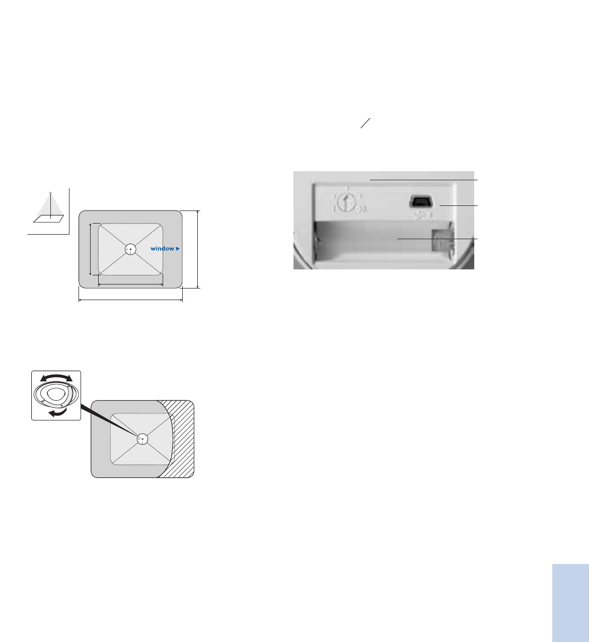
8-17
Lighting Electronics Atlas 2010-2011
CONTROLS
Controls
Wireless Occupancy Sensor Specifications
Detection Technology
Passive Infrared (PIR)
Mounting Height
Can be installed for up to 12ft ceiling height
Detection Area
Will vary based on ceiling height.
For a typical ceiling height of 8 ft (2.4m):
Major motion coverage 17.7 x 23.6ft (5.40m x 7.20m)
Minor motion coverage 11.8 x 17.7ft (3.60m x 5.40m)
Larger areas will require multiple sensors.
23.6ft (7.2m)
17.7ft (5.4m)
17.7ft (5.4m)
11.8ft (3.6m)
h= 8ft (2.4m)
Large movements
Small movements
h
The orientation of the window arrow on the mounting plate aligns the
direction of the rectangular detection area.
Rotating Shield
During installation the retractable sensor shield can be rotated to partially
mask the sensor’s field of view and prevent unwanted movement detection.
Wireless Network Protocol ZigBee Pro 2.4GHz
Universal license free band
Wireless Compatibility
Can be connected with multiple OccuSwitch Wireless Wall Switches.
Up to 10 sensors and switches can be networked together.
Wireless Range
Switch to Sensor: 50ft (17m)
Switch to Switch (same plane): 18ft (6m)
Switch to Switch (line of sight): 50ft (17m)
Battery
Standard AA size 3.6V DC Lithium-thionyl chloride (Included)
10-year battery life design.
Actual battery lifetime will vary based on
application and occupancy activity.
Intelligent Delay Timer
The switch-off delay can be manually set between 1 and 30 minutes
using the dial on the sensor. Once system is operational, the initial
setting is automatically adjusted to the user’s occupancy pattern
USB Port
Incorporates ability for future field firmware upgrades
Dimensions
Diameter 3.3 inches (84mm)
Height (with ceiling plate) 0.98 inches (25mm)
Operating Conditions
Temperature 41°F – 104°F (5°C – 40°C)
For Indoor use only.
Humidity 20% – 85%, non-condensing
Environmental Compliance RoHS
Regulatory Compliance UL, CSA, FCC, California Title 24
Energy Efficient Standards
Intelligent Delay
Timer
Battery
USB port
OccuSwitch Wireless
Occupancy Sensor LRM 1742
Switch LRM 1720

Lighting Electronics Atlas 2010-2011
CONTROLS
8-18
Controls
Wireless Wall Switch Specifications
Operating Voltage Universal Input
120V AC or 277V AC, 60 Hz
Load Rating
Electronic Fluorescent Ballast: 120V / 1300VA
277V / 1300VA
Electromagnetic Fluorescent Ballast: 120V / 1300VA
277V / 1300VA
Incandescent lamps 120V / 800W
Motor load 120V / 0.25HP
Wireless Network Protocol ZigBee Pro 2.4GHz
Universal license free band
Wireless Compatibility
Can be connected to multiple OccuSwitch Wireless Sensors
and Switches. Up to 10 sensors and switches can be
networked together.
Stand alone or 3-way switching
Each Wireless Switch can be configured to operate as a standalone
switch or a 3-way switch.
By default the switch will act as a stand-alone switch: the switch only
controls the load that is connected to it.
When configured as a 3-way switch, all loads are controlled from
any switch.
USB Port
Incorporates ability for future field firmware upgrades
Color White
Almond
Dimensions
length x width x depth 4.13 x 2.56 x 1.79 inches
(105 x 65 x 45mm)
Designed to fit in a standard single-gang wall box.
Can also be installed in a multi-gang configuration.
Operating Conditions
Temperature 41°F – 104°F (5°C – 40°C)
For Indoor use only.
Humidity 20% – 85%, non-condensing
Environmental Compliance RoHS
Regulatory Compliance UL, CSA, FCC, California Title 24
Energy Efficient Standards
Type Description Quantity
LRM 1742/00 OccuSwitch Wireless occupancy sensor 1
LRA 1720/00 OccuSwitch Wireless wall switch (White color) 1
LRA 1720/01 OccuSwitch Wireless wall switch (Almond color) 1
Product Warranty
2-year limited warranty. Go to our website for up-to-date warranty
information on this product: www.philips.com/advancewarranty.
For complete ordering information, contact your local sales representative.
OccuSwitch Wireless
Occupancy Sensor LRM 1742
Switch LRM 1720
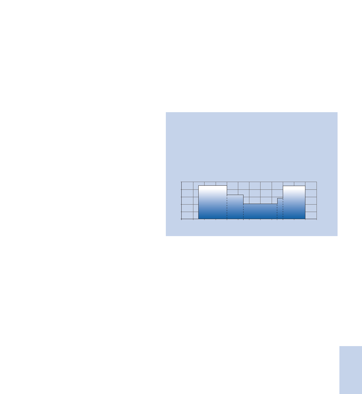
8-19
Lighting Electronics Atlas 2010-2011
CONTROLS
Controls
The Dynadimmer is a stand-alone dimming
control with a 0-10 volt dimming output that can
be used in combination with a compatible dimmable
electronic driver. Easy to install into a luminaire
or pole without any need for external control
components or additional signal wiring, it is fully
flexible and can be reprogrammed at any time to
fit new lighting demands if changes are needed.
The Dynadimmer can be configured to dim to any
level that the end-user wishes at set periods, with
a maximum of five set periods. Both the levels and
the time period are configured with an easy-to-use
software tool, which also calculates and displays the
energy savings that may be obtained from a particular
dimming schedule.
The designed configuration is then loaded into a
standard personal computer that will be used later
to program the Dynadimmer via a USB cable. This
configuration can be modified at any time by down-
loading a new dimming schedule to adapt the lighting
to a new situation or simply fine-tune the savings.
The five time periods and five dim levels guarantee
an optimal schedule whether the application is an
industrial area, parking lot, residential area or road.
The Dynadimmer can help to meet certain road/
area-lighting requirements and standards, which
entail the introduction of illumination levels that take
account of road use and/or traffic flows.
Dynadimmer™
A simple, easy to install outdoor controller for electronic lighting systems
Features
Energy savings and reduced light nuisance through dimming
Small size that can fit within almost any luminaire
Easy-to-use software that can provide a forecast of
energy savings
Energy savings may be are maximized with the Dynadimmer.
The fact that any level can be configured at any time makes
very low levels late at night possible, high levels at peak times
(though not necessarily 100%) and medium levels during
the transitional periods. For example, a dimming schedule
like the one shown in the picture projects an overall yearly
energy saving of 40%.
Avaialble in Q2, 2010 – Contact your local sales rep or agent
for more details.
12:00
0%
20%
40%
60%
80%
100%
12:0014:00
T1
D1
D2
D3
D4
D5
T2 T3 T4 T5
16:00 18:00 20:00
23:00 5:00 6:0015:00
10:0022:00 00:00 2:00 4:00 6:00 8:00

Lighting Electronics Atlas 2010-2011
CONTROLS
8-20
Controls
The Chronosense is a stand-alone dimming control
with a 1-step dim control output that can be used in
combination with one multi-wattage electro-magnetic
ballast or additional dim ballast. Easy to install into a
luminaire or pole without any need for external con-
trol components or additional signal wiring, it is fully
flexible and can be reprogrammed at any time to fit
new lighting demands if changes are needed.
The time period for which the Chronosense applies
the 1-step dimming can easily be changed by means
of dipswitches in the unit and can be modified at any
time in the future. To calculate the hours for which
it should operate, Chronosense counts the time that
the lights were turned on and determines a mid-
point, which is used as an intelligent reference point.
The Chronosense comes ready to operate with a
factory pre-set value of a 6-hour dimming period.
The six-position dipswitch sets both mode of
operation (test/normal) and the appropriate dimming
period. Switches 1-3 set the dim hours before the
midpoint of the night, switches 4-5 the dim hours
after and the sixth sets the mode of operation.
The Chronosense is suitable for new installations
as well as retrofit solutions for electro-magnetic
controlled luminaires. The flexible dipswitch
settings guarantee an optimal schedule whether
the application is an industrial area, parking lot or
residential area. The Chronosense can help to meet
certain Outdoor lighting requirements and standards,
which entail the introduction of illumination levels
that take account of use and/or traffic flows.
Chronosense™
A simple, easy to install outdoor controller for magnetic lighting systems
Features
Energy savings and reduced light nuisance through dimming
Easy to install and flexible to reprogram
Suitable for new installations as well as retrofit
The energy savings with Chronosense are determined by the
ballast combination used. A typical configuration with a
multi-wattage 100/150W ballast projects an overall yearly
energy saving of 20%. The ballast determines the dim
level, but using the combination with the multi-wattage
100/150W it is usually about 65% of full power (as shown
in the picture).
Avaialble in Q2, 2010 – Contact your local sales rep or agent.
12:00
0%
20%
40%
60%
80%
100%
12:0014:00 16:00 18:00 20:00
22:00 10:005:0015:00
10:0022:00 00:00 2:00 4:00 6:00 8:00
ON OFF

8-21
Lighting Electronics Atlas 2010-2011
CONTROLS
Controls
Notes
Reference
Lighting Electronics Atlas 2010-2011
REFERENCE MATERIALS
1
Centium® Optanium® SmartMate® Mark 10® Powerline
MasterColor CDM™ Elite MV Core & Coil F-Can Ballasts Encapsulated Core & Coil
EssentiLine™ 0-10V Mark III® e-Vision® CosmoPolis™
AmbiStar™ LED Drivers for ActiLume™ OccuSwitch
™
Luxeon Brand LEDs

REFERENCE MATERIALS
Reference
9-i
Lighting Electronics Atlas 2010-2011
Contents
Philips Lighting Electronics Warranty 9-ii
Industry Terms 9-1 to 9-3
Ballast Specifications
Fixed Light Output Electronic 9-5 to 9-14
Controlled Light Output Electronic 9-15 to 9-20
Magnetic HID 9-21
Electronic HID [Metal Halide] 9-22 to 9-23
Xitanium LED Drivers 9-24
Ballast Catalog Number to Page Number
Fluorescent 9-25 to 9-30
HID 9-31 to 9-32
eHID & Ignitors 9-32
Discontinued Ballasts – Replacements
Electromagnetic Fluorescent 9-33 to 9-34
High Frequency Electronic Fluorescent 9-35 to 9-36
HID 9-37 to 9-41
Lamp Index
Fluorescent 9-42 to 9-45
HID 9-46
Compact Fluorescent Lamp Reference Guide 9-47
Visit our web site at www.philips.com/advance
Customer Support/Technical Service
(800) 372-3331 • (+) 1 847 390-5000 (International)
Corporate Offices
(800) 322-2086

Reference
Lighting Electronics Atlas 2010-2011
REFERENCE MATERIALS
9-ii
Philips Lighting Electronics N.A. Lamp Ballast Limited Warranty
Philips Lighting Electronics N.A., 10275 W. Higgins Road, Rosemont, IL 60018
warrants that its lamp ballasts will be free from defects in material
and workmanship from the date of manufacture by
Philips Lighting Electronics for specific time periods.
Ballast warranty depends upon ballast type, product family and maximum case temperature.
Please go to our web site for up-to-date warranty information.
www.philips.com/advancewarranty
Limited Warranty Terms and Conditions
This limited warranty is conditioned upon proper storage,
installation, use and maintenance. This warranty is
not applicable to any ballast which is not installed and
operated in accordance with the current edition of
The National Electric Code (NEC), the Standards for
Safety of Underwriters’ Laboratory, Inc. (UL), the Standards
for the American National Standards Institute (ANSI),
and with Philips Lighting Electronics’ instructions and
guidelines for the ballast.
This warranty is not applicable to any ballast which is
installed with lamps not meeting ANSI requirements
unless the ballast is designed to operate a specific
non-ANSI lamp and marked accordingly. This warranty
is not applicable to any ballast subjected to abnormal
stresses and operating conditions.
Philips Lighting Electronics N.A. shall correct any defects, at
Philips Lighting Electronics’ option, by either repairing any
defective part or parts or by replacing any defective part or
parts or by making available a new replacement ballast.
The conditions of any tests concerning any ballast which
is claimed to have not performed to this warranty shall
be mutually agreed upon in writing and Philips Lighting
Electronics shall be notified of, and may be represented
at any such tests. This express limited warranty is extended
by Philips Lighting Electronics only to the original or first
end-user purchaser.
Warranty claims are to be made in accordance with Philips
Lighting Electronics’ published Warranty Service Program.
NO IMPLIED STATUTORY WARRANTY OF
MERCHANTABILITY OR FITNESS FOR A
PARTICULAR PURPOSE SHALL APPLY BEYOND
THE AFOREMENTIONED WARRANTY PERIOD.
The foregoing warranty is exclusive of all other statutory,
written or oral warranties, and no other warranties of
any kind, statutory or otherwise, are given or herein
expressed. This warranty sets forth Philips Lighting
Electronics’ responsibilities regarding the ballast and
claimant’s exclusive remedy.
LIMITATION OF LIABILITY. Philips Lighting Electronics
N.A. will not under any circumstances whether as a result
of breach of contract, breach of warranty, tort, strict liability
or otherwise be liable for consequential, incidental,
special or exemplary damages including but not limited
to, loss of profits or revenues, loss of use of ballast or any
other goods or associated equipment or damage to any
associated equipment, cost of capital, cost of substitute
products, facilities of services, down time cost, or claims
of claimant’s customers.
Philips Lighting Electronics’ liability on any claim of any
kind for any loss or damages arising out of, resulting from
or concerning any aspect of this agreement of from the
product or services furnished hereunder shall not exceed
the price of the specific ballast or ballasts to the claim.
This warranty gives the claimant specific legal rights.
The claimant may also have other rights which vary
from state to state.

REFERENCE MATERIALS
Reference
9-1
Lighting Electronics Atlas 2010-2011
5-Tap - An HID ballast that allows for a choice of five different input voltages
AC (Alternating Current) - The common form of electricity from power
plant to home/office. Its direction is reversed 60 times per second in the
U.S.; 50 times in Europe
AllnGaP - The preferred LED (Light Emitting Diode) chip technology
containing Aluminum, Indium, Gallium, and Phosphorous to produce red,
orange and amber-colors.
Ambient Sound Levels - “Background noise” generated by electrical
equipment operating in a building.
Ambient Temperature - Temperature of the atmosphere of the sur-
rounding environment.
Ampere (“Amp”) - A measure of electrical current
ANSI (American National Standards Institute) - Group that
generates voluntary product performance standards for many U.S. industries.
ANSI Watts - System wattage as measured utilizing a reference ballast
and lamps on a bench top in open air as prescribed by ANSI C82.2
Anti-Arc Circuit - Circuitry used to detect and limit arcing of ballast
output leads
Anti-Striation Circuit - Circuitry used to dectect and reduce striations
or spiraling in energy saving lamps due to low temperature or low
current operation
Arc (Lamp) - Intense luminous discharge formed by the passage of
electric current across a space between electrodes.
Auto-Restrike - Circuitry used to restart the lamps without resetting the
power to the ballast
Autotransformer - Tapped winding transformer that changes the voltage
available to the voltage required by a particular load
Ballast - Device for starting and regulating fluorescent and high intensity
discharge lamps.
Ballast Cycling - Undesirable condition under which the ballast turns
lamps on and off (cycles) due to the overheating of the thermal switch
inside the ballast. This may be due to incorrect lamps, improper voltage
being supplied, high ambient temperature around the fixture, or the early
stage of ballast failure.
Ballast Efficacy Factor (BEF) - Measure used to compare various lighting
systems based upon light output and power input. Higher BEF is favor-
able. BEF = Ballast Factor x 100 / Input Watts
Ballast Factor - Measure of light output from lamp operated by commer-
cial ballast, as compared to a laboratory standard reference ballast.
Ballast Losses - Power that is supplied to the ballast but is not converted
into light energy.
Ballast Noise “Hum” - Sound made by operating Core & Coil assemblies
in both electromagnetic and electronic ballasts, generated by the vibra-
tion of laminations in the electromagnetic field that transforms the voltage
and current used by discharge lamps. The sound made by high frequency
electronic ballasts is lower and any noise made by models with electronic
power factor correction circuits is inaudible.
Ballast Regulation - The ability of a ballast to control lamp wattage (and
therefore light output) when subject to changes in line voltage.
Bin - In LED’s, the systematic dividing of distribution of performance
parameters (Flux, Color or CCT, and Vf) in to smaller groups that meet
aesthetic requirements of the assembly.
Binning - The separation of LEDs subsequent to a production run for full
manufactured, distribution in terms of clor, flux and forward voltage.
Canadian Energy Standards - Indicates the ballast complies with
the Canadian Energy Standards and meets the requirements of
CAN/CSA-C654-M91
Canadian Standards Association (CSA) - Association that generates
product performance and safety standards for many Canadian industries.
Capacitor - Device in ballast that stores electrical energy.
Centigrade (C) - Celsius temperature scale where 0°C = 32°F and
100°C = 212°F.
Chip - A very small square of semi-conducting material. Also known as a
die, it is the active light-emitting component of an LED.
Circle E - Marking on ballast that shows compliance with Federal Ballast
Energy Law (Public Law 100-357)
Coil - Windings of copper or aluminum wire surrounding a core in ballast.
Conformal Coating - Material that surrounds and adheres to components
and protects them.
Constant Wattage Autotransformer (CWA) - An HID ballast in which
the primary and secondary coils are electrically connected.
Core - Component of electromagnetic ballast that is surrounded by the
coil and comprised of steel laminations or solid ferrite material.
Core & Coil Ballast - Another term for electromagnetic ballast.
Crest Factor - Ratio of peak lamp current to RMS (average) lamp current.
CSA E - Marking on ballast that shows compliance with Canadian Ballast
Energy Law.
Cycling - See ‘Ballast Cycling’
DC forward current - Continuous direct current applied which is
constant over time.
Decibel (dB) - Unit of measurement of the volume of sounds
Die - Chip: heart of the LED
Digital Addressable Lighting Interface (DALI) - An industry standard
digital protocol that allows components from different manufacturers
(ballasts, sensors, controllers, etc.) to be mixed together seamlessly into
complete systems.
Diode - A two-electrode device with an anode and a cathode that passes
current in only one direction. It may be designed as an electron tube or
as a semiconductor device.
Direct Current (DC) - An electrical current flowing steadily in one
direction only.
Discharge Lamp - A light producing device that depends on an electric
arc, rather than a filament, to create illumination.
Driver - Electronics used to power illumination sources. Ballast.
Efficacy - See ‘System Efficacy’
Electrode - See ‘Filament’
Electromagnetic Ballast - A low frequency (50 - 60 Hz.) ballast that uses
a “Core & Coil” assembly to transform electrical energy (voltage and current)
to start and operate fluorescent and high intensity discharge (HID) lamps.
Electromagnetic Interference(EMI) - Electrical interference (noise)
generated by electrical and electronic devices. Levels generated by high
frequency electronic devices are subject to regulation by the Federal
Communications Commission (FCC). Two classifications exist Non-
Consumer (also referred to as Class A or Commercial) and Consumer
(also referred to as Class B or Residential).
Electronic Ballast - A ballast that, with the aid of electronic components
converts 60 Hz. input voltage and current to high frequency (20 kHz to
60 kHz.) to operate fluorescent and high intensity discharge (HID) lamps.
Electronic Component - A device or part employed in an electronic
circuit to obtain some desired electronic action.
Energy - Work done by an electrical system measured in watts.
EOL Protection Circuit - For all T5 and smaller lamps, operating
parameters within the ballast that, when exceeded, will shutdown
the ballast
ETL - Independent electrical testing laboratory, which performs
ballast testing.

Reference
Lighting Electronics Atlas 2010-2011
REFERENCE MATERIALS
9-2
Federal Communication Commission (FCC) - The U.S. federal agency
that is charged with regulating electrical interference emissions of the
electromagnetic spectrum. The regulation entitled, “Part 18” deals with
electromagnetic interference (EMI) from all lighting devices operating at
frequencies higher than 9 kilohertz (kHz).
Feedback Signal - A control signal which regulates power through the
LED driver to produce various effects in LEDs.
Filament - Coated coil of special wire that emits electrons or light
when heated.
Filament Voltage - Voltage applied to heat the lamp filament coil.
Fluorescent Lamp - Gas filled lamp in which light is produced by the
interaction of an arc with phosphors lining the lamp’s glass tube.
Forward Current - Current through a diode in the direction of its
greatest conduction.
Forward Voltage (VF) - The voltage across a diode for a given
forward current.
Frequency - Rate of alteration in an AC current. Expressed in cycles
per second or Hertz (Hz).
Fundamental Frequency - Lowest frequency in a complex waveform.
Also known as first harmonic
Harmonic Distortion - A measurement of the magnitude of voltage and
current harmonics as compared with the amplitude of the fundamental
frequency. Harmonic distortion can be generated by a load and fed back
into the AC mains, causing distortion of the sinusoidal waveform.
Harmonics - Refers to components of the overall frequency, an integral
multiple of the fundamental sinewave frequency.
Hertz (Hz) - Unit used to measure frequency (cycles per second) of
alternating current or voltage.
High Frequency Electronic Ballast - In this book, refers to the operation of
electronic ballasts as frequencies > 20,000 Hertz (20 kHz)
High Intensity Discharge (HID) Lamp - A discharge lamp containing
an arc tube in which the active elements within (mercury, sodium, etc.)
becomes vaporized (a gaseous state) within the electric arc stream to
produce light.
High Light Output - Ballast with a nominal ballast factor of 1.18
High Power Factor Ballast - A ballast in which the power factor is greater
than 0.9 (90%). These ballasts require less line current than normal
power factor ballast.
High Reactance Autotransformer Ballast (HX) - HID ballast used when
the input voltage does not meet the starting voltage requirement for a
lamp. The ballast will transform the input voltage to the required level.
Hot Restart Time - The time it takes a HID lamp to restart and reach
90% of its light output after going from on to off to on. Typical restart
times are 1 to 2 minutes for HPS and 5 to 20
minutes for Metal Halide.
IEC (International Electrotechnical Commission) - Organization made
up of national committees from over 60 countries that sets international
electrical and electronics standards
IEEE (Institute of electrical and Electronics Engineers)- Organization of
engineers that establishes standards for electrical and electronics industries.
Ignitor (Starter) - A device used within the ballast circuit to generate high
voltage electrical pulses needed to start high pressure sodium and some
metal halide lamps
Illuminating Engineering Society (IES) - Recognized technical authority on
the advancement of the art and science of illumination and its dissemination.
InGaN - The preferred LED (Light Emitting Diode) semiconductor tech-
nology containing Indium, Gallium, and Nitrogen to produce green, blue
and white-colored LED light sources.
Input Power - See Input Watts
Input Voltage - Voltage, provided by a power line or power supply, to
the ballast or driver.
Input Watts - Total power input to the ballast that includes lamp watts
and ballast losses.
Inrush Current - Initial surge of current when an electrical device is turned on.
Instant Start Ballast - Electromagnetic or electronic lighting circuit without
lamp filament heating that produces instant light.
IntelliVolt - Multi-voltage feature of Philips Advance electronic ballasts
that allow the ballast to operate from a nominal input voltage range of
120 - 277V at nominal frequencies of 50 or 60 Hz.
Kilohertz (kHz) - One thousand Hertz (cycles per second).
Laminations - Layers of steel, making up the ballast “core” that is
surrounded by the coils in a core & coil ballast.
Lamp - The lighting industry term for light bulb. It refers to the complete
assembly including the internal parts as well as the outer bulb or tube
and base(s).
Lamp Current - The current delivered to the lamp by the ballast to
generate light.
Lamp Current Crest Factor - See “Crest Factor.”
Lamp Watts (Rated) - The power consumed by the lamp to generate light.
Lead-Lag Slimline Ballast - Ballast that operate fluorescent lamps
independently of one another. Can start lamps at 0°F.
LED Driver - See ‘Driver’
Light - Radiant energy that can be sensed or seen by the human eye.
Visible light is measured in lumens.
Light Emitting Diode (LED) - A solid-state semiconductor device that
converts electrical energy directly into light. On its most basic level,
the semiconductor is comprised of two regions. The p-region contains
positive electrical charges while the n-region contains negative electrical
charges. When voltage is applied and current begins to flow, the electrons
move across the n region into the p region. The process of an electron
moving through the p-n junction releases energy. The dispersion of this
energy produces photons with visible wavelengths.
Line Current - See Ampere
Low Power Factor - See ‘Normal Power Factor’
Low Voltage Control - DC voltage used for signaling purposes
Low Watt - Ballast with a nominal ballast factor of 0.78 or less
Lumens - Measurement of light emitted by a lighted lamp.
Luminaire - A complete lighting fixture consisting of a lamp (or lamps),
ballast(or ballasts) as required, together with the parts designed to
distribute the light, position and protect the lamp, and connect them
to the incoming power.
National Electric Code (NEC) - A nationally accepted electrical
installation code developed by the National Fire Protection Association
to reduce the risk of fire.
National Electrical Manufacturers Association (NEMA) - U.S. based
association that sets many common standards used in electrical products
NOM (Normas Oficial Mexicana) - Laboratory that sets safety standards
for building materials, electrical appliances and other products for Mexico.
Normal Light Output - Ballast with a nominal ballast factor of 0.88 for
most T8 ballasts, and 1.00 for most T5 and dimming ballasts.
Normal Power Factor - Ballast in which the power factor is less than
0.80 (80%). These ballasts require about twice the line current of high
power factor ballasts.
Open Circuit Voltage [OCV] - Voltage, as measured at the lamp socket
(HID or CFL) or across the lamp holders (fluorescent) when the lamp is
not present, generated by the ballast needed to start a lamp when power
is turned on.

REFERENCE MATERIALS
Reference
9-3
Lighting Electronics Atlas 2010-2011
Operating Position or Burn Position - The orientation of an HID lamp in
a lighting fixture such as base up, base down, horizontal, or universal.
Packaged LED - Consists of the die, a lead frame, which houses the die,
the encapsulation epoxy that protectively surrounds the die, and also
disperses the light.
Parallel (LED) - Electrical condition where LEDs operate under the same
voltage being provided by a driver.
Parallel Circuit - Ballast circuit in which the lamps connected to one
ballast operate independently of one another - if one lamp fails, the
rest remain lit.
PCB (Polychlorinated Biphenyls) - An organic compound that was used
in ballasts manufactured prior to 1979. The ballast industry transitioned to
non-PCB capacitors during 1979, as a result of EPA directions.
Potting - Compound used to completely surround and cover components
of some magnetic and electronic ballasts in order to protect components,
dampen sound, and dissipate heat.
Power - The amount of energy consumed or needed by a device
(ballast, lamp, or ballast plus lamp) to perform its function. Power is
measured in watts.
Power Factor (PF) - A measurement of how efficiently an electrical device
uses power supplied by the power line. PF = Watts / (Volts x Amps).
Power Factor Corrected (PFC) - Ballast with a power factor from
0.80 to 0.89
Powerline Control - Method of dimming control where the phase of the
sine wave is ‘chopped’ to dim the lamps.
Preheat Ballast - Electromagnetic ballast that requires a separate starter in
order to ignite the lamp
Probe Start - Method of starting mercury vapor and specific metal halide
lamps in which an additional electrode at one end of the arc tube assists
in lamp starting.
Programmed Start Ballast - An electronic lighting circuit similar to
rapid start that provides precise heating of the lamp filaments and
tightly controls the preheat duration before applying starting voltage
to ignite the lamp.
Pulse Start - Method of starting high pressure sodium and specific metal
halide lamps in which a high voltage starting pulse starts the lamps
Quadri-Volt (Quad-Tap) - Feature within a ballast which gives you a
choice of 4 different input voltages
Rank - See ‘Bin’
Rapid Start Ballast - Electromagnetic or electronic ballast that provides
both filament heating and starting voltage to the lamp at the same time in
order to ignite the lamp.
Reference Ballast (standard reactor) - Laboratory device used to provide
ANSI specified measurements of initial and mean lamp lumens.
Regulation, Lamp Wattage - The measure of the ability of a ballast or
ballast circuit type to control (regulate) a lamp’s operating wattage as
the input voltage varies from nominal. It is the ratio of the percent
change in line voltage (input voltage) divided by the resultant percent
change in lamp wattage
Reverse Current - Current flowing through a diode in the direction
opposite to the direction of maximum conduction
Reverse Voltage - Volatge across the diode for a given reverse current.
RFI (Radio Frequency Interference) - Form of electromagnetic interference.
Series (LED) - Electrical condition where LEDS operate under the same
current being provided by a driver.
Series Circuit - Ballast circuit in which the lamps connected to one ballast
operate as a group. If one lamp fails or is removed, then all lamps in the
circuit turn off
Series-Sequence Slimline Ballast - Ballasts that operate with lamps starting
in sequence.
Series-Parallel Circuit - Ballast circuit in which the lamps connected
to one ballast operate both as a group and independently. If one lamp
fails or is removed in the series connected section, then all lamps in that
section will turn off, but the lamps in the parallel circuit remain on.
Sine Wave - A mathematical function used to represent voltage
and current.
Sound Rating - Classification given to a ballast based upon ballast noise.
Starting Temperature - The minimum ambient temperature at which the
lamp will start. Light output may be affected due to lamp characteristics.
Striation - Spiraling or swirling of fluorescent lamps at initial turn on
mostly with energy-saving lamps at low temperature or low current.
System Efficacy - Overall efficiency of the lamp/ballast system. System
efficacy = total lamp lumens/system wattage
Thermal Protector - A self-resetting switch that disconnects power
to the ballast if internal temperatures rise above the trip point
(typically 105°C)
Third Harmonic - Third multiple of the fundamental frequency that will
add in the neutral wire of a three phase, 4 wire, Wye system and will
cause over heating of the neutral wire should it exceed 33 1/3 percent.
Three-Phase, Four-Wire Wye - Most popular electrical wiring system
used today for commercial building
Total Harmonic Current (THC) - The combined effect of all of the
harmonic distortion on the AC waveform produced by a ballast or other
device. Excessive levels of THC can create large currents on the neutral
line of a 3 phase 4 wire wye power system. See Harmonic Distortion.
Total Harmonic Distortion (THD) - Total Harmonic Current (THC)
expressed as a percentage.
Transients - High voltage and resultant high current surges through
an electrical system caused by lightning strikes to nearby transformers,
overhead lines or the ground. May also be caused by switching of large
motors or other electrical loads, as well as by short circuits or utility sys-
tem switching. Can lead to premature failure of ballasts or other electrical
devices.
Trigger Start Ballast - Electromagnetic ballast that starts and operates
preheat lamps similar to a rapid start lamp. No separate starter is needed
to ignite the lamp.
UL (Underwriters’ Laboratories, Inc.) - A not for profit organization
in the US that generates product performance and safety standards for
electrical equipment, building materials, and other products. End use
products such as lighting fixtures, fully encased ballasts, and home
appliances are examples of UL Listed products and bear the UL logo.
Components such as HID open core & coil ballasts, electrical insulating
materials are UL Component Recognized products and bear the UL
Component Recognition logo
UR (UL Recognized) - A part or subassembly covered under UL’s
Recognition Service and intended for factory installation in UL certified
products. They are intended for use as components of complete
equipment submitted for investigation by UL.
Voltage - A measurement of the electromotive force (electrical pressure)
in an electrical circuit or device expressed in volts. Voltage can be thought
of as being analogous to the pressure in a plumbing system.
Voltage Sag - Drop in voltage levels of electrical distribution system
that interferes with the operation of electrical and electronic equipment.
Commonly called “Brownout”. Results when demand for electricity
exceeds capacity of the distribution system.
Watt - The unit of measurement of electrical power.
Watts = Volts x Amps x Power Factor

REFERENCE MATERIALS
Reference
Lighting Electronics Atlas 2010-2011
9-4
Ballast Specification for Lighting
Electronic Fluorescent
• Standard
• Centium® Micro Can
• Centium T5
• Centium T8, T12 and FT5
• Optanium®
• Mark 5™
• SmartMate®
• AmbiStar™
• PowrKut®
• PureVOLT™
• Optanium® Step-Dim
• EssentiaLine™
• Mark 7® 0-10V
• Mark 10® Powerline
• ROVR™
Magnetic HID (Including Metal Halide, High Pressure Sodium, Low Pressure Sodium
and Mercury Vapor)
Electronic HID (Metal Halide)
• e-Vision®
• DynaVision®
Xitanium™ LED Drivers
Visit our web site at www.philips.com/advance
Customer Support/Technical Service
(800) 372-3331 • (+) 1 847 390-5000 (International)
Corporate Offices
(800) 322-2086

REFERENCE MATERIALS
Reference
9-5
Lighting Electronics Atlas 2010-2011
Electronic Fluorescent
Ballast Specification for Electronic Fluorescent
Standard
Section I - Physical Characteristics
1.1 Ballast shall be physically interchangeable with
standard electromagnetic or standard electronic
ballasts, where applicable.
1.2 Ballast shall be provided with integral leads
color-coded per ANSI C82.11.
Section II - Performance Requirements
2.1 Ballast shall be __________ (Instant or Rapid) Start.
2.2 Ballast shall provide Independent Lamp Operation
(ILO) for Instant Start ballasts allowing remaining
lamp(s) to maintain full light output when one or
more lamps fail.
2.3 Ballast shall contain auto restart circuitry in order to
restart lamps without resetting power.
2.4 Ballast shall operate from 60 Hz input source of
120V, 277V or 347V as applicable with sustained
variations of +/- 10% (voltage and frequency).
2.5 Ballast shall be high frequency electronic type and
operate lamps at a frequency between 20 kHz and
30 kHz or above 42 kHz to avoid interference with
infrared devices and eliminate visible flicker.
2.6 Ballast shall have a Power Factor greater than
0.98 for primary lamp.
2.7 Ballast shall have a minimum ballast factor for primary
lamp application as follows: 0.75 for Low Watt, 0.85
for Normal Light Output, and 1.20 for High Light.
2.8 Ballast shall provide for a Lamp Current Crest Factor
of 1.7 or less.
2.9 Ballast input current shall have Total Harmonic
Distortion (THD) of less than 20% for Standard
models and THD of less than 10% for Centium
models when operated at nominal line voltage
with primary lamp.
2.10 Ballast shall have a Class A sound rating for all 4-foot
lamps and smaller.
2.11 Ballast shall have a minimum starting temperature
of _______ [-18C (0F) for standard T8 lamps,
10C (50F) for T8/HO, standard T12, Slimline T12
and Long Twin Tube lamps, 0C (32F) for Slimline
T8, -29C (-20F) for T12/HO lamps,] for primary
lamp application. Ballast shall have a minimum
starting temperature of 60F (16C) for energy-saving
T8 and T12 lamps.
2.12 Ballast shall tolerate sustained open circuit and short
circuit output conditions.
Section III - Regulatory Requirements
3.1 Ballast shall not contain any Polychlorinated
Biphenyl (PCB).
3.2 Ballast shall be Underwriters Laboratories (UL)
listed, Class P and Type 1 Outdoor; and Canadian
Standards Association (CSA) certified where
applicable.
3.3 Ballast shall comply with ANSI C62.41 Category A
for Transient protection.
3.4 Ballast shall comply with ANSI C82.11 where
applicable.
3.5 Ballast shall comply with the requirements of
the Federal Communications Commission (FCC)
rules and regulations, Title 47 CFR part 18,
Non-Consumer (Class A) for EMI/RFI (conducted
and radiated).
3.6 Ballast shall comply with NEMA 410 for in-rush
current limits.
Section IV - Other
4.1 Ballast shall be manufactured in a factory certified to
ISO 9001 Quality System Standards.
4.2 Ballast shall carry a ______ limited warranty from
date of manufacture against defects in material or
workmanship for operation at a maximum case
temperature of ______ (Go to our web site for
up-to-date warranty information:
www.philips.com/advancewarranty).
4.3 Manufacturer shall have a twenty-year history
of producing electronic ballasts for the North
American market.
4.4 Ballast shall be Philips Advance part # __________
or approved equal.
Note: Energy saving T8 lamps (25W, 28W or 30W) may experience lamp
striations if operated on ballasts not rated for their use. See pages 1-49 to 1-56 for
recommended ballasts.

Reference
Lighting Electronics Atlas 2010-2011
REFERENCE MATERIALS
9-6
Ballast Specification for Electronic Fluorescent
Centium® Micro Can
Section I - Physical Characteristics
1.1 Ballast shall be physically interchangeable with
standard electromagnetic or standard electronic
ballasts, where applicable.
1.2 Ballast shall be provided with integral leads
color-coded per ANSI C82.11.
Section II - Performance Requirements
2.1 Ballast shall be Instant Start.
2.2 Ballast shall contain auto restart circuitry in order
to restart lamps without resetting power.
2.3 Ballast shall operate from 50/60 Hz input source
of 120V through 277V with sustained variations of
+/- 10% (voltage and frequency).
2.4 Ballast shall be high frequency electronic type and
operate lamps at a frequency above 42 kHz to avoid
interference with infrared devices and eliminate
visible flicker.
2.5 Ballast shall have a Power Factor greater than
0.98 for primary lamp.
2.6 Ballast shall have a minimum ballast factor for
primary lamp application as follows: 0.75 for Low
Watt, 0.85 for Normal Light Output, and 1.20
for High Light.
2.7 Ballast shall provide for a Lamp Current Crest Factor
of 1.7 or less.
2.8 Ballast input current shall have Total Harmonic
Distortion (THD) of less than 10% when operated
at nominal line voltage with primary lamp.
2.9 Ballast shall have a Class A sound rating.
2.10 Ballast shall have a minimum starting temperature
of -18C (0F) for standard T8 lamps and 16C (60F)
for energy-saving T8 lamps.
2.11 Ballast shall provide Lamp EOL Protection Circuit.
2.12 Ballast shall tolerate sustained open circuit and short
circuit output conditions.
Section III - Regulatory Requirements
3.1 Ballast shall not contain any Polychlorinated
Biphenyl (PCB).
3.2 Ballast shall be Underwriters Laboratories (UL)
listed, Class P and Type 1 Outdoor; and Canadian
Standards Association (CSA) certified where
applicable.
3.3 Ballast shall comply with ANSI C62.41 Category A
for Transient protection.
3.4 Ballast shall comply with ANSI C82.11 where
applicable.
3.5 Ballast shall comply with the requirements of
the Federal Communications Commission (FCC)
rules and regulations, Title 47 CFR part 18,
Non-Consumer (Class A) for EMI/RFI (conducted
and radiated).
3.6 Ballast shall comply with NEMA 410 for in-rush
current limits.
Section IV - Other
4.1 Ballast shall be manufactured in a factory certified to
ISO 9001 Quality System Standards.
4.2 Ballast shall carry a ______ limited warranty from
date of manufacture against defects in material or
workmanship for operation at a maximum case
temperature of ______ (Go to our web site for
up-to-date warranty information:
www.philips.com/advancewarranty).
4.3 Manufacturer shall have a twenty-year history
of producing electronic ballasts for the North
American market.
4.4 Ballast shall be Philips Advance part # __________
or approved equal.
Note: Energy saving T8 lamps (25W, 28W or 30W) may experience lamp
striations if operated on ballasts not rated for their use. See pages 1-49 to 1-56 for
recommended ballasts.

REFERENCE MATERIALS
Reference
9-7
Lighting Electronics Atlas 2010-2011
Ballast Specification for Electronic Fluorescent
Centium® T5
Section I - Physical Characteristics
1.1 Ballast shall be physically interchangeable with
standard electromagnetic or standard electronic
ballasts, where applicable.
1.2 Ballast shall be provided with integral leads
or poke-in wire trap connectors color-coded
per ANSI C82.11.
Section II - Performance Requirements
2.1 Ballast shall be Programmed Start.
2.2 Ballast shall contain auto restart circuitry in order
to restart lamps without resetting power.
2.3 Ballast shall operate from 50/60 Hz input source of
___________ (120V through 277V or 347V through
480V) with sustained variations of +/- 10% (voltage
and frequency).
2.4 Ballast shall be high frequency electronic type and
operate lamps at a frequency above 42 kHz to avoid
interference with infrared devices and eliminate
visible flicker.
2.5 Ballast shall have a Power Factor greater than
0.98 for primary lamp.
2.6 Ballast shall have a minimum ballast factor of 1.00
for primary lamp application.
2.7 Ballast shall provide for a Lamp Current Crest Factor
of 1.7 or less.
2.8 Ballast input current shall have Total Harmonic
Distortion (THD) of less than 10% when operated
at nominal line voltage with primary lamp.
2.9 Ballast shall have a Class A sound rating.
2.10 Ballast shall have a minimum starting temperature of
_______ {-18C (0F) or -28C (-20F)} for primary
lamp. Consult lamp manufacturer for temperature
versus light output characteristics.
2.11 Ballast shall provide Lamp EOL Protection Circuit.
2.12 Ballast shall tolerate sustained open circuit and short
circuit output conditions.
2.13 Four lamp ballast shall have (semi-independent or
independent) lamp operation
Section III - Regulatory Requirements
3.1 Ballast shall not contain any Polychlorinated
Biphenyl (PCB).
3.2 Ballast shall be Underwriters Laboratories (UL)
listed, Class P and Type 1 Outdoor; and Canadian
Standards Association (CSA) certified where
applicable.
3.3 Ballast shall comply with ANSI C62.41 Category A
for Transient protection.
3.4 Ballast shall comply with ANSI C82.11 where
applicable.
3.5 Ballast shall comply with the requirements of
the Federal Communications Commission (FCC)
rules and regulations, Title 47 CFR part 18,
Non-Consumer (Class A) for EMI/RFI (conducted
and radiated).
3.6 Ballast shall comply with UL Type CC rating.
3.7 Ballast shall comply with NEMA 410 for in-rush
current limits.
Section IV - Other
4.1 Ballast shall be manufactured in a factory certified to
ISO 9001 Quality System Standards.
4.2 Ballast shall carry a ______ limited warranty from
date of manufacture against defects in material or
workmanship for operation at a maximum case
temperature of ______ (Go to our web site for
up-to-date warranty information:
www.philips.com/advancewarranty).
4.3 Manufacturer shall have a twenty-year history
of producing electronic ballasts for the North
American market.
4.4 Ballast shall be Philips Advance part # __________
or approved equal.

Reference
Lighting Electronics Atlas 2010-2011
REFERENCE MATERIALS
9-8
Ballast Specification for Electronic Fluorescent
Centium® T8, T12 & FT5
Section I - Physical Characteristics
1.1 Ballast shall be physically interchangeable with
standard electromagnetic or standard electronic
ballasts, where applicable.
1.2 Ballast shall be provided with integral leads
color-coded per ANSI C82.11.
Section II - Performance Requirements
2.1 Ballast shall be _________ (Instant, Rapid
or Programmed).
2.2 Ballast shall provide Independent Lamp Operation
(ILO) for Instant Start ballats allowing remaining
lamp(s) to maintain full light output when one or
more lamps fail.
2.3 Ballast shall contain auto restart circuitry in order
to restart lamps without resetting power (except for
T8/HO ballasts).
2.4 Ballast shall operate from 60 Hz input source of
120V, 277V or 347V as applicable with sustained
variations of +/- 10% (voltage and frequency).
IntelliVolt models shall operate from 50/60 Hz
input source of 120V through 277V with sustained
variations of +/- 10% (voltage and frequency).
2.5 Ballast shall be high frequency electronic type and
operate lamps at a frequency above 42 kHz (“GCN”
models between 20kHz and 30kHz) to avoid
interference with infrared devices and eliminate
visible flicker.
2.6 Ballast shall have a Power Factor greater than 0.98
for primary lamp.
2.7 Ballast shall have a minimum ballast factor for
primary lamp application as follows: 0.75 for
Low Watt, 0.85 for Normal Light Output, and
1.20 for High Light.
2.8 Ballast shall provide for a Lamp Current Crest Factor
of 1.7 or less.
2.9 Ballast input current shall have Total Harmonic
Distortion (THD) of less than 10% when operated
at nominal line voltage with primary lamp.
2.10 Ballast shall have a Class A sound rating.
2.11 Ballast shall have a minimum starting temperature
of _______ [-18C (0F) for standard T8 and Long
Twin Tube lamps, 10C (50F) for standard T12
lamps, 0C (32F) for Slimline T8 lamps and “GCN”
models, -29C (-20F) for T8/HO lamps] for primary
lamp application. Ballast shall have a minimum
starting temperature of 16C (60F) for energy-saving
T8 and T12 lamps.
2.12 Ballast shall tolerate sustained open circuit and short
circuit output conditions.
2.13 Ballast for FT5 lamps shall provide Lamp EOL
Protection Circuit.
Section III - Regulatory Requirements
3.1 Ballast shall not contain any Polychlorinated
Biphenyl (PCB).
3.2 Ballast shall be Underwriters Laboratories (UL)
listed, Class P and Type 1 Outdoor; and Canadian
Standards Association (CSA) certified where
applicable.
3.3 Ballast shall comply with ANSI C62.41 Category A
for Transient protection.
3.4 Ballast shall comply with ANSI C82.11 where
applicable.
3.5 Ballast shall comply with the requirements of
the Federal Communications Commission (FCC)
rules and regulations, Title 47 CFR part 18,
Non-Consumer (Class A) for EMI/RFI (conducted
and radiated).
3.6 Ballast shall comply with NEMA 410 for in-rush
current limits.
Section IV - Other
4.1 Ballast shall be manufactured in a factory certified to
ISO 9001 Quality System Standards.
4.2 Ballast shall carry a ______ limited warranty from
date of manufacture against defects in material or
workmanship for operation at a maximum case
temperature of ______ (Go to our web site for
up-to-date warranty information:
www.philips.com/advancewarranty).
4.3 Manufacturer shall have a twenty-year history
of producing electronic ballasts for the North
American market.
4.4 Ballast shall be Philips Advance part # __________
or approved equal.
Note: Energy saving T8 lamps (25W, 28W or 30W) may experience lamp
striations if operated on ballasts not rated for their use. See pages 1-49 to 1-56 for
recommended ballasts.

REFERENCE MATERIALS
Reference
9-9
Lighting Electronics Atlas 2010-2011
Ballast Specification for Electronic Fluorescent
Optanium®
Section I - Physical Characteristics
1.1 Ballast shall be physically interchangeable with
standard electromagnetic or standard electronic
ballasts, where applicable.
1.2 Ballast shall be provided with integral leads
color-coded per ANSI C82.11.
Section II - Performance Requirements
2.1 Ballast shall be _________ (Instant or
Programmed) Start.
2.2 Ballast shall provide Independent Lamp Operation
(ILO) for Instant Start and Programmed Start Parallel
ballats allowing remaining lamp(s) to maintain full
light output when one or more lamps fail.
2.3 Ballast shall contain auto restart circuitry in order to
restart lamps without resetting power.
2.4 Ballast shall operate from 50/60 Hz input source of
120V through 277V with sustained variations of +/-
10% (voltage and frequency). GOPA ballasts shall
operate from an input source of 347V.
2.5 Ballast shall be high frequency electronic type and
operate lamps at a frequency between 42 kHz and
52kHz to avoid interference with infrared devices,
eliminate visible flicker and avoid Article Surveillance
Systems, such as anti-theft devices.
2.6 Ballast shall have a Power Factor greater than 0.98
for primary lamp.
2.7 Ballast shall have a minimum ballast factor for
primary lamp application as follows: 0.77 for Low
Watt, 0.87 for Normal Light Output, and 1.18 for
High Light for Instant Start ballasts or 0.71 for Low
Watt and 0.88 for Normal Light Output for
Programmed Start ballasts.
2.8 Ballast shall provide for a Lamp Current Crest Factor
of 1.7 or less.
2.9 Ballast input current shall have Total Harmonic
Distortion (THD) of less than 10% when operated
at nominal line voltage with primary lamp.
2.10 Ballast shall have a Class A sound rating for all 4-foot
lamps and smaller.
2.11 Ballast shall have a minimum starting temperature
of -29C (-20F) on Instant Start ballasts or -18C
(0F) on Programmed Start ballasts for standard T8
lamps and 16C (60F) for energy-saving T8 lamps.
Consult lamp manufacturer for temperature versus
light output characteristics.
2.12 Ballast shall tolerate sustained open circuit and short
circuit output conditions.
2.13 Ballast shall have lamp striation-reduction circuitry.
2.14 Programmed Start ballast shall provide lamp EOL
protection circuitry.
Section III - Regulatory Requirements
3.1 Ballast shall not contain any Polychlorinated
Biphenyl (PCB).
3.2 Ballast shall be Underwriters Laboratories (UL)
listed, Class P and Type 1 Outdoor; and Canadian
Standards Association (CSA) certified where
applicable.
3.3 Ballast shall comply with ANSI C62.41 Category A
for Transient protection.
3.4 Ballast shall comply with ANSI C82.11 where
applicable.
3.5 Ballast shall comply with the requirements of
the Federal Communications Commission (FCC)
rules and regulations, Title 47 CFR part 18,
Non-Consumer (Class A) for EMI/RFI (conducted
and radiated).
3.6 Ballast shall meet NEMA/CEE High Performance
T8 Lighting System Specifications.
3.7 IOP ballasts shall comply with UL Type CC rating.
3.8 Ballast shall comply with NEMA 410 for in-rush
current limits.
Section IV - Other
4.1 Ballast shall be manufactured in a factory certified to
ISO 9001 Quality System Standards.
4.2 Ballast shall carry a ______ limited warranty from
date of manufacture against defects in material or
workmanship for operation at a maximum case
temperature of ______ (Go to our web site for
up-to-date warranty information:
www.philips.com/advancewarranty).
4.3 Manufacturer shall have a twenty-year history
of producing electronic ballasts for the North
American market.
4.4 Ballast shall be Philips Advance part # __________
or approved equal.
Note: Energy saving T8 lamps (25W, 28W or 30W) may experience lamp
striations if operated on ballasts not rated for their use. See pages 1-49 to 1-56 for
recommended ballasts.

Reference
Lighting Electronics Atlas 2010-2011
REFERENCE MATERIALS
9-10
Ballast Specification for Electronic Fluorescent
Mark 5™
Section I - Physical Characteristics
1.1 Ballast shall be physically interchangeable with
standard electromagnetic or standard electronic
ballasts, where applicable.
1.2 Ballast shall be provided with integral leads
color-coded per ANSI C82.11.
Section II - Performance Requirements
2.1 Ballast shall be Programmed Start.
2.2 Ballast shall contain auto restart circuitry in order
to restart lamps without resetting power.
2.3 Ballast shall operate from 50/60 Hz input source of
120V through 277V with sustained variations of
90V – 305V.
2.4 Ballast shall be high frequency electronic type and
operate lamps at a frequency above 42 kHz to avoid
interference with infrared devices and eliminate
visible flicker.
2.5 Ballast shall have a Power Factor greater than 0.98
for primary lamp.
2.6 Ballast shall have a minimum ballast factor for
primary lamp application as follows: 0.75 for Low
Watt, 0.85 for Normal Light Output, and 1.20 for
High Light.
2.7 Ballast shall provide for a Lamp Current Crest Factor
of 1.5 or less for primary lamp and 1.6 or less for
all others.
2.8 Ballast input current shall have Total Harmonic
Distortion (THD) of less than 10% when operated
at nominal line voltage with primary lamp.
2.9 Ballast shall have a Class A sound rating.
2.10 Ballast shall have a minimum starting temperature of
-18C (0F) for standard T8 lamps and 16C (60F) for
energy-saving T8 lamps.
2.11 Ballast shall tolerate sustained open circuit and short
circuit output conditions.
2.12 Ballast shall provide lamp EOL protection circuitry.
Section III - Regulatory Requirements
3.1 Ballast shall not contain any Polychlorinated
Biphenyl (PCB).
3.2 Ballast shall be Underwriters Laboratories (UL)
listed, Class P and Type 1 Outdoor; and Canadian
Standards Association (CSA) certified where
applicable.
3.3 Ballast shall comply with ANSI C62.41 Category A
for Transient protection.
3.4 Ballast shall comply with ANSI C82.11 where
applicable.
3.5 Ballast shall comply with the requirements of
the Federal Communications Commission (FCC)
rules and regulations, Title 47 CFR part 18,
Non-Consumer (Class A) for EMI/RFI (conducted
and radiated).
3.6 Ballast shall comply with NEMA 410 for in-rush
current limits.
Section IV - Other
4.1 Ballast shall be manufactured in a factory certified to
ISO 9001 Quality System Standards.
4.2 Ballast shall carry a ______ limited warranty from
date of manufacture against defects in material or
workmanship for operation at a maximum case
temperature of ______ (Go to our web site for
up-to-date warranty information:
www.philips.com/advancewarranty).
4.3 Manufacturer shall have a twenty-year history
of producing electronic ballasts for the North
American market.
4.4 Ballast shall be Philips Advance part # __________
or approved equal.
Note: Energy saving T8 lamps (25W, 28W or 30W) may experience lamp
striations if operated on ballasts not rated for their use. See pages 1-49 to 1-56 for
recommended ballasts.

REFERENCE MATERIALS
Reference
9-11
Lighting Electronics Atlas 2010-2011
Ballast Specification for Electronic Fluorescent
SmartMate®
Section I - Physical Characteristics
1.1 Ballast shall be physically interchangeable with
standard electromagnetic or standard electronic
ballasts, where applicable.
1.2 Ballast shall be available in a plastic/metal can or
all metal can construction to meet all plenum
requirements.
1.3 Ballast shall be provided with poke-in wire trap
connectors color-coded per ANSI C82.11.
Section II - Performance Requirements
2.1 Ballast shall be Programmed Start except for ballasts
with -QS suffix, which shall be Rapid Start.
2.2 Ballast shall contain auto restart circuitry in order to
restart lamps without resetting power.
2.3 Ballast shall operate from 50/60 Hz input source of
120V through 277V with sustained variations of
+/- 10% (voltage and frequency).
2.4 Ballast shall be high frequency electronic type and
operate lamps at a frequency above 42 kHz to avoid
interference with infrared devices and eliminate
visible flicker.
2.5 Ballast shall have a Power Factor greater than 0.98
for primary lamp.
2.6 Ballast shall have a minimum ballast factor of 1.00
for primary lamp.
2.7 Ballast shall provide for a Lamp Current Crest Factor
of 1.7 or less.
2.8 Ballast input current shall have Total Harmonic
Distortion (THD) of less than 10% when operated
at nominal line voltage with primary lamp.
2.9 Ballast shall have a Class A sound rating.
2.10 Ballast shall have a minimum starting temperature of
-18C (0F) for primary lamp. Ballasts for PL-H lamps
shall have a minimum starting temperature of -30C
(-22F) for primary lamp.
2.11 Ballast shall provide Lamp EOL Protection Circuit.
2.12 Ballast shall tolerate sustained open circuit and short
circuit output conditions.
Section III - Regulatory Requirements
3.1 Ballast shall not contain any Polychlorinated
Biphenyl (PCB).
3.2 Ballast shall be Underwriters Laboratories (UL)
listed, Class P and Type 1 Outdoor; and Canadian
Standards Association (CSA) certified where
applicable.
3.3 Ballast shall be rated for use in air-handling spaces.
3.4 Ballast shall comply with ANSI C62.41 Category A
for transient protection.
3.5 Ballast shall comply with ANSI C82.11 where
applicable.
3.6 Ballast shall comply with the requirements of
the Federal Communications Commission (FCC)
rules and regulations, Title 47 CFR part 18,
Non-Consumer (Class A) for EMI/RFI (conducted
and radiated).
3.7 Ballast shall comply with NEMA 410 for in-rush
current limits.
Section IV - Other
4.1 Ballast shall be manufactured in a factory certified to
ISO 9001 Quality System Standards.
4.2 Ballast shall carry a ______ limited warranty from
date of manufacture against defects in material or
workmanship for operation at a maximum case
temperature of ______ (Go to our web site for
up-to-date warranty information:
www.philips.com/advancewarranty).
4.3 Manufacturer shall have a twenty-year history
of producing electronic ballasts for the North
American market.
4.4 Ballast shall be Philips Advance part # __________
or approved equal.

Reference
Lighting Electronics Atlas 2010-2011
REFERENCE MATERIALS
9-12
Ballast Specification for Electronic Fluorescent
AmbiStar™
Section I - Physical Characteristics
1.1 Ballast shall be physically interchangeable with
standard electromagnetic or standard electronic
ballasts, where applicable.
1.2 Ballast shall be provided with integral leads
or poke-in wire trap connectors color-coded
per ANSI C82.11.
Section II - Performance Requirements
2.1 Ballast shall be ________ (Instant or Rapid) Start.
2.2 Ballast shall provide Independent Lamp Operation
(ILO) for Instant Start ballasts allowing remaining
lamp(s) to maintain full light output when one or
more lamps fail.
2.3 Ballast shall contain auto restart circuitry in order to
restart lamps without resetting power
2.4 Ballast shall operate from 60 Hz input source of
120V with sustained variations of +/- 10% (voltage
and frequency).
2.5 Ballast shall be high frequency electronic type and
operate lamps at a frequency above 42 kHz to avoid
interference with infrared devices and eliminate
visible flicker.
2.6 Ballast shall have a Power Factor for primary lamp as
follows: greater than 0.98 for RCF and RELB models
or greater than 0.50 for REB and RMB models.
2.7 Fixed Output Ballast shall have a minimum ballast
factor of 0.85 for primary lamp.
2.8 Dimming Ballast shall have a minimum ballast factor
of 0.85 at maximum light output and 0.15 at
minimum light output for primary lamp.
2.9 Ballast shall provide for a Lamp Current Crest Factor
of 1.7 or less.
2.10 Ballast input current shall have Total Harmonic
Distortion (THD) when operated at nominal line
voltage with primary lamp as follows: less than 10%
for RCF models, less than 20% for RELB models or
less than 150% for REB and RMB models.
2.11 Ballast shall have a Class A sound rating.
2.12 Ballast shall have a minimum starting temperature for
primary lamp as follows: 0°F/-18°C for RCF, REB
and RMB models, 50°F/10°C for Dimming Ballasts
or 50°F/10°C for standard T12 lamps and
60°F/16°C for energy-saving T12 lamps.
2.13 Ballast shall provide Lamp EOL Protection Circuit for
CFL and T5 lamps.
2.14 Ballast shall tolerate sustained open circuit and short
circuit output conditions.
2.15 Dimming Ballast shall ignite the lamps at any
light output setting without first going to another
output setting.
Section III - Regulatory Requirements
3.1 Ballast shall not contain any Polychlorinated
Biphenyl (PCB).
3.2 Ballast shall be Underwriters Laboratories (UL)
listed, Class P and Type 1 Outdoor; and Canadian
Standards Association (CSA) certified where
applicable.
3.3 Ballast for CFL lamps shall be rated for use in
air-handling spaces.
3.4 Ballast shall comply with ANSI C62.41 Category A
for Transient protection.
3.5 Ballast shall comply with ANSI C82.11 where
applicable.
3.6 Ballast shall comply with the requirements of
the Federal Communications Commission (FCC)
rules and regulations, Title 47 CFR part 18,
Non-Consumer (Class A) for EMI/RFI (conducted
and radiated).
3.7 Ballast shall comply with NEMA 410 for in-rush
current limits.
Section IV - Other
4.1 Ballast shall be manufactured in a factory certified to
ISO 9001 Quality System Standards.
4.2 Ballast shall carry a ______ limited warranty from
date of manufacture against defects in material or
workmanship for operation at a maximum case
temperature of ______ (Go to our web site for
up-to-date warranty information:
www.philips.com/advancewarranty).
4.3 Manufacturer shall have a twenty-year history
of producing electronic ballasts for the North
American market.
4.4 Ballast shall be Philips Advance part # __________
or approved equal.
Note: Energy saving T8 lamps (25W, 28W or 30W) may experience lamp
striations if operated on ballasts not rated for their use. See pages 1-49 to 1-56 for
recommended ballasts.

REFERENCE MATERIALS
Reference
9-13
Lighting Electronics Atlas 2010-2011
Ballast Specification for Electronic Fluorescent
PowrKut®
Section I - Physical Characteristics
1.1 Ballast shall be physically interchangeable with
standard electromagnetic or standard electronic
ballasts, where applicable.
1.2 Ballast shall be provided with integral leads
color-coded per ANSI C82.11.
Section II - Performance Requirements
2.1 Ballast shall be Rapid Start.
2.2 Ballast shall contain auto restart circuitry in order to
restart lamps without resetting power.
2.3 Ballast shall operate from 60 Hz input source of
120V, 277V or 347V as applicable with sustained
variations of +/- 10% (voltage and frequency).
2.4 Ballast shall operate lamps at a frequency of 60 Hz.
2.5 Ballast shall have a Power Factor greater than 0.90
for primary lamp.
2.6 Ballast shall have a minimum ballast factor of 0.85
for primary lamp
2.7 Ballast shall provide for a Lamp Current Crest Factor
of 1.7 or less.
2.8 Ballast input current shall have Total Harmonic
Distortion (THD) of less than 20% when operated
at nominal line voltage with primary lamp.
2.9 Ballast shall have a Class A sound rating.
2.10 Ballast shall have a minimum starting temperature
of 10C (50F) for primary lamp.
2.11 Ballast shall tolerate sustained open circuit and short
circuit output conditions.
Section III - Regulatory Requirements
3.1 Ballast shall not contain any Polychlorinated
Biphenyl (PCB).
3.2 Ballast shall be Underwriters Laboratories (UL)
listed, Class P and Type 1 Outdoor; and Canadian
Standards Association (CSA) certified where
applicable.
3.3 Ballast shall comply with ANSI C62.41 Category A
for transient protection.
3.4 Ballast shall comply with ANSI C82.11 where
applicable.
3.5 Ballast shall comply with the requirements of
the Federal Communications Commission (FCC)
rules and regulations, Title 47 CFR part 18,
Non-Consumer (Class A) for EMI/RFI (conducted
and radiated).
Section IV - Other
4.1 Ballast shall be manufactured in a factory certified to
ISO 9001 Quality System Standards.
4.2 Ballast shall carry a ______ limited warranty from
date of manufacture against defects in material or
workmanship for operation at a maximum case
temperature of ______ (Go to our web site for
up-to-date warranty information:
www.philips.com/advancewarranty).
4.3 Manufacturer shall have a twenty-year history
of producing electronic ballasts for the North
American market.
4.4 Ballast shall be Philips Advance part # __________
or approved equal.
Note: Energy saving T8 lamps (25W, 28W or 30W) may experience lamp
striations if operated on ballasts not rated for their use. See pages 1-49 to 1-56 for
recommended ballasts.

Reference
Lighting Electronics Atlas 2010-2011
REFERENCE MATERIALS
9-14
Ballast Specification for Electronic Fluorescent
PureVOLT™
Section I - Physical Characteristics
1.1 Ballast shall be physically interchangeable with
standard electromagnetic or standard electronic
ballasts, where applicable.
1.2 Ballast shall be provided with integral leads
color-coded per ANSI C82.11.
Section II - Performance Requirements
2.1 Ballast shall be Programmed Start.
2.2 Ballast shall contain auto restart circuitry in order to
restart lamps without resetting power.
2.3 Ballast shall operate from 50/60 Hz input source of
120V through 277V with sustained variations of
+/- 10% (voltage and frequency).
2.4 Ballast shall be high frequency electronic type and
operate lamps at a frequency above 42 kHz to avoid
interference with infrared devices and eliminate
visible flicker.
2.5 Ballast shall have a Power Factor greater than 0.96
for primary lamp.
2.6 Ballast shall provide for a Lamp Current Crest Factor
of 1.7 or less.
2.7 Ballast input current shall have Total Harmonic
Distortion (THD) of less than 10% when operated
at nominal line voltage with primary lamp.
2.8 Ballast shall have a Class A sound rating.
2.9 Ballast shall have a minimum starting temperature of
-18C (0F) for primary lamp.
2.10 Ballast shall provide Lamp EOL Protection Circuit.
2.11 Ballast shall tolerate sustained open circuit and short
circuit output conditions.
Section III - Regulatory Requirements
3.1 Ballast shall not contain any Polychlorinated
Biphenyl (PCB).
3.2 Ballast shall be Underwriters Laboratories (UL)
listed, Class P and Type 1 Outdoor; and Canadian
Standards Association (CSA) certified where
applicable.
3.3 Ballast shall be rated for use in air-handling spaces.
3.4 Ballast shall comply with ANSI C62.41 Category A
for Transient protection.
3.5 Ballast shall comply with ANSI C82.11 where
applicable.
3.6 Ballast shall comply with the requirements of
the Federal Communications Commission (FCC)
rules and regulations, Title 47 CFR part 18,
Non-Consumer (Class A) for EMI/RFI (conducted
and radiated).
3.7 Ballast shall comply with NEMA 410 for in-rush
current limits.
Section IV - Other
4.1 Ballast shall be manufactured in a factory certified to
ISO 9001 Quality System Standards.
4.2 Ballast shall carry a ______ limited warranty from
date of manufacture against defects in material or
workmanship for operation at a maximum case
temperature of ______ (Go to our web site for
up-to-date warranty information:
www.philips.com/advancewarranty).
4.3 Manufacturer shall have a twenty-year history
of producing electronic ballasts for the North
American market.
4.4 Ballast shall be Philips Advance part # __________
or approved equal.

REFERENCE MATERIALS
Reference
9-15
Lighting Electronics Atlas 2010-2011
Ballast Specification for Controllable Light Output Electronic Fluorescent
Optanium® Step-Dim
Section I - Physical Characteristics
1.1 Ballast shall be physically interchangeable with
standard electromagnetic or standard electronic
ballasts, where applicable.
Section II - Performance Requirements
2.1 Ballast shall be Programmed Start.
2.2 Ballast shall contain auto restart circuitry in order
to restart lamps without resetting power.
2.3 Ballast shall operate from 50/60 Hz input source
of 120V through 277V with sustained variations
of +/- 10% (voltage and frequency).
2.4 Ballast shall be high frequency electronic type and
operate lamps at a frequency between 42 kHz and
52 KHz to avoid interference with infrared devices
eliminate visible flicker and avoid Article Surveillance
Systems, such as anti-theft devices.
2.5 Ballast shall have a Power Factor greater than 0.98 at
100% power and greater than 0.90 at 50% power.
2.6 Ballast shall have a ballast factor of 0.95 or 1.15
depending on model.
2.7 Ballast shall provide for a Lamp Current Crest Factor
of 1.7 or less.
2.8 Ballast input current shall have Total Harmonic
Distortion (THD) of less than 10% when operated
at nominal line voltage and 100% power.
2.9 Ballast shall have a Class A sound rating.
2.10 Ballast shall have a minimum starting temperature
of 0C (32F). Consult lamp manufacturer for
temperature versus light output characteristics.
2.11 Ballast shall tolerate sustained open circuit and short
circuit output conditions.
2.12 Ballast shall provide lamp EOL protection circuitry.
2.13 Ballast shall control lamp light output in two steps -
100% power and 50% power. Control shall be
from any device that switches the input mains.
Both input mains must be on the same phase for
proper operation.
2.14 Ballast shall ignite the lamps at any light output
setting without first going to another output setting.
Section III - Regulatory Requirements
3.1 Ballast shall not contain any Polychlorinated
Biphenyl (PCB).
3.2 Ballast shall be Underwriters Laboratories (UL)
listed, Class P and Type 1 Outdoor; and Canadian
Standards Association (CSA) certified where
applicable.
3.3 Ballast shall comply with ANSI C62.41 Category A
for Transient protection.
3.4 Ballast shall comply with ANSI C82.11 where
applicable.
3.5 Ballast shall comply with the requirements of
the Federal Communications Commission (FCC)
rules and regulations, Title 47 CFR part 18,
Non-Consumer (Class A) for EMI/RFI (conducted
and radiated).
3.6 Ballast shall comply with UL Type CC rating.
3.7 Ballast shall comply with NEMA 410 for in-rush
current limits.
Section IV - Other
4.1 Ballast shall be manufactured in a factory certified to
ISO 9001 Quality System Standards.
4.2 Ballast shall carry a ______ limited warranty from
date of manufacture against defects in material or
workmanship for operation at a maximum case
temperature of ______ (Go to our web site for
up-to-date warranty information:
www.philips.com/advancewarranty).
4.3 Manufacturer shall have a twenty-year history
of producing electronic ballasts for the North
American market.
4.4 Ballast shall be Philips Advance part # __________
or approved equal.

Reference
Lighting Electronics Atlas 2010-2011
REFERENCE MATERIALS
9-16
Ballast Specification for Controllable Light Output Electronic Fluorescent
EssentiaLine™ 0-10V
Section I - Physical Characteristics
1.1 Ballast shall be physically interchangeable with
standard electromagnetic or standard electronic
ballasts, where applicable.
1.2 Ballast shall be provided in an all metal housing to
meet all plenum requirements.
Section II - Performance Requirements
2.1 Ballast shall be Programmed Start.
2.2 Ballast shall be provided with integral protection
circuitry to withstand connection of low voltage
control leads to mains power supply. In this event,
ballast shall default to maximum light output.
2.3 Ballast shall contain auto restart circuitry in order
to restart lamps without resetting power.
2.4 Ballast shall operate from 50/60 Hz input source of
120V through 277V with sustained variations of
+/- 10% (voltage and frequency).
2.5 Ballast shall be high frequency electronic type and
operate lamps above 42kHz to avoid interference
with infrared devices and eliminate visible flicker.
2.6 Ballast shall have a Power Factor greater than
0.98 at full light output, and greater than 0.90
throughout the dimming range for the primary lamp.
2.7 Ballast shall have Ballast Factor of 0.88 at full light
output and 0.20 at minimum light output for the
primary lamp.
2.8 Ballast shall provide for a Lamp Current Crest
factor of 1.7 or less throughout the dimming
range in accordance with lamp manufacturer’s
recommendations.
2.9 Ballast shall have a Class A sound rating.
2.10 Ballast shall have a minimum starting temperature of
10°C (50°F) for primary lamp.
2.11 Ballast shall start the lamps at any selected light
output setting without first going to any other light
output setting.
2.12 Ballast input current shall have Total Harmonic
Distortion (THD) of less than 20% at maximum light
output when operated at nominal line voltage with
primary lamp.
2.13 Ballast shall tolerate sustained open circuit or
momentary short circuit output conditions.
2.14 Ballast shall properly start lamps in the event lamps
are replaced with ballast energized.
Section III - Regulatory Requirements
3.1 Ballast shall not contain any Polychlorinated
Biphenyl (PCB).
3.2 Ballast shall be Underwriters Laboratories (UL)
listed, Class P and Type 1 Outdoor; and Canadian
Standards Association (CSA) certified where
applicable.
3.3 Ballast shall comply with ANSI C62.41 Category A
for Transient protection.
3.4 Ballast shall comply with ANSI C82.11 where
applicable.
3.5 Ballast shall comply with the requirements of
the Federal Communications Commission (FCC)
rules and regulations, Title 47 CFR part 18,
Non-Consumer (Class A) for EMI/RFI (conducted
and radiated).
3.6 Ballast shall be RoHS compliant.
3.7 Ballast shall meet the requirements of California
Title 24 Energy Efficient Standards for Residential
and Non-residential Buildings and NEMA Premium.
3.8 Ballast shall comply with NEMA 410 for in-rush
current limits.
Section IV - Other
4.1 Ballast shall be manufactured in a factory certified to
ISO 9002 Quality System Standards.
4.2 Ballast shall carry a ______ limited warranty from
date of manufacture against defects in material or
workmanship for operation at a maximum case
temperature of ______ (Go to our web site for
up-to-date warranty information:
www.philips.com/advancewarranty).
4.3 Manufacturer shall have a twenty-year history
of producing electronic ballasts for the North
American market.
4.4 Ballast shall be controlled by a Class 1 or Class 2
low voltage 0-10VDC controller.

REFERENCE MATERIALS
Reference
9-17
Lighting Electronics Atlas 2010-2011
Ballast Specification for Controllable Light Output Electronic Fluorescent
Mark 7® 0-10V
Section I - Physical Characteristics
1.1 Ballast shall be physically interchangeable with
standard electromagnetic or standard electronic
ballasts, where applicable.
1.2 Ballast shall be available in a plastic/metal can
or all metal can construction to meet all
plenum requirements.
1.3 Ballast shall be provided with poke-in wire trap
connectors or integral leads color coded per
ANSI C82.11.
Section II - Performance Requirements
2.1 Ballast shall be Programmed Start.
2.2 Ballast shall be provided with integral protection
circuitry to withstand connection of low voltage
control leads to mains power supply. In this event,
ballast shall default to maximum light output.
2.3 Ballast shall contain auto restart circuitry in order
to restart lamps without resetting power.
2.4 Ballast shall operate from 50/60 Hz input source
of 120V or 277V with sustained variations of +/-
10% (voltage and frequency). IntelliVolt models shall
operate from 50/60 Hz input source of 120V through
277V with sustained variations of +/- 10% (voltage
and frequency).
2.5 Ballast shall be high frequency electronic type and
operate lamps at a frequency above 42 kHz to avoid
interference with infrared devices and eliminate
visible flicker.
2.6 Ballast shall have a Power Factor greater than 0.98
at full light output and greater than 0.90 throughout
the dimming range for primary lamp.
2.7 Ballast shall have a minimum ballast factor of 1.00
(1-3 lamp models) or 0.88 (4-lamp models with 1.18
for HL version) at maximum light output and 0.03 at
minimum light output for primary lamp.
2.8 Ballast shall provide for a Lamp Current Crest Factor
of 1.7 or less.
2.9 Ballast input current shall have Total Harmonic
Distortion (THD) of less than 10% when operated
at nominal line voltage and 100% power.
2.10 Ballast shall have a Class A sound rating.
2.11 Ballast shall have a minimum starting temperature
of 10C (50F) for primary lamp.
2.12 Ballast shall provide Lamp EOL Protection Circuit for
all T5, T5/HO, and CFL lamps.
2.13 Ballast shall control lamp light output from 100% - 3%
relative light output for series operation T8 and CFL
lamps, 100%-10% relative light output for parallel
operation T8, and 100% - 1% relative light output for
T5/HO lamps.
2.14 Ballast shall ignite the lamps at any light output
setting without first going to another output setting.
2.15 Ballast shall tolerate sustained open circuit and short
circuit output conditions.
2.16 For parallel operation ballasts, lamps shall be switched
off when ballast receives a control signal <0.4VDC
and restrike when ballast receives a signal >1.0VDC.
Section III - Regulatory Requirements
3.1 Ballast shall not contain any Polychlorinated
Biphenyl (PCB).
3.2 Ballast shall be Underwriters Laboratories (UL)
listed, Class P and Type 1 Outdoor; and Canadian
Standards Association (CSA) certified where
applicable.
3.3 Ballast shall comply with ANSI C62.41 Category A
for Transient protection.
3.4 Ballast shall comply with ANSI C82.11 where
applicable.
3.5 Ballast shall comply with the requirements of
the Federal Communications Commission (FCC)
rules and regulations, Title 47 CFR part 18,
Non-Consumer (Class A) for EMI/RFI (conducted
and radiated).
3.6 Ballast shall comply with NEMA 410 for in-rush
current limits.
Section IV - Other
4.1 Ballast shall be manufactured in a factory certified to
ISO 9001 Quality System Standards.
4.2 Ballast shall carry a ______ limited warranty from
date of manufacture against defects in material or
workmanship for operation at a maximum case
temperature of ______ (Go to our web site for
up-to-date warranty information:
www.philips.com/advancewarranty).
4.3 Manufacturer shall have a twenty-year history
of producing electronic ballasts for the North
American market.
4.4 Ballast shall be controlled by a Class 1 or Class 2
low voltage 0-10VDC controller.
4.5 Ballast shall be Philips Advance part # __________
or approved equal.

Reference
Lighting Electronics Atlas 2010-2011
REFERENCE MATERIALS
9-18
Ballast Specification for Controllable Light Output Electronic Fluorescent
Mark 10® Powerline
Section I - Physical Characteristics
1.1 Ballast shall be physically interchangeable with
standard electromagnetic or standard electronic
ballasts, where applicable.
1.2 Ballast shall be available in a plastic/metal can
or all metal can construction to meet all
plenum requirements.
1.3 Ballast shall be provided with poke-in wire trap
connectors or integral leads color coded per
ANSI C82.11.
Section II - Performance Requirements
2.1 Ballast shall be Programmed Start.
2.2 Ballast shall contain auto restart circuitry in order
to restart lamps without resetting power.
2.3 Ballast shall operate from 60 Hz input source of
120V, 277V or 347V as applicable with sustained
variations of +/- 10% (voltage and frequency).
2.4 Ballast shall be high frequency electronic type and
operate lamps at a frequency above 42 kHz to avoid
interference with infrared devices and eliminate
visible flicker.
2.5 Ballast shall have a Power Factor greater than 0.98
at full light output and greater than 0.90 throughout
the dimming range for primary lamp.
2.6 Ballast shall have a minimum ballast factor of 1.00 at
maximum light output and 0.05 at minimum light
output for primary lamp.
2.7 Ballast shall provide for a Lamp Current Crest Factor
of 1.7 or less.
2.8 Ballast input current shall have Total Harmonic
Distortion (THD) of less than 10% at maximum light
output when operated at nominal line voltage with
primary lamp. Total Harmonic Current (THC) at
minimum light output shall not exceed THC at
maximum light output.
2.9 Ballast shall have a Class A sound rating.
2.10 Ballast shall have a minimum starting temperature
of 10C (50F) for primary lamp.
2.11 Ballast shall provide Lamp EOL Protection Circuit for
all T5, T5/HO, and CFL lamps.
2.12 Ballast shall control lamp light output from 100% -
3% relative light output for T8 and CFL lamps and
100% - 1% relative light output for T5/HO lamps.
2.13 Ballast shall ignite the lamps at any light output
setting without first going to another output setting.
2.14 Ballast shall tolerate sustained open circuit and short
circuit output conditions.
Section III - Regulatory Requirements
3.1 Ballast shall not contain any Polychlorinated
Biphenyl (PCB).
3.2 Ballast shall be Underwriters Laboratories (UL)
listed, Class P and Type 1 Outdoor; and Canadian
Standards Association (CSA) certified where
applicable.
3.3 Ballast shall comply with ANSI C62.41 Category A
for Transient protection.
3.4 Ballast shall comply with ANSI C82.11 where
applicable.
3.5 Ballast shall comply with the requirements of
the Federal Communications Commission (FCC)
rules and regulations, Title 47 CFR part 18,
Non-Consumer (Class A) for EMI/RFI (conducted
and radiated).
3.6 Ballast shall comply with NEMA 410 for in-rush
current limits.
Section IV - Other
4.1 Ballast shall be manufactured in a factory certified to
ISO 9001 Quality System Standards.
4.2 Ballast shall carry a ______ limited warranty from
date of manufacture against defects in material or
workmanship for operation at a maximum case
temperature of ______ (Go to our web site for
up-to-date warranty information:
www.philips.com/advancewarranty).
4.3 Manufacturer shall have a twenty-year history
of producing electronic ballasts for the North
American market.
4.4 Ballast shall be controlled by a compatible
Mark 10 Powerline two-wire dimmer.
4.5 Ballast shall be Philips Advance part # __________
or approved equal.

REFERENCE MATERIALS
Reference
9-19
Lighting Electronics Atlas 2010-2011
Ballast Specification for Controllable Light Output Electronic Fluorescent
ROVR™
Section I - Physical Characteristics
1.1 Ballast shall be physically interchangeable with
standard electromagnetic or standard electronic
ballasts, where applicable.
1.2 Ballast shall be available in a plastic/metal can
or all metal can construction to meet all
plenum requirements.
1.3 Ballast shall be provided with poke-in wire trap
connectors or integral leads color coded per
ANSI C82.11.
Section II - Performance Requirements
2.1 Ballast shall be Programmed Start.
2.2 Ballast shall be provided with integral protection
circuitry to withstand connection of low voltage
control leads to mains power supply. In this event,
ballast shall default to maximum light output.
2.3 Ballast shall contain auto restart circuitry in order
to restart lamps without resetting power.
2.4 Ballast shall operate from 50/60 Hz input source
of 120V or 277V with sustained variations of +/-
10% (voltage and frequency). IntelliVolt models shall
operate from 50/60 Hz input source of 120V
through 277V with sustained variations of +/- 10%
(voltage and frequency).
2.5 Ballast shall be high frequency electronic type and
operate lamps at a frequency above 42 kHz to avoid
interference with infrared devices and eliminate
visible flicker.
2.6 Ballast shall have a Power Factor greater than 0.98
at full light output and greater than 0.90 throughout
the dimming range for primary lamp.
2.7 Ballast shall have a minimum ballast factor of 1.00
at maximum light output and 0.03 at minimum light
output for primary lamp.
2.8 Ballast shall provide for a Lamp Current Crest Factor
of 1.7 or less.
2.9 Ballast input current shall have Total Harmonic
Distortion (THD) of less than 10% when operated
at nominal line voltage with primary lamp.
2.10 Ballast shall have a Class A sound rating.
2.11 Ballast shall have a minimum starting temperature
of 10C (50F) for primary lamp.
2.12 Ballast shall provide Lamp EOL Protection Circuit for
all T5, T5/HO, and CFL lamps.
2.13 Ballast shall control lamp light output from 100% -
3% relative light output for T8 and CFL lamps and
100% - 1% relative light output for T5/HO lamps.
2.14 Ballast shall ignite the lamps at any light output
setting without first going to another output setting.
2.15 Ballast shall tolerate sustained open circuit and short
circuit output conditions.
Section III - Regulatory Requirements
3.1 Ballast shall not contain any Polychlorinated
Biphenyl (PCB).
3.2 Ballast shall be Underwriters Laboratories (UL)
listed, Class P and Type 1 Outdoor; and
Canadian Standards Association (CSA) certified
where applicable.
3.3 Ballast shall comply with ANSI C62.41 Category A
for Transient protection.
3.4 Ballast shall comply with ANSI C82.11 where applicable.
3.5 Ballast shall comply with the requirements of
the Federal Communications Commission (FCC)
rules and regulations, Title 47 CFR part 18,
Non-Consumer (Class A) for EMI/RFI (conducted
and radiated).
3.6 Ballast shall comply with NEMA 410 for in-rush
current limits.
Section IV - Other
4.1 Ballast shall be manufactured in a factory certified to
ISO 9001 Quality System Standards.
4.2 Ballast shall carry a ______ limited warranty from
date of manufacture against defects in material or
workmanship for operation at a maximum case
temperature of ______ (Go to our web site for
up-to-date warranty information:
www.philips.com/advancewarranty).
4.3 Manufacturer shall have a twenty-year history
of producing electronic ballasts for the North
American market.
4.4 Ballast shall be controlled by a compatible
DALI protocol control.
4.5 Ballast shall be Philips Advance part # __________
or approved equal.

Reference
Lighting Electronics Atlas 2010-2011
REFERENCE MATERIALS
9-20
Magnetic HID
Ballast Specification for Magnetic HID Ballasts
Metal Halide, High Pressure Sodium &
Low Pressure Sodium
Performance Requirements:
1. Ballasts shall be designed in accordance with all
applicable ANSI specifications including ANSI C82.4.
2. The Core & Coil ballast shall be designed with class
“H” (180°C) or higher insulation system and
vacuum-pressure impregnated with a silica-filled
polyester resin.
3. All coils shall be precision wound.
4. Core & Coil ballasts shall be designed to operate
for 60,000 hours of continuous operation at their
maximum rated temperature.
5. Core & Coil ballasts and starter combinations shall
be designed to provide a reliable lamp starting down
to -40°C for High Pressure Sodium and -30°C for
Metal Halide at nominal line voltage of plus or
minus 10%.
6. All HID ballast shall have a nominal ballast factor
of 1.0
7. All HID ballasts shall contain no exposed live parts.
Other Requirements
1. Ballast shall be manufactured in an ISO 9001
and ISO 14001Certified Facility.
2. Ballast shall carry a 2-year limited warranty from
date of manufacture against defects in material or
workmanship. (Go to our website for up-to-date
warranty information: www.philips.com/advance).
3. Manufacturer shall have been manufacturing HID
ballasts for at least ten years.
4. All HID ballasts shall be UL component recognized.
5. All HID ballasts shall be CSA certified.
6. Ballast must be a Philips Advance branded ballast
(or approved equal).
Capacitors for HID
1. All capacitors will be provided with a self-contained
internal bleeder resistor where required according
to UL1029.
2. Oil-filled capacitors will be housed in aluminum or
corrosion resistant steel cans and contain .25” quick
disconnect terminals.
3. Oil filled capacitors shall have a 90°C max case
temperature rating.
4. Dry film capacitors shall have a 105°C max. case
temperature rating.
5. All dry film capacitors provided by the ballast
manufacturer have been tested and approved for
use with the manufacturer’s ballast.
6. All capacitors rated 400V or less shall be dry film type.
7. All dry film capacitors shall have no exposed live parts.
Ignitors for HID
1. All ignitors will be polyester resin-filled with either
a plastic or aluminum external housing.
2. The ignitor shall be so designed to provide six months
of lamp open circuit operation without failure.
3. All ignitors shall have a case rating temperature of 105°C.
4. All ignitors shall be designed to withstand 10,000
hours of continuous pulsing.
5. All ignitors shall have no exposed live parts.
HID Retrofit Kits
1. All HID kits shall be precision wound to insure
proper insulation.
2. All HID kits shall be pre-wired with ignitors.
3. HID core and coil shall be interchangeable with prior
ballast or include mounting bracket to adapt ballast to
intended fixture.
4. All HID kits shall be supplied with pre-insulated input
voltage leads.
5. All HID kits are to be UL and CSA recognized
following the guidelines found in UL 1029 and
CAN/CSA-22.2 No. 74-92 (part 2 and 3).
8. The core & coil shall be designed with class “H”
(180°C) or higher insulation system and vacuum-
pressure impregnated with a silica-filled polyester resin.
9. All capacitors rated 400V or less shall be dry film type
rated 105°C.
10. There are to be no exposed live parts on the core &
coil, ignitor, or dry capacitor.
11. Must meet all ANSI Specifications for the specified lamp.
12. Kit must include installation instructions and a
1-800# for field assistance.
13. Ballast must be Philips Advance Part #____________
(or approved equal).

REFERENCE MATERIALS
Reference
9-21
Lighting Electronics Atlas 2010-2011
Electronic HID (Metal Halide)
Ballast Specification for Electronic Metal Halide
e-Vision™ Electronic Ballast Specifications
Section I - Physical Characteristics
1.1 The electronic ballast shall be furnished with
integral, color-coded leads.
Section II - Performance Requirements
2.1 The electronic ballast shall be IntelliVolt® and
operate from a nominal line voltage range of
120-277 volts, +/-10%, 50/60 Hz unless
stated otherwise.
2.2 The electronic ballast input current shall have
Total Harmonic Distortion (THD) of less than 15%.
2.3 The electronic ballast shall have a Power Factor
greater than 90%.
2.4 The electronic ballast shall have a lamp end-of-life
detection and shutdown circuit.
2.5 The electronic ballast shall be Sound Rated A.
2.6 The electronic ballast output frequency to the lamps
shall be less than 200 Hz to prevent acoustic
resonance inside the lamp arc tube and to minimize
visible flicker.
2.7 The electronic ballast shall provide a “Lamp Current
Crest Factor” of less than 1.5.
2.8 The electronic ballast shall be thermally protected
to shut off when operating temperatures reach
unacceptable levels.
Section III - Regulatory Requirements
3.1 The electronic ballast shall meet the requirements
of the Federal Communications Commission rules
and regulations, Title 47 CFR part 18, for
Non-Consumer equipment.
3.2 The electronic ballast shall be Underwriters
Laboratories (UL) Listed and CSA Certified
where applicable.
Section IV - Other
4.1 The electronic ballast shall not contain
Polychlorinated Biphenyl (PCB’s).
4.2 Ballast shall carry a 3-year limited warranty from
date of manufacture against defects in material or
workmanship at marked case temperature or less.
(Go to our website for up-to-date warranty
information: www.philips.com/advance).
4.3 The manufacturer shall have a twenty-five year
history of producing HID lamp ballasts for the North
American market.
4.4 The electronic ballast shall be produced in a factory
certified to ISO 9001 Quality System Standards

Reference
Lighting Electronics Atlas 2010-2011
REFERENCE MATERIALS
9-22
Electronic HID (Metal Halide)
Ballast Specification for Electronic Metal Halide
DynaVision™ Electronic Ballast Specifications
Section I - Physical Characteristics
1.1 The electronic ballast shall be fully enclosed in
an aluminum housing painted white.
1.2 The aluminum housing shall include a divided
wiring compartment to separate the power leads
from the control leads. All leads to be color-coded.
Section II - Performance Requirements
2.1 The electronic ballast shall be multivoltage capable
and operate from a line voltage range of 180 – 305
volts, 50/60 Hz.
2.2 The electronic ballast shall incorporate a
microprocessor controller to provide for optimum
starting and operation of the HID lamp.
2.3 The electronic ballast input current shall have Total
Harmonic Distortion (THD) of less than 15% when
operated at nominal line voltage (200V, 208V, 230V,
240V, 277V).
2.4 The ballast shall incorporate a 0-10V dimming
interface and control the dimming function such that
the HID lamp is allowed to warm up for fifteen
minutes at full power before the lamp will be
allowed to dim, regardless of the level of the 0-10V
signal. 10V applied to the dimming control leads,
shall result in full light output. 0V applied, or shorting
the control leads together, shall result in dimming to
50% of nominal lamp power.
2.5 The ballast shall include a 120V/250W auxiliary
output for stand-by incandescent lighting that shall
include an integral control to turn the auxiliary lamp
on and off. The integral control shall include a time
delay feature to keep the auxiliary lamp on until the
HID lamp reaches 50% power.
2.6 The electronic ballast shall have a Power Factor
greater than 90%.
2.7 The electronic ballast shall have a lamp end-of-life
detection and shutdown circuit.
2.8 The electronic ballast shall be Sound Rated A.
2.9 The electronic ballast output frequency to the lamps
shall be higher than 100 kHz to prevent acoustic
resonance inside the lamp arc tube and to minimize
visible flicker.
210 The electronic ballast shall be thermally protected
to shut off when operating temperatures reach
unacceptable levels.
Section III - Regulatory Requirements
3.1 The electronic ballast shall meet the requirements
of the Federal Communications Commission rules
and regulations, Title 47 CFR part 18, for Non-
Consumer equipment.
3.2 The electronic ballast shall be Underwriters
Laboratories (UL) Listed and CSA Certified
where applicable.
Section IV - Other
4.1 The electronic ballast shall not contain
Polychlorinated Biphenyl (PCB’s).
4.2 The electronic ballast shall carry a three-year limited
warranty from the date of manufacture against defects
in material or workmanship for operation at an
ambient temperature of 55° C or less and when
operated as a stand alone product (i.e. remotely from
a lighting fixture housing). When operated within a
lighting fixture housing, the same three-year limited
warranty shall apply for a maximum ballast case
hot spot temperature of 76° C or less (Go to
our website for up-to-date warranty information:
www.philips.com/advance).
4.3 The manufacturer shall have a twenty-five year
history of producing HID lamp ballasts for the North
American market.
4.4 The electronic ballast shall be produced in a factory
certified to ISO 9001 Quality System Standards

REFERENCE MATERIALS
Reference
9-23
Lighting Electronics Atlas 2010-2011
Xitanium™ LED Drivers
Ballast Specification Xitanium™ LED Drivers
Xitanium™
Section I - Physical Characteristics
1.1 Driver shall be available in a plastic/metal can or
all metal can construction to meet all plenum
requirements.
1.2 Driver shall be provided with poke-in wire trap
connectors or integral leads color coded per
ANSI C82.11.
Section II - Performance Requirements
2.1 Driver shall operate from 60 Hz input source of
120V with sustained variations of +/- 10% (voltage
and frequency) with no damage to the Driver.
2.2 Driver output shall be regulated to +/- 5%
across published load range.
2.3 Driver shall operate LEDs at a frequency of 60 Hz.
2.4 Driver shall have a Power Factor greater than 0.90
for primary application.
2.5 Driver input current shall have Total Harmonic
Distortion (THD) of less than 20%.
2.6 Driver shall have a Class A sound rating.
2.7 Driver shall have a minimum operating temperature
of -40C (-40F).
2.8 Driver shall tolerate sustained open circuit and short
circuit output conditions without damage and without
need for external fuses or trip devices.
Section III - Regulatory Requirements
3.1 Driver shall not contain any Polychlorinated
Biphenyl (PCB).
3.2 Driver shall be Underwriters Laboratories (UL) listed,
Class 2 Outdoor; and Canadian Standards Association
(CSA) certified where applicable.
3.3 Driver shall comply with ANSI C62.41 Category A
for Transient protection.
3.4 Driver shall comply with the requirements of the
Federal Communications Commission (FCC) rules and
regulations, Title 47 CFR part 15, Non-Consumer
(Class A) for EMI/RFI (conducted and radiated).
Section IV - Other
4.1 Driver shall be manufactured in a factory certified
to ISO 9001 Quality System Standards.
4.2 Driver shall carry a five-year limited warranty from
date of manufacture against defects in material or
workmanship, including replacement, for operation
at a maximum case temperature of 90C (Go to
our web site for up-to-date warranty information:
www.philips.com/advancewarranty).
4.3 Manufacturer shall have a twenty-year history of
producing electronic ballasts for the North
American market.
4.4 Dimmable drivers shall be controlled by a Class 2
low voltage 0-10VDC controller.
4.5 Driver shall be Philips Advance Part #______
or approved equal.
REFERENCE MATERIALS
Reference
Lighting Electronics Atlas 2010-2011
9-24
* Electromagnetic ballasts packed in individual cartons (IC) have shorter leads, typically 12 inches. Electronic ballasts in individual cartons (IC) have same lead lengths as listed in table.
** Also includes 36” violet & grey control leads.
Catalog Number to Page Number Lead Lengths and Shipping Data
Catalog Number See Page No.
Lead Lengths for ballasts purchased in bulk or mid-pack cartons Tolerance: +2", -1"Shipping Data
Black White Blue Red Yellow Blue/
White
Black/
White
Yellow/
Blue Brown Red/
White
Or-
ange
Orange/
Black
Units
Std.
Ctn.
Weight
Std. Ctn.
(lbs.)
Avail
IC*
Ctn.
ASB-0412-12-BL-TP 3-24 18 18 33 33 51 1 12 ✓
ASB-0620-24-BL-TP 3-24 24 24 75 46 75 46 46 1 12 ✓
ASB-1224-24-BL-TP 3-24 24 24 74 32 70 52 78 1 14 ✓
ASB-1240-46-BL-TP 3-24 24 24 50 80 70 50 50 50 50 1 21 ✓
ASB-2040-24-BL-TP 3-24 24 24 80 80 72 54 72 1 21 ✓
ASB-2432-34-BL-TP 3-24 24 24 72 72 72 72 72 1 18 ✓
ASB-2448-46-BL-TP 3-24 24 24 50 50 70 50 50 50 50 1 21 ✓
DIM-140-H-TP 3-22 35 35 20 20 20 10 37
DIM-240-H-TP 3-22 18 34 34 20 20 34 18 6 38 ✓
H-1B13-TP-W 3-21 15 15 15 36 36 ✓
H-1B9-TP-W 3-21 15 15 15 36 29 ✓
H-1Q26-TP-W 3-21 15 15 15 20 46 ✓
H-2B13-TP-BLS 3-21 7 7 7 20 36
H-2B13-TP-W 3-21 15 15 15 20 36
H-2Q26-TP-BLS 3-21 7 7 7 10 40
H-2Q26-TP-W 3-21 15 15 15 10 40
HCN-2S54-90C-WL 1-30, 1-32, 1-33, 1-38, 1-39, 1-40 31 31 28 28 48 12 12 ✓
HCN-4S54-90C-2LS-G 1-30, 1-32, 1-33, 1-39, 1-40 54 51 60 42 32 60 42 32 6 18 ✓
HM-1P20-TP 3-18 8 10 10 8 10 32 ✓
HM-2SP20-TP 3-18 10 10 13 13 16 10 34 ✓
GOPA-1P32-LW-SC 1-41, 1-45, 1-49, 1-51, 1-53, 1-57 25 31 37 25 20 28
GOPA-1P32-SC 1-41, 1-45, 1-49, 1-51, 1-53, 1-57 25 31 37 25 20 28
GOPA-2P32-LW-SC 1-41, 1-42, 1-45, 1-46, 1-49, 1-51,
1-53, 1-54, 1-57, 1-58, 1-61 25 25 31 37 20 28
GOPA-2P32-SC 1-41, 1-42, 1-45, 1-46, 1-49, 1-51,
1-53, 1-54, 1-57, 1-58, 1-61 25 25 31 37 20 28
GOPA-3P32-LW-SC 1-42, 1-43, 1-46, 1-47, 1-49, 1-50,
1-51, 1-52, 1-54, 1-55, 1-58, 1-59, 1-61 25 25 31 37 20 28
GOPA-3P32-SC 1-42, 1-43, 1-46, 1-47, 1-49, 1-50,
1-51, 1-52, 1-54, 1-55, 1-58, 1-59, 1-61 25 25 31 37 20 28
GOPA-4P32-LW-SC 1-43, 1-44, 1-47, 1-48, 1-50, 1-52,
1-55, 1-56, 1-59, 1-60, 1-62 25 25 31 31 39 20 28
GOPA-4P32-SC 1-43, 1-44, 1-47, 1-48, 1-50, 1-52,
1-55, 1-56, 1-59, 1-60, 1-62 25 25 31 31 39 20 28
ICF-1D38-H1-LD 1-35, 1-38 No Leads - Poke in Connectors 20 8
ICF-1H120-M4-LD 1-29 No Leads - Poke in Connectors 16 21
ICF-2S13-H1-LD 1-23, 1-25, 1-34 No Leads - Poke in Connectors 20 8
ICF-2S13-H1-LD-K 1-23, 1-25, 1-34 No Leads - Poke in Connectors 20 8 ✓
ICF-2S13-M1-BS 1-23, 1-25, 1-34 No Leads - Poke in Connectors 16 6.4
ICF-2S13-M1-BS-QS 1-23, 1-25 No Leads - Poke in Connectors 16 6.4
ICF-2S18-H1-LD 1-23, 1-26, 1-34 No Leads - Poke in Connectors 20 8
ICF-2S18-H1-LD-K 1-23, 1-26, 1-34 No Leads - Poke in Connectors 20 8 ✓
ICF-2S18-M1-BS 1-23, 1-26, 1-34 No Leads - Poke in Connectors 16 6.4
ICF-2S18-M1-BS-QS 1-23, 1-26 No Leads - Poke in Connectors 16 6.4
ICF-2S26-H1-LD 1-24, 1-27, 1-28, 1-30, 1-34 No Leads - Poke in Connectors 20 8
ICF-2S26-H1-LD-K 1-24, 1-27, 1-28, 1-30, 1-34 No Leads - Poke in Connectors 20 8 ✓
ICF-2S26-M1-BS 1-24, 1-27, 1-28, 1-30, 1-34 No Leads - Poke in Connectors 16 6.4
ICF-2S26-M1-BS-QS 1-24, 1-27, 1-28 No Leads - Poke in Connectors 16 6.4
ICF-2S42-M2-BS 1-24, 1-27, 1-28, 1-30, 1-31, 1-35, 1-38 No Leads - Poke in Connectors 16 13
ICF-2S42-M2-LD 1-24, 1-27, 1-28, 1-30, 1-31, 1-35, 1-38 No Leads - Poke in Connectors 20 16
ICF-2S42-M2-LD-K 1-24, 1-27, 1-28, 1-30, 1-31, 1-35, 1-38 No Leads - Poke in Connectors 20 16 ✓
ICF-2S42-90C-M2-BS 1-24, 1-27, 1-28, 1-30, 1-31, 1-35, 1-38 No Leads - Poke in Connectors 16 13
ICF-2S42-90C-M2-LD 1-24, 1-27, 1-28, 1-30, 1-31, 1-35, 1-38 No Leads - Poke in Connectors 20 16
ICF-2S70-M4-LD 1-28 No Leads - Poke in Connectors 20 26
ICN-132-MC 1-41, 1-45, 1-53, 1-57 25 31 37 25 20 15 ✓
ICN-1P32-LW-SC 1-41, 1-45, 1-53, 1-57 25 31 37 25 20 28 ✓
ICN-1P32-N 1-41, 1-45, 1-53, 1-57 25 31 37 25 20 28 ✓
ICN-2S110-SC 1-68 25 25 46 46 79 20 34 ✓
ICN-1S80 1-33, 1-40, 6-6 No Leads - Poke in Connectors 12 12
ICN-1TTP40-SC 1-31 25 30 30 25 20 28 ✓
ICN-2M32-MC 1-42, 1-46, 1-54, 1-58 25 25 31 37 20 15 ✓
ICN-2P32-LW-SC 1-41, 1-42, 1-45, 1-46, 1-53, 1-54,
1-57, 1-58, 1-61 25 25 31 37 20 28 ✓
ICN-2P32-N 1-41, 1-42, 1-45, 1-46, 1-53, 1-54,
1-57, 1-61 25 25 31 37 20 28 ✓
ICN-2P60-SC 1-67 25 25 46 79 20 28 ✓
ICN-2S24 1-30, 1-31, 1-38, 1-39 No Leads - Poke in Connectors 12 12 ✓
ICN-2S28 No Leads - Poke in Connectors 12 12 ✓
ICN-2S28-N 1-36 23 23 27 27 42 30 30 ✓
9-25
Lighting Electronics Atlas 2010-2011
REFERENCE MATERIALS
Reference
Catalog Number to Page Number Lead Lengths and Shipping Data
* Electromagnetic ballasts packed in individual cartons (IC) have shorter leads, typically 12 inches. Electronic ballasts in individual cartons (IC) have same lead lengths as listed in table.
** Also includes 36” violet & grey control leads.
Catalog Number See Page No.
Lead Lengths for ballasts purchased in bulk or mid-pack cartons Tolerance: +2", -1"Shipping Data
Black White Blue Red Yellow Blue/
White
Black/
White
Yellow/
Blue Brown Red/
White
Or-
ange
Orange/
Black
Units
Std.
Ctn.
Weight
Std. Ctn.
(lbs.)
Avail
IC*
Ctn.
ICN-2S39 1-30, 1-31, 1-38, 1-39 No Leads - Poke in Connectors 12 12 ✓
ICN-2S40-N 1-66 25 25 31 31 46 30 30 ✓
ICN-2S54 1-30, 1-32, 1-33, 1-38, 1-39, 1-40, 6-6 No Leads - Poke in Connectors 12 12 ✓
ICN-2S54-90C 1-30, 1-32, 1-33, 1-38, 1-39, 1-40, 6-6 12 12 ✓
ICN-2S54-90C-SC 1-30, 1-32, 1-33, 1-38, 1-39, 1-40 35 35 31 32 52 12 12 ✓
ICN-2S86 1-64 22 22 46 46 70 6 25 ✓
ICN-3P32-LW-SC 1-42, 1-43, 1-46, 1-47, 1-54, 1-55, 1-58,
1-59, 1-61 25 25 31 37 20 28 ✓
ICN-3P32-SC 1-42, 1-43, 1-46, 1-47, 1-54, 1-55, 1-58,
1-59, 1-61 25 25 31 37 20 28 ✓
ICN-3S14-D 1-37 No Leads - Poke in Connectors 12 12
ICN-2TTP40-SC 1-31 25 25 30 30 20 28 ✓
ICN-4P32-LW-SC 1-43, 44, 47, 48, 55, 56, 59, 60, 62 25 25 31 31 39 20 28 ✓
ICN-4P32-SC 1-43, 44, 147, 48, 55, 56, 59, 60, 62 25 25 31 31 39 20 28 ✓
ICN-4S54-90C-2LS 1-30, 1-32, 1-39, 1-40 No Leads - Poke in Connectors 12 18
ICN-4S54-90C-2LS-G 1-30, 1-32, 1-33, 1-39, 1-40, 6-6 32 32 54 51 60 42 60 42 6 18 ✓
ICN-3TTP40-SC 1-31 25 25 30 30 20 28 ✓
IDA-132-SC 2-23 22 46 26 22 20 15
IDA-154 2-21, 2-22 No Leads - Poke in Connectors 12 12
IDA-2S32-SC 2-23 22 22 26 26 46 20 21
IDA-2S54 2-21, 2-22 No Leads - Poke in Connectors 12 12
IDA-3S32-G 2-23 22 22 28 54 28 54 6 18
IDA-4S32 2-23 No Leads - Poke in Connectors 12 12
IDL-2S26-M5-BS 2-20 No Leads - Poke in Connectors 16 14
IDL-2S26-M5-LD 2-20 No Leads - Poke in Connectors 20 16
IDL-2T42-M5-BS 2-20 No Leads - Poke in Connectors 16 14
IDL-2T42-M5-LD 2-20 No Leads - Poke in Connectors 20 16
IEZ-2S24-D 2-10, 2-11 No Leads - Poke in Connectors 12 12
IIC-132-SC 1-41, 1-45, 1-53, 1-57 22 46 26 22 20 20 ✓
IIC-2S32-SC 1-42, 1-46, 1-54, 1-58 22 22 26 26 46 20 20 ✓
IIC-3S32-SC 1-43, 1-47, 1-55, 1-59 22 22 26 46 26 46 20 30 ✓
ILV-2S32-SC 2-7 22 22 26 26 46 20 21
ILV-4S32-G 2-7 22 22 15 15 64 15 64 50 50 6 12
IOP-1P32-HL-SC 1-41, 1-45, 1-49, 1-51, 1-53, 1-57 25 31 37 25 20 28 ✓
IOP-1P32-LW-SC 1-41, 1-45, 1-49, 1-51, 1-53, 1-57 25 31 37 25 20 28 ✓
IOP-1P32-SC 1-41, 1-45, 1-49, 1-51, 1-53, 1-57 25 31 37 25 20 28 ✓
IOP-1S32-LW-SC 1-41, 1-45, 1-49, 1-51, 1-53, 1-57 25 36 26 25 20 20
IOP-1S32-SC 1-41, 1-45, 1-49, 1-51, 1-53, 1-57 25 36 26 25 20 20
IOP-2P32-HL-SC 1-51, 1-42, 1-45, 1-46, 1-49, 1-51,
1-53, 1-54, 1-57, 1-58, 1-61 25 25 31 37 20 28 ✓
IOP-2P32-LW-SC 1-41, 1-42 1-45, 1-46, 1-49, 1-51,
1-53,1-54, 1-57, 1-58,1-61 25 25 31 37 20 28 ✓
IOP-2P32-SC 1-41, 1-42 1-45, 1-46, 1-49, 1-51,
1-53,1-54, 1-57, 1-58,1-61 25 25 31 37 20 28 ✓
IOP-2P59-SC 1-63 22 22 46 70 20 20 ✓
IOP-2S28-115-SC 22 22 26 26 36 20 20
IOP-2S28-115-SC-SD 2-3 (2) 22 22 26 26 36 20 20
IOP-2S28-95-SC 22 22 26 26 36 20 20
IOP-2S28-95-SC-SD 2-3 (2) 22 22 26 26 36 20 20
IOP-2S32-LW-SC 1-41, 1-42 1-45, 1-46, 1-49, 1-51,
1-53,1-54, 1-57, 1-58,1-61 25 25 26 26 36 20 20 ✓
IOP-2S32-SC 1-41, 1-42 1-45, 1-46, 1-49, 1-51,
1-53,1-54, 1-57, 1-58,1-61 25 25 26 26 36 20 20 ✓
IOP-3P32-HL-90C-SC 1-42, 1-43, 1-46, 1-47, 1-49, 1-50,
1-51, 1-52, 1-54, 1-55, 1-58, 1-59, 1-61 25 25 31 37 20 32 ✓
IOP-3P32-LW-SC 1-42, 1-43, 1-46, 1-47, 1-49, 1-50,
1-51, 1-52, 1-54, 1-55, 1-58, 1-59, 1-61 25 25 31 37 20 28 ✓
IOP-3P32-SC 1-42, 1-43, 1-46, 1-47, 1-49, 1-50,
1-51, 1-52, 1-54, 1-55, 1-58, 1-59, 1-61 25 25 31 37 20 28 ✓
IOP-3PSP32-SC 1-47, 1-50, 1-52, 1-55, 1-59 25 25 33 33 48 33 20 28
IOP-3S32-LW-SC 1-43, 1-47, 1-50, 1-52, 1-55, 1-59 25 25 46 36 36 36 20 28 ✓
IOP-3S32-SC 1-43, 1-47, 1-50, 1-52, 1-55, 1-59 25 25 46 36 36 36 20 28 ✓
IOP-4P32-HL-90C-G 1-43, 1-44, 1-47, 1-48, 1-50, 1-52,
1-55, 1-56, 1-59, 1-60, 1-62 25 25 31 31 39 6 18 ✓
IOP-4P32-LW-SC 1-43, 1-44, 1-47, 1-48, 1-50, 1-52,
1-55, 1-56, 1-59, 1-60, 1-62 25 25 31 31 39 20 28 ✓
IOP-4P32-SC 1-43, 1-44, 1-47, 1-48, 1-50, 1-52,
1-55, 1-56, 1-59, 1-60, 1-62 25 25 31 31 39 20 28 ✓
IOP-4PSP32-SC 1-44, 1-48, 1-50, 1-52, 1-56, 1-60 25 25 33 33 48 33 33 20 28
IOP-4S32-LW-SC 1-44, 1-48, 1-50, 1-52, 1-56, 1-60 25 25 26 26 36 36 46 20 28 ✓
IOP-4S32-SC 1-44, 1-48, 1-50, 1-52, 1-56, 1-60 25 25 26 26 36 36 46 20 28 ✓
REFERENCE MATERIALS
Reference
Lighting Electronics Atlas 2010-2011
9-26
Catalog Number to Page Number Lead Lengths and Shipping Data
* Electromagnetic ballasts packed in individual cartons (IC) have shorter leads, typically 12 inches.Electronic ballasts in individual cartons (IC) have same lead lengths as listed in table.
** Also includes 36” violet & grey control leads.
Catalog Number See Page No.
Lead Lengths for ballasts purchased in bulk or mid-pack cartons Tolerance: +2", -1"Shipping Data
Black White Blue Red Yellow Blue/
White
Black/
White
Yellow/
Blue Brown Red/
White
Or-
ange
Orange/
Black
Units
Std.
Ctn.
Weight
Std. Ctn.
(lbs.)
Avail
IC*
Ctn.
IOPA-1P32-LW-SC 1-41, 1-45, 1-49, 1-51, 1-53, 1-57 25 31 37 25 20 28 ✓
IOPA-1P32-SC 1-41, 1-45, 1-49, 1-51, 1-53, 1-57 25 31 37 25 20 28 ✓
IOPA-1P32-HL-SC 1-41, 1-45, 1-49, 1-51, 1-53, 1-57 25 31 37 25 20 28 ✓
IOPA-2P32-LW-SC 1-41, 1-42, 1-45, 1-46, 1-49, 1-51,
1-53, 1-54, 1-57, 1-58, 1-61 25 25 31 37 20 28 ✓
IOPA-2P32-SC 1-41, 1-42, 1-45, 1-46, 1-49, 1-51, 1-53,
1-54, 1-57, 1-58, 1-61 25 25 31 37 20 28 ✓
IOPA-2P32-HL-SC 1-41, 1-42, 1-45, 1-46, 1-49, 1-51, 1-53,
1-54, 1-57, 1-58, 1-61 25 25 31 37 20 28 ✓
IOPA-3P32-LW-SC 1-42, 1-43, 1-46, 1-47, 1-49, 1-50, 1-51,
1-52, 1-54, 1-55, 1-58, 1-59, 1-61 25 25 31 37 20 28 ✓
IOPA-3P32-SC 1-42, 1-43, 1-46, 1-47, 1-49, 1-50, 1-51,
1-52, 1-54, 1-55, 1-58, 1-59, 1-61 25 25 31 37 20 28 ✓
IOPA-3P32-HL-SC 1-42, 1-43, 1-46, 1-47, 1-49, 1-50, 1-51,
1-52, 1-54, 1-55, 1-58, 1-59, 1-61 25 25 31 37 20 32 ✓
IOPA-4P32-LW-SC 1-43, 1-44, 1-47, 1-48, 1-50 1-52, 1-55,
1-56, 1-59, 1-60, 1-62 25 25 31 31 39 20 28 ✓
IOPA-4P32-SC 1-43, 1-44, 1-47, 1-48, 1-50 1-52, 1-55,
1-56, 1-59, 1-60, 1-62 25 25 31 31 39 20 28 ✓
IOPA-4P32-HL 1-43, 1-44, 1-47, 1-48, 1-50 1-52, 1-55,
1-56, 1-59, 1-60, 1-62 25 25 31 31 39 20 28 ✓
IUV-2S18-H1-LD 6-5 No Leads - Poke in Connectors 20 8
IUV-2S36-M2-LD 6-5 No Leads - Poke in Connectors 20 16
IUV-2S60-M4-LD 6-5 No Leads - Poke in Connectors 20 26
IZT-132-SC 2-17, 2-18 22 46 26 22 20 15 ✓
IZT-2S26-M5-BS 2-14 No Leads - Poke in Connectors 16 14
IZT-2S26-M5-LD 2-14 No Leads - Poke in Connectors 20 16
IZT-2S32-SC 2-17, 2-18 22 22 26 26 46 20 21 ✓
IZT-2T42-M5-BS 2-14 No Leads - Poke in Connectors 16 14
IZT-2T42-M5-LD 2-14 No Leads - Poke in Connectors 20 16
IZT-2TTS40-SC 2-15 12 12 24 24 24 20 21
IZT-3S32-SC 2-17, 2-18 22 22 26 46 26 46 20 21 ✓
IZT-4S32 2-17, 2-18 No Leads - Poke in Connectors 12 12
JOP-2S84-G 1-65 28 28 48 31 31 6 18 ✓
L-140F-TP 3-16, 3-17 43 27 14 20 42 ✓
LC-13-TP 3-20 17 14 50 35
LC-14-20-C 3-16, 3-17 14, 17 50 30 ✓
LC-14-20-C-TP 17 14 50 35
LC-25-TP 3-17, 3-20 18 22 50 35 ✓
LC-4-9-C 3-16 (2) 10 50 30 ✓
LC-4-9-C-TP 3-20 10 10 50 30
LO-13-22 3-16, 3-17 (2) 15 72 43
LO-13-22-TP 3-20 15 15 72 43
LOS-1Q28 3-20 (2) 15 72 58
LPL-5-9 3-16 (2) 9 135 41
LPL-5-9-TP 3-20 9 9 120 36
LX-140-F-TP 26 26 26 10 26 20 40 ✓
R-140-TP 3-6 12 12 12 12 10 36 ✓
R-1P32-TP 3-5 18 36 23 18 10 37 ✓
R-2E60-S-TP 3-15 12 12 12 12 6 49 ✓
R-2E75-S-TP 3-14, 3-15 12 12 12 12 6 49 ✓
R-2P32-TP 3-5 20 20 24 24 36 10 37 ✓
R-2S110-TP 3-10, 3-11 22 22 46 46 70 6 71 ✓
R-2S34-TP 3-6 12 12 12 12 12 10 36 ✓
R-2S40-TP 3-6 12 12 12 12 12 10 36 ✓
R-4S40-A-TP-AC 3-6 No Leads - Poke in Connectors 1 7 ✓
RC-2S102-TP 3-12, 3-13 18 18 43 43 19 4 46 ✓
RC-2S110-FO 3-23 6.5 6.5 6.5 6.5 6.5 1 17 ✓
RC-2S200-TP 3-12, 3-13 22 22 44 44 68 4 60 ✓
RC-2S85-FO 3-23 6.5 6.5 6.5 6.5 6.5 1 18 ✓
RC-2S85-TP 3-7, 3-8, 3-9, 3-10, 3-11 18 18 33 33 51 6 60 ✓
RC-4S60-TP 3-7, 3-8, 3-10 24 24 46 46 46 46 46 6 66 ✓
RC-4S85-TP 3-8, 3-9, 3-10, 3-11 24 24 74 32 70 52 78 4 55 ✓
RCF-2S13-H1-LD-QS 1-23, 1-25, 6-4 No Leads - Poke in Connectors 20 8
RCF-2S13-M1-BS-QS 1-23, 1-25, 6-4 No Leads - Poke in Connectors 16 6.4
RCF-2S18-H1-LD-QS 1-23, 1-26, 6-4 No Leads - Poke in Connectors 20 8
RCF-2S18-M1-BS-QS 1-23, 1-26, 6-4 No Leads - Poke in Connectors 16 6.4
RCF-2S26-H1-LD-QS 1-24, 1-27, 1-28, 6-4 No Leads - Poke in Connectors 20 8
RCF-2S26-M1-BS-QS 1-24, 1-27, 1-28, 6-4 No Leads - Poke in Connectors 16 6.4
RCN-1S32-SC 1-41, 1-45, 1-53, 1-57 25 36 26 25 20 28 ✓
9-27
Lighting Electronics Atlas 2010-2011
REFERENCE MATERIALS
Reference
Catalog Number to Page Number Lead Lengths and Shipping Data
* Electromagnetic ballasts packed in individual cartons (IC) have shorter leads, typically 12 inches. Electronic ballasts in individual cartons (IC) have same lead lengths as listed in table.
** Also includes 36” violet & grey control leads.
Catalog Number See Page No.
Lead Lengths for ballasts purchased in bulk or mid-pack cartons Tolerance: +2", -1"Shipping Data
Black White Blue Red Yellow Blue/
White
Black/
White
Yellow/
Blue Brown Red/
White
Or-
ange
Orange/
Black
Units
Std.
Ctn.
Weight
Std. Ctn.
(lbs.)
Avail
IC*
Ctn.
RCN-2S32-SC 1-42, 1-46, 1-54, 1-58 25 25 26 26 36 20 28 ✓
RCN-3S32-SC 1-43, 1-47, 1-55, 1-59 25 25 46 36 36 36 20 28 ✓
RCN-4S32-SC 1-44, 1-48, 1-56, 1-60 25 25 36 36 46 36 46 20 28 ✓
REB-113-M6-BLS 1-23, 1-25, 6-4 6 6 6 6 20 10
REB-113-M6-EL 1-23, 1-25, 6-4 6 6 6 6 30 15
REB-118-M6-BLS 1-23, 6-4 6 6 6 6 20 10
REB-118-M6-EL 1-23, 6-4 6 6 6 6 30 15
REB-126-M6-BLS 1-24, 1-27, 6-4 6 6 6 6 20 10
REB-126-M6-EL 1-24, 1-27, 6-4 6 6 6 6 30 15
REB-2P32-SC 1-41, 1-42, 1-45, 1-45, 1-57, 1-58, 6-4 25 25 31 37 20 15
REB-2S13-M6-EL 1-23, 1-25, 6-4 6 6 6 6 6 16 6.4
REB-2S13-M6-BL 1-23, 1-25, 6-4 6 6 6 6 6 20 8
REB-2S18-M6-EL 1-23, 1-26, 6-4 6 6 6 6 6 16 6.4
REB-2S18-M6-BL 1-23, 1-26, 6-4 6 6 6 6 6 20 8
REB-2S26-M6-EL 1-24, 1-27, 6-4 6 6 6 6 6 16 6.4
REB-2S26-M6-BL 1-24, 1-27, 6-4 6 6 6 6 6 20 8
REB-2S26-M1-BS-DIM 2-5, 6-4 6 6 6 6 6 16 6.4
REB-2S26-M1-LS-DIM 2-5, 6-4 6 6 6 6 6 20 8
REB-4P32-SC 1-43, 1-44, 1-47, 1-48, 1-59, 1-60, 6-4 25 25 31 31 39 20 20
RELB-1S40-SC 1-66, 6-4 22 36 26 22 20 24 ✓
RELB-2S40-SC 1-66, 6-4 22 22 26 26 36 20 24 ✓
REZ-132-SC 2-12 22 46 26 22 20 20 ✓
REZ-154 2-10, 2-11 No Leads - Poke in Connectors 12 12
REZ-1Q18-M2-BS 2-9 No Leads - Poke in Connectors 16 14
REZ-1Q18-M2-LD 2-9 No Leads - Poke in Connectors 20 16
REZ-1T42-M2-BS 2-9 No Leads - Poke in Connectors 16 14
REZ-1T42-M2-LD 2-9 No Leads - Poke in Connectors 20 16
REZ-1T42-M2-LD-K 2-9 No Leads - Poke in Connectors 20 16 ✓
REZ-1TTS40-SC 2-10 12 24 24 12 20 20
REZ-2Q18-M2-BS 2-9 No Leads - Poke in Connectors 16 14
REZ-2Q18-M2-LD 2-9 No Leads - Poke in Connectors 20 16
REZ-2Q26-M2-BS 2-9 No Leads - Poke in Connectors 16 14
REZ-2Q26-M2-LD 2-9 No Leads - Poke in Connectors 20 16
REZ-2Q26-M2-LD-K 2-9 No Leads - Poke in Connectors 20 16 ✓
REZ-2S32-SC 2-12 22 22 26 26 46 20 20 ✓
REZ-2S54 2-10, 2-11 No Leads - Poke in Connectors 12 12
REZ-2T42-M3-BS 2-9 No Leads - Poke in Connectors 16 18
REZ-2T42-M3-LD 2-9 No Leads - Poke in Connectors 20 22
REZ-2TTS40-SC 2-10 12 12 24 24 24 20 20
REZ-3S32-SC 2-12 22 22 26 46 26 46 20 20 ✓
RIF-1 3-22 6 (2) 6 6 24 22
RK-132-TP 1-57 22 35 23 22 10 35 ✓
RK-2S32-TP 1-58 22 22 26 26 36 10 38 ✓
RL-140-TP 3-5, 3-6, 3-19 36 36 25 10 20 42 ✓
RL-2SP20-TP 3-18 15 15 15 15 18 20 50 ✓
RLCS-140-TP-W 3-19 11 11 11 10 10 21 ✓
RLQ-120-TP 3-18 18 18 12 10 20 42 ✓
RLQS-122-TP-W 3-19 13/11 11 11 13 10 22 ✓
RM-2S35-TP 3-6 22 22 26 26 36 10 35 ✓
RM-2SP30-TP 3-5 18 18 17 17 26 10 37 ✓
RMB-1P13-S1 1-22, 1-23, 1-25, 1-36, 1-37, 6-4 No Leads - Poke in Connectors 75 10
RMB-1P26-S2 1-24, 1-27, 1-30, 1-38, 1-66, 6-4 No Leads - Poke in Connectors 60 11
RMB-2P13-S2 1-22, 1-23, 1-25, 1-26, 1-36, 1-37, 6-4 No Leads - Poke in Connectors 60 11
RS-110-TP 3-7, 3-8, 3-9, 3-10, 3-11 22 70 46 22 6 59
RS-22-32-TP-W 3-19 15 15 10 10 10 10 26 ✓
RS-2S200-TP 3-12, 3-13 22 22 44 44 68 4 60 ✓
RS-32-40-TP-W 3-19 10 10 10 10 10 10 26 ✓
RSM-175-S-TP 3-14, 3-15 70 46 19 10 62 ✓
RZT-154 2-15, 2-16 No Leads - Poke in Connectors 12 12
RZT-2S54 2-15, 2-16 No Leads - Poke in Connectors 12 12
SM-140-S-TP 3-14 34 22 10 6 40 ✓
SM-2E40-S-TP 3-14 41 41 23 23 10 58 ✓
V-140-TP 3-6 12 12 12 12 10 36 ✓
V-1P32-TP 3-5 18 36 23 18 10 37 ✓
V-2E60-S-TP 3-15 12 12 12 12 12 6 49 ✓
V-2E75-S-TP 3-14, 3-15 12 12 12 12 12 6 49 ✓
V-2P32-TP 3-5 20 20 24 24 36 10 37 ✓
REFERENCE MATERIALS
Reference
Lighting Electronics Atlas 2010-2011
9-28
Catalog Number to Page Number Lead Lengths and Shipping Data
* Electromagnetic ballasts packed in individual cartons (IC) have shorter leads, typically 12 inches. Electronic ballasts in individual cartons (IC) have same lead lengths as listed in table.
** Also includes 36” violet & grey control leads.
Catalog Number See Page No.
Lead Lengths for ballasts purchased in bulk or mid-pack cartons Tolerance: +2", -1"Shipping Data
Black White Blue Red Yellow Blue/
White
Black/
White
Yellow/
Blue Brown Red/
White
Or-
ange
Orange/
Black
Units
Std.
Ctn.
Weight
Std. Ctn.
(lbs.)
Avail
IC*
Ctn.
V-2S110-TP 3-10, 3-11 22 22 46 46 70 6 71 ✓
V-2S34-TP 3-6 12 12 12 12 12 10 36 ✓
V-2S40-TP 3-6 12 12 12 12 12 10 36 ✓
VC-2S102-TP 3-12, 3-13 18 18 43 43 19 4 47 ✓
VC-2S85-TP 3-7, 3-8, 3-9, 3-10, 3-11 22 22 47 47 70 6 60 ✓
VCN-1S32-SC 1-41, 1-45, 1-53, 1-57 25 36 26 25 20 28 ✓
VCN-2S32-SC 1-42, 1-46, 1-54, 1-58 25 25 26 26 36 20 28 ✓
VCN-3S32-SC 1-43, 1-47, 1-55, 1-59 25 25 46 36 36 36 20 28 ✓
VCN-4S32-SC 1-44, 1-48, 1-56, 1-60 25 25 36 36 46 36 46 20 28 ✓
VEL-1S40-SC 1-66 22 36 26 22 20 32 ✓
VEZ-132-SC 2-12 22 46 26 22 20 20 ✓
VEZ-154 2-10, 2-11 No Leads - Poke in Connectors 12 12
VEZ-1Q18-M2-BS 2-9 No Leads - Poke in Connectors 16 14
VEZ-1Q18-M2-LD 2-9 No Leads - Poke in Connectors 20 16
VEZ-1T42-M2-BS 2-9 No Leads - Poke in Connectors 16 14
VEZ-1T42-M2-LD 2-9 No Leads - Poke in Connectors 20 16
VEZ-1T42-M2-LD-K 2-9 No Leads - Poke in Connectors 20 16 ✓
VEZ-1TTS40-SC 2-10 12 24 24 12 20 20
VEZ-2Q18-M2-BS 2-9 No Leads - Poke in Connectors 16 14
VEZ-2Q18-M2-LD 2-9 No Leads - Poke in Connectors 20 16
VEZ-2Q26-M2-BS 2-9 No Leads - Poke in Connectors 16 14
VEZ-2Q26-M2-LD 2-9 No Leads - Poke in Connectors 20 16
VEZ-2Q26-M2-LD-K 2-9 No Leads - Poke in Connectors 20 16 ✓
VEZ-2S32-SC 2-12 22 22 26 26 46 20 20 ✓
VEZ-2S54 2-10, 2-11 No Leads - Poke in Connectors 12 12
VEZ-2T42-M3-BS 2-9 No Leads - Poke in Connectors 16 18
VEZ-2T42-M3-LD 2-9 No Leads - Poke in Connectors 20 22
VEZ-2TTS40-SC 2-10 12 12 24 24 24 20 20
VEZ-3S32-SC 2-12 22 22 26 46 26 46 20 20 ✓
VH-1B13-TP-W 3-21 15 15 15 24 34 ✓
VH-1B9-TP-W 3-21 15 15 15 24 26
VH-1Q26-TP-W 3-21 15 15 15 24 36 ✓
VH-2B13-TP-BLS 3-21 7 7 7 27 40
VH-2B13-TP-W 3-21 15 15 15 24 36
VH-2Q26-TP-BLS 3-21 7 7 7 10 36
VH-2Q26-TP-W 3-21 15 15 15 10 36
VK-132-TP 1-57 22 35 23 22 10 35 ✓
VK-2S32-TP 1-58 22 22 26 26 36 10 38 ✓
VLO-13-TP 3-20 15 15 72 72 ✓
VLO-2S13-TP 3-20 7 7 20 26 ✓
VS-110-TP 3-7, 3-8, 3-9, 3-10, 3-11 22 40 46 22 6 59 ✓
VS-2S200-TP 3-12, 3-13 22 22 44 44 68 4 60 ✓
VSB-0412-12-BL-TP 3-24 18 18 33 33 51 1 12 ✓
VSB-0620-24-BL-TP 3-24 24 24 75 46 75 46 46 1 12 ✓
VSB-1224-24-BL-TP 3-24 24 24 74 32 70 52 78 1 14 ✓
VSB-1240-46-BL-TP 3-24 24 24 50 80 70 50 50 50 50 1 21 ✓
VSB-2040-24-BL-TP 3-24 24 24 80 80 72 54 72 1 21 ✓
VSB-2448-46-BL-TP 3-24 24 24 50 50 70 50 50 50 50 1 21 ✓
VSM-175-S-TP 3-14, 3-15 70 48 10 10 62 ✓
VSM-2E40-S-TP 3-14 25 35 23 23 35 10 58 ✓
VZT-154 2-15, 2-16 No Leads - Poke in Connectors 12 12
VZT-180 2-15, 2-16 No Leads - Poke in Connectors 12 12
VZT-2S54 2-15, 2-16 No Leads - Poke in Connectors 12 12
VZT-4PSP32-G** 2-18 32 32 58 58 9 58 58 6 12
VZT-4S32-G** 2-18 32 32 15 15 60 15 50 6 12
VZT-4S32-HL** 2-18 12 12 12 15 59 15 45 6 12
9-29
Lighting Electronics Atlas 2010-2011
REFERENCE MATERIALS
Reference
Catalog Number to Page Number
Catalog
Number
Page
Number
71A0280 5-36
71A0490 5-36
71A0490-001D 5-8, 5-36
71A04F0 5-36
71A0590 5-37
71A0590-001D 5-37
71A05F0 5-37
71A0790 5-37
71A07F0 5-37
71A5005-P 5-12
71A5037-P 5-12
71A5037-BP 5-12
71A5081 5-12, 5-41
71A5105-P 5-12
71A5137-BP 5-12
71A5137-P 5-12
71A5181-001D 5-12
71A5191 5-6, 5-12
71A5191-001D 5-6, 5-12
71A5205-P 5-13
71A5237-BP 5-13
71A5237-P 5-13
71A5280 5-13
71A5292 5-6, 5-13, 5-41
71A5292-001D 5-6, 5-13
71A52A1 5-13
71A52A2 5-9, 5-13, 5-41
71A52A2-001D 5-9, 5-13
71A52H2 5-13
71A5337-BP 5-14
71A5337-P 5-14
71A5340-T
71A5383 5-14, 5-41
71A5390 5-14, 5-41
71A5390-001D 5-6, 5-14
71A53A0 5-14
71A53A0-001D 5-9, 5-14
71A53H0 5-14
71A5437-BP 5-15
71A5437-P 5-15
71A5442-T
71A5490 5-15
71A5492 5-15
71A5492-001D 5-6, 5-15
71A54A2 5-15
71A5443-T
71A5493 5-15, 5-38
71A54A3 5-15, 5-38, 5-39, 5-41
71A5540-001D 5-6, 5-16
71A5540-T 5-16
71A5541-TEE
71A5543-TEE
71A5570-001D 5-6, 5-16
71A5590 5-16
71A5591-EE
71A5593-EE 5-6, 5-16
71A5593-001D 5-6, 5-16
71A55A0 5-16
71A55A0-001D 5-9, 5-16
71A55A3 5-16
71A55H0 5-16
71A5637--001DEE 5-6, 5-17
71A5637-BPEE
71A5642-TEE
71A5692-EE 5-6, 5-17
71A5692-001D 5-6, 5-17
71A5693 5-17
71A56A2 5-17
71A5737-001DEE 5-6, 5-19
71A5737-BPEE 5-6, 5-19
71A5740-001D 5-6, 5-18
Catalog
Number
Page
Number
71A5740-T
71A5741 5-18
71A5741-001D 5-6
71A5742-TEE
71A5744-T
71A5750 5-18
71A5750-001D 5-6, 5-18
71A5752-AEE
71A5770-001D 5-6
71A5771-001D 5-6, 5-18
71A5790 5-18
71A5791 5-18
71A5792 5-6, 5-19
71A5792-EE 5-6, 5-19
71A5792-001D 5-6, 5-19
71A57A0 5-18
71A57A0-001D 5-9, 5-18
71A57A2 5-19
71A57A2-001D 5-9, 5-19
71A57H0 5-18
71A5837-001D 5-6, 5-20
71A5837-BPEE
71A5842-001DT 5-6, 5-20
71A5842-TAEE 5-6, 5-20
71A5852-AEE
71A5892-AEE 5-6, 5-20
71A5892-001D 5-6, 5-20
71A58A2 5-9, 5-20
71A5937-001DEE 5-6, 5-20
71A5937-BPEE
71A5943-TAEE
71A5953-AEE
71A5993-AEE 5-6, 5-20
71A5993-001D 5-6, 5-20
71A59A3 5-20
71A6037-001DEE
71A6037-BEE
71A6041-001DT 5-6, 5-21
71A6041-T 5-6
71A6042-TAEE 5-22
71A6051-001D 5-6, 5-21
71A6052-AEE
71A6071-001D 5-6, 5-21
71A6091 5-21
71A6092-AEE 5-6, 5-22
71A6092-001D 5-6, 5-22
71A60A1 5-21
71A60A1-001D 5-9, 5-21
71A60A2 5-9, 5-22
71A60E6 5-21
71A60H1 5-21
71A6137-001DEE 5-6, 5-22
71A6137-BPEE
71A6337-BPEE
71A6343-TEE
71A6393-EE
71A63A3 5-22
71A6452-001D 5-6, 5-23
71A6490 5-23
71A6498 5-23
71A64E2 5-23
71A64F0-T
71A64F2-001D 5-6, 5-23
71A64F2-T
71A64F8-T
71A6542-001 5-6, 5-24
71A6542-T
71A6552 5-24
71A6552-001 5-6, 5-24
71A6572-001 5-6, 5-24
71A6590 5-24
Catalog
Number
Page
Number
71A6591 5-24
71A6592 5-24
71A6593 5-6, 5-24
71A65A2 5-24
71A65A2-001 5-9, 5-24
71A65E6-T
71A65F0-T
71A65F1-T 5-24
71A65F3-T 5-24
71A65J2 5-24
71A6742 5-25
71A6742-T 5-25
71A6742-001 5-6, 5-25
71A6772-001 5-6, 5-25
71A6792 5-25
71A67A2 5-25
71A67A2-001 5-9, 5-25
71A68F0 5-25
71A7707 5-26, 5-39, 5-43
71A7707-001DB 5-7, 5-26
71A7707-B
71A7801 5-27, 5-43
71A7801-001D 5-7, 5-27
71A7807 5-27, 5-43
71A7807-001DB 5-7, 5-27
71A7807-B
71A7891 5-27
71A7907 5-28, 5-43
71A7907-001DB 5-7, 5-28
71A7907-B
71A7941 5-28
71A7971-001D 5-7, 5-28
71A7988 5-28
71A7991 5-28
71A79A1 5-28
71A79A1-001D 5-9, 5-28
71A79E6 5-28
71A79H8 5-28
71A79J1 5-28
71A8007 5-29, 5-43
71A8007-001DB 5-7, 5-29
71A8007-B
71A8041 5-29
71A8041-001D 5-7, 5-29
71A8048-T
71A8071-001D 5-7, 5-29
71A8088 5-29
71A8091 5-7, 5-29
71A80A1 5-29
71A80A1-001D 5-9, 5-29
71A80E6 5-29
71A80H8 5-29
71A80J8 5-29
71A8107 5-30, 5-39, 5-43
71A8107-001DB 5-7, 5-30
71A8107-B 5-30
71A8142 5-30
71A8142-001D 5-7, 5-30
71A8142-T 5-30
71A8146-001D 5-7, 5-31
71A8148 5-31
71A8172-001D 5-7, 5-30
71A8176-001D 5-7, 5-31
71A8188 5-31
71A8192 5-30
71A8192-001DC 5-7
71A8196 5-31
71A81A2 5-30
71A81A2-001D 5-9, 5-30
71A81E6 5-31
71A81H8 5-31
Catalog
Number
Page
Number
71A81J2 5-30
71A81J9 5-31
71A8241 5-33
71A8241-001D 5-8, 5-33
71A8241-T
71A8251 5-33
71A8251-001D 5-8, 5-33
71A8271-001D 5-8, 5-33
71A8291 5-33
71A8291-001DC 5-8
71A82A1 5-33
71A82A1-001D 5-9, 5-33
71A82E6 5-33
71A82H1 5-33
71A82J9 5-33
71A8351 5-34
71A8371-001D 5-8, 5-34
71A8443 5-34
71A8443-001D 5-8, 5-34
71A8443-T 5-34
71A8453 5-34
71A8453-001D 5-8, 5-34
71A8473-001D 5-8, 5-34
71A8493 5-34
71A8493-001DC 5-8
71A84A3 5-9
71A84A3-001D 5-9, 5-34
71A84E6 5-34
71A85E5 5-35
71A85F5 5-35
71A86E5 5-35
71A86F5 5-35
71A8743 5-35
71A8743-001 5-8, 5-35
71A8753 5-35
71A8753-001 5-8, 5-35
71A8793 5-35
71A87A3 5-35
71A87A3-001 5-39, 5-35
71A87J3 5-35
71A8940-001D 5-8, 5-32
71A8941 5-32
71A8970-001D 5-8, 5-32
71A8990 5-32
71A8991 5-32
71A9741 5-45
71A9743 5-45
71A9749 5-45
71A9833 5-45
71A9839 5-45
71A9843 5-45
71A9862 5-45
71A9876 5-45
71A9900 5-45
72C5081-NP 5-46
72C5181-NP 5-46
72C5181-NP-001 5-46
72C51C1-NP 5-46
72C5280-NP-001 5-46
72C5281-NP-900 5-46
72C5282-NP 5-46
72C5282-NP-001 5-46
72C5282-NP-900 5-46
72C52C0-NP 5-46
72C52C1-NP-900 5-46
72C52C2-NP 5-46
72C5381-NP 5-46
72C5381-NP-001 5-46
72C5381-NP-900 5-46
72C53C1-NP 5-46
72C5481-NP 5-46
Catalog
Number
Page
Number
72C5482-NP 5-46
72C5482-NP-900 5-46
72C54C2-NP
72C54C2-NP-900 5-46
72C5581-NP-001 5-47
72C5582-NP 5-47
72C55C1-NP 5-47
72C5782-NP-001 5-47
72C5783-NP 5-47
72C5783-NP-001
72C57C2-NP 5-47
72C5882-NP 5-47
72C5983-NP 5-47
72C6082-NP-001 5-47
72C6182-NP
72C6182-NP-001 5-47
72C7884-NP-001 5-48
72C7984-NP 5-48
72C7984-NP-001 5-48
72C79C4-NP 5-48
72C8084-NP 5-48
72C8084-NP-001 5-48
72C8185-NP 5-48
73B5282 5-49
73B5383 5-49
73B5482 5-49
73B5590 5-49
73B5591-EE 5-49
73B5790
73B5792-EE
73B57A0 5-49
73B5892-AEE
73B5993-AEE
73B6052-AEE 5-50
73B6091 5-50
73B6092-AEE
73B60A1 5-50
73B6590 5-50
73B6593 5-50
73B65A2 5-50
73B8291 5-51
73B8483
74P5104-011P 5-52
74P7703-011P 5-53
74P7803-011P 5-53
74P7933-011P 5-53
74P8003-011P 5-53
74P8013-011P 5-53
74P8023-011P 5-53
74P8033-011P 5-53
74P8104-011P 5-53
77L5292-001D 5-10
77L5390-001D 5-10
77L5492-001D 5-10
77L5570-001D 5-10
77L5750-001D 5-10
77L6051-001D 5-10
77L6552-001 5-10
77L8071-001D-MED 5-10
77L8172-001D-MOG 5-10
77L8251-001D 5-10
77L8453-001D 5-10
77L8753-001 5-10
78E5590-001 5-55
78E5591-001EE 5-55
78E5790-001 5-55
78E5752-001EE 5-55
78E5892-001EE
78E5993-001 5-55
78E5953-001EE 5-55
78E6041-001 5-55
REFERENCE MATERIALS
Reference
Lighting Electronics Atlas 2010-2011
9-30
Catalog Number to Page Number
Catalog
Number
Page
Number
Catalog
Number
Page
Number
Catalog
Number
Page
Number
78E6091-001 5-55
78E6052-001EE 5-55
78E6341-001 5-55
78E6351-001 5-55
78E6381-001 5-55
78E6542-001 5-55
78E6592-001 5-55
78E6592-WC1 5-55
78E6593-WC1 5-55
78E65A2-001 5-55
78E65F3-WC1 5-55
78E8443-001
78E8493-001 5-54
78E8743-001 5-54
78E8793-001 5-54
78E9379-001
79W5590-001 5-56
79W5790-001 5-56
79W6041-001
79W6091-001 5-56
79W6341-001 5-56
79W6351-001 5-56
79W6542-001 5-56
79W6592-001 5-56
79W8443-001 5-57
79W8493-001 5-57
79W8743-001 5-57
79W8793-001 5-57
6C035-IC
6C050-IC
6C100-IC
LI501-H4-IC 4-43, 4-44
LI501-J4-IC 4-41, 4-43, 4-44
LI522-H5-IC 4-41
LI523-H5-IC 4-41
LI533-H4-IC 4-41
LI533-LR 4-41
LI533-LR1 4-41
LI533-LR3 4-41
LI534-H5-IC
LI551-H4-IC 4-43
LI551-J4-IC 4-43
LI561-H5 4-35, 4-41
LI561-H5-IC 4-41, 4-44
LI571-H5-IC 4-41, 4-44
LI571-J5-IC 4-44
LI572-H5-IC 4-41
LI573-H5 4-23, 4-41
LI573-H5-IC 4-41
LISOD1 4-42
LISOD1-IC 4-42
ICW60NLS
ICW90MLS
ICW140MLS
ILCW140MLS10
ILCW140MLS6
ILCW140MLS8
ILCW60NLS10
ILCW60NLS6
ILCW60NLS8
ILCW90MLS10
ILCW90MLS6
ILCW90MLS8
IMH-100-A-BLS-ID 4-8
IMH-100-B-LF 4-8
IMH-100-D-BLS 4-8
IMH-100-D-LF 4-8
IMH-150-H-BLS 4-8
IMH-150-H-LF 4-8
IMH-175-C-BLS 4-8
IMH-175-C-LF 4-8
IMH-239-A-BLS 4-7
IMH-239-A-LF 4-7
IMH-39-A-BLS-ID 4-7
IMH-39-E-LF 4-7
IMH-39-G-BLS 4-7
IMH-39-G-LF 4-7
IMH-50-A-BLS 4-7
IMH-50-A-LF 4-7
IMH-70-A-BLS-ID 4-8
IMH-70-D-BLS 4-8
IMH-70-D-LF 4-8
IMH-70-E-LF 4-8
IMH-70-G-BLS 4-8
IMH-70-G-LF 4-8
IMH-G20-E-LF 4-7
IMH-G20-G-BLS 4-7
IMH-G20-G-LF 4-7
IMH-P39-G-BLS 4-7
IMH-P39-G-LF 4-7
IWSN-100-C-LF 4-8
IZTEMH4003PS 4-11, 4-13
IZTEMH4003PSXJ
IZTEMH4003PSXJF
IZTMH150CLF
IZTMH210315RLF
RCW140TLS
RCW60MLS
RCW90TLS
RLCW140TLS10
RLCW140TLS6
RLCW140TLS8
RLCW60MLS10
RLCW60MLS6
RLCW60MLS8
RLCW90TLS10
RLCW90TLS6
RLCW90TLS8
RMH-20-E-BLS 4-7
RMH-20-E-LF 4-7
RMH-20-K-LF 4-7
RMH-20-K-LFS 4-7
RMH-39-K-BLS 4-7
RMH-39-K-LF 4-7
RMH-39-K-LFS 4-7
RMH-G20-K-LF 4-7
RMH-G20-KLFS
eHID Ignitors
9-31
Lighting Electronics Atlas 2010-2011
REFERENCE MATERIALS
Reference
R-2E75-S-TP-MC R-2E75-S-TP 3-14, 3-15
R-2P817-TP ICN-2P32-N 1-41, 1-42, 1-45, 1-46,
1-53, 1-54, 1-57, 1-61
R-2P825-TP ICN-2P32-N 1-41, 1-42, 1-45, 1-46,
1-53, 1-54, 1-57, 1-61
R-2P840-TP ICN-2P32-N 1-41, 1-42, 1-45, 1-46,
1-53, 1-54, 1-57, 1-61
R-2SP30-TP RM-2SP30-TP 3-5
R-2Q18-4P-TP-BLS - -
R-2Q18-4P-TP-W - -
R-2Q26-4P-TP-BLS - -
R-2Q26-4P-TP-W - -
R-2S32-TP R-2P32-TP 3-5
R-2S40-TP-AC R-2S40-TP 3-6
R-2S40-TP-MC R-2S40-TP 3-6
R-2S65-TP ICN-2S86 1-64
R-2S86-TP ICN-2S86 1-64
R-32-40-TP RS-32-40-TP-W 3-19
R-3S34-TP - -
RC-140-TP - -
RC-160-(FO or RO) RC-2S85-FO 3-23
RC-160-TP RS-110-TP 3-7, 3-8, 3-9,
3-10, 3-11
RC-180 - -
RC-1P40-TP - -
RC-2E75-S-TP - -
RC-2S102-FO - -
RC-2S102-RO - -
RC-2S110 R-2S110-TP 3-10, 3-11
RC-2S110-RO RC-2S110-FO 3-23
RC-2S200-(FO or RO) - -
RC-2S40-TP - -
RC-2S85-RO RC-2S85-FO 3-23
RC-2SP40-TP - -
RC-2SP830-TP - -
RC-3S150-TP - -
RC-3S200-TP - -
RC-4S155 - -
RH-2S200 RS-2S200-TP 3-12, 3-13
RL-3SP20-TP - -
RLC-140 RL-140-TP 3-5, 3-6, 3-19
RLCS-140 RLCS-140-TP-W 3-19
RLM-2SP20 RL-2SP20-TP 3-18
RLQ-122-TP RLQS-122-TP-W 3-19
RLQC-1100-CW - -
RLQC-140 RL-140-TP 3-5, 3-6, 3-19
RLQCS-140 RLCS-140-TP-W 3-19
RM-140-TP R-140-TP 3-6
RM-2S40-TP R-2S40-TP 3-6
RMS-22-32-TP-W RS-22-32-TP-W 3-19
RMS-32-40-TP-W RS-32-40-TP-W 3-19
RQB-2S102 RC-2S102-TP 3-12, 3-13
RQC-102-(FO or RO) - -
RQC-102-CW RC-2S102-TP 3-12, 3-13
RQC-1100-CW - -
RQC-2S100-CW - -
RQC-2S102-(FO or RO) - -
RQC-2S102-CW RC-2S102-TP 3-12, 3-13
RQC-3S60-CW RC-4S60-TP 3-7, 3-8, 3-10
RQC-3S85-CW RC-4S60-TP 3-7, 3-8, 3-10
RQM-2S40-TP R-2S40-TP 3-6
RS-110-(FO or RO) RC-2S85-FO 3-23
RS-160-TP RS-110-TP 3-7, 3-8, 3-9,
3-10, 3-11
RS-2S100-TP - -
RS-2S110-(FO or RO) RS-2S110-FO -
RS-2S110-TP R-2S110-TP 3-10, 3-11
RS-2S40-TP R-2S40-TP 3-6
RS-2S60-TP RC-2S85-TP 3-7, 3-8, 3-9,
3-10, 3-11
RS-2S80 - -
RS-2S85 RC-2S85-TP 3-7, 3-8, 3-9,
3-10, 3-11
H-1B13-TP-BLS - -
H-1B9-TP-BLS - -
H-1Q16-TP - -
H-1Q18-TP-BLS - -
H-1Q18-TP-W - -
H-1Q22-TP-BLS - -
H-1Q26-TP-BLS - -
H-1Q22-TP-W - -
H-1Q28-TP-BLS - -
H-1Q28-TP-W - -
H-2B9-TP-BLS - -
H-2B9-TP-W - -
H-2Q18-TP-BLS - -
H-2Q18-TP-W - -
HD-140 DIM-140-H-TP 3-22
HM-140-TP R-140-TP 3-6
HM-1P30-TP RELB-1S40-SC
HM-2SP15 HM-2SP20-TP 3-18
HM-3P20 - -
HQM-1P40 R-140-TP 3-6
HQM-2S40 R-2S40-TP 3-6
L-120F LC-14-20-C 3-16, 3-17
L-132 L-140-F-TP 3-16, 3-17
L-1B13-TP-BLS - -
L-1B13-TP-W - -
L-1B9-TP-BLS - -
L-1B9-TP-W - -
L-1BC13-TP-BLS - -
L-1BC13-TP-W - -
L-1Q13-TP-W - -
L-1Q18-TP-BLS - -
L-1Q18-TP-W - -
L-1Q26-TP-BLS H-1Q26-TP-BLS -
L-1Q26-TP-W H-1Q26-TP-W 3-21
L-220F (2) LC-14-20-C 3-16, 3-17
LC-4-8-C LC-4-9-C 3-16
LC-25 LC-25-TP 3-17, 3-20
LO-14-20-C LC-14-20-C 3-16, 3-17
LO-1Q16-TP - -
LO-1Q22 - -
LO-1Q28 LOS-1Q28 3-20
LO-1Q28-TP - -
LO-4-8-C LC-4-9-C 3-16
LPL-7-9 LPL-5-9 3-16
LQ-106F-TP - -
LQ-206F-TP - -
LQ-2S40 R-2S40-TP 3-6
LQF-140 - -
LS-113-TP RMB-1P13-S1 1-22, 1-23, 1-25,
1-36, 1-37
LSX-113-TP RMB-1P13-S1 1-22, 1-23, 1-25,
1-36, 1-37
LSX-213-TP RMB-2P13-S2 1-22, 1-23, 1-25,
1-26, 1-36, 1-37
MSM-175-S - -
MT-2S110-TP ICN-2S110-SC
MT-2S200-TP - -
MTM-140-TP -
MTM-2E75-S - -
MTM-2S40-TP ICN-2S40-N
R-1BP27-TP - -
R-1BP39-TP - -
R-1BP40-TP - -
R-1P817-TP ICN-1P32-N 1-41, 1-45, 1-53, 1-57
R-1P825-TP ICN-1P32-N 1-41, 1-45, 1-53, 1-57
R-1P840-TP ICN-1P32-N 1-41, 1-45, 1-53, 1-57
R-1S32-TP R-1P32-TP 3-5
R-1U40-TP RELB-1S40-SC 1-66
R-22-32-TP RS-22-32-TP-W 3-19
R-2BP27-TP - -
R-2BS39-TP - -
R-2BS40-TP - -
R-2E75-S-TP-AC R-2E75-S-TP 3-14, 3-15
038-A40 - -
065-A40 ASB-0620-24-BL-TP 3-24
217-A40 - -
268-A40 ASB-0412-12-BL-TP 3-24
276-A40 - -
296-A40 - -
492-A40 ASB-0620-24-BL-TP 3-24
494-A40 - -
580-A40 - -
752-A40 ASB-0620-24-BL-TP 3-24
760-A40 - -
762-A40 - -
763-A40 - -
826-A40 ASB-0620-24-BL-TP 3-24
834-A40 - -
843-A40 ASB-2040-24-BL-TP 3-24
844-A40 ASB-1224-24-BL-TP 3-24
849-A40 - -
868-A40 - -
902-A40 - -
903-A40 - -
915-A40 - -
944-A40 ASB-1224-24-BL-TP 3-24
957-A40 - -
966-A40 ASB-0412-12-BL-TP 3-24
967-A40 - -
976-A40 ASB-0620-24-BL-TP 3-24
977-A40 - -
A-175-S RSM-175-S-TP 3-14, 3-15
A-2E75-S R-2E75-S-TP 3-14, 3-15
AD-240 - -
ADM-251-S - -
ADM-2E40-S SM-2E40-S-TP 3-14
ADM-2E75-S R-2E75-S-TP 3-14, 3-15
ASB-0412-12 ASB-0412-12-BL-TP 3-24
ASB-0412-12-BL ASB-0412-12-BL-TP 3-24
ASB-06-20-24 ASB-06-20-24-BL-TP 3-24
ASB-06-20-24-BL ASB-06-20-24-BL-TP 3-24
ASB-1224-24 ASB-1224-24-BL-TP 3-24
ASB-1224-24-BL ASB-1224-24-BL-TP 3-24
ASB-1240-46 ASB-1240-46-BL-TP 3-24
ASB-1240-46-BL ASB-1240-46-BL-TP 3-24
ASB-2040-24 ASB-2040-24-BL-TP 3-24
ASB-2040-24-BL ASB-2040-24-BL-TP 3-24
ASB-2448-46 ASB-2448-46-BL-TP 3-24
ASB-2448-46-BL ASB-2448-46-BL-TP 3-24
DIM-140-L-TP - -
DS-2S110 - -
DS-2S200-TP - -
DSC-110 - -
DSC-2S100 - -
DSC-2S110 - -
DSM-1P40 - -
DSM-2E75-S - -
ESEQM-240-S - -
ESM-2E40-S - -
ESM-2E75-S - -
G-140-TP - -
G-1S32-TP - -
G-2E75-S-TP - -
G-2S110-TP - -
G-2S32-TP - -
G-2S34-TP - -
G-2S40-TP - -
G-2S86-TP - -
GC-140-TP - -
GC-2S40-TP - -
GM-2S20-TP - -
GQM-2S40-TP - -
GSC-2S110-TP - -
GSC-2S200 - -
GSM-2E75-S-TP - -
H-140 L-140-F-TP 3-16, 3-17
Discontinued
Catalog
Number
Discontinued
Catalog
Number
Discontinued
Catalog
Number
Current
Catalog
Number
Current
Catalog
Number
Current
Catalog
Number
Page
No.
Page
No.
Page
No.
Discontinued Catalog Number to Replacement Number Electromagnetic Fluorescent
REFERENCE MATERIALS
Reference
Lighting Electronics Atlas 2010-2011
9-32
V-1P840-TP ICN-1P32-N 1-41, 1-45, 1-53, 1-57
V-1U40-TP VEL-1S40-SC 1-66
V-2BP27-TP - -
V-2BS39-TP - -
V-2BS40-TP - -
V-2P817-TP ICN-2P32-N 1-41, 1-42, 1-45,
1-46, 1-53, 1-54,
1-57, 1-61
V-2P825-TP ICN-2P32-N 1-41, 1-42, 1-45,
1-46, 1-53, 1-54,
1-57, 1-61
V-2P840-TP ICN-2P32-N 1-41, 1-42, 1-45,
1-46, 1-53, 1-54,
1-57, 1-61
V-2Q18-4P-TP-BLS - -
V-2Q18-4P-TP-W - -
V-2Q26-4P-TP-BLS - -
V-2Q26-4P-TP-W - -
V-2S86-TP ICN-2S86 1-64
V2SP30TP VEL-2S40-SC -
V-3S34-TP -
VADM-2E75-S V-2E75-S-TP 3-14, 3-15
VC-160-(FO or RO) - -
VC-160-TP VS-110-TP 3-7, 3-8, 3-9,
3-10, 3-11
VC-1P40-TP - -
VC-2E75-S-TP - -
VC-2S102-FO - -
VC-2S102-RO - -
VC-2S110-FO - -
VC-2S200-RO - -
VC-2S200-TP - -
VC-2SP40-TP - -
VH-1B13-TP-BLS - -
VH-1B9-TP-BLS - -
VH-1Q18-TP-BLS - -
VH-1Q18-TP-W - -
VH-1Q26-TP-BLS - -
VH-2B9-TP-BLS - -
VH-2B9-TP-W - -
VH-2Q18-TP-BLS - -
VH-2Q18-TP-W - -
VHM-1P20-TP - -
VHQM-1P40 V-140-TP 3-6
VL-1B13-TP-BLS - -
VL-1B13-TP-W - -
VL-1B9-TP-BLS - -
VL-1B9-TP-W - -
VL-1Q18-TP-BLS - -
VL-1Q18-TP-W - -
VL-1Q26-TP-BLS - -
VL-1Q26-TP-W - -
VLQ-106F-TP - -
VM-140-TP V-140-TP 3-6
VM-1P30-TP VEL-1S40-SC 1-66
VM-2S40-TP V-2S40-TP 3-6
VM-2SP15
VM-2SP20-TP - -
VM-2SP30-TP ICN-2S40-N 1-66
VQB-2S102 VC-2S102-TP 3-12, 3-13
VQC-1100-CW - -
VQC-2S100-CW - -
VQC-2S102-(FO or RO) - -
VQC-2S102-CW VC-2S102-TP 3-12, 3-13
VQM-2S40-TP V-2S40-TP 3-6
VS-110-(FO or RO) - -
VS-140-TP V-140-TP 3-6
VS-160-TP VS-110-TP 3-7, 3-8, 3-9,
3-10, 3-11
VS-2S110-(FO or RO) - -
VS-2S110-TP V-2S110-TP 3-10, 3-11
VS-2S200-FO - -
VS-2S200-RO - -
VS-2S40-TP V-2S40-TP 3-6
VS-2S60-TP VC-2S85-TP 3-7, 3-8, 3-9,
3-10, 3-11
VS-2S85 VC-2S85-TP 3-7, 3-8, 3-9,
3-10, 3-11
VS-2S85-(FO or RO) - -
VS-3P40 - -
VSH-240 - -
VSH-240-S VSM-2E40-S-TP 3-14
VSH-275-S-TP - -
VSH-285 - -
VSH-2E75-S V-2E75-S-TP 3-14, 3-15
VSHM-125-S - -
VSHM-140 V-140-TP 3-6
VSL-108-F-TP - -
VSM-140-S - -
VSM-225-S - -
VSM-2E75-S-TP V-2E75-S-TP 3-14, 3-15
X-140-TP - -
XHM-1P20-TP - -
XHQM-1P40-TP - -
XM-2SP20-TP - -
XQM-2S40-TP ICN-2S40-N 1-66
XSM-2E75-S-TP - -
XT-2E57-S-TP - -
XTH-1B13-TP-W - -
YHQM-1P40-TP - -
YQM-2S40-TP ICN-2S40-N 1-66
YQC-2S102-TP - -
YS-2S110-TP ICN-2S110-SC 1-68
YS-2S85-TP - -
YSC-2S200-TP - -
YSM-2E75-S-TP ICN-2P60-SC 1-67
Discontinued Catalog Number to Replacement Number Electromagnetic Fluorescent
Discontinued
Catalog
Number
Discontinued
Catalog
Number
Discontinued
Catalog
Number
Current
Catalog
Number
Current
Catalog
Number
Current
Catalog
Number
Page
No.
Page
No.
Page
No.
RS-2S85-(FO or RO) RC-2S85-FO 3-23
RS-2S200-FO - -
RS-3P40-TP - -
RSC-2S155-TP RC-2S200-TP 3-12, 3-13
RSC-4S60 RC-4S60-TP 3-7, 3-8, 3-10
RSD-140 - -
RSH-115 HM-1P20-TP 3-18
RSH-120 HM-1P20-TP 3-18
RSH-180 - -
RSH-1D40 - -
RSH-215 HM-2SP20-TP 3-18
RSH-220 HM-2SP20-TP 3-18
RSH-225-F - -
RSH-248-S - -
RSH-2E75-S R-2E75-S-TP 3-14, 3-15
RSHM-130 L-140-F-TP 3-16, 3-17
RSHM-140-TP R-140-TP 3-6
RSHM-175-S RSM-175-S-TP 3-14, 3-15
RSHM-230-TP - -
RSHM-240-TP R-2S40-TP 3-6
RSL-104 - -
RSL-118-G - -
RSL-122 LC-14-20-C 3-16, 3-17
RSL-125 LC-25-TP 3-17, 3-20
RSL-131-G - -
RSL-150 - -
RSL-180 - -
RSL-2232 - -
RSL-225 - -
S-240 R-2S40-TP 3-6
S-251-S-TP - -
S-269-S - -
S-275-S-TP - -
S-285-TP - -
SI-240-S-TP SM-2E40-S-TP 3-14
SM-116-G - -
SM-125-S-TP - -
SM-148-S - -
SM-151-S-TP - -
SM-225-S-TP - -
SM-233-S - -
SM-2E51-S-TP - -
SM-2E57-S-TP R-2E75-S-TP 3-14, 3-15
SM-2E75-S-TP R-2E75-S-TP 3-14, 3-15
TM-2E75-S-TP - -
TM-2S40-TP - -
UHQM-1P40 V-140-TP 3-6
UM-140 V-140-TP 3-6
UM-1P30 - -
UM-2S40 V-2S40-TP 3-6
UM-2SP30 - -
UQC-2S102 VC-2S102-TP 3-12, 3-13
UQC-2S102-CW VC-2S102-TP 3-12, 3-13
UQM-2S40 V-2S40-TP 3-6
UQM-2SP20 - -
US-110-TP VS-110-TP 3-7, 3-8, 3-9,
3-10, 3-11
US-140 V-140-TP 3-6
US-2S110 V-S110-TP -
US-2S60 VC-2S85-TP 3-7, 3-8, 3-9,
3-10, 3-11
US-3P40 - -
USC-2S200 VS-2S200-TP 3-12, 3-13
USH-110 VS-110-TP 3-7, 3-8, 3-9,
3-10, 3-11
USM-175-S VSM-175-S-TP -
USM-2E40-S VSM-2E40-S-TP 3-14
USM-2E75-S V-2E75-S-TP 3-14, 3-15
V-1BP27-TP - -
V-1BP39-TP - -
V-1BP40-TP - -
V-1P817-TP ICN-1P32-N 1-41, 1-45, 1-53, 1-57
V-1P825-TP ICN-1P32-N 1-41, 1-45, 1-53, 1-57
9-33
Lighting Electronics Atlas 2010-2011
REFERENCE MATERIALS
Reference
Discontinued
Catalog
Number
Current
Catalog
Number
Page
No.
REL-2S40-TP RELB-2S40-SC 1-66, 1-67
REL-2S110 ICN-2S110-SC 1-68
REL-3P32-HL IOPA-3P32-HL-SC 1-42, 43, 46, 47, 49, 50,
51, 52, 54, 55, 58, 59, 61
REL-3P32-HL-SC IOPA-3P32-HL-SC 1-42, 43, 46, 47, 49, 50,
51, 52, 54, 55, 58, 59, 61
REL-3P32-LW-RH-TP ICN-3P32-LW-SC 1-42, 43, 46, 47, 54,
55, 58, 59, 61
REL-3P32-RH-TP ICN-3P32-SC 1-42, 43, 46, 47, 54,
55, 58, 59, 61
REL-3P32-LW-SC ICN-3P32-LW-SC 1-42, 43, 46, 47, 54,
55, 58, 59, 61
REL-3P32-SC ICN-3P32-SC 1-42, 43, 46, 47, 54,
55, 58, 59, 61
REL-3P32-TP ICN-3P32-SC 1-42, 43, 46, 47, 54,
55, 58, 59, 61
REL-3S32-LW-RH-TP ICN-3P32-LW-SC 1-42, 43, 46, 47, 54,
55, 58, 59, 61
REL-3S32-RH-TP RCN-3S32-SC 1-43, 47, 55, 59
REL-3S40-RH-TP - -
REL-3S40-TP - -
REL-4P32 ICN-4P32-SC 1-43, 44, 47, 48, 55,
56, 59, 60, 62
REL-4P32-LW-SC ICN-4P32-LW-SC 1-43, 44, 47, 48, 55,
56, 59, 60, 62
REL-4P32-2LS - -
REL-4P32-LW-RH-TP ICN-4P32-LW-SC 1-43, 44, 47, 48, 55,
56, 59, 60, 62
REL-4P32-RH-TP ICN-4P32-SC 1-43, 44, 47, 48, 55,
56, 59, 60, 62
REL-4P32-SC ICN-4P32-SC 1-43, 44, 47, 48, 55,
56, 59, 60, 62
REL-4P32-TP ICN-4P32-SC 1-43, 44, 47, 48, 55,
56, 59, 60, 62
REZ-132 REZ-132-SC 2-12
REZ-1T32 REZ-1T42-M2-LD-K 2-9
REZ-1T42 REZ-1T42-M2-LD-K 2-9
REZ-1TTS40 REZ-1TTS40-SC 2-10
REZ-2Q26 REZ-2Q26-M2-LD-K 2-9
REZ-2S32 REZ-2S32-SC 2-12
REZ-2TTS40 REZ-2TTS40-SC 2-10
REZ-3S32 REZ-3S32-SC 2-12
REZ-C1200-A …. ….
REZ-C500-1 …. ….
RIC-132 IIC-132-SC 1-41, 45, 53, 57
RIC-132-TP IIC-132-SC 1-41, 45, 53, 57
RIC-140-TP RELB-1S40-SC 1-66, 6-4
RIC-2S32 IIC-2S32-SC 1-42, 46, 54, 58
RIC-2S32-TP IIC-2S32-SC 1-42, 46, 54, 58
RIC-2S40-TP ICN-2S40-N 1-66
RIC-3S32 IIC-2S32-SC 1-42, 46, 54, 58
RIC-3S32-TP IIC-2S32-SC 1-42, 46, 54, 58
RIC-3S40-TP …. ….
ROP-2P32-LW-SC IOP-2P32-LW-SC 1-41, 42, 45, 46, 49,
51, 53, 54, 57, 58, 61
ROP-2P32-SC IOP-2P32-SC 1-41, 42, 45, 46, 49,
51, 53, 54, 57, 58, 61
ROP-3P32-LW-SC IOP-3P32-LW-SC 1-42, 43, 46, 47, 49, 50,
51, 52, 54, 55, 58, 59, 61
ROP-3P32-SC IOP-3P32-SC 1-42, 43, 46, 47, 49, 50,
51, 52, 54, 55, 58, 59, 61
ROP-4P32-LW-SC IOP-4P32-LW-SC 1-43, 44, 47, 48, 50,
52, 55, 56, 59, 60, 62
ROP-4P32-SC IOP-4P32-SC 1-43, 44, 47, 48, 50,
52, 55, 56, 59, 60, 62
RZT-132 IZT-132-SC 2-17, 2-18
RZT-1TTS40 …. ….
RZT-1TTS40-SC …. ….
RZT-2S32 IZT-2S32-SC 2-17, 2-18
RCN-2S40 ICN-2S40-N 1-66
RCN-2S40-SC ICN-2S40-N 1-66
RCN-2S86 ICN-2S86 1-64
RCN-2TTP40-SC ICN-2TTP40-SC 1-31
RCN-3P32 ICN-3P32-SC 1-42, 43, 46, 47, 54,
55, 58, 59, 61
RCN-3P32-LW-SC ICN-3P32-LW-SC 1-42, 43, 46, 47, 54,
55, 58, 59, 61
RCN-3P32-SC ICN-3P32-SC 1-42, 43, 46, 47, 54,
55, 58, 59, 61
RCN-3TTP40-SC ICN-3TTP40-SC 1-31
RCN-4P32 ICN-4P32-SC 1-43, 44, 47, 48, 55,
56, 59, 60, 62
RCN-4P32-LW-SC ICN-4P32-LW-SC 1-43, 44, 47, 48, 55,
56, 59, 60, 62
RCN-4P32-SC ICN-4P32-SC 1-43, 44, 47, 48, 55,
56, 59, 60, 62
RDC-132-TP IZT-132-SC 2-17, 2-18
RDC-140-TP …. ….
RDC-2BS40-TP IZT-2TTS40-SC 2-15
RDC-2S32-TP IZT-2S32-SC 2-17, 2-18
RDC-2S40-TP …. ….
RDC-3S32-TP IZT-3S32-SC 2-17, 2-18
RDC-3S40-TP …. ….
REL-1P32-HL-SC IOPA-1P32-HL-SC 1-41, 45, 49, 51, 53, 57
REL-1P32-LW-SC ICN-1P32-LW-SC 1-41, 45, 53, 57
REL-1P32-RH-TP ICN-1P32-N 1-41, 45, 53, 57
REL-1P32-SC ICN-1P32-N 1-41, 45, 53, 57
REL-1S32-RH-TP RCN-1S32-SC 1-41, 45, 53, 57
REL-1S40-RH-TP RELB-1S40-SC 1-66, 6-6
REL-1S40-SC RELB-1S40-SC 1-66, 6-6
REL-1S40-TP RELB-1S40-SC 1-66, 6-6
REL-1T32 ICF-2S26-H1-LD 1-24, 27, 28, 30, 34
REL-1T42 ICF-2S26-H1-LD 1-24, 27, 28, 30, 34
REL-2P17-RH-TP ICN-2P32-N 1-41, 42, 45, 46, 49,
53, 54, 57, 61
REL-2P30-G …. ….
REL-2P32-HL-RH-TP IOPA-2P32-HL-SC 1-41, 42, 45, 46, 49,
51, 53, 54, 57, 58, 61
REL-2P32-HL-SC IOPA-2P32-HL-SC 1-41, 42, 45, 46, 49,
51, 53, 54, 57, 58, 61
REL-2P32-LW-RH-TP ICN-2P32-LW-SC 1-41, 42, 45, 46,
53, 54, 57, 58, 61
REL-2P32-RH-TP ICN-2P32-N 1-41, 42, 45, 46,
53, 54, 57, 61
REL-2P32-LW-SC ICN-2P32-LW-SC 1-41, 42, 45, 46,
53, 54, 57, 58, 61
REL-2P32-SC ICN-2P32-N 1-41, 42, 45, 46,
53, 54, 57, 61
REL-2P50-SC …. ….
REL-2P59-HL …. ….
REL-2P59-S-RH-TP IOP-2P59-SC 1-63
REL-2P59-SC IOP-2P59-SC 1-63
REL-2P60-S ICN-2P60-SC 1-67
REL-2P60-S-A ICN-2P60-SC 1-67
REL-2P64-IS …. ….
REL-2P75-S-RH-TP ICN-2P60-SC 1-67
REL-2P75-S-TP ICN-2P60-SC 1-67
REL-2S86 ICN-2S86 1-64
REL-2P64-IS …. ….
REL-2Q18 ICF-2S18-H1-LD 1-23, 26, 34
REL-2Q26 ICF-2S26-H1-LD 1-24, 27, 28,
30, 34
REL-2S32-LW-RH-TP ICN-2P32-LW-SC 1-41, 42, 45, 46,
53, 54, 57, 58, 61
REL-2S32-RH-TP RCN-2S32-SC 1-42, 46, 54, 58
REL-2S40-RH-TP RELB-2S40-SC 1-66, 6-4
REL-2S40-SC RELB-2S40-SC 1-66, 6-4
Discontinued Catalog Number to Replacement Number High Frequency Electronic Fluorescent
Discontinued
Catalog
Number
Current
Catalog
Number
Page
No.
GCN-1P32-SC GOPA-1P32-SC 1-41, 45, 49, 51, 53, 57
GCN-1S32 …. ….
GCN-2P32 GOPA-2P32-SC 1-41, 42, 45, 46, 49,
51, 53, 54, 57, 58, 61
GCN-2P32-SC GOPA-2P32-SC 1-41, 42, 45, 46, 49,
51, 53, 54, 57, 58, 61
GCN-2P60-S-A
GCN-2S32 …. ….
GCN-3P32-SC GOPA-3P32-SC 1-42, 43, 46, 47, 49, 50,
51, 52, 54, 55, 58, 59, 61
GCN-3S32 …. ….
GCN-4P32-SC GOPA-4P32-SC 1-43, 44, 47, 48, 50, 52,
55, 56, 59, 60, 62
GEL-1P32-SC GOPA-1P32-SC 1-41, 45, 51, 53, 57
GEL-2P32-LW-RH-TP GOPA-2P32-LW-SC 1-42, 43, 46, 47, 49, 50,
51, 52, 54, 55, 58, 59, 61
GEL-2P32-SC GOPA-2P32-SC 1-42, 43, 46, 47, 49, 50,
51, 52, 54, 55, 58, 59, 61
GEL-2P59 …. ….
GEL-2S32-RH-TP ….
GEL-2S40-RH-TP …. ….
GEL-3P32-RH-TP GOPA-3P32-SC 1-42, 43, 46, 47, 49, 50,
51, 52, 54, 55, 58, 59, 61
GEL-3P32-SC GOPA-3P32-SC 1-42, 43, 46, 47, 49, 50,
51, 52, 54, 55, 58, 59, 61
GEL-4P32-LW GOPA-4P32-LW-SC 1-43, 44, 47, 48, 50, 52,
55, 56, 59, 60, 62
GEL-4P32-RH-TP GOPA-4P32-SC 1-43, 44, 47, 48, 50, 52,
55, 56, 59, 60, 62
GEL-4P32-SC GOPA-4P32-SC 1-43, 44, 47, 48, 50, 52,
55, 56, 59, 60, 62
GDC-132-TP …. ….
GDC-140-TP …. ….
GDC-2S32-TP …. ….
GDC-2S40-TP …. ….
GIC-132-TP …. ….
GIC-140-TP …. ….
GIC-2S32-TP …. ….
GIC-2S40-TP …. ….
ICN-1P32-SC ICN-1P32-N 1-41, 1-45, 1-53, 1-57
ICN-2P32-SC ICN-2P32-N 1-41, 42, 45, 46, 53,
54, 57, 61
IZT-1T42-M2-BS* IZT-2S26-M5-BS 2-14
IZT-1T42-M2-LD* IZT-2S26-M5-LD 2-14
IZT-2Q26-M2-BS* IZT-2S26-M5-BS 2-14
IZT-2Q26-M2-LD* IZT-2S26-M5-LD 2-14
IZT-2T42-M3-BS* IZT-2T42-M5-BS 2-14
IZT-2T42-M3-LD* IZT-2T42-M5-LD 2-14
JOP-2S95-G …. ….
RCN-132-MC ICN-132-MC 1-41, 1-45, 1-53, 1-57
RCN-1P32 ICN-1P32-N 1-41, 1-45, 1-53, 1-57
RCN-1P32-SC ICN-1P32-N 1-41, 1-45, 1-53, 1-57
RCN-1S28* ICN-2S28 ....
RCN-1S40-SC RELB-1S40-SC 1-66, 6-4
RCN-1TTP40-SC ICN-1TTP40-SC 1-31
RCN-2M32-MC ICN-2M32-MC 1-42, 1-46, 1-54, 1-58
RCN-2P32 ICN-2P32-N 1-41, 42, 45, 46, 53,
54, 57, 61
RCN-2P32-LW ICN-2P32-LW-SC 1-41, 42, 45, 46, 53,
54, 57, 58, 61
RCN-2P32-SC ICN-2P32-N 1-41, 42, 45, 46, 53,
54, 57, 61
RCN-2P54-SC ICN-2S54 1-30, 32, 33, 38,
39, 40, 6-6
RCN-2P59 IOP-2P59-SC 1-63
RCN-2S28* ICN-2S28 ....
RCN-2S32-LW ICN-2P32-LW-SC 1-41, 42, 45, 46, 53,
54, 57, 58, 61
Discontinued
Catalog
Number
Current
Catalog
Number
Page
No.
REFERENCE MATERIALS
Reference
Lighting Electronics Atlas 2010-2011
9-34
VEL-2P32-SC ICN-2P32-N 1-41, 42, 45, 46,
53, 54, 57, 61
VEL-2P50-SC …. ….
VEL-2P59-HL …. ….
VEL-2P59-S-RH-TP IOP-2P59-SC 1-63
VEL-2P59-SC IOP-2P59-SC 1-63
VEL-2P75-S ICN-2P60-SC 1-67
VEL-2Q18 ICF-2S18-H1-LD 1-23, 1-26, 1-34
VEL-2Q26 ICF-2S26-H1-LD 1-24, 37, 28, 30, 34
VEL-2S32-LW-RH-TP ICN-2P32-LW-SC 1-41, 42, 45, 46, 53,
54, 57, 58, 61
VEL-2S32-RH-TP VCN-2S32-SC 1-42, 46, 54, 58
VEL-2S40-RH-TP ICN-2S40-N 1-66
VEL-2S40-SC ICN-2S40-N 1-66
VEL-2S40-TP ICN-2S40-N 1-66
VEL-2S86 ICN-2S86 1-64
VEL-2S110 ICN-2S110-SC 1-68
VEL-3P32-HL IOPA-3P32-HL-SC 1-42, 43, 46, 47, 49, 50,
51, 52, 54, 55, 58, 59, 61
VEL-3P32-HL-SC IOPA-3P32-HL-SC 1-42, 43, 46, 47, 49, 50,
51, 52, 54, 55, 58, 59, 61
VEL-3P32-LW-RH-TP ICN-3P32-LW-SC 1-42, 43, 46, 47,
54, 55, 58, 59, 61
VEL-3P32-LW-SC ICN-3P32-LW-SC 1-42, 43, 46, 47,
54, 55, 58, 59, 61
VEL-3P32-RH-TP ICN-3P32-SC 1-42, 43, 46, 47,
54, 55, 58, 59, 61
VEL-3P32-SC ICN-3P32-SC 1-42, 43, 46, 47,
54, 55, 58, 59, 61
VEL-3P32-TP ICN-3P32-SC 1-42, 43, 46, 47,
54, 55, 58, 59, 61
VEL-3S32-LW-RH-TP ICN-3P32-LW-SC 1-42, 43, 46, 47,
54, 55, 58, 59, 61
VEL-3S32-RH-TP VCN-3S32-SC 1-43, 47, 55, 59
VEL-3S40-RH-TP …. ….
VEL-3S40-TP …. ….
VEL-4P32-2LS …. ….
VEL-4P32-LW-RH-TP ICN-4P32-LW-SC 1-43, 44, 47, 48, 55,
56, 59, 60, 62
VEL-4P32-LW-SC ICN-4P32-LW-SC 1-43, 44, 47, 48, 55,
56, 59, 60, 62
VEL-4P32-RH-TP ICN-4P32-SC 1-43, 44, 47, 48, 55,
56, 59, 60, 62
VEL-4P32-SC ICN-4P32-SC 1-43, 44, 47, 48, 55,
56, 59, 60, 62
VEL-4P32-TP ICN-4P32-SC 1-43, 44, 47, 48, 55,
56, 59, 60, 62
VEZ-132 VEZ-132-SC 2-12
VEZ-1T32 VEZ-1T42-M2-LD-K 2-9
VEZ-1T42 VEZ-1T42-M2-LD-K 2-9
VEZ-1TTS40 VEZ-1TTS40-SC 2-10
VEZ-2Q26 VEZ-2Q26-M2-LD-K 2-9
VEZ-2S32 VEZ-2S32-SC 2-12
VEZ-2TTS40 VEZ-2TTS40-SC 2-10
VEZ-3S32 VEZ-2S32-SC 2-12
VEZ-C1200-A …. ….
VEZ-C500-1 …. ….
VIC-132 IIC-132-SC 1-41, 45, 53, 57
VIC-132-TP IIC-132-SC 1-41, 45, 53, 57
VIC-140-TP …. ….
VIC-2S32 IIC-2S32-SC 1-42, 46, 54, 58
VIC-2S32-TP IIC-2S32-SC 1-42, 46, 54, 58
VIC-2S40-TP ICN-2S40-N 1-66
VIC-3S32 IIC-2S32-SC 1-42, 46, 54, 58
VIC-3S32-TP IIC-2S32-SC 1-42, 46, 54, 58
VIC-3S40-TP …. ….
VZT-132 IZT-132-SC 2-17, 2-18
VZT-1TTS40 …. ….
VZT-2S32 IZT-2S32-SC 2-17, 2-18
RZT-2TTS40 IZT-2TTS40-SC 2-15
RZT-3S32 IZT-3S32-SC 2-17, 2-18
VCN-132-MC ICN-132-MC 1-41, 45, 53, 57
VCN-1P32 ICN-2P32-N 1-41, 42, 45, 46, 53,
54, 57, 61
VCN-1P32-SC ICN-2P32-N 1-41, 42, 45, 46, 53,
54, 57, 61
VCN-1S28* ICN-2S28 ….
VCN-1S40-SC VEL-1S40-SC 1-66
VCN-1TTP40-SC ICN-1TTP40-SC 1-31
VCN-2M32-MC ICN-2M32-MC 1-42, 46, 54, 58
VCN-2P32 ICN-2P32-N 1-41, 42, 45, 46, 53,
54, 57, 61
VCN-2P32-LW ICN-2P32-LW-SC 1-41, 42, 45, 46, 53,
54, 57, 58, 61
VCN-2P32-SC ICN-2P32-N 1-41, 42, 45, 46, 53,
54, 57, 61
VCN-2P54-SC ICN-2S54 1-30, 32, 33, 38,
39, 40, 6-6
VCN-2P59 IOP-2P59-SC 1-63
VCN-2S28* ICN-2S28 ….
VCN-2S32-LW ICN-2P32-LW-SC 1-41, 42, 45, 46, 53,
54, 57, 58, 61
VCN-2S40 ICN-2S40-N 1-66
VCN-2S40-SC ICN-2S40-N 1-66
VCN-2S86 ICN-2S86 1-64
VCN-2TTP40-SC ICN-2TTP40-SC 1-31
VCN-3P32 ICN-3P32-SC 1-42, 43, 46, 47, 54,
55, 58, 59, 61
VCN-3P32-LW-SC ICN-3P32-LW-SC 1-42, 43, 46, 47, 54,
55, 58, 59, 61
VCN-3P32-SC ICN-3P32-SC 1-42, 43, 46, 47, 54,
55, 58, 59, 61
VCN-3TTP40-SC ICN-3TTP40-SC 1-31
VCN-4P32 ICN-4P32-SC 1-43, 44, 47, 48, 55,
56, 59, 60, 62
VCN-4P32-LW-SC ICN-4P32-LW-SC 1-43, 44, 47, 48, 55,
56, 59, 60, 62
VCN-4P32-SC ICN-4P32-SC 1-43, 44, 47, 48, 55,
56, 59, 60, 62
VDC-132-TP IZT-132-SC 2-17, 2-18
VDC-140-TP …. ….
VDC-2BS40-TP IZT-2TTS40-SC 2-15
VDC-2S32-TP IZT-2S32-SC 2-17, 2-18
VDC2S40-TP …. ….
VDC-3S32-TP IZT-3S32 2-17, 2-18
VDC-3S40-TP …. ….
VEL-175-S-TP ICN-2P60-SC 1-67
VEL-1P32-HL-SC IOPA-1P32-HL-SC 1-41, 45, 49, 53, 57
VEL-1P32-LW-SC ICN-1P32-LW-SC 1-41, 1-45, 1-53, 1-57
VEL-1P32-RH-TP ICN-1P32-N 1-41, 1-45, 1-53, 1-57
VEL-1P32-SC ICN-1P32-N 1-41, 1-45, 1-53, 1-57
VEL-1S32-RH-TP VCN-1S32-SC 1-41, 1-45, 1-53, 1-57
VEL-1S40-RH-TP VEL-1S40-SC 1-66
VEL-1S40-TP VEL-1S40-SC 1-66
VEL-1T32 ICF-2S26-H1-LD 1-24, 27, 28, 30, 34
VEL-1T42 ICF-2S26-H1-LD 1-24, 27, 28, 30, 34
VEL-2E75-S-TP ICN2P60-SC ….
VEL-2P17-RH-TP ICN-2P32-N 1-41, 42, 45, 46, 53,
54, 57, 61
VEL-2P32-HL-RH-TP IOPA-2P32-HL-SC 1-41, 42, 45, 46, 49, 51,
53, 54, 57, 58, 61
VEL-2P32-HL-SC IOPA-2P32-HL-SC 1-41, 42, 45, 46, 49, 51,
53, 54, 57, 58, 61
VEL-2P32-LW-RH-TP ICN-2P32-LW-SC 1-41, 42, 45, 46,
53, 54, 57, 58, 61
VEL-2P32-LW-SC ICN-2P32-LW-SC 1-41, 42, 45, 46,
53, 54, 57, 58, 61
VEL-2P32-RH-TP ICN-2P32-N 1-41, 42, 45, 46,
53, 54, 57, 61
Discontinued Catalog Number to Replacement Number High Frequency Electronic Fluorescent
VZT-2TTS40-SC IZT-2TTS40-SC 2-15
VZT-3S32* IZT-3S32-SC 2-17, 2-18
VZT-4S32-4 IZT-4S32 2-17, 2-18
VZT-4S32-8 IZT-4S32 2-17, 2-18
VOP-2P32-LW-SC IOP-2P32-LW-SC 1-41, 42, 45, 46, 49,
51, 53, 54, 57, 58, 61
VOP-2P32-SC IOP-2P32-SC 1-41, 42, 45, 46, 49,
51, 53, 54, 57, 58, 61
VOP-3P32-LW-SC IOP-3P32-LW-SC 1-42, 43, 46, 47, 49, 50,
51, 52, 54, 55, 58, 59, 61
VOP-3P32-SC IOP-3P32-SC 1-42, 43, 46, 47, 49, 50,
51, 52, 54, 55, 58, 59, 61
VOP-4P32-LW-SC IOP-4P32-LW-SC 1-43, 44, 47, 48, 50,
52, 55, 56, 59, 60, 62
VOP-4P32-SC IOP-4P32-SC 1-43, 44, 47, 48, 50,
52, 55, 56, 59, 60, 62
GK-132-TP …. ….
GK-2S110-TP …. ….
GK-2S32-TP …. ….
RK-134-TP …. ….
RK-2S110-TP …. ….
RK-2S34-TP …. ….
RK-2S40-TP …. ….
RK-3S34-TP …. ….
VK-134-TP …. ….
VK-2S34-TP …. ….
VK-2S40-TP …. ….
VK-3S34-TP …. ….
YK-2S32-TP …. ….
Low Frequency Electronic Fluorescent
Discontinued
Catalog
Number
Discontinued
Catalog
Number
Discontinued
Catalog
Number
Current
Catalog
Number
Current
Catalog
Number
Current
Catalog
Number
Page
No.
Page
No.
Page
No.
Discontinued
Catalog
Number
Current
Catalog
Number
Page
No.
9-35
Lighting Electronics Atlas 2010-2011
REFERENCE MATERIALS
Reference
Obsolete
Catalog
Numbers
Obsolete
Catalog
Numbers
Suggested
Replacement Catalog
Number
Suggested
Replacement Catalog
Number
Page
No.
Page
No.
Alternate
Quadri-volt
120/208/
240/277V
Alternate
Quadri-volt
120/208/
240/277V
71A0201 71A0280 5-36 ....
71A0401-791 .... .... ....
71A0410 71A0490 5-36 71A0490
71A0430 71A0490 5-36 71A0490
71A0440 71A04F0 5-36 ....
71A0450 71A0490 5-36 71A0490
71A04D0 71A0490/04F0 5-36 ....
71A0540 71A05F0 5-37 ....
71A0550 71A0590 5-37 71A0590
71A0560 71A0590 5-37 71A0590
71A05D0 71A0590/05F0 5-37 ....
71A0740 71A07F0 5-37 ....
71A0750 71A0790 5-37 71A0790
71A0760 71A0790 5-37 71A0790
71A07D0 71A0790/07F0 5-37 ....
71A1500 .... .... ....
71A1510 .... .... ....
71A1530 .... .... ....
71A1540 .... .... ....
71A1580 .... .... ....
71A15R0 .... .... ....
71A1800 .... .... ....
71A1801 .... .... ....
71A1810 .... .... ....
71A1820 .... .... ....
71A1830 .... .... ....
71A2000 .... .... ....
71A2020 .... .... ....
71A2030 .... .... ....
71A2080 .... .... ....
71A20R0 .... .... ....
71A2300 .... .... ....
71A2301 .... .... ....
71A2303 .... .... ....
71A2310 .... .... ....
71A2320 .... .... ....
71A2330 .... .... ....
71A2340 .... .... ....
71A2500 .... .... ....
71A2501 .... .... ....
71A2502 .... .... ....
71A2510 .... .... ....
71A2512 .... .... ....
71A2520 .... .... ....
71A2522 .... .... ....
71A2530 .... .... ....
71A2531 .... .... ....
71A2532 .... .... ....
71A2540 .... .... ....
71A2541 .... .... ....
71A2542 .... .... ....
71A2551 .... .... ....
71A2561 .... .... ....
71A2571 .... .... ....
71A2591 .... .... ....
71A25D1
(120/240/347V)
.... .... ....
71A25J1 .... .... ....
71A25M1 .... .... ....
71A25N1 .... .... ....
71A25R1 .... .... ....
71A2800 .... .... ....
71A2801 .... .... ....
71A2802 .... .... ....
71A2803 .... .... ....
Philips Advance Replacement ballasts shown are functionally equivalent to listed obsolete ballasts.
Dimensional differences can exist.
Suffix “T” ballast catalog numbers indicate ballast is equipped with 120V output tap.
Standard practice is to use 120V tap on quadri-volt ballast, where quadri-volt ballasts are available.
Where no replacement ballast is shown, ballast has been discontinued and inventories are exhausted.
Consult nearest Philips Lighing Electronics sales office for assistance.
* Availability limited to existing stocks.
** The CWA ballasts offered as replacements are furnished with a capacitor which must be used
in the ballast circuit as shown in the wiring diagram in this Atlas. The original ballast circuit in
the lighting fixture may have been low or normal power factor, and therefore, no capacitor was
used. If the CWA ballast with its capacitor does not fit in the fixture, contact Philips Lighing
Electronics for assistance.
Discontinued Catalog Number to Replacement Number HID
71A2810 .... .... ....
71A2820 .... .... ....
71A2840 .... .... ....
71A29G0 .... .... ....
71A3000 .... .... ....
71A3001 .... .... ....
71A3002 .... .... ....
71A3010 .... .... ....
71A3011 .... .... ....
71A3012 .... .... ....
71A3020 .... .... ....
71A3021 .... .... ....
71A3022 .... .... ....
71A3030 .... .... ....
71A3031 .... .... ....
71A3032 .... .... ....
71A3040 .... .... ....
71A3041 .... .... ....
71A3042 .... .... ....
71A3050 .... .... ....
71A3052 .... .... ....
71A3060 .... .... ....
71A3062 .... .... ....
71A3072 .... .... ....
71A3092 .... .... ....
71A30J2 .... .... ....
71A3140 .... .... ....
71A3150 .... .... ....
71A3301 .... .... ....
71A3306 .... .... ....
71A3307 .... .... ....
71A3320 .... .... ....
71A3325 .... .... ....
71A3330 .... .... ....
71A3335 .... .... ....
71A3340 .... .... ....
71A3500 .... .... ....
71A3501 .... .... ....
71A3502 .... .... ....
71A3510 .... .... ....
71A3520 .... .... ....
71A3521 .... .... ....
71A3522 .... .... ....
71A3530 .... .... ....
71A3531 .... .... ....
71A3532 .... .... ....
71A3540 .... .... ....
71A3541 .... .... ....
71A3542 .... .... ....
71A3552 .... .... ....
71A3562 .... .... ....
71A3592 .... .... ....
71A35J2 .... .... ....
71A35R2 .... .... ....
71A3640 .... .... ....
71A3650 .... .... ....
71A3800 .... .... ....
71A3810 .... .... ....
71A3820 .... .... ....
71A3825 .... .... ....
71A3825-791 .... .... ....
71A3830 .... .... ....
71A3840 .... .... ....
71A4000 .... .... ....
71A4001 .... .... ....
71A4020 .... .... ....
71A4021 .... .... ....
71A4030 .... .... ....
71A4031 .... .... ....
71A4040 .... .... ....
71A4041 .... .... ....
71A4051 .... .... ....
71A4061 .... .... ....
71A4091 .... .... ....
71A40D1 .... .... ....
71A40J1 .... .... ....
71A40R1 .... .... ....
71A4142 .... .... ....
71A4152 .... .... ....
71A4310 .... .... ....
71A4320 .... .... ....
71A4401 .... .... ....
71A4411 .... .... ....
71A4421 .... .... ....
71A4431 .... .... ....
71A4441 .... .... ....
71A4451 .... .... ....
71A5000 .... .... ....
71A5005 71A5005-P 5-12 ....
71A5030* .... .... ....
71A5037 71A5037-P 5-12 ....
71A5037-B 71A5037-BP 5-12 ....
71A5050 .... .... ....
71A5060 .... .... ....
71A5090 .... .... ....
71A5090 .... .... ....
71A50R0 .... .... ....
71A50Y1 .... .... ....
71A50Y5 .... .... ....
71A5102 .... .... ....
71A5105 71A5105-P 5-12 ....
71A5122 .... .... ....
71A5137 71A5137-P 5-12 ....
71A5137-B 71A5137-BP 5-12 ....
71A5142 .... .... ....
71A5181 71A5191 5-6, 12 ....
71A5202 .... .... ....
71A5205 71A5205-P 5-13 ....
71A5227
(Reactor)
.... .... 71A5292
(3x4 Core)
71A5228 .... .... ....
71A5229
(Reactor)
.... .... 71A5292
(3x4 Core)
71A5237 71A5237-P 5-13 ....
71A5237-B 71A5237-BP 5-13 ....
71A5281 71A52A1 5-13 ....
71A5282 71A5292 5-13 ....
71A5283 .... .... ....
71A5288 .... .... ....
71A5289
(Reactor +
Transformer)
.... .... 71A5292
(3x4 Core)
71A52C0 .... .... ....
71A52C2 71A52A2 5-9,
13, 41
71A5292
(3x4 Core)
71A52S7 .... .... ....
71A5300 71A5390 5-14, 41 ....
71A5303 71A5383 5-14, 41 ....
71A5337 71A5337-P 5-14 ....
71A5337-B 71A5337-BP 5-14 ....
71A5338 .... .... ....
Obsolete
Catalog
Numbers
Suggested
Replacement Catalog
Number
Page
No.
Alternate
Quadri-volt
120/208/
240/277V
REFERENCE MATERIALS
Reference
Lighting Electronics Atlas 2010-2011
9-36
Discontinued Catalog Number to Replacement Number HID
71A5380 71A5390 5-14, 41 ....
71A5386 .... .... ....
71A5387
(Reactor +
Transformer)
.... .... 71A5390
(3x4 Core)
71A5388 .... .... ....
71A53C0 71A53A0 5-14 71A5390
(3x4 Core)
71A53M0 .... .... ....
71A53Y3 .... .... ....
71A5402 .... .... ....
71A5427
(Reactor)
.... .... 71A5390
(3x4 Core)
71A5428
(Reactor)
.... .... 71A5390
(3x4 Core)
71A5429
(Reactor)
.... .... 71A5392
(3x4 Core)
71A5437 71A5437-P 5-15 ....
71A5437-B 71A5437-BP 5-15 ....
71A5480 71A5490 5-15 ....
71A5482 71A5492 5-15 ....
71A5486 .... .... ....
71A5488
(Reactor +
Autotransformer)
.... .... 71A5490 (3x4
Core)
71A5489
(Reactor +
Autotransformer)
.... .... 71A5492 (3x4
Core)
71A54C0 .... .... ....
71A54J9 .... .... ....
71A54M2 .... .... ....
71A54Y2 .... .... ....
71A5500 71A5570/90 5-6, 16 ....
71A5504 .... .... ....
71A5510 71A5570/90 5-6, 16 71A5570/90
71A5520 71A5570/90 5-6, 16 71A5570/90
71A5530 71A5570/90 5-6, 16 ....
71A5534 .... .... ....
71A5544 .... .... ....
71A5550 71A5570/90 5-6, 16 71A5570/90
71A5560 71A5570/90 5-6, 16 71A5570/90
71A5580 71A5570/90 5-6, 16 ....
71A5592 71A5593 5-16 71A5593
71A55A2 71A55A3 5-16 ....
71A55B0 71A55A0 5-16 ....
71A55D0
(120/240/347V)
71A55A0
(120/240/347V)
5-16 71A5570/90
71A55G0 71A55H0 5-16 ....
71A55J0 71A55H0 5-16 ....
71A55M0 .... .... ....
71A55R0 71A55N0 6-9 ....
71A5693 71A5692 5-6, 17 ....
71A56A3 71A56A2 5-17 ....
71A56J9 .... .... ....
71A56N3 .... .... ....
71A5700 71A5770/90 .... ....
71A5701 71A5771/91 .... ....
71A5710 71A5770/90 5-6 71A5770/90
71A5711 71A5771/91 5-6, 18 71A5771/91
71A5720 71A5770/90 5-6 71A5770/90
71A5721 71A5771/91 5-6, 18 71A5771/91
71A5730 71A5770/90 5-6 ....
71A5731 71A5771/91 5-6, 18 ....
71A5734 .... .... ....
71A5744 .... .... ....
71A5750 .... .... 71A5770/90
71A5756 .... .... ....
71A5760 .... .... 71A5770/90
71A5766 .... .... ....
71A5780 71A5770/90 5-6 ....
71A5792 71A5792-EE 5-6, 19 ....
71A5793 71A5792 5-6, 19 71A5792
71A57A3 71A57A2 5-19 ....
71A57D0
(120/240/347V)
71A57A0
(120/240/347V)
5-18 71A5770/90
71A57E6 .... .... ....
71A57J0 71A55H0 5-16 ....
71A57R0 71A57N0 6-9 ....
71A57V0 .... .... ....
71A5841 .... .... ....
71A5842 71A5842-TEE 5-6, 20 ....
71A5843-T 71A5842-T 5-6, 20
71A5871 .... .... ....
71A5880 .... .... ....
71A5893 71A5892 5-6, 20 71A5892
71A58A3 71A58A2 5-9, 20 ....
71A58H2 .... .... ....
71A58N3 71A58N2 6-9 ....
71A5937 71A5737 5-6, 19 ....
71A5942-T 71A5943-T .... ....
71A5992 71A5993 5-6, 20 71A5993
71A59A2 71A59A3 5-20 ....
71A59N2 .... .... ....
71A59N3 .... .... ....
71A6000 71A6001 .... 71A6071/91
71A6001 71A6071/91 5-6, 21 ....
71A6004 .... .... ....
71A6010 71A6071/91 5-6, 21 71A6071/91
71A6011 71A6071/91 5-6, 21 71A6071/91
71A6020 71A6021 .... 71A6071/91
71A6021 71A6071/91 5-6, 21 71A6071/91
71A6030 71A6031 .... 71A6071/91
71A6031 71A6071/91 5-6, 21 ....
71A6034 .... .... ....
71A6040 71A6041 5-6, 21 71A6071/91
71A6042 71A6042-TEE 5-22 ....
71A6043-T 71A6042-T 5-22 ....
71A6044 .... .... ....
71A6056 .... .... ....
71A6061 71A6071/91 5-6, 21 71A6071/91
71A6066 .... .... ....
71A6071 71A6071/91 5-6, 21 ....
71A6081 71A6071/91 5-6, 21 ....
71A6084
(120/277V)
.... .... ....
71A6093 71A6092 5-6, 22 71A6092
71A60A3 71A60A2 5-6, 22 ....
71A60B1 71A60A1
(120/277/347V)
5-21 ....
71A60D1
(120/240/347V)
71A60A1
(120/240/347V)
5-21 71A6071/91
71A60F6 .... .... ....
71A60J1 71A60H1 5-21 ....
71A60J9 .... .... ....
71A60M2 .... .... ....
71A60N3 71A60N2 6-9 ....
71A60R1 71A60N1 6-9 ....
71A60S4 .... .... ....
71A60V1 .... .... ....
71A60Y1 .... .... ....
71A61E6 .... .... ....
71A6240 .... .... ....
71A62E0 .... .... ....
71A6300 (Series) .... .... ....
71A6310 (Series) .... .... ....
71A6320 (Series) .... .... ....
71A6330 (Series) .... .... ....
71A6340 (Series) .... .... ....
71A6342 .... .... ....
71A6352
(120/240V)
.... .... ....
71A6382 .... .... ....
71A63J2 .... .... ....
71A6492 71A6490 5-23 ....
71A64F8 .... .... ....
71A6500 .... .... 71A6572/92
71A6501 .... .... 71A6572/92
71A6502 71A6572/92 5-6, 24 ....
71A6510 71A6572/92 5-6, 24 71A6572/92
71A6511 71A6572/92 5-6, 24 71A6572/92
71A6512 71A6572/92 5-6, 24 71A6572/92
71A6520 71A6572/92 5-6, 24 71A6572/92
71A6521 71A6572/92 5-6, 24 71A6572/92
71A6522 71A6572/92 5-6, 24 71A6572/92
71A6530 71A6532 .... 71A6572/92
71A6531 71A6532 .... 71A6572/92
71A6532 71A6572/92 5-6, 24 ....
71A6540 71A6552 5-24 ....
71A6541 71A65F1 5-24 ....
71A6551 71A6572/92 5-6, 24 71A6572/92
71A6561 71A6572/92 5-6, 24 71A6572/92
71A6571 71A6572 5-6, 24 71A6572/92
71A6586 .... .... ....
71A65B2 71A65A2
(120/277/347V)
5-24 ....
71A65D2
(120/240/347V)
71A65A2 5-24 ....
71A65E3
(120/240/347V)
71A6593
(120/240/347V)
5-6, 24 71A6593
71A65F3
(277/347/480V)
71A65F3-T
(277/347/480V)
5-24 ....
71A65M6 .... .... ....
71A65N3 .... .... ....
71A65R2 71A65N2 6-9 ....
71A65Y6 .... .... ....
71A6700 71A6702 .... 71A6772/92
71A6701 71A6772/92 5-6, 25 71A6772/92
71A6710 71A6772/92 5-6, 25 71A6772/92
71A6711 71A6772/92 5-6, 25 71A6772/92
71A6712 71A6772/92 5-6, 25 71A6772/92
71A6720 71A6772/92 5-6, 25 71A6772/92
71A6721 71A6772/92 5-6, 25 71A6772/92
71A6722 71A6772/92 5-6, 25 71A6772/92
71A6730 71A6772/92 5-6, 25 71A6772/92
71A6731 71A6772/92 5-6, 25 71A6772/92
71A6740 71A6742 5-25 ....
71A6753 71A6742 5-25 ....
71A6771 71A6772 5-6, 25 71A6772/92
71A6791 71A6792 5-25 71A6772/92
71A67D2
(120/240/347V)
71A67A2
(120/240/347V)
5-25 71A6772/92
71A67J2 .... .... ....
71A6890 .... .... ....
71A68J0 .... .... ....
71A69E5 .... .... ....
71A69H0 .... .... ....
71A7781 .... .... ....
71A7805 .... .... ....
Philips Advance Replacement ballasts shown are functionally equivalent to listed obsolete ballasts.
Dimensional differences can exist.
Suffix “T” ballast catalog numbers indicate ballast is equipped with 120V output tap.
Standard practice is to use 120V tap on quadri-volt ballast, where quadri-volt ballasts are available.
Where no replacement ballast is shown, ballast has been discontinued and inventories are exhausted.
Consult nearest Philips Lighing Electronics sales office for assistance.
* Availability limited to existing stocks.
** The CWA ballasts offered as replacements are furnished with a capacitor which must be used
in the ballast circuit as shown in the wiring diagram in this Atlas. The original ballast circuit in
the lighting fixture may have been low or normal power factor, and therefore, no capacitor was
used. If the CWA ballast with its capacitor does not fit in the fixture, contact Philips Lighing
Electronics for assistance.
Obsolete
Catalog
Numbers
Suggested
Replacement Catalog
Number
Page
No.
Alternate
Quadri-volt
120/208/
240/277V
Obsolete
Catalog
Numbers
Suggested
Replacement Catalog
Number
Page
No.
Alternate
Quadri-volt
120/208/
240/277V
Obsolete
Catalog
Numbers
Suggested
Replacement Catalog
Number
Page
No.
Alternate
Quadri-volt
120/208/
240/277V
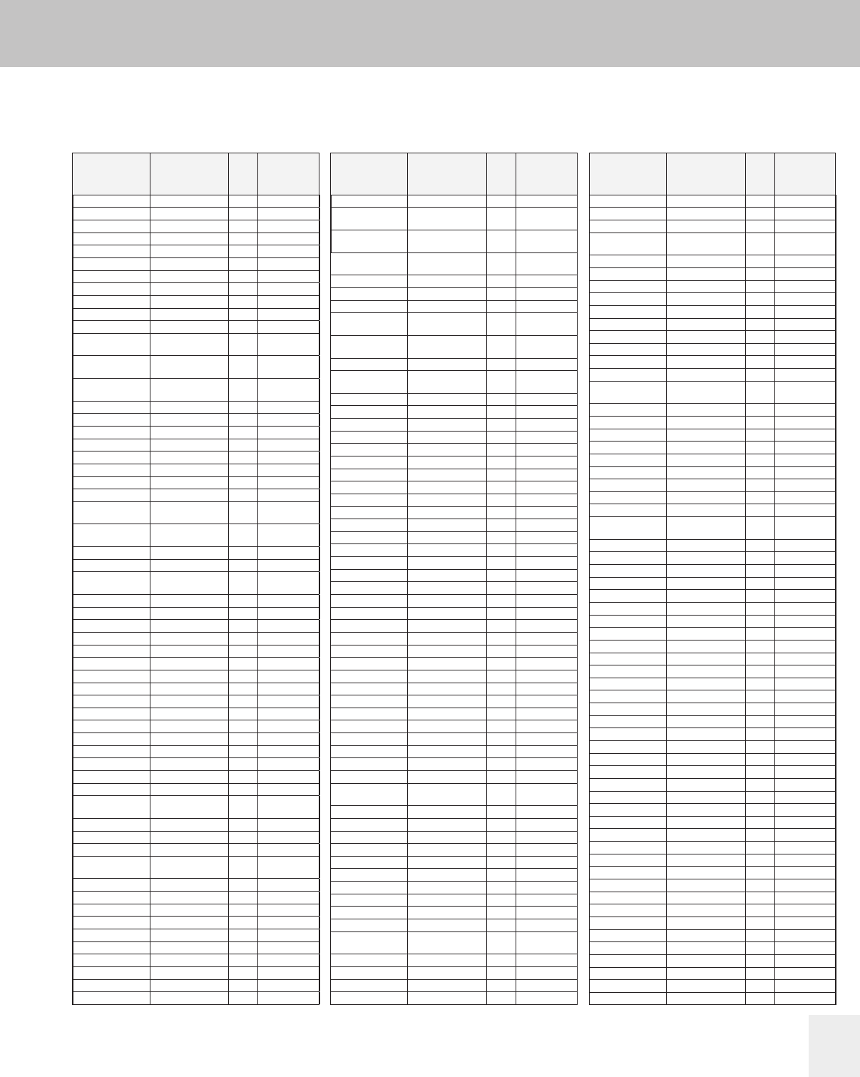
9-37
Lighting Electronics Atlas 2010-2011
REFERENCE MATERIALS
Reference
Discontinued Catalog Number to Replacement Number HID
71A7809 .... .... ....
71A7891 71A7801 5-27, 43 ....
71A78H1 71A79H8 5-28 ....
71A78R1 .... .... ....
71A7900 .... .... ....
71A7901 71A7991 5-28 ....
71A7910* .... .... ....
71A7920 .... .... ....
71A7931 71A7991 5-28 ....
71A7948 .... .... ....
71A7950 .... .... ....
71A7956 71A79E6
(120/208/240V)
5-28 ....
71A7960
(240/480V)
.... .... ....
71A79D1
(120/240/347V)
71A79A1
(120/240/347V)
5-28 71A7971/91
71A79S1 .... .... ....
71A79T8 .... .... ....
71A8000 .... .... ....
71A8001 71A8091 5-7, 29 ....
71A8005 .... .... ....
71A8021 71A8091 5-7, 29 ....
71A8030 .... .... ....
71A8050 .... .... ....
71A8056 71A80E6
(120/277/347)
5-29 ....
71A8060
(240/480V)
.... .... ....
71A8080 .... .... ....
71A80B6 .... .... ....
71A80D1
(120/240/347V)
71A80A1
(120/240/347V)
5-29 71A8071/91
71A80J9 .... .... ....
71A80L1 71A8071/91 5-7, 29 ....
71A80R1 71A79N1,71A80N1 6-10 ....
71A80S1 .... .... ....
71A80W1 .... .... ....
71A8102 71A8192 5-30 ....
71A8106* .... .... 71A8176/96
71A8111 .... .... 71A8176/96
71A8116* .... .... 71A8176/96
71A8127 .... .... ....
71A8130 .... .... ....
71A8131 71A8176/96 5-7, 31 71A8176/96
71A8136 71A8176/96 5-7, 31 71A8176/96
71A8141 .... .... ....
71A8150 .... .... ....
71A8151 .... .... 71A8176/96
71A8156 71A81E6
(120/208/240V)
5-31 ....
71A8160 .... .... ....
71A8180 .... .... ....
71A81B6 .... .... ....
71A81D2
(120/240/347V)
71A81A2
(120/240/347V)
5-30 71A8172/92
71A81L2 .... .... ....
71A81R2 71A81N2 6-10 ....
71A81R6 .... .... ....
71A81S2 .... .... ....
71A81T8 71A81N2 6-10 ....
71A81W2 .... .... ....
71A8201 71A8291 5-33 ....
71A8211 71A8271/91 5-8, 33 71A8271/91
71A8221 71A8271/91 5-8, 33 71A8271/91
71A8230 .... .... ....
71A8231 71A8291 5-33
71A8250
(120/240V)
.... .... ....
71A8256 71A82E6
(120/208/240V)
5-33 ....
71A8260
(240/480V)
.... .... ....
71A8280 .... .... ....
71A8281 71A8271/91 5-8, 33 ....
71A8290 .... .... ....
71A8294
(120/208/240/277V)
.... .... ....
71A82B1 71A82A1
(120/277/347V)
5-33 ....
71A82B6 .... .... ....
71A82D1
(120/240/347V)
71A82A1
(120/240/347V)
5-33 71A8271/91
71A82L1 71A8271/91 5-8, 33 ....
71A82R1 71A82N1 6-10 ....
71A82V1 .... .... ....
71A82W1 .... .... ....
71A8311 .... .... 71A8371/91
71A8321 .... .... 71A8371/91
71A8331 .... .... 71A8371/91
71A8341 71A8351 5-34 ....
71A8343 .... ....
71A8350 .... .... ....
71A8360 .... .... ....
71A8391 71A8351 5-34 ....
71A8392 .... .... ....
71A8401 71A8403 .... 71A8473/93
71A8402 71A8403 ..... 71A8473/93
71A8403 71A8473/93 5-8, 34 ....
71A8411 71A8473/93 5-8, 34 71A8473/93
71A8412 71A8473/93 5-8, 34 71A8473/93
71A8413 71A8473/93 5-8, 34 71A8473/93
71A8420 .... .... ....
71A8421 71A8473/93 5-8, 34 71A8473/93
71A8422 71A8473/93 5-8, 34 71A8473/93
71A8423 71A8473/93 5-8, 34 71A8473/93
71A8430 .... .... ....
71A8431 71A8473/93 5-8, 34 71A8473/93
71A8432 71A8473/93 5-8, 34 71A8473/93
71A8433 71A8473/93 5-8, 34 ....
71A8440 .... .... ....
71A8441 71A8443 5-34 ....
71A8442 71A8443 5-34 ....
71A8450 .... .... ....
71A8456 71A84E6
(120/208/240V)
5-34 ....
71A8460 .... .... ....
71A8471 .... .... 71A8473/93
71A8472 .... .... 71A8473/93
71A8480 --- .... ....
71A8482 .... .... 71A8473/93
71A8484 .... .... ....
71A8490 .... .... ....
71A8491 .... .... 71A8473/93
71A8492 .... .... 71A8473/93
71A84B6 .... .... ....
71A84D3
(120/240/347V)
71A84A3
(120/240/347V)
5-9, 34 71A8473/93
71A84H3 .... .... ....
71A84J7 .... .... ....
71A84L3 71A8473/93 5-8, 34 ....
71A84R2 71A84N3 6-10 ....
71A84V3 .... .... ....
71A84W2 .... .... ....
71A8540 71A85F5 5-35 ....
71A8590
(120/208/240/277V)
71A85E5
(120/208/240V)
5-35 71A85F5
(277/347/480)
71A85A3 .... .... ....
71A85B0 .... .... ....
71A85E6 .... .... ....
71A85F6 .... .... ....
71A8703 71A8773/93 5-8, 35 ....
71A8733 71A8773/93 5-8, 34 ....
71A8741 71A8743 5-35 ....
71A8755 71A8753 5-35 ....
71A8771 71A8773/93 5-8, 34 71A8773/93
71A8791 71A8773/93 5-8, 34 71A8773/93
71A87D3
(120/240/347V)
71A87A3
(120/240/347V)
5-35 71A8773/93
71A87V9 .... .... ....
71A8900 .... .... 71A8970/90
71A8930 .... .... 71A8970/90
71A8931 .... .... 71A8991
71A8941 .... .... ....
71A8950 71A8940/90 5-8, 32 ....
71A8954 .... .... ....
71A8964 .... .... ....
71A8976 71A8970/90 5-8, 34 ....
71A8984
(120/277V)
.... .... 71A8970/90
(CWA)
71A9068 .... .... ....
71A9073 .... .... ....
71A9074 .... .... ....
71A9082 .... .... ....
71A9114 .... .... ....
71A9115 .... .... ....
71A9116 71A65N2 6-9 ....
71A9124 .... .... ....
71A9127 .... .... ....
71A9135 .... .... ....
71A9136 .... .... ....
71A9137 .... .... ....
71A9138 .... .... ....
71A9139 .... .... ....
71A9189 71A0590 5-37 ....
71A9192 71A0490 5-36 ....
71A9209 71A5570/90 5-6, 16 71A5570/90
71A9212 .... .... ....
71A9240 .... .... ....
71A9242 .... .... 71A5570/90
71A9243 71A5540 5-6, 16 ....
71A9263 .... .... ....
71A9278 .... .... ....
71A9279 .... .... ....
71A9280 71A55N0 6-9 ....
71A9282 71A65N2 6-9 ....
71A9301 71A07F0 5-37 ....
71A9302 .... .... 71A6071/91
71A9303 .... .... 71A6071/91
71A9305 .... .... 71A6572/92
71A9306 .... .... ....
71A9312 .... .... ....
71A9313 .... .... ....
71A9314 .... .... ....
71A9315 .... .... ....
71A9316 .... .... ....
71A9317 71A0790 5-37 ....
Philips Advance Replacement ballasts shown are functionally equivalent to listed obsolete ballasts.
Dimensional differences can exist.
Suffix “T” ballast catalog numbers indicate ballast is equipped with 120V output tap.
Standard practice is to use 120V tap on quadri-volt ballast, where quadri-volt ballasts are available.
Where no replacement ballast is shown, ballast has been discontinued and inventories are exhausted.
Consult nearest Philips Lighing Electronics sales office for assistance.
* Availability limited to existing stocks.
** The CWA ballasts offered as replacements are furnished with a capacitor which must be used
in the ballast circuit as shown in the wiring diagram in this Atlas. The original ballast circuit in
the lighting fixture may have been low or normal power factor, and therefore, no capacitor was
used. If the CWA ballast with its capacitor does not fit in the fixture, contact Philips Lighing
Electronics for assistance.
Obsolete
Catalog
Numbers
Suggested
Replacement Catalog
Number
Page
No.
Alternate
Quadri-volt
120/208/
240/277V
Obsolete
Catalog
Numbers
Suggested
Replacement Catalog
Number
Page
No.
Alternate
Quadri-volt
120/208/
240/277V
Obsolete
Catalog
Numbers
Suggested
Replacement Catalog
Number
Page
No.
Alternate
Quadri-volt
120/208/
240/277V
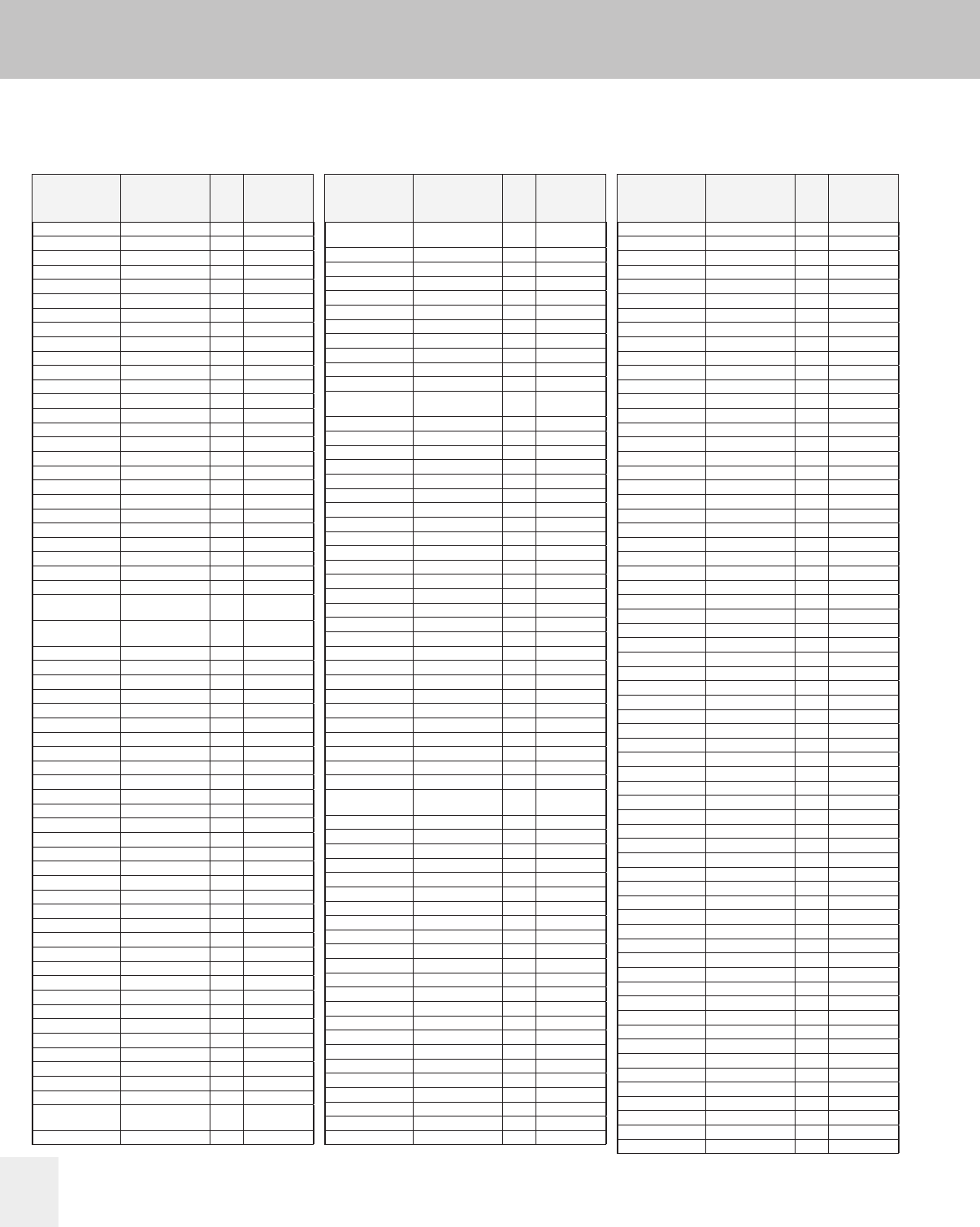
REFERENCE MATERIALS
Reference
Lighting Electronics Atlas 2010-2011
9-38
71A9318 71A0790 5-37 ....
71A9319 .... .... ....
71A9325 ....
71A9326 71A07F0 5-37 ....
71A9327 71A04F0 5-36 ....
71A9328 71A05F0 5-37 ....
71A9331 .... .... ....
71A9332 .... .... ....
71A9334 .... .... ....
71A9335 .... .... ....
71A9341 71A0590 5-37 ....
71A9352 .... .... ....
71A9355 71A0790 5-37 ....
71A9356 71A0590 5-37 ....
71A9357 71A0490 5-36 ....
71A9359 71A0490 5-36 ....
71A9366 .... .... ....
71A9377* .... .... ....
71A9378* .... .... ....
71A9416 .... .... ....
71A9417 .... .... ....
71A9418 .... .... ....
71A9424 71A65A2 5-24 ....
71A9426 71A57N0 6-9 ....
71A9429 71A82N1 6-10 ....
71A9430 71A84N3 6-10 ....
71A9432
(240/480V)
.... .... ....
71A9437
(240/480V)
.... .... ....
71A9441 71A87R3 6-10 ....
71A9445 71A0490 5-36 ....
71A9446 .... .... ....
71A9449 .... .... ....
71A9451 71A82H1 5-33 ....
71A9452 .... .... ....
71A9462 .... .... ....
71A9465 .... .... ....
71A9467 .... .... ....
71A9468 .... .... ....
71A9469 .... .... ....
71A9470 .... .... ....
71A9471 .... .... ....
71A9473 .... .... ....
71A9474 .... .... ....
71A9475 .... .... ....
71A9476 .... .... ....
71A9477 .... .... ....
71A9478 71A65N2 6-9 ....
71A9479 71A55N0 6-9 ....
71A9480 71A57N0 6-9 ....
71A9481 71A60N1 6-9 ....
71A9482 71A65N2 6-9 ....
71A9483 71A67R2 6-9 ....
71A9484 71A79N1 6-10 ....
71A9485 71A80N1 6-10 ....
71A9486 71A81N2 6-10 ....
71A9487 .... .... ....
71A9489 71A82N1 6-10 ....
71A9491 .... ..... ....
71A9492 70A87R3 .... ....
71A9494 .... .... ....
71A9502(240/480V) 71A8241
(480V)
5-33 71A8271/91
(240V)
71A9519 .... .... ....
71A9520 .... .... ....
71A9521 .... .... ....
71A9522 71A7941 5-28 ....
71A9523 71A8041 5-29 ....
71A9524 .... .... ....
71A9525 .... .... ....
71A9526 71A07F0 5-37 ....
71A9530 .... .... ....
71A9532 .... .... ....
71A9533 .... .... ....
71A9534 .... .... ....
71A9545 71A8107 5-30,
39, 43
....
71A9546 71A8007 5-29, 43 ....
71A9547 71A7907 5-28, 43 ....
71A9590 .... .... 71A8176/96
71A9597 .... .... ....
71A9646 .... .... ....
71A9665 .... .... ....
71A9696 .... .... ....
71A9720 71A60H1 5-21 ....
71A9722 71A55H0 5-16 ....
71A9733 .... .... ....
71A9734 .... .... ....
71A9735 .... .... ....
71A9737 .... .... ....
71A9740 .... .... ....
71A9740-2T .... .... ....
71A9742 71A9743 5-45 ....
71A9744 .... .... ....
71A9745-2T .... .... ....
71A9748* .... .... ....
71A9761 71A65J2 5-24 ....
71A9770 ....
71A9775 .... .... ....
71A9784 71A57H0 5-18 ....
71A9787 .... .... ....
71A9789 .... .... ....
71A9791 .... .... ....
71A980
(120/277V)
.... .... ....
71A9808* .... .... ....
71A9814 .... .... ....
71A9833 .... .... ....
71A9846 .... .... ....
71A9847 .... .... ....
71A9863 .... .... ....
71A9877 71A9900 5-45 ....
71A9884 .... .... ....
71A9885 71A9862 5-45 ....
71A9893 .... .... ....
71A9907 71A8192 5-30 ....
71A9911 71A80J1 5-29 ....
71A9923 .... .... ....
71A9928 .... .... ....
71A9932 .... .... ....
71A9934 .... .... ....
71A9945 71A8990 5-32 ....
71A9947 71A8271 5-8, 33 ....
71A9948 .... .... ....
71A9951 .... .... ....
71A9955 71A8196 5-31 ....
71A9969 .... .... ....
72C2584 .... .... ....
72C3084 .... .... ....
72C5005 72C5081 5-46 ....
72C54C1 .... .... ....
72C55C1 .... .... ....
72C57C2 .... .... ....
72C8005 .... .... ....
72C80C4 .... .... ....
72C81C5 .... .... ....
72C9156 .... .... ....
72C9159 .... .... ....
72C9160 .... .... ....
72C9163 .... .... ....
72C9164 .... .... ....
72C9167 .... .... ....
72C9168 .... .... ....
72C9171 .... .... ....
72C9221 .... .... ....
72C9222 .... .... ....
72C9223 .... .... ....
72C9224 .... .... ....
72E5005-NP IMH50ALF .... ....
72E5005-NP-BLS IMH50ABLS .... ....
73B5181 .... .... ....
73B5380 .... .... ....
73B5480 .... .... ....
73B5492 73B5482 5-49 ....
73B54A3 .... .... ....
73B5580 73B5590 5-49 73B5590
73B5593 73B5591-EE 5-49 ....
73B55A0 .... .... ....
73B5692 .... .... ....
73B5740 .... .... ....
73B5780 73B5790 .... 73B5790
73B57A2 .... .... ....
73B58A2 .... .... ....
73B6041 73B6041-T ..... ....
73B6042 73B6052-EE 5-50 ....
73B6081 73B6091 5-50 73B6091
73B60A2 .... .... ....
73B6542 .... .... ....
73B6592 73B6590 5-50 ....
73B65N2 .... .... ....
73B7705 .... .... ....
73B7901 .... .... ....
73B8005 .... .... ....
73B8102 .... .... ....
73B8188 .... .... ....
73B8281 73B8291 5-51 ....
73B82A1 .... .... ....
73B8483 73B8493 5-51 ....
74P1801 .... .... ....
74P1831-011 .... .... ....
74P2001 .... .... ....
74P2321-011 .... .... ....
74P2503 .... .... ....
74P2513 .... .... ....
74P2523 .... .... ....
74P2533 .... .... ....
74P2802 .... .... ....
74P2832 .... .... ....
74P3003 .... .... ....
74P3013 .... .... ....
74P3023 .... .... ....
74P3033 .... .... ....
74P3303 .... .... ....
Philips Advance Replacement ballasts shown are functionally equivalent to listed obsolete ballasts.
Dimensional differences can exist.
Suffix “T” ballast catalog numbers indicate ballast is equipped with 120V output tap.
Standard practice is to use 120V tap on quadri-volt ballast, where quadri-volt ballasts are available.
Where no replacement ballast is shown, ballast has been discontinued and inventories are exhausted.
Consult nearest Philips Lighing Electronics sales office for assistance.
* Availability limited to existing stocks.
** The CWA ballasts offered as replacements are furnished with a capacitor which must be used
in the ballast circuit as shown in the wiring diagram in this Atlas. The original ballast circuit in
the lighting fixture may have been low or normal power factor, and therefore, no capacitor was
used. If the CWA ballast with its capacitor does not fit in the fixture, contact Philips Lighing
Electronics for assistance.
Obsolete
Catalog
Numbers
Suggested
Replacement Catalog
Number
Page
No.
Alternate
Quadri-volt
120/208/
240/277V
Obsolete
Catalog
Numbers
Suggested
Replacement Catalog
Number
Page
No.
Alternate
Quadri-volt
120/208/
240/277V
Obsolete
Catalog
Numbers
Suggested
Replacement Catalog
Number
Page
No.
Alternate
Quadri-volt
120/208/
240/277V
Discontinued Catalog Number to Replacement Number HID
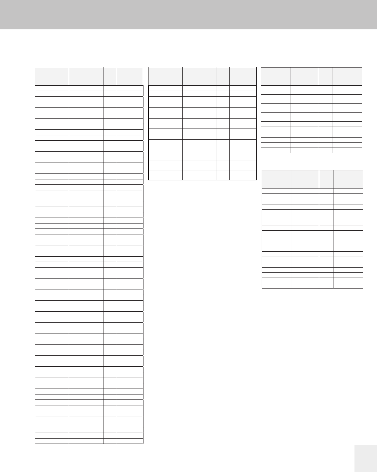
9-39
Lighting Electronics Atlas 2010-2011
REFERENCE MATERIALS
Reference
Philips Advance Replacement ballasts shown are functionally equivalent to listed obsolete ballasts.
Dimensional differences can exist.
Suffix “T” ballast catalog numbers indicate ballast is equipped with 120V output tap.
Standard practice is to use 120V tap on quadri-volt ballast, where quadri-volt ballasts are available.
Where no replacement ballast is shown, ballast has been discontinued and inventories are exhausted.
Consult nearest Philips Lighing Electronics sales office for assistance.
* Availability limited to existing stocks.
** The CWA ballasts offered as replacements are furnished with a capacitor which must be used
in the ballast circuit as shown in the wiring diagram in this Atlas. The original ballast circuit in
the lighting fixture may have been low or normal power factor, and therefore, no capacitor was
used. If the CWA ballast with its capacitor does not fit in the fixture, contact Philips Lighing
Electronics for assistance.
Discontinued Catalog Number to Replacement Number HID
74P3313 .... .... ....
74P3323 .... .... ....
74P3333 .... .... ....
74P3503 .... .... ....
74P3533 .... .... ....
74P5103 74P5104 5-52 ....
74P7702 74P7703 5-53 ....
74P7802 74P7803 5-53 ....
74P7902 74P7903 5-53 ....
74P7913 .... .... ....
74P7923 .... .... ....
74P8002 74P8003 5-53 ....
74P8103 74P8104 5-53 ....
77K5570 77L5570 5-10 ....
77K5892 .... .... ....
77K5993 .... .... ....
77K6051 77L6051 5-10 ....
77K6071 77L6051 5-10 ....
77K8071 77L8071 5-10 ....
77K8172 77L8172 5-10 ....
77K8473 77L8453 5-10 ....
78E3542-001 .... .... ....
78E4041 .... .... ....
78E4300 (Series) .... .... ....
78E4310 (Series) .... .... ....
78E4320 (ILO) .... .... ....
78E4330 (Series) .... .... ....
78E4340 (Series) .... .... ....
78E5040-001 .... .... ....
78E5090-001 .... .... ....
78E5330 .... .... ....
78E5993 78E5593-EE .... ....
78E6092 78E6052-EE 5-55 ....
78E6300 (Series) .... .... ....
78E6310 (Series) .... .... ....
78E6320 (Series) .... .... ....
78E6330 (Series) .... .... ....
78E6340 (Series) .... .... ....
78E6351* .... .... ....
78E64E2 .... .... ....
78E64F2 .... .... ....
78E65A2 .... .... ....
78E8291 .... .... ....
78E8391 .... .... ....
78E8492 78E8493 5-54 ....
78E8703 .... .... ....
79W3092 .... .... ....
79W3140 .... .... ....
79W3150 .... .... ....
79W3640 .... .... ....
79W3650 .... .... ....
79W4041 .... .... ....
79W4300 (Series) 79W6351(ILO) 5-56 ....
79W4320 (Series) 79W6351(ILO) 5-56 ....
79W4330 (Series) .... .... ....
79W4340 (Series) 79W6341(ILO) 5-56 ....
79W5090 .... .... ....
79W6300 (Series) 79W6351(ILO) 5-56 ....
79W6310 (Series) .... .... ....
79W6320 (Series) 79W6351(ILO) 5-56 ....
79W6330 (Series) .... .... ....
79W6340 (Series) 79W6341(ILO) 5-56 ....
79W6381* .... .... ....
79W6541 79W6542 5-56 ....
79W6591 79W6592 5-56 ....
79W65Z6 .... .... ....
79W6742 .... .... ....
79W6792 .... .... ....
79W8192 .... .... ....
79W8241 .... .... ....
79W8291 .... .... ....
79W8463
(240/480V)
79W8443
(480V)
5-57 79W8493
(240V)
79W8492 79W8493 5-57 ....
79W9256 79W6351 5-56 ....
79W9499* .... .... ....
79W9500
(240/480V)
.... .... ....
79W9501* .... .... ....
79W9502
(240/480V)
.... .... ....
79W9503
(240/480V)
79W8443
(480V)
5-57 79W8493
(240V)
Obsolete
Catalog
Numbers
Suggested
Replacement Catalog
Number
Page
No.
Alternate
Quadri-volt
120/208/
240/277V
Obsolete
Catalog
Numbers
Suggested
Replacement Catalog
Number
Page
No.
Alternate
Quadri-volt
120/208/
240/277V
Obsolete
Catalog
Numbers
Suggested
Replacement
Catalog Number
Page
No.
Alternate
Quadri-volt
120/208/240/277V
IMH100ALF IMH100BLF x-xx ....
(100W operation)
IMH100ALF IMH70ALF x-xx ....
(70W operation)
IMH100ABLS IMH100DBLS x-xx ....
(100W operation)
IMH100ABLS IMH70DBLS x-xx ....
(70W operation)
IMH39JLF IMH39ELF x-xx ....
IMH70JLF IMH70ELF x-xx ....
IMH200CLF .... .... ....
IWSN100CBLS .... .... ....
IZTEMH4003PSF .... .... ....
IZTSN150CLF .... .... ....
eHID
Obsolete
Catalog
Numbers
Suggested
Replacement
Catalog Number
Page
No.
Alternate
Quadri-volt
120/208/240/277V
LI500 LI501-H4 5-31, 32, 33, 34 ....
LI501-A LI501-H4 5-31, 32, 33, 34 ....
LI501-B5 LI501-H4 5-31, 32, 33, 34 ....
LI501-E LI501-J4 4-41, 43, 44 ....
LI505-H4 (Cut-off) LI501-H4 (Std.) 5-31, 32, 33, 34 ....
LI520-H5 LI522-H5 4-41 ....
LI521-H5 LI522-H5 4-41 ....
LI525-H6 (Cut-off) LI522-H5 (Std.) 4-41 ....
LI530-H5 LI533-H4 4-41 ....
LI531-H5 LI533-H4 4-41 ....
LI532-H4 LI533-H4 4-41 ....
LI533-H4A LI533-H4 4-41 ....
LI540-H4 .... .... ....
LI550 LI551-H4 4-43 ....
LI551-B5 LI551-H4 4-43 ....
LI551-RS .... .... ....
LI555-H4 (Cut-off) LI551-H4 (Std.) 4-43 ....
LI560-H5 LI561-H5 4-35, 41 ....
LI570 LI571-H5 4-35, 41 ....
Ignitors

REFERENCE MATERIALS
Reference
Lighting Electronics Atlas 2010-2011
9-40
Fluorescent Lamp to Ballast
Ballast Type
Lamp Type
Electronic Electromagnetic
Dimming
Page Number
Standard
Page Number
Sign & Weatherproof
Page Number
High Frequency
Page Number
CF13DD 3-29, 3-31
CF13DD/E 1-23 2-12, 2-18
CF13DS 3-29, 3-31
CF13DS/E
CF13DT/E 1-25 2-12, 2-18
CF18DD 3-32
CF18DD/E 1-23 2-7, 2-12, 2-18
CF18DF
CF18DT 3-32
CF18DT/E 1-36 2-7, 2-12, 2-18
CF24DF
CF26DD 3-30, 3-32
CF26DD/E 1-24 2-5, 2-7, 2-12, 2-18
CF26DT 3-32
CF26DT/E 1-27 2-5, 2-7, 2-12, 2-18
CF32DT/E 1-27 2-5, 2-7, 2-12, 2-18
CF36DF
CF42DT/E 1-28 2-5, 2-7, 2-12, 2-18
CF57DT/E 2-7, 2-12, 2-18
CF5DS 3-29, 3-31
CF5DS/E
CF70DT/E 1-28 2-7, 2-12, 2-18
CF7DS 3-29, 3-31
CF7DS/E 1-22
CF9DD 3-29, 3-31
CF9DS 3-29, 3-31
CF9DS/E 1-22
CFM18W/2G10
CFM24W/2G10
CFM36W/2G10
CFQ10W/G24q
CFQ13W/G24d
CFQ13W/G24q 1-23 2-12, 2-18
CFQ13W/GX23 3-29, 3-31
CFQ18W/G24d 3-32
CFQ18W/G24q 2-7, 2-12, 2-18
CFQ20W/GX32d
CFQ26W/G24d 3-30, 3-32
CFQ26W/G24q 2-5, 2-7, 2-12, 2-18
CFQ27W/GX32d 3-30
CFQ9W/G23 3-29, 3-31
CFS10W/GR10q 1-34
CFS16W/GR10q 1-34
CFS21W/GR10q 1-34 3-33
CFS28W/GR10q 1-35 3-33
CFS38W/GR10q 1-35
CFS55W/GRY10q
CFT13W/2GX7
CFT13W/GX23 3-29, 3-31
CFT5W/2G7
CFT5W/G23 3-29, 3-31
CFT7W/2G7 1-22
CFT7W/G23 3-29, 3-31
CFT9W/2G7 1-22
CFT9W/G23 3-29, 3-31
CFTR13W/GX24q 1-25 2-12, 2-18
CFTR18W/GX24d 3-32
CFTR18W/GX24q 1-26 2-7, 2-12, 2-18
CFTR26W/GX24d 3-32
CFTR26W/GX24q 1-27 2-5, 2-7, 2-12, 2-18
CFTR32W/GX24q 1-27 2-5, 2-7, 2-12, 2-18
CFTR42W/GX24q 1-28 2-5, 2-7, 2-12, 2-18
CFTR57W/GX24q 1-28 2-5, 2-7, 2-12, 2-18
CFTR70W/GX24q 1-28 2-5, 2-7, 2-12, 2-18
9-41
Lighting Electronics Atlas 2010-2011
REFERENCE MATERIALS
Reference
Fluorescent Lamp to Ballast
Ballast Type
Lamp Type
Electronic Electromagnetic
Dimming
Page Number
Standard
Page Number
Sign & Weatherproof
Page Number
High Frequency
Page Number
F10 2D/4P 1-34
F13BX 3-29, 3-31
F13DBX/4P 1-23 2-12, 2-18
F13DBX23T4 3-29, 3-31
F13DBXT4
F13T5 1-36
F13T8 3-23, 3-25
F13TBX/4P 1-25 2-12, 2-18
F14T12 3-24, 3-26, 6-13
F14T5 1-37
F14T8 3-23
F15T12 3-24, 3-26, 6-13
F15T8 3-23, 3-25, 6-13
F15T8/PLUS
F15T8/XL
F16 2D/4P 1-34
F17T8 1-41, 1-42, 1-43, 1-44 2-10, 2-15, 2-21
F18BX 3-30
F18BX/RS 1-30
F18DBX/4P 1-23 2-7, 2-12, 2-18
F18DBXT4 3-32
F18T12/HO 3-34, 3-36
F18T8 3-23
F18TBX/4P 1-26 2-7, 2-12, 2-18
F19T8 3-23
F20T12 3-24, 3-26, 6-13
F21 2D/4P 1-34 3-33
F21T5 1-37
F24T12 3-19
F24T12/HO 3-11 3-34, 3-36
F24T5/HO 1-39 2-9
F25T12 (28-33”) 3-24
F25T12 (36”) 3-6
F25T8 1-45, 1-46, 1-47, 1-48 2-10, 2-15, 2-21
F26DBX/4P 1-24 2-5, 2-7, 2-12, 2-18
F26DBXT4 3-32
F26TBX/4P 1-27 2-5, 2-7, 2-12, 2-18
F27BX/RS 1-30 2-8
F28 2D/4P 1-35 3-33
F28T5 1-37 2-3
F30T12 1-66 3-6, 3-24, 6-10
F30T12/HO 3-11 3-36
F30T8 3-23
F32T8 1-57, 1-58, 1-59, 1-60 2-10, 2-16, 2-21 3-5
F32T8/ES (25W) 1-49, 1-50
F32T8/ES (28W) 1-51, 1-52
F32T8/ES (30W) 1-53, 1-54, 1-55, 1-56
F32T8/U6 1-57, 1-58, 1-59, 1-60 2-10, 2-16, 2-21 3-5
F32TBX/4P 1-27 2-5, 2-7, 2-12, 2-18
F34T12 1-66 3-7, 6-10
F34T12/U 1-66 3-9
F35T5
F36T12 3-19
F36T12/HO 3-11 3-34, 3-36
F38 2D/4P 1-35
F39BX/RS 1-30 2-8, 2-13
F39T5/HO 1-39
F40BX 1-31 2-8, 2-13
F40T10 3-6
F40T12 1-66 3-8, 3-10, 3-24, 6-10
F40T12/IS 3-19
F40T12/U 1-66 3-9, 3-10
F40T17/IS 3-19
F40T8 1-61, 1-62
REFERENCE MATERIALS
Reference
Lighting Electronics Atlas 2010-2011
9-42
Fluorescent Lamp to Ballast
Ballast Type
Lamp Type
Electronic Electromagnetic
Dimming
Page Number
Standard
Page Number
Sign & Weatherproof
Page Number
High Frequency
Page Number
F42T12 3-19
F42T12/HO 3-12 3-34, 3-36
F42T6 3-18
F42TBX/4P 1-28 2-5, 2-7, 2-12, 2-18
F48PG17/VHO 3-16 3-35
F48T10/VHO 3-16 3-35
F48T12 3-19
F48T12/ES 3-19
F48T12/HO 3-12, 6-11 3-34, 3-36
F48T12/VHO 3-16 3-35
F48T5/VHO
F48T8/HO 1-64
F48T8/VHO 1-65
F4T5 3-22
F50BX/RS 1-32
F54T5/HO 1-39, 1-50 2-9, 2-14, 2-20
F55 2D/4P
F55BX 1-33 2-8, 2-13, 2-19
F57QBX/4P 1-28 2-7, 2-12, 2-18
F58T8 6-6
F5BX 3-29, 3-31
F60T10/VHO 3-16 3-35
F60T12 3-20, 6-12
F60T12/HO 3-13 3-34, 3-36
F60T12/VHO 3-16 3-35
F60T8/HO 1-64
F64T12 3-20, 6-12
F64T12/HO 3-13 3-34, 3-36
F64T6 3-18
F6T5 3-22
F70QBX/4P 1-28 2-7, 2-12, 2-18
F70T8 6-6
F72PG17/VHO 3-16 3-35
F72T10/VHO 3-16 3-35
F72T12 1-67 3-20, 6-12
F72T12/HO 3-14, 6-11 3-34, 3-36
F72T12/VHO 3-16 3-35
F72T8 (200mA) 1-63 3-18
F72T8 (265mA) 1-63
F72T8/HO 1-64
F7BX 3-29, 3-31
F80T5/HO 1-40 2-14
F84T12 3-20
F84T12/HO 3-14 3-36
F8T5 1-36 3-22
F96PG17/HO/ES 3-17
F96PG17/VHO 3-17 3-35
F96T10/VHO 3-17 3-35
F96T12 1-67 3-21, 6-12
F96T12/ES 1-67 3-21
F96T12/HO 1-68 3-15, 6-11 3-34, 3-36
F96T12/HO/ES 1-68 3-15
F96T12/VHO 3-17 3-35
F96T12/VHO/ES 3-17
F96T8 (200mA) 1-63 3-18
F96T8 (265mA) 1-63
F96T8/ES 1-63
F96T8/HO 1-64
F9BX 3-29, 3-31
F9DBX23T4 3-29, 3-31
FB016T8 2-10, 2-15, 2-21
FB024T8 2-10, 2-15, 2-21
FB031T8 2-10, 2-16, 2-21 3-5
FC12T5 1-48
9-43
Lighting Electronics Atlas 2010-2011
REFERENCE MATERIALS
Reference
FC12T5/HO 1-38 2-9, 2-14, 2-20
FC12T9 3-27, 3-28
FC16T9 3-27, 3-28, 6-13
FC6T9 3-27, 3-28
FC8T9 1-66 3-27, 3-28
FC9T5 1-38
FO13T8/XP
FT18DL 3-30
FT18DL/RS 1-30
FT18W/2G11 3-30
FT18W/2G11/RS 1-30
FT24DL 1-30 2-8
FT24W/2G11 1-30 2-8
FT36DL 1-30 2-8, 2-13
FT36W/2G11 1-30 2-8, 2-13
FT40DL/RS 2-8, 2-13
FT40W/2G11/RS 2-8, 2-13
FT50W/2G11/RS 1-32
FT55DL 1-33 2-8, 2-13, 2-19
FT55W/2G11 1-33 2-8, 2-13, 2-19
FT80DL 1-33 2-13
FT80W/2G11 1-33 2-13
G15T8
G30T8
G64T5
PL-C13W
PL-C13W/4P 1-23
PL-C13W/USA 3-29, 3-31
PL-C15MM/22W
PL-C15MM/28W 3-30
PL-C18W 3-32
PL-C18W/4P 1-27 2-7, 2-12, 2-18
PL-C26W 3-30, 3-32
PL-C26W/4P 1-24 2-5, 2-7, 2-12, 2-18
PL-H120W/4P 1-29
PL-H60W/4P 1-29
PL-H85W/4P 1-29
PL-L18W 3-30
PL-L18W/TUV 6-5
PL-L24W 1-30 2-8
PL-L35WHO/TUV 6-5
PL-L36W 1-30 2-8, 2-13
PL-L36W/TUV 6-5
PL-L40W 1-31 2-8, 2-13
PL-L50W 1-32
PL-L55W 1-33 2-8, 2-13, 2-19
PL-L60WHO/TUV 6-5
PL-L80W 1-33 2-13
PL-L95WHO/TUV 6-5
PL-Q 28W/4P 1-35 3-33
PL-Q 38W/4P 1-35
PL-S13W 3-29, 3-31
PL-S5W 3-29, 3-31
PL-S7W 3-29, 3-31
PL-S9W 3-29, 3-31
PL-T18W 1-26 2-7, 2-12, 2-18
PL-T26W 1-27 2-5, 2-7, 2-12, 2-18
PL-T32W 1-27 2-5, 2-7, 2-12, 2-18
PL-T42W 1-28 2-5, 2-7, 2-12, 2-18
PL-T57W 1-28 2-7, 2-12, 2-18
TUV36T5/HO
TUV64T5/HO
Ballast Type
Lamp Type
Electronic Electromagnetic
Dimming
Page Number
Standard
Page Number
Sign & Weatherproof
Page Number
High Frequency
Page Number
Fluorescent Lamp to Ballast
REFERENCE MATERIALS
Reference
Lighting Electronics Atlas 2010-2011
9-44
Metal Halide
HID Lamp to Ballast
Ballast Type
Lamp Description Core & Coil Encapsulated
Page
Number
F-Can
Page
Number
Postline
Page
Number
Indoor
Enclosed
Page No.
Outdoor
Weatherproof
Page Number
ANSI
Code
Replacement
Page Number
OEM
Page No.
50 Hz
Page Number
Electronic
Page No.
Watts
20 M156 4-7 .... .... .... .... .... .... .... ....
22 C175 .... .... .... .... .... .... .... .... ....
35/39 C179 .... .... .... .... .... .... .... .... ....
35/39 M130 4-7 5-12 .... .... .... .... .... .... ....
50 M110 4-7 5-12 .... .... .... 5-46 5-52 .... ....
50 M148 4-7 5-12 .... .... .... 5-46 .... .... ....
60 TBD 4-14 .... .... .... .... .... .... .... ....
70 M98 4-8 5-13 .... 6-9 5-49 5-46 .... .... ....
70 M85 .... 5-13 .... .... .... 5-46 .... .... ....
70 M143 4-8 5-13 .... 6-9 .... 5-46 .... .... ....
70 M139 4-8 5-13 .... .... .... 5-46 .... .... ....
90 TBD 4-14 .... .... .... .... .... .... .... ....
100 M90 4-8 5-14 .... 6-9 5-49 5-46 .... .... ....
100 M140 4-8 5-14 .... .... 5-49 5-46 .... .... ....
140 TBD 4-14 .... .... .... .... .... .... .... ....
150 M102 4-8 5-15 .... .... 5-49 5-46 .... .... ....
150 M107 .... 5-16 .... 6-9 .... 5-47 .... 5-55 5-56
150 M81 .... 5-15 .... .... .... 5-46 .... .... ....
150 M142 4-8 5-15 .... .... 5-49 5-46 .... .... ....
175 M57 .... 5-16 .... .... 5-49 5-47 .... 5-55 5-56
175 (Pulse-Start) M137 4-8 5-16 .... .... 5-49 5-47 .... 5-55 ....
175 (Pulse-Start) M152 4-8 5-16 .... .... 5-49 5-47 .... 5-55 ....
200 (Pulse-Start) M136 ... 5-17 .... .... .... .... .... .... ....
210 C183 4-15 .... .... .... .... .... .... .... ....
250 M58 .... 5-18 .... .... 5-49 5-47 .... 5-55 5-56
250 M80 .... .... .... .... .... .... .... .... ....
250 (Pulse-Start) M138 .... 5-19 .... .... 5-49 5-47 .... 5-55 ....
250 (Pulse-Start) M153 .... 5-19 .... .... 5-49 5-47 .... 5-55 ....
315 C182 4-15 .... .... .... .... .... .... .... ....
320 (Pulse-Start) M132 4-13 5-20 .... .... 5-49 5-47 .... 5-55 ....
320 (Pulse-Start) M154 4-13 5-20 .... 6-9 5-49 5-47 .... .... ....
350 (Pulse-Start) M131 4-13 5-20 .... .... 5-49 5-47 .... 5-55 ....
400 M59 .... 5-21 .... 6-9 5-50 5-47 .... 5-55 5-56
400 (Pulse-Start) M128 .... .... .... .... .... .... .... .... ....
400 (Pulse-Start) M135 4-13 5-22 .... .... 5-50 5-47 .... 5-55 ....
400 (Pulse-Start) M155 4-13 5-22 .... .... 5-50 5-47 .... 5-55 ....
450 (Pulse-Start) M144 .... 5-22 .... .... .... .... .... .... ....
750 (Pulse-Start) M149 .... 5-23 .... .... .... .... .... .... ....
1000 (Pulse-Start) M141 .... 5-24 .... .... 5-50 .... .... 5-55 ....
1000 M47 .... 5-24 .... .... 5-50 .... .... 5-55 5-56
1500 M48 .... 5-25 .... 6-9 .... .... .... .... ....
1650 M112 .... 5-25 .... .... .... .... .... .... ....
2000 M134 .... .... .... .... .... .... .... .... ....
18 L69 .... 5-36 .... .... .... .... .... .... ....
35 L70 .... 5-36 .... .... .... .... .... .... ....
55 L71 .... 5-36 .... .... .... .... .... .... ....
90 L72 .... 5-37 .... .... .... .... .... .... ....
135 L73 .... 5-37 .... .... .... .... .... .... ....
180 L74 .... 5-37 .... .... .... .... .... .... ....
High Pressure Sodium
35 S76 .... 5-26 .... .... .... .... 5-53 .... ....
50 S68 .... 5-27 .... .... .... 5-48 5-53 .... ....
70 S62 .... 5-28 .... 6-10 .... 5-48 5-53 .... ....
100 S54 .... 5-29 .... 6-10 .... 5-48 5-53 .... ....
150 (55V) S55 .... 5-30, 5-31 .... 6-10 .... 5-48 5-53 .... 5-63
150 (100V) S56 .... 5-31 .... .... .... .... .... .... ....
200 S66 .... 5-32 .... .... .... .... .... .... ....
250 S50 .... 5-33 .... 6-10 5-51 .... .... .... ....
310 S67 .... 5-34 .... .... .... .... .... .... ....
400 S51 .... 5-34 .... 6-10 5-51 .... .... 5-54 5-57
430 S145 .... .... .... .... .... .... .... .... ....
600 S106 .... 5-35 .... .... .... .... .... .... ....
750 S111 .... 5-35 .... .... .... .... .... .... ....
1000 S52 .... 5-35 .... 6-10 .... .... .... 5-54 5-57
Low Pressure Sodium
9-45
Lighting Electronics Atlas 2010-2011
REFERENCE MATERIALS
Reference
2-Pin lamps with built-in starter
5W CFT5W/G23 PL-S5W F5BX CF5DS - 3-20, 21
7W CFT7W/G23 PL-S7W F7BX CF7DS - 3-20, 21
9W CFT9W/G23 PL-S9W F9BX CF9DS - 3-20, 21
13W CFT13W/GX23 PL-S13W F13BX CF13DS - 3-20, 21
9W CFQ9W/G23 - F9DBX23T4 CF9DD - 3-20, 21
13W CFQ13W/GX23 PL-C13W/USA F13DBX23T4 CF13DD FDS13/2 3-20, 21
13W CFQ13W/G24d PL-C13W F13DBXT4 - - -
18W CFQ18W/G24d PL-C18W F18DBXT4 CF18DD FDS18/2 -
22W CFQ20W/GX32d PL-C15MM/22W - - FDL22 -
26W CFQ26W/G24d PL-C26W F26DBXT4 CF26DD FDS26/2 3-20, 21
28W CFQ27W/GX32d PL-C15MM/28W - - FDL28 3-20
18W CFTR18W/GX24d - - CF18DT - -
26W CFTR26W/GX24d - - CF26DT - 3-21
4-Pin lamps
18W CFM18W/2G10 - - CF18DF - -
24W CFM24W/2G10 - - CF24DF - -
36W CFM36W/2G10 - - CF36DF - -
5W CFT5W/2G7 - - CF5DS/E - -
7W CFT7W/2G7 - - CF7DS/E - 1-22
9W CFT9W/2G7 - - CF9DS/E - 1-22
13W CFT13W/2GX7 - - CF13DS/E - -
10W CFQ10W/G24q - - - FDS10/4 -
13W CFQ13W/G24q PL-C13W/4P F13DBX/4P CF13DD/E FDS13/4 1-23
18W CFQ18W/G24q PL-C18W/4P F18DBX/4P CF18DD/E FDS18/4 1-23
26W CFQ26W/G24q PL-C26W/4P F26DBX/4P CF26DD/E - -
13W CFTR13W/GX24q - F13TBX/4P CF13DT/E - 1-25
18W CFTR18W/GX24q PL-T18W F18TBX/4P CF18DT/E FHT18 1-26
26W CFTR26W/GX24q PL-T26W F26TBX/4P CF26DT/E FHT26 1-27
32W CFTR32W/GX24q PL-T32W F32TBX/4P CF32DT/E FHT32 1-27
42W CFTR42W/GX24q PL-T42W F42TBX/4P CF42DT/E - 1-28
57W CFTR57W/GX24q PL-T57W F57QBX/4P CF57DT/E - 1-28
60W PL-H60W/4P - - - -
70W CFTR70W/GX24q - F70QBX/4P CF70DT/E - 1-28
85W PL-H85W/4P - - - -
120W PL-H120W/4P - - - -
10W CFS10W/GR10q - F10 2D/4P - - 1-34
16W CFS16W/GR10q - F16 2D/4P - - 1-34
21W CFS21W/GR10q - F21 2D/4P - - 1-34
28W CFS28W/GR10q PL-Q 28W/4P F28 2D/4P - - 1-35
38W CFS38W/GR10q PL-Q 38W/4P F38 2D/4P - - 1-35
55W CFS55W/GRY10q - F55 2D/4P - - -
18W FT18W/2G11 PL-L18W F18BX FT18DL - 3-20
18W FT18W/2G11/RS - F18BX/RS FT18DL/RS - 1-30
24-27W FT24W/2G11 PL-L24W F27BX/RS FT24DL - 1-30
36-39W FT36W/2G11 PL-L36W F39BX/RS FT36DL - 1-30
40W FT40W/2G11/RS PL-L40W F40BX FT40DL/RS - 1-31
50W FT50W/2G11/RS PL-L50W F50BX/RS - - 1-32
55W FT55W/2G11 PL-L55W F55BX FT55DL - 1-33
80W FT80W/2G11 PL-L80W - FT80DL - 1-33
Compact Fluorescent Lamp Reference Guide
NEMA Lamp
Designation PHILIPS GE OSRAM/
SYLVANIA PANASONIC Page
No.
Lamp
Type
Lamp
Watts
Twin
Tube
Quad
Tube
Triple
Tube
Twin
Tube
Quad
Tube
Triple
Tube
2D
Long
Twin
Tube
Flat
Tube

REFERENCE MATERIALS
Reference
Lighting Electronics Atlas 2010-2011
9-46
Notes

9-47
Lighting Electronics Atlas 2010-2011
REFERENCE MATERIALS
Reference
Notes

REFERENCE MATERIALS
Reference
Lighting Electronics Atlas 2010-2011
9-48
Notes

Lighting Electronics Atlas 2010-2011
Philips Lighting Electronics N.A.
10275 W. Higgins Road
Rosemont, IL 60018
Tel: 800-322-2086 Fax: 888-423-1882
Customer Support/Technical Service: 800-372-3331
OEM Support: 866-915-5886
www.philips.com/advance
© 2010 Philips Lighting Electronics N.A.
All rights reserved. Reproduction in whole or part is prohibited without the prior written consent of
the copyright owner. The information presented in this document, is believed to be accurate and
reliable and may be changed without notice. No liability will be accepted by the publisher for any
consequences of its use. Publication thereof does not convey nor imply any license under patent or
other industrial or intellectual property rights.
Form No. CO-7044-B 4/10
Printed in USA 4/10
®
®
Lighting Electronics Atlas
Full Line Catalog 2010-2011
