Product Detail Manual
133297-Catalog 133297-Catalog 133297-Catalog Batch9 unilog cesco-content
108378-Catalog 108378-Catalog 108378-Catalog 786364 Batch10 unilog cesco-content
109118-Catalog 109118-Catalog 109118-Catalog 786364 Batch7 unilog cesco-content
2014-09-05
: Pdf 66995-Attachment 66995-Attachment 786364 Batch7 unilog
Open the PDF directly: View PDF ![]() .
.
Page Count: 244 [warning: Documents this large are best viewed by clicking the View PDF Link!]
A PART OF
GENERAL ENGINEERING CATALOG – NO. 17

Unistrut is the original metal framing system featuring a unique
weldless connection. The Unistrut system eliminates welding
and drilling, and is easily adjustable and reusable for infinite
configurations. Over time, our brand has evolved from a simple
connection concept to a comprehensive engineered building
and support system featuring a robust line of channels, fittings,
fasteners, hangers, pipe clamps, and accessories. Backed by our
worldwide network of engineering and distribution centers, we
provide customers with total-resource capability, making Unistrut
the brand everyone asks for by name.
The Unistrut World of Support
starts with our network of Unistrut
Service Centers across the nation.
The Unistrut World of Support starts with our network of Unistrut
Service Centers across North America. They go far beyond providing
local product inventories... by offering complete application solutions,
based on experience gained from thousands of projects worldwide.
It’s the kind of knowledgeable assistance that can help save time and
cost now, and simplify change in the future.
Technical help? No one knows the engineering side of Unistrut support
systems like your local Unistrut team. And if it’s special fabrication, cutting
or custom finishing you want, the pros at your local Unistrut Service
Center will make it happen...quickly, efficiently, economically.
So when it’s help you need, call your Unistrut Service Center—
the quickest way to unlock Unistrut’s World of Support.
INTRODUCTION .................. 2-20
Unistrut Introduction..................................2-3
Table of Contents....................................4-5
Unistrut Metal Framing Systems ........................6-9
Quality Assurance ....................................10
Materials and Finishes.............................11 - 13
Design Fundamentals .............................14 - 15
Conversion Factors ...................................16
Reference Tables and Data .........................17 - 18
Guide Specification ...................................19
New Products .......................................20
15»8" CHANNEL .................. 21-62
Channel Selection Chart ...............................23
P1000 (12 Gauge) ................................24 - 29
P1100 (14 Gauge) ................................30 - 32
P2000 (16 Gauge) ................................33 - 35
P3000 (12 Gauge) ................................36 - 38
P3300 (12 Gauge) ................................39 - 41
P4000 (16 Gauge) ................................42 - 44
P4100 (14 Gauge) ................................45 - 47
P4400 (12 Gauge) ................................48 - 50
P4520 (12 Gauge) ................................51 - 53
P5000 (12 Gauge) ................................54 - 56
P5500 (12 Gauge) ................................57 - 59
Closure Strips .......................................60
End Caps and Frame Caps .............................61
Lateral Bracing Load Reduction Chart & Bearing Loads.......62
TELESTRUT® SYSTEM ............ 63-70
Telescoping Tube.................................65 - 67
Connection Methods ..................................69
Specialized Fittings ...................................68
Post Bases......................................68 - 69
Cutting Chart ........................................70
NUTS & HARDWARE ............. 71-76
Channel Nuts ...................................72 - 73
Top Retainer Nuts ....................................75
Stud Nuts...........................................74
Hardware.......................................74 - 76
Threaded Rod .......................................75
GENERAL FITTINGS ............. 77-106
Flat Plate Fittings.................................81 - 82
Ninety Degree Fittings .............................82 - 85
Angular Fittings ......................................85
“Z” Shape Fittings ....................................86
“U” Shape Fittings ................................87 - 88
Wing Shape Fittings...............................89 - 90
Post Bases..........................................90
Brackets........................................90 - 93
Brace Fittings........................................94
Beam Clamps ..................................95 - 101
Trolleys ...........................................102
Special Application Fittings .......................103 - 104
Seismic Retrofit Fittings..........................104 - 106
PIPE/CONDUIT SUPPORTS....... 107-126
Pipe/Conduit Clamps............................108 - 111
Unicushion® .......................................112
Pipe & Tubing (Cush-A-Clamp®) Clamps.............113 - 116
Pipe Hangers.......................................117
Pipe Rollers ...................................117 - 119
Pipe Brackets.......................................119
Reference Tables...............................120 - 126
ELECTRICAL FITTINGS .......... 127-138
Electrical Fittings ...............................128 - 130
Receptacles........................................131
Fixture Hangers .....................................131
Accessories and Connectors ..........................132
Junction Boxes .....................................132
In-Channel Joiners...................................133
Swivel Hangers .....................................133
Cable Entrance Tubing and Accessories.............134 - 136
Electrical Fittings Technical Data ...................137 - 138
CONCRETE INSERTS............ 139-146
Heavy-Duty Inserts ..................................141
Standard-Duty Inserts ............................142, 144
Light-Duty Inserts....................................143
Spot Inserts ........................................144
Deck Inserts........................................145
Components .......................................145
Technical Data ......................................146
SOLAR COMPONENTS.......... 147-150
Application Example .................................148
Solar Connectors....................................149
Key Advantages.....................................150
TABLE OF CONTENTS
UNIPIER® .................... 151-168
Sleeper Support................................153 - 154
Strut Support ..................................155 - 158
Conduit Supports
Mounted Support, Polycarbonate Base...................157
Elevated Support, Polycarbonate Base...................157
Elevated Support, Steel Base ..........................158
Gas and Mechanical Supports
Mounted Support, Polycarbonate Base...................158
Mounted Support, w/Roller Polycarbonate Base............158
Elevated Support, w/Roller, Polycarbonate Base ...........159
Elevated Support, w/Roller, Steel Base...................160
Accessories
Spacer............................................160
Support Pads, Deck Plates ............................160
Pipe Hanger Bases, Polycarbonate and Steel..............161
Fabricated Supports
Single Base Trapeze .................................162
Double Base Trapeze ................................163
Heavy Duty Double Base Trapeze.......................163
Double Base Duct Support ............................163
Mechanical Supports .................................164
Bridge Cross-Over, Walkway, Service Platform or Ramp .....164
Installation .........................................165
Pipe Diameters and Loading ...........................166
Technical Data .................................167 – 168
11»4" FRAMING SYSTEM......... 169-180
A1000 (14 Gauge) ..............................171 - 172
A3300 (14 Gauge) ..............................173 - 174
A4000 (19 Gauge) ..............................175 - 176
A5000 (14 Gauge) ...................................177
Channel Nuts and Closure Strips .......................178
Flat Plate Fittings...............................178 - 179
Ninety Degree Fittings ...........................179 - 180
Angle and Wing Shape Fittings .........................179
“U” Shape Fittings ...................................180
Pipe / Tubing Clips...................................180
Brackets...........................................180
13»16" FRAMING SYSTEM ........ 181-190
P6000 (19 Gauge) ..............................183 - 184
P7000 (19 Gauge) ..............................185 - 186
Channel Nuts, End Caps, and Closure Strips ..............187
Flat Plate Fittings...............................187 - 188
Ninety Degree Fittings ................................188
Angular Fittings, Wing Shape Fittings ...............189 - 190
“Z” Shape Fittings ...................................189
“U” Shape Fittings ..............................189 - 190
Special Application Fittings ............................190
Beam Clamps ......................................190
Tubing Clips........................................190
FIBERGLASS SYSTEM........... 191-206
Heavy Duty Channel (Flange Profile) ....................193
Light Duty Channel (Flange Profile)......................194
Heavy Duty Channel (SST Profile) ......................195
Nuts & Hardware...............................196 - 198
Fittings .......................................199 - 200
Pipe Clamps and Straps ..............................201
Clevis Hangers and Channel Inserts .....................202
Beam Clamps ......................................203
Power Rack Stanchions...............................203
Chemical Compatibility ..........................204 - 205
Specifications.......................................206
SPECIAL METALS .............. 207-212
Stainless Steel Channel...............................209
Stainless Steel Nuts and Closure Strips ..................210
Aluminum Channel .............................211 - 212
Aluminum Closure Strips and End Caps ..................212
PRIMEANGLE™................ 213-218
PrimeAngle™.......................................214
Accessories........................................215
PrimeAngle™ Technical Data .....................216 - 218
UNITED INTERLOCK® GRATING. . . 219-234
Ease of Installation ..................................220
Plank Grating..................................221 - 222
Accessories...................................223 - 225
Heavy Duty Stair Treads ..............................226
Design and Testing ..................................227
Plank Loads and Deflections ......................228 - 233
Architectural Specifications ............................234
ROOFWALKS® ................ 235-236
Roofwalk® Grating Planks .............................236
Hardware for Membrane, Foam or Coated Roof ............236
Standing Seam Installation ............................236
INDEX....................... 237-242
6
Unistrut – The Original Metal Framing
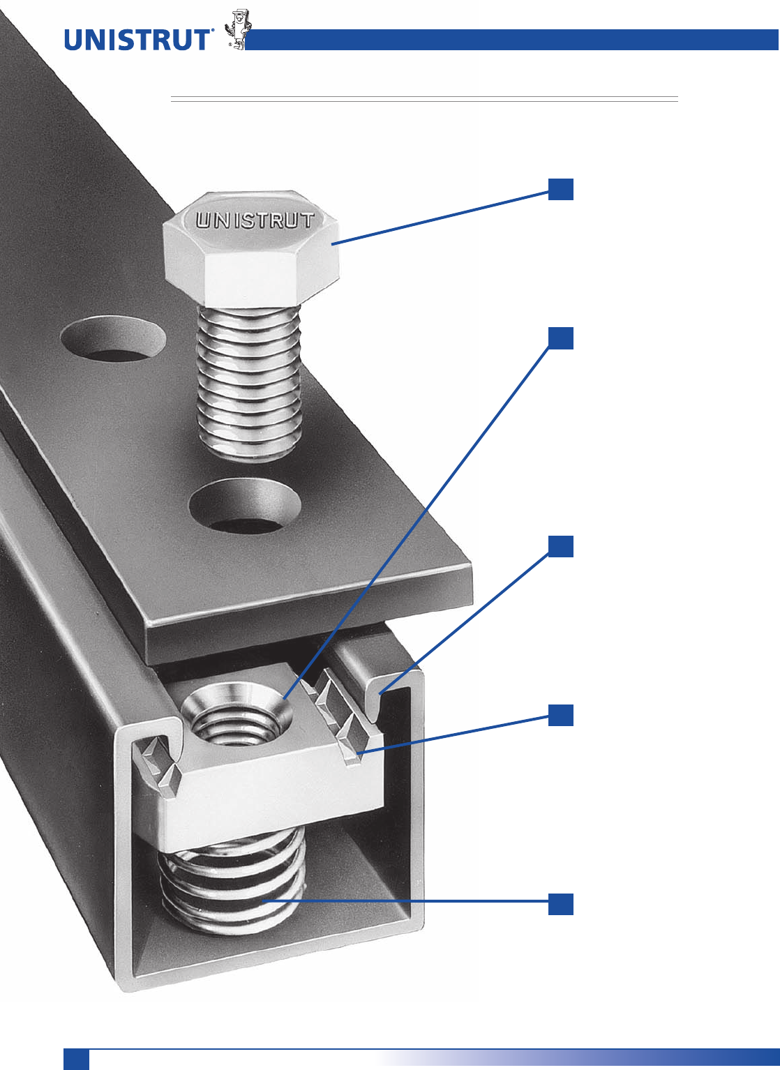
Unistrut Metal Framing – The Original Strut System
Featuring The Unique Weldless Connection
Hex-head bolt connects
fitting to channel as it
is threaded into spring
nut.
Chamfer in the nut
eases starting of the
bolt. Nut teeth create
a strong, vise-like grip
when tightened against
the inturned channel
edges.
Channel edges and the
nut's tapered grooves
act as guides to provide
fool-proof alignment of
connection.
Nut teeth grip the
channel's inturned
edges, tying the
channel sides together
in a "box" configuration
for added strength.
Spring allows precision
placement anywhere
along channel length,
then holds the nut in
position while the
connection is
completed.
7
Unistrut – The Original Metal Framing
Strong, Fast, Economical and Adjustable
1
3
2
4
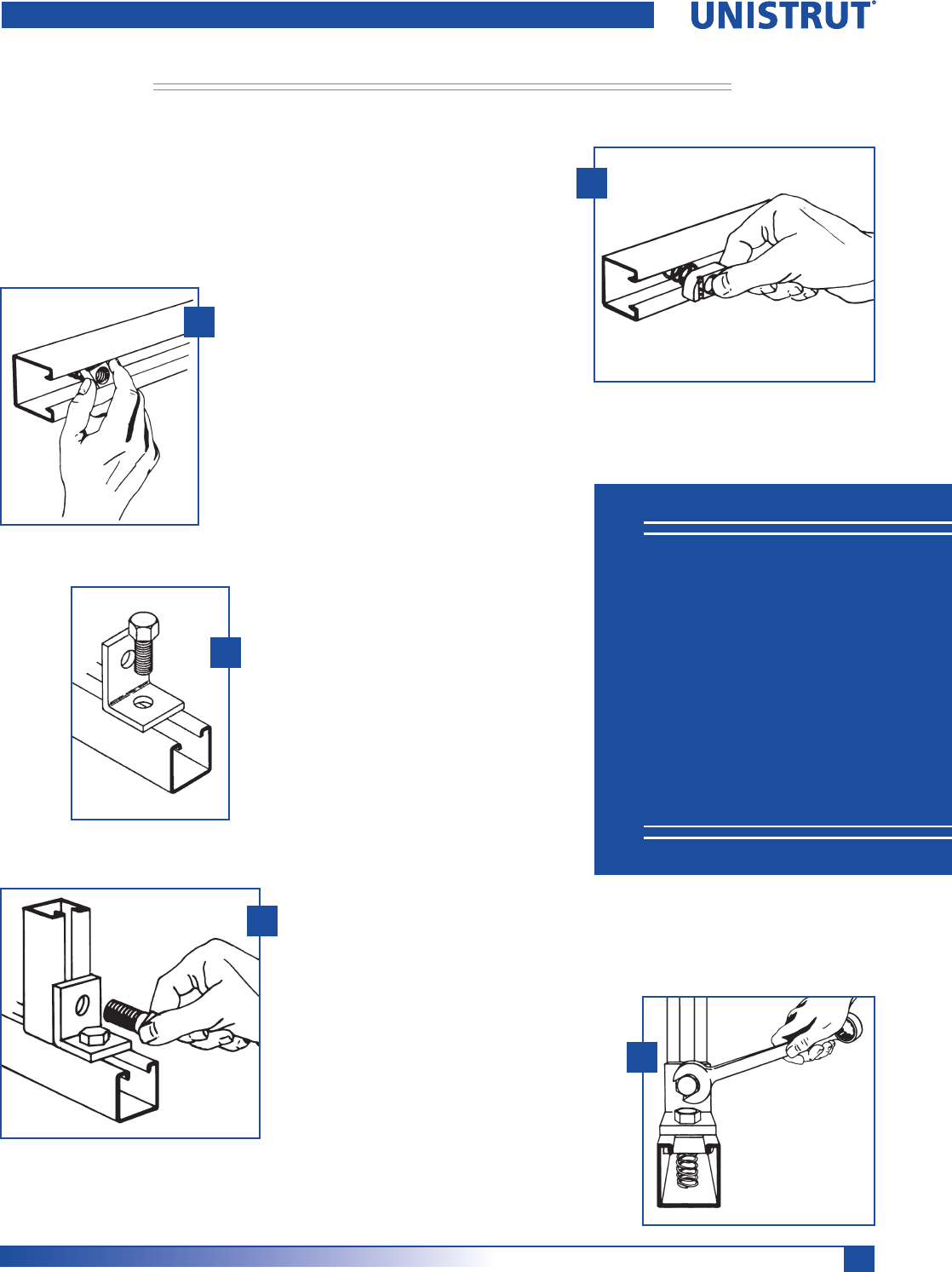
Unistrut Connection
1
5
Q 100% Adjustable
Q 100% Reusable
Q No Welding
Q No Drilling
Q No Special Tools
Insert the spring nut anywhere
along the continuous slotted
channel. The rounded nut ends
permit easy insertion.
A 90° clockwise turn aligns
the grooves in the nut with the
inturned edges of the channel.
Fittings can be placed anywhere
along the channel opening,
permitting complete freedom of
adjustment. The need for drilling
holes is eliminated.
Insert the bolt through the
fitting and into the spring
nut. (See illustration 5 for
end view showing the nut in
place)
Additional channel sections can
now be bolted to the fitting
already in place by following
procedure described in steps 1–3.
Tightening with a wrench
locks the serrated teeth of the
nut into the inturned edges
of the channel, to complete a
strong, vise-like connection.
8
Unistrut – The Original Metal Framing
Serving Design
Professionals for
Over 85 Years
Unistrut products have been
helping to build a better world
since 1924. Used extensively in
nuclear, industrial and com-
mercial construction markets
for over 85 years, Unistrut Met-
al Framing has set the standard
for product design, quality and
performance.
The initial Unistrut concept —
a simple spring nut and bolt
connecting a fitting to a
continuous slotted channel —
has evolved into a comprehen-
sive engineered building and
support system.
Unistrut® — The Original
Metal Framing System
There is only one Unistrut
Metal Framing System. It
incorporates the innovative
product improvements that
Unistrut Service Centers
A North American network
of Unistrut Service Centers —
stocking standard Unistrut
components — are located
in principal cities to serve you
quickly and directly. Many
Service Centers are equipped
to design and supply drawings
for any type of metal fram-
ing application and also offer
fabrication and installation
services.
This catalog is a comprehensive
presentation of Unistrut Metal
Framing components plus tech-
nical data required by design,
specification and construction
professionals.
our research and development
group has created to give you
the most complete and flex-
ible support system available.
Backed by our worldwide
network of engineering and
distribution centers, Unistrut
provides customers with total-
resource capability.
®
9
Unistrut – The Original Metal Framing
THE MOST COMPLETE METAL FRAMING SYSTEM — FOUR CHANNEL-WIDTH OPTIONS
Adjustability, demountability and reusability are engineered into each of the four Unistrut channel series.
Each series offers channels of varying depth and gage plus a complete line of fittings and accessories.
1 5⁄8"
VARIOUS
HEIGHTS
AVAILABLE
1 1⁄2"
VARIOUS
HEIGHTS
AVAILABLE
1 1⁄4"
VARIOUS
HEIGHTS
AVAILABLE
13⁄16"
VARIOUS
HEIGHTS
AVAILABLE
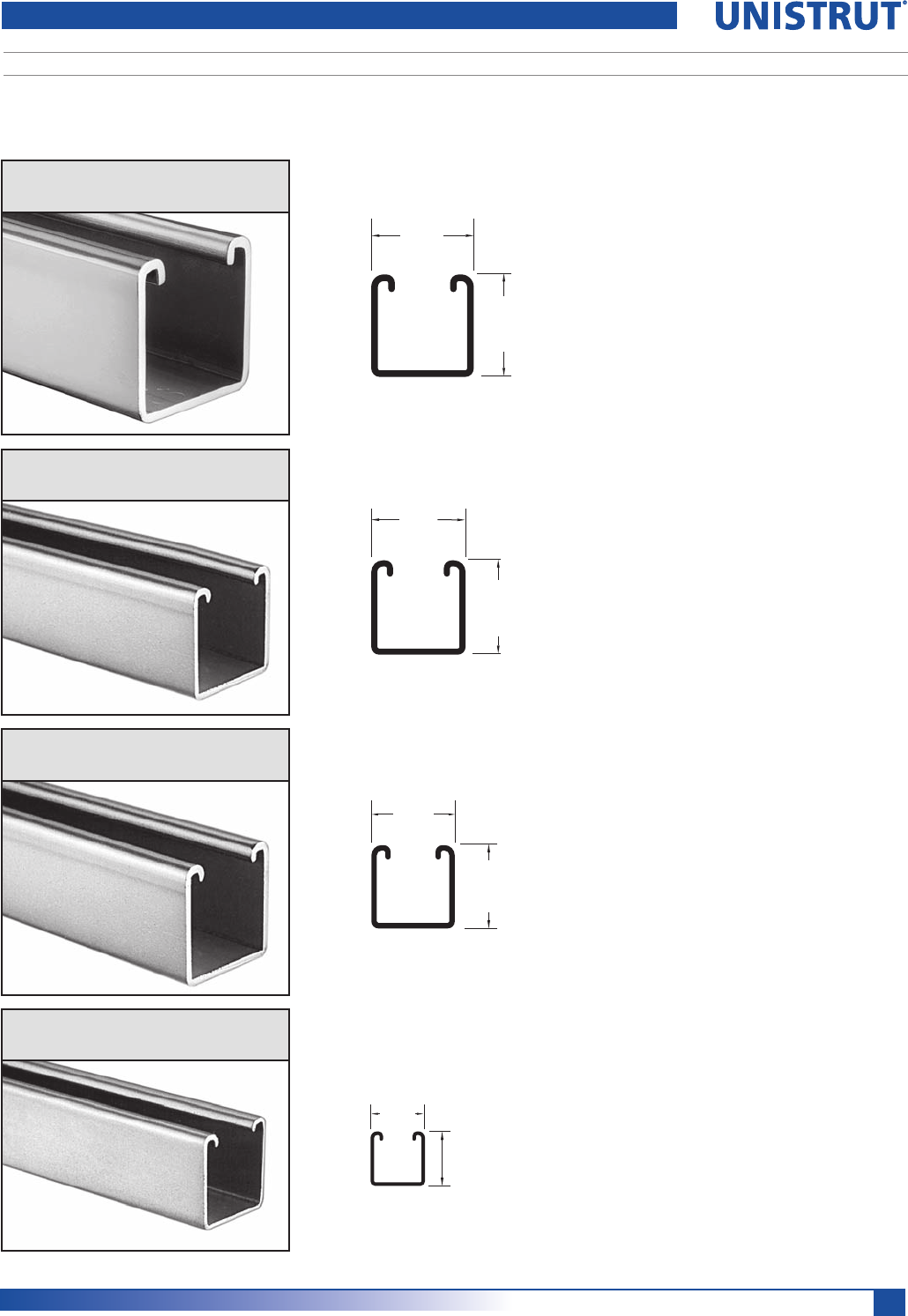
Unistrut Framing Systems
15»8” (41.3 mm) width
Designed to carry the heaviest
loads and provide the widest
variety of applications, the 15»8"
series has become the accepted
standard for use in mechanical,
electrical and general construction
applications where supports and
attachments must meet the high-
est strength requirements.
11»4” (31.8 mm) width
A framing system designed for
medium loads, the 11»4" series is
especially suitable for use in the
OEM, commercial and display
markets. It maintains a light-
ness in scale and a clean line that
makes it aesthetically pleasing
as well as functional.
13»16” (20.6 mm) width
A unique half-size reduction of
the 15»8" channel-width series, this
smaller channel size can be used
to carry light loads economically
in applications such as instrumen-
tation, retail displays and light-
duty laboratory supports. It also
provides the flexibility found in
all Unistrut framing systems.
13»16" width Series Channel
11»4" width Series Channel
11»2" width Series Channel
15»8" width Series Channel
11»2” (38.1 mm) width
A framing system designed for
medium to heavy loads, the
11»2" series offers hole spacing
and fittings where all parts
fit together, no matter where
they’re used, or at what angle.
10
Unistrut – The Original Metal Framing
QUALITY PROGRAM
Quality Assurance and Traceability
Product testing is an important
part of Unistrut’s Quality
Assurance Program. We utilize
our own testing facilities, as well
as those of independent testing
laboratories, to determine design
loads with proper and adequate
safety factors. These design loads
are indicated, where applicable,
throughout the catalog. Loads are
based on AISI Specification For
The Design Of Cold-Formed Steel
Structural Members, 2007 Edition.
PRODUCT LOAD TESTING
Destructive and non-destructive
testing procedures are used to test
for variables such as corrosion,
conductivity, electro-static
dissipation, ultra-violet resistance,
wind resistance, dimensional
accuracy, material integrity and
slip resistance.
In short, if there’s a specification
to meet, Unistrut will develop
a test to quantify and verify it.
Using design properties of the
Unistrut framing members, load
data given in this catalog, and/or
design procedures of the
American Iron & Steel Institute
Specification For The Design Of
Cold-Formed Steel Structural
Members, 2007 Edition, it is
possible to design any type of
structure within the capabilities
of the system.
Assemblies or connections that
cannot be calculated using
provisions of the AISI specifications
must be established by application-
specific tests.
Unistrut is committed to being
the “best” in the metal framing
industry. In order to meet this
goal, Unistrut has adopted the
philosophy of “Zero Defects and
Continuous Improvement”. This
means on-going reviews of our
manufacturing processes,
operating procedures and quality
systems to find ways of improving
efficiency, productivity and qual-
ity. It means establishing process
controls and problem-prevention
techniques to ensure that superior
quality is built into every Unistrut
product.
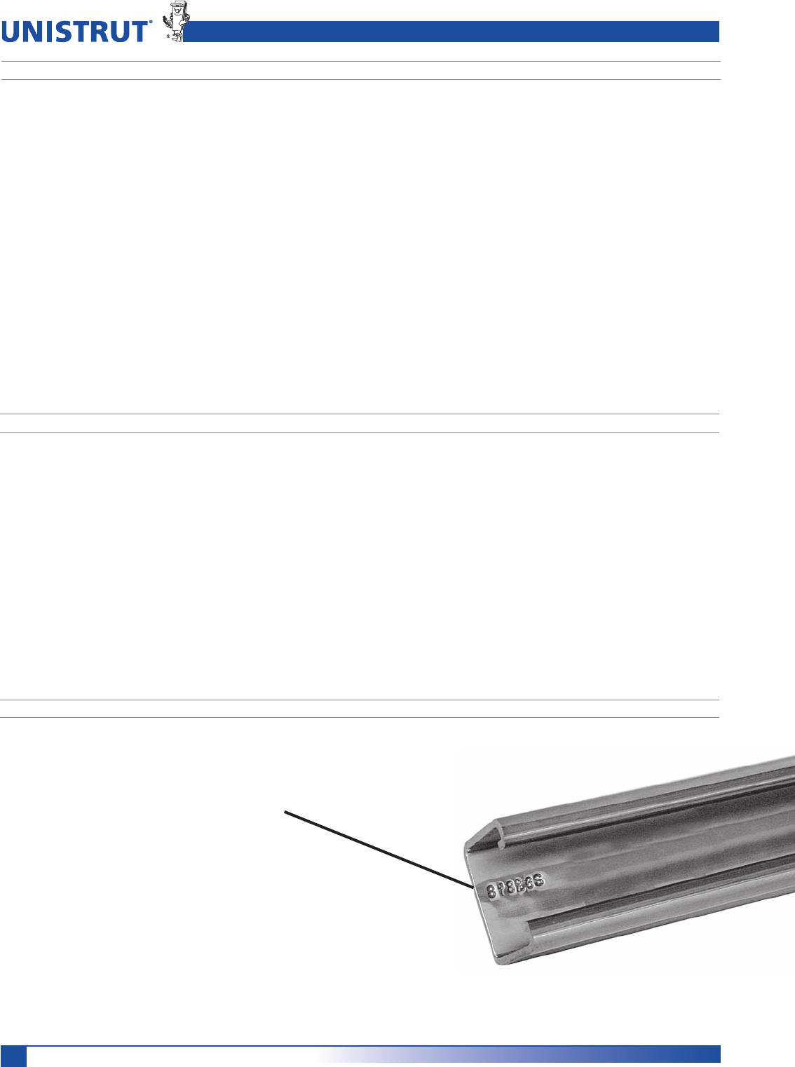
TRACEABILITY
Unistrut channel is stamped with a
numeric code that allows traceability
to the origin of the steel
Our drive to be the best includes
not just quality products, but
on-time delivery and prompt
resolution of customer needs and
concerns. At Unistrut, quality is
number one.
11
Unistrut – The Original Metal Framing
Materials and Finishes
Fittings
Unistrut fittings, unless noted
otherwise, are punch-press made
from hot rolled, pickled and oiled
steel plates, strip or coil, and
conform to ASTM specifications
A575, A576, A635 or A36. The
fitting steel also meets the
physical requirement of ASTM
A1011 SS GR 33. The pickling
of the steel produces a smooth
surface free from scale.
Framing Members
Unistrut channels and continuous
inserts are accurately and care-
fully cold-formed to size from
low carbon strip steel. One side
of the channel has a continuous
slot with inturned edges. Secure
attachments may be made to the
framing member with the use of
hardened, toothed, slotted nuts
which engage the inturned edges.
Raw steel shall conform to the
following ASTM specifications:
MATERIAL
Nuts and Bolts
Unistrut nuts are made from
steel bars. After all machining
operations are complete, they
are thoroughly case hardened.
Nuts are rectangular with ends
shaped to permit a quarter turn
clockwise in the framing member
after insertion through the slotted
opening in the channel. Two
toothed grooves in the top of the
nut engage the inturned edges
of the channel and, after bolting
operations are completed, will
prevent any movement of the
bolt and nut within the framing
member.
All bolts and nuts have Unified
coarse screw threads. The standard
framing nut is 1»2" and conforms to
ASTM A576 GR 1015 modified and
A1011 SS GR 45. Screws conform
to SAE J429 GR 2.
Weights given for all materials are
approximate shipping weights.
All dimensions are subject to
commercial tolerance within
published specifications.
WEIGHTS AND DIMENSIONS
WE RESERVE THE RIGHT TO MAKE SPECIFICATION CHANGES
WITHOUT NOTICE.
WHILE EVERY EFFORT HAS BEEN MADE TO ASSURE THE ACCURACY
OF INFORMATION CONTAINED IN THIS CATALOG AT THE TIME OF
PUBLICATION, WE CANNOT ACCEPT RESPONSIBILITY FOR
INACCURACIES RESULTING FROM UNDETECTED ERRORS OR OMISSIONS.
THE BLUE COLOR USED ON UNISTRUT COMPONENTS ILLUSTRATED
IN THIS CATALOG IS FOR GRAPHIC ENHANCEMENT ONLY, AND DOES
NOT REPRESENT ACTUAL PRODUCT COLOR.
®
GAGE FINISH ASTM NO.
12 GR & HG A1011 SS GR 33
PG A653 GR 33
14 GR & HG A1011 SS GR 33
PG A653 GR 33
16 GR & HG A1011 SS GR 33
PG A653 GR 33
19 GR A1008
12
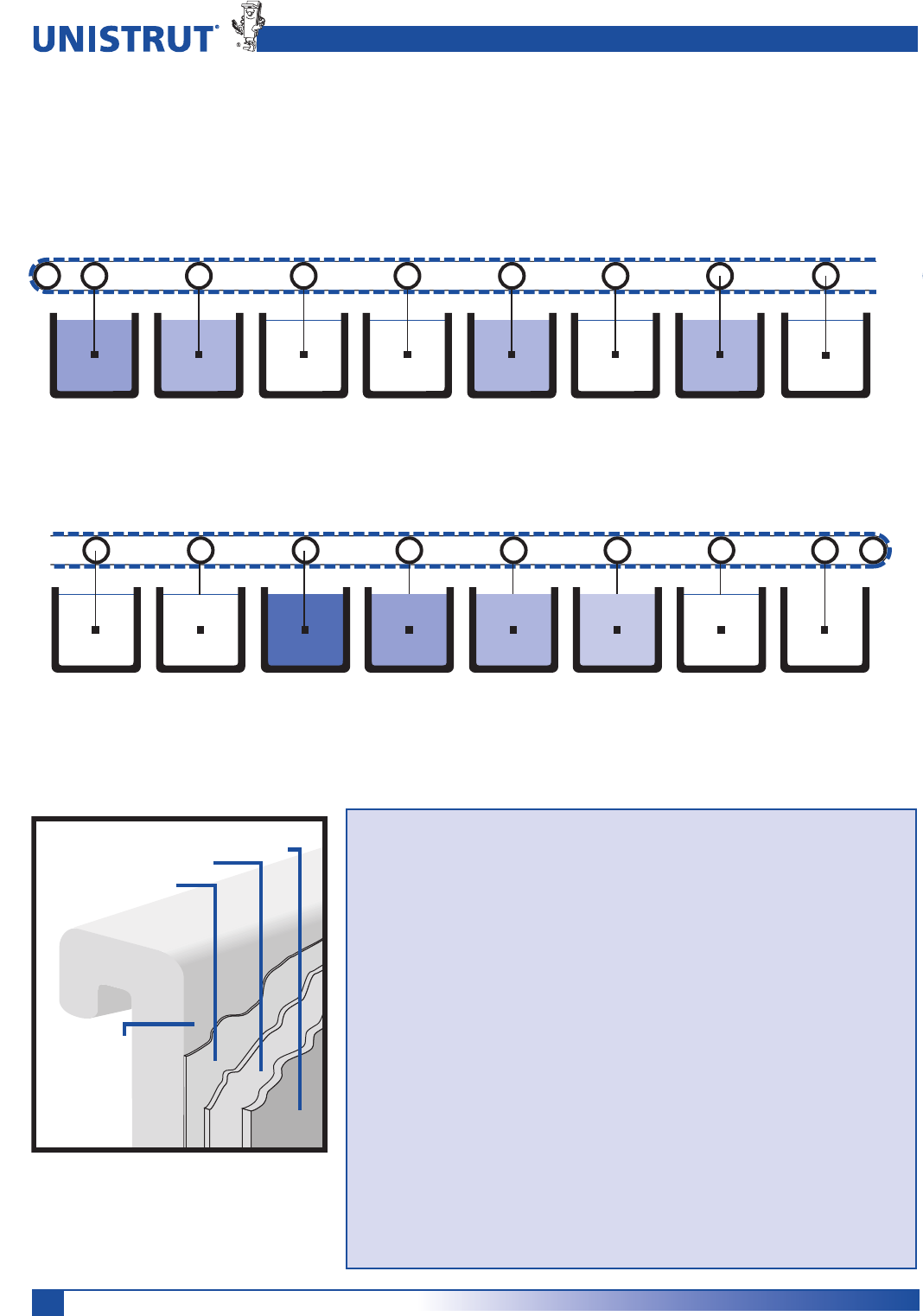
Unistrut – The Original Metal Framing
Perma-Green® III
Sealer
Phosphate
E-Coat
Prepared
Steel
Finishes
STEEL SUBSTRATE PREPARATION
Ten stage continuous cleaning,
phosphate process.
Substrate after “prep”: sealed
phosphate conversion coating.
COATING
Thermoset epoxy
Color:
Federal Highway Green
Color Tolerance Chart
PR Color No. 4
Hardness: 2H.
Coating Process:
Cathodic Electrodeposition.
The performance of Unistrut’s Perma-Green III
far exceeds that of conventional finishes. And
compared to competitive “high-performance” coatings,
Perma-Green III provides superior resistance to chalk-
ing, checking and fading and is far less vulnerable to
common acidic atmospheres, solvents and alkalis.
Just as important, Perma-Green III is the result of
an environmentally neutral process that virtually
eliminates the toxic metals commonly found in
competitive paint-based finishes.
First stage hot
alkaline cleaning
of channel.
Second stage
hot alkaline
cleaning of
channel.
Channel is rinsed
with clean water
to remove
cleaning
solution.
Conditioning
rinse.
Channel is
phosphated to
produce a
phosphate
coating.
Channel is rinsed
to remove
excess
phosphate
solution.
Sealer is applied. First stage
deionizer water
rinse to remove
excess sealer.
Second stage
deionized water
rinse to prepare
channel for
E-Coating.
Final deionizer
water rinse.
Electro-deposition
tank applies the
epoxy Perma-
Green III to all
surfaces.
Post rinse spray. Post rinse dip
tray.
Post rinse spray. Virgin deionized
water halo rinse.
The oven cure
process dries the
channel and cross
links the epoxy
thermoset resins at
375° F.
PERFORMANCE
Salt Spray:
Scribed: exceeds 400 hours per
ASTM B117. (1»8" creep)
Unscribed: exceeds 600 hours per
ASTM B117. (6% red rust)
Chalk:
Nominal at 1,000 hours per
weatherometer G-23 test.
Checking:
None at 1,000 hours per
weatherometer G-23 test.
Fade:
Less than 50% compared to
standard epoxy E.C. coatings.
ENVIRONMENTAL ISSUES
Formulated as a “heavy metal”-free
coating (trace elements only).
Outgassing in service: essentially none
at 350°F for 24 hours.
PERMA-GREEN® III (GR) TECHNICAL DATA
13
Unistrut – The Original Metal Framing
Finishes
PLAIN (PL)
Plain finish designation means that
the channel retains the oiled surface
applied to the raw steel during the
rolling process. The fittings have the
original oiled surface of the coil or
strip steel material.
Pregalvanized Zinc (PG)
ASTM A653
Pregalvanized steel is zinc coated by
a hot dip process. Steel strip from a
coil is fed through a continuous zinc
coater which cleans, fluxes and coats
the steel with molten zinc. After cool-
ing, the steel is recoiled.
The pregalvanized zinc coating
conforms to a G-90 thickness
designation per ASTM A653.
The zinc thickness is .75 MIL or
.45 oz./sq. ft. of surface area.
This coating is offered on Unistrut
channel and tubing and is a well-prov-
en, time-tested performer for indoor
and outdoor applications. For severe
corrosion applications, hot dip galva-
nizing, as described below, is a good
alternative.
HOT DIP GALVANIZED (HG)
ASTM A123 OR A153
In hot dip galvanizing, the finished
part is immersed in a bath of molten
zinc. This method results in complete
zinc coverage and a thicker coating
than pregalvanized or plated zinc.
The zinc coating is typically 2.6 MIL or
1.5 oz./sq. ft. of surface area.
This is the coating of choice for
applications where severe corrosion is
a design factor.
SPECIAL COATING
When specific applications require
other than standard available finishes,
special finishes can be supplied per
customer requirements.
Zinc Coating
Unistrut products are available in four
types of zinc coatings:
s%LECTROPLATED%'
s0ERMA'OLD:$
s0REGALVANIZED0'
s(OT$IP'ALVANIZED('
:INCOFFERTWOTYPESOFPROTECTION
sBarrier: The zinc coating protects
the steel substrate from direct
contact with the environment.
sSacrificial: The zinc coating will
protect scratches, cut edges, etc.
through an anodic sacrificial
process.
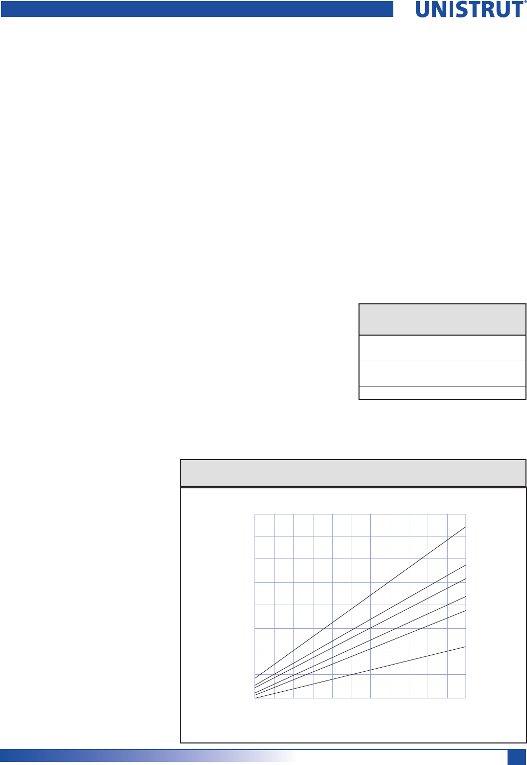
The service life of zinc coating is
directly related to the zinc coating
thickness as shown below.
Comparison of Zinc Finishes
Finish
Zinc
Thickness
(OT$IP'ALVANIZED 2.6 MIL
Pre-galvanized 0.75 MIL
Electro-Galvanized (SC1) 0.2 MIL
Electro-Galvanized (SC3) 0.5 MIL
Perma-Gold (SC3) 0.5 MIL
As shown in the graph, when the zinc
coating is double, the service life is
double under most conditions.
80
.50 .75 1.00 1.25 1.50 1.75 2.00 2.25 2.50 2.75 3.00
* Service Life is defined as the time to 5% rusting of the steel surface
70
60
50
40
30
20
10
.25
0.8 1.3 1.7 2.1 2.6 3.0 3.4 3.8 4.2 4.7 5.10.4
21 32 43 54 65 75 86 97 108 118 12911
Oz. of Zinc/Sq. Ft. of Surface
Service Life, Years*
Thickness of Zinc in Mils
RURAL
TROPICAL MARINE
TEMPERATE MARINE
SUBURBAN
MODERATELY INDUSTRIAL
HEAVY INDUSTRIAL
Life of Protection vs. Thickness of Zinc
and Type of Atmosphere
Electroplated Zinc (EG)
ASTM B633, Type III SC1 or SC3
In the electroplating process, the
part to be zinc coated is immersed
in a solution of zinc ions. An electric
current causes the zinc to be
deposited on the part.
3#-ILDHASA:INCCOATINGOF
and is recommended for dry indoor
use. SC1 is the standard finish thick-
ness.
3#3EVEREHASA:INCCOATINGOF
0.5 mill and is the standard finish
thickness only on UL Listed raceway
products.
Perma-Gold (ZD)
ASTM B633, Type II SC3
Similar to the EG process except in a
yellow color.
14
Unistrut – The Original Metal Framing
Design Fundamentals
Beams are structural members loaded
at right angles (perpendicular) to their
length. Most beams are horizontal and
subjected to gravity or vertical loads,
e.g. a shelf support. However a vertical
member can act as a beam under certain
conditions, such as a curtain wall mullion
subjected to wind loading. The bending
moment developed in a beam is depen-
dent on:
(a) The amount of load applied,
(b) The type of loading applied, and
(c) The support conditions
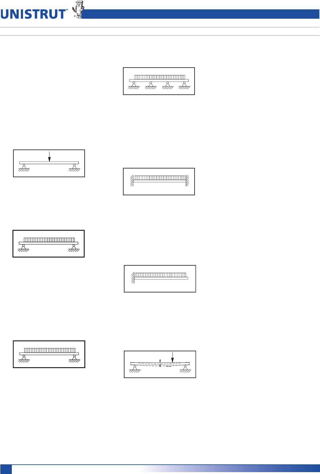
BEAM LOADING - POINT LOAD
A load concentrated onto a very small
length of the beam is a point load.
BEAM LOADING - UNIFORM LOAD
A load spread evenly over a relatively long
length of the beam is a uniform load.
Point and uniform loads can be placed on
a beam in any combination. A series of
point loads can approximate a uniform
loading. The load charts and tables are
based on a uniform load unless identified
otherwise.
SUPPORT CONDITIONS - SIMPLE BEAM
A simple beam has supports that prevent
movement left and right, or up and down,
but do not restrain the beam from rotating
at the supports into a natural deflected
curve. Most Unistrut Metal Framing con-
nections produce simple beams. The load
charts and tables are based on simple
beams unless identified otherwise.
SUPPORT CONDITIONS -
CONTINUOUS BEAM
Any simple beam that is supported at one
or more intermediate points is a continu-
ous beam. A mezzanine joist that passes
over three or more columns is an example
of a continuous beam.
SUPPORT CONDITIONS -
FIXED-END BEAM
Supports that prevent the beam from
rotating into a natural deflected curve
produce a fixed-end beam. A welded end
connection to very rigid support produces
a fixed-end beam.
SUPPORT CONDITIONS -
CANTILEVER BEAM
A cantilever beam is a fixed-end beam that
is supported at one end only, while the
other end is unsupported. Unistrut brack-
ets are examples of cantilever beams.
DEFLECTION
All beams deflect under load. The amount
of deflection is dependent on
(a) the amount of load,
(b) the support conditions,
(c) the stiffness of the beam’s
cross-sectional shape, and
(d) the stiffness of the beam material.
BEAMS
The stiffness of the beam’s cross-sectional
shape is measured by its “Moment Of
Inertia” or "I". The larger a beam’s "I", the
stiffer it is and the less it will deflect. A
beam’s "I" can change for each major axis.
The "I" of both major axes (I 1-1 and I 2-2)
are provided.
The stiffness of a beam’s material is mea-
sured by its “Modulus of Elasticity” or "E".
The larger a material’s "E", the stiffer it is
and the less it deflects. For example, steel
is about three times stiffer than aluminum
and as a result, deflects only one-third
ASMUCH$ONOTCONFUSESTIFFNESSWITH
strength. Two materials may have identical
strengths yet still have different "E’s". A
high-strength aluminum may be as strong
as steel and still deflect three times as
much.
The load charts and tables give calculated
deflections for the loads shown. In many
cases, a final design will be determined by
the maximum deflection, not the maxi-
mum load.
BENDING MOMENT
Is it strong enough? This is the final
consideration for any beam. A beam must
not only hold up the anticipated loads, but
must also have sufficient additional capac-
ity to safely hold unforeseen variations
in applied loads and material strengths.
This additional capacity is called a safety
factor and is usually regulated by the
various design codes and standards. A
beam’s strength is usually measured by an
allowable bending moment or an allow-
able stress. The traditional approach is the
allowable stress method, where a beam is
determined to have a maximum allowable
stress (in pounds per square inch) which
is not to be exceeded.
The approach of the current AISI “Speci-
lCATION&OR4HE$ESIGN/F#OLD&ORMED
Steel Structural Members” is to use a
maximum allowable bending moment (in
inch-pounds) which is not to be exceeded.
Bending moment divided by a beam’s sec-
tion modulus or "S" equals stress.
15
Unistrut – The Original Metal Framing
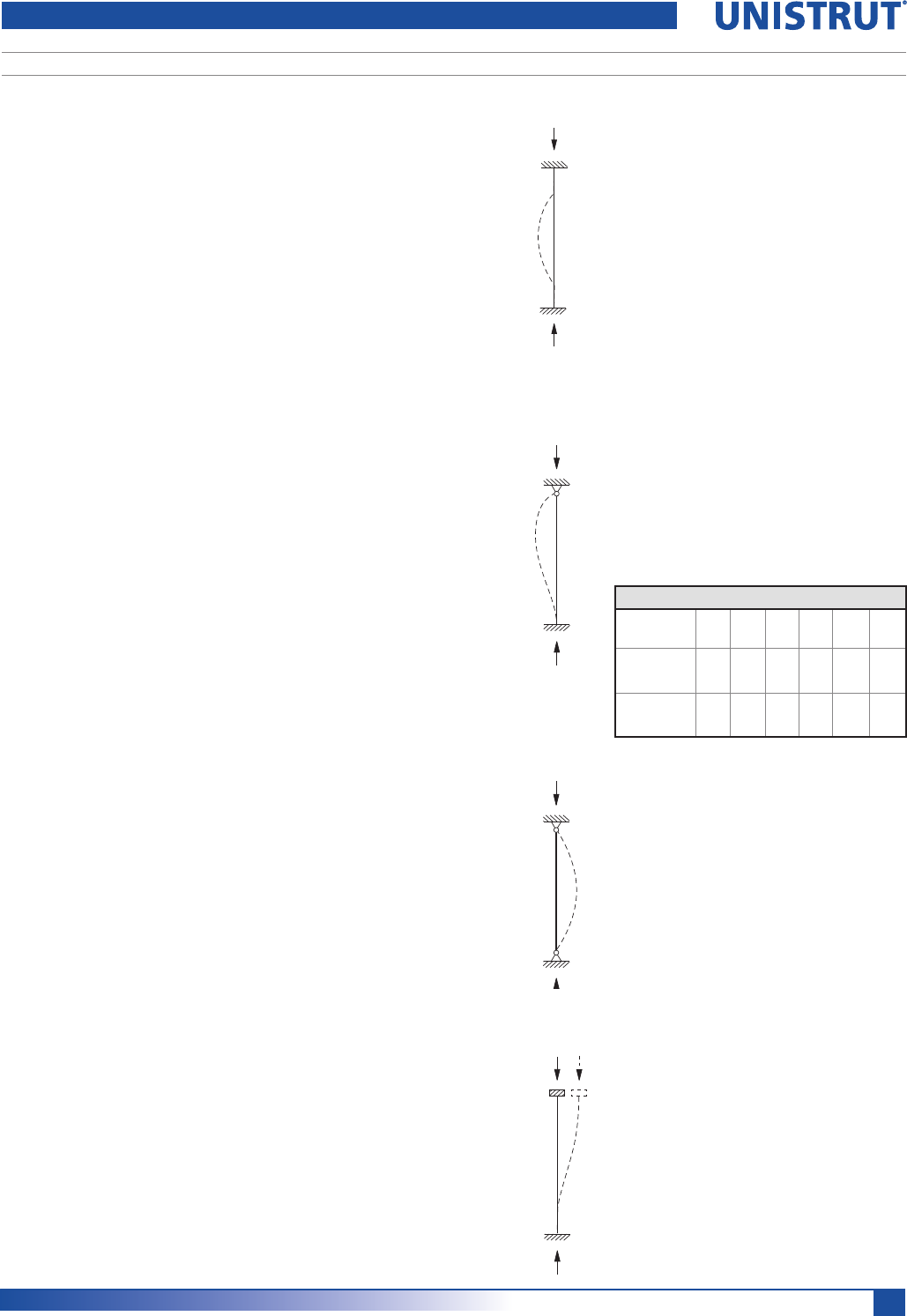
COLUMNS
SUPPORT CONDITIONS -
FIXED TOP – FIXED BOTTOM
Both ends are restrained
against rotation and
lateral movement
(translation).
CROSS-SECTIONAL SHAPE
The cross-sectional shape of a column
member determines the value of its
“Radius of Gyration” or "r". In general, a
member with a large "r" makes a better
column than a member with a small "r".
Each axis of a column has a different "r".
Typically the axis with the smallest "r"
determines the final design.
BOLT TORQUE
Bolt torque values are given to ensure
the proper connection between Unistrut
Metal Framing components. It is important
to understand that there is a direct, but
not necessarily consistent, relationship
between bolt torque and tension in the
bolt. Too much tension in the bolt can
cause it to break or crush the component
parts. Too little tension in the bolt can
prevent the connection from developing
its full load capacity. The torque values
given have been developed over many
years of experience and testing.
Design Fundamental
Columns are structural members that
are loaded parallel to their length. Most
columns are vertical and are used to carry
loads from a higher level to a lower level.
However any member subjected to com-
pression loads, such as a diagonal or prop
brace, is a column.
A column fails by “buckling”, which is a
sudden loss of straightness and subse-
quent collapse. Allowable column load is
dependent on:
(a) the length of column,
(b) the type of loading,
(c) the support conditions, and
(d) the column’s cross-sectional shape
and material.
COLUMN LENGTH
The column length is measured from
braced point to braced point. A braced
point is where the column is restrained
from lateral movement (translation) in all
directions.
COLUMN LOADING –
CONCENTRIC LOADING
Loads applied to the center of gravity of
the column cross-section are considered
concentric. A beam that passes over
and rests on the top of a column is an
example of concentric loading.
COLUMN LOADING –
ECCENTRIC LOADING
Any load which is not concentric is ec-
centric. The amount of eccentricity (in
inches) has a major effect on the load-car-
rying capacity of any particular column.
A load that is transmitted to a Unistrut
Metal Framing column using a standard
fitting bolted to the slot face is considered
eccentric.
The load tables give allowable loads for
both concentric (loaded at C.G.) and cer-
tain eccentric (loaded at slot face) load-
ing. Allowable loads for other eccentric
loading must be determined by a qualified
design professional.
SUPPORT CONDITIONS
Based on the support conditions, an ap-
propriate "K" value is selected. This “K”
value, which mathematically describes
the column end conditions, is used in the
column design equations. The most com-
mon support condition combinations are
as follows:
K = 0.65
K = 1.0
SUPPORT CONDITIONS -
PINNED TOP – FIXED BOTTOM
The top is restrained
against lateral
movement (translation)
but is allowed to rotate.
The bottom is restrained
against rotation and
lateral movement.
This is a common
support condition and
is used to construct the
allowable column load
applied at the Slot Face
tables.
SUPPORT CONDITIONS -
PINNED TOP –
PINNED BOTTOM
Both ends are
restrained against
lateral movement
(translation) but, are
allowed to rotate.
SUPPORT CONDITIONS -
FIXED / FREE TOP – FIXED BOTTOM
The top is restrained
against rotation but
is allowed to move
laterally. The bottom
is restrained against
rotation and lateral
movement (translation).
These are based on using a properly
calibrated torque wrench with a clean dry
(non-lubricated) Unistrut fitting, bolt and
nut. A lubricated bolt or nut can cause
extremely high tension in the connection
and may lead to bolt failure. It must be
noted that the accuracy of commercial
torque wrenches varies widely and it is the
responsibility of the installer to ensure that
proper bolt torque has been achieved.
K = 0.80
K = 1.2
Bolt Torque
BOLT
SIZE
1»4"
-20
5»16"
-18
3»8"
-16
1»2"
-13
5»8"
-11
3»4"
-10
Rec.Torque
Ft/Lbs
1P
6
(8)
11
(15)
19
(26)
50
(68)
100
(136)
125
(170)
Max Torque
Ft/Lbs
1P
7
(9)
15
(20)
25
(34)
70
(95)
125
(170)
135
(183)

16
Unistrut – The Original Metal Framing
Conversion Factors
English To Metric
To Convert From To Multiply By
Length
Inch [in] Millimeter [mm] 25.400 000
Foot [ft] Meter [m] 0.304 800
Yard [yd] Meter [m] 0.914 400
Mile [mi] (U.S. Statute) Kilometer [km] 1.609 347
Area
Square Inch [in2] Square Millimeter [mm2] 645.16
Square Foot [ft2] Square Meter [m2] 0.092 903
Square Yard [yd2] Sqare Meter [m2] 0.836 127
Square Mile [mi2] (U.S. Statute) Square Kilometer [km2] 2.589 998
Acre Square Meter [m2] 4046.873
Acre Hectare 0.404 687
Volume
Cubic Inch [in3] Cubic Millimeter [mm3] 16387.06
Cubic Foot [ft3] Cubic Meter [m3] 0.028 317
Cubic Yard [yd3] Cubic Meter [m3] 0.764 555
Gallon [gal] (U.S. Liquid) Litre [l] 3.785 412
Quart [qt] (U.S. Liquid) Litre [l] 0.946 353
Mass
Ounce (Avoirdupois) [oz] Gram [g] 28.349 520
Pound (Avoirdupois) [lb] Kilogram [kg] 0.453 592
Short Ton Kilogram [kg] 907.185
Force
Ounce-Force Newton [N] 0.278 014
Pound-Force [lbf] Newton [N] 4.448 222
Bending Moment
Pound-Force-Inch [lbf-in] Netwon-Meter [N-m] 0.112 985
Pound-Force-Foot [lbf-ft] Newton-Meter [N-m] 1.355 818
Pressure, Stress
Pound-Force per Kilopascal [kPa] 6.894 757
Square Inch [lbf/in2]
Foot of Water (39.2 F) Kilopascal [kPa] 2.988 980
Inch of Mercury (32 F) Kilopascal [kPa] 3.386 380
Energy, Work, Heat
Foot-Pound-Force [ft-lbf] Joule [J] 1.355 818
British Thermal Unit [Btu] Joule [J] 1055.056
Calorie [cal] Joule [J] 4.186 800
Kilowatt Hour [kW-h] Joule [J] 3,600,000
Power
Foot-Pound-Force Watt [W] 1.355 818
/Second [ft-lbs/s]
British Thermal Unit Watt [W] 0.293 071
/Hour [Btu/h]
Horsepower [hp] (550 Ft. Lbf/s) Kilowatt [kW] 0.745 700
Angle
Degree Radian [rad] 0.017 453
Temperature
Degree Fahrenheit [°F] Degree Celsius [°C] (F° -32)/1.8
Metric to English
To Convert From To Multiply By
Length
Millimeter [mm] Inch [in] 0.039 370
Meter [m] Foot [ft] 3.280 840
Meter [m] Yard [yd] 1.093 613
Kilometer [km] Mile [mi] (U.S. Statute) 0.621 370
Area
Square Millimeter [mm2] Square Inch [in2] 0.001550
Square Meter [m2] Square Foot [ft2] 10.763 915
Sqare Meter [m2] Square Yard [yd2] 1.195 991
Square Kilometer [km2] Square Mile [mi2](U.S. Statute) 0.386 101
Square Meter [m2] Acre 0.000 247
Hectare Acre 2.471 046
Volume
Cubic Millimeter [mm3] Cubic Inch [in3] 0.000061
Cubic Meter [m3] Cubic Foot [ft3] 35.314 662
Cubic Meter [m3] Cubic Yard [yd3] 1.307 950
Litre [l] Gallon [gal] (U.S. Liquid) 0.264 172
Litre [l] Quart [qt] (U.S. Liquid) 1.056 688
Mass
Gram [g] Ounce (Avoirdupois) [oz] 0.035 274
Kilogram [kg] Pound (Avoirdupois) [lb] 2.204 624
Kilogram [kg] Short Ton 0.00110
Force
Newton [N] Ounce-Force 3.596 941
Newton [N] Pound-Force [lbf] 0.224 809
Bending Moment
Netwon-Meter [N-m] Pound-Force-Inch [lbf-in] 8.850 732
Newton-Meter [N-m] Pound-Force-Foot [lbf-ft] 0.737 562
Pressure, Stress
Kilopascal [kPa] Pound-Force per 0.145 038
Square Inch [lbf/in2]
Kilopascal [kPa] Foot of Water (39.2 F) 0.334 562
Kilopascal [kPa] Inch of Mercury (32 F) 0.295 301
Energy, Work, Heat
Joule [J] Foot-Pound-Force [ft-lbf] 0.737 562
Joule [J] British Thermal Unit [Btu] 0.000948
Joule [J] Calorie [cal] 0.238 846
Joule [J] Kilowatt Hour [kW-h] 2.78-7
Power
Watt [W] Foot-Pound-Force 0.737 562
/Second [ft-lbs/s]
Watt [W] British Thermal Unit 3.412 142
/Hour [Btu/h]
Kilowatt [kW] Horsepower (550 Ft. Lbf/s) [hp] 1.341 022
Angle
Radian [rad] Degree 57.295 788
Temperature
Degree Celsius [°C] Degree Fahrenheit [°F] 1.8xC°+32
UNIT CONVERSIONS
17
Unistrut – The Original Metal Framing
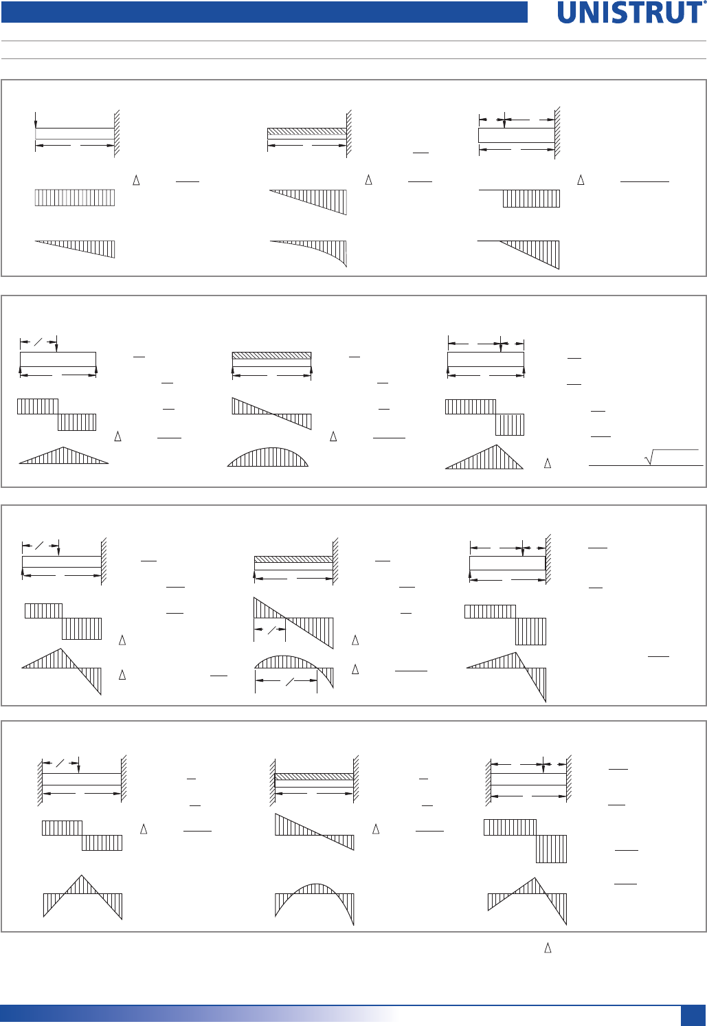
Reference Tables and Data
BEAM SUPPORT CONDITIONS
Cantilever Beams
P
L
V
M
L
ab
P
M
V
M
V
V max. = P
M max. = PL
max. = PL3
3EI
V max. = W
max. = WL3
8EI
WL
2
M max. =
V max. = P
max. = Pb2(3L-b)
6EI
M max. = Pb
L
Beams Fixed At One End & Supported At The Other
L
R1R2
ab
P
V
M
L
R1
P
L2
V
M
L
V
M
3L
8
3L
4
R2=
M at point of load = R1a
M at fixed end =
Pb2
2L3
R1=
Pa
2L3
(a+2L)
(3L2-a2)
Pab
2L3(a+L)
R1=
V max. =
M max. =
max. at x = 0.447L
5P
16
11P
16
3PL
16
max. = 0.009317
PL3
EI
R1=
V max. =
M max. =
max. at x = 0.4215L
3W
8
5W
8
WL
8
max. = WL3
185EI
R1
Beams Fixed At Both Ends
V
M2
L
R1R2
ab
P
V
M
L
P
L2
V
M
L
M1
R2=
M1 =
M2 =
Pb2
L3
R1=
Pa2
L3
(3a+b)
(a+3b)
Pab2
L2
Pa2b
L2
V max. =
M max. =
max. = PL3
192EI
P
2
PL
8
V max. =
M max. =
max. = WL3
384EI
W
2
WL
12
Simple Beams
M
V
L
P
L2
RR
M
V
L
RR
L
R1R2
M
V
ab
P
R=
V max. =
M max. =
max. = PL3
48EI
P
2
P
2
PL
4
R=
V max. =
M max. =
max. = 5WL3
384EI
W
2
W
2
WL
8
R2=
V max. =
M max. =
Pb
L
R1=
Pa
L
Pa
L
Pab
L
Pab(a+2b) 3a(a+2b)
27EIL
max. =
R – Reaction
M – Moment
P – Concentrated Load
W – Total Uniform Load
V – Shear
L – Length
– Deflection
E – Modulus of Elasticity
I – Moment of Inertia
18
Unistrut – The Original Metal Framing
EXAMPLE I:
Determine load and deflection of a
P 1000 beam continuous over one
support and loaded uniformly on one span.
SOLUTION:
A. From load table for P1000 on page 25 load for a 5'-0" span is
680# and deflection is .35".
B. Multiply by factors from Table above.
Load = 680# x 1.30 = 884#
Deflection = .35" x .92 = .32"
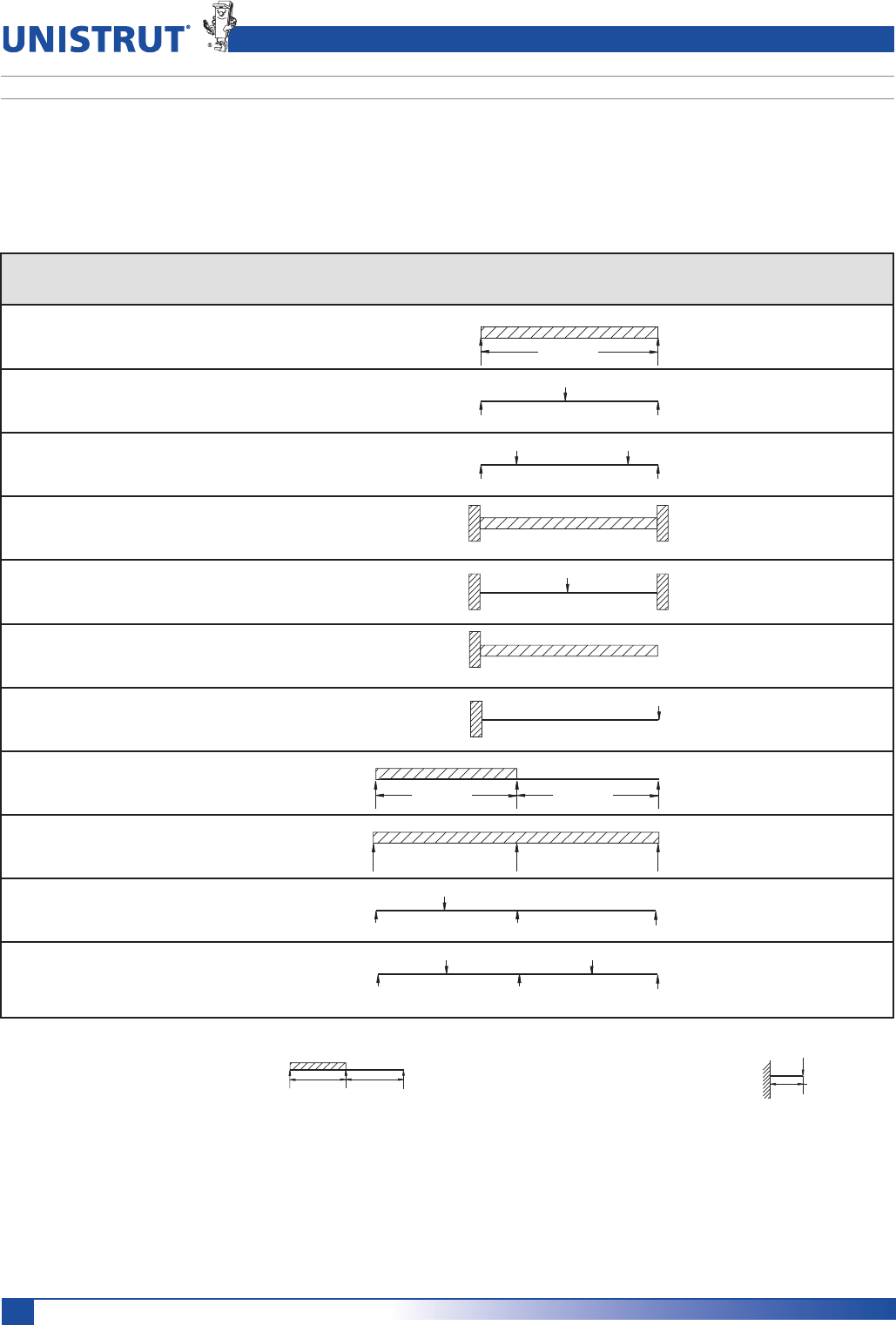
Reference Tables and Data
CONVERSION FACTORS FOR BEAMS WITH VARIOUS STATIC LOADING CONDITIONS
All Beam Load tables are for single-span (simple) beams supported at the ends. These can be used in the majority of the
cases. However, there are times when it is necessary to know what happens with other loading and support conditions.
Some common arrangements are shown below. Simply multiply the values from the Beam Load tables by
factors given below
5' - 0" 5' - 0"
EXAMPLE II
Determine load and deflection of a P 5500
cantilever beam with a concentrated load on
the end.
SOLUTION:
A. From load table P5500 on page 58 load for a 3'-0" span is
2180# and deflection is .09".
B. Multiply by factors from Table above.
Load = 2180# x .12 = 262#
Deflection = .09" x 3.20 = .29"
3' - 0"
Continuous Beam, Two Equal Spans,
Concentrated Load at Center of Each Span .67 .48
SPAN
1.00
1.00
.50
.25
1.50
1.00
1.00
.12
1.30
.62
1.10
1.00
.80
2.40
.30
.40
.42
3.20
.92
.71
1. Simple Beam,
Uniform Load
2. Simple Beam,
Concentrated Load at Center
3. Simple Beam,
Two Equal Concentrated Loadcs at 1/4 pts
4. Beam Fixed at Both Ends,
Uniform Load
5. Beam Fixed at Both Ends,
Concentrated Load at Center
6. Cantilever Beam,
Uniform Load
7. Cantilever Beam,
Concentrated Load at End
8. Continuous Beam, Two Equal Spans,
Uniform Load on One Span
9. Continuous Beam, Two Equal Spans,
Uniform Load on Both Ends
10. Continuous Beam, Two Equal Spans,
Concentrated Load at Center of One Span
11.
SPAN SPAN
Load and Support Load Deflection
Condition Factor Factor

19
Unistrut – The Original Metal Framing
Guide Specification
PART I - GENERAL
1.01 SCOPE OF WORK
A. Provide all Unistrut Metal Framing
material, fittings and related
accessories (Strut System) as
INDICATEDONTHE#ONTRACT$RAWINGS
B. Provide all labor, supervision,
engineering, and fabrication required
for installation of the Strut System in
ACCORDANCEWITHTHE#ONTRACT$RAW-
ings and as specified herein.
C. Related work specified elsewhere.
1.02 QUALITY ASSURANCE
A. Manufacturer’s qualifications:
1. The manufacturer shall not
have had less than 10 year’s
experience in manufacturing
Strut Systems.
2. The manufacturer must certify
in writing all components
supplied have been produced in
accordance with an established
quality assurance program.
B. Installer’s qualifications:
1. Installer must be a Unistrut
trained manufacturer’s autho-
rized representative/installer
with not less than 5 years
experience in the installation
of Strut Systems of this size and
conformation.
2. All Strut System components
must be supplied by a single
manufacturer.
C. Standards:
1. Work shall meet the require-
ments of the following
standards:
a. Federal, State and Local codes.
b. American Iron and Steel
Institute (AISI) Specification
FORTHE$ESIGNOF#OLD
Formed Steel Structural
Members 2007 Edition.
c. American Society for Testing
And Materials (ASTM).
1.03 SUBMITTALS
A. Structural Calculations and Shop
$RAWINGS
1. Submit structural calculations
for approval by the project engi-
neer. Calculations may include,
but are not limited to:
A $ESCRIPTIONOFDESIGNCRITERIA
b. Stress and deflection analysis.
c. Selection of Unistrut framing
members, fittings, and
accessories.
2. Submit all shop/assembly draw-
ings necessary to completely
install the Strut System in
compliance with the Contract
$RAWINGS
3. Submit all pertinent manufactur-
ers published data.
02%'!,6!.):%$0'
:INCCOATEDBYHOTDIPPED
process prior to roll forming.
The zinc weight shall be G90
conforming to ASTM A 653.
(/4$)00%$'!,6!.):%$('
:INCCOATEDAFTERALLMANUFACTUR-
ing operations are complete.
Coating shall conform to
ASTM A 123 or A 153.
5. SPECIAL COATING / MATERIAL
$ESCRIBEASAPPLICABLE
PART 3 - EXECUTION
3.01 EXAMINATION
A. The installer shall inspect the work
area prior to installation. If work
area conditions are unsatisfactory,
installation shall not proceed until
satisfactory corrections are
completed.
3.02 INSTALLATION
A. Installation shall be accomplished by
a fully trained manufacturer autho-
rized installer.
B. Set Strut System components into
final position true to line, level and
plumb, in accordance with approved
shop drawings.
C. Anchor material firmly in place.
Tighten all connections to their
recommended torques.
3.03 CLEANUP
A. Upon completion of this section of
work, remove all protective wraps
and debris. Repair any damage due to
installation of this section of work.
3.04 PROTECTION
!$URINGINSTALLATIONITSHALLBETHERE-
sponsibility of the installer to protect
this work from damage.
B. Upon completion of this scope
of work, it shall become the respon-
sibility of the general contractor
to protect this work from damage
during the remainder of construction
on the project and until substantial
completion.
1.04 PRODUCT DELIVERY,
STORAGE, AND HANDLING
A. All material is to be delivered to
the work site in original factory
packaging to avoid damage to the
finish.
B. Upon delivery to the work site,
all components shall be protected
from the elements by a shelter or
other covering.
1.05 GUARANTEE
A. Separate guarantees shall be issued
from the erector and manufacturer,
valid for a period of 1 year, against
any defects that may arise from the
installation or manufacture of the
Strut System components.
PART 2 - PRODUCTS
2.01 ACCEPTABLE MANUFACTURERS
A. All Strut System components shall
be as manufactured by UNISTRUT
CORPORATION or approved equal
as determined by the Architect or
Engineer of record in writing 10
days prior to bid date.
2.02 MATERIALS
A. All channel members shall be
fabricated from structural grade steel
conforming to one of the following
ASTM specifications:
A 1011 SS GR 33, A 653 GR 33.
B. All fittings shall be fabricated from
steel conforming to one of the fol-
lowing ASTM specifications:
A 575, A 576, A 36 or A 635.
C. Substitutions
Any substitutions of product or
manufacturer must be approved in
writing ten days prior to bid date, by
Architect or Engineer of record.
2.03 FINISHES
A. Strut System components shall be
finished in accordance with one of
the following standards:
1. PERMA-GREEN® III (GR)
Rust inhibiting epoxy enamel
paint applied by electro-
deposition, after cleaning and
phosphating, and thoroughly
baked. Color is per Federal
Highway Green, Color Tolerance
Chart PR Color No. 4. Finish to
withstand minimum 400 hours
salt spray when tested in accor-
dance with ASTM B117.
%,%#42/'!,6!.):%$%'
Electrolytically zinc coated per
ASTM B 633 Type III SC 1
20
Unistrut – The Original Metal Framing
New Products
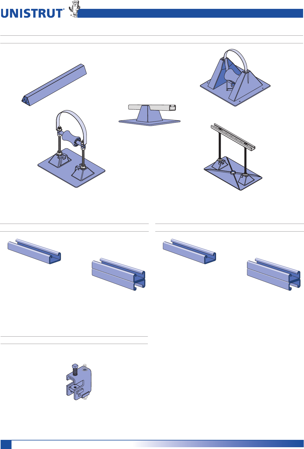
UNIPIER® ROOFTOP PIPE SUPPORT SYSTEM
NEW CHANNEL SECTION P4520/P4521 (15/8" X 13/16") NEW CHANNEL SECTION P4400/P4401 (15/8" X 1")
NEW BEAM CLAMP P1640
21
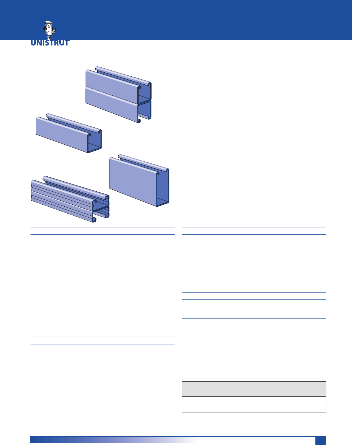
MATERIAL
Unistrut channels are accurately and carefully cold formed
to size from low-carbon strip steel.
All spot-welded combination members, except P1001T,
are welded 3" (76 mm) maximum on center.
STEEL: PLAIN
12 Ga. (2.7 mm), 14 Ga.(1.9 mm) and
16 Ga. (1.5 mm) ASTM A1011 SS GR 33.
STEEL: PRE-GALVANIZED
12 Ga. (2.7 mm), 14 Ga. (1.9 mm) and
16 Ga. (1.5mm) ASTM A653 GR 33.
For other materials, see Special Metals or Fiberglass
sections.
FINISHES
All channels are available in:
UÊ *iÀ>ÊÀiiÊÊ,®°
UÊ *Ài}>Û>âi`Ê*®]ÊVvÀ}ÊÌÊ
ASTM A653 G90.
UÊ Ì`««i`Ê}>Û>âi`Ê®]ÊVvÀ}ÊÌÊ
ASTM A123.
UÊ *>Ê*®°
DIMENSIONS
Imperial dimensions are illustrated in inches. Metric dimen-
sions are shown in millimeters and rounded to one decimal
place.
STANDARD LENGTHS
Standard lengths are 10 feet (3.05m) and 20 feet (6.10m).
Tolerances are ±1⁄8" (3 mm). Special lengths are available
for a small cutting charge with a tolerance of ±1⁄8" (3 mm).
CURVED CHANNEL
Contact your local Unistrut Service Center or Unistrut
Corporation for more information.
LOAD DATA
All beam and column load data pertains to carbon steel
and stainless steel channels. Load tables and charts are con-
structed to be in accordance with the SPECIFICATION FOR
THE DESIGN OF COLD-FORMED STEEL STRUCTURAL MEM-
BERS 2007 EDITION published by the AMERICAN IRON AND
STEEL INSTITUTE USING ASD METHOD. Loads are based on
33 ksi steel cold formed to 42 ksi.
Type
of Load
Safety Factor
to Yield Strength
Safety Factor
to Ultimate Strength
Beam Loads 1.67 2.0
Column Load 1.80 2.2
Channel Selection Chart ...................................................................23
P1000 (12 Gauge) .......................................................................24 - 29
P1100 (14 Gauge) .......................................................................30 - 32
P2000 (16 Gauge) .......................................................................33 - 35
P3000 (12 Gauge) .......................................................................36 - 38
P3300 (12 Gauge) .......................................................................39 - 41
P4000 (16 Gauge) .......................................................................42 - 44
P4100 (14 Gauge) .......................................................................45 - 47
P4400 (12 Gauge) .......................................................................48 - 50
P4520 (12 Gauge) .......................................................................51 - 53
P5000 (12 Gauge) .......................................................................54 - 56
P5500 (12 Gauge) .......................................................................57 - 59
Closure Strips ....................................................................................60
End Caps and Frame Caps ................................................................61
Lateral Bracing Load Reduction Chart & Bearing Loads .................62
15⁄8" CHANNEL
22
15⁄8" Framing System
1 5¼8" ChannelTelestrutNuts & HardwareGeneral FittingsPipe/Conduit SupportsElectrical FittingsConcrete InsertsSolarUnipier®
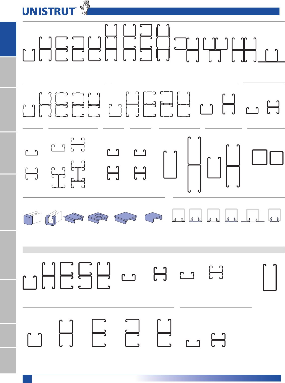
Channel Pictorial Index
P1001 C3
Pg 27
P1001 D3
Pg 27
P1001 C41
Pg 27
P1003
Pg 27
P1004A
Pg 27
P1100
Pg 30
P4000
Pg 42
P1001 B3
Pg 27
P1000
Pg 24
P1001
Pg 24
P1001T
Pg 27
P1001A
Pg 27
P1001B
Pg 27
P1001 A3
Pg 27
P1001 3
Pg 27
P1001C
Pg 27
P1101
Pg 30
P1101A
Pg 30
P1101B
Pg 30
P1101C
Pg 30
P3000
Pg 36
P3001
Pg 36
P2000
Pg 33
P2001
Pg 33
P2001A
Pg 33
P2001B
Pg 33
P2001C
Pg 33
P3300
Pg 39
P3301
Pg 39
P4001
Pg 42
P4003
Pg 42
P4004
Pg 42
P4100
Pg 45
P4101
Pg 45
P4400
Pg 48
P4401
Pg 48
P1000 Series (12 ga.)
P1100 Series (14 ga.) P2000 Series (16 ga.) P3000 Series (12 ga.) P3300 Series (12 ga.)
P4100
Series
(14 ga.)
P4400
Series
(12 ga.)
P4520
Pg 51
P4521
Pg 51
P4520
Series
(12 ga.)
P4000 Series (16 ga.)
P5000
Pg 54
A3300
Pg 173
P6000
Pg 183
P6001
Pg 183
P6001A
Pg 184
P6001C
Pg 184
P7001
Pg 185
P7000
Pg 185
P6001B
Pg 184
A3301
Pg 173
A4000
Pg 175
A4001
Pg 175
A5000
Pg 177
P5001
Pg 54
P5500
Pg 57
P5501
Pg 57
P9200
Pg 65
P9000
Pg 65
A1001C
Pg 173
P3184P
Pg 60
P3184F
Pg 60
P3712P
Pg 60
P1280
Pg 61
P1280 A, P2280 A
Pg 61
P1180, P2280
P4280, P5280, P5580
Pg 61
P2407
P3280, P3380
Pg 61
P1184P
Pg 60
P1184
Pg 60
P3184
Pg 60
P2860 Series
Pg 61
P2859
Pg 61
A1001B
Pg 172
A1001A
Pg 172
A1001
Pg 171
A1000
Pg 171
A1000 Series (14 gauge) –11⁄4" Channel
15⁄8" Channel Closure Strips
End Caps and Frame Caps
A3300 Series (14 gauge)
11⁄4" Channel
A4000 Series (19 gauge)
11⁄4" Channel
A5000 Series (14 gauge)
11⁄4" Channel
P7000 Series (19 gauge)
13⁄16" Channel
P9000
Series (12 ga.)
Telestrut Channel
P6000 Series (19 gauge) – 13⁄16" Channel
P5000 Series (12 ga.) P5500
Series (12 ga.)
Alternate Framing Systems
23
15⁄8" Framing System
1 5¼8" ChannelTelestrutNuts & HardwareGeneral FittingsPipe/Conduit SupportsElectrical FittingsConcrete InsertsSolarUnipier®
Channel Selection
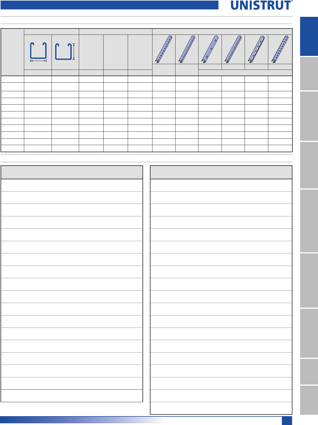
CHANNEL SELECTION CHART
CHANNELS & COMBINATIONS IN DESCENDING ORDER OF STRENGTH
Channel
Area
In2 (cm2)
Weight
lbs/ft (kg/m)
I
In4 (cm4)
s
In3(cm3)
Allow. Moment
In-lbs 1P
P5001 1.793 6.10 6.227 1.916 48,180
11.57 9.1 259.2 31.4 5,440
P1004A 1.965 6.68 4.068 1.669 41,980
12.68 9.9 169.3 27.4 4,740
P5501 1.452 4.94 2.805 1.151 28,940
9.37 7.3 116.8 18.9 3,270
P1001C41 2.221 7.55 1.856 1.142 28,720
14.33 11.2 77.2 18.7 3,250
P5000 0.897 3.05 1.098 0.627 15,770
5.78 4.5 45.7 10.3 1,780
P1001 1.111 3.78 0.928 0.571 14,360
7.16 5.6 38.6 9.4 1,620
P1101 0.835 2.84 0.733 0.451 11,340
5.39 4.2 30.5 7.4 1,280
P3001 1.000 3.40 0.591 0.430 10,810
6.45 5.1 24.6 7.0 1,220
P5500 0.726 2.47 0.522 0.390 9,820
4.68 3.7 21.7 6.4 1,110
P2001 0.684 2.32 0.618 0.381 9,570
4.41 3.5 25.7 6.2 1,080
P9200 0.489 2.23 0.279 0.297 7,480
3.16 3.3 11.6 4.9 850
A5000 0.492 1.67 0.358 0.265 6,670
3.17 2.5 14.9 4.3 750
P4401 0.849 5.77 0.26 0.26 6,410
5.48 8.5 10.6 4.2 725
A1001 0.609 2.07 0.302 0.242 6,070
3.93 3.1 12.6 4.0 690
P9000 0.387 1.88 0.166 0.205 5,150
2.50 2.8 6.9 3.4 580
P1000 0.555 1.89 0.185 0.202 5,070
3.58 2.8 7.7 3.3 570
P3301 0.790 2.69 0.176 0.201 5,060
5.10 4.0 7.3 3.3 570
P4521 0.77 2.62 0.15 0.18 4,538
4.97 3.9 6.1 2.9 513
Combinations not shown in catalog are available on special order.
Consult factory for more details.
Channel
Area
In2 (cm2)
Weight
lbs/ft (kg/m)
I
In4 (cm4)
s
In3(cm3)
Allow. Moment
In-lbs 1P
P1100 0.418 1.42 0.145 0.162 4,060
2.69 2.1 6.0 2.6 460
P3000 0.500 1.70 0.120 0.153 3,850
3.23 2.5 5.0 2.5 430
P4101 0.579 1.97 0.117 0.143 3,610
3.74 2.9 4.9 2.4 410
P2000 0.342 1.16 0.125 0.140 3,520
2.21 1.7 5.2 2.3 400
P4001 0.478 1.66 0.104 0.128 3,210
3.14 2.5 4.3 2.1 360
A3301 0.459 1.56 0.077 0.103 2,590
2.96 2.3 3.2 1.7 290
P4400 0.424 2.89 0.053 0.092 2,300
2.74 4.3 2.2 1.5 260
A1000 0.305 1.04 0.061 0.086 2,170
1.96 1.5 2.5 1.4 250
P3300 0.395 1.34 0.037 0.072 1,800
2.55 2.0 1.5 1.2 200
P4520 0.384 1.31 0.031 0.064 1,615
2.48 1.9 1.3 1.0 183
A4001 0.264 0.90 0.037 0.058 1,470
1.70 1.3 1.5 1.0 170
P6001 0.213 0.73 0.045 0.055 1,400
1.38 1.1 1.9 0.9 160
P4100 0.290 0.98 0.026 0.054 1,360
1.87 1.5 1.1 0.9 150
P4000 0.244 0.83 0.023 0.049 1,230
1.57 1.2 0.9 0.8 140
A3300 0.230 0.78 0.017 0.038 950
1.48 1.2 0.7 0.6 110
A4000 0.132 0.45 0.008 0.022 560
0.85 0.7 0.3 0.4 60
P6000 0.107 0.36 0.009 0.020 510
0.69 0.5 0.4 0.3 60
P7001 0.148 0.50 0.007 0.018 460
0.96 0.8 0.3 0.3 50
P7000 0.074 0.25 0.002 0.007 170
0.48 0.4 0.1 0.1 20
Channel
Channel Dimensions Material & Thickness Hole Pattern Styles
Width Height Steel
Stainless
Steel Alum. HS T KO SL DS H3
In (mm) In (mm) gauge gauge In (mm) Steel Only
P1000 15»8 (41.3) 15»8 (41.3) 12 ga 12 ga 0.109 (2.8) QQQQQ Q
P1100 15»8 (41.3) 15»8 (41.3) 14 ga 14 ga — QQQQ ––
P2000 15»8 (41.3) 15»8 (41.3) 16 ga — — QQQQ ––
P3000 15»8 (41.3) 13»8 (34.9) 12 ga — — QQQQ ––
P3300 15»8 (41.3) 7»8 (22.2) 12 ga 12 ga — QQ –Q––
P4000 15»8 (41.3) 13»16 (20.6) 16 ga 16 ga 0.078 (2.0) QQ –Q––
P4100 15»8 (41.3) 13»16 (20.6) 14 ga — — QQ –Q––
P4400 15»8 (41.3) 1(25.4) 12 ga — — QQ –Q––
P4520 15»8 (41.3) 13»16 (20.6) 12 ga — — QQ –Q––
P5000 15»8 (41.3) 31»4 (82.6) 12 ga 12 ga — QQQQ ––
P5500 15»8 (41.3) 27»16 (61.9) 12 ga — 0.109 (2.8) QQQQ ––
24
15⁄8" Framing System
1 5¼8" ChannelTelestrutNuts & HardwareGeneral FittingsPipe/Conduit SupportsElectrical FittingsConcrete InsertsSolarUnipier®
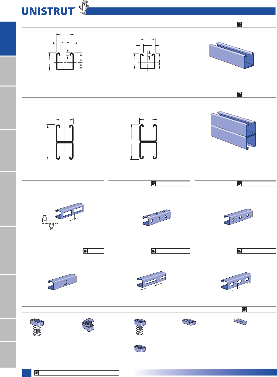
.915"
.710"
2
1
9⁄32"
1 5⁄8"
3⁄8"
3⁄8"
1 5⁄8"
7⁄8"41.3
18.0
23.2
7.1
1
22.2 9.5
9.5
2
41.3
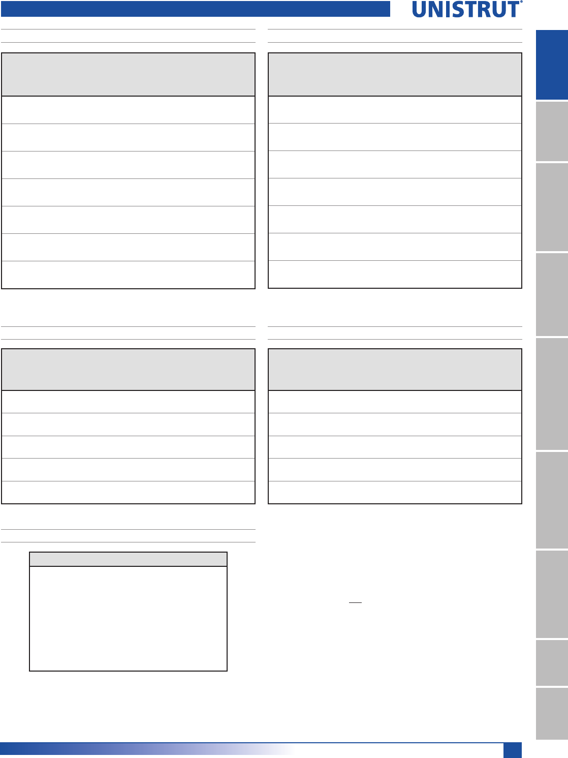
P1000®
Channel Finishes: PL, GR, HG, PG, ZD; Standard Lengths: 10' & 20'
Wt/100 Ft:189 Lbs (281 kg/100 m)
$OORZDEOH0RPHQW,Q/EV1P
12 Gauge Nominal Thickness .105" (2.7mm)
41.3
82.6
2
1
2
1 5⁄8"
3 1⁄4"1
P1001
P1000 TP1000 SLP1000 KO
P1000 DS P1000 HS P1000 H3
CHANNEL NUTS (REFER TO PAGES 73,74 FOR DETAILS)
Wt/100 Ft: 378 Lbs (562 kg/100 m)
$OORZDEOH0RPHQW,Q/EV1P
12 Gauge Nominal Thickness .105" (2.7mm)
P1012
P1023
P1024S
P1000® & P1001 Channels
P1006-0832
P1006-1024
P1006-1420
P1007
P1008
P1009
P1010
P1024
P1012S
P1023S
P1008T
P1006T1420
P1010T
P3016-0632
P3016-0832
P3016-1024
P3016-1420
P3006-0832
P3006-1024
P3006-1420
P3007
P3008
P3009
P3010
Wt/100 Ft: 173 Lbs (257 kg/100 m) Wt/100 Ft: 175 Lbs (260 kg/100 m) Wt/100 Ft:185 Lbs (275 kg/100 m)
Wt/100 Ft: 190 Lbs (283 kg/100 m) Wt/100 Ft: 185 Lbs (275 kg/100 m) Wt/100 Ft: 185 Lbs (275 kg/100 m)
U
N
I
S
T
R
U
T
U
N
I
S
T
R
U
T
7⁄8" (22.2) Knockouts
6" (152.4) on Center
9⁄16" (14.3) Dia. Holes
1 7⁄8" (47.6) on Center
1⁄2"
(12.7)
1"
(25.4)
Slots are
3" (76.2) x 13⁄32" (10.3)
4" (101.6) on Center
1 3⁄16"
(30.2)
Slots are
11⁄8" (28.6) x 9⁄16" (14.3)
2" (50.8) on Center
7⁄8"
(22.2)
9⁄16" (14.3) Dia. Holes
1 7⁄8" (47.6) on Center
Slots are 2 3⁄4" (69.9) x 7⁄8" (22.2)
3 1⁄2" (88.9) on Center
Pipe Clamps can be
Mounted on Both Sides
3⁄4"
(19.1)
GR HG PG PL
GR HG PG PL
CORE PRODUCTS - TYPICALLY AVAILABLE FROM STOCK
GR PG
GR HG PG PLGR HG PG PL
GR HG PG PLGR HG PG PL
SEE PAGE 73, 74
25
15⁄8" Framing System
1 5¼8" ChannelTelestrutNuts & HardwareGeneral FittingsPipe/Conduit SupportsElectrical FittingsConcrete InsertsSolarUnipier®
P1000/P1001 - ELEMENTS OF SECTION
Unbraced
Height
In
Max. Allowable
Load at
Slot Face
Lbs
Maximum Column Load Applied at C.G.
K = 0.65
Lbs
K = 0.80
Lbs
K =1.0
Lbs
K = 1.2
Lbs
24 3,550 10,740 9,890 8,770 7,740
36 3,190 8,910 7,740 6,390 5,310
48 2,770 7,260 6,010 4,690 3,800
60 2,380 5,910 4,690 3,630 2,960
72 2,080 4,840 3,800 2,960 2,400
84 1,860 4,040 3,200 2,480 1,980
96 1,670 3,480 2,750 2,110 1,660
108 1,510 3,050 2,400 1,810 **
120 1,380 2,700 2,110 ** **
144 1,150 2,180 1,660 ** **
Unbraced
Height
In
Max. Allowable
Load
at Slot Face
Lbs
Maximum Column Load Applied at C.G.
K = 0.65
Lbs
K = 0.80
Lbs
K =1.0
Lbs
K = 1.2
Lbs
24 6,430 24,280 23,610 22,700 21,820
36 6,290 22,810 21,820 20,650 19,670
48 6,160 21,410 20,300 18,670 16,160
60 6,000 20,210 18,670 15,520 12,390
72 5,620 18,970 16,160 12,390 8,950
84 5,170 16,950 13,630 9,470 6,580
96 4,690 14,890 11,190 7,250 5,040
108 4,170 12,850 8,950 5,730 3,980
120 3,690 10,900 7,250 4,640 **
144 2,930 7,630 5,040 ** **
Notes:
* Load limited by spot weld shear.
./»U !
NR = Not Recommended.
1. Beam loads are given in total uniform load (W Lbs) not uniform load (w lbs/ft or
w lbs/in).
2. Beam loads are based on a simple span and assumed to be adequately laterally
braced. Unbraced spans can reduce beam load carrying capacity. Refer to Page 62
for reduction factors for unbraced lengths.
3. For pierced channel, multiply beam loads by the following factor:
"KO" Series .......95% "T" Series ..........85%
"HS" Series .......90% "SL" Series ........85%
"H3" Series ........90% "DS" Series ........70%
4. Deduct channel weight from the beam loads.
5. For concentrated midspan point loads, multiply beam loads by 50% and the
corresponding deflection by 80%. For other load conditions refer to page 18.
6. All beam loads are for bending about Axis 1-1.
P1000 - BEAM LOADING
Span
In
Max. Allowable
Uniform Load
Lbs
Defl. at
Uniform
Load
In
Uniform Loading at Deflection
Span/180
Lbs
Span/240
Lbs
Span/360
Lbs
24 3,500* 0.02 3,500* 3,500* 3,500*
36 3,190 0.07 3,190 3,190 3,190
48 2,390 0.13 2,390 2,390 2,390
60 1,910 0.20 1,910 1,910 1,620
72 1,600 0.28 1,600 1,600 1,130
84 1,370 0.39 1,370 1,240 830
96 1,200 0.51 1,200 950 630
108 1,060 0.64 1,000 750 500
120 960 0.79 810 610 410
144 800 1.14 560 420 280
168 680 1.53 410 310 210
192 600 2.02 320 240 160
216 530 2.54 250 190 130
240 480 3.16 200 150 100
P1000 & P1001 Channels
P1000 - COLUMN LOADING P1001 - COLUMN LOADING
Span
In
Max. Allowable
Uniform Load
Lbs
Defl. at
Uniform
Load
In
Uniform Loading at Deflection
Span/180
Lbs
Span/240
Lbs
Span/360
Lbs
24 1,690 0.06 1,690 1,690 1,690
36 1,130 0.13 1,130 1,130 900
48 850 0.22 850 760 500
60 680 0.35 650 480 320
72 560 0.50 450 340 220
84 480 0.68 330 250 160
96 420 0.89 250 190 130
108 380 1.14 200 150 100
120 340 1.40 160 120 80
144 280 2.00 110 80 60
168 240 2.72 80 60 40
192 210 3.55 60 50 NR
216 190 4.58 50 40 NR
240 170 5.62 40 NR NR
Parameter P1000 P1001
Area of Section 0.555 In21.111 In2
Axis 1-1
Moment of Inertia (I) 0.185 In40.928 In4
Section Modulus (S) 0.202 In30.571 In3
Radius of Gyration (r) 0.577 In 0.914 In
Axis 2-2
Moment of Inertia (I) 0.236 In40.471 In4
Section Modulus (S) 0.290 In30.580 In3
Radius of Gyration (r) 0.651 In 0.651 In
P1001 - BEAM LOADING

26
15⁄8" Framing System
1 5¼8" ChannelTelestrutNuts & HardwareGeneral FittingsPipe/Conduit SupportsElectrical FittingsConcrete InsertsSolarUnipier®
Unbraced
Height
mm
Maximum
Allowable Load
at Slot Face
kN
Maximum Column Load Applied at C.G.
K = 0.65
kN
K = 0.80
kN
K =1.0
kN
K = 1.2
kN
600 15.8 48.0 44.3 39.4 34.8
750 15.2 44.0 39.4 33.8 28.9
1,000 13.7 37.5 32.0 26.1 21.3
1,250 12.1 31.6 26.1 20.3 16.5
1,500 10.7 26.7 21.3 16.5 13.4
1,750 9.6 22.7 17.8 13.8 11.3
2,000 8.7 19.3 15.3 11.9 9.6
2,250 7.9 16.9 13.4 10.4 8.2
2,500 7.2 15.0 11.9 9.1 **
2,750 6.7 13.5 10.6 8.1 **
Unbraced
Height
mm
Maximum
Allowable
Load
at Slot Face
kN
Maximum Column Load Applied at C.G.
K = 0.65
kN
K = 0.80
kN
K =1.0
kN
K = 1.2
kN
600 28.6 108.2 105.3 101.3 97.4
750 28.3 105.0 101.3 96.5 92.2
1,000 27.8 99.6 95.0 89.7 83.9
1,250 27.3 94.7 89.7 81.7 70.1
1,500 26.8 90.3 83.9 70.1 56.4
1,750 25.4 86.7 74.8 58.6 43.5
2,000 23.9 79.4 65.5 47.7 33.3
2,250 22.2 71.9 56.4 37.9 26.3
2,500 20.4 64.4 47.7 30.7 21.3
2,750 18.5 56.9 39.6 25.4 17.6
P1000® & P1001 Channels
Span
mm
Max
Allowable
Uniform Load
kN
Defl. at
Uniform
Load
mm
Uniform Loading at Deflection
Span/180
kN
Span/240
kN
Span/360
kN
600 7.6 1 7.6 7.6 7.6
750 6.1 2 6.1 6.1 5.9
1,000 4.6 4 4.6 4.6 3.3
1,250 3.6 6 3.6 3.2 2.1
1,500 3.1 9 3.0 2.2 1.5
1,750 2.6 12 2.2 1.6 1.1
2,000 2.3 15 1.6 1.2 0.8
2,500 1.8 24 1.1 0.8 0.5
3,000 1.5 34 0.8 0.5 0.4
3,500 1.3 46 0.5 0.4 0.3
4,000 1.2 62 0.4 0.3 0.2
4,500 1.0 78 0.3 0.3 0.2
5,000 0.9 97 0.3 0.2 NR
6,000 0.8 136 0.2 NR NR
Span
mm
Max
Allowable
Uniform Load
kN
Defl. at
Uniform
Load
mm
Uniform Loading at Deflection
Span/180
kN
Span/240
kN
Span/360
kN
600 15.6 * 1 15.6 * 15.6 * 15.6 *
750 15.6 * 1 15.6 * 15.6 * 15.6 *
1,000 13.0 2 13.0 13.0 13.0
1,250 10.4 3 10.4 10.4 10.4
1,500 8.7 5 8.7 8.7 7.4
1,750 7.4 7 7.4 7.4 5.5
2,000 6.5 9 6.5 6.3 4.2
2,500 5.2 13 5.2 4.0 2.7
3,000 4.3 19 3.7 2.8 1.9
3,500 3.7 26 2.8 2.0 1.4
4,000 3.2 34 2.1 1.6 1.1
4,500 2.9 44 1.6 1.2 0.8
5,000 2.6 53 1.3 1.0 0.7
6,000 2.2 78 0.9 0.7 0.4
Parameter P1000 P1001
Area of Section 3.58 cm27.16 cm2
Axis 1-1
Moment of Inertia (I) 7.68 cm438.62 cm4
Section Modulus (S) 3.30 cm39.36 cm3
Radius of Gyration (r) 1.46 cm 2.32 cm
Axis 2-2
Moment of Inertia (I) 9.80 cm419.60 cm4
Section Modulus (S) 4.75 cm39.50 cm3
Radius of Gyration (r) 1.65 cm 1.65 cm
P1000/P1001 - ELEMENTS OF SECTION (METRIC)
P1000 - BEAM LOADING (METRIC)
P1000 - COLUMN LOADING (METRIC)P1001 - COLUMN LOADING (METRIC)
P1001 - BEAM LOADING (METRIC)
Notes:
* Load limited by spot weld shear.
./»U !
NR = Not Recommended.
1. Beam loads are given in total uniform load (W Lbs) not uniform load (w lbs/ft or
w lbs/in).
2. Beam loads are based on a simple span and assumed to be adequately laterally
braced. Unbraced spans can reduce beam load carrying capacity. Refer to Page 62
for reduction factors for unbraced lengths.
3. For pierced channel, multiply beam loads by the following factor:
"KO" Series .......95% "T" Series ..........85%
"HS" Series .......90% "SL" Series ........85%
"H3" Series ........90% "DS" Series ........70%
4. Deduct channel weight from the beam loads.
5. For concentrated midspan point loads, multiply beam loads by 50% and the
corresponding deflection by 80%. For other load conditions refer to page 18.
6. All beam loads are for bending about Axis 1-1.
27
15⁄8" Framing System
1 5¼8" ChannelTelestrutNuts & HardwareGeneral FittingsPipe/Conduit SupportsElectrical FittingsConcrete InsertsSolarUnipier®
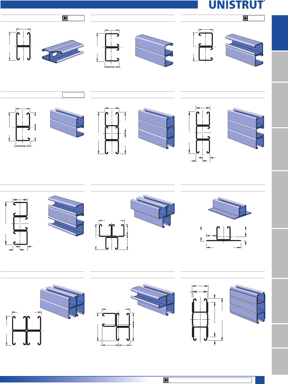
P1001 3
Wt/100 Ft: 566 Lbs (843 kg/100 m)
$OORZDEOH0RPHQW,Q/EV1P
12 Gauge Nominal Thickness .105" (2.7mm)
P1001 A P1001 B
P1001 C
Wt/100 Ft: 378 Lbs (562 kg/100 m)
$OORZDEOH0RPHQW,Q/EV1P
12 Gauge Nominal Thickness .105" (2.7mm)
Wt/100 Ft: 378 Lbs (562 kg/100 m)
$OORZDEOH0RPHQW,Q/EV1P
12 Gauge Nominal Thickness .105" (2.7mm)
Wt/100 Ft: 378 Lbs (562 kg/100 m)
$OORZDEOH0RPHQW,Q/EV1P
12 Gauge Nominal Thickness .105" (2.7mm)
2
1 5⁄8"
3 1⁄4"1
.916"
.709"
(41.3)
(82.6)
(23.3)
(18.0)
2
1 5⁄8"
3 1⁄4"1
(41.3)
(82.6)
.761" .864"
(21.9)
(19.3)
1
2
1.573"
(40.0)
1.677"
(42.6)
1 5⁄8" (41.3)
31⁄4"
(82.6)
Channel Finishes: PL, GR, HG, PG, ZD; Standard Lengths: 10' & 20'
P1000 Channel Combinations
P1001 A3
P1001 B3
Wt/100 Ft: 566 Lbs (843 kg/100 m)
$OORZDEOH0RPHQW,Q/EV1P
12 Gauge Nominal Thickness .105" (2.7mm)
Wt/100 Ft: 566 Lbs (843 kg/100 m)
$OORZDEOH0RPHQW,Q/EV1P
12 Gauge Nominal Thickness .105" (2.7mm)
P1001 C3
P1001 D3
Wt/100 Ft: 566 Lbs (843 kg/100 m)
$OORZDEOH0RPHQW,Q/EV1P
12 Gauge Nominal Thickness .105" (2.7mm)
Wt/100 Ft: 566 Lbs (843 kg/100 m)
$OORZDEOH0RPHQW,Q/EV1P
12 Gauge Nominal Thickness .105" (2.7mm)
2
1 5⁄8" (41.3)
4 7⁄8"
(123.8)
1
.847"
(21.5)
.778"
(19.8)
2
1
1 5⁄8" (41.3)
4 7⁄8"
(123.8)
.847"
(21.5)
.778"
(19.8)
2
1
1.320"
(33.5)
1.354"
(34.4)
1.896"
(48.2)
1.930"
(49.0)
3 1⁄4" (82.6)
3 1⁄4"
(82.6)
2
1
3 1⁄4"
(82.6)
1.388"
(35.3)
1.862"
(47.3)
3 1⁄4"(82.6)
P1003
P1004 A
Wt/100 Ft: 333 Lbs (495 kg/100 m)
$OORZDEOH0RPHQW,Q/EV1P
12 Gauge Nominal Thickness .105" (2.7mm)
Wt/100 Ft: 668 Lbs (994 kg/100 m)
$OORZDEOH0RPHQW,Q/EV1P
12 Gauge Nominal Thickness .105" (2.7mm)
P1001 C41
Wt/100 Ft: 755 Lbs (1,124 kg/100 m)
$OORZDEOH0RPHQW,Q/EV1P
12 Gauge Nominal Thickness .105" (2.7mm)
1
.48
9
(12.
4
113⁄64"
(30.6)
147⁄64"
(44.1)
41⁄32"(102.4)
1.245"
(31.6)
1
2
3 1⁄4" (82.6)
3 1⁄4"
(82.6)
127⁄32" (46.8)
2
1
4"
(101.6)
7⁄16" (11.1)
7⁄16" (11.1)
1 5⁄8"
(41.3)
4 7⁄8"
(123.8)
P1001 T
1 5⁄8"
3 1⁄4"
(41.3)
(82.6)
Wt/100 Ft: 321 Lbs (478 kg/100 m)
$OORZDEOH0RPHQW,Q/EV1P
12 Gauge Nominal Thickness .105" (2.7mm)
1
2
2.403"
(61.0)
2.472"
(62.8)
1 5⁄8" (41.3)
4 7⁄8"
(123.8)
GR PG
CORE PRODUCTS - TYPICALLY AVAILABLE FROM STOCK
GR PG
GR PG

28
15⁄8" Framing System
1 5¼8" ChannelTelestrutNuts & HardwareGeneral FittingsPipe/Conduit SupportsElectrical FittingsConcrete InsertsSolarUnipier®
P1001 C41 - COLUMN LOADING
P1001 C41/ P1004 A - ELEMENTS OF SECTION
Unbraced
Height
In
Maximum
Allowable
Load
at Slot Face
Lbs
Maximum Column Load Applied at C.G.
K = 0.65
Lbs
K = 0.80
Lbs
K =1.0
Lbs
K = 1.2
Lbs
24 12,690 46,920 44,980 42,360 39,890
36 12,250 42,680 39,890 36,660 34,050
48 11,820 38,740 35,720 32,640 30,430
60 11,470 35,500 32,640 29,980 28,220
72 11,180 32,970 30,430 28,220 26,820
84 10,900 31,040 28,840 27,010 24,870
96 10,580 29,570 27,680 26,170 19,840
108 10,310 28,440 26,820 22,310 15,670
120 10,070 27,560 26,170 18,280 12,700
144 8,740 26,320 19,840 12,700 8,820
168 7,360 21,890 14,570 9,330 **
P1004 A - COLUMN LOADING
Unbraced
Height
In
Maximum
Allowable
Load
at Slot Face
Lbs
Maximum Column Load Applied at C.G.
K = 0.65
Lbs
K = 0.80
Lbs
K =1.0
Lbs
K = 1.2
Lbs
24 11,420 36,800 33,890 30,440 27,600
36 10,600 30,840 27,600 24,400 22,160
48 9,860 26,400 23,560 21,060 19,470
60 9,160 23,370 21,060 19,160 18,020
72 8,610 21,310 19,470 18,020 17,140
84 8,170 19,890 18,410 17,260 15,240
96 7,790 18,890 17,670 16,760 11,670
108 7,460 18,160 17,140 13,280 9,220
120 7,150 17,590 16,760 10,750 7,470
144 5,660 16,840 11,670 7,470 **
168 4,520 12,990 8,570 ** **
P1001 C41 - BEAM LOADING P1004 A - BEAM LOADING
Span
In
Max
Allowable
Uniform Load
Lbs
Defl. at
Uniform
Load
In
Uniform Loading at Deflection
Span/180
Lbs
Span/240
Lbs
Span/360
Lbs
24 7,040* 0.02 7,040* 7,040* 7,040*
36 6,380 0.07 6,380 6,380 6,380
48 4,790 0.13 4,790 4,790 4,790
60 3,830 0.20 3,830 3,830 3,240
72 3,190 0.28 3,190 3,190 2,250
84 2,740 0.39 2,740 2,480 1,660
96 2,390 0.50 2,390 1,900 1,270
108 2,130 0.64 2,000 1,500 1,000
120 1,910 0.78 1,620 1,220 810
144 1,600 1.14 1,130 840 560
168 1,370 1.55 830 620 410
192 1,200 2.02 630 480 320
216 1,060 2.54 500 380 250
240 960 3.16 410 300 200
Span
In
Max
Allowable
Uniform Load
Lbs
Defl. at
Uniform
Load
In
Uniform Loading at Deflection
Span/180
Lbs
Span/240
Lbs
Span/360
Lbs
24 9,100* 0.01 9,100* 9,100* 9,100*
36 9,100* 0.05 9,100* 9,100* 9,100*
48 7,000 0.08 7,000 7,000 7,000
60 5,600 0.13 5,600 5,600 5,600
72 4,660 0.19 4,660 4,660 4,660
84 4,000 0.26 4,000 4,000 3,630
96 3,500 0.34 3,500 3,500 2,780
108 3,110 0.43 3,110 3,110 2,200
120 2,800 0.52 2,800 2,670 1,780
144 2,330 0.75 2,330 1,850 1,230
168 2,000 1.03 1,810 1,360 910
192 1,750 1.34 1,390 1,040 690
216 1,550 1.69 1,100 820 550
240 1,400 2.10 890 670 440
P1000 Channel Combinations
Parameter P1001 C41 P1004 A
Area of Section 2.221 In21.965 In2
Axis 1-1
Moment of Inertia (I) 1.856 In44.068 In4
Section Modulus (S) 1.142 In31.669 In3
Radius of Gyration (r) 0.914 In 1.439 In
Axis 2-2
Moment of Inertia (I) 2.408 In41.092 In4
Section Modulus (S) 1.482 In31.190 In3
Radius of Gyration (r) 1.041 In 0.745 In
Notes:
* Load limited by spot weld shear.
./»U !
NR = Not Recommended.
1. Beam loads are given in total uniform load (W Lbs) not uniform load (w lbs/ft or
w lbs/in).
2. Beam loads are based on a simple span and assumed to be adequately laterally
braced. Unbraced spans can reduce beam load carrying capacity. Refer to Page 62
for reduction factors for unbraced lengths.
3. For pierced channel, multiply beam loads by the following factor:
"KO" Series .......95% "T" Series ..........85%
"HS" Series .......90% "SL" Series ........85%
4. Deduct channel weight from the beam loads.
5. For concentrated midspan point loads, multiply beam loads by 50% and the
corresponding deflection by 80%. For other load conditions refer to page 18.
6. All beam loads are for bending about Axis 1-1.
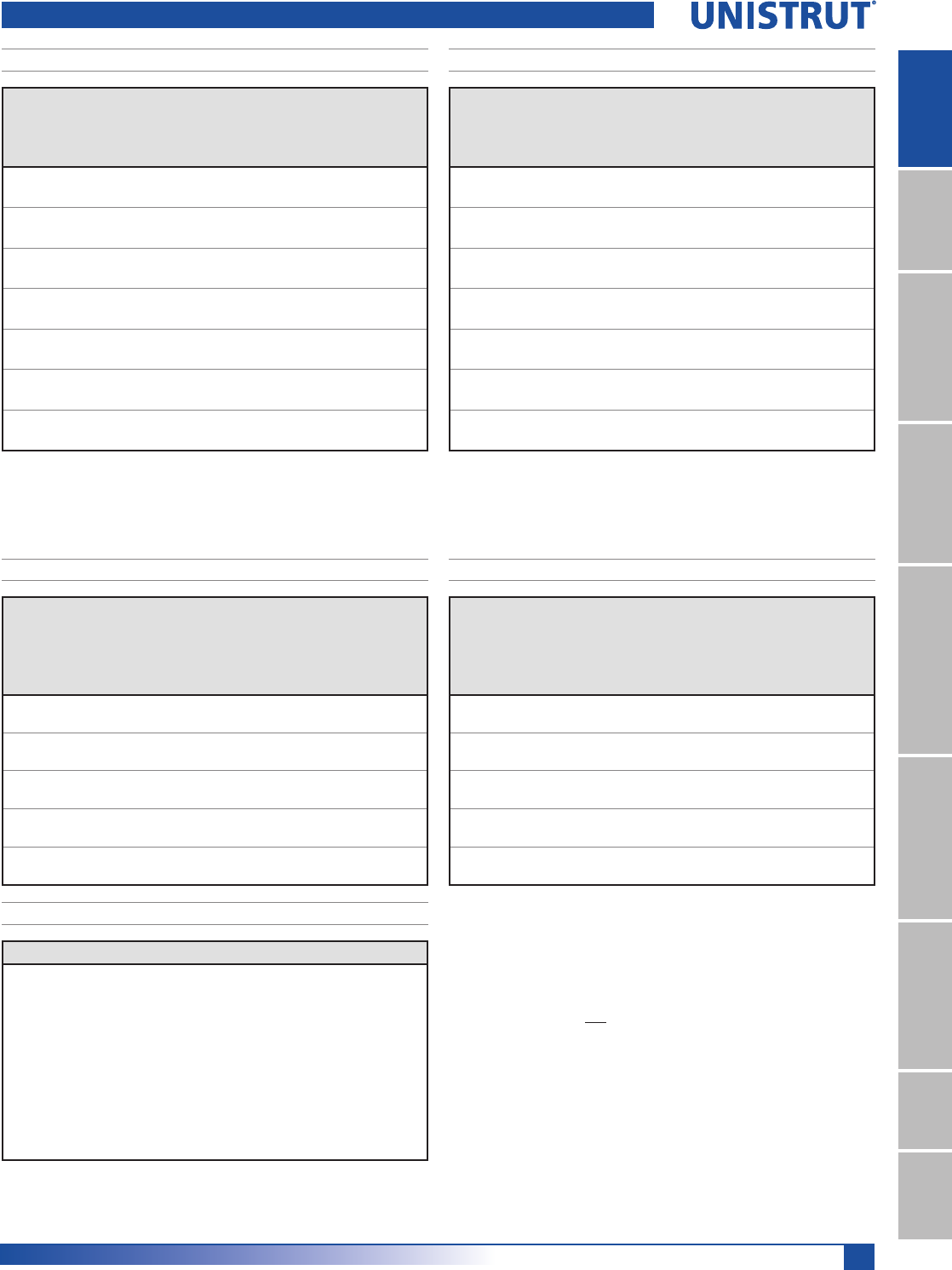
29
15⁄8" Framing System
1 5¼8" ChannelTelestrutNuts & HardwareGeneral FittingsPipe/Conduit SupportsElectrical FittingsConcrete InsertsSolarUnipier®
Unbraced
Height
mm
Maximum
Allowable
Load
at Slot Face
kN
Maximum Column Load Applied at C.G.
K = 0.65
kN
K = 0.80
kN
K =1.0
kN
K = 1.2
kN
600 56.5 209.3 200.8 189.3 178.4
750 55.6 200.1 189.3 175.8 164.1
1,000 53.9 184.7 171.7 157.3 146.1
1,250 52.4 170.7 157.3 143.8 134.1
1,500 51.1 158.9 146.1 134.1 126.1
1,750 50.0 149.3 137.6 127.3 120.7
2,000 49.2 141.5 131.1 122.3 116.8
2,250 47.9 135.4 126.1 118.6 101.9
2,500 46.8 130.4 122.3 114.5 83.9
2,750 45.9 126.4 119.2 98.8 69.4
Unbraced
Height
mm
Maximum
Allowable
Load
at Slot Face
kN
Maximum Column Load Applied at C.G.
K = 0.65
kN
K = 0.80
kN
K =1.0
kN
K = 1.2
kN
600 50.9 164.6 151.8 136.5 123.8
750 49.1 150.8 136.5 121.1 109.5
1,000 46.3 130.9 116.9 103.4 94.3
1,250 43.5 115.8 103.4 92.6 85.8
1,500 40.9 104.8 94.3 85.8 80.6
1,750 38.9 96.8 88.1 81.3 77.0
2,000 37.1 91.0 83.7 78.1 74.8
2,250 35.7 86.6 80.6 75.8 60.9
2,500 34.3 83.3 78.1 71.1 49.4
2,750 33.1 80.7 76.2 58.8 40.8
P1000 Channel Combinations
Span
mm
Max
Allowable
Uniform Load
kN
Defl. at
Uniform
Load
mm
Uniform Loading at Deflection
Span/180
kN
Span/240
kN
Span/360
kN
600 31.3 * 1 31.3 * 31.3 * 31.3 *
750 31.3 * 1 31.3 * 31.3 * 31.3 *
1,000 26.0 2 26.0 26.0 26.0
1,250 20.8 3 20.8 20.8 20.8
1,500 17.3 5 17.3 17.3 14.9
1,750 14.8 7 14.8 14.8 10.9
2,000 13.0 9 13.0 12.6 8.4
2,500 10.4 13 10.4 8.1 5.4
3,000 8.7 19 7.4 5.6 3.7
3,500 7.4 26 5.5 4.1 2.8
4,000 6.5 34 4.2 3.2 2.1
4,500 5.8 44 3.3 2.5 1.6
5,000 5.2 54 2.7 2.0 1.3
6,000 4.3 77 1.9 1.4 0.9
Span
mm
Max
Allowable
Uniform Load
kN
Defl. at
Uniform
Load
mm
Uniform Loading at Deflection
Span/180
kN
Span/240
kgN
Span/360
kN
600 40.5 * 1 40.5 * 40.5 * 40.5 *
750 40.5 * 1 40.5 * 40.5 * 40.5 *
1,000 37.9 2 37.9 37.9 37.9
1,250 30.3 3 30.3 30.3 30.3
1,500 25.3 4 25.3 25.3 25.3
1,750 21.7 6 21.7 21.7 21.7
2,000 18.9 9 18.9 18.9 18.4
2,500 15.2 13 15.2 15.2 11.7
3,000 12.6 18 12.6 12.2 8.2
3,500 10.9 23 10.9 9.0 6.0
4,000 9.5 29 9.2 6.9 4.6
4,500 8.5 36 7.2 5.4 3.6
5,000 7.6 52 5.9 4.4 2.9
6,000 6.3 77 4.1 3.1 2.0
P1001 C41 - COLUMN LOADING (METRIC)
P1001 C41/ P1004 A - ELEMENTS OF SECTION (METRIC)
P1004 A - COLUMN LOADING (METRIC)
P1001 C41 - BEAM LOADING (METRIC) P1004 A - BEAM LOADING (METRIC)
Parameter P1001 C41 P1004 A
Area of Section 14.33 cm212.68 cm2
Axis 1-1
Moment of Inertia (I) 77.24 cm4169.33 cm4
Section Modulus (S) 18.71 cm327.35 cm3
Radius of Gyration (r) 2.32 cm 3.66 cm
Axis 2-2
Moment of Inertia (I) 100.24 cm445.44 cm4
Section Modulus (S) 24.29 cm319.50 cm3
Radius of Gyration (r) 2.64 cm 1.89 cm
Notes:
* Load limited by spot weld shear.
./»U !
NR = Not Recommended.
1. Beam loads are given in total uniform load (W Lbs) not uniform load (w lbs/ft or
w lbs/in).
2. Beam loads are based on a simple span and assumed to be adequately laterally
braced. Unbraced spans can reduce beam load carrying capacity. Refer to Page 62
for reduction factors for unbraced lengths.
3. For pierced channel, multiply beam loads by the following factor:
"KO" Series .......95% "T" Series ..........85%
"HS" Series .......90% "SL" Series ........85%
4. Deduct channel weight from the beam loads.
5. For concentrated midspan point loads, multiply beam loads by 50% and the
corresponding deflection by 80%. For other load conditions refer to page 18.
6. All beam loads are for bending about Axis 1-1.
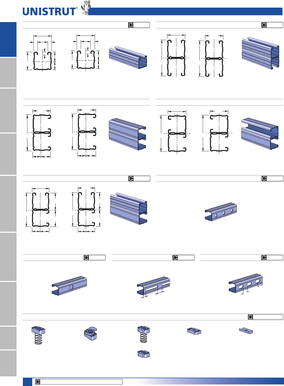
30
15⁄8" Framing System
1 5¼8" ChannelTelestrutNuts & HardwareGeneral FittingsPipe/Conduit SupportsElectrical FittingsConcrete InsertsSolarUnipier®
P1101 A P1101 B
P1101 C
Wt/100 Ft: 284 Lbs (423 kg/100 m)
$OORZDEOH0RPHQW,Q/EV1P
14 Gauge Nominal Thickness .075" (1.9mm)
Wt/100 Ft: 284 Lbs (423 kg/100 m)
$OORZDEOH0RPHQW,Q/EV1P
14 Gauge Nominal Thickness .075" (1.9mm)
Wt/100 Ft: 284 Lbs (423 kg/100 m)
$OORZDEOH0RPHQW,Q/EV1P
14 Gauge Nominal Thickness .075" (1.9mm)
1 5⁄8"
3 1⁄4"
1
.729" .896"
2
41.3
82.6
22.818.5
2
1
41.3
82.6 1
2
1
2
41.3
82.6
40.2
42.3
19.6 21.7
1 5⁄8"
3 1⁄4"1
2
1 5⁄8"
3 1⁄4"
1
2
1.666"
1.584"
.854"
.771"
P1100 P1101
1
7.1
22.9
41.3
22.2 9.5
9.5
18.4
2
41.3
Wt/100 Ft: 142 Lbs (211 kg/100 m)
$OORZDEOH0RPHQW,Q/EV1P
14 Gauge Nominal Thickness .075" (1.9mm)
1 5⁄8"
3 1⁄4"
1
2
41.3
82.6
1
2
Wt/100 Ft: 284 Lbs (423 kg/100 m)
$OORZDEOH0RPHQW,Q/EV1P
14 Gauge Nominal Thickness .075" (1.9mm)
1
2
9⁄32"
1 5⁄8"
7⁄8"3⁄8"
3⁄8"
.900"
.725"
1 5⁄8"
P1100 TP1100 SLP1100 KO
P1100 HS
Channel Finishes: PL, GR, HG, PG, ZD; Standard Lengths: 10' & 20'
P1012
P1023
P1024S
P1006-0832
P1006-1024
P1006-1420
P1007
P1008
P1009
P1010
P1024
P1012S
P1023S
P1008T
P1006T1420
P1010T
P3016-0632
P3016-0832
P3016-1024
P3016-1420
P3006-0832
P3006-1024
P3006-1420
P3007
P3008
P3009
P3010
P1100 & P1101 Channels
7⁄8" (22.2) Knockouts
6" (152.4) on Center
1⁄2"
(12.7)
1"
(25.4)
Slots are
3" (76.2) x 13⁄32" (10.3)
4" (101.6) on Center
1 3⁄16"
(30.2)
Slots are
11⁄8" (28.6) x 9⁄16" (14.3)
2" (50.8) on Center
7⁄8"
(22.2)
9⁄16" (14.3) Dia. Holes
1 7⁄8" (47.6) on Center
Wt/100 Ft: 136 Lbs (202 kg/100 m)
Wt/100 Ft: 140 Lbs (208 kg/100 m) Wt/100 Ft: 136 Lbs (202 kg/100 m) Wt/100 Ft: 136 Lbs (202 kg/100 m)
U
N
I
S
T
R
U
T
U
N
I
S
T
R
U
T
CORE PRODUCTS - TYPICALLY AVAILABLE FROM STOCK
CHANNEL NUTS (REFER TO PAGES 73,74 FOR DETAILS) SEE PAGE 73, 74
GR PG GR PG
GR PGGR PG
GR PG GR PG GR PG
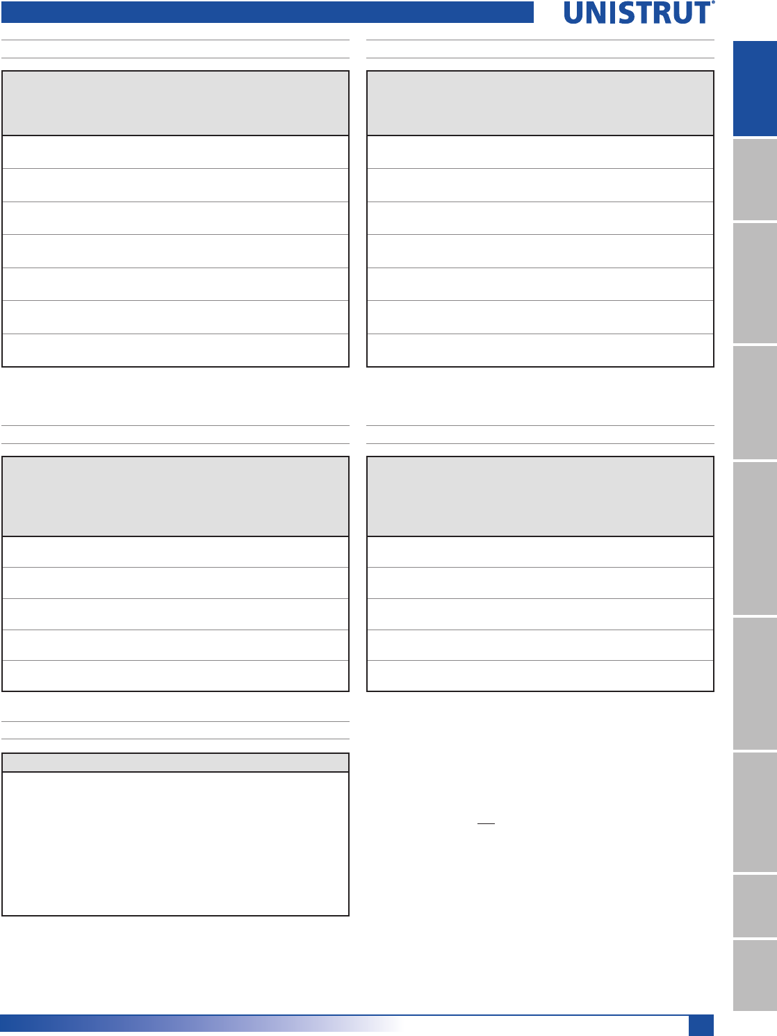
31
15⁄8" Framing System
1 5¼8" ChannelTelestrutNuts & HardwareGeneral FittingsPipe/Conduit SupportsElectrical FittingsConcrete InsertsSolarUnipier®
P1100 - COLUMN LOADING
P1100/P1101 - ELEMENTS OF SECTION
Unbraced
Height
In
Maximum
Allowable
Load
at Slot Face
Lbs
Maximum Column Load Applied at C.G.
K = 0.65
Lbs
K = 0.80
Lbs
K =1.0
Lbs
K = 1.2
Lbs
24 2,800 8,040 7,330 6,360 5,430
36 2,410 6,480 5,430 4,190 3,210
48 1,940 4,990 3,830 2,760 2,160
60 1,550 3,740 2,760 2,050 1,640
72 1,290 2,860 2,160 1,640 1,320
84 1,100 2,310 1,780 1,370 1,110
96 950 1,950 1,520 1,180 950
108 840 1,690 1,320 1,030 **
120 760 1,490 1,180 ** **
144 630 1,210 950 ** **
P1101 - COLUMN LOADING
Unbraced
Height
In
Maximum
Allowable
Load
at Slot Face
Lbs
Maximum Column Load Applied at C.G.
K = 0.65
Lbs
K = 0.80
Lbs
K =1.0
Lbs
K = 1.2
Lbs
24 5,010 18,250 17,700 16,880 16,030
36 4,860 16,990 16,030 14,770 13,620
48 4,700 15,610 14,380 12,930 11,750
60 4,480 14,280 12,930 11,490 9,290
72 4,210 13,100 11,750 9,290 6,700
84 3,880 12,090 10,220 7,090 4,930
96 3,480 11,170 8,390 5,430 3,770
108 3,060 9,640 6,700 4,290 2,980
120 2,680 8,170 5,430 3,480 **
144 2,090 5,710 3,770 ** **
P1100 - BEAM LOADING P1101 - BEAM LOADING
Span
In
Max
Allowable
Uniform Load
Lbs
Defl. at
Uniform
Load
In
Uniform Loading at Deflection
Span/180
Lbs
Span/240
Lbs
Span/360
Lbs
24 1,350 0.06 1,350 1,350 1,350
36 900 0.13 900 900 700
48 680 0.23 680 590 400
60 540 0.36 510 380 250
72 450 0.51 350 260 180
84 390 0.70 260 190 130
96 340 0.92 200 150 100
108 300 1.15 160 120 80
120 270 1.42 130 90 60
144 230 2.09 90 70 40
168 190 2.75 60 50 30
192 170 3.67 50 40 NR
216 150 4.61 40 30 NR
240 140 5.90 30 NR NR
Span
In
Max
Allowable
Uniform Load
Lbs
Defl. at
Uniform
Load
In
Uniform Loading at Deflection
Span/180
Lbs
Span/240
Lbs
Span/360
Lbs
24 2,180* 0.02 2,180* 2,180* 2,180*
36 2,180* 0.06 2,180* 2,180* 2,180*
48 1,890 0.13 1,890 1,890 1,890
60 1,510 0.20 1,510 1,510 1,280
72 1,260 0.28 1,260 1,260 890
84 1,080 0.39 1,080 980 650
96 950 0.51 950 750 500
108 840 0.64 790 590 400
120 760 0.79 640 480 320
144 630 1.13 440 330 220
168 540 1.54 330 250 160
192 470 2.00 250 190 130
216 420 2.55 200 150 100
240 380 3.16 160 120 80
P1100 & P1101 Channels
Parameter P1100 P1101
Area of Section 0.418 In20.835 In2
Axis 1-1
Moment of Inertia (I) 0.145 In40.733 In4
Section Modulus (S) 0.162 In30.451 In3
Radius of Gyration (r) 0.589 In 0.937 In
Axis 2-2
Moment of Inertia (I) 0.176 In40.353 In4
Section Modulus (S) 0.217 In30.434 In3
Radius of Gyration (r) 0.650 In 0.650 In
Notes:
* Load limited by spot weld shear.
./»U !
NR = Not Recommended.
1. Beam loads are given in total uniform load (W Lbs) not uniform load (w lbs/ft or
w lbs/in).
2. Beam loads are based on a simple span and assumed to be adequately laterally
braced. Unbraced spans can reduce beam load carrying capacity. Refer to Page 62
for reduction factors for unbraced lengths.
3. For pierced channel, multiply beam loads by the following factor:
"KO" Series .......95% "T" Series ..........85%
"HS" Series .......90% "SL" Series ........85%
4. Deduct channel weight from the beam loads.
5. For concentrated midspan point loads, multiply beam loads by 50% and the
corresponding deflection by 80%. For other load conditions refer to page 18.
6. All beam loads are for bending about Axis 1-1.

32
15⁄8" Framing System
1 5¼8" ChannelTelestrutNuts & HardwareGeneral FittingsPipe/Conduit SupportsElectrical FittingsConcrete InsertsSolarUnipier®
P1100/P1101 - ELEMENTS OF SECTION (METRIC)
P1100 & P1101 Channels
Unbraced
Height
mm
Maximum
Allowable
Load
at Slot Face
kN
Maximum Column Load Applied at C.G.
K = 0.65
kN
K = 0.80
kN
K =1.0
kN
K = 1.2
kN
600 12.5 35.9 32.9 28.6 24.5
750 11.8 32.6 28.6 23.5 19.0
1,000 10.1 26.9 22.0 16.4 12.5
1,250 8.5 21.6 16.4 11.8 9.3
1,500 7.0 17.0 12.5 9.3 7.4
1,750 6.0 13.5 10.1 7.7 6.2
2,000 5.2 11.2 8.6 6.5 5.3
2,250 4.6 9.6 7.4 5.7 4.7
2,500 4.1 8.4 6.5 5.1 **
2,750 3.7 7.5 5.9 4.5 **
Unbraced
Height
mm
Maximum
Allowable
Load
at Slot Face
kN
Maximum Column Load Applied at C.G.
K = 0.65
kN
K = 0.80
kN
K =1.0
kN
K = 1.2
kN
600 22.3 81.4 79.0 75.4 71.7
750 22.0 78.7 75.4 70.7 66.1
1,000 21.4 73.8 69.2 63.3 58.0
1,250 20.8 68.8 63.3 56.8 51.6
1,500 20.0 64.0 58.0 51.6 42.3
1,750 19.0 59.5 53.5 44.0 32.6
2,000 18.0 55.6 49.2 35.7 25.0
2,250 16.6 52.3 42.3 28.4 19.7
2,500 15.1 48.3 35.7 23.0 16.0
2,750 13.6 42.7 29.7 19.0 13.2
Span
mm
Max
Allowable
Uniform Load
kN
Defl. at
Uniform
Load
mm
Uniform Loading at Deflection
Span/180
kN
Span/240
kN
Span/360
kN
600 6.1 1 6.1 6.1 6.1
750 4.9 2 4.9 4.9 4.7
1,000 3.7 4 3.7 3.7 2.6
1,250 2.9 6 2.9 2.5 1.7
1,500 2.4 9 2.3 1.7 1.2
1,750 2.1 12 1.7 1.3 0.8
2,000 1.8 15 1.3 1.0 0.7
2,500 1.5 24 0.8 0.6 0.4
3,000 1.2 36 0.6 0.4 0.3
3,500 1.1 49 0.4 0.3 0.2
4,000 0.9 64 0.3 0.3 0.2
4,500 0.8 77 0.3 0.2 0.1
5,000 0.8 100 0.2 0.2 NR
6,000 0.6 143 0.1 NR NR
Span
mm
Max
Allowable
Uniform Load
kN
Defl. at
Uniform
Load
mm
Uniform Loading at Deflection
Span/180
kN
Span/240
kN
Span/360
kN
600 9.7 * 0 9.7 * 9.7 * 9.7 *
750 9.7 * 1 9.7 * 9.7 * 9.7 *
1,000 9.7 * 2 9.7 * 9.7 * 9.7 *
1,250 8.2 3 8.2 8.2 8.2
1,500 6.9 5 6.9 6.9 5.9
1,750 5.9 7 5.9 5.9 4.3
2,000 5.1 9 5.1 5.0 3.3
2,500 4.1 13 4.1 3.2 2.1
3,000 3.4 19 2.9 2.2 1.5
3,500 2.9 26 2.2 1.6 1.1
4,000 2.6 35 1.6 1.2 0.8
4,500 2.3 43 1.3 1.0 0.7
5,000 2.0 54 1.1 0.8 0.5
6,000 1.7 77 0.8 0.5 0.4
P1100 - COLUMN LOADING (METRIC) P1101 - COLUMN LOADING (METRIC)
P1100 - BEAM LOADING (METRIC) P1101 - BEAM LOADING (METRIC)
Parameter P1100 P1101
Area of Section 2.69 cm25.39 cm2
Axis 1-1
Moment of Inertia (I) 6.03 cm430.51 cm4
Section Modulus (S) 2.65 cm37.39 cm3
Radius of Gyration (r) 1.50 cm 2.38 cm
Axis 2-2
Moment of Inertia (I) 7.34 cm414.69 cm4
Section Modulus (S) 3.56 cm37.12 cm3
Radius of Gyration (r) 1.65 cm 1.65 cm
Notes:
* Load limited by spot weld shear.
./»U !
NR = Not Recommended.
1. Beam loads are given in total uniform load (W Lbs) not uniform load (w lbs/ft or
w lbs/in).
2. Beam loads are based on a simple span and assumed to be adequately laterally
braced. Unbraced spans can reduce beam load carrying capacity. Refer to Page 62
for reduction factors for unbraced lengths.
3. For pierced channel, multiply beam loads by the following factor:
"KO" Series .......95% "T" Series ..........85%
"HS" Series .......90% "SL" Series ........85%
4. Deduct channel weight from the beam loads.
5. For concentrated midspan point loads, multiply beam loads by 50% and the
corresponding deflection by 80%. For other load conditions refer to page 18.
6. All beam loads are for bending about Axis 1-1.
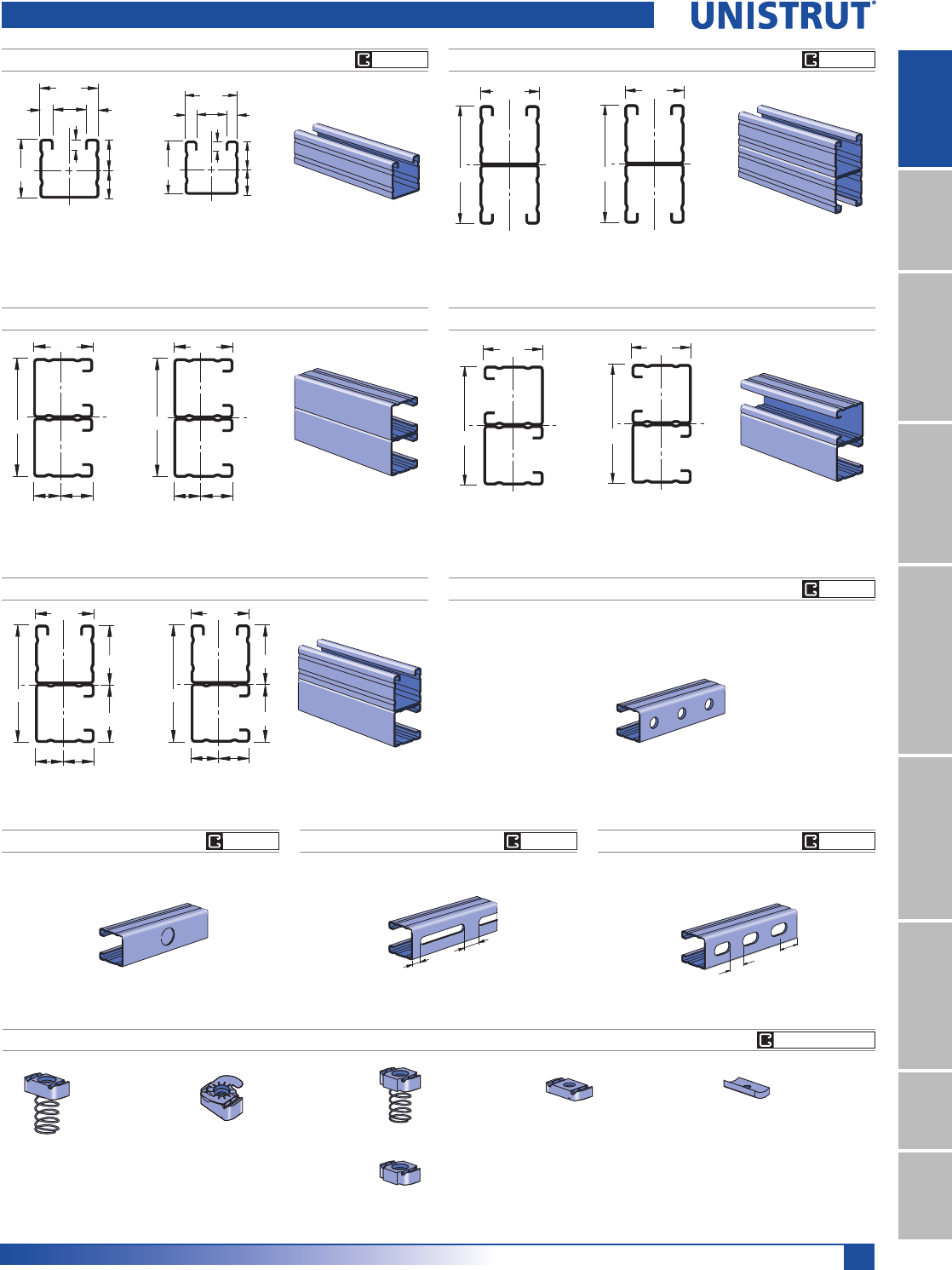
33
15⁄8" Framing System
1 5¼8" ChannelTelestrutNuts & HardwareGeneral FittingsPipe/Conduit SupportsElectrical FittingsConcrete InsertsSolarUnipier®
P2001 A P2001 B
P2001 C
41.3
82.6 1
22.618.7
2
41.3
82.6
2
21.619.7
1
40.3
42.3
Wt/100 Ft: 232 Lbs (346 kg/100 m)
$OORZDEOH0RPHQW,Q/EV1P
16 Gauge Nominal Thickness .060" (1.5mm)
Wt/100 Ft: 232 Lbs (346 kg/100 m)
$OORZDEOH0RPHQW,Q/EV1P
16 Gauge Nominal Thickness .060" (1.5mm)
Wt/100 Ft: 232 Lbs (346 kg/100 m)
$OORZDEOH0RPHQW,Q/EV1P
16 Gauge Nominal Thickness .060" (1.5mm)
1 5⁄8"
3 1⁄4"
.774" .851"
1.664"
1.586"
2
1
1 5⁄8"
3 1⁄4"
.735" .890"
1
2
1 5⁄8"
3 1⁄4"
1
2
41.3
82.6
1
2
P2000
Wt/100 Ft: 116 Lbs (173 kg/100 m)
$OORZDEOH0RPHQW,Q/EV1P
16 Gauge Nominal Thickness .060" (1.5mm)
7.1
18.7
22.6
41.3
41.3
22.2 9.5
9.5
2
1
1 5⁄8"
3 1⁄4"
2
1
41.3
82.6
2
1
P2001
P2000 TP2000 SLP2000 KO
P2000 HS
Channel Finishes: PL, GR, HG, PG, ZD; Standard Lengths: 10' & 20'
P1012
P1023
P1024S
P1006-0832
P1006-1024
P1006-1420
P1007
P1008
P1009
P1010
P1024
P1012S
P1023S
P1008T
P1006T1420
P1010T
P3016-0632
P3016-0832
P3016-1024
P3016-1420
P3006-0832
P3006-1024
P3006-1420
P3007
P3008
P3009
P3010
P2000 & P2001 Channels
9⁄16" (14.3) Dia. Holes
1 7⁄8" (47.6) on Center
7⁄8" (22.2) Knockouts
6" (152.4) on Center
1⁄2"
(12.7)
1"
(25.4)
Slots are
3" (76.2) x 13⁄32" (10.3)
4" (101.6) on Center
1 3⁄16"
(30.2)
Slots are
11⁄8" (28.6) x 9⁄16" (14.3)
2" (50.8) on Center
7⁄8"
(22.2)
Wt/100 Ft: 232 Lbs (346 kg/100 m)
$OORZDEOH0RPHQW,Q/EV1P
16 Gauge Nominal Thickness .060" (1.5mm)
3⁄8"
7⁄8"
9⁄32"
3⁄8"
15⁄8"
15⁄8"
2
1
.735"
.890"
Wt/100 Ft: 113 Lbs (168 kg/100 m)
Wt/100 Ft: 117 Lbs (174 kg/100 m) Wt/100 Ft: 113 Lbs (168 kg/100 m) Wt/100 Ft: 113 Lbs (168 kg/100 m)
U
N
I
S
T
R
U
T
U
N
I
S
T
R
U
T
CHANNEL NUTS (REFER TO PAGES 73,74 FOR DETAILS) SEE PAGE 73, 74
GR PG GR PG
GR PG
GR PG GR PG GR PG

34
15⁄8" Framing System
1 5¼8" ChannelTelestrutNuts & HardwareGeneral FittingsPipe/Conduit SupportsElectrical FittingsConcrete InsertsSolarUnipier®
P2000 - COLUMN LOADING
P2000/P2001 - ELEMENTS OF SECTION
Unbraced
Height
In
Maximum
Allowable
Load
at Slot Face
Lbs
Maximum Column Load Applied at C.G.
K = 0.65
Lbs
K = 0.80
Lbs
K =1.0
Lbs
K = 1.2
Lbs
24 2,400 6,650 6,080 5,280 4,470
36 2,050 5,380 4,470 3,370 2,500
48 1,600 4,090 3,040 2,100 1,590
60 1,230 2,960 2,100 1,500 1,160
72 970 2,190 1,590 1,160 910
84 790 1,720 1,270 950 760
96 660 1,410 1,060 800 650
108 570 1,200 910 700 **
120 510 1,040 800 620 **
144 420 830 650 ** **
P2001 - COLUMN LOADING
Unbraced
Height
In
Maximum
Allowable
Load
at Slot Face
Lbs
Maximum Column Load Applied at C.G.
K = 0.65
Lbs
K = 0.80
Lbs
K =1.0
Lbs
K = 1.2
Lbs
24 4,200 15,030 14,600 13,940 13,220
36 4,070 14,030 13,220 12,090 10,990
48 3,920 12,850 11,720 10,290 9,040
60 3,700 11,630 10,290 8,760 7,530
72 3,410 10,460 9,040 7,530 5,740
84 3,140 9,410 7,990 6,080 4,220
96 2,890 8,490 7,120 4,650 3,230
108 2,530 7,700 5,740 3,680 2,550
120 2,210 6,950 4,650 2,980 **
144 1,690 4,890 3,230 ** **
P2000 - BEAM LOADING P2001 - BEAM LOADING
Span
In
Max
Allowable
Uniform Load
Lbs
Defl. at
Uniform
Load
In
Uniform Loading at Deflection
Span/180
Lbs
Span/240
Lbs
Span/360
Lbs
24 1,170 0.06 1,170 1,170 1,170
36 780 0.13 780 780 610
48 590 0.23 590 510 340
60 470 0.36 440 330 220
72 390 0.52 300 230 150
84 340 0.71 220 170 110
96 290 0.91 170 130 90
108 260 1.16 130 100 70
120 230 1.41 110 80 50
144 200 2.12 80 60 40
168 170 2.86 60 40 30
192 150 3.76 40 30 20
216 130 4.64 30 30 NR
240 120 5.88 30 NR NR
Span
In
Max
Allowable
Uniform Load
Lbs
Defl. at
Uniform
Load
In
Uniform Loading at Deflection
Span/180
Lbs
Span/240
Lbs
Span/360
Lbs
24 1,610* 0.02 1,610* 1,610* 1,610*
36 1,610* 0.05 1,610* 1,610* 1,610*
48 1,600 0.13 1,600 1,600 1,600
60 1,280 0.20 1,280 1,280 1,080
72 1,060 0.28 1,060 1,060 750
84 910 0.38 910 830 550
96 800 0.51 800 630 420
108 710 0.64 670 500 330
120 640 0.79 540 410 270
144 530 1.13 380 280 190
168 460 1.56 280 210 140
192 400 2.02 210 160 110
216 350 2.52 170 130 80
240 320 3.16 140 100 70
P2000 & P2001 Channels
Parameter P2000 P2001
Area of Section 0.342 In20.684 In2
Axis 1-1
Moment of Inertia (I) 0.125 In40.618 In4
Section Modulus (S) 0.140 In30.381 In3
Radius of Gyration (r) 0.604 In 0.951 In
Axis 2-2
Moment of Inertia (I) 0.151 In40.302 In4
Section Modulus (S) 0.186 In30.372 In3
Radius of Gyration (r) 0.665 In 0.665 In
Notes:
* Load limited by spot weld shear.
./»U !
NR = Not Recommended.
1. Beam loads are given in total uniform load (W Lbs) not uniform load (w lbs/ft or
w lbs/in).
2. Beam loads are based on a simple span and assumed to be adequately laterally
braced. Unbraced spans can reduce beam load carrying capacity. Refer to Page 62
for reduction factors for unbraced lengths.
3. For pierced channel, multiply beam loads by the following factor:
"KO" Series .......95% "T" Series ..........85%
"HS" Series .......90% "SL" Series ........85%
4. Deduct channel weight from the beam loads.
5. For concentrated midspan point loads, multiply beam loads by 50% and the
corresponding deflection by 80%. For other load conditions refer to page 18.
6. All beam loads are for bending about Axis 1-1.

35
15⁄8" Framing System
1 5¼8" ChannelTelestrutNuts & HardwareGeneral FittingsPipe/Conduit SupportsElectrical FittingsConcrete InsertsSolarUnipier®
P2000/P2001 - ELEMENTS OF SECTION (METRIC)
P2000 & P2001 Channels
Unbraced
Height
mm
Maximum
Allowable
Load
at Slot Face
kN
Maximum Column Load Applied at C.G.
K = 0.65
kN
K = 0.80
kN
K =1.0
kN
K = 1.2
kN
600 10.7 29.8 27.3 23.8 20.2
750 10.1 27.0 23.8 19.3 15.3
1,000 8.5 22.3 18.0 12.9 9.6
1,250 6.9 17.6 12.9 9.0 6.8
1,500 5.6 13.5 9.6 6.8 5.2
1,750 4.6 10.5 7.6 5.5 4.3
2,000 3.8 8.5 6.2 4.6 3.6
2,250 3.3 7.1 5.2 4.0 3.2
2,500 2.8 6.1 4.6 3.5 2.8
2,750 2.5 5.3 4.1 3.1 **
Unbraced
Height
mm
Maximum
Allowable
Load
at Slot Face
kN
Maximum Column Load Applied at C.G.
K = 0.65
kN
K = 0.80
kN
K =1.0
kN
K = 1.2
kN
600 18.7 67.0 65.1 62.2 59.1
750 18.4 64.9 62.2 58.3 54.2
1,000 17.9 61.0 56.9 51.5 46.3
1,250 17.3 56.6 51.5 45.0 39.5
1,500 16.5 52.1 46.3 39.5 34.0
1,750 15.5 47.9 41.6 34.8 27.9
2,000 14.5 43.9 37.5 30.4 21.3
2,250 13.6 40.2 34.0 24.3 16.9
2,500 12.5 37.0 30.4 19.7 13.7
2,750 11.3 34.2 25.4 16.3 11.3
Span
mm
Max
Allowable
Uniform Load
kN
Defl. at
Uniform
Load
mm
Uniform Loading at Deflection
Span/180
kN
Span/240
kN
Span/360
kN
600 5.3 1 5.3 5.3 5.3
750 4.2 2 4.2 4.2 4.0
1,000 3.2 4 3.2 3.2 2.3
1,250 2.5 6 2.5 2.2 1.4
1,500 2.1 9 2.0 1.5 1.0
1,750 1.8 12 1.5 1.1 0.8
2,000 1.6 16 1.1 0.8 0.6
2,500 1.3 25 0.7 0.5 0.4
3,000 1.1 36 0.5 0.4 0.3
3,500 0.9 47 0.4 0.3 0.2
4,000 0.8 63 0.3 0.2 0.1
4,500 0.7 80 0.2 0.2 0.1
5,000 0.6 96 0.2 0.1 0.1
6,000 0.5 142 0.1 NR NR
Span
mm
Max
Allowable
Uniform Load
kN
Defl. at
Uniform
Load
mm
Uniform Loading at Deflection
Span/180
kN
Span/240
kN
Span/360
kN
600 7.2 * 0 7.2 * 7.2 * 7.2 *
750 7.2 * 1 7.2 * 7.2 * 7.2 *
1,000 7.2 * 2 7.2 * 7.2 * 7.2 *
1,250 6.9 3 6.9 6.9 6.9
1,500 5.8 5 5.8 5.8 5.0
1,750 4.9 7 4.9 4.9 3.6
2,000 4.3 9 4.3 4.2 2.8
2,500 3.5 13 3.5 2.7 1.8
3,000 2.9 19 2.5 1.9 1.2
3,500 2.5 27 1.8 1.4 0.9
4,000 2.2 35 1.4 1.1 0.7
4,500 1.9 43 1.1 0.8 0.5
5,000 1.7 54 0.9 0.7 0.4
6,000 1.4 76 0.6 0.4 0.3
P2000 - COLUMN LOADING (METRIC)P2001 - COLUMN LOADING (METRIC)
P2000 - BEAM LOADING (METRIC)P2001 - BEAM LOADING (METRIC)
Parameter P2000 P2001
Area of Section 2.21 cm24.41 cm2
Axis 1-1
Moment of Inertia (I) 5.19 cm425.74 cm4
Section Modulus (S) 2.29 cm36.24 cm3
Radius of Gyration (r) 1.53 cm 2.42 cm
Axis 2-2
Moment of Inertia (I) 6.29 cm412.58 cm4
Section Modulus (S) 3.05 cm36.10 cm3
Radius of Gyration (r) 1.69 cm 1.69 cm
Notes:
* Load limited by spot weld shear.
./»U !
NR = Not Recommended.
1. Beam loads are given in total uniform load (W Lbs) not uniform load (w lbs/ft or
w lbs/in).
2. Beam loads are based on a simple span and assumed to be adequately laterally
braced. Unbraced spans can reduce beam load carrying capacity. Refer to page 62
for reduction factors for unbraced lengths.
3. For pierced channel, multiply beam loads by the following factor:
"KO" Series .......95% "T" Series ..........85%
"HS" Series .......90% "SL" Series ........85%
4. Deduct channel weight from the beam loads.
5. For concentrated midspan point loads, multiply beam loads by 50% and the
corresponding deflection by 80%. For other load conditions refer to page 18.
6. All beam loads are for bending about Axis 1-1.
36
15⁄8" Framing System
1 5¼8" ChannelTelestrutNuts & HardwareGeneral FittingsPipe/Conduit SupportsElectrical FittingsConcrete InsertsSolarUnipier®
P3000
P3001
7.1
19.9
34.9
22.2 9.5
1
2
15.0
9.5
41.3
1 3⁄8"
9⁄32"
1 5⁄8"
7⁄8"3⁄8"
3⁄8"
.784"
.591"
1
2Wt/100 Ft: 170 Lbs (253 kg/100 m)
$OORZDEOH0RPHQW,Q/EV1P
12 Gauge Nominal Thickness .105" (2.7mm)
Wt/100 Ft: 340 Lbs (506 kg/100 m)
$OORZDEOH0RPHQW,Q/EV1P
12 Gauge Nominal Thickness .105" (2.7mm)
2 3⁄4"
1 5⁄8"
1
2
69.9
41.3
1
2
P3000 T
P3000 SLP3000 KOP3000 HS
Channel Finishes: PL, GR, HG, PG, ZD; Standard Lengths: 10' & 20'
P1012
P1023
P1024S
P1006-0832
P1006-1024
P1006-1420
P1007
P1008
P1009
P1010
P1024
P1012S
P1023S
P1008T
P1006T1420
P1010T
P3016-0632
P3016-0832
P3016-1024
P3016-1420
P3006-0832
P3006-1024
P3006-1420
P3007
P3008
P3009
P3010
P3000 & P3001 Channels
9⁄16" (14.3) Dia. Holes
1 7⁄8" (47.6) on Center
7⁄8" (22.2) Knockouts
6" (152.4) on Center
1⁄2"
(12.7)
1"
(25.4)
Slots are
3" (76.2) x 13⁄32" (10.3)
4" (101.6) on Center
1 3⁄16"
(30.2)
Slots are
11⁄8" (28.6) x 9⁄16" (14.3)
2" (50.8) on Center
7⁄8"
(22.2)
Wt/100 Ft: 165 Lbs (246 kg/100 m) Wt/100 Ft: 170 Lbs (253 kg/100 m)
Wt/100 Ft: 165 Lbs (246 kg/100 m)
Wt/100 Ft: 165 Lbs (246 kg/100 m)
U
N
I
S
T
R
U
T
U
N
I
S
T
R
U
T
CORE PRODUCTS - TYPICALLY AVAILABLE FROM STOCK
CHANNEL NUTS (REFER TO PAGES 73,74 FOR DETAILS) SEE PAGE 73, 74
GR PG
GR PG
GR PG
GR PG
GR PG
GR PG

37
15⁄8" Framing System
1 5¼8" ChannelTelestrutNuts & HardwareGeneral FittingsPipe/Conduit SupportsElectrical FittingsConcrete InsertsSolarUnipier®
P3000 - BEAM LOADING P3001 - BEAM LOADING
Span
In
Max
Allowable
Uniform Load
Lbs
Defl. at
Uniform
Load
In
Uniform Loading at Deflection
Span/180
Lbs
Span/240
Lbs
Span/360
Lbs
24 1,280 0.07 1,280 1,280 1,280
36 850 0.15 850 850 580
48 640 0.26 640 490 330
60 510 0.41 420 310 210
72 430 0.59 290 220 150
84 370 0.81 210 160 110
96 320 1.05 160 120 80
108 280 1.30 130 100 60
120 260 1.66 100 80 50
144 210 2.32 70 50 40
168 180 3.15 50 40 30
192 160 4.18 40 30 NR
216 140 5.21 NR NR NR
240 130 6.64 NR NR NR
Span
In
Max
Allowable
Uniform Load
Lbs
Defl. at
Uniform
Load
In
Uniform Loading at Deflection
Span/180
Lbs
Span/240
Lbs
Span/360
Lbs
24 2,960* 0.03 2,960* 2,960* 2,960*
36 2,400 0.08 2,400 2,400 2,400
48 1,800 0.15 1,800 1,800 1,610
60 1,440 0.23 1,440 1,440 1,030
72 1,200 0.33 1,200 1,080 720
84 1,030 0.46 1,030 790 530
96 900 0.59 810 610 400
108 800 0.75 640 480 320
120 720 0.93 520 390 260
144 600 1.34 360 270 180
168 510 1.81 260 200 130
192 450 2.38 200 150 100
216 400 3.01 160 120 80
240 360 3.72 130 100 NR
P3000 & P3001 Channels
P3000 - COLUMN LOADING
Unbraced
Height
In
Maximum
Allowable
Load
at Slot Face
Lbs
Maximum Column Load Applied at C.G.
K = 0.65
Lbs
K = 0.80
Lbs
K =1.0
Lbs
K = 1.2
Lbs
24 3,180 9,690 8,980 8,050 7,210
36 2,920 8,160 7,210 6,130 5,240
48 2,590 6,820 5,810 4,730 3,860
60 2,300 5,740 4,730 3,690 2,990
72 2,040 4,850 3,860 2,990 2,270
84 1,830 4,100 3,240 2,400 **
96 1,650 3,530 2,770 1,840 **
108 1,450 3,080 2,270 ** **
120 1,250 2,710 1,840 ** **
P3001 - COLUMN LOADING
Unbraced
Height
In
Maximum
Allowable
Load
at Slot Face
Lbs
Maximum Column Load Applied at C.G.
K = 0.65
Lbs
K = 0.80
Lbs
K =1.0
Lbs
K = 1.2
Lbs
24 5,740 21,780 21,200 20,430 19,720
36 5,620 20,520 19,720 18,830 17,680
48 5,520 19,400 18,570 16,570 14,260
60 5,330 18,510 16,570 13,670 10,810
72 5,030 16,850 14,260 10,810 7,730
84 4,630 14,990 11,930 8,180 5,680
96 4,190 13,090 9,720 6,260 4,350
108 3,720 11,230 7,730 4,950 **
120 3,300 9,460 6,260 4,010 **
144 2,620 6,590 4,350 ** **
P3000/P3001 - ELEMENTS OF SECTION
Parameter P3000 P3001
Area of Section 0.500 In21.000 In2
Axis 1-1
Moment of Inertia (I) 0.120 In40.591 In4
Section Modulus (S) 0.153 In30.430 In3
Radius of Gyration (r) 0.489 In 0.769 In
Axis 2-2
Moment of Inertia (I) 0.203 In40.407 In4
Section Modulus (S) 0.250 In30.501 In3
Radius of Gyration (r) 0.638 In 0.638 In
Notes:
* Load limited by spot weld shear.
./»U !
NR = Not Recommended.
1. Beam loads are given in total uniform load (W Lbs) not uniform load (w lbs/ft or
w lbs/in).
2. Beam loads are based on a simple span and assumed to be adequately laterally
braced. Unbraced spans can reduce beam load carrying capacity. Refer to Page 62
for reduction factors for unbraced lengths.
3. For pierced channel, multiply beam loads by the following factor:
"KO" Series .......95% "T" Series ..........85%
"HS" Series .......90% "SL" Series ........85%
4. Deduct channel weight from the beam loads.
5. For concentrated midspan point loads, multiply beam loads by 50% and the
corresponding deflection by 80%. For other load conditions refer to page 18.
6. All beam loads are for bending about Axis 1-1.

38
15⁄8" Framing System
1 5¼8" ChannelTelestrutNuts & HardwareGeneral FittingsPipe/Conduit SupportsElectrical FittingsConcrete InsertsSolarUnipier®
Unbraced
Height
mm
Maximum
Allowable
Load
at Slot Face
kN
Maximum Column Load Applied at C.G.
K = 0.65
kN
K = 0.80
kN
K =1.0
kN
K = 1.2
kN
600 14.2 43.3 40.2 36.1 32.4
750 13.6 39.9 36.1 31.5 27.6
1,000 12.5 34.5 30.2 25.3 21.3
1,250 11.4 29.8 25.3 20.5 16.7
1,500 10.3 25.8 21.3 16.7 13.6
1,750 9.4 22.5 18.1 14.0 11.0
2,000 8.5 19.6 15.5 11.9 8.5
2,250 7.8 17.2 13.6 9.6 **
2,500 7.2 15.3 11.9 ** **
2,750 6.4 13.7 10.1 ** **
Unbraced
Height
mm
Maximum
Allowable
Load
at Slot Face
kN
Maximum Column Load Applied at C.G.
K = 0.65
kN
K = 0.80
kN
K =1.0
kN
K = 1.2
kN
600 25.5 97.1 94.5 91.1 88.0
750 25.3 94.3 91.1 87.3 84.0
1,000 24.9 89.8 86.1 82.2 74.5
1,250 24.6 85.8 82.2 72.4 61.8
1,500 23.8 82.6 74.5 61.8 49.2
1,750 22.8 77.0 66.1 51.3 37.5
2,000 21.4 70.3 57.6 41.3 28.7
2,250 19.9 63.4 49.2 32.7 22.7
2,500 18.2 56.5 41.3 26.5 18.4
2,750 16.5 49.8 34.2 21.9 **
P3000 & P3001 Channels
Span
mm
Max
Allowable
Uniform Load
kN
Defl. at
Uniform
Load
mm
Uniform Loading at Deflection
Span/180
kN
Span/240
kN
Span/360
kN
600 5.8 2 5.8 5.8 5.8
750 4.6 3 4.6 4.6 3.8
1,000 3.5 4 3.5 3.2 2.2
1,250 2.8 7 2.8 2.1 1.4
1,500 2.3 10 1.9 1.4 1.0
1,750 2.0 14 1.4 1.1 0.7
2,000 1.7 18 1.1 0.8 0.5
2,500 1.4 28 0.7 0.5 0.4
3,000 1.2 40 0.5 0.4 0.2
3,500 1.0 54 0.4 0.3 0.2
4,000 0.9 73 0.3 0.2 0.1
4,500 0.8 89 0.2 0.2 NR
5,000 0.7 115 0.2 0.1 NR
6,000 0.6 161 NR NR NR
Span
mm
Max
Allowable
Uniform Load
kN
Defl. at
Uniform
Load
mm
Uniform Loading at Deflection
Span/180
kN
Span/240
kN
Span/360
kN
600 13.2 * 1 13.2 * 13.2 * 13.2 *
750 13.0 1 13.0 13.0 13.0
1,000 9.8 3 9.8 9.8 9.8
1,250 7.8 4 7.8 7.8 6.9
1,500 6.5 6 6.5 6.5 4.8
1,750 5.6 8 5.6 5.2 3.5
2,000 4.9 10 4.9 4.0 2.7
2,500 3.9 16 3.4 2.6 1.7
3,000 3.2 23 2.4 1.8 1.2
3,500 2.8 31 1.7 1.3 0.9
4,000 2.4 41 1.3 1.0 0.7
4,500 2.2 52 1.1 0.8 0.5
5,000 2.0 64 0.8 0.6 0.4
6,000 1.6 92 0.6 0.4 0.3
P3000 - BEAM LOADING (METRIC) P3001 - BEAM LOADING (METRIC)
P3000 - COLUMN LOADING (METRIC)P3001 - COLUMN LOADING (METRIC)
P3000/P3001 - ELEMENTS OF SECTION (METRIC)
Parameter P3000 P3001
Area of Section 3.23 cm26.45 cm2
Axis 1-1
Moment of Inertia (I) 4.97 cm424.61 cm4
Section Modulus (S) 2.51 cm37.05 cm3
Radius of Gyration (r) 1.24 cm 1.95 cm
Axis 2-2
Moment of Inertia (I) 8.47 cm416.93 cm4
Section Modulus (S) 4.10 cm38.20 cm3
Radius of Gyration (r) 1.62 cm 1.62 cm
Notes:
* Load limited by spot weld shear.
./»U !
NR = Not Recommended.
1. Beam loads are given in total uniform load (W Lbs) not uniform load (w lbs/ft or
w lbs/in).
2. Beam loads are based on a simple span and assumed to be adequately laterally
braced. Unbraced spans can reduce beam load carrying capacity. Refer to Page 62
for reduction factors for unbraced lengths.
3. For pierced channel, multiply beam loads by the following factor:
"KO" Series .......95% "T" Series ..........85%
"HS" Series .......90% "SL" Series ........85%
4. Deduct channel weight from the beam loads.
5. For concentrated midspan point loads, multiply beam loads by 50% and the
corresponding deflection by 80%. For other load conditions refer to page 18.
6. All beam loads are for bending about Axis 1-1.
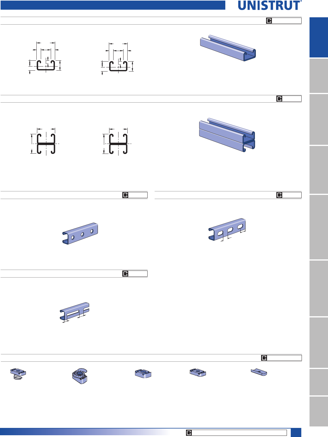
39
15⁄8" Framing System
1 5¼8" ChannelTelestrutNuts & HardwareGeneral FittingsPipe/Conduit SupportsElectrical FittingsConcrete InsertsSolarUnipier®
P3300
P3301
9.1
13.1 7.1
41.3
22.2
22.2
9.5 9.5
2
1
41.3
44.5 1
2
7⁄8"
1 5⁄8"
3⁄8"3⁄8"
7⁄8"
.515"
.360"
9⁄32"
2
1
1 3⁄4"
1 5⁄8"
1
2
Wt/100 Ft: 134 Lbs (200 kg/100 m)
$OORZDEOH0RPHQW,Q/EV1P
12 Gauge Nominal Thickness .105" (2.7mm)
Wt/100 Ft: 269 Lbs (400 kg/100 m)
$OORZDEOH0RPHQW,Q/EV1P
12 Gauge Nominal Thickness .105" (2.7mm)
P3006-0832
P3006-1024
P3006-1420
P3007
P3008
P3009
P3013
P3016-0632
P3016-0832
P3016-1024
P3016-1420
P3300 T
P3300 SL
P3300 HS
P4006-0832
P4006-1024
P4006-1420
P4007
P4008
P4009
P4010
P4006T1420
P4008T
P4010T
P4012
P4023
Channel Finishes: PL, GR, HG, PG, ZD; Standard Lengths: 10' & 20'
P3300 & P3301 Channels
9⁄16" (14.3) Dia. Holes
1 7⁄8" (47.6) on Center
1⁄2"
(12.7)
1"
(25.4)
Slots are
3" (76.2) x 13⁄32" (10.3)
4" (101.6) on Center
1 3⁄16"
(30.2)
Slots are
11⁄8" (28.6) x 9⁄16" (14.3)
2" (50.8) on Center
7⁄8"
(22.2)
Wt/100 Ft: 130 Lbs (193 kg/100 m) Wt/100 Ft: 130 Lbs (193 kg/100 m)
Wt/100 Ft: 130 Lbs (193 kg/100 m)
U
N
I
S
T
R
U
T
U
N
I
S
T
R
U
T
GR PG PL
CORE PRODUCTS - TYPICALLY AVAILABLE FROM STOCK
CHANNEL NUTS (REFER TO PAGES 73,74 FOR DETAILS) SEE PAGE 73, 74
GR PG
GR PGGR PG
GR PG

40
15⁄8" Framing System
1 5¼8" ChannelTelestrutNuts & HardwareGeneral FittingsPipe/Conduit SupportsElectrical FittingsConcrete InsertsSolarUnipier®
P3300 - COLUMN LOADING
P3300/P3301 - ELEMENTS OF SECTION
Unbraced
Height
In
Maximum
Allowable
Load
at Slot Face
Lbs
Maximum Column Load Applied at C.G.
K = 0.65
Lbs
K = 0.80
Lbs
K =1.0
Lbs
K = 1.2
Lbs
24 2,360 7,740 7,260 6,350 5,390
36 2,120 6,470 5,390 3,990 2,810
48 1,760 4,910 3,550 2,270 1,580
60 1,380 3,440 2,270 1,460 **
72 1,080 2,390 1,580 ** **
P3301 - COLUMN LOADING
Unbraced
Height
In
Maximum
Allowable
Load
at Slot Face
Lbs
Maximum Column Load Applied at C.G.
K = 0.65
Lbs
K = 0.80
Lbs
K =1.0
Lbs
K = 1.2
Lbs
24 4,290 16,990 16,580 15,770 14,720
36 4,150 15,890 14,720 12,980 11,120
48 3,940 14,160 12,360 9,880 7,510
60 3,650 12,210 9,880 6,940 4,820
72 3,270 10,190 7,510 4,820 3,350
84 2,800 8,220 5,530 3,540 **
96 2,410 6,420 4,240 ** **
108 2,080 5,070 3,350 ** **
P3300 - BEAM LOADING P3301 - BEAM LOADING
Span
In
Max
Allowable
Uniform Load
Lbs
Defl. at
Uniform
Load
In
Uniform Loading at Deflection
Span/180
Lbs
Span/240
Lbs
Span/360
Lbs
24 600 0.10 600 600 400
36 400 0.22 360 270 180
48 300 0.40 200 150 100
60 240 0.62 130 100 60
72 200 0.89 90 70 40
84 170 1.20 70 50 30
96 150 1.59 50 40 30
108 130 1.96 40 30 20
120 120 2.48 30 20 20
Span
In
Max
Allowable
Uniform Load
Lbs
Defl. at
Uniform
Load
In
Uniform Loading at Deflection
Span/180
Lbs
Span/240
Lbs
Span/360
Lbs
24 1,690 0.06 1,690 1,690 1,690
36 1,130 0.13 1,130 1,130 860
48 840 0.23 840 720 480
60 680 0.37 620 460 310
72 560 0.52 430 320 210
84 480 0.71 310 240 160
96 420 0.93 240 180 120
108 380 1.20 190 140 100
120 340 1.47 150 120 80
144 280 2.09 110 80 50
P3300 & P3301 Channels
Parameter P3300 P3301
Area of Section 0.395 In20.790 In2
Axis 1-1
Moment of Inertia (I) 0.037 In40.176 In4
Section Modulus (S) 0.072 In30.201 In3
Radius of Gyration (r) 0.306 In 0.472 In
Axis 2-2
Moment of Inertia (I) 0.143 In40.285 In4
Section Modulus (S) 0.176 In30.351 In3
Radius of Gyration (r) 0.601 In 0.601 In
Notes:
* Load limited by spot weld shear.
./»U !
NR = Not Recommended.
1. Beam loads are given in total uniform load (W Lbs) not uniform load (w lbs/ft or
w lbs/in).
2. Beam loads are based on a simple span and assumed to be adequately laterally
braced. Unbraced spans can reduce beam load carrying capacity. Refer to Page 62
for reduction factors for unbraced lengths.
3. For pierced channel, multiply beam loads by the following factor:
"KO" Series .......95% "T" Series ..........85%
"HS" Series .......90% "SL" Series ........85%
4. Deduct channel weight from the beam loads.
5. For concentrated midspan point loads, multiply beam loads by 50% and the
corresponding deflection by 80%. For other load conditions refer to page 18.
6. All beam loads are for bending about Axis 1-1.
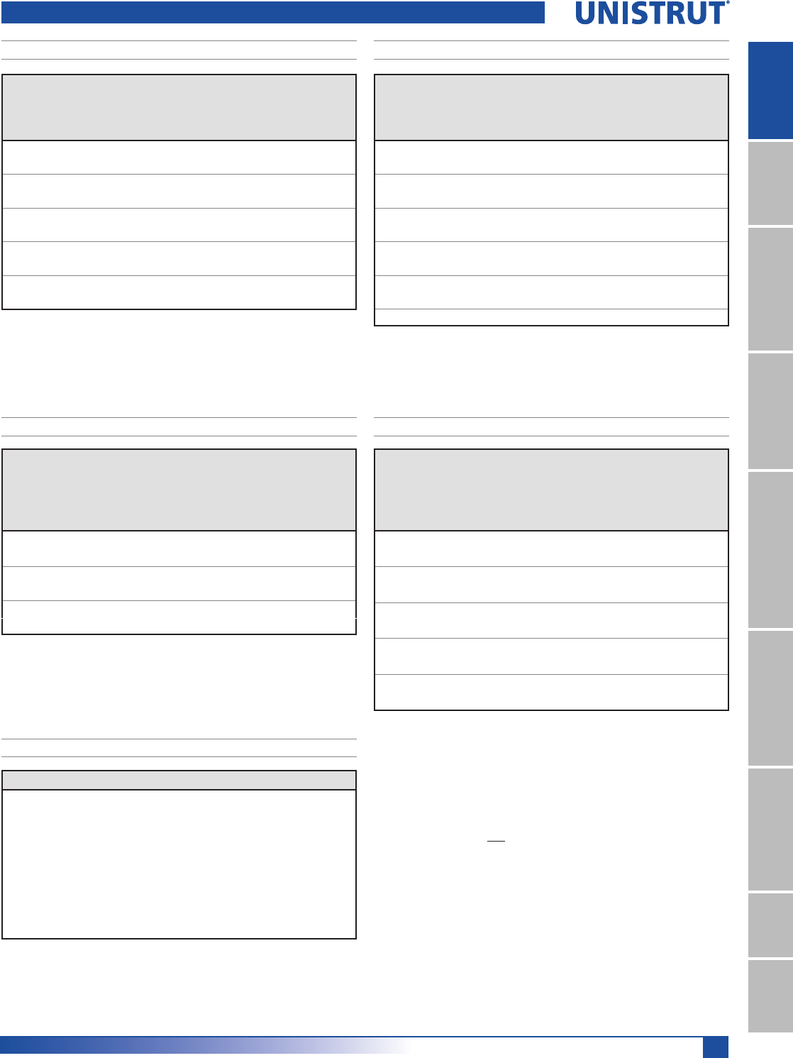
41
15⁄8" Framing System
1 5¼8" ChannelTelestrutNuts & HardwareGeneral FittingsPipe/Conduit SupportsElectrical FittingsConcrete InsertsSolarUnipier®
P3300 & P3301 Channels
Unbraced
Height
mm
Maximum
Allowable
Load
at Slot Face
kN
Maximum Column Load Applied at C.G.
K = 0.65
kN
K = 0.80
kN
K =1.0
kN
K = 1.2
kN
600 10.5 34.6 32.6 28.6 24.4
750 10.1 32.3 28.6 23.3 18.2
1,000 9.1 26.9 21.6 15.0 10.5
1,250 7.6 21.2 15.0 9.6 6.7
1,500 6.3 15.8 10.5 6.7 **
1,750 5.1 11.6 7.6 ** **
Unbraced
Height
mm
Maximum
Allowable
Load
at Slot Face
kN
Maximum Column Load Applied at C.G.
K = 0.65
kN
K = 0.80
kN
K =1.0
kN
K = 1.2
kg
600 19.1 75.7 73.9 70.5 66.0
750 18.9 73.8 70.5 64.7 58.4
1,000 18.2 68.6 62.7 53.9 44.8
1,250 17.4 62.1 53.9 42.6 31.9
1,500 16.4 55.0 44.8 31.9 22.2
1,750 15.0 47.6 36.0 23.4 16.3
2,000 13.3 40.3 28.0 17.9 **
2,250 11.8 33.4 22.2 14.1 **
2,500 10.4 27.2 17.9 ** **
2,750 9.2 22.5 14.8 ** **
Span
mm
Max
Allowable
Uniform Load
kN
Defl. at
Uniform
Load
mm
Uniform Loading at Deflection
Span/180
kN
Span/240
kN
Span/360
kN
600 2.7 2 2.7 2.7 1.9
750 2.2 4 2.2 1.8 1.2
1,000 1.6 7 1.3 1.0 0.7
1,250 1.3 10 0.8 0.6 0.4
1,500 1.1 15 0.6 0.4 0.3
1,750 0.9 21 0.4 0.3 0.2
2,000 0.8 27 0.3 0.3 0.2
2,500 0.7 43 0.2 0.2 0.1
3,000 0.5 60 0.1 0.1 0.1
3,500 0.4 79 0.1 0.1 NR
Span
mm
Max
Allowable
Uniform Load
kN
Defl. at
Uniform
Load
mm
Uniform Loading at Deflection
Span/180
kN
Span/240
kN
Span/360
kN
600 7.6 1 7.6 7.6 7.6
750 6.1 2 6.1 6.1 5.6
1,000 4.6 4 4.6 4.6 3.2
1,250 3.6 6 3.6 3.1 2.0
1,500 3.1 9 2.8 2.1 1.4
1,750 2.6 12 2.1 1.6 1.0
2,000 2.3 16 1.6 1.2 0.8
2,500 1.8 25 1.0 0.8 0.5
3,000 1.5 36 0.7 0.5 0.4
3,500 1.3 48 0.5 0.4 0.3
4,000 1.2 65 0.4 0.3 0.2
P3300 - COLUMN LOADING (METRIC)
P3300/P3301 - ELEMENTS OF SECTION (METRIC)
P3301 - COLUMN LOADING (METRIC)
P3300 - BEAM LOADING (METRIC) P3301 - BEAM LOADING (METRIC)
Parameter P3300 P3301
Area of Section 2.55 cm25.10 cm2
Axis 1-1
Moment of Inertia (I) 1.54 cm47.33 cm4
Section Modulus (S) 1.18 cm33.30 cm3
Radius of Gyration (r) 0.78 cm 1.20 cm
Axis 2-2
Moment of Inertia (I) 5.94 cm411.87 cm4
Section Modulus (S) 2.88 cm35.75 cm3
Radius of Gyration (r) 1.53 cm 1.53 cm
Notes:
* Load limited by spot weld shear.
./»U !
NR = Not Recommended.
1. Beam loads are given in total uniform load (W Lbs) not uniform load (w lbs/ft or
w lbs/in).
2. Beam loads are based on a simple span and assumed to be adequately laterally
braced. Unbraced spans can reduce beam load carrying capacity. Refer to Page 62
for reduction factors for unbraced lengths.
3. For pierced channel, multiply beam loads by the following factor:
"KO" Series .......95% "T" Series ..........85%
"HS" Series .......90% "SL" Series ........85%
4. Deduct channel weight from the beam loads.
5. For concentrated midspan point loads, multiply beam loads by 50% and the
corresponding deflection by 80%. For other load conditions refer to page 18.
6. All beam loads are for bending about Axis 1-1.
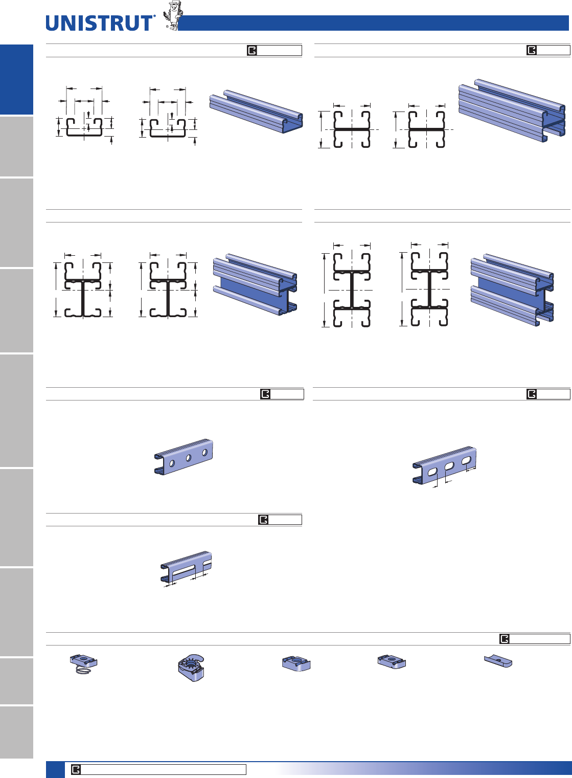
42
15⁄8" Framing System
1 5¼8" ChannelTelestrutNuts & HardwareGeneral FittingsPipe/Conduit SupportsElectrical FittingsConcrete InsertsSolarUnipier®
P4003 P4004
2 7⁄16"
1 5⁄8"
1.240"
1.198"
2
1
3 1⁄4"
1 5⁄8"
2
1
41.3
82.6
2
1
Wt/100 Ft: 248 Lbs (370 kg/100 m)
$OORZDEOH0RPHQW,Q/EV1P
16 Gauge Nominal Thickness .060" (1.5mm)
41.3
61.9
2
1
30.4
31.5
Wt/100 Ft: 331 Lbs (493 kg/100 m)
$OORZDEOH0RPHQW,Q/EV1P
16 Gauge Nominal Thickness .060" (1.5mm)
P4000 P4001
8.7
20.6
41.3
6.4
22.2
9.5 9.5
11.9
2
1
13⁄16"
15⁄8"
3⁄8"3⁄8"
7⁄8"
.343"
.470"
1⁄4"
2
1
1 5⁄8"
1 5⁄8"1
2
41.3
41.3 1
2
Wt/100 Ft: 83 Lbs (123 kg/100 m)
$OORZDEOH0RPHQW,Q/EV1P
16 Gauge Nominal Thickness .060" (1.5mm)
Wt/100 Ft: 166 Lbs (246 kg/100 m)
$OORZDEOH0RPHQW,Q/EV1P
16 Gauge Nominal Thickness .060" (1.5mm)
P4000 T
P4000 SL
P4000 HS
P3006-0832
P3006-1024
P3006-1420
P3007
P3008
P3009
P3013
P3016-0632
P3016-0832
P3016-1024
P3016-1420
P4006-0832
P4006-1024
P4006-1420
P4007
P4008
P4009
P4010
P4006T1420
P4008T
P4010T
P4012
P4023
Channel Finishes: PL, GR, HG, PG, ZD; Standard Lengths: 10' & 20'
P4000 & P4001 Channels
9⁄16" (14.3) Dia. Holes
1 7⁄8" (47.6) on Center
1⁄2"
(12.7)
1"
(25.4)
Slots are
3" (76.2) x 13⁄32" (10.3)
4" (101.6) on Center
1 3⁄16"
(30.2)
Slots are
11⁄8" (28.6) x 9⁄16" (14.3)
2" (50.8) on Center
7⁄8"
(22.2)
U
N
I
S
T
R
U
T
U
N
I
S
T
R
U
T
Wt/100 Ft: 79 Lbs (118 kg/100 m)
Wt/100 Ft: 79 Lbs (118 kg/100 m)
Wt/100 Ft: 79 Lbs (118 kg/100 m)
HG PG GR
CORE PRODUCTS - TYPICALLY AVAILABLE FROM STOCK
CHANNEL NUTS (REFER TO PAGES 73,74 FOR DETAILS) SEE PAGE 73, 74
GR PG
GR PGGR PG
GR PG
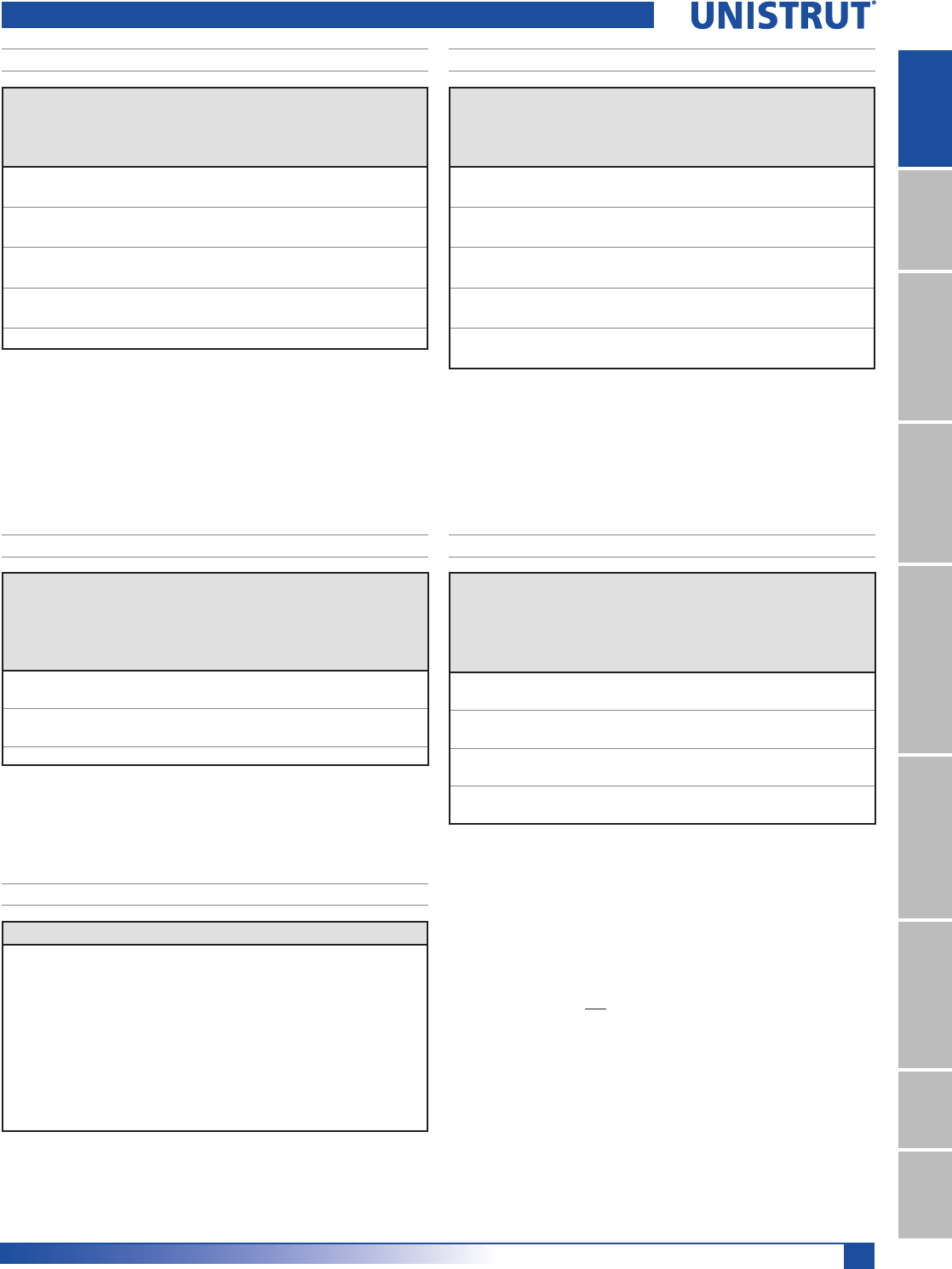
43
15⁄8" Framing System
1 5¼8" ChannelTelestrutNuts & HardwareGeneral FittingsPipe/Conduit SupportsElectrical FittingsConcrete InsertsSolarUnipier®
P4000 - COLUMN LOADING
P4000/P4001 - ELEMENTS OF SECTION
Unbraced
Height
In
Maximum
Allowable
Load
at Slot Face
Lbs
Maximum Column Load Applied at C.G.
K = 0.65
Lbs
K = 0.80
Lbs
K =1.0
Lbs
K = 1.2
Lbs
24 1,630 4,670 4,290 3,780 3,310
36 1,450 3,840 3,310 2,460 1,730
48 1,160 3,030 2,190 1,400 970
60 870 2,120 1,400 900 **
72 670 1,470 970 ** **
P4001 - COLUMN LOADING
Unbraced
Height
In
Maximum
Allowable
Load
at Slot Face
Lbs
Maximum Column Load Applied at C.G.
K = 0.65 K = 0.80 K =1.0 K = 1.2
Lbs Lbs Lbs Lbs
24 2,830 10,390 10,000 9,470 8,960
36 2,740 9,530 8,960 7,870 6,700
48 2,590 8,620 7,480 5,910 4,440
60 2,340 7,380 5,910 4,090 2,840
72 2,020 6,110 4,440 2,840 1,970
84 1,700 4,880 3,260 2,090 **
96 1,440 3,780 2,500 ** **
108 1,230 2,990 1,970 ** **
P4000 - BEAM LOADING P4001 - BEAM LOADING
Span
In
Max
Allowable
Uniform Load
Lbs
Defl. at
Uniform
Load
In
Uniform Loading at Deflection
Span/180
Lbs
Span/240
Lbs
Span/360
Lbs
24 410 0.11 410 370 250
36 270 0.24 220 170 110
48 200 0.43 120 90 60
60 160 0.67 80 60 40
72 140 1.01 60 40 30
84 120 1.38 40 30 20
96 100 1.72 30 20 20
108 90 2.20 20 20 10
120 80 2.68 20 10 10
Span
In
Max
Allowable
Uniform Load
Lbs
Defl. at
Uniform
Load
In
Uniform Loading at Deflection
Span/180
Lbs
Span/240
Lbs
Span/360
Lbs
24 810* 0.05 810* 810* 810*
36 710 0.14 710 710 500
48 540 0.25 540 430 280
60 430 0.40 360 270 180
72 360 0.57 250 190 130
84 310 0.78 190 140 90
96 270 1.02 140 110 70
108 240 1.29 110 80 60
120 210 1.54 90 70 50
144 180 2.29 60 50 30
P4000 & P4001 Channels
Parameter P4000 P4001
Area of Section 0.244 In20.487 In2
Axis 1-1
Moment of Inertia (I) 0.023 In40.104 In4
Section Modulus (S) 0.049 In30.128 In3
Radius of Gyration (r) 0.306 In 0.462 In
Axis 2-2
Moment of Inertia (I) 0.092 In40.183 In4
Section Modulus (S) 0.113 In30.225 In3
Radius of Gyration (r) 0.613 In 0.613 In
Notes:
* Load limited by spot weld shear.
./»U !
NR = Not Recommended.
1. Beam loads are given in total uniform load (W Lbs) not uniform load (w lbs/ft or
w lbs/in).
2. Beam loads are based on a simple span and assumed to be adequately laterally
braced. Unbraced spans can reduce beam load carrying capacity. Refer to Page 62
for reduction factors for unbraced lengths.
3. For pierced channel, multiply beam loads by the following factor:
"KO" Series .......95% "T" Series ..........85%
"HS" Series .......90% "SL" Series ........85%
4. Deduct channel weight from the beam loads.
5. For concentrated midspan point loads, multiply beam loads by 50% and the
corresponding deflection by 80%. For other load conditions refer to page 18.
6. All beam loads are for bending about Axis 1-1.

44
15⁄8" Framing System
1 5¼8" ChannelTelestrutNuts & HardwareGeneral FittingsPipe/Conduit SupportsElectrical FittingsConcrete InsertsSolarUnipier®
P4000 & P4001 Channels
Unbraced
Height
mm
Maximum Al-
lowable Load
at Slot Face
kN
Maximum Column Load Applied at C.G.
K = 0.65
kN
K = 0.80
kN
K =1.0
kN
K = 1.2
kN
600 7.2 20.9 19.2 17.0 14.9
750 6.9 19.1 17.0 14.4 11.3
1,000 6.1 16.1 13.3 9.2 6.5
1,250 5.0 13.0 9.2 5.9 4.1
1,500 4.0 9.7 6.5 4.1 **
1,750 3.2 7.2 4.7 ** **
Unbraced
Height
mm
Maximum
Allowable
Load
at Slot Face
kN
Maximum Column Load Applied at C.G.
K = 0.65
kN
K = 0.80
kN
K =1.0
kN
K = 1.2
kN
600 12.6 46.3 44.6 42.3 40.0
750 12.4 44.5 42.3 39.5 35.4
1,000 12.1 41.3 38.2 32.6 26.9
1,250 11.4 37.8 32.6 25.4 18.8
1,500 10.5 33.3 26.9 18.8 13.0
1,750 9.4 28.6 21.3 13.8 9.6
2,000 8.1 24.1 16.5 10.5 **
2,250 7.1 19.8 13.0 8.4 **
2,500 6.2 16.0 10.5 ** **
2,750 5.4 13.2 8.7 ** **
Span
mm
Max
Allowable
Uniform Load
kN
Defl. at
Uniform
Load
mm
Uniform Loading at Deflection
Span/180
kN
Span/240
kN
Span/360
kN
600 1.9 3 1.9 1.7 1.2
750 1.5 4 1.5 1.1 0.7
1,000 1.1 8 0.8 0.6 0.4
1,250 0.9 12 0.5 0.4 0.3
1,500 0.8 17 0.4 0.3 0.2
1,750 0.6 23 0.3 0.2 0.1
2,000 0.5 29 0.2 0.1 0.1
2,500 0.4 47 0.1 0.1 NR
3,000 0.4 65 0.1 0.1 NR
Span
mm
Max
Allowable
Uniform Load
kN
Defl. at
Uniform
Load
mm
Uniform Loading at Deflection
Span/180
kN
Span/240
kN
Span/360
kN
600 3.6 * 1 3.6 * 3.6 * 3.6 *
750 3.6 * 2 3.6 * 3.6 * 3.3
1,000 2.9 4 2.9 2.8 1.9
1,250 2.3 7 2.3 1.8 1.2
1,500 2.0 10 1.6 1.2 0.8
1,750 1.6 13 1.2 0.9 0.6
2,000 1.5 17 0.9 0.7 0.5
2,500 1.2 27 0.6 0.4 0.3
3,000 1.0 39 0.4 0.3 0.2
3,500 0.8 54 0.3 0.2 0.1
P4000 - COLUMN LOADING (METRIC)
P4000/P4001 - ELEMENTS OF SECTION (METRIC)
P4001 - COLUMN LOADING (METRIC)
P4000 - BEAM LOADING (METRIC)P4001 - BEAM LOADING (METRIC)
Parameter P4000 P4001
Area of Section 1.57 cm23.14 cm2
Axis 1-1
Moment of Inertia (I) 0.95 cm44.32 cm4
Section Modulus (S) 0.80 cm32.09 cm3
Radius of Gyration (r) 0.78 cm 1.17 cm
Axis 2-2
Moment of Inertia (I) 3.81 cm47.62 cm4
Section Modulus (S) 1.85 cm33.69 cm3
Radius of Gyration (r) 1.56 cm 1.56 cm
Notes:
* Load limited by spot weld shear.
./»U !
NR = Not Recommended.
1. Beam loads are given in total uniform load (W Lbs) not uniform load (w lbs/ft or
w lbs/in).
2. Beam loads are based on a simple span and assumed to be adequately laterally
braced. Unbraced spans can reduce beam load carrying capacity. Refer to Page 62
for reduction factors for unbraced lengths.
3. For pierced channel, multiply beam loads by the following factor:
"KO" Series .......95% "T" Series ..........85%
"HS" Series .......90% "SL" Series ........85%
4. Deduct channel weight from the beam loads.
5. For concentrated midspan point loads, multiply beam loads by 50% and the
corresponding deflection by 80%. For other load conditions refer to page 18.
6. All beam loads are for bending about Axis 1-1.
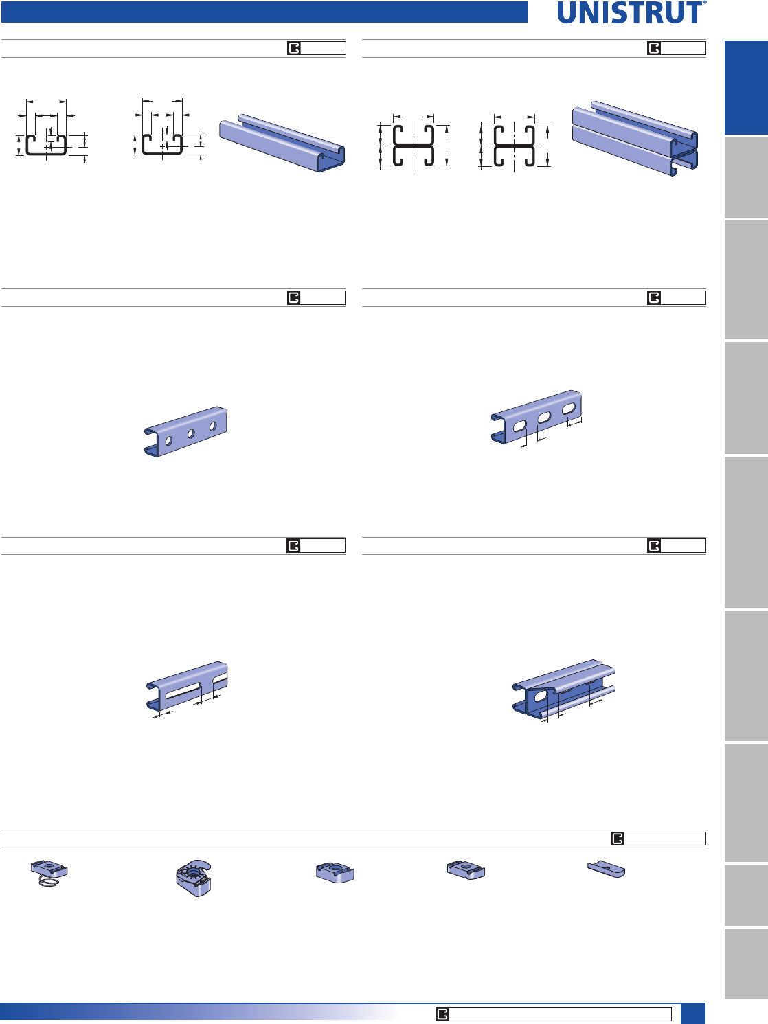
45
15⁄8" Framing System
1 5¼8" ChannelTelestrutNuts & HardwareGeneral FittingsPipe/Conduit SupportsElectrical FittingsConcrete InsertsSolarUnipier®
P4100 P4101
1
9.59.5
41.3
20.6
6.4
8.5
12.1
2
22.2
7⁄8"
.336"
.477"
13⁄16"
1 5⁄8"
3⁄8"3⁄8"
1⁄4"
1
2
41.3
41.3
20.6
20.6
1
2
Wt/100 Ft: 98 Lbs (147 kg/100 m)
$OORZDEOH0RPHQW,Q/EV1P
14 Gauge Nominal Thickness .075" (1.9mm)
Wt/100 Ft: 197 Lbs (293 kg/100 m)
$OORZDEOH0RPHQW,Q/EV1P
14 Gauge Nominal Thickness .075" (1.9mm)
13⁄16"
13⁄16"1 5⁄8"
1 5⁄8"
1
2
P4100 T
P4100 SL
P4100 HS
P3006-0832
P3006-1024
P3006-1420
P3007
P3008
P3009
P3013
P3016-0632
P3016-0832
P3016-1024
P3016-1420
P4006-0832
P4006-1024
P4006-1420
P4007
P4008
P4009
P4010
P4006T1420
P4008T
P4010T
P4012
P4023
Channel Finishes: PL, GR, HG, PG, ZD; Standard Lengths: 10' & 20'
P4100 & P4101 Channels
9⁄16" (14.3) Dia. Holes
1 7⁄8" (47.6) on Center
1⁄2"
(12.7)
1"
(25.4)
Slots are
3" (76.2) x 13⁄32" (10.3)
4" (101.6) on Center
1 3⁄16"
(30.2)
Slots are
11⁄8" (28.6) x 9⁄16" (14.3)
2" (50.8) on Center
7⁄8"
(22.2)
P4101 T
1 3⁄16"
(30.2)
Slots are
11⁄8" (28.6) x 9⁄16" (14.3)
2" (50.8) on Center
7⁄8"
(22.2)
Wt/100 Ft: 87 Lbs (129 kg/100 m) Wt/100 Ft: 87 Lbs (129 kg/100 m)
Wt/100 Ft: 174 Lbs (259 kg/100 m)Wt/100 Ft: 87 Lbs (129 kg/100 m)
U
N
I
S
T
R
U
T
U
N
I
S
T
R
U
T
CORE PRODUCTS - TYPICALLY AVAILABLE FROM STOCK
CHANNEL NUTS (REFER TO PAGES 73,74 FOR DETAILS) SEE PAGE 73, 74
GR PG
GR PG
GR PG
GR PG
GR PG
GR PG

46
15⁄8" Framing System
1 5¼8" ChannelTelestrutNuts & HardwareGeneral FittingsPipe/Conduit SupportsElectrical FittingsConcrete InsertsSolarUnipier®
P4100 - BEAM LOADING P4101 - BEAM LOADING
Span
In
Max
Allowable
Uniform Load
Lbs
Defl. at
Uniform
Load
In
Uniform Loading at Deflection
Span/180
Lbs
Span/240
Lbs
Span/360
Lbs
24 450 0.11 450 420 280
36 300 0.24 250 190 130
48 230 0.44 140 110 70
60 180 0.67 90 70 50
72 150 0.96 60 50 30
84 130 1.32 50 30 20
96 110 1.67 40 30 20
108 100 2.16 30 20 10
120 90 2.67 20 20 10
144 80 4.09 20 NR NR
168 60 4.88 NR NR NR
192 60 7.28 NR NR NR
216 50 8.64 NR NR NR
240 50 11.85 NR NR NR
Span
In
Max
Allowable
Uniform Load
Lbs
Defl. at
Uniform
Load
In
Uniform Loading at Deflection
Span/180
Lbs
Span/240
Lbs
Span/360
Lbs
24 1,090* 0.06 1,090* 1,090* 1,090*
36 800 0.14 800 800 570
48 600 0.25 600 480 320
60 480 0.39 410 310 200
72 400 0.57 280 210 140
84 340 0.76 210 160 100
96 300 1.00 160 120 80
108 270 1.29 130 90 60
120 240 1.57 100 80 50
144 200 2.26 70 50 40
168 170 3.05 50 40 30
192 150 4.02 40 NR NR
216 130 4.96 NR NR NR
240 120 6.28 NR NR NR
P4100 & P4101 Channels
P4100 - COLUMN LOADING
Unbraced
Height
In
Maximum
Allowable
Load
at Slot Face
Lbs
Maximum Column Load Applied at C.G.
K = 0.65
Lbs
K = 0.80
Lbs
K =1.0
Lbs
K = 1.2
Lbs
24 1,840 5,610 5,210 4,570 3,850
36 1,640 4,660 3,850 2,800 1,960
48 1,310 3,490 2,480 1,590 1,100
60 1,000 2,400 1,590 ** **
72 770 1,670 1,100 ** **
P4101 - COLUMN LOADING
Unbraced
Height
In
Maximum
Allowable
Load
at Slot Face
Lbs
Maximum Column Load Applied at C.G.
K = 0.65
Lbs
K = 0.80
Lbs
K =1.0
Lbs
K = 1.2
Lbs
24 3,240 12,370 11,950 11,370 10,540
36 3,120 11,470 10,540 9,160 7,720
48 2,940 10,090 8,680 6,770 4,980
60 2,680 8,560 6,770 4,590 3,190
72 2,310 7,010 4,980 3,190 2,220
84 1,950 5,530 3,660 2,340 **
96 1,650 4,250 2,800 ** **
108 1,410 3,360 2,220 ** **
P4100/P4101 - ELEMENTS OF SECTION
Parameter P4100 P4101
Area of Section 0.290 In20.579 In2
Axis 1-1
Moment of Inertia (I) 0.026 In40.117 In4
Section Modulus (S) 0.054 In30.143 In3
Radius of Gyration (r) 0.298 In 0.449 In
Axis 2-2
Moment of Inertia (I) 0.107 In40.214 In4
Section Modulus (S) 0.132 In30.264 In3
Radius of Gyration (r) 0.609 In 0.608 In
Notes:
* Load limited by spot weld shear.
./»U !
NR = Not Recommended.
1. Beam loads are given in total uniform load (W Lbs) not uniform load (w lbs/ft or
w lbs/in).
2. Beam loads are based on a simple span and assumed to be adequately laterally
braced. Unbraced spans can reduce beam load carrying capacity. Refer to Page 62
for reduction factors for unbraced lengths.
3. For pierced channel, multiply beam loads by the following factor:
"KO" Series .......95% "T" Series ..........85%
"HS" Series .......90% "SL" Series ........85%
4. Deduct channel weight from the beam loads.
5. For concentrated midspan point loads, multiply beam loads by 50% and the
corresponding deflection by 80%. For other load conditions refer to page 18.
6. All beam loads are for bending about Axis 1-1.
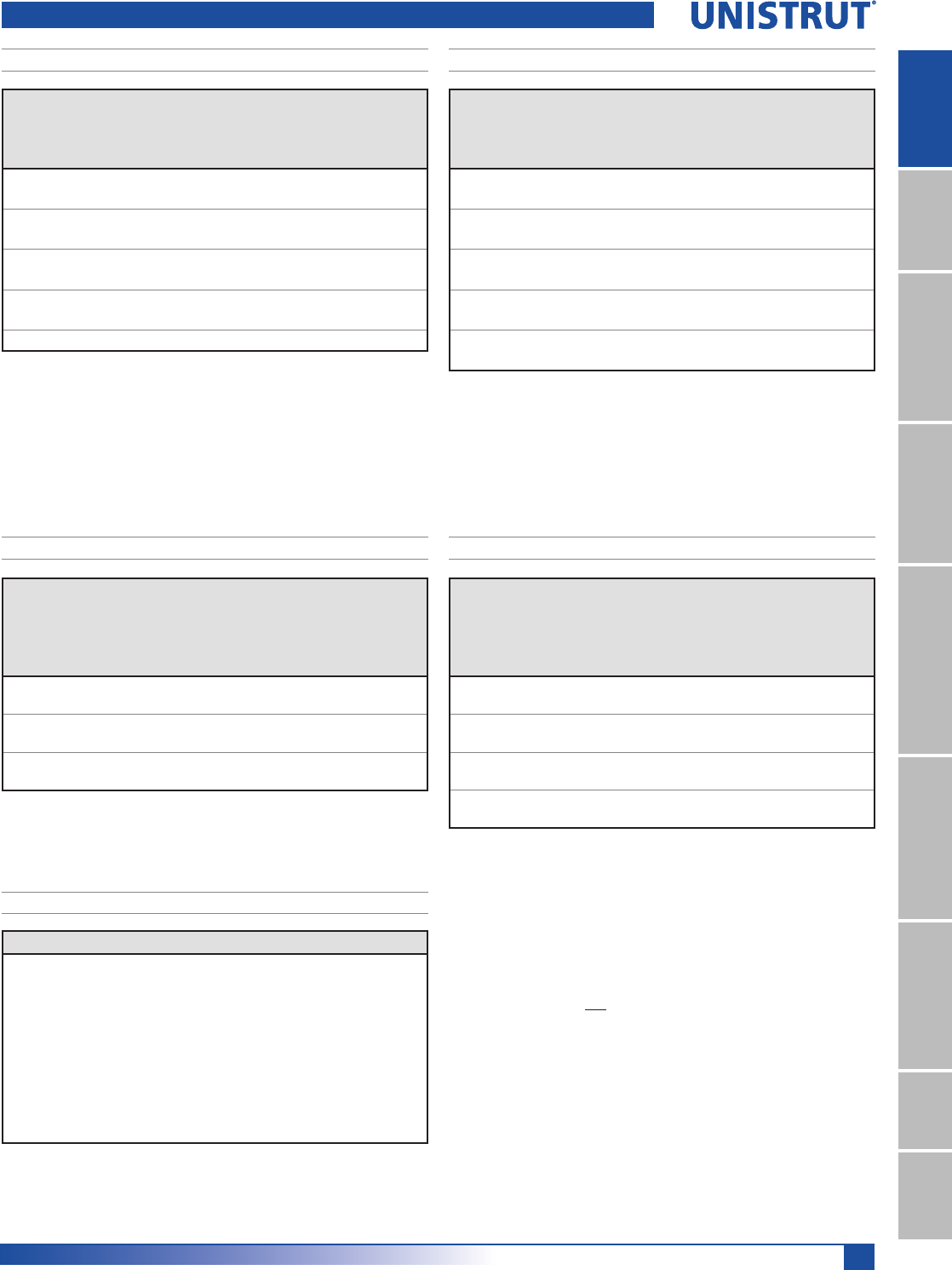
47
15⁄8" Framing System
1 5¼8" ChannelTelestrutNuts & HardwareGeneral FittingsPipe/Conduit SupportsElectrical FittingsConcrete InsertsSolarUnipier®
P4100 & P4101 Channels
Unbraced
Height
mm
Maximum
Allowable
Load
at Slot Face
kN
Maximum Column Load Applied at C.G.
K = 0.65
kN
K = 0.80
kN
K =1.0
kN
K = 1.2
kN
600 8.2 25.1 23.3 20.6 17.4
750 7.8 23.2 20.6 16.6 12.8
1,000 6.9 19.3 15.3 10.5 7.3
1,250 5.6 15.0 10.5 6.7 4.7
1,500 4.5 11.0 7.3 4.7 **
1,750 3.6 8.1 5.3 ** **
Unbraced
Height
mm
Maximum
Allowable
Load
at Slot Face
kN
Maximum Column Load Applied at C.G.
K = 0.65
kN
K = 0.80
kN
K =1.0
kN
K = 1.2
kN
600 14.4 55.1 53.3 50.8 47.2
750 14.2 53.2 50.8 46.3 41.2
1,000 13.7 49.4 44.7 37.8 30.8
1,250 13.0 44.2 37.8 29.1 21.1
1,500 12.0 38.7 30.8 21.1 14.6
1,750 10.7 33.0 24.2 15.5 10.8
2,000 9.3 27.4 18.5 11.9 **
2,250 8.1 22.2 14.6 9.4 **
Span
mm
Max
Allowable
Uniform Load
kN
Defl. at
Uniform
Load
mm
Uniform Loading at Deflection
Span/180
kN
Span/240
kN
Span/360
kN
600 2.0 3 2.0 2.0 1.3
750 1.6 4 1.6 1.2 0.8
1,000 1.2 7 0.9 0.7 0.4
1,250 1.0 11 0.6 0.4 0.3
1,500 0.8 16 0.4 0.3 0.2
1,750 0.7 23 0.3 0.2 0.1
2,000 0.6 30 0.2 0.2 0.1
2,500 0.5 46 0.1 0.1 0.1
3,000 0.4 65 0.1 0.1 NR
Span
mm
Max
Allowable
Uniform Load
kN
Defl. at
Uniform
Load
mm
Uniform Loading at Deflection
Span/180
kN
Span/240
kN
Span/360
kN
600 4.8 * 1 4.8 * 4.8 * 4.8 *
750 4.4 2 4.4 4.4 3.7
1,000 3.2 4 3.2 3.2 2.1
1,250 2.6 7 2.6 2.0 1.3
1,500 2.2 10 1.9 1.4 0.9
1,750 1.9 13 1.4 1.0 0.7
2,000 1.6 17 1.1 0.8 0.5
2,500 1.3 27 0.7 0.5 0.4
3,000 1.1 38 0.5 0.4 0.2
3,500 0.9 53 0.4 0.3 0.2
P4100 - BEAM LOADING (METRIC)P4101 - BEAM LOADING (METRIC)
P4100 - COLUMN LOADING (METRIC)P4101 - COLUMN LOADING (METRIC)
P4100/P4101 - ELEMENTS OF SECTION (METRIC)
Parameter P4100 P4101
Area of Section 1.87 cm23.74 cm2
Axis 1-1
Moment of Inertia (I) 1.07 cm44.85 cm4
Section Modulus (S) 0.88 cm32.35 cm3
Radius of Gyration (r) 0.76 cm 1.14 cm
Axis 2-2
Moment of Inertia (I) 4.46 cm48.93 cm4
Section Modulus (S) 2.16 cm34.32 cm3
Radius of Gyration (r) 1.55 cm 1.55 cm
Notes:
* Load limited by spot weld shear.
./»U !
NR = Not Recommended.
1. Beam loads are given in total uniform load (W Lbs) not uniform load (w lbs/ft or
w lbs/in).
2. Beam loads are based on a simple span and assumed to be adequately laterally
braced. Unbraced spans can reduce beam load carrying capacity. Refer to Page 62
for reduction factors for unbraced lengths.
3. For pierced channel, multiply beam loads by the following factor:
"KO" Series .......95% "T" Series ..........85%
"HS" Series .......90% "SL" Series ........85%
4. Deduct channel weight from the beam loads.
5. For concentrated midspan point loads, multiply beam loads by 50% and the
corresponding deflection by 80%. For other load conditions refer to page 18.
6. All beam loads are for bending about Axis 1-1.
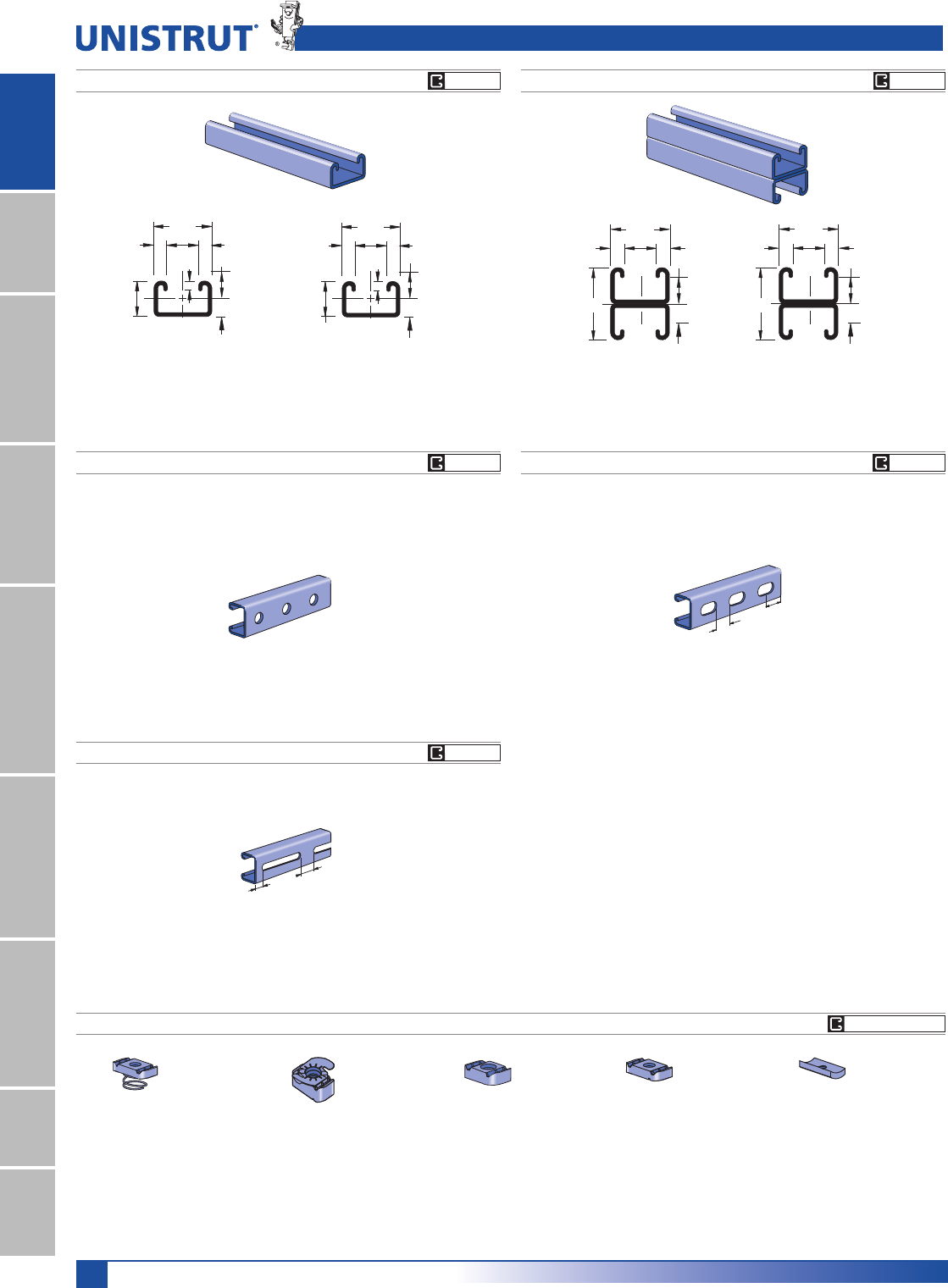
48
15⁄8" Framing System
1 5¼8" ChannelTelestrutNuts & HardwareGeneral FittingsPipe/Conduit SupportsElectrical FittingsConcrete InsertsSolarUnipier®
P3006-0832
P3006-1024
P3006-1420
P3007
P3008
P3009
P3013
P3016-0632
P3016-0832
P3016-1024
P3016-1420
P4006-0832
P4006-1024
P4006-1420
P4007
P4008
P4009
P4010
P4006T1420
P4008T
P4010T
P4012
P4023
Channel Finishes: PL, GR, HG, PG, ZD; Standard Lengths: 10' & 20'
P4400 & P4401 Channels
U
N
I
S
T
R
U
T
U
N
I
S
T
R
U
T
1"
15⁄8"
3⁄8"
9⁄32"
3⁄8"7»8"
0.404"
0.596"
2
1
2
1
10.3"
15.1"
25.4
41.3
6.4
22.2
9.5 9.5
P4400 P4401
Wt/100 Ft: 144 Lbs (210 kg/100 m)
$OORZDEOH0RPHQW,Q/EV1P
12 Gauge Nominal Thickness .105" (2.7mm)
Wt/100 Ft: 289 Lbs (430 kg/100 m)
$OORZDEOH0RPHQW,Q/EV1P
12 Gauge Nominal Thickness .105" (2.7mm)
P4400 HS P4400 T
P4400 SL
Wt/100 Ft: 136 Lbs (201 kg/100 m)
Wt/100 Ft: 136 Lbs (201 kg/100 m) Wt/100 Ft: 136 Lbs (201 kg/100 m)
9⁄16" (14.3) Dia. Holes
1 7⁄8" (47.6) on Center
1⁄2"
(12.7)
1"
(25.4)
Slots are
3" (76.2) x 13⁄32" (10.3)
4" (101.6) on Center
1 3⁄16"
(30.2)
Slots are
11⁄8" (28.6) x 9⁄16" (14.3)
2" (50.8) on Center
7⁄8"
(22.2)
2"
15⁄8"
3⁄8"3⁄8"
7»8"
1"
1"
2
1
2
1
25.4
50.8
25.4
41.3
22.2
9.5 9.5
CHANNEL NUTS (REFER TO PAGES 73,74 FOR DETAILS) SEE PAGE 73, 74
GR PG
GR PG
GR PG
GR PG
GR PG

49
15⁄8" Framing System
1 5¼8" ChannelTelestrutNuts & HardwareGeneral FittingsPipe/Conduit SupportsElectrical FittingsConcrete InsertsSolarUnipier®
P4400 - BEAM LOADING P4401 - BEAM LOADING
Span
In
Max
Allowable
Uniform Load
Lbs
Defl. at
Uniform
Load
In
Uniform Loading at Deflection
Span/180
Lbs
Span/240
Lbs
Span/360
Lbs
24 770 0.09 770 770 580
36 510 0.20 510 390 260
48 380 0.35 290 220 150
60 310 0.56 190 140 90
72 260 0.80 130 100 60
84 220 1.08 90 70 50
96 190 1.39 70 50 40
108 170 1.78 60 40 30
120 150 2.15 50 30 20
144 130 3.22 30 20 20
Span
In
Max
Allowable
Uniform Load
Lbs
Defl. at
Uniform
Load
In
Uniform Loading at Deflection
Span/180
Lbs
Span/240
Lbs
Span/360
Lbs
24 2,140* 0.05 2,140* 2,140* 2,140*
36 1,420 0.11 1,420 1,420 1,240
48 1,070 0.20 1,070 1,040 700
60 850 0.32 850 670 450
72 710 0.46 620 460 310
84 610 0.63 450 340 230
96 530 0.81 350 260 170
108 470 1.03 280 210 140
120 430 1.29 220 170 110
144 360 1.86 150 120 80
168 310 2.54 110 90 60
192 270 3.31 90 70 NR
216 240 4.19 70 NR NR
240 210 5.03 60 NR NR
P4400 & P4401 Channels
P4400 - COLUMN LOADING
Unbraced
Height
In
Maximum
Allowable
Load
at Slot Face
Lbs
Maximum Column Load Applied at C.G.
K = 0.65
Lbs
K = 0.80
Lbs
K =1.0
Lbs
K = 1.2
Lbs
24 2,620 8,280 7,760 7,140 6,580
36 2,470 7,210 6,580 5,310 4,030
48 2,180 6,200 4,870 3,280 2,280
60 1,770 4,760 3,280 2,100 **
72 1,420 3,450 2,280 ** **
84 1,150 2,530 1,670 ** **
96 ** 1,940 ** ** **
P4401 - COLUMN LOADING
Unbraced
Height
In
Maximum
Allowable
Load
at Slot Face
Lbs
Maximum Column Load Applied at C.G.
K = 0.65
Lbs
K = 0.80
Lbs
K =1.0
Lbs
K = 1.2
Lbs
24 4,720 18,310 17,840 17,300 16,760
36 4,640 17,360 16,760 15,260 13,610
48 4,470 16,280 14,720 12,460 10,170
60 4,230 14,590 12,460 9,610 6,980
72 3,930 12,750 10,170 6,980 4,840
84 3,520 10,880 7,990 5,130 3,560
96 3,070 9,050 6,130 3,920 **
108 2,690 7,340 4,840 3,100 **
120 2,360 5,940 3,920 ** **
P4400/P4401 - ELEMENTS OF SECTION
Parameter P4400 P4401
Area of Section 0.424 In20.849 In2
Axis 1-1
Moment of Inertia (I) 0.053 In40.255 In4
Section Modulus (S) 0.092 In30.255 In3
Radius of Gyration (r) 0.354 In 0.548 In
Axis 2-2
Moment of Inertia (I) 0.161 In40.322 In4
Section Modulus (S) 0.198 In30.396 In3
Radius of Gyration (r) 0.616 In 0.616 In
Notes:
* Load limited by spot weld shear.
./»U !
NR = Not Recommended.
1. Beam loads are given in total uniform load (W Lbs) not uniform load (w lbs/ft or
w lbs/in).
2. Beam loads are based on a simple span and assumed to be adequately laterally
braced. Unbraced spans can reduce beam load carrying capacity. Refer to Page 62
for reduction factors for unbraced lengths.
3. For pierced channel, multiply beam loads by the following factor:
"KO" Series .......95% "T" Series ..........85%
"HS" Series .......90% "SL" Series ........85%
4. Deduct channel weight from the beam loads.
5. For concentrated midspan point loads, multiply beam loads by 50% and the
corresponding deflection by 80%. For other load conditions refer to page 18.
6. All beam loads are for bending about Axis 1-1.

50
15⁄8" Framing System
1 5¼8" ChannelTelestrutNuts & HardwareGeneral FittingsPipe/Conduit SupportsElectrical FittingsConcrete InsertsSolarUnipier®
P4400 & P4401 Channels
Unbraced
Height
mm
Maximum
Allowable
Load
at Slot Face
kN
Maximum Column Load Applied at C.G.
K = 0.65
kN
K = 0.80
kN
K =1.0
kN
K = 1.2
kN
600 11.9 37.7 35.4 32.6 30.1
750 11.6 35.2 32.6 29.5 24.5
1000 10.9 31.5 27.9 21.3 15.3
1250 9.7 27.4 21.3 14.2 9.8
1500 8.2 22.1 15.3 9.8 **
1750 6.8 17.1 11.3 7.2 **
2000 5.7 13.1 8.6 ** **
2500 ** 8.4 ** ** **
Unbraced
Height
mm
Maximum
Allowable
Load
at Slot Face
kN
Maximum Column Load Applied at C.G.
K = 0.65
kN
K = 0.80
kN
K =1.0
kN
K = 1.2
kN
600 21.4 83.2 81.1 78.7 76.4
750 21.2 81.0 78.7 75.4 69.8
1000 20.9 77.7 73.6 65.8 57.3
1250 20.2 73.1 65.8 55.2 44.5
1500 19.3 66.8 57.3 44.5 32.7
1750 18.2 60.0 48.8 34.6 24.0
2000 16.8 53.1 40.5 26.4 18.4
2500 13.6 39.5 26.4 16.9 **
3000 10.9 27.9 18.4 ** **
Span
mm
Max
Allowable
Uniform Load
kN
Defl. at
Uniform
Load
mm
Uniform Loading at Deflection
Span/180
kN
Span/240
kN
Span/360
kN
600 3.5 2.2 3.5 3.5 2.7
750 2.8 3.4 2.8 2.6 1.7
1000 2.1 6.0 2.0 1.5 1.0
1250 1.7 9.3 1.3 1.0 0.6
1500 1.4 13.4 0.9 0.6 0.5
1750 1.2 18.6 0.6 0.5 0.3
2000 1.0 23.6 0.5 0.4 0.2
2500 0.9 38.1 0.3 0.2 0.1
3000 0.7 55.5 0.2 0.2 0.1
3500 0.6 71.6 0.2 0.1 0.1
Span
mm
Max
Allowable
Uniform Load
kN
Defl. at
Uniform
Load
mm
Uniform Loading at Deflection
Span/180
kN
Span/240
kN
Span/360
kN
600 9.7 1.2 9.7 9.7 9.7
750 7.9 2.0 7.9 7.9 7.9
1000 5.9 3.5 5.9 5.9 4.7
1250 4.7 5.5 4.7 4.5 3.0
1500 3.9 7.9 3.9 3.1 2.1
1750 3.4 10.6 3.1 2.3 1.5
2000 2.9 14.0 2.4 1.8 1.2
2500 2.4 21.8 1.5 1.1 0.8
3000 2.0 31.2 1.0 0.8 0.5
3500 1.7 42.6 0.8 0.6 0.4
4000 1.5 56.7 0.6 0.5 0.3
4500 1.3 70.9 0.5 0.4 0.2
5000 1.2 87.2 0.4 0.3 NR
6000 1.0 127.5 0.3 NR NR
P4400 - BEAM LOADING (METRIC) P4401 - BEAM LOADING (METRIC)
P4400 - COLUMN LOADING (METRIC)P4401 - COLUMN LOADING (METRIC)
P4400/P4401 - ELEMENTS OF SECTION (METRIC)
Parameter P4100 P4101
Area of Section 2.74 cm25.48 cm2
Axis 1-1
Moment of Inertia (I) 2.21 cm410.61 cm4
Section Modulus (S) 1.51 cm34.18 cm3
Radius of Gyration (r) 0.90 cm 1.39 cm
Axis 2-2
Moment of Inertia (I) 6.70 cm413.40 cm4
Section Modulus (S) 3.24 cm36.49 cm3
Radius of Gyration (r) 1.57 cm 1.57 cm
Notes:
* Load limited by spot weld shear.
./»U !
NR = Not Recommended.
1. Beam loads are given in total uniform load (W Lbs) not uniform load (w lbs/ft or
w lbs/in).
2. Beam loads are based on a simple span and assumed to be adequately laterally
braced. Unbraced spans can reduce beam load carrying capacity. Refer to Page 62
for reduction factors for unbraced lengths.
3. For pierced channel, multiply beam loads by the following factor:
"KO" Series .......95% "T" Series ..........85%
"HS" Series .......90% "SL" Series ........85%
4. Deduct channel weight from the beam loads.
5. For concentrated midspan point loads, multiply beam loads by 50% and the
corresponding deflection by 80%. For other load conditions refer to page 18.
6. All beam loads are for bending about Axis 1-1.
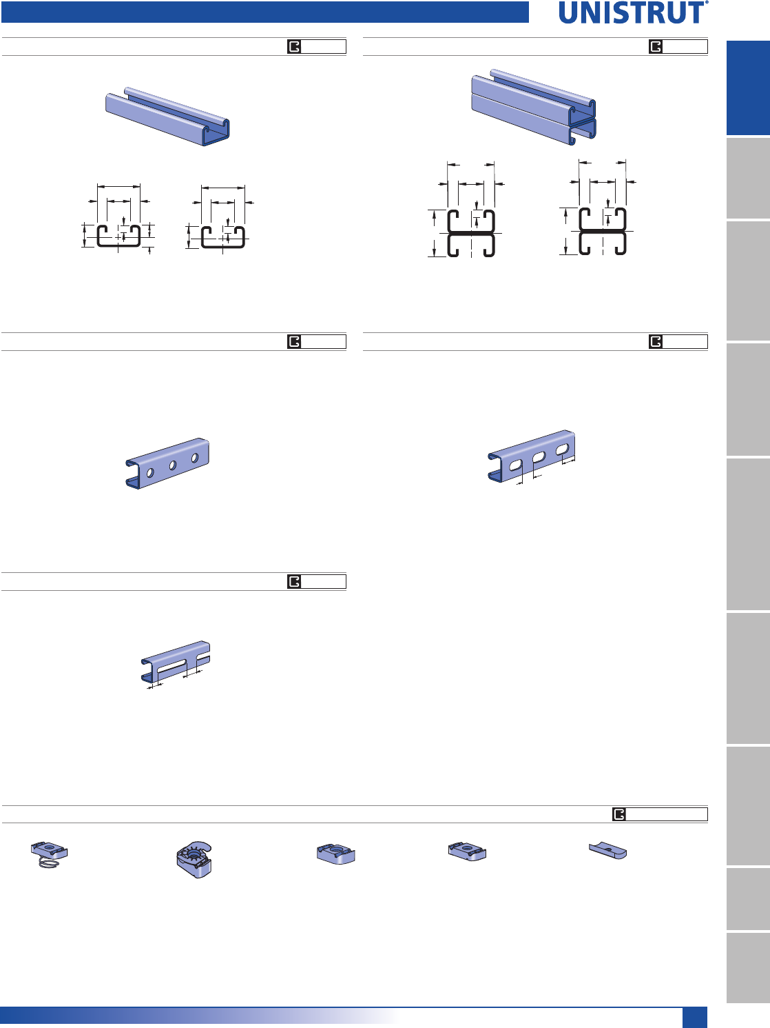
51
15⁄8" Framing System
1 5¼8" ChannelTelestrutNuts & HardwareGeneral FittingsPipe/Conduit SupportsElectrical FittingsConcrete InsertsSolarUnipier®
7⁄8"
13⁄16"
15⁄8"
3⁄8"3⁄8"
9⁄32"
2
1
.321"
.492"
2
1
22.2
20.6
41.3
9.5 9.5
7.1
2
1
15⁄8"
15⁄8"
3⁄8"
9⁄32"
3⁄8"
7⁄8"
2
1
41.3
41.3
22.2
9.5 9.5
7.1
P4520 P4521
P4520 HS P4520 T
P4520 SL
Wt/100 Ft: 118 Lbs (175 kg/100 m)
Wt/100 Ft: 120 Lbs (177 kg/100 m) Wt/100 Ft: 120 Lbs (177 kg/100 m)
9⁄16" (14.3) Dia. Holes
1 7⁄8" (47.6) on Center
1⁄2"
(12.7)
1"
(25.4)
Slots are
3" (76.2) x 13⁄32" (10.3)
4" (101.6) on Center
1 3⁄16"
(30.2)
Slots are
11⁄8" (28.6) x 9⁄16" (14.3)
2" (50.8) on Center
7⁄8"
(22.2)
P3006-0832
P3006-1024
P3006-1420
P3007
P3008
P3009
P3013
P3016-0632
P3016-0832
P3016-1024
P3016-1420
P4006-0832
P4006-1024
P4006-1420
P4007
P4008
P4009
P4010
P4006T1420
P4008T
P4010T
P4012
P4023
U
N
I
S
T
R
U
T
U
N
I
S
T
R
U
T
Channel Finishes: PL, GR, HG, PG, ZD; Standard Lengths: 10' & 20'
Wt/100 Ft: 131 Lbs (190 kg/100 m)
$OORZDEOH0RPHQW,Q/EV1P
12 Gauge Nominal Thickness .105" (2.7mm)
Wt/100 Ft: 262 Lbs (390 kg/100 m)
$OORZDEOH0RPHQW,Q/EV1P
12 Gauge Nominal Thickness .105" (2.7mm)
CHANNEL NUTS (REFER TO PAGES 73,74 FOR DETAILS) SEE PAGE 73, 74
GR PG GR PG
GR PGGR PG
GR PG
P4520 & P4521 Channels
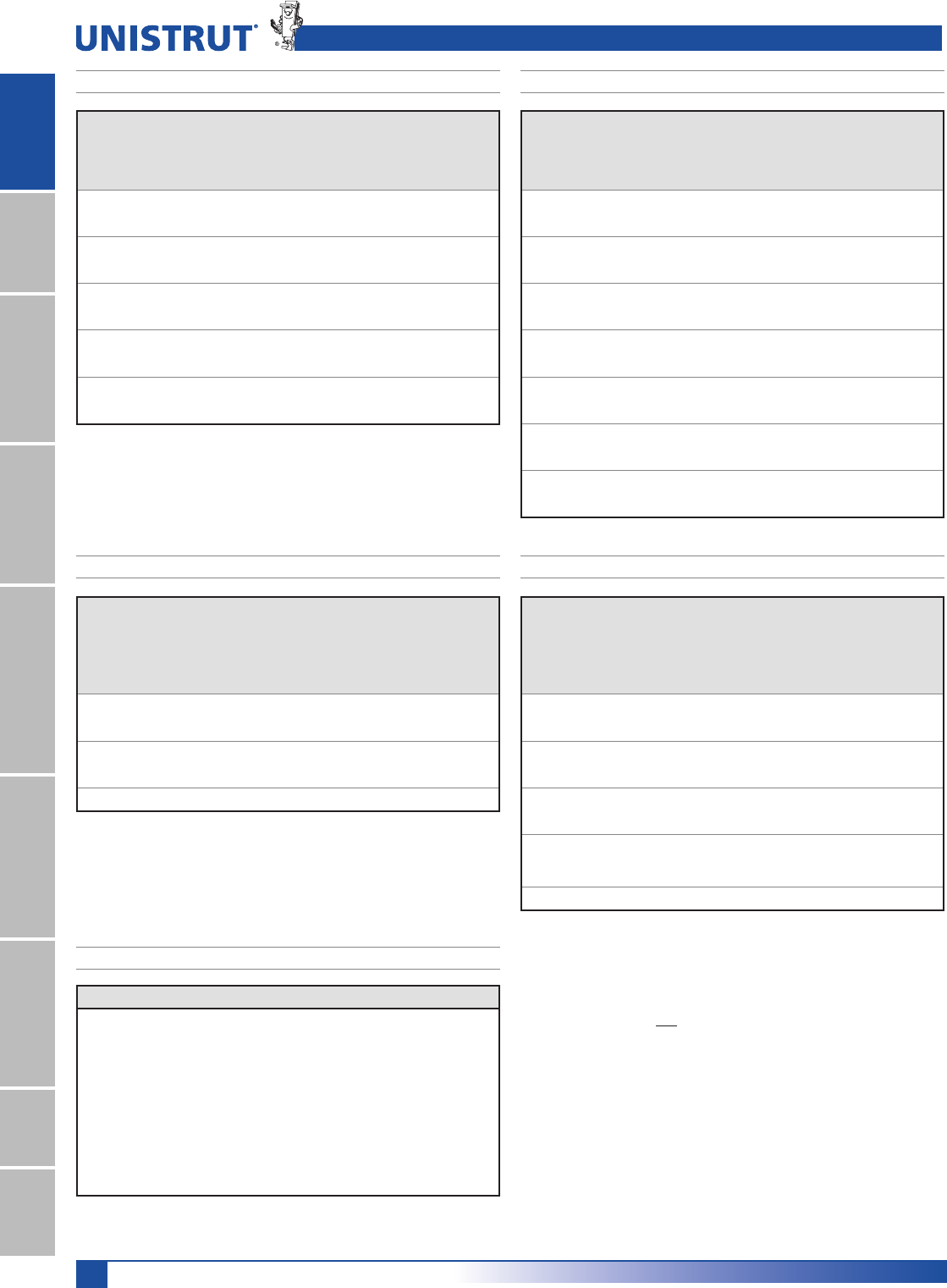
52
15⁄8" Framing System
1 5¼8" ChannelTelestrutNuts & HardwareGeneral FittingsPipe/Conduit SupportsElectrical FittingsConcrete InsertsSolarUnipier®
P4520 - BEAM LOADING P4521 - BEAM LOADING
Span
In
Max
Allowable
Uniform Load
Lbs
Defl. at
Uniform
Load
In
Uniform Loading at Deflection
Span/180
Lbs
Span/240
Lbs
Span/360
Lbs
24 540 0.11 540 510 340
36 360 0.24 300 220 150
48 270 0.43 170 130 80
60 220 0.68 110 80 50
72 180 0.96 70 60 40
84 150 1.27 60 40 30
96 130 1.65 40 30 20
108 120 2.16 30 20 20
120 110 2.72 30 20 NR
144 90 3.84 20 NR NR
Span
In
Max
Allowable
Uniform Load
Lbs
Defl. at
Uniform
Load
In
Uniform Loading at Deflection
Span/180
Lbs
Span/240
Lbs
Span/360
Lbs
24 1,510 0.06 1,510 1,510 1,510
36 1,010 0.14 1,010 1,010 710
48 760 0.25 760 600 400
60 610 0.40 510 380 260
72 500 0.56 360 270 180
84 430 0.77 260 200 130
96 380 1.01 200 150 100
108 340 1.29 160 120 80
120 300 1.56 130 100 60
144 250 2.25 90 70 40
168 220 3.14 70 50 NR
192 190 4.05 50 NR NR
216 170 5.16 NR NR NR
240 150 6.24 NR NR NR
P4520 - COLUMN LOADING
Unbraced
Height
In
Maximum
Allowable
Load
at Slot Face
Lbs
Maximum Column Load Applied at C.G.
K = 0.65
Lbs
K = 0.80
Lbs
K =1.0
Lbs
K = 1.2
Lbs
24 2,250 7,480 6,800 5,820 4,810
36 1,980 5,950 4,810 3,380 2,350
48 1,580 4,310 2,970 1,900 **
60 1,210 2,880 1,900 ** **
72 950 2,000 ** ** **
P4521 - COLUMN LOADING
Unbraced
Height
In
Maximum
Allowable
Load
at Slot Face
Lbs
Maximum Column Load Applied at C.G.
K = 0.65
Lbs
K = 0.80
Lbs
K =1.0
Lbs
K = 1.2
Lbs
24 4,140 16,490 15,980 14,970 13,810
36 3,980 15,100 13,810 11,910 9,940
48 3,730 13,190 11,260 8,650 6,270
60 3,390 11,090 8,650 5,780 4,010
72 2,950 8,970 6,270 4,010 2,790
84 2,510 6,980 4,610 2,950 **
96 2,130 5,340 3,530 ** **
108 1,820 4,220 2,790 ** **
120 ** 3,420 ** ** **
P4520/P4521 - ELEMENTS OF SECTION
Parameter P4400 P4401
Area of Section 0.384 In20.770 In2
Axis 1-1
Moment of Inertia (I) 0.031 In40.146 In4
Section Modulus (S) 0.064 In30.180 In3
Radius of Gyration (r) 0.283 In 0.436 In
Axis 2-2
Moment of Inertia (I) 0.138 In40.277 In4
Section Modulus (S) 0.170 In30.340 In3
Radius of Gyration (r) 0.599 In 0.599 In
Notes:
* Load limited by spot weld shear.
./»U !
NR = Not Recommended.
1. Beam loads are given in total uniform load (W Lbs) not uniform load (w lbs/ft or
w lbs/in).
2. Beam loads are based on a simple span and assumed to be adequately laterally
braced. Unbraced spans can reduce beam load carrying capacity. Refer to Page 62
for reduction factors for unbraced lengths.
3. For pierced channel, multiply beam loads by the following factor:
"KO" Series .......95% "T" Series ..........85%
"HS" Series .......90% "SL" Series ........85%
4. Deduct channel weight from the beam loads.
5. For concentrated midspan point loads, multiply beam loads by 50% and the
corresponding deflection by 80%. For other load conditions refer to page 18.
6. All beam loads are for bending about Axis 1-1.
P4520 & P4521 Channels
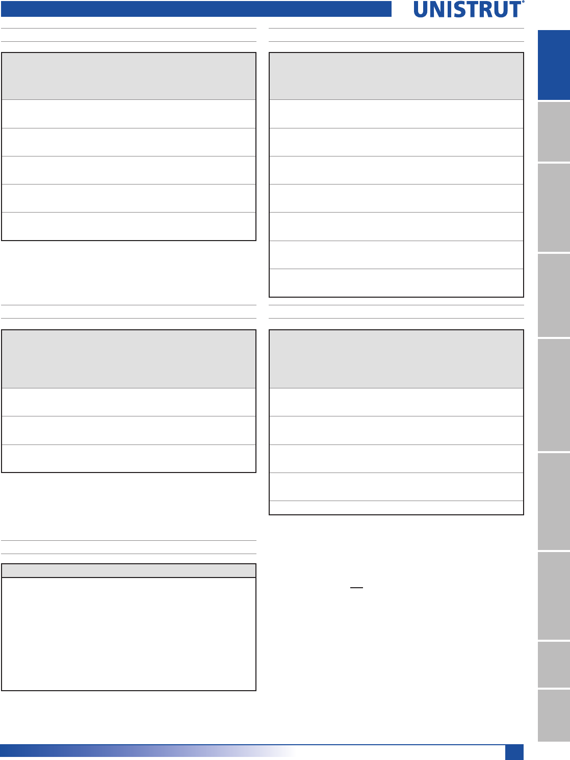
53
15⁄8" Framing System
1 5¼8" ChannelTelestrutNuts & HardwareGeneral FittingsPipe/Conduit SupportsElectrical FittingsConcrete InsertsSolarUnipier®
Unbraced
Height
mm
Maximum
Allowable
Load
at Slot Face
kN
Maximum Column Load Applied at C.G.
K = 0.65
kN
K = 0.80
kN
K =1.0
kN
K = 1.2
kN
600 10.3 34.1 31.1 26.8 22.2
750 9.7 30.9 26.8 21.1 15.8
1000 8.5 24.9 19.3 12.8 8.9
1250 6.9 18.9 12.8 8.2 **
1500 5.6 13.5 8.9 ** **
1750 4.6 9.9 6.5 ** **
Unbraced
Height
mm
Maximum
Allowable
Load
at Slot Face
kN
Maximum Column Load Applied at C.G.
K = 0.65
kN
K = 0.80
kN
K =1.0
kN
K = 1.2
kN
600 18.8 74.9 72.8 68.3 63.1
750 18.5 72.5 68.3 61.8 54.7
1000 17.8 66.2 59.5 49.8 40.1
1250 16.8 58.9 49.8 37.8 27.0
1500 15.5 51.1 40.1 27.0 18.8
1750 14.0 43.1 31.1 19.9 13.8
2000 12.2 35.5 23.8 15.2 **
2500 9.3 23.0 15.2 ** **
3000 ** 16.0 ** ** **
Span
mm
Max
Allowable
Uniform Load
kN
Defl. at
Uniform
Load
mm
Uniform Loading at Deflection
Span/180
kN
Span/240
kN
Span/360
kN
600 2.5 2.6 2.5 2.4 1.6
750 2.0 4.1 2.0 1.5 1.0
1000 1.5 7.3 1.1 0.9 0.6
1250 1.2 11.3 0.7 0.5 0.4
1500 1.0 16.5 0.5 0.4 0.3
1750 0.9 22.6 0.4 0.3 0.2
2000 0.7 28.4 0.3 0.2 0.1
2500 0.6 45.0 0.2 0.1 0.1
3000 0.5 65.8 0.1 0.1 NR
3500 0.4 85.5 0.1 0.1 NR
Span
mm
Max
Allowable
Uniform Load
kN
Defl. at
Uniform
Load
mm
Uniform Loading at Deflection
Span/180
kN
Span/240
kN
Span/360
kN
600 7.0 1.6 7.0 7.0 7.0
750 5.6 2.4 5.6 5.6 4.8
1000 4.2 4.3 4.2 4.0 2.7
1250 3.4 6.7 3.4 2.6 1.7
1500 2.8 9.6 2.4 1.8 1.2
1750 2.4 13.3 1.8 1.3 0.9
2000 2.1 17.2 1.4 1.0 0.7
2500 1.7 27.0 0.9 0.6 0.5
3000 1.4 39.1 0.6 0.5 0.3
3500 1.2 52.0 0.5 0.3 0.2
4000 1.0 68.7 0.3 0.3 0.2
4500 0.9 85.1 0.3 0.2 NR
5000 0.8 105.0 0.2 NR NR
6000 0.7 151.2 NR NR NR
P4520 - BEAM LOADING (METRIC) P4521 - BEAM LOADING (METRIC)
P4520 - COLUMN LOADING (METRIC)P4521 - COLUMN LOADING (METRIC)
P4520/P4521 - ELEMENTS OF SECTION (METRIC)
Parameter P4100 P4101
Area of Section 2.48 cm24.97 cm2
Axis 1-1
Moment of Inertia (I) 1.29 cm46.08 cm4
Section Modulus (S) 1.05 cm32.95 cm3
Radius of Gyration (r) 0.72 cm 1.11 cm
Axis 2-2
Moment of Inertia (I) 5.74 cm411.53 cm4
Section Modulus (S) 2.79 cm35.57 cm3
Radius of Gyration (r) 1.52 cm 1.53 cm
Notes:
* Load limited by spot weld shear.
./»U !
NR = Not Recommended.
1. Beam loads are given in total uniform load (W Lbs) not uniform load (w lbs/ft or
w lbs/in).
2. Beam loads are based on a simple span and assumed to be adequately laterally
braced. Unbraced spans can reduce beam load carrying capacity. Refer to Page 62
for reduction factors for unbraced lengths.
3. For pierced channel, multiply beam loads by the following factor:
"KO" Series .......95% "T" Series ..........85%
"HS" Series .......90% "SL" Series ........85%
4. Deduct channel weight from the beam loads.
5. For concentrated midspan point loads, multiply beam loads by 50% and the
corresponding deflection by 80%. For other load conditions refer to page 18.
6. All beam loads are for bending about Axis 1-1.
P4520 & P4521 Channels
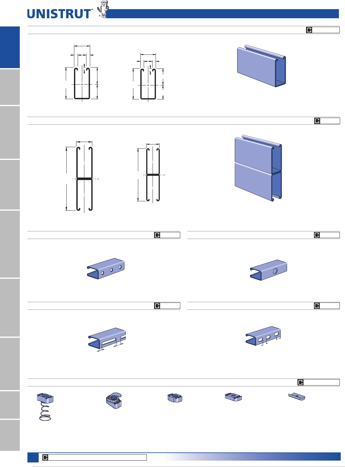
54
15⁄8" Framing System
1 5¼8" ChannelTelestrutNuts & HardwareGeneral FittingsPipe/Conduit SupportsElectrical FittingsConcrete InsertsSolarUnipier®
P5000
P5001
1
2
41.3
44.5
9.5 9.5
22.2
38.1
7.1
82.6
1
3 1⁄4"
1 5⁄8"
3⁄8"
3⁄8"
7⁄8"
9⁄32"
1.750"
1.500"
2
6 1⁄2"
1 5⁄8"
2
1
2
1
41.3
165.1
Wt/100 Ft: 610 Lbs (907 kg/100 m)
$OORZDEOH0RPHQW,Q/EV1P
12 Gauge Nominal Thickness .105" (2.7mm)
Wt/100 Ft: 305 Lbs (454 kg/100 m)
$OORZDEOH0RPHQW,Q/EV1P
12 Gauge Nominal Thickness .105" (2.7mm)
P5000 TP5000 SL
P5000 KO
P5000 HS
P3006-0832
P3006-1024
P3006-1420
P3007
P3008
P3009
P3010
P3016-0632
P3016-0832
P3016-1024
P3016-1420
P1006T1420
P1008T
P1010T
P1012
P1023
P1024
Channel Finishes: PL, GR, HG, PG, ZD; Standard Lengths: 10' & 20'
P5000 & P5001 Channels
9⁄16" (14.3) Dia. Holes
1 7⁄8" (47.6) on Center
7⁄8" (22.2) Knockouts
6" (152.4) on Center
1⁄2"
(12.7)
1"
(25.4)
Slots are
3" (76.2) x 13⁄32" (10.3)
4" (101.6) on Center
1 3⁄16"
(30.2)
7⁄8"
(22.2)
Slots are
11⁄8" (28.6) x 9⁄16" (14.3)
2" (50.8) on Center
Wt/100 Ft: 300 Lbs (446 kg/100 m) Wt/100 Ft: 305 Lbs (454 kg/100 m)
Wt/100 Ft: 300 Lbs (446 kg/100 m) Wt/100 Ft: 300 Lbs (446 kg/100 m)
U
N
I
S
T
R
U
T
U
N
I
S
T
R
U
T
GR PL PG
CORE PRODUCTS - TYPICALLY AVAILABLE FROM STOCK
CHANNEL NUTS
(
REFER TO HARDWARE SECTION FOR DETAILS
)
P5506-0832
P5506-1024
P5506-1420
P5507
P5508
P5509
P5510
CHANNEL NUTS (REFER TO PAGES 73,74 FOR DETAILS) SEE PAGE 73, 74
GR PG
GR PG
GR PG
GR PG
GR PG

55
15⁄8" Framing System
1 5¼8" ChannelTelestrutNuts & HardwareGeneral FittingsPipe/Conduit SupportsElectrical FittingsConcrete InsertsSolarUnipier®
Span
In
Max
Allowable
Uniform Load
Lbs
Defl. at
Uniform
Load
In
Uniform Loading at Deflection
Span/180
Lbs
Span/240
Lbs
Span/360
Lbs
24 6,890*0.01 6,890*6,890*6,890*
36 6,890*0.02 6,890*6,890*6,890*
48 6,890*0.05 6,890*6,890*6,890*
60 6,420 0.10 6,420 6,420 6,420
72 5,350 0.14 5,350 5,350 5,350
84 4,590 0.19 4,590 4,590 4,590
96 4,020 0.25 4,020 4,020 4,020
108 3,570 0.32 3,570 3,570 3,360
120 3,210 0.39 3,210 3,210 2,720
144 2,680 0.57 2,680 2,680 1,890
168 2,290 0.77 2,290 2,080 1,390
192 2,010 1.01 2,010 1,590 1,060
216 1,780 1.27 1,680 1,260 840
240 1,610 1.58 1,360 1,020 680
Span
In
Max
Allowable
Uniform Load
Lbs
Defl. at
Uniform
Load
In
Uniform Loading at Deflection
Span/180
Lbs
Span/240
Lbs
Span/360
Lbs
24 5,260 0.03 5,260 5,260 5,260
36 3,500 0.07 3,500 3,500 3,500
48 2,630 0.12 2,630 2,630 2,630
60 2,100 0.18 2,100 2,100 1,920
72 1,750 0.26 1,750 1,750 1,330
84 1,500 0.36 1,500 1,470 980
96 1,310 0.47 1,310 1,120 750
108 1,170 0.59 1,170 890 590
120 1,050 0.73 960 720 480
144 880 1.06 670 500 330
168 750 1.43 490 370 240
192 660 1.88 370 280 190
216 580 2.35 300 220 150
240 530 2.95 240 180 120
P5000 - COLUMN LOADING
P5000/P5001 - ELEMENTS OF SECTION
Unbraced
Height
In
Maximum
Allowable
Load
at Slot Face
Lbs
Maximum Column Load Applied at C.G.
K = 0.65
Lbs
K = 0.80
Lbs
K =1.0
Lbs
K = 1.2
Lbs
24 5,650 16,870 15,180 12,850 10,600
36 4,690 13,140 10,600 7,650 5,660
48 3,560 9,550 6,860 4,790 3,660
60 2,730 6,680 4,790 3,450 2,710
72 2,160 4,980 3,660 2,710 2,170
84 1,760 3,950 2,960 2,240 1,820
96 1,500 3,270 2,500 1,930 1,580
108 1,310 2,800 2,170 1,690 1,390
120 1,170 2,450 1,930 1,510 **
144 980 1,980 1,580 ** **
168 850 1,670 1,340 ** **
P5001 - COLUMN LOADING
Unbraced
Height
In
Maximum
Allowable
Load
at Slot Face
Lbs
Maximum Column Load Applied at C.G.
K = 0.65
Lbs
K = 0.80
Lbs
K =1.0
Lbs
K = 1.2
Lbs
24 10,670 39,230 38,030 36,210 34,240
36 10,350 36,450 34,240 31,200 28,260
48 9,940 33,220 30,200 26,430 23,190
60 9,290 29,950 26,430 22,470 19,380
72 8,560 26,880 23,190 19,380 16,450
84 7,860 24,140 20,520 17,040 12,090
96 7,220 21,790 18,370 13,330 9,250
108 6,600 19,790 16,450 10,530 7,310
120 5,760 18,130 13,330 8,530 **
144 4,390 14,020 9,250 ** **
168 3,420 10,300 6,800 ** **
P5000 - BEAM LOADING P5001 - BEAM LOADING
P5000 & P5001 Channels
Parameter P5000 P5001
Area of Section 0.897 In21.793 In2
Axis 1-1
Moment of Inertia (I) 1.098 In46.227 In4
Section Modulus (S) 0.627 In31.916 In3
Radius of Gyration (r) 1.107 In 1.864 In
Axis 2-2
Moment of Inertia (I) 0.433 In40.866 In4
Section Modulus (S) 0.533 In31.066 In3
Radius of Gyration (r) 0.695 In 0.695 In
Notes:
* Load limited by spot weld shear.
./»U !
NR = Not Recommended.
1. Beam loads are given in total uniform load (W Lbs) not uniform load (w lbs/ft or
w lbs/in).
2. Beam loads are based on a simple span and assumed to be adequately laterally
braced. Unbraced spans can reduce beam load carrying capacity. Refer to Page 62
for reduction factors for unbraced lengths.
3. For pierced channel, multiply beam loads by the following factor:
"KO" Series .......95% "T" Series ..........85%
"HS" Series .......90% "SL" Series ........85%
4. Deduct channel weight from the beam loads.
5. For concentrated midspan point loads, multiply beam loads by 50% and the
corresponding deflection by 80%. For other load conditions refer to page 18.
6. All beam loads are for bending about Axis 1-1.
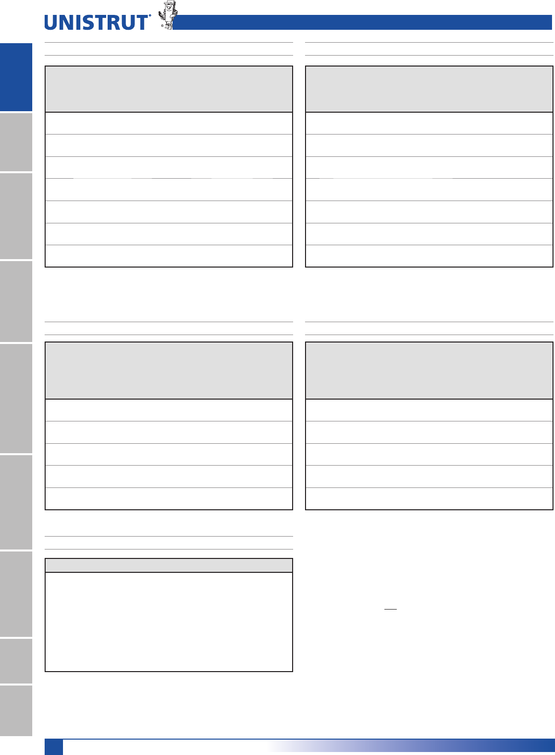
56
15⁄8" Framing System
1 5¼8" ChannelTelestrutNuts & HardwareGeneral FittingsPipe/Conduit SupportsElectrical FittingsConcrete InsertsSolarUnipier®
Unbraced
Height
mm
Maximum
Allowable
Load
at Slot Face
kN
Maximum Column Load Applied at C.G.
K = 0.65
kN
K = 0.80
kN
K =1.0
kN
K = 1.2
kN
600 25.2 75.5 68.1 58.0 48.0
750 23.5 67.5 58.0 45.7 35.0
1,000 19.4 53.7 41.9 29.3 21.8
1,250 15.4 41.0 29.3 20.5 15.7
1,500 12.4 30.5 21.8 15.7 12.3
1,750 10.2 23.8 17.3 12.8 10.2
2,000 8.5 19.3 14.4 10.8 8.7
2,250 7.3 16.3 12.3 9.4 7.6
2,500 6.5 14.1 10.8 8.3 6.9
2,750 5.8 12.4 9.6 7.5 6.2
Unbraced
Height
mm
Maximum
Allowable
Load
at Slot Face
kN
Maximum Column Load Applied at C.G.
K = 0.65
kN
K = 0.80
kN
K =1.0
kN
K = 1.2
kN
600 47.5 174.9 169.7 161.7 153.2
750 46.8 169.2 161.7 150.9 139.8
1,000 45.6 158.2 147.2 132.6 118.8
1,250 44.0 146.3 132.6 115.6 101.2
1,500 41.6 134.3 118.8 101.2 87.4
1,750 38.9 122.9 106.6 89.4 76.8
2,000 36.3 112.5 96.2 80.0 61.2
2,250 33.9 103.2 87.4 69.6 48.4
2,500 31.6 95.0 80.0 56.4 39.1
2,750 29.3 87.8 72.9 46.6 32.4
P5000 & P5001 Channels
Span
mm
Max
Allowable
Uniform Load
kN
Defl. at
Uniform
Load
mm
Uniform Loading at Deflection
Span/180
kN
Span/240
kN
Span/360
kN
600 23.8 1 23.8 23.8 23.8
750 19.0 1 19.0 19.0 19.0
1,000 14.2 2 14.2 14.2 14.2
1,250 11.4 3 11.4 11.4 11.4
1,500 9.5 5 9.5 9.5 8.8
1,750 8.1 6 8.1 8.1 6.5
2,000 7.1 8 7.1 7.1 4.9
2,500 5.7 12 5.7 4.8 3.2
3,000 4.8 18 4.4 3.3 2.2
3,500 4.1 25 3.2 2.4 1.6
4,000 3.6 32 2.5 1.9 1.2
4,500 3.2 40 2.0 1.5 1.0
5,000 2.8 50 1.6 1.2 0.8
6,000 2.4 71 1.1 0.8 0.5
Span
mm
Max
Allowable
Uniform Load
kN
Defl. at
Uniform
Load
mm
Uniform Loading at Deflection
Span/180
kN
Span/240
kN
Span/360
kN
600 30.6 * 0 30.6 * 30.6 * 30.6 *
750 30.6 * 0 30.6 * 30.6 * 30.6 *
1,000 30.6 * 1 30.6 * 30.6 * 30.6 *
1,250 30.6 * 1 30.6 * 30.6 * 30.6 *
1,500 29.0 2 29.0 29.0 29.0
1,750 24.9 3 24.9 24.9 24.9
2,000 21.8 4 21.8 21.8 21.8
2,500 17.4 7 17.4 17.4 17.4
3,000 14.5 10 14.5 14.5 12.5
3,500 12.5 13 12.5 12.5 9.2
4,000 10.9 17 10.9 10.5 7.0
4,500 9.7 22 9.7 8.3 5.6
5,000 8.7 27 8.7 6.8 4.5
6,000 7.2 39 6.2 4.7 3.1
P5000 - COLUMN LOADING (METRIC)
P5000/P5001 - ELEMENTS OF SECTION (METRIC)
P5001 - COLUMN LOADING (METRIC)
P5000 - BEAM LOADING (METRIC)P5001 - BEAM LOADING (METRIC)
Parameter P5000 P5001
Area of Section 5.78 cm211.57 cm2
Axis 1-1
Moment of Inertia (I) 45.70 cm4259.17 cm4
Section Modulus (S) 10.28 cm331.40 cm3
Radius of Gyration (r) 2.81 cm 4.73 cm
Axis 2-2
Moment of Inertia (I) 18.02 cm436.04 cm4
Section Modulus (S) 8.73 cm317.46 cm3
Radius of Gyration (r) 1.77 cm 1.77 cm
Notes:
* Load limited by spot weld shear.
./»U !
NR = Not Recommended.
1. Beam loads are given in total uniform load (W Lbs) not uniform load (w lbs/ft or
w lbs/in).
2. Beam loads are based on a simple span and assumed to be adequately laterally
braced. Unbraced spans can reduce beam load carrying capacity. Refer to Page 62
for reduction factors for unbraced lengths.
3. For pierced channel, multiply beam loads by the following factor:
"KO" Series .......95% "T" Series ..........85%
"HS" Series .......90% "SL" Series ........85%
4. Deduct channel weight from the beam loads.
5. For concentrated midspan point loads, multiply beam loads by 50% and the
corresponding deflection by 80%. For other load conditions refer to page 18.
6. All beam loads are for bending about Axis 1-1.
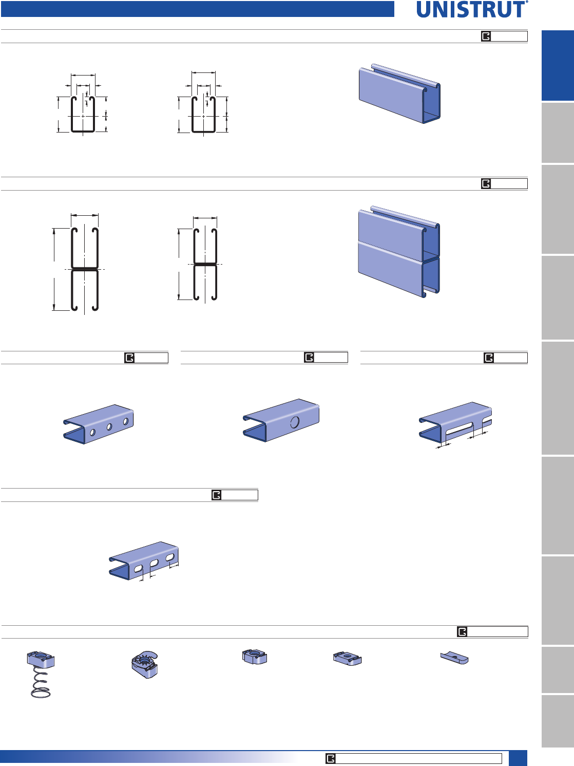
57
15⁄8" Framing System
1 5¼8" ChannelTelestrutNuts & HardwareGeneral FittingsPipe/Conduit SupportsElectrical FittingsConcrete InsertsSolarUnipier®
P5500
P5501
1
28.0
33.9
61.9 7.1
22.2 9.59.5
41.3
2
4 7⁄8"
1 5⁄8"
2
1
Wt/100 Ft: 247 Lbs (367 kg/100 m)
$OORZDEOH0RPHQW,Q/EV1P
12 Gauge Nominal Thickness .105" (2.7mm)
Wt/100 Ft: 494 Lbs (734 kg/100 m)
$OORZDEOH0RPHQW,Q/EV1P
12 Gauge Nominal Thickness .105" (2.7mm)
1
2 7⁄16"
1 5⁄8"
3⁄8"
3⁄8"7⁄8"
9⁄32"1.336"
1.102"
2
41.3
123.8
2
1
P5500 T
P5500 SLP5500 KOP5500 HS
P3006-0832
P3006-1024
P3006-1420
P3007
P3008
P3009
P3010
P3016-0632
P3016-0832
P3016-1024
P3016-1420
P1006T1420
P1008T
P1010T
P1012
P1023
P1024
Channel Finishes: PL, GR, HG, PG, ZD; Standard Lengths: 10' & 20'
P5506-0832
P5506-1024
P5506-1420
P5507
P5508
P5509
P5510
P5500 & P5501 Channels
9⁄16" (14.3) Dia. Holes
1 7⁄8" (47.6) on Center
7⁄8" (22.2) Knockouts
6" (152.4) on Center
1⁄2"
(12.7)
1"
(25.4)
Slots are
3" (76.2) x 13⁄32" (10.3)
4" (101.6) on Center
1 3⁄16"
(30.2)
7⁄8"
(22.2)
Slots are
11⁄8" (28.6) x 9⁄16" (14.3)
2" (50.8) on Center
Wt/100 Ft: 242 Lbs (360 kg/100 m) Wt/100 Ft: 247 Lbs (368 kg/100 m) Wt/100 Ft: 242 Lbs (360 kg/100 m)
Wt/100 Ft: 242 Lbs (360 kg/100 m)
U
N
I
S
T
R
U
T
U
N
I
S
T
R
U
T
GR PG
GR PG
GR PG
CORE PRODUCTS - TYPICALLY AVAILABLE FROM STOCK
CHANNEL NUTS (REFER TO PAGES 73,74 FOR DETAILS) SEE PAGE 73, 74
GR PG GR PG GR PG

58
15⁄8" Framing System
1 5¼8" ChannelTelestrutNuts & HardwareGeneral FittingsPipe/Conduit SupportsElectrical FittingsConcrete InsertsSolarUnipier®
P5500 - BEAM LOADING P5501 - BEAM LOADING
Span
In
Max
Allowable
Uniform Load
Lbs
Defl. at
Uniform
Load
In
Uniform Loading at Deflection
Span/180
Lbs
Span/240
Lbs
Span/360
Lbs
24 3,270 0.04 3,270 3,270 3,270
36 2,180 0.09 2,180 2,180 2,180
48 1,640 0.15 1,640 1,640 1,420
60 1,310 0.24 1,310 1,310 910
72 1,090 0.34 1,090 950 630
84 940 0.47 930 700 470
96 820 0.61 710 530 360
108 730 0.78 560 420 280
120 650 0.95 460 340 230
144 550 1.39 320 240 160
168 470 1.89 230 170 120
192 410 2.46 180 130 90
216 360 3.07 140 110 70
240 330 3.86 110 90 60
Span
In
Max
Allowable
Uniform Load
Lbs
Defl. at
Uniform
Load
In
Uniform Loading at Deflection
Span/180
Lbs
Span/240
Lbs
Span/360
Lbs
24 5,220* 0.01 5,220* 5,220* 5,220*
36 5,220* 0.04 5,220* 5,220* 5,220*
48 4,820 0.08 4,820 4,820 4,820
60 3,860 0.13 3,860 3,860 3,860
72 3,220 0.19 3,220 3,220 3,220
84 2,760 0.26 2,760 2,760 2,500
96 2,410 0.34 2,410 2,410 1,920
108 2,140 0.42 2,140 2,140 1,510
120 1,930 0.52 1,930 1,840 1,230
144 1,610 0.76 1,610 1,280 850
168 1,380 1.03 1,250 940 630
192 1,210 1.35 960 720 480
216 1,070 1.70 760 570 380
240 960 2.09 610 460 310
P5500 & P5501 Channels
P5500 - COLUMN LOADING
Unbraced
Height
In
Maximum
Allowable
Load
at Slot Face
Lbs
Maximum Column Load Applied at C.G.
K = 0.65
Lbs
K = 0.80
Lbs
K =1.0
Lbs
K = 1.2
Lbs
24 4,640 13,840 12,570 10,840 9,190
36 3,970 11,050 9,190 7,030 5,370
48 3,180 8,420 6,390 4,620 3,630
60 2,550 6,250 4,620 3,450 2,780
72 2,120 4,790 3,630 2,780 2,260
84 1,810 3,890 3,010 2,330 1,910
96 1,580 3,290 2,580 2,020 1,650
108 1,400 2,860 2,260 1,770 1,440
120 1,270 2,530 2,020 1,580 **
144 1,060 2,070 1,650 ** **
168 920 1,750 1,380 ** **
P5501 - COLUMN LOADING
Unbraced
Height
In
Maximum
Allowable
Load
at Slot Face
Lbs
Maximum Column Load Applied at C.G.
K = 0.65
Lbs
K = 0.80
Lbs
K =1.0
Lbs
K = 1.2
Lbs
24 8,580 31,810 30,880 29,520 28,100
36 8,350 29,700 28,100 26,000 24,070
48 8,080 27,390 25,330 22,910 20,940
60 7,720 25,170 22,910 20,510 17,170
72 7,270 23,190 20,940 17,170 12,700
84 6,780 21,510 18,740 13,430 9,330
96 6,130 20,110 15,630 10,290 7,150
108 5,450 17,750 12,700 8,130 5,650
120 4,800 15,260 10,290 6,590 **
144 3,760 10,830 7,150 ** **
168 2,970 7,950 5,250 ** **
P5500/P5501 - ELEMENTS OF SECTION
Parameter P5500 P5501
Area of Section 0.726 In21.452 In2
Axis 1-1
Moment of Inertia (I) 0.522 In42.805 In4
Section Modulus (S) 0.390 In31.151 In3
Radius of Gyration (r) 0.848 In 1.390 In
Axis 2-2
Moment of Inertia (I) 0.334 In40.669 In4
Section Modulus (S) 0.411 In30.823 In3
Radius of Gyration (r) 0.679 In 0.679 In
Notes:
* Load limited by spot weld shear.
./»U !
NR = Not Recommended.
1. Beam loads are given in total uniform load (W Lbs) not uniform load (w lbs/ft or
w lbs/in).
2. Beam loads are based on a simple span and assumed to be adequately laterally
braced. Unbraced spans can reduce beam load carrying capacity. Refer to Page 62
for reduction factors for unbraced lengths.
3. For pierced channel, multiply beam loads by the following factor:
"KO" Series .......95% "T" Series ..........85%
"HS" Series .......90% "SL" Series ........85%
4. Deduct channel weight from the beam loads.
5. For concentrated midspan point loads, multiply beam loads by 50% and the
corresponding deflection by 80%. For other load conditions refer to page 18.
6. All beam loads are for bending about Axis 1-1.
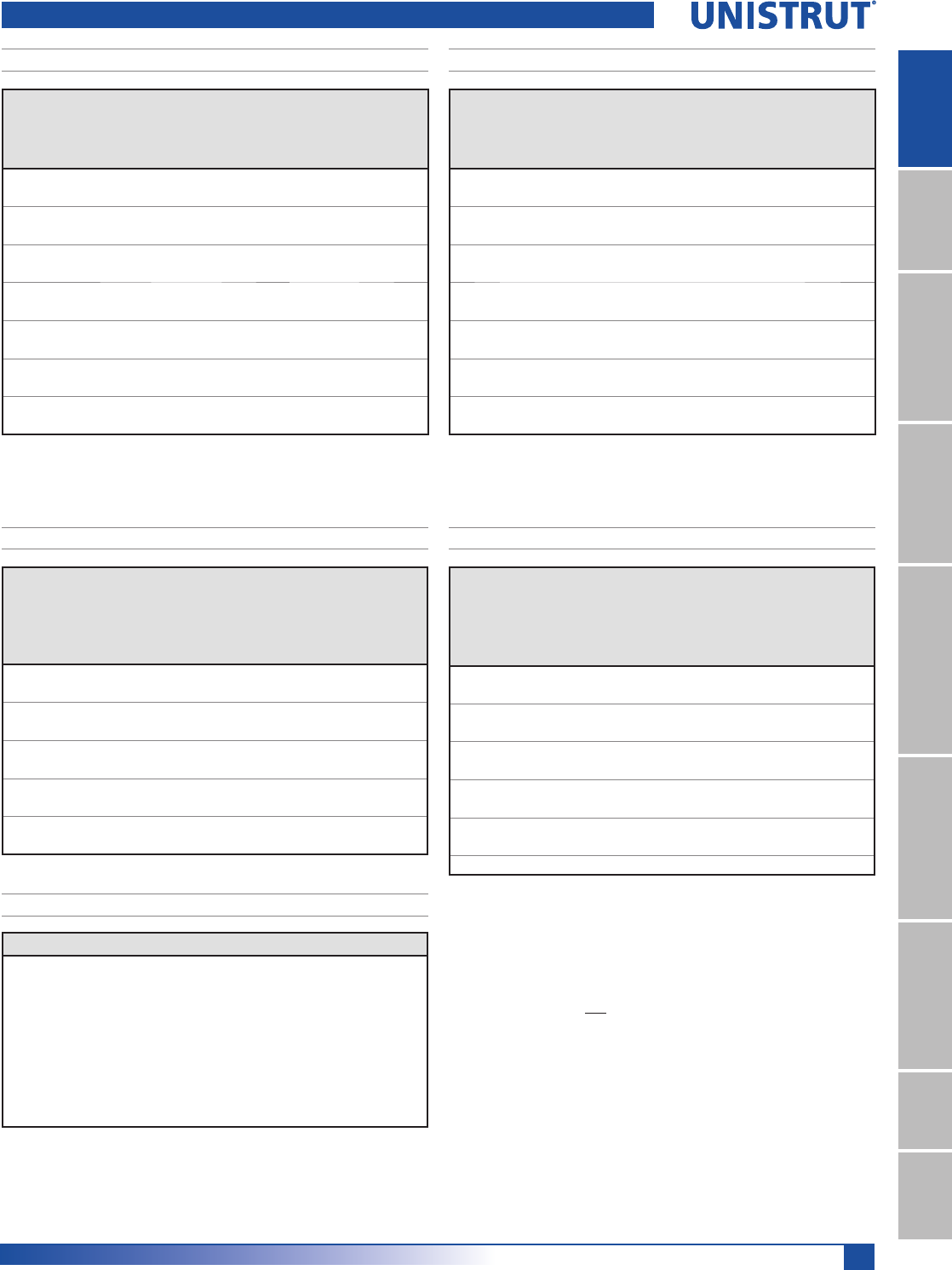
59
15⁄8" Framing System
1 5¼8" ChannelTelestrutNuts & HardwareGeneral FittingsPipe/Conduit SupportsElectrical FittingsConcrete InsertsSolarUnipier®
Unbraced
Height
mm
Maximum
Allowable
Load
at Slot Face
kN
Maximum Column Load Applied at C.G.
K = 0.65
kN
K = 0.80
kN
K =1.0
kN
K = 1.2
kN
600 20.7 61.9 56.4 48.8 41.6
750 19.6 55.9 48.8 39.8 31.9
1,000 16.7 45.7 37.0 27.4 21.0
1,250 13.8 36.4 27.4 19.9 15.7
1,500 11.5 28.5 21.0 15.7 12.6
1,750 9.8 22.6 17.1 13.0 10.6
2,000 8.6 18.9 14.5 11.2 9.1
2,250 7.6 16.2 12.6 9.8 8.0
2,500 6.9 14.2 11.2 8.7 7.2
2,750 6.2 12.7 10.1 7.9 6.4
Unbraced
Height
mm
Maximum
Allowable
Load
at Slot Face
kN
Maximum Column Load Applied at C.G.
K = 0.65
kN
K = 0.80
kN
K =1.0
kN
K = 1.2
kN
600 38.2 141.5 137.4 131.3 125.0
750 37.1 132.1 125.0 115.6 107.1
1,000 35.9 121.8 112.7 101.9 93.1
1,250 34.3 112.0 101.9 91.2 76.4
1,500 32.3 103.2 93.1 76.4 56.5
1,750 30.2 95.7 83.4 59.7 41.5
2,000 27.3 89.5 69.5 45.8 31.8
2,500 24.2 79.0 56.5 36.2 25.1
3,000 21.3 67.9 45.8 29.3 **
3,500 16.7 48.2 31.8 ** **
4,000 13.2 35.4 23.3 ** **
P5500 & P5501 Channels
Span
mm
Max
Allowable
Uniform Load
kN
Defl. at
Uniform
Load
mm
Uniform Loading at Deflection
Span/180
kN
Span/240
kN
Span/360
kN
600 14.8 1 14.8 14.8 14.8
750 11.8 1 11.8 11.8 11.8
1,000 8.9 3 8.9 8.9 8.9
1,250 7.1 4 7.1 7.1 6.1
1,500 5.9 6 5.9 5.9 4.2
1,750 5.1 8 5.1 4.6 3.1
2,000 4.5 10 4.5 3.5 2.4
2,500 3.6 16 3.0 2.3 1.5
3,000 3.0 24 2.1 1.6 1.1
3,500 2.5 32 1.6 1.2 0.8
4,000 2.2 42 1.2 0.9 0.6
4,500 2.0 53 0.9 0.7 0.4
5,000 1.8 66 0.8 0.6 0.4
6,000 1.5 94 0.5 0.4 0.3
Span
mm
Max
Allowable
Uniform Load
kN
Defl. at
Uniform
Load
mm
Uniform Loading at Deflection
Span/180
kN
Span/240
kN
Span/360
kN
600 23.2 * 0 23.2 * 23.2 * 23.2 *
750 23.2 * 1 23.2 * 23.2 * 23.2 *
1,000 23.2 * 1 23.2 * 23.2 * 23.2 *
1,250 20.9 2 20.9 20.9 20.9
1,500 17.4 3 17.4 17.4 17.4
1,750 14.9 4 14.9 14.9 14.9
2,000 13.1 6 13.1 13.1 12.7
2,500 10.5 9 10.5 10.5 8.1
3,000 8.7 13 8.7 8.5 5.6
3,500 7.5 18 7.5 6.2 4.1
4,000 6.5 23 6.3 4.8 3.2
4,500 5.8 29 5.0 3.7 2.5
5,000 5.2 36 4.1 3.0 2.0
6,000 4.4 52 2.8 2.1 1.4
P5500 - BEAM LOADING (METRIC)P5501 - BEAM LOADING (METRIC)
P5500 - COLUMN LOADING (METRIC)P5501 - COLUMN LOADING (METRIC)
P5500/P5501 - ELEMENTS OF SECTION (METRIC)
Parameter P5500 P5501
Area of Section 4.68 cm29.37 cm2
Axis 1-1
Moment of Inertia (I) 21.71 cm4116.76 cm4
Section Modulus (S) 6.40 cm318.86 cm3
Radius of Gyration (r) 2.15 cm 3.53 cm
Axis 2-2
Moment of Inertia (I) 13.91 cm427.83 cm4
Section Modulus (S) 6.74 cm313.48 cm3
Radius of Gyration (r) 1.72 cm 1.72 cm
Notes:
* Load limited by spot weld shear.
./»U !
NR = Not Recommended.
1. Beam loads are given in total uniform load (W Lbs) not uniform load (w lbs/ft or
w lbs/in).
2. Beam loads are based on a simple span and assumed to be adequately laterally
braced. Unbraced spans can reduce beam load carrying capacity. Refer to Page 62
for reduction factors for unbraced lengths.
3. For pierced channel, multiply beam loads by the following factor:
"KO" Series .......95% "T" Series ..........85%
"HS" Series .......90% "SL" Series ........85%
4. Deduct channel weight from the beam loads.
5. For concentrated midspan point loads, multiply beam loads by 50% and the
corresponding deflection by 80%. For other load conditions refer to page 18.
6. All beam loads are for bending about Axis 1-1.
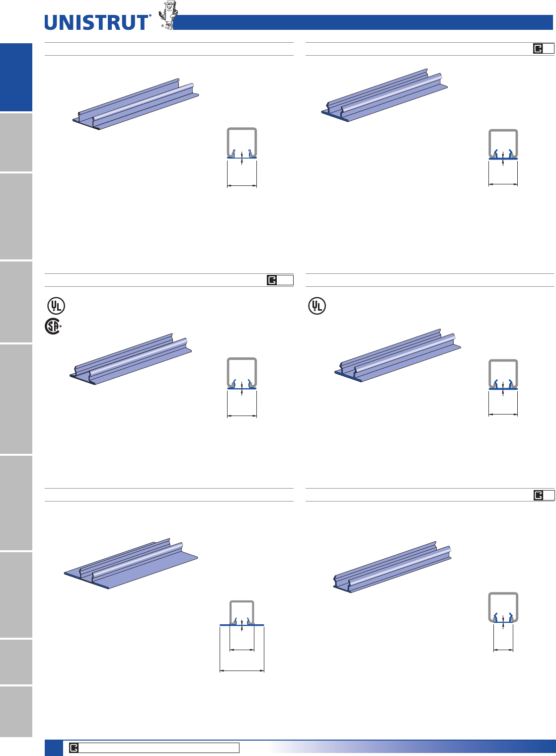
60
15⁄8" Framing System
1 5¼8" ChannelTelestrutNuts & HardwareGeneral FittingsPipe/Conduit SupportsElectrical FittingsConcrete InsertsSolarUnipier®
Finish: PG, PL
Standard length: 10' (3m)
.020"
1 5⁄8"
(41.3)
(0.5)
.085"
1 5⁄8"
(2.2)
(41.3)
.085"
1 5⁄8"
(2.2)
(41.3)
.040"
1 1⁄16"
(1.0)
(27.0)
.040"
1 5⁄8"
(1.0)
(41.3)
(76.2)
3"
.040"
1 5⁄8"
(1.0)
(41.3)
Material: Paintable PVC
Color: Green, Grey
Standard length: 10' (3m)
Material : G.E. Noryl® Plastic
Color: Green, Grey and White
Standard length: 10' (3m)
Finish: GR, PG, PL
Standard length: 10' (3m)
Finish: GR, PG, PL
Standard length: 16' (4.9m)
Material: Plastic
Color: Black
Standard length: 10' (3m)
Note: Use with P3170, P3270, and
P3370 series concrete insert.
P3184 P3184 P
P3712 PP3184 F
Wt/100 Ft: 90 Lbs (134 kg/100 m) Wt/100 Ft: 5.4 Lbs (8.0 kg/100 m)
Wt/100 Ft: 9.4 Lbs (14.0 kg/100 m)Wt/100 Ft: 47 Lbs (69.9 kg/100 m)
P1184 PP1184
Wt/100 Ft: 11 Lbs (16.5 kg/100 m)Wt/100 Ft: 27 Lbs (40.2 kg/100 m)
Closure Strips for 15⁄8" (41mm) Channel
PG
CORE PRODUCTS - TYPICALLY AVAILABLE FROM STOCK
P
P
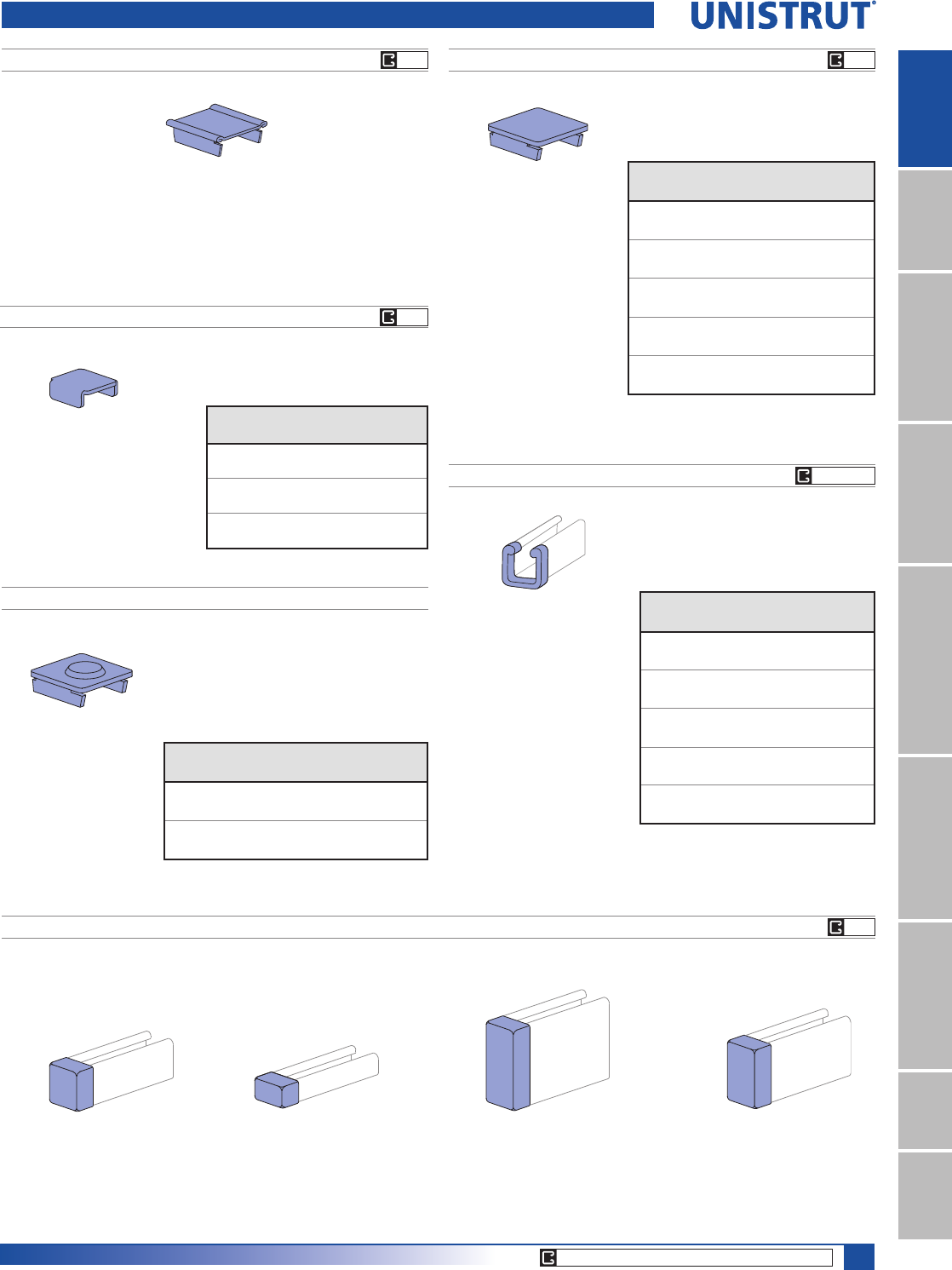
61
15⁄8" Framing System
1 5¼8" ChannelTelestrutNuts & HardwareGeneral FittingsPipe/Conduit SupportsElectrical FittingsConcrete InsertsSolarUnipier®
End Caps and Frame Caps
P1280
P2860-10
Use with P1000, P1100, P2000
channels & P9000 Telestrut.
Wt/100 pcs 3.4 Lbs (1.5 kg)
P1180, P2280,P4280, P5280, P5580
P1280 A, P2280 A
P2860-33
Use with P3300 channel.
Wt/100 pcs 2.5 Lbs (1.1 kg)
P2860-50
Use with P5000 & P1001 channels.
Wt/100 pcs 5 Lbs (2.3 kg)
P2860-55
Use with P5500 channel.
Wt/100 pcs 4.7 Lbs (2.1 kg)
Use with P1000
Material: .060" (1.5)
Material: .075" (1.9)
P2860 PLASTIC WHITE END CAPS
P2859 FRAME CAPS
Part
Number
Use With
Channel
Wt/100 pcs
Lbs (kg)
P1280A P1000 11
5.0
P2280A P2000 11
5.0
Part
Number
Use With
Channel
Wt/100 pcs
/EVNJ
P1180 P1100 12
5.4
P2280 P2000 11
5.0
P4280 P4000 5
2.3
P5280 P5000 22
10.0
P5580 P5500 17
7.7
Material: .075" (1.9)
Part
Number*
Use With
Channel
Wt/100 pcs
Lbs (kg)
P2859-10 P1000 12
5.4
P2859-11 P1001 12
5.4
P2859-12 P3300 5
2.3
P2859-13 P5000 22
10.0
P2859-14 P5500 17
7.7
* $GGFRORUVXI¿[
GR - Green
WH - White
GY - Grey
"A" series frame caps available
Wt/100 pcs: 11 Lbs (5.0 Kg.)
P2407, P3280, P3380 END CAPS
Part
Number
Fits
Channel
Wt/100 pcs
Lbs (kg)
P2407 P1000 10
4.5
P3280 P3000 8
3.6
P3380* P3300 5
2.3
EG EG
EG
GY WH
VY
CORE PRODUCTS - TYPICALLY AVAILABLE FROM STOCK
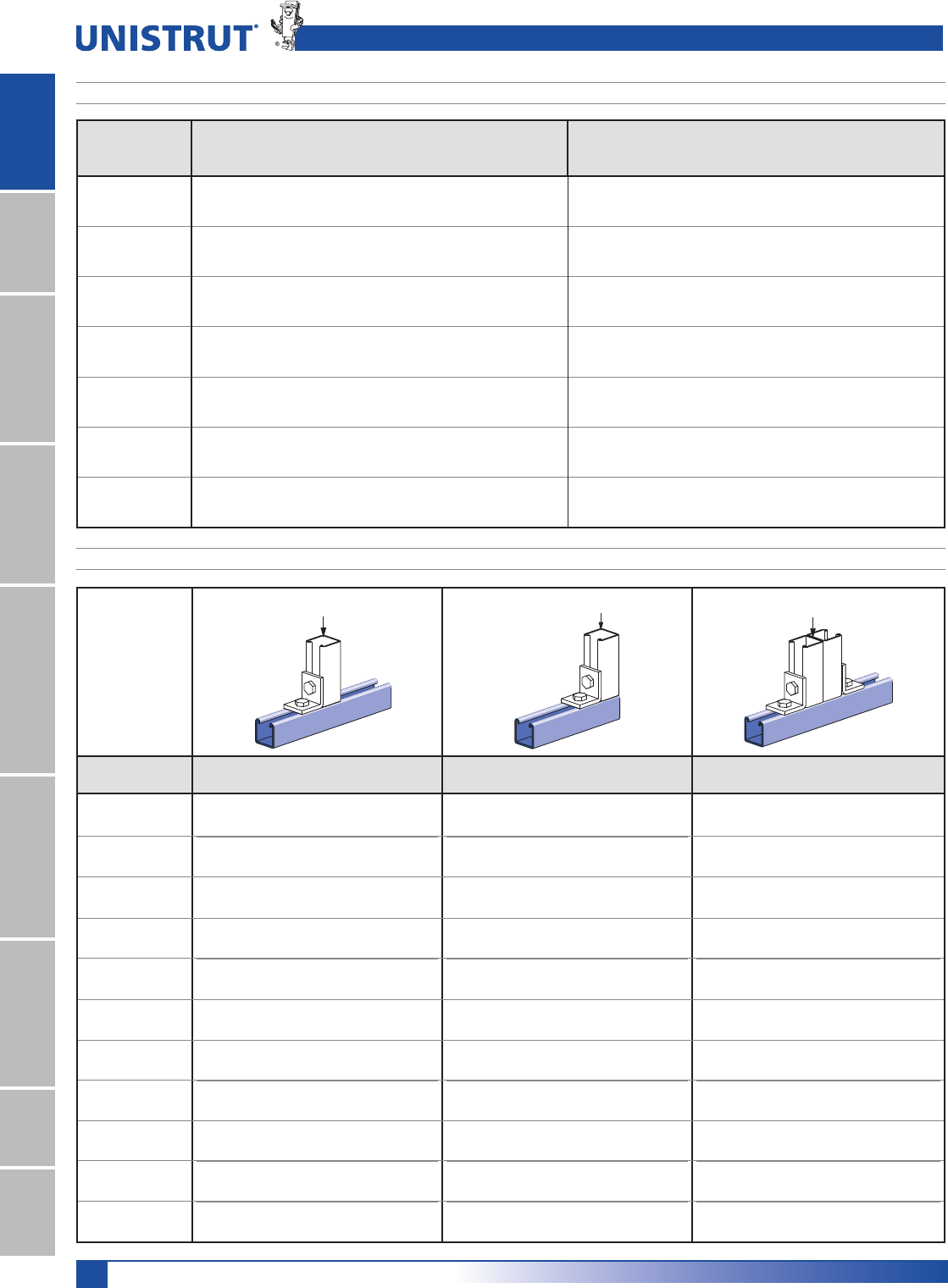
62
15⁄8" Framing System
1 5¼8" ChannelTelestrutNuts & HardwareGeneral FittingsPipe/Conduit SupportsElectrical FittingsConcrete InsertsSolarUnipier®
Lateral Bracing Load Reduction & Bearing Loads
LATERAL BRACING LOAD REDUCTION CHARTS
Span Single Channel Double Channel
Ft. (m) In. (cm) P1000 P1100 P2000 P3000 P3300 P4000 P4100 P4400 P4520 P5000 P5500 P1001 P1101 P2001 P3001 P3301 P4001 P4101 P4401 P4521 P5001 P5501
2 (0.61) 24 (61) 1.00 1.00 1.00 1.00 1.00 1.00 1.00 1.00 1.00 0.98 0.99 1.00 1.00 1.00 1.00 1.00 1.00 1.00 1.00 1.00 1.00 1.00
3 (0.91) 36 (91) 0.94 0.89 0.88 0.96 1.00 0.94 0.98 1.00 1.00 0.85 0.89 1.00 1.00 1.00 1.00 1.00 1.00 1.00 1.00 1.00 1.00 1.00
4 (1.22) 48 (122) 0.88 0.78 0.75 0.91 1.00 0.88 0.94 0.98 1.00 0.70 0.77 1.00 0.98 0.98 1.00 1.00 0.98 1.00 1.00 1.00 0.97 0.98
5 (1.52) 60 (152) 0.82 0.68 0.61 0.88 0.98 0.83 0.91 0.96 1.00 0.55 0.67 0.97 0.93 0.92 0.98 1.00 0.93 0.96 1.00 1.00 0.90 0.93
6 (1.83) 72 (183) 0.78 0.59 0.48 0.84 0.97 0.79 0.89 0.94 0.98 0.44 0.58 0.93 0.87 0.85 0.95 0.97 0.88 0.92 0.97 0.97 0.83 0.87
7 (2.13) 84 (213) 0.75 0.52 0.41 0.82 0.96 0.75 0.86 0.92 0.97 0.38 0.51 0.89 0.82 0.78 0.92 0.95 0.83 0.89 0.95 0.95 0.76 0.81
8 (2.44) 96 (244) 0.71 0.47 0.35 0.79 0.94 0.72 0.84 0.91 0.96 0.33 0.46 0.85 0.76 0.71 0.88 0.92 0.79 0.85 0.92 0.92 0.68 0.76
9 (2.74) 108 (274) 0.69 0.43 0.32 0.77 0.93 0.69 0.82 0.89 0.95 0.30 0.42 0.81 0.70 0.64 0.85 0.90 0.74 0.81 0.90 0.90 0.61 0.70
10 (3.05) 120 (305) 0.66 0.40 0.29 0.75 0.92 0.66 0.80 0.87 0.94 0.28 0.40 0.78 0.65 0.57 0.82 0.87 0.69 0.78 0.87 0.87 0.54 0.64
12 (3.66) 144 (366) 0.61 0.36 0.25 0.70 0.89 0.60 0.76 0.84 0.91 0.24 0.36 0.70 0.54 0.45 0.76 0.82 0.60 0.71 0.82 0.83 0.43 0.53
14 (4.27) 168 (427) 0.55 0.32 0.23 0.66 0.86 0.55 0.73 0.81 0.89 0.22 0.32 0.63 0.45 0.38 0.70 0.78 0.51 0.64 0.77 0.78 0.35 0.45
16 (4.88) 192 (488) 0.51 0.30 0.21 0.62 0.84 0.50 0.69 0.78 0.87 0.21 0.30 0.56 0.39 0.32 0.64 0.73 0.44 0.57 0.72 0.73 0.30 0.39
18 (5.49) 216 (549) 0.47 0.28 0.19 0.58 0.81 0.47 0.65 0.75 0.84 0.19 0.28 0.49 0.34 0.28 0.58 0.68 0.39 0.50 0.67 0.68 0.27 0.34
20 (6.10) 240 (610) 0.44 0.26 0.18 0.54 0.78 0.43 0.61 0.72 0.82 0.18 0.26 0.44 0.31 0.25 0.52 0.63 0.35 0.45 0.62 0.63 0.24 0.30
Loads are
calculated based on
2007 Specification
For The Design Of
Cold Formed Steel
Structural Members
published by AISI
LOAD LOAD
Channel
Bearing Length 15¼8PP
Maximum Allowable Loads Lbs (kN)
Bearing Length 15¼8PP
Maximum Allowable Loads Lbs (kN)
Bearing Length 31¼4PP
Maximum Allowable Loads Lbs (kN)
P1000 6,700 3,100 7,700
29.80 13.79 34.25
P1100 3,500 1,700 4,000
15.57 7.56 17.79
P2000 2,500 1,200 3,000
11.12 5.34 13.34
P3000 6,700 3,200 7,700
29.80 14.23 34.25
P3300 6,800 3,200 7,800
30.25 14.23 34.70
P4000 2,600 1,200 3,000
11.57 5.34 13.34
P4100 3,500 1,800 4,100
15.57 8.01 18.24
P4400 7,300 3,400 8,400
32.47 15.12 37.37
P4520 7,300 3,400 8,400
32.47 15.12 37.37
P5000 6,500 3,000 7,500
28.91 13.34 33.36
P5500 6,600 3,100 7,600
29.36 13.79 33.81
BEARING LOADS ON UNISTRUT CHANNEL
LOAD
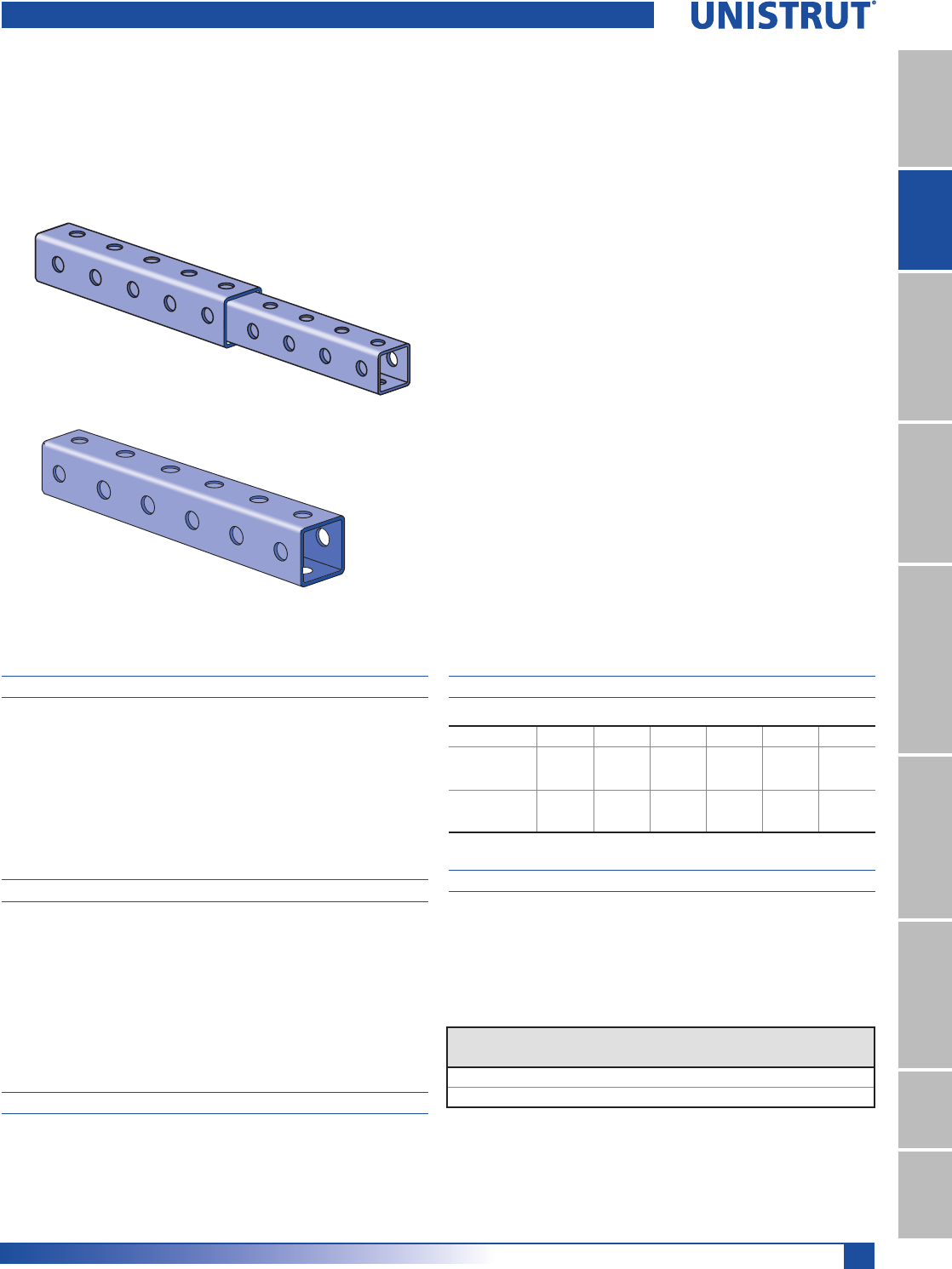
63
15⁄8" Framing System
1 5¼8" ChannelTelestrutNuts & HardwareGeneral FittingsPipe/Conduit SupportsElectrical FittingsConcrete InsertsSolarUnipier®
MATERIAL
Unistrut channels are accurately and carefully cold formed
to size from low-carbon strip steel.
STEEL: PLAIN
12 Ga. (2.7 mm), 14 Ga.(1.9 mm) and
16 Ga. (1.5 mm) ASTM A1011 SS GR 33.
STEEL: PRE-GALVANIZED
12 Ga. (2.7 mm), 14 Ga. (1.9 mm) and
16 Ga. (1.5mm) ASTM A653 GR 33.
FINISHES
Fittings are available in:
Green Powder Coat (GR), conforming to
commercial standards for Powder Coating,
Electro-galvanized (EG), conforming to
ASTM B633 Type III SC1;
Hot-dipped Galvanized (HG), conforming to
ASTM A123 or A153
Plain (PL).
DIMENSIONS
Imperial dimensions are illustrated in inches. Metric dimen-
sions are shown in parenthesis or as noted. Unless noted,
all metric dimensions are in millimeters and rounded to
one decimal place.
DESIGN BOLT TORQUE
BOLT SIZE 1»4"-20 5»16"-18 3»8"-16 1»2"-13 5»8"-11 3»4"-10
Rec.Torque
Ft/Lbs
1P
6
(8)
11
(15)
19
(26)
50
(68)
100
(136)
125
(170)
Max Torque
Ft/Lbs
1P
7
(9)
15
(20)
25
(34)
70
(95)
125
(170)
135
(183)
DESIGN LOAD
Load tables and charts are constructed to be in accor-
dance with the SPECIFICATION FOR THE DESIGN OF COLD-
FORMED STEEL STRUCTURAL MEMBERS 2007 EDITION
published by the AMERICAN IRON AND STEEL INSTITUTE
USING ASD METHOD.
Telescoping Tube ..................................................................65-67
Specialized Fittings ................................................................... 68
Connection Methods ................................................................69
Post Bases .............................................................................68-69
Cutting Chart ............................................................................. 70
Telestrut® System
Type
of Load
Safety Factor
to Yield Strength
Safety Factor
to Ultimate Strength
Beam Loads 1.67 2.0
Column Load 1.80 2.2
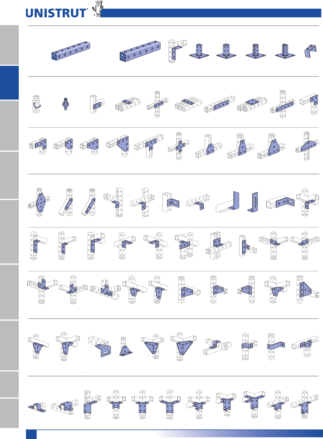
64
15⁄8" Framing System
1 5¼8" ChannelTelestrutNuts & HardwareGeneral FittingsPipe/Conduit SupportsElectrical FittingsConcrete InsertsSolarUnipier®
Telestrut Pictorial Index
Telestrut Telescoping Tubing Special Fittings and Post Bases for Telestrut Telescoping Tubing
P9012-Pg 68 P9014-Pg 69P9013-Pg 69P9324-Pg 68P9000-Pg 65 P9200-Pg 65 P9011-Pg 68 P9207-Pg 68
15⁄8" x 15⁄8"
12 Ga.
17⁄8" x 17⁄8"
12 Ga.
P9209-Pg 68 P9010-Pg 68 P2079-Pg 81P1065-Pg 81 P1066-Pg 81 P1067-Pg 81P1925-Pg 81P1924-Pg 81 P1941-Pg 81 P1036-Pg 81
P1873-Pg 82P1334-Pg 81 P1380-Pg 81P1380A-Pg 81 P1726-Pg 82 P1953-Pg 82
P1028-Pg 82P1031-Pg 82 P1356-Pg 82 P1358-Pg 82
Standard 15⁄8" – Flat Plate Fittings
Standard 15⁄8" – Ninety Degree Fittings
P1950-Pg 82 P2324-Pg 81P2325-Pg 81 P1498-Pg 83P1538A-Pg 83 P1747-Pg 83
P1750-Pg 83
P1026-Pg 82 P1068-Pg 82 P1281-Pg 82 P1458-Pg 82
P1822-Pg 83
P1326-Pg 83 P1346-Pg 83 P1325-Pg 83 P1823-Pg 83 P1934-Pg 84P1821-Pg 83 P1033-Pg 83 P1037-Pg 83 P1038-Pg 83
P1029-Pg 84P1034-Pg 83 P1035-Pg 84 P1357-Pg 84 P1359-Pg 84 P1381-Pg 84 P1290-Pg 84 P1291-Pg 84 P1579-Pg 84 P1727-Pg 84
Standard 15⁄8" – "Z" and "U" Shape Fittings
P1130-Pg 85P1713-Pg 84
P1728-Pg 84 P1956-Pg 84 P1957-Pg 84
P2235-Pg 84 P1045-Pg 86 P1047-Pg 87P1347-Pg 86 P1479A-Pg 86
Standard 15⁄8" – Wing Shape Fittings
P1048-Pg 88 P2326-Pg 88 P2223-Pg 89 P2224-Pg 89 P2225-Pg 89P2343 R-L-Pg 89 P2227-Pg 89 P2228-Pg 89 P2345-Pg 89 P2346-Pg 89P2229-Pg 89
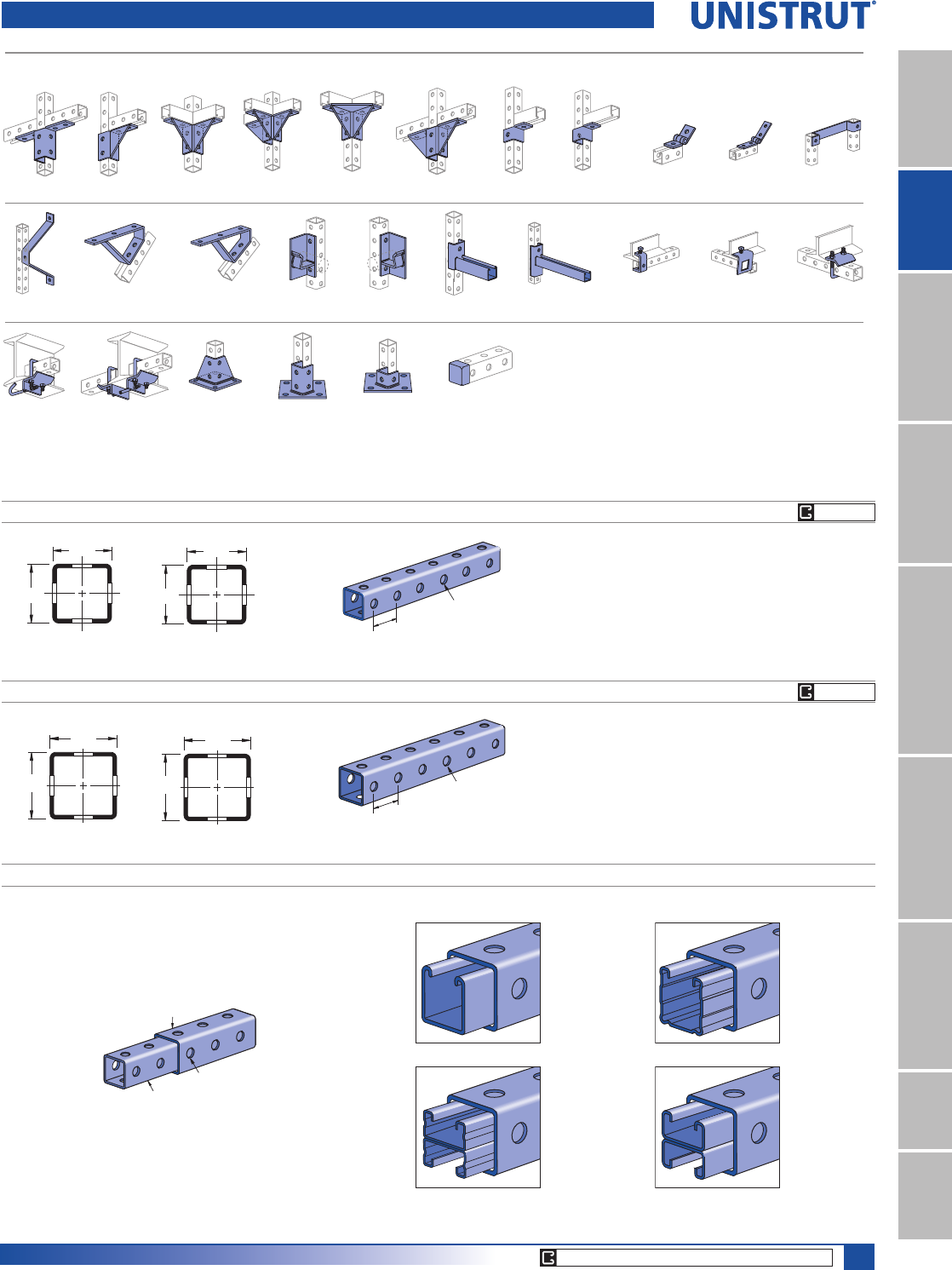
65
15⁄8" Framing System
1 5¼8" ChannelTelestrutNuts & HardwareGeneral FittingsPipe/Conduit SupportsElectrical FittingsConcrete InsertsSolarUnipier®
Telestrut Pictorial Index
P1201-Pg 103P1354A-Pg 104P1843-Pg 104P2226-Pg 89P2344 R-L-Pg 89P2347-Pg 89 P2348-Pg 90
P2230-Pg 89 P2245-Pg 89 P2341 R-L-Pg 89 P2472 R-L-Pg 89
P1204-Pg 103 P1271S-Pg 98 P1796S-Pg 98P1944-Pg 103 P2231-Pg 93P2354L-Pg 103 P2354R-Pg 103P2655-Pg 103 P2233-Pg 93 P2785-Pg 98
P1887-Pg 90 P2072A-Pg 90 P2072-Pg 90 P2860-10-Pg 61
P2867-Pg 98 P2868-Pg 99
Standard 15⁄8" Metal Framing – Wing Shape Fittings Standard 15⁄8" – Misc. Fittings
Many of the standard metal framing components are compatible with the Telestrut telescoping tubing.
Refer to the appropriate page in other sections of the catalog for information on the particular fittings shown here.
P9000
Wt/100 Ft: 188 Lbs (279 kg/100 m)
$OORZDEOH0RPHQW,Q/EV1P
12 Gauge Nominal Thickness .105" (2.7mm)
1 5⁄8"
1 5⁄8"
2
1
41.3
41.3
2
1
1 7⁄8"
(47.6)
9⁄16" (14.3) Dia. Holes
1 7⁄8" (47.6) on Center
P9200
Wt/100 Ft: 223 Lbs (331 kg/100 m)
$OORZDEOH0RPHQW,Q/EV1P
12 Gauge Nominal Thickness .105" (2.7mm)
17⁄8"
17⁄8"
2
1
2
1
47.6
47.6
17⁄8"
(47.6)
9⁄16" (14.3) Dia. Holes
1 7⁄8" (47.6) on Center
TELESTRUT'S TELESCOPING POWER
P9000
P9200
9⁄16" (14.3) Dia. Holes
1 7⁄8" (47.6) on Center
Telestrut can be combined with metal framing channel
P1000 Series P1100 Series
P4001 Series P4101 Series
1RWH:LOOQRWWHOHVFRSHZLWK*5RU+*¿QLVK
GR PG
GR PG
CORE PRODUCTS - TYPICALLY AVAILABLE FROM STOCK
66
15⁄8" Framing System
1 5¼8" ChannelTelestrutNuts & HardwareGeneral FittingsPipe/Conduit SupportsElectrical FittingsConcrete InsertsSolarUnipier®
Unbraced
Height
In
Maximum
Allowable
Load
at Slot Face
Lbs
Maximum Column Load Applied at C.G.
K = 0.65
Lbs
K = 0.80
Lbs
K =1.0
Lbs
K = 1.2
Lbs
24 3,640 8,730 8,570 8,330 8,040
36 3,540 8,360 8,040 7,530 6,950
48 3,400 7,880 7,340 6,530 5,660
60 3,210 7,290 6,530 5,440 4,360
72 2,990 6,640 5,660 4,360 3,160
84 2,730 5,940 4,790 3,340 2,320
96 2,430 5,220 3,940 2,560 1,780
108 2,110 4,520 3,160 2,020 1,400
120 1,820 3,840 2,560 1,640 **
144 1,390 2,690 1,780 ** **
Unbraced
Height
In
Maximum
Allowable
Load
at Slot Face
Lbs
Maximum Column Load Applied at C.G.
K = 0.65
Lbs
K = 0.80
Lbs
K =1.0
Lbs
K = 1.2
Lbs
24 4,620 11,120 10,980 10,740 10,460
36 4,530 10,770 10,460 9,950 9,370
48 4,390 10,300 9,760 8,940 8,030
60 4,220 9,720 8,940 7,800 6,590
72 4,000 9,050 8,030 6,590 5,180
84 3,750 8,320 7,080 5,410 3,890
96 3,460 7,560 6,110 4,290 2,980
108 3,140 6,770 5,180 3,390 2,360
120 2,790 5,990 4,290 2,750 1,910
144 2,170 4,510 2,980 1,910 **
168 1,720 3,320 2,190 ** **
Span
In
Max
Allowable
Uniform Load
Lbs
Defl. at
Uniform
Load
In
Uniform Loading at Deflection
Span/180
Lbs
Span/240
Lbs
Span/360
Lbs
24 1,710 0.06 1,710 1,710 1,710
36 1,140 0.14 1,140 1,140 810
48 860 0.25 860 680 450
60 690 0.40 580 440 290
72 570 0.57 400 300 200
84 490 0.77 300 220 150
96 430 1.01 230 170 110
108 380 1.27 180 130 90
120 340 1.56 150 110 70
144 290 2.30 100 80 50
168 240 3.02 70 60 40
192 210 3.95 60 40 NR
216 190 5.09 40 NR NR
240 170 6.24 40 NR NR
Span
In
Max
Allowable
Uniform Load
Lbs
Defl. at
Uniform
Load
In
Uniform Loading at Deflection
Span/180
Lbs
Span/240
Lbs
Span/360
Lbs
24 2,490 0.05 2,490 2,490 2,490
36 1,660 0.12 1,660 1,660 1,350
48 1,250 0.22 1,250 1,140 760
60 1,000 0.34 980 730 490
72 830 0.49 680 510 340
84 710 0.67 500 370 250
96 620 0.87 380 290 190
108 550 1.10 300 230 150
120 500 1.37 240 180 120
144 420 1.98 170 130 80
168 360 2.70 120 90 60
192 310 3.47 100 70 50
216 280 4.47 80 60 NR
240 250 5.47 60 50 NR
P9000 & P9200 Telestrut Channels
P9000 - BEAM LOADING P9200 - BEAM LOADING
P9000 - COLUMN LOADING P9200 - COLUMN LOADING
P9000/P9200 - ELEMENTS OF SECTION
Parameter P9000 P9200
Area of Section 0.387 In20.489 In2
Axis 1-1
Moment of Inertia (I) 0.166 In40.279 In4
Section Modulus (S) 0.205 In30.297 In3
Radius of Gyration (r) 0.655 In 0.755 In
Axis 2-2
Moment of Inertia (I) 0.166 In40.279 In4
Section Modulus (S) 0.205 In30.297 In3
Radius of Gyration (r) 0.655 In 0.755 In
Notes:
* Load limited by spot weld shear.
./»U !
NR = Not Recommended.
1. Beam loads are given in total uniform load (W Lbs) not uniform load
(w lbs/ft or w lbs/in).
4. Deduct Telestrut weight from the beam loads.
5. For concentrated midspan point loads, multiply beam loads by 50% and the
corresponding deflection by 80%. For other load conditions refer to page 18.
67
15⁄8" Framing System
1 5¼8" ChannelTelestrutNuts & HardwareGeneral FittingsPipe/Conduit SupportsElectrical FittingsConcrete InsertsSolarUnipier®
Span
mm
Max
Allowable
Uniform Load
kN
Defl. at
Uniform
Load
mm
Uniform Loading at Deflection
Span/180
kN
Span/240
kN
Span/360
kN
600 11.3 1 11.3 11.3 11.3
750 9.0 2 9.0 9.0 8.9
1,000 6.8 4 6.8 6.8 5.0
1,250 5.4 6 5.4 4.8 3.2
1,500 4.5 8 4.5 3.3 2.2
1,750 3.9 11 3.3 2.4 1.6
2,000 3.4 15 2.5 1.9 1.2
2,500 2.7 23 1.6 1.2 0.8
3,000 2.3 34 1.1 0.8 0.6
3,500 1.9 45 0.8 0.6 0.4
4,000 1.7 60 0.6 0.5 0.3
4,500 1.5 76 0.5 0.4 0.3
5,000 1.3 92 0.4 0.3 0.2
6,000 1.1 132 0.3 0.2 NR
Unbraced
Height
mm
Maximum
Allowable
Load
at Slot Face
kN
Maximum Column Load Applied at C.G.
K = 0.65
kN
K = 0.80
kN
K =1.0
kN
K = 1.2
kN
600 16.2 38.9 38.2 37.1 35.9
750 16.0 38.2 37.1 35.5 33.7
1,000 15.6 36.7 35.0 32.3 29.4
1,250 15.0 34.8 32.3 28.6 24.6
1,500 14.4 32.6 29.4 24.6 19.8
1,750 13.6 30.3 26.2 20.6 15.3
2,000 12.7 27.8 23.0 16.8 11.7
2,250 11.7 25.2 19.8 13.3 9.3
2,500 10.5 22.6 16.8 10.8 7.5
2,750 9.3 20.0 14.0 8.9 6.2
Unbraced
Height
mm
Maximum
Allowable Load
at Slot Face
kN
Maximum Column Load Applied at C.G.
K = 0.65
kN
K = 0.80
kN
K =1.0
kN
K = 1.2
kN
600 20.6 49.5 48.9 47.9 46.6
750 20.4 48.8 47.9 46.3 44.4
1,000 20.0 47.4 45.7 43.1 40.1
1,250 19.5 45.6 43.1 39.3 35.1
1,500 18.8 43.5 40.1 35.1 29.9
1,750 18.1 41.1 36.8 30.7 24.6
2,000 17.2 38.5 33.4 26.3 19.7
2,250 16.2 35.7 29.9 22.1 15.6
2,500 15.1 32.9 26.3 18.2 12.6
2,750 13.9 30.1 23.0 15.0 10.4
P9000 & P9200 Telestrut Channels
Span
mm
Max
Allowable
Uniform Load
kN
Defl. at
Uniform
Load
mm
Uniform Loading at Deflection
Span/180
kN
Span/z0
kN
Span/360
kN
600 7.7 2 7.7 7.7 7.7
750 6.2 2 6.2 6.2 5.3
1,000 4.7 4 4.7 4.5 3.0
1,250 3.7 7 3.7 2.9 1.9
1,500 3.1 10 2.7 2.0 1.3
1,750 2.7 13 2.0 1.5 1.0
2,000 2.3 17 1.5 1.1 0.8
2,500 1.9 27 1.0 0.7 0.5
3,000 1.6 39 0.7 0.5 0.3
3,500 1.3 53 0.5 0.4 0.3
4,000 1.2 68 0.4 0.3 0.2
4,500 1.0 86 0.3 0.2 0.1
5,000 0.9 108 0.2 0.2 NR
6,000 0.8 151 0.2 NR NR
P9000/P9200 - ELEMENTS OF SECTION (METRIC)
P9000 - BEAM LOADING (METRIC) P9200 - BEAM LOADING (METRIC)
P9000 - COLUMN LOADING (METRIC)P9200 - COLUMN LOADING (METRIC)
Parameter P9000 P9200
Area of Section 2.50 cm23.16 cm2
Axis 1-1
Moment of Inertia (I) 6.92 cm411.61 cm4
Section Modulus (S) 3.35 cm34.87 cm3
Radius of Gyration (r) 1.66 cm 1.92 cm
Axis 2-2
Moment of Inertia (I) 6.92 cm411.61 cm4
Section Modulus (S) 3.35 cm34.87 cm3
Radius of Gyration (r) 1.66 cm 1.92 cm
Notes:
* Load limited by spot weld shear.
./»U !
NR = Not Recommended.
1. Beam loads are given in total uniform load (W Lbs) not uniform load
(w lbs/ft or w lbs/in).
4. Deduct Telestrut weight from the beam loads.
5. For concentrated midspan point loads, multiply beam loads by 50% and the
corresponding deflection by 80%. For other load conditions refer to page 18.
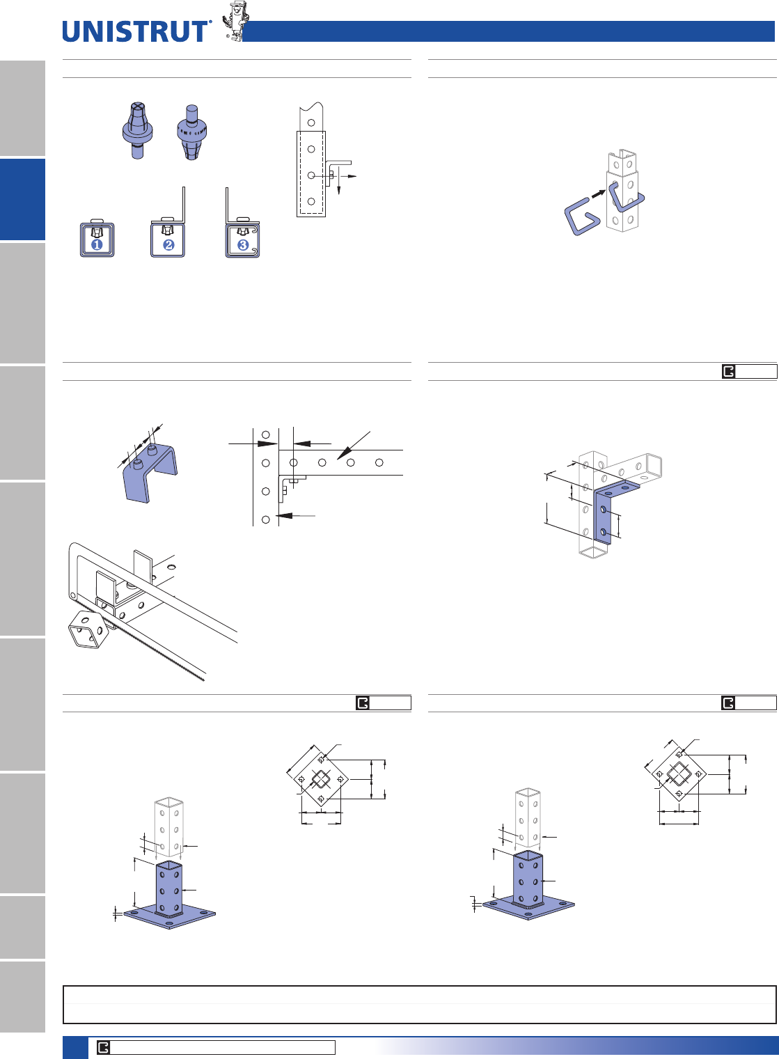
68
15⁄8" Framing System
1 5¼8" ChannelTelestrutNuts & HardwareGeneral FittingsPipe/Conduit SupportsElectrical FittingsConcrete InsertsSolarUnipier®
P9010 MULTI-GRIP RIVET P9209 GRAVITY PIN
Specialized Fittings & Post Bases
P9324
Wt/100 pcs: 78 Lbs (35.0 kg)
P9000 Inside
P9200
Fitting Attached
to Tube Section
or Channel
Fitting Attached
to Tube Section
with Tube Section
or Channel Inside
327⁄32"
(97.6)
327⁄32"
(97.6)
(29.4)
15⁄32"
17⁄8"
(47.6)
750 Lbs.
(3.40 kN)
Pullout
1,200 Lbs.
(5.44 kN)
Wt/100 pcs: 10 Lbs (4.5 kg) Wt/100 pcs: 47 Lbs (21.3 kg)
P9207 CUTTING ALIGNMENT GAUGE
17⁄8"
(47.6)
15⁄16"
(23.8)
11⁄16"
(27.0)
The cutting alignment guide
ensures correct cutting of branch
members when used with fittings
to make connections. Refer to the
table of page 70 for the appropri-
ate value for "A" for cutting.
Trunk
Branch
A
P9012P9011
Wt/100 pcs: 332 Lbs (150.7 kg) Wt/100 pcs: 340 Lbs (154 kg)
P9000
1⁄4"
(6.4)
59⁄16"
(141.3)
P9200
(Slides over)
Cut to
11⁄16"
(17.5)
P9000
(76.2)
3"
(76.2)
3"
(76.2)
3"
(76.2)
3"
(152.4)
6"
(152.4)
6"
(152.4)
6"
4 Holes
3⁄4" (19.1) Dia.
P9200
1⁄4"
(6.4)
59⁄16"
(141.3)
Any 15⁄8"
Section
(Slides Inside)
Cut to
13⁄16"
(20.6)
P9200
(152.4)
6"
(152.4)
6"
(152.4)
6"
3"
(76.2)
3"
(76.2)
3"
(76.2)
3"
(76.2)
4 Holes
3⁄4" (19.1) Dia.
EG, GR
EG, GR
EG, GR
CORE PRODUCTS - TYPICALLY AVAILABLE FROM STOCK
Standard Dimensions for 15»8PPZLGWKVHULHVFKDQQHOILWWLQJV(Unless Otherwise Shown on Drawing)
Hole Diameter: 9»16PP+ROH6SDFLQJ)URP(QG13»16PP+ROH6SDFLQJ2Q&HQWHU7»8PP:LGWK5»8PP7KLFNQHVV1»4PP
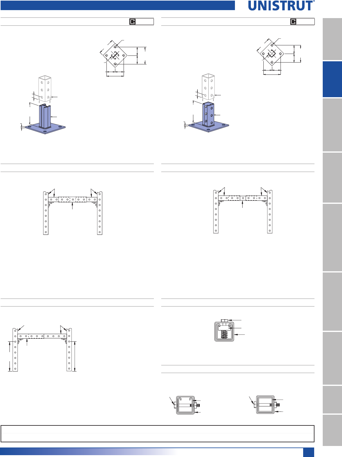
69
15⁄8" Framing System
1 5¼8" ChannelTelestrutNuts & HardwareGeneral FittingsPipe/Conduit SupportsElectrical FittingsConcrete InsertsSolarUnipier®
CHANNEL NUT CONNECTION – INFINITE ADJUSTMENT
THROUGH-BOLT CONNECTION – INCREMENTAL ADJUSTMENT
Any of the 15»8" (41.3 mm) channel can be connected to
the P9000 using standard channel nuts.
P1000 H3
P9200
Nut &
Bolt
Channel Nut
Bolt
P9200
P9000
P9200
Nut &
Bolt
P9013P9014
Wt/100 pcs: 318 Lbs (144.7 kg)Wt/100 pcs: 303 Lbs (137.5 kg)
P4101
P9200
(Slides over)
1⁄4"
(6.4)
Cut to
any
length
53⁄8"
(136.5) P1000 H3
P9200
(Slides over)
1⁄4"
(6.4)
53⁄8"
(136.5)
Cut to
13⁄16"
(20.6)
P1000 H3
(152.4)
6"
(152.4)
6"
(152.4)
6"
3"
(76.2)
3"
(76.2)
3"
(76.2)
3"
(76.2)
4 Holes
3⁄4" (19.1) Dia.
P4101
(152.4)
6"
(152.4)
6"
(152.4)
6"
3"
(76.2)
3"
(76.2)
3"
(76.2)
3"
(76.2)
4 Holes
3⁄4" (19.1) Dia.
Post Bases & Telestrut Connection Methods
PREFERRED THREE-PIECE ASSEMBLY
P9000 (15⁄8")
P9200 (17⁄8")
P9000 (15⁄8")
ALTERNATE THREE-PIECE ASSEMBLY
In most applications, telescoping assemblies should be made from
three sections of Telestrut material. The simplest construction utilizes
a center section of 17»8" material (P9200) into which a 15»8" member
(P9000) is telescoped from each end. In this way, all intersecting
verticals and horizontals are formed from 15»8" members assuring
maximum compatibility and ease of assembly
A similar technique is to use a center 15»8" center member (P9000)
which can be telescoped into 17»8" members used at both ends. With this
method, all intersecting connections should be formed from compatible
17»8" members.
P9200 (17⁄8")
P9000 (15⁄8")
or any other 15⁄8"
Metal Framing Channel
(e.g., P1000 H3)
P9200 (17⁄8")
P9000 (15⁄8")
P9200 (17⁄8")
A
A + 1 ⁄8"
P9000 (15⁄8")
TWO-PIECE ASSEMBLY
Two-piece telescoping
assemblies can be used,
but special cutting of one or
both telescoping members
is needed to achieve proper
alignment of fittings at the
intersecting connections.
In addition, the right-angle members to which telescoping pieces are
attached must be cut according to the illustration at right to insure smooth
movement of telescoping members.
EG, GREG, GR
Standard Dimensions for 15»8PPZLGWKVHULHVFKDQQHOILWWLQJV8QOHVV2WKHUZLVH6KRZQRQ'UDZLQJ
Hole Diameter: 9»16PP+ROH6SDFLQJ)URP(QG13»16PP+ROH6SDFLQJ2Q&HQWHU7»8PP:LGWK5»8PP7KLFNQHVV1»4PP
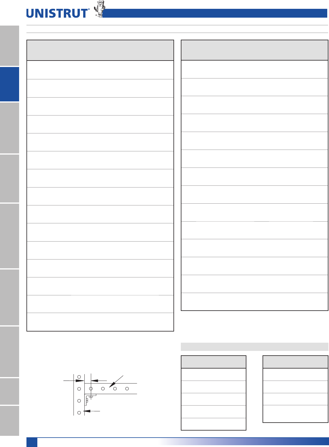
70
15⁄8" Framing System
1 5¼8" ChannelTelestrutNuts & HardwareGeneral FittingsPipe/Conduit SupportsElectrical FittingsConcrete InsertsSolarUnipier®
CUTTING CHART
Fitting
15»8" (41.3) Branch 17»8" (47.6) Branch
Trunk
15»8" (41.3)
Trunk
17»8" (47.6)
Trunk
15»8" (41.3)
Trunk
17»8" (47.6)
P1726 A A A B
P1727 B NR NR NR
P1728 † † † †
P1747 † † † †
P1750 † † † †
P1821 † † † †
P1822 † † † †
P1823 † † † †
P1843 D D D D
P1873 † † † †
P1834 † NR NR NR
P1941 A A A B
P1950 A A A B
P1953 A A A B
P1956 † † † †
P1957 † † † †
P2223 A NR A NR
P2224 A NR A NR
P2225 A NR A NR
P2226 A NR A NR
P2227 A NR A NR
P2228 A NR A NR
P2229 A NR A NR
P2230 A NR A NR
P2235 A NR NR NR
P2245 A NR A NR
P2324 E NR NR F
P2325 E A A F
P2326 E NR NR F
P2341 R-L A NR A NR
P2343 R-L A NR A NR
P2344 R-L A NR A NR
P2345 A NR A NR
P2346 A NR A NR
P2347 A NR A NR
P2348 A NR A NR
P2472 R-L C NR A NR
P2815 C NR NR NR
P2815 D C NR NR NR
P9324 G G G G
P9325 A A A A
P9484 A A A A
Designator
"A"
In (mm)
A11»16"
27.0
B
15»16"
23.8
C
13»16"
20.6
D11»4"
31.8
E
5»8" *
15.9
This table shows the value for "A" when using the specified fitting to connect the
branch and trunk. Sizes "A" and "B" can be cut with the cutting alignment gauge
(P9207). Other sizes require special cutting. Those marked NR are not recommended.
Trunk
Branch
A
Cutting Chart
Legend
Fitting
15»8" (41.3) Branch 17»8" (47.6) Branch
Trunk
15»8" (41.3)
Trunk
17»8" (47.6)
Trunk
15»8" (41.3)
Trunk
17»8" (47.6)
P1026 A A A B
P1028 A A A B
P1029 † † † †
P1031 A A A B
P1033 B A A B
P1034 † † † †
P1035 A † † †
P1036 A A A B
P1037 † † † †
P1038 † † † †
P1045 † † † †
P1047 † † † †
P1048 † † † †
P1049 † † † †
P1050 † † † †
P1065 A A A B
P1066 A A A B
P1068 C NR NR NR
P1130 A A A C
P1131 A A A C
P1290 A NR NR NR
P1291 A NR NR NR
P1325 A NR NR NR
P1326 C NR NR NR
P1334 A A A B
P1346 A A A B
P1347 C NR NR NR
P1354 D D D D
P1356 A A A B
P1357 A NR NR NR
P1358 A A A B
P1359 A NR NR NR
P1380 A A A B
P1380 A A A A B
P1381 † † † †
P1382 † † † †
P1458 A NR NR NR
P1498 † † † †
P1499 † † † †
P1538 A C A A C
P1538 B C A A C
P1538 C C A A C
P1538 D C A A C
P1579 A NR NR NR
P1713 † † † †
Designator
"A"
In (mm)
F
7»16" *
11.1
G15»32"
29.4
NR Not
Recommended
†
Special
Cutting Req'd
(See part dwg)
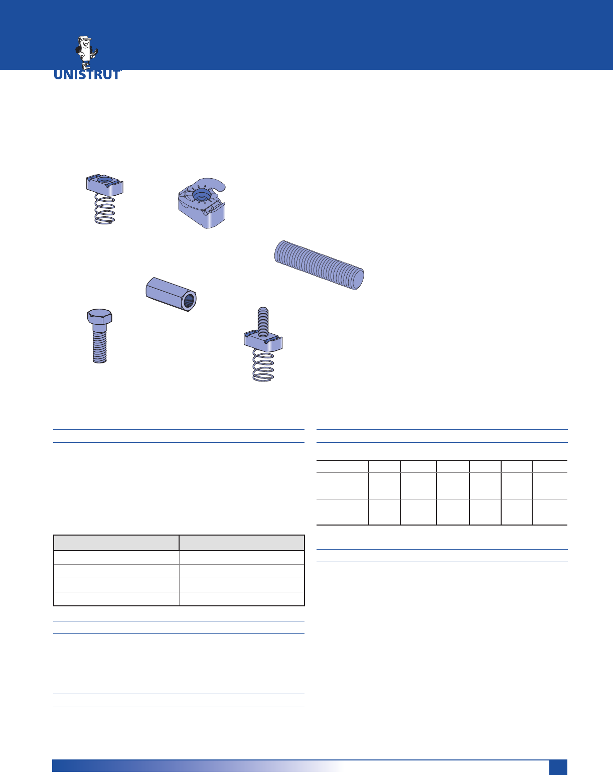
71
MATERIAL
Unistrut channel nuts are manufactured from mild steel
bars, and after machining operations are completed, they
are case hardened, assuring positive biting action into the
inturned edge of the Unistrut channel.
Screws conform to SAE J429 GR 2 (exceeds ASTM A307).
Proof Load 55KSI, Tensile Load 74 KSI
Bolt Size Channel Nut ASTM
1»4" & 5»16" A1011 SS GR45
3»8", 7»16" & 1»2" A576 GR1015 Modified
5»8" & 3»4" A36 or A675 GR60
7»8"A36
FINISHES
Nuts, bolts and washers are electro-galvanized (EG),
ASTM B633 Type III SC1 finish, unless otherwise noted.
Many hardware items are also available in stainless steel.
Consult factory for ordering information.
THREADS
All threads on the nuts and bolts are Unified and
American coarse screw threads.
DESIGN BOLT TORQUE
BOLT SIZE 1»4"-20 5»16"-18 3»8"-16 1»2"-13 5»8"-11 3»4"-10
Rec.Torque
Ft/Lbs
1P
6
(8)
11
(15)
19
(26)
50
(68)
100
(136)
125
(170)
Max Torque
Ft/Lbs
1P
7
(9)
15
(20)
25
(34)
70
(95)
125
(170)
135
(183)
DIMENSIONS
Imperial dimensions are illustrated in inches. Metric dimen-
sions are shown in parenthesis or as noted.
Unless noted, all metric dimensions are in millimeters
and rounded to one decimal place.
Many Unistrut nuts, bolts and hardware items are also
available in standard metric dimensions. Consult factory
for ordering information.
NUTS & HARDWARE
Channel Nuts With Springs ...................................................... 73
Channel Nuts Without Springs ................................................73
Top Retainer Nuts .....................................................................73
Stud Nuts ................................................................................... 74
Hardware .............................................................................. 74-76
U
N
I
S
T
R
U
T
U
N
I
S
T
R
U
T
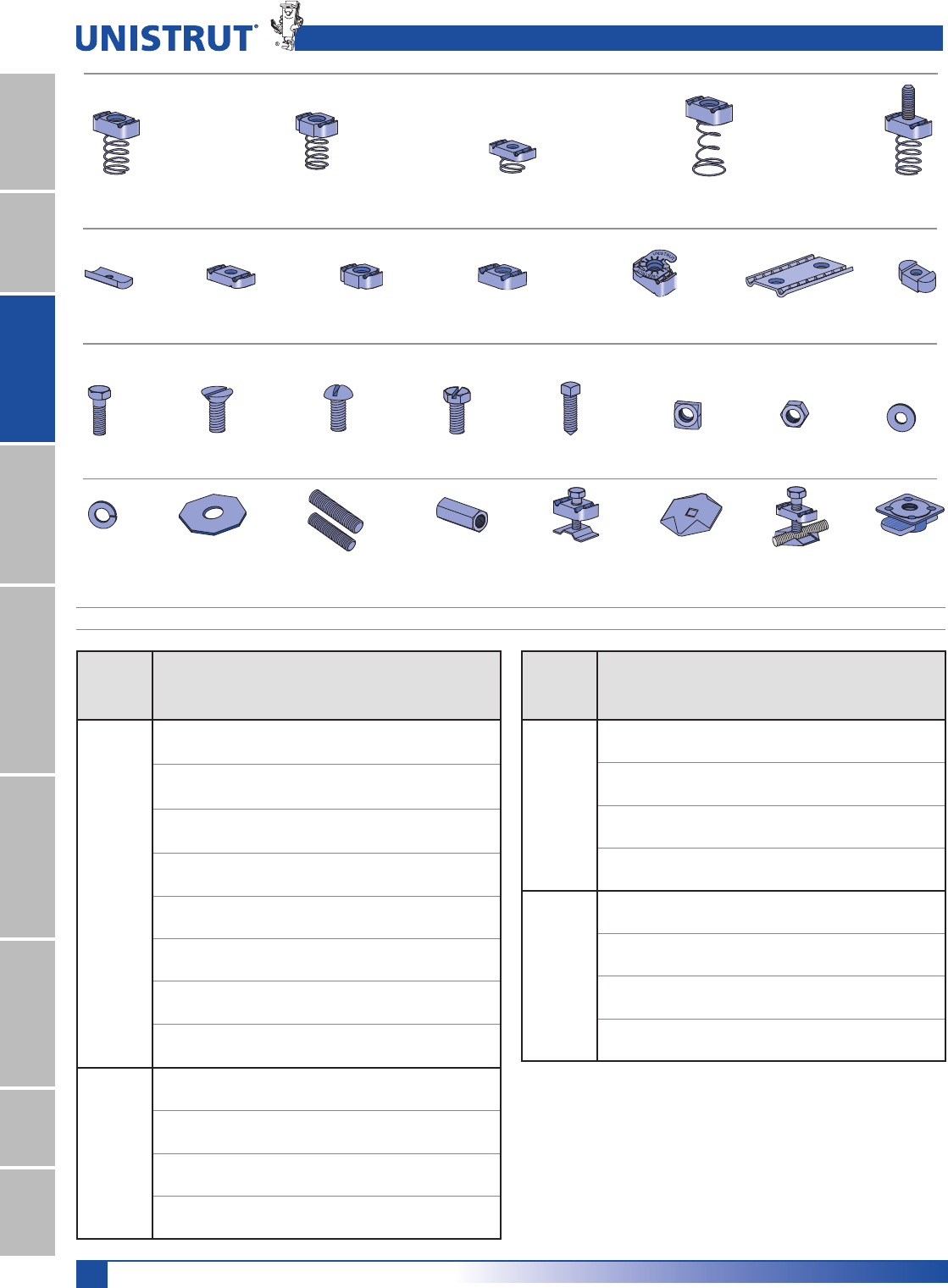
72
15⁄8" Framing System
1 5¼8" ChannelTelestrutNuts & HardwareGeneral FittingsPipe/Conduit SupportsElectrical FittingsConcrete InsertsSolarUnipier®
Nuts & Hardware Pictorial Index and Channel Nut Loads
MAXIMUM ALLOWABLE PULL-OUT AND SLIP LOADS
Channel Nuts With Spring
Channel Nuts Without Spring
Hardware
HHCS
Pg 74
HFMS
Pg 74
HRMS
Pg 74
HSHS
Pg 74
HCSS
Pg 74
HFLW
Pg 75
HSQN
Pg 75
HHXN
Pg 75
P1006 - P1010
Pg 73
P1012S - P1024S
Pg 73
P4006 - P4010
Pg 73
P5506 - P5510
Pg 73
P2378 - P2382
Pg 74
P3016
Pg 73
P3006 - P3013
Pg 73
P1012 - P1024
Pg 73
P4012 - P4023
Pg 73
P4908
Pg 73
P1016
Pg 73
P1006T - P1010T, P4010T
Pg 73
HTHR
Pg 75
HRCN
Pg 75
P2486
Pg 76
HLKW
Pg 75
P2485
Pg 76
P2485K
Pg 76
K1062 - K1064
Pg 76
HOCW
Pg 76
* May require 3»8" or 1»2" thick fitting.
Nut design loads include a minimum safety factor of 3.
Note: Refer to the Channel Nut Selection Chart on the following two pages for
the part number.
Channel
Channel
Nut
Size-
Thread Gauge
Allowable
Pull-Out
Strength
Lbs (kN)
Resistance
to Slip
Lbs (kN)
Torque
Ft-Lbs
1P
P1000
P3000
P5000
P5500
7»8" - 9 12 2,500 1,700 *125
11.12 7.56 170
3»4" - 10 12 2,500 1,700 *125
11.12 7.56 170
5»8" - 11 12 2,500 1,500 *100
11.12 6.67 135
1»2" - 13 12 2,000 1,500 50
8.90 6.67 70
7»16" - 14 12 1,400 1,000 35
6.23 4.45 50
3»8" - 16 12 1,000 800 19
4.45 3.56 25
5»16" - 18 12 800 500 11
3.56 2.22 15
1»4" - 20 12 600 300 6
2.67 1.33 8
P3300
1»2" - 13 12 1,500 1,500 50
6.67 6.67 70
3»8" - 16 12 1,000 800 19
4.45 3.56 25
5»16" - 18 12 800 500 11
3.56 2.22 15
1»4" - 20 12 600 300 6
2.67 1.33 8
Channel
Channel
Nut
Size-
Thread Gauge
Allowable
Pull-Out
Strength
Lbs (kN)
Resistance
to Slip
Lbs (kN)
Torque
Ft-Lbs
1P
P1100
&
P4100
1»2" - 13 14 1,400 1,000 50
6.23 4.45 70
3»8" - 16 14 1,000 750 19
4.45 3.34 25
5»16" - 18 14 800 400 11
3.56 1.78 15
1»4" - 20 14 600 300 6
2.67 1.33 8
P2000
&
P4000
1»2" - 13 16 1,000 1,000 50
4.45 4.54 70
3»8" - 16 16 1,000 750 19
4.45 3.34 25
5»16" - 18 16 800 400 11
3.56 1.78 15
1»4" - 20 16 600 300 6
2.67 1.33 8
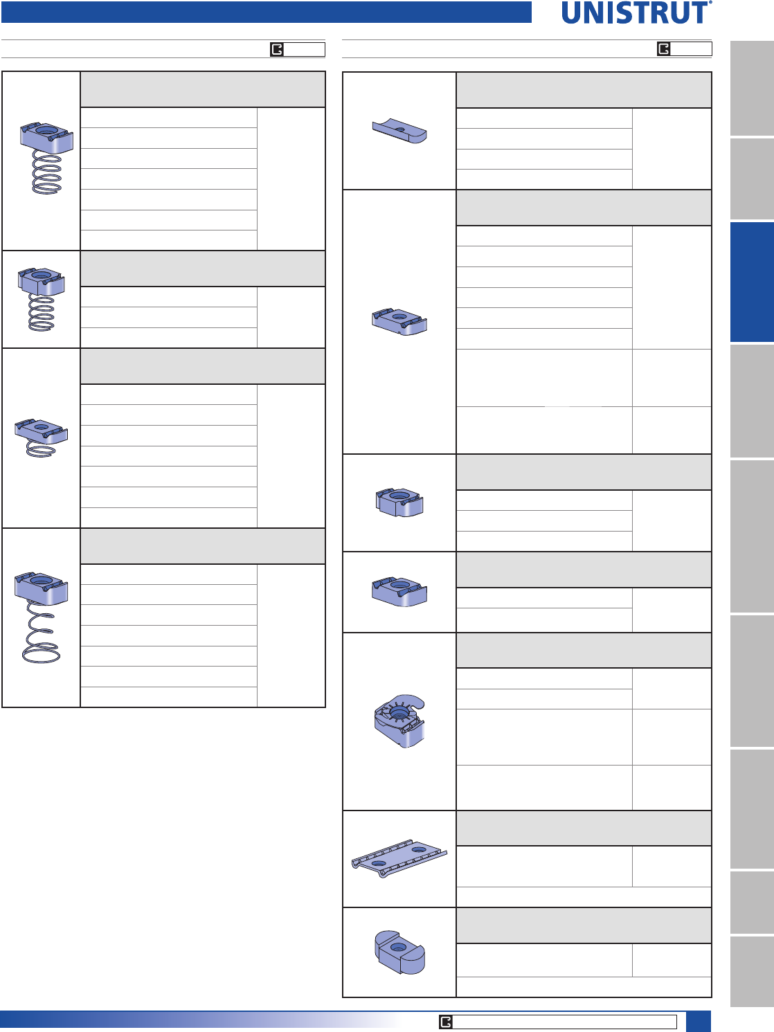
73
15⁄8" Framing System
1 5¼8" ChannelTelestrutNuts & HardwareGeneral FittingsPipe/Conduit SupportsElectrical FittingsConcrete InsertsSolarUnipier®
Part
Number
Nut Size
Thread
Wt/100 pcs
Lbs (kg) Use With
P3016-0632 #6 -32 2 (0.9)
Any
Channel
P3016-0832 #8 -32 2 (0.9)
P3016-1024 #10 -24 4 (1.8)
P3016-1420 1»4" -20 4 (1.8)
Part
Number
Nut Size
Thread
Wt/100 pcs
Lbs (kg) Use With
P3006-0832 #8 -32 6 (2.7)
Any
Channel
P3006-1024 #10 -24 6 (2.7)
P3006-1420 1»4" -20 6 (2.7)
P3007 5»16" -18 6 (2.7)
P3008 3»8" -16 9 (4.1)
P3009 7»16" -14 9 (4.1)
P3010 1»2" -13 11 (5.0)
Any Channel
Except P3300,
P4000, P4400,
P4520,P4100
P3013 1»2" -13 8 (3.6)
P3300,
P4000,P4400,
P4520,P4100
Part
Number
Nut Size
Thread
Wt/100 pcs
Lbs (kg) Use With
P1012 5»8" -11 20 (9.1) Any Channel
Except P3300,
P4000, P4400,
P4520,P4100
P1023 3»4" -10 20 (9.1)
P1024 7»8" -9 20 (9.1)
Part
Number
Nut Size
Thread
Wt/100 pcs
Lbs (kg) Use With
P4012 5»8" -11 11 (5.0) P3300, P4000,
P4400,P4520,
P4100
P4023 3»4" -10 11 (5.0)
U
N
I
S
T
R
U
T
U
N
I
S
T
R
U
T
Part
Number
Nut Size
Thread
Wt/100 pcs
Lbs (kg) Use With
P1006T1420 1»4" -20 7 (3.2) Any
Channel
P1008T 3»8" -16 10 (4.5)
P1010T 1»2" -13 12 (5.4)
Any Channel
Except P3300,
P4000, P4400,
P4520, P4100
P4010T 1»2" -13 8 (3.6) P3300, P4000,
P4400, P4520,
P4100
Part
Number
Nut Size
Thread
Wt/100 pcs
Lbs (kg) Use With
P4908 3»8" -16 17.5 (7.9) Any
Channel
Double Conveyor Adjusting Nut
Part
Number
Nut Size
Thread
Wt/100 pcs
Lbs (kg) Use With
P1016 3»8" -16 17.5 (7.9) Any Slotted
Channel
Missing Link Multi-Purpose Strut Fastener
Channel Nuts With and Without Spring
Part
Number
Nut Size
Thread
Wt/100 pcs
Lbs (kg) Use With
P1006-0832 #8 -32 7 (3.2)
P1000,
P1100,
P2000,
P3000
P1006-1024 #10 -24 7 (3.2)
P1006-1420 1»4" -20 7 (3.2)
P1007 5»16" -18 6 (2.7)
P1008 3»8" -16 10 (4.5)
P1009 7»16" -14 9 (4.1)
P1010 1»2" -13 12 (5.4)
Part
Number
Nut Size
Thread
Wt/100 pcs
Lbs (kg) Use With
P1012S 5»8" -11 21 (9.5) P1000,
P1100,
P2000,
P3000
P1023S 3»4" -10 21 (9.5)
P1024S 7»8" -9 21 (9.5)
Part
Number
Nut Size
Thread
Wt/100 pcs
Lbs (kg) Use With
P4006-0832 # 8 -32 7 (3.2)
P3300,
P4000,
P4400,
P4520,
P4100
P4006-1024 #10 -24 7 (3.2)
P4006-1420 1»4" -20 7 (3.2)
P4007 5»16" -18 6 (2.7)
P4008 3»8" -16 9 (4.1)
P4009 7»16" -14 9 (4.1)
P4010 1»2" -13 8 (3.6)
Part
Number
Nut Size
Thread
Wt/100 pcs
Lbs (kg) Use With
P5506-0832 #8 -32 7 (3.2)
P5000,
P5500
P5506-1024 #10 -24 7 (3.2)
P5506-1420 1»4" -20 7 (3.2)
P5507 5»16" -18 6 (2.7)
P5508 3»8" -16 10 (4.5)
P5509 7»16" -14 10 (4.5)
P5510 1»2" -13 12 (5.4)
CHANNEL NUT WITH SPRING CHANNEL NUT WITHOUT SPRING
EG, HG
CORE PRODUCTS - TYPICALLY AVAILABLE FROM STOCK
EG, HG
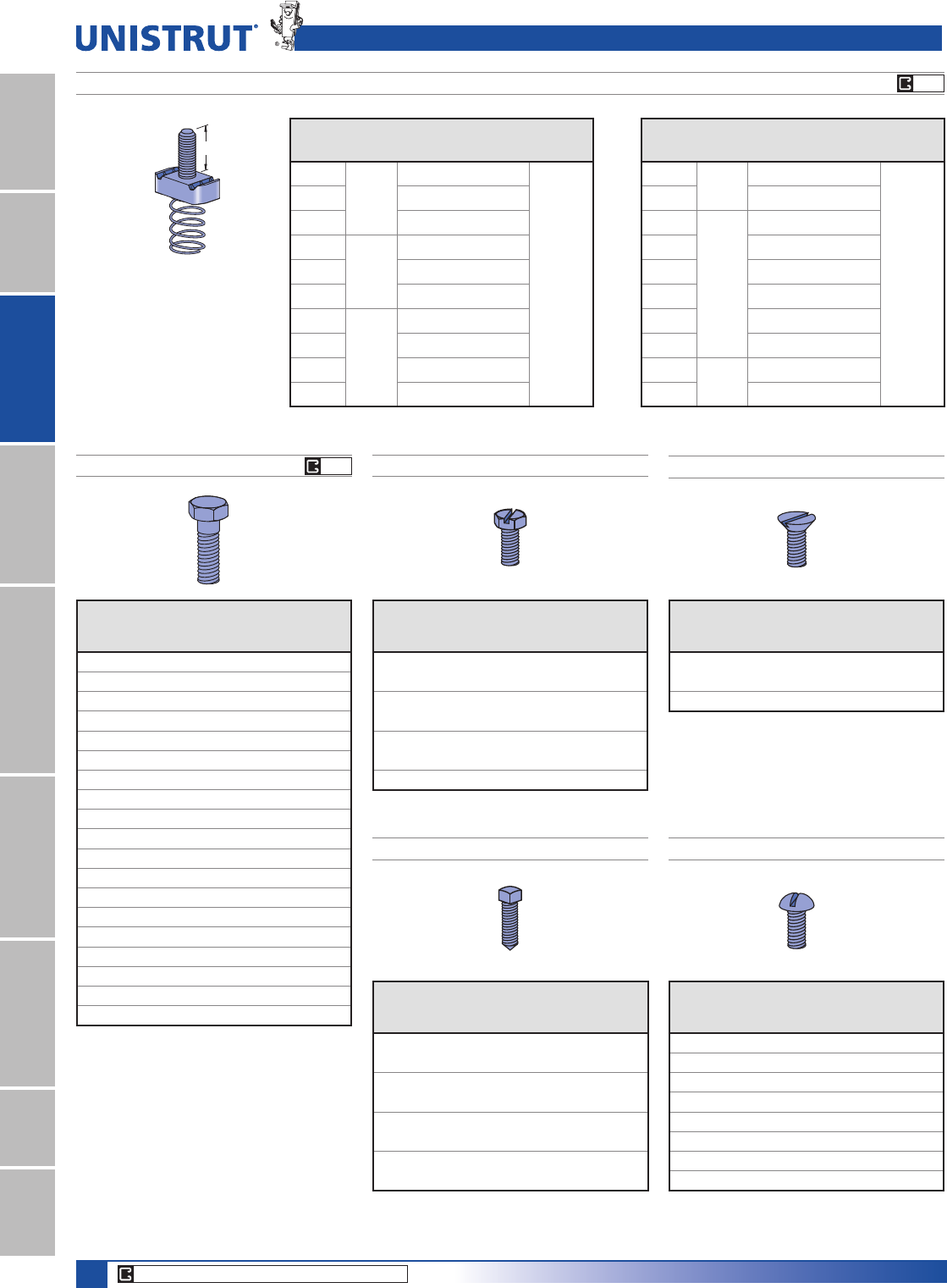
74
15⁄8" Framing System
1 5¼8" ChannelTelestrutNuts & HardwareGeneral FittingsPipe/Conduit SupportsElectrical FittingsConcrete InsertsSolarUnipier®
Part No. Thread
"A" Stud
In (mm)
Wt/100 pcs
Lbs (kg)
P2378-1
1»4" - 20
1 (25.4) 8 (3.6)
Use With
P1000,
P1100,
P2000,
P3000
P2378-2 11»4 (31.8) 9 (4.1)
P2378-3 11»2 (38.1) 9 (4.1)
P2379-1
5»16" - 18
1 (25.4) 12 (5.4)
P2379-2 11»4 (31.8) 12 (5.4)
P2379-3 11»2 (38.1) 13 (5.9)
P2380-1
3»8" - 16
1 (25.4) 13 (5.9)
P2380-2 11»4 (31.8) 13 (5.9)
P2380-3 11»2 (38.1) 13 (5.9)
P2380-4 13»4 (44.5) 15 (6.8)
All Stud Nut grooves are serrated.
A
HEX HEAD CAP SCREWS
ROUND HEAD MACHINE SCREWS
CHANNEL STUD NUT WITH SPRING
Part
No. Size
Wt/
100 pcs
Lbs (kg)
HHCS025044EG 1»4" x 7»16"1.0 (0.5)
HHCS025075EG 1»4" x 3»4"1.3 (0.6)
HHCS025150EG 1»4" x 11»2"2.6 (1.2)
HHCS031125EG 5»16" x 11»4"3.6 (1.6)
HHCS037075EG 3»8" x 3»4"4.0 (1.8)
HHCS037087EG 3»8" x 7»8"4.4 (2.0)
HHCS037100EG 3»8" x 1" 4.5 (2.0)
HHCS037125EG 3»8" x 11»4"5.3 (2.4)
HHCS037150EG 3»8" x 11»2"6.0 (2.7)
HHCS037200EG 3»8" x 2" 7.6 (3.4)
HHCS037225EG 3»8" x 21»4"8.4 (3.8)
HHCS037250EG 3»8" x 21»2"9.2 (4.2)
HHCS050094EG 1»2" x 15»16"9.1 (4.1)
HHCS050119EG 1»2" x 13»16"10.2 (4.6)
HHCS050150EG 1»2" x 11»2" 11.6 (5.3)
HHCS050175EG 1»2" x 13»4" 13.1 (5.9)
HHCS050200EG 1»2" x 2" 14.6 (6.6)
HHCS050225EG 1»2" x 21»4"16 (7.3)
HHCS050250EG 1»2" x 21»2" 17.5 (7.9) Part No. Size
Wt/
100 pcs
Lbs (kg)
HRMS025050EG 1»4" x 1»2"1 (0.5)
HRMS025075EG 1»4" x 3»4"1.2 (0.5)
HRMS025100EG 1»4" x 1" 1.5 (0.7)
HRMS031100EG 5»16" x 1" 2.6 (1.2)
HRMS031125EG 5»16" x 11»4"3.0 (1.4)
HRMS037100EG 3»8" x 1" 4.1 (1.9)
HRMS037125EG 3»8" x 11»4"4.7 (2.1)
HRMS037150EG 3»8" x 11»2"5.3 (2.4)
Part No. Thread
"A" Stud
In (mm)
Wt/100 pcs
Lbs (kg)
P2380-5 3»8" - 16 2 (50.8) 16 (7.3)
Use With
P1000,
P1100,
P2000,
P3000
P2380-6 21»4 (57.2) 16 (7.3)
P2381-2
1»2" - 13
1 (25.4) 14 (6.4)
P2381-3 11»4 (31.8) 15 (6.8)
P2381-4 11»2 (38.1) 17 (7.7)
P2381-5 13»4 (44.5) 18 (8.2)
P2381-6 2 (50.8) 19 (8.6)
P2381-7 21»4 (57.2) 20 (9.1)
P2382-2 5»8" - 11 11»4 (31.8) 18 (8.2)
P2382-3 11»2 (38.1) 20 (9.1)
FLAT HEAD MACHINE SCREWS
HEX SLOTTED MACHINE SCREWS
CONE POINT SET SCREWS
Part No. Size
Wt/
100 pcs
Lbs (kg)
HSHS025050EG 1»4" x 1»2"1.4 (0.6)
HSHS025062EG 1»4" x 5»8"1.5 (0.7)
HSHS025075EG 1»4" x 3»4"1.7 (0.8)
HSHS031100EG 5»16" x 1" 2.6 (1.2)
HSHS031125EG 5»16" x 11»4"3.0 (1.4)
HSHS031150EG 5»16" x 11»2"3.4 (1.5)
HSHS037125EG 3»8" x 11»4"5.3 (2.4)
Part No. Size
Wt/
100 pcs
Lbs (kg)
HCSS025100EG 1»4" x 1" 2.8 (1.3)
HCSS031150EG 5»16" x 11»2"3.9 (1.8)
HCSS037150EG 3»8" x 11»2"4.5 (2.0)
HCSS037200EG 3»8" x 2" 6.1 (2.8)
HCSS050150EG 1»2" x 11»2"8.5 (3.9)
HCSS050200EG 1»2" x 2" 11.4 (5.2)
HCSS062150EG 5»8" x 11»2"14.5 (6.6)
HCSS062200EG 5»8" x 2" 23.0 (10.4)
Part No. Size
Wt/
100 pcs
Lbs (kg)
HFMS025062EG 1»4" x 5»8" 1.2 (0.5)
HFMS031100EG 5»16" x 1" 2.6 (1.2)
HFMS050100EG 1»2" x 1" 9.3 (4.2)
Hardware
EG
EG
CORE PRODUCTS - TYPICALLY AVAILABLE FROM STOCK
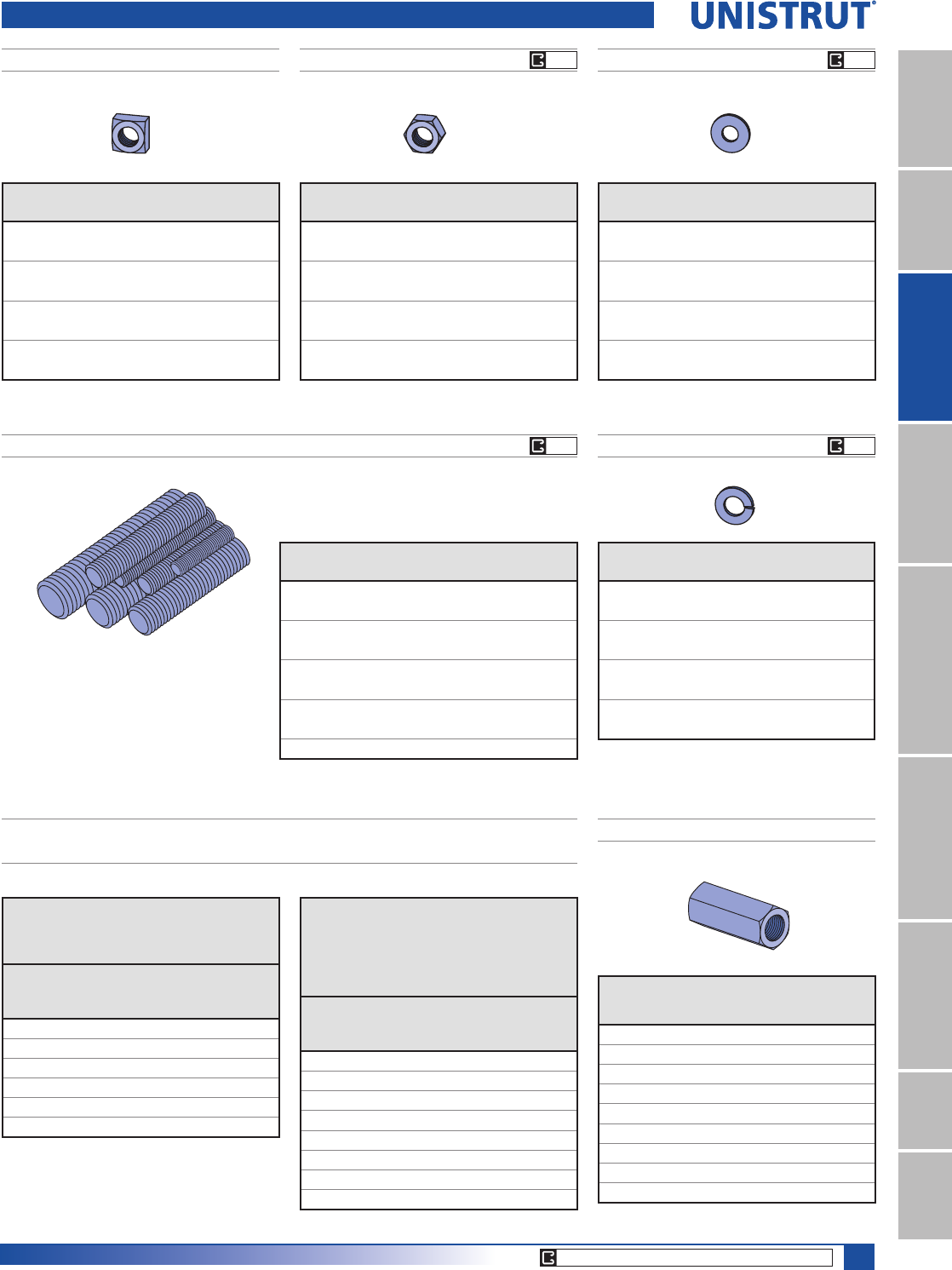
75
15⁄8" Framing System
1 5¼8" ChannelTelestrutNuts & HardwareGeneral FittingsPipe/Conduit SupportsElectrical FittingsConcrete InsertsSolarUnipier®
Hardware
SQUARE NUTS HEXAGON NUTS
Part No. Size
Wt/100 pcs
Lbs (kg)
HSQN025EG 1»4"0.9 (0.4)
HSQN031EG 5»16"1.6 (0.7)
HSQN037EG 3»8"2.7 (1.2)
HSQN050EG 1»2"5.8 (2.6)
HSQN062EG 5»8" 10.7 (4.9)
HSQN075EG 3»4" 15.4 (6.9)
HSQN087EG 7»8" 24.9 (11.3)
HSQN100EG 1" 36.3 (16.5)
Part No. Size
Wt/100 pcs
Lbs(kg)
HHXN025EG 1»4"0.6 (0.3)
HHXN031EG 5»16"1.2 (0.5)
HHXN037EG 3»8"1.6 (0.7)
HHXN050EG 1»2"4.8 (2.2)
HHXN062EG 5»8"7.3 (3.3)
HHXN075EG 3»4" 11.9 (5.4)
HHXN087EG 7»8" 19.0 (8.6)
HHXN100EG 1" 28.3 (12.8)
FLAT WASHERS
Part No. Size
Wt/100 pcs
Lbs(kg)
HFLW025EG 1»4"0.8 (0.4)
HFLW031EG 5»16" 1.0 (0.5)
HFLW037EG 3»8"1.5 (0.7)
HFLW050EG 1»2"3.5 (1.6)
HFLW062EG 5»8"7.7 (3.5)
HFLW075EG 3»4"11.0 (5.0)
HFLW087EG 7»8" 15.3 (6.9)
HFLW100EG 1" 18.8 (8.5)
LOCK WASHERS
Part No. Size
Wt/100 pcs
Lbs (kg)
HLKW025EG 1»4" 0.25 (0.1)
HLKW031EG 5»16" 0.41 (0.2)
HLKW037EG 3»8" 0.63 (0.3)
HLKW050EG 1»2" 1.32 (0.60)
HLKW062EG 5»8" 2.20 (1.0)
HLKW075EG 3»4" 3.80 (1.7)
HLKW087EG 7»8" 6.00 (2.7)
HLKW100EG 1" 8.80 (4.0)
STEEL THREADED ROD
Standard Length 12’ (3.7m)
Low Carbon Steel Grade 1006 - 1010
Fy = 36,000 psi minimum
Ft = 58,000 psi minimum
Part No. Size
Wt/100 Ft.
Lbs (kg)
HTHR025 1»4" x 20 13 (5.9)
HTHR031 5»16" x 18 20 (9.1)
HTHR037 3»8" x 16 30 (13.6)
HTHR044 7»16" x 14 30 (13.6)
HTHR050 1»2" x 13 53 (24.0)
HTHR062 5»8" x 11 84 (38.1)
HTHR075 3»4" x 10 124 (56.2)
HTHR087 7»8" x 9 170 (77.1)
HTHR100 1" x 8 223 (101.2)
LOAD CARRYING CAPACITY OF THREADED HOT ROLLED STEEL
CONFORMING TO ASTM A575 AND A576
Threaded Rod Loads
for Piping Applications
EDVHGRQ06663
Nominal
Dia.
Root Area
In2 (mm2)
Max. Safe Load
DW)&
Lbs (kN)
3»80.068 (43.9) 730 (3.25)
1»20.126 (81.3) 1,350 (6.01)
5»80.202 (130.3) 2,160 (9.61)
3»40.302 (194.8) 3,230 (14.37)
7»80.419 (270.3) 4,480 (19.93)
1 0.552 (356.1) 5,900 (26.24)
Threaded Rod Loads
for Structural Applications
(Based on AISC, Steel Construction Manual,
ASD, 14th Edition. Per AISC, Allowed
Tensile Stress = 0.33 * Fu
Nominal
Dia.
Nominal Area
In2 (mm2)
Allowed
Tension Load
Lbs (kN)
1»40.049 (31.6) 930 (4.14)
3»80.110 (71.0) 2,110 (9.39)
7»16 0.150 (96.8) 2,870 (12.77)
1»20.196 (126.5) 3,750 (16.68)
5»80.307 (198.2)5,870 (26.11)
3»40.442 (285.4)8,450 (37.59)
7»80.601 (388.0)11,500 (51.15)
1 0.785 (506.8)15,030 (66.86)
STEEL COUPLER NUTS
Part
Number Size
Length
,QPP
Wt/100
pcs
/EVNJ
HRCN025 1»4" - 20 7»8" (22.2) 1.9 (0.9)
HRCN031 5»16" - 18 13»4" (44.5) 7.5 (3.4)
HRCN037 3»8" - 16 13»4" (44.5) 9.0 (4.1)
HRCN044 7»16" - 14 13»4" (44.5) 10.4 (4.7)
HRCN050 1»2" - 13 13»4" (44.5) 10.0 (4.5)
HRCN062 5»8" - 11 21»8" (54.0) 18.0 (8.2)
HRCN075 3»4" - 10 21»4" (57.2) 28.0 (12.7)
HRCN087 7»8" - 9 21»2" (63.5) 55.0 (24.9)
HRCN100 1" - 8 23»4" (69.9) 73.0 (33.1)
EG EG
EG EG
CORE PRODUCTS - TYPICALLY AVAILABLE FROM STOCK
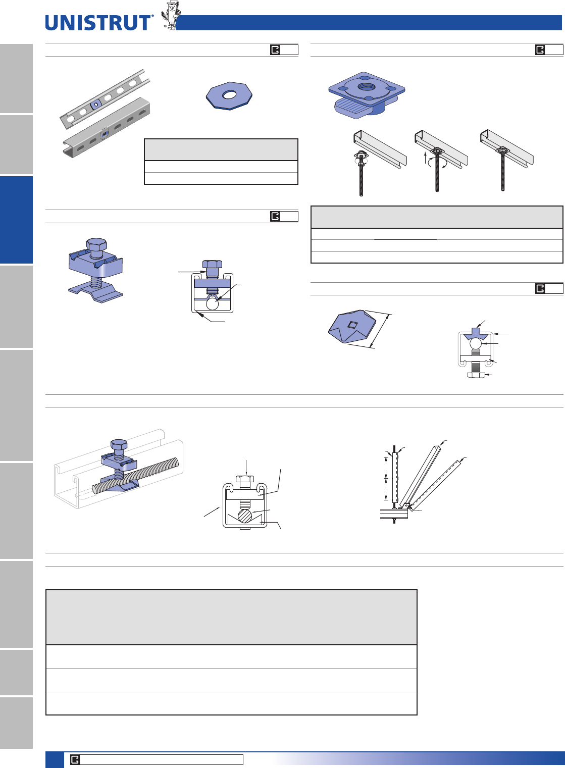
76
15⁄8" Framing System
1 5¼8" ChannelTelestrutNuts & HardwareGeneral FittingsPipe/Conduit SupportsElectrical FittingsConcrete InsertsSolarUnipier®
Hardware
SLOT ADAPTER™
Part No.
Bolt
Size
Wt/100 pcs
/EVNJ
HOCW025 1»4" (6.4) 1 (0.5)
HOCW037 3»8" (9.5) 1.5 (0.7)
P2485 CRADLE CLIP
P2485K SEISMIC CRADLE CLIP ASSEMBLY
P2485
Cradle Clip
Threaded Rod
3⁄8" - 5⁄8"
P1000T
P3008 Nut
3⁄8" x 1" Hex Head
Cap Screw
P1000T
Channel
Stiffener
P1000 Channel
Lateral Brace
P1000 Channel
Transverse Brace
Cradle
Clip
L
L
P1546
1 1⁄4"
(31.8)
Cradle clip only, order
other items seperately.
5RG6WLIIHQHU&OLS6SDFLQJ/
Rod Size
In (mm)
Root
Area
In2 (mm2)
Radius of
Gyration
In (mm)
Design
Load
Lbs (kN)
Rod Stress
@100%
10,700 PSI
In (mm)
Rod Stress
@75%
8,025 PSI
In (mm)
Rod Stress
@50%
5,350 PSI
In (mm)
Rod Stress
@35%
3,745 PSI
In (mm)
3»80.068 0.074 730 9 11 13 15
9.5 49.5 1.99 3.25 228.6 279.4 330.2 381.0
1»20.126 0.100 1,350 12 14 17 21
12.7 72.4 2.40 6.01 304.8 355.6 431.8 533.4
5»80.202 0.127 2,160 15 18 22 26
15.9 138.3 3.32 9.61 381.0 457.2 558.8 660.4
Notes:
1. Minimum Tensile Stress is 50,000 psi
(345MPa)
2. Working Stress is 10,700 psi (73.9 MPa) –
Same as for Tension
3. Compression Will Only Occur During a
Seismic Event
4. Compression Requires the Use of Rod
Stiffeners
5. KL/r = 200 When Rod Stress is at 35%
Refer to seismic bracing systems
catalog for more detailed information.
Wt/100 pcs: 3.0 Lbs (1.4 kg)
KWIK WASHER™
Overhead installation with one hand.
Available in zinc plated and hot dip galvanized
1
2
Part No.
Size
In (mm)
Load
Lbs (kN)
Wt/100 pcs
Lbs (kg)
K1062 1»4" (6.4) 250 (1.11) 1.2 (0.5)
K1063 3»8" (9.5) 610 (2.71) 2.6 (1.2)
K1064 1»2" (12.7) 1,130 (5.03) 9.3 (4.2)
P2486 SEISMIC ROD STIFFENER
Wt/100 pcs: 16 Lbs (7.3 kg)
P2486 Threaded Rod
3⁄8" - 5⁄8"
P1000 Rod
Stiffener
P2485 & P2486 – SPACING CHART
3/8"x1" HHCS P3008 Nut
All-Thread Rod
P2485 Cradle Clip
P1000T
(8" Shorter than Rod)
EG
EG
EG
EG
CORE PRODUCTS - TYPICALLY AVAILABLE FROM STOCK
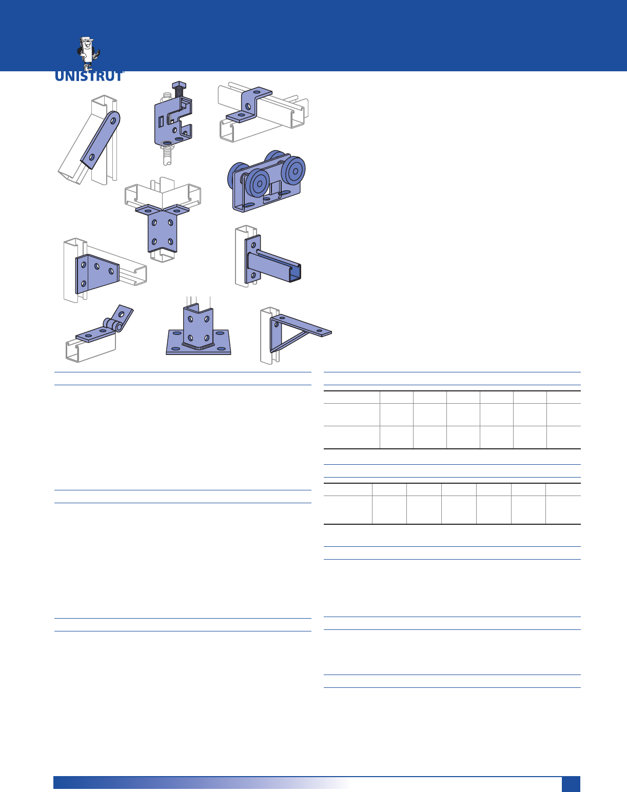
77
MATERIAL
Fittings, unless noted, are made from hot-rolled, pickled
and oiled steel plates, strip or coil, and conform to ASTM
specifications A575, A576, A635, or A36. The fitting steel
also meets the physical requirements of ASTM A1011 SS
GR 33. The pickling of the steel produces a smooth surface
free from scale.
Many fittings are also available in stainless steel, aluminum
and fiberglass. Consult factory for ordering information.
FINISHES
Fittings are available in:
Green Powder Coat (GR), conforming to
commercial standards for Powder Coating
Electro-galvanized (EG), conforming to
ASTM B633 Type III SC1;
Hot-dipped galvanized (HG), conforming to
ASTM A123 or A153 and
Plain (PL).
APPLICATION
All parts drawings illustrate only one application of each
fitting. In most cases many other applications are possible.
The channels shown in the illustrations are P1000, 15⁄8"
square, except where noted otherwise.
All 9⁄16" diameter holes use 1⁄2" x 15⁄16" hex head cap screws
and 1⁄2" nuts – P1010, P3010, P4010 or P5510 – depending
on the channel used. Nuts and bolts are not included with
the fitting and must be ordered separately.
DESIGN BOLT TORQUE
BOLT SIZE 1»4"-20 5»16"-18 3»8"-16 1»2"-13 5»8"-11 3»4"-10
Rec. Torque
)W/EV1P
6 11 19 50 100 125
(8) (15) (26) (68) (136) (170)
Max Torque
)W/EV1P
7 15 25 70 125 135
(9) (20) (34) (95) (170) (183)
SET SCREW TORQUE
BOLT SIZE 1»4"-20 5»16"-18 3»8"-16 1»2"-13 5»8"-11 3»4"-10
Set Screw
Torque
,Q/EV1P
40
(4)
60
(7)
125
(14)
250
(28)
400
(44.5)
665
(75)
Note: Caution should be taken not to overtighten the set screw
DIMENSIONS
Imperial dimensions are illustrated in inches. Metric
dimensions are shown in parenthesis or as noted. Unless
noted, all metric dimensions are in millimeters and
rounded to one decimal place.
DESIGN LOAD
Design load data, where shown, is based on the ultimate
strength of the connection with a safety factor of 2.5,
unless otherwise noted.
BEAM CLAMPS
Clamps are designed to be used with W, M, S and HP Shape
beams, Standard C and Miscellaneous MC Channels, Angles
and Structural Tees. Clamps must be used in pairs mounted
in opposite directions where indicated. For beam clamps
with HG finish, standard hardware is EG finish. For optional
stainless steel hardware, please contact the factory for
availability.
GENERAL FITTINGS
Flat Plate Fittings ...............................................................81 - 82
Ninety Degree Fittings.......................................................82 - 85
Angular Fittings ........................................................................ 85
“Z” Shape Fittings ..................................................................... 86
“U” Shape Fittings .............................................................87 - 88
Wing Shape Fittings ..........................................................88 - 90
Post Bases .................................................................................. 90
Brackets ..............................................................................90 - 93
Brace Fittings ............................................................................. 94
Beam Clamps ....................................................................95 - 101
Trolleys ..................................................................................... 102
Special Application Fittings ...........................................103 - 104
Seismic Retrofit Fittings.................................................104 - 106
GENERAL FITTINGS
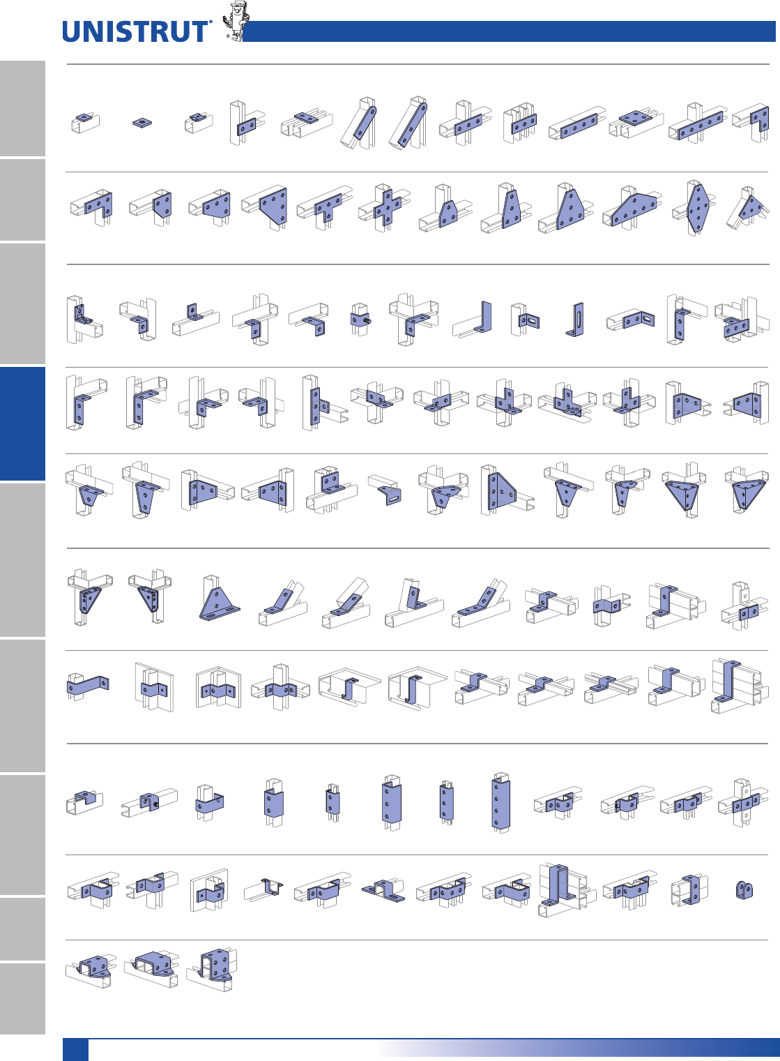
78
15⁄8" Framing System
1 5¼8" ChannelTelestrutNuts & HardwareGeneral FittingsPipe/Conduit SupportsElectrical FittingsConcrete InsertsSolarUnipier®
General Fittings Pictorial Index
P2469-Pg 86P3045-Pg 86P5560-Pg 86 P4045-Pg 86P3345, P612-Pg 86 P5545-Pg 86P2360-Pg 86P1736-Pg 86P1730-Pg 86 P1734-Pg 86P1479A-Pg 86
"U" Shape Fittings
P4376A-Pg 87 P1377-Pg 87P1363A-Pg 87P1320-Pg 87P2800-Pg 87 P4376-Pg 87P1376-Pg 87 P1376A-Pg 87 P1455-Pg 87P1047-Pg 87 P3047, P976-Pg 87 P4047-Pg 87
P1383-Pg 88 P1732-Pg 88P5547-Pg 87 P1044-Pg 88 P1973-Pg 88P2473-Pg 88 P4043-Pg 88P5543-Pg 88P2237-Pg 88 P1043A-Pg 88P1048-Pg 88 P1737-Pg 88
P2328-Pg 88P2326-Pg 88 P2329-Pg 88
P1062-Pg 81 P1959-Pg 81 P2862-Pg 81 P1065-Pg 81 P1924-Pg 81 P2325-Pg 81 P2324-Pg 81 P1066-Pg 81 P1925-Pg 81 P1067-Pg 81 P2079-Pg 81 P1941-Pg 81 P1036-Pg 81
P1380 A-Pg 81 P1334-Pg 81 P1380-Pg 81 P1873-Pg 82 P1031-Pg 82 P1028-Pg 82 P1356-Pg 82 P1358-Pg 82 P1726-Pg 82 P1953-Pg 82 P1950-Pg 82 P1962-Pg 82
P2626-Pg 82 P1026-Pg 82 P1723-Pg 82 P1068-Pg 82 P1281-Pg 82 P1315-Pg 82 P1538A-Pg 83P1458-Pg 82 P1750-Pg 83 P1747-Pg 83P1498-Pg 83 P1821-Pg 83P1326-Pg 83
P1325-Pg 83 P1823-Pg 83P1822-Pg 83 P1033-Pg 83P1346-Pg 83 P1290-Pg 84 P1291-Pg 84P1038- Pg 83P1037-Pg 83 P1029-Pg 84P1034-Pg 83 P1035-Pg 84
P1357-Pg 84 P1359-Pg 84 P2235-Pg 84 P1956-Pg 84P1727-Pg 84 P1728-Pg 84P1382- Pg 84P1381-Pg 84 P1713-Pg 84P1934-Pg 84 P1579-Pg 84 P1957-Pg 84
Angle Fittings
"Z" Shape Fittings
Flat Plate Fittings
P1347-Pg 86P1045-Pg 86 P1454-Pg 86P1453-Pg 86
P2101-Pg 85 P1186-Pg 85 P2260-Pg 85
P2484-Pg 85 P1130-Pg 85P2484W-Pg 85 P1546-Pg 85
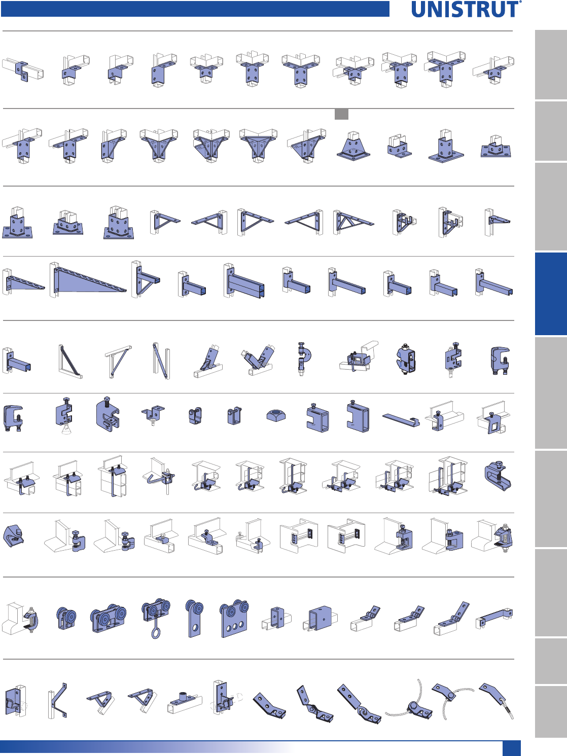
79
15⁄8" Framing System
1 5¼8" ChannelTelestrutNuts & HardwareGeneral FittingsPipe/Conduit SupportsElectrical FittingsConcrete InsertsSolarUnipier®
General Fittings Pictorial Index
Wing Shape Fittings
Post Bases
P2223-Pg 89 P2224-Pg 89P2472-Pg 89 P2343-Pg 89P1046A-Pg 88 P2341-Pg 89 P2227-Pg 89P2225-Pg 89 P2229-Pg 89P2228-Pg 89 P2345-Pg 89
P2344-Pg 89 P2226-Pg 89P2346-Pg 89 P2347-Pg 89 P2245-Pg 89P2230-Pg 89 P2348-Pg 90 P2453-Pg 90P1887-Pg 90 P2072-Pg 90P2941-Pg 90
Brackets and Brace Fittings
P2073-Pg 90 P2073A-Pg 90P2072A-Pg 90 P2491-Pg 91P1075-Pg 91 P1593-Pg 91P1771-Pg 90P1769-Pg 90 P1775-Pg 91P1773-Pg 91 P1777-Pg 91
P2494-Pg 92 P2500-Pg 92 P2547-Pg 91 P2231-Pg 93P2944-Pg 92 P2542-Pg 92 P2513-Pg 93P2233-Pg 93 P2233A-Pg 93P2231A-Pg 93
Beam Clamps
P2513A-Pg 93 P2458-Pg 94P2452-Pg 94 P2815-Pg 94P2459-Pg 94 P2815D-Pg 94 P2675-Pg 95P2784-Pg 95 PFL2-Pg 95P2897-Pg 95 P2898-Pg 96
P2899-Pg 96 P2398S-Pg 97 P1654A-Pg 97
P2679-Pg 96 P1648S-Pg 97
P2676-Pg 96 P2677-Pg 96P1640-Pg 97 P2682-Pg 96 P1796S-Pg 98P1271S-Pg 98
P2674-Pg 97
P2786-Pg 98P2785-Pg 98 P2868-Pg 99 P2868A-Pg 99 P2868B-Pg 99
P2867-Pg 98 P2867A-Pg 98 P2867B-Pg 98
P2787-Pg 98 P2824-Pg 98 P2893-Pg 99
P2894-Pg 99 P2895-Pg 99 P2896-Pg 99 P3087-Pg 100 P3088-Pg 100P1379S-Pg 100 P1272S-Pg 100P1386-Pg 100 PFL037-Pg 101PLLC025-Pg 100 PLF3037-Pg 101
Trolley Assemblies Special Applications Fittings
PLF9037-Pg 101 P2749-Pg 102 P2750-Pg 102 P2950-Pg 102 P1834-Pg 102P2751-Pg 102 P2949-Pg 102 P1834A-Pg 102 P1354-Pg 104P1354A-Pg 104P1843-Pg 104 P1201-Pg 103
Seismic Retrofit Fittings
P1944-Pg 103P2354-Pg 103 P1204-Pg 103 P2470-Pg 103 P2454-Pg 103P2655-Pg 103 LS500-Pg 106SPF 200-Pg 104SPF 100-Pg 104 SPF 400-Pg 105SPF 300-Pg 105 LS 410-Pg 106
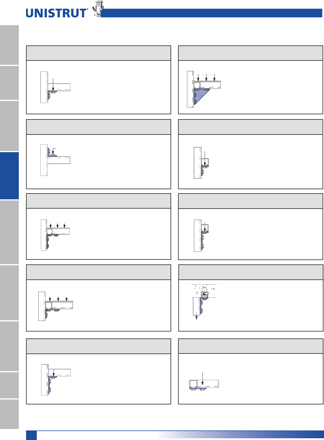
80
15⁄8" Framing System
1 5¼8" ChannelTelestrutNuts & HardwareGeneral FittingsPipe/Conduit SupportsElectrical FittingsConcrete InsertsSolarUnipier®
DESIGN LOAD DATA FOR TYPICAL UNISTRUT CHANNEL CONNECTIONS
90° Fittings (When used in position shown)
Design Load Data
Note:
(1) Both ends of beams supported.
(2) Load data is based on P1010 nut and 1»2" bolt.
(3) Safety factor = 21»2 based on ultimate strength of connection.
Load – P1026
Channel Thickness
12 ga. 14 ga. 16 ga.
LOAD
Lbs 1,500 1,000 750
kN 6.67 4.45 3.34
Load – P2484
Channel Thickness
12 ga. 14 ga. 16 ga.
LOAD
Lbs 3,000 2,000 1,500
kN 13.34 8.90 6.67
Load – P1026
Channel Thickness
12 ga. 14 ga. 16 ga.
LOAD
Lbs 1,000 650 500
kN 4.45 2.89 2.22
Channel Thickness
Load – P1068 12 ga. 14 ga. 16 ga.
LOAD
Lbs 500 500 500
kN 2.22 2.22 2.22
Channel Thickness
Load – P1325, P2235 12 ga. 14 ga. 16 ga.
LOAD
Lbs 2,000 2,000 1,500
kN 8.90 8.90 6.67
Channel Thickness
Load – P1326 12 ga. 14 ga. 16 ga.
LOAD
Lbs 500 500 500
kN 2.22 2.22 2.22
Load – P1458, P1579
Channel Thickness
12 ga. 14 ga. 16 ga.
LOAD
Lbs 1,500 1,000 1,000
kN 6.67 4.45 4.45
Load – P1346
Channel Thickness
12 ga. 14 ga. 16 ga.
LOAD
Lbs 1,200 1,200 1,000
kN 5.34 5.34 4.45
Load – P1065
Channel Thickness
12 ga. 14 ga. 16 ga.
LOAD
Lbs 1,000 800 600
kN 4.45 3.56 2.67
Load – P1346
Channel Thickness
12 ga. 14 ga. 16 ga.
LOAD
Lbs 2,000 1,500 900
kN 8.90 6.67 4.00
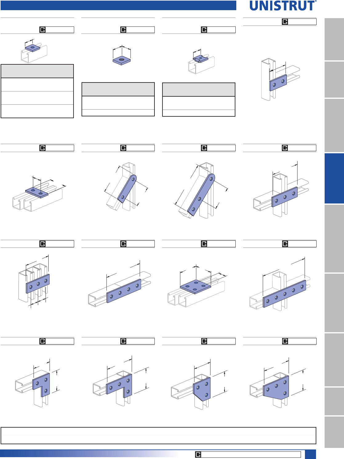
81
15⁄8" Framing System
1 5¼8" ChannelTelestrutNuts & HardwareGeneral FittingsPipe/Conduit SupportsElectrical FittingsConcrete InsertsSolarUnipier®
P1067P1925
P1066P2324
Wt/100 pcs: 75 Lbs (34.0 kg)
Wt/100 pcs: 78 Lbs (35.4 kg)
Wt/100 pcs: 56 Lbs (25.4 kg)
7 1⁄4"
(184.2)
9 1⁄8"
(231.8)
5 3⁄8"
(136.5)
3 1⁄2"
(88.9) (82.6)
3 1⁄4"1 5⁄8"
(41.3)
7 1⁄8"
(181.0)
(92.1)
3 5⁄8"
4 7⁄8"
(123.8)
(41.3)
1 5⁄8"
(41.3)
1 5⁄8"
P1941
Wt/100 pcs: 94 Lbs (42.6 kg)
P2079
Wt/100 pcs: 73 Lbs (33.1 kg)Wt/100 pcs: 50 Lbs (22.7 kg)
P1065
P1924 P2325
Wt/100 pcs: 55 Lbs (24.9 kg)Wt/100 pcs: 35 Lbs (15.9 kg)
Wt/100 pcs: 38 Lbs (17.2 kg)
(133.4)
5 1⁄4"
3 5⁄8"
(92.1)
31⁄2"
(88.9)
1 5⁄8"
(41.3) (82.6)
3 1⁄4"
1 1⁄2"
(38.1) (34.9)
1 3⁄8"
Tapped Hole
1 5⁄8"
(41.3)
P1062, P1063, P1064,P1964,
P2471, P2490
1 5⁄8"(41.3)
Flat Plate Fittings
P1959, P1960,
P1961
P2862, 2863,
2864
Material: 3»8" (9.5 mm) thick
Part
Number
U.S. Std.
Thd Size
Wt/100 pcs
Lbs (kg)
P1959 3»8" - 16 21 (9.5)
P1960 1»2" - 13 20 (9.1)
P1961 5»8" - 11 19 (8.6)
Part
No.
Bolt
Size
Hole
Size
Wt/100 pcs
/EVNJ
P1062 5»16"11»32" 18 (8.2)
P1063 3»8"7»16" 18 (8.2)
P1064 1»2"9»16" 17 (7.7)
P1964 5»8"11»16" 16 (7.3)
P2471 3»4"13»16" 15 (6.8)
P2490 7»8"15»16" 14 (6.4)
Part
Number
Bolt
Size
Hole
Size
Wt/100 pcs
Lbs (kg)
P2862 5»16"11»32" 18 (8.2)
P2863 3»8"7»16" 18 (8.2)
P2864 1»2"9»16" 17 (7.7)
P1036 P1380 A P1380P1334
Wt/100 pcs: 58 Lbs (26.3 kg) Wt/100 pcs: 80 Lbs (36.3 kg) Wt/100 pcs: 70 Lbs (31.8 kg) Wt/100 pcs: 105 Lbs (47.6 kg)
(88.9)
3 1⁄2"
(88.9)
3 1⁄2"3 1⁄2"
(88.9)
3 1⁄2"
(88.9)
5 3⁄8"
(136.5)
3 1⁄2"
(88.9)
(136.5)
5 3⁄8"
3 1⁄2"
(88.9)
EG, GR, HG EG, GR, HG EG, GR, HG
EG, GR, HG
EG, GR, HG
EG, GR, HG
EG, GR, HG
EG, GR, HG
EG, GR, HG
EG, GR, HG
EG, GR, HG
EG, GR, HG
EG, GR, HG
EG, GR, HG
EG, GR, HG
EG, GR, HG
CORE PRODUCTS - TYPICALLY AVAILABLE FROM STOCK
Standard Dimensions for 15»8PPZLGWKVHULHVFKDQQHOILWWLQJV(Unless Otherwise Shown on Drawing)
Hole Diameter: 9»16PP+ROH6SDFLQJ)URP(QG13»16PP+ROH6SDFLQJ2Q&HQWHU7»8PP:LGWK5»8PP7KLFNQHVV1»4PP
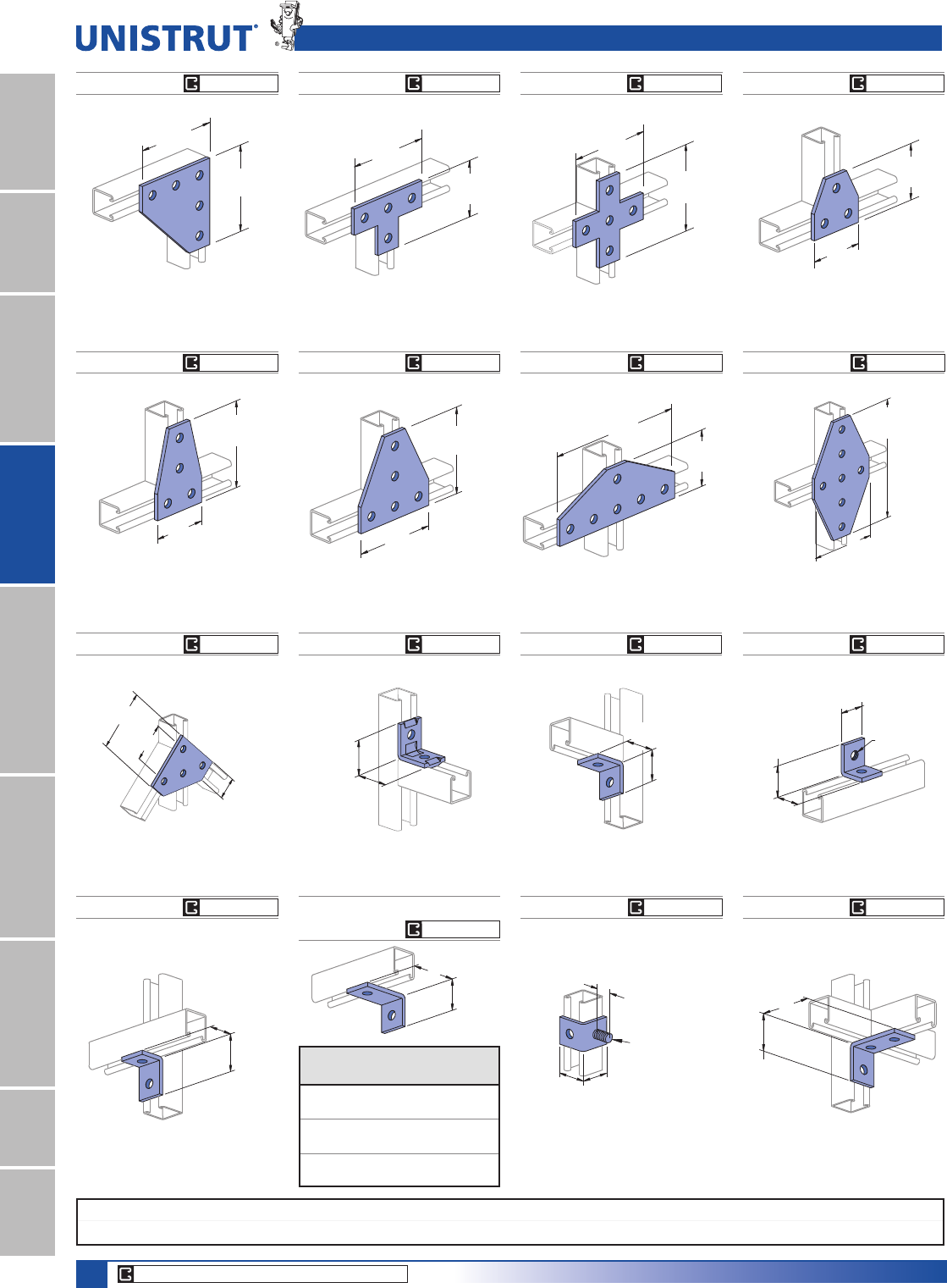
82
15⁄8" Framing System
1 5¼8" ChannelTelestrutNuts & HardwareGeneral FittingsPipe/Conduit SupportsElectrical FittingsConcrete InsertsSolarUnipier®
P1028 P1356
P1726P1358 P1950P1953
Wt/100 pcs: 105 Lbs (47.6 kg) Wt/100 pcs: 70 Lbs (31.8 kg)
Wt/100 pcs: 105 Lbs (47.6 kg) Wt/100 pcs: 148 Lbs (67.1 kg) Wt/100 pcs: 240 Lbs (108.9 kg)Wt/100 pcs: 176 Lbs (79.8 kg)
5 3⁄8"
(136.5)
(88.9)
3 1⁄2"
9 1⁄8"
3 1⁄2"
(88.9)
(231.8)
(136.5)
5 3⁄8"
(136.5)
5 3⁄8"
3 1⁄2"
(88.9)
3 1⁄2"
(88.9)
(136.5)
5 3⁄8"
(136.5)
5 3⁄8"
5 3⁄8"
(136.5)
9 1⁄8"
(231.8)
P1031P1873
Flat Plate & Ninety Degree Angle Fittings
Wt/100 pcs: 150 Lbs (68.0 kg) Wt/100 pcs: 80 Lbs (36.3 kg)
5 3⁄8"
(136.5)
5 3⁄8"
(136.5)
(88.9)
3 1⁄2"
5 3⁄8"
(136.5)
P1315 P1458
Wt/100 pcs: 45 Lbs (20.4 kg)
1 7⁄8"
(47.6)
1 7⁄8"
(47.6)
1 "
(25.4)
1⁄2"
- 13 Stud
Wt/100 pcs: 58 Lbs (26.3 kg)
(57.2)
2 1⁄4"
3 1⁄2"
(88.9)
P1026 P1723
P1281, P1282,
P1283
P1068
P2626
Wt/100 pcs: 38 Lbs (17.2 kg) Wt/100 pcs: 34 Lbs (15.4 kg)
Wt/100 pcs: 38 Lbs (17.2 kg)
Wt/100 pcs: 40 Lbs (18.1 kg)
2 1⁄8"
(54.0)
(54.0)
2 1⁄8"
1 7⁄8"
(47.6)
(50.8)
2"
1 5⁄8"
(41.3)
2 1⁄4"
(57.2)
1 7⁄8"
(47.6)
A
Tapped
5⁄16"-18 Thd.
1 5⁄8"
(41.3)
1 5⁄8"
(41.3)
(47.6)
1 7⁄8"
Part No.
“A”
In (mm)
Wt/100 pcs
Lbs (kg)
P1281 349
76.2 22.2
P1282 31/254
88.9 24.5
P1283 461
101.6 27.7
P1962
Wt/100 pcs: 112 Lbs (50.8 kg)
41⁄2"
(114.3)
27⁄8"
(73.0)
15⁄8"
(41.3)
CORE PRODUCTS - TYPICALLY AVAILABLE FROM STOCK
EG, GR, HG
EG, GR, HG
EG, GR, HG
EG, GR, HG
EG, GR, HG
EG, GR, HG
EG, GR, HG
EG, GR, HG
EG, GR, HG
EG, GR, HG
EG, GR, HG
EG, GR, HG
EG, GR, HG
EG, GR, HG
EG, GR, HG
EG, GR, HG
Standard Dimensions for 15»8PPZLGWKVHULHVFKDQQHOILWWLQJV(Unless Otherwise Shown on Drawing)
Hole Diameter: 9»16PP+ROH6SDFLQJ)URP(QG13»16PP+ROH6SDFLQJ2Q&HQWHU7»8PP:LGWK5»8PP7KLFNQHVV1»4PP
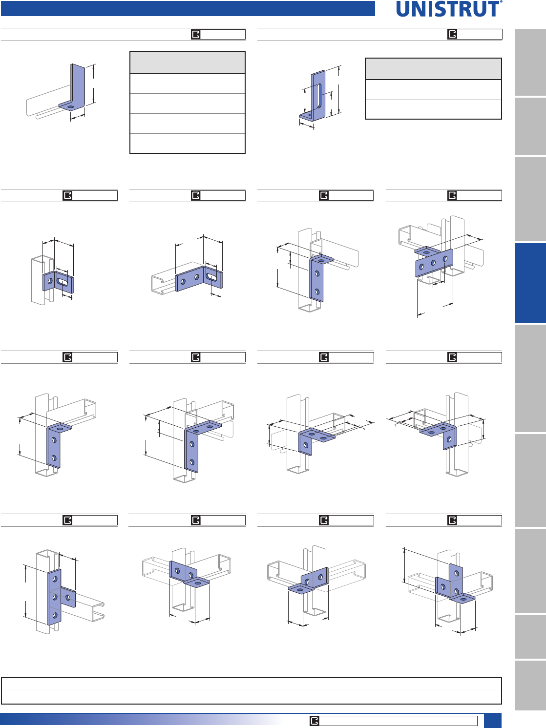
83
15⁄8" Framing System
1 5¼8" ChannelTelestrutNuts & HardwareGeneral FittingsPipe/Conduit SupportsElectrical FittingsConcrete InsertsSolarUnipier®
P1538A THRU P1538D
P1750
P1498, P1499
Wt/100 pcs: 38 Lbs (17.2 kg)
A
1 7⁄8"
(47.6)
B
A
(63.5)
2 1⁄2"
1 7⁄8"
(47.6)
2 5⁄8"
(66.7)
1 5⁄8"
(41.3)
(33.3)
1 5⁄16"
(38.1)
1 1⁄2"
Part
Number
“A”
In (mm)
Wt/100 pcs
Lbs (kg)
P1538A 37»861
98.4 27.7
P1538B 57»884
149.2 38.1
P1538C 77»8107
200.0 48.5
P1538D 97»8130
250.8 59.0
Part
Number
“A”
In (mm)
“B”
In (mm)
Wt/100 pcs
Lbs (kg)
P1498 47»821»265
123.8 63.5 29.5
P1499 67»841»285
174.6 114.3 38.6
Ninety Degree Angle Fittings
P1033 P1037 P1034P1038
Wt/100 pcs: 58 Lbs (26.3 kg)Wt/100 pcs: 80 Lbs (36.3 kg) Wt/100 pcs: 58 Lbs (26.3 kg) Wt/100 pcs: 80 Lbs (36.3 kg)
2"
(50.8) 3 1⁄2"
(88.9)
(50.8)
2"
(136.5)
5 3⁄8"
2"
(50.8)
3 1⁄2"
(88.9)
(88.9)
3 1⁄2"
(88.9)
3 1⁄2"
2"
(50.8)
P1346 P1325 P1823P1822
P1821
Wt/100 pcs: 58 Lbs (26.3 kg) Wt/100 pcs: 78 Lbs (35.4 kg) Wt/100 pcs: 55 Lbs (24.9 kg) Wt/100 pcs: 55 Lbs (24.9 kg)
Wt/100 pcs: 71 Lbs (32.2 kg)
3 7⁄8"
(98.4)
(47.6)
1 7⁄8"
(82.6)
3 1⁄4"
1 7⁄8"
(47.6)
(50.8)
2"
(41.3)
1 5⁄8"
(82.6)
3 1⁄4"
(41.3)
1 5⁄8"
1 7⁄8"
(47.6)
2"
(50.8)
4 1⁄8"
(104.8)
(88.9)
3 1⁄2"
(36.5)
1 7⁄16"
(50.8)
2"
(123.8)
4 7⁄8"
(41.3)
1 5⁄8"
P1326
Wt/100 pcs: 58 Lbs (26.3 kg)
4 1⁄16"
(103.2)
1 5⁄8"
(41.3)
(34.9)
1 3⁄8"
P1747
Wt/100 pcs: 66 Lbs (29.9 kg)
(98.4)
3 7⁄8"
1 1⁄2"
(38.1)
(66.7)
2 5⁄8"
1 5⁄16"
(33.3)
CORE PRODUCTS - TYPICALLY AVAILABLE FROM STOCK
EG, GR, HG
EG, GR, HG
EG, GR, HG
EG, GR, HG EG, GR, HG
EG, GR, HG
EG, GR, HG
EG, GR, HG
EG, GR, HG
EG, GR, HG
EG, GR, HG
EG, GR, HG
EG, GR, HG
EG, GR, HG
Standard Dimensions for 15»8PPZLGWKVHULHVFKDQQHOILWWLQJV(Unless Otherwise Shown on Drawing)
Hole Diameter: 9»16PP+ROH6SDFLQJ)URP(QG13»16PP+ROH6SDFLQJ2Q&HQWHU7»8PP:LGWK5»8PP7KLFNQHVV1»4PP
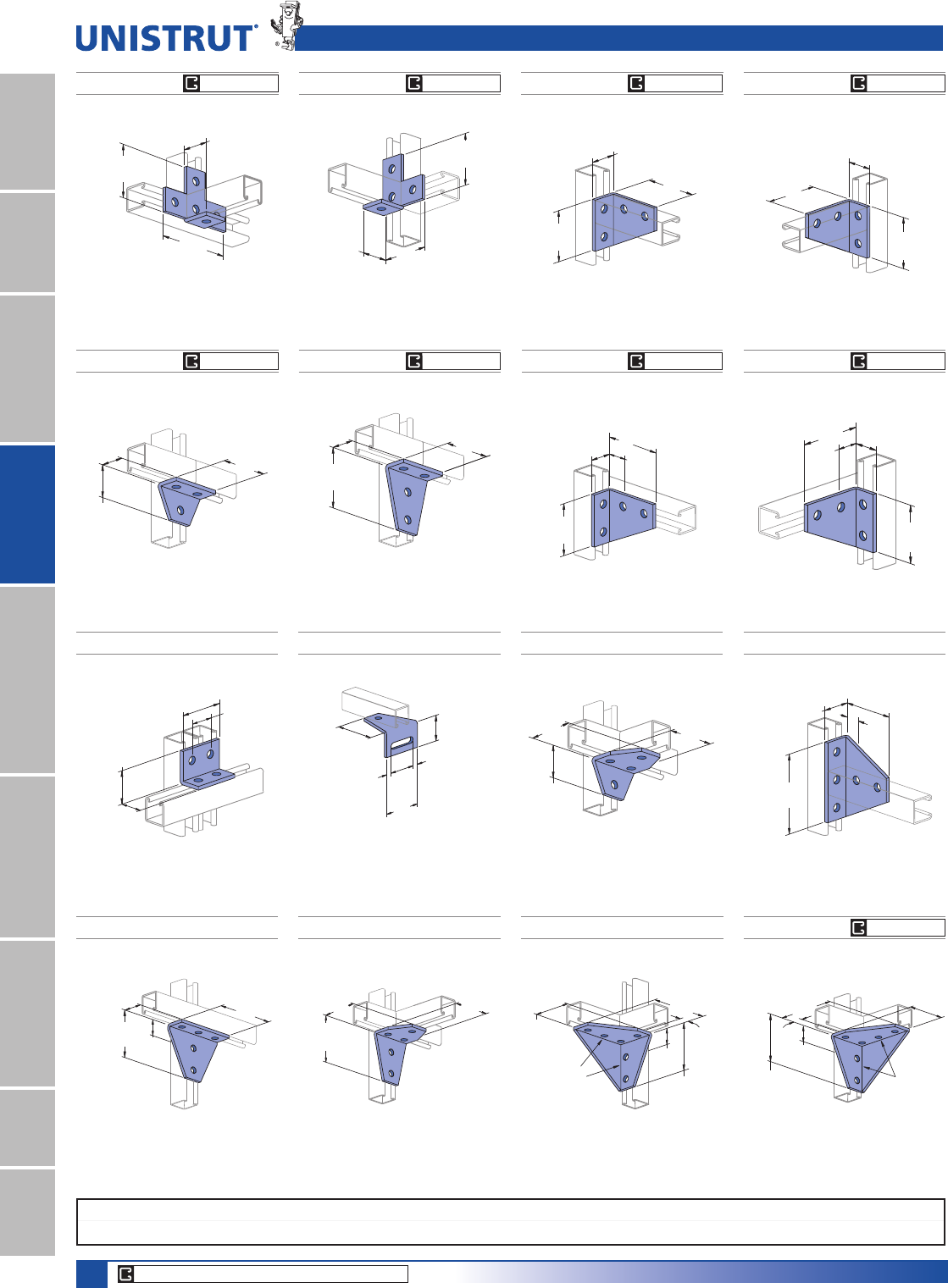
84
15⁄8" Framing System
1 5¼8" ChannelTelestrutNuts & HardwareGeneral FittingsPipe/Conduit SupportsElectrical FittingsConcrete InsertsSolarUnipier®
P1579 P1727
P1728
P1713
Wt/100 pcs: 97 Lbs (44.0 kg) Wt/100 pcs: 103 Lbs (46.7 kg) Wt/100 pcs: 154 Lbs (69.9 kg)
Wt/100 pcs: 154 Lbs (69.9 kg)
(63.5)
2 1⁄2"
3 1⁄2"
(88.9)
3 1⁄2"
(88.9)
2 1⁄4"
(57.2)
1⁄2"
(12.7)
1⁄2"
(12.7)
(136.5)
5 3⁄8"
(30.2)
1 3⁄16"
(98.4)
3 7⁄8"
1 7⁄8"
(47.6)
(104.8)
4 1⁄8"
(41.3)
1 5⁄8"
(36.5)
1 7⁄16"
(136.5)
5 3⁄8"
3 1⁄2"
(88.9)
(57.2)
2 1⁄4"
(88.9)
3 1⁄2"
P1934
Wt/100 pcs: 75 Lbs (34.0 kg)
(41.3)
1 5⁄8"
(41.3)
1 5⁄8"
(82.6)
3 1⁄4"
(57.2)
2 1⁄4"
P1357 P1359 P1382
P1381
P1291P1290
Ninety Degree Angle Fittings
Wt/100 pcs: 101 Lbs (45.8 kg)
Wt/100 pcs: 70 Lbs (31.8 kg) Wt/100 pcs: 105 Lbs (47.6 kg) Wt/100 pcs: 105 Lbs (47.6 kg)Wt/100 pcs: 105 Lbs (47.6 kg)
Wt/100 pcs: 101 Lbs (45.8 kg)
(104.8)
4 1⁄8"
1 7⁄16"
(36.5)
1 5⁄8"
(41.3)
(88.9)
3 1⁄2"
(104.8)
4 1⁄8"
1 7⁄16"
(36.5)
1 5⁄8"
(41.3)
(88.9)
3 1⁄2"
1
7
⁄
8
"
(47.6)
3
7
⁄
8
"
(98.4)
3
1
⁄
2
"
(88.9)
1
7
⁄
8
"
(47.6)
3
7
⁄
8
"
(98.4)
(88.9)
3 1⁄2"
(88.9)
3 1⁄2"
(57.2)
2 1⁄4"
1 5⁄8"
(41.3)
(41.3)
1 5⁄8"
4 1⁄8"
(104.8)
3 1⁄2"
(88.9)
P1035
Wt/100 pcs: 80 Lbs (36.3 kg)
2"
(50.8)
(88.9)
3 1⁄2"
(88.9)
3 1⁄2"
P1029
Wt/100 pcs: 105 Lbs (47.6 kg)
(50.8)
2"
5 3⁄8"
(136.5)
(88.9)
3 1⁄2"
P1956 P1957
Wt/100 pcs: 230 Lbs (104.3 kg) Wt/100 pcs: 230 Lbs (104.3 kg)
(20.6)
13⁄16"
(136.5)
5 3⁄8"
(88.9)
3 1⁄2"
(36.5)
1 7⁄16"
4 1⁄8"
(104.8)
Continuous
Weld
(20.6)
13⁄16"
(136.5)
5 3⁄8"(88.9)
3 1⁄2"
(36.5)
1 7⁄16"
4 1⁄8"
(104.8)
Continuous
Weld
P2235
Wt/100 pcs: 135 Lbs (61.2 kg)
4 1⁄8"
(104.8)
3 1⁄2"
(88.9) (88.9)
3 1⁄2"
CORE PRODUCTS - TYPICALLY AVAILABLE FROM STOCK
EG, GR, HG
EG, GR, HG
EG, GR, HG
EG, GR, HG
EG, GR, HG
EG, GR, HG
EG, GR, HG
EG, GR, HG
EG, GR, HG
Standard Dimensions for 15»8PPZLGWKVHULHVFKDQQHOILWWLQJV(Unless Otherwise Shown on Drawing)
Hole Diameter: 9»16PP+ROH6SDFLQJ)URP(QG13»16PP+ROH6SDFLQJ2Q&HQWHU7»8PP:LGWK5»8PP7KLFNQHVV1»4PP
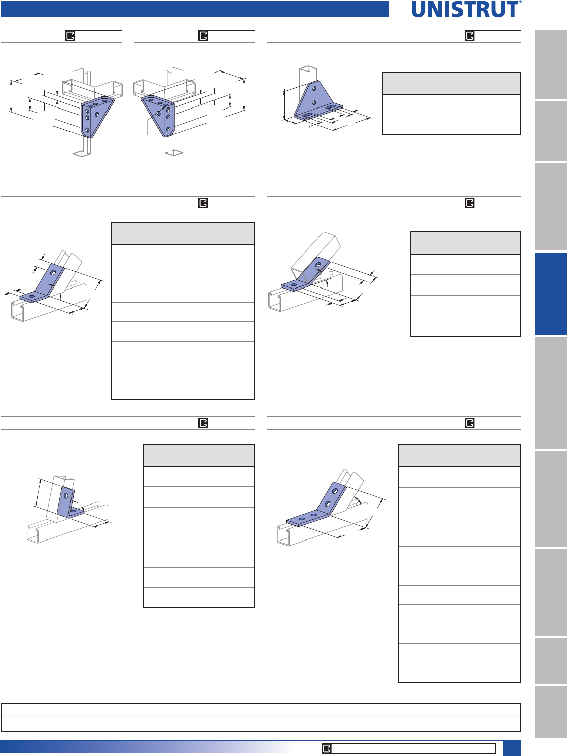
85
15⁄8" Framing System
1 5¼8" ChannelTelestrutNuts & HardwareGeneral FittingsPipe/Conduit SupportsElectrical FittingsConcrete InsertsSolarUnipier®
13⁄16"
(20.6)
(101.6)
4"
(22.2)
7⁄8"
1 9⁄16"
(39.7)
(101.6)
4"
Continuous
Weld
P1546, P2094 THRU P2100 P2101 THRU P2104
Wt/100 pcs: 58 Lbs (26.3 kg)
P1186, P2105 THRU P2110
Wt/100 pcs: 58 Lbs (26.3 kg)
Wt/100 pcs: 58 Lbs (26.3 kg)
(63.5)
2 1⁄2"
A
B
B
(27.0)
1 1⁄16"
1 1⁄16"
(52.4)
2 1⁄16"
A(27.0)
(27.0)
1 1⁄16"
(27.0)
1 1⁄16"
B
C
A
Part
No.
“A”
Degree (rad)
“B”
In (mm)
“C”
In (mm)
P2094 821»2°3
9»16 111»16
1.44 90.5 42.9
P2095 75° 39»16 111»16
1.31 90.5 42.9
P2096 671»2°3
1»213»4
1.18 88.9 44.5
P2097 60° 33»817»8
1.05 85.7 47.6
P2098 521»2°3
1»421»16
0.92 82.6 52.4
P1546 45° 3 25»16
0.79 76.2 58.7
P2099 371»2°3
1»2113»16
0.65 88.9 46.0
P2100 371»2°2
11»16 25»8
0.65 68.3 66.7
Part
No.
“A”
Degree (rad)
“B”
In (mm)
P2101 30° 31»4
0.52 82.6
P2102 221»2°3
5»16
0.39 84.1
P2103 15° 35»16
0.26 84.1
P2104 71»2°3
5»16
0.13 84.1
Part
Number
“A”
Degree (rad)
“B”
In (mm)
P2105 821»2°3
1»4
1.44 82.6
P2106 75° 31»4
1.31 82.6
P2107 671»2°3
3»16
1.18 81.0
P2108 60° 33»16
1.05 81.0
P2109 521»2°3
1»8
0.92 79.4
P1186 45° 31»8
0.79 79.4
P2110 371»2°3
1»16
0.65 77.8
P2484WP2484
Wt/100 pcs: 134 Lbs (60.8 kg) Wt/100 pcs: 134 Lbs (60.8 kg)
13⁄16"
(20.6)
(22.2)
7⁄8"
1 9⁄16"
(39.7)
(101.6)
4"
(101.6)
4"
Ninety Degree Angle & Angular Fittings
P1130, P1131
(47.6)
1 7⁄8"
(95.3)
3 3⁄4"
A
(38.1)
1 1⁄2"
1 1⁄2"
(38.1)
B
Part
Number
“A”
In (mm)
“B”
In (mm)
Wt/100 pcs
Lbs (kg)
P1130 65»84 190
168.3 101.6 86.2
P1131 85»86 242
219.1 152.4 109.8
A
B
3 1⁄2"
(88.9)
P2260 THRU P2270
Wt/100 pcs: 78 Lbs (35.4 kg)
Part
Number
“A”
Degree (rad)
“B”
In (mm)
P2270 821»2°3
5»8
1.44 92.1
P2269 75° 35»8
1.31 92.1
P2268 671»2°3
5»8
1.18 92.1
P2267 60° 311»16
1.05 93.7
P2266 521»2°3
11»16
0.92 93.7
P2265 45° 311»16
0.79 93.7
P2264 371»2°3
11»16
0.65 93.7
P2263 30° 311»16
0.52 93.7
P2262 221»2°3
3»4
0.39 95.3
P2261 15° 33»4
0.26 95.3
P2260 71»2°3
3»4
0.13 95.3
CORE PRODUCTS - TYPICALLY AVAILABLE FROM STOCK
EG, GR, HG EG, GR, HG
EG, GR, HG
EG, GR, HG
EG, GR, HG
EG, GR, HG
EG, GR, HG
Standard Dimensions for 15»8PPZLGWKVHULHVFKDQQHOILWWLQJV(Unless Otherwise Shown on Drawing)
Hole Diameter: 9»16PP+ROH6SDFLQJ)URP(QG13»16PP+ROH6SDFLQJ2Q&HQWHU7»8PP:LGWK5»8PP7KLFNQHVV1»4PP
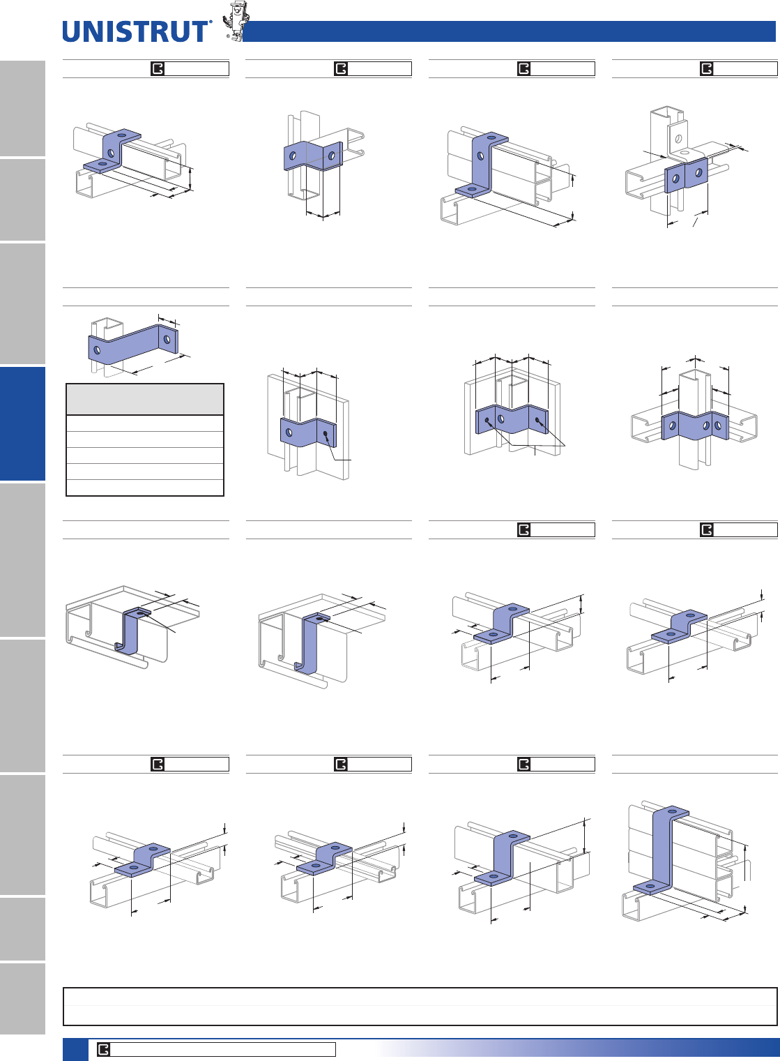
86
15⁄8" Framing System
1 5¼8" ChannelTelestrutNuts & HardwareGeneral FittingsPipe/Conduit SupportsElectrical FittingsConcrete InsertsSolarUnipier®
P1734 P1736
Wt/100 pcs: 70 Lbs (31.8 kg) Wt/100 pcs: 70 Lbs (31.8 Kg)
(47.6)
1 7⁄8"
(47.6)
1 7⁄8"
(88.9)
3 1⁄2"
(88.9)
3 1⁄2"
(41.3)
1 5⁄8"
(41.3)
1 5⁄8"
(47.6)
1 7⁄8"
(47.6)
1 7⁄8"
Tapped
5⁄16" - 18 Thd.
P1730P1479A THRU P1479E
Wt/100 pcs: 54 Lbs (24.5 kg)
Tapped
5⁄16" - 18 Thd.
1 7⁄8"
(41.3)
1 5⁄8"
(41.3)
1 5⁄8"
(47.6)
A
1 5⁄8"
(41.3)
Part
Number
“A”
In (mm)
Wt/100 pcs
Lbs (kg)
P1479A 4 (101.6) 81 (36.7)
P1479B 5 (127.0) 92 (41.7)
P1479C 6 (152.4) 104 (47.2)
P1479D 7 (177.8) 115 (52.2)
P1479E 8 (203.2) 127 (57.6)
P1045 P1347 P1454P1453
“Z” Shape Fittings
Wt/100 pcs: 55 Lbs (24.9 kg)
(41.3)
1 5⁄8"
(41.3)
1 5⁄8"
Wt/100 pcs: 38 Lbs (17.2 kg)Wt/100 pcs: 55 Lbs (24.9 kg) Wt/100 pcs: 70 Lbs (31.8 kg)
(27.0)
1 1⁄16"
(54.0)
2 1⁄8"
1 5⁄8"
(41.3)
(82.6)
3 1⁄4"
(47.6)
1 7⁄8"
P1001
P5000
(6.4)
Offset
1⁄4"
Splice
(88.1)
3 "
32
15
P3045
Wt/100 pcs: 53 Lbs (24.0 kg)
(34.9)
1 3⁄8"
P3000
1 1⁄16"
3 3⁄4"
(95.3)
(27.0)
P5560P2360
Wt/100 pcs: 9 Lbs (4.1 kg) Wt/100 pcs: 11 Lbs (5.0 kg)
(20.6)
13⁄16"
9⁄32" (7.1) Hole
P1000
P1100
P2000 Note: material 1⁄8" (3.2) Thick
(20.6)
13⁄16"
P5500
9⁄32" (7.1) Hole
Note: material 1⁄8" (3.2) Thick
P4045 P5545 P2469
Wt/100 pcs: 47 Lbs (21.3 kg) Wt/100 pcs: 67 Lbs (30.4 kg) Wt/100 pcs: 93 Lbs (42.2 kg)
(20.6)
13⁄16"
(27.0)
1 1⁄16"
(95.3)
3 3⁄4"
P4000
P4100
(61.9)
2 7⁄16"
P5500
1 1⁄16"
(27.0)
3 3⁄4"
(95.3) (27.0)
1 1⁄16"
(54.0)
2 1⁄8"
(123.8)
4 7⁄8"
P1001A3 (shown)
or P5501
P3345
P612
Wt/100 pcs: 47 Lbs (21.3 kg)
Wt/100 pcs: 47 Lbs (21.3 kg)
1 1⁄16"
(27.0)
(22.2)
7⁄8"
3 3⁄4"
(95.3)
P3300
CORE PRODUCTS - TYPICALLY AVAILABLE FROM STOCK
EG, GR, HG
EG, GR, HG
EG, GR, HG
EG, GR, HG
EG, GR, HG
EG, GR, HG
EG, GR, HG
EG, GR, HG
EG, GR, HG
(25.4)
3"
3 1»2"
(88.9)
P4400
Standard Dimensions for 15»8PPZLGWKVHULHVFKDQQHOILWWLQJV(Unless Otherwise Shown on Drawing)
Hole Diameter: 9»16PP+ROH6SDFLQJ)URP(QG13»16PP+ROH6SDFLQJ2Q&HQWHU7»8PP:LGWK5»8PP7KLFNQHVV1»4PP
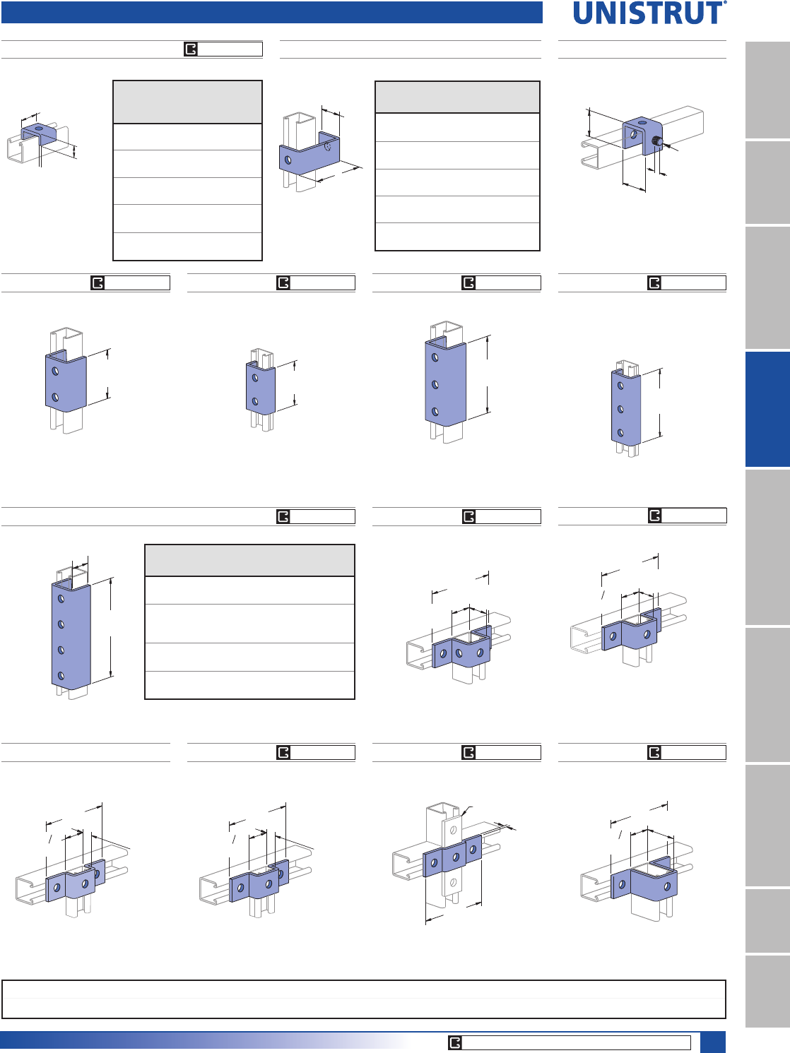
87
15⁄8" Framing System
1 5¼8" ChannelTelestrutNuts & HardwareGeneral FittingsPipe/Conduit SupportsElectrical FittingsConcrete InsertsSolarUnipier®
P1363A THRU P1363E
A
1 7⁄8"
(47.6)
Part
Number
“A”
In (mm)
Wt/100 pcs
Lbs (kg)
P1363A 478
101.6 35.4
P1363B 589
127.0 40.4
P1363C 6 101
152.4 45.8
P1363D 7112
177.8 50.8
P1363E 8 124
203.2 56.2
P2800
“U” Shape Fittings
P1320
Wt/100 pcs: 63 Lbs (28.6 kg)
1 7⁄8"
(47.6)
(19.1)
3⁄4"
(54.8)
2 5⁄32"
1⁄2"-13 Thd.
Part
Number
Bolt
Size
LQ
Hole
Size
LQ
Wt/100
pcs
Lbs (kg)
P2800-25
1»4"9»32"14
6.4
P2800-37
3»8"7»16"14
6.4
P2800-50
1»2"9»16"13
5.9
P2800-62
5»8"11»16"13
5.9
P2800-75
3»4"13»16"13
5.9
31⁄2"
(88.9)
P3300
P4000
P4100
P5547
Wt/100 pcs: 108 Lbs (49.0 kg)
2 7⁄16"
(61.9)
(136.5)
5 3⁄8"
1 "
(42.1)
21 32
P5500
P1455
Wt/100 pcs: 58 Lbs (26.3 kg)
5 5⁄16"
(134.9)
1⁄4"
(6.4)
Offset
1⁄4" (6.4) Plate
P1047 P3047
P4047P976
Wt/100 pcs: 88 Lbs (39.9 kg) Wt/100 pcs: 84 Lbs (38.1 kg)
1 "
(136.5)
5 3⁄8"
(34.9)
1 3⁄8"
21 32
P3000
(42.1)
Wt/100 pcs: 71 Lbs (32.2 kg)Wt/100 pcs: 71 Lbs (32.2 kg)
(136.5)
5 3⁄8"
(20.6)
13⁄16"
1 "
(42.1)
21 32
P3300
P4000
P4100
(41.3)
1 5⁄8"
1 21⁄32"
(136.5)
5 3⁄8"
(42.1)
P1377, P4377, P5077, P5577
7 1⁄4"
A
(184.2)
Part
Number
For
Use With
"A"
LQPP
Wt/100 pcs
/EVNJ
P1377 P1000, P1100,
P2000
1 9»16
39.7
265
120
P4377
P3300,
P4000,
P4100
15»16
23.8
176
80
P5077 P5000 33»16
81.0
390
177
P5577 P5500 23»8
60.3
310
141
P1376 P4376 P4376AP1376A
Wt/100 pcs: 128 Lbs (58.1 kg) Wt/100 pcs: 85 Lbs (38.6 kg) Wt/100 pcs: 197 Lbs (89.4 kg) Wt/100 pcs: 130 Lbs (59.0 kg)
5 3⁄8"
(136.5)
5 3⁄8"
(136.5)
P3300
P4000
P4100
3 1⁄2"
(88.9)
15⁄32"
11 Ga.
1 5⁄8"
(41.3)
(11.9)
CORE PRODUCTS - TYPICALLY AVAILABLE FROM STOCK
EG, GR, HG
EG, GR, HG
EG, GR, HG
EG, GR, HG
EG, GR, HG
EG, GR, HG
EG, GR, HG
EG, GR, HG
EG, GR, HG
EG, GR, HG
EG, GR, HG
(147.6)
5 13⁄16"
(25.4)
1"
1 "
(42.1)
21 32
P4400
Standard Dimensions for 15»8PPZLGWKVHULHVFKDQQHOILWWLQJV(Unless Otherwise Shown on Drawing)
Hole Diameter: 9»16PP+ROH6SDFLQJ)URP(QG13»16PP+ROH6SDFLQJ2Q&HQWHU7»8PP:LGWK5»8PP7KLFNQHVV1»4PP
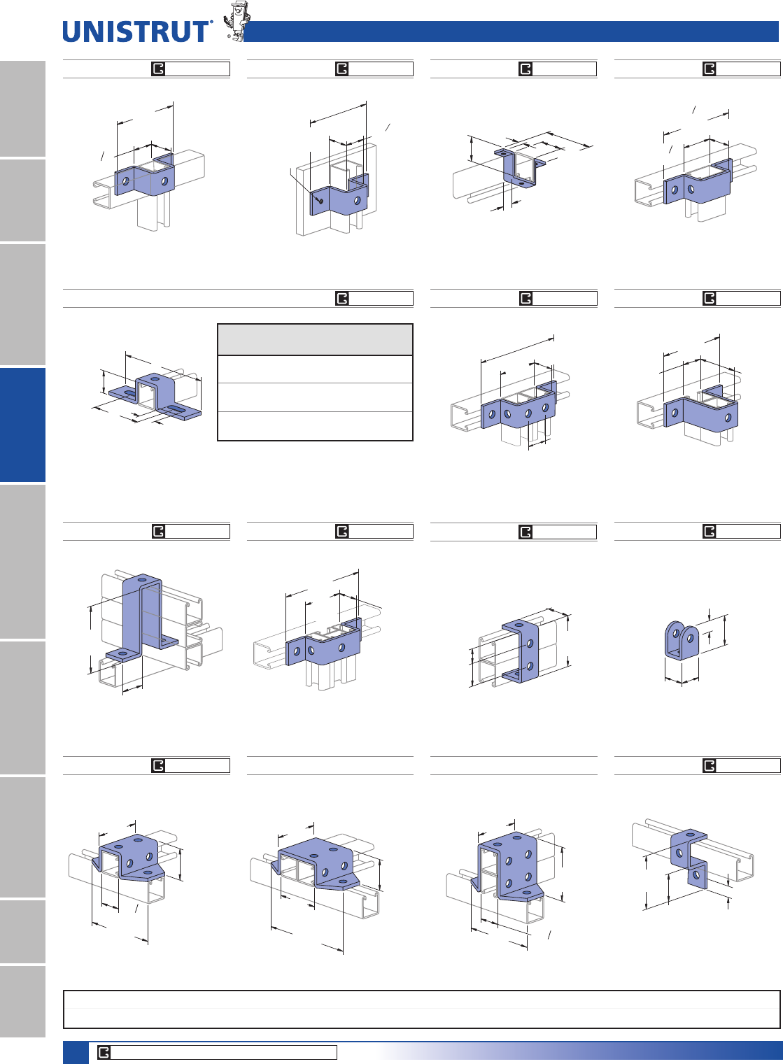
88
15⁄8" Framing System
1 5¼8" ChannelTelestrutNuts & HardwareGeneral FittingsPipe/Conduit SupportsElectrical FittingsConcrete InsertsSolarUnipier®
P2326
Wt/100 pcs: 171 Lbs (77.6 kg)
5 3⁄8"
(136.5)
3 1⁄2"
(88.9)
1 7⁄8"
(47.6)
1 "
(42.1)
21 32
P1000 (shown), P1100,
P2000, P4001 or P4101
P1973
P1044
1 5⁄8"
(41.3)
1 5⁄8"
(41.3)
13⁄16"
(20.6)
2 1⁄4"
(57.2)
(96.0)
1 7⁄8"
3 25⁄32"
(47.6)
1 5⁄64"
(27.4)
1 5⁄8"
(41.3)
P1001 (shown),
P1101, P2001
or P4004
Wt/100 pcs: 70 Lbs (31.8 kg) Wt/100 pcs: 53 Lbs (24.0 kg)
P1043A P1737
P4043P2473
“U” Shape Fittings
Wt/100 pcs: 128 Lbs (58.1 kg)
Wt/100 pcs: 197 Lbs (89.4 kg)
Wt/100 pcs: 105 Lbs (47.6 kg)
Wt/100 pcs: 106 Lbs (48.1 kg)
7"
(177.8)
(83.3)
3 9⁄32"
1 5⁄8"
(41.3)
(41.3)
1 5⁄8"
P1001A
(47.2)
1 55⁄64"
4 7⁄8"
(123.8)
P1001A3 (shown)
or P5501
(136.5)
5 3⁄8"
P1001(shown), P1101,
P2001, P4004 or P5000
(82.6)
3 1⁄4"
1 21⁄32"
(42.1)
7"
(177.8)
3 9⁄32"
(83.3) (41.3)
1 5⁄8"
P4004 (shown), P1001,
P1101, P2001, or P5000
P1732 P5543P2237
Wt/100 pcs: 88 Lbs (39.9 kg) Wt/100 pcs: 18 Lbs (8.2 kg) Wt/100 pcs: 97 Lbs (44.0 kg)
(41.3)
1 5⁄8"
5 3⁄8"
(136.5)
Tapped
5⁄16"-18
Thread
(42.1)
1 "
21 32
(62.7)
2 "
(161.1) 1 7⁄8"
(47.6)
15 32
6 "
11 32
P5500
Material: 1»8" (3.2) thick.
(41.3)
1 5⁄8"
(19.1)
3⁄4"
(10.3) (93.7)
3 11⁄16"
(42.9)
1 11⁄16"
All Holes
9⁄32" (7.1) Dia.
13⁄32"
P1048, P1049, P1050
1 5⁄8"
(41.3)
B
1 1⁄2"
(38.1)
A
Part
Number
“A”
In (mm)
“B”
In (mm)
Wt/100 pcs
Lbs (kg)
P1048 71»441»8105
184.2 104.8 47.6
P1049 81»253»8120
215.9 136.5 54.4
P1050 103»871»4130
263.5 184.2 59.0
P1383
5 3⁄8"
(136.5)
(42.1)
1 7⁄8"
(47.6)
1 "
21 32
Wt/100 pcs: 95 Lbs (43.1 kg)
P2328 P1046AP2329
Wt/100 pcs: 76 Lbs (34.5 kg)Wt/100 pcs: 209 Lbs (94.8 kg) Wt/100 pcs: 257 Lbs (116.6 kg)
1 "
(42.1)
21 32
3 1⁄2"
P1001(shown),
P1101, P2001,
P4004 or P5000
3 1⁄2"
(88.9)
(88.9)
5 3⁄8"
(136.5)
4 1⁄32"
(102.4)
1 7⁄8"1 5⁄64"
(47.6) (27.4)
7"
(177.8)
3 1⁄2"
(88.9)
1 7⁄8"
P1001(shown),
P1101, P2001,
P4004 or P5000
3 9⁄32"
(83.3)
(47.6)
CORE PRODUCTS - TYPICALLY AVAILABLE FROM STOCK
EG, GR, HG
EG, GR, HG
EG, GR, HG
EG, GR, HG
EG, GR, HG
EG, GR, HG
EG, GR, HG
EG, GR, HG
EG, GR, HG
EG, GR, HG
EG, GR, HG
EG, GR, HG
EG, GR, HG
Standard Dimensions for 15»8PPZLGWKVHULHVFKDQQHOILWWLQJV(Unless Otherwise Shown on Drawing)
Hole Diameter: 9»16PP+ROH6SDFLQJ)URP(QG13»16PP+ROH6SDFLQJ2Q&HQWHU7»8PP:LGWK5»8PP7KLFNQHVV1»4PP
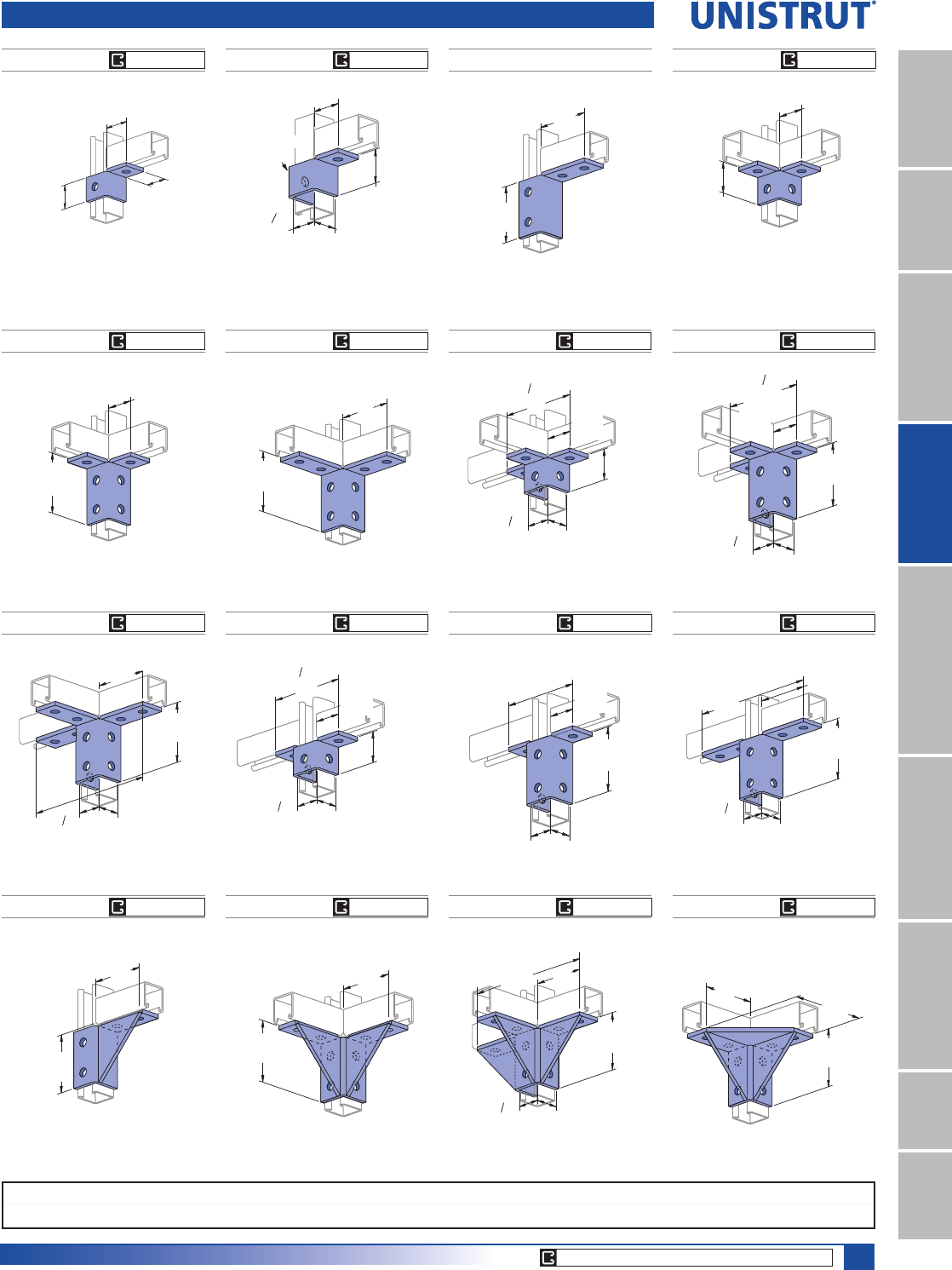
89
15⁄8" Framing System
1 5¼8" ChannelTelestrutNuts & HardwareGeneral FittingsPipe/Conduit SupportsElectrical FittingsConcrete InsertsSolarUnipier®
Wing Shape Fittings
P2472 R-LP2341 R-L
R - As shown
L - Opposite hand
Wt/100 pcs: 75 Lbs (34.0 kg)
R - As shown
L - Opposite hand
Wt/100 pcs: 60 Lbs (27.2 kg)
2"
(50.8)
(41.3)
Note: Hole
on back flange
not shown
1 5⁄8"
(47.6)
1 7⁄8"
(42.1)
1 "
21 32
P2343 R-L
Wt/100 pcs: 119 Lbs (54.0 kg)
(88.9)
3 1⁄2"
(95.3)
3 3⁄4"
P2223
Wt/100 pcs: 76 Lbs (34.5 kg)
2"
(50.8)
(47.6)
1 7⁄8"
R - As shown
L - Opposite hand
P2224
Wt/100 pcs: 115 Lbs (52.2 kg)
3 7⁄8"
(98.4)
1 7⁄8"
(47.6)
P2225
Wt/100 pcs: 155 Lbs (70.3 kg)
3 7⁄8"
(98.4)
3 3⁄4"
(95.3)
P2228P2227
Wt/100 pcs: 113 Lbs (51.3 kg) Wt/100 pcs: 177 Lbs (80.3 kg)
2"
(50.8)
5
(137.3)
1 7⁄8"
(47.6)
(41.3)
1 5⁄8"
(42.1)
13 32
1 "
21 32
"
(47.6)
1 7⁄8"
(98.4)
3 7⁄8"
1 5⁄8"
(41.3)
5 "
(137.3)
13 32
(42.1)
1 "
21 32
P2229
Wt/100 pcs: 230 Lbs (104.3 kg)
(41.3)
1 5⁄8"
9 5⁄32"
(232.6)
3 7⁄8"
(98.4)
(95.3)
3 3⁄4"
(42.1)
1 "
21 32
P2345 P2347P2346
Wt/100 pcs: 93 Lbs (42.2 kg) Wt/100 pcs: 150 Lbs (68.0 kg) Wt/100 pcs: 193 Lbs (87.5 kg)
2"
(50.8)
(137.3) 1 7⁄8"
(47.6)
(41.3)
1 5⁄8"
(42.1)
1 "
21 32
5 "
13 32
(41.3)
1 5⁄8"
3 7⁄8"
(98.4)
9 5⁄32"
(232.6)
(95.3)
3 3⁄4"
(42.1)
1 "
32
21
3 7⁄8"
(98.4)
(137.3)
(
41.3
)
1 5⁄8"
5 13⁄32"
1 21⁄32"
(
42.1
)
1 7⁄8"
(47.6)
P2344 R-L
R - As shown
L - Opposite hand
Wt/100 pcs: 176 Lbs (79.8 kg)
3 7⁄8"
(98.4)
(95.3)
3 3⁄4"
P2226
Wt/100 pcs: 217 Lbs (98.4 kg)
3 7⁄8"
(98.4)
(95.3)
3 3⁄4"
P2230
Wt/100 pcs: 310 Lbs (140.6 kg)
(232.6)
3 7⁄8"
(98.4)
(95.3)
3 3⁄4"
1 5⁄8"
9 5⁄32"
(41.3)
(42.1)
1 "
21 32
P2245
(95.3)
3 3⁄4"
5 3⁄8"
(136.5)
(95.3)
3 3⁄4"
Wt/100 pcs: 315 Lbs (142.9 kg)
Fitting notched for
continuous vertical.
(41.3)
1 11⁄16"
(42.9)
(47.6)
1 7⁄8"
1 5⁄8"
CORE PRODUCTS - TYPICALLY AVAILABLE FROM STOCK
EG, GR, HG EG, GR, HG EG, GR, HG
EG, GR, HG
EG, GR, HG
EG, GR, HG
EG, GR, HG
EG, GR, HG
EG, GR, HG
EG, GR, HG
EG, GR, HG
EG, GR, HG
EG, GR, HG
EG, GR, HG
EG, GR, HG
Standard Dimensions for 15»8PPZLGWKVHULHVFKDQQHOILWWLQJV(Unless Otherwise Shown on Drawing)
Hole Diameter: 9»16PP+ROH6SDFLQJ)URP(QG13»16PP+ROH6SDFLQJ2Q&HQWHU7»8PP:LGWK5»8PP7KLFNQHVV1»4PP
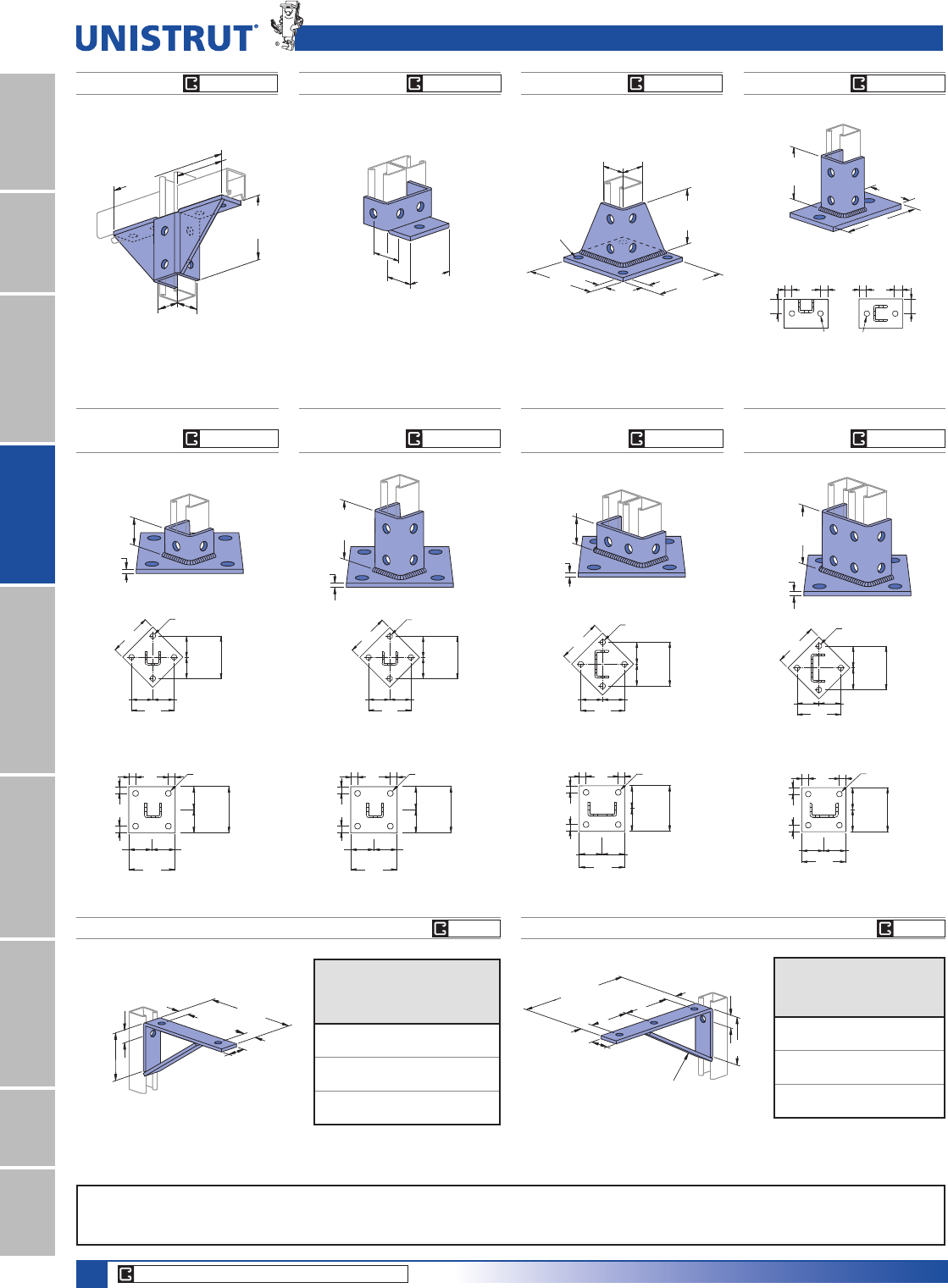
90
15⁄8" Framing System
1 5¼8" ChannelTelestrutNuts & HardwareGeneral FittingsPipe/Conduit SupportsElectrical FittingsConcrete InsertsSolarUnipier®
6"
(152.4)
6"
(152.4)
7⁄8"
(22.2)
7⁄8"
(22.2)
7⁄8"
(22.2)
7⁄8"
(22.2)
3"
(76.2)
3"
(76.2)
3"
(76.2)
3"
(76.2)
4 Holes
3⁄4" (19.1) Dia.
6"
(152.4)
(76.2)
3"
(76.2)
3"
(152.4)
6"
3"
(76.2)
3"
(76.2)
6"
(152.4)
4 Holes
3
⁄
4
" (19.1) Dia.
6"
(152.4)
6"
(152.4)
7
⁄
8
"
(22.2)
7
⁄
8
"
(22.2)
7
⁄
8
"
(22.2)
7
⁄
8
"
(22.2)
3"
(76.2)
3"
(76.2)
3"
(76.2)
3"
(76.2)
4 Holes
3
⁄
4
"
(19.1) Dia.
6"
(152.4)
6"
(152.4)
7
⁄
8
"
(22.2)
7
⁄
8
"
(22.2)
7
⁄
8
"
(22.2)
7
⁄
8
"
(22.2)
3"
(76.2)
3"
(76.2)
3"
(76.2)
3"
(76.2)
4 Holes
3
⁄
4
"
(19.1) Dia.
6"
(152.4)
(152.4)
6"
3"
(76.2)
3"
(76.2)
3"
(76.2)
3"
(76.2)
6"
(152.4)
4 Holes
3
⁄
4
"
(19.1) Dia.
6"
(152.4)
6"
(152.4)
7⁄8"
(22.2)
7⁄8"
(22.2)
7⁄8"
(22.2)
7⁄8"
(22.2)
3"
(76.2)
3"
(76.2)
3"
(76.2)
3"
(76.2)
4 Holes
3⁄4" (19.1) Dia.
6"
(152.4)
(152.4)
6"
3"
(76.2)
3"
(76.2)
3"
(76.2)
3"
(76.2)
6"
(152.4)
4 Holes
3
⁄
4
"
(19.1) Dia.
6"
(152.4)
(76.2)
3"
(76.2)
3"
(152.4)
6"
3"
(76.2)
3"
(76.2)
6"
(152.4)
4 Holes
3⁄4" (19.1) Dia.
Wing Shape Fittings, Post Bases & Brackets
P2453
Wt/100 pcs: 116 Lbs (52.6 kg)
1 11⁄16"
(42.9)
(49.2)
1 15⁄16"
3 1⁄8"
(79.4)
P2348
1 5⁄8"
1 21⁄32"
(41.3)
(42.1)
(98.4)
3 7⁄8"
(95.3)
3 3⁄4"
(232.6)
9 5⁄32"
Wt/100 pcs: 274 Lbs (124.3 kg)
P1887
Wt/100 pcs: 297 Lbs (134.8 kg)
5"
(127.0) 5"
(127.0)
(15.9)
4 Holes
7⁄16" (11.1)
Dia.
1 5⁄8"
(41.3)
1 5⁄8"
(41.3)
3 1⁄2"
(88.9)
5⁄8"
P2941, P2942
Wt/100 pcs: 358 Lbs (162.4 kg)
P2941 P2942
2"
(50.8)
2"
(50.8)
1"
(25.4)
1"
(25.4)
1"
(25.4)
1"
(25.4)
2 Holes
11⁄16 "
(17.5) Dia.
3 1⁄2"
(88.9)
6"
(152.4)
4"
(101.6)
P2072,
P2072 SQ
Wt/100 pcs: 307 Lbs (139.3 kg)
1 5⁄8"
(41.3)
1⁄4"
(6.4)
P2072
P2072 SQ
P2072A,
P2072A SQ
1⁄4"
(6.4)
3 1⁄2"
(88.9)
P2072A
P2072A SQ
Wt/100 pcs: 373 Lbs (169.2 kg)
P2073,
P2073 SQ
Wt/100 pcs: 325 Lbs (147.4 kg)
1 5⁄8"
(41.3)
1⁄4"
(6.4)
P1001A
P2073
P2073 SQ
P2073A,
P2073A SQ
Wt/100 pcs: 408 Lbs (185.1 kg)
1⁄4"
(6.4)
3 1⁄2"
(88.9)
P1001A
P2073A
P2073A SQ
P1769
Wt/100 pcs: 174 Lbs (78.9 kg)
6 1⁄8"
1 3⁄16"
(30.2)
1 3⁄16"
1 1⁄16"
3 3⁄4"
(95.3)
(215.9)
8 1⁄2"
(155.6)
1 5⁄8"
(41.3)
(30.2)
(27.0)
Vertical
Channel
Uniform
Design Load
Part No. Gauge Lbs (kN)
P1000 12 800
3.56
P1100 14 600
2.67
P2000 16 400
1.81
P1771
Wt/100 pcs: 206 Lbs (93.4 kg)
(101.6)
4"
10 1⁄2"
(266.7)
(30.2)
1 3⁄16"
4 3⁄8"
(111.1)
3 3⁄4"
(30.2)
(41.3)
1 5⁄8"
1 3⁄16"
(95.3)
5⁄16" (7.9) Thick
1 1⁄16"
(27.0)
Safety Factor 21»2
Vertical
Channel Uniform
Design Load
Lbs (kN)Part No. Gauge
P1000 12 800
3.56
P1100 14 600
2.67
P2000 16 400
1.81
Material: 1»4" (6.4) thick steel. Safety Factor 21»2Material: 1»4" (6.4) thick steel.
CORE PRODUCTS - TYPICALLY AVAILABLE FROM STOCK
EG, GR, HG
EG, GR, HG
EG, GR, HG
EG, GR, HG
EG, GR, HG
EG, GR, HG
EG, GR, HG
EG, GR, HG
EG, GREG, GR
Standard Dimensions for 15»8PPZLGWKVHULHVFKDQQHOILWWLQJV(Unless Otherwise Shown on Drawing)
Hole Diameter: 9»16PP+ROH6SDFLQJ)URP(QG13»16PP+ROH6SDFLQJ2Q&HQWHU7»8PP:LGWK5»8PP7KLFNQHVV1»4PP
Note : When used for mechanical supports, load capacities of brackets and fittings should be in compliance with the American Standard Code for Pressure Piping.
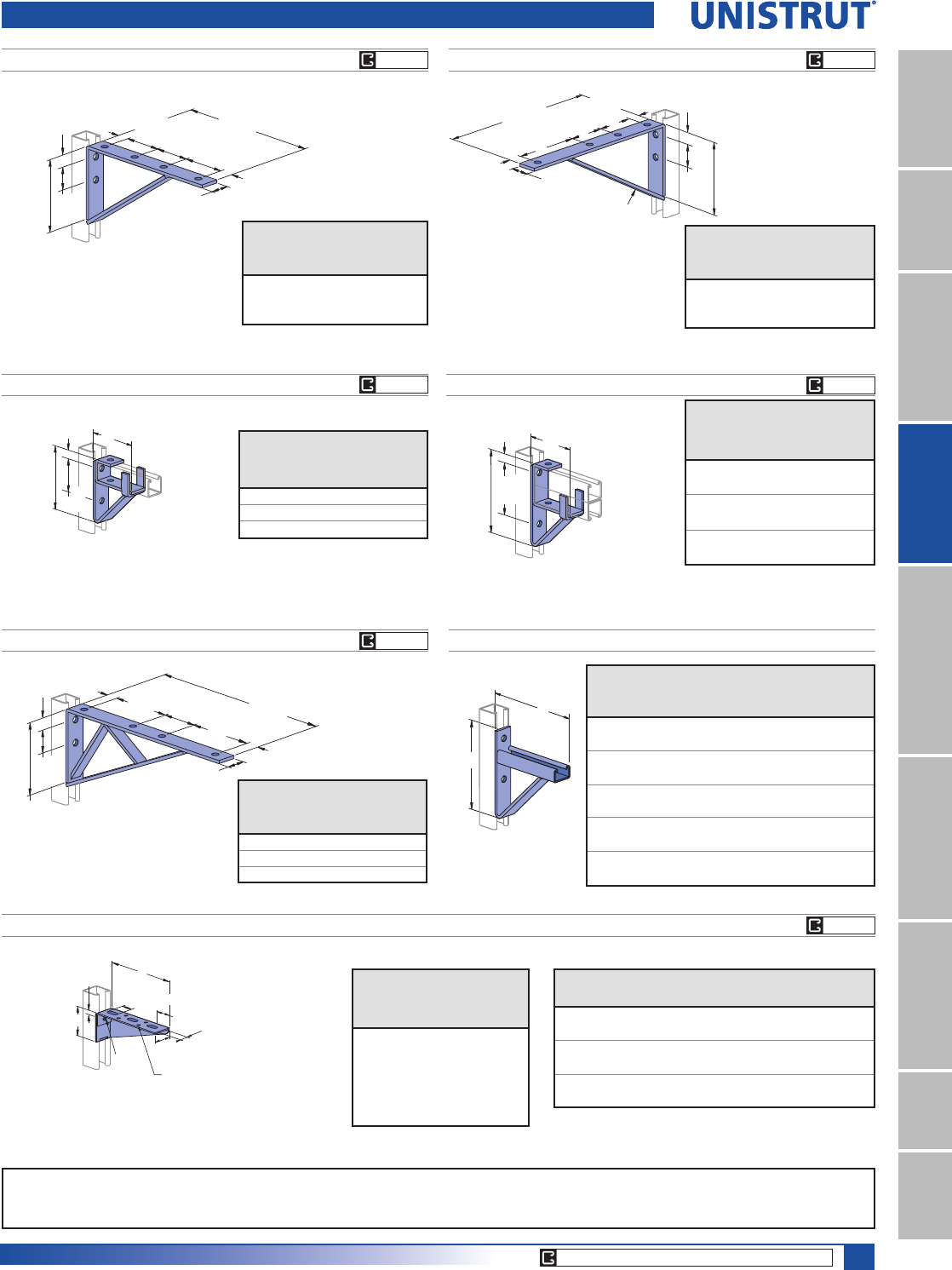
91
15⁄8" Framing System
1 5¼8" ChannelTelestrutNuts & HardwareGeneral FittingsPipe/Conduit SupportsElectrical FittingsConcrete InsertsSolarUnipier®
Brackets
P1773
Wt/100 pcs: 264 Lbs (119.7 kg)
Material: 1»4" (6.4) thick steel.
(152.4)
6"
(30.2)
1 3⁄16"
(30.2)
1 3⁄16"
(41.3)
1 5⁄8"
(95.3)
3 3⁄4"
(82.6)
3 1⁄4"
(63.5)
2 1⁄2"
(317.5)
12 1⁄2"
3 1⁄8"
(79.4)
1 1⁄16"
(27.0)
Safety Factor 21»2
Vertical Channel Uniform
Design Load
Lbs (kN)Part No. Gauge
P1000 12 900 (4.00)
P1100 14 800 (3.56)
P2000 16 450 (2.04)
P1775
Wt/100 pcs: 295 Lbs (133.8 kg)
Material: 1»4" (6.4) thick steel.
(146.1)
5 3⁄4"
(82.6)
3 1⁄4"(30.2)
1 3⁄16"
(368.3)
14 1⁄2"
1 3⁄16"
(30.2) (41.3)
1 5⁄8"
5⁄16" (7.9) Thick
(152.4)
6"
(63.5)
2 1⁄2"
1 1⁄16"
(27.0)
3 1⁄8"
(79.4)
Safety Factor 21»2
Vertical Channel Uniform
Design Load
Lbs (kN)Part No. Gauge
P1000 12 900 (4.00)
P1100 14 800 (3.56)
P2000 16 450 (2.04)
P1593P1075
Wt/100 pcs: 229 Lbs (103.9 kg) Wt/100 pcs: 272 Lbs (123.4 kg) $OORZDEOHPRPHQWIRU¿WWLQJRQO\
Channel may determine overall capacity.
$OORZDEOHPRPHQWIRU¿WWLQJRQO\
Channel may determine overall capacity.
Material: 1»4" (6.4) thick steel. Material: 1»4" (6.4) thick steel.
4 15⁄16"
(125.4)
7 1⁄2"
(190.5) (117.5)
4 5⁄8"
1 1⁄16"
(27.0)
4 7⁄8"
(123.8)
5 29⁄32"
(150.0)
(76.2)
3"
1 1⁄16"
(27.0)
P1000
P1100
P2000
P4001
Safety Factor 21»2
Vertical Channel Allowable
Moment*
In-Lbs 10Part No. Gauge
P1000 12 5,100 (576)
P1100 14 4,400 (497)
P2000 16 3,200 (362)
Vertical
Channel Allowable
Moment*
In-Lbs 10Part No. Gauge
P1000 12 13,000
1,469
P1100 14 9,100
1,028
P2000 16 6,500
734
Safety Factor 21»2
P1001
P1101
P5000
P2001
P1777
Wt/100 pcs: 385 Lbs (174.6 kg)
Material: 1»4" (6.4) thick steel.
(41.3)
1 5⁄8"
1 3⁄16"
16 1⁄2"
(419.1)
5 3⁄4"
(146.1)
(79.4)
3 1⁄8"
5 1⁄4"
(133.4)
(152.4)
6"
(63.5)
2 1⁄2"
1 1⁄16"
(27.0)
(30.2)
1 3⁄16"
(30.2)
Vertical Channel Uniform
Design Load
Lbs (kN)Part No. Gauge
P1000 12 1,200 (5.44)
P1100 14 900 (4.00)
P2000 16 600 (2.67)
Safety Factor 21»2
P2547 THRU P2551 CABLE TRAY BRACKET
Part
Number
“A”
In (mm)
“B”
In (mm)
Wt/100 pcs
Lbs (kg)
Uniform
Load*
Lbs (kN)
P2547 15 83»4420 1,000
381.0 222 190.5 4.45
P2548 21 83»4628 1,000
533.4 222 284.9 4.45
P2549 27 111»4860 900
685.8 286 390.1 4.00
P2550 33 111»41010 900
838.2 286 458.1 4.00
P2551 39 16 1257 800
990.6 406.4 683.3 3.56
B
A
R - As shown; L - Opposite hand
Part
Number
Stamped
Ident. No.
“A”
In (mm)
“B”
In (mm)
Wt/100 pcs
Lbs (kg)
P2491 R-L 121892 R-L 61
15»16 67
152.4 49.2 30.4
P2492 R-L 121893 R-L 82
7»16 92
203.2 61.9 41.7
P2493 R-L 121894 R-L 10 215»16 120
254.0 74.6 54.4
Safety Factor - 21»2
Vertical
Channel Uniform
Design Load
Lbs (kN)Part No. Gauge
P1000 12 300
(1.33)
P1100 14 250
(1.11)
P2000 16 200
(.89)
Material : 12 Gauge Steel.
A
B
(15.9)
5⁄8"
1"
(25.4)
9⁄32" (7.1) Dia.
13⁄16"
(20.6)
(41.3)
1 5⁄8"
(11.1) Dia.
3⁄8" x 1"
(9.5 x 25.4)
7⁄16"
P2491 R-L THRU P2493 R-L
CORE PRODUCTS - TYPICALLY AVAILABLE FROM STOCK
EG, GR
EG, GR
EG, GR
EG, GR
EG, GR
EG, GR
Standard Dimensions for 15»8PPZLGWKVHULHVFKDQQHOILWWLQJV(Unless Otherwise Shown on Drawing)
Hole Diameter: 9»16PP+ROH6SDFLQJ)URP(QG13»16PP+ROH6SDFLQJ2Q&HQWHU7»8PP:LGWK5»8PP7KLFNQHVV1»4PP
Note : When used for mechanical supports, load capacities of brackets and fittings should be in compliance with the American Standard Code for Pressure Piping.
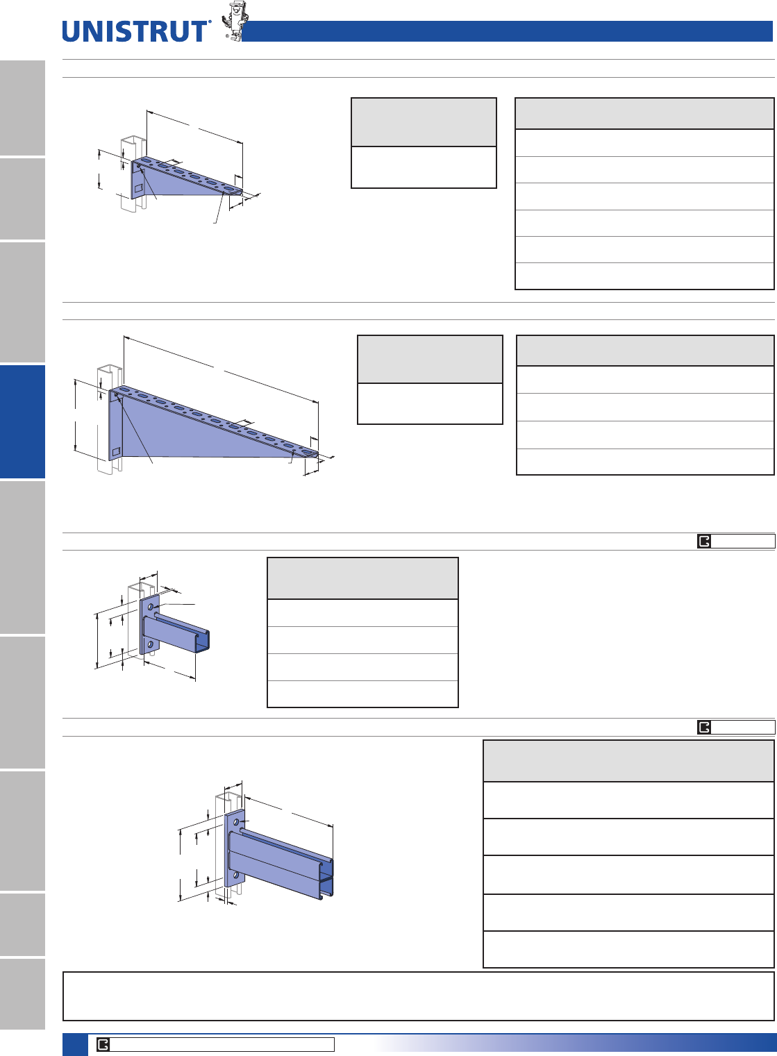
92
15⁄8" Framing System
1 5¼8" ChannelTelestrutNuts & HardwareGeneral FittingsPipe/Conduit SupportsElectrical FittingsConcrete InsertsSolarUnipier®
B(15.9)
(41.3)
(25.4)
1 5⁄8"
(20.6)
7⁄16" (11.1) Dia.
9⁄32" (7.1) Dia.
5⁄8"
A
3⁄8" x 1"
1"
(9.5 x 25)
13⁄16"
Safety Factor - 21»2
Part
Number
Stamped
Ident. No.
“A”
In (mm)
“B”
In (mm)
Wt/100 pcs
Lbs (kg)
P2494 R-L 121895 R-L 12 37»16 152
304.8 87.3 68.9
P2495 R-L 121896 R-L 14 315»16 173
355.6 100.0 78.5
P2496 R-L 121897 R-L 16 47»16 223
406.4 112.7 101.2
P2497 R-L 121898 R-L 18 415»16 266
457.2 125.4 120.7
P2498 R-L 121899 R-L 20 57»16 308
508.0 138.1 139.7
P2499 R-L 121900 R-L 22 515»16 355
558.8 150.8 161.0
Brackets
P2494 R-L THRU P2499 R-L
P2500 R-L THRU P2503 R-L
R - As shown; L - Opposite hand
Material : 12 Gauge Steel.
Vertical
Channel Uniform
Design Load
Lbs (kN)Part No. Gauge
P1000 12 300 (1.33)
P1100 14 250 (1.11)
P2000 16 200 (.89)
B
(41.3)
1 5⁄8"
9⁄32" (7.1) Dia.
7⁄16" (11.1) Dia.
5⁄8"(25.4)
1"
13 ⁄16 "
(20.6)
A
3⁄8" x 1"
(9.5 x 25)
(15.9)
Safety Factor - 21»2
Vertical
Channel Uniform
Design Load
Lbs (kN)Part No. Gauge
P1000 12 300 (1.33)
P1100 14 250 (1.11)
P2000 16 200 (.89)
Part
Number
Stamped
Ident. No.
“A”
In (mm)
“B”
In (mm)
Wt/100 pcs
Lbs (kg)
P2500 R-L 121901 R-L 24 67»16 400
609.6 164 181.4
P2501 R-L 121902 R-L 26 615»16 445
660 176 201.8
P2502 R-L 121903 R-L 28 77»16 493
711 189 223.6
P2503 R-L 121904 R-L 30 715»16 545
762.0 202 247.2
P2944, P2945, P2946, P2947
3⁄8"
(9.5)
9⁄16"
(14.3)
A
2"
(50.8)
13⁄16"
(20.6)
13⁄16"
(20.6)
45⁄8"3"
(117.5) (76.2)
Part
Number
“A”
In (mm)
Wt/100 pcs
Lbs (kg)
Uniform
Load*
Lbs (kN)
P2944 6 185 1200
152.4 84 5.34
P2945 12 293 600
304.8 133 2.67
P2946 18 401 400
457.2 182 1.78
P2947 24 509 300
609.6 231 1.33
Safety Factor 21»2
* Mounted on 12 Ga. Channel
Safety Factor - 21»2
P2542 THRU P2546
Part
Number
“A”
In (mm)
Wt/100 pcs
Lbs (kg)
Vertical Channel Uniform
Design Load
Lbs (kN)Part No. Gauge
P2542 12
304.8
502
228
P1000 12 2,000 (8.90)
P1100 14 1,400 (6.23)
P2000 16 1,000 (4.45)
P2543 18
457.2
692
314
P1000 12 1,300 (5.78)
P1100 14 900 (4.00)
P2000 16 650 (2.89)
P2544 24
609.6
882
400
P1000 12 1,000 (4.45)
P1100 14 700 (3.11)
P2000 16 500 (2.22)
P2545 30
762.0
1,072
486
P1000 12 800 (3.56)
P1100 14 560 (2.49)
P2000 16 400 (1.78)
P2546 36
914.4
1,262
572
P1000 12 650 (2.89)
P1100 14 450 (2.00)
P2000 16 320 (1.42)
3⁄8"
(9.5)
9⁄16"
(14.3)
13⁄16"
(20.6)
13⁄16"
(20.6)
61⁄4"
(158.8)
45⁄8"
(117.5)
A
2" (50.8)
P1001
R - As shown; L - Opposite hand
Material : 12 Gauge Steel.
CORE PRODUCTS - TYPICALLY AVAILABLE FROM STOCK
EG, GR, HG
EG, GR, HG
Standard Dimensions for 15»8PPZLGWKVHULHVFKDQQHOILWWLQJV(Unless Otherwise Shown on Drawing)
Hole Diameter: 9»16PP+ROH6SDFLQJ)URP(QG13»16PP+ROH6SDFLQJ2Q&HQWHU7»8PP:LGWK5»8PP7KLFNQHVV1»4PP
Note : When used for mechanical supports, load capacities of brackets and fittings should be in compliance with the American Standard Code for Pressure Piping.
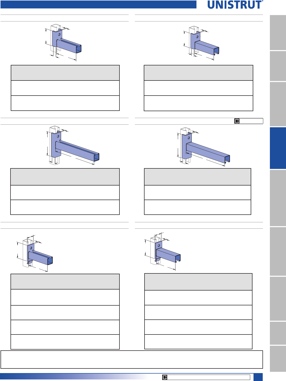
93
15⁄8" Framing System
1 5¼8" ChannelTelestrutNuts & HardwareGeneral FittingsPipe/Conduit SupportsElectrical FittingsConcrete InsertsSolarUnipier®
P2231, P2232
P2233, P2234
Safety Factor - 21»2
3 1⁄2"
(88.9)
1⁄4"
(6.4)
A
(27.0)
1 1⁄16"
(136.5)
5 3⁄8"
(6.4)
1⁄4"
A
(27.0)
1 1⁄16"
Part
Number
“A”
In (mm)
Wt/100 pcs
Lbs (kg)
Vertical Channel Uniform
Design Load
Lbs (kN)Part No. Gauge
P2231 6
152.4
191
86.6
P1000 12 1,600 (7.12)
P1100 14 1,200 (5.34)
P2000 16 800 (3.56)
P2232 12
304.8
292
132.4
P1000 12 800 (3.56)
P1100 14 600 (2.67)
P2000 16 400 (1.78)
Part
Number
“A”
In (mm)
Wt/100 pcs
Lbs (kg)
Vertical Channel Uniform
Design Load
Lbs (kN)Part No. Gauge
P2233 18
457.2
436
197.8
P1000 12 600 (2.67)
P1100 14 450 (2.00)
P2000 16 300 (1.33)
P2234 24
609.6
536
243.1
P1000 12 450 (2.00)
P1100 14 330 (1.47)
P2000 16 220 (.98)
Brackets
P2231A, P2232A
Safety Factor - 21»2
Part
Number
“A”
In (mm)
Wt/100 pcs
Lbs (kg)
Vertical Channel Uniform
Design Load
Lbs (kN)Part No. Gauge
P2231A 6
152.4
191
86.6
P1000 12 1,600 (7.12)
P1100 14 1,200 (5.34)
P2000 16 800 (3.56)
P2232A 12
304.8
292
132.4
P1000 12 800 (3.56)
P1100 14 600 (2.67)
P2000 16 400 (1.78)
P2233A, P2234A
Part
Number
“A”
In (mm)
Wt/100 pcs
Lbs (kg)
Vertical Channel Uniform
Design Load
Lbs (kN)Part No. Gauge
P2233A 18
457.2
436
197.8
P1000 12 600 (2.67)
P1100 14 450 (2.00)
P2000 16 300 (1.33)
P2234A 24
609.6
536
243.1
P1000 12 450 (2.00)
P1100 14 330 (1.47)
P2000 16 220 (.98)
(136.5)
5 3⁄8"
(6.4)
1⁄4"
A
(27.0)
1 1⁄16"
(27.0)
1 1⁄16"
(88.9)
3 1⁄2"(6.4)
1⁄4"
A
Safety Factor - 21»2
Safety Factor - 21»2
P2513 THRU P2516
When installed in
inverted position use
60% of loads shown.
(95.3)
3 3⁄4"(6.4)
1⁄4"
A
2"
(50.8)
Part
Number
“A”
In (mm)
Wt/100 pcs
Lbs (kg)
Vertical Channel Uniform
Design Load
Lbs (kN)Part No. Gauge
P2513 6
152.4
161
73.0
P1000 12 1,200 (5.34)
P1100 14 800 (3.56)
P2000 16 600 (2.67)
P2514 12
304.8
261
118.4
P1000 12 600 (2.67)
P1100 14 400 (1.78)
P2000 16 300 (1.33)
P2515 18
457.2
361
163.7
P1000 12 400 (1.78)
P1100 14 270 (1.20)
P2000 16 200 (.89)
P2516 24
609.6
461
209.1
P1000 12 300 (1.33)
P1100 14 200 (.89)
P2000 16 150 (.67)
P2513A THRU P2516A
Safety Factor 21»2
Part
Number
“A”
In (mm)
Wt/100 pcs
Lbs (kg)
Vertical Channel Uniform
Design
Lbs (kN)Part No. Gauge
P2513A 6
152.4
161
73.0
P1000 12 1,200 (5.34)
P1100 14 800 (3.56)
P2000 16 600 (2.67)
P2514A 12
304.8
261
118.4
P1000 12 600 (2.67)
P1100 14 400 (1.78)
P2000 16 300 (1.33)
P2515A 18
457.2
361
163.7
P1000 12 400 (1.78)
P1100 14 270 (1.20)
P2000 16 200 (.89)
P2516A 24
609.6
461
209.1
P1000 12 300 (1.33)
P1100 14 200 (.89)
P2000 16 150 (.67)
When installed in inverted position use
60% of loads shown.
(95.3)
3 3⁄4"(6.4)
1⁄4"
A
2"
(50.8)
Safety Factor 21»2
CORE PRODUCTS - TYPICALLY AVAILABLE FROM STOCK
EG, GR, HG
Standard Dimensions for 15»8PPZLGWKVHULHVFKDQQHOILWWLQJV(Unless Otherwise Shown on Drawing)
Hole Diameter: 9»16PP+ROH6SDFLQJ)URP(QG13»16PP+ROH6SDFLQJ2Q&HQWHU7»8PP:LGWK5»8PP7KLFNQHVV1»4PP
Note : When used for mechanical supports, load capacities of brackets and fittings should be in compliance with the American Standard Code for Pressure Piping.
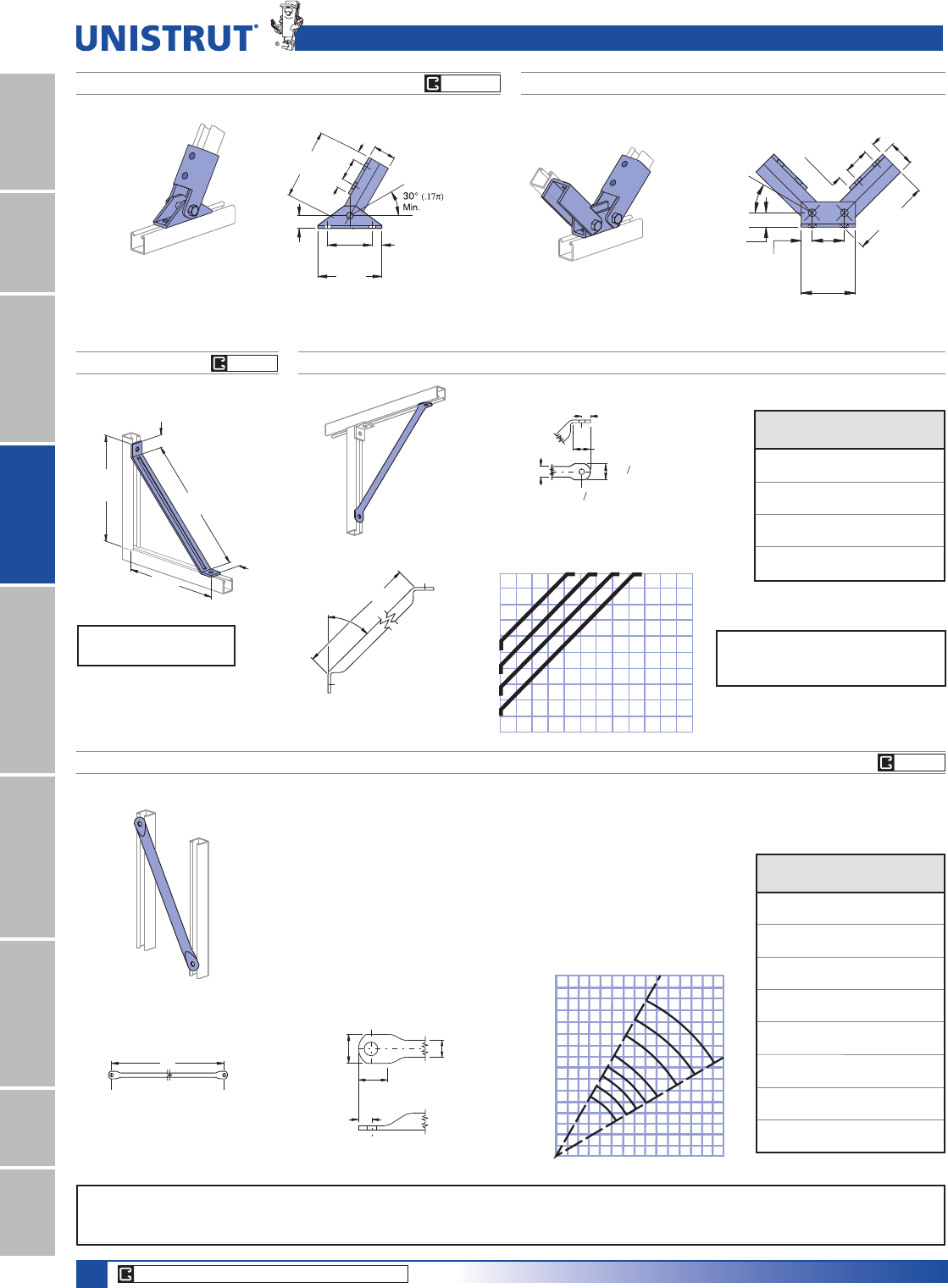
94
15⁄8" Framing System
1 5¼8" ChannelTelestrutNuts & HardwareGeneral FittingsPipe/Conduit SupportsElectrical FittingsConcrete InsertsSolarUnipier®
Brace Fittings
P2815 ADJUSTABLE BRACE FITTING P2815D ADJUSTABLE BRACE FITTING
Wt/100 pcs: 497 Lbs (225.4 kg)Wt/100 pcs: 307 Lbs (139.3 kg)
5 7⁄8"
1 7⁄8"
(47.6)
(20.6)
13⁄16"
(47.6)
(20.6)
13⁄16"
13⁄16"
(20.6)
(101.6)
4"
(27.0)
1 1⁄16"
2 3⁄8"
(60.3)
(149.2)
30°
(.17π)
Min.
1 7⁄8"
(136.5)
5 3⁄8"
3 3⁄4"
(95.3)
1 1⁄16"
(27.0)
(149.2)
5 7⁄8"
13⁄16"
(20.6)
13⁄16"
(20.6)
13⁄16"
(20.6)
(47.6)
1 7⁄8"
(47.6)
1 7⁄8"
P2452 KNEE BRACE
Wt/100 pcs: 277 Lbs (125.6 kg)
13 5⁄8"
(346.1)
16 5⁄8"
(422.3)
1 5⁄8"
(41.3)
1 5⁄8"
(41.3)
13 5⁄8"
(346.1)
Material: 1»4" (6.4) thick steel.
Design Axial Load
1200 Lbs (5.34 kN)
P2459-36 THRU P2459-96 TUBULAR BACK BRACES
1. The vertical lines of the graph correspond to the center to
center line dimension of the uprights.
2. Along this vertical line locate the (maximum usable) horizontal
bracing height line.
3. The arc line that intersects the point formed by the intersection
of the two lines, indicates the brace required.
4. 30° - 60° maximum, minimum brace angles are indicated for
maximum effect.
A(25.4)
1"
17⁄32" (13.5) Dia. Hole
13⁄16"
(20.6)
1 17⁄32"
(38.9)
1 5⁄8"
(41.3)
CENTER TO CENTER OF UPRIGHT
BRACING HEIGHT
2'
1'
1'
3'
4'
5'
6'
7'
8'
2' 3' 4' 5' 6' 7'
8
7
6
5
4
1
/
2
4
3
3
1
/
2
60°
30°
P 2459-96
P 2459-84
P 2459-72
P 2459-54
P 2459-48
P 2459-42
P 2459-36
P 2459-60
Part
Number
“A”
In (mm)
Wt/100 pcs
Lbs (kg)
P2459-36 36 255
914.4 115.7
P2459-42 42 296
1,066.8 134.3
P2459-48 48 336
1,219.2 152.4
P2459-54 54 377
1,371.6 171.0
P2459-60 60 418
1,524.0 189.6
P2459-72 72 499
1,828.8 226.3
P2459-84 84 580
2,133.6 263.1
P2459-96 96 661
2,438.4 299.8
45°
A
(20.6)
13⁄16"
1 5⁄8"
(41.3)
1 "
(38.9)
1"
(25.4) Dia Hole
(13.5)
17 32
"
17 32
01/2'1'1
1/2'2'2
1/2'3'
1/2'
11/2'
1 '
2'
21/2'
WIDTH
HEIGHT
P 2458-18
P 2458-24
P 2458-30
P 2458-36
P2458-18 THRU P2458-36 TUBULAR KNEE BRACES
Part
Number
“A”
In (mm)
Wt/100 pcs
Lbs (kg)
P2458-18 18 146
457.2 66.2
P2458-24 24 186
609.6 84.4
P2458-30 30 227
762.0 103.0
P2458-36 36 267
914.4 121.1
Design Loads
Compression = 1500 Lbs (6.67 kN)
Tension = 300 Lbs (1.33 kN)
CORE PRODUCTS - TYPICALLY AVAILABLE FROM STOCK
EG HG
EG GR
EG GR
Standard Dimensions for 15»8PPZLGWKVHULHVFKDQQHOILWWLQJV(Unless Otherwise Shown on Drawing)
Hole Diameter: 9»16PP+ROH6SDFLQJ)URP(QG13»16PP+ROH6SDFLQJ2Q&HQWHU7»8PP:LGWK5»8PP7KLFNQHVV1»4PP
Note : When used for mechanical supports, load capacities of brackets and fittings should be in compliance with the American Standard Code for Pressure Piping.
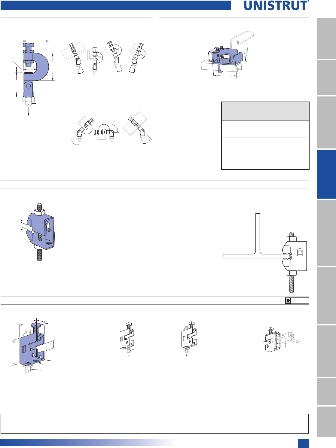
95
15⁄8" Framing System
1 5¼8" ChannelTelestrutNuts & HardwareGeneral FittingsPipe/Conduit SupportsElectrical FittingsConcrete InsertsSolarUnipier®
Beam Clamps
P2897
Wt/100 pcs: 33 Lbs (15.0 kg)
Max.
11⁄16"
(17.5)
11⁄16"
(27.0)
21⁄16"
(52.4)
21⁄4"
(57.2)
21⁄4"
(57.2)
3⁄8" Threaded
Rod
Design Load (Safety Factor of 4)
(angles ≤ 25°) - 550 Lbs (2.45 kN)
(angles > 25°) - 330 Lbs (1.47 kN)
25 ° Max. 25 ° Max.
25 ° Max.
25 ° to 45 °
25 ° to 45 °
90 °
P2784
3"
(76.2)
(31.8) (31.8)
(130.2)
1 1⁄4"
5 1⁄8"
1 1⁄4"
Part
Number
For
Use With
Load
Lbs
N1
Wt/100 pcs
/EVNJ
P2784-1
P1000,
P1100,
P2000
1,200 175
5.34 79.3
P2784-2
P1001,
P1101,
P2001
1,200 179
5.34 81.1
P2784-3 P5001,
P5501
1,200 180
5.34 81.5
Safety Factor 4
Torque: 13 Ft-Lbs 1P
PFL2-37 SWIFTGRIP
Wt/100 pcs: 26 Lbs (11.9 kg)
(3.2 to 19.1)
1⁄8" to 3⁄4"
'HVLJQHGWRVLJQL¿FDQWO\UHGXFHLQVWDOODWLRQWLPHZKLOHRIIHULQJJUHDWHUSHUIRU-
mance than cast beam clamps, the Swiftgrip enables connection of drop rod to
beam in one simple operation.
Ideal for the suspension of building services equipment including heating,
YHQWLODWLQJDQGDLUFRQGLWLRQLQJHTXLSPHQWSLSHZRUN¿UHSURWHFWLRQV\VWHPV
electrical equipment and cable tray.
$YDLODEOH¿QLVKFKRLFHVDUH6WDLQOHVV6WHHORU3HUPD*ROG
Industry Standard Yellow Dichromate.
Design Load is 540 Lbs (2.40 kN).
Safety Factor is 4
7RUTXHLV)W/EV1P
Rod Size is 3»8" (9.5mm)
P2675
Clamp Materials: .105" (2.7) thick steel.
Clamp P2675 is designed for light duty rod suspension.
It also may be used with P3016-1024 or P3016-1420 nut as illustrated
above for mounting insulators, etc.
Design Load
150 Lbs (.67 kN)
Wt/100 pcs: 33 Lbs (15.0 kg)
P3016-1024, or
P3016-1420
Channel Nut Insulator
Design Load
250 Lbs (1.11 kN)
Rod Size up to 3⁄8"
2 Holes 9⁄32" (7.1) Dia.
2 1⁄16"
(52.4)
5⁄8"
4 Holes 13⁄32" (10.3) Dia.
(15.9)
1 7⁄8"
(47.6) 3⁄8" X 1 1⁄2" Set Screw
and Nut Included
7⁄8"
(22.2)
Rod Size
up to 3⁄8"
EG GR
Note: When used for mechanical supports, load capacities of brackets and fittings should be in compliance with the American Standard Code for Pressure Piping.
Clamps are designed to be used with W, M, S & HP Shape beams, Standard C & Misc. MC Channels, Angles & Structural Tees. Clamps must be used in pairs where indicated.
For beam clamps with HG finish, standard hardware is EG finish. For optional stainless steel hardware, please contact the factory for availability.
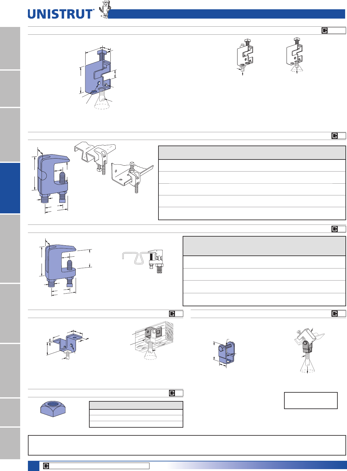
96
15⁄8" Framing System
1 5¼8" ChannelTelestrutNuts & HardwareGeneral FittingsPipe/Conduit SupportsElectrical FittingsConcrete InsertsSolarUnipier®
P2898 UNIVERSAL BEAM CLAMP
A
G
F
E
B
D
C
0D[LPXPWHPSHUDWXUHRIÛ)&
$WOHDVWRQHIXOOWKUHDGPXVWEHH[SRVHG
A
In
B
In PP
C
In PP
D
In PP
E
In PP
F
In PP
G
In PP
Max Load
Lbs (kN)
Wt/100 pcs
Lbs (kg)
P2898-37
3»8 11
1»21»213»4 7»8400 33
25.4 38.1 12.7 25.4 19.1 22.2 1.78 15.0
P2898-50
1»2 1
5»16 11»21»213»4 7»8500 33
25.4 38.1 12.7 25.4 19.1 22.2 2.22 15.0
P2898-62
5»811»211»21»213»4 1 600 22
38.1 38.1 12.7 25.4 19.1 25.4 2.67 10.0
P2898-75
3»417»813»45»813»811
1»4800 88
47.6 44.5 15.9 34.9 25.4 31.8 3.56 40.0
P2898-87
7»821
3»45»811»211
1»41,200 79
50.8 44.5 15.9 38.1 25.4 31.8 5.34 35.9
P2676
Design Load
500 Lbs (2.22 kN)
Design Load
300 Lbs (1.33 kN)
Rod Size
up to 1⁄2"
Rod Size up to 1⁄2"
Rod Swivel 15° (0.8π)
All Directions
2 Holes
9⁄16" (14.3) Dia.
2 7⁄8"
(73.0)
7⁄8"
2 Holes 7⁄16" (11.1) Dia.
(22.2)
2 5⁄8"
(66.7)
1 5⁄16"
(33.3)
1⁄2" X 2" Set Screw
and Nut Included
1⁄8"(3.2) Thick
Swivel Nut and
Jam Nut not Included Clamp P2676 provides a means of rod suspension where a free swing
of up to 15° (0.8π) is required. Clamp will accommodate 1»4" (6.4),
3»8" (9.5), or 1»2" (12.7) rods. Order swivel nuts P2679-4,-6, or -8 as
required. Clamp may also be used with P2677 as illustrated in
application drawings.
Wt/100 pcs: 72 Lbs (32.7 kg) Clamp Materials: 1»8" (3.2) thick steel. Not available in SS or ST.
P2899 WIDE THROAT BEAM CLAMP
A
D
B
E
C
11⁄4"
3⁄4"
(31.8)
(19.1)
0D[LPXPWHPSHUDWXUHRIÛ)&
Rod Size
A
in
B
In (mm)
C
In (mm)
D
In (mm)
E
In (mm)
Max.
Load
Lbs (kN)
Wt/100
pcs
Lbs (kg)
P2899-37
3»8 1
5»8217»8400 28
41.3 50.8 25.4 22.2 1.78 12.7
P2899-50
1»2 1
5»8217»8500 34
41.3 50.8 25.4 22.2 2.22 15.4
P2899-62
5»813»421»4 1
1»4 1 600 66
44.5 57.2 31.8 25.4 2.67 30.0
P2899-75
3»417»823»813»8 1
1»4800 83
47.6 60.3 34.9 31.8 3.56 37.7
Rod Size
up to 1⁄2"
Rod Swivel 15° (0.08π)
All Directions
P2682
P2677
P2679-4, -6 & -8 SWIVEL NUT
P2677P2682
Wt/100 pcs: 55 Lbs (24.9 kg)
Wt/100 pcs: 30 Lbs (13.6 kg)
Hanger clevis for up to 1»2" (12.7) rod suspension
from wood ceilings. May also be used with P2677 as
illustrated in application drawings.
3⁄16"
(4.8)
1 3⁄4"
(44.5)
Rod Size
up to 1⁄2"
4 Holes
7⁄16" (11.1) Dia.
5⁄8"
(15.9)
1 5⁄8"
(41.3)
3 25⁄32"
(96.0)
3⁄8" X 2"
Screw, Nut,
and Lock Was
h
Included
1⁄8" (3.2) Thick
2 1⁄2"
(63.5)
1 1⁄4"
(31.8)
1 3⁄8" (34.9)
Clevis hanger to be used with P2676 or P2682 to
provide angle adjustment and 15° (0.08 π) free
swing for up to 1»2" (12.7) rod suspension. Order
swivel nuts P2679-4, -6, or -8 as required.
s5SEW0AND0
s/RDERSIZEASREQUIRED
Rod Size
up to 1⁄2"
Rod Swivel 15° (0.08π)
All Directions
P2676
Design Load
500 Lbs (2.22 kN)
Part No. Thread Size :WSFV/EVNJ
P2679-4 1»4"-20 4 (1.8)
P2679-6 3»8"-16 5 (2.3)
P2679-8 1»2"-13 6 (2.7)
Beam Clamps
CORE PRODUCTS - TYPICALLY AVAILABLE FROM STOCK
EG GR
EG
EG
EG
EG
EG
Note: When used for mechanical supports, load capacities of brackets and fittings should be in compliance with the American Standard Code for Pressure Piping.
Clamps are designed to be used with W, M, S & HP Shape beams, Standard C & Misc. MC Channels, Angles & Structural Tees. Clamps must be used in pairs where indicated.
For beam clamps with HG finish, standard hardware is EG finish. For optional stainless steel hardware, please contact the factory for availability.
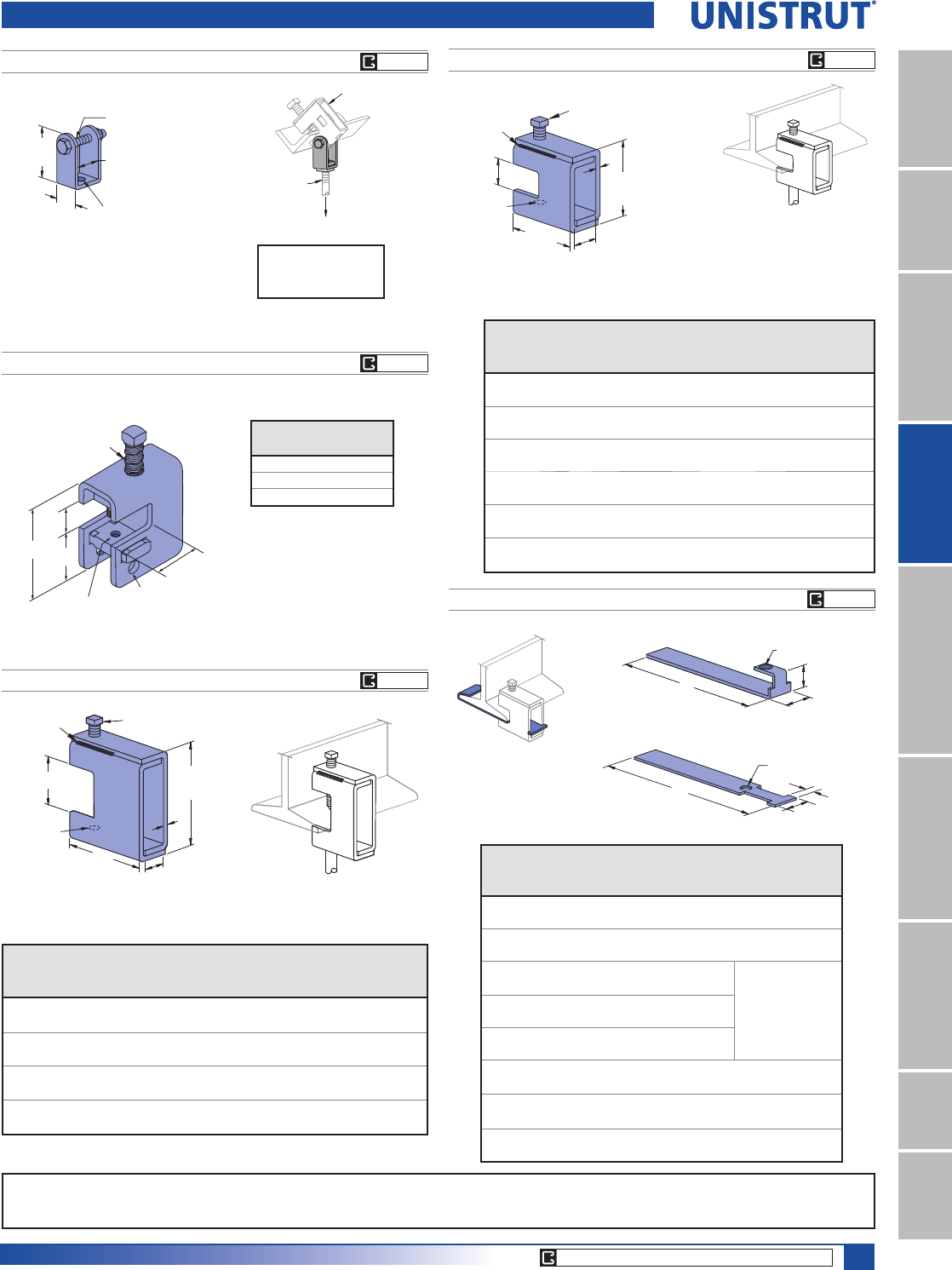
97
15⁄8" Framing System
1 5¼8" ChannelTelestrutNuts & HardwareGeneral FittingsPipe/Conduit SupportsElectrical FittingsConcrete InsertsSolarUnipier®
Beam Clamps
P1648S THRU P1653S
For beams under
7»8" (22.2) thick
flange.
Weld
7⁄8"
(22.2)
Tapped
Hole
Size A
Set Screw
Size C
Included
2
1⁄2"
(63.5)
21⁄2"
(63.5)
B
D
Part
Number
“A”
In
“B”
In (mm)
“C”
In
“D”
In (mm)
Wt/100
pcs
Lbs (kg)
Design
Load
Lbs (kN)
P1648S
1»4 - 20 1»83»8 x 11»27»867 650
3.2 22.2 30.4 2.89
P1649S
5»16 - 18 1»83»8 x 11»27»867 650
3.2 22.2 30.4 2.89
P1650S
3»8 - 16 3»16 1»2 x 11»215»16 100 1,100
4.8 23.8 45.4 4.89
P1651S
1»2 - 13 1»41»2 x 11»215»16 130 1,600
6.4 23.8 59.0 7.12
P1652S
5»8 - 11 5»16 5»8 x 11»215»16 160 2,400
7.9 33.3 72.6 10.68
P1653S
3»4 - 10 5»16 5»8 x 11»215»16 160 2,400
7.9 33.3 72.6 10.68
Weld is not continuous it is either 11»4" (31.8) - 13»4" (44.5) long or
2 spot welds. All welds are on the top and bottom.
P2674P2674
P1640
Wt/100 pcs: 17 Lbs (7.7 kg)
Clevis hanger to be used with P2675
to provide angle adjustment for up to
3»8" rod suspension as illustrated.
1⁄4" X 1 1⁄2"
1 3⁄4"
(44.5)
(20.6)
Hole 13⁄32" (10.3) Dia.
1⁄8" (3.2) Thick
7⁄8" (22.2)
Screw, Nut,
and Lock Washer
Included
13⁄16"
P2675
Rod Size
up to 3⁄8"
Design Load
250 Lbs (1.11 kN)
P2398S, P2401S, P2403S, P2405S
For beams between 3»4" (19.1) to 15»8" (41.3) thick flanges.
Part
Number
“A”
In
“B”
In (mm)
“C”
In
“D”
In (mm)
“E”
In (mm)
Wt/100 pcs
Lbs (kg)
Design
Load
Lbs (kN)
P2398S
1»4 - 20 1»83»8 x 2 121»32 7»8109 800
3.2 42.1 22.2 49.4 3.56
P2401S
3»8 - 16 3»16 1»2 x 2 111»16 29»32 156 1,300
4.8 42.9 23.0 70.8 5.78
P2403S
1»2 - 13 1»41»2 x 2 111»16 15»16 201 1,900
6.4 42.9 23.8 91.2 8.45
P2405S
5»8 - 11 5»16 5»8 x 2 111»16 15»16 311 2,400
7.9 42.9 33.3 141.1 10.68
Weld is not continuous it is either 11»4" (31.8) - 13»4" (44) long or 2 spot
welds. All welds are on the top and bottom.
3 1⁄4"
D
Weld
B
E
(92.1)
3 5⁄8"
(82.6)
Set Screw
Size C Included
Tapped
Hole
Size A
P1654A THRU P1661A RETAINER STRAP
For beams under 7»8"
(22.2) thick flange.
A
(25.4)
1"
(22.2)
7⁄16" (11.1) Hole
12 Gage
7⁄8"
P1654 A & P1655 A
(12.7)
A
17⁄32" (13.5) Hole
1 3⁄8"
(34.9)
1⁄2"
P1656 A thru P1661 A
Strap
Part
Number
Flange
Width
In (mm)
“A”
In (mm)
Wt/100 pcs
Lbs (kg)
Beam
Clamp
Used With
P1654 A 67 25 P2675
152.4 177.8 11.3
P1655 A 910 34 P2675
228.6 254.0 15.4
P1656 A 69 35
P1648 S Thru
P1651 S,
P2398S, P2401S
& P2403S
152.4 228.6 15.9
P1657 A 912 47
228.6 304.8 21.3
P1658 A 12 15 59
304.8 381.0 26.8
P1659 A 69 33 P2676
152.4 228.6 15.0
P1660 A 912 45 P2676
228.6 304.8 20.4
P1661 A 12 15 57 P2676
304.8 381.0 25.9
CORE PRODUCTS - TYPICALLY AVAILABLE FROM STOCK
Part
Number
Thread
Size
P1640-025 1»4"-20
P1640-037 3»8"-16
P1640-050 1»2"-13
1⁄2" x 2" Cone Point
Set Screw w/spring
11⁄2"
ø0.44
.88"
Tapped
UNC Bolt Size
3.19" 11⁄2"
EG GR
EG GR
EG GR
EG GR
EG GR
Note: When used for mechanical supports, load capacities of brackets and fittings should be in compliance with the American Standard Code for Pressure Piping.
Clamps are designed to be used with W, M, S & HP Shape beams, Standard C & Misc. MC Channels, Angles & Structural Tees. Clamps must be used in pairs where indicated.
For beam clamps with HG finish, standard hardware is EG finish. For optional stainless steel hardware, please contact the factory for availability.
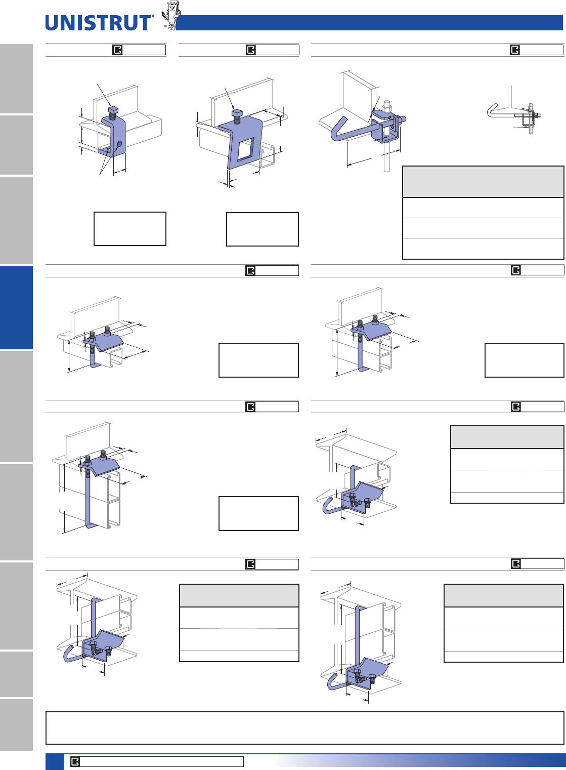
98
15⁄8" Framing System
1 5¼8" ChannelTelestrutNuts & HardwareGeneral FittingsPipe/Conduit SupportsElectrical FittingsConcrete InsertsSolarUnipier®
P1796SP1271S
(44.5)
1 3⁄4"
7⁄8"
(22.2)
1⁄4"
(6.4)
1⁄2" - 13 X 11⁄2"
Set Screw Included
3 1⁄2"
(88.9)
3 1⁄2"
(88.9)
3⁄8"
(9.5)
7⁄8"
(22.2)
1 5⁄8"
(41.3)
1 1⁄2"
(38.1)
1⁄2" - 13 X 11⁄2"
Set Screw Included
2 Holes 9⁄16" (14.3) Dia.
Design Load Each
500 Lbs (2.22 kN)
Use in Pairs Only
Wt/100 pcs: 95 Lbs (43.1 kg) Wt/100 pcs: 91 Lbs (41.3 kg)
Note: Requires
P1010 Channel
Nut and bolt.
P2785
P2824-6,-9,-12
Wt/100 pcs: 83 Lbs (37.6 kg)
)RUXVHZLWK%HDPVXSWR3»4" (19.1)
Flanges and with
Channels P1000, P1100, P2000,
P3000, P3300, P3301,
P4000, P4001, P4100, and P4101.
7⁄8"
3⁄8" Hex Nuts and
"U" Bolt Included
(22.2)
3"
(76.2)
3 3⁄8"
(85.7)
1⁄4"
(6.4)
A
3⁄16"
(4.8)
3⁄16"
(4.8)
Clamp Requires
1⁄2" Diameter Rod and
2 Hex Nuts (Sold Seperately)
Part
Number
“A”
In (mm)
Wt/100 pcs
Lbs (kg)
Design
Load
Lbs (kN)
P2824-6 21»2 - 6 125 500
63.5 - 152.4 56.7 2.22
P2824-9 51»2 - 9 140 500
139.7 - 228.6 63.5 2.22
P2824-12 81»2 - 12 171 500
215.9- 304.8 77.6 2.22
(76.2)
3"
81⁄4"
(209.6)
1⁄4" (6.4)
Thick
A
(76.2)
3"
5"
(127.0)
1⁄4" (6.4)
Thick
A
P2867A
,QFOXGHV-%ROW8%ROWDQG+H[1XWV
)RUXVHZLWK&KDQQHO33333DQG3
Part
Number
Beam
Size "A"
Wt/100 pcs
/EVNJ
P2867A 4"-6" 151 (68.5)
P2867A-9 6"-9" 157 (71.2)
P2867A-12 9"-12" 166 (75.3)
P2867A-15 12"-15" 176 (79.8)
P2867A-18 15"-18" 185 (83.9)
P2867
(76.2)
3"
3 3⁄8"
(85.7)
A
1⁄4" (6.4)
Thick
,QFOXGHV-%ROW8%ROWDQG+H[1XWV
)RUXVHZLWK&KDQQHOV33
P2000, P3000, P3300, P3301, P4000, P4001,
P4100, and P4101.
Part
Number
Beam
Size "A"
Wt/100 pcs
/EVNJ
P2867 4"-6" 142 (64.4)
P2867-9 6"-9" 151 (68.5)
P2867-12 9"-12" 160 (72.6)
P2867-15 12"-15" 170 (77.1)
P2867-18 15"-18" 179 (81.2)
P2867B
Part
Number
Beam
Size "A"
Wt/100 pcs
/EVNJ
P2867B 4"-6" 161 (73.0)
P2867B-9 6"-9" 167 (75.7)
P2867B-12 9"-12" 176 (79.8)
P2867B-15 12"-15" 186 (84.4)
P2867B-18 15"-18" 195 (88.5)
,QFOXGHV-%ROW8%ROWDQG+H[1XWV
)RUXVHZLWK&KDQQHO3DQG3
P2786
Wt/100 pcs: 92 Lbs (41.7 kg)
)RUXVHZLWK%HDPVXSWR3»4" (19.1)
Flanges and with
Channels P1001, P1101, P2001,
P3001, P5000, and P5500.
1⁄4"
(6.4)
5"
3"
(76.2)
7⁄8"
(22.2)
3⁄8" Hex Nuts and
"U" Bolt Included
(127.0)
Design Load Each
1000 Lbs (4.45 kN)
Use in Pairs Only
P2787
)RUXVHZLWK%HDPVXSWR3»4" (19.1)
Flanges and with
Channels P5001 and P5501.
Design Load Each
1000 Lbs (4.45 kN)
Use in Pairs Only
1⁄4"
(6.4)
81⁄4"
3"
(76.2)
7⁄8"
(22.2)
3⁄8" Hex Nuts and
"U" Bolt Included
(209.6)
Wt/100 pcs: 112 Lbs (50.8 kg)
Beam Clamps
Design Load Each
500 Lbs (2.22 kN)
Use in Pairs Only
Design Load Each
1000 Lbs (4.45 kN)
Use in Pairs Only
For use with Beams up to
3»4PD[ÀDQJHWKLFNQHVV
CORE PRODUCTS - TYPICALLY AVAILABLE FROM STOCK
EG GR HG EG GR HG
EG GR HG
EG GR HG
EG GR HG
EG GR HG
EG GR HG
EG GR HG
EG GR HG
Note: When used for mechanical supports, load capacities of brackets and fittings should be in compliance with the American Standard Code for Pressure Piping.
Clamps are designed to be used with W, M, S & HP Shape beams, Standard C & Misc. MC Channels, Angles & Structural Tees. Clamps must be used in pairs where indicated.
For beam clamps with HG finish, standard hardware is EG finish. For optional stainless steel hardware, please contact the factory for availability.
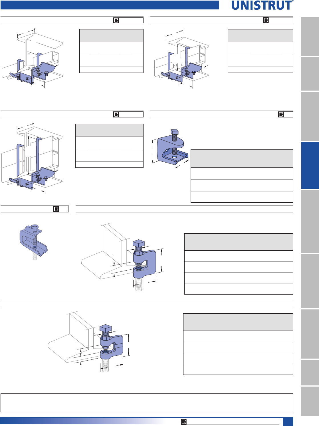
99
15⁄8" Framing System
1 5¼8" ChannelTelestrutNuts & HardwareGeneral FittingsPipe/Conduit SupportsElectrical FittingsConcrete InsertsSolarUnipier®
A
(76.2)
3"
3 3⁄8"
(85.7)
1⁄4" (6.4)
Thick
P2868
,QFOXGHV&HQWHU5RG8%ROWVDQG+H[1XWV
)RUXVHZLWK&KDQQHOV3333
P3300, P3301, P4000, P4001, P4100, and P4101.
Beam Clamps
Part
Number
Beam
Size "A"
Wt/100 pcs
/EVNJ
P2868 4"-6" 282 (127.9)
P2868-9 6"-9" 289 (131.1)
P2868-12 9"-12" 296 (134.3)
P2868-15 12"-15" 304 (137.9)
P2868-18 15"-18" 311 (141.1)
A
(76.2)
3"
1⁄4" (6.4)
Thick
5"
(127.0)
P2868A
,QFOXGHV&HQWHU5RG8%ROWVDQG+H[1XWV
)RUXVHZLWK&KDQQHOV33333DQG3
Part
Number
Beam
Size "A"
Wt/100 pcs
/EVNJ
P2868A 4"-6" 300 (136.1)
P2868A-9 6"-9" 307 (139.3)
P2868A-12 9"-12" 314 (142.2)
P2868A-15 12"-15" 322 (146.1)
P2868A-18 15"-18" 329 (149.2)
P2868B
,QFOXGHV&HQWHU5RG8%ROWV
and Hex Nuts.
)RUXVHZLWK&KDQQHOV3
and P5501.
A
(76.2)
3"
1⁄4" (6.4)
Thick
81⁄4"
(209.6)
Part
Number
Beam
Size "A"
Wt/100 pcs
/EVNJ
P2868B 4"-6" 320 (145.1)
P2868B-9 6"-9" 327 (148.3)
P2868B-12 9"-12" 334 (151.5)
P2868B-15 12"-15" 342 (155.1)
P2868B-18 15"-18" 349 (153.3)
P2894
Material: Malleable Iron
7»8" Maximum Flange Thickness
Note: Tapped Hole on Top and Bottom
Part
Number
Rod
Size
In
“A”
In (mm)
“B”
In (mm)
Load
Ratings
Lbs (kN)
Wt/100
pcs
Lbs (kg)
P2894-25
1»411»811»4150 23
28.6 31.8 .67 10.4
P2894-37
3»82 2 350 95
50.8 50.8 1.56 43.1
P2894-50
1»225»821»2400 195
66.7 63.5 1.78 88.5
P2893
Material: Steel
Use With: 1»4" rod
Load Rating: 75 lbs. (.33 kN)
Wt/100 pcs: 14 lbs. (6.4 kg)
B
A
P2895
Material: Steel
3⁄4"
(19.1)
2 1⁄4"
(57.2)
A
BPart
Number
Rod
Size
In
“A”
In (mm)
“B”
In (mm)
Load
Ratings
Lbs (kN)
Wt/100 pcs
Lbs (kg)
P2895-37
3»825»16 3»8330 35
58.7 9.5 1.47 15.9
P2895-50
1»221»41»2380 41
57.2 12.7 1.69 18.6
P2895-62
5»823»85»8450 67
60.3 15.9 2.00 30.4
P2895-75
3»421»41»2500 72
57.2 12.7 2.22 32.7
P2896
3⁄4"
(19.1)
1⁄2"
(12.7)
3⁄8"
(9.5)
A
B
Part
Number
Rod
Size
In
“A”
In (mm)
“B”
In (mm)
Load
Ratings
Lbs (kN)
Wt/100 pcs
Lbs (kg)
P2896-37
3»8111»16 13»4400 38
42.9 44.5 1.78 17.2
P2896-50
1»2123»32 13»4400 52
43.7 44.5 1.78 23.6
P2896-62
5»8115»16 2 450 68
49.2 50.8 2.00 30.8
P2896-75
3»421»32 2 600 128
51.6 50.8 2.67 58.1
Material: Malleable Iron,
Steel Set Screw
CORE PRODUCTS - TYPICALLY AVAILABLE FROM STOCK
EG
EG
EG GR HG
EG GR HG
EG GR HG
Note: When used for mechanical supports, load capacities of brackets and fittings should be in compliance with the American Standard Code for Pressure Piping.
Clamps are designed to be used with W, M, S & HP Shape beams, Standard C & Misc. MC Channels, Angles & Structural Tees. Clamps must be used in pairs where indicated.
For beam clamps with HG finish, standard hardware is EG finish. For optional stainless steel hardware, please contact the factory for availability.
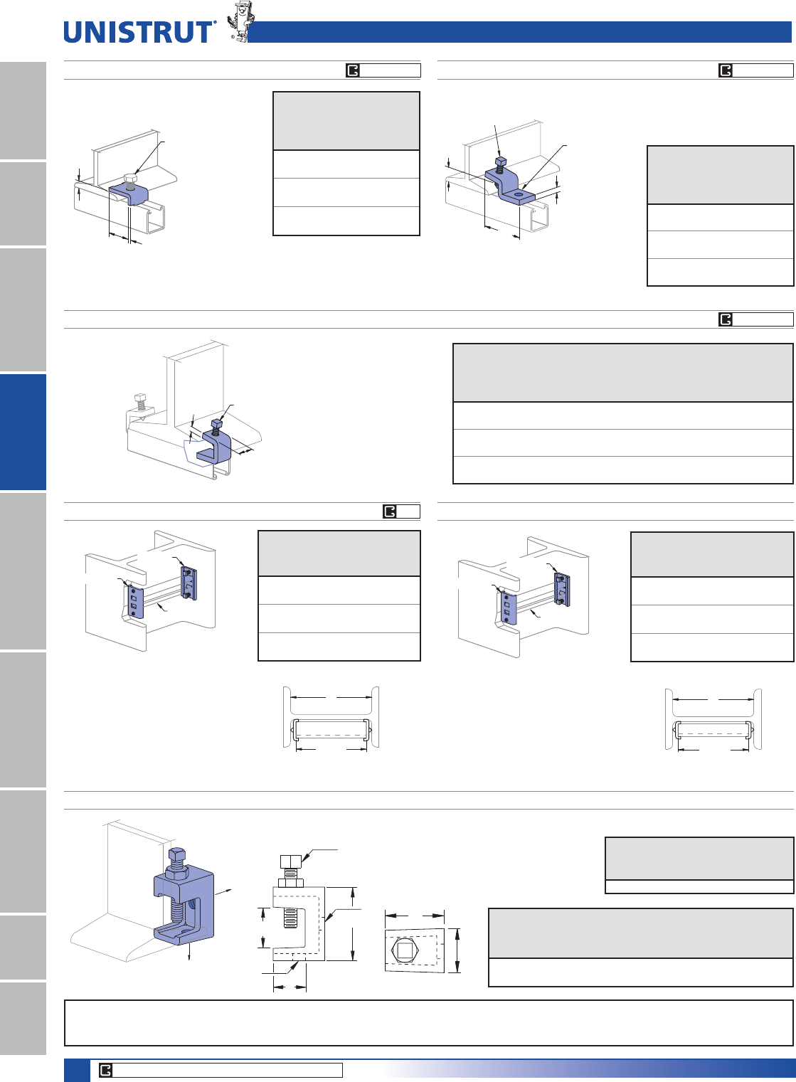
100
15⁄8" Framing System
1 5¼8" ChannelTelestrutNuts & HardwareGeneral FittingsPipe/Conduit SupportsElectrical FittingsConcrete InsertsSolarUnipier®
Beam Clamps
P1386
(45.2)
(6.4)
1⁄4"
(12.7)
1⁄2"
Clamp Requires
1⁄2" - 13 X 11⁄2"
Hex Head Cap Screw
and 1⁄2" Channel
Nut Not Included.
1 25⁄32"
Channel
Style
Design
Load Each
8VHLQ3DLUV2QO\
/EVN1
P1000 600
2.67
P1100 500
2.22
P2000 450
2.00
Wt/100 pcs: 27 Lbs (12.2 kg)
P1379S
(82.6)
3 1⁄4"
(25.4)
1"
(9.5)
3⁄8"
1⁄2" - 13 X 11⁄2"
Set Screw Included Clamp Requires
1⁄2" x 13⁄16"
Hex Head Cap Screw
and 1⁄2" Channel
Nut Not Included.
Channel
Style
Design
Load Each
8VHLQ3DLUV2QO\
Lbs (kN)
P1000 600
2.67
P1100 500
2.22
P2000 450
2.00
Wt/100 pcs: 75 Lbs (34.0kg)
P1272S, P1985S, P1986S
D
A
1 1⁄4"
(31.8)
Part
Number
“A”
In (mm)
Flange
Thickness
In (mm)
“D” Set
Screw
Included
Wt/100
pcs
Lbs (kg)
Design Load
Per Pair
8VHLQ3DLUV2QO\
Lbs (kN)
P1272S
1»4Up to 3»43»8-16 x 11»239 450
6.4 Up to 19.1 17.7 2.00
P1985S
3»8Up to 3»41»2-13 x 11»262 1,000
9.5 Up to 19.1 28.1 4.45
P1986S
3»87»8 to 2 1»2-13 x 11»274 900
9.5 22.2 - 50.8 33.6 4.00
P3087 COLUMN INSERT
Safety factor of 3.
Wt/100 pcs: 136 Lbs (61.7 kg)
A - 1"
(A - 25)
A
$GMXVWLQJ6FUHZV,QFOXGHG
8QLVWUXWFKDQQHOQRWLQFOXGHG
3DUWQXPEHU3FRQVLVWVRI
(1) piece P3087A,
(1) piece P3087B and
(2) set screws, 3»8" Dia.
P3087A
P3087B
Adjusting Screws
Included
Channel
Channel
Part
Number
Design Pull
Out Load
Lbs (kN)
Design
Slip Load
Lbs (kN)
P1000 1,000 800
4.45 3.56
P1100 700 500
3.34 2.22
P2000 500 300
2.22 1.33
P3088 COLUMN INSERT
Wt/100 pcs: 120 Lbs (54.4 kg)
$GMXVWLQJ6FUHZV,QFOXGHG
8QLVWUXWFKDQQHOQRWLQFOXGHG
3DUWQXPEHU3FRQVLVWVRI
(1) piece P3088A,
(1) piece P3088B and
(2) set screws, 3»8" Dia.
Safety factor of 3.
Channel
Part
Number
Design Pull
Out Load
Lbs (kN)
Design
Slip Load
Lbs (kN)
P3300 1,000 800
4.45 3.56
P4100 700 500
3.11 2.22
P4000 500 300
2.22 1.33
P3088A
P3088B
Adjusting Screws
Included
Channel
A - 1"
(A - 25)
A
PLLC025 FLANGE CLAMP
Set Screw Torque = 3 Ft-Lb
Lock Nut Torque = 3.5 Ft-Lb
135 Lbs.
40 Lbs.
Part
Number
Rod
Size
“Z” Set
Screw
Size
Wt/100 pcs
Lbs (kg)
PLLC025 1»4"1»4" 16 (7.3)
Cup point set screw
and lock nut included.
S
U
W
X
Y
Z
T
V
Material: Malleable Iron.
Dimensions
Part
Number
“S”
In (mm)
“T”
In (mm)
“U”
In (mm)
“V”,“W”
In (mm)
“X”,“Y”
In
PLLC025
5»811
7»16 3»41»4 X 20
15.9 25.4 36.5 19.1
X, Y are threaded holes.
CORE PRODUCTS - TYPICALLY AVAILABLE FROM STOCK
EG
EG GR HG
EG GR HGEG GR HG
Note: When used for mechanical supports, load capacities of brackets and fittings should be in compliance with the American Standard Code for Pressure Piping.
Clamps are designed to be used with W, M, S & HP Shape beams, Standard C & Misc. MC Channels, Angles & Structural Tees. Clamps must be used in pairs where indicated.
For beam clamps with HG finish, standard hardware is EG finish. For optional stainless steel hardware, please contact the factory for availability.
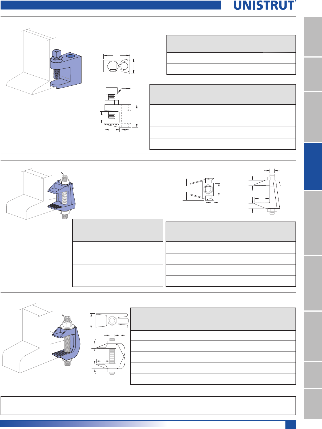
101
15⁄8" Framing System
1 5¼8" ChannelTelestrutNuts & HardwareGeneral FittingsPipe/Conduit SupportsElectrical FittingsConcrete InsertsSolarUnipier®
Threaded Rod & Nut
Not Included
PFL037 THRU PFL050T FLANGE CLAMP
Beam Clamps
Material: Malleable Iron.
Part
Number
Type of
Hole
Rod
Size
“Z” Set
Screw
Size
Wt/100 pcs
Lbs (kg)
Max. Allowable
Load
Lbs (kN)
PFL037 Clear 3»8"3»8" 28 (12.7) 540 (2.40)
PFL037T Tapped 3»8"3»8" 28 (12.7) 540 (2.40)
PFL050 Clear 1»2"3»8" 40 (18.1) 700 (3.11)
PFL050T Tapped 1»2"3»8" 40 (18.1) 700 (3.11)
Dimensions
Part
Number
“T”
In (mm)
“U”
In (mm)
“V”
In (mm)
“W”
In(mm)
“X”
In (mm)
“Y”
In (mm)
PFL037 111»16 19»16 7»83»417»16
42.9 39.7 22.2 19.1 25.4 11.1
PFL037T 111»16 19»16 7»83»413»8Tapped
42.9 39.7 22.2 19.1 25.4 Hole
PFL050 21
23»32 129»32 13»32 9»16
50.8 43.7 25.4 23.0 27.8 14.3
PFL050T 21
23»32 129»32 13»32 1»2Tapped
50.8 43.7 25.4 23.0 27.8 Hole
Safety Factor: 4
V
T
Z
U
Y
X
W
Cup point set screw
and lock nut included.
Set Screw Torque = 6 Ft-Lb
Lock Nut Torque = 16 Ft-Lb
PLF3037 THRU PLF3075 FLANGE CLAMP
Part
Number
Rod
Size
Wt/100
pcs
Lbs (kg)
Max.
Allowable
Load
Lbs (kN)
Torque
Ft-Lbs
PLF3037 3»8"53 270 15
24 1.20
PLF3050 1»2"91 450 29
41 2.00
PLF3062 5»8"186 900 69
84 4.00
PLF3075 3»4"334 1,350 130
152 6.01
Dimensions
Part
Number
“X”
In (mm)
“W”
In (mm)
“V”
In (mm)
“T“
In (mm)
“R”
In (mm)
“S”
In (mm)
PLF3037 1 0 - 13»16 3»89»32 11»27»8
25.4 0 - 30.2 9.5 7.1 38.1 22.2
PLF3050 13»80 - 19»16 1»211»32 115»16 15»32
34.9 0 - 39.7 12.7 8.7 49.2 29.4
PLF3062 113»16 0 - 23»16 5»81»2211»32 17»16
46.0 0 - 55.6 15.9 12.7 59.5 36.5
PLF3075 23»16 0 - 13»43»45»831
3»4
55.6 0 - 44.5 19.1 15.9 76.2 44.5
Material: Malleable Iron.
S
T
R
Z
V
X
W
V
Safety Factor: 4
Threaded Rod & Nut
Not Included
PLF9037 THRU PLF9100 FLANGE CLAMP
S
Material: Malleable Iron. Safety Factor: 4
ZT
V
V
WX
Part
Number
Rod
Size
Wt/100
pcs
Lbs
(kg)
Max.
Allowable
Load
Lbs (kN)
Torque
Ft-Lbs
“X”
In
(mm)
“W”
In (mm)
“V”
In
(mm)
“T”
In
(mm)
“S”
In
(mm)
PLF9037 3»8"55 440 15 1 3»4 - 111»16 1»23»41
24.9 1.96 25.4 19.1 - 42.9 12.7 19.1 25.4
PLF9050 1»2"122 630 29 13»81 - 23»821»32 15»16 13»16
55.3 2.80 34.9 25.4 - 60.3 16.7 23.8 30.2
PLF9062 5»8"200 1,260 69 111»16 11»8 - 23»413»16 11»813»8
90.7 5.60 42.9 28.6 - 69.9 20.6 28.6 34.9
PLF9075 3»4"367 1,880 131 2 11»4 - 31»411
3»813»4
166.5 8.36 50.8 31.8 - 82.6 25.4 34.9 44.5
PLF9100 1" 1,101 3,150 173 3 13»4 - 33»411»223»16 21»2
499.4 14.01 76.2 44.9 - 95.3 38.1 55.6 63.5
Note: When used for mechanical supports, load capacities of brackets and fittings should be in compliance with the American Standard Code for Pressure Piping.
Clamps are designed to be used with W, M, S & HP Shape beams, Standard C & Misc. MC Channels, Angles & Structural Tees. Clamps must be used in pairs where indicated.
For beam clamps with HG finish, standard hardware is EG finish. For optional stainless steel hardware, please contact the factory for availability.
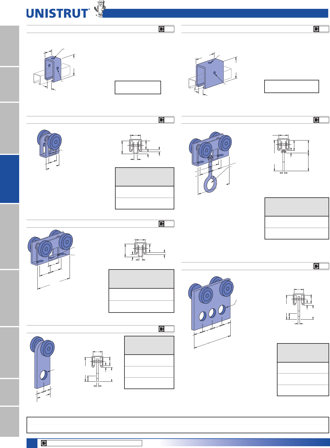
102
15⁄8" Framing System
1 5¼8" ChannelTelestrutNuts & HardwareGeneral FittingsPipe/Conduit SupportsElectrical FittingsConcrete InsertsSolarUnipier®
(31.8)
1 1⁄4"
(15.9)
5⁄8"
5⁄8"
(15.9)
Hole
9⁄16" (14.3) Dia.
(49.2)
115⁄16"
(33.3)
1 5⁄16"
9⁄32"
(7.1)
(30.2)
1 3⁄16"
(20.6)
13⁄16"
313⁄32"
(86.5)
(6.4)
1⁄4"
3 9⁄32"
(83.3)
3 1⁄2"
(88.9)
(26.2)
2 Holes
7⁄16" (11.1) Dia.
1 Hole
9⁄16" (14.3) Dia.
1 1⁄32"
Trolley Assemblies
P2949
P2950
Wt/100 pcs: 46 Lbs (20.9 kg) Wt/100 pcs: 110 Lbs (49.9 kg)
Wheel bearings are
stainless steel.
Do not lubricate.
(88.9)
3 1⁄2"
15⁄16"
(23.8)
15⁄16"
(23.8)
(20.6)
13⁄16"
(20.6)
13⁄16"
3 Holes
9⁄16" (14.3)
Dia.
FPM RPM
Design Load
In P1000
Lbs (kN)
180 600 150
.67
90 300 225
1.00
30 100 437
1.94
FPM RPM
Design Load
In P1000
Lbs (kN)
180 600 300
1.33
90 300 450
2.00
30 100 600
2.67
P1834A CHANNEL TROLLEY SUPPORTP1834 CHANNEL TROLLEY SUPPORT
Wt/100 pcs: 102 Lbs (46.3 kg) Wt/100 pcs: 220 Lbs (99.8 kg)
Requires 3»8" x 21»2" Bolt and 3»8" Nut
(not included)
Requires 3»8" x 21»2" Bolt and 3»8" Nut
(not included)
Design Load
1200 Lbs (5.34 kN)
Design Load
2500 Lbs (11.12 kN)
(49.2)
115⁄16"
(33.3)
1 5⁄16"
9⁄32"
(7.1)
(30.2)
1 3⁄16"
(20.6)
13⁄16"
313⁄32"
(86.5)
(6.4)
1⁄4"
3⁄4" (19.1) Dia.
1"
(25.4)
1"
(25.4)
1"
(25.4)
3 1⁄8"
(79.4)
Clevis Material:
12 gauge.
*Wheel bearings are stainless steel, and
should not be lubricated.
† "N" indicates acetal wheels.
1"(25.4)
1"
(25.4)
1" (25.4)
3 1⁄8"
(79.4)
9⁄32" (7.1)
Dia. Hole
9⁄16"x 9⁄32"
(14.3 x 7.1) Slots
1 3⁄16"
(30.2)
9⁄32"
(7.1)
1 23⁄32"
(43.7)
(31.8)
1 1⁄4"
1⁄4"
(6.4)
7⁄16"
(11.1)
(61.9)
2 7⁄16"
1 21⁄32"
(42.1)
(105.6)
4 5⁄32"
1 1⁄4"
(31.8)
(6.4)
1⁄4"
(35.7)
1 13⁄32"
(6.4)
1⁄4"
(11.1)
7⁄16"
(42.1)
1 21⁄32"
(4.8)
3⁄16"9⁄32"
(7.1)
(30.2)
1 3⁄16"
1 1⁄4"
(31.8)
(31.8)
1 1⁄4"
3⁄4"
(19.1)
9⁄32" (7.1) Dia. Hole
Clevis Material: 12 gauge.
*Wheel bearings are stainless steel, and
should not be lubricated.
† "N" indicates acetal wheels.
Clevis Material: 12 gauge.
*Wheel bearings are stainless steel, and
should not be lubricated.
† "N" indicates acetal wheels.
P2749, P2749N†
P2750, P2750N†
P2751, P2751 N†
Part
Number
Design
Load
Lbs (kN)
Wt/100
pcs
Lbs (kg)
P2749 50 21
.22 9.5
P2749N 10 13
.04 5.9
Part
Number
Design
Load
Lbs (kN)
Wt/100 pcs
Lbs (kg)
P2750 100 55
.44 24.9
P2750N 20 32
.09 14.5
Part
Number
Design
Load
Lbs (kN)
Wt/100 pcs
Lbs (kg)
P2751 100 63
.44 28.6
P2751N 20 40
.09 18.1
3 25⁄32"
(96.0)
1 5⁄8"
(41.3)
2 Holes
7⁄16" (11.1) Dia.
1 Hole
9⁄16" (14.3) Dia.
1 1⁄32"
(26.2)
Wheel bearings are stainless
steel. Do not lubricate.
CORE PRODUCTS - TYPICALLY AVAILABLE FROM STOCK
EG EG
EG
EG
EG
EG
EG
Standard Dimensions for 15»8PPZLGWKVHULHVFKDQQHOILWWLQJV(Unless Otherwise Shown on Drawing)
Hole Diameter: 9»16PP+ROH6SDFLQJ)URP(QG13»16PP+ROH6SDFLQJ2Q&HQWHU7»8PP:LGWK5»8PP7KLFNQHVV1»4PP
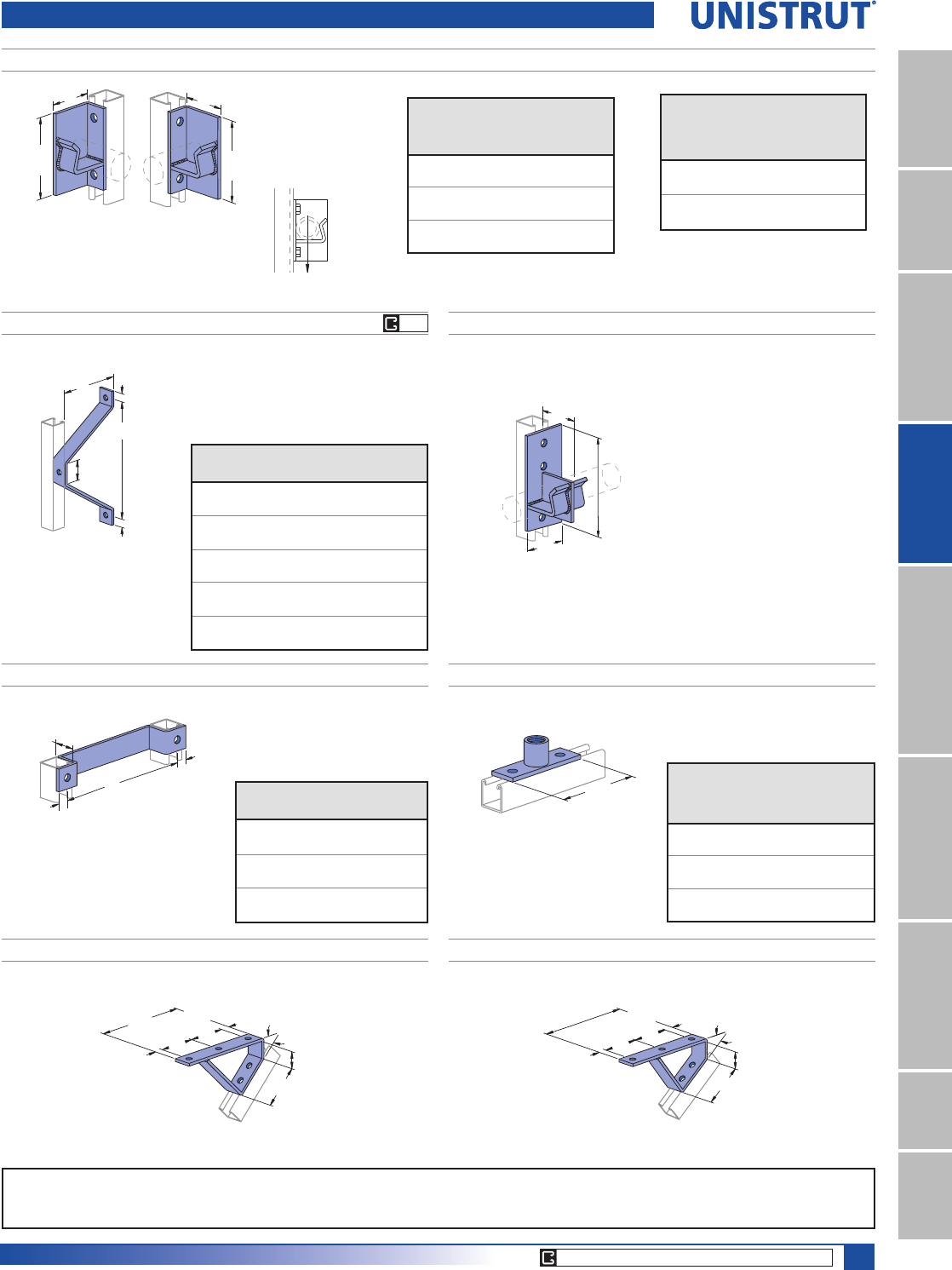
103
15⁄8" Framing System
1 5¼8" ChannelTelestrutNuts & HardwareGeneral FittingsPipe/Conduit SupportsElectrical FittingsConcrete InsertsSolarUnipier®
Special Application Fittings
P1204 THRU P1208 WALL LADDER BRACKET
Part
Number
“A”
In (mm)
“B”
In (mm)
Wt/100 pcs
Lbs (kg)
P1204 23»86113
60.3 152.4 51.3
P1205 43»88 164
111.1 203.2 74.4
P1206 63»810 216
161.9 254.0 98.0
P1207 83»812 267
212.7 304.8 121.1
P1208 103»814 318
263.5 355.6 144.2
P1201, P1202, P1203 LADDER RUNG
1 5⁄8"
(41.3)
13⁄16"
(20.6)
13⁄16"
(20.6)
APart
Number
“A”
In (mm)
Wt/100 pcs
Lbs (kg)
P1201 12 186
304.8 84.4
P1202 15 221
381.0 100.2
P1203 18 254
457.2 115.2
B
13⁄16"
(20.6)
2"
(50.8)
A
13⁄16"
(20.6)
P2454 DOUBLE PIPE AXLE SUPPORT
P2470-50, -75, -100 PIPE COUPLING FITTING
(136.5)
5 3⁄8"
Wt/100 pcs: 310 Lbs (140.6 kg)
Pipe Coupling
Part
Number
Size
In
Wt/100 pcs
Lbs (kg)
P2470-50 1»277
(34.9)
P2470-75 3»493
(42.2)
P2470-100 1103
(46.7)
For 11»4" (31.8) Standard Pipe
75⁄8"
3"
(76.2)
3"
(76.2)
(193.7)
Load Rating 4,000 Lbs (17.79 kN)
P2354 R-L, P2355 R-L REEL RACK SUPPORTS FOR 11»4" & 2" PIPE
5 3⁄8"
(136.5)
A
5 3⁄8"
(136.5)
A
Right Hand
Left Hand
Vertical
Channel Max.
Allowable Load
Lbs (kN)Part No. Gauge
P1000 12 3,000
(13.34)
P1100 14 2,000
(8.90)
P2000 16 2,000
(8.90)
Part
Number
“A”
In
(mm)
Std.
Pipe
Size
In (mm)
Wt/100
pcs
Lbs (kg)
P2354 R-L 31
1»4220
76.2 31.8 99.8
P2355 R-L 35»82 252
92.1 50.8 114.3
Wt/100 pcs: 213 Lbs (96.6 kg)Wt/100 pcs: 220 Lbs (99.8 kg)
13⁄16"
(20.6)
8 7⁄8"
(225.4) 3 1⁄2"
(88.9)
3 1⁄2"
(88.9)
1 1⁄16"
(27.0) 37 1⁄2°
(0.21π)
3 3⁄4"
(95.3)
(47.6)
1 7⁄8"
13⁄16"
(20.6)
8 7⁄8"
(225.4)
45°
(0.25π)
3 3⁄4"
(95.3)
1 7⁄8"
(47.6)
1 1⁄16"
(27.0)
3 1⁄2"
(88.9)
3 1⁄2"
(88.9)
P2655 371»2° (.21Π) STAIR TREAD SUPPORTP1944 45° (.25Π) STAIR TREAD SUPPORT
CORE PRODUCTS - TYPICALLY AVAILABLE FROM STOCK
EG
Standard Dimensions for 15»8PPZLGWKVHULHVFKDQQHOILWWLQJV(Unless Otherwise Shown on Drawing)
Hole Diameter: 9»16PP+ROH6SDFLQJ)URP(QG13»16PP+ROH6SDFLQJ2Q&HQWHU7»8PP:LGWK5»8PP7KLFNQHVV1»4PP
Note : When used for mechanical supports, load capacities of brackets and fittings should be in compliance with the American Standard Code for Pressure Piping.
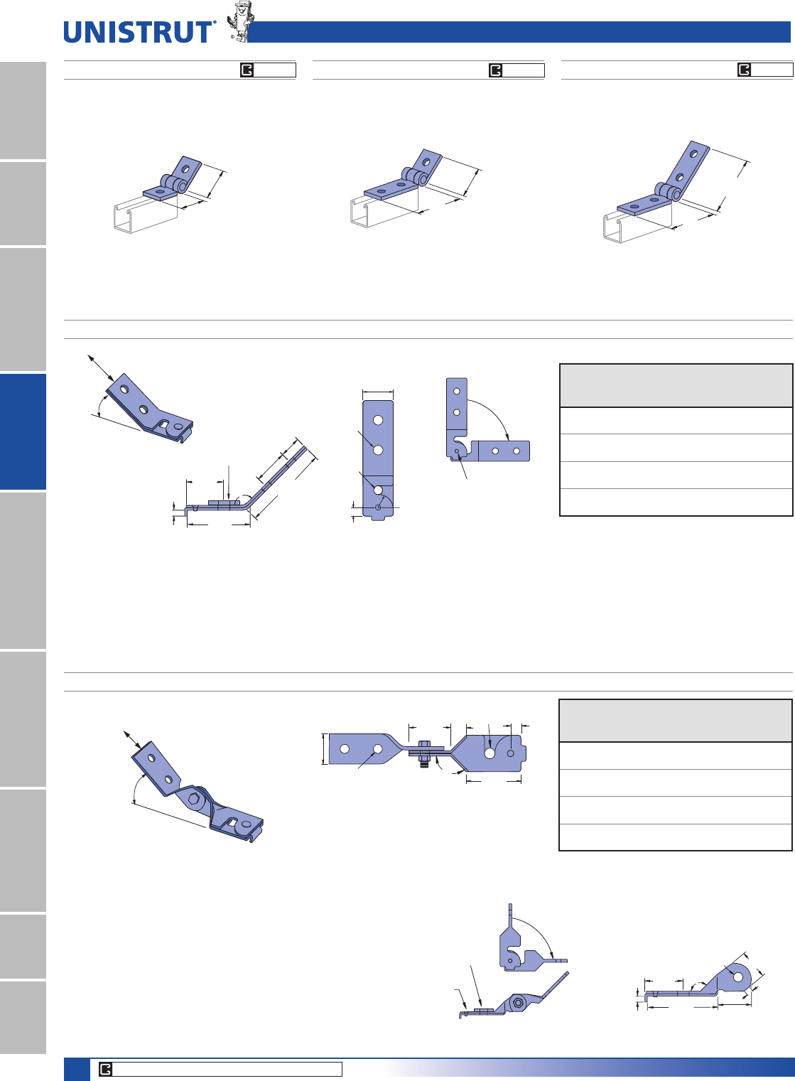
104
15⁄8" Framing System
1 5¼8" ChannelTelestrutNuts & HardwareGeneral FittingsPipe/Conduit SupportsElectrical FittingsConcrete InsertsSolarUnipier®
Special Application Fittings & Seismic Retrofit Fittings
SPF® 100 SEISMIC PIVOT FITTINGS
SPF® 200 ADJUSTABLE SEISMIC PIVOT FITTINGS
45°
Design
Load
Part
Number
Rod
Size
In (mm)
“R” - Hole
Diameter
In (mm)
Design
Load
Lbs (KN)
SPF 100-037
3»87»16 1,400
9.5 11.1 6.23
SPF 100-050
1»29»16 2,100
12.7 14.3 9.34
SPF 100-062
5»811»16 2,100
15.9 17.5 9.34
SPF 100-075
3»413»16 2,400
19.1 20.6 10.68
Part
Number
Rod
Size
In (mm)
“R” - Hole
Diameter
In (mm)
Design
Load
Lbs (KN)
SPF 200-037
3»87»16 1,400
9.5 11.1 6.23
SPF 200-050
1»29»16 2,100
12.7 14.3 9.34
SPF 200-062
5»811»16 2,100
15.9 17.5 9.34
SPF 200-075
3»413»16 2,400
19.1 20.6 10.68
15⁄8"
(41.3)
1⁄4"
(6.4)
25⁄8"
(66.7)
41⁄8"
(104.8)
11⁄8"
(28.6)
17⁄8"
135°
(47.6)
Square
Washer R
13⁄4"
(44.5)
1⁄2"
(12.7)
7⁄8"
(22.2)
(TYP)
9⁄16"
(14.3)
Rivet
Rotate Around
Rod to Close
Fitting Open
2"
(50.8)
1⁄2"
(12.7)
3⁄4"
(19.1)
9⁄16"
(14.3) 25⁄8"
(66.7)
13⁄4"
(44.5)
135°
R
Notes:
1. Design load is limited to slip capacity of a channel nut at hole "R".
2. Allowable loads have been determined by the manufacturers testing, analysis and technical specifications.
3. For retrofit application, engineer of record must verify.
4. Square washer provided with fitting.
5. When a hanger rod is thru-bolted (in lieu of channel nut installation), higher transverse loads may be transmitted
due to the higher allowed rod shear loads compared to channel nut slip values. This higher load may be used with
verification through engineering calculations.
Safety Factor = 3
FINISH
Electro-galvanized (EG), conforming to
ASTM B633 Type III SC1.
15⁄8"
(41.3)
1⁄4"
(6.4)
1⁄2"
(12.7)
9⁄16"
(14.3)
33⁄8"
(85.7) 17⁄8"
(47.6)
13⁄4"
(44.5)
135°
Notes:
1. Design load is limited to slip capacity of a channel nut at hole "R"..
2. Allowable loads have been determined by the manufacturers testing,
analysis and technical specifications at 45° from horizontal.
3. For retrofit application, engineer of record must verify.
4. Square washer provided with fitting.
5. When a hanger rod is thru-bolted (in lieu of channel nut installation),
higher transverse loads may be transmitted due to the higher allowed rod
shear loads compared to channel nut slip values. This higher load may
be used with verification through engineering calculations.
30° - 60°
Design
Load
Rivet
Square
Washer
Rotate Around
Rod to Close
Safety Factor = 3.0
P1354
ADJ. HINGE CONNECTION
P1843
ADJ. HINGE CONNECTION
Wt/100 pcs: 89 Lbs (40.4 kg)Wt/100 pcs: 68 Lbs (30.8 kg)
(101.8)
4"
(101.8)
4"
2 3⁄16"
(55.6)
2 3⁄16"
(55.6)
P1354A
ADJ. HINGE CONNECTION
Wt/100 pcs: 109 Lbs (49.4 kg)
4"
(101.6)
2 3⁄16"
(55.6)
FINISH
Electro-galvanized (EG), conforming to
ASTM B633 Type III SC1.
CORE PRODUCTS - TYPICALLY AVAILABLE FROM STOCK
EG GR EG GR EG GR
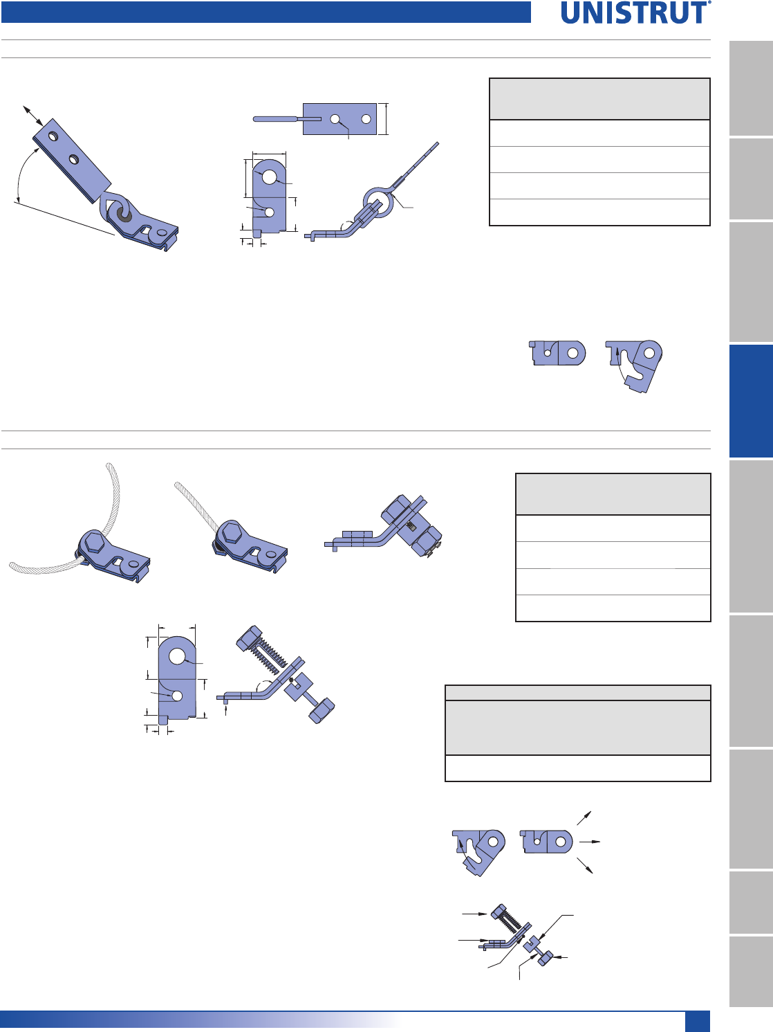
105
15⁄8" Framing System
1 5¼8" ChannelTelestrutNuts & HardwareGeneral FittingsPipe/Conduit SupportsElectrical FittingsConcrete InsertsSolarUnipier®
SPF® 400 SEISMIC PIVOT FITTINGS
Seismic Retrofit Fittings
Engagement Tab
R
2"
(50.8)
2"
(50.8)
3⁄8"
(9.5) 3⁄8"(9.5)
13⁄4"
(44.5)
9⁄16"
(14.3)
Nut
Gripper
3⁄16" Galvanized
Cable
Slotted
Bolt
LOAD
LOAD
LOAD
Slotted
Spacer
Square
Washer
Rotate Around
Rod to Close
Notes:
1. Allowable loads have been determined by the manufacturers
testing, analysis and technical specifications.
2. Galvanized wire rope, 7 x 19 IWSC, RHRL (Prestretched).
3. Torque on nut/spacer: 50 ft-lbs.
4. Safety Factor of 3 for prestreched cable..
Part
Number
Rod
Size
In (mm)
“R” - Hole
Diameter
In (mm)
SPF 400-037
3»87»16
9.5 11.1
SPF 400-050
1»29»16
12.7 14.3
SPF 400-062
5»811»16
15.9 17.5
SPF 400-075
3»413»16
19.1 20.6
Horizontal Design Load
Wire
Rope
Diameter
In (mm)
4-Way Splayed
Single Cable
Transverse
lbs (kN)
Transverse
lbs (kN)
Longitudinal
lbs (kN)
3»16 1050 1116 650
4.8 4.67 4.96 2.89
SPF® 300 SEISMIC PIVOT FITTINGS
Welded Eye
2"
(50.8)
2"
(50.8)
3⁄8"
(9.5) 3⁄8"
(9.5)
9⁄16"
(14.3)
13⁄16"
(20.6)
13⁄4"
(44.5)
13⁄4"
(44.5)
135°
R
30° - 60°
Design
Load
Notes:
1. Design load is limited to slip capacity of a channel nut at hole "R".
2. Allowable loads have been determined by the manufacturers testing, analysis and technical
specifications at 45° from horizontal.
3. For retrofit application, engineer of record must verify.
4. Square washer provided with fitting.
5. When a hanger rod is thru-bolted (in lieu of channel nut installation), higher transverse loads
may be transmitted due to the higher allowed rod shear loads compared to channel nut slip
values. This higher load may be used with verification through engineering calculations.
Part
Number
Rod
Size
In (mm)
“R” - Hole
Diameter
In (mm)
Design
Load
Lbs (KN)
SPF 300-037
3»87»16 1,400
9.5 11.1 6.23
SPF 300-050
1»29»16 2,100
12.7 14.3 9.34
SPF 300-062
5»811»16 2,100
15.9 17.5 9.34
SPF 300-075
3»413»16 2,400
19.1 20.6 10.68
Safety Factor = 3.0
FINISH
Electro-galvanized (EG), conforming to
ASTM B633 Type III SC1.
Rotate Around
Rod to Close
FINISH
Electro-galvanized (EG), conforming to
ASTM B633 Type III SC1.
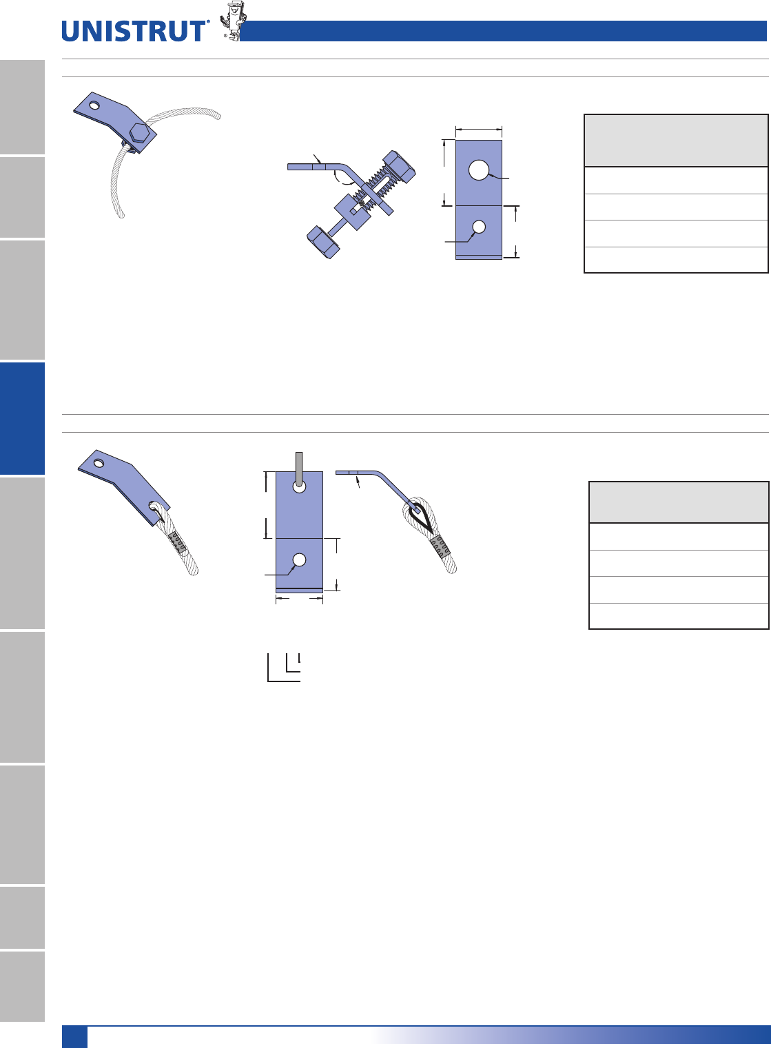
106
15⁄8" Framing System
1 5¼8" ChannelTelestrutNuts & HardwareGeneral FittingsPipe/Conduit SupportsElectrical FittingsConcrete InsertsSolarUnipier®
LS 410 SEISMIC PIVOT FITTINGS
FINISH
Electro-galvanized (EG), conforming to
ASTM B633 Type III SC1.
R
R
135°
2"
(50.8)
9⁄16"
(14.3)
15⁄8"
(41.3)
21⁄2"
(63.5)
Anchor “R” - Hole
Part Size Diameter
Number In (mm) In (mm)
LS 410-037
3»87»16
9.5 11.1
LS 410-050
1»29»16
12.7 14.3
LS 410-062
5»811»16
15.9 17.5
LS 410-075
3»413»16
19.1 20.6
Note:
1. Allowable loads have been determined by the manufacturers testing, analysis and technical specifications.
2. For retrofit application, engineer of record must verify.
3. Torque on nut/spacer: 50 ft-lbs.
4. Square washer provided with fitting.
5. Loads are the same as the SPF 400
LS 500 SEISMIC PIVOT FITTINGS
FINISH
Electro-galvanized (EG), conforming to
ASTM B633 Type III SC1.
Cable Length
096 8' (2.4M)
120 10' (3.0M)
144 12' (3.6M)
180 15' (4.5M)
240 20' (6.1M)
300 25' (7.6M)
360 30' (9.1M)
480 40' (12.2M)
Example
LS500-037-096
Cable Length
Anchor Size
Fitting Number
Cable,
Fixed
R
R
15⁄8"
(41.3)
2"
(50.8)
21⁄2"
(63.5) Part
Number
Anchor
Size
In (mm)
“R” - Hole
Diameter
In (mm)
LS 500-037
3»87»16
9.5 11.1
LS 500-050
1»29»16
12.7 14.3
LS 500-062
5»811»16
15.9 17.5
LS 500-075
3»413»16
19.1 20.6
Note:
1. Allowable loads have been determined by the manufacturers testing, analysis and technical specifications.
2. For retrofit application, engineer of record must verify.
3. Square washer provided with fitting.
4. Loads are the same as the SPF 400
Seismic Retrofit Fittings
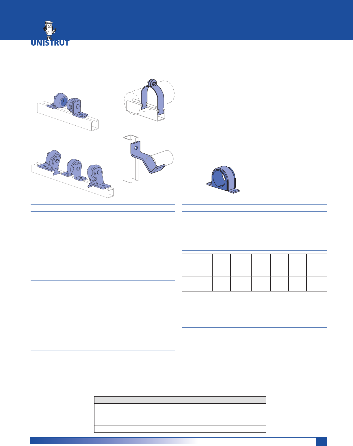
107
MATERIAL
Unistrut pipe clamps, unless noted, are punch-press made
from hot-rolled, pickled and oiled steel plates, strip or coil,
and conform to ASTM specifications A1008, A575, A576,
A635, or A36. The fitting steel also meets the physical
requirements of ASTM A1011 SS GR 33. The pickling of the
steel produces a smooth surface free from scale.
Many items are also available in stainless steel.
Consult factory for ordering information.
FINISHES
Pipe supports are available in:
UÊ iVÌÀ}>Û>âi`Ê®]ÊVvÀ}ÊÌÊ
ASTM B633 Type III SC1
UÊ Ì`««i`Ê}>Û>âi`Ê®]ÊVvÀ}ÊÌÊ
ASTM A123 or A153 (hardware)
UÊ ÀiiÊ*Ü`iÀÊ>ÌÊ,®]ÊVvÀ}ÊÌÊ
commercial standards for Powder Coating, and plain
(PL).
APPLICATION
Unistrut pipe clamps, pipe hangers, brackets and rollers
are designed for the support of electrical and mechanical
services. Supports to meet nearly every requirement can be
attained using Unistrut Metal Framing components.
DIMENSIONS
Imperial dimensions are illustrated in inches. Metric dimen-
sions are shown in parenthesis or as noted. Unless noted,
all metric dimensions are in millimeters and rounded to
one decimal place.
DESIGN BOLT TORQUE
BOLT SIZE 1»4"-20 5»16"-18 3»8"-16 1»2"-13 5»8"-11 3»4"-10
Rec.Torque
Ft/Lbs
1P
6
(8)
11
(15)
19
(26)
50
(68)
100
(136)
125
(170)
Max Torque
Ft/Lbs
1P
7
(9)
15
(20)
25
(34)
70
(95)
125
(170)
135
(183)
Note: When tightening 1⁄4" screws used with a two piece
pipe clamp, a torque of 5 foot pounds (60 inch-pounds)
should be used.
DESIGN LOAD
Design load data, where shown, is based on the ultimate
strength of the connection with a safety factor of 5.0, un-
less otherwise noted.
Pipe Clamps In Special Materials (P1109, P1211, P1425, P2024 Series)
Material Add Suffix to P/N Example
Steel Strap, Everdur Hardware E P1109 E
Copper Coated Steel Strap & Hardware CC P1109 CC
Aluminum. AL P1109 AL
Stainless Steel 304 or 316 SS or ST P1109 SS
PIPE/CONDUIT SUPPORTS
Pipe/Conduit Clamps .....................................................108 - 111
Unicushion® ............................................................................ 112
Pipe & Tubing (Cush-A-Clamp®) Clamps .......................113 - 115
Pipe & Tubing (Cush-A-Grip® & Cush-A-Therm™) Clamps ...... 116
Pipe Hangers ........................................................................... 117
Pipe Rollers .....................................................................117 - 119
Pipe Brackets ........................................................................... 119
Reference Tables ............................................................120 - 126
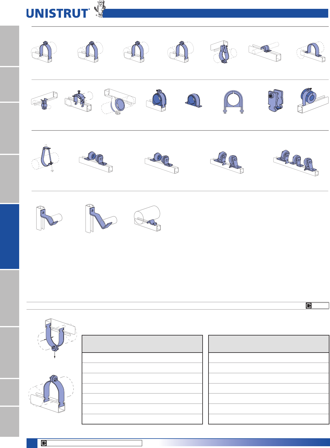
108
15⁄8" Framing System
1 5¼8" ChannelTelestrutNuts & HardwareGeneral FittingsPipe/Conduit SupportsElectrical FittingsConcrete InsertsSolarUnipier®
Slotted hex head screw and nut included with EG or HG Finish.
P1109 THRU P1126 PIPE CLAMPS FOR RIGID STEEL CONDUIT
Part
No.
Conduit
Size
In
O.D.
Size
In (mm)
Thickness
Gauge
(mm)
Wt/100
pcs
Lbs (kg)
Design
Load
Lbs (kN)
P1109 3»80.675 16 10 400
17.1 1.5 4.5 1.78
P1111 1»20.840 16 11 400
21.3 1.5 5.0 1.78
P1112 3»41.050 14 15 600
26.7 1.9 6.8 2.67
P1113 11.315 14 17 600
33.4 1.9 7.7 2.67
P1114 11»41.660 14 19 600
42.2 1.9 8.6 2.67
P1115 11»21.900 12 29 800
48.3 2.7 13.2 3.56
P1117 22.375 12 34 800
60.3 2.7 15.4 3.56
Pipe & Conduit Pictorial Index
P1109 - Pg 108 P1211 - Pg 109 P1425 - Pg 109 P2024 - Pg 110 P1563 - Pg 109 P2008 - Pg 109 P2558 - Pg 110
J1205 - Pg 117 P2474 - Pg 117 P2474-1 - Pg 118 P2475 - Pg 118 P2476 - Pg 119
P2481 - Pg 119
Pipe & Conduit Clamps
Pipe Rollers
Pipe Brackets
P2482 - Pg 119 P2243 - Pg 119
P3409 - Pg 111 MU025 - Pg 111 P2600 - Pg 112 004T008 - Pg 113 004M007 - Pg 114 UB1⁄2PA - Pg 115 CG-10 - Pg 116 PUX3834 - Pg 116
1 1⁄4"
(31.8)
Design Load
Part
No.
Conduit
Size
In
O.D.
Size
In (mm)
Thickness
Gauge
(mm)
Wt/100
pcs
Lbs (kg)
Design
Load
Lbs (kN)
P1118 21»22.875 12 40 800
73.0 2.7 18.1 3.56
P1119 33.500 12 47 800
88.9 2.7 21.3 3.56
P1120 31»24.000 11 62 1,000
101.6 3.0 28.1 4.45
P1121 44.500 11 67 1,000
114.3 3.0 30.4 4.45
P1123 55.563 11 80 1,000
141.3 3.0 36.3 4.45
P1124 66.625 10 102 1,000
168.3 3.4 46.3 4.45
P1126 88.625 10 130 1,000
219.1 3.4 59.0 4.45
CORE PRODUCTS - TYPICALLY AVAILABLE FROM STOCK
EG HG
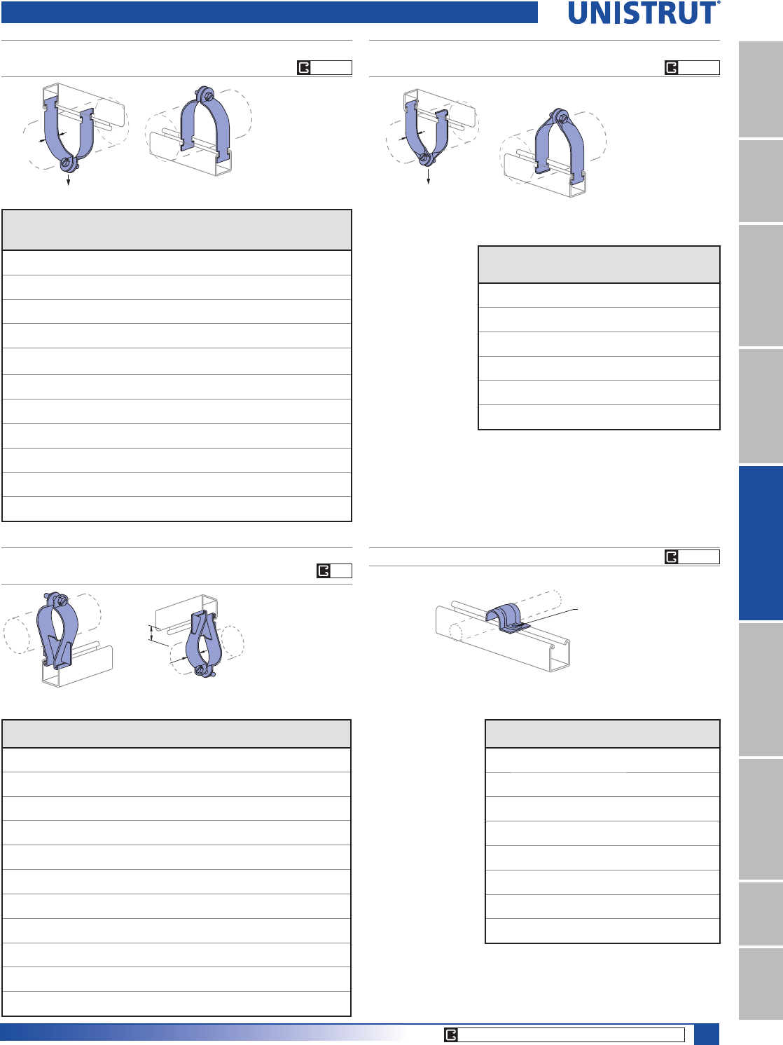
109
15⁄8" Framing System
1 5¼8" ChannelTelestrutNuts & HardwareGeneral FittingsPipe/Conduit SupportsElectrical FittingsConcrete InsertsSolarUnipier®
Pipe & Conduit Clamps
P1425 THRU P1431
PIPE CLAMPS FOR THIN WALL CONDUIT (E.M.T.)
Part
No.
Conduit
Size
In (mm)
O.D.
Size
In (mm)
Thickness
Gauge (mm)
Wt/100
pcs
Lbs (kg)
Design
Load
Lbs (kN)
P1425 3»80.577 16 9 400
9.5 14.7 1.5 4.1 1.78
P1426 1»20.706 16 11 400
12.7 17.9 1.5 5.0 1.78
P1427 3»40.922 16 12 400
19.1 23.4 1.5 5.4 1.78
P1428 1 1.163 14 15 600
25.4 29.5 1.9 6.8 2.67
P1429 11»41.510 14 18 600
31.8 38.4 1.9 8.2 2.67
P1430 11»21.740 12 29 800
38.1 44.2 2.7 13.2 3.56
P1431 2 2.197 12 33 800
50.8 55.8 2.7 15.0 3.56
P1118 21»22.875 12 40 800
63.5 73.0 2.7 18.1 3.56
P1119 3 3.500 12 47 800
76.2 88.9 2.7 21.3 3.56
P1120 31»24.000 11 62 1,000
88.9 101.6 3.0 28.1 4.45
P1121 4 4.500 11 67 1,000
101.6 114.3 3.0 30.4 4.45
1 1⁄4"
(31.8)
Design Load
Slotted hex head screw
and nut included with EG
or HG Finish.
P1211 THRU P1217
UNIVERSAL CLAMPS FOR RIGID OR THINWALL CONDUIT
Part
No.
Conduit
Size
In (mm)
Thickness
Gauge
(mm)
Wt/100
pcs
Lbs (kg)
Design
Load
Lbs (kN)
P1211 1»216 10 400
12.7 1.5 4.5 1.78
P1212 3»416 11 400
19.1 1.5 5.0 1.78
P1213 1 16 12 400
25.4 1.5 5.4 1.78
P1214 11»414 18 600
31.8 1.9 8.2 2.67
P1215 11»214 20 600
38.1 1.9 9.1 2.67
P1217 2 14 22 600
50.8 1.9 10.0 2.67
Design Load
1 1⁄4"
(31.8)
Slotted hex head
screw and nut
included with EG
or HG Finish.
P1563 THRU P1573
PARALLEL CLAMPS FOR RIGID CONDUIT AND PIPE
Slotted hex head
screw and nut
included.
Part
No.
Pipe Size
In (mm)
O.D. Size
In (mm)
Thickness
Gauge (mm)
Wt/100 pcs
Lbs (kg)
P1563 3»80.675 14 27
9.5 17.1 1.9 12.2
P1564 1»20.840 14 29
12.7 21.3 1.9 13.2
P1565 3»41.050 14 30
19.1 26.7 1.9 13.6
P1566 1 1.315 14 31
25.4 33.4 1.9 14.1
P1567 11»41.660 14 38
31.8 42.2 1.9 17.2
P1568 11»21.900 12 40
38.1 48.3 2.7 18.1
P1569 2 2.375 12 47
50.8 60.3 2.7 21.3
P1570 21»22.875 12 66
63.5 73.0 2.7 29.9
P1571 3 3.500 12 78
76.2 88.9 2.7 35.4
P1572 31»24.000 12 87
88.9 101.6 2.7 39.5
P1573 4 4.500 12 90
101.6 114.3 2.7 40.8
P2008 THRU P2020
ONE HOLE CLAMP FOR O.D. TUBING
1⁄4" X 3⁄4" Round Head
Machine Screw
and Channel Nut
Not Included
Finish: Electro-galvanized and Aluminum
Part
No.
O.D. Tube
Size In (mm)
Thickness
Gauge (mm)
Wt/100 pcs
Lbs (kg)
P2008 1»416 4
6.4 1.5 1.8
P2009 5»16 16 5
7.9 1.5 2.3
P2010 3»816 5
9.5 1.5 2.3
P2012 1»216 6
12.7 1.5 2.7
P2014 5»814 8
15.9 1.9 3.6
P2016 3»414 9
19.1 1.9 4.1
P2018 7»814 10
22.2 1.9 4.5
P2020 11411
25.4 1.9 5.0
1 3⁄8"
(34.9)
1 1⁄4"
(31.8)
Finish: Electro-galvanized.
CORE PRODUCTS - TYPICALLY AVAILABLE FROM STOCK
EG
EG HG EG HG
EG HG
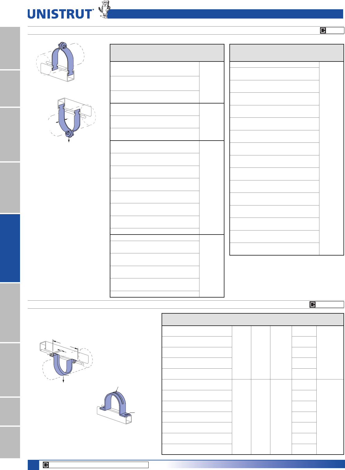
110
15⁄8" Framing System
1 5¼8" ChannelTelestrutNuts & HardwareGeneral FittingsPipe/Conduit SupportsElectrical FittingsConcrete InsertsSolarUnipier®
Supporting
Rib on
P2558-60
Hole
Size B
P2024 THRU P2070-84 PIPE CLAMPS FOR O.D. TUBING
P2024 - P2029 16 ga.
P2030 - P2035 14 ga.
P2037 - P2052 12 ga.
P2053 - P2066 11 ga.
P2067 - P2070-84 10 ga.
Slotted hex head screw and nut
included with EG or HG Finish.
Pipe & Conduit Clamps
1 1⁄4"
(31.8)
Design Load
Part
Number
O.D.
Size
In (mm)
Wt/100
pcs
Lbs (kg)
Design
Load
Lbs (kN)
P2024 1»4 (6.4) 8 (3.6)
400
(1.78)
P2025 3»8 (9.5) 8 (3.6)
P2026 1»2 (12.7) 9 (4.1)
P2027 5»8 (15.9) 10 (4.5)
P2028 3»4 (19.1) 11 (5.0)
P2029 7»8 (22.2) 12 (5.4)
P2030 1 (25.4) 14 (6.4)
600
(2.67)
P2031 11»8 (28.6) 15 (6.8)
P2032 11»4 (31.8) 16 (7.3)
P2033 13»8 (34.9) 17 (7.7)
P2034 11»2 (38.1) 18 (8.2)
P2035 15»8 (41.3) 19 (8.6)
P1430 13»4 (44.5) 29 (13.2)
800
(3.56)
P2037 17»8 (47.6) 28 (12.7)
P2038 2 (50.8) 31 (14.1)
P2039 21»8 (54.0) 32 (14.5)
P2040 21»4 (57.2) 33 (15)
P1117 23»8 (60.3) 34 (15.4)
P2042 21»2 (63.5) 35 (15.9)
P2043 25»8 (66.7) 37 (16.8)
P2044 23»4 (69.9) 38 (17.2)
P1118 27»8 (73.0) 40 (18.1)
P2046 3 (76.2) 41 (18.6)
P2047 31»8 (79.4) 43 (19.5)
P2048 31»4 (82.6) 45 (20.4)
P2049 33»8 (85.7) 46 (20.9)
P1119 31»2 (88.9) 47 (21.3)
P2051 35»8 (92.1) 56 (25.4)
1000
(4.45)
P2052 33»4 (95.3) 58 (26.3)
P2053 37»8 (98.4) 60 (27.2)
P1120 4 (101.6) 62 (28.1)
P2055 41»8 (104.8) 62 (28.1)
P2056 41»4 (108.0) 64 (29.0)
P2057 43»8 (111.1) 66 (29.9)
P1121 41»2 (114.3) 67 (30.4)
P2059 45»8 (117.5) 70 (31.8)
P2060 43»4 (120.7) 72 (32.7)
Part
Number
O.D.
Size
In (mm)
Wt/100
pcs
Lbs (kg)
Design
Load
Lbs (kN)
P2061 47»8 (123.8) 73 (33.1)
1000
(4.45)
P2062 5 (127.0) 74 (33.6)
P2063 51»8 (130.2) 76 (34.5)
P2064 51»4 (133.4) 77 (34.9)
P2065 53»8 (136.5) 78 (35.4)
P2066 51»2 (140.0) 79 (35.8)
P2067 55»8 (142.9) 88 (39.9)
P2068 53»4 (146.1) 90 (40.8)
P2069 57»8 (149.2) 92 (41.7)
P2070 6 (152.4) 94 (42.6)
P2070-61 61»8 (155.6) 96 (43.5)
P2070-62 61»4 (158.8) 98 (44.5)
P2070-63 63»8 (161.9) 99 (44.9)
P2070-64 61»2 (165.1) 100 (45.4)
P1124 65»8 (168.3) 102 (46.3)
P2070-66 63»4 (171.5) 104 (47.2)
P2070-67 67»8 (174.6) 106 (48.1)
P2070-70 7 (177.8) 108 (49.0)
P2070-71 71»8 (181.0) 110 (49.9)
P2070-72 71»4 (184.2) 112 (50.8)
P2070-73 73»8 (187.3) 114 (51.7)
P2070-74 71»2 (190.5) 116 (52.6)
P2070-75 75»8 (193.7) 117 (53.1)
P2070-76 73»4 (196.9) 119 (54.0)
P2070-77 77»8 (200.0) 121 (54.9)
P2070-80 8 (203.2) 123 (55.8)
P2070-81 81»8 (206.4) 125 (56.7)
P2070-82 81»4 (209.6) 126 (57.2)
P2070-83 83»8 (212.7) 128 (58.1)
P2070-84 81»2 (215.9) 129 (58.5)
P1126 85»8 (219.1) 130 (59.0)
P2558-5 THRU P2558-60 SINGLE PIECE PIPE STRAP
Hardware sold separately.
Part No.
Nom. Pipe
Size In
A
,QPP
“B”
,QPP
C
,QPP
Thickness
,QPP
Wt/100 pcs
/EVNJ
Design Load
/EVN1
P2558-05 1»227»8
9»32
7.1
7»16
11.1
1»8
3.2
23
500
2.22
73.0 10.4
P2558-07 3»431»826
79.4 11.8
P2558-10 13
3»831
85.7 14.1
P2558-12 11»433»435
95.3 15.9
P2558-15 11»237»839
98.4 17.7
P2558-20 25
3»4
7»16
11.1
11»16
17.5
1»4
6.4
94
1,000
4.45
146.1 42.6
P2558-25 21»261»4114
158.8 51.7
P2558-30 36
7»8133
174.6 60.3
P2558-35 31»273»8152
187.3 68.9
P2558-40 47
7»8176
200.0 79.8
P2558-50 5 9 198
228.6 89.8
P2558-60 6 10 225
254.0 102.1
A ± 1⁄8"
C
Design Load
CORE PRODUCTS - TYPICALLY AVAILABLE FROM STOCK
EG GR HG
EG HG
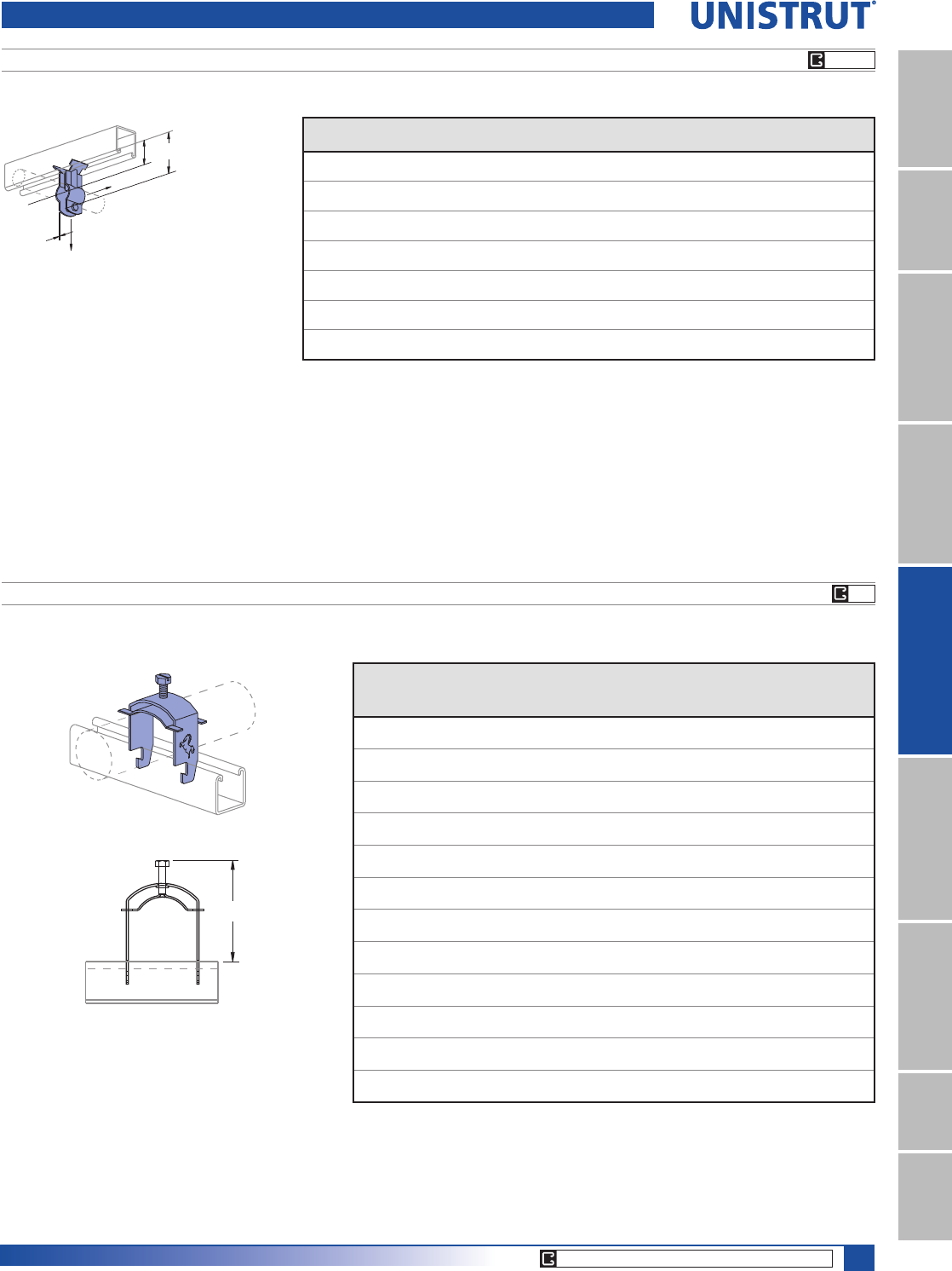
111
15⁄8" Framing System
1 5¼8" ChannelTelestrutNuts & HardwareGeneral FittingsPipe/Conduit SupportsElectrical FittingsConcrete InsertsSolarUnipier®
Hardware included.
Finish: Electro-galvanized.
Pipe Clamp 11»4" Wide
B
C
D
E
A
P3409 THRU P3417 STAND-OFF PIPE CLAMPS
MU025 THRU MU400 MUSTANG UNIVERSAL ONE-PIECE PIPE, CONDUIT (GRC, EMT & IMC) AND TUBING CLAMPS
Part
No.
Pipe Size
In (mm)
O.D. Size
In (mm)
Load “D”
Lbs (kN)
Load “E”
Lbs (kN)
A
In (mm)
B
In (mm)
C Gauge
(mm)
Wt/100 pcs
Lbs (kg)
P3409 3»80.675 100 25 11»821»814 14
9.5 17.1 0.44 0.11 28.6 54.0 1.9 6.4
P3411 1»20.840 150 35 11»425»16 14 15
12.7 21.3 0.67 0.16 31.8 58.7 1.9 6.8
P3412 3»41.050 175 40 15»16 21»214 19
19.1 26.7 0.78 0.18 33.3 63.5 1.9 8.6
P3413 1 1.315 200 50 11»223»414 22
25.4 33.4 0.89 0.22 38.1 69.9 1.9 10.0
P3414 11»41.660 300 70 111»16 31»412 34
31.8 42.2 1.33 0.31 42.9 82.6 2.7 15.4
P3415 11»21.900 400 80 13»431»211 49
38.1 48.3 1.78 0.36 44.5 88.9 3.0 22.2
P3417 2 2.375 500 120 2 4 10 55
50.8 60.3 2.22 0.53 50.8 101.6 3.4 24.9
Pipe & Conduit Clamps
Finish: Electro-galvanized.
Clamps are 14 ga.
Part No.
Nominal Trade
Size
In (mm)
Trade Size O.D. Height Above Channel "H"
Min
In (mm)
Max
In (mm)
Min
In (mm)
Max.
In (mm)
MU025
1»40.375 0.5 13»42
6.4 9.5 13.7 44.5 50.8
MU037
3»80.5 0.7 17»821»8
9.5 12.7 17.1 47.6 54.0
MU050
1»20.63 0.84 2 21»4
12.7 15.9 21.3 50.8 57.2
MU075
3»40.88 1.05 21»421»2
19.1 22.2 26.7 57.2 63.5
MU100 1 1.13 1.32 23»823»4
25.4 28.6 33.4 60.3 69.9
MU125 11»41.38 1.66 23»431»8
31.8 34.9 42.2 69.9 79.4
MU150 11»21.63 1.90 3 33»8
38.1 41.3 48.3 76.2 85.7
MU200 2 2.13 2.38 33»837»8
50.8 54.0 60.3 85.7 98.4
MU250 21»22.63 2.88 41»445»8
63.5 66.7 73.0 108.0 117.5
MU300 3 3.13 3.50 47»853»8
76.2 79.4 88.9 123.8 136.5
MU350 31»23.63 4.00 51»457»8
88.9 92.1 101.6 133.4 149.2
MU400 4 4.13 4.50 53»463»8
101.6 104.8 114.3 146.1 161.9
Safety factor of 5
H
CORE PRODUCTS - TYPICALLY AVAILABLE FROM STOCK
EG
EG HG
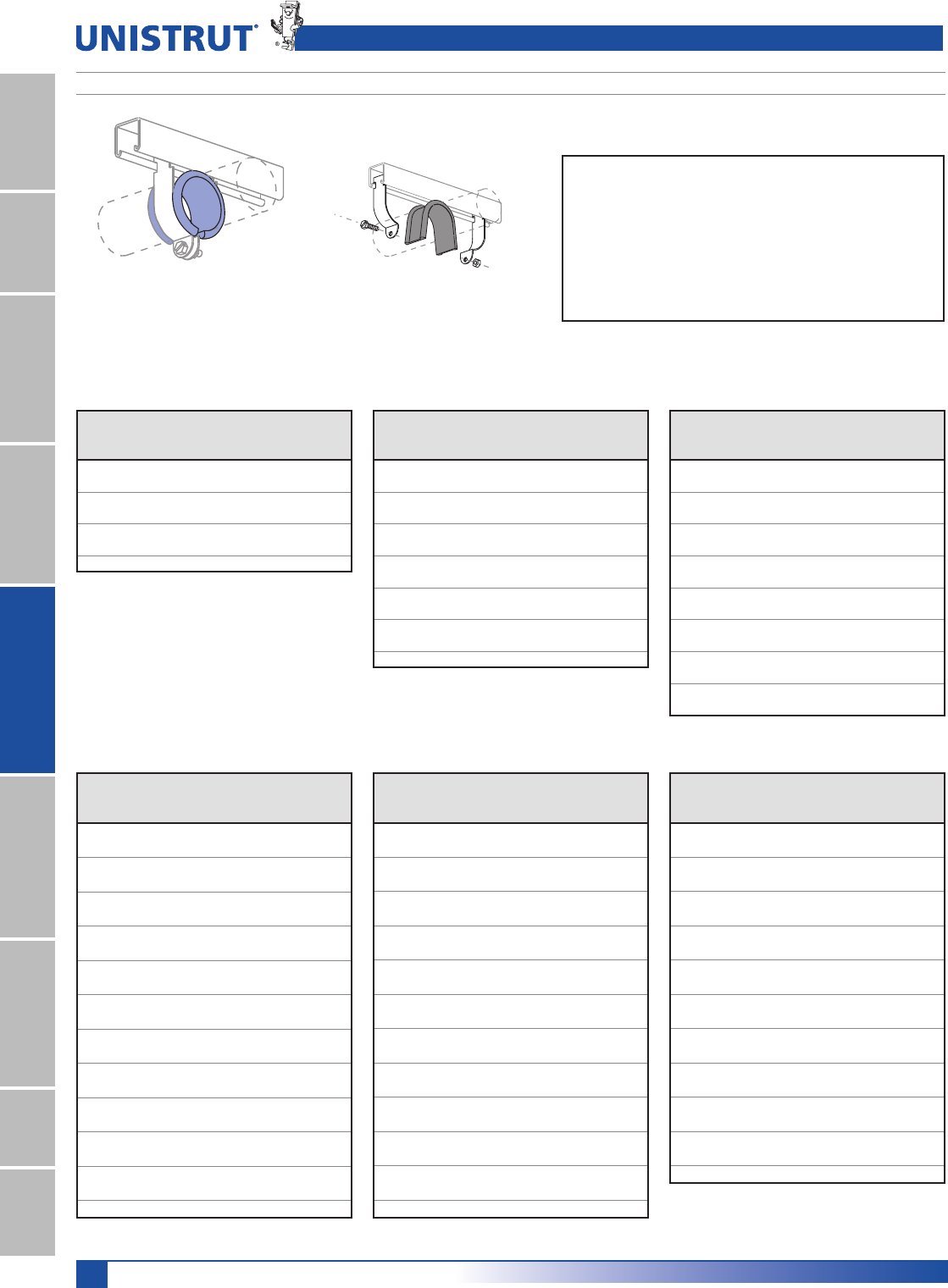
112
15⁄8" Framing System
1 5¼8" ChannelTelestrutNuts & HardwareGeneral FittingsPipe/Conduit SupportsElectrical FittingsConcrete InsertsSolarUnipier®
P2600 UNICUSHION®: ISOLATION MATERIAL
COPPER TUBING TYPE K OR L
STANDARD PIPE OR
RIGID CONDUIT
EMT CONDUIT
UNICUSHION® CLAMP SELECTION GUIDE
IHHWSHUFDUWRQ
&XWWROHQJWKDVVKRZQLQFKDUWEHORZ
Wt/Carton: 2.5 Lbs (1.1 kg)
UNICUSHION FEATURES
s3HOCKABSORPTION
s0ROTECTIONFROMCORROSIONANDABRASION
s!LLOWANCEFOREXPANSIONANDCONTRACTIONINPIPEDIAMETER
s3OUNDANDVIBRATIONISOLATION
s3TABILITYINUSEFROM&#TO&#
s&LEXIBLEELASTOMERMATERIAL
s7ILLNOTSUPPORTCOMBUSTION
Nominal
Size
Use
with
Clamp
UNICUSHION
Length
In (mm)
3»8" P1426 13»4 (44.5)
1»2" P1111 21»8 (54.0)
3»4" P1112 23»4 (69.9)
1" P2032 35»8 (92.1)
11»4" P2035 43»4 (120.7)
11»2" P2037 51»2 (139.7)
2" P1117 63»4 (171.5)
Nominal
Size
Use
with
Clamp
UNICUSHION
Length
In (mm)
3»8" P1111 21»8 (54.0)
1»2" P2030 3 (76.2)
3»4" P2031 31»4 (82.6)
1" P2034 41»4 (108.0)
11»4" P2037 51»4 (133.4)
11»2" P2038 6 (152.4)
2" P2042 71»2 (190.5)
21»2" P2046 9 (228.6)
3" P2051 11 (279.4)
31»2" P2055 121»4 (311.2)
4" P2059 14 (355.6)
5" P2067 171»2 (444.5)
6" P2070-66 203»4 (527.1)
Nominal
Size
Use
with
Clamp
UNICUSHION
Length
In (mm)
1»4" P2026 11»16 (27.0)
3»8" P2027 11»2 (38.1)
1»2" P2028 21»8 (54.0)
5»8" P2029 21»4 (57.2)
3»4" P2030 3 (76.2)
1" P2032 35»8 (92.1)
11»4" P2034 41»2 (114.3)
11»2" P1430 51»4 (133.4)
2" P2040 63»4 (171.5)
21»2" P2044 81»4 (209.6)
3" P2048 10 (254.0)
31»2" P2052 111»4 (285.8)
4" P2056 121»2 (317.5)
5" P2064 16 (406.4)
6" P2070-62 19 (482.6)
8" P2070-82 25 (635.0)
UNICUSHION®
O. D.
Size
In (mm)
Use
With
Clamp
UNICUSHION
Length
In (mm)
1»4 (6.4) P2025 7»8 (22.2)
3»8 (9.5) P2026 11»16 (27.0)
1»2 (12.7) P2027 11»2 (38.1)
5»8 (15.9) P2028 21»8 (54.0)
3»4 (19.1) P2029 21»4 (57.2)
7»8 (22.2) P2030 3 (76.2)
1 (25.4) P2031 31»4 (82.6)
11»8 (28.6) P2032 35»8 (92.1)
11»4 (31.8) P2033 4 (101.6)
13»8 (34.9) P2034 41»2 (114.3)
11»2 (38.1)) P2035 47»8 (123.8)
15»8 (41.3) P1430 51»4 (133.4)
13»4 (44.5) P2037 51»2 (139.7)
17»8 (47.6) P2038 6 (152.4)
2 (50.8) P2039 61»2 (165.1)
21»8 (54.0) P2040 63»4 (171.5)
21»4 (57.2) P1117 71»4 (184.2)
23»8 (60.3) P2042 71»2 (190.5)
21»2 (63.5) P2043 8 (203.2)
25»8 (66.7) P2044 81»4 (209.6)
23»4 (69.9) P1118 83»4 (222.3)
27»8 (73.0) P2046 91»4 (235.0)
3 (76.2) P2047 91»2 .3(241.3)
O. D.
Size
In (mm)
Use
With
Clamp
UNICUSHION
Length
In (mm)
31»8 (79.4) P2048 10 (254.0)
31»4 (82.6) P2049 101»2 (266.7)
33»8 (85.7) P1119 103»4 (273.1)
31»2 (88.9) P2051 11 (279.4)
35»8 (92.1) P2052 111»4 (285.8)
33»4 (95.3) P2053 111»2 (292.1)
37»8 (98.4) P1120 113»4 (298.5)
4 (101.6) P2055 12 (304.8)
41»8 (104.8) P2056 121»2 (317.5)
41»4 (108.0) P2057 13 (330.2)
43»8 (111.1) P1121 131»2 (342.9)
41»2 (114.3) P2059 14 (355.6)
45»8 (117.5) P2060 141»4 (362.0)
43»4 (120.7) P2061 143»4 (374.7)
47»8 (123.8) P2062 15 (381.0)
5 (127.0) P2063 151»2 (393.7)
51»8 (130.2) P2064 16 (406.4)
51»4 (133.4) P2065 161»4 (412.8)
53»8 (136.5) P2066 161»2 (419.1)
51»2 (139.7) P2067 17 (431.8)
55»8 (142.9) P2068 171»2 (444.5)
53»4 (146.1) P2069 173»4 (450.9)
57»8 (149.2) P2070 181»4 (463.6)
O. D.
Size
In (mm)
Use
With
Clamp
UNICUSHION
Length
In (mm)
6 (152.4) P2070-61 181»2 (469.9)
61»8 (155.6) P2070-62 19 (482.6)
61»4 (158.8) P2070-63 191»4 (489.0)
63»8 (161.9) P2070-64 193»4 (501.7)
61»2 (165.1) P1124 20 (508.0)
65»8 (168.3) P2070-66 201»2 (520.7)
63»4 (171.5) P2070-67 21 (533.4)
67»8 (174.6) P2070-70 211»4 (539.8)
7 (177.8) P2070-71 213»4 (552.5)
71»8 (181.0) P2070-72 22 (558.8)
71»4 (184.2) P2070-73 221»2 (571.5)
73»8 (187.3) P2070-74 223»4 (577.9)
71»2 (190.5) P2070-75 231»4 (590.6)
75»8 (193.7) P2070-76 231»2 (596.9)
73»4 (196.9) P2070-77 24 (609.6)
77»8 (200.0) P2070-80 241»2 (622.3)
8 (203.2) P2070-81 243»4 (628.7)
81»8 (206.4) P2070-82 25 (635.0)
81»4 (209.6) P2070-83 251»2 (647.7)
83»8 (212.7) P2070-84 26 (660.4)
81»2 (215.9) P1126 261»4 (666.8)
UNICUSHION® CLAMP CUTTING GUIDE
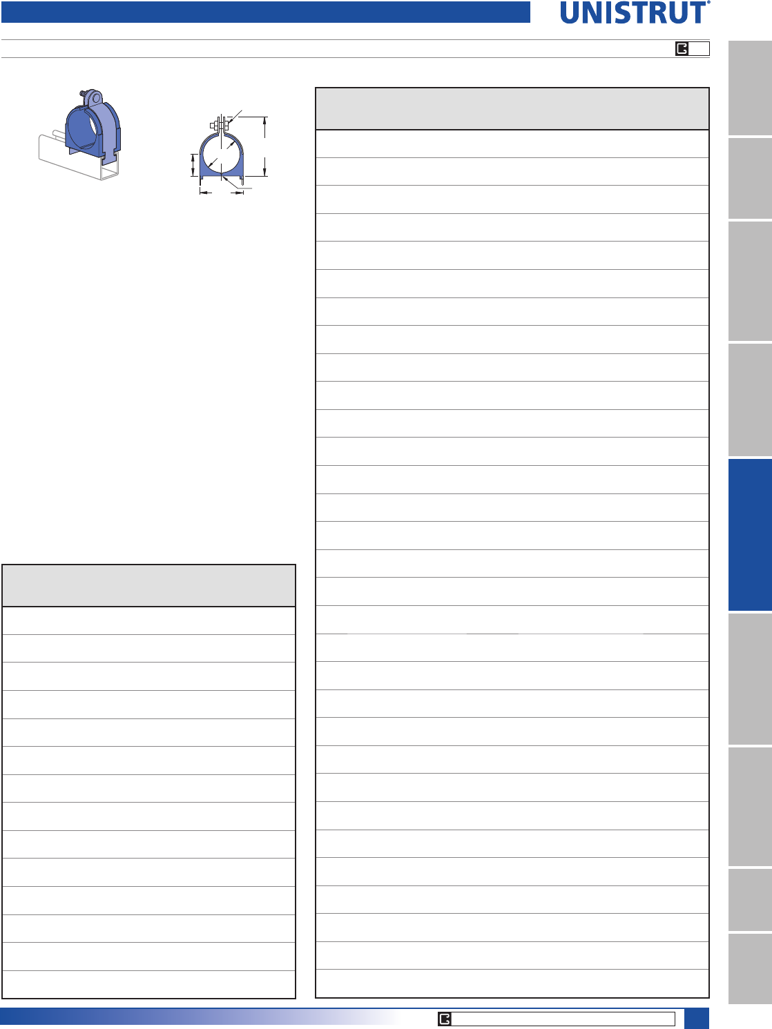
113
15⁄8" Framing System
1 5¼8" ChannelTelestrutNuts & HardwareGeneral FittingsPipe/Conduit SupportsElectrical FittingsConcrete InsertsSolarUnipier®
004T008 THRU 098N106, 009N012 THRU 106N114 CUSH-A-CLAMP® ASSEMBLY
Tube Series Assembly
C
B
D
Controlled Squeeze
Shoulder Bolt
on sizes up to 13⁄8" OD
“Living
Hinge”
A
Materials:
Clamp: Electro-galvanized or stainless steel.
Cushion: Thermoplastic elastomer. (UV Resistant)
Includes cushion, clamp and hardware.
Temperature Rating:
&TO&#TO#
Insert Width: 1.56" (39.6)
Part Numbers are "coded" to designate cushion size and
clamp size. Examples:
004T008 004 - Cushion Size 4⁄16" (6.4)
T - With Controlled Squeeze Shoulder Bolt
Available on sizes up to 1 3⁄8"
008 - Clamp Size 8⁄16" (12.7)
009N012 009 - Cushion Size 9⁄16" (14.3)
N - With Standard Bolt
012 - Clamp Size 12⁄16" (19.1)
Pipe Series Assembly
Part No.
Nominal
Pipe
Size
Dimensions Wt/100
pcs
Lbs(kg)
“A”
In(mm)
“B”
In(mm)
“C”
In(mm)
“D”
In(mm)
009N012 1»40.54 0.98 1.34 0.43 13
13.7 24.9 34.0 10.9 5.9
011N014 3»80.67 1.13 1.54 0.49 14
17.0 28.7 39.1 12.4 6.4
014N018 1»20.84 1.29 1.82 0.58 15
21.3 32.8 46.2 14.7 6.8
017N022 3»41.05 1.5 1.95 0.7 17
26.7 38.1 49.5 17.8 7.7
021N026 11.31 1.76 2.34 0.81 19
33.3 44.7 59.4 20.6 8.6
027N032 11»41.66 2.17 2.73 0.99 35
42.2 55.1 69.3 25.1 15.9
030N034* 11»21.9 2.35 2.86 1.09 39
48.3 59.7 72.6 27.7 17.7
038N044 22.37 2.82 3.67 1.41 49
60.2 71.6 93.2 35.8 22.2
046N052 21»22.87 3.32 4.17 1.66 57
72.9 84.3 105.9 42.2 25.9
056N062 33.5 3.95 4.79 1.97 55
88.9 100.3 121.7 50.0 24.9
064N072 31»24 4.45 5.42 2.28 88
101.6 113.0 137.7 57.9 39.9
072N080 44.5 4.95 5.92 2.53 110
114.3 125.7 150.4 64.3 49.9
089N096 55.56 6.01 6.92 3.06 130
141.2 152.7 175.8 77.7 59.0
106N114 66.62 7.07 8.23 3.59 140
168.1 179.6 209.0 91.2 63.5
Part
Number
Copper &
Steel Tube
O. D. Size
Copper
Water Pipe
1RPLQDO
Dimensions Wt/100
pcs
Lbs(kg)
“A”
In(mm)
“B”
In(mm)
“C”
In(mm)
“D”
In(mm)
004T008 1»40.25 0.62 0.98 0.27 10
6.4 15.7 24.9 6.9 4.5
006T010 3»81»40.37 0.82 1.13 0.33 11
9.4 20.8 28.7 8.4 5.0
008T012 1»23»80.5 0.94 1.34 0.4 13
12.7 23.9 34.0 10.2 5.9
010T014 5»81»20.62 1.06 1.54 0.46 14
15.7 26.9 39.1 11.7 6.4
012T016 3»45»80.75 1.2 1.68 0.52 14
19.1 30.5 42.7 13.2 6.4
014T018 7»83»40.87 1.31 1.82 0.58 15
22.1 33.3 46.2 14.7 6.8
016T020 11 1.44 1.95 0.65 17
25.4 36.6 49.5 16.5 7.7
018T022 11»811.12 1.57 2.08 0.7 18
28.4 39.9 52.8 17.8 8.2
020T024 11»41.25 1.7 2.21 0.77 18
31.8 43.2 56.1 19.6 8.2
022T026 13»811»41.37 1.82 2.34 0.83 20
34.8 46.2 59.4 21.1 9.1
024N028 11»21.5 1.95 2.47 0.9 33
38.1 49.5 62.7 22.9 15.0
026N030 15»811»21.62 2.07 2.6 0.96 35
41.1 52.6 66.0 24.4 15.9
028N032 13»41.75 2.2 2.73 1.02 37
44.5 55.9 69.3 25.9 16.8
030N034 17»81.9 2.35 2.86 1.09 39
48.3 59.7 72.6 27.7 17.7
032N036 222.45 3.04 1.15 46
50.8 62.2 77.2 29.2 20.9
034N040 21»822.12 2.57 3.23 1.27 47
53.8 65.3 82.0 32.3 21.3
038N044 23»82.37 2.82 3.67 1.41 49
60.2 71.6 93.2 35.8 22.2
040N046 21»22.5 2.94 3.79 1.46 51
63.5 74.7 96.3 37.1 23.1
042N048 25»82.62 3.1 3.92 1.53 55
66.5 78.0 99.6 38.9 24.9
046N052 27»82.87 3.3 4.17 1.66 57
72.9 84.3 105.9 42.2 25.9
050N054 333.6 4.42 1.78 60
76.2 90.7 112.3 45.2 27.2
050N056 31»83.12 3.6 4.42 1.78 60
79.2 90.7 112.3 45.2 27.2
053N060 35»16 3.31 4.0 4.75 1.9 62
84.1 100.6 120.7 48.3 28.1
056N062 31»23.5 4.0 4.79 1.97 55
88.9 100.3 121.7 50.0 24.9
058N064 35»83.62 4.2 4.99 2.03 70
91.9 106.7 126.7 51.6 31.8
064N072 44 4.5 5.42 2.28 88
101.6 113.0 137.7 57.9 39.9
066N074 41»84.12 4.6 5.54 2.34 94
104.6 116.1 140.7 59.4 42.6
069N076 45»16 4.34 5.0 5.84 2.4 100
110.2 126.0 148.3 61.0 45.4
072N080 41»24.5 5.0 5.92 2.53 110
114.3 125.7 150.4 64.3 49.9
082N090 51»85.12 5.6 6.54 2.84 125
130.0 141.5 166.1 72.1 56.7
098N106 61»86.12 6.6 7.54 3.34 130
155.4 166.9 191.5 84.8 59.0
Pipe & Tubing Clamps
EG
CORE PRODUCTS - TYPICALLY AVAILABLE FROM STOCK
114
15⁄8" Framing System
1 5¼8" ChannelTelestrutNuts & HardwareGeneral FittingsPipe/Conduit SupportsElectrical FittingsConcrete InsertsSolarUnipier®
004M007 THRU 034M040 CUSH–A–CLAMP® ASSEMBLY OMEGA SERIES™
Note: Not to be used with Unistrut Channel.
Can be mounted to any flat surface.
A
B
F
G
DC
EHE
J
Includes clamp and cushion.
Materials: Clamp: ZD or stainless steel.
Cushion: Thermoplastic elastomer.
Part
Number
Copper
& Steel
Tubing
O. D.
In
Copper
Water
Pipe
1RPLQDO
In
Pipe
Size
1RPLQDO
In
Dimensions
Wt/100 pcs
Lbs (kg)
“A”
In (mm)
“B”
In (mm)
“C”
In (mm)
“D”
In (mm)
“E”
In (mm)
“F”
In (mm)
“G”
In (mm)
“H”
In (mm)
“J”
In (mm)
004M007 1»4
0.25 1.8 0.06 0.6 0 0.53 0.48 0.62 0.78 3.4
6.4 46.0 1.5 15.2 5.1 13.5 12.2 15.7 19.8 1.5
006M008 3»81»4
0.37 1.9 0.06 0.65 0 0.62 0.62 0.62 0.81 4.0
9.4 48.3 1.5 16.5 5.1 15.7 15.7 15.7 20.6 1.8
008M011 1»23»81»4
0.5 2.2 0.06 0.8 0 0.82 0.75 0.75 0.98 5.5
12.7 55.9 1.5 20.3 6.6 20.8 19.1 19.1 24.9 2.5
010M013 5»81»23»8
0.62 2.3 0.06 0.86 0 0.94 0.87 0.75 0.98 6.0
15.7 58.9 1.5 21.8 6.6 23.9 22.1 19.1 24.9 2.7
012M015 3»45»8
0.75 2.4 0.06 0.9 0 1.03 1.01 0.75 0.98 6.5
19.1 61.2 1.5 22.9 6.6 26.2 25.7 19.1 24.9 2.9
014M017 7»83»41»2
0.87 2.6 0.06 0.98 0 1.18 1.03 0.75 0.98 7.1
22.1 65.0 1.5 24.9 6.6 30.0 26.2 19.1 24.9 3.2
016M019 11 2.7 0.06 1.04 0 1.31 1.25 0.75 0.98 7.8
25.4 68.1 1.5 26.4 6.6 33.3 31.8 19.1 24.9 3.5
018M020 3»4
1.05 2.7 0.06 1.04 0 1.31 1.25 0.75 0.98 8.1
26.7 68.1 1.5 26.4 6.6 33.3 31.8 19.1 24.9 3.7
018M021 11»811.12 2.8 0.06 1.11 0 1.44 1.33 0.75 0.98 8.4
28.4 71.6 1.5 28.2 6.6 36.6 33.8 19.1 24.9 3.8
020M024 11»4
1.25 3.0 0.08 1.2 0 1.65 1.47 1.25 1.56 17
31.8 76.2 2.0 30.5 6.6 41.9 37.3 31.8 39.6 7.7
021M026 11.31 3.1 0.08 1.26 0 1.76 1.71 1.25 1.56 20
33.3 79.2 2.0 32.0 6.6 44.7 43.4 31.8 39.6 9.1
022M026 13»811»4
1.37 3.1 0.08 1.26 0 1.76 1.71 1.25 1.56 19
34.8 79.2 2.0 32.0 6.6 44.7 43.4 31.8 39.6 8.6
024M028 11»2
1.5 3.7 0.08 1.42 0 1.93 1.88 1.25 1.56 20
38.1 92.7 2.0 36.1 6.6 49.0 47.8 31.8 39.6 9.1
026M030 15»811»2
1.62 3.8 0.08 1.48 0 2.07 2 1.25 1.56 23
41.1 95.8 2.0 37.6 6.6 52.6 50.8 31.8 39.6 10.4
027M032 11»4
1.66 3.9 0.1 1.55 0 2.21 2.12 1.25 1.56 32
42.2 99.1 2.5 39.4 8.4 56.1 53.8 31.8 39.6 14.5
028M032 13»4
1.75 3.9 0.1 1.55 0 2.21 2.12 1.25 1.56 32
44.5 99.1 2.5 39.4 8.4 56.1 53.8 31.8 39.6 14.5
030M034 17»811»2
1.87 4.0 0.1 1.61 0 2.33 2.25 1.25 1.56 34
47.5 102.1 2.5 40.9 8.4 59.2 57.2 31.8 39.6 15.4
032M036 22 4.2 0.1 1.67 0 2.46 2.38 1.25 1.56 36
50.8 105.4 2.5 42.4 8.4 62.5 60.5 31.8 39.6 16.3
034M040 21»8
2.12 4.4 0.1 1.8 0 2.71 2.62 1.25 1.56 41
53.8 111.8 2.5 45.7 8.4 68.8 66.5 31.8 39.6 18.6
038M044 22.37 4.7 0.1 1.94 0 2.96 2.88 1.25 1.56 44
60.2 119.6 2.5 49.3 8.4 75.2 73.2 31.8 39.6 20.0
082M090 51»8
5.12 7.6 0.1 3.41 0 5.83 6.75 1.25 1.56 120
130.0 194.1 2.5 86.6 10.2 148.1 171.5 31.8 39.6 54.4
Pipe & Tubing Clamps
CORE PRODUCTS - TYPICALLY AVAILABLE FROM STOCK
EG
115
15⁄8" Framing System
1 5¼8" ChannelTelestrutNuts & HardwareGeneral FittingsPipe/Conduit SupportsElectrical FittingsConcrete InsertsSolarUnipier®
UB1¼2PA THRU UB12PA CUSH–A–CLAMP® ASSEMBLY U-BOLT SERIES
Includes U bolt, cushion, and hardware.
Materials:
U Bolt: Electro-galvanized finish or Type 316SS
Cushion: Thermoplastic elastomer.
Note: Not intended for use with metal framing components due to the length of the
thread.
C
H
B
D
E30°
(0.2π)
A
1»2" thru 6" assembly. 8" thru 12" assembly.
Part
Number
Pipe Size
1RPLQDO
In (mm)
Dimensions
H
Wt/100
pcs
Lbs (kg)
“A”
In (mm)
“B”
In (mm)
“C”
In (mm)
“D”
In (mm)
“E”
In (mm)
“F”
In (mm)
8%»3$
1»20.84 1.6 0.68 1.5 1 1»41»4-20 UNC-2B 9
12.7 21.3 40.6 17.3 38.1 17.0 6.4 4.1
8%»3$
3»41.1 1.8 0.7 1.6 0.8 » 1»4-20 UNC-2B 10
19.1 26.7 45.7 17.3 40.6 19.8 6.4 4.5
UB1PA 1 1.3 2.1 0.7 1.7 0.9 » 1»4-20 UNC-2B 12
25.4 33.3 52.1 17.3 43.2 23.1 6.4 5.4
8%»3$ 11»41.7 2.5 1.2 2.1 1.1 » 3»8-16 UNC-2B 36
31.8 42.2 64.5 31.5 53.3 27.4 9.5 16.3
8%»3$ 11»21.9 2.8 1.2 2.2 1.2 » 3»8-16 UNC-2B 32
38.1 48.3 70.6 31.5 55.9 30.2 9.5 14.5
UB2PA2 2.4 3.3 1.2 2.5 1.5 » 3»8-16 UNC-2B 42
50.8 60.2 84.3 31.5 63.5 36.8 9.5 19.1
8%»3$ 21»22.9 3.9 1.2 3.0 1.7 » 1»2-13 UNC-2B 72
63.5 72.9 98.6 31.5 76.2 42.9 12.7 32.7
UB3PA 3 3.5 4.5 1.2 3.3 2.0 » 1»2-13 UNC-2B 84
76.2 88.9 114.3 31.5 83.8 50.8 12.7 38.1
8%»3$ 31»24.0 5.0 1.2 3.7 2.3 » 1»2-13 UNC-2B 93
88.9 101.6 127.0 31.5 94.0 57.2 12.7 42.2
UB4PA 4 4.5 5.5 1.2 3.9 2.5 » 1»2-13 UNC-2B 102
101.6 114.3 139.7 31.5 99.1 63.5 12.7 46.3
UB5PA 5 5.6 6.6 1.2 4.5 3.0 » 1»2-13 UNC-2B 123
127.0 141.2 167.4 31.5 114.3 77.0 12.7 55.8
UB6PA 6 6.6 7.8 1.4 5.4 3.6 » 5»8-11 UNC-2B 123
152.4 168.1 198.4 36.6 137.2 90.4 15.9 55.8
UB8PA 8 8.6 9.8 1.4 6.4 4.6 » 5»8-11 UNC-2B 243
203.2 218.9 249.9 36.6 162.6 115.8 15.9 110.2
UB10PA 10 10.8 12.3 1.7 7.7 5.7 » 3»4-10 UNC-2B 492
254.0 273.1 311.2 41.9 195.6 144.3 19.1 223.2
UB12PA 12 12.8 14.3 1.7 8.7 6.7 » 3»4-10 UNC-2B 563
304.8 323.9 362.0 41.9 221.0 169.7 19.1 255.4
Pipe & Tubing Clamps
EG
116
15⁄8" Framing System
1 5¼8" ChannelTelestrutNuts & HardwareGeneral FittingsPipe/Conduit SupportsElectrical FittingsConcrete InsertsSolarUnipier®
PUX1234 THRU PUX41810 CUSH–A–THERM™
Part
Number
Hole
Size
In(mm)
Copper
Nom. I.D.
In(mm)
O.D.
In(mm)
IPS
In(mm)
O.D.
In(mm)
Length
In(mm)
PUX3834 3»8 ID 1»4 3»8 - 1.81 2.17
9.5 6.4 9.5 - 46.0 55.1
PUX1234 1»2 ID 3»8 1»2 1»4 1.89 2.17
12.7 9.5 12.7 6.4 48.0 55.1
PUX5834 5»8 ID 1»2 5»8 3»8 2.05 2.17
15.9 12.7 15.9 9.5 52.1 55.1
PUX3434 3»4 ID 5»8 3»4 - 2.22 2.17
19.1 15.9 19.1 - 56.4 55.1
PUX7834 7»8 ID 3»4 7»8 1»2 2.44 2.17
22.2 19.1 22.2 12.7 62.0 55.1
PUX11834 11»8 ID 1 11»8 3»4 2.76 2.17
28.6 25.4 28.6 19.1 70.1 55.1
PUX13834 13»8 ID 11»413»8 1 3.19 2.56
34.9 31.8 34.9 25.4 81.0 65.0
PUX15834 15»8 ID 11»2 1
5»8 1
1»4 3.35 2.58
41.3 38.1 41.3 31.8 85.1 65.5
PUX21834 21»8 ID 2 21»8 - 3.86 2.56
54.0 50.8 54.0 - 98.0 65.0
PUX23834 23»8 ID 21»4 2
3»8 2 4.29 2.96
60.3 57.2 60.3 50.8 109.0 75.2
PUX25834 25»8 ID 21»2 2
5»8 - 4.87 2.96
66.7 63.5 66.7 - 123.7 75.2
PUX31834 31»8 ID 3 31»8 - 5 3.35
79.4 76.2 79.4 - 127.0 85.1
PUX35834 35»8 ID 31»2 3
5»8 - 5.94 3.94
92.1 88.9 92.1 - 150.9 100.1
PUX41834 41»8 ID 4 41»8 3
1»2 6.14 3.94
104.8 101.6 104.8 88.9 156.0 100.1
Part
Number
Hole
Size
In(mm)
Copper
Nom. I.D.
In(mm)
O.D.
In(mm)
IPS
In(mm)
O.D.
In(mm)
Length
In(mm)
PUX5810 5»8 ID 1»2 5»8 3»8 2.54 2.2
15.9 12.7 15.9 9.5 64.5 55.1
PUX3410 3»4 ID 5»8 3»4 - 2.82 2.2
19.1 15.9 19.1 - 71.6 55.1
PUX7810 7»8 ID 3»4 7»81»2 2.82 2.2
22.2 19.1 22.2 12.7 71.6 55.1
PUX11810 11»8 ID 1 11»8 3»4 3.06 2.2
28.6 25.4 28.6 19.1 77.7 55.1
PUX13810 13»8 ID 11»413»8 1 3.33 2.6
34.9 31.8 34.9 25.4 84.6 65.0
PUX15810 15»8 ID 11»2 1
5»8 1
1»43.65 2.6
41.3 38.1 41.3 31.8 92.7 65.0
PUX21810 21»8 ID 2 21»8 - 4.16 2.6
54.0 50.8 54.0 - 105.7 65.0
PUX23810 23»8 ID 21»4 2
3»8 2 3.92 2.6
60.3 57.2 60.3 50.8 99.6 65.0
PUX25810 25»8 ID 21»2 2
5»8 - 4.87 3.0
66.7 63.5 66.7 - 123.7 75.2
PUX31810 31»8 ID 3 31»8 - 5.14 3.4
79.4 76.2 79.4 - 130.6 85.1
PUX35810 35»8 ID 31»2 3
5»8- 6.48 3.9
92.1 88.9 92.1 - 164.6 100.1
PUX41810 41»8 ID 4 41»8 3
1»2 6.48 3.9
104.8 101.6 104.8 88.9 164.6 100.1
Nominal 3⁄4" Wall Nominal 1" Wall
The only airtight, crush-resistant insulation
clamp on the market.
UÊ>Ì>ÃÊÌiÀ>ÊL>ÀÀiÀÊ«ÀÌiVÌ
UÊ*ÀiÛiÌÃÊV`iÃ>Ì
UÊ*À«iÀÞÊÃÕ««ÀÌÃÊ««iÊ>`ÊÌÕLi
UÊLÃÀLÃÊÛLÀ>Ì
CG-10 THRU CG-40 CUSH–A–GRIP®
Includes Cushion, V-pad, and Hardware.
Materials: Cushion: Thermoplastic elastomer.
Hardware: Stainless Steel with Captured Nylon Locknut
Temperature Rating:
-40°F to +275°F (-40°C to 135°C)
Part
Number
O.D.
Tube Sizes
In(mm)
Nominal
Pipe Sizes
In(mm)
Diameters
In(mm)
PullOut
Load
Lbs(kN)
Slip
Load
/EVN1
CG-10 1»43»81»21»40.25 - 0.54 500 40
6.4 9.5 12.7 6.4 6.4 - 13.7 2.22 0.18
CG-20 5»83»47»83»81»20.62 - 0.87 500 40
15.9 19.1 22.2 9.5 12.7 15.7 - 22.1 2.22 0.18
CG-30 7»811
1»83»40.87 - 1.12 500 40
22.2 25.4 28.6 19.1 22.1 - 28.4 2.22 0.18
CG-40 11
1»811»43»41 1.00 - 1.31 500 40
25.4 28.6 31.8 19.1 25.4 25.4 - 33.3 2.22 0.18
Part
Number
Nominal
Pipe
Size
Dimensions Hex Head
Cap Screw
& Lock Nut
Wt/100
pcs
Lbs(kg)
“A”
In(mm)
“B”
In(mm)
“C”
In(mm)
“D”
In(mm)
CG-10 1»4115»16 13»83»83»16 1»4-20 x 11»2"4
49.2 34.9 9.5 4.8 1.8
CG-20 3»823»815»87»16 1»41»4-20 x 2" 6
60.3 41.3 11 6.4 2.7
CG-30 1»229»16 113»16 7»16 5»16 1»4-20 x 2" 8
65.1 46.0 11 7.9 3.6
CG-40 3»4211»16 115»16 7»16 5»16 1»4-20 x 2" 8
68.3 49.2 11 7.9 3.6
B
CD
V-Pad
17⁄16"
(36.5)
A
Pipe & Tubing Clamps
1. Insulation slides
over pipes
2. Pipe hanger inserts
are put in place and
glued to insuation.
3. Joints are wrapped
and sealed with
ProTape.
Size
Range
Captured
Nylon Lock-Nut Hex
Bolt
"V" Pad
"V" Pad
15⁄8" Series
Channel
117
15⁄8" Framing System
1 5¼8" ChannelTelestrutNuts & HardwareGeneral FittingsPipe/Conduit SupportsElectrical FittingsConcrete InsertsSolarUnipier®
P2474 PIPE ROLLER FOR 1¼2" - 4" PIPE
Hex Bolt
Size as Listed
Rod Size A
Listed
Sold in pairs.
Chart for Dimension A
Requires 2 each 1»2" x 15»16" bolts and
1»2" channel nuts per assembly. Sold
separately.
Wt/100 pcs: 268 Lbs (121.6 kg)
Cast iron rollers.
A
2 1⁄2"
(63.5)
Saddle by
others.
Design Load
500 Lbs (2.22kN)
Pipe
Size
In
No
Insulation
In (mm)
Insulation Thickness
1"
In (mm)
11¼2"
In (mm)
2"
In (mm)
21¼2"
In (mm)
3"
In (mm)
4"
In (mm)
1»2
61»2 6
1»2 -----
165.1 165.1 - - - - -
3»4
61»2 6
1»2 6
5»8 6
7»8 ---
165.1 165.1 168.3 174.6 - - -
161»2 6
1»2 6
5»8 6
7»8 ---
165.1 165.1 168.3 174.6 - - -
11»4
61»2 6
1»2 6
7»8 7
1»8 7
3»8 --
165.1 165.1 174.6 181.0 187.3 - -
11»2
61»2 6
1»2 6
7»8 7
1»8 7
3»8 --
165.1 165.1 174.6 181.0 187.3 - -
261»2 6
5»8 7
1»8 7
3»8 7
1»2 8-
165.1 168.3 181.0 187.3 190.5 203.2 -
21»2
61»2 6
5»8 7
1»8 7
3»8 7
1»2 8-
165.1 168.3 181.0 187.3 190.5 203.2 -
361»2 77
1»2 7
3»4 7
7»8 8
1»8 -
165.1 177.8 190.5 196.9 200.0 206.4 -
31»2
61»2 77
1»2 7
3»4 7
7»8 8
1»8 -
165.1 177.8 190.5 196.9 200.0 206.4 -
465»8 7
1»4 7
5»8 7
7»8 88
3»8 9
168.3 184.2 193.7 200.0 203.2 212.7 228.6
J1205 THRU J1280, J1205 N THRU J 1280 N (PLASTIC COATED) "J" CONDUIT & PIPE HANGER
*Standard glass drainline and glass process pipe sizes. Minimum safety factor of five (5) on ultimate load.
"T" Bolt and Nut Included
Plastic Coated
Hanger Rod Suspended
Hole
Diameter E
BD
CRod
Size A
Bolt
Size F
Plastic Coated
("N" Suffix)
Part
No.
Wt/100
pcs
Lbs (kg)
Part
No.
Wt/100
pcs
Lbs (kg)
Pipe
Size
In
“A”
In (mm)
“B”
In (mm)
“C”
In (mm)
“D”
In (mm)
“E”
In (mm)
“F”
In (mm)
Load
Lbs (kN)
J1205 20 J1205N 21 1»23»825»812
13»32 1»4 x 21»4400
9.1 9.5 9.5 66.7 25.4 50.8 10.3 [ 1.78
J1207 21 J1207N 22 3»43»827»812
1»413»32 1»4 x 21»4400
9.5 10.0 9.5 73.0 25.4 57.2 10.3 [ 1.78
J1210 24 J1210N* 25 1 3»8312
3»813»32 1»4 x 21»2400
10.9 11.3 9.5 76.2 25.4 60.3 10.3 [ 1.78
J1212 27 J1212N 29 11»43»831»412
1»213»32 1»4 x 23»4400
12.2 13.2 9.5 82.6 25.4 63.5 10.3 [ 1.78
J1215 29 J1215N* 31 11»23»831»212
5»813»32 1»4 x 3 400
13.2 14.1 9.5 88.9 25.4 66.7 10.3 [ 1.78
J1220 33 J1220N* 35 2 3»833»411»825»813»32 1»4 x 31»2400
15.0 15.9 9.5 95.3 28.6 66.7 10.3 [ 1.78
J1225 71 J1225N 74 21»21»243»811»835»89»16 3»8 x 41»2800
32.2 33.6 12.7 111.1 28.6 92.1 14.3 [ 3.56
J1230 78 J1230N* 81 3 1»247»811»849»16 3»8 x 5 800
35.4 36.7 12.7 123.8 28.6 101.6 14.3 [ 3.56
J1235 85 J1235N 88 31»21»251»811»841»49»16 3»8 x 6 800
38.6 39.9 12.7 130.2 28.6 108.0 14.3 [ 3.56
J1240 178 J1240N* 182 4 5»861»811»851»89»16 3»8 x 6 800
80.7 82.6 15.9 155.6 28.6 130.2 14.3 [ 3.56
J1250 199 J1250N 203 5 5»863»411»853»49»16 3»8 x 71»2800
90.3 92.1 15.9 171.5 28.6 146.1 14.3 [ 3.56
J1260 231 J1260N* 236 6 3»473»411»461»29»16 3»8 x 81»21,000
104.8 107.0 19.1 196.9 31.8 165.1 14.3 [ 4.45
J1280 449 J1280N 458 8 7»891»411»489»16 3»8 x 10 1,200
203.7 207.7 22.2 235.0 31.8 203.2 14.3 [ 5.34
Pipe Hangers
CORE PRODUCTS - TYPICALLY AVAILABLE FROM STOCK
EG
EG GR
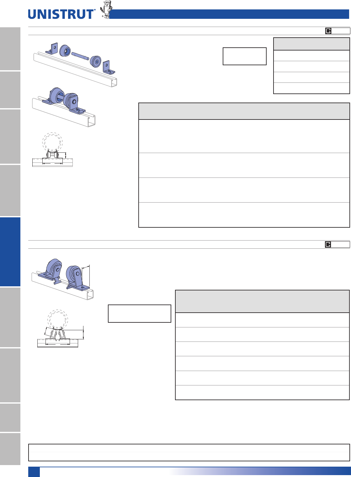
118
15⁄8" Framing System
1 5¼8" ChannelTelestrutNuts & HardwareGeneral FittingsPipe/Conduit SupportsElectrical FittingsConcrete InsertsSolarUnipier®
A
3 1⁄2"
(88.9) (95.3)
3 3⁄4"
TO
3"
(76.2)
Saddle by
others.
5HTXLUHVHDFK1»2" x 15»16" bolts
and 1»2" channel nuts per assembly.
Sold separately.
Chart for Dimension A
Wt/100 pcs: 680 Lbs (308.4 kg)
Material: Cast iron rollers.
P2475 PIPE ROLLER FOR 6" - 16" PIPE
Pipe
Size
In
No
Insulation
In (mm)
Insulation Thickness
1"
In (mm)
11¼2"
In (mm)
2"
In (mm)
21¼2"
In (mm)
3"
In (mm)
4"
In (mm)
69
1»2101»4 101»2 103»4 11 113»8 117»8
241.3 260.4 266.7 273 279.4 288.9 301.6
810
1»8 *1111
3»8 113»4 12 121»2
257.2 279.4 288.9 298.5 304.8 317.5
10 103»4 *11
5»8 12 121»4 121»2 13
273.1 295.3 304.8 311.2 317.5 330.2
12 111»4 *12
1»8 121»2 123»4 13 131»2
285.8 308.0 317.5 323.9 330.2 342.9
14 115»8 *12
1»2 127»8 13 133»8 14
295.3 317.5 327.0 330.2 339.7 355.6
16 121»8 *1313
3»8 137»8 14 141»2
308.0 330.2 339.7 352.4 355.6 368.3
Design Load
1500 Lbs (6.67 kN)
2"
(50.8)
(*Not used for this size)
P2474-1 THRU P2474-4 PIPE ROLLER FOR 1" - 8" PIPE
Chart for Roller Part Number Selection
3LSHUROOHUZLOOILWVWDQGDUGVDGGOHV
6HOHFWSURSHUUROOHUIURPFKDUW
5HTXLUHVHDFK1»2" x 15»16" bolts and 1»2"
channel nuts per assembly. Sold separately.
A
2 1⁄2"
(63.5)
Saddle by
others.
Part
Number
A
In (mm)
Wt/100 pcs
Lbs (kg)
P2474-1 63»4299
171.5 135.6
P2474-2 71»2304
190.5 137.9
P2474-3 81»2311
215.9 141.1
P2474-4 99»16 319
242.9 144.7
Pipe Size
In
No
Insulation
Insulation Thickness
1" (25.4) 11¼2" (38.1) 2" (50.8) 21¼2" (63.5) 3" (76.2) 4" (101.6)
1¼2P2474-1 P2474-1 P2474-1 P2474-2 - - -
3¼4P2474-1 P2474-1 P2474-1 P2474-2 - - -
1P2474-1 P2474-1 P2474-1 P2474-2 - - -
11¼4P2474-1 P2474-1 P2474-1 P2474-2 - - -
11¼2P2474-1 P2474-1 P2474-2 P2474-2 P2474-2 - -
2P2474-1 P2474-1 P2474-2 P2474-2 P2474-2 - -
21¼2P2474-1 P2474-1 P2474-2 P2474-2 P2474-2 - -
3P2474-1 P2474-2 P2474-2 P2474-3 P2474-3 P2474-3 -
31¼2P2474-1 P2474-2 P2474-2 P2474-3 P2474-3 P2474-3 -
4P2474-1 P2474-2 P2474-2 P2474-3 P2474-3 P2474-3 -
5P2474-2 P2474-3 P2474-3 P2474-3 P2474-3 P2474-4 P2474-4
6P2474-2 P2474-3 P2474-3 P2474-3 P2474-3 P2474-4 P2474-4
8P2474-2 P2474-3 P2474-4 P2474-4 P2474-4 P2474-4 P2474-4
Pipe Rollers
Sold in pairs.
Parts are shipped loose and are easily assembled
during installation.
Design Load
750 Lbs (3.34 kN)
EG GR
EG GR
Standard Dimensions for 15»8PPZLGWKVHULHVFKDQQHOILWWLQJV(Unless Otherwise Shown on Drawing)
Hole Diameter: 9»16PP+ROH6SDFLQJ)URP(QG13»16PP+ROH6SDFLQJ2Q&HQWHU7»8PP:LGWK5»8PP7KLFNQHVV1»4PP
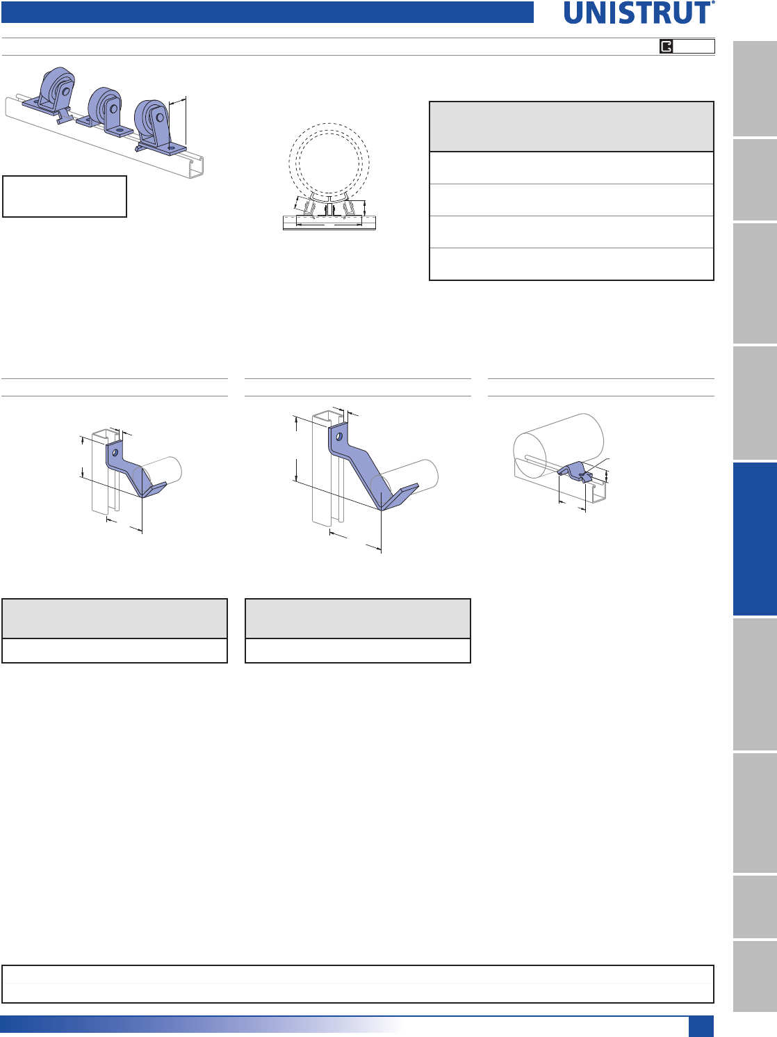
119
15⁄8" Framing System
1 5¼8" ChannelTelestrutNuts & HardwareGeneral FittingsPipe/Conduit SupportsElectrical FittingsConcrete InsertsSolarUnipier®
Chart for Dimension A
Wt/100 pcs: 1046 Lbs (474.5 kg)
Material: Cast iron rollers. A
3 1⁄4"
(82.6)
3"
(76.2)
5HTXLUHVHDFK1»2" x 15»16" bolts
and 1»2" channel nuts per assembly.
Sold separately.
2"
(50.8)
Saddle by
others.
P2476 PIPE ROLLER FOR 16" - 24" PIPE
Design Load
2000 Lbs (8.90 kN)
Pipe
Size
In
Insulation Thickness
11¼2"
In (mm)
2"
In (mm)
21¼2"
In (mm)
3"
In (mm)
4"
In (mm)
16 --13
7»8 14 141»2
- - 352.4 355.6 368.3
18 135»8 14 141»8 141»215
346.1 355.6 358.8 368.3 381.0
20 141»8 141»2 143»4 15 151»2
358.8 368.3 374.7 381.0 393.7
24 151»4 151»2 157»8 161»8 165»8
387.4 393.7 403.2 409.6 422.3
For 2" pipe to 3" pipe.For 1»2" pipe to 11»2" pipe.
Wt/100 pcs: 40 Lbs (18.1 kg)
For 2" (50.8) to 8" (203.2) Pipes
Hole Size 7⁄16" (11.1)
1"
(25.4)
3"
(76.2) Clamp Requires bolt and
channel nut.
Sold seperately
3 1⁄2"
(88.9)
4"
(101.6)
1⁄4"
(6.4) 4 3⁄8"
(111.1)
4"
(101.6)
3⁄8"
(9.5)
P2481 PIPE SUPPORT BRACKET P2243 PIPE BLOCK
Wt/100 pcs
Lbs (kg)
Design Load (Upright Channel)
P1000
Lbs (kN)
P1100
Lbs (kN)
P2000
Lbs (kN)
90 85 85 85
40.8 0.38 0.38 0.38
Wt/100 pcs
Lbs (kg)
Design Load (Upright Channel)
P1000
Lbs (kN)
P1100
Lbs (kN)
P2000
Lbs (kN)
139 185 120 95
63.0 0.82 0.53 0.42
Pipe Brackets
P2482 PIPE SUPPORT BRACKET
EG GR
Standard Dimensions for 15»8PPZLGWKVHULHVFKDQQHOILWWLQJV(Unless Otherwise Shown on Drawing)
Hole Diameter: 9»16PP+ROH6SDFLQJ)URP(QG13»16PP+ROH6SDFLQJ2Q&HQWHU7»8PP:LGWK5»8PP7KLFNQHVV1»4PP

120
15⁄8" Framing System
1 5¼8" ChannelTelestrutNuts & HardwareGeneral FittingsPipe/Conduit SupportsElectrical FittingsConcrete InsertsSolarUnipier®
Nominal
Pipe Dia.
&HQWHUOLQHWR&HQWHUOLQH,QPP
3¼4" (19.1mm) 1" (25.4mm) 11¼4" (31.8mm) 11¼2" (38.1mm) 2" (50.8mm) 21¼2" (63.5mm)
TSTFSTFSTFSTFSTFS
3¼4"
PP
T43»4––––––––––––––––
120.7 ––––––––––––––––
S41»243»4–––––––––––––––
114.3 120.7 –––––––––––––––
1"
25.4mm
T5 43»451»4––––––––––––––
127.0 120.7 133.4 ––––––––––––––
F6 53»461»471»4–––––––––––––
152.4 146.1 158.8 184.2 –––––––––––––
S43»441»25 6 41»2––––––––––––
120.7 114.3 127.0 152.4 114.3 – – – – – – ––––––
11¼4"
31.8mm
T51»45 51»261»25 51»2–––––––––––
133.4 127.0 139.7 165.1 127.0 139.7 – – – – – ––––––
F61»46 61»271»261»463»473»4––––––––––
158.8 152.4 165.1 190.5 158.8 171.5 196.9 – – – – – –––––
S43»441»25 6 41»251»461»443»4–––––––––
120.7 114.3 127.0 152.4 114.3 133.4 158.8 120.7 – ––––––––
11¼2"
38.1mm
T51»45 51»261»251»453»463»451»453»4––––––––
133.4 127.0 139.7 165.1 133.4 146.1 171.5 133.4 146.1 ––––––––
F61»261»463»473»461»463»48 61»27 8 –––––––
165.1 158.8 171.5 196.9 158.8 171.5 203.2 165.1 177.8 203.2 –––––––
S5 43»451»461»443»451»46 5 51»261»25 ––––––
127.0 120.7 133.4 158.8 120.7 133.4 152.4 127.0 139.7 165.1 127.0 ––––––
2"
50.8mm
T53»451»26 7 51»26 71»453»461»471»453»461»2–––––
146.1 139.7 152.4 177.8 139.7 152.4 184.2 146.1 158.8 184.2 146.1 165.1 – – – – –
F7 63»471»481»463»471»481»27 71»281»27 73»49 ––––
177.8 171.5 184.2 209.6 171.5 184.2 215.9 177.8 190.5 215.9 177.8 196.9 228.6 – – – –
S51»45 51»261»25 51»263»451»453»463»451»46 71»451»2–––
133.4 127.0 139.7 165.1 127.0 139.7 171.5 133.4 146.1 171.5 133.4 152.4 184.2 139.7 – – –
21¼2"
63.5mm
T6 53»461»471»46 61»271»26 61»273»461»47 81»461»271»4––
152.4 146.1 158.8 184.2 152.4 165.1 190.5 152.4 165.1 196.9 158.8 177.8 209.6 165.1 184.2 – –
F71»271»473»483»471»473»49 71»28 9 71»281»491»273»483»410 –
190.5 184.2 196.9 222.3 184.2 196.9 228.6 190.5 203.2 228.6 190.5 209.6 241.3 196.9 222.3 254.0 –
S51»251»453»463»451»453»47 51»26 7 51»261»471»253»463»48 6
139.7 133.4 146.1 171.5 133.4 146.1 177.8 139.7 152.4 177.8 139.7 158.8 190.5 146.1 171.5 203.2 152.4
3"
76.2mm
T61»46 61»271»261»463»473»461»463»48 61»271»481»263»471»29 7
158.8 152.4 165.1 190.5 158.8 171.5 196.9 158.8 171.5 203.2 165.1 184.2 215.9 171.5 190.5 228.6 177.8
F73»471»28 9 71»28 91»473»481»491»473»481»293»48 9 101»481»4
196.9 190.5 203.2 228.6 190.5 203.2 235.0 196.9 209.6 235.0 196.9 215.9 247.7 203.2 228.6 260.4 209.6
S53»451»26 7 51»26 71»453»461»471»453»461»273»46 7 81»461»4
146.1 139.7 152.4 177.8 139.7 152.4 184.2 146.1 158.8 184.2 146.1 165.1 196.9 152.4 177.8 209.6 158.8
4"
101.6mm
T71»271»473»483»471»473»49 71»28 9 71»281»491»273»483»410 8
190.5 184.2 196.9 222.3 184.2 196.9 228.6 190.5 203.2 228.6 190.5 209.6 241.3 196.9 222.3 254.0 203.2
F9 83»491»4101»483»491»4101»29 91»2101»29 93»411 91»4101»4111»291»2
228.6 222.3 235.0 260.4 222.3 235.0 266.7 228.6 241.3 266.7 228.6 247.7 279.4 235.0 260.4 292.1 241.3
S63»461»27 8 61»27 81»463»471»481»463»471»283»47 8 91»471»4
171.5 165.1 177.8 203.2 165.1 177.8 209.6 171.5 184.2 209.6 171.5 190.5 222.3 177.8 203.2 235.0 184.2
5"
127.0mm
T8 73»481»491»473»481»491»28 81»291»28 83»410 81»491»4101»281»2
203.2 196.9 209.6 235.0 196.9 209.6 241.3 203.2 215.9 241.3 203.2 222.3 254.0 209.6 235.0 266.7 215.9
F91»291»493»4103»491»493»411 91»210 11 91»2101»4111»293»4103»412 10
241.3 235.0 247.7 273.1 235.0 247.7 279.4 241.3 254.0 279.4 241.3 260.4 292.1 247.7 273.1 304.8 254.0
S71»47 71»281»47 71»283»471»473»483»471»48 91»471»281»293»473»4
184.2 177.8 190.5 209.6 177.8 190.5 222.3 184.2 196.9 222.3 184.2 203.2 235.0 190.5 215.9 247.7 196.9
6"
152.4mm
T83»481»29 10 81»29 101»483»491»4101»483»491»2103»49 10 111»491»4
222.3 215.9 228.6 254.0 215.9 228.6 260.4 222.3 235.0 260.4 222.3 241.3 273.1 228.6 254.0 285.8 235.0
F10 93»4101»4111»493»4101»4111»210 101»2111»210 103»412 101»4111»4121»2101»2
254.0 247.7 260.4 285.8 247.7 260.4 292.1 254.0 266.7 292.1 254.0 273.1 304.8 260.4 285.8 317.5 266.7
S73»471»28 9 71»28 91»473»481»491»473»481»293»48 9 101»481»4
196.9 190.5 203.2 228.6 190.5 203.2 235.0 196.9 209.6 235.0 196.9 215.9 247.7 203.2 228.6 260.4 209.6
8"
203.2mm
T83»491»210 11 93»4101»2111»493»4101»4111»210 103»412 101»211 121»2101»2
222.3 241.3 254.0 279.4 247.7 266.7 285.8 247.7 260.4 292.1 254.0 273.1 304.8 266.7 279.4 317.5 266.7
F111»411 111»2121»211 111»2123»4111»4113»4123»4111»412 131»4111»2121»2133»4113»4
285.8 279.4 292.1 317.5 279.4 292.1 323.9 285.8 298.5 323.9 285.8 304.8 336.6 292.1 317.5 349.3 298.5
10"
254.0mm
T111»411 111»2121»211 111»2123»4111»4113»4123»4111»412 131»4111»2121»2133»4113»4
285.8 279.4 292.1 317.5 279.4 292.1 323.9 285.8 298.5 323.9 285.8 304.8 336.6 292.1 317.5 349.3 298.5
F121»2121»4123»4133»4121»4123»414 121»213 14 121»2131»4141»2123»4133»415 13
317.5 311.2 323.9 349.3 311.2 323.9 355.6 317.5 330.2 355.6 317.5 336.6 368.3 323.9 349.3 381.0 330.2
12"
304.8mm
T121»412 121»2131»212 121»2133»4121»4123»4133»4121»413 141»4121»2131»2143»4123»4
311.2 304.8 317.5 342.9 304.8 317.5 349.3 311.2 323.9 349.3 311.2 330.2 362.0 317.5 342.9 374.7 323.9
F14 133»4141»4151»4133»4141»4151»214 141»2151»214 143»416 141»4151»4161»2141»2
355.6 349.3 362.0 387.4 349.3 362.0 393.7 355.6 368.3 393.7 355.6 374.7 406.4 362.0 387.4 419.1 368.3
Pipe & Conduit Reference Data
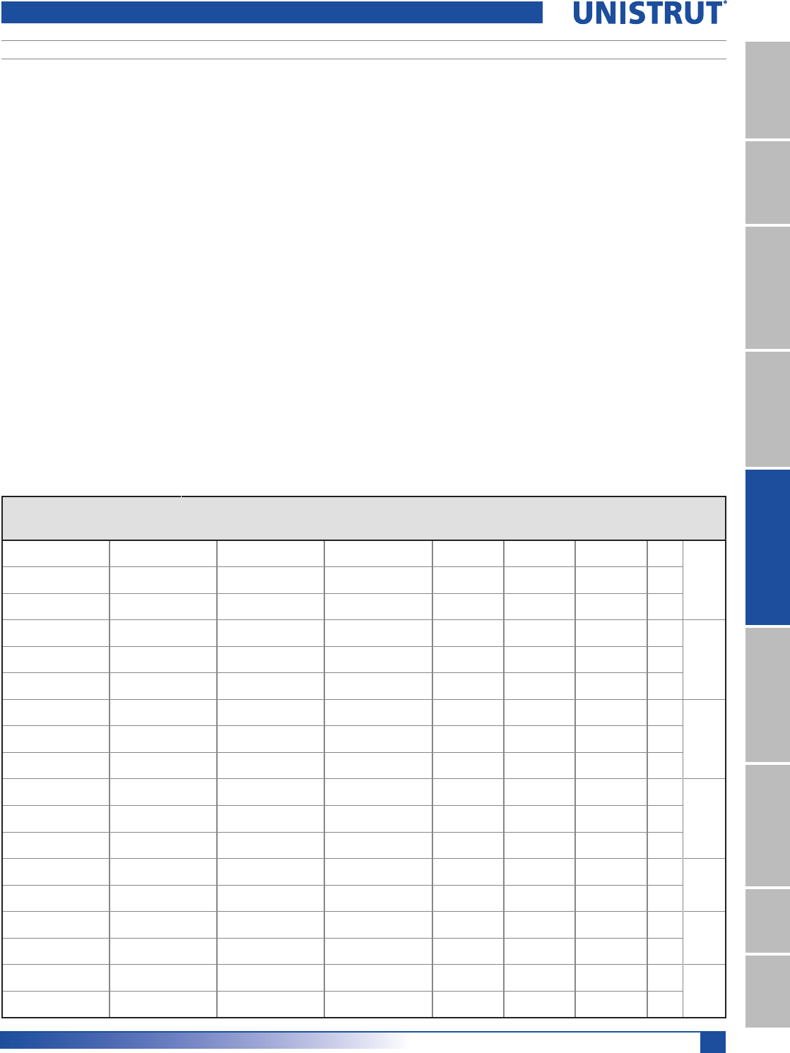
121
15⁄8" Framing System
1 5¼8" ChannelTelestrutNuts & HardwareGeneral FittingsPipe/Conduit SupportsElectrical FittingsConcrete InsertsSolarUnipier®
PIPE SPACING TABLE
This chart, developed by Julius Getlan of Seelye Stevenson Value & Knect, consulting
engineers, New York City, enables one to quickly determine the
centerline-to-centerline dimension between any two size pipes on a rack.
Select the smaller pipe size at top and select the other at the side of the table. Where
the appropriate columns intersect, the dimension is given.
These factors are included in the dimensions given:
2'RIIODQJHVDQGILWWLQJV
LQVXODWLRQRYHUIODQJHVDQGILWWLQJV
$OOIUDFWLRQDOGLPHQVLRQVOHVVWKDQ1»4" were increased to the next larger 1»4".
&OHDUVSDFHEHWZHHQILWWLQJVDVIROORZV
1. 1" between piping 3" and smaller.
2. 11»2" between a pipe 3" and smaller and a pipe 4" or larger.
3. 2" between piping 4" and larger.
T – denotes threaded IPS pipe. F – denotes flanged fittings on pipe. S – denotes soldered or brazed tubing.
&HQWHUOLQHWR&HQWHUOLQH,QPP
Nominal
Pipe Dia.
3" (76.2mm) 4" (101.6mm) 5" (127.0mm) 6" (152.4mm) 8" (203.2mm) 10" (254.0mm) 12" (304.8mm)
TFSTFSTFSTFSTFTFTF
73»4–––––––––––––––––T
3"
76.2mm
196.9 –––––––––––––––––
91»4101»2––––––––––––––––F
235.0 266.7 ––––––––––––––––
71»481»261»2–––––––––––––––S
184.2 215.9 165.1 –––––––––––––––
9 101»481»410 ––––––––––––––T
4"
101.6mm
228.6 260.4 209.6 254.0 ––––––––––––––
101»2113»493»4111»213 –––––––––––––F
266.7 298.5 247.7 292.1 330.2 –––––––––––––
81»491»271»291»4103»481»2––––––––––––S
209.6 241.3 190.5 235.0 273.1 215.9 ––––––––––––
91»2103»483»4101»412 93»411 –––––––––––T
5"
127.0mm
241.3 273.1 222.3 260.4 304.8 247.7 279.4 –––––––––––
11 121»4101»412 131»2111»4121»214 ––––––––––F
279.4 311.2 260.4 304.8 342.9 285.8 317.5 355.6 ––––––––––
83»410 8 93»4111»49 101»4113»491»2–––––––––S
222.3 254.0 203.2 247.7 285.8 228.6 260.4 298.5 241.3 –––––––––
101»4111»291»2111»4123»4101»2113»4131»411 121»2––––––––T
6"
152.4mm
260.4 292.1 241.3 285.8 323.9 266.7 298.5 336.6 279.4 317.5 ––––––––
111»2121»4103»4121»214 113»413 141»2121»4131»415 –––––––F
292.1 311.2 273.1 317.5 355.6 298.5 330.2 368.3 311.2 336.6 381.0 –––––––
91»4101»281»2101»4113»491»2103»4121»410 111»2123»4101»2––––––S
235.0 266.7 215.9 260.4 298.5 241.3 273.1 311.2 254.0 292.1 323.9 266.7 – – – – – –
111»4123»4103»4121»214 113»413 141»2121»4133»415 123»4143»4–––––T
8"
203.2mm
285.8 323.9 273.1 317.5 355.6 298.5 330.2 368.3 311.2 349.3 381.0 323.9 374.7 – – – – –
123»414 12 133»4151»413 141»4153»4131»215 161»414 161»417 .5––––F
323.9 355.6 304.8 349.3 387.4 330.2 362.0 400.1 342.9 381.0 412.8 355.6 412.8 17 .5 – – – –
123»414 12 133»4151»413 141»4153»4131»215 161»414 161»4171»2171»2–––T
10"
254.0mm
323.9 355.6 304.8 349.3 387.4 330.2 362.0 400.1 342.9 381.0 412.8 355.6 412.8 444.5 444.5 – – –
14 151»4131»415 161»2141»4151»217 143»4161»4171»2151»4171»2183»4183»420 – – F
355.6 387.4 336.6 381.0 419.1 362.0 393.7 431.8 374.7 412.8 444.5 387.4 444.5 476.3 476.3 508.0 – –
133»415 13 143»4161»414 151»4163»4141»216 171»415 171»4181»2181»2193»4191»2–T
12"
304.8mm
349.3 381.0 330.2 374.7 412.8 355.6 387.4 425.5 368.3 406.4 438.2 381.0 438.2 469.9 469.9 501.7 495.3 –
151»2163»4143»4161»218 153»417 181»4161»4173»419 163»414 201»4201»4211»2211»429 F
393.7 425.5 374.7 419.1 457.2 400.1 431.8 463.6 412.8 450.9 482.6 425.5 355.6 514.4 514.4 546.1 539.8 736.6
Pipe & Conduit Reference Data
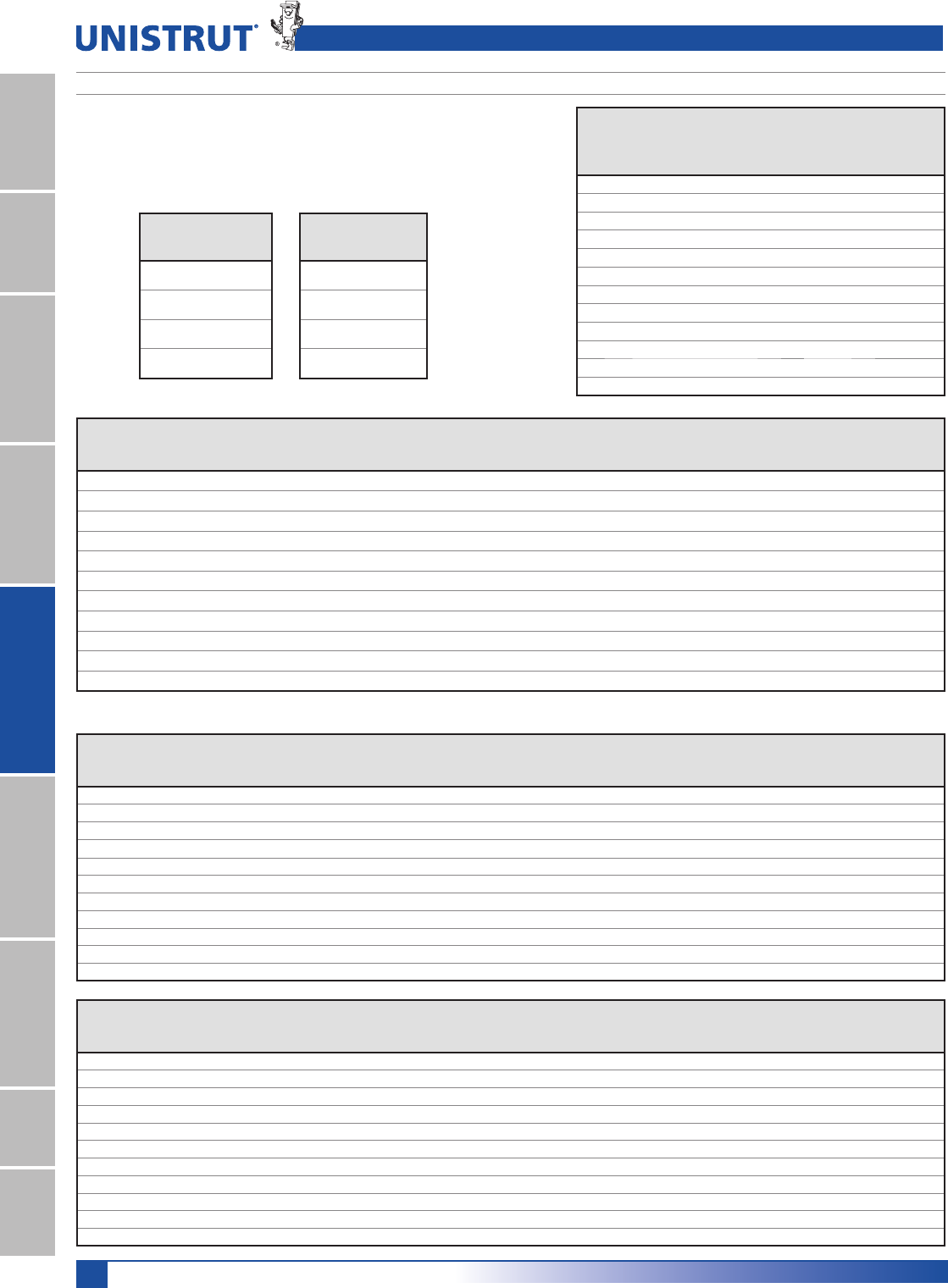
122
15⁄8" Framing System
1 5¼8" ChannelTelestrutNuts & HardwareGeneral FittingsPipe/Conduit SupportsElectrical FittingsConcrete InsertsSolarUnipier®
Note: Based on NFPA-13-2013-Table 9.1.1.7.1(a). Each of the following tables indicate
the allowable span of the trapeeze and the nominal pipe size for the specified channel
. An entry of “N/A” indicates that the channel cannot be used for this span/pipe size
combination. The table is based on a maximum allowable bending stress of 15 KSI and
a midspan concentrated load from 15 ft of water-filled pipe, plus 250 lb.
CHANNEL SELECTION FOR SCHEDULE 10 SPRINKLER PIPE TRAPEZE HANGERS
Pipe & Conduit Reference Data
Schedule 10 Pipe
Nominal
Pipe Dia.
LQ
O.D.
LQ
Wall
Thickness
LQ
I. D.
LQ
Pipe
Weight
SI
Water
Weight
SI
Total
Weight
SI
1 1.315 0.109 1.097 1.41 0.42 1.83
11»41.660 0.109 1.442 1.81 0.73 2.54
11»21.900 0.109 1.682 2.09 0.99 3.08
2 2.375 0.109 2.157 2.64 1.63 4.28
21»22.875 0.120 2.635 3.53 2.44 5.97
3 3.500 0.120 3.260 4.34 3.73 8.07
31»24.000 0.120 3.760 4.98 4.97 9.95
4 4.500 0.120 4.260 5.62 6.38 12.00
5 5.563 0.134 5.295 7.78 9.85 17.63
6 6.625 0.134 6.357 9.30 14.20 23.50
8 8.625 0.188 8.249 16.96 23.91 40.87
10 10.750 0.188 10.374 21.23 37.82 59.04
Trapeze
Span
Single Channel Trapeze for Sch 10 Pipe
Pipe Diameter
1" 11¼4"1
1¼2"2"2
1¼2"3"3
1¼2"4"5"6"8"10"
1' - 6" P3000 P3000 P3000 P3000 P3000 P3000 P3000 P3000 P3000 P1000 P5500 P5500
2' - 0" P3000 P3000 P3000 P3000 P3000 P3000 P1000 P1000 P1000 P5500 P5500 P5000
2' - 6" P3000 P3000 P3000 P1000 P1000 P5500 P5500 P5500 P5500 P5500 P5000 N/A
3' - 0" P1000 P1000 P1000 P1000 P1000 P5500 P5500 P5500 P5500 P5500 P5000 N/A
4' - 0" P5500 P5500 P5500 P5500 P5500 P5500 P5500 P5500 P5000 P5000 N/A N/A
5' - 0" P5500 P5500 P5500 P5500 P5500 P5500 P5000 P5000 P5000 P5000 N/A N/A
6' - 0" P5500 P5500 P5500 P5500 P5000 P5000 P5000 P5000 P5000 N/A N/A N/A
7' - 0" P5500 P5500 P5000 P5000 P5000 P5000 P5000 P5000 N/A N/A N/A N/A
8' - 0" P5000 P5000 P5000 P5000 P5000 P5000 P5000 N/A N/A N/A N/A N/A
9' - 0" P5000 P5000 P5000 P5000 P5000 N/A N/A N/A N/A N/A N/A N/A
10' - 0" P5000 P5000 P5000 P5000 N/A N/A N/A N/A N/A N/A N/A N/A
Trapeze
Span
Double Channel Trapeze for Sch 10 Pipe
Pipe Diameter
1" 11¼4"1
1¼2"2"2
1¼2"3"3
1¼2"4"5"6"8"10"
1' - 6" P3001 P3001 P3001 P3001 P3001 P3001 P3001 P3001 P3001 P3001 P3001 P3001
2' - 0" P3001 P3001 P3001 P3001 P3001 P3001 P3001 P3001 P3001 P3001 P3001 P3001
2' - 6" P3001 P3001 P3001 P3001 P3001 P3001 P3001 P3001 P3001 P3001 P1001 P5501
3' - 0" P3001 P3001 P3001 P3001 P3001 P3001 P3001 P3001 P3001 P3001 P1001 P5501
4' - 0" P3001 P3001 P3001 P3001 P3001 P3001 P3001 P3001 P3001 P1001 P5501 P5501
5' - 0" P3001 P3001 P3001 P3001 P3001 P3001 P3001 P3001 P1001 P5501 P5501 P5501
6' - 0" P3001 P3001 P3001 P3001 P3001 P1001 P1001 P1001 P5501 P5501 P5501 P5001
7' - 0" P3001 P3001 P3001 P1001 P1001 P1001 P1001 P5501 P5501 P5501 P5001 P5001
8' - 0" P3001 P1001 P1001 P1001 P1001 P5501 P5501 P5501 P5501 P5501 P5001 P5001
9' - 0" P1001 P1001 P1001 P1001 P5501 P5501 P5501 P5501 P5501 P5501 P5001 N/A
10' - 0" P1001 P1001 P5501 P5501 P5501 P5501 P5501 P5501 P5501 P5501 P5001 N/A
Values taken from NFPA 13 (2013 Edition), Table 9.1.1.7.1(a)
Trapeze
Span
NFPA 13 Required Trapeze Section Modulus for Sch 10 Pipe
Pipe Diameter
1" 11¼4"1
1¼2"2"2
1¼2"3"3
1¼2"4"5"6"8" 10"
1' - 6" 0.08 0.08 0.09 0.09 0.10 0.11 0.12 0.13 0.15 0.18 0.26 0.34
2' - 0" 0.11 0.11 0.12 0.13 0.14 0.15 0.16 0.17 0.2 0.24 0.34 0.45
2' - 6" 0.14 0.14 0.15 0.16 0.18 0.21 0.23 0.25 0.3 0.36 0.5 0.69
3' - 0" 0.16 0.17 0.18 0.19 0.2 0.22 0.24 0.26 0.31 0.36 0.51 0.67
4' - 0" 0.22 0.22 0.24 0.25 0.27 0.30 0.32 0.34 0.41 0.48 0.68 0.89
5' - 0" 0.27 0.28 0.3 0.31 0.34 0.37 0.40 0.43 0.51 0.60 0.85 1.12
6' - 0" 0.33 0.34 0.35 0.38 0.41 0.44 0.48 0.51 0.61 0.71 1.02 1.34
7' - 0" 0.38 0.39 0.41 0.44 0.47 0.52 0.56 0.6 0.71 0.83 1.19 1.56
8' - 0" 0.43 0.45 0.47 0.5 0.54 0.59 0.63 0.68 0.82 0.95 1.36 1.79
9' - 0" 0.49 0.50 0.53 0.56 0.61 0.66 0.71 0.77 0.92 1.07 1.53 2.01
10' - 0" 0.54 0.56 0.59 0.63 0.68 0.74 0.79 0.85 1.02 1.19 1.7 2.23
Unistrut
Channel
Section
Modulus
in3 (cm3)
P3000 0.154
2.52
P1000 0.202
3.31
P5500 0.391
6.41
P5000 0.628
10.29
Unistrut
Channel
Section
Modulus
in3 (cm3)
P3001 0.431
7.06
P1001 0.572
9.37
P5501 1.153
18.89
P5001 1.916
31.40
123
15⁄8" Framing System
1 5¼8" ChannelTelestrutNuts & HardwareGeneral FittingsPipe/Conduit SupportsElectrical FittingsConcrete InsertsSolarUnipier®
Pipe & Conduit Reference Data
CHANNEL SELECTION FOR SCHEDULE 40 SPRINKLER PIPE TRAPEZE HANGERS
Note: Based on NFPA-13-2013-Table 9.1.1.7.1(a). Each of the following tables indicate
the allowable span of the trapeeze and the nominal pipe size for the specified chan-
nel . An entry of “N/A” indicates that the channel cannot be used for this span/pipe
size combination. The table is based on a maximum allowable bending stress of 15
KSI and a midspan concentrated load from 15 ft of water-filled pipe, plus 250 lb.
Values taken from NFPA 13 (2013 Edition), Table 9.1.1.7.1(a)
Trapeze
Span
NFPA 13 Required Trapeze Section Modulus for Sch 40 Pipe
Pipe Diameter
1" 11¼4"1
1¼2"2"2
1¼2"3"3
1¼2"4"5"6"8"10"
1' - 6" 0.08 0.09 0.09 0.1 0.11 0.12 0.14 0.15 0.18 0.22 0.3 0.41
2' - 0" 0.11 0.11 0.12 0.13 0.15 0.16 0.18 0.2 0.24 0.29 0.4 0.55
2' - 6" 0.14 0.14 0.15 0.16 0.17 0.18 0.2 0.21 0.25 0.3 0.43 0.56
3' - 0" 0.16 0.17 0.18 0.2 0.22 0.25 0.27 0.3 0.36 0.43 0.6 0.82
4' - 0" 0.22 0.23 0.24 0.26 0.29 0.33 0.36 0.4 0.48 0.58 0.8 1.1
5' - 0" 0.27 0.29 0.3 0.33 0.37 0.41 0.45 0.49 0.6 0.72 1 1.37
6' - 0" 0.33 0.34 0.36 0.39 0.44 0.49 0.54 0.59 0.72 0.87 1.2 1.64
7' - 0" 0.38 0.4 0.43 0.46 0.52 0.58 0.63 0.69 0.84 1.01 1.41 1.92
8' - 0" 0.44 0.46 0.49 0.52 0.59 0.66 0.72 0.79 0.96 1.16 1.61 2.19
9' - 0" 0.49 0.51 0.55 0.59 0.66 0.74 0.81 0.89 1.08 1.3 1.81 2.47
10' - 0" 0.55 0.57 0.61 0.65 0.74 0.82 0.9 0.99 1.2 1.45 2.01 2.74
Schedule 40 Pipe
Nominal
Pipe Dia.
LQ
O.D.
LQ
Wall
Thickness
LQ
I. D.
LQ
Pipe
Weight
SI
Water
Weight
SI
Total
Weight
SI
1 1.315 0.133 1.049 1.68 0.39 2.07
11»41.660 0.140 1.380 2.27 0.67 2.94
11»21.900 0.145 1.610 2.72 0.91 3.63
2 2.375 0.154 2.067 3.66 1.50 5.16
21»22.875 0.203 2.469 5.80 2.14 7.94
3 3.500 0.216 3.068 7.58 3.31 10.89
31»24.000 0.226 3.548 9.12 4.42 13.54
4 4.500 0.237 4.026 10.80 5.70 16.50
5 5.563 0.258 5.047 14.63 8.95 23.58
6 6.625 0.280 6.065 18.99 12.93 31.92
8 8.625 0.322 7.981 28.58 22.38 50.96
10 10.750 0.365 10.020 40.52 35.28 75.80
Trapeze
Span
Single Channel Trapeze for Sch 40 Pipe
Pipe Diameter
1" 11¼4"1
1¼2"2"2
1¼2"3"3
1¼2"4"5"6"8"10"
1' - 6" P3000 P3000 P3000 P3000 P3000 P3000 P3000 P3000 P1000 P5500 P5500 P5000
2' - 0" P3000 P3000 P3000 P3000 P3000 P1000 P1000 P1000 P5500 P5500 P5000 P5000
2' - 6" P3000 P3000 P3000 P1000 P1000 P1000 P1000 P1000 P5500 P5500 P5000 P5000
3' - 0" P1000 P1000 P1000 P1000 P5500 P5500 P5500 P5500 P5500 P5000 P5000 N/A
4' - 0" P5500 P5500 P5500 P5500 P5500 P5500 P5000 P5000 P5000 P5000 N/A N/A
5' - 0" P5500 P5500 P5500 P5500 P5500 P5000 P5000 P5000 P5000 N/A N/A N/A
6' - 0" P5500 P5500 P5500 P5500 P5000 P5000 P5000 P5000 N/A N/A N/A N/A
7' - 0" P5500 P5000 P5000 P5000 P5000 P5000 P5000 N/A N/A N/A N/A N/A
8' - 0" P5000 P5000 P5000 P5000 P5000 N/A N/A N/A N/A N/A N/A N/A
9' - 0" P5000 P5000 P5000 P5000 N/A N/A N/A N/A N/A N/A N/A N/A
10' - 0" P5000 P5000 P5000 N/A N/A N/A N/A N/A N/A N/A N/A N/A
Trapeze
Span
Double Channel Trapeze for Sch 40 Pipe
Pipe Diameter
1" 11¼4"1
1¼2"2"2
1¼2"3"3
1¼2"4"5"6"8"10"
1' - 6" P3001 P3001 P3001 P3001 P3001 P3001 P3001 P3001 P3001 P3001 P3001 P3001
2' - 0" P3001 P3001 P3001 P3001 P3001 P3001 P3001 P3001 P3001 P3001 P3001 P1001
2' - 6" P3001 P3001 P3001 P3001 P3001 P3001 P3001 P3001 P3001 P3001 P3001 P1001
3' - 0" P3001 P3001 P3001 P3001 P3001 P3001 P3001 P3001 P3001 P3001 P5501 P5501
4' - 0" P3001 P3001 P3001 P3001 P3001 P3001 P3001 P3001 P1001 P5501 P5501 P5501
5' - 0" P3001 P3001 P3001 P3001 P3001 P3001 P1001 P1001 P5501 P5501 P5501 P5001
6' - 0" P3001 P3001 P3001 P3001 P1001 P1001 P1001 P5501 P5501 P5501 P5001 P5001
7' - 0" P3001 P3001 P3001 P1001 P1001 P5501 P5501 P5501 P5501 P5501 P5001 P5001
8' - 0" P1001 P1001 P1001 P1001 P5501 P5501 P5501 P5501 P5501 P5001 P5001 N/A
9' - 0" P1001 P1001 P1001 P5501 P5501 P5501 P5501 P5501 P5501 P5001 P5001 N/A
10' - 0" P1001 P1001 P5501 P5501 P5501 P5501 P5501 P5501 P5001 P5001 N/A N/A
Unistrut
Channel
Section
Modulus
in3 (cm3)
P3000 0.154
2.52
P1000 0.202
3.31
P5500 0.391
6.41
P5000 0.628
10.29
Unistrut
Channel
Section
Modulus
in3 (cm3)
P3001 0.431
7.06
P1001 0.572
9.37
P5501 1.153
18.89
P5001 1.916
31.40

124
15⁄8" Framing System
1 5¼8" ChannelTelestrutNuts & HardwareGeneral FittingsPipe/Conduit SupportsElectrical FittingsConcrete InsertsSolarUnipier®
Tubing Size
1RPLQDO
In
Outside
Diameter
In (mm)
Inside
Diameter
In (mm)
Weight
Of Tubing
Lbs/Ft (kg/m)
3»80.577 0.497 0.23
14.7 12.6 0.34
1»20.706 0.626 0.29
17.9 15.9 0.43
3»40.922 0.830 0.44
23.4 21.1 0.65
11.163 1.055 0.64
29.5 26.8 0.95
11»41.510 1.388 0.95
38.4 35.3 1.41
11»21.740 1.618 1.10
44.2 41.1 1.64
22.197 2.075 1.40
55.8 52.7 2.08
21»22.875 2.731 2.30
73.0 69.4 3.42
33.500 3.356 2.70
88.9 85.2 4.02
31»24.000 3.834 3.40
101.6 97.4 5.06
44.500 4.334 4.00
114.3 110.1 5.95
ELECTRICAL METALLIC TUBING (EMT) - THIN WALL INTERMEDIATE METALLIC CONDUIT (IMC)
Conduit
Size
1RPLQDO
In
Outside
Diameter
In (mm)
Inside
Diameter
In (mm)
Weight
Of Conduit
Lbs/Ft (kg/m)
Weight of
Conduit and
Conductor
Lbs/Ft (kg/m)
1»20.815 0.745 0.60 0.12
20.7 18.9 0.89 0.18
3»41.029 0.954 0.82 1.13
26.1 24.2 1.22 1.68
11.290 1.205 1.16 1.82
32.8 30.6 1.73 2.71
11»41.638 1.553 1.50 2.67
41.6 39.4 2.23 3.97
11»21.883 1.793 1.82 3.42
47.8 45.5 2.71 5.09
22.360 2.266 2.42 5.04
59.9 57.6 3.60 7.50
21»22.857 2.727 4.01 7.75
72.6 69.3 5.97 11.53
33.476 3.346 4.43 10.69
88.3 85.0 6.59 15.91
31»23.971 3.841 5.73 13.46
100.9 97.6 8.53 20.03
44.466 4.336 6.38 16.37
113.4 110.1 9.49 24.36
Pipe & Conduit Reference Data
Nom. Tube
Size
O.D. Tubing
In (mm)
O.D.
In (mm)
Wall Thick.
In (mm)
Weight
Lbs/Ft
(kg/m))
Weight
Water
Lbs/Ft (kg/m)
1»4"3»80.375 0.030 0.126 0.034
9.5 9.5 0.8 0.19 0.05
3»8"1»20.500 0.035 0.198 0.062
12.7 12.7 0.9 0.29 0.09
1»2"5»80.625 0.040 0.285 0.100
15.9 15.9 1.0 0.42 0.15
5»8"3»40.750 0.042 0.362 0.151
19.1 19.1 1.1 0.54 0.22
3»4"7»80.875 0.045 0.455 0.209
22.2 22.2 1.1 0.68 0.31
1" 11»81.125 0.050 0.655 0.357
28.6 28.6 1.3 0.97 0.53
11»4"13»81.375 0.055 0.884 0.546
34.9 34.9 1.4 1.32 0.81
11»2"15»81.625 0.060 1.140 0.767
41.3 41.3 1.5 1.70 1.14
2" 21»82.125 0.070 1.750 1.341
54.0 54.0 1.8 2.60 2.00
21»2"25»82.625 0.080 2.480 2.064
66.7 66.7 2.0 3.69 3.07
3" 31»83.125 0.090 3.330 2.949
79.4 79.4 2.3 4.96 4.39
31»2"35»83.625 0.100 4.290 3.989
92.1 92.1 2.5 6.38 5.94
4" 41»84.125 0.110 5.380 5.188
104.8 104.8 2.8 8.01 7.72
5" 51»85.125 0.125 7.610 8.081
130.2 130.2 3.2 11.32 12.03
6" 61»86.125 0.140 10.200 11.616
155.6 155.6 3.6 15.18 17.29
8" 81»88.125 0.200 19.290 20.289
206.4 206.4 5.1 28.71 30.19
10" 101»810.125 0.250 30.100 31.590
257.2 257.2 6.4 44.79 47.01
12" 121»812.125 0.280 40.400 45.426
308.0 308.0 7.1 60.12 67.60
COPPER TUBE (TYPE L)
Nom. Tube
Size
O.D. Tubing
In (mm)
O.D.
In (mm)
Wall Thick.
In (mm)
Weight
Lbs/Ft
(kg/m))
Weight
Water
Lbs/Ft (kg/m)
1»4"3»80.375 0.035 0.145 0.032
9.5 9.53 0.89 0.22 0.05
3»8"1»20.500 0.005 0.269 0.055
12.7 12.70 0.13 0.40 0.08
1»2"5»80.625 0.049 0.344 0.094
15.9 15.88 1.24 0.51 0.14
5»8"3»40.750 0.049 0.418 0.144
19.1 19.05 1.24 0.62 0.21
3»4"7»80.875 0.065 0.641 0.188
22.2 22.23 1.65 0.95 0.28
1" 11»81.125 0.065 0.839 0.337
28.6 28.58 1.65 1.25 0.50
11»4"13»81.375 0.065 1.040 0.527
34.9 34.93 1.65 1.55 0.78
11»2"15»81.625 0.072 1.360 0.743
41.3 41.28 1.83 2.02 1.11
2" 21»82.125 0.083 2.060 1.310
54.0 53.98 2.11 3.07 1.95
21»2"25»82.625 0.095 2.920 2.000
66.7 66.68 2.41 4.35 2.98
3" 31»83.125 0.109 4.000 2.960
79.4 79.38 2.77 5.95 4.40
31»2"35»83.625 0.120 5.120 3.900
92.1 92.08 3.05 7.62 5.80
4" 41»84.125 0.134 6.510 5.060
104.8 104.78 3.40 9.69 7.53
5" 51»85.125 0.160 9.670 8.000
130.2 130.18 4.06 14.39 11.91
6" 61»86.125 0.192 13.870 11.200
155.6 155.58 4.88 20.64 16.67
8" 81»88.125 0.271 25.900 19.500
206.4 206.38 6.88 38.54 29.02
10" 101»810.125 0.338 40.300 30.423
257.2 257.18 8.59 59.97 45.27
12" 121»812.125 0.405 57.800 43.675
308.0 307.98 10.29 86.02 65.00
COPPER TUBE (TYPE K)
125
15⁄8" Framing System
1 5¼8" ChannelTelestrutNuts & HardwareGeneral FittingsPipe/Conduit SupportsElectrical FittingsConcrete InsertsSolarUnipier®
Table 344.30 (B)(2)
Support for Rigid Metal Conduit
* Maximum weight equals weight of rigid conduit plus weight of heaviest conductor
combination (from the National Electrical Code Handbook.)
346-12. Supports. Rigid metal conduit shall be installed
as a complete system as provided in Article 344 and
shall be securely fastened in place. Conduit shall be
firmly fastened within 3 feet (914.4 mm) of each outlet
box, junction box, cabinet, or fitting. Conduit shall be sup-
ported at least every 10 feet (3.05 m).
Exception: If made up with threaded couplings, it shall be
permissible to support straight runs of rigid metal conduit
in accordance with Table 344.30 (B)(2), provided such
supports prevent transmission of stresses to termination
where conduit is deflected between supports.
The above spacing based on a combined bending
and shear stress of 1500 PSI when pipe is filled
with water and the pitch of the line is such that a
sag of 0.1 in. between supports is permissible.
RIGID STEEL (HEAVY DUTY) CONDUIT WATER FILLED PIPE SUPPORT SPACING
Conduit
Size
1RPLQDO
In
I. D. Of
Conduit
In (mm)
O. D. Of
Conduit
In (mm)
O. D. Of
Coupling
In (mm)
Weight of
Conduit
Lbs/Ft
(kg/m)
Maximum Weight*
Of Conduit
And Conductor
Lead Covered
Lbs/Ft (kg/m)
Not Lead
Covered
Lbs/Ft
(kg/m)
1»20.622 0.840 1.063 0.85 1.20 1.00
15.8 21.3 27.0 1.26 1.79 1.49
3»40.824 1.050 1.297 1.13 1.80 1.40
20.9 26.7 32.9 1.68 2.68 2.08
11.049 1.315 1.563 1.68 2.60 2.30
26.6 33.4 39.7 2.50 3.87 3.42
11»41.380 1.660 1.969 2.28 4.30 3.60
35.1 42.2 50.0 3.39 6.40 5.36
11»21.610 1.900 2.234 2.73 5.90 4.50
40.9 48.3 56.7 4.06 8.78 6.70
22.067 2.375 2.719 3.68 8.50 7.20
52.5 60.3 69.1 5.48 12.65 10.71
21»22.469 2.875 3.313 5.82 11.50 10.20
62.7 73.0 84.2 8.66 17.11 15.18
33.068 3.500 3.938 7.62 16.50 14.50
77.9 88.9 100.0 11.34 24.55 21.58
31»23.548 4.000 4.438 9.20 19.00 17.50
90.1 101.6 112.7 13.69 28.28 26.04
44.026 4.500 4.938 10.89 24.80 21.50
102.3 114.3 125.4 16.21 36.91 32.00
55.047 5.563 6.296 14.81 35.90 30.80
128.2 141.3 159.9 22.04 53.43 45.84
66.065 6.625 7.358 19.19 50.70 43.40
154.1 168.3 186.9 28.56 75.45 64.59
Nominal
Pipe Size
In
Max.
Span
Ft (m)
Nominal
Pipe Size
In
Max.
Span
Ft (m)
17819
2.13 5.79
11»2910 22
2.74 6.71
210 12 23
3.05 7.01
21»211 14 25
3.35 7.62
312 16 27
3.66 8.23
31»213 18 28
3.96 8.53
414 20 30
4.27 9.14
516 24 32
4.88 9.75
Conduit Size
In (mm)
Maximum Distance
Between Supports
Ft (m)
1»2-3»410
12.7 - 19.1 3.05
112
25.4 3.66
11»4- 11»214
31.8 - 38.1 4.27
2- 21»216
50.8 - 63.5 4.88
3 & larger 20
76.2 - Larger 6.10
Pipe & Conduit Reference Data
Pipe Size
1RPLQDO
In
Outside
Diameter
In (mm)
Inside
Diameter
In (mm)
Pipe
Weight
Lbs/Ft (kg/m)
Pipe and
Water
Weight
Lbs/Ft (kg/m)
1»40.540 0.354 0.081 0.12
13.7 9.0 0.12 0.18
3»80.675 0.483 0.109 0.19
17.1 12.3 0.16 0.28
1»20.840 0.608 0.161 0.29
21.3 15.4 0.24 0.43
3»41.050 0.810 0.214 0.44
26.7 20.6 0.32 0.65
11.315 1.033 0.315 0.68
33.4 26.2 0.47 1.01
11»41.660 1.364 0.426 1.06
42.2 34.6 0.63 1.58
11»21.900 1.592 0.509 1.37
48.3 40.4 0.76 2.04
22.375 2.049 0.682 2.11
60.3 52.0 1.01 3.14
21»22.875 2.445 1.076 3.11
73.0 62.1 1.60 4.63
33.500 3.042 1.409 4.55
88.9 77.3 2.10 6.77
44.500 3.998 2.006 7.44
114.3 101.5 2.99 11.07
66.625 6.031 3.535 15.90
168.3 153.2 5.26 23.66
88.625 7.943 5.305 26.75
219.1 201.8 7.89 39.81
10 10.750 9.976 7.532 41.35
273.1 253.4 11.21 61.54
SCHEDULE 40: PVC PLASTIC PIPECONDUIT SUPPORT SPACING
126
15⁄8" Framing System
1 5¼8" ChannelTelestrutNuts & HardwareGeneral FittingsPipe/Conduit SupportsElectrical FittingsConcrete InsertsSolarUnipier®
DATA FOR SCHEDULE STEEL PIPE
Pipe & Conduit Reference Data
Nom.
Size
In
Pipe
Schedule
Outside
Dia.
In(mm)
Inside
Dia.
In (mm)
Pipe
Weight
Lbs/Ft (kg/m)
Pipe and Water
Weight
Lbs/Ft (kg/m)
4
40 4.500 4.026 10.78 16.30
114.3 102.3 16.04 24.26
80 4.500 3.826 14.97 19.95
114.3 97.2 22.28 29.69
120 4.500 3.624 18.98 23.45
114.3 92.0 28.25 34.90
160 4.500 3.438 22.48 26.51
114.3 87.3 33.45 39.45
5
40 5.563 5.047 14.60 23.27
141.3 128.2 21.73 34.63
80 5.563 4.813 20.75 28.64
141.3 122.2 30.88 42.62
120 5.563 4.563 27.01 34.09
141.3 115.9 40.20 50.73
160 5.563 4.313 32.92 39.26
141.3 109.5 48.99 58.43
6
40 6.625 6.065 18.95 31.48
168.3 154.1 28.20 46.85
80 6.625 5.761 28.54 39.84
168.3 146.3 42.47 59.29
120 6.625 5.501 36.35 46.66
168.3 139.7 54.09 69.44
160 6.625 5.187 45.30 54.47
168.3 131.7 67.41 81.06
8
20 8.625 8.125 22.34 44.82
219.1 206.4 33.25 66.70
30 8.625 8.071 24.67 46.85
219.1 205.0 36.71 69.72
40 8.625 7.981 28.52 50.21
219.1 202.7 42.44 74.72
60 8.625 7.813 35.60 56.39
219.1 198.5 52.98 83.92
80 8.625 7.625 43.34 63.14
219.1 193.7 64.50 93.96
100 8.625 7.437 50.89 69.73
219.1 188.9 75.73 103.77
120 8.625 7.187 60.65 78.23
219.1 182.5 90.26 116.42
140 8.625 7.001 67.68 84.37
219.1 177.8 100.72 125.56
160 8.625 6.813 74.61 90.42
219.1 173.1 111.03 134.56
10
20 10.750 10.250 28.01 63.78
273.1 260.4 41.68 94.92
30 10.750 10.136 34.20 69.19
273.1 257.5 50.90 102.97
40 10.750 10.020 40.44 74.63
273.1 254.5 60.18 111.06
60 10.750 9.750 54.68 87.05
273.1 247.7 81.37 129.54
80 10.750 9.562 64.36 95.50
273.1 242.9 95.78 142.12
100 10.750 9.312 76.95 106.47
273.1 236.5 114.51 158.44
120 10.750 9.062 89.20 117.16
273.1 230.2 132.74 174.35
140 10.750 8.750 104.02 130.09
273.1 222.3 154.80 193.60
160 10.750 8.500 115.52 140.13
273.1 215.9 171.91 208.54
Nom.
Size
In
Pipe
Schedule
Outside
Dia.
In(mm)
Inside
Dia.
In (mm)
Pipe
Weight
Lbs/Ft (kg/m)
Pipe and Water
Weight
Lbs/Ft (kg/m)
1
¼
8
40 0.405 0.269 0.24 0.27
10.3 6.8 0.36 0.40
80 0.405 0.215 0.31 0.33
10.3 5.5 0.46 0.49
1
¼
4
40 0.540 0.364 0.42 0.47
13.7 9.2 0.63 0.70
80 0.540 0.302 0.53 0.57
13.7 7.7 0.79 0.85
3
¼
8
40 0.675 0.493 0.57 0.65
17.1 12.5 0.85 0.97
80 0.675 0.423 0.74 0.80
17.1 10.7 1.10 1.19
1
¼
2
40 0.840 0.622 0.85 0.98
21.3 15.8 1.26 1.46
80 0.840 0.546 1.09 1.19
21.3 13.9 1.62 1.77
160 0.840 0.464 1.31 1.38
21.3 11.8 1.95 2.05
3
¼
4
40 1.050 0.824 1.13 1.36
26.7 20.9 1.68 2.02
80 1.050 0.742 1.47 1.66
26.7 18.8 2.19 2.47
160 1.050 0.612 1.94 2.07
26.7 15.5 2.89 3.08
1
40 1.315 1.049 1.68 2.05
33.4 26.6 2.50 3.05
80 1.315 0.957 2.17 2.48
33.4 24.3 3.23 3.69
160 1.315 0.815 2.84 3.07
33.4 20.7 4.23 4.57
1
1
¼
4
40 1.660 1.380 2.27 2.92
42.2 35.1 3.38 4.35
80 1.660 1.278 2.99 3.55
42.2 32.5 4.45 5.28
160 1.660 1.160 3.76 4.22
42.2 29.5 5.60 6.28
1
1
¼
2
40 1.900 1.610 2.71 3.60
48.3 40.9 4.03 5.36
80 1.900 1.500 3.63 4.39
48.3 38.1 5.40 6.53
160 1.900 1.338 4.85 5.46
48.3 34.0 7.22 8.13
2
40 2.375 2.067 3.65 5.10
60.3 52.5 5.43 7.59
80 2.375 1.939 5.02 6.30
60.3 49.3 7.47 9.38
160 2.375 1.687 7.45 8.42
60.3 42.8 11.09 12.53
2
1
¼
2
40 2.875 2.469 5.79 7.86
73.0 62.7 8.62 11.70
80 2.875 2.323 7.65 9.49
73.0 59.0 11.38 14.12
160 2.875 2.125 10.00 11.54
73.0 54.0 14.88 17.17
3
40 3.500 3.068 7.57 10.77
88.9 77.9 11.27 16.03
80 3.500 2.900 10.24 13.11
88.9 73.7 15.24 19.51
160 3.500 2.624 14.31 16.65
88.9 66.6 21.30 24.78
3
1
¼
2
40 4.000 3.548 9.10 13.39
101.6 90.1 13.54 19.93
80 4.000 3.364 12.49 16.35
101.6 85.4 18.59 24.33
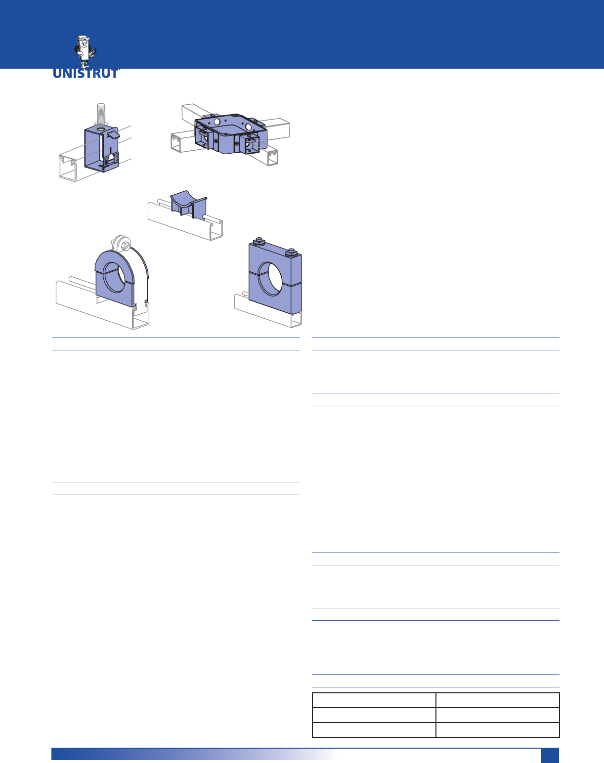
127
MATERIAL
Unistrut fittings, unless noted, are made from hot-rolled,
pickled and oiled steel plates, strip or coil, and conform to
ASTM specifications A575, A576, A635, or A36. The fitting
steel also meets the physical requirements of ASTM A1011
SS GR 33. The pickling of the steel produces a smooth
surface free from scale.
Maple cable saddles, cable clamps and bus bar clamps are
made from kiln-dry maple treated with paraffin to a depth
of 1⁄16" (1.6mm). Special sizes of clamps can be fabricated
upon request. Cable saddles are fiberglass-reinforced
polyester.
CHANNEL RACEWAYS
The Unistrut Metal Framing System includes an exclusive
combination of channel, fittings and hardware listed under
new UL classification 5B. This classification covers strut-type
channel raceways and fittings for use in accordance with
Article 384 of the National Electrical Code, NFPA 70. In-
cluded are metal strut-type channel raceways at least .071
inch (1.81mm) thick and metal or non-metal closure strips
at least .040 inch (1.02mm) thick.
The Unistrut system requires no welding, drilling or other
complex fabrication techniques. This means faster, easier
solutions for virtually any electrical support problem.
Unistrut channel offers structural and spanning capabilities
not available with conventional surface raceway products
and is available in continuous lengths of up to 20 feet. Just
as important, it is part of an integrated system that can be
used for raceways, trapeze hangers, cable-tray supports,
lighting grids, fluorescent-fixture supports and countless
other electrical applications.
CHANNEL COMPATABILITY
All of the electrical components in this section are intended
for use with any of the 15⁄8" wide channel. They are not
intended for use with 11⁄4" or 13⁄16" framing systems.
FINISHES
Components listed in this section are available in:
Electro-galvanized (EG), conforming to
ASTM B633 Type III SC1;
Hot-dipped galvanized (HG), conforming to
ASTM A123 or A153,
Green Powder Coat (GR), conforming to
commercial standards for Powder Coating
Plain (PL).
Note: Many Unistrut Metal Framing components, when
used with appropriate closures, are UL® listed, and CSA ap-
proved.
DESIGN LOAD
Design load data, where shown, is based on the ultimate
strength of the connection with a safety factor of 2.5, un-
less otherwise noted.
DIMENSIONS
Imperial dimensions are illustrated in inches. Metric dimen-
sions are shown in parenthesis or as noted. Unless noted,
all metric dimensions are in millimeters and rounded to
one decimal place.
LISTINGS
UL File No. - E19459 Channel & Closure Strips
UL File No. - E25629 Fittings
CSA File No. - 013669 All Products
ELECTRICAL FITTINGS
Electrical Fittings ............................................................128 - 130
Receptacles .............................................................................. 131
Fixture Hangers ....................................................................... 131
Accessories and Connectors .................................................. 132
Junction Boxes ........................................................................ 132
In-Channel Joiners ..................................................................133
Swivel Hangers ....................................................................... 133
Cable Entrance Tubing and Accessories .......................134 - 136
Electrical Fittings Technical Data ...................................137 - 138
ELECTRICAL FITTINGS
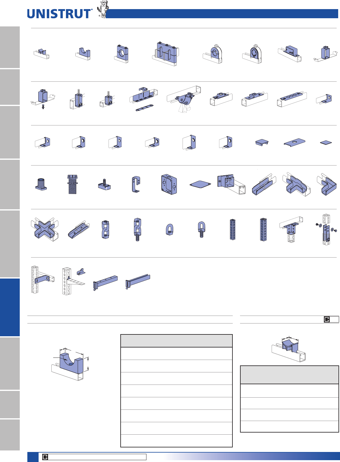
128
15⁄8" Framing System
1 5¼8" ChannelTelestrutNuts & HardwareGeneral FittingsPipe/Conduit SupportsElectrical FittingsConcrete InsertsSolarUnipier®
FG
CORE PRODUCTS - TYPICALLY AVAILABLE FROM STOCK
Electrical Fittings Pictorial Index
P2539-Pg 131 P2755-Pg 131 P2855-Pg 131 P3922-Pg 131 P2534-50-Pg 129 P2535-Pg 130 P2536-Pg 130 P2522-Pg 130 P3521-50-Pg 131
P2521-50-Pg 131 P5521-50-Pg 131 P5021-50-Pg 132 P2521-100-Pg 131 P5021-100-Pg 132 P5521-100-Pg 132 P1180 W-Pg 132 P2541-Pg 132 P2552-Pg 133
Electrical Fittings
P1753-Pg 128 P2649 A-Pg 128 P2645 A-Pg 129 P2647 A-Pg 129 P1690-Pg 129 P1787-Pg 130 P2567-Pg 129 P2537-Pg 131
P2823-Pg 136 P2821-Pg 136 P2920-Pg 136 P2928-Pg 136
M2137-Pg 133 M2250-Pg 133 M2350-Pg 133P2903-Pg 133 P2904-Pg 133 M2037-Pg 133 P16F-Pg 134 P21H-Pg 134 P2822-Pg 136P2820-Pg 136
P2540-Pg 132 P2603-Pg 132 P3116-125-Pg 133 P2602-Pg 131 P2801-Pg 132 P2802-Pg 132 P2803-Pg 132 P2900-Pg 133 P2901-Pg 133 P2902-Pg 133
P2649A THRU P2649H MAPLE CABLE SADDLES
3»8" Flat Head Machine Screw included.
6SHFLI\KROHVL]HZKHQRUGHULQJ
2UGHUFKDQQHOQXWVDVUHTXLUHG
Material: Paraffin impregnated maple hardwood.
A
(41.3)
1 5⁄8"
B
Hole Size
Part
No.
Hole Size
In (mm)
“A”
In (mm)
“B”
In (mm)
Wt/100 pcs
Lbs (kg)
P2649A 0 - 1 3 13»431
0 - 25.4 76.2 44.5 14.1
P2649B 1 - 11»231»2238
[ 88.9 50.8 17.2
P2649C 11»2 - 2 4 21»447
38.1 - 50.8 101.6 57.2 21.3
P2649D 2 - 21»241»221»257
[ 114.3 63.5 25.9
P2649E 21»2 - 3 5 23»468
63.5 - 76.2 127.0 69.9 30.8
P2649F 3 - 31»251»2380
[ 139.7 76.2 36.3
P2649G 31»2 - 4 6 31»494
88.9 - 101.6 152.4 82.6 42.6
P2649H over 4
over 101.6
P1753, P1754 CABLE SADDLES
A
(50.8)
2"
Material: FG - Fiberglass Reinforced Polyester,
PO - Dry Process White Glazed Porcelain
Part
Number
“A”
In (mm)
Maximum
Cable Dia.
In (mm)
Wt/100 pcs
Lbs (kg)
P1753 FG 213»16 312
71.4 76.2 5.4
P1754 FG 33»441»217
95.3 114.3 7.7
P1753 PO 3375
76.2 76.2 34.0
P1754 PO 44
1»295
101.6 114.3 43.1
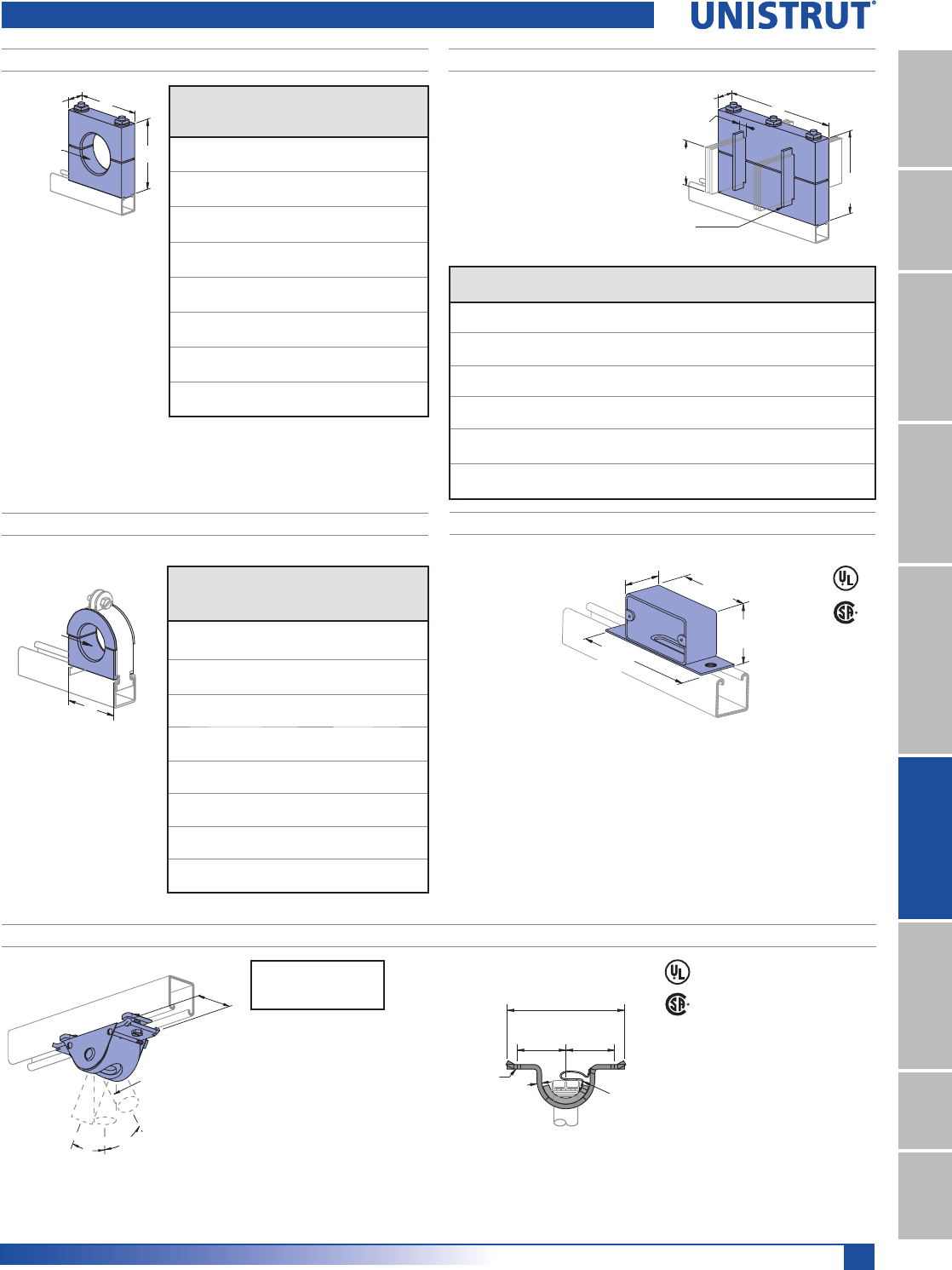
129
15⁄8" Framing System
1 5¼8" ChannelTelestrutNuts & HardwareGeneral FittingsPipe/Conduit SupportsElectrical FittingsConcrete InsertsSolarUnipier®
Electrical Fittings
P2645A THRU P2645H MAPLE CABLE CLAMPS
3»8" studs, square nuts and
washers included.
6SHFLI\KROHVL]H
when ordering.
2UGHUFKDQQHOQXWV
as required.
Material: Paraffin impregnated
maple hardwood.
Hole Size
A
1 5⁄8"
B
(41.3) Part
No.
Hole Size
In (mm)
“A” & “B”
Dimensions
In (mm)
Wt/100
pcs
Lbs (kg)
P2645A 0 - 1 31»284
0 - 25.4 88.9 38.1
P2645B 1 - 11»24 102
[ 101.6 46.3
P2645C 11»2 - 2 41»2121
38.1 - 50.8 114.3 54.9
P2645D 2 - 21»251»2165
[ 139.7 74.8
P2645E 21»2 - 3 6 189
63.5 - 76.2 152.4 85.7
P2645F 3 - 31»261»2215
[ 165.1 97.5
P2645G 31»2 - 4 7 243
88.9 - 101.6 177.8 110.2
P2645H over 4 ––
over 101.6
1»2" studs, square nuts and washers
are included.
&KDQQHOQXWVPXVWEHRUGHUHG
separately.
%XVEDUPDSOHFODPSVDOVR
available in 1»4" (6.4) x 2" (50.8)
and 1»4" (6.4) x 6" (152.4).
Material: Paraffin impregnated
maple hardwood.
P2647A THRU P2647F 4" (101.6) BUS BAR MAPLE CLAMPS
Part
No.
“A”
In (mm)
“B”
In (mm)
No. Bus
Separators
No. Bars
Per Leg
Wt/100 pcs
Lbs (kg)
P2647A 81»29»32 01
421
215.9 7.1 191.0
P2647B 91»213»16 22
465
241.3 20.6 210.9
P2647C 101»215»16 43
509
266.7 33.3 230.9
P2647D 111»2113»16 64
553
292.1 46.0 250.8
P2647E 121»223»885
597
317.5 60.3 270.8
P2647F 131»227»810 6 631
342.9 73.0 286.2
(41.3)
1 5⁄8"A
4"
(101.6)
1⁄4" (6.4) Maple
Separator
7 3⁄8"
(187.3)
B
8VHZLWKVWHHOFODPSDQG
Everdur hardware. Order
clamp separately.
6SHFLI\KROHVL]HZKHQ
ordering.
Material: Paraffin
impregnated maple
hardwood.
Hole Size
A
P1690 THRU P1697 MAPLE CABLE CLAMPS
Part
No.
Steel
Clamp
No.
Hole Size
In (mm)
“A”
In
(mm)
Wt/100
pcs
Lbs (kg)
P1690 P1113 E 0 -5»815»16 24
0 - 15.9 33.3 10.9
P1691 P1115 E
1»2 - 1 115»16 42
12.7- 25.4 49.2 19.1
P1692 P1117 E
3»4 - 11»223»854
[ 60.3 24.5
P1693 P1118 E 11»4 - 13»427»865
[ 73.0 29.5
P1694 P1119 E 11»2 - 21»431»284
[ 88.9 38.1
P1695 P1120 E 2 - 21»24 107
[ 101.6 48.5
P1696 P1121 E 21»4 - 3 41»2123
57.2 - 76.2 114.3 55.8
P1697 P1123 E 3 - 4 59»16 163
76.2 - 101.6 141.3 73.9
(47.6)
17⁄8"
(101.6)
4"
(146.1)
53⁄4"
(57.2)
21⁄4"
Material: 14 Gauge (.075)
Assembly: 1 Box, 2 Screws, 2 Channel Nuts
Wt/100 pcs: 88 Lbs (47.8 kg)
Ground Wire
2 Holes
9⁄32" (7.1)
2"
(50.8) 2"
(50.8)
4 13⁄16"
(122.2)
(4.8)
3⁄16"
Bushing
Not Included
15°
(.08π)
2"
(50.8)
P2534-50 For 1⁄2" Rigid Conduit
P2534-75 For 3⁄4" Rigid Conduit
1⁄4" X 3⁄4" Slotted Hex Head
Screws and Nuts Included
15°
(.08π)
P2534-50, P2534-75 CONDUIT SWING FITTING
Wt/100 pcs: 96 Lbs (43.5 kg)
&RQGXLWKDQJHUILWWLQJVDOORZDIUHHVZLYHORI° in one direction.
)LWWLQJPD\EHPRXQWHGWRWKHVORWVLGHRIWKH8QLVWUXWFKDQQHORUWRWKHEDFN
Design Load
300 Lbs (1.33 kN)
P2567 OUTLET BOX
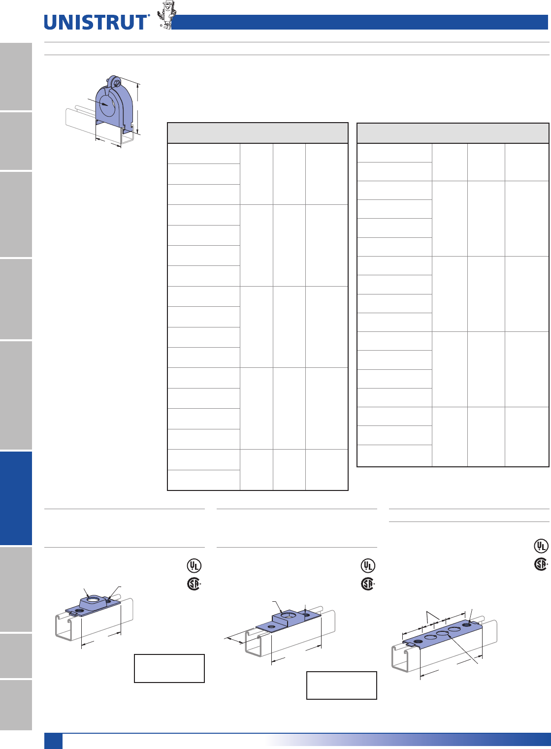
130
15⁄8" Framing System
1 5¼8" ChannelTelestrutNuts & HardwareGeneral FittingsPipe/Conduit SupportsElectrical FittingsConcrete InsertsSolarUnipier®
7⁄8" (22.2) Dia.
(101.6)
1⁄4" X 5⁄8" Flat Head
Machine Screws and
P3006-1420 Nuts
Included
4"
1 3⁄32" (27.8) Dia.
(130.2)
1 5⁄8"
(41.3)
1⁄4" X 5⁄8" Flat Head
Machine Screws and
P3016-1420 Nuts Included
5 1⁄8"
115⁄16"
(49.2)
1⁄4" X 5⁄8" Flat Head
Machine Screws and
P3016-1420 Nuts Included
1 3⁄16"
(30.2)
1 15⁄16"
(49.2)
6 1⁄4"
(158.8)
3 Knockouts
7⁄8" (22.2) Dia.
P1787 THRU P1795 PORCE-A-CLAMP™
Patents Pending
Strap Material:
Electro-galvanized Steel (EG) or
Stainless Steel (SS)
Use With: All 15»8" channel
Porce-A-Clamp™
1RQ%UHDNDEOH73(0DWHULDO
895HVLVWDQW
8//LVWHG
2SWLRQDO6WDLQOHVV6WHHO&ODPSV
7DSHUHG)ODQJHWR3URWHFW&DEOH
'LHOHFWULF6WUHQJWK9ROWV
Per Mil.
2QH3LHFH,QVXODWRU
5HSODFHV3RUFHODLQ0DSOH
Cable Clamp.
)RUXVHLQDFFRUGDQFHZLWK1DWLRQDO
Electrical Code ANSI/NFPA 70.
,QFOXGHV3LSH6WUDS
7HPSHUDWXUH5DWLQJ)WR)
(-45°C to +135°C)
Part
Number
Hole Size
In (mm)
“A”
In (mm)
“B”
In (mm)
Wt/100 pcs
Lbs (kg)
P1791B 21»2
3.36
85.3
4.05
102.9
90
40.8
63.5
P1791C 25»8
66.7
P1792 23»4
3.86
98.0
4.75
120.7
109
49.4
69.9
P1792A 27»8
73.0
P1792B 3
76.2
P1792C 31»8
79.4
P1793 31»4
4.36
110.7
5.125
130.2
130
59.0
82.6
P1793A 33»8
85.7
P1793B 31»2
88.9
P1793C 35»8
92.1
P1794 33»4
4.86
123.4
5.54
140.7
160
72.6
95.3
P1794A 37»8
98.4
P1794B 4
101.6
P1794C 41»8
104.8
P1795 41»4
5.24
133.1
5.92
150.4
160
72.6
108.0
P1795A 43»8
111.1
P1795B 41»2
114.3
Electrical Fittings
Hole Size
A
B
Part
Number
Hole Size
In (mm)
“A”
In (mm)
“B”
In (mm)
Wt/100 pcs
Lbs (kg)
P1787A
3»8
1.36
34.5
1.82
46.2
25
11.3
9.5
P1787B
1»2
12.7
P1787C
5»8
15.9
P1788
3»4
1.86
47.2
2.34
59.4
37
16.8
19.1
P1788A
7»8
22.2
P1788B 1
25.4
P1788C 11»8
28.6
P1789 11»4
2.36
59.9
2.86
72.6
58
26.3
31.8
P1789A 13»8
34.9
P1789B 11»2
38.1
P1789C 15»8
41.3
P1790 13»4
2.86
72.6
3.50
88.9
76
34.5
44.5
P1790A 17»8
47.6
P1790B 2
50.8
P1790C 21»8
54.0
P1791 21»4
3.36
835
4.05
102.9
90
40.8
57.2
P1791A 23»8
60.3
P2535
CONDUIT HANGER CONNECTION
FOR 1¼2"CONDUIT
Material: 12 gauge (2.7).
Design Load
400 Lbs (1.78 kN)
P2536
CONDUIT HANGER CONNECTION
FOR 3¼4"CONDUIT
Material: 16 gauge (1.5) Design Load
200 Lbs (0.89 kN)
P2522 OUTLET BOX CONNECTION
Wt/100 pcs: 28 Lbs (12.7 kg) Wt/100 pcs: 36 Lbs (16.3 kg) Wt/100 pcs: 35 Lbs (15.9 kg)
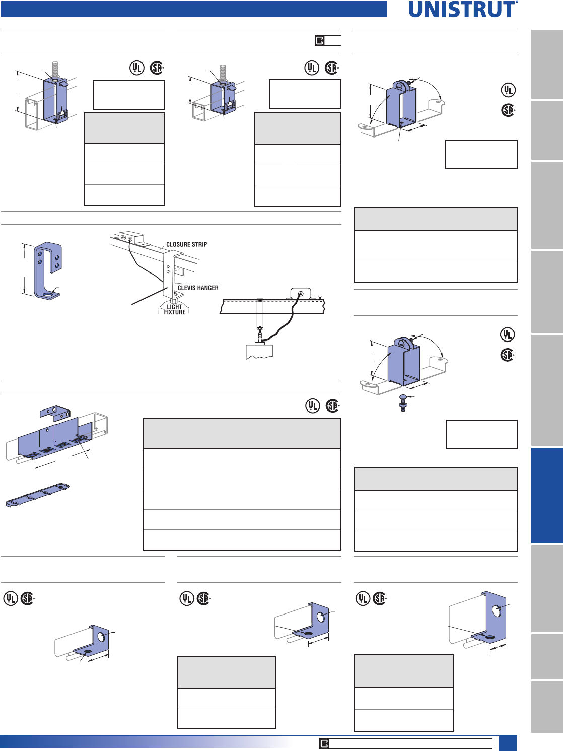
131
15⁄8" Framing System
1 5¼8" ChannelTelestrutNuts & HardwareGeneral FittingsPipe/Conduit SupportsElectrical FittingsConcrete InsertsSolarUnipier®
CORE PRODUCTS - TYPICALLY AVAILABLE FROM STOCK
EG
2 1⁄16"
(52.4)
A
1⁄4" X 5⁄8" Flat Head
Machine Screw and
P3016-1420 Nut
Included
(108.0)
4 1⁄4"
A
9⁄32" (7.1)
Sq. Hole
9⁄32" (7.1)
Sq. Hole
2 3⁄4"
(69.9)
A
6 3⁄4"
(171.5) 1⁄4" X 5⁄8" Flat Head
Machine Screws
and 4 Hole Splice
Plate Nut Included
P2869 14 (2) Gage
Threaded
Plate Nut
7⁄8" (22.2) Dia.
2 1⁄4"
(57.2)
1⁄4" X 5⁄8" Flat Head Machine
Screw and P3016-1420 Nut
Included
P3000
A
P5500
1⁄4" X 5⁄8" Flat Head
Machine Screw and
P3016-1420 Nut
Included
(34.9)
1 3⁄8"
P2537, P5537
FLUORESCENT FIXTURE HANGERS
+DQJHUSURYLGHVPRUHWKDQ1»2" (12.7) space
between channel and fixtures.
Materials: 18 gauge (1.2).
1⁄4" X 1" RHMS and
Sq. Nut Included
A
9⁄32" (7.1) Dia. Hole
1 5⁄8"
(41.3)
Design Load
120 Lbs (0.53 kN)
Part
No.
Use
w/Channel
“A”
In (mm)
Wt/100 pcs
Lbs (kg)
P2537
P1000 27»16
61.9
19
8.6
P1100
P3000
P5537 P5500 31»422
82.6 10.0
P2539, P3539, P5539
FLUORESCENT FIXTURE HANGERS
+DQJHUSURYLGHV1»8" (3.2)
space between channel
and fixtures.
Materials: 18 gauge (1.2).
A
(41.3)
1 5⁄8"
1⁄4" X 3⁄4"
Carriage Bolt
and Sq. Nut Included
1⁄4" X 1" RHMS and
Sq. Nut Included
Design Load
120 Lbs (0.53 kN)
Part
No. Use w/Channel
“A”
In (mm)
Wt/100 pcs
Lbs (kg)
P2539 P1000 13»417
P1100 44.5 7.7
P3539 P3000 11»215
38.1 6.8
P5539 P5500 29»16 18
65.1 8.2
P2755, P2756, P2757
RACEWAY HANGERS
P2855, P2856, P2857
RACEWAY HANGERS
Use with Channels:
P1001, P1101, P2001,
P5000, & P5500.
Material: 14 gauge (1.9).
Use with Channels:
P1000, P1100,
P3000, P3300
Material: 14 gauge (1.9).
Design Load
120 Lbs (0.53 kN)
Part
No.
“A”
In
(mm)
Wt/100
pcs
Lbs (kg)
P2755
9»16 44
14.3 20.0
P2756
7»844
22.2 20.0
P2757
13»32 44
10.3 20.0
Part
No.
“A”
In
(mm)
Wt/100
pcs
Lbs (kg)
P2855
9»16 32
14.3 14.5
P2856
7»832
22.2 14.5
P2857
13»32 32
10.3 14.5
Receptacles & Fixture Hangers
Design Load
120 Lbs (0.53 kN)
P3922 THRU P3926 SPLICE FITTINGS
Material: 16 gauge (1.6).
Assy.
No.
Use W/
Channel
“A”
In
(mm)
Clevis
No.
Back
Clevis
No.
Plate
Nut
No.
Wt/100
pcs
Lbs (kg)
P3922 P1000 15»8P2377 P2517 P2869 100
P1100 41.3 45.4
P3923 P3000 13»8P3377 P2517 P2869 97
34.9 44.0
P3924 P4000
13»16 P5377 P2517 P2869 80
20.6 36.3
P3925 P5500 15»8P2377 P5517 P2869 103
41.3 46.7
P3926 P5000 15»8P2377 P5017 P2869 106
41.3 48.1
P3521-50
END CONNECTORS FOR 1¼2"CONDUIT
Material: 12 gauge (3).
P2521-50, P2521-75
END CONNECTORS FOR 1¼2" & 3¼4" CONDUIT
Use with channels:
P1000 and P1100.
Material:
12 gauge (3)
Part
No.
Conduit
Size A
In
Wt/100
pcs
Lbs (kg)
P2521-50 1»227
12.2
P2521-75 3»426
11.8
P5521-50, P5521-75
END CONNECTORS FOR 1¼2" & 3¼4" CONDUIT
Material:
12 gauge (3).
Part
No.
Conduit
Size A
In
Wt/100
pcs
Lbs (kg)
P5521-50 1»2
27
12.2
P5521-75 3»4
26
11.8
Wt/100 pcs: 27 Lbs (12.2 kg)
P2602 MECURY VAPOR FIXTURE HANGER
6 3⁄4"
(171.5)
Hole Size
1 1⁄16"
(27.0)
Wt/100 pcs: 154 Lbs (69.9 kg)
Use with 15»8" Channel
Finish: Electro-galvanized
Stock Size: 1»4"
NOTE: Supports fixture in slot up or down system.
Requires P2603
wiring nipple
Where swivel joint
is required
CLOSURE
STRIP
CHANNEL
LIGHT
FIXTURE
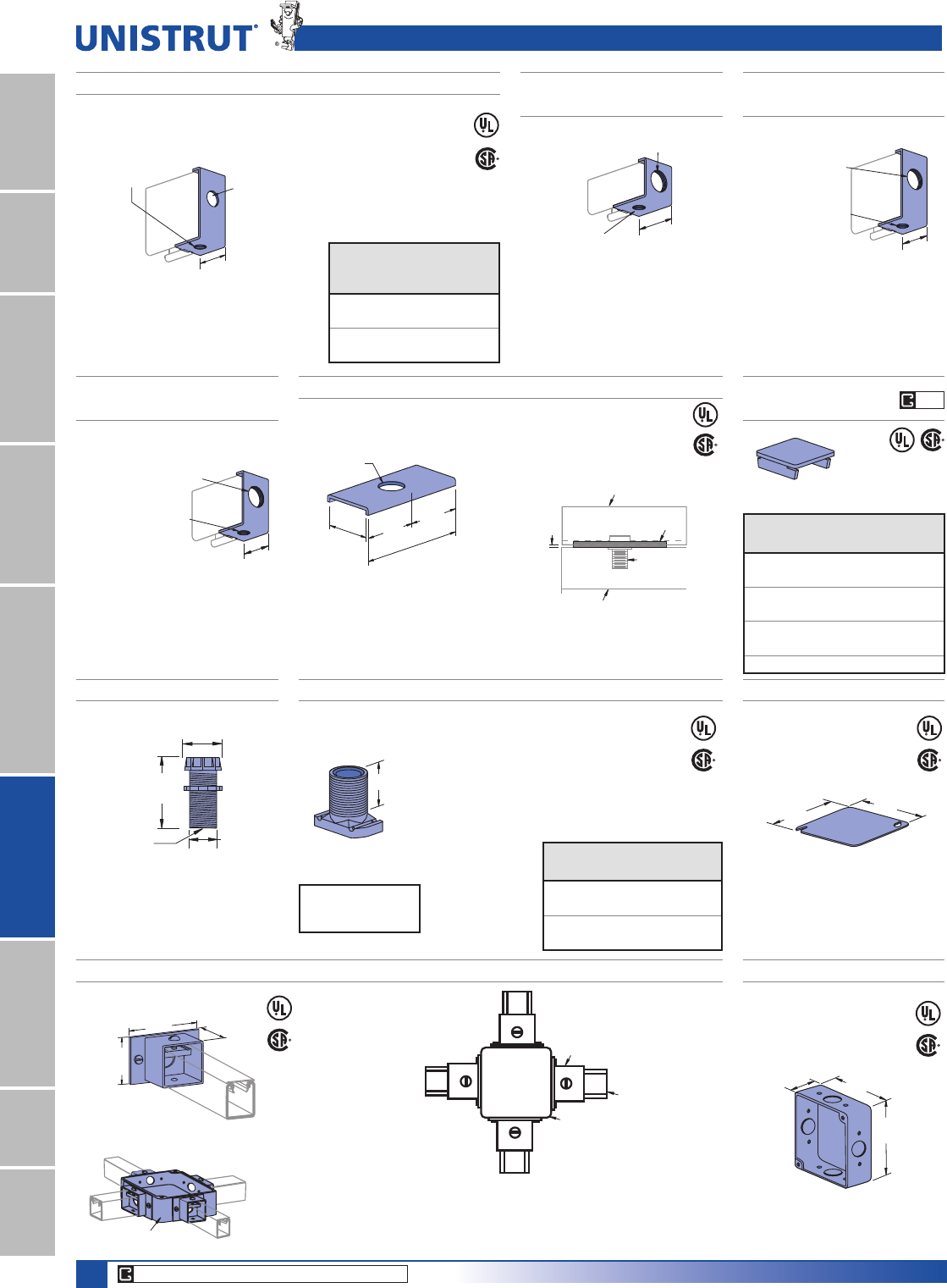
132
15⁄8" Framing System
1 5¼8" ChannelTelestrutNuts & HardwareGeneral FittingsPipe/Conduit SupportsElectrical FittingsConcrete InsertsSolarUnipier®
P2540, P2540A WIRING STUD NUTP2603 FIXTURE WIRING NIPPLE
A
1»2" American Standard
Straight Pipe Thread
Design Load
320 Lbs (1.42 kN)
Part
No.
“A”
In (mm)
Wt/100 pcs
Lbs (kg)
P2540 15»64 10.0
27.4 4.5
P2540A
5»88
15.9 3.6
2 1⁄8"
(54)
1.10"
(27.9)
0.80"
(20.3)
Hole Dia.
.600" (15.2)
Wt/100 pcs: 14 Lbs (6.4 kg)
Assembly: 1»2" x 2" rigid conduit
nipple Bushing Locknut
Stamped Ident. No.
P2540 – 121961
P2540A – 121960
Material: Sintered metal.
P5021-50, P5021-75 END CONNECTOR FOR 1¼2" & 3¼4" CONDUIT P2521-100
END CONNECTOR FOR 1" CONDUIT
P5021-100
END CONNECTOR FOR 1" CONDUIT
P1180W THRU
P5580W END CAPS
(41.3)
1 5⁄8"
A
P5000
1⁄4" X 5⁄8" Flat Head
Machine Screw and
P3016-1420 Nut
Included
Material: 12 gauge (2.7).
1 5⁄8"
(41.3)
P5000
Tapped for 1"
Conduit Thread
1⁄4" x 5⁄8" Flat Head
Machine Screw and
P3016-1420 Nut
Included
Material: 12 gauge (2.7).
Tapped for 1"
Conduit Thread
(52.4)
P1000
1⁄4" x 5⁄8" Flat Head
Machine Screw and
P3016-1420 Nut
Included
2 1⁄16"
Material: 14 gauge (1.9)
Part
Number
Use
With
Wt/100 pcs
Lbs (kg)
P1180W P1100 12 (5.4)
P1280W P1000 11 (5.0)
P2280W P2000 11 (5.0)
P3280W P3000 8 (3.6)
P4280W P4000 5 (2.3)
P5280W P5000 22 (10.0)
P5580W P5500 18 (8.2)
Part
No.
Conduit
Size A
In
Wt/100
pcs
Lbs (kg)
P5021-50 1»231
14.1
P5021-75 3»430
13.6
Electrical Accessories & Junction Boxes
P2541 SPACER CLEVIS
Wt/100 pcs: 24 Lbs (10.9 kg)
2"
(50.8)
(101.6)
121⁄32"
(42.1)
7⁄8" DIA.
(22.2)
(50.8)
4"
2"
1⁄8"
(3.2)
UNISTRUT Channel
Flourescent Fixture
P2541
P2540 Wiring
Stud Nut
Material: 12 gauge (2.7).
Wt/100 pcs: 24 Lbs (10.9 kg) Wt/100 pcs: 28 Lbs (12.7 kg)
P5521-100
END CONNECTOR FOR 1" CONDUIT
Material: 12 gauge (2.7).
P5500
Tapped for 1"
Conduit Thread
1⁄4" x 5⁄8" Flat Head
Machine Screw and
P3016-1420 Nut
Included 15⁄8"
(41.3)
Wt/100 pcs: 24 Lbs (10.9 kg)
Material: 12 gauge (2.7).
2 1⁄4"4"
(101.6)
4"
(101.6)
(57.2)
P2801 JUNCTION BOX
Wt/100 pcs: 113 Lbs (51.4 kg)
P2803 HUB ASSEMBLY
Wt/100 pcs: 32 Lbs (14.5 kg)
3"
(76.2) (42.9)
2"
(50.8)
1 11⁄16"
4 3⁄16"
(106.4)
4 3⁄16"
(106.4)
P2802 JUNCTION BOX COVER
Wt/100 pcs: 30 Lbs (13.6kg)
Note: Combine junction box (P2801) and
hub assemblies (P2803) to make
1, 2, 3, or 4 way junction box.
P2801
Junction Box
P2803 Hub
P1000
Channel
Stamp ID No. 122022
P2801
CORE PRODUCTS - TYPICALLY AVAILABLE FROM STOCK
EG
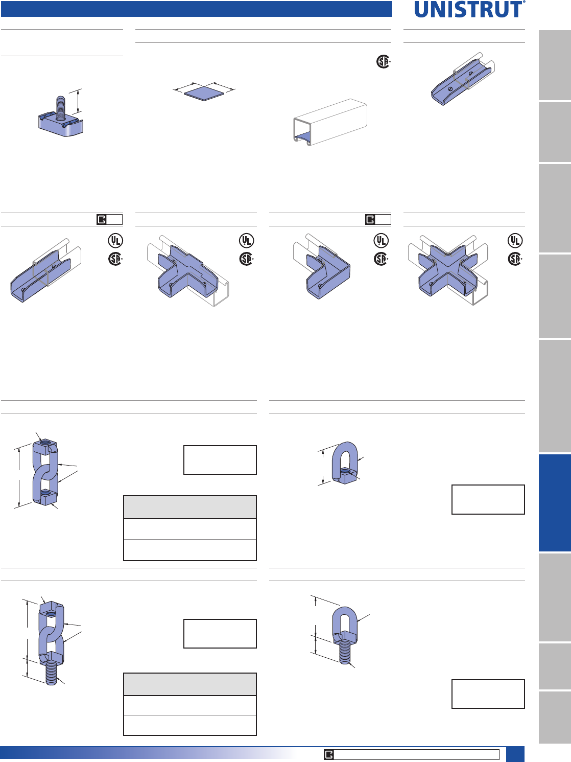
133
15⁄8" Framing System
1 5¼8" ChannelTelestrutNuts & HardwareGeneral FittingsPipe/Conduit SupportsElectrical FittingsConcrete InsertsSolarUnipier®
P2552 POLYPROPYLENE WIRE RETAINERP3116-125
FIXTURE STUD NUT
Wt/100 pcs: 11 Lbs (5.0 kg)
Retainer may be easily pushed into
channel to support wires until
closure strip is installed.
Wt/100 pcs: .30 Lbs (.1 kg)
1 1⁄2"
(38.1)
1 1⁄2"
(38.1)
1 3⁄16"
(30.2)
1⁄4" x 20 Thd.
P2900 P2901 P2902 P2903
Wt/100 pcs: 35 Lbs (15.9 kg)
P1000
P1000 P1000
P1000
Wt/100 pcs: 45 Lbs (20.4 kg)Wt/100 pcs: 27 Lbs (12.2 kg)Wt/100 pcs: 20 Lbs (9.1 kg)
P2904
Wt/100 pcs: 12 Lbs (5.4kg)
P3300, P4000,
P4100
3/8"-16 x 1/4" Socket Cup Point
Set Screws Included
Extruded Aluminum
3/8"-16 x 1/4" Socket Cup Point
Set Screws Included
Material: Cast aluminum.
3/8"-16 x 1/4" Socket Cup Point
Set Screws Included
Material: Cast aluminum.
3/8"-16 x 1/4" Socket Cup Point
Set Screws Included
Material: Cast aluminum.
3/8"-16 x 1/4" Socket Cup Point
Set Screws Included
Material: Cast aluminum.
Swivel Hangers & In-Channel Joiners
M2037, M2050 SWIVEL HANGERS
A
3⁄8" (9.5) DIA.
A
B
Part
No.
“A”
In
“B”
In (mm)
Wt/100 pcs
Lbs (kg)
M2037 3»8" - 16 231»32 23
75.4 10.4
M2050 1»2" - 13 23»432
69.9 14.5
Design Load
600 Lbs (2.67 kN)
M2137, M2150 SWIVEL HANGERS
A
3⁄8" (9.5) DIA.
A
B
(25.4)
1"
Part
No.
“A”
In
“B”
In (mm)
Wt/100 pcs
Lbs (kg)
M2137 3»8" - 16 229»32 27
74 12.2
M2150 1»2" - 13 23»445
69.9 20.4
Design Load
600 Lbs (2.67 kN)
M2250 SWIVEL HANGER
Wt/100 pcs: 18 Lbs (8.2 kg)
3⁄8" (9.5) DIA.
1⁄2" - 13 THD.
1 3⁄4"
(44.5)
Design Load
600 Lbs (2.67 kN)
M2350 SWIVEL HANGER
3⁄8" (9.5) DIA.
1 3⁄4"
(44.5)
(25.4)
1"
1⁄2" - 13 THD.
Wt/100 pcs: 20 Lbs (9.1 kg)
Design Load
600 Lbs (2.67 kN)
CORE PRODUCTS - TYPICALLY AVAILABLE FROM STOCK
AL AL
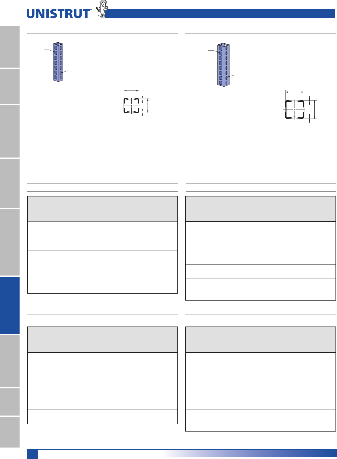
134
15⁄8" Framing System
1 5¼8" ChannelTelestrutNuts & HardwareGeneral FittingsPipe/Conduit SupportsElectrical FittingsConcrete InsertsSolarUnipier®
P16F P21H
Slot Size
17⁄32" x 7⁄8"
(13.5) x (22.2)
Slot Size
3⁄4" X 7⁄8"
(19.1) x (22.2)
Slot Size
17⁄32" x 7⁄8"
(13.5) x (22.2)
Slot Size
3⁄4" X 7⁄8"
(19.1) x (22.2)
1
1
2
27⁄32" (5.6)
7⁄32" (5.6)
2 3⁄16"
(55.6)
2 5⁄32"
(54.8)
1
2
1
27⁄32" (5.6)
7⁄32" (5.6)
1 3⁄4"
(44.5)
1 23⁄32"
(43.7)
Cable Entrance Tubing
Slot spacing
11»4" (31.8)
on center.
Slot spacing
11»4" (31.8)
on center.
Unbraced
Height
In
Max. Allowable Load
Column Loaded
at C.G.
Lbs
Max. Allowable Load
Column Loaded
at Slot Face
Lbs
24 9,600 3,300
36 9,000 3,100
48 8,300 2,900
60 7,500 2,700
72 6,600 2,400
84 5,600 2,200
96 4,500 1,900
108 3,600 1,600
120 2,900 1,400
144 2,000 1,100
Unbraced
Height
mm
Max. Allowable Load
Column Loaded
at C.G.
kN
Max. Allowable Load
Column Loaded
at Slot Face
kN
610 42.7 14.7
914 40.0 13.8
1,219 36.9 12.9
1,524 33.4 12.0
1,829 29.4 10.7
2,134 24.9 9.8
2,438 20.0 8.5
2,743 16.0 7.1
3,048 12.9 6.2
3,658 8.9 4.9
Unbraced
Height
In
Max. Allowable Load
Column Loaded
at C.G.
Lbs
Max. Allowable Load
Column Loaded
at Slot Face
Lbs
24 17,700 6,200
36 16,900 6,000
48 16,000 5,700
60 15,000 5,400
72 13,900 5,100
84 12,600 4,700
96 11,300 4,300
108 9,900 3,900
120 8,300 3,500
144 5,800 2,800
168 4,230 2,300
Unbraced
Height
mm
Max. Allowable Load
Column Loaded
at C.G.
kN
Max. Allowable Load
Column Loaded
at Slot Face
kN
610 78.7 27.6
914 75.2 26.7
1,219 71.2 25.4
1,524 66.7 24.0
1,829 61.8 22.7
2,134 56.0 20.9
2,438 50.3 19.1
2,743 44.0 17.3
3,048 36.9 15.6
3,658 25.8 12.5
4,267 18.8 10.2
Wt/100 Ft: 178 Lbs (260 kg/100 m)
$OORZDEOH0RPHQW,Q/EV1P
12 Gauge Nominal Thickness .105" (2.7mm)
Wt/100 Ft: 297 Lbs (440 kg/100 m)
$OORZDEOH0RPHQW,Q/EV1P
12 Gauge Nominal Thickness .105" (2.7mm)
Tubing Finishes: PL, GR, HG, PG;
Standard Lengths: 10' & 20' Tubing Finishes: PL, GR, HG, PG;
Standard Lengths: 10' & 20'
P16F - COLUMN LOADING P21H - COLUMN LOADING
P16F - COLUMN LOADING (METRIC) P21H - COLUMN LOADING (METRIC)
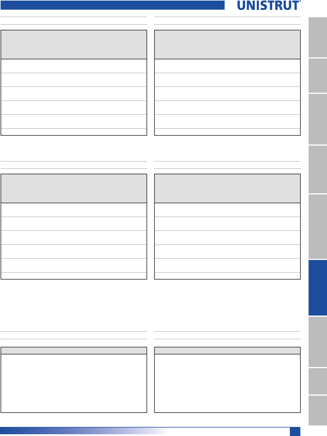
135
15⁄8" Framing System
1 5¼8" ChannelTelestrutNuts & HardwareGeneral FittingsPipe/Conduit SupportsElectrical FittingsConcrete InsertsSolarUnipier®
Cable Entrance Tubing
P16F - ELEMENTS OF SECTION
Parameter P16F P16F (metric)
Area of Section 0.416 In22.68 FP2
Axis 1-1
Moment of Inertia (I) 0.168 In47.0 FP4
Section Modulus (S) 0.192 In33.1 FP3
Radius of Gyration (r) 0.650 In 1.7 FP
Axis 2-2
Moment of Inertia (I) 0.210 In48.7 FP4
Section Modulus (S) 0.240 In33.9 FP3
Radius of Gyration (r) 0.725 In 1.8 FP
Parameter P21H P21H (metric)
Area of Section 0.749 In24.83 FP2
Axis 1-1
Moment of Inertia (I) 0.490 In420.4 FP4
Section Modulus (S) 0.455 In37.5 FP3
Radius of Gyration (r) 0.820 In 2.1 FP
Axis 2-2
Moment of Inertia (I) 0.590 In424.6 FP4
Section Modulus (S) 0.540 In38.8 FP3
Radius of Gyration (r) 0.900 In 2.3 FP
P21H - ELEMENTS OF SECTION
Notes:
1. Above loads include the weight of the member. This weight must be deducted to arrive at the net allowable load the beam will support.
2. Long span beams should be supported in such a manner as to prevent rotation and twist.
3. Allowable uniformly distributed loads are listed for various simple spans, that is, a beam on two supports. If load is concentrated at the center
of the span, multiply load from the table by 0.5 and corresponding deflection by 0.8.
Span
In
Max
Allowable
Uniform Load
Lbs
Defl. at
Uniform
Load
In
Uniform Loading at Deflection
Span/180
Lbs
Span/240
Lbs
Span/360
Lbs
24 1,600 0.06 1,600 1,600 1,600
36 1,070 0.13 1,070 1,070 820
48 800 0.23 800 690 460
60 640 0.36 590 440 290
72 530 0.52 410 310 200
84 460 0.71 300 220 150
96 400 0.93 230 170 110
108 360 1.18 180 140 90
120 320 1.45 150 110 70
144 270 2.09 100 80 50
168 230 2.85 70 60 40
Span
mm
Max
Allowable
Uniform Load
kN
Defl. at
Uniform
Load
mm
Uniform Loading at Deflection
Span/180
kN
Span/240
kN
Span/360
kN
600 7.2 1 7.2 7.2 7.2
750 5.8 2 5.8 5.8 5.4
1,000 4.3 4 4.3 4.3 3.0
1,250 3.5 6 3.5 2.9 1.9
1,500 2.9 9 2.7 2.0 1.4
1,750 2.5 12 2.0 1.5 1.0
2,000 2.2 16 1.5 1.1 0.8
2,500 1.7 25 1.0 0.7 0.5
3,000 1.5 36 0.7 0.5 0.3
3,500 1.2 49 0.5 0.4 0.2
4,000 1.1 64 0.4 0.3 0.2
Span
In
Max
Allowable
Uniform Load
Lbs
Defl. at
Uniform
Load
In
Uniform Loading at Deflection
Span/180
Lbs
Span/240
Lbs
Span/360
Lbs
24 3,790 0.05 3,790 3,790 3,790
36 2,530 0.11 2,530 2,530 2,380
48 1,900 0.19 1,900 1,900 1,340
60 1,520 0.29 1,520 1,280 860
72 1,260 0.42 1,190 890 590
84 1,080 0.58 870 660 440
96 950 0.76 670 500 330
108 840 0.96 530 400 260
120 760 1.18 430 320 210
144 630 1.70 300 220 150
168 540 2.31 220 160 110
Span
mm
Max
Allowable
Uniform Load
kN
Defl. at
Uniform
Load
mm
Uniform Loading at Deflection
Span/180
kN
Span/240
kN
Span/360
kN
600 17.1 1 17.1 17.1 17.1
750 13.7 2 13.7 13.7 13.7
1,000 10.3 3 10.3 10.3 8.8
1,250 8.2 5 8.2 8.2 5.7
1,500 6.9 7 6.9 5.9 3.9
1,750 5.9 10 5.8 4.3 2.9
2,000 5.1 13 4.4 3.3 2.2
2,500 4.1 20 2.8 2.1 1.4
3,000 3.4 29 2.0 1.5 1.0
3,500 2.9 40 1.4 1.1 0.7
4,000 2.6 52 1.1 0.8 0.5
P16F - BEAM LOADING P21H - BEAM LOADING
P16F - BEAM LOADING (METRIC) P21H - BEAM LOADING (METRIC)
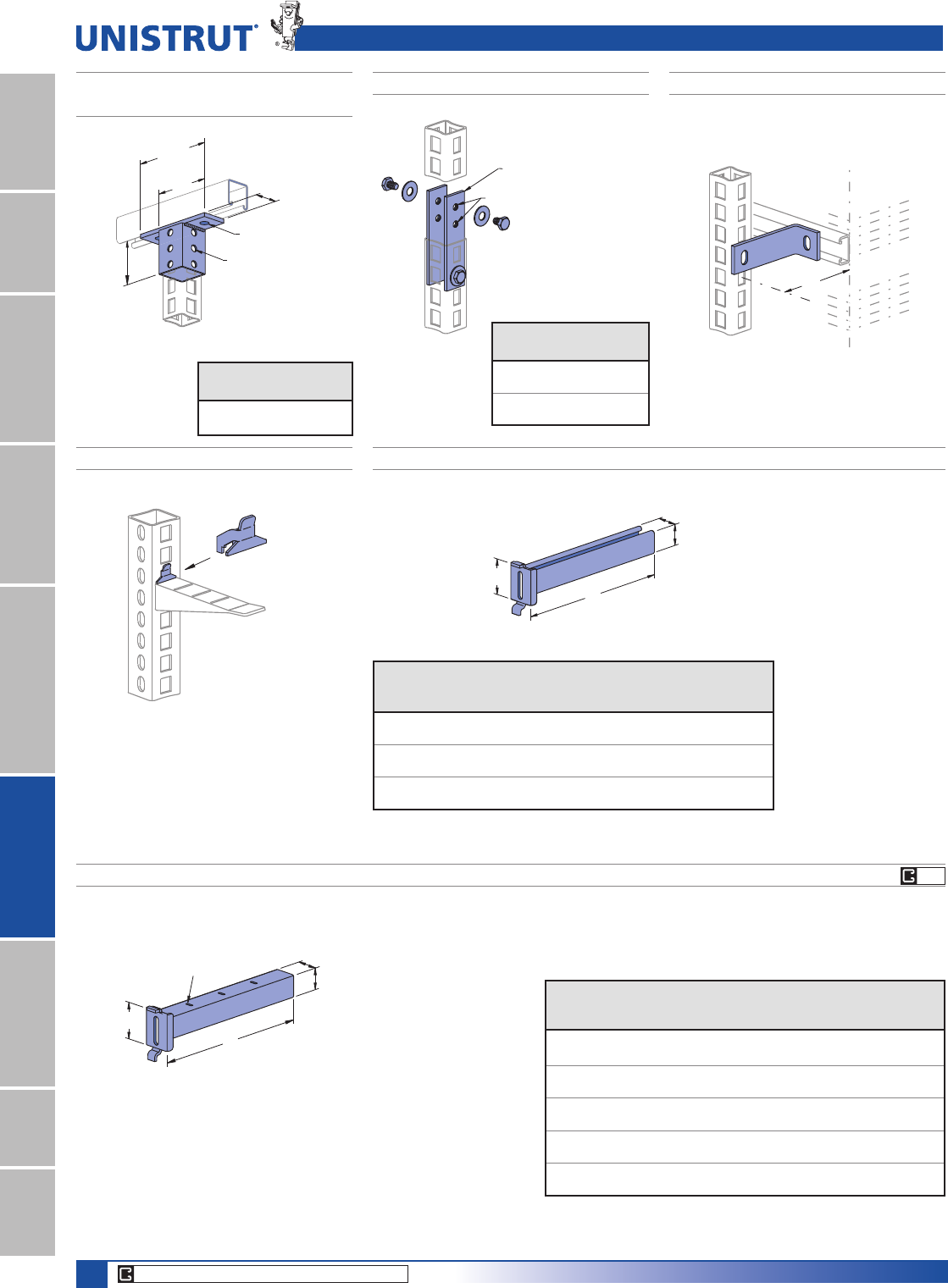
136
15⁄8" Framing System
1 5¼8" ChannelTelestrutNuts & HardwareGeneral FittingsPipe/Conduit SupportsElectrical FittingsConcrete InsertsSolarUnipier®
Cable Entrance Fittings
P2822, P2932 SPLICE FITTINGS P2823 90° RACK FITTING
P2821 LOCKING CLIP
Exclusive Cable Hook
Locking Clip prevents Cable
Hook removal.
P2821
Locking Clip
3"
(76.2)
53⁄8"
(136.5)
33⁄4"
(95.3) 15⁄8"
(41.3)
9⁄16" (14.3) Dia. Holes
7⁄16" (11.1) Dia. Holes
P2820, P2940
CHANNEL/TUBE CONNECTORS
Cable Hook
supplied by others.
(127.0)
5"
P4000
Splice Fitting Assembly
Secured to Flat Side with
Hardware Provided
Use Either Threaded Hole
Part
No.
Use
With
Wt/100 pcs
Lbs (kg)
P2820 P16F 116 (2.6)
P2940 P21H 148 (67.1)
Part
No.
Use
With
Wt/100 pcs
Lbs (kg)
P2822 P16F 97
(44.0)
P2932 P21H 122
(55.3)
Splicing should occur
within the top one quarter of
column height.
P2920 THRU P2924 CABLE BRACKETS
L
A
1 5⁄8"
(41.3)
B
3⁄16" (4.8) x 3⁄4" (19.1) Slots
2 3⁄4" (69.9) on Center
Safety factor of 3.
Material: 12 gauge steel.
Use with P16F or P21H.
Part
Number
“L”
In (mm)
“A”
In (mm)
“B”
In (mm)
Wt/100 pcs
Lbs (kg)
Uniform
Design Load
Lbs (kN)
P2920 51»231»27»890 500
139.7 88.9 22.2 40.8 2.22
P2921 81»431»27»8120 325
209.6 88.9 22.2 54.4 1.45
P2922 11 31»215»8300 275
279.4 88.9 41.3 136.1 1.22
P2923 133»431»215»8340 220
349.3 88.9 41.3 154.2 0.98
P2924 191»431»215»8430 160
489.0 88.9 41.3 195.0 0.71
P2928, P2929 AND P2930 CABLE BRACKETS
L
A
1 5⁄8"
(41.3)
B
Safety factor of 3.
Material: 12 gauge steel.
Use with P16F or P21H.
Part
Number
“L”
In (mm)
“A”
In (mm)
“B”
In (mm)
Wt/100 pcs
Lbs (kg)
Uniform
Design Load
Lbs (kN)
P2928 63
1»27»892 500
152.4 88.9 22.2 41.7 2.22
P2929 12 31»215»8320 250
304.8 88.9 41.3 145.1 1.11
P2930 18 31»215»8420 170
457.2 88.9 41.3 190.5 0.76
Wt/100 pcs: 66 Lbs (29.9 kg)
Wt/100 pcs: 3 Lbs (1.4 kg)
CORE PRODUCTS - TYPICALLY AVAILABLE FROM STOCK
HG
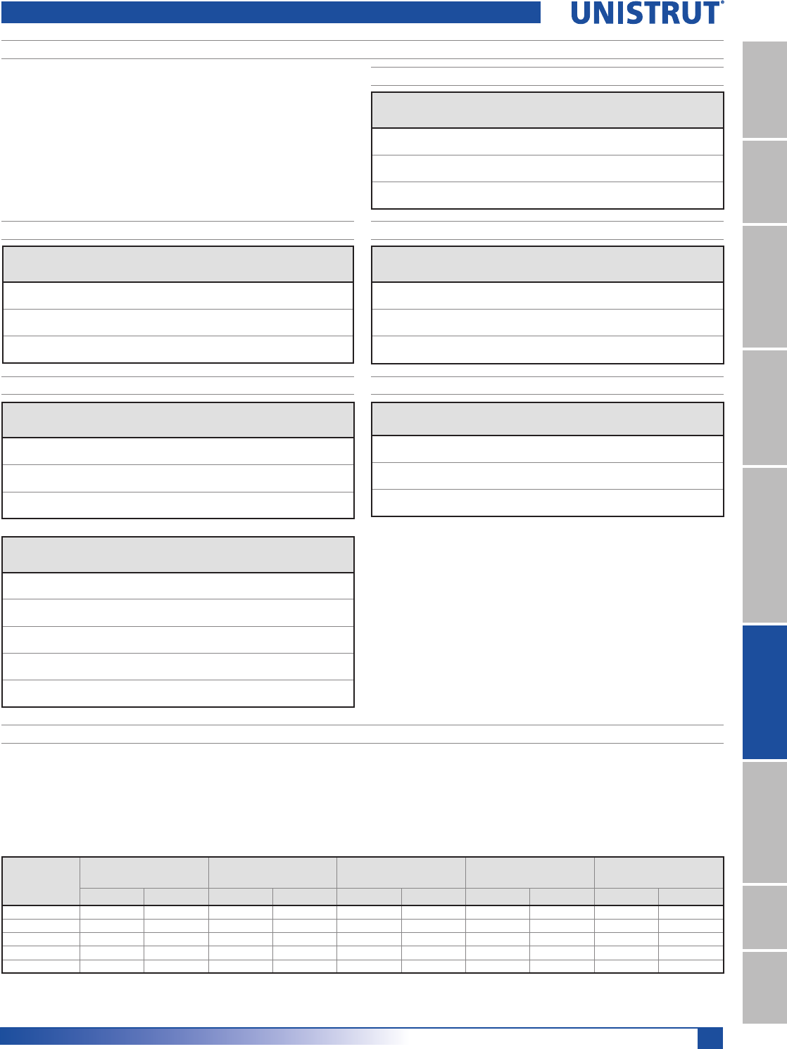
137
15⁄8" Framing System
1 5¼8" ChannelTelestrutNuts & HardwareGeneral FittingsPipe/Conduit SupportsElectrical FittingsConcrete InsertsSolarUnipier®
U.L. LISTED
C.S.A. APPROVED
Electrical Technical Data
Unistrut channels are also certified by Canadian Standards Association.
Unistrut channel is listed by Underwriters' Laboratories as a surface metal raceway.
Snap-in closure strip is used to complete the raceway. Accessory parts listed by
Underwriters are noted on drawings.
The following tables represent maximum number of conductors when raceway is
not employed with fixtures or where the clearance between fixtures and raceway is
greater than 1»2" (12.7). In all cases the snap-in cover is required to complete raceway
enclosure.
P3300
P3000, & -KO
P5500, & -KO
P5000, & -KOP1000, & -KO, P1100 & -KO
Suitable for number of wires in Column A when installed to support and supply electric
discharge type lighting fixtures when raceway wiring is suitable for at least 75° C
except wire suitable for 60° C may be used when clearance between fixtures and
raceways is at least 1»2" (12.7). Also suitable for number of wires in column B when
Gauge
1XPEHUDQG&RQGXFWRU6L]H$:*
14 12 10 8 6
THWN, THHN 72 54 34 17 12
XHHW 48 37 29 13 10
T, TW 46 36 28 13 7
THW 30252010 7
RH 27 22 13 7 5
RHH, RHW 19 16 13 7 5
Gauge
1XPEHUDQG&RQGXFWRU6L]H$:*
14 12 10 8 6
THWN, THHN 141 105 66 33 23
XHHW 93 73 57 27 19
T, TW 91 58 55 26 15
THW 59493920 15
RH 53 44 26 14 10
RHH, RHW 37 32 26 14 10
Gauge
1XPEHUDQG&RQGXFWRU6L]H$:*
14 12 10 8 6
THWN, THHN 40 30 19 9 6
XHHW 26 21 16 7 5
T, TW 26 20 15 7 4
THW 17 14 11 6 4
RH 15 12 7 4 3
RHH, RHW 10 9742
Gauge
1XPEHUDQG&RQGXFWRU6L]H$:*
14 12 10 8 6
THWN, THHN 88 66 42 20 14
XHHW 58 46 35 16 12
T, TW 57 44 34 16 9
THW 37302412 9
RH 33 27 16 9 6
RHH, RHW 23 20 16 9 6
Gauge
Number and Conductor Size (AWG)
14 12 10 8 6
THWN, THHN 193 105 91 45 32
XHHW 128 101 78 37 27
T, TW 125 98 75 35 20
THW 81675428 20
RH 73 60 36 19 13
RHH, RHW 51 44 36 19 13
Raceway Wire
Size
AWG
P1000, &-KO
P1100, &-KO P3000, &-KO P3300 P5000 &-KO P5500, &-KO
A B A BA B A B A B
14 6 10 5 10 4 6 10 10 10 10
12 6 10 4 10 3 6 10 10 10 10
10 5846 - -810810
8 4634- -6968
6 2322- -4646
installed to support electric discharge type lighting fixtures when raceway wiring is
suitable for at least 75° C and clearance between fixtures and raceway is at least 1»8"
(3.2).
Maximum number of wires for types T, THHN,
THW, THWN, TW, R, RH, RHH, RHW or XHHW
Channel Size and Inside Area
Channel Part Number Size Area 40% Area 25% Area
P3300 & KO 15»8" x 7»8"0.975 0.390 0.244
629 252 157
P3000 & KO 15»8" x 13»8"1.677 0.671 0.419
1,082 433 270
P1000 & KO, P1100 & KO 15»8" x 15»8"2.028 0.811 0.507
1,308 523 327
P5500 & KO 15»8" x 27»16"3.169 1.268 0.792
2,045 818 511
P5000 & KO 15»8" x 31»4"4.308 1.723 1.077
2,779 1,112 695
Note:
Raceways with external joiners shall use a 40% wire fill calculation to determine the
number of conductors permitted.
Raceways with internal joiners shall use a 25% wire fill calculation to determine the
number of conductors permitted
Also UL Listed
P1001, P1101, P3001, P3301, P5001 & P5501
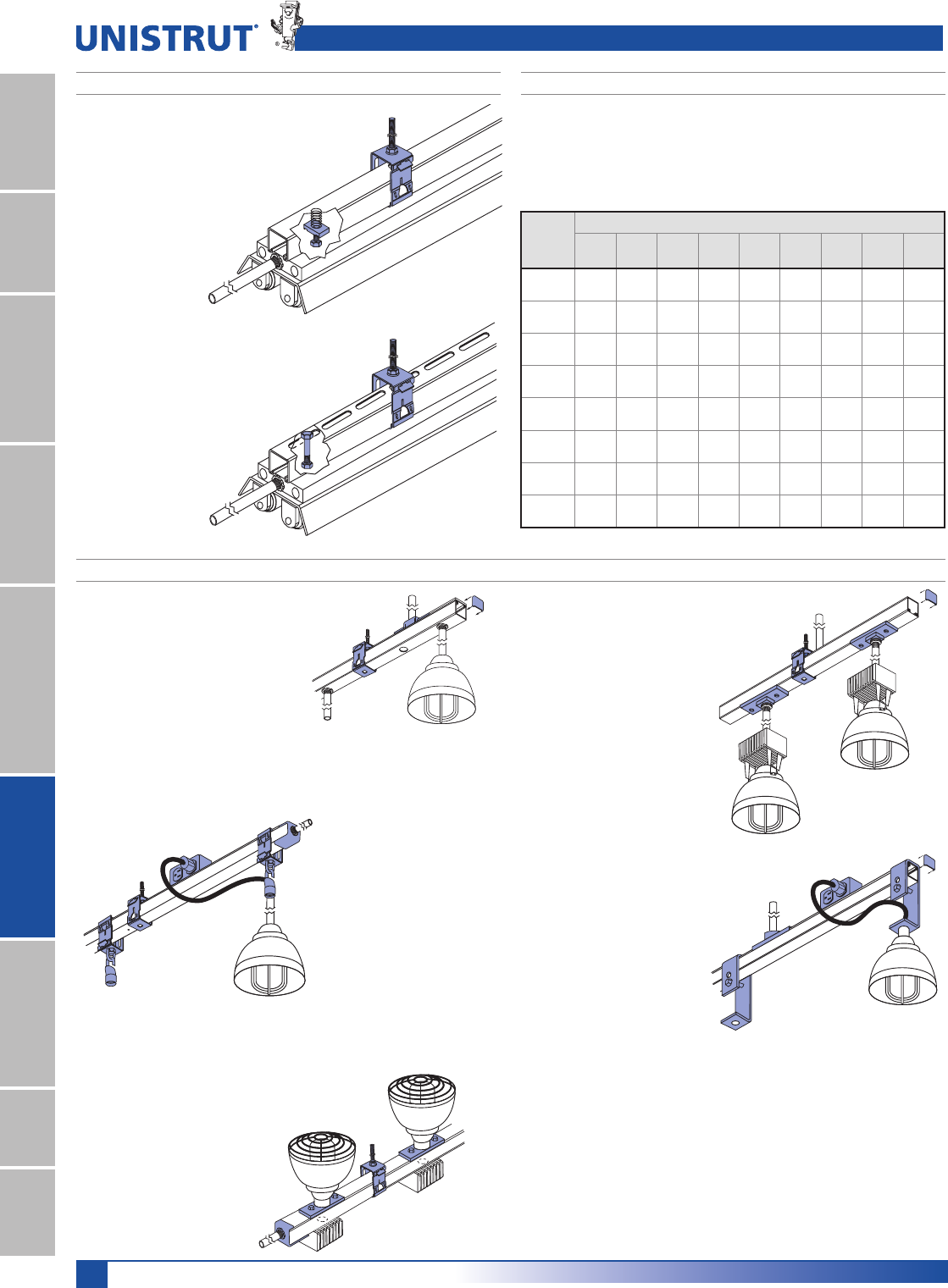
138
15⁄8" Framing System
1 5¼8" ChannelTelestrutNuts & HardwareGeneral FittingsPipe/Conduit SupportsElectrical FittingsConcrete InsertsSolarUnipier®
FLUORESCENT FIXTURES - SUPPORT APPLICATIONS
Electrical Technical Data
Spring-Nut attachment system
Conduit connects through knockout in fixture. Fixture
is supported by P1006-1420 spring nut and 1/4"
round head machine screw. Assembly is supported
by P2855 hinged hanger.
Slotted channel attachment system
Conduit connects through knockout in fixture.
Fixture is supported by HCSS series hex bolt and
hex nut. Raceway is supported by P2855 hanger.
To splice a continuous run, use P3922.
RECOMMENDED SUPPORT SPACING FOR FIXTURES
Deflections are based on continuity of span and use of 4 ft. fixtures weighing ap-
proximately 30 lbs. each. Do not use joiner fittings between supporting hangers. When
using knock-out or slotted channels deflections will be increased approximately 5%.
With fixtures spaced 2' - 0" apart, deflection is 60-70% of table. When spaced 4' - 0"
apart, deflection is 50-60% of table.
Channel
Distance Between Supports - In (mm)
8'
P
10'
P
12'
P
14'
P
16'
P
18'
P
20'
P
22'
P
24'
P
P3300 0.187 ––––––––
4.7
P3000 0.100 0.250 0.500 ––––––
2.5 6.4 12.7
P1100 0.088 0.250 0.437 0.875 –––––
2.2 6.4 11.1 22.2
P1000 – 0.180 0.312 0.625 1.000 1.625 –––
4.6 7.9 15.9 25.4 41.3
P5500 – – – 0.250 0.500 0.812 1.620 ––
6.4 12.7 20.6 41.1
P5000 ––––
0.310 0.625 1.000 1.800 2.500
7.9 15.9 25.4 45.7 63.5
P1001 ––––
0.310 0.625 1.000 1.800 2.500
7.9 15.9 25.4 45.7 63.5
P5001 –––––
0.200 0.250 0.400 0.500
5.1 6.4 10.2 12.7
Deflection Table
HIGH-BAY FIXTURE RACEWAY APPLICATIONS
Fixtures are supported by P2602
clevis hangers. Cover plate on
P2567 outlet box provides access
to receptacle box. Raceway is
supported and wired by top mounted
P2535 conduit connectors. P1280W
end caps and P3184 closure strip
complete assembly.
Fixture attached to and wired from raceway
by 1»2" nipple assembly of desired length at
channel knockout. P1280W end cap, P3184
closure strip, P2535 conduit connector, and
P2855 channel hanger complete assembly. For
splicing channels into continuous raceway runs,
use joiner fitting P3922.
Fixtures, supported by P2855 hang-
ers and M2250 eyelets, plug into
receptacle mounted in P2567 outlet
box. P2855 hangers also support
raceway. P2521-75 end connector
joins conduit to raceway. P1280W end
caps (not shown) and P3184 closure
strip complete assembly.
Fixtures are connected to and wired
form raceway by conduit connector
fitting P2536. Raceway is supported by
P2855 hanger. P1280W end caps and
P3184 closure strip complete the as-
sembly. Conduit connected to raceway
through channel knockout.
Uplighting with underhung or
remote ballast
High-Bay dual
mounted system
H.I.D. Knockout
mounted system
H.I.D. Plug-in system
ULJLGPRXQW
H.I.D. Plug-in system
ZLWKVZLYHO
Fixtures attached to and wired from P2535 conduit fittings mounted to slot side of
channel. Raceway can be wired by P2521 as shown or, conduit can enter through
available knockout. Ballasts in P2521 are connected at the knockout by fixture
adapter. In remote ballast installations, follow manufacturers instructions. P2855
hinged hangers support both types of installations. P3184 closure strip and P1280W
end caps complete assembly. For continuous raceways, use joiner fitting P3922.
P2521-75 end connector joins conduit to raceway.
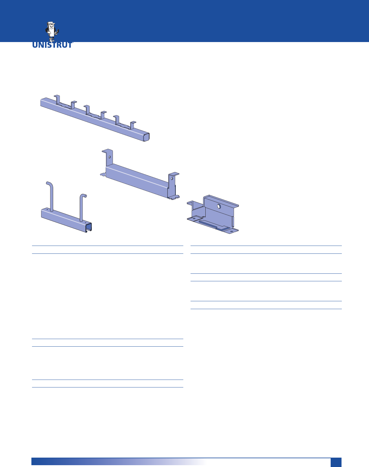
139
MATERIAL
Cold-formed inserts are manufactured from standard 12
gauge (2.7 mm) Unistrut channel sections conforming to
ASTM A1011 SS GR 33 or ASTM A653 GR 33, unless other-
wise noted.
Hot-rolled inserts, as noted, are manufactured from carbon
steel meeting physical requirements of ASTM A283 GR D.
To inhibit concrete seepage, all inserts (except spot inserts)
are provided with closure strips and end caps or foam filler,
unless otherwise requested.
Most concrete inserts are available in stainless steel on spe-
cial order. Consult factory for ordering information.
APPLICATION
A wide range of heavy-duty to light-duty “continuous” and
“spot” concrete inserts are available for use in pre-cast,
pre-stressed or poured-in-place concrete floors, walls or
ceilings.
FINISHES
Cold-formed, standard-duty, light-duty and spot concrete
inserts are available in:
Hot dipped galvanized (HG), conforming to
ASTM A123 or A153;
Pre-galvanized (PG), conforming to ASTM A653 GR 33
Plain (PL).
DESIGN LOAD
Design loads, where shown, are based on 3,000 PSI
concrete, unless noted.
STANDARD LENGTHS
Insert lengths range from 3 inches (76.2 mm) to 20 feet
(6.10m) with a tolerance of ±1⁄4-inch (6.4mm).
DIMENSIONS
Imperial dimensions are illustrated in inches. Metric dimen-
sions are shown in parentheses or as noted. Unless noted,
all metric dimensions are in millimeters and rounded to
one decimal place.
Custom-designed inserts are available on special order.
Consult factory for ordering information.
CONCRETE INSERTS
Heavy-Duty Inserts ................................................................. 141
Standard-Duty Inserts.....................................................142, 144
Light-Duty Inserts ................................................................... 143
Spot Inserts .............................................................................144
Deck Inserts ............................................................................. 145
Components ............................................................................ 145
Technical Data ......................................................................... 146
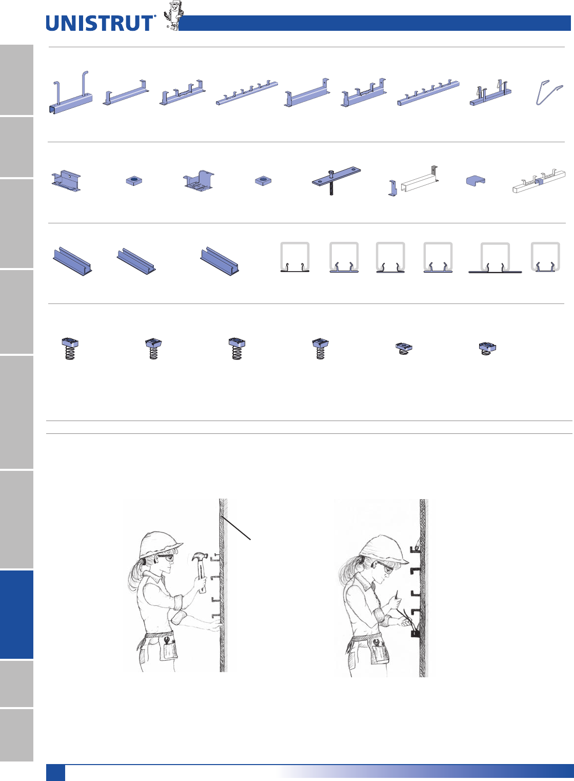
140
15⁄8" Framing System
1 5¼8" ChannelTelestrutNuts & HardwareGeneral FittingsPipe/Conduit SupportsElectrical FittingsConcrete InsertsSolarUnipier®
Concrete Inserts Pictorial Index & Installation
Heavy Duty Standard Duty
Light Duty
Spot Inserts and Components
P3754-Pg 141 P3249-Pg 142 P3253-Pg 142 P3254-Pg 142 P3165-Pg 144 P2865-Pg 144P3349-Pg 143 P3352-Pg 143 P3354-Pg 143
Channel Nuts
Heavy Duty-Pg 73 Heavy Duty-Pg 73 Light Duty-Pg 73 Light Duty-Pg 73Standard Duty-Pg 73 Standard Duty-Pg 73
Fiberglass Concrete Inserts Closure Strips
Heavy Duty-Pg 193 Heavy Duty - Standard Profile-Pg 195
Light Duty-Pg 194
P3245-Pg 144 P3245N4-Pg 144 M24-Pg 144 M2506-Pg 144 P1703-Pg 145 P2407-Pg 145 P3663-Pg 145P3700-Pg 145
P3184P
Pg 60
P3184F
Pg 60
P3712P
Pg 60
P1184P
Pg 60
P1184
Pg 60
P3184
Pg 60
The Unistrut concrete insert is firmly fixed to the concrete side of the form before
pouring. When the forms are removed, the insert is ready for use. Brackets and other
components can be attached at any point of the continuous entry channel.
Concrete
Form
INSTALLING CONCRETE INSERTS
1. Nail insert to concrete form using
prepunched nail holes 2. Attach rebars to flanges on insert
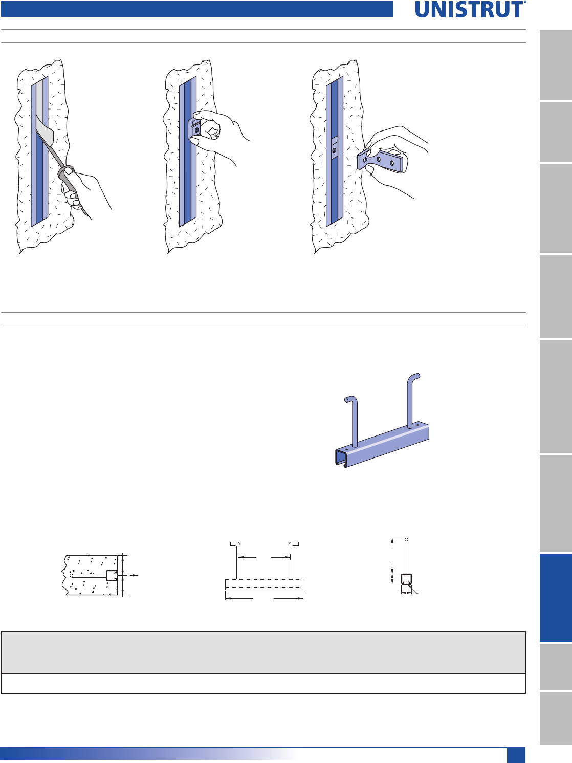
141
15⁄8" Framing System
1 5¼8" ChannelTelestrutNuts & HardwareGeneral FittingsPipe/Conduit SupportsElectrical FittingsConcrete InsertsSolarUnipier®
Installation and Heavy Duty Inserts
1. Scrape out filler 2. Insert channel nut. 3. Attach fitting
USING INSTALLED CONCRETE INSERT
&ORVXUHVWULS33DQGDVW\UHQHEHDGHQGFDSWKDWILWVLQVLGHWKHFKDQQHOWRLQKLELW
concrete seepage are included.
7KHUHFRPPHQGHGGHVLJQORDGZKHQXVHGIRUFXUWDLQZDOODQFKRUDJHLVSRXQGV
and is based on use in average, good concrete. The design load includes 1»3 increase in
load as permitted by AISI Specifications and Uniform Building Code when stresses are
produced by wind or earthquake and other loads.
7KHUHFRPPHQGHGGHVLJQORDGLVEDVHGRQXVLQJWZR3QXWVDWQROHVVWKDQ
O.C. and no closer than 2" to either end of the insert. The distance between the insert
centerline and the concrete edge must be a minimum of 3".
$OOQXWVDQGILWWLQJVIRU3VHULHVFRQFUHWHLQVHUWVZLOOILW
0DWHULDO&ROGIRUPHGIURP*DPPVWHHOFRQIRUPLQJWR$670$66*5
or ASTM A653 GR 33 A. Stainless steel available on special order.
)LQLVK&KRLFHRIKRWGLSSHGJDOYDQL]HG+*FRQIRUPLQJWR$670$RU$
or pre-galvanized (PG) conforming to ASTM A653-G90.
3"
(76.2)
3"
(76.2)
Load
P3754 15¼8" X 15¼8" CHANNEL
Part
Number
Insert
Length
±1¼4" (6.4mm)
In (mm)
Wt/100
pcs
Lbs (kg)
Max.
Anchor
Spacing
In (mm)
Max.
Allowable
Point Load
Lbs (kN)
Spacing
of Point
Loads
In (mm)
Max.
Allowable
Uniform Load
Lbs (kN)
P3754 12 210 8 2,500 3 5,000
304.8 95.3 203.2 11.12 76.2 22.24
(203.2)
8"
1'- 0"
(304.8)
1 5⁄8"
(41.3)
5 3⁄4"
(146.1)
1 5⁄8"
(41.3)
P3712P
Safety factor 3
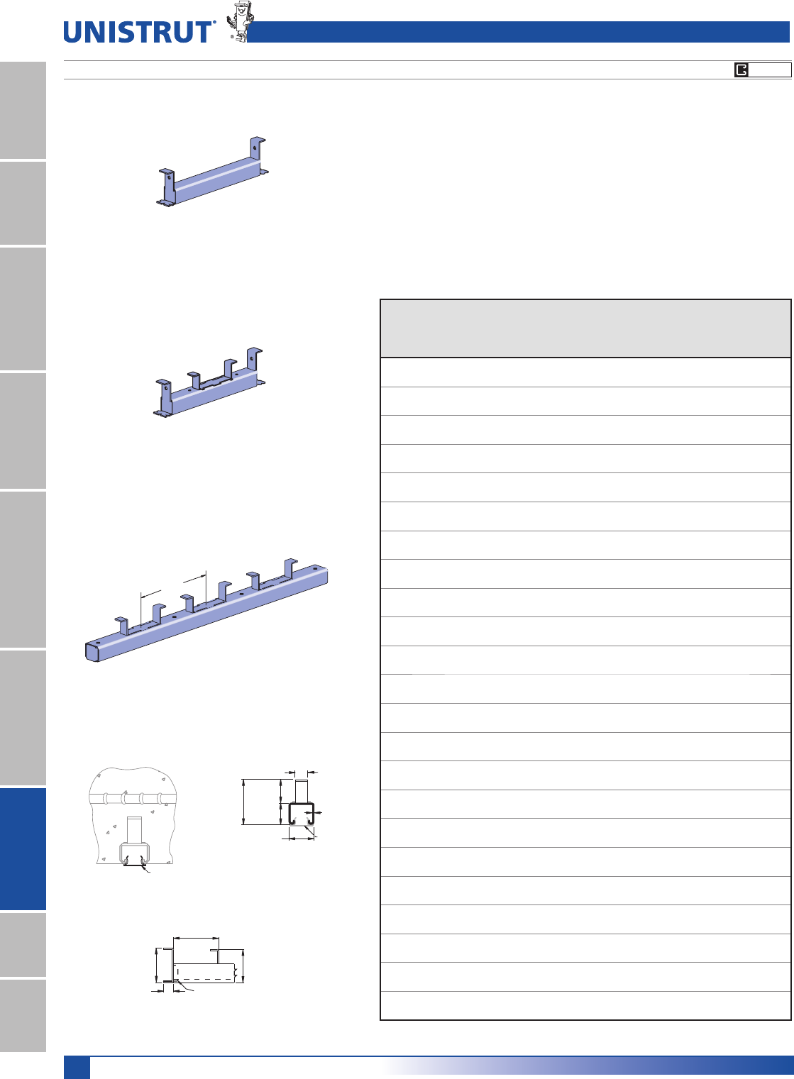
142
15⁄8" Framing System
1 5¼8" ChannelTelestrutNuts & HardwareGeneral FittingsPipe/Conduit SupportsElectrical FittingsConcrete InsertsSolarUnipier®
P3200 SERIES 1
5¼8" X 13¼8" CHANNEL
Standard Duty
8"
(203.2)
2 7⁄8"
(73.0)
1 1⁄2"
(38.1)
1 5⁄8"
(41.3)
12 Ga.
(3.2)
(20.6)
13⁄16"
P3712P
1 3⁄8"
(34.9)
3"
(76.2)
>2"
(>50.8)
2 7⁄8"
(73.0)
P3704
1"
(25.4)
P3712P
Part
Number
Insert
Length
In/Ft (mm)
Wt/100
pcs
Lbs (kg)
Max.
Allowable
Point Load
Lbs (kN)
Min.
Spacing
of Pt. Loads
In (mm)
Max.
Allowable
Uniform Load
Lbs (kN)
P3249 3" 85 500 —500
76.2 39 2.22 2.22
P3250 4" 100 800 —800
101.6 45 3.56 3.56
P3251 6" 130 1,000 —1,000
152.4 59 4.45 4.45
P3252 8" 159 1,200 —1,200
203.2 72 5.34 5.34
P3253 12" 227 2,000 —2,000
304.8 103 8.90 8.90
P3254 16" 270 2,000 12 4,000
406.4 122 8.90 304.8 17.79
P3255 20" 357 2,000 12 4,000
508.0 162 8.90 304.8 17.79
P3256 24" 399 2,000 12 4,000
609.6 181 8.90 304.8 17.79
P3257 32" 527 2,000 12 2,000 Lbs./Ft.
812.8 239 8.90 304.8 2,976.3 NJP
P3257A 36" 616 2,000 12 2,000 Lbs./Ft.
914.4 279 8.90 304.8 2,976.3 NJP
P3258 40" 661 2,000 12 2,000 Lbs./Ft.
1,016.0 300 8.90 304.8 2,976.3 NJP
P3259 4' 786 2,000 12 2,000 Lbs./Ft.
1,219.2 357 8.90 304.8 2,976.3 NJP
P3260 5' 1,003 2,000 12 2,000 Lbs./Ft.
1,524.0 455 8.90 304.8 2,976.3 NJP
P3261 6' 1,173 2,000 12 2,000 Lbs./Ft.
1,828.8 532 8.90 304.8 2,976.3 NJP
P3262 7' 1,390 2,000 12 2,000 Lbs./Ft.
2,133.6 630 8.90 304.8 2,976.3 NJP
P3263 8' 1,560 2,000 12 2,000 Lbs./Ft.
2,438.4 708 8.90 304.8 2,976.3 NJP
P3264 9' 1,741 2,000 12 2,000 Lbs./Ft.
2,743.2 790 8.90 304.8 2,976.3 NJP
P3265 10' 1,947 2,000 12 2,000 Lbs./Ft.
3,048.0 883 8.90 304.8 2,976.3 NJP
P3266 12' 2,334 2,000 12 2,000 Lbs./Ft.
3,657.6 1,059 8.90 304.8 2,976.3 NJP
P3267 14' 2,717 2,000 12 2,000 Lbs./Ft.
4,267.2 1,232 8.90 304.8 2,976.3 NJP
P3268 16' 3,116 2,000 12 2,000 Lbs./Ft.
4,876.8 1,413 8.90 304.8 2,976.3 NJP
P3269 18' 3,530 2,000 12 2,000 Lbs./Ft.
5,486.4 1,601 8.90 304.8 2,976.3 NJP
P3270 20' 3,882 2,000 12 2,000 Lbs./Ft.
6,096.0 1,761 8.90 304.8 2,976.3 NJP
,QFOXGHVFORVXUHDQGHQGFDSVXQOHVVRWKHUZLVHUHTXHVWHG
3HQGFDSXVHGZKHQGLVWDQFHWRILUVWDQFKRULVXSWRPP
3HQGFDSLVXVHGZKHQHQGGLVWDQFHWRILUVWDQFKRULVRYHUPP
1DLORUDQFKRULQVHUWVWRIRUPVHYHU\PPWRPP
$QFKRUVDUHPPRQFHQWHU
0DWHULDO&ROGIRUPHGIURP*DVWHHOFRQIRUPLQJWR
ASTM A1011 SS GR 33 or ASTM A653 GR 33. A. Stainless steel
available on special order.
)LQLVK&KRLFHRIKRWGLSSHGJDOYDQL]HG+*FRQIRUPLQJWR$670$RU$
or pre-galvanized (PG) conforming to ASTM A653-G90.
P3253
P3249 thru P3252
P3254 thru P3270
"NC" Suffix – No Closure Strip, With End Caps
"WC" Suffix – With Closure Strip & End Caps
"NC" Suffix – No Closure Strip, With End Caps & Back Plates
"WC" Suffix – With Closure Strip, End Caps & Back Plates
"NC" Suffix – No Closure Strip, W/End Caps & Back Plates
"WC" Suffix – W/Closure Strip, End Caps & Back Plates
"X" – No Closure Strip, No End Caps, W/Back Plates
Safety factor 3.
PG HG
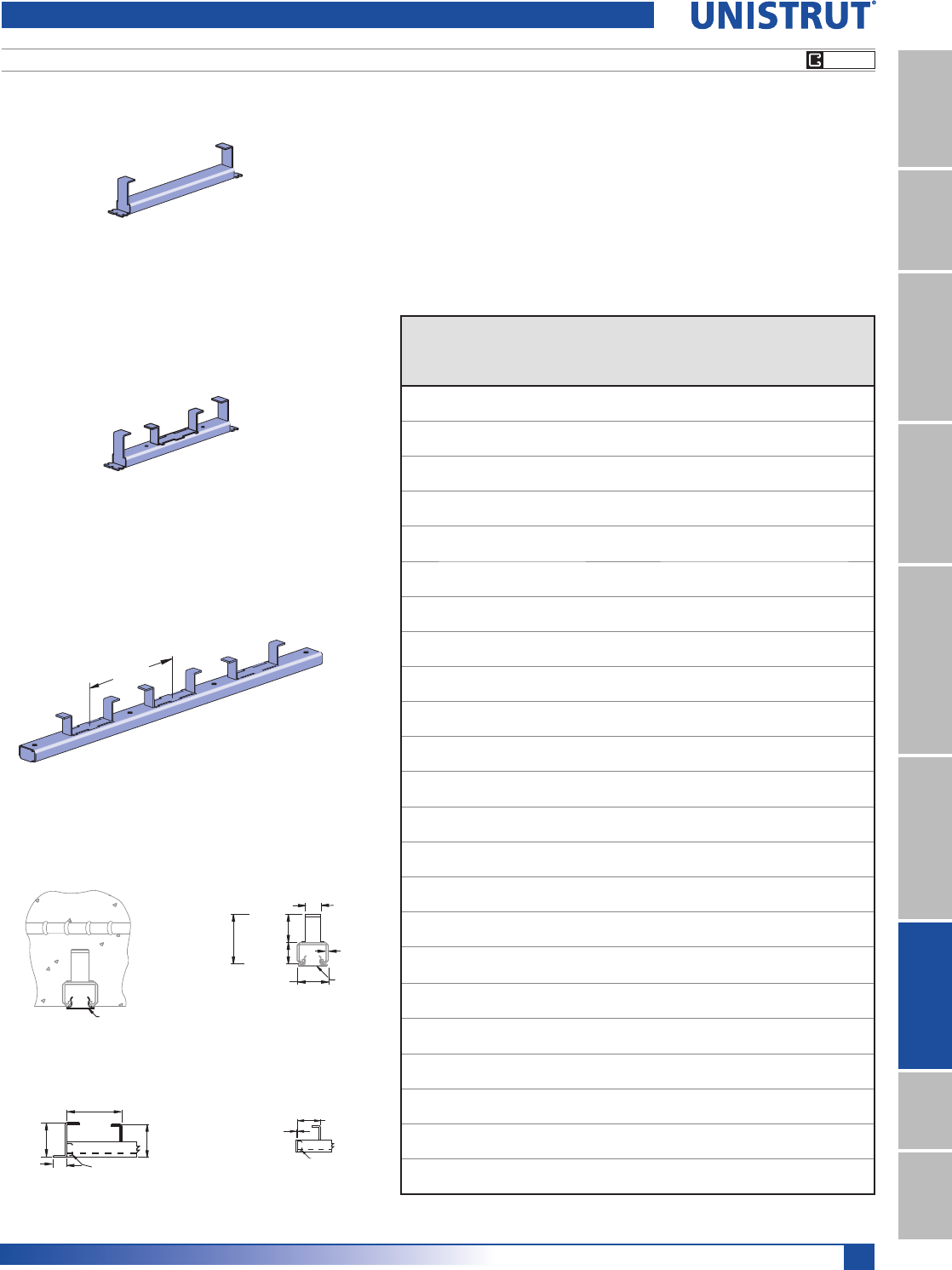
143
15⁄8" Framing System
1 5¼8" ChannelTelestrutNuts & HardwareGeneral FittingsPipe/Conduit SupportsElectrical FittingsConcrete InsertsSolarUnipier®
Light Duty
2 7⁄16"
(61.9)
1"
(25.4)
(60.3)
2 3⁄8"
P3703
>2"
(>50.8)
P3380
≤2"
(≤50.8)
1⁄8"
(3.2)
(22.2)
7⁄8"
1 1⁄2"
(60.3)
2 3⁄8"(38.1)
1 5⁄8"
(41.3)
12 Ga.
(20.6)
(3.2)
13⁄16"
P3712P
P3712P
P3352 thru P3353
P3300 SERIES 1
5¼8" X 7¼8" CHANNEL
,QFOXGHVFORVXUHDQGHQGFDSVXQOHVVRWKHUZLVHUHTXHVWHG
3HQGFDSXVHGZKHQGLVWDQFHWRILUVWDQFKRULVXSWRPP
3HQGFDSLVXVHGZKHQHQGGLVWDQFHWRILUVWDQFKRULVRYHUPP
1DLORUDQFKRULQVHUWVWRIRUPVHYHU\PPWRPP
$QFKRUVDUHPPRQFHQWHU
0DWHULDO&ROGIRUPHGIURP*DPPVWHHOFRQIRUPLQJWR$670$66*5
or A653 GR 33. A. Stainless steel available on special order.
)LQLVK&KRLFHRIKRWGLSSHGJDOYDQL]HG+*FRQIRUPLQJWR$670$RU$
or pre-galvanized (PG) conforming to ASTM A653-G90.
Part
Number
Insert
Length
In/Ft. (mm)
Wt/100
pcs
Lbs (kg)
Max.
Allowable
Point Load
Lbs (kN)
Min.
Spacing
of Pt. Loads
In (mm)
Max.
Allowable
Uniform Load
Lbs (kN)
P3349 3" 68 400 —400
76.2 31 1.78 1.78
P3350 4" 81 500 —500
101.6 37 2.22 2.22
P3351 6" 102 750 —750
152.4 46 3.34 3.34
P3352 8" 122 1,000 —1,000
203.2 55 4.45 4.45
P3353 12" 174 1,500 —1,500
304.8 79 6.67 6.67
P3354 16" 185.0 1,500 12 3,000
406.4 84 6.67 304.8 13.34
P3355 20" 231 1,500 12 3,000
508.0 105 6.67 304.8 13.34
P3356 24" 277 1,500 12 3,000
609.6 126 6.67 304.8 13.34
P3357 32" 370 1,500 12 1,500 Lbs./Ft.
812.8 168 6.67 304.8 2,232.2 NJP
P3357A 36" 416 1,500 12 1,500 Lbs./Ft.
914.4 189 6.67 304.8 2,232.2 NJP
P3358 40" 463 1,500 12 1,500 Lbs./Ft.
1,016.0 210 6.67 304.8 2,232.2 NJP
P3359 4' 555 1,500 12 1,500 Lbs./Ft.
1,219.2 252 6.67 304.8 2,232.2 NJP
P3360 5' 694 1,500 12 1,500 Lbs./Ft.
1,524.0 315 6.67 304.8 2,232.2 NJP
P3361 6' 832 1,500 12 1,500 Lbs./Ft.
1,828.8 377 6.67 304.8 2,232.2 NJP
P3362 7' 971 1,500 12 1,500 Lbs./Ft.
2,133.6 440 6.67 304.8 2,232.2 NJP
P3363 8' 1,110 1,500 12 1,500 Lbs./Ft.
2,438.4 503 6.67 304.8 2,232.2 NJP
P3364 9' 1,249 1,500 12 1,500 Lbs./Ft.
2,743.2 567 6.67 304.8 2,232.2 NJP
P3365 10' 1,387 1,500 12 1,500 Lbs./Ft.
3,048.0 629 6.67 304.8 2,232.2 NJP
P3366 12' 1,665.0 1,500 12 1,500 Lbs./Ft.
3,657.6 755 6.67 304.8 2,232.2 NJP
P3367 14' 1,942 1,500 12 1,500 Lbs./Ft.
4,267.2 881 6.67 304.8 2,232.2 NJP
P3368 16' 2,220 1,500 12 1,500 Lbs./Ft.
4,876.8 1,007 6.67 304.8 2,232.2 NJP
P3369 18' 2,497 1,500 12 1,500 Lbs./Ft.
5,486.4 1,133 6.67 304.8 2,232.2 NJP
P3370 20' 2,775 1,500 12 1,500 Lbs./Ft.
6,096.0 1,259 6.67 304.8 2,232.2 NJP
P3349 thru P3351
8"
(203.2)
P3354 thru P3370
"NC" Suffix – No Closure Strip, With End Caps
"WC" Suffix – With Closure Strip & End Caps
"NC" Suffix – No Closure Strip, With End Caps & Back Plates
"WC" Suffix – With Closure Strip, End Caps & Back Plates
"NC" Suffix – No Closure Strip, W/End Caps & Back Plates
"WC" Suffix – W/Closure Strip, End Caps & Back Plates
"X" – No Closure Strip, No End Caps, W/Back Plates
Safety factor 3.
PG HG
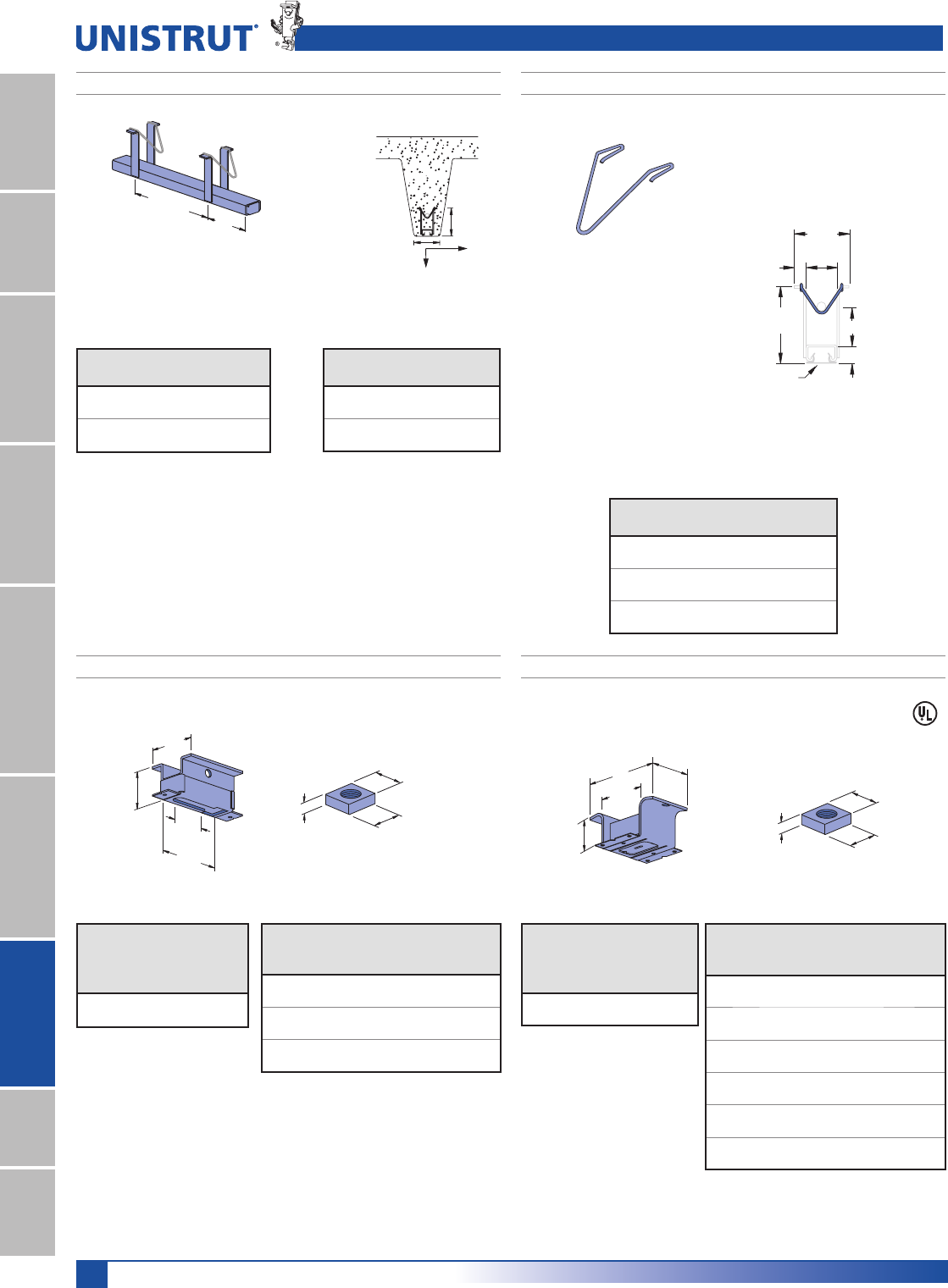
144
15⁄8" Framing System
1 5¼8" ChannelTelestrutNuts & HardwareGeneral FittingsPipe/Conduit SupportsElectrical FittingsConcrete InsertsSolarUnipier®
(101.6)
4"
Anchors 8" (203.2)
On Center
'HVLJQHGIRUXVHLQSUHVWUHVVHGFRQFUHWH
$QFKRUVPPRQFHQWHUILUVWDQFKRUPPIURPHQG
,QFOXGHVFORVXUHDQGHQGFDSVXQOHVVRWKHUZLVHUHTXHVWHG
0DWHULDO&ROGIRUPHGIURP*DPPVWUHHOFRQIRUPLQJWR
ASTM A1011 SS GR 33 or ASTM A653 GR 33. A.
Stainless steel available on special order.
)LQLVK&KRLFHRISUHJDOYDQL]HG3*FRQIRUPLQJWR$670$*RUSODLQ3/
P3165 SERIES 1
5¼8" X 7¼8" CHANNEL
Standard Duty and Accessories
A
(41.3)
1 5⁄8"
(73.0)
2 7⁄8"
(15.9)
5⁄8"
(101.6)
4"
(22.2)
7⁄8"
P3712P
Finish: Plain
P2865-10, -15, -20 HOLD-DOWN SPRINGS
3 3⁄4"A
Load
B
Load
(95.3)
(101.6)
4"
Maximum allowable load/ft.
Safety factor 3.
Concrete
A
Lbs (kN)
B
Lbs (kN)
Light Wt 425 800
1.89 3.56
Normal Wt 500 1,000
2.22 4.45
Safety factor 3.
Part
No.
Length
Ft 0
Wt/100 pcs
Lbs (kg)
P3165 10 1,650
3.05 748.4
P3170 20 3,280
6.10 1,487.8
Part
Number
A
In (mm)
Wt/100 pcs
Lbs (kg)
P2865-10 12
25.4 0.9
P2865-15 11»22
38.1 0.9
P2865-20 22
50.8 0.9
"X" Suffix – No Closure Strip, No End Caps
"WC" Suffix – With Closure Strip & End Caps
11⁄4"
(31.8)
11⁄4"
(31.8)
T
Square Nut for P3245 Insert
2"
(50.8)
2 1⁄4"
(57.2)
3"
(76.2)
1 5⁄8"
(41.3)
Finish: Pre-galvanized
Safety factor of 3
)RU1»4", 3»8", or 1»2" size attachment or hanger rod.
,QVHUWQXWVWREHRUGHUHGVHSDUDWHO\
P3245
Part
Number
Wt/100
pcs
Lbs (kg)
Max.
Allowable
Pt. Load
Lbs (kN)
P3245 54 1,000
24.5 4.45
Part
Number
Size/Thread
In
T
,QPP
Wt/100
pcs
Lbs (kg)
P3245-N4 1»4" — 20
5»16"6
7.9 2.7
P3245-N6 3»8" — 16
5»16"5
7.9 2.3
HSQN050 1»2" — 13
7»16"6
11.1 2.7
2 1⁄4"
(57.2)
3 3⁄4"
(95.3)
2"
(50.8)
1 5⁄8"
(41.3)
Finish: Electro-galvanized
Safety factor of 5
5LEVDORQJVLGHVRIVORWJLYHH[WUDVWUHQJWKWRFDVH
,QVHUWQXWV0WKUX0WREHRUGHUHGVHSDUDWHO\
Square Nut for M24
M24 SPOT INSERT
Part
Number
Wt/100
pcs
Lbs (kg)
Max.
Allowable
Pt. Load
Lbs (kN)
M24 52 800
23.6 3.56
Part
Number
Size/
Thread
In
T
,QPP
Wt/100
pcs
Lbs (kg)
M2506 1»4" — 20
1»4"13
6.4 5.9
M2508 3»8" — 16
3»8"14
9.5 6.4
M2510 1»2" — 13
1»2"14
12.7 6.4
M2512 5»8" — 11
1»2"12
12.7 5.4
M2523 3»4" — 10
1»2"11
12.7 5.0
M2524 7»8" — 9
1»2"10
12.7 4.5
13⁄16"
(20.6)
13⁄16"
(20.6)
T
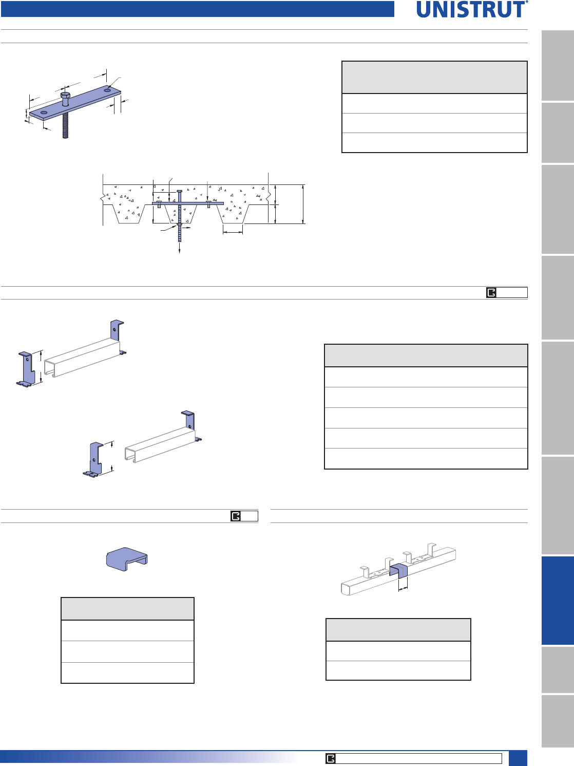
145
15⁄8" Framing System
1 5¼8" ChannelTelestrutNuts & HardwareGeneral FittingsPipe/Conduit SupportsElectrical FittingsConcrete InsertsSolarUnipier®
CORE PRODUCTS - TYPICALLY AVAILABLE FROM STOCK
6"
(152.4)
4"
(101.6)
2"
(50.8)
11⁄4"
(31.8)
9⁄16"
(14.3)
13⁄32"
(10.3) HOLE
A
P1000, P3000 or P4000
2 7⁄16"
(61.9) P3300
1 5⁄8"
(41.3)
P1703, P1704, P3703, P3704, P4703 END CAP ANCHORS
P2407, P3280, P3380 END CAPS P3663, P4663 JOINT COVERS
Part
Number
Fits
Channel
Wt/100 pcs
Lbs (kg)
P2407 P1000 10
4.5
P3280 P3000 8
3.6
P3380 P3300 5
2.3
NOTE: Joint cover for use with 15»8" wide
standard Unistrut inserts only.
Part
Number
Use With
Insert Series
Wt/100 pcs
Lbs (kg)
P3663 P3270 10
4.5
P4663 P3370 6
2.7
Note: End cap anchor for use with 15»8" wide
standard Unistrut inserts only.
Part
Number Channel
“A”
In (mm)
Wt/100 pcs
Lbs (kg)
P1703 P1000 213»32 30
61.1 13.6
P1704 P1000 317»32 37
89.7 16.8
P3703 P3300 27»16 17
61.9 7.7
P3704 P3000 320
76.2 9.1
P4703 P4000 23»827
60.3 12.2
Deck Inserts
P3700 SERIES DECK INSERT
Part
Number
Rod
Dia.
In
Tension
Load
Lbs (kN)
Shear
Load
Lbs (kN)
Wt/100 pcs
Lbs (kg)
P3700-37 3»8850 600 89
3.78 2.67 40.4
P3700-50 1»21,380 1000 111
6.14 4.45 50.3
P3700-62 5»81920 1760 141
8.54 7.83 64.0
TENSION
SHEAR
SETTING SCREWS
EMBED
JAM NUT
OPTIONAL 41⁄2" (114.3)
RIB WIDTH
5"
(127.0) 2"
(50.8)
6"
(152.4)
3"
(76.2)
3"
(76.2)
Notes:
1. Allowable loads have been determined by the manu-
facturer’s testing, analysis, and
technical specification.
2. Values are based on a safety factor of 5.
3. 20 Gauge Metal Deck
EG
PG HG
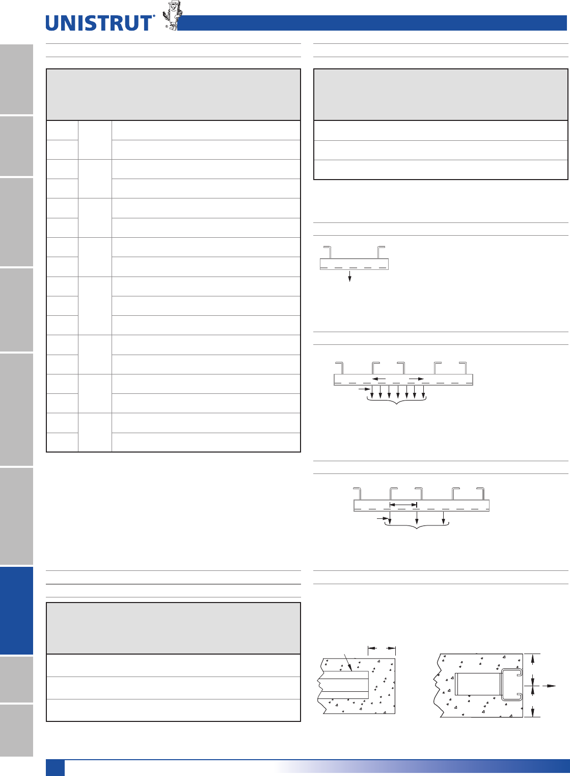
146
15⁄8" Framing System
1 5¼8" ChannelTelestrutNuts & HardwareGeneral FittingsPipe/Conduit SupportsElectrical FittingsConcrete InsertsSolarUnipier®
Concrete Inserts Technical Data
SPOT INSERT LOAD CHART
Part
Number
Wt/100
pcs
Lbs (kg)
Anchor
Spacing
In (mm)
Max.
Allowable
Point
Load
Lbs (kN)
Min.
Spacing
Between
Pt. Loads
In (mm)
Max.
Allowable
Uniform
Load
Lbs/Ft (kg/m)
M26/M2812 54 –1,500 –1,500
24.5 6.67 2,232
M3245 52 –1,000 –1,000
23.6 4.45 1,488
M24/M2512 52 –800 –800
23.6 3.56 1,190
A
A
Max. Allowable Uniform Load
Pt. Loads
12 in.
MAXIMUM ALLOWABLE UNIFORM LOAD
The maximum allowable
uniform load must be placed
as a series of point loads.
The maximum allowable point load may be
placed anywhere along the insert.
All loads placed less than 2" from the end of an
insert must be reduced by 50%.
Max. Allowable
Point Load
SPACING OF MULTIPLE POINT LOADS
Max. Allowable Uniform Load
Max. Allowable
Pt. Loads
Min. Load Spacing
PULL-OUT LOAD
Minimum Edge Distance to Achieve Rated Pull-Out Capacity
MAXIMUM ALLOWABLE POINT LOAD
Part
Number
Wt/100
ft
Lbs (kg)
Anchor
Spacing
In (mm)
Max.
Allowable
Point
Load
Lbs (kN)
Min.
Spacing
Between
Pt. Loads
In (mm)
Max.
Allowable
Uniform
Load
Lbs/Ft (kg/m)
P3270 194 4 2,000 12 2,000
88.0 101.6 8.90 304.8 2,976.3
P3370 139 4 1,500 12 1,500
63.0 101.6 6.67 304.8 2,232.2
P3170* 165 8 1,000 12 1,000
74.8 203.2 4.45 304.8 1,488.2
Part
Number
Insert
Length
In (mm)
Wt/100
ft
Lbs (kg)
Anchor
Spacing
In (mm)
Max.
Allowable
Point
Load
Lbs (kN)
Min.
Spacing
Between
Pt. Loads
In (mm)
Max.
Allowable
Uniform
Load
Lbs (kN)
P3249 3
76.2
85 3 500 –500
38.6 76.2 2.22 2.22
P3349 68 3 400 –400
30.8 76.2 1.78 1.78
P3250 4
101.6
100 4 800 –800
45.4 101.6 3.56 3.56
P3350 81 4 500 –500
36.7 101.6 2.22 2.22
P3251 6
152.4
130 6 1,000 –1,000
59.0 152.4 4.45 4.45
P3351 102 6 750 –750
46.3 152.4 3.34 3.34
P3252 8
203.2
159 8 1,200 –1,200
72.1 203.2 5.34 5.34
P3352 122 8 1,000 –1,000
55.3 203.2 4.45 4.45
P3754
12
304.8
210 8 2,500 3 5,000
95.3 203.2 11.12 76.2 22.24
P3253 227 4 2,000 –2,000
103.0 101.6 8.90 8.90
P3353 174 4 1,500 –1,500
78.9 101.6 6.67 6.67
P3254 16
406.4
270 4 2,000 12 4,000
122.5 101.6 8.90 304.8 17.79
P3354 185 4 1,500 12 3,000
83.9 101.6 6.67 304.8 13.34
P3255 20
508.0
357 4 2,000 12 4,000
161.9 101.6 8.90 304.8 17.79
P3355 231 4 1,500 12 3,000
104.8 101.6 6.67 304.8 13.34
P3256 24
609.6
399 4 2,000 12 4,000
181.0 101.6 8.90 304.8 17.79
P3356 277 4 1,500 12 3,000
125.6 101.6 6.67 304.8 13.34
LOAD CHART BY LENGTH
CONTINUOUS CONCRETE INSERT LOAD CHART
UP TO 20 FT. (6.10M)
*When used in prestressed concrete “T” Beam.
Load data is based on use of 3000 PSI concrete.
Insert
17⁄8" (47.6mm); P3170
A = 3" (76.2mm); all others
A
147
MATERIAL
Unistrut channels are accurately and carefully cold formed
to size from low-carbon strip steel.
STEEL: PLAIN
12 Ga. (2.7 mm), 14 Ga.(1.9 mm) and
16 Ga. (1.5 mm) ASTM A1011 SS GR 33.
STEEL: PRE-GALVANIZED
12 Ga. (2.7 mm), 14 Ga. (1.9 mm) and
16 Ga. (1.5mm) ASTM A653 GR 33.
FINISHES
Fittings are available in:
Green Powder Coat (GR), conforming to
commercial standards for Powder Coating,
Electro-galvanized (EG), conforming to
ASTM B633 Type III SC1;
Hot-dipped Galvanized (HG), conforming to
ASTM A123 or A153
Plain (PL).
DIMENSIONS
Imperial dimensions are illustrated in inches. Metric dimen-
sions are shown in parenthesis or as noted. Unless noted,
all metric dimensions are in millimeters and rounded to
one decimal place.
DESIGN BOLT TORQUE
BOLT SIZE 1»4"-20 5»16"-18 3»8"-16 1»2"-13 5»8"-11 3»4"-10
Rec.Torque
Ft/Lbs
1P
6
(8)
11
(15)
19
(26)
50
(68)
100
(136)
125
(170)
Max Torque
Ft/Lbs
1P
7
(9)
15
(20)
25
(34)
70
(95)
125
(170)
135
(183)
Application Example ............................................................... 148
Solar Connectors ..................................................................... 149
Key Advantages ...................................................................... 150
SOLAR COMPONENTS
Unistrut® represents a line of steel,
aluminum, and fiberglass strut and
accessories used extensively in electrical
infrastructure support.
Unistrut is available in a range of
corrosion inhibiting finishes making it a
prime choice in today’s marketplace. The
Unistrut system is infinitely adjustable for
a multitude of configurations and uses.
The solar components shown in this
section allow you to shape an effective
solution for mounting solar panels that fits
your exact needs.
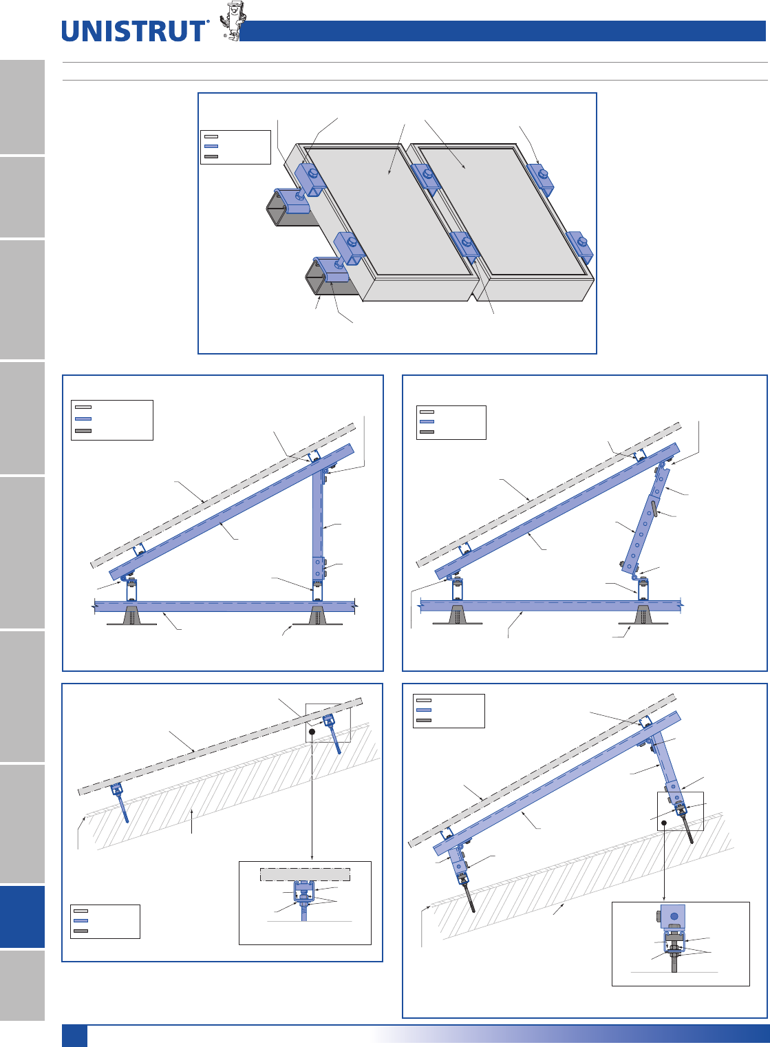
148
15⁄8" Framing System
1 5¼8" ChannelTelestrutNuts & HardwareGeneral FittingsPipe/Conduit SupportsElectrical FittingsConcrete InsertsSolarUnipier®
TYPICAL SOLAR INSTALLATION
Unistrut® SLR 100 (
Mid-Clamp
); SLR 150 (
End-Clamp
) Solar Panel Clamps
SLR200
End-Stop
SLR 150
Solar End-Clamp
5»16" HHCS
Stainless Steel SLR 150
Solar End-Clamp
Solar Panels
(typcial)
SLR 100
Solar Mid-Clamp
P1000T,
Aluminum (typical)
SLR 150
UNISTRUT P-S
SLR 150
UNISTRUT P-S
SLR 150
UNISTRUT P-S
SLR 150
UNISTRUT P-S
UNISTRUT
SLR 100
P-S
UNISTRUT
SLR 100
P-S
Solar Panel
Strut
Hardware
Solar Panel Support Frame Flat Roof with Fixed Angle
P1843 – Attach to
Vertical P1000T
P1000T
P2346
Solar Panel & Attachment to
P1000T - See Attachment Clamp
Example
P1843 –
Atttach to
P5000T
P1000T
UniPier (typical) – Includes Hardware
to Attach P1000T
P1000T (typical) – Attach to
P1000T with 3»8" HHCS,
HOCW037 & P3008 Strut Nut
P5000T (typical) – Attach to
P1000T with 3»8" HHCS,
HOCW037 & P3008 Strut Nut
P1000T
Solar Panel
Strut
Hardware
Solar Panel Support Frame Flat Roof with Variable Angle
Solar Panel & Attachment to
P1000T - See Attachment
Clamp Example
P1843 – Atttach to P5000T
P1000T
P1000T
UniPier (typical) –
Includes Hardware to
Attach P1000T
P1000T(typical) – Attach to
P1000T with 3»8" HHCS,
HOCW037 & P3008 Strut Nut
P5000T (typical) – Attach to
P1000T with 3»8" HHCS,
HOCW037 & P3008 Strut Nut
P1843 – Attach to P5000T with
1»2" HHCS & P3010 Strut Nut
& to P9200 with 1»2" HHCS
Thru-Bolt with 1»2" HHXN
P1843 – Attach to P1000HS with
1»2" HHCS & P3010 Strut Nut &
Thru the Half-Slot in the P1000T with
3»8" HHCS, HOCW037 & P1016
P1000HS
P9209 Gravity Pin
P9200
Solar Panel
Strut
Hardware
Solar Panel Support Frame Residential Shingle, Angled From Roof Slope
Solar Panel
Strut
Hardware
Solar Panel & Attachment
to P100T - See Attachment
Clamp Example
Roof Sheathing – Shingles
Not Shown for Clarity
Roof Rafter or Top
Chord of Roof Truss
P1000T (typical)
P1000T
P1000T
3
»
8
" HHXN
HOCW037
HFLW037
DETAIL #1
P1000T
P1000T
P2345
P1000T (typical)
P2346 – Use
1
»
2
" HHCS &
P3010 Strut Nuts
P1843 (typical) – Attach to
Vertical P1000T
P1000T (typical) – Attach to
P1000T with
3
»
8
" HHCS,
HOCW037 & P3008 Strut Nut
Solar Panel & Attachment to
P100T - See Attachment
Clamp Example
Roof Sheathing – Shingles
Not Shown for Clarity
Roof Rafter or Top
Chord of Roof Truss
P100T (typical)
P1000T
3»8" HHXN
HOCW037
HFLW037
DETAIL #1
Solar Panel Support Frame Residential Roof, Parallel to Roof Slope
Solar Panel
Strut
Hardware
Solar Application Example
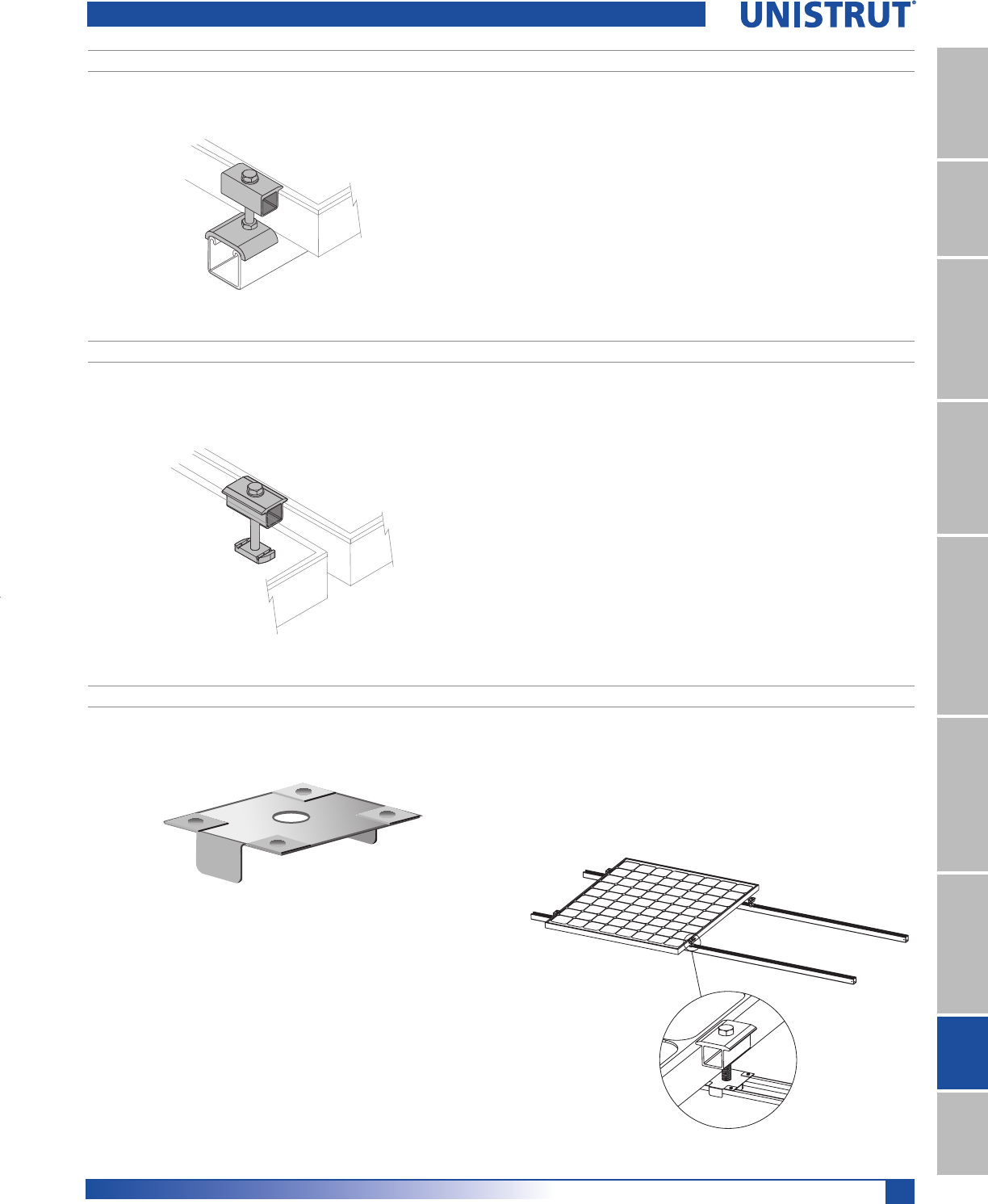
149
15⁄8" Framing System
1 5¼8" ChannelTelestrutNuts & HardwareGeneral FittingsPipe/Conduit SupportsElectrical FittingsConcrete InsertsSolarUnipier®
SLR 150
UNISTRUT P-S
SLR 100
UNISTRUT P-S
WEEB - WMC
– ELECTRICAL EQUIPMENT BONDING WASHER
SLR100
– SOLAR MID-CLAMP
SLR200
– SOLAR END CLAMP
5/16" x 23/4" hex head cap screw; stainless steel nut; lock washer included
(QGFODPSGHVLJQIRUXVHZLWKVWUXWEDVHGracking system
3DWHQWSHQGLQJHQGVWRSIHDWXUHDOORZVXVHZLWKYHUWLFDOVWUXW
0HHWVXSOLIWORDGVRIOEV
*Patent-pending
5/16" x 23/4" hex head cap screw; stainless steel nut; lock washer included
0LGFODPSGHVLJQIRUXVHZLWKVWUXWEDVHGUDFNLQJV\VWHP
3URYLGHV´PPSDQHOVSDFLQJ
0HHWVVSDFLQJUHTXLUHPHQWVRI:((%:0&
0HHWVXSOLIWORDGVRIOEV
3DWHQWHGGHVLJQIHDWXUHVVWDLQOHVVVWHHOWHHWKWKDWSLHUFHLQWRDQ
RGL]HGDOXPLQXPSURYLGLQJDJDVWLJKWFRQQHFWLRQZKLFKSUHYHQWV
R[LGDWLRQ
0HHWV$16,8/UHTXLUHPHQWVIRUERQGLQJJURXQGLQJV\VWHPV
4XLFNLQVWDOODWLRQWKDWLVVDIHUHOLDEOHDQGFRQVLVWHQW
Solar Connectors
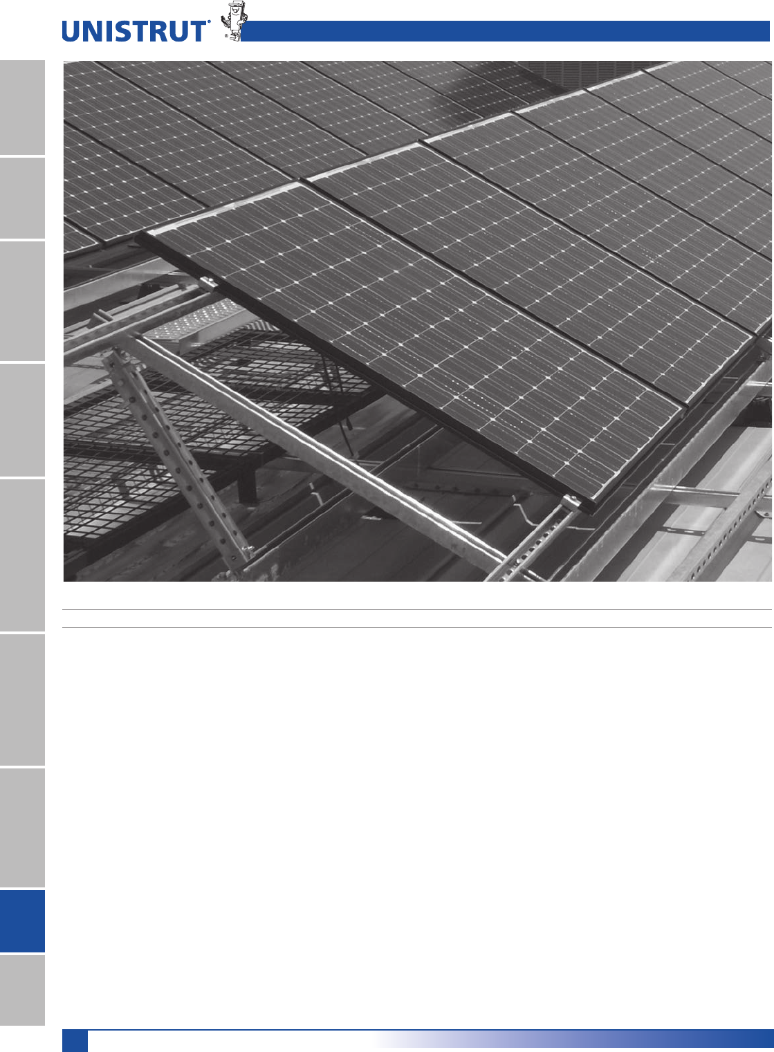
150
15⁄8" Framing System
1 5¼8" ChannelTelestrutNuts & HardwareGeneral FittingsPipe/Conduit SupportsElectrical FittingsConcrete InsertsSolarUnipier®
Solar Panel Installation
KEY ADVANTAGES
7KHPDUNHWVRQO\VSHFLILFSDQHOPRXQWLQJ
FRPSRQHQWVPDGHH[FOXVLYHO\IRUXVHZLWK
8QLVWUXW
6LPSOHGHVLJQXVHGE\WKHLQGXVWU\IRUDYDULHW\RI
LQVWDOODWLRQPHWKRGVDQGDSSOLFDWLRQV
6WDLQOHVVVWHHOKDUGZDUHLQFOXGHGZLWKDOOVRODU
FODPSV
$YDLODEOHLQ%ODFNRU6LOYHU$QRGL]HG0DWHULDO
$$7IRUFRUURVLRQSURWHFWLRQDQGVOHHN
DSSHDUDQFH
%HVWILWZLWK8QLVWUXWFKDQQHOWRFUHDWHOHVV
SHQHWUDWLRQDQGVXSHULRUVOLSUHVLVWDQFH
'HVLJQHGIRUPD[LPXPORDGVXSWRPLOHVSHU
KRXU
$YDLODEOHDQGVXSSRUWHGE\8QLVWUXW¶VQDWLRQDO
QHWZRUNRIGLVWULEXWRUV
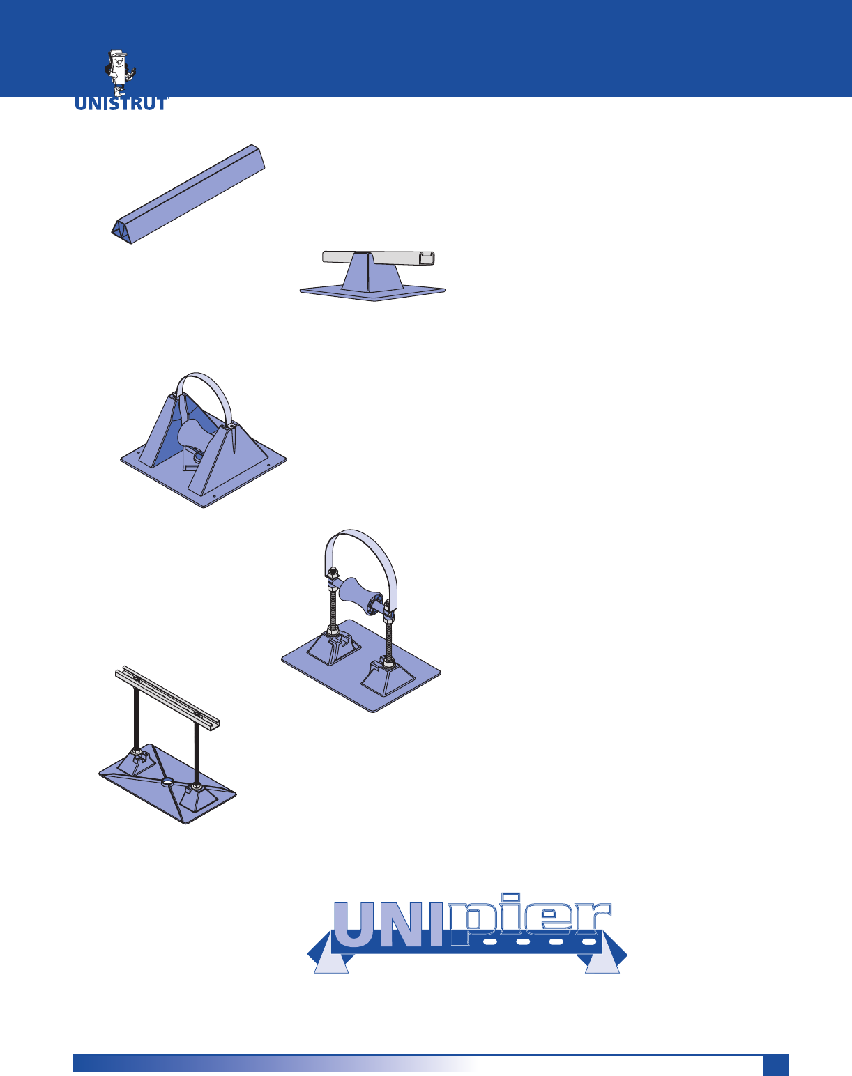
151
Unipier®
Sleeper Support .................................................................153 - 154
Strut Support .....................................................................155 - 156
Conduit Supports
Mounted Support, Polycarbonate Base ....................................157
Elevated Support, Polycarbonate Base .....................................157
Elevated Support, Steel Base .....................................................158
Gas and Mechanical Supports
Mounted Support, Polycarbonate Base ....................................158
Mounted Support, w/Roller Polycarbonate Base .....................158
Elevated Support, w/Roller, Polycarbonate Base .....................159
Elevated Support, w/Roller, Steel Base .....................................160
Accessories
Spacer ..........................................................................................160
Support Pads, Deck Plates ..........................................................160
Pipe Hanger Bases, Polycarbonate and Steel ...........................161
Fabricated Supports
Single Base Trapeze ....................................................................162
Double Base Trapeze ..................................................................163
Heavy Duty Double Base Trapeze ..............................................163
Double Base Duct Support .........................................................163
Mechanical Supports ..................................................................164
Bridge Cross-Over, Walkway, Service Platform or Ramp .........164
Installation ..................................................................................165
Pipe Diameters and Loading ......................................................166
Technical Data ................................................................... 167 – 168
ROOFTOP PIPE SUPPORT SYSTEM
pierpierpier
®
UNIPIER®
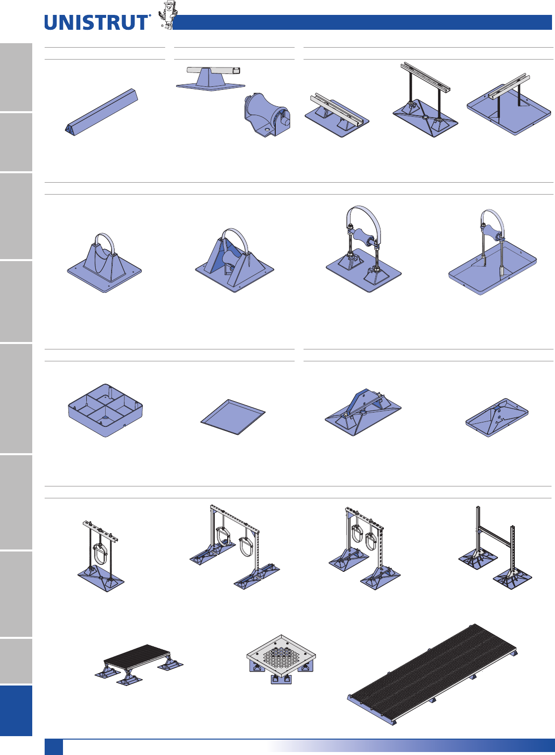
152
15⁄8" Framing System
1 5¼8" ChannelTelestrutNuts & HardwareGeneral FittingsPipe/Conduit SupportsElectrical FittingsConcrete InsertsSolarUnipier®
Mounted
Polycarbonate Base
Pg 157
Model UP
Strut Support
Pg 155
M-RBS Roller for
Model UP
Strut Support
Pg 155
Mounted
Polycarbonate Base
Pg 158
Mounted, w/Roller
Polycarbonate Base
Pg 158
Elevated Support, w/Roller
Polycarbonate Base
Pg 159
Elevated Support, w/Roller
Steel Base
Pg 160
Elevated Support
Steel Base
Pg 158
Elevated Support
Polycarbonate Base
Pg 157
Gas and Mechanical Support
Accessories
Conduit Support
Single Base Trapeze
Pg 162
Steel Bases
Pg 161
Support Pads &
Deck Plates
Pg 160
Double Base Trapeze
Pg 163
Heavy Duty, Double Base Trapeze
Pg 163
Polycarbonate Bases
Pg 161
Pipe Hanger Bases
Fabricated Supports
Sleeper Support
Rooftop Sleeper Support
Pg 153 - 154
Strut Support
Heavy Duty Mechanical Support
Pg 164
Light Duty Mechanical Support
Pg 164
Double Base Duct Support
Pg 163
Spacer for Model 1.5, 3-R
Pg 160
Bridge Cross-Over, Walkway,
Service Platform or Ramp
Pg 164
Unipier® Rooftop Pipe Support System
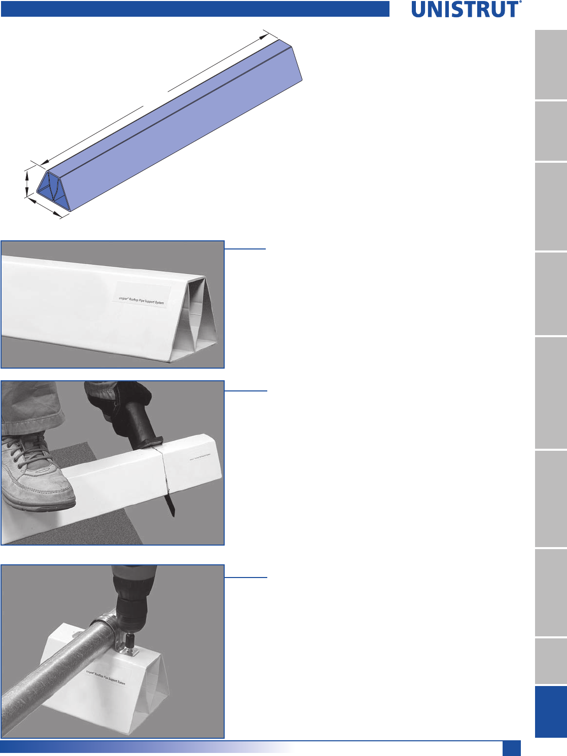
153
15⁄8" Framing System
1 5¼8" ChannelTelestrutNuts & HardwareGeneral FittingsPipe/Conduit SupportsElectrical FittingsConcrete InsertsSolarUnipier®
31»2"
47»8"
(89.0)
4'
(1219)
(123.8)
7KH8QLSLHUURRIWRSVOHHSHULVWKH¿UVWURRIWRSVXSSRUWWKDWLVZKLWH
WRUHÀHFWWKHVXQ¶V89UD\V,WLVFRVWHIIHFWLYHOLJKWZHLJKWDQGFDQ
be cut to the desired length while on the job site.
The model RSS4 is conveniently packaged in shrink wrap bundles
of 9 - 4 ft. supports that can be easily carried to the rooftop.
The Unipier sleeper support is lightweight, just 4 lbs./4 ft. section,
so it is easily transported to the job site in bundles of 9 supports.
The Unipier sleeper support can be conveniently cut to lengths of
6" or longer right on the job site.
TEK screws or other self tapping fasteners are used to attach
FRQGXLWVXSSRUWVSLSHFODPSVRURWKHUFODPSLQJ¿WWLQJV
NOTE: Load not to exceed 50 lbs./6" length
Part Number: RSS4
Unipier® Rooftop Pipe Support System - Sleeper Support
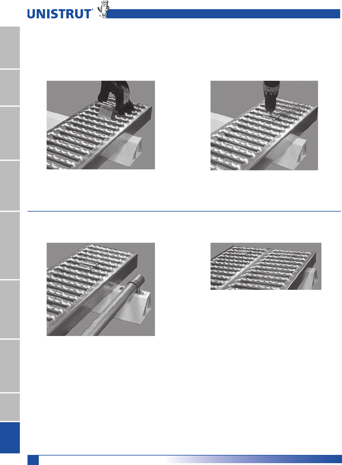
154
15⁄8" Framing System
1 5¼8" ChannelTelestrutNuts & HardwareGeneral FittingsPipe/Conduit SupportsElectrical FittingsConcrete InsertsSolarUnipier®
Position the grating on the Unipier sleeper
support and insert the appropriate size hold
down clip (G639, G607, or G620).
You can even use the Unipier support for multiple
tasks. Here we have Unistrut Roofwalks®
Rooftop Walkways and a piece of electrical
conduit attached to the sleeper.
Grating can also be used to construct a platform
for heavy equipment or even as a workstand.
Use a TEK screw to attach the hold down clip.
That’s all that is required!
The Sleeper Support is not restricted to just pipe clamps. It makes a perfect companion for the Roofwalk® Rooftop
Walkways.
Unipier® Rooftop Pipe Support System - Sleeper Support
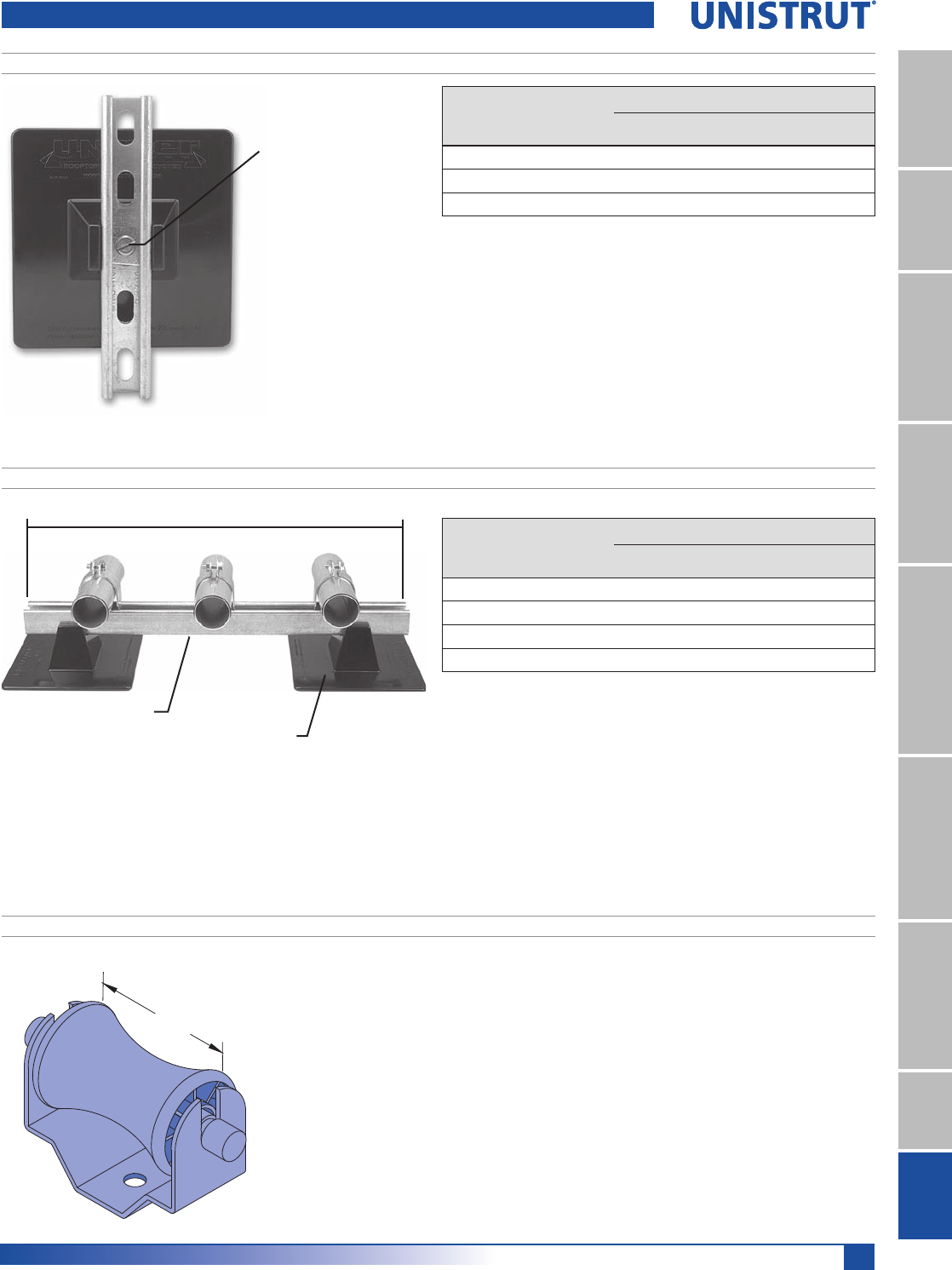
155
15⁄8" Framing System
1 5¼8" ChannelTelestrutNuts & HardwareGeneral FittingsPipe/Conduit SupportsElectrical FittingsConcrete InsertsSolarUnipier®
Part
Number
Qty.
Unipier
Bases
Supporting Channel
Qty. Description
UP-MPDS-26HG 4 2 26" - P1000T HG for Trapeze
UP-MPDS-38HG 4 2 38" - P1000T HG for Trapeze
UP-MPDS-50HG 4 2 50" - P1000T HG for Trapeze
UP-MPDS-62HG 4 2 62" - P1000T HG for Trapeze
NOTE:
1. The maximum uniform load on P1000T is 400 lbs.
2. Uniform load is limited by roof base allowed load of 200 lbs. (5 psi on roof).
Part
Number
Qty.
Unipier
Bases
Supporting Channel
Qty. Description
UP-BK 4 0 Base Only
UP-SPSS-6 HG 4 4 6" - P4100T HG (up to 31»2" Pipe)
UP-SPSS-10HG 4 4 10" - P4100T HG (4" to 8" Pipe)
NOTE:
1. The maximum uniform load on P1000T is 400 lbs.
2. Uniform load is limited by roof base allowed load of 200 lbs. (5 psi on roof).
Single Pier Installation
1. Align center hole of Unistrut P4100T on base and attach using
supplied hardware. Torque screw to 19 ft./lbs.
2. Place pipe/tubing on P4100T and attach pipe/tubing clamp.
Trapeze Installation
1. Align end holes of Unistrut P1000T on bases and attach using
supplied hardware. Torque screw to 19 ft./lbs.
2. Place pipe/tubing on support and attach with appropriate pipe/
tubing clamp.
NOTE: Kits do not include pipe/tubing or clamps.
UP-SPSS Style Support
UP-MPDS Style Support
$OLJQ&HQWHUKROHRI
P4100T on base.
3ODFHVTXDUHZDVKHU
inside P4100T.
,QVHUWVFUHZ
torque to 19 ft./lbs.
&KDQQHO/HQJWK
37
%DVH
3"
(76.2)
M-RBS
The M-RBS roller is designed for use with the UP-BK base. The roller is made of
polycarbonate and the roller rod is 6/6 nylon.
Note: Maximum load is 100 lbs. and should not extend more than 12" above the roof.
Wt./Ea.: 0.7 lbs.
Unipier® Rooftop Pipe Support System - Strut Support
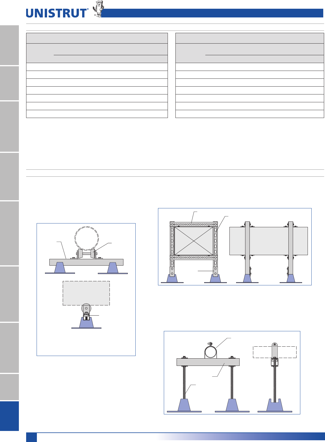
156
15⁄8" Framing System
1 5¼8" ChannelTelestrutNuts & HardwareGeneral FittingsPipe/Conduit SupportsElectrical FittingsConcrete InsertsSolarUnipier®
Support Spacing
Pipe Size
1RP
Sch. 40 Pipe
Water-FilledD Conduit GRCE
Single Pier TrapezeG Single Pier TrapezeG
3»8" 7' 7' N/A N/A
1»2" 7' 7' 10' 10'
3»4" 7' 7' 10' 10'
1" 7' 7' 12' 12'
11»4" 7' 7' 14' 14'
11»2" 9' 9' 14' 14'
2" 10' 10' 16' 16'
Note:
(a) Based on ANSI/MSS SP-69, 2003 Edition, Table 3.
(b) Based on 2002 NEC, Table 344.30(B)(2).
(c) Spacing limited to roof base allowed load of 200 lbs. (5 psi on roof).
(d) Spacing may be limited by maximum allowed weight on trapeze to 400 lbs.
Support Spacing
Pipe Size
1RP
Sch. 40 Pipe
Water-FilledD Conduit GRCE
Single Pier TrapezeG Single Pier TrapezeG
21»2" 11' 11' 16' 16'
3" 12' 12' 13'(c) 20'
31»2" 13' 13' 11'(c) 20'
4" 12'(c) 14' 9'(c) 20'
5" 8'(c) 16' 6'(c) 20'
6" 6'(c) 17' 4'(c) 20'
8" 4'(c) 19' N/A N/A
P2474
P1000
Strut Nut
Unistrut Pipe Clamp
P1000 T
Threaded rod
Unipier Rooftop Support System provides a simple and versatile way to support and manage pipe, tubing, conduit, HVAC systems, and
the like. The Unipier Rooftop Support System does not require roof surface penetration and allows the parts to remain off the surface.
Prime Angle
P1000T
P1326
HVAC Duct
Support Spacing
Application Examples
Unipier® Rooftop Pipe Support System Strut Support
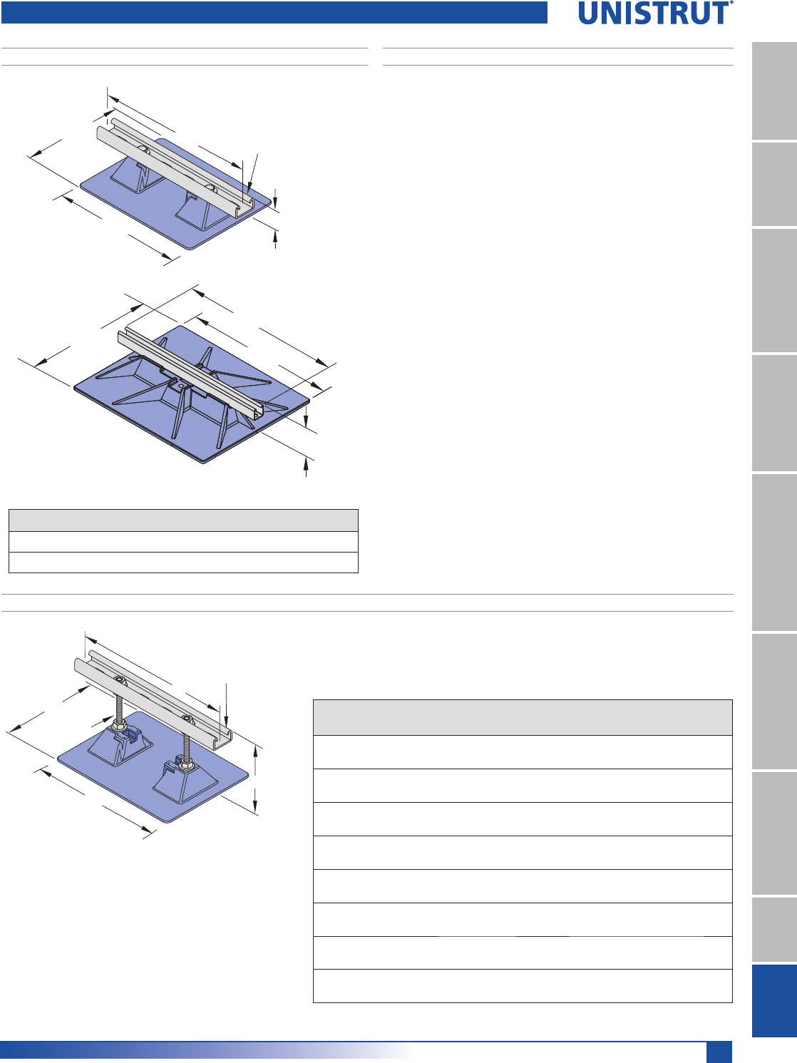
157
15⁄8" Framing System
1 5¼8" ChannelTelestrutNuts & HardwareGeneral FittingsPipe/Conduit SupportsElectrical FittingsConcrete InsertsSolarUnipier®
Mounted Support, Polycarbonate Base
Part
Number
+PD[
LQPP
"W"
LQPP
"L"
LQPP
"T"
LQPP
Max.
Uniform Load
Wt./Each
OEV
2.5-CS-5 5"
(127.0)
7 1»2"
(190.5)
10"
(254.0)
12"
(304.8)
100 lbs. 2.1
2.5-CS-7 7 1»2"
(190.5)
7 1»2"
(190.5)
10"
(254.0)
12"
(304.8)
100 lbs. 2.5
2.5-CS-12 12"
(304.8)
9"
(228.6)
15 1»4"
(387.4)
12"
(304.8)
100 lbs. 4.0
16-BS-7 7"
(177.8)
9"
(228.6)
15 1»4"
(387.4)
16"
(406.4)
125 lbs. 5.0
16-BS-12 12"
(304.8)
9"
(228.6)
15 1»4"
(387.4)
16"
(406.4)
125 lbs. 8.0
20-BS-7 7"
(177.8)
16"
(406.4)
18"
(457.2)
20"
(508.0)
440 lbs. 10.8
20-BS-12 12"
(304.8)
16"
(406.4)
18"
(457.2)
20"
(508.0)
440 lbs. 15.1
24-BS-18 12"
(304.8)
23"
(584.2)
19"
(482.6)
24"
(609.6 )
640 lbs. 8.0
10"
(254.0)
71⁄2"
(190.5)
21⁄2"
(63.5)
12"
(304.8) P4100 T (15⁄8" x 13⁄16")
H
T
P1000 T (15⁄8" x 15⁄8"); 24-BS-18 only
P4100 T (15⁄8" x 13⁄16")
3⁄8"-16 S.S.Rod
W
L
Note: Base for 2.5-CS-5, 2.5-CS-7 shown. Other bases
have additional support or flanges to handle the increased
loads.
All bases are polycarbonate material
Shipped assembled.
Elevated Support, Polycarbonate Base
Part Number Material Max. Uniform Load Wt./Each
2.5-CS-2 Polycarbonate 100 lbs. 2.3 lbs.
24-BS-4 Polycarbonate 640 lbs. 8.0 lbs.
Determining Maximum Pipe Size
Maximum pipe size supported by any of the strut supports is
determined by the load and the clear space required between the
pipes. The spacing between pipes should be as follows:
EHWZHHQSLSLQJDQGVPDOOHU
1»2" between a pipe 3" and smaller and a pipe 4" or larger.
EHWZHHQSLSLQJDQGODUJHU
$WOHDVWEHWZHHQSLSHFODPSDQGHQGRIVWUXW
For example, a support for two 3" pipes would require:
1" + 3" + 1-1»2" + 3" + 1" = 9-1»2" wide channel support
Shipped assembled.
Unipier® Rooftop Pipe Support System - Strut Support
19"
(482.6) 23"
(584.2)
24"
(609.6)
41»8"
(104.8)
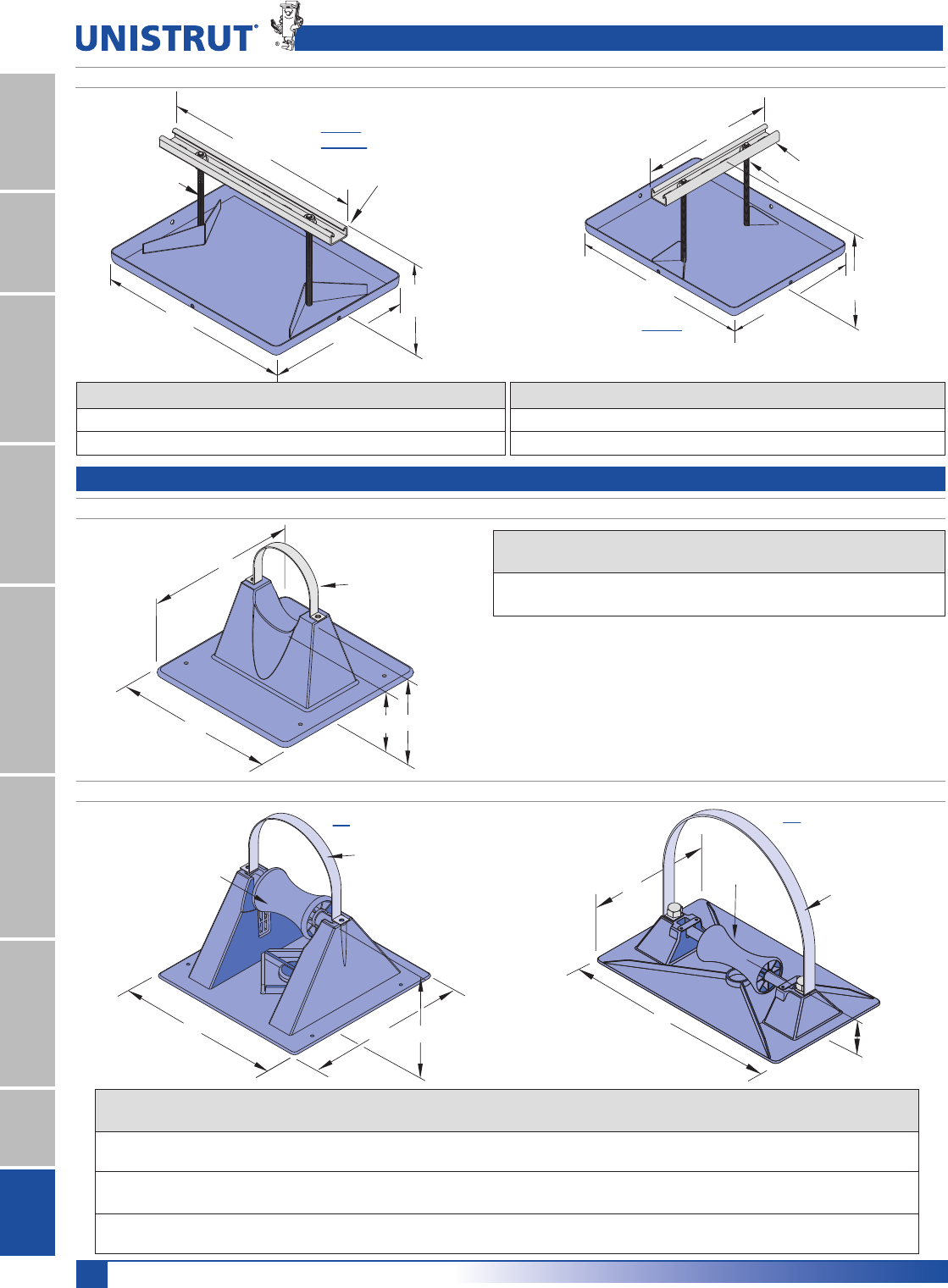
158
15⁄8" Framing System
1 5¼8" ChannelTelestrutNuts & HardwareGeneral FittingsPipe/Conduit SupportsElectrical FittingsConcrete InsertsSolarUnipier®
16"
(406.4)
P4100 T HG (15⁄8" x 13⁄16")
16"
(406.4)
12"
(304.8)
1⁄2" - 13 S.S.Rod
16-BS-7
16-BS-12
71⁄2"
(190.5)
Mounted, Polycarbonate Base
Mounted, with Roller, Polycarbonate Base
6"
6" Optional Part
1.5 Pipe Strap
(order separately)
2" 3"
Roller
Optional
Alum. Pipe Strap
w/SS Screws
(order separately)
H
W
L
3-R
Part Number
Max. Pipe
Capacity
Max.
Uniform Load
Wt./Ea.
Optional
Pipe Strap
1.5 Pipe Support 11»2" ID ,
1.9" OD
80 lbs. 0.35 lbs. 1.5 Pipe Strap
Part
Number
"H"
LQPP
"W"
LQPP
"L"
LQPP
Roller
size
Max. Pipe
Capacity
Max. Uniform
Load
Wt./Ea.
Lbs.
Optional
Pipe Strap
3-R-2 2.15"
(54.6)
7 3»4"
(196.9)
7 3»4"
(196.9)
3"
(76.2)
3" ID
3 3»4" OD
100 lbs. 1.1 lbs. 3-R-2 Pipe Strap
3-R-4 4"
(101.6)
7 3»4"
(196.9)
7 3»4"
(196.9)
3"
(76.2)
3" ID
3 3»4" OD
100 lbs. 1.2 lbs. 3-R-4 Pipe Strap
5-R 2.35"
(59.7)
9"
(228.6)
15 1»4"
(387.4)
5"
(127.0)
5" ID
6" OD
150 lbs. 2.4 lbs. 6-RAH Pipe Strap
Note: All bases are polycarbonate
Note: Base is polycarbonate
Optional pipe strap aluminum w/SS Screws
Shipped assembled.
Unipier® Rooftop Pipe Support System - Strut Support
Elevated Support, Steel Base
Part Number Base Material Max. Uniform Load Wt./Each
12-BS-7 HG Hot-Dipped Galvanized 150 lbs. 7.5 lbs.
12-BS-7 SS Stainless Steel 150 lbs. 7.5 lbs.
16"
(406.4) 12"
(304.8)
12"
(304.8)
71⁄2"
(190.5)
P4100 T HG (15⁄8" x 13⁄16")
3⁄8" - 16 S.S.Rod
12-BS-7
Part Number Base Material Max. Uniform Load Wt./Each
16-BS-7 HG Hot-Dipped Galvanized 150 lbs. 7.5 lbs.
16-BS-7 SS Stainless Steel 150 lbs. 7.5 lbs.
Shipped assembled.
L
W
H
Roller
Optional Part
6-RAH Alum. Pipe Strap
w/SS Screws
(order separately)
5-R
Unipier® Rooftop Pipe Support System - Gas & Mechanical Support
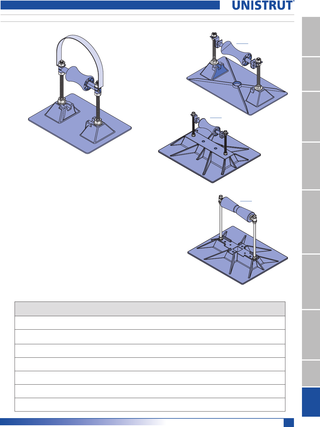
159
15⁄8" Framing System
1 5¼8" ChannelTelestrutNuts & HardwareGeneral FittingsPipe/Conduit SupportsElectrical FittingsConcrete InsertsSolarUnipier®
Elevated Support, with Roller, Polycarbonate Base
Part
Number
+PD[
LQPP
"W"
LQPP
"L"
LQPP
Roller Size
LQPP
Max. Pipe
Capacity
Max.
Uniform Load
Wt./Ea.
Lbs.
Optional
Pipe Strap
3-RAH-7 7"
(177.8)
7 1»2"
(190.5)
10"
(254.0)
3"
(76.2)
3" ID
33»4" OD
100 lbs. 1.9 3-RAH Pipe Strap
3-RAH-12 12"
(304.8)
9"
(228.6)
15 1»4"
(387.4)
3"
(76.2)
3" ID
33»4" OD
100 lbs. 5.8 3-RAH Pipe Strap
5-RAH-7 7"
(177.8)
9"
(228.6)
15 1»4"
(387.4)
5"
(127.0)
5" ID
6" OD
150 lbs. 4.8 6-RAH Pipe Strap
5-RAH-12 12"
(304.8)
9"
(228.6)
15 1»4"
(387.4)
5"
(127.0)
5" ID
6" OD
150 lbs. 4.8 6-RAH Pipe Strap
6-RAH-7 7 1»2"
(190.5)
16"
(406.4)
18"
(457.2)
5"
(127.0)
6" ID
8 1»2" OD
250 lbs. 8.8 6-RAH Pipe Strap
6-RAH-12 12"
(304.8)
16"
(406.4)
18"
(457.2)
5"
(127.0)
6" ID, 8 1»2" OD 250 lbs. 9.8 6-RAH Pipe Strap
8-RAH-18 18"
(457.2)
19"
(482.6)
23"
(584.2)
12"
(304.8)
6" ID, 8 1»2" OD 640 lbs. 20.0 8-RAH Pipe Strap
Note: Base for 3-RAH-7 shown. Other bases have
additional support or flanges to handle the increased loads.
All bases are polycarbonate material
Optional pipe strap aluminum w/SS Screws
Shipped
assembled.
Unipier® Rooftop Pipe Support System - Gas & Mechanical Support
6-RAH
8-RAH
5-RAH
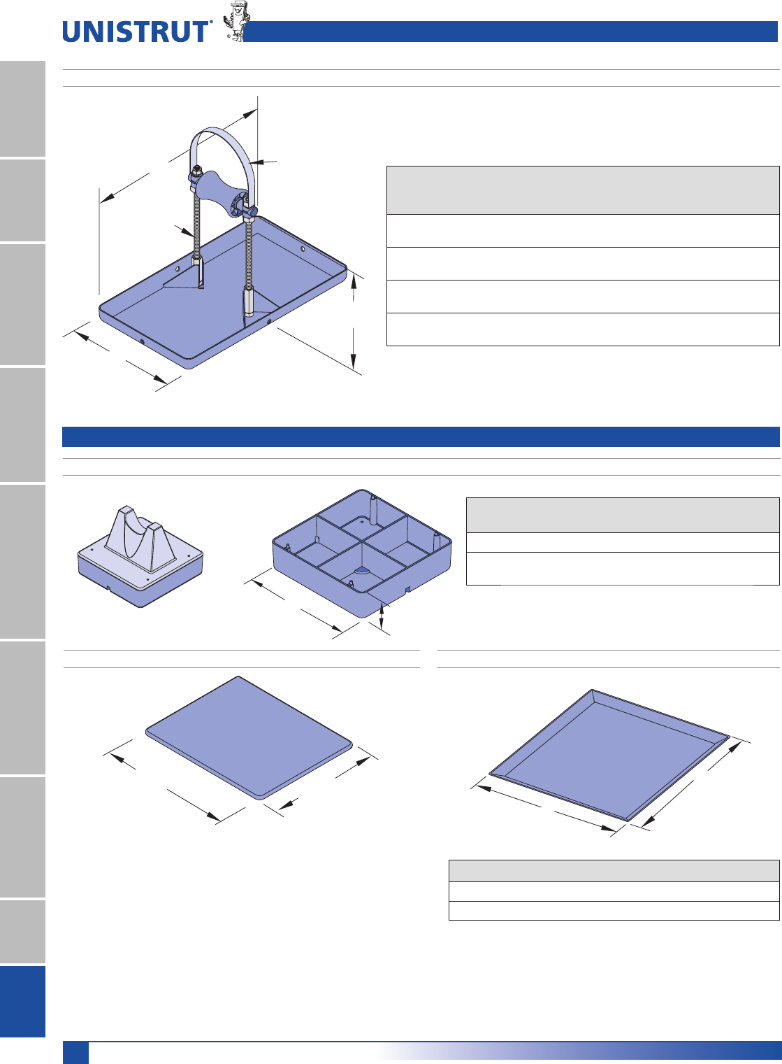
160
15⁄8" Framing System
1 5¼8" ChannelTelestrutNuts & HardwareGeneral FittingsPipe/Conduit SupportsElectrical FittingsConcrete InsertsSolarUnipier®
Spacer for Model 1.5 and Model 3-R
W1.5"
(38.1)
Example: Spacer with Model 1.5
Part
Number
Use With
"W"
Added Pipe
Clearance Wt./Ea.
1.5 Spacer 1.5 6" 1 1»2" 0.43 lbs
3-R Spacer 3-R-2
or 3-R-4
7-1»2" 2" 0.75 lbs
Material: Polycarbonate
193»4"
(501.7) 153»4"
(400.0)
W
W
Part Number Material Width "W" Wt./Each
Deck Plates 12 SS Stainless Steel 12" 2.0 lbs.
Deck Plates 18 SS Stainless Steel 18" 4.5 lbs.
Deck Plate, Stainless SteelSupport Pad, Polycarbonate
The Unipier support pad is designed to provide a barrier between the roof membrane
and rooftop equipment. The support pad is 1/8" thick and are compatible with all cur-
rent types of decking and commonly used built-up and single-ply roof membranes.
Support pads should be installed in the following areas:
8QGHUDOO8QLSLHUSLSHVXSSRUWV7KHSLSHVXSSRUWPXVWEHSODFHGHYHQO\RYHUWKH
support pad.
,QKLJKWUDIILFSRLQWVRUZKHUHUHJXODUPDLQWHQDQFHLVQHFHVVDU\WRVHUYLFHURRIWRS
equipment.
When installing the support pad, remove all rock, aggregate, dirt and excess dust from
an area of the roof membrane slightly larger than the support pad. Then, apply the sup-
port pad on the cleaned area and center the Unipier pipe support on the rooftop pad.
The maximum roof top load should not exceed 5 p.s.i. The rooftop pad can withstand
higher loading, but the roof membrane and insulation are typically limited to 5 p.s.i.
W
L
7"
(177.8)
3⁄8
"
- 16 S.S. Rod
Optional
3-RAH Pipe Strap
(order separately)
Part
Number
"W"
in.
PP
"L"
in.
PP
Roller
in.
PP
Material
Max.
Pipe
Capacity
Max.
Uniform
Load
Wt.
Each
Lbs
3-RAH-7 HG 8"
(203.2)
14"
(355.6)
3"
(76.2)
Hot-Dipped
Galvanized
3" ID
33»4" OD
100 lbs. 3.3
3-RAH-7 SS 8"
(203.2)
14"
(355.6)
3"
(76.2)
Stainless
Steel
3" ID
33»4" OD
100 lbs. 3.3
4-RAH-7 HG 12.07"
(306.6)
16.07"
(408.2)
5"
(127.0)
Hot-Dipped
Galvanized
4" ID
5" OD
150 lbs. 6.8
4-RAH-7 SS 12.07"
(306.6)
16.07"
(408.2)
5"
(127.0)
Stainless
Steel
4" ID
5" OD
150 lbs. 5.8
Elevated Support, with Roller, Steel Base
Note: Optional 3-RAH Pipe Strap aluminum w/SS Screws
Shipped assembled.
Unipier® Rooftop Pipe Support System - Gas & Mechanical Support
Unipier® Rooftop Pipe Support System - Accessories
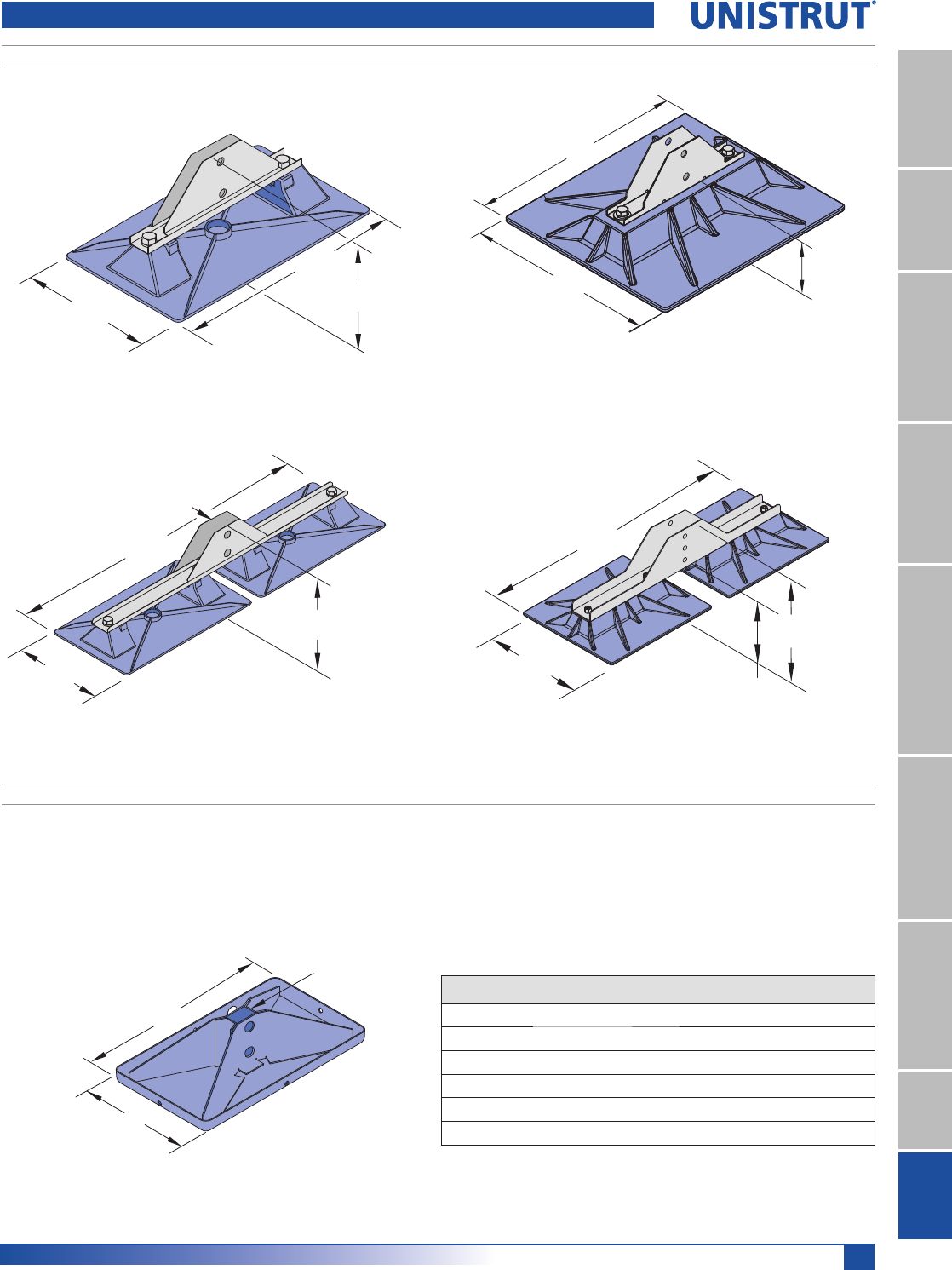
161
15⁄8" Framing System
1 5¼8" ChannelTelestrutNuts & HardwareGeneral FittingsPipe/Conduit SupportsElectrical FittingsConcrete InsertsSolarUnipier®
Polycarbonate Base
9"
(228.6)
6"
(152.4)
1.65" ID
(41.9)
31.69"
(804.9)
Model 8-H-DB Base P
151»4"
(387.4)
9"
(228.6)
6"
(152.4)
Model 6-H Base P
Note: Maximum 150 lbs. Load
Wt./Ea.: 2.5 lbs.
Note: Maximum 350 lbs. Load
Wt./Ea.: 4.5 lbs.
16"
406.4
21»2"
(63.5)
18"
457.2
Model 8-H-SB Base P
Note: Maximum 350 lbs. Load
Wt./Ea.: 5.5 lbs.
Note: Contact Unistrut for optional configuration to allow for adjustability.
Note: Maximum 350 lbs. Load
Wt./Ea.:18.5 lbs.
W
L
Opening
Model 6-H, 8-H, 16-H Base HG or S.S.
39"
(990.6)
16"
(406.4)
3.12"
(79.2)
Model 16-H Base P
9"
(228.6)
Stainless Steel / Hot Dip Galvanized Steel Base
Part Number "W" "L" "Opening"
6-H Base HG 8" PP 14" PP 1-5/8" x 7/8" [
6-H Base SS 8" PP 14" PP 1-5/8" x 7/8" [
8-H Base HG 16" PP 12" PP 1-5/8" x 1-5/8"[
8-H Base SS 16" PP 12" PP 1-5/8" x 1-5/8"[
16-H Base HG 20" PP 20" PP 3" x 3" [
16-H Base SS 20" PP 20" PP 3" x 3" [
Unipier® Rooftop Pipe Support System - Bases
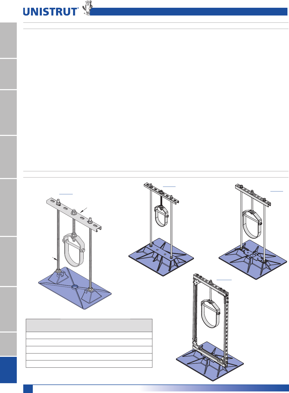
162
15⁄8" Framing System
1 5¼8" ChannelTelestrutNuts & HardwareGeneral FittingsPipe/Conduit SupportsElectrical FittingsConcrete InsertsSolarUnipier®
Custom Fabrication
7KH8QLSLHUSURGXFWVRIIHUDJUHDWGHDORIÀH[LELOLW\,I\RXGRQRW
¿QGDQ³RIIWKHVKHOI´VXSSRUWIRU\RXUSDUWLFXODUDSSOLFDWLRQFRQWDFW
Unistrut with your requirements. We can design and build the proper
support for your unique application.
Samples of typical custom fabrications are shown in this section of the
catalog.
Custom products are shown on the following pages. For a quotation
on custom fabrication, contact Unistrut with the parameters for your
design as shown below.
3LSH6WDQGV
1. Quantity of supports required (or total footage of pipe)
2. Type of pipe
3. Size of pipe and number of pipes per support
4. Pipe contents
5. Clearance height above roof
6. Thickness of any insulation around pipe
'XFWDQG&DEOH7UD\6XSSRUWV
1. Dimension of duct
2. Clearance height above roof
3. Total footage of duct
4. Thickness of insulation, if any
8QLVWUXW5RRIZDONV®5RRIWRS:DONZD\V
&URVVRYHU5DPSDQG3ODWIRUPV
1. Width and length desired
2. Height off roof
3. Specify if railing is needed
7\SHRIURRI
0HFKDQLFDO6XSSRUWV
1. Width and length desired
2. Height off roof
3. Weight of unit
Single Base Trapeze
Model
Material
Max. Uniform Load
Per Pipe Stand
2.5-SB-H (shown) Polycarbonate 125 lbs.
5-SB-H Polycarbonate 250 lbs.
5-SB-H HG Hot-Dipped Galvanized 170 lbs.
8-SB-H Polycarbonate 296 lbs.
8-SB-HD Polycarbonate 640 lbs.
NOTE: For maximum pipe size, refer to note on page 163.
P1000 T HG (15»8" x 15»8") - 8-SB Only
P4100 T HG (15»8" x 13»16")
1»2" - 13 S.S.Rod
2.5-SB-H
Unipier® Rooftop Pipe Support System - Fabricated Support
5-SB-H
8-SB-H
8-SB-HD
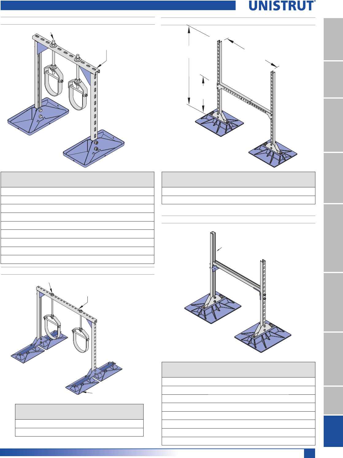
163
15⁄8" Framing System
1 5¼8" ChannelTelestrutNuts & HardwareGeneral FittingsPipe/Conduit SupportsElectrical FittingsConcrete InsertsSolarUnipier®
Double Base Duct Support
Model
Material
Max. Uniform Load
Per Duct
6-DSA Polycarbonate 150 lbs.
8-DSA Polycarbonate 300 lbs.
8-DS-P Shown
P1000 T HG (15⁄8" x 15⁄8")
Model Material
Max. Uniform Load
Per Duct
6-DS-P Polycarbonate 150 lbs.
6-DS-HG Hot-Dipped Galvanized 300 lbs.
6-DS-SS Stainless Steel 300 lbs.
8-DS-P Polycarbonate 300 lbs.
8-DS-HG Hot-Dipped Galvanized 300 lbs.
8-DS-SS StainlessSteel 300 lbs.
8-DS-DB-P Polycarbonate 300 lbs.
10-DS-P Polycarbonate 300 lbs.
24" to 36"
(609.6 to 914.4)
48"
(1,219.2)
36" max
(914.4)
Model 8-DSA Shown
Double Base Duct Support
Model 6-H Shown
P1000 T HG (15⁄8" x 15⁄8") - 10-H, 16-H
P4100 T HG (15⁄8" x 13⁄16") - 6-H, 8-H
3⁄8" - 16 S.S. Rod
Model
Material
Max. Uniform Load
Per Pipe Stand
Max. Pipe
Capacity
6-H-P Polycarbonate 300 lbs. 7 1»2"
8-H-P Polycarbonate 700 lbs. 9"
6-H-HG Hot-Dipped Galvanized 300 lbs. 7 1»2"
6-H-SS Stainless Steel 300 lbs. 7 1»2"
8-H-HG Hot-Dipped Galvanized 700 lbs. 9"
8-H-SS Stainless Steel 700 lbs. 9"
10-H-P Polycarbonate 1,600 lbs. 9"
16-H-HG Hot-Dipped Galvanized 1,600 lbs. 18"
16-H-SS Stainless Steel 1,600 lbs. 18"
Double Base Trapeze
Model
Max. Uniform Load
Per Pipe Stand
Max. Pipe
Capacity
8-H-DB 700 lbs. 9"
16-H-DB 1,600 lbs. 18"
Base Material: Polycarbonate
Heavy Duty Double Base Trapeze
8-H-DB (shown), or
16-H-DB
P1000 T HG (15⁄8" x 15⁄8") - 16-H-DB
P4100 T HG (15⁄8" x 13⁄16") - 8-H-DB (shown)
3⁄8" - 16 S. S. Rod
Unipier® Rooftop Pipe Support System - Fabricated Support
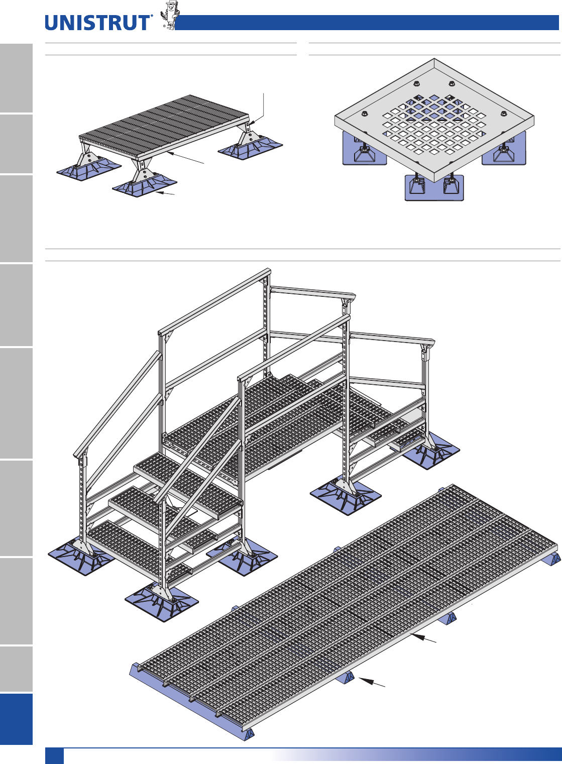
164
15⁄8" Framing System
1 5¼8" ChannelTelestrutNuts & HardwareGeneral FittingsPipe/Conduit SupportsElectrical FittingsConcrete InsertsSolarUnipier®
Note: Adjustable height, maximum load 200 lbs.
Available Sizes: 18" x 18", 24" x 24", 30" x 30", 36" x 36"
Note: Custom sizes available, Contact Unistrut for information.
Heavy Duty Mechanical Support
8-H-SB Base P
P1000 (15⁄8" x 15⁄8")
P1000 T HG (15⁄8" x 15⁄8")
Light Duty Mechanical Support
Bridge Cross-Over, Walkway, Service Platform or Ramp
Unistrut United Interlock Grating®
Attached with grating hold down clip.
Sleeper Support
Unipier® Rooftop Pipe Support System - Fabricated Support

165
15⁄8" Framing System
1 5¼8" ChannelTelestrutNuts & HardwareGeneral FittingsPipe/Conduit SupportsElectrical FittingsConcrete InsertsSolarUnipier®
Product Description:
$SLSHVXSSRUWXVHGWRVXSSRUWURRIPRXQWHGJDVSLSHV
HOHFWULFDOFRQGXLWVRODUSLSLQJDQGRWKHUPHFKDQLFDO
SLSLQJ8QLTXHGHVLJQDEVRUEVWKHUPDOH[SDQVLRQDQG
FRQWUDFWLRQRISLSHVWKXVSUHYHQWLQJGDPDJHWRWKHURRI
PHPEUDQH3LSHVUHVWVLQFOXGH
8VKDSHGFUDGOHVLWXDWHGLQDSRO\FDUERQDWHUHVLQVHDW
6HOIOXEULFDWLQJUROOHUSRO\FDUERQDWHUHVLQURGDQGUROOHU$VGD\WLPH
temperatures warm the roof membrane and the mechanical pipe
network found on the roof, causing them to expand, the roller
bearing in the pipe stand rolls beneath the pipe it supports. A
difference between night and day temperatures of 20° F. causes
100 ft. of 1" steel pipe to move as much as 1/4".
$VWUXWV\VWHPFRQVWUXFWHGRIKRWGLSSHGJDOYDQL]HGVWHHO
components including clevis hangers or band hangers.
)RUWKHGXFWVXSSRUWVWKHGXFWVUHVWRQD5»8" x 1 5»8" or 1 5»8" x 7»8"
Unistrut channel and are adjustable in height.
Composition and Material:
Support base is made of polycarbonate resin or hot-dipped
galvanized or stainless steel as indicated for the specific base. The
base is gently rounded to prevent gouging the roof membrane.
Carbon black is added to the polycarbonate resin for UV resistance
and protection.
Pipe Roller is made of polycarbonate, or steel as indicated for the
specific part.
Other Metal Parts are made of hot-dipped galvanized or stainless
steel.
Duct Supports are made of hot-dipped galvanized Unistrut channel
All-Thread Rod are 1/2" or 3/8" stainless steel and are used for
vertical supports.
Compatibility:
3LOORZ%ORFN3LSH6WDQGVDUHUHFRPPHQGHGIRUXVHRQ
DQGFRPSDWLEOHZLWKDOOFXUUHQWW\SHVRIGHFNLQJDQG
ZLWKDOOFRPPRQO\XVHGEXLOWXSDQGVLQJOHSO\URRILQJ
PHPEUDQHVZKHUHURRIPRXQWHGSLSHVRFFXU)RU
KHDYLHUORDGVLWLVSUXGHQWWRXVHD8QLSLHU6XSSRUW3DG
RURWKHUWUDIILFSDGWRIXUWKHUSURWHFWWKHURRIPHPEUDQH
Adjustable Height:
6HYHUDOPRGHOVDOORZDGMXVWDEOHKHLJKWDVGHVLUHGRU
UHTXLUHGE\WKHFRGHRUURRIV\VWHP(DFKPRGHOFDQ
EHFRQILJXUHGWRDOORZSOXVRUPLQXVKHLJKWDERYHWKH
URRI3XUFKDVHUVVKRXOGVSHFLI\GHVLUHGKHLJKWVXSRQ
RUGHULQJWKHSLOORZEORFNKDQJHUV
Installation Process:
1. Center the support beneath the pipes or ducts so that the pipe or
ducts are squarely over the pipe stand.
2. For adjustable models, adjust the support to the desired height and
to ensure a uniform load with other supports. Make certain the
horizontal support strut is level.
3. Place the pipe or duct on the support without dropping or causing
undue impact.
)RUKHDYLHUORDGVLWLVSUXGHQWWRLQVWDOODQDGGLWLRQDO
VKHHWRIURRILQJPDWHULDOD8QLSLHU'HFN3ODWHRU
8QLSLHU6XSSRUW3DGEHQHDWKWKHGXFWVXSSRUW
)RUEXLOWXSURRIVDOOORRVHDJJUHJDWHIURPDQDUHD
ODUJHUWKDQHDFKEDVHVKRXOGEHUHPRYHGIURPWKHDUHD
GLUHFWO\EHQHDWKWKHVXSSRUW&DUHVKRXOGEHWDNHQWR
LQVWDOOHDFKVXSSRUWVRLWVXSSRUWVDSURSRUWLRQDODQG
HTXDODPRXQWRIZHLJKWDWHDFKVXSSRUW
Optional Straps:
)RUPDQ\RIWKHPRGHOVWKHSLSHPD\EHVHFXUHGWRWKH
SLSHVWDQGE\XVLQJRSWLRQDO8QLSLHU3LSH6WUDSV
Note:
:KHQXVLQJDSLSHVWUDSDOORZVXIILFLHQWURRPEHWZHHQ
WKHSLSHDQGWKHVWUDSWRDOORZIUHHPRYHPHQWRIWKH
SLSHZLWKRXWELQGLQJ
Loads and Spacing:
8QLVWUXWUHFRPPHQGVWKDWVSDFLQJQRWH[FHHG
EHWZHHQFHQWHUVGHSHQGLQJXSRQWKHORDG0DNHFHUWDLQ
HDFKSLSHVWDQGLVSURSHUO\HOHYDWHGWRHQVXUHDXQLIRUP
ORDGZHLJKWDWDOOSLSHVWDQGVDQGQRWH[FHHGWKHORDG
VSHFLILHGIRUWKHSDUWLFXODUPRGHOVXSSRUW$OOORDGV
JLYHQLQWKLVFDWDORJDUHIRUXQLIRUPO\GLVWULEXWHGORDGV
Maintenance:
1RUPDOO\PDLQWHQDQFHLVQRWUHTXLUHG6HPLDQQXDO
LQVSHFWLRQLVUHTXLUHGWRFKHFNSLSHVWDQGSRVLWLRQDQG
VHWSLSHDOLJQPHQWZHLJKWGLVWULEXWLRQDQGLPSURSHU
LQVWDOODWLRQZKLFKPD\FDXVHSLSHVWDQGGDPDJHRU
IDLOXUH
Unipier® Rooftop Pipe Support System - Installation
166
15⁄8" Framing System
1 5¼8" ChannelTelestrutNuts & HardwareGeneral FittingsPipe/Conduit SupportsElectrical FittingsConcrete InsertsSolarUnipier®
For Schedule 40 Steel Pipe. (ASTM A53-86)
Pipe Size
Pounds per Foot
of Pipe Empty
Pounds per Foot
Containing Gas
PSI per Foot on
Model 6-RAH-7 BASE 5 Feet Spacing 7.5 Feet Spacing 10 Feet Spacing
Pounds per Foot
Containing Water
3" 7.575 7.578 .02 37.89 lbs. .13 psi 56.84 lbs. .20 psi 75.78 lbs. .26 psi
13.4 .04 67.00 lbs. .23 psi 100.50 lbs. .35 psi 134.00 lbs. .47 psi
4" 10.790 10.794 .03 53.97 lbs. .19 psi 80.96 lbs. .28 psi 107.94 lbs. .37 psi
16.3 .05 81.50 lbs. .28 psi 122.25 lbs. .42 psi 163.00 lbs. .57 psi
5" 14.620 14.627 .04 73.14 lbs. .25 psi 109.7 lbs. .38 psi 146.27 lbs. .51 psi
23.2 .07 116.00 lbs. .40 psi 174.00 lbs. .60 psi 232.00 lbs. .80 psi
6" 18.970 18.98 .05 94.49 lbs. .33 psi 142.35 lbs. .49 psi 189.80 lbs. .66 psi
31.5 .09 157.50 lbs. .55 psi 236.25 lbs. .82 psi 315.00 lbs. 1.09 psi
8" 28.55 28.567 .08 142.84 lbs. .50 psi 214.25 lbs. .74 psi 285.67 lbs. .99 psi
50.1 .14 250.00 lbs. .87 psi 375.75 lbs. 1.30 psi 501.00 lbs. 1.74 psi
10" 40.48 40.507 .12 202.54 lbs. .70 psi 303.80 lbs. 1.05 psi 405.07 lbs. 1.41 psi
74.6 .21 373.00 lbs. 1.30 psi 559.50 lbs. 1.94 psi 746.00 lbs. 2.60 psi
Typical Steel Pipe Weights – Pipe Standing Load
PSI is in pounds per square inch on models 6-RAH-7 BASE, which contain 2 bases for a total of 288 square inches of roof contact area support.
Chart of Usual Pipe Diameters
PIPE
PVC
6WHHO6L]H
PVC
& Cast Iron Steel Conduit
Inside Diameter Outside Diameter Outside Diameter Outside Diameter Outside Diameter Outside Diameter
1»2".84" – – .84" .840"
3»4"1.05" – – 1.05" 1.050"
1" 1.32" – – 1.32" 1.315"
1 1»4"1.66" – – 1.66" 1.660"
1 1»2"1.90" – – 1.90" 1.90"
2" 2.38" 2.50" 2.50" 2.38" 2.375"
2 1»2"2.88" – – 2.88" 2.875"
3" 3.50" – 3.96" 3.50" 3.500"
3 1»2"––––4.000"
4" 4.50" 4.80" 5.00" 4.50" 4.500"
5" – – – 5.56" 5.563"
6" 6.63" 6.90" 7.22" 6.63" 6.625"
8" 8.63" 9.05" 9.42" 8.63" –
10" 10.75" 11.10" 11.60" 10.75" –
The above dimensions are for usual and customary pipe sizes. Actual pipe sizes may vary from manufacturer to manufacturer.
Unipier® Rooftop Pipe Support System - Pipe Diameters & Loading

167
15⁄8" Framing System
1 5¼8" ChannelTelestrutNuts & HardwareGeneral FittingsPipe/Conduit SupportsElectrical FittingsConcrete InsertsSolarUnipier®
Base Model
Outside Dimension
DW5RRI&RQWDFWLQ
Roof Contact
Area (in.2
Allowable Loading in
Pounds
PSI on Roof for Each Base
Under Maximum Load
Composition of Material
of Base
1.5 6 X 6 24.42 80 3.27 P
1.5 SPACER 6 X 6 33.06 80 2.41 P
2.5-CS-2, 2.5-CS-5, 2.5-CS-7 7.5 X 10 57.50 100 1.73 P
2.5-CS-12 9 X 15.25 111.75 100 0.89 P
2.5-SB-H P 9 X 15.25 111.75 125 1.11 P
3-R-2; 3-R-4 7.75 X 7.75 39.64 100 2.52 P
3-R SPACER 7.25 X 7.25 52.56 100 1.90 P
3-RAH-7 7.5 X 10 57.50 100 1.73 P
3-RAH-12 9 X 15.25 111.75 100 1.11 P
3-RAH-7 HG / SS 8 X 14 96.06 100 1.04 HG / SS
4-RAH-7 HG / SS 12 X 16 174.89 150 0.85 HG / SS
5-R; 5-RAH-7; 5-RAH-12 9 X 15.25 111.75 150 1.34 P
5-SB-H HG 12 X 16 174.89 170 0.97 HG / SS
5-SB-H P 16 X 18 220.32 250 1.13 P
6-RAH-7; 6-RAH-12 16 X 18 220.32 250 1.13 P
6-RAH-7 HG/SS; 6-RAH-RS HG/SS 12 X 16 174.89 150 0.85 HG / SS
6-H-P (used in pairs) 9 X 15.25 223.50 310 1.38 P
6-H (2 Bases) HG / SS 8 X 14 192.12 310 1.61 HG / SS
8-H-SB-P (used in pairs) 16 X 18 440.64 700 1.58 P
8-H-DB-P (used in pairs) 9 X 31.69 447.00 700 1.56 P
8-H HG / SS (used in pairs) 12 X 16 349.78 700 2.00 HG / SS
8-RAH-18 19 x 23 325.98 640 1.96 P
8-SB-H 19 x 23 325.98 640 1.96 P
10-H-DS P 19 x 23 325.98 640 1.96 P
12-BS-7 HG / SS 12 X 16 174.89 150 0.85 HG / SS
16-BS-7; 16-BS-12 9 X 15.25 111.75 125 1.11 P
16-BS-7 HG / SS 12 X 16 174.89 150 0.85 HG / SS
16-H-P (used in pairs) 16 X 39 881.28 1600 1.81 P
16-H HG / SS (used in pairs) 20 X 20 800.00 1600 2.00 HG / SS
20-BS-7; 20-BS-12 16 X 18 220.32 250 1.13 P
24-BS-4; 24-BS-18 19 x 23 325.98 640 1.96 P
P – Polycarbonate Resin, SS – Stainless Steel - ASTM No. 304, HG – Hot-Dipped Galvanized
Note: Care should be taken to properly engineer the roof design so as to not overload the actual limits or manufacturer’s recommended limits for each pipe support, the roof
membrane, the roof top insulation, or the roof structure.
Note: Unipier has set the above load limits for each base to come within usual and customary roof structure, roof insulation, and roof membrane load limits. Unipier’s manufac-
turing recommendations do not replace actual engineering required for each specific job.
Unipier Specifications for Typical Bases
Unipier® Rooftop Pipe Support System - Technical Data
168
15⁄8" Framing System
1 5¼8" ChannelTelestrutNuts & HardwareGeneral FittingsPipe/Conduit SupportsElectrical FittingsConcrete InsertsSolarUnipier®
PROPERTY ASTM
TEST METHOD
VALUE
PHYSICAL
Specific Gravity D792 1.20
Specific Volume, in 3/lb (cm3/g) – 23.1 (0.83)
Weight/Volume, lbs/in3 (g/cm3) – 0.043 (1.20)
Water Absorption % D570 –
24 hours @ 73°F (23°C) – 0.15
Equilibrium, 73°F (23°C) – 0.35
Equilibrium, 212°F (100°C) – 0.58
Mold Shrinkage, in/in (mm/mm) D955 0.005-0.007
Light Transmittance, % at 0.125" D1003 89
Haze, % @ 0.125" D1003 1
Refractive Index – 1.586
THERMAL
Deflection Temperature °F (°C) D648 –
@ 66 psi (0.46 MPa) – –
@ 254 psi (1.82 MPa) – 270 ( )
Specific Heat, Btu/lb/°F (kJ/kg/°K) – 0.30 (1.25)
Thermal Conductivity – –
Btu-in/h-ft2- °F (W/Km) – 1.35 (.19)
Coefficient of Thermal Expansion – –
in/in/°F (m.m/°C) D696 3.75 x 10⁻⁵
(6.75 s 10-5)
Vicat Softening Temperature, °F (°C) D1525 305-315
(152-157)
Viscosity Midpoint D1238 9.5
(Melt Flow Rate) g/10 min. Condition 0 –
Brittleness Temperature, °F (°C) D746 <-200 (-129)
Flammability Ratings – –
ASTM D365° $(%!
UL Standard 94° 1»16 (1.6 mm) UL94 V-2
UL Standard 94° 1»8" (3.2 mm) UL94 V-2
Oxygen Index D2863 25.0
PHYSICAL
Dielectric Strength, volts/mil (kV/mm) D149 380 (15.0)
Short time, 125 mils (3.2mm) – –
Dielectric Constant D150 –
60 Hz – 3.17
106 Hz – 2.96
Dielectric Factor D150 –
60 Hz – 0.0009
106 Hz– 0.010
Volume Resistivity, ohm-cm – D257
@ 73°F, dry (23°C) – !16
Arc Resistance, sec D495 –
Stainless Steel Electrodes – 10-11
Tungsten Electrodes – 120
Technical Properties For Polycarbonate Resin*
PROPERTY ASTM
TEST METHOD
VALUE
MECHANICAL
Tensile Strength, psi (MPa) D638 –
Yield – 9,000 (62)
Ultimate – 10,000 (69)
Elongation, % D638 –
Rupture – 130
Flexural Strength, psi (MPa) D790 14,000 (97)
Flexural Modules, 105 psi (MPa) D790 3.40 (2,300)
Compressive Strength, psi (MPa) D695 12,500 (86)
Compressive Modules, psi (MPa) D695 –
105 osu (MPa) – 3.45 (2,400)
Shear Strength, psi (MPa) D732 –
Yield – 6,000 (40)
Ultimate – 10,000 (70)
Shear Modules, 105 psi (MPa) – 1.14 (790)
Izod Impact Strength, ft-lbs/in (J/m) D1822 –
Notched, 1»8" thick (3.22mm) – 15 (801)
Tensile Impact Strength, ft-lbs/in2 (kJ/m2) D1822 –
S-type – 275 (579)
Dynatup Impact Strength, ft-lbs/in (J) D3763 47 (64)
Fatigue Strength, psi @ 2.5mm D671 –
cycles (MPa) – 1,000 (7.0)
Rockwell Hardness D785 –
M–70
R–118
Deformation Under Load % D621 –
4000 psi @ 73°F (27 MPa @ 23°C) – 0.2
4000 psi @ 158°F (27 MPa @ 70°C) – 0.5
Taber Abrasion Resistance – –
Weight Loss, mg/1000 cycles D1044 10
*Polycarbonate Resin is used in all models indicated in catalog as Polycarbonate, and
in all rollers.
Unipier® Rooftop Pipe Support System - Technical Data
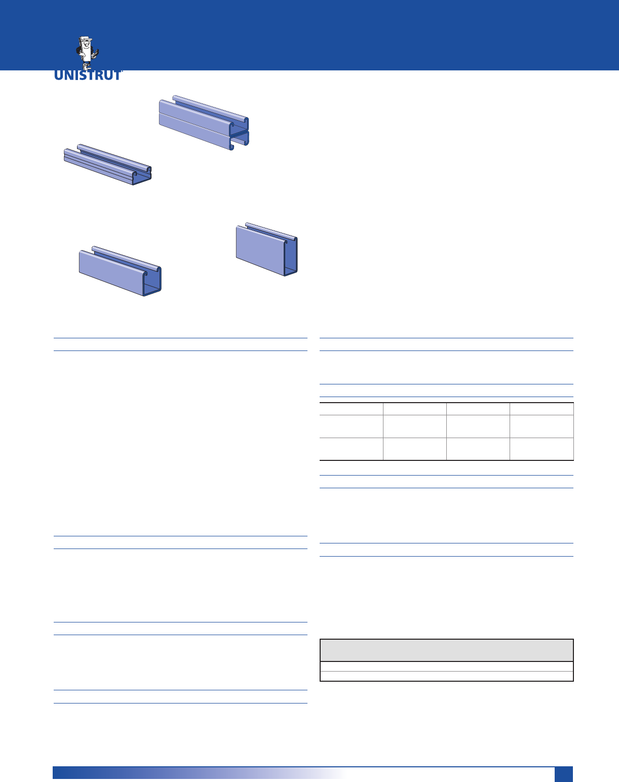
169
MATERIAL
Unistrut channels are accurately and carefully cold formed
to size from low-carbon strip steel.
STEEL: PLAIN
14 Gauge (1.9 mm), ASTM A1011 SS GR 33
19 Gauge (1.0 mm) ASTM A1008
STEEL: PRE-GALVANIZED
14 Gauge (1.9 mm) ASTM A653 GR 33,
19 Gauge (1.0 mm) ASTM A653 GR 33
Channel nuts are manufactured from mild steel bars con-
forming to ASTM A576, GR 1015, and are case hardened.
Fittings are made from hot rolled, pickled and oiled steel
plate or strip and conform to ASTM A1011 SS GR 33.
Many framing channels are available in special metal on
request. Consult factory for ordering information.
FINISHES
All channels and fittings are available in: Perma-Green III
(GR), Pre-galvanized (PG), conforming to ASTM A653 GR 33
and plain (PL).
Nuts are available in plain or electro-galvanized (EG) finish.
Fittings are available in Perma-Green III (GR) or plain (PL).
STANDARD LENGTHS
Standard lengths are 10 feet (3.05M) and 20 feet (6.10M).
Tolerances are: +1»8" (3.2 mm) to +1»2" (12.7 mm) to allow
for cutting. Special lengths are available for a small cutting
charge with a tolerance of ±1»8" (3.2mm).
APPLICATION
A framing system designed for medium loads, the 11»4"
series is especially suitable for use in the OEM, commercial
and display markets. It maintains a lightness in scale and
a clean line that makes it aesthetically pleasing as well as
functional.
THREADS
All threads on the nuts and bolts are Unified and American
coarse screw threads.
DESIGN BOLT TORQUE
BOLT SIZE 1»4"-20 5»16"-18 3»8"-16
Rec. Torque
)W/EV1P
61119
(8) (15) (26)
Max Torque
)W/EV1P
71525
(9) (20) (34)
DIMENSIONS
Imperial dimensions are illustrated in inches. Metric dimen-
sions are shown in parenthesis or as noted. Unless noted,
all metric dimensions are in millimeters and rounded to
one decimal place.
LOAD DATA
All beam and column load data pertains to carbon steel
and stainless steel channels. Load tables and charts are con-
structed to be in accordance with the SPECIFICATION FOR
THE DESIGN OF COLD-FORMED STEEL STRUCTURAL MEM-
BERS 2007 EDITION published by the AMERICAN IRON AND
STEEL INSTITUTE USING ASD METHOD. Loads are based on
33 ksi steel cold formed to 42 ksi.
11»4" FRAMING SYSTEM
A1000 (14 Gauge) ..........................................................171 - 172
A3300 (14 Gauge) ..........................................................173 - 174
A4000 (19 Gauge) ..........................................................175 - 176
A5000 (14 Gauge) ...................................................................177
Channel Nuts and Closure Strips ...........................................178
Flat Plate Fittings ...........................................................178 - 179
Ninety Degree Fittings............................................................179
Angle and Wing Shape Fittings ............................................. 179
“U” Shape Fittings .................................................................. 180
Pipe / Tubing Clips ..................................................................180
Brackets ................................................................................... 180
Type
of Load
Safety Factor
to Yield Strength
Safety Factor
to Ultimate Strength
Beam Loads 1.67 2.0
Column Load 1.80 2.2
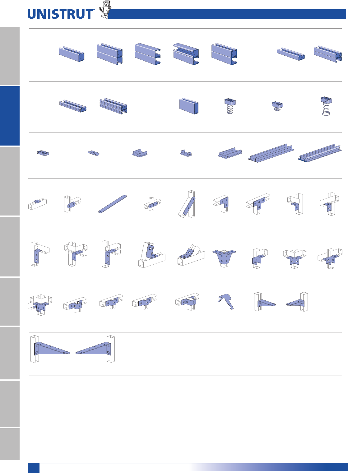
170
11⁄4" Framing System
11¼4" System
13¼16" SystemFiberglass SystemSpecial MetalsPrimeAngleMetal GratingRoofwalkIndex
11»4" Framing System Pictorial Index
A3006-1420-Pg 178 A3016-0832-Pg 178 A1280-Pg 178 A4280-Pg 178 A5280-Pg 178 A1184-Pg 178 A1184P-Pg 178
A1000 Series A3300 Series
A4000 Series A5000 Series Channel Nuts & Closures
A1000-Pg 171 A1001-Pg 171 A1001 A-Pg 172 A1001 B-Pg 172 A1001 C-Pg 172 A3300-Pg 173 A3301-Pg 173
11⁄4" x 11⁄4"
14 Ga.
11⁄4" x 3⁄4"
14 Ga.
A4000-Pg 175 A4001-Pg 175 A5000-Pg 177 A1006-1420-Pg 178 A4006-1420-Pg 178 A5006-1420-Pg 178
11⁄4" x 5⁄8"
19 Ga.
11⁄4" x 21⁄2"
14 Ga.
A1063-Pg 178 A1065-Pg 178 A1191-Pg 178 A1066-Pg 179 A2324-Pg 179 A1036-Pg 179 A1031-Pg 179 A1026-Pg 179 A1068-Pg 179
A1326-Pg 179 A1458-Pg 179 A1325-Pg 179 A2084-Pg 179 A2472 R-L-Pg 179 A2223-Pg 179 A2345-Pg 179
A2227-Pg 179 A1047-Pg 180 A3347-Pg 180 A4047-Pg 180 A5047-Pg 180 A2608-Pg 180 A2492 R-Pg 180 A2492 L-Pg 180
A2494 R-Pg 180 A2494 L-Pg 180
A Series Fittings
A2110-Pg 179 A2126-Pg 179
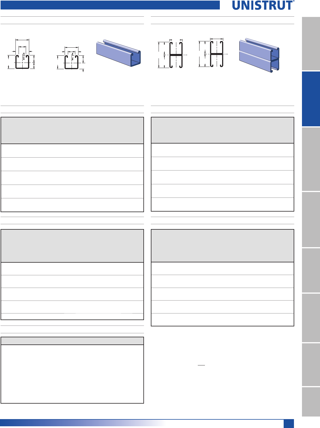
171
11⁄4" Framing System
11¼4" System
13¼16" SystemFiberglass SystemSpecial MetalsPrimeAngle
Metal GratingRoofwalkIndex
A1001 – 11»4" X 21»2"A1000 – 11»4" X 11»4"
.706"
.544"
2
1
3⁄16"
1 1⁄4"
1 1⁄4"
11⁄16"
9⁄32"
9⁄32"
31.8
31.8
13.8
17.9
4.8
17.5
7.1 7.1
2
1
31.8
31.8
31.8
63.5
2
1
2
2 1⁄2"1
1 1⁄4"
1 1⁄4"
1 1⁄4"
A1000 & A1001 Channels
Wt/100 Ft: 104 Lbs(154 kg/100m)
$OORZDEOH0RPHQW,Q/EV1P
14 Gauge Nominal Thickn,ess .075" (1.9mm)
Wt/100 Ft: 207 Lbs (308 kg/100m)
$OORZDEOH0RPHQW,Q/EV1P
14 Gauge Nominal Thickness .075" (1.9mm)
A1000 - BEAM LOADING A1001 - BEAM LOADING
Span
In
Max
Allowable
Uniform Load
Lbs
Defl. at
Uniform
Load
In
Uniform Loading at Defl.
Span/180
Lbs
Span/240
Lbs
Span/360
Lbs
18 960 0.04 960 960 960
24 720 0.07 720 720 660
36 480 0.16 480 440 300
48 360 0.29 330 250 170
60 290 0.45 210 160 110
72 240 0.65 150 110 70
84 210 0.90 110 80 50
96 180 1.16 80 60 40
108 160 1.46 70 50 30
120 140 1.75 50 40 30
Span
In
Max
Allowable
Uniform Load
Lbs
Defl. at
Uniform
Load
In
Uniform Loading at Defl.
Span/180
Lbs
Span/240
Lbs
Span/360
Lbs
18 1,650* 0.01 1,650* 1,650* 1,650*
24 1,650* 0.03 1,650* 1,650* 1,650*
36 1,350 0.09 1,350 1,350 1,350
48 1,010 0.16 1,010 1,010 820
60 810 0.26 810 790 530
72 670 0.37 670 550 370
84 580 0.50 540 400 270
96 510 0.66 410 310 210
108 450 0.83 330 240 160
120 400 1.01 260 200 130
Unbraced
Height
In
Maximum
Allowable
Load
at Slot Face
Lbs
Maximum Column Load Applied at C.G.
K = 0.65
Lbs
K = 0.80
Lbs
K =1.0
Lbs
K = 1.2
Lbs
18 1,960 5,900 5,430 4,800 4,210
24 1,840 5,210 4,590 3,850 3,220
36 1,500 3,940 3,220 2,480 2,010
48 1,220 2,950 2,300 1,790 1,460
60 1,020 2,260 1,790 1,400 1,130
72 880 1,840 1,460 1,130 910
84 780 1,550 1,230 940 **
96 690 1,340 1,050 ** **
108 620 1,170 910 ** **
Unbraced
Height
In
Maximum
Allowable
Load
at Slot Face
Lbs
Maximum Column Load Applied at C.G.
K = 0.65
Lbs
K = 0.80
Lbs
K =1.0
Lbs
K = 1.2
Lbs
18 3,530 13,300 12,920 12,400 11,880
24 3,480 12,750 12,220 11,550 10,950
36 3,370 11,630 10,950 10,220 9,150
48 3,260 10,680 10,020 8,260 6,500
60 2,960 9,930 8,260 6,080 4,270
72 2,630 8,480 6,500 4,270 2,970
84 2,260 7,040 4,900 3,140 2,180
96 1,940 5,680 3,750 2,400 **
108 1,670 4,490 2,970 ** **
120 1,440 3,640 2,400 ** **
A1000/A1001 - ELEMENTS OF SECTION
A1001 - COLUMN LOADINGA1000 - COLUMN LOADING
Parameter A1000 A1001
Area of Section 0.305 In20.609 In2
Axis 1-1
Moment of Inertia (I) 0.061 In40.302 In4
Section Modulus (S) 0.086 In30.242 In3
Radius of Gyration (r) 0.447 In 0.704 In
Axis 2-2
Moment of Inertia (I) 0.078 In40.156 In4
Section Modulus (S) 0.125 In30.250 In3
Radius of Gyration (r) 0.506 In 0.506 In
Notes:
* Load limited by spot weld shear.
./»U !
NR = Not Recommended.
1. Beam loads are given in total uniform load (W Lbs) not uniform load (w lbs/ft or
w lbs/in).
2. Beam loads are based on a simple span and assumed to be adequately laterally
braced. Unbraced spans can reduce beam load carrying capacity. Refer to Page
177 for reduction factors for unbraced lengths.
3. Deduct channel weight from the beam loads.
4. For concentrated midspan point loads, multiply beam loads by 50% and the
corresponding deflection by 80%. For other load conditions refer to page 18.
5. All beam loads are for bending about Axis 1-1.
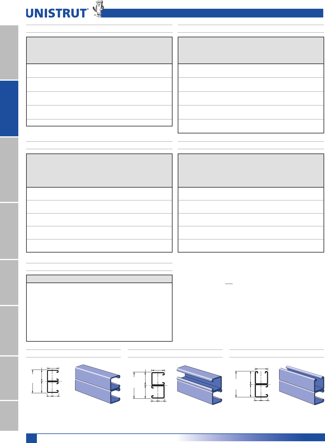
172
11⁄4" Framing System
11¼4" System
13¼16" SystemFiberglass SystemSpecial MetalsPrimeAngleMetal GratingRoofwalkIndex
Unbraced
Height
mm
Maximum
Allowable
Load
at Slot Face
kN
Max. Column Load Applied at C.G.
K = 0.65
kN
K = 0.80
kN
K =1.0
kN
K = 1.2
kN
600 8.2 23.4 20.7 17.3 14.6
750 7.5 20.5 17.3 14.0 11.3
1,000 6.3 16.2 13.0 9.9 8.1
1,250 5.3 12.8 9.9 7.7 6.3
1,500 4.6 10.2 8.1 6.3 5.2
1,750 4.1 8.6 6.8 5.3 4.3
2,000 3.6 7.4 5.9 4.5 **
2,250 3.3 6.5 5.2 3.9 **
2,500 3.0 5.8 4.5 ** **
2,750 2.7 5.2 4.0 ** **
Unbraced
Height
mm
Maximum
Allowable
Load
at Slot Face
kN
Max. Column Load Applied at C.G.
K = 0.65
kN
K = 0.80
kN
K =1.0
kN
K = 1.2
kN
600 15.5 56.9 54.5 51.6 48.9
750 15.2 54.4 51.6 48.4 45.7
1,000 14.9 50.4 47.4 43.9 37.4
1,250 14.4 47.2 43.9 35.7 27.8
1,500 13.3 44.6 37.4 27.8 19.6
1,750 12.1 39.4 30.9 20.7 14.4
2,000 10.8 34.1 24.8 15.9 11.0
2,250 9.5 29.0 19.6 12.5 **
2,500 8.4 24.1 15.9 10.2 **
2,750 7.4 19.9 13.1 ** **
A1000 & A1001 Channels
Span
mm
Max
Allowable
Uniform Load
kN
Defl. at
Uniform
Load
mm
Uniform Loading at Deflection
Span/180
kN
Span/240
kN
Span/360
kN
600 3.2 2 3.2 3.2 3.1
750 2.6 3 2.6 2.6 2.0
1,000 2.0 5 2.0 1.6 1.1
1,250 1.6 8 1.4 1.1 0.7
1,500 1.3 11 1.0 0.7 0.5
1,750 1.1 15 0.7 0.5 0.4
2,000 1.0 20 0.5 0.4 0.3
2,500 0.8 32 0.4 0.3 0.2
3,000 0.7 46 0.2 0.2 0.1
Span
mm
Max
Allowable
Uniform Load
kN
Defl. at
Uniform
Load
mm
Uniform Loading at Deflection
Span/180
kN
Span/240
kN
Span/360
kN
600 7.3* 1 7.3* 7.3* 7.3
750 7.3* 2 7.3* 7.3* 7.3
1,000 5.5 3 5.5 5.5 5.5
1,250 4.4 4 4.4 4.4 3.5
1,500 3.6 6 3.6 3.6 2.4
1,750 3.2 9 3.2 2.7 1.8
2,000 2.8 11 2.7 2.0 1.4
2,500 2.2 17 1.7 1.3 0.9
3,000 1.8 25 1.2 0.9 0.6
3,500 1.6 34 0.9 0.7 0.4
A1000 - BEAM LOADING (METRIC) A1001 - BEAM LOADING (METRIC)
A1000/A1001 - ELEMENTS OF SECTION (METRIC)
A1001 - COLUMN LOADING (METRIC)A1000 - COLUMN LOADING (METRIC)
Parameter A1000 A1001
Area of Section 1.96 cm23.93 cm2
Axis 1-1
Moment of Inertia (I) 2.53 cm412.57 cm4
Section Modulus (S) 1.41 cm33.96 cm3
Radius of Gyration (r) 1.14 cm 1.79 cm
Axis 2-2
Moment of Inertia (I) 3.25 cm46.50 cm4
Section Modulus (S) 2.05 cm34.09 cm3
Radius of Gyration (r) 1.29 cm 1.29 cm Finishes: PL, GR, HG, PG Standard Lengths: 10' & 20'
2
1 1⁄4"
2 1⁄2"
1
.705
.544
(31.8)
1 1⁄4"
(31.8)
1 1⁄4"
(31.8)
(63.5)
(13.8) (17.9) .625 (15.9).625 (15.9)
1 1⁄4"
2
1
2 1⁄2"
1 1⁄4"
(63.5)
(31.8) (31.8)
1 1⁄4"
(31.8) 1.21"
1.29"
.665.585
2 1⁄2"
1 1⁄4"
2
1
(31.8)
(63.5)
(14.9) (16.9)
(32.8)
(30.7)
A1001B – 11»4" X 21»2" A1001C – 11»4" X 21»2" A1001A – 11»4" X 21»2"
Wt/100 Ft: 207 Lbs (308 kg/100m)
$OORZDEOH0RPHQW,Q/EV1P
14 Gauge Nominal Thickness .075" (1.9mm)
Wt/100 Ft: 207 Lbs (308 kg/100m)
$OORZDEOH0RPHQW,Q/EV1P
14 Gauge Nominal Thickness .075" (1.9mm)
Wt/100 Ft: 207 Lbs (308 kg/100m)
$OORZDEOH0RPHQW,Q/EV1P
14 Gauge Nominal Thickness .075" (1.9mm)
Notes:
* Load limited by spot weld shear.
./»U !
NR = Not Recommended.
1. Beam loads are given in total uniform load (W Lbs) not uniform load (w lbs/ft or
w lbs/in).
2. Beam loads are based on a simple span and assumed to be adequately laterally
braced. Unbraced spans can reduce beam load carrying capacity. Refer to Page
177 for reduction factors for unbraced lengths.
3. Deduct channel weight from the beam loads.
4. For concentrated midspan point loads, multiply beam loads by 50% and the
corresponding deflection by 80%. For other load conditions refer to page 18.
5. All beam loads are for bending about Axis 1-1.
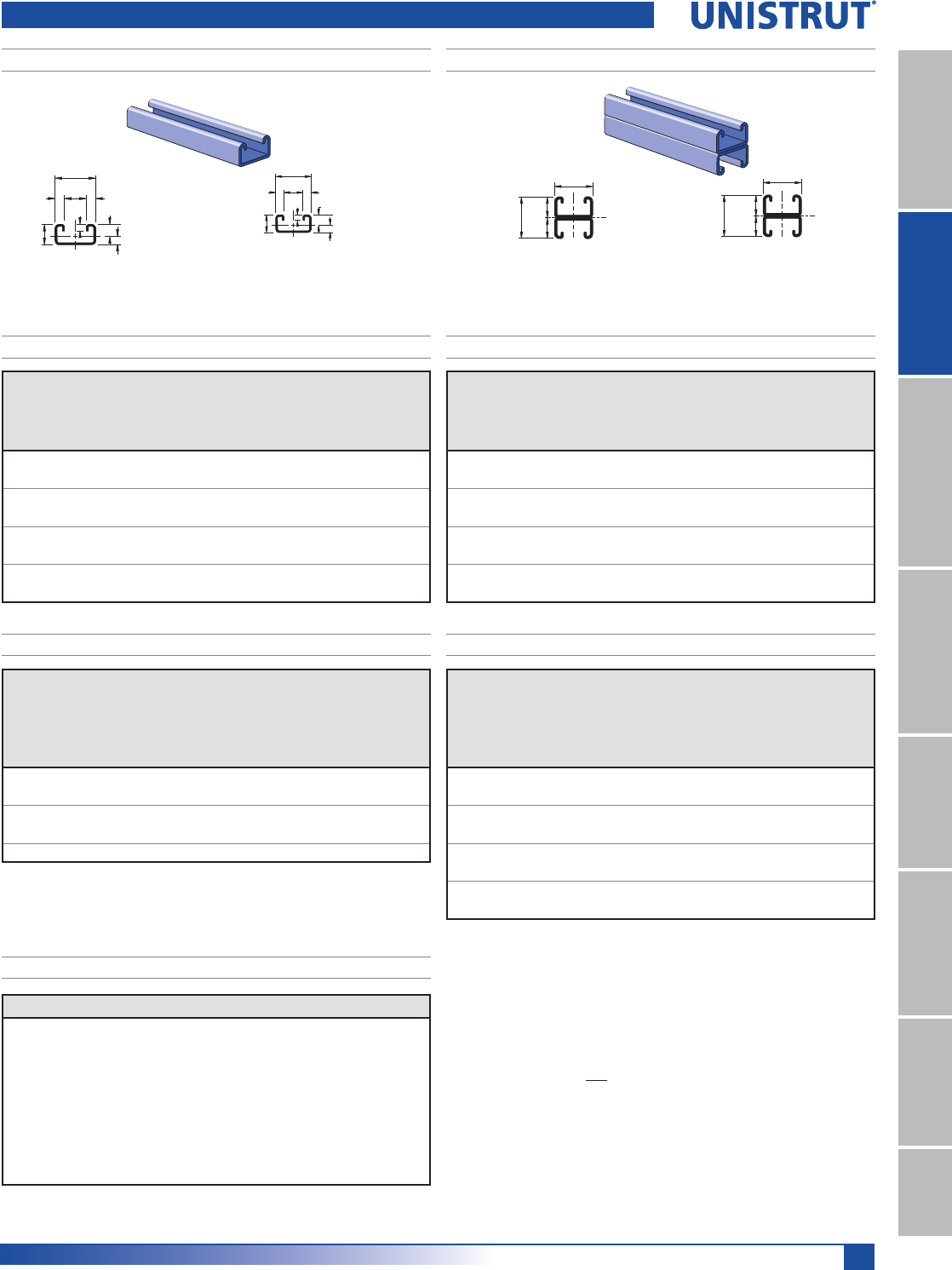
173
11⁄4" Framing System
11¼4" System
13¼16" SystemFiberglass SystemSpecial MetalsPrimeAngle
Metal GratingRoofwalkIndex
A3300 – 11»4" X 3»4"
Wt/100 Ft: 78 Lbs (116 kg/100m)
$OORZDEOH0RPHQW,Q/EV1P
14 Gauge Nominal Thickness .075" (1.9mm)
Wt/100 Ft: 156 Lbs (232 kg/100m)
$OORZDEOH0RPHQW,Q/EV1P
14 Gauge Nominal Thickness .075" (1.9mm)
11⁄16"
.440"
9⁄32"
1 1⁄4"
9⁄32"
3⁄4"
.310"
3⁄16"
2
1
1
2
19.1
7.1
31.8
7.1
11.2
7.9
4.8
17.5
1
31.8
38.1 19.1
19.1
2
A3301 – 11»4" X 11»2"
1 1⁄2"
1 1⁄4"
3⁄4"
3⁄4"
2
1
A3300 - BEAM LOADING A3301 - BEAM LOADING
Span
In
Max
Allowable
Uniform Load
Lbs
Defl. at
Uniform
Load
In
Uniform Loading at Deflection
Span/180
Lbs
Span/240
Lbs
Span/360
Lbs
18 420 0.07 420 420 320
24 320 0.12 320 270 180
36 210 0.26 160 120 80
48 160 0.47 90 70 50
60 130 0.75 60 40 30
72 110 1.09 40 30 20
84 90 1.42 30 20 10
96 80 1.88 20 20 10
Span
In
Max
Allowable
Uniform Load
Lbs
Defl. at
Uniform
Load
In
Uniform Loading at Deflection
Span/180
Lbs
Span/240
Lbs
Span/360
Lbs
18 990* 0.03 990* 990* 990*
24 860 0.07 860 860 850
36 580 0.15 580 560 380
48 430 0.27 420 320 210
60 350 0.43 270 200 140
72 290 0.62 190 140 90
84 250 0.85 140 100 70
96 220 1.11 110 80 50
A3300 & A3301 Channels
Unbraced
Height
In
Maximum
Allowable
Load
at Slot Face
Lbs
Max. Column Load Applied at C.G.
K = 0.65
Lbs
K = 0.80
Lbs
K =1.0
Lbs
K = 1.2
Lbs
18 1,430 4,490 4,210 3,860 3,550
24 1,370 4,090 3,750 3,310 2,680
36 1,190 3,390 2,680 1,820 1,260
48 900 2,380 1,600 1,020 **
60 680 1,550 1,020 ** **
Unbraced
Height
In
Maximum
Allowable Load
at Slot Face
Lbs
Max. Column Load Applied at C.G.
K = 0.65
Lbs
K = 0.80
Lbs
K =1.0
Lbs
K = 1.2
Lbs
18 2,540 9,890 9,620 9,300 9,020
24 2,510 9,510 9,200 8,710 7,960
36 2,410 8,800 7,960 6,730 5,490
48 2,230 7,560 6,320 4,690 3,310
60 1,970 6,210 4,690 3,050 2,120
72 1,650 4,890 3,310 2,120 **
84 1,380 3,680 2,430 ** **
96 1,160 2,820 1,860 ** **
A3300 - COLUMN LOADING A3301 - COLUMN LOADING
A3300/A3301 - ELEMENTS OF SECTION
Parameter A3300 A3301
Area of Section 0.230 In20.459 In2
Axis 1-1
Moment of Inertia (I) 0.017 In40.077 In4
Section Modulus (S) 0.038 In30.103 In3
Radius of Gyration (r) 0.269 In 0.411 In
Axis 2-2
Moment of Inertia (I) 0.052 In40.104 In4
Section Modulus (S) 0.083 In30.167 In3
Radius of Gyration (r) 0.477 In 0.477 In
Notes:
* Load limited by spot weld shear.
./»U !
NR = Not Recommended.
1. Beam loads are given in total uniform load (W Lbs) not uniform load (w lbs/ft or
w lbs/in).
2. Beam loads are based on a simple span and assumed to be adequately laterally
braced. Unbraced spans can reduce beam load carrying capacity. Refer to Page
177 for reduction factors for unbraced lengths.
3. Deduct channel weight from the beam loads.
4. For concentrated midspan point loads, multiply beam loads by 50% and the
corresponding deflection by 80%. For other load conditions refer to page 18.
5. All beam loads are for bending about Axis 1-1.
174
11⁄4" Framing System
11¼4" System
13¼16" SystemFiberglass SystemSpecial MetalsPrimeAngleMetal GratingRoofwalkIndex
Unbraced
Height
mm
Maximum
Allowable
Load
at Slot Face
kN
Max. Column Load Applied at C.G.
K = 0.65
kN
K = 0.80
kN
K =1.0
kN
K = 1.2
kN
600 6.1 18.3 16.8 14.9 12.2
750 5.8 16.7 14.9 11.5 8.4
1,000 4.9 13.8 10.4 6.8 4.7
1,250 3.9 10.1 6.8 4.3 **
1,500 3.1 7.1 4.7 ** **
Unbraced
Height
mm
Maximum
Allowable
Load
at Slot Face
kN
Max. Column Load Applied at C.G.
K = 0.65
kN
K = 0.80
kN
K =1.0
kN
K = 1.2
kN
600 11.2 42.4 41.0 39.0 35.7
750 11.0 40.9 39.0 34.9 30.4
1,000 10.5 37.7 33.4 27.4 21.4
1,250 9.8 33.0 27.4 20.0 14.0
1,500 8.9 28.1 21.4 14.0 9.7
1,750 7.7 23.2 16.1 10.3 **
2,000 6.7 18.6 12.3 7.9 **
2,250 5.8 14.7 9.7 ** **
2,500 5.0 11.9 7.9 ** **
A3300 & A3301 Channels
Span
mm
Max
Allowable
Uniform Load
kN
Defl. at
Uniform
Load
mm
Uniform Loading at Deflection
Span/180
kN
Span/240
kN
Span/360
kN
600 1.4 3 1.4 1.2 0.8
750 1.2 5 1.1 0.8 0.5
1,000 0.8 8 0.6 0.4 0.3
1,250 0.7 12 0.4 0.3 0.2
1,500 0.6 18 0.3 0.2 0.1
1,750 0.5 24 0.2 0.1 0.1
2,000 0.4 33 0.1 0.1 0.1
Span
mm
Max
Allowable
Uniform Load
kN
Defl. at
Uniform
Load
mm
Uniform Loading at Deflection
Span/180
kN
Span/240
kN
Span/360
kN
600 3.9 2 3.9 3.9 3.9
750 3.1 3 3.1 3.1 2.5
1,000 2.4 5 2.4 2.1 1.4
1,250 1.9 7 1.8 1.3 0.9
1,500 1.6 10 1.2 0.9 0.6
1,750 1.3 14 0.9 0.7 0.4
2,000 1.2 18 0.7 0.5 0.4
2,500 0.9 29 0.4 0.4 0.2
3,000 0.8 43 0.3 0.2 0.1
A3300 - BEAM LOADING (METRIC) A3301 - BEAM LOADING (METRIC)
A3300 - COLUMN LOADING (METRIC) A3301 - COLUMN LOADING (METRIC)
A3300/A3301 - ELEMENTS OF SECTION (METRIC)
Parameter A3300 A3301
Area of Section 1.48 cm22.96 cm2
Axis 1-1
Moment of Inertia (I) 0.69 cm43.22 cm4
Section Modulus (S) 0.62 cm31.69 cm3
Radius of Gyration (r) 0.68 cm 1.04 cm
Axis 2-2
Moment of Inertia (I) 2.17 cm44.34 cm4
Section Modulus (S) 1.37 cm32.73 cm3
Radius of Gyration (r) 1.21 cm 1.21 cm
Notes:
* Load limited by spot weld shear.
./»U !
NR = Not Recommended.
1. Beam loads are given in total uniform load (W Lbs) not uniform load (w lbs/ft or
w lbs/in).
2. Beam loads are based on a simple span and assumed to be adequately laterally
braced. Unbraced spans can reduce beam load carrying capacity. Refer to Page
177 for reduction factors for unbraced lengths.
3. Deduct channel weight from the beam loads.
4. For concentrated midspan point loads, multiply beam loads by 50% and the
corresponding deflection by 80%. For other load conditions refer to page 18.
5. All beam loads are for bending about Axis 1-1.
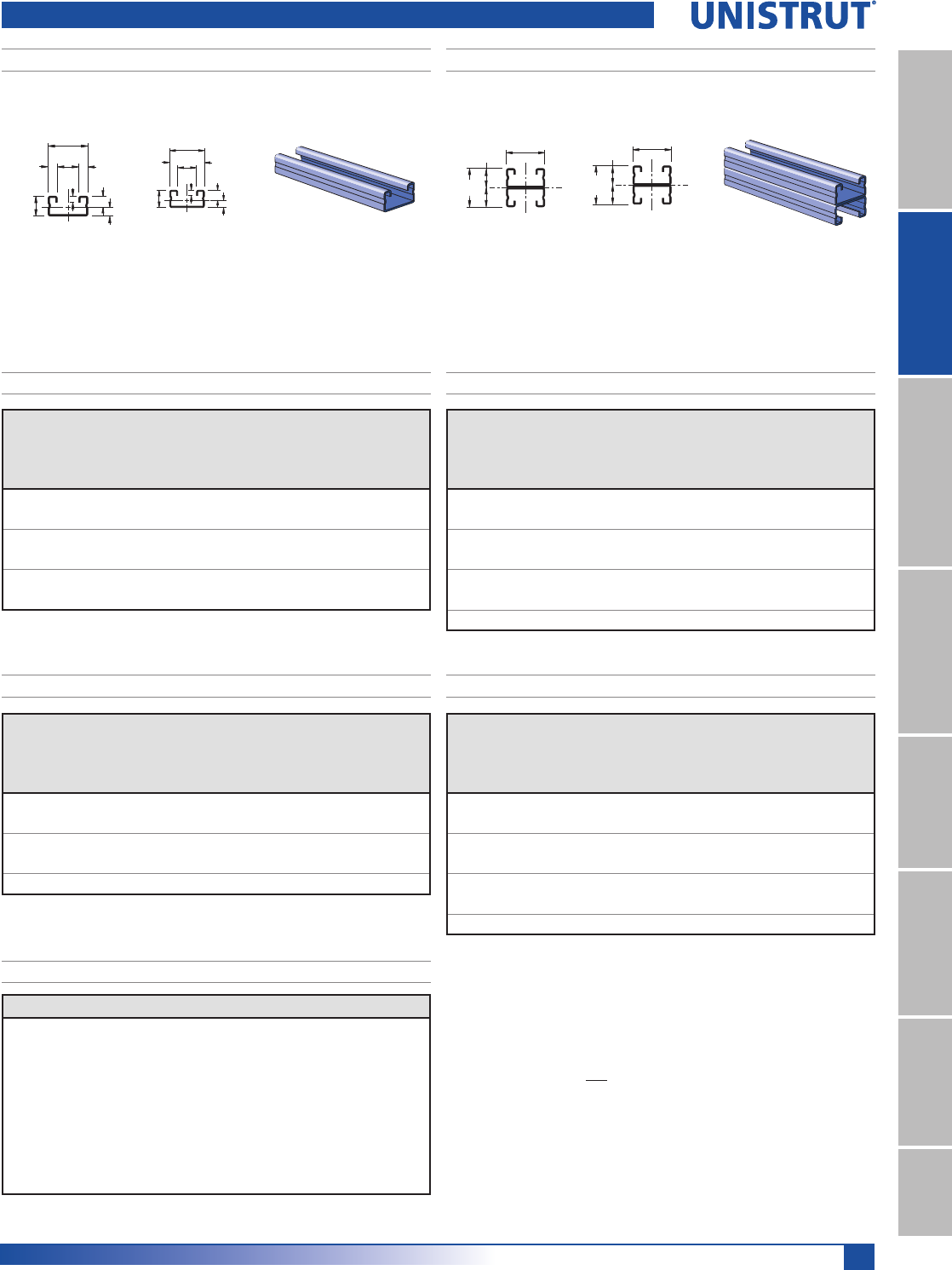
175
11⁄4" Framing System
11¼4" System
13¼16" SystemFiberglass SystemSpecial MetalsPrimeAngle
Metal GratingRoofwalkIndex
Wt/100 Ft: 90 Lbs (134 kg/100m)
$OORZDEOH0RPHQW,Q/EV1P
19 Gauge Nominal Thickness .040" (1.0mm)
Wt/100 Ft: 45 Lbs (67 kg/100m)
$OORZDEOH0RPHQW,Q/EV1P
19 Gauge Nominal Thickness .040" (1.0mm)
1
31.8
31.8
15.9
15.9
2
1 1⁄4"
1 1⁄4"
5⁄8"
5⁄8"
1
2
31.8
2
9.2
15.9
4.8
7.1 17.5 7.1
6.7
1
5⁄8"
1 1⁄4"
9⁄32"
9⁄32"
3⁄16"
.262"
.363"
2
1
11⁄16"
A4000 – 11»4" X 5»8"A4001– 11»4" X 11»4"
Span
In
Max
Allowable
Uniform Load
Lbs
Defl. at
Uniform
Load
In
Uniform Loading at Deflection
Span/180
Lbs
Span/240
Lbs
Span/360
Lbs
18 250 0.08 250 220 150
24 190 0.15 170 120 80
36 120 0.32 70 60 40
48 90 0.58 40 30 20
60 70 0.88 30 20 10
72 60 1.30 20 10 10
Span
In
Max
Allowable
Uniform Load
Lbs
Defl. at
Uniform
Load
In
Uniform Loading at Deflection
Span/180
Lbs
Span/240
Lbs
Span/360
Lbs
18 350* 0.02 350* 350* 350*
24 350* 0.06 350* 350* 350*
36 330 0.19 330 270 180
48 240 0.32 200 150 100
60 200 0.52 130 100 60
72 160 0.72 90 70 40
84 140 1.00 70 50 30
A4000 & A4001 Channels
Unbraced
Height
In
Maximum
Allowable Load
at Slot Face
Lbs
Max. Column Load Applied at C.G.
K = 0.65
Lbs
K = 0.80
Lbs
K =1.0
Lbs
K = 1.2
Lbs
18 960 2,510 2,290 1,990 1,700
24 880 2,190 1,890 1,530 1,230
36 670 1,570 1,230 830 580
48 470 1,110 730 470 **
60 340 710 470 ** **
Unbraced
Height
In
Maximum
Allowable Load
at Slot Face
Lbs
Max. Column Load Applied at C.G.
K = 0.65
Lbs
K = 0.80
Lbs
K =1.0
Lbs
K = 1.2
Lbs
18 1,640 5,640 5,420 5,110 4,800
24 1,600 5,320 5,000 4,600 4,240
36 1,510 4,650 4,240 3,500 2,730
48 1,330 4,030 3,240 2,250 1,560
60 1,090 3,170 2,250 1,440 1,000
72 870 2,370 1,560 1,000 **
84 700 1,740 1,150 ** **
A4000 - BEAM LOADING A4001 - BEAM LOADING
A4000 - COLUMN LOADING A4001 - COLUMN LOADING
A4000/A4001 - ELEMENTS OF SECTION
Parameter A4000 A4001
Area of Section 0.132 In20.264 In2
Axis 1-1
Moment of Inertia (I) 0.008 In40.037 In4
Section Modulus (S) 0.022 In30.058 In3
Radius of Gyration (r) 0.240 In 0.372 In
Axis 2-2
Moment of Inertia (I) 0.029 In40.058 In4
Section Modulus (S) 0.046 In30.093 In3
Radius of Gyration (r) 0.469 In 0.469 In
Notes:
* Load limited by spot weld shear.
./»U !
NR = Not Recommended.
1. Beam loads are given in total uniform load (W Lbs) not uniform load (w lbs/ft or
w lbs/in).
2. Beam loads are based on a simple span and assumed to be adequately laterally
braced. Unbraced spans can reduce beam load carrying capacity. Refer to Page
177 for reduction factors for unbraced lengths.
3. Deduct channel weight from the beam loads.
4. For concentrated midspan point loads, multiply beam loads by 50% and the
corresponding deflection by 80%. For other load conditions refer to page 18.
5. All beam loads are for bending about Axis 1-1.
176
11⁄4" Framing System
11¼4" System
13¼16" SystemFiberglass SystemSpecial MetalsPrimeAngleMetal GratingRoofwalkIndex
Unbraced
Height
mm
Maximum
Allowable
Load
at Slot Face
kN
Max. Column Load Applied at C.G.
K = 0.65
kN
K = 0.80
kN
K =1.0
kN
K = 1.2
kN
600 3.9 9.8 8.5 6.9 5.6
750 3.5 8.4 6.9 5.3 3.8
1,000 2.8 6.4 4.8 3.1 2.1
1,250 2.0 4.7 3.1 ** **
1,500 1.5 3.2 2.1 ** **
Unbraced
Height
mm
Maximum
Allowable
Load
at Slot Face
kN
Max. Column Load Applied at C.G.
K = 0.65
kN
K = 0.80
kN
K =1.0
kN
K = 1.2
kN
600 7.1 23.8 22.4 20.6 19.0
750 6.9 22.3 20.6 18.6 15.8
1,000 6.6 19.9 17.8 13.9 10.3
1,250 5.8 17.5 13.9 9.5 6.6
1,500 4.9 14.4 10.3 6.6 4.6
1,750 4.1 11.4 7.6 4.8 **
2,000 3.4 8.8 5.8 ** **
2,250 2.9 6.9 4.6 ** **
A4000 & A4001 Channels
Span
mm
Max
Allowable
Uniform Load
kN
Defl. at
Uniform
Load
mm
Uniform Loading at Deflection
Span/180
kN
Span/240
kN
Span/360
kN
600 0.8 4 0.8 0.6 0.4
750 0.7 6 0.5 0.4 0.3
1,000 0.5 10 0.3 0.2 0.1
1,250 0.4 16 0.2 0.1 0.1
1,500 0.4 24 0.1 0.1 0.0
Span
mm
Max
Allowable
Uniform Load
kN
Defl. at
Uniform
Load
mm
Uniform Loading at Deflection
Span/180
kN
Span/240
kN
Span/360
kN
600 1.6* 1 1.6* 1.6* 1.6
750 1.6* 3 1.6* 1.6* 1.2
1,000 1.3 6 1.3 1.0 0.7
1,250 1.1 9 0.8 0.6 0.4
1,500 0.9 13 0.6 0.4 0.3
1,750 0.8 17 0.4 0.3 0.2
2,000 0.7 22 0.3 0.3 0.2
A4000 - BEAM LOADING (METRIC) A4001 - BEAM LOADING (METRIC)
A4000 - COLUMN LOADING (METRIC) A4001 - COLUMN LOADING (METRIC)
A4000/A4001 - ELEMENTS OF SECTION (METRIC)
Parameter A4000 A4001
Area of Section 0.85 cm21.70 cm2
Axis 1-1
Moment of Inertia (I) 0.32 cm41.52 cm4
Section Modulus (S) 0.37 cm30.96 cm3
Radius of Gyration (r) 0.61 cm 0.94 cm
Axis 2-2
Moment of Inertia (I) 1.21 cm42.42 cm4
Section Modulus (S) 0.76 cm31.52 cm3
Radius of Gyration (r) 1.19 cm 1.19 cm
Notes:
* Load limited by spot weld shear.
./»U !
NR = Not Recommended.
1. Beam loads are given in total uniform load (W Lbs) not uniform load (w lbs/ft or
w lbs/in).
2. Beam loads are based on a simple span and assumed to be adequately laterally
braced. Unbraced spans can reduce beam load carrying capacity. Refer to Page
177 for reduction factors for unbraced lengths.
3. Deduct channel weight from the beam loads.
4. For concentrated midspan point loads, multiply beam loads by 50% and the
corresponding deflection by 80%. For other load conditions refer to page 18.
5. All beam loads are for bending about Axis 1-1.
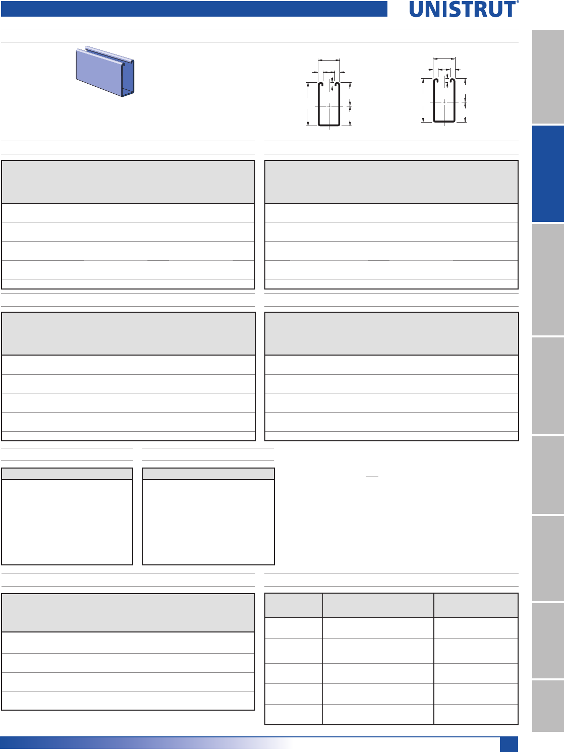
177
11⁄4" Framing System
11¼4" System
13¼16" SystemFiberglass SystemSpecial MetalsPrimeAngle
Metal GratingRoofwalkIndex
63.5
34.3
29.2
31.8
17.5 7.1
7.1
4.8
2
1
2 1⁄2"
1 1⁄4"
11⁄16"
3⁄16"1.349"
1.151"
9⁄32"
9⁄32"
1
2
A5000 – 11»4" X 21»2"
Span
In
Max
Allowable
Uniform Load
Lbs
Defl. at
Uniform
Load
Lbs
Uniform Loading at Deflection
Span/180
Lbs
Span/240
Lbs
Span/360
Lbs
24 2,220 0.04 2,220 2,220 2,220
36 1,480 0.09 1,480 1,480 1,480
48 1,110 0.15 1,110 1,110 980
60 890 0.24 890 890 630
72 740 0.34 740 650 430
84 640 0.47 640 480 320
96 560 0.61 490 370 240
108 490 0.76 390 290 190
120 440 0.94 310 230 160
Unbraced
Height
In
Maximum
Allowable Load
at Slot Face
Lbs
Max. Column Load Applied at C.G.
K = 0.65
Lbs
K = 0.80
Lbs
K =1.0
Lbs
K = 1.2
Lbs
24 2,790 7,950 6,670 5,080 3,760
36 1,950 5,270 3,760 2,600 1,970
48 1,360 3,290 2,350 1,690 1,330
60 990 2,300 1,690 1,260 1,010
72 790 1,750 1,330 1,010 830
84 660 1,420 1,100 860 710
96 570 1,200 940 740 **
108 510 1,040 830 ** **
120 460 930 740 ** **
A5000 Channels
Span
mm
Max
Allowable
Uniform Load
kN
Defl. at
Uniform
Load
mm
Uniform Loading at Deflection
Span/180
kN
Span/240
kN
Span/360
kN
600 10.1 1 10.1 10.1 10.1
750 8.1 1 8.1 8.1 8.1
1,000 6.1 3 6.1 6.1 6.1
1,250 4.8 4 4.8 4.8 4.1
1,500 4.0 6 4.0 4.0 2.9
1,750 3.4 8 3.4 3.2 2.1
2,000 3.0 10 3.0 2.4 1.6
2,500 2.4 16 2.1 1.6 1.0
3,000 2.0 23 1.4 1.1 0.7
Unbraced
Height
mm
Maximum
Allowable Load
at Slot Face
kN
Max. Column Load Applied at C.G.
K = 0.65
kN
K = 0.80
kN
K =1.0
kN
K = 1.2
kN
600 12.5 35.8 30.2 23.1 17.2
750 10.7 29.7 23.1 16.0 11.9
1,000 7.8 20.5 14.4 10.1 7.7
1,250 5.8 14.0 10.1 7.3 5.7
1,500 4.5 10.5 7.7 5.7 4.6
1,750 3.7 8.3 6.2 4.8 3.9
2,000 3.2 6.9 5.3 4.1 3.3
2,250 2.8 5.9 4.6 3.6 3.0
2,500 2.5 5.2 4.1 3.2 **
A5000 - BEAM LOADING A5000 - BEAM LOADING (METRIC)
A5000 - COLUMN LOADING
A5000 - ELEMENTS OF SECTION
A5000 - ELEMENTS OF SECTION (METRIC)
Wt/100 Ft: 167 Lbs (249 kg/100m)
$OORZDEOH0RPHQW,Q/EV1P
14 Gauge Nominal Thickness .075" (1.9mm)
A5000 - COLUMN LOADING (METRIC)
Parameter A5000
Area of Section 0.492 In2
Axis 1-1
Moment of Inertia (I) 0.358 In4
Section Modulus (S) 0.265 In3
Radius of Gyration (r) 0.853 In
Axis 2-2
Moment of Inertia (I) 0.143 In4
Section Modulus (S) 0.229 In3
Radius of Gyration (r) 0.539 In
Parameter A5000
Area of Section 3.17 cm2
Axis 1-1
Moment of Inertia (I) 14.91 cm4
Section Modulus (S) 4.35 cm3
Radius of Gyration (r) 2.17 cm
Axis 2-2
Moment of Inertia (I) 5.94 cm4
Section Modulus (S) 3.74 cm3
Radius of Gyration (r) 1.37 cm
Notes:
/RDGOLPLWHGE\VSRWZHOGVKHDU./»U !15 1RW5HFRPPHQGHG
1. Beam loads are given in total uniform load (W Lbs) not uniform load (w lbs/ft
or w lbs/in).
2. Beam loads are based on a simple span and assumed to be adequately later-
ally braced. Unbraced spans can reduce beam load carrying capacity. Refer
to table below for reduction factors for unbraced lengths.
3. Deduct channel weight from the beam loads.
4. For concentrated midspan point loads, multiply beam loads by 50% & the
corresponding deflection by 80%. Other load conditions refer to page 18.
5. All beam loads are for bending about Axis 1-1.
MAXIMUM ALLOWABLE PULL-OUT AND SLIP LOADS
Nut Size/
Thread Channel Gauge
Max
Allowable
Pull-Out
/EVN1
Resistaance
to Slip
/EVN1
Torque
)W/EV1P
3»8" -16 A1000 14 900 500 19
4.00 2.22 26
5»16" -18 A3300 14 900 500 11
4.00 2.22 15
1»4" -20 A5000 14 900 500 6
4.00 2.22 8
3»8" -16 A4000 19 300 400 19
1.33 1.78 26
Nut design loads include a minimum safety factor of 3.
LATERAL BRACING LOAD REDUCTION CHARTS
Span Single Channel Double Channel
Ft. (m) In. (cm) A1000 A3300 A4000 A5000 A1001 A3301 A4001
2 (0.6) 24 (61) 0.95 1.00 0.94 0.90 1.00 1.00 1.00
3 (0.9) 36 (91) 0.86 0.97 0.83 0.69 1.00 1.00 0.97
4 (1.2) 48 (122) 0.78 0.94 0.73 0.49 0.95 0.99 0.89
5 (1.5) 60 (152) 0.72 0.91 0.65 0.37 0.90 0.95 0.82
6 (1.8) 72 (183) 0.67 0.89 0.58 0.31 0.84 0.91 0.74
7 (2.1) 84 (213) 0.63 0.87 0.53 0.27 0.79 0.88 0.67
8 (2.4) 96 (244) 0.59 0.85 0.49 0.24 0.74 0.84 0.59
9 (2.7) 108 (274) 0.55 0.83 0.45 0.22 0.69 0.81 0.52
10 (3.1) 120 (305) 0.52 0.80 0.42 0.21 0.64 0.77 0.46
12 (3.7) 144 (366) 0.46 0.76 0.38 0.19 0.54 0.70 0.38
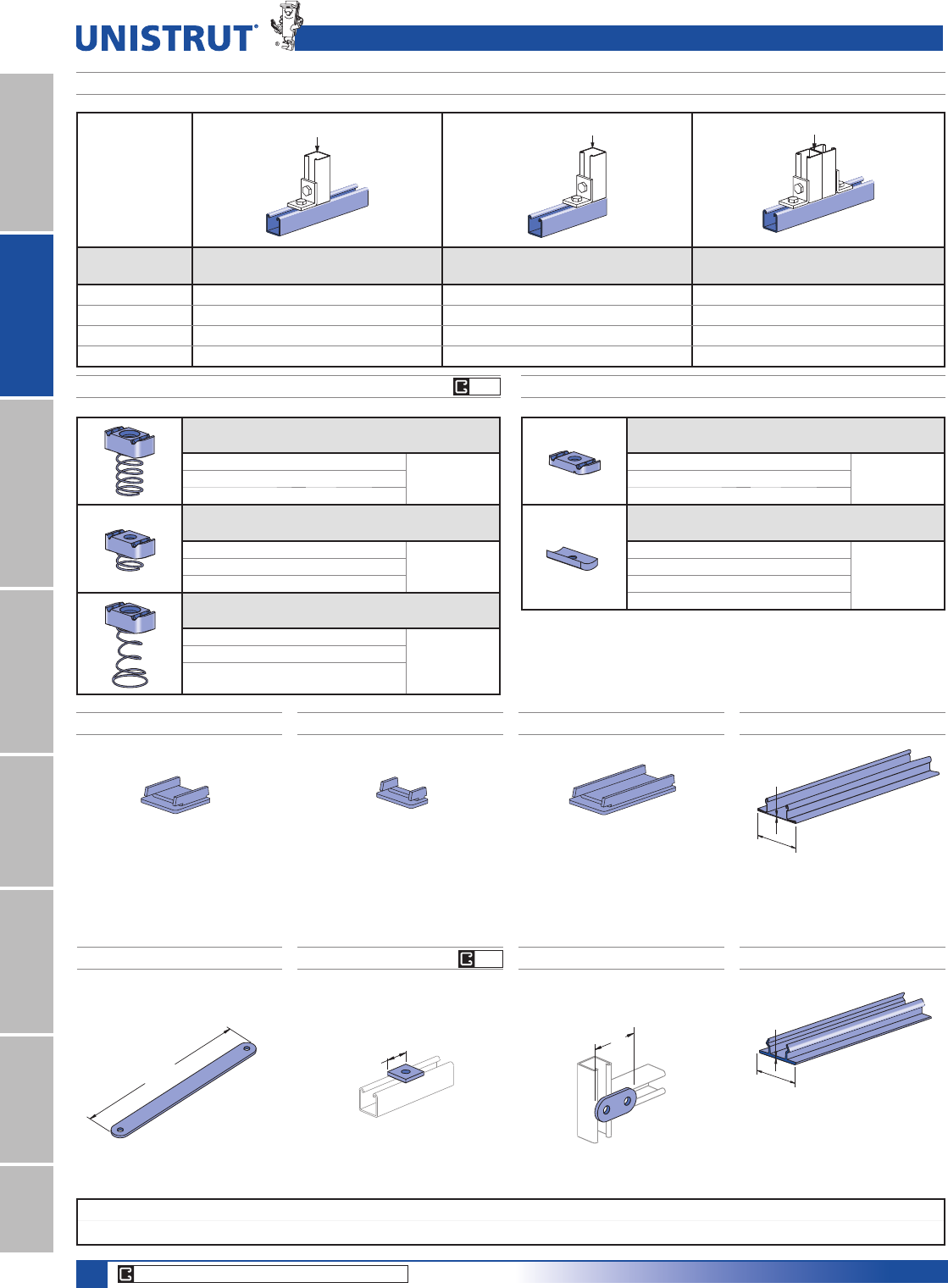
178
Standard Dimensions for 11¼4" (31.8 mm) width series channel fittings (Unless Otherwise Shown on Drawing)
Hole Diameter: 13»32" (10.3mm); Hole Spacing - From End: 5»8" (15.9 mm); Hole Spacing - On Center: 11»2" (38.1mm); Width: 11»4"(31.8mm); Thickness: 3»16" (4.8mm)
11⁄4" Framing System
11¼4" System
13¼16" SystemFiberglass SystemSpecial MetalsPrimeAngleMetal GratingRoofwalkIndex
EG
CORE PRODUCTS - TYPICALLY AVAILABLE FROM STOCK
EG
2 3⁄4"
(69.9)
1 1⁄4"
(31.8)
A1280 END CAP A4280 END CAP A5280 END CAP A1184 CLOSURE STRIP
A1184P CLOSURE STRIP
(0.5)
.020"
(31.8)
1 1⁄4"
Material: .075" (1.9)
Note: Use with A1000 channel
Material: .075" (1.9)
Note: Use with A4000 channel.
Material: .075" (1.9)
Note: Use with A5000 channel.
3⁄32"
1"
(2.4)
(25.4)
Finish:
Perma-Green II (GR), Plain (PL).
Material: Paintable PVC.
Color: Green, Grey.
Wt/100 Ft: 21 Lbs (31.3 kg/100M)
Wt/100 pcs: 7 Lbs (3.2 kg) Wt/100 pcs: 3 Lbs (1.4 kg) Wt/100 pcs: 14 Lbs (6.4 kg) Wt/100 Ft: 21 Lbs (31.3 kg/100M)
Standard Length 10 Feet
Standard length: 10 Ft.
A1063 A1065
Wt/100 pcs: 8 Lbs (3.6 kg) Wt/100 pcs: 17 Lbs (7.7 kg)
A1191
Wt/100 pcs: 87 Lbs (39.5 kg)
(336.6)
13 1⁄4"
Channel Nuts and Load Data, End Caps, Closure Strips, Flat Fittings
Loads are
calculated based on
2001 Specification
For The Design Of
Cold Formed Steel
Structural Members
published by AISI
LOAD LOAD LOAD
Channel
Bearing Length 11»4PP
Maximum Allowable Loads - Lbs (kN)
Bearing Length 11»4PP
Maximum Allowable Loads - Lbs (kN)
Bearing Length 21»2PP
Maximum Allowable Loads - Lbs (kN)
A1000 3,700 (16.46) 1,700 (7.56) 4,300 (19.13)
A3300 3,800 (16.90) 1,700 (7.56) 4,300 (19.13)
A4000 1,200 (5.34) 600 (2.67) 1,400 (6.23)
A5000 3,600 (16.01) 1,600 (7.12) 4,200 (18.68)
BEARING LOADS ON UNISTRUT CHANNEL
Part
Number
Nut Size
Thread
Wt/100 pcs
Lbs (kg) Use With
A1006-1420 1»4" -20 6 (2.7)
A1000
A1007 5»16" -18 6 (2.7)
A1008 3»8" -16 6 (2.7)
Part
Number
Nut Size
Thread
Wt/100 pcs
Lbs (kg) Use With
A4006-1420 1»4" -20 5 (2.3) A3300,
A4000
A4007 5»16" -18 5 (2.3)
A4008 3»8" -16 5 (2.3)
Part
Number
Nut Size
Thread
Wt/100 pcs
Lbs (kg) Use With
A5006-1420 1»4" -20 6 (2.7)
A5000
A5007 5»16" -18 6 (2.7)
A5008 3»8" -16 6 (2.7)
CHANNEL NUT WITH SPRING
Part
Number
Nut Size
Thread
Wt/100 pcs
Lbs (kg) Use With
A3006-1420 1»4" -20 5 (2.3) A1000, A3300,
A4000, & A5000
A3007 5»16" -18 5 (2.3)
A3008 3»8" -16 5 (2.3)
Part
Number
Nut Size
Thread
Wt/100 pcs
Lbs (kg) Use With
A3016-0832 #8 -32 1 (0.5)
A1000, A3300,
A4000, & A5000
A3016-1024 #10 -24 1 (0.5)
A3016-1032 #10 -32 1 (0.5)
A3016-1420 1»4"-20 1 (0.5)
CHANNEL NUT WITHOUT SPRINGS
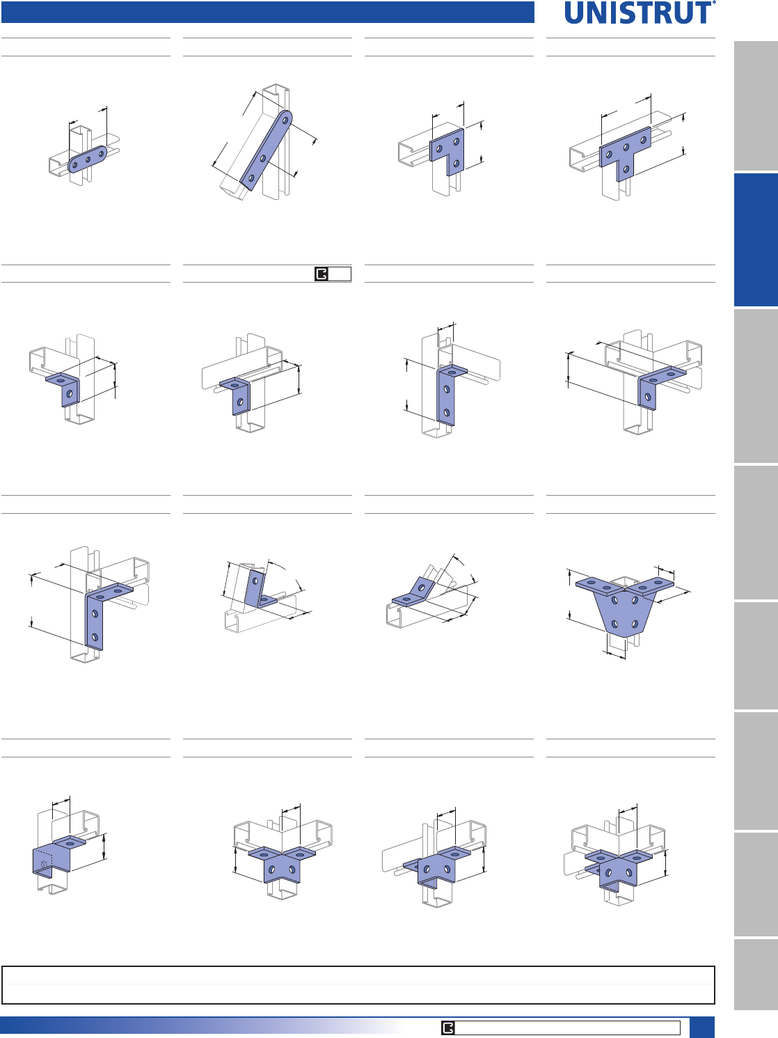
179
Standard Dimensions for 11¼4" (31.8 mm) width series channel fittings (Unless Otherwise Shown on Drawing)
Hole Diameter: 13»32" (10.3mm); Hole Spacing - From End: 5»8" (15.9 mm); Hole Spacing - On Center: 11»2" (38.1mm); Width: 11»4"(31.8mm); Thickness: 3»16" (4.8mm)
11⁄4" Framing System
11¼4" System
13¼16" SystemFiberglass SystemSpecial MetalsPrimeAngle
Metal GratingRoofwalkIndex
CORE PRODUCTS - TYPICALLY AVAILABLE FROM STOCK
GR
Flat, 90°, Angle, Wing Fittings
A2324 A1036A1066
Wt/100 pcs: 39 Lbs (17.7 kg) Wt/100 pcs: 27 Lbs (12.2 kg)Wt/100 pcs: 26 Lbs (11.8 kg)
4 1⁄4"
(108.0)
(69.9)
2 3⁄4"
2 3⁄4"
(69.9)
5 3⁄4"
(146.1)
(76.2)
3"
A1031
A1026
Wt/100 pcs: 34 Lbs (15.4 kg)
Wt/100 pcs: 17 Lbs (7.7 kg)
(69.9)
2 3⁄4"
4 1⁄4"
(108.0)
1 7⁄16"
(36.5)
1 19⁄32"
(40.5)
A1068 A1326
Wt/100 pcs: 27 Lbs (12.2 kg)Wt/100 pcs: 17 Lbs (7.7 kg)
1 1⁄4"
(31.8)
1 25/32"
(45.2) 3 9⁄32"
(83.3)
1 1⁄4"
(31.8)
A1458
Wt/100 pcs: 27 Lbs (12.2 kg)
(45.2)
1 25⁄32"
2 3⁄4"
(69.9)
(31.8)
1 1⁄4"
(74.6)
2 15⁄16"
1 1⁄4"
(31.8)
(67.5)
2 21⁄32"
A2126 A2084A2110
Wt/100 pcs: 23 Lbs (10.4 kg) Wt/100 pcs: 17 Lbs (7.7 kg) Wt/100 pcs: 90 Lbs (40.8 kg)
2 1⁄4"
(57.2)
45°
(.79)
(44.5)
1 3⁄4"
(36.5)
1 7⁄16"
45°
(.79)
11⁄4"
(
31.8
)
A2472 R-L
Wt/100 pcs: 33 Lbs (15.0 kg)
R-As shown
L-Opposite hand
1 19⁄32"
(40.5)
(36.5)
1 7⁄16"
1 19⁄32"
(40.5)
(36.5)
1 7⁄16"
1 19⁄32"
(40.5)
1 7⁄16"
(36.5)
A2223 A2345
Wt/100 pcs: 41 Lbs (18.6 kg)Wt/100 pcs: 34 Lbs (15.4 kg)
1 19⁄32"
(40.5)
(36.5)
1 7⁄16"
A2227
Wt/100 pcs: 52 Lbs (23.6 kg)
A1325
Wt/100 pcs: 38 Lbs (17.2 kg)
3 9⁄32"
(83.3)
(69.9)
2 3⁄4"
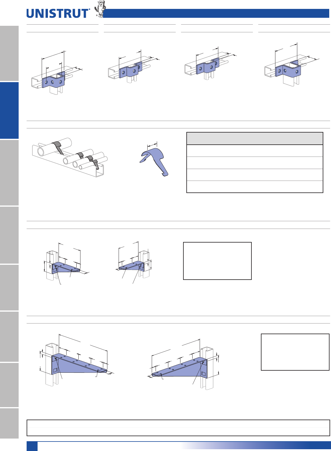
180
Standard Dimensions for 11¼4" (31.8 mm) width series channel fittings (Unless Otherwise Shown on Drawing)
Hole Diameter: 13»32" (10.3mm); Hole Spacing - From End: 5»8" (15.9 mm); Hole Spacing - On Center: 11»2" (38.1mm); Width: 11»4"(31.8mm); Thickness: 3»16" (4.8mm)
11⁄4" Framing System
11¼4" System
13¼16" SystemFiberglass SystemSpecial MetalsPrimeAngleMetal GratingRoofwalkIndex
(114.3)
4 1⁄2"
3 1⁄4"
(82.6)
A1000
1 1⁄4"
(31.8)
A3347 A4047 A5047
Wt/100 pcs: 34 Lbs (15.4 kg) Wt/100 pcs: 58 Lbs (26.3 kg)Wt/100 pcs: 37 Lbs (16.8 kg)
(114.3)
4 1⁄2"
A3300
(19.1)
3⁄4"
(114.3)
4 1⁄2"
A5000
2 1⁄2"
(63.5)
(114.3)
4 1⁄2"
A4000
(15.9)
5⁄8"
A1047
Wt/100 pcs: 43 Lbs (19.5 kg)
"U" Shape Fittings, Pipe/Tube Clips and Brackets
A2608 THRU A2617 UNI-CLIP®
Stainless steel, Type 301.
Part
Number
Pipe Size
,QPP
O.D. Size
,QPP
Wt/100 pcs
/EVNJ
A2608 1»4 (6.4) 0.540 (13.7) 0.6 (0.3)
A2609 3»8 (9.5) 0.675 (17.1) 0.7 (0.3)
A2611 1»2 (12.7) 0.840 (21.3) 1.0 (0.5)
A2612 3»4 (19.1) 1.050 (26.7) 1.4 (0.6)
A2613 1 (25.4) 1.35 (33.4) 2.0 (0.9)
A2614 11»4 (31.8) 1.660 (42.2) 2.4 (1.1)
A2615 11»2 (38.1) 1.900 (48.3) 3.2 (1.5)
A2617 2 (50.8) 2.375 (60.3) 4.7 (2.1)
1"
(25.4)
(76.2)
3"
(76.2)
3"
1"
(25.4)
(15.9)
5⁄8"
(14.3)
9⁄16"(50.8)
2"
3⁄16" (4.8) Holes
13⁄32" (10.3) Dia.
12"
(304.8)
3"
(76.2)
31⁄2"
(88.9)
A2492 R-L
A2494 R-L
(50.8)
2"
(25.4)
1"
(15.9)
5⁄8"
3⁄16" (4.8) Holes
13⁄32" (10.3) Dia.
(14.3)
9⁄16"(203.2)
8"
(127.0)
5"
(63.5)
21⁄2"
(50.8)
2"
(25.4)
1"
(203.2)
8"
(127.0)
5"
(15.9)
5⁄8"
(63.5)
21⁄2"
3⁄16" (4.8) Holes
13⁄32" (10.3) Dia.
(14.3)
9⁄16"
Material: 14 Gauge Steel.
Left
Right
Material: 14 Gauge Steel.
(76.2)
3"
1"
(25.4)
12"
(304.8)
3"
(76.2)
3"
(76.2)
31⁄2"
(88.9)
(15.9)
5⁄8"
(50.8)
2"
3⁄16" (4.8) Holes
13⁄32" (10.3) Dia.
(14.3)
9⁄16"
Design Uniform Load
(Channel Upright Listed)
A1000 200 Lbs (.89 kN)
A4000 130 Lbs (.58 kN)
Safety Factor of 21»2
Design Uniform Load
(Channel Upright Listed)
A1000 200 Lbs (.89 kN)
A4000 130 Lbs (.58 kN)
Safety Factor of 21»2
Right Left
Wt/100 pcs: 56 Lbs (25.4 kg)
Wt/100 pcs: 94 Lbs (42.6 kg)
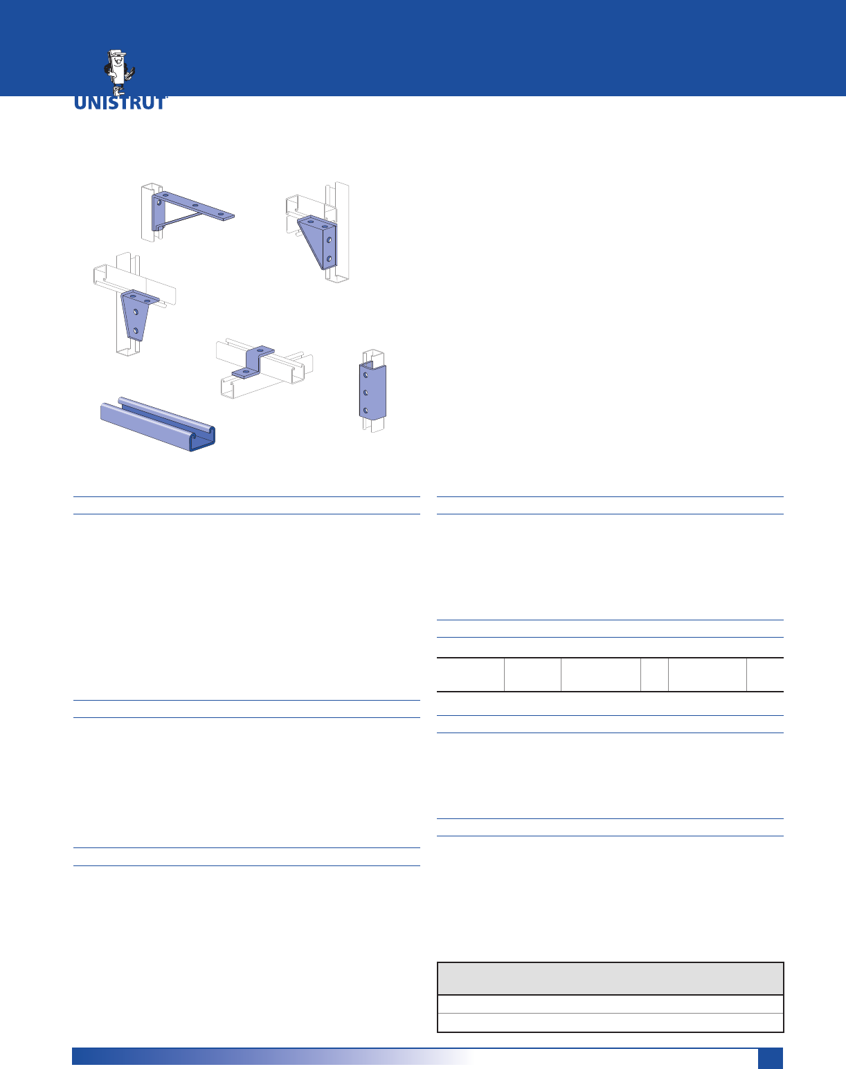
181
MATERIAL
Channels are accurately and carefully cold formed to size
from low-carbon strip steel.
STEEL: PLAIN
19 Gauge (1.0 mm) ASTM A1008
STEEL: PRE-GALVANIZED
19 Gauge (1.0 mm) ASTM A653 GR 33
All nuts are manufactured from mild steel bars conforming
to ASTM A1011 SS Grade 33.
Fittings are made from hot rolled, pickled and oiled steel
plate or strip and conform to ASTM A1011 SS GR 33.
FINISHES
Channels are available in: Perma-Green III (GR),
electro-galvanized (EG), Pre-galvanized (PG), conforming to
ASTM A653 GR 33 and plain (PL).
Nuts are available in plain or electro-galvanized (EG) finish.
Fittings are available in Perma-Green III, electrogalvanized
(EG) with zinc electrolytically to commercial standards
ASTM B653-G90 Type III SC1; or plain (PL).
STANDARD LENGTHS
P-6000 – 16 Feet (4.88m)
P-7000 – 10 Feet (3.05m)
Tolerances are +1⁄8" (3.2 PP) to +1⁄2" (12.7 PP) to allow for
cutting. Special lengths are available for a small cutting
charge with a tolerance of ±1⁄8" (3.2PP).
APPLICATION
A unique half-size reduction of the 15⁄8" channel width
series, this smaller channel size can be used to carry light
loads economically in applications such as instrumenta-
tion, retail displays and light-duty laboratory supports. It
also provides the flexibility found in all Unistrut® framing
systems.
DESIGN BOLT TORQUE
BOLT SIZE 1/4"-20 Rec. Torque
)W/EV1P
6
(8)
Max Torque
)W/EV1P
7
(9)
DIMENSIONS
Imperial dimensions are illustrated in inches. Metric dimen-
sions are shown in parenthesis or as noted. Unless noted,
all metric dimensions are in millimeters and rounded to
one decimal place.
LOAD DATA
All beam and column load data pertains to carbon steel
and stainless steel channels. Load tables and charts are con-
structed to be in accordance with the SPECIFICATION FOR
THE DESIGN OF COLD-FORMED STEEL STRUCTURAL MEM-
BERS 2007 EDITION published by the AMERICAN IRON AND
STEEL INSTITUTE USING ASD METHOD. Loads are based on
33 ksi steel cold formed to 42 ksi.
P6000 (19 Gauge) .............................................................183-184
P7000 (19 Gauge) .............................................................185-186
Channel Nuts, End Caps, and Closure Strips ......................... 187
Flat Plate Fittings .............................................................187-188
Ninety Degree Fittings............................................................188
Angular Fittings, Wing Shape Fittings ...........................189-190
“Z” Shape Fittings ................................................................... 189
“U” Shape Fittings ...........................................................189-190
Special Application Fittings .................................................... 190
Beam Clamps ........................................................................... 190
Tubing Clips ............................................................................. 190
13⁄16" FRAMING SYSTEM
Type
of Load
Safety Factor
to Yield Strength
Safety Factor
to Ultimate Strength
Beam Loads 1.67 2.0
Column Load 1.80 2.2
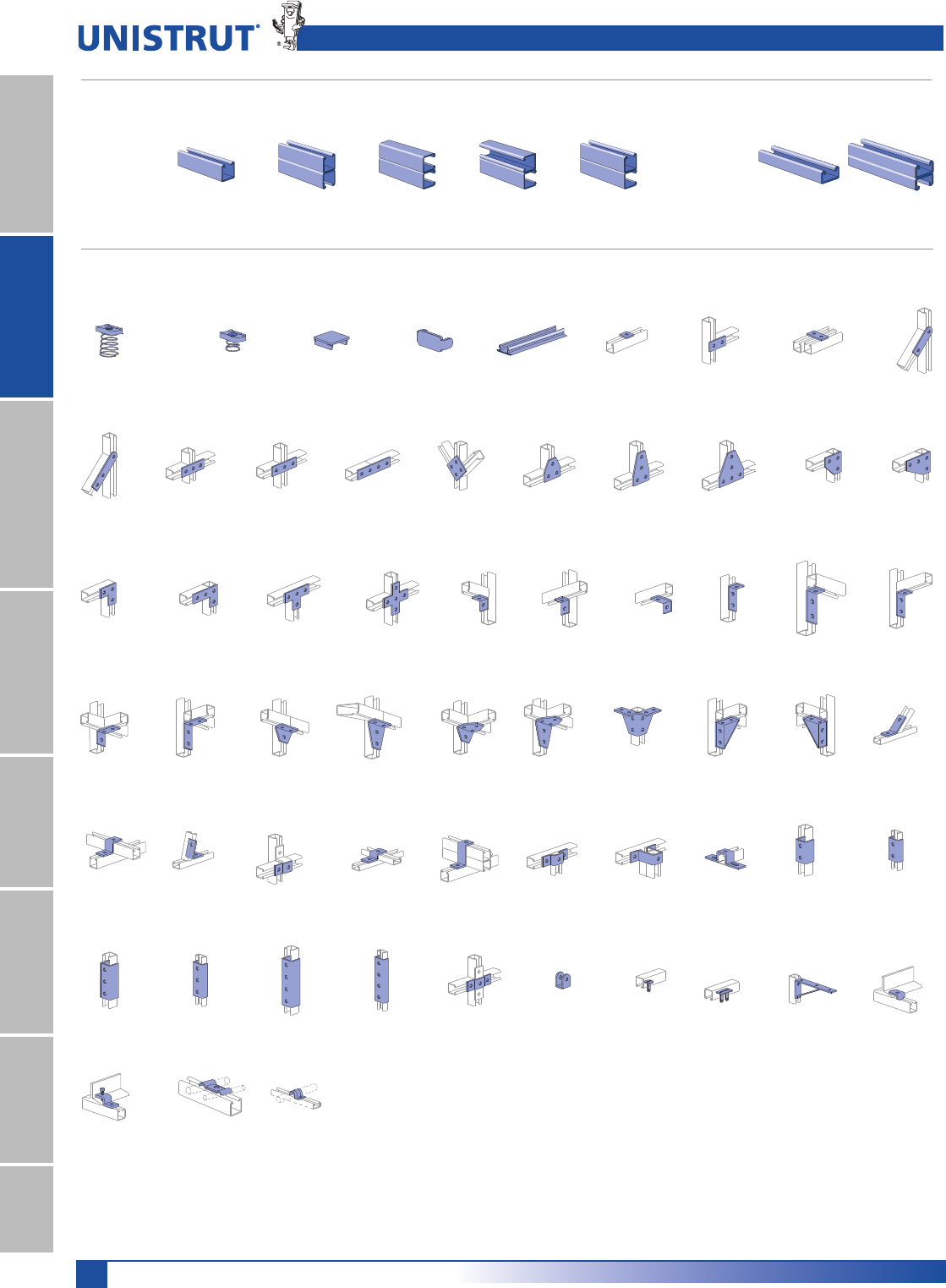
13⁄16" Framing System
182
11¼4" System
13¼16" SystemFiberglass SystemSpecial MetalsPrimeAngleMetal GratingRoofwalkIndex
13⁄16" Framing System Pictorial Index
P7324 - Pg 187 P6925 - Pg 187 P6066 - Pg 187 P6067 - Pg 187 P6962 - Pg 187 P6356 A - Pg 187 P6358 A - Pg 187 P6726 A - Pg 187 P6334 - Pg 187 P6380 - Pg 187
P6036 - Pg 187 P6380 A - Pg 187 P6031 - Pg 188 P6028 - Pg 188 P6026 - Pg 188 P6068 - Pg 188 P6281 - Pg 188 P6069 - Pg 188 P6326 - Pg 188 P6346 - Pg 188
P6000 Series P7000 Series
Channel Nuts & Closures 13¼16" Series Fittings
P6000 - Pg 183 P6001 - Pg 183 P6001 A - Pg 184 P6001 B - Pg 184 P6001 C - Pg 184 P7000 - Pg 185 P7001 - Pg 185
13⁄16" x 13⁄16"
19 Ga.
13⁄16" x 13⁄32"
19 Ga.
P6006-0832 - Pg 187 P7006-0832 - Pg 187 P6280 - Pg 187 P7280 - Pg 187 P6184P - Pg 187 P6062 - Pg 187 P6065 - Pg 187 P6924 - Pg 187 P7325 - Pg 187
P6458 - Pg 188 P6325 - Pg 188 P6357 - Pg 188 P6359-Pg 188 P6579-Pg 188 P7235-Pg 188 P6887-Pg 188 P6331-Pg 188 P6332-Pg 189 P6546-Pg 189
P6186-Pg 189P6045-Pg 189 P7045-Pg 189 P6453-Pg 189P6454-Pg 189 P6047-Pg 189 P6737-Pg 189 P6048-Pg 189 P6376-Pg 189 P7376-Pg 189
P6376 A-Pg 189 P7376 A-Pg 189 P6377-Pg 189 P7377-Pg 189 P6455-Pg 190 P6973-Pg 190 P6349-Pg 190 P6353-Pg 190 P6127-Pg 190
P6379 S-Pg 190
P6386-Pg 190
P6805-Pg 190 P7008-Pg 190
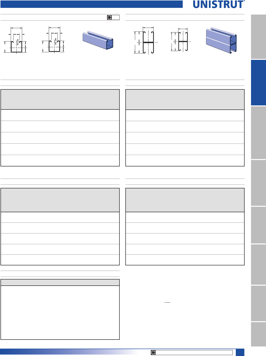
13⁄16" Framing System
183
11¼4" System
13¼16" SystemFiberglass SystemSpecial MetalsPrimeAngle
Metal GratingRoofwalkIndex
CORE PRODUCTS - TYPICALLY AVAILABLE FROM STOCK
PG P6001
P6000
1
11.1 4.84.8
20.6
20.6
11.8
8.9
2.4
2
2
1
7⁄16"3⁄16"
3⁄16"
13⁄16"
13⁄16"
3⁄32"
.463"
.350"
20.6
20.6
20.6
41.3
2
1
2
1
1 5⁄8"
13⁄16"
13⁄16"
13⁄16"
Wt/100 Ft: 36 Lbs (54 kg/100 m)
$OORZDEOH0RPHQW,Q/EV1P
19 Gauge Nominal Thickness .040" (1.0 PP)
P6000 & P6001 Channel
Wt/100 Ft: 73 Lbs (108 kg/100 m)
$OORZDEOH0RPHQW,Q/EV1P
19 Gauge Nominal Thickness .040" (1.0 PP)
P6000 - BEAM LOADING
Span
In
Max
Allowable
Uniform Load
Lbs
Defl. at
Uniform
Load
In
Uniform Loading at Deflection
Span/180
Lbs
Span/240
Lbs
Span/360
Lbs
18 230 0.06 230 230 180
24 170 0.11 170 150 100
30 140 0.18 130 100 70
36 110 0.24 90 70 50
42 100 0.35 70 50 30
48 80 0.42 50 40 30
54 80 0.60 40 30 20
60 70 0.72 30 20 20
66 60 0.82 30 20 10
72 60 1.06 20 20 10
Span
In
Max
Allowable
Uniform Load
Lbs
Defl. at
Uniform
Load
In
Uniform Loading at Deflection
Span/180
Lbs
Span/240
Lbs
Span/360
Lbs
18 620 0.04 620 620 620
24 460 0.06 460 460 460
30 370 0.10 370 370 320
36 310 0.14 310 310 220
42 270 0.20 270 240 160
48 230 0.25 230 180 120
54 210 0.32 190 150 100
60 190 0.40 160 120 80
66 170 0.48 130 100 70
72 150 0.55 110 80 50
P6001 - BEAM LOADING
P6000 - COLUMN LOADING
Unbraced
Height
In
Maximum
Allowable
Load
at Slot Face
Lbs
Maximum Column Load Applied at C.G.
K = 0.65
Lbs
K = 0.80
Lbs
K =1.0
Lbs
K = 1.2
Lbs
18 600 1,660 1,400 1,100 860
24 490 1,300 1,010 740 590
30 420 990 740 560 450
36 340 770 590 450 370
42 300 630 490 380 310
48 260 540 420 330 270
54 240 470 370 290 **
60 210 410 330 ** **
66 210 370 300 ** **
72 180 340 270 ** **
Unbraced
Height
In
Maximum
Allowable
Load
at Slot Face
Lbs
Maximum Column Load Applied at C.G.
K = 0.65
Lbs
K = 0.80
Lbs
K =1.0
Lbs
K = 1.2
Lbs
18 1,210 4,320 4,080 3,770 3,500
24 1,170 3,980 3,680 3,330 3,060
30 1,130 3,650 3,330 3,000 2,460
36 1,070 3,370 3,060 2,460 1,800
42 1,020 3,140 2,690 1,900 1,320
48 900 2,930 2,230 1,460 1,010
54 820 2,550 1,800 1,150 800
60 700 2,180 1,460 930 **
66 700 1,830 1,210 770 **
72 550 1,530 1,010 ** **
P6001 - COLUMN LOADING
P6000 & P6001 - ELEMENTS OF SECTION
Parameter P6000 P6001
Area of Section 0.107 In20.213 In2
Axis 1-1
Moment of Inertia (I) 0.009 In40.045 In4
Section Modulus (S) 0.020 In30.055 In3
Radius of Gyration (r) 0.295 In 0.460 In
Axis 2-2
Moment of Inertia (I) 0.012 In40.024 In4
Section Modulus (S) 0.029 In30.058 In3
Radius of Gyration (r) 0.333 In 0.333 In
Notes:
* Load limited by spot weld shear.
./»U !
NR = Not Recommended.
1. Beam loads are given in total uniform load (W Lbs) not uniform load (w lbs/ft or
w lbs/in).
2. Beam loads are based on a simple span and assumed to be adequately laterally
braced. Unbraced spans can reduce beam load carrying capacity. Refer to Page
186 for reduction factors for unbraced lengths.
3. Deduct channel weight from the beam loads.
4. For concentrated midspan point loads, multiply beam loads by 50% and the
corresponding deflection by 80%. For other load conditions refer to page 18.
5. All beam loads are for bending about Axis 1-1.
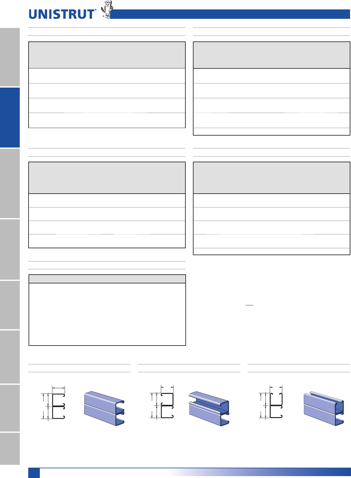
13⁄16" Framing System
184
11¼4" System
13¼16" SystemFiberglass SystemSpecial MetalsPrimeAngleMetal GratingRoofwalkIndex
P6000 & P6001 - ELEMENTS OF SECTION (METRIC)
Span
PP
Max
Allowable
Uniform Load
kN
Defl. at
Uniform
Load
PP
Uniform Loading at Deflection
Span/180
kN
Span/240
kN
Span/360
kN
300 2.9* 0 2.9* 2.9* 2.9*
450 2.8 1 2.8 2.8 2.8
600 2.1 2 2.1 2.1 2.1
750 1.7 2 1.7 1.7 1.5
1,000 1.2 4 1.2 1.2 0.8
1,250 1.0 7 1.0 0.8 0.5
1,500 0.8 10 0.7 0.5 0.4
1,750 0.7 13 0.5 0.4 0.3
2,000 0.6 17 0.4 0.3 0.2
Unbraced
Height
PP
Maximum
Allowable
Load
at Slot Face
kN
Maximum Column Load Applied at C.G.
K = 0.65
kgN
K = 0.80
kN
K =1.0
kN
K = 1.2
kN
300 5.5 20.7 20.1 19.2 18.2
450 5.4 19.3 18.2 16.9 15.7
600 5.2 17.8 16.5 14.9 13.7
750 5.0 16.4 14.9 13.5 11.2
1,000 4.6 14.4 12.9 9.5 6.7
1,250 3.9 12.7 9.5 6.2 4.3
1,500 3.2 9.9 6.7 4.3 **
1,750 2.6 7.5 4.9 ** **
2,000 2.2 5.7 3.8 ** **
P6000 & P6001 Channel
Span
PP
Max
Allowable
Uniform Load
kN
Defl. at
Uniform
Load
PP
Uniform Loading at Deflection
Span/180
kN
Span/240
kN
Span/360
kN
300 1.5 1 1.5 1.5 1.5
450 1.0 2 1.0 1.0 0.8
600 0.8 3 0.8 0.7 0.5
750 0.6 4 0.6 0.4 0.3
1,000 0.4 7 0.4 0.3 0.2
1,250 0.4 11 0.2 0.2 0.1
1,500 0.3 17 0.1 0.1 0.1
1,750 0.3 24 0.1 0.1 0.0
Unbraced
Height
PP
Maximum
Allowable
Load
at Slot Face
kN
Maximum Column Load Applied at C.G.
K = 0.65
kN
K = 0.80
kN
K =1.0
kN
K = 1.2
kN
300 3.1 9.2 8.4 7.3 6.3
450 2.7 7.5 6.3 5.0 3.9
600 2.2 5.9 4.6 3.4 2.7
750 1.8 4.5 3.4 2.5 2.0
1,000 1.4 3.0 2.4 1.8 1.5
1,250 1.1 2.3 1.8 1.4 1.2
1,500 0.9 1.9 1.5 1.2 **
1,750 0.8 1.6 1.2 ** **
P6000 - BEAM LOADING (METRIC) P6001 - BEAM LOADING (METRIC)
P6000 - COLUMN LOADING (METRIC)P6001 - COLUMN LOADING (METRIC)
Parameter P6000 P6001
Area of Section 0.69 cm21.38 cm2
Axis 1-1
Moment of Inertia (I) 0.39 cm41.88 cm4
Section Modulus (S) 0.33 cm30.91 cm3
Radius of Gyration (r) 0.75 cm 1.17 cm
Axis 2-2
Moment of Inertia (I) 0.49 cm40.99 cm4
Section Modulus (S) 0.48 cm30.96 cm3
Radius of Gyration (r) 0.85 cm 0.85 cm
P6001A P6001B P6001C
1 5⁄8"
(41.3)
13⁄16"
(20.6)
13⁄16"
(20.6)
13⁄16"
(20.6)
1 5⁄8"
(41.3)
13⁄16"
(20.6)
13⁄16"
(20.6)
13⁄16"
(20.6)
1 5⁄8"
(41.3)
13⁄16"
(20.6)
13⁄16"
(20.6)
13⁄16"
(20.6)
Wt/100 Ft: 73 Lbs (108 kg/100 m)
$OORZDEOH0RPHQW,Q/EV1P
19 Gauge Nominal Thickness .040" (1.0 PP)
Wt/100 Ft: 73 Lbs (108 kg/100 m)
$OORZDEOH0RPHQW,Q/EV1P
19 Gauge Nominal Thickness .040" (1.0 PP)
Wt/100 Ft: 73 Lbs (108 kg/100 m)
$OORZDEOH0RPHQW,Q/EV1P
19 Gauge Nominal Thickness .040" (1.0 PP)
Notes:
* Load limited by spot weld shear.
./»U !
NR = Not Recommended.
1. Beam loads are given in total uniform load (W Lbs) not uniform load (w lbs/ft or
w lbs/in).
2. Beam loads are based on a simple span and assumed to be adequately laterally
braced. Unbraced spans can reduce beam load carrying capacity. Refer to Page
186 for reduction factors for unbraced lengths.
3. Deduct channel weight from the beam loads.
4. For concentrated midspan point loads, multiply beam loads by 50% and the
corresponding deflection by 80%. For other load conditions refer to page 18.
5. All beam loads are for bending about Axis 1-1.
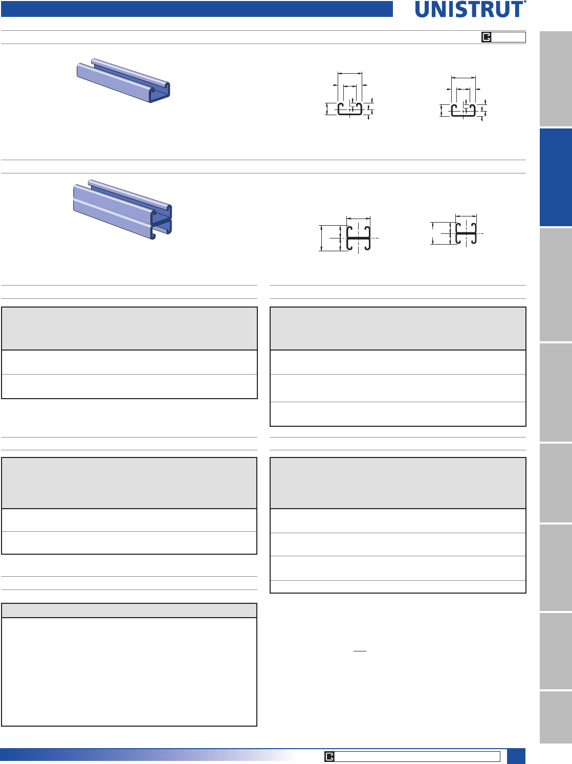
13⁄16" Framing System
185
11¼4" System
13¼16" SystemFiberglass SystemSpecial MetalsPrimeAngle
Metal GratingRoofwalkIndex
PG PL
CORE PRODUCTS - TYPICALLY AVAILABLE FROM STOCK
P7000
P7001
7⁄16"3⁄16"
3⁄16"
13⁄16"
3⁄32".243"
.163"
13⁄32"1
2
10.3
11.1
20.6
4.84.8
6.2
4.1
2.4
2
1
1
2
13⁄16"
13⁄32"
13⁄32"
13⁄16"1
20.6 10.3
10.3
20.6
2
Span
In
Max
Allowable
Uniform Load
Lbs
Defl. at
Uniform
Load
In
Uniform Loading at Deflection
Span/180 Span/240 Span/360
Lbs Lbs Lbs
18 80 0.12 60 50 30
24 60 0.22 40 30 20
30 50 0.36 20 20 10
36 40 0.50 20 10 10
Unbraced
Height
In
Maximum
Allowable
Load
at Slot Face
Lbs
Maximum Column Load Applied at C.G.
K = 0.65
Lbs
K = 0.80
Lbs
K =1.0
Lbs
K = 1.2
Lbs
18 420 1,200 990 720 510
24 330 900 640 410 280
30 260 620 410 ** **
36 200 430 280 ** **
P7000 & P7001 Channels
Wt/100 Ft: 25 Lbs (38 kg/100m)
$OORZDEOH0RPHQW,Q/EV1P
19 Gauge Nominal Thickness .040" (1.0 PP)
Wt/100 Ft: 50 Lbs (75 kg/100m)
$OORZDEOH0RPHQW,Q/EV1P
19 Gauge Nominal Thickness .040" (1.0 PP)
P7000 - BEAM LOADING P7001 - BEAM LOADING
P7000 - COLUMN LOADING P7001 - COLUMN LOADING
Span
In
Max
Allowable
Uniform Load
Lbs
Defl. at
Uniform
Load
In
Uniform Loading at Deflection
Span/180 Span/240 Span/360
Lbs Lbs Lbs
18 200 0.07 200 200 140
24 150 0.12 150 120 80
30 120 0.19 100 80 50
36 100 0.28 70 50 40
42 90 0.40 50 40 30
48 80 0.53 40 30 20
Unbraced
Height
In
Maximum
Allowable
Load
at Slot Face
Lbs
Maximum Column Load Applied at C.G.
K = 0.65
Lbs
K = 0.80
Lbs
K =1.0
Lbs
K = 1.2
Lbs
18 790 2,930 2,690 2,330 1,960
24 740 2,570 2,210 1,720 1,260
30 680 2,180 1,720 1,160 800
36 580 1,780 1,260 800 560
42 500 1,400 920 590 **
48 420 1,070 710 ** **
54 360 850 560 ** **
P7000 & P7001 - ELEMENTS OF SECTION
Parameter P7000 P7001
Area of Section 0.074 In20.148 In2
Axis 1-1
Moment of Inertia (I) 0.002 In40.007 In4
Section Modulus (S) 0.007 In30.018 In3
Radius of Gyration (r) 0.150 In 0.222 In
Axis 2-2
Moment of Inertia (I) 0.007 In40.014 In4
Section Modulus (S) 0.017 In30.034 In3
Radius of Gyration (r) 0.307 In 0.307 In
Notes:
* Load limited by spot weld shear.
./»U !
NR = Not Recommended.
1. Beam loads are given in total uniform load (W Lbs) not uniform load (w lbs/ft or
w lbs/in).
2. Beam loads are based on a simple span and assumed to be adequately laterally
braced. Unbraced spans can reduce beam load carrying capacity. Refer to Page
186 for reduction factors for unbraced lengths.
3. Deduct channel weight from the beam loads.
4. For concentrated midspan point loads, multiply beam loads by 50% and the
corresponding deflection by 80%. For other load conditions refer to page 18.
5. All beam loads are for bending about Axis 1-1.
13⁄16" Framing System
186
11¼4" System
13¼16" SystemFiberglass SystemSpecial MetalsPrimeAngleMetal GratingRoofwalkIndex
Span
mm
Max
Allowable
Uniform Load
kN
Defl. at
Uniform
Load
mm
Uniform Loading at Deflection
Span/180
kN
Span/240
kN
Span/360
kN
300 1.4 1 1.4 1.4 1.4
450 0.9 2 0.9 0.9 0.7
600 0.7 3 0.7 0.5 0.4
750 0.5 5 0.5 0.4 0.2
1,000 0.4 8 0.3 0.2 0.1
1,250 0.3 13 0.2 0.1 0.1
1,500 0.3 19 0.1 0.1 NR
Unbraced
Height
mm
Maximum
Allowable
Load
at Slot Face
kN
Maximum Column Load Applied at C.G.
K = 0.65
kN
K = 0.80
kN
K =1.0
kN
K = 1.2
kN
300 3.6 14.0 13.6 13.0 12.1
450 3.5 13.1 12.1 10.5 8.9
600 3.3 11.6 10.0 7.8 5.8
750 3.0 9.8 7.8 5.3 3.7
1,000 2.4 6.9 4.7 3.0 **
1,250 1.8 4.5 3.0 ** **
Nut Size/
Thread
Max. Allowable
Pull-Out Lbs (kN)
Resistance
to Slip Lbs (kN)
Torque
)W/EV1P
1»4"-20 250 150 6
1.11 0.67 8
MAXIMUM ALLOWABLE PULL-OUT AND SLIP LOADS
P7000 & P7001 Channel
P7000 - BEAM LOADING (METRIC) P7001 - BEAM LOADING (METRIC)
P7000 - COLUMN LOADING (METRIC)P7001 - COLUMN LOADING (METRIC)
Span
mm
Max
Allowable
Uniform Load
kN
Defl. at
Uniform
Load
mm
Uniform Loading at Deflection
Span/180
kN
Span/240
kN
Span/360
kN
300 0.5 1 0.5 0.5 0.4
450 0.4 3 0.3 0.2 0.1
600 0.3 5 0.2 0.1 0.1
750 0.2 9 0.1 0.1 0.0
1,000 0.2 16 0.0 0.0 0.0
1,250 0.1 24 0.0 0.0 NR
1,500 0.1 28 0.0 NR NR
Unbraced
Height
mm
Maximum
Allowable
Load
at Slot Face
kN
Maximum Column Load Applied at C.G.
K = 0.65
kN
K = 0.80
kN
K =1.0
kN
K = 1.2
kN
300 2.1 6.4 6.0 5.3 4.5
450 1.9 5.4 4.5 3.3 2.3
600 1.5 4.1 2.9 1.9 1.3
750 1.2 2.8 1.9 1.2 **
P7000 & P7001 - ELEMENTS OF SECTION (METRIC)
Parameter P7000 P7001
Area of Section 0.48 cm20.96 cm2
Axis 1-1
Moment of Inertia (I) 0.07 cm40.31 cm4
Section Modulus (S) 0.11 cm30.30 cm3
Radius of Gyration (r) 0.38 cm 0.57 cm
Axis 2-2
Moment of Inertia (I) 0.29 cm40.58 cm4
Section Modulus (S) 0.28 cm30.56 cm3
Radius of Gyration (r) 0.78 cm 0.78 cm
Loads are
calculated
based on 2001
Specification For
The Design Of
Cold Formed Steel
Structural Mem-
bers published
by AISI
LOAD LOAD LOAD
Channel
Bearing Length
13¼16PP
Maximum Allowable
Loads - Lbs (kN)
Bearing Length
13¼16PP
Maximum Allowable
Loads - Lbs (kN)
Bearing Length
15¼8PP
Maximum Allowable
Loads - Lbs (kN)
P6000 1,000 (4.45) 500 (2.22) 1,200 (5.34)
P7000 1,000 (4.45) 500 (2.22) 1,200 (5.34)
BEARING LOADS ON UNISTRUT CHANNEL
Notes:
* Load limited by spot weld shear.
./»U !
NR = Not Recommended.
1. Beam loads are given in total uniform load (W Lbs) not uniform load (w lbs/ft or
w lbs/in).
2. Beam loads are based on a simple span and assumed to be adequately laterally
braced. Unbraced spans can reduce beam load carrying capacity. Refer to table
below for reduction factors for unbraced lengths.
3. Deduct channel weight from the beam loads.
4. For concentrated midspan point loads, multiply beam loads by 50% and the
corresponding deflection by 80%. For other load conditions refer to page 18.
5. All beam loads are for bending about Axis 1-1.
LATERAL BRACING LOAD REDUCTION CHARTS
Span
Single
Channel
Double
Channel
In. (cm) P6000 P7000 P6001 P7001
24 (61) 0.80 0.95 0.99 1.00
36 (91) 0.63 0.90 0.89 0.93
48 (122) 0.52 0.87 0.79 0.86
60 (152) 0.45 0.83 0.70 0.80
72 (183) 0.40 0.80 0.60 0.73
84 (213) 0.37 0.76 0.51 0.67
96 (244) 0.34 0.73 0.44 0.60
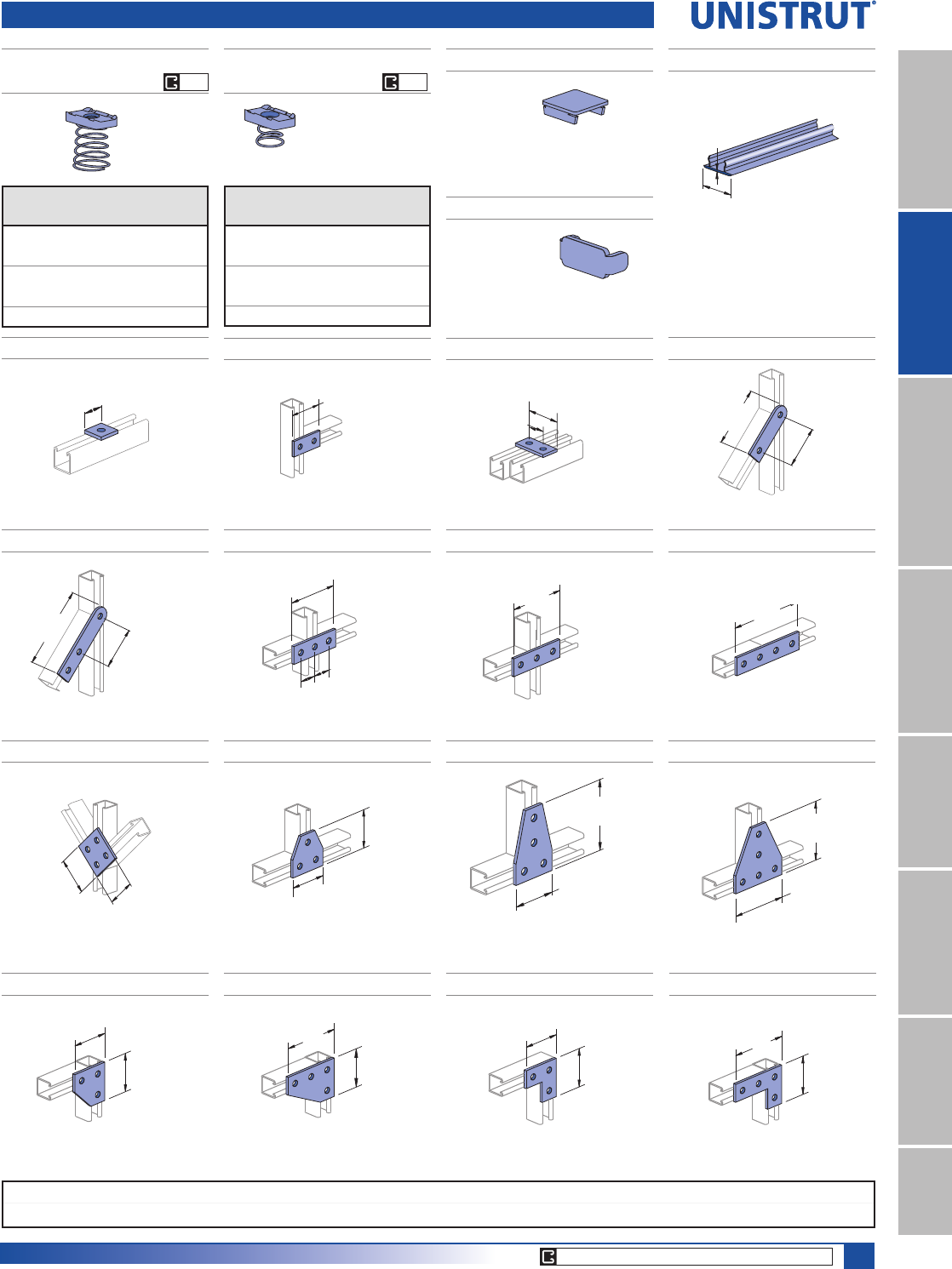
187
13⁄16" Framing System
Standard Dimensions for 13¼16" (20.6mm) width series channel fittings (Unless Otherwise Shown on Drawing)
Hole Diameter: 9¼32" (7.1mm); Hole Spacing - From End: 13¼32" (10.3mm); Hole Spacing - On Center: 11¼16" (27.0mm); Width: 13¼16"(20.6mm); Thickness: 1¼8" (3.2mm)
11¼4" System
13¼16" SystemFiberglass SystemSpecial MetalsPrimeAngle
Metal GratingRoofwalkIndex
P6006-0832 THRU P6006-1420
CHANNEL NUT W/SPRING
P7006-0832 THRU P7006-1420
CHANNEL NUT W/SPRING
P6280 - END CAP FOR P6000
P7280 - END CAP FOR P7000
P6184 P - CLOSURE STRIP
Wt/100 Ft: 4 Lbs (6.0 kg/100m)
Wt/100 pcs: 3 Lbs (1.4 kg)
Wt/100 pcs: 1 Lbs (0.5 kg)
Material: .060" (1.5)
Material: .048" (1.2)
Material: PVC, Plastic.
Standard Length: 10 Feet (3.05 m).
.706"
(17.9)
1⁄16"
(1.6)
Part
Number
Thread
Size In
Wt/100 pcs
Lbs (kg)
P6006-0836 #8 - 36 1 (0.5)
P6006-0832 #8 - 32 1 (0.5)
P6006-1032 #10 - 32 1 (0.5)
P6006-1024 #10 - 24 1 (0.5)
P6006-1420 1»4"- 20 1 (0.5)
Part
Number
Thread
Size In
Wt/100 pcs
Lbs (kg)
P7006-0836 #8 - 36 1 (0.5)
P7006-0832 #8 - 32 1 (0.5)
P7006-1032 #10 - 32 1 (0.5)
P7006-1024 #10 - 24 1 (0.5)
P7006-1420 1»4"- 20 1 (0.5)
Channel Nuts, Caps, Closures, and Flat Plate Fittings
P6062
Wt/100 pcs: 2 Lbs (0.9 kg)
13⁄16"
(20.6)
P6065
Wt/100 pcs: 5 Lbs (2.3 kg)
1 7⁄8"
(47.6)
P6924 P7325
Wt/100 pcs: 5 Lbs (2.3 kg) Wt/100 pcs: 7 Lbs (3.2 kg)
2 11⁄16"
1 7⁄8"
(47.6)
(68.3)
13⁄16"
(20.6)
(41.3)
1 5⁄8"
P6066
Wt/100 pcs: 8 Lbs (3.6 kg)
2 15⁄16"
(74.6)
P7324 P6925
Wt/100 pcs: 10 Lbs (4.5 kg) Wt/100 pcs: 7 Lbs (3.2 kg)
3 3⁄4"
(95.3)
(47.6)
1 7⁄8"
2 7⁄16"
(61.9)
(20.6)
13⁄16"
(20.6)
13⁄16"
P6067
P6962 P6356A
Wt/100 pcs: 11 Lbs (5.0 kg)
(101.6)
Wt/100 pcs: 19 Lbs (8.6 kg) Wt/100 pcs: 10 Lbs (4.5 kg)
2 5⁄16"
(58.7)
2 5⁄16"
(58.7)
1 7⁄8"
(47.6)
1 7⁄8"
(47.6)
P6358A
Wt/100 pcs: 15 Lbs (6.8 kg)
2 15⁄16"
(74.6)
1 7⁄8"
(47.6)
EG EG
CORE PRODUCTS - TYPICALLY AVAILABLE FROM STOCK
P6726A
Wt/100 pcs: 22 Lbs (10.0 kg)
(74.6)
2 15⁄16"
(74.6)
2 15⁄16"
P6334
Wt/100 pcs: 11 Lbs (5.0 kg)
(47.6)
1 7⁄8"
(47.6)
1 7⁄8"
P6380 P6036
Wt/100 pcs: 15 Lbs (6.8 kg) Wt/100 pcs: 8 Lbs (3.6 kg)
2 15⁄16"
(74.6)
1 7⁄8"
(47.6) (47.6)
1 7⁄8"
(47.6)
1 7⁄8"
P6380A
Wt/100 pcs: 11 Lbs (5.0 kg)
(74.6)
2 15⁄16"
1 7⁄8"
(47.6)
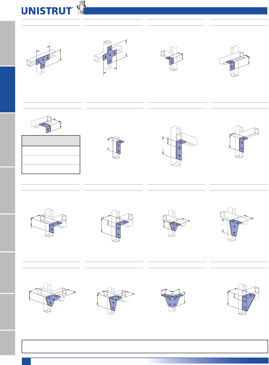
188
Standard Dimensions for 13¼16" (20.6mm) width series channel fittings (Unless Otherwise Shown on Drawing)
Hole Diameter: 9¼32" (7.1mm); Hole Spacing - From End: 13¼32" (10.3mm); Hole Spacing - On Center: 11¼16" (27.0mm); Width: 13¼16"(20.6mm); Thickness: 1¼8" (3.2mm)
13⁄16" Framing System
11¼4" System
13¼16" SystemFiberglass SystemSpecial MetalsPrimeAngleMetal GratingRoofwalkIndex
P6026 P6068
P6281 , P6282, P6283 P6069
Wt/100 pcs: 8 Lbs (3.6 kg)
Wt/100 pcs: 5 Lbs (2.3 kg) Wt/100 pcs: 5 Lbs (2.3 kg)
15⁄16"
(23.8)
A
15⁄16"
(23.8)
1 1⁄8"
(28.6)
13⁄16"
(20.6)
1 1⁄4"
(31.8)
2"
(50.8)
(28.6)
1 1⁄8"
P6031 P6028
Wt/100 pcs: 11 Lbs (5.0 kg) Wt/100 pcs: 14 Lbs (6.4 kg)
(74.6)
2 15⁄16"
(74.6)
2 15⁄16"
(47.6)
1 7⁄8"
2 15⁄16"
(74.6)
Part
Number
A
In PP
Wt/100 pcs
Lbs (kg)
P6281 28
50.8 3.6
P6282 21»29
63.5 4.1
P6283 310
76.2 4.5
P6458 P6325
Wt/100 pcs: 11 Lbs (5.0 kg)Wt/100 pcs: 8 Lbs (3.6 kg)
(31.8)
1 1⁄4"
1 7⁄8"
(47.6)
2 5⁄16"
(58.7)
(47.6)
1 7⁄8"
(21.4)
27⁄32"
P6326 P6346
Wt/100 pcs: 8 Lbs (3.6 kg)Wt/100 pcs: 8 Lbs (3.6 kg)
2 3⁄16"
(55.6)
(23.8)
15⁄16"
2 5⁄16"
(58.7)
(21.4)
27⁄32"
Flat and 90° Fittings
P6359
P6579 P7235
Wt/100 pcs: 15 Lbs (6.8 kg)
Wt/100 pcs: 15 Lbs (6.8 kg) Wt/100 pcs: 18 Lbs (8.2 kg)
2 5⁄16"
(58.7)
1 7⁄8"
(47.6)
(31.8)
1 1⁄4"
(47.6)
1 7⁄8"
(47.6)
1 7⁄8"
2 5⁄16"
(58.7)
(47.6)
1 7⁄8"
(47.6)
1 7⁄8"
P6357
Wt/100 pcs: 10 Lbs (4.5 kg)
(47.6)
1 7⁄8"
(31.8)
1 1⁄4"
P6331
Wt/100 pcs: 19 Lbs (8.6 kg)
2 5⁄16"
(58.7)
(47.6)
1 7⁄8"
(21.4)
27⁄32"
P6887
(23.8)
15⁄16"
(50.8)
2"
1 31⁄32"
(50.0) (50.0)
1 31⁄32"
Wt/100 pcs: 28 Lbs (12.7 kg)
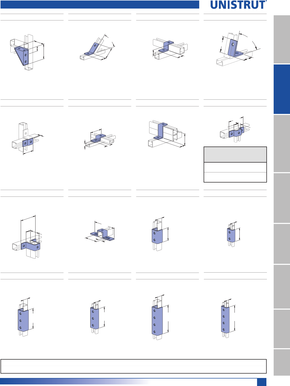
189
13⁄16" Framing System
Standard Dimensions for 13¼16" (20.6mm) width series channel fittings (Unless Otherwise Shown on Drawing)
Hole Diameter: 9¼32" (7.1mm); Hole Spacing - From End: 13¼32" (10.3mm); Hole Spacing - On Center: 11¼16" (27.0mm); Width: 13¼16"(20.6mm); Thickness: 1¼8" (3.2mm)
11¼4" System
13¼16" SystemFiberglass SystemSpecial MetalsPrimeAngle
Metal GratingRoofwalkIndex
Angle, "Z", and "U" Shape Fittings
P6332 P6546
Wt/100 pcs: 8 Lbs (3.6 kg)Wt/100 pcs: 19 Lbs (8.6 kg)
2 5⁄16"
(58.7)
(47.6)
1 7⁄8"
(21.4)
27⁄32"
(30.2)
1 3⁄16"
(43.7)
1 23⁄32"
45°
P6045
Wt/100 pcs: 7 Lbs (3.2 kg)
(27.0)
1 1⁄16"
(20.6)
13⁄16"
P6000
P6186
1 1⁄4"
45°
(31.8)
1 13⁄16"
(46.0)
Wt/100 pcs: 8 Lbs (3.6 kg)
P7045
Wt/100 pcs: 6 Lbs (2.7 kg)
(10.3)
13⁄32"
(10.3)
13⁄32"
(47.6)
1 7⁄8"
P7000
P6453P6454
(41.3)
1 5⁄8"
(23.8)
15⁄16"
P6001
Wt/100 pcs: 9 Lbs (4.1 kg)Wt/100 pcs: 5 Lbs (2.3 kg)
(3.2)
1⁄8"
(46.8)
1 27⁄32"
P6047, P7047
P6737
Wt/100 pcs: 16 Lbs (7.3 kg)
(41.3)
1 5⁄8"
27⁄32"
(21.4)
(69.1)
2 23⁄32"
P6001
27⁄32"
(21.4)
(74.6)
2 15⁄16"
P7000
A
Part
No.
A
In PP
Wt/100
pcs
Lbs (kg)
Use with
Channel
P6047
13»16 12 P6000
20.6 5.4
P7047
13»32 10 P7000
10.3 4.5
P6048
Wt/100 pcs: 14 Lbs (6.4 kg)
3⁄4"
(19.1)
(95.3)
3 3⁄4"
2 3⁄16"
(55.6)
P6000
P6376
Wt/100 pcs: 17 Lbs (7.7 kg)
13⁄16"
(20.6)
1 7⁄8"
(47.6)
P6000
P7376
P6376A P6377P7376A
Wt/100 pcs: 36 Lbs (16.3 kg)
Wt/100 pcs: 11 Lbs (5.0 kg)
Wt/100 pcs: 16 Lbs (7.3 kg)Wt/100 pcs: 26 Lbs (11.8 kg)
13⁄16"
(20.6)
4"
(101.6)
P6000
2 15⁄16"
(74.6)
P6000
13⁄16"
(20.6)
1 7⁄8"
(47.6)
P7000
13⁄32"
(10.3)
2 15⁄16"
(74.6)
P7000
13⁄32"
(10.3)
P7377
Wt/100 pcs: 24 Lbs (10.9 kg)
4"
(101.6)
P7000
13⁄32"
(10.3)
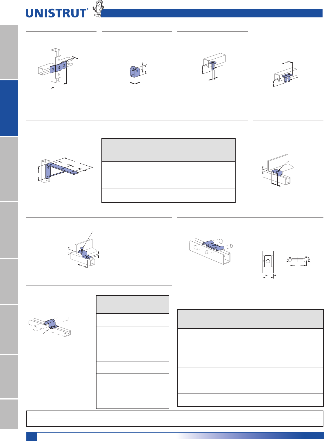
190
Standard Dimensions for 13¼16" (20.6mm) width series channel fittings (Unless Otherwise Shown on Drawing)
Hole Diameter: 9¼32" (7.1mm); Hole Spacing - From End: 13¼32" (10.3mm); Hole Spacing - On Center: 11¼16" (27.0mm); Width: 13¼16"(20.6mm); Thickness: 1¼8" (3.2mm)
13⁄16" Framing System
11¼4" System
13¼16" SystemFiberglass SystemSpecial MetalsPrimeAngleMetal GratingRoofwalkIndex
“U” Shape Fittings, Beam Clamps, Slides, Brackets, and Tubing Clips
P6455 P6973 P6349 ACETAL SLIDE
Wt/100 pcs: 8 Lbs (3.6 kg)
13⁄16"
(20.6)
13⁄16"
(20.6)
13⁄32"
(10.3)
1 1⁄4"
(31.8)
Wt/100 pcs: 8 Lbs (3.6 kg)
2 7⁄8"
(73.0)
(3.2)
1⁄8"
Wt/100 pcs: 1 Lbs (0.5 kg)
3⁄16" (4.8) Dia.
(31.8)
1 1⁄4"(17.5)
11⁄16"
27⁄32"
(21.4)
5⁄16"
(7.9)
13⁄32"
(10.3)
3⁄16"
(4.8) Dia.
Safety Factor 21»2
P6127 - P6129 BRACKET
A
CC
(28.6)
1 1⁄8"
B
P6000
Part
No.
Uniform
Design
Load
Lbs (kN)
“A”
In PP
“B”
In PP
“C”
In PP
Wt/100
pcs
Lbs (kg)
P6127 150 61»221»221»230
0.67 165.1 63.5 63.5 13.6
P6128 150 81»231»431»240
0.67 215.9 82.6 88.9 18.1
P6129 130.0 101»244
1»250
0.58 266.7 101.6 114.3 22.7
Wt/100 pcs: 1 Lbs (0.5 kg)
P6353 ACETAL SLIDE
9⁄32" (7.1)
Dia. Hole
P7000
C
13⁄32"
(10.3)
13⁄16"
(20.6)
Size ASize B
9⁄32"
(7.1) Dia.
Material: 16 Gauge (1.5)
P6805 THRU P6810 TUBING CLIPS
P7008 THRU P7020 TUBING CLIPS
Part
Number
O.D. Tube
Size “A”
In PP
O.D. Tube
Size “B”
In PP
“C”
In PP
Wt/100 pcs
Lbs (kg)
P6805
1»41»43»41
6.4 6.4 19.1 0.5
P6806
3»83»812
9.5 9.5 25.4 0.9
P6807
1»21»211»43
12.7 12.7 31.8 1.4
P6808
1»43»87»82
6.4 9.5 22.2 0.9
P6809
1»41»212
6.4 12.7 25.4 0.9
P6810
3»81»211»83
9.5 12.7 28.6 1.4
Part
Number
O.D. Tube
Size “A”
In PP
Wt/100 pcs
Lbs (kg)
P7008
1»41
6.4 0.45
P7009
5»16 1
7.9 0.45
P7010
3»82
9.5 0.91
P7012
1»22
12.7 0.91
P7014
5»83
15.9 1.4
P7016
3»44
19.1 1.8
P7018
7»85
22.2 2.3
P7020 15
25.4 2.3
(3.2)
(6.4)
1⁄4"9⁄32" (7.1) Dia.
(22.2)
7⁄8"
1⁄8"
Requires 1⁄4" x 3⁄4"
(6.4) x (19.1)
Machine Screw
and Channel Nut
Not Included
Use in pairs.
P6386 BEAM CLAMP
Wt/100 pcs: 4 Lbs (1.8 kg)
(6.4)
1⁄4"
5⁄16" (7.9) - 18 X 11⁄2"
Set Screw Included
Requires 1⁄4" x 3⁄4"
(6.4) x (19.1) Machine
Screw and Channel Nut
Not Included
(20.6)
13⁄16"
(47.6)
1 7⁄8"
P6379 S BEAM CLAMP
Wt/100 pcs: 13 Lbs (5.9 kg)
Use in pairs.
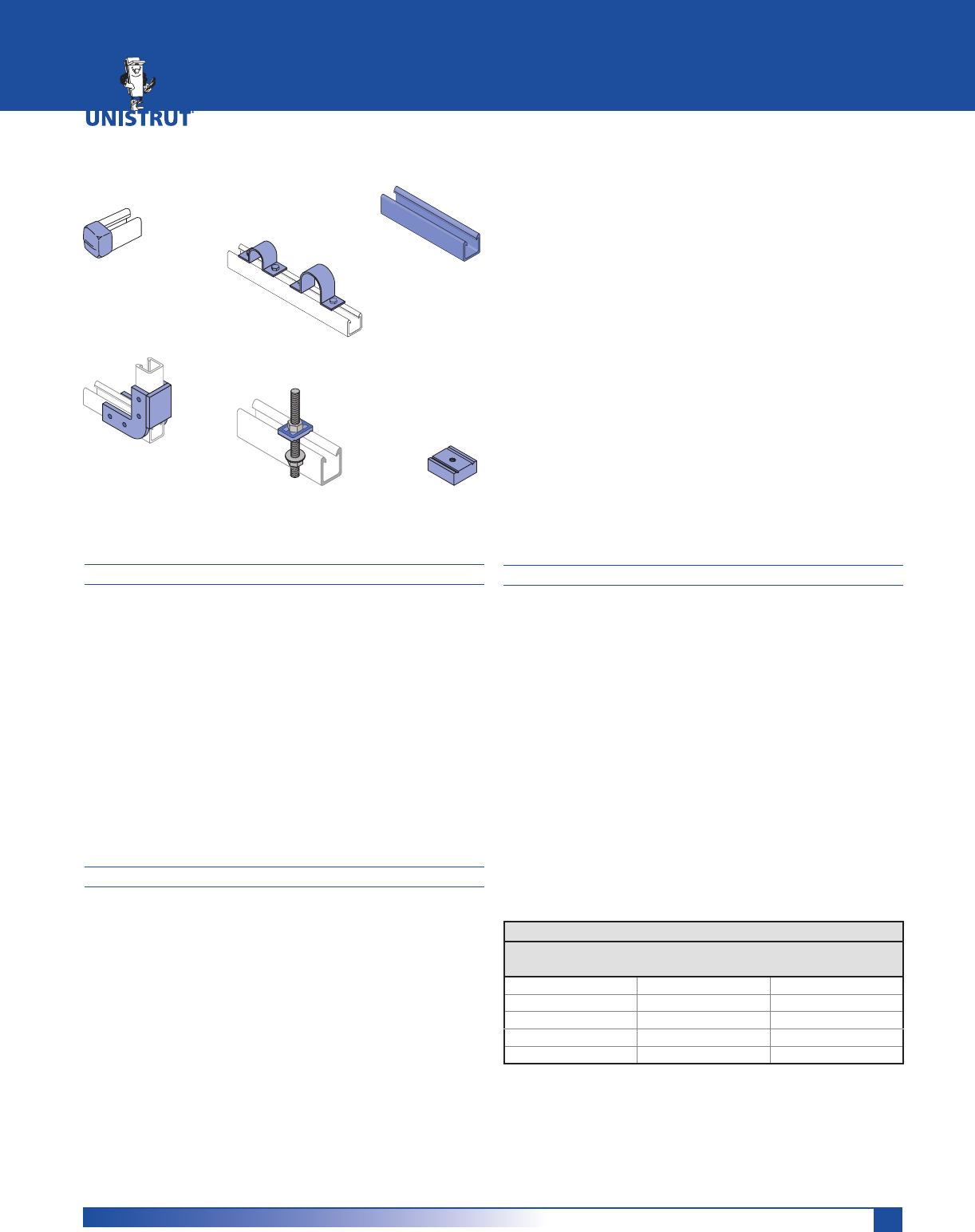
191
POLYESTER AND VINYL ESTER MATERIALS
Polyester and vinyl ester channels are manufactured from
the pultrusion process and are color coded gray and beige
respectively. Components are made by reinforcing a poly-
mer resin (polyester or vinyl ester) with multiple strands of
glass filament, alternating layers of glass mat and U.V. re-
sistant surfacing veils. The glass is drawn through the liquid
resin, which coats and saturates the fibers. The combina-
tion of resin, glass and veil is then continuously guided and
pulled (pultruded) through a heated die that determines
the shape of the component.
In the die, the resin is cured to form a reinforced part
which can be cut to length. The hardened fiberglass
pultrusion is reinforced with an internal arrangement of
permanently bonded continuous glass fibers to increase its
strength.
INSTALLATION
Fabrication requires just three simple operations: cutting,
drilling and sealing as described below.
Cutting – Hand held saws, such as hack saws (24 to 32
teeth per inch) are suitable when a few cuts are required.
For frequent cutting, a circular power saw with a carbide-
tipped masonry blade yields the best results. When using a
power saw, dust filter masks, gloves and long sleeve cloth-
ing should be worn.
Drilling – Any standard twist bit, even when used with bat-
tery-powered drills will work well. Carbide-tipped drill bits
are recommended.
Sealing – To protect against future migration of corrosive
elements into the cut sections, all cuts and holes should be
properly sealed with clear urethane sealer.
OPERATING ENVIRONMENT
Temperature Ranges – Fiberglass parts are supplied in five
different materials covering distinct temperature ranges.
The temperature ranges indicated are meant to be used
only as a general guideline. Continual exposure to elevated
temperatures reduces the strength properties of plastics
and glass-reinforced fiberglass. Actual resin test data
confirms that a 50% reduction in strength occurs at the
extreme high temperature levels.
Chemical Resistance – See the chart on page 204-205
for corrosion resistance. The results are based upon
immersion for a 24 hour period. This is typically the “worst
case” exposure to corrosion. Less severe contact such
as spills, splashes and vapor condensate will exceed the
performance results listed in the table.
Loading – Channel loading is defined with description of
each type of channel. Additional loading and design
limitations for fittings and accessories are described in the
appropriate section for that part.
Material Temperature Ratings
Material
Code
Low
Temp.
High
Temp.
E - (Rigid PVC) -25°F (-31°C) 130°F (54°C)
P - (Poly/Glass) -35°F (-37°C) 200°F (93°C)
V - (Vinyl/Glass) -35°F (-37°C) 200°F (93°C)
PU - (Poly) -40°F (-40°C) 140°F (60°C)
N - (Nylon) -20°F (-29°C) 150°F (66°C)
FIBERGLASS SYSTEMS
Heavy Duty Channel (Flange Profile) ....................................193
Light Duty Channel (Flange Profile) ......................................194
Heavy Duty Channel (SST Profile)..........................................195
Nuts & Hardware ...........................................................196 - 198
Fittings ............................................................................199 - 200
Pipe Clamps ............................................................................. 201
Clevis Hangers and Channel Inserts ......................................202
Beam Clamps ........................................................................... 203
Power Rack Stanchions ..........................................................203
Chemical Compatibility .................................................204 - 205
Specifications .......................................................................... 206
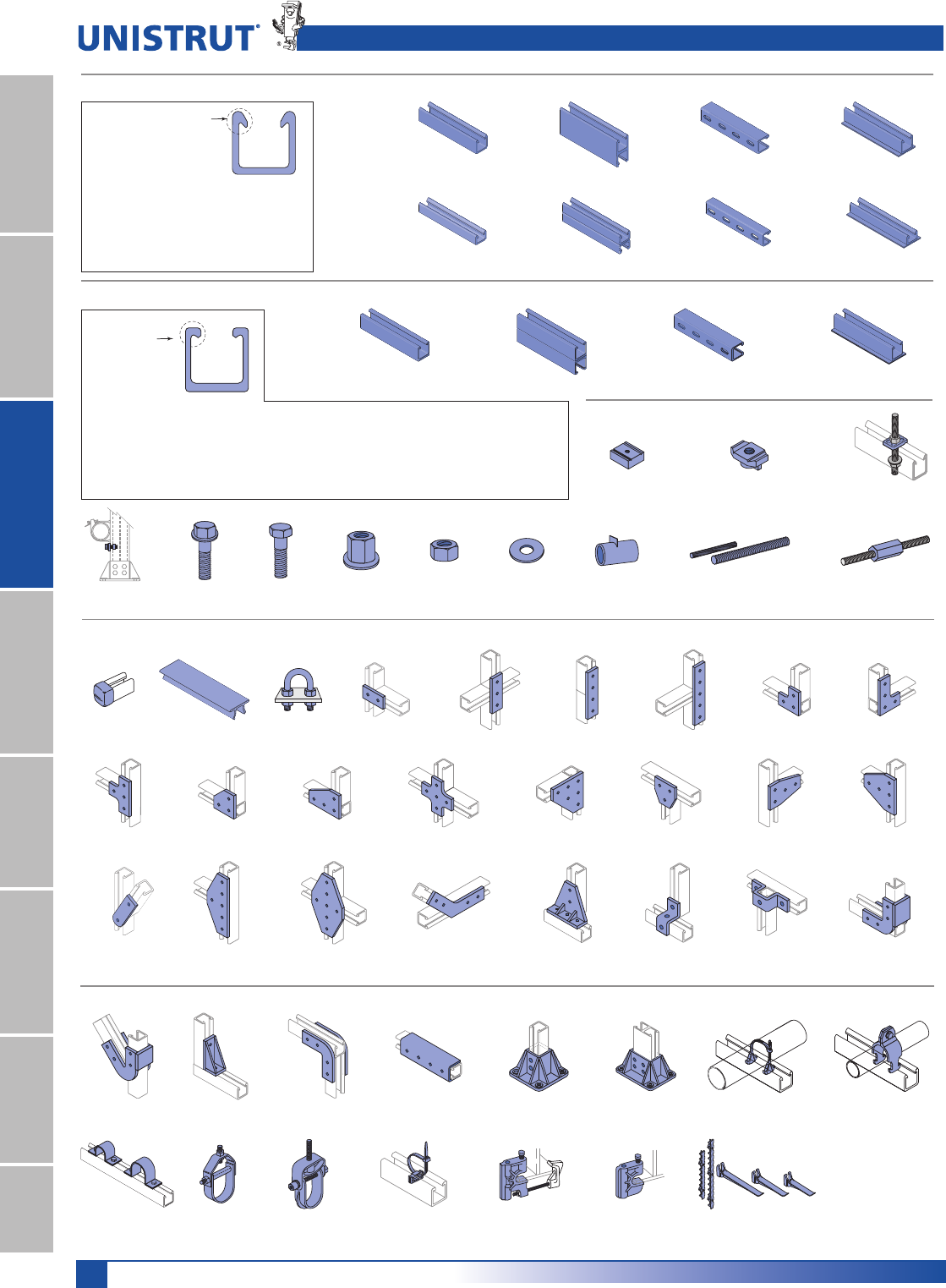
192
Fiberglass
11¼4" System
13¼16" SystemFiberglass SystemSpecial MetalsPrimeAngleMetal GratingRoofwalkIndex
Fiberglass Pictorial Index
Stop Lock-
Pg 196
Hex Flange
Bolt-Pg 196
Hex Bolt-
Pg 197
Hex Flange
Nut-Pg 197
Hex Nut -
Pg 197
Flat Washer-
Pg 197
Spacer -
Pg 197
Threaded Rod-
Pg 198 Rod Coupler-Pg 198
Channel - Aickinstrut Flange Profile
Channel - SST Profile
20P/V-2000-Pg 193 20P/V-2100-Pg 193 20P/V-2200-Pg 193 20P/V-2300-Pg 193
20P/V-1000-Pg 194 20P/V-1100-Pg 194 20P/V-1200-Pg 194 20P/V-1300-Pg 194
Heavy Duty
Aickinstrut
Flange Profile
15⁄8" x 15⁄8"
Light Duty
Aickinstrut
Flange Profile
11⁄2" x 11⁄8"
Aickinstrut
Flange
Unistrut fiberglass channels,
except the SST series,
incorporate the Aickinstrut flange design which
provides reliable fastening and interlocking of
components and accessories.
It is important to note that standard metal framing
components such as pipe clamps and strut nuts
will not work with the flange design.
End Cap-Pg 198 Capping Strip-Pg 198 U-Bolt-Pg 198 20P/V-2500-Pg 199 20P/V-2502-Pg 199 20P/V-2504-Pg 199 20P/V-2506-Pg 199 20P/V-2508-Pg 199 20P/V-2510-Pg 199
Fittings
20P/V-2512-Pg 199 20P/V-2514-Pg 199 20P/V-2516-Pg 199 20P/V-2518-Pg 199 20P/V-2520-Pg 199 20P/V-2522-Pg 199 20P/V-2524-Pg 199 20P/V-2526-Pg 200
20P/V-2528-Pg 200 20P/V-2530-Pg 200 20P/V-2534-Pg 200 20P/V-2540-Pg 200 20PU-2538-Pg 200 20PU-2611-Pg 200 20PU-2613-Pg 200 50PU-1508
50PU-2008-Pg 200
50PU-2045-Pg 200 50PU-2636-Pg 200 50PU-2090-Pg 200 50PU-2616-Pg 200 20PU-5853
20PU-5855-Pg 200
20PU-5903
20PU-5095-Pg 200
Adj. Pipe Clamp-Pg 201 Rigid Pipe Clamp-Pg 201
Pipe Strap-Pg 201 Fabricated Clevis
Hanger-Pg 202
Molded Clevis
Hanger-Pg 202
Channel Insert-Pg 202 Molded Beam
Clamp Assembly-Pg 203
Molded
Beam Clamp-Pg 203
Rack Stanchion-Pg 203
Pipe Clamps, Beam Clamps and Stanchions
20P/V-2000 SST-Pg 195 20P/V-2100 SST-Pg 195 20P/V-2200 SST-Pg 195 20P/V-2300 SST-Pg 195
Heavy Duty-Pg 196 Standard Duty-Pg 196 Saddle Clip-Pg 196
Hardware & Accessories
Heavy Duty
SST Profile
15⁄8" x 15⁄8"
SST
Flange
The Unistrut SST
profile is similar
to the profile of
standard metal channel. The Unistrut SST profile will accommodate standard 15⁄8" metal channel fittings
and components. This profile is available in polyester or vinyl ester resin. The Unistrut SST profile is not
compatible with the fiberglass pipe clamps and channel nuts shown in this section. Typically, stainless
steel clamps and strut nuts (listed elsewhere in this catalog) are used with this profile.
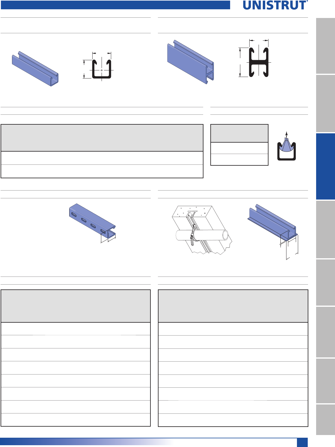
193
Fiberglass
11¼4" System
13¼16" SystemFiberglass SystemSpecial MetalsPrimeAngle
Metal GratingRoofwalkIndex
F20P-2000, F20V-2000
HEAVY DUTY SINGLE CHANNEL - AICKINSTRUT FLANGE PROFILE
Part
Number
Weight
lbs./ft.
(kg/m)
Area
in2
(mm2
----------------- X - X Axis ----------------- --------- Y - Y Axis ---------
I
in4
(mm4
R
In (mm)
C1
In (mm)
C2
In (mm)
I
in4
(mm4
R
In (mm)
C
In (mm)
F20P-2000,
F20V-2000
0.82 1.06 0.31 0.54 0.7 0.93 0.42 0.63 0.82
1.2 6.8 12.9 13.7 17.8 23.622 17.5 16.0 20.8
F20P-2100,
F20V-2100
1.64 2.12 1.77 0.91 1.63 1.63 0.85 0.63 0.82
2.4 13.7 73.7 23.1 41.4 41.402 35.4 16.0 20.8
F20P-2100, F20V-2100
HEAVY DUTY BACK-TO-BACK CHANNEL - AICKINSTRUT FLANGE PROFILE
15⁄8"
1⁄4"
15⁄8"
23⁄8"
(6.4)
(60.3)
(41.3)
(41.3)
F20P-2300, F20V-2300 W/CONCRETE INSERTF20P-2200, F20V-2200 SLOTTED CHANNEL
15⁄8"
15⁄8"X
Y
(41.3)
(41.3)
11⁄2"
21⁄4"X
Y
SECTION PROPERTIES
Heavy Duty Channel - Aickinstrut flange Profile
15⁄8"
Slots are 1" (25.4) x 7⁄16" (11.1)
2" (50.8) on Center
15⁄8"
(41.3)
(41.3)
Wt/100 Ft: 82 Lbs(122 kg/100 m) Wt/100 Ft: 164 Lbs (244 kg/100 m)
Wt/100 Ft: 82 Lbs (122 kg/100 m) Wt/100 Ft: 88 Lbs (131 kg/100 m)
Span
In (mm)
Max. Uniform
Beam Load
6DIHW\)DFWRU
Uniform Load at
Deflection of 1/360 Span Maximum
Column Load
Lbs (kN)
Load
Lbs (kN)
Deflection
In (mm)
Load
Lbs (kN)
Deflection
In (mm)
12 3,561 0.102 1,159 0.033 5,160
304.8 15.8 2.6 5.2 0.8 23.0
18 2,374 0.23 515 0.05 4,704
457.2 10.6 5.8 2.3 1.3 20.9
24 1,781 0.41 290 0.067 4,168
609.6 7.9 10.4 1.3 1.7 18.5
30 1,424 0.64 185 0.083 3,553
762.0 6.3 16.3 0.8 2.1 15.8
36 1,187 0.922 129 0.1 2,859
914.4 5.3 23.4 0.6 2.5 12.7
48 890 1.638 72 0.133 1,636
1,219.2 4.0 41.6 0.3 3.4 7.3
60 712 2.56 46 0.167 1,047
1,524.0 3.2 65 0.2 4.2 4.7
72 594 3.686 32 0.2 727
1,828.8 2.6 93.6 0.1 5.1 3.2
F20P-2000, F20V-2000 CHANNEL BEAM/COLUMN LOADING
Span
In (mm)
Max. Uniform
Beam Load
6DIHW\)DFWRU
Uniform Load at
Deflection of 1/360 Span Maximum
Column
Load
Lbs (kN)
Load
Lbs (kN)
Deflection
In (mm)
Load
Lbs (kN)
Deflection
In (mm)
12 5,559 0.028 5,559 0.033 9,454
304.8 24.7 0.7 24.7 0.8 42.1
18 3,706 0.064 2,914 0.05 8,866
457.2 16.5 1.6 13.0 1.3 39.4
24 2,780 0.113 1,639 0.067 8,181
609.6 12.4 2.9 7.3 1.7 36.4
30 2,224 0.177 1,049 0.083 7,405
762.0 9.9 4.5 4.7 2.1 32.9
36 1,853 0.254 730 0.1 6,451
914.4 8.2 6.5 3.2 2.5 28.7
48 1,390 0.452 410 0.133 4,534
1,219.2 6.2 11.5 1.8 3.4 20.2
60 1,112 0.707 262 0.167 2,902
1,524.0 4.9 18.0 1.2 4.2 12.9
72 927 1.018 182 0.2 2,015
1,828.8 4.1 25.9 0.8 5.1 9.0
F20P-2100, F20V-21000 CHANNEL BEAM/COLUMN LOADING
FLANGE LOAD
FLANGE LOADING
Part
Number
Pull-Out
Strength*
Lbs (kN)
F20V-2000/2100 449
2.0
F20P-2000/2100 360
1.6
*Values shown represent a 3:1 safety factor
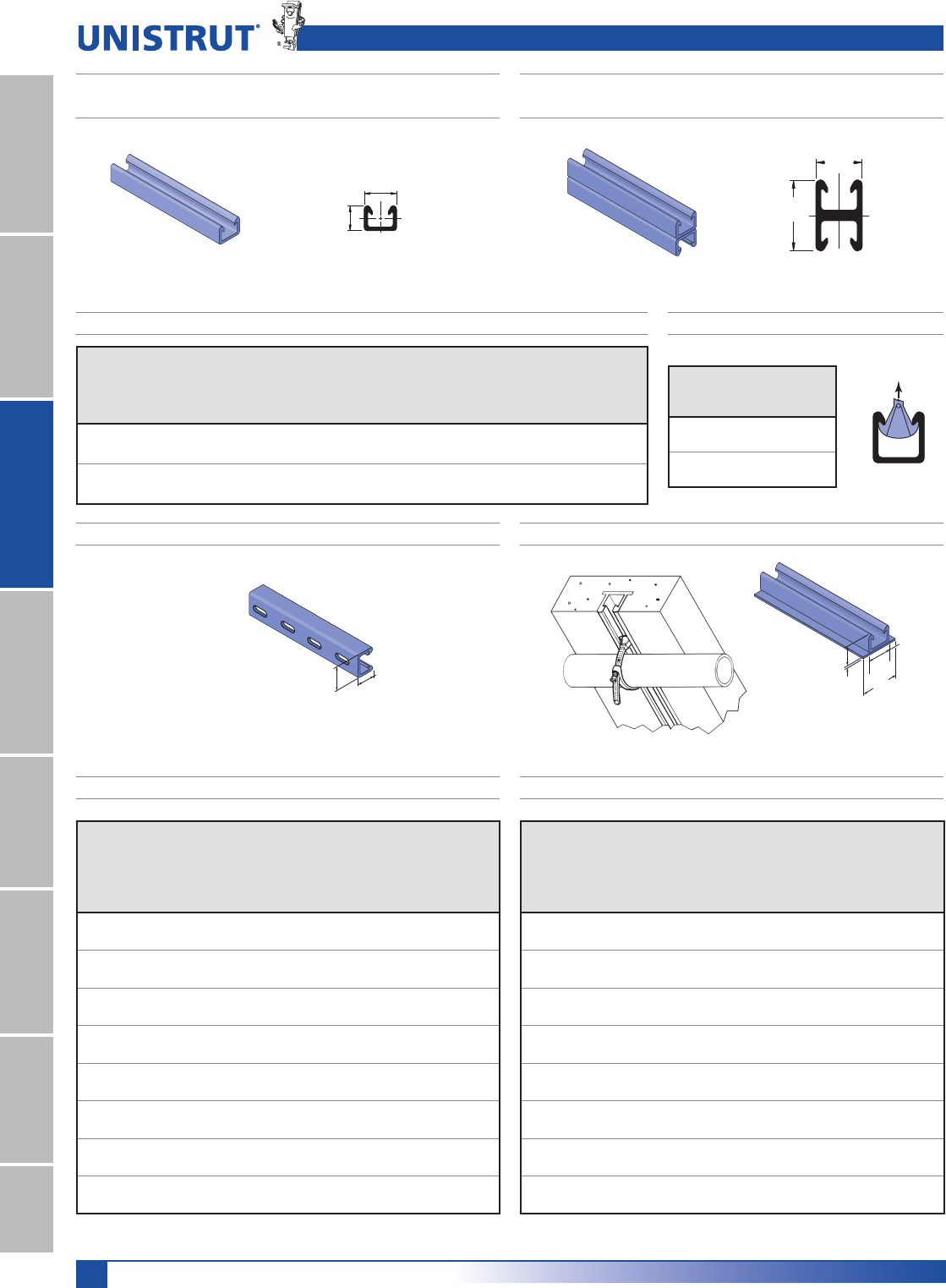
194
Fiberglass
11¼4" System
13¼16" SystemFiberglass SystemSpecial MetalsPrimeAngleMetal GratingRoofwalkIndex
Part
Number
Weight
lbs./ft.
(kg/m)
Area
in2
(mm2
X - X Axis Y - Y Axis
I
in4
(mm4
R
In (mm)
C1
In (mm)
C2
In (mm)
I
in4
(mm4
R
In (mm)
C
In (mm)
F20P-1000,
F20V-1000
0.47 0.61 0.1 0.4 0.51 0.62 0.22 0.6 0.75
0.7 3.9 4.2 10 13 16 9.2 15 19
F20P-1100,
F20V-1100
0.94 1.22 0.42 0.59 1.13 1.13 0.44 0.6 0.75
1.4 7.9 17.5 15 29 28 18.3 15 19.1
F20P-1000, F20V-1000
LIGHT DUTY SINGLE CHANNEL - AICKINSTRUT FLANGE PROFILE
11⁄2"
21⁄4"
X
Y
(38.1)
(57.2)
11⁄2"
11⁄8"X
Y
(38.1)
(28.6)
11⁄8"
1⁄4"
11⁄2"
23⁄8"
(28.6)
(6.4)
(38.1)
(60.3)
F20P-1100, F20V-1100
LIGHT DUTY BACK-TO-BACK CHANNEL - AICKINSTRUT FLANGE PROFILE
F20P-1300, F20V-1300 W/CONCRETE INSERTF20P-1200, F20V-1200 SLOTTED CHANNEL
SECTION PROPERTIES
Light Duty Channel - Aickinstrut flange Profile
11⁄2"11⁄8"
(38.1)
(28.6)
Slots are 1" (25.4) x 7⁄16" (11.1)
2" (50.8) on Center
Wt/100 Ft: 47 Lbs (70 kg/100 m)
Wt/100 Ft: 47 Lbs (70 kg/100 m) Wt/100 Ft: 94 Lbs (140 kg/100 m)
Wt/100 Ft: 53 Lbs (79 kg/100 m)
F20P-1000, F20V-1000 CHANNEL BEAM/COLUMN LOADING
FLANGE LOAD
F20P-1100, F20V-1100 CHANNEL BEAM/COLUMN LOADING
FLANGE LOADING
Span
In (mm)
Max. Uniform Beam
Load
6DIHW\)DFWRU
Uniform Load at
Deflection of 1/360
Span Maximum
Column Load
Lbs (kN)
Load
Lbs (kN)
Deflection
In (mm)
Load
Lbs (kN)
Deflection
In (mm)
12 3,804 0.082 1,556 0.033 5,961
304.8 16.9 2.1 6.9 0.8 26.5
18 2,536 0.183 691 0.05 5,509
457.2 11.3 4.6 3.1 1.3 24.5
24 1,902 0.326 389 0.067 4,979
609.6 8.5 8.3 1.7 1.7 22.1
30 1,522 0.509 249 0.083 4,375
762.0 6.8 12.9 1.1 2.1 19.5
36 1,268 0.734 173 0.1 3,698
914.4 5.6 18.6 0.8 2.5 16.4
48 951 1.304 97 0.133 2,254
1,219.2 4.2 33.1 0.4 3.4 10.0
60 761 2.038 62 0.167 1,442
1,524.0 3.4 51.8 0.3 4.2 6.4
72 634 2.935 43 0.2 1,001
1,828.8 2.8 74.5 0.2 5.1 4.5
Span
In (mm)
Max. Uniform
Beam Load
6DIHW\)DFWRU
Uniform Load at
Deflection of 1/360
Span Maximum
Column Load
Lbs (kN)
Load
Lbs (kN)
Deflection
In (mm)
Load
Lbs (kN)
Deflection
In (mm)
12 1,629 0.151 359 0.033 2,759
304.8 7.2 3.8 1.6 0.8 12.3
18 1,086 0.340 160 0.050 2,351
457.2 4.8 8.6 0.7 1.3 10.5
24 815 0.605 90 0.067 1,862
609.6 3.6 15.4 0.4 1.7 8.3
30 652 0.945 57 0.083 1,298
762.0 2.9 24.0 0.3 2.1 5.8
36 543 1.360 40 0.100 901
914.4 2.4 34.5 0.2 2.5 4.0
48 407 2.418 22 0.133 507
1,219.2 1.8 61.4 0.1 3.4 2.3
60 326 3.779 14 0.167 324
1,524.0 1.5 96.0 0.1 4.2 1.4
72 272 5.441 10 0.200 225
1,828.8 1.2 138.2 0.0 5.1 1.0
Part Number
Pull-Out
Strength*
Lbs (kN)
F20V-1000/1100 213
1.0
F20P-1000/1100 213
1.0
*Values shown represent a 3:1 safety factor
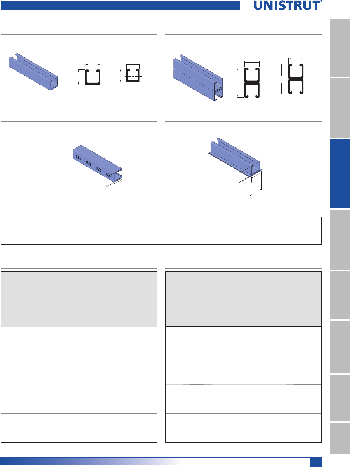
195
Fiberglass
11¼4" System
13¼16" SystemFiberglass SystemSpecial MetalsPrimeAngle
Metal GratingRoofwalkIndex
F20P-2000 SST, F20V-2000 SST
HEAVY DUTY SINGLE CHANNEL - SST PROFILE
F20P-2100 SST, F20V-2100 SST
HEAVY DUTY BACK-TO-BACK CHANNEL - SST PROFILE
F20P-2300 SST, F20V-2300 SST W/CONCRETE INSERTF20P-2200 SST, F20V-2200 SST SLOTTED CHANNEL
(6.4)
(41.3)
(41.3)
(60.3)
15⁄8"
1⁄4"
15⁄8"
23⁄8"
1 5⁄8"
1 5⁄8"X
Y
41.3
41.3 X
Y
1 5⁄8"
3 1⁄4"X
Y
41.3
82.6 X
Y
NOTE: Unistrut SST Channel is not compatible with the Unistrut fiberglass pipe clamps and channel nuts shown in
this catalog. Metal clamps and channel nuts are compatible with this profile and are shown elsewhere in this catalog.
Heavy Duty Channel - Standard Profile
15⁄8"15⁄8"
(41.3
)
(41.3)
Slots are 1" (25.4) x 7⁄16" (11.1)
2" (50.8) on Center
Wt/100 Ft: 82 Lbs (122 kg/100 m) Wt/100 Ft: 164 Lbs (244 kg/100 m)
Wt/100 Ft: 82 Lbs (122 kg/100 m) Wt/100 Ft: 88 Lbs (131 kg/100 m)
F20P-2000 SST, F20V-2000 SST
CHANNEL BEAM/COLUMN LOADING
Span
In
(mm)
Maximum
Uniform
Beam Load
(Safety Fac-
WRU
Deflection
@ Max. Al-
lowable
Beam Load
Deflection
@ Max.
Deflection
= 0.25 In
/EV
Uniform
Load
@ Max.
Deflection
= 0.50 In
/EV Max.
Column
Load
Lbs (kN)
Poly
Lbs
(kN)
Vinyl
Lbs
(kN)
Poly
In
(mm)
Vinyl
In
(mm)
Poly
Lbs
(kN)
Vinyl
Lbs
(kN)
Poly
Lbs
(kN)
Vinyl
Lbs
(kN)
12 5,080 6,350 0.04 0.04 ————7,300
304.8 22.6 28.2 1.0 1.0 32.5
18 3,390 4,240 0.09 0.1 ————6,740
457.2 15.1 18.9 2.3 2.5 30.0
24 2,540 3,180 0.16 0.17 ————5,920
609.6 11.3 14.1 4.1 4.3 26.3
30 2,040 2,550 0.24 0.27 —2,350 ——4,900
762.0 9.1 11.3 6.1 6.9 10.5 21.8
36 1,700 2,130 0.35 0.39 1,220 1,370 ——3,600
914.4 7.6 9.5 8.9 9.9 5.4 6.1 16.0
48 1,270 1,590 0.62 0.69 520 590 1,040 1,170 2,020
1,219.2 5.6 7.1 15.7 17.5 2.3 2.6 4.6 5.2 9.0
60 1,020 1,280 0.97 1.09 270 310 540 610 520
1,524.0 4.5 5.7 24.6 27.7 1.2 1.4 2.4 2.7 2.3
72 850 1,070 1.4 1.57 160 180 320 360 NR
1,828.8 3.8 4.8 35.6 39.9 0.7 0.8 1.4 1.6 NR
Span
In
(mm)
Maximum
Uniform
Beam Load
(Safety Fac-
WRU
Deflection
@ Max.
Allowable
Beam Load
Deflection
@ Max.
Deflection
= 0.25 In
/EV
Uniform
Load
@ Max.
Deflection
= 0.50 In
/EV Max.
Column
Load
Lbs (kN)
Poly
Lbs
(kN)
Vinyl
Lbs
(kN)
Poly
In
(mm)
Vinyl
In
(mm)
Poly
Lbs
(kN)
Vinyl
Lbs
(kN)
Poly
Lbs
(kN)
Vinyl
Lbs
(kN)
12 1,720 2,150 0.07 0.07 ————3,650
304.8 7.6 9.6 1.8 1.8 16.2
18 1,150 1,440 0.15 0.17 ————3,370
457.2 5.1 6.4 3.8 4.3 15.0
24 860 1,080 0.27 0.3 810 910 ——2,960
609.6 3.8 4.8 6.9 7.6 3.6 4.0 13.2
30 690 870 0.42 0.48 410 460 —— 2,450
762.0 3.1 3.9 10.7 12.2 1.8 2.0 10.9
36 580 730 0.61 0.69 240 270 480 540 1,800
914.4 2.6 3.2 15.5 17.5 1.1 1.2 2.1 2.4 8.0
48 430 540 1.07 1.2 100 115 200 230 1,010
1,219.2 1.9 2.4 27.2 30.5 0.4 0.5 0.9 1.0 4.5
60 350 440 1.7 1.91 60 70 120 135 260
1,524.0 1.6 2.0 43.2 48.5 0.3 0.3 0.5 0.6 1.2
72 290 370 2.44 2.78 30 34 60 70 NR
1,828.8 1.3 1.6 62.0 70.6 0.1 0.2 0.3 0.3 NR
F20P-2100 SST, F20V-2100 SST
CHANNEL BEAM/COLUMN LOADING
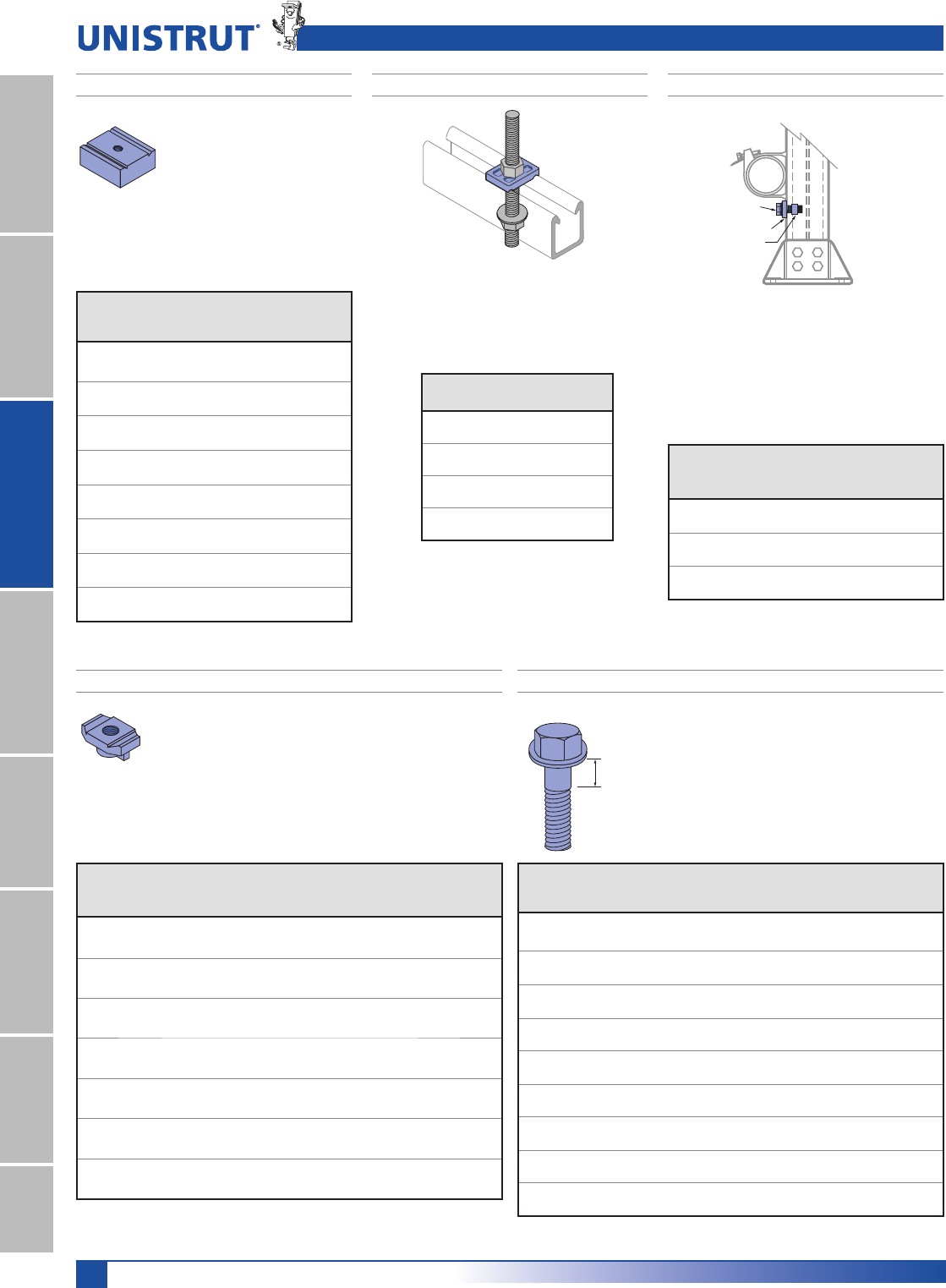
196
Fiberglass
11¼4" System
13¼16" SystemFiberglass SystemSpecial MetalsPrimeAngleMetal GratingRoofwalkIndex
STANDARD DUTY CHANNEL NUTS
HEAVY DUTY CHANNEL NUTS STOP-LOCK ASSEMBLIESSADDLE CLIPS
6DGGOHFOLSVPDWHZLWKWKHH[WHULRURIWKHFKDQQHO
flanges and are secured with threaded rods and nuts.
0DWHULDOJODVVUHLQIRUFHGSRO\XUHWKDQH 6WRS/RFN$VVHPEOLHVUHGXFHWKHFKDQFHRISLSH
slippage when running supports vertically and are
recommended for applications that are subject to
vibration, have regular contact with fluids or are
vertically mounted. The Stop-Locks fit both sizes of
channel.
0DWHULDOJODVVUHLQIRUFHGSRO\XUHWKDQH
+HDY\GXW\FKDQQHOQXWVDUH
designed to be used where high
thread shear values or spring nuts
are required. They can not be
used with light duty 1000 series
channel or SST profile channel.
0DWHULDOJODVVUHLQIRUFHGSRO\XUH-
thane.
6WDQGDUG'XW\FKDQQHOQXWVDUHGHVLJQHGIRUOLJKWGXW\
applications that do not require high thread shear values.
They can be used with both light duty series 1000 and
heavy duty series 2000 fiberglass channel.
1RWIRUXVHZLWK667SURILOHFKDQQHO
0DWHULDOJODVVUHLQIRUFHGSRO\XUHWKDQH
Hex Head
Flange Bolt
Saddle Clip
Channel Nut
*Thread shear values shown represent a 3:1
safety factor.
Part
Number Size
Thread
Shear
Lbs (kN)*
Torque
Ft/Lbs
1P
Wt/100
pcs
Lbs (kg)
F375PU-CNHD 3»8"-16 1,400 8 5.7
6.23 11 2.6
F500PU-CNHD 1»2"-13 1,400 8 5.3
6.23 11 2.4
F625PU-CNHD 5»8"-11 1,400 10 5.1
6.23 14 2.3
F750PU-CNHD 3»4"-10 1,400 10 4.4
6.23 14 2.0
F10PU-CNMHD 10 mm 1,400 8 5.8
6.23 11 2.6
F12PU-CNMHD 12 mm 1,400 8 5.5
6.23 11 2.5
F16PU-CNMHD 16 mm 1,400 10 5.3
6.23 14 2.4
F20PU-CNMHD 20 mm 1,400 10 4.4
6.23 14 2.0
Part
Number
Size
,Q
Wt/100 pcs
Lbs (kg)
F200-4226 3»83.5
1.6
F200-4217 1»22.5
1.1
F200-4341 5»83.0
1.4
F200-4342 3»42.5
1.1
*Thread shear values shown represent a 3:1 safety factor.
Part
Number
Size
LQ
Force
Resistance
Lbs (kN)*
Torque
Ft/Lbs
1P
Wt/100
pcs
Lbs (kg)
F200-4227 3»8"200 7 6.3
0.9 9 2.9
F200-4219 1»2"220 12 6.4
1.0 16 2.9
F200-4343 5»8"** 250 15 11.0
1.1 20 5.0
Fiberglass Channel Nuts & Accessories
Part
Number Size
Thread Shear
Lbs (kN)*
Torque
Ft/Lbs 1P
Wt/100
pcs
Lbs (kg)
F250PU-CN 1»4"-20 460 2 1.8
2.05 3 0.8
F312PU-CN 5»16"-18 460 2 1.7
2.05 3 0.8
F375PU-CN 3»8"-16 460 3 1.8
2.05 4 0.8
F500PU-CN 1»2"-13 460 3 1.4
2.05 4 0.6
F10PU-CN 10 mm 460 3 1.7
2.05 4 0.8
F12PU-CN 12 mm 460 3 1.4
2.05 4 0.6
F10PU-CNS #10 Screw 460 N/A 1.9
2.05 0.9
HEX FLANGE BOLTS
Shoulder
Length
)LEHUIDVWEROWVDUHLGHDOIRUPHFKDQLFDOFRQQHFWLRQV
that require a high degree of corrosion resistance.
The 3»8" diameter fasteners are recommended for all
channel fitting mechanical connections.
0DWHULDOJODVVUHLQIRUFHGSRO\XUHWKDQH
*Thread shear values shown represent a 3:1 safety factor.
Part
Number
Size
LQ
Thread
Shear
Lbs (kN)*
Shank
Shear
Lbs (kN)*
Shoulder
Length
In (mm)
Torque
Ft/Lbs
1P
Wt/100
pcs
Lbs (kg)
F250PU-075 1»4 x 3»4110 210 Full Thread 0.8 .4
0.49 0.93 1 0.2
F250PU-100 1»4 x 1 110 210 Full Thread 0.8 .5
0.49 0.93 1 .02
F250PU-150 1»4 x 11»2110 210 1»20.8 .6
0.49 0.93 12.7 1 0.3
F500PU-125 1»2 x 11»4450 870 Full Thread 8 1.0
2.00 3.87 11 0.5
F500PU-150 1»2 x 11»2450 870 Full Thread 8 1.1
2.00 3.87 11 .05
F500PU-200 1»2 x 2 450 870 3»481.3
2.00 3.87 19.1 11 0.6
F500PU-250 1»2 x 21»2 450 870 Full Thread 81.6
2.00 3.87 11 0.7
F500PU-300 1»2 x 3 450 870 1 8 1.8
2.00 3.87 25.4 11 0.8
F500PU-350 1»2 x 31»2 450 870 23»16 82.0
2.00 3.87 55.6 11 0.9
* Force resistance values shown represents a 3:1
safety factor.
** Supplied with a heavy duty channel nut for use only
with the heavy duty series 2000 channel.
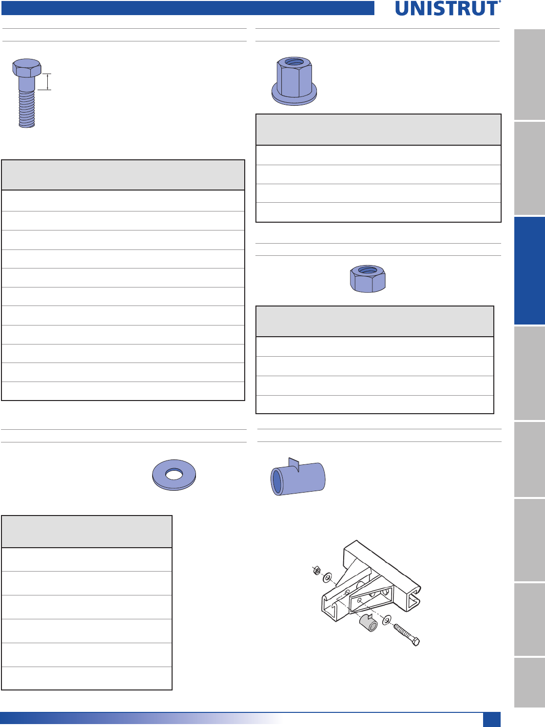
197
Fiberglass
11¼4" System
13¼16" SystemFiberglass SystemSpecial MetalsPrimeAngle
Metal GratingRoofwalkIndex
HEX BOLTS
HEX NUTS
HEX FLANGE NUTS
Shoulder
Length
)LEHUIDVWEROWVDUHLGHDOIRUPHFKDQLFDOFRQQHFWLRQV
that require a high degree of corrosion resistance.
The 3»8" diameter fasteners are recommended for all
channel fitting mechanical connections.
0DWHULDOJODVVUHLQIRUFHGSRO\XUHWKDQH
*Thread shear values shown represent a 3:1 safety factor.
Part
Number
Size
LQ
Thread
Shear
Lbs (kN)*
Shank
Shear
Lbs (kN)*
Shoulder
Length
In (mm)
Torque
Ft/Lbs
1P
Wt/100
pcs
Lbs (kg)
F375PU-125 3»8 x 11»4250 470 Full Thread 31.0
1.11 2.09 4 0.5
F375PU-150 3»8 x 11»2250 470 1»431.1
1.11 2.09 6.4 4 0.5
F375PU-200 3»8 x 2 250 470 1»231.3
1.11 2.09 12.7 4 0.6
F375PU-250 3»8 x 21»2250 470 3»431.6
1.11 2.09 19.1 4 0.7
F375PU-300 3»8 x 3 250 470 1 3 1.8
1.11 2.09 25.4 4 0.8
F625PU-125 5»8 x 11»4700 1,360 1»412 2.5
3.11 6.05 6.4 16 1.1
F625PU-150 5»8 x 11»2700 1,360 1»412 2.8
3.11 6.05 6.4 16 1.3
F625PU-200 5»8 x 2 700 1,360 1»412 3.2
3.11 6.05 6.4 16 1.5
F625PU-250 5»8 x 21»2700 1,360 1»412 3.4
3.11 6.05 6.4 16 1.5
F625PU-300 5»8 x 3 700 1,360 1»412 3.9
3.11 6.05 6.4 16 1.8
F625PU-350 5»8 x 31»2700 1,360 11»412 5.5
3.11 6.05 6.4 16 2.5
*Thread shear values shown represent a 3:1 safety factor.
*Thread shear values shown represent a 3:1 safety factor.
Part
Number
Size
LQ
Thread
Shear
Lbs (kN)*
Height
In (mm)
Torque
Ft/Lbs
1P
Wt/100 pcs
Lbs (kg)
F250PU-000 1»4-20 150 0.218 0.8 0.1
0.67 5.5 1 0.05
F375PU-000 3»8-16 460 0.328 3 0.3
2.05 8.3 4 0.1
F500PU-000 1»2-13 800 0.437 8 0.5
3.56 11.1 11 0.2
F625PU-000 5»8-11 1,000 0.546 12 1.5
4.45 13.9 16 0.7
Part
Number
Size
LQ
Thread
Shear
Lbs (kN)*
Height
In (mm)
Torque
Ft/Lbs
1P
Wt/100 pcs
Lbs (kg)
F375PU-FN-000 3»8-16 500 0.750 3 0.8
2.22 19.1 4 0.4
F500PU-FN-000 1»2-13 1,200 0.855 8 1.6
5.34 21.7 11 0.7
F625PU-FN-000 5»8-11 2,200 1.220 12 3.5
9.79 31.0 16 1.6
F750PU-FN-000 3»4-10 2,900 1.590 15 5.5
12.90 40.4 20 2.5
Fiberglass Hardware
7KHKH[IODQJHQXWLVSUHIHUUHGIRUDSSOLFDWLRQVWKDW
require additional thread engagement (such as with
all-thread rod) or maximum thread shear strength.
0DWHULDOJODVVUHLQIRUFHGSRO\XUHWKDQH
FLAT WASHERS
Material: PVC
Note: PVC washers are recommended for
connections that utilize hex nuts and bolts.
Part
Number
Size
LQ
Outside
Diameter
In (mm)
Wt/100 pcs
Lbs (kg)
F250E-999 1»4
0.49 0.1
12 0.05
F375E-999 3»8
1.00 0.1
25 0.05
F500E-999 1»2
1.25 0.5
32 0.2
F625E-999 5»8
1.50 0.5
38 0.2
F750E-999 3»4
1.50 1.0
38 0.5
F1000E-999 12.25 1.5
57 0.7
F50PU-500SP CHANNEL SPACERS
&KDQQHOVSDFHUVDUHGHVLJQHGWRSUHYHQWZDOO
compression under heavy loading conditions. Such
loading occurs during the torquing of hardware for
channel fittings.
7KHVSDFHUVDUHGHVLJQHGWREHXVHGRQO\ZLWK5»8"
channels and will accommodate 3»8" and 1»2" bolts.
0DWHULDOPROGHGIURPSRO\XUHWKDQH
Wt/100 pcs: 2.0 Lbs (.91 kg)
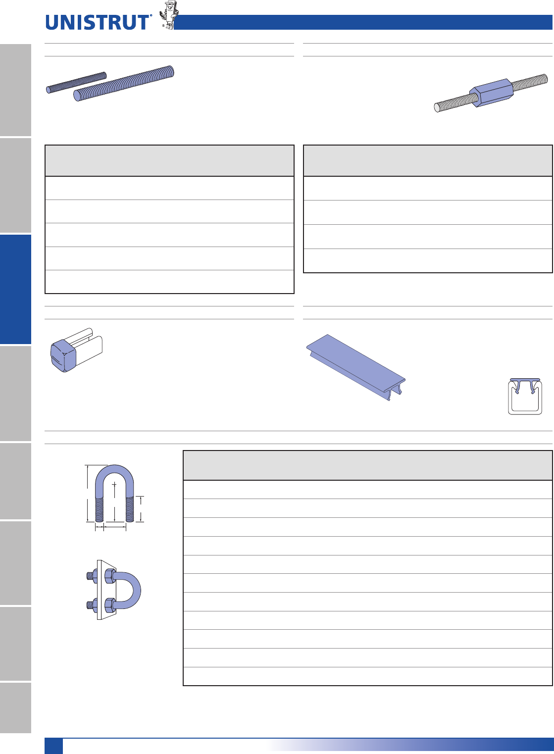
198
Fiberglass
11¼4" System
13¼16" SystemFiberglass SystemSpecial MetalsPrimeAngleMetal GratingRoofwalkIndex
A-KONNECTOR ROD COUPLERSTHREADED ROD
Material: pultruded vinyl ester resin
and is gray in color.
A-Konnectors provide an excellent means
for extending FRP all-thread rods beyond
their standard lengths. A-Konnectors
are manufactured from glass-reinforced
polyurethane and are colored gray.
A-Konnectors are packaged in bags
containing 25 pieces.
* Thread shear values shown represent
a 3:1 safety factor.
** Standard lengths are 4' and 8'. The
part number shown is for 4' lengths.
To order eight foot lengths, add suffix
“-96” to part number
(Example: F200-3827-96)
Part
Number
Size
LQ
Weight
Lbs (kg)
Thread
Shear
Lbs (kN)*
Torque
Ft/Lbs1P
Wt/100 pcs
4' in Len.
Lbs (kg)
F200-3827 3»8-16 0.07 415 5 35
0.03 1.85 7 15.9
F200-3828 1»2-13 0.12 570 10 57
0.05 2.54 14 25.9
F200-3829 5»8-11 0.18 1,260 40 91
0.08 5.60 54 41.3
F200-3830 3»4-10 0.28 1,700 50 133
0.13 7.56 68 60.3
F200-3831 1-8 0.50 3,000 60 200
0.23 13.34 81 90.7
* Thread shear values shown represent a 3:1 safety factor.
Part
Number
Size
LQ
Length
,QPP
Thread
Shear
/EVN1
Wt/100 pcs
/EVNJ
F200-3840 3»8-16 21»4800 6.5
57.2 3.56 2.9
F200-3841 1»2-13 21»4870 6.0
57.2 3.87 2.7
F200-3842 5»8-11 21»41,500 13.0
57.2 6.67 5.9
F200-3843 3»4-10 21»41,500 11.0
57.2 6.67 5.0
Fiberglass Hardware
0DWHULDOUHG39&DQGGHVLJQHGIRU5»8" channel.
(QGFDSVDUHGHVLUHGZKHQWKHHQGVRIWKHFKDQQHOQHHGWR
be enclosed. The cap easily installs by pressing it onto the
end of the channel opening.
FAIC-EC – CHANNEL END CAP
Wt/100 pcs: 3.4 Lbs (1.5 kg)
Supplied in 10
foot lengths.
0DWHULDO39&
,QVWDOOVVLPSO\E\SUHVVLQJLWRQWRWKHFKDQQHO
opening. It is designed to be used when a cover
is desired for the channel opening (such as
concrete embedment channel).
NONMETALLIC U-BOLTS
8QLVWUXW1RQPHWDOOLF8%ROWVSURYLGHDFRUURVLRQUHVLVWDQWDOWHUQDWLYHWRWUDGLWLRQDOPHWDOOLF8%ROWV
They have oversized diameters which allow them to hold steel conduit and plastic pipe. These bolts will outlast stainless steel in most corrosive applications.
(DFK8%ROWFRPHVZLWKWZRSRO\XUHWKDQHKH[QXWV$GGLWLRQDOQXWVDQGZDVKHUVFDQEHSXUFKDVHGVHSDUDWHO\
0DWHULDOJODVVUHLQIRUFHGSRO\XUHWKDQH
C
BA
TL
D
F20E-5000 – CHANNEL CAPPING STRIP
Part
Number
Size
In
“A” Dim.
In (mm)
“B” Dim.
In (mm)
“C” Dim.
In (mm)
“D” Dim.
In (mm)
“TL” Dim.
In (mm)
Load
Lbs (kN)*
Torque
In/Lbs
1P
Wt/100
pcs
Lbs (kg)
FUB-050 1»20.937 0.375 1.568 2.412 1.25 135 40 3
23.8 9.5 39.8 61.3 31.8 0.60 5 1.4
FUB-075 3»41.125 0.375 1.662 2.600 1.25 135 40 3
28.6 9.5 42.2 66.0 31.8 0.60 5 1.4
FUB-100 11.375 0.375 1.787 2.850 1.25 135 40 4
34.9 9.5 45.4 72.4 31.8 0.60 5 1.8
FUB-125 11»41.687 0.375 1.943 3.162 1.25 135 40 4
42.8 9.5 49.4 80.3 31.8 0.60 5 1.8
FUB-150 11»22.000 0.375 2.100 3.475 1.25 135 40 5
50.8 9.5 53.3 88.3 31.8 0.60 5 2.3
FUB-200 22.437 0.500 2.468 4.187 1.50 135 80 10
61.9 12.7 62.7 106.3 38.1 0.60 9 4.5
FUB-250 21»22.937 0.500 2.718 4.687 1.50 135 80 11
74.6 12.7 69.0 119.0 38.1 0.60 9 5.0
FUB-300 33.562 0.500 3.031 5.312 1.50 135 80 14
90.5 12.7 77.0 134.9 38.1 0.60 9 6.4
FUB-350 31»24.062 0.500 3.281 5.812 1.50 135 80 15
103.2 12.7 83.3 147.6 38.1 0.60 9 6.8
FUB-400 44.562 0.500 3.531 6.312 1.50 135 80 16
115.9 12.7 89.7 160.3 38.1 0.60 9 7.3
FUB-600 66.750 0.625 5.750 9.875 3.25 135 120 17
171.5 15.9 146.1 250.8 82.6 0.60 14 7.7
*Torque and load values shown repre-
sent a 3:1 safety factor.
Note: Plate not included.
Illustration purpose only
Wt/100 Ft: 5 Lbs (7.4 kg/100 m)
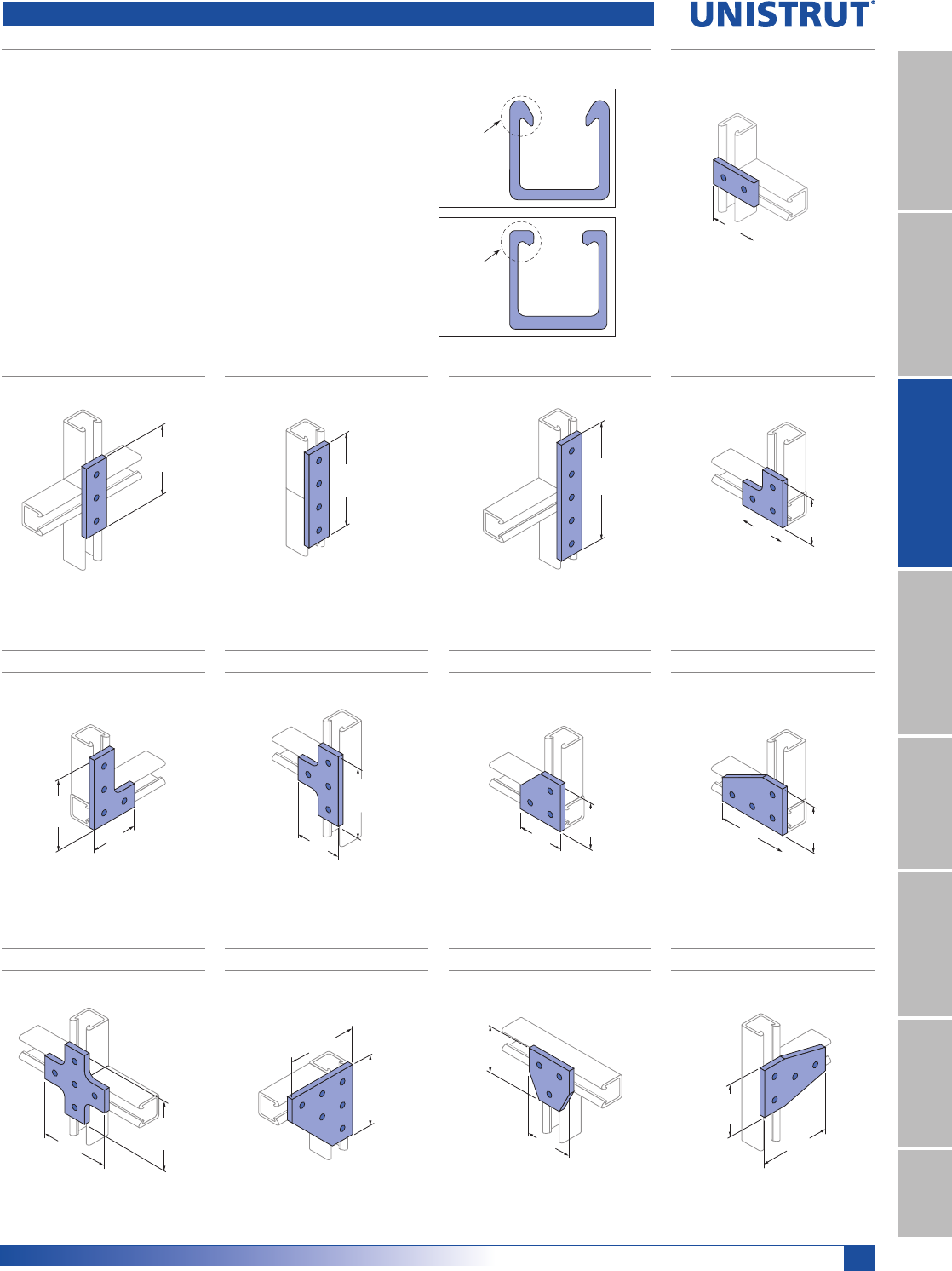
199
Fiberglass
11¼4" System
13¼16" SystemFiberglass SystemSpecial MetalsPrimeAngle
Metal GratingRoofwalkIndex
F20P-2518, F20V-2518
Wt/100 pcs: 33 Lbs (15.0 kg)
47⁄8"
47⁄8"
(123.8)
(123.8)
F20P-2512, F20V-2512F20P-2510, F20V-2510
F20P-2508, F20V-2508
Wt/100 pcs: 26 Lbs (11.8 kg)
Wt/100 pcs: 17 Lbs (7.7 kg)
F20P-2516, F20V-2516
Wt/100 pcs: 32 Lbs (14.5 kg)
F20P-2514, F20V-2514
Wt/100 pcs: 20 Lbs (9.1 kg)Wt/100 pcs: 25 Lbs (11.3 kg)
31⁄4"
31⁄4"
(82.6)
(82.6)
47⁄8"
31⁄4"
(82.6)
(123.8)
47⁄8"
31⁄4"
(123.8)
(82.6)
31⁄4"
31⁄4"
(82.6)
(82.6)
31⁄4"
47⁄8"(82.6)
(123.8)
F20P-2502, F20V-2502
F20P-2500, F20V-2500 CHANNEL FITTINGS
Wt/100 pcs: 17 Lbs (7.7 kg)
F20P-2506, F20V-2506
Wt/100 pcs: 32 Lbs (14.5 kg)
F20P-2504, F20V-2504
Wt/100 pcs: 24 Lbs (10.9 kg)
Wt/100 pcs: 12 Lbs (5.4 kg)
31⁄4"
(82.6)
47⁄8"
(123.8)
61⁄2"
(165.1)
81⁄8"
(206.4)
&KDQQHO)LWWLQJVDUHUHTXLUHGWRIDEULFDWHVWUXFWXUHVDQGDUHHDVLO\DWWDFKHGWR
Channels with channel nuts and polyurethane fasteners. The fittings are offered
in two types; fabricated (cut from flat stock) or molded.
0DWHULDO)DEULFDWHG)LWWLQJV
Either polyester (P Series) or vinyl ester (V Series) material.
0DWHULDO0ROGHG)LWWLQJV$OOPROGHGILWWLQJVZLWKWKHH[FHSWLRQRIWKHSRVW
bases are molded in polyurethane.
Note: The drawings for all fittings are shown with the Aickinstrut flange profile,
however they can be used with either channel profile.
Flat Fiberglass Fittings
Aickinstrut
Flange
SST
Flange
F20P-2522, F20V-2522F20P-2520, F20V-2520
Wt/100 pcs: 45 Lbs (20.4 kg) Wt/100 pcs: 21 Lbs (9.5 kg)
31⁄4"
31⁄4"
(82.6)
(82.6)
47⁄8"
47⁄8"
(123.8)
(123.8)
F20P-2524, F20V-2524
Wt/100 pcs: 32 Lbs (14.5 kg)
31⁄4"
47⁄8"
(123.8)
(82.6)
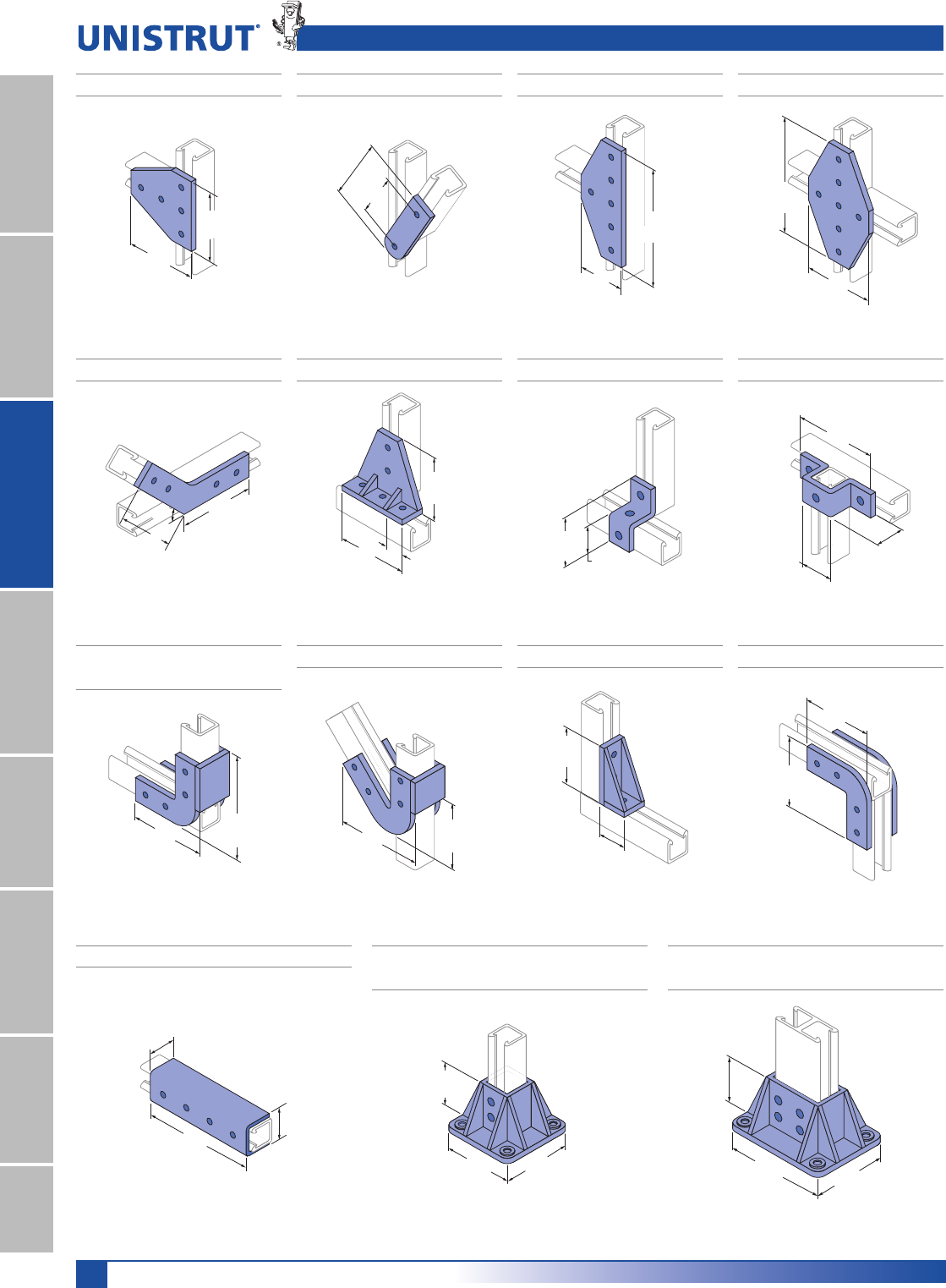
200
Fiberglass
11¼4" System
13¼16" SystemFiberglass SystemSpecial MetalsPrimeAngleMetal GratingRoofwalkIndex
Flat Fiberglass Fittings
F20P-2526, F20V-2526
Wt/100 pcs: 45 Lbs (20.4 kg)
47⁄8"
47⁄8"
(123.8)
(123.8)
F20P-2528, F20V-2528
Wt/100 pcs: 20 Lbs (9.1 kg)
51⁄4"
35⁄8"
(92.1)
(133.4)
F20P-2530, F20V-2530
Wt/100 pcs: 50 Lbs (22.7 kg)
81⁄8"
31⁄4"
(82.6)
(206.4)
47⁄8"
(123.8)
47⁄8"
(123.8)
F50PU-2611F50PU-2538F20P-2540, F20V-2540
F20P-2534, F20V-2534
Wt/100 pcs: 77 Lbs (34.9 kg)
Wt/100 pcs: 9 Lbs (4.1 kg)Wt/100 pcs: 41 Lbs (18.6 kg)
F50PU-1508 (11¼2"),
F50PU-2008 (15¼8")
Wt/100 pcs: 27 Lbs (12.2 kg)
F50PU-2613
Wt/100 pcs: 16 Lbs (7.3 kg)
81⁄8"
47⁄8"
(206.4)
(123.8)
4"
5" 15⁄8"
(127.0) (41.3)
(101.6)
51⁄4"
51⁄4"
45° (133.4)
(133.4) 17⁄8"
31⁄2"
(88.9)
(47.6)
17⁄8"
513⁄32"
2 5⁄32"
(137.3)
(47.6)
(54.8)
Wt/100 pcs: 57 Lbs (26.0 kg)
F50PU-2636F50PU-2045 (15¼8")
Wt/100 pcs: 35 Lbs (15.9 kg) Wt/100 pcs: 14 Lbs (6.4 kg)
4"
15⁄8"
(41.3)
(101.6)
41⁄2"
51⁄2"
(139.7)
(114.3)
F50PU-2090 (15¼8")
Wt/100 pcs: 35 Lbs (15.9 kg)
47⁄8"
47⁄8"
(123.8)
(123.8)
F20PU-5903 (31¼4"),
F20PU-5905 (21¼4")
F20PU-5853 (15¼8"),
F20PU-5855 (11¼8")
3"
5" 5"
(127.0)
(76.2)
(127.0)
3"
5"
6 5⁄8"
(127.0)
(168.3)
(76.2)
F50PU-2616
Wt/100 pcs: 51 Lbs (23.1 kg)
17⁄8"
71⁄4"
25⁄32"
(47.6)
(54.8)
(184.2)
Wt/100 pcs: 71 Lbs (32.2 kg) Wt/100 pcs: 86 Lbs (39.0 kg)
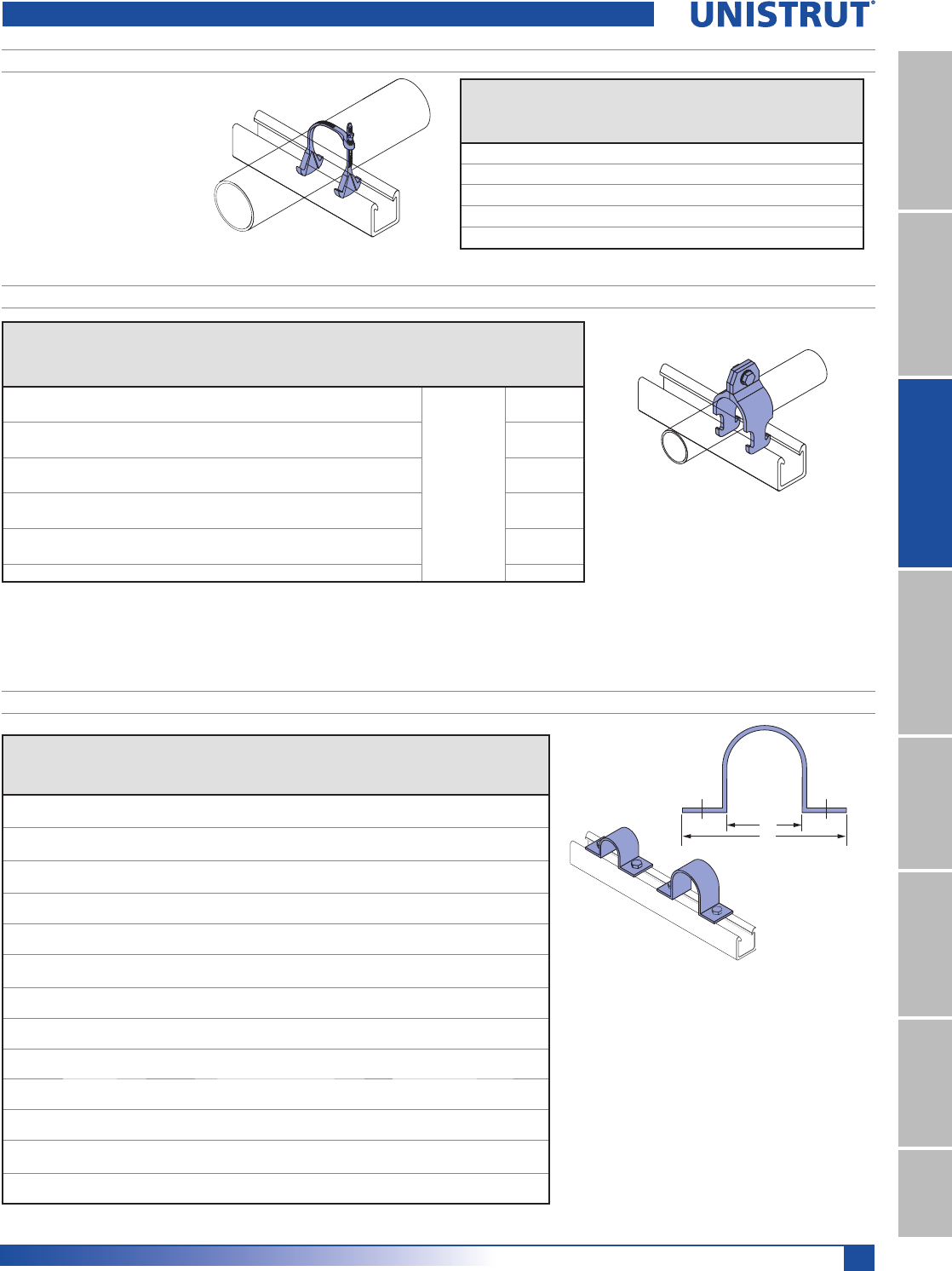
201
Fiberglass
11¼4" System
13¼16" SystemFiberglass SystemSpecial MetalsPrimeAngle
Metal GratingRoofwalkIndex
ADJUSTABLE PIPE CLAMPS
8QLVWUXW$GMXVWDEOH3LSH&ODPSVDUH
manufactured from glass-reinforced
polyurethane and are adjustable
to accommodate a wide range of
outside diameters. They can be uti-
lized with a variety of piping systems
including: PVC, fiberglass, copper,
rigid steel conduit and PVC coated
rigid steel conduit.
&DUHVKRXOGEHWDNHQQRWWRH[FHHG
3 ft./lbs. of torque on the adjustable
pipe straps. *Design loads shown represent a 3:1 safety factor.
Part
Number
O.D. Pipe
6L]HLQ
Design Load Torque
Ft/Lbs
1P
Wt/100 pcs
Lbs (kg)
Type 1
Lbs (kN)
Type 2
Lbs (kN)
200-3100 1»2 – 11»2135 (0.6) 65 (0.3) 0.8 (1) 3 (1.4)
200-3110 11»2 – 21»4135 (0.6) 65 (0.3) 3 (4) 5 (2.3)
200-3120 21»4 – 31»4145 (0.6) 70 (0.3) 3 (4) 5 (2.3)
200-3130 3 – 4 215 (1.0) 70 (0.3) 3 (4) 8 (3.6)
200-3140 4 – 61»2215 (1.0) 70 (0.3) 3 (4) 10 (4.5)
Pipe Clamps and Pipe Straps
RIGID PIPE CLAMPS
Rigid Pipe Clamps resemble the more traditional style of pipe clamps and are sized based on the pipe inside diameter or nominal size.
Polyurethane clamps are recommended for applications up to 160°F. For high temperature applications (up to 230°F).
Care should be taken not to exceed the recommended torque values of the rigid pipe clamps.
Material: glass-reinforced polyurethane.
*Design loads shown represent a 3:1 safety factor.
Part
Number
PVC, Sch. 80 Design Loads* FRP Bolt
Wt/100 pcs
/EVNJ
Nominal & Rigid Metal Type 1
/EVN1
Type 2
/EVN1
FRP Bolt
6L]HLQ
Torque
)W/EV1P6L]HLQ ,QPP
FPCR-050 1»20.840 (21.3) 225 (1.0) 90 (0.4) 3»8 x 11»4
3 (4)
3 (1.4)
FPCR-075 3»41.050 (26.7) 225 (1.0) 90 (0.4) 3»8 x 11»43 (1.4)
FPCR-100 1 1.315 (33.4) 225 (1.0) 90 (0.4) 3»8 x 11»44 (1.8)
FPCR-125 11»41.660 (42.2) 225 (1.0) 90 (0.4) 3»8 x 11»45 (2.3)
FPCR-150 11»21.900 (48.3) 225 (1.0) 90 (0.4) 3»8 x 11»45 (2.3)
FPCR-200 2 2.375 (60.3) 225 (1.0) 90 (0.4) 3»8 x 11»45 (2.3)
FPCR-250 21»22.875 (73.0) 225 (1.0) 90 (0.4) 3»8 x 11»47 (3.2)
FPCR-300 3 3.500 (88.9) 225 (1.0) 90 (0.4) 3»8 x 11»410 (4.5)
FPCR-400 4 4.500 (114.3) 300 (1.3) 125 (0.6) 3»8 x 11»412 (5.4)
FPCR-600 6 6.625 (168.3) 300 (1.3) 125 (0.6) 3»8 x 11»415 (6.8)
FPCR-800 8 8.625 (219.1) 300 (1.3) 125 (0.6) 3»8 x 11»418 (8.1)
TWO HOLE PIPE STRAPS
7ZR+ROH3LSH6WUDSVDUHGHVLJQHGIRUXVHLQVHFXULQJSLSH
conduit and ducts to Channel. Two hole fiberglass straps
can also be used independently from the channel for surface
mounting. All sizes of the straps are suitable for load bearing
applications.
0DWHULDOILUHUHWDUGDQWJODVVUHLQIRUFHGSRO\HVWHUUHVLQ
)RUH[WUHPHFKHPLFDOHQYLURQPHQWVWKHVWUDSVFDQEH
manufactured from vinyl ester resin. Larger diameter straps for
special applications are also available. Contact the factory for
pricing and availability of vinyl ester and large diameter straps.
Two hole pipe straps should not be torqued above recom-
mended values.
Notes:
(1) Bolts and channel nuts are sold separately.
(2) When bolting onto 15»8" channel a 11»4" long bolt is req'd.
*Design loads shown represent a 3:1 safety factor.
Part
No.
Dim. A
,QPP
Dim. B
,QPP
Bolt
Size
LQ
Material
Thick.
,QPP
Design Load
Torque
)W/EV1P
Wt/100 pcs
/EVNJ
Type 1
/EVN1
Type2
/EVN1
FPS200 2.375 6.375 1»2
1»4135 50 4 14
60.33 161.93 6.4 0.60 0.22 5 6.4
FPS250 2.875 6.875 1»2
1»4135 50 4 17
73.03 174.63 6.4 0.60 0.22 5 7.7
FPS300 3.500 7.500 1»2
1»4135 50 4 20
88.90 190.50 6.4 0.60 0.22 5 9.1
FPS350 4.000 8.000 1»2
1»4135 50 4 33
101.60 203.20 6.4 0.60 0.22 5 15.0
FPS400 4.500 8.500 1»2
1»4175 60 4 23
114.30 215.90 6.4 0.78 0.27 5 10.4
FPS500 5.563 9.563 1»2
1»4175 60 4 39
141.30 242.90 6.4 0.78 0.27 5 17.7
FPS600 6.625 10.625 1»2
1»4175 60 4 39
168.28 269.88 6.4 0.78 0.27 5 17.7
FPS800 8.625 12.625 1»2
1»4225 125 4 51
219.08 320.68 6.4 1.00 0.56 5 23.1
FPS1000 10.750 15.750 5»8
1»4225 125 10 77
273.05 400.05 6.4 1.00 0.56 14 34.9
FPS1200 12.750 16.250 5»8
1»4225 125 10 83
323.85 412.75 6.4 1.00 0.56 14 37.6
FPS1400 14.000 18.000 5»8
3»8250 150 10 125
355.60 457.20 9.5 1.11 0.67 14 56.7
FPS1600 16.000 20.000 5»8
3»8250 150 10 143
406.40 508.00 9.5 1.11 0.67 14 64.9
FPS1800 18.000 23.000 5»8
3»8250 150 10 160
457.20 584.20 9.5 1.11 0.67 14 72.6
A
B
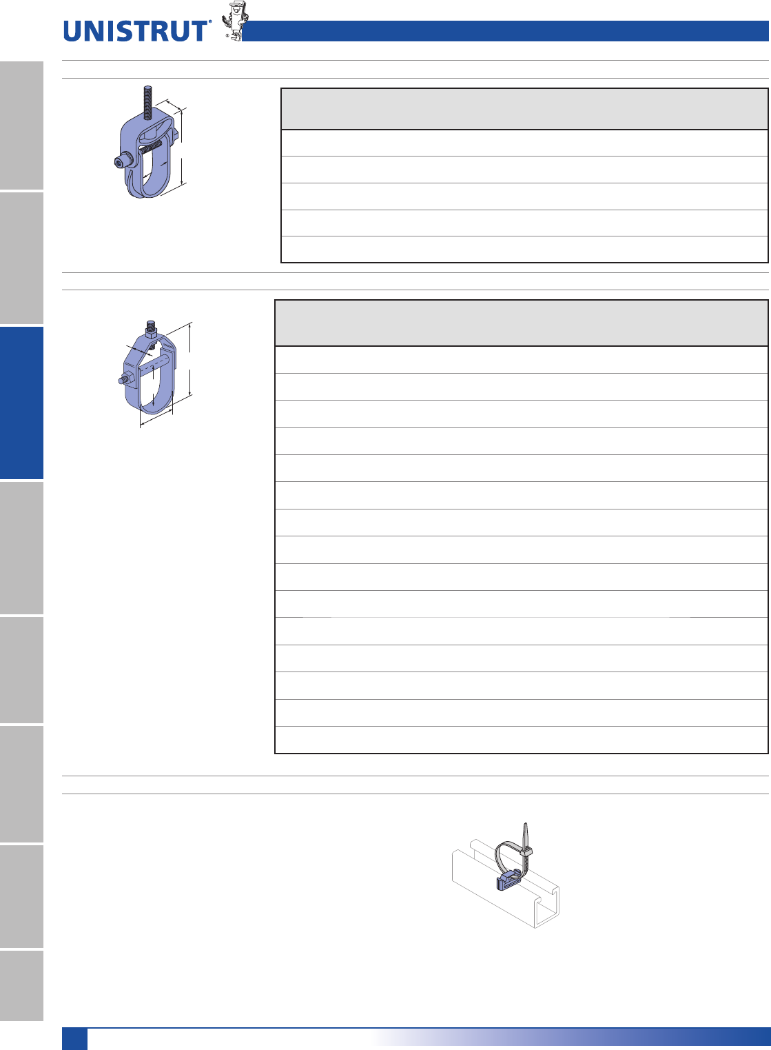
202
Fiberglass
11¼4" System
13¼16" SystemFiberglass SystemSpecial MetalsPrimeAngleMetal GratingRoofwalkIndex
F200-4101 UNISERT CHANNEL INSERT
8QLVHUWLVDSRO\XUHWKDQHQRQPHWDOOLFLQVHUWZKLFKFDQEHXVHGZLWKVWDQGDUG
cable ties for securing tubing, conduit and cables to standard metal channels.
7KH8QLVHUWZRUNVZLWKDOO5»8" channels that are 13»16" deep or more. One size
fits 12, 14 and 16 metal gauge channels.
Note: For use only with metallic channel.
H
H1
W
T
A
B
C
C
FABRICATED CLEVIS HANGERS
MOLDED CLEVIS HANGERS
Material: glass-reinforced polyurethane.
Material: glass-reinforced polyester resin.
*Design load values shown represent a 3:1
safety factor.
*Design load values shown represent a 3:1
safety factor.
Part
Number
Nominal
Diameter
In (mm)
Max.
Pipe O.D.
In (mm)
“A” Dim.
In (mm)
“B” Dim.
In (mm)
“C” Dim.
In (mm)
Hanger
Rod
In (mm)
Load*
Lbs (kN)
Wt/100 pcs
Lbs (kg)
FCVHPU-100
1»2 - 1 1 1.500 4.25 1.25 1»2670 29
12.7 - 25.4 25.4 38.1 108 32 12.7 2.98 13.2
FCVHPU-150 11»4- 11»211»22.000 5.14 1.25 1»2670 40
31.8 - 38.1 38.1 50.8 131 32 12.7 2.98 18.1
FCVHPU-200 11»2 - 2 2 2.500 6.52 1.25 1»2730 43
38.1 - 50.8 50.8 63.5 166 32 12.7 3.25 19.5
FCVHPU-400 21»2 - 4 4 5.125 10.00 1.50 1»21,150 129
63.5 - 101.6 101.6 130.2 254 38 12.7 5.12 58.5
FCVHPU-600 41»2 - 6 6 6.750 12.33 1.50 1»21,170 168
114.3 - 152.4 152.4 171.5 313 38 12.7 5.20 76.2
Part
Number
Size Range
In (mm)
A
Dimensions - In (mm) Hanger
Rod
In (mm)
Trans
Rod
In (mm)
Spreader
Rod O.D.
In (mm)
Loads*
Lbs
(kN)
Wt/100 pcs
Lbs (kg)THH1W
F100-1500 1–11»2 1»823»417»81 1»2 1»23»8 1»260 21
25.4 – 38.1 3.2 69.9 47.6 38.1 12.7 9.5 12.7 0.27 9.5
F100-1501 11»2 – 2 1»831»223»81 1»2 1»23»8 1»260 25
38.1 – 50.8 3.2 88.9 60.3 38.1 12.7 9.5 12.7 0.27 11.3
F100-1502 2 – 25»8 1»843»432
1»23»8 1»290 55
50.8 – 66.7 3.2 120.7 76.2 50.8 12.7 9.5 12.7 0.40 24.9
F100-1503 21»2 – 31»4 1»851»235»82
1»23»8 1»2120 57
63.5 – 82.6 3.2 139.7 92.1 50.8 12.7 9.5 12.7 0.53 25.9
F100-1504 3 – 37»8 1»874
1»425»83»8 1»2160 61
76.2 – 98.4 3.2 177.8 108.0 50.8 15.9 9.5 12.7 0.71 27.7
F100-1505 4 – 51»8 13»16 81»255»825»83»8 1»2250 82
101.6 – 130.2 20.6 215.9 142.9 50.8 15.9 9.5 12.7 1.11 37.2
F100-1506 6 – 71»8 13»16 107»871»235»83»8 1»2300 136
152.4 – 181.0 20.6 276.2 190.5 76.2 15.9 9.5 12.7 1.33 61.7
F100-1507 8 – 91»4 1»414 93»435»83»8 1»2350 189
203.2 – 235.0 6.4 355.6 247.7 76.2 15.9 9.5 12.7 1.56 85.7
F100-1508 10 – 113»8 1»418 12 4 5»8 1»23»4450 333
254.0 – 288.9 6.4 457.2 304.8 101.6 15.9 12.7 19.1 2.00 151.0
F100-1509 12 – 131»2 1»4211»2141»855»8 1»23»4600 350
304.8 – 342.9 6.4 546.1 358.8 127.0 15.9 12.7 19.1 2.67 158.8
F100-1510 14 – 153»4 1»4241»2161»253»4 1»23»4700 872
355.6 – 400.1 6.4 622.3 419.1 127.0 19.1 12.7 19.1 3.11 395.5
F100-1511 16 – 18 3»8273»8191»263»43»41 750 1,023
406.4 – 457.2 9.5 695.3 495.3 152.4 19.1 19.1 25.4 3.34 464.0
F100-1512 19 – 21 3»8341»2221»263»43»41 800 1,673
482.6 – 533.4 9.5 876.3 571.5 152.4 19.1 19.1 25.4 3.56 758.9
F100-1513 21 – 22 1»2351»224 6 3»43»41 850 2,323
533.4 - 558.8 12.7 901.7 609.6 152.4 19.1 19.1 25.4 3.78 1,053.7
F100-1514 22 – 24 1»241 28 6 3»43»41 900 2,973
558.8 - 609.6 12.7 1,041.4 711.2 152.4 19.1 19.1 25.4 4.00 1,348.5
Fiberglass Clevis Hangers and Channel Insert
Wt/100 pcs: 1.0 Lbs (.5 kg)
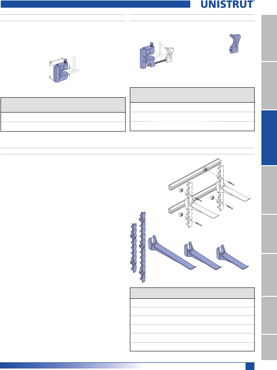
203
Fiberglass
11¼4" System
13¼16" SystemFiberglass SystemSpecial MetalsPrimeAngle
Metal GratingRoofwalkIndex
Material: glass-reinforced polyurethane.
25⁄8"
(66.7)
3"
(76.2)
3⁄4"
(19.1)
F375PU & F500PU MOLDED BEAM CLAMPS FRGBC MOLDED BEAM CLAMP ASSEMBLY
Material: glass-reinforced
polyurethane
POWER-RACK STANCHIONS
The Power-Rack Stanchion is made entirely from glass-reinforced nylon, these
stanchions offer greater corrosion resistance than classical metal stanchions. The
interlocking design allows the arm to “lock” into nine different levels on the 141»4"
stanchions and fourteen on the 171»2" stanchion. Glass-reinforced polyurethane stan-
chions are available as a special order. Contact Unistrut for pricing and availability.
Dimensions – The stanchion back has 9»16" x 15»16" holes to accept fasteners for
mounting. There are two mounting holes in the 213»8" long stanchion and three in the
335»16" long stanchion. Thickness at the slotted mounting holes is 17»8". The mounting
holes are spaced on 12" centers and require 1»2" diameter fasteners.
Installation – The Stanchions can be anchored into existing concrete structures
using any industrial anchoring system. For new concrete structures, the Stanchions
FDQEHPRXQWHGWR¿EHUJODVVFRQFUHWHHPEHGPHQWFKDQQHODQGDWWDFKHGZLWK1»2"
channel nuts and 1»2"x 3" Fiberfast Bolts.
Fire Retardance – Power-Rack materials meet or exceed the requirements of
UL94 HB.
Loading – The recommended allowable loads on Power-Rack Stanchions vary
depending upon the position of the arm. Use these guidelines for a safe, reliable
installation:
7RWDOORDGRQDQ\RQHDUPVKRXOGQRWH[FHHGOEV
7KHVXPRIWKHORDGVRQDQDUPPXOWLSOLHGE\WKHLUGLVWDQFHVWRWKHZDOO
stanchion should not exceed 1200 in./lbs.
Example: A cable weighing 200 lbs. is positioned on an arm at a distance
of 5" from the wall stanchion.
If the total load is less than 800 lbs and the sum of the load multiplied by their
distances to the wall stanchion does not exceed 1200 in./lbs., then the system is
adequate. In this case,
Total load (200<800 lbs) = OK
Tot. moment (200x5 in. = 1000<1200 in./lbs.) = OK
Fiberglass Beam Clamps, Power-Rack Stanchions
*Design load values shown represent a 3:1 safety factor. *Design load values shown represent a 3:1 safety factor.
Assembly
Part
Number
Size
In
Thread
Shear
Lbs (kN)*
Torque
Ft/Lbs 1P
Wt/100 pcs
Lbs (kg)
F375PU-BC 3»8400 10 30
1.78 14 13.6
F500PU-BC 1»2400 10 30
1.78 14 13.6
Part
Number
Size
In
Thread
Shear
Lbs (kN)*
Torque
Ft/Lbs 1P
Wt/100 pcs
Lbs (kg)
FRGBC-1 3»8500 10 43
2.22 14 19.5
FRGBC-2 1»2500 10 43
2.22 14 19.5
FRGBC-3 5»8500 10 43
2.22 14 19.5
F375PU-BCCLP (3»8")
Beam Clip Only
*Design load values shown represent a 3:1 safety factor.
Part No. Description
Size
In (mm)
Wt/100 pcs
Lbs (kg)
/RDGOEV
Lbs (kN)
F20N-ARM08 Arm 8 100 800
203.2 45.4 3.56
F20N-ARM14 Arm 141»4116 800
362.0 52.6 3.56
F20N-ARM17 Arm 171»2145 800
444.5 65.8 3.56
F20N-ARM23 Arm »8186 800
606.4 84.4 3.56
F20N-STA21 Stanchion 213»8149 N/A
542.9 67.6
F20N-STA33 Stanchion 335»16 231 N/A
846.1 104.8
Note: Beam clamp clip must
be purchased separately.
Illustration purpose only
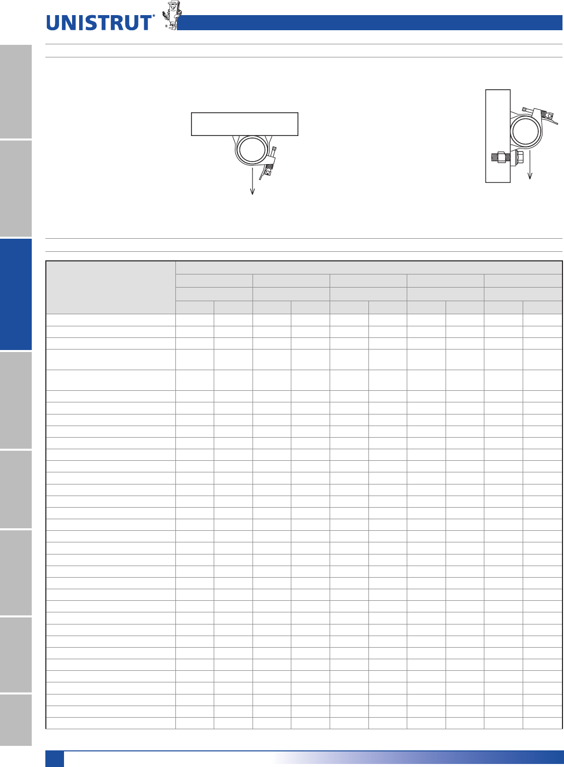
204
Fiberglass
11¼4" System
13¼16" SystemFiberglass SystemSpecial MetalsPrimeAngleMetal GratingRoofwalkIndex
CHEMICAL COMPATIBILITY TABLE
Fiberglass Technical Data
Chemical
Series
EPVPUN
Rigid PVC Poly/Glass Vinyl/Glass Poly Nylon
70° 160°F 70° 160°F 70° 160°F 70° 160°F 70° 160°F
Acetic Acid, Up to 50% RRRRRRR–nrnr
Acetone, Up to 10% nr nr nr nr nr nr R – R R
Aluminum Hydroxide RRRRRRR–nrnr
Ammonium Hydroxide
(Aqueous Ammonia), Up to 5% R R nr nr R R R – – –
Ammonium Hydroxide
(Aqueous Ammonia), Up to 10% R R nr nr R 150° R – – –
Ammonium Hydroxide, Up to 20% R R nr nr R 150° R – – –
Ammonium Nitrate R nr RRRRR– – –
Ammonium Phosphate R R R nr R R R – – –
Ammenium Sulfide, saturated R R nr nr R 120° R – – –
Aqua Regia, fumes nr nr nr nr R 150° nr – – –
Benzene nr nr nr nr nr nr R R – R
Benzoic Acid RRRRRRR– – –
Bromine, wet gas R nr nr nr R 100° – – – –
Butylene Glycol, Up to 100% RRRRRRR–RR
Butyric Acid, Up to 50% nr nr R R R R R – – –
Calcium Hydroxide R R R nr R R R – – –
Calcium Hypochlorite R R R nr R R R – nr nr
Chlorine, Dry Gas nr nr nr nr R R – – – –
Chlorine, Wet Gas nr nr nr nr R R – – – –
Chlorine, Liquid nr nr nr nr nr nr – – – –
Chlorine, Water nr nr RRRRR–nrnr
Chromic Acid, Up to 5% R R nr nr R R – – R R
Copper Chloride RRRRRRR– – –
Copper Cyanide R R R nr R R R – – –
Copper Fluoride R R R nr R R R – – –
Copper Nitrate RRRRRRR– –
Copper Sulfate RRRRRRR– – –
Dechlorinated Brine Storage R R – – R R R – – –
Esters, Fatty Acid nr nr R R R R R – – –
Ferric Chloride RRRRRRR– – –
Ferrous Chloride RRRRRRR– – –
Fluoboric Acid R R R 120° R R – – – –
Fluosilicic Acid, Up to 10% nr nr nr nr R R – – nr nr
Fluosilicic Acid, Up to 32% nr nr nr nr R 100° – – – –
FIBERGLASS CLAMPS DESIGN LOAD INFORMATION
There are two types of piping system loadings:
RYHUKHDG7\SHDQG
YHUWLFDO7\SH
as described below.
All pipe straps and clamps show the
recommended loading for both types of
loading.
Type 1 Overhead Design Load
The design load shown represents pipes
supported below the strut. The design loads
shown are based on a minimum ultimate
failure safety factor of 3:1.
Type 2 Vertical Design Load
The design loading shown can be achieved with the ad-
dition of a vertical stop lock assembly (Part #F200-4219)
installed directly beneath the pipe clamp. The adjacent
illustration shows how the vertical stop lock assembly
provides additional support for pipe and how it can be
used to achieve full Type 2 design loads.
Design loads are based on a minimum clamp slip safety
factor or 3:1. It is recommended that stop lock assem-
blies be used for all vertical pipe support applications.

205
Fiberglass
11¼4" System
13¼16" SystemFiberglass SystemSpecial MetalsPrimeAngle
Metal GratingRoofwalkIndex
Note
The recommendations contained in this table are made without guarantee of representation as to results. Since the actual use
by others is beyond our control, no guarantee, expressed or implied, is made by Unistrut as to effects of such use or results to
be obtained nor does Unistrut assume any liability arising out of the use by others of the products referenced in this table. Nor
is the information herein to be construed as absolutely complete since additional information may be needed or desirable when
particular or exceptional conditions or circumstances exist or because of applicable laws or government regulations. We suggest
that you evaluate these recommendations and suggestions in your own laboratory prior to use. Our responsibility for claims
arising from breach of warranty, negligence, or otherwise is limited to the purchase price of the material.
Legend
“nr“ - “Not Recommended” for use
“R“ - “Recommended”
“–“ - no information available
Fiberglass Technical Data
Chemical
Series
EPVPUN
Rigid PVC Poly/Glass Vinyl/Glass Poly Nylon
70° 160°F 70° 160°F 70° 160°F 70° 160°F 70° 160°F
Formic Acid, Up to 10% R R nr nr R R R – nr nr
Formic Acid, Up to 50% R R nr nr R 100° R – – –
Gasoline, Aviation R nr R nr R R R – – –
Green Liquor, Pulp Mill R R – – R R – – – –
Hydrochloric Acid, Up to 15% R R R nr R R R – – –
Hydrochloric Acid, Up to 37% R R R nr R R R – – –
Hydrofluoric Acid,Up to 10% R R nr nr R 150° – – – –
Hydrofluoric Acid, Up to 20% R nr nr nr R 100° – – – –
Hydrogen Chloride Wet Gas nr nr R nr R R nr – – –
Hydrogen Sulfide Wet Gas R R R nr R R R – – –
Lactic Acid R R R nr R R R – – –
Lead Nitrate R R – – R R R – – –
Magnesium Hydroxide R R nr nr R R R – R R
Nickel Sulfate R R nr nr R R R – – –
Nitric Acid, Up to 5% R R nr nr R 150° R – – –
Nitric Acid, Up to 35% R R nr nr R 150° R – – –
Nitric Acid, Vapor R R nr nr R R R – – –
Perchloric Acid, Up to 10% nr nr nr nr R 150° R – nr nr
Pickling Liquids, 3-5% H2S04 RRRRRRR– – –
Phosphoric Acid R R nr nr R R R – nr nr
Super or Poly (115%, P20%) R R nr nr R R R – – –
Vapor or Condensate R R nr nr R R R – – –
Potassium Chloride RRRRRRR– – –
Potassium Nitrate RRRRRRR– – –
Potassium Persulfate R R nr nr R R R – – –
Silver Cyanide, Up to 5% R R nr nr R R R – – –
Sodium Hydroxide,Up to 25% R R nr nr R 150° R – – –
Sodium Hydroxide, Up to 50% R R nr nr R 180° R – R R
Sodium Hypochlorite, Up to 15% R R nr nr R 150° R – nr nr
Sodium Nitrate RRRRRRR– – –
Sodium Sulfate R R R nr R R R – – –
Sodium Sulfide R R nr nr R R R – – –
Sulfuric Acid, Up to 25% RRRRRRR–nrnr
Sulfuric Acid, Up to 70% R R nr nr R R R – nr nr
Sulfuric Acid, Up to 75% nr nr nr nr R 120° R – nr nr
Sulfuric Acid, Up to 80% nr nr nr nr nr nr nr – nr nr
Sulfuric Acid, Vapor R R R nr R R R – – –
Trichlorethylene, Fumes nr nr nr nr R 120° R – – –
Trisodium Phosphate R R R nr R R R – – –
Urea R R R nr R 150° R – R R
Vegetable Oils RRRRRRR–RR
Vinegar RRRRRRRRRR
White Liquor, Pulp Mill R R – – R R R – – –
CHEMICAL COMPATIBILITY TABLE

206
Fiberglass
11¼4" System
13¼16" SystemFiberglass SystemSpecial MetalsPrimeAngleMetal GratingRoofwalkIndex
Fiberglass Sample Specifications
5.0 STANDARDS
5.1 Glass-reinforced channels covered in this
specification shall have a flame spread rating of
25 or less when tested per ASTM E84 and meet
the requirements of UL 94V0 thereby qualifying
them as Class 1 material in the Uniform Building
Code.
5.2 Glass-reinforced channels covered in this speci-
fication shall comply with the requirements of
!34-$AND!34-$WHICHGOVERN
the dimensional tolerance and visual defects of
pultruded shapes.
6.0 GENERAL
6.1 Unistrut nonmetallic Channel Framing shall be
furnished as a system which includes all the nec-
essary fasteners, channel splice plates, brackets,
sealants, hangers, pipe clamps, etc.
6.2 Nonmetallic fasteners shall be manufactured from
long glass fiber reinforced polyurethane to ensure
maximum strength and corrosion resistance.
6.3 All components of the Unistrut Channel Framing
System shall be nonmetallic except where type
316 stainless steel hardware is used as part of the
assembly.
6.4 The manufacturer shall not have had less than 10
years experience in manufacturing strut systems.
6.5 All products are manufactured in the United
States of America.
FIBERGLASS SPECIFICATIONS
1.0 SCOPE
1.1 This specification covers the requirements for
the Unistrut Nonmetallic Channel Framing Sys-
tem.
2.0 MATERIAL
2.1 FRP channel shall be of pultruded glass-rein-
forced polyester or vinyl ester resin having the
physical property values listed in this catalog.
2.2 Some accessories shall be of injection molded,
40% long glass fiber reinforced polyurethane, or
nylon.
3.0 COMPOSITION
3.1 Glass-reinforced channel shall have a synthetic
surfacing veil applied on exterior surfaces to
improve weatherability and inhibit ultraviolet
degradation. An ultraviolet stabilizer shall be
incorporated in the resin formulation to further
inhibit ultraviolet degradation.
4.0 STRUCTURAL DESIGN
4.1 Channel shall incorporate Unistrut's Aickinstrut
flange profile design which allows full and posi-
tive interlocking contact of channel accessories
and prohibits premature flange failure from
torqued accessories.
4.2 Channel profile dimensions shall be:
1
5⁄8" x 15⁄8" x 1⁄4" or
1
1⁄2" x 11⁄8" x 1⁄8".
4.3 All 15⁄8" x 15⁄8" channel profiles shall have a mini-
mum pull out resistance of 1,000 pounds when
load is applied over a 3⁄8" long section of the
inside flanges.
4.4 Channel section lengths shall be supplied in 10'
or 20' lengths (±1⁄8").
4.5 Universal Pipe Clamps shall have full interlock-
ing contact with interior channel flanges to
maximize pull-out resistance and be adjustable to
accommodate a minimum 3⁄4" variance in piping
ORCONDUIT/$SIZES
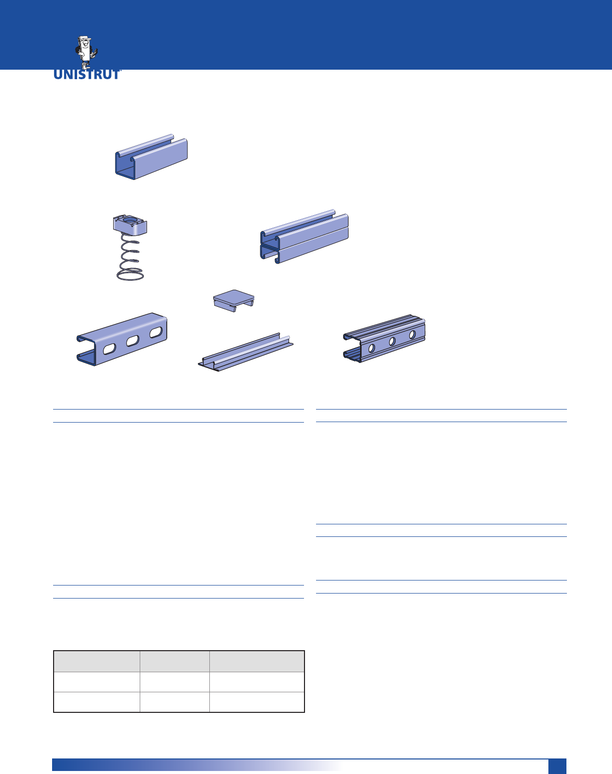
207
MATERIAL
STAINLESS STEEL
Channels:ASTM A 240 (Type 304)
Sintered nuts: ASTM B783 (Type SS316N1-25)
Fittings:
ASTM A240 (Type 304) or ASTM A276 (Type 304)
Type 316 stainless also available for most products.
Contact factory for specific material availability.
ALUMINUM
Channels (Extruded): ASTM B221 (Type 6063-T6)
Fittings: ASTM B209 (Type 1100F or Type 5052-H32)
Nuts: Stainless steel nuts are recommended for
Aluminum change
LOAD DATA (BEAM & COLUMN)
To determine maximum allowable beam and column load-
ing for channels in this section, multiply the load data in
the appropriate mild steel channel sections of this catalog
by the following factors:
Channel
Material
Beam Load
% Factor
Column Load
% Factor
Extruded
Aluminum 33% 33%
Stainless
Steel 100% 100%
LOAD DATA (SLIP & PULL OUT)
EXTRUDED ALUMINUM
To determine nut slip resistance, multiply load data
for appropriate nut by 75%. To determine nut
pull-out load, multiply load data for appropriate
nut by 50%.
STAINLESS STEEL
For design assistance, consult Unistrut customer
engineering.
PRODUCT AVAILABILITY
Most fittings and channels shown in this catalog, are
available in aluminum or stainless steel. Consult factory
for ordering information.
DIMENSIONS
Imperial dimensions are illustrated in inches. Metric dimen-
sions are shown in parenthesis or as noted. Unless noted,
all metric dimensions are in millimeters and rounded to
one decimal place.
SPECIAL METALS
Stainless Steel Channel ..........................................................209
Stainless Steel Nuts and Closure Strips ................................. 210
Extruded Aluminum Channels ......................................211 - 212
Aluminum Closure Strips and End Caps ................................ 212
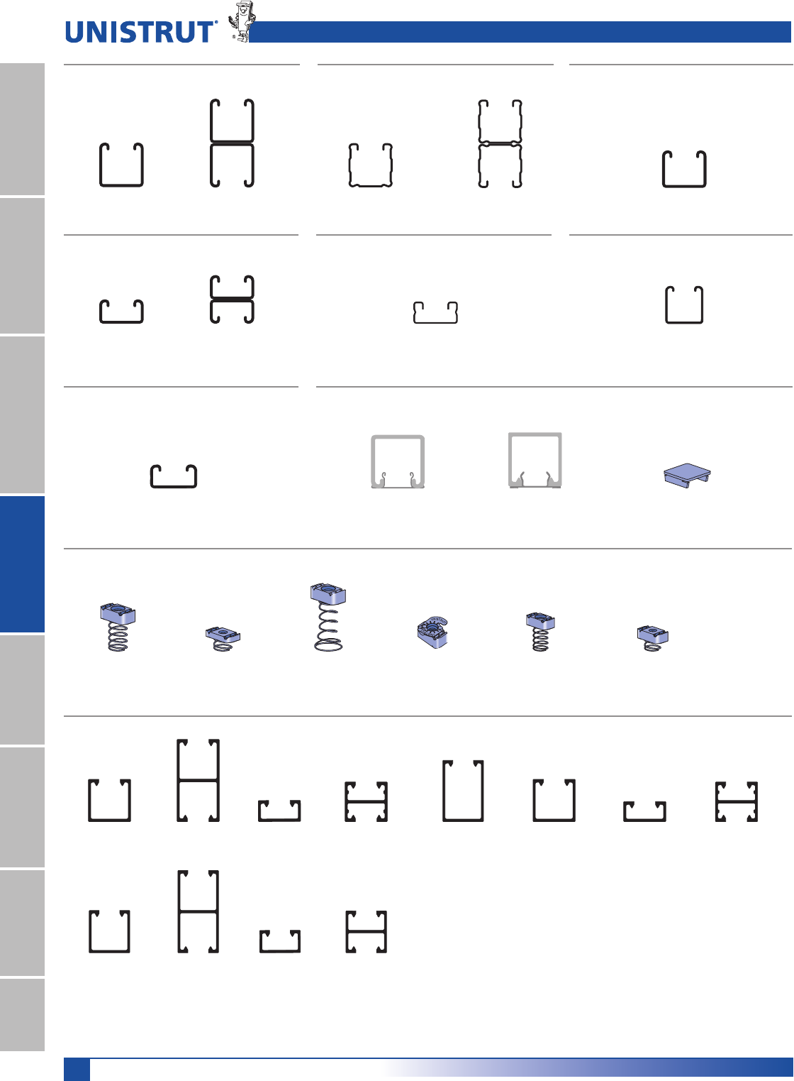
208
Special Metals
11¼4" System
13¼16" SystemFiberglass SystemSpecial MetalsPrimeAngleMetal GratingRoofwalkIndex
Special Metals Pictorial Index
P1100 SS
Pg 209
P4000 SS
Pg 209
P6000 SS
Pg 209
P7000 SS
Pg 209
P1184 SS
Pg 210
P1000 SS
Pg 209
P1000 EA
Pg 211
P6000 EA
Pg 212
P6001 EA
Pg 212
P7000 EA
Pg 212
P7001 EA
Pg 212
P1280 EA, P4280 EA,
P5580 EA Pg 212
P3184 EA
Pg 212
P1001 EA
Pg 211
P4000 EA
Pg 211
P4001 EA
Pg 211
P5500 EA
Pg 211
A1000 EA
Pg 211
A4000 EA
Pg 211
A4001 EA
Pg 212
P1006 U - P1010U
Pg 210
P4006 U - P4010
Pg 210
P5506 U - P5510U
Pg 210
A1006 SS, A1008 SS
Pg 210
A4006 SS, A4008 SS
Pg 210
P4006T, P4008UT
Pg 210
P1001 SS
Pg 209
P1101 SS
Pg 209
P3000 SS
Pg 209
P3300 SS
Pg 209
P3301 SS
Pg 209
P3300 Series (12 gauge) P4000 Series (16 gauge) P6000 Series (19 gauge)
P7000 Series (19 gauge) Closure Strips and End Caps
Stainless Steel Channel Nuts
Extruded Aluminum Channels
P1000 Series (12 gauge) P1100 Series (14 gauge) P3000 Series (12 gauge)
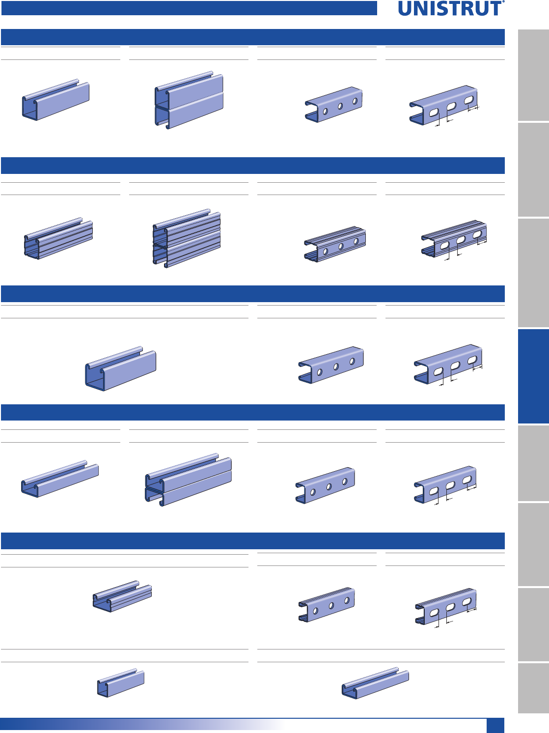
209
Special Metals
11¼4" System
13¼16" SystemFiberglass SystemSpecial MetalsPrimeAngle
Metal GratingRoofwalkIndex
Stainless Steel Channel
P1100 Series
P1000 Series
P3300 Series
P1000 SS P1001 SS P1000HS SS P1000T SS
P3300 SS P3301 SS
P1100 SS P1101 SS P1100HS SS P1100T SS
P3300HS SS P3300T SS
P3000 Series
P3000 SS
Wt/100 Ft: 170 Lbs (253 kg/100m)
P3000HS SS P3000T SS
9⁄16" (14.3) Dia. Holes
1 7⁄8" (47.6) on Center
1 3⁄16"
(30.2)
Slots are
11⁄8" (28.6) x 9⁄16" (14.3)
2" (50.8) on Center
7⁄8"
(22.2)
9⁄16" (14.3) Dia. Holes
1 7⁄8" (47.6) on Center
1 3⁄16"
(30.2)
Slots are
11⁄8" (28.6) x 9⁄16" (14.3)
2" (50.8) on Center
7⁄8"
(22.2)
9⁄16" (14.3) Dia. Holes
1 7⁄8" (47.6) on Center
1 3⁄16"
(30.2)
Slots are
11⁄8" (28.6) x 9⁄16" (14.3)
2" (50.8) on Center
7⁄8"
(22.2)
9⁄16" (14.3) Dia. Holes
1 7⁄8" (47.6) on Center
1 3⁄16"
(30.2)
Slots are
11⁄8" (28.6) x 9⁄16" (14.3)
2" (50.8) on Center
7⁄8"
(22.2)
P6000 SS
P4000 Series
P7000 SS
Wt/100 Ft: 37 Lbs (55 kg/100m) Wt/100 Ft: 36 Lbs (54 kg/100m)
9⁄16" (14.3) Dia. Holes
1 7⁄8" (47.6) on Center
1 3⁄16"
(30.2)
Slots are
11⁄8" (28.6) x 9⁄16" (14.3)
2" (50.8) on Center
7⁄8"
(22.2)
P4000 SS P4000HS SS P4000T SS
Wt/100 Ft: 190 Lbs (283 kg/100m) Wt/100 Ft: 380 Lbs (566 kg/100m) Wt/100 Ft: 185 Lbs (275 kg/100m) Wt/100 Ft: 185 Lbs (275 kg/100m)
Wt/100 Ft :142 Lbs (211 kg/100m) Wt/100 Ft : 284 Lbs (422 kg/100m) Wt/100 Ft : 136 Lbs (202 kg/100 m) Wt/100 Ft: 136 Lbs (202 kg/100m)
Wt/100 Ft: 165 Lbs (112 kg/100m) Wt/100 Ft: 165 Lbs (112 kg/100m)
Wt/100 Ft: 135 Lbs (201 kg/100m) Wt/100 Ft: 270 Lbs (402 kg/100m) Wt/100 Ft: 130 Lbs (193 kg/100m) Wt/100 Ft: 130 Lbs (193 kg/100m)
Wt/100 Ft: 82 Lbs (122 kg/100m) Wt/100 Ft: 79 Lbs (110 kg/100m) Wt/100 Ft: 79 Lbs (110 kg/100m)
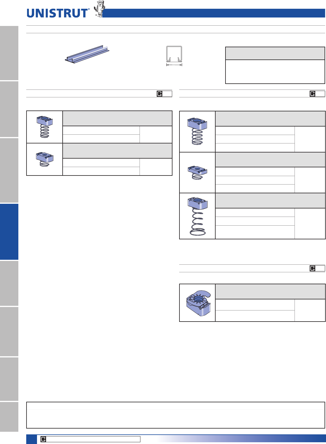
210
Special Metals
11¼4" System
13¼16" SystemFiberglass SystemSpecial MetalsPrimeAngleMetal GratingRoofwalkIndex
CORE PRODUCTS - TYPICALLY AVAILABLE FROM STOCK
EG
EGEG
Note
Most fittings, as shown in this catalog are available in stainless steel or aluminum.
It is recommended that stainless steel channel nuts be used with aluminum channels.
Stainless Steel Channel Nuts & Closure Strips
Part number
Nut Size
Thread
Wt/100 pcs
Lbs (kg) Use With
A1006-1420 SS 1»4" -20 6 (2.7)
A1000
A1008 SS 3»8" -16 6 (2.7)
Part number
Nut Size
Thread
Wt/100 pcs
Lbs (kg) Use With
A4006-1420 SS 1»4" -20 5 (2.3) A3300,
A4000
A4008 SS 3»8" -16 5 (2.3)
Part number
Nut Size
Thread
Wt/100 pcs
Lbs (kg)
Use With
15¼8" Channel
P1006U-1420 SS 1»4"20 7 (3.2) P1000,
P1100,
P2000,
P3000
P1008U SS 3»8" 16 10 (4.5)
P1010U SS 1»2" 13 12 (5.4)
Part number
Nut Size
Thread
Wt/100 pcs
Lbs (kg)
Use With
15¼8" Channel
P4006U-1420 SS 1»4"20 7 (3.2)
P3300,
P4000,
P4100
P4008 SS 3»8"16 9 (4.1)
P4010 SS 1»2"13 9 (4.1)
Part number
Nut Size
Thread
Wt/100 pcs
Lbs (kg)
Use With
15¼8" Channel
P5506U-1420 SS 1»4"20 7 (3.2)
P5500
P5508U SS 3»8" 16 10 (4.5)
P5510U SS 1»2" 13 10 (4.5)
CHANNEL NUT WITH SPRING – USE WITH 15¼8" CHANNELCHANNEL NUT WITH SPRING– USE WITH 11¼4" CHANNEL
CHANNEL NUT WITHOUT SPRINGS – USE WITH 15¼8" CHANNEL
U
N
I
S
T
R
U
T
U
N
I
S
T
R
U
T
Part number
Nut Size
Thread
Wt/100 pcs
Lbs (kg)
Use With
15¼8" Channel
P4006T-1420 SS 1»4"20 7 (3.2) P1000, P1100,
P2000, P3000
P5500P4008UT SS 3»8" 16 12 (5.4)
P1184 SS CLOSURE STRIP
Standard length 10 Ft.
Material: Stainless steel type 304.
W
Part
Number
Use With
Channel
“W”
,QPP
Wt/100 Ft
/EVNJP
P1184 SS
P1000
15»8
41.3
27
40.2
P1100
P3300
P4000
* All Springs are Pre-Galvanized
The letter "U" in Part number = Sintered type 316 stainless steel
The letter "U" in Part number = Sintered type 316 stainless steel
* All Springs are Pre-Galvanized
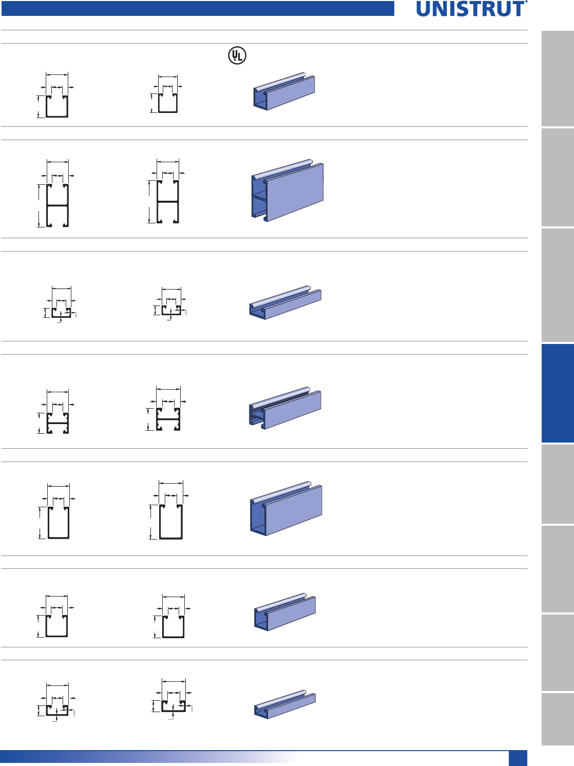
211
Special Metals
11¼4" System
13¼16" SystemFiberglass SystemSpecial MetalsPrimeAngle
Metal GratingRoofwalkIndex
When used
with P3184 EA.
P1000 EA
1 5⁄8"
1 5⁄8"
3⁄8"
7⁄8"
3⁄8"
41.3
41.3
22.2 9.5
9.5 Wt/100 Ft: 76 Lbs (113 kg/100 m)
Aluminum Type 6063-T6
Nominal Thickness .109" (2.8mm)
P1001 EA
Wt/100 Ft: 134 Lbs (199 kg/100 m)
Aluminum Type 6063-T6
12 Gauge Nominal Thickness .109" (2.8mm)
3 1⁄4"
1 5⁄8"
3⁄8"
7⁄8"
3⁄8"
82.6
41.3
22.2 9.59.5
P4000 EA
Wt/100 Ft: 45 Lbs (67 kg/100 m)
Aluminum Type 6063-T6
Nominal Thickness .078" (2.0mm)
13⁄16"
.078" .109"
3⁄8"
7⁄8"
3⁄8"
1 5⁄8"
20.6
22.8
22.2 9.59.5
41.3
P4001 EA
Wt/100 Ft: 66 Lbs (98 kg/100 m)
Aluminum Type 6063-T6
Nominal Thickness .078" (2.0mm)
1 5⁄8"
1 5⁄8"
3⁄8"
7⁄8"
3⁄8"
41.3
41.3
22.2 9.59.5
P5500 EA
Wt/100 Ft: 97 Lbs (144 kg/100 m)
Aluminum Type 6063-T6
Nominal Thickness .109" (2.8mm)
2 7⁄16"
1 5⁄8"
3⁄8"
3⁄8"
7⁄8"
61.9
41.3
22.2 9.59.5
A1000 EA
Wt/100 Ft: 40 Lbs (60 kg/100 m)
Aluminum Type 6063-T6
Nominal Thickness .075" (1.9mm)
A4000 EA
Wt/100 Ft: 25 Lbs (37 kg/100 m)
Aluminum Type 6063-T6
12 Gauge Nominal Thickness .050" (1.3mm)
Standard Length 16 Ft.
1 1⁄4"
1 1⁄4"
11⁄16"
9⁄32"9⁄32"
31.8
31.8
17.5
7.1 7.1
5⁄8"
.050" .075"
1 1⁄4"
11⁄16"
9⁄32"9⁄32"
15.9
1.3 1.9
31.8
17.5
7.1 7.1
Extruded Aluminum Channels
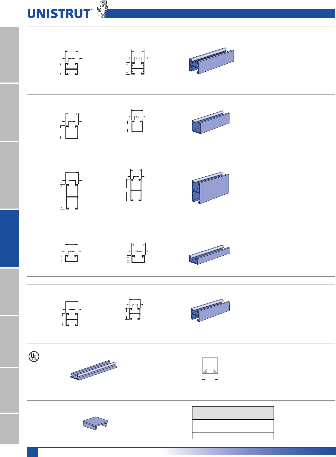
212
Special Metals
11¼4" System
13¼16" SystemFiberglass SystemSpecial MetalsPrimeAngleMetal GratingRoofwalkIndex
Extruded Aluminum Channels, Closure Strips, and End Caps
A4001 EA
Wt/100 Ft: 40 Lbs (60 kg/100 m)
Aluminum Type 6063-T6
Nominal Thickness .078" (2.0mm)
Standard Length 16 Ft.
P6000 EA
Wt/100 Ft: 12 Lbs (18 kg/100 m)
Aluminum Type 6063-T6
Nominal Thickness .040" (1.0mm)
Standard Length 16 Ft.
P6001 EA
Wt/100 Ft: 20 Lbs (30 kg/100 m)
Aluminum Type 6063-T6
Nominal Thickness .040" (1.0mm)
Standard Length 16 Ft.
1 1⁄4"
1 1⁄4"
11⁄16"9⁄32"
9⁄32"
31.8
31.8
17.5
7.1 7.1
13⁄16"
7⁄16"3⁄16"
13⁄16"
3⁄16"
20.6
20.6
11.1
4.8 4.8
1 5⁄8"
7⁄16"3⁄16"
3⁄16"
13⁄16"
41.3
4.84.8
20.6
11.1
P7000 EA
Wt/100 Ft: 9 Lbs (13 kg/100 m)
Aluminum Type 6063-T6
Nominal Thickness .040" (1.0mm)
Standard Length 10 Ft.
P7001 EA
Wt/100 Ft: 17 Lbs (25 kg/100 m)
Aluminum Type 6063-T6
12 Gauge Nominal Thickness .040" (1.0mm)
Standard Length 10 Ft
13⁄32"
7⁄16"3⁄16"
3⁄16"
13⁄16"
10.3
4.84.8
20.6
11.1
13⁄16"
7⁄16"3⁄16"
3⁄16"
13⁄16"
20.6
4.84.8
20.6
11.1
P3184 EA CLOSURE STRIP
P1280 EA, P4280 EA, P5580 EA END CAPS
Part
Number
Use With
Channel
Wt/100 Ft
/EVNJP
P1280 EA P1000 EA 3.5 (1.6)
P4280 EA P4000 EA 1.5 (0.7)
P5500 EA P5500 EA 4.9 (2.2)
Wt/100 Ft: 21 Lbs (31 kg/100 m)
Aluminum Type 6063-T6
Standard Length 10 Ft
1 5⁄8"
(41.3)
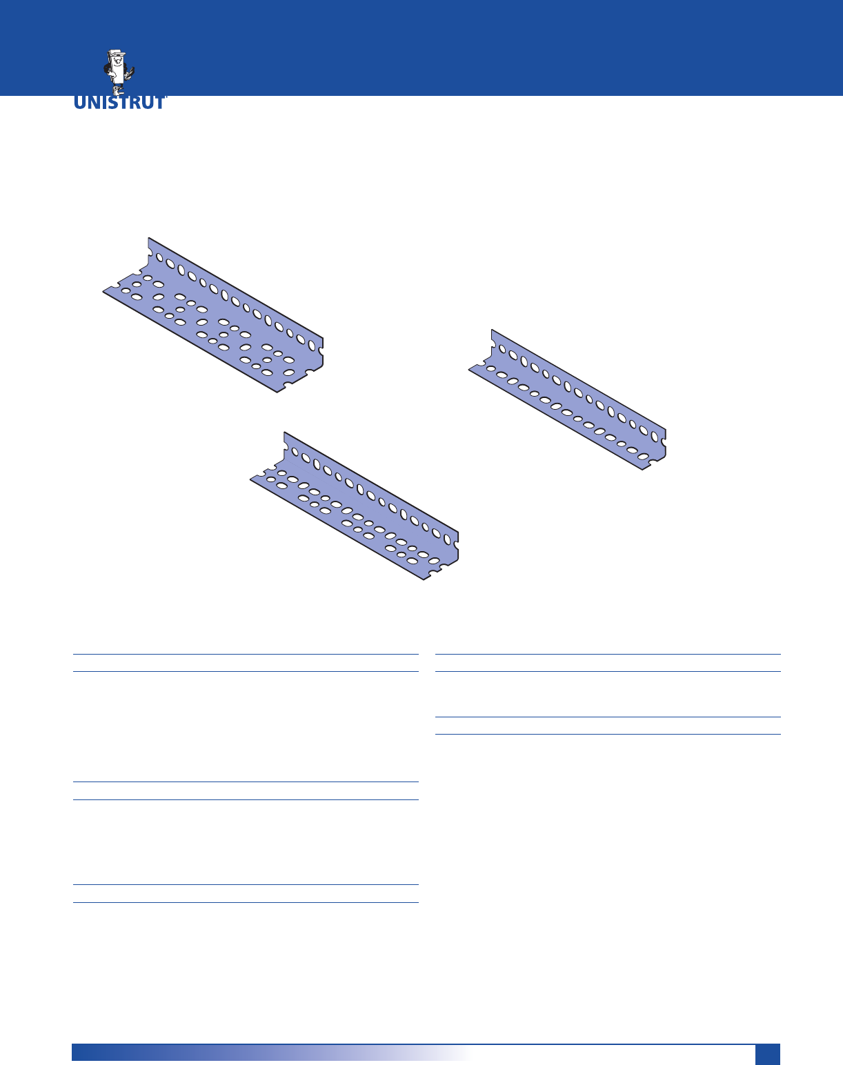
213
MATERIAL
STEEL: PLAIN
12 Gauge (.105" 1.0 mm) ASTM 1011 SS GR 33,
14 Gauge (.076) ASTM 1011 SS GR 33
STEEL: PRE-GALVANIZED
12 Gauge (.105" 1.0 mm) ASTM A653 GR 33,
14 Gauge (.076) ASTM A653 GR 33
FINISHES
Available in two durable, long-lasting finishes:
Pre-Galvanized (PG) or
Perma–Green III (GR) conforming to
ASTM B633 Type III SC1.
STANDARD LENGTHS
Standard lengths are 10' and 12'. Slotted angle is shipped
in ten-piece bundles complete with 75 pieces of 3⁄8" - 16 x
3⁄4" hex head bolts and 3⁄8" nuts.
ORDERING INFORMATION:
When ordering, add the length or size and finish to the
part number.
DIMENSIONS
Imperial dimensions are illustrated in inches. Metric dimen-
sions are shown in parenthesis or as noted. Unless noted,
all metric dimensions are in millimeters and rounded to
one decimal place.
PRIMEANGLE™
PrimeAngle™ .......................................................................... 214
Accessories .............................................................................. 215
PrimeAngle™ Technical Data ........................................216 - 218
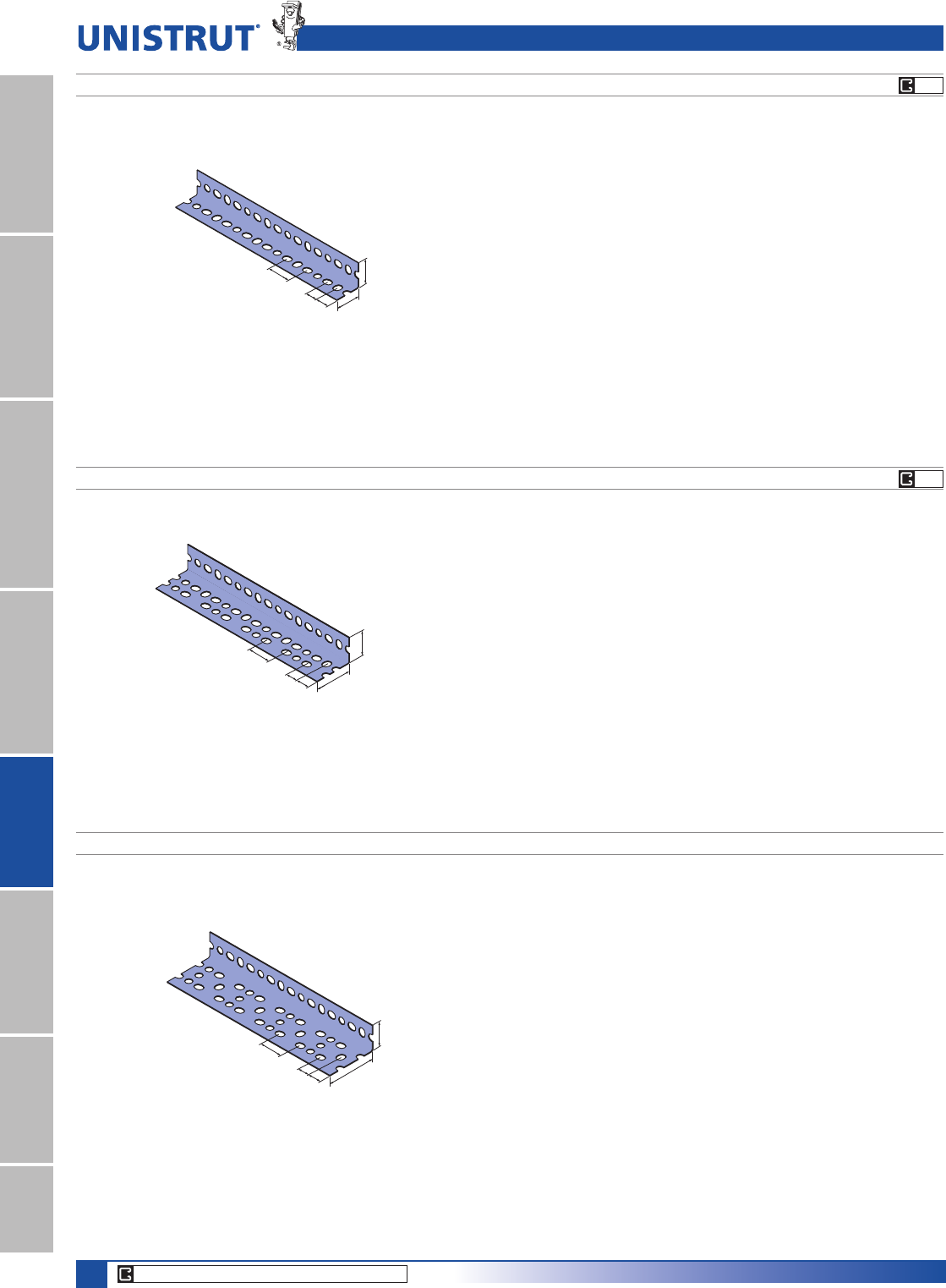
214
PrimeAngle
11¼4" System
13¼16" SystemFiberglass SystemSpecial MetalsPrimeAngleMetal GratingRoofwalkIndex
CORE PRODUCTS - TYPICALLY AVAILABLE FROM STOCK
PG
PG
PA 158 (15¼8" X 15¼8" X 14 GA.) LIGHT DUTY
15⁄8"
(41.3)
15⁄8"
(41.3)
11⁄2"
(38.1) 3⁄4"
(19.1) 3⁄4"
(19.1)
PA 238 (15¼8" X 23¼8" X 14 GA.) MEDIUM DUTY
23⁄8"
(60.3)
15⁄8"
(41.3)
11⁄2"
(38.1)
3⁄4"
(19.1)
3⁄4"
(19.1)
31⁄8"
(79.4)
1⁄8"
(41.3)
11⁄"
(38.1)
3⁄4"
(19.1)
3⁄4"
(19.1)
PA 318 (15¼8" X 31¼8" X 12 GA.) HEAVY DUTY
Note: Includes Serrated
Nuts & Bolts
Note: Includes Serrated
Nuts & Bolts
Note: Includes Serrated
Nuts & Bolts
PrimeAngle
For those jobs where extra strength is not
necessary. Ideal for light-duty shelving or
racking.
Perfect for the majority of framing
needs, including shelving, racking and
electrical or mechanical support jobs.
Suitable for balconies, ramps, large racks and
shelving systems, as well as other structures
with substantial load requirements.
Wt/100 Ft.: 66 lbs (29.9 kg)
Wt/100 Ft: 80 lbs(36.3 kg)
Wt/100 Ft: 130 lbs (59.0 kg)
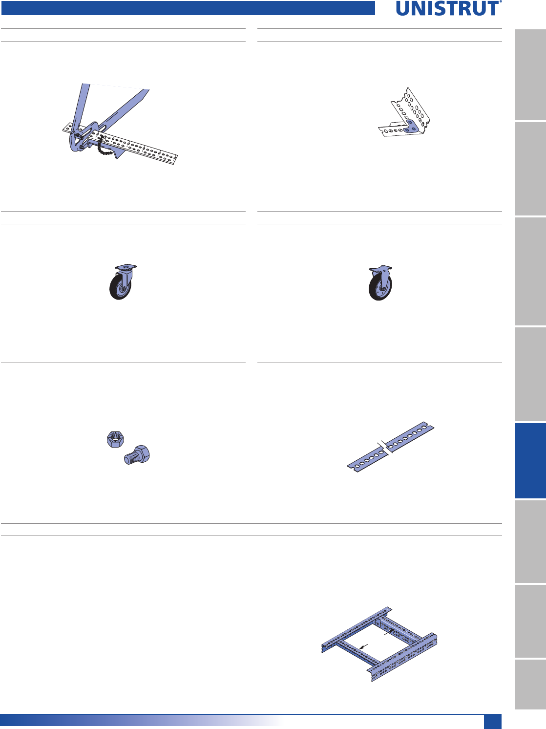
215
PrimeAngle
11¼4" System
13¼16" SystemFiberglass SystemSpecial MetalsPrimeAngle
Metal GratingRoofwalkIndex
PA 1GP GUSSET PLATEPA 1HDC PORTABLE CUTTER
PA 1RP SLOTTED STRAP
PA 1SC SWIVEL CASTER PA 1RC RIGID CASTER
PA 1SNB SERRATED NUTS AND BOLTS
3'-6''
(106.7 cm)
Max.
When supporting concentrated loads, the capacity of a pair of
slotted-angle beams can be increased by the addition of trans-
verse stiffeners. These should be placed immediately under the
load bearing point. The slotted-angle segment used as the stiffen-
er is bolted into place using a metal connector at each junction.
Beams that are 6' (182.9 cm) long or less require only one
stiffener in the center of the span. Seven-foot beams need two
stiffeners placed 2' (61.0 cm) from each end. Eight-foot beams
require two stiffeners 2’6" (76.2 cm) from the ends. For beams
with a nine-foot span, it is necessary to have three stiffeners at
2’3" (68.6 cm) intervals. Ten-foot beams need three stiffeners
with 2’6" spacings.
For maximum effectiveness, transverse stiffeners should never be
spaced more than 3’6" (106.7 cm) apart.
.OTE!LLLOADSBASEDONACTUALPHYSICALTESTING$OCUMENTATION
available on request.
TRANSVERSE STIFFENERS
PrimeAngle Accessories
Wt/100 pcs: 17 lbs (7.7 kg) Wt/100 pcs: 9 lbs (4.1 kg)
Wt/100 pcs: 170 lbs (77.1 kg) Wt/100 pcs: 110 lbs (49.9 kg)
Wt/100 pcs: 7 lbs (3.2 kg) Wt/100 pcs: 35 lbs (15.9 kg)
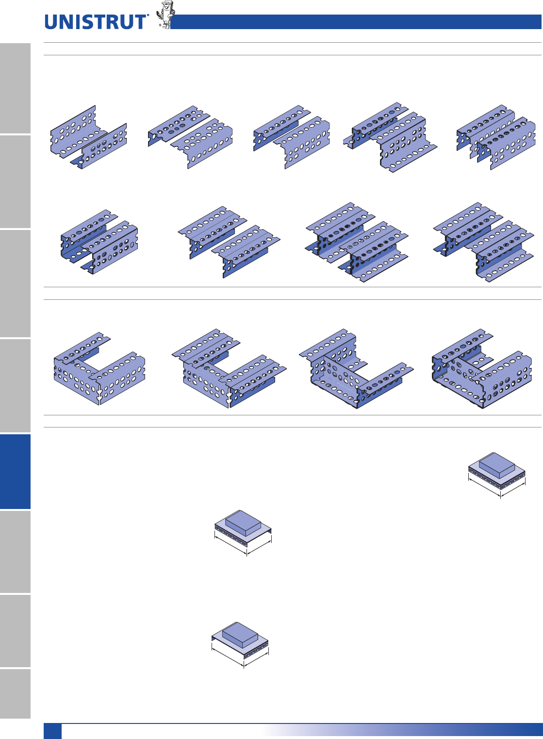
216
PrimeAngle
11¼4" System
13¼16" SystemFiberglass SystemSpecial MetalsPrimeAngleMetal GratingRoofwalkIndex
Example - Load “C”
Load “C” is supported by all four
beam sections. The load is distributed
uniformly on two 3' (91.4 cm) and
two 4' (121.9 cm) beams which total
14' (426.7 cm) of supporting beam
LENGTH$IVIDINGTHELBSK.
load by 14-feet equals 72 lbs. per foot
(106.3 kg per meter). Using the two 4'
(121.9 cm) longest (weakest) lengths,
calculate the total weight as follows:
2 (beams) x 4' (length) x 72 lbs./ft. = 576 lbs. total wt.
2 (beams) x 121.9cm (length) x 106.3 kg/M = 25,915 kg total wt.
The 36" (91.4 cm) row in the PA 238 table on next page indicates
what each beam configuration will support. Since the columns
are sorted from lowest to highest load, the first configuration
that satisfies the requirement is “J” which will support 830 lbs.
(3.7 kN) and is adequate for this requirement. The 3-foot beams
configured in the same manner will support the load because
they are shorter and stronger.
The beam loading depends on which slotted angle is used and the
manner in which the beam is constructed. The diagrams above
show how individual slotted angle components can be combined
to form a beam. The loading for each beam configuration is shown
in the beam loading tables on the next page.
Example - Load “A”
Load “A” is supported by two 48" (121.9
cm) sections of PA-238 (15⁄8" x 23⁄8")
(41.3mm x 60.3mm). The 48" row in
the PA 238 table on next page indicates
what each beam configuration will
support. Since the columns are sorted
from lowest to highest load, the
first configuration that satisfies the
requirement is “J” which will support 1,100 lbs (4.9 kN).
Example - Load “B”
Load “B” is supported by two 36"
(91.4 cm) sections of PA-238 (15⁄8"
x 23⁄8") (41.3mm x 60.3mm). The
36" row in the PA 238 table on next
page indicates what each beam
configuration will support. Since the
columns are sorted from lowest to
highest load, the first configuration that satisfies the requirement
is “J” which will support 1,100 lbs (4.9 kN).
BEAM CONFIGURATIONS
(See corresponding letters in table on following page for load data)
BEAM CONFIGURATIONS WITH STIFFENERS (See corresponding letters in table on following page for load data)
G – Two Single
Pieces (Up)
H – Two Single
Pieces (Level)
I – Two Single
Pieces (Down)
J – Two Z-Sections K – Two Narrow Channels
L – Two Broad Channels M – Two T-Sections N – Two I-Sections
P – Single Pieces w/Stiffener Q – T-Sections w/Stiffener R – Z-Sections w/Stiffener R – I-Sections w/Stiffener
4'
(121.9 cm)
1,000 LBS.
A
3'
(91.4 cm)
1,000 LBS.
B
4'
(121.9 cm) 3'
(91.4 cm)
1,000 LBS.
C
4'
(121.9 cm)
3'
(91.4 cm)
O – Two J-Sections
BEAM LOAD CALCULATIONS
PrimeAngle Beam Loads
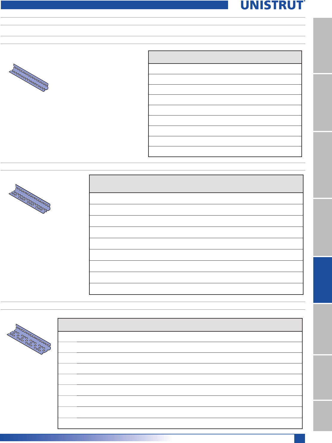
217
PrimeAngle
11¼4" System
13¼16" SystemFiberglass SystemSpecial MetalsPrimeAngle
Metal GratingRoofwalkIndex
BEAM LOADS
PA 158 LIGHT DUTY, (15¼8" X 15¼8" X 14 GA.)
PA 238 MEDIUM DUTY, (15¼8" X 23¼8" X 14 GA.)
PA 318 HEAVY DUTY, (15¼8" X 31¼8" X 12 GA.)
Span
,QFP
G
/EVN1
H
/EVN1
I
/EVN1
P
/EVN1
L
/EVN1
R
/EVN1
M
/EVN1
24 550 830 830 920 1,600 1,700 1,840
61.0 2.45 3.69 3.69 4.09 7.12 7.56 8.18
36 370 560 560 610 1,070 1,130 1,230
91.4 1.65 2.49 2.49 2.71 4.76 5.03 5.47
48 280 420 420 460 800 850 920
121.9 1.25 1.87 1.87 2.05 3.56 3.78 4.09
60 220 330 330 370 640 680 740
152.4 0.98 1.47 1.47 1.65 2.85 3.02 3.29
72 180 280 280 310 530 570 610
182.9 0.80 1.25 1.25 1.38 2.36 2.54 2.71
84 240 240 260 460 490 530
213.4 1.07 1.07 1.16 2.05 2.18 2.36
96 210 210 230 400 430 460
243.8 0.93 0.93 1.02 1.78 1.91 2.05
108
360 380 410
274.3 1.60 1.69 1.82
120
320 340 370
304.8 1.42 1.51 1.65
6HHFRUUHVSRQGLQJOHWWHUVLQWDEOHRQSUHYLRXVSDJHIRUFRQ¿JXUDWLRQV
Span
In.
FP
G
Lbs
N1
H
Lbs
N1
I
Lbs
N1
P
Lbs
N1
J
Lbs
N1
L
Lbs
N1
R
Lbs
N1
M
Lbs
N1
K
Lbs
N1
Q
Lbs
N1
O
Lbs
N1
N
Lbs
N1
24 700 1,020 1,660 1,740 2,220 3,170 3,230 3,490 3,590 3,630 6,060 7,560
61.0 3.11 4.54 7.38 7.74 9.88 14.10 14.37 15.52 15.97 16.15 26.96 33.63
36 460 680 1,100 1,160 1,480 2,110 2,150 2,320 2,390 2,420 4,040 5,040
91.4 2.05 3.02 4.89 5.16 6.58 9.39 9.56 10.32 10.63 10.76 17.97 22.42
48 350 510 830 870 1,110 1,580 1,620 1,740 1,800 1,810 3,030 3,780
121.9 1.56 2.27 3.69 3.87 4.94 7.03 7.21 7.74 8.01 8.05 13.48 16.81
60 280 410 660 700 890 1,270 1,290 1,390 1,440 1,450 2,420 3,020
152.4 1.25 1.82 2.94 3.11 3.96 5.65 5.74 6.18 6.41 6.45 10.76 13.43
72 230 340 550 580 740 1,060 1,080 1,160 1,200 1,210 2,020 2,520
182.9 1.02 1.51 2.45 2.58 3.29 4.72 4.80 5.16 5.34 5.38 8.99 11.21
84 290 470 500 630 910 920 1,000 1,030 1,040 1,730 2,160
213.4 1.29 2.09 2.22 2.80 4.05 4.09 4.45 4.58 4.63 7.70 9.61
96 260 410 440 550 790 810 870 900 910 1,520 1,890
243.8 1.16 1.82 1.96 2.45 3.51 3.60 3.87 4.00 4.05 6.76 8.41
108
490 700 720 770 800 810 1,350 1,680
274.3 2.18 3.11 3.20 3.43 3.56 3.60 6.01 7.47
120
440 630 650 700 720 730 1,210 1,510
304.8 1.96 2.80 2.89 3.11 3.20 3.25 5.38 6.72
Span
,QFP
G
/EVN1
H
/EVN1
I
/EVN1
P
/EVN1
J
/EVN1
L
/EVN1
R
/EVN1
M
/EVN1
K
/EVN1
Q
/EVN1
O
/EVNJ
N
/EVNJ
24 1,790 1,610 4,300 4,960 6,520 7,910 8,070 9,920 9,990 10,170 14,600 16,120
61.0 7.96 7.16 19.13 22.06 29.00 35.19 35.90 44.13 44.44 45.24 64.94 71.71
36 1,200 1,070 2,870 3,310 4,350 5,270 5,380 6,610 6,660 6,780 9,730 10,750
91.4 5.34 4.76 12.77 14.72 19.35 23.44 23.93 29.40 29.63 30.16 43.28 47.82
48 900 810 2,150 2,480 3,260 3,950 4,030 4,960 4,990 5,080 7,300 8,060
121.9 4.00 3.60 9.56 11.03 14.50 17.57 17.93 22.06 22.20 22.60 32.47 35.85
60 720 640 1,720 1,980 2,610 3,160 3,230 3,970 4,000 4,070 5,840 6,450
152.4 3.20 2.85 7.65 8.81 11.61 14.06 14.37 17.66 17.79 18.10 25.98 28.69
72 600 540 1,430 1,650 2,170 2,640 2,690 3,310 3,330 3,390 4,870 5,370
182.9 2.67 2.40 6.36 7.34 9.65 11.74 11.97 14.72 14.81 15.08 21.66 23.89
84 460 1,230 1,420 1,860 2,260 2,300 2,830 2,850 2,910 4,170 4,610
213.4 2.05 5.47 6.32 8.27 10.05 10.23 12.59 12.68 12.94 18.55 20.51
96 400 1,080 1,240 1,630 1,980 2,020 2,480 2,500 2,540 3,650 4,030
243.8 1.78 4.80 5.52 7.25 8.81 8.99 11.03 11.12 11.30 16.24 17.93
108
1,100 1,450 1,760 1,790 2,200 2,220 2,260 3,240 3,580
274.3 4.89 6.45 7.83 7.96 9.79 9.88 10.05 14.41 15.92
120
990 1,300 1,580 1,610 1,980 2,000 2,030 2,920 3,220
304.8 4.40 5.78 7.03 7.16 8.81 8.90 9.03 12.99 14.32
PrimeAngle Beam Loads
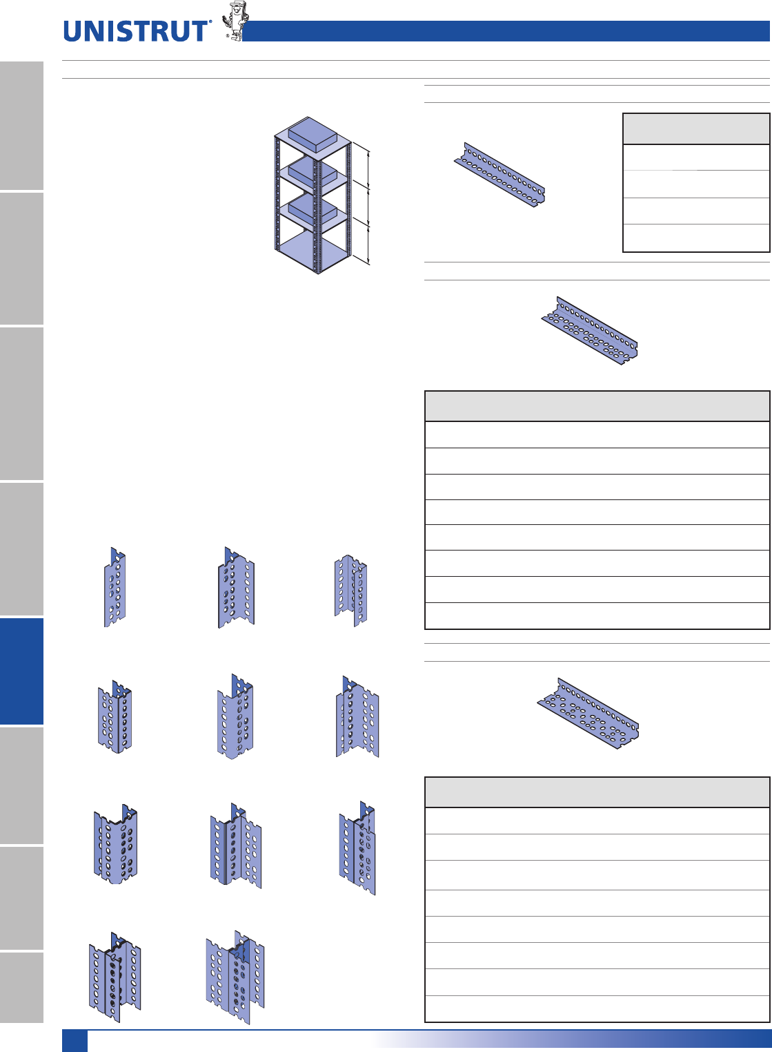
218
PrimeAngle
11¼4" System
13¼16" SystemFiberglass SystemSpecial MetalsPrimeAngleMetal GratingRoofwalkIndex
COLUMN LOADS
PA 158 (15¼8" X 15¼8" X 14 GA.)
PA 238 (15¼8" X 23¼8" X 14 GA.)
PA 318 (15¼8" X 31¼8" X 12 GA.)
A – Single Piece B – T-Section B – Broad
Channel Section
B – Narrow Channel
Section
C – Uneven
T-Section
C – Uneven Channel
Section
D – Dual
Channel Section
D – T-Channel
Section
D – T-Channel Section
E – I-Section F – Uneven I-Section
Column sections are calculated as
described in the following example:
(Assumes use of PA-238 15⁄8" x
23⁄8"(41.3mm x 60.3mm), material.)
Since all load areas are supported
equally by the 4-columns, the
calculations are based on a single-
column section.
Section MN is one-fourth of “X”,
or 250 pounds (1.1 kN). Column
section NP supports one-fourth
of “Y” (250 pounds) plus the load
supported by MN, or a total of
500 pounds (2.2 kN). Section PQ
SUPPORTSONEFOURTHOFh:v
pounds) plus the 500 pound load on section NP, or a total of
750 (3.3kN) pounds.
Column loads are based on free and unbraced column lengths.
Since MN, NP and PQ are each 3' long, the load requirement is
for a 36" section that will bear 750 pounds safely. A reference to
the PA 238 table to the right indicates that all sections designated
“A” will support 2,280 lbs. (10.1 kN) and meet the necessary
requirements.
Note: To simplify assembly, we recommend using the same size
material as for the horizontal members. This would be found in
Table 2 to match the 14 gauge 15⁄8" x 23⁄8" (41.3mm x 60.3mm)
material selected for the beams of this structure.
X
1,000 LBS.
Y
1,000 LBS.
Z
1,000 LBS.
M
N
P
Q
3'
(91.4cm)
3'
(91.4cm)
3'
(91.4cm)
Span
,QFP
A
/EVN1
B
/EVN1
36 1,450 3,850
91.4 6.45 17.13
48 1,150 3,500
121.9 5.12 15.57
60 950 3,000
152.4 4.23 13.34
72 750 2,500
182.9 3.34 11.12
Span
,QFP
A
/EVN1
B
/EVN1
C
/EVN1
D
/EVN1
E
/EVN1
F
/EVN1
36 2,280 4,760 4,940 7,270 9,520 9,865
91.4 10.14 21.17 21.97 32.34 42.35 43.88
48 1,970 4,490 4,680 6,920 8,970 9,330
121.9 8.76 19.97 20.82 30.78 39.90 41.50
60 1,520 3,995 4,310 6,370 7,990 8,620
152.4 6.76 17.77 19.17 28.34 35.54 38.34
72 1,070 3,140 3,870 5,840 6,280 7,715
182.9 4.76 13.97 17.21 25.98 27.93 34.32
84 660 2,340 3,665 4,930 4,660 6,740
213.4 2.94 10.41 16.30 21.93 20.73 29.98
96 1,750 2,700 3,850 3,500 5,365
243.8 7.78 12.01 17.13 15.57 23.86
108
2,060 2,870 4,115
274.3 9.16 12.77 18.30
120
1,610 2,690 3,210
304.8 7.16 11.97 14.28
Span
,QFP
A
/EVN1
B
/EVN1
C
/EVN1
D
/EVN1
E
/EVN1
F
/EVN1
36 3,470 7,970 8,770 12,560 15,940 17,550
91.4 15.44 35.45 39.01 55.87 70.90 78.07
48 2,870 7,360 8,580 11,970 14,750 17,150
121.9 12.77 32.74 38.17 53.25 65.61 76.29
60 1,970 6,570 8,180 11,360 13,160 16,360
152.4 8.76 29.22 36.39 50.53 58.54 72.77
72 1,280 5,270 7,690 10,480 10,560 15,360
182.9 5.69 23.44 34.21 46.62 46.97 68.32
84 3,670 6,970 9,470 7,370 13,970
213.3 16.32 31.00 42.12 32.78 62.14
96 2,580 6,260 8,370 5,170 12,570
243.8 11.48 27.85 37.23 23.00 55.91
108
5,460 6,880 10,970
274.3 24.29 30.60 48.80
120
4,460 5,370 8,960
304.8 19.84 23.89 39.86
PrimeAngle Column Loads
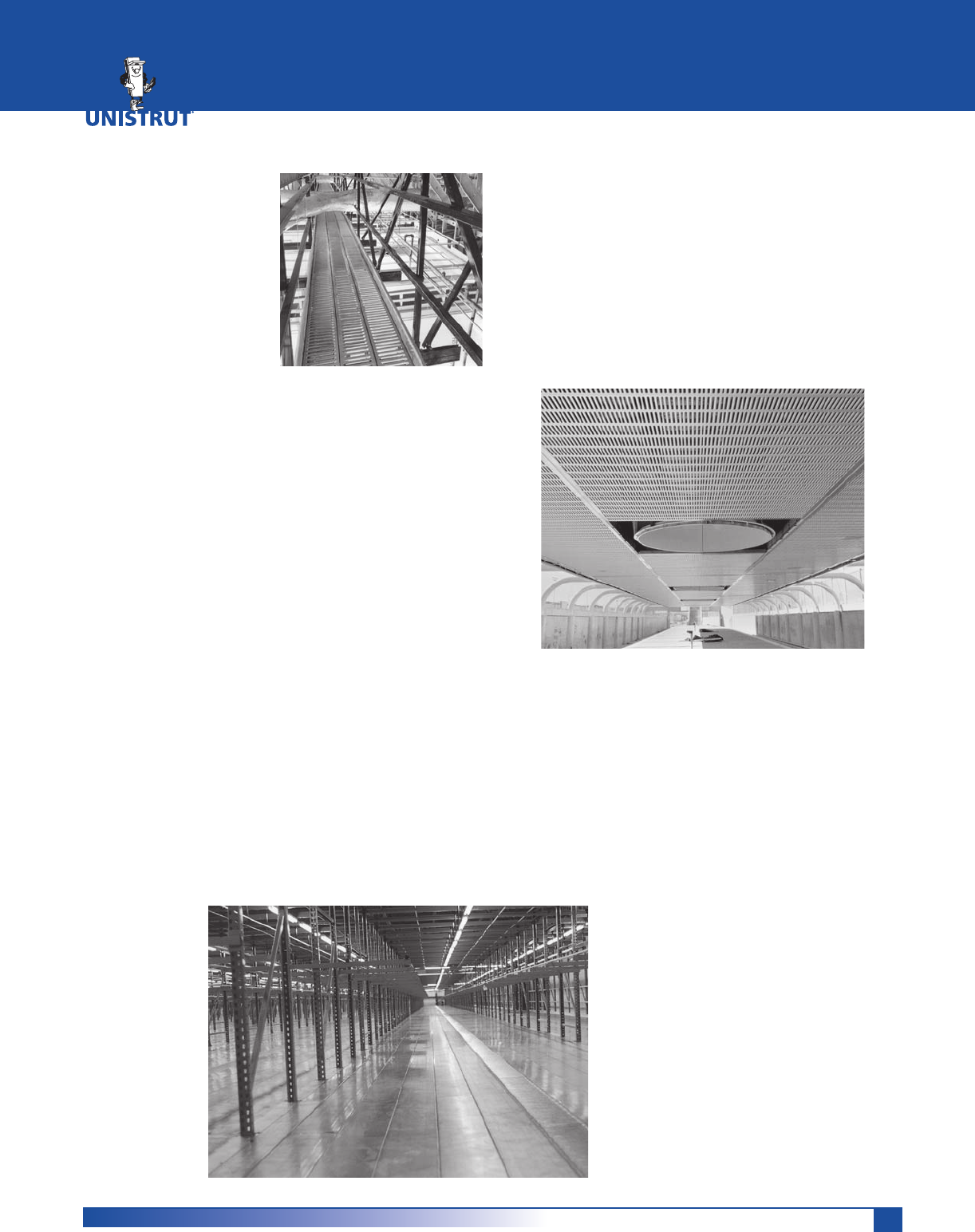
219219
United Interlock® Grating
United Interlock Plank
Grating System from
Unistrut, commonly
known as Interlock
Grating, fills a multitude
of needs including
flooring and walkways,
mezzanines, stair treads,
maintenance and staging
platforms, scaffolding
planks, architectural wall coverings and more. United
Interlock Grating Systems meets your needs for
strength, durability, safety and aesthetics.
Customers choose United Interlock Grating Systems for
many reasons:
s #OSTEFFECTIVENESS
s %ASYTOINSTALLPRODUCT
s 1UALITYASSURANCETHATCOMESFROM
extensive load testing
s ,ARGEINVENTORIESANDFASTDELIVERY
s 3TRONGDESIGNLOOKOFOURPLANKGRATING
In addition to supplying the grating, Unistrut offers
turnkey service for your project. This includes
engineering, support structures, and installation.
United Interlock Grating Applications include:
s!RCHITECTURALWALLCOVERINGS
s#ATWALKSWALKWAYSANDPEDESTRIANRAMPS
s-AINTENANCEANDINSPECTIONWALKWAYS
s6ENTILATIONCOVERSFORTANKSANDWELLS
s-ININGANDQUARRYTOWERDECKING
s0UMPINGANDDRILLINGPLATFORMS
s3UBFLOORING
s-EZZANINES
s3HELVING
s3TAIRS
UNITED INTERLOCK® GRATING
Ease of Installation ..........................................................................220
Plank Grating ..........................................................................221 - 222
Accessories ..............................................................................223 - 225
Heavy Duty Stair Treads ..................................................................226
Design and Testing ..........................................................................227
Plank Loads and Deflections ..................................................228 - 233
Architectural Specifications .............................................................234
Architectural Applications
Interlock Grating provides a functional and
aesthetically appealing look to architectural
APPLICATIONS!LUMINUMGRATINGSRESISTCORROSION
to give walls, ceilings, ledges, trim, flooring, and
SPECIALTYPROJECTSACLEANLASTINGHIGHTECHLOOK
Interlocking plank grating works especially well in
INTENSIVEUSEAREAS)NADDITIONTOITSDURABILITYITIS
easy to clean and does not reflect sound like a solid
surface.
!RCHITECTSHAVEOFTENSELECTED)NTERLOCK
Grating because it protects lights,
insulation support columns, wiring, and
OTHERlXTURES!NDTHEPANELSALLOW
authorized personnel to access the
fixtures.
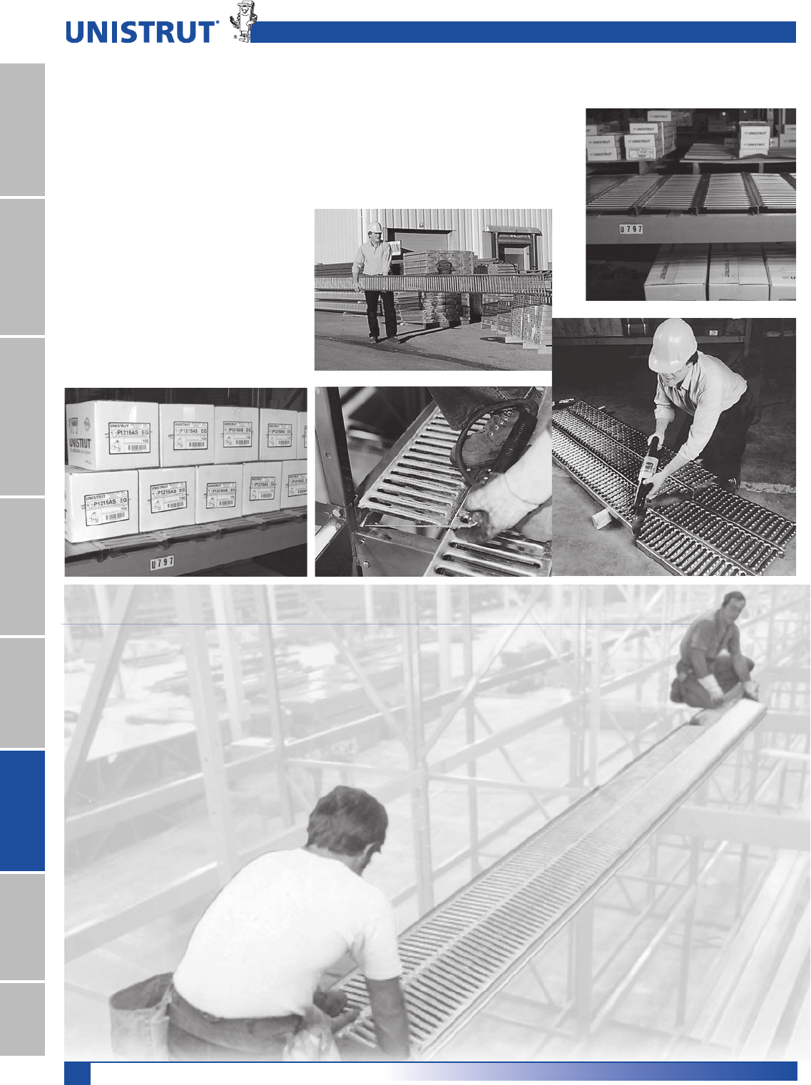
220
United Interlock® Grating
11¼4" System
13¼16" SystemFiberglass SystemSpecial MetalsPrimeAngleMetal GratingRoofwalkIndex
Contractors have reported installed cost savings of up to 75% with Interlock
'RATING-ANYFACTORSCOMBINETOMAKEINSTALLATIONQUICKANDEASY
1) The lightweight grating is easy to handle. One person can carry a 24' plank.
2) Interlock Grating is easy to install with a minimal number of laborers.
3) Interlock Grating’s light weight reduces shipping costs.
4) The planks interlock with positive friction, eliminating costly
welding and bolting.
5) Field modifications are easy.
Interlock Grating can be cut
to size, shape, and angle at the
jobsite.
)NTERLOCK'RATINGREQUIRESFEWER
support structures.
United Interlock distribution network provides
local support for complete project administration as
DESIREDORREQUIREDBYOURCUSTOMERS4HISINCLUDES
engineering, design, and installation of all the United
Interlock Grating Systems.
Our engineers can design a grating system which
will safely span the area using existing supports at
your facility, perform load and deflection tests for
unusual loading conditions,
advise you of the most
economical placement of
grating and supports, and
provide fabrication and erection
drawings.
We can complete your project
by coordinating all aspects of
installation. Our local distribution network can
coordinate shipping and staging of materials, provide
and supervise local installation crews, and arrange
FORSPECIALERECTIONEQUIPMENTSERVICES
Project Services
Ease of Installation
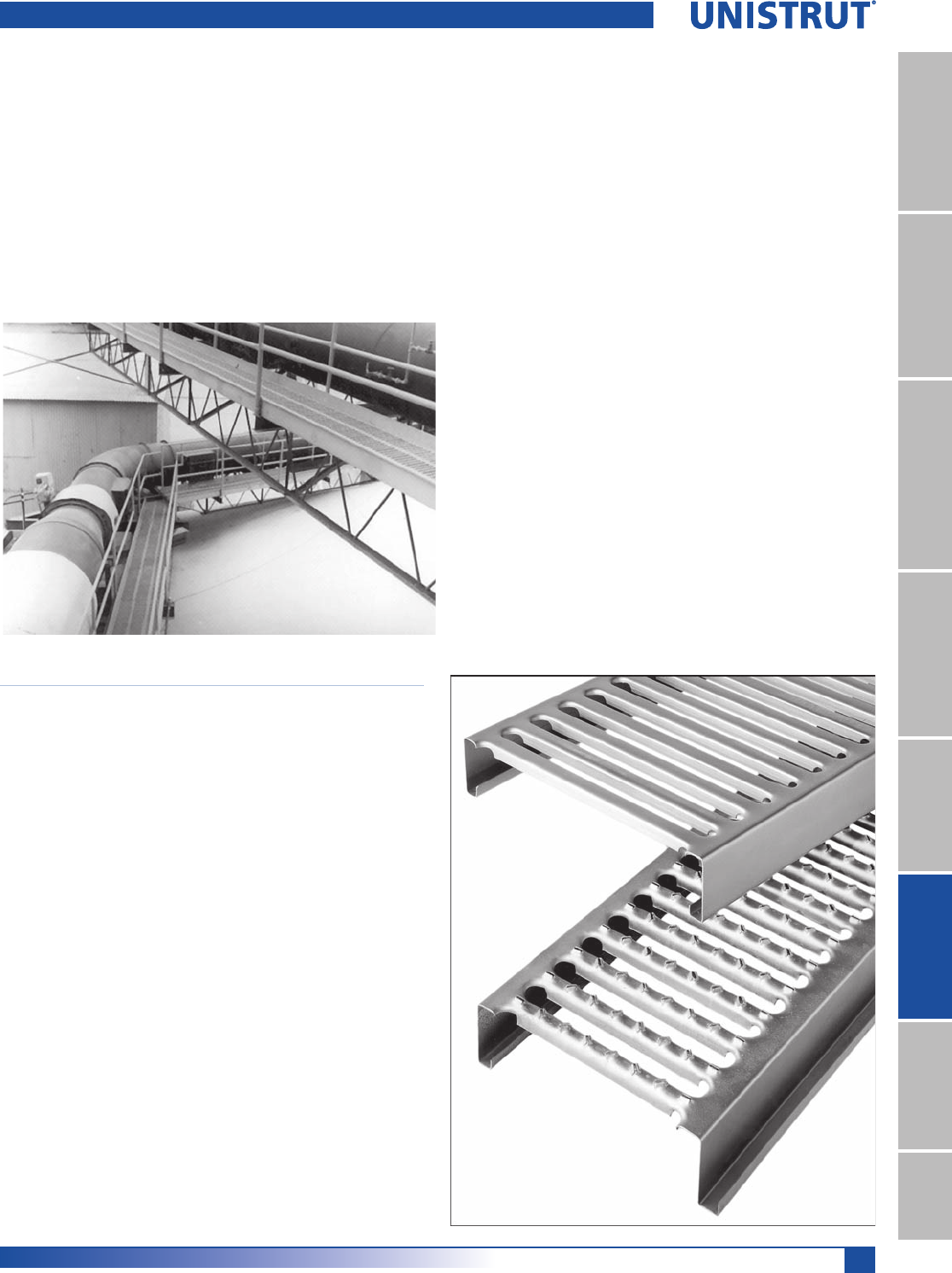
221
United Interlock® Grating
11¼4" System
13¼16" SystemFiberglass SystemSpecial MetalsPrimeAngle
Metal GratingRoofwalkIndex
Interlock Grating Features
Maximizes performance and safety…
s!NTISKIDSURFACEPROVIDESOFSLIPRESISTANCE
s3UPERIORULTIMATELOADPERFORMANCETESTEDIN
ACCORDANCEWITH!)3)STANDARDS
s!LLSECTIONSMADEFROMSTRUCTURALGRADESTEEL
s2OLLFORMEDDESIGNPROVIDESSUPERIORSTRENGTH
s/PTIONALHEELTOESIDEANDENDPLATES
s/PENDESIGNPREVENTSBUILDUPOFWATERGREASE
oil and small debris
And gives you complete project versatility.
sANDPLANKWIDTHSALLOWDESIGNIN
increments
s3TANDARDLENGTHSOFgANDgANDSPECIAL
LENGTHSUPTOgPROVIDEEXCELLENTDESIGN
flexibility
s#HOICEOFSMOOTHPUNCHEDANTISKIDPUNCHED
or solid unpunched surfaces
s4HREELEGHEIGHTSANDTWOMATERIALGAUGES
meet a wide range of load, space and budget
REQUIREMENTS
5NITED)NTERLOCK'RATINGSTRENGTHTOWEIGHTRATIO
allows it to withstand substantial loads while being
EASYTOHANDLE4HEMALEFEMALELEGSOFTHEROLL
FORMEDGRATINGINTERLOCKSECURELYANDDOUBLEMALE
legs provide a safe finished edge for end planks.
4WOSTANDARDSURFACESAREAVAILABLESLOTTEDSMOOTH
ANDANTISKID!NTISKIDISTHEIDEALCHOICEWHENSAFE
WALKINGCONDITIONSAREIMPORTANT$IEFORMEDTEETH
INTHETRANSVERSERIBSGIVEYOUOFSHOEGRIPPING
traction even when the grating is wet, oily, muddy, or
icy.
Punched Interlock Grating has an open area of 42%
FORGRATINGANDFORGRATING4HISPREVENTS
dirt, debris, ice, and snow from building up on the
surface and allows light and air to pass through.
5NITED)NTERLOCKSTEELGRATINGISMADEFROMPRE
GALVANIZEDSTEELWHICHCONFORMSTOA'THICKNESS
DESIGNATIONPER!34-!4HEALUMINUMGRATINGIS
MADEFROMTYPEALUMINUMWITHATHICKNESSOF
Unpunched smooth surface grating is also available
for special applications.
United Interlock Grating Systems are strong,
economical, versatile, and easy to specify.
Variety of choices
sANDSTANDARDDUTYWIDTH
sLIGHTDUTYWIDTH
sGAUGEANDGAUGE
s1⁄21⁄2ANDLEGHEIGHTS
sgANDgSTOCKLENGTHS
s!NTISKIDSLOTTEDSMOOTHPUNCHEDSURFACESAND
solid unpunched surface
s$OUBLEMALEANDMALEFEMALELEGSHAPES
s3TEELORANDALUMINUMOR
Plank Grating
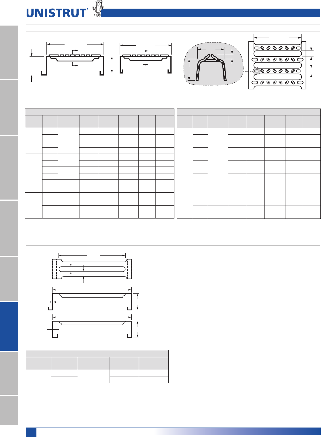
222
United Interlock® Grating
11¼4" System
13¼16" SystemFiberglass SystemSpecial MetalsPrimeAngleMetal GratingRoofwalkIndex
21⁄2"
18 gauge
12''
10
1
⁄
2
"
3
⁄
4
"
3
⁄
4
"
[MF] Male-Female Leg
21⁄2"
18 gauge
12''
[DM] Double Male Leg
For Light Traffic Applications
)DEALFORMEZZANINESANDOTHERLARGEAREAAPPLICA
TIONSEXTRAWIDEINTERLOCKINGPLANKGRATING
is designed to simplify installation and reduce the
cost of mezzanines, flooring, decking, staging plat
FORMS2OOFWALKS® and similar applications. With a
43% open area, it allows water, light and air to pass
through.
7ITHITSEXTRAWIDTH5NISTRUTWIDEPLANKGRATING
covers more area with fewer planks, lowering instal
LATIONCOSTS)TSHIGHSTRENGTHTOWEIGHTRATIO
gauge, 21⁄2LEGHEIGHTMAKESITIDEALFORCOVERING
LARGELIGHTTRAFlCAREAS)TSSNAPTOGETHERFRICTIONlT
make it easy to install, with no welding or bolting
REQUIRED
-ADEOFPREGALVANIZEDSTEELITSMAINTENANCEFREE
and long lasting. Specifiers can choose a smooth or
ANTISKIDSURFACETOMEETAWIDEVARIETYOFAPPLICA
tion needs.
12" Wide Planks, 18 Gauge
Leg
Height
Leg
Shape
Finish
Material
Slotted,
Smooth Anti-Skid
21⁄2"DM PG
18 Gauge
G 11281 G 11282
MF G 12281 G 12282
Note: 3TANDARDGRATINGLENGTHSAREgORg$-n$OUBLE-ALE-&n-ALE&EMALE
Unpunched smooth surface grating is also available for special applications. Contact Unistrut for more information.
9" Wide Planks (14 Ga, 18 Ga, 0.080 Aluminum)
Leg
Height
Leg
Shape
Finish
Material
Slotted,
Smooth
Anti-
Skid
Un-
punched
Wt.
Lbs./Ft
Wt.
Lbs./Ft2
11⁄2"
DM PG
14 Ga.
G91141 G91142 G91143 3.5 4.7
MF G92141 G92142 G92143 3.5 4.7
DM PG
18 Ga.
G91181 G91182 G91183 2.3 3.1
MF G92181 G92182 G92183 2.3 3.1
21⁄2"
DM PG
14 Ga.
G91241 G91242 G91243 4.0 5.3
MF G92241 G92242 G92243 4.0 5.3
DM PG
18 Ga.
G91281 G91282 G91283 2.7 3.6
MF G92281 G92282 G92283 2.7 3.6
DM AL
0.080"
G91221 G91222 G91223 1.5 2.0
MF G92221 G92222 G92223 1.5 2.0
4"
DM PG
14 Ga.
G91341 G91342 G91343 4.8 6.4
MF G92341 G92342 G92343 4.8 6.4
DM PG
18 Ga.
G91381 G91382 G91383 3.2 4.3
MF G92381 G92382 G92383 3.2 4.3
6" Wide Planks (14 Ga, 18 Ga, 0.080 Aluminum)
Leg
Height
Leg
Shape
Finish
Material
Slotted,
Smooth
Anti-
Skid
Un-
punched
Wt.
Lbs./Ft
Wt.
Lbs./Ft2
11⁄2"
DM PG
14 Ga.
G61141 G61142 G61143 2.7 5.4
MF G62141 G62142 G62143 2.7 5.4
DM PG
18 Ga.
G61181 G61182 G61183 1.8 3.6
MF G62181 G62182 G62183 1.8 3.6
21⁄2"
DM PG
14 Ga.
G61241 G61242 G61243 3.4 6.8
MF G62241 G62242 G62243 3.4 6.8
DM PG
18 Ga.
G61281 G61282 G61283 2.2 4.4
MF G62281 G62282 G62283 2.2 4.4
DM AL
0.080"
G61221 G61222 G61223 1.2 2.3
MF G62221 G62222 G62223 1.2 2.3
4"
DM PG
14 Ga.
G61341 G61342 G61343 4.2 8.4
MF G62341 G62342 G62343 4.2 8.4
DM PG
18 Ga.
G61381 G61382 G61383 2.8 5.6
MF G62381 G62382 G62383 2.8 5.6
1⁄2"
1⁄8"
Nom.
3⁄4"
3⁄4"
3⁄4"
43⁄4" or 71⁄2"
Anti-skid Rib Anti-Skid Surface Shown
Plank Grating
UNITED INTERLOCK® GRATING SYSTEMS—6" AND 9"
UNITED INTERLOCK® GRATING SYSTEMS—12"
9'' or 6''
Leg
Height
B
B
9'' or 6''
Leg
Height
B
B
[DM] Double Male Leg
Male-Female Leg [DM] Double-Male Leg
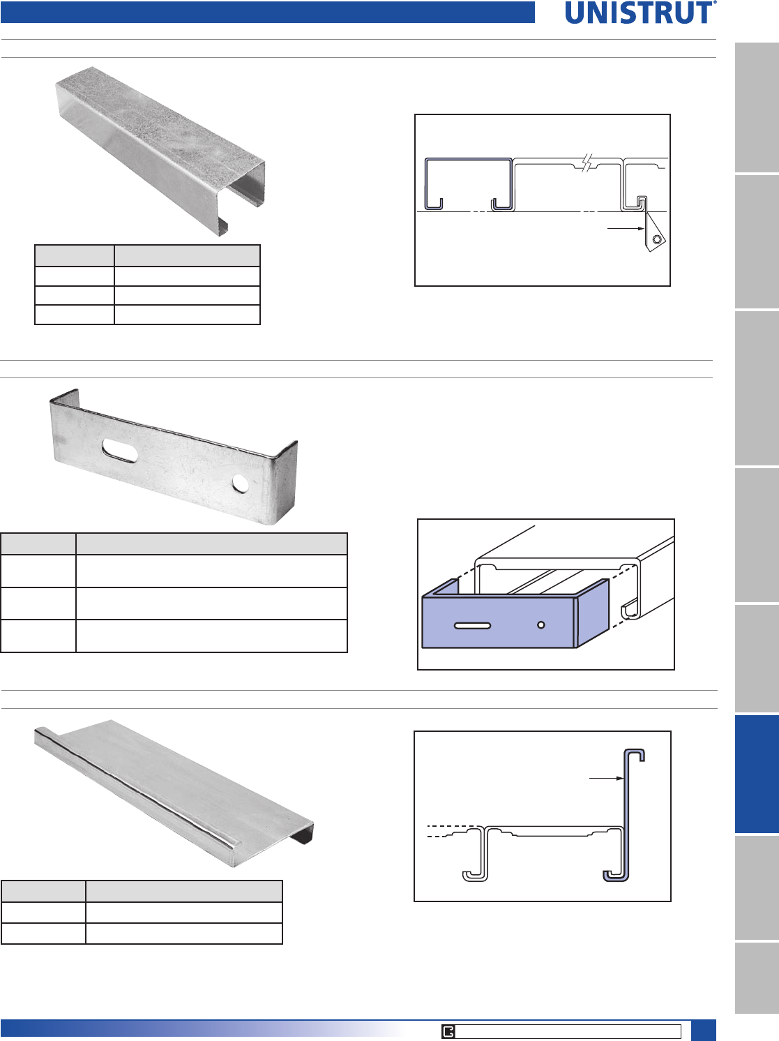
223
United Interlock® Grating
11¼4" System
13¼16" SystemFiberglass SystemSpecial MetalsPrimeAngle
Metal GratingRoofwalkIndex
Part No.* Description
G631 PG* 14 ga. x 61⁄2HIGHXgLONG
G621 PG GAXHIGHXgLONG
Forms a curb along grating length that defines a structure’s side
edge, and helps contain loose objects.
0ARTNUMBERSSHOWNAREFORGALVANIZED-OSTACCESSORIESAREALSOAVAILABLEINALUMINUM
Part No.* Description
G31183 PG 3" Wide x 11»2" Leg Height
G31283 PG 3" Wide x 21»2" Leg Height
G31383 PG 3" Wide x 4" Leg Height
0ROVIDEDINSTANDARDLENGTHSOFgANDg
FILLER PANEL
Beam Clip
Filler Panel Plank
CARRIER PLATE
Part No.* Description
G603 PG 10 ga.- for 9" wide heavy duty stair treads
(9»16" hole and 11»2" x 9»16" slot)
G618 PG 10 ga. for 101»2" wide stair treads
(9»16" hole and 11»2" x 9»16" slot)
G642 PG 10 ga. for 11" wide stair treads
(9»16" hole and 11»2" x 9»16" slot)
Provides easy attachment of stair treads to support structures and stringers.
Carrier Plate
Plank
Accessories
HEEL/TOE SIDE PLATES – 61»2" AND 8" HEIGHTS
Side Plate
Plank
CORE PRODUCTS - TYPICALLY AVAILABLE FROM STOCK
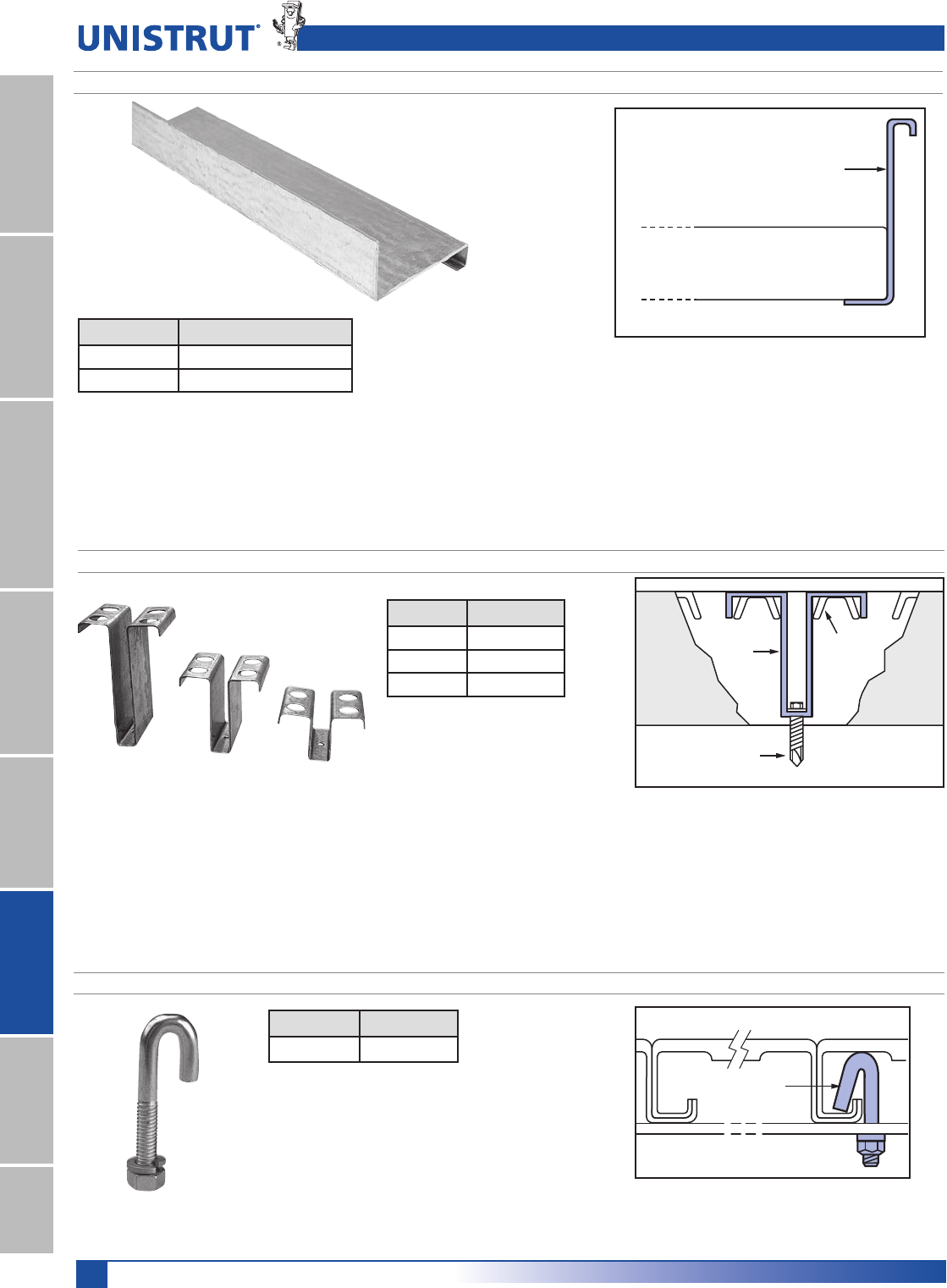
224
United Interlock® Grating
11¼4" System
13¼16" SystemFiberglass SystemSpecial MetalsPrimeAngleMetal GratingRoofwalkIndex
HOLD DOWN CLIP
Part No. Description
G639 PG 11»2" leg height
G607 PG* 21»2" leg height
G620 PG 4" leg height
“J” BOLT/NUT LOCK WASHER
Part No.* Description
G600 EG 5⁄16X1⁄2
!TTACHMENTFORFASTENINGPANELSTOSUPPORTING
members from underside of grating.
0ARTNUMBERSSHOWNAREFORGALVANIZED-OSTACCESSORIESAREALSOAVAILABLEINALUMINUM
Hold
Down
Clip
Plank
Plank
Ribs
Self-Drilling,
Self-Tapping
Screw
“J” Bolt
Plank
Accessories
HEEL/TOE END PLATES – 61»2" AND 8" HEIGHTS
Part No.* Description
G622 PG 14 ga. x 61»2" high x 12' long
G623 PG 14 ga. x 8" high x 12' long
Forms a curb along grating ends that defines a structure’s edge,
and helps contains loose objects.
End Plate
Plank
!GAUGEATTACHMENTFORFASTENINGGRATINGTOSUPPORTSTRUCTURE
BELOW!TTACHESTHROUGHTOPSIDEOFGRATING
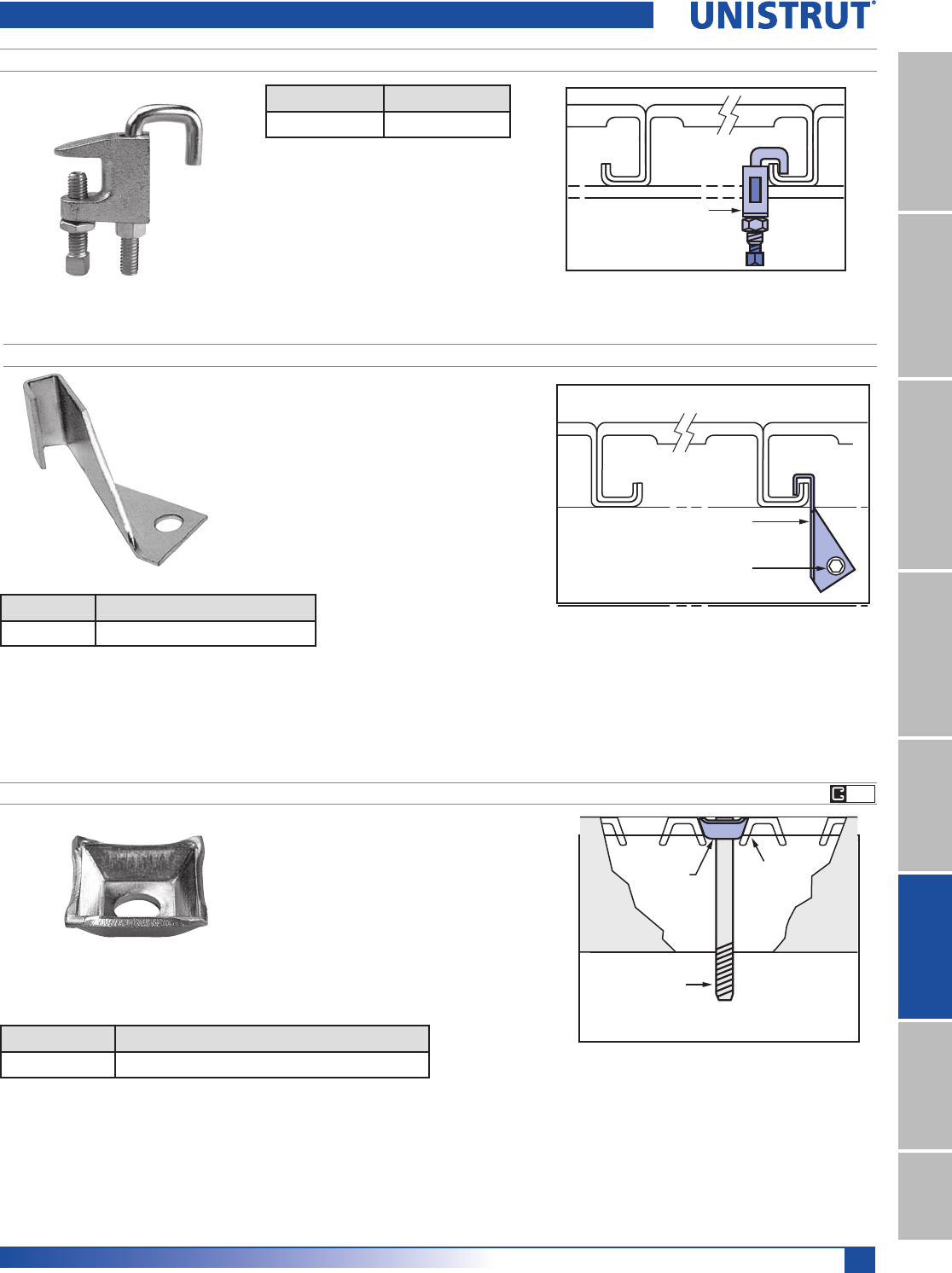
225
United Interlock® Grating
11¼4" System
13¼16" SystemFiberglass SystemSpecial MetalsPrimeAngle
Metal GratingRoofwalkIndex
0ARTNUMBERSSHOWNAREFORGALVANIZED-OSTACCESSORIESAREALSOAVAILABLEINALUMINUM
GRATING BEAM CLAMP
Part No.* Description
G640 EG Beam clamp
!TTACHESGRATINGTOSTRUCTURAL)BEAMS
2EQUIRESNOWELDINGORDRILLING
Plank
Grating
Beam
Clamp
RECESSED WASHER
Part No.* Description
G714 EG 11⁄X1⁄GAUGESQUAREWASHER
(OLDSDOWNGRATINGFROMABOVE%LIMINATESTRIPPOINTS
Recessed
Washer
Plank
Bolt Attached
to Support
Structure
Plank
Ribs
LIGHT GAUGE BEAM CLIP
Part No.* Description
G124 EG ,IGHT'AUGE"EAM#LIP
1UICKLYATTACHESGRATINGTORACKORSHELVINGBEAMS
2EQUIRESSELFDRILLINGSELFTAPPINGSCREW'(43%'
NOTINCLUDED
Beam Clip
Self-Drilling,
Self-Tapping
Screw
Plank
Accessories
EG
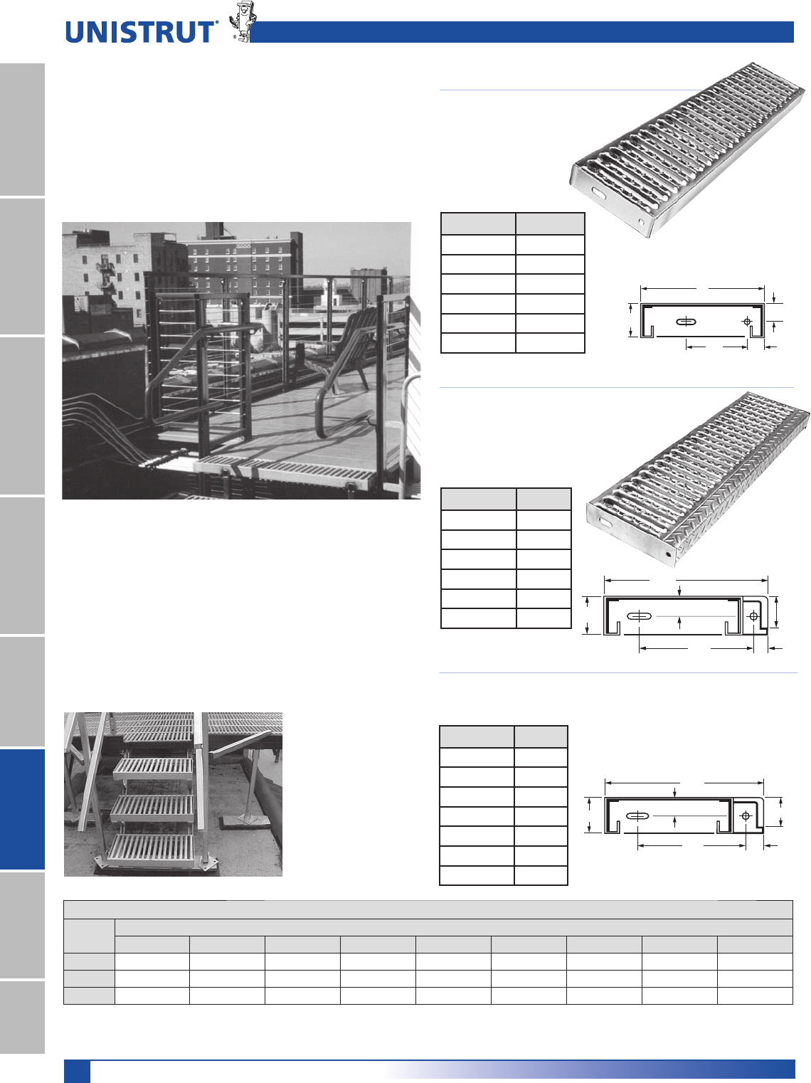
226
United Interlock® Grating
11¼4" System
13¼16" SystemFiberglass SystemSpecial MetalsPrimeAngleMetal GratingRoofwalkIndex
101⁄2" Stair Tread
14 gauge x 21⁄2X1⁄2
Completely galvanized,
WELDEDGAUGEENDPLATES
Part No.* Len. (in.)
G 901-24 PG 24
G 901-30 PG 30
G 901-36 PG 36
G 901-42 PG 42
G 901-48 PG 48
G 901-60 PG 60
9" Stair Tread
14 gauge x 21⁄2X
Completely galvanized,
WELDEDGAUGE
end plates
!NYONEWHOHASSLIPPEDONASTAIRWAYCAN
APPRECIATETHESAFETYOFTHEANTISKIDSTAIRTREADS
4HOSEWHOHAVETRIEDTOCLEANSOLIDSURFACESTAIRS
CANAPPRECIATEOURMAINTENANCEFREESLOTTEDDESIGN
WHICHISBOTHRUSTRESISTANTANDSELFCLEANING
United’s stair treads make it easy for you to meet
/3(!REGULATIONS&ACTORSTOCONSIDERWHENSELECT
INGSTAIRTREADSINCLUDELOADSIMPACTFREQUENCYOF
USEANDFUTUREUSE/UR1⁄2ANDTREADFEATURES
ACHECKERPLATENOSINGTHATSTRENGTHENSTHETREADAND
INCREASESTHEWIDTHOFTHEBASICTREAD
The failure loading data shown below indicates
ULTIMATEFAILUREINPOUNDSATVARIOUSSPANS!1⁄2
DIAMETERLOADWASAPPLIEDTOTHEOUTEREDGEOFA
WIDESTAIRTREADATTHECENTEROFTHESPANWIDE
stair treads are also available.
11⁄4"
11⁄4"
41⁄2"
21⁄2"
9"
11" Stair Treads
14 gauge x 21⁄2X#OMPLETELYGALVANIZEDWELDED
GAUGEENDPLATES
Part No.* Len. (in.)
G 904-24 PG 24
G 904-30 PG 30
G 904-36 PG 36
G 904-42 PG 42
G 904-48 PG 48
G 904-54 PG 54
G 904-60 PG 60
Part No.* Length (in.)
G 900-24 PG 24
G 900-30 PG 30
G 900-36 PG 36
G 900-42 PG 42
G 900-48 PG 48
G 900-60 PG 60
11»4"
21»2"
71»4"7»8"
2"
101»4"
Note: This table represents failure loads, not design loads. Designers should apply their own safety factor to these values to
determine maximum design loads.
11''
71⁄2''
11⁄4''
11⁄4''
21⁄2'' 2''
The stair treads
can also be used
with Unistrut Metal
Framing as shown
here to create a stair
with guide rail
Ultimate Failure Loading (pounds): Interlock Grating Stair Treads—Galvanized Steel—3 Widths
Width Distance Between Supports (feet)
2 2.5 3 3.5 4 4.5 5 5.5 6
9" 2,200 2,050 1,900 1,750 1,600 1,450 1,300 1,150 1,000
101⁄2" 4,325 3,900 3,400 2,950 2,550 2,200 1,950 1,800 1,700
11" 4,325 3,900 3,400 2,950 2,550 2,200 1,950 1,800 1,700
Heavy-Duty Stair Treads
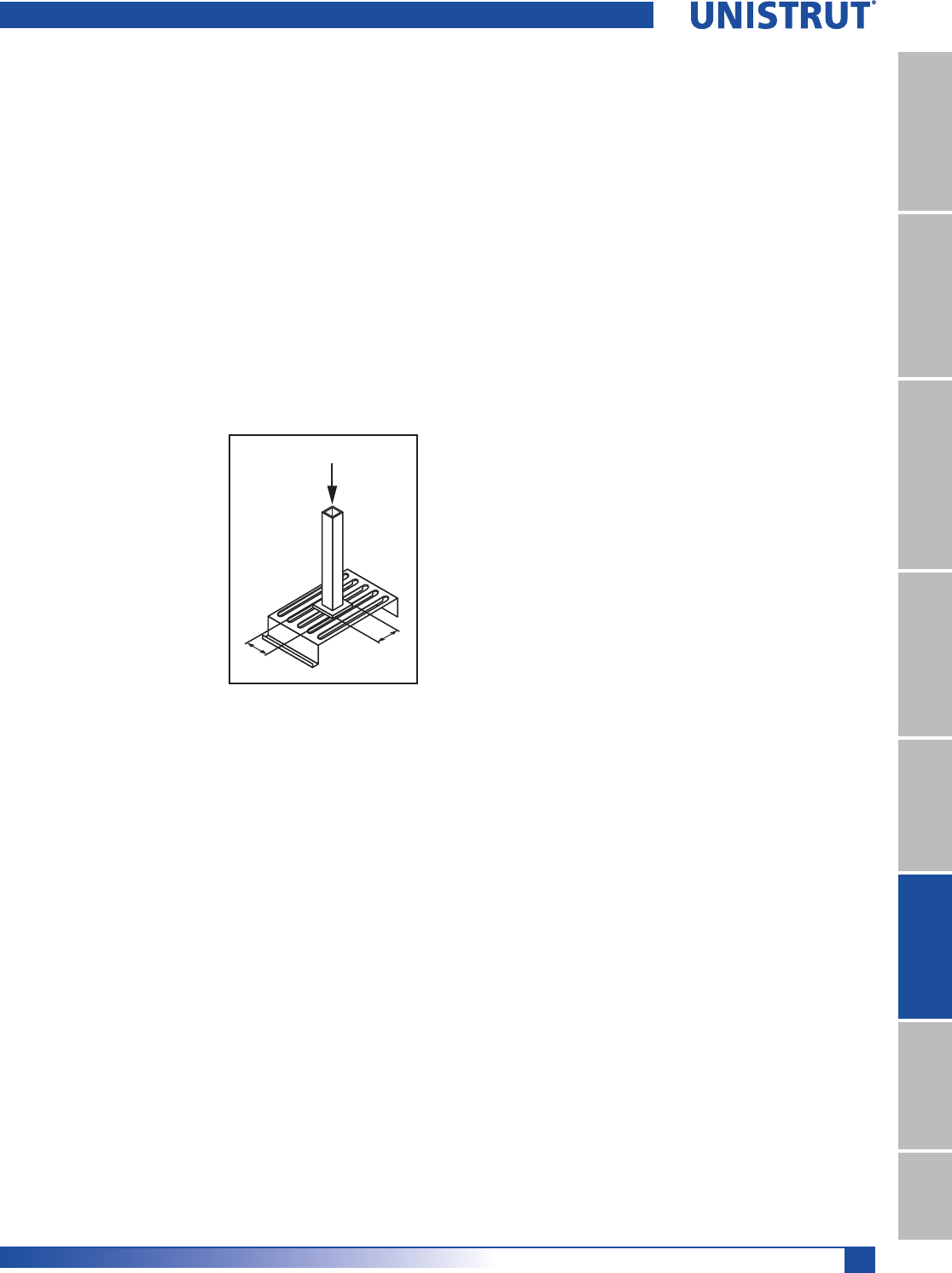
227
United Interlock® Grating
11¼4" System
13¼16" SystemFiberglass SystemSpecial MetalsPrimeAngle
Metal GratingRoofwalkIndex
Design Considerations
Designers must consider both uniform and concen
trated loads. Design considerations are most critical
WHERELOADSARECONCENTRATEDONASMALLAREA!STHE
area of the application gets larger, the reactions ap
proach those of uniform loads.
!LTHOUGHAPLANKOFGRATINGMAYTAKEACONSIDERABLE
allowable load, there may be more deflection than
the designer feels is comfortable for foot traffic. We
believe dividing the number of inches in the span
LENGTHBYPRODUCESAREASONABLEDEmECTION
Designing for overloads and future usage is generally
a wise investment considering the costs of future
maintenance, obsolescence and replacement, as well
as the danger of accidents.
Point (Concentrated) Loads
Point loads should be dis
tributed over a minimum
of two transverse ribs,
regardless of what size
or gauge plank grating is
utilized.
Good design practice for
point loading plank grating
employs a “foot” plate at
the load point with a mini
MUMDIMENSIONOFX
This plate will assure that
the point load has been
DISTRIBUTEDOVERTHETWOTRANSVERSERIBMINIMUM
-AXIMUMPOINTLOADPERRIBONXGASTEEL
PLANKGRATINGISLBS!SARESULTTHROUGHTHE
USEOFTHEREQUIREDXhFOOTvPLATEAMAXIMUM
DESIGNLOADFORTHEMINIMUMDIMENSIONFOOTPLATE
ISLBS(IGHERLOADSCANBESUPPORTEDBYTHE
transverse ribs. However, larger “foot” plates will
THENBEREQUIREDTODISTRIBUTETHEHIGHERLOADSOVER
additional ribs.
Light Traffic Areas
Floor areas immediately adjacent to racks, shelves,
conveyors, etc., are generally loaded by light traffic.
%NDSOFAISLESSINGLEAISLESETCAREFURTHEREXAMPLES
OFLIGHTTRAFlCAREAS4HESEANDSIMILARAREASARESATIS
FACTORILYCOVEREDBYECONOMICALGRATING
Floor area beneath package conveyors or other
MATERIALHANDLINGDEVICESARETYPICALLYSUBJECTTO
little or no loading. However, for safety reasons,
THESEAREASMUSTBECOVERED4HEUSEOFPLANK
grating in these areas provides an economical floor
COVERINGTHATCANALSOBEUSEDASALOADBEARINGmOOR
IFREQUIREMENTSCHANGE
33
LOAD
Design & Testing
0LANK'RATINGISDESIGNEDTOPROVIDEANECONOMI
CALLIGHTWEIGHTmOORSURFACEFORLIGHTTRAFlCAREAS
-AINTENANCEPLATFORMSACCESSWAYSANDROOFTOP
walkway applications are examples of areas where
GRATINGISTHEBESTECONOMICALCHOICE
High-Traffic Areas
-EZZANINESANDAISLESFORSTOCKSTORAGEARETYPICAL
HIGHTRAFlCZONES!SARESULTGRATINGINTHESEAREAS
must have higher fatigue strengths. High fatigue
STRENGTHSAREAVAILABLEUTILIZINGNARROWHIGHSTRENGTH
ORMIDRANGEWIDTHGRATING
Within these high traffic areas are floor sections that
receive little or no traffic, but must be covered for
SAFETYREASONS)NNOVATIVEDESIGNERSEMPLOYGRAT
INGINTHISSITUATION#OMBININGGRATINGWITHOTHER
grating widths and gauges lowers overall installed
COSTSFORHIGHTRAFlCAPPLICATIONS
Testing
Unistrut is dedicated to the research, development
and testing of all our manufactured products. The
United Interlock Grating System has been tested in
ACCORDANCEWITHSECTIONOFTHE!MERICAN)RONAND
3TEEL)NSTITUTES!)3)3PECIlCATIONSFORTHE$ESIGNOF
#OLD&ORMED3TEEL3TRUCTURAL-EMBERS
Tests for allowable loads were performed on product
randomly selected from stock. These tests were
run on simple spans with no end restrictions, over
AENDBEARING#ONCENTRATEDLOADSWEREAPPLIED
ACROSSTHEPLANKWITHABEARINGWHILEUNIFORM
loads were applied by stacking narrow strips of sheet
steel uniformly over the plank surface. Concentrated
load tests for galvanized steel grating were run on
all strength combinations for spans of 2', 3', 4', 5', 6',
ggggggANDg5NIFORMLOADTESTSFOR
GALVANIZEDSTEELWERERUNONSPANSOFggggg
ANDg
#ONCENTRATEDLOADRESULTSARETHESAMEFORAND
wide planks.
!LLOWABLECONCENTRATEDLOADSAREFOUNDBYREDUC
ing the ultimate load by 11⁄2 times the weight of the
grating and dividing the remaining load by two. This
GIVESASAFETYFACTOROF!LLOWABLEUNIFORMLOADS
were calculated by standard formulas from the results
found in the concentrated load tests.
228
United Interlock® Grating
11¼4" System
13¼16" SystemFiberglass SystemSpecial MetalsPrimeAngleMetal GratingRoofwalkIndex
Code Key: 5,5NIFORM,OADPOUNDSPERSQUAREFOOT
5$$EmECTIONUNDERUNIFORMLOAD)NCHES
#,#ONCENTRATED,OADPOUNDS
#$$EmECTIONUNDERCONCENTRATEDLOAD)NCHES
6" x 14 Gauge
Leg
Height Codes Distance Between Supports (Feet)
2 2.5 3 3.5 4 4.5 5 5.5 6 6.5 7 8 9 10 12 14
11⁄2"
UL 1,232788548402293204150113866854––––
UD 0.050.080.120.160.200.220.250.270.300.320.35–––– –
CL 616493411352308274234193162138119–––– –
CD 0.040.060.100.130.170.210.250.270.300.320.35–––– –
21⁄2"
UL 4,886 3,296 2,150 1,601 1,257 924 734 597 501 431 369 263 204 150 84 47
UD 0.15 0.17 0.18 0.22 0.26 0.36 0.41 0.45 0.47 0.52 0.61 0.81 0.89 1.13 1.33 1.42
CL 2,443 2,060 1,612 1,400 1,257 1,040 917 820 752 700 647 525 460 374 250 165
CD 0.17 0.17 0.17 0.20 0.22 0.25 0.29 0.34 0.40 0.46 0.55 0.66 0.79 0.90 1.07 1.18
4"
UL 5,261 4,016 3,147 2,321 1,755 1,520 1,307 1,019 858 738 648 548 420 342 215 165
UD 0.08 0.10 0.11 0.13 0.16 0.16 0.17 0.23 0.27 0.33 0.40 0.52 0.65 0.82 1.07 1.18
CL 2,630 2,510 2,360 2,080 1,755 1,710 1,633 1,400 1,288 1,200 1,134 1,094 980 854 643 577
CD 0.13 0.14 0.15 0.17 0.18 0.19 0.20 0.23 0.26 0.30 0.33 0.45 0.57 0.69 0.91 1.26
6" x 18 Gauge
Leg
Height Codes Distance Between Supports (Feet)
2 2.5 3 3.5 4 4.5 5 5.5 6 6.5 7 8 9 10 12 14
11⁄2"
UL 85854838028120414410478604838–––––
UD 0.05 0.08 0.12 0.16 0.20 0.22 0.25 0.27 0.30 0.32 0.35 –––––
CL 4293432862452141901631351139683–––––
CD 0.04 0.06 0.10 0.13 0.17 0.21 0.25 0.27 0.30 0.32 0.35 –––––
21⁄2"
UL 2,472 1,664 1,220 881 663 516 414 342 284 237 197 164 134 102 66 41
UD 0.14 0.15 0.16 0.21 0.26 0.31 0.36 0.38 0.44 0.47 0.49 0.79 0.89 1.12 1.37 1.58
CL 1,236 1,040 915 770 663 580 518 470 426 385 344 327 300 255 200 140
CD 0.12 0.14 0.16 0.18 0.21 0.24 0.28 0.29 0.30 0.37 0.46 0.61 0.74 0.91 1.20 1.50
4"
UL 3,296 2,544 2,010 1,520 1,179 947 744 626 522 449 402 314 249 191 147 101
UD 0.12 0.13 0.14 0.15 0.15 0.21 0.26 0.29 0.31 0.35 0.42 0.58 0.59 0.70 0.81 0.89
CL 1,648 1,590 1,507 1,330 1,179 1,065 930 860 783 730 704 628 560 477 440 350
CD 0.11 0.12 0.13 0.14 0.14 0.17 0.18 0.22 0.26 0.28 0.32 0.39 0.48 0.51 0.88 1.07
6" Aluminum
(0.080)
Leg
Height Codes Distance Between Supports (Feet)
2 2.5 3 3.5 4 4.5 5 5.5 6 6.5 7 7.5 8 9 10
21⁄2"
UL 2,676 1,590 1,065 840 706 600 517 412 313 277 255 210 177 – –
UD 0.20 0.30 0.35 0.40 0.47 0.55 0.63 0.78 1.01 1.09 1.20 1.4 1.66 – –
CL 1,338 925 825 755 706 630 575 515 469 435 410 385 355 – –
CD 0.16 0.20 0.25 0.31 0.36 0.45 0.54 0.67 0.81 0.90 0.99 1.12 1.27 – –
Loads and Deflection – 6" Planks
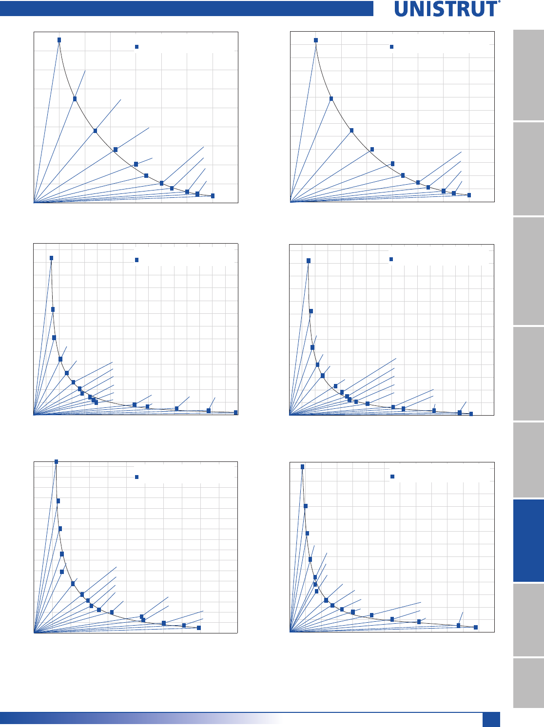
229
United Interlock® Grating
11¼4" System
13¼16" SystemFiberglass SystemSpecial MetalsPrimeAngle
Metal GratingRoofwalkIndex
0.00 0.05 0.10 0.15 0.20 0.25 0.30 0.35 0.40
0
100
200
300
400
500
600
700
800
900
0.00 0.05 0.10 0.15 0.20 0.25 0.30 0.35 0.40
0
100
200
300
400
500
600
700
800
900
1000
1100
1200
1300
0.0 0.1 0.2 0.3 0.4 0.5 0.6 0.7 0.8 0.9 1.0 1.1 1.2 1.3 1.4 1.5 1.6
0
200
400
600
800
1000
1200
1400
1600
1800
2000
2200
2400
2600
0.0 0.1 0.2 0.3 0.4 0.5 0.6 0.7 0.8 0.9 1.0 1.1 1.2 1.3 1.4 1.5 1.6
0
400
800
1200
1600
2000
2400
2800
3200
3600
4000
4400
4800
5200
0.0 0.1 0.2 0.3 0.4 0.5 0.6 0.7 0.8 0.9 1.0 1.1
0
200
400
600
800
1000
1200
1400
1600
1800
2000
2200
2400
2600
2800
3000
3200
0.0 0.1 0.2 0.3 0.4 0.5 0.6 0.7 0.8 0.9 1.0 1.1 1.2 1.3
0
400
800
1200
1600
2000
2400
2800
3200
3600
4000
4400
4800
5200
2' (858 Lbs.)
2.5' (548 Lbs.)
3' (380 Lbs.)
3.5' (281 Lbs.)
4' (144 Lbs.)
4.5' (204 Lbs.)
5' (104 Lbs.)
5.5' (78 Lbs.)
6' (60 Lbs.)
6.5' (48 Lbs.)
7' (38 Lbs.)
2' (2472 Lbs.)
2.5' (1664 Lbs.)
3' (1220 Lbs.)
3.5' (881 Lbs.)
4' (663 Lbs.)4.5' (516 Lbs.)
5' (414 Lbs.)
5.5' (342 Lbs.)
6' (284 Lbs.)
6.5' (237 Lbs.)
7' (197 Lbs.)8' (164 Lbs.)
9' (134 Lbs.)
10' (102 Lbs.)12' (66 Lbs.)
14' (44 Lbs.)
2' (3296 Lbs.)
2.5' (2544 Lbs.)
3' (2010 Lbs.)
3.5' (1520 Lbs.)
4' (1179 Lbs.)
4.5' (947 Lbs.)
5' (744 Lbs.)
5.5' (626 Lbs.)
8' (314 Lbs.)
9' (249 Lbs.)
6' (522 Lbs.)
10' (191 Lbs.)
12' (147 Lbs.)
14' (101 Lbs.)
6.5' (449 Lbs.)
7' (402 Lbs.)
2' (1232 Lbs.)
2.5' (788 Lbs.)
3' (548 Lbs.)
3.5' (402 Lbs.)
4' (204 Lbs.)
4.5' (293 Lbs.)
5' (100 Lbs.)
5.5' (113 Lbs.)
6' (86 Lbs.)
6.5' (68 Lbs.)
7' (54 Lbs.)
2' (4886 Lbs.)
2.5' (3296 Lbs.)
3' (2150 Lbs.)
3.5' (1601 Lbs.)
4' (1257 Lbs.)
4.5' (924 Lbs.)
5' (734 Lbs.)
5.5' (597 Lbs.)
6' (501 Lbs.)
6.5' (431 Lbs.)
7' (369 Lbs.)9' (204 Lbs.)
10' (150 Lbs.)
8' (263 Lbs.)
12' (84 Lbs.)
14' (47 Lbs.)
2' (5261 Lbs.)
2.5' (4016 Lbs.)
3' (3147 Lbs.)
3.5' (2321 Lbs.)
4' (1755 Lbs.)
4.5' (1520 Lbs.)
5' (1307 Lbs.)
5.5' (1019 Lbs.)
6' (858 Lbs.)
8' (548 Lbs.)
9' (420 Lbs.)
10' (342 Lbs.)
12' (215 Lbs.)
14' (165 Lbs.)
6.5' (738 Lbs.)
7' (648 Lbs.)
6" x 11⁄2" x 18 Ga.
Span (Max Uniform Load - Lbs.)
6" x 11⁄2" x 14 Ga.
Span (Max Uniform Load - Lbs.)
6" x 21⁄2" x 18 Ga.
Span (Max Uniform Load - Lbs.)
6" x 21⁄2" x 14 Ga.
Span (Max Uniform Load - Lbs.)
6" x 4" x 18 Ga.
Span (Max Uniform Load - Lbs.)
6" x 4" x 14 Ga.
Span (Max Uniform Load - Lbs.)
LOAD (Pounds)
DEFLECTION (Inches)
LOAD (Pounds)
DEFLECTION (Inches)
LOAD (Pounds)
DEFLECTION (Inches)
LOAD (Pounds)
DEFLECTION (Inches)
LOAD (Pounds)
DEFLECTION (Inches)
LOAD (Pounds)
DEFLECTION (Inches)
Uniform Loads vs. Deflection – 6" Planks
230
United Interlock® Grating
11¼4" System
13¼16" SystemFiberglass SystemSpecial MetalsPrimeAngleMetal GratingRoofwalkIndex
9" x 14 Gauge
Leg
Height Codes Distance Between Supports (Feet)
2 2.5 3 3.5 4 4.5 5 5.5 6 6.5 7 8 9 10 12 14
11⁄2"
UL 82152536526819513610075574536–––––
UD 0.05 0.08 0.12 0.16 0.20 0.22 0.25 0.27 0.30 0.32 0.35 –––––
CL 616493411352308274234193162138119–––––
CD 0.04 0.06 0.10 0.13 0.17 0.21 0.25 0.27 0.30 0.32 0.35 –––––
21⁄2"
UL 3,257 2,197 1,433 1,067 838 616 489 398 334 287 246 175 136 100 56 31
UD 0.15 0.17 0.18 0.22 0.26 0.36 0.41 0.45 0.47 0.52 0.61 0.81 0.89 1.13 1.33 1.42
CL 2,443 2,060 1,612 1,400 1,257 1,040 917 820 752 700 647 525 460 374 250 165
CD 0.17 0.17 0.17 0.20 0.22 0.25 0.29 0.34 0.40 0.46 0.55 0.66 0.79 0.90 1.07 1.18
4"
UL 3,507 2,677 2,098 1,547 1,170 1,013 871 679 572 492 432 365 280 228 143 110
UD 0.08 0.10 0.11 0.13 0.16 0.16 0.17 0.23 0.27 0.33 0.40 0.52 0.65 0.82 1.07 1.18
CL 2,630 2,510 2,360 2,080 1,755 1,710 1,633 1,400 1,288 1,200 1,134 1,094 980 854 643 577
CD 0.13 0.14 0.15 0.17 0.18 0.19 0.20 0.23 0.26 0.30 0.33 0.45 0.57 0.69 0.91 1.26
9" x 18 Gauge
Leg
Height Codes Distance Between Supports (Feet)
2 2.5 3 3.5 4 4.5 5 5.5 6 6.5 7 8 9 10 12 14
11⁄2"
UL 572365253187136966952403225–––––
UD 0.050.080.120.160.200.220.250.270.300.320.35–––––
CL 4293432862452141901631351139683–––––
CD 0.040.060.100.130.170.210.250.270.300.320.35–––––
21⁄2"
UL 1,648 1,109 813 587 442 344 276 228 189 158 131 109 89 68 44 27
UD 0.14 0.15 0.16 0.21 0.26 0.31 0.36 0.38 0.44 0.47 0.49 0.79 0.89 1.12 1.37 1.58
CL 1,236 1,040 915 770 663 580 518 470 426 385 344 327 300 255 200 140
CD 0.12 0.14 0.16 0.18 0.21 0.24 0.28 0.29 0.30 0.37 0.46 0.61 0.74 0.91 1.2 1.5
4"
UL 2,197 1,696 1,340 1,013 786 631 496 417 348 299 268 209 166 127 98 67
UD 0.12 0.13 0.14 0.15 0.15 0.21 0.26 0.29 0.31 0.35 0.42 0.58 0.59 0.70 0.81 0.89
CL 1,648 1,590 1,507 1,330 1,179 1,065 930 860 783 730 704 628 560 477 440 350
CD 0.11 0.12 0.13 0.14 0.14 0.17 0.18 0.22 0.26 0.28 0.32 0.39 0.48 0.51 0.88 1.07
9" Aluminum
(0.080)
Leg
Height Codes Distance Between Supports (Feet)
2 2.5 3 3.5 4 4.5 5 5.5 6 6.5 7 7.5 8
21⁄2"
UL 1,784 1,060 710 560 471 400 345 275 209 185 170 140 118
UD 0.20 0.30 0.35 0.40 0.47 0.55 0.63 0.78 1.01 1.09 1.20 1.4 1.66
CL 1,338 925 825 755 706 630 575 515 469 435 410 385 355
CD 0.16 0.20 0.25 0.31 0.36 0.45 0.54 0.67 0.81 0.90 0.99 1.12 1.27
Code Key: 5,5NIFORM,OADPOUNDSPERSQUAREFOOT
5$$EmECTIONUNDERUNIFORMLOAD)NCHES
#,#ONCENTRATED,OADPOUNDS
#$$EmECTIONUNDERCONCENTRATEDLOAD)NCHES
Loads and Deflection – 9" Planks
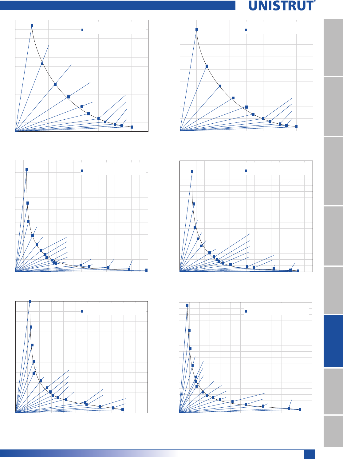
231
United Interlock® Grating
11¼4" System
13¼16" SystemFiberglass SystemSpecial MetalsPrimeAngle
Metal GratingRoofwalkIndex
0.00 0.05 0.10 0.15 0.20 0.25 0.30 0.35 0.40
0
50
100
150
200
250
300
350
400
450
500
550
600
0.00 0.05 0.10 0.15 0.20 0.25 0.30 0.35 0.4
0
0
100
200
300
400
500
600
700
800
900
0.0 0.1 0.2 0.3 0.4 0.5 0.6 0.7 0.8 0.9 1.0 1.1 1.2 1.3 1.4 1.5 1.6
0
200
400
600
800
1000
1200
1400
1600
1800
0.0 0.1 0.2 0.3 0.4 0.5 0.6 0.7 0.8 0.9 1.0 1.1 1.2 1.3 1.4 1.5 1.6
0
200
400
600
800
1000
1200
1400
1600
1800
2000
2200
2400
2600
2800
3000
3200
3400
3600
0.0 0.1 0.2 0.3 0.4 0.5 0.6 0.7 0.8 0.9 1.0 1.1
0
200
400
600
800
1000
1200
1400
1600
1800
2000
2200
0.0 0.1 0.2 0.3 0.4 0.5 0.6 0.7 0.8 0.9 1.0 1.1 1.2 1.3
0
200
400
600
800
1000
1200
1400
1600
1800
2000
2200
2400
2600
2800
3000
3200
3400
3600
2' (572 Lbs.)
2.5' (365 Lbs.)
3' (253 Lbs.)
3.5' (187 Lbs.)
4' (96 Lbs.)
4.5' (136 Lbs.)
5' (69 Lbs.)
5.5' (52 Lbs.)
6' (40 Lbs.)
6.5' (32 Lbs.)
7' (25 Lbs.)
2' (1648 Lbs.)
2.5' (1109 Lbs.)
3' (813 Lbs.)
3.5' (587 Lbs.)
4' (442 Lbs.)4.5' (344 Lbs.)
5' (276 Lbs.)
5.5' (228 Lbs.)
6' (189 Lbs.)
6.5' (158 Lbs.)
7' (131 Lbs.)8' (109 Lbs.)
9' (89 Lbs.)
10' (68 Lbs.)12' (44 Lbs.)
14' (27 Lbs.)
2' (2197 Lbs.)
2.5' (1696 Lbs.)
3' (1340 Lbs.)
3.5' (1013 Lbs.)
4' (786 Lbs.)
4.5' (631 Lbs.)
5' (496 Lbs.)
5.5' (417 Lbs.)
8' (209 Lbs.)
9' (166 Lbs.)
6' (348 Lbs.)
10' (127 Lbs.)
12' (98 Lbs.)
14' (67 Lbs.)
6.5' (299 Lbs.)
7' (268 Lbs.)
2' (821 Lbs.)
2.5' (525 Lbs.)
3' (365 Lbs.)
3.5' (268 Lbs.)
4' (136 Lbs.)
4.5' (195 Lbs.)
5' (100 Lbs.)
5.5' (75 Lbs.)
6' (57 Lbs.)
6.5' (45 Lbs.)
7' (36 Lbs.)
2' (3257 Lbs.)
2.5' (2197 Lbs.)
3' (1433 Lbs.)
3.5' (1067 Lbs.)
4' (838 Lbs.)
4.5' (616 Lbs.)
5' (489 Lbs.)
5.5' (398 Lbs.)
6' (334 Lbs.)
6.5' (287 Lbs.)
7' (246 Lbs.)9' (136 Lbs.)
10' (100 Lbs.)
8' (175 Lbs.)
12' (56 Lbs.)
14' (31 Lbs.)
2' (3507 Lbs.)
2.5' (2677 Lbs.)
3' (2098 Lbs.)
3.5' (1547 Lbs.)
4' (1170 Lbs.)
4.5' (1013 Lbs.)
5' (871 Lbs.)
5.5' (679 Lbs.)
6' (572 Lbs.)
8' (365 Lbs.)
9' (280 Lbs.)
10' (228 Lbs.)
12' (1432 Lbs.)
14' (110 Lbs.)
6.5' (492 Lbs.)
7' (432 Lbs.)
9" x 11⁄2" x 18 Ga.
Span (Max Uniform Load - Lbs.)
9" x 11⁄2" x 14 Ga.
Span (Max Uniform Load - Lbs.)
9" x 21⁄2" x 18 Ga.
Span (Max Uniform Load - Lbs.)
9" x 21⁄2" x 14 Ga.
Span (Max Uniform Load - Lbs.)
9" x 4" x 18 Ga.
Span (Max Uniform Load - Lbs.)
9" x 4" x 14 Ga.
Span (Max Uniform Load - Lbs.)
LOAD
(P
oun
d
s
)
DEFLECTION (Inches) DEFLECTION (Inches)
DEFLECTION (Inches) DEFLECTION (Inches)
DEFLECTION (Inches) DEFLECTION (Inches)
LOAD (Pounds)
LOAD
(P
oun
d
s
)
LOAD (Pounds)
LOAD
(P
oun
d
s
)
LOAD (Pounds)
Uniform Loads vs. Deflection – 9" Planks
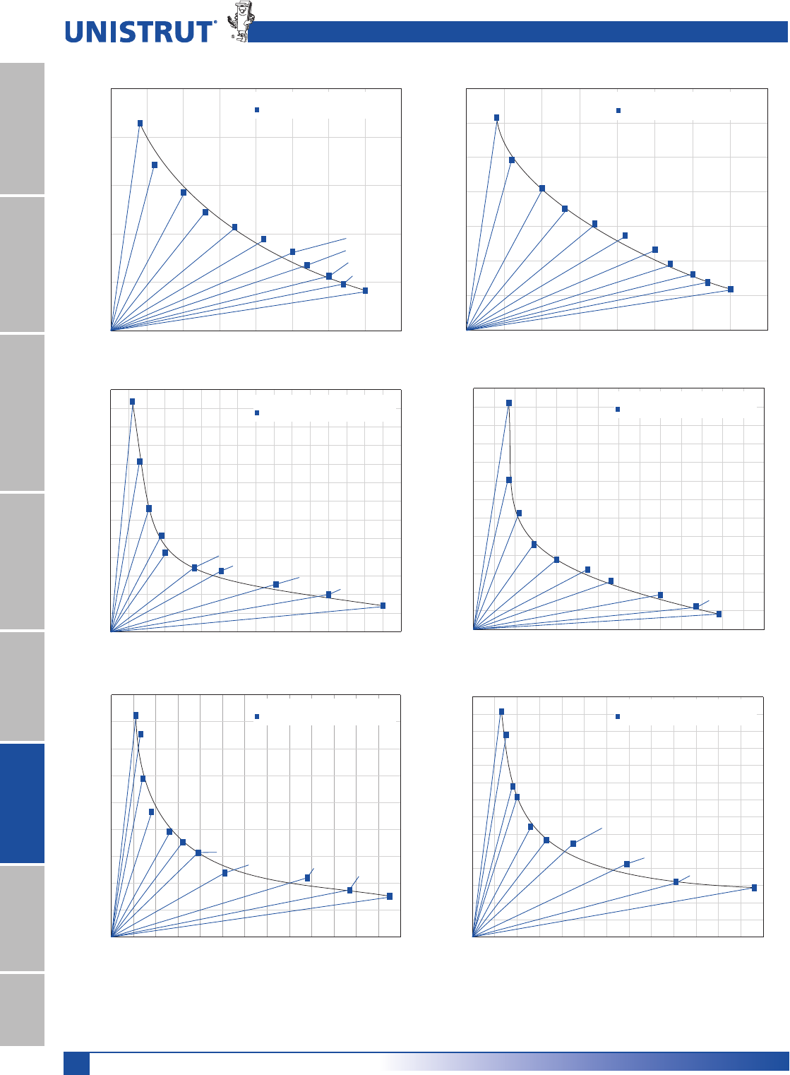
232
United Interlock® Grating
11¼4" System
13¼16" SystemFiberglass SystemSpecial MetalsPrimeAngleMetal GratingRoofwalkIndex
0.00 0.05 0.10 0.15 0.20 0.25 0.30 0.35 0.40
0
100
200
300
400
500
0.00 0.05 0.10 0.15 0.20 0.25 0.30 0.35 0.40
0
100
200
300
400
500
600
700
0.0 0.1 0.2 0.3 0.4 0.5 0.6 0.7 0.8 0.9 1.0 1.1 1.2 1.3 1.4 1.5 1.6
0
100
200
300
400
500
600
700
800
900
1000
1100
1200
1300
0.0 0.1 0.2 0.3 0.4 0.5 0.6 0.7 0.8 0.9 1.0 1.1 1.2 1.3 1.4
0
200
400
600
800
1000
1200
1400
1600
1800
2000
2200
2400
2600
0.0 0.1 0.2 0.3 0.4 0.5 0.6 0.7 0.8 0.9 1.0 1.1 1.2 1.3
0
200
400
600
800
1000
1200
1400
1600
1800
0.0 0.1 0.2 0.3 0.4 0.5 0.6 0.7 0.8 0.9 1.0 1.1 1.2 1.3
0
200
400
600
800
1000
1200
1400
1600
1800
2000
2200
2400
2600
2800
2' (429
Lbs.
)
2.5' (343
Lbs.
)
3' (286
Lbs.
)
3.5' (245
Lbs.
)
4' (214
Lbs.
)
4.5' (190
Lbs.
)5' (163
Lbs.
)
5.5' (135
Lbs.
)
6' (113
Lbs.
)
6.5' (96
Lbs.
)
7' (83
Lbs.
)
2' (1236
Lbs.
)
3' (915
Lbs.
)
4' (663
Lbs.
)
5' (518
Lbs.
)
6' (426
Lbs.
)7' (344
Lbs.
)
8' (327
Lbs.
)
10' (255
Lbs.
)
12' (200
Lbs.
)
14' (140
Lbs.
)
2' (1648
Lbs.
)
3' (1507
Lbs.
)
4' (1179
Lbs.
)
5' (930
Lbs.
)
8' (628
Lbs.
)
10' (477
Lbs.
)
6' (783
Lbs.
)
12' (440
Lbs.
)14' (350
Lbs.
)
16' (304
Lbs.
)
7' (704
Lbs.
)
2' (616
Lbs.
)
2.5' (493
Lbs.
)
3' (411
Lbs.
)
3.5' (352
Lbs.
)
4' (308
Lbs.
)
4.5' (274
Lbs.
)
5' (234
Lbs.
)
5.5' (193
Lbs.
)
6' (162
Lbs.
)
6.5' (138
Lbs.
)
7' (119
Lbs.
)
2' (2443
Lbs.
)
3' (1612
Lbs.
)
4' (1257
Lbs.
)
5' (917
Lbs.
)
6' (752
Lbs.
)
7' (647
Lbs.
)
10' (374
Lbs.
)
8' (525
Lbs.
)
12' (250
Lbs.
)
14' (165
Lbs.
)
2' (2630
Lbs.
)
3' (2360
Lbs.
)
4' (1755
Lbs.
)
5' (1633
Lbs.
)
6' (1288
Lbs.
)
7' (1134
Lbs.
)8' (1094
Lbs.
)
10' (854
Lbs.
)
12' (643
Lbs.
)14' (577
Lbs.
)
6" x 1
1
⁄
2
" x 18 Ga.
Span (Max Concentrated Load - Lbs.)
6" x 11⁄2" x 14 Ga.
Span (Max Concentrated Load - Lbs.)
6" x 2
1
⁄
2
" x 18 Ga.
Span (Max Concentrated Load - Lbs.)
6" x 2
1
⁄
2
" x 14 Ga.
Span (Max Concentrated Load - Lbs.)
6" x 4" x 18 Ga.
Span (Max Concentrated Load - Lbs.)
6" x 4" x 14 Ga.
Span (Max Concentrated Load - Lbs.)
LOAD
(Pounds)
DEFLECTION
(Inches)
LOAD
(Pounds)
DEFLECTION
(Inches)
LOAD
(Pounds)
DEFLECTION
(Inches)
LOAD
(Pounds)
DEFLECTION
(Inches)
LOAD
(Pounds)
DEFLECTION
(Inches)
LOAD
(Pounds)
DEFLECTION
(Inches)
Concentrated Loads vs. Deflection – 6" & 9" Planks
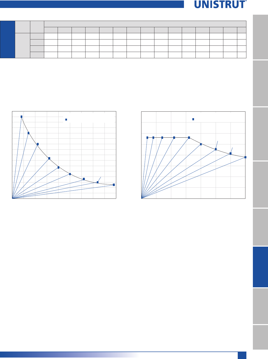
233
United Interlock® Grating
11¼4" System
13¼16" SystemFiberglass SystemSpecial MetalsPrimeAngle
Metal GratingRoofwalkIndex
0.00 0.05 0.10 0.15 0.20 0.25 0.30 0.35 0.40 0.45
0
50
100
150
200
250
300
350
400
450
500
550
600
650
700
750
800
0.00 0.05 0.10 0.15 0.20 0.25 0.30 0.35
0
100
200
300
400
500
600
700
800
2' (750 Lbs.)
2.5' (600 Lbs.)
3' (500 Lbs.)
3.5' (370 Lbs.)
4' (285 Lbs.)
4.5' (225 Lbs.)
5' (180 Lbs.)5.5' (150 Lbs.)
6' (127 Lbs.)
2', 2.5', 3', 3.5', 4' (560 Lbs.)
6' (380 Lbs.)
4.5' (500 Lbs.)5' (455 Lbs.)
5.5' (415 Lbs.)
12" x 21⁄2" x 18 Ga.
Span (Max Uniform Load - Lbs.)
12" x 21⁄2" x 18 Ga.
Span (Max Concentrated Load - Lbs.)
LOAD (Pounds)
DEFLECTION (Inches)
LOAD (Pounds)
DEFLECTION (Inches)
Code Key: 5,5NIFORM,OADPOUNDSPERSQUAREFOOT
5$$EmECTIONUNDERUNIFORMLOAD)NCHES
#,#ONCENTRATED,OADPOUNDS
#$$EmECTIONUNDERCONCENTRATEDLOAD)NCHES
12" x 18
Gauge
Leg
Height Codes Distance Between Supports (Feet)
2 2.5 3 3.5 4 4.5 5 5.5 6 6.5 7 7.5 8 9 10
21⁄2"
UL 750 600 500 370 285 225 180 150 127 – – – – – –
UD 0.04 0.07 0.11 0.16 0.20 0.25 0.31 0.37 0.44 – – – – – –
CL 560 560 560 560 560 500 455 415 380 – – – – – –
CD 0.02 0.04 0.07 0.11 0.16 0.20 0.25 0.30 0.35 – – – – – –
Loads and Deflection – 12" Planks

234
United Interlock® Grating
11¼4" System
13¼16" SystemFiberglass SystemSpecial MetalsPrimeAngleMetal GratingRoofwalkIndex
1. GENERAL
1.1 Scope of Work
!0ROVIDEALLMATERIALANDLABORREQUIREDFORTHE
interlocking plank grating as indicated in the
contract documents.
1.2 Related Work Specified Elsewhere
!3TRUCTURAL3TEEL
"#OLD&ORMED-ETAL&RAMING
#-ETAL&ABRICATIONS
1.3 Quality Assurance
!-ATERIALSHALLBEPROVIDEDBYAQUALIFIEDCONTRACTOR
WITHATLEASTFIVEYEARSEXPERIENCEINTHE
manufacture of interlock grating. Contractor shall
demonstrate experience in projects of similar
scope.
"!NTI3KIDSURFACEDGRATINGSHALLCONFORMTO&EDERAL
3PECIFICATION22'!
C. The Grating shall be designed to withstand the
following load criteria:
5NIFORM,IVE,OAD __________________ psf.
#ONCENTRATED,OAD _________________ lbs.
D. Contractor shall certify that grating has been
tested, indicating maximum allowable uniform and
concentrated loads, with a factor of safety of 2, per
!)3#3ECTION
%)FPRODUCTISREQUIREDINNUCLEARANDORSAFETY
related application, it shall be supplied under the
REQUIREMENTSOFNUCLEARSPECIFICATION#&2
appendix B.
1.4 Submittals
!#ONTRACTORSHALLSUBMITSHOPDRAWINGSSHOWING
grating layout, support structure and detailed
sections depicting assembly.
2. PRODUCTS
2.1 Acceptable Manufacturer
!)NORDERTODEFINETHEREQUIREMENTSFORQUALITY
function, sizes, gauges, surfaces, etc., these material
specifications designate manufacturers, brands and
other pertinent data that describe the minimum
product standards of the products that conform to
THEPROJECTSREQUIREMENTS
B. Products of other manufacturers may also be
acceptable, provided that such products are
EQUIVALENTTOORBETTERTHANTHOSESPECIFIED
and, further, that use of such substitute products
will not involve additional cost to owner due to
POSSIBLEREQUIREDCHANGESTOACCOMMODATETHEM
#4HEALTERNATESUBSTITUTEPRODUCTMUSTBEA
PROVENEQUIVALENTTOTHATSPECIFIEDBYSUBMITTING
technical data, test reports, samples, typical details,
comparative layout and engineering calculations
for evaluation.
$4HEACCEPTANCEOFANALTERNATESUBSTITUTE
product is at the discretion of the owner or his
agents, whose decision shall be final.
2.2 Products
!'RATINGSHALLBE5NITED)NTERLOCK0LANK'RATING
System, as manufactured by Unistrut,
3,ATHROP!VE(ARVEY),53!
0HONE
"-ATERIALSSHALLCONFORMTO!34-!'RADE!
WITHA#LASS'COATING
#-ATERIALSHALLBE????????GAUGE7ITHALEG
height of ________inches.
D. The surface pattern shall provide a minimum of
35% but not more than 42% open area. Openings
SHALLBEAMINIMUMOFLONGANDAMAXIMUMOF
3⁄4WIDTH4HESURFACESHALLBE????????
!NTI3KIDSURFACESHALLPROVIDEPOSITIVE
TRACTIONANDBEMADEOFTAPEREDSELFCLEANING
teeth, approximately 1⁄HIGH
!NTI3KIDSURFACETEETHSHALLHAVESLOTS
approximately 1⁄16WIDEBY3⁄LONGUNIFORMLY
SPACEDWITHAMINIMUMOFANDA
MAXIMUMOFTEETHPERSQUAREFOOT
3. INSTALLATION
3.1 Site Examination
!#ONTRACTORSHALLEXAMINETHESUPPORTSTRUCTURE
work area and conditions for the grating
installation. If the supports, area or conditions are
not satisfactory, installation shall not commence
until satisfactory conditions are present.
3.2 Erection
!'RATINGSHALLBEINSTALLEDASDETAILEDONTHE
approved shop drawings.
B. Grating shall be installed in single, unspliced
SECTIONSFORALLREQUIREMENTSTOgLENGTHS
#'RATINGSHALLINTERLOCKWITHMALEFEMALELEGS
providing a lock prohibiting horizontal movement.
The outside leg of all members shall be male.
D. Connections of grating to support elements shall
be by bolting, clamping, screwing, welding or use
OFAMANUFACTURERSAPPROVEDHOLDDOWNCLIP
Architectural Specificaitons
235
PrimeAngle
235
Roodfwalks® Rooftop Walkways
ROOFWALKS®
Roofwalks® Planks .................................................................. 236
Hardware for Membrane, Foam or Coated Roof .................. 236
Standing Seam Installation .................................................... 236
PROTECT ROOFS FROM
BIGFOOT WITH ROOFWALKS®
ROOFTOP WALKWAYS
Roofwalks walkways are your low-cost solution to
damage caused by rooftop foot traffic. On membrane,
built-up, foam and coated roofs, they protect against
puncture, abrasion and wear. On standing-seam metal
ROOFSWORKERSOFALLSIZESnEVENTHE"IGFOOTSOF
THEWORLDnCANWALKSAFELYONTHEANTISKIDSURFACE
without causing seam distortion, “dishing” or harmful
stress to roof panels. Steel planks are strong yet light-
weight, making installation quick and easy. Thanks
to special system hardware, no roof penetration is
required for anchoring. Roofwalks are versatile and
adapt to any roofing system.
ROOFWALKS® SYSTEMS WILL…
UÊ*ÀÛ`iÊ>ÊÃ>viÊÜ>Ü>ÞÊvÀÊÀvÌ«ÊÌÀ>vvV
UÊ*ÀÌiVÌÊÌiÊÀvÊvÀÊvÌÊÌÀ>vvV
UÊ,iÃÃÌÊÜi>ÌiÀÊÊiÌiÀÊ}>Û>âi`ÊÃÌiiÊÀÊ
aluminum finish
UÊÌÌ>VÊÌÊ>ÊiÌ>ÊÃÌ>`}Ãi>ÊÀvÃ
(including metric)
ROOFWALKS® SYSTEMS WILL NOT…
UÊ*iiÌÀ>ÌiÊÀvÌ«ÊÃÕÀv>Vi
(except on rib roofs)
UÊ/À>«ÊÜ>ÌiÀÊ
…like rubber pads will
UÊÕÀÊV>ÕÃ}ÊÌÀ«Ê>â>À`ÃÊ
…like rubber pads will
UÊÃ>««i>ÀÊÊÃÜÊ
…like rubber pads will
UÊ,ÌÊÀÊ`ÃÌi}À>ÌiÊ
…like wood or patio blocks will
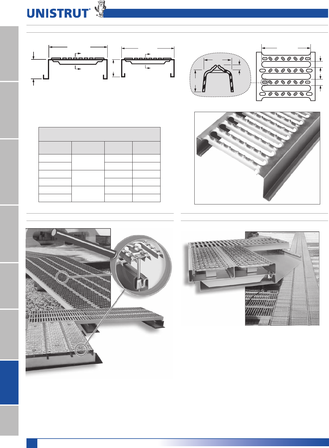
236
PrimeAngle
236
Roodfwalks® Rooftop Walkways
11¼4" System
13¼16" SystemFiberglass SystemSpecial MetalsPrimeAngleMetal GratingRoofwalkIndex
Interlocking Planks 20' or 24' planks in 6", 9" or 12" widths roll formed from
18 gauge galvanized steel (G-90 coating). Planks available with double-male or
male-female leg shapes. Anti-Skid surface and 21⁄2" leg height, standard.
Roofwalk Grating (20' & 24' Stock Lengths)
Leg Height: 21⁄2"; Finish: PG; Surface: Anti-Skid
Part No. Plank
Width Leg Shape Weight
Lbs./Ft.
G 91282 9" DM 2.7
G 92282 MF 2.7
G 61281 6" DM 2.3
G 62281 MF 2.3
G 11282 12" DM 3.2
G 12282 MF 3.2
9'' or 6''
Leg
Height
B
B
9'' or 6''
Leg
Height
B
B
[DM] Double Male Leg
Male-Female Leg Double-Male Leg
1⁄2"
1⁄8"
Nom.
3⁄4"
3⁄4"
3⁄4"
43⁄4" or 71⁄2"
Anti-Skid Rib Anti-Skid Surface Shown
ROOFWALK GRATING PLANKS 18 GAUGE
MEMBRANE / COMPOSITE INSTALLATION STANDING SEAM INSTALLATION
Installation on a standing seam room uses a custom support plate
specifically designed for each manufacturers standing seem roof
to form a mounting platform.
The mounting hardware also depends on the specific standing
seem room. Refer to our website (www.unistrut.com) for
detailed installation instructions and a description of the
mounting hardware used.
Installation on a membrane roof uses the support stands or the
Unipier® sleeper support as a mounting platform.
Refer to our website (www.unistrut.com) for detailed installation
instructions and a description of the mounting hardware used.

237
PRODUCT INDEX
200..................................................................201
004M007 thru 034M040 ...............................114
004T008 thru 098N106, 009N012 thru 106N114 .
113
1.5 Pipe Strap .................................................158
1.5 Pipe Support .............................................158
1.5 Spacer ......................................................160
10-DS .............................................................163
10-H ................................................................163
12-BS ..............................................................158
16-BS ..............................................................157
16-BS ..............................................................158
16-H ................................................................163
16-H Base .......................................................161
16-H-DB ..........................................................163
2.5-CS ............................................................157
2.5-CS-7 .........................................................157
2.5-SB-H .........................................................162
20-BS ..............................................................157
20-BS-7 ..........................................................157
24-BS-4 ..........................................................157
3-R Spacer .....................................................160
3-R-2 ...............................................................158
3-R-2 Pipe Strap .............................................158
3-R-4 ...............................................................158
3-R-4 Pipe Strap .............................................158
3-RAH .............................................................159
3-RAH .............................................................160
3-RAH Pipe Strap ...........................................159
4-RAH-7 ..........................................................160
5-R ..................................................................158
5-RAH .............................................................159
5-SB-H ............................................................162
6-DS, 6-DSA ...................................................163
6-H ..................................................................163
6-H Base .........................................................161
6-RAH .............................................................159
6-RAH Pipe Strap ...........................................159
8-DS, 8-DS-DB, 8-DSA ...................................163
8-H ..................................................................163
8-H Base .........................................................161
8-H-DB ............................................................163
8-RAH .............................................................159
8-RAH Pipe Strap ...........................................159
8-SB-H, 8-SB-HD ...........................................162
A1000 .............................................................171
A1000 EA ........................................................211
A1001 .............................................................171
A1001A ...........................................................172
A1001B ...........................................................172
A1001C ..........................................................172
A1006 .............................................................178
A1007 .............................................................178
A1008 .............................................................178
A1026 .............................................................179
A1031 .............................................................179
A1036 .............................................................179
A1047 .............................................................180
A1063 .............................................................178
A1065 .............................................................178
A1066 .............................................................179
A1068 .............................................................179
A1184 .............................................................178
A1184P ...........................................................178
A1191 .............................................................178
A1280 .............................................................178
A1325 .............................................................179
A1326 .............................................................179
A1458 .............................................................179
A2084 .............................................................179
A2110 .............................................................179
A2126 ............................................................179
A2223 .............................................................179
A2227 .............................................................179
A2324 .............................................................179
A2345 .............................................................179
A2472 .............................................................179
A2492 .............................................................180
A2494 .............................................................180
A2608 thru A2617 .........................................180
A3006 .............................................................178
A3007 .............................................................178
A3008 .............................................................178
A3016 .............................................................178
A3300 .............................................................173
A3301 .............................................................173
A3347 .............................................................180
A4000 .............................................................175
A4000 EA ........................................................211
A4001 .............................................................175
A4001 EA ........................................................212
A4006 .............................................................178
A4007 .............................................................178
A4008 .............................................................178
A4047 .............................................................180
A4280 .............................................................178
A5000 .............................................................177
A5006 .............................................................178
A5007 .............................................................178
A5008 .............................................................178
A5047 .............................................................180
A5280 .............................................................178
CG-10 thru CG-40 ........................................116
Deck Plates 12 SS ..........................................160
Deck Plates 18 SS ..........................................160
F100 ...............................................................202
F1000E ...........................................................197
F10PU ............................................................196
F12PU ............................................................196
F200-3827 thru F200-3843 .............................198
F200-4101 ......................................................202
F200-4217 thru F200-4343 .............................196
F20E-5000 ......................................................198
F20N ...............................................................203
F20P-1000, F20V-1000 ..................................194
F20P-1100, F20V-1100 ...................................194
F20P-1200, F20V-1200 ..................................194
F20P-1300, F20V-1300 ..................................194
F20P-2000 SST, F20V-2000 SST ...................195
F20P-2000, F20V-2000 ..................................193
F20P-2100 SST, F20V-2100 SST ...................195
F20P-2100, F20V-2100 ..................................193
F20P-2200 SST, F20V-2200 SST ...................195
F20P-2200, F20V-2200 ..................................193
F20P-2300 SST, F20V-2300 SST ...................195
F20P-2300, F20V-2300 ..................................193
F20P-2500, F20V-2500 .................................199
F20P-2502, F20V-2502 ..................................199
F20P-2504, F20V-2504 ..................................199
F20P-2506, F20V-2506 ..................................199
F20P-2508, F20V-2508 ..................................199
F20P-2510, F20V-2510 ..................................199
F20P-2512, F20V-2512 ..................................199
F20P-2514, F20V-2514 ..................................199
F20P-2516, F20V-2516 ..................................199
F20P-2518, F20V-2518 ..................................199
F20P-2520, F20V-2520 ..................................199
F20P-2522, F20V-2522 ..................................199
F20P-2524, F20V-2524 ..................................199
F20P-2526, F20V-2526 ..................................200
F20P-2528, F20V-2528 ..................................200
F20P-2530, F20V-2530 ..................................200
F20P-2534, F20V-2534 ..................................200
F20P-2540, F20V-2540 ..................................200
F20PU ............................................................196
F20PU ............................................................200
F250E .............................................................197
F250PU ..........................................................197
F312PU ..........................................................196
F375E .............................................................197
F375PU ..........................................................203
F375PU-000 thru F375PU-300 .......................197
F375PU-CN ....................................................196

238
Product Index
238
Product Index
11¼4" System
13¼16" SystemFiberglass SystemSpecial MetalsPrimeAngleMetal GratingRoofwalkIndex
Part Number Index
F375PU-CNHD ...............................................196
F375PU-FN-000 .............................................197
F500E-999 ......................................................197
F500PU ..........................................................196
F500PU ..........................................................196
F500PU ..........................................................203
F500PU-000 ...................................................197
F500PU-FN-000 .............................................197
F50PU ............................................................200
F50PU-500SP ................................................197
F625E-999 ......................................................197
F625PU ..........................................................196
F625PU-000 thru F625PU-350 .......................197
F625PU-125 ...................................................197
F625PU-FN-000 .............................................197
F750E-999 ......................................................197
F750PU ..........................................................196
F750PU-FN-000 .............................................197
FAIC-EC .........................................................198
FCVHPU .........................................................202
FPCR ..............................................................201
FPS .................................................................201
FRGBC ...........................................................203
FUB ................................................................198
G 11282 ..........................................................236
G 12282 ..........................................................236
G 61281 ..........................................................236
G 62281 ..........................................................236
G 91282 ..........................................................236
G 92282 ..........................................................236
G11281 ...........................................................222
G12281 ...........................................................222
G124 ...............................................................225
G31183 thru G31383 ......................................223
G600 thru G639 ..............................................224
G603 thru G642 ..............................................223
G61141 thru G61143 ......................................222
G61181 thru G61183 ......................................222
G61221 thru G61223 ......................................222
G61241 thru G61243 ......................................222
G61281 thru G61283 ......................................222
G61341 thru G61343 ......................................222
G61381 thru G61383 ......................................222
G62141 thru G62143 ......................................222
G62181 thru G62183 ......................................222
G62221 thru G62223 ......................................222
G62241 thru G62243 ......................................222
G62281 thru G62283 ......................................222
G62341 thru G62343 ......................................222
G640 ...............................................................225
G714 ...............................................................225
G900 thru G904 ..............................................226
G91141 thru G91143 ......................................222
G91181 thru G91183 ......................................222
G91221 thru G91223 ......................................222
G91241 thru G91243 ......................................222
G91281 thru G91283 ......................................222
G91341 thru G91343 ......................................222
G91381 thru G91383 ......................................222
G92141 thru G92143 ......................................222
G92181 thru G92183 ......................................222
G92221 thru G92223 ......................................222
G92241 thru G92243 ......................................222
G92281 thru G92283 ......................................222
G92341 thru G92343 ......................................222
G92381 thru G92383 ......................................222
HCSS ................................................................74
HFLW ................................................................75
HFMS ...............................................................74
HHCS ...............................................................74
HHXN ...............................................................75
HLKW ...............................................................75
HOCW ..............................................................76
HRCN ...............................................................75
HRMS ...............................................................74
HSHS ................................................................74
HSQN ...............................................................75
HSQN050 .......................................................144
HTHR ................................................................75
J1205 thru J1280 ............................................117
K1062 ...............................................................76
K1063 ...............................................................76
K1064 ...............................................................76
LS 410 ............................................................106
LS 500 ............................................................106
M2037 .............................................................133
M2050 .............................................................133
M2137 .............................................................133
M2150 .............................................................133
M2250 .............................................................133
M2350 .............................................................133
M24 .................................................................144
M2506 .............................................................144
M2508 .............................................................144
M2510 .............................................................144
M2512 .............................................................144
M2523 .............................................................144
M2524 .............................................................144
MU025 thru MU400 ...................................... 111
P1000 ...............................................................24
P1000 DS .........................................................24
P1000 EA ........................................................211
P1000 H3, P1000 HS, P1000 KO, P1000 SL ...24
P1000 SS .......................................................209
P1000 T ............................................................24
P1000HS SS ..................................................209
P1000T SS .....................................................209
P1001 ...............................................................24
P1001 3 ............................................................27
P1001 A, P1001 A3, P1001 B, P1001 B3 .........27
P1001 C, P1001 C3, P1001 C41, P1001 D3 ....27
P1001 EA ........................................................211
P1001 SS .......................................................209
P1001 T ............................................................27
P1003 ...............................................................27
P1004 A ............................................................27
P1006-0832 ......................................................73
P1006-1024 ......................................................73
P1006-1420 ......................................................73
P1006T1420 .....................................................73
P1007 ...............................................................73
P1008 ...............................................................73
P1008T .............................................................73
P1009 ...............................................................73
P1010 ...............................................................73
P1010T .............................................................73
P1012 ...............................................................73
P1012S .............................................................73
P1016 ...............................................................73
P1023 ...............................................................73
P1023S .............................................................73
P1024 ...............................................................73
P1024S .............................................................73
P1026 ...............................................................82
P1028 ...............................................................82
P1029 ...............................................................84
P1031 ...............................................................82
P1033 ...............................................................83
P1034 ...............................................................83
P1035 ...............................................................84
P1036 ...............................................................81
P1037 ...............................................................83
P1038 ...............................................................83
P1043A .............................................................88
P1044 ...............................................................88
P1045 ...............................................................86
P1046A .............................................................88
P1047 ...............................................................87
P1048, P1049, P1050 ......................................88
P1062 ...............................................................81
P1063 ...............................................................81
P1064 ...............................................................81
P1065 .............................................................81
P1066 ...............................................................81
P1067 ...............................................................81
P1068 ...............................................................82
P1075 ...............................................................91
P1100 ..............................................................30
P1100 HS, P1100 KO, P1100 SL ......................30

239
Product Index
239
Product Index
11¼4" System
13¼16" SystemFiberglass SystemSpecial MetalsPrimeAngle
Metal GratingRoofwalkIndex
Part Number Index
P1100 SS ........................................................209
P1100 T ............................................................30
P1100HS SS ...................................................209
P1100T SS .....................................................209
P1101 ...............................................................30
P1101 A, P1101 B, P1101 C .............................30
P1101 SS ........................................................209
P1109 thru P1126 ..........................................108
P1130 ...............................................................85
P1131 ...............................................................85
P1180 ...............................................................61
P1180W ..........................................................132
P1184 ...............................................................60
P1184 P ............................................................60
P1184 SS ........................................................210
P1186, P2105 thru P2110 ...............................85
P1201 .............................................................103
P1202 .............................................................103
P1203 .............................................................103
P1204 thru P1208 ...........................................103
P1211 thru P1217 ...........................................109
P1271S .............................................................98
P1272S ...........................................................100
P1280 ...............................................................61
P1280 EA ........................................................212
P1280A .............................................................61
P1280W ..........................................................132
P1281 ...............................................................82
P1282 ...............................................................82
P1283 ...............................................................82
P1290 ...............................................................84
P1291 ...............................................................84
P1315 ...............................................................82
P1320 ...............................................................87
P1325 ...............................................................83
P1326 ...............................................................83
P1334 ...............................................................81
P1346 ...............................................................83
P1347 ...............................................................86
P1354 .............................................................104
P1354A ...........................................................104
P1356 ...............................................................82
P1357 ...............................................................84
P1358 ...............................................................82
P1359 ...............................................................84
P1363A thru P1363E ......................................87
P1376 ...............................................................87
P1376A .............................................................87
P1377 ...............................................................87
P1379S ...........................................................100
P1380 ...............................................................81
P1380 A ............................................................81
P1381 ...............................................................84
P1382 ...............................................................84
P1383 ...............................................................88
P1386 .............................................................100
P1425 thru P1431 .........................................109
P1430 .............................................................110
P1453 ...............................................................86
P1454 ...............................................................86
P1455 ...............................................................87
P1458 ...............................................................82
P1479A thru P1479E ......................................86
P1498 ...............................................................83
P1499 ...............................................................83
P1538A thru P1538D ........................................83
P1546, P2094 thru P2100 ..............................85
P1563 thru P1573 .........................................109
P1579 ...............................................................84
P1593 ...............................................................91
P1640 ...............................................................97
P1648S thru P1653S ......................................97
P1654A thru P1661A ......................................97
P1690 thru P1697 ...........................................129
P16F ...............................................................134
P1703 .............................................................145
P1704 .............................................................145
P1713 ...............................................................84
P1723 ...............................................................82
P1726 ...............................................................82
P1727 ...............................................................84
P1728 ...............................................................84
P1730 ...............................................................86
P1732 ...............................................................88
P1734 ...............................................................86
P1736 ...............................................................86
P1737 ...............................................................88
P1747 ...............................................................83
P1750 ...............................................................83
P1753, P1754 .................................................128
P1769 ...............................................................90
P1771 ...............................................................90
P1773 ...............................................................91
P1775 ...............................................................91
P1777 ...............................................................91
P1787 thru P1795 ...........................................130
P1796S .............................................................98
P1821 ...............................................................83
P1822 ...............................................................83
P1823 ...............................................................83
P1834 .............................................................102
P1834A ...........................................................102
P1843 .............................................................104
P1873 ...............................................................82
P1887 ...............................................................90
P1924 ...............................................................81
P1925 ...............................................................81
P1934 ...............................................................84
P1941 ...............................................................81
P1944 .............................................................103
P1950 ...............................................................82
P1953 ...............................................................82
P1956 ...............................................................84
P1957 ...............................................................84
P1959 ...............................................................81
P1960 ...............................................................81
P1961 ...............................................................81
P1962 ...............................................................82
P1964 ...............................................................81
P1973 ...............................................................88
P1985S ...........................................................100
P1986S ...........................................................100
P2000 ..............................................................33
P2000 HS, P2000 KO, P2000 SL, P2000 T .....33
P2001 ...............................................................33
P2001 A ............................................................33
P2001 B ............................................................33
P2001 C ............................................................33
P2008 thru P2020 .........................................109
P2024 thru P2070-84 ...................................110
P2070 .............................................................110
P2072 SQ .........................................................90
P2072, ..............................................................90
P2072A SQ .......................................................90
P2072A, ............................................................90
P2073 SQ .........................................................90
P2073, ..............................................................90
P2073A SQ .......................................................90
P2073A, ............................................................90
P2079 ...............................................................81
P2101 thru P2104 ...........................................85
P21H ...............................................................134
P2223 ...............................................................89
P2224 ...............................................................89
P2225 ...............................................................89
P2226 ...............................................................89
P2227 ...............................................................89
P2228 ...............................................................89
P2229 ...............................................................89
P2230 ...............................................................89
P2231, P2232 ...................................................93
P2231A, P2232A ..............................................93
P2233, P2234 ...................................................93
P2233A, P2234A ..............................................93
P2235 ...............................................................84
P2237 ...............................................................88
P2243 ............................................................119
P2245 ...............................................................89
P2260 thru P2270 .............................................85

240
Product Index
240
Product Index
11¼4" System
13¼16" SystemFiberglass SystemSpecial MetalsPrimeAngleMetal GratingRoofwalkIndex
Part Number Index
P2280 ...............................................................61
P2280A .............................................................61
P2280W ..........................................................132
P2324 ...............................................................81
P2325 ...............................................................81
P2326 ...............................................................88
P2328 ...............................................................88
P2329 ...............................................................88
P2341 R-L ........................................................89
P2343 R-L ........................................................89
P2344 R-L ........................................................89
P2345 ...............................................................89
P2346 ...............................................................89
P2347 ...............................................................89
P2348 ...............................................................90
P2354 R-L ......................................................103
P2355 R-L ......................................................103
P2360 ...............................................................86
P2378 ...............................................................74
P2379 ...............................................................74
P2380 ...............................................................74
P2381 ...............................................................74
P2382 ...............................................................74
P2398S .............................................................97
P2401S .............................................................97
P2403S .............................................................97
P2405S .............................................................97
P2407 ...............................................................61
P2407 .............................................................145
P2452 ...............................................................94
P2453 ...............................................................90
P2454 .............................................................103
P2458-18 thru P2458-36 ................................94
P2459-36 thru P2459-96 ................................94
P2469 ...............................................................86
P2470 .............................................................103
P2471 ...............................................................81
P2472 R-L ........................................................89
P2473 ...............................................................88
P2474-1 thru P2474-4 ..................................118
P2475 .............................................................118
P2476 .............................................................119
P2481 .............................................................119
P2482 .............................................................119
P2484 ...............................................................85
P2484W ............................................................85
P2485 ...............................................................76
P2485K .............................................................76
P2486 ...............................................................76
P2490 ...............................................................81
P2491 R-L thru P2493 R-L ............................91
P2494 R-L thru P2499 R-L ............................92
P2500 R-L thru P2503 R-L ............................92
P2513 thru P2516 .............................................93
P2513A thru P2516A ........................................93
P2521 .............................................................131
P2521 .............................................................132
P2522 .............................................................130
P2534-50, P2534-75 ......................................129
P2535 .............................................................130
P2536 .............................................................130
P2537 .............................................................131
P2539 .............................................................131
P2540 .............................................................132
P2540A ...........................................................132
P2541 .............................................................132
P2542 thru P2546 .............................................92
P2547 thru P2551 .............................................91
P2552 ............................................................133
P2558 .............................................................110
P2558 .............................................................110
P2567 .............................................................129
P2600 .............................................................112
P2602 .............................................................131
P2603 .............................................................132
P2626 ...............................................................82
P2645A thru P2645H ....................................129
P2645H ...........................................................129
P2647A thru P2647F ....................................129
P2649A thru P2649H ......................................128
P2655 .............................................................103
P2674 ...............................................................97
P2675 ...............................................................95
P2676 ...............................................................96
P2677 ...............................................................96
P2679-4, -6 & -8 ...............................................96
P2682 ...............................................................96
P2749 .............................................................102
P2749N ...........................................................102
P2750 .............................................................102
P2750N ...........................................................102
P2751 .............................................................102
P2751N ...........................................................102
P2755 .............................................................131
P2756 .............................................................131
P2757 .............................................................131
P2784 ...............................................................95
P2785 ...............................................................98
P2786 ...............................................................98
P2787 ...............................................................98
P2800 ...............................................................87
P2801 .............................................................132
P2802 .............................................................132
P2803 .............................................................132
P2815 ...............................................................94
P2815D .............................................................94
P2820 .............................................................136
P2821 .............................................................136
P2822 .............................................................136
P2823 .............................................................136
P2824-6,-9,-12 ..................................................98
P2855 .............................................................131
P2856 .............................................................131
P2857 .............................................................131
P2859 ...............................................................61
P2860 ...............................................................61
P2862 ...............................................................81
P2863 ...............................................................81
P2864 ...............................................................81
P2865 .............................................................144
P2867 ...............................................................98
P2867A, P2867B ..............................................98
P2868 ...............................................................99
P2868A, P2868B ..............................................99
P2893 ...............................................................99
P2894 ...............................................................99
P2895 ...............................................................99
P2896 ...............................................................99
P2897 ...............................................................95
P2898 ...............................................................96
P2899 ...............................................................96
P2900 .............................................................133
P2901 .............................................................133
P2902 .............................................................133
P2903 .............................................................133
P2904 .............................................................133
P2920 .............................................................136
P2921 .............................................................136
P2922 .............................................................136
P2923 .............................................................136
P2924 .............................................................136
P2928 .............................................................136
P2929 .............................................................136
P2930 .............................................................136
P2932 .............................................................136
P2940 .............................................................136
P2941, P2942 ...................................................90
P2944, P2945, P2946, P2947 ..........................92
P2949 .............................................................102
P2950 .............................................................102
P3000 ..............................................................36
P3000 SS ......................................................209
P3000 HS, P3000 KO, P3000 SL, P3000 T .....36
P3000HS SS ..................................................209
P3000T SS .....................................................209
P3001 ...............................................................36
P3006 ...............................................................73
P3007 ...............................................................73
P3008 ...............................................................73

241
Product Index
241
Product Index
11¼4" System
13¼16" SystemFiberglass SystemSpecial MetalsPrimeAngle
Metal GratingRoofwalkIndex
P3009 ...............................................................73
P3010 ...............................................................73
P3013 ...............................................................73
P3016 ...............................................................73
P3045 ...............................................................86
P3047 ...............................................................87
P3087 .............................................................100
P3088 .............................................................100
P3116 .............................................................133
P3165 .............................................................144
P3170 .............................................................144
P3184 ...............................................................60
P3184 EA ........................................................212
P3184 F ............................................................60
P3184 P ............................................................60
P3245 .............................................................144
P3249 .............................................................142
P3250 .............................................................142
P3251 .............................................................142
P3252 .............................................................142
P3253 .............................................................142
P3254 .............................................................142
P3255 .............................................................142
P3256 .............................................................142
P3257 .............................................................142
P3257A ...........................................................142
P3258 .............................................................142
P3259 .............................................................142
P3260 .............................................................142
P3261 .............................................................142
P3262 .............................................................142
P3263 .............................................................142
P3264 .............................................................142
P3265 .............................................................142
P3266 .............................................................142
P3267 .............................................................142
P3268 .............................................................142
P3269 .............................................................142
P3270 .............................................................142
P3280 ...............................................................61
P3280 .............................................................145
P3280W ..........................................................132
P3300 ..............................................................39
P3300 HS ........................................................39
P3300 SL ..........................................................39
P3300 SS .......................................................209
P3300 T ............................................................39
P3300HS SS ..................................................209
P3300T SS .....................................................209
P3301 ...............................................................39
P3301 SS .......................................................209
P3345 ...............................................................86
P3349 .............................................................143
P3350 .............................................................143
P3351 .............................................................143
P3352 .............................................................143
P3353 .............................................................143
P3354 .............................................................143
P3355 .............................................................143
P3356 .............................................................143
P3357 .............................................................143
P3357A ...........................................................143
P3358 .............................................................143
P3359 .............................................................143
P3360 .............................................................143
P3361 .............................................................143
P3362 .............................................................143
P3363 .............................................................143
P3364 .............................................................143
P3365 .............................................................143
P3366 .............................................................143
P3367 .............................................................143
P3368 .............................................................143
P3369 .............................................................143
P3370 .............................................................143
P3380 ...............................................................61
P3380 .............................................................145
P3409 thru P3417 ......................................... 111
P3521 .............................................................131
P3539 .............................................................131
P3663 .............................................................145
P3700 .............................................................145
P3703 .............................................................145
P3704 .............................................................145
P3712 P ............................................................60
P3754 .............................................................141
P3922 thru P3926 ...........................................131
P4000 ..............................................................42
P4000 SS ......................................................209
P4000 EA ........................................................211
P4000 HS ........................................................42
P4000 SL ..........................................................42
P4000 T ............................................................42
P4000HS SS ..................................................209
P4000T SS .....................................................209
P4001 ...............................................................42
P4001 EA ........................................................211
P4003 ...............................................................42
P4004 ...............................................................42
P4006 ...............................................................73
P4007 ...............................................................73
P4008 ...............................................................73
P4009 ...............................................................73
P4010 ...............................................................73
P4010T .............................................................73
P4012 ...............................................................73
P4023 ...............................................................73
P4043 ...............................................................88
P4045 ...............................................................86
P4047 ...............................................................87
P4100 ..............................................................45
P4100 HS ........................................................45
P4100 SL ..........................................................45
P4100 T ............................................................45
P4101 ...............................................................45
P4101 T ............................................................45
P4280 ...............................................................61
P4280 EA ........................................................212
P4280W ..........................................................132
P4376 ...............................................................87
P4376A .............................................................87
P4377 ...............................................................87
P4400 ..............................................................48
P4400 HS .........................................................48
P4400 SL ..........................................................48
P4400 T ............................................................48
P4401 ...............................................................48
P4520 ...............................................................51
P4520 HS .........................................................51
P4520 SL ..........................................................51
P4520 T ............................................................51
P4521 ...............................................................51
P4663 .............................................................145
P4703 .............................................................145
P4908 ...............................................................73
P5000 ..............................................................54
P5000 HS, P5000 KO, P5000 SL, P5000 T .....54
P5001 ...............................................................54
P5021 .............................................................132
P5077 ...............................................................87
P5280 ...............................................................61
P5280W ..........................................................132
P5500 ..............................................................57
P5500 EA ........................................................211
P5500 HS, P5500 KO, P5500 SL, P5500 T .....57
P5501 ...............................................................57
P5506 ...............................................................73
P5506-1420 ......................................................73
P5507 ...............................................................73
P5508 ...............................................................73
P5509 ...............................................................73
P5510 ...............................................................73
P5521 .............................................................131
P5521 thru P5580 ...........................................132
P5537 .............................................................131
P5539 .............................................................131
P5543 ...............................................................88
P5545 ...............................................................86
P5547 ...............................................................87

242
Product Index
242
Product Index
11¼4" System
13¼16" SystemFiberglass SystemSpecial MetalsPrimeAngleMetal GratingRoofwalkIndex
P5560 ...............................................................86
P5577 ...............................................................87
P5580 ...............................................................61
P5580 EA ........................................................212
P5580W ..........................................................132
P6000 .............................................................183
P6000 EA ........................................................212
P6000 SS .......................................................209
P6001 .............................................................183
P6001 EA ........................................................212
P6001A, P6001B, P6001C .............................184
P6006 .............................................................187
P6026 .............................................................188
P6028 .............................................................188
P6031 .............................................................188
P6036 .............................................................188
P6045 .............................................................189
P6047 .............................................................189
P6048 .............................................................189
P6062 .............................................................187
P6065 .............................................................187
P6066 .............................................................187
P6067 .............................................................187
P6068 .............................................................188
P6069 .............................................................188
P612 .................................................................86
P6127 thru P6129 ...........................................190
P6184 P ..........................................................187
P6186 .............................................................189
P6280 .............................................................187
P6281 thru P6283 ...........................................188
P6325 .............................................................188
P6326 .............................................................188
P6331 .............................................................189
P6332 .............................................................190
P6334 .............................................................188
P6346 .............................................................188
P6347 .............................................................190
P6353 .............................................................190
P6356A, P6358A ............................................187
P6357 .............................................................188
P6359 .............................................................188
P6376 .............................................................189
P6376A ...........................................................189
P6377 .............................................................189
P6379 S ..........................................................190
P6380 .............................................................188
P6380A ...........................................................188
P6386 .............................................................190
P6453 .............................................................189
P6454 .............................................................189
P6455 .............................................................190
P6458 .............................................................188
P6546 .............................................................189
P6579 .............................................................188
P6726A ...........................................................187
P6737 .............................................................189
P6805 thru P6810 .........................................190
P6887 .............................................................188
P6924 .............................................................187
P6925 .............................................................187
P6962 .............................................................187
P6973 .............................................................190
P7000 .............................................................185
P7000 EA ........................................................212
P7000 SS .......................................................209
P7001 .............................................................185
P7001 EA ........................................................212
P7006 .............................................................187
P7008 thru P7020 .........................................190
P7045 .............................................................189
P7047 .............................................................189
P7108 thru P7110 ...........................................189
P7235 .............................................................188
P7280 .............................................................187
P7324 .............................................................187
P7325 .............................................................187
P7376 .............................................................190
P7376A ...........................................................190
P7377 .............................................................190
P9000 ...............................................................65
P9010 ...............................................................68
P9011 ...............................................................68
P9012 ...............................................................68
P9013 ...............................................................69
P9014 ...............................................................69
P9200 ...............................................................65
P9207 ...............................................................68
P9209 ...............................................................68
P9324 ...............................................................68
P976 .................................................................87
PA 158 ............................................................218
PA 1GP ...........................................................215
PA 1HDC ........................................................215
PA 1RC ...........................................................215
PA 1RP ...........................................................215
PA 1SC ...........................................................215
PA 1SNB .........................................................215
PA 238 ............................................................218
PA 318 ............................................................218
PFL037 thru PFL050T ....................................101
PFL2-37 ............................................................95
PLF3037 thru PLF3075 ................................101
PLF9037 thru PLF9100 ................................101
PLLC025 .........................................................100
PLLC025 .........................................................100
PLLC025 .........................................................100
PUX1234 thru PUX41810 ...............................116
RSS4 ..............................................................153
SLR100 ...........................................................149
SLR200 ...........................................................149
SPF® 100 .......................................................104
SPF® 200 .......................................................104
SPF® 300 .......................................................105
SPF® 400 .......................................................105
8%»3$WKUX8%3$ ..................................115
UP-BK .............................................................155
UP-MPDS .......................................................155
UP-SPSS ........................................................155
WEEB - WMC .................................................149


585 Finley Avenue
Ajax, Ontario, L1S 2E4 Canada
PHONE / 905-683-8131
FAX / 905-683-8987
16100 South Lathrop Avenue
Harvey, IL 60426
TOLL-FREE / 800-882-5543
FAX / 708-339-7814
www.unistrut.com
®
©2013 Atkore International, Inc. All rights reserved. US-L-1000-1310
