Micropulse Transducers BTL/BIW Linear Position Sensing – High Precision With Extreme Reliability 686996 Catalog
2014-05-16
: Pdf 686996-Catalog 686996-Catalog 017688 Batch3 unilog
Open the PDF directly: View PDF ![]() .
.
Page Count: 172 [warning: Documents this large are best viewed by clicking the View PDF Link!]
Micropulse Transducers BTL/BIW
Linear position sensing – high precision with extreme reliability
Object Detection
Linear Position Sensing
Industrial Identifi cation
Industrial Networking and Connectivity
Mechanical Accessories
Micropulse Transducers BTL/BIW – Linear position sensing – high precision with extreme reliability
Balluff GmbH
Schurwaldstrasse 9
73765 Neuhausen a.d.F.
Germany
Phone +49 7158 173-0
Fax +49 7158 5010
balluff@balluff.com
www.balluff.com
Doc. No. 844641/Mat. No. 123757 E · Edition 1002; Subject to modifi cations. Replaces edition 0507.
2
Micropulse Transducers
Linear position sensing for greater effi ciency
With over 50 years of sensor experience, Balluff is a leading global
sensor specialist that has developed well-engineered distance
measurement technology and its own line of connectivity products
for every area of factory automation. Balluff is based in Germany and
has a tight international network of 54 representatives and subsidiar-
ies.
Balluff stands for comprehensive systems from a single source,
continuous innovation, the most modern technology, highest qual-
ity and greatest reliability and prides itself on distinctive customer
orientation, custom-tailored solutions, fast worldwide service and
outstanding application assistance.
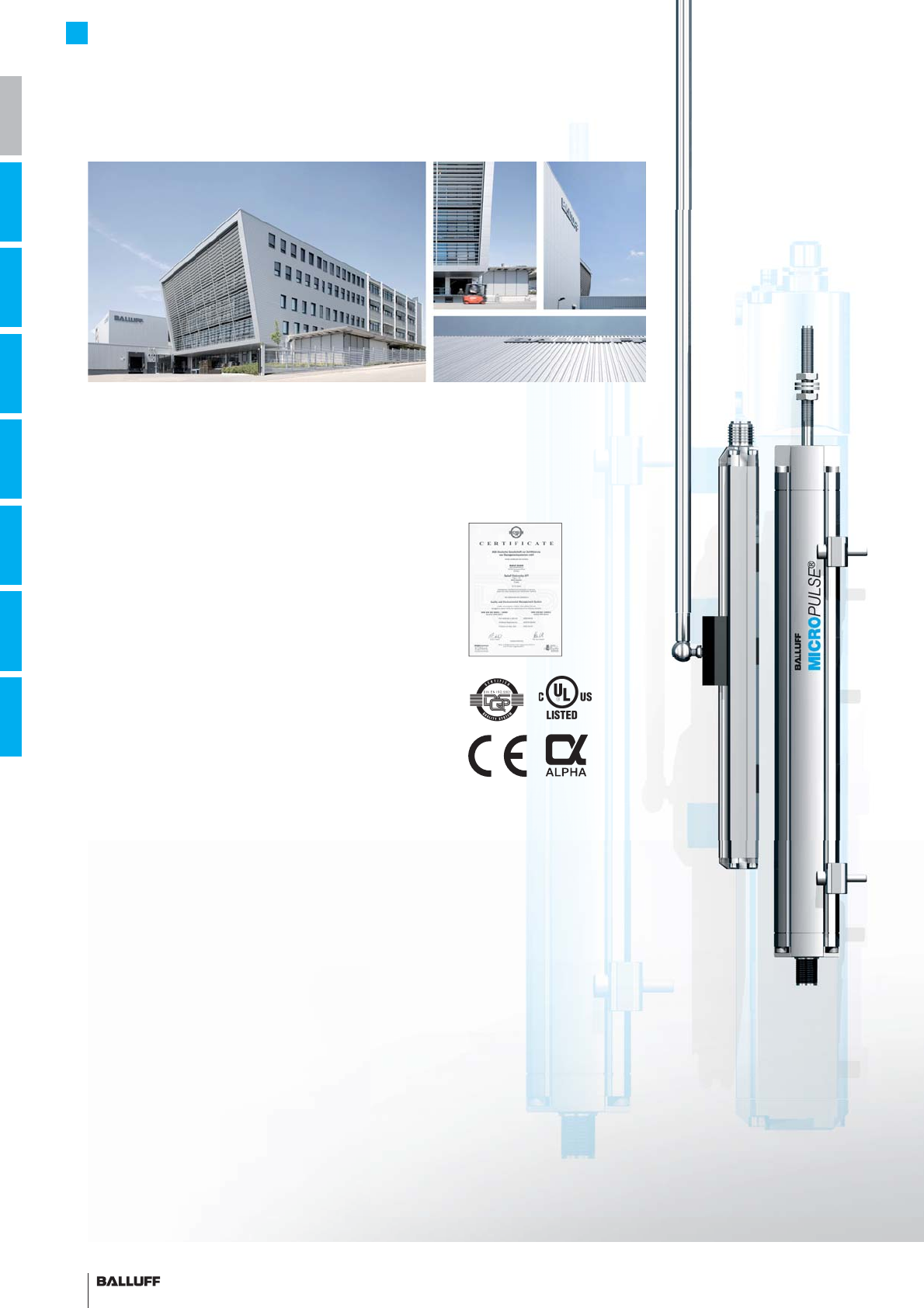
High-quality, innovative products tested in our own accredited
laboratory and a quality management system certifi ed according
to DIN ISO 9001 (EN 2008) form a secure foundation for optimized
added value for our customers and reliable partnership with
deliveries and logistics organized according to requirements.
Whether electronic and mechanical sensors, rotary and linear trans-
ducers, identifi cation systems or optimized connection technology
for high-performance automation, Balluff masters not only the entire
technological variety with all of the different operating principles, but
Balluff technology fulfi lls regional quality standards and is suitable
for use worldwide. Wherever you are in the world, Balluff technology
is never far away. You won't have to look far for you nearest Balluff
expert.
Balluff products increase performance, quality and productivity
around the world every day. They satisfy prerequisites for meeting
demands for greater performance and cost reductions on the global
market. Even in the most demanding areas. No matter how stringent
your requirements may be, Balluff provides state-of-the-art solutions.
Fully exploit the potential
of high quality with sophis-
ticated distance measure-
ment technology for greater
effi ciency
3■ www.balluff.com
i
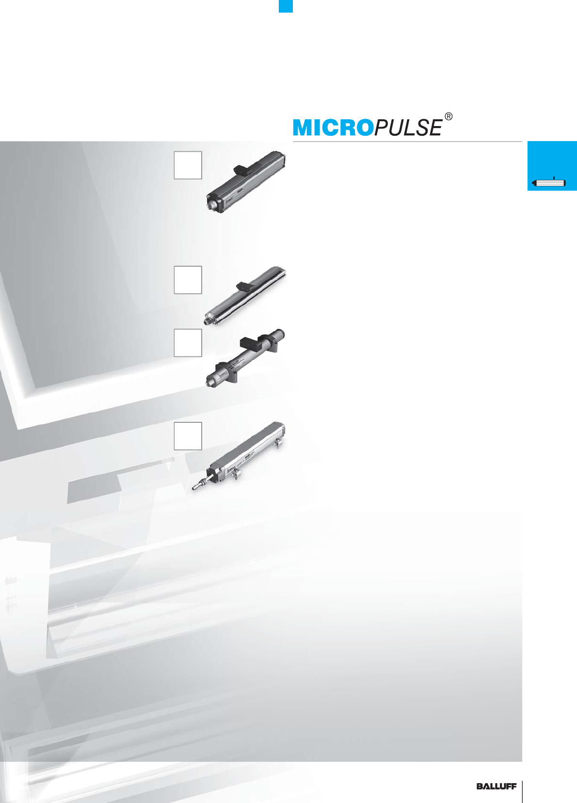
MICROPULSE
®
Micropulse Transducers
Basic Information and Defi nitions 17
Profi le Series 29
Rod Series 73
Compact Rod and AR Rod Series 101
EX Rod and T Rod Series 127
SF Rod Series 141
Accessories 147
Alphanumeric Directory 164
Worldwide Sales 168
4
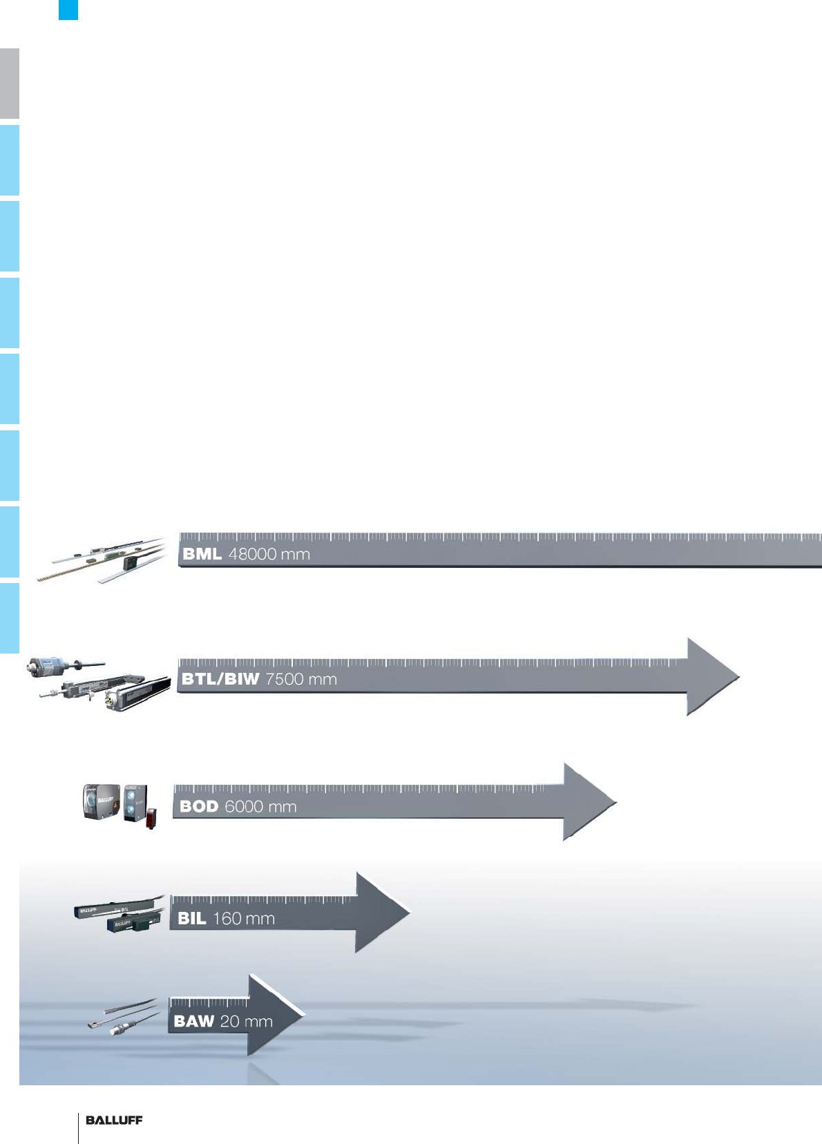
Magnetic linear encoder system BML – High precision and extended lengths
Micropulse transducers BTL/Inductive linear position sensor BIW – Extremely robust and reliable
Photoelectric distance sensors BOD – Independent of material and color
Magneto-inductive position sensors BIL – Compact and absolute
Inductive distance sensors BAW – For short strokes
Micropulse Transducers
Overview
Linear position sensing
MICROPULSE
®

5■ www.balluff.com
i
Balluff distance measurement –
the right solution for you
Balluff distance measurement
offers effi cient individual solutions
that are adapted to your specifi c
requirements.
Different working principles are
available for distances from
1 to 48000 mm and resolutions
from 1 to 100 µm.
From position detection to distance
measurement.
Fully exploit the benefi ts available.
Choose the option that's right
for you and increase your added
value with superior Balluff distance
measurement technology.
Robust industrial Balluff distance
measurement technology is
accurate, reliable, non-contact,
wear-free and brings out the best
from your machines.
– Full-range assortment for greater fl exibility
– Greater effi ciency with optimized solutions
– Superior distance measurement technology for increased productivity
Micropulse Transducers
Overview
Linear position sensing
6
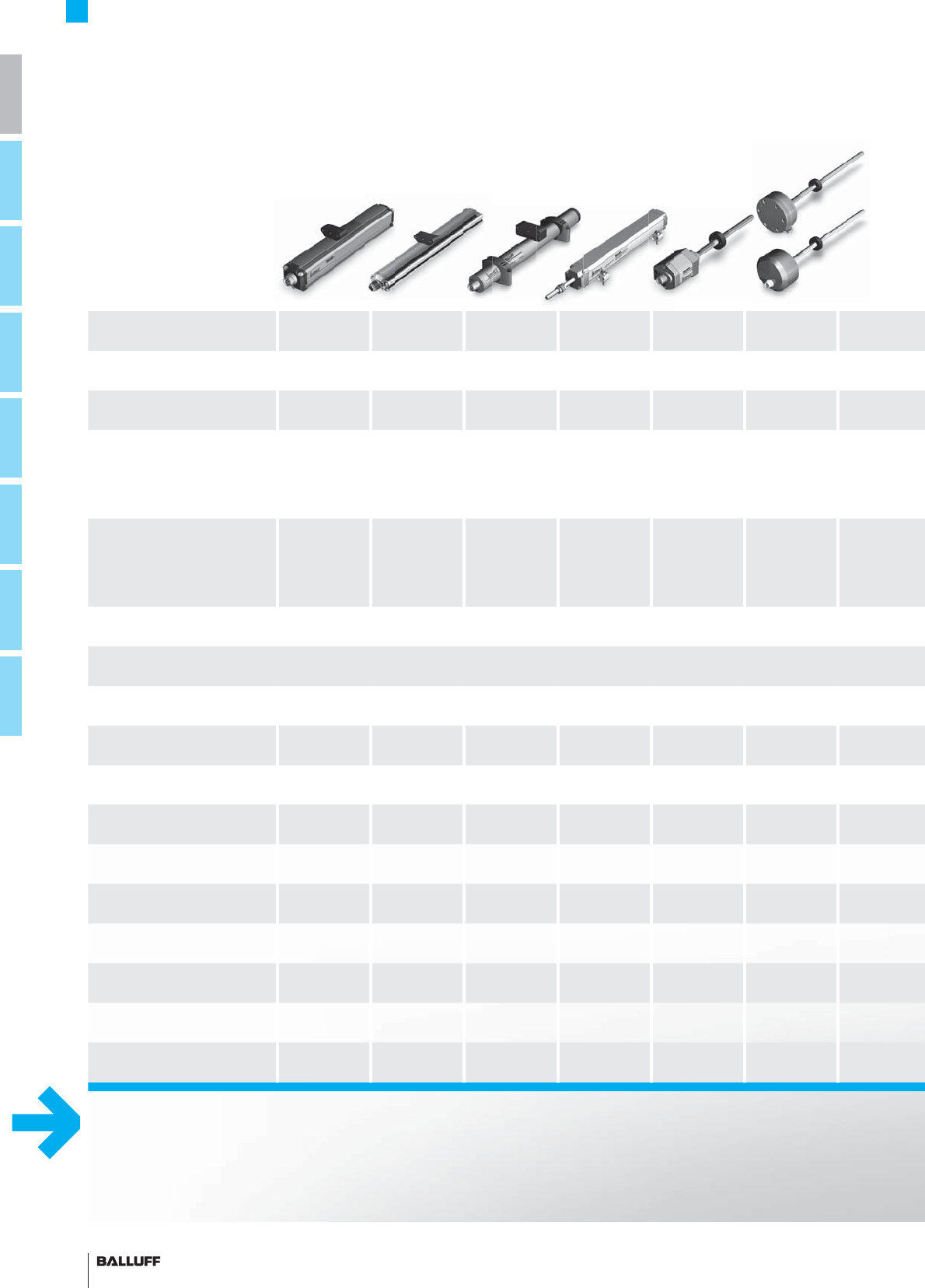
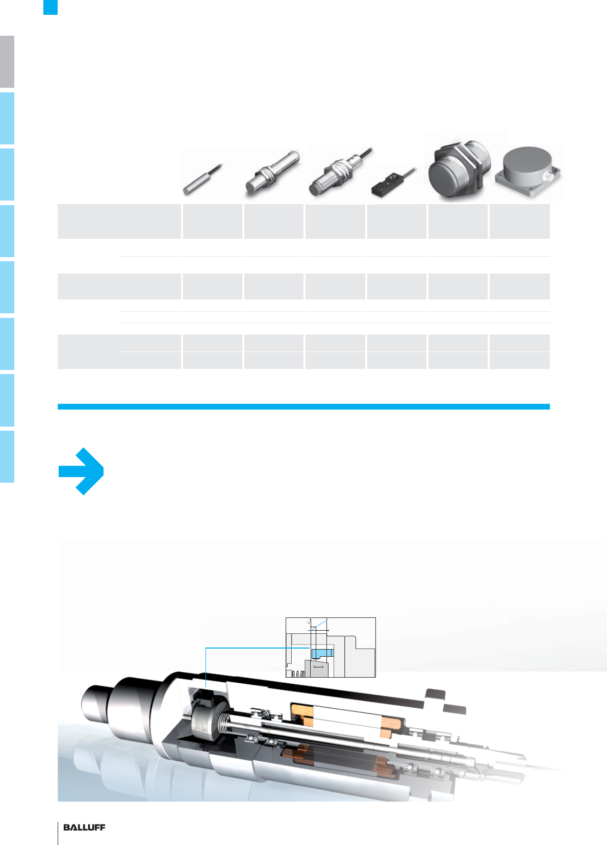
Micropulse Transducers
Overview
Distance measurement
Series Profi le P Profi le PF Profi le A1 Profi le BIW Rod
B, A, Z, Y
Rod
compact
Internal fi tting version
e.g. in hydraulic cylinders ■■
External fi tting version
e.g. on machine frames ■■■■
Filling level sensor
e.g. device fi lling systems
Special approvals
Magnet free/captive free/captive free captive
push rod
free or
fl oating
free or
fl oating
Interfaces
Analog voltage
0...10 V, 10...0 V, –10 V...+10 V ■■■■■■
Analog current
4...20 mA, 0...20 mA ■■ ■■■
SSI ■■■
SSI-SYNC ■■■
CANopen ■■■
DeviceNet ■
PROFIBUS-DP ■■
Start/Stop pulse interface ■■■
VARAN ■
From page 30 48 56 68 74 102
Micropulse transducers BTL
Inductive linear position sensor BIW
... extremely robust and reliable
7■ www.balluff.com
i
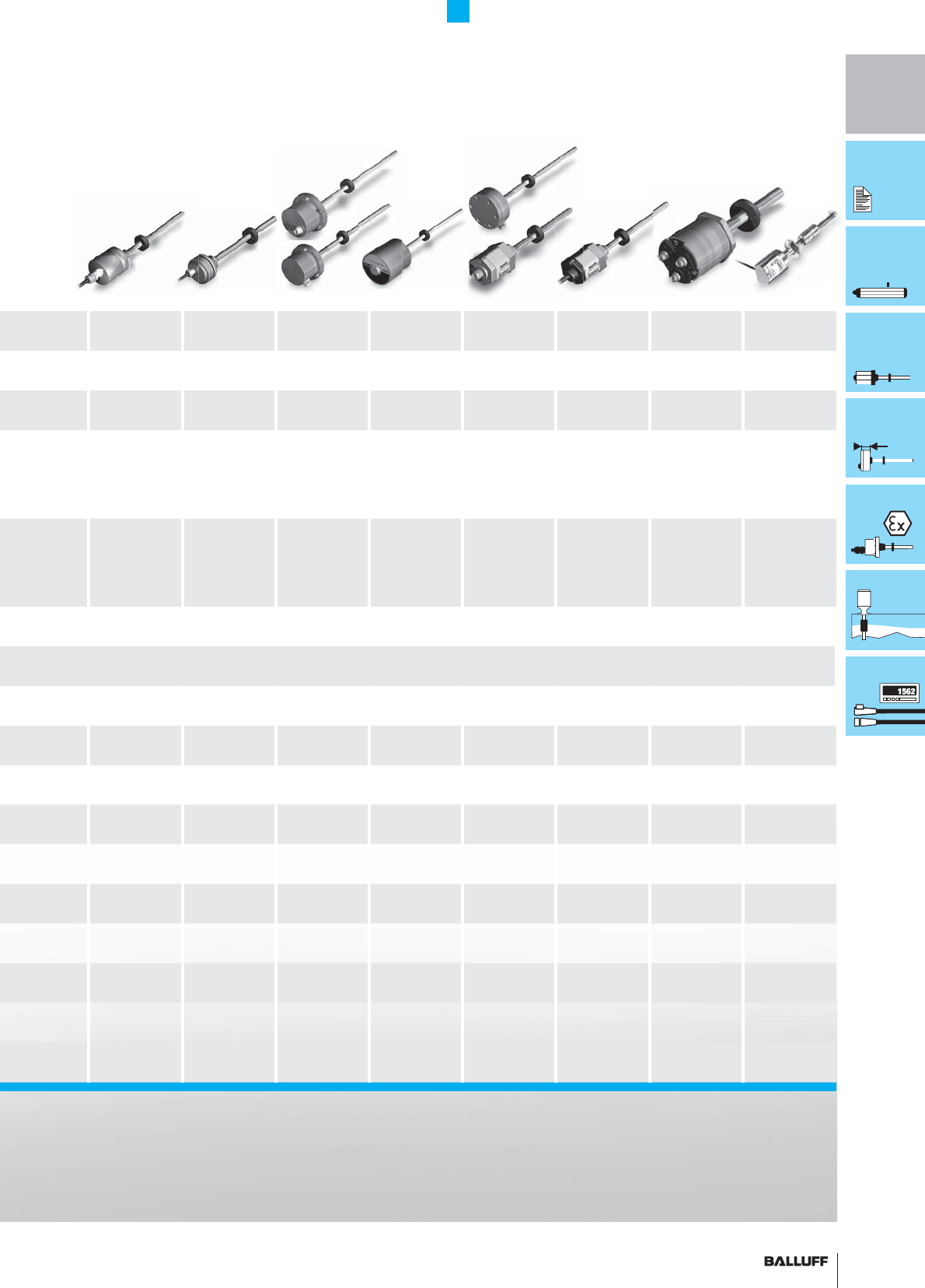
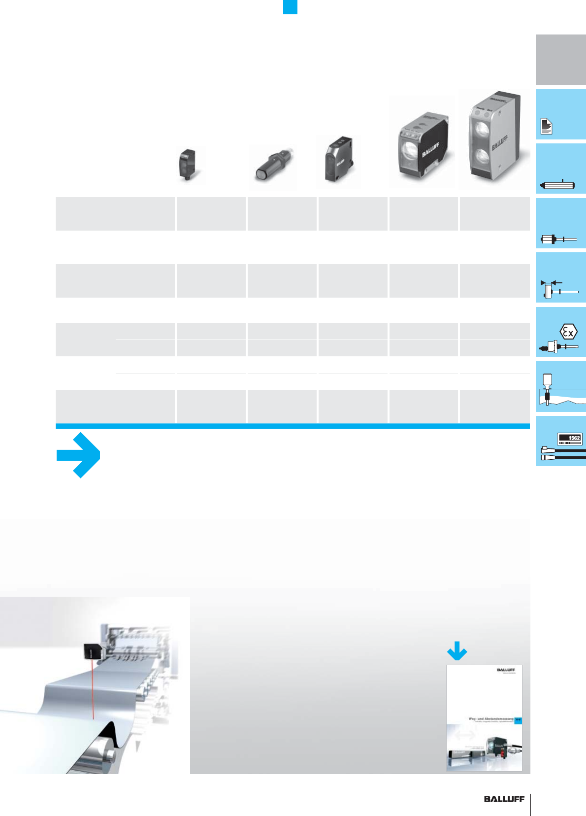
Micropulse Transducers
Overview
Distance measurement
Rod pro
compact Rod AR Compact rod
DEX B/J Rod DEX C Rod NEX Rod PEX Rod T Rod SF
■■■■■■
Vehicle
approval
Potentially
explosive
operation
Potentially
explosive
operation
Potentially
explosive
operation
Potentially
explosive
operation
Certifi ed for
foodstuffs
KBA, e1
Flameproof "d"
zone 0,
zone 1, ATEX,
KOSHA, GOST
Flameproof "d",
zone 0,
zone 1, ATEX,
CENELEC, FM,
CSA
protection type
"n" zone 2
Dust protec-
tion zone 22
Increased
safety
2 or 3-way
redundant
Conforms with
FDA, 3A,
ECOLAB,
EHEDG
free or
fl oating
free or
fl oating
free or
fl oating
free or
fl oating
free or
fl oating
free or
fl oating
free or
fl oating fl oating
■■■■■ ■■
■■■■■ ■■
■■■
■■
■■
■
■■■■■■■
108 118 130 132 135 134 138 142
MICROPULSE
®
8
Distance Measurement
Summary
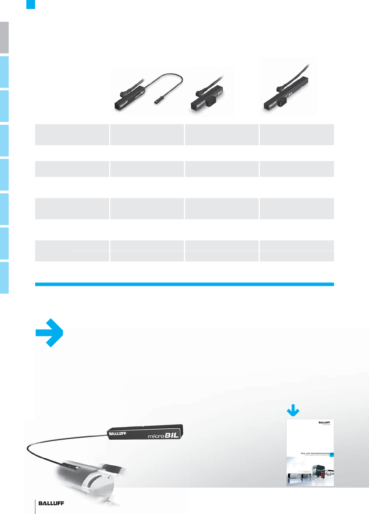
Magneto-inductive distance sensors
Magneto-inductive
distance sensors BIL Micro-BIL BIL 60 BIL 160
Working range 0...10 mm 0...60 mm 0...160 mm
Resolution ±0.15 mm ±0.4 mm
Linearity ±0.3 mm ±1 mm ±2.4 mm
Repeat accuracy ±30 µm ±60 µm ±0.5 mm
Housing size 28×6.2×4.4 mm 95×15.2×15.2 mm 230×15.2×15.2 mm
Output 0...10 V ■■■
4...20 mA ■■■
Special features Mounted in T-slot
SMARTSENS SMARTSENS SMARTSENS
SMARTSENS
Magneto-inductive distance sensors BIL
... compact and absolute
8
Refer to our
Linear Position Sensing catalog
for more information on
BIL magneto-inductive position sensors
or visit our website at www.balluff.com
9■ www.balluff.com
i
Distance Measurement
Overview
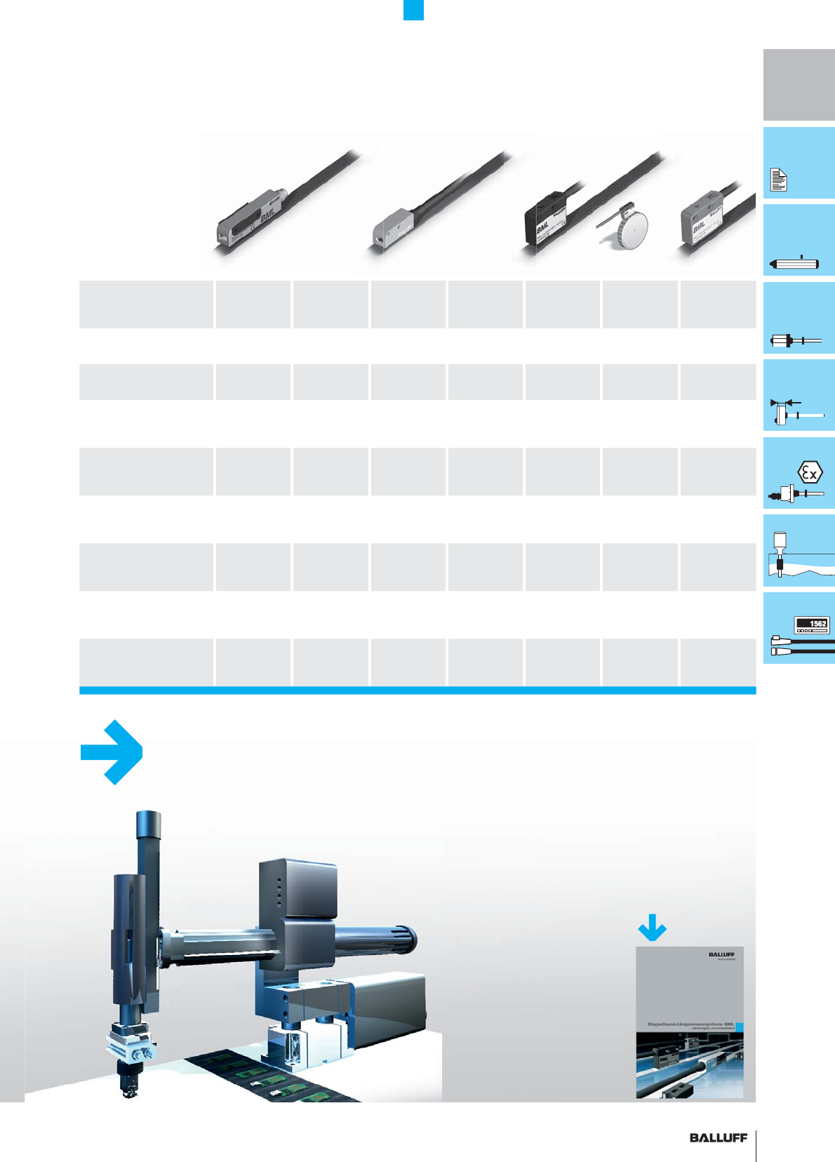
Magnetic linear encoder system
Magnetic linear encoder system BML
... high precision and extended lengths
Refer to our catalog
Magnetic Linear Encoder Systems BML
for more information
or visit our website at www.balluff.com
gp
Magnetic linear
encoder system BML
BML-S1A_-Q...
digital
BML-S1A_-A...
analog
sin/cos, 1 Vss
BML-S1F_-Q...
digital
BML-S1F_-A...
analog
sin/cos, 1 Vss
BML-S1B0-Q...
digital
BML-S1E0-Q...
digital
BML-S1C0-Q...
digital
Resolution 1...10 µm 1...10 µm 5...50 µm 5...50 µm
100...2000 µm
System accuracy ±10 µm/
±20 µm
±10 µm/
±20 µm ±10 µm ±10 µm ±50 µm/
±60 µm ±100 µm ±100 µm
Distance to tape 0.1...
0.35 mm
0.1...
0.35 mm
0.1...
0.35 mm
0.1...
0.35 mm 0.1...2 mm 0.1...2 mm 0.1...2 mm
Digital output signal
RS422 (TTL) ■■■■
Digital output signal HTL (as
operating voltage 10...30 V)
■■■
Analog output signal os
(1 Vss)■■
Linear tape
up to 48 m ■■■■■■■
Rotary magnetic tape (mag-
netic ring) ∅ 30...300 mm
■■■■■
10
Inductive distance sensors
BAW
BAW
Ø 6.5 mm
BAW M12 BAW M18 BAW R03 BAW PG 36 BAW
80×80 mm
Linear range Flush 0.5...2 mm 0.5...2 mm 1...5 mm 1...4 mm 0...20 mm
Not fl ush 1...4 mm 2...16 mm 0...50 mm
Housing size Ø 6.5 mm M12×1 M12×1 10×30×6 mm PG 36 80×80 mm
Output
0...10 V ■■■■■■
0...20 mA ■■
4...20 mA ■■
Connection Connectors ■■■■■■
Cable ■■■■
Special features
Teachable
switching output
Distance Measurement
Overview
Inductive distance sensors
Inductive distance sensors BAW
... for short strokes
11■ www.balluff.com
i
Distance Measurement
Overview
Photoelectric distance sensors
Photoelectric
distance sensors BOD
... independent of material and color
Refer to our
catalog Linear Position Sensing
for more information on
photoelectric distance sensors BOD or
visit our website at www.balluff.com
Photoelectric
distance sensors BOD BOD 6K BOD 18K BOD 26K BOD 63M BOD 66M
Distance sensor
measuring range 20...80 mm 50...100 mm
45...85 mm
30...100 mm
80...300 mm
200...2000 mm
200...6000 mm
100...600 mm
200...2000 mm
Diffuse sensor measuring range
with background suppression 20...80 mm 30...100 mm
80...300 mm
200...2000 mm
200...6000 mm
100...600 mm
200...2000 mm
Housing size 20 × 32 mm M18×1 50 × 50 mm 90 × 70 mm 73 × 90 mm
Output 0...10 V ■■■■■
4...20 mA ■■■
Connection Connectors ■■■■■
Cable ■■■■■
Special features Teachable
switching output
Teachable switching
output, adjustable
measuring range
Teachable
switching output
Teachable
switching output
12
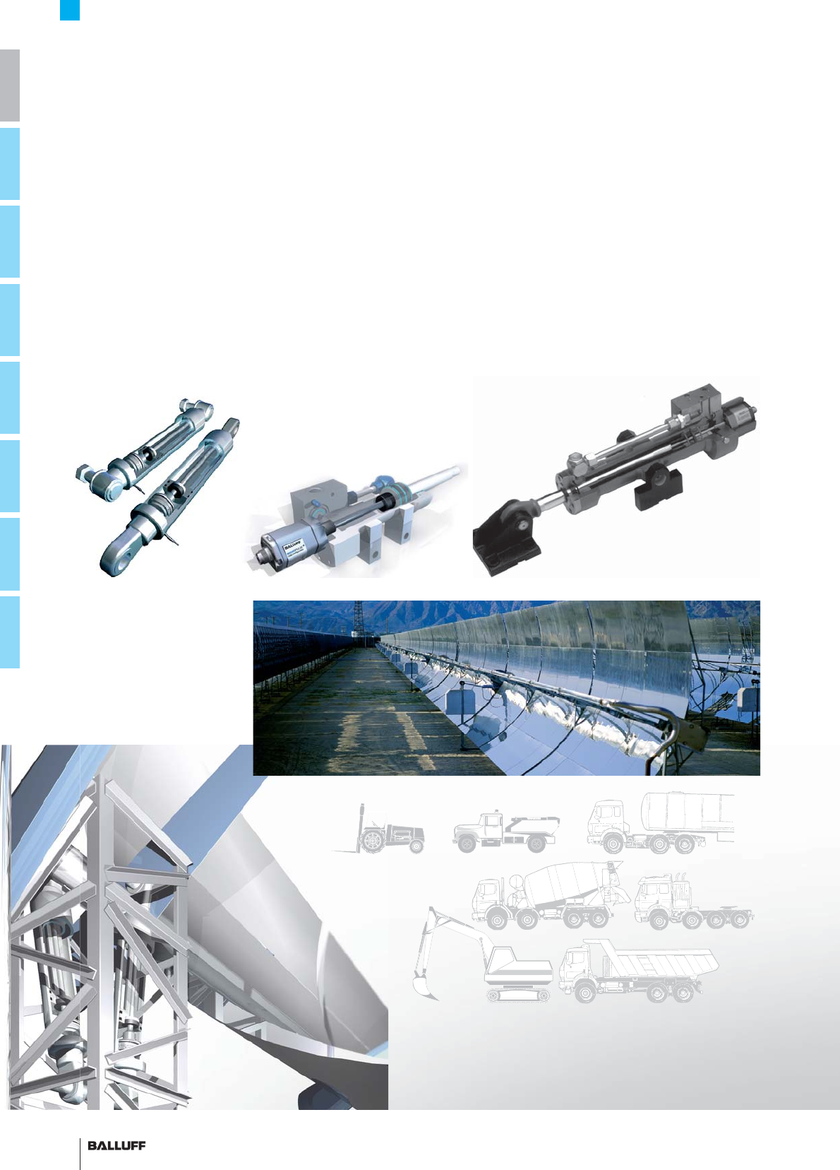
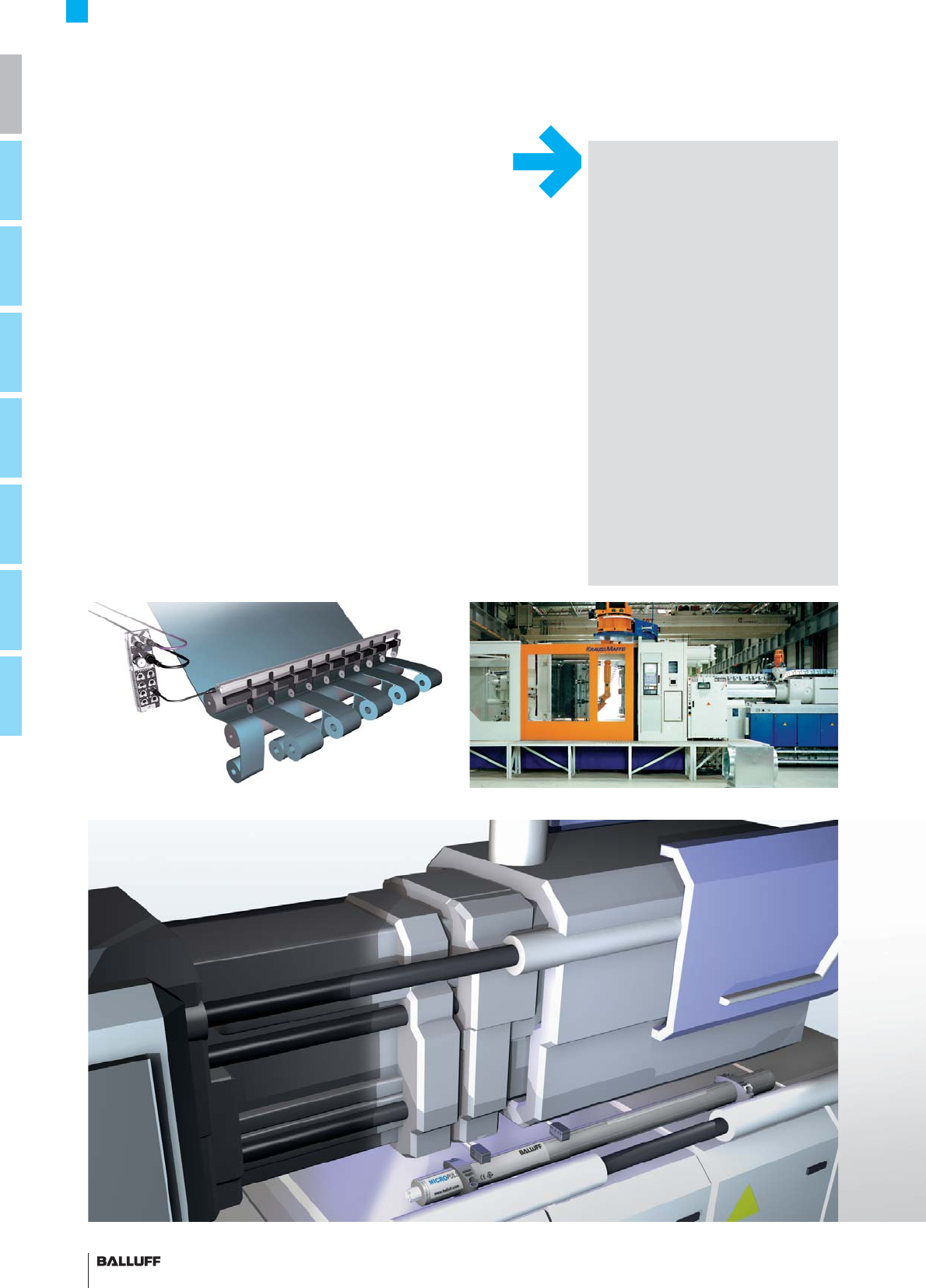
Micropulse Transducers
Applications
Hydraulic press
Micropulse transducers are perfect for applications that require a
high degree of reliability and precision.
Suitable for measurement lengths between 25 and 7500 mm, inte-
grable and compact Micropulse displacement systems are extremely
versatile.
The non-contact working principle of the systems ensures a com-
plete absence of wear and a virtually endless service life. The high-
precision output signal serves as an absolute signal for the controller
in a wide range of different interfaces.
Integrated in the pressure section of hydraulic cylinders, Micropulse
transducers are used as displacement systems for position sensing
in a wide variety of sectors.
Thermosolar power stations
Integrated in construction machinery Hydraulic axis with integrated Micropulse transducer
Application areas:
– Pitch movement on wind generators
– Monitoring refl ection channels on thermosolar power stations
– Large hydraulically powered valves
– Casting and rolling mills
– Lift controls
– Flight simulators
– Foundries
– Logging machines
– Automation engineering
– Hydroelectric power stations
– Locks and fl oodgates
– Construction machinery
– Combine harvesters
13■ www.balluff.com
i
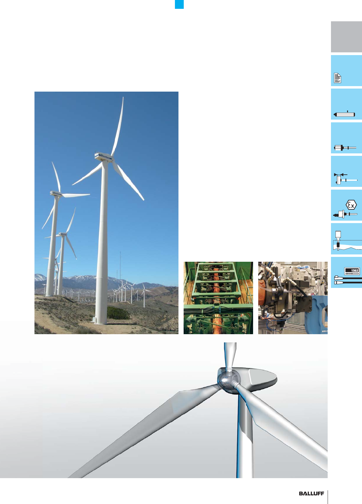
Micropulse Transducers
Applications
Sawmill machinery Hydraulic riveting systemWind power generator
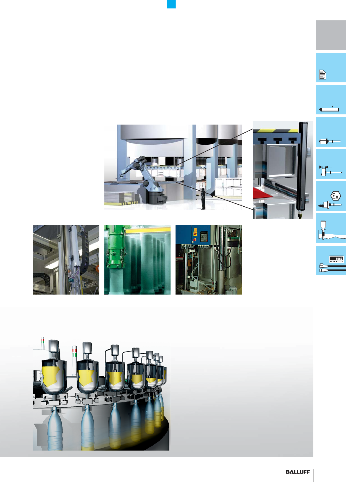
14
Micropulse Transducers
Applications
In the automation of a wide range of different machine types, the
most important requirements include maximum precision, no wear,
easy installation, a high degree of protection and a low price.
Micropulse transducers in a profi le housing fulfi ll requirements in the
automation industry 100 %.
Application areas:
– Injection molding
– Presses
– Handling systems
– Portal robots
– Woodworking machinery
– Packaging machines
– Conveying
– Leveling machines
– Operating tables
– Concrete blockmaking machines
Injection molding machineFilm slitting machine
Equipped for the future !
– Extremely fl exible
– Product changes using keyboard
– Longer cycle times
– Increased availability
– Short set-up times
– Downtimes prevented
– Greater degree of automation
are just some of the requirements
designers and developers must fulfi ll for
future machine generations.
The perfect solution for your
application !
From the Balluff full-range assortment of
distance measurement technology, we
can work out the most economical and
technically appropriate solution for you.
Competent
application consultation:
Phone: +49 7158 173-370 or
+49 7158 173-777
tsm@balluff.de bzw.
service@balluff.de
15■ www.balluff.com
i
Micropulse Transducers
Applications
Laundry pressConcrete construction machinery
The non-contact magnetostrictive working principle is also ideal for
special applications.
Application areas:
– Process technology
– Filling of foodstuffs
– Level monitoring in milk tanks
– Dosimetry
– Perfume manufacture
– Pharmaceuticals
– Alcohol production
Automation engineering
Level monitoring
Multiple-stage press
16 ■ www.balluff.com
1
6
■
■
www.
ba
ll
u
ff.
co
m
17
Basic Information and Defi nitions
Contents
Defi nitions 18
Principles of operation 21
Housings 22
Interfaces 24
Quality and service 26
B
as
i
c
I
n
f
ormat
i
on an
d
D
e
fi
n
i
t
i
on
s
Co
nt
e
nt
s
D
e
fi
n
i
t
i
ons
18
Pri
Pri
nci
nci
ple
ple
so
s o
fo
f o
per
per
ati
ati
on
on
21
H
Hou
Hou
ou
i
sin
sin
s
gs
gs
g
2
2
Int
erf
ace
s
2
4
Quality and servic
e
26
18
Basic Information
Defi nitions
Output signal, characteristic
curve, resolution, sensitivity
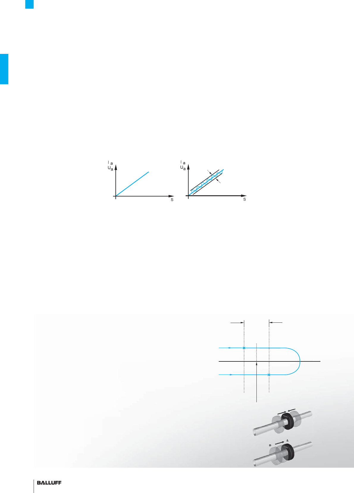
Linearity
Non-linearity
Hysteresis
Repeatability
Repeat accuracy
Non-linearity is the maximum deviation from a straight line which
connects the null point of the measuring range with the end point
(full scale). There is a linear relationship between the position or
stroke to be measured and the output signal for a voltage, cur-
rent or digitized information. The linearity curve of magnetostrictive
transducers does not change during the life of the system. The curve
however can be corrected.
Hysteresis is the signal difference resulting when arriving at a certain
position, traveling beyond it and then returning to this position from
the other direction.
Repeatability is moving to a certain position from both directions.
Repeatability is the sum of the hysteresis and the resolution.
The characteristic curve describes the relationship between the
output signal and the input signal. The slope of the curve represents
the sensitivity of the device.
The sensitivity (resolution) is the quotient of the input signal change
and the change in the output signal. On Micropulse transducers, the
input signal change is the change in the position of the magnet and
the output signal change is the change in the electrical output signal.
A measuring device has a linear characteristic curve and a constant
sensitivity when the relationship between the input and output
variable is represented by a straight line (linear function). Linear
scales are assumed for the X and Y-axes. A characteristic curve is
not linear if it is not a straight line.
Repeat accuracy is the value resulting when moving to the same po-
sition from the same direction under unchanging ambient conditions.
Linear
deviation
Linear function Linear deviation from a linear function
Turn-off point
Travel
Turn-on point
Hysteresis
Axis of travel
Specifi ed position

■ www.balluff.com 19
Basic Information
Defi nitions
SYNC mode
Incremental
Absolute
The absolute positioning information of the displacement system is
established and transmitted synchronously to the read cycle of the
processing electronics, e.g. an axis controller or a regulating control-
ler.
Temperature coeffi cient
The temperature coeffi cient is the relative change of a physical
quantity with changing temperature. The temperature dependence
of a physical quantity y can be approximated at least for a limited
temperature range by using the temperature coeffi cient α with a
linear relationship y = y0 (1 + α *ΔT).
The temperature coeffi cient indicates the relative change in length as
temperature changes. This means that temperature factors change
the output value by the indicated amount.
Null point The null point is the position with the lowest output value along the
measuring range. For some transducer models the null point can be
set by the user. The null point must lie within the measuring range.
Sampling rate The sampling rate is the frequency at which the output information
is updated. It can be the same as the number of measurements
per second. A high sampling rate for rapidly changing positions is
important when the process is time-critical.
Nominal stroke The nominal stroke is the usable area along the transducer, and is
represented by the length indication in the part number (see also
Characteristic curve). The nominal stroke is always shorter than the
overall length of the transducer.
Damping zone The damping zone is the area in which the second (undesired)
magnetostrictive wave is damped. This area is always outside of the
measuring range. Depending on the transducer model, either an
erroneous output signal or an error signal will be output if the magnet
is allowed to travel into this zone, which must not be considered
valid information.
Temperature coeffi cient,
formula
After the system is switched off, the measured value currently avail-
able is not retained. A reference run to a defi ned point is necessary
in order to obtain a position value. The position value is calculated by
adding or subtracting single identical increments from the reference
point.
The measured value for the current position is available immediately
after the system is switched on. An absolute coded digital signal
or an analog value is assigned to each position, e.g. along a wave-
guide. A reference run is not required.

20
Basic Information
Defi nitions
Intrinsically safe "i"
Coding "Ex i"
Parts which could ignite a potentially explosive atmosphere must be
housed in an enclosure:
– which in case of an explosion of an explosive mixture inside the
housing can contain the pressure, and
– which prevents the internal explosion from igniting the atmosphere
surrounding the enclosure.
Protection type "n"
designation "Ex n"
Devices in these categories are intended for use in areas where an
explosive atmosphere is not expected. Even if the atmosphere were
to become explosive, in all probability it would be infrequent and only
for a short space of time.
A manufacturer's certifi cate is provided, confi rming that the product
satisfi es requirements for the use of electrical equipment in poten-
tially explosive areas according to EN 60079-15.
Several methods of fl ameproofi ng are combined under the designa-
tion.
e1 type approval The e1 type approval is granted by the German Federal Motor
Transport Authority KBA and confi rms that special motor vehicle
standards have been maintained.
The devices may be mounted on vehicles which travel on public
roads. The standards describe EMC conditions under which
the devices must operate without failure. e1 approved Micropulse
transducers are indicated by "-SA265-" in the Part number.
The FDA (Food and Drug Administration) oversees the US food and
pharmaceutical industry and certifi es devices, materials, systems
and machines from these sectors. A product designation of this kind
makes your system eligible for FDA approval.
FDA
e1
A circuit is intrinsically safe if it does not permit a spark or thermal
effect which could ignite an explosive atmosphere as defi ned by
Group IIA, IIB or IIC, whereby the test conditions prescribed in the
standard must be applied. The test conditions take into account
normal operation and certain fault conditions.
The implementation of intrinsically-safe circuits results in certain re-
strictions pertaining to the selection of components for the electrical
and electronic circuits.
In addition the permissible load on the components as compared
with normal industrial applications must be reduced:
– with respect to the voltage in terms of dielectric strength, and
– with respect to the current in terms of thermal effects.
Flameproof enclosure "d"
Designation "Ex d"
■ www.balluff.com 21
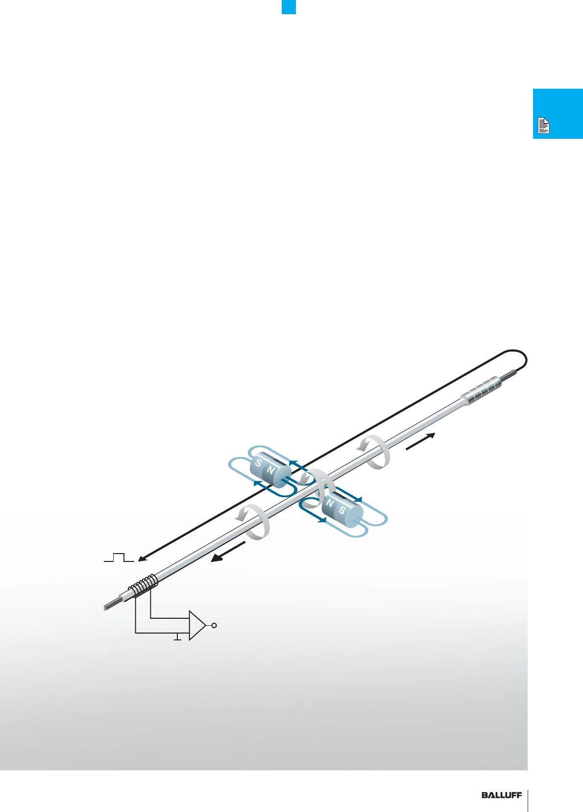
The measuring element ("waveguide") consists of a special nickel-
iron alloy with 0.7 mm outer and 0.5 mm inner diameter. A copper
conductor is introduced through the length of this tube. A short
current pulse initiates the measurement process. This current gener-
ates a circular magnetic fi eld which rotates around the waveguide.
A permanent magnet at the point of measurement is used as the
marker element, whose lines of fi eld run at right angles to the elec-
tromagnetic fi eld.
In the area on the waveguide where the two fi elds intersect,
a magnetostrictive effect causes an elastic deformation of the wave-
guide (in the microrange), which propagates along the waveguide in
both directions in the form of a mechanical wave.
The propagation velocity of this wave in the waveguide is 2830 m/s,
and is almost completely insensitive to environmental effects such as
temperature, shock and contamination.
The component of the wave which reaches the far end of the
waveguide is damped, whereas the component which arrives at the
signal converter is changed into an electrical signal by reversing the
magnetostrictive effect. The time the wave takes to travel from its
point of origin to the signal converter is directly proportional to the
distance between the permanent magnet and the signal converter.
A time measurement then allows this distance to be calculated with
extreme accuracy.
Damping
Receiver
Mechanical wave
Electromagnetic fi eld
Magnet
Magnets
Mechanical wave
Waveguide
Signal converter
Copper
conductor
Exciting current pulse
Basic Information and Defi nitions
Principles of operation
Principles of operation
MICROPULSE
®
22
Basic Information and Defi nitions
Form factors
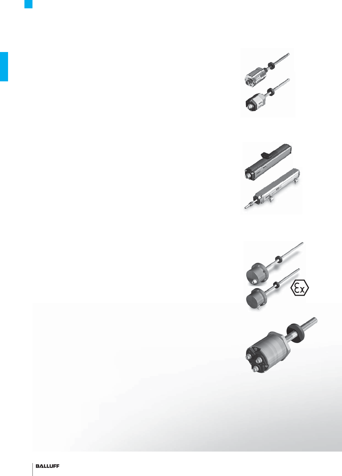
Rod housings Rod housings are mainly used in hydraulic drive applications. When
installed in the pressure section of the hydraulic cylinder, the distance
sensor requires the same pressure rating as the actual hydraulic
cylinder. In practice, the sensor must be able
to withstand pressures up to 1000 bar. The electronics are inte-
grated in an aluminum or stainless steel housing and the waveguide
in a pressure-resistant tube made from nonmagnetic stainless steel
that is sealed off at the face end with a welded plug. An O-ring seal
in the fl ange at the opposite end seals off the high-pressure section.
An magnet ring with magnets slides over the tube or rod with internal
waveguide to mark the position prior to detection.
Profi le housings The electronics and waveguide are enclosed in an aluminum profi led
housing. The aluminum housing is hermetically sealed according to
degree of protection IP67. The magnets on the magnet act on the
waveguide through the wall of the aluminum profi le.
There are two different versions of magnet, namely captive and free
magnets. Free magnets are secured directly on the moving machine
part and move with the part above and along the profi le at a certain
distance. The advantage is that guide precision is not an issue with
this type of sensor. The sensors tolerate a lateral and upward offset
of several millimeters. If these generous tolerances are exceeded,
you can always revert to using captive magnets. With captive
magnets, the profi le housing of the distance sensor acts as a sliding
rail along which the magnet travels. In this case, a control arm with
spherical heads compensates for unparallel movements.
Explosion-proof
versions
Many applications require the use of distance sensors in potentially
explosive areas. Flameproof magnetostrictive Micropulse transduc-
ers are available in a wide range of designs for use in zone 0 and 1.
Magnetostrictive distance sensors are ideal for applications requir-
ing a high degree of safety or availability. The sensors often have a
2-way or even 3-way redundant design in order to ensure mutual
monitoring or provide a reserve channel when required. A distance
sensor with a redundant 3-way design incorporates 3 adjacent
waveguides offset by 120°C and housed in a collective outer
tube along which an magnet moves in much the same way as on
standard housings. The magnets on the magnet act on all three
waveguides simultaneously. The three positions are evaluated by
three interdependent, completely separate electronics modules
that can be integrated in the same housing. Application examples
include ship propulsion drives, power stations and tilting technology
in trains.
Redundancy increases safety

■ www.balluff.com 23
The magnetostrictive working principle is also ideal for the continu-
ous high-precision measurement of fl uid fi lling levels. Waveguides
and processing electronics are enclosed inside a housing made from
stainless steel. Stainless steel fl oats with permanent integrated mag-
nets mark the current fi lling level in the tank or vessel. The design of
the sensors meets international hygiene standards.
Basic Information and Defi nitions
Form factors
Filling level sensor
d
e f
rom
d
mag-
ign
of
MICROPULSE
®

24
Analog
voltage output
The output voltage is
directly proportional to the
position of the magnet
along the waveguide.
The most important
parameter for analog
outputs is the refresh rate
and the ripple of the
output signal. Many trans-
ducers on the market
attain the specifi ed values
for output ripple only by
means of low-pass fi lter-
ing. This always carries
with it an undesirable time
delay of the output signal.
Micropulse transducers
attain the specifi ed signal
quality without low-pass
fi lters, instead using an
improved circuit design.
This means fast update
times with low levels of
ripple and noise on the
output signal.
Micropulse transducers
with voltage output have
2 outputs, one rising and
one falling.
Available versions include:
0...10 V (10...0 V) and
–10...10 V (10...–10 V).
See technical data on
page 32
Analog
current output
The output current is
directly proportional to the
position of the magnet
along the waveguide.
Analog current interfaces
of 0...20 mA and
4...20 mA are standard
in numerous applications
and in many industries.
Current interfaces are
signifi cantly less sensitive
to induced noise voltage
than analog voltage inter-
faces. A 500 Ω resistor
can be used to convert
the 0...20 mA signal into
a voltage of 0...10 V.
The 4...20 mA signal
provides a simple form of
cable break monitoring,
since a current of 4 mA
must fl ow even at the
null point of the stroke.
Micropulse transducers
with current output are
available with rising or
falling signals.
See technical data on
page 32
Pulse interface
The time between an
interrogation and the
reply signal is directly pro-
portional to the position
of the magnet along the
waveguide.
These pulses are trans-
mitted using RS485/422
differential line drivers,
guaranteeing noise-free
signal transmission
over distances of up to
500 m.
The great advantage
of these interfaces is the
noise-immune signal
transmission with a
simple and economical
interface. Interfaces with
tristate outputs allow
multiplexing of several
Micropulse transducers.
Appropriate control cards
are available.
See technical data on
page 34
Synchronous serial
SSI interface
The position of the
magnet along the
waveguide is sent to the
controller serially in a
data word.
Micropulse transducers
with SSI interface can
be connected directly
to controllers or to axis
control cards with SSI
interface. The transmis-
sion of data from the
sensor to the controller is
synchronized by a clock
pulse from the controller.
Transducers with 16, 24
or 25-bit data words are
available depending on
the required resolution.
The maximum non-linear-
ity of the SSI Micropulse
transducer of ±30 µm
over the entire stroke, the
update frequency of
5 kHz and a resolution of
1 µm make SSI Micro-
pulse transducers an
ideal feedback sensor –
even in the most de-
manding positioning and
control applications.
See technical data on
page 36
Basic Information and Defi nitions
Interfaces
■ www.balluff.com 25
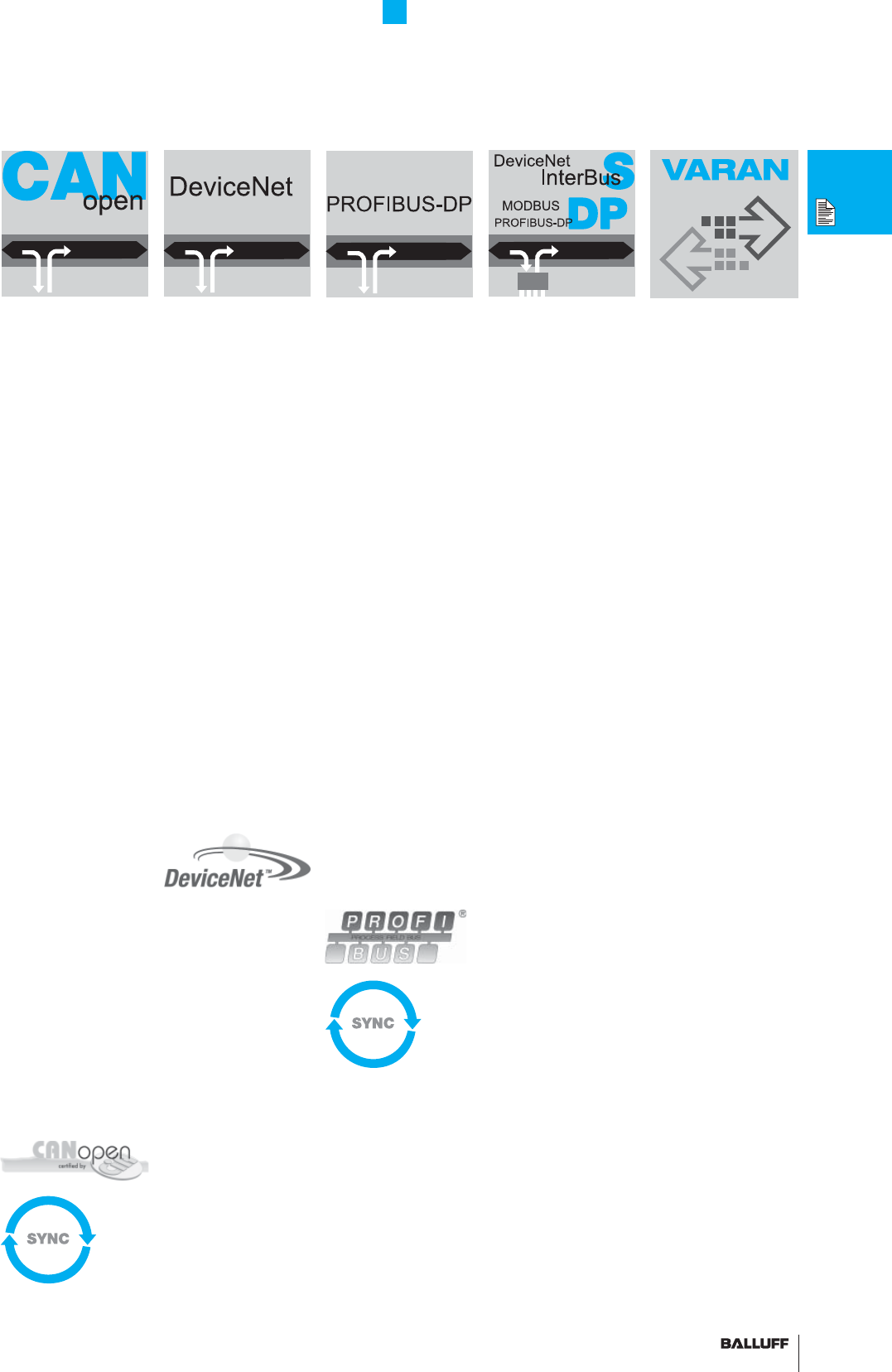
CANopen
The position of the
magnet along the wave-
guide is sent over the
CAN bus to the controller
in so-called Process Data
Objects or PDOs.
Micropulse transduc-
ers work with standard
CANopen protocols as
per CiA DS 301 and
with the standard device
profi le as per DS406.
CANopen offers greater
fl exibility because of the
large number of con-
fi guration options for the
transducer.
For example, the
resolution is program-
mable for 5, 10, 20 or
100 µm – depending on
your application. Alter-
natively you can select
whether both position
and velocity information
are sent to your controller.
Cyclically or on-demand.
And there's more:
Up to 4 so-called
software cams can be
defi ned in the active mea-
suring range. Each time
the status of one
of these cams changes,
high-priority emergency
messages are sent to the
controller.
See technical data on
page 38
DeviceNet
DeviceNet is a fi eldbus
network which permits
communication between
basic sensors/actuators
as well as programmable
logic controllers.
Micropulse transducers
transmit the absolute
position and the velocity
to the controller in the
form of a 4 byte value
with a maximum cycle
time of 1 ms.
The communication pa-
rameters and the objects
available to the Micro-
pulse transducer can be
parameterized using the
electronic device data
sheet (EDS fi le).
See technical data on
page 40
Bus interface modules
WAGO/Phoenix Contact
One fl exible way of
connecting Micropulse
transducers to various
bus systems is to use
the interface modules
available from WAGO and
Phoenix Contact. These
provide the option of
transmitting the position-
ing information from sev-
eral transducers through
a single bus interface to
the supervisory controller
within a single bus cycle.
The resolution and the
null point of the transduc-
ers with the pulse inter-
face can be programmed
through the respective
bus interface. For further
technical data and
ordering bus interface
modules, contact WAGO
and Phoenix Contact.
See technical data on
page 162
PROFIBUS-DP
The Process Data Unit
sends position and veloc-
ity information for the
transducer to the control-
ler via the PROFIBUS-DP.
Micropulse transducers
operate according
to EN 50170 and sup-
port the PROFIBUS-DP
encoder profi le as well as
multi-magnet operation.
Micropulse transducers
can be parameterized
using the GSD fi le. The
position resolution can be
confi gured in 5 µm incre-
ments and the velocity
resolution in increments
of 0.1 mm/s.
Working ranges and the
null point can be confi g-
ured individually for each
magnet.
See technical data on
page 42
VARAN bus
VARAN is an open
realtime Ethernet bus
system. Micropulse AT
VARAN linear displace-
ment systems detect
the movements of highly
dynamic axes in complex
applications.
The realtime Ethernet
system is extremely
economical, easy to
implement and simple
to program. Widely
available on the market,
VARAN networks are
used in combination with
Sigmatek controllers, for
example.
VARAN is fully integrated
in hardware and designed
according to IEEE 802.3
for standard Ethernet
physics.
The simple design
guarantees extremely
rapid cycle times while
achieving maximum data
security and reducing
implementation costs.
See technical data on
page 64
Basic Information and Defi nitions
Interfaces
26
Basic Information and Defi nitions
Quality and service Reliability doesn't
happen by chance
Tests
1. Electromagnetic compatibility (EMC)
Immunity from discharge of static electricity (EN 61000-4-2)
Immunity from electro-magnetic fi elds (EN 61000-4-3)
Immunity from rapid transient interference (bursts) (EN 61000-4-4)
Immunity from surge voltages (EN 61000-4-5)
Immunity from line-borne high-frequency interference
(EN 61000-4-6)
Immunity from magnetic fi elds with power transmission frequencies
(EN 61000-4-8)
Immunity from voltage dips, short breaks in power supply and voltage fl uctuations
(EN 61000-4-11)
Radiated emissions (EN 55011)
Mains-borne emissions (EN 55011)
Emissions, HF magnetic fi eld (DIN EN 300 330-1)
2. Product-specifi c tests Making capacity / breaking capacity (EN 60947-5-2) Testing cable anchoring of
devices with integral connection cables (EN 60947-5-2)
Short circuit testing (EN 60947-5-2)
3. Shock, sinusoidal and noise testing
Shock, sinusoidal and noise testing (EN 60068-2-6) (EN 60068-2-27;
EN 60068-2-29) (EN 60068-2-64)
4. Other X-ray analysis
Reliability doesn't happen by chance!
Maximum quality and reliability always take top
priority at Balluff. All EMC, shock and vibration tests
relevant to products are conducted in our internal
company testing laboratory, which has been certifi ed
for 15 years.
The sophisticated test equipment in the testing labora-
tory can be used to implement special, more stringent
tests that extend beyond standard specifi cations.
Each product series must pass the specifi ed tests
prior to obtaining approval for the customer.
Tests for reliability and quality:
Global online availability
The latest product information from our databases.
We offer the latest
– Data sheets
– CAD drawings in
2D or 3D
– Catalogs
– Brochures
– Manuals
– Software descriptions
– Operating manuals
– FAQs
– Worldwide addresses
and much more.
www.balluff.com
■ www.balluff.com 27
Basic Information and Defi nitions
Quality and service
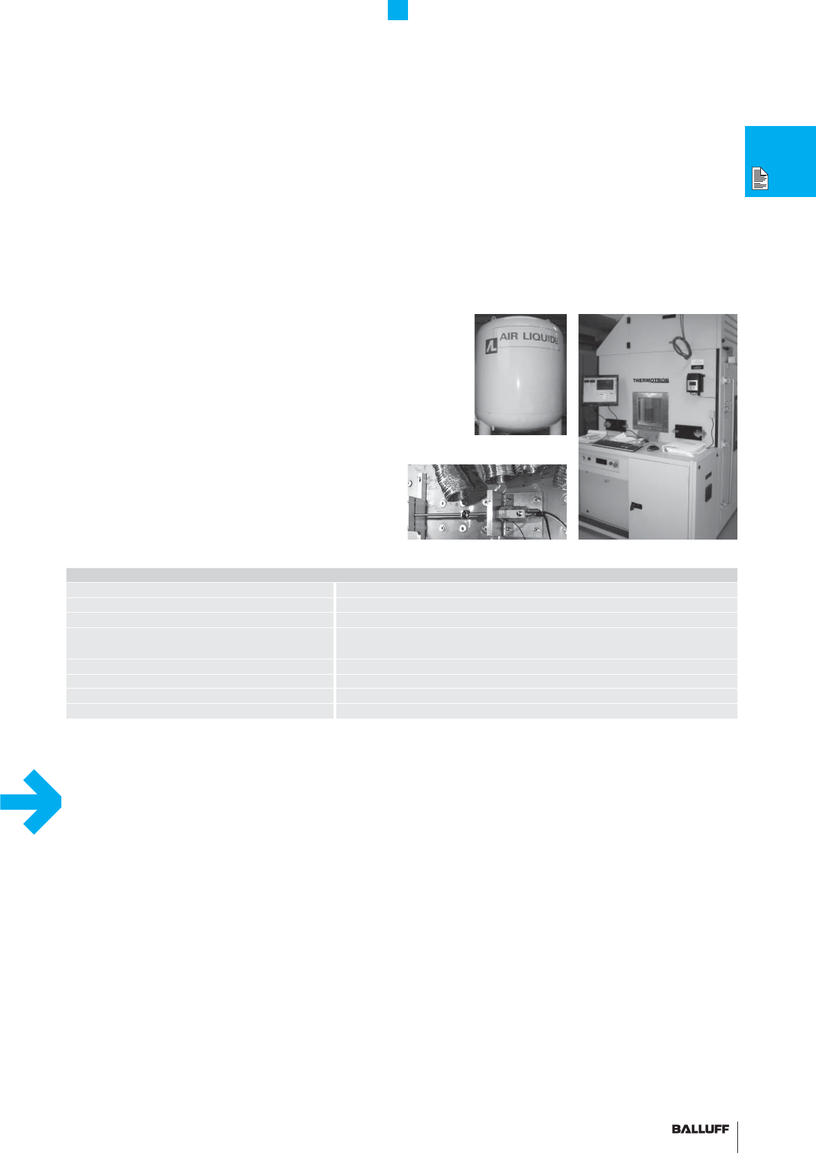
HALT tests were designed to detect weaknesses early during
the product development phase and eliminate them
The result is linear displacement systems and sensors of the highest
quality and reliability which will continue to perform with the same
safety and precision for years to come. The tests reduce equipment
downtimes, prevent service and repair costs and achieve signifi -
cantly greater effi ciency. Rapid temperature cycles from –100 °C to
+200 °C and vibration loads between 10 °C and 50 °C can simulate
aging of a sensor. This procedure is used to test the specifi cations
of products to determine the degree of reliability, load capacity and
life expectancy of the sensor. The sample is intentionally destroyed
so that we can immediately improve the fi rst component to fail. Both
sensors and transducers can be tested in the HALT system.
HALT system
Manufacturer Thermotron Industries USA
Frequency range 2...10000 Hz
Acceleration up to 50 g
Excitation 9 pneumatic cylinders, noise spectrum, 3-axis, 3 linear and
3 rotary degrees of freedom
Temperature range –100 °C...+200 °C
Temperature gradient 70 K/min
Electrical power 96 kW
Procedure Electric heater, liquid nitrogen for cooling
Nitrogen tank for the cooling system
Stress on the sample Multifunctional climate chamber
We offer ...
– Qualifi ed technical consultation on the complete
Balluff product range
– Technical solutions for all your applications
– Flexible assistance in dealing with your specifi c
questions and problems
– Support whenever you need it
– Know-how for integrating controllers
– Product repair service
We will gladly answer any questions relating to ...
– Technical product features
– Suitability of products for your application
– Operating instructions and data sheets
– Conversion of models from other manufacturers
– Balluff successor products
We are happy to help!
Phone: +49 7158 173-370
E-mail: service@balluff.de
Fax: +49 7158 173-691
Weekdays 7am to 8pm
Saturdays 8am to 12pm
Do you have a claim?
You are welcome to return your Balluff product to
us for inspection and repair.
Request a return consignment number from the
"Technical Service" area on our website.
Service Center
... competent customer service
HALT – High Accelerated Lifetime Test
... highest function security over years

28
28
28
29■ www.balluff.com
29
■www.
b
a
ll
u
ff
.com
P
General data 30
Analog interface 32
Digital pulse interface 34
SSI interface 36
CANopen interface 38
DeviceNet interface 40
PROFIBUS-DP interface 42
Free magnets 44
Captive magnets, control arm 46
PF
General data 48
Analog interface 50
Free magnets 52
Captive magnets, control arm 54
AT
General data 56
Analog interface 58
Modes 60
Analog interface 61
Digital pulse interface 62
VARAN bus interface 64
Accessories 66
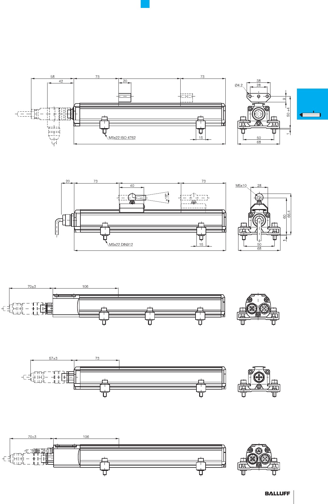
BIW
General data 68
Analog interface 70
The electronics and waveguide are enclosed in an aluminum profi led
housing. The aluminum housing is hermetically sealed according
to degree of protection IP67. The magnets on the magnet act on the
waveguide through the wall of the aluminum profi le.
There are two different versions of magnet, namely captive and free
magnets. Free magnets are secured directly on the moving machine
part and move with the part above and along the profi le at a certain
distance. The advantage is that guide precision is not an issue with
this type of sensor. The sensors tolerate a lateral and upward offset
of several millimeters. If these generous tolerances are exceeded,
you can always revert to using captive magnets. With captive
magnets, the profi le housing of the distance sensor acts as a sliding
rail along which the magnet travels. In this case, a control arm with
spherical heads compensates for unparallel movements.
Profi le Series
Contents
A
A
29■ www.balluff.com
P
PF
AT
BIW
30
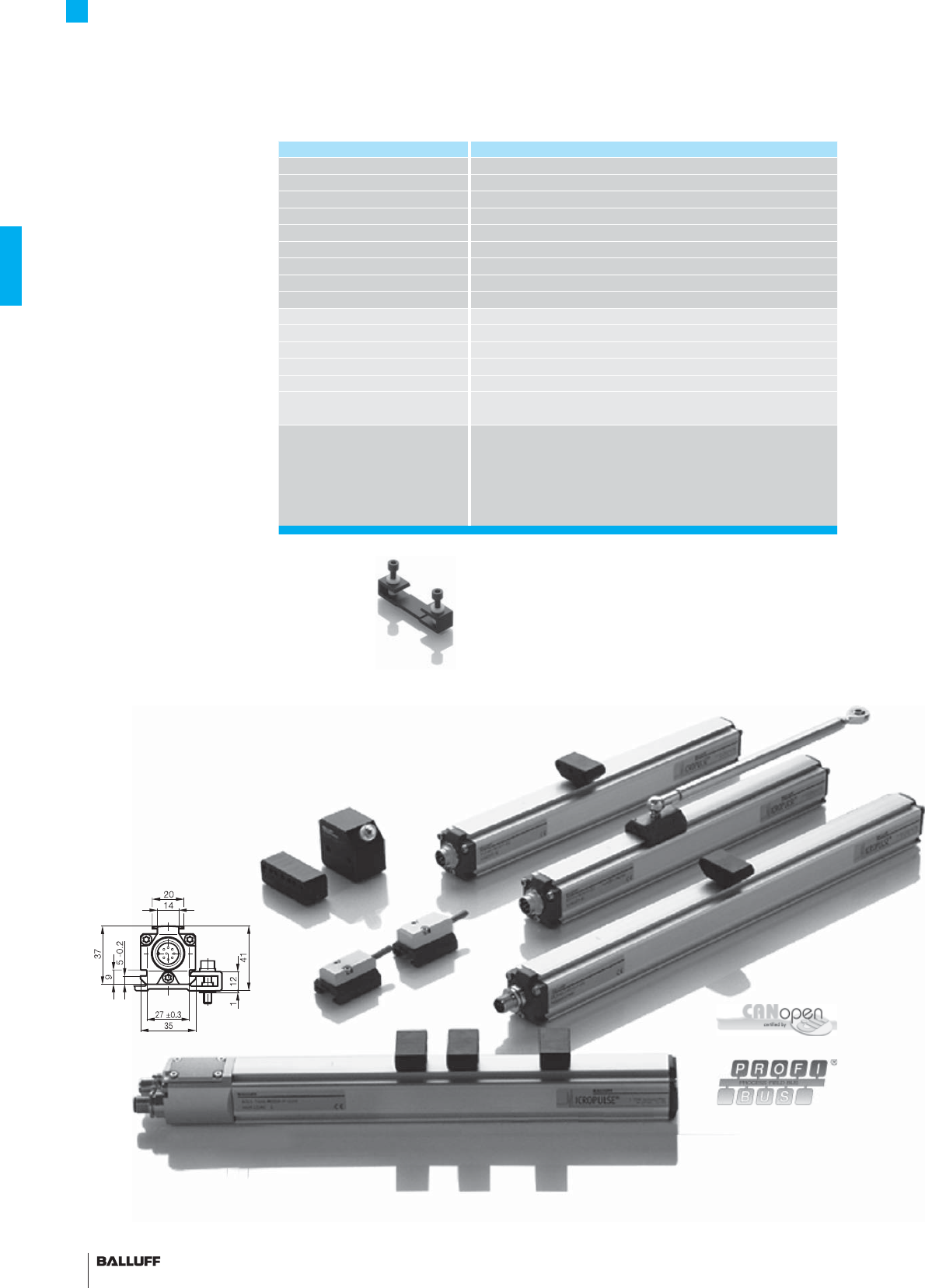
Profi le P Series
General data
The structural design, high
degree of protection and simple
installation of Balluff Micropulse
transducers in a profi led hous-
ing makes them an excellent
alternative to linear transducers,
e.g. potentiometers, glass rulers
and LVDTs. The linear sensing
element is protected inside
an extruded aluminum profi le.
A passive magnet with no power
supply marks the measuring
point along the waveguide with-
out making contact.
Measuring ranges between 50
and 5000 mm are available.
– Non-contact detection of
the actual position
– Insensitive to dirt, IP 67
– Wear-free
– Insensitive to shock and
vibration
– Absolute output signal
– Resolution up to 0.001 mm
(depending on processing
electronics used)
– Direct signal processing or in
conjunction with processors
for all control and regulating
systems
Series BTL5 profi le P
Shock load 100 g/6 ms per IEC 60068-2-27
Vibration 12 g, 10...2000 Hz as per IEC 60068-2-6
Polarity reversal protected yes
Overvoltage protection Transzorb protection diodes
Dielectric strength 500 V (GND to housing)
Degree of protection as per IEC 60529
IP 67 (with BKS-S... IP 67 connector attached)
Housing material Anodized aluminum
Housing attachment Compression clamps
Connection type Connectors/cables
EMC testing:
RF emission EN 55016 Group 1, Class A
Static electricity (ESD) IEC 61000-4-2 Severity Level 3
Electromagnetic fi elds (RFI) IEC 61000-4-3 Severity Level 3
Fast transients (BURST) IEC 61000-4-4 Severity Level 4
Conducted interference induced
by high-frequency fi elds
IEC 61000-4-6 Severity Level 3
Standard nominal strokes [mm] 0050, 0100, 0130, 0150, 0175, 0200, 0225, 0250, 0300, 0350,
0360, 0400, 0450, 0500, 0550, 0600, 0650, 0700, 0750, 0800,
0850, 0900, 0950, 1000, 1100, 1200, 1250, 1300, 1400, 1500,
1600, 1700, 1750, 1800, 1900, 2000, 2250, 2500, 2750, 3000,
3250, 3500, 3550, 3750, 4000, (4250, 4500, 4750, 5000, 5250,
5500) or in 5 mm increments (depending on interface) on request
■ Included:
– Transducer (select your interface from page 32)
– Short user's guide
– Mounting clamps with isolation washers and screws
Please order separately:
Magnets from page 44
Connectors, page 148
Floating or captive magnets!
31■ www.balluff.com
CANopen connection S 94 with connectors BKS-S 94-00 and BKS-S 92-00 for transducers
with CANopen interface, page 38
Profi le P Series
General data
Transducer with fl oating magnet, S 32 connection with BKS-S 32M/BKS-S 32M-C/BKS-S 33M connector
for transducers with analog interface, digital pulse interface and SSI interface, from page 32
Nominal stroke
Installation length
Transducers with captive magnets and cable outlet for transducers with analog interface, digital pulse interface
and SSI interface, from page 32
Nominal stroke
DeviceNet connection S 93 with connectors BKS-S 92-00, BKS-S 93-00 and BKS-S 48-15-CP-_ _, page 40
PROFIBUS-DP plug connector S103 with connectors BKS-S 103-00, BKS-S 105-00 and BKS-S 48-15-CP-_ _ page 42
CANopen connection S 92 with connector BKS-S 92-00 for transducers with CANopen interface, page 38
Installation length
P
General
data
Analog
interface
Digital
pulse
interface
SSI
interface
CANopen
interface
DeviceNet
interface
PROFIBUS-DP
interface
Magnets
fl oating
Magnets
captive,
control arm
PF
General
data
Analog
interface
Magnets
fl oating
Magnets
captive,
control arm
AT
General
data
Analog
interface
Modes
Digital
pulse
interface
VARAN bus
interface
Accessories
BIW
General
data
Analog
interface
32
Series
Output signal
Transducer interface
Input interface
Part number
Output
Output voltage
Output current
Load current
max. ripple
Load resistance
System resolution
Hysteresis
Repeat accuracy
Sampling rate
Max. non-linearity
Temperature coeffi cient Voltage output
Current output
Operating voltage
Current consumption
Polarity reversal protected
Overvoltage protection
Dielectric strength
Operating temperature
Storage temperature range
Pin assignments Pin Color
Output signals 1 YE
2GY
3PK
5GN
Operating voltage 6 BU
7BN
8WH
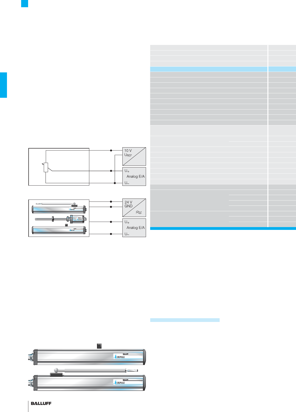
The analog outputs of the profi le series are potential-free with
respect to the input voltage. The isolation is galvanic using DC/DC
converters.
Analog type BTL transducers are available in various output confi gu-
rations: 0...10 V, 4...20 mA, 0...20 mA and –10...10 V, with rising and
falling output slope.
Profi le P Series
Analog interface
Micropulse transducers – a non-contact alternative
to contacting feedback devices
Potentiometer connections, block diagram
Micropulse transducer connections, block diagram
potential-free up to 4500 mm
Connect shield to housing
■ Please enter the code for the output signal and
nominal stroke length in the ordering code.
Preferred models interface A11 and E10
BTL5-A11-M_ _ _ _-P-S32
BTL5-E10-M_ _ _ _-P-S32
are available from stock in the nominal lengths highlighted in blue.
■ Included:
– Transducer
– Mounting clamps with isolation washers and screws
– Short user's guide
Please order separately:
Magnets from page 44
Connectors, page 148/149
33■ www.balluff.com
Profi le P Series
Analog interface
BTL5 profi le P BTL5 profi le P BTL5 profi le P BTL5 profi le P
analog analog analog analog
AECG
analog analog analog analog
BTL5-A11-M_ _ _ _-P-_ _ _ _ BTL5-E1_-M_ _ _ _-P-_ _ _ _ BTL5-C1_-M_ _ _ _-P-_ _ _ _ BTL5-G11-M_ _ _ _-P-_ _ _ _
potential-free potential-free potential-free potential-free
0...10 V and 10...0 V –10...10 V and 10...–10 V
4...20 mA or 20...4 mA 0...20 mA or 20...0 mA
max. 5 mA max. 5 mA
≤ 5 mV ≤ 5 mV
≤ 500 ohms ≤ 500 ohms
≤ 0.1 mV ≤ 0.2 µA ≤ 0.2 µA ≤ 0.1 mV
≤ 4 µm ≤ 4 µm ≤ 4 µm ≤ 4 µm
System resolution/min. 2 µm System resolution/min. 2 µm System resolution/min. 2 µm System resolution/min. 2 µm
fSTANDARD = 1 kHz fSTANDARD = 1 kHz fSTANDARD = 1 kHz fSTANDARD = 1 kHz
±100 µm up to 500 mm nominal stroke
±0.02 % 500... max. nominal stroke
±100 µm up to 500 mm nominal stroke
±0.02 % 500... max. nominal stroke
±100 µm up to 500 mm nominal stroke
±0.02 % 500... max. nominal stroke
±100 µm up to 500 mm nominal stroke
±0.02 % 500... max. nominal stroke
[150 µV/°C + (5 ppm/°C × P × U/L)] × ΔT[150 µV/°C + (5 ppm/°C × P × U/L)] × ΔT
[0.6 µA/°C + (10 ppm/°C × P × I/L)] × ΔT [0.6 µA/°C + (10 ppm/°C × P × I/L)] × ΔT
20...28 V DC 20...28 V DC 20...28 V DC 20...28 V DC
≤ 150 mA ≤ 150 mA ≤ 150 mA ≤ 150 mA
yes yes yes yes
Transzorb protection diodes Transzorb protection diodes Transzorb protection diodes Transzorb protection diodes
500 V DC (ground to housing) 500 V DC (ground to housing) 500 V DC (ground to housing) 500 V DC (ground to housing)
–40...+85 °C –40...+85 °C –40...+85 °C –40...+85 °C
–40...+100 °C –40...+100 °C –40...+100 °C –40...+100 °C
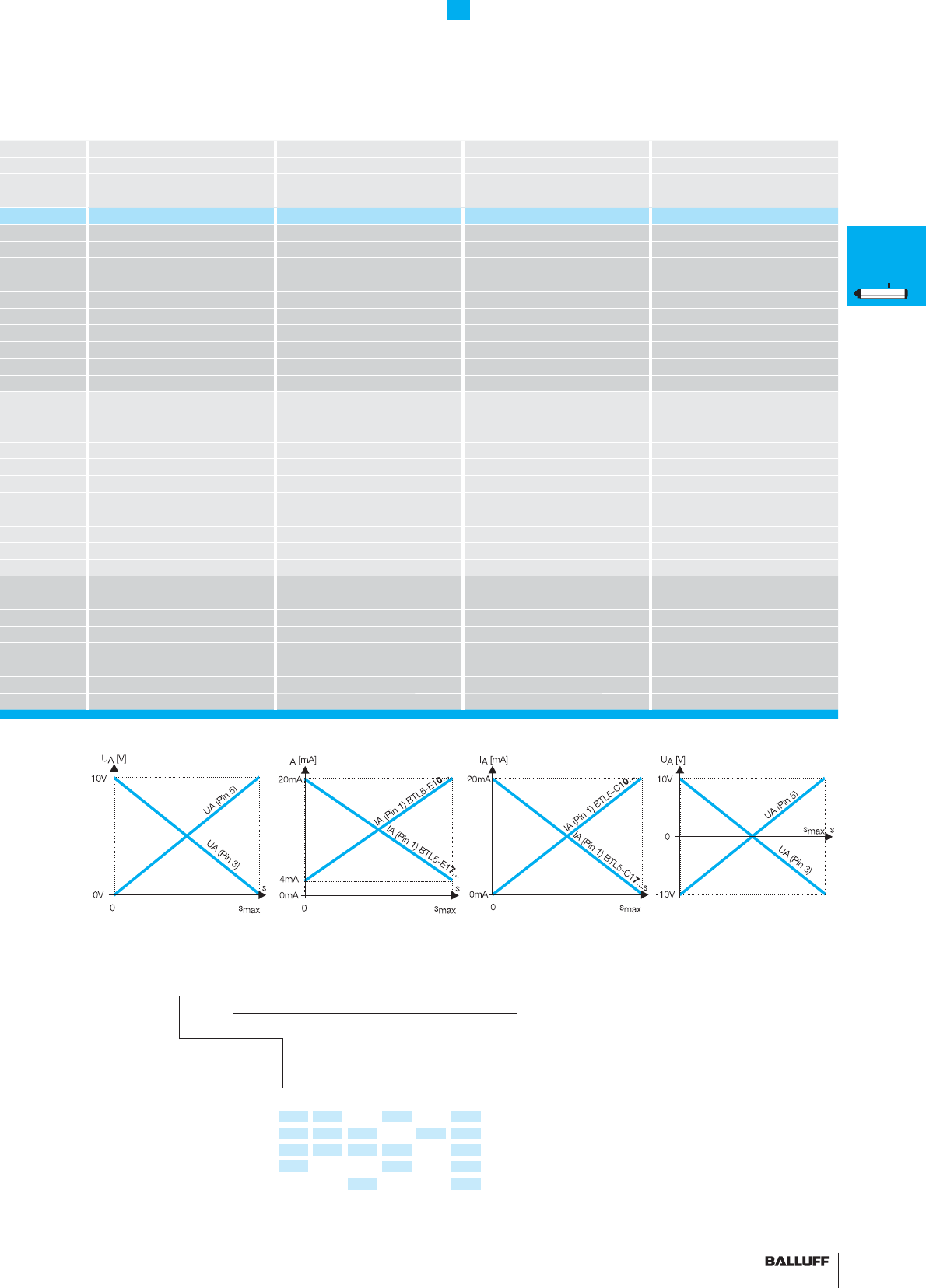
BTL5-A11... BTL5-E10... BTL5-E17... BTL5-C10... BTL5-C17... BTL5-G11...
4...20 mA 20...4 mA 0...20 mA 20...0 mA
0 V Output 0 V Output 0 V Output 0 V Output 0 V Output 0 V Output
10...0 V 10...0 V 10...0 V 10...0 V 10...0 V 10...–10 V
0...10 V 0...10 V 0...10 V 0...10 V 0...10 V –10...10 V
GND GND GND GND GND GND
+24 V DC +24 V DC +24 V DC +24 V DC +24 V DC +24 V DC
(GND) (GND) (GND) (GND) (GND) (GND)
Output
signal
Standard
nominal stroke [mm]
Ordering example:
BTL5-E1_-M_ _ _ _-P-_ _ _ _
S32 Connector
KA02 PUR cable 2 m
KA05 PUR cable 5 m
KA10 PUR cable 10 m
KA15 PUR cable 15 m
0050, 0100, 0130, 0150, 0175, 0200,
0225, 0250, 0300, 0350, 0360, 0400,
0450, 0500, 0550, 0600, 0650, 0700,
0750, 0800, 0850, 0900, 0950, 1000,
1100, 1200, 1250, 1300, 1400, 1500,
1600, 1700, 1750, 1800, 1900, 2000,
2250, 2500, 2750, 3000, 3250, 3500,
3550, 3750, 4000, 4250, 4500 or
in 5 mm increments (depending on
interface) on request
1 Rising
and falling
(with A and G)
0 Rising
7 Falling
(with C and E)
Connection type
P
General
data
Analog
interface
Digital
pulse
interface
SSI
interface
CANopen
interface
DeviceNet
interface
PROFIBUS-DP
interface
Magnets
fl oating
Magnets
captive,
control arm
PF
General
data
Analog
interface
Magnets
fl oating
Magnets
captive,
control arm
AT
General
data
Analog
interface
Modes
Digital
pulse
interface
VARAN bus
interface
Accessories
BIW
General
data
Analog
interface
34
Profi le P Series
Digital pulse interface
P Interface
Compatible with BTA/BTM processors as well as controllers and
modules from various manufacturers, including Siemens, B & R,
Phoenix Contact, Mitsubishi, Sigmatek, Esitron and WAGO. Reliable
signal transmission, even over cable lengths up to 500 m between
BTA and BTL, is assured by the noise-immune RS485 differential line
drivers and receivers. Noise signals are effectively suppressed.
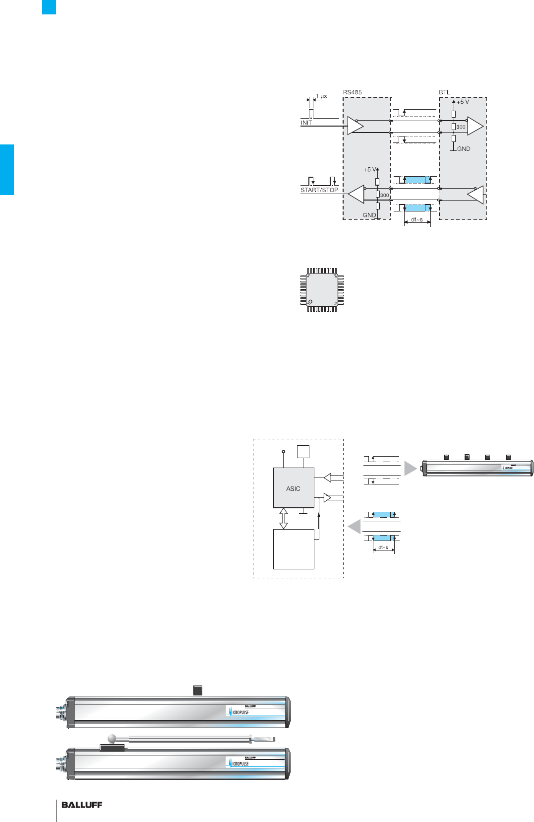
Block diagram of P interface
M Interface
The I and M interfaces are control-specifi c interface variations.
Highly precise digitizing of the P pulse signal
Companies developing their own control and processing electronics
can create a highly accurate P interface cost effectively and with mi-
nimum effort using the Balluff digitizing chip. The digitizing chip was
developed as a high-resolution, confi gurable ASIC for Micropulse
transducers with P interface.
Advantages:
– Position resolution 1 µm!
The 1 µm resolution of the Micropulse distance measurement
system is achieved by the high resolution of the digitizing chip
(133 pS). (Clock frequency 2 or 20 MHz)
– Position data from 4 magnets can be processed simultaneously
– 4/8-bit processor interface
Digitizing chip 44QFP
CPU
controller
4/8-
bit bus
5 V
Osc.
INIT
Micropulse transducer with 1 to
4 magnets
P pulse signal
Controller or
processing electronics
ASIC INFO:
+49 7158 173-370
economical + synchronous
35■ www.balluff.com
Profi le P Series
Digital pulse interface
Series BTL5 profi le P BTL5 profi le P
Transducer interface Pulse PPulse M
Input interface Pulse PPulse M
Part number BTL5-P1-M_ _ _ _-P-_ _ _ _ BTL5-M1-M_ _ _ _-P-_ _ _ _
System resolution processing-dependent processing-dependent
Repeat accuracy
2 µm or ±1 digit depending on processing electronics 2 µm or ±1 digit depending on processing electronics
Resolution ≤ 2 µm ≤ 2 µm
Hysteresis ≤ 4 µm ≤ 4 µm
Sampling rate
3 kHz...500 Hz depending on nominal stroke 3 kHz...500 Hz depending on nominal stroke
Max. non-linearity ±100 µm up to 500 mm nominal stroke
±0.02 % 500...5000 mm nominal stroke
±100 µm up to 500 mm nominal stroke
±0.02 % 500...5000 mm nominal stroke
Temperature coeffi cient of overall system (6 µm + 5 ppm × L)/°C (6 µm + 5 ppm × L)/°C
Operating voltage 20...28 V DC 20...28 V DC
Current consumption ≤ 90 mA ≤ 90 mA
Operating temperature –40...+85 °C –40...+85 °C
Storage temperature range –40...+100 °C –40...+100 °C
Pin assignments Pin
Color
BTL5-P1-M... BTL5-M1-M...
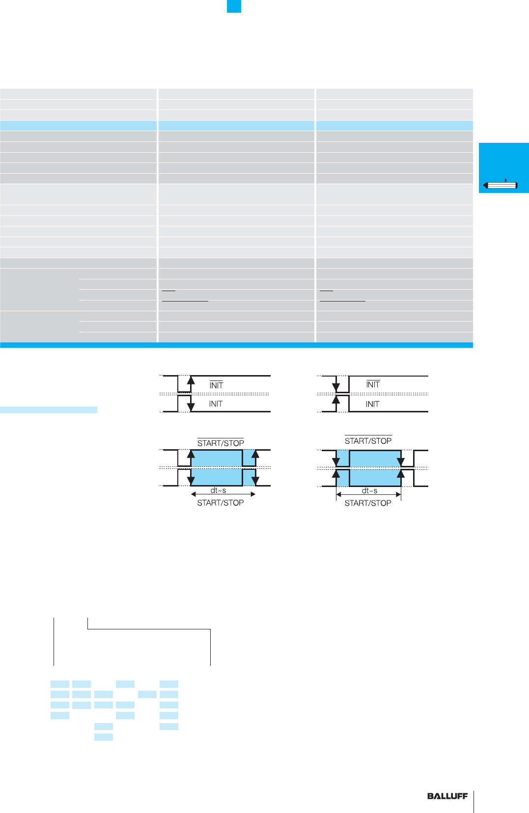
Input/Output Input 1 YE INIT INIT
signals Output 2 GY START/STOP START/STOP
Input 3 PK INIT INIT
Output 5 GN START/STOP START/STOP
Operating voltage 6 BU GND GND
7BN+24 V DC +24 V DC
8 WH (GND) (GND)
■ Please enter the code for the nominal
stroke in the ordering code!
Preferred models interface P
BTL5-P1-M_ _ _ _-P-S32
are available from stock in the nominal
lengths highlighted in blue.
■ Included:
– Transducer
– Mounting clamps with isolation washers
and screws
– Short user's guide
Please order separately:
Magnets from page 44
Connectors from page 148/149
Standard
nominal stroke [mm]
Ordering example:
BTL5-P1-M_ _ _ _-P-_ _ _ _
Connection type
S32 Connector
KA02 PUR cable 2 m
KA05 PUR cable 5 m
KA10 PUR cable 10 m
KA15 PUR cable 15 m
0050, 0100, 0130, 0150, 0175, 0200,
0225, 0250, 0300, 0350, 0360, 0400,
0450, 0500, 0550, 0600, 0650, 0700,
0750, 0800, 0850, 0900, 0950, 1000,
1100, 1200, 1250, 1300, 1400, 1500,
1600, 1700, 1750, 1800, 1900, 2000,
2250, 2500, 2750, 3000, 3250, 3500,
3550, 3750, 4000, 4250, 4500, 5000,
5250, 5500 or in 5 mm increments
(depending on interface) on request
noise-immune up to 500 m
P
General
data
Analog
interface
Digital
pulse
interface
SSI
interface
CANopen
interface
DeviceNet
interface
PROFIBUS-DP
interface
Magnets
fl oating
Magnets
captive,
control arm
PF
General
data
Analog
interface
Magnets
fl oating
Magnets
captive,
control arm
AT
General
data
Analog
interface
Modes
Digital
pulse
interface
VARAN bus
interface
Accessories
BIW
General
data
Analog
interface
36
Cable length
Clock frequency
< 25 m < 1000 kHz
< 50 m < 500 kHz
< 100 m < 400 kHz
< 200 m < 200 kHz
< 400 m < 100 kHz
Synchronized SSI interface
BTL5-S1_ _B-M_ _ _ _-P-_ _ _ _
Micropulse transducers with synchronized SSI interface are suit-
able for dynamic control applications. The data acquisition in the
transducer is synchronized with the external clock of the controller,
permitting an optimum calculation of the velocity in the controller.
The prerequisite for this synchronous mode of transducer operation
is consistent clock signal timing.
The maximum sampling frequency fA, at which a new current
value is generated for each sample, can be derived from the follow-
ing table:
Clock frequency depends on the cable length
mm mm Hz
< Nominal stroke
≤ 100 : 1500
120
< Nominal stroke
≤ 1000 : 1000
475
< Nominal stroke
≤ 1400 : 666
750
< Nominal stroke
≤ 2600 : 500
1250
< Nominal stroke
≤ 4000 : 333
Profi le P Series
SSI interface
Standard SSI interface
Synchronous serial data transmission for controllers from various
manufacturers, including Siemens, Bosch-Rexroth, WAGO, B & R,
Esitron and PEP as well as for Balluff BDD-AM 10-1-SSD and
BDD-CC 08-1-SSD displays/controllers. Reliable signal transmission,
even with cable lengths of up to 400 m between controller and BTL
transducer is assured by noise-immune RS485/422 differential line
drivers and receivers. Any noise signals are effectively suppressed.
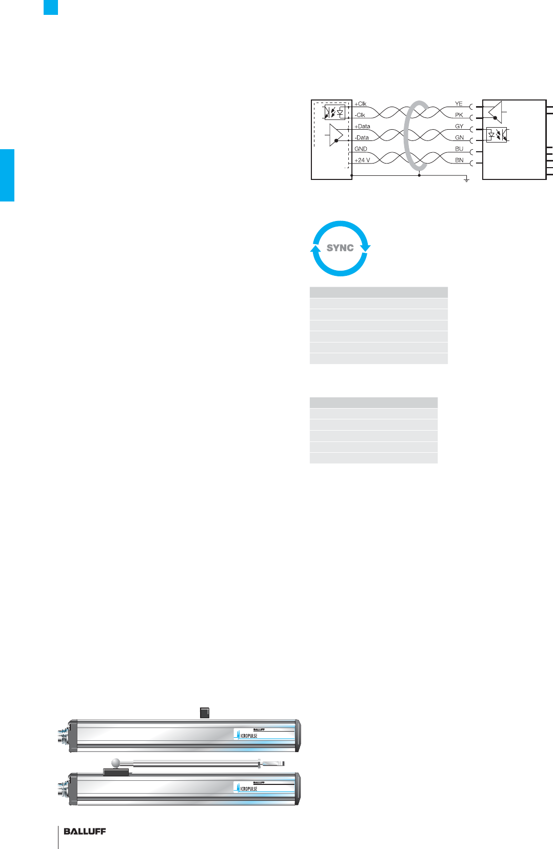
BTL5-S1... with processor/controller, wiring example
Processor
or
controller
Transducer
BTL5-S1...
Super-fast 2.5 kHz sampling rate
37■ www.balluff.com
Profi le P Series
SSI interface
Series BTL5 profi le P
Output signal synchronous serial
Transducer interface S
Input interface synchronous serial (SSI)
Part number BTL5-S1_ _-M_ _ _ _-P-_ _ _ _
Part number synchronization BTL5-S1_ _B-M_ _ _ _-P-_ _ _ _
System resolution depending on version (LSB)
1, 2, 5, 10, 20, 40 or 100 µm
Repeat accuracy ±5 µm
Hysteresis ≤ 4 µm or ≤ 1 digit
Sampling rate fSTANDARD = 2 kHz
Max. non-linearity ±30 µm at ≤ 10 µm resolution or ≤ ±2 LSB at > 10 µm resolution
Temperature coeffi cient of overall system (6 µm + 5 ppm × L)/°C
Operating voltage 20...28 V DC
Current consumption ≤ 80 mA
Operating temperature –40...+85 °C
Storage temperature range –40...+100 °C
Pin assignments Pin Color
Control and 1 YE +Clk
data signals 2 GY +Data
3 PK –Clk
5 GN –Data
Operating 6 BU GND
voltage (external) 7 BN +24 V DC
8 WH must remain unconnected
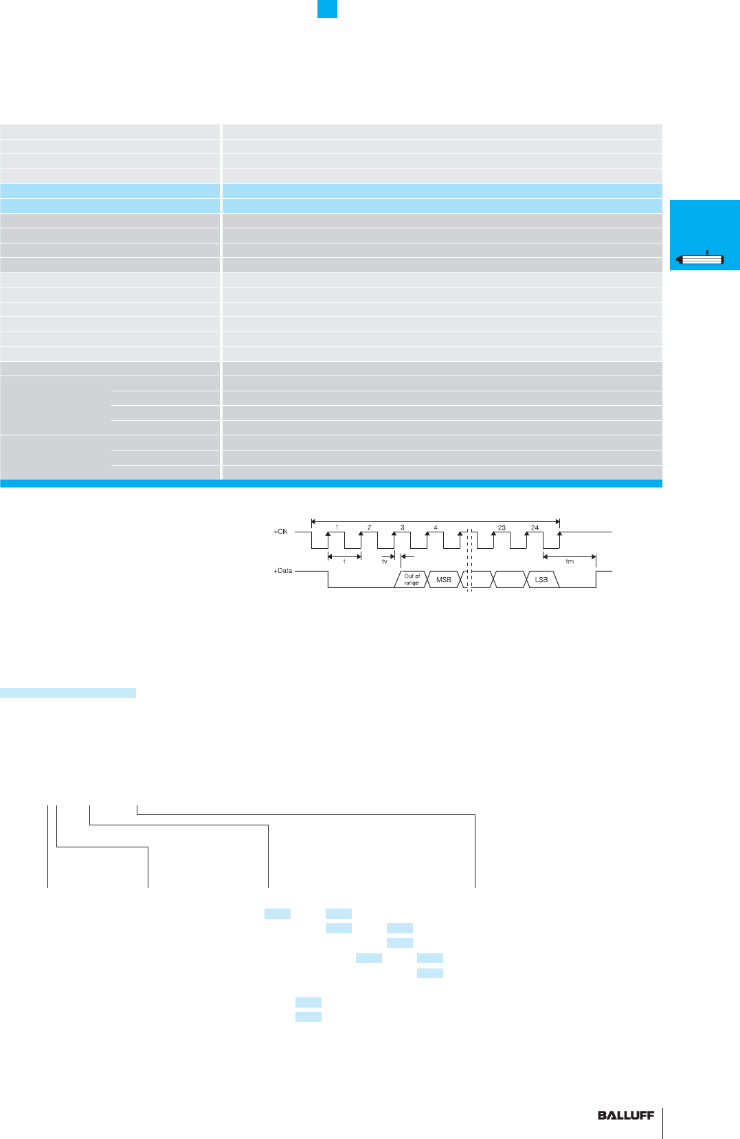
Coding
0 Binary code
rising
(24 bit)
1 Gray code
rising
(24 bit)
6 Binary code
rising
(25 bit)
7 Gray code
rising
(25 bit)
Ordering example:
BTL5-S1_ _-M_ _ _ _-P-_ _ _ _
Standard
nominal stroke [mm] Connection type
S32 Connector
KA02 PUR cable 2 m
KA05 PUR cable 5 m
KA10 PUR cable 10 m
KA15 PUR cable 15 m
0100, 0130, 0150, 0175, 0200, 0225,
0250, 0300, 0350, 0360, 0400, 0450,
0500, 0550, 0600, 0650, 0700, 0750,
0800, 0850, 0900, 0950, 1000, 1100,
1200, 1250, 1300, 1400, 1500, 1600,
1700, 1750, 1800, 1900, 2000, 2250,
2500, 2750, 3000, 3250, 3500, 3550,
3750, 4000 or in 5 mm increments
(depending on interface) on request
System
resolution
1 1 µm
2 5 µm
3 10 µm
4 20 µm
5 40 µm
6 100 µm
7 2 µm
Clock sequence
Ordering code for SSI interface with synchronization to clock (dynamic control
applications) insert the letter B! BTL5-S1_ _B-M_ _ _ _-P-_ _ _ _
■ Please enter the code for the coding, system
resolution and nominal stroke in the ordering code!
Preferred models interface S
BTL5-S112-M_ _ _ _-P-S32 are available from
stock in the nominal lengths highlighted in blue.
super linear and
synchronized
P
General
data
Analog
interface
Digital
pulse
interface
SSI
interface
CANopen
interface
DeviceNet
interface
PROFIBUS-DP
interface
Magnets
fl oating
Magnets
captive,
control arm
PF
General
data
Analog
interface
Magnets
fl oating
Magnets
captive,
control arm
AT
General
data
Analog
interface
Modes
Digital
pulse
interface
VARAN bus
interface
Accessories
BIW
General
data
Analog
interface
■ Included:
– Transducer
– Mounting clamps with isolation washers
and screws
– Short user's guide
Please order separately:
Magnets from page 44
Connectors, page 148/149

38
Profi le P Series
CANopen® interface
CANopen interface
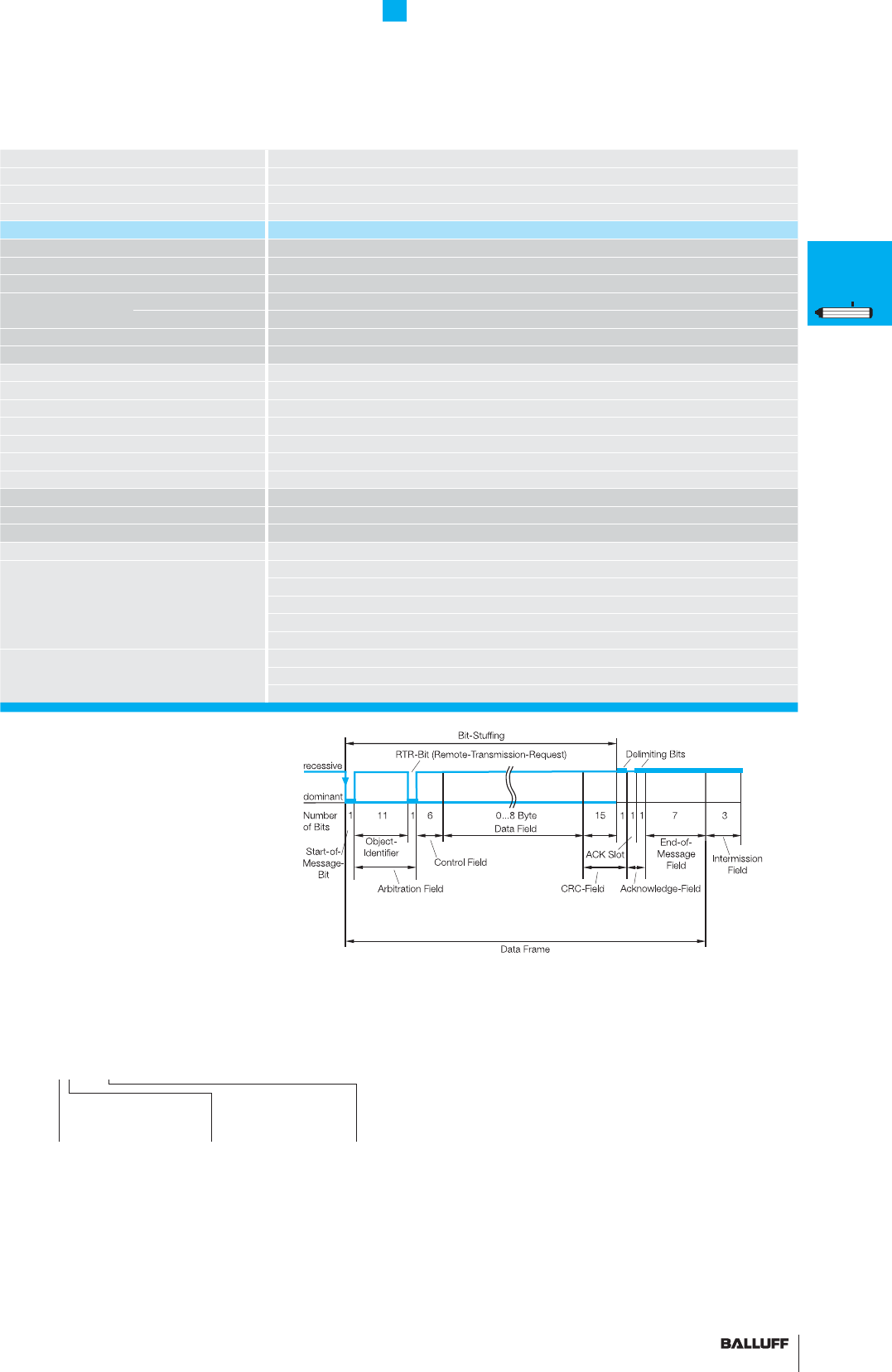
Based on CAN (ISO/IEC 7498 and DIN ISO 11898), CANopen
provides a Layer-7 implementation for industrial CAN networks. The
serial data protocol of the CAN specifi cation is defi ned accord-
ing to the producer-consumer principle as opposed to most other
fi eldbus protocols. This eliminates target addressing of the process
data. Each bus station decides for itself how the received data is
processed.
The CANopen interface of the Micropulse transducer is compatible
with CANopen conforming with CiA Standard DS301 Rev. 3.0, and
with CAL and Layer 2 CAN networks.
CAN-BUS features
– Line topology, star structure also possible via repeaters
– Low-cost wiring with two-wire cable
– Fast response times, high data integrity using CRC, hamming
distance of 6
– 1 MBit/s with cable lengths < 25 m
– Protocol limits number of stations to 127
– Using multiple magnets: A minimum spacing of > 65 mm must be
maintained.
CANopen offers a high level of fl exibility with respect to functionality
and data exchange. Using a standard data sheet in the form of an
EDS fi le it is easy to link the Micropulse transducers to any CANopen
system.
Process Data Object (PDO)
Micropulse transducers send their position information optionally in
one, two or four PDOs with 8 bytes of data each. The contents of
the PDOs are freely confi gurable. The following information can be
sent:
– Current magnet position with resolution in 5 µm increments
– Current velocity of the magnet with resolution selectable in
0.1mm/s increments
– Current status of the four freely programmable cams per magnet.
Synchronization Object (SYNC)
Serves as a net-wide trigger for synchronizing all network partici-
pants. When the SYNC object is received, all Micropulse transducers
connected to the bus store their current position and velocity infor-
mation and then send it sequentially to the controller. This assures
time-synchronous acquisition of the measured values.
LED
Display of the CANopen status to DS303-3
FMM
The sensor can be operated as a 4-magnet type, whereby the sen-
sor itself recognizes how many magnets are currently active.
So if only two magnets are positioned in the measuring range, a valid
value is output for the fi rst two positions and a defi ned error value for
positions 3 and 4.
Emergency Object
This object is sent with the highest priority and is used for example
for error messages when the cam states change.
Service Data Object (SDO)
Service Data Objects transmit the confi guration parameters to the
transducer. The transducer may be confi gured on the bus by the
controller or offl ine using a PC with a confi guration tool which runs
under Windows. The confi guration is stored in the non-volatile
memory of the transducer.
certifi ed
CiA 199911-301v30/11-009
Use of multiple magnets
A minimum spacing of > 65 mm must be maintained.
Node ID can be set by DIP switch.
BTL5-H1_ _-M_ _ _ -P-S94 BTL5-H1_ _-M_ _ _ -P-S92
Position of the DIP switch S1,
only on BTL-H1_ _ _ _-P-S94
User-friendly hardware
and software set-up
39■ www.balluff.com
Profi le P Series
CANopen® interface
Series BTL5 profi le P
Output signal CANopen
Transducer interface H
Input interface CANopen
Part number BTL5-H1_ _-M_ _ _ _-P-S92
BTL5-H1_ _-M_ _ _ _-P-S94
CANopen Version DS301, DS406
Repeat accuracy ±1 digit
System resolution Position 5 µm increments confi gurable
Confi gurable Velocity 0.1 mm/s increments confi gurable
Hysteresis ≤ 1 digit
Sampling rate fSTANDARD = 1 kHz
Max. non-linearity ±30 µm at 5 µm resolution
Temperature coeffi cient of overall system (6 µm + 5 ppm × L)/°C
Magnet traverse velocity any
Operating voltage 20...28 V DC
Current consumption ≤ 100 mA
Operating temperature –40...+85 °C
Storage temperature range –40...+100 °C
Cable length [m] per CiA DS301 < 25 < 50 < 100 < 250 < 500 < 1000 < 1250 < 2500
Baud rate [kBaud] per CiA DS301 1000 800 500 250 125 100 50 20/10
Pin assignments Pin Color
Control and 1 WH CAN_GND
data signals 4 GY CAN_HIGH
5 GN CAN_LOW
Operating 2 BN +24 V
voltage (external) 3 BU 0 V (GND)
Software
confi guration
1 1 × position and
1 × velocity
2 2 × position and
2 × velocity
Ordering example:
BTL5-H1_ _-M_ _ _ _-P-S92
BTL5-H1_ _-M_ _ _ _-P-S94
0050, 0100, 0130, 0150, 0175, 0200,
0225, 0250, 0300, 0350, 0360, 0400,
0450, 0500, 0550, 0600, 0650, 0700,
0750, 0800, 0850, 0900, 0950, 1000,
1100, 1200, 1250, 1300, 1400, 1500,
1600, 1700, 1750, 1800, 1900, 2000,
2250, 2500, 2750, 3000, 3250, 3500,
3550, 3750, 4000 or in 5 mm
increments (depending on interface) on
request
Baud rate
0 1 MBaud
1 800 kBaud
2 500 kBaud
3 250 kBaud
4 125 kBaud
5 100 kBaud
6 50 kBaud
7 20 kBaud
8 10 kBaud
■ Please enter the code for the software
confi guration, baud rate and nominal stroke
length in the ordering code.
■ Included:
– Transducer
– Mounting clamps with isolation washers
and screws
– Short user's guide
Please order separately:
Magnets from page 44
Connectors, page 150/151
Position +
Velocity
Using the CANopen interface and cable lengths up to 2500 m, the
signal is sent at a length-dependent baud rate to the controller. The
high noise immunity of the connection is achieved using differential
drivers and by the data monitoring scheme.
Standard
nominal stroke [mm]
P
General
data
Analog
interface
Digital
pulse
interface
SSI
interface
CANopen
interface
DeviceNet
interface
PROFIBUS-DP
interface
Magnets
fl oating
Magnets
captive,
control arm
PF
General
data
Analog
interface
Magnets
fl oating
Magnets
captive,
control arm
AT
General
data
Analog
interface
Modes
Digital
pulse
interface
VARAN bus
interface
Accessories
BIW
General
data
Analog
interface

40
Profi le P Series
DeviceNet interface
DeviceNet
DeviceNet is a manufacturer-independent open fi eldbus standard
used in automation technology for connecting programmable
logic controllers (PLCs) to intelligent devices such as sensors,
pushbuttons, I/O modules, basic user interfaces and drives via
a single cable. DeviceNet is an application protocol (OSI layer 7)
based on the Controller Area Network (CAN) principle. It offers
high reliability for demanding applications with a high number of
I/O modules.
The transmission speed is between 125 kBit/s and 500 kBit/s
depending on type and length of the cable.
Master
DeviceNet is multi-master capable, i.e. several DeviceNet devices
can simultaneously request the current position. The data trans-
fer is controlled by the priority of the message. Messages on the
DeviceNet carry an identifi er.
The message that was sent can be received by all devices
simultaneously (broadcast). Message fi ltering is performed by
the device only for messages intended for it. The criterion for this
decision is
the identifi er, with which each message is transmitted.
EDS
DeviceNet offers parameterization of functionality and data
exchange. Using a standard data sheet in the form of an EDS
fi le it is easy to link the Micropulse transducers to any DeviceNet
system.
DeviceNet features:
– Linear topology
– Low-cost wiring with two-wire cable
– Fast response times
– High data security due to CRC checking
– Hamming distance of 6
– Potential-free data transmission (RS485)
– 125 Kb/s at cable length < 500 m
250 Kb/s at cable length < 250 m
500 Kb/s at cable length < 100 m
– Protocol limits number of stations to 64
Device address can
be set by DIP switch
Use of multiple magnets
A minimum spacing of > 65 mm must be maintained.
Position of the DIP switch S1,
Position Sensor Object
The DeviceNet interface of the Micropulse transducer is compatible
with the CIP Common Specifi cation Object Library "Position Sensor
Object" of the ODVA.
The Micropulse transducers transmit their measurement values in an
entity of the Position Sensor Objects as a 32-bit value.
The following information can be sent:
– Current magnet position with resolution in 5 µm increments
– Current magnet velocity in increments of 0.1 nm/s
– Current status of the four freely programmable cams.
Synchronization
Measurement can be triggered by the master I/O bit Strobe
Command Message. On receiving this bit, the respective Micropulse
transducer saves its current position and velocity information and
sends it back to the controller.
FMM
The sensor can be operated as a 1...4-magnet type, whereby the
sensor itself recognizes how many magnets are currently active.
So if only two magnets are positioned in the measuring range, a valid
value is output for the fi rst two positions and a defi ned error value for
positions 3 and 4.
41■ www.balluff.com
Profi le P Series
DeviceNet interface
Series BTL5 profi le P
Output signal DeviceNet
Transducer interface D
Input interface DeviceNet
Part number plug version S103 BTL5-D1_ _-M_ _ _ _-P-S93
Profi bus version Encoder profi le
Profi bus interface potential-free
Repeat accuracy ±1 digit
System resolution
Confi gurable
Position 5 µm increments confi gurable
Velocity 0.1 mm/s increments confi gurable
Hysteresis ≤ 1 digit
Sampling rate fSTANDARD = 1 kHz
Max. non-linearity ±30 µm at 5 µm resolution
Temperature coeffi cient of overall system (6 µm + 5 ppm × L)/°C
Magnet traverse velocity any
Operating voltage 20...28 V DC
Current consumption ≤ 100 mA
Operating temperature –40...+85 °C
Storage temperature range –40...+100 °C
Address assignment mechanical switches or DeviceNet
Cable length [m] 100 250 500
Baud rate [Kbps] 500 250 125
Pin assignments S93 5-pin S93 3-pin
Control and data signals CAN GND 1
V+ 2
V– (GND) 3
CAN HIGH 4
CAN LOW 5
Operating voltage and shielding +24 V 1
GND 3
Shield supply 4
■ Please enter the code for the software
confi guration, baud rate and nominal stroke
length in the ordering code.
■ Included:
– Transducer
– Mounting clamps with isolation washers
and screws
– Short user's guide
Please order separately:
Magnets from page 44
Connectors, page 150/151
Software
confi guration
1 Magnet FMM
Ordering example:
BTL5-D1_ _-M_ _ _ _-P-S93
Standard
nominal stroke [mm]
Baud rate
2 500 kBaud
3 250 kBaud
4 125 kBaud
0050, 0100, 0130, 0150, 0175, 0200,
0225, 0250, 0300, 0350, 0360, 0400,
0450, 0500, 0550, 0600, 0650, 0700,
0750, 0800, 0850, 0900, 0950, 1000,
1100, 1200, 1250, 1300, 1400, 1500,
1600, 1700, 1750, 1800, 1900, 2000,
2250, 2500, 2750, 3000, 3250, 3500,
3550, 3750, 4000 or in 5 mm increments
(depending on interface) on request
P
General
data
Analog
interface
Digital
pulse
interface
SSI
interface
CANopen
interface
DeviceNet
interface
PROFIBUS-DP
interface
Magnets
fl oating
Magnets
captive,
control arm
PF
General
data
Analog
interface
Magnets
fl oating
Magnets
captive,
control arm
AT
General
data
Analog
interface
Modes
Digital
pulse
interface
VARAN bus
interface
Accessories
BIW
General
data
Analog
interface

42
Profi le P Series
PROFIBUS-DP interface
As the market leading standard for serial data transmission for pro-
cess automation, PROFIBUS-DP is the ideal choice for implementing
automation tasks with cycle times of > 5 ms.
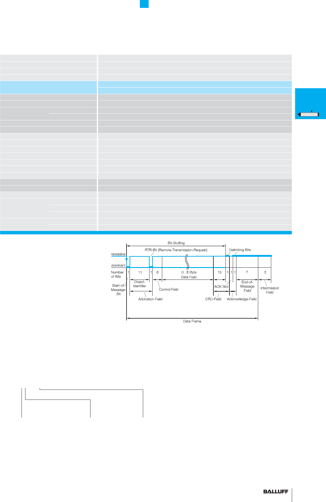
Data transmission
A PROFIBUS telegram can contain up to 244 bytes of user data per
telegram and station. The BTL5-T uses max. 32 bytes (max. 4 posi-
tion values and max. 4 velocity values) for process data transmis-
sion. Up to 126 active stations (Address 0...125) can be connected
on PROFIBUS-DP. User data cannot be sent with station address
126. This address is used as the default address for bus stations
that have to be parameterized by a Class 2 master (for setting the
device address if there are no mechanical switches available). Each
PROFIBUS station has the same priority. Prioritizing of individual sta-
tions is not intended, but can be done by the master since the bus
transmission only makes up a fraction of the process cycle anyway.
At a transfer rate of 12 Mbps, the transmission time for an average
data telegram is in the 100 µs range.
Master
There are two types of possible masters for PROFIBUS-DP. Master
Class 1 carries out the user data interchange with the connected
slaves. Master Class 2 is intended for startup and diagnostic purpos-
es and may be used to briefl y assume control of a slave.
GSD (Device Master Data)
The length of the data exchangeable with a slave is defi ned in the
Device Master Data fi le (GSD) and is checked by the slave with the
confi guration telegram and confi rmed for correctness.
In modular systems, various confi gurations are defi ned in the GSD
fi le. Depending on the desired functionality, one of these confi gura-
tions can be selected by the user when the system is confi gured.
The BTL5-T is a modular device with the possibility of selecting the
number of magnets (position values).
Use of multiple magnets
A minimum spacing of > 65 mm must be maintained.
Position of the DIP switch S1,
Slave
Once a PROFIBUS master has received the parameter set defi ned
for the slave, it is able to exchange data. The parameter set consists
of slave parameters and confi guration data.
The parameter data contain the description of the slave settings
(e.g. resolution of a position value). The confi guration data describe
the length and structure of the data telegram.
Process data
Under PROFIBUS-DP the default is for process data to be sent from
the master to slaves acyclically and for the slave data to then be
queried. To ensure synchronization of multiple devices, the master
may use the SYNC and FREEZE services.
DP/V1 and DP/V2 isochronous mode
Isochronous mode enables quick and deterministic
data exchange through the synchronicity of cycles on the bus sys-
tem. A cyclic equidistant clock signal is sent by the master to all bus
devices. This signal allows master and slaves to be synchronized
irrespective of application – with an accuracy < 1 µs.
Cross traffi c between slaves
Cross traffi c permits two DP slaves to exchange data directly with
each other: the master ensures that the slave publishes its data on
the bus with a request for "Data-eXchange-Broadcast" (DXB-Re-
quest) and thus makes it available to other slaves. Since the process
data is available in the process periphery without being diverted
through the master application, cross-traffi c permits very fast control
system responses.
Acyclic services
The DP functions for prioritized communication
allow the transfer of acyclic read and write functions between master
and slaves, independently of the cyclic user data traffi c. The transfer
of acyclic data is performed at a lower priority in parallel to the high
speed cyclic data exchange – as if in the background. The back-
ground / foreground split means the ratio of cyclic to acyclic data
can be adjusted if required.
FMM
The sensor can be operated as a 4-magnet type, whereby the
sensor itself recognizes how many magnets are currently active. So
if only two magnets are positioned in the measuring range, a valid
value is output for the fi rst two positions and a defi ned error value for
positions 3 and 4.
User-friendly hardware
and software set-up
Device address can
be set by DIP switch

43■ www.balluff.com
Profi le P Series
PROFIBUS-DP interface
Series BTL5 profi le P
Output signal PROFIBUS-DP
Transducer interface T
Input interface PROFIBUS-DP
Part number plug version S103 BTL5-T1_ 0-M_ _ _ _-P-S103
Profi bus version DPV1/DPV2 EN 50170, encoder profi le
Profi bus interface potential-free
Repeat accuracy ±1 digit
System resolution Position 5 µm increments confi gurable
confi gurable Velocity 0.1 mm/s increments confi gurable
Hysteresis ≤ 1 digit
Sampling rate fSTANDARD = 1 kHz
Max. non-linearity ±30 µm at 5 µm resolution
Temperature coeffi cient of overall system (6 µm + 5 ppm × L)/°C
Magnet traverse velocity any
Operating voltage 20...28 V DC
Current consumption ≤ 120 mA
Operating temperature –40...+85 °C
Storage temperature range –40...+100 °C
GSD fi le BTL504B2.GSD
Address assignment mechanical switches and Master Class 2
Cable length [m] < 100 < 200 < 400 < 1000 < 1200
Baud rate [Kbps] 12000 1500 900 187,5 93,7/19,2/9,6
Pin assignments S103 5-pin S103 3-pin
Control and data signals Data GND 3
RxD/TxD-N (A) 2
RxD/TxD-P (B) 4
VP +5 V 1
+24 V 1
Operating voltage and shielding 0 V (GND) 3
Ground PROFIBUS-DP 5
Shield supply 4
Software
confi guration
1 1 Magnet
1 Position
1 Velocity
2 2 Position
2 Velocity
Ordering example:
BTL5-T1_ 0-M_ _ _ _-P-S103
Standard
nominal stroke [mm]
0050, 0100, 0130, 0150, 0175, 0200,
0225, 0250, 0300, 0350, 0360, 0400,
0450, 0500, 0550, 0600, 0650, 0700,
0750, 0800, 0850, 0900, 0950, 1000,
1100, 1200, 1250, 1300, 1400, 1500,
1600, 1700, 1750, 1800, 1900, 2000,
2250, 2500, 2750, 3000, 3250, 3500,
3550, 3750, 4000 or in 5 mm
increments (depending on interface) on
request
■ Please enter the code for the software
confi guration and nominal stroke length in the
ordering code!
■ Included:
– Transducer
– Mounting clamps with isolation washers
and screws
– Short user's guide
Please order separately:
Magnets from page 44
Connectors from page 153
4 × position
+ velocity
P
General
data
Analog
interface
Digital
pulse
interface
SSI
interface
CANopen
interface
DeviceNet
interface
PROFIBUS-DP
interface
Magnets
fl oating
Magnets
captive,
control arm
PF
General
data
Analog
interface
Magnets
fl oating
Magnets
captive,
control arm
AT
General
data
Analog
interface
Modes
Digital
pulse
interface
VARAN bus
interface
Accessories
BIW
General
data
Analog
interface
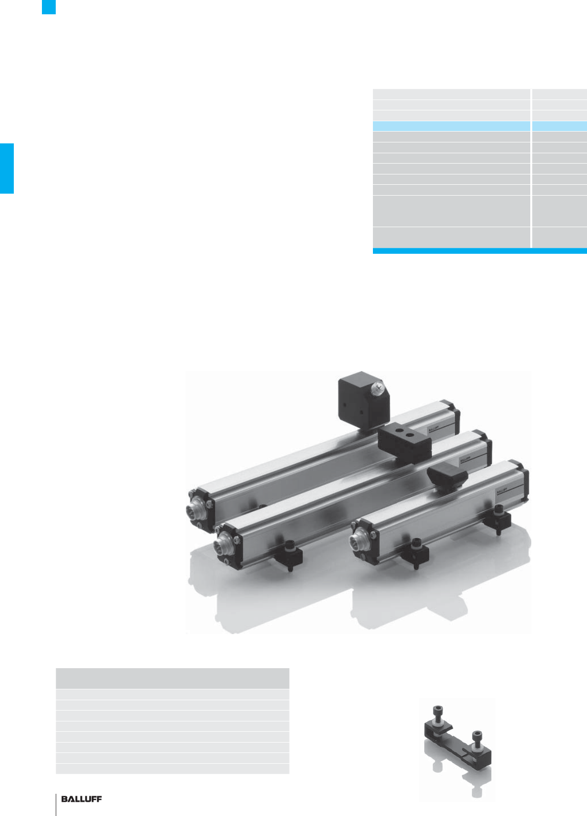
44
Profi le P Series
Magnets fl oating
Balluff magnets are available in captive or fl oating design. Maximum
resolution and repeatability are achieved using transducers with cap-
tive magnets.
The BTL5-P-4500-1 is an electromagnet and requires an operating
voltage of 24V, which can be turned on and off for selective
activation. This allows multiplex operation with multiple magnets on a
single transducer, since only one magnet is active at a time.
Mounting clamps with isolation
washers and screws included
with transducer.
1 pair of replacement clamps
and screws, item no.: 110404
Length Number of
mounting clamp pairs
to 250 mm 1
251 to 750 mm 2
751 to 1250 mm 3
1251 to 1750 mm 4
1751 to 2250 mm 5
2251 to 2750 mm 6
2751 to 3250 mm 7
more than
3251 mm 8
Non-contact!
Vertical offset
0.1...4 mm or 5...15 mm
Description
for series
Version
Part number
Housing material
Weight
Magnet traverse velocity
Operating voltage
Current consumption
Operating temperature/Storage temperature range
Included
Accessories
(please order separately)
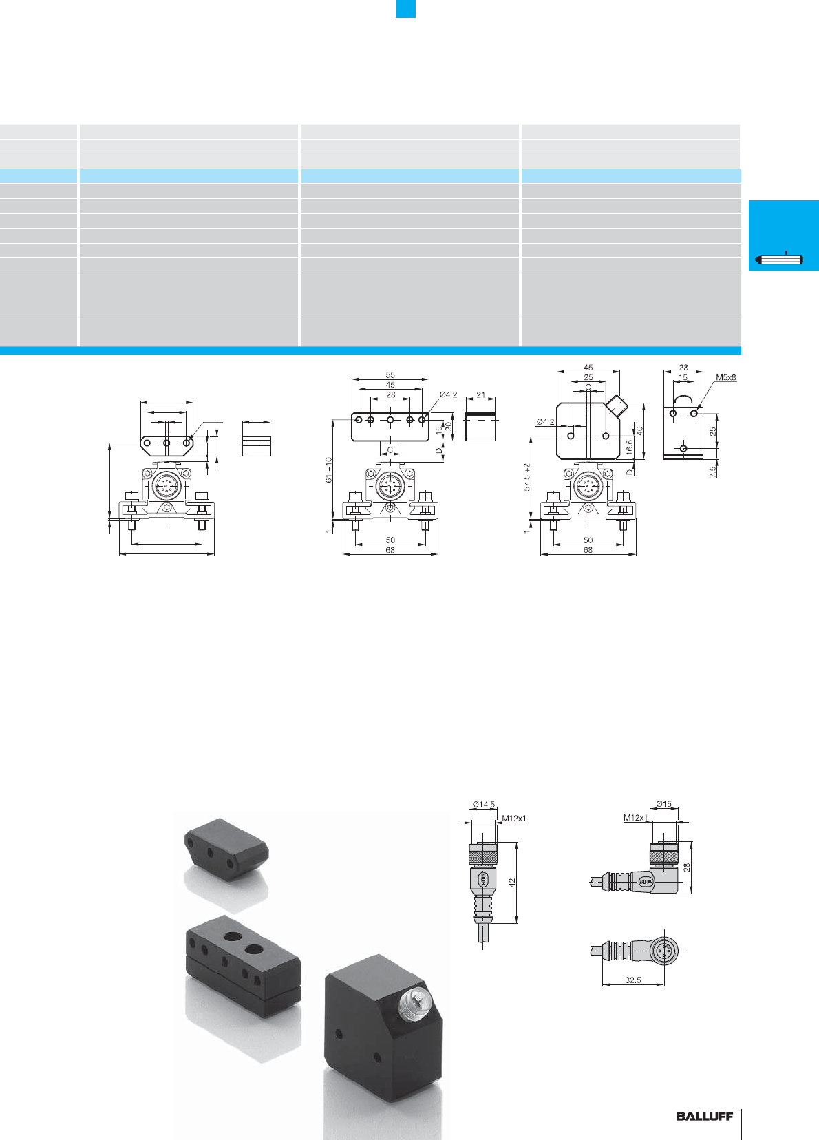
45■ www.balluff.com
Profi le P Series
Magnets fl oating
14
D9
150 +4
68
50
C
38
20
28
Ø4.2
■ Please indicate the cable length in the
ordering code!
03, 05, 10, 15
= PVC, 3 m, 5 m, 10 m or 15 m
PU-03, PU-05, PU-10, PU-15
= PUR, 3 m, 5 m, 10 m or 15 m
Lateral offset:
C = ±2 mm
Vertical distance of magnet:
D = 0.1...4 mm
Lateral offset:
C = ±15 mm
Vertical distance of magnet:
D = 5...15 mm
Lateral offset:
C = ±2 mm
Vertical distance of magnet:
D = 0.1...2 mm
P
General
data
Analog
interface
Digital
pulse
interface
SSI
interface
CANopen
interface
DeviceNet
interface
PROFIBUS-DP
interface
Magnets
fl oating
Magnets
captive,
control arm
PF
General
data
Analog
interface
Magnets
fl oating
Magnets
captive,
control arm
AT
General
data
Analog
interface
Modes
Digital
pulse
interface
VARAN bus
interface
Accessories
BIW
General
data
Analog
interface
Magnet Magnet Magnet
BTL5 profi le P BTL5 profi le P BTL5 profi le P
free free free
BTL5-P-3800-2 BTL5-P-5500-2 BTL5-P-4500-1
Plastic Plastic Plastic
approx. 12 g approx. 40 g approx. 90 g
any any any
24 V DC
100 mA
–40...+85 °C –40...+85 °C –40...+60 °C
Magnet
2 fastening screws DIN 84 M4×35-A2 with
washers and nuts
Magnet Magnet
Straight connector BKS-B 19-1-_ _
Right-angle connector BKS-B 20-1-_ _
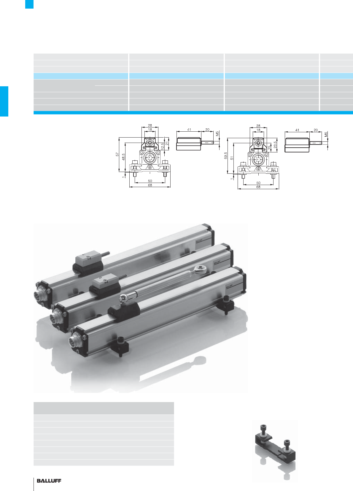
46
Profi le P Series
Magnets captive
Description Magnet Magnet
for series BTL5 profi le P BTL5 profi le P
Version captive captive
Part number BTL5-M-2814-1S BTL5-N-2814-1S
Material Housing Anodized aluminum Anodized aluminum
Sliding surface
Plastic Plastic
Weight approx. 32 g approx. 35 g
Magnet traverse velocity any any
Operating temperature/Storage temperature range
–40...+85 °C –40...+85 °C
Mounting clamps with isolation
washers and screws included with
transducer.
1 pair of replacement mounting
clamps and screws, item no.: 110404
Length Number of
mounting clamp pairs
to 250 mm 1
251 to 750 mm 2
751 to 1250 mm 3
1251 to 1750 mm 4
1751 to 2250 mm 5
2251 to 2750 mm 6
2751 to 3250 mm 7
more than
3251 mm 8
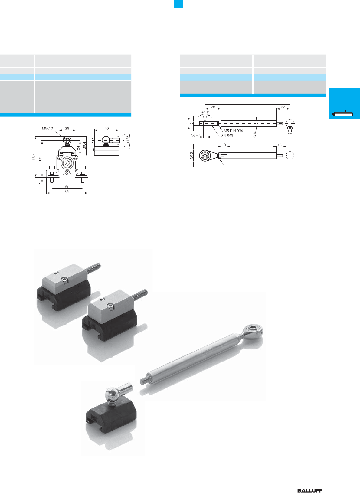
47■ www.balluff.com
Profi le P Series
Magnets captive, control arm
Magnet
BTL5 profi le P
captive
BTL5-F-2814-1S
Anodized aluminum
Plastic
approx. 28 g
any
–40...+85 °C
When using captured
magnets with ball joint and
control arm, transverse
forces do not impinge on
the transducer system.
■ Please the enter code for the
nominal stroke in the ordering code!
Description Control arm
for series BTL5 profi le P
Version captive
Part number BTL2-GS10-_ _ _ _-A
Material Al
Weight approx. 150 g/m
Ordering example:
BTL2-GS10-_ _ _ _-A
Standard
nominal stroke [mm]
0075, 0100, 0125, 0150, 0200, 0250,
0350, 0400, 0450, 0500, 0600, 0800,
1000, 1500, 2000
Swivel eye
Material number 714619
Adjustment range –5 mm
Nominal stroke
P
General
data
Analog
interface
Digital
pulse
interface
SSI
interface
CANopen
interface
DeviceNet
interface
PROFIBUS-DP
interface
Magnets
fl oating
Magnets
captive,
control arm
PF
General
data
Analog
interface
Magnets
fl oating
Magnets
captive,
control arm
AT
General
data
Analog
interface
Modes
Digital
pulse
interface
VARAN bus
interface
Accessories
BIW
General
data
Analog
interface
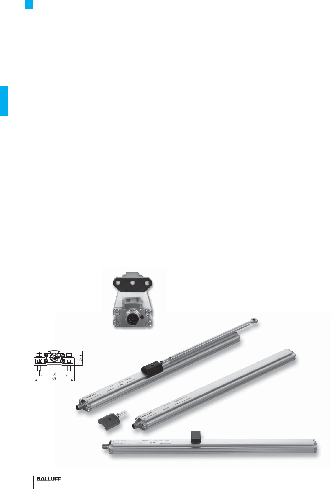
48
Profi le Series PF
General data
The structural design, high degree of protection and simple instal-
lation of Balluff Micropulse transducers in a profi led housing makes
them an excellent alternative to linear transducers, e.g. potentiome-
ters, glass rulers and LVDTs. The linear sensing element is protected
inside an extruded aluminum profi le.
A passive magnet with no power supply marks the measuring point
along the waveguide without making contact. Measuring ranges
between 50 and 4572 mm are possible.
– Non-contact detection of the actual position
– IP 67, insensitive to contamination
– Wear-free
– Insensitive to shock and vibration
– Absolute output signal
– Max. resolution of 0.005 mm (depending on the processing
electronics)
– Direct signal processing or in conjunction with processors for
all control and regulating systems
Flat! 20 mm with free or
captive magnet
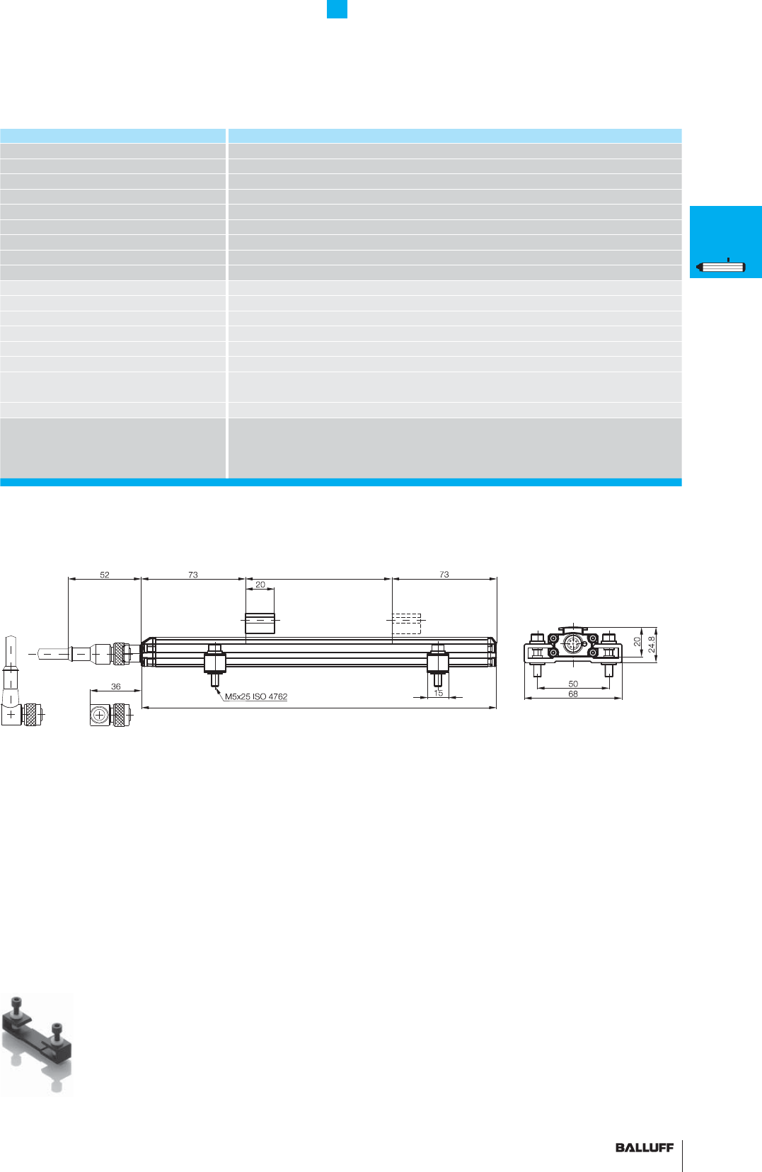
49■ www.balluff.com
Profi le Series PF
General data
Series BTL6 profi le PF
Shock load 50 g/6 ms per IEC 60068-2-27
Vibration 12 g, 10...2000 Hz per IEC 60068-2-6
Polarity reversal protected Yes (up to 36 V)
Overvoltage protection to 36 V
Dielectric strength 500 VDC (GND to housing)
Degree of protection as per IEC 60529 IP 67 (with BKS-S... IP 67 connector attached)
Housing material Anodized aluminum
Housing attachment Compression clamps
Connection type Connectors
EMC testing:
RF emission EN 55016-2-3 Group 1, Class A and B
Static electricity (ESD) IEC 61000-4-2 Severity Level 3
Electromagnetic fi elds (RFI) IEC 61000-4-3 Severity Level 3
Fast transients (BURST) IEC 61000-4-4 Severity Level 3
Surge voltage IEC 61000-4-5 Severity Level 2
Conducted interference induced
by high-frequency fi elds
IEC 61000-4-6 Severity Level 3
Magnetic fi elds IEC 61000-4-8 Severity Level 4
Standard nominal strokes [mm] 0050, 0100, 0130, 0150, 0175, 0200, 0225, 0250, 0300, 0350, 0360, 0400, 0450, 0500,
0550, 0600, 0650, 0700, 0750, 0800, 0850, 0900, 0950, 1000, 1100, 1200, 1250, 1300,
1400, 1500, 1600, 1700, 1750, 1800, 1900, 2000, 2250, 2500, 2750, 3000, 3250, 3500,
3550, 3750, 4000, 4250, 4500, 4572
■ Included:
– Transducer (select your interface from page 50)
– Short user's guide
– Mounting clamps with isolation washers and screws
Please order separately:
Magnets from page 52
Connectors, page 156
Transducers with fl oating magnet and S115 connection with BKS-S115/BKS-S116 connector
for transducers with analog interface, page 50
Nominal stroke
Installation length
P
General
data
Analog
interface
Digital
pulse
interface
SSI
interface
CANopen
interface
DeviceNet
interface
PROFIBUS-DP
interface
Magnets
fl oating
Magnets
captive,
control arm
PF
General
data
Analog
interface
Magnets
fl oating
Magnets
captive,
control arm
AT
General
data
Analog
interface
Modes
Digital
pulse
interface
VARAN bus
interface
Accessories
BIW
General
data
Analog
interface
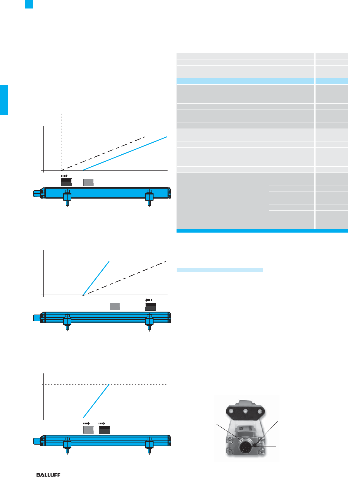
50
Series
Output signal
Transducer interface
Input interface
Part number
Output voltage*
Output current*
Load current
max. ripple
Load resistance (recommended)
System resolution
Sampling rate
max. non-linearity
Temperature coeffi cient
Operating voltage
Current consumption
Operating temperature
Storage temperature range
Pin assignments Pin Color
Output signals 1 YE
2GY
3PK
4RD
5GN
8WH
Operating voltage 6 BU
7BN
Profi le Series PF
Analog interface Adjustable measuring range
Output and measuring range setting
The measuring range and the output signal can be adapted to the
relevant application requirements via programming inputs. In teach-in
mode with inversion or reset function.
Programmable
input La
Programmable
input Lb
Measuring range adjustment via programming inputs
La and Lb
1. Place magnet in new start position.
Adopting a new start position
3. The new measuring range
2. Place magnet at new end position.
Adopting a new end position
LED for
diagnostics and
programming
assistance
■ Please enter the code for the output signal and the
nominal stroke in the ordering code!
Preferred models interface A500 and E500
BTL6-A500-M_ _ _ _-PF-S115
BTL6-E500-M_ _ _ _-PF-S115
are available from stock in the nominal lengths highlighted in blue.
■ Included:
– Transducer
– Mounting clamps with isolation washers and screws
– Short user's guide
Please order separately:
Magnets from page 52
Connectors, page 156
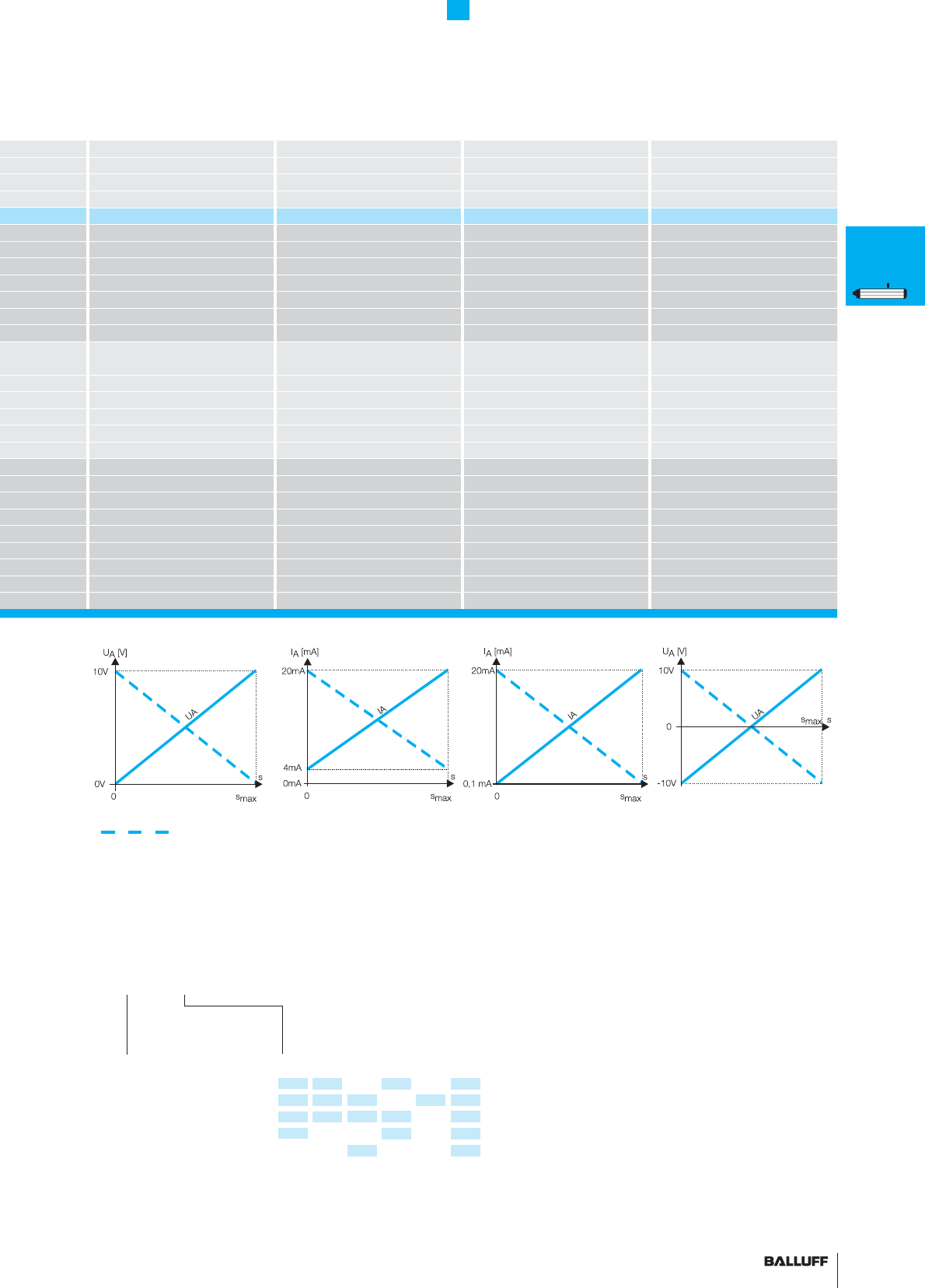
51■ www.balluff.com
Profi le Series PF
Analog interface
BTL6 profi le PF BTL6 profi le PF BTL6 profi le PF BTL6 profi le PF
analog analog analog analog
AECG
analog analog analog analog
BTL6-A500-M_ _ _ _-PF-S115 BTL6-E500-M_ _ _ _-PF-S115 BTL6-C500-M_ _ _ _-PF-S115 BTL6-G500-M_ _ _ _-PF-S115
0...10 V –10...10 V
4...20 mA 0.1...20 mA
max. 5 mA max. 5 mA
≤ 5 mV ≤ 5 mV
≤ 500 ohms (500 ohms) ≤ 500 ohms (500 ohms)
≤ 0.35 mV ≤ 0.7 µA ≤ 0.7 µA ≤ 0.35 mV
fmax = 2 kHz fmax = 2 kHz fmax = 2 kHz fmax = 2 kHz
±200 µm up to 500 mm nominal stroke
±0.04 % 500... max. nominal stroke
±200 µm up to 500 mm nominal stroke
±0.04 % 500... max. nominal stroke
±200 µm up to 500 mm nominal stroke
±0.04 % 500... max. nominal stroke
±200 µm up to 500 mm nominal stroke
±0.04 % 500... max. nominal stroke
30 ppm at 500 mm 30 ppm at 500 mm 30 ppm at 500 mm 30 ppm at 500 mm
10...30 V DC 10...30 V DC 10...30 V DC 10...30 V DC
≤ 150 mA ≤ 150 mA ≤ 150 mA ≤ 150 mA
–25...+70 °C –25...+70 °C –25...+70 °C –25...+70 °C
–40...+100 °C –40...+100 °C –40...+100 °C –40...+100 °C
BTL6-A500... BTL6-E500... BTL6-C500... BTL6-G500...
0 V 0 V 0 V 0 V
0 V Output 0 V Output 0 V Output 0 V Output
La (programming input) La (programming input) La (programming input) La (programming input)
0...10 V 4...20 mA 0.1...20 mA –10...10 V
Lb (programming input) Lb (programming input) Lb (programming input) Lb (programming input)
GND GND GND GND
10...30 V 10...30 V 10...30 V 10...30 V
Output signal
A 0...10 V
E 4...20 mA
C 0.1...20 mA
G –10...10 V
Standard
nominal stroke [mm]
Ordering example:
BTL6-_500-M_ _ _ _-PF-S115
0050, 0100, 0130, 0150, 0175, 0200,
0225, 0250, 0300, 0350, 0360, 0400,
0450, 0500, 0550, 0600, 0650, 0700,
0750, 0800, 0850, 0900, 0950, 1000,
1100, 1200, 1250, 1300, 1400, 1500,
1600, 1700, 1750, 1800, 1900, 2000,
2250, 2500, 2750, 3000, 3250, 3500,
3550, 3750, 4000, 4250, 4572
* Output signal can be inverted via programming inputs.
P
General
data
Analog
interface
Digital
pulse
interface
SSI
interface
CANopen
interface
DeviceNet
interface
PROFIBUS-DP
interface
Magnets
fl oating
Magnets
captive,
control arm
PF
General
data
Analog
interface
Magnets
fl oating
Magnets
captive,
control arm
AT
General
data
Analog
interface
Modes
Digital
pulse
interface
VARAN bus
interface
Accessories
BIW
General
data
Analog
interface
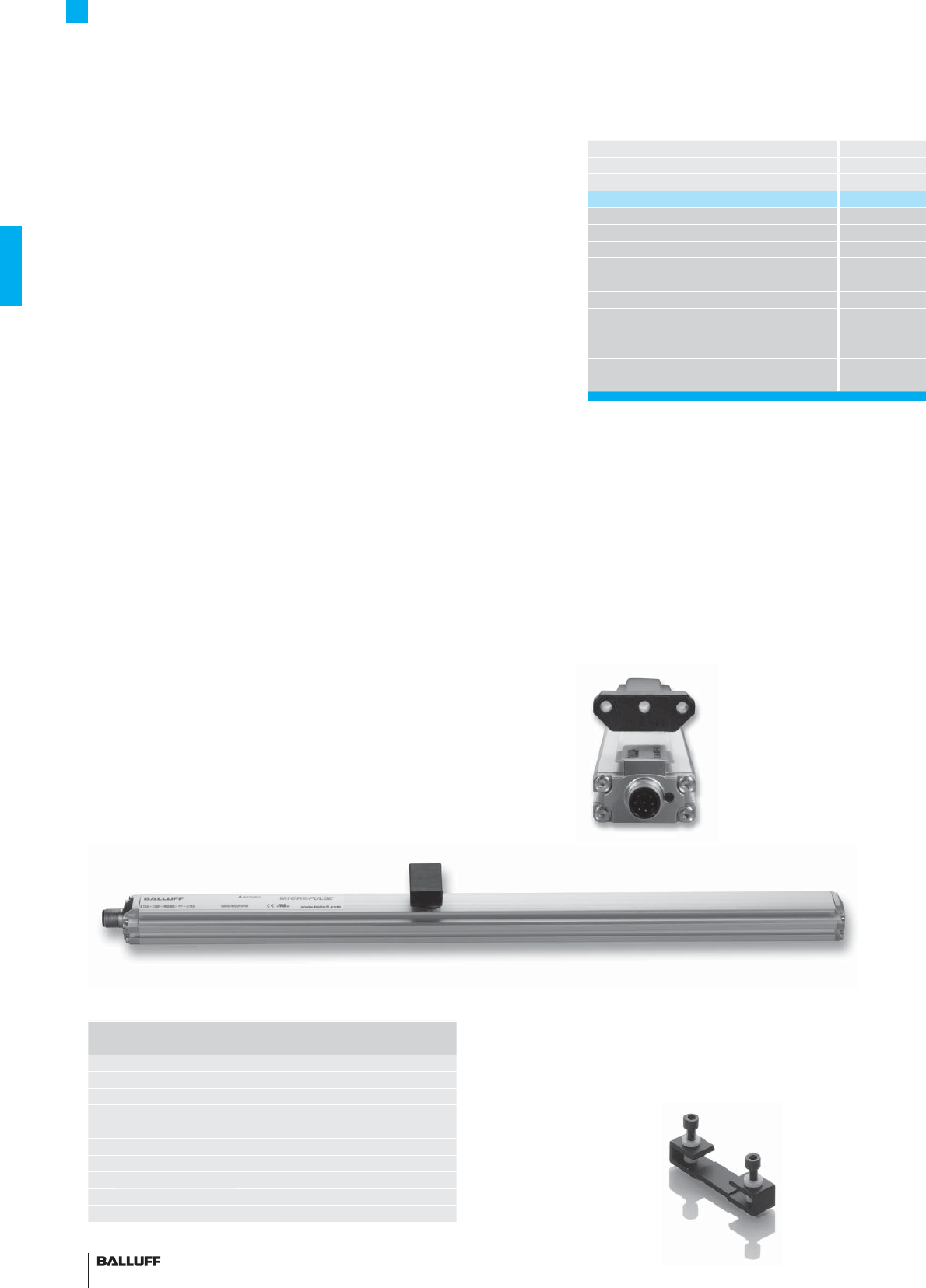
52
Profi le Series PF
Magnets fl oating
Balluff magnets are available in captive or fl oating designs. Maximum
resolution and repeatability are achieved using transducers with cap-
tive magnets.
The BTL5-P-4500-1 is an electromagnet and requires an operating
voltage of 24V, which can be turned on and off for selective
activation. This allows multiplex operation with multiple magnets on a
single transducer, since only one magnet is active at a time.
Description
for series
Version
Part number
Housing material
Weight
Magnet traverse velocity
Operating voltage
Current consumption
Operating temperature/Storage temperature range
Included
Accessories
(please order separately)
Mounting clamps with isolation
washers and screws included with
transducer.
BTL6-A-MF07-A-PF/M5 1 pair of
replacement mounting clamps and
screws, item no.: 180961
Length Number of
mounting clamp pairs
to 250 mm 1
251 to 750 mm 2
751 to 1250 mm 3
1251 to 1750 mm 4
1751 to 2250 mm 5
2251 to 2750 mm 6
2751 to 3250 mm 7
3251 to 3750 mm 8
3751 to 4250 mm 9
more than
4251 mm 10
Non-contact!
Vertical offset
0.1...4 mm or 5...15 mm
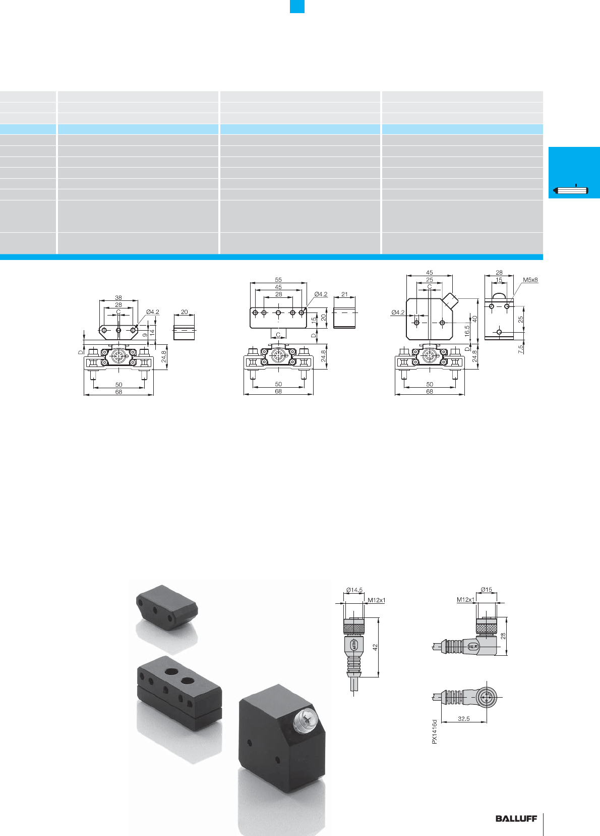
53■ www.balluff.com
Profi le Series PF
Magnets fl oating
Magnet Magnet Magnet
BTL6 profi le PF BTL6 profi le PF BTL6 profi le PF
fl oating fl oating fl oating
BTL5-P-3800-2 BTL5-P-5500-2 BTL5-P-4500-1
Plastic Plastic Plastic
approx. 12 g approx. 40 g approx. 90 g
any any any
24 V DC
100 mA
–40...+85 °C –40...+85 °C –40...+60 °C
Magnet
2 fastening screws DIN 84 M4×35-A2 with
washers and nuts
Magnet Magnet
Straight connector BKS-B 19-1-_ _
Right-angle connector BKS-B 20-1-_ _
Lateral offset:
C = ±2 mm
Vertical distance of magnet:
D = 0.1...4 mm
Lateral offset:
C = ±15 mm
Vertical distance of magnet:
D = 5...15 mm
Lateral offset:
C = ±2 mm
Vertical distance of magnet:
D = 0.1...2 mm
P
General
data
Analog
interface
Digital
pulse
interface
SSI
interface
CANopen
interface
DeviceNet
interface
PROFIBUS-DP
interface
Magnets
fl oating
Magnets
captive,
control arm
PF
General
data
Analog
interface
Magnets
fl oating
Magnets
captive,
control arm
AT
General
data
Analog
interface
Modes
Digital
pulse
interface
VARAN bus
interface
Accessories
BIW
General
data
Analog
interface
■ Please indicate the cable length in the
ordering code!
03, 05, 10, 15
= PVC, 3 m, 5 m, 10 m or 15 m
PU-03, PU-05, PU-10, PU-15
= PUR, 3 m, 5 m, 10 m or 15 m
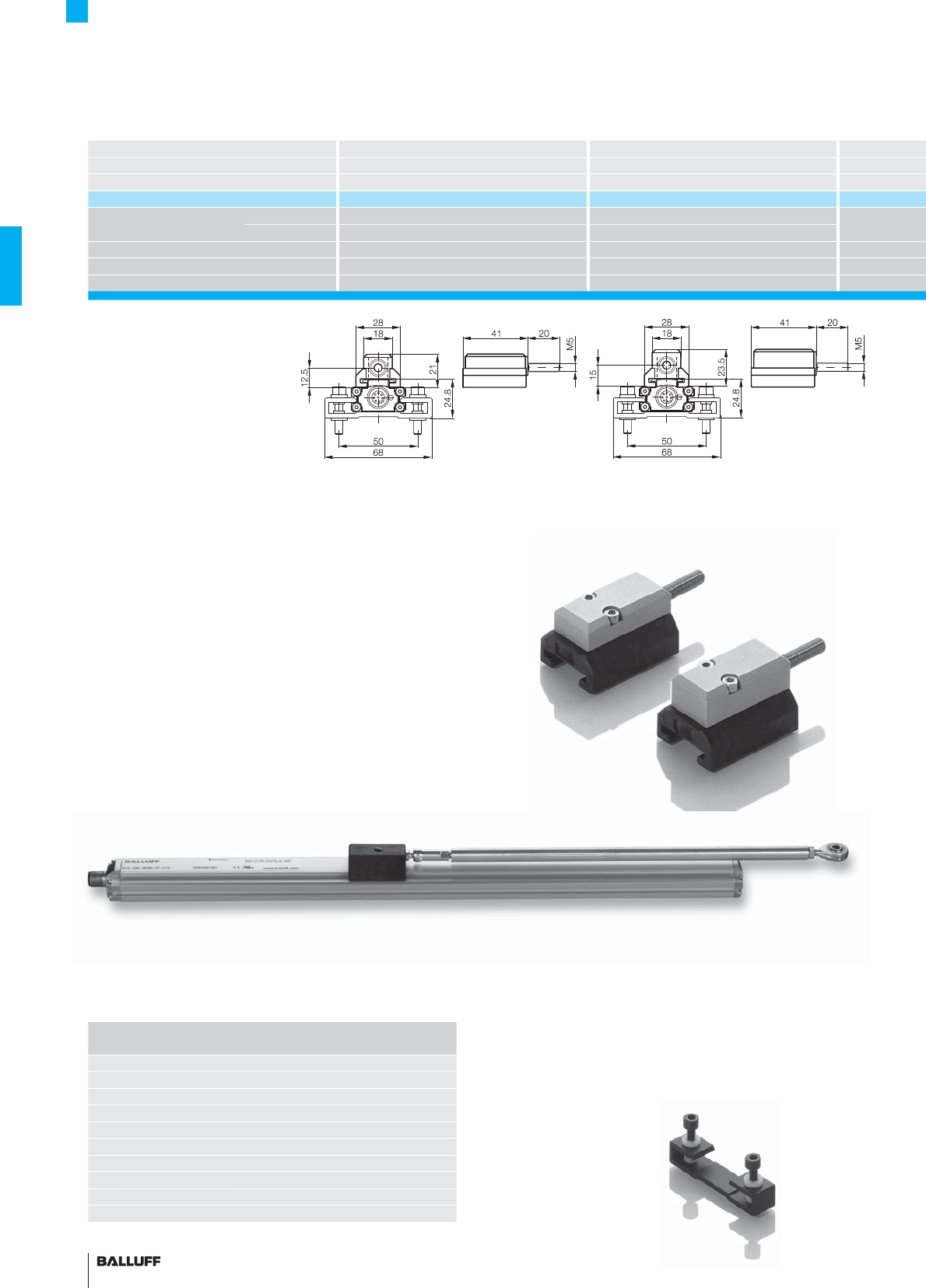
54
Description Magnet Magnet
for series BTL6 profi le PF BTL6 profi le PF
Version captive captive
Part number BTL5-M-2814-1S BTL5-N-2814-1S
Material Housing Anodized aluminum Anodized aluminum
Sliding surface Plastic Plastic
Weight approx. 32 g approx. 35 g
Magnet traverse velocity any any
Operating temperature/Storage temperature range
–40...+85 °C –40...+85 °C
Profi le Series PF
Magnets captive
Mounting clamps with isolation
washers and screws included with
transducer.
BTL6-A-MF07-A-PF/M5 1 pair of
replacement mounting clamps and
screws, item no.: 180961
Length Number of
mounting clamp pairs
to 250 mm 1
251 to 750 mm 2
751 to 1250 mm 3
1251 to 1750 mm 4
1751 to 2250 mm 5
2251 to 2750 mm 6
2751 to 3250 mm 7
3251 to 3750 mm 8
3751 to 4250 mm 9
more than
4251 mm 10
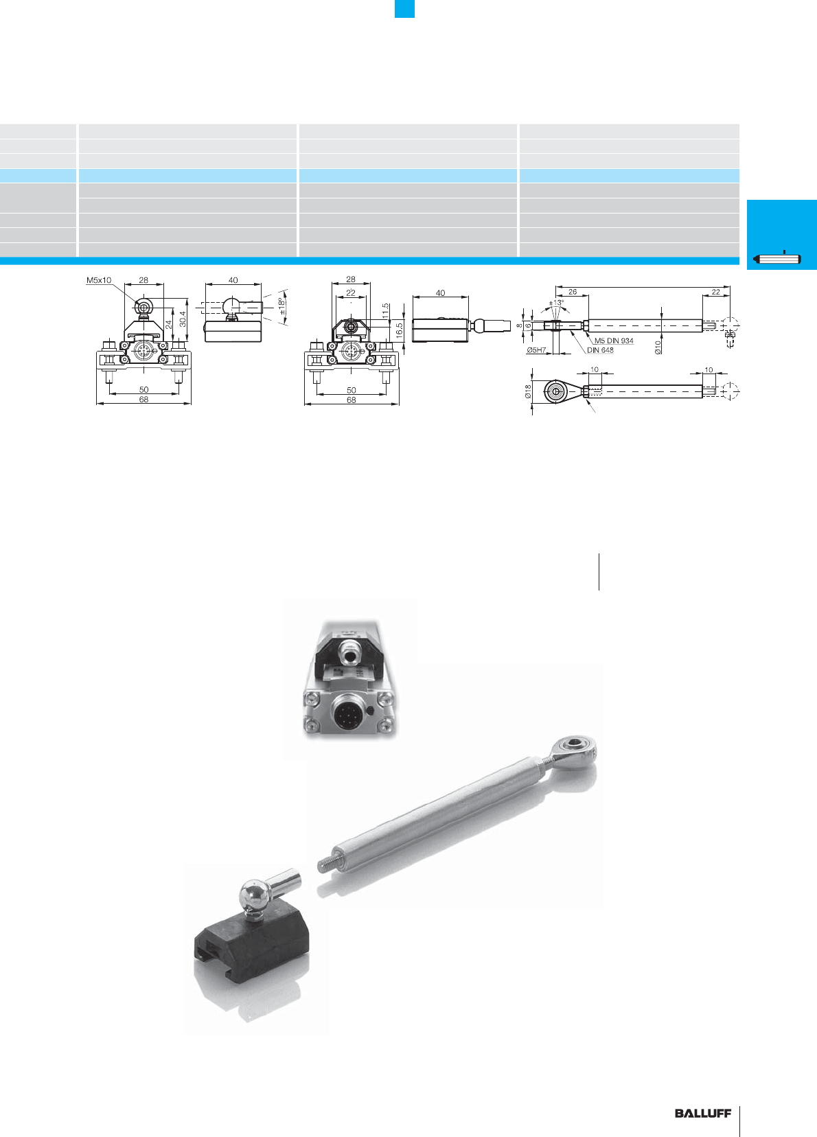
55■ www.balluff.com
Magnet Magnet Control arm
BTL6 profi le PF BTL6 profi le PF BTL6 profi le PF
captive captive captive
BTL5-F-2814-1S BTL5-T-2814-1S BTL2-GS10-_ _ _ _-A
Anodized aluminum Anodized aluminum Al
Plastic Plastic
approx. 28 g approx. 28 g approx. 150 g/mg
any any
–40...+85 °C –40...+85 °C
Profi le Series PF
Magnets captive, control arm
When using captured magnets with
ball joint and control arm, transverse
forces do not impinge on the transducer
system.
■ Please enter the code for the
nominal stroke in the ordering code!
Swivel eye
Material number 714619
Adjustment range –5 mm
Nominal stroke
Ordering example:
BTL2-GS10-_ _ _ _-A
Standard
nominal stroke [mm]
0075, 0100, 0125, 0150,
0200, 0250, 0350, 0400,
0450, 0500, 0600, 0800,
1000, 1500, 2000
P
General
data
Analog
interface
Digital
pulse
interface
SSI
interface
CANopen
interface
DeviceNet
interface
PROFIBUS-DP
interface
Magnets
fl oating
Magnets
captive,
control arm
PF
General
data
Analog
interface
Magnets
fl oating
Magnets
captive,
control arm
AT
General
data
Analog
interface
Modes
Digital
pulse
interface
VARAN bus
interface
Accessories
BIW
General
data
Analog
interface
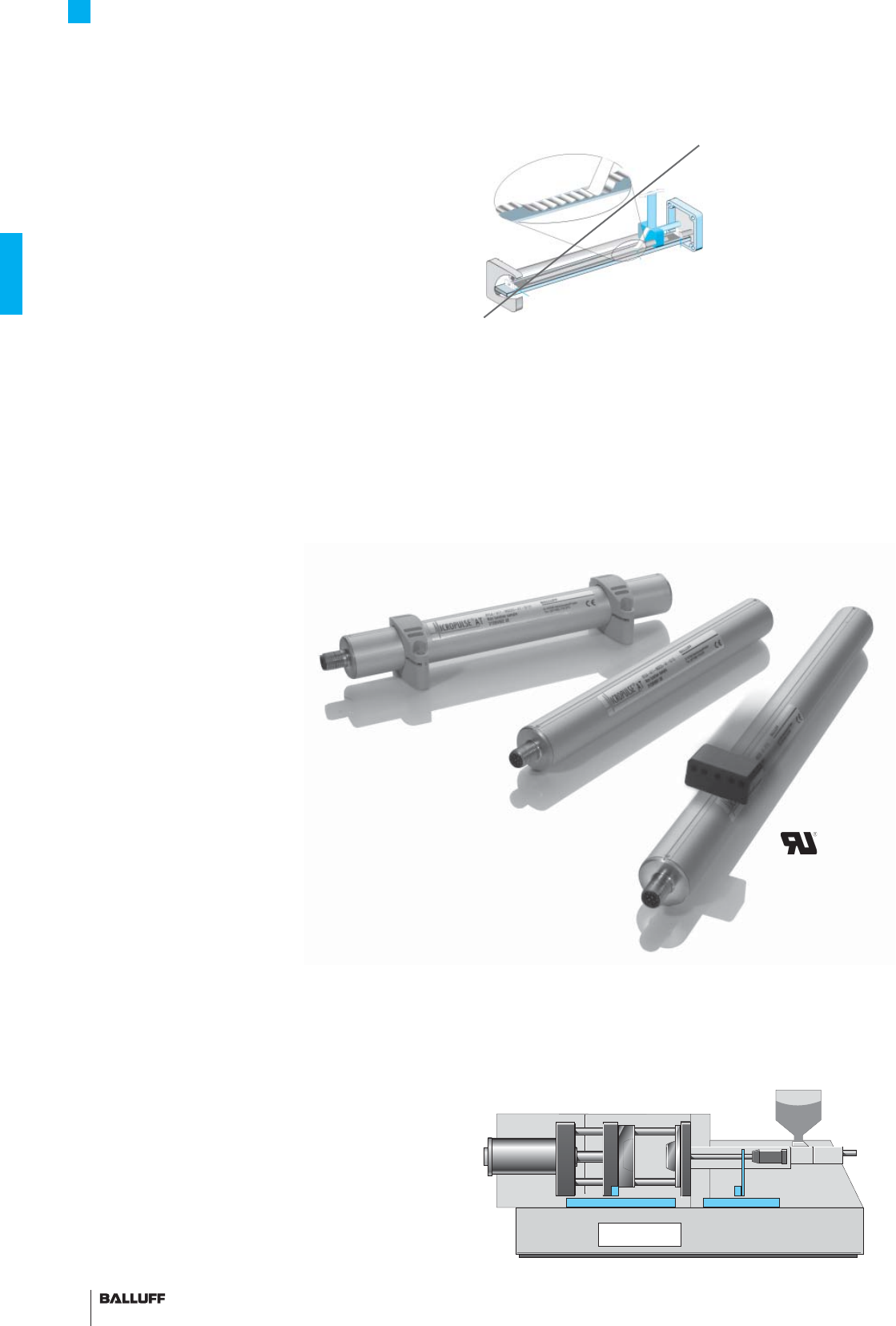
56
Profi le Series AT
General data
Micropulse transducers – a non-contact alternative
to contacting feedback devices
The structural design, high degree of protection and simple instal-
lation of non-contact Balluff Micropulse AT transducers in a profi led
housing makes them an excellent alternative to contacting potenti-
ometers. The linear sensing element is protected inside an extruded
aluminum profi le.
A passive magnet with no power supply marks the measuring point
along the waveguide without making contact. Measuring ranges
between 50 and 1500 mm are possible.
– Non-contact detection of the actual position
– IP 67, insensitive to contamination
– Wear-free
– Insensitive to shock and vibration
– Absolute output signal
– Direct signal processing or in conjunction with processors for all
control and regulating systems
From optional to standard
Micropulse transducers have long been standard in the plastics ma-
chinery industry on high-precision machines and offered on standard
machines as a non-contact option to potentiometric systems. The
only thing that has stood in the way of more widespread use has
been the comparatively high price.
The Micropulse AT has been designed in cooperation with develop-
ment engineers from the plastics machinery industry and represents
a system that is competitively priced and meets all the technical
demands of the industry.
With the Micropulse AT position feedback system, now even
standard machines can feature the benefi t of minimum downtime
provided by non-contact transducer systems.
This product is certifi ed
in accordance with File
No. E227256
Easy and fl exible installation

57■ www.balluff.com
Profi le Series AT
General data
Series BTL6 Profi le A1
Part number BTL6-_ _ _-M_ _ _ _-A1-S115
BTL6-A301-M_ _ _ _-A1-S115
Shock load 50 g/6 ms per IEC 60068-2-27
Vibration 12 g, 10...2000 Hz per IEC 60068-2-6
Polarity reversal protected yes
Overvoltage protection yes
Degree of protection as per IEC 60529 IP 67 (with BKS-S... IP 67 connector attached)
Housing material Anodized aluminum
Housing attachment Mounting clamps
Connection type Connector M12, 8-pin standard
EMC testing:
RF emission EN 55016-2-3 Group 1, Class A+B
Static electricity (ESD) IEC 61000-4-2 Severity Level 3
Electromagnetic fi elds (RFI) IEC 61000-4-3 Severity Level 3
Fast transients (BURST) IEC 61000-4-4 Severity Level 3
Line-induced disturbances,
induced by high-frequency fi elds
IEC 61000-4-6 Severity Level 3
IEC 61000-4-8 Severity Level 4
■ Included:
– Transducer (select your
interface from page 58)
– Short user's guide
Please order separately:
Magnets, page 67
Mounting clamps/cuff, page 66
Connectors, page 156
Mounting clamps
page 66
Magnets,
page 67
Mounting cuff,
page 66
Transducers with fl oating magnet and S115 connection with BKS-S115/BKS-S116 connector
for transducers with analog interface, digital pulse interface and VARAN bus interface from page 58
Nominal stroke
Installation length
P
General
data
Analog
interface
Digital
pulse
interface
SSI
interface
CANopen
interface
DeviceNet
interface
PROFIBUS-DP
interface
Magnets
fl oating
Magnets
captive,
control arm
PF
General
data
Analog
interface
Magnets
fl oating
Magnets
captive,
control arm
AT
General
data
Analog
interface
Modes
Digital
pulse
interface
VARAN bus
interface
Accessories
BIW
General
data
Analog
interface
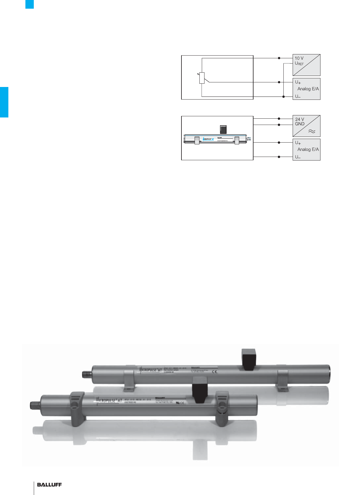
58
Profi le Series AT
Analog interface
The analog outputs of the standard series BTL6-A110 are potential
non-isolated.
BTL6 transducers exist in the variants 0...10 V and –10...10 V with
rising and falling characteristics. The version –10...10 V generally has
potential isolated output signals.
Potentiometer connections, block diagram
Micropulse transducer connections, block diagram
The non-contact potentiometer
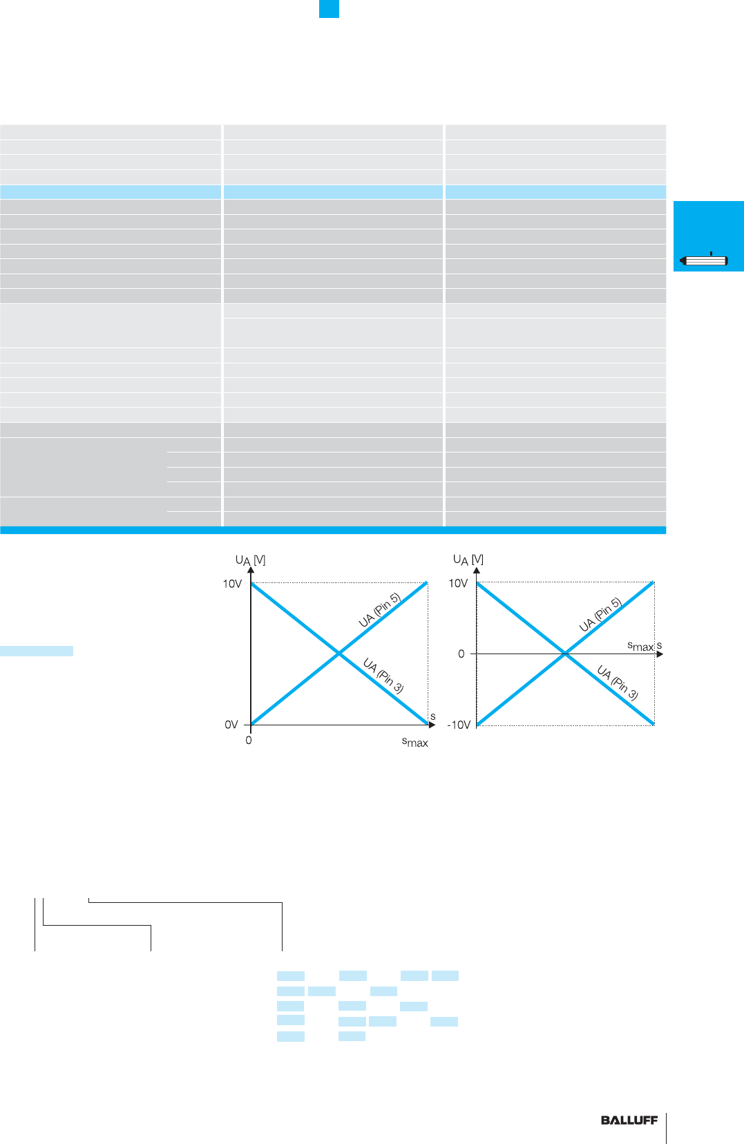
59■ www.balluff.com
Profi le Series AT
Analog interface
Series BTL6 Profi le A1 BTL6 Profi le A1
Output signal analog analog
Transducer interface AG
Input interface analog analog
Part number BTL6-A110-M_ _ _ _-A1-S115 BTL5-G310-M_ _ _ _-A1-S115
Output voltage 0...10 V and 10...0 V –10...10 V and 10...–10 V
Load current max. 5 mA max. 5 mA
max. ripple ≤ 5 mV ≤ 5 mV
System resolution ≤ 10 µm ≤ 10 µm
Repeat accuracy ≤ 10 µm ≤ 10 µm
Repeatability ≤ 20 µm ≤ 20 µm
Sampling rate fSTANDARD = 1 kHz fSTANDARD = 1 kHz
Non-linearity ≤ ±200 µm up to 500 mm nominal stroke ≤ ±200 µm up to 500 mm nominal stroke
typ. ±0.02 %, max. ±0.04 %
500...1500 mm nominal stroke
typ. ±0.02 %, max. ±0.04 %
500...1500 mm nominal stroke
Operating voltage 20...28 V DC 20...28 V DC
Current consumption ≤ 70 mA ≤ 70 mA
Polarity reversal protected yes yes
Operating temperature 0...+70 °C 0...+70 °C
Storage temperature range –40...+100 °C –40...+100 °C
Pin assignments Pin BTL6-A110.../A310 BTL6-G310...
Output signals 1 0 V Output 0 V Output
2 0 V Output 0 V Output
3 10...0 V –10...10 V
5 0...10 V 10...–10 V
Operating voltage 6 GND GND
7+24 V DC +24 V DC
Output signal
A 0...10 V
10...0 V
G –10...10 V
10...–10 V
Ordering example:
BTL6-_ _ 10-M_ _ _ _-A1-S115
Standard
nominal stroke [mm]
0100, 0130, 0150, 0160, 0175, 0200,
0225, 0250, 0275, 0300, 0325, 0350,
0360, 0375, 0400, 0425, 0450, 0475,
0500, 0550, 0600, 0650, 0700, 0750,
0800, 0850, 0900, 0950, 1000, 1100,
1200, 1250, 1300, 1400, 1500,
in 25 mm increments on request
Output signal
1 potential
non-isolated*
3 potential
unconnected
Connect shield to housing,
pins 4 and 8 must remain unconnected.
■
Please enter the code for the output signal and
the nominal stroke length in the ordering code.
Preferred models
BTL6-A110-M_ _ _ _-A1-S115 are available
from stock in the nominal lengths highlighted
in blue.
■ Included:
– Transducer
– Short user's guide
Please order separately:
Magnets, page 67
Mounting clamps/cuff, page 66
Connectors, page 156
*only for BTL6-A110-M_ _ _ _-A1-S115
P
General
data
Analog
interface
Digital
pulse
interface
SSI
interface
CANopen
interface
DeviceNet
interface
PROFIBUS-DP
interface
Magnets
fl oating
Magnets
captive,
control arm
PF
General
data
Analog
interface
Magnets
fl oating
Magnets
captive,
control arm
AT
General
data
Analog
interface
Modes
Digital
pulse
interface
VARAN bus
interface
Accessories
BIW
General
data
Analog
interface
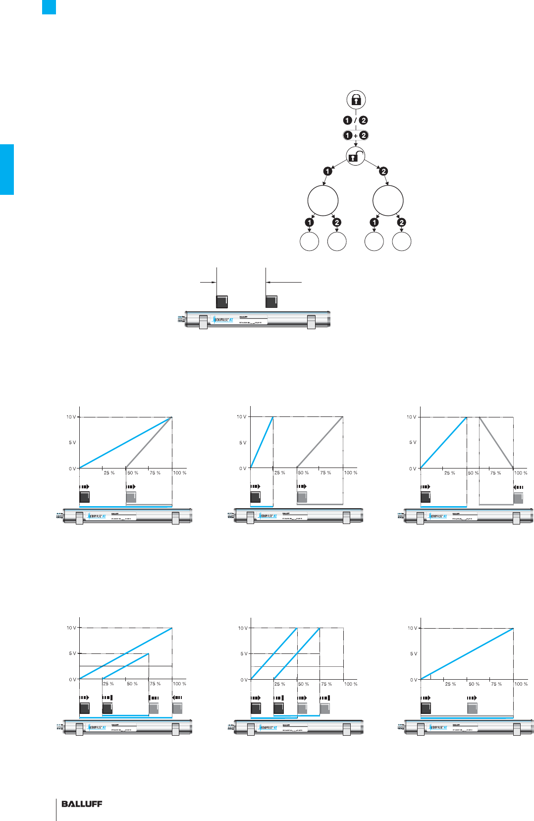
60
Profi le Series AT
Modes
BTL6-A301-... 2 in 1
Two moving members on a machine often travel in the same direc-
tion. Each axis normally requires a separate feedback sensor.
With the Micropulse AT you can now sense both movements at the
same time using just one transducer with 2 analog outputs.
The position of the respective null and end points can be set
individually using 2 programming inputs.
The two measuring ranges may be adjacent, may overlap, and can
be programmed for a rising or falling output signal. The transducer
can be operated using one or two magnets. If one magnet
leaves the measuring range or if only one is present, the position is
indicated on Output 1. Output 2 then indicates an error value.
Mode 1: Single measurement of 2 positions
(single measurement default setting 100 %/50 %)
Basic default setting Programming example:
Output 1: 50 % nominal stroke, signal rising
Output 2: 37.5 % nominal stroke, signal falling
Default setting: Differential measurement
Output 1: Standard travel signal (not shown)
Output 2: differential signal 100 % nominal stroke = 10 V
Programming example:
Differential travel 50 % nominal stroke = 5 V differential
signal
Programming example: Differential
travel 50 % nominal stroke = 10 V differential signal
Mode 2: Differential measurement between 2 magnets
Minimum magnet
separation 65 mm Minimum magnet
separation 65 mm
Programming example:
Output 1: 25 % nominal stroke, signal rising
Output 2: 50 % nominal stroke, signal rising
Mode 3: Single measurement
(both magnets 0...100 %)
Magnet 1 Magnet 2
Null
point End
point
Inputs
inactive
Inputs
active
Null
point End
point
Teach-in
Used for changing the factory
set null and end point to a new
null and end point. First the mag-
net must be brought to the new
null point and then to the new
end position, and the respective
values stored by pressing the
button.
Mode selection
The standard function is the
separate measurement of two
positions. The programming
inputs are used to switch the
mode. The separation between two
magnets should not generally be
less than 65 mm.
min 65 mm
Example: Programming steps
for setting the measuring range
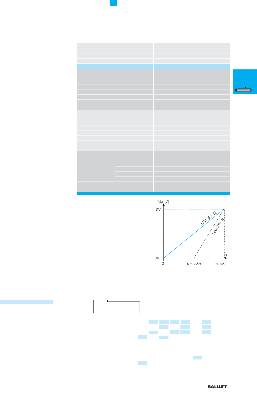
61■ www.balluff.com
Profi le Series AT
Analog interface
Series BTL6 Profi le A1
Output signal analog
Transducer interface A
Input interface analog
Part number BTL6-A301-M_ _ _ _-A1-S115
Output potential-free
Output voltage 0...10 V programmable
Load current max. 5 mA
max. ripple ≤ 5 mV
System resolution ≤ 10 µm
Repeat accuracy ≤ 10 µm
Repeatability ≤ 20 µm
Sampling rate fSTANDARD = 1 kHz (< 850 mm)
Non-linearity ≤ ±200 µm up to 500 mm nominal stroke
typ. ±0.02 %, max. ±0.04 %
500...1500 mm nominal stroke
Operating voltage 18...30 V DC
Current consumption ≤ 100 mA
Polarity reversal protected yes
Operating temperature 0...+70 °C
Storage temperature range –40...+100 °C
Pin assignments Pin Color* BTL6-A301...
Output signals 1 YE Programming input La
2 GY 0 V Output
3 PK 0...10 V, output 2, programmable
4 RD Programming input Lb
5 GN 0...10 V, output 1, programmable
Operating voltage 6 BU GND
7BN+24 V DC
Output signal
potential isolated
2 analog outputs
Single or differential
measurement, rising,
falling, zero and end
point programmable
Ordering example:
BTL6-A301-M_ _ _ _-A1-S115
Standard
nominal stroke [mm]
0160, 0175, 0200, 0225, 0250, 0275, 0300,
0325, 0350, 0360, 0375, 0400, 0425, 0450,
0475, 0500, 0550, 0600, 0650, 0700, 0750,
0800, 0850, 0900, 0950, 1000, 1100, 1200,
1250, 1300, 1400, 1500, in
25 mm increments on request.
Standard nominal stroke (mm)
0050, 0100, 0130,
0150 for single magnet only
■ Please the enter code for
the nominal stroke in the ordering code!
Preferred models interface A301
BTL6-A301-M_ _ _ _-A1-S115
are available from stock in the nominal
lengths highlighted in blue.
■ Included:
– Transducer
– Short user's guide
Please order separately:
Magnets, page 67
Mounting clamps/cuff, page 66
Features of Micropulse
BTL6-A
– 100 % adjustment
of analog signal
– Error signal, no magnet within
measuring range, transducer
in calibration mode
– LED indicator for
programming assistance
– Separate teach-in for
all zero and span points
– Freely selectable single
position or differential
measurement
Measure two motions with
one system
– One transducer senses two
motions at the same time
– Signifi cant cost reduction, half
the installation costs
– Two 0...10 V analog outputs
Connect shield to housing, pin 8 (WH) must
remain unconnected.
*Connector with
cable BKS-S115/BKS-S116
"2 in 1" –
100% stroke adjustment
P
General
data
Analog
interface
Digital
pulse
interface
SSI
interface
CANopen
interface
DeviceNet
interface
PROFIBUS-DP
interface
Magnets
fl oating
Magnets
captive,
control arm
PF
General
data
Analog
interface
Magnets
fl oating
Magnets
captive,
control arm
AT
General
data
Analog
interface
Modes
Digital
pulse
interface
VARAN bus
interface
Accessories
BIW
General
data
Analog
interface
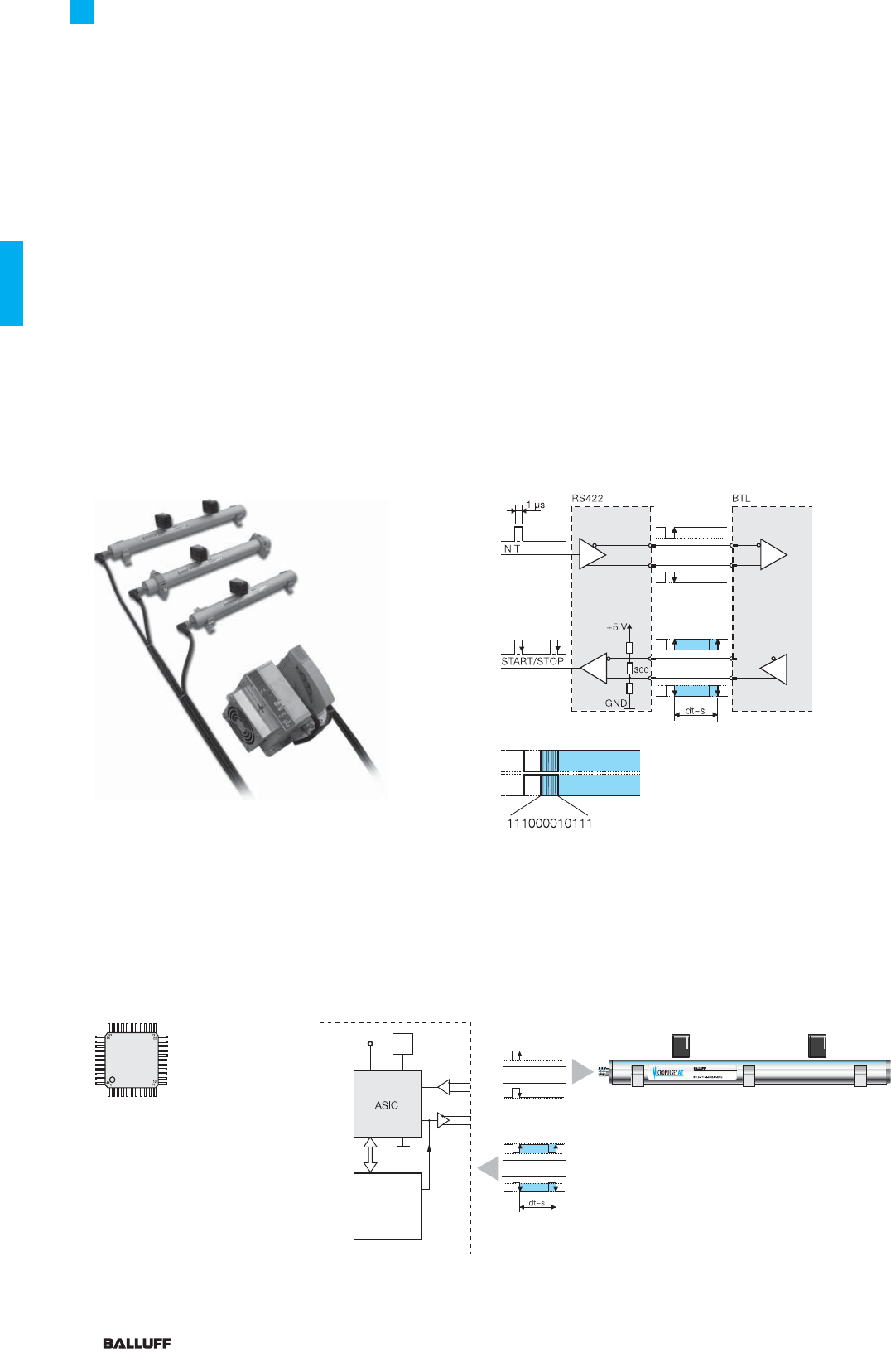
62
Profi le Series AT
Digital pulse interface
P110 interface
Compatible with BTA processors as well as controllers and modules
from various manufacturers including Siemens, B & R, Phoenix Con-
tact, Mitsubishi, Sigmatek, Esitron and WAGO.
Reliable signal transmission, even over cable lengths up to 500 m
between BTA and transducer is assured by the noise-immune
RS485 differential line drivers and receivers. Noise signals are effec-
tively suppressed.
P110 replaces P1 and M1
Based on differing philosophies, two controller-specifi c interfaces
have been established for the digital pulse versions. The difference
lies in how the edges are processed. The falling edges are pro-
cessed in the "P interface" and the rising edges in the "M interface".
To reduce the number of different models to a minimum, the "P110
interface" was created as a universal pulse interface which combines
both functions. The reference point for the propagation time measu-
rement is the "start pulse".
Extremely precise digitizing chip for P110 pulse interface
Companies developing their own control and processing electronics
can create a highly accurate P interface cost effectively and
with minimum effort using the Balluff digitizing chip. The digitizing
chip was developed as a high-resolution, confi gurable ASIC for
Micropulse transducers with P interface.
P111 interface – Cost savings using DPI/IP for
start-up and installation
DPI/IP is a protocol for direct data interchange between a controller
and transducer. The signal lines are used to send additional informa-
tion such as manufacturer, stroke length and waveguide gradient.
This allows start-up or replacement of a transducer without having
to make manual changes to the controller parameters. The fi rst to
integrate these functions were the controllers from Sigmatek.
Features:
– Bi-directional communication
– Transducer controlled using Init and Start/Stop signals
– Integrated diagnostic functions
– Plug and Play
– Automatic parameterization reduces downtimes
– Sending of sensor model, stroke length, specifi c parameters
– Measurement length up to 3250 mm
Block diagram of P interface
ASIC INFO:
+49 7158 173-370
Digitizing chip 44QFP
CPU
controller
4/8-
bit bus
5 V
Osc.
INIT
Micropulse transducer with 1 to
4 magnets
Controller or
processing electronics
P pulse signal
Advantages:
– High resolution: the actual 1 µm of the BTL is fully supported
by the 133 ps resolution of the chip (at low clock frequency 2 or
20 MHz)
– Position data from 4 magnets can be processed simultaneously
– 4/8-bit processor interface
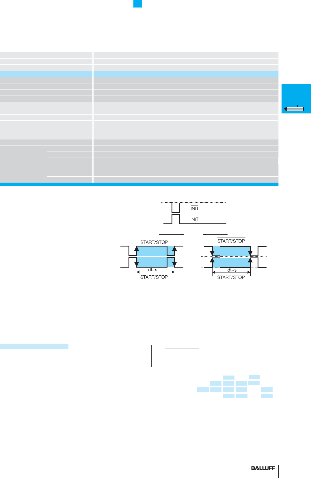
63■ www.balluff.com
Profi le Series AT
Digital pulse interface
Series BTL6 Profi le A1
Transducer interface Pulse P11_
Input interface Pulse P11_
Part number BTL6-P11_-M_ _ _ _-A1-S115
System resolution processing-dependent
Repeat accuracy ≤ 10 µm
Repeatability ≤ 20 µm
Resolution ≤ 10 µm
Non-linearity ≤ ±200 µm up to 500 mm nominal stroke
typ. ±0.02 %, max. ±0.04 % 500...1500 mm nominal stroke
Operating voltage 20...28 V DC
Current consumption ≤ 60 mA (at 1kHz)
Operating temperature 0...+70 °C
Storage temperature range –40...+100 °C
Pin assignments Pin BTL6-P11_-M...
Input/Output Input 1 INIT
signals Output 2 START/STOP
Input 3 INIT
Output 5 START/STOP
Operating voltage 6 GND
7+24 V DC
Data protocol
0 without
DPI/IP*
(standard)
1 with DPI/IP
Ordering example:
BTL6-P11_-M_ _ _ _-A1-S115
Standard
nominal stroke [mm]
0050, 0075, 0100, 0130, 0150, 0160,
0175, 0200, 0225, 0250, 0300, 0350,
0360, 0400, 0450, 0500, 0550, 0600,
0650, 0700, 0750, 0800, 0850, 0900,
0950, 1000, 1100, 1200, 1250, 1300,
1400, 1500, 1700, 2000, 2100, 2500,
2800, 3000, 3250, in 25 mm
increments on request
*the version without DPI/IP is only available up to a nominal stroke of 1500
■ Please enter code for the data protocol
and nominal stroke length in the ordering code.
Preferred models interface P11_
BTL6-P11_-M_ _ _ _-A1-S115 are available
from stock in the nominal lengths highlighted
in blue.
■ Included:
– Transducer
– Short user's guide
Please order separately:
Magnets, page 67
Mounting clamps/cuff, page 66
Connectors, page 156
P1 P110 M1
Plug and Play –
self-confi guring
P
General
data
Analog
interface
Digital
pulse
interface
SSI
interface
CANopen
interface
DeviceNet
interface
PROFIBUS-DP
interface
Magnets
fl oating
Magnets
captive,
control arm
PF
General
data
Analog
interface
Magnets
fl oating
Magnets
captive,
control arm
AT
General
data
Analog
interface
Modes
Digital
pulse
interface
VARAN bus
interface
Accessories
BIW
General
data
Analog
interface
Connect shield to housing,
pins 4 and 8 must remain unconnected.
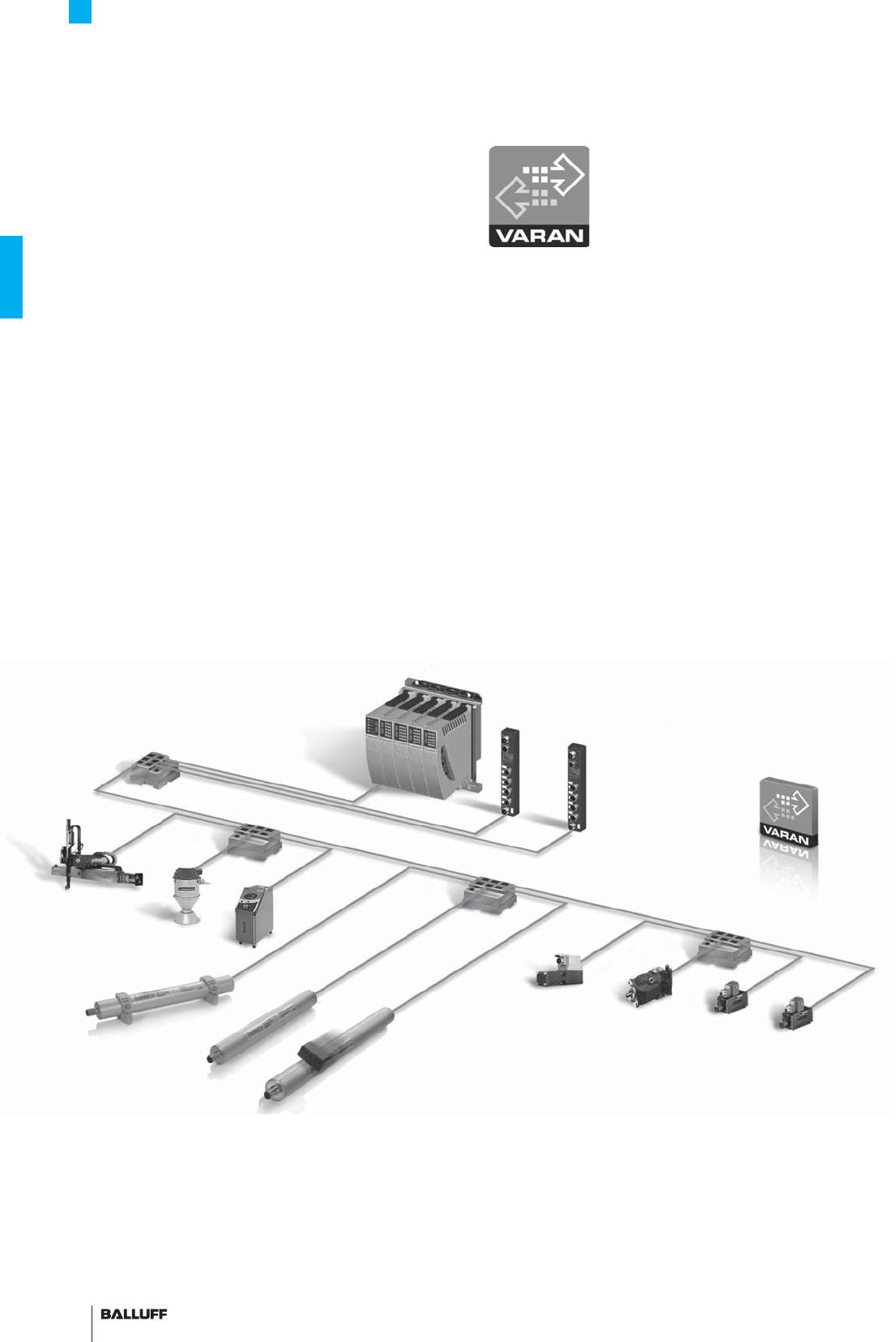
64
Profi le Series AT
VARAN bus interface
VARAN Ethernet technology and non-contact Micropulse distance
measurement technology from Balluff form an outstanding team.
Micropulse AT VARAN linear displacement systems detect the move-
ments of highly dynamic axes in complex applications.
The realtime Ethernet system is extremely economical, easy to
implement and simple to program. Widely available on the market,
VARAN networks are used in combination with Sigmatek controllers,
for example.
VARAN is fully integrated in hardware and designed according to
IEEE 802.3 for standard Ethernet physics.
The simple design guarantees extremely rapid cycle times while
achieving maximum data security and reducing implementation
costs.
Micropulse AT V11V features:
– Robust non-contact IP 67 sensor –
reliable and wear-free
– Simple hardware structure – low system costs
– M12, 8-pin plug connection –
simple economical cabling
VARAN features:
– Hard realtime data transfer – cycle times < 100µs
– High reliability – repeat in bus cycle
– Cost-conscious hardware design – low overall system costs
– Open standard – no restrictive dependences
– Easy implementation – cost-effective
MICROPULSE
®
Realtime Ethernet, reliable and economical
I/O systems C-DIAS
IP 67
I/O systems P-DIAS
Topology example
with VARAN bus
Splitter
Splitter
Splitter
Splitter
Hydraulic components
BTL profi le AT
Robots
Tempering/
Dosing
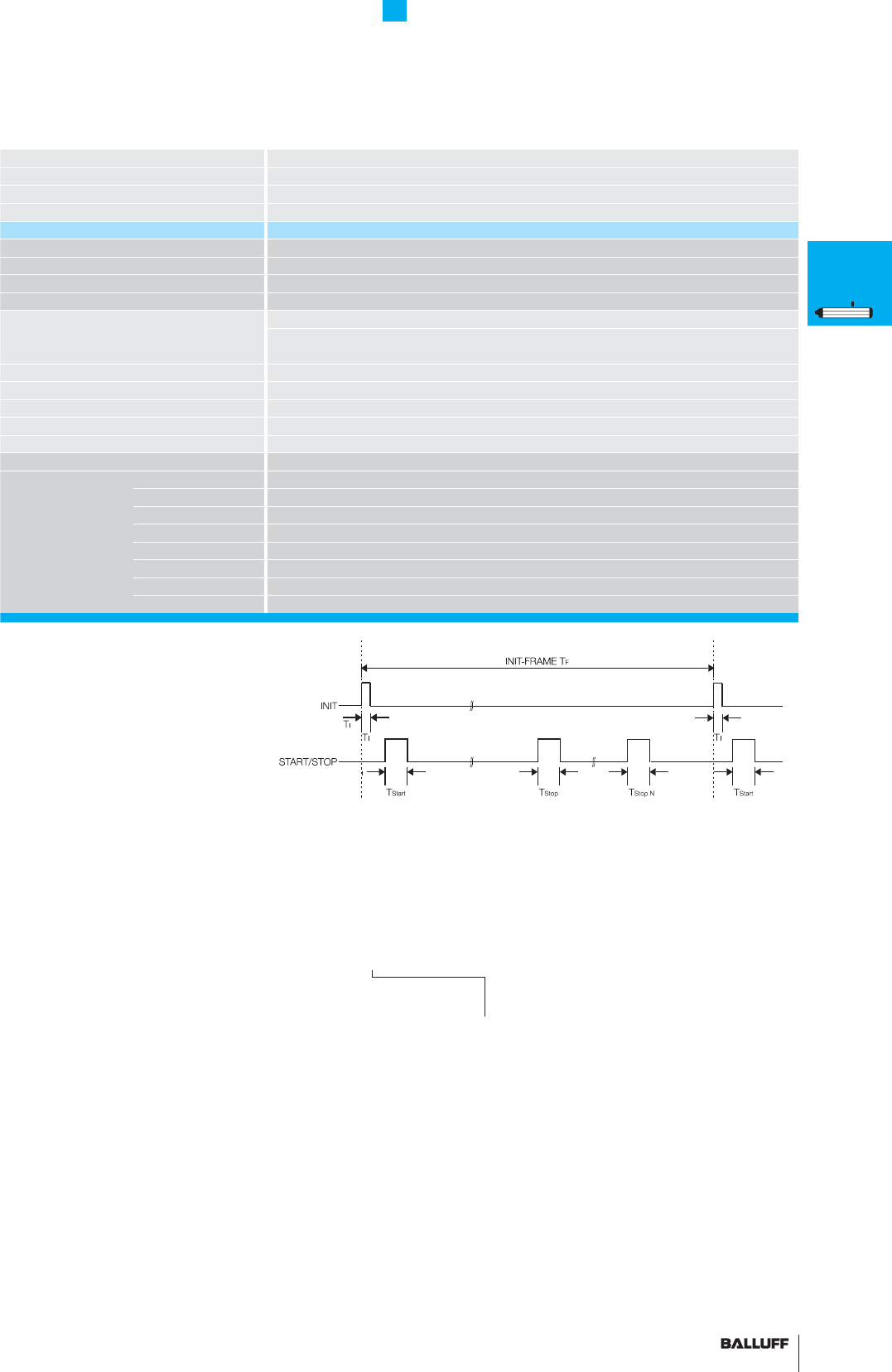
65■ www.balluff.com
Profi le Series AT
VARAN bus interface
Series BTL6 -V11V
Output signal VARAN (Ethernet)
Transducer interface V11V
Input interface VARAN
Part number BTL6-V11V-M_ _ _ _-A1-S115
System resolution ≤ 15 µm
Repeat accuracy ≤ 30 µm
Repeatability ≤ 30 µm
Sampling rate fSTANDARD = 1 kHz (< 850 mm)
Non-linearity ≤ ±200 µm up to 500 mm nominal stroke
±0.04 %
500...1500 mm nominal stroke
Operating voltage 18...30 V DC
Current consumption ≤ 75 mA
Polarity reversal protected yes
Operating temperature 0...+70 °C
Storage temperature range –40...+100 °C
Pin assignments Pin Color BTL6-V11V-...
Output signals 1
2 OG/WH Tx+
3 OG Tx-
4
5 GN/WH Rx+
6 BU GND
7 BN +24 V DC
8 GN Rx-
Ordering example:
BTL6-V11V-M_ _ _ _-A1-S115
Standard
nominal stroke [mm]
0160, 0175, 0200, 0225, 0250, 0275, 0300,
0325, 0350, 0360, 0375, 0400, 0425, 0450,
0475, 0500, 0550, 0600, 0650, 0700, 0750,
0800, 0850, 0900, 0950, 1000, 1100, 1200,
1250, 1300, 1400, 1500, in
25 mm increments on request.
Standard nominal stroke (mm) 0050, 0100,
0130, 0150 for single magnet only
■ Please enter code for the
nominal stroke in the ordering code!
■ Included:
– Transducer
– Short user's guide
Please order separately:
Magnets, page 67
Mounting clamps/cuff, page 66
P
General
data
Analog
interface
Digital
pulse
interface
SSI
interface
CANopen
interface
DeviceNet
interface
PROFIBUS-DP
interface
Magnets
fl oating
Magnets
captive,
control arm
PF
General
data
Analog
interface
Magnets
fl oating
Magnets
captive,
control arm
AT
General
data
Analog
interface
Modes
Digital
pulse
interface
VARAN bus
interface
Accessories
BIW
General
data
Analog
interface
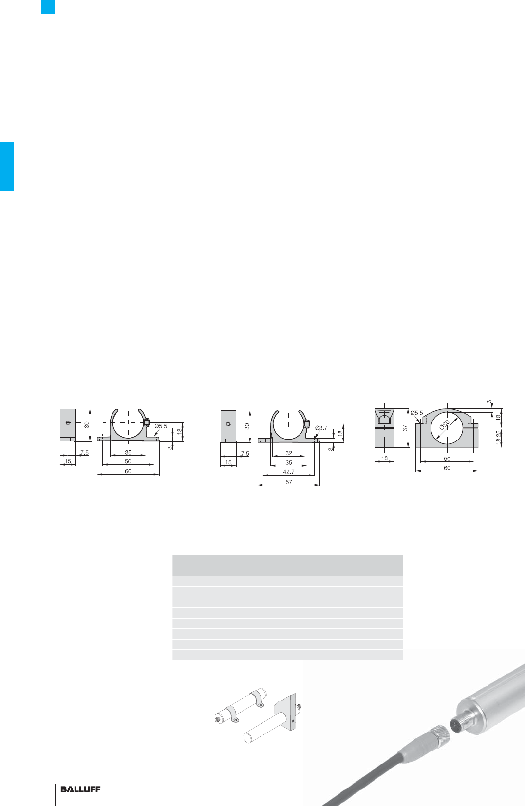
66
Profi le Series AT
Accessories
The BTL6-A-3800-2 magnet can be operated at a distance of
4...8 mm from the top surface of the profi le housing.
In conjunction with mounting clamp BTL6-A-MF01-A-50 and mount-
ing cuff BTL6-A-MF03-K-50, the mechanical installation is compat-
ible with series BTL5-...-P-S32 with magnet BTL5-P-3800-2 or
BTL5-P-5500-2.
As a result, large measurement lengths or transducers with a bus
connection, for example, can be implemented optionally without
requiring mechanical modifi cations.
Mounting clamp
Ordering code: BTL6-A-MF01-A-50
Includes: 1 clamp
Mounting clamps/cuff
Mounting clamp
Ordering code: BTL6-A-MF01-A-43
Includes: 1 clamp
Mounting cuff
Ordering code: BTL6-A-MF03-K-50
Includes: 1 cuff
When extreme shock and
vibration loads are present, we
recommend spacing mounting
clamps every 250 mm.
Custom mounting options
Connector accessories, page 156
Length Number of
mounting clamp pairs
to 250 mm 1
251 to 750 mm 2
751 to 1250 mm 3
1251 to 1750 mm 4
1751 to 2250 mm 5
2251 to 2750 mm 6
2751 to 3250 mm 7
more than
3251 mm 8
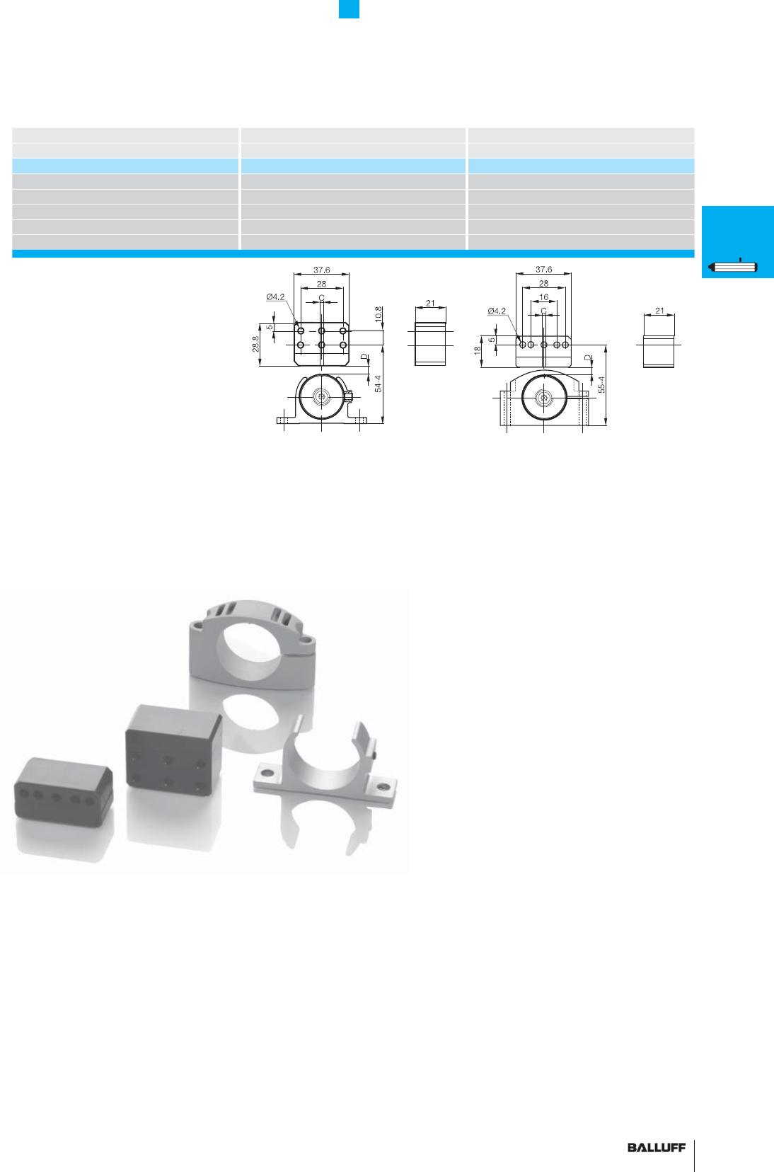
67■ www.balluff.com
Profi le Series AT
Accessories
Description Magnet Magnet
for series BTL6 Profi le A1 BTL6 Profi le A1
Part number BTL6-A-3800-2 BTL6-A-3801-2
Housing material Plastic Plastic
Weight ca. 30 g ca. 25 g
Magnet traverse velocity any any
Operating temperature/Storage temperature range
–40...+85 °C –40...+85 °C
Included Magnet Magnet
Lateral offset: C = ±5 mm
Vertical distance of magnet:
D = 4...8 mm
Lateral offset: C = ±5 mm
Vertical distance of magnet:
D = 4...8 mm
P
General
data
Analog
interface
Digital
pulse
interface
SSI
interface
CANopen
interface
DeviceNet
interface
PROFIBUS-DP
interface
Magnets
fl oating
Magnets
captive,
control arm
PF
General
data
Analog
interface
Magnets
fl oating
Magnets
captive,
control arm
AT
General
data
Analog
interface
Modes
Digital
pulse
interface
VARAN bus
interface
Accessories
BIW
General
data
Analog
interface
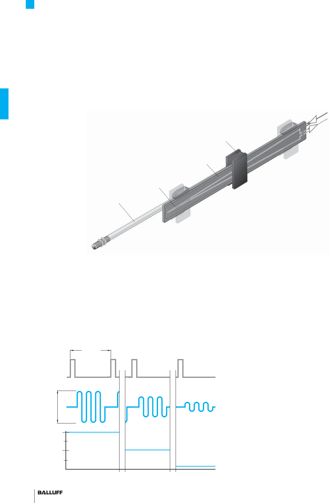
68
Position 2
Position 1
Position 3
Triangular
receiver coil
Rectangular
excitation coil
Passive oscillator
Push rod
Profi le Series BIW1
General data
The inductive BIW transducer is based on a new, patented
operating principle that detects the actual position without
making contact.
The BIW transducer contains an excitation/receiving sensor element
and an oscillator, protected inside an extruded aluminum housing.
The oscillator is attached to a rod which is secured on the moving
member of the machine whose position needs to be determined.
A momentary excitation pulse is applied to the rectangular excitation
coil at a sampling rate of 32 KHz. The excitation pulse causes pas-
sive oscillations in the resonator. These are inductively coupled to a
triangular receiving coil. The position is immediately available on the
output and is absolute (not incremental).
The slope of the output signal (rising or falling) can be determined
through the use of pins 1 and 4 on the connector.
Function of inductive Micropulse BIW technology:
– Short exciter pulses excite the rectangular excitation coil
– The exciter pulses activate the passive oscillator on the magnet
via the excitation coil
– The oscillator on the magnet transmits the frequency inductively to
the triangular receiver coil without making contact
– The amplitude level varies according to the position of the magnet
oscillator. Comparable to the amplitude level, the electronics
integrated in the Micropulse BIW issue a standard analog, voltage
or current signal
Position 1 Position 2 Position 3
–10 V 0 V
0 V or 5 V
+10 V +10 V
30 µS
Output signal
Received
oscillations
Excitation pulse
Variable
Sampling rate 32 kHz
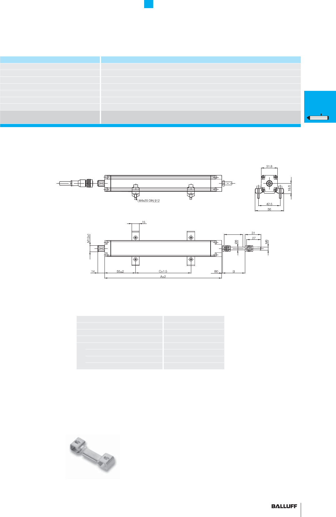
69■ www.balluff.com
Profi le Series BIW1
General data
Series BIW1
Shock load 100 g/2 ms
Vibration 12 g, 10...2000 Hz
Dielectric strength 500 V (GND to housing)
Degree of protection as per IEC 60529 IP 54
Housing material Anodized aluminum
Mounting Mounting clamps
Connection type Connector M12, 8-pin standard
Standard nominal strokes [mm] 0075, 0100, 0130, 0150, 0175, 0225, 0260, 0300, 0360, 0375, 0400, 0450, 0500, 0600,
0650, 0750
■ Included:
– Transducer
– Short user's guide
– 2 mounting clamps
BIW-A-MF01-M-43
Please order separately:
Connectors, page 156
Housing length
A = nominal stroke + 100 mm
Mechanical null point
B0 = 0 + 2 mm
Electrical null point
B0 + 5 mm
Electrical stroke = mechanical stroke
B = nominal stroke + 10 mm
Recommend clamp distance
Nominal stroke ≤ 300 mm
C = nominal stroke – 20 mm
Nominal stroke 300 mm to ≤ 600 mm
C = nominal stroke – 15 mm
Nominal stroke 600 mm
C = nominal stroke – 10 mm
Calculation example:
BIW1-...-M0100-P1-S115
Nominal stroke 100
A = 200
B = 110
C = 80
P
General
data
Analog
interface
Digital
pulse
interface
SSI
interface
CANopen
interface
DeviceNet
interface
PROFIBUS-DP
interface
Magnets
fl oating
Magnets
captive,
control arm
PF
General
data
Analog
interface
Magnets
fl oating
Magnets
captive,
control arm
AT
General
data
Analog
interface
Modes
Digital
pulse
interface
VARAN bus
interface
Accessories
BIW
General
data
Analog
interface
Transducers with fl oating magnet and S115 connection with BKS-S115/BKS-S116 connector
for transducers with analog interface, from page 70
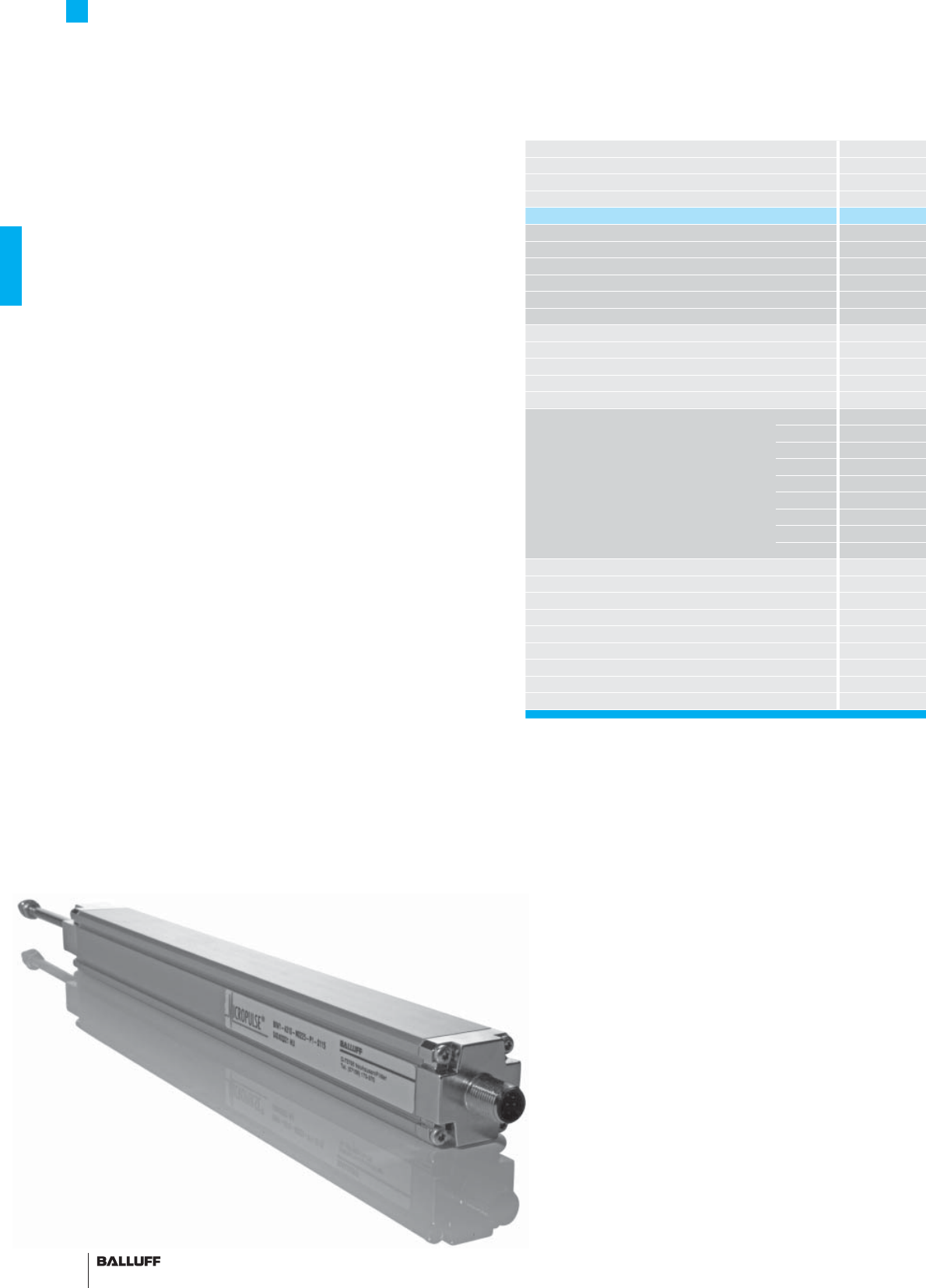
70
Series
Output signal
Transducer interface
Input interface
Part number
Output voltage*UA
Output current* IA
Max. current load per output
System resolution
Repeat accuracy
Sampling rate
Max. non-linearity
Operating voltage
No-load current consumption
Operating temperature
Storage temperature range
Pin assignments Pin
1
2
3
4
5
6
7
8
Shock load
Vibration
Dielectric strength
Degree of protection as per IEC 60529
Housing material
Mounting
Connection type
Housing length A
Mechanical stroke B
Features:
BIW transducers are characterized by:
– High resolution and repeatability
– Resistance to shock, vibration and noise fi elds
– An absolute rising or falling analog output signal
– A captive sensor element
– 32 kHz sampling rate
– Potential-free
– Non-contact measuring principle
Profi le Series BIW1
Analog interface
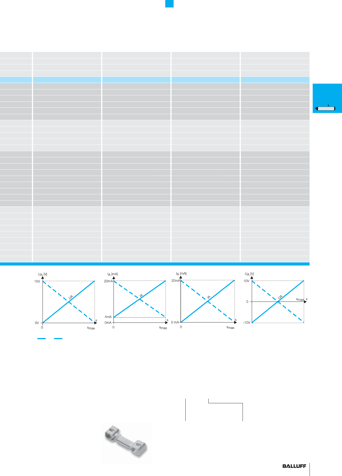
71■ www.balluff.com
Profi le Series BIW1
Analog interface
BIW1 BIW1 BIW1 BIW1
analog analog analog analog
AECG
analog analog analog analog
BIW1-A310... BIW1-E310... BIW1-C310... BIW1-G310...
0...10 V –10...10 V
4...20 mA 0...20 mA
6 mA 6 mA
5 µm 5 µm 5 µm 5 µm
10 µm 10 µm 10 µm 10 µm
typ. 32 kHz typ. 32 kHz typ. 32 kHz typ. 32 kHz
≤ 0.02 % ≤ 0.02 % ≤ 0.02 % ≤ 0.02 %
18...30 V DC 18...30 V DC 18...30 V DC 18...30 V DC
≤ 80 mA ≤ 80 mA ≤ 80 mA ≤ 80 mA
–20...+85 °C –20...+85 °C –20...+85 °C –20...+85 °C
–40...+100 °C –40...+100 °C –40...+100 °C –40...+100 °C
Slope selector Slope selector Slope selector Slope selector
0 V Output 0 V Output 0 V Output 0 V Output
reserved reserved reserved reserved
Slope selector Slope selector Slope selector Slope selector
0...10 V 4...20 mA 0...20 mA –10...10 V
GND GND GND GND
+24 V DC +24 V DC +24 V DC +24 V DC
reserved reserved reserved reserved
100g/2 ms 100g/2 ms 100g/2 ms 100g/2 ms
12 g, 10...2000 Hz 12 g, 10...2000 Hz 12 g, 10...2000 Hz 12 g, 10...2000 Hz
500 V (GND to housing) 500 V (GND to housing) 500 V (GND to housing) 500 V (GND to housing)
IP 54 IP 54 IP 54 IP 54
Anodized aluminum Anodized aluminum Anodized aluminum Anodized aluminum
Mounting clamps Mounting clamps Mounting clamps Mounting clamps
Connector M12, 8-pin standard Connector M12, 8-pin standard Connector M12, 8-pin standard Connector M12, 8-pin standard
Nominal stroke + 100 mm Nominal stroke + 100 mm Nominal stroke + 100 mm Nominal stroke + 100 mm
Nominal stroke + 10 mm Nominal stroke + 10 mm Nominal stroke + 10 mm Nominal stroke + 10 mm
Output
signal
A 0...+10 V
G –10...+10 V
E 4...20 mA
C 0...20 mA
Standard
nominal stroke [mm]
Ordering example:
BIW1-_ 310-M_ _ _ _-P1-S115
0075, 0100, 0130, 0150, 0175,
0225, 0260, 0300, 0360, 0375,
0400, 0450, 0500, 0600, 0650,
0750
* Output signal can be inverted via programming inputs.
P
General
data
Analog
interface
Digital
pulse
interface
SSI
interface
CANopen
interface
DeviceNet
interface
PROFIBUS-DP
interface
Magnets
fl oating
Magnets
captive,
control arm
PF
General
data
Analog
interface
Magnets
fl oating
Magnets
captive,
control arm
AT
General
data
Analog
interface
Modes
Digital
pulse
interface
VARAN bus
interface
Accessories
BIW
General
data
Analog
interface
■ Please enter the code for the output signal and
nominal stroke length in the ordering code.
■ Included:
– Transducer
– Short user's guide
– 2 mounting clamps BIW-A-MF01-M-43
Please order separately:
Connectors, page 156
72

73■ www.balluff.com■www.
b
a
ll
u
ff
.com
BTL7
General data 74
Analog interface 76
Programming 80
BTL5
General data 82
Digital pulse interface 84
SSI interface 86
CANopen interface 88
PROFIBUS-DP interface 92
4 programmable switching points 94
Floats 96
Magnets 97
Installation notes 98
73
■ www.balluff.com 73
A
B
G
D
S
C
P
4
F
Rod housings are mainly used in hydraulic drive applications. When
installed in the pressure section of the hydraulic cylinder, the distance
sensor requires the same pressure rating as the actual hydraulic
cylinder. In practice, the sensor must be able
to withstand pressures up to 1000 bar. The electronics are inte-
grated in an aluminum or stainless steel housing and the waveguide
in a pressure-resistant tube made from nonmagnetic stainless steel
that is sealed off at the face end with a welded plug. An O-ring seal
in the fl ange at the opposite end seals off the high-pressure section.
An magnet ring with magnets slides over the tube or rod with internal
waveguide to mark the position prior to detection.
BTL7
B
BTL5
B
Rod Series
Contents
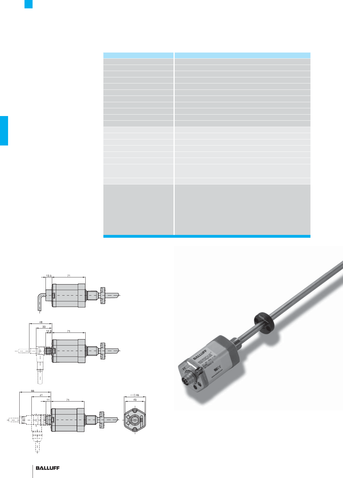
74
BTL7 Rod Series
General data
Pressure rated to 600 bar,
High repeatability,
Non-contacting, rugged
The BTL Micropulse transducer
is a robust position feedback
system for measuring ranges
between 25 and 7620 mm as
well as use under extreme ambi-
ent conditions.
The actual waveguide is pro-
tected inside a high-pressure
resistant stainless steel tube.
The system is ideal for use in
hydraulic cylinders for position
feedback or as a level monitor
with aggressive media in the
food and chemical industries.
Series BTL7 rod
Shock load 150 g/6 ms as per IEC 60068-2-27
Vibration 20 g, 10...2000 Hz as per IEC 60068-2-6
Polarity reversal protected yes
Overvoltage protection Transzorb protection diodes
Dielectric strength 500 V AC (GND to housing)
Degree of protection as per IEC 60529
IP 68 with cable outlet, IP 67 with BKS-S... connector attached
Housing material
Anodized aluminum/1.4571 stainless steel outer tube, 1.3952 stainless steel cast fl ange
Mounting Housing B thread M18×1.5, housing Z 3/4"-16UNF
Pressure rating with 10.2 mm outer tube
600 bar installed in hydraulic cylinder
Pressure rating with 8 mm outer tube
250 bar installed in hydraulic cylinder
Connection type Connector or integral cable
EMC testing:
RF emission EN 55016-2-3 Group 1, Class A and B
Static electricity (ESD) IEC 61000-4-2 Severity Level 3
Electromagnetic fi elds (RFI) IEC 61000-4-3 Severity Level 3
Fast transients (BURST)
IEC 61000-4-4 Severity Level 3
Surge voltage
IEC 61000-4-5 Severity Level 2
Conducted interference induced
by high-frequency fi elds
IEC 61000-4-6 Severity Level 3
Magnetic fi elds IEC 61000-4-8 Severity Level 4
Standard nominal strokes [mm]
with 8 mm outer tube is the
max. nominal stroke 1016 mm
0025, 0050, 0075, 0100, 0125, 0150, 0175, 0200, 0225, 0250,
0275, 0300, 0325, 0350, 0375, 0400, 0425, 0450, 0475, 0500,
0550, 0600, 0650, 0700, 0750, 0800, 0850, 0900, 0950, 1000,
1100, 1200, 1300, 1400, 1500, 1600, 1700, 1800, 1900, 2000,
2250, 2500, 2750, 3000, 3250, 3500, 3750, 3850, 4000, 4250,
4500, 4750, 5000, 5250, 5500, 5750, 6000, 6250, 6500, 6750,
7000, 7250, 7500, 7600, 7620 or in 5 mm increments (depending
on interface) on request
Caution!
Prior to design, installation and startup, please read the
instructions in the user guide! www.balluff.com
Shock and vibration resistant
Please order separately:
USB communication box, page 81
Magnets/fl oats, from page 96
Mounting nuts, page 97
Connectors, page 148/156
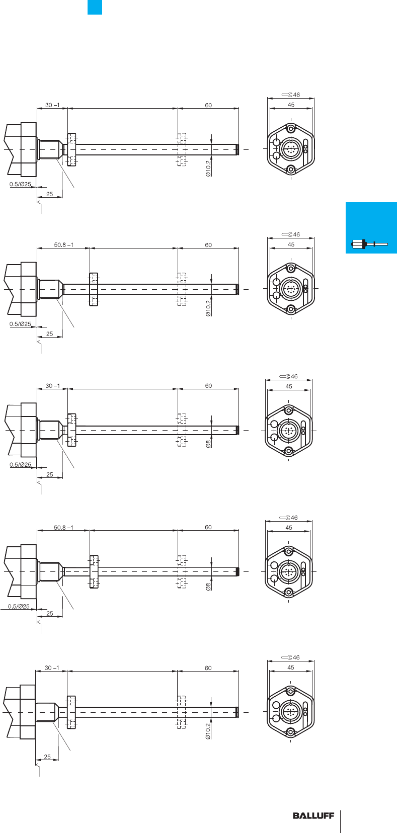
75■ www.balluff.com
BTL7 Rod Series
General data
Housing B
BTL7_ _ _ _ -B-_ _ _ _
Metric
mounting thread M18×1.5
B = Standard housing
Mounting surface
Thread
M4×4/6 deep
Nominal stroke = measuring range Damping zone
(non-usable area)
Magnet
Thread M18x1.5
Housing Z
BTL7_ _ _ _ -Z-_ _ _ _
3/4" UNF mounting thread
Housing B8
BTL7_ _ _ _ -B8-_ _ _ _
Metric mounting thread
M18×1.5
8 mm outer tube
max. 1016 mm nominal stroke
Housing Z8
BTL7_ _ _ _ -Z8-_ _ _ _
3/4" UNF mounting thread
8 mm outer tube
max. 1016 mm nominal stroke
Housing A
BTL7-_ _ _ _-A-_ _ _ _
Metric mounting thread
M18×1.5
Flange without
0.5/Ø 25 mm mounting surface
Mounting surface
Nominal stroke = measuring range
Magnet
Thread 3/4"-16UNF
Damping zone
(non-usable area)
Thread
M4×4/6 deep
Mounting surface
Nominal stroke = measuring range
Thread M18x1.5
Damping zone
(non-usable area)
Thread
M4×4/6 deep
Mounting surface
Nominal stroke = measuring range
Thread 3/4"-16UNF
Damping zone
(non-usable area)
Thread
M4×4/6 deep
Thread M18x1.5
Mounting surface
Nominal stroke = measuring range Damping zone
(non-usable area)
Thread
M4×4/6 deep
BTL7
General
data
Analog
interface
Programming
BTL5
General
data
Digital
pulse
interface
SSI
interface
CANopen
interface
PROFIBUS-DP
interface
Position
recognition in
the hydraulics
Floats
Magnets
Installation
notes
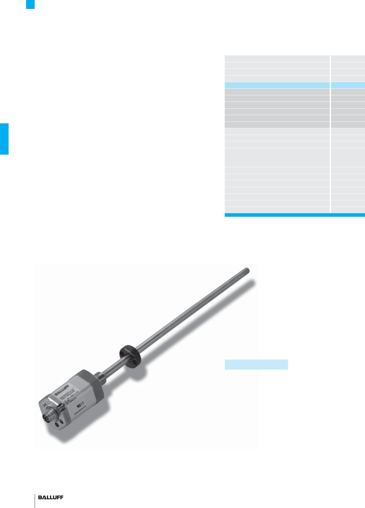
76
Series
Output signal
Transducer interface
Input interface
Part number
Output voltage
Output current
Load current
max. ripple
Load resistance
System resolution
Hysteresis
Repeat accuracy
Sampling rate, length-dependent
Max. non-linearity
Temperature coeffi cient
Operating voltage
Current consumption at 24 V DC
Polarity reversal protected
Overvoltage protection
Dielectric strength
Operating temperature
Features of Micropulse BTL7-A/C/E/G...B
– Status LEDs for indicating operating status and diagnostics
– Extended application range with high degree
of protection IP 68 (cable version)
– Electronics head can be replaced if needed
– Short housing, saves space
– Error signal, no magnet within measuring range
Flexible measuring range
The start and end point of the measuring range can be adapted
to the application. The points are set directly on the unit using the
calibration device included or remotely, see page 80.
BTL7 Rod Series
Analog interface
Caution!
Prior to design, installation and startup,
please read the instructions in the user
guide! www.balluff.com
Compatible with BTL5
■ Please enter the code for the output signal,
nominal stroke, housing and connection type
in the ordering code.
Preferred models
A110 and E100 interfaces
BTL7-A110-M_ _ _ _-B-S32,
BTL7-E100-M_ _ _ _-B-S32
are available from stock in the nominal
lengths highlighted in blue.
■ Included:
– Transducer
– Calibration device
– Short user's guide
Please order separately:
USB communication box, page 81
Magnets/fl oats, from page 96
Mounting nuts, page 97
Connectors, page 148/156
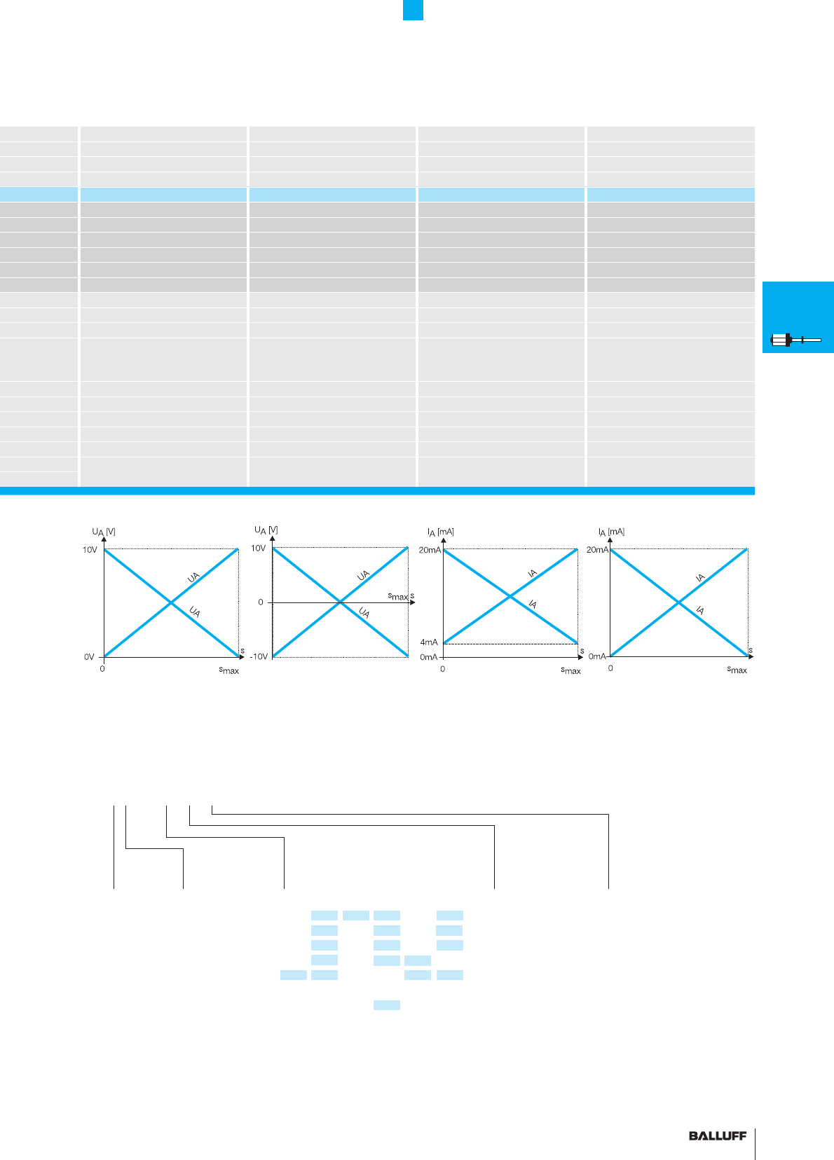
77■ www.balluff.com
BTL7 Rod Series
Analog interface
BTL7 rod BTL7 rod BTL7 rod BTL7 rod
analog analog analog analog
AGEC
analog analog analog analog
BTL7-A110-M_ _ _ _-_-_ _ _ _ BTL7-G110-M_ _ _ _-_-_ _ _ _ BTL5-E1_0-M_ _ _ _-_-_ _ _ _ BTL7-C1_0-M_ _ _ _-_-_ _ _ _
0...10 V and 10...0 V –10...10 V and 10...–10 V
4...20 mA or 20...4 mA 0...20 mA or 20...0 mA
max. 5 mA max. 5 mA
≤ 5 mVss ≤ 5 mVss
≤ 500 ohms ≤ 500 ohms
≤ 0.33 mV ≤ 0.33 mV ≤ 0.66 µA ≤ 0.66 µA
≤ 5 µm ≤ 5 µm ≤ 5 µm ≤ 5 µm
System resolution/min. 2 µm System resolution/min. 2 µm System resolution/min. 2 µm System resolution/min. 2 µm
max. 4 kHz max. 4 kHz max. 4 kHz max. 4 kHz
±50 µm to ≤ 500 mm nominal stroke
±0.01 % FS > 5500 mm nominal stroke
±0.02 % FS > 5500 mm nominal stroke
±50 µm to ≤ 500 mm nominal stroke
±0.01 % FS > 5500 mm nominal stroke
±0.02 % FS > 5500 mm nominal stroke
±50 µm to ≤ 500 mm nominal stroke
±0.01 % FS > 5500 mm nominal stroke
±0.02 % FS > 5500 mm nominal stroke
±50 µm to ≤ 500 mm nominal stroke
±0.01 % FS > 5500 mm nominal stroke
±0.02 % FS > 5500 mm nominal stroke
≤ 30 ppm/K ≤ 30 ppm/K ≤ 30 ppm/K ≤ 30 ppm/K
20...28 V DC 20...28 V DC 20...28 V DC 20...28 V DC
≤ 150 mA ≤ 150 mA ≤ 150 mA ≤ 150 mA
yes yes yes yes
yes yes yes yes
500 V AC (ground to housing) 500 V AC (ground to housing) 500 V AC (ground to housing) 500 V AC (ground to housing)
–40...+85 °C –40...+85 °C –40...+85 °C –40...+85 °C
Output
signal
A
G
E
C
Standard
nominal stroke [mm]
Ordering example:
BTL7-_1_0-M_ _ _ _-_-_ _ _ _
Housing
B = Standard
M 18×1.5
Other housings on
page 75
0025, 0050, 0075, 0100, 0125, 0150,
0175, 0200, 0225, 0250, 0275, 0300,
0325, 0350, 0375, 0400, 0425, 0450,
0475, 0500, 0550, 0600, 0650, 0700,
0750, 0800, 0850, 0900, 0950, 1000,
1100, 1200, 1300, 1400, 1500, 1600,
1700, 1800, 1900, 2000, 2250, 2500,
2750, 3000, 3250, 3500, 3750, 3850,
4000, 4250, 4500, 4750, 5000, 5250,
5500, 5750, 6000, 6250, 6500, 6750,
7000, 7250, 7500, 7600, 7620 or in 5
mm increments (depending on interface)
on request
Output
signal
1 Rising and
falling (with
A and G)
0 Rising (with
C and E)
7 Falling (with
C and E)
Connection type
S32 Connector
S115 Connector
KA02 PUR cable 2 m
KA05 PUR cable 5 m
KA10 PUR cable 10 m
KA15 PUR cable 15 m
BTL7
General
data
Analog
interface
Programming
BTL5
General
data
Digital
pulse
interface
SSI
interface
CANopen
interface
PROFIBUS-DP
interface
Position
recognition in
the hydraulics
Floats
Magnets
Installation
notes
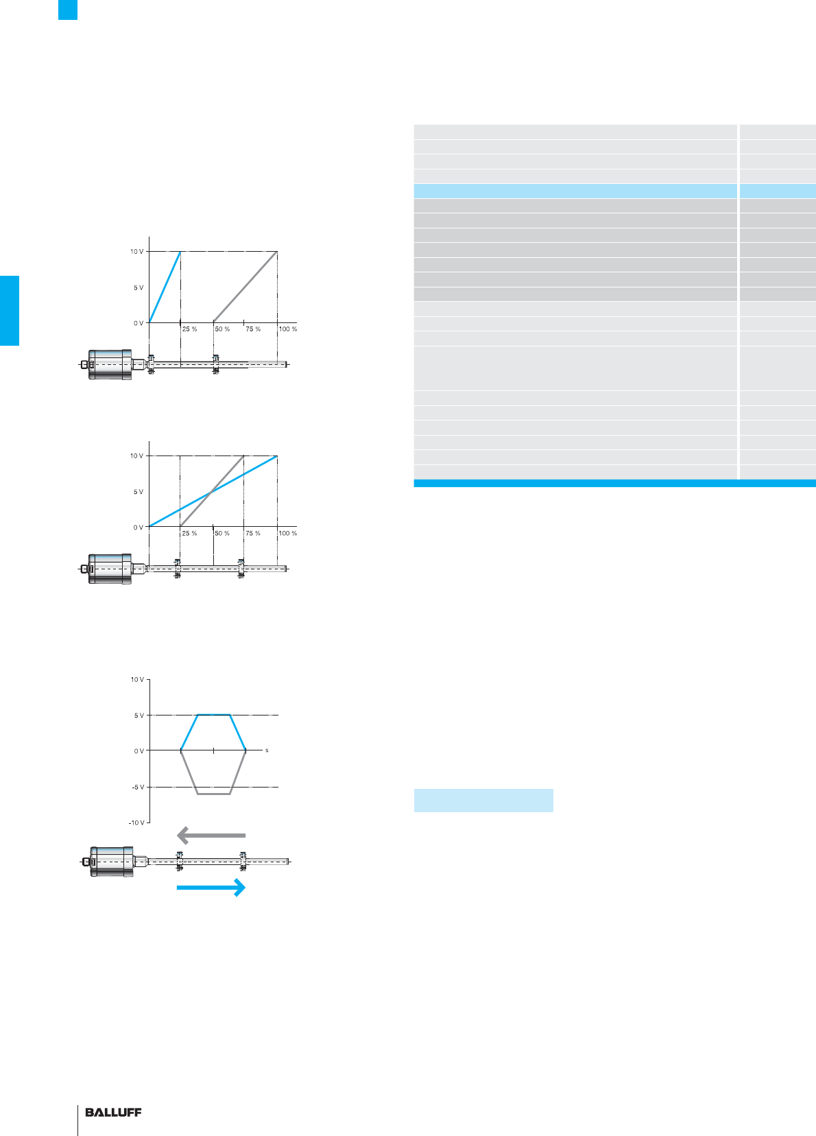
78
BTL7 Rod Series
Analog interface
Position and velocity
Two outputs can be assigned any position value and velocity signal
using the USB interface.
Mode examples:
Double magnet
2 magnets, 2 movements, 2 output signals
Differential
Differential signal between
2 magnets, position and difference possible.
Velocity
Velocity output
Series
Output signal
Transducer interface
Position signal input interface
Part number
Output signal factory setting
Output signal adjusted via USB Confi gurable
Load current
max. ripple
Load resistance
System resolution
Current consumption at 24 V DC
Hysteresis
Repeat accuracy
Sampling rate, length-dependent
Non-linearity, max.
Temperature coeffi cient
Operating voltage
Polarity reversal protected
Overvoltage protection
Dielectric strength
Operating temperature
Features of Micropulse+ USB-Confi gurable BTL7-A/E501
– Simple confi guration and setting of the start
and end point via the USB interface, fast startup
– "Easy Setup" for manual adjustment
– Confi gurable dual output functions, position and velocity
– Increased operating reliability with status LEDs for
indicating the operating status and diagnostic information
– Extended application range with high degree of
protection IP 68 (cable version)
– Electronics head can be replaced if needed
– Short housing
– Error signals, no magnet within measuring range
■ Please enter the code for the output signal, nominal stroke,
housing and connection type in the ordering code!
Preferred models
A501 and E501 interfaces
BTL7-A501-M_ _ _ _-B-S32,
BTL7-E501-M_ _ _ _-B-S32
are available from stock in the nominal lengths highlighted in blue.
■ Included:
– Transducer
– Calibration device
– Short user's guide
Please order separately:
USB communication box, page 81
Magnets/fl oats, from page 96
Mounting nuts, page 97
Connectors, page 156
Caution!
Prior to design, installation and startup, please read the
instructions in the user guide! www.balluff.com
USB-confi gurable
Position + Velocity

79■ www.balluff.com
BTL7 Rod Series
Analog interface
BTL7 rod BTL7 rod
analog analog
AE
analog analog
BTL7-A501-M_ _ _ _-_-_ _ _ _ BTL7-E501-M_ _ _ _-_-_ _ _ _
0...10 V and 10...0 V 4...20 mA and 20...4 mA
–10...10 V and 10...-10 V 0...20 mA and 20...0 mA
max. 5 mA
≤ 5 mVss
≤ 500 ohms
≤ 0.33 mV ≤ 0.66 µA
≤ 150 mA ≤ 180 mA
≤ 5 µm ≤ 5 µm
System resolution/min. 2 µm System resolution/min. 2 µm
max. 4 kHz max. 4 kHz
±50 µm to ≤ 500 mm nominal stroke
±0.01 % FS > 500...≤ 5500 mm nominal stroke
±0.02 % FS > 5500 mm nominal stroke
±50 µm to ≤ 500 mm nominal stroke
±0.01 % FS > 500...≤ 5500 mm nominal stroke
±0.02 % FS > 5500 mm nominal stroke
≤ 30 ppm/K ≤ 30 ppm/K
10...30 V DC 10...30 V DC
yes yes
yes yes
500 V AC (ground to housing) 500 V AC (ground to housing)
–40...+85 °C –40...+85 °C
Standard
nominal stroke [mm]
Ordering example:
BTL7-_501-M_ _ _ _-_-_ _ _ _
Connection type
S32 Connector
S115 Connector
KA02 PUR cable 2 m
KA05 PUR cable 5 m
KA10 PUR cable 10 m
KA15 PUR cable 15 m
KA15 PUR cable 15 m
0025, 0050, 0075, 0100, 0125, 0150,
0175, 0200, 0225, 0250, 0275, 0300,
0325, 0350, 0375, 0400, 0425, 0450,
0475, 0500, 0550, 0600, 0650, 0700,
0750, 0800, 0850, 0900, 0950, 1000,
1100, 1200, 1300, 1400, 1500, 1600,
1700, 1800, 1900, 2000, 2250, 2500,
2750, 3000, 3250, 3500, 3750, 3850,
4000, 4250, 4500, 4750, 5000, 5250,
5500, 5750, 6000, 6250, 6500, 6750,
7000, 7250, 7500, 7600, 7620 or in 5
mm increments (depending on interface)
on request
Output
signal
A Voltage
E Current
Housing
B = Standard
M18×1.5
Other housings on
page 75
BTL7
General
data
Analog
interface
Programming
BTL5
General
data
Digital
pulse
interface
SSI
interface
CANopen
interface
PROFIBUS-DP
interface
Position
recognition in
the hydraulics
Floats
Magnets
Installation
notes
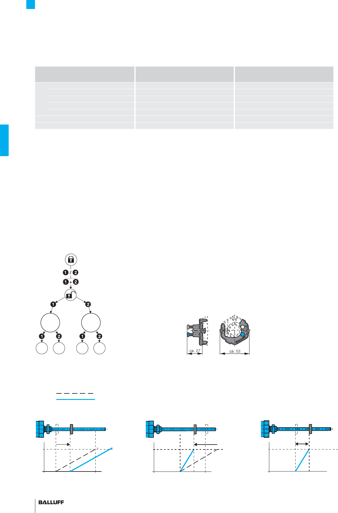
80
BTL7 Rod Series
Programming
1. Calibration device
100 % start and end point calibration
Start and end point of the analog signal can be set to the desired
position at the touch of a button. Depending on the application,
"teach-in" or "adjust" mode is used, selectable by pressing a button
combination. Two-color LED indicators assist the procedure.
"Easy Setup"
For BTL7-A/E501, Micropulse+ only. Simple programming mode for
adjusting the start and end point of the transducer to the current
application in just a few steps. The magnet is brought to the new po-
sition. Confi rm by pressing a button. The "Adjust" function allows the
new value to be fi ne-tuned for a stationary magnet. No error value is
output during the setup procedure.
BTL7 Standard BTL7-A/E501... Micropulse+
USB-Confi gurable
1. Calibration device ■■
– Teach-in ■
– Adjustment ■
– Online setting ■
– Easy Setup ■
2. Remote setup ■
3. USB-Confi gurate ■
Procedure for teach-in, rising signal
Store new null value
1. Place magnet in new null position. 2. Place magnet at new end position. 3. Newly set measurement distance
Store new end value
before
after
Setting start and end point using the calibration device
BTL7-A/E501
Setting options for the start and end point
simple commissioning
fast confi guration
Teach-in
Used for changing the factory default start and end point to a new
start and end point.
First the magnet must be brought to the new start point and then to
the new end position, and the respective values stored by pressing
the button.
Adjust
Here you can adjust to a new start and end value. This may be re-
quired when you cannot physically move the magnet to the standard
start and/or end point. Move the magnet to the new start and end
position, and adjust the displayed value by pressing the button until
the desired output values are reached.
Online setting
This programming function allows you to set the start and end point
while in run mode, such as in a closed loop confi guration. No error
value is output during the setup procedure. The calibration range is
limited to ±25 %.
Selecting the calibration procedure BTL7 Standard
Teach-in Adjust
Start
point End
point
Buttons
inactive
Buttons
active
End
point
Start
point
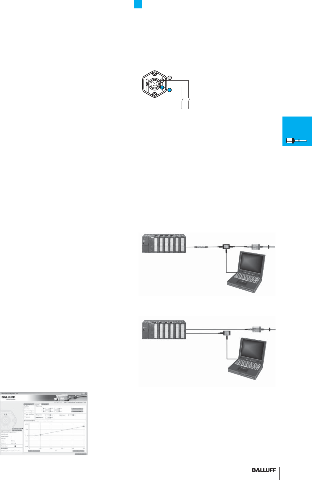
81■ www.balluff.com
BTL7 Rod Series
Programming
3. USB-Confi gurate
Start, end value setting and confi guration via USB
The Micropulse Confi guration Tool allows the quick and easy
confi guration of Balluff transducers type BTL7-A/E501... on a PC.
The most signifi cant features include:
– Online display of the current position of the magnet
– Graphical assistance for setting the functions and characteristic
curves
– Display of information about the connected transducer
– Selectable number formats and units for display
– Factory reset possible
– Calibration device can be disabled
– Demo mode without having a transducer connected
The PC software and
associated manual
can be downloaded from
the Internet at
www.balluff.com/
downloads-btl7
Connecting the communication box
with S32 or S115 connector
Connecting the communication box via
cable in the switching cabinet
2. Remote setup aid
Remote setting of the start and end point using
programming inputs
If the transducer is located in an inaccessible place or a hazardous
area, the start and end point can be adjusted remotely. Teach-in,
adjustment and online setting are identical to programming with the
calibration device. Button 1 blue corresponds to programming input
La and button 2 gray to input Lb.
Caution!
Prior to design, installation and startup, please read the
instructions in the user guide! www.balluff.com
Lb, pin 8
La,
pin 4
24 V
Button 2
Button 1
System requirements:
– Standard PC
– Windows 2000/XP/Vista
– Screen resolution at least 1024 × 768 pixels
– 10 MB available hard disk space
– Java Runtime Environment (JRE) version 1.4.2 or higher
http://java.sun.com/getjava
– USB port
Connecting the USB communication box
For model BTL7-A/E501-M...-S32/S115 transducers, the com-
munication box can be installed between the transducer and the
controller. The communication box is connected to the PC using a
USB cable.
USB communication box
BTL7-A-CB01-USB-S32,
for BTL7-A/E501... with S32 connector
BTL7-A-CB01-USB-S115,
for BTL7-A/E501... with S115 connector
BTL7-A-CB01-USB-KA,
for BTL7-A/E501... with cable connection
Included:
– USB communication box
– Cable set
– Short user's guide
BTL7
General
data
Analog
interface
Programming
BTL5
General
data
Digital
pulse
interface
SSI
interface
CANopen
interface
PROFIBUS-DP
interface
Position
recognition in
the hydraulics
Floats
Magnets
Installation
notes
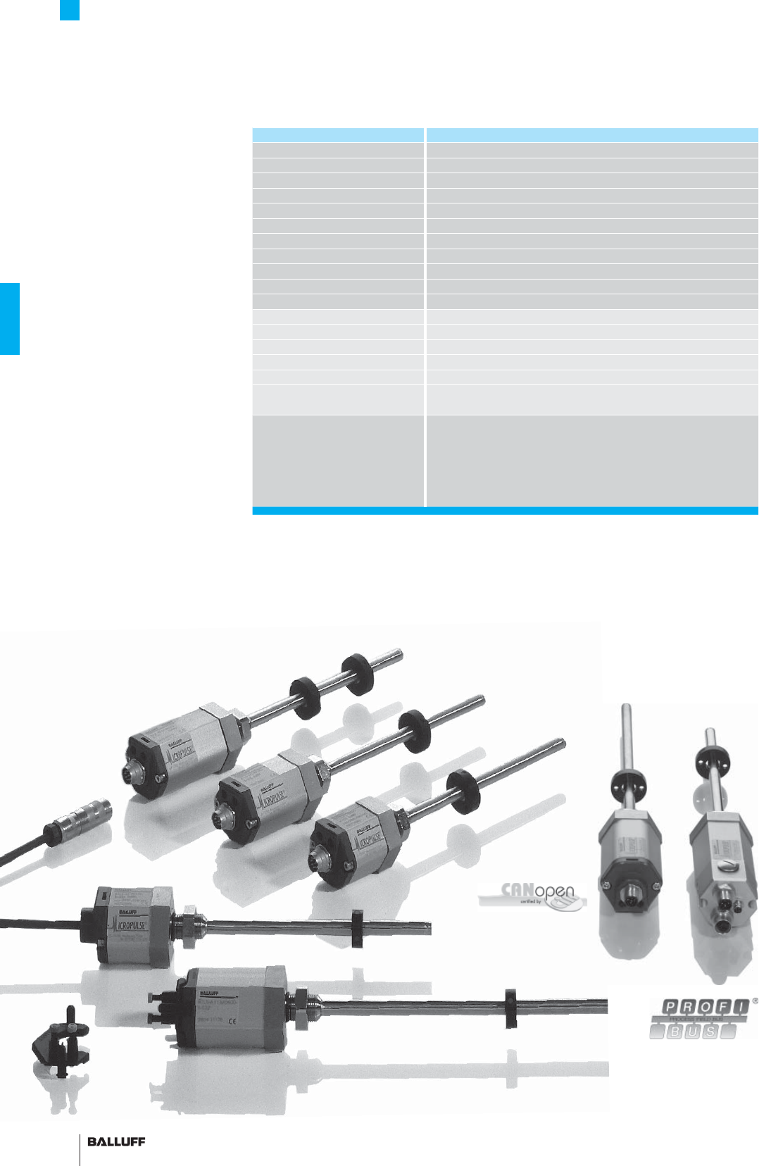
82
BTL5 Rod Series
General data
Pressure rated to 600 bar,
High repeatability,
Non-contact, rugged
The BTL Micropulse transducer
is a rugged position feedback
system for use under extreme
ambient conditions for
measuring ranges between
25 and 5500 mm.
The actual waveguide is pro-
tected inside a high-pressure
resistant stainless steel tube.
The system is ideal for use in
hydraulic cylinders for position
feedback or as a level monitor
with aggressive media in the
food and chemical industries.
Series BTL5 Rod
Shock load 100 g/6 ms per IEC 60068-2-27
Vibration 12 g, 10...2000 Hz per IEC 60068-2-6
Polarity reversal protected yes
Overvoltage protection Transzorb protection diodes
Dielectric strength 500 V DC (GND to housing)
Degree of protection as per IEC 60529
IP 67 (with BKS-S... IP 67 connector attached)
Housing material
Anodized aluminum/1.4571 stainless steel outer tube, 1.3952 stainless steel cast fl ange
Housing attachment Housing B thread M18×1.5, housing Z 3/4"-16UNF
Pressure rating with 10.2 mm outer tube
600 bar installed in hydraulic cylinder
Pressure rating with 8 mm outer tube
250 bar installed in hydraulic cylinder
Connection type Connectors/cables
EMC testing:
RF emission EN 55016-2-3 Group 1, Class A
Static electricity (ESD) IEC 61000-4-2 Severity Level 3
Electromagnetic fi elds (RFI) IEC 61000-4-3 Severity Level 3
Fast transients (BURST) IEC 61000-4-4 Severity Level 3
Conducted interference induced
by high-frequency fi elds
IEC 61000-4-6 Severity Level 3
Standard nominal strokes [mm]
with 8 mm outer tube is the
max. nominal stroke 1016 mm
0025, 0050, 0075, 0100, 0125, 0150, 0175, 0200, 0225, 0250,
0275, 0300, 0325, 0350, 0375, 0400, 0425, 0450, 0475, 0500,
0550, 0600, 0650, 0700, 0750, 0800, 0850, 0900, 0950, 1000,
1100, 1200, 1300, 1400, 1500, 1600, 1700, 1800, 1900, 2000,
2250, 2500, 2750, 3000, 3250, 3500, 3750, 3850, 4000
or in
5 mm increments up to 5500 mm (depending on interface) on request
■ Included:
– Transducer (select your
interface from page 84)
– Short user's guide
Please order separately:
Magnets/fl oats, from page 96
Mounting nuts, page 97
Connectors, page 148
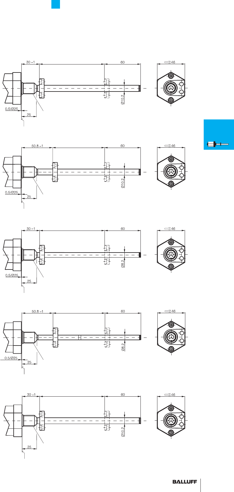
83■ www.balluff.com
BTL5 Rod Series
General data
Housing B
BTL5_ _ _ _ -B-_ _ _ _
Metric
mounting thread M18×1.5
Mounting surface
Thread
M4×4/6 deep
Nominal stroke = measuring range Damping zone
(non-usable area)
Magnet
Thread M18x1.5
Housing Z
BTL5_ _ _ _ -Z-_ _ _ _
3/4" UNF mounting thread
Housing B8
BTL5_ _ _ _ -B8-_ _ _ _
Metric mounting thread
M18×1.5
8 mm outer tube
max. 1016 mm nominal stroke
Mounting surface
Nominal stroke = measuring range
Magnet
Thread 3/4"-16UNF
Damping zone
(non-usable area)
Thread
M4×4/6 deep
Mounting surface
Nominal stroke = measuring range
Thread M18x1.5
Damping zone
(non-usable area)
Thread
M4×4/6 deep
Housing Z8
BTL5_ _ _ _ -Z8-_ _ _ _
3/4" UNF mounting thread
8 mm outer tube
max. 1016 mm nominal stroke
Mounting surface
Nominal stroke = measuring range
Thread 3/4"-16UNF
Damping zone
(non-usable area)
Thread
M4×4/6 deep
Housing A
BTL5-_ _ _ _-A-_ _ _ _
Metric mounting thread
M18×1.5
Flange without
0.5/Ø 25 mm mounting surface
Thread M18x1.5
Mounting surface
Nominal stroke = measuring range Damping zone
(non-usable area)
Thread
M4×4/6 deep
BTL7
General
data
Analog
interface
Programming
BTL5
General
data
Digital
pulse
interface
SSI
interface
CANopen
interface
PROFIBUS-DP
interface
Position
recognition in
the hydraulics
Floats
Magnets
Installation
notes
B = Standard housing
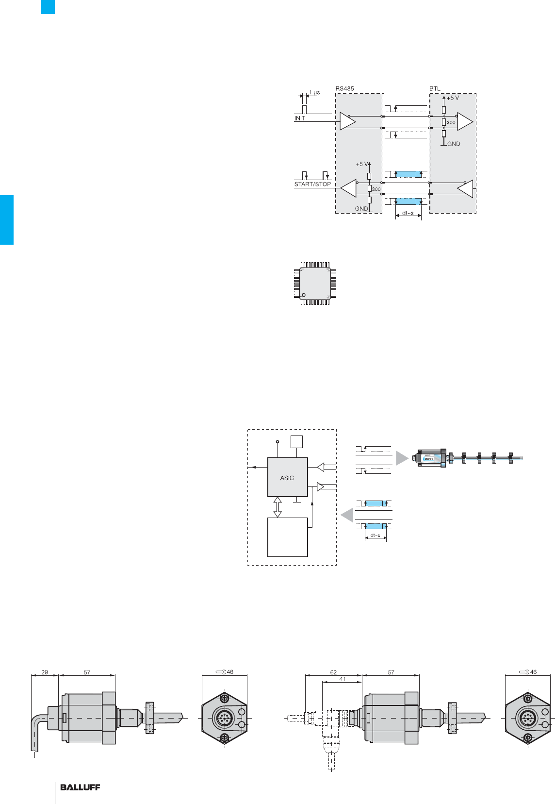
84
BTL5 Rod Series
Digital pulse interface
P Interface
Compatible with BTA/BTM processors as well as controllers and
modules from various manufacturers including Siemens, B & R,
Phoenix Contact, Mitsubishi, Sigmatek, Parker, Esitron and WAGO.
Reliable signal transmission, even over cable lengths up to 500 m
between BTA and BTL, is assured by the noise-immune RS485
differential line drivers and receivers. Noise signals are effectively
suppressed.
M Interface
The M interface is a controller-specifi c interface variation.
Block diagram of P interface
Highly precise digitizing of the P pulse signal
Companies developing their own control and processing electron-
ics can create a highly accurate P interface cost effectively and with
minimum effort using the Balluff digitizing chip. The digitizing chip
was developed as a high-resolution, confi gurable ASIC for Micro-
pulse transducers with P interface. Digitizing chip 44QFP
ASIC INFO: +49 7158 173-370
Advantages:
– Position resolution 1 µm!
The 1 µm resolution of the Micropulse distance measurement
system is achieved by the high resolution of the digitizing chip
(133 pS). (Clock frequency 2 or 20 MHz)
– Position data from 4 magnets can be processed simultaneously
– 4/8-bit processor interface
CPU
controller
4/8-
bit bus
5 V
Osc.
INIT
Micropulse transducer with 1 to
4 magnets
Controller or processing electronics
P pulse signal
economical + synchronous
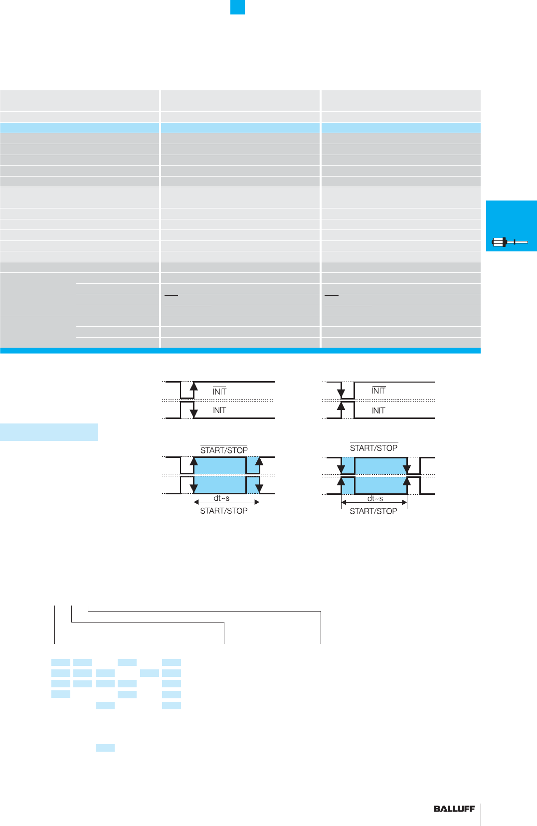
85■ www.balluff.com
BTL5 Rod Series
Digital pulse interface
Series BTL5 Rod BTL5 Rod
Transducer interface Pulse PPulse M
Input interface Pulse PPulse M
Part number BTL5-P1-M_ _ _ _-_-_ _ _ _ BTL5-M1-M_ _ _ _-_-_ _ _ _
System resolution processing-dependent processing-dependent
Repeat accuracy
2 µm or ±1 digit depending on processing electronics 2 µm or ±1 digit depending on processing electronics
Resolution ≤ 2 µm ≤ 2 µm
Hysteresis ≤ 4 µm ≤ 4 µm
Sampling rate fSTANDARD = 1 kHz = ≤ 1400 mm fSTANDARD = 1 kHz = ≤ 1400 mm
Max. non-linearity ±100 µm up to 500 mm nominal stroke
±0.02 % 500...5500 mm nominal stroke
±100 µm up to 500 mm nominal stroke
±0.02 % 500...5500 mm nominal stroke
Temperature coeffi cient of overall system (6 µm + 5 ppm × L)/°C (6 µm + 5 ppm × L)/°C
Operating voltage 20...28 V DC 20...28 V DC
Current consumption ≤ 90 mA ≤ 90 mA
Operating temperature –40...+85 °C –40...+85 °C
Storage temperature range –40...+100 °C –40...+100 °C
Pin assignments Pin Color BTL5-P1-M... BTL5-M1-M...
Input/Output
Input 1 YE INIT INIT
signals Output 2 GY START/STOP START/STOP
Input 3 PK INIT INIT
Output 5 GN START/STOP START/STOP
Operating voltage 6 BU GND GND
7BN+24 V DC +24 V DC
8 WH (GND) (GND)
Connect shield to housing
■ Please enter the code for the nominal
stroke, housing and connection type in the
ordering code.
Preferred models interface P
BTL5-P1-M_ _ _ _-B-S 32
are available from stock in the nominal
lengths highlighted in blue.
■ Included:
– Transducer
– Short user's guide
Please order separately:
Magnets/fl oats, from page 96
Mounting nuts, page 97
Connectors from page 148
Standard
nominal stroke [mm]
Ordering example:
BTL5-P1-M_ _ _ _-_-_ _ _ _
Connection type
S32 Connector
KA02 PUR cable 2 m
KA05 PUR cable 5 m
KA10 PUR cable 10 m
KA15 PUR cable 15 m
0025, 0050, 0075, 0100, 0125, 0150,
0175, 0200, 0225, 0250, 0275, 0300,
0325, 0350, 0375, 0400, 0425, 0450,
0475, 0500, 0550, 0600, 0650, 0700,
0750, 0800, 0850, 0900, 0950, 1000,
1100, 1200, 1300, 1400, 1500, 1600,
1700, 1800, 1900, 2000, 2250, 2500,
2750, 3000, 3250, 3500, 3750, 3850,
4000, 4250, 4500, 5000, 5250, 5500
or in 5 mm increments on request.
Housing
B = Standard
M18×1.5, other
housings on page 83
BTL7
General
data
Analog
interface
Programming
BTL5
General
data
Digital
pulse
interface
SSI
interface
CANopen
interface
PROFIBUS-DP
interface
Position
recognition in
the hydraulics
Floats
Magnets
Installation
notes
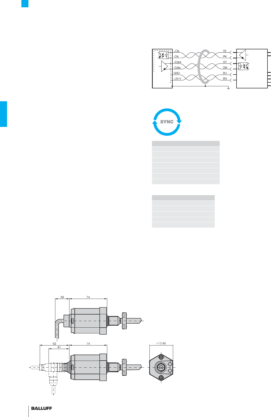
86
BTL5 Rod Series
SSI interface
Standard SSI interface
Synchronous serial data transmission for controllers from
various manufacturers, including Siemens, Bosch-Rexroth, WAGO,
B & R, Parker, Esitron, PEP etc. as well as for Balluff
BDD-AM 10-1-SSD and BDD-CC 08-1-SSD displays/controllers.
Reliable signal transmission, even over cable lengths of up to
400 m between controller and BTL transducer is assured by espe-
cially noise-immune RS485/422 differential line drivers and receivers.
Any noise signals are effectively suppressed.
Synchronized SSI interface
BTL5-S1_ _B-M_ _ _ _-P-_ _ _ _
Micropulse transducers with synchronized SSI interface are suit-
able for dynamic control applications. The data acquisition in the
transducer is synchronized with the external clock of the controller,
permitting an optimum calculation of the velocity in the controller.
The pre-requirement for this synchronous mode of transducer opera-
tion is consistent clock signal timing.
The maximum sampling frequency fA, at which a new current
value is generated for each sample, can be derived from the follow-
ing table:
Clock frequency depends on the cable length
Super-fast 2.5 kHz sampling rate
BTL5-S1... with processor/controller, wiring example
Processor
or
controller
Transducer
BTL5-S1...
Cable length
Clock frequency
< 25 m < 1000 kHz
< 50 m < 500 kHz
< 100 m < 400 kHz
< 200 m < 200 kHz
< 400 m < 100 kHz
mm mm Hz
< Nominal stroke
≤ 120 : 2500
120
< Nominal stroke
≤ 475 : 2000
475
< Nominal stroke
≤ 750 : 1500
750
< Nominal stroke
≤ 1250 : 1000
1250
< Nominal stroke
≤ 2600 : 500
2600
< Nominal stroke
≤ 4000 : 333
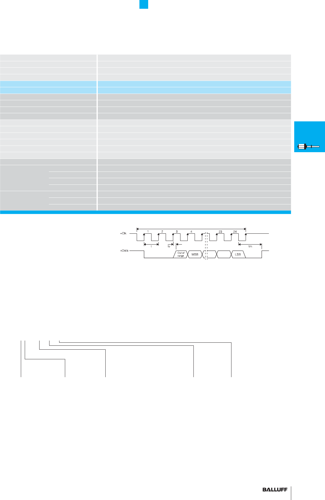
87■ www.balluff.com
BTL5 Rod Series
SSI interface
Series BTL5 Rod
Output signal synchronous serial
Transducer interface S
Input interface synchronous serial
Part number BTL5-S1_ _-M_ _ _ _-_-_ _ _ _
Part number synchronization BTL5-S1_ _B-M_ _ _ _-_-_ _ _ _
System resolution depending on version (LSB)
1, 2, 5, 10, 20, 40 or 100 µm
Repeat accuracy ±1 digit
Hysteresis ≤ 1 digit
Sampling rate fSTANDARD = 2 kHz
Max. non-linearity ±30 µm at 5 and 10 µm resolution or ≤ ±2 LSB
Temperature coeffi cient of overall system (6 µm + 5 ppm × L) /°C
Operating voltage 20...28 V DC
Current consumption ≤80 mA
Operating temperature –40...+85 °C
Storage temperature range –40...+100 °C
Pin assignments Pin Color
Control and 1 YE +Clk
data signals 2 GY +Data
3 PK –Clk
5 GN –Data
Operating 6 BU GND
voltage (external) 7 BN +24 V DC
8 WH must remain unconnected
Clock sequence
Ordering code for SSI interface with synchronization to clock (dynamic control
applications) insert the letter B! BTL5-S1_ _B-M_ _ _ _-B-S32
■ Included:
– Transducer
– Short user's guide
Please order separately:
Magnets/fl oats, from page 96
Mounting nuts, page 97
Connectors, page 148
Coding
0 Binary code
rising
(24 bit)
1 Gray code
rising
(24 bit)
6 Binary code
rising
(25 bit)
7 Gray code
rising
(25 bit)
Ordering example:
BTL5-S1_ _-M_ _ _ _-_-_ _ _ _
Standard
nominal stroke [mm] Connection type
S32 Connector
KA02 PUR cable 2 m
KA05 PUR cable 5 m
KA10 PUR cable 10 m
KA15 PUR cable 15 m
0025, 0050, 0075, 0100, 0125, 0150,
0175, 0200, 0225, 0250, 0275, 0300,
0325, 0350, 0375, 0400, 0425, 0450,
0475, 0500, 0550, 0600, 0650, 0700,
0750, 0800, 0850, 0900, 0950, 1000,
1100, 1200, 1300, 1400, 1500, 1600,
1700, 1800, 1900, 2000, 2250, 2500,
2750, 3000, 3250, 3500, 3750, 3850,
4000 or in 5 mm increments on request
System
resolution
1 1 µm
2 5 µm
3 10 µm
4 20 µm
5 40 µm
6 100 µm
7 2 µm
Housing
B = Standard
M18×1.5,
other housings
on page 83
super linear and
synchronized
BTL7
General
data
Analog
interface
Programming
BTL5
General
data
Digital
pulse
interface
SSI
interface
CANopen
interface
PROFIBUS-DP
interface
Position
recognition in
the hydraulics
Floats
Magnets
Installation
notes
■ Please enter the code for the coding,
system resolution, nominal stroke, design and
connection type in the ordering code!
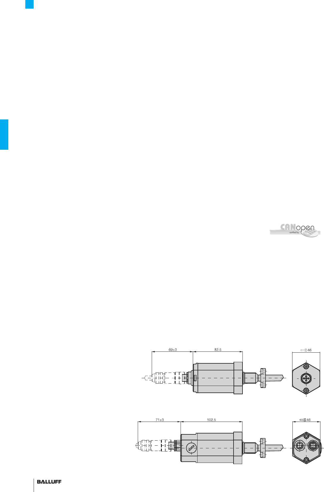
88
BTL5 Rod Series
CANopen® interface
CANopen interface
Based on CAN (ISO/IEC 7498 and DIN ISO 11898), CANopen
provides a Layer-7 implementation for industrial CAN networks. The
serial data protocol of the CAN specifi cation is defi ned accord-
ing to the producer-consumer principle as opposed to most other
fi eldbus protocols. This eliminates target addressing of the process
data. Each bus station decides for itself how the received data are
processed.
The CANopen interface of the Micropulse transducer is compatible
with CANopen conforming with CiA Standard DS301 Rev. 3.0, and
with CAL and Layer 2 CAN networks.
CAN-BUS features
– Line topology, star structure also possible via repeaters
– Low-cost wiring with two-wire cable
– Fast response times, high data integrity using CRC, hamming
distance of 6
– 1 MBit/s with cable lengths < 25 m
– Protocol limits number of stations to 127
– Using multiple magnets: A minimum spacing of > 65 mm must be
maintained.
CANopen offers a high level of fl exibility with respect to functionality
and data exchange. Using a standard data sheet in the form of an
EDS fi le it is easy to link the Micropulse transducers to any CANopen
system.
Process Data Object (PDO)
12 Micropulse transducers send their position information optionally
in one, two or four PDOs with 8 bytes of data each. The contents
of the PDOs are freely confi gurable. The following information can be
sent:
– Current magnet position with resolution in 5 µm increments
– Current velocity of the magnet with resolution selectable in
0.1mm/s increments
– Current status of the four freely programmable cams per magnet.
Synchronization Object (SYNC)
Serves as a net-wide trigger for synchronizing all network partici-
pants. When the SYNC object is received, all Micropulse transducers
connected to the bus store their current position and velocity
information and then send it sequentially to the controller. This as-
sures time-synchronous acquisition of the measured values.
LED
Display of the CANopen status to DS303-3
FMM
The sensor can be operated as a 4-magnet type, whereby the sen-
sor itself recognizes how many magnets are currently active.
So if only two magnets are positioned in the measuring range, a valid
value is output for the fi rst two positions and a defi ned error value for
positions 3 and 4.
Emergency Object
This object is sent with the highest priority and is used for example
for error messages when the cam states change.
Service Data Object (SDO)
Service Data Objects transmit the parameters for the transducer
confi guration. The transducer may be confi gured on the bus by
the controller or offl ine using a PC with a confi guration tool which
runs under Windows. The confi guration is stored in the non-volatile
memory of the transducer.
certifi ed
CiA 199911-301v30/11-009
Use of multiple magnets
A minimum spacing of > 65 mm must be maintained.
BTL5-H1_ _-M_ _ _ -B-S94
BTL5-H1_ _-M_ _ _ -B-S92
Node ID can be set by DIP switch.
User-friendly hardware
and software set-up
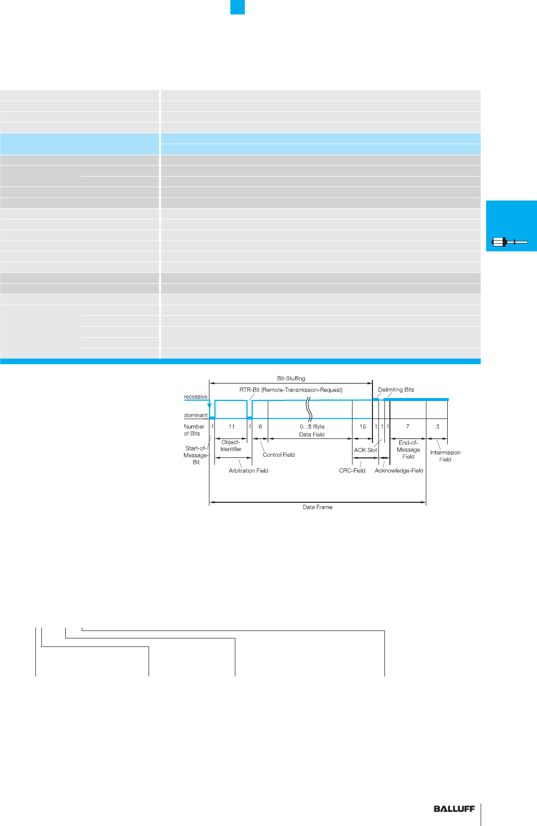
89■ www.balluff.com
BTL5 Rod Series
CANopen® interface
Series BTL5 Rod
Output signal CANopen
Transducer interface H
Input interface CANopen
Part number BTL5-H1_ _-M_ _ _ _-_-S92
BTL5-H1_ _-M_ _ _ _-_-S94
Repeat accuracy ±1 digit
System resolution Position 5 µm increments
confi gurable Velocity 0.1 mm/s increments
Hysteresis ≤ 1 digit
Sampling rate fSTANDARD = 1 kHz
Max. non-linearity ±30 µm at 5 µm resolution
Temperature coeffi cient of overall system (6 µm + 5 ppm × L)/°C
Operating voltage 20...28 V DC
Current consumption ≤ 100 mA
Operating temperature –40...+85 °C
Storage temperature range –40...+100 °C
Cable length [m] per CiA DS301 < 25 < 50 < 100 < 250 < 500 < 1000 < 1250 < 2500
Baud rate [kBaud] per CiA DS301 1000 800 500 250 125 100 50 20/10
Pin assignments Pin Color
Control and 1 WH CAN_GND
data signals 2 BN +24 V
3 BU 0 V (GND)
4 GY CAN_HIGH
5 GN CAN_LOW
Software
confi guration
1 1 × position and
1 × velocity
2 2 × position and
2 × velocity
3 4 × position
Ordering example:
BTL5-H1_ _-M_ _ _ _-_-S92
BTL5-H1_ _-M_ _ _ _-_-S94
Standard
nominal stroke [mm]
0025, 0050, 0075, 0100, 0125, 0150,
0175, 0200, 0225, 0250, 0275, 0300,
0325, 0350, 0375, 0400, 0425, 0450,
0475, 0500, 0550, 0600, 0650, 0700,
0750, 0800, 0850, 0900, 0950, 1000,
1100, 1200, 1300, 1400, 1500, 1600,
1700, 1800, 1900, 2000, 2250, 2500,
2750, 3000, 3250, 3500, 3750, 3850,
4000 or in 5 mm increments on request.
Baud rate
0 1 MBaud
1 800 kBaud
2 500 kBaud
3 250 kBaud
4 125 kBaud
5 100 kBaud
6 50 kBaud
7 20 kBaud
8 10 kBaud
■ Please enter the code for the software
confi guration, baud rate and nominal stroke
in the ordering code. Cable upon request.
■ Included:
– Transducer
– Short user's guide
Please order separately:
Magnets/fl oats, from page 96
Mounting nuts, page 97
Connectors, page 150/151
Housing
B = Standard
M18×1.5, more
housings on page 83
Position +
Velocity
Using the CANopen interface and cable lengths up to 2500 m, the
signal is sent at a length-dependent baud rate to the controller. The
high noise immunity of the connection is achieved using differential
drivers and by the data monitoring scheme.
BTL7
General
data
Analog
interface
Programming
BTL5
General
data
Digital
pulse
interface
SSI
interface
CANopen
interface
PROFIBUS-DP
interface
Position
recognition in
the hydraulics
Floats
Magnets
Installation
notes
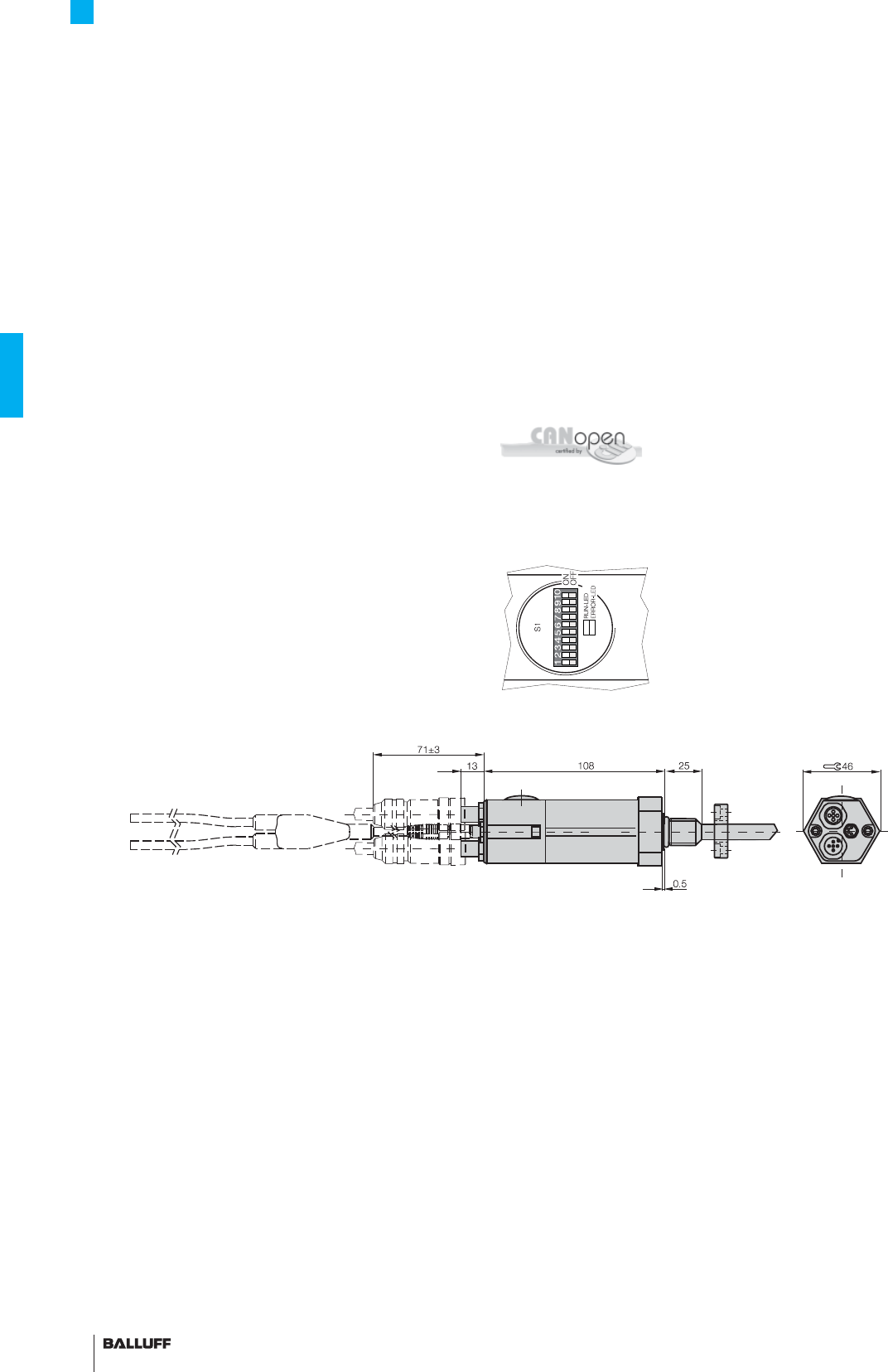
90
BTL5 Rod Series
CANopen® interface
Connecting analog sensors
BTL5-H1A/C/E _ -M _ _ _ _ -A/B/Y/Z(8)-C001 allows the use of ana-
log pressure or temperature sensors in parallel with the transducer.
Measured values from the analog sensor can be transmitted to the
CAN protocol with ease as a result.
Analog inputs are detected in series, not simultaneously. The second
channel is converted while the fi rst channel is being read and vice
versa.
The analog process signal from the BTL is converted into digital
form because the analogue values from the BTL are only processed
in digital form. The overall conversion time consists of the time the
converter takes to perform the conversion plus additional processing
time in the microcontroller (µC).
The analogue values are displayed in the form of a fi xed-point num-
ber in the 2's complement. The prefi x of the analog value is always
in bit 15.
– "0" for +
– "1" for - CiA 199911-301v30/11-009
Use of 1-4 magnets
The number of magnets can be preset to 1-4 via CANopen. The
transducer is preset to operate with an magnet on delivery. A mini-
mum spacing of > 65 mm must be maintained.
BTL5-H1_ _-M_ _ _ _-_-C001
Node ID can be set by DIP switch.
Setting the node ID
For the node ID, values between 0...63 are preset using the DIP
switch S1.1...S1.6.
Top view of DIP switch S1
Implementing CANopen® + 2 analog
inputs "Condition Monitoring"
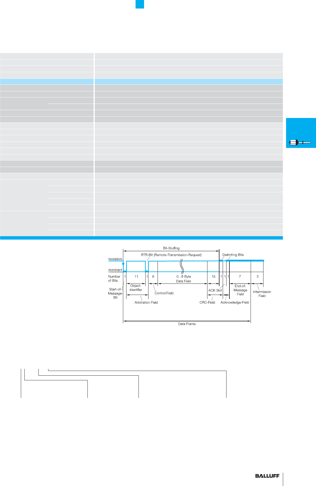
91■ www.balluff.com
BTL5 Rod Series
CANopen® interface
Series BTL5 Rod
Output signal CANopen
Transducer interface H
Input interface CANopen
Part number BTL5-H1_ _-M_ _ _ _-_-_ _ _ _
CANopen Version potential-free
Repeat accuracy ±1 digit
System resolution Position 5 µm increments
confi gurable Velocity 0.1 mm/s increments
Hysteresis ≤ 1 digit
Sampling rate fSTANDARD = 1 kHz
Max. non-linearity ±30 µm at 5 µm resolution
Temperature coeffi cient of overall system (6 µm + 5 ppm × L)/°C
Operating voltage 20...28 V DC
Current consumption ≤ 100 mA
Operating temperature –40...+85 °C
Storage temperature range –40...+100 °C
Cable length [m] per CiA DS301 < 25 < 50 < 100 < 250 < 500 < 1000 < 1250 < 2500
Baud rate [kBaud] per CiA DS301 1000 800 500 250 125 100 50 20/10
Pin assignments Pin Color
Control and 1 WH CAN_GND
data signals 2 BN +24 V
3 BU 0 V (GND)
4 GY CAN_HIGH
5 GN CAN_LOW
Analog connection 1 +24 V
Sensor 2 0 V
3 Input sensor 1
4 Input sensor 2
■ Please enter the code for the input
confi guration, baud rate and nominal stroke in
the ordering code. Cable upon request.
■ Included:
– Transducer
– Short user's guide
Please order separately:
Magnets/fl oats, from page 96
Mounting nuts, page 97
Connectors from page 150
Input
confi guration
A 3-wire voltage,
0...+10 V, 12-bit,
max. 2 inputs
C 3-wire current,
0...20 mA, 12-bit,
max. 2 inputs
E 2-wire current,
4...20 mA, 12-bit,
max. 2 inputs
Ordering example:
BTL5-H1_ _-M_ _ _ _-_-C001
Standard
nominal stroke [mm]
0025, 0050, 0075, 0100, 0125, 0150,
0175, 0200, 0225, 0250, 0275, 0300,
0325, 0350, 0375, 0400, 0425, 0450,
0475, 0500, 0550, 0600, 0650, 0700,
0750, 0800, 0850, 0900, 0950, 1000,
1100, 1200, 1300, 1400, 1500, 1600,
1700, 1800, 1900, 2000, 2250, 2500,
2750, 3000, 3250, 3500, 3750, 3850,
4000 or in 5 mm increments on request.
Baud rate
0 1MBaud
1 800 kBaud
2 500 kBaud
3 250 kBaud
4 125 kBaud
5 100 kBaud
6 50 kBaud
7 20 kBaud
8 10 kBaud
Housing
B = Standard
M18×1.5, more
housings on page 83
Using the CANopen interface and cable lengths up to 2500 m, the
signal is sent at a length-dependent baud rate to the controller. The
high noise immunity of the connection is achieved using differential
drivers and by the data monitoring scheme.
BTL7
General
data
Analog
interface
Programming
BTL5
General
data
Digital
pulse
interface
SSI
interface
CANopen
interface
PROFIBUS-DP
interface
Position
recognition in
the hydraulics
Floats
Magnets
Installation
notes
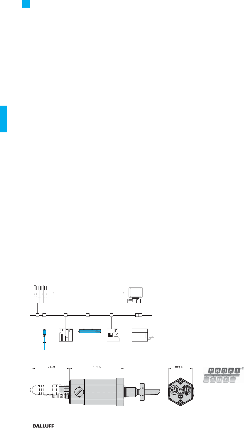
92
BTL5 Rod Series
PROFIBUS-DP interface
Device address can
be set by DIP switch
Slave
Once a PROFIBUS master has received the parameter set defi ned
for the slave, it is able to exchange data.
The parameter set consists of slave parameters and confi gura-
tion data. The parameter data contain the description of the slave
settings (e.g. resolution of a position value). The confi guration data
describe the length and structure of the data telegram.
Process data
Under PROFIBUS-DP the default is for process data to be sent from
the master to slaves acyclically and for the slave data to then be
queried. To ensure synchronization of multiple devices, the master
may use the SYNC and FREEZE services.
DP/V1 and DP/V2 isochronous mode
Isochronous mode enables quick and deterministic data exchange
by means of clock synchronicity on the bus system. A cyclic equidis-
tant clock signal is sent by the master to all bus devices. This signal
allows master and slaves to be synchronized irrespective of applica-
tion – with an accuracy < 1 µs.
Cross traffi c between slaves
Cross traffi c permits two DP slaves to exchange data directly with
each other: the master ensures that the slave publishes its data on
the bus with a request for "Data-eXchange-Broadcast" (DXB-Re-
quest) and thus makes it available to other slaves. Since the process
data is available in the process periphery without being diverted
through the master application, cross-traffi c permits very fast control
system responses.
Acyclic services
The DP functions for prioritized communication allow the transfer
of acyclic read and write functions between master and slaves,
independently of the cyclic user data traffi c. The transfer of acyclic
data is performed at a lower priority in parallel to the high speed
cyclic data exchange – as if in the background. The background
/ foreground split means the ratio of cyclic to acyclic data can be
adjusted if required.
FMM
The sensor can be operated as a 4-magnet type, whereby the sen-
sor itself recognizes how many magnets are currently active.
So if only two magnets are positioned in the measuring range, a valid
value is output for the fi rst two positions and a defi ned error value for
positions 3 and 4.
Address can be set by DIP switch.
As the market leading standard for serial data transmission for pro-
cess automation, PROFIBUS-DP is the ideal choice for implementing
automation tasks with cycle times of > 5 ms.
Data transmission
A PROFIBUS telegram can contain up to 244 bytes of user data per
telegram and station. The BTL5-T uses max. 32 bytes (max. 4 posi-
tion values and max. 4 velocity values) for process data transmis-
sion. Up to 126 active stations (Address 0...125) can be connected
on PROFIBUS-DP. User data cannot be sent with station address
126. This address is used as the default address for bus stations
that have to be parameterized by a Class 2 master (for setting the
device address if there are no mechanical switches available).
Each PROFIBUS station has the same priority. Prioritizing of indi-
vidual stations is not intended, but can be done by the master since
the bus transmission only makes up a fraction of the process cycle
anyway. At a transfer rate of 12 Mbps, the transmission time for an
average data telegram is in the 100 µs range.
Master
There are two types of possible masters for PROFIBUS-DP. Master
Class 1 carries out the user data interchange with the connected
slaves. Master Class 2 is intended for startup and diagnostic
purposes and may be used to briefl y assume control of a slave.
GSD (Device Master Data)
The length of the data exchangeable with a slave is defi ned in the
Device Master Data fi le (GSD) and is checked by the slave with the
confi guration telegram and confi rmed for correctness. In modular
systems, various confi gurations are defi ned in the GSD fi le. Depend-
ing on the desired functionality, one of these confi gurations can be
selected by the user when the system is confi gured. The BTL5-T
is a modular device with the possibility of selecting the number of
magnets (position values).
Slave 1 Slave 2 Slave 3 Slave 4 Slave x
Master Class 1 Master Class 2
User-friendly hardware
and software set-up
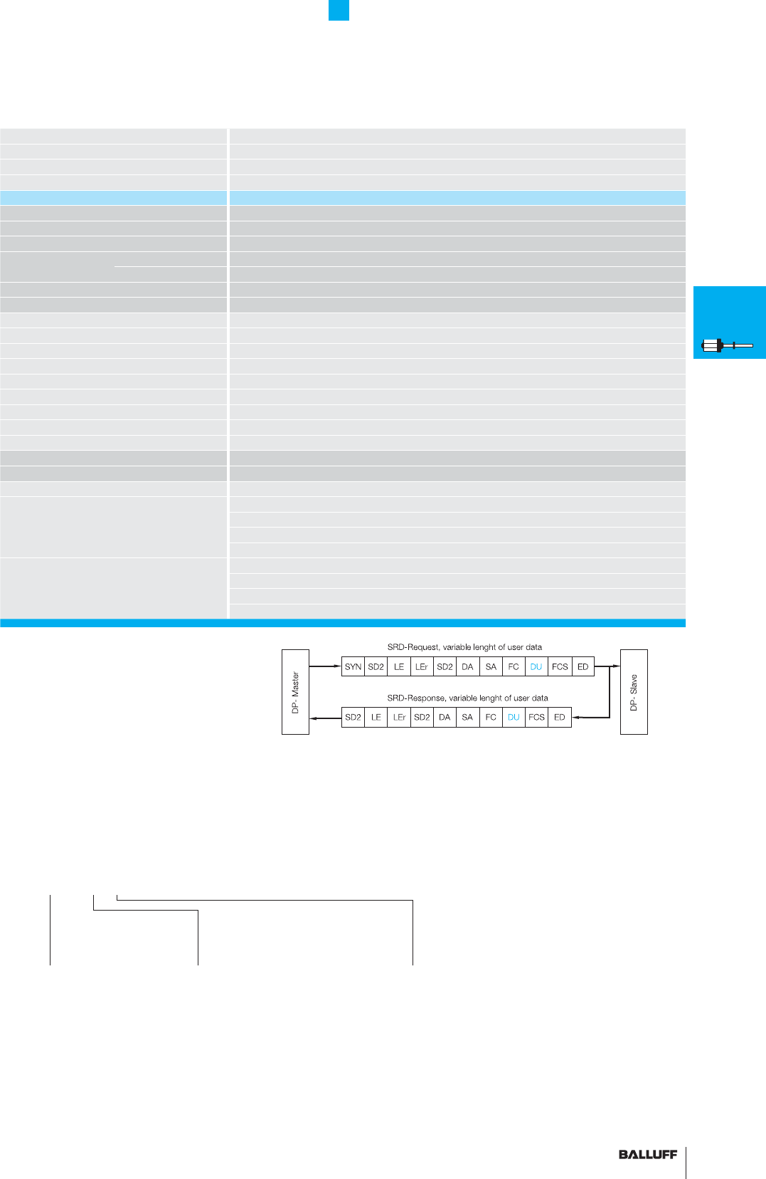
93■ www.balluff.com
BTL5 Rod Series
PROFIBUS-DP interface
Series BTL5 Rod
Output signal PROFIBUS-DP
Transducer interface T
Input interface PROFIBUS-DP
Part number plug version S103 BTL5-T1_ 0-M_ _ _ _-_-S103
Profi bus-Version EN 50170, Encoder profi le
Profi bus interface potential-free
Repeat accuracy ±1 digit
System resolution Position 5 µm increments confi gurable
confi gurable Velocity 0.1 mm/s increments confi gurable
Hysteresis ≤ 1 digit
Sampling rate fSTANDARD = 1 kHz
Max. non-linearity ±30 µm at 5 µm resolution
Temperature coeffi cient of overall system
(6 µm + 5 ppm × L)/°C
Magnet traverse velocity any
Operating voltage 20...28 V DC
Current consumption ≤ 120 mA
Operating temperature –40...+85 °C
Storage temperature range –40...+100 °C
GSD fi le BTL504B2.GSD
Address assignment mechanical switches and Master Class 2
Cable length [m] < 100 < 200 < 400 < 1000 < 1200
Baud rate [Kbps] 12000 1500 900 187,5 93,7/19,2/9,6
Pin assignments S103 5-pin S103 3-pin
Control and data signals Data GND 3
R×D/T×D-N (A) 2
R×D/T×D-P (B) 4
VP +5 V 1
Operating voltage and shielding +24 V 1
0 V (GND) 3
Ground PROFIBUS-DP 5
Shield supply 4
Software
confi guration
1 1 Position
1 Velocity
2 2 Position
2 Velocity
Ordering example:
BTL5-T1_ 0-M_ _ _ _-_-S103
Standard
nominal stroke [mm]
0025, 0050, 0075, 0100, 0125, 0150,
0175, 0200, 0225, 0250, 0275, 0300,
0325, 0350, 0375, 0400, 0425, 0450,
0475, 0500, 0550, 0600, 0650, 0700,
0750, 0800, 0850, 0900, 0950, 1000,
1100, 1200, 1300, 1400, 1500, 1600,
1700, 1800, 1900, 2000, 2250, 2500,
2750, 3000, 3250, 3500, 3750, 3850,
4000 or in 5 mm increments on request.
■ Please enter the code for the software
confi guration, nominal stroke and housing in
the ordering code.
■ Included:
– Transducer
– Short user's guide
Please order separately:
Magnets/fl oats, from page 96
Mounting nuts, page 97
Connectors from page 153
Housing
B = Standard
M18×1.5, other
housings on page 83
Position +
Velocity
BTL7
General
data
Analog
interface
Programming
BTL5
General
data
Digital
pulse
interface
SSI
interface
CANopen
interface
PROFIBUS-DP
interface
Position
recognition in
the hydraulics
Floats
Magnets
Installation
notes
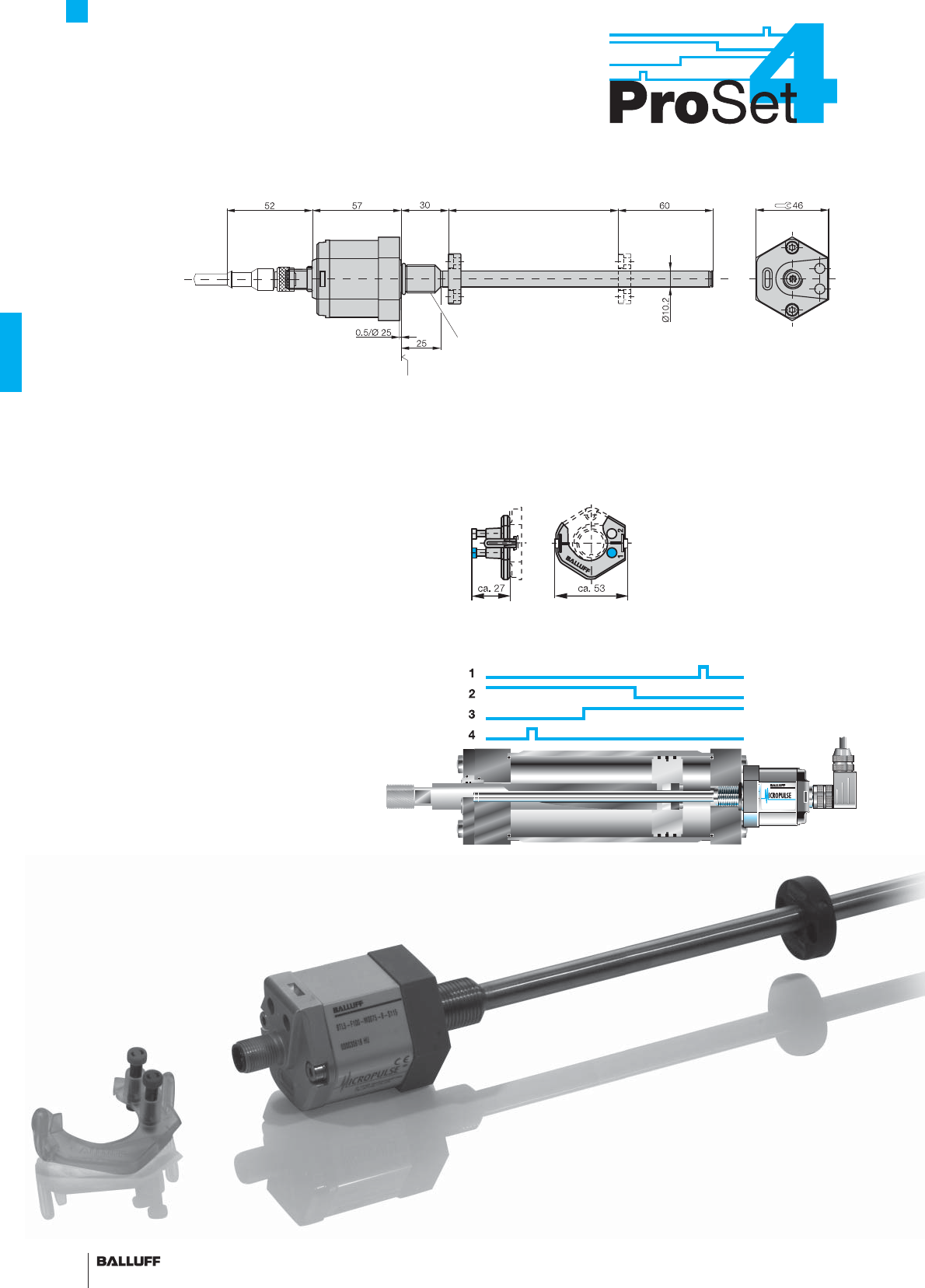
94
BTL5 Rod Series
4 programmable switching points
Mounting surface
Thread
M4×4/6 deep
Nominal stroke = measuring range Damping zone
(non-usable
area)
Magnet
Thread M18x1.5
Single position measurement between the piston limits of
travel on standard cylinder series
Advantages:
– no special design of piston or piston rod necessary
– no permanent magnet required between the piston seals
– easy to program
– no time-consuming adjustment
– high resolution and repeatability
– switching points freely programmable using calibration
device or programming inputs
Calibration device BTL5-A-EH01 for programming the outputs
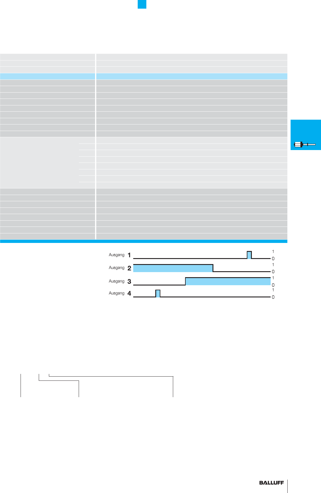
95■ www.balluff.com
BTL5 Rod Series
4 programmable switching points
Series BTL5 Rod
Transducer interface F
Input interface digital
Part number BTL5-F1_ 0-M_ _ _ _-_-S115
Output signals 4 switching outputs
Max. current load per output 100 mA
Max. current load for 4 outputs 200 mA
Repeat accuracy ±0.1 mm
Sampling rate fSTANDARD = 1 kHz = ≤ 1400 mm
Operating voltage 24 V DC ±20 %
No-load current consumption ≤ 100 mA
Operating temperature –40...+85 °C
Storage temperature range –40...+100 °C
Pin assignments Pin 1 Output 1
Pin 2 Output 2
Pin 3 Output 3
Pin 4 Output 4
Pin 5 La; Programming input (low-active)
Pin 6 GND
Pin 7 +24 V DC
Pin 8 Lb; Programming input (low-active)
Shock load 100 g/6 ms per IEC 60068-2-27
Vibration 12 g, 10...2000 Hz per IEC 60068-2-6
Dielectric strength 500 V DC (GND to housing)
Degree of protection as per IEC 60529 IP 67 (with BKS-S... IP 67 connector attached)
Housing material Anodized aluminum/1.4571 stainless steel outer tube, 1.3952 stainless steel cast fl ange
Mounting Thread M18×1.5, 3/4"-16UNF on request
Pressure rating 600 bar installed in hydraulic cylinder
Connection type Connectors
Output
0 Output
NPN switching
1 Output
PNP switching
Ordering example:
BTL5-F1_0-M_ _ _ _-_-S115
Standard
nominal stroke [mm]
0025, 0050, 0075, 0100, 0125, 0150,
0175, 0200, 0225, 0250, 0275, 0300,
0325, 0350, 0375, 0400, 0425, 0450,
0475, 0500, 0550, 0600, 0650, 0700,
0750, 0800, 0850, 0900, 0950, 1000,
1100, 1200, 1300, 1400, 1500, 1600,
1700, 1800, 1900, 2000, 2250, 2500,
2750, 3000, 3250, 3500, 3750, 3850,
4000 or in 5 mm increments on request.
■ Please enter the code for the output, nomi-
nal stroke and housing in the ordering code.
■ Included:
– Transducer
– Short user's guide
– Calibration device
Please order separately:
Magnets/fl oats, from page 96
Mounting nuts, page 97
Connectors, page 156
Housing
B = Standard
M18×1.5, other
housings on page xx
Position +
Velocity
BTL7
General
data
Analog
interface
Programming
BTL5
General
data
Digital
pulse
interface
SSI
interface
CANopen
interface
PROFIBUS-DP
interface
Position
recognition in
the hydraulics
Floats
Magnets
Installation
notes
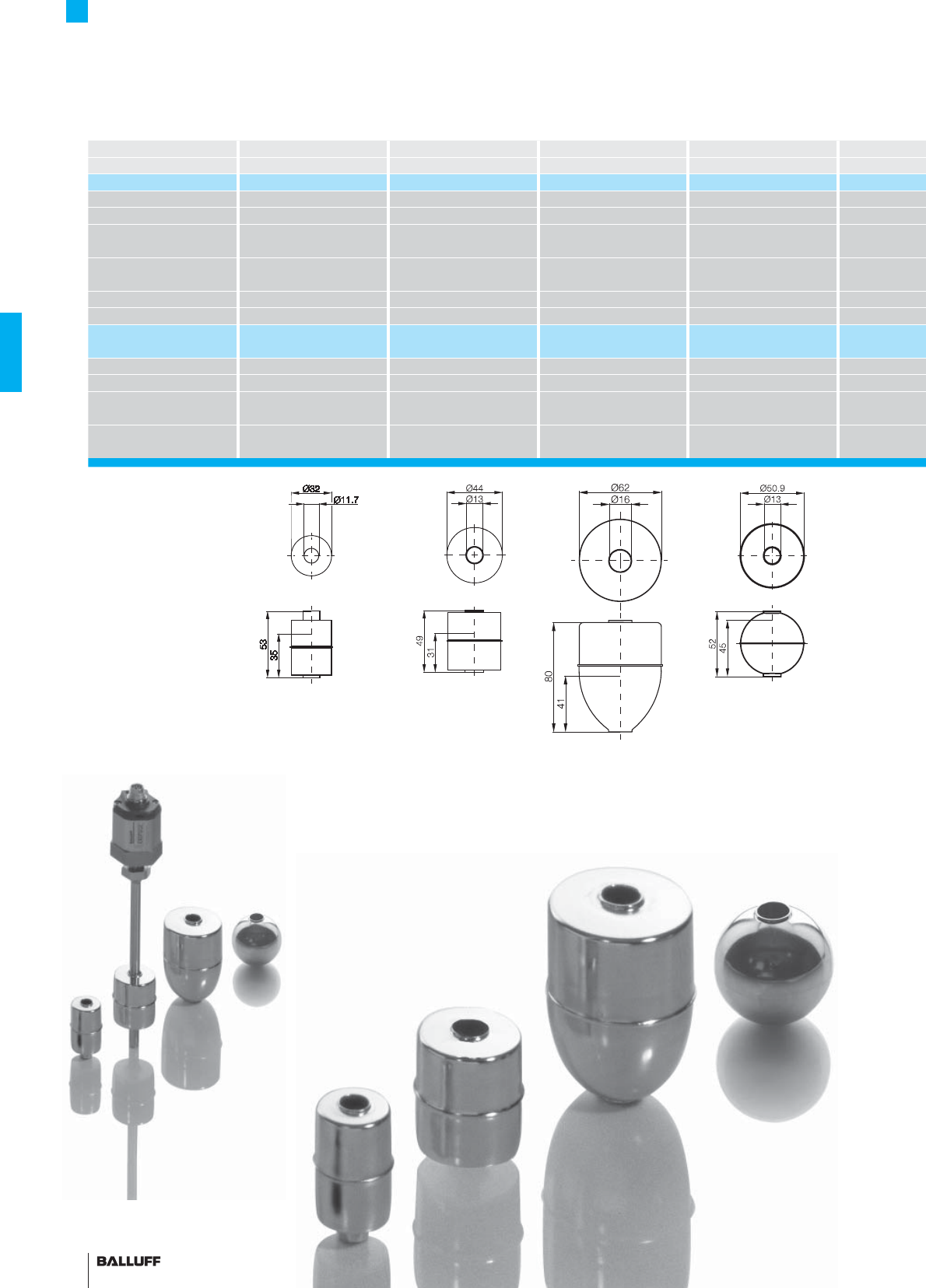
96
BTL5 Rod Series
Float
Description Float Float Float Float
for series BTL rod BTL rod BTL rod BTL rod
Part number BTL2-S-3212-4Z BTL2-S-4414-4Z BTL2-S-6216-8P BTL2-S-5113-4K
Material Stainless steel 1.4404 Stainless steel 1.4404 Stainless steel 1.4404 Stainless steel 1.4404
Weight approx. 20 g approx. 34 g approx. 69 g approx. 35 g
Magnet traverse velocity
Operating temperature/
–20...+120 °C –20...+120 °C –20...+120 °C –20...+120 °C
Storage temperature range
Displacement in water approx. 35 mm approx. 31 mm approx. 41 mm approx. 26 mm
Pressure rating (static) 24 bar 20 bar 15 bar 40 bar
Part number PA 60
glass fi ber reinforced
Material
Weight
Magnet traverse velocity
Operating temperature/
Storage temperature range
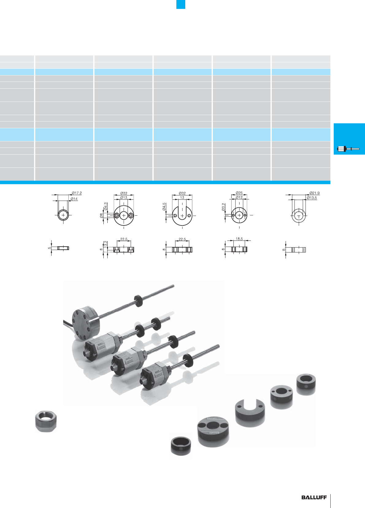
97■ www.balluff.com
BTL5 Rod Series
Magnet
Magnet Magnet Magnet Magnet Magnet
BTL rod BTL rod BTL rod BTL rod BTL rod
BTL-P-0814-GR-PAF BTL-P-1013-4R BTL-P-1013-4S BTL-P-1012-4R BTL-P-1014-2R
Ferrite integrated in PA Al Al Al Al
approx. 1.5 g approx. 12 g approx. 12 g approx. 12 g approx. 10 g
any any any any any
–40...+100 °C –40...+100 °C –40...+100 °C –40...+100 °C –40...+100 °C
BTL-P-1013-4R-PA BTL-P-1012-4R-PA
PA 60 glass fi ber reinforced PA 60 glass fi ber reinforced
approx. 10 g approx. 10 g
any any
–40...+100 °C –40...+100 °C
M18×1.5 mounting nut
Order designation:
BTL-A-FK01-E-M18×1.5
3/4"-16 UNF mounting nut
Order designation:
BTL-A-FK01-E-3/4"-16 UNF
Caution!
Prior to design, installation and startup, please read the
instructions in the user guide! www.balluff.com
BTL7
General
data
Analog
interface
Programming
BTL5
General
data
Digital
pulse
interface
SSI
interface
CANopen
interface
PROFIBUS-DP
interface
Position
recognition in
the hydraulics
Floats
Magnets
Installation
notes
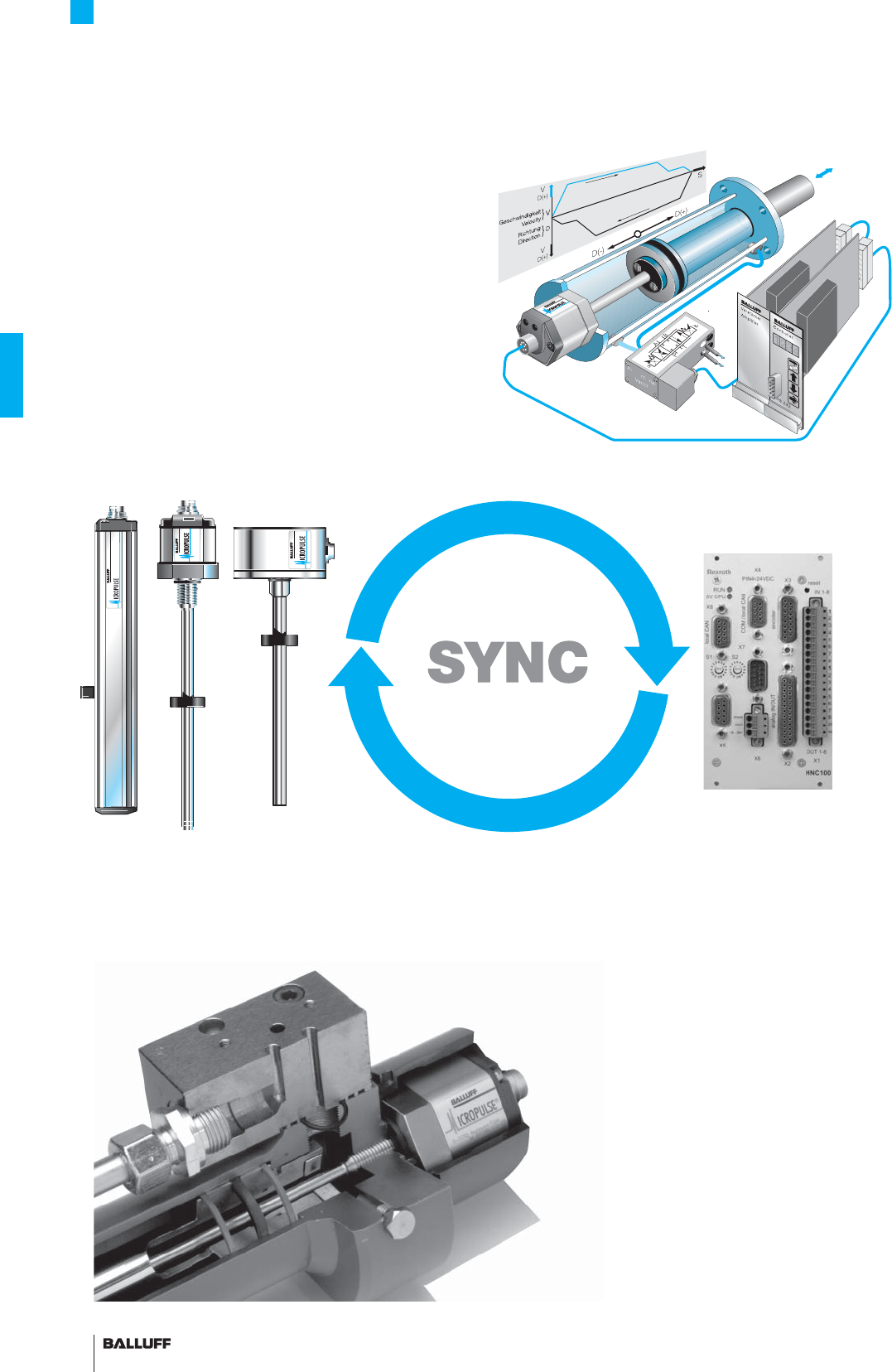
98
BTL5 Rod Series
Installation notes
SSI-SYNC –
better control characteristics and higher dynamics
The absolute positioning information from the Micropulse transducer
is transmitted synchronously to the axis control card. This synchro-
nous data acquisition enables exact calculation of the velocity and
acceleration.
The feedback of these variables (velocity and acceleration) allows
the damping and resonant frequency of a hydraulic system to be in-
creased. These measures permit greater loop gain and with it better
control behavior and higher dynamics.
Micropulse transducer BTL5-S1_ _ -S1-...
Installation
in hydraulic cylinders
Control card with SSI
interface for connecting
Micropulse transducers
Application with hydraulic cylinder in a control circuit
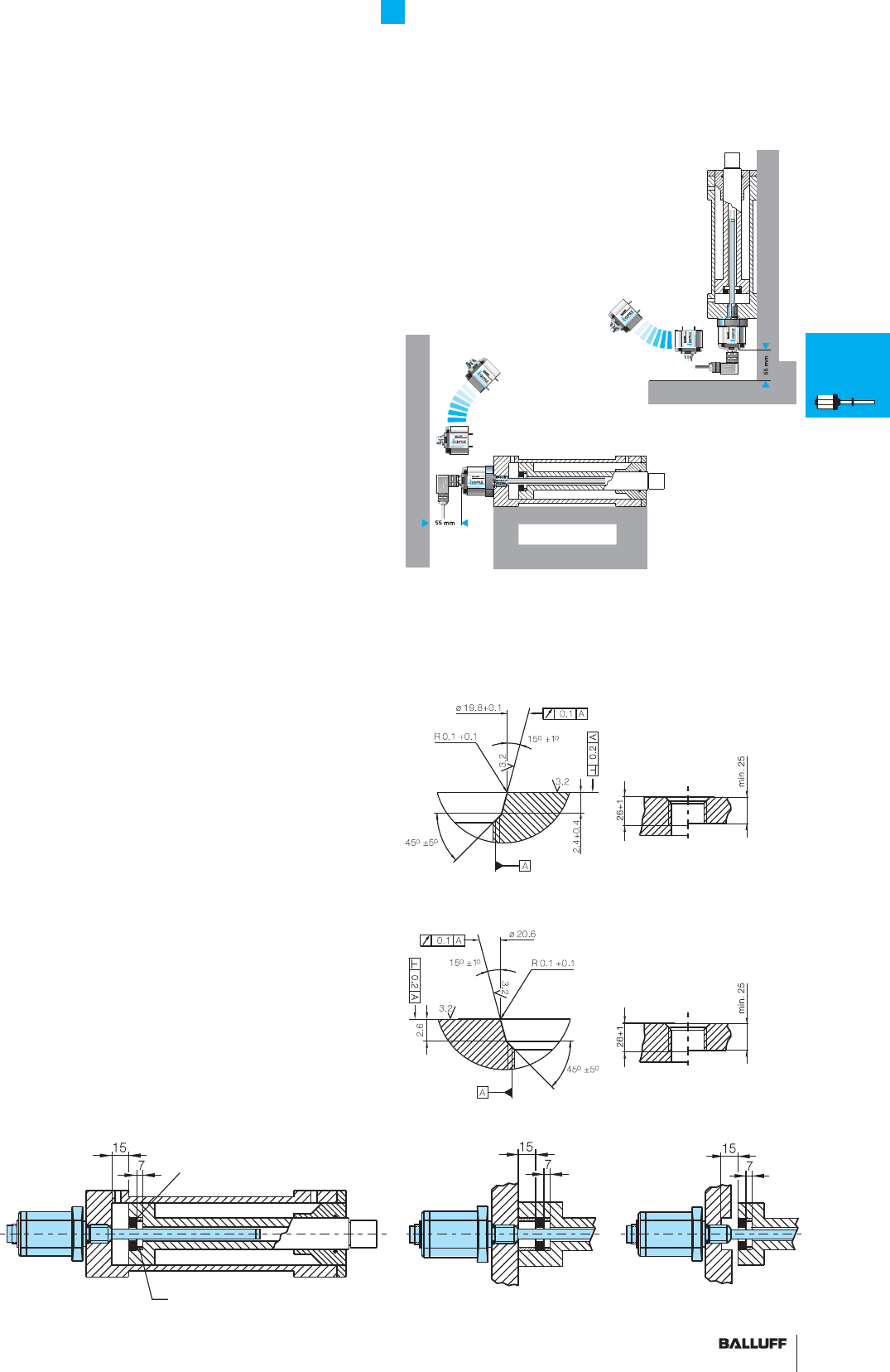
99■ www.balluff.com
BTL5 Rod Series
Installation notes
Hassle-free service
Cylinder-mounted transducers are often located in diffi cult to access
spots. If a transducer is damaged or fails, replacing the complete
transducer with head and waveguide is often a diffi cult and expen-
sive proposition.
Should a problem occur in the electronics of the Micropulse trans-
ducer, the electronics head can be easily and quickly exchanged
for a new one. The fl uid circuit also remains intact, with no draining
necessary.
Servicing a horizontal installation
Servicing a vertical installation
Installation
The Micropulse transducer BTL has a mounting thread M18×1.5.
We recommend that the mounting is made of non-magnetizable
material. If magnetizable materials are used, the installation must be
carried out as shown in the drawing below. Sealing is at the fl ange
mounting surface using the supplied O-ring 15.4×2.1 with M18×1.5
thread.
Insertion hole
The transducer is fi tted with a M18×1.5 (as per ISO) or 3/4“-16UNF
(as per SAE) mounting thread. Depending on the version, the
insertion hole may have to be manufactured prior to assembly.
Non-magnetizable spacer
Magnet
Insertion hole M18×1.5, as per ISO 6149, O-ring 15.4×2.1
Insertion hole 3/4"-16UNF as per SAE J475, O-ring 15.3×2.4
BTL7
General
data
Analog
interface
Programming
BTL5
General
data
Digital
pulse
interface
SSI
interface
CANopen
interface
PROFIBUS-DP
interface
Position
recognition in
the hydraulics
Floats
Magnets
Installation
notes
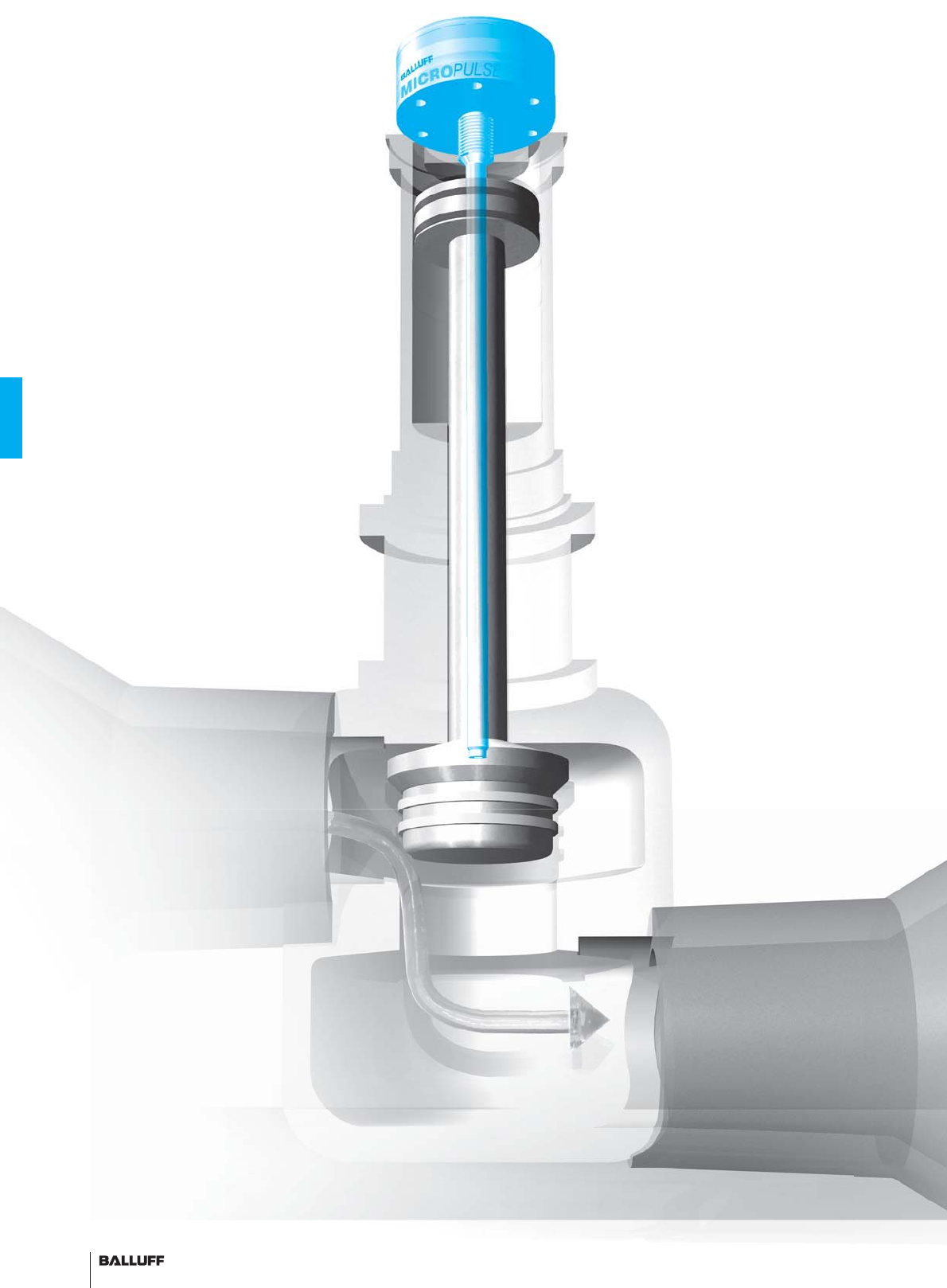
100
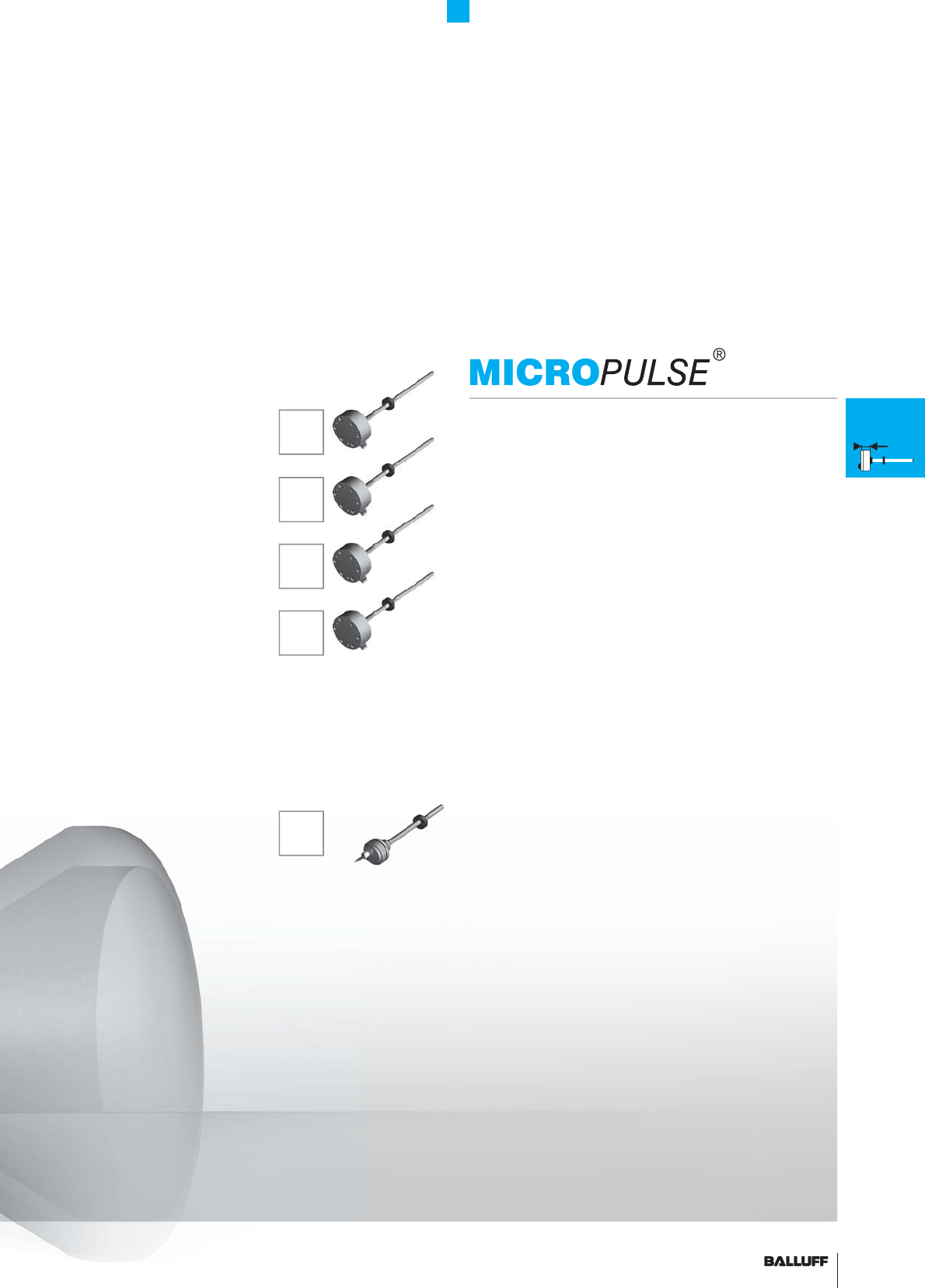
101■ www.balluff.com 101■ www.balluff.com 101
Compact Rod and AR Rod Series
Contents
K
Installation notes 102
General data 103
H
Installation notes 104
General data 105
W
Installation notes 106
General data 107
Pro Compact HB/WB
Installation notes 108
General data 109
Analog interface 110
Digital pulse interface 112
SSI interface 114
CANopen interface 116
AR
General data 118
Analog interface 120
Digital pulse interface P510 122
Installation notes 124
K
H
W
HB/
WB
Rod housings are mainly used in hydraulic drive applications. When
installed in the pressure section of the hydraulic cylinder, the distance
sensor requires the same pressure rating as the actual hydraulic
cylinder. In practice, the sensor must be able
to withstand pressures up to 1000 bar. The electronics are inte-
grated in an aluminum or stainless steel housing and the waveguide
in a pressure-resistant tube made from nonmagnetic stainless steel
that is sealed off at the face end with a welded plug. An O-ring seal
in the fl ange at the opposite end seals off the high-pressure section.
An magnet ring with magnets slides over the tube or rod with internal
waveguide to mark the position prior to detection.
AR

102
Compact Rod Series K
Installation notes
Pressure rated to 600 bar,
high repeatability, non-contact, rugged
The BTL Micropulse transducer is a rugged position feedback
system for measuring ranges between 25 and 5500 mm as well as
use under extreme ambient conditions.
The actual waveguide is protected inside a high-pressure resistant
stainless steel tube. The system is ideal for use in hydraulic cylinders
for position feedback or as a level monitor with aggressive media in
the food and chemical industries.
Installation BTL5 Compact rod K
The Micropulse transducer has 6 mounting holes for cylinder
head screws (ISO 4762 M6×18 A2-70). We recommend that the
mounting is made of non-magnetizable material. If magnetizable
materials are used, the installation must be carried out as shown
above. Sealing is at the fl ange mounting surface using the supplied
O-ring 15.4×2.1 mm.
– Stainless
– extremely short 34 mm
– IP 68 with cable
Compact rod Micropulse transducer installed in clevis mount cylinder
thru-hole
O-ring groove
15.4 × 2.1
non-magnetizable material
1-2 with magnetizable material
4 with non-magnetizable material
a Spacer made from
non-magnetizable material
b Magnet
■ Included:
– Transducer (select your
interface from page 110)
– Short user's guide
Please order separately:
Magnets/fl oats, page 96
Mounting nuts, page 97
Connectors, page 148/149
Caution! Prior to design,
installation and startup,
please read the instructions
in the user guide!
www.balluff.com
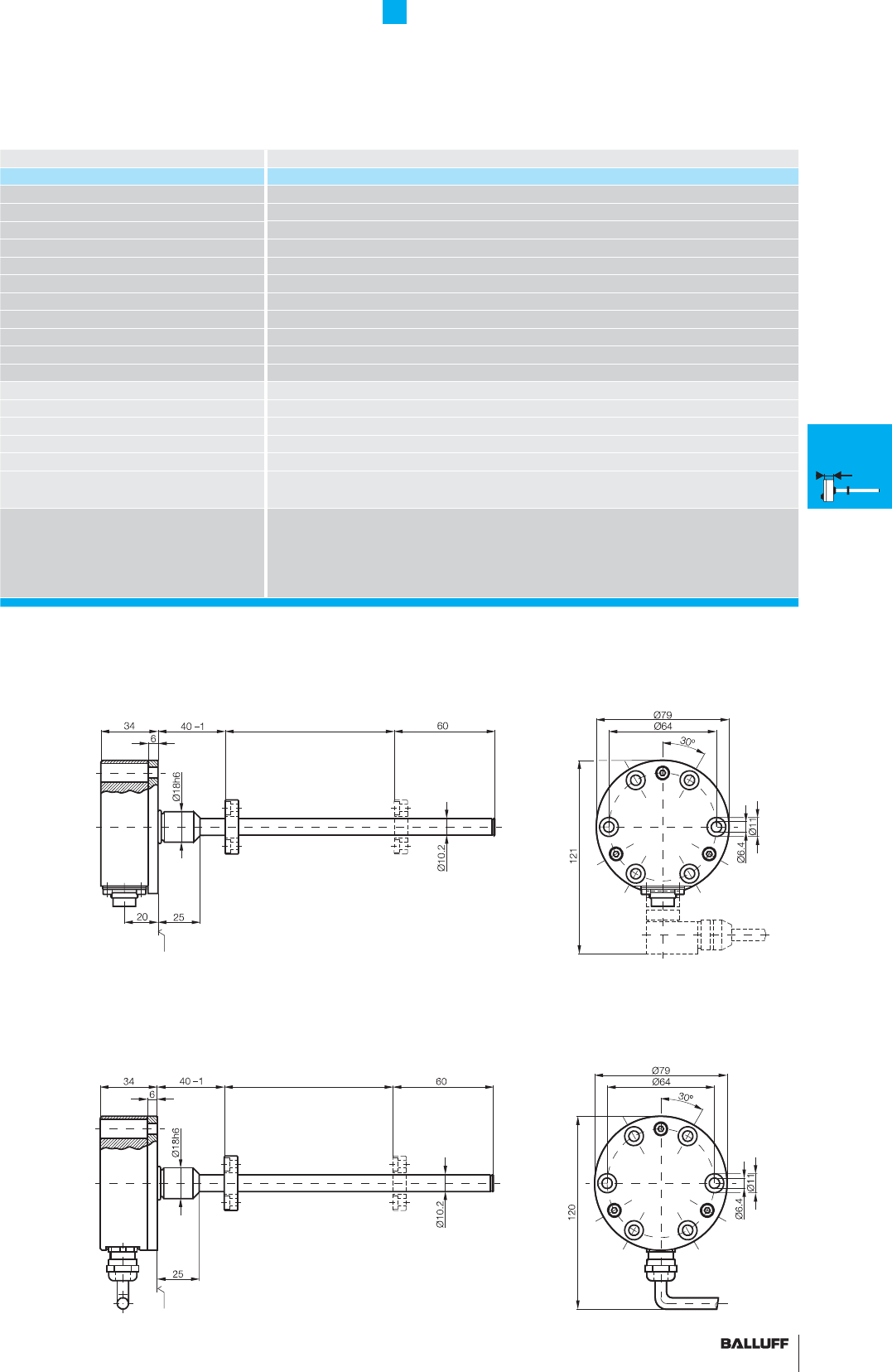
103■ www.balluff.com
Compact Rod Series K
General data
Series BTL5 Compact Rod K
Part number BTL5-...-M_ _ _ _ -K-_ _ _ _
Shock load 100 g/6 ms per IEC 60068-2-27 and 100 g/2 ms per IEC 60068-2-29
Vibration 12 g, 10...2000 Hz per IEC 60068-2-6
Polarity reversal protected yes
Overvoltage protection Transzorb protection diodes
Dielectric strength 500 V DC (GND to housing)
Degree of protection as per IEC 60529 IP 67 (when BKS-S32/33 is installed); IP 68 connector, 5 bar for cable version
Housing material Stainless steel 1.4305
Flange and tube material Tube stainless 1.4571, fl ange 1.4571 or 1.4429 or 1.4404
Housing attachment fl ange with 6 mounting holes
Connection type connector or integral cable
Recommended connector, see page 148/149
BKS-S 32M/BKS-S 32M-C/BKS-S 33M
EMC testing:
RF emission EN 55016-2-3 Group 1, Class A
Static electricity (ESD) IEC 61000-4-2 Severity Level 3
Electromagnetic fi elds (RFI) IEC 61000-4-3 Severity Level 3
Fast transients (BURST) IEC 61000-4-4 Severity Level 3
Conducted interference induced
by high-frequency fi elds
IEC 61000-4-6 Severity Level 3
Standard nominal strokes [mm] 0025, 0050, 0075, 0100, 0125, 0150, 0175, 0200, 0225, 0250, 0275, 0300, 0325, 0350,
0375, 0400, 0425, 0450, 0475, 0500, 0550, 0600, 0650, 0700, 0750, 0800, 0850, 0900,
0950, 1000, 1100, 1200, 1300, 1400, 1500, 1600, 1700, 1800, 1900, 2000, 2250, 2500,
2750, 3000, 3250, 3500, 3750, 3850, 4000, 4250, 4500, 4750, 5000, 5250, 5500 or in
5 mm increments (depending on interface) on request
Housing K
BTL5-...-M_ _ _ _-K-SR32
Flange ∅ 18 mm, PCD ∅ 64 mm
Radial connection
Housing K
BTL5-...-M_ _ _ _-K-K_ _
Flange ∅ 18 mm, PCD ∅ 64 mm
Radial cable
M4×4/6 threaded
blind hole,
security disk Ø 9 DIN 6799
Mounting surface
Magnet
BKS-S 33M
Nominal stroke = measuring range Damping zone
(non-usable area)
M4×4/6 threaded
blind hole,
security disk Ø 9 DIN 6799
Mounting surface
Magnet
Nominal stroke = measuring range Damping zone
(non-usable area)
K
Installation
notes
General
data
H
Installation
notes
General
data
W
Installation
notes
General
data
HB/WB
Installation
notes
General
data
Analog
interface
Digital
pulse
interface
SSI
interface
CANopen
interface
AR
General
data
Analog
interface
Digital
pulse
interface
Installation
notes
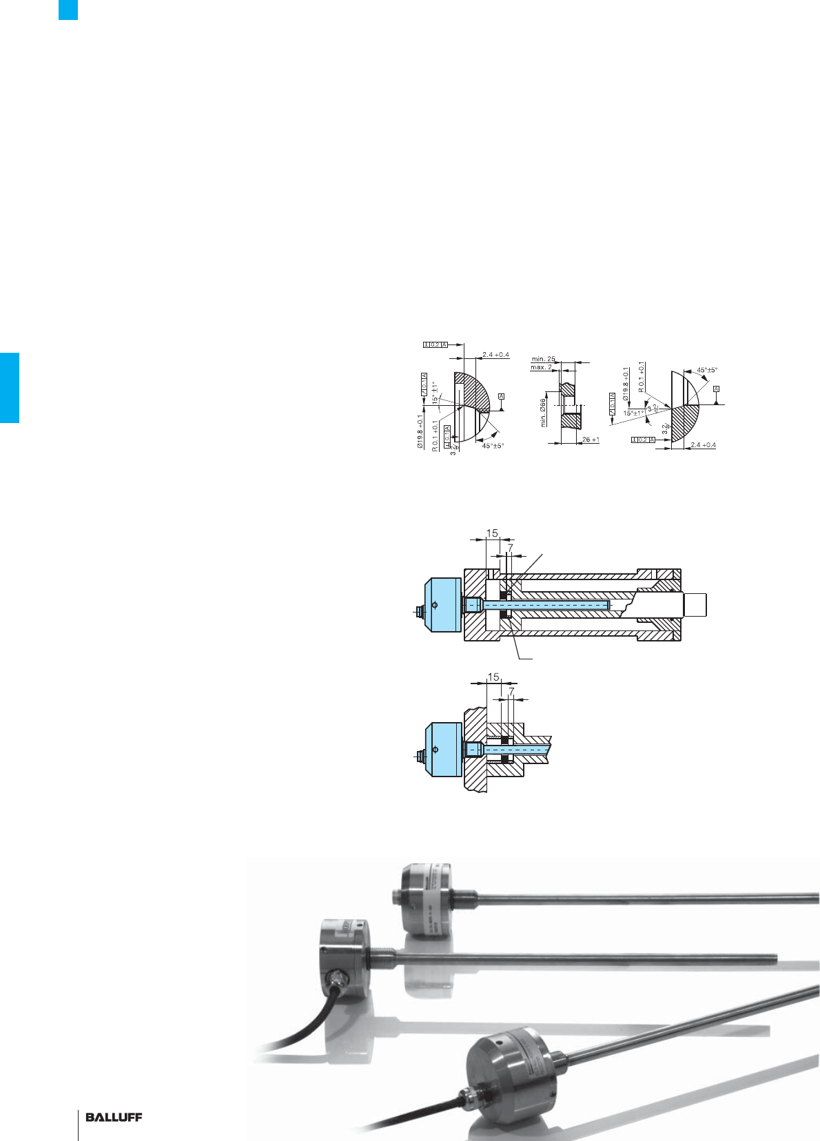
104
Compact Rod Series H
Installation notes
Pressure rated to 600 bar,
high repeatability, non-contact, rugged
The BTL Micropulse transducer is a robust position feedback system
for measuring ranges between 25 and 5500 mm as well as use
under extreme ambient conditions.
The actual waveguide is protected inside a high-pressure resistant
stainless steel tube. The system is ideal for use in hydraulic cylinders
for position feedback or as a level monitor with aggressive media in
the food and chemical industries.
– Stainless
– IP 68 with cable
Installation BTL5 Compact rod H
The Micropulse transducer BTL has a mounting thread M18×1.5.
We recommend that the mounting is made of non-magnetizable
material.
If magnetizable materials are used, the installation must be carried
out as shown in the drawing below. Sealing is at the fl ange mounting
surface using the supplied O-ring 15.4×2.1 with M18×1.5 thread.
O-ring groove,
view A Insertion hole
M18×1.5 to
ISO 6149,
O-ring 15.4×2.1
O-ring groove,
view B
Non-magnetizable spacer
Magnet
■ Included:
– Transducer (select your
interface from page 110)
– Short user's guide
Please order separately:
Magnets/fl oats, page 96
Mounting nuts, page 97
Connectors, page 148/149
Caution! Prior to design,
installation and startup,
please read the instructions
in the user guide!
www.balluff.com
AB
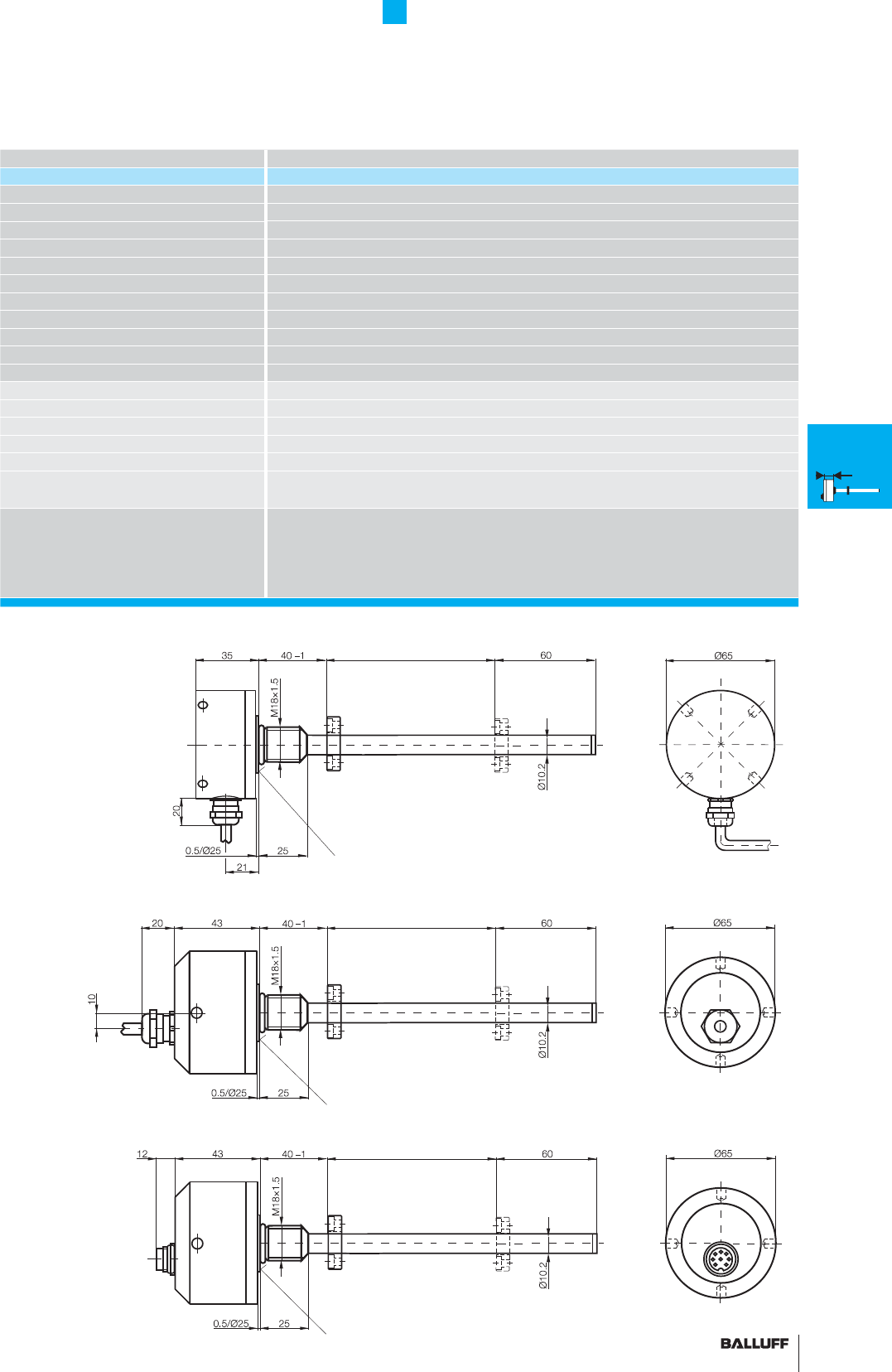
105■ www.balluff.com
Compact Rod Series H
General data
Series BTL5 Compact Rod H
Part number BTL5-...-M_ _ _ _ -H-_ _ _ _
Shock load 100 g/6 ms per IEC 60068-2-27 and 100 g/2 ms per IEC 60068-2-29
Vibration 12 g, 10...2000 Hz per IEC 60068-2-6
Polarity reversal protected yes
Overvoltage protection Transzorb protection diodes
Dielectric strength 500 V DC (GND to housing)
Degree of protection as per IEC 60529 IP 67 (when BKS-S32/33 is installed); IP 68 connector, 5 bar for cable version
Housing material Stainless steel 1.4305
Flange and tube material Tube stainless 1.4571, fl ange 1.4571 or 1.4429 or 1.4404
Housing attachment Flange with thread M18×1.5
Connection type connector or integral cable
Recommended connector, see page 148/149
BKS-S 32M/BKS-S 32M-C/BKS-S 33M
EMC testing:
RF emission EN 55016-2-3 Group 1, Class A
Static electricity (ESD) IEC 61000-4-2 Severity Level 3
Electromagnetic fi elds (RFI) IEC 61000-4-3 Severity Level 3
Fast transients (BURST) IEC 61000-4-4 Severity Level 3
Conducted interference induced
by high-frequency fi elds
IEC 61000-4-6 Severity Level 3
Standard nominal strokes [mm] 0025, 0050, 0075, 0100, 0125, 0150, 0175, 0200, 0225, 0250, 0275, 0300, 0325, 0350,
0375, 0400, 0425, 0450, 0475, 0500, 0550, 0600, 0650, 0700, 0750, 0800, 0850, 0900,
0950, 1000, 1100, 1200, 1300, 1400, 1500, 1600, 1700, 1800, 1900, 2000, 2250, 2500,
2750, 3000, 3250, 3500, 3750, 3850, 4000, 4250, 4500, 4750, 5000, 5250, 5500 or
in 5 mm increments on request.
M4×4/6 threaded
blind hole, security disk
Ø 9 DIN 6799
Mounting surface
Magnet
Housing H,
BTL5-...-M_ _ _ _-H-K_ _
Mounting
thread M18×1.5
Radial cable outlet
Nominal stroke = measuring range Damping zone
(non-usable area)
M4×4/6 threaded
blind hole, security disk
Ø 9 DIN 6799
Mounting surface
Housing H, BTL5-...-M_ _ _ _-H-KA _ _
Mounting
thread M18×1.5
Cable outlet
axial
Magnet
Nominal stroke = measuring range Damping zone
(non-usable area)
M4×4/6 threaded
blind hole, security disk
Ø 9 DIN 6799
Mounting surface
Housing H, BTL5-...-M_ _ _ _-H-S32
Mounting
thread M18×1.5
Plug connector
Axial
Nominal stroke = measuring range Damping zone
(non-usable area)
Magnet
K
Installation
notes
General
data
H
Installation
notes
General
data
W
Installation
notes
General
data
HB/WB
Installation
notes
General
data
Analog
interface
Digital
pulse
interface
SSI
interface
CANopen
interface
AR
General
data
Analog
interface
Digital
pulse
interface
Installation
notes
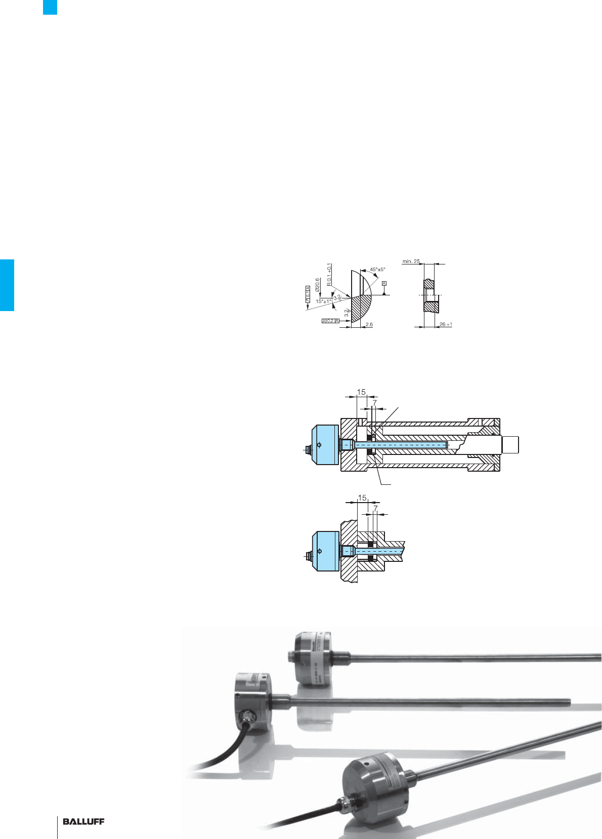
106
Compact W Rod Series
Installation notes
Pressure rated to 600 bar,
high repeatability, non-contact, rugged
The BTL Micropulse transducer is a robust position feedback system
for measuring ranges between 25 and 5500 mm as well as use
under extreme ambient conditions.
The actual waveguide is protected inside a high-pressure resistant
stainless steel tube. The system is ideal for use in hydraulic cylinders
for position feedback or as a level monitor with aggressive media in
the food and chemical industries.
– Stainless
– IP 68 with cable
Installation BTL5 Compact rod W
The Micropulse transducer BTL has a mounting thread M18×1.5.
We recommend that the mounting is made of non-magnetizable
material.
If magnetizable materials are used, the installation must be carried
out as shown in the drawing below. Sealing is at the fl ange mounting
surface using the supplied O-ring 15.4×2.1 with M18×1.5 thread.
O-ring groove, view A Insertion hole
thread 3/4"-16 UNF
O-ring groove,
view B
Non-magnetizable spacer
Magnet
■ Included:
– Transducer (select your
interface from page 110)
– Short user's guide
Please order separately:
Magnets/fl oats, page 96
Mounting nuts, page 97
Connectors, page 148/149
Caution! Prior to design,
installation and startup,
please read the instructions
in the user guide!
www.balluff.com
AB

107■ www.balluff.com
Compact W Rod Series
General data
Series BTL5 Compact W rod
Part number BTL5-...-M_ _ _ _ -W-_ _ _ _
Shock load 100 g/6 ms per IEC 60068-2-27 and 100 g/2 ms per IEC 60068-2-29
Vibration 12 g, 10...2000 Hz per IEC 60068-2-6
Polarity reversal protected yes
Overvoltage protection Transzorb protection diodes
Dielectric strength 500 V DC (GND to housing)
Degree of protection as per IEC 60529 IP 67 (when BKS-S32/33 is installed); IP 68 connector, 5 bar for cable version
Housing material Stainless steel 1.4305
Flange and tube material Tube stainless 1.4571, fl ange 1.4571 or 1.4429 or 1.4404
Housing attachment Flange with thread 3/4"-UNF
Connection type connector or integral cable
Recommended connector, see page 148/149
BKS-S 32M/BKS-S 32M-C/BKS-S 33M
EMC testing:
RF emission EN 55016-2-3 Group 1, Class A
Static electricity (ESD) IEC 61000-4-2 Severity Level 3
Electromagnetic fi elds (RFI) IEC 61000-4-3 Severity Level 3
Fast transients (BURST) IEC 61000-4-4 Severity Level 3
Conducted interference induced
by high-frequency fi elds
IEC 61000-4-6 Severity Level 3
Standard nominal strokes [mm] 0025, 0050, 0075, 0100, 0125, 0150, 0175, 0200, 0225, 0250, 0275, 0300, 0325, 0350,
0375, 0400, 0425, 0450, 0475, 0500, 0550, 0600, 0650, 0700, 0750, 0800, 0850, 0900,
0950, 1000, 1100, 1200, 1300, 1400, 1500, 1600, 1700, 1800, 1900, 2000, 2250, 2500,
2750, 3000, 3250, 3500, 3750, 3850, 4000, 4250, 4500, 4750, 5000, 5250, 5500 or
in 5 mm increments on request.
Thread
M4×6 deep
Mounting surface
Magnet
Nominal stroke = measuring range Damping zone
(non-usable area)
Housing W,
BTL5-...-M_ _ _ _-W-K_ _
Thread
3/4"-16 UNF
Magnet
Nominal stroke = measuring range Damping zone
(non-usable area)
Mounting surface
Housing W, BTL5-...-M_ _ _ _-W-S 32
Thread
3/4"-16 UNF
Nominal stroke = measuring range Damping zone
(non-usable area)
Mounting surface
Housing W, BTL5-...-M_ _ _ _-W-KA_ _
Thread
3/4"-16 UNF Magnet
Thread 3/4"-16UNF
Thread
M4×6 deep
Thread 3/4"-16UNF
Thread
M4×6 deep
Thread 3/4"-16UNF
K
Installation
notes
General
data
H
Installation
notes
General
data
W
Installation
notes
General
data
HB/WB
Installation
notes
General
data
Analog
interface
Digital
pulse
interface
SSI
interface
CANopen
interface
AR
General
data
Analog
interface
Digital
pulse
interface
Installation
notes
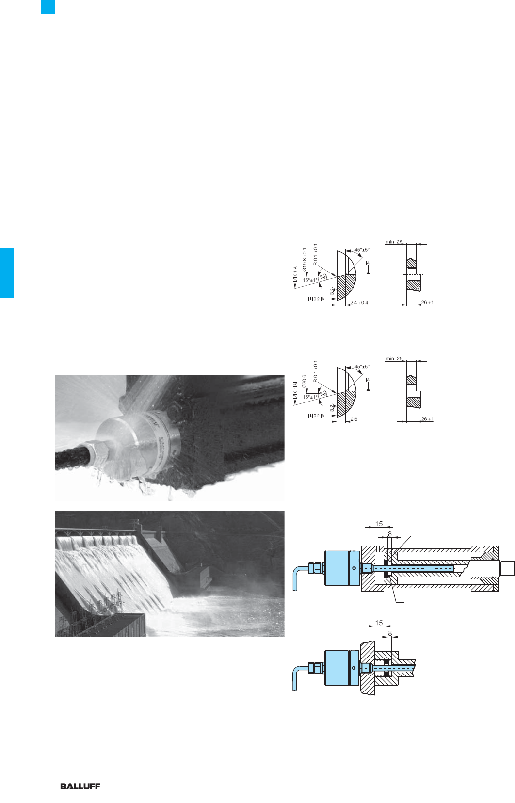
108
Pro Compact HB/WB Rod Series
Installation notes
Pressure rated to 600 bar,
high repeatability, non-contact, rugged
The BTL Micropulse transducer is a robust position feedback system
for measuring ranges between 25 and 5500 mm as well as use
under extreme ambient conditions.
The actual waveguide is protected inside a high-pressure resistant
stainless steel tube. The system is ideal for use in hydraulic cylinders
for position feedback or as a level monitor with aggressive media in
the food and chemical industries.
– Stainless
– IP 68 with cable
– IP 69/K
with cable protection system
Installation BTL5 Pro Compact HB/WB rod
The Micropulse transducer BTL has a mounting thread M18×1.5.
We recommend that the mounting is made of non-magnetizable
material.
If magnetizable materials are used, the installation must be carried
out as shown in the drawing below. Sealing is at the fl ange mounting
surface using the supplied O-ring 15.4×2.1 with M18×1.5 thread.
The fl ange and housing are completely sealed and cannot be
opened as a result. The measuring range preset in the factory can-
not be modifi ed as a result.
Insertion hole M18×1.5 as
per ISO 6149, O-ring 15.4×2.1
O-ring groove, view A
O-ring groove,
view B
Non-magnetizable spacer
Magnet
AB
■ Included:
– Transducer (select your
interface from page 110)
– Short user's guide
Please order separately:
Magnets/fl oats, page 96
Mounting nuts, page 97
Insertion hole 3/4",
O-ring 15.3×2.4
O-ring groove, view A
O-ring groove,
view B
Caution! Prior to design,
installation and startup,
please read the instructions
in the user guide!
www.balluff.com
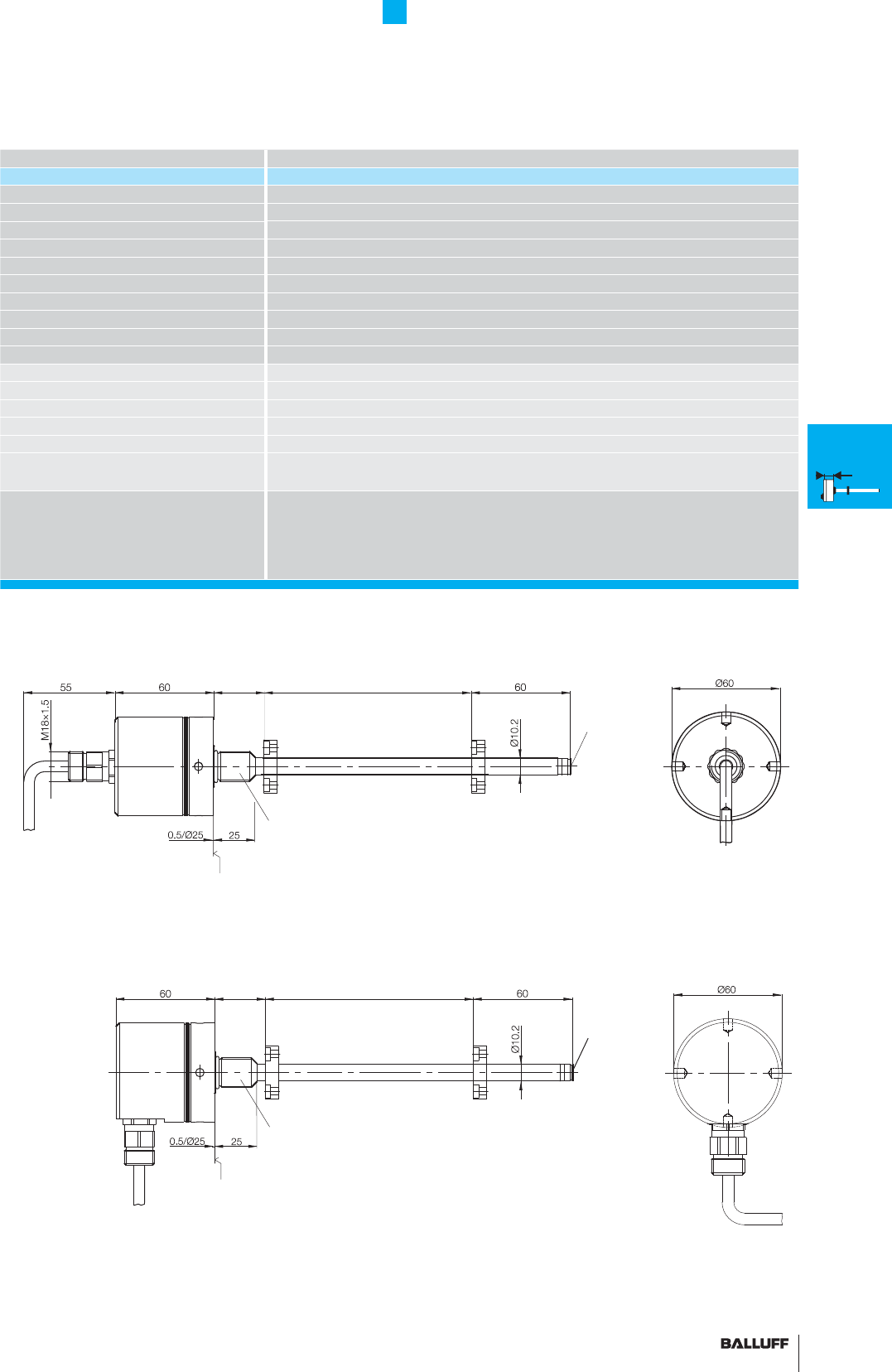
109■ www.balluff.com
Pro Compact HB/WB Rod Series
General data
Series BTL5 Compact HB/WB rod
Part number BTL5-...-M_ _ _ _ -HB/WB-_ _ _ _-C
Shock load 100 g/6 ms per IEC 60068-2-27 and 100 g/2 ms per IEC 60068-2-29
Vibration 12 g, 10...2000 Hz per IEC 60068-2-6
Polarity reversal protected yes
Overvoltage protection Transzorb protection diodes
Dielectric strength 500 V DC (GND to housing)
Degree of protection as per IEC 60529 IP 68 (5 bar with cable); IP 69K (with cable protection system)
Housing material Stainless steel 1.4404
Flange and tube material Stainless steel tube 1.4571, fl ange 1.4404
Housing attachment Flange with thread
Connection type Cable connection
EMC testing:
RF emission EN 55016-2-3 Group 1, Class A+B
Static electricity (ESD) IEC 61000-4-2 Severity Level 3
Electromagnetic fi elds (RFI) IEC 61000-4-3 Severity Level 3
Fast transients (BURST) IEC 61000-4-4 Severity Level 3
Conducted interference induced
by high-frequency fi elds
IEC 61000-4-6 Severity Level 3
Standard nominal strokes [mm] 0025, 0050, 0075, 0100, 0125, 0150, 0175, 0200, 0225, 0250, 0275, 0300, 0325, 0350,
0375, 0400, 0425, 0450, 0475, 0500, 0550, 0600, 0650, 0700, 0750, 0800, 0850, 0900,
0950, 1000, 1100, 1200, 1300, 1400, 1500, 1600, 1700, 1800, 1900, 2000, 2250, 2500,
2750, 3000, 3250, 3500, 3750, 3850, 4000, 4250, 4500, 4750, 5000, 5250, 5500 or
in 5 mm increments on request.
M4×4/6 deep
Internal thread
Mounting surface
Magnet
HB/WB housing
BTL5-...-HB/WB-_ _ _ _-C
radial
HB: 30 mm
WB: 2"
HB: M18×1.5
WB: 3/4"-16 UNF
M4×4/6 deep
Internal thread
Mounting surface
Magnet
HB/WB housing
BTL5-...-HB/WB-_ _ _ _-C
Axial
HB: 30 mm
WB: 2"
HB: M18×1.5
WB: 3/4"-16 UNF
Nominal stroke = measuring range Damping zone
(non-usable area)
Nominal stroke = measuring range Damping zone
(non-usable area)
K
Installation
notes
General
data
H
Installation
notes
General
data
W
Installation
notes
General
data
HB/WB
Installation
notes
General
data
Analog
interface
Digital
pulse
interface
SSI
interface
CANopen
interface
AR
General
data
Analog
interface
Digital
pulse
interface
Installation
notes
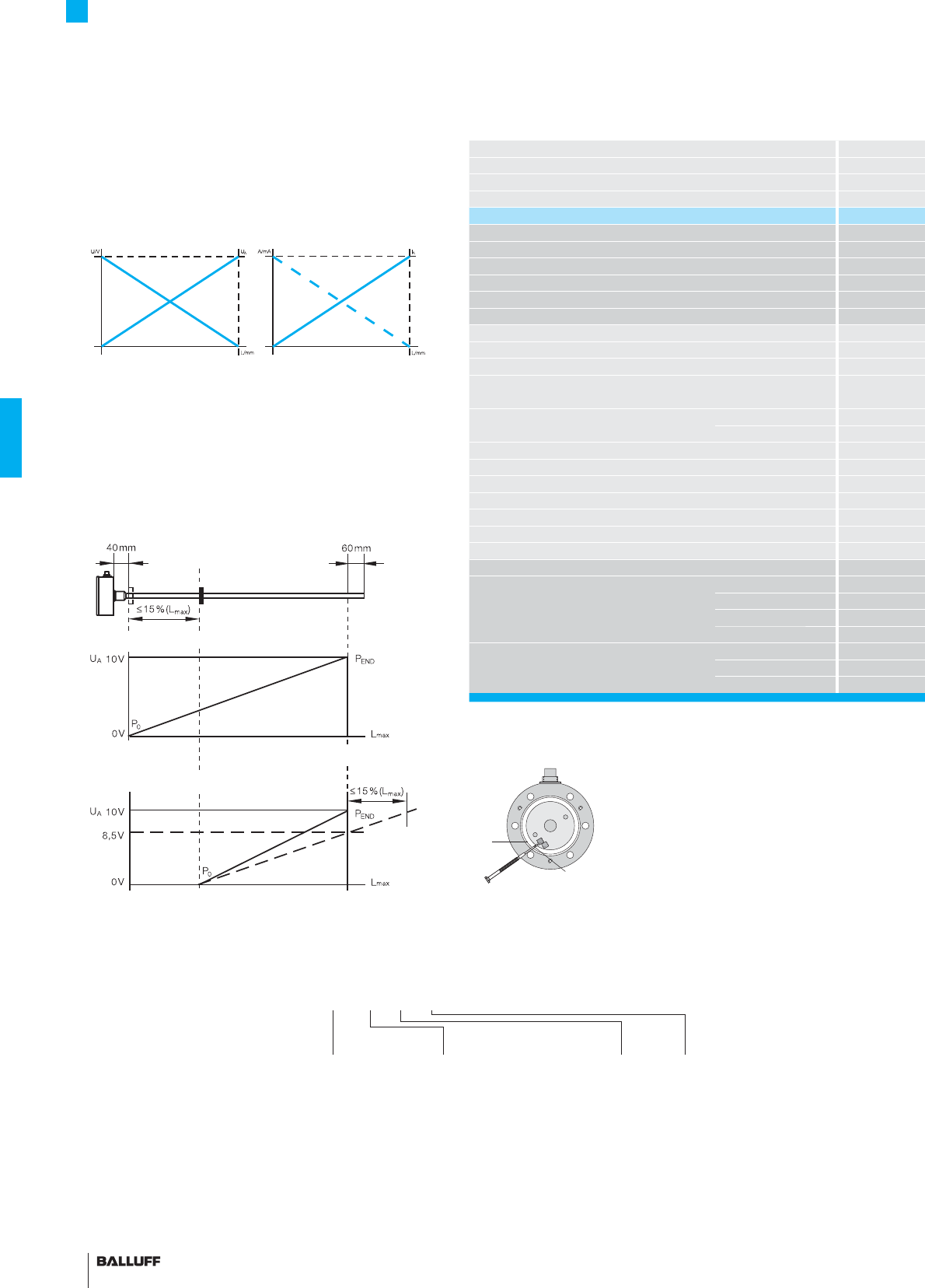
110
Series
Output signal
Transducer interface
Input interface
Part number
Output voltage
Output current
Load current
max. ripple
Load resistance
System resolution
Hysteresis
Repeat accuracy
Sampling rate
Max. non-linearity
Temperature coeffi cient Voltage output
Current output
Operating voltage
Current consumption
Polarity reversal protected
Overvoltage protection
Dielectric strength
Operating temperature
Storage temperature range
Pin assignments Pin Color
Output signals 1 YE
2GY
3PK
5GN
Operating voltage 6 BU
7BN
8WH
An integrator circuit provides resolution of better than 0.1 mV. BTL
transducers with analog outputs are available for 0...10 V, 4...20 mA,
0...20 mA and –10...10 V as rising or falling signals.
Compact Rod Series
Analog interface
UA rising and UA falling
are both present
Outputs
IA rising or falling
Compensating the output signal
BTL transducers with analog output have two potentiometers for
adapting the null and end point of the output signal to the particular
application. The null point can be shifted by max. 15 % of the nomi-
nal stroke in the direction of the rod end.
The output signal cannot be adjusted on the Compact H, W and Pro
Compact HB/WB versions.
BTL with compensated null and end point
BTL factory setting
Null point
Factory set End point
Factory set
Null point
Factory set desired null point
Location of trim pots
with cover removed
Pot "0"
Pot "E"
slot max. 1.5 mm
■ Please enter the code for the
output signal, nominal stroke,
housing and connection type in
the ordering code!
■ Included:
– Transducer
– Short user's guide
Please order separately:
Magnets/fl oats, page 96
Mounting nuts, page 97
Connectors, page 148/149
Standard
nominal stroke [mm]
Ordering example:
BTL5-E1_-M_ _ _ _-_ _-_ _ _ _-C
Connection type
Radial output
F05 Tefl on cable 5 m
Axial output
FA05 Tefl on cable 5 m
0025, 0050, 0075, 0100, 0125,
0150, 0175, 0200, 0225, 0250,
0275, 0300, 0325, 0350, 0375,
0400, 0425, 0450, 0475, 0500,
0550, 0600, 0650, 0700, 0750,
0800, 0850, 0900, 0950, 1000,
1100, 1200, 1300, 1400, 1500,
1600, 1700, 1800, 1900, 2000,
2250, 2500, 2750, 3000, 3250,
3500, 3750, 3850, 4000, 4250,
4500, 5000, 5250, 5500 or
in 5 mm increments on request.
Housing
HB
WB
Output
signal
1 Rising and
falling (with
A and G)
0 Rising
7 Falling (with
C and E)
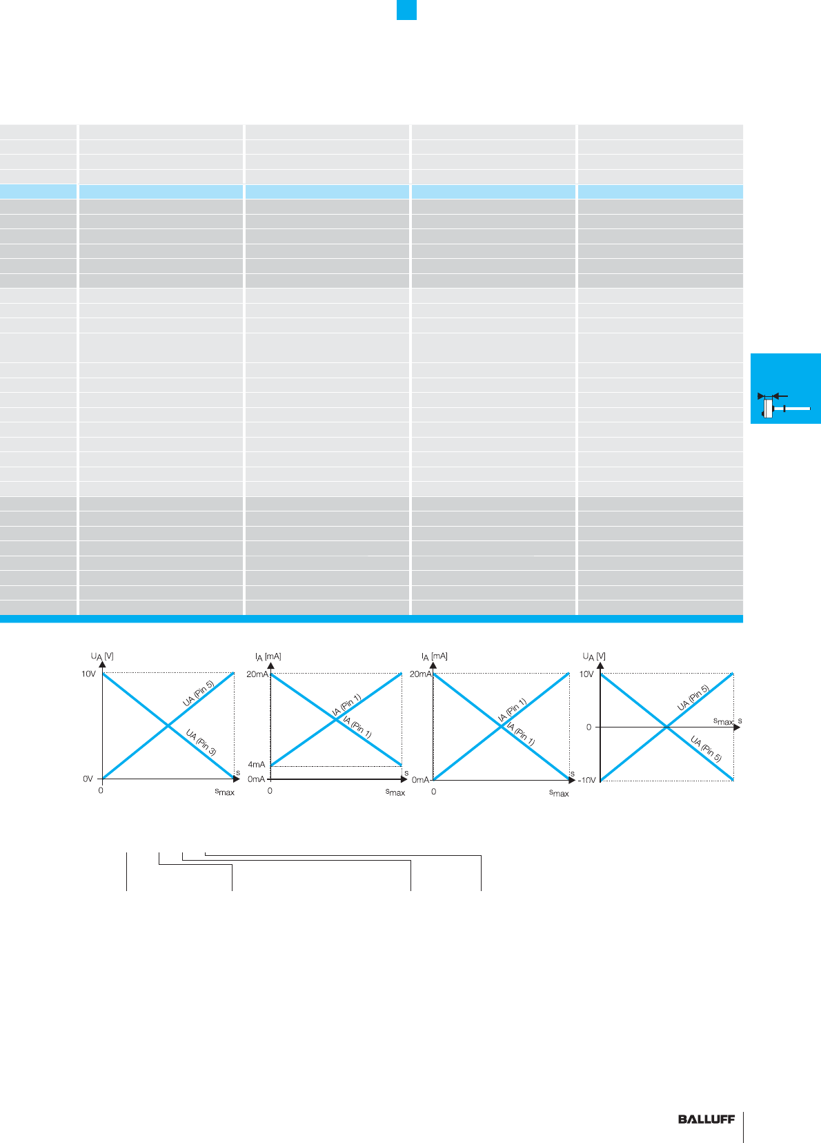
111■ www.balluff.com
BTL5 Compact Rod BTL5 Compact Rod BTL5 Compact Rod BTL5 Compact Rod
analog analog analog analog
AECG
analog analog analog analog
BTL5-A11-M_ _ _ _-_-_ _ _ _ BTL5-E1_-M_ _ _ _-_-_ _ _ _ BTL5-C1_-M_ _ _ _-_-_ _ _ _ BTL5-G11-M_ _ _ _-_-_ _ _ _
0...10 V and 10...0 V –10...10 V and 10...–10 V
4...20 mA or 20...4 mA 0...20 mA or 20...0 mA
max. 5 mA max. 5 mA
≤ 5 mV ≤ 5 mV
≤ 500 ohms ≤ 500 ohms
≤ 0.1 mV ≤ 0.2 µA ≤ 0.2 µA ≤ 0.1 mV
≤ 4 µm ≤ 4 µm ≤ 4 µm ≤ 4 µm
System resolution/min. 2 µm System resolution/min. 2 µm System resolution/min. 2 µm System resolution/min. 2 µm
fSTANDARD = 1 kHz fSTANDARD = 1 kHz fSTANDARD = 1 kHz fSTANDARD = 1 kHz
±100 µm up to 500 mm nominal stroke
±0.02 % 500... max. nominal stroke
±100 µm up to 500 mm nominal stroke
±0.02 % 500... max. nominal stroke
±100 µm up to 500 mm nominal stroke
±0.02 % 500... max. nominal stroke
±100 µm up to 500 mm nominal stroke
±0.02 % 500... max. nominal stroke
[150 µV/°C + (5 ppm/°C × P × U/L)] × ΔT[150 µV/°C + (5 ppm/°C × P × U/L)] × ΔT
[0.6 µA/°C + (10 ppm/°C × P × I/L)] × ΔT [0.6 µA/°C + (10 ppm/°C × P × I/L)] × ΔT
20...28 V DC 20...28 V DC 20...28 V DC 20...28 V DC
≤ 150 mA ≤ 150 mA ≤ 150 mA ≤ 150 mA
yes yes yes yes
Transzorb protection diodes Transzorb protection diodes Transzorb protection diodes Transzorb protection diodes
500 V DC (ground to housing) 500 V DC (ground to housing) 500 V DC (ground to housing) 500 V DC (ground to housing)
–40...+85 °C –40...+85 °C –40...+85 °C –40...+85 °C
–40...+100 °C –40...+100 °C –40...+100 °C –40...+100 °C
BTL5-A11... BTL5-E10... BTL5-E17... BTL5-C10... BTL5-C17... BTL5-G11...
4...20 mA 20...4 mA 0...20 mA 20...0 mA
0 V Output 0 V Output 0 V Output 0 V Output 0 V Output 0 V Output
10...0 V 10...0 V 10...0 V 10...0 V 10...0 V 10...–10 V
0...10 V 0...10 V 0...10 V 0...10 V 0...10 V –10...10 V
GND GND GND GND GND GND
+24 V DC +24 V DC +24 V DC +24 V DC +24 V DC +24 V DC
(GND) (GND) (GND) (GND) (GND) (GND)
Compact Rod Series
Analog interface
Standard
nominal stroke [mm]
Ordering example:
BTL5-E1_-M_ _ _ _-_-_ _ _ _
Connection type
Radial output
K02 PUR cable 2 m
K05 PUR cable 5 m
K10 PUR cable 10 m
K15 PUR cable 15 m
SR32 Connector
Radial output
K02 PUR cable 2 m
K05 PUR cable 5 m
K10 PUR cable 10 m
K15 PUR cable 15 m
0025, 0050, 0075, 0100, 0125,
0150, 0175, 0200, 0225, 0250,
0275, 0300, 0325, 0350, 0375,
0400, 0425, 0450, 0475, 0500,
0550, 0600, 0650, 0700, 0750,
0800, 0850, 0900, 0950, 1000,
1100, 1200, 1300, 1400, 1500,
1600, 1700, 1800, 1900, 2000,
2250, 2500, 2750, 3000, 3250,
3500, 3750, 3850, 4000, 4250,
4500 or in 5 mm increments on
request.
Housing
K
H
W
Axial output
KA02 PUR cable 2 m
KA05 PUR cable 5 m
KA10 PUR cable 10 m
KA15 PUR cable 15 m
S32 Connector
Output
signal
1 Rising and
falling (with
A and G)
0 Rising
7 Falling (with
C and E)
K
Installation
notes
General
data
H
Installation
notes
General
data
W
Installation
notes
General
data
HB/WB
Installation
notes
General
data
Analog
interface
Digital
pulse
interface
SSI
interface
CANopen
interface
AR
General
data
Analog
interface
Digital
pulse
interface
Installation
notes
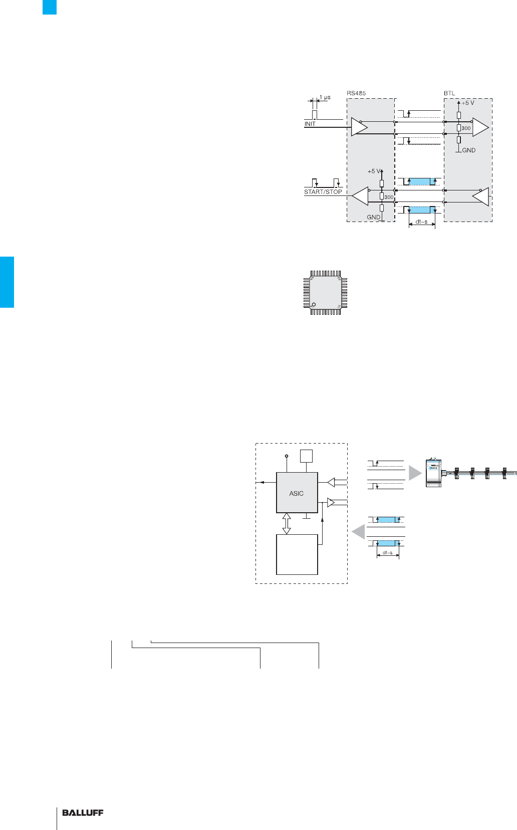
112
P Interface
Compatible with BTA processors as well as controllers and modules
from various manufacturers including Siemens, B & R, Phoenix
Contact, Mitsubishi, Sigmatek, Parker, Esitron and WAGO. Reliable
signal transmission, even over cable lengths up to 500 m between
BTA and BTL, is assured by the noise-immune RS485 differential line
drivers and receivers. Noise signals are effectively suppressed.
M interface
The I and M interfaces are control-specifi c interface variations.
Compact Rod Series
Digital pulse interface
Block diagram of P interface
Highly precise digitizing of the P pulse signal
Companies developing their own control and processing electronics
can create a highly accurate P interface cost effectively and
with minimum effort using the Balluff digitizing chip. The digitizing
chip was developed as a high-resolution, confi gurable ASIC for
Micropulse transducers with P interface.
Benefi ts
– Position resolution 1 µm!
The 1 µm resolution of the Micropulse distance measurement
system is achieved by the high resolution of the digitizing chip
(133 pS) (Clock frequency 2 or 20 MHz).
– Position data from 4 magnets can be processed simultaneously
– 4/8-bit processor interface
Digitizing chip 44QFP
CPU
controller
4/8-bit
bus
SSD
5 V
Osc.
INIT
Micropulse transducer with 1 to
4 magnets
Controller or
processing electronics
P pulse signal
ASIC INFO:
+49 7158 173-370
short and
economical
Standard
nominal stroke [mm]
Ordering example:
BTL5-P1-M_ _ _ _-_ _-_ _ _ _-C
Connection type
Radial output
F05 Tefl on cable 5 m
Axial output
FA05 Tefl on cable 5 m
0025, 0050, 0075, 0100, 0125, 0150,
0175, 0200, 0225, 0250, 0275, 0300,
0325, 0350, 0375, 0400, 0425, 0450,
0475, 0500, 0550, 0600, 0650, 0700,
0750, 0800, 0850, 0900, 0950, 1000,
1100, 1200, 1300, 1400, 1500, 1600,
1700, 1800, 1900, 2000, 2250, 2500,
2750, 3000, 3250, 3500, 3750, 3850,
4000, 4250, 4500, 5000, 5250, 5500
or in 5 mm increments on request.
Housing
HB
WB
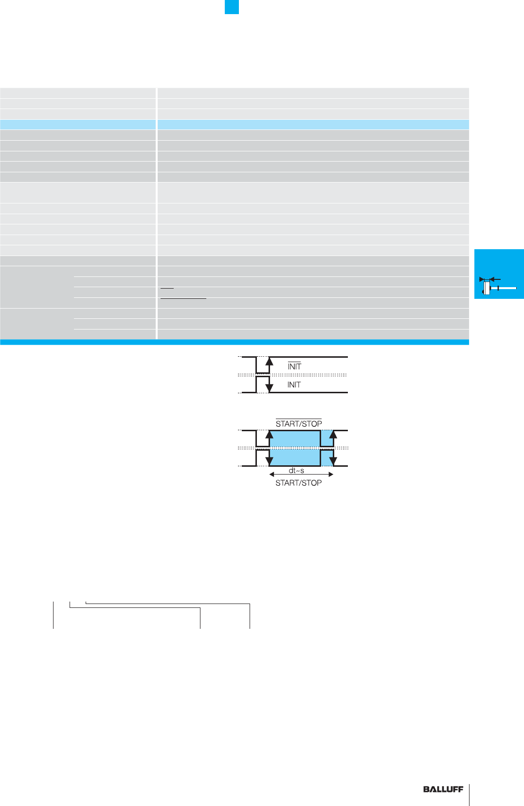
113■ www.balluff.com
Compact Rod Series
Digital pulse interface
Series BTL5 Compact rod
Transducer interface Pulse P
Input interface Pulse P
Part number BTL5-P1-M_ _ _ _-_-_ _ _ _
System resolution processing-dependent
Repeat accuracy 2 µm or ±1 digit depending on processing electronics
Resolution ≤ 2 µm
Hysteresis ≤ 4 µm
Sampling rate fSTANDARD = 1 kHz = ≤ 1400 mm
max. non-linearity ±100 µm up to 500 mm nominal stroke
±0,02 % 500...5500 mm nominal stroke
Temperature coeffi cient of overall system (6 µm + 5 ppm × L)/°C
Operating voltage 20...28 V DC
Current consumption ≤ 100 mA
Operating temperature –40...+85 °C
Storage temperature range –40...+100 °C
Pin assignments Pin Color BTL5-P1-M...
Input/Output
Input 1 YE INIT
signals Output 2 GY START/STOP
Input 3 PK INIT
Output 5 GN START/STOP
Operating voltage 6 BU GND
7BN+24 V DC
8WH
Connect shield to housing
■ Please enter the code for the nominal
stroke, housing and connection type in the
ordering code.
■ Included:
– Transducer
– Short user's guide
Please order separately:
Magnets/fl oats, page 96
Mounting nuts, page 97
(for Compact rod H)
Connectors, page 148/149
Standard
nominal stroke [mm]
Ordering example:
BTL5-P1-M_ _ _ _-_-_ _ _ _
Connection type
Radial output
K02 PUR cable 2 m
K05 PUR cable 5 m
K10 PUR cable 10 m
K15 PUR cable 15 m
SR32 Connector
Radial output
K02 PUR cable 2 m
K05 PUR cable 5 m
K10 PUR cable 10 m
K15 PUR cable 15 m
0025, 0050, 0075, 0100, 0125, 0150,
0175, 0200, 0225, 0250, 0275, 0300,
0325, 0350, 0375, 0400, 0425, 0450,
0475, 0500, 0550, 0600, 0650, 0700,
0750, 0800, 0850, 0900, 0950, 1000,
1100, 1200, 1300, 1400, 1500, 1600,
1700, 1800, 1900, 2000, 2250, 2500,
2750, 3000, 3250, 3500, 3750, 3850,
4000, 4250, 4500, 5000, 5250, 5500
or in 5 mm increments on request.
Housing
K
H
W
K
Installation
notes
General
data
H
Installation
notes
General
data
W
Installation
notes
General
data
HB/WB
Installation
notes
General
data
Analog
interface
Digital
pulse
interface
SSI
interface
CANopen
interface
AR
General
data
Analog
interface
Digital
pulse
interface
Installation
notes
Axial output
KA02 PUR cable 2 m
KA05 PUR cable 5 m
KA10 PUR cable 10 m
KA15 PUR cable 15 m
S32 Connector
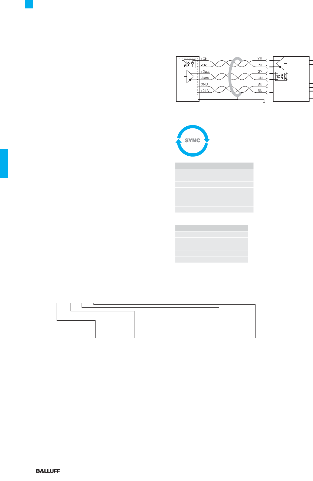
114
Compact Rod Series
SSI interface
Standard SSI interface
Controllers from Siemens, Bosch-Rexroth, WAGO, B & R, Parker,
Esitron, PEP etc. as well as Balluff BDD-AM 10-1-SSD and
BDD-CC 08-1-SSD display/controllers are used for synchronous
serial data transmission.
Reliable signal transmission, even with cable lengths of up to 400 m
between controller and BTL transducer is assured by noise-immune
RS485/422 differential line drivers and receivers. Any noise signals
are effectively suppressed.
Synchronized SSI interface
BTL5-S1_ _B-M_ _ _ _-P-_ _ _ _
Micropulse transducers with synchronized SSI interface are suit-
able for dynamic control applications. The data acquisition in the
transducer is synchronized with the external clock of the controller,
permitting an optimum calculation of the velocity in the controller.
The prerequisite for this synchronous mode of transducer operation
is consistent clock signal timing.
The maximum sampling frequency fA, at which a new current
value is generated for each sample, can be derived from the follow-
ing table:
Clock frequency depends on the cable length
Super-fast 2.5 kHz
sampling rate
Coding
0 Binary code
rising
(24 bit)
1 Gray code
rising
(24 bit)
6 Binary code
rising
(25 bit)
7 Gray code
rising
(25 bit)
Ordering example:
BTL5-S1_ _-M_ _ _ _-_ _-_ _ _ _-C
Standard
nominal stroke [mm] Connection type
Radial output
F05 Tefl on cable 5 m
Axial output
FA05 Tefl on cable 5 m
0025, 0050, 0075, 0100, 0125, 0150,
0175, 0200, 0225, 0250, 0275, 0300,
0325, 0350, 0375, 0400, 0425, 0450,
0475, 0500, 0550, 0600, 0650, 0700,
0750, 0800, 0850, 0900, 0950, 1000,
1100, 1200, 1300, 1400, 1500, 1600,
1700, 1800, 1900, 2000, 2250, 2500,
2750, 3000, 3250, 3500, 3750, 3850,
4000 or in 5 mm increments on request
System
resolution
1 1 µm
2 5 µm
3 10 µm
4 20 µm
5 40 µm
6 100 µm
7 2 µm
Housing
HB
WB
BTL5-S1... with processor/controller, wiring example
Processor
or
controller
Transducer
BTL5-S1...
Cable length
Clock frequency
< 25 m < 1000 kHz
< 50 m < 500 kHz
< 100 m < 400 kHz
< 200 m < 200 kHz
< 400 m < 100 kHz
mm mm Hz
< Nominal stroke
≤ 120 : 2500
120
< Nominal stroke
≤ 475 : 2000
475
< Nominal stroke
≤ 750 : 1500
750
< Nominal stroke
≤ 1250 : 1000
1250
< Nominal stroke
≤ 2600 : 500
2600
< Nominal stroke
≤ 4000 : 333
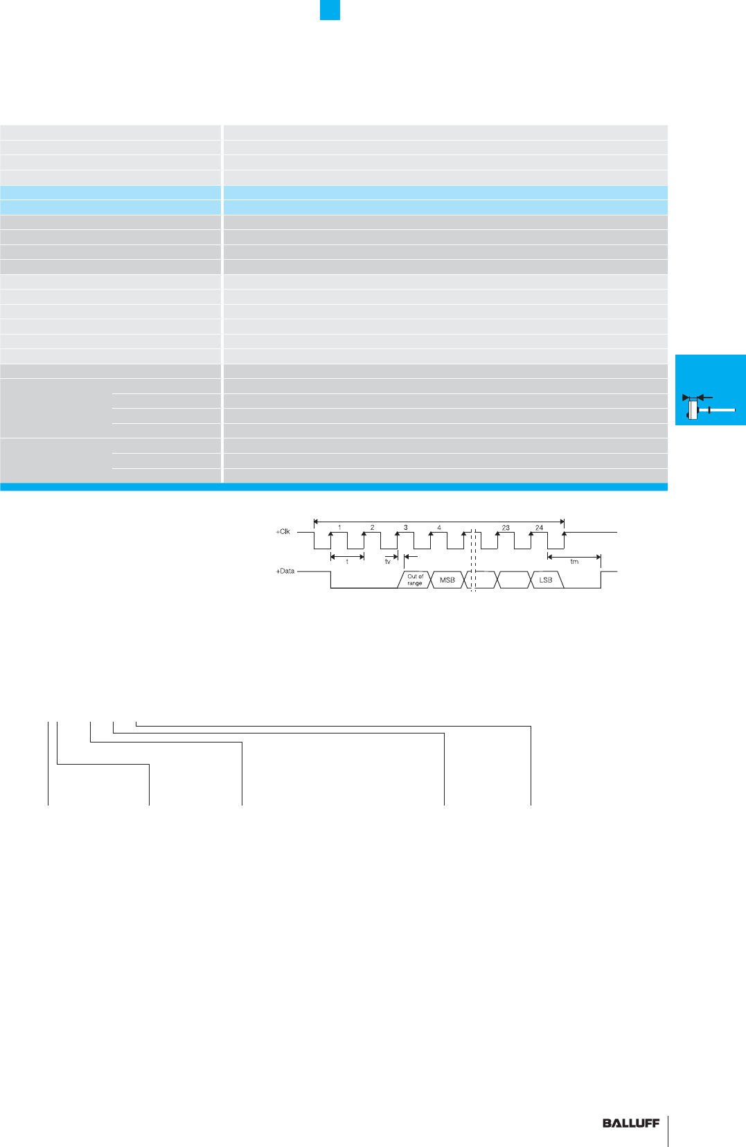
115■ www.balluff.com
Compact Rod Series
SSI interface
Series BTL5 rod
Output signal synchronous serial
Transducer interface S
Input interface synchronous serial
Part number BTL5-S1_ _-M_ _ _ _-_-_ _ _ _
Part number synchronization BTL5-S1_ _B-M_ _ _ _-_-_ _ _ _
System resolution depending on version (LSB)
1, 2, 5, 10, 20, 40 or 100 µm
Repeat accuracy ±1 digit
Hysteresis ≤ 1 digit
Sampling rate fSTANDARD = 2 kHz
max. non-linearity ±30 µm at 5 and 10 µm resolution or ≤ ±2 LSB
Temperature coeffi cient of overall system (6 µm + +5 ppm × L)/°C
Operating voltage 20...28 V DC
Current consumption ≤80 mA
Operating temperature –40...+85 °C
Storage temperature range –40...+100 °C
Pin assignments Pin Color
Control and data 1 YE +Clk
signals 2 GY +Data
3 PK –Clk
5 GN –Data
Operating 6 BU GND
voltage (external) 7 BN +24 V DC
8 WH must remain unconnected
short and
synchronized
Clock sequence
Ordering code for SSI interface with synchronization to clock (dynamic control applications)
insert the letter B! BTL5-S1_ _B-M_ _ _ _-_-_ _ _ _
■ Please enter the code for the coding,
system resolution, nominal stroke, design and
connection type in the ordering code!
Coding
0 Binary code
rising
(24 bit)
1 Gray code
rising
(24 bit)
6 Binary code
rising
(25 bit)
7 Gray code
rising
(25 bit)
Ordering example:
BTL5-S1_ _-M_ _ _ _-_-_ _ _ _
Standard
nominal stroke [mm] Connection type
Output radial
K02 PUR cable 2 m
K05 PUR cable 5 m
K10 PUR cable 10 m
K15 PUR cable 15 m
SR32 connector
Output radial
K02 PUR cable 2 m
K05 PUR cable 5 m
K10 PUR cable 10 m
K15 PUR cable 15 m
Output axial
KA02 PUR cable 2 m
KA05 PUR cable 5 m
KA10 PUR cable 10 m
KA15 PUR cable 15 m
S32 connector
0025, 0050, 0075, 0100, 0125, 0150,
0175, 0200, 0225, 0250, 0275, 0300,
0325, 0350, 0375, 0400, 0425, 0450,
0475, 0500, 0550, 0600, 0650, 0700,
0750, 0800, 0850, 0900, 0950, 1000,
1100, 1200, 1300, 1400, 1500, 1600,
1700, 1800, 1900, 2000, 2250, 2500,
2750, 3000, 3250, 3500, 3750, 3850,
4000 or in 5 mm increments on request
System
resolution
1 1 µm
2 5 µm
3 10 µm
4 20 µm
5 40 µm
6 100 µm
7 2 µm
Housing
K
H
W
■ Included:
– Transducer
– Short user's guide
Please order separately:
Magnets/fl oats, page 96
Mounting nuts, page 97
Connectors, page 148/149
K
Installation
notes
General
data
H
Installation
notes
General
data
W
Installation
notes
General
data
HB/WB
Installation
notes
General
data
Analog
interface
Digital
pulse
interface
SSI
interface
CANopen
interface
AR
General
data
Analog
interface
Digital
pulse
interface
Installation
notes

116
Compact Rod Series
CANopen® interface
CANopen interface
Based on CAN (ISO/IEC 7498 and DIN ISO 11898), CANopen pro-
vides a Layer-7 implementation for industrial CAN networks.
The serial data protocol of the CAN specifi cation is defi ned accord-
ing to the producer-consumer principle as opposed to most other
fi eldbus protocols. This eliminates target addressing of the process
data. Each bus station decides for itself how the received data are
processed.
The CANopen interface of the Micropulse transducer is compatible
with CANopen conforming with CiA Standard DS301 Rev. 3.0 as
well as with CAL and Layer 2 CAN networks.
CAN-BUS features
– Line topology, star structure also possible via repeaters
– Low-cost wiring with two-wire cable
– Fast response times, high data integrity using CRC, hamming
distance of 6
– 1 MBit/s with cable lengths < 25 m
– Protocol limits number of stations to 127
– Using multiple magnets: A minimum spacing of > 65 mm must be
maintained.
CANopen offers a high level of fl exibility with respect to functionality
and data exchange. Using a standard data sheet in the form of an
EDS fi le it is easy to link the Micropulse transducers to any CANopen
system.
Process Data Object (PDO)
12 Micropulse transducers send their position information optionally
in one, two or four PDOs with 8 bytes of data each. The contents
of the PDOs are freely confi gurable. The following information can be
sent:
– Current magnet position with resolution in 5 µm increments
– Current velocity of the magnet with resolution selectable in
0.1mm/s increments
– Current status of the four freely programmable cams per magnet.
Synchronization Object (SYNC)
Serves as a net-wide trigger for synchronizing all network partici-
pants. When the SYNC object is received, all Micropulse transducers
connected to the bus store their current position and velocity
information and then send it sequentially to the controller. This as-
sures time-synchronous acquisition of the measured values.
LED
Display of the CANopen status to DS303-3
FMM
The sensor can be operated as a 4-magnet type, whereby the sen-
sor itself recognizes how many magnets are currently active.
So if only two magnets are positioned in the measuring range, a valid
value is output for the fi rst two positions and a defi ned error value for
positions 3 and 4.
Emergency Object
This object is sent with the highest priority and is used for example
for error messages when the cam states change.
Service Data Object (SDO)
Service Data Objects transmit the parameters for the transducer
confi guration. The transducer may be confi gured on the bus by
the controller or offl ine using a PC with a confi guration tool which
runs under Windows. The confi guration is stored in the non-volatile
memory of the transducer.
CiA 199911-301v30/11-009
Use of multiple magnets
A minimum spacing of > 65 mm must be maintained.
User-friendly hardware
and software set-up
Software
confi guration
1 1 × position and
1 × velocity
2 2 × position and
2 × velocity
3 4 × position
Ordering example:
BTL5-H1_ _-M_ _ _ _-_ _-_ _ _ _-C
Standard
nominal stroke [mm]
0025, 0050, 0075, 0100,
0125, 0150, 0175, 0200,
0225, 0250, 0275, 0300,
0325, 0350, 0375, 0400,
0425, 0450, 0475, 0500,
0550, 0600, 0650, 0700,
0750, 0800, 0850, 0900,
0950, 1000, 1100, 1200,
1300, 1400, 1500, 1600,
1700, 1800, 1900, 2000,
2250, 2500, 2750, 3000,
3250, 3500, 3750, 3850,
4000 or in 5 mm
increments on request.
Baud rate
0 1 MBaud
1 800 kBaud
2 500 kBaud
3 250 kBaud
4 125 kBaud
5 100 kBaud
6 50 kBaud
7 20 kBaud
8 10 kBaud
Housing
HB
WB
Connection type
Radial output
K05 PUR cable 5 m
Axial output
KA05 PUR cable 5 m
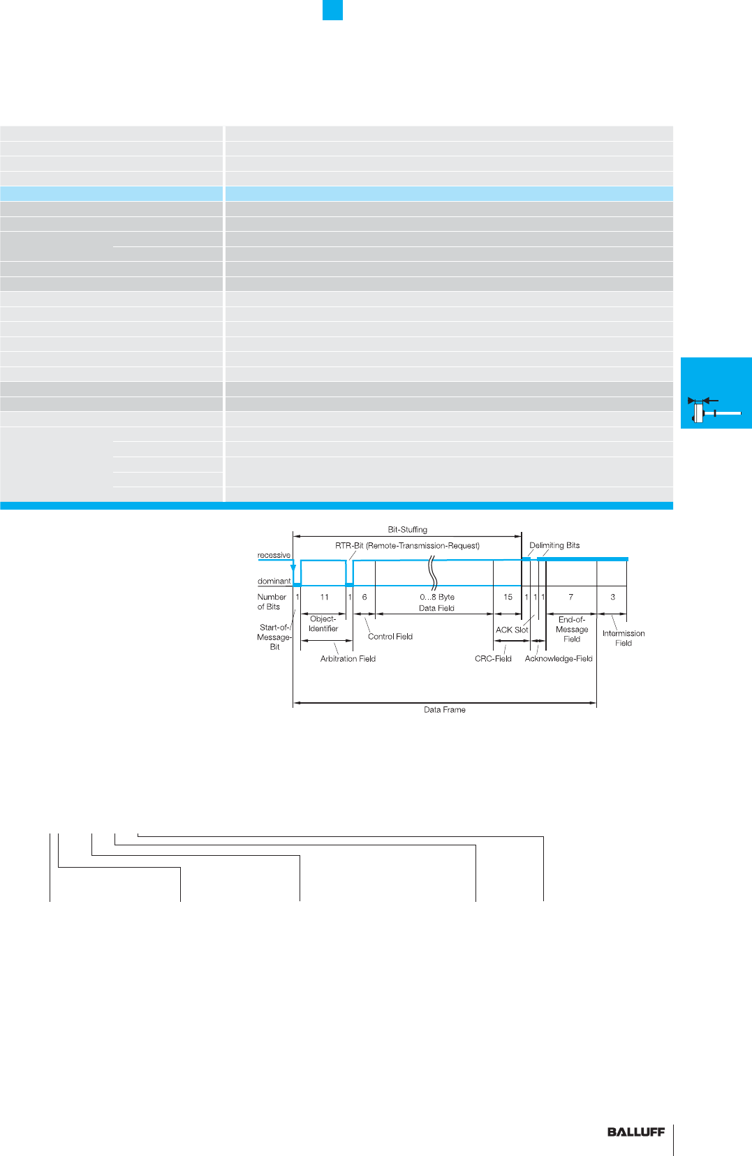
117■ www.balluff.com
Compact Rod Series
CANopen® interface
Series BTL5 rod
Output signal CANopen
Transducer interface H
Input interface CANopen
Part number BTL5-H1_ _-M_ _ _ _-...
CANopen Version potential-free
Repeat accuracy ±1 digit
System resolution Position 5 µm increments
confi gurable Velocity 0.1 mm/s increments
Hysteresis ≤ 1 digit
Sampling rate fSTANDARD = 1 kHz
max. non-linearity ±30 µm at 5 µm resolution
Temperature coeffi cient of overall system (6 µm + 5 ppm × L)/°C
Operating voltage 20...28 V DC
Current consumption ≤ 100 mA
Operating temperature –40...+85 °C
Storage temperature range –40...+100 °C
Cable length [m] per CiA DS301 < 25 < 50 < 100 < 250 < 500 < 1000 < 1250 < 2500
Baud rate [kBaud] per CiA DS301 1000 800 500 250 125 100 50 20/10
Pin assignments Pin Color
Control and 1 WH CAN_GND
data signals 2 BN +24 V
3 BU 0 V (GND)
4 GY CAN_HIGH
5 GN CAN_LOW
■ Please enter the code for the software
confi
guration, baud rate, nominal stroke
and housing in the ordering code. Cable on
request.
■ Included:
– Transducer
– Short user's guide
Please order separately:
Magnets/fl oats, page 96
Mounting nuts, page 97
Connectors, page 148/149
Position +
Velocity
Using the CANopen interface and cable lengths up to 2500 m, the
signal is sent at a length-dependent baud rate to the controller. The
high noise immunity of the connection is achieved using differential
drivers and by the data monitoring scheme.Ordering example:
BTL5-H1_ _-M_ _ _ _-_-_ _ _ _
Software
confi guration
1 1 × position and
1 × velocity
2 2 × position and
2 × velocity
3 4 × position
Standard
nominal stroke [mm]
0025, 0050, 0075, 0100, 0125,
0150, 0175, 0200, 0225, 0250,
0275, 0300, 0325, 0350, 0375,
0400, 0425, 0450, 0475, 0500,
0550, 0600, 0650, 0700, 0750,
0800, 0850, 0900, 0950, 1000,
1100, 1200, 1300, 1400, 1500,
1600, 1700, 1800, 1900, 2000,
2250, 2500, 2750, 3000, 3250,
3500, 3750, 3850, 4000 or in
5 mm increments on request.
Baud rate
0 1 MBaud
1 800 kBaud
2 500 kBaud
3 250 kBaud
4 125 kBaud
5 100 kBaud
6 50 kBaud
7 20 kBaud
8 10 kBaud
Housing
K
H
W
K
Installation
notes
General
data
H
Installation
notes
General
data
W
Installation
notes
General
data
HB/WB
Installation
notes
General
data
Analog
interface
Digital
pulse
interface
SSI
interface
CANopen
interface
AR
General
data
Analog
interface
Digital
pulse
interface
Installation
notes
Connection type
Radial output
K02 PUR cable 2 m
K05 PUR cable 5 m
SR92 Connector
Radial output
K02 PUR cable 2 m
K05 PUR cable 5 m
Axial output
KA02 PUR cable 2 m
KA05 PUR cable 5 m
S92 Connector
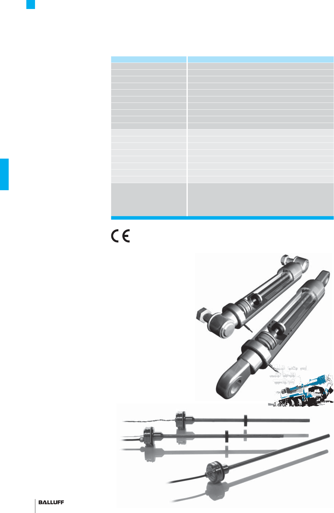
118
AR Rod Series
General data
Position detection in
mobile hydraulics
Sensors are being used increas-
ingly to extend the useful life and
improve safety in mobile equip-
ment. The new Micropulse AR
transducer from Balluff senses
the piston position in mobile
hydraulic cylinders.
The sensor operates according
to the proven magnetostrictive
principle. The compact size of
the transducer makes it ideal for
use in pivot bearing and spheri-
cal eye end cylinders or large
bore cylinders. The processing
electronics integrated in the
transducer have been designed
to meet the strict EMC Directives
for industrial lift trucks, agricul-
tural and forestry equipment and
earthmoving machinery.
Compatibility testing
according to EMC Directives
ISO 14982 Agricultural and
Forestry Machinery
ISO 13766 Earthmoving
Machinery
ISO 7637-1/2/3
Road Vehicles
EN 12895 Industrial Trucks
EN 50121-3-2
Railway Applications
ISO 11452-5 Electromagnetic
HF fi eld, 200 V/m
e1 type approval
The e1 type approval is granted
by the German Federal Motor
Transport Authority KBA and
confi rms that special motor
vehicle standards have been
maintained. The devices may be
mounted on vehicles which travel
on public roads. The standards
describe EMC conditions under
which the devices must operate
without failure. e1 approved
Micropulse transducers are
indicated by the designation
"-SA265-" in the part number.
Series BTL6 rod AR
Shock load 100 g/6 ms per IEC 60068-2-27
Continuous shock 50 g/2 ms
Vibration 12 g, 10...2000 Hz per IEC 60068-2-6
Polarity reversal protected yes
Dielectric strength 500 V DC (GND to housing)
Degree of protection as per IEC 60529
IP 67
Housing material Stainless steel outer tube 1.4571, stainless steel fl ange 1.4404
Pressure rating with 10.2 mm outer tube E2
350 bar installed in hydraulic cylinder
Pressure rating with 8 mm outer tube E28
250 bar installed in hydraulic cylinder
Connection type Cable connection or pigtail
EMC tests:
RF emission EN 55016-2-3 Group 1, Class A/B
Static electricity (ESD) IEC 61000-4-2 Severity Level 3
Electromagnetic fi elds (RFI) IEC 61000-4-3 Severity Level 3
Fast transients (BURST) IEC 61000-4-4 Severity Level 3
Surge voltage IEC 61000-4-5 Severity Level 2
Line-induced disturbances IEC 61000-4-6 Severity Level 3
Magnetic fi elds IEC 61000-4-8 Severity Level 4
Standard nominal strokes [mm]
with 8 mm outer tube
(style E28) is the max. nominal
stroke 1016 mm
0025, 0050, 0075, 0100, 0125, 0150, 0175, 0200, 0225, 0250,
0275, 0300, 0325, 0350, 0375, 0400, 0425, 0450, 0475, 0500,
0550, 0600, 0650, 0700, 0750, 0800, 0850, 0900, 0950, 1000,
1100, 1200, 1300, 1400, 1500, 1524 or 1 mm increments on
request
e1
Integrated in cylinders for
controlled work processes
Caution! Prior to design,
installation and startup,
please read the instructions
in the user guide!
www.balluff.com
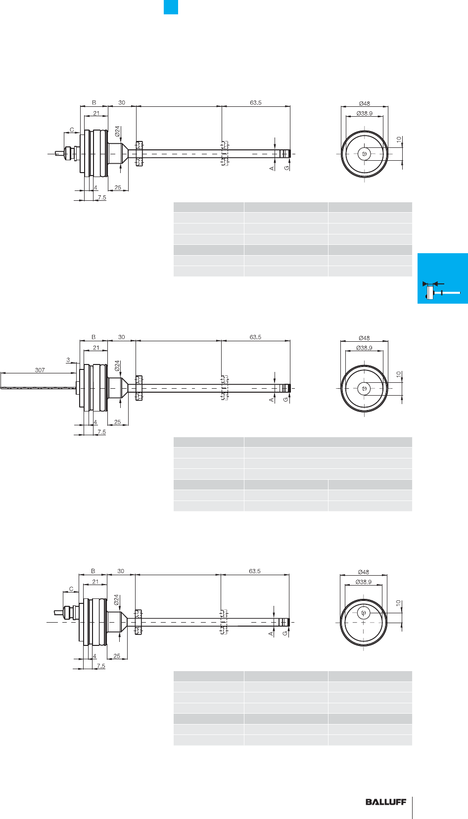
119■ www.balluff.com
AR Rod Series
General data
Housing E2/E28
BTL6-...-E2/E28-_ _ _ _-KA
Cable outlet
axial centric
Housing E2/E28
BTL6-...-E2/E28-_ _ _ _-LA
Cable outlet
axial with pigtail
Housing E2/E28
BTL6-...-E2/E28-_ _ _ _-KE
Cable outlet
axial eccentric
BC
BTL6-A/B 25.2 13
BTL6-E 29.75 13
BTL6-P 25.2 16
AG
E2 10.2 Thread M4×4/6 deep
E28 8 without thread
BC
BTL6-A/B 25.2 13
BTL6-E 29.75 13
BTL6-P 25.2 16
AG
E2 10.2 Thread M4×4/6 deep
E28 8 without thread
B
BTL6-A/B 25.7
BTL6-E 30.25
BTL6-P 25.7
AG
E2 10.2 Thread M4×4/6 deep
E28 8 without thread
Magnet
Nominal stroke = measuring range
Damping zone
(non-usable area)
Magnet
Nominal stroke = measuring range Damping zone
(non-usable area)
Magnet
Nominal stroke = measuring range
Damping zone
(non-usable area)
K
Installation
notes
General
data
H
Installation
notes
General
data
W
Installation
notes
General
data
HB/WB
Installation
notes
General
data
Analog
interface
Digital
pulse
interface
SSI
interface
CANopen
interface
AR
General
data
Analog
interface
Digital
pulse
interface
Installation
notes
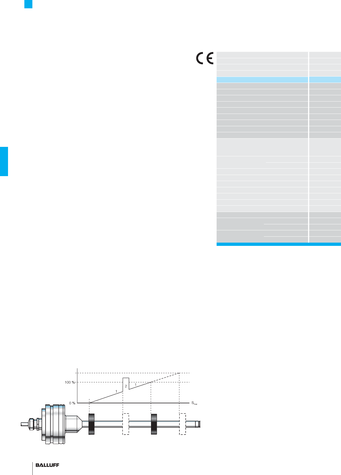
120
AR Rod Series
Analog interface
Magnet position
1 Within the measuring range
2 Magnet not present
Output signal
Error signal
The propagation time of an ultrasonic wave induced by magneto-
striction is used to determine the position of the magnet.
The position is output as an analog value which rises. This is done
with high precision and repeatability within the measuring range des-
ignated as the nominal stroke length. If there is no magnet within the
measuring range, an error signal is output. There is a damping zone
at the rod end. When an magnet is in this zone the output is spuri-
ous. The electrical connection between the transducer, the controller
and the power supply is established using a cable or pigtail.
Series
Output signal
Transducer interface
Input interface
Part number
Output voltage
Output current
Load current
max. ripple
Load resistance
System resolution
Hysteresis
Repeat accuracy
Sampling rate
max. non-linearity
Temperature
coeffi cient
voltage output
Current output
Operating voltage
Current consumption
Polarity reversal protected
Overvoltage protection
Dielectric strength
Operating temperature
Storage temperature range
Pin assignments Color
Output signals GY
GN
Operating voltage BU
BN
Output signal rising
■ Please enter the code for the output signal,
nominal stroke, housing and connection type
in the ordering code!
■ Included:
– Transducer
– Short user's guide
Please order separately:
Magnets/fl oats, page 96
Connect shield to housing
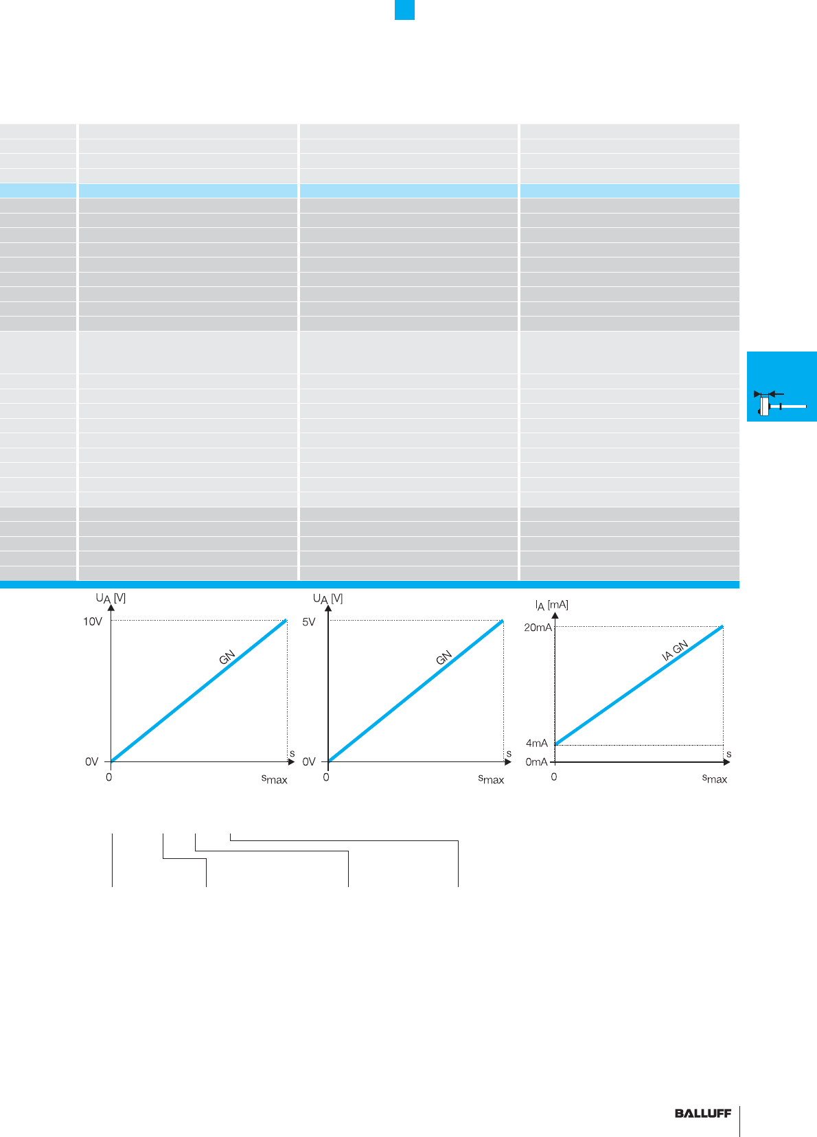
121■ www.balluff.com
AR Rod Series
Analog interface
BTL6 rod AR BTL6 rod AR BTL6 rod AR
analog analog analog
ABE
analog analog analog
BTL6-A500-M_ _ _ _-_ _ _-_ _ _ _ BTL6-B500-M_ _ _ _-_ _ _-_ _ _ _ BTL6-E500-M_ _ _ _-_ _ _-_ _ _ _
0...10 V 0...5 V
4...20 mA
max. 2 mA max. 2 mA
≤ 5 mV ≤ 2 mV
≤ 500 ohms
±
1.5 mV
±
1.5 mV
±
7 µA
≤ 5 µm ≤ 4 µm
System resolution/min. 2 µm System resolution/min. 2 µm System resolution/min. 2 µm
fSTANDARD = 1 kHz fSTANDARD = 1 kHz fSTANDARD = 1 kHz
±200 µm up to 500 mm nominal stroke
typ. ±0.02 % ≥ 500 nominal stroke
±200 µm up to 500 mm nominal stroke
typ. ±0.02 % ≥ 500 nominal stroke
±200 µm up to 500 mm nominal stroke
typ. ±0.02 % ≥ 500 nominal stroke
[150 µV/°C + (5 ppm/°C × P × U/L)] × ΔT [150 µV/°C + (5 ppm/°C × P × U/L)] × ΔT [150 µV/°C + (5 ppm/°C × P × U/L)] × ΔT
[0.6 µA/°C + (10 ppm/°C × P × I/L)] × ΔT [0.6 µA/°C + (10 ppm/°C × P × I/L)] × ΔT [0.6 µA/°C + (10 ppm/°C × P × I/L)] × ΔT
10...30 V DC 10...30 V DC 10...30 V DC
typ. ≤ 60 mA typ. ≤ 60 mA typ. ≤ 60 mA
yes yes yes
yes yes yes
500 V DC (ground to housing) 500 V DC (ground to housing) 500 V DC (ground to housing)
–40...+85 °C –40...+85 °C –40...+85 °C
–40...+100 °C –40...+100 °C –40...+100 °C
BTL6-A500... BTL6-B500... BTL6-E500...
0 V Output 0 V Output 0 V Output
0...10 V 0...5 V 4...20 mA
GND GND GND
10...30 V DC 10...30 V DC 10...30 V DC
Output
signal
A 0...10 V
B 0...5 V
E 4...20 mA
Standard
nominal stroke [mm]
Ordering example:
BTL6-_500-M_ _ _ _-_ _ _-_ _ _ _ _
Housing
E2 Outer tube
Ø 10.2 mm
E28 Outer tube
Ø 8 mm, max.
nominal stroke
1016 mm
0025, 0050, 0075, 0100,
0125, 0150, 0175, 0200,
0225, 0250, 0275, 0300,
0325, 0350, 0375, 0400,
0425, 0450, 0475, 0500,
0550, 0600, 0650, 0700,
0750, 0800, 0850, 0900,
0950, 1000, 1100, 1200,
1300, 1400, 1500, 1524
or in 1 mm increments
on request
Connection type
Axial output
KA02 PUR cable 2 m
KA05 PUR cable 5 m
KA10 PUR cable 10 m
KA15 PUR cable 15 m
KA20 PUR cable 20 m
Axial eccentric output
KE02 PUR cable 2 m
KE05 PUR cable 5 m
KE10 PUR cable 10 m
KE15 PUR cable 15 m
KE20 PUR cable 20 m
K
Installation
notes
General
data
H
Installation
notes
General
data
W
Installation
notes
General
data
HB/WB
Installation
notes
General
data
Analog
interface
Digital
pulse
interface
SSI
interface
CANopen
interface
AR
General
data
Analog
interface
Digital
pulse
interface
Installation
notes
Axial output
LA00.3 PUR pigtail 0.3 m
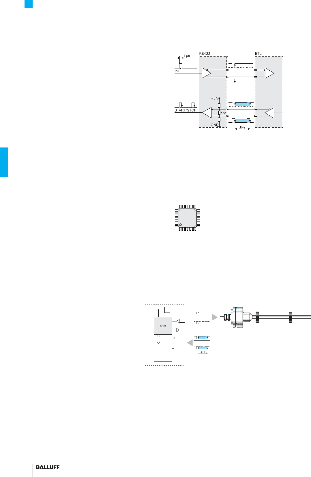
122
AR Rod Series
Digital pulse interface P510
P510 interface
Compatible with Balluff BTA processors as well as controllers and
modules from various manufacturers, including Siemens, B & R,
Bosch, Phoenix Contact, Mitsubishi, Sigmatek, Parker, Esitron and
WAGO. Reliable signal transmission, even over cable lengths up to
500 m between BTA and transducer is assured by the noise-immune
RS485 differential line drivers and receivers. Noise signals are ef-
fectively suppressed.
Universal P510 for rising and falling edge evaluation
As a consequence of different control philosophies, digital pulse
interfaces are available in two different types depending on the
controller.
The difference lies in how the edges are processed. The falling
edges are processed in the "P interface" and the rising edges in the
"M interface".
To reduce the number of different models to a minimum, the "P510
interface" was created as a universal pulse interface which combines
both functions. The reference point for the propagation time mea-
surement is the "start pulse".
Block diagram of P interface
Extremely precise digitizing chip for P510 pulse interface
Companies developing their own control and processing electronics
can create a highly accurate P interface cost effectively and with mi-
nimum effort using the Balluff digitizing chip. The digitizing chip was
developed as a high-resolution, confi gurable ASIC for Micropulse
transducers with P interface. Digitizing chip 44QFP
Benefi ts
– High resolution: the actual 1 µm of the BTL is fully supported
by the 133 ps resolution of the chip (at low clock frequency 2 or
20 MHz)
– Position data from 4 magnets can be processed simultaneously
– 4/8-bit processor interface
ASIC INFO: +49 7158 173-370
CPU
controller
4/8-
bit
BUS
5 V
Osc.
INIT
Micropulse transducer with 1 to
4 magnets
Controller or processing
electronics
P pulse signal
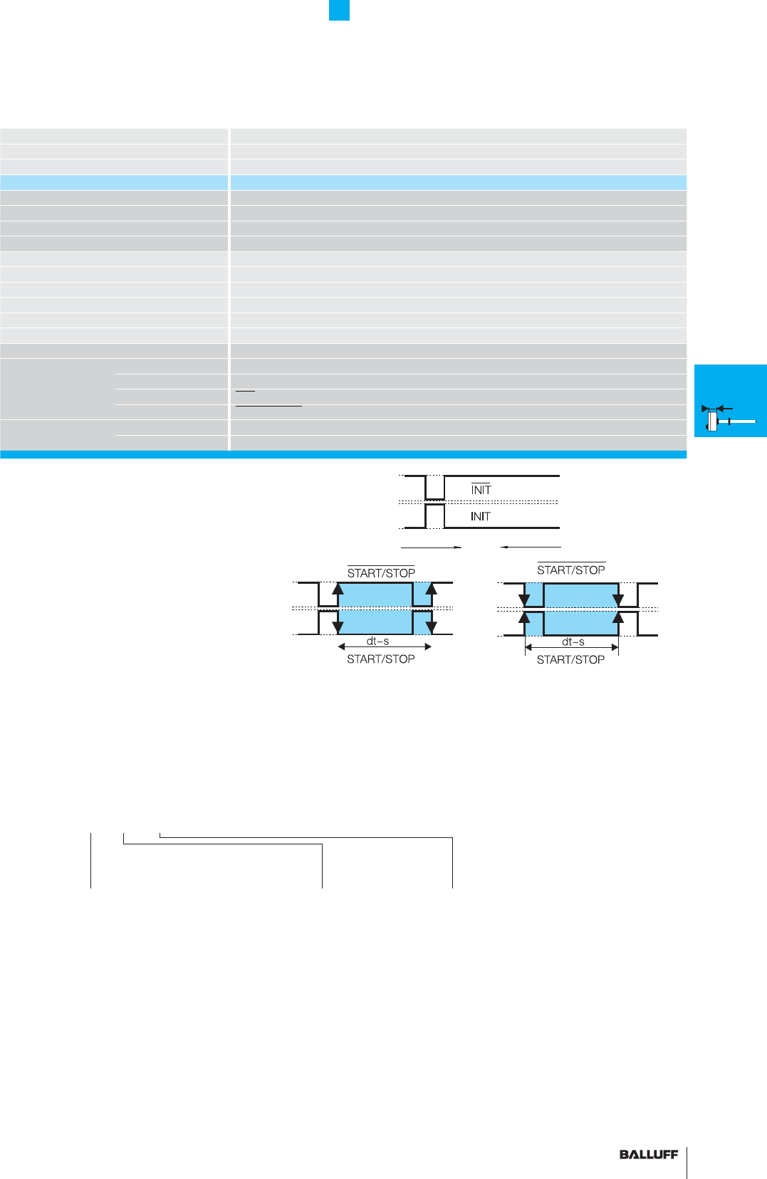
123■ www.balluff.com
AR Rod Series
Digital pulse interface P510
Series BTL6 rod AR
Transducer interface Pulse P510
Input interface Pulse P510
Part number BTL6-P510-M_ _ _ _-_ _ _- _ _ _ _ _
System resolution processing-dependent
Repeat accuracy ≤ 10 µm
Repeatability ≤ 20 µm
Resolution ≤ 10 µm
Non-linearity ±200 µm up to 500 mm nominal stroke
typ. ±0.02 %, max.. ±0.04 % 500...1500 mm nominal stroke
Operating voltage 10...30 V DC
Current consumption ≤ 60 mA (at 1kHz)
Operating temperature –40...+85 °C
Storage temperature range –40...+100 °C
Pin assignments Color BTL6-P510-M...
Input/Output Input YE INIT
signals Output GY START/STOP
Input PK INIT
Output GN START/STOP
Operating voltage BU GND
BN 10...30 V DC
Ordering example:
BTL6-P510-M_ _ _ _-_ _ _-_ _ _ _ _
Standard
nominal stroke [mm]
0025, 0050, 0075, 0100, 0125, 0150,
0175, 0200, 0225, 0250, 0275, 0300,
0325, 0350, 0375, 0400, 0425, 0450,
0475, 0500, 0550, 0600, 0650, 0700,
0750, 0800, 0850, 0900, 0950, 1000,
1100, 1200, 1300, 1400, 1500, 1524
or in 1 mm increments on request
Connect shield to housing
■ Please enter the code for the nominal
stroke, housing and connection type in the
ordering code.
■ Included:
– Transducer
– Short user's guide
Please order separately:
Magnets/fl oats, page 96
P1 P510 M1
Housing
E2 Outer tube
Ø 10.2 mm
E28 Outer tube
Ø 8 mm, max.
nominal stroke
1016 mm
Connection type
Axial output
KA02 PUR cable 2 m
KA05 PUR cable 5 m
KA10 PUR cable 10 m
KA15 PUR cable 15 m
KA20 PUR cable 20 m
Axial eccentric output
KE02 PUR cable 2 m
KE05 PUR cable 5 m
KE10 PUR cable 10 m
KE15 PUR cable 15 m
KE20 PUR cable 20 m
Axial output
LA00.3 PUR pigtail 0.3 m
K
Installation
notes
General
data
H
Installation
notes
General
data
W
Installation
notes
General
data
HB/WB
Installation
notes
General
data
Analog
interface
Digital
pulse
interface
SSI
interface
CANopen
interface
AR
General
data
Analog
interface
Digital
pulse
interface
Installation
notes
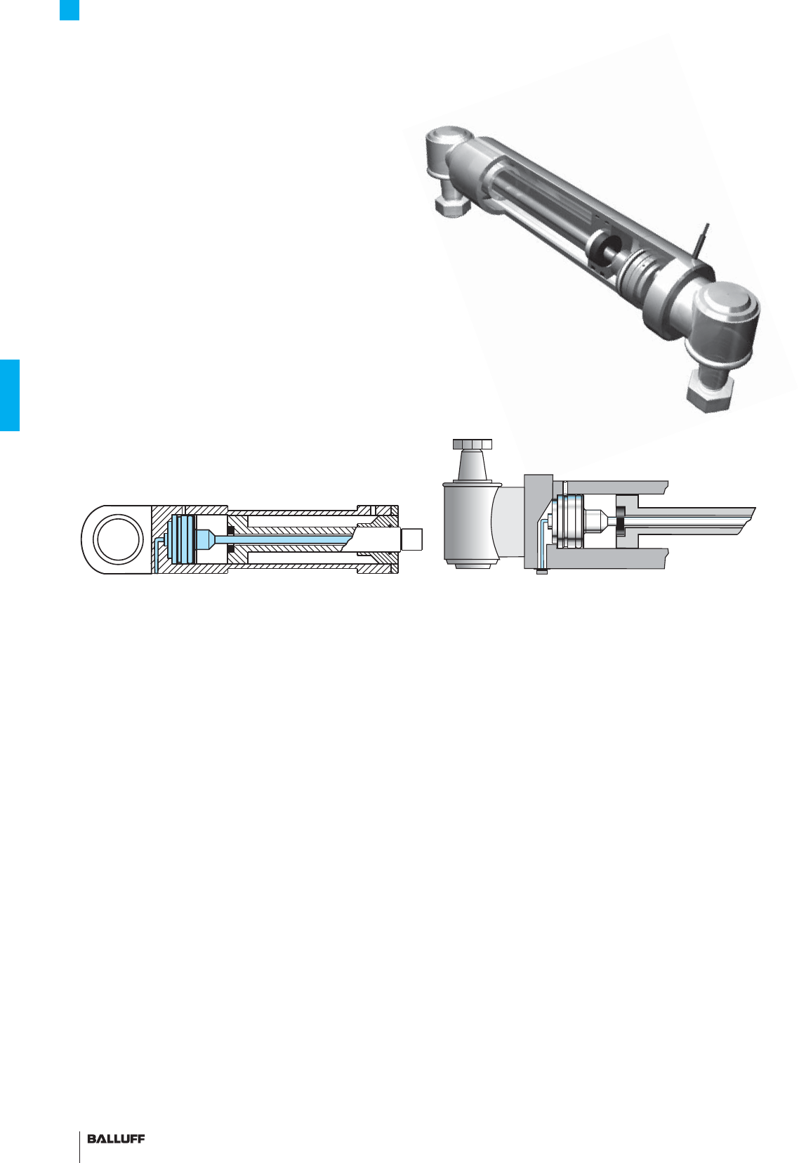
124
AR Rod Series
Installation notes
Series AR BTL Micropulse transducers are designed for integration
in hydraulic cylinders. The transducer is supported mechanically by
the housing. Three M5 set screws spaced at an angle of 120 °C hold
the transducer, which fi ts into a Ø 48 H8 hole.
Sealing is accomplished using the supplied O-ring and support ring.
The magnet integrated in the piston marks the actual position of the
piston without making contact.
The metal surrounding of the cylinder eliminates the need for a cable shield when the BTL AR...LA, cable outlet pigtail version
is installed in the cylinder. The pigtail version cannot be used without additional EMC protection (shield).
Caution! Prior to design,
installation and startup,
please read the instructions
in the user guide!
www.balluff.com
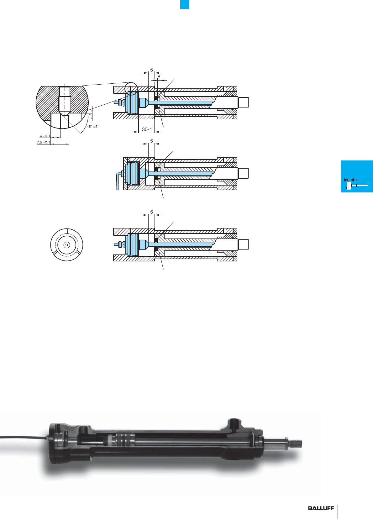
125■ www.balluff.com
Non-magnetizable spacer
Magnet
Installation examples
non-magnetizable material
Magnet
Set screw
DIN 914 M5×8
Fixing the
transducer using
three M5 set screws
spaced 120 °C
Non-magnetizable spacer
Magnet
1 Installation on piston side,
in magnetic piston material
2 Installation from rear,
in magnetic piston material
3 Installation on piston side
AR Rod Series
Installation notes
K
Installation
notes
General
data
H
Installation
notes
General
data
W
Installation
notes
General
data
HB/WB
Installation
notes
General
data
Analog
interface
Digital
pulse
interface
SSI
interface
CANopen
interface
AR
General
data
Analog
interface
Digital
pulse
interface
Installation
notes
1
2
3

126
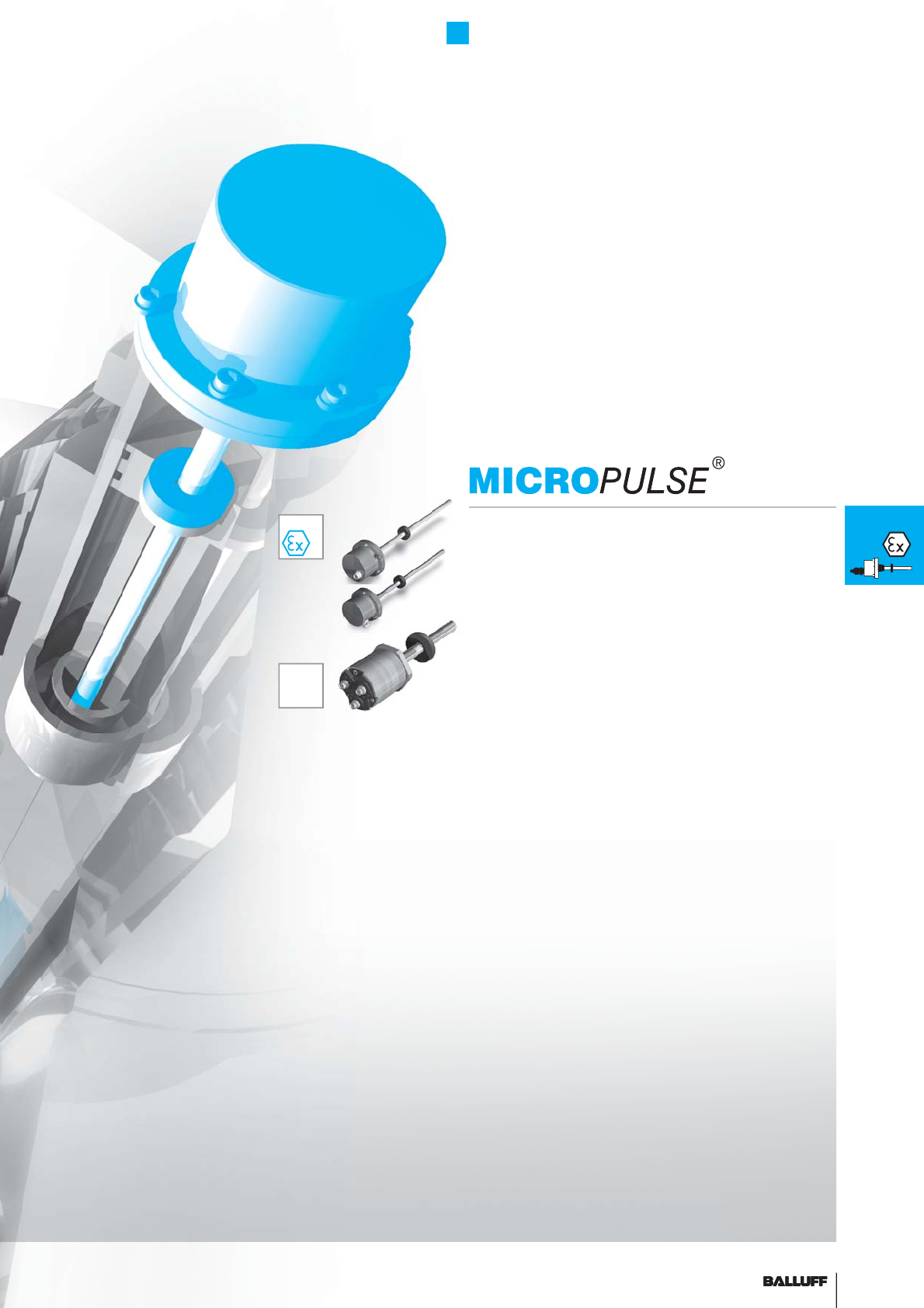
127■ www.balluff.com■www.
b
a
ll
u
ff
.com 127■ www.balluff.com 127■ www.balluff.com 127
EX
Filling level sensor in zone 0/1 128
Transducer in zone 1 129
Dex rod series, general data 130
J-DEXC rod series, general data 132
PEX rod series, general data 134
NEX rod series, general data 135
Floats and magnets 136
T
Redundant 138
Rod Series EX
Contents
T
Many applications require the use of distance sensors in potentially
explosive areas. Flameproof magnetostrictive Micropulse transduc-
ers are available in a wide range of designs for use in zone 0 and 1.
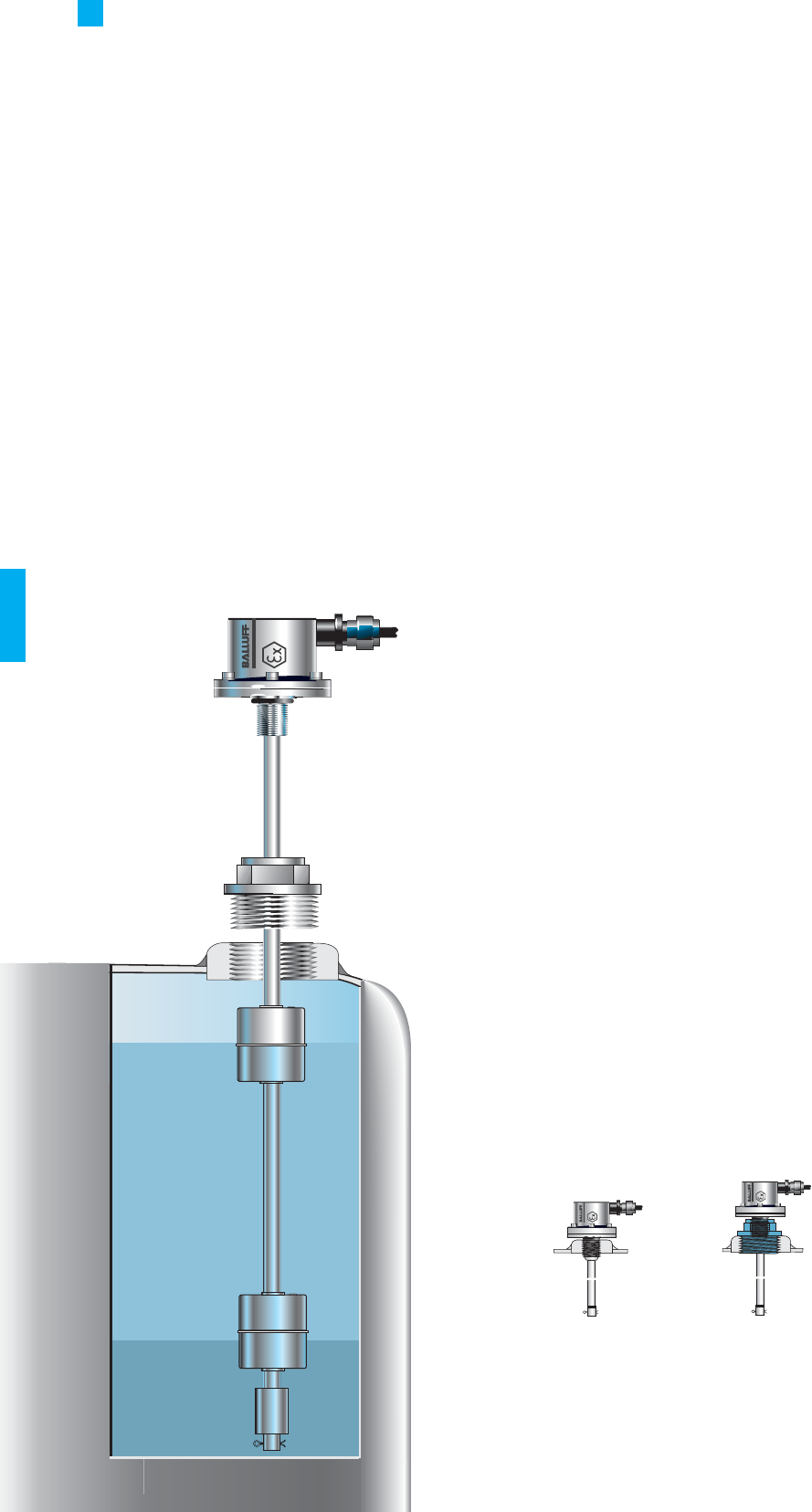
Rod Series EX
Filling level sensor in zone 0/1
BTL5-_1-M....-B-DEXA-_ _ _
The "DEXA" rod version is the safe and reliable approach to level
applications in Zone 0. The fl oat is protected against loss by a cotter
pin. Floats, page 136
Applications
– Filling stations
– Tank systems
– Refi neries
– Chemical industry
– Pharmaceuticals
Zone 0
Zone 1
Caution! Prior to design, installation and startup, please read
the instructions in the user guide!
www.balluff.com
Installation examples
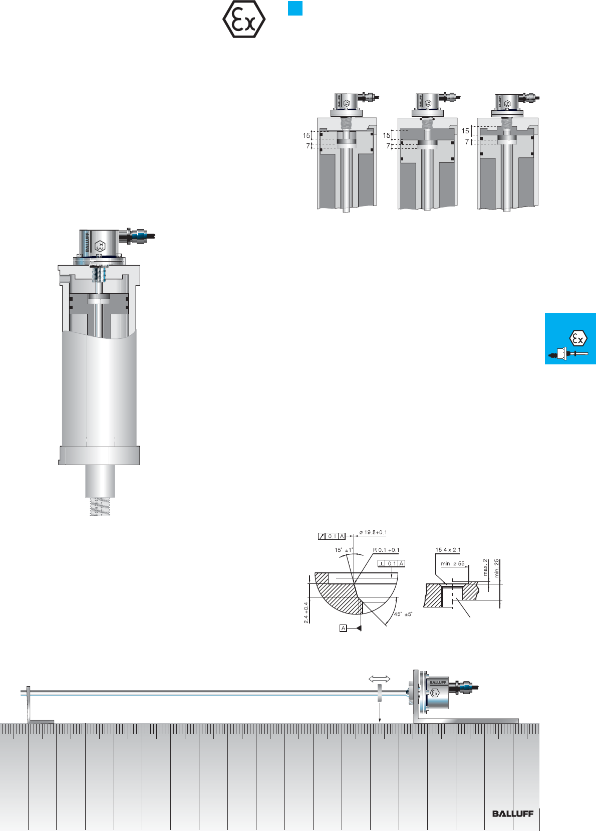
■ www.balluff.com 129
Rod Series EX
Transducer in zone 1
BTL5-_1-M....-B-DEXB-_ _
The BTL can be used to sense the position of a hydraulic piston
directly without making contact, even up to pressures of 600 bar.
The BTL is threaded into the head of the cylinder. The rod section
enters a drilled hole in the piston.
Applications
– Position feedback in hydraulic cylinders
– Valve positioning in power plants
– Dosimetry
– Positioning spray guns
Installation
The Micropulse transducer BTL has a mounting thread M18×1.5.
We recommend that the mounting is made of non-magnetizable
material.
If magnetizable materials are used, the installation must be carried
out as shown in the drawing below. Sealing is at the fl ange mounting
surface using the supplied O-ring 15.4×2.1 with M18×1.5 thread.
Insertion hole
per ISO 6149
O-ring groove
General linear positioning in zone 1
EX
Filling level
sensor
in zone 0/1
Transducer
in zone 1
Rod DEX
Rod J-DEXC
Rod PEX
Rod NEX
Floats
and
magnets
T
Redundant
130
Rod Series DEX
General data
Pressure rated to 600 bar, high repeatability, non-contact, robust
The BTL Micropulse transducer is a robust position feedback system
for measuring ranges between 25 and 4000 mm as well as use
under extreme ambient conditions.
Ex protection type "d" fl ameproof enclosure
Transducers designated Ex d IIB + H2 T6 meet the requirements for
electrical devices in explosive atmospheres. When using you must
follow the relevant safety regulations, such as:
– Explosion protection guidelines (EX-RL)
– Constructing electrical equipment in potentially explosive areas
(VDE 0165)
– Protection type "d", fl ameproof enclosure (EN 60079-1)
Transducers from category II 1/2 G designated Ex d IIB+H2 T6 meet
the requirements for electrical devices in areas containing potentially
explosive gases. Requirements for areas containing fl ammable
dust are also fulfi lled in accordance with category II 3D designated
Ex tD IP67 T85°C, A zone 22.
Flameproof "d"
Ex d IIB + H2 T6, stainless steel
Zone 1
partition
Zone 0
ATEX
A11 0...10 V and 10...0 V,
Rising and falling
E10 4...20 mA, rising
E17 20...4 mA, falling
C10 0...20 mA, rising
C17 20...0 mA, falling
G11 –10...10 V and
10...–10 V,
Rising and falling
Analog interface no null or end point trim possible, see page 110 for technical data
Ordering example:
BTL5-_ _ _-M_ _ _ _-_-DEX_-_ _ _ _
Standard nominal stroke [mm] Connection type
Axial cable outlet,
housing B only
KA02 PUR cable 2 m
KA05 PUR cable 5 m
KA10 PUR cable 10 m
KA15 PUR cable 15 m
Radial cable outlet
K02 PUR cable 2 m
K05 PUR cable 5 m
K10 PUR cable 10 m
K15 PUR cable 15 m
0025, 0050, 0075, 0100, 0125,
0150, 0175, 0200, 0225, 0250,
0275, 0300, 0325, 0350, 0375,
0400, 0425, 0450, 0475, 0500,
0550, 0600, 0650, 0700, 0750,
0800, 0850, 0900, 0950, 1000,
1100, 1200, 1300, 1400, 1500,
1600, 1700, 1800, 1900, 2000,
2250, 2500, 2750, 3000, 3250,
3500, 3750, 3850, 4000 or
in 5 mm increments on request
Housing
B
J
Rod end
A Float stop
B Short stop
0 Binary code rising (24 bit)
1 Gray code rising (24 bit)
6 Binary code rising (25 bit)
7 Gray code rising (25 bit)
SSI interface, see page 114 for technical data
Ordering example:
BTL5-S1_ _-M_ _ _ _-B-DEX_-_ _ _ _
BTL5-S1_ _-M_ _ _ _-B-DEX _-_ _ _ _
System
resolution Connection type
see above
analog interface DEX
1 1 µm
2 5 µm
3 10 µm
4 20 µm
5 40 µm
Rod end
A Float stop
B Short stop
Standard
nominal stroke [mm]
see above
analog interface DEX
Output signal
P Pulse interface P
M Pulse interface M
I Pulse interface I
Digital pulse interface, see page 112 for technical data
Ordering example:
BTL5-_1-M_ _ _ _-B-DEX_-_ _ _ _
Standard nominal stroke [mm] Connection type
see above
analog interface DEX
see above
analog interface DEX
Rod end
A Float stop
B Short stop
Interface
Coding
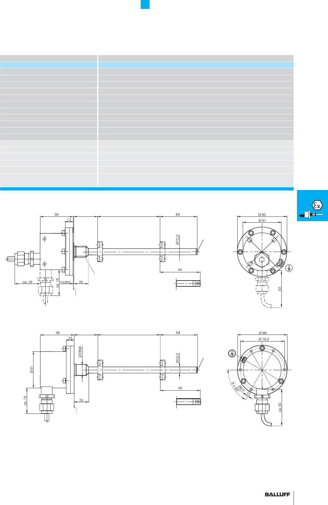
131■ www.balluff.com
■ Included:
– Transducer
– User guide
Please order separately:
Magnets, page 96
Floats, page 136
Rod Series DEX
General data
Series BTL5 Compact rod, Ex
Part number BTL5-_1-M_ _ _ _ _ -_-DEX_-_ _ _ _
Shock load 100 g/6 ms per IEC 60068-2-27 and 100 g/2 ms per IEC 60068-2-29
Vibration 12 g, 10...2000 Hz per IEC 60068-2-6
Operating temperature –40...+60 °C
Polarity reversal protected yes
Overvoltage protection Transzorb protection diodes
Dielectric strength 500 V DC (GND to housing)
Degree of protection as per IEC 60529 IP 67
Housing material Stainless steel 1.4305
Flange and tube material Tube stainless steel 1.4571, fl ange 1.4571 or 1.4429 or 1.4404
Housing attachment Thread M18×1.5, 3/4"-16 UNF on request
Connection type Cable connection
EMC testing:
RF emission EN 55016-2-3 Group 1, Class A
Static electricity (ESD) IEC 61000-4-2 Severity Level 3
Electromagnetic fi elds (RFI) IEC 61000-4-3 Severity Level 3
Fast transients (BURST) IEC 61000-4-4 Severity Level 4
Conducted interference induced
by high-frequency fi elds
IEC 61000-4-6 Severity Level 3
Housing B, metric mounting thread
cable outlet axial, radial
Housing J,
fl ange ∅ 18 mm, PCD ∅ 76.2 mm,
Radial cable outlet
Caution! Prior to design, installation and startup, please read
the instructions in the user guide!
www.balluff.com
Magnet
B: 30
Safety stop
BTL5...B-DEXA-KA_ _
Thread
M4×4, 6 deep
Short safety stop
BTL5...B-DEXB-KA_ _
Mounting surface
Thread M18×1.5
Nominal stroke = measuring range Damping zone
(non-usable area)
J: 30
Magnet
Thread
M4×4, 6 deep
Short safety stop
BTL5...J-DEXB-K_ _
Safety stop
BTL5...J-DEXA-K_ _
Mounting surface
Nominal stroke = measuring range Damping zone
(non-usable area)
■ Please enter the code for the
output signal, interface, coding,
nominal stroke, housing, rod
end and connection type in the
ordering code!
EX
Filling level
sensor
in zone 0/1
Transducer
in zone 1
Rod DEX
Rod J-DEXC
Rod PEX
Rod NEX
Floats
and
magnets
T
Redundant
132
Rod Series J-DEXC
General data Flameproof enclosure
A51 0...10 V and 10...0 V,
rising and falling
E50 4...20 mA, rising
E57 20...4 mA, falling
C50 0...20 mA, rising
C57 20...0 mA, falling
G51 –10...10 V and
10...–10 V,
rising and falling
Analog interface, see page 76/77 for technical data
Ordering example:
BTL5-_ _ _-M_ _ _ _-J-DEXC-TA12
Standard nominal stroke [mm] Connection type
TA12 = 1/2" - 14 NPT
internal thread
0025, 0050, 0075, 0100, 0125, 0150, 0175,
0200, 0225, 0250, 0275, 0300, 0325, 0350,
0375, 0400, 0425, 0450, 0475, 0500, 0550,
0600, 0650, 0700, 0750, 0800, 0850, 0900,
0950, 1000, 1100, 1200, 1300, 1400, 1500,
1600, 1700, 1800, 1900, 2000, 2250, 2500,
2750, 3000, 3250, 3500, 3750, 3850, 4000,
4250 or in 5 mm increments on request
P Pulse interface P
M Pulse interface M
I Pulse interface I
Digital pulse interface, see page 84/85 for technical data
Ordering example:
BTL5-_1-M_ _ _ _-J-DEXC-TA12
Standard nominal stroke [mm] Connection type
TA12 = 1/2" - 14 NPT
internal thread
see above
Analog interface J-DEXC
0 Binary code rising (24 bit)
1 Gray code rising (24 bit)
6 Binary code rising (25 bit)
7 Gray code rising (25 bit)
SSI interface, see page 86/87 for technical data
Ordering example:
BTL5-S1_ _-M_ _ _ _-J-DEXC-TA12
System
resolution Connection type
TA12 = 1/2" - 14 NPT
internal thread
1 1 µm
2 5 µm
3 10 µm
4 20 µm
5 40 µm
Standard
nominal stroke [mm]
see above
Analog interface
J-DEX max. 4000 mm
Caution! Prior to design,
installation and startup,
please read the instructions
in the user guide!
www.balluff.com
Programming tool for null point and end point BTL5-A-EH03
1 1 × position and
1 × velocity
2 2 × position and
2 × velocity
CANopen interface, see page 88/89 for technical data
Ordering example:
BTL5-H1_ _-M_ _ _ _-J-DEXC-TA12
Baud
rate Connection type
TA12 = 1/2" - 14 NPT
internal thread
Standard
nominal stroke [mm]
see above
Analog interface
J-DEXC max. 4000 mm
1 1 × position and
1 × velocity
2 2 × position and
2 × velocity
PROFIBUS DP interface, see page 90/91 for technical data
Ordering example:
BTL5-T1_ 0-M_ _ _ _-J-DEXC-TA12
Connection type
TA12 = 1/2" - 14 NPT
internal thread
Standard
nominal stroke [mm]
see above
Analog interface
J-DEXC max. 4000 mm
Class I, Division I,
Groups A, B, C and D
Class II/III, Division I,
Groups E, F, and G
T6 Ta = 65°C,
T5 Ta = 80°C
Version 4X/6P
Class I Zone 1
AEx d IIC
T6 Ta = 65°C,
T5 Ta = 80°C
EX d IIC T6
Ta = 65°C,
T5 Ta = 80°C
IP 68
SIRA 04 ATEX 1290
CE 0518
II 1/2 GD
Output signal
Interface
Coding
Software confi guration
Software confi guration
0 1 MBaud
1 800 kBaud
2 500 kBaud
3 250 kBaud
4 125 kBaud
5 100 kBaud
6 50 kBaud
7 20 kBaud
8 10 kBaud
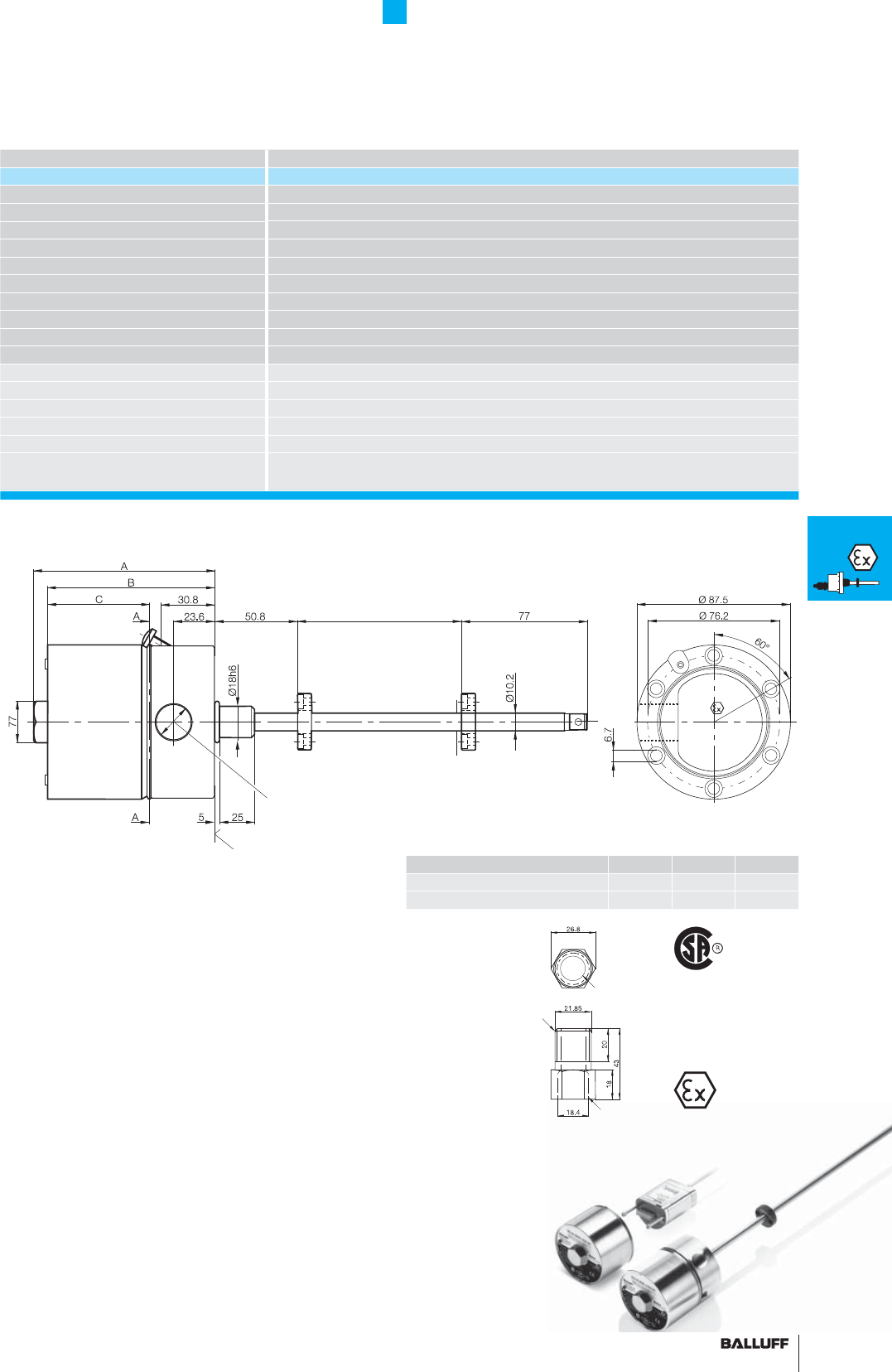
133■ www.balluff.com
Rod Series J-DEXC
General data
Series BTL5_ _-M_ _ _ _-J-DEXC-TA12
Part number BTL5-_ _-M_ _ _ _-J-DEXC-TA12
Shock load 100 g/6 ms per IEC 60068-2-27
Vibration 12 g, 10...2000 Hz per IEC 60068-2-6
Operating temperature –20...+80 °C
Storage temperature range –40...+100 °C
Degree of protection IP 68
Housing material Stainless steel Nitronics 60
Outer tube 1.4571 stainless steel
Pressure rating 600 bar max.
Connection type Screw terminals
Cable entry Ex cable gland BTL-A-AD09-M-00EX
EMC testing:
RF emission EN 55016-2-3 Group 1, Class A
Static electricity (ESD) IEC 61000-4-2 Severity Level 3
Electromagnetic fi elds (RFI) IEC 61000-4-3 Severity Level 3
Fast transients (BURST) IEC 61000-4-4 Severity Level 3
Conducted interference induced
by high-frequency fi elds
IEC 61000-4-6 Severity Level 3
■ Please enter the code for the output signal, interface, coding,
system solution, software confi guration, baud rate, nominal stroke
and connection type in the ordering code!
■ Included:
– Transducer
– Short user's guide
Interface A (mm) B (mm) C (mm)
Analog A, E, C, digital P, M, I, SSI
104.12 96.12 59.5
PROFIBUS-DP, CANopen 135.62 127.62 91
The Micropulse transducer J-DEXC has been specially developed
for use in hazardous areas. The J-DEXC system fulfi lls demanding
requirements in the oil and gas industry for high reliability and ease
of servicing.
J-DEXC comprises a robust fl ameproof Ex housing and an electron-
ics module that is easily accessed and exchanged for servicing.
Spare electronics modules can be ordered from Balluff Service Dept.
Applications:
– Hydraulic or pneumatically actuated valves
– Clutch travel monitoring for compressors
– Level monitoring
– Level control
– Position sensing for hydraulic cylinders in hazardous areas
Cable gland
1/2" - 14 NPT to
M20 metric
BTL-A-AD09-M-00EX
CSA/AEx
AEx de Class I, Zone I,
Groups I & IIC
Class I, Division I & 2,
Groups A, B, C, D
Class II & III, Groups
E, F, G
CENELEC
SIRA 00A TEX1094
EX de I & IIC
I M2, II 2 GD
M20 thread
1/2" NPT thread
International
approval!
Housing J-DEXC
Flange
∅
18 mm, PCD
∅
76.2 mm
Magnet
Nominal stroke = measuring range
Mounting surface
1/2
"
-14 NPT
Please order separately:
Magnets, page 97
Floats, page 136
EX
Filling level
sensor
in zone 0/1
Transducer
in zone 1
Rod DEX
Rod J-DEXC
Rod PEX
Rod NEX
Floats
and
magnets
T
Redundant
134
Rod Series PEX
General data
Dust protection zone 22
Devices in these categories are intended for use in areas where
swirling dust is not expected to create an explosive atmosphere. The
probability is extremely small. Even if it were to occur, it would be
only for a short time.
A manufacturer's certifi cate with the designation
II 3 D T 90°C X
is provided to confi rm that the transducer code satisfi es require-
ments for the use of electrical equipment in areas with infl ammable
dust.
Dust protection zone 22 II 3 D T 90°C X
Digital pulse interface, see page 84/85 for technical data
Ordering example:
BTL5-P1-M_ _ _ _-_-PEX-KA02
Standard nominal stroke [mm] Connection type
PUR cable 2 m0025, 0050, 0075, 0100, 0125, 0150, 0175,
0200, 0225, 0250, 0275, 0300, 0325, 0350,
0375, 0400, 0425, 0450, 0475, 0500, 0550,
0600, 0650, 0700, 0750, 0800, 0850, 0900,
0950, 1000, 1100, 1200, 1300, 1400, 1500,
1600, 1700, 1800, 1900, 2000, 2250, 2500,
2750, 3000, 3250, 3500, 3750, 3850, 4000,
4250, 4500, 4750, 5000, 5250, 5500 or
in 5 mm increments on request.
Housing
B M18×1.5
Z 3/4"-16UNF
Caution! Prior to design, installation and startup, please read
the instructions in the user guide!
www.balluff.com

135■ www.balluff.com
Rod Series NEX
General data
Protection type
"n" for zone 2
Protection type "n"
designated "EEx n"
Devices in these categories are intended for use in areas where an
explosive atmosphere is not expected. The probability is extremely
small. Even if it were to occur, it would be only for a short time.
A manufacturer's certifi cate is provided, confi rming that the product
satisfi es requirements for the use of electrical equipment in potential-
ly explosive areas.
Several methods of fl ameproofi ng are combined under the designa-
tion.
A11
E10
E17
C10
C17
P1
Housing K, see page 110/111 for analog interface and page 112/113 for digital pulse interface
Ordering example:
BTL5-_ _ _-M_ _ _ _-K-NEX-_ _ _ _
Standard nominal stroke [mm] Connection type
SR32 with connector plug
K05 PUR cable 5 m
0025, 0050, 0075, 0100, 0125, 0150, 0175,
0200, 0225, 0250, 0275, 0300, 0325, 0350,
0375, 0400, 0425, 0450, 0475, 0500, 0550,
0600, 0650, 0700, 0750, 0800, 0850, 0900,
0950, 1000, 1100, 1200, 1300, 1400, 1500,
1600, 1700, 1800, 1900, 2000, 2250, 2500,
2750, 3000, 3250, 3500, 3750, 3850, 4000,
4250, 4500 or in 5 mm increments on
request.
Rod series, see page 76/77 for analog interface and page 84/85 for digital pulse interface
Ordering example:
BTL5-_ _ _-M_ _ _ _-_-NEX-_ _ _ _
Standard nominal stroke [mm] Connection type
S32 with connector plug
K05 PUR cable 5 m
0025, 0050, 0075, 0100, 0125, 0150,
0175, 0200, 0225, 0250, 0275, 0300,
0325, 0350, 0375, 0400, 0425, 0450,
0475, 0500, 0550, 0600, 0650, 0700,
0750, 0800, 0850, 0900, 0950, 1000,
1100, 1200, 1300, 1400, 1500, 1600,
1700, 1800, 1900, 2000, 2250, 2500,
2750, 3000, 3250, 3500, 3750, 3850,
4000, 4250, 4500 or
in 5 mm increments on request.
Housing
B M18×1.5
Z 3/4"-16UNF
■ Please enter the code
for the output signal, nominal
stroke, housing and connection
type in the ordering code!
Output signal
0...10 V and 10...0 V
4...20 mA, rising
20...4 mA, falling
0...20 mA, rising
20...0 mA, falling
Pulse interface P
A11
E10
E17
C10
C17
P1
Output signal
0...10 V and 10...0 V
4...20 mA, rising
20...4 mA, falling
0...20 mA, rising
20...0 mA, falling
Pulse interface P
Please order separately:
Magnets, page 97
Floats, page 136
Connectors, page 148/149
EX
Filling level
sensor
in zone 0/1
Transducer
in zone 1
Rod DEX
Rod J-DEXC
Rod PEX
Rod NEX
Floats
and
magnets
T
Redundant

136
Rod Series EX
Floats and Magnets User-friendly hardware
and software set-up
BTL2-S-4414-4Z-Ex
Cylindrical fl oat, zone 0 permitted up to density ρ ≥ 0,7 g/cm3
Orientation:
Raised dimple on upper side of fl oat
BTL2-S-4414-4Z01-Ex
Cylindrical fl oat, zone 0, density of fl oat ρ = 0.85 g/cm3 for liquid
interface sensing
Orientation:
2 raised dimples on upper side of fl oat
Floats (Zone 0)
Interface
A second fl oat can be added to measure the position of the interface
between two liquids, such as oil and condensed water.
Suitable: BTL2-S-4414-4Z01-Ex.
BTL2-A-DH01-E-32-Ex
Spacer sleeve for the fl oat:
BTL2-S-4414-4Z-Ex
BTL2-S-4414-4Z01-Ex
BTL2-S-5113-4K-Ex
The sleeve is included.
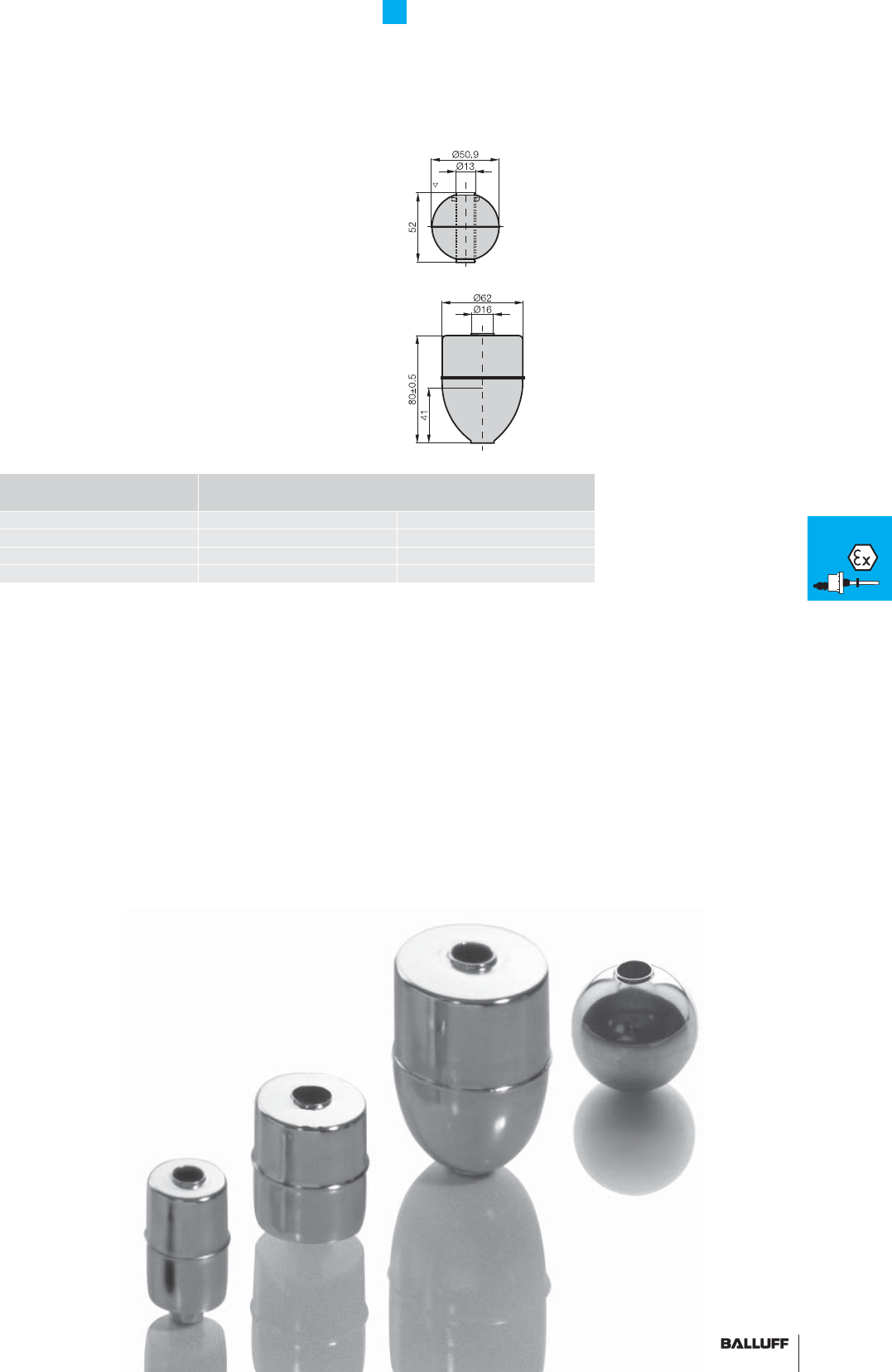
137■ www.balluff.com
BTL2-S-5113-4K-Ex
Ball fl oat, zone 0 permitted up to density ρ ≥ 0,7 g/cm3
Orientation:
Raised dimple on upper side of fl oat
BTL2-S-6216-8P-Ex
Parabolic fl oat, approved up to ρ ≥ 0,6 g/cm3
See technical data on page 96
Float model Immersion depths assuming
ρ = 1 g/cm3 (H2O)
ρ = 0.7 g/cm3
BTL2-S-6216-8P-Ex ss ~ 41 mm ss ~ 57 mm
BTL2-S-5113-4K-Ex ss ~ 26 mm ss ~ 40 mm
BTL2-S-4414-4Z-Ex ss ~ 30 mm ss ~ 39 mm
BTL2-S-4414-4Z01-Ex ss ~ 45 mm submerges
See page 97
See page 163
Magnets (Zone 1)
for installation in
hydraulic cylinders
Processors,
digital displays
Rod Series EX
Floats and Magnets
EX
Filling level
sensor
in zone 0/1
Transducer
in zone 1
Rod DEX
Rod J-DEXC
Rod PEX
Rod NEX
Floats
and
magnets
T
Redundant
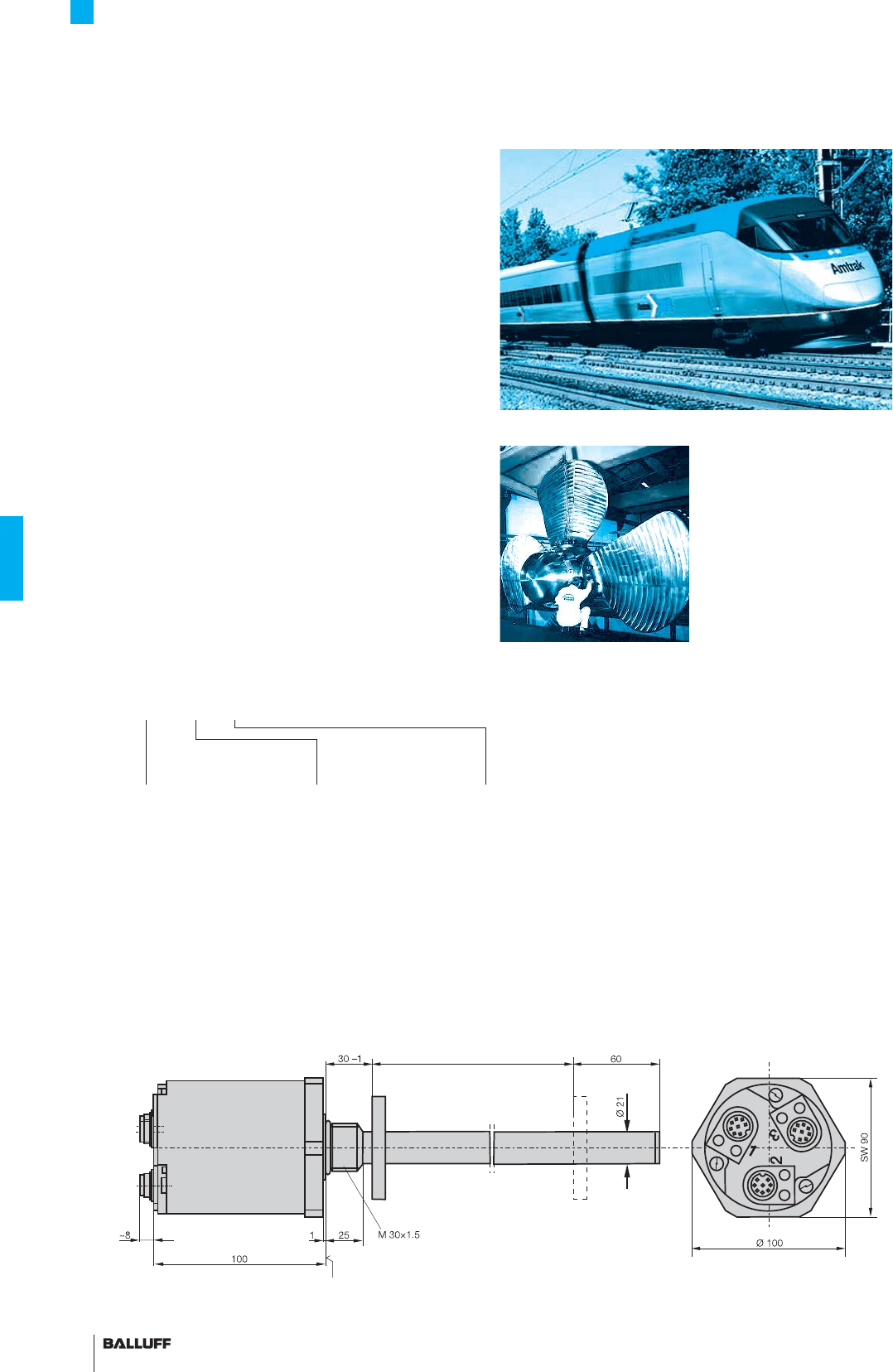
138
Rod Series T
Redundant
Special series
Diffi cult applications often make special demands on the sensors.
Balluff meets these requirements with transducers that have been
specifi ed and developed in conjunction with the system integrator.
Behind this is a large, highly motivated Micropulse development
team as well as Balluff's own EMC Testing Laboratory and shock
and vibration test centers.
The "3-in-1" transducer!
– 2 or 3-way redundant distance measurement system for
heightened safety requirements
– One transducer consists of two or three completely separate
distance measurement systems
– Start/Stop or analog interfaces
– Compact housing
– Max. nominal stroke 1000 mm
Available outputs:
– Analog 0...10 V, 4...20 mA, 0...20 mA, –10...10 V
– Pulse interface
Download the operating instructions from
www.balluff.com for more information
Tilting technology on rail cars
Propeller pitch control
Mounting surface
Ordering example:
BTL5-_ _ _-M_ _ _ _-T-_S 32
Standard
nominal stroke [mm]
0025...1000
Number of
redundant systems
Analog:
Voltage output
A10
G10
Current output
C10
C17
E10
E17
P1
0...10 V
–10...10 V
0...20 mA, rising
20...0 mA, falling
4...20 mA, rising
20...4 mA, falling
Pulse interface P
Interfaces
2 with two independent
outputs
3 with three independent
outputs
Three times safer!
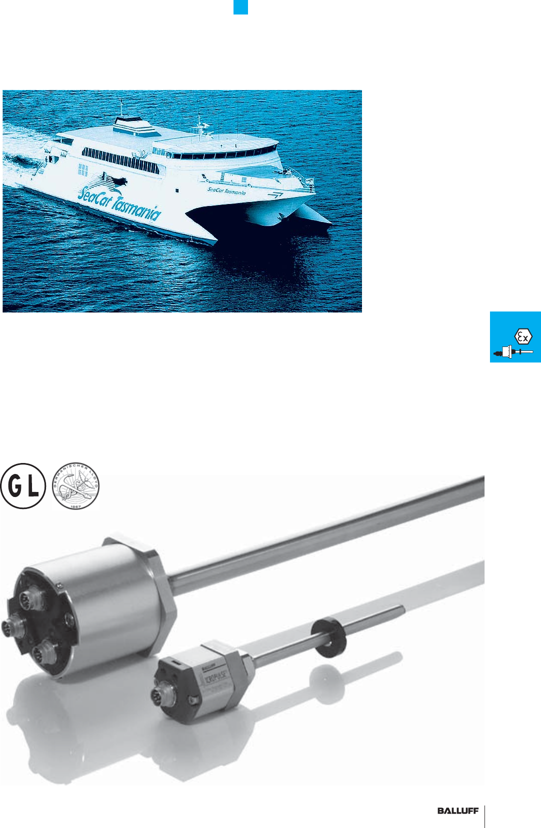
139■ www.balluff.com
Rod Series T
Redundant
Rudder control
0...10 V
4...20 mA
0...20 mA
–10...10 V
EX
Filling level
sensor
in zone 0/1
Transducer
in zone 1
Rod DEX
Rod J-DEXC
Rod PEX
Rod NEX
Floats
and
magnets
T
Redundant
140
140
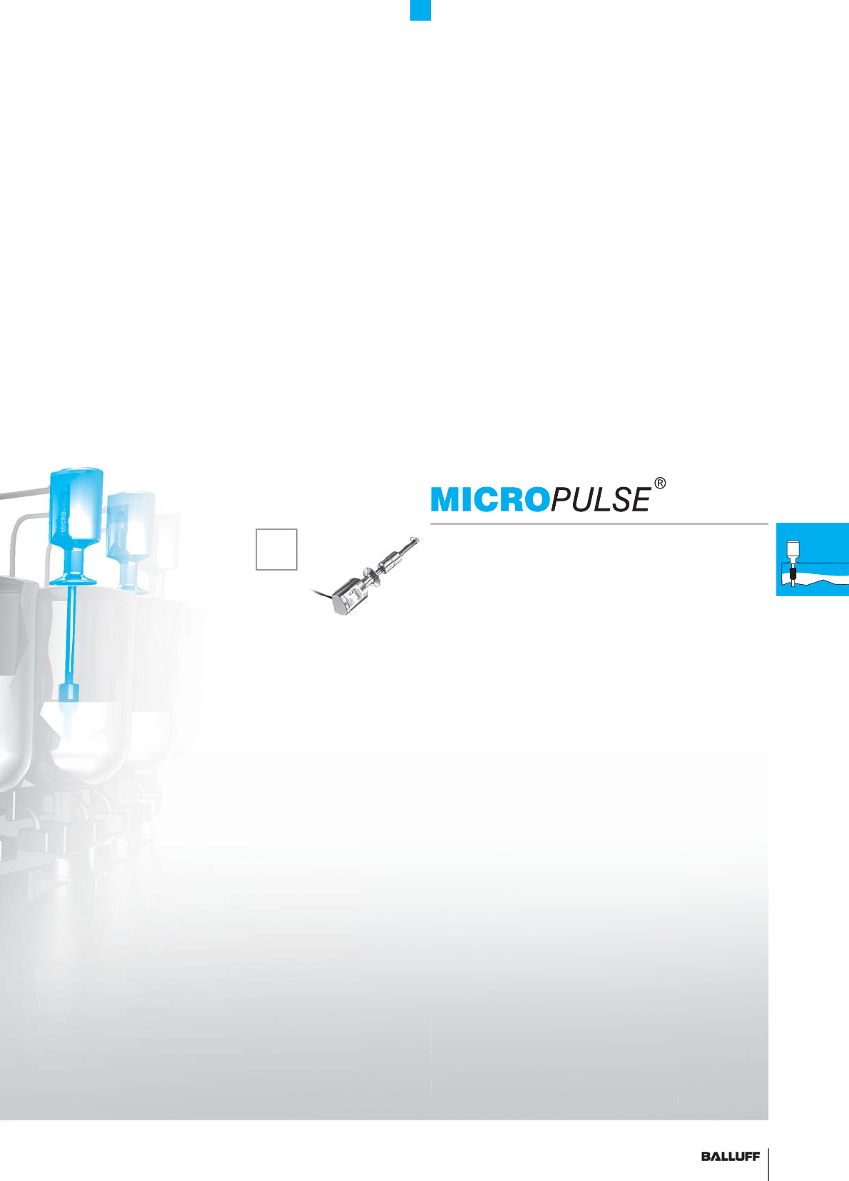
141■ www.balluff.com
BTL-SF Filling Level Sensor
Contents
SF
General data 142
Analog interface 144
Floats and accessories 146
SF
The magnetostrictive working principle is ideal for the continuous
high-precision measurement of fl uid fi lling levels. Waveguides and
processing electronics are enclosed inside a housing made from
stainless steel. Stainless steel fl oats with permanent integrated mag-
nets mark the current fi lling level in the tank or vessel. The design of
the sensors meets international hygiene standards.
1
41
■
www.
b
a
ll
u
ff
.com
S
F
General data 142
Analog interface 144
Floats and accessories 146
S
F
A
F
T
he ma
gne
tostrictive workin
g p
rin
cip
le is ideal for the continuous
high
-prec
i
s
i
on measurement o
f
fl
u
id
fi
lli
n
g
l
eve
l
s.
W
ave
g
u
id
es an
d
p
rocess
i
ng e
l
ectron
i
cs are enc
l
ose
d
i
ns
id
e a
h
ous
i
ng ma
d
e
f
rom
s
tainless steel.
S
tainless steel fl oats with permanent integrated mag
-
n
ets mark the current fi llin
g
level in the tank or vessel. The desi
g
n of
th
e sensors meets
i
nternat
i
ona
l
h
ygi
ene stan
d
ar
d
s.

142
Maximum precision for food hygiene –
internationally certifi ed
The BTL-SF fi lling level sensor ensures continuously precise
measurement in applications that demand extreme hygiene. Made
from corrosion-free stainless steel with excellent surface quality and
rounded edges, the sensor meets the highest international hygiene
standards and fulfi lls all strict requirements of the food industry.
Take advantage of the best quality directly from the manufacturer.
Other benefi ts:
– Neutral for all liquids
– Compensates for foam, thus delivering reliable fi lling level values
– Adjustment-free installation
– Easy to clean in installed state (CIP – Clean in Place)
– For process temperatures up to 130 °C (SIP – Sterilization in
Place)
– Standardized interfaces ensure fl exible installation
– Internationally certifi ed quality guarantees global marketing and
sales of your system
– Rising and falling signal available
– Continuously precise measurement in µ area
delivers excellent fi lling results
– 100 % stainless steel ensures top hygiene
standards and long service life
– International certifi cate guarantees maximum
quality
In the USA, 3-A Sanitary Standards Inc. formulates and monitors
hygiene guidelines for devices used in the manufacture and
packaging of milk and foodstuffs. Our products with this designation
are 3-A approved.
The EHEDG (European Hygienic Engineering & Design) designa-
tion is the European standard for hygiene in the food industry. Our
products with this logo conform to EHEDG standards.
The FDA (Food and Drug Administration) oversees the US food and
pharmaceutical industry and certifi es devices, materials, systems
and machines from these sectors. A product designation of this kind
makes your system eligible for FDA approval.
BTL-SF Filling Level Sensor
General data
The ECOLAB designation stands for consistency against aggres-
sive cleaning agents. Devices with ECOLAB markings fulfi ll their
standards.
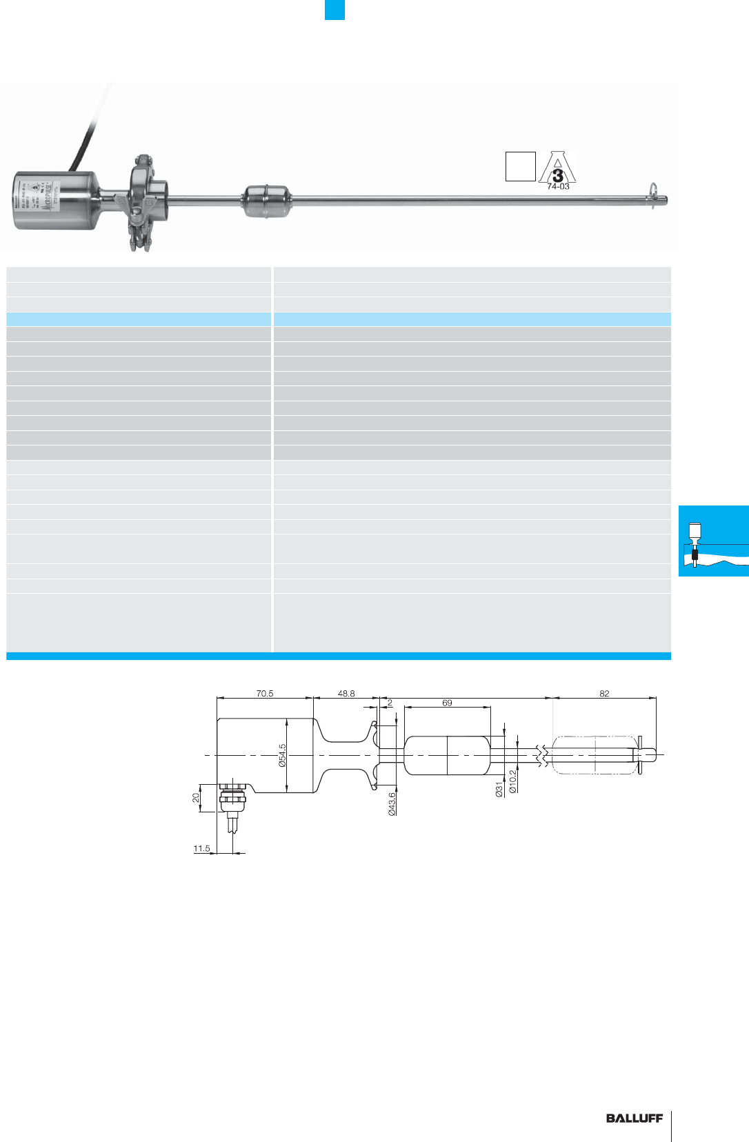
143■ www.balluff.com
Series BTL5 rod SF
Transducer interface analog
Input interface analog
Part number BTL5-...-M_ _ _ _-SF-F_ _ _ _
Polarity reversal protected yes
Overvoltage protection 36 V
Dielectric strength 500 V DC (GND to housing)
Degree of protection as per IEC 60529 IP 67/IP 69K (fl ange and tube)
Housing material Stainless steel 1.4404
Flange and tube material 1.4404
Connection Cable connection
Mounting 1.5" Tri Clamp as per SSI 3A standard 74-03
Pressure rating 300 bar (depending on fl oat)
EMC testing:
RF emission EN 55016-2-3 Group 1, Class A and B
Static electricity (ESD) EN 61000-4-2/EN 61000-4-2 Severity Level 3
Electromagnetic fi elds (RFI) EN 61000-4-3/EN 61000-4-3 Severity Level 3
Fast transients (BURST) EN 61000-4-4/EN 61000-4-4 Severity Level 3
Line-induced disturbances,
induced by high-frequency fi elds
EN 61000-4-6/EN 61000-4-6 Severity Level 3
Surge voltage IEC 61000-4-5/EN 61000-4-5 Severity Level 2
Magnetic fi elds IEC 61000-4-8/EN 61000-4-8 Severity Level 4
Standard nominal stroke (mm) 0025, 0050, 0075, 0100, 0125, 0150, 0175, 0200, 0225, 0250, 0275, 0300,
0325, 0350, 0375, 0400, 0425, 0450, 0475, 0500, 0550, 0600, 0650, 0700,
0750, 0800, 0850, 0900, 0950, 1000, 1100, 1200, 1300, 1400, 1500, 1600,
1700, 1800, 1900, 2000, 2250, 2500 or in 5 mm increments on request
BTL-SF Filling Level Sensor
General data
■ Included:
– Transducer
– Short user's guide
Please order separately:
Tri Clamp, page 146
Floats, page 146
O-ring, page 146
Welded hexagon nipple, page 146
FDA and
EHEDG
conformity
100 %
stainless steel
IP69K
Caution! Prior to design,
installation and startup,
please read the instructions
in the user guide!
www.balluff.com
SF
General
data
Analog
interface
Floats
and
accessories
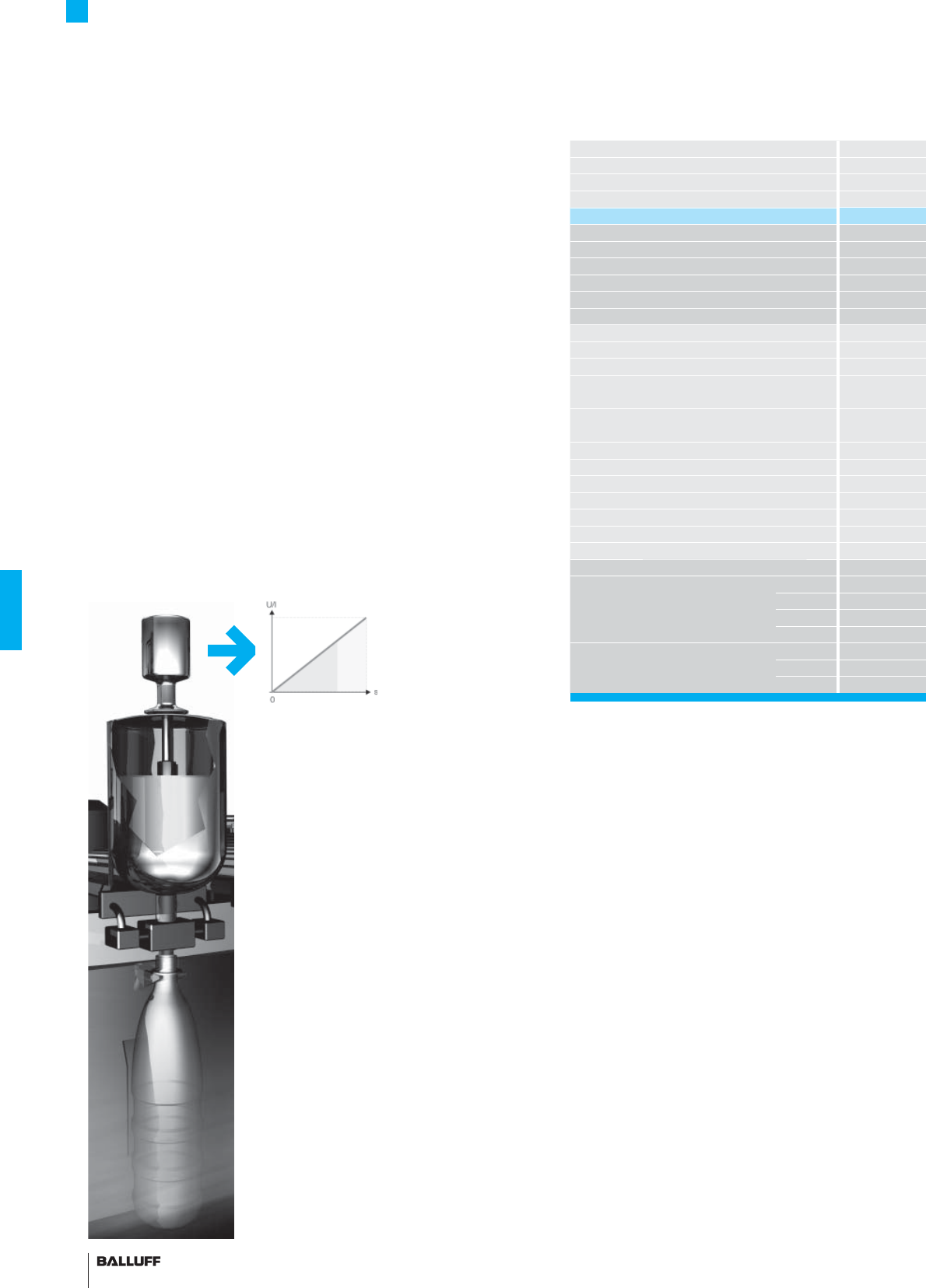
144
Series
Output signal
Transducer interface
Input interface
Part number
Output voltage
Output current
Load current
max. ripple
Load resistance
System resolution
Hysteresis
Repeat accuracy
Sampling rate
Non-linearity, max.
Temperature coeffi cient
Operating voltage
Current consumption
Polarity reversal protected
Overvoltage protection
Dielectric strength
Operating temperature
Process temperature 130° C for one hour
Pin assignments Color
Output signals YE
GY
PK
GN
Operating voltage BU
BN
WH
BTL-SF Filling Level Sensor
Analog interfaces
The industry-standard fi lling level sensor works with the tried-
and-tested Micropulse technology, an absolute and contact-free
magnetostrictive measurement, which has been associated with top
reliability for years. In addition, it has analog interfaces and due to
this common standard signal, can be used in process automation.
Analog signal
A signal that can accept continuous, (almost) infi nitely variable,
values between a minimum and a maximum is described as an
analog signal.
The output signal of the BTL-SF fi lling level sensor is analog and
directly proportional to the position of the fl oat on the sensor tube.
Features:
– Reasonably priced system solution
– Can be used from each controller
– Cable break monitoring through 4...20 mA signal
– Current signal, interference-free signal transfer
– High resolution and repeatability
– Rising and falling signal available
Variants:
– Current (4...20 mA or 0...20 mA)
– Voltage (0...10 V or 10...0 V)
Connect shield to housing
■ Included:
– Transducer
– Short user's guide
Please order separately:
Tri Clamp, page 146
Floats, page 146
O-ring, page 146
Welded hexagon nipple, page 146
Tefl on cable – LIF5Y-FC-5Y (7x0.25mm²):
– Temperature-resistant up to 200 °C
– Good resistance against chemicals and oil
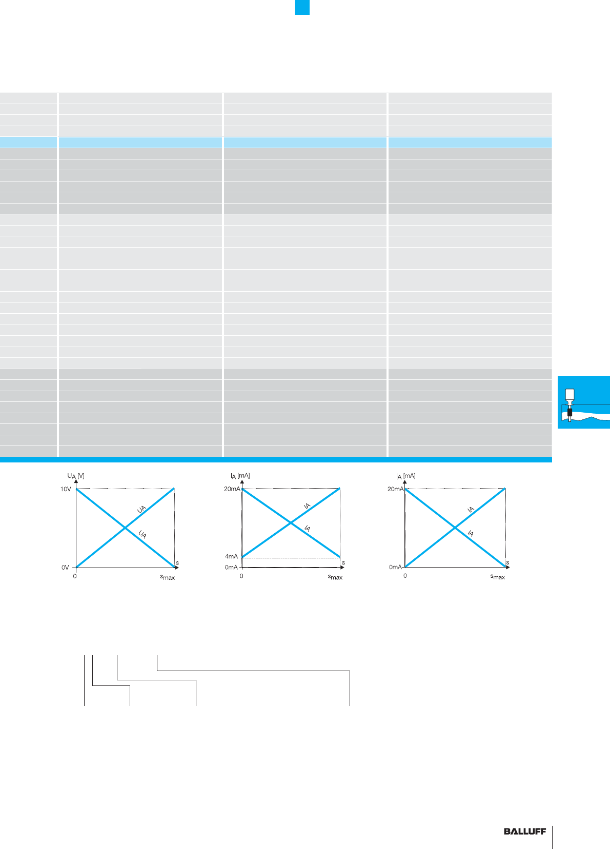
145■ www.balluff.com
BTL5 rod SF BTL5 rod SF BTL5 rod SF
analog analog analog
AEC
analog analog analog
BTL5-A11-M_ _ _ _-SF-_ _ _ _ BTL5-E1_-M_ _ _ _-SF-_ _ _ _ BTL5-C1_-M_ _ _ _-SF-_ _ _ _
0...10 V and 10...0 V
4...20 mA or 20...4 mA 0...20 mA or 20...0 mA
max. 5 mA
≤ 5 mV
≤ 500 ohms (500 ohms) ≤ 500 ohms (500 ohms)
≤ 0.1 mV ≤ 0.2 µA ≤ 0.2 µA
≤ 4 µm ≤ 4 µm ≤ 4 µm
System resolution/min. 2 µm System resolution/min. 2 µm System resolution/min. 2 µm
fSTANDARD = 500 Hz fSTANDARD = 500 Hz fSTANDARD = 500 Hz
±100 µm up to 500 mm nominal stroke
±0.02 % 500... max. nominal stroke
±100 µm up to 500 mm nominal stroke
±0.02 % 500... max. nominal stroke
±100 µm up to 500 mm nominal stroke
±0.02 % 500... max. nominal stroke
≤ 40 ppm/K for nominal stroke 500 mm,
fl oat at center of measuring range
≤ 40 ppm/K for nominal stroke 500 mm,
fl oat at center of measuring range
≤ 40 ppm/K for nominal stroke 500 mm,
fl oat at center of measuring range
20...28 V DC 20...28 V DC 20...28 V DC
≤ 150 mA ≤ 150 mA ≤ 150 mA
yes yes yes
36 V 36 V 36 V
500 V DC (ground to housing) 500 V DC (ground to housing) 500 V DC (ground to housing)
–40...+85 °C –40...+85 °C –40...+85 °C
–40...+100 °C –40...+100 °C –40...+100 °C
BTL5-A11... BTL5-E10... BTL5-E17... BTL5-C10... BTL5-C17...
4...20 mA 20...4 mA 0...20 mA 20...0 mA
0 V Output 0 V Output 0 V Output 0 V Output 0 V Output
10...0 V
0...10 V
GND GND GND GND GND
+24 V DC +24 V DC +24 V DC +24 V DC +24 V DC
BTL-SF Filling Level Sensor
Analog interfaces
Standard
nominal stroke [mm]
Ordering example:
BTL5-_1_-M_ _ _ _-SF-_ _ _ _
0025, 0050, 0075, 0100, 0125, 0150,
0175, 0200, 0225, 0250, 0275, 0300,
0325, 0350, 0375, 0400, 0425, 0450,
0475, 0500, 0550, 0600, 0650, 0700,
0750, 0800, 0850, 0900, 0950, 1000,
1100, 1200, 1300, 1400, 1500, 1600,
1700, 1800, 1900, 2000, 2250, 2500
or in 5 mm increments on request
Output
signal
1 Rising
and falling
with A
0 Rising
(with C and E)
7 Falling
(with C and E)
Radial connection
F02 Tefl on cable 2 m
F05 Tefl on cable 5 m
F10 Tefl on cable 10 m
F15 Tefl on cable 15 m
F20 Tefl on cable 20 m
Inter-
face
A
E
C
maximum precision
SF
General
data
Analog
interface
Floats
and
accessories
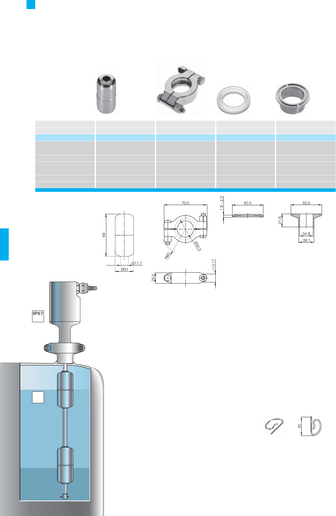
146
Description Float Tri Clamp (DIN 32676) O-ring
Welded hexagon nipple
for series BTL5 rod SF BTL5 rod SF BTL5 rod SF BTL5 rod SF
Part number BTL-S-3112-4Z
BAM MC-XA-006-D38.1-5
BAM SE-XA-002-D38.1-5 BAM-AD-XA-003-D38.1-5
Material Stainless steel 1.4404 USA ASTM 316 (1.4401) Platinum catalyzed
silicone
Part no. W. 1.4435 BN2
(Fe ≤ 0.5 %) as per EB 10088
Weight ca. 30 g
Operating temperature/
–40...+130 °C
Storage temperature range
Displacement in water approx. 31 mm
Pressure rating (static) 24 bar
BTL-SF Filling Level Sensor
Floats and accessories
Caution!
Approvals only issued through
use of these components.
Prior to design, installation and
startup, please read the
instructions in the user guide!
■ Included in scope of
delivery for fl oat:
– Float
– Instructions
– Cotter pin (spring pin 2×30)
"Junction fl oat"
on request.
IP69K Process temperature:
maximum permissible temperature
of the rod under the fl ange (with
media contact).
Certain production processes
require, for example sterilization at
120 °C – 130 °C for 0.5 – 1 hour.
120 °C –
130 °C

147■ www.balluff.com 147
Accessories
Contents
Connectors 148
Processors 158
Profi bus module P111 160
BUS interface module 162
Digital display, CAM controller 163
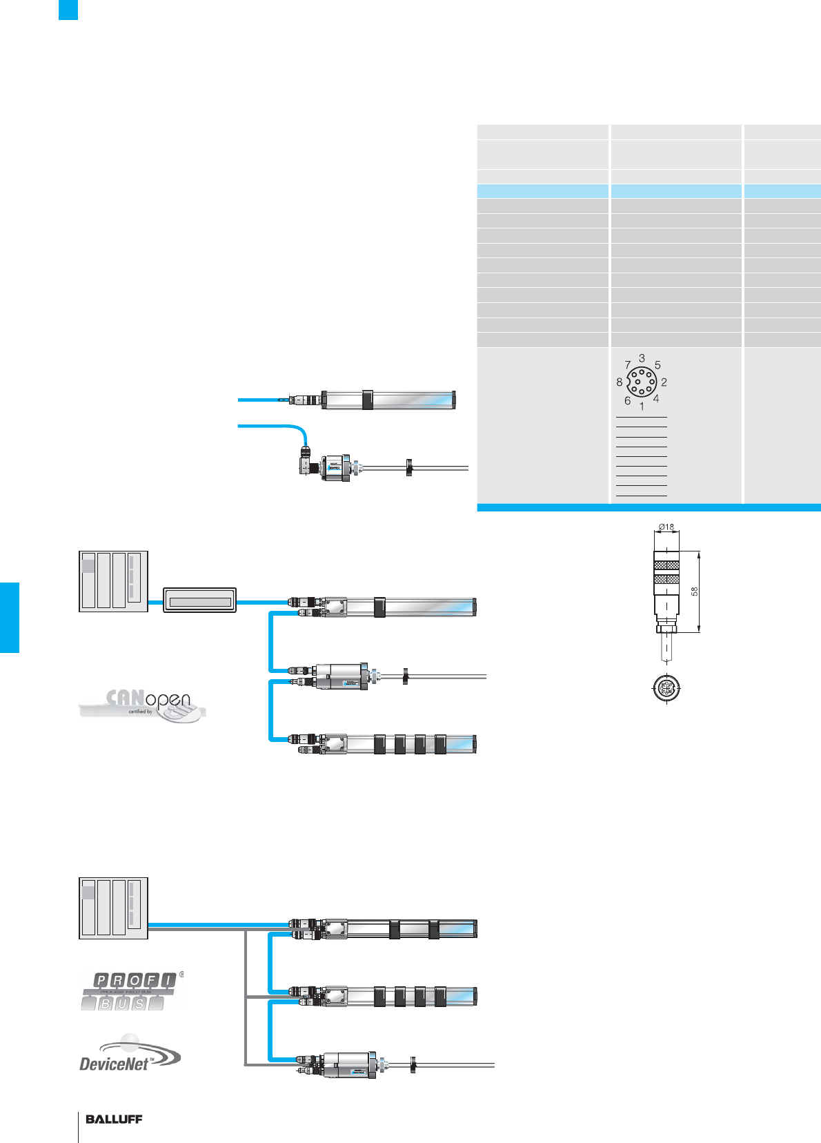
148
Accessories
Connectors overview
Connectors BKS-S 32M
for series BTL5-...-S 32
Soldered connections
Version Straight, female
Part number BKS-S 32M-_ _
Crimp contacts
Solder max. 0.75 mm2
Housing material Nickel-plated brass
Contacts Brass
Contact fi nish 0.8 µm gold plated
Cable strain relief PG 9
Cable diameter min. 6...8 mm
Cable Lif2Y-FC-11Y- 0
No. of wires × conductor cross-section
7×0.25 mm²
Degree of protection as per IEC 60529
IP 67 (when attached)
View of
female solder side
PIN Color
1YE
2GY
3PK
5GN
6BU
7BN
8WH
Connector for analog,
pulse and SSI interfaces
Connectors
for CANopen
Connectors for PROFIBUS-DP and
DeviceNet interfaces
CiA 199911-301v30/11-009
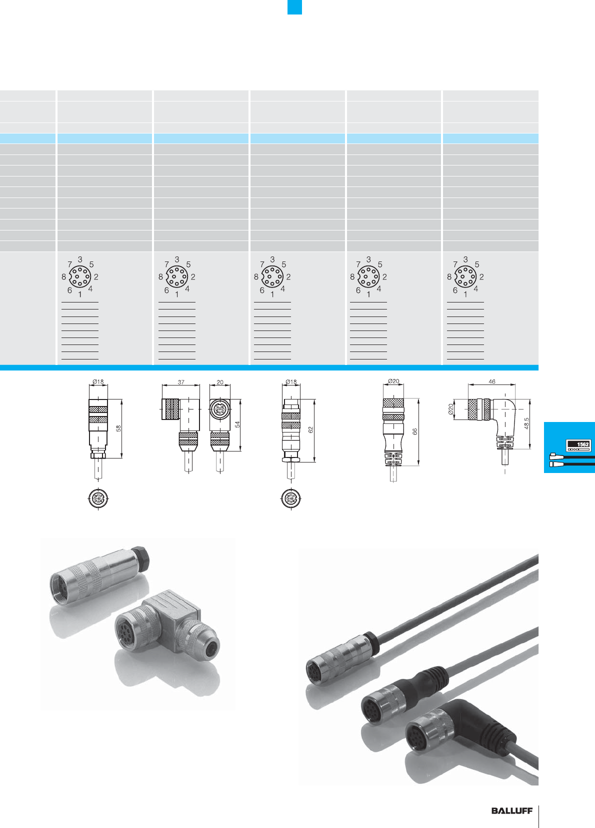
149■ www.balluff.com
Accessories
Connectors for analog, pulse
and SSI interfaces
BKS-S 32M-C BKS-S 33M BKS-S 78M BKS-S232 BKS-S233
BTL5-...-S 32
Crimp contacts
BTL5-...-S 32
Soldered connections
BTL5-...-S 32
Soldered connections
BTL7-_ _ _-S32 BTL7-_ _ _-S32
Straight, female Right-angle, female Straight, male
BKS-S 32M-C-_ _ BKS-S 32M-_ _ BKS-S 78M-00 BKS-S232-PU-_ _ BKS-S233-PU-_ _
max. 0.5 mm²
max. 0.75 mm2max. 0.75 mm2
Nickel-plated brass ZnAlCu1 nickel-plated Nickel-plated brass PUR PUR
Brass Brass Brass Brass Brass
0.8 µm gold plated 0.8 µm gold plated 0.8 µm gold plated 0.8 µm gold plated 0.8 µm gold plated
PG 9 PG 9 PG 9
6...8 mm 6...8 mm 6...8 mm
Lif2Y-FC-11Y- 0 Lif2Y-FC-11Y- 0 LifgY+LifgY, FC-11Y LifgY+LifgY, FC-11Y
7×0.25 mm² 7×0.25 mm² 8×0.25 mm² 8×0.25 mm²
IP 67 (when attached) IP 67 (when attached) IP 67 (when attached) IP 67 (when attached) IP 67 (when attached)
Please include the Part number in the ordering code!
Code 00 for self-assembly
(please use shielded cable).
Code 05, 10, 15, 20, 25, 30 m
for fi nished cable assembly.
PIN Color
1YE
2GY
3PK
5GN
6BU
7BN
8WH
PIN Color
1YE
2GY
3PK
5GN
6BU
7BN
8WH
PIN Color
1YE
2GY
3PK
5GN
6BU
7BN
8WH
PIN Color
1YE
2GY
3PK
5GN
6BU
7BN
8WH
PIN Color
1YE
2GY
3PK
5GN
6BU
7BN
8WH
Connectors
Processors
Profi bus
module P111
BUS interface
modules
Digital display
CAM controller
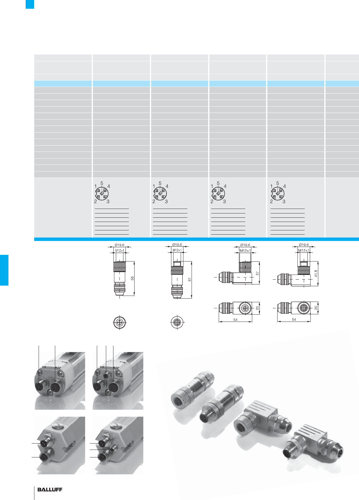
150
Connectors BKS-S92-00 BKS-S94-00 BKS-S93-00 BKS-S95-00
for series
BTL5-H_ _ _-S92/S93/S94
Screw terminals
BTL5-H_ _ _-S92/S93/S94
Screw terminals
BTL5-H_ _ _-S92/S93/S94
Screw terminals
BTL5-H_ _ _-S92/S93/S94
Screw terminals
Version 5-pin, female 5-pin, male 5-pin, female 5-pin, male
Part number BKS-S92-00 BKS-S94-00 BKS-S93-00 BKS-S95-00
Screw terminal max. 0.75 mm2max. 0.75 mm2max. 0.75 mm2max. 0.75 mm2
Housing material Nickel-plated brass Nickel-plated brass Nickel-plated brass Nickel-plated brass
Contacts Brass Brass Brass Brass
Contact fi nish 0.8 µm gold plated 0.8 µm gold plated 0.8 µm gold plated 0.8 µm gold plated
Cable strain relief PG 9 PG 9 PG 9 PG 9
Cable diameter 6...8 mm 6...8 mm 6...8 mm 6...8 mm
No. of wires × conductor cross-section
Degree of protection as per IEC 60529
IP 67 (when attached) IP 67 (when attached) IP 67 (when attached) IP 67 (when attached)
Knurled coupling ring
Finish
O-ring
Resistor
Coding A A A A
Socket on transducer 1 2 1 2
View of
female coupling side
Accessories
Connectors for CANopen and
DeviceNet interfaces
PIN Signal
1 CAN_GND
2 +24 V
3 GND (0 V)
4 CAN_HIGH
5 CAN_LOW
PIN Signal
1 CAN_GND
2 +24 V
3 GND (0 V)
4 CAN_HIGH
5 CAN_LOW
PIN Signal
1 CAN_GND
2 +24 V
3 GND (0 V)
4 CAN_HIGH
5 CAN_LOW
PIN Signal
1 CAN_GND
2 +24 V
3 GND (0 V)
4 CAN_HIGH
5 CAN_LOW
CANopen
1
2
DeviceNet
123
1
2
3
Socket 3
Power supply for DeviceNet:
BKS-S48-15-CP-... page 155
12
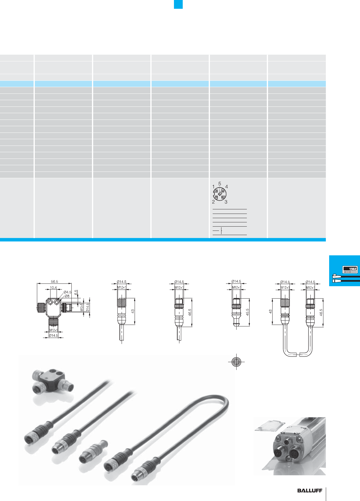
151■ www.balluff.com
Accessories
Connectors for CANopen and
DeviceNet interfaces
BKS-S92-TA1 BKS-S137-19-PC-... BKS-S151-19-PC-... BKS-S94-R01 BKS-S92-16/GS92-_ _
BTL5-H_ _ _-S92
BTL5-H_ _ _-S92/S93/S94 BTL5-H_ _ _-S92/S93/S94 BTL5-H_ _ _-S92/S93/S94 BTL5-H_ _ _-S92/S93/S94
T-splitter, 2 × female, 1 × male
5-pin, female 5-pin, male Terminating resistor, male Male/female extension
BKS-S92-TA1 BKS-S137-19-PC-... BKS-S151-19-PC-... BKS-S94-R01 BKS-S92-16/GS92-_ _
PA PUR PUR TPU PUR
Brass Brass Brass Brass Brass
NI 0.8 µm gold plated 0.8 µm gold plated 0.8 µm gold plated 0.8 µm gold plated
5×0.25 mm25×0.25 mm25×0.34 mm2
IP 67 IP 67 IP 67 IP 68 IP 67
Brass Brass Brass Brass Brass
2.5 µm Ni 2.5 µm Ni 2.5 µm Ni 2.5 µm Ni 2.5 µm Ni
HBR Viton Viton Viton Viton
121 ohms
AAAAA
1* 1 2 2 1/2
Please order the clear
view cover separately!
Order designation:
BTL5-A-CP01-K
Please include the type des-
ignation in the ordering code!
02 = Length 2 m
05 = Length 5 m
10 = Length 10 m
Please include the type des-
ignation in the ordering code!
02 = Length 2 m
05 = Length 5 m
10 = Length 10 m
Please include the type des-
ignation in the ordering code!
02 = Length 2 m
05 = Length 5 m
10 = Length 10 m
*only for
BTL5-H1...-M-P/B-S92
PIN Signal
1–
2–
3–
4 121 ohms
5
Connectors
Processors
Profi bus
module P111
BUS interface
modules
Digital display
CAM controller
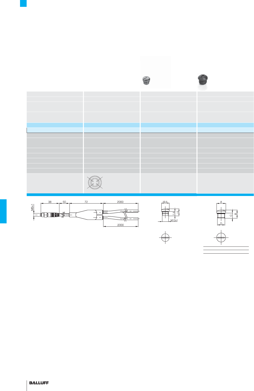
152
Accessories
Y connectors M8 for CANopen®
Connector 1×M8 straight/2×3-wire
Description Y connector M12 screw plug M12 screw plug
Version Male
Use Splitter boxes IP 65 screw plug for
unused ports
IP 65 screw plug for
unused ports
Ordering code BAM0114 BAM00K7
Part number
BKS-S 75-TB4-05-PU-00.05/02/02
BKS 12-CS-01 BKS 12-CS-00
Operating voltage UB10...30 V DC
No. of wires ×
cross-section
4×0.34 mm2
Cable diameter min. max. 51 mm
Connection molded-in
Degree of protection as per IEC 60529
IP 67
Ambient temperature range Ta–25...+85 °C –20...+80 °C –20...+80 °C
Housing material PUR Nickel-plated brass Plastic
View of
female/male side
ABCD
BKS12 Ø13.5 12 7,5 M12×1
4
3
1
2
PIN 1: brown
PIN 2: white
PIN 3: blue
PIN 4: black
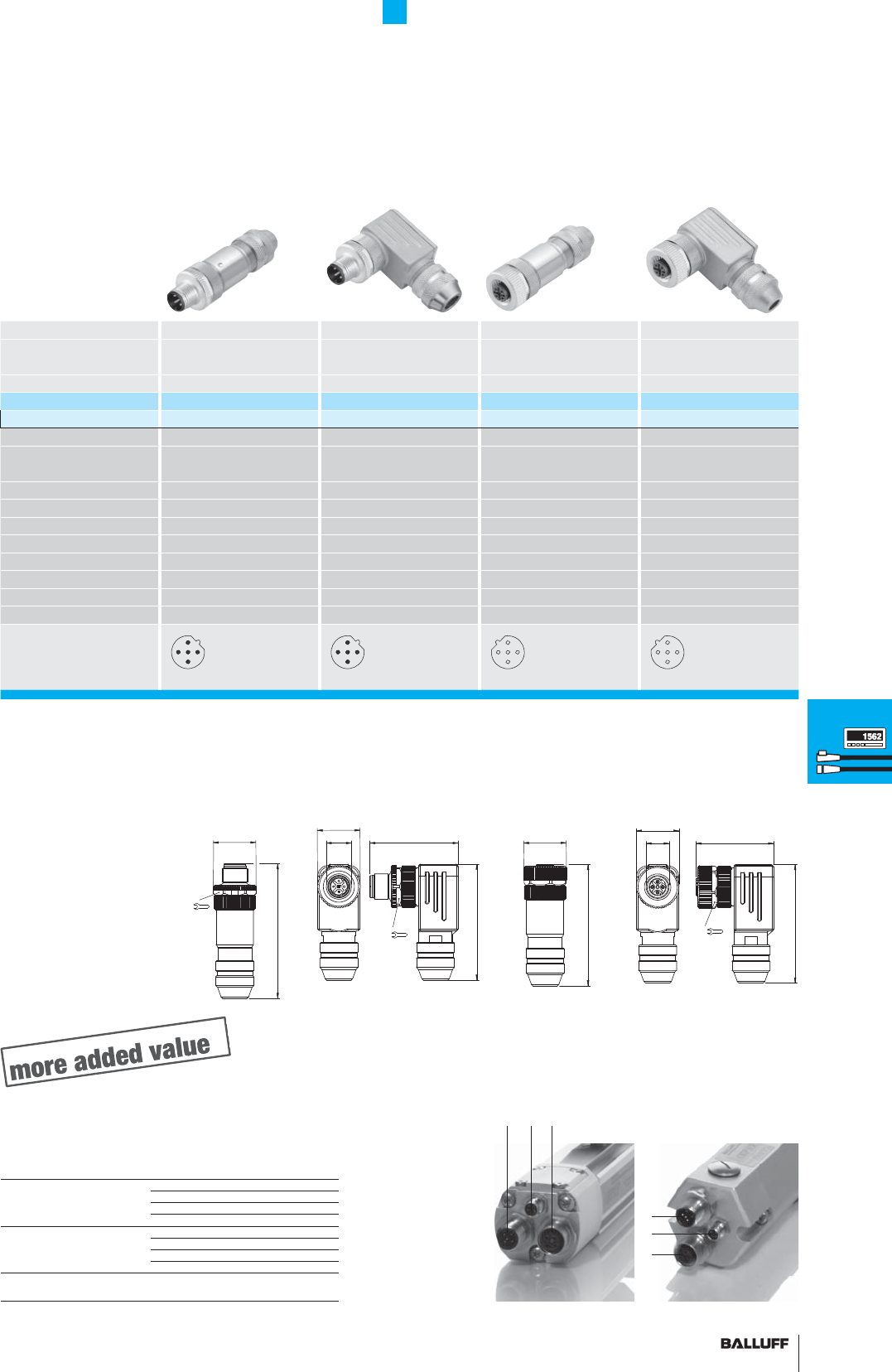
153■ www.balluff.com
Accessories
Connectors for PROFIBUS-DP
Connectors M12 M12 M12 M12
Version B-coded
5-pin
B-coded
5-pin
B-coded
5-pin
B-coded
5-pin
Use Male Male Female Female
Ordering code BCC0714 BCC0716 BCC0715 BCC0717
Part number
BCC M475-0000-2B-000-01X575-000 BCC M485-0000-2B-000-01X575-000 BCC M475-0000-1B-000-01X575-000 BCC M485-0000-1B-000-01X575-000
Operating voltage UB10...30 V DC 10...30 V DC 10...30 V DC 10...30 V DC
No. of wires ×
cross-section
5× max. 0.75 mm25× max. 0.75 mm25× max. 0.75 mm25× max. 0.75 mm2
Cable diameter min. Max. 8.0 mm Max. 8.0 mm Max. 8.0 mm Max. 8.0 mm
Connection Screw terminal Screw terminal Screw terminal Screw terminal
Degree of protection as per IEC 60529
IP 67 IP 67 IP 67 IP 67
Ambient temperature range Ta
–25...+85 °C –25...+85 °C –25...+85 °C –25...+85 °C
Housing material Brass Brass Brass Brass
Shielded version Yes* Yes* Yes* Yes*
Coding B B B B
Socket on transducer 2 2 1 1
View of
female/male side
*Knurled ring used
for shielding
13
4
2
513
4
2
5
31
5
2
4
31
5
2
4
63.7
18
Ø20.2
54.9
41.8
M12×1
Ø20.2
18
57.4
Ø20.2
56.0
36.7
18
20.2
M12×1
Shielded throughout!
PROFIBUS-DP
123
1
2
3
Control and data signals Data GND 3
RxD/TxD-N (A) 2
RxD/TxD-N (B) 4
VP +5V 1
Operating voltage +24 V 1
0 V (GND) 3
Ground PROFIBUS-DP
5
Shield supply 4
Socket on
transducer 1/2 3
Pin assignments
BTL5-T1_ _-M-_ _ _ -_-S103 5-pin 3-pin
previously
BKS-S 105-00
00.3 = Length 0.3 m
02 = Length 2 m
05 = Length 5 m
10 = Length 10 m
previously
BKS-S 106-00
00.3 = Length 0.3 m
02 = Length 2 m
05 = Length 5 m
10 = Length 10 m
previously
BKS-S 103-00
00.3 = Length 0.3 m
02 = Length 2 m
05 = Length 5 m
10 = Length 10 m
previously
BKS-S 104-00
00.3 = Length 0.3 m
02 = Length 2 m
05 = Length 5 m
10 = Length 10 m Connectors
Processors
Profi bus
module P111
BUS interface
modules
Digital display
CAM controller
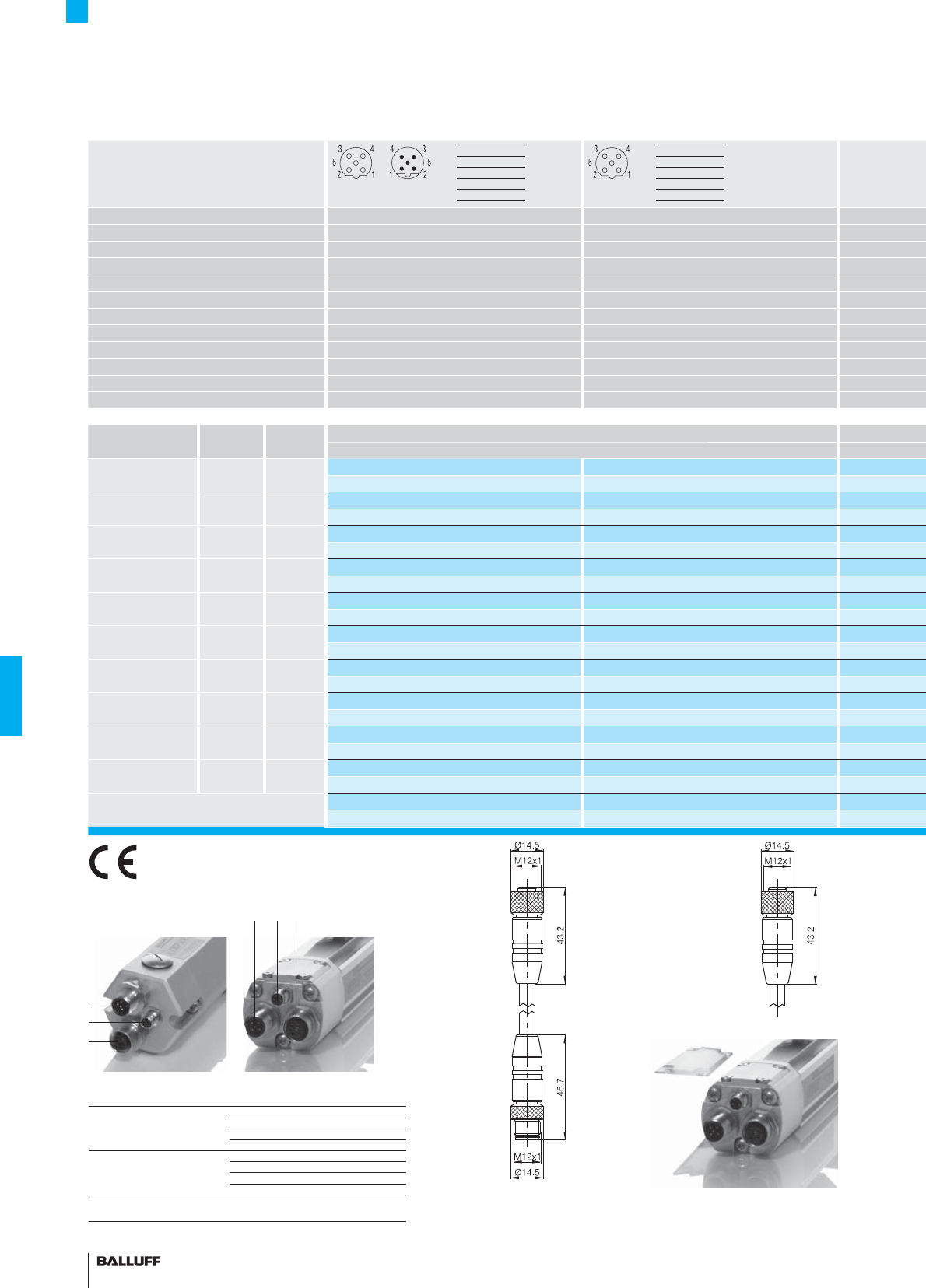
154
Connector diagram and wiring
Confi guration
Version
Use Female/male Female
Operating voltage UB300 V 300 V
Cable PUR PUR
No. of wires × conductor cross-section 2×0.38 mm22×0.38 mm2
Degree of protection as per IEC 60529 IP 67 IP 67
Ambient temperature range Ta–25...+80 °C –25...+80 °C
Housing material PUR PUR
Knurled coupling ring Nickel-plated brass Nickel-plated brass
Coding B B
Socket on transducer 1/2 1
Cable material Color Length Ordering code
Part number
PUR Violet 0.6 m BCC070M
BCC M415-M415-3B-329-PS72N1-006
PUR Violet 1 m BCC070N
BCC M415-M415-3B-329-PS72N1-010
PUR Violet 2 m BCC070P BCC070Y
BCC M415-M415-3B-329-PS72N1-020 BCC M415-0000-1B-031-PS72N1-020
PUR Violet 5 m BCC070R BCC070Z
BCC M415-M415-3B-329-PS72N1-050 BCC M415-0000-1B-031-PS72N1-050
PUR Violet 10 m BCC070T BCC0710
BCC M415-M415-3B-329-PS72N1-100 BCC M415-0000-1B-031-PS72N1-100
PUR Violet 15 m BCC070U
BCC M415-M415-3B-329-PS72N1-150
PUR Violet 20 m BCC070W
BCC M415-M415-3B-329-PS72N1-200
PUR Black 2 m
PUR Black 5 m
PUR Black 10 m
Please order the clear view cover
separately!
Order designation: BTL5-A-CP01-K
Accessories
M12 connectors, 5-pin, B-coded
for PROFIBUS-DP
1NC
2 Line A green
3NC
4 Line B red
5NC
previously BKS-S103/GS103-CP-_ _
00.3 = Length 0.3 m
02 = Length 2 m
05 = Length 5 m
10 = Length 10 m
previously BKS-S103-CP-_ _
00.3 = Length 0.3 m
02 = Length 2 m
05 = Length 5 m
10 = Length 10 m
PROFIBUS-DP
123
1
2
3
Control and data signals Data GND 3
RxD/TxD-N (A) 2
RxD/TxD-N (B) 4
VP +5V 1
Operating voltage +24 V 1
0 V (GND) 3
Ground PROFIBUS-DP
5
Shield supply 4
Socket on
transducer 1/2 3
Pin assignments
BTL5-T1_ _-M-_ _ _ -_-S103 5-pin 3-pin
1NC
2 Line A green
3NC
4 Line B red
5NC
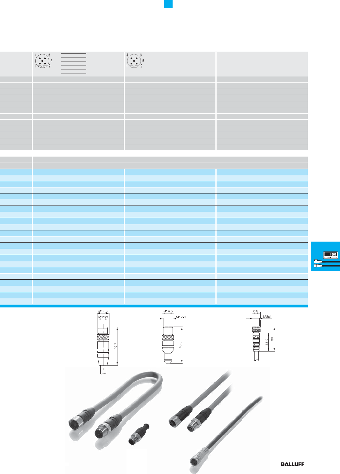
155■ www.balluff.com
M12 terminating resistor
B-coded, 5-pin
Male Male
300 V 10...30 V DC
PUR
2×0.38 mm22×0.25 mm2
IP 67 IP 67 IP 67
–25...+80 °C –40...+85 °C
PUR Plastic PUR
Nickel-plated brass
BB
223*
Ordering code
Part number
BCC0711
BCC M415-0000-2B-031-PS72N1-020
BCC0712
BCC M415-0000-2B-031-PS72N1-050
BCC0713
BCC M415-0000-2B-031-PS72N1-100
BKS-S 48-15-CP-02
BKS-S 48-15-CP-05
BKS-S 48-15-CP-10
BCC00Y8
BKS-S105-R01
Accessories
M12 connectors, 5-pin, B-coded
for PROFIBUS-DP
o
m
previously BKS-S105-CP-_ _
00.3 = Length 0.3 m
02 = Length 2 m
05 = Length 5 m
10 = Length 10 m
1NC
2 Line A green
3NC
4 Line B red
5NC
Connectors
Processors
Profi bus
module P111
BUS interface
modules
Digital display
CAM controller
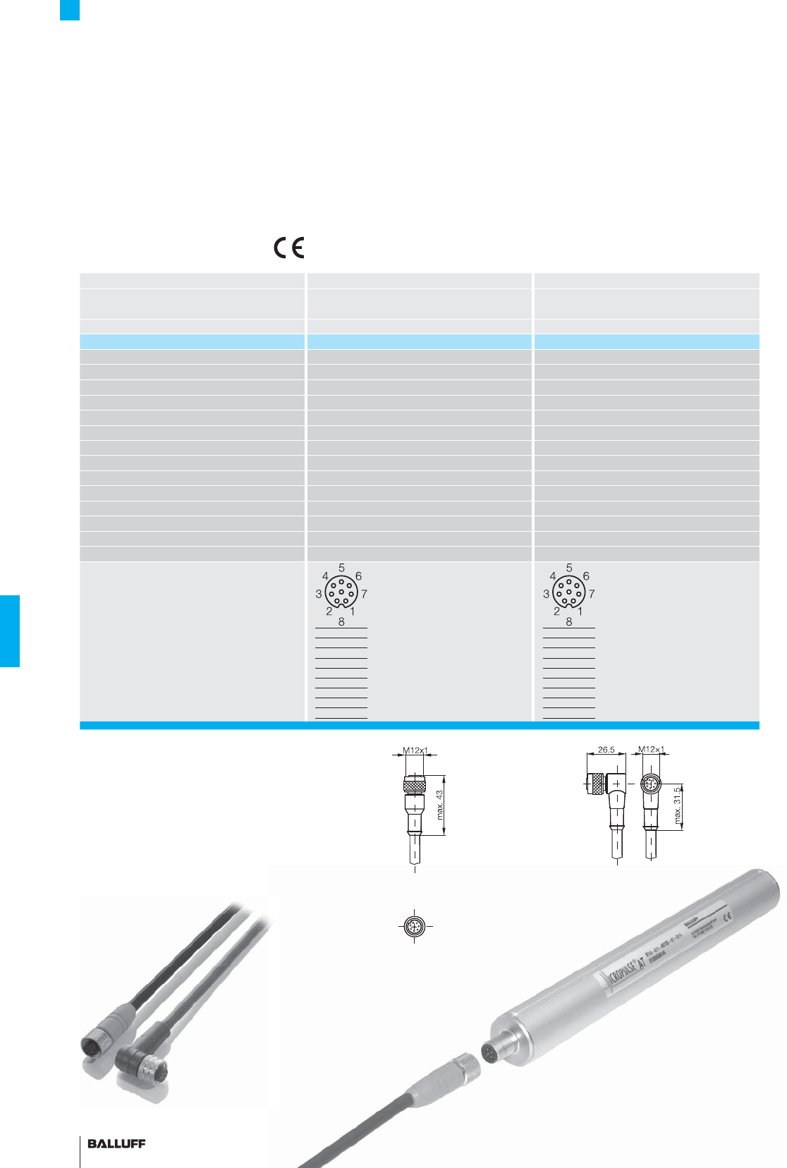
156
Accessories
M12 female straight and right-angle
connectors, 8-pin, customized assembly
Connectors BKS-S115-PU-_ _ BKS-S116-PU-_ _
for series BTL6-...-S115
BTL6-...-S115
Version 8-pin, straight, female 8-pin, right-angle, female
Part number BKS-S115-PU-_ _ BKS-S116-PU-_ _
Screw terminal
Housing material PUR PUR
Contacts Brass Brass
Contact fi nish 0.8 µm gold plated 0.8 µm gold plated
Degree of protection as per IEC 60529 IP 67 IP 67
Knurled coupling ring Brass Brass
Finish 2.5 µm Ni 2.5 µm Ni
O-ring Viton Viton
Cable Molded PUR Molded PUR
No. of wires × conductor cross-section
8×0.25 mm2 8×0.25 mm2
Version LIYY-CF11Y LIYY-CF11Y
Conductor confi guration 14 × 0.15 mm 14 × 0.15 mm
Outer diameter 6.6 ±0.2 mm 6.6 ±0.2 mm
Min. bending radius dynamic 4 × D, static 3 × D dynamic 4 × D, static 3 × D
Pin assignments
View of female
PIN Color
1YE
2GY
3PK
4RD
5GN
6BU
7BN
8WH
Adapter BKS-S115 to
BKS-S 32
Ordering code:
BKS-S115/GS32-PU-00.2
PIN Color
1YE
2GY
3PK
4RD
5GN
6BU
7BN
8WH
Please include the type
designation in the ordering code!
02 = Length 2 m
05 = Length 5 m
10 = Length 10 m
15 = Length 15 m
20 = Length 20 m
25 = Length 25 m
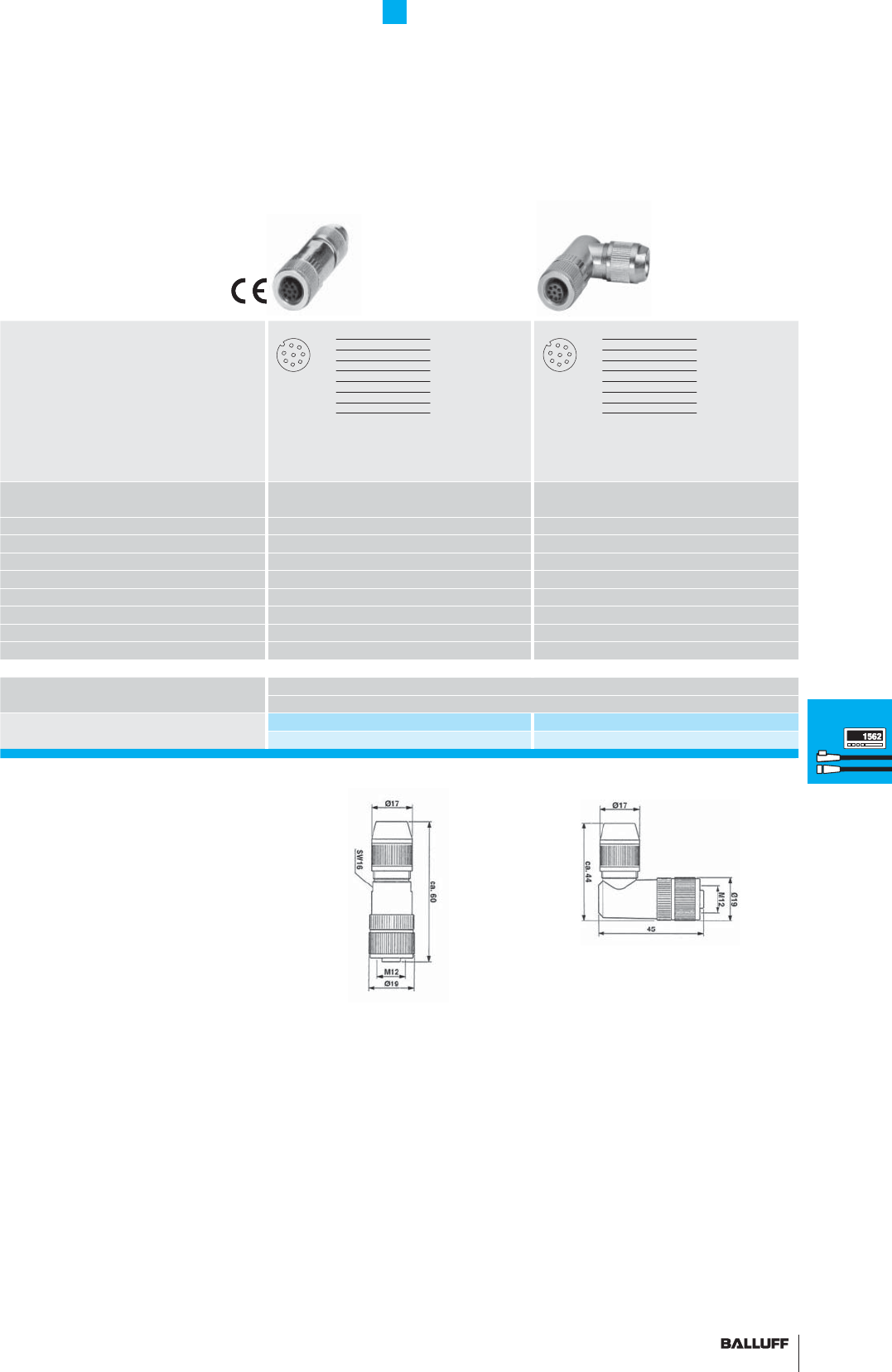
157■ www.balluff.com
Accessories
M12 female straight and right-angle
connector, 8-pin, customized assembly
for AT VARAN profi le series
View of
Female/male side
Version M12 female straight, 8-pin M12 female right-angle, 8-pin
Operating voltage max. US18...30 V DC 18...30 V DC
Rated operating current le250 V DC 250 V DC
Cable 4...8 mm 4...8 mm
No. of wires × conductor cross-section 8×0.14...0.25 mm28×0.14...0.25 mm2
Degree of protection as per IEC 60529 IP 67 IP 67
Ambient temperature range Ta–25...+85° C –25...+85° C
Housing material Brass Brass
Use BPI, M8, 3-pin, 8-way, BIC BPI, M8, 3-pin, 8-way, BIC
Ordering code
Part number
BCC04MC BCC050F
BCC M478-0000-1A-000-43X834-000 BCC M488-0000-1A-000-43X834-000
1
23
4
5
6
7
82
3
4
5
1
6
7
8
1
23
4
5
6
7
82
3
4
5
1
6
7
8
Connectors
Processors
Profi bus
module P111
BUS interface
modules
Digital display
CAM controller
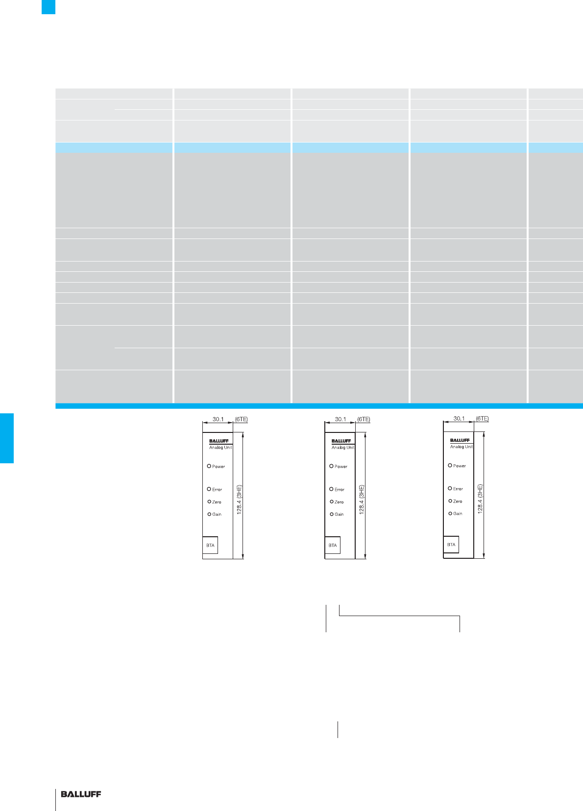
158
Accessories
Analog processors
Series BTA-A BTA-C BTA-E
Output signal Travel signal analog analog analog
Velocity
analog analog analog
Input interface
(transducer)
PPP
Part number BTA-A1_-_ _ _ _ BTA-C1_-_ _ _ _ BTA-E1_-_ _ _ _
Features Resolution 0.1 mV/0.2 µA,
LED function indicator,
End point adjust 15 %,
Span adjust 15 %,
Velocity output,
Error output (relay)
Resolution 0.1 mV/0.2 µA,
LED function indicator,
End point adjust 15 %,
Span adjust 15 %,
Velocity output,
Error output (relay)
Resolution 0.1 mV/0.2 µA,
LED function indicator,
End point adjust 15 %,
Span adjust 15 %,
Velocity output,
Error output (relay)
Nominal stroke of transducer 50...5500 mm 50...5500 mm 50...5500 mm
Housing Edge connector, 32-pin,
DIN 41612 F, 19" plug-in card
Edge connector, 32-pin,
DIN 41612 F, 19" plug-in card
Edge connector, 32-pin,
DIN 41612 F, 19" plug-in card
Operating voltage 20...28 V DC
Current consumption 130 mA at 24 V DC 130 mA at 24 V DC 130 mA at 24 V DC
Operating temperature 0...60 °C 0...60 °C 0...60 °C
Update time for standard 1 kHz 1 kHz 1 kHz
Interface analog
voltage
analog
voltage, current
analog
voltage, current
Output
signals
Travel signals analog
0...10 V and 10...0 V
analog
0...10 V and 10...0 V, 0...20 mA
analog
0...10 V and 10...0 V, 4...20 mA
Velocity analog
±10 V at ±2.5 m/s
analog
±10 V at ±2.5 m/s
analog
±10 V at ±2.5 m/s
Accessories
(please order separately)
Card holder
48-pin
Form F/627164
Card holder
48-pin
Form F/627164
Card holder
48-pin
Form F/627164
Features:
– The processors are confi gured
in a Eurocard format for
use in 19" racks and card
holders / top-hat rail fi tting
– The position values are
updated at a frequency of
max. 2 kHz, so that the actual
position can be captured
even at high traverse speeds
with negligible lag error
– High resolution (down to
0.01 mm) provided by micro-
controller-controlled digitizing
– Parallel data format selectable
binary, BCD or gray.
– Data format SSI (only BTM-H)
– Noise-immune data trans-
mission between processor
and transducer provided by
RS485/422 differential line
drivers, with cable lengths up
to 500 m.
– ERROR output for immediate
notifi cation of cable break,
defective or missing magnet.
Micropulse analog processor
■ Please enter the code for the
output signal and nominal stroke
in the ordering code!
Output signal
Ordering examples:
BTA-A1_-_ _ _
Nominal stroke
Transducer in [mm]
BTM-H1-_ _ _
Output driver
240 Source driver (PNP with SCP, 10...30 V) and
24-bit synchronous serial data transmission (SSI)
340 TTL outputs tri-state and
24-bit synchronous serial data transmission (SSI)
Micropulse digital processor
■ Please enter the code for the
output signal and nominal stroke
in the ordering code!
0 Rising, use only for
current output
7 Falling, use only for
current output
1 Rising/falling, use only
for voltage output
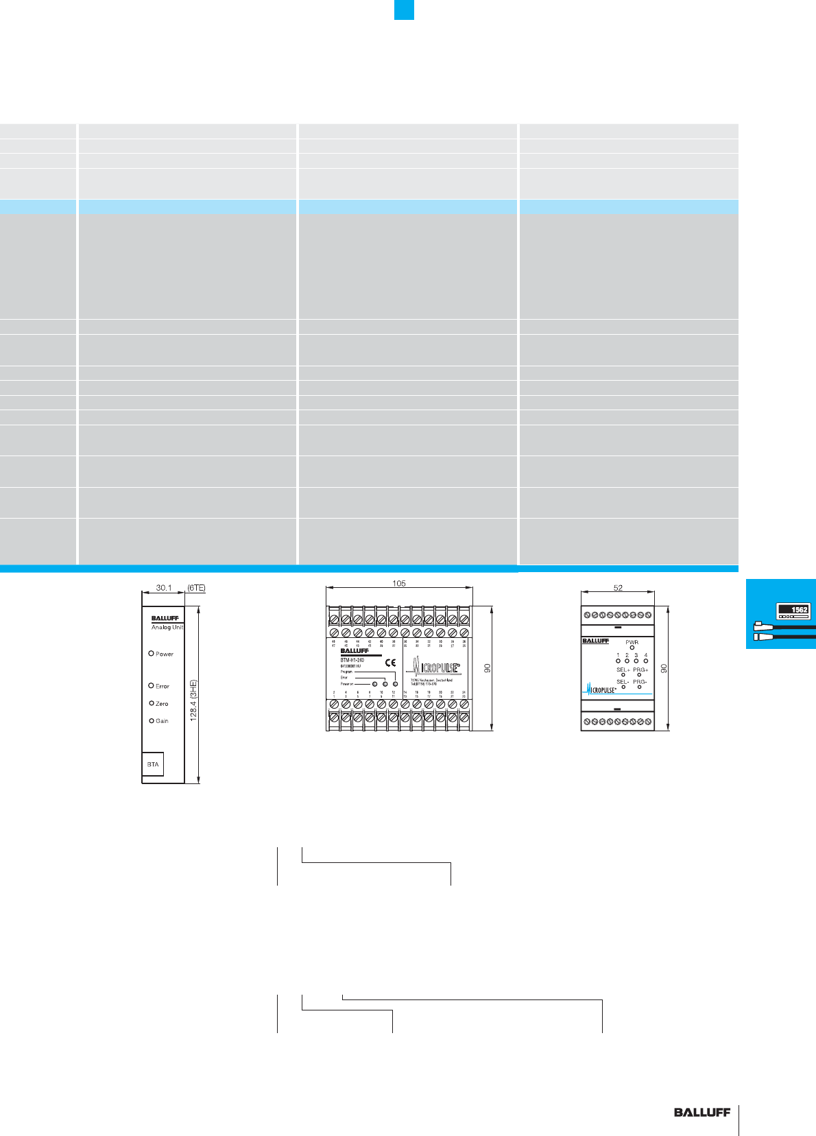
159■ www.balluff.com
BTA-G BTM-H1 BTM-_1
analog digital analog
analog analog
PPP
BTA-G1_-_ _ _ _ BTM-H1_-_ _ _ BTM-_1_-_ _ _
Resolution 0.1 mV/0.2 µA,
LED function indicator,
End point adjust 15 %,
Span adjust 15 %,
Velocity output,
Error output (relay)
Resolution 0.01 mm, 0.025 mm, 0.1 mm,
1 mm, BCD, binary, gray code, null point
adjustment, direction signal, DATA READY,
min./max. programming, ENABLE, DATA
HOLD, bus-compatible, ERROR output.
Replaces processors:
BTA-D, BTA-H, BTA-P
Resolution 16 bits
Up to 4 magnets on a single transducer can
be processed individually. Analog
velocity output. 100 % programmable
measuring range,
ERROR output
50...5500 mm 50...5500 mm 25...4000 mm
Edge connector, 32-pin,
DIN 41612 F, 19" plug-in card
Plastic housing for mounting on standard
top-hat rail EN 50022-35
Plastic housing for mounting on standard
top-hat rail EN 50022-35
130 mA at 24 V DC max. 500 mA max. 300 mA
0...60 °C 0...60 °C 0...70 °C
1 kHz 2 kHz 2 kHz
analog
voltage
digital 22 bit parallel BCD, binary, gray code,
24 bit synchronous serial (SSI) gray code
analogue, voltage or current
see ordering code
analog
–10...+10 V and +10...–10 V
Digital TTL 5 V DC (BTM-H1-340)
PNP source driver, 24 V DC (BTM-H1-240)
Analog, voltage or current
see ordering code
analog
±10 V at ±2.5 m/s
analog ±10 V programmed to 1000 mm/s,
adjustable over the range 50 mm/s...10 m/s
Card holder
48-pin
Form F/627164
Accessories
Analog and digital processors,
analog module
Output signal
A 0...10 V, 10...0 V
–10...10 V, 10...–10 V
E 4...20 mA, 20...4 mA
0...20 mA, 20...0 mA
Ordering examples:
BTM-_1-_ _ _
Versions
101 1 analog output, 1 magnet
102 2 analog outputs, 2 magnets
103 3 analog outputs, 3 magnets
104 4 analog outputs, 4 magnets
Output signal
A
E
BTM-_1-102-VM1000
Versions
2 analog outputs, 1 magnet
with velocity
Velocity
±10 V at a velocity of
1000 mm/s
Micropulse analog module
■ Please enter the code for
the output signal and version in
the ordering code!
Connectors
Processors
Profi bus
module P111
BUS interface
modules
Digital display
CAM controller
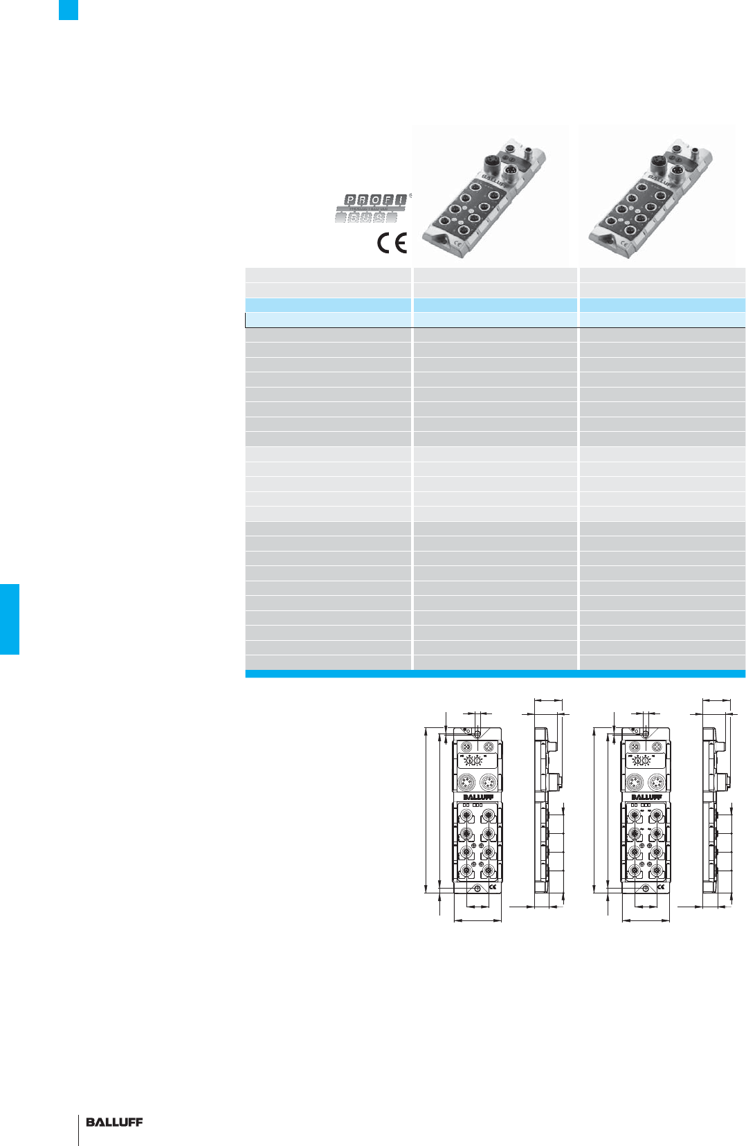
160
digital
Inputs
analog
Inputs
Fieldbus Profi bus Profi bus
Version 4× P111 or M1 4× P111 or M1
Ordering code BNI001A BNI002H
Part number BNI-PBS-551-000-Z001 BNI-PBS-552-000-Z001
Operating voltage UB18...30 V DC 18...30 V DC
Function indicator BUS RUN BUS RUN
Fault function indicator Red LED
Power indicator UA, US, undervoltage UA, US, undervoltage
Connection: Fieldbus M12, B-coded M12, B-coded
Connection: Operating voltage 7/8", 5-pin, female and male 7/8", 5-pin, female and male
Connection: I/O ports M12, A-coded, 5-pin, female M12, A-coded, 5-pin, female
Connection: P111 port M12, A-coded, 8-pin, female M12, A-coded, 8-pin, female
No. of I/O ports 8 8
No. of digital inputs 8
No. of analog inputs 4
Outputs 0 0
No. of P111 inputs 4 4
max. load current sensors/channel
1 A 1 A
Port status indicator (signal status)
Yellow LED Yellow LED
Port diagnostic indicator (overload)
Red LED Red LED
Total current USensor 9 A 9 A
Degree of protection as per IEC 60529
IP 67 (when attached) IP 67 (when attached)
Operating temperature Ta0...+55 °C 0...+55 °C
Weight approx. 735 g approx. 735 g
Mounting 2 mounting holes 2 mounting holes
Dimensions (L×W×H) 224×68×36.9 224×68×36.9
Housing material Nickel-plated GD-Zn, matt fi nish Nickel-plated GD-Zn, matt fi nish
P111 Profi bus modules are an
elegant, cost-effective solution
from Balluff.
The modules have a robust
metal housing that was
designed for use in harsh
industrial environments and
is capable of withstanding
powerful mechanical loads.
These modules are fi tted with
four interdependent ports
for Micropulse transducers
BTL with P111 or M1 pulse
interfaces. A maximum of 16
magnets can be used per BTL
port. The maximum nominal
stroke is 7500 mm. Four addi-
tional ports can be confi gured
with digital or analog sensors,
depending on the version.
You can achieve maximum
functionality and cost effi ciency
for fi eldbus integration by com-
bining Micropulse transducers
BTL with Profi bus modules
P111.
Accessories
Profi bus modules P111 for BTL
All modules include
4 screw plugs
and 1 label set.
45
01
0
1
01
BUS
UD
US
UD
US
10 1
3
0
2
76
30.8
36.9
7.5
20.2
224
2096.5 1.8
25252530.5
30
68
45
01
0
1
01
BUS
UD
US
UD
US
10 1
3
0
2
76
30.8
36.9
7.5
20.2
224
2096.5 1.8
25252530.5
30
68
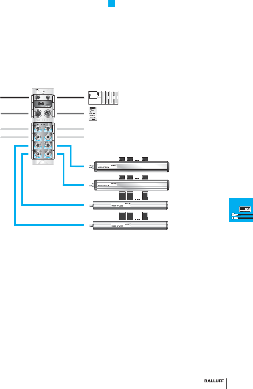
161■ www.balluff.com
Accessories
Profi bus modules P111 for BTL
Profi bus
8 digital inputs or
4 optional analog inputs
1-15 magnets
Maximum number of magnets per BTL is
16, however with a total of only 60 per module
Connectors
Processors
Profi bus
module P111
BUS interface
modules
Digital display
CAM controller
162
WAGO digital pulse interface 750-635 for BTL5-P1-_ _
or BTL6-P1_ _-
The digital pulse interface was developed for connecting Micropulse
transducers (BTL5-P1-...). Die RS422 interface assures quick and
noise-immune transmission of signals with a resolution down to
1µm. The absolute position of the Micropulse transducer is sent to
the supervisory controller as a 24-bit value.
The controller can perform a null point offset and confi gure the
number of magnets.
The bus terminal with digital pulse interface can be operated by all
bus drivers of the WAGO-I/O-SYSTEM 750, except the Economy
variants.
Interfaces:
– InterBus
– PROFIBUS-DP
– CANopen
– DeviceNet
– Ethernet TCP/IP
– MODBUS
– CC Link
Resolution: 1 µm Number of magnets confi gurable (1...4)
Further technical details and orders from:
WAGO
Kontakttechnik GmbH
Hansastraße 27
32423 Minden
Phone +49 571 887-0
Fax +49 571 887-169
E-mail: info@wago.com
www.wago.com
Phoenix Contact IMPULSE-IN terminal for BTL5-P1-_ _
or BTL6-P1_ _-
The IB IL IMPULSE-IN is a terminal from the Inline product family
by Phoenix Contact and processes the Micropulse transducer with
pulse interface.
The IMPULSE-IN terminal enables particularly cost-effective solutions
because it senses the positions using the low-cost pulse interface. In
addition, the pulse interface has the advantage of real-time capabil-
ity, making it especially suitable for applications with position or
bearing control.
Interfaces:
– InterBus
– PROFIBUS-DP
– CANopen
– DeviceNet
– Ethernet
Further technical details and orders from:
Phoenix Contact
GmbH & Co. KG
Flachsmarktstraße 8
32823 Blomberg
Phone +49 5235-300
Fax +49 5235-341200
E-mail:
info@phoenixcontact.com
www.phoenixcontact.com
Accessories
BUS interface modules
WAGO/Phoenix Contact

163■ www.balluff.com
Accessories
Digital display, CAM controller
Series BDD-UM 3023
BDD-AM 10-1-P
BDD-AM 10-1-SSD
BDD-CC 08-1-P
BDD-CC 08-1-SSD
Digital display
for analog input signals
Digital display
for BTL5-P with
Digital display
for BTL5-S with
CAM controller
for BTL5-P with
CAM controller
for BTL5-S with
Current/voltage P Interface SSD interface P Interface SSD interface
Part number BDD-UM 3023
BDD-AM 10-1-P
BDD-AM 10-1-SSD
BDD-CC 08-1-P
BDD-CC 08-1-SSD
Features – 4-digit display with prefi x
– LED display 14 mm high red
7-segment
– Programmable decimal point
setting
– 12-bit AC/DC converter
– Measuring range selection
– Voltage input 0-10V
– Current input 0/4-20 mA
– Scalable display range
– Seven 1/2-digit display with
prefi x
– LED display 14 mm high red
7-segment
– Scalable units
– Variable decimal point setting
– Adjustable null point
– Operating voltage 10...32 V
– 2 programmable relay outputs,
defi ned as
– Limit switch/comparator
– Dwell
– 2-position controller
– 1 confi gurable input
– External null set
– Latch display value
– Isolated DIN housing
for mounting in front panel
(mounting hardware included)
– 8 programmable outputs
– 8 directional switching points
possible
– LED display, 14 mm high red
7-segment, 6-digit
– LEDs for switching point status
on front panel
– 300 switching points
can be distributed over up to
15 programs
– Adjustable null point offset
– Dynamic deadtime
compensation for each individu-
al switching point
– Multiple BDD-CC 08 can be
wired in parallel
– Integrated transducer supply
voltage 300 mA, 24 V
– Isolated DIN housing
for mounting in front panel
(mounting hardware included)
Housing depth 55.5 mm Housing depth 110 mm Housing depth 110 mm
Connectors
Processors
Profi bus
module P111
BUS interface
modules
Digital display
CAM controller

164
Alphanumeric Directory
BAM to BTL
Part number
Ordering code
Page
BAM MC-XA-006-D38.1-5 146
BAM SE-XA-002-D38.1-S 146
BAM-AD-XA-003-D38.1-5 146
BCC M415-0000-1B-031-PS72N1-020 BCC070Y 154
BCC M415-0000-1B-031-PS72N1-050 BCC070Z 154
BCC M415-0000-1B-031-PS72N1-100 BCC0710 154
BCC M415-0000-2B-031-PS72N1-020 BCC0711 155
BCC M415-0000-2B-031-PS72N1-050 BCC0712 155
BCC M415-0000-2B-031-PS72N1-100 BCC0713 155
BCC M415-M415-3B-329-PS72N1-006 BCC070M 154
BCC M415-M415-3B-329-PS72N1-010 BCC070N 154
BCC M415-M415-3B-329-PS72N1-020 BCC070P 154
BCC M415-M415-3B-329-PS72N1-050 BCC070R 154
BCC M415-M415-3B-329-PS72N1-100 BCC070T 154
BCC M415-M415-3B-329-PS72N1-150 BCC070U 154
BCC M415-M415-3B-329-PS72N1-200 BCC070W 154
BCC M475-0000-1B-000-01X575-000 BCC0715 153
BCC M475-0000-2B-000-01X575-000 BCC0714 153
BCC M478-0000-1A-000-43X834-000 BCC04MC 157
BCC M485-0000-1B-000-01X575-000 BCC0717 153
BCC M485-0000-2B-000-01X575-000 BCC0716 153
BCC M488-0000-1A-000-43X834-000 BCC050F 157
BDD-AM 10-1-P 163
BDD-AM 10-1-SSD 163
BDD-CC 08-1-P 163
BDD-CC 08-1-SSD 163
BDD-UM 3023 163
BIW1-A310... 71
BIW1-C310... 71
BIW1-E310... 71
BIW1-G310... 71
BKS 12-CS-00 BAM00K7 152
BKS 12-CS-01 BAM0114 152
BKS-S 32M-_ _ 148
BKS-S 32M-_ _ 149
BKS-S 32M-C-_ _ 149
BKS-S 75-TB4-05-PU-00,05/02/02 152
BKS-S 78M-00 149
BKS-S 92-00 150
BKS-S 92-16/GS92-_ _ 151
BKS-S 92-TA1 151
BKS-S 93-00 150
BKS-S 94-00 150
BKS-S 94-R01 151
BKS-S 95-00 150
BKS-S105-R01 BCC00Y8 155
BKS-S115-PU-_ _ 156
BKS-S116-PU-_ _ 156
BKS-S137-19-PC-... 151
BKS-S151-19-PC-... 151
BKS-S232-PU-_ _ 149
BKS-S233-PU-_ _ 149
BNI-PBS-551-000-Z001 BNI001A 160
BNI-PBS-552-000-Z001 BNI002H 160
BTA-A1_-_ _ _ _ 158
BTA-C1_-_ _ _ _ 158
BTA-E1_-_ _ _ _ 158
BTA-G1_-_ _ _ _ 159
BTL2-GS10-_ _ _ _-A 47
BTL2-GS10-_ _ _ _-A 55
BTL2-S-3212-4Z 96
BTL2-S-4414-4Z 96
BTL2-S-5113-4K 96
BTL2-S-6216-8P 96
Part number
Ordering code
Page
BTL5-...-M_ _ _ _ -H-_ _ _ _ 105
BTL5-...-M_ _ _ _ -HB/WB-_ _ _ _ 109
BTL5-...-M_ _ _ _ -K-_ _ _ _ 103
BTL5-...-M_ _ _ _ -W-_ _ _ _ 107
BTL5-...-M_ _ _ _-SF-F_ _ _ _ 143
BTL5-_ _-M_ _ _ _-J-DEXC-TA12 133
BTL5-_1-M_ _ _ _ _ -_-DEX_-_ _ _ _ 131
BTL5-A11-M_ _ _ _-... 111
BTL5-A11-M_ _ _ _-P-_ _ _ _ 33
BTL5-A11-M_ _ _ _-SF-_ _ _ _ 145
BTL5-C1_-M_ _ _ _-... 111
BTL5-C1_-M_ _ _ _-P-_ _ _ _ 33
BTL5-C1_-M_ _ _ _-SF-_ _ _ _ 145
BTL5-D1_ _-M_ _ _ _-P-S93 41
BTL5-E1_0-M_ _ _ _-... 77
BTL5-E1_-M_ _ _ _-... 111
BTL5-E1_-M_ _ _ _-P-_ _ _ _ 33
BTL5-E1_-M_ _ _ _-SF-_ _ _ _ 145
BTL5-F1_0-M_ _ _ _-_-S115 95
BTL5-F-2814-1S 47
BTL5-F-2814-1S 55
BTL5-G11-M_ _ _ _-... 111
BTL5-G11-M_ _ _ _-P-_ _ _ _ 33
BTL5-G310-M_ _ _ _-A1-S115 59
BTL5-H1_ _-M_ _ _ _-... 89
BTL5-H1_ _-M_ _ _ _-... 91
BTL5-H1_ _-M_ _ _ _-... 117
BTL5-H1_ _-M_ _ _ _-P-S92 39
BTL5-H1_ _-M_ _ _ _-P-S94 39
BTL5-M1-M_ _ _ _-... 85
BTL5-M1-M_ _ _ _-P-_ _ _ _ 35
BTL5-M-2814-1S 46
BTL5-M-2814-1S 54
BTL5-N-2814-1S 46
BTL5-N-2814-1S 54
BTL5-P1-M_ _ _ _-... 85
BTL5-P1-M_ _ _ _-... 113
BTL5-P1-M_ _ _ _-P-_ _ _ _ 35
BTL5-P-3800-2 45
BTL5-P-3800-2 53
BTL5-P-4500-1 45
BTL5-P-4500-1 53
BTL5-P-5500-2 45
BTL5-P-5500-2 53
BTL5-S1_ _B-M_ _ _ _-... 87
BTL5-S1_ _B-M_ _ _ _-... 115
BTL5-S1_ _B-M_ _ _ _-P-_ _ _ _ 37
BTL5-S1_ _-M_ _ _ _-... 87
BTL5-S1_ _-M_ _ _ _-... 115
BTL5-S1_ _-M_ _ _ _-P-_ _ _ _ 37
BTL5-T1_ 0-M_ _ _ _-_-S103 93
BTL5-T1_ 0-M_ _ _ _-P-S 103 43
BTL5-T-2814-1S 55
BTL6-_ _ _-M_ _ _ _-A1-S115 57
BTL6-A110-M_ _ _ _-A1-S115 59
BTL6-A301-M_ _ _ _-A1-S115 57
BTL6-A301-M_ _ _ _-A1-S115 61
BTL6-A-3800-2 67
BTL6-A-3801-2 67
BTL6-A500-M_ _ _ _-... 121
BTL6-A500-M_ _ _ _-PF-S115 51
BTL6-B500-M_ _ _ _-... 121
BTL6-C500-M_ _ _ _-PF-S115 51
BTL6-E500-M_ _ _ _-... 121

165■ www.balluff.com
Alphanumerical Directory
BTL to BTM
Part number
Ordering code
Page
BTL6-E500-M_ _ _ _-PF-S115 51
BTL6-G500-M_ _ _ _-PF-S115 51
BTL6-P11_-M_ _ _ _-A1-S115 63
BTL6-P510-M_ _ _ _-... 123
BTL6-V11V-M_ _ _ _-A1-S115 65
BTL7-A110-M_ _ _ _-... 77
BTL7-A501-M_ _ _ _-... 79
BTL7-C1_0-M_ _ _ _-... 77
BTL7-E501-M_ _ _ _-... 79
BTL7-G110-M_ _ _ _-... 77
BTL-P-0814-GR-PAF 97
BTL-P-1012-4R 97
BTL-P-1012-4R-PA 97
BTL-P-1013-4R 97
BTL-P-1013-4R-PA 97
BTL-P-1013-4S 97
BTL-P-1014-2R 97
BTL-S-3112-4Z 146
BTM-_1_-_ _ _ 159
BTM-H1_-_ _ _ 159
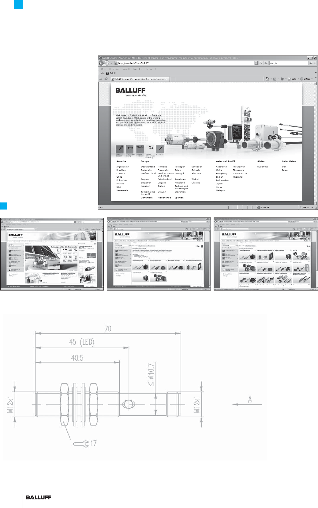
166
Sales and Logistics Services
Convenient online access to the latest information
Global online availability of
the latest product information
Our Sales and Logistics Services
offer you the latest
– Data sheets
– CAD drawings in
2D or 3D
– Catalogs
– Brochures
– Manuals
– Software descriptions
– Operating manuals
– FAQs
– Worldwide addresses
and much more.
.at
.be
.ca
.ch
.co.il
.jp
.co.kr
.co.uk
.com
.com.ar
.com.au
.com.br
.com.by
.com.cn
.com.hk
.ru
.com.sg
.com.tr
.cz
.de
.dk
.es
.fr
.gr
.hu
.it
.nl
.no
.pl
.se
www.balluff.com
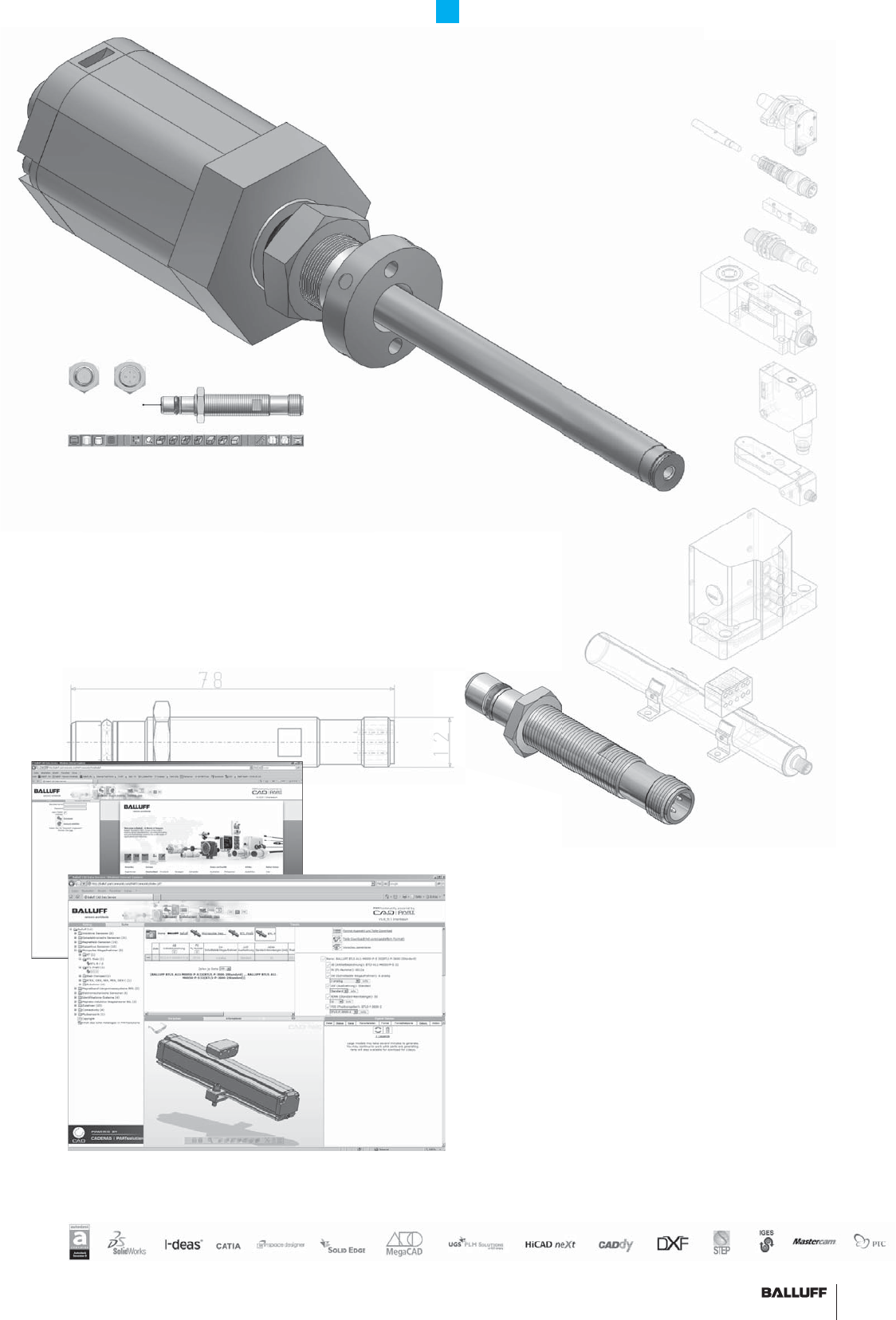
167■ www.balluff.com
Sales and Logistics Services
Retrieve product information online in 3D
CAD formats on the Cadenas PARTserver
The benefi ts to you
– Faster and more effi cient
designing
– Free availability of all
Balluff catalog products
– All common CAD formats
– Convenient preview in 3D
– Confi gurable products
And here's how it works
– At www.balluff.com, go
to 3D data in the respective
product area
– You are automatically redirect-
ed to the Cadenas PARTserver
– Select a sensor and
perform an optional check via
3D preview
– Add to shopping basket
– Once you have entered your
details, the CAD fi les of
your choice are sent to you
by e-mail
– Graphics reduced to
the essentials for optimized
performance
– All catalog products are
available:
Inductive sensors,
photoelectric sensors,
sensors for pneumatic
cylinders, Micropulse
transducers, industrial RFID
systems, mechanical single
and multiple position switches,
industrial networking
and connectivity, and so on.
Sales and Logistics
S
d
Logistics
S
Retrieve p
r
r
oduct informat
i
– Gra
p
hics reduced to
the essentials for optimized
pe
rf
o
rm
a
n
ce
–
All
cata
l
og pro
d
ucts are
a
v
a
il
ab
l
e:
In
duct
iv
e
se
n
so
r
s,

168
Worldwide Sales
Headquarters
Germany
Balluff GmbH
Schurwaldstrasse 9
73765 Neuhausen a.d.F.
Phone +49 7158 173-0
Fax +49 7158 5010
balluff@balluff.com
Subsidiaries and
Representatives
Argentina
Nortécnica S.R.L
103 – Heredia 638
B1672BKD
Villa Lynch – San Martin
Pcia. de Buenos Aires
Phone +54 11 47573129
Fax +54 11 47571088
info@nortecnica.com.ar
Australia
Balluff-Leuze Pty. Ltd.
12 Burton Court
Bayswater VIC 3153
Phone +61 397 204100
Fax +61 397 382677
sales@balluff.com.au
Austria
Balluff GmbH
Industriestraße B16
2345 Brunn am Gebirge
Phone +43 2236 32521-0
Fax +43 2236 32521-46
sensor@balluff.at
Belarus
Automaticacentre OOO.
Nezavisimosti Av. 185,
Block 19, Offi ce 3
220125 Minsk
Phone +375 17 2181713
Fax +375 17 2181798
balluff@nsys.by
Belgium
Balluff bvba
Researchpark Haasrode 1820
Interleuvenlaan 62,
3001 Leuven
Phone +32 16 397800
Fax +32 16 397809
info.be@balluff.be
Brazil
Balluff Controles
Elétricos Ltda.
Rua Francisco Foga, 25
Distrito Industrial
CEP 13280.000
Vinhedo – Sao Paulo
Phone +55 19 38769999
Fax +55 19 38769990
balluff@balluff.com.br
Bulgaria
BPS AG
41, Nedelcho Bonchev St.
1528 Sofi a
Phone +359 2 9609875
Fax +359 2 9609896
bps@bps.bg
Canada
Balluff Canada Inc.
2840 Argentia Road, Unit 2
Mississauga, Ontario L5N 8G4
Phone +1 905 816-1494
Toll-free 1-8 00-927-9654
Fax +1 905 816-1411
balluff.canada@balluff.ca
Chile
Balluff Controles
Elétricos Ltda.,
Brazil
China
Balluff (Shanghai) Trading Co. Ltd.
Room 337, Xinxing Building
2005 Yanggao Rd. North
200131 Shanghai
Tel. +86 21 51698788, 50644131
Fax +86 21 50644131, 22818067
info@balluff.com.cn
Columbia
Balluff Controles
Elétricos Ltda.,
Brazil
Croatia
HSTEC d.d.
Zagrebacka 100
23000 Zadar
Phone +385 23 205-405
Fax +385 23 205-406
info@hstec.hr
Czech Republic
Balluff CZ, s.r.o
Pelušková 1400
198 00 Praha 9 – Kyje
Phone +420 281 000 666
Fax +420 281 940066
obchod@balluff.cz
Denmark
Balluff ApS
Åbogade 15
8200 Århus N
Phone +45 70 234929
Fax +45 70 234930
info.dk@balluff.dk
Egypt
EGEC Taksym El Kodah-smouha
24 St. El Helal El Ahmer
Alexandria
Phone +20 3 4299771
Fax +20 3 4261773
info@egecgroup.com
Finland
Murri Pääkonttori
Koukkukatu 1
15700 Lahti
Phone +358 3 8824000
Fax +358 3 8824040
myynti@murri.fi
France
Balluff SAS
ZI Nord de Torcy-Bat 3
Rue des Tanneurs – BP 48
77201 Marne La Vallée Cedex 1
Phone +33 1 64111990
Fax +33 1 64111991
info.fr@balluff.fr
Greece
S. NAZOS S.A.
10 KLM Thessalonikis-Kilkis
P.O. Box 57008
Thessaloniki
Phone +30 2310 462120
Fax +30 2310 474079
parasxos@nazos.gr
Hong Kong
Sensortech Company
No. 43, 18th Street
Hong Lok Yuen,
Tai Po, NT
Phone +852 26510188
Fax +852 26510388
sensortech@netvigator.com
Hungary
Balluff Elektronika Kft.
Pápai út. 55.
8200 Veszprém
Phone +36 88 421808
Fax +36 88 423439
saleshu@balluff.hu
India
Balluff India
405 Raikar Chambers
Deonar Village Road,
Govandi, Mumbai 400088
Phone +91 22 67551646
Fax +91 22 67973257
balluff@balluff.co.in
Indonesia
PT. Multiguna Cemerlang
Bumi Serpong Damai Sektor XI
Multipurpose Industrial Building
Block H 3-31
Serpong Tangerang
15314 Banten
Phone +62 21 75875555
Fax +62 21 75875678
sales_bsd@multigunacemerlang.com
Israel
Ancitech Ltd.
19, Hamashbir St.
Industrial Zone Holon
58853 Holon
Phone +972 3 5568351
Fax +972 3 5569278
moshe@ancitech.com
Italy
Balluff Automation S.R.L.
Via Morandi 4
10095 Grugliasco, Torino
Phone +39 11 3150711
Fax +39 11 3170140
info.italy@balluff.it
Japan
Balluff Co., Ltd.
Ishikawa Bldg. 2nd Fl.
1-5-5 Yanagibashi, Taito-Ku
Tokyo 111-0052
Tel. +81 03 5833-5440
Fax +81 03 5833-5441
info.jp@balluff.jp
Kazakhstan
elcos electric control systems
2A, Molodezhniy Str. 3D
block O., offi ces 318-319
050061 Almaty
Phone +7 727 3340536
Fax +7 727 3340539
info@elcos.kz
Lithuania
UAB Interautomatika
Kęstučio 47
08127 Vilnius
Phone +370 5 2607810
Fax +370 5 2411464
andrius@interautomatika.lt
Malaysia
Sumber Engineering (M) Sdn. Bhd.
20T 558 Jalan Subang 6
077 Persiaran Subang,
Sungai Penaga Industrial Parc
47500 Subang Jaya, Selangor
Phone +60 3 56334227
Fax +60 3 56334239
louis@sumbersarana.com
Team Automation Systems (M) Sdn. Bhd.
No. 26, 1st Floor, Jalan TTC 23,
Taman Teknologi Cheng,
75250 Melaka
Phone +60 6 3366223
Fax +60 6 3368223
sales@teamtas.com.my
Mexico
Balluff de México S.A. de C.V.
Prol. Av. Luis M. Vega #109
Col. Ampliación Cimatario
C.P. 76030
Queretaro, Qro.
Phone +52 442 2124882
Fax +52 442 2140536
balluff.mexico@balluff.com
Netherlands
Balluff B.V.
Kempenlandstraat 11H
5262 GK Vught
Phone +31 73 6579702
Fax +31 73 6579786
info.nl@balluff.nl
New Zealand
Balluff-Leuze Pty. Ltd.,
Australia
Norway
Primatec as
Lillesandsveien 44
4877 Grimstad
Phone +47 37 258700
Fax +47 37 258710
post@primatec.no
Philippines
Technorand Sales Corporation
803 Wilshire Annapolis Plaza,
No. 11 Annapolis Street,
San Juan, Metro Manila 1500
Phone +63 2 7245006
Fax +63 2 7245010
techno@compass.ph
Poland
Balluff Sp. z o.o.
Ul. Muchoborska 16
54-424 Wrocław
Phone +48 71 3384929
Fax +48 71 3384930
balluff@balluff.pl
Portugal
LA2P Lda.
Rua Teofi lo Braga, 156 A
Escrit. F – Edifi cio S. Domingos
Cabeco Do Mouro
2785-122 S. Domingos De Rana
Phone +351 21 4447070
Fax +351 21 4447075
la2p@la2p.pt
Romania
East Electric s.r.l.
256 Basarabia Blvd.
030352 Bucuresti
Phone +40 31 4016301
Fax +40 31 4016302
offi ce@eastelectric.ro

169■ www.balluff.com
Worldwide Sales
Russia
Balluff OOO
M. Kaluzhskaja Street 15
Building 17, Offi ce 500
119071 Moscow
Tel. +7 495 78071-94
Fax +7 495 78071-97
balluff@balluff.ru
Serbia
ENEL d.o.o.
Ul. Vasilja Pavlovica 10
14000 Valjevo
Phone +381 14 291161
Fax +381 14 244641
enelva@ptt.rs
Singapore
Balluff Asia Pte. Ltd.
BLK 1004 Toa Payoh
Ind. Park
Lorong 8, #03-1489
Singapore 319076
Phone +65 62524384
Fax +65 62529060
balluff@balluff.com.sg
Slovakia
Balluff Slovakia s.r.o.
Blagoevova 9
85104 Bratislava
Phone +421 2 67200062
Fax +421 2 67200060
info@balluff.sk
Slovenia
Senzorji SB d.o.o.,
Proizvodnja,
trgovina in storitve d.o.o.
Livadna ulica 1
2204 Miklavž na Dravskem polju
Phone +386 2 6290300
Fax +386 2 6290302
senzorji.sb@siol.net
Spain
Balluff S.L.
Edifi cio Forum SCV
Planta 5°, Ofi cina 4°
Carretera Sant Cugat a Rubi
Km01, 40-50
08190 Sant Cugat del Vallés
Barcelona
Phone +34 93 5441313
Fax +34 93 5441312
info.es@balluff.es
South Africa
PAL Distributers CC
P.O. Box 211
Randburg, 2125 Johannesburg
Phone +27 11 7814381
Fax +27 11 7818166
pal@polka.co.za
South Korea
Mahani Electric Co. Ltd.
792-7 Yeoksam-Dong
Kangnam-Gu, Seoul
Post code: 135-080
Phone +82 2 21943300
Fax +82 2 21943397
yskim@balluff.co.kr
Sweden
Balluff AB
Industrivägen 2
43361 Sävedalen
Phone +46 31 3408630
Fax +46 31 3409431
info.se@balluff.se
Switzerland
Balluff Sensortechnik AG
Riedstrasse 6
8953 Dietikon
Phone +41 43 3223240
Fax +41 43 3223241
sensortechnik@balluff.ch
Taiwan
Canaan Electric Corp.
6F-5, No. 63 Sec. 2
Chang An East Road
10455 Taipei
Phone +886 22 5082331
Fax +886 22 5084744
sales@canaan-elec.com.tw
Thailand
Compomax Co. Ltd.
16 Soi Ekamai 4,
Sukhumvit 63 Rd.
Prakanongnua, Vadhana,
Bangkok 10110
Phone +66 2 7269595
Fax +66 2 7269800
info@compomax.co.th
Turkey
Balluff Sensor Otomasyon
Sanayi Ve Ticaret Ltd. Sti.
Perpa Ticaret Is Merkezi
A Blok, Kat 1-2-3
No: 0013-0014
34381 Okmeydani/Istanbul
Phone +90 212 3200411
Fax +90 212 3200416
balluff@balluff.com.tr
Ukraine
Micronlogistik Ltd
Ul. Promyischlennaya Street 37
65031 Odessa
Phone +380 48 7781278
Fax +380 48 2358760
info@balluff-ua.com
United Kingdom and Ireland
Balluff Ltd.
4 Oakwater Avenue
Cheadle Royal Business Park
Cheadle, Cheshire SK8 3SR
Phone +44 161 282-4700
Fax +44 161 282-4701
sales@balluff.co.uk
USA
Balluff Inc.
8125 Holton Drive
Florence, KY 41042-0937
Phone +1 859 727-2200,
Toll-free 1-800-543-8390
Fax +1 859 727-4823
balluff@balluff.com
Venezuela
Balluff Controles
Elétricos Ltda.,
Brazil
.
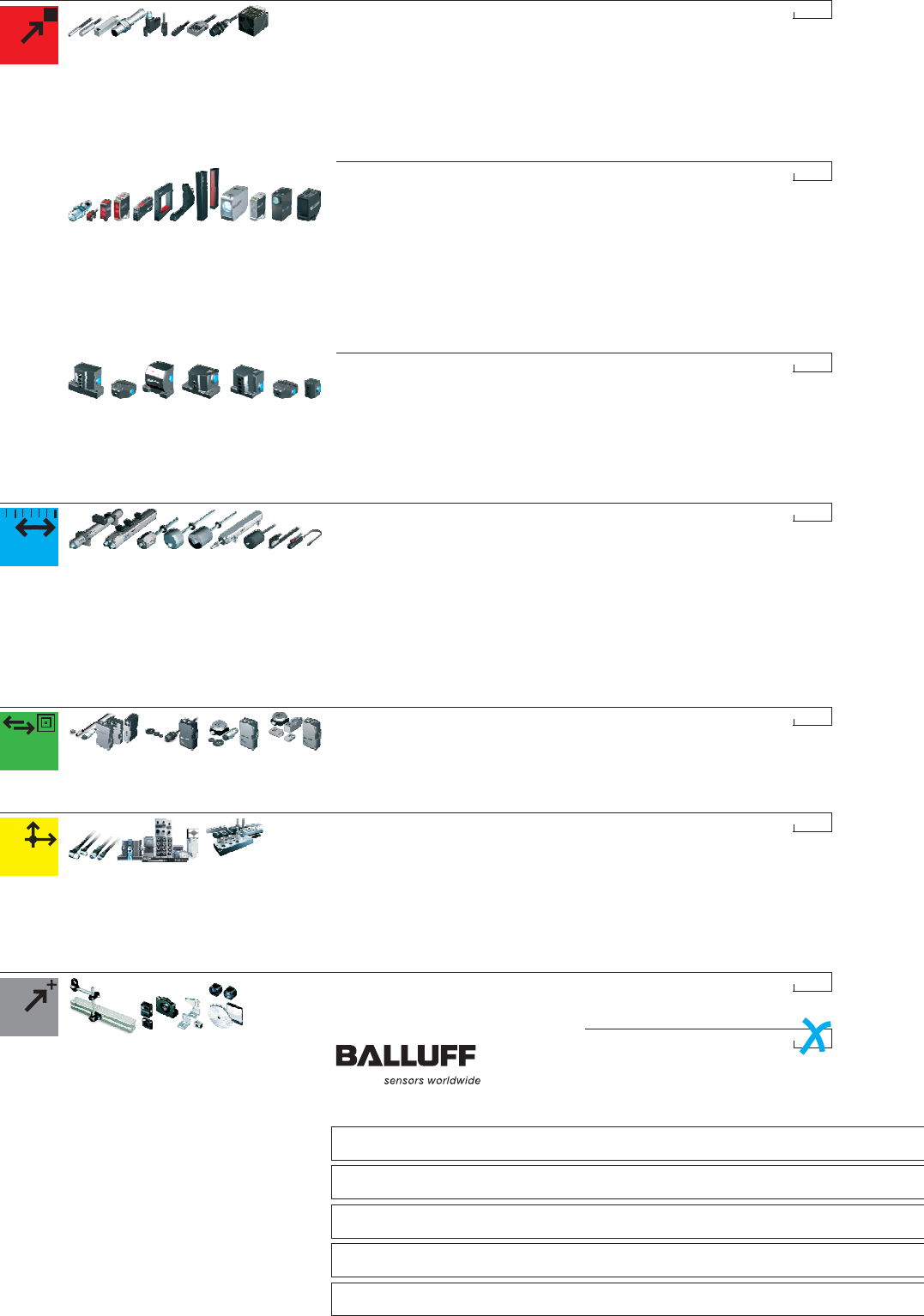
■ www.balluff.com
Company
Name,
Department
Street
Postal Code/City
Phone
Fax +49 7158 173-299
Mechanical Product Line
Mechanical single and multiple position switches
Mechanical single and multiple position switches to DIN EN 60204-1/VDE 0113
Mechanical single and multiple position switches with forced opening
Mechanical single and multiple position switches with quick-change plunger unit
Inductive single and multiple position switches
Inductive single and multiple position switches with extended switching distance
Mechanical wireless position switches
Mixed assembly multiple position switches
Sensor Product Line
Inductive sensors BES DC 3-/4-wire
Inductive sensors BES DC 2-wire
Inductive sensors BES AC/DC
Inductive sensors BES with special properties
Sensors for pneumatic cylinders BMF
Magnetic fi eld sensors BMF
Capacitive sensors BCS
Ultrasonic sensors BUS
Pressure sensors BSP
Linear Displacement Product Line
Micropulse® transducer BTL Profi le series
Micropulse® transducer BTL AT series
Micropulse® transducer BTL Rod series
Micropulse® transducer BTL Compact Rod series
Micropulse® processors, BUS interfaces
Magnetic linear encoder system BML
Incremental and absolute encoders BDG/BRG
Inductive linear position sensor BIW
Inductive distance sensors BAW
Magneto-inductive position sensors BIL
Photoelectric distance sensors BOD
Ultrasonic sensors BUS
Industrial Identifi cation
Industrial RFID systems BIS C
Industrial RFID Systems BIS L
Industrial RFID systems BIS M
Industrial RFID systems BIS S
Vision sensor BVS
Industrial Networking and Connectivity
Connectors and cables BCC
Passive splitter boxes BPI
Active splitter boxes BNI
IO-Link
Remote inductive transmission systems
Inductive couplers BIC
BUS systems
Wireless
Electrical devices
Photoelectric Product Line
Diffuse energetic BOS with fore- and background suppression
Retro-refl ective sensors BOS
Through-beam sensors BOS (emitter/receiver)
Fiber optic devices BFB
Through-beam fork sensors BGL
Dynamic optical windows BOWA
Light grids BLG
Contrast sensors BKT
Luminescence sensors BLT
Color sensors BFS
Photoelectric distance sensors BOD
Mechanical Accessories
Holders and fastening systems
Mounting system BMS
Please check and send by fax!
Object Detection
Linear Position Sensing
Industrial Identifi cation
Industrial Networking and Connectivity
Mechanical Accessories

Micropulse Transducers BTL/BIW
Linear position sensing – high precision with extreme reliability
Object Detection
Linear Position Sensing
Industrial Identifi cation
Industrial Networking and Connectivity
Mechanical Accessories
Micropulse Transducers BTL/BIW – Linear position sensing – high precision with extreme reliability
Balluff GmbH
Schurwaldstrasse 9
73765 Neuhausen a.d.F.
Germany
Phone +49 7158 173-0
Fax +49 7158 5010
balluff@balluff.de
www.balluff.com
Doc. No. 822987/Mat. No. 123757 E · Edition 1003; Subject to modifi cations. Replaces edition 1002.
