700541 Service Manual
2017-04-29
: Pdf 700541 Service-Manual 700541_Service-Manual product s
Open the PDF directly: View PDF ![]() .
.
Page Count: 118 [warning: Documents this large are best viewed by clicking the View PDF Link!]

AIR CONDITIONER CONTENTS
MULTI AIR CONDITIONER
1. Precautions
2. Product Specications
3. Disassembly and Reassembly
4. Troubleshooting
5. PCB Diagram and Parts List
6. Wiring Diagram
7. Reference Sheet
OUTDOOR UNIT
AJ020JCJ2CH
AJ024JCJ3CH
AJ036JCJ5CH
AJ020JCJ2CH/AA
AJ024JCJ3CH/AA
AJ036JCJ5CH/AA
Model name:
AJ009JNNDCH
AJ012JNNDCH
AJ018JNNDCH
AJ007JNADCH
AJ009JNADCH
AJ012JNADCH
Model code:
AJ009JNNDCH/AA
AJ012JNNDCH/AA
AJ018JNNDCH/AA
AJ007JNADCH/AA
AJ009JNADCH/AA
AJ012JNADCH/AA
AJ018JNADCH
AJ024JNADCH
AJ009JNLDCH
AJ012JNLDCH
AJ018JNLDCH
AJ018JNADCH/AA
AJ024JNADCH/AA
AJ009JNLDCH
/AA
AJ012JNLDCH/AA
AJ018JNLDCH/AA
INDOOR UNIT
AJ009JNNDCH
AJ012JNNDCH
AJ018JNNDCH
AJ009JNLDCH
AJ012JNLDCH
AJ018JNLDCH
AJ007JNADCH
AJ009JNADCH
AJ012JNADCH
AJ018JNADCH
AJ024JNADCH
AJ020JCJ2CH
AJ024JCJ3CH
AJ036JCJ5CH

Contents
11. Precautions
........................................................................................................................................
1-1
1-1 Installing the air conditioner
..........................................................................................................
1-1
1-2 Power supply and circuit breaker
..................................................................................................
1-1
1-3 During operation
..............................................................................................................................
1-2
1-4 Disposing of the unit
.......................................................................................................................
1-2
1-5 Others
.................................................................................................................................................
1-2
12. Product Specifications
...............................................................................................................
2-1
2-1 The Feature of Product
....................................................................................................................
2-1
2-2 Product Specifications
.....................................................................................................................
2-2
2-3 Accessory and Specifications
..........................................................................................................
2-8
3. Disassembly and Reassembly
..............................................................................................
3-1
3-1 Indoor Unit
.........................................................................................................................................
3-2
3-2 Outdoor Unit
.....................................................................................................................................
3-29
4. Trouble shooting
...........................................................................................................................
4-1
4-1 Display Error and Check Method ................................................................................................................ 4-1
4-1-1 Indoor Unit ................................................................................................................................................ 4-1
4-1-2 Outdoor Unit ............................................................................................................................................ 4-5
4-2 Setting Option Setup Method ...................................................................................................................... 4-7
4-2-1 Setting an indoor unit address and installation option ......................................................... 4-7
4-2-2 Changing a particular option ............................................................................................................ 4-11
4-3 Items to be checked first ................................................................................................................................. 4-12
4-4 Checking and Testing operation .................................................................................................................. 4-16
4-5 Fault Diagnosis by Symptom ........................................................................................................................ 4-24
4-5-1 Indoor ....................................................................................................................................................... 4-24
4-5-1-1 Indoor temperature sensor (open/short) ........................................................................... 4-24
4-5-1-2 Indoor FAN Error ( BLDC MOTOR MODEL ) ....................................................................... 4-25
4-5-1-3 Communication error after finishing Tracking ............................................................... 4-26
4-5-1-4 EEPROM circuit failure ............................................................................................................... 4-27
4-5-2 Outdoor unit is not powered on – Initial diagnosis(1phase) ............................................. 4-28
4-5-3 Outdoor unit fan error ....................................................................................................................... 4-29
4-5-4 Compressor startup error, Compressor Lock error, Compressor rotation error. ........ 4-30
4-5-5 IPM Over Current error ...................................................................................................................... 4-31
4-5-6 Checking Temperature sensor ........................................................................................................ 4-32
4-5-6-1 Outdoor Discharge/OLP temperature sensor error ...................................................... 4-32
4-5-6-2 Outdoor out/cond temperature sensor error .................................................................. 4-33
4-5-7 Checking EEV .......................................................................................................................................... 4-33
4-6 PCB Inspection Method ................................................................................................................................... 4-34
5. PCB Diagram and Parts list
......................................................................................................
5-1
5-1 Indoor Unit
.......................................................................................................................................
5-1
5-2 Outdoor Unit
....................................................................................................................................
5-5
6. Wiring Diagram
..............................................................................................................................
6-1
6-1 Indoor Unit
.......................................................................................................................................
6-1
6-2 Outdoor Unit
....................................................................................................................................
6-4
7. Reference Sheet
.............................................................................................................................
7-1
Samsung Electronics 1-1
1. Precautions
1-1 Installing the air conditioner
O
Users should not install the air conditioner by themselves.
Ask the dealer or authorized company to install the air conditioner except the
window-type air conditioner in U.S.A and Canada.
O
If you don’t install the air conditioner properly, it may cause a fire, a water leak-
age or an electric shock.
O
You must install the air conditioner according to the national wiring regulations
and safety regulations.
O
Install the indoor unit higher than 2.5m from the floor to avoid the injury caused
by the operation of the fan. (except the window-type air conditioner)
O
The manufacturer is not responsible for any accidents or injury caused by an
incorrect installation.
When installing the built-in type air conditioner, keep all electric cables such as
the power cable and the connection cord in pipes, ducts, or cable channels to
protect them from the danger of impact or any other incidents.
O
More than 2 indoor units should be installed when you use Free Joint Multi air
conditioner.
1-2 Power supply and circuit breaker
O
If the power cord of the air conditioner is damaged, it must be replaced by the
manufacturer or a qualified person in order to avoid a hazard.
O
The air conditioner must be plugged into an independent circuit if applicable or
connect the power cable to the auxiliary circuit breaker.
An all pole disconnection from the power supply must be incorporated in
the fixed wiring with a contact opening of >3mm.
O
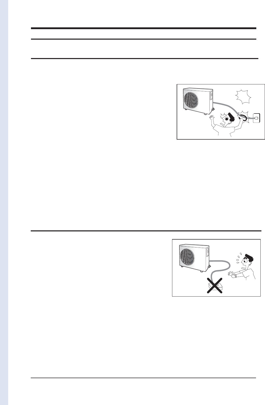
Do not extend an electric cord to the air conditioner.
O
The air conditioner must be plugged in after you complete the installation.
suoregnad
Avoid Dangerous Contact
No Tapping and No Extension Cords
O
AJ020JCJ2CH
- 77018/02477indoor unites cannot be connected.
AJ024JCJ3CH
- 770247777indoor units cannot be connected.
1-2 Samsung Electronics
1-4 Disposing of the unit
O
Before throwing out the air conditioner, remove the batteries from the remote control.
O
When you dispose of the air conditioner, consult your dealer. If pipes are removed incorrectly, refrigerant may blow out and cause
air pollution. When it contacts with your skin, it can cause skin injury.
O
The package of the air conditioner should be recycled or disposed of properly for environmental reasons.
1-5 Others
O
Never store or load the air conditioner upside down or sideways to prevent the damage to the compressor.
O
Young children or infirm persons should be always supervised when they use the air conditioner.
O
Max current is measured according to IEC standard for safety.
O
Current is measured according to ISO standard for energy efficiency.
O
When installing, make sure there is no leakage. When recovering the refrigerant, ground the compressor first before removingthe
connection pipe. If the refrigerant pipe is not properly connected and the compressor works with the service valve open, the pipe
inhales the air and it makes the pressure inside of the refrigerant cycle abnormally high. It may cause explosion and injury.
O
Pump Down Procedure (When removing the product)
- Turn on the air conditioner and select Cool mode to run the compressor for 3 minutes.
- Release the valve caps on High and Low pressure side.
- Use L wrench to close the valve on the high pressure side.
- Approximately 2 minutes after, close the valve on the low pressure side.
- Stop operation of the air conditioner.- Disconnect the pipes.
1-3 During operation
O
Do not repair the air conditioner at your discretion.
It is recommended to contact a service center directly.
O
Never spill any kind of liquid on the air conditioner.
If this happens, turn off the air conditioner and contact an authorized service cen-
ter.
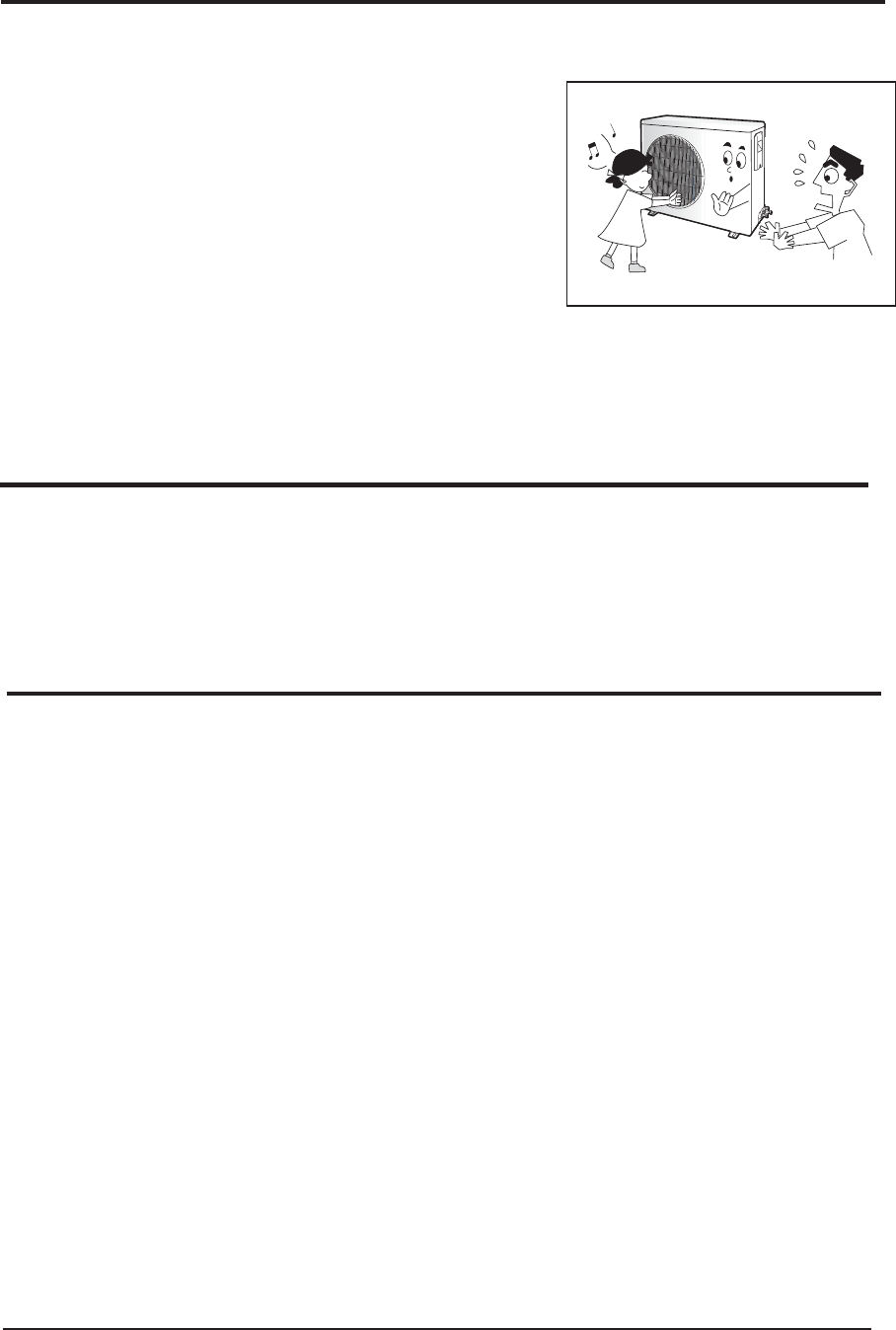
O
Do not insert anything between the airflow blades to prevent damage of the inner
fan and consequent injury. Keep children away from the air conditioner.
O
Do not place any obstacles in front of the air conditioner.
O
Do not spray any kind of liquid into the indoor unit. If this happens, turn off the air
conditioner and contact a service center.
O
Make sure that the air conditioner is well ventilated at all times:
Do not place a cloth or other materials over it.
O
Remove the batteries if you don’t use the remote control for a long time. (If appli-
cable)
O
Use the remote control within 7 meters from the indoor unit. (If applicable)
No children Nearby

Samsung Electronics 2-1
2. Product Specifications
2-1 The Feature of Product
ÿMulti Inverter(Free Joint Multi) Series delivers comfort to 2~5 rooms with a Single Outdoor Unit.
ÿInverter for High Efficiency Operation.
Thanks to inverter control, efficiency of operation of the outdoor unit is enhanced depending on the number of indoor units
operated and the temperature setting.
When only one indoor unit is used, power is saved, resulting in a smaller electricity bill. When all indoor units are used, high-power
operation achieves comfort quickly in all rooms.
ÿInstallation of indoor units on different floors is possible.
ÿCharacteristics
t6TJOHFMFDUSPOJDFYQBOTJPOWBMWFDPOUSPM
ÿVarious Indoor units & combinations
t.JOJXBZDBTTFUUF
t4MJNEVDU
t"
ÿConvenient Installation
Auto addressing option : Automated checking of pipe connection.(Refer to the installation manual for detail)
ÿSpace saving & Environmental Friendly
t$PNQBDUMJHIUPVUEPPSVOJU
t4MJNBOERVJFUJOEPPSVOJUT
t1JQFTJ[FSFEVDUJPO
t0[POFGSJFOEMZ3FGSJHFSBOU3"
t-FBE'SFFDPOUSPMMFS
ÿReliability
t*OTUBMMBUJPOQPTTJCJMJUJFT-FOHUI)FJHIU
t$POWFOJFOUJOTUBMMBUJPOOPOQPMBSJUZBVUPBEESFTTJOH
t*OUFMMJHFOUDPOUSPMOFUXPSL
t&BTZDIFDLJOHTZTUFNDPOEJUJPOCZTFHNFOU
ÿSmart & Low Noise outdoor units in any condition
t5#34JOF8BWF$POUSPMMFS/PJTF3FEVDUJPO$POUSPM%VBM'FMUFUD
t'FMU4USVDUVSF/FXGFMUIBTTFMFDUFEUPSFEVDFUIFOPJTFDPNJOHPVUPGUIFDPNQSFTTPS
Double layered felt structure absorbs noise by two times and felt is also covering top of the compressor to
reduce the noise even more.
2-2 Samsung Electronics
2-2 Product Specifications
ITEM
AJ009JNLDCH AJ012JNLDCH AJ018JNLDCH
INDOOR UNIT
Type Slim Duct
Performance
Cooling Btu/h 9000 12000 18000
Heating 10000 13000 19000
Air Volume Cooling m3/min 8.3 9.8 14.8
Heating 8.3 9.8 14.8
Noise Cooling dB(A) 37
Heating 38 37
Power Φ,V,Hz 1, 208~230, 60
Power
Power
Consumption
Cooling W76 150
Heating 76 150
Operating
Current
Cooling A0.35 0.69
Heating 0.35 0.69
EER Cooling/Heating Btu/Wh - / - - / - - / -
Size
Outer Dimension W*H*D mm 900*199*600 1100*199*600
Weight kg 23.3 29.0
Refrigerant Pipe Gas mm 9.52 12.7
Liquid mm 6.35
Fan Motor
Blower
Blower Type -
Size mm Φ92XL634 Φ92XL844.3
Motor Type -
Capacitor uFxVAC -
Heat Exchanger Φ7,FP1.5,SLIT,NGS Φ7,FP1.3,SLIT,NGS
Option Code 015201-14023E-
200001-300000
015201-160370-
200001-300000
011224-1940E6-
200001-300000
ITEM
AJ009JNNDCH AJ012JNNDCH AJ018JNNDCH
INDOOR UNIT
Type Mini 4 way cassette
Performance
Cooling Btu/h 8900 11900 17700
Heating 9900 13000 19100
Air Volume Cooling m3/min 9 9.6 10.5
Heating 10.6 11.3 13.5
Noise Cooling dB(A) 38 41 44
Heating 39 42 45
Power Φ,V,Hz 1, 208~230, 60
Power
Power
Consumption
Cooling W19 22 28
Heating 19 22 28
Operating
Current
Cooling A0.51 0.52 0.53
Heating 0.51 0.52 0.53
EER Cooling/Heating Btu/Wh - / - - / - - / -
Size
Outer Dimension W*H*D mm 575*250*575
Weight kg 11.4 11.8
Refrigerant Pipe Gas Inch '3/8
Liquid Inch '1/4
Fan Motor
Blower
Blower Type -
Size mm Φ320*1ea, 7B
Motor Type BLDC
Capacitor uFxVAC -
Heat Exchanger Φ7*2R*8S*1357
(1387.3+1327.5)
Φ7*2R*10S*1357
(1387.3+1327.5)
Option Code 01507F-1660F8-
231A21-300100
01507F-166219-
232328-300100
01507F-17625D-
23343C-300100
Samsung Electronics 2-3
Product Specifications(cont.)
ITEM
AJ018JNADCH AJ024JNADCH
INDOOR UNIT
Type Wall-mounted
Performance
Cooling Btu/h 17100 22000
Heating 20000 25500
Air Volume Cooling m3/min --
Heating - -
Noise Cooling dB(A) 50 51
Heating 46 50
Power Φ,V,Hz 1, 208~230, 60
Power
Power
Consumption
Cooling W50 50
Heating 50 50
Operating
Current
Cooling A0.4 0.4
Heating 0.4 0.4
EER Cooling/Heating Btu/Wh - / - - / -
Size
Outer Dimension W*H*D mm 1063*317*294
Weight kg 13 14
Refrigerant Pipe Liquid mm 6.35 (1/4 inch)
Gas mm 12.70 (1/2 inch) 15.88 (5/8 inch)
Fan Motor
Blower
Blower Type Cross Flow Fan
Size mm Φ106xL830
Motor Type BLDC
Capacitor uFxVAC -
Heat Exchanger Φ7, F.P1.3, H-fin(hydrophile) Φ7, F.P1.3, H-fin, NGS
Option Code 010025-15622A-
27323C-372604
010025-15625C-
274450-372604
ITEM
AJ007JNADCH AJ009JNADCH AJ012JNADCH
INDOOR UNIT
Type Wall-mounted
Performance
Cooling Btu/h 7000 9000 12000
Heating 7500 10900 14000
Air Volume Cooling m3/min ---
Heating - - -
Noise Cooling dB(A) 45 47
Heating 43 45
Power Φ,V,Hz 1, 208~230, 60
Power
Power
Consumption
Cooling W30 30 30
Heating 30 30 30
Operating
Current
Cooling A0.3 0.3 0.3
Heating 0.3 0.3 0.3
EER Cooling/Heating Btu/Wh - / - - / - - / -
Size
Outer Dimension W*H*D mm 826*275*260
Weight kg 9.5
Refrigerant Pipe Liquid mm 6.35 (1/4 inch)
Gas mm 9.52 (3/8 inch)
Fan Motor
Blower
Blower Type Cross Flow Fan
Size mm Φ98xL633
Motor Type BLDC
Capacitor uFxVAC -
Heat Exchanger Φ7, F.P1.3, H-fin, Hydrophille Φ7, F.P1.3, H-fin, hydro
Option Code 010025-16623A-
271416-372A04
010025-16624A-
271920-372A04
010025-16626B-
272328-372B04
2-4 Samsung Electronics
Product Specifications(cont.)
ITEM AJ020JCJ2CH AJ024JCJ3CH AJ036JCJ5CH
OUTDOOR UNIT
Type Free Joint Multi
Performance
Capacity Cooling Btu/h 17000 22000 36000
Heating 22000 25000 4000
Air Volume m3/min
47.5 46.89 70.58
Noise Cooling dB(A) 54 55 59
Heating 57 57 63
Power Φ,V,Hz 1, 208~230, 60
Power
Power Consumption Cooling W1390 1820 3450
Heating 1730 1780 3150
Operating Current Cooling A6.7 8.7 16.5
Heating 8.3 8.5 15.1
Fuse Capacity A 30 -
EER/COP Cooling/Heating EER : Btu/Wh
COP : W/W 12.2 / 3.73 12.1 / 4.12 10 / 3.72
Size Dimension W*H*D mm 880
*
798
*
310 940*998*330
Net Weight kg
57.3 65.0 75.5
Compressor
Type Twin BLDC Rotary
Model name UG4T200FUAE4 G8T260FUAEW UG8T300FUBJU
Motor Type BLDC
Lubricant Oil Type POE
Capacity cc 650 700 1200
Protection Device
---
Fan Motor
Blower
Blower Type
Propeller
Size mm
ø460 ø520
Motor Type
---
Capacitor uFxVAC
---
Heat Exchanger
---
Refrigerant Control Unit
---
Charging Refrigenrant(R410A) g
2200
(charged for
30m)
2800
(charged for
40m)
3300
(charged for
40m)
Additional Refrigerant (R410A) g/m
10 10 20
Total Piping length m
50 70 80
Max. Length (ODU to IDU) m
25 25 25
Max. Height (OUD, more height) m
15 15 15
Model Total connecting pipe length (L) Adding refrigerant
AJ020JCJ2CH LT≤30m Chargeless
LT>30m (LT- 30m)x10g
AJ024JCJ3CH LT≤40m Chargeless
LT>40m (LT- 40m)x10g
AJ036JCJ5CH LT≤40m Chargeless
LT>40m (LT- 40m)x20g
Samsung Electronics 2-5
Product Specifications(cont.)
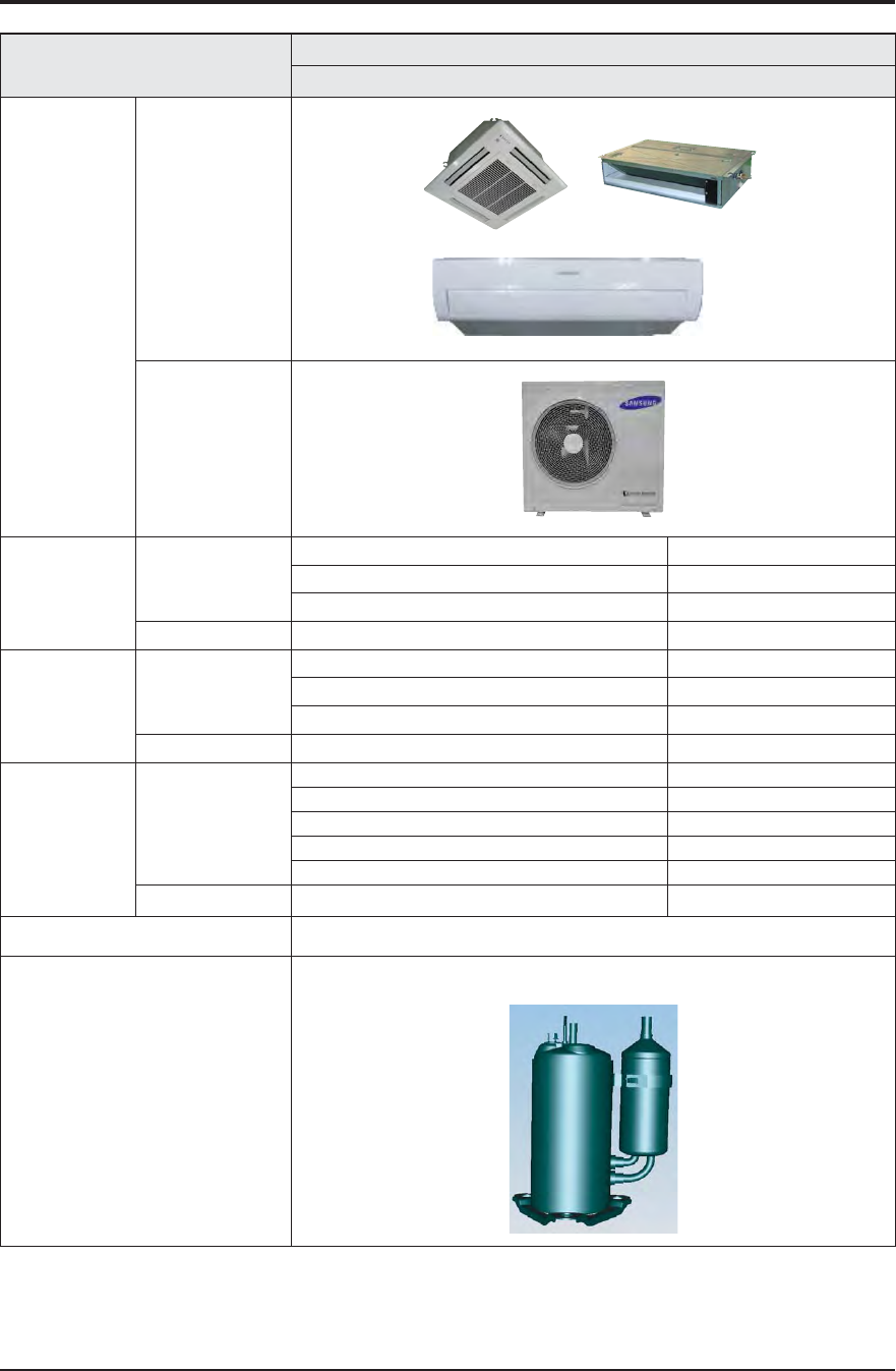
ITEM Model
AJ020JCJ2CH
Design
Indoor Unit
Outdoor Unit
Net Weight Indoor Unit
AJ007/009/012JNADCH 9.5 kg
AJ009/012JNNDCH 11.4 kg
AJ009/012JNLDCH 23.3 kg
Outdoor Unit
AJ020JCJ2CH 57.3 kg
Dimemsion Indoor Unit
AJ007/009/012JNADCH 826*275*260 mm
AJ009/012JNNDCH 575*250*575 mm
AJ009/012JNLDCH 900*199*600 mm
Outdoor Unit AJ020JCJ2CH
880*798*310 mm
Noise Indoor Unit
AJ007/009JNADCH 45 dBp
AJ012JNADCH dBp
AJ009JNNDCH 38 dBp
AJ012JNNDCH 41 dBp
AJ009/012JNLDCH 37 dBp
Outdoor Unit AJ020JCJ2CH
54 dBp
The Feature of Product
Free Joint Multi(Variable Indoor Unit)
Refrigerant Control Unit
BLDC INVERTER COMPRESSOR
UG4T200FUAE4
2-6 Samsung Electronics
Product Specifications(cont.)
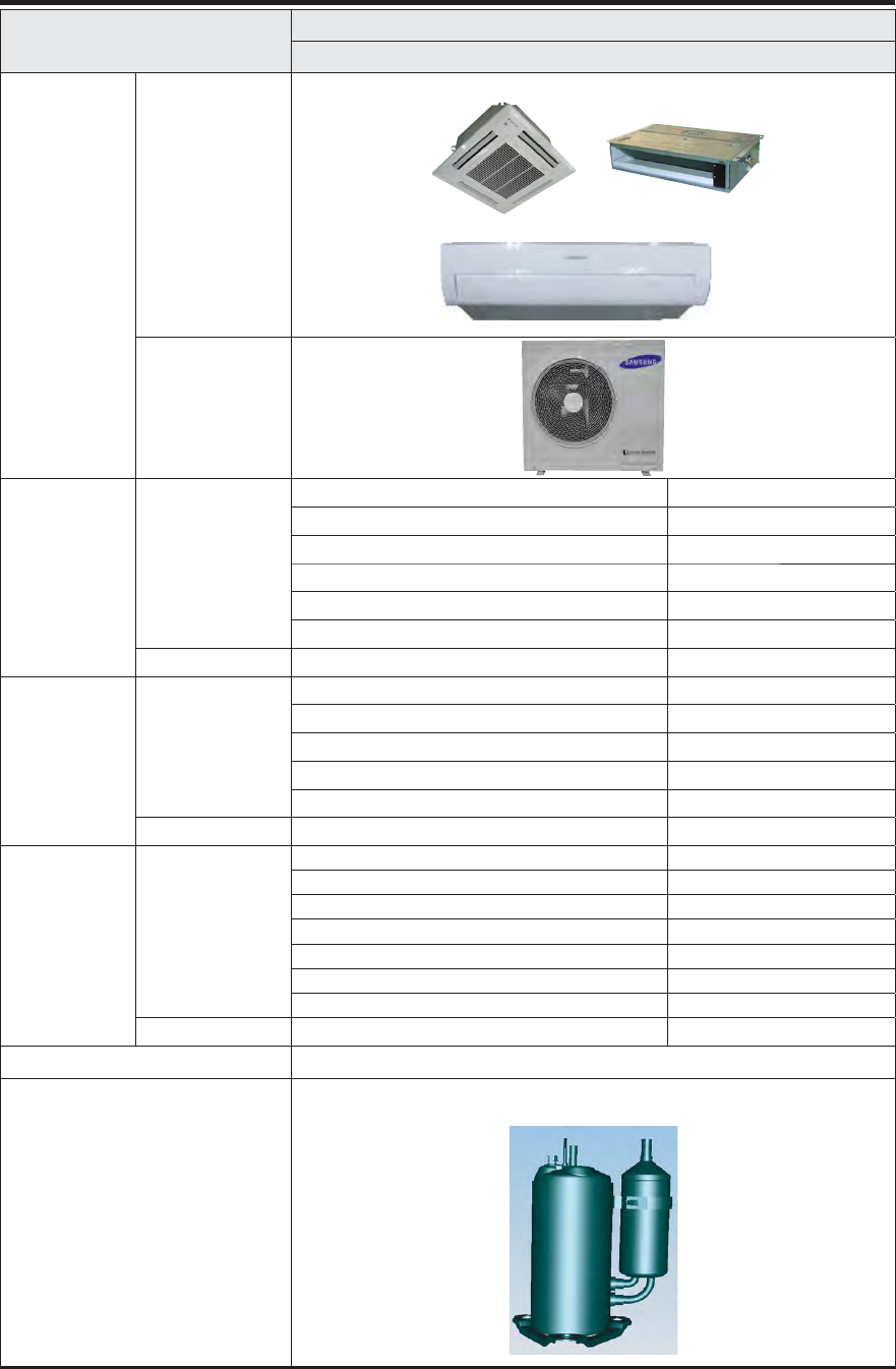
ITEM Model
AJ024JCJ3CH
Design
Indoor Unit
Outdoor Unit
Net Weight Indoor Unit
AJ007/009/012JNADCH 9.5 kg
AJ018JNADCH 13.0 kg
AJ009/012JNNDCH 11.4 kg
AJ018JNNDCH 11.8 kg
AJ009/012JNLDCH 23.3 kg
AJ018JNLDCH 29.0 kg
Outdoor Unit
AJ024JCJ3CH 65.0 kg
Dimemsion Indoor Unit
AJ007/009/012JNADCH 826*275*260 mm
AJ018JNADCH 1063*317*294 mm
AJ009/012/018JNNDCH 575*250*575 mm
AJ009/012JNLDCH 900*199*600 mm
AJ018JNLDCH 1100*199*600 mm
Outdoor Unit AJ024JCJ3CH
880*798*310 mm
Noise Indoor Unit
AJ007/009JNADCH 45 dBp
AJ012JNADCH dBp
AJ018JNADCH 50 dBp
AJ009JNNDCH 38 dBp
AJ012JNNDCH 41 dBp
AJ018JNNDCH dBp
AJ009/012/018JNLDCH 37 dBp
Outdoor Unit AJ024JCJ3CH
54 dBp
The Feature of Product
Free Joint Multi(Variable Indoor Unit)
Refrigerant Control Unit
BLDC INVERTER COMPRESSOR
G8T260FUAEW
Samsung Electronics 2-7
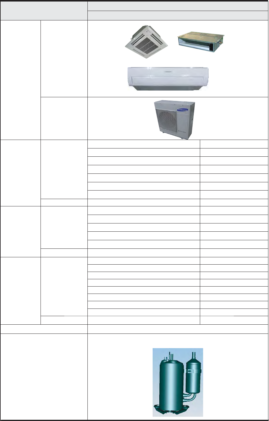
ITEM Model
AJ036JCJ5CH
Design
Indoor Unit
Outdoor Unit
Net Weight Indoor Unit
AJ007/009/012JNADCH 9.5 kg
AJ018JNADCH 13.0 kg
AJ024JNADCH 14..0 kg
AJ009/012JNNDCH 11.4 kg
AJ018JNNDCH 11.8 kg
AJ009/012JNLDCH 23.3 kg
AJ018JNLDCH 29.0 kg
Outdoor Unit
AJ036JCJ5CH 75.5 kg
Dimemsion Indoor Unit
AJ007/009/012JNADCH 826*275*260 mm
AJ018/024JNADCH 1063*317*294 mm
AJ009/012/018JNNDCH 575*250*575 mm
AJ009/012JNLDCH 900*199*600 mm
AJ018JNLDCH 1100*199*600 mm
Outdoor Unit AJ036JCJ5CH
940*998*330 mm
Noise Indoor Unit
AJ007/009JNADCH 45 dBp
AJ012JNADCH dBp
AJ018JNADCH dBp
AJ024JNADCH 51 dBp
AJ009JNNDCH 38 dBp
AJ012JNNDCH 41 dBp
AJ018JNNDCH dBp
AJ009/012/018JNLDCH 37 dBp
Outdoor Unit AJ036JCJ5CH
54 dBp
The Feature of Product
Free Joint Multi(Variable Indoor Unit)
Refrigerant Control Unit
BLDC INVERTER COMPRESSOR
UG8T300FUBJU
Product Specifications(cont.)
2-8 Samsung Electronics
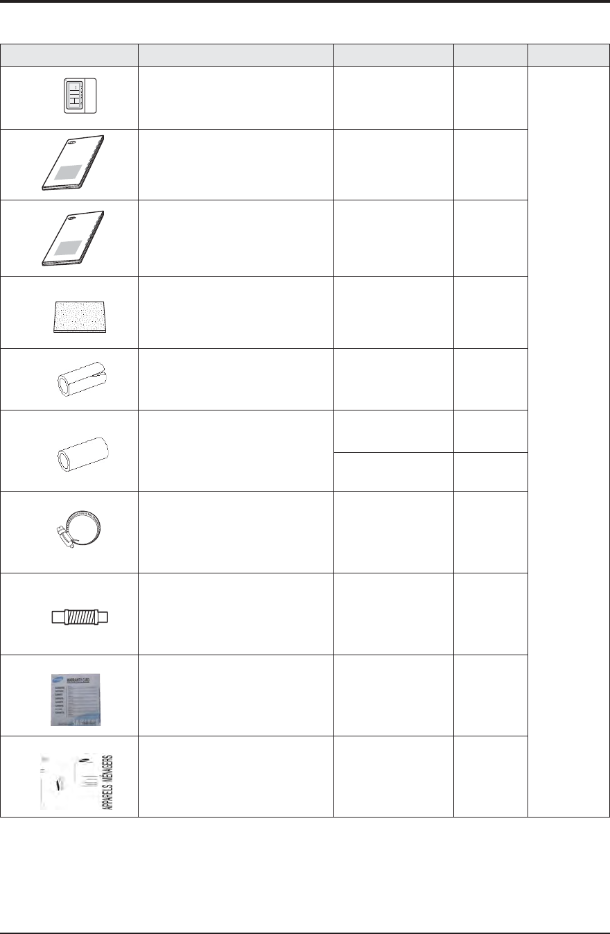
2-3 Accessory and Specifications
Item Descriptions Code-No. Q'TY Remark
Wired remote controller DB97-15070D
1
Indoor
Unit
Owner's Manual DB68-04994A
1
Installation Manual DB68-04995A
1
Insulation cover
DB62-04318S
1
Insu drain hose DB62-11028A
1
Insu hose C/D
DB62-11028E
1
DB62-11028D
1
Ass'y Holder Drain Pipe DB90-06701A 1
Hose Drain DB67-01191A 1
CARD WARRANTY
DB68-01675A
1
GARANTIE CARD
DB98-13261A
1
OWNER'S INSTRUCTIONS
MANUAL DE INSTRUCCIONES
ISTRUZIONI PER L'USO
MANUAL DE INSTRU‚ÍES
MANUEL D'UTILISATION
GEBRAUCHSANWEISUNG
Splut-type Room Air Conditioner
Aire acondicionado domĿstico sistema Split
Condizionatore d'aria per ambienti ad unitˆ Separate
Aparelho de ar condicionado tipo Split
Climatiseur de type sĿparĿ
Geteilte raumklimaanlage
Q AJ009JNLDCH/AJ012JNLDCH/AJ018JNLDCH
7The design and shape can be changed according to the model.
Samsung Electronics 2-9
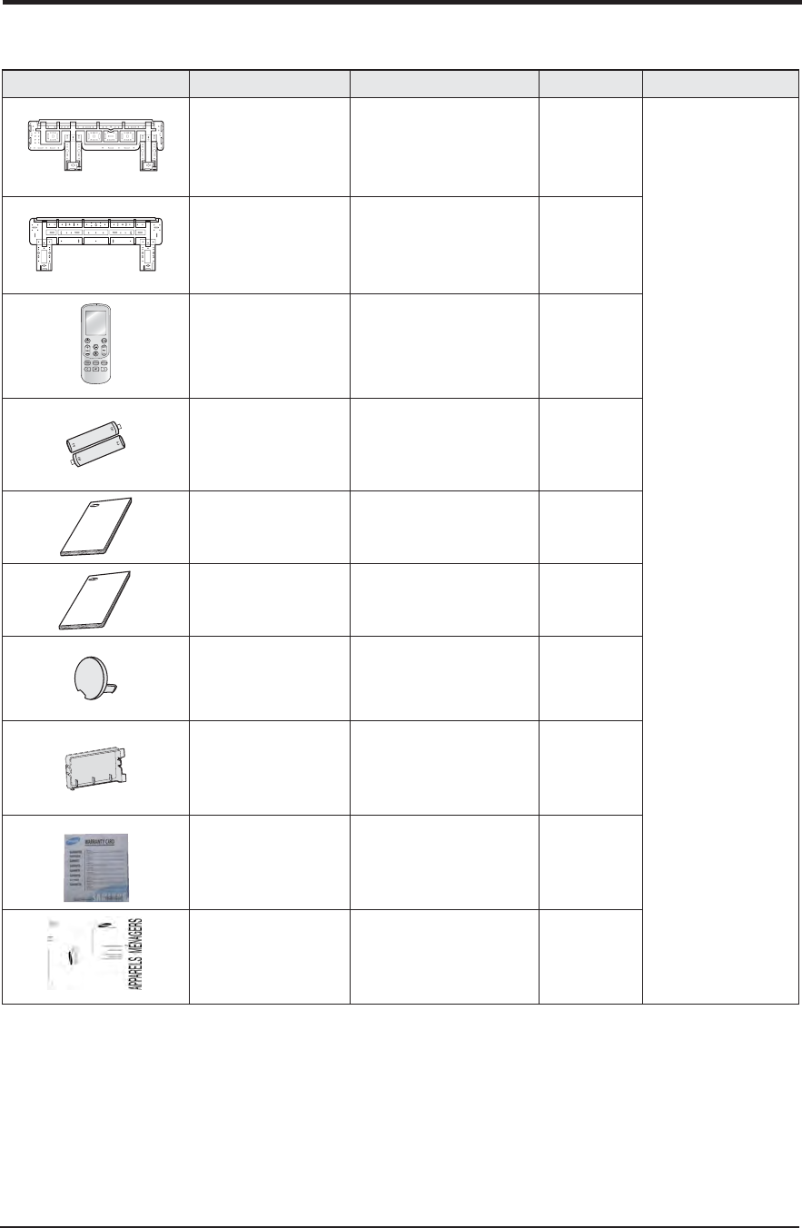
Accessories(cont.)
Item Descriptions Code No Qty Rmark
Istallation Plate DB90-07732A
(03 frame)
1
Indoor Unit
Istallation Plate
DB90-07731A
(05 frame)
1
Remote Control
DB93-14643R 1
Batteries for Remote
Control
4301-000121 2
User’s Manual
DB68-04992A 1
Installation Manual
DB68-04993A 1
Cap Screws
DB67-01404A 1
Case Sub PCB
DB61-06101A 1
CARD WARRANTY
DB68-01675A 1
GARANTIE CARD
DB98-13261A 1
Q
AJ007JNADCH/AJ009JNADCH/AJ012JNADCH/AJ018JNADCH/AJ024JNADCH
7The design and shape can be changed according to the model.
2-10 Samsung Electronics
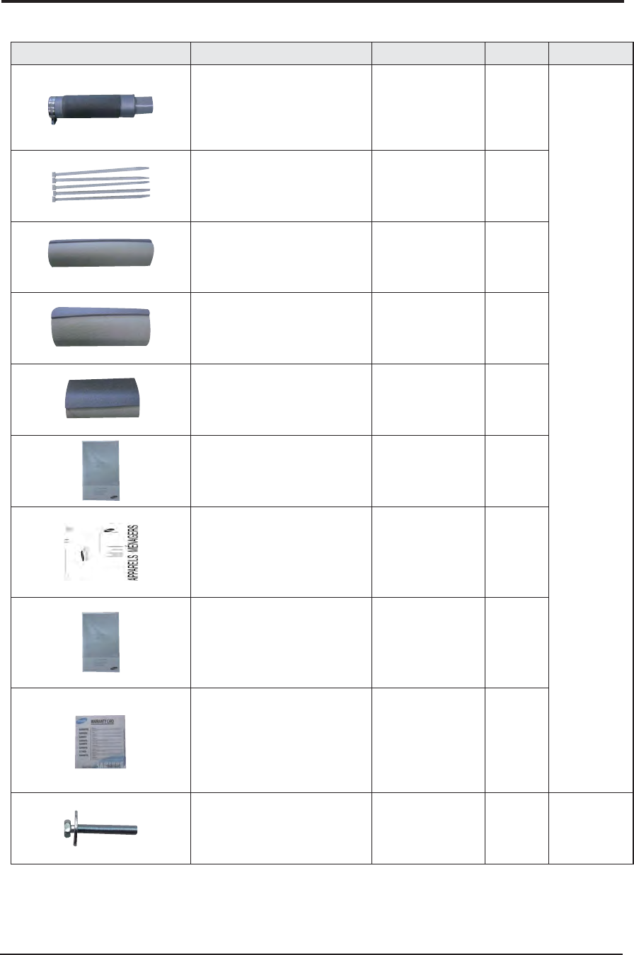
Item Description Code No. Q’ty Remark
Ass'y drain hose DB94-03287A 1
Essential Offer
(Indoor Unit)
Cable-tie DB65-10088C 6
Seal-drain ass'y DB62-11028A 1
Seal-drain ass'y DB62-11028H 1
Seal-drain ass'y DB62-11028J 1
USER MANUAL DB68-04990A 1
GARANTIE CARD DB98-13261A 1
ASSY-INSTALLATION MANUAL DB68-04991A 1
CARD WARRANTY DB68-01675A 1
BOLT 6011-003975 4 Essential Offer
(Panel)
Accessories(cont.)
Q AJ009JNNDCH/AJ012JNNDCH/AJ018JNNDCH
7The design and shape can be changed according to the model.
Samsung Electronics 2-11
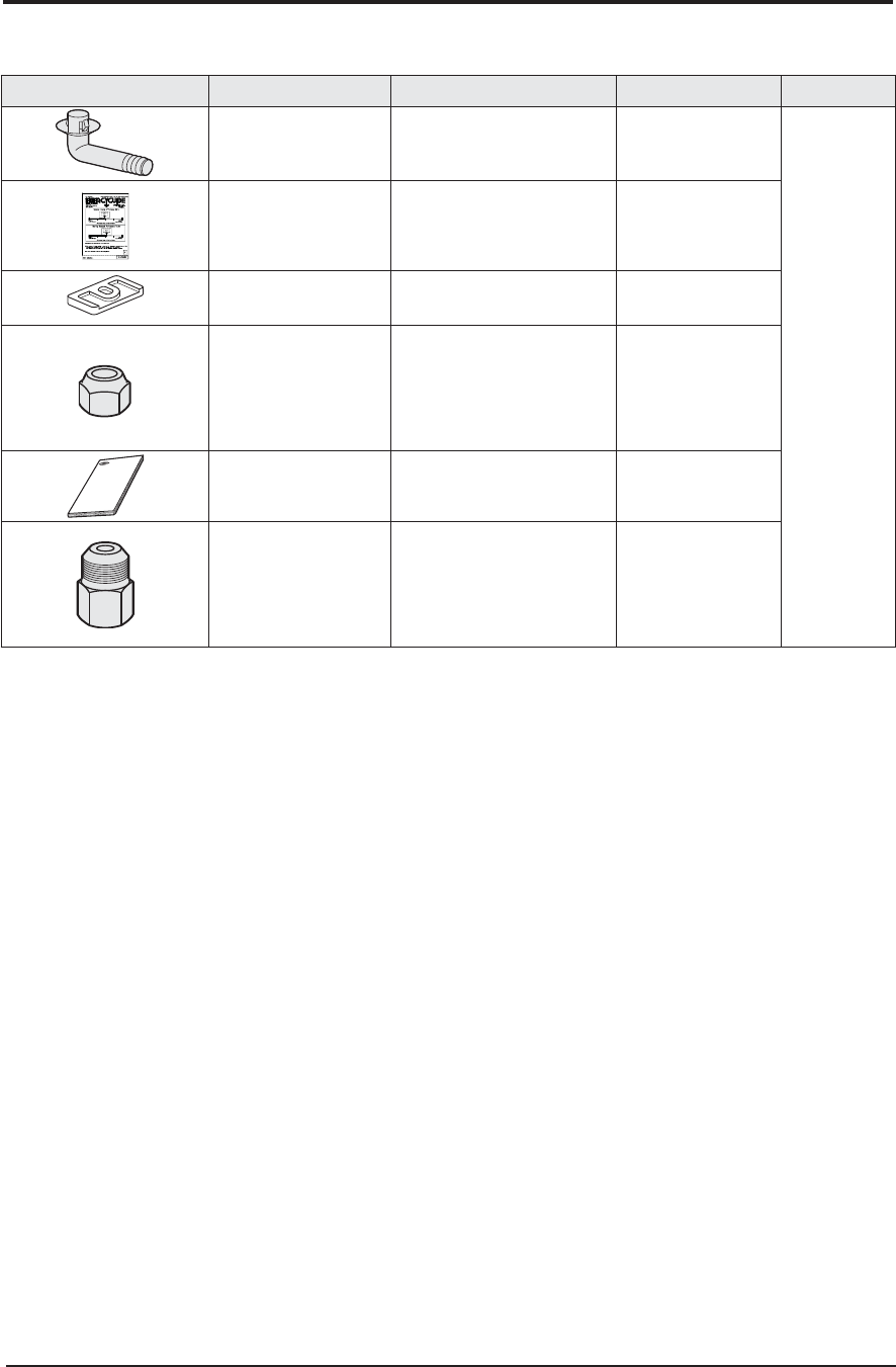
Accessories(cont.)
Item Descriptions Code No Qty Rmark
Drain Plug Out DB67-00477A 1
Outdoor Unit
Energy Label DB68-05062A(AJ020JCJ2CH)
DB68-05062B(AJ024JCJ3CH) 2
Rubber Leg DB73-20134A 4
Flare Nuts, 9.52mm outer
pipe diameter
DB60-30010B
(Only for AJ024JCJ3CH) 1
Installation Manual DB68-04989A 1
Nipple Connector DB67-00788A
(Only for AJ024JCJ3CH) 1
Q
AJ020JCJ2CH/AJ024JCJ3CH
7The design and shape can be changed according to the model.
7The design and shape can be changed according to the model.
2-12 Samsung Electronics
Accessories(cont.)
Item Descriptions Code No Qty Rmark
Drain Plug Out DB67-00806A 1
Outdoor Unit
Energy Label DB68-05115A 2
Rubber Leg DB73-20134A 4
Cap Drain DB63-10355C 3
Installation Manual DB68-05013A 1
Flare Nuts 3/8” DB96-16155A 3
Flare Nuts 5/8” DB96-16155B 2
Q
AJ036JCJ5CH
7The design and shape can be changed according to the model.
Samsung Electronics 3-1
3. Disassembly and Reassembly
■Necessary Tools
Item Remark
+SCREW DRIVER
MONKEY SPANNER
3-2 Samsung Electronics
3-1 Indoor Unit
Take care of the electrical shock by contact on the charging parts before the discharge after power of.(If takes
approximately 2 minutes to discharge.).
■ AJ007JNADCH/AJ009JNADCH/AJ012JNADCH/AJ018JNADCH/AJ024JNADCH
No Parts Procedure Remark
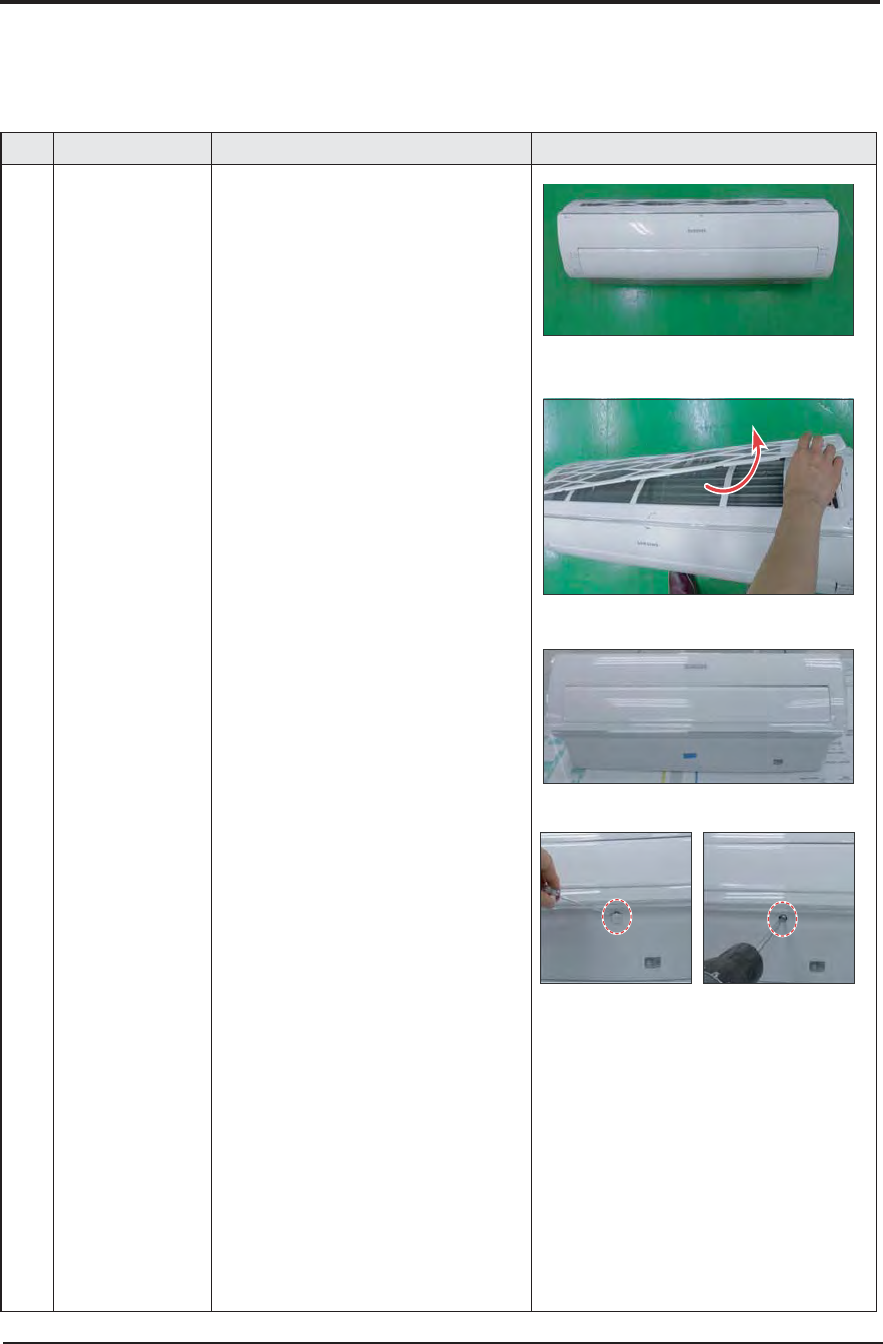
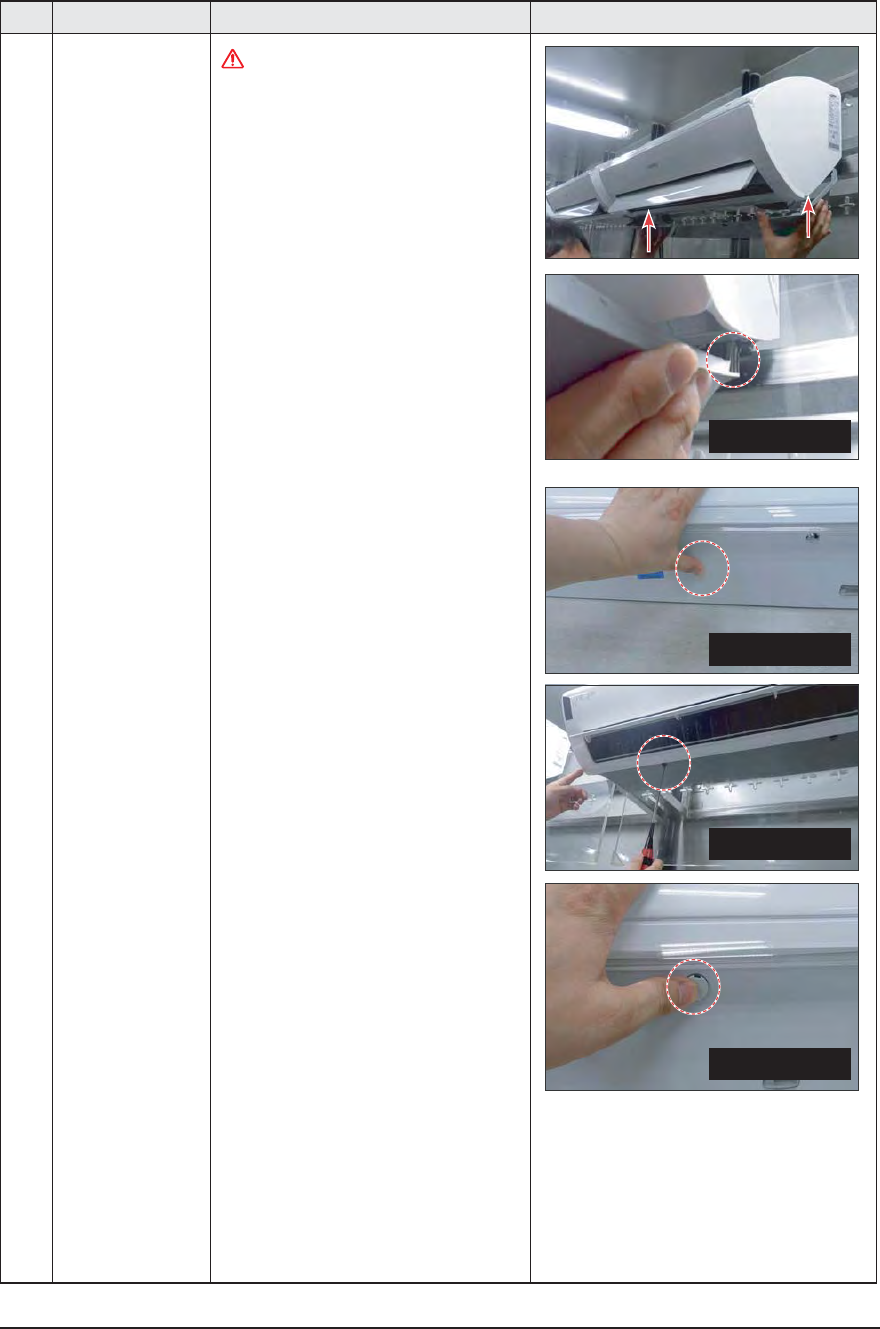
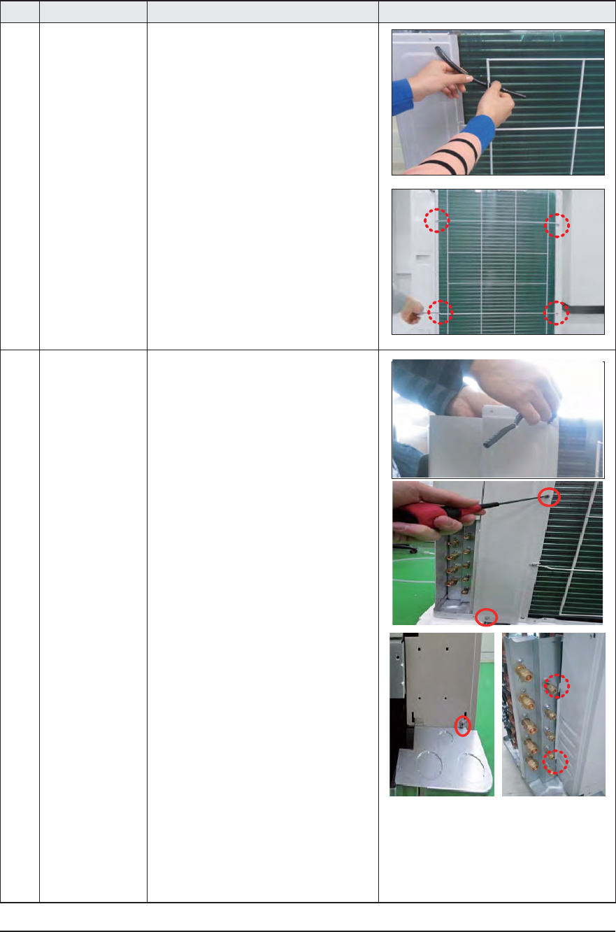
1 PANEL-FRONT 1) Stop the driving of air conditioner and shut
o main power supply.
2) Detach FILTER PRE from the PANEL FRONT.
3) Cover Panel is assembled on bottom of
indoor unit as shown in the figure.
Remove the Cap Screw as shown on the
right side and then remove the screw and
separate the Cover Panel.
Samsung Electronics 3-3
No Parts Procedure Remark
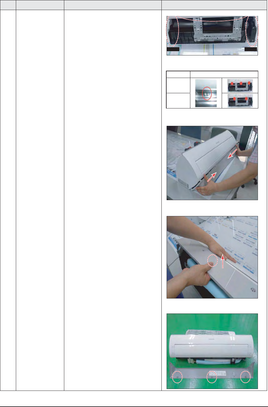
4) Cover Panel is fixed to body by Hook in
center area and side area.
5) Separate the hook after pushing both end
of Cover Panel as shown in the figure.
(Watch out for the damage of the hook)
6) Raise front part upward obliquely as
shown in the figure and then remove the
hooks
4JEFBSFB
4JEFBSFB
)00,
,
,
3-4 Samsung Electronics
No Parts Procedure Remark
Caution
Assembly of Cover Panel after service end.
- Reassembly is in the reverse order of the
removal.
- Piping and drain hose must be careful not
to damage and Progress must be done
with both hands.
)PPL4JEF
)PPL$FOUFS
4DSFX
$BQ4DSFX
Samsung Electronics 3-5
No Parts Procedure Remark
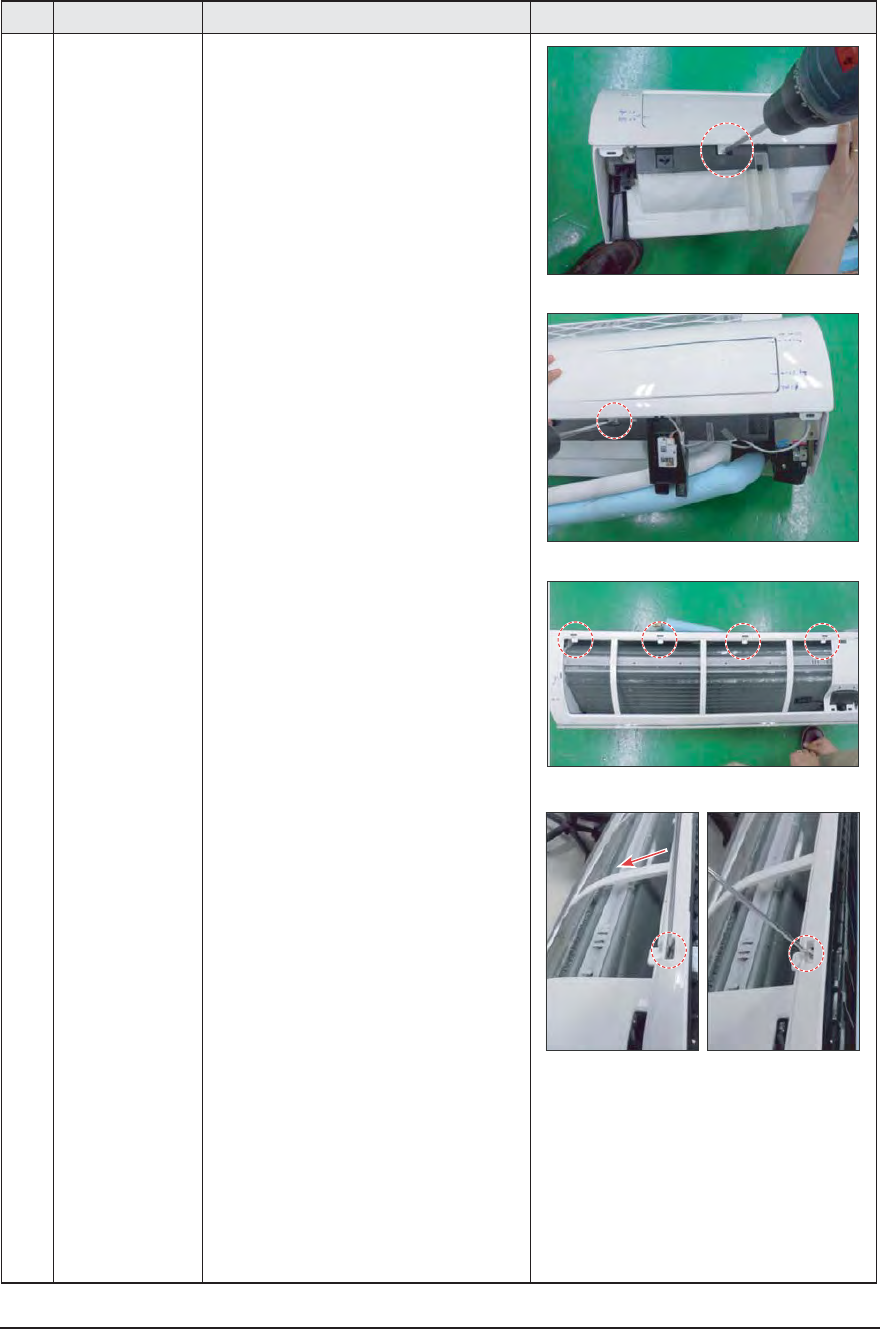
7) To detach the PANEL-FRONT from the main
frame, unfasten 2 screws at the bottom.
(use + Screw Driver)
8) To detach the COVER-PANEL from the main
frame, loosen 4 HOOK Structures.
When separate the hook :
Use the (-) screw Driver.
(-)Screw Driver Insert the hook and then pull
the hook as shown on the right side.
(Watch out for the damage of the hook)
3-6 Samsung Electronics
No Parts Procedure Remark
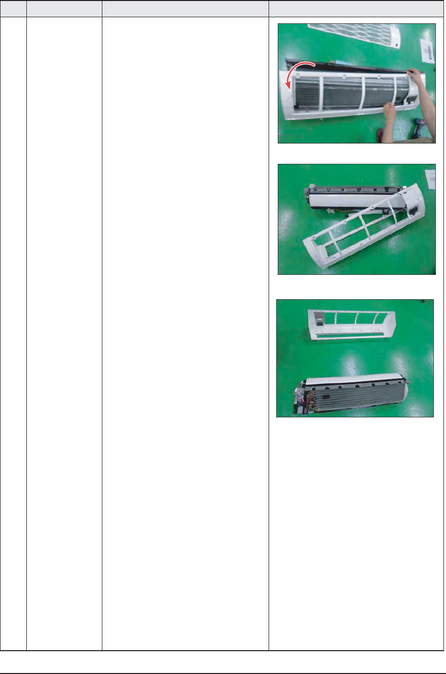
9) Remove the Panel Frame from the Main
Frame as shown on the right side.
Samsung Electronics 3-7
No Parts Procedure Remark
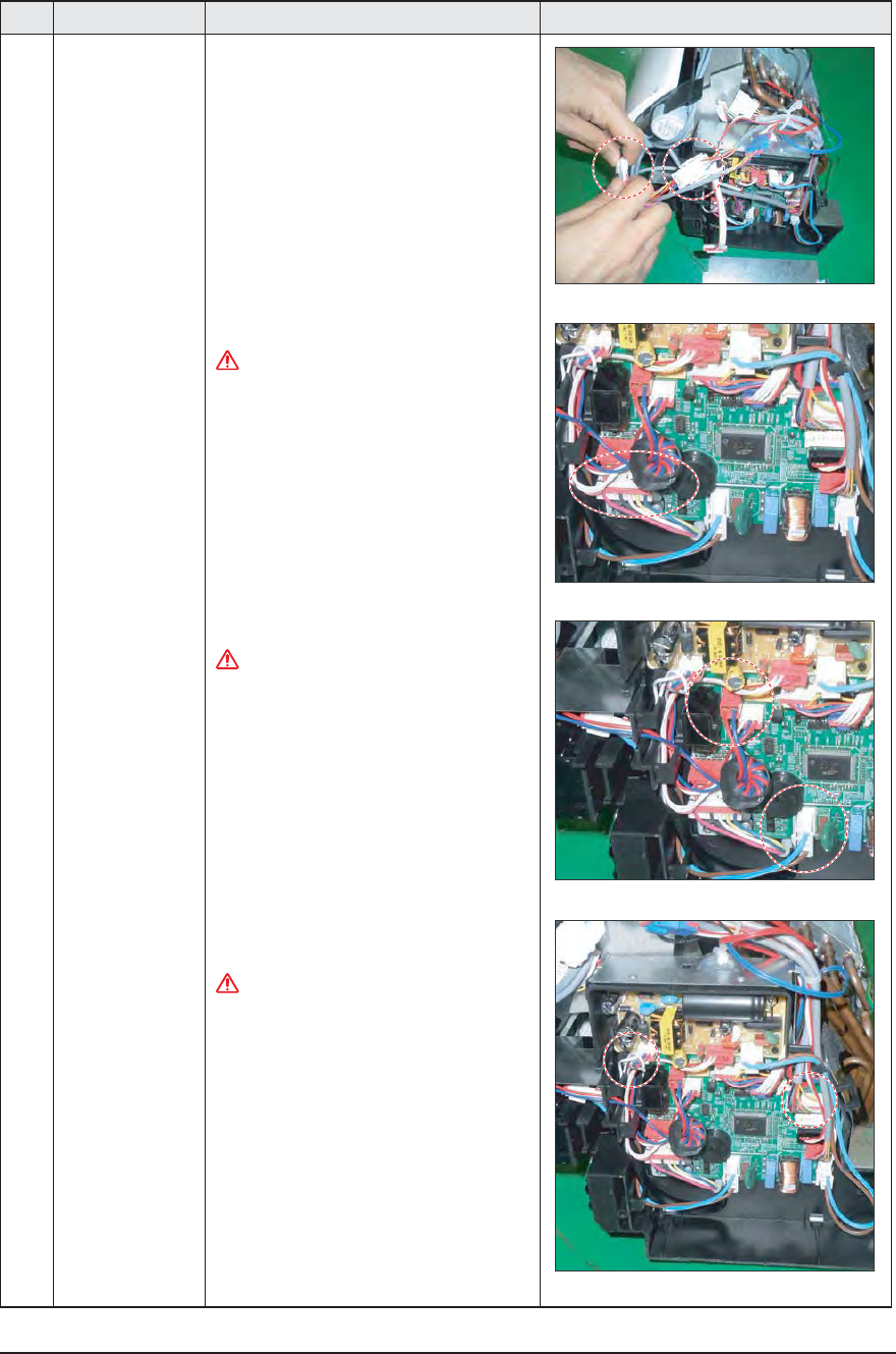
2 CONTROL IN 1) Loosen Stepping MOTOR Wire / BLADE Wire
2) Loosen MOTOR Wire.
Caution:
When you separate the connector,pull pressing
the locking button.
3) Loosen the terminal block wires.
Caution:
When you separate the connector,pull pressing
the locking button.
4) Loosen the Thermistor wire connector,
Display wire connector.
Caution:
When you separate the connector,pull pressing
the locking button.
3-8 Samsung Electronics
No Parts Procedure Remark
2 CONTROL IN 5) Take o the CASE-CONTROL from the
main
frame after loosen the remaining con-
nector.
Caution:
When you separate the connector,pull
pressing the locking button
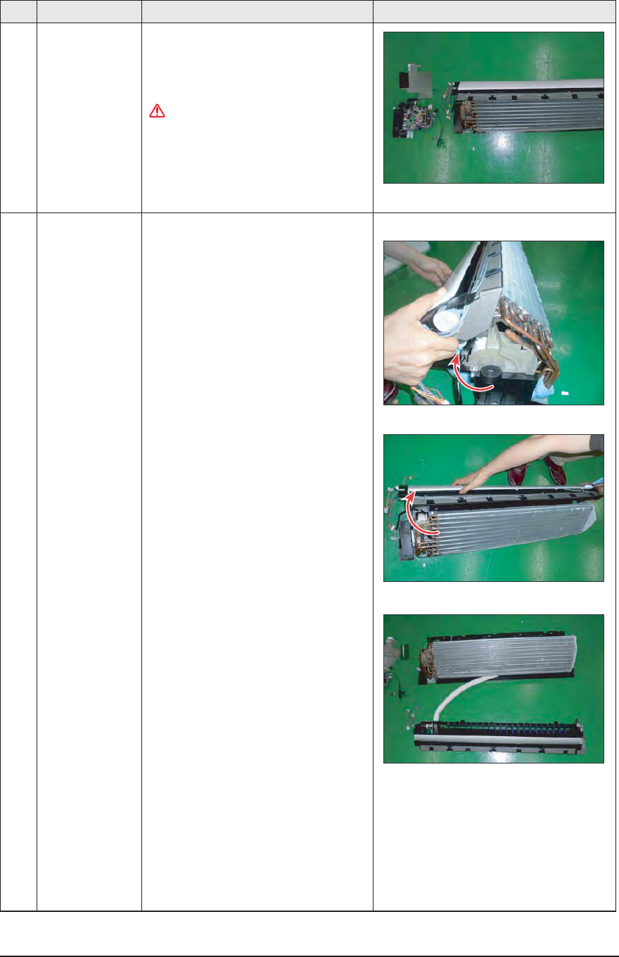
3 TRAY DRAIN 1) To detach TRAY-DRAIN from the main
frame, pull the bottom of the TRAY-
DRAIN towards you.
Samsung Electronics 3-9
No Parts Procedure Remark
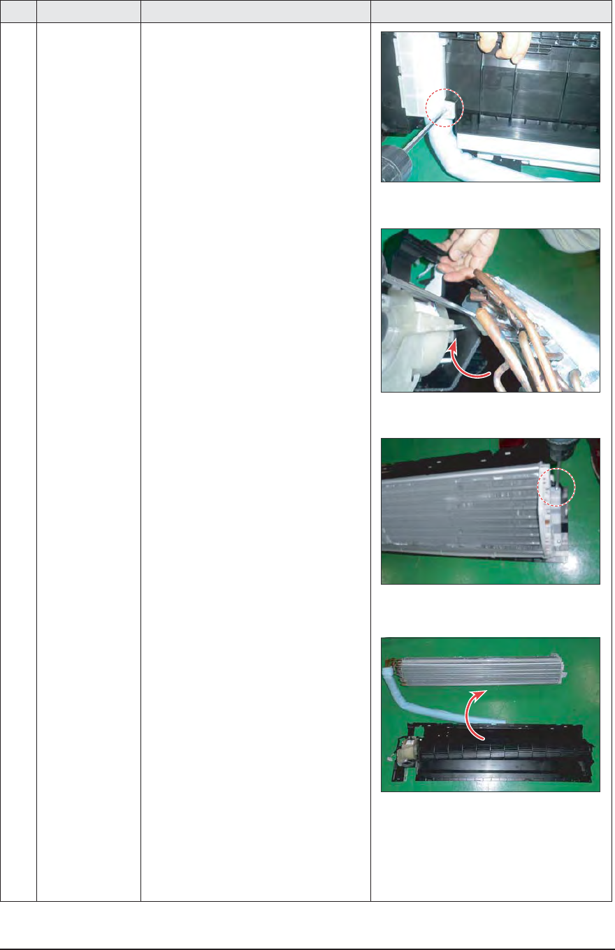
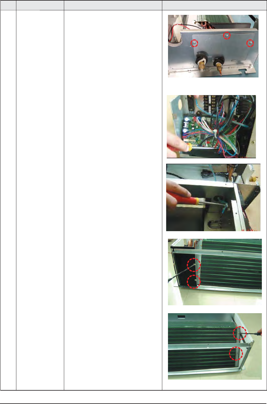
4 Evaporator 1) Detach the HOLDER PIPE.
2) Unfasten the screw at the left side.
(use + Screw Driver)
3) Unfasten the screw at the right side.
(use + Screw Driver)
4) To detach Evaporator from the main frame,
pull the bottom of the Evaporator towards
you.
3-10 Samsung Electronics
No Parts Procedure Remark
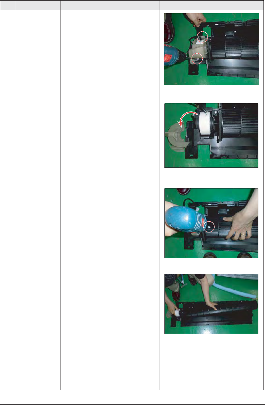
5 FAN MOTOR
CROSS FAN
1) Unfasten the screw.
(use + Screw Driver)
2) Detach the FAN Motor case.
3) Unfasten the screw a little.
(use + Screw Driver)
4) Pull the CROSS-FAN to the left side.
Samsung Electronics 3-11
No Parts Procedure Remark
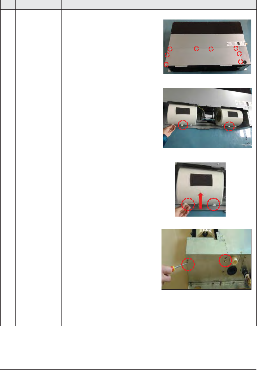
1 Motor
Blower
1) Disassemble the Cabinet Top Motor.
- Unscrew 8 screws
2) Disassemble 2 Cover Blower Uppers.
- After unscrewing 2 screws
- Disassemble the Cover Blower Upper
with pushing its hook.
3) Disassemble the Cover Control.
- Unscrew 2 screws
ÿ AJ009JNLDCH/AJ012JNLDCH
3-12 Samsung Electronics
No Parts Procedure Remark
4) Disassemble Motor Wires connected to
the inside of PCB and connected to the
Capacitor.
5) Disassemble the Motor earth wire
connected to the Partition.
- Unscrew a screw
6) Disassemble the band Motor for fixing
the Motor.
- Unscrew 2 screws
7) After disassembling the Motor and Blower
for the set, disassemble the Blower by use
of 3mm wrench.
Samsung Electronics 3-13
No Parts Procedure Remark
2 Drain Pan 1) Disassemble the Cabinet Top Evap.
- Unscrew 11 screws
2) Disassemble the Bracket Outlet Sub that
fixes the Drain Pan equipped on the front
of the set.
- Unscrew 6 screws
3) Disassemble the Drain Cushion from the
set.
3-14 Samsung Electronics
No Parts Procedure Remark
3 Evaporator The Evaporator should be disassembled
after disassembling the Cover Control
1-3) and the Drain Pan 2-1), 2-2), 2-3).
1) Disassemble the Cover Pipe that fixes
the high/low pressure Pipe.
- Unscrew 3 screws
2) Disassemble the refrigerant temperature
sensor, Inlet air temperature sensor.
3) Disassemble the Support Evap. LF that
fixes the Evaporator.
- Unscrew 2 screws
4) Disassemble the Support Evap RH.
- Unscrew 2 screws
Samsung Electronics 3-15
No Parts Procedure Remark
5) Disassemble the Evaporator form the set.
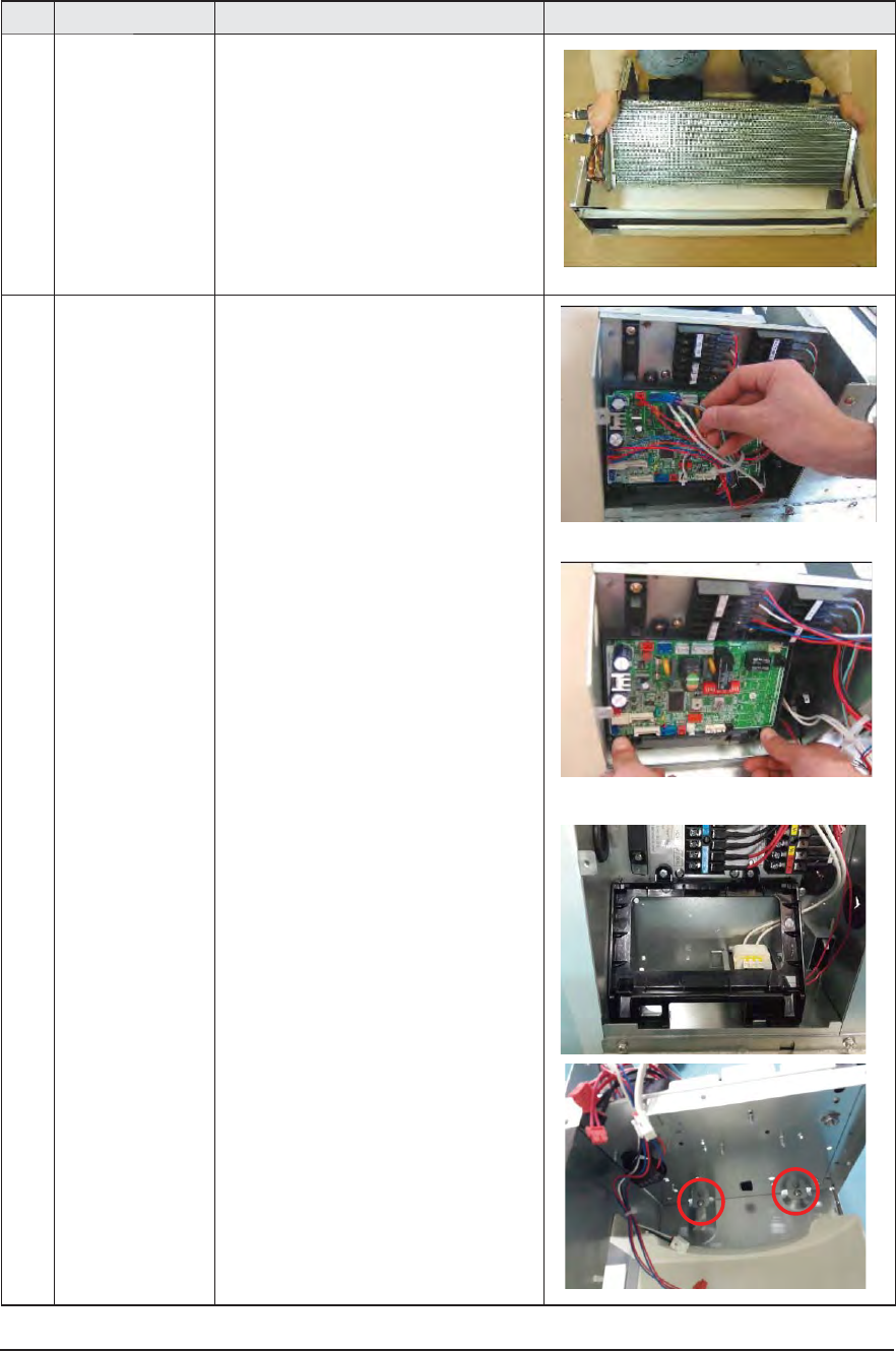
4 Control In * The Control In should be disassembled after
disassembling the Cover Control 1-3).
1) Disassemble all Control Wires connected
to the inside of PCB.
2) In case of disassembling the PCB
separately, disassemble the PCB from
the case with pushing the hook after
unscrewing the screw.
- Unscrew 1 screw
3) Disassemble the Case PCB from Case con-
trol in
- Unscrew 2 screws
4) In case of disassembling the Case
Control,disassemble the Case Control from the
set after unscrewing the screw connected to
cover bottom fan.
- Unscrew 2 screws
3-16 Samsung Electronics
ÿ AJ018JNLDCH
No Parts Procedure Remark
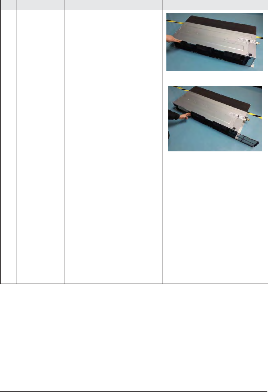
1 Filter 1) Pull out the Filter as picture 1 or picture 2.
Samsung Electronics 3-17
No Parts Procedure Remark
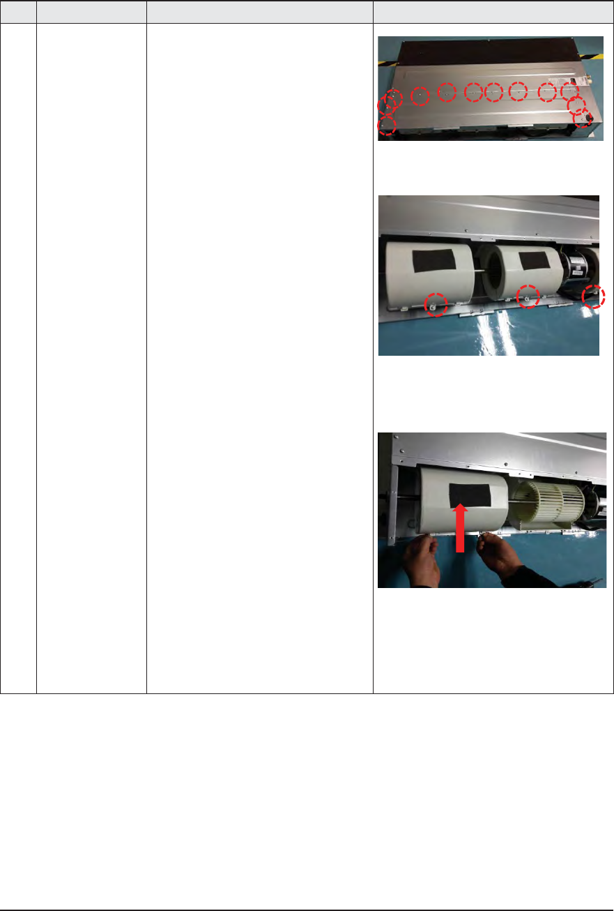
2 Blower
Motor
1) After disassembling 13 indicating screws,
detach Ass’y Cabinet-Top Motor.
2) After disassembling 3 indicating screws,
detach Ass’y Case Blower Upper.
– Press the pothook of the Case Blower
and detach Ass’y Case Blower Upper.
3-18 Samsung Electronics
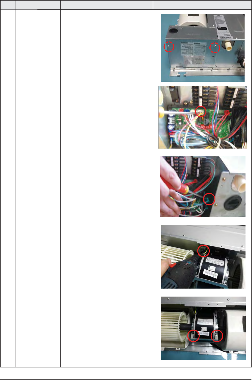
No Parts Procedure Remark
3) After disassembling 2 indicating screws,
detach the Cover Control.
4) Detach the Motor Wire Connected to
PCB and Capacitor.
5) After disassembling the indicating
screws, detach the wire connected to
the Partition.
6) After disassembling 2 indicating screws,
detach the Ass’y Band Motor.
Samsung Electronics 3-19
No Parts Procedure Remark
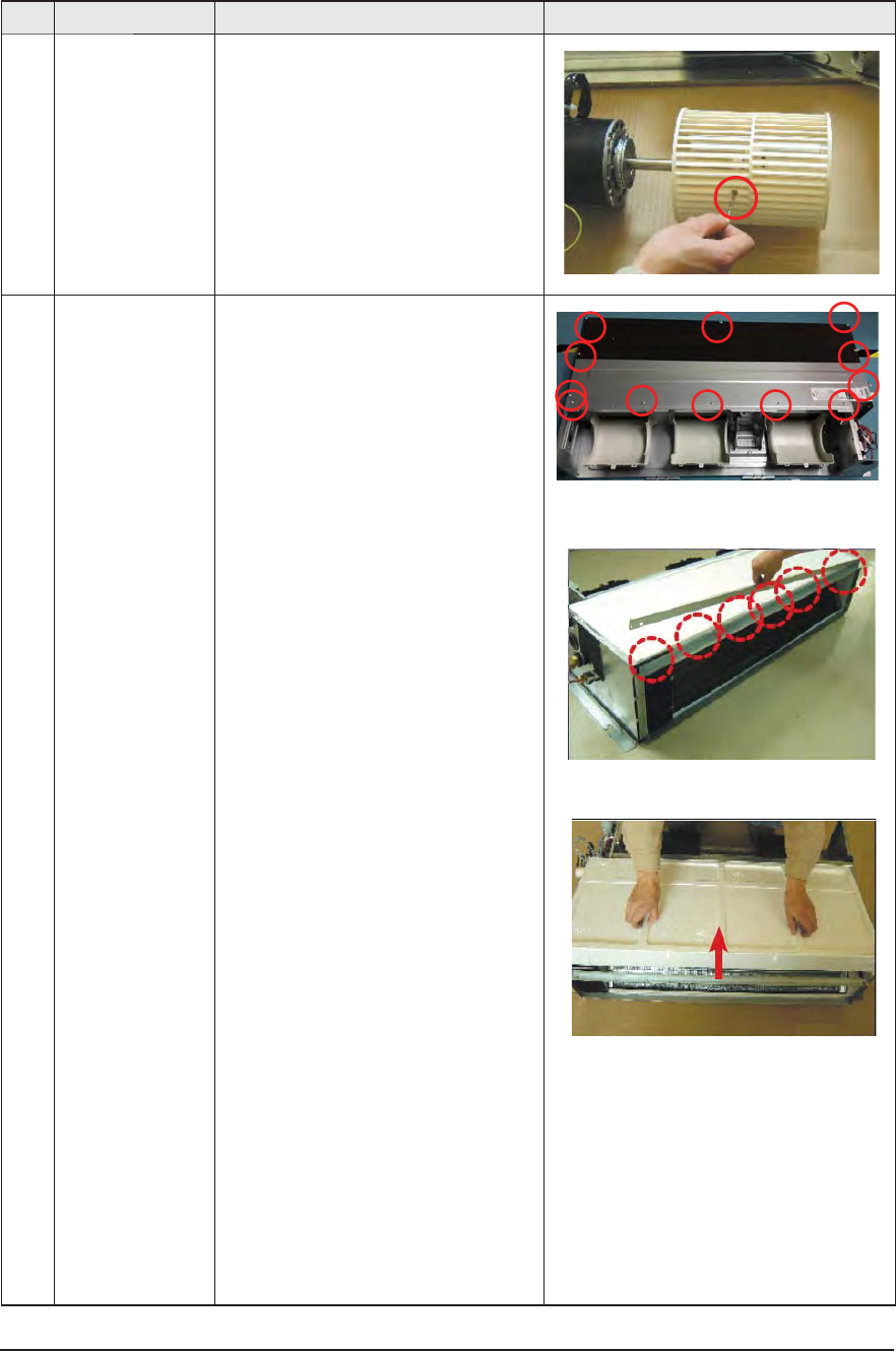
7) After disassembling the Motor and Blowers,
detach the Blowers from the axis of the
Motor by 3mm inner hexagon spanner.
3 Drain Pan 1) After disassembling 12 indicating screws,
detach Ass’y Cabinet-Top Evap.
2) After disassembling 6 indicating screws,
detach the Bracket Outlet.
3) Detach the Drain Pan.
3-20 Samsung Electronics
No Parts Procedure Remark
4 Evaporator The Evaporator should be disassembled
after disassembling the Cover Control
1-3) and the Drain Pan 2-1), 2-2), 2-3).
1) Disassemble the Cover Pipe that fixes
the high/low pressure Pipe.
- Unscrew 3 screws
2) Disassemble the refrigerant temperature sen-
sor, Inlet air temperature sensor.
3) After disassembling 2 indicating screws,
detach Ass'y Support Evap LF.
4) After disassembling 2 indicating screws,
detach Ass'y Support Evap RH.
Samsung Electronics 3-21
No Parts Procedure Remark
5) Disassemble the Evaporator form the set.
5 Control In The Control In should be disassembled
after disassembling the Cover Control
1-3).
1) Disassemble all Control Wires connected to
the inside of PCB.
2) In case of disassembling the PCB
separately, disassemble the PCB from
the case with pushing the hook.
3) Disassemble the Case PCB from Case con-
trol in
- Unscrew 2 screws
4) If only the disassembly of Case Control is
required, detach it from the set after
disassembling 2 indicating screws.
3-22 Samsung Electronics
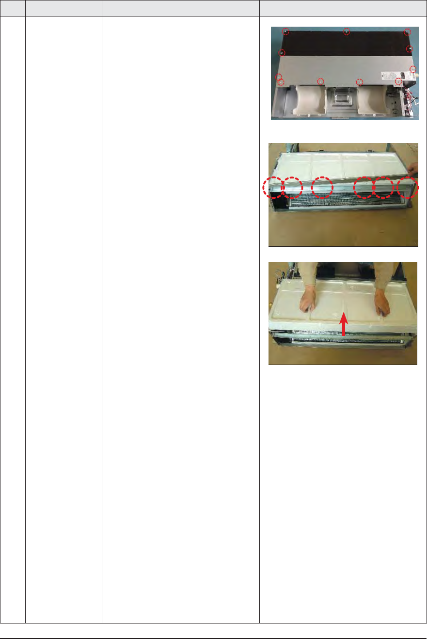
No Parts Procedure Remark
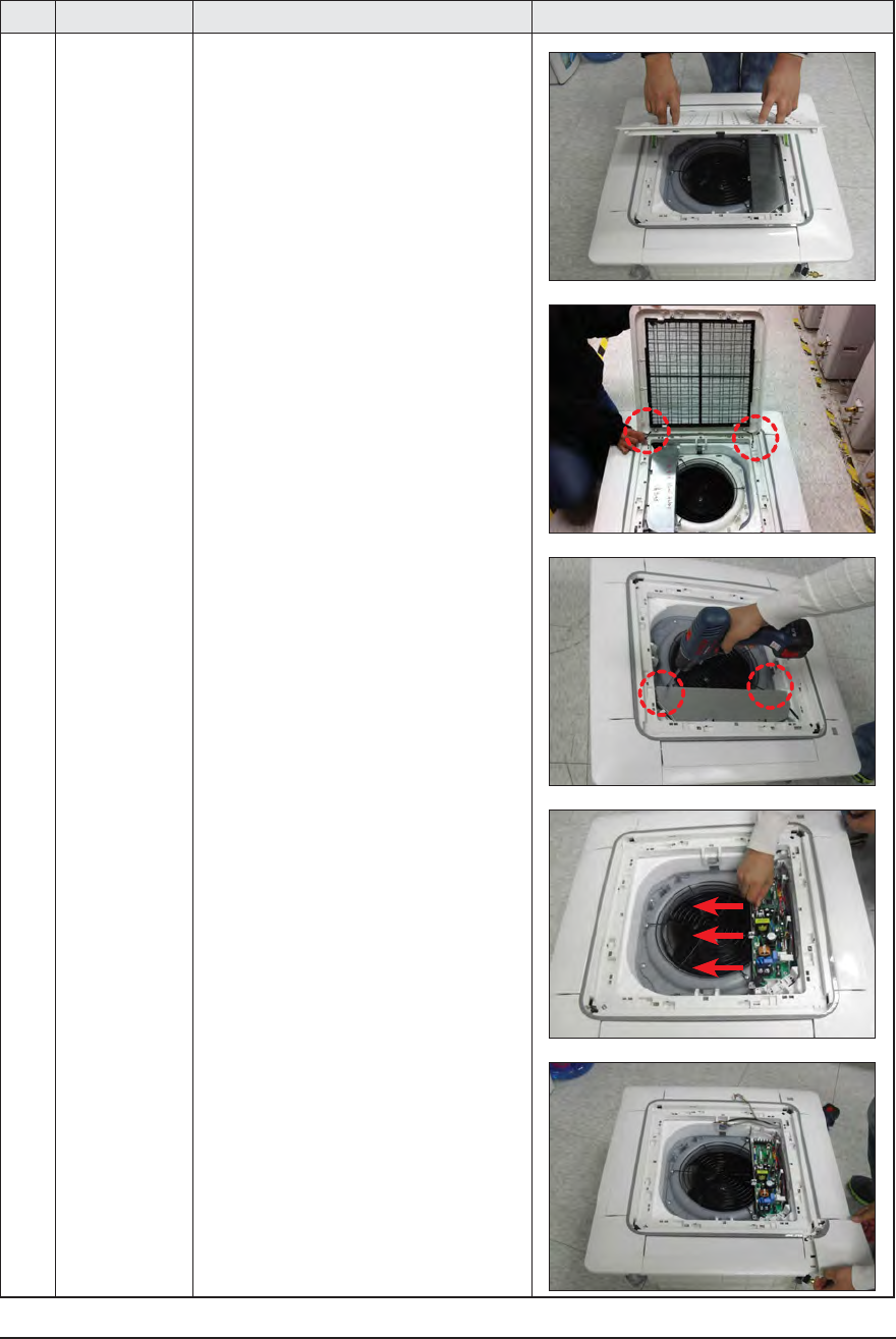
1 Panel 1) Pull both hooks and take the grille downward.
Two safety clips are mounted to the front grille to
prevent it from dropping.
2) Detach the safity clip and take up the grille.
3) Remove the 2 fixed screws to remove the
Control-Box Cover. (Use +Screw Driver)
4) Remove the Remocon-Receiver and Blade
Connector Wire from the PBA. (3EA)
5) Push the 4 panel corners and cover downwards
to remove it.
ÿ AJ009JNNDCH/AJ012JNNDCH/AJ018JNNDCH
Samsung Electronics 3-23
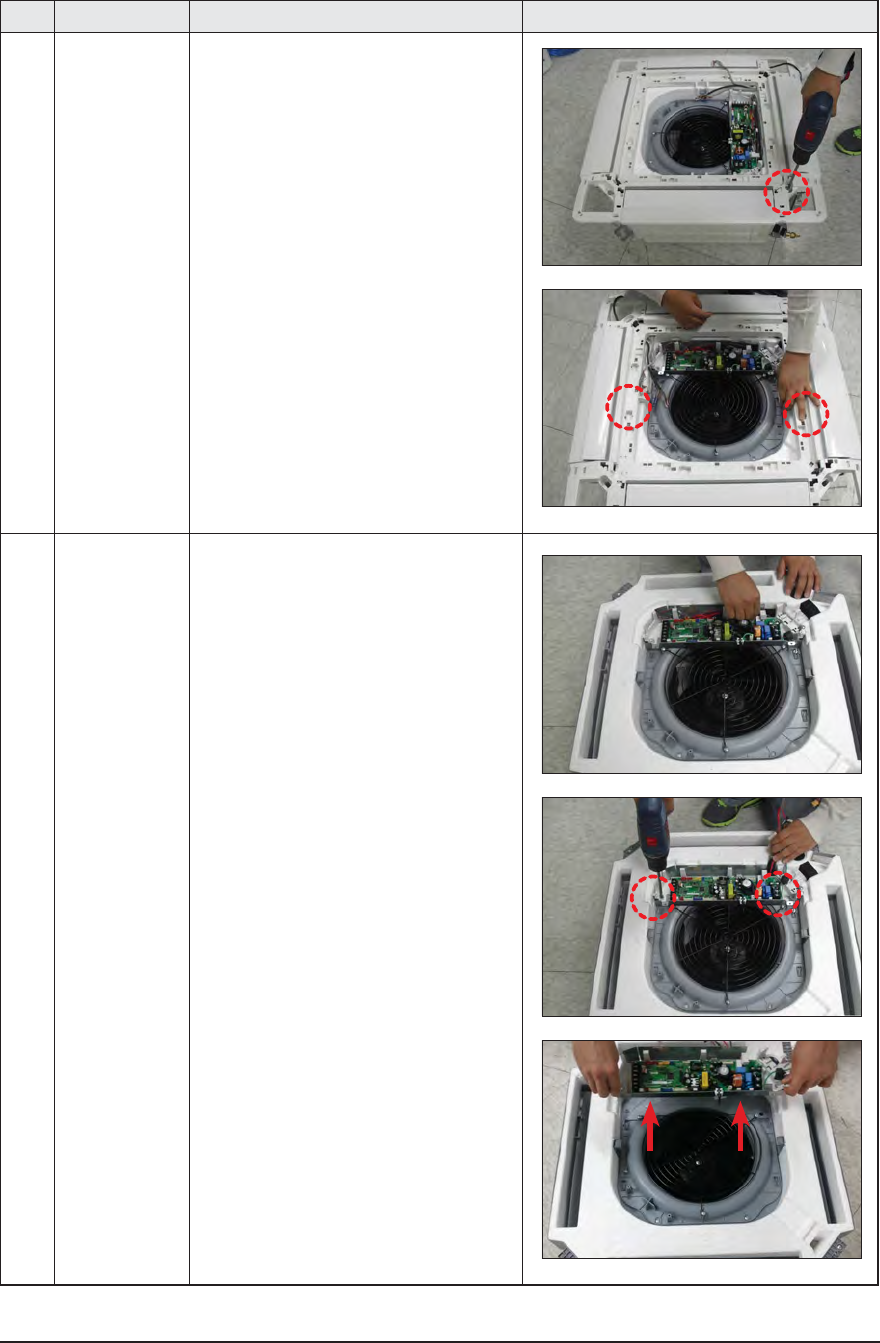
No Parts Procedure Remark
6) Disassemble the bolts that are assembled
with the indoor unit at the 4 panel corners.
7) Press the Hangers at both sides of the panel
inwards, to remove it from the indoor unit’s hook.
Remove the panel from the indoor unit.
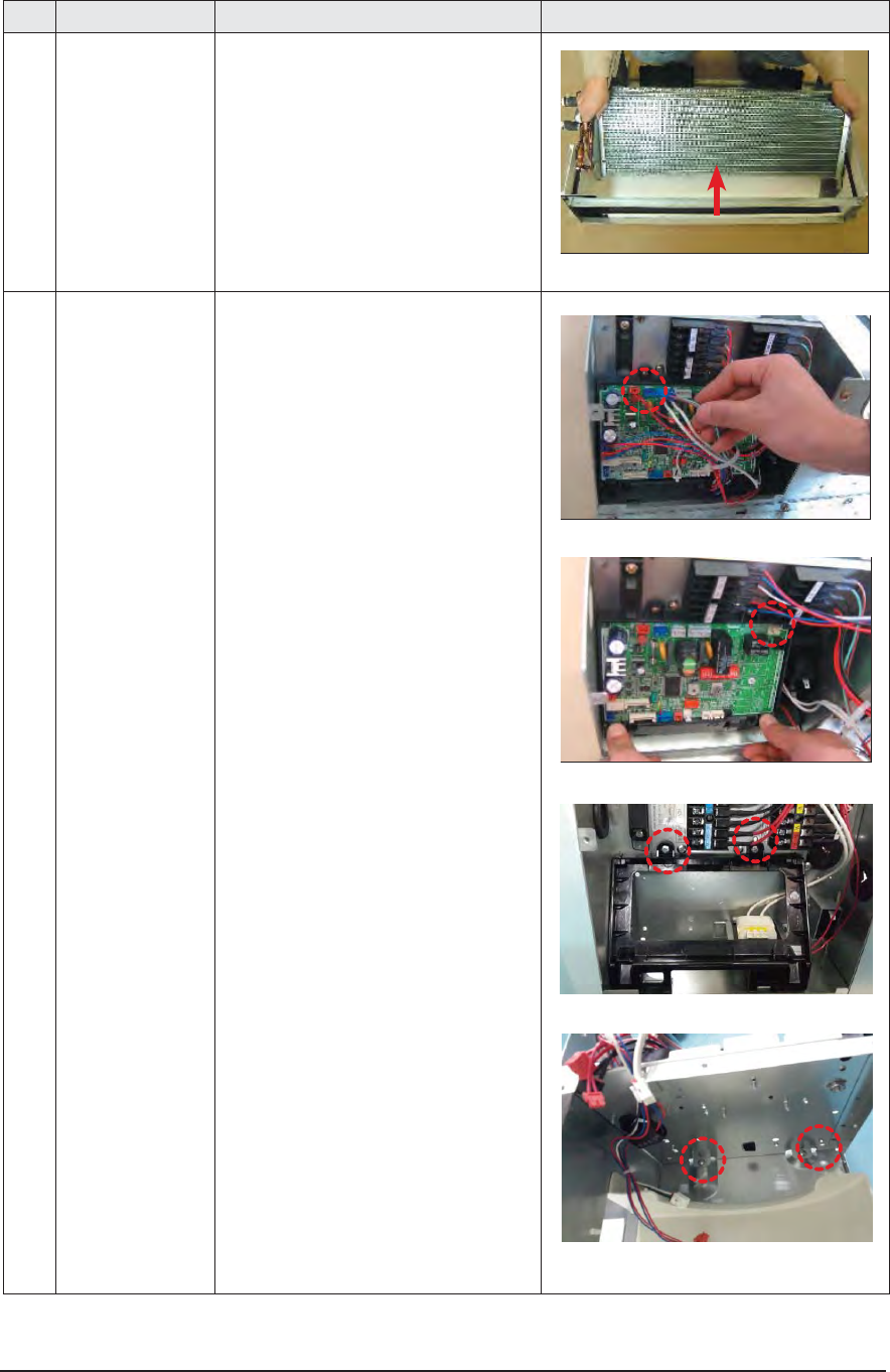
2 Control-Box 1) Disconnect the Connector Wire that is con-
nected to the indoor unit’s PBA
2) Unscrew the 2 fixed screws on both sides of
the Control Box, and disassemble the Control Box
from the indoor unit.(Use +Screw Driver)
3-24 Samsung Electronics
No Parts Procedure Remark
3 Bell-Mouth 1) Unscrew the screw fixed on the Bell-Mouth.
(Use +Screw Driver)
2) Push the Bell-Mouth in the direction oppo-
site to where it’s installed on the Control-Box
to remove it.
4 Drain Pan 1) Unscrew the screws on the 4 corners
of the indoor unit. (Use +Screw Driver)
2) Remove the Drain Pan from the indoor unit.
Samsung Electronics 3-25
No Parts Procedure Remark
5 Drain Pump
Hose
1) Remove the 2 fixed screws and discon-
nect the white drainage hose from the
Drain Pump. (Use +Screw Driver)
2) Remove the 2 screws and take the
Drain-Hose out from the indoor unit to disas-
semble the transparent Drain-Hose fixed on
the side of the indoor unit.
(Use +Screw Driver)
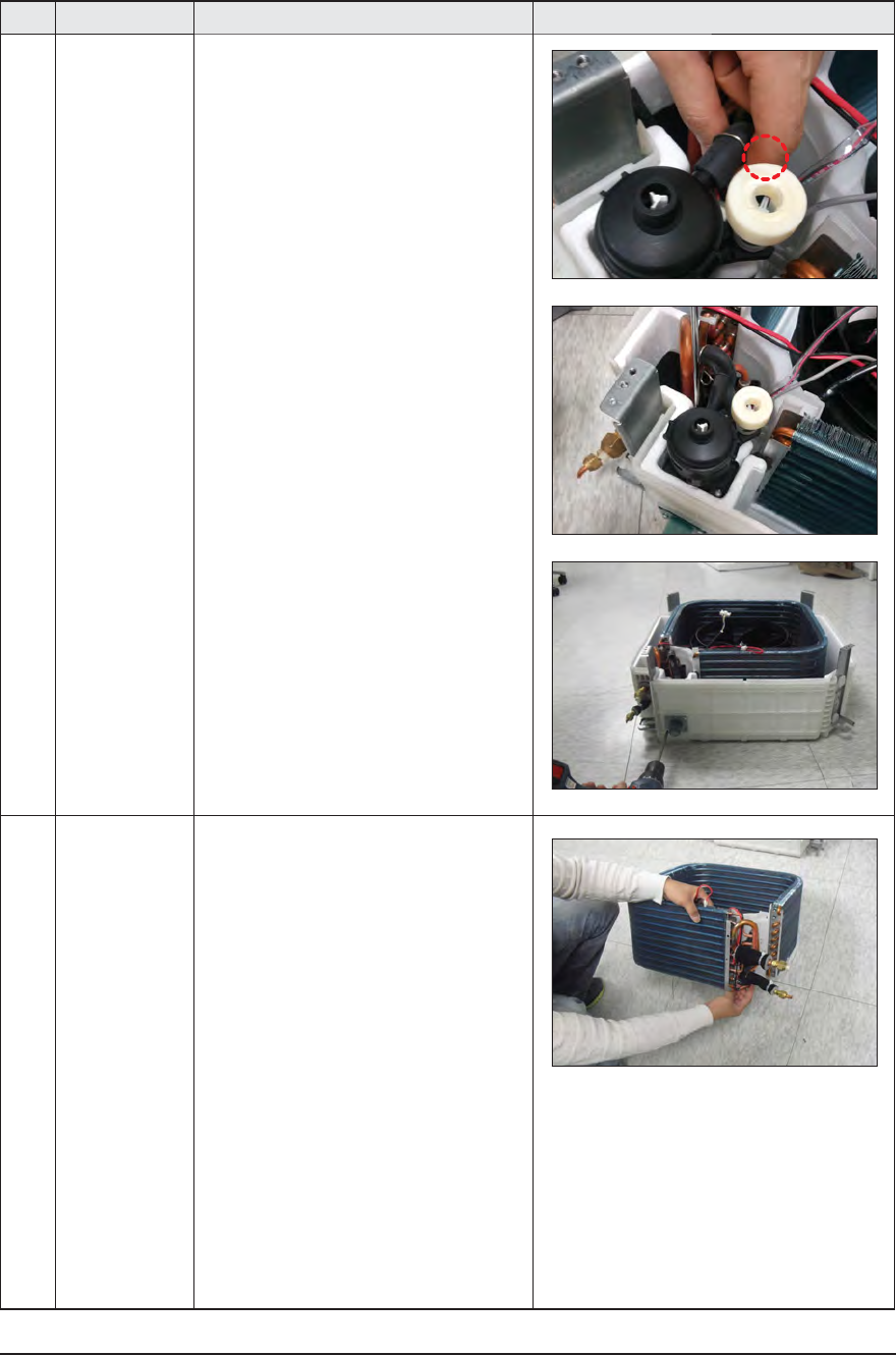
6Evap.
Temperature
Sensor
1) Use your hand to remove the temperature
sensor attached to the Evap Pipe along with
the fixing clip.
3-26 Samsung Electronics
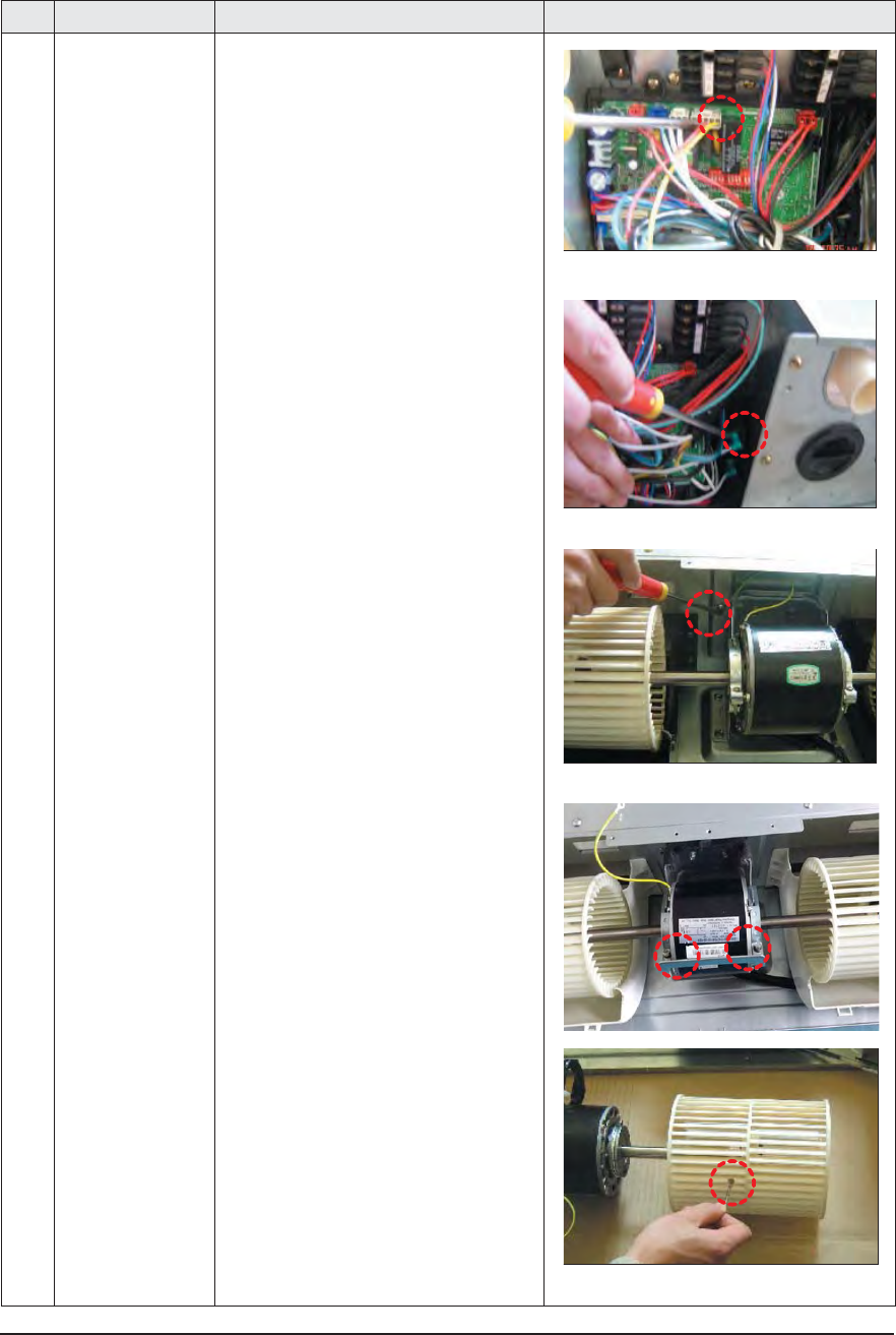
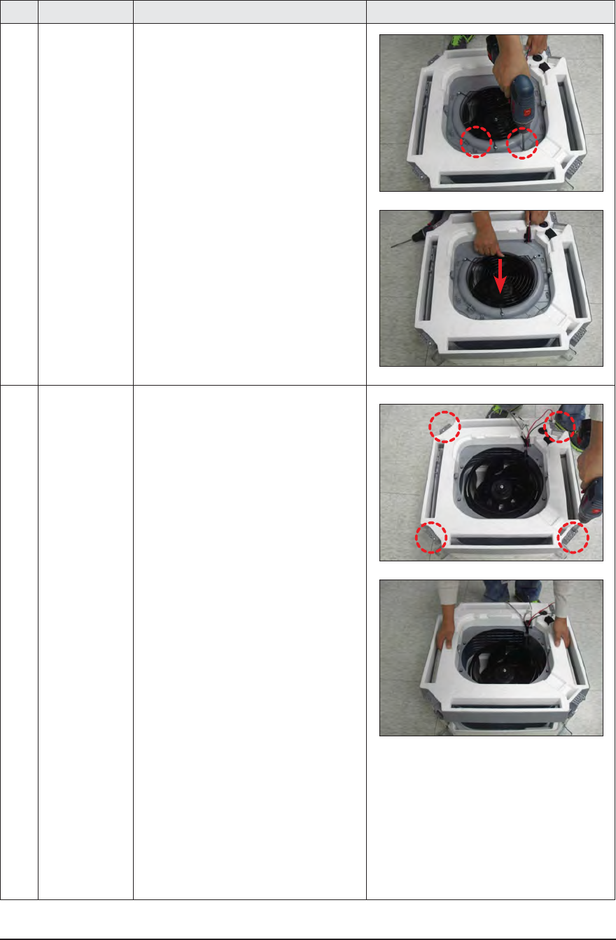
No Parts Procedure Remark
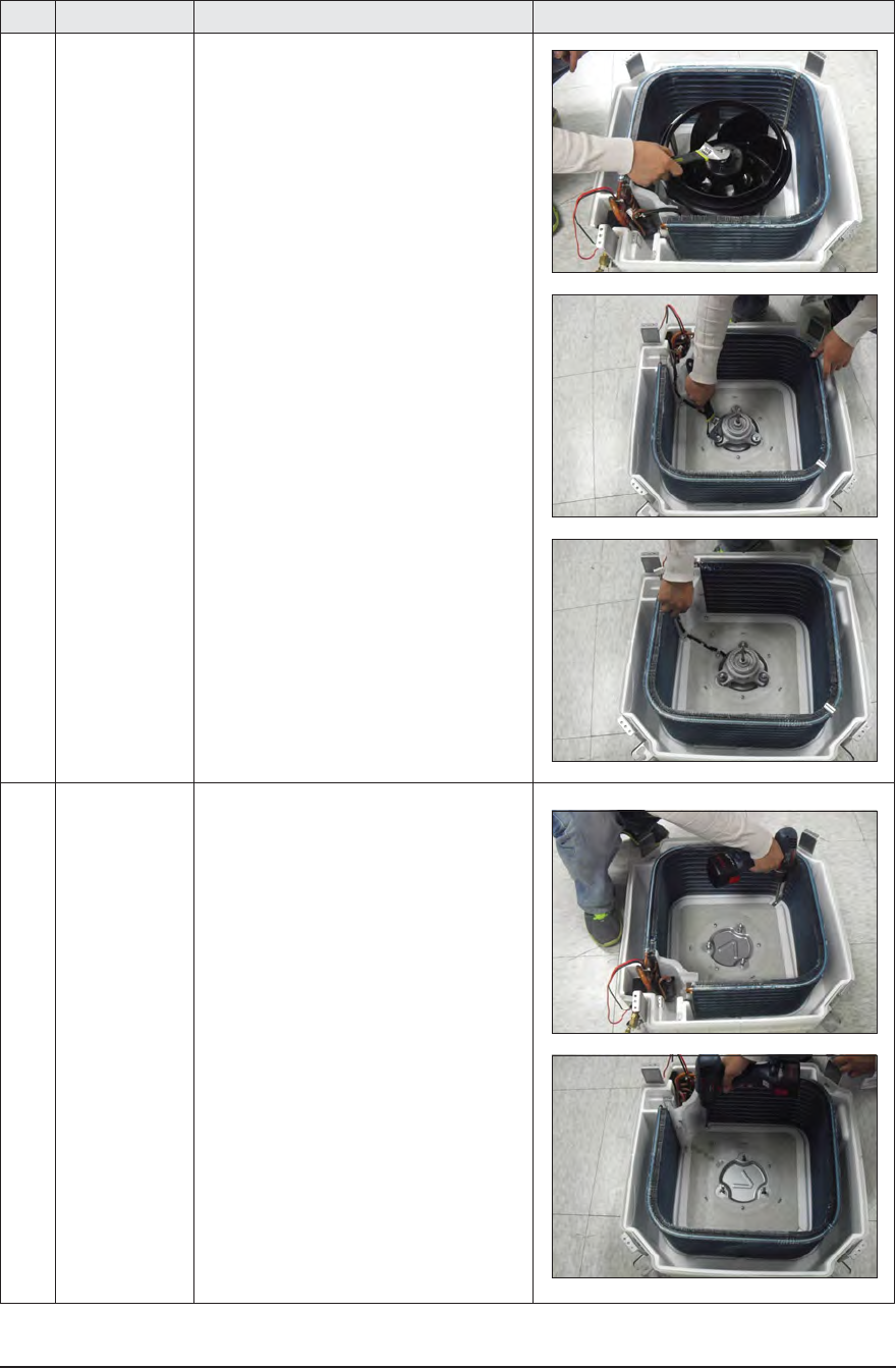
7 Fan
Motor
1) Turn the hexangular nut attached to the
top of the Fan counterclockwise to remove it.
Take the Fan out of the Motor.
2) Turn the three hexangular nuts on the
Motor counterclockwise to remove the nuts.
Take the Motor Wires attached to these three
locations out with your hands prior to remov-
ing the Motor.
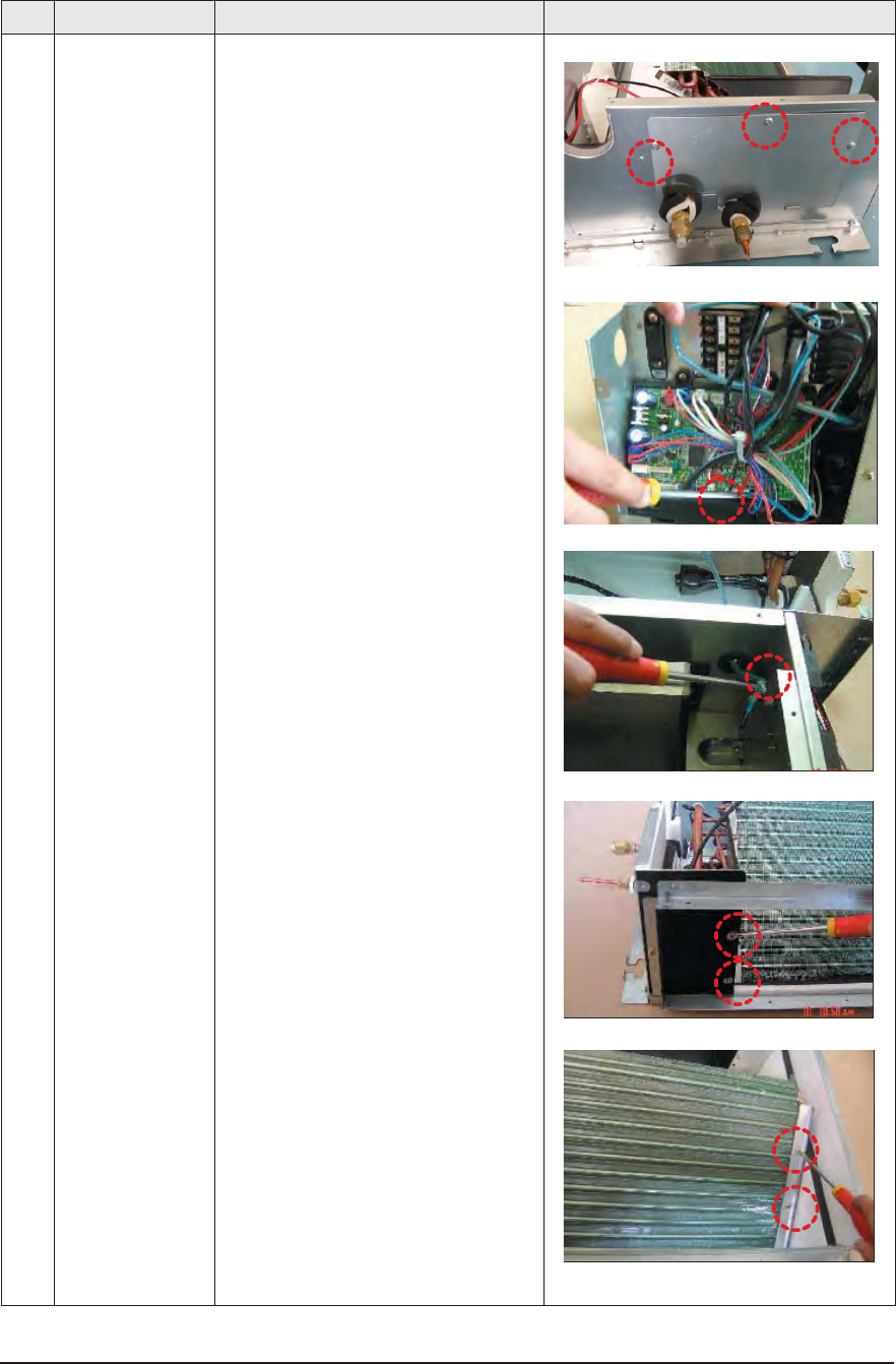
8 Evaporator 1) Remove the screws of the Steel Holder Evaps
that are used to fix the Heat Exchanger, and
then remove it. (Use +Screw Driver)
2) Remove the 2 fixing screws of the Partition
Evap at the Heat Exchanger’s In/Out Pipe.
(Use +Screw Driver)
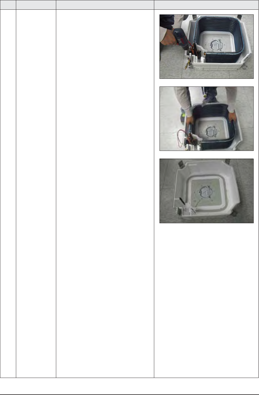
Samsung Electronics 3-27
No Parts Procedure Remark
3) Remove the screw of the Cover Pipe
that is used to fix the In/Out Pipe.
Remove the In/Out Pipe. (Use +Screw Driver)
4) Remove the Heat Exchanger from the
indoor unit’s cabinet.
3-28 Samsung Electronics
ÿ AJ020JCJ2CH/AJ024JCJ3CH
3-2 Outdoor Unit
Take care of the electrical shock by contact on the charging parts before the discharge after power of.(If takes
approximately 2 minutes to discharge.).
No Parts Procedure Remark
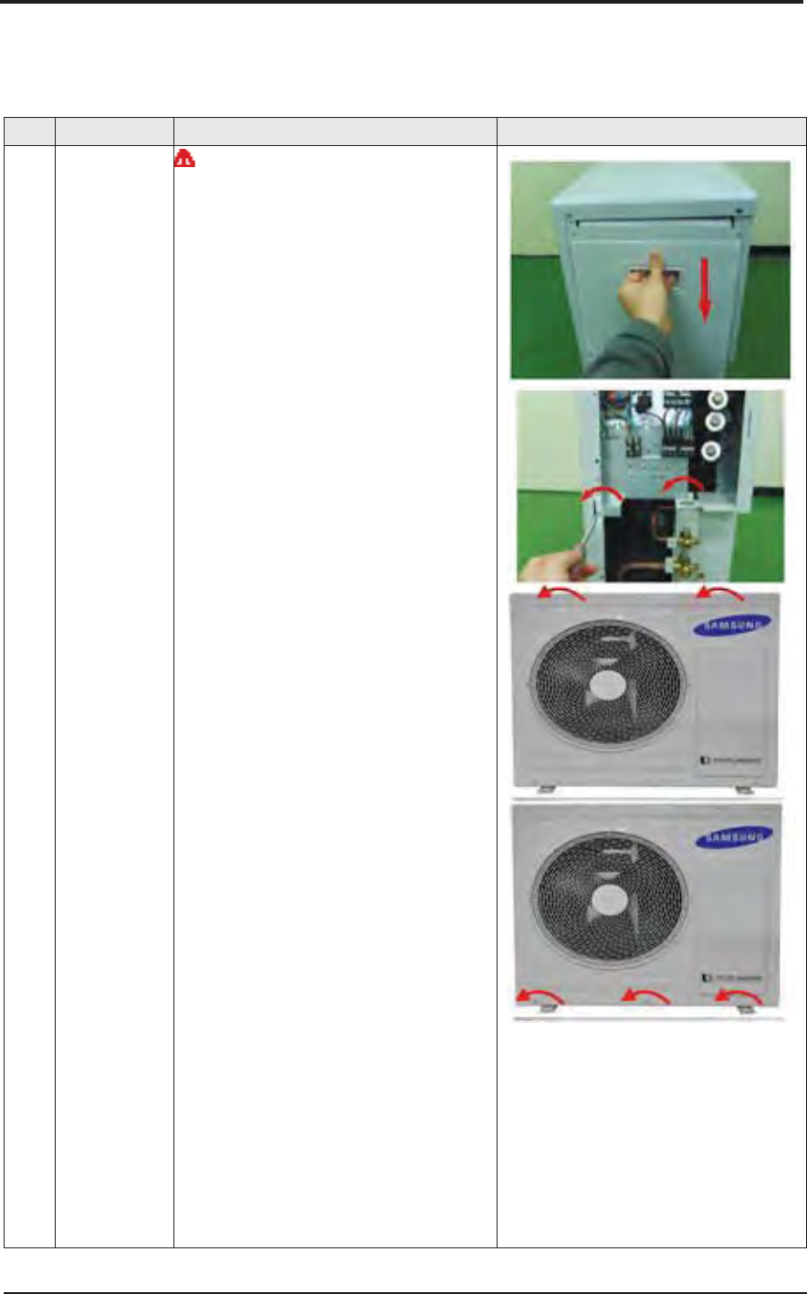
1 Common Work
Control Out
You must turn off the Power before
disassembly.
1) Loosen 7 xing screws and detach the
Cabinet side RH.
(Use +Screw Driver.)
2) Detach the Cable-Connector Wire from
the Terminal-Block.
3) Loosen 2 fixing screws of the Ass'y
Control Out.
(Use +Screw Driver.)
4) Loosen 6 fixing screws and detach the
Cabinet Upper.
(Use +Screw Driver.)
5) Loosen 2 fixing screws, 7 bolts and
detach the Cabinet Front.
(Use +Screw Driver.)
Samsung Electronics 3-29
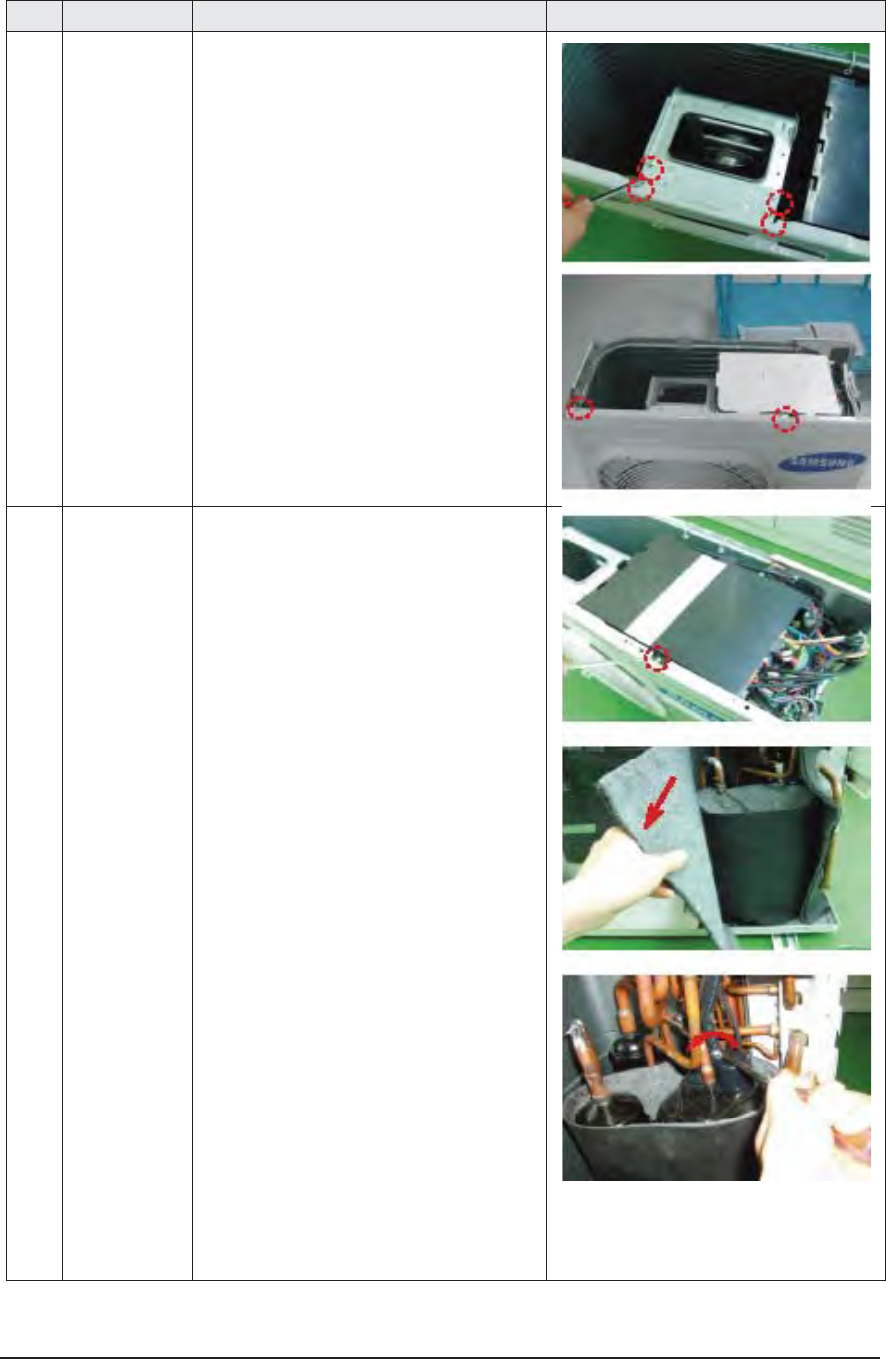
No Parts Procedure Remark
6) Loosen 2 fixing screw and pull up the
Control Box.
(Use +Screw Driver.)
7) Pull the felt and detach it.
8) Detach the Terminal Cover and detach
the comp lead wire.
3-30 Samsung Electronics
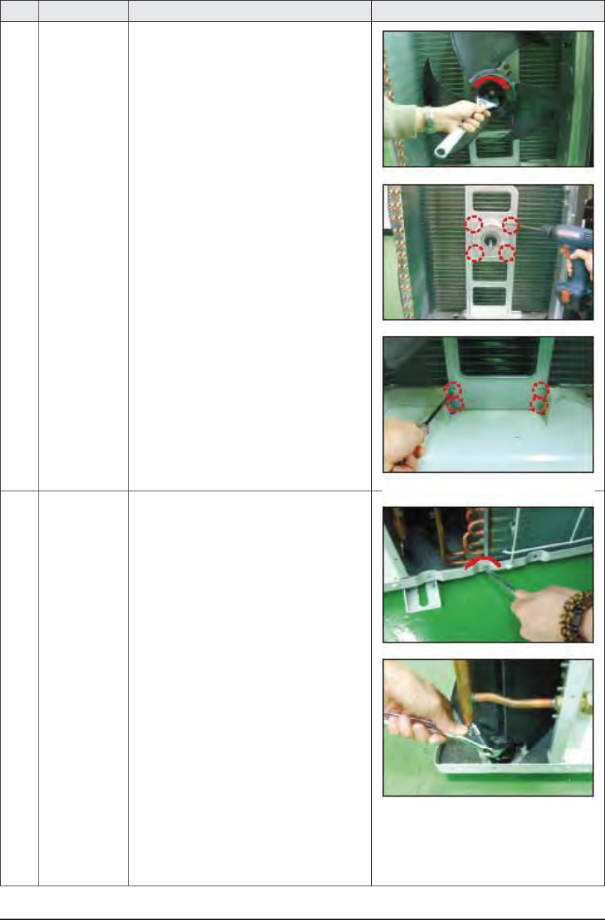
No Parts Procedure Remark
2Fan
Moter
1) Loosen the fixing nut and detach the
Fan.
(Use Monkey Spanner.)
2) Loosen 4 fixing bolts and detach the
Motor. (Use +Screw Driver.)
3) Loosen 4 fixing bolts and detach the
Bracket Motor. (Use +Screw Driver.)
3 Heat Exchanger
Compressor
1) Release the refrigerant at first.
2) Disassemble the Inlet and Outlet Pipe
by welding.
3) Loosen the fixing screw of the Heat
Exchanger. (Use +Screw Driver.)
4) Detach the Heat Exchanger.
5) Loosen 3 nuts of the Compressor. (Use
Monkey Spanner.)
6) Detach the Compressor.
Samsung Electronics 3-31
ÿ AJ036JCJ5CH
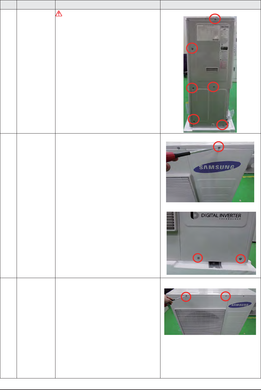
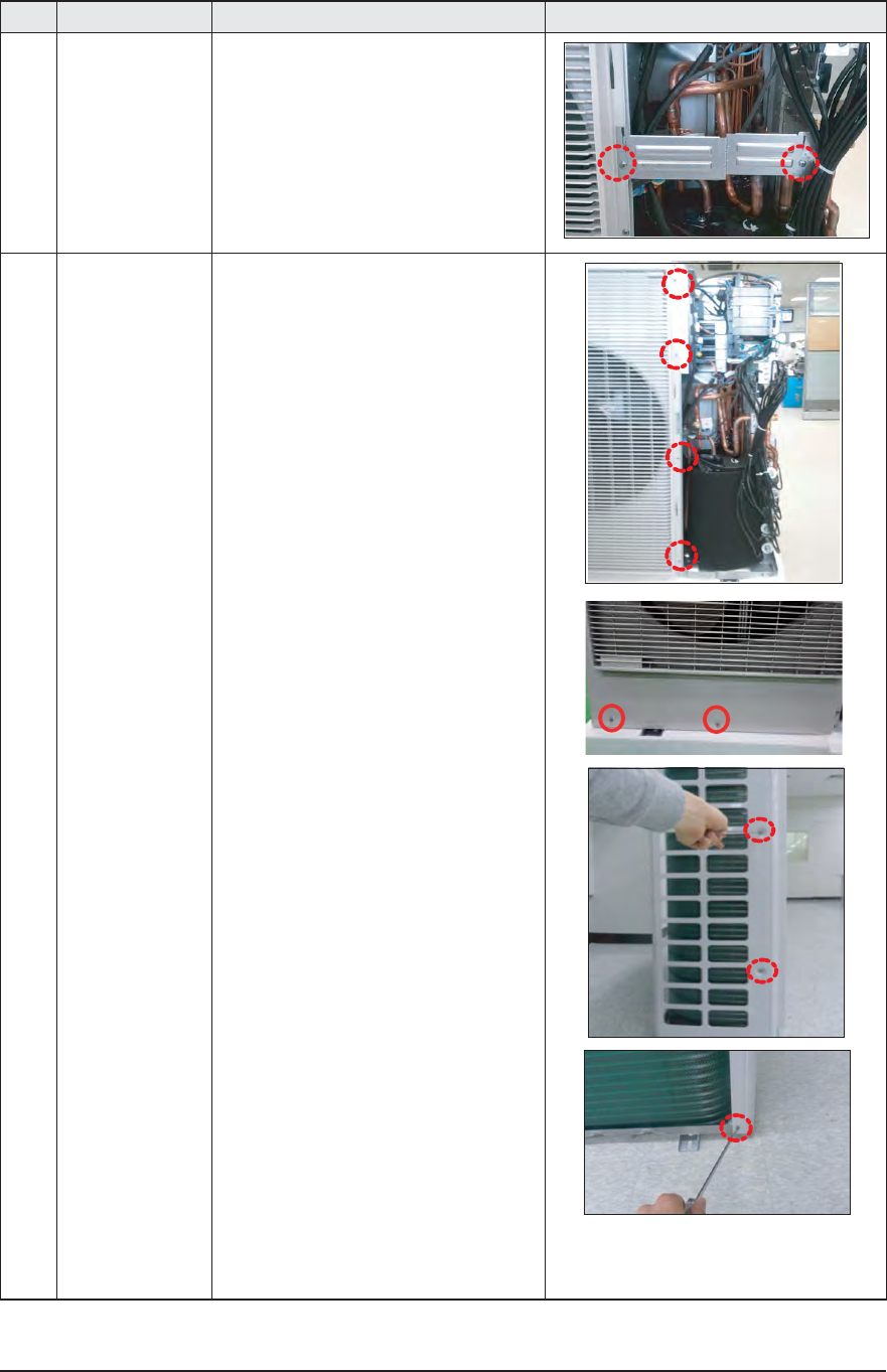
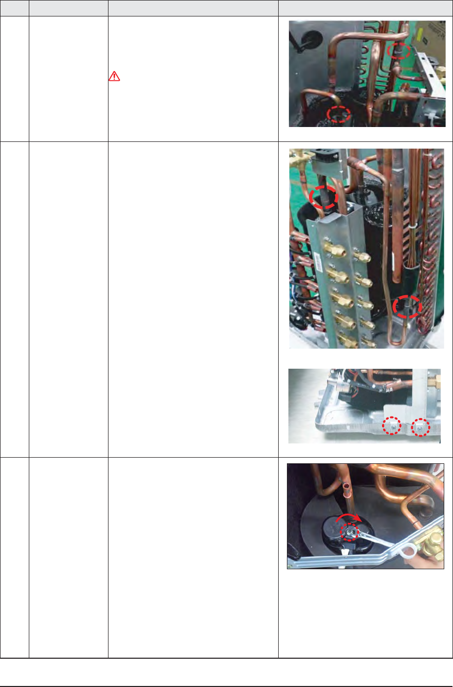
No Parts Procedure Remark
1 Cabi Side RH You must turn off the Power before
disassembly.
1) Unscrew and remove 6 mounting screw
in the Cabinet Side RH. (Use +Screw
Driver)
2 Cabi Front RH 1) Unscrew and remove 6 mounting screw
in the Cabinet Side RH. (Use +Screw
Driver)
3 Cabi Top 1) Unscrew and remove 9 screws on each
side of the Cabinet-Top. (Use +Screw
Driver)
3-32 Samsung Electronics
No Parts Procedure Remark
4 Guard Cond 1) Pull the sensor from Guard Cond.
2) Unscrew and remove 4 screws
in the Guard Cond.
( Use + Screw Driver )
5 Cabi Back RH 1) Pull the sensor from Cabi Back RH.
2) Unscrew and remove 5 screws
on each side of the Cabinet Back RH.
( Use + Screw Driver )
3) Pull the hook of Cabi Back RH
from the Bracket Valve.
Samsung Electronics 3-33
No Parts Procedure Remark
6 Plate Case Control
Support
1) Unscrew and remove 2 screws
in the plate Case control Support.
( Use + Screw Driver )
7 Cabi Back RH 1) Unscrew and remove 10 screws
in the Cabinet-Front LF
( Use + Screw Driver )
3-34 Samsung Electronics
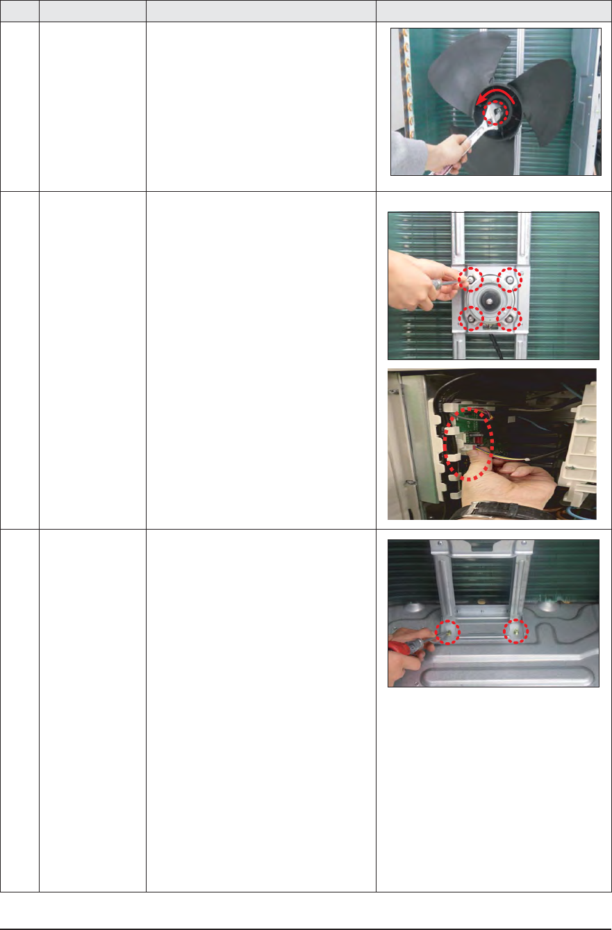
No Parts Procedure Remark
8Fan 1) Turn 2 mounting nuts as shown in the
picture and remove it.
(Use Adjustable Wrench)
9 Motor 1) Separate the Fan Propeller.
2) Unscrew and remove the 8 Motor
mounting screws.
(Use +Screw Driver)
3) Disconnect the Motor wire From Ass'y
Control Out.
10 Bracket Motor 1) Unscrew and remove 2 mounting
screws in Bracket Motor.
(Use +Screw Driver)
Samsung Electronics 3-35
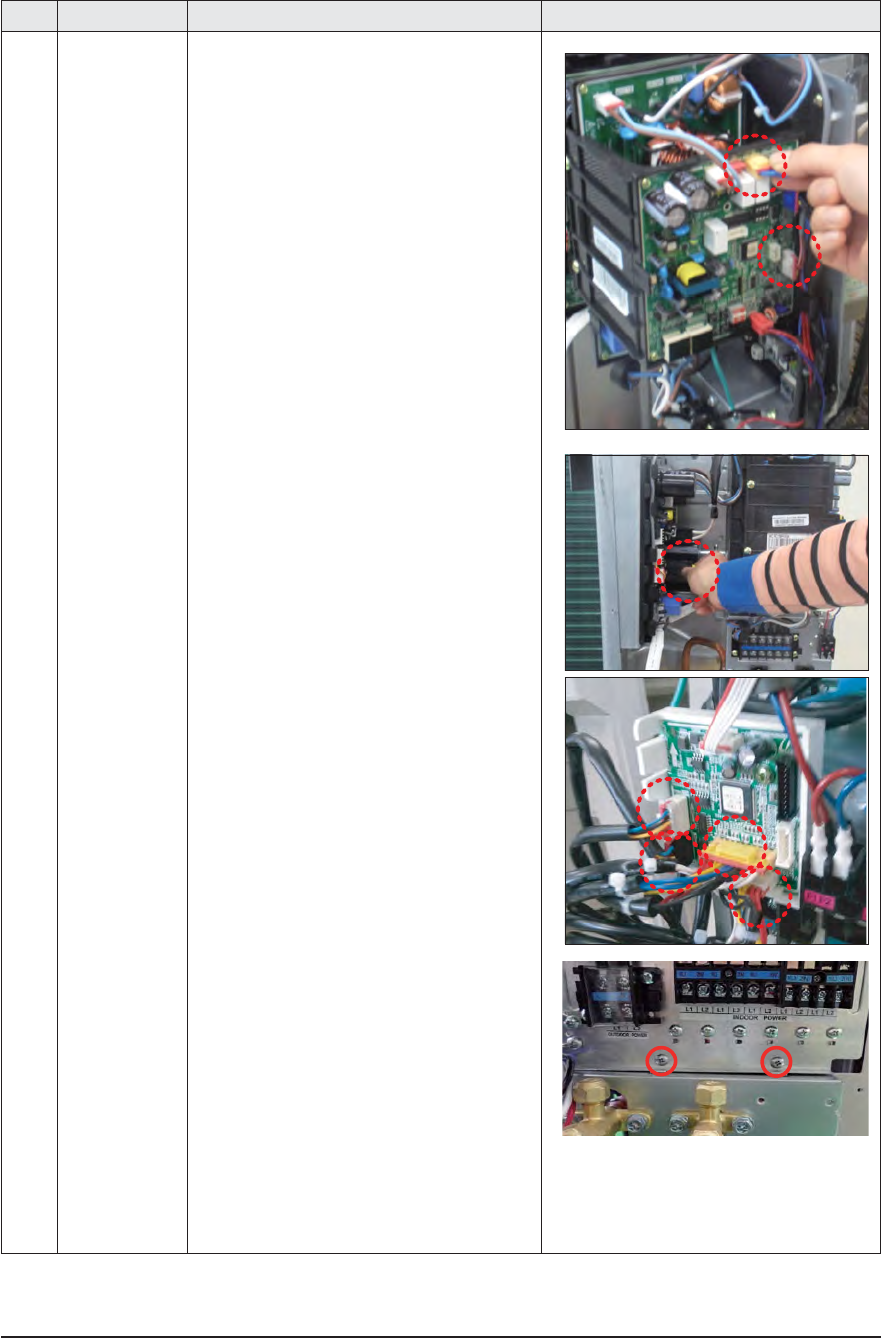
No Parts Procedure Remark
11 Control Out 1) Disconnect 9 Connecters From Ass'y
Control Out.
2)
3)
Unscrew and remote 2 mounting screw
in Control Out.(Use + Screw Driver)
Separate Ass'y Control Out
3-36 Samsung Electronics
No Parts Procedure Remark
12 Ass'y 4way Valve 1) Purge the Coolant first.
2) Separate the pipe from the Entrance/
Exit using a welder.
When removing the compressor,Heat
Exchanger, and Pipe, purge the
Coolant inside the Compressor
completely and remove the pipe with
a welding flame.
13 Assy EEV Valve 1) Separate the pipe from the Entrance/
Exit using a welder.
2) Unscrew and remove 2 mounting
screws in Service Valve.
(Use +Screw Driver)
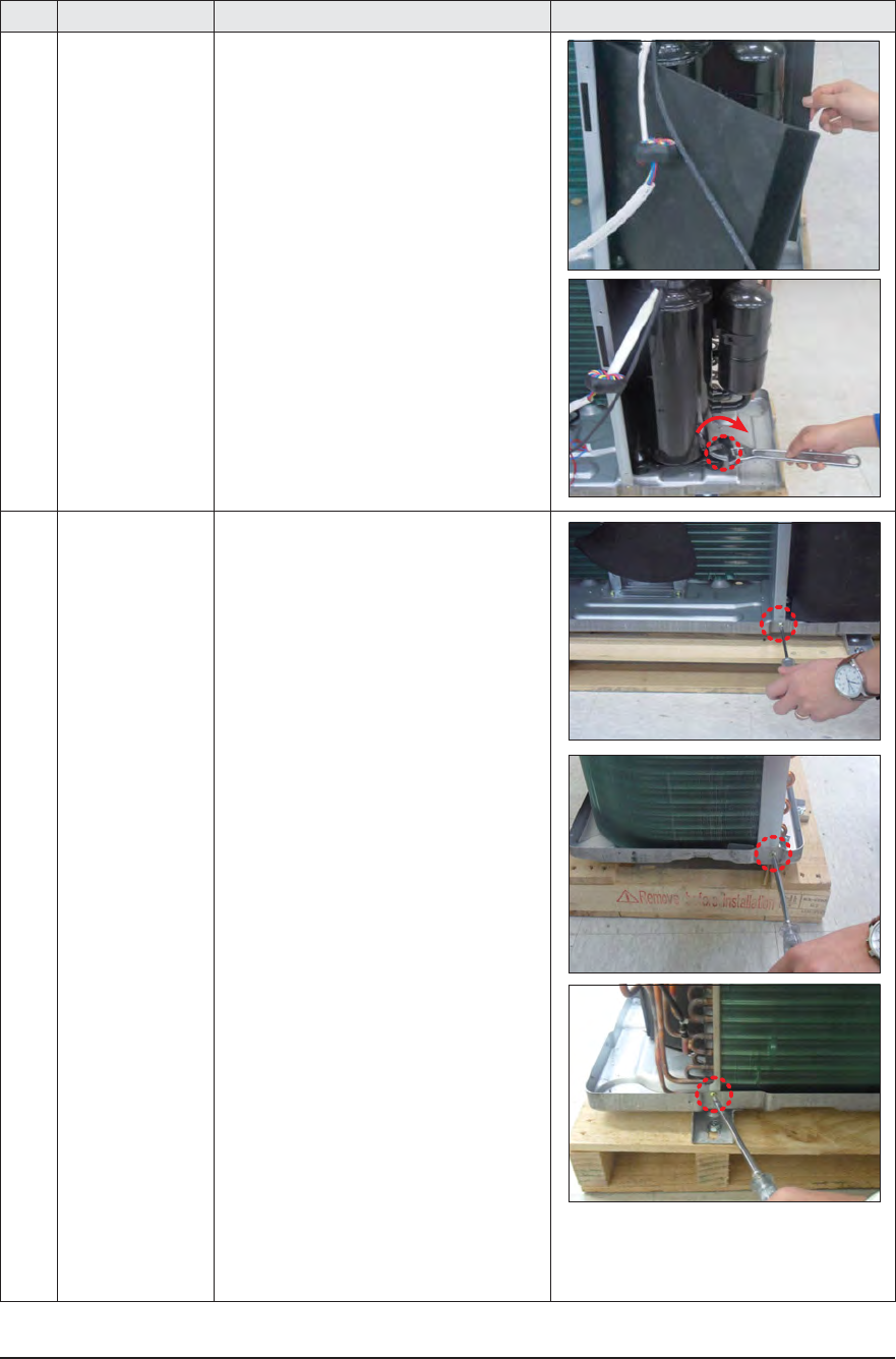
14 Compressor 1) Unscrew and remove 1 mounting nut
in Cover Terminal.
(Use Adjustable Wrench)
Samsung Electronics 3-37
No Parts Procedure Remark
2) Separate the Compressor Felt Sound.
3) As shown in the picture, unscrew and
remove 3 mounting screws from the
bottom.
(Use Adjustable Wrench)
15 Cond Out 1) Unscrew and remove 3 screws on each
side of the Assy Cond Out.
(Use +Screw Driver)

3-38 Samsung Electronics
MEMO
Samsung Electronics 4-1
4. Troubleshooting
4-1 Display Error and Check Method
4-1-1
Indoor unit
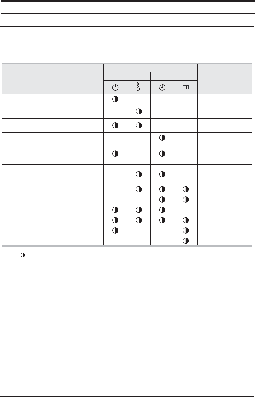
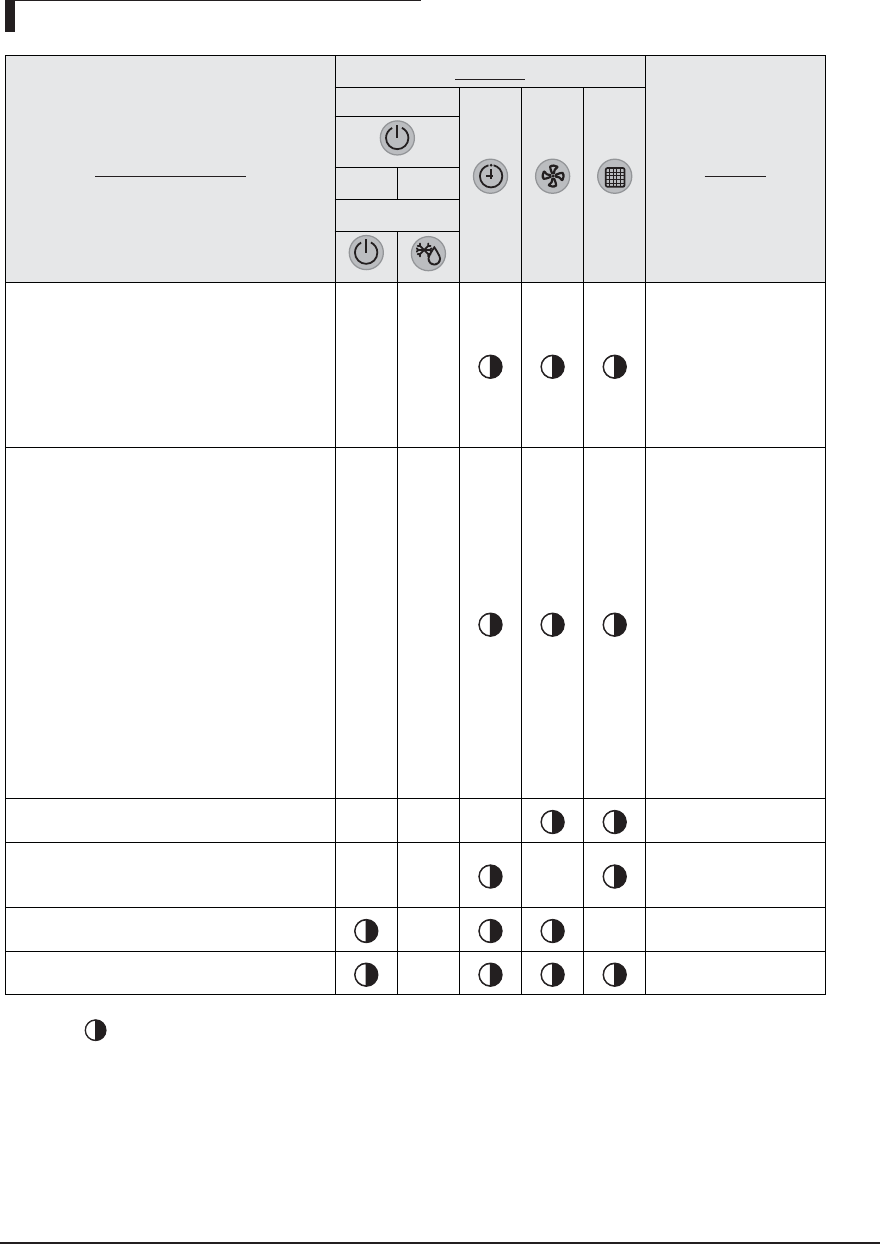
Q AJ009JNNDCH/AJ012JNNDCH/AJ018JNNDCH
Abnormal conditions
LED lamp display
Remarks
Operation
Defrost Timer Filter
Power reset XXX
Error of temperature sensor in the indoor unit
(Open/Short) XXX
Error of heat exchanger sensor in the indoor unit
(Open/Short) XX
Error of fan motor in the indoor unit X X X
Error of the outdoor temperature sensor
Error of the condensor temperature sensor
Error of the discharge temperature sensor
X X
No communication for 2 minutes between
indoor and outdoor unit
(communication error for more than 2minutes)
XX
Error of outdoor unit X
Detection of the float switch X X
EEPROM error X
EEPROM option error
Motion detect sensor error XX
Mixed operation error X X X
◆ If you turn off the air conditioner when the LED is flickering, the LED is also turned off.
● On
Flickering
X
Off
4-2 Samsung Electronics
Abnormal conditions
Indicators
Remarks
Concealed Type
Green Red
Standard Type
Power reset
XXXX
Error of temperature sensor
in the indoor unit (Open/Short)
XX XX
Displayed on appropriate
indoor unit which is oper-
ating
Error of heat exchanger sensor in the indoor unit
Error of heat exchanger OUT sensor in indoor unit
Error of outlet temperature sensor in indoor unit
(Open/Short): For heat pump models only
XXX
Displayed on appropriate
indoor unit which is oper-
ating
Error of mixed operation
X X X
Error of outdoor temperature sensor
Error of COND sensor
Error of DISCHARGE sensor
XX X
Displayed on appropriate
indoor unit which is oper-
ating
Displayed on outdoor unit
1. No communication for 2 minutes
between indoor units
(Communication error for more than 2 minutes)
2. Indoor unit receiving the
communication error from outdoor unit
3. Outdoor unit tracking 3 minutes error
4. When sending the communication
error from the outdoor unit, the
mismatching of the communication numbers
and installed numbers after completion of
tracking.
(Communication error for more than 2 minutes)
XX X
1. Error of indoor unit:
Displayed on the indoor
unit regardless of opera-
tion
2. Error of outdoor unit:
Displayed on the indoor
unit which is operating
◆ If you turn off the air conditioner when the LED is flickering, the LED is also turned off.
◆ If you re-operate the air conditioner, it operates normally at first, then detect an error again.
● On Flickering
X
Off
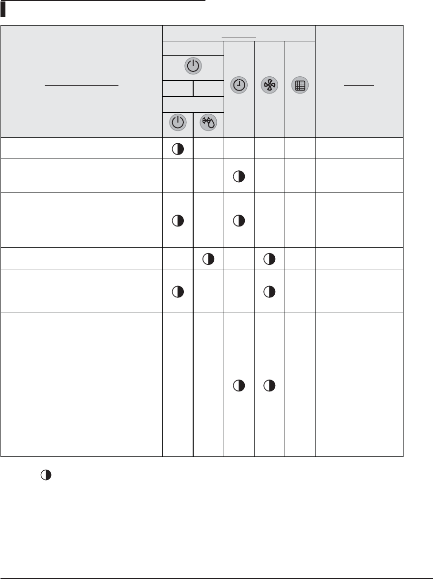
LED Display on the receiver & display unit
Q AJ009JNLDCH/AJ012JNLDCH/AJ018JNLDCH
Samsung Electronics 4-3
◆ If you turn off the air conditioner when the LED is flickering, the LED is also turned off.
◆ If you re-operate the air conditioner, it operates normally at first, then detect an error again.
● On Flickering
X
Off
Abnormal conditions
Indicators
Remarks
Concealed Type
Green Red
Standard Type
Self-diagnostic error
(including the indoor unit not detected)
1. Error of electronic expansion valve close
2. Error of electronic expansion valve open
3. Breakaway of EVA OUT sensor
4. Breakaway of EVA IN sensor
XX
Displayed on appropriate
indoor unit which is oper-
ating
Displayed on outdoor unit
5. Breakaway of COND MID sensor
6. 2nd detection of refrigerant completely leak
7. 2nd detection of high temperature COND
8. 2nd detection of high temperature
DISCHARGE
9. COMP DOWN due to 2nd detection of low
pressure switch
10. Error of reverse phase
11. Compressor down due to 6th detection of
freezing
12. Self-diagnosis of condensation sensor (G8,
G9)
13. Compressor down due to condensation ratio
control
XX
Displayed on appropriate
indoor unit which is oper-
ating
Displayed on outdoor unit
Error of float switch
XXX
Error of setting option switches for optional
accessories
XX X
EEPROM error
X X
EEPROM option error
X
LED Display on the receiver & display unit
Q AJ009JNLDCH/AJ012JNLDCH/AJ018JNLDCH
4-4 Samsung Electronics
◆ If you turn off the air conditioner when the LED is flickering, the LED is also turned off.
◆ If you re-operate the air conditioner, it operates normally at first, then detect an error again.
● On Flickering
X
Off
LED Display on the receiver & display unit
Q AJ007JNADCH/AJ009JNADCH/AJ012JNADCH/AJ018JNADCH/AJ024JNADCH
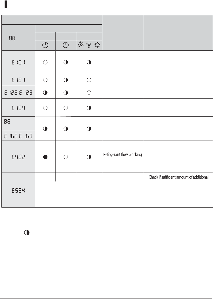
Error indicator
Error Measures to take by an installer
Display
LED Display
LED 1 LED 2 LED 3
/ /
Commnuication Error
between Indoor and
outdoor unit
1. Check the connection wire between
indoor and outdoor unit. (whether the
power cable and commnunication cable
is crossed or not)
Error on indoor
temperature sensor
1. Check the connection of the connector
, Error on indoor heat
exchanger
1. Check the connection of the connector
Error on indoor fan motor
1. Check the connection of the connector
2. Remove foreign substance (Check for the
cause that restrains motor)
display and all
LED blinks EEPROM/Option error
1. Re-set options
,
Error
1. Check if the service valve is completely
open.
2. Check if there’s any blockage in the
refrigerant pipe which connects indoor
and outdoor unit.
3. Check for refrigerant leak.
Lack of Refrigerant
(For Inverter model only)
1.
refrigerant was charged for the pipe
length that exceeds 7.5m.
2. Check for refrigerant leak between valve
and pipe connection.
K Above LED pattern is displayed when
there’s error is occurred on outdoor unit.
Check the LED display on outdoor unit for
the details.
Samsung Electronics 4-5
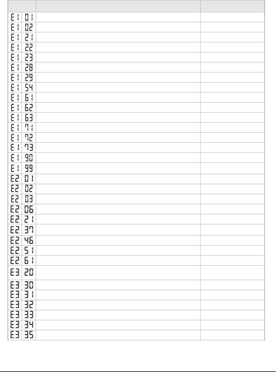
The error indicated on the PCB display of outdoor unit
DISPLAY EXPLANATION (The error indicated on the PCB display of outdoor unit) REMARK
Communiaction error(indoor unable to receive data)
Check electrical connection and setting
Outdoor unit communication error(Abnormal data from indoor unit over 60 packet)
Check electrical connection and setting
Indoor unit room temperature sensor error (Open/Short)
Indoor unit heat exchanger in temperature sensor error (Open/Short)
Indoor unit heat exchanger out temperature sensor error (Open/Short)
Indoor unit sensor error-Evaporator pipe in sensor - Self diagnosis
Indoor unit sensor error-Evaporator pipe out sensor - Self diagnosis
Indoor Unit FAN Error
More than two indoor units cool and heat simultaneously
Indoor Unit EEPROM Error
Indoor Unit EEPROM Option Error
EVA-MID BREAK AWAY
EVA-IN BREAK AWAY
EVA-OUT BREAK AWAY
Failure of pipe check operation
Check piping connection and setting
No pipe check operation check
- occasion : try to operation after the installation through auto addressing mode without pipe check operation.
Check setting
The number of Indoor unit mismatched
Check electrical connection and setting
Communication error between the outdoor and indoor unit
Check electrical connection and setting
Outdoor communication error between main micom and inverter micom
Outdoor communication error beween main micom and hub micom
Outside temperature sensor error(Short/Open)
- Error level: over 4.9V(-50°C) under 0.4V(93°C)
Condenser temperature sensor error(Short/Open)
- Error level: over 4.9V(-50°C) under 0.4V(93°C)
Outdoor unit sensor error - Condenser out sensor(Short/Open) - Self diagnosis
Compressor Discharge temperature sensor error
Compressor discharge sensor detached - Self diagnosis
Compressor OLP sensor error (Short/Open)
- Error condition : outdoor temperature under -20°C
- Error level : over 4.95V(-30°C) under 0.5V(151°C)
EvaIn1 Sensor Short/Open
EvaIn2 Sensor Short/Open
EvaIn3 Sensor Short/Open
EvaIn4 Sensor Short/Open
EvaIn5 Sensor Short/Open
EvaOut1 Sensor Short/Open
The table below give indication about self diagnostic routine. Some of error code requires activities
exclusively for Authorise Service Center.
4-1-2
Outdoor unit
Q
AJ020JCJ2CH/AJ024JCJ3CH/AJ036JCJ5CH
4-6 Samsung Electronics
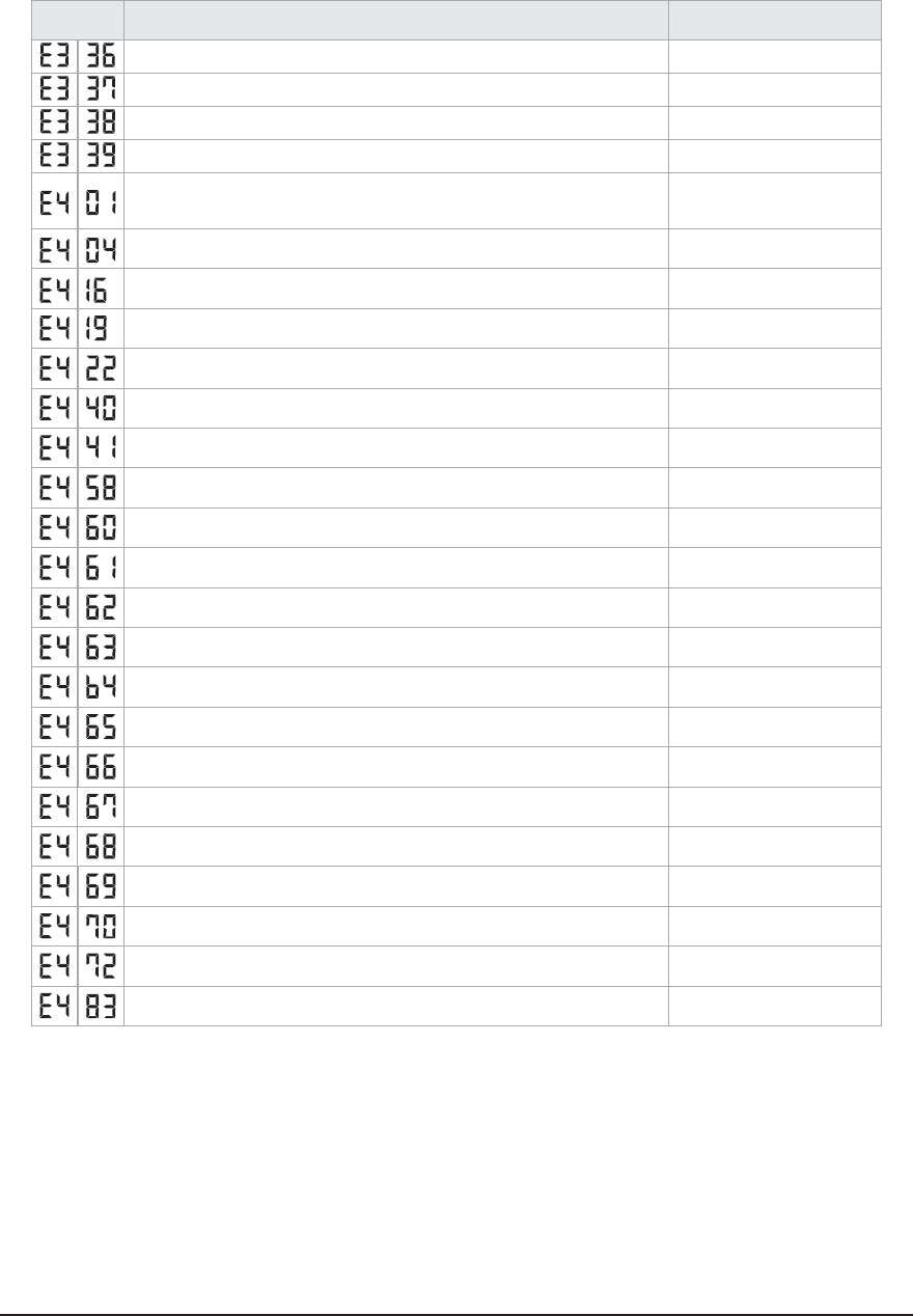
DISPLAY EXPLANATION (The error indicated on the PCB display of outdoor unit) REMARK
EvaOut2 Sensor Short/Open
EvaOut3 Sensor Short/Open
EvaOut4 Sensor Short/Open
EvaOut5 Sensor Short/Open
Outdoor unit freezing(Compressor stop)
check pipe lenght, indoor unit lter,
refrigerant leakage/charge and
service port
Outdoor unit overload - Safety control(Compressor stop) check pipe lenght, refrigerant
leakage/charge
Outdoor unit high discharge temperature - Safety control (Compressor stop) check pipe lenght, refrigerant
leakage/charge
Outdoor unit EEV open (Stopped indoor unit’s) -Self diagnosis
Outdoor unit EEV open (operating indoor unit’s) -Self diagnosis
High temperature(over 30°C) of outdoor as heating mode
Low temperature(under -10°C) of outdoor as cooling mode
Outdoor Fan Error
Communication cable mismatched between indoor and outdoor unit Check electrical connection
Inverter compressor starting failure (5 times)
Compressor trip by input current control mode (PFC over current)
Compressor trip by OLP temperature control mode
Over current
Compressor Vlimit Error
DC link Voltage error (under 150V, over 410V)
Abnormal compressor running (Compressor Rotation Error)
Current sensor error
DC link Voltage sensor error
Outdoor unit EEPROM Error
Inverter micom zero-crossing error
Over voltage Error
Q
AJ020JCJ2CH/AJ024JCJ3CH/AJ036JCJ5CH
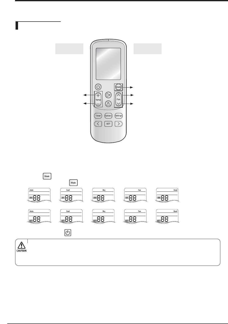
Samsung Electronics 4-7
Setting Option
High Temp Button High Fan Button
Mode change
Low Temp Button Low Fan Button
Entering mode for
setting option
Option
setting mode
X Setting Option
1. Remove batteries from the remote controller
2. Insert batteries and enter the option setting mode while pressing High Temp button and Low Temp button.
3. Each time you press Low Fan button, 7-seg on left side is increased by “1” and each time you press High Fan button,
7-seg on right side is increased by “1”
4. You press button to move to the next setteing page.
5. After setting option, press button to check whether the option code you input is correct or not.
6. Press operation button with the direction of remote control for set.
t 4&(4&(4&(4&(BSFOPUTFUBTQBHFPQUJPO
t 4FUUIF4&(4&(BT0/TUBUVTBOE4&(4&(BT0''TUBUVT
EX) Set the each option separately since you cannot set the ADDRESS setting and indoor unit
installation setting option at the same time.
¤
¤
¤
¤
¤
¤
¤
¤
¤
(AJ***JNN/JNA***)
4-2 Setting Option Setup Method
4-2-1 Setting an indoor unit address and installation option
4-8 Samsung Electronics
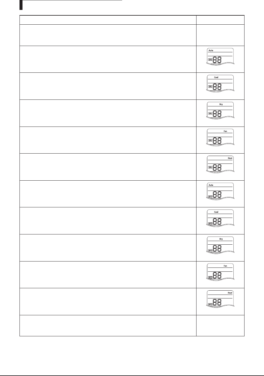
The procedure of setting option
Operation Indication
* Step 1
1. Remove the batteries from the remote controller.
2. Insert batteries while pressing High Temp Button and Low Temp Button.
* Step 2
1. Press Low Fan button to enter SEG2 value.
2. Press High Fan button to enter SEG3 value.
* Step 3
Press Mode button to be change to Cool mode in the ON status.
1. Press Low Fan button to enter SEG4 value.
2. Press High Fan button to enter SEG5 value.
* Step 4
Press Mode button to be changed to DRY mode in the ON status.
1. Press Low Fan button to enter SEG6.
2. Press High Fan button to enter SEG8.
* Step 5
Press Mode button to be changed to FAN mode in the ON status.
1. Press Low Fan button to enter SEG9 value.
2. Press High Fan button to enter SEG10 value.
* Step 6
Press Mode button to be changed to HEAT mode in the ON status.
1. Press Low Fan button to enter SEG11 value.
2. Press High Fan button to enter SEG12value
* Step 7
Press Mode button to be changed to AUTO mode in the OFF status.
1. Press Fan button to enter SEG14 value.
2. Press High Fan button to enter SEG15 value.
* Step 8
Press Mode button to be changed to Cool mode in the OFF status.
1. Press Low Fan button to enter SEG16 value.
2. Press High Fan button to enter SEG17 value.
* Step 9
Press Mode button to be changed to DRY mode in the OFF status.
1. Press Low Fan button to enter SEG18 value.
2. Press High Fan button to enter SEG20 value.
* Step 10
Press Mode button to be changed to FAN mode in OFF status
1. Press Low Fan button to enter SEG21 value.
2. Press High Fan button to enter SEG22 value.
* Step 11
Press Mode button to be changed to HEAT mode in the OFF status
1. Press Low Fan button to enter SEG23 value.
2. Press High Fan button to enter SEG24 value.
* Step 12
Press Mode button to check whether the option code you entered is correct or not.
Press operation button to enter option.
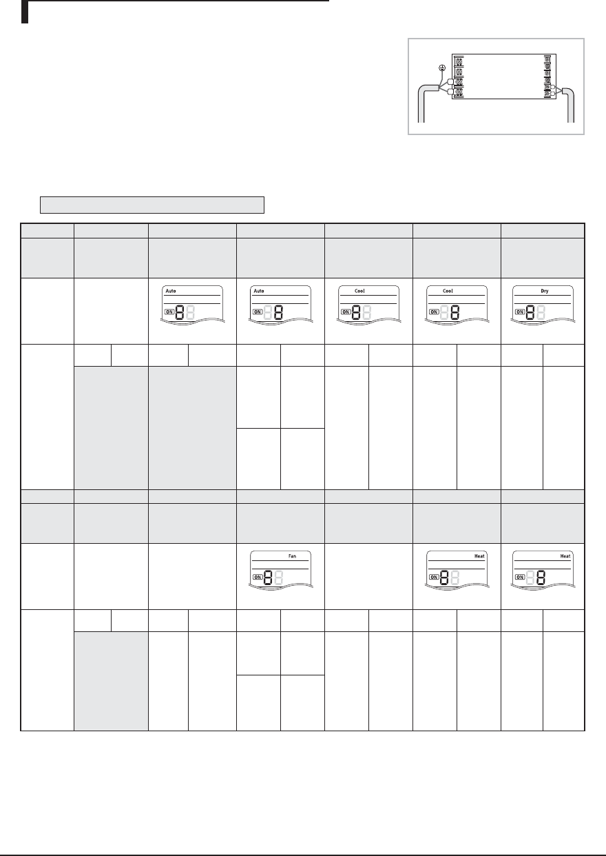
Samsung Electronics 4-9
1. Check whether power is supplied or not.
- When the indoor unit is not plugged in, there should be additional power
supply in the indoor unit.
2. The panel(display ) should be connected to an indoor unit to receive option.
3. Before installing the indoor unit, assign an address to the indoor unit according
to the air conditioning system plan.
4. Assign an indoor unit address by wireless remote controller.
- The initial setting status of indoor unit ADDRESS(MAIN/RMC) is "0A0000-100000-200000-300000"
- There is no need to assign extra ADDRESS for 1:1 installation between indoor unit and outdoor unit.
Option No. : 0AXXXX-1XXXXX-2XXXXX-3XXXXX
Option SEG1 SEG2 SEG3 SEG4 SEG5 SEG6
Explanation
PAGE MODE Setting Main
address
100-digit of indoor
unit address
10-digit of indoor
unit
A single digit of
indoor unit
Remote
Controller
Display
Indication
and Details
Indication
Details Indication
Details
Indication
Details
Indication Details Indication Details Indication
Details
0A
0No Main
address
0~9
100-digit
0~9
10-digit
0~9 A single
digit
1
Main
address
setting
mode
Option SEG7 SEG8 SEG9 SEG10 SEG11 SEG12
Explanation
PAGE Setting RMC
address
Group
channel(*16) Group address
Remote
Controller
Display
Indication
and Details
Indication
Details
Indication
Details
Indication
Details
Indication
Details
Indication Details Indication Details
1
0
No RMC
address
RMC1 1~F RMC2 1~F
1
RMC
address
setting
mode
Setting an indoor unit address (MAIN/RMC)
Indoor Unit
1(L)
2(N) F2
F1
※ You must set RMC address setting mode when using the centralized Control .
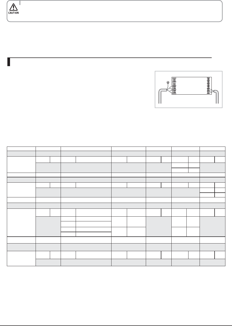
4-10 Samsung Electronics
1. Check whether power is supplied or not.
- When the indoor unit is not plugged in, there should be additional power
supply in the indoor unit.
2. The panel(display ) should be connected to an indoor unit to receive option.
3. Before installing the indoor unit, assign an option to the indoor unit according
to the air conditioning system plan.
- The default setting of an indoor unit installation option is “02000-100000-200000-300000”.
- Individual control of a remote controller(SEG20) is The function that controls an indoor unit individually when there is
more than one indoor unit.
4. Set the indoor unit option by wireless remote controller.
- When entering Address option, connect remote controller receiver.
Setting an indoor unit installation option (suitable for the condition of each installation location)
Option SEG1 SEG2 SEG3 SEG4 SEG5 SEG6
Explanation PAGE MODE Central control
Indication and Details
Indication Details Indication Details Indication Details Indication Details Indication Details Indication Details
02 00
0 No use 0
1Use
Option SEG7 SEG8 SEG9 SEG10 SEG11 SEG12
Explanation PAGE Master / Slave
Indication and Details
Indication Details Indication Details Indication Details Indication Details Indication Details Indication Details
10 00
0
0 Slave
1 Master
Option SEG13 SEG14 SEG15 SEG16 SEG17 SEG18
Explanation PAGE External control External control output Buzzer
Indication and Details
Indication Details Indication Details Indication Details Indication Details Indication Details Indication Details
2
0 No use 0 Thermo ON
0
0Use
0
1 On/O control
2O control1 Operation ON 1 No Use
3 Window On/O control1)
Option SEG19 SEG20 SEG21 SEG22 SEG23 SEG24
Explanation PAGE
Indication and Details
Indication Details Indication Details Indication Details Indication Details Indication Details Indication Details
30 0000
▶
If you input a number other than 0~4 of the individual control of the indoor unit(SEG20), the indoor is set as "indoor 1".
t8IFOi"w_w'wJTFOUFSFEUP4&(_UIFJOEPPSVOJU."*/"%%3&44JTOPUDIBOHFE
t*GZPVTFUUIF4&(BTUIFJOEPPSVOJUXJMMNBJOUBJOUIFQSFWJPVT."*/"%%3&44FWFOJGZPVJOQVUUIFPQUJPOWBMVFPG4&(_
t*GZPVTFUUIF4&(BTUIFJOEPPSVOJUXJMMNBJOUBJOQSFWJPVT3.$"%%3&44FWFOJGZPVJOQVUUIFPQUJPOWBMVFPG4&(_
5. The MAIN address is for commnication between the indoor unit and the outdoor unit. Therefore, you must set it to
operate the air conditioner properly.
Indoor Unit
1(L)
2(N) F2
F1
1) The window on/o function applies to the following unit
- AJN**/AR**
Samsung Electronics 4-11
XIf you are going to use up to SEG 24, please refer to following instruction.
SEG 18 :
7 If you want to use multiple functions, add each of the ‘use’ value of the function you want to used and input the final
addition as option value. (Use Fahrenheit + Sound mute : 1 + 2 = 3)
Ex) 044217-1d00e6-200000-300000
When using Sound mute : 044217-1d00e6-200002-300000
When using Fahrenheit and Sound mute : 044217-1d00e6-200003-300000
Not in use Use
Change temperature display 0(Celsius) 1(Fahrenheit)
Sound Mute 0 2
4-2-2 Changing a particular option
MODEL OPTION CODE
AJ007JNADCH 010025-16623A-271416-372A04
AJ009JNADCH 010025-16624A-271920-372A04
AJ012JNADCH 010025-16626B-272328-372B04
AJ018JNADCH 010025-15622A-27323C-372604
AJ024JNADCH 010025-15625C-274450-372604
AJ009JNLDCH 015201-14023E-200001-300000
AJ012JNLDCH 015201-160370-200001-300000
AJ018JNLDCH 011224-1940E6-200001-300000
AJ009JNNDCH 01507F-1660F8-231A21-300100
AJ012JNNDCH 01507F-166219-232328-300100
AJ018JNNDCH 01507F-17625D-23343C-300100
4-12 Samsung Electronics
4-3 Items to be checked first
1. The input voltage should be rating voltage ±10% range.
The air conditioner may not operate properly if the voltage is out of this range.
2. Is the link cable linking the indoor unit and the outdoor unit linked properly?
The indoor unit and the outdoor unit shall be linked by 4 cables.
Check the terminals if the indoor unit and outdoor unit are properly linked by the same number of cables.
Otherwise the air conditioner may not operate properly.
3. When a problem occurs due to the contents illustrated in the table below it is a symptom not related to the malfunction of
the air conditioner.
Operation of air conditionerNo
1
2
3
4
5
6
7
8
In a COOL operation mode, the compressor does not
operate at a room temperature higher than the setting
temperature that the INDOOR FAN should operate.
In a HEAT operation mode, the compressor does not
operate at a room temperature lower than the setting
temperature that indoor fan should operate.
Fan speed setting is not allowed in AUTO( ) or
DRY( ) mode.
Compressor stops operation intermittently in
DRY( ) mode.
Compressor of the outdoor unit is operating although
it is turned off in a HEAT mode.
Timer LED( ) only of the indoor unit lights up and
the air conditioner does not operate.
The compressor and indoor fan stop intermittently in
HEAT mode.
Indoor fan and outdoor fan stop operation
intermittently in a HEAT mode.
The compressor stops intermittently in a
COOL mode or DRY mode, and fan speed of the
indoor unit decreases.
Explanation
In happens after a delay of 3 minutes when the compressor
is reoperated. The same phenomenon occurs when a power
is on.
As a phenomenon that the compressor is reoperated after a
delay of 3 minutes, the indoor fan is adjusted automatically with
reference to a temperature of the air blew
The speed of the indoor fan is set to LL in DRY mode.
Fan speed is 5 steps and is selected automatically in AUTO
mode.
Compressor operation is controlled automatically in DRY mode
depending on the room temperature and humidity.
When the unit is turned off while de-ice is activated, the
compressor continues operation for up to 12 minutes (maxi-
mum) until the deice is completed.
Timer is being activated and the unit is in ready mode.
The unit operates normally if the timer operation is cancelled.
The compressor and indoor fan stop intermittently if room
temperature exceeds a setting temperature in order to protect
the compressor from overheated air in a HEAT mode.
The compressor operates in a reverse cycle to remove
exterior ice in a HEAT mode, and indoor fan and outdoor fan
do not operate intermittently for within 20% of the total heater
operation.
The compressor stops intermittently or the fan speed of the
indoor unit decreases to prevent inside/outside air frozen
depending on the inside/outside air temperature.
Samsung Electronics 4-13
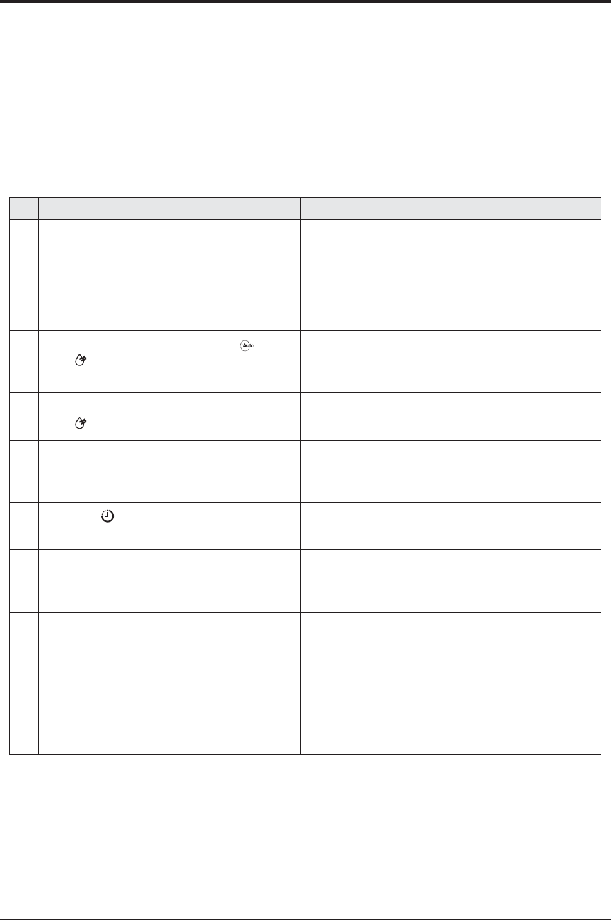
◆ Switch the system on and wait for code " " to appear on the display of
the external unit (this requires approximately 60 seconds **).
◆ As soon as code " "displays, press once the red button (K1) shown on
the gure on the side of the page:
WARNING
If the quantity of indoor units connected is lower than maximum con-
nectable to outdoor unit, the rotary switch SW01 has to be
positioned, in order to select a number equal to indoor units’
quantity you connected.
◆
After the operations described above have been performed, the system starts in Cooling or
Heating mode, depending on the external ambient temperature. After a few minutes (from a
minimum of 3 to 5 minutes for the internal unit), the system stops automatically, completing
the self-test and addressing procedure.
" " appears on the display of the external unit.
◆ 20 seconds after the display of " " (that conrms the correct execution of the
procedure), the following codes (if four internal units are connected) display in sequence on
the display of the external unit:
Display 1 Display 2 Description
The outdoor unit is communication correctly together the in-
door unit connected to refrigerant pipe A.
The outdoor unit is communication correctly together the in-
door unit connected to refrigerant pipe B.
The outdoor unit is communication correctly together the in-
door unit connected to refrigerant pipe C.
The outdoor unit is communication correctly together the in-
door unit connected to refrigerant pipe D.
At this point it is possible to start the internal units in the desired mode
䭭 If " "doesn’t display, the procedure has failed and it is therefore necessary to read ALL
the operator’s manual before repeating the operating described in steps 1-2-3-4.
Display of the external unit
※ During the initial 60 seconds,
display 1 shows in sequence:
00→ 01→02 →...15→ 00...
WARNING
This product is prohibited one indoor unit installation. Don't use pipe checking operation and Auto Addressing Mode when one
indoor unit isinstalled.
Display 1 Display 2
K1 Rotary
Switch
DIP
Switch
AJ020JCJ2CH/AJ024JCJ3CH
AJ036JCJ5CH
4-3-1 Wiring checking function
4-14 Samsung Electronics
Step 1
Review all the following elements in the installation:
◆ Installation site strength
◆ Piping connection tightness to detect any gas leakage
◆ Connection wiring
◆ Heat-resistant insulation of the piping
◆ Drainage
◆ Earthing wire connection
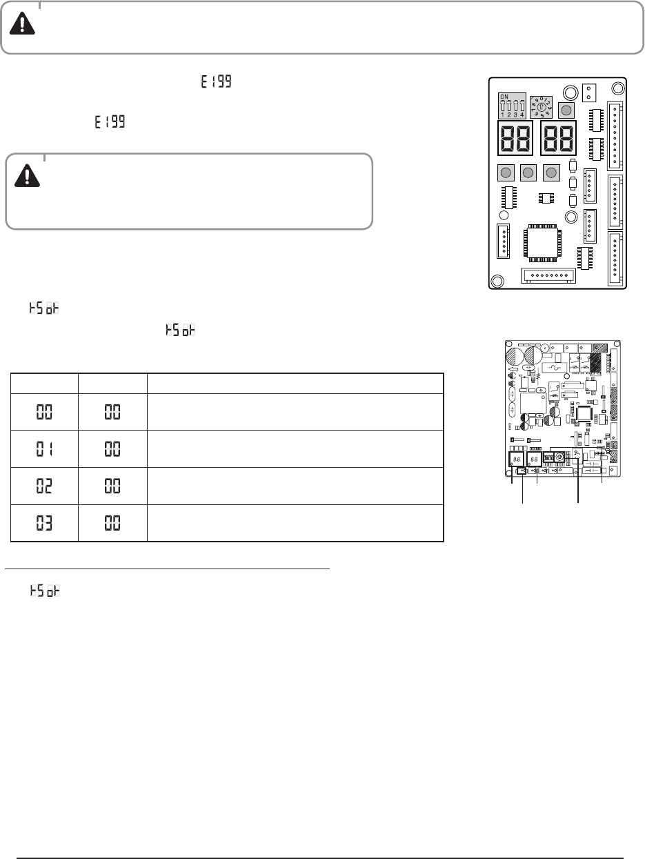
Step 2 IMPORTANT!
Before selecting switch turn off the system power supply
Step 3 Follow of indication reported into table below for indoor unit addressing
Step 4
Turn on the system power supply and waiting for 60 seconds after estabilishing communication
between outdoor and indoor units.
During this phase, the left display of outdoor unit display PCB “DIS01” will count fom 00--01--02 to 15.
Estabilished communication the left display will count sequentially:
00--communication with indoor unit A;
01--communication with indoor unit B;
02--communication with indoor unit C;
03--communication with indoor unit D;
※ In case of Manual address mode,you can do pipe check operation for check whether you connect the pipes correctly or not.
But you need set indoor address switch yourselves.
Switch
Indoor unit
address
Display of the external unit
SW 02
Manual
addressing
Move down the
switch n°1
- Move dipswitch n°1 of “SW02 - outdoor
unit display PCB” down;
Advise control we are going to proceeed with manual addressing as follow:
Display 1 Display 2
K1 Rotary
Switch
DIP
Switch
AJ036JCJ5CH
AJ020JCJ2CH/AJ024JCJ3CH
4-3-2 Without wiring checking function
Samsung Electronics 4-15
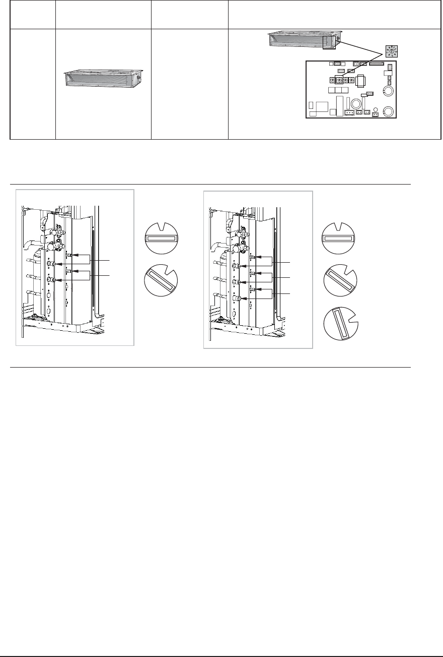
TYPE PICTURE MODEL TO SET ADDRESSING MANUALLY BY
ROTARY SWITCH “SW02”
SLIM DUCT
AJ009JNLDCH
AJ012JNLDCH
AJ018JNLDCH
SW
Same for:
ROTARY SWITCH “SW02” POSITION ACCORDING TO REFRIGERANT CIRCUIT CONNECTED ( 0=A; 1=B; 2=C; 3=D )
OUTDOOR UNIT
A unit
OUTDOOR UNIT
A unit
B unit
C unit
Indoor Unit
SW02
Indoor Unit
SW02
0 0
INSTALLATION TEST MODE (with all indoor units functioning)
Please do cool mode try-run or heat mode try run.
Cool mode try-run : Push the [K2] button three times.
Heat mode try-run : Push the [K2] button once.
After 12 minutes of stationary condition check each indoor unit air treatment:
Cooling mode (indoor unit check) --> Inlet air temp. - Outlet air temp: From 10°K to 12°K ( indicative delta T)
Heating mode (indoor unit check) --> Outlet air temp. - Inlet air temp: From 11°K to 14°K (indicative delta T)
In heating mode, the indoor fan motor can remain o to avoid cold air blown into conditioned space.
Att. "A" Att. "A"
1
1
2
Att. "B" Att. "B"
Att. "C"
B unit
AJ020JCJ2CH AJ024JCJ3CH
4-16 Samsung Electronics
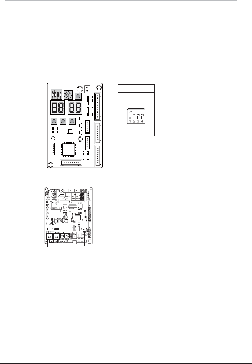
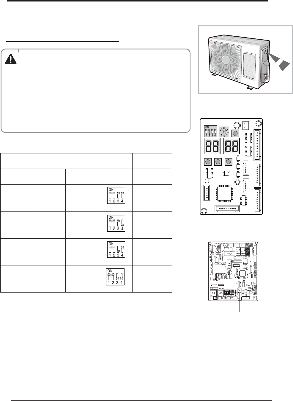
4-4 Checking and Testing operations
Ampere Limit Setting & Changing Procedure
※ The designs and shape are subject to
change according to the model.
Switch
Selection
AJ020JCJ2CH AJ024JCJ3CH AJ036JCJ5CH Switch 3 4
14.0A
(Default)
16.6A
(Default)
23.0A
(Default)
(OFF)
ON ON
13.0A 14.0A 20.0A
(OFF)
ON OFF
10.0A 11.0A 18.0A
(OFF)
OFF ON
8.5A 10.0A 16.0A
(OFF)
OFF OFF
It could take maximum 60 minutes to operate for the protection of the compressor. if the outdoor
temperature is below -5°C.
Display of the external unit
WARNING
◆ Do not adjust the “Ampere Limit Switch”, if it’s not necessary :
before modifying it, evaluate the total number of electric and electronics
loads consumption and use “Ampere limits switch” just as
emergency solution or in case the system is anyway oversized compared to
real thermal load needed.
◆ “Ampere Limit Switch” is initially set to the default value (table below).
◆ “Ampere Limit Switch” is on the PCB of outdoor unit.
◆ Contact the authorized service technician or dealer for setting and changing
the “Ampere Limit Switch”.
◆ Before changing the “Ampere Limit Switch”, turn off the main power of the
system.
Display 1 Display 2
K1 Rotary
Switch
DIP
Switch
AJ036JCJ5CH
AJ020JCJ2CH/AJ024JCJ3CH
Samsung Electronics 4-17
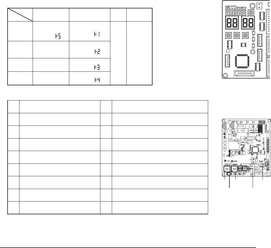
Q Settings of PCB Display of the Outdoor unit
ý Key Options of PCB Display
- K1 : pipe checking operation button - K2 : Function button
- K3 : Reset button - K4 : View mode change button
Key
Push K1 K2 K3 K4
1
Pipe Checking
Operation
(Display: )
Heat Mode Try run
(Display: )
Reset View mode
change
2-
Refrigerant Charging
(Display: )
3-
Cool Mode Try run
(Display: )
4-
Pump down
(Display: )
ý K4 View mode Display changes
To complete the installation, perform the following checks and tests to ensure that the air conditioner is operating
correctly.
1. Review all the following elements in the installation:
t*OTUBMMBUJPOTJUFTUSFOHUI
t1JQJOHDPOOFDUJPOUJHIUOFTTOPUUPMFBLBOZHBT
t$POOFDUJPOXJSJOH
t)FBUSFTJTUBOUJOTVMBUJPOPGUIFQJQJOH
t%SBJOBHF
t&BSUIJOHXJSFDPOOFDUJPO
t4FUUJOHOVNCFSPGUIFJOEPPSVOJUJOTUBMMFE0VUEPPSVOJU48
t4FUUJOH48GPSBEESFTTJOHNPEF"650PS."/6"-
t"EESFTTOVNCFSPOFBDIJOEPPSVOJU.BOVBMBEESFTTJOHNPEF
t$PSSFDUPQFSBUJPOGPSQJQFDIFDLJOHDPOOFDUJPOGPMMPXUIFTUFQCFMPX
t*GUIFBVUPBEESFTTJOHSFGFSUPOFYUQBHF
t*GUIFNBOVBMBEESFTTJOHQMFBTFEPDPPMNPEFUSZSVOPSIFBUNPEFUSZSVOSFGFSUPCFMPX
Push Display Explanation Push Display Explanation
0 Present Compressor Frequency 8 Discharge temperature
1 Target Compressor Frequency 9 OLP temperature
2 Order Compressor Frequency 10 Condenser temperature
3 EEV0 current step 11 Outdoor temperature
4 EEV1 current step 12 Running current
5 EEV2 current step 13 Target Discharge temperature
6 EEV3 current step3 14 Total capacity of the indoor units
7 Fan RPM (H: high, L: low, Blank: o ) 15
Safety Control (just For Service Technician)
ö The EEV 2 and EEV 3 of AJ020JCJ2CHmodel is always displayed as blank
ö The EEV 3 of AJ024JCJ3CHmodel is always displayed as blank
Display of the external unit
※ During the initial 60 seconds,
display 1 shows in sequence:
00→ 01→02 →...15→ 00...
K1
K2 K3 K4
Display 1 Display 2
K1 Rotary
Switch
DIP
Switch
AJ036JCJ5CH
AJ020JCJ2CH/AJ024JCJ3CH
4-18 Samsung Electronics
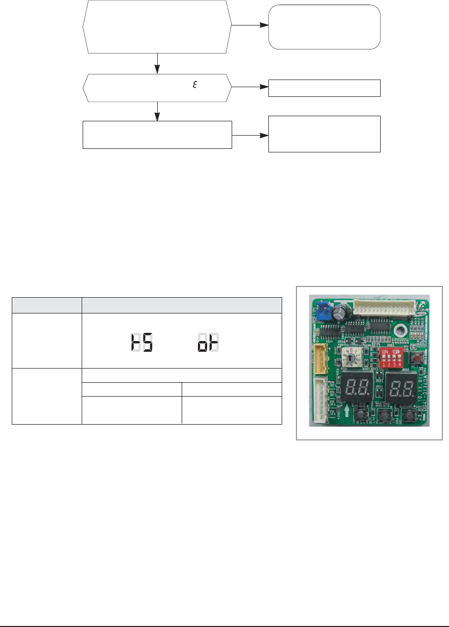
2.
2.
OK : This number is displayed
only while communicating,
so each number is displayed
for a short time in order.
Nothing is displayed on the LED.
Check the power source,
power cable & FUSE on
the outdoor unit.
Yes
No
Yes
No
Does LED show "Normal display"?
"Normal display" means, right 2 digit of
LED on Display PCB displays '00' and
left 2 digit of LED displays indoor unit
address number.
Is error code started with '' ''
displayed on the LED?
Check the indoor unit, outdoor unit or wiring
according the error code table.
[DIS 01 ] is flickering on the setting time.
Outdoor Temperature
Ň% or more less than Ň%
(Cool mode) (Heat mode)
5min~10min 20min~50min
Button [K1] 1 times
DIS 01 DIS 02
Display
Time duration
2. Apply the power to the outdoor unit.
Outdoor unit will try to communicate the number of indoor units specified by SW01 on outdoor display PCB.
Q
Pipe Checking Operation (Auto Addressing Mode)
Automated checking of pipe connection (Auto addressing option)
t5VSOPOUIFPVUEPPSVOJUBOEXBJUGPSPOFNJOVUF
-During these 60 seconds,the left dispaly DIS01 will show sequentially 00-01-02-03-...15-00.
t&JTTIPXFEPOUIFEJTQMBZ1$#PGPVUEPPSVOJU
-It means you didn ’t do “Pipe check operation“
t1VTI<,>CVUUPOPOUIFEJTQMBZ1$#PGPVUEPPSVOJUPODFUIFOCFHJOTUPTUBSUi1JQFDIFDLPQFSBUJPOwXJUI
displaying as below.

Samsung Electronics 4-19
7 Expected time of 4 indoor units installation.
t<%*4>TIPXTUIFJOEPPSVOJUVOEFSTFBSDIJOH
t*UDPVMEUBLFNPSFUJNFEFQFOEJOHPOUIFJOEPPSBOEPVUEPPSUFNQFSBUVSF
t"GUFSDPNQMFUFJOHQJQFDIFDLPQFSBUJPOJUTIPXTiwPOUIFEJTQMBZ1$#
t5IFMFGUEJTQMBZ%*4XJMMTIPXTFRVFOUJBMMZUIFGPMMPXJOHNFTTBHF
00 -Estabilished communication with indoor unit “A”;
01 -Estabilished communication with indoor unit “B”;
02 -Estabilished communication with indoor unit “C”;
03 -Estabilished communication with indoor unit “D”;
00 -Estabilished communication with indoor unit “A”...
t'VODUJPOPGStep 3
Mode Function
Auto Addressing $IFDLJOHUIFDPOOFDUJPOBEESFTTJOH
Manual Addressing Checking the connection only
- If the auto addressing does not work according to the indoor unit capacity, model or installation
condition,apply the manual addressing.
7 When SW01 set "0"on Auto address mode,it means you install the maximum number of indoor unit.
1) Installation ID Unit Number=MAX Installation ID Unit Number of OD Unit.
®Don't need set SW01.
2) Installation ID Unit Number<MAX Installation ID Unit Number of OD Unit.
®Pls set SW01 as the number of which you install the indoor unit.
7 On Manual address mode,you must set SW01 as the number of which you install the indoor unit.
- This mode is for nding the combination between indoor unit and each valve on the outdoor unit. Because refrigerant
ow is controlled with EEV in the outdoor, controller should know which EEV will control which indoor unit.
- Once "PIPE CHECK MODE" is done normally, each indoor unit will remember the given address number by the outdoor
unit and no need to do this checking. But in case of listed below, PIPE CHECK MODE should be done again.
t3FJOTUBMMUIFTZTUFNJFIPVTFNPWJOH
t3FNPWFJOEPPSVOJU"EEOFXJOEPPSVOJU$IBOHFJOEPPS1$#GPSSFQBJS
t.PEFDIBOHFGSPNNBOVBMBEESFTTJOHUPBVUPBEESFTTJOH
- On this mode the controller will ignore the manual address number set on the rotary switch on the indoor PCB.
- To conrm the indoor address number assigned by this mode, use "TESTMODE" and the address number will be
displayed on the LED display on the indoor unit.
4-20 Samsung Electronics
If Error code is displayed on indoor or outdoor LED, check as follows;
- Manaul address setting
Q1
Step 1
Step 2
Contents
Turn on the system. But outdoor units PCB displayed E201 or E101 Error code.
Check point Remarks
Check to Number of indoor unit’s SW01. Outdoor PCB
SW01
Check to power cable to indoor units.
Check to communication cable indoor units. Wire connect
Q2
Guidance
Step 1
Contents
Turn on the system. But outdoor units PCB displayed E203 Error code.
Check point Remarks
Outdoor communication error between the outdoor main
PCB and sub PCB.
Outdoor PCB
SW01
Check to sub PCB wire and replace it. Wire connect
Q3
Error code
E121
E122
E123
E154
Guidance
Contents
Turn on the indoor units. But indoor unit displayed E121/122/123/154 Error code.
Explanation
Indoor unit room temperature sensor error (open/short)
Indoor unit heat exchanger in temperature sensor error (open/short)
Indoor unit heat exchanger out temperature sensor error (open/short)
Indoor unite fan error
Please, all units turn off and check to indoor unit’s PCB and wire connection. E121/122/123 error detected, replace
related sensor.
Q4
Error code
E162
E163
Guidance
Contents
Turn on the system. But indoor unit displayed E162/163 Error code.
Explanation
Indoor unit EEPROM Error.
Indoor unit EEPROM Option Error.
Please, all units turn off and follow guidance.
E163 : Please reset indoor Option code.
E163 : If you don’t know about that, replace indoor unit PCB which is related.
E162 : Please replace indoor unit PCB which is related.
Q5
Error code
E221
E237
E251
E251
E320
Guidance
Contents
Turn on the system. But outdoor unit displayed E221/237/251/320 Error code.
Explanation
Outside temperature sensor error (open/short)
Indoor unit heat exchanger in temperature sensor error (open/short)
Condenser temperature sensor error (open/short)
Compressor Discharge temperature sensor error (open/short)
Compressor OLP sensor error (open/short)
Please, The System turn off and replace sensor which is related.
Samsung Electronics 4-21
- Auto address setting
Q6
Analysis
Step 1
Step 2
Step 3
Guidance
Contents
Indoor units address SW setting correct, but outdoor unit’s PCB displayed E201 Error Code.
Check point Remarks
Indoor unit’s sub PCB address SW or sub PCB is
connected by mistake.
Check to indoor unit’s sub PCB wire connecting
condition.(misconnecting or Sub PCB is out of order)
Indoor
Sub PCB
Address setting mode change to auto address setting.
Following auto address setting steps.
Manual Address setting is Option in FJM PLUS A.
But we solved problem like this situation, with auto address setting.
Q1
Analysis
Step 1
Step 2
Step 3
Guidance
Contents
When the pipe checking operation is finished, outdoor sub PCB display E190 Error code.
Check point Remarks
Outdoor unit fails to search indoor units or to check
indoor address. The pipe checking operation
Whether The gas and liquid pipes are crossed with
each other, check to connecting. Pipe connecting
Check to outdoor unit’s EEV coil being connected in
proper location. EEV Coil
Check to indoor unit’s sensor being connected in
proper location. Indoor sensor
During the pipe checking operation , system check temperature change of indoor Heat exchanger.In case, indoor
sensor defect, EEV coil connector detach, malfunction of EEV, Leakage of Refrigerant, and etc can make this case.
- Address setting another case
Q1
Analysis
Step 1
Step 2
Guidance
Contents
When the system installation is finished, outdoor unit’s PCB display E202 Error code.
Check point Remarks
This problem is caused by outdoor unit’s communication
part trouble or indoor units power and communication
line trouble.
The pipe checking operation
Check to connect outdoor unit and indoor units cable. Pipe connecting
Replace outdoor unit’s ass’y control or indoor unit’s
ass’y control. EEV Coil
Basically, This error caused by communication between Indoor Units and Outdoor Unit.
First of all, check the all communication connection and PCB’s status.
4-22 Samsung Electronics
- Operation Error
Q1
Analysis
Guidance
Contents
While using cooling or heating, indoor units display E161 Error code
Check point Remarks
This problem is caused by user’s fault. User’s simultaneously operate 2 more indoor units in the same time cooling
and heating mode.
FJM is operate by just cooling or heating mode only. (Only, HR system can operate cooling and heating mode
simultaneously in the same time)
Outdoor unit will be operate by first received signal, another operation signal is not applied system.
Q2
Analysis
Step 1
Contents
While using cooling or heating, System turn off and display E416 Error code.
Check point Remarks
E416 is outdoor unit high discharge temperature safety control Error code.
After System restart automatically until 3 times, system stop and display this error.
System can be operated by remote controller signal and K3(reset) key input.
Check outdoor units installation environment.
(air flow blocking, the halation of another outdoor air flow)
Step 2 Check refrigerant leakage.
Step 3 Check outdoor EEV operation.
Q3
Analysis
Step 1
Contents
While using cooling or heating, System Turn off and display E458 Error code
Check point Remarks
E458 Error is related with outdoor unit fan Error.
Especially, If system have a some problem in fan, in heating mode , it will be happened.
And In auto address setting, without pipe checking operation must be happened it.
Check to outdoor fan operation.
Step 2 If outdoor fan operation is clear, start to pipe checking operation.
Guidance
When Auto address setting is finished without pipe checking operation, in heating mode, outdoor unit refrigerant
distribution control is malfunction.
It make our system to confuse it’s condition.
But, basically this error code is concerned about fan error.
Q4
Analysis
Step 1
Contents
While using cooling mode, outdoor unit turn off and display E401 Error code.
Check point Remarks
This is caused by protection mode behavior.
This is indoor Evaporator Freezing protection mode.
Please, check indoor unit, whether inlet or outlet grill is closed.
Step 2 Please, check indoor unit, whether indoor fan is working.
Samsung Electronics 4-23
- Try-run Check Error
Q5
Analysis
Contents
When system start in cooling mode, System don’t operate and display E441 Error code
Check point Remarks
FJM PLUS is able to operate by -10ŇC
But we admit that minimum Cooling temperature is by -5ŇC
Please, Remember cooling operation range.
Q7
Analysis
Contents
When system start in Heating mode, System don’t operate and display E440 Error code.
Check point Remarks
FJM PLUS is able to operate up to 30ŇC
But we admit that Maximum Heating temperature is up to 24ŇC
Please, Remember Heating operation range.
Q1
Analysis
Contents
While the system is working try-run mode, system turn off and display E128 / 129 / 246 / 261 / 419 / 422 / 554
Error code.
Check point Remarks
These Error codes only apply with Try-run mode, in case of system have some defect as result of try-run operation.
Refer to self-detection algorithm (Check Error Code meaning and check it out)
Q6
Analysis
Contents
While using heating, outdoor unit turn off and display E404 Error code.
Check point Remarks
Heating overload safety mode make this situation.
After System restart automatically until 3 times, System display this error code and stop.
System can operate by remote controller input signal or K3(reset) key input.
Step 1 Check indoor units air flow.
Step 2 Check outdoor unit air flow and installation (outdoor air flow blocking & over charging)
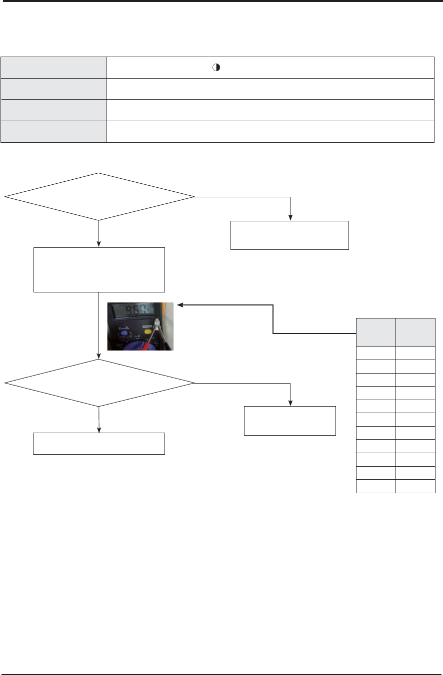
4-24 Samsung Electronics
4-5 Fault Diagnosis by Symptom
4-5-1 Indoor
4-5-1-1 Indoor temperature sensor (open/short)
*OEPPSVOJUEJTQMBZ 90QFSBUJPO 9%FGSPTU
4ZNQUPN
&SSPSPG3PPNTFOTPSJOUIFJOEPPSVOJU0QFO4IPSU
'BJMVSF
4IPSUPSMFBLBHFPGUIF3PPNTFOTPS
:FT
/P
/P
*OUIJTDBTFJTUIFSFTJTUBODF
WBMVFPVUPGSBOHFJOUIFUFNQFSBUVSF
UBCMFPOUIFSJHIU
:FT
*TJOEPPSUFNQFSBUVSF
TFOTPSEJTDPOOFDUFEGSPNUIF
DPOOFDUPSJO1$#
3FTUBSUUIFTZTUFNBGUFSSFQMBDJOHUIF1$#
3FTUBSUUIFTZTUFNBGUFSDPOOFDUJOH
UPUIF1$#DPOOFDUPS
*OEPPSUFNQFSBUVSFTFOTPS
GBJMVSFSFQMBDF
3FNPWFUIFJOEPPSUFNQFSBUVSFTFOTPS
DPOOFDUPSGSPNUIF1$#BOENFBTVSFUIF
SFTJTUBODFCFUXFFOUXPUFSNJOBMT
$VSSFOU
UFNQFSBUVSF
¡$
3FTJTUBODF
LƮ
5FNQFSBUVSFTFOTPS
SFTJTUBODFWBMVF
5JNFS9'BO9'JMUFS
8JSFSFNPUFDPOUSPMMFSEJTQMBZ
&
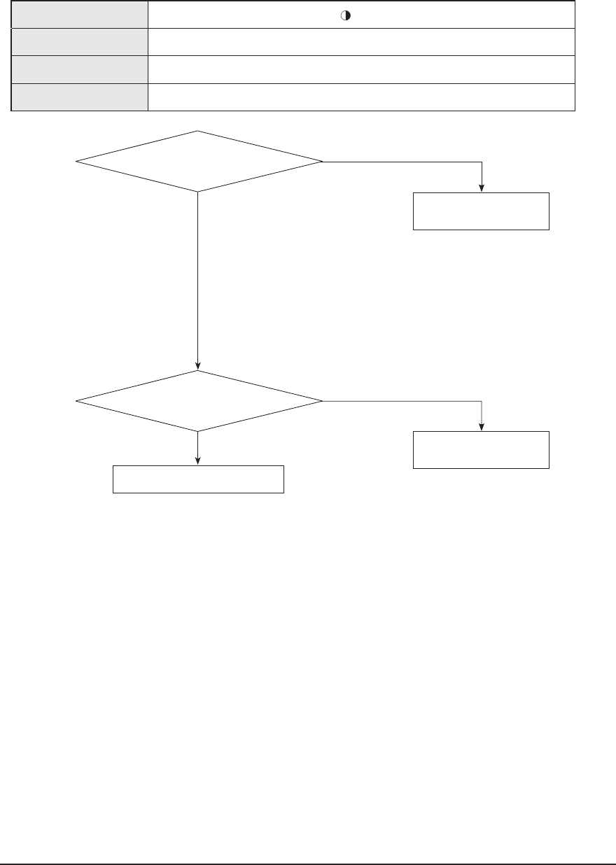
Samsung Electronics 4-25
4-5-1-2 Indoor FAN Error ( BLDC MOTOR MODEL )
:FT
/P
:FT
*TUIFSFGPSFJHOTVCTUBODF
TUVDLJOUIFNPUPSGBO
:FT
*TUIFNPUPSDPOOFDUPS
EJTDPOOFDUFEGSPNUIF1$#
3FQMBDFUIF1$#BOESFTUBSUUIFVOJU
$POOFDUUIFDPOOFDUPSUP
1$#BOESFTUBSUUIFVOJU
3FNPWFUIFGPSFJHOTVCTUBODF
BOESFTUBSUUIFVOJU
*OEPPSVOJUEJTQMBZ
90QFSBUJPO 9%FGSPTU
4ZNQUPN &SSPSPG'BONPUPSJOUIFJOEPPSVOJU
'BJMVSF 'BOTFOTPS
95JNFS
8JSFSFNPUFDPOUSPMMFSEJTQMBZ &
'BO9'JMUFS
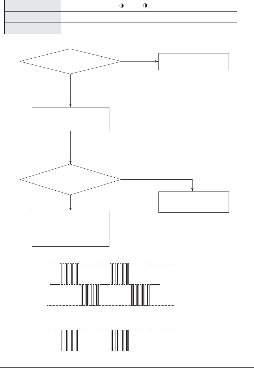
4-26 Samsung Electronics
4-5-1-3 Communication error after finishing Tracking
*OEPPSVOJUEJTQMBZ
4ZNQUPN $PNNVOJDBUJPOFSSPSCFUXFFOUIFJOEPPSBOEPVUEPPSVOJUGPSUXPNJOVUFT
'BJMVSF $PNNVOJDBUJPOFSSPSCFUXFFOUIFJOEPPSVOJUBOEPVUEPPSVOJU
/P
:FT
/P
:FT
*TUIFSFBSFTQPOTFGSPNUIFJOEPPS1$#
-&%3&%JTOPU0/
*OUIJTDBTFJTUIF
WPMUBHFXBWFGPSNCFUXFFOUIFMJOFTTRVBSF
XBWFXJUIBNQMJUVEFPWFS7BTTIPXO
JOUIFGPMMPXJOHQJDUVSF
$IFDLUIFDPNNVOJDBUJPODBCMFBOE
SFQMBDFUIFJOEPPSVOJU1$#
3FNPWFUIFDPNNVOJDBUJPODBCMF
DPOOFDUJOHUIFPVUEPPSVOJUUPJOEPPSVOJU
BOENFBTVSFUIFTJHOBMPO-*/&PGUIF
PVUEPPSVOJUXJUIBTDPQF
3FDPOOFDUUIFDBCMFDPOOFDUJOH
UIFPVUEPPSVOJUUPUIFJOEPPSVOJU
BOESFTUBSUUIFVOJU
*GUIFDPNNVOJDBUJPOTUJMMEPFTOUXPSL
SFQMBDFUIFJOEPPSVOJU1$#
$IFDLUIFDPNNVOJDBUJPO
DBCMFJOUIFPVUEPPSVOJU1$#
BOESFQMBDFUIF1$#
$"4&/PFNBMDPOEJUJPO
7
7
7
065%003594*(/"-
*/%003594*(/"-
065%003594*(/"-
0/-:
$"4&"COPFNBMDPOEJUJPO
7
7
90QFSBUJPO 9%FGSPTU 5JNFS 'BO9'JMUFS
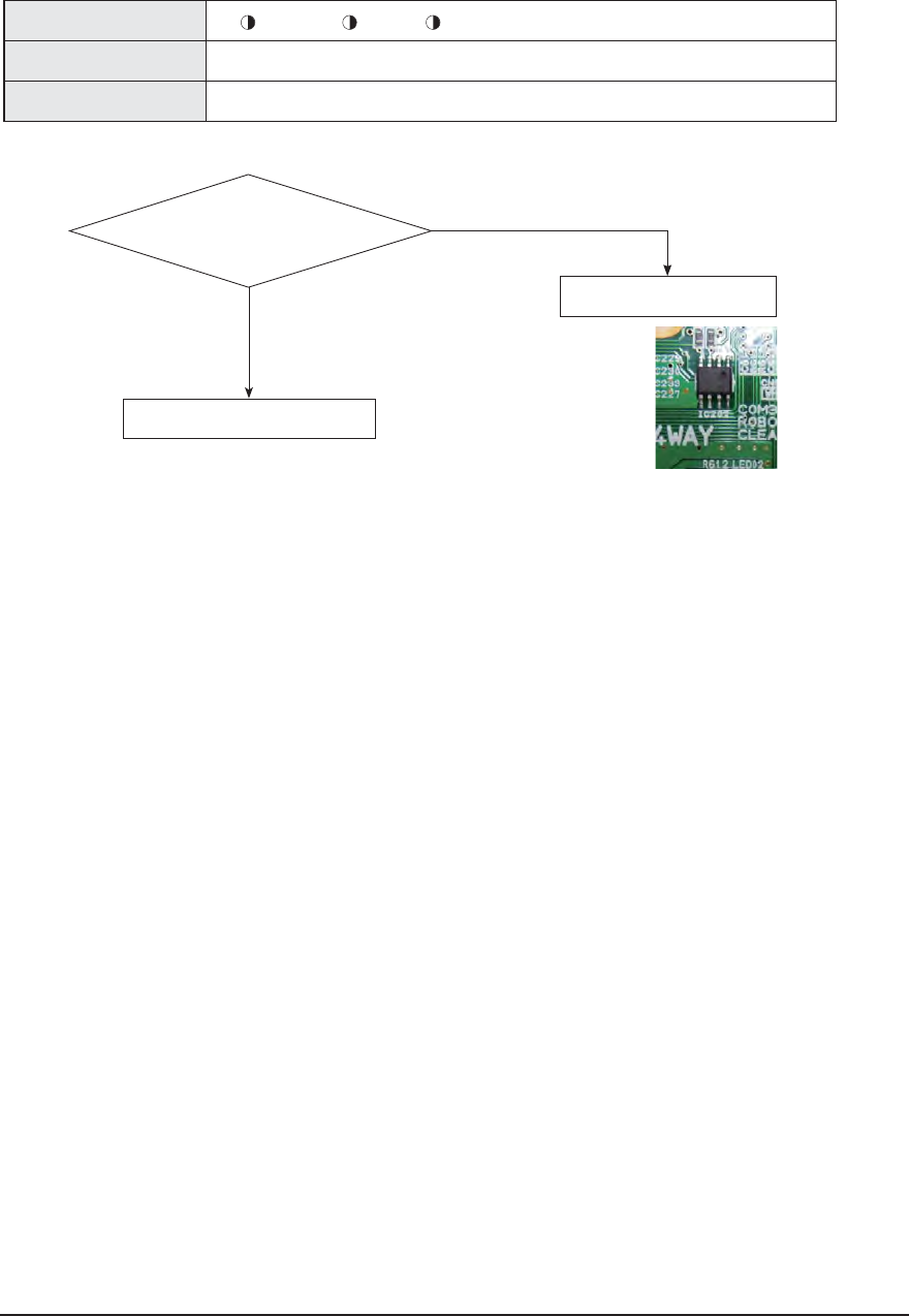
Samsung Electronics 4-27
3FTUBSUUIFVOJUBGUFSSFQMBDJOHUIF1$#
*OEPPSVOJUEJTQMBZ
0QFSBUJPO
%FGSPTU 5JNFS9'JMUFS
4ZNQUPN &&130.DJSDVJUGBJMVSF
'BJMVSF &&130.DPNQPOFOUGBJMVSF&&130.DJSDVJUQBSUTNJTTJOHEBNBHFETPMEFSJOHGBJMVSF
/P
:FT
"SFUIF&&130.DJSDVJU
DPNQPOFOUTJOHPPEDPOEJUJPOT
NJTTJOHDPNQPOFOUTEBNBHF
TPMEFSJOHGBJMVSF
3FQMBDFUIF1$#JGUIFSFTUBSUGBJMT
4-5-1-4 EEPROM circuit failure
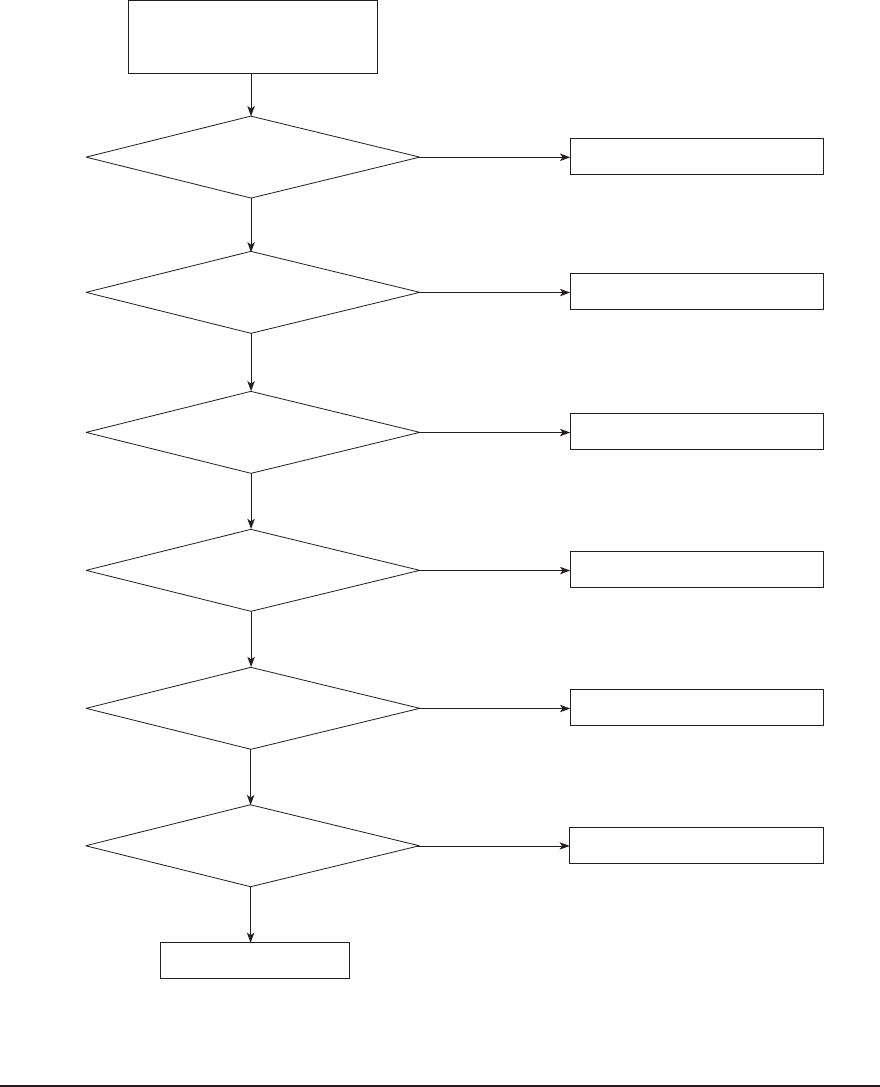
4-28 Samsung Electronics
:FT
Turn off the main power switch
DJSDVJUCSFBLPGQPXFSPVUMFUBOEUVSOPO
BHBJOBGUFSTFDPOET
$IFDLUIFJOQVUQPXFS
/P
*TUIFPVUEPPSVOJUQPXFS
TVQQMZ-/7
:FT
$IFDLUIFDPOOFDUJPOPGUIFUFSNJOBMCMPDL
/P
*TUIFPVUEPPSVOJUQPXFS
WPMUBHF-/7
:FT
3FQMBDFUIFJOWFSUFS1#"
/P
*TUIFWPMUBHFCFUXFFO
UIFUFSNJOBM_BOE_PGUIF
CSJEHFEJPEF7
:FT
3FQMBDFUIFGVTF
/P
*TUIFGVTFDPOOFDUFE
3FQMBDFUIFJOWFSUFS1#"
/P
*TUIFSFTJTUBODFWBMVFPG3Ʈ
:FT
:FT
$POOFDUUIFSFBDUPS
/P
*TUIFSFBDUPSDPOOFDUPS
DPOOFDUFEDPSSFDUMZ
3FQMBDFUIF1#"
4-5-2 Outdoor unit is not powered on – Initial diagnosis(1phase)
1. Check items
1) Is the power supply voltage 220V?
2) Is the AC power connected correctly?
3) Are the LEDs in the main PCB and inverter PCB of the outdoor unit ON?
4) Is the input power voltage of the indoor unit 220V?
5) Is the wired remote controller connected correctly?
2. Check procedure
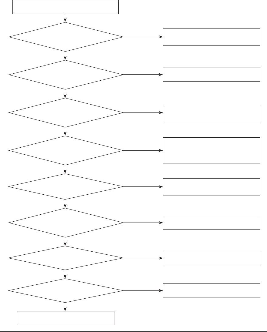
Samsung Electronics 4-29
:FT
:FT
/P
:FT
:FT
:FT
/P
*TUIFGBO$/DPOOFDUFEDPSSFDUMZ
5VSOPõUIFQPXFSBOESFTUBSUUIFVOJU
3FQMBDFUIFJOWFSUFS1$#
/P
*TUIFSFTJTUBODFCFUXFFO
QJOBOEQJOPGUIFGBO$/
PWFS.Ʈ
/P
*TUIFWPMUBHFCFUXFFO
QJOBOEQJOPGUIFGBO$/
PWFS7
/P
*TUIFWPMUBHFCFUXFFO
QJOBOEQJOPGUIFGBO$/
PWFS7
/P
*TUIFGBOSVOOJOHUIFPQFSBUJPONPEF
%PFTUIFWPMUBHFCFUXFFO
QJOBOEQJOPGUIFGBO$/
nVDUVBUF )JHI7_7-PX7_7
/P
*TUIFWPMUBHFCFUXFFO
QJOBOEQJOPGUIFGBO$/
7_7
*TUIFWPMUBHFCFUXFFO
QJOBOEQJOPGUIFGBO$/
EVSJOHUIFPQFSBUJPO7_7
:FT
/P
:FT
:FT
$IFDL$/
3FQMBDFUIFGBONPUPS
$IFDLUIFPVUEPPSVOJUQPXFSTVQQMZFSSPS
3FQMBDFUIFJOWFSUFS1$#
3FQMBDFUIFGBONPUPS
3FQMBDFJOWFSUFS1$#
3FQMBDFUIFGBONPUPS
3FQMBDFUIFJOWFSUFS1$#
4-5-3 Outdoor unit fan error
1. Check items
1) Are the input voltage and power connection correct?
2) Is the motor connecting wire connected to the outdoor unit PCB correctly?
3) Are the indoor/outdoor fuses connected?
4) Are there any obstacles near the motor or propeller?
5) Is the motor driver out of order?
6) AJ020/024 Model check CN901 , AJ036 Model Check CN 90
2. Check procedure
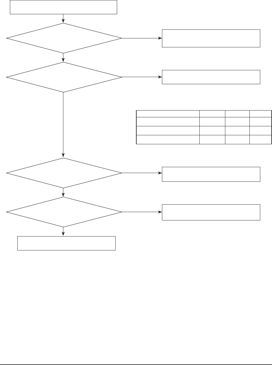
4-30 Samsung Electronics
:FT
:FT
:FT
:FT
/P
*TUIFSFBOFSSPS
5VSOPõUIFQPXFSBOESFTUBSUUIFVOJU
3FQMBDFUIFPVSEPPSVOJUNBJO1$#
/P
*TUIFSFTJTUBODFWBMWF
CFUFXXOUIFQIBTFT677886
CFMPXOPSNBMWBMWF
/P
*TUIFSFTJTUBODFWBMVF
CFUXFFOUIFDPNQSFTTPSCPEZBOEUIFDIBTTJT
JOUIFSBOHFPG.FHBƮ
/P
*TUIFDPNQSFTTPSDPOOFDUJPO
XJSFDPOOFDUFEUPUIFDPNQSFTTPS
DPSSFDUMZ
4FSWJDFFOE
3FQMBDFUIFDPNQSFTTPS
3FQMBDFUIFDPNQSFTTPS
$IFDLUIFDPOOFDUJPOXJSF
4-5-4 Compressor startup error, Compressor Lock error, Compressor rotation error.
1. Check items
1) Are the power supply and compressor connecting wires connected correctly?
2) Is the inter-phase resistance of the compressor normal?
2. Check procedure
Checking Comp Resistance ( Normal value )
U-V V-W W-U
AJ020JCJ2CH 0.5~1.1Ω 0.5~1.1Ω 0.5~1.1Ω
AJ024JCJ3CH 0.2~0.6Ω 0.2~0.6Ω 0.2~0.6Ω
AJ036JCJ5CH 0.1~0.5Ω 0.1~0.5Ω 0.1~0.5Ω
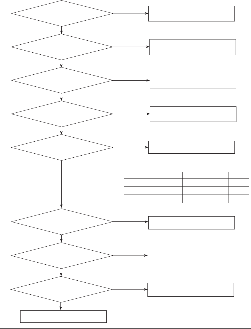
Samsung Electronics 4-31
:FT
:FT
:FT
:FT
/P
*TUIFPVSEPPSVOJUJOTUBMMFEDPSSFDUMZ
3FQMBDFUIF1$#
/P
*TUIFSFTJTUBODFWBMWF
CFUFXXOUIFQIBTFT677886
CFMPXOPSNBMWBMWF
/P
*TUIFSFTJTUBODFWBMVF
CFUXFFOUIFDPNQSFTTPSCPEBZBOEUIFDIBTTJT
JOUIFSBOHFPG.FHBƮ
/P
*TUIFDBCMFCFUXFFOUIFDPNQSFTTPSBOEUIF
1$#DPOOFDUFEDPSSFDUMZ
3FNPWFUIFPCTUBDMFTBOEJOTUBMMUIFVOJUBHBJO
3FQMBDFUIFDPNQSFTTPS
3FQMBDFUIFDPNQSFTTPS
Turn off the power and correct or replace the
temperature sensor location
:FT
*TUIFJOEPPSVOJUJOTUBMMFEDPSSFDUMZ
/P 3FNPWFUIFPCTUBDMFTBOEJOTUBMMUIFVOJUBHBJO
:FT
*TUIFTFSWJDFWBMWFDPNQMFUFMZPQFO /P 0QFOUIFWBMWF
:FT
*TUIFDPNQSFTTPSDPOOFDUJPO
XJSFDPOOFDUFEUPUIFDPNQSFTTPSDPSSFDUMZ
/P $IFDLUIFDPNQSFTTPSDPOOFDUJPOTUBUVT
:FT
"SFUIFUFNQFSBUVSFTFOTPSMPDBUJPOBOEUIF
NFBTVSSFEWBMVFOPNBM
/P
Turn off the power and reconnect the table.
4-5-5 IPM Over Current error
1. Check items
1) Is the coolant changed?
2) Is the compressor running normally?
3) Is the compressor connected correctly?
4) Are there any obstacles near the indoor and outdoor units?
2. Check procedure
U-V V-W W-U
AJ020JCJ2CH 0.5~1.1Ω 0.5~1.1Ω 0.5~1.1Ω
AJ024JCJ3CH 0.2~0.6Ω 0.2~0.6Ω 0.2~0.6Ω
AJ036JCJ5CH 0.1~0.5Ω 0.1~0.5Ω 0.1~0.5Ω
Checking Comp Resistance ( Normal value )
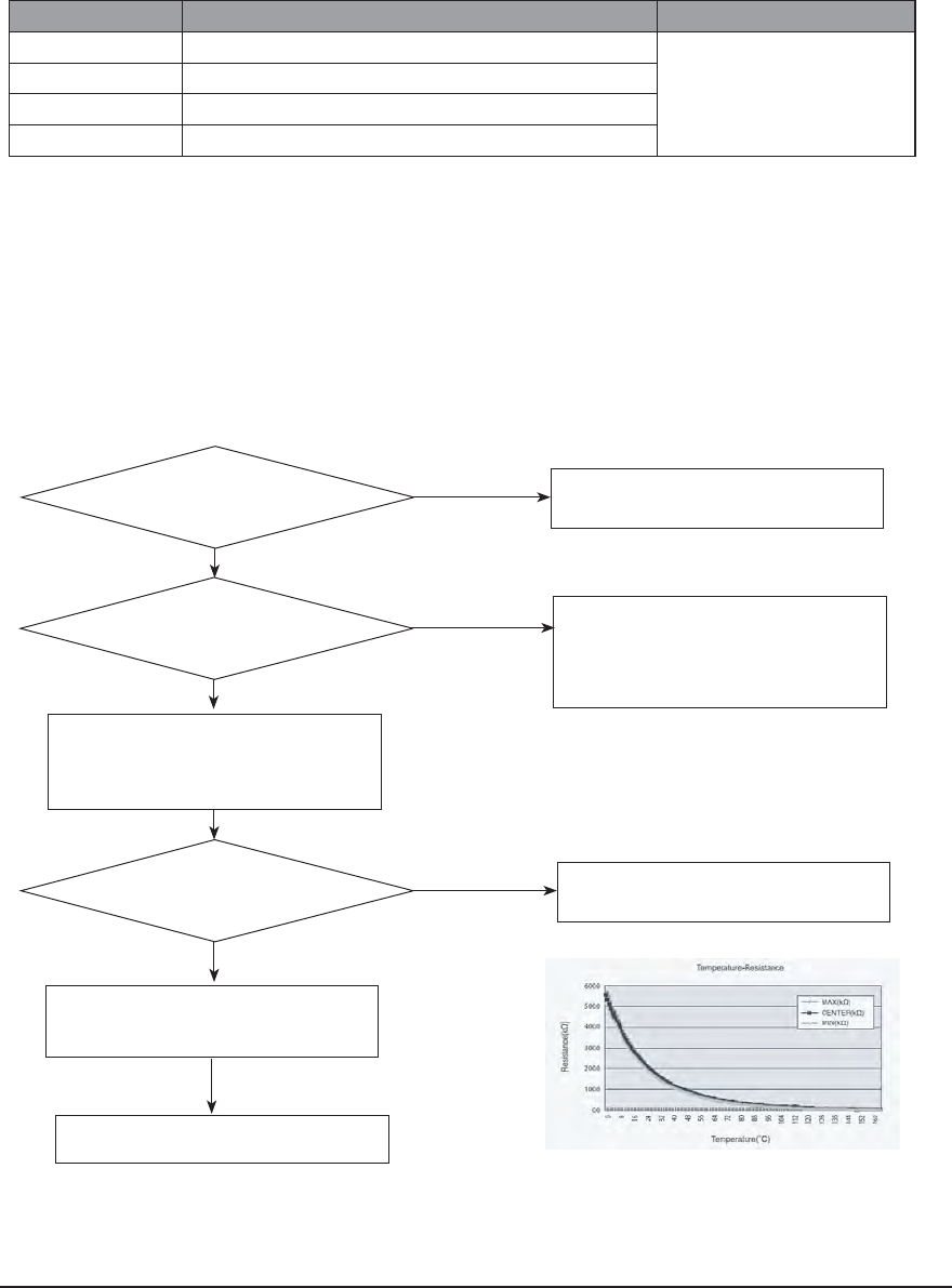
4-32 Samsung Electronics
:FT
:FT
/P
*TUIFTFOTPSDPOOFDUPSDPOOFDUFE
DPSSFDUMZJOBDDPSEBODFXJUIBDPMPS
&YDIBOHFUIF0VUEPPS1#"
.JDPNFSSPSPSDPOOFDUPSDIFDL
3FDPOOFDUUIFTFOTPSDPOOFDUPS
:FT
*TUIFTFOTPSSFTJTUBODFWBMVF
LPINBUUIFSPPNUFNQFSBUVSF
PGȟ
/P 4FOTPS3FQMBDF
4FOTPSSFTJTUBODFWBMVFȟLPIN
ȟPIN
ȟPIN
ȟLPIN
$POOFDUUIFTFOTPSUP1#"DPOOFDUPS
TVQQMZQPXFSBOENFBTVSFUIF
WPMUBHFPGTFOTPSJOUIFDPOOFDUPS
/P
#FMPX7PS0WFS7 :FT &YDIBOHFUIF0VUEPPS1#"
4-5-6 Checking Temperature sensor
In case of a sensor in outdoor unit, temperature can be monitored with "VIEW MODE".
Press K4 key on the outdoor display PCB for several time to change the display to sensor temperature value.
Left 1 digit of the LED is data index and Right 2 digits are the value.
Index
Value Remark
8 Discharge sensor temperature
The unit is degree C
9 OLPsensor temperature
A Condenser sensor temperature
B Outdoor sensor temperature
4-5-6-1 Outdoor Discharge/OLP temperature sensor error
1. Check Items:
1) Is the sensor connected correctly?
2) Is the sensor placed correctly?
3) Does the both terminal of sensor satisfy the resistance value in accordance with temperature?
4) Is the resistance value of sensor connection pull-up correct?
2. Troubleshooting procedure
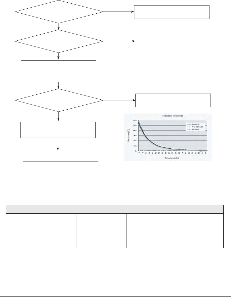
Samsung Electronics 4-33
Yes
Yes
4-5-
6-2 Outdoor out / cond temperature sensor error
1. Check Items:
1) Is the sensor connected correctly?
2) Is the sensor placed correctly?
2. Troubleshooting procedure
No
Is the sensor connector connected
correctly in accordance with a color?
Exchange the Outdoor PBA
Micom error or connector check
Reconnect the sensor connector.
3) Does the both terminal of sensor satisfy the resistance value in accordance with temperature?
4) Is the resistance value of sensor connection pull-up correct?
Yes
Is the sensor resistance value
200kohm±3% at the room temperature
of 25ºс
No Sensor Replace
Sensor resistance value : 20ºс - 12.09kohm
30ºс - 8.31kohm
35ºс - 6.94kohm
40ºс - 5.83kohm
Connect the sensor to PBA connector
supply power and measure the
voltage of sensor in the connector
No
Below 0.5V or Over 4.5V? Yes Exchange the Outdoor PBA
4-5-7 Checking EEV
Current EEV step value can monitored with "VIEW MODE"
Press K4 key on the outdoor display PCB for several time to change the display to current EEV value.
Left 1 digit of the LED is data index and Right 3 digits is the value.
Index Value Remark
3 EEV-A step
4 EEV-B step
5
AJ020JCJ2CH
EEV-C step
The step value range is
between Zero and 480.
AJ024JCJ3CH
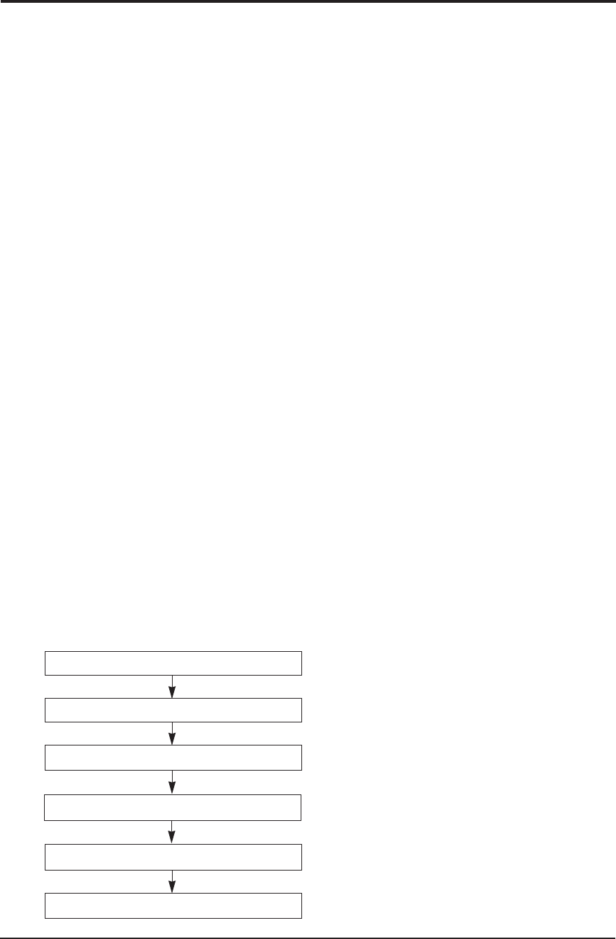
4-34 Samsung Electronics
4-6 PCB Inspection
4-6-2 Procedure
12-4-2
The parts should be replaced in the following procedure.
1. The human body carries much static electricity.
Before touching a part for repair, replacement or the
similar purpose, be sure to touch a grounded metal-
lic portion by hand to let the static electricity go
through the metallic portion to the earth.
Especially when handling any micro computer or IC,
carefully remove such static electricity before touch-
ing them.
2. When repairing any part on a work bench, be sure
to place an insulative sheet on the bench and always
keep the sheet surface neat without any metal frag-
ments. If any such fragment touches a part, a sec-
ondary trouble will possibly be caused in the part.
3. Before replacing any parts, be sure to turn off the
power supply. If such replacement is done with the
power supply kept on, an electric shock, short circuit
or destruction of a part may result.
4. During replacement or repair of a part, carefully han-
dle it : The printed circuit board has fine lead wires
(jumper wires) and glass-made parts (diode) on its
substrate.
So if a circuit board is roughly handled, such lead
wires and parts will be easily broken or damaged by
bending or shock.
5. When soldering the lead wires of any new part, be
sure to polish them using an emery paper or the like
before soldering them.
Since the lead wires of any new part are covered
with an oxide film, solder cannot adhere to the lead
wires if not polished.
6. When soldering any part, care should be exercised
not to apply any high-wattage soldering iron to the
part for a long time. Some parts are of so low a heat
resistance that they may be broken or have the
properties changed if a soldering iron is so applied
(Otherwise, the pattern may possibly be separated
and raised).
7. The heat of the soldering iron should be transferred
to the entire object to be soldered. If the solder
pieces are not well fused due to insufficient transfer
of the heat from the soldering iron, no satisfactory
electrical continuity can be assured even if the sol-
dered objects appear well connected to each other.
8. The solder used should be limited to a minimum.
If excessive solder is used, it will cause inter-pattern
contact, which may cause malfunction of the circuit.
9. Although some part of the PCB surface are coated
with coating material for protection from dust and
dirt, soldering is also available to the coating part.
Because this coating is thin and is weak for solder-
ing heat.
But coating material remaining on the solder part
should be cleaned up before soldering a new
component to prevent the solder part from becoming
bad conduction.
The repair is completed.
Check the operation of the new part.
Replace it with a new part.
Detach the faulty part.
Check for any faulty part.
4-6-1 Cautions for Part Replacement
10. After replacing a faulty PCB by a new one, the same
address setting must be applied to the new PCB.
(refer to the page 4-19 ~ page 4-24)
Set an address.
11. When connected to an outdoor unit manufactured after
June, 2011, a new option code is not needed.
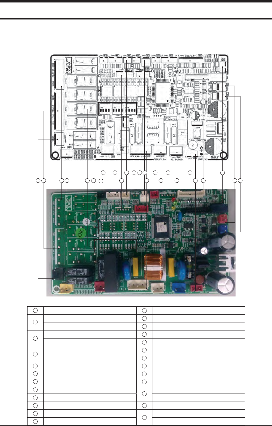
Samsung Electronics 5-1
5. PCB Diagram and Parts list
5-1. Indoor Unit
19 18 15 20 17 16 21 14 22 23 24 25 11
1 2 3 4 9 5 6 7 8 10
12 13
Floating S/W : SMW250-02(BLK)
Wired Remote Controller Communication : YW396-02(BLU)
Indoor Pipe In Temperature Sensor : SMW250-04(WHT) Option Load Connector : SMW250-05(YEL)
Indoor Room Temperature Sensor : SMW250-04(WHT) Heater : YW39607AV(WHT)
Indoor Pipe Out : SMW250-02(WHT) Indoor Address S/W
Temperature Sensor : SMW250-02(WHT) Indoor Option S/W
Heater Discharge : SMW250-02(YEL) Indoor Fan(TAP) : YW396-09AV(WHT)
Temperature Sensor : SMW250-02(YEL) Ventilator : YW396-03AV(BLK)
Wired Remote Controller Power : YW396-02(WHT) Drain Pump : YW396-03AV(YEL)
External Control(S/W Part) : SMW250-02(RED) Hot Coil : YW396-03AV(RED)
EEV : SMW250-05(BLU) : SMW250-05(BLU) Indoor Fan(SSR) : YW396-03AV(RED)
Display : SMW200-11(WHT) : SMW200-11(WHT) Power : YW396-03AV(WHT)
External Control(Display Part) : SMW250-04(RED) Transformer Out : YW396-03AV(WHT)
HALL IC : SMW250-03(BLU) Main Power In : YW396-03AV(BLU)
MICOM Download : SMW200-10(WHT) Power : YW396-03AV(BLU)
Indoor/Outdoor Communication : YW396-02(RED) Transformer In : SMW250-03(RED)
1
2
3
4
5
9
11
12
14
15
16
17
18
19
20
21
22
23
24
25
10
8
7
6
13
Q
AJ009JNLDCH/AJ012JNLDCH/AJ018JNLDCH
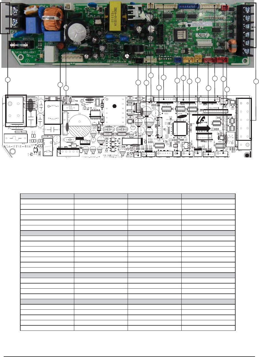
5-2 Samsung Electronics
2
145
3
614
13
8
7
10 11
913
12
15
16
(1) Main power input (2) BLDC fan (3) Earth wire (4) Float switch
1(L):Phase L 1:DC310V 1:GND 1:Float_SW
2(N):Phase N 2:Not used 2:GND
3:AGND
4:DC15V
5:FAN PRM
6:PRM FEEDBACK
(5) Eva in/out sensor (6) Room temperature (7) S/W download (8) Panel display
1:EVA IN temperture sensor 1:Room remperature sensor S/W download 1:DC12V
2,4,6:GND 2:GND 2-5:LED control signal
3:EVA OUT temperture sensor 6:REMOCON signal out
5:EVA discharge 7,8:Not used
9:REMOCON_INT
10:GND
11:Vcc
(9) VENT (10) Panel flaps (11) SPI (12) Drain Pump
1:DC12V 1:DC12V 1,2:GND 1:DC12V
2:VENT_OUT 2-5: Louver control signal 3:SPI CONTROL 2:DRAOM_PUMP_OUT
6:DV12V 4:Not Used
7-10:Louver control signal
(13) Human Sensor (14) External (15) External (16) COM1,COM2,V1,V2
1:DC12V 1,3:DC12V 1:EXT_CTRL F3-F4: Com2
2:Com4_TXD 2:Error_CHK_OUT 2:GND V1-V2:DC12V
3:Com4_RXD 3:Comp_CHK_OUT F1-F2:Com1
4:Human sensor reset
5:GND
QAJ012JNNDCH/AJ018JNNDCH
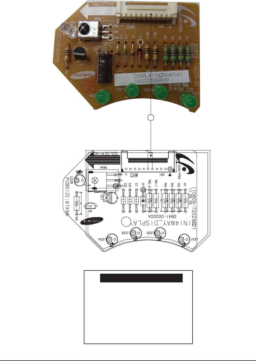
Samsung Electronics 5-3
①
#1 : DC 12V
#2~5 : LED control signal
#6 : Remocon signal out
#7~8 : Not used
#9 : Remocon signal IN
#10: GND
#11: DC 5V
CN01-DISPLAY
1
QPanel PCB
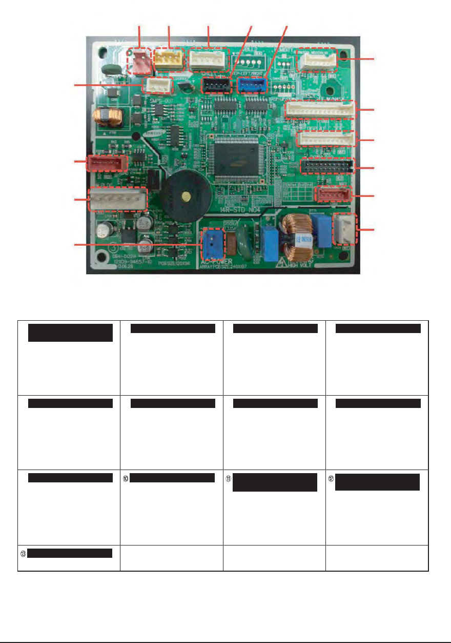
5-4 Samsung Electronics
①
$/$/$/
45&1.0503
%$7
_45&1.05034*(/"-
②
$/108&3*/
"$_7
/$
③
$/41*
41*4*(/"-
%$7
④
$/8*'*.0%6-&
8*'*6"354*(/"-
8*'*6"354*(/"-
8*'*3&4&54*(/"-
(/%
%$7
/$
⑤
$/%*41-":
__.*$0.%08/
/$
⑥
$/5&.1&3"563&4&/403
300.4&/403
&7".*%4&/403
&7"*/4&/403
⑦
$/$0..6/*$"5*0/
$0..4*(/"-
⑧
$/#-%$'"/.0503
%$_7
/$
"(/%
%$7
'"/31.
'"/'&&%#"$,
⑨
$/'+./"4"
__'+./"4"4*(/"-
%$7
(/%
%$7
$/4.14108&3*/
"$_7
/$
$/4.14%$065
7(/%7
%$7
(/%
%$7
$/4.14%$065
7(/%7
%$7_7
/$
%$7_7
"(/%
$/%08/-0"%
%08/-0"%
$/ $/$/ $/$/
$/
$/
$/
$/
$/
$/
$/
$/
$/
$/
Q
AJ007JNADCH/AJ009JNADCH/AJ012JNADCH/AJ018JNADCH/AJ024JNADCH
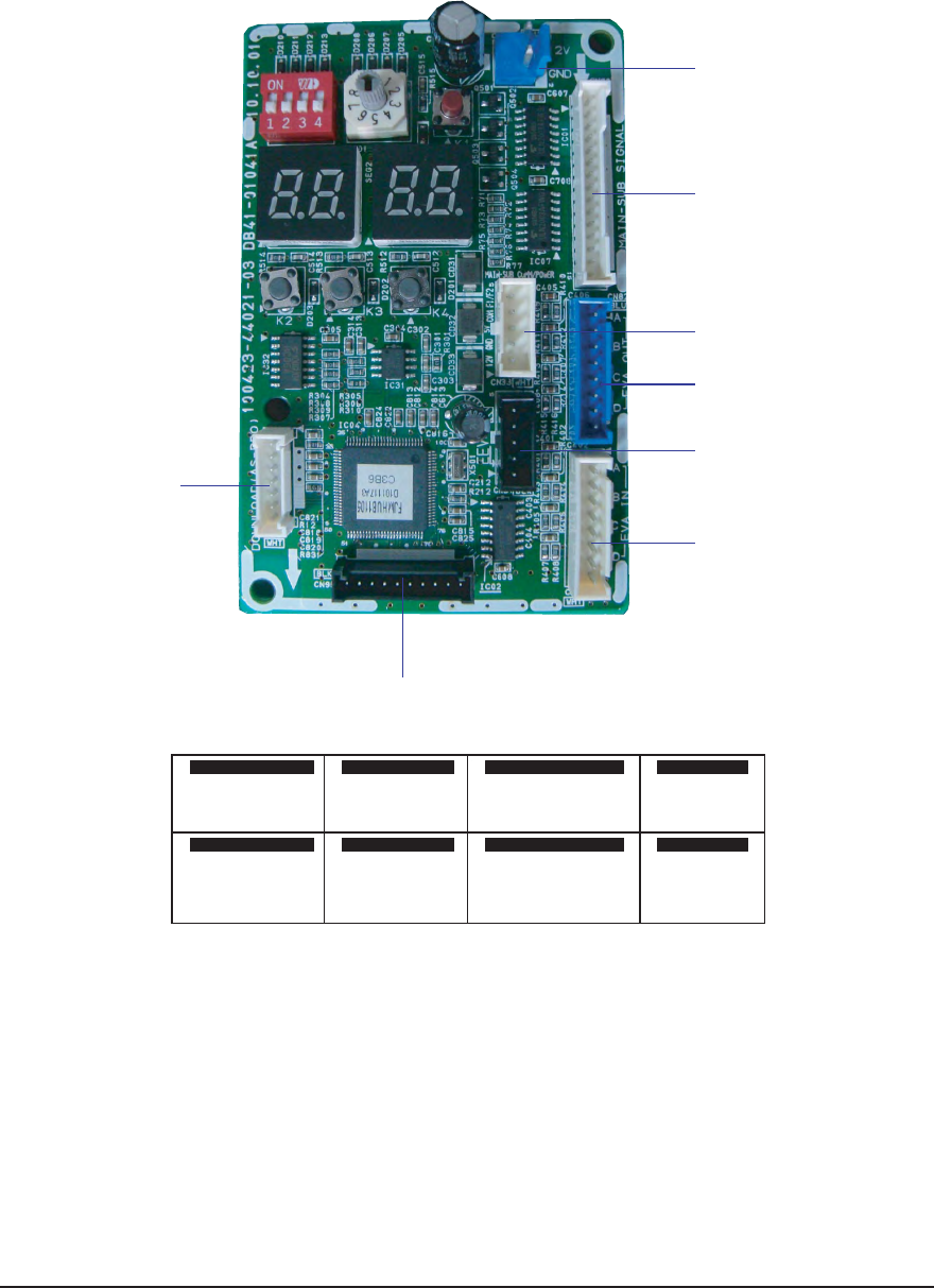
Samsung Electronics 5-5
5-2. Outdoor Unit
Q AJ020JCJ2CH/AJ024JCJ3CH
1
2
3
4
5
6
7
8
#.-)#/-$/7. #.%6!).3 %.3/2 # . !3 0 2 /- # .%% 6$
^-)#/-$/7. ^%6!).! ^-)#/-$/7. ^%% 6SIGNAL
^% 6!)." !302/53).' $#6
^% 6!).#
^% 6!).$
#.%6 !/543 % .3 /2 #.-!).(5" #.$ISPLAY #.$# 6
^% 6 !/54! 6 ^3 EGMENT^ $#6
^% 6!/54" '.$ ^+EYIN^ '.$
^% 6!/54# 6 ^'RID^
^% 6!/54$ #/-
#/-
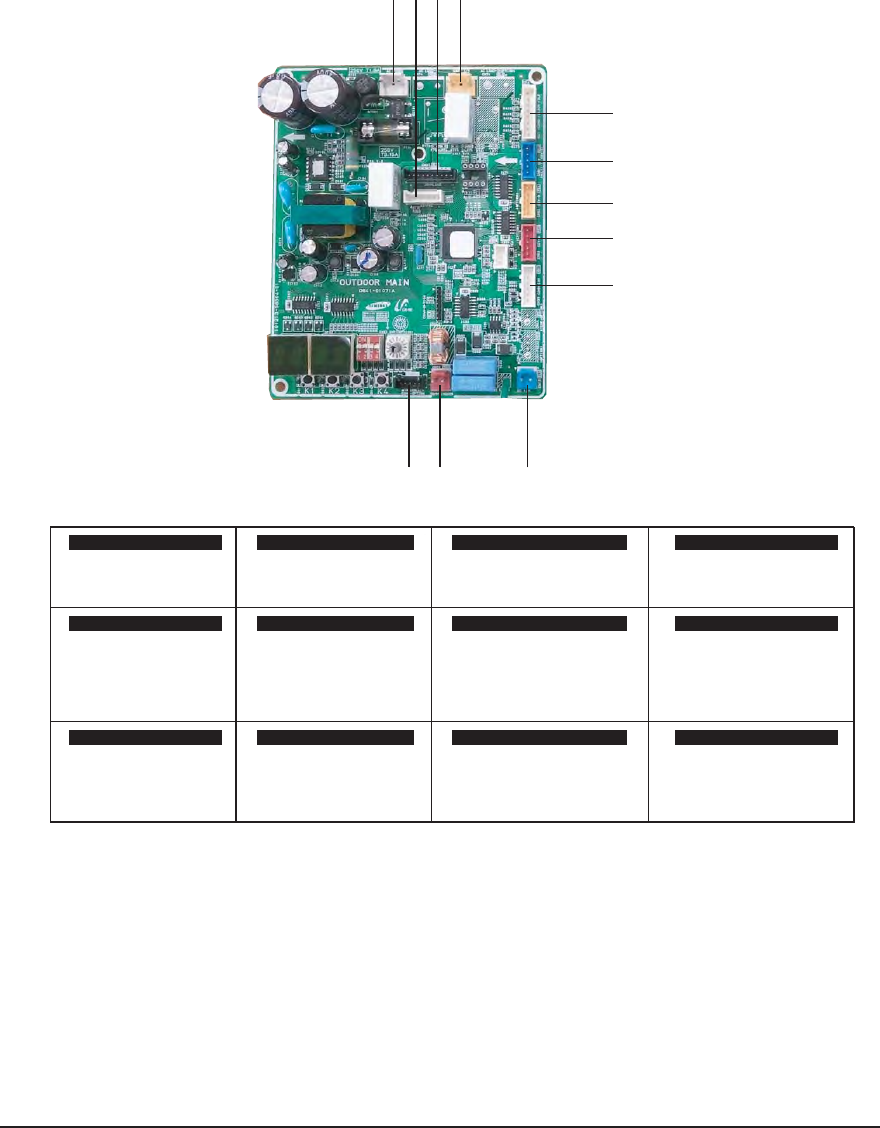
5-6 Samsung Electronics
Q AJ036JCJ5CH MAIN PCB
1211 12
3
4
5
6
7
8910
12 3 4
#1~#3 : 220~240 Vac #1~#3 : 220~240 Vac #1~#2 Outdoor Temp #1~#4 EEV signal
#3~#4 Cond Temp #5 DC 12V
#5~#6 Discharge Temp
#7~#8 OLP Temp
56 7 8
#1~#4 EEV signal #1~#4 EEV signal #1 TXD #1 DC12V
#5 DC 12V #5 DC 12V #2 RXD #2 GND
#3 GND
#4 DC 5V
#5 DC 12V
#6 INV. SMPS signal
9CN31 - COMM 10 CN33-Sub Comm 11 12
#1 : COM1 #1 DC12V #1~#10 MICOM DOWN #1~#7 MICOM DOWN
#2 : COM2 #2 GND (AS PRO USING)
#3 DC5V
#4 COM1
#5 COM2
CN11-ACPOWER CN75-4WAY V/V CN43-Sensor CN81-EEV C
CN82-EEV B CN81-EEV A CN39-COMM-INV CN12 - DC12V
CN35- AS PROMCN37-MICOM DOWN
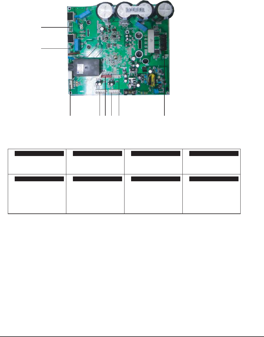
Samsung Electronics 5-7
2
1
36475 8
①
3FBDUPS"8)5
3FBDUPS#8)5
②
3FBDUPS"#-,
3FBDUPS##-,
③
39%59%
(/%%$7
%$7*/74.14TJHOBM
④
39%@"5"3059%@"5"30
/$_%"5"TJHOBM
(/%%$7
⑤
'PS48FOHJOFFSEFCVHHJOH
⑥
%$7
/$
(/%
%$7
'"/31.
'"/31.GFFECBDL
⑦
%$7
/$
(/%
%$7
'"/31.
'"/31.GFFECBDL
⑧
$0.16QIBTF3&%
$0.17QIBTF#-6
$0.16QIBTF:&-
3FBDUPS"# 3FBDUPS"#
$/1*/3&%$PNNVOJDBUJPO
$/%PXOMPBEFS
$/%"$&/$0%&3
$/'"/
$/'"/ $/$0.1
Q AJ036JCJ5CH INVERTER PCB
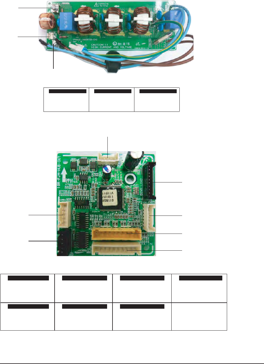
5-8 Samsung Electronics
2
3
1
1
2
3
4
5
6
7
12 3 4
#1 DC12V #1~#10 MICOM DOWN #1~#7 MICOM DOWN #1~#2 EVA IN A
#2 GND (AS PRO USING) #3~#4 EVA IN B
#3 DC5V #5~#6 EVA IN C
#4 COM1 #7~#8 EVA IN D
#5 COM2 #9~#10 EVA IN E
56 7
#1~#2 EVA OUT A #1~#4 EEV signal #1~#4 EEV signal
#3~#4 EVA OUT B #5 DC 12V #5 DC 12V
#5~#6 EVA OUT C
#7~#8 EVA OUT D
#9~#10 EVA OUT E
CN33-Sub Comm CN10-MICOM DOWN CN10- AS PROM CN52 EVA IN SENSOR
CN52 EVA OUT SENSOR CN83-EEV D CN84-EEV E
①
-#3/
②
/4,:#-6
③
"$_7
-"$108&3-QIBTF /"$108&3/QIBTF $/"$108&3
Q AJ036JCJ5CH EMI PCB
Q AJ036JCJ5CH HUB PCB
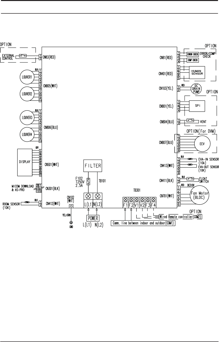
Samsung Electronics 6-1
6. Wiring Diagram
6-1. INDOOR UNIT
QAJ009JNNDCH/AJ012JNNDCH/AJ018JNNDCH
This Document can not be used without Samsung's authorization.
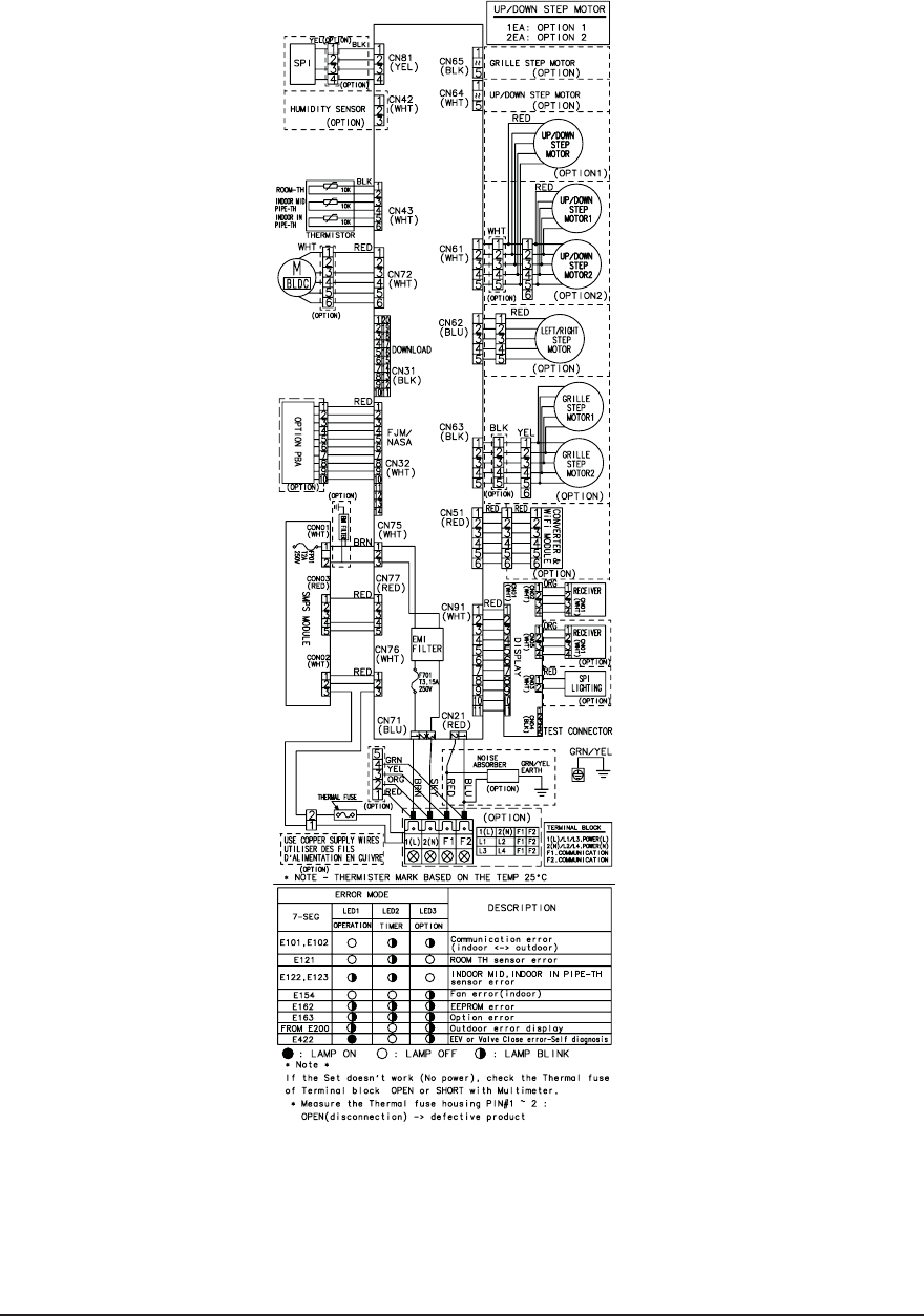
6-2 Samsung Electronics
QAJ007JNADCH/AJ009JNADCH/AJ012JNADCH/AJ018JNADCH/AJ024JNADCH
This Document can not be used without Samsung's authorization.
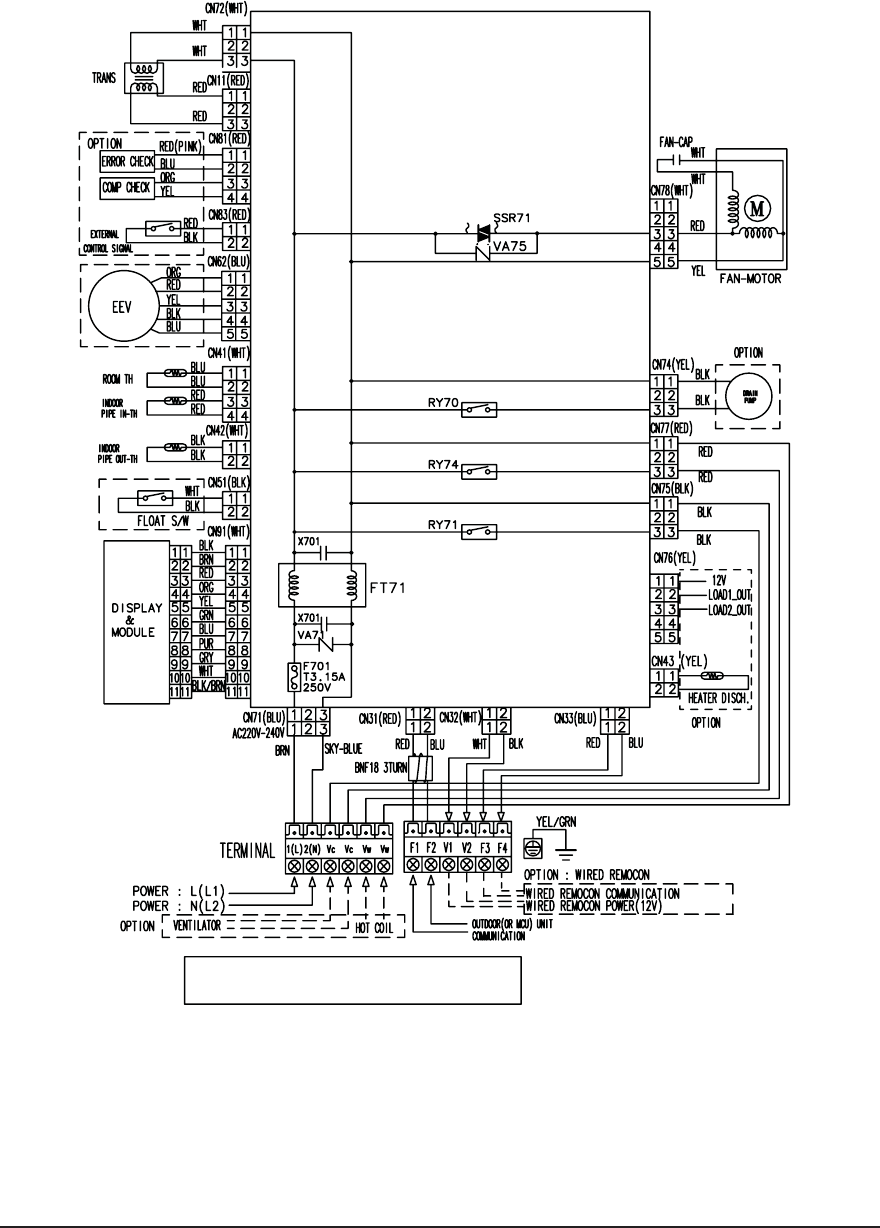
Samsung Electronics 6-3
QAJ009JNLDCH/AJ012JNLDCH/AJ018JNLDCH
This Document can not be used without Samsung's authorization.
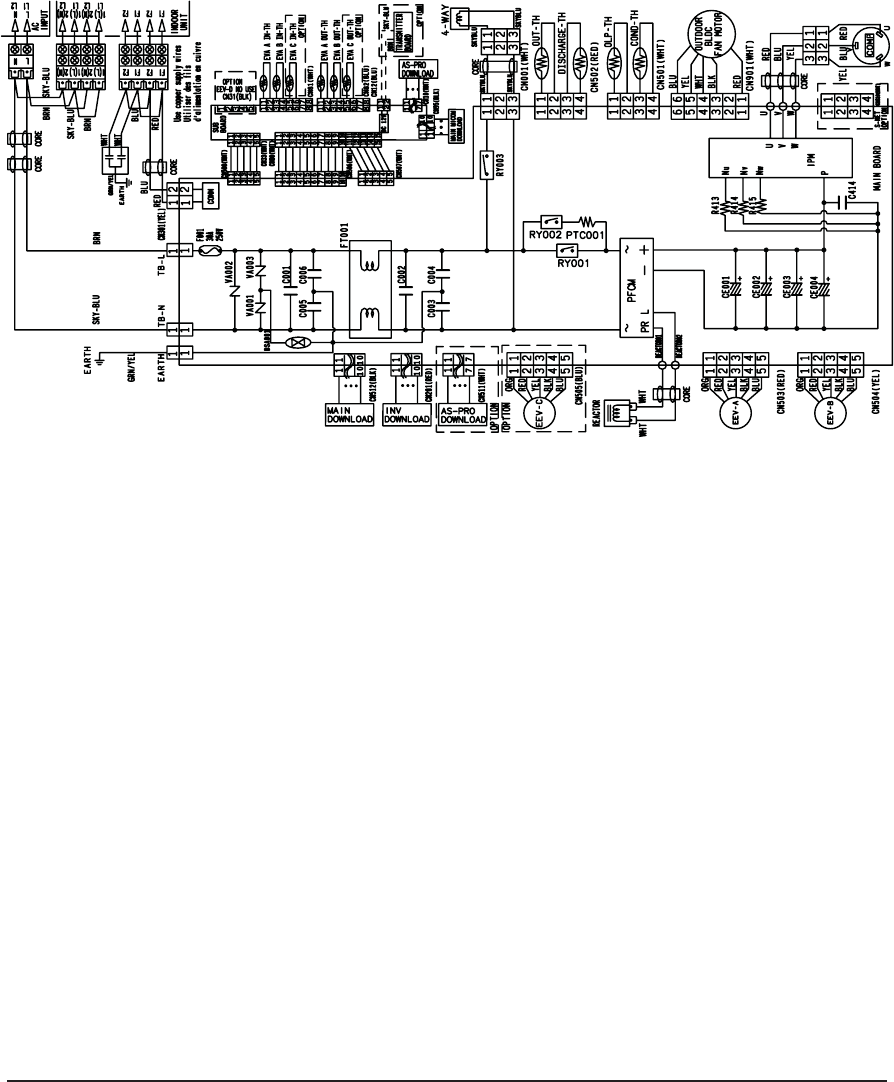
6-4 Samsung Electronics
6-2. OUTDOOR UNIT
QAJ020JCJ2CH/AJ024JCJ3CH
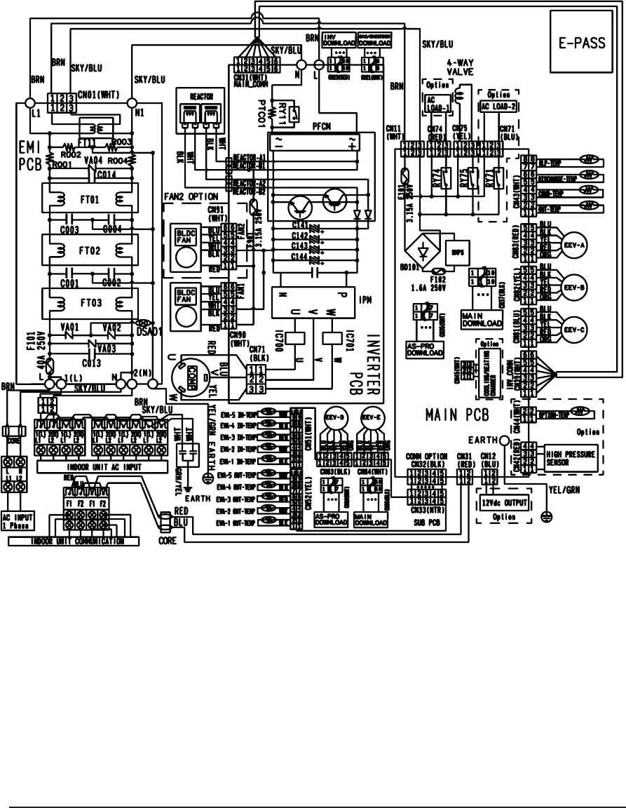
Samsung Electronics 6-5
QAJ036JCJ5CH

6-6 Samsung Electronics
MEMO
Samsung Electronics 7-1
7. Reference Sheet
7-1 Selecting Area for Installtaion
1 Make sure that you install the indoor unit in an area providing good ventilation.
It must not be blocked by an obstacle affecting the airflow near the air inlet and the air outlet.
2 Make sure that you install the indoor unit in an area allowing good air handling and endurance of vibration of the indoor
unit.
3 Make sure that you install the indoor unit in an area where there is no source of heat or vapor nearby.
4 Make sure that you install the indoor unit in an area from which hot or cool air is spread evenly in a room.
5 Make sure that you install the indoor unit in an area away from TVs, audio units, cordless phones, fluorescent lighting
fixtures and other electrical appliances (at least 1 meter).
6 Make sure that you install the indoor unit in an area which provides easy pipe connection with the outdoor unit, and
easy drainage for condensed water.
7 Make sure that you install the indoor unit in an area which is large enough to accommodate the measurements shown
in figure on the next page.
Select an area for installation that is suitable to customer's needs.
7-1-1 Indoor Unit
It is harmful to the air conditioner if it is used in the following environments: greasy areas (including areas
near machines), salty areas such as coast areas,areas where sulfuric gas is present such as hot spring areas.
Contact your dealer for advice.
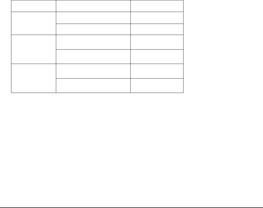
7-2 Samsung Electronics
1 Make sure that you install the outdoor unit in area not exposed to the rain or direct sun light.(Install a separate sunblind
if exposed to direct sun light.)
2 Make sure that you install the outdoor unit in area allowing the good air moment, not amplifying noise or vibration,
especialy to avoid disturbing neighbors. (Fix the unit firmly if it is mounted in a high place.)
3 Make sure that you install the outdoor unit in area providing the good ventilation and which is not dusty. It must not be
blocked by any obstacle affecting the airflow near the air inlet and the air outlet.
4 Make sure that you install the outdoor unit in area free from animals or plants.
5 Make sure that you install the outdoor unit in area not blocking the traffic.
6 Make sure that you install the outdoor unit in area easy to drain condensed water from the indoor unit.
7 Make sure that you install the outdoor unit in area which provides easy connection within the maximum allowable
length of a coolant pipe.
If you install within 50m, no add a additional refrigerent : This model is chargeless within 50m.
8 Make sure that you install the outdoor unit in an area which is large enough to accommodate the measurements
shown in figure on the next page.
If you install the excessive length of pipe, add additional refrigerant as 20g or 10g per unit meter; refer to the table
below.
7-1-2 Outoor Unit
7-1-3 Remote Control Unit
1 Make sure that you use the remote control unit in an area free from obstacles such as curtains etc, which may block
signals from the remote control unit.
2 Make sure that you put the remote control unit in an area not exposed to direct sunlight, and where there is no source of
heat.
3 Make sure that you use the remote control unit in an area away from TVs, audio units, cordless phones, fluorescent
lighting fixtures and other electrical appliances (at least 1 meter).
Model Total connecting pipe length (L) Adding refrigerant
AJ020JCJ2CH LT≤30m Chargeless
LT>30m (LT- 30m)x10g
AJ024JCJ3CH
LT≤40m Chargeless
LT>40m (LT- 40m)x10g
AJ036JCJ5CH
LT≤40m Chargeless
LT>40m (LT- 40m)x20g
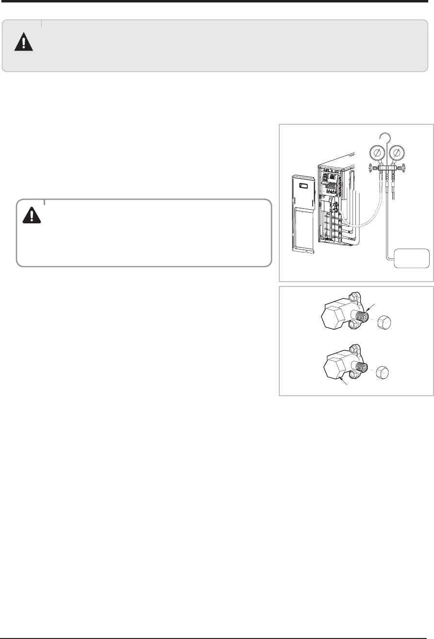
Samsung Electronics 7-3
7-2 Connecting Up and Purging the Circuit
The air in the indoor unit and in the pipe must be purged. If air remains in the refrigeration pipes, it will affect
the compressor, reduce to cooling capacity and could lead to a malfunction. Refrigerant for air purging is not
charged in the outdoor unit. Use Vacuum Pump as shown at the right figure. Each unit must be purged in turn.
A
B
C
1 Check the piping connections.
2 Connect the charging hose of low pressure side of manifold
gauge to the packed valve having a service port (5/8” Packed
valve) as shown at the figure (Value stem: 1/2” - 20UNF).
3 Open the valve of the low pressure side of manifold gauge
counter clockwise.
4 Purge the air from the system using vacuum pump for about
30 minutes.
- Close the valve of the low pressure side of manifold gauge
clockwise.
- Make sure that pressure gauge show -0.1MPa(-76cmHg) after
about30 minutes.
This procedure is very important in order to avoid gas leak.
- Turn off the vacuum pump.
- Remove the hose of the low pressure side of manifold gauge.
5 Set valve cork of both liquid side and gas side of packed valve
to the open position.
6 Mount the valve stem nuts and the service port cap to the
WBMWFBOEUJHIUFOUIFNBUUIFUPSRVFPGLHGtDNXJUIB
torque wrench.
7 Check for gas leakage.
- At this time, especially check for gas leakage from the 3-way
valve’s stem nuts, and from the service port cap.
Stem cap
Service port
WARNING
ý
Make the electrical connection and leave the system
into “stand by mode”. Do not turn on the system! This is
necessary for better vacuum operation (full OPEN position
of Electronic Expansion Valve - EEV -).
Vacuum
Pump
Valve stem
Q
AJ020JCJ2CH/AJ024JCJ3CH/AJ036JCJ5CH
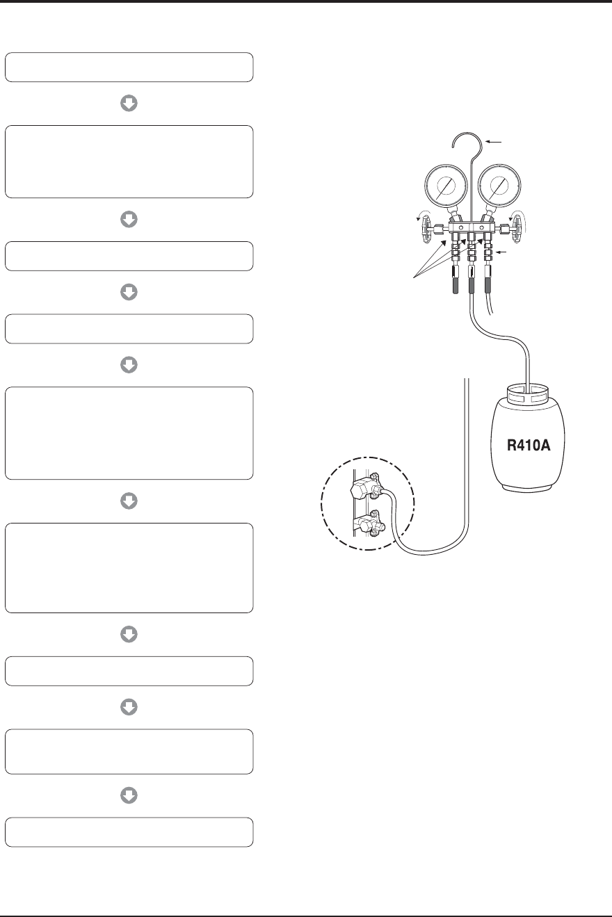
7-4 Samsung Electronics
7-3 Refrigerant Refill
Refill an air conditioner with refrigerant when refrigerant has been leaked at installing or using.
1) Purge air(for new installation only).
3) Connect the tank to refill with refrigerant.
4) Set the unit to cool operation mode.
7) Stop operation of the air conditioner.
9) Close the cap of each valve.
2) Turn the 3 way valve clockwise to close,
connect the pressure gauge (low pressure side)
to the service valve, and open the 3 way valve
again.
5) Check the pressure indicated by the pressure
gauge(low pressure side).
* Standard pressure should be 8.0~9.0kg/cm
2
in a regular and high operation mode.
6) Open the refrigerant tank and fill with refrigerant
until the rated pressure is reached.
* It is recommended not to pour the refrigerant
in too quickly, but gradually while operating a
pressure valve.
8) Close the 3 way valve, disconnect the pressure
gauge, and open the 3 way valve again.
Suspension hook
High
pressure
gauge
Hand
wheel
Finger tight
fittings
Connected to
high pressure
side
Charging line
For mounting
other and of
hose when
not in use
Compound
gauge
AJ020JCJ2CH
AJ024JCJ3CH
AJ036JCJ5CH
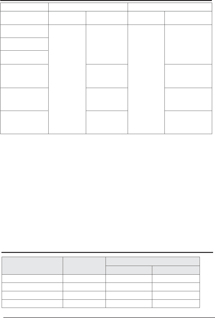
Samsung Electronics 7-5
7-4 Refrigerant Adjustment
7-5 Flare Nut Fixing Torque
Class At installation At service
Connection Pipe Length Air-Purge Method Refrigerant
Adjustment Air-Purge Method Refrigerant Quantity
Standard 30m
(AJ020JCJ2CH)
Refer to the detailed
conneting up and
purging the circuit.
(7-2 page)
Unnecessary
Purge air using a
vaccume pump
or an additional
refrigerant cylinder.
refer to specification sheet
Standard 40m
(AJ024JCJ3CH)
Standard 40m
(AJ036JCJ5CH)
Standard<Total≤50m
(AJ020JCJ2CH)
In case of exeeding total
pipe lengh 30m,
Add "10g" of refrigerant
(R410A) for every 1m
In case of exeeding total
pipe lengh 30m,
Add "10g" of refrigerant
(R410A) for every 1m
Standard<Total≤70m
(AJ024JCJ3CH)
In case of exeeding total
pipe lengh 40m,
Add "10g" of refrigerant
(R410A) for every 1m
In case of exeeding total
pipe lengh 40m,
Add "10g" of refrigerant
(R410A) for every 1m
Standard<Total≤80m
(AJ036JCJ5CH)
In case of exeeding total
pipe lengh 40m,
Add "20g" of refrigerant
(R410A) for every 1m
In case of exeeding total
pipe lengh 40m,
Add "20g" of refrigerant
(R410A) for every 1m
It would be the best choice to use the standard tube length to keep the basic quality of Room Air conditioner,
for example cooling capacity, sound level, vibration level, and reliability.
But, according to a certain different installation condition, the connection tube length could be changed in the
recommendation length that is shown above.
In this case, installer should keep the installation condition to keep the quality of Room Air conditioner.
O Refrigerant should be charged additionally as written above according to the change of the length of the
connection tube.
It needs to affect the decrease in cooling and heating capacity or of the reliability of compressor that may be
caused by a lac k of refriger ant.
O Installation position difference between the indoor unit and the outdoor unit should not exceed over than 15
meters.
OWhen the connection pipe is been extended longer than 5 meters, it might need to change the diameter
of the electrical wire to a larger size in order to keep a voltage drop for starting room air conditioner is not less
than 85% of the rated voltage. And then, a voltage meter will be useful to check the rate of the voltage drop.
Outer Diameter (D) Thickness Torque
N·m ft·lb(kgf·cm)
ø6.35 mm(1/4") 0.8 mm(0.03 ") 14~18 10.1~13.0(140~180)
ø9.52 mm(3/8") 0.8 mm(0.03 ") 34~42 25.3~31.1(350~430)
ø12.70 mm(1/2") 0.8 mm(0.03 ") 49~61 36.2~44.8(500~620)
ø15.88 mm(5/8") 0.8 mm(0.03 ") 68~82 49.9~60.0(690~830)
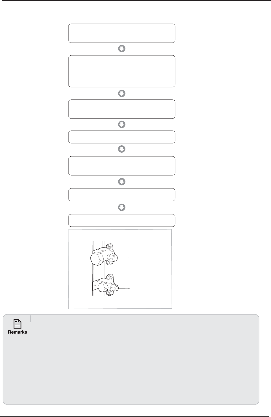
7-6 Samsung Electronics
7-6 "Pump down" Procedure
Pump down will be carried out when an evaporator is replaced or when the unit is relocated in another area.
Relocation of the air conditioner
Ŗ Refer to this procedure when the unit is relocated.
Ŗ1. Carry out the pump down procedure (refer to the details of ‘ pump down ’ ).
Ŗ2. Remove the power cord.
Ŗ3. Disconnect the assembly cable from the indoor and outdoor units.
Ŗ4. Remove the flare nut connecting the indoor unit and the pipe.
Ŗ 4. At this time, cover the pipe of the indoor unit and the other pipe using a cap or vinyl plug to avoid foreign
material entering.
Ŗ5. Disconnect the pipe connected to the outdoor unit.
Ŗ 4. At this time, cover the valve of the outdoor unit and the other pipe using a cap or vinyl plug to avoid foreign
material entering.
Ŗ6. Make sure you do not bend the connection pipes in the middle and store together with the cables.
Ŗ7. Move the indoor and outdoor units to a new location.
Ŗ8. Remove the mounting plate for the indoor unit and move it to a new location.
5/8" Service Valve
3/8" Service Valve
AJ020JCJ2CH/AJ024JCJ3CH/AJ036JCJ5CH
1) Remove the caps from the 3/8" service valve and
the 5/8" service valve.
3) Set the unit to cool operation mode.
(Check if the compressor is operating.)
4) Turn the 3/8" service valve clockwise to close.
7) Close the cap of each valve.
2) Turn the 5/8" service valve clockwise to close and
connect a pressure gauge (low pressure side)
to the service valve, and open the 5/8" service valve
again.
5) When the pressure gauge indicates "0" turn the
5/8" service valve clockwise to close.
6) Stop operation of the air conditioner.

Samsung Electronics 7-7
7-7 Index of Model Name
Model Code (INDOOR)
H
D
H
N
H
C
H
AA
H
/
H
009
H
H
H
AJ
H
J
H
N
Product Type
Code Type
AM
DVM
AJ PMA
AC CAC (USD) / ASD
AE EHS
AN VTL
AK PAK (Packaged
System)
AG CHR
Year
Code Type
E 2012
F 2013
H 2014
J 2015
K 2016
L 2017
Separator
Code Type
S Normal Set (NASA)
N Indoor (No NASA)
X Outdoor(NASA)
A Set (NASA)
B
Indoor
(NASA)
C
Outdoor
(No NASA)
Grade
Code Type
F FLAGSHIP
P PREMIUM
D DELUXE
S STANDARD
Capacity (3 DIGIT)
KW / BTU / Liter
Rating Voltage
Code Type
A A(115V, 60hz, 1Ф)
B B(220V, 60Hz, 1Ф)
C C(208~230V, 60Hz)
D D(200~220V, 50Hz)
E E(220~240V, 50Hz)
F F(208~230V, 60Hz, 3Ф)
G G(380~415V, 50Hz, 3Ф)
H H(380V, 60Hz, 3Ф)
J J(460V, 60Hz, 3Ф)
K K(220~240V, 50/60Hz, 1Ф)
M M(127V, 50Hz)
N N (380~415V, 50/60Hz, 3Ф)
Refrigerant
Code Type
Refrigerant
C
COOLING ONLY
R410a
H HEAT PUMP
R HEAT RECOVERY
D COOLING ONLY R22
E HEAT PUMP
A Cooling only R134
B Heat Pump
N N/A
ö/ can be removed from the buyer card if there are not enough digits.
Buyer Name
Product Type (Indoor)
Code Type
1 1 WAY CST
2 2 WAY CST
N MINI 4 WAY CST
4 4 WAY CST
H
HSP DUCT
M
MSP DUCT
L LSP DUCT
E FRESH AIR INTAKE DUCT
V
RAC-A3050(EEV)
Q RAC-NEO FORTE(EEV)
T RAC-NEO FORTE
D RAC-Domestic
R RAC-MALDIVE
A RAC-A3050
7 RAC-Crystal
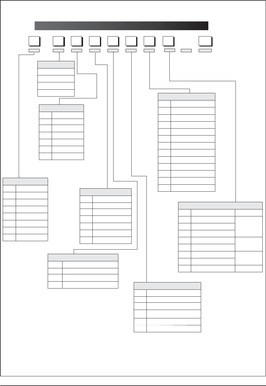
7-8 Samsung Electronics
Model Code (OUTDOOR)
H
2
H
J
H
C
H
AA
H
/
H
020
H
H
H
AJ
H
J
H
C
Product Type
Code Type
AM
DVM
AJ PMA
AC CAC (USD) / ASD
AE EHS
AN VTL
AK PAK
AG CHR
Year
Code Type
E 2012
F 2013
H 2014
J 2015
K 2016
L 2017
Feature
Code Type
J
IFREE JOINT MULTI
P PACK MULTI
H DVM HOME
Grade
Code Type
2 2 Room
3 3 Room
4 4 Room
5 5 Room
N Multi Room
Capacity
BTU/H(*100)
CMH(*10)
HP(/10)
WATT(*100)
Rating Voltage
Code Type
A A(115V, 60hz, 1Ф)
B B(220V, 60Hz, 1Ф)
C C(208~230V, 60Hz)
D D(200~220V, 50Hz)
E E(220~240V, 50Hz)
F F(208~230V, 60Hz, 3Ф)
G G(380~415V, 50Hz, 3Ф)
H H(380V, 60Hz, 3Ф)
J J(460V, 60Hz, 3Ф)
K K(220~240V, 50/60Hz, 1Ф)
M M(127V, 50Hz)
N N (380~415V, 50/60Hz, 3Ф)
Refrigerant
Code Type
Refrigerant
C
COOLING ONLY
R410a
H HEAT PUMP
R HEAT RECOVERY
D COOLING ONLY R22
E HEAT PUMP
A Cooling only R134
B Heat Pump
N N/A
ö/ can be removed from the buyer card if there are not enough digits.
Buyer Name
J
PMA is FJM Model.
Separator
Code Type
S Normal Set (NASA)
N Indoor (No NASA)
X Outdoor(NASA)
A Set (NASA)
B
Indoor
(NASA)
C
Outdoor
(No NASA)
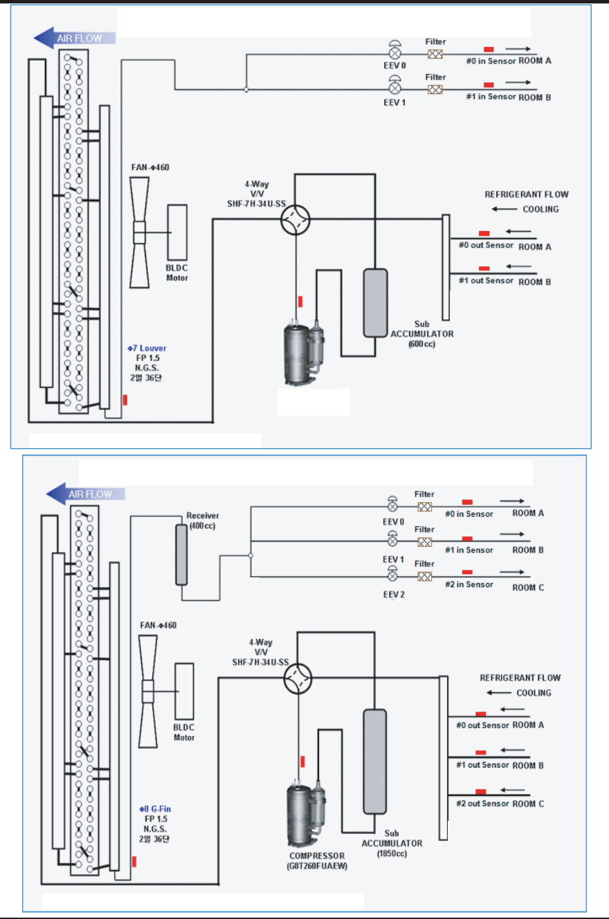
Samsung Electronics 7-9
AJ020JCJ2CH CYCLE DIAGRAM
7-8 Refrigerating Cycle Diagram
AJ024JCJ3CH CYCLE DIAGRAM
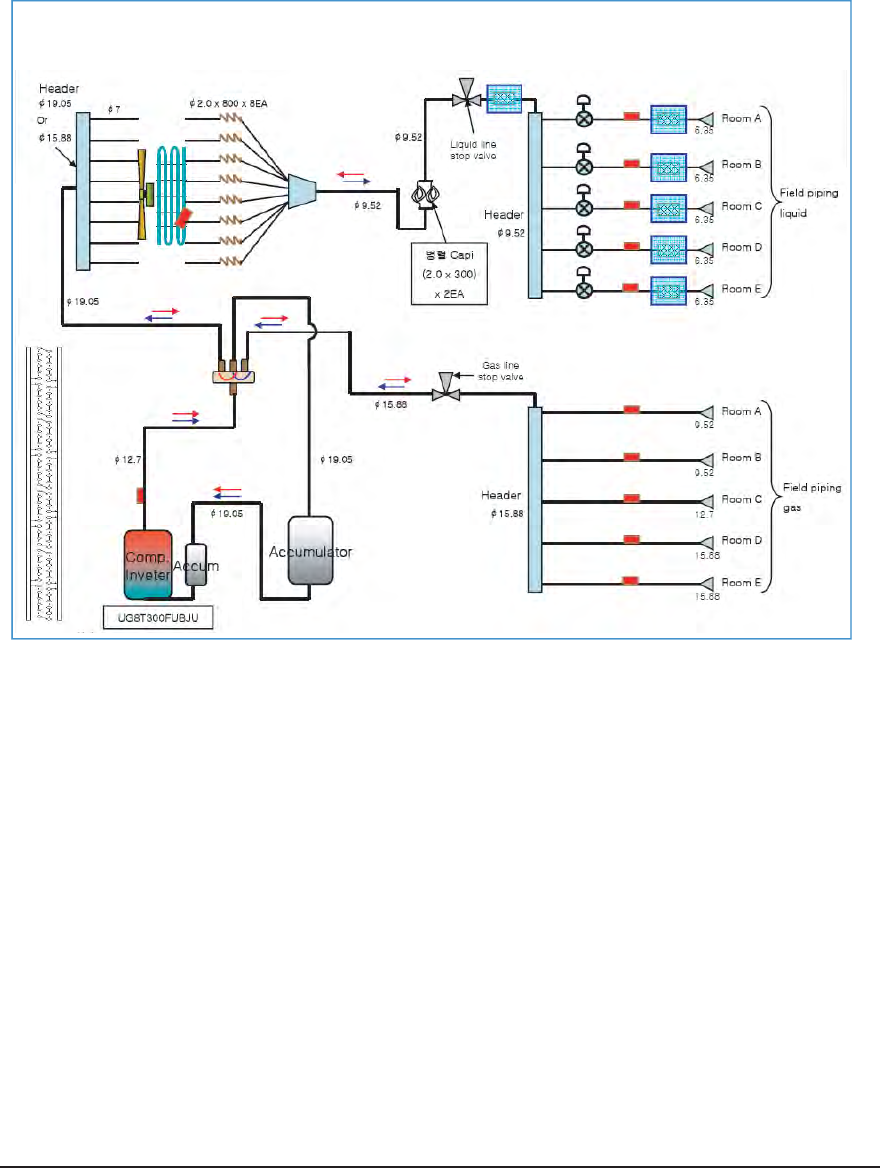
7-10 Samsung Electronics
AJ036JCJ5CH CYCLE DIAGRAM
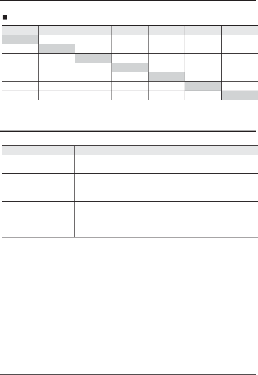
Samsung Electronics 7-11
7-9 Pressure & Capacity mark
7-10 The abbreviated technology words & the definition of technology terms
W cal/s kcal/h Btu/h HP kg.m/s ib.m/s
1
4.1868
1.163
0.29307
745.7
9.8067
1.3558
0.23885
1
0.27778
0.06999
178.11
2.3423
0.32383
0.85985
3.6
1
0.252
641.19
8.4322
1.1658
3.4121
14.286
3.9683
1
2,544.4
33.462
4.6262
0.001341
0.0056146
0.0015596
3.9302x10
-4
1
0.013151
0.0018182
0.10197
0.42693
0.11859
0.029885
76.04
1
0.13826
0.73756
3.088
0.85778
0.21616
550
7.233
1
Power/Heat
Abbreviated technology words Definition of technology terms
COMP(Full name compressor)
BLOWER
FAN
ASS’Y CONTROL BOX
(Full name : Assemble control box)
MOTOR
ASS’Y EVAP/ASS’Y COND
(Full name : assemble evaporator /
assemble condenser)
One that compresses, especially a machine used to compress gases.
One that blows, especially a mechanical device, such as f fan, that produces a current of air.
A device for reeating a current of air or a breeze.
A restraining device of air-condition, measure, or limit.
Something, such as a machine or an engine, that produces or imparts motion.
Heat exchanger; A device, used to transfer heat from a fluid on one side of a barrier to a fluid
on the other side without bringing the fluids into direct contact.

7-12 Samsung Electronics
7-11 Q & A for Non-trouble
Q The cooling is weak.
A When it is hot outside, its cooling capacity decreases due to the increase of the ambient temperature.
When the dust filter gets blocked or warm outside air gets in, the cooling capacity will decrease. So,
make sure to clean the dust filter frequently, prevent heat loss by closing the doors and insulate the
cooling area by using curtains, blinds, shades or window tinting.
Q The cooling is good generally. But, it gets weak when it is considerably hot.
A It occurs when the outdoor unit is exposed to direct sun light and heat-up air is not ventilated well.
So, set up a sunblind over the outdoor unit and keep stuff away from the unit to increase the ventila-
tion. When the cooling capacity decreases during a heat wave, clean the heat exchanger of the out-
door unit or spray some cold water to the heat exchanger to increase the cooling capability.
Q The cooling is weak. Does it need refrigerant charging?
A It is not correct charging refrigerant regularly. Except that you have moved in several times or the
connection pipes are broken, the refrigerant does not run low. So, when refrigerant is additionally
charged, it could be costly and cause a product's failure. When the refrigerant leaks, all of it will
escape in a short time resulting in cooling failure and no water coming out of the drain hose. So, if
water comes out from the drain hose, it indicates the normal operation of the product and it does not
need refrigerant charging.
Q It fails to do cooling.
A When the air conditioner is set to Ventilation or the desired temperature is set higher than the current
temperature, it fails to do cooling. In this case, select Cooling or set the desired temperature lower.
Q It floods the floor.
A Place the drain hose properly. When it is not placed properly, the drain water would flow back flooding
the floor. So, straighten out the drain hose for the water to be drained well.
Q Water drips at the drain connection (service valve) of the outdoor unit.
A When a glass bottle is taken out of the refrigerator, moisture gets condensed on its surface due to the
temperature differences. The same principle applies to the air conditioner. When cold refrigerant goes
through the copper tube, moisture gets condensed on the surface of the tube and the connection
areas. To prevent the water condensation, the pipes are insulated. But, the connection areas of the
outdoor unit are not insulated for the purpose of maintenance or repair, and water gets condensed due
to the temperature differences and drips down. Generally, it evaporates right away. But, when it drips
much during muggy days, put a water pan on the floor.
Q It leaks even though a drain pump is used.
A It occurs when the drain pump is plugged out or it is out of order. Check the power of the drain pump
and the position of the drain hose, and when the pump is faulty, contact the drain pump manufacturer.
Samsung Electronics do not manufacture drain pumps. So, we are not able to correct the drain pump
problems.
Q Whenever the air conditioner is turned on, it irritates my eyes and gives me a headache.
A There are no components in the air conditioner irritating the eyes and sending out chemical smells.
But, when the air conditioner is turned on, other smell sources are sucked into the air conditioner and
get out of it. So, find and root out the smell sources. Generally, it occurs at a interior renovated place,
a pharmacy, a gasoline handling place, a tire shop, a second-hand book shop or an electronic
Cooling
Leakage
Smells
Classification Class Description
Samsung Electronics 7-13
Q & A for Non-trouble (cont.)
component handling place; when its chemical or musty smells are sucked in and sent out, it can be
misled that the air conditioner generates them. So, find and root out the problem or refresh the room
frequently.
Q Whenever the air conditioner is turned on, it stinks.
A There are no components in the air conditioner sending out chemical smells. But, when the air condi-
tioner is turned on, other smell sources are sucked into the air conditioner and get out of it. So, find
and root out the smell sources. Generally, when the drain hose is taken out to the washing room or
there are sources of smells such as a diaper bin, a shoe shelf or a socks bin, bad smells generate.
Also, it occurs where glass cleaners or air fresheners are used; when they are sucked in interacting
with dusts and moistures inside, bad smells generate. These kinds of organic materials noxious to
human bodies. So, we recommend against the use of them.
Q Whenever the air conditioner is turned on, it smells sour.
A When the room is papered recently, its paste smells would be sucked inside. Also, when the air condi-
tioner is installed in the study room of young boys loving sweat-generating activities such as the bas-
ketball, excessive sweats evaporate and get sucked into the air conditioner resulting in bad smells. So,
find and root out the problem or refresh the room frequently.
Q Whenever the air conditioner is turned on, it smells musty.
A It is due to the improper keeping of the product after its use. When keeping the product, dry up the
inside with the operation of Ventilation to prevent must. When the product is kept without drying up the
inside with Ventilation, mold would grow inside resulting in must. So, open the windows and switch on
the Ventilation function to get rid of the saturated smell inside.
Q Whenever the air conditioner is turned on, it sends out bad smells such as stale smells.
A It occurs generally when there are pet animals in the house. Their smells stay at the same place.
But, when the air conditioner is turned on, the air gets circulated resulting in the circulation of the
smells. So, find and root out the problem or refresh the room frequently.
Q It sends out bad smells.
A When the air filter is filthy, it could send out bad smells. So, clean the filter and ventilate the room with
the windows open while operating the Ventilation function.
Q It won't start.
A There is a power failure or it is plugged out. Also, check if the power distribution panel is switched off.
Q It goes off during operation.
A When the hot air does not escape properly, it goes off during operation. It occurs when it does not
ventilate properly because the outdoor unit is covered, the back of the outdoor unit is blocked by a
cardboard or a plywood panel, and the front of the outdoor unit is blocked by the closed window or
other obstacles. Clear the above obstacles from the outdoor unit.
Q It generally works properly. But, when it's considerably hot, it goes off during operation.
A It occurs when the outdoor unit is exposed to direct sunlight and the hot air does not escape properly.
Set up a sun blind over the outdoor unit and clear the neighboring obstacles from the outdoor unit to
provide good ventilation. When it goes off frequently during a heat wave, it would prevent the turn-off and
increase the cooling capacity cleaning the outdoor unit or spraying some water to the heat exchanger.
Smells
Operation
Classification Class Description
7-14 Samsung Electronics
Q The remote controller won't operate.
A When the batteries run out or the transmitter or receiver of the remote controller is blocked by obsta-
cles, change the batteries or keep the obstacles away from the controlling area. Also, the remote con-
troller may not work under intensive light from a 3-wave length lamp or a neon sign due to the EMI.
In this case, take the remote controller closer to the receiver.
Q Who installs the air conditioner? (Relocation/Re-installation)
A When relocating or re-installing the air conditioner, make sure to contact Samsung Electronics Service
Center or Authorized Service Agent and have them to do the job.(If not, it could cause personal injury
or product damage.)
The cost for the relocation/re-installation of the air conditioner is subject to the customer's expense.
There is a cost table. But, our service engineer needs to visit to total up the cost correctly.
When you move in, make sure to contact Samsung Electronics Service Center or Authorized Service
Agent in advance to streamline the process.
Q Is it possible to install the outdoor unit outside?
A It is possible to install it at a designated place in the apartment or on the rooftop nearby.
But, it's illegal hanging an angle iron case with the outdoor unit in it outside the apartment. Also, it is
illegal obstructing passers-by with the outdoor unit installed outside.
Q What can be done to install the outdoor unit facing the road because it is a commercial building?
A The following is an excerpt from Building Code going into effect from JUNE 1st 2005. "The exhaust
pipe of a cooling or ventilation facility installed in a building adjacent to the streets of commercial or
residential areas shall be installed higher than 2m to prevent the exhaust air from blowing directly to
passers-by and the current facilities shall be corrected by MAY 31st 2005." So, please install it higher
than 2m or not to blow the hot exhausting air directly to passers-by.
Q What about installing a windscreen during installation not to blow hot air directly to passers-by?
A When the hot air from the front of the outdoor unit is blocked, the product's performance will be
affected and it will fail to operate properly. So, keep it at least 300mm away from its surrounding walls
and give it good ventilation.
Operation
Installation
Classification Class Description
Q & A for Non-trouble (cont.)
Samsung Electronics 7-15
7-12 Common sense of refrigeration
Air supplier?
It supplies fresh air to the building or room through procedure of air circulation for fresh environment.
Effectiveness of air supplier
It diminishes the stress or fatigue and enhances vivid desire through fresh air circulation. Also, filthy air indoor is being
cleaned by Air-Filter and it keeps clean and fresh environment and dehumidification. Temperature, humidity, air stream,
cleanness are called for factors of air supplier and they are kept in proper condition for usage purpose.
Four factors of air suppliers
The human body keeps regular temperature regarding the human body's freshness.
For keeping freshness, heat generated from human body should emit outside of the body by air circulation, conduction,
emission, and evaporation. The human body feels freshness when the emission rate is 40~45%, which was emitted by a
radiation when it is comfortable and warm, and air circulation and conduction is 20~30%, and evaporation is 20~24%.
It sometimes may depends on seasonal factor, wearing condition, age, sex and mental state other than indoor environment.
But generally the value of fresh indoor temperature is that below 0.2(m/s) of indoor air circulation, the temperature is 21~28ŇC
when the wall temperature is the same as the indoor's and relative humidity is 30~31% in summer, the winter temperature is
20~24ŇC and relative humidity is 30~60% in winter.
Humidity
(Moisture)
Temperature
(Heat) Air stream
(Aircirculation)
Cleanness
(Air)
Control the indoor air into cool or warm Remove humidity in air or humidify
Remove filthy dirt in air Circulate air every corner of indoor
This Service Manual is a property of Samsung Electronics Co., Ltd.
Any unauthorized use of Manual can be punished under applicable
International and/or domestic law.
© Samsung Electronics Co., Ltd. 2014.
Printed in China.
Code No. DB68-14112A(1)
