VGC 27 Instruction 12 06 702565 Instructions
2017-04-29
: Pdf 702565 Instructions 702565_Instructions product s
Open the PDF directly: View PDF ![]() .
.
Page Count: 8
Specifications
Amps / Volts requirements 400 ma @ 24 VDC
Propane pressure (VGC-27LP) 11” WC / 2.8 kpa
Natural Gas pressure (VGC-27NG) 4.5” WC / 1.15 kpa
Cu ft per hour / CO2 6-27 SCFH
BTU Rating (Variable) LP 4,526 - 22,630
NG 5,534 - 27,670
Weight / Dimensions 22 lbs / 17.7” x 15” x 10”
Life Expectancy > 10 years
VariableCO2 Modes 2 - 5 - 7 - 10 burners
Sentinel products are distributed by:
GPS / Global Product
Solutions LLC.
www.growgps.com
Sentinel CO2
Generators offer a
3-year warranty.
Ask your retailer for
details.
Instruction Manual
VCG-27
Variable CO2 Generator

Carbon Dioxide / CO2 is critical for all plants. Normal atmospheric
air around the world averages about 380 Parts-Per-Million (PPM.)
When plants are provided higher levels of carbon dioxide, they can
grow faster and larger. It is normally agreed by experts that up to
1500 PPM is beneficial to plants and the best way to increase the
CO2 level is by using a CO2 generator that burns either natural gas
or propane.
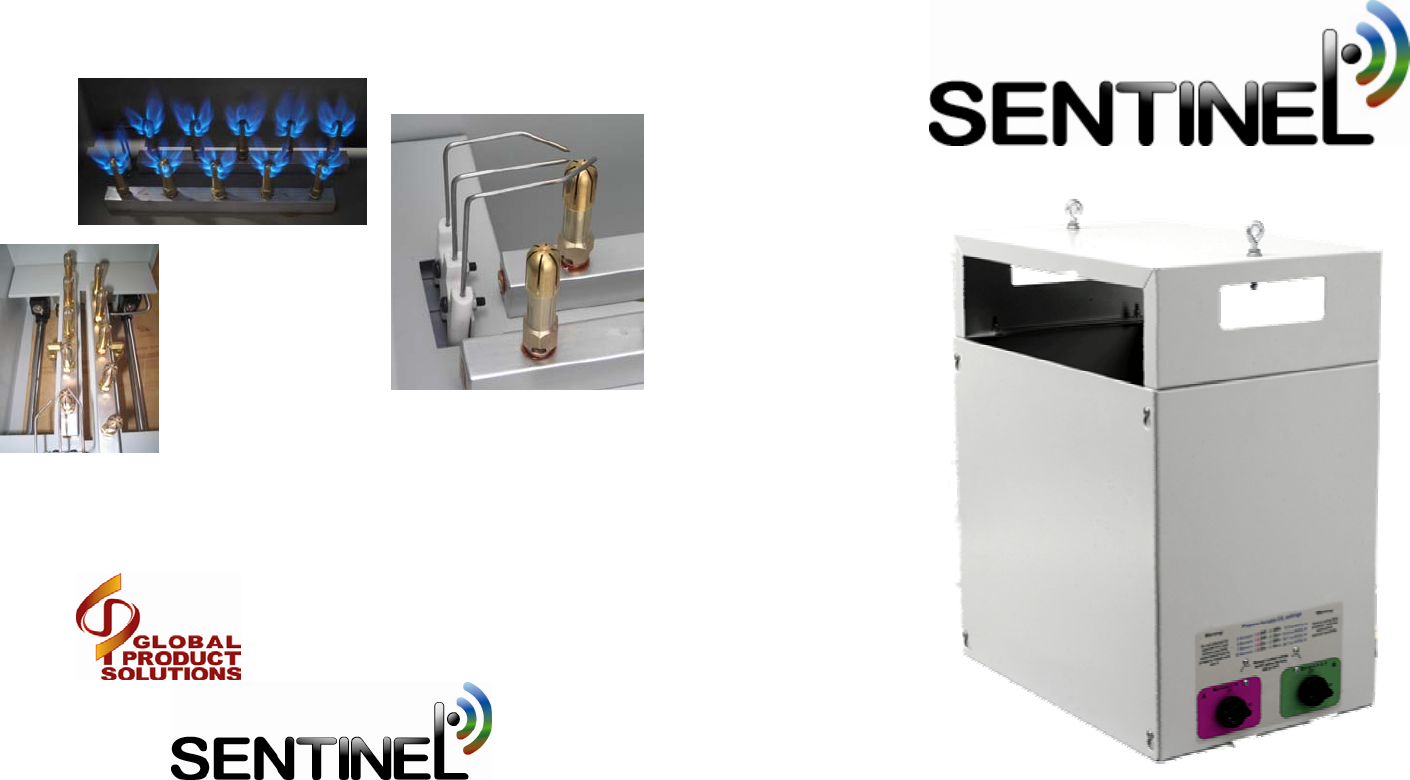
The VCG-27 has two models, the LP (propane) and an NG
(Natural Gas) model. Both come complete with (10) clean burning
brass burners pre-installed and the appropriate regulator & hose.
The VCG-27 CO2 generator is the most advanced CO2 generator
available today.
1) The VCG-27 has a variable output from 6 to 27 cubic ft of
CO2 per hour.
2) It has an electronic ignition control module that eliminates the
open pilot flame for safer operation.
3) The 10 brass burners have been designed to burn cleaner and
produce a consistent blue flame.
4) The tip-over switch automatically shuts off the entire unit in
the event the unit falls or tips over.
TABLE OF CONTENTS
A quick look at the VCG-27
Installation of the VCG-27
VCG-27 Propane & Natural Gas
Starting the unit for the first time
Variable output and area sizes
Burner control valves
Ignition control module
Connection Examples
Optional Air-Cooling Module VCG-COOL
Troubleshooting & Specs
Introduction
Problem: The growing area is getting too hot and / or humid.
Decrease the number of burners that are operating. Refer to the Burner
control valve explanation on page #8.
Problem: The CO2 level does not seem to be increasing enough.
Increase the number of burners that are operating. Refer to the Burner
control valve explanation on page #8.
Problem: I hear the unit buzzing and sparking.
The unit will attempt to fire the burners 5 times for 5 seconds each.
During that time, you will hear a “sparking” sound. This is normal. It is
not normal for the unit to fail to light after 3 tries. Check the gas
supply / LP tank. If the gas supply tests OK, consult the factory.
Problem: Some of the burners seem to be not burning correctly.
Make sure that the burner control valves are either fully ON or fully
OFF. Make sure the gas supply is adequate and the gas hose is not
kinked or twisted.
Red Lock Out LED is blinking On & Off
The Lock Out function is automatic and will be activated if 5 attempts
to light the pilot are not successful. Normally, it will mean the propane
has run out or the gas supply has been interrupted. Once the problem is
determined and fixed, cycling the power switch Off and then On will
reset the error.
* High-altitude operation: The burners on the VGC-27
have been selected to operate correctly from sea-level up to
4500ft elevation. If you are at high altitude (4500+) and notice
yellow flames, contact the factory. Special high-altitude burners
are available.
Some of the more common questions and problems are listed here.
Consult the factory for other concerns not listed.
Troubleshooting
Problem: There is a gas smell in the area.
Shut off the gas supply immediately. Do not turn ON any electrical
devices and ventilate the area by opening vent, doors or windows. Exit
until the gas smell is not evident.
After ventilating, determine where the gas is leaking from by using a
spray bottle with soapy water in it. Spray all gas connection with the
water and look for small bubbles. Seal any leaks. If the problem per-
sists, consult the factory.
Problem: The unit is trying but the burners are not lighting.
When the unit is first started or a LP tank is replaced, the gas lines
make take some time to fill with gas. The unit will attempt to fire the
burners 5 times for 5 seconds each. Each attempt is followed by a 20
second “purge” time. After three tries, the unit is locked out. Determine
why gas is not getting to the unit. To reset the unit, cycle power OFF
and then back ON.
Problem: The power is connected, but the Green indicator is not
on.
The “tip-over” switch may be activated. Tilt the unit to one side and
listen for a clicking noise. The switch is like a pendulum and will shut
off the burner if the unit is not operated level.
Problem: The flames appear to be too large or yellow.
Verify you are using the correct fuel, (LP or NG). The supplied
regulator must be installed or high pressure may increase the flames to
dangerous heights. Check the regulator. DO NOT operate the unit
with yellow or large flames. Consult the factory.
Problem: Some of the flames appear to be blue but small in size or
“lazy”. The flames should resemble a flower when operating
correctly.
Verify the manual burner control valves are either in the ON or OFF
position. If the valves are set in the middle, improper operation will
result. Check the regulator and gas supply, low pressure/ low LP tank
level will also cause this condition to occur. DO NOT operate the
unit with lazy blue flames. Consult the factory.
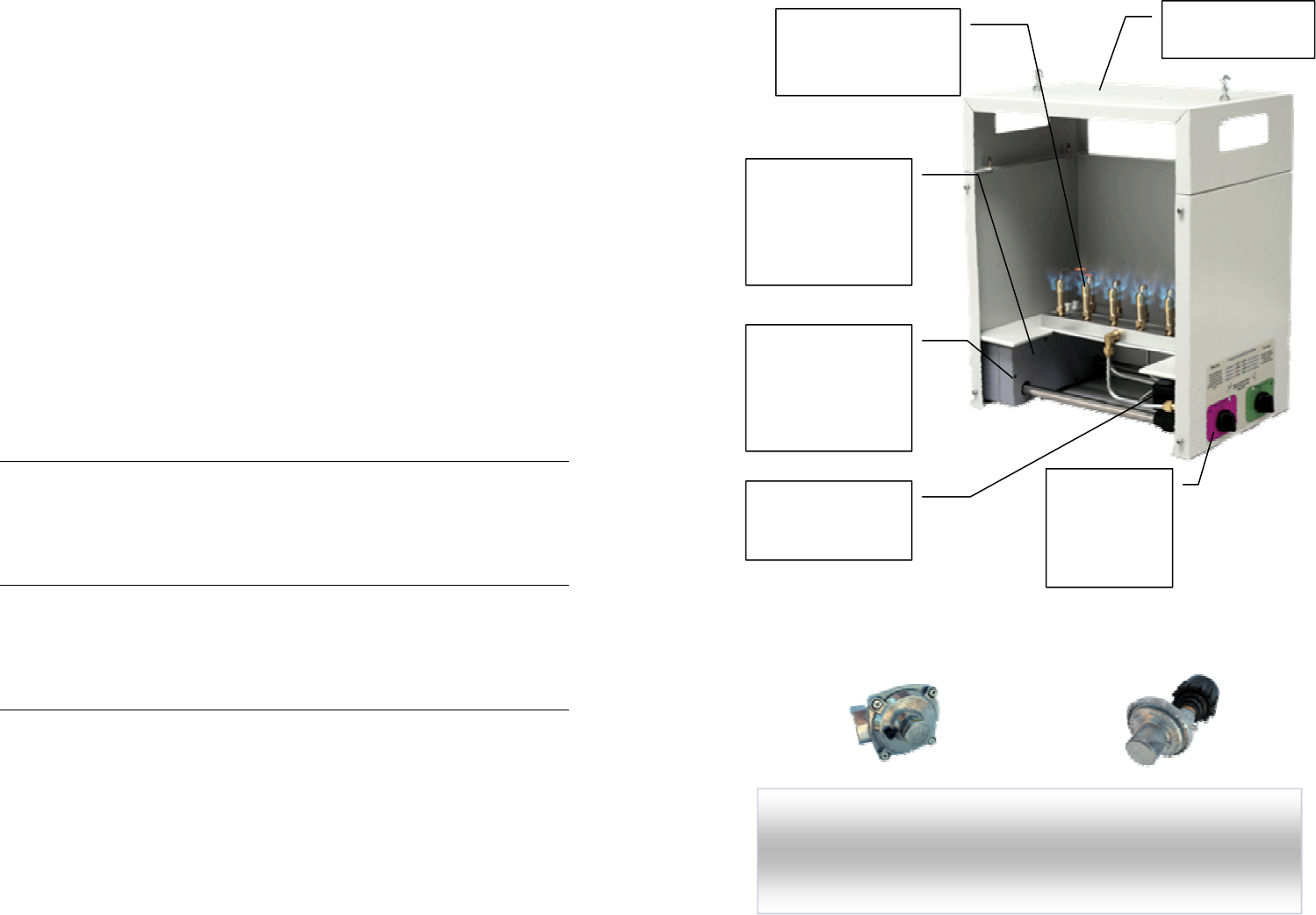
A quick look at the VCG-27…
Electronic Ignition
control module
provides sure starts
and safe
operation.
Powder coated
steel enclosure
Variable
output
selectable
with two
control valves
Tip-over switch
shuts off entire unit
if tilted more than
25 degrees from
vertical.
Comes standard with
(10) clean burning
brass burners.
NOTE:
The ignition control module produces a spark from a pair of
electrodes near the tip of one of the brass burners to ignite the gas. Do not
attempt to service the sparking electrode or place foreign objects anywhere
near the electrodes.
Regulator supplied with
Natural Gas Generators
Regulator supplied with
Propane Generators
Dual redundant
solenoid valves for
added safety.
Installing the VCG-27
1) The unit is designed to hang from a ceiling joist or overhead
support. It comes with two eyebolts, hooks and sections of chain.
2) DO NOT place the unit on top of something like a table to
operate it The generator requires a free flow of air coming in
through the bottom of the enclosure.
3) The chains provided are 18” long. A minimum of 18” must be
maintained between the unit and any walls or other obstructions.
4) Install the two screw hooks into a suitable supports. The chains
are then secured to the unit and the screw hooks with the included
S hooks. Bend the S hooks so that they cannot slip from the chain
and the hanging hooks. Ensure that the unit is hanging level.
5) The gas connections must be tightened properly. The supplied 12
foot hose is connected from the flare fitting on the CO2 generator to
the provided gas regulator. Secure the connection with two wrenches.
6) Once the gas connections are secured, pressurize the gas line and
check for leaks using the soapy water. Spray the water onto the gas
connection fittings and look for any bubbles. Re-secure if necessary.
7) The VCG-27 operates on 24 volts DC. The power supply
included with the unit is connected to a controller or timer that will
determine how long / often the unit will operate. Connect the power
supply jack to the unit and the desired controller or timer.
8) The main power switch on the side of the unit will activate the
ignition module and firing sequence. When the RED indicator light is
illuminated, the unit is powered and operating.
NOTE:
When you are ready to start the unit for the first time, refer to the
“Starting the unit for the first time” section of this manual.
NOTE:
In order to ensure a safe and proper installation, follow the
steps below. Be aware that in closed spaces without ventilation,
toxic levels (above 5000 PPM) of CO2 can accumulate. Do not
allow the unit to operate without the proper controls or timers.
1) Disconnect power to the VCG-27 generator & shut off the gas line.
2) Lower the unit from the hanging point and set it on top of a stable surface.
3) Loosen the (4) screws and remove the front access cover.
4) Loosen and remove the (4) screws that secure the top of the VCG-27 to the
bottom section. The 2 sections can now be separated.
5) Place the VCG-COOL on top of the VCG-27 and align the (4) screws. Slip
the VCG-COOL into place and tighten the (4) screws.
6) Replace the access cover and tighten the (4) screws.
7) Re-hang the unit and ensure all screws are tightened.
8) Install the circulating fan. The fan inlet needs to draw air from outside the
growing area. The outlet of the fan gets connected to one side of the
VCG-COOL using metal NON FLAMABLE metal ducting.
9) The other side of the VCG-COOL is connected to another piece of metal
NON FLAMABLE ducting. The ducting is then routed so that the hot air is
exhausted out of the growing area.
10) The fan must be connected to be turned ON when the VCG-27 is operating.
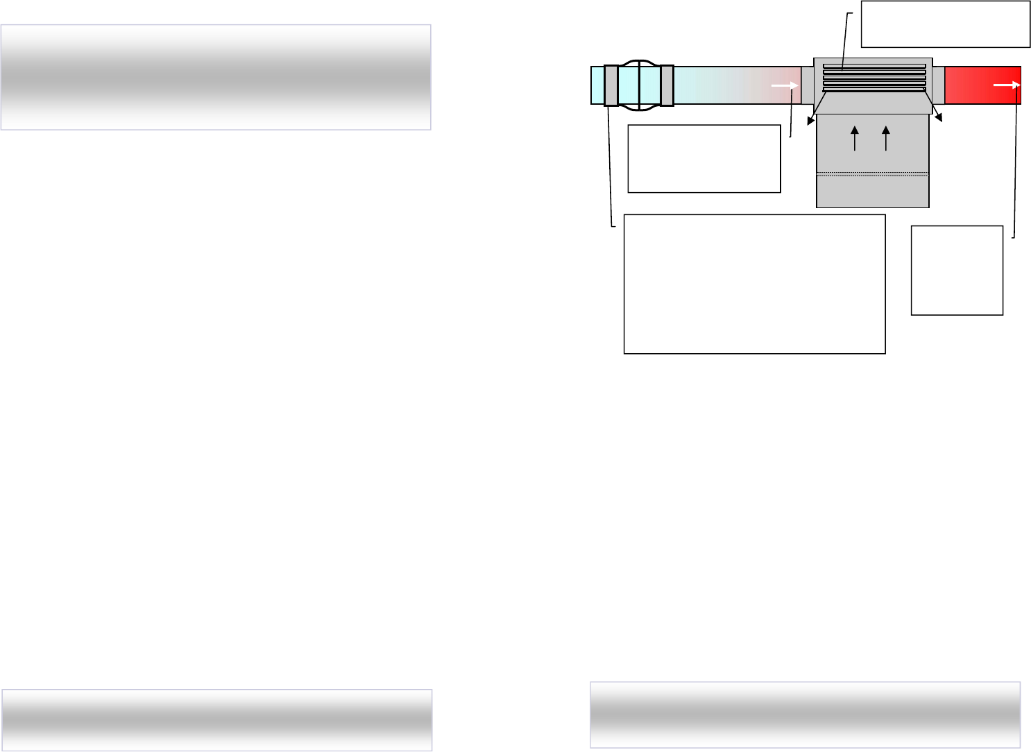
Typical installation
Flexible alumi-
num or steel
duct vents
HOT air out
of growing
1) Centrifugal fan draws COOL air in from
outside the growing area. Air is forced through
cooling chamber. (Minimum 300CFM)
2) The hot gasses from the burners pass heat
into the heat exchanger. The cool air blowing
though the exchanger, removes the heat.
3) The “cooled” CO2 is allowed to flow into
the growing area through the vents.
Flexible aluminum duct
from fan connects to
Air-Cooling module
“Cooled” CO2 is released
into the growing area.
NOTE: Incorrect installation of the VGC-COOL could damage
the fan connected to it. Make sure the fan pushes air through the
VGC-COOL.
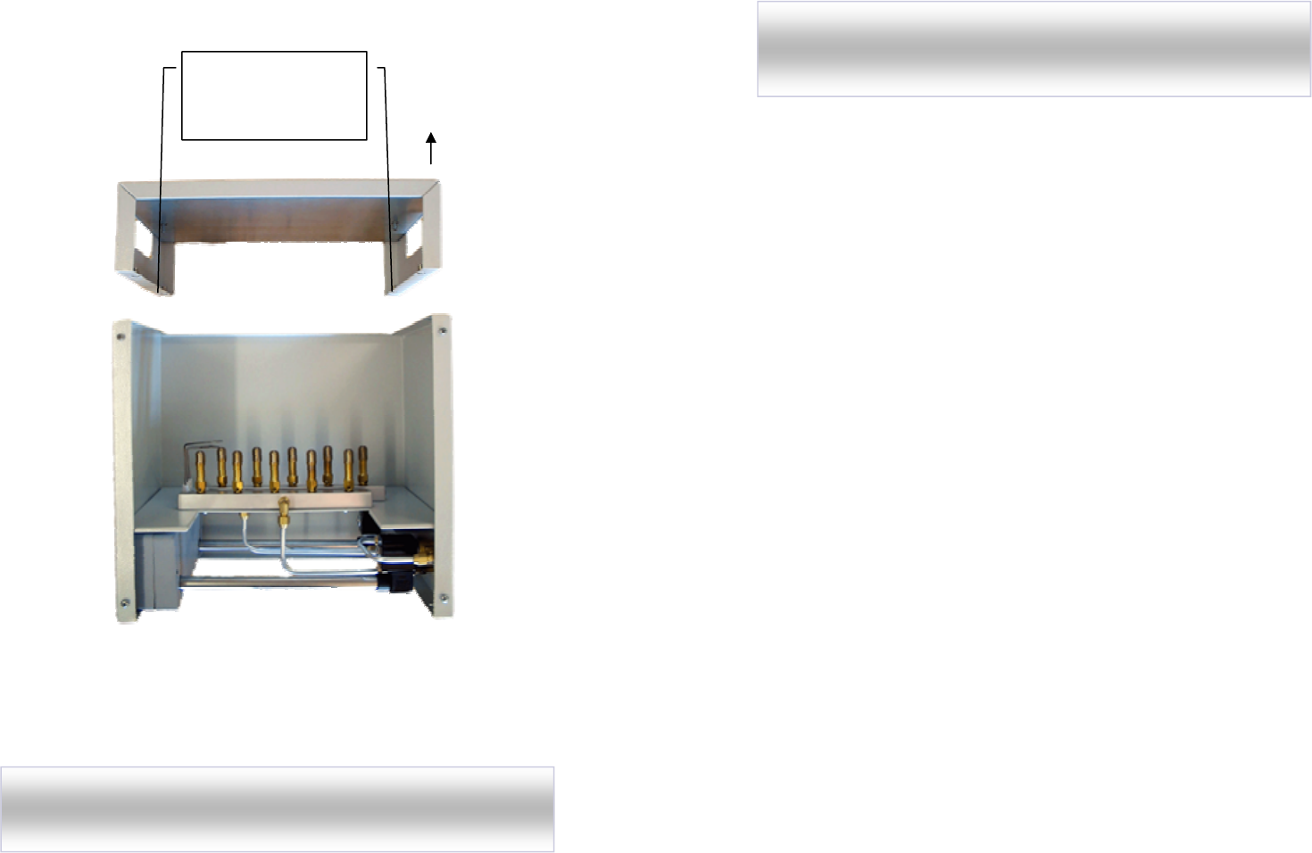
Optional Air-cooling module VCG-COOL
(4) Screws secure the
top section to the
bottom section
Once the top section is removed from the bottom section, the
VGC-COOL (not shown) can be installed on top of the unit.
NOTE: Make sure all (4) screws are securely tightened after
installing the VGC-COOL.
Top section lifts off
VCG-27 Propane & Natural Gas
There are two different VCG-27 units, one is used for Propane
(VCG-27LP) and one is used for Natural Gas (VCG-27NG).
Below is the differences between the two units. Make sure you
have selected the correct unit and are using the matching gas.
VCG-27LP / Propane: Liquid Propane otherwise known as LP or
Propane is stored in pressurized tanks of varying sizes. The gas exiting
the pressurized tank must first be regulated to a very low pressure
before it enters the gas burners. The standard for measuring the low
pressure is inches of water column or ” WC. The VCG-27LP operates
at 11” WC or about 1/2 PSI. Once the gas is regulated down to the
correct pressure, it enters the unit and flows through the brass burners.
Each brass burner has been designed to produce approximately 3 cu ft
of CO2 per hour. Each LP burner will also produce 2263 BTU of heat
and quite a lot of water vapor along with the 3 cu ft of carbon dioxide.
The Propane regulator provided with the unit MUST be used unless it is
verified that the propane gas supply is already regulated to 11” WC.
The provided LP regulator is designed to connect directly to portable
LP tanks. It also has a built-in safety function that limits the flow of gas
to a very low level in the event of a large gas leak.
Any questions...Consult a licensed installer or contact the factory.
VCG-27NG / Natural Gas: Natural Gas otherwise known as NG is
piped directly into homes and businesses from an extensive pipeline
system. The gas supply entering the building can vary from very low
pressure (less than 1/4 PSI) to over 5 PSI. The natural gas provided to
the VCG-27NG must first be regulated to a very low pressure before it
enters the gas burners. The standard for measuring the low pressure is
inches of water column or INCH /WC. The VCG-27NG operates at
4.5” WC or about 1/4 PSI. Once the gas is regulated down to the
correct pressure, it enters the unit and flows through the brass burners.
Each brass burner has been designed to produce approximately 3 cu ft
of CO2 per hour. Each NG burner will also produce 2767 BTU of heat
and quite a lot of water vapor along with the 3 cu ft of carbon dioxide.
The NG regulator provided with the unit MUST be used unless it is
verified that the natural gas supply is already regulated to 4.5” WC.
Any questions...Consult a licensed installer or contact the factory.
NOTE:
The VCG-27 MUST be used on the appropriate gas supply and
MUST be used with the supplied gas regulator.

Starting the unit for the first time
Here is a quick checklist and suggested start-up procedure.
1) Follow the installation instructions on page 4 of this manual. Once
installed go to step #2.
2) Look inside the unit and verify there is no loose packing material or
other foreign objects. Look at the gas connections and verify nothing
appears damaged or out of place.
3) Make sure the power switch is turned OFF.
4) Pressurize the gas lines by opening any shut-off valves on the gas
supply. Double check for leaks if this is the first time the unit will be
used. Gas leaks can be extremely dangerous.
5) Once the gas supply has been pressurized and tested for leaks, verify
there is no objects within 18” of the surface of the unit.
6) Turn both burner selection control knobs to the OFF position.
Initially, we will test just two burners. After the lowest setting is
tested, the two control valves can be opened.
7) Plug in the 24 volt DC power supply to a 120 volt power source.
Connect the small cable to the power inlet jack of the unit.
8) Turn the power switch ON, the Green indicator light should turn
ON. After a short pause, the ignition module will attempt to ignite the
burners for 5 seconds. If the unit fires, go to step #9. If this is the
first time the unit was used or if the LP tank was recently replaced, it
may not successfully start after the first attempt. After a 20-second
delay, the unit will attempt to re-fire for 5 seconds. If after five (5)
attempt to fire the burners is unsuccessful, the module will lock itself
until power to the unit is recycled OFF & ON. (See troubleshooting)
9) Once the burners fire, look from under the unit and verify the flame is
blue and consistent.
10) Once the first two burners are tested, open the two burner selection
valves one at a time and visually verify the burners also look OK.
11) Open both burner control valves and test all of the burners operating
together. If the unit will be operated in the maximum configuration,
ensure no materials around the unit are getting hot. The VCG-27
produces up to 27,000 BTUs of heat at full capacity so be sure the
heat will not become too great for the area or the surroundings.
12) Once tested at full capacity, set the control valves at the desired
setting and connect the unit to your controller or timer.
NOTE:
If the flame appears yellow or excessively large, shut the unit
off and refer to the troubleshooting section of the manual. The flames
should appear blue and resemble a small 6-pointed star.
Optional Air-cooling module VCG-COOL
Like any other CO2 generator, the VCG-27 can produce a lot of
unwanted heat… up to 27,000 BTU. There is no way to effectively
remove ALL of the heat, while keeping the CO2 in the growing area.
BUT, there is a way to remove up to 6,600 BTU of heat, by using the
optional VCG-COOL Air-Cooling module. Unlike other less effective
attempts to remove heat from CO2 generators, the VCG-COOL module
has been designed to absorb as much heat as possible while leaving the
cooled CO2 in the growing area.
Up to an 8” centrifugal fan is connected to one end of the cooling
module using fireproof flexible aluminum or steel ducting. The fan forces
cool air from outside the growing area into the cooling chamber. Since
the cooling chamber is sealed, no outside air is allowed to enter the
growing area and no inside CO2 is allowed to pass through the unit to the
outside. The outlet from the cooling module is connected to another
length of flexible aluminum duct and the hot air is exhausted outside of
the area. (Recommend using an 6-8” fan with 300-700 CFM)
The total amount of heat that can be removed varies with the total
amount of heat the generator is producing. See the chart below.
Removing heat from the area will reduce the stress on the plants and also
reduce the amount of cooling required. See the connection example and
installation procedure for the Air– Cooling module on the next page.
# of
burners
BTUs of Heat
Produced
Amount of heat
removed (BTU)
Amount of heat
remaining (BTU)
2 LP 4,523
NG 5,534
Up to 3000 LP 1,523
NG 2,534
5 LP 11,315
NG 13,835
Up to 4200 LP 7,115
NG 9,635
7 LP 15,841
NG 19,369
Up to 5400
LP 10,441
NG 13,969
10 LP 22,630
NG 27,670
Up to 6600 LP 16,030
NG 21,070
NOTE: Because of high temperatures…
DO NOT use mylar,
polyester or other flammable flexible ducting with the Air-Cooling
module. Use only flexible aluminum or sheet metal ducting.
A CO2 generator is the most cost-effective method of adding CO2 to an area.
You must also consider what type of controller will turn the CO2 generator
On and Off to avoid creating too much CO2 and heat. CO2 can be measured by
special sensors the measure CO2 levels in Part-Per-Million or PPM.
CO2 above 2500 PPM will make you feel uncomfortable and may cause
headaches and other problems. CO2 levels above 500 PPM can be fatal so it is
important to control the amount of CO2 being created by the VGC-27.
Normally 1200 to 1500 PPM is considered correct for rapid growth of plants,
above that level is a waste. To properly control CO2 levels, nothing is better
than a CO2 PPM controller like the CTC-1. It automatically measures the
amount of CO2 in the area and activates the VGC-27 only when required.
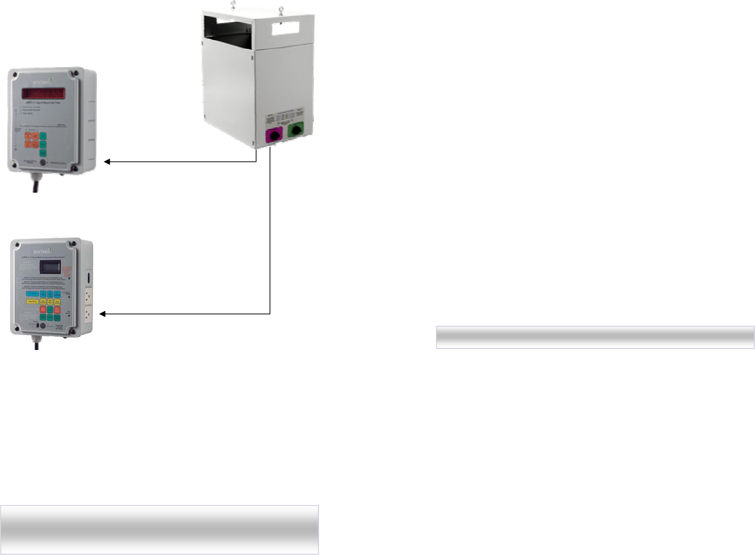
Connection Examples
Use a timer like
the DRT-1 to
turn the CO2
generator On
and Off and
Good
Better Use a Part-per-million CO2
controller like the CTC-1.
Measuring the exact
amount of CO2 in PPM,
provides the most accurate
method of control.
NOTE: Do not operate the VGC-27 or any other CO2 generator
without proper controls or timers. Do not operate the VGC-27 in
closed spaces with inadequate ventilation.
Variable output and area sizes
One of the best features of the VCG-27 is the variable CO2
output. The user can select up to four different CO2 settings
depending on their
“individual”
requirements.
Both the Propane (LP) and Natural Gas (NG) burners have been
designed to produce about 3 cu ft of CO2 per hour each. LP has a higher
fuel value than NG so each LP burner produces 2263 BTUs of heat while
the NG burners produce 2767 BTUs of heat to create 3 cu ft of CO2.
Determine your area’s cubic feet by multiplying height x width x
depth and then refer at the recommended burner setting.
The most common recommendation for PPM levels for rapid plant
growth is between 1000 and 1500 PPM. The plants will benefit most by
maintaining the CO2 level within this range during the daylight hours. By
setting the burner control valves to activate more burners, CO2 will be
produced quicker and will increase the CO2 level faster. However, along
with CO2 production, heat will also be added to the growing area faster.
Make sure your cooling system can handle the increased heat load before
operating the unit at a high output level.
Operating the unit with only the two standard burners activated (both
valves closed) will only add 1/5 of the heat as the unit would produce if
both valves were opened. It is best to operate the unit at as low a setting
as possible to maintain the CO2 level without adding too much heat.
Whenever possible, use a CO2 PPM controller or other appropriate
controller to maintain an accurate CO2 level.
# of
burners
Cu Ft of
CO2 / hr
BTUs of Heat Recommended Area
size (Cu Ft)
2 LP 5.3
NG 5.5
LP 4,523
NG 5,534
0 - 2,000
5 LP 13.4
NG 13.8
LP 11,315
NG 13,835
2,000 - 5,000
7 LP 18.7
NG 19.4
LP 15,841
NG 19,369
5,000 - 7,000
10 LP 26.7
NG 27.7
LP 22,630
NG 27,670
7,000 - 10,000
NOTE:
Each area is different, this is only a basic recommendation
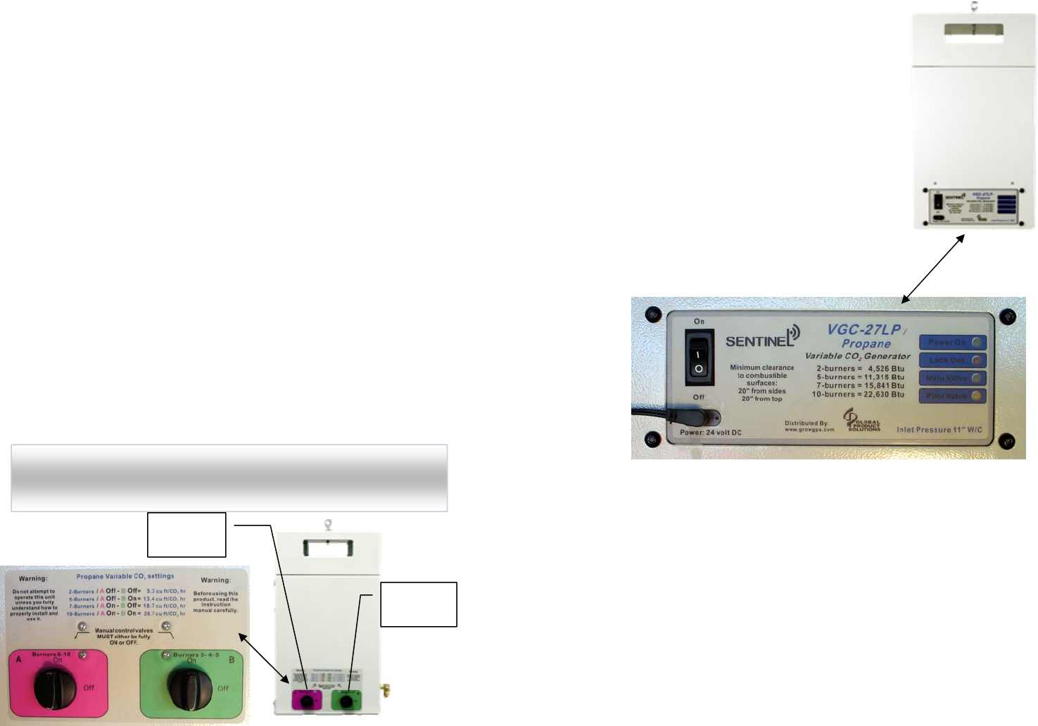
Burner control valves
The magic behind the Variable CO2 of the VCG-27 is (2) burner
control valves that provide gas only to the burners that are selected.
The aluminum gas manifolds and brass burners inside the generator
are connected to the selection valves. When the valve is opened, gas
is allowed to flow to the burners connected to the valve.
Valve A is connected to 5 burners and Valve B is connected to 3
burners. Activating the valves in up to four combinations provide
the variable CO2 output of either 2, 3, 7 or 10 burners.
The burner control valves are located on the end of the unit and
are labeled A & B. The chart below indicates how to set the valves
depending on how many burners you want to operate. Remember,
more burners activated = more CO2 & more heat produced.
With both valves turned OFF, there are 2 standard burners that will
receive gas. Two burners is the lowest possible setting.
NOTE:
Make sure the burner control valves are either fully
opened or fully closed during operation. DO NOT operate the
unit with the burner control valves partially open.
OFF /closed OFF / closed 2 5.3 / 5.5
OFF / closed ON / opened 5 13.4 / 13.8
ON / opened OFF / closed 7 18.7 / 19.4
ON / opened ON / opened 10 26.7 / 27.7
Valve A
Burners 6- 10
Valve B
Burners 3-4-5
Burners
operating
Cu Ft CO2/hr
(LP / NG)
Burner
Valve A
Burner
Valve B
Ignition control module
The VGC-27 uses the newest and most
advanced ignition controller available today.
The module provides the spark to light the
(2) pilot burners, and then allows the main
burners to ignite only after the flame has
been verified. This provides consistent &
controlled starts. If the module senses the
flame is not present, it shuts off the solenoid
valves.
One feature that is also worth mentioning
is the “dual-redundant” solenoid valves that
are controlled by the ignition controller.
The ignition controller has (4) LED
indicators to verify correct operation.
Power On (Green LED) Indicates 24 volt power is supplied to the unit.
Lock Out (Red LED) The Lock Out LED blinking indicates the ignition
controller shut off the solenoid valves and the unit is locked out.
Cycling the power switch Off & On will reset the error. (See trouble-
shooting for more info)
Main Valve (Green LED) Indicates the ignition controller has activated
the main solenoid and the unit is in operation.
Pilot Valve (Yellow LED) When the power is switched On, the ignition
controller will provide a spark for 5 seconds, During that time, the pilot
solenoid is activated. The Pilot Valve LED indicates that the pilot
solenoid has been activated. (Should be On during operation)
