712 25 31 Rev B Logic LPI CRPS Op Tech
2014-08-07
: Pdf 712-25-31 Revb Logic Lpi Crps Optech 712-25-31_RevB_Logic_LPI_CRPS_OpTech 8 2014 pdf
Open the PDF directly: View PDF ![]() .
.
Page Count: 40
CR/PS Low Profile
Instrumentation (LPI®)
EXACTECH KNEE
Operative Technique
®

TABLE OF CONTENTS
INTRODUCTION ................................................................................................................. 1
DESIGN RATIONALE .......................................................................................................... 1
PRE-OPERATIVE PLANNING ............................................................................................. 1
OPERATIVE TECHNIQUE OVERVIEW .............................................................................. 2
DETAILED OPERATIVE TECHNIQUE ................................................................................. 4
APPROACH AND EXPOSURE .................................................................................... 4
PREPARATION OF THE FEMUR .................................................................................. 5
Step 1: Opening the Intra-medullary Canal ....................................................... 5
Step 2: Distal Femoral Resection ....................................................................... 6
Step 3: Sizing of Femoral Component ............................................................... 7
Step 4: Rotation of Femoral Component ........................................................... 8
Step 5: Resection of Anterior, Posterior and Chamfer Femoral Bone ............. 8
Step 6: Femoral Notch Preparation .................................................................... 9
PREPARATION OF THE TIBIA ....................................................................................10
Assembly of the Extra-medullary Tibial Alignment Guide ..............................10
Placement of the LPI Extra-medullary Tibial Alignment Guide .......................11
TRADITIONAL TIBIAL APPROACH: RECOMMENDED FOR PS KNEES.................. 12
CR TIBIAL RESECTION: POSTERIOR CRUCIATE REFERENCING TECHNIQUE ..... 13
Step 1: Identification of the Posterior Cruiciate Ligament (PCL)
Insertion Points .................................................................................................. 13
Step 2: Placement and Distal Alignment
of the Extra-medullary Alignment Guide ........................................................ 13
Step 3: Determination of Posterior Tibial Slope .............................................. 13
Step 4: Determination of Tibial Resection Depth ............................................ 13
Step 5: Securing Tibial Resection Guide to Tibia and Final Checking ............14
PREPARATION OF THE PATELLA ..............................................................................14
FINAL PROSTHESIS TRIAL CHECK .......................................................................... 15
Trial Placement .................................................................................................. 15
Alignment Check ............................................................................................... 15
Stability Check ................................................................................................... 15
PS Surgical Approach ....................................................................................... 15
CR Surgical Approach ....................................................................................... 16
Motion Check ..................................................................................................... 16
Patellar Tracking Check ...................................................................................... 17
FINAL PREPARATION OF THE TIBIA ........................................................................ 17
IMPLANTATION OF FINAL COMPONENTS .............................................................19
Step 1: Final Bone Preparation ..........................................................................19
Step 2: Implantation of the Tibial Prosthesis ................................................... 20
Step 3: Implantation of Femoral Component ................................................. 21
Step 4: Polymerization of Cement ................................................................... 22
Step 5: Implantation of Patellar Component ................................................... 22
Step 6: Installation of Tibial Polyethylene Insert
(Modular Tibial Component Only) .................................................................... 23
FINAL CHECK AND CLOSURE ................................................................................. 23
DESIGN SPECIFICATIONS ....................................................................................... 24
PTS ANNEX ...................................................................................................................... 24
INSTRUMENT LISTING ................................................................................................... 26

1
INTRODUCTION
Total knee replacement surgery has been one
of the most successful orthopaedic procedures
during the past three decades. Advanced surgical
techniques and implant design improvements
have been two of the factors responsible for
that success. Exactech developed Low Profile
Instrumentation (LPI®) to provide user-friendly
instruments that achieve reproducible bone
preparation and limb alignment and allow for
superior visualization and accessibility while
keeping soft tissue disruption to a minimum.
Based on more than 30 years of clinical results
from Hospital for Special Surgery, Exactech’s
comprehensive knee systems address your
concerns for contact stress, patellar tracking,
polyethylene wear, joint stability and bone
preservation with streamlined instrumentation
that allows you to work quickly and efficiently.
DESIGN RATIONALE
Exactech’s LPI instrumentation is not a
radical departure from the classic Optetrak
instrumentation. It is, rather, an optimized system
of instruments that can be used in total knee
replacement surgery, regardless of the size of the
incision or method of handling soft tissues. The
system’s easy-to-use instrumentation allows you
to work quickly and efficiently with streamlined
solutions for your preferred surgical technique.
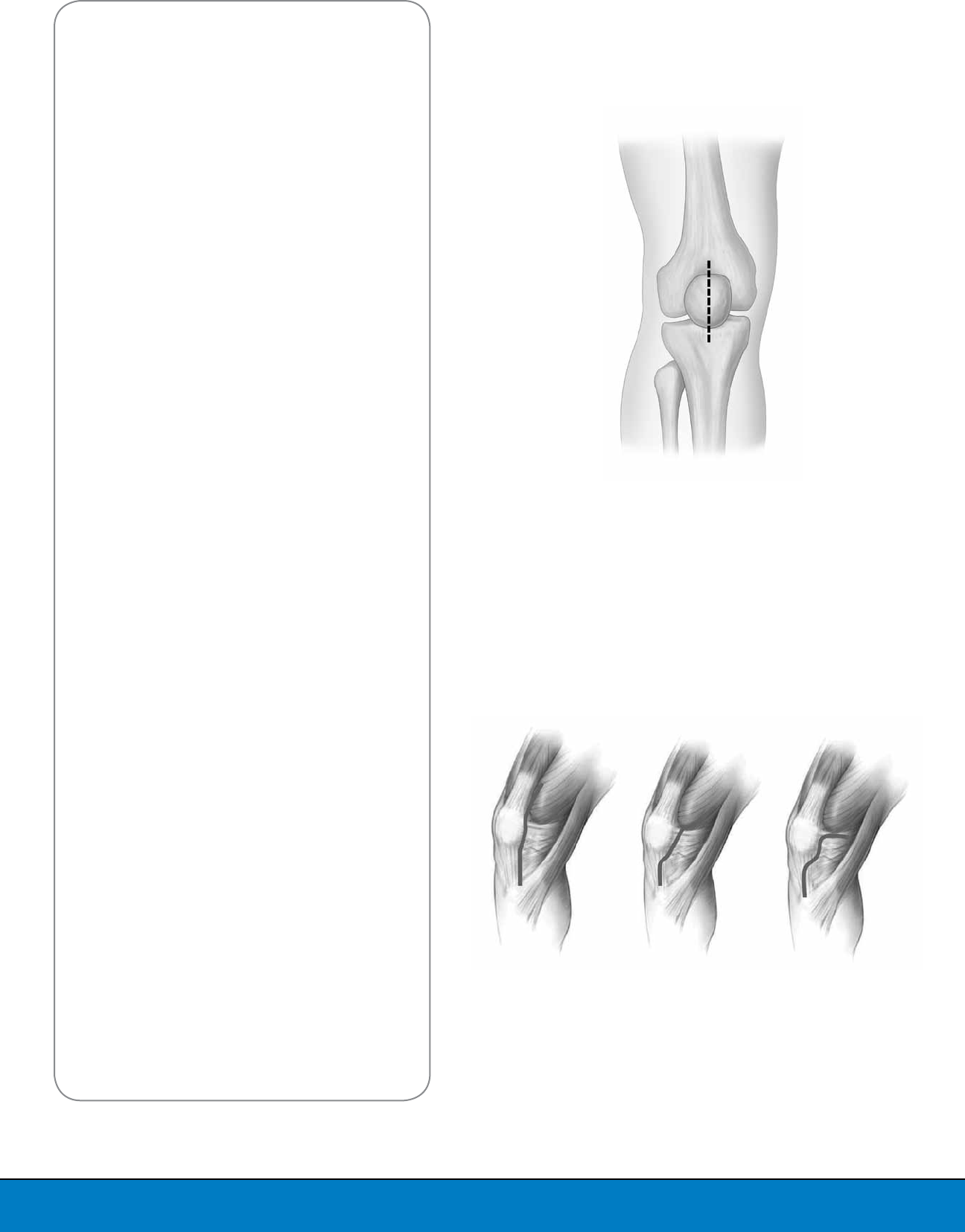
PRE-OPERATIVE PLANNING
The mechanical goal of total knee surgery is to
effectively restore the normal alignment of the
affected limb. Normal alignment implies that the
mechanical axis, from the center of the femoral
head to the center of the ankle, passes through
the center of the knee joint. The implant should
be positioned perpendicular to this axis. Correct
positioning is usually accomplished by performing
the tibial cut perpendicular to the frontal plane,
usually with some degree of posterior slope and
by cutting the distal femur between 5-7 degrees
of valgus from the anatomical axis (Figure 1).
Templating is done in both the frontal and sagittal
planes to estimate the implant size for both the
femur and tibia.
Optetrak Logic® is an advanced approach to total knee replacement that
introduces modern design features and intuitive instrumentation while
building on the wisdom of a strong design lineage.
Figure 1
Different Alignment Angles of the
Mechanical Axis of the Lower Limb
5°6°7°
2
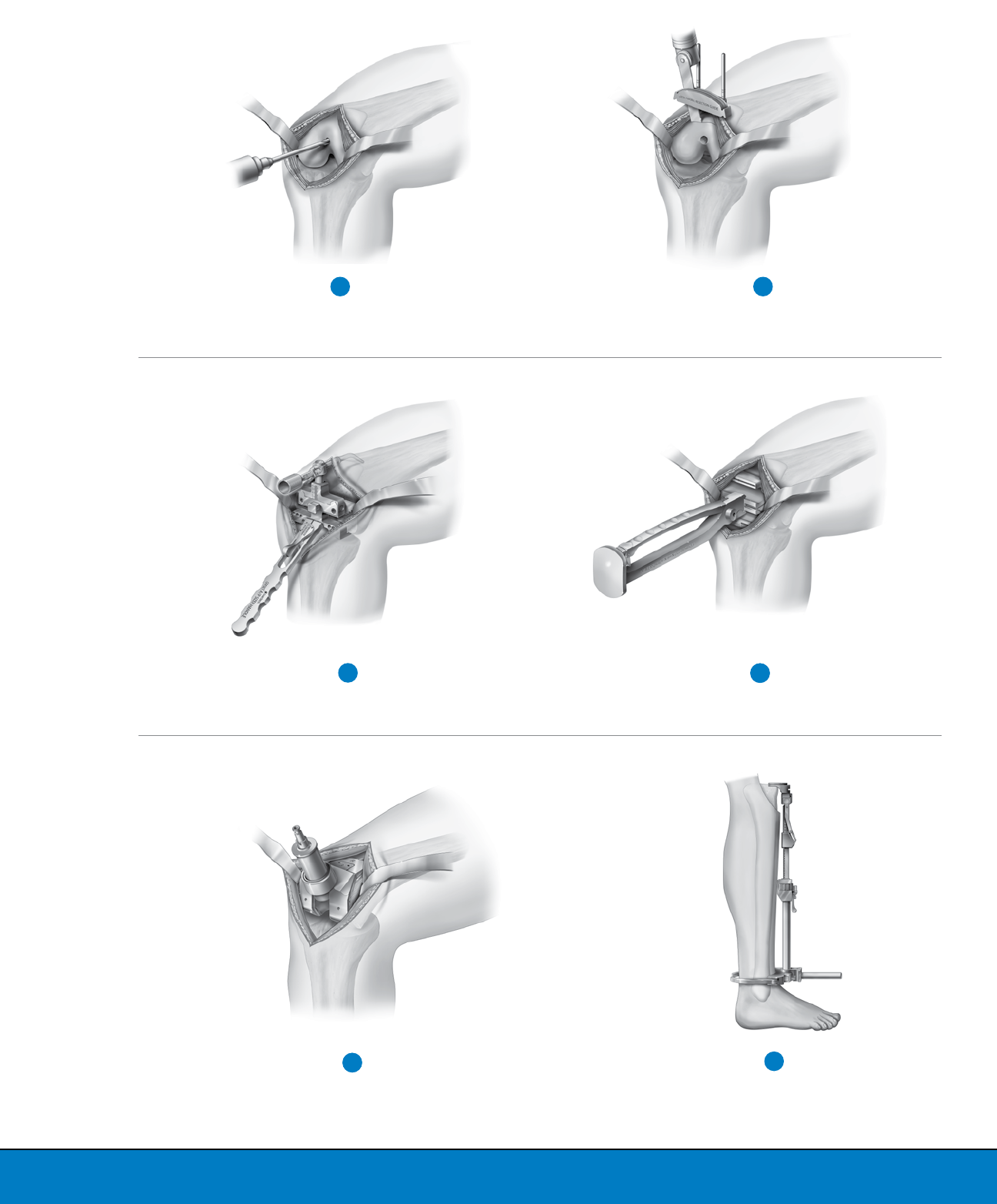
OPERATIVE TECHNIQUE OVERVIEW
Enter Intra-medullary Canal
with the IM Pilot Drill
Perform Distal Femoral Resection
12
Prepare Femur with Femoral
Finishing Guide
Prepare PS Notch with Notch Cutting Guide* Prepare Tibia with Extra-medullary
Alignment Guide and
Perform Tibial Resection
6
54
65
Determine Femoral A/P Size
3
*For PS Only
3
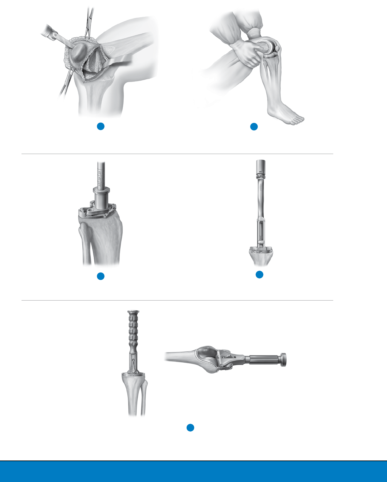
Prepare Patella
7
Assemble Trials and Perform
Final Stability Assessment
Drill Pilot Hole on Tibia
8
9
Prepare Tibia with Fit Tamp
410
Implant Final Components
511
4
DETAILED OPERATIVE TECHNIQUE
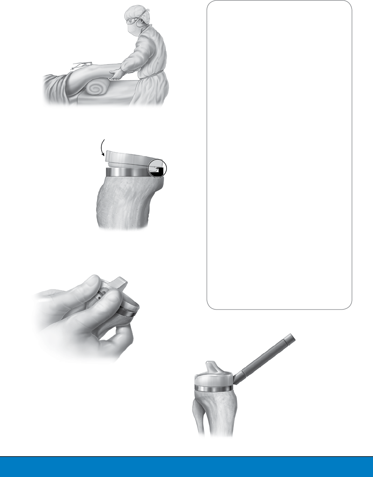
APPROACH AND EXPOSURE
Setup is important, and because the degree of
flexion and extension of the knee must be adjusted
and optimized for each step of the procedure,
an adjustable foot holder, an extra assistant or
placement of multiple bolsters on the surgical
table is helpful. Although a great deal of traditional
arthroplasty is performed with the knee in a
flexed or hyperflexed position, the use of reduced
exposure is often facilitated by placing the knee
in a more extended position, thereby relaxing
the anterior soft tissue envelope. The landmarks
shown in this procedure performed with the
Optetrak Low Profile Instrumentation (LPI) are the
same ones used during standard incision total
knee replacement surgery, including the shape of
the patella, the anterior tibial tuberosity and the
joint line (Figure 2).
An 8-10cm incision is made, beginning at or 1cm
above the superior pole of the patella and extending
2cm distal of the joint line. Fascia adhesions of
the quadriceps muscle to the tissues are freed
with blunt and sharp dissection, which facilitates
subsequent soft tissue and patellar mobilization.
The joint is then entered through one of three
approaches: subvastus, midvastus or rectus
femoris split (Figure 3).
During a subvastus approach, the arthrotomy
is capsular only, preserving the entire extensor
mechanism insertion onto the patella. A fascia
rim is preserved bordering the vastus medialis
obliquus (VMO) to assure retractors are placed
against this rim and not directly on the muscle over
the quadriceps itself. The reflected retinaculum
contains the medial patellofemoral ligament
and must be tagged, retracted and protected.
The medial capsular reflection under the VMO is
released, allowing the quadriceps to be displaced
laterally.
In the midvastus approach, an incision is made
between the vastus medialis and the vastus
medialis obliquus, beginning at the superior and
medial corner of the patella. The muscle is split
bluntly in line with its fibers, while the underlying
fascia is split sharply by pushing scissors in a similar
direction. This 2cm split can be safely extended for
3-4cm, although this is rarely necessary.
The rectus femoris split approach is simply a
shortened conventional arthrotomy. Of course, all
approaches can be and are being used successfully.
To optimize the ease and efficiency of the procedure
in patients with increased obesity, increased thigh
muscularity, increased distal femoral dimension,
patella baja, a more horizontal VMO insertion, a
decreased extensor mechanism mobility, or in any
case when difficult exposure is anticipated, it is
recommended to move away from the subvastus
toward either the midvastus, or on occasion, the
rectus split approach.
Figure 2
Skin Incision. Bony Landmarks Can Be
Recognized Underneath the Skin
SubvastusMini-midvastusRectus Femoris Split
Figure 3
Enter Joint Through One of These
Three Approaches
5
The exposure is expanded medially using an
angled narrow and sharpened Hohmann Retractor.
A second Hohmann Retractor is used to push the
patella laterally. The patella is not everted. Initially,
exposure is limited to the central and medial
compartments. However, with some extension, the
entire joint can be delivered into the wound. An
interesting paradox exists with regard to both the
number of retractors and the force of retraction:
less is more. Retraction for exposure in one area
will result in a proportionate and obligate reduction
of exposure in another. Using fewer and narrower
angled retractors and pulling reciprocally rather
than forcefully is recommended. The retractor
and leg position must be constantly adjusted and
optimized for each step of the procedure.
Exposure during the remainder of the procedure
is achieved by moving the soft tissue window. The
anterior cruciate ligament (ACL) and the anterior
horns of both menisci are resected. The superficial
layers of the medial collateral ligament (MCL)
are subperiosteally elevated, and a meticulous
resection of osteophytes is performed. This not only
helps to mobilize the unresected patella into the
lateral gutter of the knee, but also relieves tension
off the lateral and medial collateral ligaments.
A very important precaution in every small incision
procedure is to keep the suprapatellar pouch as
intact as possible; this decreases the incidence of
short-term post-operative pain and long-term scar
formation and limited flexion.
PREPARATION OF THE FEMUR
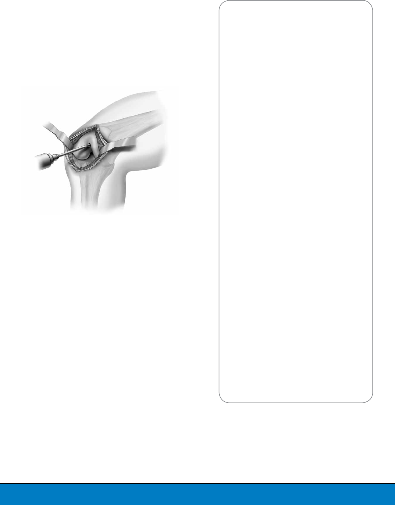
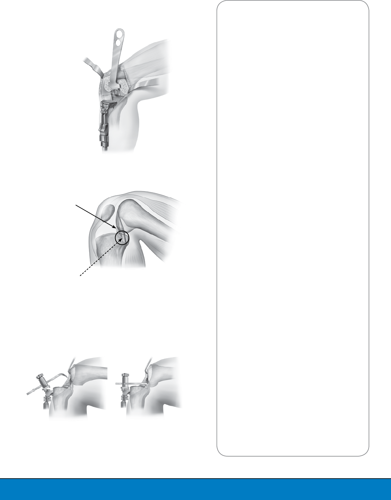
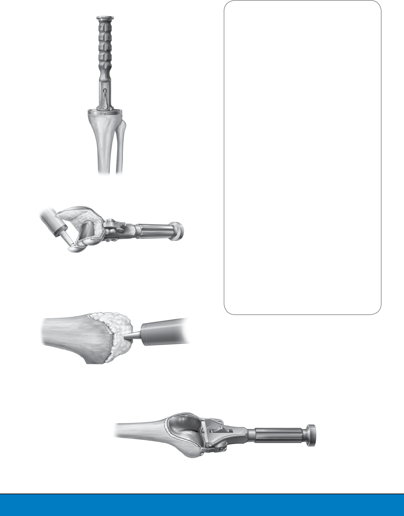
Step 1: Opening the Intra-medullary Canal
The Intra-medullary (IM) Pilot Drill should be used
to drill a hole in the distal femur coaxially with the
femoral endosteal canal (Figure 4). The entry point
for this drill is located in the intercondylar groove
5-10mm anterior to the intercondylar notch. This
entry point may be more accurately located by one
of these two methods:
1. palpating the femur in the cephalad portion of
the exposure, or
2. opening the cortex anterior to the femoral notch
with a rongeur, osteotome or gouge.
It may be beneficial to enlarge the hole in the distal
femur while drilling so that a slightly malpositioned
entrance point does not affect the alignment of the
T-Handle Intra-medullary Rod. After the canal has
been opened with the IM Pilot Drill, the T-Handle IM
Rod should be inserted into the femoral canal to be
sure it passes easily. The T-Handle IM Rod should
then be removed from the canal.
Figure 4
Enter Intra-medullary Canal
with the IM Pilot Drill
6
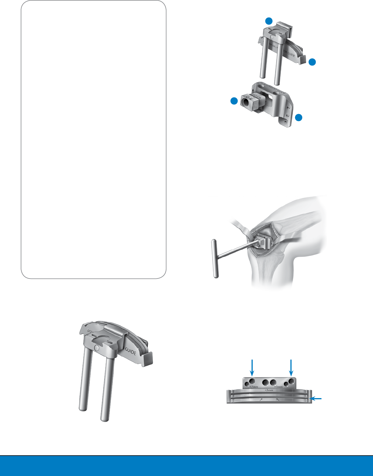
Step 2: Distal Femoral Resection
To set the distal femoral valgus alignment of
the femoral cut, insert the LPI Intra-medullary
Alignment Guide Bushing into the LPI Intra-
medullary Alignment Guide with the proper side
(left or right) facing anteriorly (Figure 5). The release
button underneath the rectangular hole in the IM
Alignment Guide should be pressed, allowing the
IM Alignment Guide Bushing to slide into it.
Place the T-Handle IM Rod through the LPI IM
Alignment Guide Bushing and introduce the
assembly onto the distal femur (Figure 6). The IM
Alignment Guide can be aligned parallel to the
transepicondylar axis, although alignment is not
crucial at this point.
Affix the LPI Distal Link to the LPI Distal Femoral
Resection Guide (Figure 5); this makes placement
of the resection guide underneath the soft tissue
easier (Figure 7a).
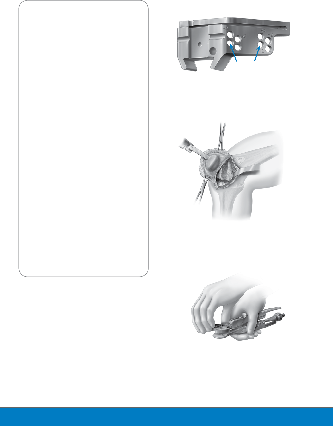
The distal femoral resection will be influenced
by the degree of flexion contracture documented
during pre-operative examination. Adjusting the
depth of distal femoral resection to the degree of
flexion contracture is important to ease balancing
the flexion and extension gaps. The Distal Femoral
Resection Guide features different pinholes that
allow for adjustment of the resection depth in 2mm
increments.
Pin the Distal Femoral Resection Guide in the
nominal holes (Figure 7b). Performing the distal
femoral cut through the standard slot resects 10mm
from the distal femur (Figure 7b); the alternative
slot resects 3mm more (13mm). The block may be
shifted to the second pin location for an additional
2mm resection. The Distal Femoral Resection Guide
also features two extra holes for cross pins that
enhance the fixation of the Resection Guide to the
bone and make it more stable during the resection.
Figure 6
Align Distal Femoral Cutting
Instruments
Figure 7a
Assemble Distal Femoral
Resection Guide to Distal Link
Figure 7b
Pin Distal Resection Guide
in Nominal Holes
4
3
1
2
Figure 5
Assemble the Femoral Alignment
Instruments for Distal Femoral Resection
1. Bushing
2. IM Alignment Guide
3. Distal Link
4. Distal Femoral Resection Guide
Nominal Holes
Standard
Slot
7
Remove the T-Handle, Alignment Guide and Distal
Link. The quadriceps and skin must be retracted
proximally and the knee slightly extended before
performing the distal femoral resection.
The distal femoral resection is performed, always
protecting the medial and lateral collateral
ligaments (Figure 8). The medial condyle should be
resected first. The surgical window should now be
mobilized to the lateral compartment of the knee
to perform the lateral condylar resection (Figure 9).
The Distal Femoral Resection Guide should now
be removed. Bone remnants may now be removed
with a rongeur, a saw or a bone file. To be sure
that the resected surfaces of the medial and lateral
femoral condyles are coplanar, a flat cutting block
may be used to check the cuts.
Step 3: Rotation of Femoral Components
Templating is essential in small incision
procedures, since the surgeon has a limited view
of the anterior aspect of the distal femur. Adjust
the LPI Femoral A/P Sizer to the templated size
or set to 3 to begin. External femoral rotation is
determined by inserting the LPI Femoral A/P Sizer
Drill Guide Bushing into the LPI Femoral A/P Sizer.
The LPI instruments feature different Drill Guide
Bushings, including 0- and 3-degree options for
both right and left. This handle does not interfere
with the Drill Guide.
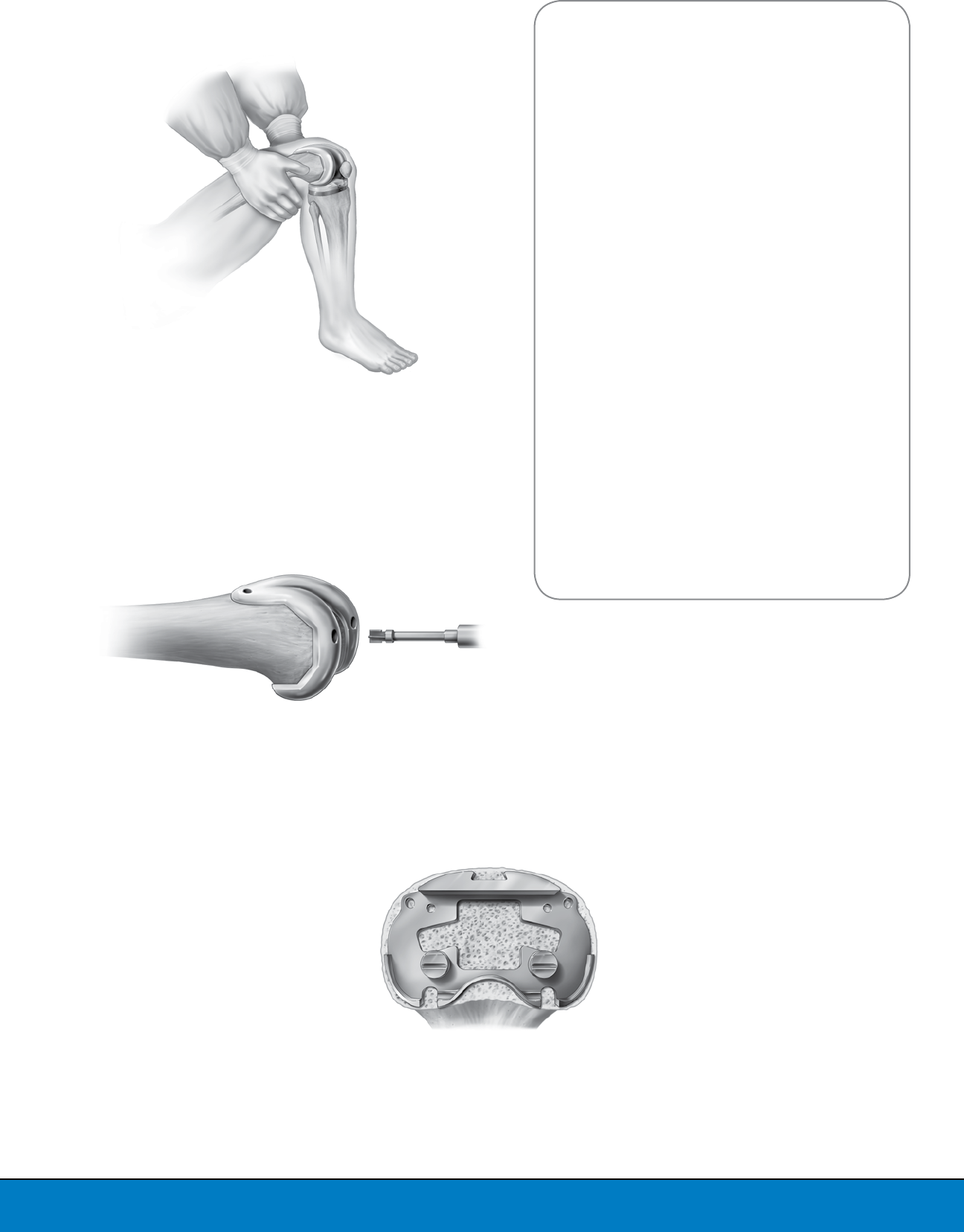
Step 4: Sizing the Femoral Component
The LPI Femoral A/P Sizer should be placed flush
against the resected distal surface of the femur.
The LPI Offset A/P Sizer Handle is provided to
facilitate insertion and manipulation of the A/P
sizer (Figure 10).
Figure 8
Perform Distal
Femoral Resection
Figure 9
Resected Distal Femur
Figure 10
Place Femoral A/P Sizer on
Distal Femur
8
The posterior feet of the Sizer should be inserted
under the posterior femoral condyles. If a posterior
condylar defect is present, the LPI Femoral A/P Sizer
should be rotated to a position that accommodates
the defect. Due to the size of the incision and the
medial arthrotomy, the A/P Sizer could be placed
slightly medial on the femoral bone. The Femoral
A/P Sizer is adjusted to the femoral size. Slide
the tip of the A/P Sizer Stylus underneath the
quadriceps and into the suprapatellar pouch. The
surgeon palpates the position of the tip of the Stylus
Pointer, trying to make it rest in the midportion of
the femoral metaphysis. It is advisable to choose a
smaller femoral size if the A/P Sizer is measuring
between sizes. The surgeon may correlate the
template size with the size given by the Femoral
A/P Sizer as a size confirmation.
Verify that the A/P Sizer is flat against the distal
femoral surface, and drill holes with the LPI Collar
Drill (Figure 11).
Step 5: Resection of Anterior, Posterior and
Chamfer Femoral Bone
The LPI Femoral Finishing Guide should be
positioned onto the distal femur using the LPI
Finishing Guide Impaction/Extraction Handle
(Figure 12).
The size of the Femoral Finishing Guide has been
determined previously with the LPI Femoral A/P
Sizer. The Femoral Finishing Guide has two pegs
that align with the pre-drilled rotation holes and
can be pinned on the medial and lateral sides, as
well as in the center with cross pins to enhance
fixation stability. The anterior and posterior cuts
are performed followed by the chamfer cuts. Once
the cuts on the distal femur have been completed,
the Femoral Finishing Guide should be removed
and the resected bone excised.
Figure 12
Position Femoral Finishing Guide
Figure 11
Verify Placement of A/P Sizer and
Drill Rotational Alignment Holes
9
If an Optetrak Logic CR implant is selected, the femoral
preparation is complete for now. Proceed to the next
section, Preparation of the Tibia.
If an Optetrak Logic PS implant is selected, proceed
to Step 6 to complete the femoral notch preparation.
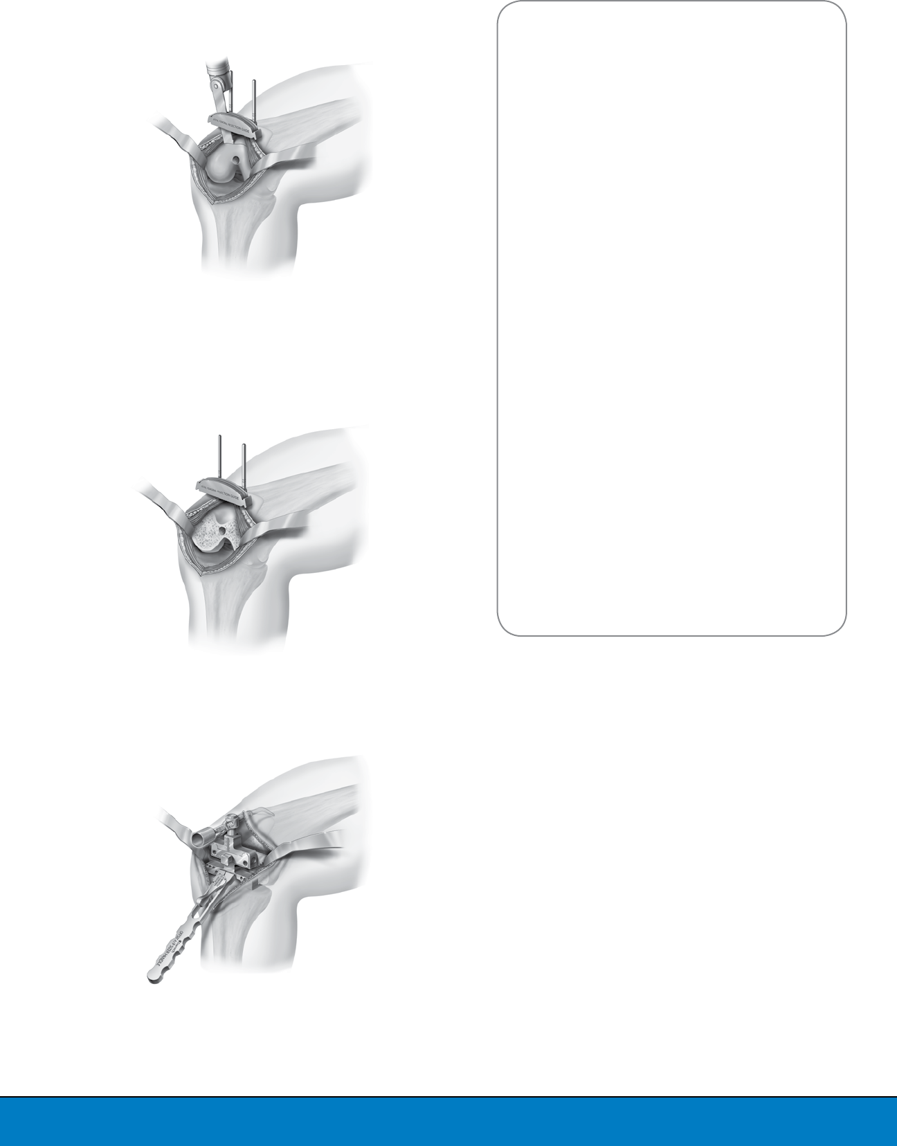
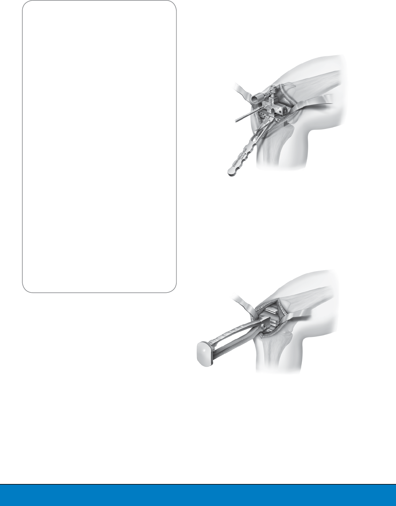
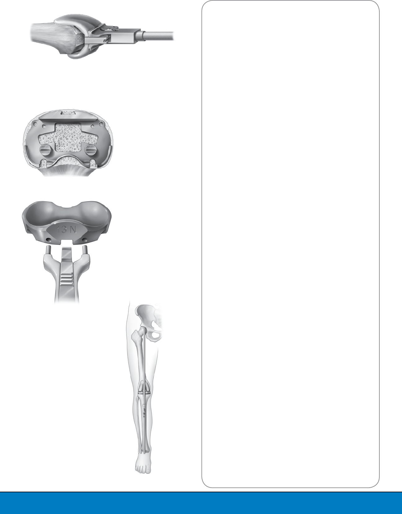
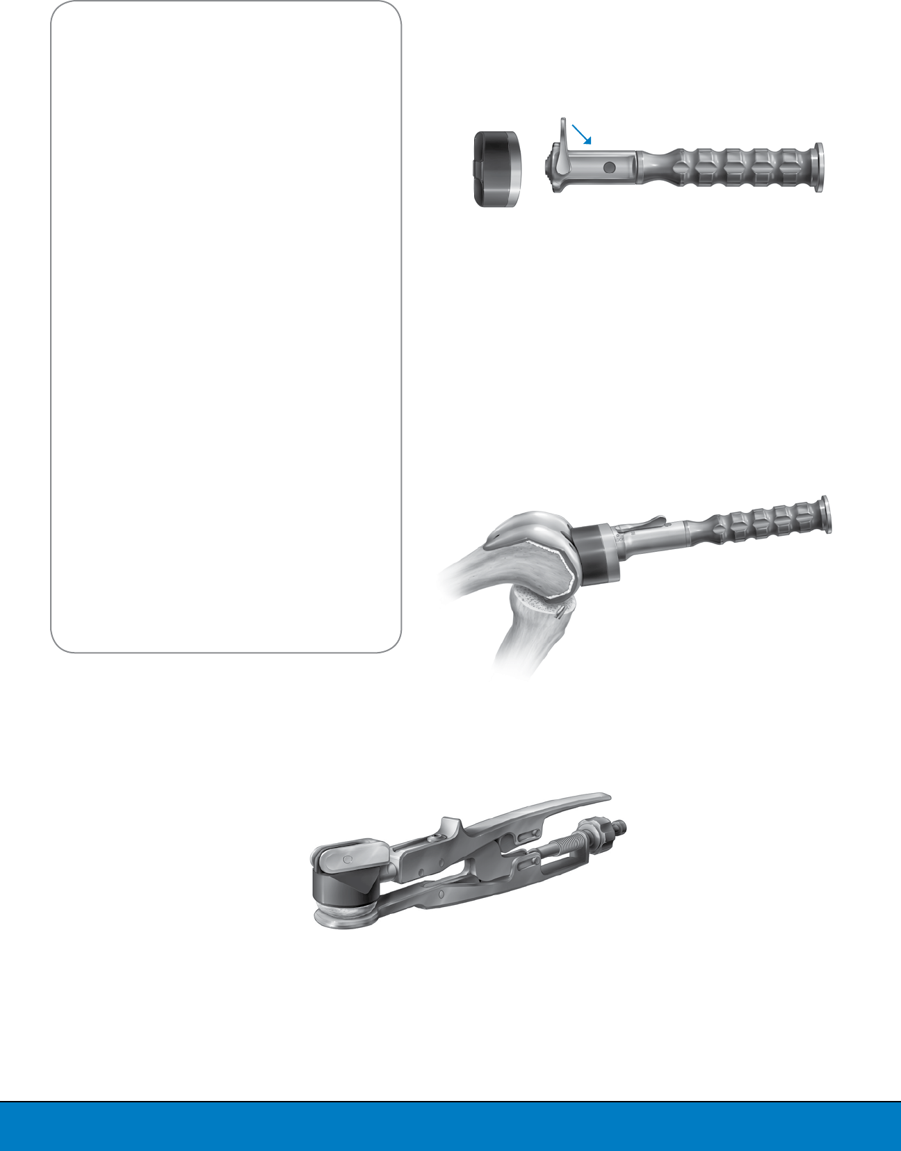
Step 6: Femoral Notch Preparation
Select the Logic PS Femoral Notch Cutting Guide and
the Logic PS Femoral Notch Cutter that correspond to
the previously determined femoral component size.
Rotate the anterior flange of the Notch Cutting Guide to
the appropriate side that corresponds to the operative
knee (left or right), place on finished cuts and affix
the Notch Cutting Guide onto the distal femur with
fixation pins.
Note: While pinning, be sure the Notch Cutting Guide
maintains contact with the distal and anterior chamfer
resections. Affix the two distal pins, then affix one pin
in the offset medial anterior flange.
Attach the Notch Cutter to a power drill. With the knee
in flexion, introduce the Notch Cutter into the Notch
Cutting Guide, making sure that the drill is set on
“drill” setting. Once the teeth on the Notch Cutter have
cleared the black bushing and before the teeth contact
the bone, activate the drill. Apply pressure to the Notch
Cutter as it travels posteriorly and ream until the Notch
Cutting Guide prevents the Notch Cutter from further
travel (Figure 13).
Turn the power drill off, and remove the Notch Cutter
from the Cutting Guide. Note: Be sure not to activate
the drill while removing the Notch Cutter in order
to prevent the cutting teeth from scoring the black
bushing.
Due to the cylindrical shape of the Notch Cutter, it
is necessary to remove any existing bone remnants
from the distal femur (Figure 14). It is recommended
to use a sagittal saw to remove the bone remnants,
aligning the saw to the inner surfaces of the Notch
Cutting Guide and trim the medial and lateral sides
of the notch. Remove the Notch Guide after all cuts
are performed. Preparation for the Optetrak Logic PS
femoral component is complete.
Figure 13
Prepare PS Notch
with Cutting Guide
Figure 14
Remove Bone Remnants from
the Distal Femur
10
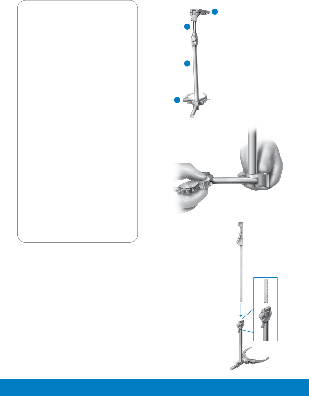
Figure 15
Assembly of LPI Extra-medullary
Tibial Alignment Guide
1. LPI Ankle Clamp Base
2. LPI Ankle Clamp Upright
3. LPI Tibial Resector Shaft
4. LPI Tibial Resection Guide
Figure 16
Insert Ankle Clamp Base
into Ankle Clamp Upright
PREPARATION OF THE TIBIA
The tibia can be prepared using either the LPI
extra-medullary preparation method or the LPI
intra-medullary preparation method.
Note: See the Intra-medullary Tibial Preparation
Operative Technique Addendum for preparation
details.
Assembly of the Extra-medullary Tibial
Alignment Guide
The proximal tibial resection can be aligned and
performed using the LPI Extra-medullary Tibial
Alignment Guide (LPI Ankle Clamp Base, LPI Ankle
Clamp Upright, LPI Tibial Resector Shaft and LPI
Tibial Resection Guide) (Figure 15).
To assemble the Extra-medullary Tibial Alignment
Guide, slide the shaft of the LPI Ankle Clamp Base
into the lower end of the LPI Ankle Clamp Upright.
The markings on the LPI Ankle Clamp Base should
face upward, and the push button on the LPI Ankle
Clamp Upright should face away from the Ankle
Clamp. While pressing the button on the LPI Ankle
Clamp Upright, assemble the upright onto the shaft
of the LPI Ankle Clamp Base (Figure 16).
Position the lever on the proximal end of LPI Ankle
Clamp Upright pointing down. Press the button on
the proximal end of the LPI Ankle Clamp Upright
and insert the LPI Tibial Resector Shaft into the
LPI Ankle Clamp Upright with the teeth facing
posteriorly, or away from the lever and button
(Figure 17).
When the button is pressed, the LPI Tibial Resector
Shaft will be able to move within the LPI Ankle
Clamp Upright. When the button is released, the
position of the LPI Tibial Resector shaft is locked.
Note: The lever can be shifted to either side to
disengage the push button locking mechanism,
allowing the LPI Tibial Resector Shaft to
move freely.
Figure 17
Insert Tibial Resector Shaft into
LPI Ankle Clamp Upright
4
3
2
1
11
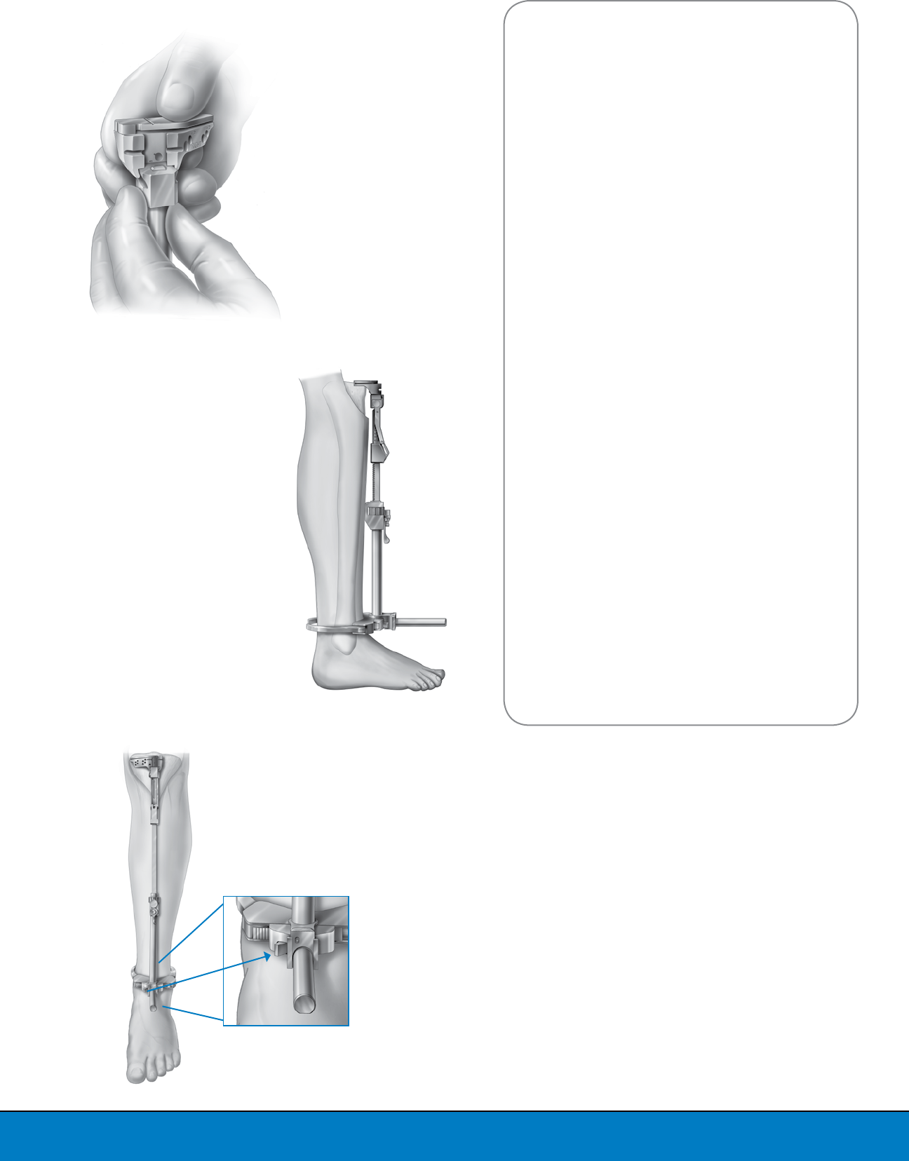
Attach the LPI Tibial Resection Guide to the
proximal end of the LPI Tibial Resector Shaft by
pressing the button on the LPI Tibial Resector Shaft
and sliding the LPI Tibial Resection Guide onto the
dovetail, from posterior to anterior (Figure 18).
Placement of the LPI Extra-medullary Tibial
Alignment Guide
Place the LPI EM Tibial Alignment Guide on the
front of the tibia and clamp the spring-loaded arms
around the ankle in the supra-malleolar position
(Figure 19).
The distal end of the LPI EM Tibial Alignment
Guide should be centered over the ankle joint.
In most instances, the LPI Ankle Clamp Base will
read 2-5mm medial when properly centered on
the ankle. The second toe is another common
landmark for the distal alignment of the Ankle
Clamp. The position of the LPI Ankle Clamp Base
can be adjusted by pressing the release lever and
shifting the Guide medially or laterally (Figure 20).
Landmarks to center the LPI Tibial Resection Guide
proximally include the medial 1/3 of the anterior
tibial tuberosity and tibial spine. In the sagittal
plane, the LPI EM Tibial Alignment Guide should be
aligned parallel to a line extending from the center
of the knee joint to the center of the ankle joint.
The posterior slope of the LPI Tibial Resection
Guide can be adjusted by positioning the proximal
end of the Resector Shaft to the desired degree
of posterior slope (0, 3, 5, 7 or 10 degrees). If the
surgeon prefers, posterior slope may also be
adjusted by repositioning the LPI Ankle Clamp
Upright on the LPI Ankle Clamp Base. Positioning
the LPI Ankle Clamp Upright more anterior onto
the base will add slope to the LPI Tibial Resection
Guide, while positioning it more posterior will
reduce slope.
The next two sections outline the tibial resection
technique for the Optetrak Logic PS and Optetrak
Logic CR systems, respectively.
Figure 18
Assemble Tibial Resection Guide and
Tibial Resector Shaft
Figure 19
Placement of Extra-medullary
Tibial Alignment Guide
Release
Lever
Figure 20
Center Distal End of LPI EM Tibial
Alignment Guide Over the Ankle
12
TRADITIONAL TIBIAL APPROACH:
RECOMMENDED FOR PS KNEES
Once the appropriate slope has been dialed in,
the LPI Fixed Tibial Stylus should be placed in the
cutting slot of the LPI Tibial Resection Guide. The
resection level should be adjusted so that the LPI
Fixed Tibial Stylus references the proximal tibia
plateau.
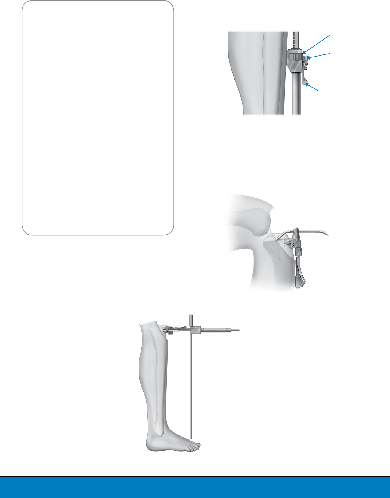
The resection level of the LPI Tibial Resection
Guide can be adjusted by pressing the button on
the proximal end of the LPI Ankle Clamp Upright.
Micro adjustments to the resection level can be
made by rotating the knob on the proximal end of
the LPI Ankle Clamp Upright (Figure 21).
To set resection depth, use the 10mm side of the
Stylus when referencing the most normal plateau
and the 1mm side when referencing the most
affected plateau (Figure 22).
The LPI Cut Line Predictor may be used to evaluate
the tibial resection level. Once the LPI Tibial
Resection Guide is adjusted to the desired resection
level and slope, it can be pinned in position.
The alignment of the resection guide can be
verified by locking the Mauldin Multi-Tool into the
anterior recess of the block and inserting the drop
rod into the holes of the Mauldin Multi-Tool. The
drop rod can be used to assess alignment with
extra-medullary landmarks (Figure 23). Proceed to
resect the proximal tibia.
Knob
Button
Lever
Figure 21
Adjust Resection Level
Figure 22
LPI Fixed Tibial Stylus on the
LPI Tibial Resection Guide
Figure 23
Assess Alignment
with Extra-medullary
Landmarks
13
CR TIBIAL RESECTION: POSTERIOR CRUCIATE
REFERENCING TECHNIQUE (PCRT)
Note: Standard CR inserts are available for a more
traditional tibial approach.
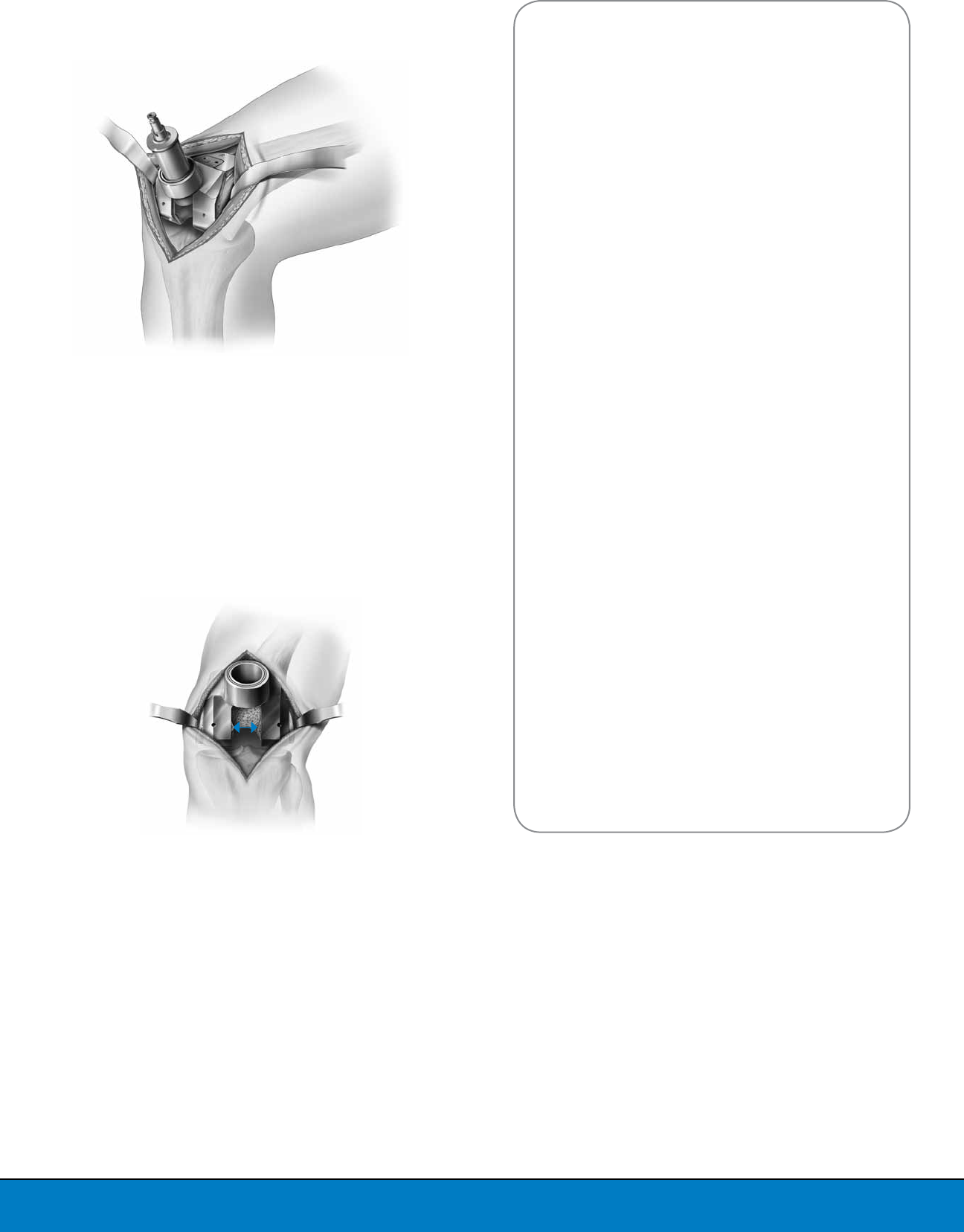
Step 1: Identification of the posterior cruciate
ligament (PCL) Insertion Points
Place the No-Touch PCL Retractor behind the tibia
with one prong medial and one prong lateral to the
PCL (Figure 24). Subluxate the posterior margin
of the tibia anterior to the femur. At this point, the
No-Touch PCL Retractor should protect both the
PCL and the resected surface of the distal femur.
Connective and scar tissues are usually present
around the anterior aspect of the tibial insertion
of the PCL. These tissues are intimately attached to
the fibers of the PCL. Proceed to release the tissues
around the anterior portion of the PCL, until the
fibers of the PCL are recognized at their insertion
into the posterior tibia (Figure 25).
Identification of the PCL fibers and release of the
scar tissue surrounding the PCL is essential at this
point. This is the anatomical landmark that will be
used to reference the proximal tibial resection.
It is also advisable to resect any remaining
posterior horns of both menisci and menisco-
femoral ligaments at this time.
Step 2: Placement and Distal Alignment of the
Extra-medullary Alignment Guide
The proximal tibial resection can be aligned and
performed using the LPI Extra-medullary Tibial
Alignment Guide. For assembly and positioning,
please refer to the LPI Extra-medullary Tibial
technique as described previously.
Step 3: Determination of Posterior Tibial Slope
When setting up the sagittal orientation of the
proximal tibial resection, aim for a posterior slope
between 0 and 3 degrees. Increasing the posterior
tibial slope angle beyond 5 degrees may damage
the tibial insertion of the PCL. Adjustments to the
flexion gap can be made during trial reduction
by using various Logic CR Slope Tibial Insert Trial
options as detailed later in the technique.
Step 4: Determination of Tibial Resection Depth
The Adjustable PCL Stylus should be placed in
the cutting slot of the LPI Tibial Resection Guide
with the stylus in the raised position (Figure 26a).
After assembly, snap the stylus down and place
the tip of the stylus at the tibial insertion of the
PCL. The Adjustable PCL stylus has three settings:
0, 2, and 4mm. This setting indicates the amount
of additional distal tibial resection from the tip of
the stylus. For example, if the stylus guide is set
to 0mm, the tibia resection is aligned exactly to
the tip of the stylus. If the stylus is set to 2mm or
4mm, the tibial resection is aligned either 2mm
or 4mm below (more distal) the tip of the stylus.
The recommended resection level is at the 2mm
position.
Figure 25
Clear Soft Tissues
around PCL
Figure 25
Place Tip of PCL Stylus
at Footprints of PCL
Figure 24
Placement of No-Touch
PCL Retractor
Figure 26a
Determine Tibial Resection Depth
14
Figure 27
Prepare Patella with Freehand
Patellar Resection Technique
Figure 26b
Place Drill Pins
Figure 28
Assemble the LPI Universal Patellar
Drill Guide to the LPI Patella
Preparation Handle
Step 5: Securing Tibial Resection Guide to Tibia
and Final Checking
When the proper positioning of the LPI Tibial
Resection Guide has been assured, drill pins
should be placed through the guide into the tibia
(Figure 26b). Drill pins should be placed in the “0”
or “nominal” holes.
The LPI Tibial Resection Guide may be adjusted
proximally or distally in 2mm increments by
shifting the LPI Tibial Resection guide to either the
+2mm or -2mm holes on the block itself on the
existing drill pins.
Proceed to make your proximal tibial resection.
PREPARATION OF THE PATELLA
For patellar resection performed without a Patellar
Resection Guide (“free hand”), the patella should
be stabilized with large towel clips or similar
instruments. The articular surface of the patella
should be resected with an oscillating saw from
either (1) the edge of the medial articular surface
to the edge of the lateral articular surface, or (2)
from the patellar tendon insertion cephalad to the
quadriceps tendon insertion (Figure 27). When
patellar resection is complete, final determination
of patellar size (diameter) and hole preparation
should be performed using the LPI Patellar
Universal Drill Guide assembled to the LPI Patella
Preparation Handle (Figure 28). With the handle
completely open, position the Drill Guide on
the patella to determine the patellar diameter.
The pattern and size of the Drill Guide holes are
universal for all three-peg patella components.
Clamp the patella and secure the handle by turning
the knob. Holes should be drilled through the
patellar universal drill guide in either the three-hole
or the single-hole configuration. After the holes are
drilled, loosen the knob and remove the handle and
Drill Guide from the patella. The appropriate size of
trial prosthesis should be placed on the patella.
Note: Other options for patella resection guides
are available. See the Patella Operative Technique
Addendum for details.
Nominal
Holes
15
FINAL PROSTHESIS TRIAL CHECK
Final prosthesis trial check should include assessment of:
ALIGNMENT,
STABILITY,
MOTION and
PATELLAR TRACKING
Trial Placement
Place the CR Femoral Trial on the distal femur utilizing
the Locking Femoral Impactor (Figure 29). Assemble the
selected femoral trial to the Locking Femoral Impactor.
Ensure that the femoral component is properly positioned
on the distal femoral condyles in the medial and lateral
direction. Apply slight upward pressure to the impactor
handle as the component is being impacted to prevent
the femoral component from rotating into flexion. Once
correct positioning is assured, the component should be
fully seated by striking the Locking Femoral Impactor with
a mallet.
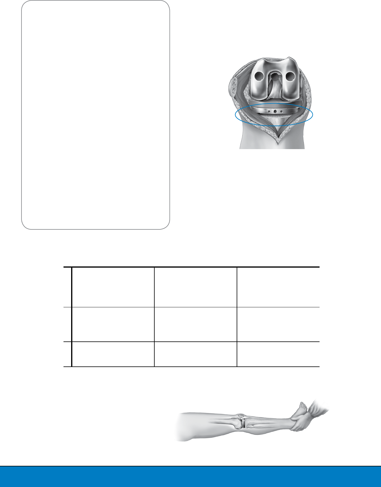
The tibial tray trial should be selected as the largest tray
that fits within the borders of the resected tibial surface,
without any overhang, and then fixed to the proximal tibia.
Please note that the position of the tibial tray trial relative
to the resected tibial surface should be centered along the
A/P direction (Figure 30). Notably any anterior offset of the
tibial tray trial should be avoided, as it would result in a
posterior shift of the femoro-tibial contact point. Next, tibial
insert trials should be exchanged using the LPI Trial Insert
Handle until a “best fit” is achieved (Figure 31).
Keep in mind that the size of the femur must always match
the size of the tibial insert in order to maintain the 0.96
femoral/tibial congruency.
Alignment Check
With the knee in full extension and the Mauldin Multi-
Tool assembled to the Tibial Tray Trial, EM Alignment Rods
should be placed in the holes in the Mauldin Multi-Tool
and the alignment should be assessed (Figure 32). Proper
rotation of the tibial component should be determined by
its congruency with the femoral component. Normally,
the anterior plane of the tibial component will point
approximately in the direction of the tibial tubercle and
second toe when congruency is established.
Stability Check
The knee should be assessed for stability in both extension
and flexion. The extension check should be performed
with the knee flexed a few degrees to relax the posterior
capsule. However, the knee should extend fully. The flexion
check should be performed with the knee flexed to 90
degrees. The most appropriate stability is achieved when
the medial and lateral opening is similar to that of a normal
knee during application of valgus and varus stress. An
adjustment of ligament balance may be needed, if there is
differential ligament tightness between varus and valgus in
flexion or extension.
PS Surgical Approach
For the PS approach, if the knee is loose in extension and
flexion, proceed to exchange the Insert Trial with greater
thickness and reassess stability. A Proximal Tibial Spacer
(PTS) can be used for gaps requiring larger than 15mm
inserts, see the PTS Annex.
Note: Optional constraint may be added by utilizing a Logic
PSC insert.
Figure 29
Place Femoral Trial
Figure 32
Assess Alignment
Figure 30
Fixation of Tibial Tray Trial
Figure 31
Assemble Trial with the Insert
Handle
16
Table 1: FLEXION/EXTENSION GAP BALANCING FOR OPTETRAK LOGIC CR
Figure 33
Anterior Lift-Off of
the Tibial Tray Trial
Figure 34
Check Motion in Extension
Note: Some studies reported that an additional degree of insert
slope on average increases peak flexion by 1.5° to 1.7° 1
CR Surgical Approach
The initial assessment should begin with the CR
9mm Neutral or Standard Tibial Insert Trial. If the
joint is tight in flexion, the CR Slope 9mm + or ++
insert may be selected. There are four different
indicators of a tight flexion space:
1. Excessive femoral rollback with limited ROM in
flexion
2. Anterior lift-off of the Tibial Insert Trial and/or
Tibial Tray Trial (Figure 33)
3. Palpable tension of the PCL when the knee is in
flexion
4. If there is difficulty in extracting the Insert Trial
with the Femoral Trial in place and the knee flexed
at 90 degrees (pull-out test)
Refer to the table for tips regarding flexion/
extension gap balancing (Table 1).
The combination of additional thicknesses and
slope continues until joint stability is achieved.
Motion Check
The knee should extend fully without force (Figure
34). To check flexion, the surgeon should elevate the
thigh and allow the leg to flex by the pull of gravity
(Figure 35). The amount of flexion determined in
this manner is the best intra-operative predictor of
the flexion that will ultimately be achieved.
Tight Extension Loose Extension OK Extension
Tight Flexion
• Use a thinner Logic CR Neutral Tibial
Insert Trial if possible
• Cut additional tibia, respecting the PCL
insertion
• Recess the PCL fi bers respecting the
PCL footprint
• Increase insert thickness and trial with
Logic CR Slope+ or Slope++ Tibial Insert
Trials
• Downsize femoral component
• Recess the PCL fi bers respecting the
PCL footprint
• Trial with Logic CR Slope+ or Slope++ Tibial
Insert Trials of the same thickness
• Downsize femoral component
• If trialed with Slope++ and fl exion gap is
still tight, convert to Logic PS
Loose Flexion
• Resect additional distal femoral bone
and use a thicker Logic CR Neutral Tibial
Insert Trial
• Verify integrity of the PCL if the Neutral
Tibial Insert Trial is thicker than 13mm
• Use a thicker Logic CR Neutral Tibial
Insert Trial
• Verify integrity of the PCL if the Neutral
Tibial Insert Trial is thicker than 13mm
• Resect additional distal femoral bone
and use a thicker Logic CR Neutral
Tibial Insert Trial
• Verify integrity of the PCL if the Neutral
Tibial Insert Trial is thicker than 13mm
OK Flexion
• Resect additional distal femoral bone
• Increase insert thickness and trial with
Logic CR Slope+ or Slope++ Tibial Insert
Trials
17
Patellar Tracking Check
As the knee is put through a range of motion
(ROM), the patella should track smoothly in the
patellar groove of the femoral prosthesis with little
or no pressure exerted against its lateral edge and
without it being held medially. If there is a tendency
to lateral subluxation, lateral retinacular release
should be performed. After final ROM assessment,
remove the Optetrak Logic Tibial Insert Trial and LPI
Tibial Tray Trial.
For Logic CR, leave the Femoral Trial in place. The
LPI One-Peg Patellar Drill is drilled through the
medial and lateral holes on the Femoral Trial. This
will create the space required to accommodate the
pegs on the Logic CR femoral implant (Figure 36).
If the small holes created for the Femoral Finishing
Guide are in the correct medial/lateral location, they
may be used for the pegs of the cruciate retaining
femoral prosthesis.
FINAL PREPARATION OF THE TIBIA
When all checks have been completed and
the appropriate size and rotation of the tibial
components have been determined, the tibia
must be prepared for the tibial tray implant. Pins
may be drilled or driven into the medial and
lateral outrigger holes on the LPI Tibial Tray Trial to
provide stability during final tibial preparation. It
is recommended to use Short-Headed Pins on the
inside holes or LPI Quick-Connect Headless Pins on
the outrigger holes (Figure 37).
Figure 35
Assemble Trials and Perform
Stability Assessment
Figure 36
Prepare Femoral Peg Hole
Figure 37
Fixation of Tibial Tray Trial
18
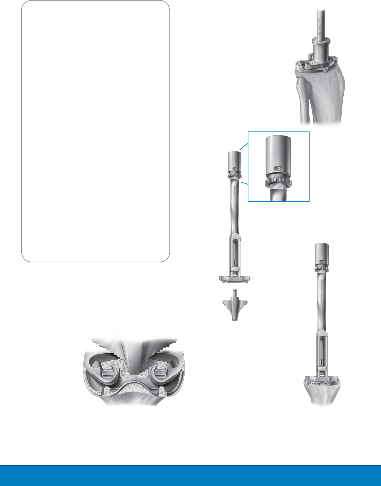
Assemble the Tibial Pilot Drill Guide to the Tibial
Tray Trial. Drill through the Tibial Pilot Drill Guide
with the IM Pilot Drill until the mark on the IM
Pilot Drill matching the selected tray size reaches
the proximal surface of the Tibial Pilot Drill Guide
(Figure 38).
Note: For Half sizes, drill down to the closest whole
size mark.
Assemble the LPI Fit Tibial Tamp to the LPI Tibial
Tamp Guide by pressing the button on the anterior
distal end of the Tibial Tamp Guide and sliding
the Fit Tibial Tamp into the Fit Tibial Tamp Guide
(Figure 39).
Select the size on the LPI Fit Tibial Tamp
corresponding to the Tibial Tray size you intend to
use. The size can be selected by rotating the dial
until the appropriate size is viewed in the window
(Figure 39).
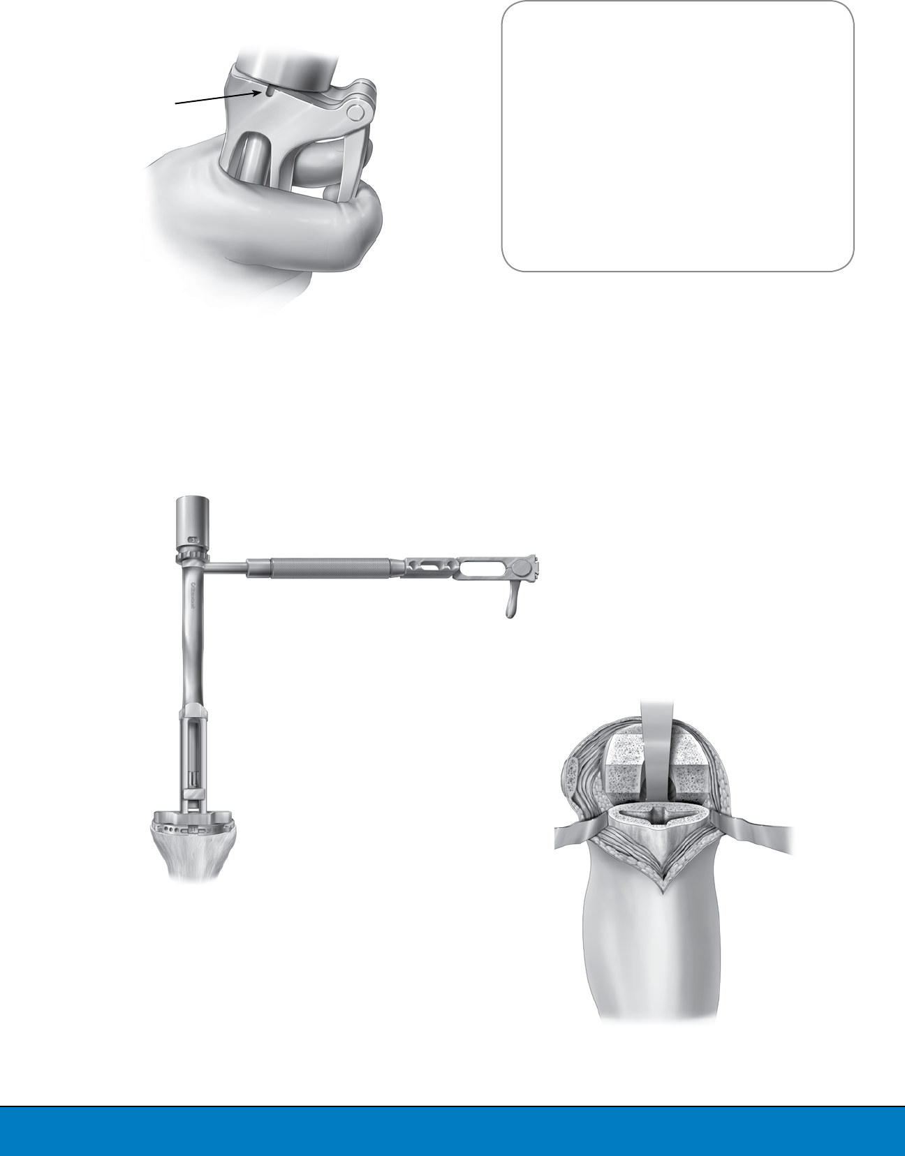
Align the Tamp Guide to the posterior pegs of the
Tray Trial and seat the Tamp Guide flush and stable
against the Tibial Tray Trial (Figure 40). The Tamp
is driven into the tibia until the impaction plate
contacts the handle (Figure 41).
Note: Be sure to hold the Tamp steady during
impaction to avoid tilt or lift-off.
The Tamp should be ejected from the proximal
tibia by squeezing the release lever (Figure 42). If
the Tamp Guide does not disengage from the tibia
with the release lever, a Mauldin Multi-Tool can be
used to disengage it by inserting the small stud on
the end of the Mauldin Multi-Tool into the hole in
the handle of the Tamp, then rotating the Mauldin
Multi-Tool to loosen the Tibial Tamp (Figure 43).
Figure 39
Assemble Tibial Tamp
Figure 40
Align Tibial Tamp Guide
Figure 38
Drill Pilot Hole on Tibia
Figure 41
Fully Impact Tamp
19
IMPLANTATION OF FINAL COMPONENTS
Surgeons have different preferences in regard
to the sequences used to place the prosthesis
components. A standard, successful technique
sequence is described here. If the surgeon prefers
another sequence, the Optetrak Logic knee system
provides sufficient flexibility to accommodate
adjustments in the implantation technique.
Step 1: Final Bone Preparation
Retractors should be placed to expose the joint
(Figure 44). All tissue debris should be removed
from resected bone surfaces. The bone trabeculae
should be thoroughly cleansed with pulsed lavage.
Figure 42
Eject Tibial Tamp Using the
Lever or Mauldin Tool
Insertion Hole
Mauldin Tool
Insertion Hole
Figure 44
Place Retractors to
Expose the Knee Joint
Figure 43
Eject Tibial Tamp Using the
Mauldin Tool
20
Step 2: Implantation of the Tibial Prosthesis
Method 1: Implantation of Modular Tibial
Component
Bone cement should be applied to the prosthesis
and prepared bone surfaces when the cement has a
viscosity low enough to promote good penetration
into the trabecular bone.
Apply bone cement to the proximal tibia and
the distal surface of the tibial tray component,
including the stem, using either a cement gun or
by manually pressurizing the cement. Assure that
both the bone and the boneside of the prosthesis
are thoroughly coated with cement. When using
the Fit tray components, ensure that cement is
pressed into the cement pockets (Figures 45a-c).
Care should be taken to limit the amount of cement
placed on the posterior lateral corner of the implant
to limit cement cleanup in the posterior capsule.
Next, assemble the LPI impactor handle to the
appropriate size Tibial Impactor Plate (Figures 46).
Introduce the tibial tray component onto the
prepared tibial surface using the Locking Tibial
Tray Impactor construct by applying a constant
downward force (Figure 47).
The extraneous cement must be removed from
the borders of the tibial component, starting
posteriorly and working around to the sides
and front. All cement must be removed from the
posterior capsular area of the knee.
Figure 45b
Coat Tray Thoroughly with Cement
Figure 45c
Coat Keel Thoroughly with Cement
Figure 45a
Press Cement Into Cement Pockets
Figure 46
Assemble Locking Tibial Tray Impactor
and Impact Tibial Component
21
Method 2: Implantation of Pre-assembled Tibial
Components
Alternately, the polyethylene tibial insert may be
assembled to the tibial tray prior to implantation.
In this case, the Tibial Insert Driver should be used
to complete the installation of the pre-assembled
tibial components. At this point, bone cement
should be applied to the prosthesis and prepared
bone surfaces as described in Method 1.
Introduce the pre-assembled tibial components
onto the prepared tibial surface using the LPI
Non-Locking Tibial Impactor, applying a constant
downward force.
All extraneous cement must be removed from
the borders of the tibial component, starting
posteriorly and working around to the sides
and front. All cement must be removed from the
posterior capsular area of the knee. The same
technique applies when using all-polyethylene or
metal-backed tibial components.
Step 3: Implantation of Femoral Component
With the femoral component assembled to the LPI
Locking Femoral Impactor, apply bone cement to
the bone mating surface of the femoral component
(Figure 48). Take care to apply only a thin layer of
cement on the posterior surface of the prosthesis
in order to avoid excessive cement extrusion
posteriorly where it could be difficult to remove.
Apply bone cement to the anterior, chamfer and
distal surfaces of the prepared femur (Figure 49).
Avoid placing cement on the posterior bone surface
to prevent excessive cement extrusion posteriorly.
Using the LPI Locking Femoral Impactor, position
the femoral component onto the distal femur
(Figure 50). Slight upward pressure should be
applied to the Impactor Handle as the component is
being impacted to prevent the femoral component
from rotating into flexion.
Figure 47
Place Tibial Prosthesis
Figure 49
Place Cement on Distal Femur
Figure 50
Position Femoral Component
on Distal Femur
Figure 48
Place Cement on
Femoral Component
22
To assemble the Non-locking Femoral Impactor to
the LPI Impactor Handle, place the lever on the LPI
Impactor Handle to the “release” position, attach
the Non-locking Femoral Impactor onto the handle
then move the lever to the “locked” position (Figure
51). Final impaction of the femoral component is
performed with the Non-locking Femoral Impactor
assembled to the LPI Impactor Handle (Figure 52).
Care should be taken to remove all excess bone
cement.
Step 4: Implantation of Patellar Component
Coat the resected patella surface and bone-mating
surface of the patellar component with cement.
Align the pegs of the patellar implant with the
previously drilled peg hole(s) in the patella bone
and press the implant onto the patella.
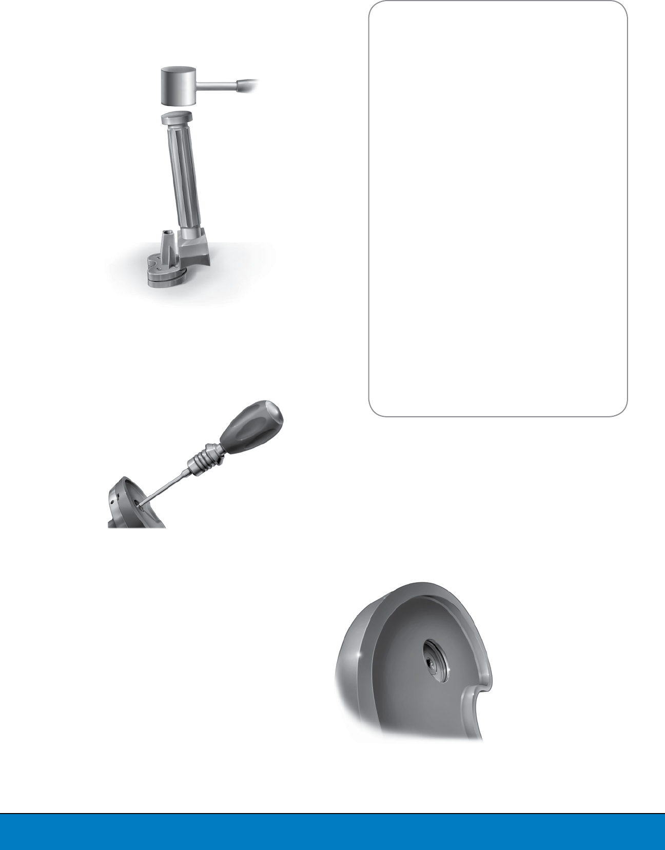
Assemble the LPI Patella Clamp Head to the LPI
Patellar Preparation Handle (Figure 53). Clamp the
patellar component onto the patella bone with the
LPI Patella Preparation Handle and Clamp Head,
avoiding excessive clamping pressure as it may
damage the patella, especially when the bone is
soft. Lock the handle by adjusting the locking nut.
Step 5: Polymerization of Cement
A Tibial Insert Trial should be used when
pressurizing the cement during polymerization.
Hold axial pressure across the joint during cement
polymerization, avoiding either hyperextension
or flexion which may tip the prosthesis into either
flexion or extension (Figure 54).
This is important in every case, but especially in
osteopenic bone. Avoid any movement of the
prosthesis until the bone cement has completely
polymerized.
Figure 51
Assemble Non-Locking
Femoral Impactor to the
LPI Impactor Handle
Figure 52
Impact Final Femoral
Component
Figure 53
Assemble LPI Patellar Clamp
Move Parallel to
Handle to Lock
23
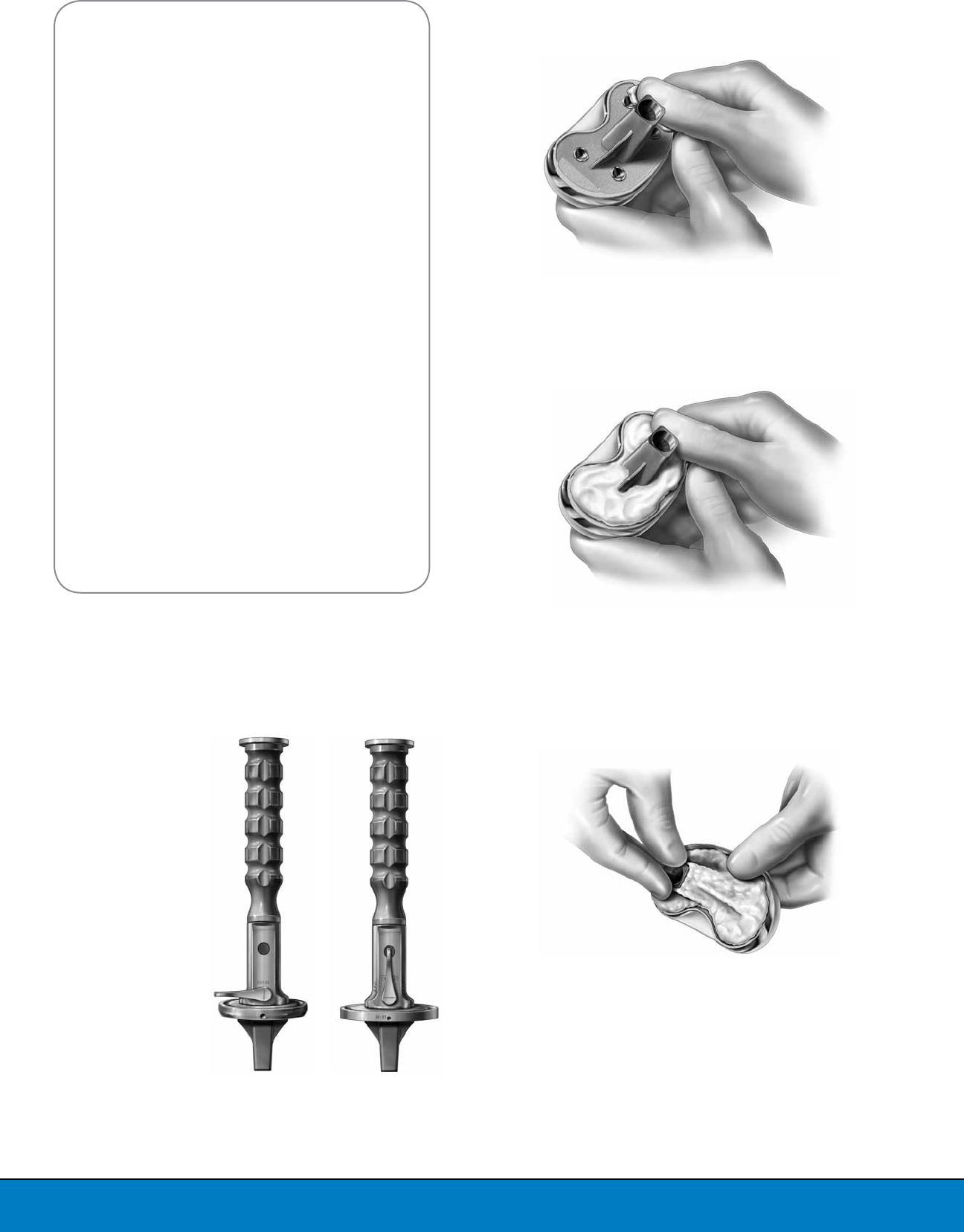
Step 6: Installation of Tibial Polyethylene Insert
(Modular Tibial Component Only)
After polymerization of the cement, introduce the
polyethylene insert into the previously implanted
tibial tray taking care that the posterior feet of the
insert appropriately engage the undercuts of the
posterior aspect of the metal tibial tray (Figure 55).
Be sure to check for any soft tissue or bony
remnants that could interfere with implant
assembly. Continue pushing the polyethylene
insert back with two thumbs until the insert is fully
engaged and the anterior gap between the tray and
the insert is closed (Figure 56).
The Tibial Insert Driver should be used to complete
the assembly of the tibial components (Figure 57).
A mallet should be used for final impaction of the
tibial component.
The surgeon should check to be certain that the
tibial insert is fully seated in the metal tibial tray.
FINAL CHECK AND CLOSURE
Final check includes the following:
1. Removal of any remaining extruded cement
2. Final assessment of:
ALIGNMENT,
STABILITY,
MOTION and
PATELLAR TRACKING
Closure:
A standard closure technique preferred by the
surgeon may be used.
Figure 54
Axial Pressure During Cement
Polymerization
Figure 55
Introduce Polyethylene Insert
Figure 56
Assemble Polyethylene
Insert to Tibial Tray
Figure 57
Complete Tibial
Component Assembly
Using Tibial Insert Driver
24
Step 1: Perform a trial reduction and assess
stability of the joint both in flexion and extension
(Figure 59). If the flexion and extension gaps are
loose during trial reduction with a 15mm tibial
insert trial, PTS can be combined with the 9, 11, 13
or 15mm tibial insert trial for 17mm to 23mm gaps
(Table 1). Select the PTS trial that corresponds with
the Optetrak Logic tibial insert trial size being used.
For example, if a Size 3 tibial insert trial is being
used, an 8mm Optetrak PTS Trial, Size 3 must be
selected.
Step 2: Place the PTS trial onto the Optetrak Logic
tibial tray trial. Place the Optetrak Logic tibial insert
trial onto the Optetrak Logic PTS trial (Figure 60).
Proceed with the trial reduction to assess stability.
If the flexion and extension gaps are loose, select
the next thickness insert trial and re-assess. Once
the flexion and extension gaps have been properly
balanced after the trial reduction, proceed to the
final preparation of the tibia.
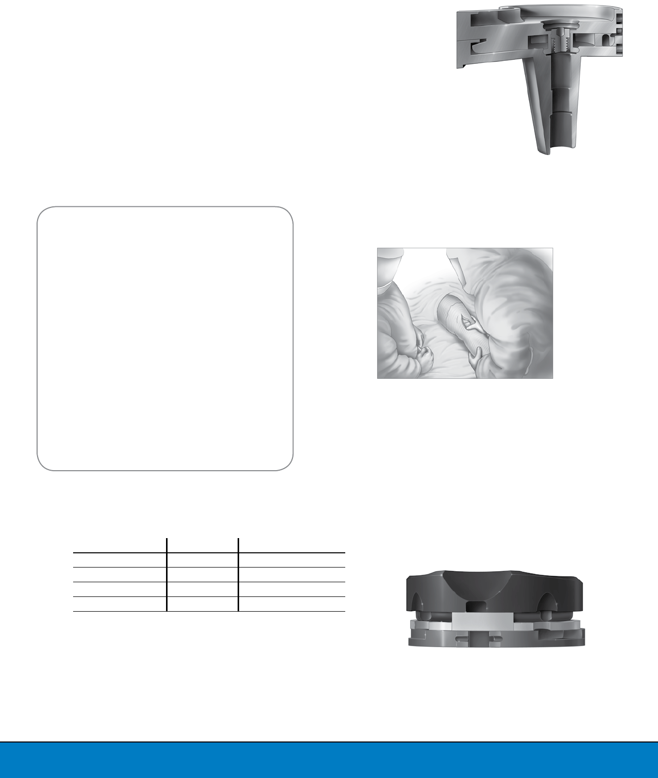
INTRODUCTION
Optetrak Logic Proximal Tibial Spacer (PTS) is a titanium spacer intended
to provide surgeons more flexibility in the adjustment of flexion and
extension gaps. PTS maintains the three-part locking features found on
all Optetrak Logic modular tibial trays, including posterior undercuts, a
central “mushroom” and a peripheral rim (Figure 58). This allows Optetrak
Logic tibial inserts to lock into PTS exactly the same way they would lock
into an Optetrak modular tibial tray.
DESIGN SPECIFICATIONS
Optetrak Logic PTS is compatible with all Optetrak Logic modular tibial
trays and tibial inserts that are 9 to 15mm thick, allowing surgeons to
accommodate flexion and extension gaps ranging from 17 to 23mm. The
femur, tibia and patella should be prepared as described previously in the
Logic LPI Operative Technique.
PTS ANNEX
For gaps that require greater than 15mm tibial inserts
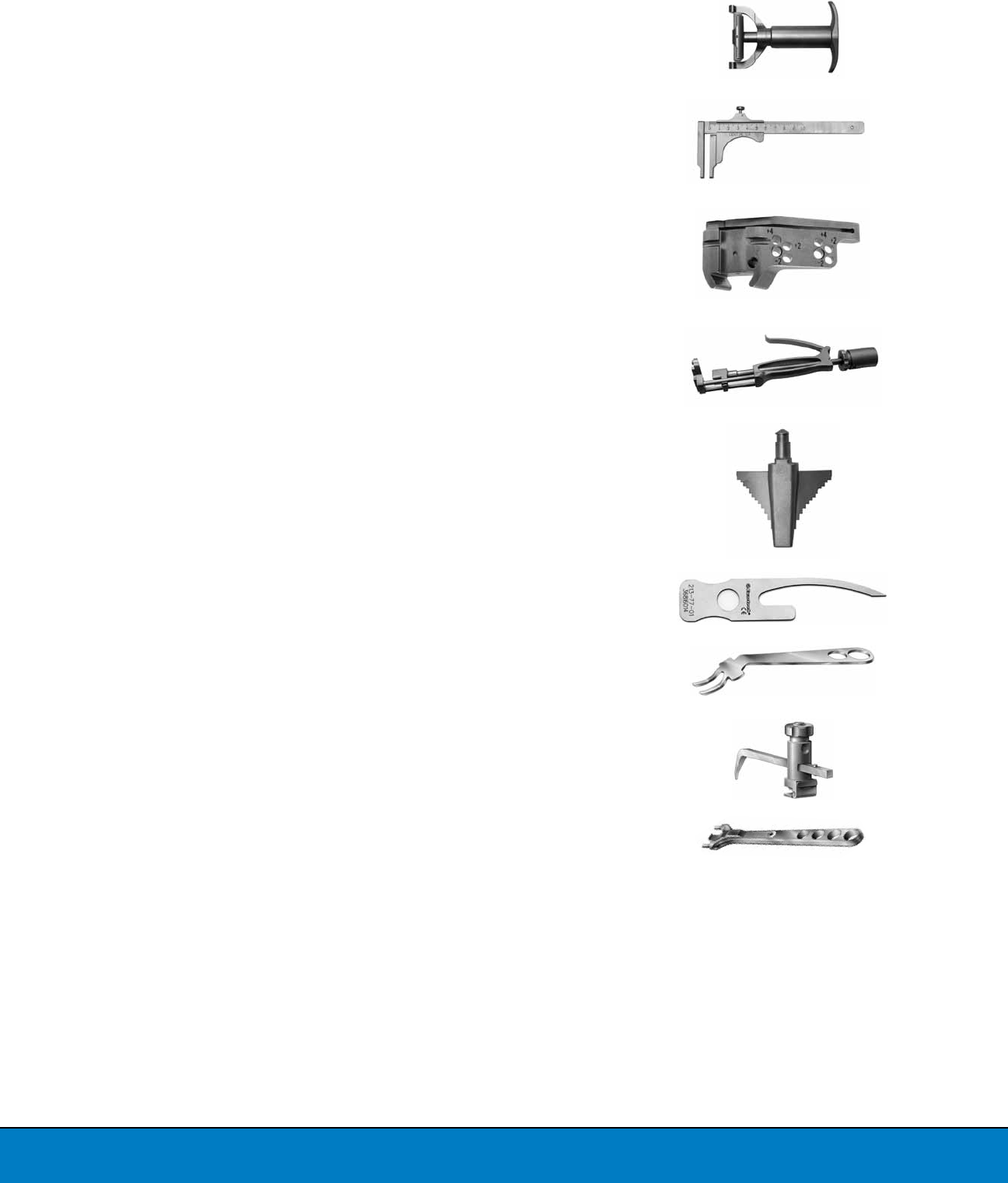
Figure 58
Cross-section of Proximal Tibial Spacer
Figure 59
Assessment of Overall Stability of Knee
Joint in Flexion and Extension
Figure 60
PTS Trial Assembled to Modular Insert Trial
Table 1: OVERALL THICKNESS OF OPTETRAK LOGIC
INSERT TRIALS AND PTS
Trial Insert Thickness PTS Thickness Overall Insert Thickness
9mm 8mm 17mm
11mm 8mm 19mm
13mm 8mm 21mm
15mm 8mm 23mm
25
Step 3: Assemble PTS onto the appropriate
Optetrak Logic tibial tray. The assembly should be
performed on the back table of the operating room.
Engage the posterior feet of PTS with the posterior
undercut of the Optetrak Logic tibial tray. Protect
the anterior of the PTS with a lap or sponge and
tap with a mallet. Place the PTS and Optetrak Logic
tibial tray assembly upside-down on a flat surface.
Protect the bottom surface of the tibial tray with a
sponge or lap. Impact the Optetrak tibial tray until
PTS is fully seated onto the tray (Figure 61).
Step 4: Insert the Optetrak Logic PTS Locking
Screw through the central hole of PTS. The screw
will keep the mushroom feature on PTS engaged
with the Optetrak Logic tibial tray. Using the
Optetrak Logic PTS Locking Hex Screwdriver,
tighten the screw (Figure 62). The PTS Locking Hex
Screwdriver should be rotated until the screw is
fully seated, or flush with the mushroom hole in
PTS (Figure 63).
Caution: Do not over-tighten the PTS Locking
Screw. Over-tightening the locking screw will cause
the hex feature on both components to deform,
making it difficult to extract the PTS Locking Hex
Screwdriver from the PTS Locking Screw.
Proceed to the implantation of final components
and final check and closure. Recommended
cementation techniques should be followed as
described in the corresponding Optetrak Logic
operative techniques.
Figure 63
PTS Locking Screw Fully Seated
Figure 62
Insert PTS Locking Screw with PTS Locking
Hex Screwdriver
Figure 61
PTS and Tibial Tray
Assembly Impaction
26
* Special order
201-02-26
201-02-29
201-02-32
201-02-35
201-02-38
201-02-41
Three-Peg Patella Trial, Size 26
Three-Peg Patella Trial, Size 29
Three-Peg Patella Trial, Size 32
Three-Peg Patella Trial, Size 35
Three-Peg Patella Trial, Size 38
Three-Peg Patella Trial, Size 41
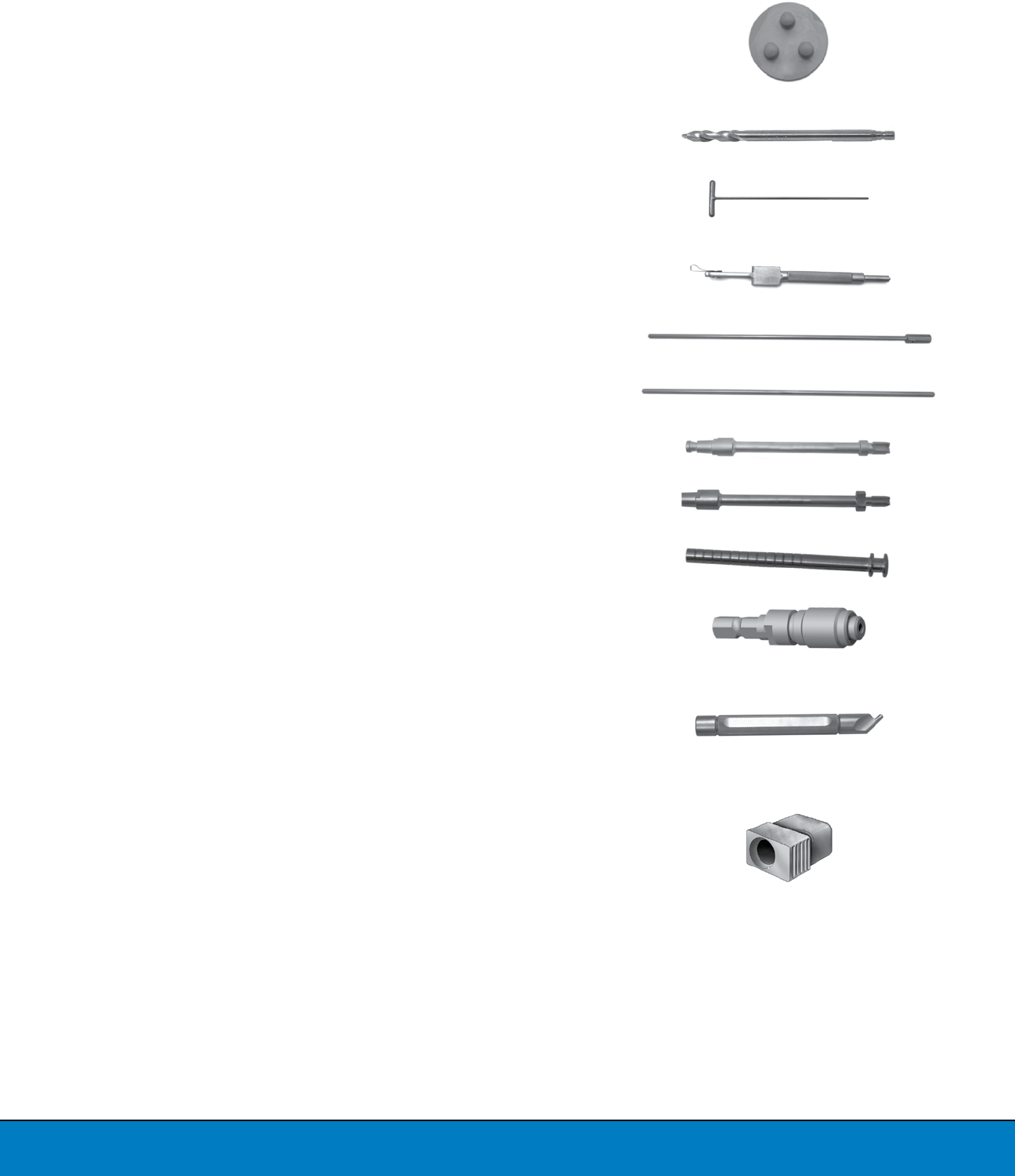
201-40-03 IM Pilot Drill
201-41-00 T-Handle Intra-medullary Rod
201-44-00 Mauldin Multi-Tool
201-58-01 Extra-medullary Tibial Alignment Rod/Coupler
201-58-02 Extra-medullary Alignment Rod
201-61-11 Patellar Drill, One-Peg, Zimmer Hudson
201-61-13 Patellar Drill, Three-Peg, Zimmer Hudson
201-78-11 Holding Pin, Small Head, Cup Point, 1.75"
201-78-51 Quick Chuck w/Hall End, 1/8"
201-78-89 Quick Connect Drill Bit modified Hex, 3", 1/8"
201-90-01 Tibial Insert Driver
213-03-02*
213-03-05
213-03-06
213-03-07
LPI Intra-medullary Alignment Guide Bushing,
2 Degrees, 8mm*
LPI Intra-medullary Alignment Guide Bushing,
5 Degrees, 8mm
LPI Intra-medullary Alignment Guide Bushing,
6 Degrees, 8mm
LPI Intra-medullary Alignment Guide Bushing,
7 Degrees, 8mm
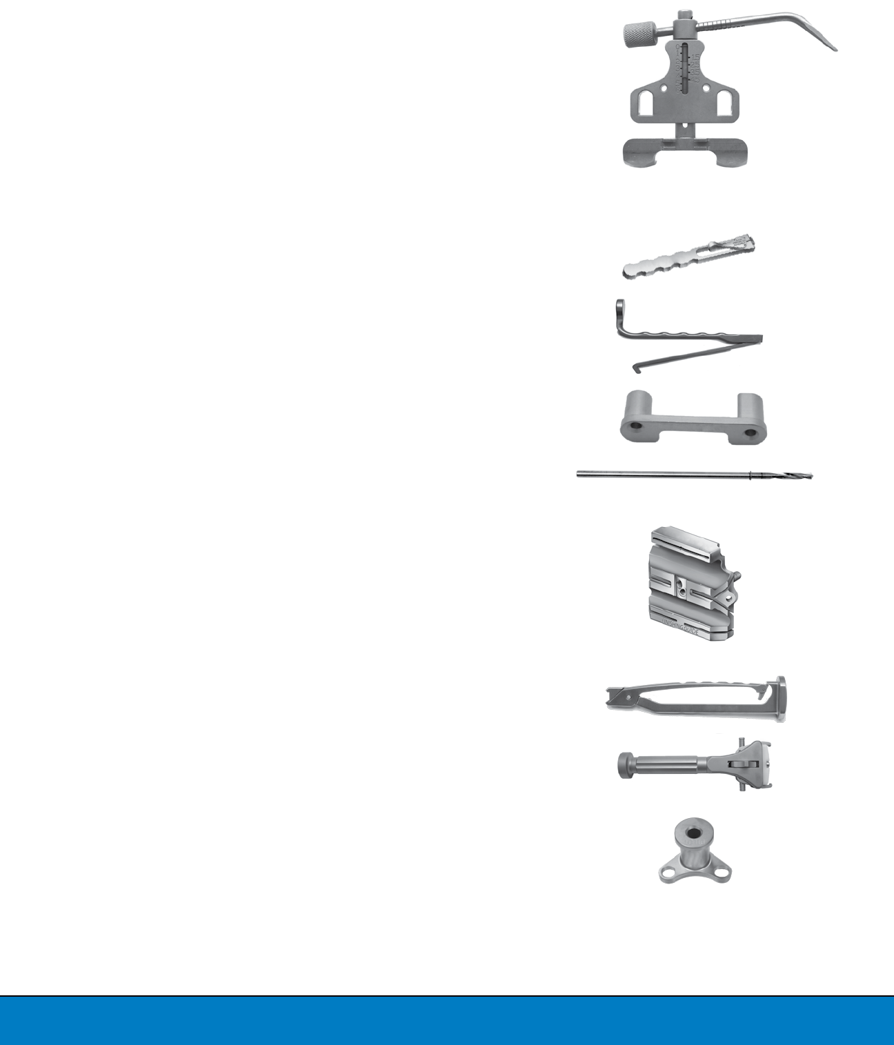
INSTRUMENT LISTING
Catalog Number Part Description
27
* Special order
213-37-02 LPI Femoral A/P Sizer
213-44-01 LPI Offset A/P Sizer Handle
213-46-12 LPI Pin Puller
213-56-00
213-56-01
213-56-02
LPI 0-Degree Femoral A/P Sizer Drill Guide
LPI 3-Degree Femoral A/P Sizer Drill Guide, Right
LPI 3-Degree Femoral A/P Sizer Drill Guide, Left
213-49-00 LPI A/P Sizer Collar Drill, 4mm
213-50-10*
213-50-11
213-50-51*
213-50-12
213-50-52
213-50-13
213-50-53
213-50-14
213-50-15
213-50-16*
LPI Femoral Finishing Guide, Size 0
LPI Femoral Finishing Guide, Size 1
LPI Femoral Finishing Guide, Size 1.5
LPI Femoral Finishing Guide, Size 2
LPI Femoral Finishing Guide, Size 2.5
LPI Femoral Finishing Guide, Size 3
LPI Femoral Finishing Guide, Size 3.5
LPI Femoral Finishing Guide, Size 4
LPI Femoral Finishing Guide, Size 5
LPI Femoral Finishing Guide, Size 6
213-52-10 LPI Finishing Guide Impaction/Extraction Handle
213-64-01 LPI Locking Femoral Impactor
213-72-00 Fit Tray Tibial Pilot Drill
Catalog Number Part Description
28
213-83-00 LPI Distal Femoral Resection Guide
213-83-10 LPI Distal Link
213-60-00 LPI Patella Prep Handle
213-60-01 LPI Patella Clamp Head
213-60-08 LPI Patellar Universal Drill Guide
213-65-00 LPI Impactor Handle
213-65-01
213-65-02
213-65-03
LPI Tibial Tray Impact Plate, Sizes 0-2
LPI Tibial Tray Impact Plate, Sizes 3,4
LPI Tibial Tray Impact Plate, Sizes 4,5
213-65-04 LPI Femoral Impactor, Non-locking
213-65-05 LPI Tibial Insert Impactor Head
213-66-03 Logic PS Femoral Trial Extractor
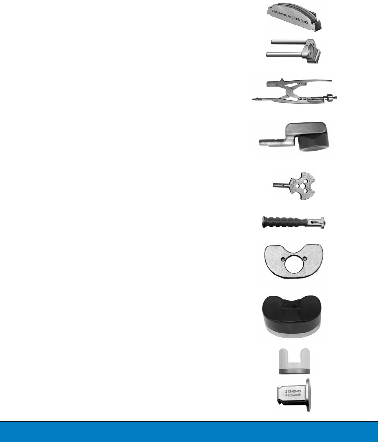
INSTRUMENT LISTING
Catalog Number Part Description
29
213-66-04 Logic CR Femoral Trial Extractor
213-67-00 Patella Thickness Gauge
213-73-17
213-73-18
LPI Tibial Resection Guide, Left
LPI Tibial Resection Guide, Right
213-75-00 LPI Fit Tibial Tamp Guide
213-75-01 LPI Fit Tibial Tamp Head
213-77-01 LPI Cut Line Predictor
231-04-01 No-Touch PCL Retractor
231-04-02 Adjustable PCL Stylus
231-04-03 LPI Trial Insert Handle
Catalog Number Part Description
* Special order
30
02-011-01-0200*
02-011-01-0300*
02-011-01-0210
02-011-01-0310
02-011-01-0215*
02-011-01-0315*
02-011-01-0220
02-011-01-0320
02-011-01-0225
02-011-01-0325
02-011-01-0230
02-011-01-0330
02-011-01-0235
02-011-01-0335
02-011-01-0240
02-011-01-0340
02-011-01-0250
02-011-01-0350
02-011-01-0260*
02-011-01-0360*
Logic Femoral Trial, PS, Size 0, Left
Logic Femoral Trial, PS, Size 0, Right
Logic Femoral Trial, PS, Size 1, Left
Logic Femoral Trial, PS, Size 1, Right
Logic Femoral Trial, PS, Size 1.5, Left
Logic Femoral Trial, PS, Size 1.5, Right
Logic Femoral Trial, PS, Size 2, Left
Logic Femoral Trial, PS, Size 2, Right
Logic Femoral Trial, PS, Size 2.5, Left
Logic Femoral Trial, PS, Size 2.5, Right
Logic Femoral Trial, PS, Size 3, Left
Logic Femoral Trial, PS, Size 3, Right
Logic Femoral Trial, PS, Size 3.5, Left
Logic Femoral Trial, PS, Size 3.5, Right
Logic Femoral Trial, PS, Size 4, Left
Logic Femoral Trial, PS, Size 4, Right
Logic Femoral Trial, PS, Size 5, Left
Logic Femoral Trial, PS, Size 5, Right
Logic Femoral Trial, PS, Size 6, Left
Logic Femoral Trial, PS, Size 6, Right
02-011-03-0200*
02-011-03-0300*
02-011-03-0210
02-011-03-0310
02-011-03-0215*
02-011-03-0315*
02-011-03-0220
02-011-03-0320
02-011-03-0225
02-011-03-0325
02-011-03-0230
02-011-03-0330
02-011-03-0235
02-011-03-0335
02-011-03-0240
02-011-03-0340
02-011-03-0250
02-011-03-0350
02-011-03-0260*
02-011-03-0360*
Logic Femoral Trial, CR, Size 0, Left
Logic Femoral Trial, CR, Size 0, Right
Logic Femoral Trial, CR, Size 1, Left
Logic Femoral Trial, CR, Size 1, Right
Logic Femoral Trial, CR, Size 1.5, Left
Logic Femoral Trial, CR, Size 1.5, Right
Logic Femoral Trial, CR, Size 2, Left
Logic Femoral Trial, CR, Size 2, Right
Logic Femoral Trial, CR, Size 2.5, Left
Logic Femoral Trial, CR, Size 2.5, Right
Logic Femoral Trial, CR, Size 3, Left
Logic Femoral Trial, CR, Size 3, Right
Logic Femoral Trial, CR, Size 3.5, Left
Logic Femoral Trial, CR, Size 3.5, Right
Logic Femoral Trial, CR, Size 4, Left
Logic Femoral Trial, CR, Size 4, Right
Logic Femoral Trial, CR, Size 5, Left
Logic Femoral Trial, CR, Size 5, Right
Logic Femoral Trial, CR, Size 6, Left
Logic Femoral Trial, CR, Size 6, Right
INSTRUMENT LISTING
Catalog Number Part Description
* Special order

3131
02-013-35-0009*
02-013-35-0011*
02-013-35-0013*
02-013-35-0015*
02-013-35-1009
02-013-35-1011
02-013-35-1013
02-013-35-1015
02-013-35-1509*
02-013-35-1511*
02-013-35-1513*
02-013-35-1515*
02-013-35-2009
02-013-35-2011
02-013-35-2013
02-013-35-2015
02-013-35-2509
02-013-35-2511
02-013-35-2513
02-013-35-2515
02-013-35-3009
02-013-35-3011
02-013-35-3013
02-013-35-3015
02-013-35-3509
02-013-35-3511
02-013-35-3513
02-013-35-3515
02-013-35-4009
02-013-35-4011
02-013-35-4013
02-013-35-4015
02-013-35-5009
02-013-35-5011
02-013-35-5013
02-013-35-5015
02-013-35-6011*
02-013-35-6013*
02-013-35-6015*
Logic Tibial Insert Trial, PS, Size 0, 9mm
Logic Tibial Insert Trial, PS, Size 0, 11mm
Logic Tibial Insert Trial, PS, Size 0, 13mm
Logic Tibial Insert Trial, PS, Size 0, 15mm
Logic Tibial Insert Trial, PS, Size 1, 9mm
Logic Tibial Insert Trial, PS, Size 1, 11mm
Logic Tibial Insert Trial, PS, Size 1, 13mm
Logic Tibial Insert Trial, PS, Size 1, 15mm
Logic Tibial Insert Trial, PS, Size 1.5, 9mm
Logic Tibial Insert Trial, PS, Size 1.5, 11mm
Logic Tibial Insert Trial, PS, Size 1.5, 13mm
Logic Tibial Insert Trial, PS, Size 1.5, 15mm
Logic Tibial Insert Trial, PS, Size 2, 9mm
Logic Tibial Insert Trial, PS, Size 2, 11mm
Logic Tibial Insert Trial, PS, Size 2, 13mm
Logic Tibial Insert Trial, PS, Size 2, 15mm
Logic Tibial Insert Trial, PS, Size 2.5, 9mm
Logic Tibial Insert Trial, PS, Size 2.5, 11mm
Logic Tibial Insert Trial, PS, Size 2.5, 13mm
Logic Tibial Insert Trial, PS, Size 2.5, 15mm
Logic Tibial Insert Trial, PS, Size 3, 9mm
Logic Tibial Insert Trial, PS, Size 3, 11mm
Logic Tibial Insert Trial, PS, Size 3, 13mm
Logic Tibial Insert Trial, PS, Size 3, 15mm
Logic Tibial Insert Trial, PS, Size 3.5, 9mm
Logic Tibial Insert Trial, PS, Size 3.5, 11mm
Logic Tibial Insert Trial, PS, Size 3.5, 13mm
Logic Tibial Insert Trial, PS, Size 3.5, 15mm
Logic Tibial Insert Trial, PS, Size 4, 9mm
Logic Tibial Insert Trial, PS, Size 4, 11mm
Logic Tibial Insert Trial, PS, Size 4, 13mm
Logic Tibial Insert Trial, PS, Size 4, 15mm
Logic Tibial Insert Trial, PS, Size 5, 9mm
Logic Tibial Insert Trial, PS, Size 5, 11mm
Logic Tibial Insert Trial, PS, Size 5, 13mm
Logic Tibial Insert Trial, PS, Size 5, 15mm
Logic Tibial Insert Trial, PS, Size 6, 11mm
Logic Tibial Insert Trial, PS, Size 6, 13mm
Logic Tibial Insert Trial, PS, Size 6, 15mm
Catalog Number Part Description
* Special order
**Special order *Special request only
INSTRUMENT LISTING
Catalog Number Part Description
02-013-44-0009*
02-013-44-0011*
02-013-44-0013*
02-013-44-0015*
02-013-44-1009
02-013-44-1011
02-013-44-1013
02-013-44-1015
02-013-44-1509*
02-013-44-1511*
02-013-44-1513*
02-013-44-1515*
02-013-44-2009
02-013-44-2011
02-013-44-2013
02-013-44-2015
02-013-44-2509
02-013-44-2511
02-013-44-2513
02-013-44-2515
02-013-44-3009
02-013-44-3011
02-013-44-3013
02-013-44-3015
02-013-44-3509
02-013-44-3511
02-013-44-3513
02-013-44-3515
02-013-44-4009
02-013-44-4011
02-013-44-4013
02-013-44-4015
02-013-44-5009
02-013-44-5011
02-013-44-5013
02-013-44-5015
02-013-44-6011*
02-013-44-6013*
02-013-44-6015*
Logic Tibial Insert Trial, PSC, SIZE 0, 9mm
Logic Tibial Insert Trial, PSC, SIZE 0, 11mm
Logic Tibial Insert Trial, PSC, SIZE 0, 13mm
Logic Tibial Insert Trial, PSC, SIZE 0, 15mm
Logic Tibial Insert Trial, PSC, SIZE 1, 9mm
Logic Tibial Insert Trial, PSC, SIZE 1, 11mm
Logic Tibial Insert Trial, PSC, SIZE 1, 13mm
Logic Tibial Insert Trial, PSC, SIZE 1, 15mm
Logic Tibial Insert Trial, PSC, SIZE 1.5, 9mm
Logic Tibial Insert Trial, PSC, SIZE 1.5, 11mm
Logic Tibial Insert Trial, PSC, SIZE 1.5, 13mm
Logic Tibial Insert Trial, PSC, SIZE 1.5, 15mm
Logic Tibial Insert Trial, PSC, SIZE 2, 9mm
Logic Tibial Insert Trial, PSC, SIZE 2, 11mm
Logic Tibial Insert Trial, PSC, SIZE 2, 13mm
Logic Tibial Insert Trial, PSC, SIZE 2, 15mm
Logic Tibial Insert Trial, PSC, SIZE 2.5, 9mm
Logic Tibial Insert Trial, PSC, SIZE 2.5, 11mm
Logic Tibial Insert Trial, PSC, SIZE 2.5, 13mm
Logic Tibial Insert Trial, PSC, SIZE 2.5, 15mm
Logic Tibial Insert Trial, PSC, SIZE 3, 9mm
Logic Tibial Insert Trial, PSC, SIZE 3, 11mm
Logic Tibial Insert Trial, PSC, SIZE 3, 13mm
Logic Tibial Insert Trial, PSC, SIZE 3, 15mm
Logic Tibial Insert Trial, PSC, SIZE 3.5, 9mm
Logic Tibial Insert Trial, PSC, SIZE 3.5, 11mm
Logic Tibial Insert Trial, PSC, SIZE 3.5, 13mm
Logic Tibial Insert Trial, PSC, SIZE 3.5, 15mm
Logic Tibial Insert Trial, PSC, SIZE 4, 9mm
Logic Tibial Insert Trial, PSC, SIZE 4, 11mm
Logic Tibial Insert Trial, PSC, SIZE 4, 13mm
Logic Tibial Insert Trial, PSC, SIZE 4, 15mm
Logic Tibial Insert Trial, PSC, SIZE 5, 9mm
Logic Tibial Insert Trial, PSC, SIZE 5, 11mm
Logic Tibial Insert Trial, PSC, SIZE 5, 13mm
Logic Tibial Insert Trial, PSC, SIZE 5, 15mm
Logic Tibial Insert Trial, PSC, SIZE 6, 11mm
Logic Tibial Insert Trial, PSC, SIZE 6, 13mm
Logic Tibial Insert Trial, PSC, SIZE 6, 15mm
32

33
**Special order
02-013-47-0009*
02-013-47-0011*
02-013-47-0013*
02-013-47-0015*
02-013-47-1009
02-013-47-1011
02-013-47-1013
02-013-47-1015
02-013-57-1509*
02-013-57-1511*
02-013-57-1513*
02-013-57-1515*
02-013-47-2009
02-013-47-2011
02-013-47-2013
02-013-47-2015
02-013-57-2509
02-013-57-2511
02-013-57-2513
02-013-57-2515
02-013-47-3009
02-013-47-3011
02-013-47-3013
02-013-47-3015
02-013-57-3509
02-013-57-3511
02-013-57-3513
02-013-57-3515
02-013-47-4009
02-013-47-4011
02-013-47-4013
02-013-47-4015
02-013-47-5009
02-013-47-5011
02-013-47-5013
02-013-47-5015
02-013-47-6011*
02-013-47-6013*
02-013-47-6015*
Logic Tibial Insert Trial, CR Neutral, Size 0, 9mm
Logic Tibial Insert Trial, CR Neutral, Size 0, 11mm
Logic Tibial Insert Trial, CR Neutral, Size 0, 13 mm
Logic Tibial Insert Trial, CR Neutral, Size 0, 15 mm
Logic Tibial Insert Trial, CR Neutral, Size 1, 9mm
Logic Tibial Insert Trial, CR Neutral, Size 1, 11mm
Logic Tibial Insert Trial, CR Neutral, Size 1, 13mm
Logic Tibial Insert Trial, CR Neutral, Size 1, 15mm
Logic Tibial Insert Trial, CR Neutral, Size 1.5, 9mm
Logic Tibial Insert Trial, CR Neutral, Size 1.5, 11mm
Logic Tibial Insert Trial, CR Neutral, Size 1.5, 13mm
Logic Tibial Insert Trial, CR Neutral, Size 1.5, 15mm
Logic Tibial Insert Trial, CR Neutral, Size 2, 9mm
Logic Tibial Insert Trial, CR Neutral, Size 2, 11mm
Logic Tibial Insert Trial, CR Neutral, Size 2, 13mm
Logic Tibial Insert Trial, CR Neutral, Size 2, 15mm
Logic Tibial Insert Trial, CR Neutral, Size 2.5, 9mm
Logic Tibial Insert Trial, CR Neutral, Size 2.5, 11mm
Logic Tibial Insert Trial, CR Neutral, Size 2.5, 13mm
Logic Tibial Insert Trial, CR Neutral, Size 2.5, 15mm
Logic Tibial Insert Trial, CR Neutral, Size 3, 9mm
Logic Tibial Insert Trial, CR Neutral, Size 3, 11mm
Logic Tibial Insert Trial, CR Neutral, Size 3, 13mm
Logic Tibial Insert Trial, CR Neutral, Size 3, 15mm
Logic Tibial Insert Trial, CR Neutral, Size 3.5, 9mm
Logic Tibial Insert Trial, CR Neutral, Size 3.5, 11mm
Logic Tibial Insert Trial, CR Neutral, Size 3.5, 13mm
Logic Tibial Insert Trial, CR Neutral, Size 3.5, 15mm
Logic Tibial Insert Trial, CR Neutral, Size 4, 9mm
Logic Tibial Insert Trial, CR Neutral, Size 4, 11mm
Logic Tibial Insert Trial, CR Neutral, Size 4, 13mm
Logic Tibial Insert Trial, CR Neutral, Size 4, 15mm
Logic Tibial Insert Trial, CR Neutral, Size 5, 9mm
Logic Tibial Insert Trial, CR Neutral, Size 5, 11mm
Logic Tibial Insert Trial, CR Neutral, Size 5, 13mm
Logic Tibial Insert Trial, CR Neutral, Size 5, 15mm
Logic Tibial Insert Trial, CR Neutral, Size 6, 11mm
Logic Tibial Insert Trial, CR Neutral, Size 6, 13mm
Logic Tibial Insert Trial, CR Neutral, Size 6, 15mm
Catalog Number Part Description

INSTRUMENT LISTING
Catalog Number Part Description
02-013-48-0009*
02-013-48-0011*
02-013-48-0013*
02-013-48-1009
02-013-48-1011
02-013-48-1013
02-013-58-1509*
02-013-58-1511*
02-013-58-1513*
02-013-48-2009
02-013-48-2011
02-013-48-2013
02-013-48-2509
02-013-48-2511
02-013-48-2513
02-013-58-3009
02-013-58-3011
02-013-58-3013
02-013-48-3509
02-013-48-3511
02-013-48-3513
02-013-58-4009
02-013-58-4011
02-013-58-4013
02-013-48-5009
02-013-48-5011
02-013-48-5013
02-013-48-6011*
02-013-48-6013*
Logic Tibial Insert Trial, CR Slope+, Size 0, 9mm
Logic Tibial Insert Trial, CR Slope+, Size 0, 11mm
Logic Tibial Insert Trial, CR Slope+, Size 0, 13mm
Logic Tibial Insert Trial, CR Slope+, Size 1, 9mm
Logic Tibial Insert Trial, CR Slope+, Size 1, 11mm
Logic Tibial Insert Trial, CR Slope+, Size 1, 13mm
Logic Tibial Insert Trial, CR Slope+, Size 1.5, 9mm
Logic Tibial Insert Trial, CR Slope+, Size 1.5, 11mm
Logic Tibial Insert Trial, CR Slope+, Size 1.5, 13mm
Logic Tibial Insert Trial, CR Slope+, Size 2, 9mm
Logic Tibial Insert Trial, CR Slope+, Size 2, 11mm
Logic Tibial Insert Trial, CR Slope+, Size 2, 13mm
Logic Tibial Insert Trial, CR Slope+, Size 2.5, 9mm
Logic Tibial Insert Trial, CR Slope+, Size 2.5, 11mm
Logic Tibial Insert Trial, CR Slope+, Size 2.5, 13mm
Logic Tibial Insert Trial, CR Slope+, Size 3, 9mm
Logic Tibial Insert Trial, CR Slope+, Size 3, 11mm
Logic Tibial Insert Trial, CR Slope+, Size 3, 13mm
Logic Tibial Insert Trial, CR Slope+, Size 3.5, 9mm
Logic Tibial Insert Trial, CR Slope+, Size 3.5, 11mm
Logic Tibial Insert Trial, CR Slope+, Size 3.5, 13mm
Logic Tibial Insert Trial, CR Slope+, Size 4, 9mm
Logic Tibial Insert Trial, CR Slope+, Size 4, 11mm
Logic Tibial Insert Trial, CR Slope+, Size 4, 13mm
Logic Tibial Insert Trial, CR Slope+, Size 5, 9mm
Logic Tibial Insert Trial, CR Slope+, Size 5, 11mm
Logic Tibial Insert Trial, CR Slope+, Size 5, 13mm
Logic Tibial Insert Trial, CR Slope+, Size 6, 11mm
Logic Tibial Insert Trial, CR Slope+, Size 6, 13mm
02-013-49-0009*
02-013-49-0011*
02-013-49-0013*
02-013-49-1009
02-013-49-1011
02-013-49-1013
02-013-59-1509*
02-013-59-1511*
02-013-59-1513*
02-013-49-2009
02-013-49-2011
02-013-49-2013
02-013-59-2509
02-013-59-2511
02-013-59-2513
02-013-49-3009
02-013-49-3011
02-013-49-3013
02-013-49-3509
02-013-49-3511
02-013-49-3513
02-013-59-4009
02-013-59-4011
02-013-59-4013
02-013-49-5009
02-013-49-5011
02-013-49-5013
02-013-49-6011*
02-013-49-6013*
Logic Tibial Insert Trial, CR Slope++, Size 0, 9mm
Logic Tibial Insert Trial, CR Slope++, Size 0, 11mm
Logic Tibial Insert Trial, CR Slope++, Size 0, 13mm
Logic Tibial Insert Trial, CR Slope++, Size 1, 9mm
Logic Tibial Insert Trial, CR Slope++, Size 1, 11mm
Logic Tibial Insert Trial, CR Slope++, Size 1, 13mm
Logic Tibial Insert Trial, CR Slope++, Size 1.5, 9mm
Logic Tibial Insert Trial, CR Slope++, Size 1.5, 11mm
Logic Tibial Insert Trial, CR Slope++, Size 1.5, 13mm
Logic Tibial Insert Trial, CR Slope++, Size 2, 9mm
Logic Tibial Insert Trial, CR Slope++, Size 2, 11mm
Logic Tibial Insert Trial, CR Slope++, Size 2, 13mm
Logic Tibial Insert Trial, CR Slope++, Size 2.5, 9mm
Logic Tibial Insert Trial, CR Slope++, Size 2.5, 11mm
Logic Tibial Insert Trial, CR Slope++, Size 2.5, 13mm
Logic Tibial Insert Trial, CR Slope++, Size 3, 9mm
Logic Tibial Insert Trial, CR Slope++, Size 3, 11mm
Logic Tibial Insert Trial, CR Slope++, Size 3, 13mm
Logic Tibial Insert Trial, CR Slope++, Size 3.5, 9mm
Logic Tibial Insert Trial, CR Slope++, Size 3.5, 11mm
Logic Tibial Insert Trial, CR Slope++, Size 3.5, 13mm
Logic Tibial Insert Trial, CR Slope++, Size 4, 9mm
Logic Tibial Insert Trial, CR Slope++, Size 4, 11mm
Logic Tibial Insert Trial, CR Slope++, Size 4, 13mm
Logic Tibial Insert Trial, CR Slope++, Size 5, 9mm
Logic Tibial Insert Trial, CR Slope++, Size 5, 11mm
Logic Tibial Insert Trial, CR Slope++, Size 5, 13mm
Logic Tibial Insert Trial, CR Slope++, Size 6, 11mm
Logic Tibial Insert Trial, CR Slope++, Size 6, 13mm
*Special request only
35
285-08-71 PTS Inserter Handle
285-08-72 PTS Hex Inserter
02-013-42-0008
02-013-42-1008
02-013-42-2008
02-013-42-2508
02-013-42-3008
02-013-42-3508
02-013-42-4008
02-013-42-5008
02-013-42-6008
Logic Proximal Tibial Spacer Trial, 8mm, Size 0
Logic Proximal Tibial Spacer Trial, 8mm, Size 1
Logic Proximal Tibial Spacer Trial, 8mm, Size 2
Logic Proximal Tibial Spacer Trial, 8mm, Size 2.5
Logic Proximal Tibial Spacer Trial, 8mm, Size 3
Logic Proximal Tibial Spacer Trial, 8mm, Size 3.5
Logic Proximal Tibial Spacer Trial, 8mm, Size 4
Logic Proximal Tibial Spacer Trial, 8mm, Size 5
Logic Proximal Tibial Spacer Trial, 8mm, Size 6
02-019-10-0100**
02-019-10-0110
02-019-10-0115*
02-019-10-0120
02-019-10-0125
02-019-10-0130
02-019-10-0135
02-019-10-0140
02-019-10-0150
02-019-10-0160**
Logic Femoral Notch Cutting Guide, PS, Size 0
Logic Femoral Notch Cutting Guide, PS, Size 1
Logic Femoral Notch Cutting Guide, PS, Size 1.5
Logic Femoral Notch Cutting Guide, PS, Size 2
Logic Femoral Notch Cutting Guide, PS, Size 2.5
Logic Femoral Notch Cutting Guide, PS, Size 3
Logic Femoral Notch Cutting Guide, PS, Size 3.5
Logic Femoral Notch Cutting Guide, PS, Size 4
Logic Femoral Notch Cutting Guide, PS, Size 5
Logic Femoral Notch Cutting Guide, PS, Size 6
02-019-11-0000**
02-019-11-0010
02-019-11-0015*
02-019-11-0020
02-019-11-0025
02-019-11-0030
02-019-11-0035
02-019-11-0040
02-019-11-0050
02-019-11-0060**
Logic Femoral Notch Cutter, PS, Size 0
Logic Femoral Notch Cutter, PS, Size 1
Logic Femoral Notch Cutter, PS, Size 1.5
Logic Femoral Notch Cutter, PS, Size 2
Logic Femoral Notch Cutter, PS, Size 2.5
Logic Femoral Notch Cutter, PS, Size 3
Logic Femoral Notch Cutter, PS, Size 3.5
Logic Femoral Notch Cutter, PS, Size 4
Logic Femoral Notch Cutter, PS, Size 5
Logic Femoral Notch Cutter, PS, Size 6
213-70-00*
213-70-10
213-70-15*
213-70-20
213-70-25
213-70-30
213-70-35
213-70-40
213-70-45
213-70-50
213-70-60*
LPI Tibial Tray Trials, Size 0
LPI Tibial Tray Trials, Size 1
LPI Tibial Tray Trials, Size 1.5
LPI Tibial Tray Trials, Size 2
LPI Tibial Tray Trials, Size 2.5
LPI Tibial Tray Trials, Size 3
LPI Tibial Tray Trials, Size 3.5
LPI Tibial Tray Trials, Size 4
LPI Tibial Tray Trials, Size 4.5
LPI Tibial Tray Trials, Size 5
LPI Tibial Tray Trials, Size 6
Catalog Number Part Description
**Special order

36

37
®

REFERENCES
1. Bellemans J, Robijns F, Duerinckx J, Banks S, Vandenneucker H. The influence of tibial slope on maximal
flexion after total knee arthroplasty. Knee Surgical Sports Traumatol Arthroscopy. (2005) 13: 193–196.
For additional device information, refer to the Exactech Optetrak® Logic® Knee System–Instructions for Use for a device
description, indications, contraindications, precautions and warnings. For further product information, please contact Customer
Service, Exactech, 2320 NW 66th Court, Gainesville, Florida 32653-1630, USA. (352) 377-1140, (800) 392-2832 or FAX (352) 378-2617.
Exactech, as the manufacturer of this device, does not practice medicine, and is not responsible for recommending the
appropriate surgical technique for use on a particular patient. These guidelines are intended to be solely informational and each
surgeon must evaluate the appropriateness of these guidelines based on his or her personal medical training and experience.
Prior to use of this system, the surgeon should refer to the product package insert for comprehensive warnings, precautions,
indications for use, contraindications and adverse effects.
The products discussed herein may be available under different trademarks in different countries. All copyrights, and pending and
registered trademarks, are property of Exactech. This material is intended for the sole use and benefit of the Exactech sales force
and physicians. It should not be redistributed, duplicated or disclosed without the express written consent of Exactech.
©2012 Exactech.
Exactech is proud to have offices and distributors around the globe.
For more information about Exactech products available in your country, please visit www.exac.com
352-377-1140
1-800-EXACTECH
www.exac.com
712-25-31 Rev. B
Logic CR LPI Operative Technique 0113
