EGS Appleton 72631 Catalog
72642-Attachment 72642-Attachment 72642-Attachment 781381 Batch10 unilog cesco-content
72632-Attachment 72632-Attachment 72632-Attachment Batch10 unilog cesco-content
72636-Attachment 72636-Attachment 72636-Attachment Batch10 unilog cesco-content
2014-10-17
: Pdf 72631-Catalog 72631-Catalog Batch10 unilog
Open the PDF directly: View PDF ![]() .
.
Page Count: 26
- Cast Junction Boxes
- RS Series Malleable Iron Junction Boxes
- RS Series Junction Boxes, Covers, and Gaskets
- W Series Cast Junction Boxes
- NEMA Ratings
- Options
- Ordering Information
- Drilling Template
- Mounting Lug Data
- Mounting Plate Information
- WYS Type Unflanged Junction or Pull Boxes
- WYL Type Overlapping Cover Boxes
- WYF Type Flat Flanged Boxes - Submersible
- WYW Type Hinged Cover Boxes
- WYR Outside Flanged Recessed Cover Boxes
- WYU Type Inside Flanged Recessed Cover Boxes
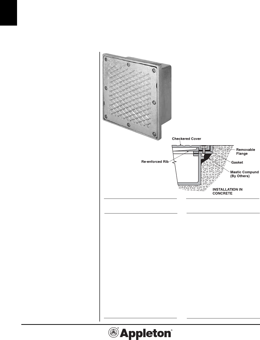
- WYT Type Checkered Cover Sidewalk Boxes
- WY58E Type Checkered Cover Sidewalk Topping Box
- WYC Type Box with Hinged Door and Trim Cabinet
- WYNY Type Checkered Cover Roadway Topping Box
C-1
C
Effective September, 2005
Copyright 2005
800-621-1506
www.appletonelec.com
PAGE 1
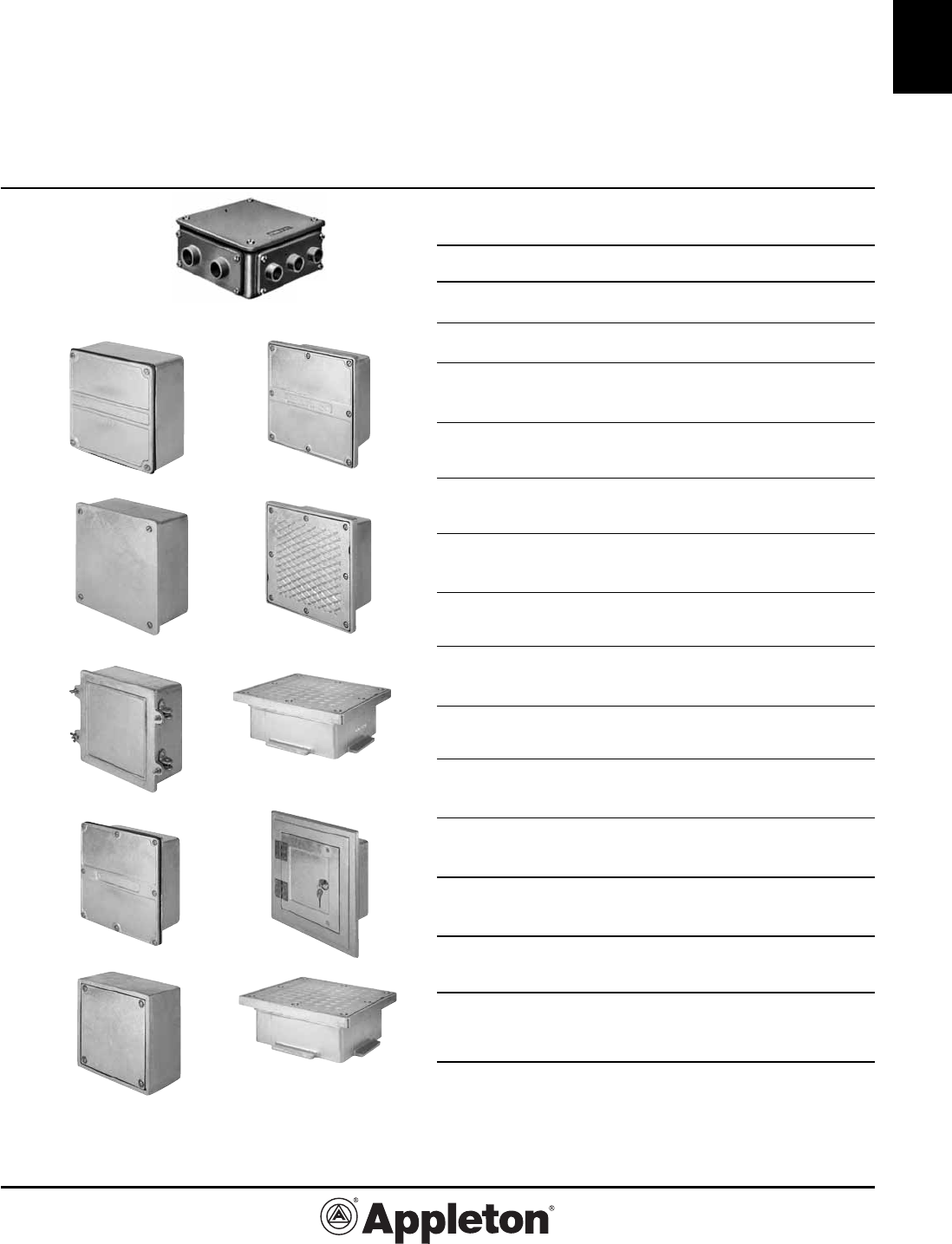
Cast Junction Boxes
Page Description
2,3 RS Series Rectangular Malleable Iron Junction
Boxes
4-24 W Series Cast Iron Junction Boxes
4 Illustrated Box Selection Guide
5 NEMA Rating for Cast Junction Boxes
6-12 Options and Ordering Information for W Series
cast iron junction boxes, including mounting plates
13 WYS Type, unflanged, with flat cover for surface
mounting
14-15 WYL Type, with overlapping cover for surface
mounting
16-17 WYF Type, flanged, with flat cover for surface
mounting
18-19 WYW Type, with hinged cover for surface
mounting
20 WYR Type, external flanged with recessed cover
for flush mounting
21 WYU Type, inside flange, recessed cover for
flush mounting
22 WYT Type, heavy-duty sidewalk box, flush
mounting
23 WY58E Type, sidewalk topping box, flush
mounting
24 WYC Type, heavy-duty hinged trim and door,
flush mounting
25 WYNY Type, roadway topping box, flush mount-
ing, one piece flange
For Explosionproof and Dust-Ignitionproof Cast
Iron and Cast Aluminum Junction Boxes, see
Catalog Section K.
WYS
WYL
WYW
WYF
WYU
WYR
WYT
WY58E
WYC
WYNY
WYS Type WYR Type
WYL Type WYT Type
WYW Type
WY58E Type
WYF Type WYC Type
WYU Type
WYNY Type
RS
Effective September, 2005
Copyright 2005
PAGE 2
800-621-1506
www.appletonelec.com
C-2
C
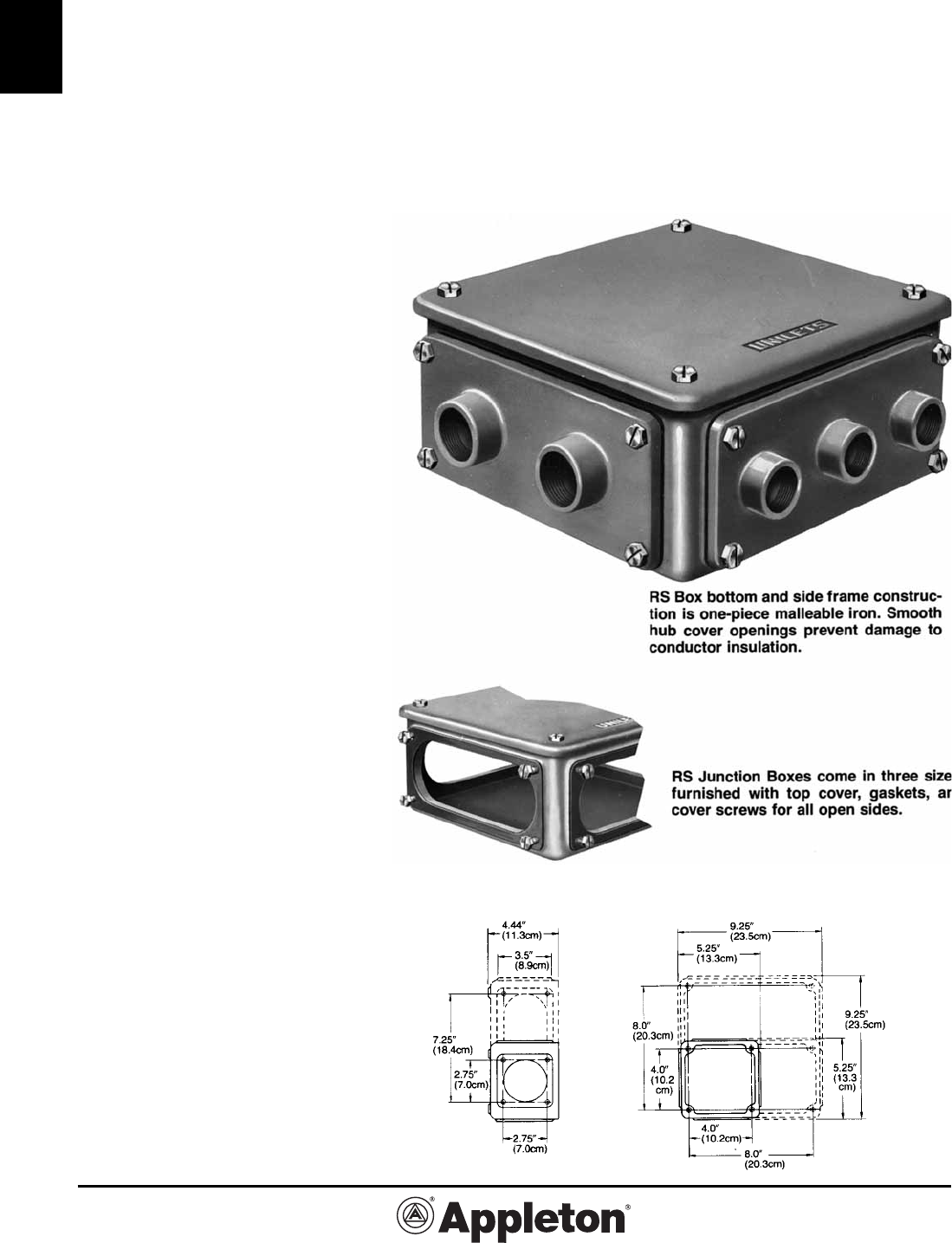
RS Series Malleable Iron Junction Boxes;
Hub Plates in Four Styles
UNILETS® for Use with Threaded Rigid Metal Conduit and IMC.
Applications
• Serve as main cable distribution cen-
ter, or can be used for adding circuits
to existing systems.
• Serve as pull boxes.
• Provide access to conductors for
maintenance.
Features
• Removable hub covers permit vari-
able hub arrangements in a wide range
of sizes.
• Furnished with top cover, gaskets,
and cover screws for all open sides.
• Side covers available blank or with 1,
2, or 3 hubs.
• Provides visibility while making con-
nections and splices (opens on four
sides and top).
• Threads are accurately tapped and
tapered for tight, rigid joints and ground
continuity.
• Hubs in all covers have integral
bushings to protect conductor insula-
tion from damage. Hub plate openings
are smooth.
Standard Materials
•
RS boxes and covers: malleable iron.
• Gaskets: composition fiber.
Standard Finishes
• RS boxes and covers: triple coat
– (1) zinc electroplate, (2) dichromate,
and (3) epoxy powder coat.
Compliances
• UL Standard 50.
• Federal Spec. W-C586B.
• Suitable for classified location use in
Class I, Division 2, if installed in com-
pliance with NEC 501-4(b).
• Appleton malleable iron products
conform to ASTM A47-77, Grade
32510, which has the following proper-
ties: tensile strength, 50,00 psi; yield,
32,000 psi; and elongation, 10%.
C-3
C
Effective September, 2005
Copyright 2005
800-621-1506
www.appletonelec.com
PAGE 3
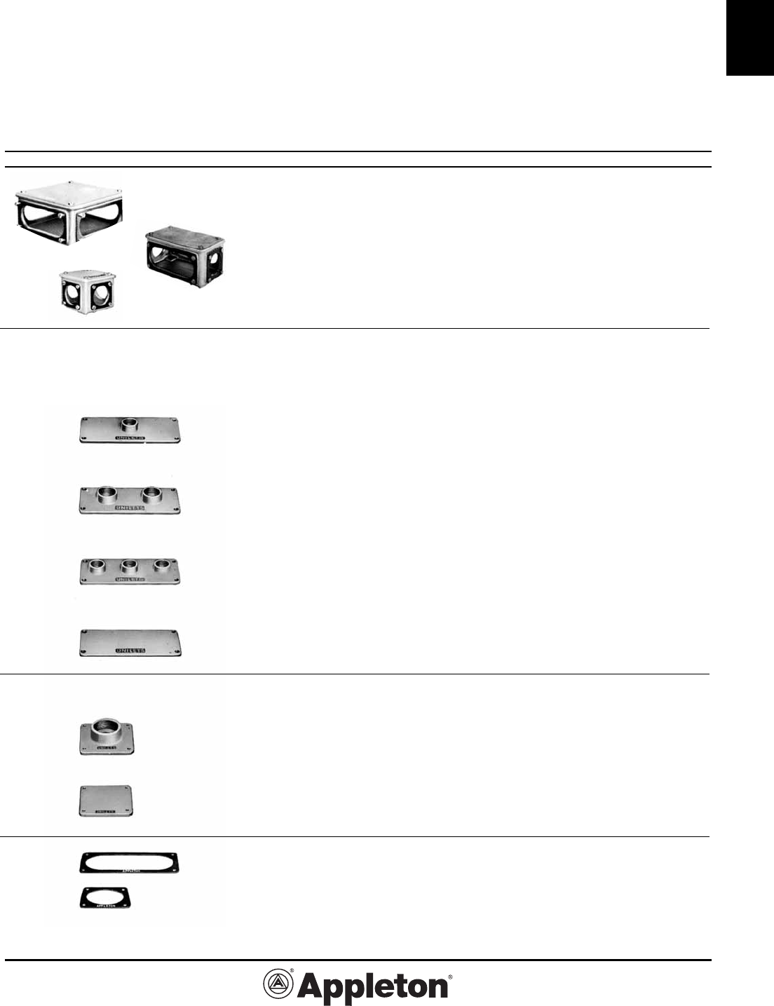
RS Series Junction Boxes, Covers, and Gaskets;
Malleable Iron
UNILETS® for Use with Threaded Rigid Metal Conduit and IMC.
Description Size (Inches) Catalog Number
RS– Boxes
Furnished with top gasketed cover
plus screws and gaskets for open sides.
RS 8-1/2” x 8-1/2” x 4 RS-1
Inside Dimensions
RSM 8-1/2” x 4-1/2” x 4 RSM-1
Inside Dimensions
RSS 4-1/2” x 4-1/2” x 4 RSS-1
Inside Dimensions
RS, RSM– Covers for 8-1/2” x 4” Sides
Gaskets and screws not included.
One Hub 1/2 RSK1-50
3/4 RSK1-75
1 RSK1-100
1-1/4 RSK1-125
1-1/2 RSK1-150
2 RSK1-200
Two Hubs 1/2 RSK2-50
3/4 RSK2-75
1 RSK2-100
1-1/4 RSK2-125
1-1/2 RSK2-150
2 RSK2-200
Three Hubs 1/2 RSK3-50
3/4 RSK3-75
1 RSK3-100
1-1/4 RSK3-125
Blank Blank RSK-B
RSS, RSM– Covers for 4-1/2” x 4” Sides
Gaskets and screws not included.
One Hub 1/2 RSSK-50
3/4 RSSK-75
1 RSSK-100
1-1/4 RSSK-125
1-1/2 RSSK-150
2 RSSK-200
Blank Blank RSSK-B
RS– Gaskets
Composition Fiber.
For RS, RSM 8-1/2” x 4” Sides RS-GK
For RSM, RSS 4-1/2” x 4” Sides RSS-GK
Effective September, 2005
Copyright 2005
PAGE 4
800-621-1506
www.appletonelec.com
C-4
C
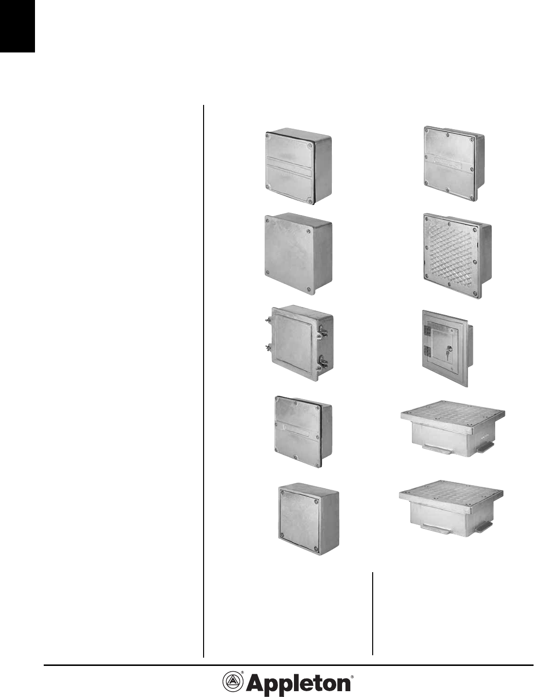
SURFACE MOUNTING
① WYS Type
• General purpose junction box. Flat
cover.
• Raintight, Watertight (NEMA 3R and 4).
② WYL Type
• Same as WYS Type except with over-
lapping cover.
• Raintight, Watertight, (NEMA 3R and 4).
➂ WYW Type
• Hinged cover type. Box same as WYS
Type except has overlapping hinged
cover.
• Raintight, Watertight, (NEMA 3R and 4).
➃ WYF Type
• Externally flanged box with flat cover
for severe environmental conditions.
• Raintight, Watertight, Submersible,
(NEMA 3R, 4 and 6 ).
FLUSH MOUNTING
⑤ WYU Type
• Primarily for flush mounting in con-
crete walls or floors, but may be surface
mounted with optional mounting lugs.
• Cover recessed in internal flange
ideal where space is limited.
• Raintight (NEMA 3R).
➅ WYR Type
•
Cover recessed in externally flanged
box for severe environmental conditions.
•
Raintight, Watertight, (NEMA 3R and 4).
➆ WYT Type
• Heavy duty sidewalk box– ideal in
concrete where subjected to pedestrian
or vehicular traffic.
• Cover and frame easily removed with-
out disturbing box or conduits.
⑧ WYC Type
• Attractive, heavy duty hinged door
and trim. Lock provided as standard.
• Typically used in masonry walls as
an enclosure for cut-outs, signal equip-
ment,
relays, switches, emergency light-
ing, etc.
➈ WY58E Type
• Three-piece bottomless box for top-
ping off underlying concrete boxes.
• Cover and frame easily removed with-
out disturbing box or conduits.
⑩ WYNY Type
• Similar to the WY58E Type except
flange is a one piece design.
• Units designed to withstand vehicular
traffic.
① WYS Type
② WYL Type
➂ WYW Type
➃ WYF Type
⑤ WYU Type
➅ WYR Type
➆ WYT Type
➇ WYC Type
⑨ WY58E Type
⑩ WYNY Type
W Series Cast Junction Boxes:
Illustrated Box Selection Guide
Boxes available for Raintight, Watertight, or Submersible applications.
C-5
C
Effective September, 2005
Copyright 2005
800-621-1506
www.appletonelec.com
PAGE 5
W Series Cast Boxes:
NEMA Ratings
incidental contact with the enclosed equip-
ment; to provide a degree of protection
against falling dirt; against hose-directed
water and the entry of water during pro-
longed submersion at a limited depth; and
that will be undamaged by the external
formation of ice on the enclosure.
Type 12— Enclosures constructed (with-
out knockouts) for indoor use to provide a
degree of protection to personnel against
incidental contact with the enclosed
equipment; to provide a degree of protec-
tion against falling dirt; against circulating
dust, lint, fibers, and flyings; and against
dripping and light splashing of liquids.
Type 12K— Enclosures constructed (with
knockouts) for indoor use to provide a
degree of protection to personnel against
incidental contact with the enclosed
equipment; to provide a degree of protec-
tion against falling dirt; against circulating
dust, lint, fibers, and flyings; and against
dripping and light splashing of liquids.
Type 13— Enclosures constructed for
indoor use to provide a degree of pro-
tection to personnel against incidental
contact with the enclosed equipment; to
provide a degree of protection against
falling dirt; against circulating dust, lint,
fibers, and flyings; and against the spray-
ing, splashing, and seepage of water, oil,
and noncorrosive coolants.
Definitions Pertaining to Hazardous (Clas-
sified) Locations*
Type 7 enclosures are for use indoors in
locations classified as Class I, Groups
A, B, C, or D, as defined in the National
Electrical Code.
Type 9 enclosures are for use in indoor
locations classified in Class II, Groups
E, F, or G, as defined in the National
Electrical Code.
Type 4— Enclosures constructed for
either indoor or outdoor use to provide
a degree of protection to personnel
against incidental contact with the en-
closed equipment; to provide a degree of
protection against falling dirt, rain, sleet,
snow, windblown dust, splashing water,
and hose-directed water; and that will be
undamaged by the external formation of
ice on the enclosure.
Type 4X— Enclosures constructed for
either indoor or outdoor use to provide a
degree of protection to personnel against
incidental contact with the enclosed
equipment; to provide a degree of protec-
tion against falling dirt, rain, sleet, snow,
windblown dust, splashing water, hose-di-
rected water, and corrosion, and that will
be undamaged by the external formation
of ice on the enclosure.
Type 5— Enclosures constructed for
indoor use to provide a degree of pro-
tection to personnel against incidental
contact with the enclosed equipment; to
provide a degree of protection against
falling dirt; against settling airborne dust,
lint, fibers, and flyings; and to provide a
degree of protection against dripping and
light splashing of liquids.
Type 6—
Enclosures constructed for either
indoor or outdoor use to provide a degree
of protection to personnel against inciden-
tal contact with the enclosed equipment;
to provide a degree of protection against
falling dirt; against hose-directed water
and the entry of water during occasional
temporary submersion at a limited depth;
and that will be undamaged by the exter-
nal formation of ice on the enclosure.
Type 6P— Enclosures constructed for
either indoor or outdoor use to provide a
degree of protection to personnel against
* Refer to Catalog Section K for Hazardous Location Cast Junction Boxes.
Type 3 Type 12
Type of Type 1 Type 3R Type12K
Enclosure Type 5 Type 2 Type 3S Type 4 Type 6 Type 13
WYS ✔ ✔ ✔ ✔ ✔
WYL ✔ ✔ ✔ ✔ ✔
WYF ✔ ✔ ✔ ✔ ✔ ✔
WYW ✔ ✔ ✔ ✔ ✔
WYU ✔ ✔ ✔ ✔
WYR ✔ ✔ ✔ ✔ ✔
WYT ✔ ✔
WYC ✔ ✔
NEMA Enclosure Ratings
NEMA Data.
Our cast junction boxes are designed,
constructed and tested to comply with
NEMA standards. The following chart
has been prepared to provide a quick
reference for selecting enclosures to
meet specific NEMA requirements.
A brief description of the more com-
mon types of enclosures used by
the electrical industry relating to their
environmental capabilities follows.
Please refer to the appropriate sec-
tions of NEMA Standards Publication
No. 250-1997. Enclosures for Electrical
Equipment (1000 Volts Maximum) for
complete information regarding appli-
cations, features and design tests.
Definitions Pertaining to Non-Hazardous
Locations
Type 1—
Enclosures constructed for
indoor use to provide a degree of protec-
tion to personnel against incidental contact
with the enclosed equipment and to provide
a degree of protection against falling dirt.
Type 2—
Enclosures constructed for in-
door use to provide a degree of protection
to personnel against incidental contact with
the enclosed equipment, to provide a de-
gree of protection against falling dirt, and
to provide a degree of protection against
dripping and light splashing of liquids.
Type 3— Enclosures constructed for
either indoor or outdoor use to pro-
vide a degree of protection to person-
nel against incidental contact with the
enclosed equipment; to provide a degree
of protection against falling dirt, rain, sleet,
snow and windblown dust; and that will be
undamaged by the external formation of
ice on the enclosure.
Type 3R—
Enclosures constructed for
either indoor or outdoor use to provide a
degree of protection to personnel against
incidental contact with the enclosed equip-
ment; to provide a degree of protection
against falling dirt, rain, sleet, and snow;
and that will be undamaged by the exter-
nal formation of ice on the enclosure.
Type 3S— Enclosures constructed for
either indoor or outdoor use to pro-
vide a degree of protection to person-
nel against incidental contact with the
enclosed equipment; to provide a degree
of protection against falling dirt, rain,
sleet, snow, and windblown dust; and in
which the external mechanism(s) remain
operable when ice laden.
Effective September, 2005
Copyright 2005
PAGE 6
800-621-1506
www.appletonelec.com
C-6
C
W Series Cast Boxes: Options
This table shows the optional items avail-
able on the different types of enclosures
shown in this section. When not furnished
as standard equipment the cost must be
added to the base price of the box.
Lettering on Covers can be furnished. These
are usually engraved letters and can be ap-
plied to the cover of any type box.
✔Available option - at additional charge.
S - Furnished as standard equipment - at no additional charge
NA - Not permitted on this type of enclosure by NEMA and Underwriters Laboratories, Inc.
standards and specifications, or basic construction of box will not allow or require this item.
* See ordering details for options on pages C7-C10.
The following information should be given on
all box orders:
Catalog Number and Inside Dimensions
(L x W x D) should be specified.
Sketch showing size and location of conduit en-
trances should be furnished similar to Drilling
Template, Fig. 2, page C-8. Tables on page C-8
give recommended spacing between conduits and
minimum distance from corner and back of box.
When spacings are not specified, they will be lo-
cated at our discretion.
Conduit Entrances - See Fig. 1, page C-7.
Slip Holes:
These are clearance holes for conduit. No
threads provided. Conduits are usually fas-
tened in slip holes by means of locknuts and
bushings. STANDARD LOCKNUT SPACINGS
MUST BE ALLOWED BETWEEN THE CON-
DUITS. See table on page C-8.
Drilled and Tapped Holes:
These are threaded holes provided in the
enclosure wall into which the conduit is
screwed. To meet UL requirements, they
must conform to the following:
Enclosures for use in Non-hazardous Loca-
tions must have a wall thickness of not less
than 1/4” at the tapped holes for the conduit
and there shall not be less than 3-1/2 threads
in the metal.
Compare the wall thickness shown in the list-
ing of these enclosures with the chart below
to determine the number of threads which the
box wall will provide for the various conduit
sizes. If more threads are required, please
order a Bossed, Drilled and Tapped hole.
Wall Thickness and Maximum Conduit Size, Inches
Conduit
Size
No. of
Threads
Per Inch
Wall Thickness Required
31⁄2
5
Threads
Threads
3⁄8
”
18 7⁄32** 9⁄32
1⁄2
” to
3⁄4
”
14 1⁄43⁄8
1” to 2”
111⁄25⁄16 7⁄16
2-
1⁄2
” to 4”
87⁄16 5⁄8
** 1⁄4” min. wall thicness must be provided
Bossed Drilled and Tapped Holes:
These are holes threaded thru the box wall
and a boss (or pad) which has been added
at the location of the conduit entrance to
provide added wall thickness for additional
thread engagement (5 threads standard).
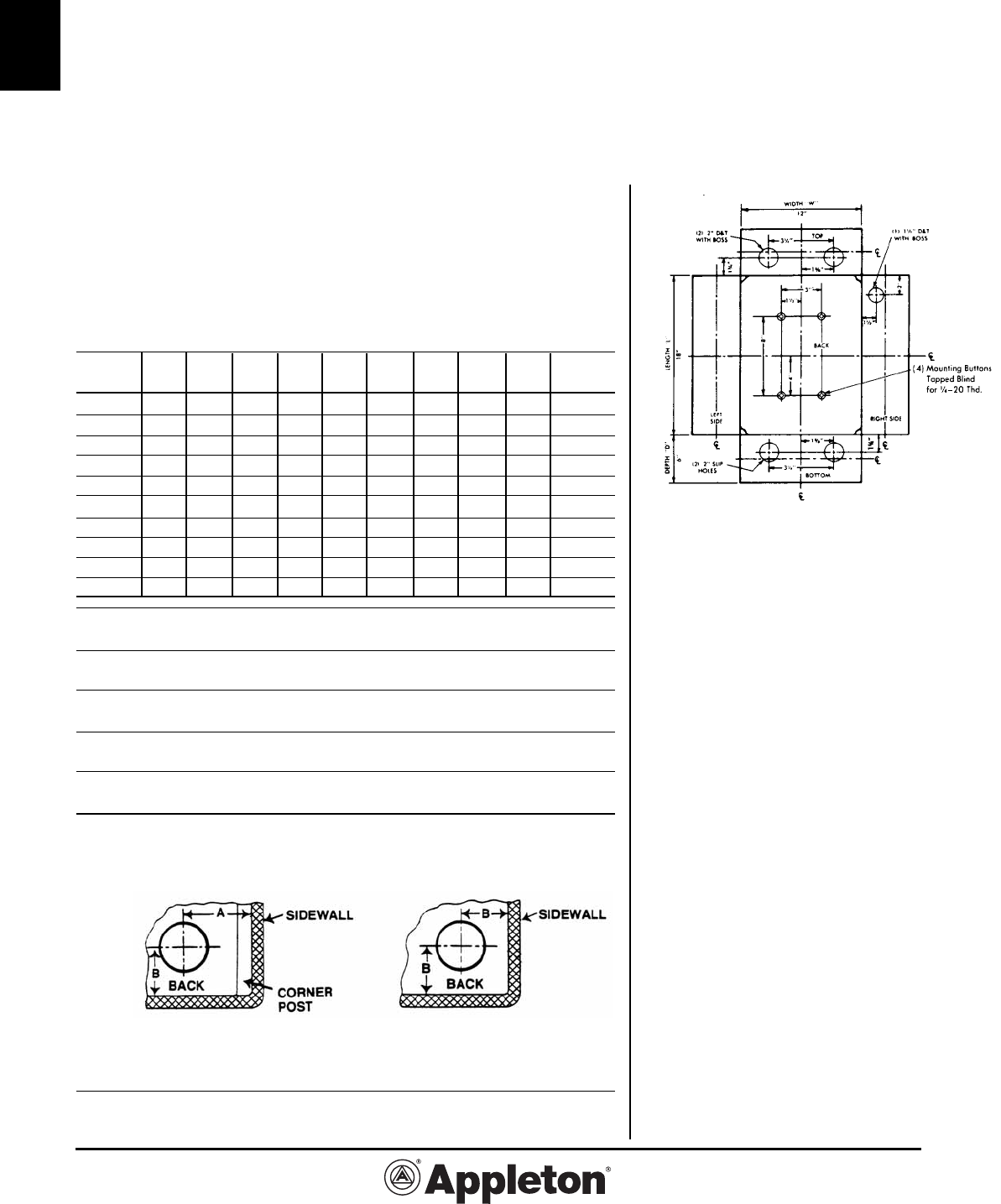
Mounting Lugs (See Fig. 1, page C-7) are
provided on all surface mounted boxes over
100 cubic inches of internal volume to meet
NEC Section 314.23(E). Boxes 100 cubic
inches or less may be supported by two or
more conduits threaded into the enclosure, or
by optional mounting lugs. All mounting
lugs will be located on the long sides of the
box, unless otherwise specified. Refer to
page C-10 for dimensional data.
Mounting Buttons (See Fig. 1 on page C-7) for
mounting equipment off the back of the box
can be furnished located on standard centers
and blind D and T for 1⁄4” - 20 screws. If spe-
cial mounting button arrangement is required
furnish a sketch showing layout including the
size of the mounting screws. Please use the
drilling template provided on page C-9.
Covers other than standard, must be specified
if required.
Gaskets other than standard must be speci-
fied if required.
TYPE OF ENCLOSURE
Options* WYS WYL WYF WYW WYU WYR WYT WY58E WYC WYNY
Slip Holes ✔ ✔ ✔ ✔ ✔ ✔ ✔ NA ✔ NA
Drill & Tap Holes
✔ ✔ ✔ ✔ ✔ ✔ ✔ NA ✔ NA
Bosses Only ✔ ✔ ✔ ✔ ✔ ✔ ✔ NA ✔ NA
Drilled & Tappped Boss ✔ ✔ ✔ ✔ ✔ ✔ ✔ NA ✔ NA
Mtg. Lugs ✔ ✔ ✔ ✔ ✔ ✔ ✔ NA ✔ NA
Mtg. Buttons ✔ ✔ ✔ ✔ ✔ ✔ ✔ NA ✔ NA
Mtg. Plates* ✔ ✔ ✔ ✔ ✔ ✔ ✔ NA ✔ NA
Hinges NA NA NA S ✔ NA NA NA S NA
Drain & Breather ✔ ✔ ✔ ✔ ✔ NA NA NA NA NA
Hasp (for padlock) NA NA NA ✔ ✔ NA NA NA NA NA

C-7
C
Effective September, 2005
Copyright 2005
800-621-1506
www.appletonelec.com
PAGE 7
W Series Cast Boxes: Options
Drilling & Tapping
Applies to: Types WYS, WYL, WYF, WYW-T, WYT, WYC, WYU, WYR
Conduit Drilling & Boss Only Boss for
Size Drilling Only Tapping 5 Threads 5 Threads
(Inches) Slip Hole No Boss w/o Hole and Tapping
Catalog Catalog Catalog Catalog
Number Number Number Number
3⁄8 ASH-38 ADT-38 ABWH-38 ABDT-38
1⁄2 ASH-50 ADT-50 ABWH-50 ABDT-50
3⁄4 ASH-75 ADT-75 ABWH-75 ABDT-75
1 ASH-100 ADT-100 ABWH-100 ABDT-100
1
1⁄4 ASH-125 ADT-125 ABWH-125 ABDT-125
1
1⁄2 ASH-150 ADT-150 ABWH-150 ABDT-150
2 ASH-200 ADT-200 ABWH-200 ABDT-200
2
1⁄2 ASH-250 ADT-250 ABWH-250 ABDT-250
3 ASH-300 ADT-300 ABWH-300 ABDT-300
3
1⁄2 ASH-350 ADT-350 ABWH-350 ABDT-350
4 ASH-400 ADT-400 ABWH-400 ABDT-400
4
1⁄2 ASH-450 ADT-450 ABWH-450 ABDT-450
5 ASH-500 ADT-500 ABWH-500 ABDT-500
6 ASH-600 ADT-600 ABWH-600 ABDT-600
Hinges
Number
Catalog of Hinges
Type Box Size Number Per Set
Stainless Steel Up to 12” x 12” AHNG-22SS 2
Butt Type Up to 18” x 18” AHNG-23SS 2
For WYU Boxes Larger than 18” x 18”
AHNG-33SS 3
Combination Drain & Breather Fittings
D&T and installation included
Size Catalog
(Inches) Number
3⁄8” AMDB-38
1⁄2” AMDB-50
Interior Mounting Buttons
Quantity Catalog
Per Box Number
1 A1-MBT
2 A2-MBT
3 A3-MBT
4 A4-MBT
Standard tapped blind for 1⁄4” - 20 thread.
Specify if other than 1⁄4”-20 thread required.
Optional Mounting Lugs with Bolt Holes
Max. Box Size No. of Lugs Number
Sizes up to 2 A2-ML-0604
6”L x 4”W 4 A4-ML-0604
Sizes 6”L x 6”W 2 A2-ML-1204
Up to 12”L x 4”W 4 A4-ML-1204
Sizes 12”L x 6”W 2 A2-ML-1816
Up to 18”L x 16”W 4 A4-ML-1816
Sizes 18”L x 18”W 4 A4-ML-3636
and larger
Mounting lugs are standard equipment on surface mounted boxes
over 100 cubic inches of internal volume at no additional charge.
Hasps
Hot dip galvanized steel (lock not Included)
Box Size Catalog Number
Up to 12” x 12” AHSP-13SG
Larger than 12” x 12” AHSP-15SG
Grounding Kits
Catalog Wire Capacity
Number Al-Cu Tinned Copper
AGK-04 #14-4 AWG
AGK-10 8-1/0 AWG
AGK-25 6 AWG-250kcmil
Letters Engraved on Box Covers
Catalog
Description Number
Up to 10 letters, one line AENGRAVE-1
Up to 20 letters, two lines A ENGRAVE-2
Additional Cost Items
S
SED, DRILLED AND
A
PPED HOLE - BDT
U
NTING BUTTONS - MBT
SLIP HOLE - SH
DRILLED AND TAPPED HOLE - D
T
MOUNTING LUGS - ML
CAST-IN OR ENGRAVED LETTERS
XXXX
BOSSED, DRILLED AND
TAPPED HOLE - ABDT
MOUNTING BUTTONS - A-MBT
MOUNTING LUGS - A-ML
DRILLED AND TAPPED HOLE - ADT
SLIP HOLE - ASH
CAST-IN OR ENGRAVED LETTERS
Figure 1
Effective September, 2005
Copyright 2005
PAGE 8
800-621-1506
www.appletonelec.com
C-8
C
Ordering Information for W Series
Cast Junction Boxes
Minimum Recommended Spacing Between Conduit Openings
Allowance made for clearance over locknuts and bushings
When unions are used, additional space must be allowed.
Table shows minimum distances between conduit opening centerlines in various
size combinations. For example, if 1-1/2” and 3/4” openings are to be drilled and
tapped into one side of box, the minimum spacing between centerlines would
be 2-1/8”.
Space Between Centers of Conduit (Inches)
Size of 4 3-1/2 3 2-1/2 2 1-1/2 1-1/4 1 3/4 1/2
Conduit
1/2 3-5/8 3-3/8 3 2-5/8 2-3/8 2 1-7/8 1-3/4 1-5/8 1-1/2
3/4 3-3/4 3-1/2 3-1/8 2-3/4 2-1/2 2-1/8 2 1-7/8 1-3/4
1 4 3-5/8 3-1/4 3 2-5/8 2-3/8 2-1/4 2
1-1/4 4-1/8 3-7/8 3-1/2 3-1/8 2-7/8 2-1/2 2-3/8
1-1/2 4-1/4 4 3-5/8 3-1/4 3 2-5/8
2 4-5/8 4-1/4 3-7/8 3-5/8 3-1/4
2-1/2 4-7/8 4-5/8 4-1/4 3-7/8
3 5-3/8 5 4-5/8
3-1/2 5-5/8 5-1/4
4 5-7/8
Locknut
Diameter 1.13 1.38 1.75 2.25 2.56 3.19 3.50 4.19 4.75 5.38
BBU Bushing
Diameter 1.06 1.31 1.56 1.94 2.19 2.69 3.19 3.88 4.38 4.88
BU Bushing
Diameter 1.13 1.25 1.63 2.06 2.31 2.94 3.25 3.88 4.56 5.06
UNY/UNF (R)
Union 1.50 1.75 2.00 2.81 3.06 3.75 4.94 5.44 5.94 6.50
Conduit
Diameter 0.88 1.06 1.38 1.69 1.94 2.38 2.88 3.50 4.00 4.50
Minimum Allowable Spacing from Back and Sides
Allowance made for clearance over locknuts and bushings
Types WYS, WYL, Types WYF, WYR,
WYW, WYT and WYC WYU and WY58E
Conduit
Size 1/2” 3/4” 1” 1-1/4” 1-1/2” 2” 2-1/2” 3” 3-1/2” 4”
Dim. “A” 1-1/4 1-3/8 1-5/8 1-7/8 2 2-3/8 2-5/8 3 3-1/4 3-5/8
Dim. “B” 1 1 1-1/8 1-3/8 1-1/2 1-3/4 2-1/8 2-1/2 2-7/8 3-1/8
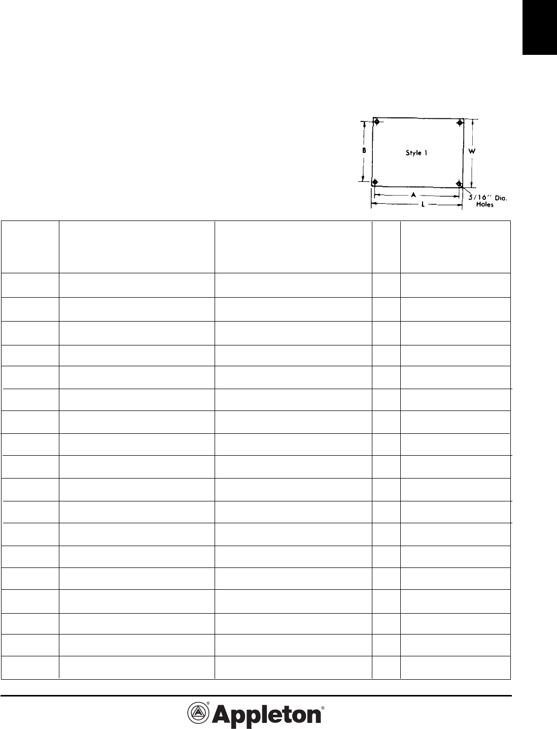
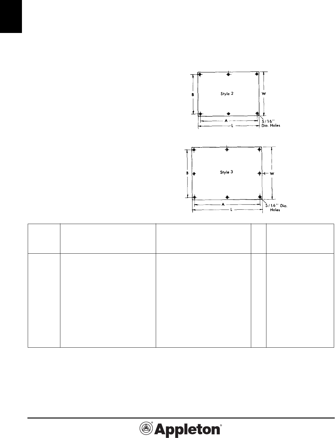
Drilling template on page C-9 can be
copied and used to transmit information
regarding conduit entries, mounting lugs,
mounting plates, or any other options or
specifications. The view is looking into
the box with sides laid down. Doors are
hinged on the right side, when required,
which is the length, when no other in-
structions are given. Unless otherwise
specified, all openings will be located in
centerline of walls and evenly spaced.
When optional Mounting Buttons are
ordered, dimensions for spacing MUST
be given, otherwise will be spaced per
our discretion.
Figure 2

C-9
C
Effective September, 2005
Copyright 2005
800-621-1506
www.appletonelec.com
PAGE 9
Drilling Template for Cast Junction Boxes
FOR COPIER REPRODUCTION OR COMPUTER SCANNING. PLEASE SEND TO YOUR LOCAL
REPRESENTATIVE FOR QUOTATION OR ORDER CONFIRMATION.
COMPANY/LOCATION SIGNATURE PRINT NAME
NOTE: Mounting Lugs are provided on all sur-
face-mount boxes over 100 cubic inches internal
volume. See Page C-6 and box catalog page.
– See Page C-10
– Locate on template
Effective September, 2005
Copyright 2005
PAGE 10
800-621-1506
www.appletonelec.com
C-10
C
Mounting Lug Data for W Series Cast Boxes
For Cast Iron & Cast Aluminum Boxes
Bolt
Box Size Hole Dia.
in Inches Dimension in Inches in Inches
L x W A B D
4 x 4 3 53⁄8 5⁄16
5 x 5 4 61⁄2 5⁄16
6 x 4 5 53⁄8 5⁄16
6 x 6 4 75⁄8 3⁄8
7 x 5 5 61⁄2 3⁄8
8 x 4 5 55⁄8 3⁄8
8 x 6 5 75⁄8 3⁄8
8 x 8 5 93⁄4 3⁄8
9 x 6 6 75⁄8 3⁄8
10 x 4 7 55⁄8 3⁄8
10 x 5 7 65⁄8 3⁄8
10 x 6 7 73⁄4 3⁄8
10 x 8 7 93⁄4 3⁄8
10 x 10 7 113⁄4 3⁄8
12 x 4 8 55⁄8 3⁄8
12 x 6 8 81⁄2 7⁄16
12 x 8 8 101⁄2 7⁄16
12 x 10 8 121⁄2 7⁄16
12 x 12 8 141⁄2 7⁄16
14 x 8 10 101⁄2 7⁄16
14 x 10 10 121⁄2 7⁄16
14 x 14 10 161⁄2 7⁄16
15 x 6 11 83⁄8 7⁄16
15 x 8 11 105⁄8 7⁄16
15 x 9 11 111⁄2 7⁄16
15 x 10 11 121⁄2 7⁄16
16 x 4 12 61⁄2 7⁄16
16 x 10 12 121⁄2 7⁄16
Types WYS, WYL, WYW,
WYU, & WYW-T
Refer to Fig. 1
Bolt
Box Size Hole Dia.
in Inches Dimension in Inches in Inches
L x W A B D
4 x 4 3 53⁄8 5⁄16
5 x 5 4 63⁄8 5⁄16
6 x 4 5 53⁄8 5⁄16
6 x 6 4 71⁄2 3⁄8
8 x 4 5 51⁄2 3⁄8
8 x 6 5 75⁄8 3⁄8
8 x 8 5 95⁄8 3⁄8
10 x 6 7 75⁄8 3⁄8
10 x 8 7 93⁄4 3⁄8
10 x 10 7 115⁄8 3⁄8
12 x 4 8 55⁄8 3⁄8
12 x 6 8 83⁄8 7⁄16
12 x 8 8 103⁄8 7⁄16
12 x 10 8 123⁄8 7⁄16
12 x 12 8 143⁄8 7⁄16
14 x 8 10 103⁄8 7⁄16
14 x 14 10 161⁄2 7⁄16
16 x 12 12 141⁄2 7⁄16
16 x 16 12 181⁄2 7⁄16
18 x 6 13 81⁄2 7⁄16
18 x 8 13 101⁄2 7⁄16
18 x 12 13 143⁄8 7⁄16
18 x 18 13 205⁄8 9⁄16
24 x 12 19 145⁄8 9⁄16
24 x 18 19 205⁄8 9⁄16
24 x 24 19 267⁄8 9⁄16
28 x 12 22 143⁄4 9⁄16
30 x 24 24 267⁄8 9⁄16
36 x 18 30 207⁄8 9⁄16
36 x 24 30 267⁄8 9⁄16
36 x 36 30 387⁄8 9⁄16
Types WYF, & WYR
Refer to Fig. 1
The dimensions listed in these tables are approximate and
may vary as much as 1⁄4” in any direction. If closer tolerances
are required or if other locations of the mounting lugs are
desired, specify on the order or drawing.
Bolt
Box Size Hole Dia.
in Inches Dimension in Inches in Inches
L x W A B D
16 x 12 12 141⁄2 7⁄16
16 x 16 12 181⁄2 7⁄16
18 x 6 13 81⁄2 7⁄16
18 x 8 13 101⁄2 7⁄16
18 x 12 13 141⁄2 7⁄16
18 x 14 13 165⁄8 7⁄16
18 x 16 13 185⁄8 7⁄16
18 x 18 13 207⁄8 9⁄16
20 x 10 15 125⁄8 9⁄16
20 x 20 15 225⁄8 9⁄16
24 x 8 19 103⁄4 9⁄32
24 x 12 19 143⁄4 9⁄32
24 x 16 19 183⁄4 9⁄32
24 x 18 19 203⁄4 9⁄32
24 x 20 19 223⁄4 9⁄16
24 x 24 19 267⁄8 9⁄16
28 x 12 22 147⁄8 9⁄16
30 x 8 24 103⁄4 9⁄16
30 x 18 24 21 9⁄16
30 x 24 24 147⁄8 9⁄16
34 x 30 28 327⁄8 9⁄16
36 x 6 30 85⁄8 9⁄16
36 x 12 30 147⁄8 9⁄16
36 x 18 30 21 9⁄16
36 x 24 30 267⁄8 9⁄16
36 x 30 30 327⁄8 9⁄16
36 x 36 30 387⁄8 9⁄16
48 x 6 42 85⁄8 9⁄16
Types WYS, WYL, WYW,
WYU, & WYW-T
Refer to Fig. 1
Fig. 1
C-11
C
Effective September, 2005
Copyright 2005
800-621-1506
www.appletonelec.com
PAGE 11
Mounting Plate Information for
W Series and EXB† and DTX† Series
Junction Boxes
Mounting plates are used for mounting equip-
ment up off the back of an enclosure. Steel
Plates are all 1/8” thick hot dip galvanized
material. Aluminum plates are 1/8” thick material
up to and including 12” x 12” size. All larger sizes
are constructed of 3/16” thick aluminum plate.
Select mounting plates based on inside length
and width of box. Order as a separate item im-
mediately following the Catalog Number of the
box as follows:
Example: Line 1 W YS-080804
Line 2 WYM-0808-2
For mounting plates in smaller boxes than
listed, use similar catalog number logic.
Example: A steel mounting plate for a WYF-
040403 box would be WYM-0404-1. Pricing will
be based upon a WYM-0808-1 price
THE CATALOG NUMBER SHOWN IN THE
TABLE BELOW INCLUDES THE MOUNTING
BUTTONS.
Inside Catalog Number – Steel Plates Catalog Number – Aluminum Plates
Length & For use in For use in For use in For use in
Width of Types WYF, WYR Types WYS Types WYF, WYR Types WYS
Junction Box DTX & EXB WYL & WYW DTX & EXB WYL & WYW
Dimension in Inches
in Inches Junction Boxes† Junction Boxes Junction Boxes† Junction Boxes Style L W A B
8 x 8 WYM-0808-1 WYM-0808-1A 1 6-3/4 6-3/4 6 6
WYM-0808-2 WYM-0808-2A 6 6 5-1/4 5-1/4
10 x 8 WYM-1008-1 WYM-1008-1A 1 8-3/4 6-3/4 8 8
WYM-1008-2 WYM-1008-2A 8 6 7-1/4 5-1/4
10 x 10 WYM-1010-1 WYM-1010-1A 1 8-3/4 8-3/4 8 8
WYM-1010-2 WYM-1010-2A 8 8 7-1/4 7-1/4
12 x 8 WYM-1208-1 WYM-1208-1A 1 10-3/4 6-3/4 10 6
WYM-1208-2 WYM-1208-2A 10 6 9-1/4 5-1/4
12 x 10 WYM-1210-1 WYM-1210-1A 1 10-3/4 8-3/4 10 8
WYM-1210-2 WYM-1210-2A 10 8 9-1/4 5-1/4
12 x 12 WYM-1212-1 WYM-1212-1A 1 10-3/4 10-3/4 10 10
WYM-1212-2 WYM-1212-2A 10 10 9-1/4 9-1/4
14 x 8 WYM-1408-1 WYM-1408-1A 1 12-3/4 6-3/4 12 6
WYM-1408-2 WYM-1408-2A 12 6 11-1/4 5-1/4
14 x 14 WYM-1414-1 WYM-1414-1A 1 12-3/4 12-3/4 12 12
WYM-1414-2 WYM-1414-2A 12 12 11-1/4 11-1/4
16 x 8 WYM-1608-1 WYM-1608-1A 1 14-3/4 6-3/4 14 6
WYM-1608-2 WYM-1608-2A 12 6 11-1/4 5-1/4
16 x 12 WYM-1612-1 WYM-1612-1A 1 14-3/4 10-3/4 14 10
WYM-1612-2 WYM-1612-2A 14 10 13-1/4 9-1/4
16 x 16 WYM-1616-1 WYM-1616-1A 1 14-3/4 14-3/4 14 14
WYM-1616-2 WYM-1616-2A 14 14 13-1/4 13-1/4
18 x 8 WYM-1808-1 WYM-1808-1A 1 16-3/4 6-3/4 16 6
WYM-1808-2 WYM-1808-2A 16 6 15-1/4 5-1/4
18 x 10 WYM-1810-1 WYM-1810-1A 1 16-3/4 8-3/4 16 8
WYM-1810-2 WYM-1818-2A 16 8 15-1/4 7-1/4
18 x 12 WYM-1812-1 WYM-1812-1A 1 16-3/4 10-3/4 16 10
WYM-1812-2 WYM-1812-2A 16 10 15-1/4 9-1/4
18 x 14 WYM-1814-1 WYM-1814-1A 1 16-3/4 12-3/4 16 12
WYM-1814-2 WYM-1814-2A 16 12 15-1/4 11-1/4
18 x 16 -- -- 1 -- -- -- --
WYM-1816-2 WYM-1816-2A 16 14 15-1/4 13-1/4
18 x 18 WYM-1818-1 WYM-1818-1A 1 16-3/4 16-3/4 16 16
WYM-1818-2 WYM-1818-2A 16 16 15-1/4 15-1/4
20 x 10 WYM-2010-1 WYM-2010-1A 1 18-3/4 8-3/4 18 8
WYM-2020-2 WYM-2020-2A 18 8 17-1/4 7-1/4
† Refer to Catalog Section K for EXB and DTX Boxes.
Effective September, 2005
Copyright 2005
PAGE 12
800-621-1506
www.appletonelec.com
C-12
C
Mounting Plate Information for
W Series and EXB† and DTX† Series
Junction Boxes
Continued from preceding page.
Inside Catalog Number – Steel Plates Catalog Number – Aluminum Plates
Length & For use in For use in For use in For use in
Width of Types WYF, WYR, Types WYS Types WYF, WYR, Types WYS
Junction Box DTX & EXB WYL & WYW DTX & EXB WYL & WYW
Dimension in Inches
in Inches Junction Boxes† Junction Boxes Junction Boxes† Junction Boxes Style L W A B
24 x 12 WYM-2412-1 WYM-2412-1 WYM-2412-1A WYM-2412-1A 2 21-3/4 9-3/4 21 9
24 x 18 WYM-2418-1 WYM-2418-1 WYM-2418-1A WYM-2418-1A 2 21-3/4 15-3/4 21 15
24 x 24 WYM-2424-1 WYM-2424-1 WYM-2424-1A WYM-2424-1A 3 21-3/4 21-3/4 21 21
28 x 12 WYM-2812-1 WYM-2812-1 WYM-2812-1A WYM-2812-1A 2 25-3/4 9-3/4 25 9
30 x 12 WYM-3012-1 WYM-3012-1 WYM-3012-1A WYM-3012-1A 2 27-3/4 9-3/4 27 9
30 x 18 WYM-3018-1 WYM-3018-1 WYM-3018-1A WYM-3018-1A 2 27-3/4 15 -3/4 27 15
30 x 24 WYM-3024-1 WYM-3024-1 WYM-3024-1A WYM-3024-1A 3 27-3/4 21-3/4 27 21
36 x 12 WYM-3612-1 WYM-3612-1 WYM-3612-1A WYM-3612-1A 2 33-3/4 9-3/4 33 9
36 x 18 WYM-3618-1 WYM-3618-1 WYM-3618-1A WYM-3618-1A 2 33-3/4 15-3/4 33 15
36 x 24 WYM-3624-1 WYM-3624-1 WYM-3624-1A WYM-3624-1A 3 33-3/4 21-3/4 33 21
36 x 30 WYM-3630-1 WYM-3630-1 WYM-3630-1A WYM-3630-1A 3 33-3/4 27-3/4 33 27
36 x 36 WYM-3636-1 WYM-3636-1 WYM-3636-1A WYM-3636-1A 3 33-3/4 33-3/4 33 33
Mounting plates are used for mounting
equipment up off the back of an en-
closure. Steel Plates are all 1/8” thick
hot dip galvanized material. Aluminum
plates are 1/8” thick material up to and
including 12” x 12” size. All larger sizes
are constructed of 3/16” thick aluminum
plate.
Select mounting plates based on in-
side length and width of box. Order
as a separate item immediately follow-
ing the Catalog Number of the box as
follows:
Example:
WYS-080804 WYM-0808-2
THE CATALOG NUMBER SHOWN IN
THE TABLE BELOW INCLUDES THE
MOUNTING BUTTONS.
† Refer to Catalog Section K for EXB and DTX Boxes.
C-13
C
Effective June, 2008
Copyright 2008
800-621-1506
www.appletonelec.com
PAGE 13
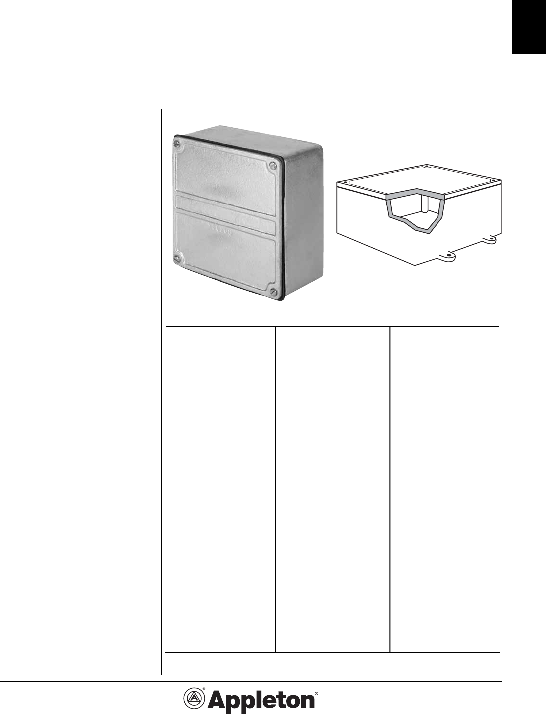
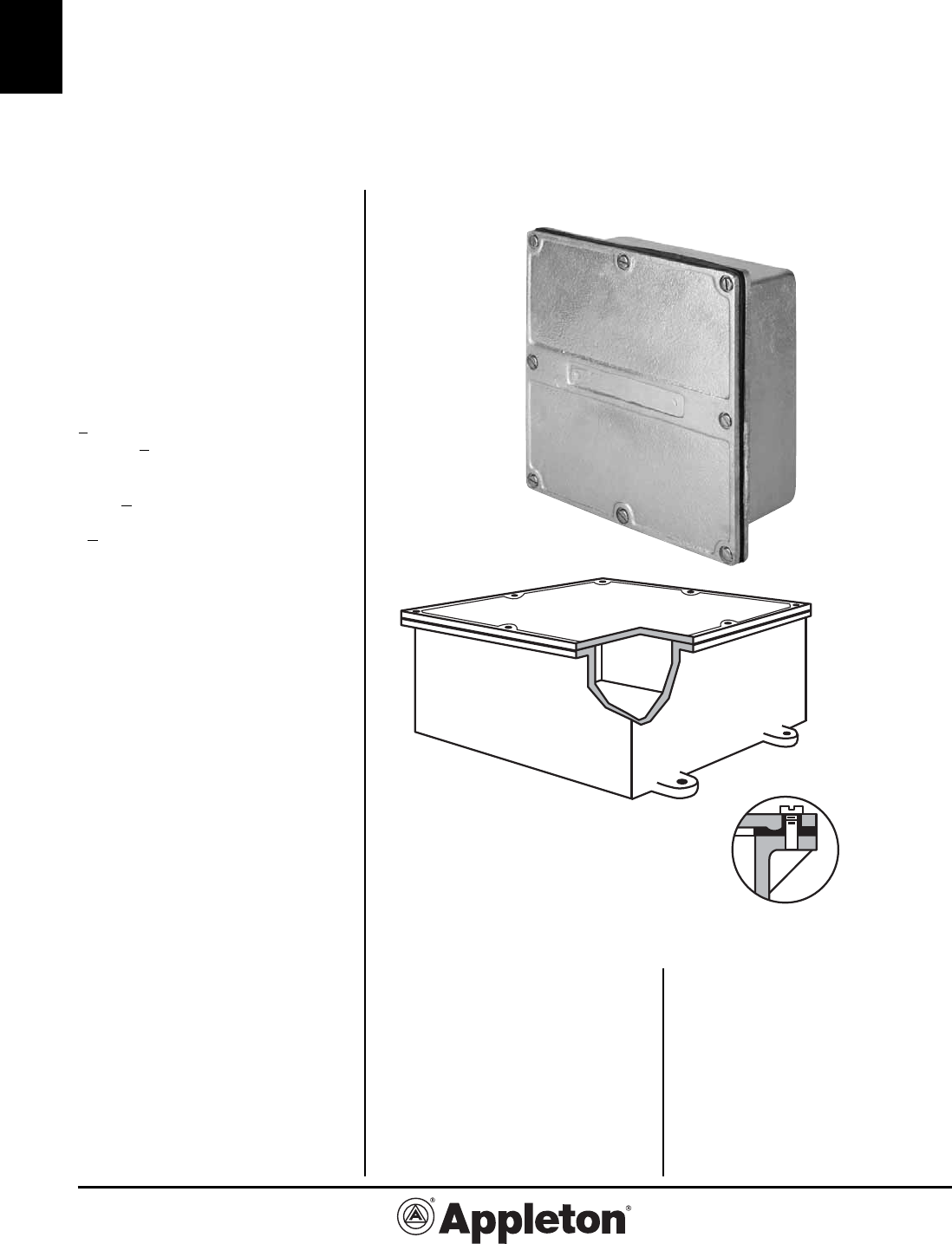
W Series: WYS Type Unflanged
Junction or Pull Boxes
Cast Iron or Aluminum Box For Surface Mounting. Raintight - Watertight.
Applications
• These boxes are general purpose
enclosures suitable for use indoors or
outdoors.
Features
•† Mounting Lugs are standard on
boxes over 100 cubic inches internal
volume, and optional on boxes 100
cubic inches or less. See pages C-6,
C-7, and C-10 for additional information
and ordering instructions.
• Type WYS boxes have a post in each
corner and allowances must be made
for them when conduit entrances are to
be located close to a corner.
• Neoprene gasket, attached to cover.
• Suitable for a variety of applications.
• Wide selection of sizes and locations
for drilled-and-tapped and slip-hole
conduit entrances.
• Choice of locations for blind tapped
holes in Interior Mounting Buttons
(optional).
Standard Materials
• Cast iron box and cover.
• Neoprene gasket.
• Stainless steel cover screws.
Standard Finishes
• Box and cover: Hot Dip Galvanized.
Options
• Available in aluminum. Add suffix “A”
to catalog number.
Other Options
Refer to pages C6- C12.
Compliances
• UL Listed: Type 4 Raintight .
• UL Standard: 514A, 50.
• NEMA 250-1997 Type 3R and 4.
Iron Aprox. Inside Dim.
Catalog Wall (inches)
Number Thick.* L x W x D
WYS-100808
5/16 10 x 8 x 8
WYS-100810
11/32 10 x 8 x 9-1/2
WYS-101003
3/16 10 x 10 x 3
WYS-101004
7/32 10 x 10 x 4
WYS-101005
1/4 10 x 10 x 5
WYS-101006
1/4 10 x 10 x 6
WYS-120404
7/32 12 x 4 x 4
WYS-120406
9/32 12 x 4 x 6
WYS-120603
3/16 12 x 6 x 3
WYS-120604
7/32 12 x 6 x 4
WYS-120606
9/32 12 x 6 x 6
WYS-120804
7/32 12 x 8 x 4
WYS-120806
9/32 12 x 8 x 6
WYS-120808
5/16 12 x 8 x 8
WYS-121004
1/4 12 x 10 x 4
WYS-121005
1/4 12 x 10 x 5
WYS-121006
1/32 12 x 10 x 6
WYS-121008
5/16 12 x 10 x 8
WYS-121203
3/16 12 x 12 x 3
WYS-121204
1/4 12 x 12 x 4
WYS-121206
9/32 12 x 12 x 6
WYS-121208
5/16 12 x 12 x 8
WYS-121210
1/32 12 x 12 x 10
WYS-121212
3/8 12 x 12 x 12
WYS-140804
1/4 14 x 8 x 4
WYS-140806
9/32 14 x 8 x 6
WYS-141006
9/32 14 x 10 x 6
WYS-141008
5/16 14 x 10 x 8
WYS-141406
9/32 14 x 14 x 6
WYS-141408
5/16 14 x 14 x 8
WYS-141410
11/32 14 x 14 x 10
WYS-150604
1/4 15 x 6 x 4
Iron Aprox. Inside Dim.
Catalog Wall (inches)
Number Thick.* L x W x D
WYS-150808
5/16 15 x 8 x 8
WYS-150904
1/4 15 x 9 x 4
WYS-150906
9/32 15 x 9 x 6
WYS-151006
9/32 15 x 10 x 6
WYS-160404
7/32 16 x 4 x 4
WYS-161006
9/32 16 x 10 x 6
WYS-161008
5/16 16 x 10 x 8
WYS-161204
1/4 16 x 12 x 4
WYS-161206
9/32 16 x 12 x 6
WYS-161208
5/16 16 x 12 x 8
WYS-161606
9/32 16 x 16 x 6
WYS-161612
11/32 16 x 16 x 12
WYS-161616
11/32 16 x 16 x 16
WYS-180604
1/4 18 x 6 x 4
WYS-180606
9/32 18 x 6 x 6
WYS-180806
9/32 18 x 8 x 6
WYS-180808
5/16 18 x 8 x 8
WYS-181204
1/4 18 x 12 x 4
WYS-181206
9/32 18 x 12 x 6
WYS-181208
5/16 18 x 12 x 8
WYS-181210
3/8 18 x 12 x 10
WYS-181212
7/16 18 x 12 x 12
WYS-181406
9/32 18 x 14 x 6
WYS-181408
5/16 18 x 14 x 8
WYS-181606
9/32 18 x 16 x 6
WYS-181608
5/16 18 x 16 x 8
WYS-181804
5/16 18 x 18 x 4
WYS-181806
5/16 18 x 18 x 6
WYS-181808
11/32 18 x 18 x 8
WYS-181810
3/8 18 x 18 x 10
WYS-181812
7/16 18 x 18 x 12
WYS-181818
7/16 18 x 18 x 18
Iron Aprox. Inside Dim.
Catalog Wall (inches)
Number Thick.* L x W x D
WYS-040402†
5/32 4 x 4 x 2
WYS-040403†
3/16 4 x 4 x 3
WYS-040404†
3/16 4 x 4 x 4
WYS-050503†
3/16 5 x 5 x 3
WYS-050504†
3/16 5 x 5 x 4
WYS-060403†
3/16 6 x 4 x 3
WYS-060404†
3/16 6 x 4 x 4
WYS-060602†
3/16 6 x 6 x 2
WYS-060603
3/16 6 x 6 x 3
WYS-060604
3/16 6 x 6 x 4
WYS-060605
7/32 6 x 6 x 5
WYS-060606
1/4 6 x 6 x 6
WYS-060610 9/32 6 x 6 x 9-1/2
WYS-070503
3/16 7 x 5 x 3
WYS-080403†
3/16 8 x 4 x 3
WYS-080404
7/32 8 x 4 x 4
WYS-080603
3/16 8 x 6 x 3
WYS-080604
7/32 8 x 6 x 4
WYS-080605
7/32 8 x 6 x 5
WYS-080606
1/4 8 x 6 x 6
WYS-080803
3/16 8 x 8 x 3
WYS-080804
7/32 8 x 8 x 4
WYS-080805
7/32 8 x 8 x 5
WYS-080806
1/4 8 x 8 x 6
WYS-080808
5/16 8 x 8 x 8
WYS-090603
3/16 9 x 6 x 3
WYS-090604
7/32 9 x 6 x 4
WYS-100403
3/16 10 x 4 x 3
WYS-100406
1/4 10 x 4 x 6
WYS-100504
7/32 10 x 5 x 4
WYS-100604
7/32 10 x 6 x 4
WYS-100605
1/4 10 x 6 x 5
WYS-100606
9/32 10 x 6 x 6
WYS-100804
7/32 10 x 8 x 4
WYS-100805
1/4 10 x 8 x 5
WYS-100806
9/32 10 x 8 x 6
NEMA 3R and 4
* Measured 2” up from back of box. †Mounting lugs are optional.
Effective June, 2008
Copyright 2008
PAGE 14
800-621-1506
www.appletonelec.com
C-14
C
W Series:
WYL Type Overlapping Cover Boxes
Cast Iron or Aluminum Box for Surface Mounting. Watertight - Raintight.
Applications
• These overlapping cover boxes are
listed by Underwriters Laboratories,
Inc. as Type 4.
• They are suitable for use outdoors, or
where they would be subjected to rain,
dripping or splashing of water .
Features
•† Mounting Lugs are standard on
boxes over 100 cubic inches internal
volume, and optional on boxes 100
cubic inches or less. See pages C-6,
C-7, and C-10 for additional information
and ordering instructions.
• Type WYL boxes have a post in each
corner and allowances must be made
for them when conduit entrances are to
be located close to a corner.
• Flat, neoprene gasket attached to
cover.
• Wide selection of sizes and locations
for drilled-and-tapped and slip-hole
conduit entrances.
• Choices of locations for blind tapped
holes in Interior Mounting Buttons (op-
tional).
Standard Materials
• Cast Iron box and cover.
• Neoprene gasket.
• Stainless steel cover screws.
Standard Finishes
• Box and cover: Hot Dip Galvanized.
Options
• Available in aluminum. Add suffix “A”
to catalog number.
Other Options
Refer to pages C6- C12.
Compliances
• UL Listed Type 4 Raintight .
• UL Standard: 514A, 50.
• NEMA 250-1997 Type 3R and 4 .
NEMA 3R and 4

C-15
C
Effective September, 2005
Copyright 2005
800-621-1506
www.appletonelec.com
PAGE 15
W Series:
WYL Type Overlapping Cover Boxes
Cast Iron or Aluminum Box for Surface Mounting. Watertight - Raintight.
Iron
Aprox. Inside Dim.
Catalog Wall (inches)
Number Thick.* L x W x D
WYL-241606
9/32 24 x 16 x 6
WYL-241608
11/32 24 x 16 x 8
WYL-241806
5/16 24 x 18 x 6
WYL-241808
11/32 24 x 18 x 8
WYL-241810
3/8 24 x 18 x 10
WYL-241812
7/16 24 x 18 x 12
WYL-242406
5/16 24 x 24 x 6
WYL-242408
11/32 24 x 24 x 8
WYL-242410
3/8 24 x 24 x 10
WYL-242412
7/16 24 x 24 x 12
WYL-281206
5/16 28 x 12 x 6
WYL-281208
3/8 28 x 12 x 8
WYL-300806
9/32 30 x 8 x 6
WYL-300808
11/32 30 x 8 x 8
WYL-301808
11/32 30 x 18 x 8
WYL-301812
7/16 30 x 18 x 12
WYL-301814
1/2 30 x 18 x 14
WYL-302406
11/32 30 x 24 x 6
WYL-302408
3/8 30 x 24 x 8
WYL-302412
7/16 30 x 24 x 12
WYL-360606
9/32 36 x 6 x 6
WYL-361208
7/16 36 x 12 x 8
WYL-361212
11/32 36 x 12 x 12
WYL-361808
7/16 36 x 18 x 8
WYL-362408
11/32 36 x 24 x 8
WYL-362412
7/16 36 x 24 x 12
WYL-363608
3/8 36 x 36 x 8
WYL-363612
7/16 36 x 36 x 12
Iron
Aprox. Inside Dim.
Catalog Wall (inches)
Number Thick.* L x W x D
WYL-121206
9/32 12 x 12 x 6
WYL-121208
5/16 12 x 12 x 8
WYL-121210
11/32 12 x 12 x 10
WYL-121212
3/8 12 x 12 x 12
WYL-140804
1/4 14 x 8 x 4
WYL-140806
9/32 14 x 8 x 6
WYL-141006
9/32 14 x 10 x 6
WYL-141008
5/16 14 x 10 x 8
WYL-141406
9/32 14 x 14 x 6
WYL-141408
5/16 14 x 14 x 8
WYL-141410
11/32 14 x 14 x 10
WYL-150604
1/4 15 x 6 x 4
WYL-150808
5/16 15 x 8 x 8
WYL-150904
1/4 15 x 9 x 4
WYL-150906
9/32 15 x 9 x 6
WYL-151006
9/32 15 x 10 x 6
WYL-161006
9/32 16 x 10 x 6
WYL-161008
5/16 16 x 10 x 8
WYL-161204
1/4 16 x 12 x 4
Iron
Aprox. Inside Dim.
Catalog Wall (inches)
Number Thick.* L x W x D
WYL-161206
9/32 16 x 12 x 6
WYL-161208
5/16 16 x 12 x 8
WYL-161606
9/32 16 x 16 x 6
WYL-180604
1/4 18 x 6 x 4
WYL-180606
9/32 18 x 6 x 6
WYL-180806
9/32 18 x 8 x 6
WYL-180808
5/16 18 x 8 x 8
WYL-181204
1/4 18 x 12 x 4
WYL-181206
9/32 18 x 12 x 6
WYL-181208
5/16 18 x 12 x 8
WYL-181210
3/8 18 x 12 x 10
WYL-181212
7/16 18 x 12 x 12
WYL-181406
9/32 18 x 14 x 6
WYL-181408
5/16 18 x 14 x 8
WYL-181606
9/32 18 x 16 x 6
WYL-181608
5/16 18 x 16 x 8
WYL-181806
5/16 18 x 18 x 6
WYL-181808
11/32 18 x 18 x 8
WYL-181810
3/8 18 x 18 x 10
WYL-181812
7/16 18 x 18 x 12
WYL-201006
9/32 20 x 10 x 6
WYL-201008
5/16 20 x 10 x 8
WYL-202006
5/16 20 x 20 x 6
WYL-240806
9/32 24 x 8 x 6
WYL-240808
11/32 24 x 8 x 8
WYL-241206
9/32 24 x 12 x 6
WYL-241208
5/16 24 x 12 x 8
WYL-241212
7/16 24 x 12 x 12
NEMA 3R and 4
* Measured 2” up from back of box.
†
Mounting lugs are optional.
Iron
Aprox. Inside Dim.
Catalog Wall (inches)
Number Thick.* L x W x D
WYL-040403†
3/16 4 x 4 x 3
WYL-040404†
3/16 4 x 4 x 4
WYL-050503†
3/16 5 x 5 x 3
WYL-050504†
3/16 5 x 5 x 4
WYL-060403†
3/16 6 x 4 x 3
WYL-060404†
3/16 6 x 4 x 4
WYL-060603
3/16 6 x 6 x 3
WYL-060604
3/16 6 x 6 x 4
WYL-060605
7/32 6 x 6 x 5
WYL-060606
1/4 6 x 6 x 6
WYL-060610
9/32 6 x 6 x 9-1/2
WYL-080403†
3/16 8 x 4 x 3
WYL-080404
7/32 8 x 4 x 4
WYL-080603
3/16 8 x 6 x 3
WYL-080604
7/32 8 x 6 x 4
WYL-080605
7/32 8 x 6 x 5
WYL-080606
1/4 8 x 6 x 6
WYL-080803
3/16 8 x 8 x 3
WYL-080804
7/32 8 x 8 x 4
WYL-080805
7/32 8 x 8 x 5
WYL-080806
1/4 8 x 8 x 6
WYL-080808
5/16 8 x 8 x 8
WYL-090603
3/16 9 x 6 x 3
WYL-090604
7/32 9 x 6 x 4
Iron
Aprox. Inside Dim.
Catalog Wall (inches)
Number Thick.* L x W x D
WYL-100604
7/32 10 x 6 x 4
WYL-100605
1/4 10 x 6 x 5
WYL-100606
9/32 10 x 6 x 6
WYL-100804
7/32 10 x 8 x 4
WYL-100805
1/4 10 x 8 x 5
WYL-100806
9/32 10 x 8 x 6
WYL-100808
5/16 10 x 8 x 8
WYL-100810
11/32 10 x 8 x 9-1/2
WYL-101003
3/16 10 x 10 x 3
WYL-101004
7/32 10 x 10 x 4
WYL-101005
1/4 10 x 10 x 5
WYL-101006
1/4 10 x 10 x 6
WYL-120603
3/16 12 x 6 x 3
WYL-120604
7/32 12 x 6 x 4
WYL-120606
9/32 12 x 6 x 6
WYL-120804
7/32 12 x 8 x 4
WYL-120806
9/32 12 x 8 x 6
WYL-120808
5/16 12 x 8 x 8
WYL-121004
1/4 12 x 10 x 4
WYL-121005
1/4 12 x 10 x 5
WYL-121006
9/32 12 x 10 x 6
WYL-121008
5/16 12 x 10 x 8
WYL-121203
3/16 12 x 12 x 3
WYL-121204
1/4 12 x 12 x 4
Effective June, 2008
Copyright 2008
PAGE 16
800-621-1506
www.appletonelec.com
C-16
C
W Series:
WYF Type Flat Flanged Boxes - Submersible‡
Cast Iron or Aluminum Box for Surface Mounting.
Watertight, Raintight, Dust Tight.
Applications
• These boxes have been listed by
Underwriters’ Laboratories, Inc. as a
Type 4 enclosure.
• They are also suitable for use in-
doors or outdoors where they would be
subjected to splashing water, seepage
of water, falling or hose directed water
and severe external condensation.
‡ Submersible Applications
•
These boxes can be tested to with-
stand occasional submersion under a
6 foot head of water for 30 minutes
(NEMA 6 requirements). Add suffix
-SUB6 to catalog number
• These boxes can be tested to with-
stand Prolonged submersion under a 6
foot head of water for 24 hours (NEMA
6P requirements). Add suffix -SUB6P
to catalog number.
• These boxes can be tested to with-
stand submersion up to a 20-foot head
of water. Add suffix -SUB___ to catalog
number, filling in the blank space with
the number of feet from 7 up to 20, fol-
lowed by P if Prolonged submersion is
required.
• All WYF-SUB enclosures are subject
to a price addition on application and
must have:
1. Mounting Lugs
2. Bossed, drilled, and tapped conduit
entrances (ABDT series).
Features
•† Mounting Lugs are standard on
boxes over 100 cubic inches internal
volume, and optional on boxes 100
cubic inches or less. See pages C-6,
C-7, and C-10 for additional information
and ordering instructions.
• Wide flange provides greater contact
between gasketed cover and box.
• Enclosed and gasketed construction-
neoprene gasket attached to cover.
• Flange ground before galvanizing.
• Choices of locations for blind tapped
holes in Interior Mounting Buttons
(optional).
Standard Materials
• Cast iron box and cover
• Neoprene gasket
• Stainless steel cover screws
NEMA 4, 6‡, 6P‡
Standard Finishes
• Box and cover: Hot Dip Galvanized.
Options
• Available in aluminum. Add suffix “A”
to catalog number.
Other Options
Refer to pages C6- C12.
Compliances
• UL Listed Type 4
• UL Standard: 514A, 50
• NEMA 4,6‡,6P‡
The ridge on the underside of
the cover assures a good seal.

C-17
C
Effective September, 2005
Copyright 2005
800-621-1506
www.appletonelec.com
PAGE 17
W Series:
WYF Type Flat Flanged Boxes - Submersible
Cast Iron or Aluminum Box for Surface Mounting.
Watertight, Raintight, Dust Tight.
Iron
Aprox. Inside Dim.
Catalog Wall (inches)
Number Thick.* L x W x D
WYF-242410
3/8 24 x 24 x 10
WYF-242412
3/8 24 x 24 x 12
WYF-242424
3/8 24 x 24 x 24
WYF-281208
3/8 28 x 12 x 8
WYF-281212
3/8 28 x 12 x 12
WYF-302408
3/8 30 x 24 x 8
WYF-302410
3/8 30 x 24 x 10
WYF-302412
3/8 30 x 24 x 12
WYF-302418
3/8 30 x 24 x 18
WYF-361806
3/8 36 x 18 x 6
WYF-361808
3/8 36 x 18 x 8
WYF-361812
3/8 36 x 18 x 12
WYF-361818
3/8 36 x 18 x 18
WYF-362418
13/32 36 x 24 x 18
WYF-363608
7/16 36 x 36 x 8
WYF-363610
36 x 36 x 10
WYF-363612
7/16 36 x 36 x 12
WYF-363618
7/16 36 x 36 x 18
Iron
Aprox. Inside Dim.
Catalog Wall (inches)
Number Thick.* L x W x D
WYF-120404
1/4 12 x 4 x 4
WYF-120604
1/4 12 x 6 x 4
WYF-120606
1/4 12 x 6 x 6
WYF-120804
1/4 12 x 8 x 4
WYF-120806
1/4 12 x 8 x 6
WYF-120808
1/4 12 x 8 x 8
WYF-121004
1/4 12 x 10 x 4
WYF-121006
1/4 12 x 10 x 6
WYF-121008
1/4 12 x 10 x 8
WYF-121204
1/4 12 x 12 x 4
WYF-121206
1/4 12 x 12 x 6
WYF-121207
5/16 12 x 12 x 7
WYF-121208
5/16 12 x 12 x 8
WYF-121210
5/16 12 x 12 x 10
WYF-121212
5/16 12 x 12 x 12
WYF-140804
1/4 14 x 8 x 4
WYF-140806
1/4 14 x 8 x 6
WYF-140808
1/4 14 x 8 x 8
WYF-141406
5/16 14 x 14 x 6
WYF-141408
5/16 14 x 14 x 8
WYF-141410
5/16 14 x 14 x 10
WYF-161204
9/32 16 x 12 x 4
WYF-161206
9/32 16 x 12 x 6
WYF-161208
9/32 16 x 12 x 8
Iron
Aprox. Inside Dim.
Catalog Wall (inches)
Number Thick.* L x W x D
WYF-161606
5/16 16 x 16 x 6
WYF-180606
9/32 18 x 6 x 6
WYF-180804
9/32 18 x 8 x 4
WYF-180806
9/32 18 x 8 x 6
WYF-181204
1/4 18 x 12 x 4
WYF-181206
9/32 18 x 12 x 6
WYF-181208
5/16 18 x 12 x 8
WYF-181210
5/16 18 x 12 x 10
WYF-181212
5/16 18 x 12 x 12
WYF-181218
11/32 18 x 12 x 18
WYF-181806
5/16 18 x 18 x 6
WYF-181808
5/16 18 x 18 x 8
WYF-181810
5/16 18 x 18 x 10
WYF-181812
5/16 18 x 18 x 12
WYF-241206
5/16 24 x 12 x 6
WYF-241208
5/16 24 x 12 x 8
WYF-241212
5/16 24 x 12 x 12
WYF-241806
11/32 24 x 18 x 6
WYF-241808
11/32 24 x 18 x 8
WYF-241810
11/32 24 x 18 x 10
WYF-241812
11/32 24 x 18 x 12
WYF-241818
11/32 24 x 18 x 18
WYF-242406
11/32 24 x 24 x 6
WYF-242408
11/32 24 x 24 x 8
NEMA 4, 6‡, 6P‡
* Measured 2” up from back of box.
† Mounting lugs are optional.
Iron
Aprox. Inside Dim.
Catalog Wall (inches)
Number Thick.* L x W x D
WYF-040403†
5/32 4 x 4 x 3
WYF-040404†
5/32 4 x 4 x 4
WYF-050504†
3/16 5 x 5 x 4
WYF-060403†
5/32 6 x 4 x 3
WYF-060404†
5/32 6 x 4 x 4
WYF-060603
3/16 6 x 6 x 3
WYF-060604
7/32 6 x 6 x 4
WYF-060606
7/32 6 x 6 x 6
WYF-080403†
3/16 8 x 4 x 3
WYF-080404
3/16 8 x 4 x 4
WYF-080603
7/32 8 x 6 x 3
WYF-080604
7/32 8 x 6 x 4
WYF-080606
7/32 8 x 6 x 6
WYF-080804
7/32 8 x 8 x 4
WYF-080806
1/4 8 x 8 x 6
WYF-080808
1/4 8 x 8 x 8
WYF-100604
7/32 10 x 6 x 4
WYF-100606
7/32 10 x 6 x 6
WYF-100804
1/4 10 x 8 x 4
WYF-100806
1/4 10 x 8 x 6
WYF-100808
1/4 10 x 8 x 8
WYF-101004
1/4 10 x 10 x 4
WYF-101006
1/4 10 x 10 x 6
WYF-101008
1/4 10 x 10 x 8
Effective June, 2008
Copyright 2008
PAGE 18
800-621-1506
www.appletonelec.com
C-18
C
W Series:
WYW Type Hinged Cover Boxes
Cast Iron or Aluminum Box for Surface Mounting.
Watertight, Raintight, Dust Tight.
Applications
• These Hinged Cover Boxes make
ideal enclosures where equipment
within the box has to be inspected
frequently or easy access is required.
• The hinges are adjusted at the
factory for proper gasket pressure, but
can be readjusted in the field.
Features
•† Mounting Lugs are standard on
boxes over 100 cubic inches internal
volume, and optional on boxes 100
cubic inches or less. See pages C-6,
C-7, and C-10 for additional information
and ordering instructions.
• Hinges are always located on the
long side of the box and unless other-
wise specified on the right side.
• Hinged cover for easy access to
wiring for inspection and maintenance.
• Three-rivet anchoring of hinges and
bolt/wingnut fasteners.
• Type WYW Boxes have a post in
each corner and allowances must be
made for them when conduit entrances
are to be located close to a corner.
• Flat, neoprene gasket attached to
cover.
• Wide selection of sizes and locations
for drilled-and-tapped and slip-hole
conduit entrances.
• Choices of locations for blind tapped
holes in Interior Mounting Buttons
(optional).
Standard Materials
• Cast Iron box and cover.
• Neoprene gasket.
• Stainless steel cover screws.
Standard Finishes
• Box and cover: Hot Dip Galvanized.
Options
• Available in aluminum. Add suffix “A”
to catalog number.
Other Options
Refer to pages C6- C12.
Compliances
• UL Listed Type 4.
• UL Standard: 514A, 50.
• NEMA 3R and 4 .
NEMA 3R and 4†

C-19
C
Effective September, 2005
Copyright 2005
800-621-1506
www.appletonelec.com
PAGE 19
W Series:
WYW Type Hinged Cover Boxes
Cast Iron or Aluminum Box for Surface Mounting.
Watertight, Raintight, Dust Tight.
Iron
Aprox. Inside Dim.
Catalog Wall (inches)
Number Thick.* L x W x D
WYW-100606
9/32 10 x 6 x 6
WYW-100804
7/32 10 x 8 x 4
WYW-100805
1/4 10 x 8 x 5
WYW-100806
9/32 10 x 8 x 6
WYW-100808
5/16 10 x 8 x 8
WYW-100810
11/32 10 x 8 x 9-1/2
WYW-101003
3/16 10 x 10 x 3
WYW-101004
7/32 10 x 10 x 4
WYW-101005
1/4 10 x 10 x 5
WYW-101006
1/4 10 x 10 x 6
WYW-120603
3/16 12 x 6 x 3
WYW-120604
7/32 12 x 6 x 4
WYW-120606
9/32 12 x 6 x 6
WYW-120804
7/32 12 x 8 x 4
WYW-120806
9/32 12 x 8 x 6
WYW-120808
5/16 12 x 8 x 8
WYW-121004
1/4 12 x 10 x 4
WYW-121005
1/4 12 x 10 x 5
WYW-121006
11/32 12 x 10 x 6
WYW-121008
5/16 12 x 10 x 8
WYW-121203
3⁄16 12 x 12 x 3
WYW-121204
1/4 12 x 12 x 4
WYW-121206
9/32 12 x 12 x 6
WYW-121208
5/16 12 x 12 x 8
Iron
Aprox. Inside Dim.
Catalog Wall (inches)
Number Thick.* L x W x D
WYW-121210
11/32 12 x 12 x 10
WYW-121212
3/8 12 x 12 x 12
WYW-140804
1/4 14 x 8 x 4
WYW-140806
9/32 14 x 8 x 6
WYW-141006
9/32 14 x 10 x 6
WYW-141008
5/16 14 x 10 x 8
WYW-141406
9/32 14 x 14 x 6
WYW-141408
5/16 14 x 14 x 8
WYW-141410
11/32 14 x 14 x 10
WYW-150604
1/4 15 x 6 x 4
WYW-150808
5/16 15 x 8 x 8
WYW-150904
1/4 15 x 9 x 4
WYW-150906
9/32 15 x 9 x 6
WYW-151006
9/32 15 x 10 x 6
WYW-161006
9/32 16 x 10 x 6
WYW-161008
5/16 16 x 10 x 8
WYW-161204
1/4 16 x 12 x 4
WYW-161206
9/32 16 x 12 x 6
WYW-161208
5/16 16 x 12 x 8
WYW-161606
9/32 16 x 16 x 6
WYW-180604
1/4 18 x 6 x 4
WYW-180606
9/32 18 x 6 x 6
WYW-180806
9/32 18 x 8 x 6
WYW-180808
5/16 18 x 8 x 8
NEMA 3R and 4
Iron
Aprox. Inside Dim.
Catalog Wall (inches)
Number Thick.* L x W x D
WYW-241808
11/32 24 x 18 x 8
WYW-241810
3/8 24 x 18 x 10
WYW-241812
7/16 24 x 18 x 12
WYW-242406
5/16 24 x 24 x 6
WYW-242408
11/32 24 x 24 x 8
WYW-242410
3/8 24 x 24 x 10
WYW-242412
7/16 24 x 24 x 12
WYW-242416
1/2 24 x 24 x 16
WYW-281206
5/16 28 x 12 x 6
WYW-281208
3/8 28 x 12 x 8
WYW-281212
7/16 28 x 12 x 12
WYW-300806
9/32 30 x 8 x 6
WYW-300808
11/32 30 x 8 x 8
WYW-301808
11/32 30 x 18 x 8
WYW-301812
7/16 30 x 18 x 12
WYW-301814
1/2 30 x 18 x 14
WYW-302406
11/32 30 x 24 x 6
WYW-302408
3/8 30 x 24 x 8
WYW-302412
7/16 30 x 24 x 12
WYW-360606
9/32 36 x 6 x 6
WYW-361208
7/16 36 x 12 x 8
WYW-361212
11/32 36 x 12 x 12
WYW-361808
7/16 36 x 18 x 8
WYW-362408
11/32 36 x 24 x 8
WYW-362412
7/16 36 x 24 x 12
WYW-363608
3/8 36 x 36 x 8
WYW-363612
7/16 36 x 36 x 12
* Measured 2” up from back of box.
† Mounting lugs are optional.
Iron
Aprox. Inside Dim.
Catalog Wall (inches)
Number Thick.* L x W x D
WYW-050503†
3/16 5 x 5 x 3
WYW-050504†
3/16 5 x 5 x 4
WYW-060403†
3/16 6 x 4 x 3
WYW-060404†
3/16 6 x 4 x 4
WYW-060603
3/16 6 x 6 x 3
WYW-060604
3/16 6 x 6 x 4
WYW-060605
7/32 6 x 6 x 5
WYW-060606
1/4 6 x 6 x 6
WYW-060610
9/32 6 x 6 x 9-1/2
WYW-080403†
3/16 8 x 4 x 3
WYW-080404
7/32 8 x 4 x 4
WYW-080603
3/16 8 x 6 x 3
WYW-080604
7/32 8 x 6 x 4
WYW-080605
7/32 8 x 6 x 5
WYW-080606
1/4 8 x 6 x 6
WYW-080803
3/16 8 x 8 x 3
WYW-080804
7/32 8 x 8 x 4
WYW-080805
7/32 8 x 8 x 5
WYW-080806
1/4 8 x 8 x 6
WYW-080808
5/16 8 x 8 x 8
WYW-090603
3/16 9 x 6 x 3
WYW-090604
7/32 9 x 6 x 4
WYW-100604
7/32 10 x 6 x 4
WYW-100605
1/4 10 x 6 x 5
Iron
Aprox. Inside Dim.
Catalog Wall (inches)
Number Thick.* L x W x D
WYW-181204
1/4 18 x 12 x 4
WYW-181206
9/32 18 x 12 x 6
WYW-181208
5/16 18 x 12 x 8
WYW-181210
3/8 18 x 12 x 10
WYW-181212
7/16 18 x 12 x 12
WYW-181406
9/32 18 x 14 x 6
WYW-181408
5/16 18 x 14 x 8
WYW-181606
9/32 18 x 16 x 6
WYW-181608
5/16 18 x 16 x 8
WYW-181806
5/16 18 x 18 x 6
WYW-181808
11/32 18 x 18 x 8
WYW-181810
3/8 18 x 18 x 10
WYW-181812
7/16 18 x 18 x 12
WYW-201006
9/32 20 x 10 x 6
WYW-201008
5/16 20 x 10 x 8
WYW-202006
5/16 20 x 20 x 6
WYW-240806
9/32 24 x 8 x 6
WYW-240808
11/32 24 x 8 x 8
WYW-241206
9/32 24 x 12 x 6
WYW-241208
5/16 24 x 12 x 8
WYW-241212
7/16 24 x 12 x 12
WYW-241606
9/32 24 x 16 x 6
WYW-241608
11/32 24 x 16 x 8
WYW-241806
5/16 24 x 18 x 6
Effective June, 2008
Copyright 2008
PAGE 20
800-621-1506
www.appletonelec.com
C-20
C
W Series:
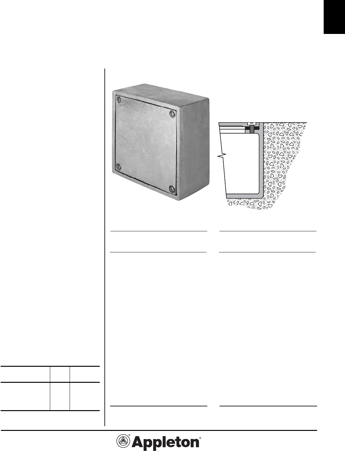
WYR Outside Flanged Recessed Cover Boxes
Cast Iron Box for Flush Mounting.
Watertight, Raintight, Dust Tight.
Applications
• These recessed cover boxes are
listed by Underwriters’ Laboratories,
Inc. as Type 4.
• They are suitable for use outdoors
where they would be subjected to rain
or dripping or splashing of water.
• This type of box is designed especial-
ly for flush mounting in walls or floors
or can be used for surface mounting
using optional mounting lugs.
Features
• Flat, neoprene gasket attached to
cover.
• Wide box flange permits greater con-
tact between gasket and box.
• Wide selection of sizes and locations
for drilled-and-tapped and slip-hole
conduit entrances.
• Choices of locations for blind tapped
holes in Interior Mounting Buttons
(optional).
Standard Materials
• Cast iron box and cover
• Neoprene gasket
• Stainless steel cover screws
Standard Finishes
• Box and cover: Hot Dip Galvanized.
Options
• Available in aluminum. Add suffix “A”
to catalog number.
• Steel checkered plate covers suitable
for pedestrian traffic add Suffix —CS.
• Steel checkered covers suitable for
vehicular traffic (H-25 loading) add
Suffix —CSV.
Other Options
Refer to pages C6- C12.
Compliances
• UL Listed Type 4
• UL Standard: 514A, 50
• NEMA 3R and 4
Iron
Aprox. Inside Dim.
Catalog Wall (inches)
Number Thick.* L x W x D
WYR-240808
9/32 24 x 8 x 8
WYR-241206
5/16 24 x 12 x 6
WYR-241208
5/16 24 x 12 x 8
WYR-241210
5/16 24 x 12 x 10
WYR-241212
5/16 24 x 12 x 12
WYR-241806
11/32 24 x 18 x 6
WYR-241808
11/32 24 x 18 x 8
WYR-241810
11/32 24 x 18 x 10
WYR-241812
11/32 24 x 18 x 12
WYR-242406
11/32 24 x 24 x 6
WYR-242408
11/32 24 x 24 x 8
WYR-242410
3/8 24 x 24 x 10
WYR-242412
3/8 24 x 24 x 12
WYR-242418
3/8 24 x 24 x 18
WYR-242424
7/16 24 x 24 x 24
WYR-302408
3/8 30 x 24 x 8
WYR-302410
3/8 30 x 24 x 10
WYR-302412
3/8 30 x 24 x 12
WYR-302418
3/8 30 x 24 x 18
WYR-361806
3/8 36 x 18 x 6
WYR-361808
3/8 36 x 18 x 8
WYR-361812
3/8 36 x 18 x 12
WYR-361818
3/8 36 x 18 x 18
WYR-362410
13/32 36 x 24 x 10
WYR-362418
13/32 36 x 24 x 18
WYR-363608
7/16 36 x 36 x 8
WYR-363610
7/16 36 x 36 x 10
WYR-363612
7/16 36 x 36 x 12
WYR-363618
7/16 36 x 36 x 18
Iron
Aprox. Inside Dim.
Catalog Wall (inches)
Number Thick.* L x W x D
WYR-040403
5/32 4 x 4 x 3
WYR-040404
5/32 4 x 4 x 4
WYR-060403
5/32 6 x 4 x 3
WYR-060404
5/32 6 x 4 x 4
WYR-060603
3/16 6 x 6 x 3
WYR-060604
7/32 6 x 6 x 4
WYR-060606
7/32 6 x 6 x 6
WYR-080403
3/16 8 x 4 x 3
WYR-080404
3/16 8 x 4 x 4
WYR-080603
7/32 8 x 6 x 3
WYR-080604
7/32 8 x 6 x 4
WYR-080606
7/32 8 x 6 x 6
WYR-080804
1/4 8 x 8 x 4
WYR-080806
1/4 8 x 8 x 6
WYR-080808
1/4 8 x 8 x 8
WYR-100604
7/32 10 x 6 x 4
WYR-100606
7/32 10 x 6 x 6
WYR-100806
1/4 10 x 8 x 6
WYR-101004 1/4 10 x 10 x 4
WYR-101006
1/4 10 x 10 x 6
WYR-101008
1/4 10 x 10 x 8
WYR-120604
1/4 12 x 6 x 4
WYR-120606
1/4 12 x 6 x 6
WYR-120804
1/4 12 x 8 x 4
WYR-120806
1/4 12 x 8 x 6
WYR-120808
1/4 12 x 8 x 8
WYR-121004
1/4 12 x 10 x 4
WYR-121006
1/4 12 x 10 x 6
Iron
Aprox. Inside Dim.
Catalog Wall (inches)
Number Thick.* L x W x D
WYR-121008
1/4 12 x 10 x 8
WYR-121010
1/4 12 x 10 x 10
WYR-121204
1/4 12 x 12 x 4
WYR-121206
1/4 12 x 12 x 6
WYR-121208
5/16 12 x 12 x 8
WYR-121210
5/16 12 x 12 x 10
WYR-121212
5/16 12 x 12 x 12
WYR-121218
3/8 12 x 12 x 18
WYR-140804
1/4 14 x 8 x 4
WYR-140806
1/4 14 x 8 x 6
WYR-161204
9/32 16 x 12 x 4
WYR-161206
9/32 16 x 12 x 6
WYR-161208
9/32 16 x 12 x 8
WYR-161408
5/16 16 x 14 x 8
WYR-180606
9/32 18 x 6 x 6
WYR-180806
9/32 18 x 8 x 6
WYR-180808
9/32 18 x 8 x 6
WYR-181008
5/16 18 x 10 x 8
WYR-181204
1/4 18 x 12 x 4
WYR-181206
9/32 18 x 12 x 6
WYR-181208
5/16 18 x 12 x 8
WYR-181210
5/16 18 x 12 x 10
WYR-181212
5/16 18 x 12 x 12
WYR-181218
11/32 18 x 12 x 18
WYR-181806
5/16 18 x 18 x 6
WYR-181808
5/16 18 x 18 x 8
WYR-181810
5/16 18 x 18 x 10
WYR-181812
5/16 18 x 18 x 12
WYR-201615
3/8 20 x 16 x 15
NEMA 3R and 4
* Measured 2” up from back of box.
Installation in
Masonry
C-21
C
Effective June, 2008
Copyright 2008
800-621-1506
www.appletonelec.com
PAGE 21
W Series:
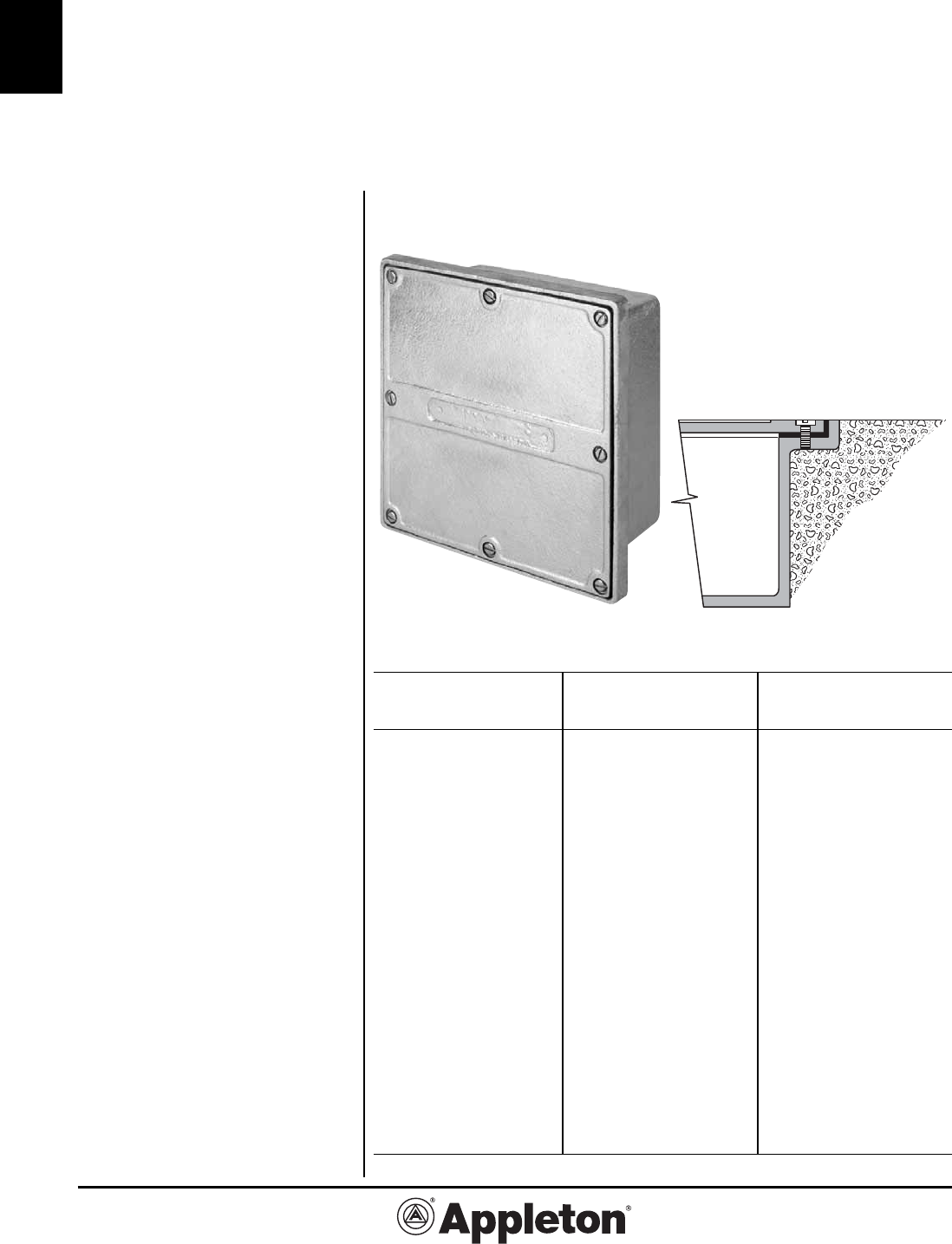
WYU Type Inside Flanged Recessed Cover Boxes
Cast Iron Box for Flush Mounting.
Raintight, Dust Tight.
Applications
• These recessed cover boxes are de-
signed for flush mounting in masonry.
• They are furnished with a plain cover
as shown but can be supplied with
steel checkered plate covers suitable
for foot traffic (see options).
Features
• Flat, neoprene gasket attached to
cover.
• Wide selection of sizes and locations
for drilled-and-tapped and slip-hole
conduit entrances.
• Choices of locations for blind tapped
holes in Interior Mounting Buttons (op-
tional).
Standard Materials
• Cast iron box and plain cover
• Neoprene gasket
• Stainless steel cover screws
Standard Finishes
• Box and cover: Hot Dip Galvanized.
Options
• Available in aluminum. Add suffix “A”
to catalog number.
• Steel checkered plate covers suitable
for pedestrian traffic add Suffix —CS.
• See optional Hinges below.
Other Options
Refer to pages C6- C12.
Compliances
• UL Standard: 514A, 50
• NEMA 3R
Iron
Aprox. Inside Dim.
Catalog Wall (inches)
Number Thick.* L x W x D
WYU-040402
7/32 4 x 4 x 2
WYU-040403
7/32 4 x 4 x 3
WYU-040404
5/32 4 x 4 x 4
WYU-060403
7/32 6 x 4 x 3
WYU-060404
7/32 6 x 4 x 4
WYU-060604
7/32 6 x 6 x 4
WYU-060606
7/32 6 x 6 x 6
WYU-080404
1/4 8 x 4 x 4
WYU-080604
1/4 8 x 6 x 4
WYU-080606
1/4 8 x 6 x 6
WYU-080804
1/4 8 x 8 x 4
WYU-080806
1/4 8 x 8 x 6
WYU-080808
1/4 8 x 8 x 8
WYU-100604
1/4 10 x 6 x 4
WYU-100605
1/4 10 x 6 x 5
WYU-100804
1/4 10 x 8 x 4
WYU-100806
1/4 10 x 8 x 6
WYU-100808
1/4 10 x 8 x 8
WYU-100811
1/4 10 x 8 x 11
WYU-101004
1/4 10 x 10 x 4
WYU-101006
1/4 10 x 10 x 6
WYU-101008
1/4 10 x 10 x 8
WYU-120604
1/4 12 x 6 x 4
WYU-120606
1/4 12 x 6 x 6
WYU-120804
1/4 12 x 8 x 4
WYU-120806
1/4 12 x 8 x 6
WYU-120808
1/4 12 x 8 x 8
WYU-120811
5/16 12 x 8 x 11
Iron
Aprox. Inside Dim.
Catalog Wall (inches)
Number Thick.* L x W x D
WYU-121204
9/32 12 x 12 x 4
WYU-121206
1/4 12 x 12 x 6
WYU-121208
9/32 12 x 12 x 8
WYU-121212
5/16 12 x 12 x 12
WYU-140806
1/4 14 x 8 x 6
WYU-141404
5/16 14 x 14 x 4
WYU-141406
5/16 14 x 14 x 6
WYU-141408
5/16 14 x 14 x 8
WYU-141410
5/16 14 x 14 x 10
WYU-160604
1/4 16 x 6 x 4
WYU-160606
1/4 16 x 6 x 6
WYU-160804
1/4 16 x 8 x 4
WYU-160808
1/4 16 x 8 x 8
WYU-161206
9/32 16 x 12 x 6
WYU-161208
9/32 16 x 12 x 8
WYU-180806
9/32 18 x 8 x 6
WYU-180808
9/32 18 x 8 x 8
WYU-181204
1/4 18 x 12 x 4
WYU-181206
1/4 18 x 12 x 6
WYU-181208
1/4 18 x 12 x 8
WYU-181210
9/32 18 x 12 x 10
WYU-181212
9/32 18 x 12 x 12
WYU-181218
3/8 18 x 12 x 18
WYU-181604
1/4 18 x 16 x 4
WYU-181608
9/32 18 x 16 x 8
WYU-240606
9/32 24 x 6 x 6
WYU-240806
5/16 24 x 8 x 6
WYU-240808
5/16 24 x 8 x 8
NEMA 3R
Optional Hinges
(Stainless Steel, Butt Type)
Hinges Catalog
Box Size per set Number
Up to 12” x 12” 2 AHNG-22SS
Up to 18” x 18” 2 AHNG-23SS
Larger than 18” x 18” 3 AHNG-33SS
* Measured 2” up from back of box.
Installation in
Masonry
Effective September, 2005
Copyright 2005
PAGE 22
800-621-1506
www.appletonelec.com
C-22
C
W Series:
WYT Type Checkered Cover Sidewalk Boxes
Cast Iron Box for Flush Mounting. Weatherproof.
Applications
• These boxes are specially designed
to be mounted in sidewalks and other
flat concrete surfaces. Their checkered
covers are made to withstand pedes-
trian traffic.
• The flanges and covers are inter-
changeable to permit replacement
without disturbing the box or conduit
system.
• Heavy checkered steel covers can
be furnished which will accommodate
vehicular traffic (see options).
Features
• Type WYT boxes have a post in each
corner and allowances must be made
for them, when conduit entrances are
to be located close to a corner.
• Cross ribbed, heavy duty cover with
prybar slots.
• Checkered cover provides non-slip
surface.
• Flat, neoprene gasket, attached to
cover.
• Wide selection of locations for drilled
and tapped and slip hole conduit
entrances.
• Choice of locations for blind tapped
holes in Interior Mounting Buttons
(optional).
Standard Materials
• Cast iron box, flange and cover.
• Neoprene gasket.
• Stainless steel cover screws.
Standard Finishes
• Box and cover: Hot Dip Galvanized.
Options
• Steel checkered covers suitable
for vehicular traffic H-25 loading, add
suffix —CSV.
• Engraved lettering on cover per spec-
ifications.
Other Options
Refer to pages C6- C12.
Compliances
• UL Standard: 514A, 50
Iron
Aprox. Inside Dim.
Catalog Wall (inches)
Number Thick. L x W x D
WYT-241210
3/8 24 x 12 x 10
WYT-241212
3/8 24 x 12 x 12
WYT-241216
3/8 24 x 12 x 16
WYT-241410
3/8 24 x 14 x 10
WYT-241412
3/8 24 x 14 x 12
WYT-241806
3/8 24 x 18 x 6
WYT-241808
3/8 24 x 18 x 8
WYT-241810
3/8 24 x 18 x 10
WYT-241812
3/8 24 x 18 x 12
WYT-242406
7/16 24 x 24 x 6
WYT-242408
7/16 24 x 24 x 8
WYT-242410
3/8 24 x 24 x 10
WYT-242412
3/8 24 x 24 x 12
WYT-301010
3/8 30 x 10 x 10
WYT-301210
3/8 30 x 12 x 10
WYT-301212
3/8 30 x 12 x 12
WYT-301410
3/8 30 x 14 x 10
WYT-301412
3/8 30 x 14 x 12
WYT-301414
3/8 30 x 14 x 14
WYT-301808
3/8 30 x 18 x 8
WYT-301812
3/8 30 x 18 x 12
WYT-361808
3/8 36 x 18 x 8
WYT-361812
3/8 36 x 18 x 12
WYT-362412
3/8 36 x 24 x 12
WYT-362414
3/8 36 x 24 x 14
Iron
Aprox. Inside Dim.
Catalog Wall (inches)
Number Thick. L x W x D
WYT-060604
1/4 6 x 6 x 4
WYT-080604
1/4 8 x 6 x 4
WYT-080804
1/4 8 x 8 x 4
WYT-080806
1/4 8 x 8 x 6
WYT-080808
1/4 8 x 8 x 8
WYT-120806
5/16 12 x 8 x 6
WYT-120808
5/16 12 x 8 x 8
WYT-121204
5/16 12 x 12 x 4
WYT-121206
5/16 12 x 12 x 6
WYT-121208
3/8 12 x 12 x 8
WYT-121212
3/8 12 x 12 x 12
WYT-141406
5/16 14 x 14 x 6
WYT-141408
3/8 14 x 14 x 8
WYT-141410
3/8 14 x 14 x 10
WYT-141412
3/8 14 x 14 x 12
WYT-181015
3/8 18 x 10 x 15
WYT-181206
3/8 18 x 12 x 6
WYT-181208
3/8 18 x 12 x 8
WYT-181210
3/8 18 x 12 x 10
WYT-181212
3/8 18 x 12 x 12
WYT-181808
3/8 18 x 18 x 8
WYT-181812
3/8 18 x 18 x 12
WYT-241206
3/8 24 x 12 x 6
WYT-241208
3/8 24 x 12 x 8
C-23
C
800-621-1506
www.appletonelec.com
PAGE 23
W Series:
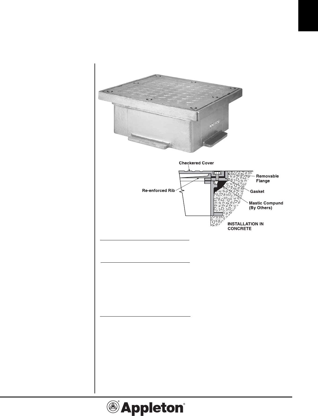
WY58E Type Checkered Cover Sidewalk
Topping Box
Cast Iron Box for Flush Mounting. Weatherproof.
Applications
• These open-bottom boxes are
designed to top off an underlying
concrete pull box.
Features
• The construction details of the cover
and flange are the same as those of a
Type WYT.
• Frame and cover are interchangeable
and may be replaced if damaged with-
out disturbing the rest of the system.
• Checkered cover provides non-slip
surface for pedestrian traffic.
• Cross-ribbed checkered cover with
pry bar slots.
• Cover secures to frame with
recessed stainless steel hex head cap
screws.
• Flat, neoprene gasket, attached to
cover.
• Wide selection of locations for drilled
and tapped and slip hole conduit
entrances.
Standard Materials
• Cast iron box, flange and cover.
• Neoprene gasket.
• Stainless steel cover screws.
Standard Finishes
• Box and cover: Hot Dip Galvanized.
Options
• Engraved lettering on cover per spec-
ifications.
Third Party Certification
• ASTM C-1028 Coefficient of Friction
standard
Iron
Aprox. Inside Dim.
Catalog Wall (inches)
Number Thick.* L x W x D
WY58E-1212
3/8 12 x 12 x 5
WY58E-1812
3/8 18 x 12 x 5
WY58E-2412
3/8 24 x 12 x 5
WY58E-2418
3/8 24 x 18 x 5
WY58E-2424
3/8 24 x 24 x 5
WY58E-3018
3/8 30 x 18 x 5
WY58E-3618
3/8 36 x 18 x 5
WY58E-3624
3/8 36 x 24 x 5
WY58E-3636
3/8 36 x 36 x 5
WY58E-4224
3/8 42 x 24 x 5
* Measured 2” up from back of box.
Effective October, 2006
Copyright 2006
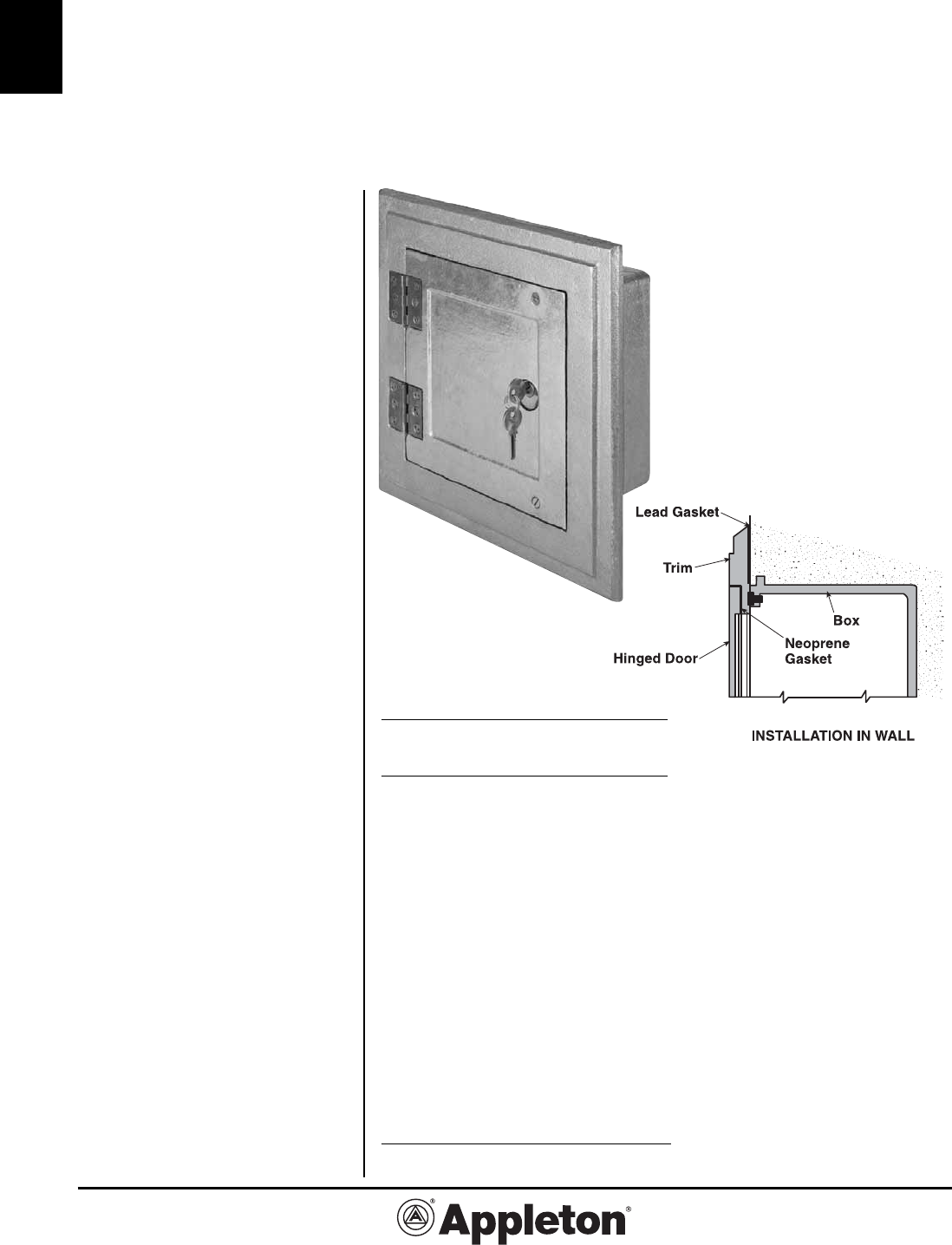
Effective September, 2005
Copyright 2005
PAGE 24
800-621-1506
www.appletonelec.com
C-24
C
W Series:
WYC Type Box with Hinged Door and Trim Cabinet
Cast Iron Box for Flush Mounting in Walls. Weatherproof.
Applications
• They are used exterior building walls,
bridge construction, underpasses and
approaches.
• They may house time switches,
relays or other types of equipment.
Features
• These boxes have ornamental trim
for flush mounting in concrete or stone
structures.
• Type WYC boxes have a post in each
corner and allowances must be made
for them, when conduit entrances are
to be located close to a corner.
Standard Materials
• Box: Cast Iron.
• Trim/Door: Cast Iron.
• Neoprene gasket and one piece lead
gasket.
• Steel, Zinc Plated, Non-removable
hinges.
• Brass cylinder lock with two keys.
Standard Finishes
• Box: Hot Dip Galvanized.
• Trim/Door: Hot Dip Galvanized.
Options
• Lettering cast on cover per specifica-
tions at price addition.
• Cast Bronze Trim/Door available at
price addition. Add Suffix —B.
Other Options
• Refer to pages C6-C12.
Iron
Aprox. Inside Dim.
Catalog Wall (inches)
Number Thick.* L x W x D
WYC-060604
1/4 6 x 6 x 4
WYC-080804
1/4 8 x 8 x 4
WYC-080806
1/4 8 x 8 x 6
WYC-080808
1/4 8 x 8 x 8
WYC-121204
5/16 12 x 12 x 4
WYC-121206
5/16 12 x 12 x 6
WYC-121208
3/8 12 x 12 x 8
WYC-141404
5/16 14 x 14 x 4
WYC-141406
5/16 14 x 14 x 6
WYC-141408
3/8 14 x 14 x 8
WYC-141410
3/8 14 x 14 x 10
WYC-161606
3/8 16 x 16 x 6
WYC-161608
3/8 16 x 16 x 8
WYC-161612
3/8 16 x 16 x 12
WYC-181206
3/8 18 x 12 x 6
WYC-181208
3/8 18 x 12 x 8
WYC-181210
3/8 18 x 12 x 10
WYC-181212
3/8 18 x 12 x 12
WYC-181806
3/8 18 x 18 x 6
WYC-181808
3/8 18 x 18 x 8
WYC-181812
3/8 18 x 18 x 12
WYC-242406
3/8 24 x 24 x 6
WYC-242408
3/8 24 x 24 x 8
WYC-242410
3/8 24 x 24 x 10
WYC-242412
3/8 24 x 24 x 12
* Measured 2” up from back of box.
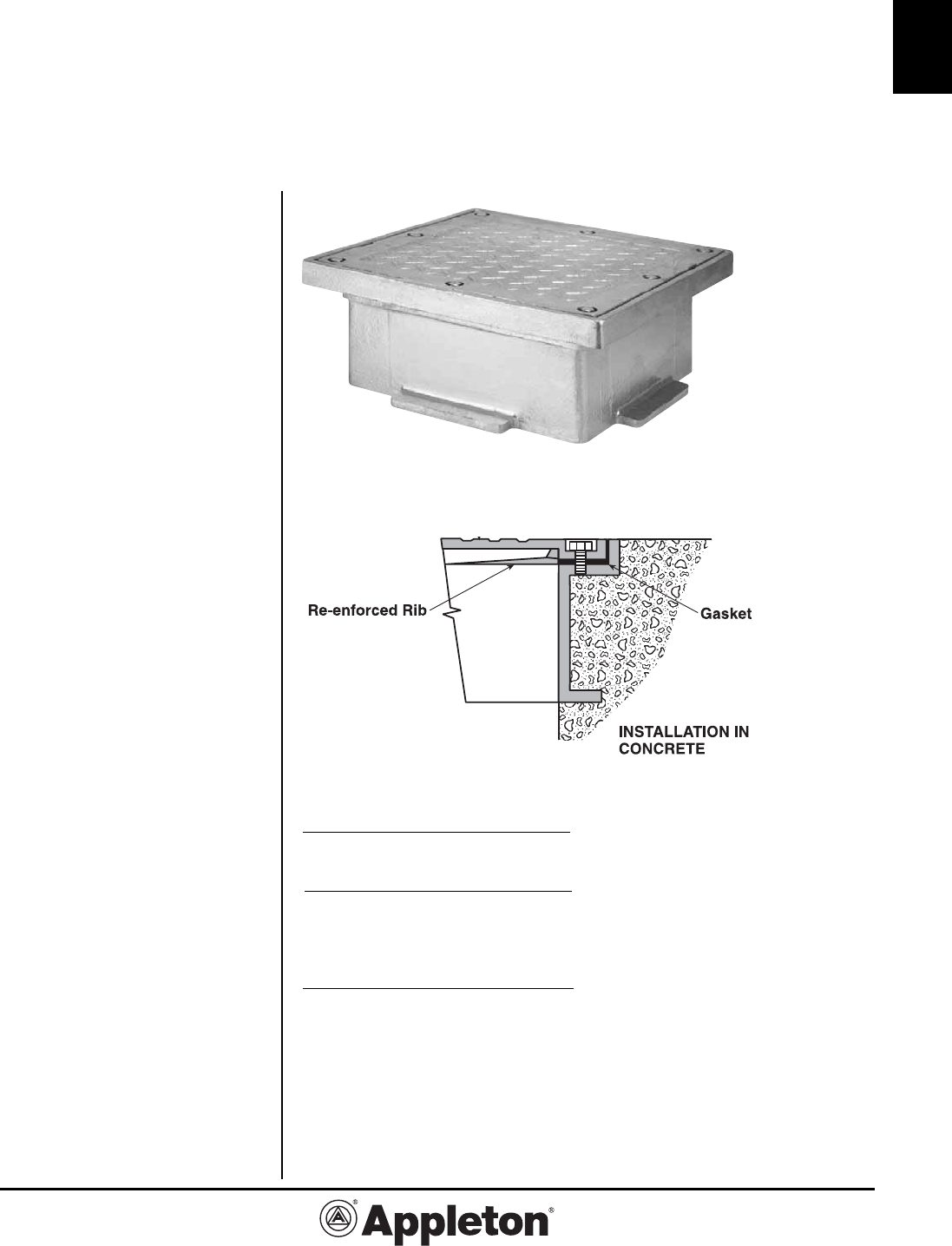
C-25
C
800-621-1506
www.appletonelec.com
PAGE 25
W Series:
WYNY Type Checkered Cover Roadway
Topping Box
Cast Iron Box for Flush Mounting. Weatherproof.
Applications
• These open-bottom boxes are
designed to top off concrete pull
boxes.
• Units designed to withstand vehicu-
lar traffic, H-20 loading.
Features
•
Design of these boxes is similar to the
type WY58E except box and flange are
one piece and cover is of cast steel or
ductile iron.
• Cross-ribbed checkered cover with
pry bar slots
Standard Materials
• Cast iron box and cast steel or
ductile iron cover.
• Neoprene gasket.
• Stainless steel cover screws.
Standard Finishes
• Box and cover: Hot Dip Galvanized.
Options
• Engraved lettering on cover per spec-
ifications.
Third Party Certification:
• ASTM C-1028 Coefficient of Friction
standard
Iron
Aprox. Inside Dim.
Catalog Wall (inches)
Number Thick.* L x W x D
WYNY-1812-DIV
3/8 18 x 12 x 5-1/2
WYNY-2418-DIV
3/8 24 x 18 x 5-1/2
WYNY-3018-DIV
3/8 30 x 18 x 5-1/2
WYNY-3618-DIV
3/8 36 x 18 x 5-1/2
WYNY-3624-DIV
3/8 36 x 24 x 5-1/2
WYNY-4824-DIV
3/8 48 x 24 x 5-1/2
* Measured 2” up from back of box.
Checkered Cover
~
Effective October, 2006
Copyright 2006

Effective September, 2005
Copyright 2005
PAGE 26
800-621-1506
www.appletonelec.com
C-26
C
®
