Motor Controls (245 332)
593552-Catalog 593552-Catalog 593552-Catalog 783166 Batch8 unilog cesco-content
2014-09-04
: Pdf 75209-Attachment 75209-Attachment 783310 Batch7 unilog
Open the PDF directly: View PDF ![]() .
.
Page Count: 88

Motor Controls 245
GREENLEE@
DIN rail mount protectors feature adjustable voltage ranges, adjustable time delay reset from 20 to 300 seconds,
and user selectable automatic and manual restart options. 41/2"x2V4"x23/4".
Motor Protectors
Adj.
Volt
Rge.
Under
140-240
300-500
Adj.
Volt
Rge.
Over
180-280
360-560
UPC
34535
34536
Volts
240
480
No.
5745-240
5745-480
Accessories
No.
5745M Desc.
DIN Rail for Mounting
GREENLEE@
For use on Delta and Wye systems to protect against phase loss or reversal, undervoltage, voltage imbalance.
Voltage range is adjustable.
Dim., In.
No.
5729-240
5729-480
UPC Volts
160-240
300-480
-
L
6
6
H
10/.
10/.
ALLEN-BRADLEY
Bulletin 509 - Full Voltage Starters
30
Type 1 General Purpose Enclosure
Open Type w/o Enclosure
Designed for full voltage starting of polyphase squirrel cage motors. NEMA sizes 00 thru 9. May be operated by remote control with push buttons, float
switches, thermostats, pressure switches, snap switches, limit switches or any other suitable two or three wire pilot device. Available with Bulletin 592
eutectic alloy overload relays as well as solid-state overloads.
Conform to NEMA/EEMAC ICS 2, UL 508, CSA 22.2, No. 14, ABS 4/5.115 and USCG 46 CFR 111.70 standards.
UL Listed;. CSA Certified. CE marked per EN 60947. American Bureau of Shipping approved.
When ordering, select voltage suffix (6th character of part number) code from table to complete number. Default code is D (115-120V).
Voltage Suffix Codes
Separate Separate
Common Control Control
Control wlo Transformer wlo Transformer
60 Hz 50 Hz 60 Hz
K J
S'
. . . . . . Dt
Continued on next page
Designs and Specifications are for reference only and are subject to change without notice.
Common
Control
50 Hz
Volts
24
110-115
115-120
CopyriQh! @ by Howard W. Sams & Co.
Motor Protectors
3-Phase
Motor Protectors
3-Phase
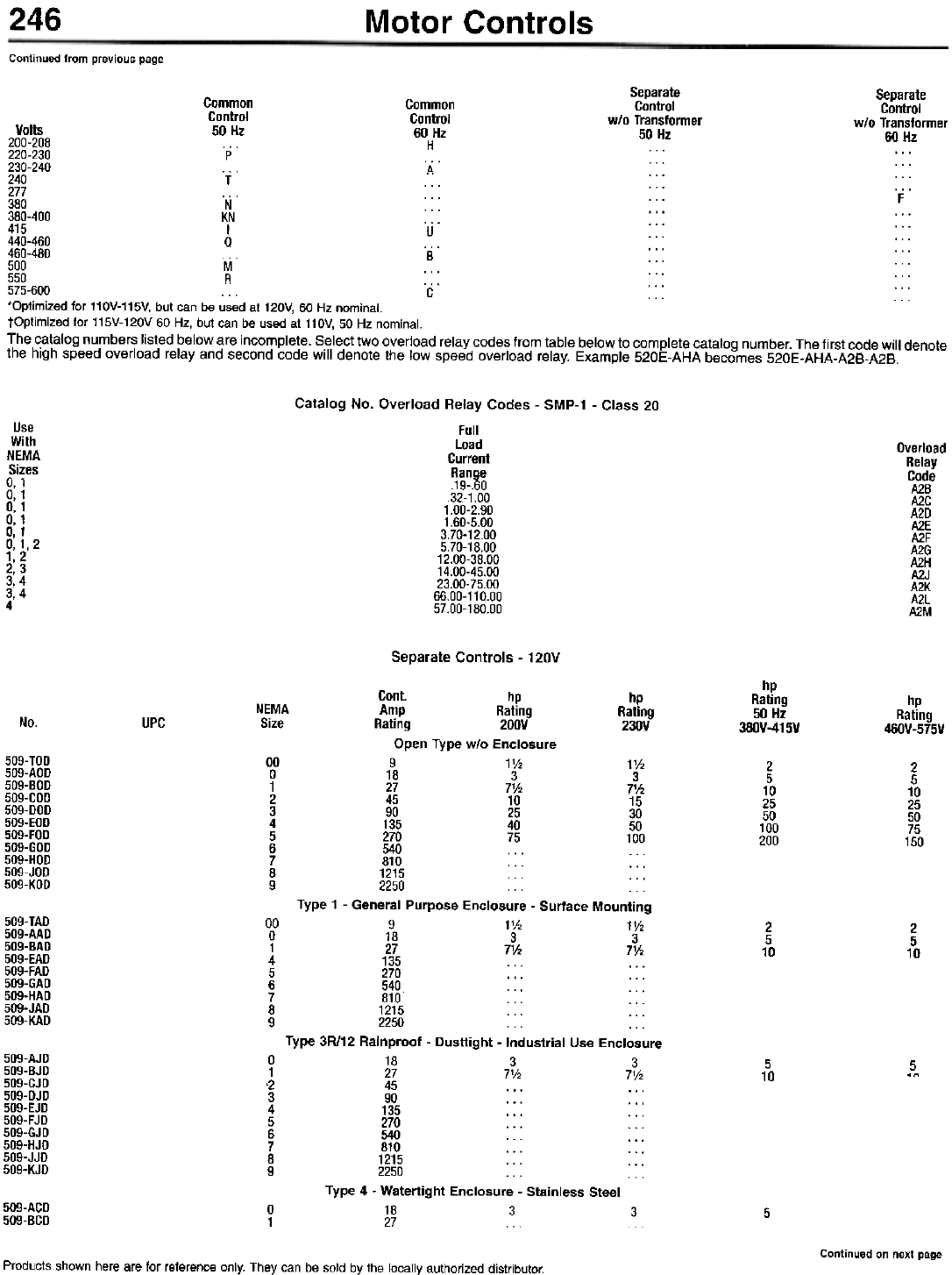
246 Motor Controls
Continued from previous page
Separate
Control
wlo Transformer
Volts 50 Hz -- -.-
200-208 ...
220-230 ...
230-240 ". . . . . .
240 . . . . . . . . .
277 . . . . . . F
380 . . . . . . . . .
380-400 ... ... ...
415 u 440-460 ... ... ."
460-480 B ... ...
500 . . . . . . . . .
550 . . . . . . . . .
575-600 ... C ... ...
.Optimized for 110V-115V, but can be used at 120V, 60 Hz nominal.
tOptimized for 115V-120V 60 Hz, but can be used at 110V, 50 Hz nominal.
The catalog numbers listed below are incomplete. Select two overload relay codes from table below to complete catalog number. The first code will denote
the high speed overload relay and second code will denote the low speed overload relay. Example 520E-AHA becomes 520E-AHA-A2B-A2B.
Separate
Control
wlo Transformer
60 Hz
Common
Control
50 Hz
p
T
N
KN
I
a
M
R
Common
Control
60 Hz
H
A
Catalog No. Overload Relay Codes - SMP-1 - Class 20
Full
Load
Current
Range
.19-60
.32-1.00
1.00-2.90
1.60-5.00
3.70-12.00
5.70-18.00
12.00-38.00
14.00-45.00
23.00-75.00
66.00-110.00
57.00-180.00
Use
With
NEMA
Sizes
0, 1
0, 1
0, 1
0, 1
0, 1
0,1,2
1,2
2,3
3,4
3,4
4
Overload
Relay
Code
A2B
A2C
A2D
A2E
A2F
A2G
A2H
A2J
A2K
A2L
A2M
Separate Controls - 120V
hp
Rating
50 Hz
380V-415V
hp
Rating
460V-575V
Cont. hp hp
NEMA Amp Rating Rating
Size Rating 200V 230V
Open Type wlo Enclosure
9 1V2 1V2
18 3 3
27 7V2 7'h
45 10 15
90 25 30
135 40 50
270 75 100
540 . . . . . .
810 ... ...
1215
2250 . . .
Type 1 - General Purpose Enclosure - Surface Mounting
9 1V2 1V2
18 3 3
27 7'h 7'h
135 . . . . . .
270 . . . . . .
540 . . . . . .
810 . ..
1215 . . . . . .
2250
Type 3R/12 Rainproof - Dusttight - Industrial Use Enclosure
18 3 3
27 7V2 7V2
45 . . . . . .
90 . . . . . .
135 . . . . . .
270 . . . . . .
540 . . . . . .
810 ... ...
1215 . . . ...
2250
Type 4 - Watertight Enclosure - Stainless Steel
18 3 3
27
No. UPC
509-TOD
509-AOD
509-BOD
509-COD
509-000
509-EOD
509-FOD
509-GOD
509-HOD
509-JOD
509-KOD
00
0
1
2
3
4
5
6
7
8
9
2
5
10
25
50
100
200
2
5
10
25
50
75
150
509-TAD
509-AAD
509-BAD
509-EAD
509-FAD
509-GAD
509-HAD
509-JAD
509-KAD
00
0
1
4
5
6
7
8
9
2
5
10
2
5
10
509-AJD
509-BJD
509-CJD
509-DJD
509-EJD
509-FJD
509-GJD
509-HJD
509-JJD
509-KJD
0
1
.2
3
4
5
6
7
8
9
5
10 5
.n
509-ACD
509-BCD 0
15
Continued on next page
Products shown here are for reference only. They can be sold by the locally authorized distributor.

247
Motor Controls
Continued from previous page
hp
Cont. Rating
NEMA Amp 50 Hz
Size Rating -uu. 380V-415V
2 45 . . . . . .
3 90 . . . . . .
4 135 ... ...
5 270 . . . . . .
6 540 ... ...
7 810 ... ...
8 1215
9 2250
Type 4X - Watertight - Corrosion-Resistant Enclosure - Fiberglass Reinforced Polyester
0 18
1 27 . . . . . .
2 45 . . . . . .
hp
Rating
?nnv
hp
Rating
?~n\/
hp
Rating
460V-575V
UPC
No.
509-CCD
509-DCD
509-ECD
509-FCD
509-GCD
509-HCD
509-JCD
509-KCD
509-ASO
509-8S0
509-CSO
Full Voltage Starters - 30 - 3 Pole
Cont. Starter
Amp Motor Coil
Rating Volts Volts
Open Type w/o Enclosure
9 200 208
9 230 240
9 460 480
9 575 600
18 200 208
18 230 240
18 460 480
18 575 600
27 200 208
27 230 240
27 460 480
27 575 600
45 200 208
45 230 240
45 460 480
45 575 600
90 200 208
90 230 240
90 460 480
90 575 600
135 200 208
135 230 240
135 460 480
135 575 600
270 200 208
270 230 240
270 460 480
270 575 600
810 230 240
810 460 480
810 575 600
1215 230 240
1215 460 480
1215 575 600
2250 230 240
2250 460 480
2250 575 600
Type 1 - General Purpose Enclosure - Surface Mounting
1
,
.
.
hp
Rating
Single 0
hp
Rating
30
NEMA
Size
UPC
No.
1'h
1'h
2
2
3
3
5
5
7'h
7'h
10
10
10
15
25
25
25
30
50
50
40
50
100
100
75
100
200
200
300
600
600
240
480
600
240
480
600
0
0
0
0
0
0
0
0
1
1
1
1
2
2
2
2
3
3
3
3
4
4
4
4
5
5
5
5
7
7
7
8
8
8
9
9
9
509-TOH
509-TOA
5O9-TOB
509-TOC
509-AOH
509-AOA
509-AOB
509-AOC
509-BOH
509-BOA
509-BOB
509-BOC
509-COH
509-COA
509-COB
509-COC
509-DOH
509-DOA
509-DOB
509-DOC
509-EOH
509-EOA
509-EOB
509-EOC
509-FOH
509-FOA
509-FOB
509-FOC
509-HOA
509-HOB
509-HOC
509-JOA
509-JOB
509-JOC
509-KOA
509-KOB
509-KOC
.2
.3
71i;
9 200 208 ... 11h
9 230 240 1 11h
9 460 480 ... 2
9 575 600 ... 2
18 200 208 ... 3
18 230 240 2 3
18 460 480 ... 5
18 575 600 ... 5
27 200 208 ... 71h
27 230 240 3 71h
27 460 480 ... 10
27 575 600 ... 10
45 200 208 ... 10
45 230 240 7V2 15
45 460 480 ... 25
45 575 600 ... 25
90 200 208 ... 25
90 230 240 ... 30
90 460 480 ... 50
90 575 600 ... 50
135 200 208 ... 40
135 230 240 ... 50
135 460 480 ... 100
135 575 600 ... 100
~70 200 208 ... 75
Continued on next page
Designs and Specifications are for reference only and are subject to change without notice.
0
0
0
0
0
0
0
0
1
1
1
1
2.
2
2
2
3
3
3
3
4
4
4
4
5
509-TAH
509-TAA
509-TAB
509-TAC
509-AAH
509-AAA
509-AAB
509-AAC
509-BAH
509-BAA
509-BAB
509-BAC
509-CAH
509-CAA
509-CAB
509-CAC
509-DAH
509-DAA
509-DAB
509-DAC
509-EAH
509-EAA
509-EAB
509-EAC
509-FAH
CoDvriqht @ bv Howard W. Sams & Co.
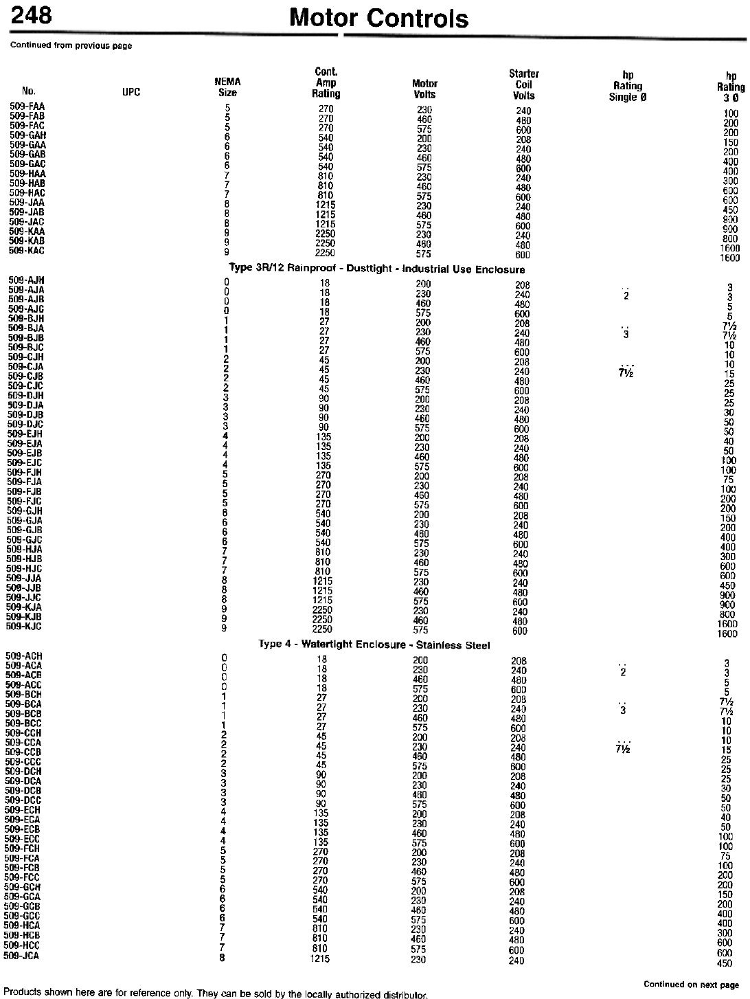
248 Motor Controls
Continued from previous page
hp
Rating
Single 0
hp
Rating
30
100
200
200
150
200
400
400
300
600
600
450
900
900
800
1600
1600
Cont. Starter
NEMA Amp Motor Coil
Size Rating Volts Volts
5 270 230 240
5 270 460 480
5 270 575 600
6 540 200 208
6 540 230 240
6 540 460 480
6 540 575 600
7 810 230 240
7 810 460 480
7 810 575 600
8 1215 230 240
8 1215 460 480
8 1215 575 600
9 2250 230 240
9 2250 460 480
9 2250 575 600
Type 3R/12 Rainproof - Dusttight - Industrial Use Enclosure
18 200 208
18 230 240
18 460 480
18 575 600
27 200 208
27 230 240
27 460 480
27 575 600
45 200 208
45 230 240
45 460 480
45 575 600
90 200 208
90 230 240
90 460 480
90 575 600
135 200 208
135 230 240
135 460 480
135 575 600
270 200 208
270 230 240
270 460 480
270 575 600
540 200 208
540 230 240
540 460 480
540 575 600
810 230 240
810 460 480
810 575 600
1215 230 240
1215 460 480
1215 575 600
2250 230 240
2250 460 480
2250 575 600
Type 4 - Watertight Enclosure - Stainless Steel
18 200
18 230
18 460
18 575
27 200
27 230
27 460
27 575
45 200
45 230
45 460
45 575
90 200
90 230
90 460
90 575
135 200
135 230
135 460
135 575
270 200
270 230
270 460
270 575
540 200
540 230
540 460
540 575
810 230
810 460
810 575
1215 230
No.
509-FAA
509-FAB
509-FAC
509-GAH
509-GAA
509-GAB
509-GAC
509-HAA
509-HAB
509-HAC
509-JAA
509-JAB
509-JAC
509-KAA
509-KAB
509-KAC
UPC
509-AJH
509-AJA
509-AJB
509-AJG
509-BJH
509-BJA
509-BJB
509-BJG
509-GJH
509-GJA
509-GJB
509-GJG
509-DJH
509-DJA
509-DJB
509-DJG
509-EJH
509-EJA
509-EJB
509-EJG
509-FJH
509-FJA
509-FJB
509-FJG
509-GJH
509-GJA
509-GJB
509-GJG
509-HJA
509-HJB
509-HJG
509-JJA
509-JJB
509-JJG
509-KJA
509-KJB
509-KJG
0
0
0
0
1
1
1
1
2
2
2
2
3
3
3
3
4
4
4
4
5
5
5
5
6
6
6
6
7
7
7
8
8
8
9
9
9
3
3
5
5
7'h
7V2
10
10
10
15
25
25
25
30
50
50
40
50
100
100
75
100
200
200
150
200
400
400
300
600
600
450
900
900
800
1600
1600
2
'3
7%"
509-ACH
509-ACA
509-ACB
509-ACC
509-BCH
509-BCA
509-BCB
509-BCC
509-CCH
509-CCA
509-CCB
509-CCC
509-DCH
509-DCA
509-DCB
509-DCC
509-ECH
509-ECA
509-ECB
509-ECC
509-FCH
509-FCA
509-FCB
509-FCC
509-GCH
509-GCA
509-GCB
509-GCC
509-HCA
509-HCB
509-HCC
509-JCA
0
0
0
0
1
1
1
1
2
2
2
2
3
3
3
3
4
4
4
4
5
5
5
5
6
6
6
6
7
7
7
8
208
240
480
600
208
240
480
600
208
240
480
600
208
240
480
600
208
240
480
600
208
240
480
600
208
240
480
600
240
480
600
240
.2
'3
ji;;
3
3
5
5
7V2
7'h
10
10
10
15
25
25
25
30
50
50
40
50
100
100
75
100
200
200
150
200
400
400
300
600
600
450
Continued on next page
Products shown here are for reference only. They can be sold by the locally authorized distributor.
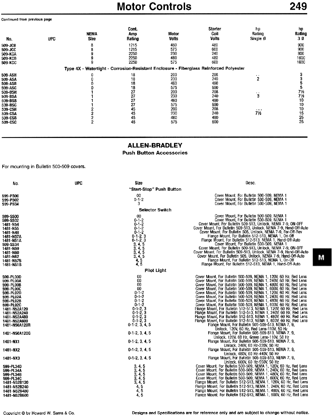
Motor Controls 249
Continued from previous page
hp
Rating
Single 0
hp
Rating
30
900
900
800
1600
1600
No.
509-JGB
509-JGG
509-KGA
509-KGB
509-KGG
UPC
Cont. Starter
NEMA Amp Motor Coil
Size Rating Volts Volts
8 1215 460 480
8 1215 575 600
9 2250 230 240
9 2250 460 480
9 2250 575 600
Type 4X - Watertight - Corrosion-Resistant Enclosure - Fiberglass Reinforced Polyester
0 18 200 208
0 18 230 240
0 18 460 480
0 18 575 600
1 27 200 208
1 27 230 240
1 27 460 480
1 27 575 600
2 45 200 208
2 45 230 240
2 45 460 480
2 45 575 600
3
3
5
5
7%
7V.
10
10
10
15
25
25
509-ASH
509-ASA
509-ASB
509-ASC
509-BSH
509-BSA
509-BSB
509-BSC
509-CSH
509-CSA
509-CSB
509-CSC
2
3
71h
ALLEN-BRADLEY
Push Button Accessories
For mounting in Bulletin 500-509 covers.
Desc.
No. UPC
Cover Mount, For Bulletin 500-509, NEMA 1
Cover Mount, For Bulletin 500-509, NEMA 1
Cover Mount, For Bulletin 500-509, NEMA 1
599-PBOO
599-PBO2
599-PB34
Size
"Start-Stop" Push Button
00
0-1-2
3
Selector Switch
00
0-1-2
0-1-2
0-1-2
0-1-2
0-1-2,3
0-1-2 3
3,4,'5
3,4,5
3,4,5
3,4,5
4, 5
4,5
Cover Mount, For Bulletin 500-509, NEMA 1
Cover Mount, For Bulletin 500-509, NEMA 1
Cover Mount, For Bulletin 509-513, Unilock, NEMA 7-9, ON-OFF
Cover Mount, For Bulletin 509-513, Unilock, NEMA 7-9, Hand-Oft-Auto
Cover Mount, For Bulletin 505, Unilock, NEMA 7-9, For-Oft-Rev
Flange Mount, For Bulletin 512-513, NEMA 1, On-Oft
Flange Mount, For Bulletin 512-513, NEMA 1, Hand-Oft-Auto
Cover Mount, For Bulletin 500-509, NEMA 1
Cover Mount, For Bulletin 509-513, Unilock, NEMA 7-9, ON-OFF
Cover Mount, For Bulletin 509-513, Unilock, NEMA 7-9, Hand-Oft-Auto
Cover Mount, For Bulletin 505, Unilock, NEMA 7-9, Hand-Oft-Auto
Flange Mount, For Bulletin 512-513, NEMA 1, On-Oft
Flange Mount, For Bulletin 512-513, NEMA 1, Hand-Oft-Auto
599-SSOO
599-5502
1481-N54
1481-N55
1481-N48
1481-N57A
1481-N51A
599-5534
1481-N59
1481-NOO
1481-N62
1481-N57B
1481-N51B
Pilot Light
Cover Mount, For Bulletin 500-509, NEMA 1, 120V, 60 Hz, Red Lens
Cover Mount, For Bulletin 500-509, NEMA 1, 240V, 60 Hz, Red Lens
Cover Mount, For Bulletin 500-509, NEMA 1, 480V, 60 Hz, Red Lens
Cover Mount, For Bulletin 500-509, NEMA 1, 600V, 60 Hz, Red Lens
Cover Mount, For Bulletin 500-509, NEMA 1, 120V, 60 Hz, Red Lens
Cover Mount, For Bulletin 500-509, NEMA 1, 240V, 60 Hz, Red Lens
Cover Mount, For Bulletin 500-509, NEMA 1, 480V, 60 Hz, Red Lens
Cover Mount, For Bulletin 500-509, NEMA 1, 600V, 60 Hz, Red Lens
Flange Mount, For Bulletin 512-513, NEMA 1, 120V, 60 Hz, Red Lens
Flange Mount, For Bulletin 512-513, NEMA 1, 240V, 60 Hz, Red Lens
Flange Mount, For Bulletin 512-513, NEMA 1, 480V, 60 Hz, Red Lens
Flange Mount, For Bulletin 512-513, NEMA 1, 600V, 60 Hz, Red Lens
Flange Mount, For Bulletin 505-509-513, NEMA 7, 9,
Unilock, 120V, 60 Hz, Red Lens-11 OV, 50 Hz
Flange Mount, For Bulletin 505-509-513, NEMA 7, 9,
Unilock, 120V, 60 Hz, Green Lens-11 OV, 50 Hz
Flange Mount, For Bulletin 505-509-513, NEMA 7, 9,
Unilock, 240V, 60 Hz-220V, 50 Hz
Flange Mount, For Bulletin 505-509-513, NEMA 7, 9,
Unilock, 480V, 60 Hz-440V, 50 Hz
Flange Mount, For Bulletin 505-509-513, NEMA 7, 9,
Unilock, 600V, 60 Hz-550V, 50 Hz
Cover Mount, For Bulletin 500-509, NEMA 1, 120V, 60 Hz, Red Lens
Cover Mount, For Bulletin 500-509, NEMA 1, 240V, 60 Hz, Red Lens
Cover Mount, For Bulletin 500-509, NEMA 1, 480V, 60 Hz, Red Lens
Cover Mount, For Bulletin 500-509, NEMA 1, 600V, 60 Hz, Red Lens
Flange Mount, For Bulletin 512-513, NEMA 1, 120V, 60 Hz, Red Lens
Flange Mount, For Bulletin 512-513, NEMA 1, 240V, 60 Hz, Red Lens
Flange Mount, For Bulletin 512-513, NEMA 1, 480V, 60 Hz, Red Lens
FlanQe Mount, For Bulletin 512-513, NEMA 1, 600V, 60 Hz, Red Lens
599-PlOOD
599-PlOOA
599-PlOOB
599-PlOOC
599-PlO2D
599-PlO2A
599-PlO2B
599-PlO2C
1481-N52A120
1481-N52A240
1481-N52A480
1481-N52A600
1481-N56A120R
1481-N56A120G
1481-NX1
1481-NX2
1481-NX3
599-Pl34D
599-Pl34A
599-Pl34B
599-Pl34C
1481-N52B120
1481-N52B240
1481-N52B480
1481-N52B600
00
00
00
00
0-1-2
0-1-2
0-1-2
0-1-2
0-1-2,3
0-1-2,3
0-1-2,3
0-1-2,3
0-1-2,3,4,5
0-1-2,3,4,5
0-1-2,3,4,5
0-1-2,3,4,5
0-1-2,3,4,5
3,4,5
3,4,5
3,4,5
3,4,5
3,4,5
4,5
4,5
4,5
Designs and Specifications are for reference only and are subject to change without notice.
Copyright @ by Howard W. Sams & Co.
250 Motor Controls
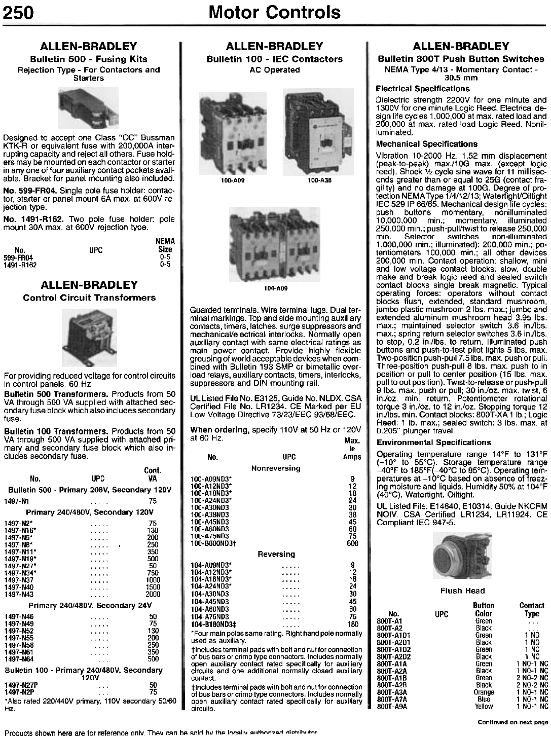
ALLEN-BRADLEY
Bulletin 100 - IEC Contactors
AC Operated
ALLEN-BRADLEY
Bulletin 500 - Fusing Kits
Rejection Type - For Contactors and
Starters
100-AO9 100-A38
Designed to accept one Class "CC" Bussman
KTK-R or equivalent fuse with 200,OOOA inter-
rupting capacity and reject all others. Fuse hold-
ers may be mounted on each contactor or starter
in anyone of four auxiliary contact pockets avail-
able. Bracket for panel mounting also included.
No. 599-FRO4. Single pole fuse holder: contac-
tor, starter or panel mount 6A max. at 600V re-
jection type.
No. 1491-R162. Two pole fuse holder: pole
mount 30A max. at 600V rejection type.
NEMA
Size
0-5
0-5
No.
599-FR04
1491-R162
UPC
ALLEN-BRADLEY
Control Circuit Transformers 104-AO9
Guarded terminals. Wire terminal lugs. Dual ter-
minal markings. Top and side mounting auxiliary
contacts, timers, latches, surge suppressors and
mechanical/electrical interlocks. Normally open
auxiliary contact with same electrical ratings as
main power contact. Provide highly flexible
grouping of world acceptable devices when com-
bined with Bulletin 193 SMP or bimetallic over-
load relays, auxiliary contacts, timers, interlocks,
suppressors and DIN mounting rail.
UL Listed File No. E3125, Guide No. NLDX. CSA
Certified File No. LR1234. CE Marked per EU
Low Voltage Directive 73/23/EEC 93/68/EEC.
When ordering, specify 11 OV at 50 Hz or 120V
at 60 Hz. Max.
Ie
No. UPC Amps
Nonreversing
For providing reduced voltage for control circuits
in control panels. 60 Hz.
Bulletin 500 Transformers. Products from 50
VA through 500 VA supplied with attached sec-
ondary fuse block which also includes secondary
fuse.
Bulletin 100 Transformers. Products from 50
VA through 500 VA supplied with attached pri-
mary and secondary fuse block which also in-
cludes secondary fuse.
100-AO9ND3*
100-A12ND3*
100-A18ND3*
100-A24ND3*
100-A30ND3
100-A38ND3
100-A45ND3
100-A60ND3
100-A75ND3
100-B600ND3t
9
12
18
24
30
38
45
60
75
608
ALLEN-BRADLEY
Bulletin BOOT Push Button Switches
NEMA Type 4/13 - Momentary Contact -
30.5 mm
Electrical Specifications
Dielectric strength 2200V for one minute and
1300V for one minute Logic Reed. Electrical de-
sign life cycles 1,000,000 at max. rated load and
200,000 at max. rated load Logic Reed. Nonil-
luminated.
Mechanical Specifications
Vibration 10-2000 Hz. 1.52 mm displacement
(peak-to-peak) max./10G max. (except logic
reed). Shock '/2 cycle sine wave for 11 millisec-
onds greater than or equal to 25G (contact fra-
gility) and no damage at 100G. Degree of pro-
tection NEMA Type 1/4/12/13; WatertighVOiltight
IEC 529 IP 66/65. Mechanical design life cycles:
push buttons momentary, nonilluminated
10,000,000 min.; momentary, illuminated
250,000 min.; push-pull/twist to release 250,000
min. Selector switches non-illuminated
1,000,000 min.; illuminated): 200,000 min.; po-
tentiometers 100,000 min.; all other devices
200,000 min. Contact operation: shallow, mini
and low voltage contact blocks: slow, double
make and break logic reed and sealed switch
contact blocks single break magnetic. Typical
operating forces: operators without contact
blocks flush, extended, standard mushroom,
jumbo plastic mushroom 2 Ibs. max.; jumbo and
extended aluminum mushroom head 3.95 Ibs.
max.; maintained selector switch 3.6 in./lbs.
max.; spring return selector switches 3.6 in./lbs.
to stop, 0.2 in./lbs. to return. Illuminated push
buttons and push-to-test pilot lights 5 Ibs. max.
Two-position push-pull 7 .5Ibs. max. push or pull.
Three-position push-pull 8 Ibs. max. push to in
position or pull to center position (15 Ibs. max.
pull to out position). Twist-to-release or push-pull
9 Ibs. max. push or pull; 30 in./oz. max. twist, 6
in./oz. min. return. Potentiometer rotational
torque 3 in./oz. to 12 in./oz. Stopping torque 12
in./lbs. min. Contact blocks: 800T -XA 1 lb.; Logic
Reed: 1 lb. max.; sealed switch: 3 Ibs. max. at
0.205" plunger travel.
Environmental Specifications
Operating temperature range 14°F to 131°F
(-10° to 55°C). Storage temperature range
--40°F to 185°F(--40°C to 85°C). Operating tem-
peratures at -10°C based on absence of freez-
ing moisture and liquids. Humidity 50% at 104°F
(40°C). Watertight. Oiltight.
UL Listed File: E14840, E10314. Guide NKCRM
NOIV. CSA Certified LR1234, LR11924. CE
Compliant lEG 947-5.
Reversing
Flush Head
Button Contact
Color Type
Green ...
Black
Green 1 NO
Black 1 NO
Green 1 NC
Black 1 NC
Green 1 NO-1 NC
Black 1 NO-1 NC
Green 2 NO-2 NC
Black 2 NO-2 NC
Orange 1 NO-1 NC
Blue 1 NO-1 NC
Yellow 1 NO-1 NC
Continued on next page
No.
BOOT-A1
BOOT-A2
800T-A1D1
BOOT-A2D1
BOOT-A1D2
BOOT-A2D2
BOOT-A1A
BOOT-A2A
BOOT-A1B
BOOT -A2B
800T-A3A
800T-A7A
800T-A9A
UPC
104-AO9ND3* 9
104-A12ND3* 12
104-A18ND3* 18
104-A24ND3* . . . . . 24
104-A30ND3 30
104-A45ND3 . . . . . 45
104-A60ND3 .. ... 60
104-A75ND3 75
104-B180ND3:I: 180
"Four main poles same rating. Right hand pole normally
used as auxiliary.
tlncludes terminal pads with bolt and nut for connection
of bus bars or crimp type connectors. Includes normally
open auxiliary contact rated specifically for auxiliary
circuits and one additional normally closed auxiliary
contact.
:j:lncludes terminal pads with bolt and nut for connection
of bus bars or crimp type connectors. Includes normally
open auxiliary contact rated specifically for auxiliary
circuits.
Cont.
No. UPC VA
Bulletin 500 - Primary 208V, Secondary 120V
1497-N1 75
Primary 240/480V, Secondary 120V
1497-N2* 75
1497-N16* 130
1497-N5* 200
1497-N8* 250
1497-N11* 350
1497-N19* 500
1497-N27* 50
1497-N34* .. ... 750
1497-N37 1000
1497-N40. 1500
1497-N43 2000
Primary 240/480V, Secondary 24V
1497-N46... 50
1497-N49 75
1497-N52 130
1497-N55 . 200
1497-N58 250
1497-N61 . . . . . 350
1497-N64. 500
Bulletin 100 - Primary 240/480V, Secondary
120V
1497-N27P 50
1497-N2P . . . . . 75
. Also rated 220/440V primary, 110V secondary 50/60
Hz.
Products shown here are for reference only. They can be sold by the IOCRllv R,rthnri7Arl rli"trih"tnr
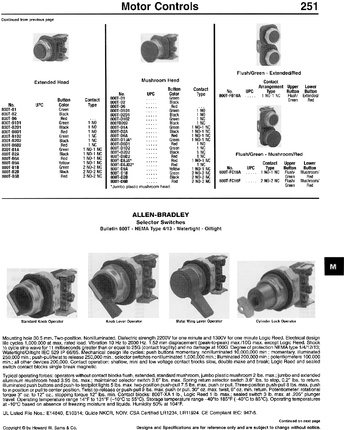
Motor Controls 251
Continued from previous page
Mushroom Head
Button
No. UPC Color
800T-01 Green
800T-02 . . Black
8O0T-06 Red
800T -0101 . . . . . Green
800T -0201 . . . . . Black
8OOT-0102 Green
800T0202 . . . . . Black
800T-01A Green
800T -02A . . . . . Black
800T -06A . . . . . Red
800T-01JA* Green
800T-0601 Red
8O0T-0102 Green
8O0T -0202 . . . . . Black
800T-0602 .. . . . Red
800T-06JA* Red
800T-06J02* . . . . . Red
800T -09A . . . . . Yellow
800T-018 Green
8OOT-028 . . . . . Black
800T-06B Red
. Jumbo plastic mushroom head.
Extended Head
Flush/Green - Extended/Red
Contact
Arrangement Upper Lower
No. UPC Type Button Button
800T -FB16A . . . 1 NO-1 NC Flush/ Extended/
Green Red
Contact
Type
Contact
Type
Button
Color
Green
Black
Red
Green
Black
Red
Green
Black
Red
Green
Black
Red
Yellow
Green
Black
Red
No.
800T-B1
800T-B2
800T-B6
800T-B1D1
800T-B2D1
800T-B6D1
800T-B1D2
800T-B2D2
800T-B6D2
800T-B1A
800T-B2A
800T-B6A
800T-B9A
800T-B1B
800T-B2B
800T-B6B
UPC
1 NO
1 NO
1 NC
1 NC
1 NO-1 NC
1 NO-1 NC
1 NO-1 NC
1 NO-1 NC
1 NO
1 NC
1 NC
1 NC
1 NO-1 NC
1 NC
1 NO-1 NC
2 NO-2 NC
2 NO-2 NC
2 NO-2 NC
1 NO
1 NO
1 NO
1 NC
1 NC
1 NC
1 NO-1 NC
1 NO-1 NC
1 NO-1 NC
1 NO-1 NC
2 NO-2 NC
2 NO-2 NC
2 NO-2 NC
Flush/Green - Mushroom/Red
Contact Upper Lower
No. UPC Type Button Button
800T-FC16A 1 NO-1 NC Flush/ Mushroom/
Green Red
800T-FC16F . . . .. 2 NO-2 NC Flush/ Mushroom/
Green Red
ALLEN-BRADLEY
Selector Switches
Bulletin BOOT - NEMA Type 4/13 - Watertight - Oiltight
-
Knob Lever Operator Metal Wing Lever Operator Cylinder Lock Operator
-
Standard Knob Operator
Mounting hole 30.5 mm. Two-position. Nonilluminated. Dialectric strength 2200V for one minute and 1300V for one minute Logic Reed. Electrical design
life cycles 1,000,000 at max. rated load. Vibration 10Hz to 2000 Hz. 1.52 mm displacement (peak-to-peak) max./10G max. except Logic Reed. Shock
'/2 cycle sine wave for 11 milliseconds greater than or equal to 25G (contact fragility) and no damage at 1 OOG. Degree of protection NEMA type 1/4/12/13;
Watertight/Oiltight lEG 529 IP 66/65. Mechanical design life cycles: push buttons momentary, nonilluminated 10,000,000 min.; momentary, illuminated
250,000 min.; push-pull/twist to release 250,000 min.; selector switches nonilluminated 1,000,000 min.; illuminated 200,000 min.; potentiometers 100,000
min.; all other devices 200,000. Contact operation: shallow, mini and low voltage contact blocks slow, double make and break; Logic Reed and sealed
switch contact blocks single break magnetic.
Typical operating forces: operators without contact blocks flush, extended, standard mushroom, jumbo plastic mushroom 2 Ibs. max.; jumbo and extended
aluminum mushroom head 3.95 Ibs. max.; maintained selector switch 3.6" Ibs. max. Spring return selector switch 3.6" Ibs. to stop, 0.2" Ibs. to return.
Illuminated push buttons and push-to-testpilot lights 5 Ibs. max. two-position push-pull 7.5 Ibs. max. push or pull. Three-position push-pull 8 Ibs. max. push
to in position or pull to center position. Twist-to-release or push-pull 9 Ibs. max. push or pull. 30" oz. max. twist, 6" oz. min. return. Potentiometer: rotational
torque 3" oz. to 12" oz.; stopping torque 12" Ibs. min. Contact blocks: 800T-XA 1 lb., Logic Reed 1 lb. max.; sealed switch 3 lb. max. at .205" plunger
travel. Operating temperature range 14°F to 131°F (-10°C to 55°C). Storage temperature range -400to 185°F (-40°C to 85°C). Operating temperatures
at -10°C based on absence of freezing moisture and liquids. Humidity 50% at 104°F.
UL Listed File Nos.: E14840, E10314; Guide NKCR, NOIV. CSA Certified LR1234, LR11924. CE Compliant lEG: 947-5.
Continued on next page
Designs and Specifications are for reference only and are subject to change without notice.
Copyright @ by Howard W. Sams & Co.
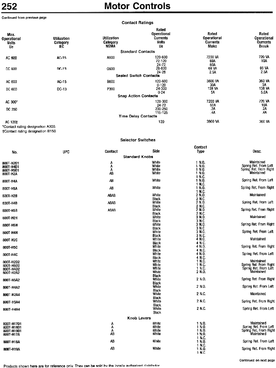
Motor Controls
252
Continued Irom previous page Contact Ratings
Rated
Operational
Currents
Volts
Ue
Rated
Operational
Currents
Make
Rated
Operational
Currents
Break
Max.
Operational
Volts
Ue
Utilization
Category
IEC
Utilization
Category
NEMA
Standard Contacts
120-600
72-120
24-72
28-600
24-28
Sealed Switch Contacts
120-600
0-120
24-300
0-24
Snap Action Contacts
120-300
24-72
230-250
115-125
Time Delay Contacts
7200 VA
60A
60A
69 VA
2.5A
720 VA
10A
69 VA
2.5A
AC-15 A600
AC 600
DC-1~ 0600
DC 600
8600
P300
3600 VA
30A
138 VA
5A
360 VA
3A
138 VA
5.0A
AC 600
DC 600
AC-15
DC-13
7200 VA
60A
.2A
.4A
720 VA
10A
.2A
.4A
AC 300'
DC 250
120 3600 VA 360 VA
AC 120t
'Contact rating designation A300.
tContact rating designation 8150
Selector Switches
Contact
Type
Contact Desc.
No. UPC
1 N.D.
1 N.D.
1 N.D.
1 N.D.
1 N.C.
1 N.D.
1 N.C.
1 N.D.
1 N.C.
2 N.D.
2 N.C.
2 N.D.
2 N.C.
2 N.D.
2 N.C.
3 N.D.
3 N.C.
3 N.D.
3 N.C.
3 N.D.
3 N.C.
4 N.D.
4 N.C.
4 N.D.
4 N.C.
4 N.D.
4 N.C.
1 N.C.
1 N.C.
1 N.C.
2 N.D.
2 N.D.
2 N.D.
2 N.C.
2 N.C.
2 N.C.
BOOT-H2D1
BOOT -H4D1
BOOT -H5D1
800T-H2A
BOOT-H4A
BOOT -H5A
BOOT-H2B
800T-H4B
BOOT -H5B
BOOT-H2H
800T-H5H
BOOT -H4H
800T-H2C
800T-H5C
BOOT -H4C
BOOT-H2D2
BOOT-H5D2
800T-H4D2
BOOT -H2A2
BOOT -H5A2
BOOT-H4A2
800T-H2A4
BOOT-H5A4
BOOT -H4A4
A
A
A
AB
AB
AB
ABAB
ABAB
ABAB
Maintained
Spring Ret. From Left
Spring Ret. From Right
Maintained
Spring Ret. From Left
Spring Ret. From Right
Maintained
Spring Ret. From Left
Spring Ret. From Right
Maintained
Spring Ret. From Right
Spring Ret. From Left
Maintained
Spring Ret. From Right
Spring Ret. From Left
Maintained
Spring Ret. From Right
Spring Ret. From Left
Maintained
Spring Ret. From Right
Spring Ret. From Left
Maintained
Spring Ret. From Right
Spring Ret. From Left
Side
Standard Knobs
White
White
White
White
White
White
White
Black
White
Black
White
Black
White
Black
White
Black
White
Black
White
Black
White
Black
White
Black
White
White
White
White
Black
White
Black
White
Black
White
Black
White
Black
White
Black
Knob Levers
1 N.D.
1 N.D.
1 N.D.
1 N.D.
1 N.C.
1 N.D.
1 N.C.
1 N.D.
1 N.C.
800T-H17D1
BOOT-H18D1
BOOT -H19D1
BOOT-H17A
BOOT-H18A
BOOT-H19A
A
A
A
AB
AB
AB
White
White
White
White
White
White
Maintained
Spring Ret. From Left
Spring Ret. From Right
Maintained
Spring Ret. From Left
Spring Ret. From Right
Continued on next page
Products shown here are for reference only. They can be sold by the locally ",rthnri7"rl rli"trihl !lnr
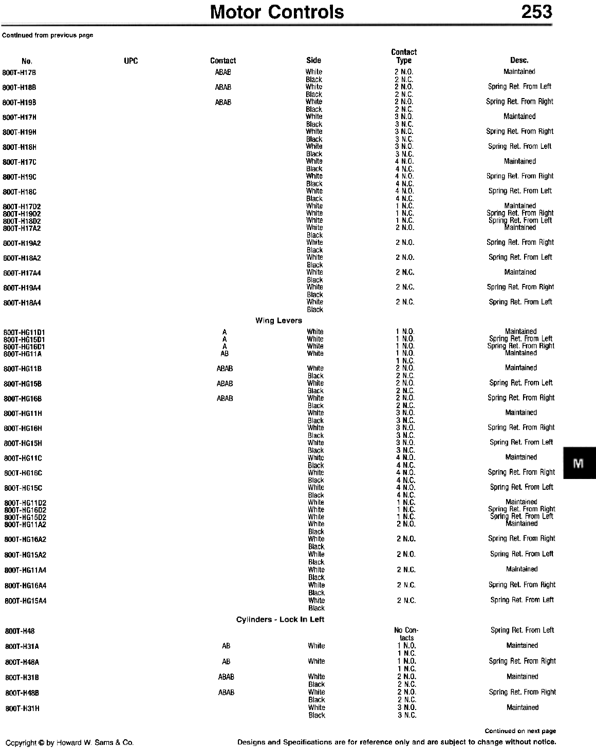
Motor Controls 253
Continued from previous page
Contact
Type
2 N.D.
2 N.C.
2 N.D.
2 N.C.
2 N.D.
2 N.C.
3 N.D.
3 N.C.
3 N.D.
3 N.C.
3 N.D.
3 N.C.
4 N.D.
4 N.C.
4 N.D.
4 N.C.
4 N.D.
4 N.C.
1 N.C.
1 N.C.
1 N.C.
2 N.D.
2 N.D.
2 N.D.
2 N.C.
2 N.C.
2 N.C.
UPC Contact
ABAB
ABAB
ABAB
Side
White
Black
White
Black
White
Black
White
Black
White
Black
White
Black
White
Black
White
Black
White
Black
White
White
White
White
Black
White
Black
White
Black
White
Black
White
Black
White
Black
No.
800T-H17B
BOOT-H18B
BOOT-H19B
BOOT-H17H
BOOT-H19H
BOOT-H18H
BOOT-H17C
BOOT-H19C
BOOT-H18C
BOOT-H17D2
BOOT -H19D2
BOOT-H18D2
800T-H17A2
BOOT-H19A2
BOOT-H18A2
BOOT-H17A4
BOOT-H19A4
BOOT-H18A4
Desc.
Mainlained
Spring ReI. From Left
Spring ReI. From RighI
Maintained
Spring ReI. From RighI
Spring ReI. From Left
Maintained
Spring ReI. From RighI
Spring ReI. From Left
Maintained
Spring ReI. From RighI
Spring ReI. From Left
Maintained
Spring ReI. From RighI
Spring ReI. From Left
Maintained
Spring ReI. From RighI
Spring ReI. From Left
Wing Levers
White
White
White
White
White
Black
White
Black
White
Black
White
Black
White
Black
White
Black
White
Black
White
Black
White
Black
White
White
White
White
Black
White
Black
White
Black
White
Black
White
Black
White
Black
Cylinders - Lock In Left
1 N.D.
1 N.D.
1 N.D.
1 N.D.
1 N.C.
2 N.D.
2 N.C.
2 N.D.
2 N.C.
2 N.D.
2 N.C.
3 N.D.
3 N.C.
3 N.D.
3 N.C.
3 N.D.
3 N.C.
4 N.D.
4 N.C.
4 N.D.
4 N.C.
4 N.D.
4 N.C.
1 N.C.
1 N.C.
1 N.C.
2 N.D.
2 N.D.
2 N.D.
2 N.C.
2 N.C.
2 N.C.
Maintained
Spring Ret. From Left
Spring Ret. From Right
Maintained
Maintained
Spring Ret. From Left
Spring Ret. From Right
Maintained
Spring Ret. From Right
Spring Ret. From Left
Maintained
Spring Ret. From Right
Spring Ret. From Left
Maintained
Spring Ret. From Right
Spring Ret. From Left
Maintained
Spring Ret. From Right
Spring Ret. From Left
Maintained
Spring Ret. From Right
Spring Ret. From Left
8OOT-HG11D1
8OOT-HG15D1
8OOT-HG16D1
8OOT-HG11A
8OOT-HG118
8OOT-HG158
8OOT-HG168
8OOT-HG11H
8OOT-HG16H
800T-HG15H
8OOT -HG11 C
8OOT-HG16C
8OOT-HG15C
8OOT -HG11 D2
8OOT-HG16D2
8OOT-HG15D2
8OOT-HG11A2
800T-HG16A2
8OOT -HG15A2
8OOT-HG11A4
8OOT-HG16A4
8OOT -HG15A4
A
A
A
AB
ABAB
ABAB
ABAB
No Con-
tacts
1 N.D.
1 N.C.
1 N.D.
1 N.C.
2 N.D.
2 N.C.
2 N.D.
2 N.C.
3 N.D.
3 N.C.
Spring Ret. From Left
Maintained
Spring Ret. From Right
Maintained
Spring Ret. From Right
Maintained
BOOT-H48
BOOT-H31 A
BOOT-H48A
BOOT -H31 8
BOOT -H488
BOOT-H31H
AB
AB
ABAB
ABAB
White
White
White
Black
White
Black
White
Black
Continued on next page
Designs and Specifications are for reference only and are subject to change without notice.
Copyright @ by Howard W. Sams & Co.
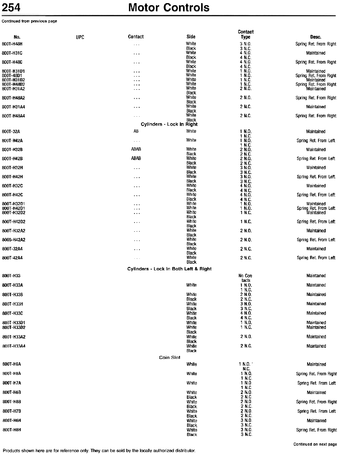
254 Motor Controls
Continued from previous page
Contact
Type
3 N.D.
3 N.C.
4 N.D.
4 N.C.
4 N.D.
4 N.C.
1 N.D.
1 N.D.
1 N.C.
1 N.C.
2 N.D.
2 N.D.
2 N.C.
2 N.C.
No.
BOOT -H48H
800T-H31C
BOOT -H48C
800T-H31D1
800T-48D1
800T-H31D2
800T-H48D2
800T-H31A2
800T-H48A2
800T-H31A4
800T-H48A4
UPC Contact Side
White
Black
... White
Black
... White
Black
... White
... White
... White
... White
... White
Black
... White
Black
... White
Black
White
Black
Cylinders - Lock In Right
AB White
... White
ABAB White
Black
ABAB White
Black
... White
Black
... White
Black
... White
Black
... White
Black
... White
... White
... White
Black
... White
Black
... White
Black
... White
Black
... White
Black
White
Black
Cylinders - Lock In Both Left & Right
Desc.
Spring Ret. From Right
Maintained
Spring Ret. From Right
Maintained
Spring Ret. From Right
Maintained
Spring Ret. From Right
Maintained
Spring Ret. From Right
Maintained
Spring Ret. From Right
800T-32A
800T-H42A
800T-H328
800T-H428
800T-H32H
800T-H42H
800T-H32C
800T-H42C
800T-H3201
800T-H4201
800T-H3202
800T-H4202
800T-H32A2
8005-H42A2
800T-32A4
800T-42A4
1 N.D.
1 N.C.
1 N.D.
1 N.C.
2 N.D.
2 N.C.
2 N.D.
2 N.C.
3 N.D.
3 N.C.
3 N.D.
3 N.C.
4 N.D.
4 N.C.
4 N.D.
4 N.C.
1 N.D.
1 N.D.
1 N.C.
1 N.C.
2 N.D.
2 N.D.
2 N.C.
2 N.C.
Maintained
Spring ReI. From Left
Mainlained
Spring ReI. From Left
Maintained
Spring ReI. From Left
Maintained
Spring ReI. From Left
Maintained
Spring ReI. From Left
Maintained
Spring ReI. From Left
Maintained
Spring ReI. From Left
Maintained
Spring ReI. From Left
800T-H33
800T-H33A
800T-H33B
800T-H33H
800T-H33C
800T-H33D1
800T-H33D2
800T-H33A2
800T-H33A4
No Con.
tacts
1 N.D.
1 N.C.
2 N.D.
2 N.C.
3 N.D.
3 N.C.
4 N.D.
4 N.C.
1 N.D.
1 N.C.
2 N.D.
2 N.C.
Maintained
Maintained
Maintained
Maintained
Maintained
Maintained
Maintained
Maintained
Maintained
White
White
Black
White
Black
White
Black
White
White
Black
White
Black
White
Black
Coin Slot
800T-H6A
800T-H8A
800T-H7A
800T-H6B
800T-H8B
800T-H7B
800T-H6H
800T-H8H
White
White
White
White
Black
White
Black
White
Black
White
Black
White
Black
1 N.D. 1
N.C.
1 N.D.
1 N.C.
1 N.D.
1 N.C.
2 N.D.
2 N.C.
2 N.D.
2 N.C.
2 N.D.
2 N.C.
3 N.D.
3 N.C.
3 N.D.
3 N.C.
Maintained
Spring Ret. From Right
Spring Ret. From Left
Maintained
Spring Ret. From Right
Spring Ret. From Left
Maintained
Spring Ret. From Right
Continued on next page
Products shown here are for reference only. They can be sold by the locally authorized distributor.
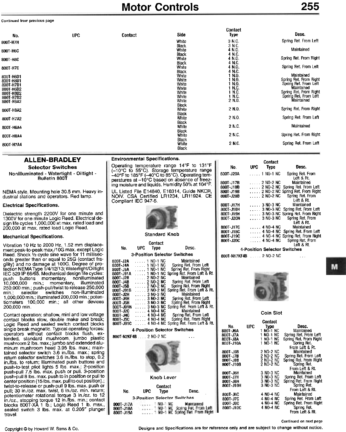
255
Motor Controls
Continued from previous page
Contact
Type
3 N.D.
3 N.C.
4 N.D.
4 N.C.
4 N.D.
4 N.C.
4 N.D.
4 N.C.
1 N.D.
1 N.D.
1 N.D.
1 N.C.
1 N.C.
1 N.C.
2 N.D.
2 N.D.
2 N.D.
2 N.C.
2 N.C.
2 N.C.
Side
White
Black
White
Black
White
Black
White
Black
White
White
White
White
White
White
White
Black
White
Black
White
Black
White
Black
White
Black
White
Black
UPC Contact
No.
800T-H7H
800T-H6C
800T-H8C
800T-H7C
800T-H6D1
800T-H8D1
800T-H7D1
800T-H6D2
800T-H8D2
800T-H7D2
800T-H6A2
800T-H8A2
800T-H7A2
800T-H6A4
800T-H8A4
800T-H7A4
Desc.
Spring Ret. From Left
Maintained
Spring Ret. From Right
Spring Ret. From Left
Maintained
Spring Ret. From Right
Spring Ret. From Left
Maintained
Spring Ret. From Right
Spring Ret. From Left
Maintained
Spring Ret. From Right
Spring Ret. From Left
Maintained
Spring Ret. From Right
Spring Ret. From Left
ALLEN-BRADLEY
Selector Switches
Nonilluminated - Watertight - Oiltight -
Bulletin 800T
Environmental Specifications.
Operating temperature range 14°F to 131°F
(-10°C to 55°C). Storage temperature range
-40°F to 185°F (-40°C to 85°C). Operating tem-
peratures at -10°C based on absence of freez-
ing moisture and liquids. Humidity 50% at 104°F.
UL Listed File E14840, E10314, Guide NKCR,
NOIV. CSA Certified LR1234, LR11924. CE
Compliant lEG 947-5.
Contact
No. UPC Type Desc.
800T -J20A . . . . . 1 NO-1 NC Spring Rei. From
Left & RI.
800T-J17B . . . . . 2 NO-2 NC Maintained
800T-J18B . . . . . 2 NO-2 NC Spring Rei. From Left
800T-J19B 2 NO-2 NC Spring Rei. From Righi
800T-J20B 2 NO-2 NC Spring Rei. From
Left & At.
800T-J17H . . . . . 3 NO-3 NC Mainlained
800T-J18H 3 NO-3 NC Spring Rei. From Left
BOOT-J19H .. . . . 3 NO-3 NC Spring Rei. From Righi
800T -J20H . . . . . 3 NO-3 NC Spring Ret. From
Left & RI.
800T-J17C .. . . . 4 NO-4 NC Maintained
800T-J18C . . . . . 4 NO-4 NC Spring Rei. From Left
800T-J19C . . . 4 NO-4 NC Spring Rei. From Righi
800T-J20C . . . . . 4 NO-4 NC Spring Rei. From
Left & Rt.
4-Position Selector Switches
800T-N17KF4B 2 NO-2 NC ...
Standard Knob
Contact
No. UPC Type Desc.
3-Position Selector Switches
800T-J2A 1 NO-1 NC Maintained
800T -J4A . . . . . 1 NO-1 NC Spring Ret. From Left
800T -J5A .. . . . 1 NO-1 NC Spring Ret. From Right
800T-J91A 1 NO-1 NC Spring Ret. From Left & RI.
BOOT-J2B . . . . 2 NO-2 NC Maintained
800T-J4B . . . . 2 NO-2 NC Spring Ret. From Left
BOOT-J5B .. . . . 2 NO-2 NC Spring Ret. From Right
800T-J91B 2 NO-2 NC Spring Ret. From Left & RI.
800T-J2H . . . . . 3 NO-3 NC Maintained
800T-J4H . . . . . 3 NO-3 NC Spring Ret. From Left
800T -J5H . . . . 3 NO-3 NC Spring Ret. From Right
800T-J91H 3 NO-3 NC Spring Ret. From Left & RI.
800T-J2C 4 NO-4 NC Maintained
800T-J4C 4 NO-4 NC Spring Ret. From Left
800T -J5C . . . 4 NO-4 NC Spring Ret. From Right
800T-J91C . . . . 4 NO-4 NC Spring Ret. From Left & RI.
4-Position Selector Switches
800T-N2KF4B 2 NO-2 NC
NEMA style. Mounting hole 30.5 mm. Heavy in-
dustrial stations and operators. Red lamp.
Electrical Specifications.
Dielectric strength 2200V for one minute and
1300V for one minute Logic Reed. Electrical de-
sign life cycles 1,000,000 at max. rated load and
200,000 at max. rated load Logic Reed.
Mechanical Specifications.
Vibration 10 Hz to 2000 Hz. 1.52 mm displace-
ment peak-to-peak max./1 OG max. except Logic
Reed. Shock 1/2 cycle sine wave for 11 millisec-
onds greater than or equal to 25G (contact fra-
gility) and no damage at 100G. Degree of pro-
tection NEMA Type 1/4/12/13; WatertightlOiltight
IEC 529 IP 66/65. Mechanical design life cycles:
push buttons momentary, nonilluminated
10,000,000 min.; momentary, illuminated
250,000 min.; push-pull/twist to release 250,000
min.; selector switches non-illuminated
1,000,000 min.; illuminated 200,000 min.; poten-
tiometers 100,000 min.; all other devices
200,000 min,
Contact operation: shallow, mini and low voltage
contact blocks slow, double make' and break;
Logic Reed and sealed switch contact blocks
single break magnetic. Typical operating forces:
operators without contact blocks flush, ex-
tended, standard mushroom, jumbo plastic
mushroom 2lbs. max.; jumbo and extended alu-
minum mushroom head 3.95 Ibs. max.; main-
tained selector switch 3.6 in./lbs. max.; spring
return selector switches 3.6 in./lbs. to stop, 0.2
in./lbs. to return; Illuminated push buttons and
push-to-test pilot lights 5 Ibs. max.; 2-position
push-pull 7.5 Ibs. max. push or pull. 3-position
push-pull 8 Ibs. max. push to in position or pull to
center position (15Ibs. max. pull to out position).;
twist-to-release or push-pull 9 Ibs. max. push or
pull; 30 in./oz. max. twist, 6 in./oz. min. return;
potentiometer rotational torque 3 in./oz. to 12
in./oz., stopping torque 12 in./lbs. min.; contact
blocks 800T-XA 1 lb.; Logic Reed 1 lb. max.,
sealed switch 3 Ibs. max. at 0.205" plunger
travel.
No.
800T-J6A
800T-J7A
800T-J8A
800T-J10A
800T-J6B
800T-J7B
800T-J8B
800T-J10B
800T-J6H
800T-J7H
800T-J8H
800T-J10H
800T-J6C
800T-J7C
800T-J8C
800T-J10C
UPC
Coin Slot
Contact
Type Desc.
1 NO-1 NC Maintained
1 NO-1 NC Spring Ret. From Left
1 NO-1 NC Spring Ret. From Right
1 NO-1 NC Spring Ret.
From Left & At.
2 NO-2 NC Maintained
2 NO-2 NC Spring Ret. From Left
2 NO-2 NC Spring Ret. From Right
2 NO-2 NC Spring Ret.
From Left & Rt.
3 NO-3 NC Maintained
3 NO-3 NC Spring Ret. From Left
3 NO-3 NC Spring Ret. From Right
3 NO-3 NC Spring Ret.
From Left & Rt.
4 NO-4 NC Maintained
4 NO-4 NC Spring Ret. From Left
4 NO-4 NC Spring Ret. From Right
4 NO-4 NC Spring Ret.
From Left & Rt.
No.
800T-J17A
BOOT-J18A
800T-J19A
Continued on next page
Designs and Specifications are for reference only and are subject to change without notice.
Copyright @ by Howard W. Sams & Co.
Knob Lever
Contact
UPC Type Desc.
~-Pn..itinn S~I~ctQr Switch~s
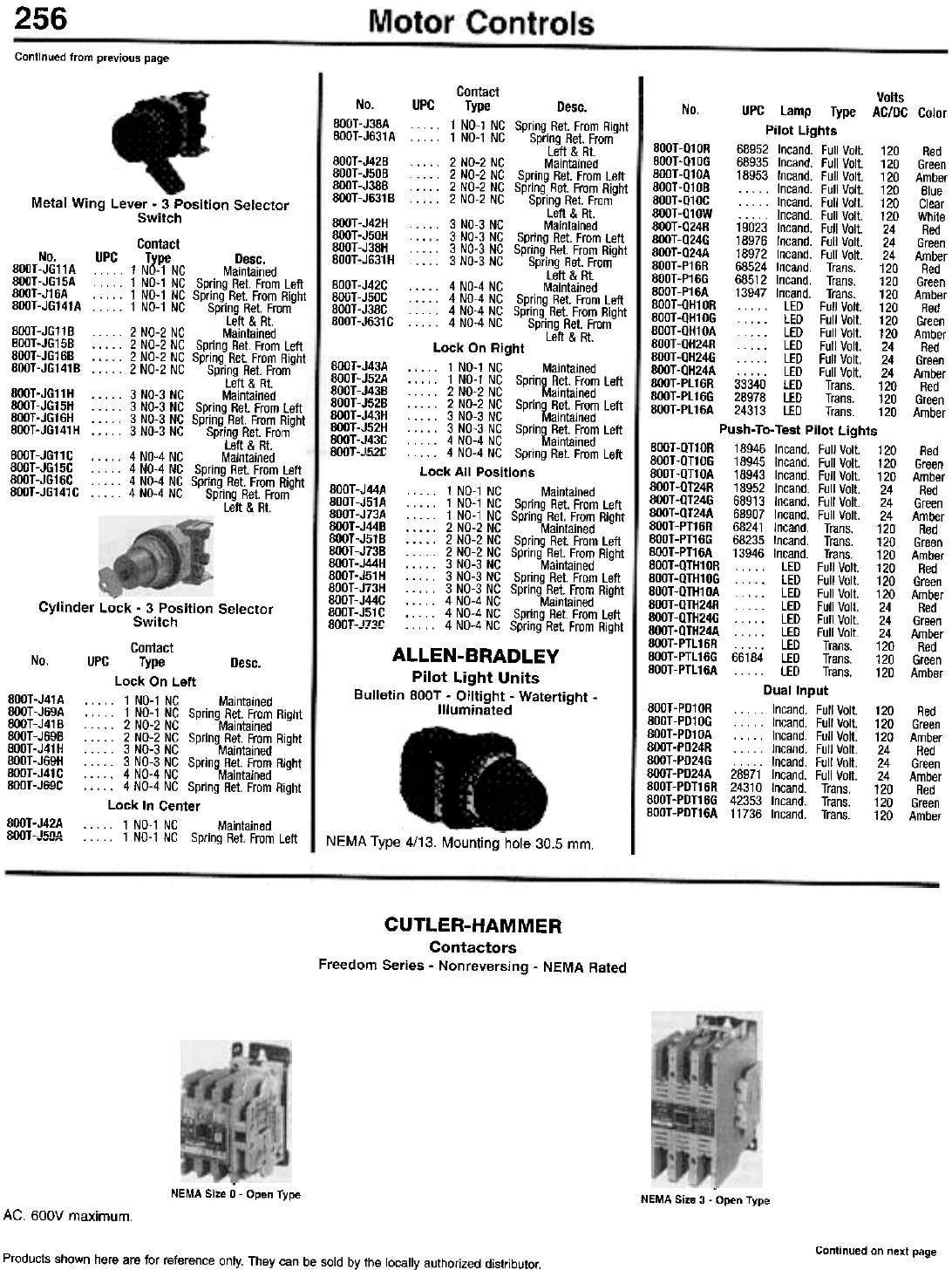
256
Continued from previous page
Contact
No. UPC Type Desc.
BOOT -J38A . . . .. 1 NO-1 NC Spring Ret. From Right
BOOT-J631A . . .. 1 NO-1 NC Spring Ret. From
Left & Rt.
800T -J42B . . .. 2 NO-2 NC Maintained
800T-J50B . 2 NO-2 NC Spring Ret. From Left
BOOT-J38B .. .. 2 NO-2 NC Spring Ret. From Right
800T-J631B 2 NO-2 NC Spring Ret. From
Left & Rt.
800T -J42H . . .. 3 NO-3 NC Maintained
BOOT -J50H . . .. 3 NO-3 NC Spring Ret. From Left
BOOT -J38H . . . .. 3 NO-3 NC Spring Ret. From Right
800T -J631 H . . .. 3 NO-3 NC Spring Ret. From
Left & Rt.
800T -J42C . . . .. 4 NO-4 NC Maintained
BOOT -J50C . . .. 4 NO-4 NC Spring Ret. From Left
800T -J38C . . .. 4 NO-4 NC Spring Ret. From Right
800T-J631C 4 NO-4 NC Spring Ret. From
Left & Rt.
Lock On Right
. . . .. 1 NO-1 NC Maintained
. . . .. 1 NO-1 NC Spring R.et. From Left
. . . .. 2 NO-2 NC Maintained
. . . .. 2 NO-2 NC Spring R.et. From Left
. . . .. 3 NO-3 NC Maintained
. . . .. 3 NO-3 NC Spring R.et. From Left
. . . .. 4 NO-4 NC Maintained
. . . . .. 4 NO-4 NC Spring Ret. From Left
Lock All Positions
. . . .. 1 NO-1 NC Maintained
. . . .. 1 NO-1 NC Spring Ret. From Left
. . . .. 1 NO-1 NC Spring Ret. From Right
. . . .. 2 NO-2 NC Maintained
. . . .. 2 NO-2 NC Spring Ret. From Left
. . . .. 2 NO-2 NC Spring Ret. From Right
. . . .. 3 NO-3 NC Maintained
. . . .. 3 NO-3 NC Spring Ret. From Left
. . . .. 3 NO-3 NC Spring Ret. From Right
. . . .. 4 NO-4 NC Maintained
. . . .. 4 NO-4 NC Spring Ret. From Left
. -. -- . . . .. 4 NO-4 NC Spring Ret. From Right
ALLEN-BRADLEY
Pilot Light Units
Bulletin BOOT - Oiltight - Watertight -
Illuminated
-
Metal Wing Lever - 3 Position Selector
Switch
Contact
No. UPC Type Desc.
800T-JG11A 1 NO-1 NC Maintained
800T-JG15A 1 NO-1 NC Spring Ret. From Left
800T-J16A 1 NO-1 NC Spring Ret. From Right
800T-JG141A 1 NO-1 NC Spring Ret. From
Left & Rt.
800T-JG11B . . . .. 2 NO-2 NC Maintained
800T-JG15B . . . .. 2 NO-2 NC Spring Ret. From Left
800T-JG16B . . . .. 2 NO-2 NC Spring Ret. From Right
800T-JG141B 2 NO-2 NC Spring Ret. From
Left & Rt.
800T-JG11H . . . " 3 NO-3 NC Maintained
800T-JG15H . . . .. 3 NO-3 NC Spring Ret. From Left
BOOT-JG16H . . . .. 3 NO-3 NC Spring Ret. From Right
800T-JG141H 3 NO-3 NC Spring Ret. From
Left & RI.
800T-JG11C . . . .. 4 NO-4 NC Maintained
800T-JG15C . . . .. 4 NO-4 NC Spring Ret. From Left
800T-JG16C . . . .. 4 NO-4 NC Spring Ret. From Right
800T-JG141C 4 NO-4 NC Spring Ret. From
Left & Rt.
BOOT -J43A
BOOT-J52A
800T-J43B
800T-J52B
BOOT-J43H
BOOT-J52H
BOOT-J43C
BOOT-.J!;?!:
BOOT-J44A
800T-J51 A
800T-J73A
BOOT -J44B
800T-J51B
BOOT -J73B
BOOT -J44H
BOOT -J51 H
800T-J73H
BOOT-J44C
BOOT -J51 C
800T-.l7~~
Cylinder Lock - 3 Position Selector
Switch
Contact
No. UPC Type Desc.
Lock On Left
. . . " 1 NO-1 NC Maintained
. . . .. 1 NO-1 NC Spring Ret. From Right
. . . .. 2 NO-2 NC Maintained
. . . .. 2 NO-2 NC Spring Ret. From Right
. . . .. 3 NO-3 NC Maintained
. . . .. 3 NO-3 NC Spring Ret. From Right
. . . .. 4 NO-4 NC Maintained
. . . .. 4 NO-4 NC Spring Ret. From Right
Lock In Center
. . . .. 1 NO-1 NC Maintained
-v~ . . . .. 1 NO-1 NC Spring Ret. From Left
800T-J41A
800T-J69A
800T-J418
BOOT -J698
BOOT-J41H
800T-J69H
BOOT-J41C
BOOT-.II;!I~
Volts
No. UPC Lamp Type AC/DC Color
Pilot Lights
800T-Q10R 68952 Incand. Full Volt. 120 Red
800T-Q10G 68935 Incand. Full Volt. 120 Green
BOOT-Q10A 18953 Incand. Full Volt. 120 Amber
800T-Q10B .. . .. Incand. Full Volt. 120 Blue
800T-Q10C . . . .. Incand. Full Volt. 120 Clear
800T-Q10W . . . .. Incand. Full Volt. 120 White
800T -Q24R 19023 Incand. Full Volt. 24 Red
800T -Q24G 18976 Incand. Full Volt. 24 Green
800T -Q24A 18972 Incand. Full Volt. 24 Amber
800T-P16R 68524 Incand. Trans. 120 Red
800T-P16G 68512 Incand. Trans. 120 Green
800T-P16A 13947 Incand. Trans. 120 Amber
800T-QH10R . . . .. LED Full Volt. 120 Red
BOOT-QH10G . . . . . LED Full Volt. 120 Green
800T-QH10A . LED Full Volt. 120 Amber
800T-QH24R . . . . . LED Full Volt. 24 Red
BOOT -QH24G . . . . . LED Full Volt. 24 Green
800T-QH24A . . . . . LED Full Volt. 24 Amber
800T-PL16R 33340 LED Trans. 120 Red
800T-PL16G 28978 LED Trans. 120 Green
BOOT -PL 16A 24313 LED Trans. 120 Amber
Push- To-Test Pilot Lights
800T-QT10R 18946 Incand. Full Volt. 120 Red
800T-QT10G 18945 Incand. Full Volt. 120 Green
800T-QT10A 18943 Incand. Full Volt. 120 Amber
BOOT -QT24R 18952 Incand. Full Volt. 24 Red
800T-QT24G 68913 Incand. Full Volt. 24 Green
800T -QT24A 68907 Incand. Full Volt. 24 Amber
800T-PT16R 68241 Incand. Trans. 120 Red
800T-PT16G 68235 Incand. Trans. 120 Green
800T-PT16A 13946 Incand. Trans. 120 Amber
800T-QTH10R LED Full Volt. 120 Red
800T-QTH10G "'" LED Full Volt. 120 Green
800T-QTH10A . . . LED Full Volt. 120 Amber
BOOT -QTH24R LED Full Volt. 24 Red
800T -QTH24G . . . LED Full Volt. 24 Green
800T -QTH24A LED Full Volt. 24 Amber
800T-PTL16R .. . . . LED Trans. 120 Red
BOOT-PTL16G 66184 LED Trans. 120 Green
800T-PTL16A . . . .. LED Trans. 120 Amber
Dual Input
800T-PD10R . . . .. Incand. Full Volt. 120 Red
800T-PD10G . .. .. Incand. Full Volt. 120 Green
BOOT-PD10A . . . .. Incand. Full Volt. 120 Amber
800T-PD24R . . . .. Incand. Full Volt. 24 Red
800T -PD24G . . . .. Incand. Full Volt. 24 Green
BOOT -PD24A 28971 Incand. Full Volt. 24 Amber
800T-PDT16R 24310 Incand. Trans. 120 Red
800T -PDT16G 42353 Incand. Trans. 120 Green
800T-PDT16A 11736 Incand. Trans. 120 Amber
800T-J42A
BOOT -.l1;n4 NEMA Type 4/13. Mounting hole 30.5 mm.
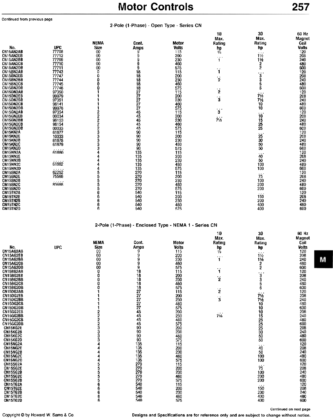
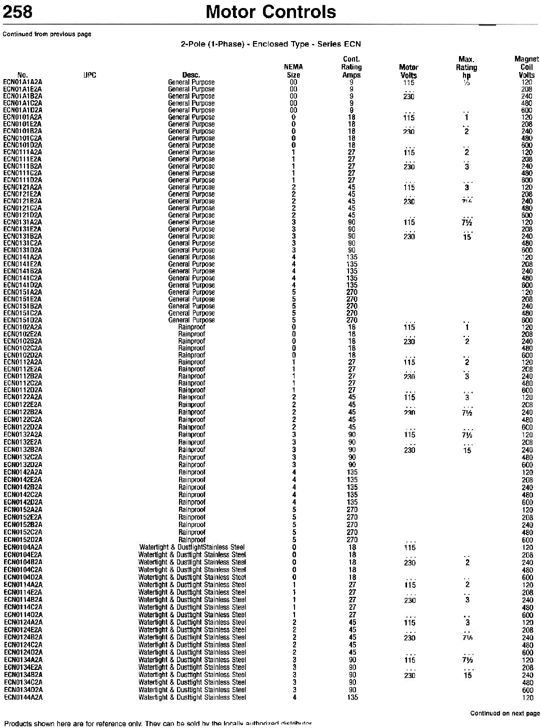
CUTLER-HAMMER
Contactors
Freedom Series - Nonreversing - NEMA Rated
.
NEMA Size 0 - Open Type NEMA Size 3 - Open Type
AG. BOOV maximum.
Continued on next page
Products shown here are for reference only. They can be sold by the locally authorized distributor.
Motor Controls 257
Continued from previous page 2-Pole (1-Phase) - Open Type - Series CN
10
Max.
Rating
~
1
30
Max.
Rating
hp
1V2
11h
2
2
3
3
5
5
71h
71h
10
10
10
15
25
25
25
30
50
50
40
50
100
100
75
100
200
200
150
200
400
400
60 Hz
Magnet
Coil
Volts
120
208
240
480
600
120
208
240
480
600
120
208
240
480
600
120
208
240
480
600
120
208
240
480
600
120
208
240
480
600
120
208
240
480
600
120
208
240
480
600
NEMA
Size
00
00
00
00
00
a
a
0
0
0
1
1
1
1
1
2
2
2
2
2
3
3
3
3
3
4
4
4
4
4
5
5
5
5
5
6
6
6
6
6
Cont.
Amps
9
9
9
9
9
18
18
18
18
18
27
27
27
27
27
45
45
45
45
45
90
90
90
90
90
135
135
135
135
135
270
270
270
270
270
540
540
540
540
540
Motor
Volts
115
200
230
460
575
115
200
230
460
575
115
200
230
460
575
115
200
230
460
575
115
200
230
460
575
115
200
230
460
575
115
200
230
460
575
115
200
230
460
575
UPC
77708
77712
77709
77710
77711
77743
77747
77744
77745
77746
97350
99979
97351
98141
99978
97354
00034
98153
98154
00033
61877
10333
61878
61879
61880
No.
CN15AN2AB
CN15AN2EB
CN15AN2BB
CN15AN2CB
CN15AN2DB
CN15BN2AB
CN15BN2EB
CN15BN2BB
CN15BN2CB
CN15BN2DB
CN15DN2AB
CN15DN2EB
CN15DN2BB
CN15DN2CB
CN15DN2DB
CN15GN2AB
CN15GN2EB
CN15GN2BB
CN15GN2CB
CN15GN2DB
CN15KN2A
CN15KN2E
CN15KN2B
CN15KN2C
CN15KN2D
CN15NN2A
CN15NN2E
CN15NN2B
CN15NN2C
CN15NN2D
CN15SN2A
CN15SN2E
CN15SN2B
CN15SN2C
CN15SN2D
CN15TN2A
CN15TN2E
CN15TN2B
CN15TN2C
CN15TN2D
-1-
'2
'2
. 3
3
7%
61882
62252
75568
83688
2-Pole (1-Phase) - Enclosed Type - NEMA 1 - Series CN
10
Max.
Rating
~X
1
30
Max.
Rating
hp
1V2
11h
2
2
3
3
5
5
71h
71h
10
10
10
15
25
25
25
30
50
50
40
50
100
100
75
100
200
200
150
200
400
400
60 Hz
Magnet
Coil
Volts
120
208
240
480
600
120
208
240
480
600
120
208
240
480
600
208
240
480
600
208
240
480
600
120
208
240
480
600
120
208
240
480
600
120
208
240
480
600
NEMA
Size
00
00
00
00
00
a
a
a
a
a
1
1
1
1
1
2
2
2
2
3
3
3
3
4
4
4
4
4
5
5
5
5
5
6
6
6
6
6
Cont.
Amps
9
9
9
9
9
18
18
18
18
18
27
27
27
27
27
45
45
45
45
90
90
90
90
135
135
135
135
135
270
270
270
270
270
540
540
540
540
540
Motor
Volts
115
200
230
460
575
115
200
230
460
575
115
200
230
460
575
200
230
460
575
200
230
460
575
115
200
230
460
575
115
200
230
460
575
115
200
230
460
575
No.
CN15AG2AB
CN15AG2EB
CN15AG2BB
CN15AG2CB
CN15AG2DB
CN15BG2AB
CN15BG2EB
CN15BG2BB
CN15BG2CB
CN15BG2DB
CN15DG2AB
CN15DG2EB
CN15DG2BB
CN15DG2CB
CN15DG2DB
CN15GG2EB
CN15GG2BB
CN15GG2CB
CN15GG2DB
CN15KG2E
CN15KG2B
CN15KG2C
CN15KG2D
CN15NG2A
CN15NG2E
CN15NG2B
CN15NG2C
CN15NG2D
CN15SG2A
CN15SG2E
CN15SG2B
CN15SG2C
CN15SG2D
CN15TG2A
CN15TG2E
CN15TG2B
CN15TG2C
CN15TG2D
UPC
"1"
'2
2
3
7'h
Continued on next page
Designs and Specifications are for reference only and are subject to change without notice.
Copyright @ by Howard W. Sams & Co.
Motor Controls
258
Continued from previous page
2-Pole (1-Phase) - Enclosed Type - Series ECN
Cont.
NEMA Rating
Desc. Size Amps
General Purpose 00 9
General Purpose 00 9
General Purpose 00 9
General Purpose 00 9
General Purpose 00 9
General Purpose 0 18
General Purpose 0 18
General Purpose 0 18
General Purpose 0 18
General Purpose 0 18
General Purpose 1 27
General Purpose 1 27
General Purpose 1 27
General Purpose 1 27
General Purpose 1 27
General Purpose 2 45
General Purpose 2 45
General Purpose 2 45
General Purpose 2 45
General Purpose 2 45
General Purpose 3 90
General Purpose 3 90
General Purpose 3 90
General Purpose 3 90
General Purpose 3 90
General Purpose 4 135
General Purpose 4 135
General Purpose 4 135
General Purpose 4 135
General Purpose 4 135
General Purpose 5 270
General Purpose 5 270
General Purpose 5 270
General Purpose 5 270
General Purpose 5 270
Rainproof 0 18
Rainproof 0 18
Rainproof 0 18
Rainproof 0 18
Rainproof 0 18
Rainproof 1 27
Rainproof 1 27
Rainproof 1 27
Rainproof 1 27
Rainproof 1 27
Rainproof 2 45
Rainproof 2 45
Rainproof 2 45
Rainproof 2 45
Rainproof 2 45
Rainproof 3 90
Rainproof 3 90
Rainproof 3 90
Rainproof 3 90
Rainproof 3 90
Rainproof 4 135
Rainproof 4 135
Rainproof 4 135
Rainproof 4 135
Rainproof 4 135
Rainproof 5 270
Rainproof 5 270
Rainproof 5 270
Rainproof 5 270
Rainproof 5 270
Watertight & DusttightStainless Steel 0 18
Watertight & Dusttight Stainless Steel 0 18
Watertight & Dusttight Stainless Steel 0 18
Watertight & Dusttight Stainless Steel 0 18
Watertight & Dusttight Stainless Steel 0 18
Watertight & Dusttight Stainless Steel 1 27
Watertight & Dusttight Stainless Steel 1 27
Watertight & Dusttight Stainless Steel 1 27
Watertight & Dusttight Stainless Steel 1 27
Watertight & Dusttight Stainless Steel 1 27
Watertight & Dusttight Stainless Steel 2 45
Watertight & Dusttight Stainless Steel 2 45
Watertight & Dusttight Stainless Steel 2 45
Watertight & Dusttight Stainless Steel 2 45
Watertight & Dusttight Stainless Steel 2 45
Watertight & Dusttight Stainless Steel 3 90
Watertight & Dusttight Stainless Steel 3 90
Watertight & Dusttight Stainless Steel 3 90
Watertight & Dusttight Stainless Steel 3 90
Watertight & Dusttight Stainless Steel 3 90
Watertight & Dusttight Stainless Steel 4 135
Max.
Rating
~
Magnet
Coil
Volts
120
208
240
480
600
120
208
240
480
600
120
208
240
480
600
120
208
240
480
600
120
208
240
480
600
120
208
240
480
600
120
208
240
480
600
120
208
240
480
600
120
208
240
480
600
120
208
240
480
600
120
208
240
480
600
120
208
240
480
600
120
208
240
480
600
120
208
240
480
600
120
208
240
480
600
120
208
240
480
600
120
208
240
480
600
120
Motor
Volts
115
230
UPC
No.
EGNO1A1A2A
EGNO1A1E2A
EGNO1A1B2A
EGNO1A1G2A
EGNO1A1D2A
EGNO101A2A
EGNO101E2A
EGNO101B2A
EGNO101G2A
EGNO101D2A
EGNO111A2A
EGNO111E2A
EGNO111B2A
EGNO111G2A
EGNO111D2A
EGNO121A2A
EGNO121E2A
EGNO121B2A
EGNO121G2A
EGNO121D2A
EGNO131A2A
EGNO131E2A
EGNO131B2A
EGNO131G2A
EGNO131D2A
EGNO141A2A
EGNO141E2A
EGNO141B2A
EGNO141G2A
EGNO141D2A
EGNO151A2A
EGNO151E2A
EGNO151B2A
EGNO151G2A
EGNO151D2A
EGNO102A2A
EGNO102E2A
EGNO102B2A
EGNO102G2A
EGNO102D2A
EGNO112A2A
EGNO112E2A
EGNO112B2A
EGNO112G2A
EGNO112D2A
EGNO122A2A
EGNO122E2A
EGNO122B2A
EGNO122G2A
EGNO122D2A
EGNO132A2A
EGNO132E2A
EGNO132B2A
EGNO132G2A
EGNO132D2A
EGNO142A2A
EGNO142E2A
EGNO142B2A
EGNO142G2A
EGNO142D2A
EGNO152A2A
EGNO152E2A
EGNO152B2A
EGNO152G2A
EGNO152D2A
EGNO104A2A
EGNO104E2A
EGNO104B2A
EGNO104G2A
EGNO104D2A
EGNO114A2A
EGNO114E2A
EGNO114B2A
EGNO114G2A
EGNO114D2A
EGNO124A2A
EGNO124E2A
EGNO124B2A
EGNO124G2A
EGNO124D2A
EGNO134A2A
EGNO134E2A
EGNO134B2A
EGNO134G2A
EGNO134D2A
EGNO144A2A
115
230
l'
'2
115
230
'2
. 3
115
230
3
71h
115
230
7'h
15
115
230
1
.2
115
230
.2
.3
115
230
3
7'h
115
230
71h
15
115
230 2
115
230
2
3
115
230
3
71h
115
230
7'h
15
Continued on next page
Products shown here are for reference only. They can be sold bv the locallv ",rthnri7"rl rli"trih"tn,
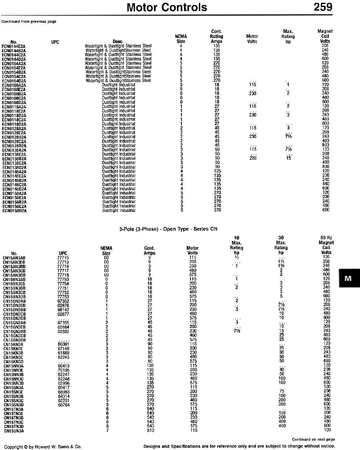
259
Motor Controls
Continued from previous page
Cont.
Rating
Amps
135
135
135
135
270
270
270
270
270
18
18
18
18
18
27
27
27
27
27
45
45
45
45
45
90
90
90
90
90
135
135
135
135
135
270
270
270
270
270
Max.
Rating
hp
Magnet
Coil
Volts
208
240
480
600
120
208
240
480
600
120
208
240
480
600
120
208
240
480
600
120
208
240
480
600
120
208
240
480
600
120
208
240
480
600
120
208
240
480
600
NEMA
Size
4
4
4
4
5
5
5
5
5
0
0
0
0
0
1
1
1
1
1
2
2
2
2
2
3
3
3
3
3
4
4
4
4
4
5
5
5
5
5
Motor
Volts
UPC
No.
ECNO144E2A
ECNO144B2A
ECNO144C2A
ECNO144D2A
ECNO154A2A
ECNO154E2A
ECNO154B2A
ECNO154C2A
ECNO154D2A
ECNO108A2A
ECNO108E2A
ECNO108B2A
ECNO108C2A
ECNO108D2A
ECNO118A2A
ECNO118E2A
ECNO118B2A
ECNO118C2A
ECNO118D2A
ECNO128A2A
ECNO128E2A
ECNO128B2A
ECNO128C2A
ECNO128D2A
ECNO138A2A
ECNO138E2A
ECNO138B2A
ECNO138C2A
ECNO138D2A
ECNO148A2A
ECNO148E2A
ECNO148B2A
ECNO148C2A
ECNO148D2A
ECNO158A2A
ECNO158E2A
ECNO158B2A
ECNO158C2A
ECNO158D2A
Desc.
Watertight & Dusttight Stainless Steel
Watertight & DusttightStainless Steel
Watertight & Dusttight Stainless Steel
Watertight & Dusttight Stainless Steel
Watertight & Dusttight Stainless Steel
Watertight & Dusttight Stainless Steel
Watertight & DusttightStainless Steel
Watertight & DusttightStainless Steel
Watertight & DusttightStainless Steel
Dusttight Industrial
Dusttight Industrial
Dusttight Industrial
Dusttight Industrial
Dusttight Industrial
Dusttight Industrial
Dusttight Industrial
Dusttight Industrial
Dusttight Industrial
Dusttight Industrial
Dusttight Industrial
Dusttight Industrial
Dusttight Industrial
Dusttight Industrial
Dusttight Industrial
Dusttight Industrial
Dusttight Industrial
Dusttight Industrial
Dusttight Industrial
Dusttight Industrial
Dusttight Industrial
Dusttight Industrial
Dusttight Industrial
Dusttight Industrial
Dusttight Industrial
Dusttight Industrial
Dusttight Industrial
Dusttight Industrial
Dusttight Industrial
Dusttight Industrial
115
230
1
.2
115
230
. 2
'3
115
230
3
j1j;
7'h
15
115
230
3-Pole (3-Phase) - Open Type - Series CN
30
Max.
Rating
hp
1V2
11/2
2
2
3
3
5
5
71/2
71/2
10
10
10
15
25
25
25
30
50
50
40
50
100
100
75
100
200
200
150
200
400
400
60 Hz
Magnet
Coil
Volts
120
208
240
480
600
120
208
240
480
600
120
208
240
480
600
120
208
240
480
600
120
208
240
480
600
120
208
240
480
600
120
208
240
480
600
120
208
240
480
600
120
10
Max.
Rating
~
, 1
NEMA
Size
00
00
00
00
00
0
0
0
0
0
1
1
1
1
1
2
2
2
2
2
3
3
3
3
3
4
4
4
4
4
5
5
5
5
5
6
6
6
6
6
7
Cant.
Amps
9
9
9
9
9
18
18
18
18
18
27
27
27
27
27
45
45
45
45
45
90
90
90
90
90
135
135
135
135
135
270
270
270
270
270
540
540
540
540
540
810
Motor
Volts
115
200
230
460
575
115
200
230
460
575
115
200
230
460
575
115
200
230
460
575
115
200
230
460
575
115
200
230
460
575
115
200
230
460
575
115
200
230
460
575
115
No.
CN15AN3AB
CN15AN3EB
CN15AN3BB
CN15AN3CB
CN15AN3DB
CN15BN3AB
CN15BN3EB
CN15BN3BB
CN15BN3CB
CN15BN3DB
CN15DN3AB
CN15DN3EB
CN15DN3BB
CN15DN3CB
CN15DN3DB
CN15GN3AB
CN15GN3EB
CN15GN3BB
CN15GN3CB
CN15GN3DB
CN15KN3A
CN15KN3E
CN15KN3B
CN15KN3C
CN15KN3D
CN15NN3A
CN15NN3E
CN15NN3B
CN15NN3C
CN15NN3D
CN15SN3A
CN15SN3E
CN15SN3B
CN15SN3C
CN15SN3D
CN15TN3A
CN15TN3E
CN15TN3B
CN15TN3C
CN15TN3D
CN15UN3A
UPC
77715
77719
77716
77717
77718
77750
77754
77751
77752
77753
97352
02678
98142
02677
97355
02684
02682
1
. 2
. 2
. 3
3
71/2
60391
67149
61889
62243
60413
70105
62247
62248
02956
60417
68963
64314
62251
68764
Continued on next page
Designs and Specifications are for reference only and are subject to change without notice.
Copyright @ by Howard W. Sams & Co.
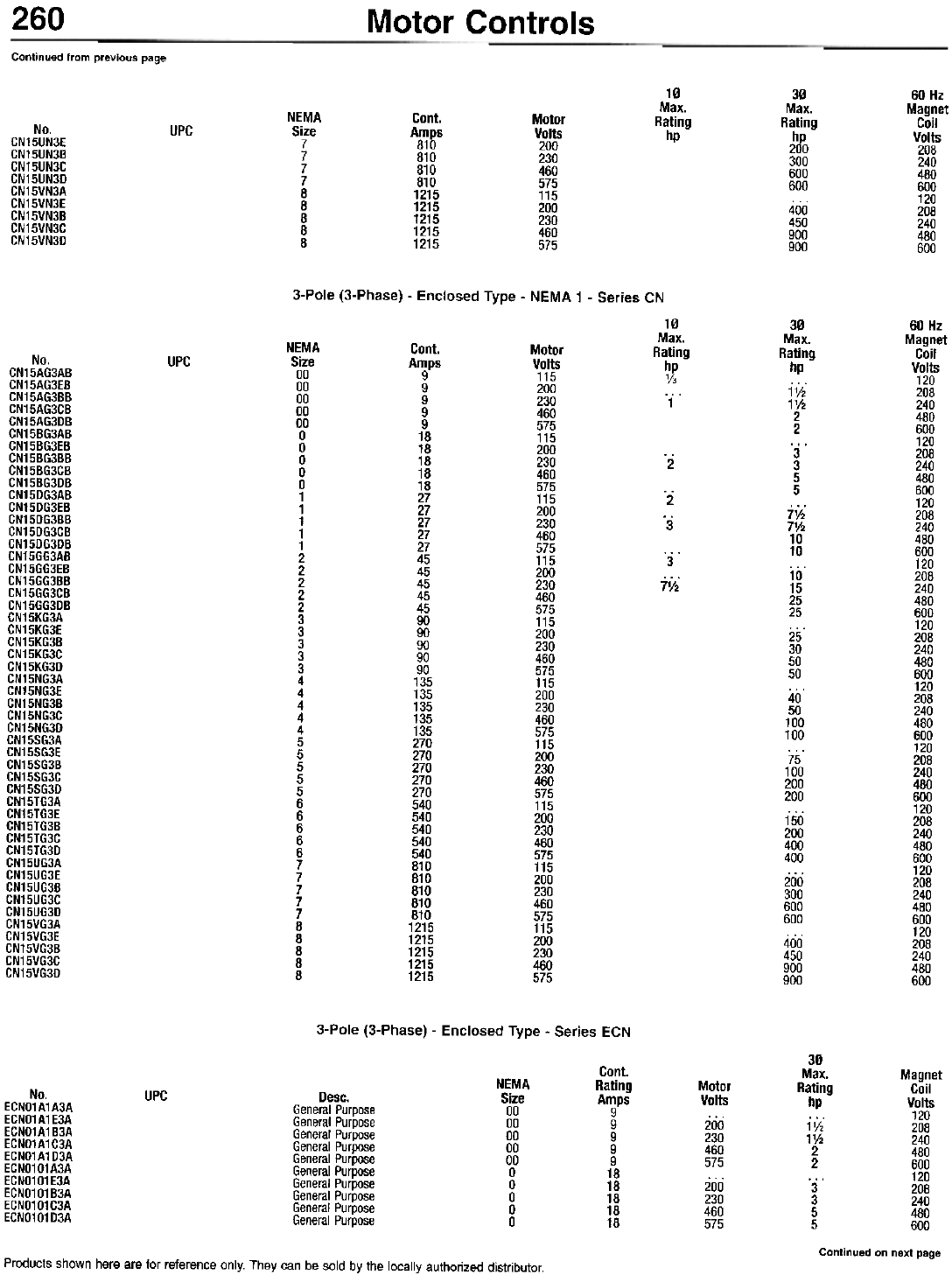
260 Motor Controls
Continued from previous page
10
Max.
Rating
hp
30
Max.
Rating
2~
300
600
600
400
450
900
900
60 Hz
Magnet
Coil
Volts
208
240
480
600
120
208
240
480
600
NEMA
Size
7
7
7
7
8
8
8
8
8
Cant.
Amps
810
810
810
810
1215
1215
1215
1215
1215
Motor
Volts
200
230
460
575
115
200
230
460
575
No.
CN15UN3E
CN15UN3B
CN15UN3C
CN15UN3D
CN15VN3A
CN15VN3E
CN15VN3B
CN15VN3C
CN15VN3D
UPC
3-Pole (3-Phase) - Enclosed Type - NEMA 1 - Series CN
10
Max.
Rating
~~
1
30
Max.
Rating
hp
1V2
1'h
2
2
3
3
5
5
j,;
7'h
10
10
10
15
25
25
25
30
50
50
40
50
100
100
75
100
200
200
150
200
400
400
200
300
600
600
400
450
900
900
60 Hz
Magnet
Coil
Volts
120
208
240
480
600
120
208
240
480
600
120
208
240
480
600
120
208
240
480
600
120
208
240
480
600
120
208
240
480
600
120
208
240
480
600
120
208
240
480
600
120
208
240
480
600
120
208
240
480
600
NEMA
Size
00
00
00
00
00
a
a
a
a
a
1
1
1
1
1
2
2
2
2
2
3
3
3
3
3
4
4
4
4
4
5
5
5
5
5
6
6
6
6
6
7
7
7
7
7
B
B
B
B
B
Cant.
Amps
9
9
9
9
9
18
18
18
18
18
27
27
27
27
27
45
45
45
45
45
90
90
90
90
90
135
135
135
135
135
270
270
270
270
270
540
540
540
540
540
810
810
810
810
810
1215
1215
1215
1215
1215
Motor
Volts
115
200
230
460
575
115
200
230
460
575
115
200
230
460
575
115
200
230
460
575
115
200
230
460
575
115
200
230
460
575
115
200
230
460
575
115
200
230
460
575
115
200
230
460
575
115
200
230
460
575
No.
GN15AG3AB
GN15AG3EB
GN15AG3BB
GN15AG3GB
GN15AG3DB
GN15BG3AB
GN15BG3EB
GN15BG3BB
GN15BG3GB
GN15BG3DB
GN15DG3AB
GN15DG3EB
GN15DG3BB
GN15DG3GB
GN15DG3DB
GN15GG3AB
GN15GG3EB
GN15GG3BB
GN15GG3GB
GN15GG3DB
GN15KG3A
GN15KG3E
GN15KG3B
GN15KG3G
GN15KG3D
GN15NG3A
GN15NG3E
GN15NG3B
GN15NG3G
GN15NG3D
GN15SG3A
GN15SG3E
GN15SG3B
GN15SG3G
GN15SG3D
GN15TG3A
GN15TG3E
GN15TG3B
GN15TG3G
GN15TG3D
GN15UG3A
GN15UG3E
GN15UG3B
GN15UG3G
GN15UG3D
GN15VG3A
GN15VG3E
GN15VG3B
GN15VG3G
GN15VG3D
UPC
'2
.2
.3
3
j~.
3-Pole (3-Phase) - Enclosed Type - Series ECN
30
Max. Magnet
Rating Coil
hp Volts
120
1V2 208
11h 240
2 480
2 600
... 120
3 208
3 240
5 480
5 600
Continued on next page
Cant.
Rating
Amps
9
9
9
9
9
18
18
18
18
18
NEMA
Size
00
00
00
00
00
0
0
0
0
0
Motor
Volts
200
230
460
575
200
230
460
575
No.
ECN01A1A3A
ECN01A1E3A
ECN01A1B3A
ECN01A1C3A
ECN01A1D3A
ECN0101A3A
ECN0101E3A
ECN01 01 B3A
ECN0101C3A
ECN0101D3A
UPC Desc.
General Purpose
General Purpose
General Purpose
General Purpose
General Purpose
General Purpose
General Purpose
General Purpose
General Purpose
General Purpose
Products shown here are for reference only. They can be sold by the locally authorized distributor.

Motor Controls 261
Continued from previous page
30
Max.
Rating
hp
7V2
71h
10
10
10
15
25
25
10
15
25
25
40
50
100
100
75
100
200
200
3
3
5
5
jih
71h
10
10
10
15
25
25
25
30
50
50
40
50
100
100
75
100
200
200
3
3
5
5
71h
71h
10
10
10
15
25
25
25
30
50
50
40
50
100
100
75
100
200
200
3
3
Cont.
Rating
A~fS
27
27
27
27
45
45
45
45
45
90
90
90
90
90
135
135
135
135
135
270
270
270
270
270
18
18
18
18
18
27
27
27
27
27
45
45
45
45
45
90
90
90
90
90
135
135
135
135
135
270
270
270
270
270
18
18
18
18
18
27
27
27
27
27
45
45
45
45
45
90
90
90
90
90
135
135
135
135
135
270
270
270
270
270
18
18
18
Magnet
Coil
Volts
120
208
240
480
600
120
208
240
480
600
120
208
240
480
600
120
208
240
480
600
120
208
240
480
600
120
240
208
480
600
120
208
240
480
600
120
208
240
480
600
120
208
240
480
600
120
208
240
480
600
120
208
240
480
600
120
208
240
480
600
120
208
240
480
600
120
208
240
480
600
120
208
240
480
600
120
208
240
480
600
120
208
240
480
600
120
208
240
NEMA
Size
1
1
1
1
1
2
2
2
2
2
3
3
3
3
3
4
4
4
4
4
5
5
5
5
5
0
0
0
0
0
1
1
1
1
1
2
2
2
2
2
3
3
3
3
3
4
4
4
4
4
5
5
5
5
5
0
0
0
0
0 '
1
1
1
1
1
2
2
2
2
2
3
3
3
3
3
4
4
4
4
4
5
5
5
5
5
0
0
0
Motor
Volts
200
230
460
575
200
230
460
575
200
230
460
575
200
230
460
575
200
230
460
575
200
230
460
575
200
230
460
575
200
230
460
575
200
230
460
575
200
230
460
575
200
230
460
575
200
230
460
575
200
230
460
575
200
230
460
575
200
230
460
575
200
230
460
575
200
230
460
575
200
230
No.
ECNO111A3A
ECNO111E3A
ECNO111B3A
ECNO111C3A
ECNO111D3A
ECNO121A3A
ECNO121E3A
ECNO121B3A
ECNO121C3A
ECNO121D3A
ECNO131A3A
ECNO131E3A
ECNO131B3A
ECNO131C3A
ECNO131D3A
ECNO141A3A
ECNO141E3A
ECNO141B3A
ECNO141C3A
ECNO141D3A
ECNO151A3A
ECNO151E3A
ECNO151B3A
ECNO151C3A
ECNO151D3A
ECNO102A3A
ECNO102E3A
ECNO102B3A
ECNO102C3A
ECNO102D3A
ECNO112A3A
ECNO112E3A
ECNO112B3A
ECNO112C3A
ECNO112D3A
ECNO122A3A
ECNO122E3A
ECNO122B3A
ECNO122C3A
ECNO122D3A
ECNO132A3A
ECNO132E3A
ECNO132B3A
ECNO132C3A
ECNO132D3A
ECNO142A3A
ECNO142E3A
ECNO142B3A
ECNO142C3A
ECNO142D3A
ECNO152A3A
ECNO152E3A
ECNO152B3A
ECNO152C3A
ECNO152D3A
ECNO104A3A
ECNO104E3A
ECNO104B3A
ECNO104C3A
ECNO104D3A
ECNO114A3A
ECNO114E3A
ECNO114B3A
ECNO114C3A
ECNO114D3A
ECNO124A3A
ECNO124E3A
ECNO124B3A
ECNO124C3A
ECNO124D3A
ECNO134A3A
ECNO134E3A
ECNO134B3A
ECNO134C3A
ECNO134D3A
ECNO144A3A
ECMO144E3A
ECNO144B3A
ECNO144C3A
ECNO144D3A
ECNO154A3A
ECNO154E3A
ECNO154B3A
ECNO154C3A
ECNO154D3A
ECNO108A3A
ECNO108E3A
ECNO108B3A
UPC Desc.
General Purpose
General Purpose
General Purpose
General Purpose
General Purpose
General Purpose
General Purpose
General Purpose
General Purpose
General Purpose
General Purpose
General Purpose
General Purpose
General Purpose
General Purpose
General Purpose
General Purpose
General Purpose
General Purpose
General Purpose
General Purpose
General Purpose
General Purpose
General Purpose
General Purpose
Rainproof
Rainproof
Rainproof
Rainproof
Rainproof
Rainproof
Rainproof
Rainproof
Rainproof
Rainproof
Rainproof
Rainproof
Rainproof
Rainproof
Rainproof
Rainproof
Rainproof
Rainproof
Rainproof
Rainproof
Rainproof
Rainproof
Rainproof
Rainproof
Rainproof
Rainproof
Rainproof
Rainproof
Rainproof
Rainproof
Watertight & Dusttlght Stainless Steel
Watertight & Dusttight Stainless Steel
Watertight & Dusttight Stainless Steel
Watertight & Dusttight Stainless Steel
Watertight & Dusttight Stainless Steel
Watertight & Dusttight Stainless Steel
Watertight & Dusttight Stainless Steel
Watertight & Dusttight Stainless Steel
Watertight & Dusttight Stainless Steel
Watertight & Dusttight Stainless Steel
Watertight & Dusttight Stainless Steel
Watertight & Dusttight Stainless Steel
Watertight & Dusttight Stainless Steel
Watertight & Dusttight Stainless Steel
Watertight & Dusttight Stainless Steel
Watertight & Dusttight Stainless Steel
Watertight & Dusttight Stainless Steel
Watertight & Dusttight Stainless Steel
Watertight & Dusttight Stainless Steel
Watertight & Dusttight Stainless Steel
Watertight & Dusttight Stainless Steel
Watertight & Dusttight Stainless Steel
Watertight & Dusttight Stainless Steel
Watertight & Dusttight Stainless Steel
Watertight & Dusttight Stainless Steel
Watertight & Dusttight Stainless Steel
Watertight & Dusttight Stainless Steel
Watertight & Dusttight Stainless Steel
Watertight & Dusttight Stainless Steel
Watertight & Dusttight Stainless Steel
Dusttight Industrial
Dusttight Industrial
Dusttight Industrial
Continued on next page
DesiQns and Specifications are for reference only and are subject to chanQe without notice.
Copyrioht @ by Howard W. Sams & Co.
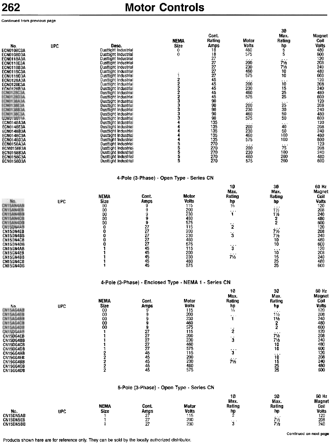
Motor Controls
262
Continued from previous page
30
Max.
Rating
h!
5
7%
7%
10
10
10
15
25
25
25
30
50
50
40
50
100
100
75
100
200
200
Cont.
Rating
A~fS
18
27
27
27
27
27
45
45
45
45
45
90
90
90
90
90
135
135
135
135
135
270
270
270
270
270
Magnet
Coil
Volts
480
600
120
208
240
480
600
120
208
240
480
600
120
208
240
480
600
120
208
240
480
600
120
208
240
480
600
NEMA
Size
a
a
Motor
Volts
460
575
200
230
460
575
200
230
460
575
200
230
460
575
200
230
460
575
200
230
460
575
UPC Desc.
Dusttight Industrial
Dusttight Industrial
Dusttight Industrial
Dusttight Industrial
Dusttight Industrial
Dusttight Industrial
Dusttight Industrial
Dusttight Industrial
Dusttight Industrial
Dusttight Industrial
Dusttight Industrial
Dusttight Industrial
Dusttight Industrial
Dusttight Industrial
Dusttight Industrial
Dusttight Industrial
Dusttight Industrial
Dusttight Industrial
Dusttight Industrial
Dusttight Industrial
Dusttight Industrial
Dusttight Industrial
Dusttight Industrial
Dusttight Industrial
Dusttight Industrial
Dusttight Industrial
Dusttight Industrial
No.
ECNO108C3A
ECNO108D3A
ECNO118A3A
ECNO118E3A
ECNO118B3A
ECNO118C3A
ECNO118D3A
ECNO128A3A
ECNO128E3A
ECNO128B3A
1
2
2
2
2
2
3
3
3
3
3
4
4
4
4
4
5
5
5
5
5
---
ECNO148A3A
ECNO148E3A
ECNO148B3A
ECNO148C3A
ECNO148D3A
ECNO158A3A
ECMO158E3A
ECNO158B3A
ECNO158C3A
ECNO158D3A
4-Pole (3-Phase) - Open Type - Series CN
10
Max.
Rating
~
1
30
Max.
Rating
hp
1V2
11/2
2
2
71/2
71/2
10
10
10
15
25
25
60 Hz
Magnet
Coil
Volts
120
208
240
480
600
120
208
240
480
600
120
208
240
480
600
NEMA
Size
00
00
00
00
00
a
a
a
a
a
1
1
1
1
1
Cont.
Amps
9
9
9
9
9
27
27
27
27
27
45
45
45
45
45
Motor
Volts
115
200
230
460
575
115
200
230
460
575
115
200
230
460
575
UPC
'2
.3
-,. CN15DN4EB
CN15DN4BB
CN15DN4CB
CN15DN4DB
CN15GN4AB
CN15GN4EB
CN15GN4BB
CN15GN4CB
CN15GN4DB
3
7';;
4-Pole (3-Phase) - Enclosed Type - NEMA 1 - Series CN
10
Max.
Rating
~~
1
30
Max.
Rating
hp
1V2
11h
2
2
j1f;
71h
10
10
10
15
25
25
60 Hz
Magnet
Coil
Volts
120
208
240
480
600
120
208
240
480
600
120
208
240
480
600
NEMA
Size
00
00
00
00
00
1
1
1
1
1
2
2
2
2
2
Cont.
Amps
9
9
9
9
9
27
27
27
27
27
45
45
45
45
45
Motor
Volts
115
200
230
460
575
115
200
230
460
575
115
200
230
460
575
UPC
Nn
2
'3
,~
CN15DG4EB
CN15DG4BB
CN15DG4CB
CN15DG4DB
CN15GG4AB
CN15GG4EB
CN15GG4BB
CN15GG4CB
CN15GG4DB
3
jl/;
5-Pole (3-Phase) - Open Type - Series CN
10
Max.
Rating
hp
2
3
30
Max.
Rating
hp
lV2
l1h
60 Hz
Magnet
Coil
Volts
120
208
240
Continued on next page
NEMA
Size
1
1
1
Cont.
Amps
27
27
27
Motor
Volts
115
200
230
UPC
No.
CN15DN5AB
CN15DN5EB
CN15DN5BB
Products shown here are for reference only. They can be sold by the locally authorized distributor.
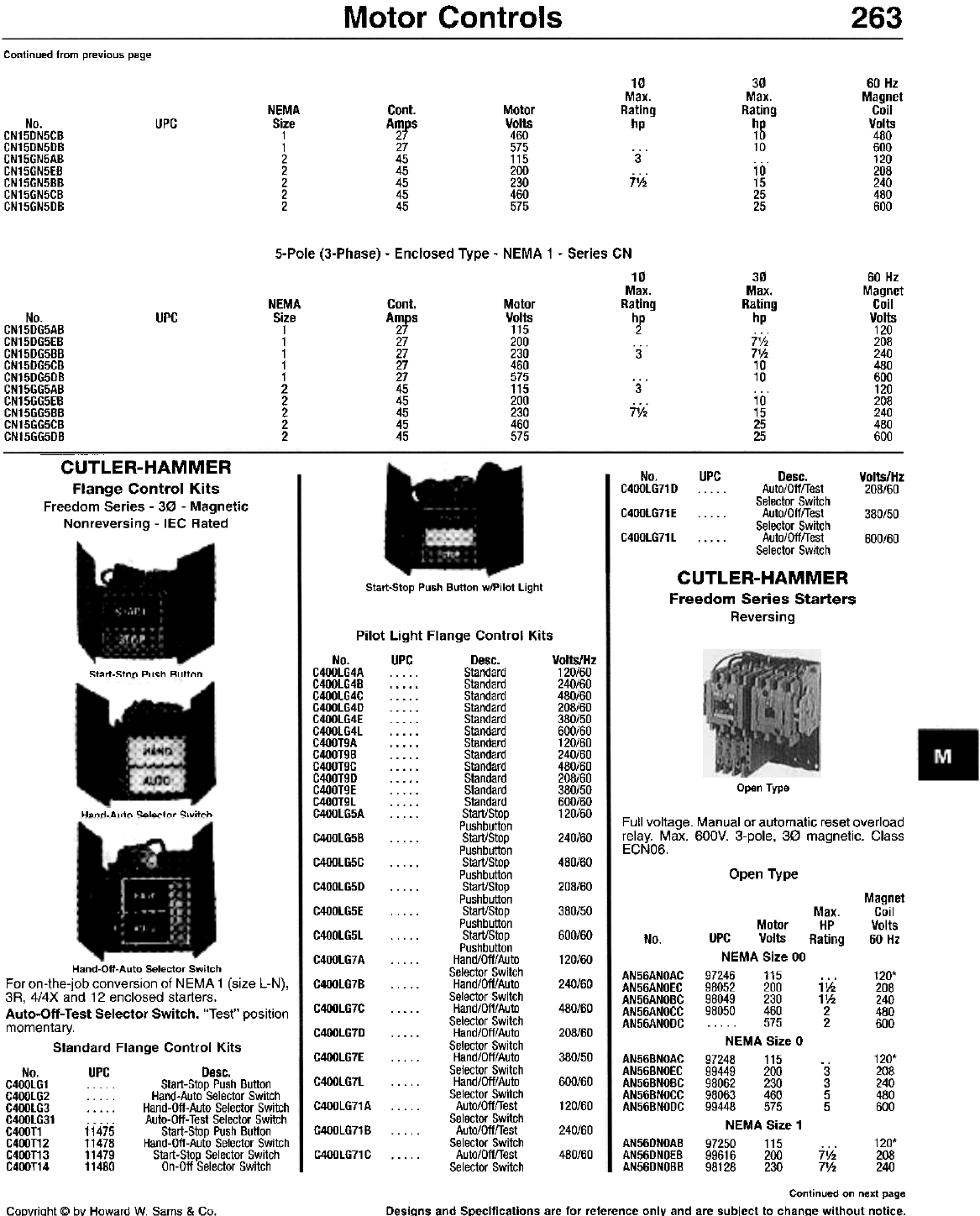
Motor Controls 263
Continued from previous page
10
Max.
Rating
hp
30
Max.
Rating
hp
10
10
10
15
25
25
60 Hz
Magnet
Coil
Volts
480
600
120
208
240
480
600
Cont.
Amps
27
27
45
45
45
45
45
NEMA
Size
1
1
2
2
2
2
2
Motor
Volts
460
575
115
200
230
460
575
No.
CN15DN5CB
CN15DN5DB
CN15GN5AB
CN15GN5EB
CN15GN5BB
CN15GN5CB
CN15GN5DB
UPC
3
71;;
5-Pole (3-Phase) - Enclosed Type - NEMA 1 - Series CN
10
Max.
Rating
hp
2
3
30
Max.
Rating
hp
lV2
l1h
10
10
10
15
25
25
60 Hz
Magnet
Coil
Volts
120
208
240
480
600
120
208
240
480
600
NEMA
Size
1
1
1
1
1
2
2
2
2
2
Cant.
Amps
27
27
27
27
27
45
45
45
45
45
Motor
Volts
115
200
230
460
575
115
200
230
460
575
UPC
No.
CN15DG5AB
CN15DG5EB
CN15DG5BB
CN15DG5CB
CN15DG5DB
CN15GG5AB
CN15GG5EB
CN15GG5BB
CN15GG5CB
CN15GG5DB
3
j1j;
CUTLER-HAMMER
Flange Control Kits
Freedom Series - 30 - Magnetic
Nonreversing - IEC Rated
No. UPC Desc.
C400lG71D . . Auto/OfffTest
Selector Switch
C400lG71 E . . . . . Auto/OfffTest
Selector Switch
C400lG71l . . . . . Auto/OfffTest
Selector Switch
CUTLER-HAMMER
Freedom Series Starters
Reversing
Volts/Hz
208/60
380/50
600/60
Start-Stop Push Button w/Pilot Light
Pilot Light Flange Control Kits
No. UPC Desc. Volts/Hz
C400lG4A Standard 120/60
C400lG4B Standard 240/60
C400lG4C . . . . . Standard 480/60
C400lG4D Standard 208/60
C400lG4E . . . . . Standard 380/50
C400lG4l . . . . . Standard 600/60
C400T9A . . . . . Standard 120/60
C400T9B . . . . . Standard 240/60
C400T9C . . . . . Standard 480/60
C400T9D Standard 208/60
C400T9E Standard 380/50
C400T9l Standard 600/60
C400lG5A . . . . . Start/Stop 120/60
Pushbutton
C400lG5B . . . . . Start/Stop 240/60
Pushbutton
C400lG5C . . . . . Start/Stop 480/60
Pushbutton
C400lG5D Start/Stop 208/60
Pushbutton
C400lG5E . . . . . Start/Stop 380/50
Pushbutton
C400lG5l . . . . . Start/Stop 600/60
Pushbutton
C400lG7A . . . . . Hand/Off/Auto 120/60
Selector Switch
C400lG7B . . . . . Hand/Off/Auto 240/60
Selector Switch
C400lG7C . . . . . Hand/Off/Auto 480/60
Selector Switch
C400lG7D . . . . . Hand/Off/Auto 208/60
Selector Switch
C400lG7E . . . . . Hand/Off/Auto 380/50
Selector Switch
C400lG7l . . . . . Hand/Off/Auto 600/60
Selector Switch
C400lG71 A . . . . . Auto/Off/Test 120/60
Selector Switch
C400lG71 B . . . . . Auto/Off/Test 240/60
Selector Switch
C400lG71C . Auto/Off/Test 480/60
Selector Switch
51arl-5100 Push Bullon
Open Type
Hand.Auto S..I..ctor Switch Full voltage. Manual or automatic reset overload
relay. Max. 600V. 3-pole, 30 magnetic. Class
ECNO6.
Open Type
Magnet
Coil
Volts
60 Hz
Max.
HP
Rating
Motor
UPC Volts
NEMA Size 00
97246 115
98052 200
98049 230
98050 460
. . . . . 575
NEMA Size 0
97248 115
99449 200
98062 230
98063 460
99448 575
NEMA Size 1
97250 115
99616 200
98128 230
No.
AN56ANOAC
AN56ANOEC
AN56ANOBC
AN56ANOCC
AN56ANODC
120'
208
240
480
600
11h
11h
2
2
Hand-Oft-Auto Selector Switch
For on-the-job conversion of NEMA 1 (size L-N),
3A, 4/4X and 12 enclosed starters.
Auto-Off- Test Selector Switch. "Test" position
momentary.
Standard Flange Control Kits
No. UPC Desc.
G400lG1 . . . . . Start-Stop Push Button
G400lG2 . . . . . Hand-Auto Selector Switch
G400lG3 . . . . . Hand-Oft-Auto Selector Switch
G400lG31 . . . . . Auto-Oft- Test Selector Switch
G400T1 11475 Start-Stop Push Button
G4OOT12 11478 Hand-Oft-Auto Selector Switch
G400T13 11479 Start-Stop Selector Switch
G400T14 11480 On-Oft Selector Switch
AN56BNOAC
AN56BNOEC
AN56BNOBC
AN56BNOCC
AN56BNODC
120'
208
240
480
600
.3
3
5
5
AN56DNDAB
AN56DNOEB
AN56DNOBB
120'
208
240
7';;
71h
Continued on next page
Designs and Specifications are for reference only and are subject to change without notice.
CoDyriaht @ bY Howard W. Sams & Co.
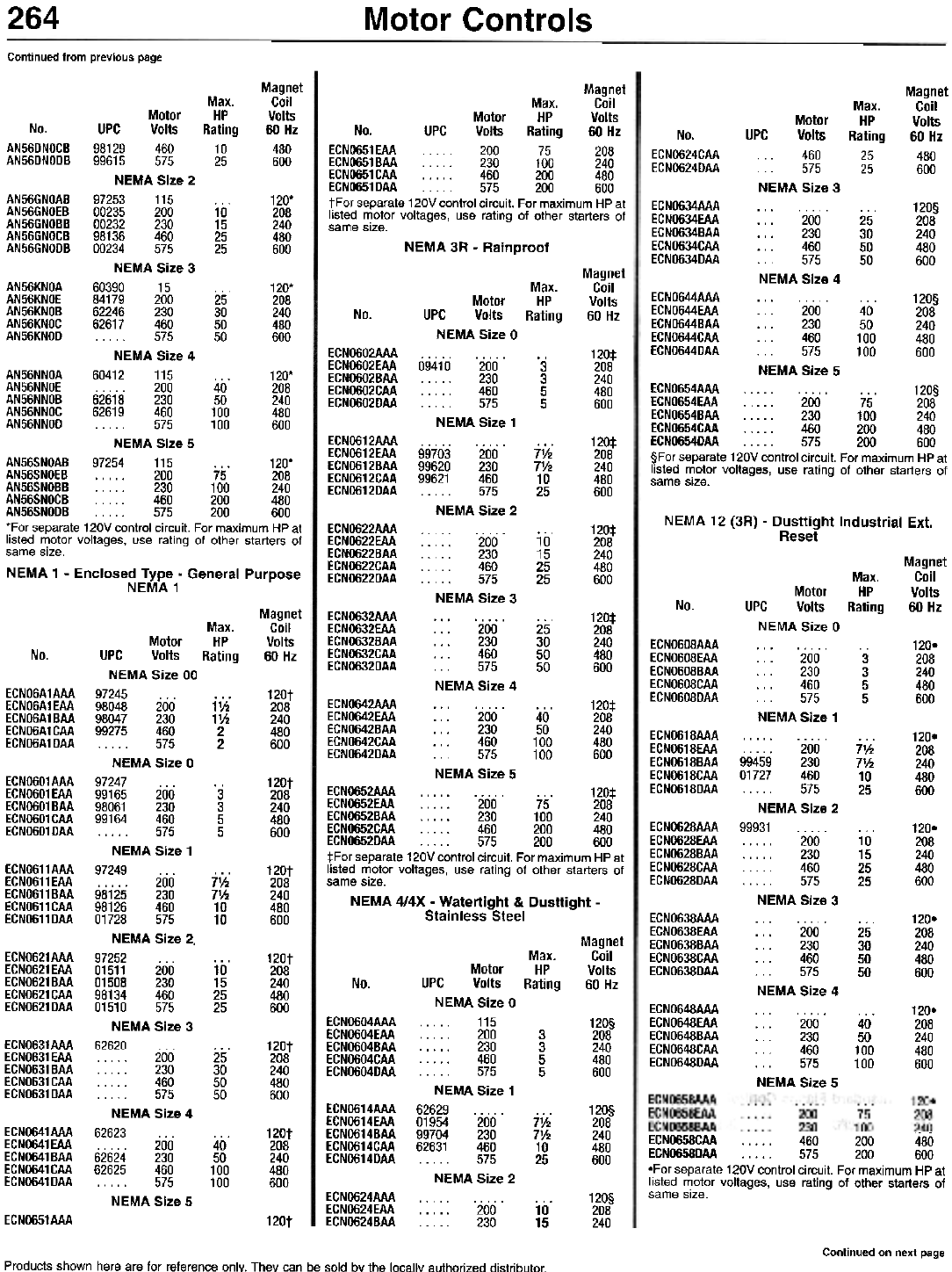
264 Motor Controls
Continued from previous page
Magnet
Max. Coil
Motor HP Volts
No. UPC Volts Rating 60 Hz
AN56DNOGB 98129 460 10 480
AN56DNODB 99615 575 25 600
NEMA Size 2
AN56GNOAB 97253 115 ... 120'
AN56GNOEB 00235 200 10 208
AN56GNOBB 00232 230 15 240
AN56GNOGB 98136 460 25 480
AN56GNODB 00234 575 25 600
NEMA Size 3
AN56KNOA 60390 15 ... 120'
AN56KNOE 84179 200 25 208
AN56KNOB 62246 230 30 240
AN56KNOG 62617 460 50 480
AN56KNOD 575 50 600
NEMA Size 4
AN56NNOA 60412 115 ... 120'
AN56NNOE 200 40 208
AN56NNOB 62618 230 50 240
AN56NNOG 62619 460 100 480
AN56NNOD 575 100 600
NEMA Size 5
AN56SNOAB 97254 115 ... 120'
AN56SNOEB 200 75 208
AN56SNOBB 230 100 240
AN56SNOGB 460 200 480
AN56SNODB 575 200 600
'For separate 120V control circuit. For maximum HP at
listed motor voltages, use rating of other starters of
same size.
NEMA 1 - Enclosed Type - General Purpose
NEMA1
Magnet
Coil
Volts
60 Hz
480
600
Max.
HP
Rating
25
25
Motor
UPC Volts
460
575
NEMA Size 3
No.
ECNO624CAA
ECNO624DAA
ECN0634AAA
ECN0634EAA
ECN0634BAA
ECN0634CAA
ECN0634DAA
120§
208
240
480
600
... . . . 200
. . . 230
... 460
575
NEMA Size 4
25
30
50
50
Magnet
Max. Coil
Motor HP Volts
No. UPC Volts Rating 60 Hz
ECN0651EAA 200 75 208
ECN0651 BAA 230 100 240
ECN0651CAA 460 200 480
ECN0651DAA 575 200 600
tFor separate 120V control circuit. For maximum HP at
listed motor voltages, use rating of other starters of
same size.
NEMA 3R - Rainproof
Magnet
Coil
Volts
60 Hz
Max.
HP
Rating
ECNO644AAA
ECNO644EAA
ECN0644BAA
ECNO644CAA
ECNO644DAA
120§
208
240
480
600
UPC
NEM
09410
NEM
99703
99620
99621
NEM
NEM
... . . . 200
. . . 230
. . . 460
575
NEMA Size 5
40
50
100
100
No.
ECNOGO2AAA
ECN0602EAA
ECN0602BAA
ECN0602CAA
ECN0602DAA
120:1:
208
240
480
600
'3
3
5
5
ECN0654AAA '" 120§
ECN0654EAA 200 75 208
ECN0654BAA 230 100 240
ECN0654CAA 460 200 480
ECN0654DAA 575 200 600
§For separate 120V control circuit. For maximum HP at
listed motor voltages, use rating of other starters of
same size.
ECN0612AAA
ECN0612EAA
ECN0612BAA
ECN0612CAA
ECN0612DAA
120:1:
208
240
480
600
7';;
7V2
10
25
NEMA 12 (3R) - Dusttight Industrial Ext.
Reset
ECN0622AAA
ECN0622EAA
ECN0622BAA
ECN0622CAA
ECN0622DAA
120:1:
208
240
480
600
10
15
25
25 Magnet
Coil
Volts
60 Hz
Max.
HP
Rating
Motor
UPC Volts
NEMA Size 0
No.
Magnet
Coil
Volts
60 Hz
ECN0632AAA
ECN0632EAA
ECN0632BAA
ECN0632CAA
ECN0632DAA
120:1:
208
240
480
600
Max.
HP
Rating
...
NEMA
25
30
50
50
ECNO608AAA
ECNO608EAA
ECNO608BAA
ECNO608CAA
ECNO608DAA
120-
208
240
480
600
No. ...
NEMA
3
3
5
5
ECNO6A1AAA
ECNO6A1EAA
ECNOOA1BAA
ECNOOA1CAA
ECNOOA1DAA
120t
208
240
480
600
ECN0642AAA
ECN0642EAA
ECN0642BAA
ECN0642CAA
ECN0642DAA
120:1:
208
240
480
600
i~
11h
2
2
... .. ...
... 200
... 230
... 460
575
NEMA Size 5
40
50
100
100
ECNO618AAA
ECNO618EAA
ECNO618BAA
ECNO618CAA
ECNO6180AA
120-
208
240
480
600
.. ... "'"
. . . . . 200
99459 230
01727 460
. . . . . 575
NEMA Size 2
99931 . . . . .
. . . . . 200
. . . . . 230
. . . . . 460
. . . . . 575
NEMA Size 3
7V2
7V2
10
25
ECNO601AAA
ECNO601EAA
ECNOOO1BAA
ECNOOO1CAA
ECNO601DAA
120t
208
240
480
600
. 3
3
5
5EGNO628AAA
EGNO628EAA
EGNO628BAA
EGNO628GAA
EGNO628DAA
120.
208
240
480
600
...
10
15
25
25
ECNO611AAA
ECNO611EAA
ECNO611 BAA
ECNO611CAA
ECN0611DAA
120t
208
240
480
600
j~'
71h
10
10
ECN0652AAA ... 120:1:
ECN0652EAA 200 75 208
ECN0652BAA 230 100 240
ECN0652CAA 460 200 480
ECN0652DAA 575 200 600
:l:For separate 120V control circuit. For maximum HP at
listed motor voltages, use rating of other starters of
same size.
NEMA 4/4X - Watertight & Dus"ight -
Stainless Steel ECN0638AAA
ECN0638EAA
ECNO638BAA
ECNO638CAA
ECNO638DAA
120-
208
240
480
600
... . . . 200
. . . 230
. . . 460
575
NEMA Size 4
... 200
... 230
460
. . . 575
NEMA Size 5
...
25
30
50
50
Magnet
Coil
Volts
60 Hz
ECNO621AAA
ECNO621EAA
ECN0621BAA
ECNO621CAA
ECNO621DAA
Max.
HP
Rating
120t
208
240
480
600
Motor
UPC Volts
NEMA Size 00
97245 , , ,
98048 200
98047 230
99275 460
. . . , , 575
NEMA Size 0
97247 '"
99165 200
98061 230
99164 460
. , , , , 575
NEMA Size 1
97249 , , ,
, , . . . 200
98125 230
98126 460
01728 575
NEMA Size 2,
97252
01511 200
01508 230
98134 460
01510 575
NEMA Size 3
62620
UPC
NEM
NEM
62629
01954
99704
62631
NEM
10
15
25
25
No.
ECNO648AAA
ECNO648EAA
ECNO648BAA
ECNO648CAA
ECN0648DAA
120.
208
240
480
600
EGNOGO4AAA
EGNOGO4EAA
EGNOGO4BAA
EGN0604GAA
EGNOGO4DAA
120§
208
240
480
600
40
50
100
100
3
3
5
5
ECNO631AAA
ECNO631EAA
ECN0631 BAA
ECNO631CAA
ECN0631DAA
120t
208
240
480
600
. . . . . 200
. . . . . 230
. . . . . 460
. . . . . 575
NEMA Size 4
62623 ...
. . . . . 200
62624 230
62625 460
. . . . . 575
NEMA Size 5
25"
30
50
50
ECN0614AAA
ECN0614EAA
ECN0614BAA
ECN0614CAA
ECN0614DAA
120§
208
240
480
600
j~
71h
10
25
ECN0641AAA
ECN0641EAA
ECNO641 BAA
ECNO641CAA
ECNO641DAA
120t
208
240
480
600
40
50
100
100
ECN0624AAA
ECN0624EAA
ECN0624BAA
120§
208
240
10
15
ECNO651AAA 120t
Continued on next page
Products shown here are for reference only. They can be sold by the locallY authorized distributor
Motor
Volts
A Size 0
200
230
460
575
A Size 1
200
230
460
575
A Size 2
200
230
460
575
A Size 3
200
230
460
575
Size 4
.
200
230
460
575
Size 1
Motor
Volts
A Size 0
115
200
230
460
575
A Size 1
200
230
460
575
A Size 2
200
230
- -
ECN0658CAA 460 200 480
ECN0658DAA 575 200 600
-For separate 120V control circuit. For maximum HP at
listed motor voltages, use rating of other starters of
same size.
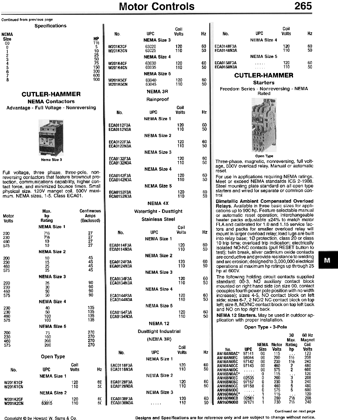
Motor Controls 265
Continued from previous page
Specifications Coil
Volts
Coil
Volts Hz No. Hz
No.
NEMA
Size
00
0
1
2
3
4
5
6
7
8
HP
11/2
5
10
25
50
75
150
300
600
900
UPC
NEMA Size 4
ECAO148F3A
ECAO148N3A 120
110 60
50
W201K3CF
W201K3CN 120
110 60
50
NEMA Size 5
60
50
W201K4CF
W201K4CN 120
110 60
50
UPC
NEMA Size 3
63020
63025
NEMA Size 4
63030
63035
NEMA Size 5
63040
63045
NEMA 3R
Rainproof
W201K5CF
W201K5CN 120
110 60
50
ECA0158F3A 120
ECA0158N3A ... 110
CUTLER-HAMMER
Starters
Freedom Series - Nonreversing - NEMA
Rated
CUTLER-HAMMER
NEMA Contactors
Advantage - Full Voltage - Nonreversing Coil
Volts Hz
No. UPC
NEMA Size 1
ECAO112F3A
ECAO112N3A 120
110 60
50
NEMA Size 2
ECAO122F3A
ECAO122N3A 120
110 60
50
NEMA Size 3
120
110 60
50
ECAO132F3A
ECAO132N3A
Nema Size 3
NEMA Size 4
Full voltage, three phase, three-pole, non-
reversing contactors that feature brownout pro-
tection, communications capability, higher con-
tact force, and minimized bounce times. Small
physical size. 120V manget coil. 600V maxi-
mum. NEMA sizes, 1-5. Class ECAO1.
60
50
ECAO142F3A
ECAO142N3A 120
110
NEMA Size 5
60
50
ECAO152F3A
ECAO152N3A 120
110
NEMA 4X
Watertight - Dusttight
Stainless Steel
Continuous
Amps
(Enclosed)
Motor
Volts
Coil
Volts Hz
No.
27
27
27
27
200
230
460
575
UPC
NEMA Size 1
60
50
ECAO114F3A
ECAO114N3A 120
110
NEMA Size 2
45
45
45
45
200
230
460
575
ECAO124F3A
ECAO124N3A 120
110 60
50
NEMA Size 3
ECAO134F3A
ECAO134N3A 120
110 60
50
200
230
460
575
90
90
90
90
NEMA Size 4
120
110 60
50
ECAO144F3A
ECAO144N3A
NEMA Size 5
135
135
135
135
200
230
460
575
120
110 60
50
ECAO154F3A
ECAO154N3A
Open Type
Three-phase, magnetic, non reversing, full volt-
age, 600V overload relay. Manual or automatic
reset.
For use in applications requiring NEMA ratings.
Meet or exceed NEMA standards ICS 2-1988.
Steel mounting plate standard on all open type
starters and wired for separate or common con-
trol.
Bimetallic Ambient Compensated Overload
Relays. Available in three basic sizes for appli-
cations up to 900 hp. Feature selectable manual
or automatic reset operation; interchangeable
heater packs adjustable :t24% to match motor
FLA and calibrated for 1.0 and 1.15 service fac-
tors and packs for smaller overload relay will
mount in larger overload relay; load lugs are built
into relay base; 10 protection, class 20 or class
10 trip time; overload trip indication; electrically
isolated NO-NC contacts (pull RESET button to
test); twin break, silver cadmium oxide contacts
are conductive and provide resistance to welding
and arc erosion; designed to 3,000,000 electrical
operations at maximum hp ratings up through 25
hp at 600V.
The following holding circuit contacts supplied
standard: 00-3, NO auxiliary contact block
mounted on right hand side (on size 00, contact
occupies fourth power pole position with no width
increase); sizes 4-5, NO contact block on left
side; sizes 6-7,2 NO/2 NC contact block on top
left; size 8, NO/NC contact block on top left back
and NO on top right back.
NEMA 12 Starters. May be used in outdoor ap-
plication with proper installation.
Open Type - 3-Pole
Max.
hp
Rating
NEMA Size 1
7V2
7'h
10
10
NEMA Size 2
10
15
25
25
NEMA Size 3
25
30
50
50
NEMA Size 4
40
50
100
100
NEMA Size 5
75
100
200
200
NEMA12
Dusttight Industrial
(NEMA 3R)
270
270
270
270
200
230
460
575
30 60 Hz
Max. Magnet
NEMA Motor Rating Coil
No. UPC Size Volts hp Volts
AN16ANOAC* 97141 00 115 ... 120
AN16ANOEC 98044 00 200 1V, 208
AN16ANOBC 97142 00 230 1'h 240
AN16ANOCC 97143 00 460 2 480
AN16ANODC 00 575 2 600
AN16BNOAC* 0 115 ... 120
AN16BNOEC 02535 0 200 3 208
AN16BNOBC 97157 0 230 3 240
AN16BNOCC 97158 0 460 5 480
AN16BNODC 0 575 5 600
AN16DNOAC* 1 115 ... 120
AN16DNOEB 02561 1 200 7'h 208
. ..- -- . AN16DNOBB 97171 1 230 7V, 240
Continued on next page
Designs and Specifications are for reference only and are subject to change without notice.
Coil
Volts Hz
No.
Open Type UPC
NEMA Size 1
Coil
Volts 60
50
EACO118F3A
ECAO118N3A 120
110
Hz
No.
NEMA Size 2
UPC
NEMA Size 1
60
50
60
50 ECAO128F3A
ECAO128N3A 120
110
W201K1CF
W201K1CN 120
110
NEMA Size 3
NEMA Size 2
60
50 ECAO138F3A
ECAO138N3A 120
11n 60
!in
W201 K2CF
W201K2CN
120
110
63015
Coovriaht @ bv Howard W. Sams & Co.
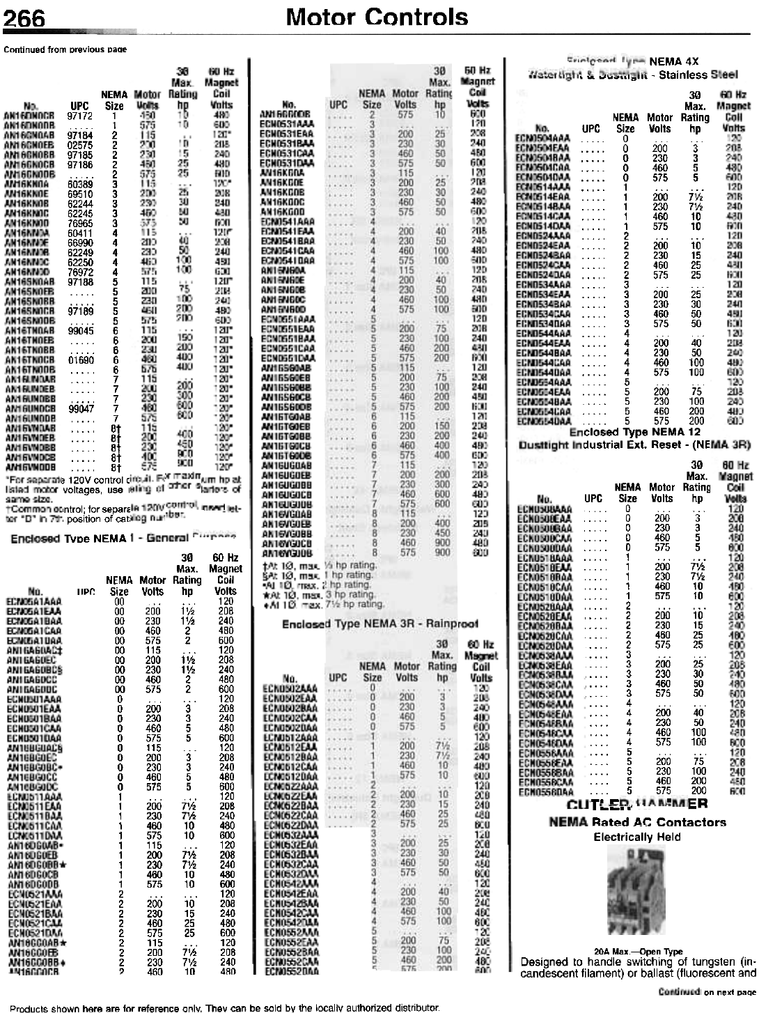
266
Products shown here are for reference only. They can be sold by the locally authorized distributor.
LIP!:
3060Hz
Max. Magnet
NEMA Motor Rating Coil
Size Volts hp Volts
00 ... 120
00 200 1 V2 208
00 230 11h 240
00 460 2 480
00 575 2 600
00 115 ... 120
00 200 11h 208
00 230 11h 240
00 460 2 480
00 575 2 600
0 . . . . . . 120
0 200 3 208
0 230 3 240
0 460 5 480
0 575 5 600
0 115 ... 120
0 200 3 208
0 230 3 240
0 460 5 480
0 575 5 600
1 . . . . . . 120
1 200 7V2 208
1 230 71h 240
1 460 10 480
1 575 10 600
1 115 ... 120
1 200 71h 208
1 230 7V2 240
1 460 10 480
1 575 10 600
2 . . . . . . 120
2 200 10 208
2 230 15 240
2 460 25 480
2 575 25 600
2 115 . . . 120
2 200 71h 208
2 230 7V2 240
? 460 10 480
Continued from previous page
Motor Controls
20A Max.-Qpen Type
Designed to handle switching of tungsten (in-
candescent filament) or ballast (fluorescent and
I on next page
T" ~
~~...'
Rated AC Contactors---
Electrically Held
, NEMA 4X
, \A '""',""",11( - Stainless
30
Max.
NEMA Motor Rating
UPC Size Volts hp
. . .. 0 .
0 200 3
0 230 3
0 460 5
. 0 575 5
. . . . . 1 . . . . . .
1 200 7V.
.. ... 1 230 7%
1 460 10
1 575 10
2 ...
2 200 10
2 230 15
2 460 25
2 575 25
3 ... ...
3 200 25
3 230 30
3 460 50
3 575 50
4 ...
4 200 40
4 230 50
4 460 100
4 575 100
5 ...
5 200 75
5 230 100
5 460 200
5 575 200
Iclosed Type NEMA 12
dustrial Ext. Reset - {NE
30
Max.
NEMA Motor RatinQ
UPC Size Volts hp
... . . 0 .
. . . . . 0 200 3
0 230 3
0 460 5
. . . . . 0 575 5
. . . . . 1 . . . . . .
1 200 7%
1 230 7%
. . . . . 1 460 10
. . . . . 1 575 10
2 ... ...
2 200 10
2 230 15
2 460 25
2 575 25
3 ... ...
3 200 25
3 230 30
3 460 50
3 575 50
4 ... ...
4 200 40
, 4 230 50
, 4 460 100
, 4 575 100
5 ... .. .
5 200 75
5 230 100
5 460 200
. . . . 5 575 200
. ER
NEMA
UPC Size
97172 1
. . . . . 1
97184 2
02575 2
97185 2
97186 2
. 2
60389 3
69510 3
62244 3
62245 3
76965 3
60411 4
66990 4
62249 4
62250 4
76972 4
97188 5
5
5
97189 5
5
99045 6
6
6
01690 6
6
7
7
7
99047 7
7
. . . . . 8t
. . . . . 8t
. . . . . 8t
. . . . . 8t
. . . . . 8t
~ 120V control c
voltages, use r
)ntrol; for separa
I position of cat,
Type NEMA
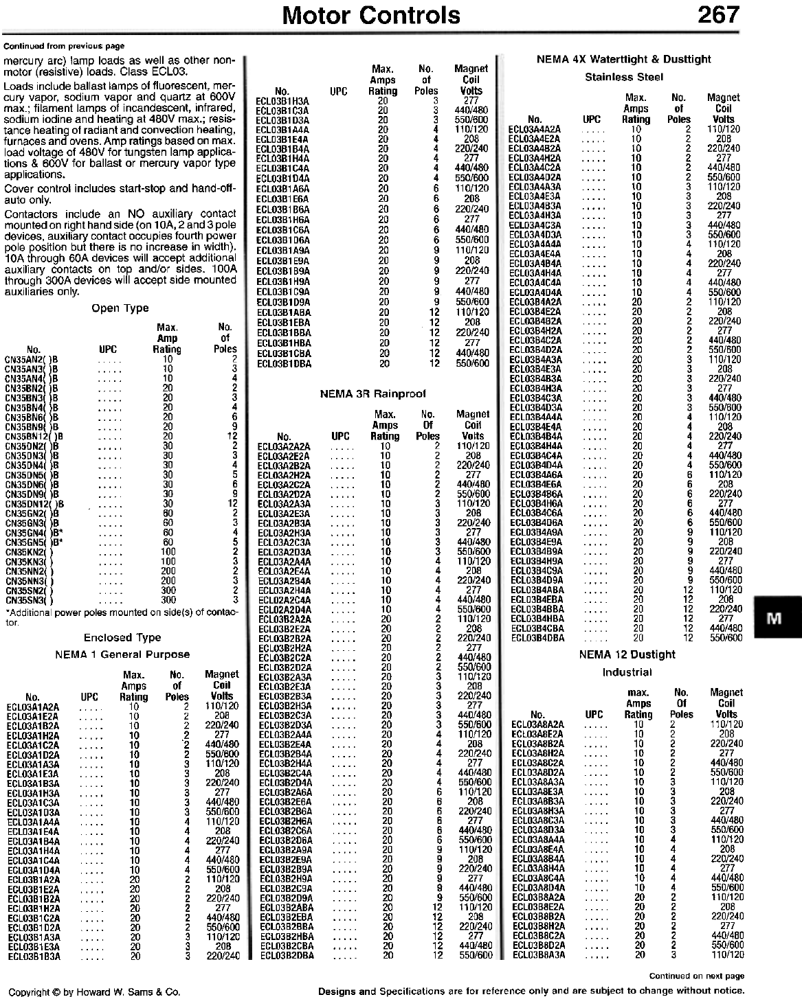
267
Motor Controls
NEMA 4X Waterttight & Dusttight
Stainless Steel
Max. No. Magnet
Amps of Coil
No. UPC Rating Poles Volts
ECL03A4A2A . . . 10 2 110/120
ECL03A4E2A 10 2 208
ECL03A4B2A 10 2 220/240
ECL03A4H2A 10 2 277
ECL03A4C2A 10 2 440/480
ECL03A4D2A 10 2 550/600
ECL03A4A3A 10 3 110/120
ECL03A4E3A 10 3 208
ECL03A4B3A 10 3 220/240
ECL03A4H3A . 10 3 277
ECL03A4C3A 10 3 440/480
ECL03A4D3A 10 3 550/600
ECL03A4A4A 10 4 110/120
ECL03A4E4A 10 4 208
ECL03A4B4A 10 4 220/240
ECL03A4H4A 10 4 277
ECL03A4C4A 10 4 440/480
ECL03A4D4A 10 4 550/600
ECL03B4A2A 20 2 110/120
ECL03B4E2A 20 2 208
ECL03B4B2A 20 2 220/240
ECL03B4H2A 20 2 277
ECL03B4C2A 20 2 440/480
ECL03B4D2A 20 2 550/600
ECL03B4A3A 20 3 110/120
ECL03B4E3A 20 3 208
ECL03B4B3A 20 3 220/240
ECL03B4H3A 20 3 277
ECL03B4C3A 20 3 440/480
ECL03B4D3A 20 3 550/600
ECL03B4A4A 20 4 110/120
ECL03B4E4A 20 4 208
ECL03B4B4A 20 4 220/240
ECL03B4H4A 20 4 277
ECL03B4C4A 20 4 440/480
ECL03B4D4A 20 4 550/600
ECL03B4A6A 20 6 110/120
ECL03B4E6A 20 6 208
ECL03B4B6A 20 6 220/240
ECL03B4H6A 20 6 277
ECL03B4C6A 20 6 440/480
ECL03B4D6A 20 6 550/600
ECL03B4A9A 20 9 110/120
ECL03B4E9A 20 9 208
ECL03B4B9A 20 9 220/240
ECL03B4H9A 20 9 277
ECL03B4C9A 20 9 440/480
ECL03B4D9A 20 9 550/600
ECL03B4ABA 20 12 110/120
ECL03B4EBA 20 12 208
ECL03B4BBA 20 12 220/240
ECL03B4HBA 20 12 277
ECL03B4CBA... 20 12 440/480
ECL03B4DBA. 20 12 550/600
NEMA 12 Dustight
Industrial
max. No. Magnet
Amps Of Coil
No. UPC Rating Poles Volts
ECL03A8A2A . . . . . 10 2 110/120
ECL03A8E2A 10 2 208
ECL03A8B2A 10 2 220/240
ECL03A8H2A 10 2 277
ECL03A8C2A 10 2 440/480
ECL03A8D2A 10 2 550/600
ECL03A8A3A 10 3 110/120
ECL03A8E3A 10 3 208
ECL03A8B3A 10 3 220/240
ECL03A8H3A 10 3 277
ECL03A8C3A 10 3 440/480
ECL03A8D3A 10 3 550/600
ECL03A8A4A .. .. 10 4 110/120
ECL03A8E4A 10 4 208
ECL03A8B4A 10 4 220/240
ECL03A8H4A 10 4 277
ECL03A8C4A 10 4 440/480
ECL03A8D4A 10 4 550/600
ECL03B8A2A 20 2 110/120
ECL03B8E2A 20 2 208
ECL03B8B2A 20 2 220/240
ECL03B8H2A 20 2 277
ECL03BBC2A 20 2 440/480
ECL03B8D2A 20 2 550/600
ECL03B8A3A . 20 3 110/120
Max.
Amps
Rating
20
20
20
20
20
20
20
20
20
20
20
20
20
20
20
20
20
20
20
20
20
20
20
20
20
20
20
No.
of
Poles
3
3
3
4
4
4
4
4
4
6
6
6
6
6
6
9
9
9
9
9
9
12
12
12
12
12
12
Magnet
Coil
Volts
277
440/480
550/600
110/120
208
220/240
277
440/480
550/600
110/120
208
220/240
277
440/480
550/600
110/120
208
220/240
277
440/480
550/600
110/120
208
220/240
277
440/480
550/600
UPC
No.
ECLO3B1H3A
ECLO3B1C3A
ECLO3B1D3A
ECLO3B1A4A
ECLO3B1E4A
ECLO3B1B4A
ECLO3B1H4A
ECLO3B1C4A
ECLO3B1D4A
ECLO3B1A6A
ECLO3B1E6A
ECLO3B1B6A
ECLO3B1H6A
ECLO3B1C6A
ECLO3B1D6A
ECLO3B1A9A
ECLO3B1E9A
ECLO3B1B9A
ECLO3B1H9A
ECLO3B1C9A
ECLO3B1D9A
ECLO3B1ABA
ECLO3B1EBA
ECLO3B1BBA
ECLO3B1HBA
ECLO3B1CBA
ECLO3B1DBA
Continued from previous page
mercury arc) lamp loads as well as other non-
motor (resistive) loads. Class ECLO3.
Loads include ballast lamps of fluorescent, mer-
cury vapor, sodium vapor and quartz at 600V
max.; filament lamps of incandescent, infrared,
sodium iodine and heating at 480V max.; resis-
tance heating of radiant and convection heating,
furnaces and ovens. Amp ratings based on max.
load voltage of 480V for tungsten lamp applica-
tions & 600V for ballast or mercury vapor type
applications.
Cover control includes start-stop and hand-off-
auto only.
Contactors include an NO auxiliary contact
mounted on right hand side (on 1 OA, 2 and 3 pole
devices, auxiliary contact occupies fourth power
pole position but there is no increase in width).
10A through 60A devices will accept additional
auxiliary contacts on top and/or sides. 100A
through 300A devices will accept side mounted
auxiliaries only.
Open Type
Max. No.
Amp of
No. UPC Rating Poles
CN35AN2( )8 . . . . . 10 2
CN35AN3( )8 . . . . . 10 3
CN35AN4()8 . . . . . 10 4
CN358N2()8 . 20 2
CN358N3()8 . . ... 20 3
CN358N4( )8 . . ... 20 4
CN358N6( )8 . . . . . 20 6
CN358N9()8 .. . . . 20 9
CN358N12()8 ... . . 20 12
CN35DN2()8 ... . . 30 2
CN35DN3( )8 . . . . . 30 3
CN35DN4()8 ... . . 30 4
CN35DN5( )8 . . . . . 30 5
CN35DN6( )8 . . . . . 30 6
CN35DN9( )8 . . . . . 30 9
CN35DN12( )8 . . . . . 30 12
CN35GN2( )8 . . . . . 60 2
CN35GN3( )8 . . . . . 60 3
CN35GN4( )8* . . . . . 60 4
CN35GN5( )8* . . . . . 60 5
CN35KN2( ) . . . . . 100 2
CN35KN3( ) . . . . . 100 3
CN35NN2( ) . . . . . 200 2
CN35NN3( ) . . . . . 200 3
CN35SN2( ) . . . . . 300 2
CN35SN3( ) . . . . . 300 3
'Additional power poles mounted on side(s) of contac-
tor.
NEMA 31
UPC
Magnet
Coil
Volts
110/120
208
220/240
277
440/480
550/600
110/120
208
220/240
277
440/480
550/600
110/120
208
220/240
277
440/480
550/600
110/120
208
220/240
277
440/480
550/600
110/120
208
220/240
277
440/480
550/600
110/120
208
220/240
277
440/480
550/600
110/120
208
220/240
277
440/480
550/600
110/120
208
220/240
277
440/480
550/600
110/120
208
220/240
277
440/480
550/600
No.
ECLO3A2A2A
ECLO3A2E2A
ECLO3A282A
ECLO3A2H2A
ECLO3A2C2A
ECLO3A2D2A
ECLO3A2A3A
ECLO3A2E3A
ECLO3A283A
ECLO3A2H3A
ECLO3A2C3A
ECLO3A2D3A
ECLO3A2A4A
ECLO3A2E4A
ECLO3A284A
ECLO3A2H4A
ECLO2A2C4A
ECLO2A2D4A
ECLO382A2A
ECLO382E2A
ECLO38282A
ECLO382H2A
ECLO382C2A
ECLO382D2A
ECLO3B2A3A
ECLO3B2E3A
ECLO3B2B3A
ECLO3B2H3A
ECLO3B2C3A
ECLO382D3A
ECLO3B2A4A
ECLO3B2E4A
ECLO3B2B4A
ECLO3B2H4A
ECLO3B2C4A
ECLO382D4A
ECLO3B2A6A
ECLO3B2E6A
ECLO3B2B6A
ECLO3B2H6A
ECLO3B2C6A
ECLO3B2D6A
ECLO3B2A9A
ECLO3B2E9A
ECLO3B2B9A
ECLO3B2H9A
ECLO3B2C9A
ECLO3B2D9A
ECLO382ABA
ECLO3B2E8A
ECLO3B28BA
ECLO3B2HBA
ECLO3B2CBA
ECLO382DBA
Enclosed Type
NEMA 1 General Purpose
Max. No.
Amps of
No. UPC Rating Poles
ECL03A1A2A 10 2
ECL03A1E2A 10 2
ECL03A1B2A 10 2
ECL03A1H2A 10 2
ECL03A1C2A 10 '2
ECL03A1D2A 10 2
ECL03A1A3A . . . . . 10 3
ECL03A1E3A 10 3
ECL03A1B3A 10 3
ECL03A1H3A 10 3
ECL03A1C3A 10 3
ECL03A1D3A 10 3
ECL03A1A4A . . . . . 10 4
ECL03A1E4A 10 4
ECL03A1B4A 10 4
ECL03A1H4A 10 4
ECL03A1C4A 10 4
ECL03A1D4A 10 4
ECL03B1A2A 20 2
ECL03B1E2A 20 2
ECL03B1 B2A . . . . . 20 2
ECL03B1H2A 20 2
ECL03B1C2A 20 2
ECL03B1D2A 20 2
ECL03B1A3A 20 3
ECL03B1E3A 20 3
ECL03B1B3A 20 3
Magnet
Coil
Volts
110/120
208
220/240
277
440/480
550/600
110/120
208
220/240
277
440/480
550/600
110/120
208
220/240
277
440/480
550/600
110/120
208
220/240
277
440/480
550/600
110/120
208
220/240
Continued on next page
Designs and Specifications are for reference only and are subject to change without notice.
Copyright @ by Howard W. Sams & Co.
R Rainprl
Max.
Amps
Rating
10
10
10
10
10
10
10
10
10
10
10
10
10
10
10
10
10
10
20
20
20
20
20
20
20
20
20
20
20
20
20
20
20
20
20
20
20
20
20
20
20
20
20
20
20
20
20
20
20
20
20
20
20
20
Dof
No.
Of
Poles
2
2
2
2
2
2
3
3
3
3
3
3
4
4
4
4
4
4
2
2
2
2
2
2
3
3
3
3
3
3
4
4
4
4
4
4
6
6
6
6
6
6
9
9
9
9
9
9
12
12
12
12
12
12
268 Motor Controls
Continued from previous page
No.
Of
Poles
3
3
3
3
3
4
4
4
4
4
4
6
6
6
6
6
6
9
9
9
9
9
9
12
12
12
12
12
12
Magnet
Coil
Volts
208
220/240
277
440/480
550/600
110/120
208
220/240
277
440/480
550/600
110/120
208
220/240
277
440/480
550/600
110/120
208
220/240
277
440/480
550/600
110/120
208
220/240
277
440/480
550/600
max.
Amps
Rating
20
20
20
20
20
20
20
20
20
20
20
20
20
20
20
20
20
20
20
20
20
20
20
20
20
20
20
20
20
Contact
Block
Config.
NO-NC
NO-NC
NO-NO
NO-NO
NO-NO
NO-NO
NC-NC
NC-NC
NC-NC
NC-NC
Button
Color
Green
Yellow
Black
Red
Green
Yellow
Black
Red
Green
Yellow
No.
ECLO3B8E3A
ECLO3B8B3A
ECLO3B8H3A
ECLO3B8C3A
ECLO3B8D3A
ECLO3B8A4A
ECLO3B8E4A
ECLO3B8B4A
ECLO3B8H4A
ECLO3B8C4A
ECLO3B8D4A
ECLO3B8A6A
ECLO3B8E6A
ECLO3B8B6A
ECLO3B8H6A
ECLO3B8C6A
ECLO3B8D6A
ECLO3B8A9A
ECLO3B8E9A
ECLO3B8B9A
ECLO3B8H9A
ECLO3B8C9A
ECLO3B8D9A
ECLO3B8ABA
ECLO3B8EBA
ECLO3B8BBA
ECLO3B8HBA
ECLO3B8CBA
ECLO3B8DBA
UPC No.
T306
T30Y
T101-2
T102-2
T103-2
T104-2
T101-3
T102-3
T103-3
T104-3
UPC
Jumbo Mushroom Head. Assembled with con-
tact blocks.
Jumbo Mushroom Head
Contact
Block
No. UPC Config.
T27B . . . . NO
T172-53 . . . . NO
T27G NO
T27Y NO
T171-51 . . . . . NC
T27R NC
T173-51 . . . . . NC
T174-51 . . . . . NC
T33B NO-NC
T33R NO-NC
T33G NO-NC
T33Y . . . . . NO-NC
T171-2 .." . NO-NO
T172-2 ... . . NO-NO
T173-2 . . . . . NO-NO
T174-2 . . . . . NO-NO
T171-3 NC-NC
T172-3 NC-NC
T173-3 . . . . . NC-NC
T174-3 . . . . . NC-NC
T17213-53* NO
T29* NC
T33* . . . . . NO-NC
T17213-2* NO-NO
T17213-3* . . . . . NC-NC
'Engraved "Emergency Stop".
Color
Black
Red
Green
Yellow
Black
Red
Green
Yellow
Black
Red
Green
Yellow
Black
Red
Green
Yellow
Black
Red
Green
Yellow
Red
Red
Red
Red
Red
Extended Button. Assembled with contact
blocks.
Extended Button
Contact
Block
UPC Config.
. . . NO
. . . . . NO
. . . . . NO
. . . . . NO
. . . . . NC
. . . . . NC
. . . . . NC
. . . . . NC
. . . . . NO-NC
. . . . . NO-NC
NO-NC
NO-NC
NO-NO
. . . . . NO-NO
. . . . . NO-NO
NO-NO
. . . . . NC-NC
NC-NC
NC-NC
. . . . . NC-NC
No.
T25-8
T112-53
T256
T25Y
T111-51
T25R
T113-51
T120-51
T318
T31R
T316
T31Y
T111-2
T112-2
T113-2
T120-2
T111-3
T112-3
T113-3
T120-3
Color
Black
Red
Green
Yellow
Black
Red
Green
Yellow
Black
Red
Green
Yellow
Black
Red
Green
Yellow
Black
Red
Green
Yellow
Magnetic Coil Selection
Coil
Code Volts
Suffix & Hz
A 120/60 or 110/50
L 380-415/50
B 240/60 or 220/50
N 550/50
C 480/60 or 440/50
T 24/60, 24/50
D 600/60 or 550/50
U 24/50
E 208/60
V 32/50
H 277/60
W 48/60
Jt 208-240/60
Y 48/50
K 240/50
tFor 10A, 20A & 30A sizes only.
Note: When ordering, specify Cat. No plus suffix letter
from magnet coil selection table.
Selector Switch. Assembled. Add appropriate
suffix for color.
Selector Switch - Color Selection Table
Code
Letter Desc. Color
B Std./iliuminated Black
Blue
R Std./iliuminated Red
G Std./iliuminated Green
W Std./lliuminated White
L Std. Blue
0 Std. Orange
A Illuminated Amber
C Illuminated Clear
Mushroom Head. Assembled with contact
blocks.
CUTLER-HAMMER
Operators
Assembled
30.5 mm. Oiltight. 4, 4X, 13 NEMA type. UL
Listed. Mushroom Head
Contact
Block
UPC Config.
. . . . NO
. . . . . NO
. . . . . NO
. . . . . NO
. . . . . NC
. . . . . NC
. . . . . NC
. . . . . NC
NO-NC
NO-NC
NO-NC
. . . . . NO-NC
. . . . . NO-NO
. . . . . NO-NO
NO-NO
NO-NO
NC-NC
NC-NC
NC-NC
NC-NC
No.
T26B
T122-53
T26G
T26Y
T121-51
T26R
T123-51
T124-51
T32B
T32R
T32G
T32Y
T121-2
T1212-2
T123-2
T124-2
T121-3
T1212-3
T123-3
T124-3
Color
Black
Red
Green
Yellow
Black
Red
Green
Yellow
Black
Red
Green
Yellow
Black
Red
Green
Yellow
Black
Red
Green
Yellow
Flush Button. Assembled with contact blocks.
Flush Button
Contact
Block
UPC Config.
NO
NO
... NO
... NO
... NC
. . . NC
. . . NC
... NC
... NO-NC
... NO-NC
2 Position Maintained Switch
Button
Color
Black
Red
Green
Yellow
Black
Red
Green
Yellow
Black
Red
No.
Contact
Blocks
No.
T23B
T23R
T23G
T23Y
T101-51
T102-51
T103-51
T104-51
T30B
T30R
No.
Position
No. UPC Desc.
Knob
Std.
IIlumin.
Lever
Std.
IIlumin.
T20K
ED1117-K 2
2
T20l
ED1117-l 2
2
Continued on next page
Products shown here are for reference only. They can be sold by the locally authorized distributor.
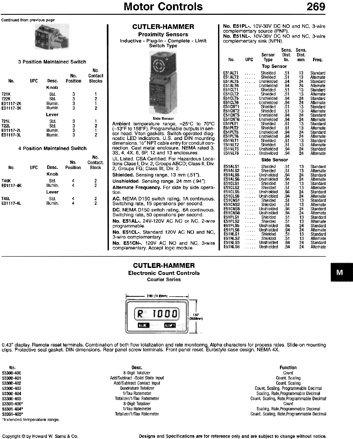
Motor Controls 269
Continued from previous page
CUTLER-HAMMER
Proximity Sensors
Inductive - Plug-In - Complete - Limit
Switch Type
No. E51PL-. 10V-30V DC NO and NC, 3-wire
complementary source (PNP).
No. E51NL-. 10V-30V DC NO and NC, 3-wire
complementary sink (NPN).
Sens. Sens.
Sensor Dist. Dist.
No. UPC Type In. rnrn Freq.
Top Sensor
E51ALT1 . . . . . Shielded .51 13 Standard
E51ALT2 . . . . . Shielded .51 13 Alternate
E51ALT5 .. . .. Unshielded .94 24 Standard
E51ALT6 Unshielded .94 24 Alternate
E51CLT1 . . . .. Shielded .51 13 Standard
E51CLT2 . . . .. Shielded .51 13 Alternate
E51CLT5 . . . .. Unshielded .94 24 Standard
E51CLT6 . . . .. Un shielded .94 24 Alternate
E51CNT1 . . . .. Shielded .51 13 Standard
E51CNT2 Shielded .51 13 Alternate
E51 CNT5 Unshielded .94 24 Standard
E51 CNT6 Unshielded .94 24 Alternate
E51PLT1 . . . .. Shielded .51 13 Standard
E51PLT2 . . . . . Shielded .51 13 Alternate
E51 PLT5 . . . .. Unshielded .94 24 Standard
E51PLT6 . . . .. Unshielded .94 24 Alternate
E51NLT1 . . . .. Shielded .51 13 Standard
E51 NLT2 . . . .. Shielded .51 13 Alternate
E51 NLT5 . . . .. Unshielded .94 24 Standard
E51NLT6 .. . .. Unshielded .94 24 Alternate
Side Sensor
E51ALS1 . . . .. Shielded .51 13 Standard
E51ALS2 Shielded .51 13 Alternate
E51ALS5 Unshielded .94 24 Standard
E51ALS6 Unshielded .94 24 Alternate
E51CLS1 . . . . . Shielded .51 13 Standard
E51CLS2 . . . . . Shielded .51 13 Alternate
E51CLS5 .. . .. Unshielded .94 24 Standard
E51CLS6 .. . .. Unshielded .94 24 Alternate
E51CNS1 ... . . Shielded .51 13 Standard
E51CNS2 Shielded .51 13 Alternate
E51CNS5 Unshielded .94 24 Standard
E51CNS6 Unshielded .94 24 Alternate
E51PLS1 . . . .. Shielded .51 13 Standard
E51PLS2 . . . .. Shielded .51 13 Alternate
E51 PLS5 . . . .. Unshielded .94 24 Standard
E51 PLS6 . . . .. Unshielded .94 24 Alternate
E51NLS1 Shielded .51 13 Standard
E51NLS2 Shielded .51 13 Alternate
E51 NLS5 Unshielded .94 24 Standard
E51 NLS6 Unshielded .94 24 Alternate
3 Position Maintained Switch
No.
Contact
Blocks
No.
PositionNo. UPC Desc.
Knob
Std.
Std.
IIlumin.
IIlumin.
Lever
Std.
Std.
IIlumin.
IIlumin.
T21K
T22K
ED1117-2K
ED1117-3K
3
3
3
3
1
2
1
2
T21L
T22L
ED1117-2L
ED1117-3L
3
3
3
3
1
2
1
2
4 Position Maintained Switch
No.
Contact.
Block
No.
PositionUPC Desc.
Knob
Std.
IIlumin.
Lever
Std.
ilium in.
No.
T46K
ED1117-4K 4
42
2
T46L
ED1117-4L 2
2
4
4
Side Sensor
Ambient temperature range, -25°C to 70°C
(-13°F to 158°F). Programmable outputs in sen-
sor head. Viton gaskets. Switch operated diag-
nostic LED indicators. U.S. and DIN mounting
dimensions. 1/2" NPT cable entry for conduit con-
nection. Cast metal enclosure. NEMA rated 3,
3S, 4, 4X, 6, 6P, 12 and 13 enclosures.
UL Listed. CSA Certified. For Hazardous Loca-
tions Class I, Div. 2, Groups ABCD; Class II, Div.
2, Groups FG; Class III, Div. 2.
Shielded. Sensing range, 13 mm (.51").
Unshielded. Sensing range, 24 mm (.94").
Alternate Frequency. For side by side opera-
tion.
AC. NEMA D150 switch rating, 1A continuous.
Switching rate, 15 operations per second.
DC. NEMA D150 switch rating, .6A continuous.
Switching rate, 50 operations per second.
No. E51AL-. 24V-120V AC NO or NC, 2-wire
programmable.
No. E51CL-. Standard 120V AC NO and NC,
3-wire complementary.
No. E51 CN-. 120V AC NO and NC, 3-wire
complementary. Accept logic module.
CUTLER-HAMMER
Electronic Count Controls
Courier Series
1- 2M'17.93mm1 .1
0.43" display. Remote reset terminals. Combination of both flow totalization and rate monitoring. Alpha characters for process rates. Slide-on mounting
clips. Protective seal gasket. DIN dimensions. Rear panel screw terminals. Front panel reset. Eurostyle case design. NEMA 4X.
Desc.
8-Digit Totalizer
Add/Subtract -Solid State Input
Add/Subtract Contact Input
Quadrature Totalizer
1/Tau Ratemeter
Totalizer/1/Tau Ratemeter
8-Digit Totalizer
1/Tau Ratemeter
Totalizer/1/Tau Ratemeter
Function
Count
Count, Scaling
Count, Scaling
Count, Scaling, Programmable Decimal
Scaling, Rate,Programmable Decimal
Count, Scaling, Rate,Programmable Decimal
Count
Scaling, Rate,Programmable Decimal
Count, Scaling, Rate,Programmable Decimal
No.
53300-400
53300-401
53300-402
53300-403
53300-404
53300-405
53301-400'
53301-404'
53301-405'
*Extended temperature range.
Copyright @ by Howard W. Sams & Co. Designs and Specifications are for reference only and are subject to change without notice.
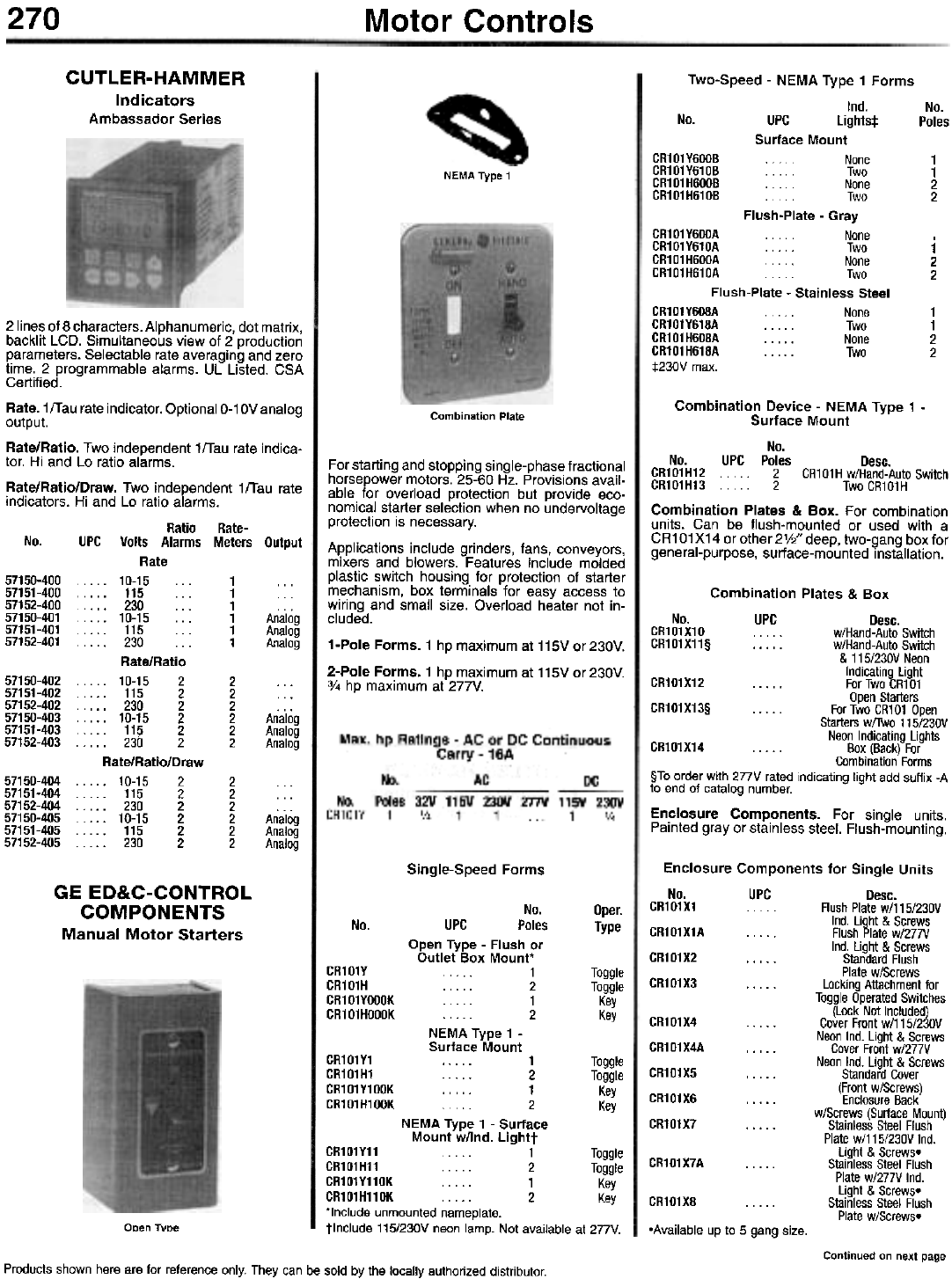
270 Motor Controls
CUTLER-HAMMER
Indicators
Ambassador Series
Two-Speed - NEMA Type 1 Forms
Ind.
No. UPC lights:!:
Surface Mount
CR101Y600B . None
CR101Y610B . . . . Two
CR101H600B None
CR101H610B . Two
Flush-Plate - Gray
CR101Y600A None
CR101Y610A Two
CR101H600A . . . . None
CR101H610A . . . . . Two
Flush-Plate - Stainless Steel
CR101Y608A None
CR101Y618A . . . . . Two
CR1 01 H608A . . . . . None
CR101H618A Two
:j:230V max.
No.
Poles
1
1
2
2
NEMA Type 1
1
2
2
1
1
2
2
Combination Plate Combination Device - NEMA Type 1 -
Surface Mount
No.
No. UPC Poles Desc.
GR101H12 .. 2 CR101H w/Hand-Auto Switch
GR101H13 ... 2 Two CR101H
Combination Plates & Box. For combination
units. Can be flush-mounted or used with a
CR1 01 X14 or other 2V2" deep, two-gang box for
general-purpose, surface-mounted installation.
2 lines of 8 characters. Alphanumeric, dot matrix,
backlit LCD. Simultaneous view of 2 production
parameters. Selectable rate averaging and zero
time. 2 programmable alarms. UL Listed. CSA
Certified.
Rate.1fTau rate indicator. Optional 0-10V analog
output.
Rate/Ratio. Two independent 1fTau rate indica-
tor. Hi and Lo ratio alarms.
Rate/Ratio/Draw. Two independent 1fTau rate
indicators. Hi and Lo ratio alarms.
Ratio Rate-
No. UPC Volts Alarms Meters Output
Rate
57150-400 10-15 1.. .
57151-400 115 ... 1
57152-400 . . . . 230 . . . 1
57150-401 10-15 . '. 1 Analog
57151-401 115 1 Analog
57152-401 . . . . 230 1 Analog
Rate/Ratio
57150-402 .. .. 10-15 2 2 ...
57151-402 115 2 2 ...
57152-402 230 2 2 . . .
57150-403 10-15 2 2 Analog
57151-403 115 2 2 Analog
57152-403 230 2 2 Analog
Rate/Ratio/Draw
57150-404 10-15 2 2 . ..
57151-404 115 2 2 .. .
57152-404 230 2 2 . . .
57150-405 10-15 2 2 Analog
57151-405 115 2 2 Analog
57152-405 230 2 2 Analog
For starting and stopping single-phase fractional
horsepower motors. 25-60 Hz. Provisions avail-
able for overload protection but provide eco-
nomical starter selection when no undervoltage
protection is necessary.
Applications include grinders, fans, conveyors,
mixers and blowers. Features include molded
plastic switch housing for protection of starter
mechanism, box terminals for easy access to
wiring and small size. Overload heater not in-
cluded.
1-Pole Forms. 1 hp maximum at 115V or 230V.
2-Pole Forms. 1 hp maximum at 115V or 230V.
3/4 hp maximum at 277V.
Combination Plates & Box
No. UPC Desc.
CR101X10 . . . w/Hand-Auto Switch
CR101X11§ . . . . . w/Hand-Auto Switch
& 115/230V Neon
Indicating Light
CR101X12 ForTwoCR101
Open Starters
CR101X13§ . .. . . For Two CR101 Open
Starters w/Two 115/230V
Neon Indicating Lights
CR101X14 . . . . . Box (Back) For
Combination Forms
§To order with 277V rated indicating light add suffix -A
to end of catalog number.
Enclosure Components. For single units.
Painted gray or stainless steel. Flush-mounting.
Single-Speed Forms Enclosure Components for Single Units
No. UPC Desc.
CR101X1 . . . . Flush Plate w/115/230V
Ind. Light & Screws
CR101X1A . . . . . Flush Plate w/277V
Ind. Light & Screws
CR101X2 . . . . . Standard Flush
Plate w/Screws
CR101X3 .. . . . Locking Attachment lor
Toggle Operated Switches
(Lock Not Included)
CR101X4 Cover Front w/115/230V
Neon Ind. Light & Screws
CR1 01 X4A . . . . . Cover Front w/277V
Neon Ind. Light & Screws
CR101X5 . . . . . Standard Cover
(Front w/Screws)
CR101X6 . ... . Enclosure Back
w/Screws (Surface Mount)
CR101X7 . . . . . Stainless Steel Flush
Plate w/115/230V Ind.
Light & Screws.
CR101X7A .. . . . Stainless Steel Flush
Plate w/277V Ind.
Light & Screws.
CR101X8 . . . . . Stainless Steel Flush
Plate w/Screws.
GE ED&C-CONTROL
COMPONENTS
Manual Motor Starters
No.
UPC Poles
Open Type - Flush or
Outlet Box Mount' 1
. 2
1
2
Oper.
Type
No.
CR101
CR101
CR101
CR101
Toggle
Toggle
Key
Key
NEMA Type 1 -
Surface Mount
CR101Y1
CR101H1
CR101Y100K
CR101H100K
. . . . . 1
2
. . . . . 1
2
NEMA Type 1 - Surface
Mount w/lnd. Lightt
CR101Y11 . . 1
CR101H11 . . . . 2
CR101Y110K 1
CR101H110K 2 .-,
'Include unmounted nameplate.
tlnclude 115/230V neon lamp. Not available at 277V.
Toggle
Toggle
Key
Key
Toggle
Toggle
Key
Kf!V
ODen TVDe -Available up to 5 gang size.
Continued on next page
Products shown here are for reference only. They can be sold by the locally authorized distributor.
y
H
YOOOK
HOOOK
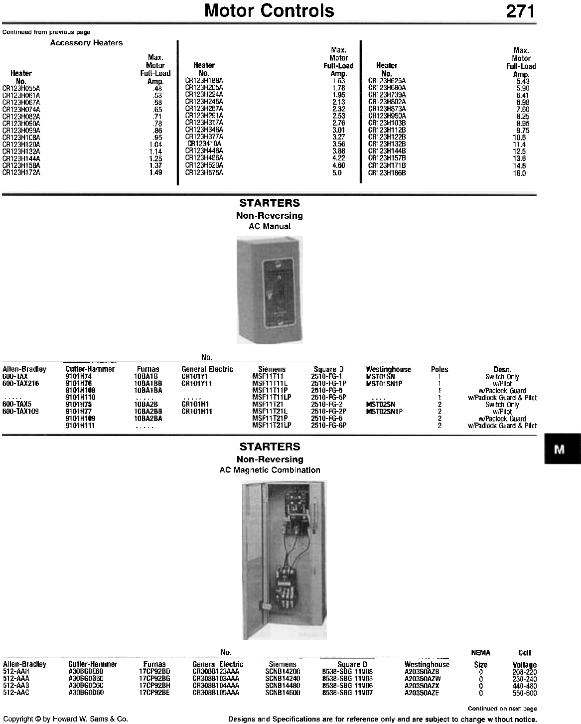
Motor Controls 271
Continued from previous page
Accessory Heaters Max.
Motor
Full-Load
Amp.
1.63
1.78
1.95
2.13
2.32
2.53
2.76
3.01
3.27
3.56
3.88
4.22
4.60
5.0
Max.
Motor
Full-Load
Amp.
5.43
5.90
6.41
6.98
7.60
8.25
8.95
9.75
10.6
11.4
12.5
13.6
14.8
16.0
Max.
Motor
Full-Load
Amp.
.48
.53
.58
.65
.71
.78
.86
.95
1.04
1.14
1.25
1.37
1.49
Heater
No.
CR123H188A
CR123H205A
CR123H224A
CR123H245A
CR123H267A
CR123H291A
CR123H317A
CR123H346A
CR123H377A
CR123410A
CR123H446A
CR123H486A
CR123H529A
CR123H575A
Heater
No.
CR123H625A
CR123H680A
CR123H739A
CR123H802A
CR123H873A
CR123H950A
CR123H103B
CR123H112B
CR123H122B
CR123H132B
CR123H144B
CR123H157B
CR123H171B
CR123H186B
Heater
No.
CR123HO55A
CR123HO61A
CR123HO67A
CR123HO74A
CR123HO82A
CR123HO90A
CR123HO99A
CR123H108A
CR123H120A
CR123H132A
CR123H144A
CR123H158A
CR123H172A
STARTERS
Non-Reversing
AC Manual
No.
Cutler-Hammer
9101H74
9101H76
9101H108
9101H110
91 01 H75
9101H77
9101 H109
9101H111
Allen-Bradley
600- TAX
6OO-TAX216
Furnas
10BA1B
10BA1BB
10BA1BA
10BA2B
10BA2BB
10BA2BA
General Electric
CR101Y1
CR101Y11
Siemens
MSF11T11
MSF11T11L
MSF11T11P
MSF11T11LP
MSF11T21
MSF11T21L
MSF11T21P
MSF11T21LP
Square D
2510-FG-1
251 O-FG-1 P
2510-FG-5
2510-FG-5P
2510-FG-2
2510-FG-2P
2510-FG-6
2510-FG-6P
Westinghouse
MSTO1SN
MSTO1SN1P
Poles
1
1
1
1
2
2
2
2
Desc.
Switch Only
w/Pilot
w/Padlock Guard
w/Padlock Guard & Pilot
Switch Only
w/Pilot
w/Padlock Guard
w/Padlock Guard & Pilot
6OO-TAX5
600- TAX1 09
CR101H1
CR101H11 MSTO2SN
MSTO2SN1P
STARTERS
Non-Reversing
AC Magnetic Combination
No. NEMA
Size
0
0
0
0
Coil
Voltage
208-220
230-240
440-480
550-600
Allen-Bradley
512-AAH
512-AAA
512-AAB
512-AAG
Cutler-Hammer
A30BGOEOO
A30BGOB60
A30BGOCOO
A30BGODOO
Furnas
17CP92BD
17CP92BG
17CP92BH
17CP92BE
General Electric
CR308B123AAA
CR308B103AAA
CR308B104AAA
CR308B105AAA
Siemens
SCNB14208
SCNB14240
SCNB14480
SCNB14600
Square D
8538-SB6 11VO8
8538-S8611VO3
8538-58611VOO
8538-58611VO7
Westinghouse
A203S0AZB
A203S0AZW
A203S0AZX
A203S0AZE
Continued on next page
Designs and Specifications are for reference only and are subject to change without notice.Copyright @ by Howard W. Sams & Co.
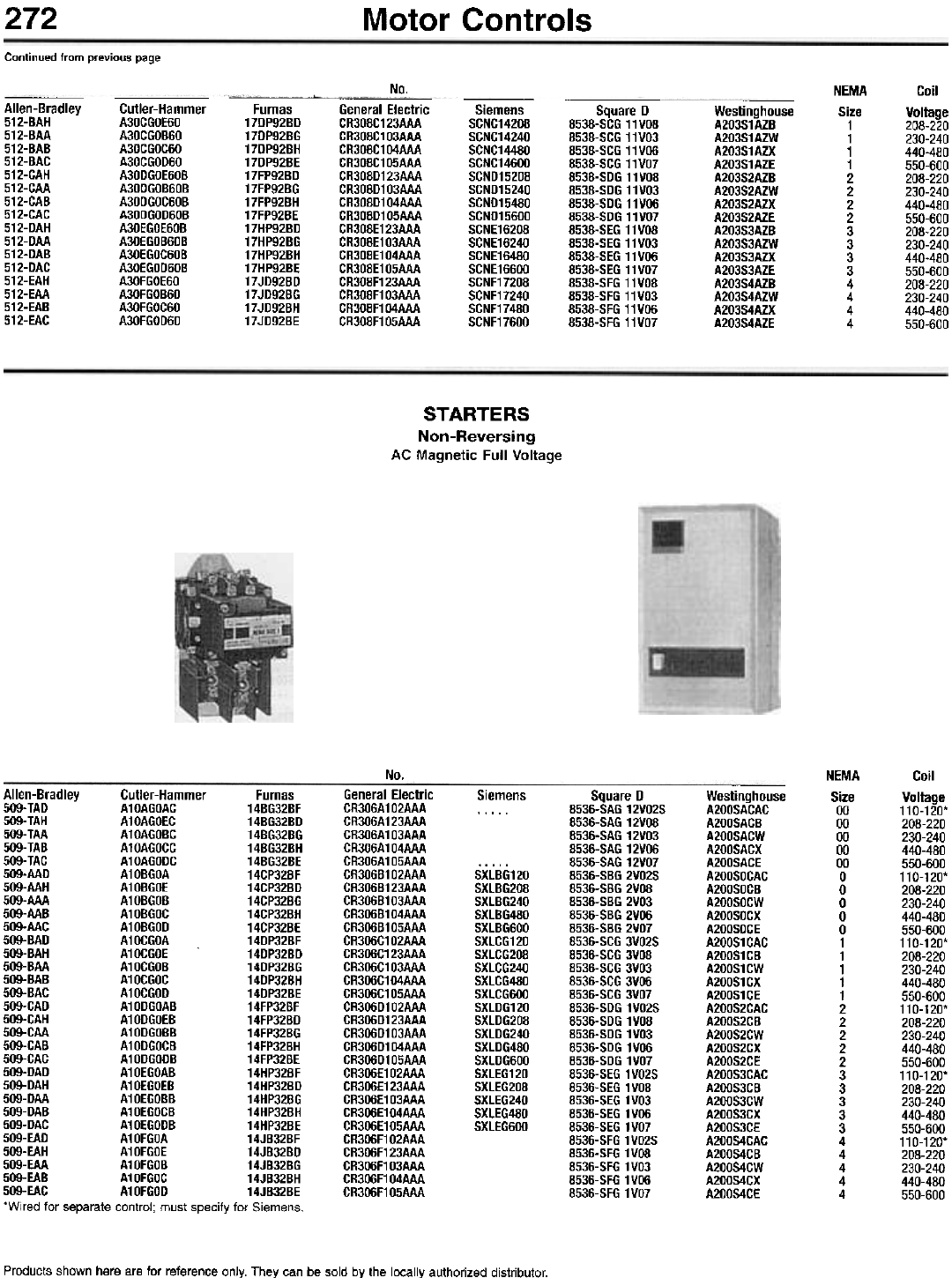
272 Motor Controls
Continued from previous page
No. NEMA
Size
1
1
1
1
2
2
2
2
3
3
3
3
4
4
4
4
Coil
Voltage
208-220
230-240
440-480
550-600
208-220
230-240
440-480
550-600
208-220
230-240
440-480
550-600
208-220
230-240
440-480
550-600
Allen-Bradley
512-BAH
512-BAA
512-BAB
512-BAC
512-CAH
512-CAA
512-CAB
512-CAC
512-DAH
512-DAA
512-DAB
512-DAC
512-EAH
512-EAA
512-EAB
512-EAC
Cutler-Hammer
A30CGOE60
A30CGOB60
A30CGOC60
A30CGOD60
A30DGOE60B
A30DGOB60B
A30DGOC60B
A30DGOD60B
A30EGOE60B
A30EGOB60B
A30EGOC60B
A30EGOD60B
A30FGOE60
A30FGOB60
A30FGOC60
A30FGOD60
Furnas
17DP92BD
17DP92BG
17DP92BH
17DP92BE
17FP92BD
17FP92BG
17FP92BH
17FP92BE
17HP92BD
17HP92BG
17HP92BH
17HP92BE
17JD92BD
17JD92BG
17JD92BH
17JD92BE
General Electric
CR30BC123AAA
CR30BC103AAA
CR30BC104AAA
CR30BC105AAA
CR30BD123AAA
CR30BD103AAA
CR30BD104AAA
CR30BD105AAA
CR30BE123AAA
CR308E103AAA
CR30BE104AAA
CR30BE105AAA
CR30BF123AAA
CR30BF103AAA
CR30BF104AAA
CR30BF105AAA
Siemens
SCNC14208
SCNC14240
SCNC14480
SCNC14600
SCND15208
SCND15240
SCND15480
SCND15600
SCNE16208
SCNE16240
SCNE16480
SCNE16600
SCNF17208
SCNF17240
SCNF17480
SCNF17600
Square D
8538-SCG 11VO8
8538-SCG 11VO3
8538-SCG 11V06
8538-SCG 11VO7
8538-SDG 11VO8
8538-SDG 11VO3
8538-SDG 11V06
8538-SDG 11VO7
8538-SEG 11VO8
8538-SEG 11VO3
8538-SEG 11V06
8538-SEG 11VO7
8538-SFG 11VO8
8538-SFG 11VO3
8538-SFG 11V06
8538-SFG 11VO7
Westinghouse
A203S1AZB
A203S1AZW
A203S1AZX
A203S1AZE
A203S2AZB
A203S2AZW
A203S2AZX
A203S2AZE
A203S3AZB
A203S3AZW
A203S3AZX
A203S3AZE
A203S4AZB
A203S4AZW
A203S4AZX
A203S4AZE
STARTERS
Non-Reversing
AC Magnetic Full Voltage
No. NEMA
Size
00
00
00
00
00
0
0
0
0
0
1
1
1
1
1
2
2
2
2
2
3
3
3
3
3
4
4
4
4
4
Coil
Voltage
110-120'
208-220
230-240
440-480
550-600
110-120'
208-220
230-240
440-480
550-600
110-120'
208-220
230-240
440-480
550-600
110-120'
208-220
230-240
440-480
550-600
110-120'
208-220
230-240
440-480
550-600
110-120'
208-220
230-240
440-480
550-600
Allen-Bradley Cutler-Hammer Furnas
509-TAD A10AGOAG 14BG32BF
509-TAH A10AGOEG 14BG32BD
509-TAA A10AGOBG 14BG32BG
509-TAB A10AGOGG 14BG32BH
509-TAG A10AGODG 14BG32BE
509-AAD A10BGOA 14GP32BF
509-AAH A10BGOE 14GP32BD
509-AAA A10BGOB 14GP32BG
509-AAB A10BGOG 14GP32BH
509-AAG A10BGOD 14GP32BE
509-BAD A10GGOA 14DP32BF
509-BAH A10GGOE 14DP32BD
509-BAA A10GGOB 14DP32BG
509-BAB A10GGOG 14DP32BH
509-BAG A10GGOD 14DP32BE
509-GAD A10DGOAB 14FP32BF
509-GAH A10DGOEB 14FP32BD
509-GAA A10DGOBB 14FP32BG
509-GAB A10DGOGB 14FP32BH
509-GAG A10DGODB 14FP32BE
509-DAD A10EGOAB 14HP32BF
509-DAH A10EGOEB 14HP32BD
509-DAA A10EGOBB 14HP32BG
509-DAB A10EGOGB 14HP32BH
509-DAG A10EGODB 14HP32BE
509-EAD A10FGOA 14JB32BF
509-EAH A10FGOE 14JB32BD
509-EAA A10FGOB 14JB32BG
509-EAB A10FGOG 14JB32BH
509-EAC A10FGOD 14JB32BE
'Wired for separate control; must specify for Siemens.
General Electric
CR306A102AAA
CR306A123AAA
CR306A103AAA
CR306A104AAA
CR306A105AAA
CR306B102AAA
CR306B123AAA
CR306B103AAA
CR306B104AAA
CR306B105AAA
CR306C102AAA
CR306C123AAA
CR306C103AAA
CR306C104AAA
CR306C105AAA
CR306D102AAA
CR306D123AAA
CR306D103AAA
CR306D104AAA
CR306D105AAA
CR306E102AAA
CR306E123AAA
CR306E103AAA
CR306E104AAA
CR306E105AAA
CR306F102AAA
CR306F123AAA
CR306F103AAA
CR306F104AAA
CR306F105AAA
Siemens Square D
8536-SAG 12VO2S
8536-SAG 12VOB
8536-SAG 12VO3
8536-SAG 12V06
8536-SAG 12VO7
8536-SBG 2VO2S
8536-SBG 2VO8
8536-SBG 2VO3
8536-SBG 2VO6
8536-SBG 2VO7
8536-SCG 3VO2S
8536-SCG 3VO8
8536-SCG 3VO3
8536-SCG 3V06
8536-SCG 3VO7
8536-SDG 1VO2S
8536-SDG 1 VO8
8536-SDG 1VO3
8536-SDG 1V06
8536-SDG 1VO7
8536-SEG 1VO2S
8536-SEG 1VO8
8536-SEG 1VO3
8536-SEG 1V06
8536-SEG 1VO7
8536-SFG 1VO2S
8536-SFG 1VO8
8536-SFG 1VO3
8536-SFG 1V06
8536-SFG 1VO7
Westinghouse
A200SACAC
A200SACB
A200SACW
A200SACX
A200SACE
A200S0CAC
A200S0CB
A200S0CW
A200S0CX
A200S0CE
A200S1CAC
A200S1CB
A200S1CW
A200S1CX
A200S1CE
A200S2CAC
A200S2CB
A200S2CW
A200S2CX
A200S2CE
A200S3CAC
A200S3CB
A200S3CW
A200S3CX
A200S3CE
A200S4CAC
A200S4CB
A200S4CW
A200S4CX
A200S4CE
SXLBG120
SXLBG208
SXLBG240
SXLBG480
SXLBG600
SXLCG120
SXLCG208
SXLCG240
SXLCG480
SXLCG600
SXLDG120
SXLDG208
SXLDG240
SXLDG480
SXLDG600
SXLEG120
SXLEG208
SXLEG240
SXLEG480
SXLEG600
Products shown here are for reference only. They can be sold by the locally authorized distributor.
Motor Controls 273
GE ED&C-CONTROL COMPONENTS
Definite Purpose Contactors
Open Type - Series CR353
600V maximum. 50A-150A maximum inductive. 50/60 Hz. Universal mounting plates with multiple holes. Straight-through wiring. Combination screw and
quick-connect power and coil terminals. Self aligning magnets. Housing offers high arc tracking resistance and dielectric strength. Corrosion resistant.
Arc confining cover to protect against contaminants. Field replaceable contacts and coils. UL Recognized. CSA Certified.
AC Coil Forms
Amp Ratings
Inductive
locked Rotor
AC Coil
Nom.
Sealed
VA
Nom.
Inrush
VA
Nom.
Sealed
Watts
Resistance
:!:10%
Ohms
No.
Poles
Full
Load
50/GO Hz
Volts
UPC
No. 240V 480V
CR353FE2BH1
CR353FE2BA1
CR353FE2BB1
CR353FE2BF1
50
50
50
50
50
50
50
50
50
50
50
50
60
60
60
60
60
60
60
60
60
60
60
60
300
300
300
300
300
300
300
300
300
300
300
300
360
360
360
360
360
360
360
360
360
360
360
360
250
250
250
250
250
250
250
250
250
250
250
250
300
300
300
300
300
300
300
300
300
300
300
300
Resist./
6OOV Pole
CR353F Forms
200 62
200 62
200 62
200 62
200 62
200 62
200 62
200 62
200 62
200 62
200 62
200 62
240 75
240 75
240 75
240 75
240 75
240 75
240 75
240 75
240 75
240 75
240 75
240 75
CR353E Forms
300
300
300
300
300
300
300
300
300
300
300
300
360
360
360
360
360
360
360
360
360
360
360
360 --
CR353G Forms'
480
480
480
480
480
.fAn ".
125
125
125
125
125
125
125
125
125
125
125
125
125
125
125
125
125
125
125
125
125
125
125
125
2
2
2
2
2
2
3
3
3
3
3
3
2
2
2
2
2
2
3
3
3
3
3
3
24
110-120
208-240
277
440-480
575-600
24
110-120
208-240
277
440-480
575-600
24
110-120
208-240
277
440-480
575-600
24
110-120
208-240
277
440-480
575-600
17
17
17
17
17
17
17
17
17
17
17
17
17
17
17
17
17
17
17
17
17
17
17
17
8
8
8
8
8
8
8
8
8
8
8
8
8
8
8
8
8
8
8
8
8
8
8
8
2.75
64.3
241
389
972
2074
2.75
64.3
241
389
972
2074
2.75
64.3
241
389
972
2074
2.75
64.3
241
389
972
2074
CR353FE3BB1
CR353FE3BF1
CR353FE3BC1
CR353FE3BD1
CR353FF2BH1
CR353FF2BA1
CR353FF2BB1
CR353FF2BF1
CR353FF2BC1
CR353FF2BD1
CR353FF3BH1
CR353FF3BA1
CR353FF3BB1
CR353FF3BF1
CR353FF3BC1
CR353FF3BD1
CR353EG2BH1
CR353EG2BA1
CR353EG2BB1
CR353EG2BF1
CR353EG2BC1
CR353EG2BD1
CR353EG3BH1
CR353EG3BA1
CR353EG3BB1
CR353EG3BF1
CR353EG3BC1
CR353EG3BD1
CR353EH2BH1
CR353EH2BA1
CR353EH2BB1
CR353EH2BF1
CR353EH2BC1
CR353EH2BD1
CR353EH3BH1
CR353EH3BA1
CR353EH3BB1
CR353EH3BF1
CR353EH3BC1
CR353EH3BD1
2
2
2
2
2
2
3
3
3
3
3
3
2
2
2
2
2
2
3
3
3
3
3
3
75
75
75
75
75
75
75
75
75
75
75
75
90
90
90
90
90
90
90
90
90
90
90
90
375
375
375
375
375
375
375
375
375
375
375
375
450
450
450
450
450
450
450
450
450
450
450
450
90
90
90
90
90
90
90
90
90
90
90
90
90
90
90
90
90
90
90
90
90
90
90
90
450
450
450
450
450
450
450
450
450
450
450
450
540
540
540
540
540
540
540
540
540
540
540
540
24
115-120
208-240
277
460
600
24
115-120
208-240
277
460
600
24
115-120
208-240
277
460
600
24
115-120
208-240
277
460
600
233
233
233
233
233
233
233
233
233
233
233
233
233
233
233
233
233
233
233
233
233
233
233
233
40
40
40
40
40
40
40
40
40
40
40
40
40
40
40
40
40
40
40
40
40
40
40
40
16
16
16
16
16
16
16
16
16
16
16
16
16
16
16
16
16
16
16
16
16
16
16
16
1.46
28.7
109
169
547
655
1.46
28.7
109
169
547
655
1.46
28.7
109
169
547
655
1.46
28.7
109
169
547
655
CR353GJ2AA1
CR353GJ2AB1
CR353GJ2AC1
CR353GJ2AD1
CR353GJ3AA1
CR353GJ3AB1
2
2
2
2
3
3
120
120
120
120
120
120
720
720
720
720
720
720
600 120 115-120 1150 80 18.4 2.11 2.0
1600 120 230-240 1150 80 18.4 10.6 10.4
600 120 460-480 1150 80 18.4 41.8 41.
600 120 575-600 1150 80 18.4 67.0 64.4
600 120 115-120 1150 80 18.4 2.11 2.02
600 ,-- !20 230-240 1150 80 18.4 10.6 10.4
Continued on next page
Designs and Specifications are for reference only and are subject to change without notice.Copyright @ by Howard W. Sams & Co
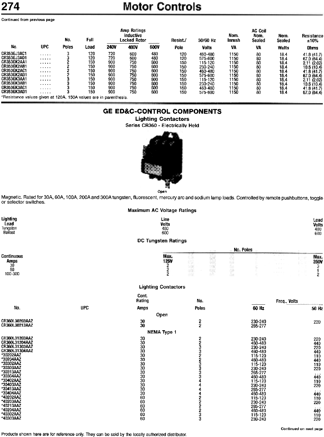
274
Continued from previous page
Amp Ratings
Inductive
locked Rotor
AC Coil
Nom.
Sealed
VA
80
80
80
80
80
80
80
80
80
80
Nom.
Inrush
VA
1150
1150
1150
1150
1150
1150
1150
1150
1150
1150
Nom.
Sealed
Watts
18.4
18.4
18.4
18.4
18.4
18.4
18.4
18.4
18.4
18.4
Resistance
:1:10%
Ohms
41.8 41.7
67.0 64.4
2.11 2.02
10.6 10.4
41.8 41.
67.0 64.4
2.11 2.02
10.6 10.4
41.8 41.7
67.0 64.4
Resist.!
Pole
120
120
150
150
150
150
150
150
150
150
50/60 Hz
Volts
460-480
575-600
115-120
230-240
460-480
575-600
115-120
230-240
460-480
575-600
No. Full
No. UPC Poles Load 240V
CR353GJ3AC1 3 120 720
CR353GJ3AD1 3 120 720
CR353GK2AA1 2 150 900
CR353GK2AB1 2 150 900
CR353GK2AC1 2 150 900
CR353GK2AD1 2 150 900
CR353GK3AA1 3 150 900
CR353GK3AB1 3 150 900
CR353GK3AC1 3 150 900
CR353GK3AD1 3 150 900
'Resistance values given at 120A. 150A values are in parenthesis.
-
480V
600
600
750
750
750
750
750
750
750
750
GOOV
480
480
600
600
600
600
600
600
600
600
GE ED&C-CONTROL COMPONENTS
Lighting Contactors
Series CR360 - Electrically Held
Open
Magnetic. Rate:d for 30A, 60A, 100A, 200A and 300A tungsten, fluorescent, mercury arc and sodium lamp loads. Controlled by remote pushbuttons, toggle
or selector switches.
Maximum AC Voltage Ratings
Line
Volts
480
600
DC Tungsten Ratings
Lighting
Load
Tungsten
Ballast
Load
Volts
480
600
No. Poles
Continuous
Amps
30
60
100-300
Lighting Contactors
Cont.
Rating
Amps
No.
Poles
Freq., Volts
No. UPC 60 Hz -
50 Hz
Open
CR360L30203AAZ
CR360L30213AAZ 30
30 2
2230-240
265-277 220
NEMA Type 1
CR360l31203AAZ
CR360l31204AAZ
CR360l31303AAZ
CR360l31304AAZ
*30202AAZ
*30204AAZ
*30302AAZ
*30303AAZ
*30313AAZ
*30304AAZ
*30402AAZ
*30403AAZ
*30413AAZ
*30404AAZ
*40202AAZ
*40203AAZ
*40213AAZ
*40204AAZ
*40302AAZ
*40303AAZ
30
30
30
30
30
30
30
30
30
30
30
30
30
30
60
60
60
60
60
60
2
2
3
3
2
2
3
3
3
3
4
4
4
4
2
2
2
2
3
3
230-240
460-480
230-240
460-480
115-120
460-480
115-120
230-240
265-277
460-480
115-120
230-240
265-277
460-480
115-120
230-240
265-277
460-480
115-120
230-240
220
440
220
440
110
440
110
220
440
110
220
440
110
220
440
110
220
Continued on next page
Products shown here are for reference only. They can be sold by the locally authorized distributor.
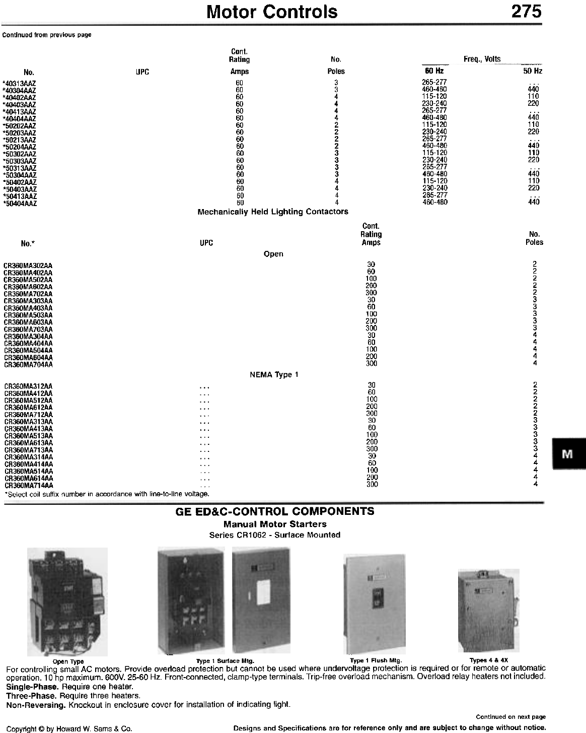
275
Motor Controls
Continued from previous page
Cant.
Rating No.
Amps Poles
60 3
60 3
60 4
60 4
60 4
60 4
60 2
60 2
60 2
60 2
60 3
60 3
60 3
60 3
60 4
60 4
60 4
60 4
Mechanically Held Lighting Contactors
Freq., Volts
-
60 Hz
265-277
460-480
115-120
230-240
265-277
460-480
115-120
230-240
265-277
460-480
115-120
230-240
265-277
460-480
115-120
230-240
265-277
460-480
-
50 Hz
UPC
No.
*40313AAZ
*40304AAZ
*40402AAZ
*40403AAZ
*40413AAZ
*40404AAZ
*50202AAZ
*50203AAZ
*50213AAZ
*50204AAZ
*50302AAZ
*50303AAZ
*50313AAZ
*50304AAZ
*50402AAZ
*50403AAZ
*50413AAZ
*50404AAZ
440
110
220
440
110
220
440
110
220
440
110
220
440
Cant.
Rating
Amps No.
Poles
UPC
No.*
Open 2
2
2
2
2
3
3
3
3
3
4
4
4
4
4
30
60
100
200
300
30
60
100
200
300
30
60
100
200
300
CR360MA302AA
CR360MA402AA
CR360MA502AA
CR360MA602AA
CR360MA702AA
CR360MA303AA
CR360MA403AA
CR360MA503AA
CR360MA603AA
CR360MA703AA
CR360MA304AA
CR360MA404AA
CR360MA504AA
CR360MA604AA
CR360MA704AA
NEMA Type 1
30
60
100
200
300
30
60
100
200
300
30
60
100
200
300
2
2
2
2
2
3
3
3
3
3
4
4
4
4
4
CR360MA312AA . . .
CR360MA412AA . . .
CR360MA512AA . . .
CR360MA612AA . . .
CR360MA712AA ...
CR360MA313AA ...
CR360MA413AA ...
CR360MA513AA ...
CR360MA613AA . . .
CR360MA713AA . . .
CR360MA314AA ...
CR360MA414AA ...
CR360MA514AA ...
CR360MA614AA . . .
CR360MA714AA . . .
'Select coil suffix number in accordance with line.to.line voltage.
GE ED&C-CONTROL COMPONENTS
Manual Motor Starters
Series CR1062 - Surface Mounted
-
Open Type Type 1 Surface Mtg. Type 1 Flush Mtg. Types 4 & 4X
For controlling small AC motors. Provide overload protection but cannot be u~ed where undervoltage protecti?n is required or for remote or ~utomatic
operation. 10 hp maximum. 600V. 25-60 Hz. Front-connected, clamp-type terminals. Trip-free overload mechanism. Overload relay heaters not Included.
Single-Phase. Require one heater.
Three-Phase. Require three heaters.
Non-Reversing. Knockout in enclosure cover for installation of indicating light.
Continued on next page
Designs and Specifications are for reference only and are subject to change without notice.
Copyright @ by Howard W. Sams & Co.
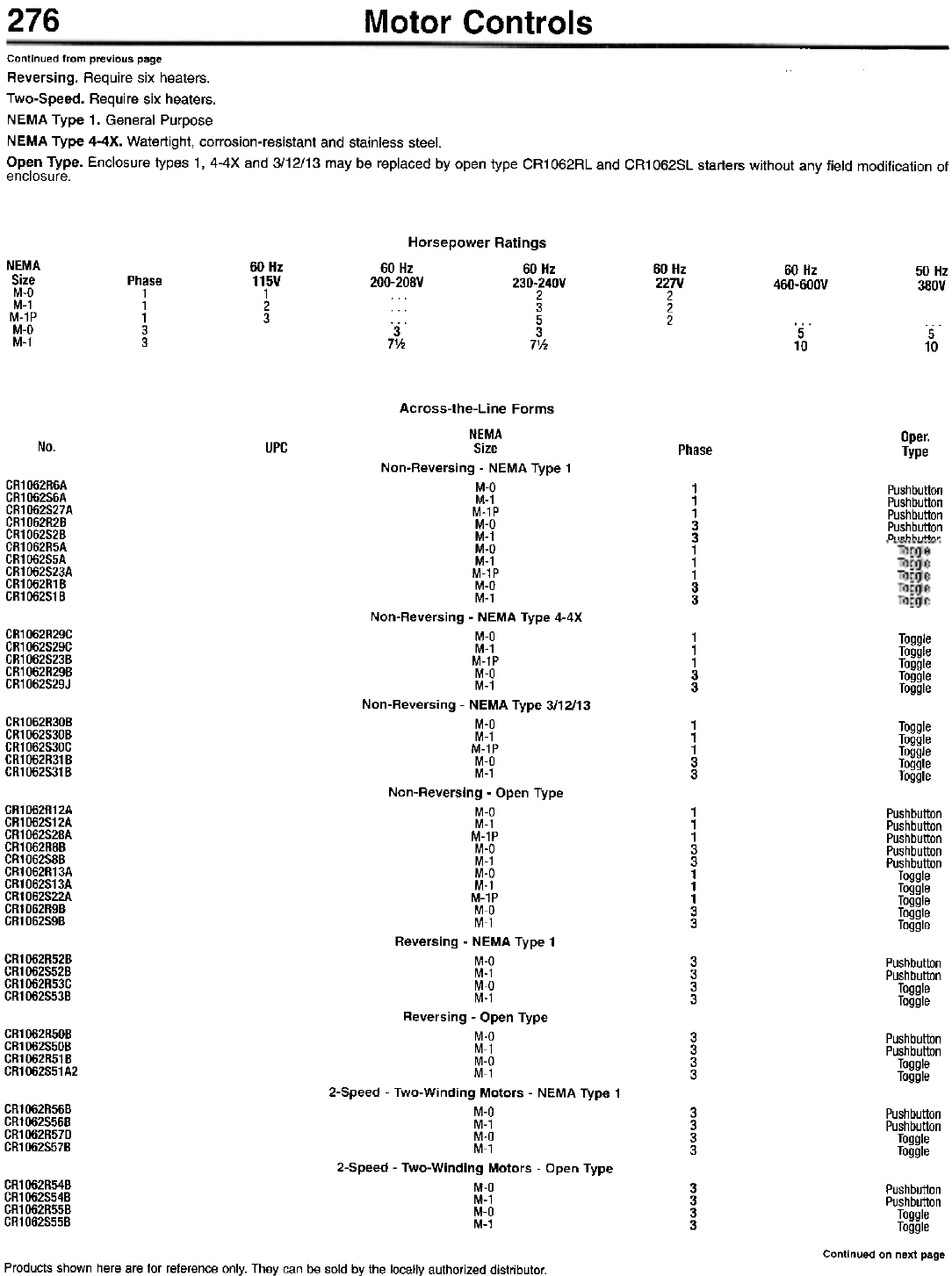
276 Motor Controls
Continued from previous page
Reversing. Require six heaters.
Two-Speed. Require six heaters.
NEMA Type 1. General Purpose
NEMA Type 4-4X. Watertight, corrosion-resistant and stainless steel.
Open Type. Enclosure types 1, 4-4X and 3/12/13 may be replaced by open type CR1062RL and CR1062SL starters without any field modification of
enclosure.
Horsepower Ratings
60 Hz 60 Hz
200-208V 230-240V
2
3
... 5
3 3
7'h 7V2
NEMA
Size
M-O
M-1
M-1P
M-O
M-1
60 Hz
115V
1
2
3
60 Hz
227V
2
2
2
60 Hz
460-600V 50 Hz
380V
Phase
1
1
1
3
35
10 5
10
Oper.
Type
No. UPC Phase
CR1062R6A
CR1062S6A
CR1062S27A
CR1062R2B
CR1062S2B
CR1062R5A
CR1062S5A
CR1062S23A
CR1062R1B
CR1062S1B
1
1
1
3
3
1
1
1
3
3
CR1062R29C
CR1062S29C
CR1062S23B
CR1062R29B
CR1062S29J
1
1
1
3
3
'"',
'"',
'"',
,~"
,~"
CR1062R30B
CR1062S30B
CR1062S30C
CR1062R31B
CR1062S31B
1
1
1
3
3
Toggle
Toggle
Toggle
Toggle
Toggle
CR1062R12A
CR1062S12A
CR1062S28A
CR1062R8B
CR1062S8B
CR1062R13A
CR1062S13A
CR1062S22A
CR1062R9B
CR1062S9B
1
1
1
3
3
1
1
1
3
3
Pushbutton
Pushbutton
Pushbutton
Pushbutton
Pushbutton
Toggle
Toggle
Toggle
Toggle
Toggle
CR1062R52B
CR1062S52B
CR1062R53C
CR1062S53B
3
3
3
3
Pushbutton
Pushbutton
Toggle
Toggle
CR1062R50B
CR1062S50B
CR1062R51B
CR1062S51A2
3
3
3
3
Pushbutton
Pushbutton
Toggle
Toggle
CR1062R56B
CR1062S56B
CR1062R57D
CR1062S57B
3
3
3
3
Pushbutton
Pushbutton
Toggle
Toggle
Across-the-Line Forms
NEMA
Size
Non-Reversing - NEMA Type 1
M-Q
M-1
M-1P
M-Q
M-1
M-Q
M-1
M-1P
M-Q
M-1
Non-Reversing - NEMA Type 4-4X
M-Q
M-1
M-1P
M-Q
M-1
Non-Reversing - NEMA Type 3/12/13
M-Q
M-1
M-1P
M-Q
M-1
Non-Reversing - Open Type
M-Q
M-1
M-1P
M-Q
M-1
M-Q
M-1
M-1P
M-Q
M-1
Reversing - NEMA Type 1
M-Q
M-1
M-Q
M-1
Reversing - Open Type
M-Q
M-1
M-Q
M-1
2-Speed - Two-Winding Motors - NEMA Type 1
M-Q
M-1
M-Q
M-1
2-Speed - Two-Winding Motors - Open Type
M-Q
M-1
M-Q
M-1
CR1062R54B
CR1062S54B
CR1062R55B
CR1062S55B
3
3
3
3
Pushbutton
Pushbutton
Toggle
Toggle
Continued on next page
Products shown here are for reference only. They can be sold by the locally authorized distributor.
Pushbutton
Pushbutton
Pushbutton
Pushbutton
p, ,ohh, ,ttnn
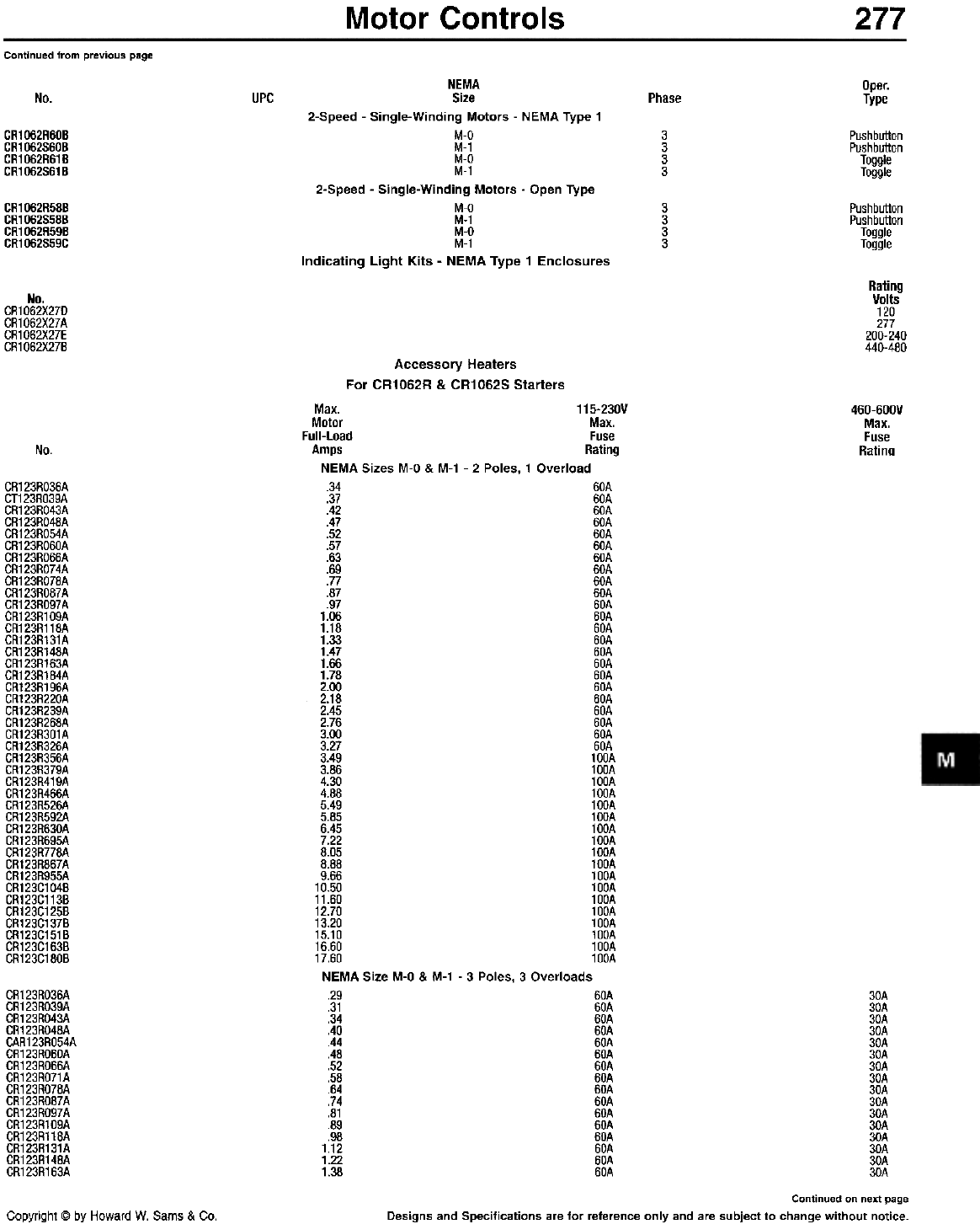
Motor Controls 277
Continued from previous page
Oper.
Type
No. UPC Phase
CR1062R60B
CR1062S60B
CR1062R61B
CR1062S61B
3
3
3
3
Pushbutton
Pushbutton
Toggle
Toggle
CR1062R58B
CR1062S58B
CR1062R59B
CR1062S59C
3
3
3
3
Pushbutton
Pushbutton
Toggle
Toggle
NEMA
Size
2-Speed - Single-Winding Motors - NEMA Type 1
M-Q
M-1
M-Q
M-1
2-Speed - Single-Winding Motors - Open Type
M-Q
M-1
M-Q
M-1
Indicating Light Kits - NEMA Type 1 Enclosures
Rating
Volts
120
277
200-240
440-480
No.
CR1062X27D
CR1062xm
CR1062X27E
CR1062X27B
Accessory Heaters
For CR1062R & CR1062S Starters
460-600V
Max.
Fuse
Ratinn
No.
CR123RO36A
CT123RO39A
CR123RO43A
CR123RO48A
CR123RO54A
CR123RO60A
CR123RO66A
CR123RO74A
CR123RO78A
CR123RO87A
CR123RO97A
CR123R109A
CR123R118A
CR123R131A
CR123R148A
CR123R163A
CR123R184A
CR123R196A
CR123R220A
CR123R239A
CR123R268A
CR123R301A
CR123R326A
CR123R356A
CR123R379A
CR123R419A
CR123R466A
CR123R526A
CR123R592A
CR123R630A
CR123R695A
CR123R778A
CR123R867A
CR123R955A
CR123C104B
CR123C113B
CR123C125B
CR123C137B
CR123C151B
CR123C163B
CR123C180B
Max. 115-230V
Motor Max.
Full-Load Fuse
Amps Rating
NEMA Sizes M-O & M-1 - 2 Poles, 1 Overload
.34 60A
.37 60A
.42 60A
.47 60A
.52 60A
.57 60A
.63 60A
.69 60A
.77 60A
.87 60A
.97 60A
1.06 60A
1.18 60A
1.33 60A
1.47 60A
1.66 60A
1.78 60A
2.00 60A
2.18 60A
2.45 60A
2.76 60A
3.00 60A
3.27 60A
3.49 100A
3.86 100A
4.30 100A
4.88 100A
5.49 100A
5.85 100A
6.45 100A
7.22 100A
8.05 100A
8.88 100A
9.66 100A
10.50 100A
11.60 100A
12.70 100A
13.20 100A
15.10 100A
16.60 100A
17.60 100A
NEMA Size M-O & M-1 - 3 Poles, 3 Overloads
.29 60A 30A
.31 60A 30A
.34 60A 30A
.40 60A 30A
.44 60A 30A
.48 60A 30A
.52 60A 30A
.58 60A 30A
.64 60A 30A
.74 60A 30A
.81 60A 30A
.89 60A 30A
.98 60A 30A
1.12 60A 30A
1.22 60A 30A
1.38 60A 30A
Continued on next page
Designs and Specifications are for reference only and are subject to change without notice.
CR123RO36A
CR123RO39A
CR123RO43A
CR123RO48A
CAR123RO54A
CR123RO60A
CR123RO66A
CR123RO71A
CR123RO78A
CR123RO87A
CR123RO97A
CR123R109A
CR123R118A
CR123R131A
CR123R148A
CR123R163A
Copyright @ by Howard W. Sams & Co.
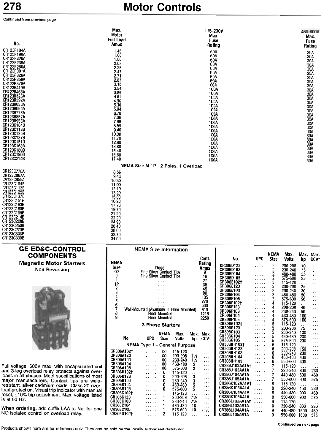
278 Motor Controls
Continued from previous page
115-230V
Max.
Fuse
Rating
60A
60A
60A
60A
60A
60A
60A
60A
60A
100A
100A
100A
100A
100A
100A
100A
100A
100A
100A
100A
100A
100A
100A
100A
100A
100A
100A
,-- ---
Max.
Fuse
Rating
30A
30A
30A
30A
30A
30A
30A
30A
30A
30A
30A
30A
30A
30A
30A
30A
30A
30A
30A
30A
30A
30A
30A
30A
30A
30A
30A
No.
CR123R184A
CR123R196A
CR123R220A
CR123R239A
CR123R268A
CR123R301A
CR123R326A
CR123R356A
CR123R379A
CR123R419A
CR123R466A
CR123R526A
CR123R592A
CR123R630A
CR123R695A
CR123R778A
CR123R867A
CR123R955A
CR123C104B
CR123C113B
CR123C125B
CR123C137B
CR123C151B
CR123C163B
CR123C180B
CR123C198B
CR123C214B
Max.
Motor
Full-Load
Amps
1.48
1.66
1.80
2.03
2.28
2.47
2.71
2.87
3.18
3.54
3.89
4.51
4.90
5.30
5.94
6.70
7.36
7.98
8.59
9.46
10.30
11.70
12.60
13.80
15.40
16.60
17.40
NEMA Size M-1 P - 2 Poles, 1 Overload
8.56
9.43
10.30
11.00
12.10
13.20
15.00
16.20
17.70
19.70
21.20
22.20
24.90
26.40
30.00
32.70
34.00
CR123C778A
CR123C867A
CR123C955A
CR123C104B
CR123C113B
CR123C125B
CR123C137B
CR123C151B
CR123C163B
CR123C180B
CR123C198B
CR123C214B
CR123C228B
CR123C250B
CR123C273B
CR123C303B
CR123C330B
GE ED&C-CONTROL
COMPONENTS
Magnetic Motor Starters
Non-Reversing
NEMA Size Information
No.
CR306D123
CR306D103
CR306D104
CR306D105
CR306E102t
CR306E123
CR306E103
CR306E104
CR306E105
CR306F102t
CR306F123
CR306F103
CR306F104
CR306F105
CR306G102t
CR306G123
CR306G103
CR306G104
CR306G105
CR306HH102t
CR306HH123
CR306HH103
CR306HH104
CR306HH105
CR386J102AA1At
CR386J103AA1A
CR386J104AA1A
CR386J105AA1A
CR386K102AA1At
CR386K103AA1A
CR386K104AA1A
CR386K105AA1A
CR386L102AA1At
CR386L103AA1A
CR386L104AA1A
CR386L105AA1A
Cont.
NEMA Rating
Size Desc. Amps
00 Fine Silver Contact Tips 9
0 Fine Silver Contact Tips 18
1 . . , 27
1P , " 36
2 , , , 45
3 ... 90
4 135
5 . .. 270
6 ... 540
7 Wall-Mounted (Available in Floor Mounted) 810
8 Floor Mounted 1215
9 Floor Mounted 2250
3 Phase Starters
NEMA Max. Max. Max.
No. UPC Size Volts hp CCV*
NEMA Type 1 - General Purpose
CR306A102t ., 00 115-120... ...
CR306A123 , 00 200-208 1'h ...
CR306A103 ..." 00 230-240 1'h ...
CR306A104 . .. .. 00 460-480 2 . . .
CR306A105 00 575-600 2 ...
CR306B102t 0 115-120 ... ...
CR306B123 0 200-208 3 ...
CR306B103 0 230-240 3 ...
CR306B104 0 460-480 5 ...
CR306B105 0 575-600 5 ...
CR306C102t 1 115-120,.. ...
CR306C123 ... . . 1 200-208 7'h ...
CR306C103 1 230-240 7'h ...
CR306C104 1 460-480 10 ...
CR306C105 1 575-60010.:,.
CR306D102t 2 115-120 ... ...
Full voltage, 600V max. with encapsulated coil
and 3-leg overload relay protects against over-
loads in all phases. Meet specifications of most
major manufacturers. Contact tips are weld-
resistant, silver cadmium oxide. Class 20 over-
load protection. Visual trip indicator with manual
reset; :t10% trip adjustment. Max. voltage listed
is at 60 Hz.
When ordering, add suffix LAA to No. for one
NO isolated control on overload relay.
NEMA Max. Max. Max.
UPC Size Volts hp CCV*
. . . . 2 200-208 10
2 230-24015 ...
2 460-480 25 ...
2 575-60025 ...
. . . . . 3 115-120 ... . . .
. . . . . 3 200-208 25 . . .
. . . . . 3 230-240 30 . . .
3 460-48050 ...
3 575-600 50 ...
. . . . . 4 115-120 ... . . .
4 200-208 40 ...
. . . . . 4 230-240 50 . . .
4 460-480100 ...
4 575-600100 ...
. . . . . 5 115-120 ... . . .
5 200-20875 ...
5230-240100...
5 460-480200 ...
5 575-600200 ...
. . . . . 6 115-120 ... . . .
6 200-208150 ...
. . . . . 6 230-240 200 . . .
. . . . . 6 460-480 400 . . .
6 550-600 400
7 115-120 ... ...
7 220-240 300 230
7 440-480 600 460
7 550-600 600 575
. . . . . 8 115-120 ... . . .
8 220-240 450 230
8 440-480 900 460
8 550-600 900 575
. . . . . 9 115-120 ... . . .
9 220-240 800 230
9 440-480 1600 460
9 550-600 1600 575
Continued on next page
Products shown here are for reference onlv Thev "An hA "nlrl hv th" In""lIv ",lthnri7~rl rli"trihlltnr
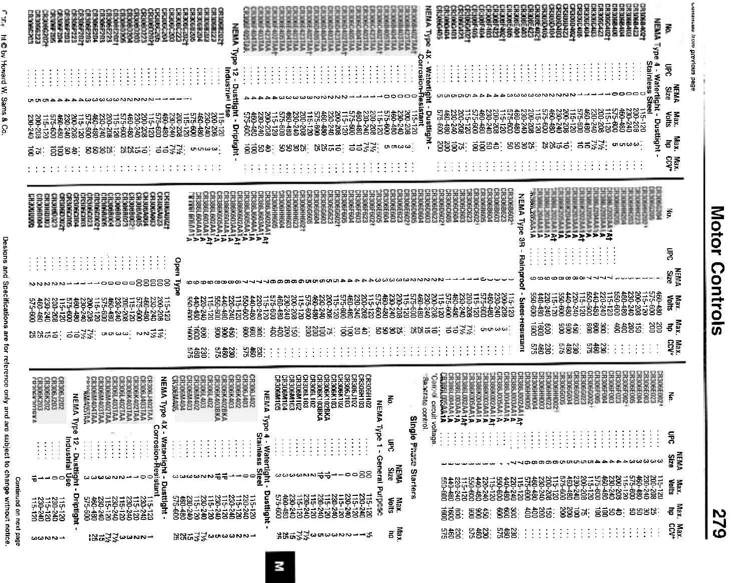
',n", n",vinu",
hi @ bY Howard W. Sams & Co.
No.
At
.A
1A
1A
At
.A
1A
1A
At
A
A
A
NEMA Max. Max. Max.
UPC Size Volts hp CCV*
i 460-480 200
i 575-600 200 ...
i 115-120 ...
) 200-208 150 ...
) 230-240 200 ...
) 460-480 400 ...
; 550-600400...
1At.,... 7 115-120... ...
A 7 220-240 300 230
IA 7 440-480 600 460
IA 7 550-600 600 575
At 8 115-120 ... ...
A 8 220-240 450 230
A 8 440-480 900 460
IA 8 550-600 900 575
At 9 115-120 ... ...
A 9 220-240 800 230
A 9 440-480 1600 460
,n"ouL,u"""..A 9 550-600 1600 575
NEMA Type 3R - Rainproof - ~leet-HeSIStam
) 115-120 ...
) 200-208 3 ...
) 230-240 3 ...
) 460-480 5 ...
.J 575-600 5 .,.
1 115-120 ... ...
1 200-208 7V2 . . .
1 230-240 7V2 . . .
1 460-480 10 ...
1 575-600 10 ...
2 115-120 ... ...
2 200-208 10 ."
2 230-240 15 ...
2 460-480 25 ...
2 575-600 25 ...
3 115-120 ... ...
3 200-208 25 ...
3 230-240 30 ...
3 460-480 50 ...
3 575-600 50 ...
4 115-120 ... ...
4 200-208 40 ...
4 230-240 50 ...
4 460-480 100 ...
4 575-600 100 ...
5 115-120 ... ...
5 200-208 75 ...
I; 230-240 100 ...
460-480 200 ...
575-600 200 ...
115-120 ... ...
200-208 150 ...
230-240 200 ...
460-480 400 ...
575-600 400 ...
115-120 ... , . .
220-240 300 230
440-480 600 460
550-600 600 575
115-120... ...
220-240 450 230
440-480 900 460
550-600 900 575
115-120 ... ...
220-240 800 230
440-480 1600 460
!i!i0-I;00 11;00 575
Open Type
00 115-120...
. . . . 00 200-208 1V2
. . . . 00 230-240 1V2
00 460-480 2
00 575-600 2
0 115-120 ...
0 200-208 3
0 230-240 3
0 460-480 5
0 575-600 5
1 115-120.. .
. . . . 1 200-208 7V2
. . . . 1 230-240 7V2
. . .. 1 460-480 10
. . . . 1 575-600 10
2 115-120 ...
2 200-208 10
. . . . 2 230-240 15
2 460-480 25
2 575-600 25
5
5
6
6
6
6
6
7
7
7
7
8
8
8
8
9
9
9
9
Motor Controls
Nn
Q-- r""~~ Starters
NEMA Max.
No. UPC Size Volts
NEMA Type 1 - General Pu. CR306H102 . 00 115-120
CR306H103 ..,.. 00 230-240
CR306J102 0 115-120
CR306J103 0 230-240
CR306K102 1 115-120
CR306K103 . . . . . 1 230-240
CR306K102BKA 1P 115-120
CR306K103BKA . 1P 230-240
CR306l102 2 115-120
CR306l103 2 230-240
CR306M102 3 115-120
CR306M103 3 230-240
CR306M104 ... 3 460-480
CR306M105 3 575-600
NEMA Type 4 - Watertight - Dusttight -
Stainless Steel
. . 0 115-120
. 0 230-240
1 115-120
. . . . . 1 230-240
1P 115-120
. . . . . 1P 230-240
2 115-120
. . . . . 2 230-240
3 115-120
. . . . . 3 230-240
. 3 460-480
..n"uu"'..u.. 3 575-600
NEMA Type 4X - Watertight - Dusttight -
Corrosion-Resistant
0 115-120
. . . 0 230-240
1 115-120
. . . . . 1 230-240
2 115-120
. . . . . 2 230-240
3 115-120
. . . . . 3 230-240
... 3 460-480
'U",..u" "'" 3 575-600
NEMA Type 12 - Dusttight - Driptight-
Industrial Use
. . . 0 115-120
. . . . 0 230-240
1 115-120
. . . . . 1 230-240
1P 115-120
Desians and Specifications are for reference only and are subject to change without notice.
NEMA Max. Max. Max.
UPC Size Volts hp CCV*
... 3 115-120 ...
3200-20825...
3 230-24030 ...
3 460-480 50 ...
. . . . . 3 575-600 50 . . .
4 115-120 ... ...
4 200-20840 ...
4230-24050...
4 460-480100 ...
4 575-600100 ...
5 115-120 ... ...
5 200-20875 ...
5 230-240100 ...
. . . . . 5 460-480 200 . . .
5 575-600200 ...
. . . . . 6 115-120 ... . . .
6200-208150...
6 230-240 200 ...
. . . . . 6 460-480 400 . . .
6 575-600 400 ...
7 115-120... ...
7 220-240 300 230
, 440-480 600 460
, 550-600 600 575
I 115-120 ... ...
I 220-240 450 230
I 440-480 900 460
! 550-600 900 575
, 115-120 ... .. .
, 220-240 800 230
, 440-480 1600 460
I 550-600 1600 575
Continued on next page
279
Max.
hp
1
2
2
3
3
5
3
71/2
71h
15
25
25
1
2
2
3
3
7'h
7V2
15
25
1/3
1
1
2
2
3
3
5
3
7V2
71h
15
25
?!i
1
2
2
3
3
. ~ page
NEMA Max. Max. Max.
UPC Size Volts hp CCV*
ype 4 - Watertight - Dusttight -
Stainless Steel
. . 0 115-120 ... ...
0200-2083 ...
0 230-2403 ...
0 460-4805 ...
0 575-6005 ...
1 115-120 ... ...
. . . . . 1 200-208 7V2 . . .
1 230-2407V2 ...
1460-48010...
1 575-60010 ...
2 115-120 ... ...
2 200-20810 ...
2 230-24015 ...
. . . . . 2 460-480 25 . . .
2 575-60025 ...
. . . . . 3 115-120 ... . . .
3200-20825...
. . . . . 3 230-240 30 . . .
3 460-48050 ...
3 575-60050 ...
4 115-120 ... ...
4200-20840...
4 230-24050 ...
4 460-480100 ...
4575-600100...
. . . . . 5 115-120 ... . . .
5 200-20875 ...
5230-240100...
. . . 5 460-480 200 . . .
. . . . . 5 575-600 200 . . .
4X - Watertight - Dusttight -
Corrosion-Resistant
. 0 115-120 ... ...
...0200-2083 ...
0 230-2403 ...
0 460-4805 ...
0 575-6005 ...
. . . . . 1 115-120. . . . . .
. . . . . 1 200-208 7V2 . . .
1 230-2407V2 ...
1 460-480 10 ...
1 575-60010 ...
2 115-120 ... ...
2 200-20810 ...
2 230-24015 ...
2 460-480 25 ...
2 575-60025 ...
3 115-120... ...
3 200-20825 ...
3 230-24030 ...
3 460-48050 ...
3 575-60050 ...
4 115-120 ... ...
. . . . . 4 200-208 40 . .
4 230-24050 ...
4460-480100..
, . . . . . 4 575-600 100 . .
rype 12 - Dusttight - Driptight -
Industril'~ Use
. . . . . 115-120. . . ..
. . 200-208 3 . .
230-2403..
460-4805..
.' 575-6005 ..
. . . . . I 115-120. . . . .
. . . . . I 200-208 7V2 . .
I 230-2407V2..
1 460-480 10 ..
1 575-60010 ..
2 115-120 ... ..
2 200-20810 ..
2 230-24015 ..
2 460-480 25 ..
. . . . . 2 575-600 25 . .
3 115-120 .,. ..
. . . . . 3 200-208 25
. . . . . 3 230-240 30
3 460-480 50 ..
3 575-60050 ..
4 115-120 ... ..
. . . . . 4 200-208 40 . .
4 230-24050 ..
4 460-480 100
. . .. . 4 575-600 100 . .
5 115-120 ...
5 200-208 75
5230-240100..
lAt. . .
IA . .
IA . . . .
A lAt. . .
IA . . . .
IA . . .
,jA . . .
1At 1A ,.A ... .
u" 1A . . . .
circuit voltage.
te control.
Sinale
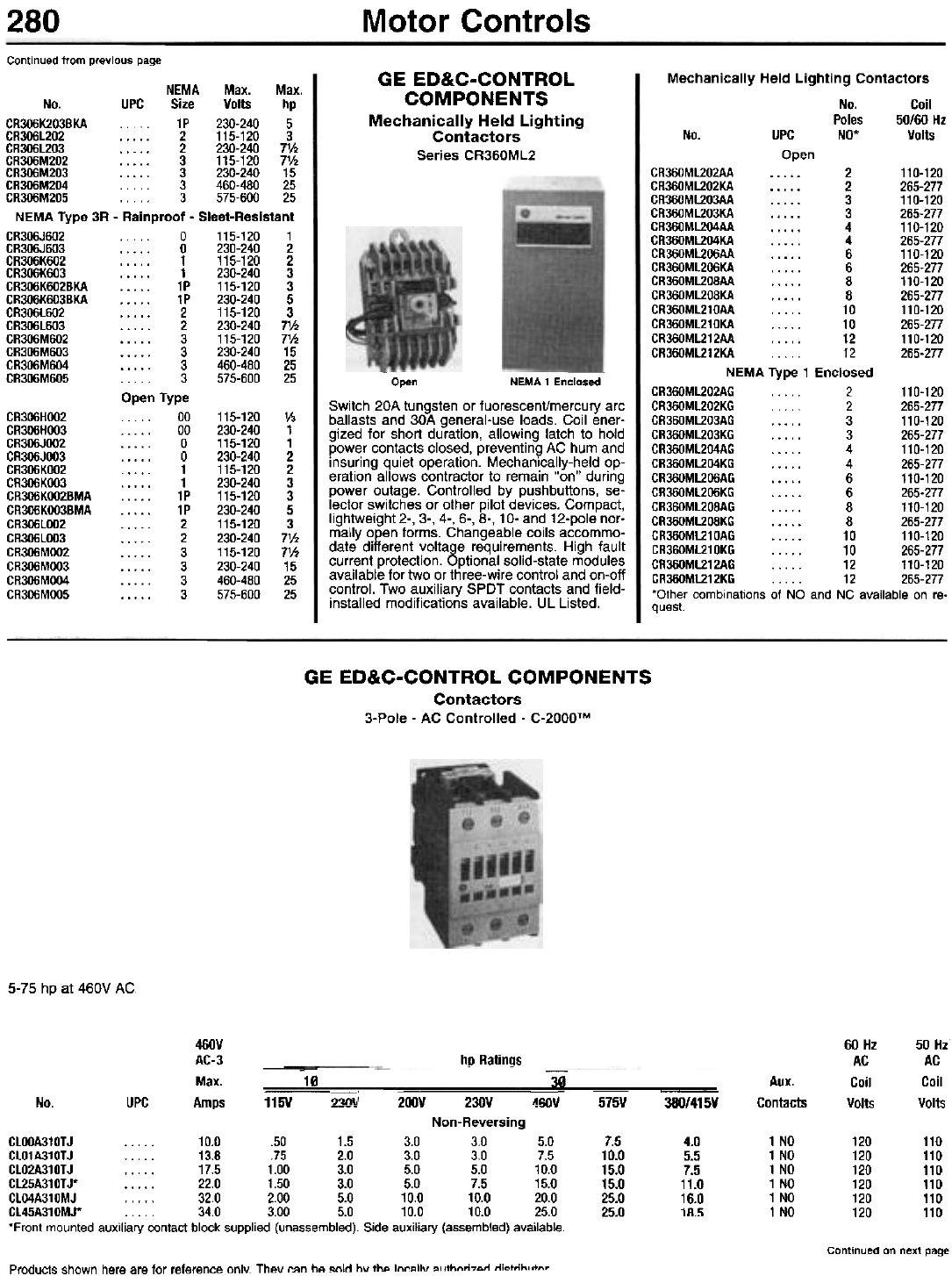
280 Motor Controls
Continued from previous page
GE ED&C-CONTROL
COMPONENTS
Mechanically Held Lighting
Contactors
Series CR360ML2
Mechanically Held Lighting Contactors
No. Coil
Poles 50/60 Hz
No. UPC NO' Volts
Open
NEMA Max. Max.
No. UPC Size Volts hp
CR306K203BKA 1P 230-240 5
CR306l202 2 115-120 3
CR306l203 2 230-240 71h
CR306M202 3 115-120 71h
CR306M203 3 230-240 15
CR306M204 3 460-480 25
CR306M205 3 575-600 25
NEMA Type 3R - Rainproof - Sleet-Resistant
CR3O6J602 0 115-120 1
CR3O6J603 0 230-240 2
CR306K602 , 1 115-120 2
CR306K603 1 230-240 3
CR306K602BKA 1P 115-120 3
CR306K603BKA 1P 230-240 5
CR306l602 2 115-120 3
CR306l603 2 230-240 71h
CR306M602 3 115-120 7V2
CR306M603 3 230-240 15
CR306M604 3 460-480 25
CR306M605 3 575-600 25
Open Type
CR306HOO2 00 115-120 1/3
CR306HOO3 00 230-240 1
CR3O6JOO2 0 115-120 1
CR306JOO3 0 230-240 2
CR306KOO2 1 115-120 2
CR306KOO3 1 230-240 3
CR306KOO2BMA .. ... 1P 115-120 3
CR306KOO3BMA . 1P 230-240 5
CR306l002 2 115-120 3
CR306l003 . . . . . 2 230-240 7V2
CR306MOO2 3 115-120 71h
CR306MOO3 3 230-240 15
CR306MOO4 3 460-480 25
CR306MOO5 3 575-600 25
GR360Ml202AA 2 110-120
GR360Ml202KA 2 265-277
GR360Ml203AA 3 110-120
GR360Ml203KA 3 265-277
GR360Ml204AA 4 110-120
GR360Ml204KA . . . . . 4 265-277
GR360Ml206AA 6 110-120
GR360Ml206KA . . . . . 6 265-277
GR360Ml208AA 8 110-120
GR360Ml208KA 8 265-277
GR360Ml210AA 10 110-120
GR360ML210KA 10 265-277
GR360Ml212AA 12 110-120
GR360Ml212KA 12 265-277
NEMA Type 1 Enclosed
GR360Ml202AG 2 110-120
GR360Ml202KG.. 2 265-277
GR360Ml203AG 3 110-120
GR360Ml203KG 3 265-277
GR360Ml204AG 4 110-120
GR360Ml204KG 4 265-277
GR360Ml206AG 6 110-120
GR360Ml206KG 6 265-277
GR360ML208AG 8 110-120
GR360Ml208KG 8 265-277
GR360Ml210AG 10 110-120
GR360ML210KG 10 265-277
GR360Ml212AG 12 110-120
GR360Ml212KG 12 265-277
'Other combinations of NO and NC available on re-
quest.
- -
Open NEMA 1 Enclosed
Switch 20A tungsten or fuorescent/mercury arc
ballasts and 30A general-use loads. Coil ener-
gized for short duration, allowing latch to hold
power contacts closed, preventing AC hum and
insuring quiet operation. Mechanically-held op-
eration allows contractor to remain "on" during
power outage. Controlled by pushbuttons, se-
lector switches or other pilot devices. Compact,
lightweight 2-, 3-, 4-, 6-, 8-, 10- and 12-pole nor-
mally open forms. Changeable coils accommo-
date different voltage requirements. High fault
current protection. Optional solid-state modules
available for two or three-wire control and on-off
control. Two auxiliary SPOT contacts and field-
installed modifications available. UL Listed.
GE ED&C-CONTROL COMPONENTS
Contactors
3-Pole - AC Controlled - C-2000TM
5-75 hp at 460V AC
460V
AC-3
Max. . -
No. UPC Amps 115V _J 200V 230V '
Non-Reversing
CLOOA310TJ 10.0 .50 1.5 3.0 3.0 5.0
CL01A310TJ 13.8 .75 2.0 3.0 3.0 7.5
CL02A310TJ 17.5 1.00 3.0 5.0 5.0 10.0
CL25A310TJ* 22.0 1.50 3.0 5.0 7.5 15.0
CL04A310MJ . . . . . 32.0 2.00 5.0 10.0 10.0 20.0
CL45A310MJ* . . . . . 34.0 3.00 5.0 10.0 10.0 25.0
'Front mounted auxiliary contact block supplied (unassembled). Side auxiliary (assembled) available.
60 Hz
AC
Coil
Volts
50 Hi
AC
Coil
Volts
hp Ratings
-
10
-
30 Aux.
Contacts
-
2~\j
-
4IiIlIJ -
575V 380/415V
7.5
10.0
15.0
15.0
25.0
25.0
4.0
5.5
7.5
11.0
16.0
18.5
1 NO
1 NO
1 NO
1 NO
1 NO
1 NO
120
120
120
120
120
120
110
110
110
110
110
110
Continued on next page
Products shown here are for reference onlY. They can be sold bv IhA In"...lIv ",IIhn,i7An n;ctrih"tn,
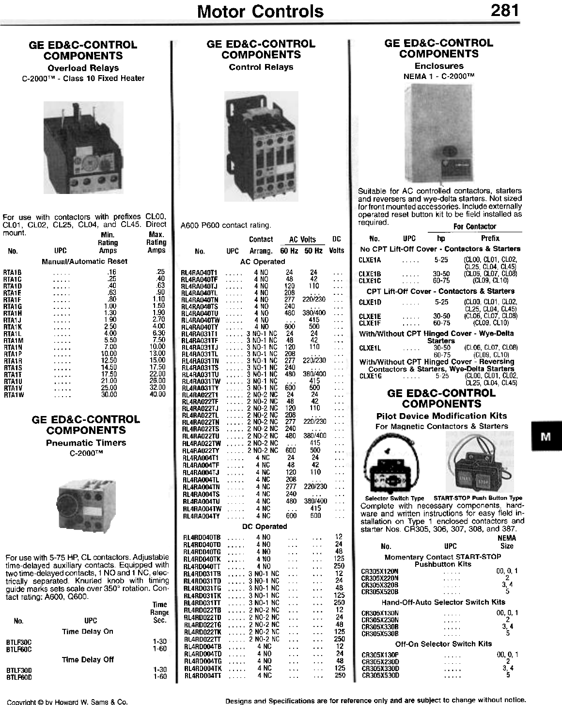
281
Motor Controls
GE ED&C-CONTROL
COMPONENTS
Control Relays
GE ED&C-CONTROL
COMPONENTS
Enclosures
NEMA 1 - C-2000TM
GE ED&C-CONTROL
COMPONENTS
Overload Relays
C-2000TM - Class 10 Fixed Heater
For use with contactors with prefixes CLOD,
CLO1, CLO2, CL25, CLO4, and CL45. Direct
mount. Min. Max.
Rating Rating
No. UPC Amps Amps
Manual/Automatic Reset
RTA1B... .16 .25
RTA1C .25 .40
RTA1D .40 .63
RTA1E .63 .90
RTA1F .80 1.10
RTA1G 1.00 1.50
RTA1H 1.30 1.90
RTA1J . . . . . 1.90 2.70
RTA1K 2.50 4.00
RTA1l 4.00 6.30
RTA1M 5.50 7.50
RTA1N 7.00 10.00
RTA1P 10.00 13.00
RTA1R 12.50 15.00
RTA1S 14.50 17.50
RTA1T 17.50 22.00
RTA1U 21.00 26.00
RTA1V 25.00 32.00
RTA1W . . . . . 30.00 40.00
Suitable for AC controlled contactors, starters
and reversers and wye-delta starters. Not sized
for front mounted accessories. Include externally
operated reset button kit to be field installed as
required. For Contactor
No. UPC hp Prefix
No CPT Lift-Off Cover - Contactors & Starters
CLXE1A . . ... 5-25 (CLOO, CL01, CL02,
CL25, CL04, CL45)
CLXE1B . . .. . 30-50 (CL06, CL07, CL08)
CLXE1C . . . 60-75 (CLOg, CL10)
CPT Lift-Off Cover - Contactors & Starters
CLXE1D 5-25 (CLOO, CL01, CL02,
CL25, CL04, CL45)
CLXE1E . . . . . 30-50 (CL06, CL07, CL08)
CLXE1F , 60-75 (CL09,CL10)
With/Without CPT Hinged Cover - Wye-Delta
Starters
CLXE1 L . 30-50 (CL06, CL07, CL08)
60-75 (CLOg, CL10)
With/Without CPT Hinged Cover - Reversing
Contactors & Starters, Wye-Delta Starters
CLXE1 G . . . 5-25 (CLOO, CL01, CL02,
CL25, CL04, CL45)
GE ED&C-CONTROL
COMPONENTS
Pilot Device Modification Kits
For Magnetic Contactors & Starters
AC Volts
A600 P600 contact rating.
Contact DC
No. UPC Arrang. 60 Hz 50 Hz Volts
AC Operated
RL4RA040T1 4 NO 24 24 . . .
RL4RAO40TF 4 NO 48 42 ...
RL4RAO40TJ 4 NO 120 110 .. .
RL4RAO4OTL 4 NO 208 . . . . . .
RL4RA040TN 4 NO 277 220/230 ...
RL4RA040TS 4 NO 240 ...
RL4RAO40TU 4 NO 480 380/400 ...
RL4RAO40TW 4 NO . . . 415 . . .
RL4RA040TY 4 NO 600 500 ...
RL4RA031T1 3 NO-1 NC 24 24 ...
RL4RA031TF 3 NO-1 NC 48 42 ...
RL4RA031TJ 3 NO-1 NC 120 110 ...
RL4RA031 TL 3 NO-1 NC 208 . . . . . .
RL4RA031 TN 3 NO-1 NC 277 220/230 ...
RL4RA031 TS , 3 NO-1 NC 240 . . . . . .
RL4RA031TU 3 NO-1 NC 480 380/400 ...
RL4RA031TW 3 NO-1 NC ... 415 ...
RL4RA031TY 3 NO-1 NC 600 500
RL4RA022T1 2 NO-2 NC 24 24 . . .
RL4RA022TF 2 NO-2 NC 48 42 ...
RL4RA022TJ 2NO-2NC 120 110 ...
RL4RA022TL 2 NO-2 NC 208 . . . . . .
RL4RA022TN 2 NO-2 NC 277 220/230 ...
RL4RA022TS 2 NO-2 NC 240 ...
RL4RA022TU 2 NO-2 NC 480 380/400 ..
RL4RA022TW 2 NO-2NC ... 415 ...
RL4RA022TY 2 NO-2 NC 600 500 ..,
RL4RAOO4T1 4 NC 24 24 ...
RL4RAO04TF 4 NC 48 42 ...
RL4RAO04TJ 4NC 120 110 ...
RL4RAO04TL 4 NC 208 . . . . . .
RL4RAOO4TN 4 NC 277 220/230 ...
RL4RAO04TS 4 NC 240 . . . . . .
RL4RAOO4TU 4 NC 480 380/400 ...
RL4RAO04TW.. 4 NC 415...
RL4RAOO4TY ... 4 NC 600 500 ...
DC Operated
. . . . . 4 NO . . .
. . . . . 4 NO . . . . . .
. . . . . 4 NO . . . . . .
. . . . . 4 NO . . . . . .
. . . . . 4 NO . . . . . .
. . . .. 3 NO-1 NC . . . . . .
. . . .. 3 NO-1 NC .. . . . .
. . . .. 3 NO-1 NC .. . . . .
. . . .. 3 NO-1 NC .. . . . .
. . . .. 3 NO-1 NC . . . . . .
. . . .. 2 NO-2 NC . . . . . .
. . . .. 2 NO-2 NC .. . . . .
. . . .. 2 NO-2 NC .. . . . .
. . . .. 2 NO-2 NC ... . . .
. . . .. 2 NO-2 NC . . . . . .
. . . . . 4 NC . . . . . .
. . . . . 4 NO . . . . . .
. . . . . 4 NO . . . . . .
. . . . . 4 NC . . . . . .
4NC ... ... ---
GE ED&C-CONTROL
COMPONENTS
Pneumatic Timers
C-2000TM
RL4RD040TB
RL4RDO40TD
RL4RDO40TG
RL4RD040TK
RL4RDO40TT
RL4RDO31TB
RL4RDO31TD
RL4RDO31TG
RL4RDO31TK
RL4RDO31TT
RL4RDO22TB
RL4RDO22TD
RL4RDO22TG
RL4RDO22TK
RL4RDO22TT
RL4RDOO4TB
RL4RDOO4TD
RL4RDOO4TG
RL4RDOO4TK
RL4RDOO4TT
12
24
48
125
250
12
24
48
125
250
12
24
48
125
250
12
24
48
125
?~n
For use with 5-75 HP, CL contactors. Adjustable
time-delayed auxiliary contacts. Equipped with
two time-delayed contacts, 1 NO and 1 NC, elec-
trically separated. Knurled knob with timing
guide marks sets scale over 3500 rotation. Con-
tact rating: A600, 0600. Time
Range
No. UPC Sec.
Time Delay On
1-30
1-60
BTLFJOC
BTLF60C
Selector Switch Type START-STOP Push Button Type
Complete with necessary components, hard-
ware and written instructions for easy field in-
stallation on Type 1 enclosed contactors and
starter Nos. CA30S, 306, 307, 308, and 387.
NEMA
No. UPC Size
Momentary Contact START-STOP
Pushbutton Kits
CR305X120N . . . 00,0,1
CR305X220N ... 2
CR305X320B 3, 4
CR305X520B. 5
Hand-Oft-Auto Selector Switch Kits
CR305X130N . 00, 0, 1
CR305X230N 2
CR305X330B . . . . . 3, 4
CR305X530B . . . . 5
Oft-On Selector Switch Kits
CR305X130P . . . . . 00,0,1
CR305X230D... 2
CR305X330D . . . . . 3, 4
CR305X530D 5
Time Delay Off
1-30
1-60
BTlF30D
BTlF60D
Designs and Specifications are for reference only and are subject to change without notice.
CoDyrioht @ bY Howard W. Sams & Co.
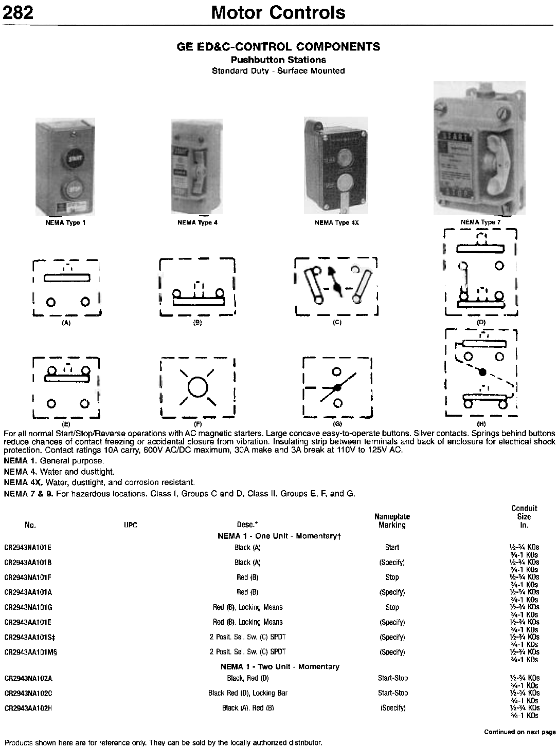
Motor Controls
282
GE ED&C-CONTROL COMPONENTS
Pushbutton Stations
Standard Duty - Surface Mounted
---
NEMA Type 7
r-;=;-,
~~
() 0 I
~
NEMA Type 1 -
NEMA Type 4 NEMA Type 4X
r - - -,
r--i
r -;--;- -I
I I~ ) I --
,'.
, e:~:~::9 I
L- - - _I
IR\
. 0 O.
L__-'
(A)
I i ~ .-. 1'\
- '-" [~ . . ~
L - - - j L: - - .~
,-, (C) (D)
r -,--;- - ,r<==-.;.J
1-- - - r -- -, 1""'<2 0 I
'0/ I~o I .. , I
, - I -, ~I
10 o. J /, J '0 I IS===oJ[
L__~ i , L J L (E) (F) (G) (H)
For all normal Start/Stop/Reverse operations with AC magnetic starters. Large concave easy-to-operate buttons. Silver contacts. Springs behind buttons
reduce chances of contact freezing or accidental closure from vibration. Insulating strip between terminals and back of enclosure for electrical shock
protection. Contact ratings 10A carry, 600V AC/DC maximum, 30A make and 3A break at 110V to 125V AC.
NEMA 1. General purpose.
NEMA 4. Water and dusttight.
NEMA 4X. Water, dusttight, and corrosion resistant.
NEMA 7 & 9. For hazardous locations. Class I, Groups C and D, Class II, Groups E, F, and G.
r--
I ce:=-:::9 I I
I
I
Conduit
Size
In.
Nameplate
Marking
UPC
No.
CR2943NA101E
CR2943AA101B
CR2943NA101F
CR2943AA101A
CR2943NA101G
CR2943AA101E
CR2943AA101S:j:
CR2943AA101M§
Start
(Specify)
Stop
(Specify)
Stop
(Specify)
(Specify)
(Specify)
1h-0/. KOs
0/.-1 KOs
1h-0/4 KOs
0/4-1 KOs
1h-0/4 KOs
0/4-1 KOs
V2-0/4 KOs
0/4-1 KOs
1h_3/. KOs
0/4-1 KOs
1h-0/4 KOs
0/4-1 KOs
1h-0/4 KOs
0/4-1 KOs
V2_3/. KOs
0/4-1 KOs
Desc.*
NEMA 1 - One Unit - Momentaryt
Black (A)
Black (A)
Red (B)
Red (B)
Red (B), Locking Means
Red (B), Locking Means
2 Posit. Sel. Sw. (C) SPOT
2 Posit. Sel. Sw. (C) SPOT
NEMA 1 - Two Unit - Momentary
Black, Red (0)
Black Red (0), Locking Bar
Black (AI. Red (B\
CR2943NA102A
CR2943NA102C
CR2943AA102H
Start-Stop
Start-Stop
(SDecify)
V2-3/. KOs
3/.-1 KOs
'h-3/. KOs
3/.-1 KOs
V2_3/. KOs
3/.-1 KOs
Continued on next page
Products shown here are for reference only. They can be sold by the locally authorized distributor.
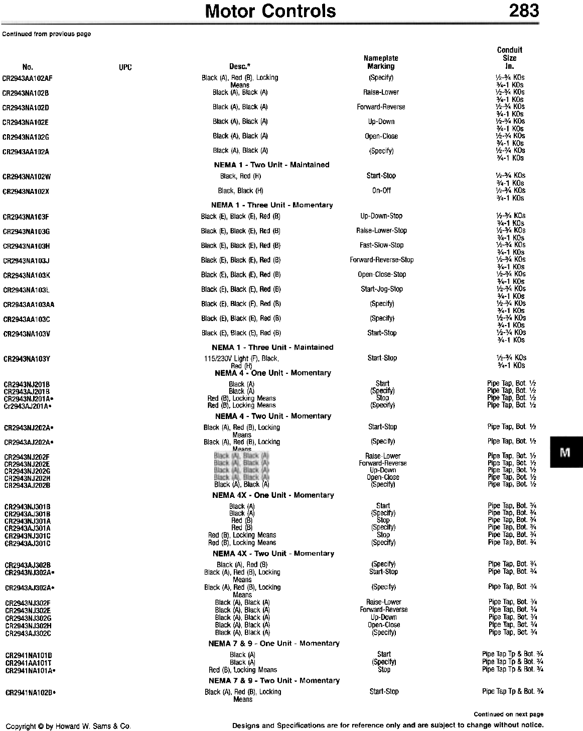
Motor Controls 283
Continued from previous page
Conduit
Size
In.
Y2-3/. KOs
0/.-1 KOs
Y2-0/' KOs
0/.-1 KOs
Jh-o/. KOs
0/.-1 KOs
Jh-3/. KOs
0/.-1 KOs
Y2-3/. KOs
0/.-1 KOs
'/2-3/. KOs
0/.-1 KOs
Nameplate
Marking
(Specify)
Raise-Lower
Forward-Reverse
Up-Down
Open-Close
(Specify)
No.
CR2943AA102AF
CR2943NA102B
CR2943NA102D
CR2943NA102E
CR2943NA102G
CR2943AA102A
UPC
Start-Stop
On-Off
V2-'/4 KOs
3/4-1 KOs
V2-'/4 KOs
'/4-1 KOs
CR2943NA102W
CR2943NA102X
Up-Down-Stop
Raise-lower-Stop
Fast-Slow-Stop
Forward-Reverse-Stop
Open-Close-Stop
Start-Jog-Stop
(Specify)
(Specify)
Start-Stop
V2-0/' KOs
0/.-1 KOs
V2-0/4 KOs
0/4-1 KOs
'h-0/4 KOs
0/4-1 KOs
V2-0/4 KOs
0/4-1 KOs
V2-0/4 KOs
0/4-1 KOs
V2-0/4 KOs
0/4-1 KOs
V2-0/4 KOs
0/4-1 KOs
'h-0/4 KOs
0/4-1 KOs
V2-0/4 KOs
0/4-1 KOs
CR2943NA103F
CR2943NA103G
CR2943NA103H
CR2943NA103J
CR2943NA103K
CR2943NA103L
CR2943AA103AA
CR2943AA103C
CR2943NA103V
'h-3/4 KOs
3/4-1 KOs
Start-Stop
CR2943NA103Y
Start
(Specify)
Stop
(Specify)
Pipe Tap, Bot. V2
Pipe Tap, Bot. V2
Pipe Tap, Bot. V2
Pipe Tap, Bot. V2
CR2943NJ201B
CR2943AJ201B
CR2943NJ201Ao
Cr2943AJ201 A °
Desc.*
Black (A), Red (B), Locking
Means
Black (A), Black (A)
Black (A), Black (A)
Black (A), Black (A)
Black (A), Black (A)
Black (A), Black (A)
NEMA 1 - Two Unit - Maintained
Black, Red (H)
Black, Black (H)
NEMA 1 - Three Unit - Momentary
Black (E), Black (E), Red (B)
Black (E), Black (E), Red (B)
Black (E), Black (E), Red (B)
Black (E), Black (E), Red (B)
Black (E), Black (E), Red (B)
Black (E), Black (E), Red (B)
Black (E), Black (E), Red (B)
Black (E), Black (E), Red (B)
Black (E), Black (E), Red (B)
NEMA 1 - Three Unit - Maintained
115/23DV Light (F), Black,
Red (H)
NEMA 4 - One Unit - Momentary
Black (A)
Black (A)
Red (B), Locking Means
Red (B), Locking Means
NEMA 4 - Two Unit - Momentary
Black (A), Red (B), Locking
Means
Black (A), Red (B), Locking
MeHnR
Start-Stop
(Specify)
Raise-Lower
Forward-Reverse
Up-Down
Open-Close
(Specify)
Pipe Tap, Bot. V2
Pipe Tap, Bot. V2
Pipe Tap, Bot. V2
Pipe Tap, Bot. V2
Pipe Tap, Bot. V2
Pipe Tap, Bot. V2
Pipe Tap, Bot. V2
CR2943NJ202A-
CR2943AJ202A-
CR2943NJ202F
CR2943NJ202E
CR2943NJ202G
CR2943NJ202H
CR2943AJ202B
Start
(Specify)
Stop
(Specify)
Stop
(Specify)
Pipe Tap, Bot. 3/.
Pipe Tap, Bot. 3/.
Pipe Tap, Bot. %
Pipe Tap, Bot. 3/.
Pipe Tap, Bot. 3/.
Pipe Tap, Bot. %
CR2943NJ301B
CR2943AJ301B
CR2943NJ301A
CR2943AJ301A
CR2943NJ301C
CR2943AJ301C
(Specify)
Start-Stop
(Specify)
Raise-Lower
Forward-Reverse
Up-Down
Open-Close
(Specify)
Pipe Tap, Bot. 3/4
Pipe Tap, Bot. 3/4
Pipe Tap, Bot. 3/4
Pipe Tap, Bot. 3/4
Pipe Tap, Bot. 3/4
Pipe Tap, Bot. 3/4
Pipe Tap, Bot. 3/4
Pipe Tap, Bot. 3/4
CR2943AJ3028
CR2943NJ302A.
CR2943AJ302A.
CR2943NJ302F
CR2943NJ302E
CR2943NJ302G
CR2943NJ302H
CR2943AJ302C
Pipe Tap Tp & Bot. 3/.
Pipe Tap Tp & Bot. 3/.
Pipe Tap Tp & Bot. 3/.
Start
(Specify)
Stop
CR2941NA101B
CR2941AA101T
CR2941NA101Ao
Black (AI: Black (AI
NEMA 4X - One Unit - Momentary
Black
~A) Black A)
Red ( )
Red (B)
Red (B), Locking Means
Red (B), Locking Means
NEMA 4X - Two Unit - Momentary
Black (A), Red (B)
Black (A), Red (B), Locking
Means
Black (A), Red (B), Locking
Means
Black (A), Black (A)
Black (A), Black (A)
Black (A), Black (A)
Black (A), Black (A)
Black (A), Black (A)
NEMA 7 & 9 - One Unit - Momentary
Black (A)
Black (A)
Red (B), Locking Means
NEMA 7 & 9 - Two Unit - Momentary
Black (A), Red (B), Locking
Means Start-Stop Pipe Tap Tp & Bot. 3/.
CR2941NA102B.
Continued on next page
Designs and Specifications are for reference only and are subject to change without notice.
Copyright @ by Howard W. Sams & Co.
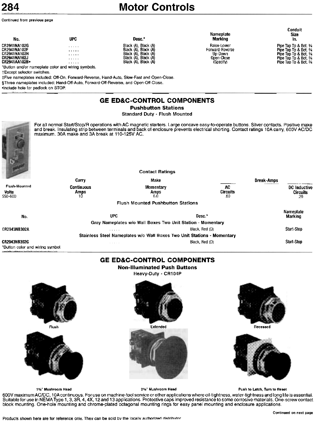
Motor Controls
284
Continued from previous page
Conduit
Size
In.
Pipe Tap Tp & Bot. %
Pipe Tap Tp & Bot. 3/4
Pipe Tap Tp & Bot. 3/4
Pipe Tap Tp & Bot. 3/4
Pipe Tap Tp & Bot. 3/4
Nameplate
Marking
Raise-Lower
Forward-Reverse
Up-Down
Open-Close
(Specify)
No. UPC Desc.*
CR2941NA102G . . . Black (A), Black (A
CR2941NA102F Black!A!' Black! A
CR2941NA102H Black A, Black A
CR2941NA102J . . . . . Black A, Black A
CR2941AA1028o . . . . . Black A, Black A
"Button and/or nameplate color and wiring symbols.
tExcept selector switches.
:j:Five nameplates included: Off-On, Forward-Reverse, Hand-Auto, Slow-Fast and Open-Close.
§Three nameplates included: Hand-Oil-Auto, Forward-Oil-Reverse, and Open-Oil-Close.
-Include hole for padlock on STOP.
GE ED&C-CONTROL COMPONENTS
Pushbutton Stations
Standard Duty - Flush Mounted
For all normal Start/Stop/R operations with AC magnetic starters. Large concave easy-to-operate buttons. Silver contacts. Positive make
and break. Insulating strip between terminals and back of enclosure prevents electrical shorting. Contact ratings 10A carry, 600V AC/DC
maximum. 30A make and 3A break at 110-125V AC.
Carry
Continuous
Amps
10
Break-Amps
Flush-Mounted
Volts
550-600
-AC
Circuits
60
DC Inductive
Circuits
20
Contact Ratings
Make
Momentary
Amps
6.0
Flush Mounted Pushbutton Stations
Nameplate
Marking
No.
CR2943NB302A Start-Stop
UPC Desc.*
Gray Nameplates w/o Wall Boxes Two Unit Station - Momentary
Black, Red (0)
Stainless Steel Nameplates w/o Wall Boxes Two Unit Stations - Momentary
Black, Red (0) Start-Stop
CR2943NB302G
'Button color and wiring symbol.
GE ED&C-CONTROL COMPONENTS
Non-Illuminated Push Buttons
Heavy-Duty - CR104P
Flush Extended Recessed
13/0" Mushroom Head 23/0" Mushroom Head Push to Latch, Turn to Reset
600V maximum AC/DC, 1 OAcontinuous. For use on machine-tool service or other applications where oil-tightness, water-tightness and long life is essential.
Suitable for use in NEMA Type 1,3, 3R, 4, 4X, 12 and 13 applications. Protective caps improved resistance to some corrosive materials. One-screw contact
block mounting. One-hole mounting and chrome-plated octagonal mounting rings for easy panel mounting and enclosure applications.
Continued on next page
Products shown here are for reference only. They can be sold bv the locallv authorizAn ni,.trih, ,tnr
Motor Controls 285
Continued from previous page
Specifications. -13°F to 158°F operating temperature range. -40°F to 158°F storage temperature range. Accept 22-12 AWG stranded or solid copper
wire. Rated life of 5,000,000 operations.
UL Listed. CSA Certified.
Step 1 - Operator Selection. Add catalog number digit to 'CR104PB'. For example, CR104PBG- is a standard push button.
Step 2 - Contact Configuration Selection. Add catalog number digit to selected operator configuration. For example, CR1 04PBG11- is a standard push
button with 1 NO and 1 NC contact.
Step 3 - Cap Color Selection. Add catalog number digit to selected operator and contact configuration. For example, CR1 04PBG11 B- is a standard push
button with 1 NO and 1 NC contact and black cap.
Step 4 - Mounting Ring or Mushroom Head Diameter Selection. Add catalog number digit to selected operator, contact configuration and cap color.
For example, CR104PBG11B2 is an extended standard push button with 1 NO and 1 NC contact, black cap and short ring.
Step 5 (Optional) - Modification Selection. Add catalog number digit to selected operator, contact configuration, cap color and mounting ring or mushroom
head diameter. For example, CR1 04PBG11 B2B is an extended standard push button with 1 NO and 1 NC contact, black cap, short ring and push on/push
off operation. Step 1 - Operator Selection
Cat.
No.
Di8it
M
Cat.
No.
Di8it
E
Cat.
No.
Di~it
K
Operator
Std. Push Button
Mushroom-Head Push Button
Operator
Wobble Stick
Key-Operated Push Button
Operator
Std. Push Button w/Maintained Latch Kit
Std. Push Button w/Mechanical Interlock Kit
Step 2 - Contact Configuration Selection
NO NC
Contacts Contacts
No Contact Block
NO
Contacts NC
Contacts NO
Contacts NC
Contacts
Single Circuit Single Circuit
01
2
2
2
2
2
2
2
3
3
3
3
3
3
4
4
4
4
4
~
7
0
1
2
3
4
5
6
0
1
2
3
4
5
0
1
2
3
4
n
5
5
5
6
6
6
7
7
8
9
1
2
3
0
1
2
0
1
0
.
Single Circuit
0
0
0
0
0
0
0
0
1
2
3
4
5
6
7
8
0
1
2
3
4
5
I;
Double Circuit
g'
g'
g'
g
2"
3"
4"
9t
Single Circuit
0
0~
'Operator code E must use one of these contact configurations.
t1NO-1NC time delay double circuit contact block available for operator code G only.
:t:2NC w/1 late-opening contact block.
§4NC w/2 late-opening contact blocks.
Step 3 - Cap Color Selection
Cat. No. Digit
For Operator Codes
M
A
B
E
~
G/D/E/S
A
B
C
E
G
L
M
N
R
W
U
v
K
1\
Cap
Color
No Cap
Black
Clear
Yellow
Green
Blue
Orange
Brown
Red
White
Comb. 1-
Comb. 2*
-Supplied w/4 caps (red, green, yellow, black).
*Supplied w/4 caps (brown, blue, orange, white).
Step 4 - Mounting Ring or Mushroom-Head Diameter Selection
Cat. No. Digit
For Operator Code
-
G/E
1
2
3
-
D
1
2
3
-
S
1
-M-
K
1
Desc.
Std. Ring for Flush Push Buttons
Short Ring for Extended Push Buttons
Extended Ring for Recessed Push Buttons
13/8" Mushroom Head
23/8" Mushroom Head .5
66
Continued on next page
Designs and Specifications are for reference only and are subject to change without notice.
Copyright @ by Howard W. Sams & Co.
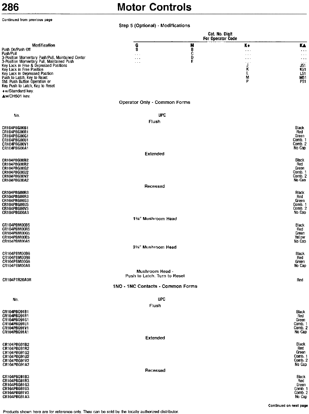
Motor Controls
286
Continued from previous page Step 5 (Optional) - Modifications
Cat. No. Digit
For Dperator Code
G M Kt U
B B ... ...
C ... ...
... D ... ...
... E ... ...
MnrJification
Push On/Push Off
Push/Pull
3-Position Momentary Push/Pull, Maintained Center
3-Position Momentary Pull, Maintained Push
Key Lock in Free & Depressed Positions
Key Lock in Free Position
Key Lock in Depressed Position
Push to Latch, Key to Reset
Std. Push Button Operation or
Key Push to Latch, Key to Reset
+w/Standard key-
.;.w/CH501 key.
J
K
L
M
P
J51
K51
L51
M51
P51
Operator Only - Common Forms
UPC
Flush
No.
CR104PBGOOB1
CR104PBGOOR1
CR104PBGOOG1
CR104PBGOOU1
CR104PBGOOV1
CR104PBGOOA1
Black
Red
Green
Comb. 1
Comb. 2
No Cap
Extended
CR104PBGOOB2
CR104PBGOOR2
CR104PBGOOG2
CR104PBGOOU2
CR104PBGOOV2
CR104PBGOOA2
Black
Red
Green
Comb. 1
Comb. 2
No Cao
Recessed
CR104PBGOOB3
CR104PBGOOR3
CR104PBGOOG3
CR104PBGOOU3
CR104PBGOOV3
CR104PBGOOA3
Black
Red
Green
Comb. 1
Comb. 2
No CaD
13/." Mushroom Head
CR104PBMOOB5
CR104PBMOOR5
CR104PBMOOG5
CR104PBMOOE5
CR104PBMOOA5
Black
Red
Green
Yellow
No Cap
23/." Mushroom Head
CR104PBMOOB6
CR104PBMOOR6
CR104PBMOOG6
CR104PBMOOA6
Black
Red
Green
No Cap
Mushroom Head -
Push to Latch. Turn to Reset
CR104PTR20AOR Red
1 NO - 1 NC Contacts - Common Forms
UPC
Flush
No.
CR104PBG91B1
CR104PBG91R1
CR104PBG91G1
CR104PBG91U1
CR104PBG91V1
CR104PBG91A1
Black
Red
Green
Comb. 1
Comb. 2
No Cap
Extended
CR1 04PBG91 B2
CR1 04PBG91 R2
CR104PBG91G2
CR1 04PBG91 U2
CR1 04PBG91 V2
CR104PBG91A2
Black
Red
Green
Comb. 1
Comb. 2
No Cap
Recessed
Black
Red
Green
Comb. 1
Comb. 2
No Cap
Continued on next page
CR104PBG91B3
CR104PBG91R3
CR104PBG91G3
CR104PBG91U3
CR104PBG91V3
CR104PBG91A3
Products shown here are for reference only. They can be sold by the locally authorized distributor.
Motor Controls 287
Continued from previous page
Cap
Color
No. UPC
13/8" Mushroom Head
Black
Red
Green
No Cap
CR104PBM91B5
CR104PBM91R5
CR104PBM91G5
CR1 04PBM91 A5
23/." Mushroom Head
Black
Red
Green
No Cap
CR104PBM91B6
CR104PBM91R6
CR104PBM91G6
CR104PBM91A6 Mushroom Head - Push to Latch, Turn to Reset
CR104PTR20AOR91 Red
2ND - 2NC Contacts - Common Forms
UPC Color
No.
Flush
CR104PBG92B1
CR104PBG92R1
CR104PBG92G1
CR104PBG92U1
CR104PBG92V1
CR104PBG92A1
Black
Red
Green
Comb. 1
Comb. 2
No Cap
Extended
GR104PBG92B2
GR104PBG92R2
GR104PBG92G2
GR104PBG92U2
GR104PBG92V2
GR104PBG92A2
Black
Red
Green
Comb. 1
Comb. 2
No Cap
Recessed
Black
Red
Green
Comb. 1
Comb. 2
No Cap
GR104PBG92B3
GR104PBG92R3
GR104PBG92G3
GR104PBG92U3
GR104PBG92V3
GR104PBG92A3
13/." Mushroom Head
Black
Red
Green
No Cap
CR104PBM92B5
CR104PBM92R5
CR104PBM92G5
CR104PBM92A5
23/8" Mushroom Head
Black
Red
Green
No Cap
CR104PBM92B6
CR104PBM92R6
CR104PBM92G6
CR104PBM92A6 Mushroom Head -
Push to Latch, Turn to Reset
1 NO Contact - Common Forms
UPC
Flush
Red
CR104PTR20AOR92
Color
No.
CR104PBG10B1
CR104PBG10R1
CR104PBG10G1
CR104PBG10U1
CR104PBG10V1
CR104PBG10A1
Black
Red
Green
Comb. 1
Comb. 2
No Cap
Extended
CR104PBG10B2
CR104PBG10R2
CR104PBG10G2
CR104PBG10U2
CR104PBG10V2
CR104PBG10A2
Black
Red
Green
Comb. 1
Comb. 2
No Cap
Recessed
Black
Red
Green
Comb. 1
Comb. 2
No Cap
CR104PBG10B3
CR104PBG10R3
CR104PBG10G3
CR104PBG10U3
CR104PBG10V3
CR104PBG10A3
13/8" Mushroom Head
CR104PBM10B5
CR104PBM10R5 Black
Red
Continued on next page
Designs and Specifications are for reference only and are subject to change without notice.
Copyright @ by Howard W. Sams & Co.
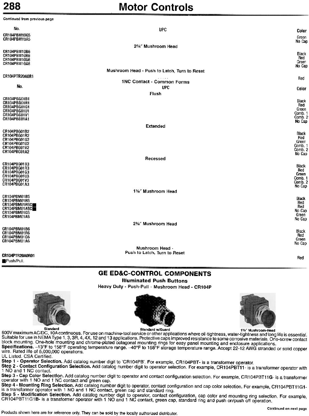
288 Motor Controls
Continued from previous page
No.
CR104PBM10G5
CR104PBM10A5
UPC Color
Green
No Cap
23/8" Mushroom Head
CR104PBM10B6
CR104PBM10R6
CR104PBM10G6
CR104PBM10A6
Black
Red
Green
No Cap
Mushroom Head - Push to Latch, Turn to Reset
CR104PTR20AOR1 Red
1 NC Contact - Common Forms
UPC
No. Color
Flush
CR104PBGO1B1
CR104PBGO1R1
CR104PBGO1G1
CR104PBGO1U1
CR104PBGO1V1
CR104PBGO1A1
Black
Red
Green
Comb. 1
Comb. 2
No Cap
Extended
CR104PBGO1B2
CR104PBGO1R2
CR104PBGO1G2
CR104PBGO1U2
CR104PBGO1V2
CR104PBGO1A2
Black
Red
Green
Comb. 1
Comb. 2
No Cap
Recessed
CR104PBGO1B3
CR104PBGO1R3
CR104PBGO1G3
CR104PBGO1U3
CR104PBGO1V3
CR104PBGO1A3
Black
Red
Green
Comb. 1
Comb. 2
No Cap
13/8" Mushroom Head
CR104PBMO1B5
CR104PBMO1R5
CR104PBMO1R5C.
CR104PBMO1A5C.
CR104PBMO1G5
CR104PBMO1A5
Black
Red
Red
No Cap
Green
No Cap
23/8" Mushroom Head
CR104PBMO1B6
CR104PBMO1R6
CR104PBMO1G6
CR104PBMO1A6
Black
Red
Green
No Cap
Mushroom Head -
Push to Latch, Turn to Reset
CR104PTR20AORO1
.Push/Pull. Red
GE ED&C-CONTROL COMPONENTS
Illuminated Push Buttons
Heavy Duty - Push-Pull - Mushroom Head - CR104P
~ - -
Standard Standard w/Guard 13/." Mushroom-Head
600V maximum AC/DC, 1 OAcontinuous. For use on machine-tool service or other applications where oil-tightness, water-tightness and long life is essential.
Suitable for use in NEMA Type 1,3, 3R, 4, 4X, 12 and 13 applications. Protective caps improved resistance to some corrosive materials. One-screw contact
block mounting. One-hole mounting and chrome-plated octagonal mounting rings for easy panel mounting and enclosure applications.
Specifications. -13°F to 158°F operating temperature range. -40°F to 158°F storage temperature range. Accept 22-12 AWG stranded or solid copper
wire. Rated life of 5,000,000 operations.
UL Listed. CSA Certified.
Step 1 - Operator Selection. Add catalog number digit to 'CR104PB'. For example, CR1 04PBT - is a transformer operator.
Step 2 - Contact Configuration Selection. Add catalog number digit to operator selection. For example, CR104PBT11- is a transformer operator with
1 NO and 1 NC contact.
Step 3 - Cap Color Selection. Add catalog number digit to operator and contact configuration selection. For example, CR1 04PBT11 G- is a transformer
operator with 1 NO and 1 NC contact and green cap.
Step 4 - Mounting Ring Selection. Add catalog number digit to operator, contact configuration and cap color selection. For example, CR104PBT11G1-
is a transformer operator with 1 NO and 1 NC contact, green cap and standard ring.
Step 5 - Modification Selection. Add catalog number digit to operator, contact configuration, cap color and mounting ring selection. For example,
CR104PBT11G1B- is a transformer operator with 1 NO and 1 NC contact, green cap, standard ring and push on/push oft operation.
Continued on next page
Products shown here are for reference only. They can be sold by the locally authorized distributor.
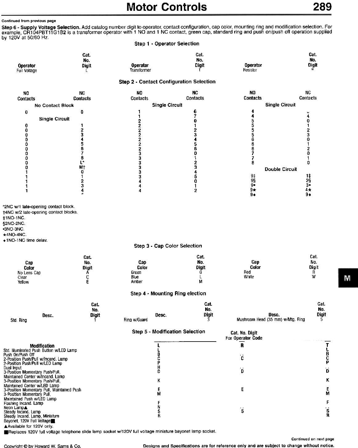
Motor Controls 289
Continued from previous page
Step 6 - Supply Voltage Selection. Add catalog number ~igit to operator, contact configuration, cap color, ~ounting ring and modification s~lection. ,:,or
example, CR 1 04PBT11 G1 B2 is a transformer operator with 1 NO and 1 NC contact, green cap. standard ring and push onlpush off operation supplied
by 120V at 50/60 Hz. Step 1 - Operator Selection
Cat.
No.
Digit
L
Cat.
No.
Digit
T
Cat.
No.
Digit
"
Operator
Transformer Operator
Resistor
Operator
Full Voltage
Step 2 - Contact Configuration Selection
NO
Contacts
NC
Contacts
NO
Contacts NC
Contacts
NO NC
Contacts Contacts
No Contact Block Single Circuit Single Circuit
6
7
0
1
2
3
4
5
6
0
1
2
3
4
5
0
1
2
4
4
5
5
5
5
6
6
6
7
7
8
001
1
2
2
2
2
2
2
2
3
3
3
3
3
3
4
4
4
4
0
1
2
3
0
1
2
0
1
0
Single Circuit
0
0
0
0
0
0
0
0
0
0
1
1
1
1
1
1
2
3
4
5
6
7
8
L'
Mt
0
1
2
3
4
,
Double Circuit
9:1:
9§
9-
9*
9.
1:1:
2§
3-
4*
9.
*2NC w/1 late-opening contact block.
t4NC w/2 late-opening contact blocks.
:t:1NO-1NC.
§2NO-2NC.
o3NO-3NC.
*4NO-4NC.
t1NO-1NC time delay. Step 3 - Cap Color Selection
Cat.
No.
Digit
G
L
M
Cat.
No.
Digit
R
W
Cat.
No.
Digit
A
C
E
Cap
Color
Green
Blue
Amber
Cap
Color
Red
White
Cap
Color
No Lens Cap
Clear
Yellow
Step 4 - Mounting Ring election
Cat.
No.
Digit
3
Cat.
No.
Digit
5
Cat.
No.
Digit
1Desc. Desc.
Mushroom Head (35 mm) w/Mtg. Ring
Desc.
Std. Ring Ring w/Guard
Step 5 - Modification Selection Cat. No. Digit
For Dperator Code
-R-
T
L
B
C
P
. ri
K
E
M
F
Os
R
. c
. D
E
. s
Modification L
Std. Illuminated Push Button w/LED Lamp L
Push On/Push Off B
2-Position Push/Pull w/lncand. Lamp C
2-Position Push/Pull w/LED Lamp P
Dual Input H
3-Position Momentary Push/Pull, D
Maintained Center w/lncand. Lamp
3-Position Momentary Push/Pull, K
Maintained Center wILED Lamp
3-Position Momentary Pull, Maintained Push E
3-Position Momentary Pull, M
Maintained Push w/LED Lamp
Flashing Incand. Lamp F
Neon Lamp. N
Steady Incand. Lamp S
Steady Incand. Lamp, Miniature R
Bayonet, 120V Full Voltage.
.Available for 120V only.
.Replaces 120V full voltage telephone slide lamp socket w/120V full voltage miniature bayonet lamp socket.
Continued on next page
Designs and Specifications are for reference only and are subject to change without notice.
CoDyriaht @ by Howard W. Sams & Co.
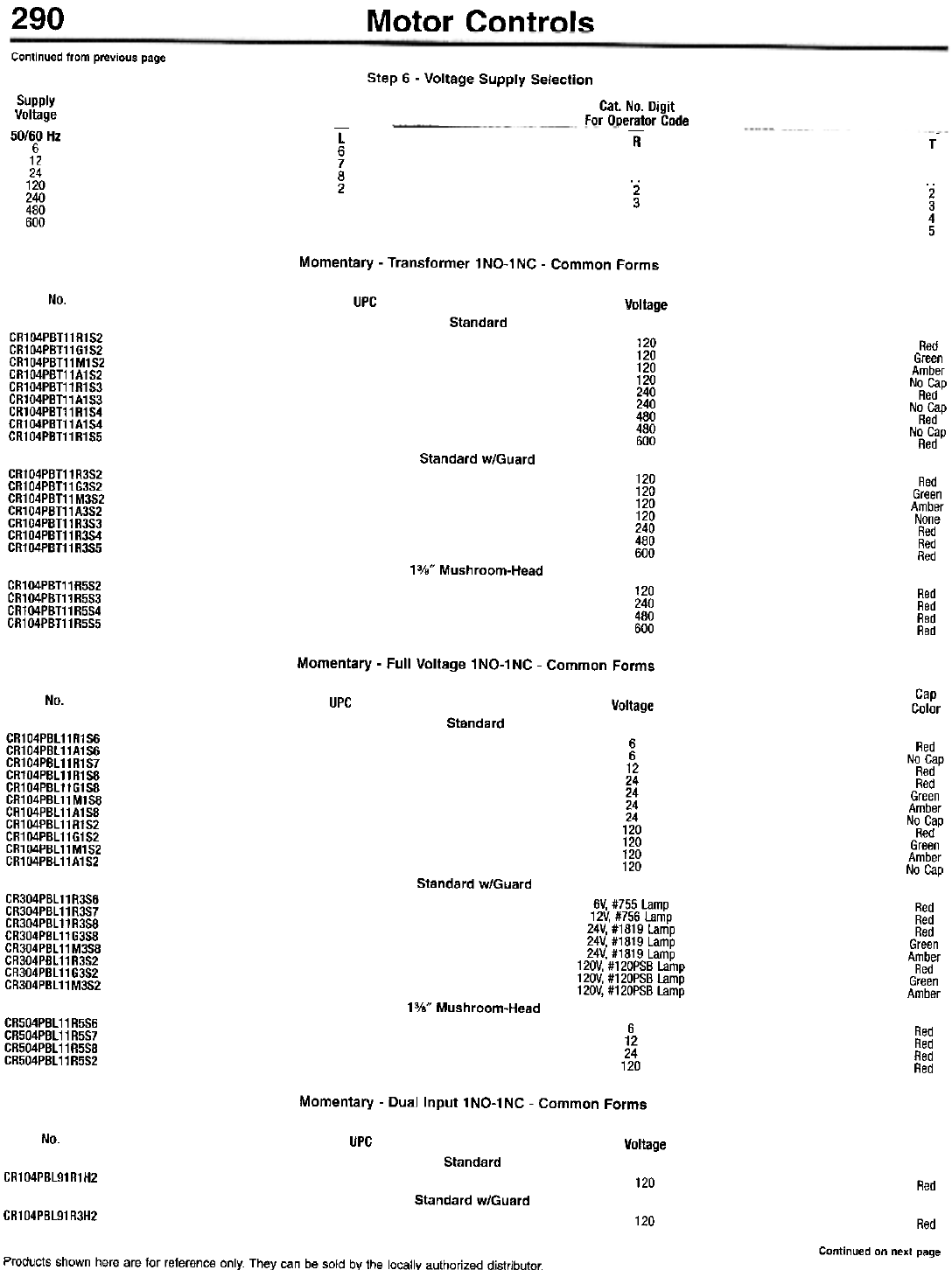
290 Motor Controls
Continued from previous page
Step 6 - Voltage Supply Selection
Supply
Voltage
50/00 Hz
6
12
24
120
240
480
600
Cat. No. Digit
For Dperator Code
L
6
7
8
2
-R-T
. 2
3.2
3
4
5
Momentary - Transformer 1 NO-1 NC - Common Forms
No. UPC Voltage
Standard
CR104PBT11R1S2
CR104PBT11G1S2
CR104PBT11M1S2
CR104PBT11A1S2
CR104PBT11R1S3
CR104PBT11A1S3
CR104PBT11R1S4
CR104PBT11A1S4
CR104PBT11R1S5
120
120
120
120
240
240
480
480
600
Red
Green
Amber
No Cap
Red
No Cap
Red
No Cap
Red
Standard w/Guard
CR104PBT11R3S2
CR1 04PBT11 G3S2
CR104PBT11M3S2
CR104PBT11A3S2
CR104PBT11R3S3
CR104PBT11R3S4
CR104PBT11R3S5
120
120
120
120
240
480
600
Red
Green
Amber
None
Red
Red
Red
13/." Mushroom-Head
CR104PBT11R5S2
CR104PBT11R5S3
CR104PBT11R5S4
CR1 04PBT11 R5S5
120
240
480
600
Red
Red
Red
Red
Momentary - Full Voltage 1NO-1NC - Common Forms
Cap
Color
No. UPC Voltage
Standard
CR104PBl11R1S6
CR104PBl11A1S6
CR104PBl11R1S7
CR104PBl11R158
CR104PBl11G158
CR104PBl11M158
CR104PBl11A1S8
CR104PBl11R1S2
CR104PBl11G1S2
CR104PBl11M1S2
CR104PBl11A1S2
6
6
12
24
24
24
24
120
120
120
120
Red
No Cap
Red
Red
Green
Amber
No Cap
Red
Green
Amber
No Cap
Standard w/Guard
CR304PBl11R3S6
CR304PBl11R3S7
CR304PBl11R3S8
CR304PBl11G3S8
CR304PBl11 M3S8
CR304PBl11R3S2
CR304PBl11G3S2
CR304PBl11M3S2
6V, #755 Lamp
12V, #756 Lamp
24V, #1819 Lamp
24V, #1819 Lamp
24V, #1819 Lamp
120V, #120PSB Lamp
120V, #120PSB Lamp
120V, #120PSB Lamp
Red
Red
Red
Green
Amber
Red
Green
Amber
13/." Mushroom-Head
CR504PBL11R5S6
CR504PBL11R5S7
CR504PBL11R5S8
CR504PBL11R5S2
6
12
24
120
Red
Red
Red
Red
Momentary - Dual Input 1NO-1NC - Common Forms
No. UPC Voltage
Standard
CR104PBl91R1H2 120 Red
Standard w/Guard
CR1 04PBL91 R3H2 120 Red
Continued on next page
Products shown here are for reference only. They can be sold by the locally authorized distributor.
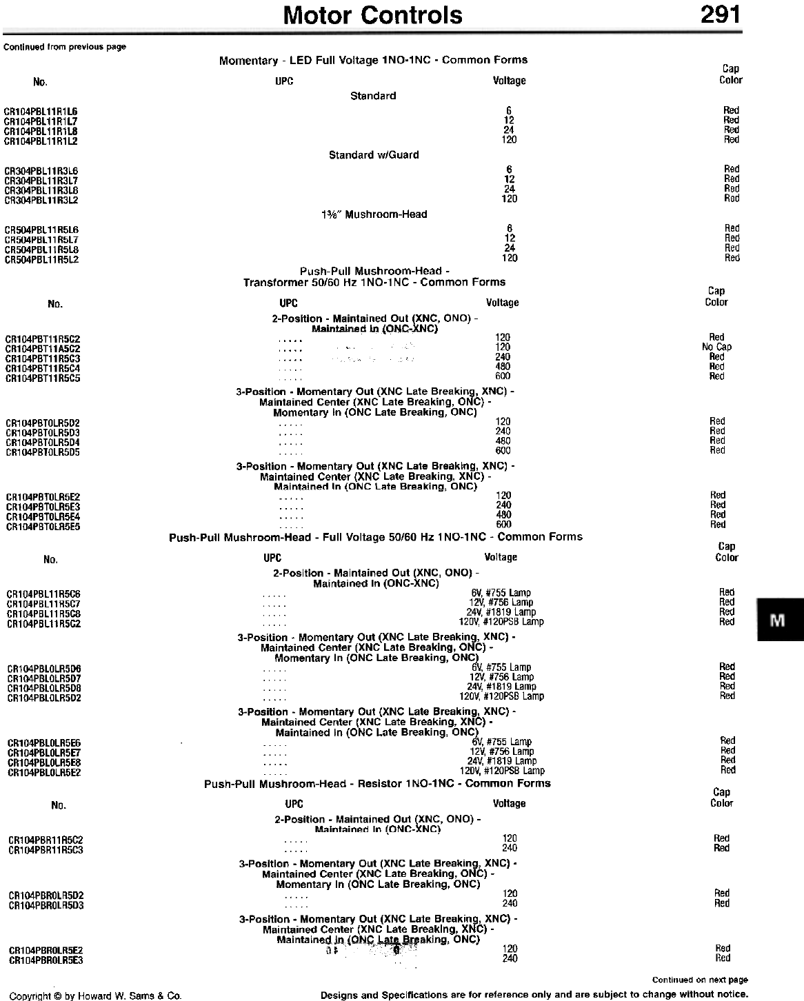
Motor Controls 291
Continued from previous page Momentary - LED Full Voltage 1 NO-1 NC - Common Forms
UPC Voltage Cap
Color
No.
Standard
Red
Red
Red
Red
6
12
24
120
CR104PBL11R1L6
CR104PBL11R1L7
CR1 04PBL11 R1LB
CR104PBL11R1L2
Standard w/Guard
6
12
24
120
Red
Red
Red
Red
CR304PBL 11 R3L6
CR304PBL 11 R3L7
CR304PBL11R3L8
CR304PBL 11 R3L2
13/." Mushroom-Head
6
12
24
120
Red
Red
Red
Red
CR504PBL11R5L6
CR504PBL11R5L7
CR504PBL 11 R5L8
CR504PBL 11 R5L2
Cap
Color
No.
Push-Pull Mushroom-Head -
Transformer 50/60 Hz 1 NO-1 NC - Common Forms
UPC Voltage
2-Position - Maintained Out (XNC, aNa) -
Maintained In IONC-XNC)
~ , 120
. . . . . 120
240
. . . . 480
. . . . 600
3-Position - Momentary Out (XNC Late Breaking, XNC) -
Maintained Center (XNC Late Breaking, ONC) -
Momentarv In IONC Late Breakina. ONC)
Red
No Cap
Red
Red
Red
CR104PBT11R5C2
CR104PBT11A5C2
CR1 04PBT11 R5C3
CR1 04PBT11 R5C4
CR1 04PBT11 R5C5
Red
Red
Red
Red
. . .. . . -. 120
. . . . . 240
. . . . . 480
. . 600
3-Position - Momentary Out (XNC Late Breaking, XNC) -
Maintained Center (XNC Late Breaking, XNC) -
Maintained In IONC Late Breakina. ONC)
CR104PBTOLR5D2
CR104PBTOLR5D3
CR104PBTOLR5D4
CR104PBTOLR5D5
Red
Red
Red
Red
Cap
Color
CR104PBTOlR5E2
CR104PBTOlR5E3
CR104PBTOlR5E4
CR104PBTOlR5E5
No.
Red
Red
Red
Red
CR104PBl11R5C6
CR1 04PBl11 R5C7
CR104PBl11R5C8
CR104PBl11R5C2
Red
Red
Red
Red
CR104PBLOLR5D6
CR104PBLOLR5D7
CR104PBLOLR5D8
CR104PBLOLR5D2
Red
Red
Red
Red
Cap
Color
CR104PBLOLR5E6
CR104PBLOLR5E7
CR104PBLOLR5E8
CR104PBLOLR5E2
No.
-. 120
. . . . . 240
. . . . . 480
. . . . . 600
Push-Pull Mushroom-Head - Full Voltage 50/60 Hz 1NO-1NC - Common Forms
UPC Voltage
2-Position - Maintained Out (XNC, aNa) -
Maintained In (ONC-XNC)
. . . . . 6V, #755 Lamp
. . . . . 12V, #756 Lamp
. . . . . 24V. #1819 Lamp
. . . . . 120V. #120PSB Lamp
3-Position . Momentary Out (XNC Late Breaking, XNC) -
Maintained Center (XNC Late Breaking, ONC) -
Momentary In (ONC Late Breaking, ONC)
. . . . . b'V, #755 Lamp
. . . . . 12V. #756 Lamp
. . . . . 24V, #1819 Lamp
. . . . . 120V. #120PSB Lamp
3-Position - Momentary Out (XNC Late Breaking, XNC) -
Maintained Center (XNC Late Breaking, XNC) -
Maintained In (ONC Late Breaking, ONC)
. . . . . b'V, #755 Lamp
. . . . . 12V. #756 Lamp
. . . . . 24V, #1819 Lamp
. . . . 120V, #120PSB Lamp
Push-Pull Mushroom-Head - Resistor 1NO-1NC - Common Forms
UPC Voltage
2-Position - Maintained Out (XNC, aNa) -
Maintained In IONC-XNC\ Red
Red
. . . . . 120
. . . . . 240
3-Position - Momentary Out (XNC Late Breaking, XNC) -
Maintained Center (XNC Late Breaking, ONC) -
Momentary In (ONC Late Breaking, ONC)
. . . . . 120
. 240
3-Position - Momentary Out (XNC Late Breaking, XNC) -
Maintained Center (XNC Late Breaking, XNC) -
Maintained In IONC Late Breakina. ONC)
CR104PBR11R5C2
CR104PBR11R5C3
Red
Red
CR104PBROLR5D2
CR104PBROLR5D3
-"5-;:-"-'-~"'rf!--' -. 120 Red
c '240 Red
Continued on next page
Designs and Specifications are for reference only and are subject to change without notice.
CR104PBROLR5E2
CR104PBROLR5E3
Copyright @ by Howard W. Sams & Co.
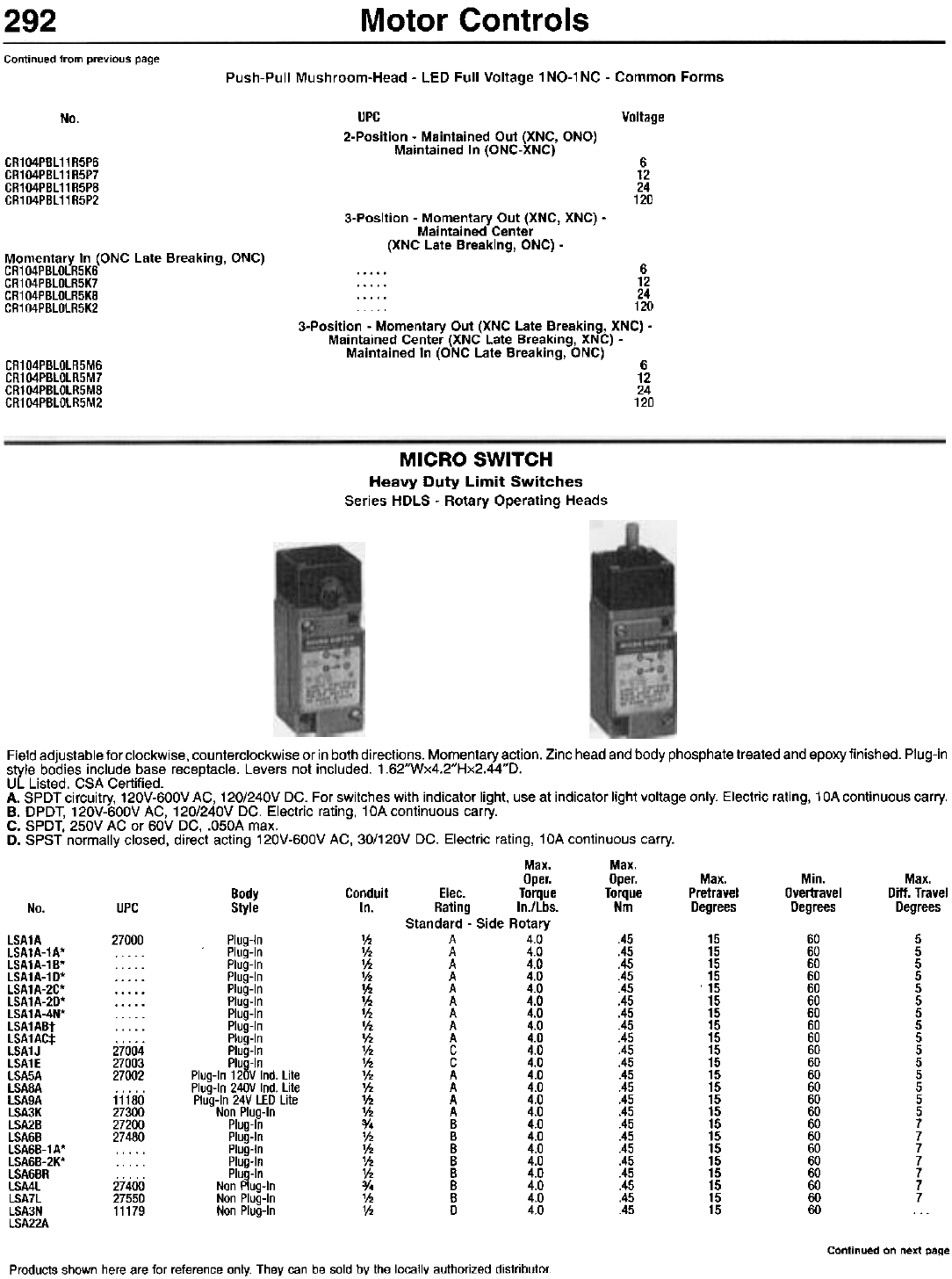
Motor Controls
292
Continued from previous page Push-Pull Mushroom-Head - LED Full Voltage 1NO-1NC - Common Forms
No. Voltage
UPC
2-Position - Maintained Out (XNC, aNa)
Maintained In (ONC-XNC)
CR104PBL11R5P6
CR104PBL11R5P7
CR104PBL11R5P8
CR104PBL11R5P2
6
12
24
120
3-Position - Momentary Out (XNC, XNC) -
Maintained Center
(XNC Late Breaking, ONC) -
Momentary In (ONC Late Breaking, ONC)
CR104PBLOLR5K6
CR104PBLOLR5K7
CR104PBLOLR5KB
CR104PBLOLR5K2
6
12
. . . . . 24
. . . . . 120
3-Position - Momentary Out (XNC Late Breaking, XNC) -
Maintained Center (XNC Late Breaking, XNC) -
Maintained In (ONC Late Breaking, ONC)
CR104PBLOLR5M6
CR104PBLOLR5M7
CR104PBLOLR5M8
CR104PBLOLR5M2
6
12
24
120
MICRO SWITCH
Heavy Duty Limit Switches
Series HDLS - Rotary Operating Heads
Field adjustable for clockwise, counterclockwise or in both directions. Momentary action. Zinc head and body phosphate treated and epoxy finished. Plug-in
style bodies include base receptacle. Levers not included. 1.62"Wx4.2"Hx2.44"D.
UL Listed. CSA Certified.
A. SPDT circuitry, 120V-600V AC, 120/240V DC. For switches with indicator light, use at indicator light voltage only. Electric rating, 1 OA continuous carry.
B. DPDT, 120V-600V AC, 120/240V DC. Electric rating, 10A continuous carry.
C. SPDT, 250V AC or 60V DC, .O50A max.
D. SPST normally closed, direct acting 120V-600V AC, 30/120V DC. Electric rating, 10A continuous carry.
Max. Max.
Oper. Oper. Max. Min. Max.
Body Conduit Elec. Torque Torque Pretravel Overtravel Ditt. Travel
No. UPC Style In. Rating In./Lbs. Nm Degrees Degrees Degrees
Standard - Side Rotary
lSA1A 27000 Plug-In 1h A 4.0 .45 15 60 5
lSA1A-1A* Plug-In 1h A 4.0 .45 15 60 5
lSA1A-1B* Plug-In 1h A 4.0 .45 15 60 5
lSA1A-1D* Plug-In 1h A 4.0 .45 15 60 5
lSA1A-2C* Plug-In 1h A 4.0 .45 . 15 60 5
lSA1A-2D* . . . . . Plug-In 1h A 4.0 .45 15 60 5
lSA1A-4N* Plug-In 1h A 4.0 .45 15 60 5
lSA1ABt Plug-In 1h A 4.0 .45 15 60 5
lSA1AC* Plug-In 1h A 4.0 .45 15 60 5
lSA1J 27004 Plug-In 1h C 4.0 .45 15 60 5
lSA1E 27003 Plug-In 1h C 4.0 .45 15 60 5
lSA5A 27002 Plug-In 120V Ind. lite 1h A 4.0 .45 15 60 5
lSA8A . . . . . Plug-In 240V Ind. lite 1h A 4.0 .45 15 60 5
lSA9A 11180 Plug-In 24V lED lite 1h A 4.0 .45 15 60 5
lSA3K 27300 Non Plug-In 1h A 4.0 .45 15 60 5
lSA2B 27200 Plug-In 3/. B 4.0 .45 15 60 7
lSA6B 27480 Plug-In 1h B 4.0 .45 15 60 7
lSA6B-1A* Plug-In 1h B 4.0 .45 15 60 7
lSA6B-2K* . . . . . Plug-In 1h B 4.0 .45 15 60 7
lSA6BR . . . . . Plug-In 1h B 4.0 .45 15 60 7
lSA4l 27400 Non Plug-In 3/. B 4.0 .45 15 60 7
lSA7l 27550 Non Plug-In 1h B 4.0 .45 15 60 7
lSA3N 11179 Non Plug-In 1h D 4.0 .45 15 60 . . .
lSA22A
Continued on next page
Products shown here are for reference only. They can be sold by the locally authorized distributor.
Motor Controls 293
Continued from previous page
Max. Max.
Oper. Oper.
Elec. Torque Torqu
Rating In./Lbs. Nm
Low Differential - Side Rotary
V2 A 4.0
V2 C 4.0
1/2 C 4.0
3/. B 4.0
1/2 B 4.0
1/2 A 4.0
1/2 A 4.0
1/2 A 4.0
1/2 A 4.0
... ... ...
3/. B 4.0
V2 B 4.0
5° Pretravel - Side Rotary
1/2 A 4.0
1/2 C 4.0
1/2 C 4.0
1/2 A 4.0
1/2 A 4.0
1/2 A 4.0
1/2 A 4.0
3/. B 4.0
1/2 B 4.0
3/. B 4.0
1/2 B 4.0
Low Torque - Side Rotary
1/2 A 1.7
1/2 C 1.7
1/2 A 1.7
1/2 A 1.7
1/2 A 1.7
1/2 A 1.7
3/. B 1.7
1/2 B 1.7
:y. B 1.7
V2 B 1.7
V2 D 1.7
Low Differential Low Torque - Side Rotary
V2 A 1.7
1/2 C 1.7
1/2 A 1.7
1/2 A 1.7
1/2 A 1.7
1/2 A 1.7
:y. B 1.7
1/2 B 1.7
:y. B 1.7
V2 B 1.7
High Overtravel - Top Rotary
V2 A 2.5
V2 C 2.5
V2 A 2.5
1/2 A 2.5
1/2 A 2.5
1/2 A 2.5
:y. B 2.5
1/2 B 2.5
:y. B 2.5
1/2 B 2.5
1/2 D 2.5
Max.
Pretravel
Degrees
Min.
Overtravel
Degrees
66
66
66
66
66
66
66
66
66
66
66
Max.
Diff. Travel
Degrees
Body
Style
Conduit
In
UPCNo.
Plug-In
Plug-In
Plug-In
Plug-In
Plug-In
Plug-In 120V Ind. Lite
Plug-In 240V Ind. Lite
Plug-In 24V LED Lite
Non Plug-In
Non Plug-In
Non Plug-In
.45
.45
.45
.45
.45
.45
.45
.45
.45
.45
:451
9
9
9
9
9
9
9
9
9
9
9
3
3
3
4
4
3
3
3
3
4
4
LSP1A
LSP1J
LSP1E
LSP2B
LSP6B
LSP5A
LSP8A
LSP9A§
LSP3K
LSP3K-1D
LSP4L
LSP4L-4N
LSP7L
29900
29977
29980
24996
... ..
29990
24995
30050
LSU1A
LSU1J
LSU1E
LSU5A
LSU8A
LSU9A§
LSU3K
LSU2B
LSU6B
LSU4L
LSU7L
11189
11190 Plug-In
Plug-In
Plug-In
Plug-In 120V Ind. Lite
Plug-In 240V Ind. Lite
Plug-In 24V LED Lite
Non Plug-In
Plug-In
Plug-In
Non Plug-In
Non Plug-In
5
5
5
5
5
5
5
5
5
5
5
70
70
70
70
70
70
70
70
70
70
70
3
3
3
3
3
3
3
4
4
4
4
.4!' I
.4!,1
.45
.45
.45
.45
.45
.45
.45
.45
.45
11191
Plug-In
Plug-In
Plug-In 120V Ind. Lite
Plug-In 240V Ind. Lite
Plug-In 24V LED Lite
Non Plug-In
Plug-In
Plug-In
Non Plug-In
Non Plug-In
Non Plug-In
.19
.19
.19
.19
.19
.19
.19
.19
.19
.19
.19
15
15
15
15
15
15
15
15
15
15
15
60
60
60
60
60
60
60
60
60
60
60
5
5
5
5
5
5
7
7
7
7
LSR1A
LSR1E
LSR5A
LSR8A
LSR9A§
LSR3K
LSR2B
LSR6B
LSR4L
LSR7L
LSR3N
30095
11188
30120
.. ...
30105
30098
30125
LSH1A
LSH1E
LSH5A
LSH8A
LSH9A§
LSH3K
LSH28
LSH68
LSH4L
LSH7L
28810
11183 Plug-In
Plug-In
Plug-In 120V Ind. Lite
Plug-In 240V Ind. Lite
Plug-In 24V LED Lite
Non Plug-In
Plug-In
Plug-In
Non Plug-In
Non Plug-In
.19
.19
.19
.19
.19
.19
.19
.19
.1!1
.191
9
9
9
9
9
9
9
9
9
9
66
66
66
66
66
66
66
66
66
66
3
3
3
3
3
3
4
4
4
4
11184
28840
28820
24988
LSB1A 27610 Plug-In
LSB1J Plug-In
LSB5A . . . . . Plug-In 120V Ind. Lite
LSB8A . . . . . Plug-In 240V Ind. Lite
LSB9A§ . . . . . Plug-In 24V LED Lite
LSB3K 27680 Non Plug-In
LSB2B . . . . . Plug-In
LSB6B 27695 Plug-In
LSB4L . . . . . Non Plug-In
LSB7L . . . . . Non Plug-In
LSB3N . . . . . Non Plug-In
'w/Lever.
tw/5-Pin receptacle.
:j:w/6 ft. of 5 conductor STOOW-A cable.
§1.5 mA max. auto polarity.
.28
.28
.28
.28
.28
.28
.28
.28
.28
.28
.28
25
25
25
25
25
25
25
25
25
25
25
110
110
110
110
110
110
110
110
110
110
110
10
10
10
10
10
10
12
12
12
.,.,
Designs and Specifications are for reference only and are subject to change without notice.
CopyriQht @ by Howard W. Sams & Co.
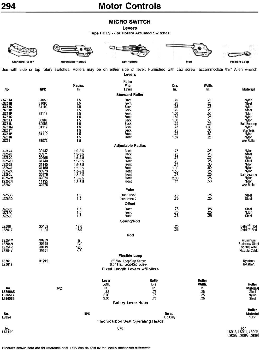
294 Motor Controls
MICRO SWITCH
Levers
Type HDLS - For Rotary Actuated Switches
Adjustable Radius
Back
Back
Front
Front
Front
Front
Front
Front
Front
Front
lSZ52A
lSZ52B
lSZ52C
lSZ52D
lSZ52E
lSZ52J
lSZ52K
lSZ52l
lSZ52M
lSZ52N
lSZ52
30147
30971
30956
31140
31145
31150
30973
30976
30974
11195
30970
1.5-3.5
1.5-3.5
1.5-3.5
1.5-3.5
1.5-3.5
1.5-3.5
1.5-3.5
1.5-3.5
1.5-3.5
1.5-3.5
.75
.75
.75
.75
.75
1.00
1.50
.75
2.00
.75
.25
.25
.25
.25
.30
.50
.25
.25
.25
.50
Nylon
Steel
Nylon
Steel
Nylon
Nylon
Nylon
Ball Bearing
Nylon
Nylon
w/o Roller
Yoke
Front-Back
Front-Front
Offset
Front
Front
Front
Spring/Rod
Steel
Steel
lSZ53B
lSZ53D 1.5
1.5 .75
.75 .25
.25
lSZ55B
lSZ55C
lSZ55D
1.5
1.5
1.5
.75
.75
.75
.25
.25
.25
Steel
Nylon
Steel
Delrin@ Rod
Delrin@ Rod
LSZ68
LSZ617 .25
.25
30152
11196 12.0
16.0
Rod
Aluminum
Stainless Steel
Spring Wire
Flexible Cable
lSZ54M
lSZ54N
lSZ54R
lSZ54V
30959
30148
30149
30151
5
13.0
12.0
4.8
Flexible Loop
6" Flex. Loop/Cap Screw
9.5" Flex. Loop/Cap Screw
Fixed Length Levers w/Roliers
LSZ61
LSZ618 31245 Nylatron
Nylatron
Lever
Lgth.
In.
.88
2.00
2.00
Roller
Dia.
In.
.75
.75
.75
Roller
Wdth.
In.
.25
.25
.25
Roller
Material
Steel
Nylon
Steel
No.
lSZ65AB
lSZ65EA
lSZ65EB
UPC
Rotary Lever Hubs
Roller
Material
Nylon
No.
LSZ54 UPC Desc.
Hub Only
Fluorocarbon Seal Operating Heads
UPC
No.
LSZ1DC For
LSD1A, LSD1J, LSD2B,
LSD5A, LSD8A, LSD6B
Products shown here are for reference only. They can be sold bY the locallv authorized di~trihl"nr
Standard Roller Adjustable Radius Spring/Rod Rod Flexible Loop
Use with side or top rotary switches. Rollers may be on either side of lever. Furnished with cap screw; accommodate 9/64" Allen wrench.
Levers
Roller
Radius Mtd. Dia. Wdth.
No. UPC In. Lever In. In. Material
Standard Roller
LSZ51A 31080 1.5 Front .75 .25 Nylon
LSZ51B 31090 1.5 Front .75 .25 Steel
LSZ51C 31100 1.5 Back .75 .25 Nylon
LSZ51D 1.5 Back .75 .25 Steel
LSZ51F 31113 1.5 Front 1.00 .50 Nylon
LSZ51G .. ... 1.5 Front 1.50 .25 Nylon
LSZ51 J 30968 1.5 Back 1.00 .50 Nylon
LSZ51L 30955 1.5 Back .75 .25 Ball Bearing
LSZ51M 31117 1.5 Back .75 1.30 Nylon
LSZ51T . . . . . 1.5 Back .75 .38 Stainless
LSZ51P 31119 1.5 Front .75 .50 Nylon
LSZ51 R . . . . . 1.5 Front 1.59 .25 Nylon
LSZ51 31075 1.5 wlo Roller
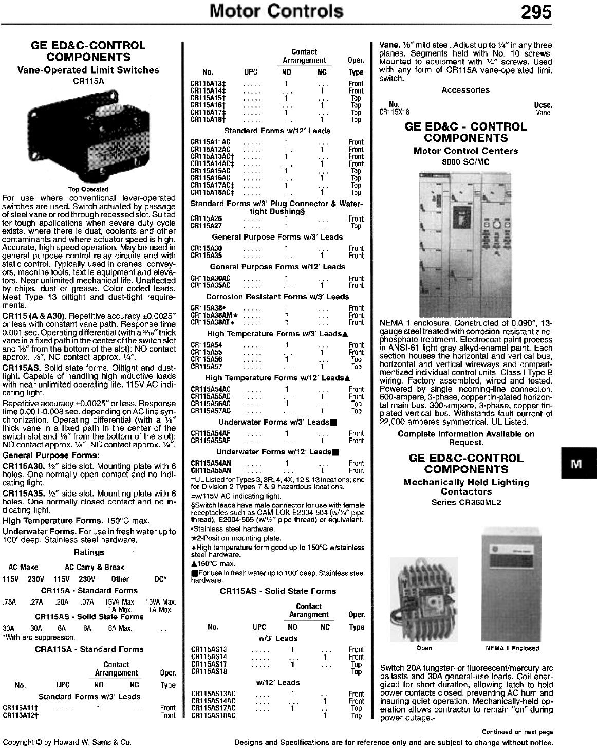
295
GE ED&C-CONTROL
COMPONENTS
Vane-Operated Limit Switches
CR115A
Vane. VB" mild steel. Adjust up to V4" in any three
planes. Segments held with No.1 0 screws.
Mounted to equipment with '/4" screws. Used
with any form of CR115A vane-operated limit
switch.
Contact
Arrangement Oper.
No. UPC NO NC Type
CR115A13:j:... 1 ... Front
CR115A14:j: ... 1 Front
CR115A15t 1 ... Top
CR115A16t ... 1 Top
CR115A17:j: 1 ... Top
CR115A18:j:.. 1 Top
Standard Forms w/12' Leads
CR115A11AC . . . . . 1 . . . Front
CR115A12AC 1 Front
CR115A13AC:j: 1 .. . Front
CR115A14AC:j: ... 1 Front
CR115A15AC . . .. . 1 .. . Top
CR115A16AC ... 1 Top
CR115A17AC:j: 1 . . . Top
CR115A18AC:j: . . . 1 Top
Standard Forms w/3' Plug Connector & Water-
tight Bushing§
CR115A26 1 Front
CR115A27 . 1 Top
General Purpose Forms w/3' Leads
CR115A30 . 1 Front
CR115A35 1 Front
General Purpose Forms w/12' Leads
CR115A30AC 1 Front
CR115A35AC 1 Front
Corrosion Resistant Forms w/3' Leads
CR115A38' . 1 Front
CR115A38AM* .. 1 Front
CR115A38AT.. 1 Front
High Temperature Forms w/3' Leads..
CR115A54 1 Front
CR115A55 ... 1 Front
CR115A56 1 ... Top
CR115A57 1 Top
High Temperature Forms w/12' Leads..
CR115A54AC . . 1 Front
CR115A55AC . . 1 Front
CR115A56AC . . 1 Top
CR115A57AC . . 1 Top
Underwater Forms w/3' Leads.
CR115A54AF . . 1 Front
CR115A55AF . . 1 Front
Underwater Forms w/12' Leads.
CR115A54AN . . . . . 1 Front
CR115A55AN . . . . . . . . 1 Front
tUL Listed for Types 3, 3R, 4, 4X, 12 & 13 locations; and
for Division 2 Types 7 & 9 hazardous locations.
:j:w/115V AC indicating light.
§Switch leads have male connector for use with female
receptacles such as CAM-LOK E2004-504 (w/3/." pipe
thread), E2004-505 (wIV2" pipe thread) or equivalent.
.Stainless steel hardware.
*2-Position mounting plate.
. High temperature form good up to 150°C w/stainless
steel hardware.
..150°C max.
.For use in fresh water up to 100' deep. Stainless steel
hardware.
CR115AS - Solid State Forms
Contact
Arrangment Oper.
No. UPC NO NC Type
w/3' Leads
... 1 ...
. . . . . . . . 1
. . . . . 1 . . .
Accessories
Desc.
Vane
No.
CR115X18
GEED&C-CONTROL
COMPONENTS
Motor Control Centers
8000 SC/MC
NEMA 1 enclosure. Constructed of 0.090", 13-
gauge steel treated with corrosion-resistant zinc-
phosphate treatment. Electrocoat paint process
in ANSI-61 light gray alkyd-enamel paint. Each
section houses the horizontal and vertical bus,
horizontal and vertical wireways and com part-
mentized individual control units. Class I Type B
wiring. Factory assembled, wired and tested.
Powered by single incoming-line connection.
600-ampere, 3-phase, copper tin-plated horizon-
tal main bus. 300-ampere, 3-phase, copper tin-
plated vertical bus. Withstands fault current of
22,000 amperes symmetrical. UL Listed.
Complete Information Available on
Request.
GE ED&C-CONTROL
COMPONENTS
Mechanically Held Lighting
Contactors
Series CR360ML2
Top Operated
For use where conventional lever-operated
switches are used. Switch actuated by passage
of steel vane or rod through recessed slot. Suited
for tough applications when severe duty cycle
exists, where there is dust, coolants and other
contaminants and where actuator speed is high.
Accurate, high speed operation. May be used in
general purpose control relay circuits and with
static control. Typically used in cranes, convey-
ors, machine tools, textile equipment and eleva-
tors. Near unlimited mechanical life. Unaffected
by chips, dust or grease. Color coded leads.
Meet Type 13 oiltight and dust-tight require-
ments.
CR115 (A & A30). Repetitive accuracy :to.0025"
or less with constant vane path. Response time
0.001 sec. Operating differential (with a 3/16" thick
vane in a fixed path in the center of the switch slot
and 1/8" from the bottom of the slot): NO contact
approx. 1/8", NC contact approx. 1/4".
CR115AS. Solid state forms. Oiltight and dust-
tight. Capable of handling high inductive loads
with near unlimited operating life. 115V AC indi-
cating light.
Repetitive accuracy :to.0025" or less. Response
time 0.001-0.008 sec. depending on AC line syn-
chronization. Operating differential (with a 1/8"
thick vane in a fixed path in the center of the
switch slot and 1/8" from the bottom of the slot):
NO contact approx. 1/8", NC contact approx. 1/4".
General Purpose Forms:
CR115A30. 1/2" side slot. Mounting plate with 6
holes. One normally open contact and no indi-
cating light.
CR115A35. 1/2" side slot. Mounting plate with 6
holes. One normally closed contact and no in-
dicating light.
High Temperature Forms. 150°C max.
Underwater Forms. For use in fresh water up to
100' deep. Stainless steel hardware.
Ratings
AC Make AC Carry & Break
Open NEMA 1 Enclosed
115V 230V 115V 230V Other DC'
CR115A - Standard Forms
.75A .27A .20A .O7A 15VAMax. 15VAMax.
1A Max. 1A Max.
CR115AS - Solid State Forms
30A 30A 6A 6A 6A Max.
'With arc suppression.
CRA115A - Standard Forms
Contact
Arrangement Oper.
Type
CR115AS13
CR115AS14
CR115AS17
CR115AS18
Front
Front
Top
Top Switch 20A tungsten or fluorescenVmercury arc
ballasts and 30A general-use loads. Coil ener-
gized for short duration, allowing latch to hold
power contacts closed, preventing AC hum and
insuring quiet operation. Mechanically-held op-
eration allows contractor to remain "on" during
power outage.-
w/12'
No. UPC NO NC
Standard Forms w/3' Leads
1
CR115AS13AC
CR115AS14AC
CR115AS17AC
CR115AS18AC
Front
Front
Top
Top
"1"
"1"
CR115A11t
CR115A12t Front
Front
Continued on next page
Designs and Specifications are for reference only and are subject to change without notice.Copyright @ by Howard W. Sams & Co.
Leads
1
1
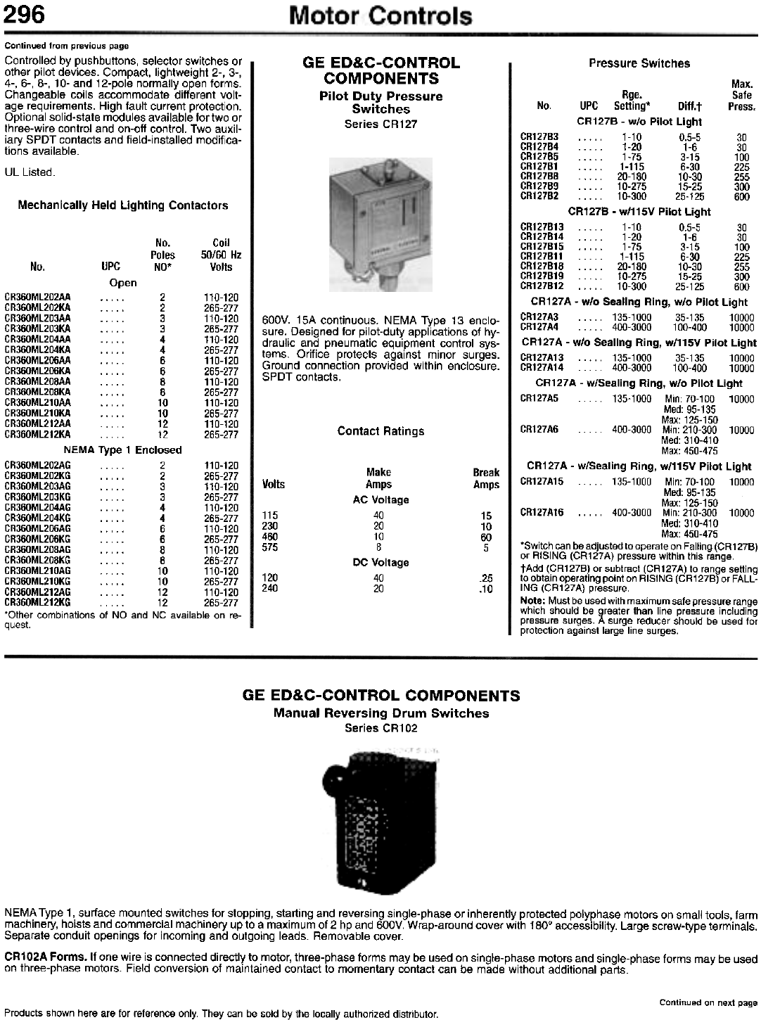
296
Continued from previous page
Controlled by pushbuttons, selector switches or
other pilot devices. Compact, lightweight 2-, 3-,
4-, 6-, 8-, 10- and 12-pole normally open forms.
Changeable coils accommodate different volt-
age requirements. High fault current protection.
Optional solid-state modules available for two or
three-wire control and on-off control. Two auxil-
iary SPOT contacts and field-installed modifica-
tions available.
UL Listed.
GE ED&C-CONTROL
COMPONENTS
Pilot Duty Pressure
Switches
Series CR127
Pressure Switches
Max.
Rge. Safe
No. UPC Setting* Diff.t Press.
CR127B - w/o Pilot Light
CR127B3 1-10 0.5-5 30
CR127B4 1-20 1-6 30
CR127B5 1-75 3-15 100
CR127B1 1-115 6-30 225
CR127BB . . . . . 20-180 10-30 255
CR127B9 10-275 15-25 300
CR127B2 . . . . . 10-300 25-125 600
CR127B - w/115V Pilot Light
CR127B13 1-10 0.5-5 30
CR127B14 1-20 1-6 30
CR127B15 1-75 3-15 100
CR127B11 . 1-115 6-30 225
CR127B18 20-180 10-30 255
CR127B19 10-275 15-25 300
CR127B12 . 10-300 25-125 600
CR127A - w/o Sealing Ring, w/o Pilot Light
CR127A3 135-1000 35-135 10000
CR127A4 400-3000 100-400 10000
CR127A - w/o Sealing Ring, w/115V Pilot Light
CR127A13 135-1000 35-135 10000
CR127A14... 400-3000 100-400 10000
CR127A - w/Sealing Ring, w/o Pilot Light
CR127A5 . .. 135-1000 Min: 70-100 10000
Med: 95-135
Max: 125-150
CR127A6 . . . .. 400-3000 Min: 210-300 10000
Med: 310-410
Max: 450-475
CR127A - w/Sealing Ring, w/115V Pilot Light
CR127A15 .. 135-1000 Min: 70-100 10000
Med: 95-135
Max: 125-150
CR127A16 . . . .. 400-3000 Min: 210-300 10000
Med: 310-410
Max: 450-475
'Switch can be adjusted to operate on Falling (CR127B)
or RISING (CR127A) pressure within this range.
tAdd (CR127B) or subtract (CR127A) to range setting
to obtain operating point on RISING (CR127B) or FALL-
ING (CR127A) pressure.
Note: Must be used with maximum safe pressure range
which should be greater than line pressure including
pressure surges. A surge reducer should be used for
protection against large line surges.
Mechanically Held Lighting Contactors
No.
Poles
NO'
Coil
50/60 Hz
Volts
No. UPC
Open
600V. 15A continuous. NEMA Type 13 enclo-
sure. Designed for pilot-duty applications of hy-
draulic and pneumatic equipment control sys-
tems. Orifice protects against minor surges.
Ground connection provided within enclosure.
SPOT contacts.
Contact Ratings
CR360Ml202AA 2 110-120
CR360Ml202KA 2 265-277
CR360Ml203AA 3 110-120
CR360Ml203KA 3 265-277
CR360Ml204AA 4 110-120
CR360Ml204KA 4 265-277
CR360Ml206AA 6 110-120
CR360Ml206KA 6 265-277
CR360Ml208AA 8 110-120
CR360Ml208KA 8 265-277
CR360Ml210AA 10 110-120
CR360Ml210KA 10 265-277
CR360Ml212AA 12 110-120
CR360Ml212KA 12 265-277
NEMA Type 1 Enclosed
CR360Ml202AG 2 110-120
CR360Ml202KG 2 265-277
CR360Ml203AG 3 110-120
CR360Ml203KG 3 265-277
CR360Ml204AG 4 110-120
CR360Ml204KG 4 265-277
CR360Ml206AG 6 110-120
CR360Ml206KG 6 265-277
CR360Ml208AG 8 110-120
CR360Ml208KG 8 265-277
CR360Ml210AG 10 110-120
CR360Ml210KG 10 265-277
CR360Ml212AG 12 110-120
CR360Ml212KG 12 265-277
'Other combinations of NO and NC available on re-
quest.
Make
Amps
AC Voltage
40
20
10
8
DC Voltage
40
20
Break
Amps
Volts
115
230
460
575
15
10
60
5
120
240 .25
.10
GE ED&C-CONTROL COMPONENTS
Manual Reversing Drum Switches
Series CR102
NEMA Type 1,. surface mounted. switche:;, for stopping, st~rting and reversing single-phase or inherently protected polyphase motors on small tools, farm
machinery, hoists and commercial machinery up to a maximum of 2 hp and 600V. Wrap-around cover with 1800 accessibility. Large screw-type terminals.
Separate conduit openings for incoming and outgoing leads. Removable cover.
CR102A Forms. If one wi~e is connect.ed directly to .motor, three-phase forms may be used on single-phase motor:;, and single-phase forms may be used
on three-phase motors. Field conversion of maintained contact to momentary contact can be made without additional parts.
Continued on next page
Products shown here are for reference only. They can be sold by the locally authorized distributor.

Motor Controls 297
Continued from previous page
Horsepower Ratings
Polyphase
230-240V
2
2
10
115V
1V2
1'h
1'h
1'h
1V2
1'h
1
10
230V
2
2
2
2
2
2
1V2
Polyphase
400-600V
2
2
DC
115/230V
'/.
V.
No.
CR102A1
CR102A13
CR102A2
CR102A3
CR102A16
CR102A23
CR102B(all) 1~
Drum Switches
For
Motor
Type
No. UPC
Both Directions Momentary or Maintained - CR102A
CR102A1
CR102A2
CR102A3
CR102A16
30
10
10 Instant. Reverse
10 Dual Voltage Reconn.
One Direction Momentary, Other Maintained - CR102A
CR102A13
CR102A23 30
10
Maintained Contact - CR102B
CR1028311A
CR1028414A
CR1028412A
CR1028312A
CR1028314A
CR1028313A
CR1028413A
CR1028415A
CR1028411A
10 Cap. Start, Split Phase;
10, Inherently Protected, 5-Lead
10 Cap. Start, Split Phase*
10 Inherently Protected, 5-Lead*
30 3-Wire; 10 Repulsion-Induction, 3 & 4-Lead
10 Repulsion-Induction, 3 & 4-Lead*
10 Instant. Reverse, 5-Lead
10 Instant. Reverse, 5-Leadt
10 Instant. Reverse, Inherently Protected, 6-Lead
10 Instant. Reverse, Inherently Protected, 6-Lead*
Maintained Contact - Panel Mounted - CR102B
CR102B321A
CR102B424A
CR102B422A
CR102B322A
CR102B324A
CR102B323A
CR102B423A
CR102B425A
CR102B421A
10 Cap. Start, Split Phase;
10 Inherently Protected, 5-Lead
10 Cap. Start, Split Phaset
10 Inherently Protected, 5-Lead*
30 3-Wire; 10 Repulsion-Induction, 3 & 4-Lead
10 Repulsion-Induction, 3 & 4-Lead*
10 Instant. Reverse, 5-Lead
10 Instant. Reverse, 5-Lead*
10 Instant. Reverse, Inherently Protected, 6-Lead
10 Instant. Reverse, Inherently Protected, 6-Lead*
Maintained Contact - Cavity Mounted w/Flush Plate - CR102B
CR102B331A
CR102B434A
CR102B432A
CR102B332A
CR102B334A
CR102B333A
CR102B433A
CR102B435A
CR102B431 A
10 Cap. Start, Split Phase;
10 Inherently Protected, 5-Lead
10 Cap. Start, Split Phase*
10 Inherently Prote.ct~d, 5-Lead*
30, 3-Wlre,
10 Repulsion-Induction, 3 & 4-Lead
10 Repulsion-Induction, 3 & 4-Lead*
10 Instant. Reverse, 5-Lead
10 Instant. Reverse, 5-Lead*
10 Instant. Reverse, Inherently Protected, 6-Lead
10 Instant. Reverse, Inherently Protected, 6-Lead*
Momentary Contact - CR1028
CR102B311A1
CR102B414A1
CR102B412A1
CR102B312A1
CR102B314A1
CR102B313A1
CR102B413A1
CR102B415A1
CR102B411A1
10 Cap. Start, Split Phase;
10 Inherently Protected, 5-Lead
10 Cap. Start, Split Phase
10 Inherently Protected, 5-Lead
30 3-Wire;
10 Repulsion-Induction, 3 & 4-Lead
10 Repulsion-Induction, 3 & 4-Lead
10 Instant. Reverse, 5-Lead
10 Instant. Reverse, 5-Lead
10lnstant. Reverse, Inherently Protected, 6-Lead
10 Instant. Reverse, Inherently Protected, 6-Lead*
Momentary Contact - Panel Mounted - CR102B
CR102B321A1
CR102B424A1
CR102B422A1
CR102B322A1
CR102B324A1
CR102B323A1
CR102B423A1
CR102B425A1
CR102B421A1
10Cap. Start, Split Phase;
10 Inherently Protected, 5-Lead
10 Cap. Start, Split Phase
10 Inherently Protected, 5-Lead*
30 3-Wire;
10 Repulsion-Induction, 3 & 4-Lead
10 Repulsion-Induction, 3 & 4-Lead*
10 Instant. Reverse, 5-Lead
10 Instant. Reverse, 5-Lead
10 Instant. Reverse, Inherently Protected, 6-Lead
10 Instant. Reverse, Inherently Protected, 6-Lead
Continued on next page
Designs and Specifications are for reference only and are subject to change without notice.
Copyright @ by Howard W. Sams & Co.
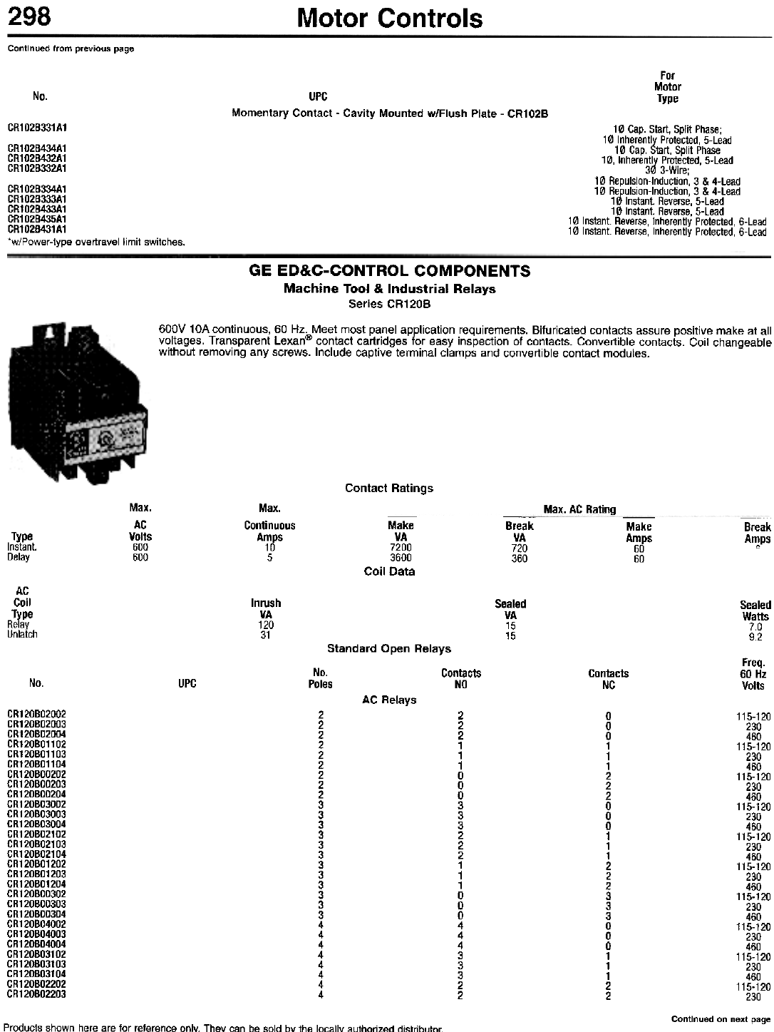
298 Motor Controls
Continued from previous page
For
Motor
Type
No. UPG
Momentary Contact - Cavity Mounted w/Flush Plate - CR102B
10 Cap. Start, Split Phase;
10 Inherently Protected, 5-Lead
10 Cap. Start, Split Phase
10, Inherently Protected, 5-Lead
30 3-Wire;
10 Repulsion-Induction, 3 & 4-Lead
10 Repulsion-Induction, 3 & 4-Lead
10 Instant. Reverse, 5-Lead
10 Instant. Reverse, 5-Lead
10 Instant. Reverse, Inherently Protected, 6-Lead
10 Instant. Reverse, Inherently Protected, 6-Lead
CR102B331A1
CR102B434A1
CR102B432A1
CR102B332A1
CR102B334A1
CR102B333A1
CR102B433A1
CR102B435A1
CR102B431A1
*w/Power-type overtravel limit switches.
GE ED&C-CONTROL COMPONENTS
Machine Tool & Industrial Relays
Series CR120B
600V 10A continuous, 60 Hz. Meet most panel application requirements. Bifuricated contacts assure positive make at all
voltages. Transparent lexan@ contact cartridges for easy inspection of contacts. Convertible contacts. Coil changeable
without removing any screws. Include captive terminal clamps and convertible contact modules.
Contact Ratings
Max.
AC
Volts
600
600
Max.
Continuous
Amps
10
5
Max. AC Rating
Coil
-Break
VA
720
360
-Make
Amps
60
60
Break
A~ps
Type
Instant.
Delay
AC
Coil
Type
Relay
Unlatch
Inrush
VA
120
31
Sealed
VA
15
15
Sealed
Watts
7.0
9.2
Standard Open Relays
No. Contacts
Poles NO
Freq.
60 Hz
Volts
Contacts
NC
No. UPC
AC Relays
CR120BO2002
CR120BO2003
CR120BO2004
CR120BO1102
CR120BO1103
CR120BO1104
CR120BOO202
CR120BOO203
CR120BOO204
CR120BO3002
CR120BO3003
CR120BO3004
CR120BO2102
CR120BO2103
CR120BO2104
CR120BO1202
CR120BO1203
CR120BO1204
CR120BOO302
CR120BOO303
CR120BOO304
CR120BO4002
CR120BO4003
CR120BO4004
CR120B031 02
CR120B03103
CR120B03104
CR120B02202
CR120B02203
2
2
2
2
2
2
2
2
2
3
3
3
3
3
3
3
3
3
3
3
3
4
4
4
4
4
4
4
4
2
2
2
1
1
1
0
0
0
3
3
3
2
2
2
1
1
1
0
0
0
4
4
4
3
3
3
2
2
0
0
0
1
1
1
2
2
2
0
0
0
1
1
1
2
2
2
3
3
3
0
0
0
1
1
1
2
2
115-120
230
460
115-120
230
460
115-120
230
460
115-120
230
460
115-120
230
460
115-120
230
460
115-120
230
460
115-120
230
460
115-120
230
460
115-120
230
Continued on next page
Products shown here are for reference only. They can be sold by the locally authorized di"trih,Jtnr
Make
VA
7200
3600
Data
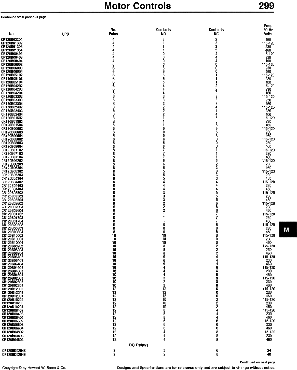
Motor Controls 299
Continued from previous page
Freq.
60 Hz
Volts
460
115-120
230
460
115-120
230
460
115-120
230
460
115-120
230
460
115-120
230
460
115-120
230
460
115-120
230
460
115-120
230
460
115-120
230
460
115-120
230
460
115-120
230
460
115-120
230
460
115-120
230
460
115-120
230
460
115-120
230
460
115-120
230
460
115-120
230
460
115-120
230
460
115-120
230
460
115-120
230
460
115-120
230
460
115-120
230
460
115-120
230
460
115-120
230
460
115-120
230
460
115-120
230
460
115-120
230
460
115-120
230
460
No.
Poles
4
4
4
4
4
4
4
6
6
6
6
6
6
6
6
6
6
6
6
6
6
6
6
6
6
6
6
6
8
8
8
8
8
8
8
8
8
8
8
8
8
8
8
8
8
8
8
8
8
8
8
8
8
8
8
10
10
10
10
10
10
10
10
10
10
10
10
10
10
10
12
12
12
12
12
12
12
12
12
12
12
12
12
12
12
Contacts
NO
2
1
1
1
0
0
0
6
6
6
5
5
5
4
4
4
3
3
3
2
2
2
1
1
1
0
0
0
8
8
8
7
7
7
6
6
6
5
5
5
4
4
4
3
3
3
2
2
2
1
1
1
0
0
0
10
10
10
8
8
8
6
6
6
4
4
4
2
2
2
12
12
12
10
10
10
8
8
8
6
6
6
4
4
4
Contacts
NC
2
3
3
3
4
4
4
0
0
0
1
1
1
2
2
2
3
3
3
4
4
4
5
5
5
6
6
6
0
0
0
1
1
1
2
2
2
3
3
3
4
4
4
5
5
5
6
6
6
7
7
7
8
8
8
0
0
0
2
2
2
4
4
4
6
6
6
8
8
8
0
0
0
2
2
2
4
4
4
6
6
6
8
8
8
UPCNo.
CR120BO2204
CR120BO1302
CR120BO1303
CR120BO1304
CR120BOO402
CR120BOO403
CR120BOO404
CR120B06002
CR120BOOOO3
CR120BOOOO4
CR120BO5102
CR120BO5103
CR120B051 04
CR120B04202
CR120B04203
CR120B04204
CR120B03302
CR120B03303
CR120B03304
CR120B02402
CR120B02403
CR120B02404
CR120B01502
CR120B01503
CR120B01504
CR120B00602
CR120B00603
CR120BOO6O4
CR120B08002
CR120B08003
CR120BOSOO4
CR120B07102
CR120B07103
CR120B07104
CR120BOO202
CR120BOO203
CR120BOO204
CR120B05302
CR120B05303
CR120B05304
CR120B04402
CR120BO4403
CR120BO4404
CR120B03502
CR120B03503
CR120B03504
CR120B02602
CR120B02603
CR120B02604
CR120B01702
CR120B01703
CR120B01704
CR120BOO802
CR120BOO803
CR120BOOS04
CR120B10002
CR120B10003
CR120B10004
CR120BOS202
CR120BOS203
CR120BOS204
CR120B06402
CR120B06403
CR120B06404
CR120B04602
CR120B04603
CR120BO46O4
CR120B02802
CR120B02803
CR120B02804
CR120B12002
CR120B12003
CR120B12004
CR120B10202
CR120B10203
CR120B10204
CR120B08402
CR120B08403
CR120B08404
CR120B06602
CR120B06603
CR120B06604
CR120B04802
CR120B04803
CR120BO4804
DC Relays
0
0
CR120BDO2048
CR120BDO2049 2
22
224
48
Continued on next page
Designs and Specifications are for reference only and are subject to change without notice.
Copyright @ by Howard W. Sams & Co.
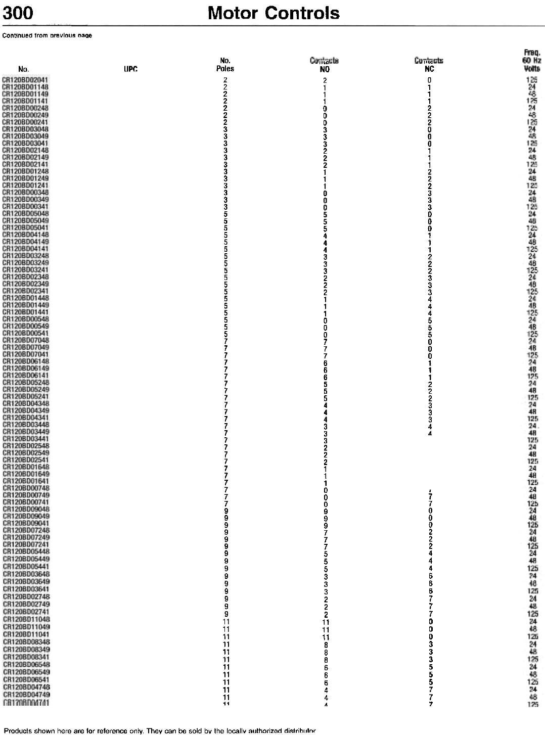
300
No.
Continued from previous oage
Products shown here are for reference only. They can be sold by the locallY authorized di!ltrib,rtnr
UPC No.
Poles
2
2
2
2
2
2
2
3
3
3
3
3
3
3
3
3
3
3
3
5
5
5
5
5
5
5
5
5
5
5
5
5
5
5
5
5
5
7
7
7
7
7
7
7
7
7
7
7
7
7
7
7
7
7
7
7
7
7
7
7
7
9
9
9
9
9
9
9
9
9
9
9
9
9
9
9
11
11
11
11
11
11
11
11
11
11
11
11
"La
NO
2
1
1
1
0
0
0
3
3
3
2
2
2
1
1
1
0
0
0
5
5
5
4
4
4
3
3
3
2
2
2
1
1
1
0
0
0
7
7
7
6
6
6
5
5
5
4
4
4
3
3
3
2
2
2
1
1
1
0
0
0
9
9
9
7
7
7
5
5
5
3
3
3
2
2
2
11
11
11
8
8
8
6
6
6
4
4
4
Motor Controls
"'"
NC
0
1
1
1
2
2
2
0
0
0
1
1
1
2
2
2
3
3
3
0
0
0
1
1
1
2
2
2
3
3
3
4
4
4
5
5
5
0
0
0
1
1
1
2
2
2
3
3
3
4
4
,
7
7
0
0
0
2
2
2
4
4
4
6
6
6
7
7
7
0
0
0
3
3
3
5
5
5
7
7
7
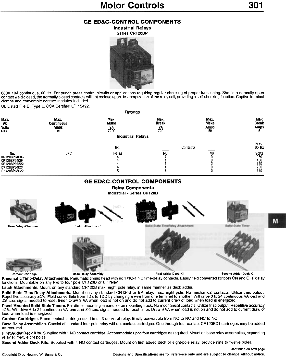
Motor Controls 301
GE ED&C-CONTROL COMPONENTS
Industrial Relays
Series CR120BP
-
600V 10A continuous, 60 Hz. For punch press control circuits or applications requiring regular checking of proper functioning. Should a normally open
contact weld closed, the normally closed contacts will not reclose upon de-energization of the relay coil, providing a self-checking function. Captive terminal
clamps and convertible contact modules included.
UL Listed File E, Type L. CSA Certified LA 15492.
Ratings
Max.
Continuous
A~gs
Max.
Make
VA
7200
Max.
Break
VA
720
Max.
Make
Amps
60
Max
Break
Amps
6
Max.
AC
Volts
600
Industrial Relays
Freq.
60 Hz
Volts
230
460
120
208
120
No.
Poles
4
4
4
4
8
Contacts
UPC -NO
4
4
2
4
8
-
NC
0
0
2
0
0
No.
CR120BPO4003
CR120BPO4004
CR120BPO2222
CR120BPO4024
CR120BPO8022
GE ED&C-CONTROL COMPONENTS
Relay Components
Industrial - Series CR120B
Latch Attachment
Time-Delay Attachment
Contact Cartridge Base Relay Assembly First Adder Deck Kit Second Adder Deck Kit
Pneumatic Time-Delay Attachments. Pneumatic timing head with no 1 NO-1 NC time-delay contacts. Easily field converted for both ON and OFF delay
functions. Mountable on any two to four pole CR120B or BP relay.
Latch Attachments. Mount on any standard CR120B max. eight pole relay, in same manner as deck adder.
Solid-State Time-Delay Attachments. Mount on any standard CR120B or BP relay, max. eight pole. No mechanical contacts. Utilize triac output.
Repetitive accuracy :t2%. Field convertible from TDE to TDD by changing a wire from one terminal to another. Will drive 6 to 24 continuous VA load and
.05 sec. signal needed to reset timer. Draw 9 VA when load is not on and do not add to current draw of load when load is energized.
Panel Mounted Solid-State Timers. For direct mounting in panel or on mounting track. No mechanical contacts. Utilize triac output. Repetitive accuracy
:t2%. Will drive 6 to 24 continuous VA load and .05 sec. signal needed to reset timer. Draw 9 VA when load is not on and do not add to current draw of
load when load is energized.
Contact Cartridges. Same contact cartridge used in all 3 decks of relay. Easily convertible from NO to NC and NC to NO.
Base Relay Assemblies. Consist of standard four-pole relay without contact cartridges. One through four contact CR120BX1 cartridges may be added
as required.
First Adder Deck Kits. Supplied with 1 NO contact cartridge. Accommodate up to four cartridges as required. Mount on base relay assemblies, expanding
relay to max. eight poles.
Second Adder Deck Kits. Supplied with 4 NO contact cartridges. Mount on first added deck or eight-pole relay; provide nine to twelve poles.
Continued on next page
Copyright @ by Howard W. Sams & Co. Designs and Specifications are for reference only and are subject to change without notice.
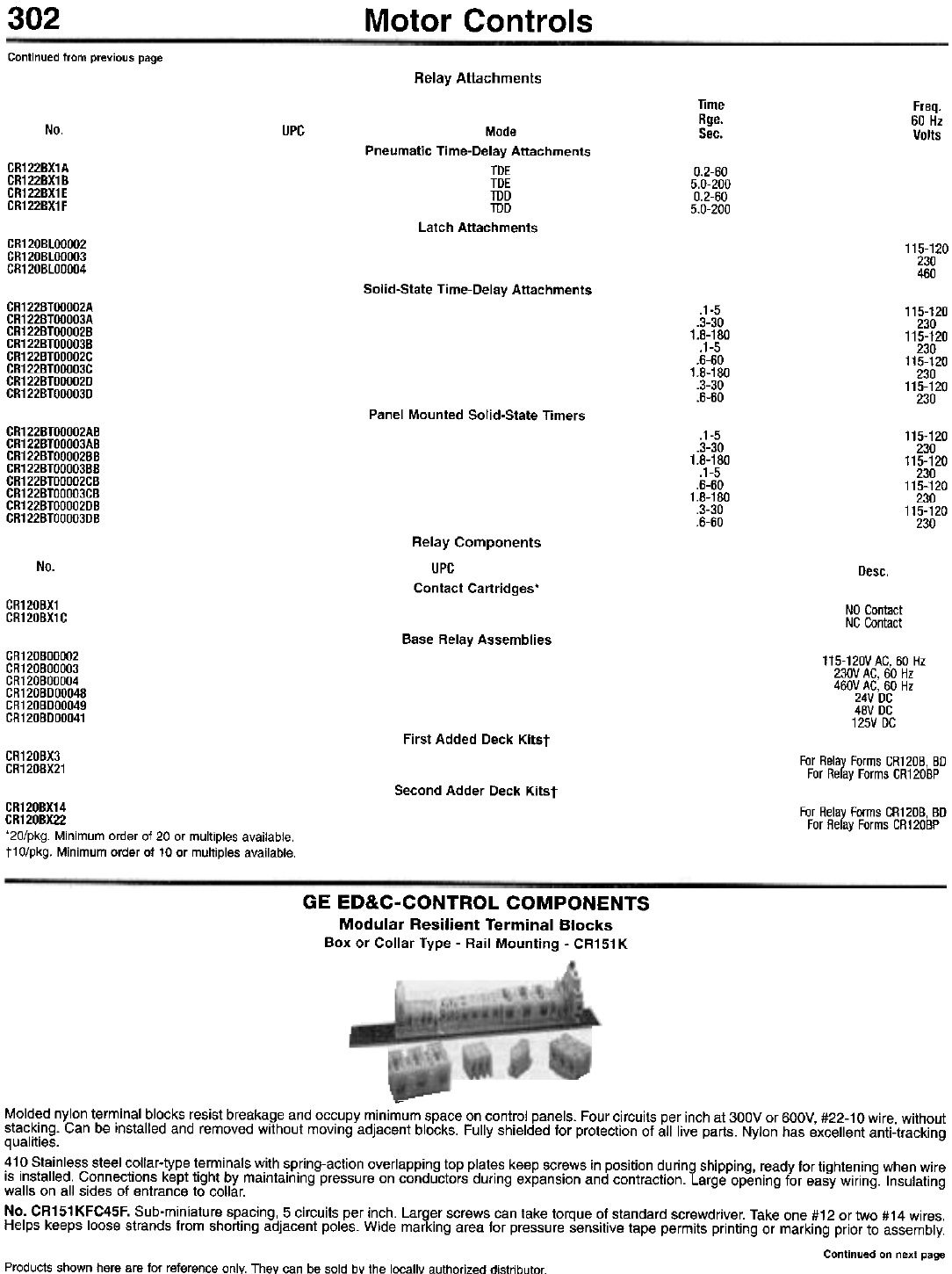
302 Motor Controls
Continued from previous page
Relay Attachments
Time
Rge.
Sec.
Freq.
60 Hz
Volts
No. UPC Mode
Pneumatic Time-Delay Attachments
TDE
TDE
TDD
TDD
Latch Attachments
CR122BX1A
CR122BX1B
CR122BX1E
CR122BX1F
0.2-60
5.0-200
0.2-60
5.0-200
CR120BLOOOO2
CR120BLOOOO3
CR120BLOOOO4
115-120
230
460
Solid-State Time-Delay Attachments
CR1228TOOOO2A
CR1228TOOOO3A
CR1228TOOOO28
CR1228TOOOO38
CR1228TOOOO2C
CR1228TOOOO3C
CR1228TOOOO2D
CR1228TOOOO3D
.1-5
.3-30
1.8-180
.1-5
.6-60
1.8-180
.3-30
.6-60
115-120
230
115-120
230
115-120
230
115-120
230
Panel Mounted Solid-State Timers
CR122BTOOOO2AB
CR122BTOOOO3AB
CR122BTOOOO2BB
CR122BTOOOO3BB
CR122BTOOOO2CB
CR122BTOOOO3CB
CR122BTOOOO2DB
CR122BTOOOO3DB
.1-5
.3-30
1.8-180
.1-5
.6-60
1.8-180
.3-30
.6-60
115-120
230
115-120
230
115-120
230
115-120
230
No. Desc.
Relay Components
UPC
Contact Cartridges'
CR120BX1
CR120BX1C NO Contact
NC Contact
Base Relay Assemblies
CR120BOOOO2
CR120BOOOO3
CR120BOOOO4
CR120BDOOO48
CR120BDOOO49
CR120BDOOO41
115-120VAC, 60 Hz
230V AC, 60 Hz
460V AC, 60 Hz
24V DC
48V DC
125V DC
First Added Deck Kitst
GR120BX3
GR120BX21 For Relay Forms CR120B, BD
For Relay Forms CR120BP
Second Adder Deck Kitst
For Relay Forms CR120B, BD
For Relay Forms CR120BP
CR120BX14
CR120BX22
'20/pkg. Minimum order of 20 or multiples available.
t10/pkg. Minimum order of 10 or multiples available.
GE ED&C-CONTROL COMPONENTS
Modular Resilient Terminal Blocks
Box or Collar Type - Rail Mounting - CR151 K
-
Molded nylon terminal blocks resist breakage and occupy minimum space on control panels. Four circuits per inch at 300V or 600V, #22-10 wire, without
stacking. Can be installed and removed without moving adjacent blocks. Fully shielded for protection of all live parts. Nylon has excellent anti-tracking
qualities.
410 Stainless steel collar-type terminals with spring-action overlapping top plates keep screws in position during shipping, ready for tightening when wire
is installed. Connections kept tight by maintaining pressure on conductors during expansion and contraction. Large opening for easy wiring. Insulating
walls on all sides of entrance to collar.
No. CR151 KFC45F. Sub-miniature spacing, 5 circuits per inch. Larger screws can take torque of standard screwdriver. Take one #12 or two #14 wires.
Helps keeps loose strands from shorting adjacent poles. Wide marking area for pressure sensitive tape permits printing or marking prior to assembly.
Continued on next page
Products shown here are for reference only. They can be sold bY the locallY authorized distributor.
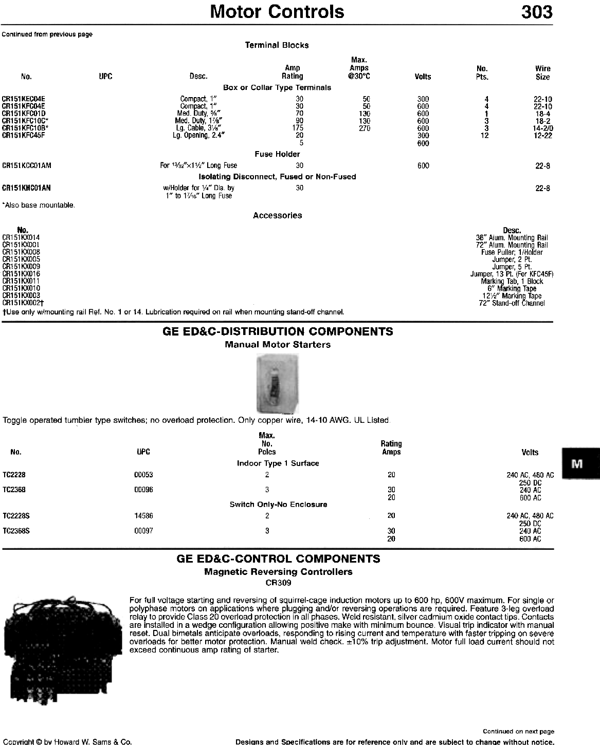
Motor Controls 303
Continued from previous page
Terminal Blocks
Max.
Amp Amps
Desc. Rating @30°C
Box or Collar Type Terminals
Compact, 1" 30
Compact, 1" 30
Med. Duty, 0/8" 70
Med. Duty, 17/8" 90
Lg. Cable, 3V8" 175
Lg. Opening, 2.4" 20
5
Fuse Holder
For 'o/32"x1V2" Long Fuse 30
Isolating Disconnect, Fused or Non-Fused
w/Holder for V." Dia. by 30
1" to 17/16" Long Fuse
No.
Pts.
Wire
Size
UPC
No. Volts
CR151KECO4E
CR151KFCO4E
CR151 KFCO1 D
CR151KFC10C*
CR151KFC10B*
CR151KFC45F
50
50
130
130
270
300
600
600
600
600
300
600
4
4
1
3
3
12
22-10
22-10
18-4
18-2
14-2/0
12-22
CR151KCCO1AM 600 22-8
22-8
CR151KHCO1AN
* Also base mountable.
Accessories
Desc.
36" Alum. Mounting Rail
72" Alum. Mounting Rail
Fuse Puller; 1/Holder
Jumper, 2 Pt.
Jumper, 5 Pt.
Jumper, 13 Pt. (For KFC45F)
Marking Tab, 1 Block
6" Marking Tape
12V2" Marking Tape
72" Stand-off Channel
No.
CR151KXO14
CR151KXOO1
CR151 KXOOB
CR151 KXOO5
CR151KXOO9
CR151KXO16
CR151KXO11
CR151KXO10
CR151KXOO3
CR151KXOO2t
fUse only w/mounting rail Ref. No.1 or 14. lubrication required on rail when mounting stand-off channel.
GE ED&C-DISTRIBUTION COMPONENTS
Manual Motor Starters
Toggle operated tumbler type switches; no overload protection. Only copper wire, 14-10 AWG. UL Listed.
Max.
No. Rating
No. UPC Poles Amps
Indoor Type 1 Surface
TC2228 00053 2 20
TC2368 00096 3 30
20
Switch Only-No Enclosure
TC2228S 14586 2
TC2368S 00097 3
Volts
240 AG, 480 AG
250 DG
240 AG
600 AG
20
30
20
240 AC, 480 AC
250 DC
240 AC
600 AC
GE ED&C-CONTROL COMPONENTS
Magnetic Reversing Controllers
CR309
For full voltage starting and reversing of squirrel-cage induction motors up to 600 hp, 600V maximum. For single or
polyphase motors on applications where plugging and/or reversing operations are required. Feature 3-leg overload
relay to provide Class 20 overload protection in all phases. Weld resistant, silver cadmium oxide contact tips. Contacts
are installed in a wedge configuration allowing positive make with minimum bounce. Visual trip indicator with manual
reset. Dual bimetals anticipate overloads, responding to rising current and temperature with faster tripping on severe
overloads for better motor protection. Manual weld check. :t10% trip adjustment. Motor full load current should not
exceed continuous amp rating of starter.
Continued on next page
Desi~ns and Specifications are for reference only and are subject to chanQe without notice.CoDyrioht @ by Howard W. Sams & Co.
304 Motor Controls
Continued from previous page
3 Pole - Three-Leg Protection
Max.
hp
Rating
Volts
Cont.
NEMA Rating
Size Amps
Open Type - w/Horizontal Mech. Int.
00 9
00 9
00 9
00 9
00 9
0 18
0 18
0 18
0 18
0 18
1 27
1 27
1 27
1 27
1 27
2 45
2 45
2 45
2 45
2 45
3 90
3 90
3 90
3 90
3 90
4 135
4 135
4 135
4 135
4 135
5 270
5 270
5 270
5 270
5 270
Open Type - wNertical Mech. Int.
0 18
0 18
0 18
0 18
0 18
1 27
1 27
1 27
1 27
1 27
2 45
2 45
2 45
2 45
2 45
3 90
3 90
3 90
3 90
3 90
4 135
4 135
4 135
4 135
4 135
5 270
5 270
5 270
5 270
5 270
Max.
hp
No. UPC
CR309AOO2
CR309AO23
CR309AOO3
CR309AOO4
CR309AOO5
CR309BOO2
CR309BO23
CR309BOO3
CR309BOO4
CR309BOO5
CR309COO2
CR309CO23
CR309COO3
CR309COO4
CR309COO5
CR309DOO2
DR309DO23
DR309DOO3
DR309DOO4
DR309DOO5
CR309EOO2
CR309EO23
CR309EOO3
CR309EO04
CR309EOO5
CR309FOO2
CR309FO23
CR309FOO3
CR309FOO4
CR309FOO5
CR309GOO2
CR309GO23
CR309GOO3
CR309GOO4
CR309GOO5
115-120'
200-208
230-240
460-480
575-600
115-120'
200-208
230-240
460-480
575-600
115-120'
200-208
230-240
460-480
575-600
115-120'
200-208
230-240
460-480
575-600
115-120'
200-208
230-240
460-480
575-600
115-120'
200-208
230-240
460-480
575-600
115-120'
200-208
230-240
460-480
575-600
1V2
1V2
2
2
3
3
5
5
7'h
7'h
10
10
10
15
25
25
25
30
50
50
40
50
100
100
75
100
200
200
CR309BOO2CAA
CR309BO23CAA
CR309BOO3CAA
CR309BOO4CAA
CR309BOO5CAA
CR309COO2CAA
CR309CO23CAA
CR309COO3CAA
CR309COO4CAA
CR309COO5CAA
CR309DOO2CAA
DR309DO23CAA
DR309DOO3CAA
DR309DOO4CAA
DR309DOO5CAA
CR309EOO2CAA
CR309EO23CAA
CR309EOO3CAA
CR309EOO4CAA
CR309EOO5CAA
CR309FOO2CAA
CR309FO23CAA
CR309FOO3CAA
CR309FOO4CAA
CR309FOO5CAA
CR309GOO2CAA
CR309GO23CAA
CR309GOO3CAA
CR309GOO4CAA
CR309GOO5CAA
115-120'
200-208
230-240
460-480
575-600
115-120'
200-208
230-240
460-480
575-600
115-120'
200-208
230-240
460-480
575-600
115-120'
200-208
230-240
460-480
575-600
115-120'
200-208
230-240
460-480
575-600
115-120'
200-208
230'240
460-480
575-600
3
3
5
5
71/z
7V2
10
10
10
15
25
25
25
30
50
50
40
50
100
100
75
100
200
200
NEMA Type 1
CR309A102
CR309A123
CR309A103
CR309A104
CR309A105
CR309B102
CR309B123
CR309B103
CR309B104
CR309B105
CR309C102
CR309C123
CR309C103
CR309C104
00
00
00
00
00
a
a
a
a
a
1
1
1
1
9
9
9
9
9
18
18
18
18
18
27
27
27
27
115-120'
200-208
230-240
460-480
575-600
115-120'
200-208
230-240
460-480
575-600
115-120'
200-208
230-240
460-480
11h
11h
2
2
3
3
5
5
71h
7V2
10
Continued on next page
Products shown here are for reference only. They can be sold by the locally authorized distributor.
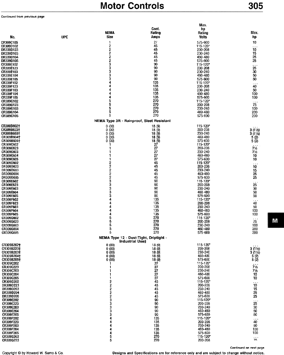
Motor Controls 305
Continued from previous page
Max.
hp
Rating
Volts
575-600
115-120'
200-208
230-240
460-480
575-600
115-120'
200-208
230-240
460-480
575-600
115-120'
200-208
230-240
460-480
575-600
115-120'
200-208
230-240
460-480
575-600
Cant.
NEMA Rating
Size Amps
1 27
2 45
2 45
2 45
2 45
2 45
3 90
3 90
3 90
3 90
3 90
4 135
4 135
4 135
4 135
4 135
5 270
5 270
5 270
5 270
5 270
NEMA Type 3R - Rainproof, Sleet Resistant
0 (00) 18 (9)
0 (00) 18 (9)
0 (00) 18 (9)
0 (00) 18 (9)
0 (00) 18 (9)
1 27
1 27
1 27
1 27
1 27
2 45
2 45
2 45
2 45
2 45
3 90
3 90
3 90
3 90
3 90
4 135
4 135
4 135
4 135
4 135
5 270
5 270
5 270
5 270
5 270
NEMA Type 12 - Dust-Tight, Driptight -
Industrial Uset
0 (00) 18 (9)
0 (00) 18 (9)
0 (00) 18 (9)
0 (00) 18 (9)
0 (00) 18 (9)
1 27
1 27
1 27
1 27
1 27
2 45
2 45
2 45
2 45
2 45
3 90
3 90
3 90
3 90
3 90
4 135
4 135
4 135
4 135
4 135
5 270
5 270
Max.
hp
10
10
15
25
25
25
30
50
50
40
50
100
100
75
100
200
200
No.
CR309C105
CR309D102
DR309D123
DR309D103
DR309D104
DR309D105
CR309E102
CR309E123
CR309E103
CR309E104
CR309E105
CR309F102
CR309F123
CR309F103
CR309F104
CR309F105
CR309G102
CR309G123
CR309G103
CR309G104
CR309G105
UPC
115-120.
200-208
230-240
460-480
575-600
115-120.
200-208
230-240
460-480
575-600
115-120.
200-208
230-240
460-480
575-600
115-120.
200-208
230-240
460-480
575-600
115-120.
200-208
230-240
460-480
575-600
115-120.
200-208
230-240
460-480
575-600
3 (1'h)
3 (1 'h)
5 (2)
5 (2)
7V.
7V.
10
10
10
15
25
25
25
30
50
50
40
50
100
100
75
100
200
200
CR309B202t
CR309B223t
CR309B203t
CR309B204t
CR309B205t
CR309C202
CR309C223
CR309C203
CR309C204
CR309C205
CR309D202
DR309D223
DR309D203
DR309D204
DR309D205
CR309E202
CR309E223
CR309E203
CR309E204
CR309E205
CR309F202
CR309F223
CR309F203
CR309F204
CR309F205
CR309G202
CR309G223
115-120'
200-208
230-240
460-480
575-600
115-120'
200-208
230-240
460-480
575-600
115-120'
200-208
230-240
460-480
575-600
115-120'
200-208
230-240
460-480
575-600
115-120'
200-208
230-240
460-480
575-600
115-120'
200-208
3 (1V2)
3 (1V2)
5 (2)
5 (2)
7V2
71h
10
10
10
15
25
25
25
30
50
50
40
50
100
100
71;
Continued on next page
Designs and Specifications are for reference only and are subject to change without notice.
Copyright @ by Howard W. Sams & Co.
CR309B604t
CR309B605t
CR309C602
CR309C623
CR309C603
CR309C604
CR309C605
CR309D602
DR309D623
DR309D603
DR309D604
DR309D605
CR309E602
CR309E623
CR309E603
CR309E604
CR309E605
CR309F602
CR309F623
CR309F603
CR309F604
CR309F605
CR309G602
CR309G623
CR309G603
CR309G604
CR309G605
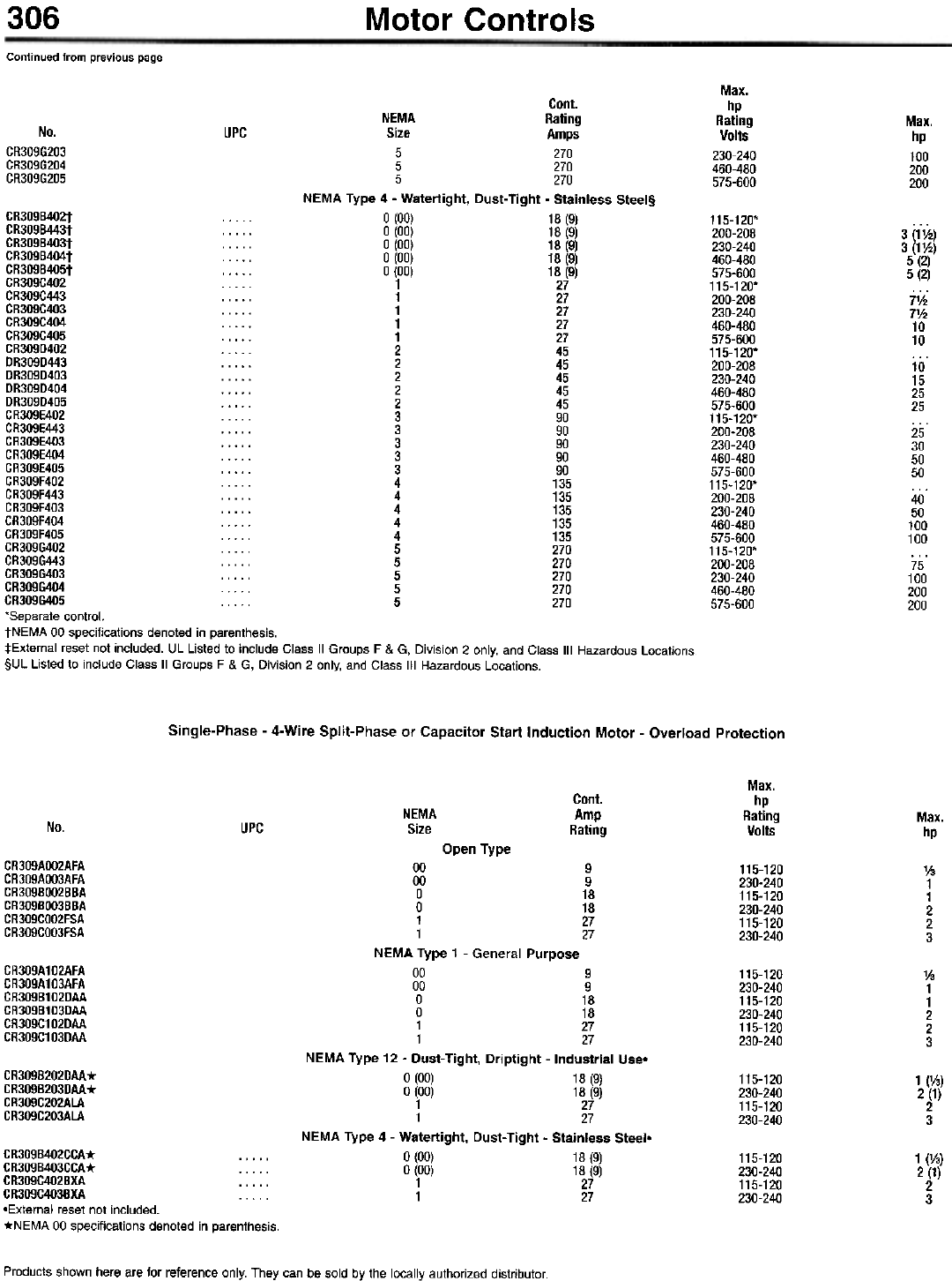
306 Motor Controls
Continued from previous page
Max.
hp
Rating
Volts
230-240
460-480
575-600
Max.
hp
100
200
200
No.
CR309G203
CR309G204
CR309G205
UPC
Cont.
NEMA Rating
Size Amps
5 270
5 270
5 270
NEMA Type 4 - Watertight, Dust-Tight - Stainless Steel§
CR309B402t . . . . . 0 (00) 18 (9)
CR309B443t . . . . . 0 (00) 18 (9)
CR309B403t . . . . . 0 (00) 18 (9)
CR309B404t . . . . . 0 (00) 18 (9)
CR309B405t . . . . . 0 (00) 18 (9)
CR309C402 1 27
CR309C443 1 27
CR309C403 1 27
CR309C404 . . . . . 1 27
CR309C405 . . . . . 1 27
CR309D402 2 45
DR309D443 2 45
DR309D403 2 45
DR309D404 2 45
DR309D405 . . . . . 2 45
CR309E402 3 90
CR309E443 . . . . . 3 90
CR309E403 3 90
CR309E404 3 90
CR309E405 . . . . . 3 90
CR309F402 4 135
CR309F443 4 135
CR309F403 4 135
CR309F404 4 135
CR309F405 4 135
CR309G402 5 270
CR309G443 5 270
CR309G403 5 270
CR309G404 5 270
CR309G405 5 270
'Separate control.
tNEMA 00 specifications denoted in parenthesis.
:j:External reset not included. UL Listed to include Class II Groups F & G, Division 2 only, and Class III Hazardous Locations.
§UL Listed to include Class II Groups F & G, Division 2 only, and Class III Hazardous Locations.
115-120'
200-208
230-240
460-480
575-600
115-120'
200-208
230-240
460-480
575-600
115-120'
200-208
230-240
460-480
575-600
115-120'
200-208
230-240
460-480
575-600
115-120'
200-208
230-240
460-480
575-600
115-120'
200-208
230-240
460-480
575-600
3 (1'h)
3 (1'h)
5 (2)
5 (2)
7V2
7'h
10
10
10
15
25
25
25
30
50
50
40
50
100
100
75
100
200
200
Single-Phase - 4-Wire Split-Phase or Capacitor Start Induction Motor - Overload Protection
Max.
hp
Rating
Volts
Cont.
Amp
Rating
NEMA
Size Max.
hp
No. UPC
Open Type
CR309AOO2AFA
CR309AOO3AFA
CR309BOO2BBA
CR309BOO3BBA
CR309COO2FSA
CR309COO3FSA
1/3
1
1
2
2
3
CR309A102AFA
CR309A103AFA
CR309B102DAA
CR309B103DAA
CR309C102DAA
CR309C103DAA
115-120
230-240
115-120
230-240
115-120
230-240
V3
1
1
2
2
3
CR3098202DAA*
CR3098203DAA*
CR309C202ALA
CR309C203ALA
115-120
230-240
115-120
230-240
1 (V3)
2 (1)
2
3
00 9
00 9
0 18
0 18
1 27
1 27
NEMA Type 1 - General Purpose
00 9
00 9
0 18
0 18
1 27
1 27
NEMA Type 12 - Dust-Tight, Driptight -Industrial Use-
0 (00) 18 (9)
0 (00) 18 (9)
1 27
1 27
NEMA Type 4 - Watertight, Dust-Tight - Stainless Steel-
0 (00) 18 (9)
0 (00) 18 (9)
1 27
1 27
115-120
230-240
115-120
230-240
1 (1/3)
2 (1)
2
3
CR309B402CCA* CR309B403CCA* CR309C402BXA CR309C403BXA -External reset not included.
*NEMA 00 specifications denoted in parenthesis.
Products shown here are for reference only. They can be sold by the locally authorized distributor.
115-120
230-240
115-120
230-240
115-120
230-240
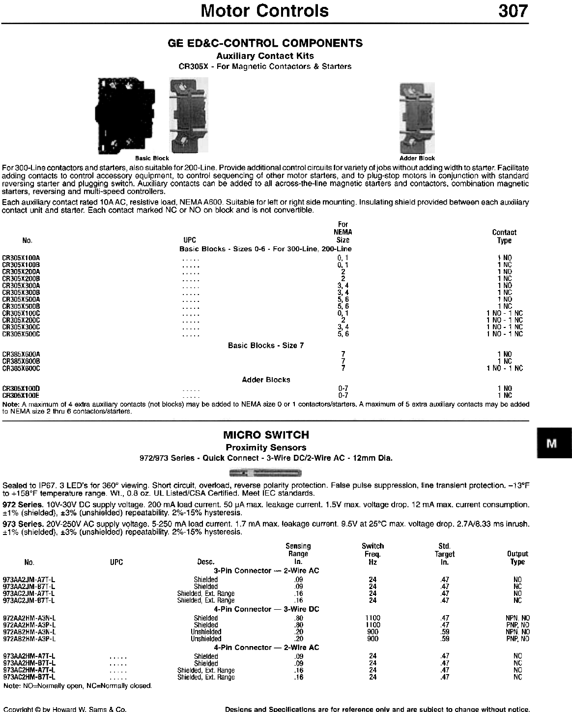
Motor Controls 307
GE ED&C-CONTROL COMPONENTS
Auxiliary Contact Kits
CR305X - For Magnetic Contactors & Starters
- -
Basic Block Adder Block
For 300-Line contactors and starters, also suitable for 200-Line. Provide additional control circuits for variety of jobs without adding width to starter. Facilitate
adding contacts to control accessory equipment, to control sequencing of other motor starters, and to plug-stop motors in conjunction with standard
reversing starter and plugging switch. Auxiliary contacts can be added to all across-the-line magnetic starters and contactors, combination magnetic
starters, reversing and multi-speed controllers.
Each auxiliary contact rated 10AAC, resistive load, NEMAA600. Suitable for left or right side mounting. Insulating shield provided between each auxiliary
contact unit and starter. Each contact marked NC or NO on block and is not convertible.
For
NEMA
UPC Size
Basic Blocks - Sizes 0-6 - For 300-Line, 200-Line
. . . . . 0, 1
. . . . . 0, 1
2
2
. . . . . 3,4
. . . . . 3, 4
. . . . . 5, 6
. . . . . 5, 6
. . . . . 0, 1
2
. . . . . 3, 4
. . . . . 5, 6
Contact
Type
No.
1
1
1
1
1
1
1
1
1 NO
1 NO
1 NO
1 NO
CR305X100A
CR305X100B
CR305X200A
CR305X200B
CR305X300A
CR305X300B
CR305X500A
CR305X500B
CR305X100C
CR305X200C
CR305X300C
CR305X500C
Basic Blocks - Size 7
CR385X600A
CR385X600B
CR385X600C
7
7
7
1 NO
1 NC
1 NO -1 NC
Adder Blocks
CR305X100D 0-7 1 NO
CR305X100E 0-7 1 NC
Note: A maximum of 4 extra auxiliary contacts (not blocks) may be added to NEMA size 0 or 1 contactors/starters. A maximum of 5 extra auxiliary contacts may be added
to NEMA size 2 thru 6 contactors/starters.
MICRO SWITCH
Proximity Sensors
972/973 Series - Quick Connect - 3-Wire DC/2-Wire AC - 12mm Dia.
Sealed to IP67. 3 LED's for 360° viewing. Short circuit, overload, reverse polarity protection. False pulse suppression, line transient protection. -13°F
to +158°F temperature range. Wt., 0.8 oz. UL Listed/CSA Certified. Meet lEG standards.
972 Series. 10V-30V DC supply voltage. 200 mA load current. 50 ~A max. leakage current. 1.5V max. voltage drop. 12 mA max. current consumption.
:t1% (shielded), :t3% (unshielded) repeatability. 2%-15% hysteresis.
973 Series. 20V-250V AC supply vqltage. 5-250 mA load current. 1.7 mA max. leakage current. 9.5V at 25°C max. voltage drop. 2.7 A/8.33 ms inrush.
:t1% (shielded), :t3% (unshielded) repeatability. 2%-15% hysteresis.
Switch
Freq.
Hz
Std.
Target
In. Output
Type
NO
NC
NO
NC
No. UPC
973AA2JM-A7T-l
973AA2JM-B7T-l
973AC2JM-A7T-l
973AC2JM-B7T-l
24
24
24
24
.47
.47
.47
.47
972AA2HM-A3N-l
972AA2HM-A3P-l
972AB2HM-A3N-l
972AB2HM-A3P-l
1100
1100
900
900
.47
.47
.59
.59
NPN, NO
PNP, NO
NPN, NO
PNP, NO
Sensing
Range
Desc. In.
3-Pin Connector - 2-Wire AC
Shielded .09
Shielded .09
Shielded, Ex!. Range .16
Shielded, Ex!. Range .16
4-Pin Connector - 3-Wire DC
Shielded .80
Shielded .80
Unshielded .20
Unshielded .20
4-Pin Connector - 2-Wire AC
Shielded .09
Shielded .09
Shielded, Ex!. Range .16
Shielded, Ex!. Range .16
24
24
24
24
.47
.47
.47
.47
NO
NC
NO
NC
973AA2HM-A7T-L 973AA2HM-B7T-L 973AC2HM-A7T-L . . . . .
973AC2HM-B7T-L Note: NO=Normally open, NC=Normally closed.
Coovriaht @ bv Haward W. Sams & Co. Desians and SDecifications are for reference on Iv and are subject to chanae without notice.
NO
NC
NO
NC
NO
NC
NO
NC
- 1
- 1
- 1
- 1
NC
NC
NC
NC
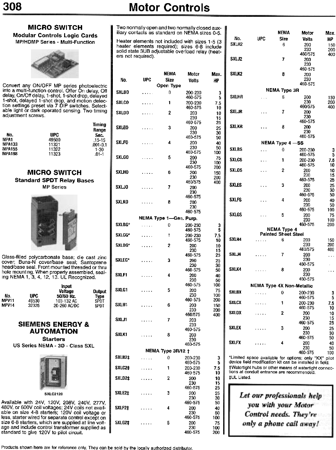
308 Motor Controls
Two normally open and two normally closed aux-
iliary contacts as standard on NEMA sizes 0-5.
Heater elements not included with sizes 1-5 (3
heater elements required); sizes 6-8 include
solid state 3UB adjustable overload relay (heat-
ers not required).
NEMA
Size
6
Motor
Volts
200
230
460/575
200
230
460-575
200
230
460-575
Max.
HP
150
200
400
MICRO SWITCH
Modular Controls Logic Cards
MP/HDMP Series - Multi-Function No.
SXlH2
UPC
SXlJ2 7
NEMA
UPC Size
Open Type
0
. . . . . 1
. 2
3
4
5
6
7
8
NEMA Type 1-Gel
. . .. 0
. . . . . 1
2
.".' 3
4
5
6
7
8
NEMA Type 3R/
. . . 0
. . . . . 1
2
3
4
5
Motor
Volts
Max.
HP
SXLK2 8
No.
Convert any ON/OFF MP series photoelectric
into a multi-function control. Offer On delay, Off
delay, On/Off delay, 1-shot, 1-shot drop, delayed
1-shot, delayed 1-shot drop, and motion detec-
tion settings preset via 7 DIP switches. Select-
able light or dark operated sensing. Two timing
adjustment screws.
NEMA Type 3R
6 200
230
460/575
... 7 200
230
460-575
... 8 200
230
460-575
NEMA Type 4 -55
0 200-230
460-575
... 1 200-230
460-575
... 2 200
230
460-575
... 3 200
230
460-575
... 4 200
230
460-575
... 5 200
230
460-575
SXLBO
SXLCO
SXLDO
3
5
7.5
10
10
15
25
25
30
50
40
50
100
75
100
200
150
200
400
SXlHR 150
200
400
SXLJR
Timing
Range
Sec.
.15-15
.001-0.1
1-30
.01-1
SXLKR
SXLEO
No.
MPA1
MPA133
MPA155
MPA188
UPC
49500
11321
11322
11323
SXLFO
SXlBS
SXlCS
SXlDS
3
5
7.5
10
10
15
25
25
30
50
40
50
100
75
100
200
SXlGO
MICRO SWITCH
Standard SPDT Relay Bases
MP Series
SXLHO
SXLES
SXlJO
SXLFS
SXLKO
SXlGS
SXlBG*
SXlCG*
SXlDG*
3
5
7.5
10
10
15
25
25
30
50
40
50
100
75
100
200
150
200
400
NEMA Type 4
Painted Sheet Steel
SXLH4 . . . . 6 200 150
230 200
460/575 400
SXLJ4 7 200 ...
230
460-575
SXLK4 8 200 ...
230
460-575
NEMA Type 4X Non-Metallic
SXLBX 0 200-230 3
460-575 5
SXLCX . . . . . 1 200-230 7.5
460-575 10
SXLDX . . .. . 2 200 10
230 15
460-575 25
SXLEX 3 200 25
230 30
460-575 50
SXLFX 4 200 40
230 50
460-575 100
-Limited space available for options; only "KX" pilot
device field modification kit can be installed in field.
tWatertight hubs or other means of watertight connec-
tions at conduit entrance are recommended.
:j:UL Listed.
Glass-filled polycarbonate base; die cast zinc
cover; Buna-N cover/base seal; Santoprene
head/base seal. Front mounted threaded or thru
hole mounting. When properly assembled, seal-
ing NEMA 1, 3, 4, 12, 13. UL Recognized.
Input
Voltage Output
No. UPC 50/60 Hz. Type
MPV11 49530 103-132AC SPDT
MPV14 32325 20-260 AC/DC SPDT
SXLEG*
SXlF1
SXlG1
SXlH1
SXLJ1
SXLK1
SIEMENS ENERGY &
AUTOMATION
Starters
us Series NEMA - 30 - Class SXL
SXLB2:j:
SXLC2:j:
SXLD2:j:
3
5
7.5
10
10
15
25
25
30
50
40
50
100
75
100
200
SXLE2:f:
SXLC2120
Available with 24V, 120V, 208V, 240V, 277V,
480V, or 600V coil voltages; 24V coils not avail-
able on size 4-8 starters; 120V coil voltage or
less, starter wired for separate control except on
size 6-8 starters, which are supplied at line volt-
age and include control transformer supplied as
standard to give 120V to pilot circuit.
SXLF2:j:
SXlG2:t:
Products shown here are for reference only. They can be sold by the locally authorized distributor.
200-230
460-575
200-230
460-575
200
230
460-575
200
230
460-575
200
230
460-575
200
230
460-575
200
230
460/575
200
230
460-575
200
230
460-575
1. Purp.
200-230
460-575
200-230
460-575
200
230
460-575
200
230
460-575
200
230
460-575
200
230
460-575
200
230
460/575
200
230
460-575
200
230
460-575
12t
200-230
460-575
200-230
460-575
200
230
460-575
200
230
460-575
200
230
460-575
200
230
460-575
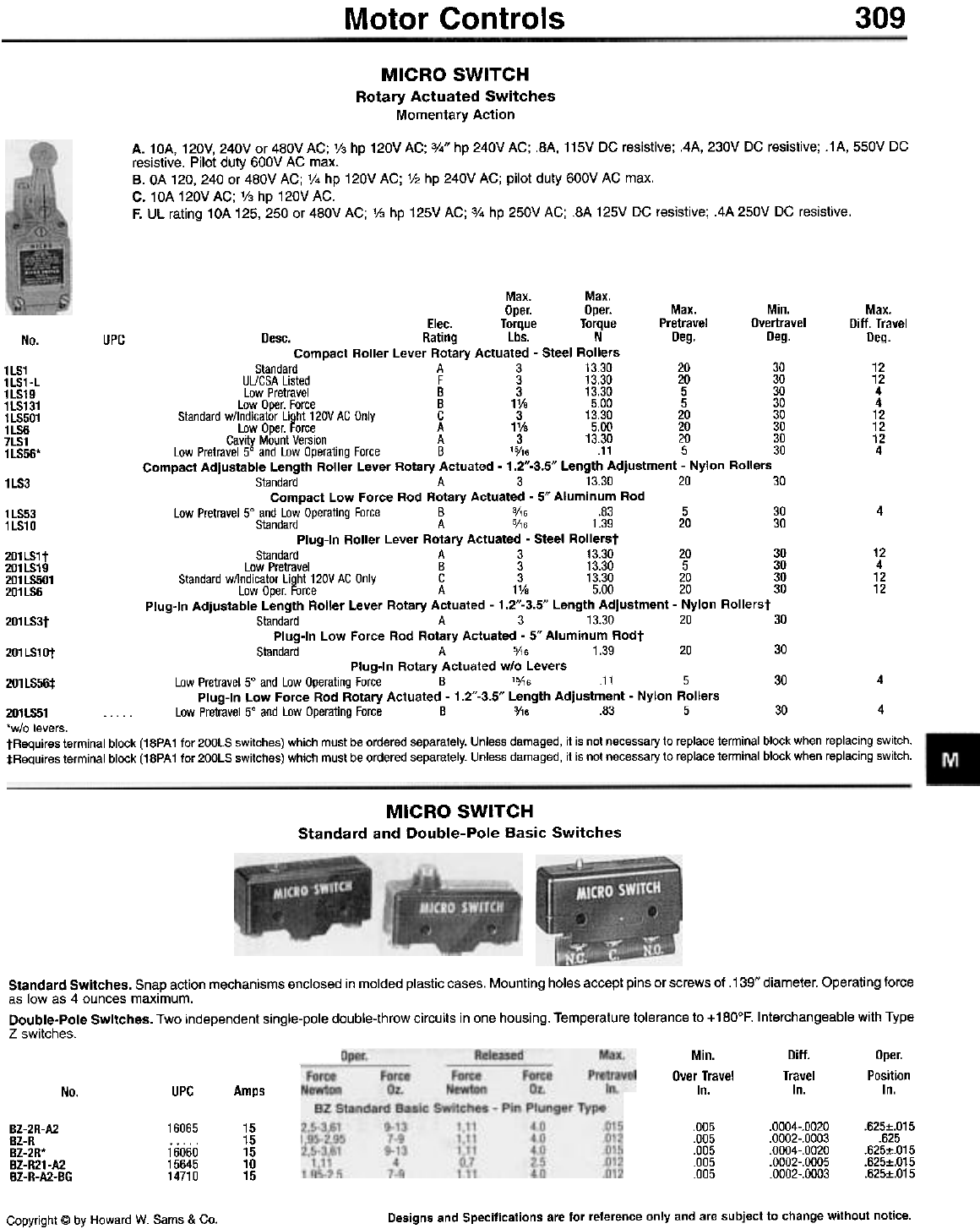
Motor Controls 309
MICRO SWITCH
Rotary Actuated Switches
Momentary Action
A. 10A, 120V, 240V or 480V AC; '/3 hp 120V AC; 3/4" hp 240V AC; .8A, 115V DC resistive; .4A, 230V DC resistive; .1 A, 550V DC
resistive. Pilot duty 600V AC max.
B. OA 120, 240 or 480V AC; V4 hp 120V AC; '/2 hp 240V AC; pilot duty 600V AC max.
C. 10A 120V AC; '/3 hp 120V AC.
F. UL rating 10A 125,250 or 480V AC; V3 hp 125V AC; 3/4 hp 250V AC; .8A 125V DC resistive; .4A 250V DC resistive.
Max. Max.
Oper. Oper. Max. Min.
Elec. Torque Torque Pretravel Overtravel
Desc. Rating Lbs. N Deg. Deg.
Compact Roller Lever Rotary Actuated - Steel Rollers
Standard A 3 13.30 20 30
UUCSA Listed F 3 13.30 20 30
Low Pretravel B 3 13.30 5 30
Low Oper. Force B 1 Va 5.00 5 30
Standard w/lndicator Light 120V AC Only C 3 13.30 20 30
Low Oper. Force A 11/8 5.00 20 30
Cavity Mount Version A 3 13.30 20 30
Low Pretravel 5° and Low Operating Force B '5/,6 .11 5 30
Compact Adjustable Length Roller Lever Rotary Actuated - 1.2"-3.5" Length Adjustment - Nylon Rollers
Standard A 3 13.30 20
Compact Low Force Rod Rotary Actuated - 5" Aluminum Rod
Low Pretravel 5° and Low Operating Force B 3/16 .83 5
Standard A 5/,6 1.39 20
Plug-In Roller Lever Rotary Actuated - Steel Rollerst
Standard A 3 13.30 20
Low Pretravel B 3 13.30 5
Standard w/lndicator Light 120V AC Only C 3 13.30 20
Low Oper. Force A 1V. 5.00 20
Plug-In Adjustable Length Roller Lever Rotary Actuated - 1.2"-3.5" Length Adjustment - Nylon Rollerst
Standard A 3 13.30 20
Plug-In Low Force Rod Rotary Actuated - 5" Aluminum Rodt
Standard A 5/,6 1.39 20
Plug-In Rotary Actuated w/o Levers
Low Pretravel 5° and Low Operating Force B 15/16 .11 5
Plug-In Low Force Rod Rotary Actuated - 1.2"-3.5" Length Adjustment - Nylon Rollers
Max.
Ditt. Travel
Deg.
No. UPC
12
12
4
4
12
12
12
4
1LS1
1LS1-L
1LS19
1LS131
1LS501
1LS6
7LS1
1 LS56*
30
1LS3
30
30 4
1 LS53
1LS10
30
30
30
30
12
4
12
12
201 LS1t
201 LS19
201 LS501
201LS6
30
201 LS3t
201 LS1Ot 30
30 4
201LS~
201lS51 . . . . . Low Pretravel 5° and Low Operating Force B 0/16 .83 5 30 ~
'w/o levers.
tRequires terminal block (18PA 1 for 200LS switches) which must be ordered separately. Unless damaged, it is not necessary to replace terminal block when replacing switch.
:l:Requires terminal block (18PA 1 for 200LS switches) which must be ordered separately. Unless damaged, it is not necessary to replace terminal block when replacing switch.
"
MICRO SWITCH
Standard and Double-Pole Basic Switches
Standard Switches. Snap action mechanisms enclosed in molded plastic cases. Mounting holes accept pins or screws of .139" diameter. Operating force
as low as 4 ounces maximum.
Double-Pole Switches. Two independent single-pole double-throw circuits in one housing. Temperature tolerance to + 180°F. Interchangeable with Type
Z switches.
Min.
Over Travel
In.
Ditt.
Travel
In.
Oper.
Position
In.
UPC Amps
No.
.0004-
.0002-
.0004-
.0002-
.0002-
.625:t.O15
.625
.625:t.O15
.625:t.O15
.625:t.O15
.005
.005
.005
.005
.005
Bl-2R-A2
Bl-R
Bl-2R*
Bl-R21-A2
Bl-R-A2-BG
16065
16060
15645
14710
15
15
15
10
15
Designs and Specifications are for reference only and are subject to change without notice.
Copyright @ by Howard W. Sams & Co.
.0020
.0003
.0020
.0005
.0003
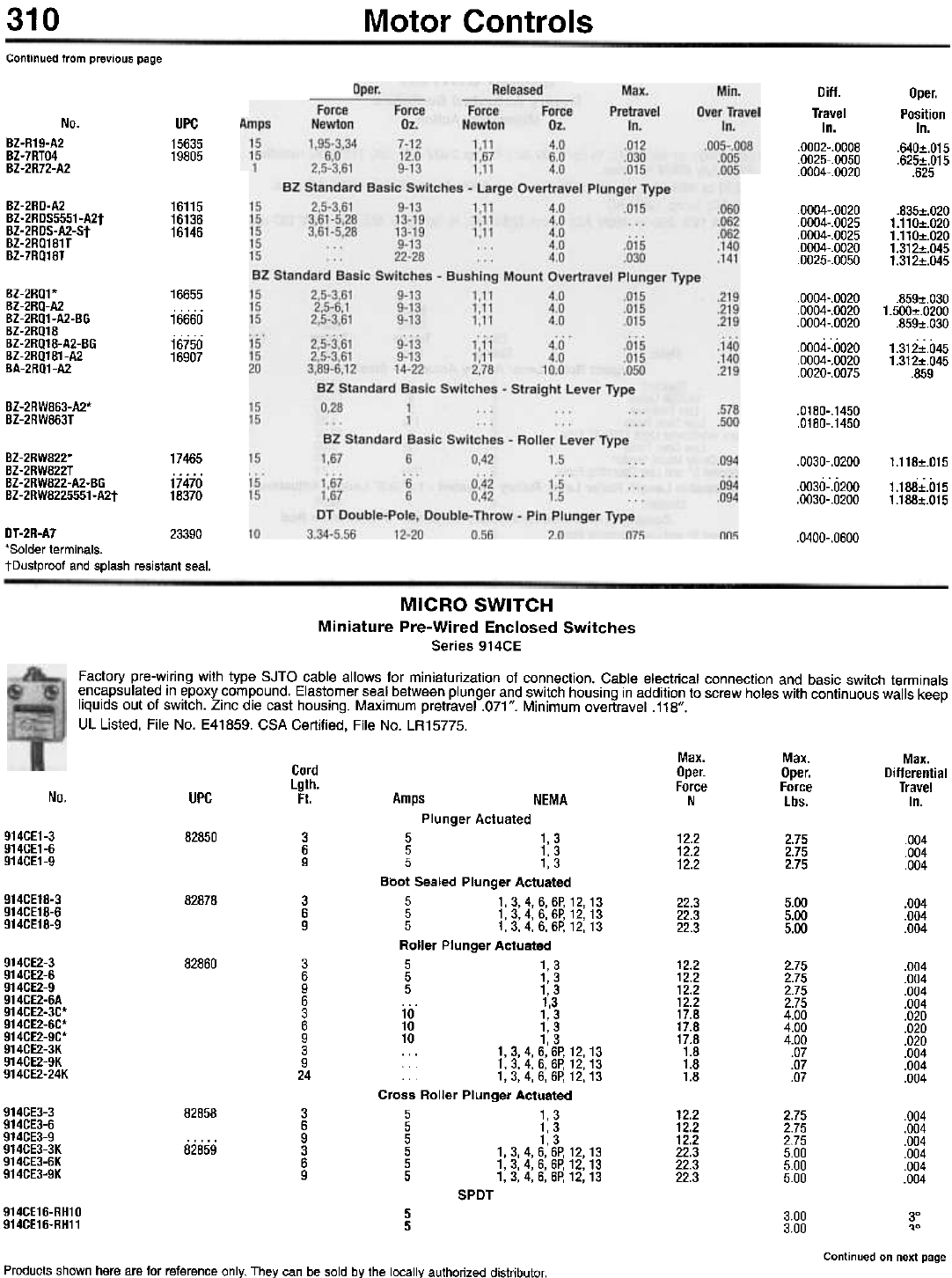
310 Motor Controls
Continued from previous page
Diff.
Travel
In.
.0002-.0008
.0025-.0050
.0004-.0020
Oper.
Position
In.
.640:t.O15
.625:t.O15
.625
No.
BZ-R19-A2
BZ-7RTO4
BZ-2R72-A2
UPC
15635
19805
BZ-2RD-A2
BZ-2RDS5551-A2t
BZ-2RDS-A2-St
BZ-2RQ181T
BZ-7RQ18T
16115
16136
16146
.0004-
.0004-
.0004-
.0004-
.0025-
.835:t.O20
1.110:t.O20
1.110:t.O20
1.312:t.O45
1.312:t.O45
BZ-2RQ1*
BZ-2RQ-A2
BZ-2RQ1-A2-BG
BZ-2RQ18
BZ-2RQ18-A2-BG
BZ-2RQ181-A2
BA-2RQ1-A2
16655
16660
16750
16907
.0004-
.0004-
.0004-
.0004-
.0004-
.0020-
.859:t.O30
1.500:t.O200
.859:t.O30
1.312:t.O45
1.312:t.O45
.859
BZ-2RW863-A2*
BZ-2RW863T .0180-.1450
.0180-.1450
BZ-2RW822*
BZ-2RW822T
BZ-2RW822-A2-BG
BZ-2RW8225551-A2t
17465
17470
18370
.0030-.0200
.0030-.0200
.0030-.0200
1.118:t.O15
1.188:t.O15
1.188:t.O15
.0400-.0600
DT-2R-A7 23390
'Solder terminals.
tDustproof and splash resistant seal.
MICRO SWITCH
Miniature Pre-Wired Enclosed Switches
Series 914CE
Factory pre-wiring with type SJTO cable allows for miniaturization of connection. Cable electrical connection and basic switch terminals
encapsulated in epoxy compound. Elastomer seal between plunger and switch housing in addition to screw holes with continuous walls keep
liquids out of switch. Zinc die cast housing. Maximum pretravel .071". Minimum overtravel .118".
UL Listed, File No. E41859. CSA Certified, File No. LR15775.
Max.
Oper.
Force
N
Max.
Oper.
Force
lbs.
Max.
Differential
Travel
In.
Cord
Lgth.
Ft.
No. UPC NEMA
Amps
Plunger Actuated
914CE1-3
914CE1-6
914CE1-9
82850 3
6
9
5 1,3
5 1,3
5 1,3
Boot Sealed Plunger Actuated
5 1,3,4,6,6P,12,13
5 1,3,4,6,6p,12,13
5 1,3,4,6,6P,12,13
Roller Plunger Actuated
5 1,3
5 1,3
5 1,3
. . . 1,3
10 1,3
10 1,3
10 1,3
.. . 1,3,4,6, 6P, 12, 13
1,3,4,6,6P,12,13
1,3,4,6,6P,12,13
Cross Roller Plunger Actuated
5 1,3
5 1,3
5 1,3
5 1,3,4,6, 6P, 12, 13
5 1,3,4,6, 6P, 12, 13
5 1,3,4,6, 6P, 12, 13
12.2
12.2
12.2
2.75
2.75
2.75
.004
.004
.004
914CE18-3
914CE18-6
914CE18-9
82878 3
6
9
22.3
22.3
22.3
5.00
5.00
5.00
.004
.004
.004
914CE2-3
914CE2-6
914CE2-9
914CE2-6A
914CE2-3C*
914CE2-6C*
914CE2-9C*
914CE2-3K
914CE2-9K
914CE2-24K
82860 3
6
9
6
3
6
9
3
9
24
12.2
12.2
12.2
12.2
17.8
17.8
17.8
1.8
1.8
1.8
2.75
2.75
2.75
2.75
4.00
4.00
4.00
.07
.07
.07
.004
.004
.004
.004
.020
.020
.020
.004
.004
.004
914CE3-3
914CE3-6
914CE3-9
914CE3-3K
914CE3-6K
914CE3-9K
82858 3
6
9
3
6
9
12.2
12.2
12.2
22.3
22.3
22.3
2.75
2.75
2.75
5.00
5.00
5.00
.004
.004
.004
.004
.004
.004
82859
SPDT
914CE16-RH10
914CE16-RH11 5
53.00
3.00 30
~o
Continued on next page
Products shown here are for reference only. They can be sold by the locally authorized distributor.
.0020
.0025
.0025
.0020
.0050
.0020
.0020
.0020
.0020
.0020
.0075
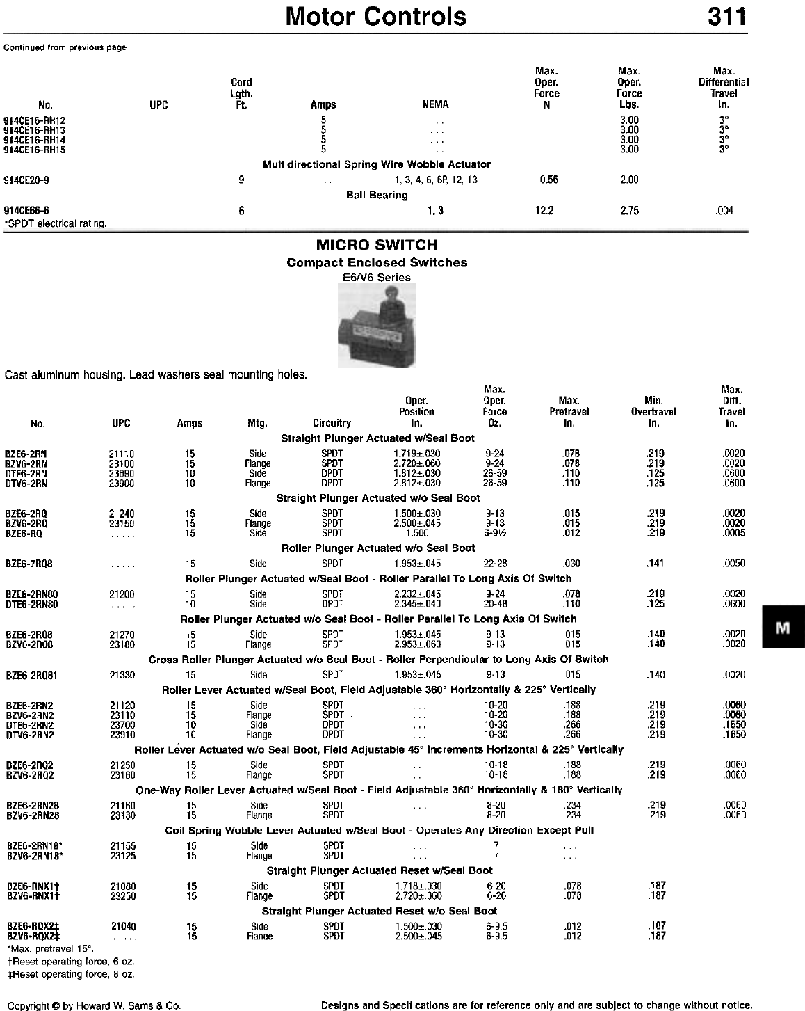
Motor Controls 311
Continued from previous page
Max.
Oper.
Force
N
Max.
Oper.
Force
Lbs.
3.00
3.00
3.00
3.00
Max.
Differential
Travel
In.
3°
3°
3°
3°
Cord
Lgth.
Ft. Amps NEMA
5
5 ...
5 ...
5
Multidirectional Spring Wire Wobble Actuator
1.3,4,6, 6P, 12, 13
Ball Bearing
No.
914CE16-RH12
914CE16-RH13
914CE16-RH14
914CE16-RH15
UPC
914CE20-9 90.56 2.00
914CE66-6
'SPOT electrical rating. 61.3 12.2 2.75 .004
MICRO SWITCH
Compact Enclosed Switches
E6N6 Series
Cast aluminum housing. Lead washers seal mounting holes.
Max.
Oper. Oper. Max.
Position Force Pretravel
UPC Amps Mtg. Circuitry In. Oz. In.
Straight Plunger Actuated w/Seal Boot
15 Side SPOT 1.719:!:.030 9-24 .078
15 Flange SPOT 2.720:!:.060 9-24 .078
10 Side OPOT 1.812:!:.030 26-59 .110
~uuuu 10 Flange OPOT 2.812:!:.030 26-59 .110
Straight Plunger Actuated w/o Seal Boot
15 Side SPOT 1.500:!:.030 9-13 .015
~u'uu 15 Flange SPOT 2.500:!:.045 9-13 .015
15 Side SPOT 1.500 6-9V2 .012
Roller Plunger Actuated w/o Seal Boot
. . . . . 15 Side SPOT 1.953:!:.045 22-28 .030
Roller Plunger Actuated w/Seal Boot - Roller Parallel To Long Axis Of Switch
21200 15 Side SPOT 2.232:!:.045 9-24 .078
10 Side OPOT 2.345:!:.040 20-48 .110
Roller Plunger Actuated w/o Seal Boot - Roller Parallel To Long Axis Of Switch
21270 15 Side SPOT 1.953:!:.045 9-13 .015
23180 15 Flange SPOT 2.953:!:.060 9-13 .015
Cross Roller Plunger Actuated w/o Seal Boot - Roller Perpendicular to Long Axis Of Switch
21330 15 Side SPOT 1.953:!:.045 9-13 .015
Roller Lever Actuated w/Seal Boot, Field Adjustable 3600 Horizontally & 2250 Vertically
21120 15 Side SPOT 10-20 .188
23110 15 Flange SPOT ... 10-20 .188
23700 10 Side OPOT . . . 10-30 .266
23910 10 Flange OPOT 10-30 .266
Roller Lever Actuated w/o Seal Boot, Field Adjustable 450 Increments Horizontal & 2250 Vertically
21250 15 Side SPOT 10-18 .188
23160 15 Flange SPOT 10-18 .188
One-Way Roller Lever Actuated w/Seal Boot - Field Adjustable 3600 Horizontally & 1800 Vertically
21160 15 Side SPOT 8-20 .234
23130 15 Flange SPOT 8-20 .234
Coil Spring Wobble Lever Actuated w/Seal Boot - Operates Any Direction Except Pull
21155 15 Side SPOT 7
23125 15 Flange SPOT 7
Straight Plunger Actuated Reset w/Seal Boot
21080 15 Side SPOT 1.718:!:.030 6-20 .078
23250 15 Flange SPOT 2.720:!:.060 6-20 .078
Straight Plunger Actuated Reset w/o Seal Boot
0 15 Side SPOT 1.500:!:.030 6-9.5 .012
15 Fiance SPOT 2.500:!:.045 6-9.5 .012
Max.
Ditt.
Travel
In.
Min.
Overtravel
In.
No.
BZE6-2RN
BZV6-2RN
DTE6-2RN
DTV6-2RN
21110
23100
23690
?~Qnn
.219
.219
.125
.125
.0020
.0020
.0600
.0600
BZE6-2RQ
BZV6-2RQ
BZE6-RQ
21240
?~1"n .219
.219
.219
.0020
.0020
.0005
BZE6-7RQ8 .141 .0050
BZE6-2RN80
DTE6-2RN80 .219
.125 .0020
.0600
.140
.140 .0020
.0020
BZE6-2RQ8
BZV6-2RQ8
.140 .0020
BZE6-2RQ81
.219
.219
.219
.219
.0060
.0060
.1650
.1650
BZE6-2RN2
BZV6-2RN2
DTE6-2RN2
DTV6-2RN2
BZE6-2RQ2
BZV6-2RQ2 .219
.219 .0060
.0060
BZE6-2RN28
BZV6-2RN28 .219
.219 .0060
.0060
BZE6-2RN18*
BZV6-2RN18*
.187
.187
BZE6-RNX1t
BZV6-RNX1t
.187
.187
BZE6-RQX2:j: 2104
BZV6-RQX2t *Max. pretravel15°.
tReset operating force, 6 oz.
:j:Reset operating force, 8 oz.
Copyright @ by Howard W. Sams & Co. Designs and Specifications are for reference only and are subject to change without notice.
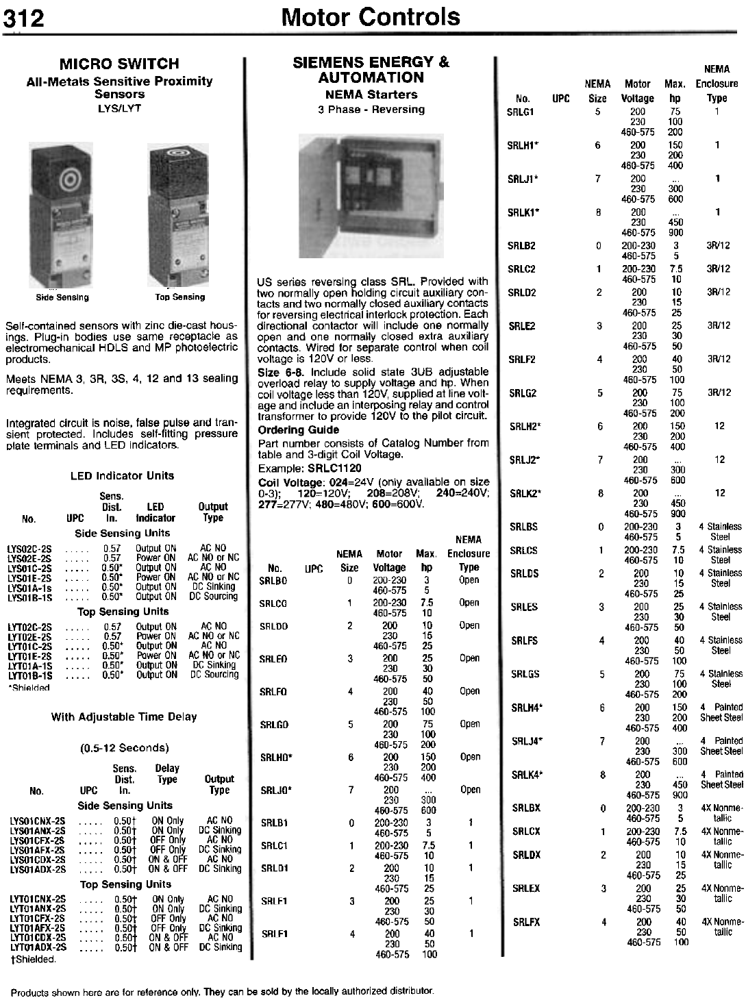
Motor Controls
312
SIEMENS ENERGY &
AUTOMATION
NEMA Starters
3 Phase - Reversing
MICRO SWITCH
All-Metals Sensitive Proximity
Sensors
LYS/LYT No.
SRLG1
UPC
SRLH1*
SRLJ1*
SRLK1*
SRlB2
SRlC2
SRlD2
Top Sensing
Side Sensing
SRLE2
SRLF2
Self-contained sensors with zinc die-cast hous-
ings. Plug-in bodies use same receptacle as
electromechanical HDLS and MP photoelectric
products.
Meets NEMA 3, 3A, 3S, 4, 12 and 13 sealing
requirements. SRLG2
Integrated circuit is noise, false pulse and tran-
sient protected. Includes self-fitting pressure
plate terminals and LED indicators.
SRLH2*
SRlJ2*
US series reversing class SRL. Provided with
two normally open holding circuit auxiliary con-
tacts and two normally closed auxiliary contacts
for reversing electrical interlock protection. Each
directional contactor will include one normally
open and one normally closed extra auxiliary
contacts. Wired for separate control when coil
voltage is 120V or less.
Size 6-8. Include solid state 3UB adjustable
overload relay to supply voltage and hp. When
coil voltage less than 120V, supplied at line volt-
age and include an interposing relay and control
transformer to provide 120V to the pilot circuit.
Ordering Guide
Part number consists of Catalog Number from
table and 3-digit Coil Voltage.
Example: SRLC1120
Coil Voltage: 024=24V (only available on size
0-3); 120=120V; 208=208V; 240=240V;
277=277V; 480=480V; 600=600V. SRLK2*
No. SRLBS
SRLCS
NEMA
NEMA Motor Max. Enclosure
Size Voltage hp Type
0 200-230 3 Open
460-575 5
1 200-230 7.5 Open
460-575 10
2 200 10 Open
230 15
460-575 25
3 200 25 Open
230 30
460-575 50
4 200 40 Open
230 50
460-575 100
5 200 75 Open
230 100
460-575 200
6 200 150 Open
230 200
460-575 400
7 200 ... Open
230 300
460-575 600
0 200-230 3 1
460-575 5
1 200-230 7.5 1
460-575 10
2 200 10 1
230 15
460-575 25
3 200 25 1
230 30
460-575 50
4 200 40 1
230 50
460-575 100
lYSO2C-2S
lYSO2E-2S
lYSO1C-2S
lYSO1E-2S
lYSO1 A-1 s
lYSO1B-1S
No.
SRlBO
SRlCO
SRlDO
UPC SRlDS
SRLES
LED Indicator Units
Sens.
Dist. LED Dutput
UPC In. Indicator Type
Side Sensing Units
. . . . . 0.57 Output ON AC NO
. . . . . 0.57 Power ON AC NO or NC
. . . . . 0.50. Output ON AC NO
. . . . . 0.50. Power ON AC NO or NC
. . . .. 0.50. Output ON DC Sinking
. . . .. 0.50. Output ON DC Sourcing
Top Sensing Units
. . . . . 0.57 Output ON AC NO
. . . . . 0.57 Power ON AC NO or NC
. . . .. 0.50. Output ON AC NO
. . . . . 0.50. Power ON AC NO or NC
. . . . . 0.50. Output ON DC Sinking
. . . .. 0.50. Output ON DC Sourcing
lYTO2C-2S
lYTO2E-2S
lYTO1 C-2S
lYTO1E-2S
lYTO1A-1S
lYTO1B-1S
'Shielded.
SRlFS
SRLEO
SRlGS
SRLFO
SRlH4*
With Adjustable Time Delay SRLGO
SRLJ4*
SRlHO.
SRLK4*
No. SRLJO*
SRLBX
SRLCX
NEMA
NEMA Motor Max. Enclosure
Size Voltage hp Type
5 200 75 1
230 100
460-575 200
6 200 150 1
230 200
460-575 400
7 200 ... 1
230 300
460-575 600
8 200 ... 1
230 450
460-575 900
0 200-230 3 3R/12
460-575 5
1 200-230 7.5 3R/12
460-575 10
2 200 10 3R/12
230 15
460-575 25
3 200 25 3R/12
230 30
460-575 50
4 200 40 3R/12
230 50
460-575 100
5 200 75 3R/12
230 100
460-575 200
6 200 150 12
230 200
460-575 400
7 200 ... 12
230 300
460-575 600
8 200 ... 12
230 450
460-575 900
0 200-230 3 4 Stainless
460-575 5 Steel
1 200-230 7.5 4 Stainless
460-575 10 Steel
2 200 10 4 Stainless
230 15 Steel
460-575 25
3 200 25 4 Stainless
230 30 Steel
460-575 50
4 200 40 4 Stainless
230 50 Steel
460-575 100
5 200 75 4 Stainless
230 100 Steel
460-575 200
6 200 150 4 Painted
230 200 Sheet Steel
460-575 400
7 200 ... 4 Painted
230 300 Sheet Steel
460-575 600
8 200 ... 4 Painted
230 450 Sheet Steel
460-575 900
0 200-230 3 4X Nonme-
460-575 5 tallic
1 200-230 7.5 4X Nonme-
460-575 10 tallic
2 200 10 4X Nonme-
230 15 tallic
460-575 25
3 200 25 4X Nonme-
230 30 tallic
460-575 50
4 200 40 4X Nonme-
230 50 tallic
460-575 100
LYSO1 CNX-2S
LYSO1ANX-2S
LYSO1CFX-2S
LYSO1AFX-2S
LYSO1CDX-2S
LYSO1ADX-2S
SRlB1
SRlC1
SRlD1
SRLDX
SRLEX
(0.5-12 Seconds)
Sens. Delay
Dist. Type Output
UPC In. Type
Side Sensing Units
. . . .. O.50t ON Only AC NO
. . . .. O.50t ON Only DC Sinking
. . . .. O.50t OFF Only AC NO
. . . .. O.50t OFF Only DC Sinking
. . . .. O.50t ON & OFF AC NO
. . . .. O.50t ON & OFF DC Sinking
Top Sensing Units
. . . .. O.50t ON Only AC NO
. . . .. O.50t ON Only DC Sinking
. . . .. O.50t OFF Only AC NO
. . . .. O.50t OFF Only DC Sinking
. . . .. O.50t ON & OFF AC NO
. . . .. O.50t ON & OFF DC Sinking
LYTO1CNX-2S
LYTO1ANX-2S
LYTO1CFX-2S
LYTO1AFX-2S
LYTO1CDX-2S
LYTO1ADX-2S
tShielded.
SRLE1
SRLFX
SRlF1
Products shown here are for reference only. They can be sold by the locally authorized distributor.
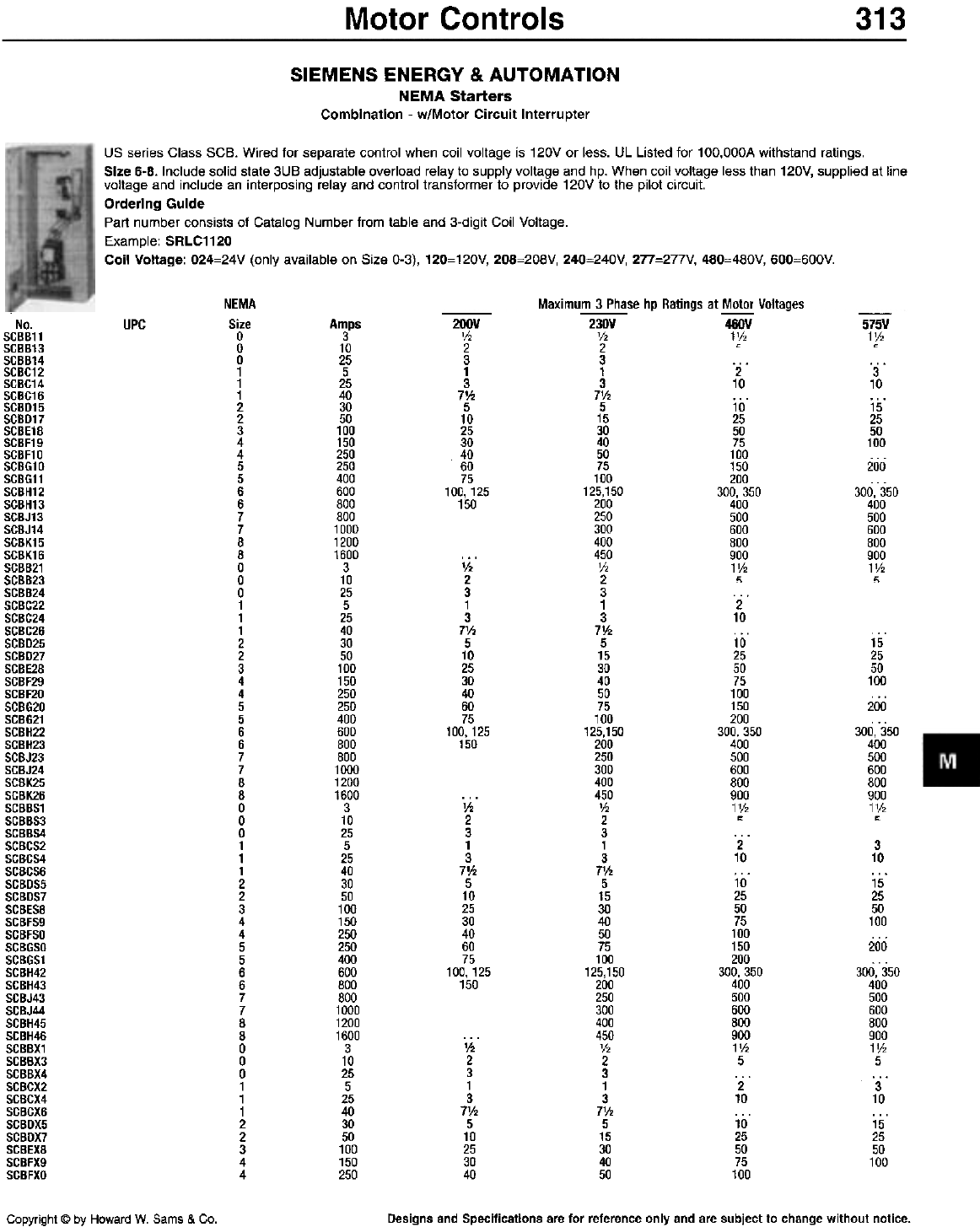
Motor Controls 313
SIEMENS ENERGY & AUTOMATION
NEMA Starters
Combination - w/Motor Circuit Interrupter
US series Class SCB. Wired for separate control when coil voltage is 120V or less. UL Listed for 1 OO,OOOA withstand ratings.
Size 6-8. Include solid state 3UB adjustable overload relay to supply voltage and hp. When coil voltage less than 120V, supplied at line
voltage and include an interposing relay and control transformer to provide 120V to the pilot circuit.
Ordering Guide
Part number consists of Catalog Number from table and 3-digit Coil Voltage.
Example: SRLC1120
Coil Voltage: 024=24V (only available on Size 0-3), 120=120V, 208=208V, 240=240V, 277=277V, 480=480V, 600=600V.
NEMA
Size
0
0
0
1
1
1
2
2
3
4
4
5
5
6
6
7
7
8
8
0
0
0
1
1
1
2
2
3
4
4
5
5
6
6
7
7
8
8
0
0
0
1
1
1
2
2
3
4
4
5
5
6
6
7
7
8
8
0
0
0
1
1
1
2
2
3
4
4
Maximum 3 Phase hp Ratings at Motor Voltages
No.
SCBB11
SCBB13
SCBB14
SCBC12
SCBC14
SCBC16
SCBD15
SCBD17
SCBE18
SCBF19
SCBF10
SCBG10
SCBG11
SCBH12
SCBH13
SCBJ13
SCBJ14
SCBK15
SCBK16
SCBB21
SCBB23
SCBB24
SCBC22
SCBC24
SCBC26
SCBD25
SCBD27
SCBE28
SCBF29
SCBF20
SCBG20
SCBG21
SCBH22
SCBH23
SCBJ23
SCBJ24
SCBK25
SCBK26
SCBBS1
SCBBS3
SCBBS4
SCBCS2
SCBCS4
SCBCS6
SCBDS5
SCBDS7
SCBES8
SCBFS9
SCBFSO
SCBGSO
SC8GS1
SCBH42
SCBH43
SCBJ43
SCBJ44
SCBH45
SCBH46
SCBBX1
SCBBX3
SCBBX4
SCBCX2
SCBCX4
SCBCX6
SCBDX5
SCBDX7
SCBEX8
SCBFX9
SCBFXO
UPC Amps
3
10
25
5
25
40
30
50
100
150
250
250
400
600
800
800
1000
1200
1600
3
10
25
5
25
40
30
50
100
150
250
250
400
600
800
800
1000
1200
1600
3
10
25
5
25
40
30
50
100
150
250
250
400
600
800
800
1000
1200
1600
3
10
25
5
25
40
30
50
100
150
250
200V
V2
2
3
1
3
7V2
5
10
25
30
40
60
75
100,125
150
-
230V
V2
2
3
1
3
7V.
5
15
30
40
50
75
100
125,150
200
250
300
400
450
V2
2
3
1
3
7V.
5
15
30
40
50
75
100
125,150
200
250
300
400
450
V.
2
3
1
3
7'12
5
15
30
40
50
75
100
125,150
200
250
300
400
450
V2
2
3
1
3
7'12
5
15
30
40
50
-460V
1V,
c
-575V
1V2
0
2
10
10
25
50
75
100
150
200
300, 350
400
500
600
800
900
1V2
~
3
10
15
25
50
100
200
300, 350
400
500
600
800
900
1V2
~
V2
2
3
1
3
7'h
5
10
25
30
40
60
75
100,125
150
2
10
10
25
50
75
100
150
200
300, 350
400
500
600
800
900
1V2
~
...
15
25
50
100
200
300, 350
400
500
600
800
900
1V2
"
V2
2
3
1
3
7V2
5
10
25
30
40
60
75
100,125
150
2
10
10
25
50
75
100
150
200
300. 350
400
500
600
800
900
1V2
5
2
10
10
25
50
75
100
3
10
15
25
50
100
200
300, 350
400
500
600
800
900
1V2
5
3
10
15
25
50
100
'h
2
3
1
3
7'h
5
10
25
30
40
Copyright @ by Howard W. Sams & Co. Designs and Specifications are for reference only and are subject to change without notice.
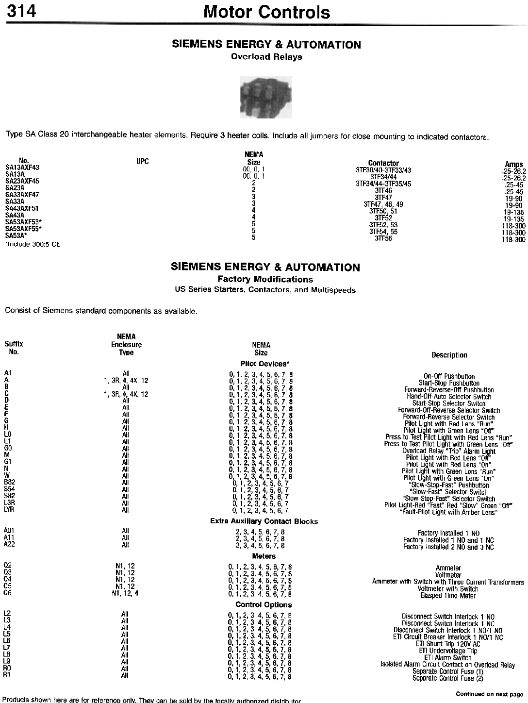
314 Motor Controls
SIEMENS ENERGY & AUTOMATION
Overload Relays
Type SA Class 20 interchangeable heater elements. Require 3 heater coils. Include all jumpers for close mounting to indicated contactors.
NEMA
Size
00,0,1
00, 0, 1
2
2
3
3
4
4
5
5
5
No.
SA13AXF43
SA13A
SA23AXF45
SA23A
SA33AXF47
SA33A
SA43AXF51
SA43A
SA53AXF53*
SA53AXF55*
SA53A*
*Include 300:5 Ct.
UPC Contactor
3TF30/40-3TF33/43
3TF34/44
3TF34/44-3TF35/45
3TF46
3TF47
3TF47, 48, 49
3TF50, 51
3TF52
3TF52, 53
3TF54, 55
3TF56
Amps
.25-26.2
.25-26.2
.25-45
.25-45
19-90
19-90
19-135
19-135
118-300
118-300
118-300
SIEMENS ENERGY & AUTOMATION
Factory Modifications
US Series Starters, Contactors, and Multispeeds
Consist of Siemens standard components as available.
NEMA
Enclosure
Type
Suffix
No. Description
NEMA
Size
Pilot Devices'
0,1,2,3,4,5,6,7,8
0,1,2,3,4,5,6,7,8
0,1,2,3,4,5,6,7,8
0,1,2,3,4.5,6,7,8
0,1,2,3.4,5,6,7,8
0,1.2,3,4,5,6,7,8
0.1,2,3,4,5,6,7,8
0,1,2,3,4,5,6,7,8
0,1,2,3,4,5,6,7,8
0,1,2,3,4,5.6.7,8
0,1,2,3,4.5,6,7,8
0,1,2,3.4.5,6,7,8
0,1,2,3,4,5,6,7,8
0,1.2,3,4,5,6,7,8
0.1,2,3,4,5,6,7.8
0,1,2,3,4,5,6,7,8
0,1,2,3,4,5,6,7
0,1,2.3.4,5,6,7
0,1.2,3,4,5,6,7
0,1,2,3,4,5,6,7
0,1,2,3,4,5,6,7
Extra Auxiliary Contact Blocks
2, 3, 4, 5, 6, 7, 8
2, 3, 4, 5, 6, 7, 8
2, 3, 4, 5, 6, 7, 8
Meters
0,1,2,3,4,5,6,7,8
0,1,2,3,4,5,6,7.8
0,1,2,3,4,5.6,7,8
0,1,2,3,4,5,6,7,8
0,1,2,3,4,5,6,7,8
Control Options
0,1,2,3,4,5,6,7,8
0,1,2,3,4,5.6,7,8
0,1,2,3,4,5,6,7,8
0,1,2,3.4,5,6,7,8
0.1.2,3,4,5,6,7,8
0,1.2.3,4,5,6,7,8
0.1,2,3,4,5,6,7,8
0.1,2,3,4,5,6,7,8
0,1,2,3,4,5,6,7.8
0,1,2,3,4,5,6.7,8
A1
A
B
C
D
E
F
G
H
LO
L1
GO
M
G1
N
W
B82
854
882
L3R
LYR
On-Oft Pushbutton
Start-Stop Pushbutton
Forward-Reverse-Oft Pushbutton
Hand-Oft-Auto Selector Switch
Start-Stop Selector Switch
Forward-Oft-Reverse Selector Switch
Forward-Reverse Selector Switch
Pilot Light with Red Lens "Run"
Pilot Light with Green Lens "Oft"
Press to Test Pilot Light with Red Lens "Run"
Press to Test Pilot Light with Green Lens "Oft"
Overload Relay "Trip" Alarm Light
Pilot Light with Red Lens "Oft"
Pilot Light with Red Lens "On"
Pilot Light with Green Lens "Run"
Pilot Light with Green Lens "On"
"Slow-Stop-Fast" Pushbutton
"Slow-Fast" Selector Switch
"Slow-Stop-Fast" Selector Switch
Pilot Light-Red "Fast" Red "Slow" Green "Oft"
"Fault-Pilot Light with Amber Lens"
1,3R.
1.3R.
AO1
A11
A22
All
All
All
Factory Installed 1 NO
Factory Installed 1 NO and 1 NC
Factory Installed 2 NO and 3 NC
02
03
04
05
06
N1,12
N1,12
N1,12
N1,12
N1, 12, 4
Ammeter
Voltmeter
Ammeter with Switch with Three Current Transformers
Voltmeter with Switch
Elasped Time Meter
L2
L3
L4
L5
L6
L7
L8
L9
RO
R1
All
All
All
All
All
All
All
All
All
All
Disconnect Switch Interlock 1 NO
Disconnect Switch Interlock 1 NC
Disconnect Switch Interlock 1 NO/1 NO
ETI Circuit Breaker Interlock 1 NO/1 NC
ETI Shunt Trip 120V AC
ETI Undervoltage Trip
ETI Alarm Switch
Isolated Alarm Circuit Contact on Overload Relay
Separate Control Fuse (1)
Separate Control Fuse (2)
Continued on next page
Products shown here are for reference only. Thev can be sold bv the locally alrthnri7"rl rli"trihlllnr
All
4, 4X, 12
All
4, 4X, 12
All
All
All
All
All
All
All
All
All
All
All
All
All
All
All
All
All
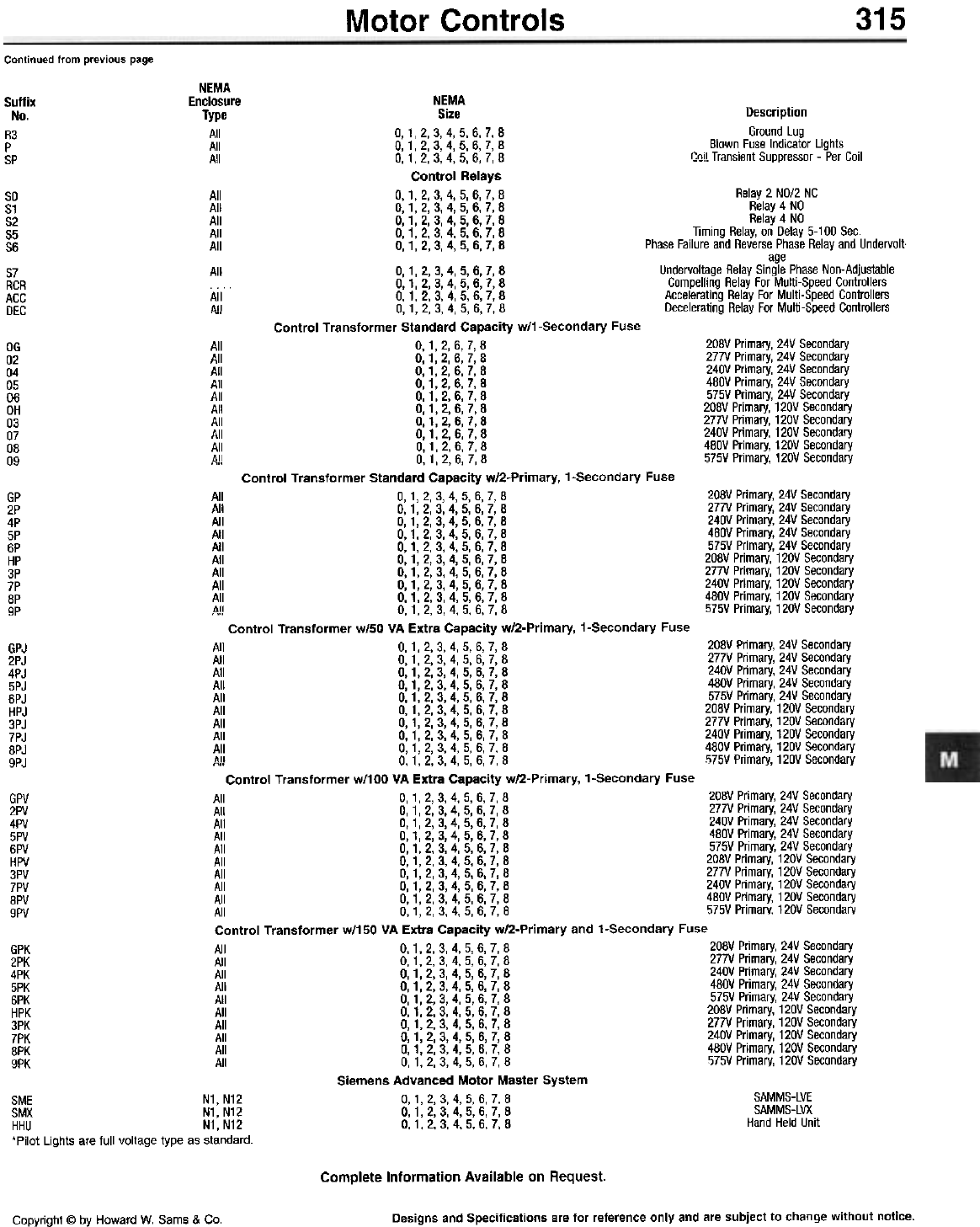
315
Motor Controls
Continued from previous page
NEMA
Enclosure NEMA
Type Size
All 0,1,2,3,4,5,6,7,8
All 0,1,2,3,4,5,6,7,8
All 0,1,2,3,4,5,6,7,8 Control Relays
0,1,2.3,4,5,6,7,8
0,1,2,3.4,5,6,7,8
0,1,2,3,4,5.6.7,8
0.1.2,3,4,5,6,7.8
0,1.2,3,4,5,6,7,8
0,1,2,3,4,5.6.7,8
0.1,2,3,4,5,6,7.8
0,1,2,3,4,5,6,7.8
,.., 0,1,2.3,4,5,6,7,8
Control Transformer Standard Capacity w/1-Secondary Fuse
0,1,2,6,7,8
0, 1, 2, 6, 7, 8
0.1,2,6,7,8
0,1.2.6,7,8
0,1,2,6.7,8
0, 1, 2, 6, 7, 8
I 0.1,2,6,7,8
I 0,1.2,6,7,8
I 0,1.2,6,7,8
...1 0,1,2,6,7,8
Control Transformer Standard Capacity w/2-Primary. 1-Secondary Fuse
0,1,2,3,4,5,6,7,8
0,1,2,3,4,5,6,7,8
0,1,2,3,4,5,6.7,8
0.1,2,3,4,5,6,7.8
0.1,2,3,4,5,6,7,8
0,1,2.3,4,5,6,7,8
0,1,2,3,4,5,6,7,8
0,1,2,3.4,5.6.7,8
0.1,2,3,4,5,6,7,8
..., 0,1,2,3,4,5,6,7.8
Control Transformer w/50 VA Extra Capacity w/2-Primary. 1-Secondary Fuse
0,1,2,3,4,5.6.7,8
0.1,2,3,4,5,6,7.8
0,1.2.3,4,5,6,7,8
0,1,2,3.4.5,6,7,8
0,1,2,3,4,5.6.7,8
0,1,2,3,4,5,6,7.8
0.1,2,3,4,5,6,7,8
0.1,2,3,4,5,6,7,8
0,1.2,3,4,5,6,7,8
~" 0,1,2,3,4,5,6,7,8
Control Transformer w/100 VA Extra Capacity w/2-Primary. 1-Secondary Fuse
All 0,1.2,3,4,5,6,7.8
All 0,1,2,3,4.5,6,7,8
All 0.1,2,3,4,5,6.7,8
All 0.1,2,3,4,5,6,7,8
All 0.1.2.3,4,5,6,7,8
All 0,1,2,3.4,5,6,7,8
All 0,1,2,3,4,5.6,7,8
All 0,1,2,3,4,5,6,7,8
All 0.1,2,3,4,5,6,7,8
All 0,1,2,3,4,5,6,7,8
Control Transformer w/150 VA Extra Capacity w/2-Primary and 1-Secondary Fuse
All 0,1,2,3,4,5,6,7,8
All 0,1,2,3,4,5,6,7,8
All 0,1.2.3,4,5,6,7,8
All 0,1,2,3.4.5,6,7,8
All 0,1,2,3,4,5,6.7,8
All 0.1,2,3,4,5,6,7,8
All 0,1.2.3,4,5,6,7,8
All 0,1,2,3.4.5,6,7,8
All 0,1,2,3,4.5,6,7,8
All 0,1,2,3,4,5,6,7,8
Siemens Advanced Motor Master System
0,1.2.3,4,5,6,7.8
0,1,2,3,4,5.6,7,8
0,1,2,3,4,5,6,7.8
Suffix
No.
R3
P
SP
Description
Ground Lug
Blown Fuse Indicator Lights
~nil Transient Suppressor - Per Coil
50
51
52
55
56
57
RCR
ACC
DEC
All
All
All
All
All
All
All
All
Relay 2 NO/2 NC
Relay 4 NO
Relay 4 NO
Timing Relay, on Delay 5-100 Sec.
Phase Failure and Reverse Phase Relay and Undervolt-
age
Undervoltage Relay Single Phase Non-Adjustable
Compelling Relay For Multi-Speed Controllers
Accelerating Relay For Multi-Speed Controllers
Decelerating Relay For Multi-Speed Controllers
20BV Primary, 24V Secondary
277V Primary, 24V Secondary
240V Primary, 24V Secondary
4BOV Primary, 24V Secondary
575V Primary, 24V Secondary
20BV Primary, 120V Secondary
277V Primary, 120V Secondary
240V Primary, 120V Secondary
4BOV Primary, 120V Secondary
575V Primary, 120V Secondary
OG
02
04
05
06
OH
03
07
08
09
All
All
All
All
All
All
All
All
All
dll
208V Primary, 24V Secondary
277V Primary, 24V Secondary
240V Primary, 24V Secondary
480V Primary, 24V Secondary
575V Primary, 24V Secondary
208V Primary, 120V Secondary
277V Primary, 120V Secondary
240V Primary, 120V Secondary
480V Primary, 120V Secondary
575V Primary, 120V Secondary
GP
2P
4P
5P
6P
HP
3P
7P
8P
gp
All
All
All
All
All
All
All
All
All
all
208V Primary, 24V Secondary
277V Primary, 24V Secondary
240V Primary, 24V Secondary
480V Primary, 24V Secondary
575V Primary, 24V Secondary
208V Primary, 120V Secondary
277V Primary, 120V Secondary
240V Primary, 120V Secondary
480V Primary, 120V Secondary
575V Primary, 120V Secondary
All
All
All
All
All
All
All
All
All
1111
GPJ
2PJ
4PJ
5PJ
6PJ
HPJ
3PJ
7PJ
8PJ
9PJ
208V Primary, 24V Secondary
277V Primary, 24V Secondary
240V Primary, 24V Secondary
480V Primary, 24V Secondary
575V Primary, 24V Secondary
208V Primary, 120V Secondary
277V Primary, 120V Secondary
240V Primary, 120V Secondary
480V Primary, 120V Secondary
i)75V Primary. 120V Secondary
GPV
2PV
4PV
5PV
6PV
HPV
3PV
7PV
8PV
9PV
20BV Primary, 24V Secondary
277V Primary, 24V Secondary
240V Primary, 24V Secondary
4BOV Primary, 24V Secondary
575V Primary, 24V Secondary
20BV Primary, 120V Secondary
277V Primary, 120V Secondary
240V Primary, 120V Secondary
4BOV Primary, 120V Secondary
575V Primary, 120V Secondary
GPK
2PK
4PK
5PK
6PK
HPK
3PK
7PK
BPK
9PK
SAMMS-LVE
SAMMS-LVX
Hand Held Unit
SME N1, N12
SMX N1, N12
HHU N1,N12
'Pilot Lights are full voltage type as standard.
Complete Information Available on Request.
Designs and Specifications are for reference only and are subject to change without notice.
Copyright @ by Howard W. Sams & Co.
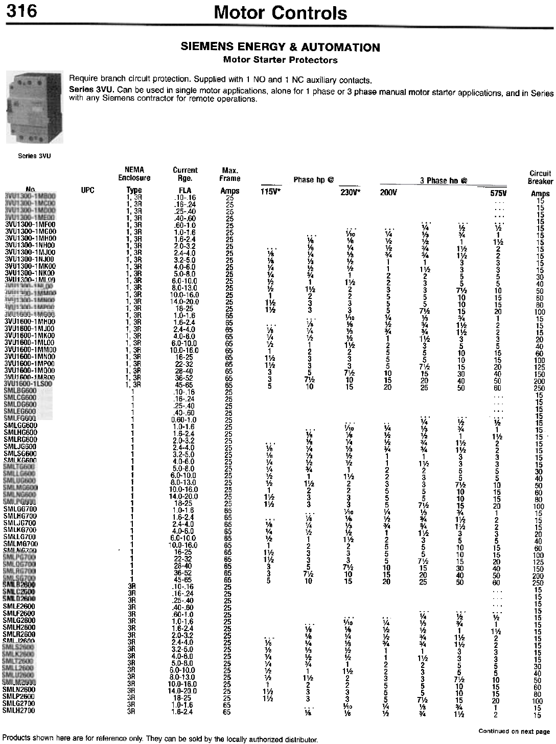
316 Motor Controls
SIEMENS ENERGY & AUTOMATION
Motor Starter Protectors
Require branch circuit protection. Supplied with 1 NO and 1 NC auxiliary contacts.
Series 3VU. Can be used in single motor applications, alone for 1 phase or 3 phase manual motor starter applications, and in Series
with any Siemens contractor for remote operations.
Series 3VU
NEMA
Enclosure
Type
1,3R
1,3R
1,3R
1,3R
1,3R
1,3R
1,3R
1,3R
1,3R
1,3R
1,3R
1,3R
1,3R
1,3R
1,3R
1,3R
1,3R
1,3R
1,3R
1,3R
1,3R
1,3R
1,3R
1,3R
1,3R
1,3R
1,3R
1,3R
1
1
1
1
1
1
1
1
1
1
1
1
1
1
1
1
1
1
1
1
1
1
1
. 1
1
1
1
1
3R
3R
3R
3R
3R
3R
3R
3R
3R
3R
3R
3R
3R
3R
3R
3R
3R
3R
3R
Current
Rge.
FLA
.10-.16
.16-.24
.25-.40
.40-.60
.60-1.0
1.0-1.6
1.6-2.4
2.0-3.2
2.4-4.0
3.2-5.0
4.0-6.0
5.0-8.0
6.0-10.0
8.0-13.0
10.0-16.0
14.0-20.0
18-25
1.0-1.6
1.6-2.4
2.4-4.0
4.0-6.0
6.0-10.0
10.0-16.0
16-25
22-32
28-40
36-52
45-65
.10-.16
.16-.24
.25-.40
.40-.60
0.60-1.0
1.0-1.6
1.6-2.4
2.0-3.2
2.4-4.0
3.2-5.0
4.0-6.0
5.0-8.0
6.0-10.0
8.0-13.0
10.0-16.0
14.0-20.0
18-25
1.0-1.6
1.6-2.4
2.4-4.0
4.0-6.0
6.0-10.0
10.0-16.0
16-25
22-32
28-40
36-52
45-65
.10-.16
.16-.24
.25-.40
.40-.60
.60-1.0
1.0-1.6
1.6-2.4
2.0-3.2
2.4-4.0
3.2-5.0
4.0-6.0
5.0-8.0
6.0-10.0
8.0-13.0
10.0-16.0
14.0-20.0
18-25
1.0-1.6
1.6-2.4
Max.
Frame
ATfS
25
25
25
25
25
25
25
25
25
25
25
25
25
25
25
25
65
65
65
65
65
65
65
65
65
65
65
25
25
25
25
25
25
25
25
25
25
25
25
25
25
25
25
25
65
65
65
65
65
65
65
65
65
65
65
25
25
25
25
25
25
25
25
25
25
25
25
25
25
25
25
25
65
65
Phase hp @ 3 Phase ho @
Nn UPC -
115V* -
230V* 200V
3VU1300-1MFOO
3VU1300-1MGOO
3VU1300-1MHOO
3VU1300-1NHOO
3VU1300-1MJOO
3VU1300-1NJOO
3VU1300-1MKOO
3VU1300-1 NKOO
3VIJ13nn-1MIf11)
V4.
1/3
1/2
0/4
0/4
1
11/2
2
3
3
5
5
71/2
1/3
0/4
0/4
11/2
3
5
5
71/2
15
20
25
ih'
:Yo
1
1'h
1'h
3
3
5
5
7'h
10
10
15
:Yo
1'h
1'h
3
5
10
10
15
30
40
50
;;;0.
1/&
V4
1/3
'h
'h
1
1'h
2
2
3
3
Via
1/&
1/3
'h
1'h
2
3
3
7V2
10
15
v,'
1h
1h
0/,
1
1
2
2
3
5
5
5
V,
1h
0/,
1
2
5
5
5
10
15
20
iie'
'Is
V.
1/3
'h
3/.
1
1'h
2
3
3
iie'
v.
'h
1
2
3
3
5
7V2
10
'ie'
Va
V4
V4
1h
1h
1
11h
11h
~ ~
3VU1600-1MHOO
3VU1600-1MJOO
3VU1600-1 MKOO
3VU1600-1MlOO
3VU1600-1MMOO
3VU1600-1MNOO
3VU1600-1MPOO
3VU1600-1MQOO
3VU16nn-1MRno
lis'
v.
'h
1
1'h
1'h
3
3
5
Ii."
1/3
1h
3/4
0/.
1
11h
2
3
3
5
5
7V2
1/3
0/.
0/.
11h
3
5
5
71h
15
20
25
'h
3/.
1
1'h
1'h
3
3
5
5
7'h
10
10
15
3/.
1V2
1V2
3
5
10
10
15
30
40
50
SMLGG600
SMLHG600
SMLRG600
SMLJG600
SMLSG600
SMLKGfinn
V;o'
1/8
v.
'h
1h
1h
1
11h
2
2
3
3
'/\0
1/8
'h
1h
11h
2
3
3
7V2
10
15
V.
'!2
'!2
3/.
1
1
2
2
3
5
5
5
V.
'!2
3/.
1
2
5
5
5
10
15
20
iia'
1/8
v.
'/3
1h
0/.
1
11h
2
3
3
iia'
V.
1h
1
2
3
3
5
71h
10
lis'
Vs
V4
V4
'h
'h
1
1'h
1'h
SMLGG700
SMLHG700
SMLJG700
SMLKG700
SMLLG700
SMLMG700
C:MI M1:7nf\
lie'
v.
'h
1
1'h
1V2
3
3
5
V4'
1/3
1h
0/4
0/4
1
11h
2
3
3
5
5
71h
1/3
0/4
ih'
0/.
1
11h
11h
3
3
5
5
71h
10
10
15
0/.
11h
V4
1h
1h
0/4
1
1
2
2
3
5
5
5
V4
1h
1ia°
Ve
v.
1/3
'h
3/.
1
1'h
2
3
3
1ia"
1ia"
Va
V.
V.
'h
'h
1
1'h
1'h
SMLN2600
SMLP2600
SMLG2700
SMLH2700
1;;0.
Ye
V4
1/3
V2
1h
1
11h
2
2
3
3
V10
Ye
Circuit
Breaker
575V A~fS
. . . 15
... 15
... 15
1h 15
1 15
1V2 15
2 15
2 15
3 15
3 15
5 30
5 40
10 50
15 60
15 80
20 100
1 15
2 15
2 15
3 20
5 40
15 60
15 100
20 125
40 150
50 200
60 250
... 15
... 15
... 15
... 15
1h 15
1 15
11h 15.
2 15
2 15
3 15
3 15
5 30
5 40
10 50
15 60
15 80
20 100
1 15
2 15
2 15
3 20
5 40
15 60
15 100
20 125
40 150
50 200
60 250
... 15
... 15
... 15
... 15
1h 15
1 15
11h 15
2 15
2 15
3 15
3 15
5 30
5 40
10 50
15 60
15 80
20 100
1 15
2 15
Continued on next page
Products shown here are for reference only. They can be sold by the locally authorized distributor.
SMlE2600
SMlF2600
SMlG2600
SMlH2600
SMlR2600
SMU?Mn
Motor Controls 317
Continued from previous page
NEMA
Enclosure
T~~e
3R
3R
3R
3R
3R
3R
3R
3R
Max.
Frame
AWfS
65
65
65
65
65
65
65
65
Circuit
Breaker
A~fS
20
40
60
100
125
150
200
250
Current
Rge.
FLA
2.4-4.0
4.0-6.0
6.0-10.0
10.0-16.0
16-25
22-32
28-40
36-52
45-65
-
115V*
Va
'/.
1h
1
11h
11h
3
3
5
-230V*
V3
V2
1'h
2
3
3
7'h
10
15
-
200V
3/.
1
2
5
5
5
10
15
20
-575V
2
3
5
15
15
20
40
50
60
No. UPC
SMLJ2700 SMLK2700 SMLL2700 SMLM2700 SMLN2700 SMLP2700 SMLQ2700 SMLR2700 SMLS2700 'Based on 3 poles wired in series.
SIEMENS ENERGY & AUTOMATION
Motor Controls
Desc.
Pushbutton - Momentary Operation
Assembled Pilot Devices. Supplied with metal chrome plated rings. For plastic front rings add suffix "P".
Operators. Include 3 unit contact block holder. For 5 unit contact block holder, change fifth digit from 3 to 6.
No. UPC
Pushbuttons - Momentary Operation"
3SBO3-PFB10
3SBO3-PFB11
3SBO3-PFG10
3SBO3-PFG11
3SBO3-PFRO1
3SBO3-PFR11
3SBO3-PERO1
3SBO3-PEB10
3SBO3-PER11
3SBO3-P4RO1
3SBO3-P4R11
Flush Black, 1 NO
Flush Black, 1 NO, 1 NC
Flush Green, 1 NO
Flush Green, 1 NO, 1 NC
Flush Red, 1 NC
Flush Red, 1 NO, 1 NC
Extended Red, 1 NC
Extended Black, 1 NO
Extended Red, 1 NO, 1 NC
Mushroom Red;1 NC
Mushroom Red;1 NO, 1 NC
16907
16918
16895
16956
Push buttons - Maintained Operation
Mushroom Red, 1 NC,
Push Lock Twist Release
Mushroom Red, 1 NO, 1 NC,
Push Lock Twist Release
3SBO3-K4RO1
3SBO3-K4R11
Selector Switches - Maintained Operation
17294
26313
2 Pas., Black, 1 NC, (Off-On)
2 Pas., Black, 1 NO, (Off-On)
2 Pas.. Black, 1 NO, 1 NC, (Off-On)
3 Pas., Black, 1 NO, 2nd
(H-O-A, Fwd.-Off-Rev.)
3 Pas.. Black, 1 NO + 1 NO, 1 NC
3SBO3-2MKBX1
3SBO3-2MKBX2
3SBO3-2MKBX3
3SBO3-3MKBX25
3SBO3-3MKBX26 Pilot Lights - Standard
3SBO3-LFCR
3SBO3-LFCG
3SBO3-LF1R
3SBO3-LF1G
3SBO3-LR1R
3SBO3-LR1G
3SBO3-LLBR
3SBO3-LLBG
3SBO3-LLBA
3SBO3-LT1R
3SBO3-LT1G
3SBO3-LL1R
3SBO3-LL1G
3SBO3-LL1A
24V, Red, Full Voltage AC/DC
24V, Green, Full Voltage AC/DC
120V, Red, Full Voltage AC/DC
120V, Green, Full Voltage AC/DC
120V, Red, Resistor AC/DC
120V, Green, Resistor AC/DC
24V, Red, LED Full Voltage AC/DC
24V, Green, LED Full Voltage AC/DC
24V, Amber, LED Full Voltage AC/DC
120V, Red, Transformer AC
120V, Green, Transformer AC
120V, Red, LED, Transformer AC
120V, Green, LED, Transformer AC
120V, Amber, LED, Transformer AC
16869
16865
Push To Test Lights
3SBO3-TFCR
3SBO3-TFCG
3SBO3-TF1R
3SBO3- TF1 G
3SBO3-TR1R
3SBO3-TR1G
3SBO3-TLBR
3SBO3-TLBG
3SBO3-TLBA
3SBO3- m R
3SBO3-mG
3SBO3-TL1R
3SBO3-TL1G
3SBO3-TL1A
3SBO3-TFA
3SBO3-TFB
3SBO3-TFC
3SBO3-TFD
. . . . . 24V, Red, Full Voltage AC/DC
. . . . . 24V, Green, Full Voltage AC/DC
. . . . . 120V, Red, Full Voltage AC/DC
. . . . . 120V, Green, Full Voltage AC/DC
. . . . . 120V, Red, Resistor, AC/DC
. . . . . 120V, Green, Resistor, AC/DC
. . . . . 24V, Red, LED Full Voltage AC/DC
. . . . . 24V, Green, LED Full Voltage AC/DC
. . . . . 24V, Amber, LED Full Voltage AC/DC
. . . . . 120V, Red, Transformer AC
. . . . . 120V, Green, Transformer AC
. . . . . 120V, Red, LED Transformer AC
. . . . . 120V, Green, LED Transformer AC
. . . . . 120V, Amber, LED Transformer AC
. . . . . 6V, w/o Lenses, Full Voltage AC/DC
. . . . . 12V, w/o Lenses, Full Voltage AC/DC
. . . . . 24V, w/o Lenses, Full Voltage AC/DC
. . . . . 48V, w/o Lenses, Full Voltage AC/DC
Continued on next page
Designs and Specifications are for reference only and are subject to change without notice.
Copyright @ by Howard W. Sams & Co.
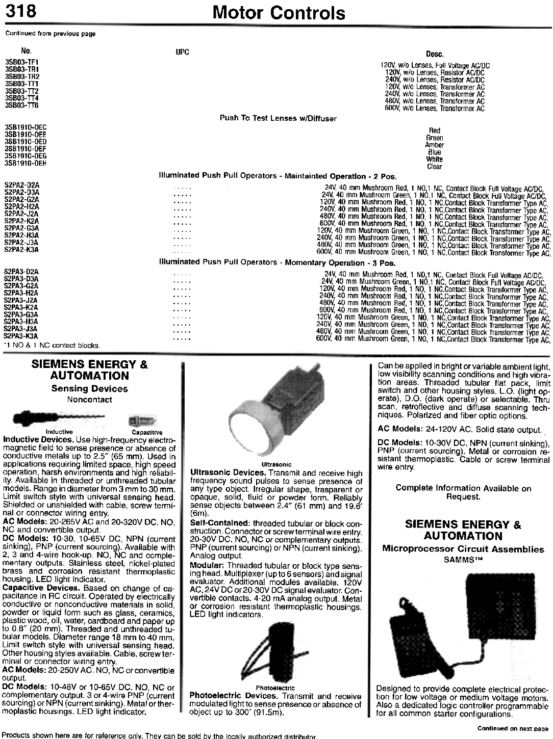
318 Motor Controls
Continued from previous page
No.
3SBO3-TF1
3SBO3-TR1
3SBO3-TR2
3SBO3-TT1
3SBO3-TT2
3SBO3-TT4
3SBO3-TT6
UPC Desc.
120V, wlo Lenses, Full Voltage AC/DC
120V, wlo Lenses, Resistor AC/DC
240V, wlo Lenses, Resistor AC/DC
120V, wlo Lenses, Transformer AC
240V, wlo Lenses, Transformer AC
480V, wlo Lenses, Transformer AC
600V, wlo Lenses, Transformer AC
Push To Test Lenses w/Diffuser
3SB1910-0EC
3SB1910-0EE
3SB1910-0ED
3SB1910-0EF
3SB1910-0EG
3SB1910-0EH
Red
Green
Amber
Blue
White
Clear
S2PA2-D2A
S2PA2-D3A
S2PA2-G2A
S2PA2-H2A
S2PA2-J2A
S2PA2-K2A
S2PA2-G3A
S2PA2-H3A
S2PA2-J3A
S2PA2-K3A
Illuminated Push Pull Operators - Maintainted Operation - 2 Pos.
0 0 0 24V, 40 mm Mushroom Red, 1 NO,1 NC, Contact Block Full Voltage AC/DC,
0 0 . . 0 24V, 40 mm Mushroom Green, 1 NO,1 NC, Contact Block Full Voltage AC/DC,
. . . . 0 120V, 40 mm Mushroom Red, 1 NO, 1 NC,Contact Block Transformer Type AC,
0 0 0 0 0 240V, 40 mm Mushroom Red, 1 NO, 1 NC,Contact Block Transformer Type AC,
0 0 0 0 0 480V, 40 mm Mushroom Red, 1 NO, 1 NC,Contact Block Transformer Type AC,
0 0 0 0 0 600V, 40 mm Mushroom Red, 1 NO, 1 NC,Contact Block Transformer Type AC,
00000 120V, 40 mm Mushroom Green, 1 NO, 1 NC,Contact Block Transformer Type AC,
0 0 0 0 0 240V, 40 mm Mushroom Green, 1 NO, 1 NC,Contact Block Transformer Type AC,
0 0 0 0 0 480V, 40 mm Mushroom Green, 1 NO, 1 NC,Contact Block Transformer Type AC,
0 0 0 0 0 600V, 40 mm Mushroom Green, 1 NO, 1 NC,Contact Block Transformer Type AC,
Illuminated Push Pull Operators - Momentary Operation - 3 Pos.
0 0 0 0 0 24V, 40 mm Mushroom Red, 1 NO,1 NC, Contact Block Full Voltage AC/DC,
0 0 . 0 . 24V, 40 mm Mushroom Green, 1 NO,1 NC, Contact Block Full Voltage AC/DC,
0 . . . 0 120V, 40 mm Mushroom Red, 1 NO, 1 NC,Contact Block Transformer Type AC,
. . . 0 0 240V, 40 mm Mushroom Red, 1 NO, 1 NC,Contact Block Transformer Type AC,
. 0 0 0 0 480V, 40 mm Mushroom Red, 1 NO, 1 NC,Contact Block Transformer Type AC,
. 0 0 0 0 600V, 40 mm Mushroom Red, 1 NO, 1 NC,Contact Block Transformer Type AC,
00000 120V, 40 mm Mushroom Green, 1 NO, 1 NC,Contact Block Transformer Type AC,
0 0 0 0 . 240V, 40 mm Mushroom Green, 1 NO, 1 NC,Contact Block Transformer Type AC,
0 . . . 0 480V, 40 mm Mushroom Green, 1 NO, 1 NC,Contact Block Transformer Type AC,
0 . . . 0 600V, 40 mm Mushroom Green, 1 NO, 1 NC,Contact Block Transformer Type AC,
S2PA3-D2A
S2PA3-D3A
S2PA3-G2A
S2PA3-H2A
S2PA3-J2A
S2PA3-K2A
S2PA3-G3A
S2PA3-H3A
S2PA3-J3A
S2PA3-K3A
*1 NO & 1 NC contact blocks.
SIEMENS ENERGY &
AUTOMATION
Sensing Devices
Noncontact
Can be applied in bright or variable ambient light,
low visibility scanning conditions and high vibra-
tion areas. Threaded tubular flat pack, limit
switch and other housing styles. L.O. (light op-
erate), D.O. (dark operate) or selectable. Thru
scan, retroflective and diffuse scanning tech-
niques. Polarized and fiber optic options.
AC Models: 24-120V AC. Solid state output.
DC Models: 10-30V DC. NPN (current sinking),
PNP (current sourcing). Metal or corrosion re-
sistant thermoplastic. Cable or screw terminal
wire entry.
"
Inductive Capacitive
Inductive Devices. Use high-frequency electro-
magnetic field to sense presence or absence of
conductive metals up to 2.5" (65 mm). Used in
applications requiring limited space, high speed
operation, harsh environments and high reliabil-
ity. Available in threaded or unthreaded tubular
models. Range in diameter from 3 mm to 30 mm.
Limit switch style with universal sensing head.
Shielded or unshielded with cable, screw termi-
nal or connector wiring entry.
AC Models: 20-265V AC and 20-320V DC. NO,
NC and convertible output.
DC Models: 10-30, 10-65V DC, NPN (current
sinking), PNP (current sourcing). Available with
2, 3 and 4-wire hook-up. NO, NC and comple-
mentary outputs. Stainless steel, nickel-plated
brass and corrosion resistant thermoplastic
housing. LED light indicator.
Capacitive Devices. Based on change of ca-
pacitance in RC circuit. Operated by electrically
conductive or nonconductive materials in solid,
powder or liquid form such as glass, ceramics,
plastic wood, oil, water, cardboard and paper up
to 0.8" (20 mm). Threaded and unthreaded tu-
bular models. Diameter range 18 mm to 40 mm.
Limit switch style with universal sensing head.
Other housing styles available. Cable, screw ter-
minal or connector wiring entry.
AC Models: 20-250V AC. NO, NC or convertible
output.
DC Models: 10-48V or 10-65V DC. NO, NC or
complementary output. 3 or 4-wire PNP (current
sourcing) or NPN (current sinking). Metal orther-
moplastic housings. LED light indicator.
Ultrasonic
Ultrasonic Devices. Transmit and receive high
frequency sound pulses to sense presence of
any type object. Irregular shape, trasparent or
opaque, solid, fluid or powder form. Reliably
sense objects between 2.4" (61 mm) and 19.6'
(6m).
Self-Contained: threaded tubular or block con-
struction. Connector or screw terrT)inal wire entry.
20-30V DC. NO, NC or complementary outputs.
PNP (current sourcing) or NPN (current sinking).
Analog output.
Modular: Threaded tubular or block type sens-
ing head. Multiplexer (up to 6 sensors) and signal
evaluator. Additional modules available. 120V
AC, 24V DC or 20-30V DC signal evaluator. Con-
vertible contacts. 4-20 mA analog output. Metal
or corrosion resistant thermoplastic housings.
LED light indicators.
Complete Information Available on
Request.
SIEMENS ENERGY &
AUTOMATION
Microprocessor Circuit Assemblies
SAMMSTM
Designed to provide complete electrical protec-
tion for low voltage or medium voltage motors.
Also a dedicated logic controller programmable
for all common starter configurations.
Continued on next paqe
Photoelectric
Photoelectric Devices. Transmit and receive
modulated light to sense presence or absence of
object up to 300' (91.5m).
Products shown here are for reference only. They can be sold by the locallv authorized dislrihlrtnr
319
Motor Controls
Coil Voltage Codes
60 Hz
Volts
24
120
208
240
480
600
Specify
Starters
50 Hz
Volts
110
220
440
550
Specify
Suffix
Code
VO1
VO2
VOB
VO3
VO6
VOl
V99
Cont.
NEMA Amp Motor Max.
No. UPC Size Rate Volts hp
Open Type
SA012V02S 62562 00 9 ... ...
SA012V08 74346 00 9 200 11h
SA012V03 77071 00 9 230 11h
SA012V06 74345 00 9 460 2
SA012V07 00 9 575 2
S802V02S 86463 0 18 ... ...
S802V08 82462 0 18 200 3
SB02V03 87182 0 18 230 3
SB02V06 86462 0 18 460 5
SB02V07 86178 0 18 575 5
SC02V02S . . . . . 1 27 200 7V2
SC03V02S 84511 1 27 ... ...
SC03V08 76791 1 27 200 7V2
SC03V03 87213 1 27 230 71h
SC03V06 86480 1 27 460 10
SC03V07 87220 1 27 575 10
SO01V02S 88212 2 45 ... ...
SD01V08 78451 2 45 200 10
SD01V03 88202 2 45 230 15
SD01V06 88203 2 45 460 25
SD01V07 . . . . . 2 45 575 25
SE01V02S 78851 3 90 ... ...
SE01V08 78833 3 90 200 25
SE01V03 78843 3 90 230 30
SE01V06 78850 3 90 460 50
SE01V07 . . . . . 3 90 575 50
SF01V02S 83323 4 135 ... ...
SF01V08 83233 4 135 200 40
SF01V03 83250 4 135 230 50
SF01V06 83253 4 135 460 100
SF01V07 4 135 575 100
SG01V02S 85482 5 270 ... ...
SG01V08 5 270 200 75
SG01V03 85472 5 270 230 100
SG01V06 85473 5 270 460 200
SG01V07 5 270 575 200
SH02V02S 62567 6 540 ... ...
SH02V08 6 540 200 150
SH02V03 6 540 230 200
SH02V06 61979 6 540 460 400
SH02V07 6 540 575 400
SJ02V02S 7 810 .., ...
SJ02V08 . . . . . 7 810 200 . . .
SJ02V03 7 810 230 300
SJ02V06 49340 7 810 460 600
SJ02V07 . . . . . 7 810 575 600
NEMA Type 1 - General Purpose Enclosure
SAG12V02S . . . . . 00 9 . . .
SAG12V08 74348 00 9 200 1V2
SAG12V03 74349 00 9 230 1V2
SAG12V06 74354 00 9 460 2
SAG12V07 00 9 575 2
SBG2V02S 86460 0 18 ... ...
SBG2V08 78980 0 18 200 3
SBG2V03 86910 0 18 230 3
SBG2V06 86453 0 18 460 5
SBG2V07 86641 0 18 575 5
SCG2V02S 1 27 200 71h
SCG3V02S 86472 1 27 ... ...
SCG3V08 76581 1 27 200 71h
SCG3V03 87192 1 27 230 7V2
SCG3V06 86471 1 27 460 10
SCG3V07 86651 1 27 575 10
SDG1V02S 88192 2 45 . . . . . .
SDG1V08 78422 2 45 200 10
SDG1V03 88170 2 45 230 15
SDG1V06 88171 2 45 460 25
SDG1V07 88172 2 45 575 25
SEG1V02S 78831 3 90 . . . . . .
SEG1V08 78822 3 90 200 25
SEG1V03 78882 3 90 230 30
SEG1V06 78823 3 90 460 50
SEG1V07 86196 3 90 575 50
Continued from previous page
Start and run thermal protection based on stator
winding and housing temperatures. Start and run
rotor winding thermal protection on medium volt-
age motor models. Programmable control logic
for all common starter circuits. Phase unbalance
or phase loss protection. Ground fault protection.
Choice of overload class from 2 to 23. Impending
trip alarm. Built-in local indication. local pro-
gramming and metering capability through hand-
held control unit. Electrical data transfer and mo-
tor control remote communications through
Siemens ACCESS system. Seven control con-
figurations. Panel mounted containing indication
and control push buttons. Current and control
transformers separately mounted. Contactor coil
control contacts internal. Connection to AC-
CESS system provided through optional com-
munications module.
Functions. FO=ambient temperature;
F1=control circuit number; F2=size for overload
No.1; F4=full load current for OlA No.1;
F4A=5A CT primary current (if used); F6=service
factor; F7=overload trip class (2 thru 23);
F9=phase unbalance; F10=time to restart;
F11=emergency restart; F12=ground fault pro-
tection or warning; F12A=ground fault pickup
current; F13=timer No.1; F14=timer No.2;
F15=motor current; F16=last trip current;
F17=percent unbalance current; F18=total ela-
pased run-time on motor; F19=total number of
motor starts; F20=number of overload trips;
F21 =reset motor data; F25=motor winding temp.
as % of full load temp.; F26=baud rate;
F27=address.
SAMMS MVX. F3=size for overload No.2 (low
speed); F5=full load current for OlA No.2;
F5A=5A CT primary current (if used);
F6A=motor type; F7A=cold stall time;
F8=automatic reset; F22=set process current
warning; F23=jam protection; F23A=jam pickup
current; F24=loss of load protection or warning;
F24A=loss of load pickup current.
SAMMS MVE. F7 A=cold stall time.
SAMMS lVX. F3=size for overload No.2 (low
speed); F5=full load current for OlA No.2;
F5A=5A CT primary current (if used);
F8=automatic reset; F22=set process current
warning; F23=jam protection; F23A=jam pickup
current; F24=loss of load protection or warning;
F24A=loss of load pickup current.
SAMMS lVE. F3=size for overload No.2 (low
speed).
Ordering Guide
Catalog number consists of model number, con-
trol type, alarm contacts configuration, alarm
contacts output, loss of voltage, ground fault and
control circuit number.
Example: SAM4 l 1 A l G 0000
Model number: SAM4=SAMMS-lVE;
SAM5=SAMMS-lVX; SAM6=SAMMS-MVE;
SAM7=SAMMS-MVX.
Control Type: l=Local and/or remote control.
Alarm Contacts Configuration: (For SAMMS-
lVX and SAMMS-MVX only) O=None; 1 =Nor-
mally closed contacts (NC); 2=Normally open
contacts (NO).
Alarm Contacts Output: (For SAMMS-lVX and
SAMMS-MVX only) A=Any of the following;
B=lmpending trip; C=Overload trip; D=External
trip; E=Ground fault; F=None.
loss of Voltage: (For SAMMS-lVX and
SAMMS-MVX only) l=loss of voltage ride-
through; O=None.
Ground Fault: G=Ground fault protection;
O=None.
Control Circuit Number: Control circuit number
loaded at factory; O=None.
Complete Information Available on
Request.
SIEMENS
SAMMSTM Advanced Motor Master
System
Ordering Guide. Catalog number consists of
SAMMS model number, control type, alarm con-
tacts configu ration, alarm contacts output, loss of
voltage, ground fault and control circuit number.
Example: SAM5 L 1 A L G 0000
SAMMS Model Numbers. SAM4=SAMMS-
lVE; SAM5=SAMMS-lVX; SAM6=SAMMS-
MVE; SAM7=SAMMS-MVX.
Control Type. l=local and/or remote control.
Alarm Contacts Configuration. SAMMS-lVX
and SAMMS-MVX only. O=none; 1 =normally
closed contacts (N.C.); 2=normally open con-
tacts (N.O.).
Alarm Contacts Output. SAMMS-lVX and
SAMMS-MVX only. A=any of the below;
B=impending trip; C=overload trip; D=exteranl
trip; E=ground fault; F=none.
Loss of Voltage. SAMMS-lVX and SAMMS-
MVX only. l=loss of voltage ridethrough;
O=none.
Ground Fault. G=ground fault protection;
O=none.
Control Circuit Number. loaded at factory.
O=none.
Common Functions. FO=Ambient temperature;
F1 =Control circuit number; F2=Size for overload
No.1; F4=Full load current for OlA No.1;
F4A=5A CT primary current (if used);
F6=Service factor; F7=Overload trip class (2 thru
23); F9=Phase unbalance; F10=Time to restart;
F11=Emergency restart; F12=Ground fault pro-
tection or warning; F12A=Ground fault pickup
current; F13=Timer No.1; F14=Timer No.2;
F15=Motor current; F16=last trip current;
F17=Percent unbalance current; F18= Total
elapsed run-time on motor; F19= Total number of
motor starts; F20=Number of overload trips;
F20=Number of overload trips; F21 =Aeset motor
data; F25=Motor winding temp. as % of full load
temp.; F26=Baud rate; F27=Address.
SAMMS-MVX Functions. F3=Size for overload
No.2 (low speed); F5=Fullload current for OlA
No.2; F5A=5A CT primary current (if used);
F6A=Motor type; F7A=Cold stall time;
F8=Automatic reset; F22=Set process current
warning; F23=Jam protection; F23A=Jam
pickup current; F24=loss of load protection or
warning; F24A=loss of load pickup current.
SAMMS-MVE Functions. F6A=Motor type;
F7A=Cold stall time.
SAMMS-LVX Functions. F3=Size for overload
No.2 (low speed); F5=Fullload current for OlA
No.2; F5A=5A CT primary current (if used);
F8=Automatic reset; F22=Set process current
warning; F23=Jam protection; F23A=Jam
pickup current; F24=loss of load protection or
warning; F24A=loss of load pickup current.
SAMMS-LVE Functions. F3=Size for overload
No.2 (low speed).
SQUARE D
Magnetic Motor Starters
Class 8536
w/Thermal Overload Relays
For full-voltage starting and stop-
ping of AC squirrel cage motors.
Motor overload protection pro-
vided by melting alloy type thermal
overload relays. Thermal units not
included; devices require 3.
When ordering, coil voltage must
be specified, add suffix code from
- Coil Voltage Code table.
S. 120V polyphase starters wired for separate
control.
Continued on next page
Designs and Specifications are for reference only and are subject to change without notice.
Copyright @ by Howard W. Sams & Co.
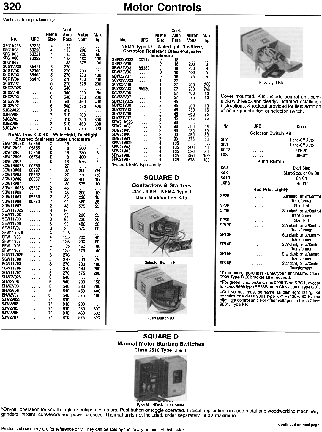
320 Motor Controls
Continued from previous page
Pilot Light Kit
Cover mounted. Kits include control unit com-
plete with leads and clearly illustrated installation
instructions. Knockout provided for field addition
of either pushbutton or selector switch.
Cant.
NEMA Amp Motor Max.
No. UPC Size Rate Volts hp
SFG1V02S 83223 4 135 ... ...
SFG1V08 83220 4 135 200 40
SFG1V03 83221 4 135 230 50
SFG1V06 83222 4 135 460 100
SFG1V07 4 135 575 100
SGG1V02S 85471 5 270 ... ."
SGG1V08 62000 5 270 200 75
SGG1V03 85463 5 270 230 100
SGG1V06 85470 5 270 460 200
SGG1V07 5 270 575 200
SHG2V02S ,6 540... ...
SHG2V08 6 540 200 150
SHG2V03 6 540 230 200
SHG2V06 6 540 460 400
SHG2V07 6 540 575 400
SJG2V02S 7 810 ...
SJG2V08 . .. .. 7 810 200 . . .
SJG2V03 , 7 810 230 300
SJG2V06 7 810 460 600
SJG2V07... 7 810 575 600
NEMA Type 4 & 4X - Watertight, Dusttight
Brushed Stainless Steel Enclosure
SBW12V02S 05759 0 18 ...
SBW12V08 05755 0 18 200 3
SBW12V03 05756 0 18 230 3
SBW12V06 05754 0 18 460 5
SBW12V07 0 18 575 5
SGW13V02S 05750 1 27 ...
SGW13V08 86287 1 27 200 7V2
SGW13V03 05752 1 27 230 71h
SGW13V06 86257 1 27 460 10
SGW13V07 1 27 575 10
SDW11V02S 05767 2 45 .., ...
SDW11V08 ...,. 2 45 200 10
SDW11V03 05768 2 45 230 15
SDW11V06 86273 2 45 460 25
SDW11V07 2 45 575 25
SEW11V02S 3 90 ... ...
SEW11V08 3 90 200 25
SEW11V03 3 90 230 30
SEW11V06 3 90 460 50
SEW11V07 3 90 575 50
SFW11V02S . . . . . 4 135 . . .
SFW11V08 ...,. 4 135 200 40
SFW11V03 4 135 230 50
SFW11V06 4 135 460 100
SFW11V07 4 135 575 100
SGW11V02S 5 270 ...
SGW11V08 5 270 200 75
SGW11V03 5 270 230 100
SGW11V06 5 270 460 200
SGW11V07 5 270 575 200
SHW2V02S 6 540 ... ...
SHW2V08 6 540 200 150
SHW2V03 6 540 230 200
SHW2V06 6 540 460 400
SHW2V07 ..". 6* 540 575 400
SJW2V02S .. . . . 7* 810 . . .
SJW2V08 7* 810 200
SJW2V03 7* 810 230 300
SJW2V06 7* 810 460 600
SJW2V07 7* 810 575 600
No. UPC Desc.
Selector Switch Kit
. . Hand-Off Auto
. . . . . Hand-Off Auto
. . . . . On-Off
. . . . . On-Off.
SC2
SC8
SC22
LXS
Push Button
Cont.
NEMA Amp Motor Max.
No. UPC Size Rate Volts hp
NEMA Type 4X - Watertight, Dusttight,
Corrosion-Resistant Glass-Polyester
Enclosure
SBW22V02S 00117 0 18 ...
SBW22V08 "'" 0 18 200 3
SBW22V03 85383 0 18 230 3
SBW22VOO 0 18 460 5
SBW22V07 0 18 575 5
SCW23V02S 1 27 ...
SCW23V08 "". 1 27 200 71/2
SCW23V03 85930 1 27 230 71/2
SCW23V06 1 27 460 10
SCW23V07 1 27 575 10
SDW21V02S 2 45 ... ...
SDW21V08 2 45 200 10
SDW21V03 2 45 230 15
SDW21V06 2 45 460 25
SDW21V07 2 45 575 25
SEW21V02S 3 90 ... ...
SEW21V08 3 90 200 25
SEW21V03 3 90 230 30
SEW21V06 3 90 460 50
SEW21V07 3 90 575 50
SFW21V02S 4 135 ... ...
SFW21V08 4 135 200 40
SFW21V03 4 135 230 50
SFW21V06 4 135 460 100
SFW21V07 4 135 575 100
'Rated NEMA Type 4 only. SA2
SA3
SA10
lXPB
Start-Stop
Start-Stop; or On-Off
On-Off
On-Off-
SQUARE D
Contactors & Starters
Class 9999 - NEMA Type 1
User Modification Kits
Red Pilot Lightt
SP2R . . Standard; or w/Control
Transformer
SP3R . . . . . Standard
SP4R . . . . . Standard; or w/Control
Transformer
SP5R . . . . . Standard
SP12R . . . . . Standard; or w/Control
Transformer
SP13R . . . . . Standard; or w/Control
Transformer
SP14R . . . . . Standard; or w/Control
Transformer
SP15R . . . . . Standard; or w/Control
Transformer
SP28R . . . . . Standard; or w/Control
Transformer:!:
'To mount control unit in NEMA type 1 enclosures, Class
9999 Type BLX bracket also required.
tFor green lens, order Class 9999 Type SPG1, except
for class 9999 type SP28R order Class 9001 , Type G31.
:j:Coil voltage must be same as pilot light rating. Kit
contains one class 9001 type KP1 R3120V, 60 Hz red
pilot light control unit. For other voltages, refer to Class
9001, Type KP.
Selector Switch Kit
Push Button Kit
SQUARE D
Manual Motor Starting Switches
Class 2510 Type M & T
Type M - NEMA 1 Enclosure
"On-off" operation for small single or polyphase motors. Pushbutton or toggle operated. Typical applications include metal and woodworking machinery,
grinders, mixers, conveyors and power presses. Thermal units not included, order separately. 600V maximum.
Continued on next page
Products shown here are for reference only. They can be sold by the locally authorized distributor.
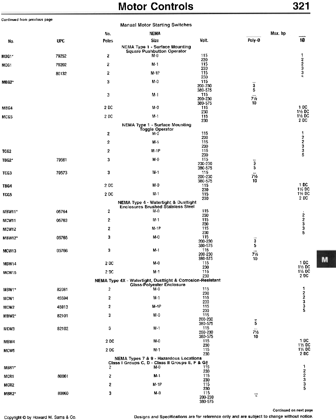
Motor Controls 321
Continued from previous page
Max. hp
No.
Poles Poly-O 10Volt.
No. UPC
Manual Motor Starting Switches
NEMA
Size
NEMA Type 1 - Surface Mounting
Square Pushbutton Operator
M-O
M-1
M-1P
M-O
115
230
115
230
115
230
115
200-230
380-575
115
200-230
380-575
115
230
115
230
1
2
2
3
3
"
79252
79202
80132
2
2
2
3
MBG1*
MCG1
MBG2* 3
5
7V.
10
3M-1
1 DC
1V2 DC
1V2 DC
2 DC
MBG4
MCG5
2 DC
2 DC
M-O
M-1
NEMA Type 1 - Surface Mounting
Toggle Operator
M-O
M-1
M-1P
M-O
115
230
115
230
115
230
115
200-230
380-575
115
200-230
380-575
115
230
115
230
1
2
2
3
3
5
2
2
2
3
TC62
T862* 79561 3
5
7V2
10
M-1
79573 3
TCG3
1 DC
1V2 DC
1V2 DC
2 DC
2 DC
2 DC
M-O
M-1
NEMA Type 4 - Watertight & Dusttight
Enclosures Brushed Stainless Steel
2 M-O 115
230
2 M-1 115
230
2 M-1P 115
230
3 M-O 115
200-230
380-575
3 M-1 115
200-230
380-575
2 DC M-O 115
230
2DC M-1 115
230
NEMA Type 4X - Watertight, Dusttight & Corrosion-Resistant
Glass-Polyester Enclosure
2 M-O 115
230
2 M-1 115
230
2 M-1P 115
230
3 M-O 115
200-230
380-575
3 M-1 115
200-230
380-575
2 DC M-O 115
230
2 DC M-1 115
230
NEMA Types 7 & 9 - Hazardous Locations
Class I Groups C, D - Class II Groups E, F & Gt
2 M-Q 115
230
2 M-1 115
230
2 M-1P 115
230
3 M-O 115
200-230
380-575
TBG4
TCG5
05764
05763
MBW11*
MCW11
MCW12
MBW12*
2
2
3
3
5
05765 3
5
7V2
10
MCW13 05766
1 DC
1V2 DC
1V2 DC
2 DC
MBW14
MCW15
1
2
2
3
3
5
MBW1*
MCW1
MCW2
MBW2*
82081
45594
45913
82101
5
7'h
10
82102
MCW3
1 DC
1V2 DC
1V2 DC
2 DC
MBW4
MCW5
1
2
2
3
3
5
MBR1*
MCR1
MCR2
MBR2*
80061
80060 .,
Continued on next page
Designs and Specifications are for reference only and are subject to change without notice.
Copyright @ by Howard W. Sams & Co.
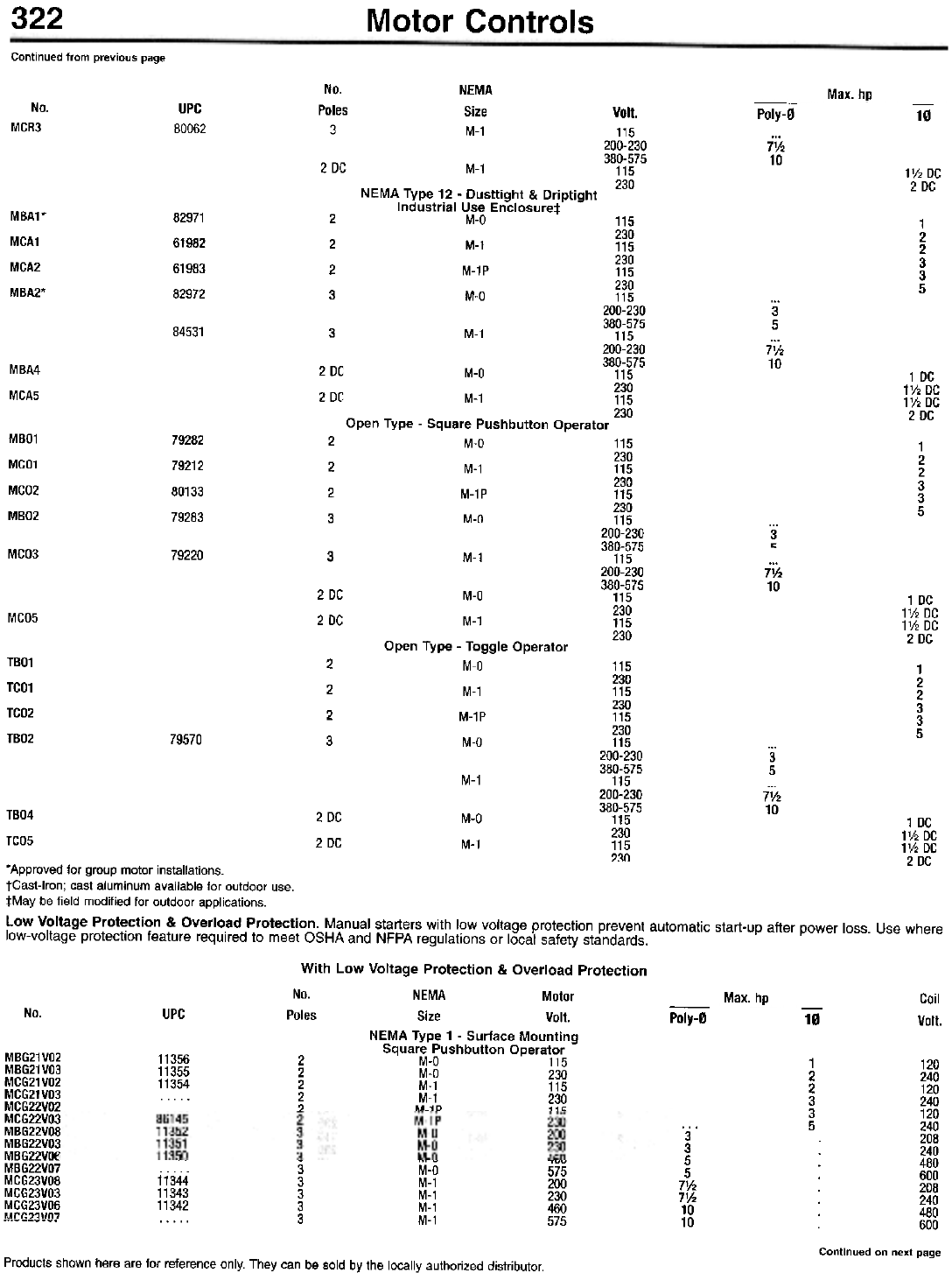
322 Motor Controls
Continued from previous page
No.
Poles
3
NEMA
Size
M-1
Max. hp
No.
MCR3
UPC
80062
Volt.
115
200-230
380-575
115
230
Poly-0 10
7V2
10
2 DC M-1
NEMA Type 12 - Dusttight & Driptight
Industrial Use Enclosure:!:
M-Q
M-1
M-1P
M-Q
1V2 DC
2 DC
MBA1*
MCA1
MCA2
MBA2*
82971
61982
61983
82972
2
2
2
3
115
230
115
230
115
230
115
200-230
380-575
115
200-230
380-575
M-O 115
230
M-1 115
230
Open Type - Square Pushbutton Operator
M-O
M-1
M-1P
M-O
1
2
2
3
3
5
3
5
7V2
10
84531 3M-1
MBA4
MCA5
2 DC
2 DC
1 DC
1V2 DC
1V2 DC
2 DC
MBO1
MCO1
MCO2
MBO2
79282
79212
80133
79283
2
2
2
3
115
230
115
230
115
230
115
200-230
380-575
115
200-230
380-575
115
230
115
230
1
2
2
3
3
5
3
~
MCO3 79220 3M-1
71h
10
2 DC
2 DC
M-Q
M-1
Open Type - Toggle Operator
M-Q
M-1
M-1P
M-Q
1 DC
1V2 DC
1V2 DC
2 DC
MCO5
TBO1
TCO1
TCO2
TBO2
2
2
2
3
115
230
115
230
115
230
115
200-230
380-575
115
200-230
380-575
115
230
115
230
1
2
2
3
3
5
79570
3
5
7V2
10
M-1
T804
TC05
2 DC
2 DC
M-O
M-1
--- - ..,v ~uu
3 M-O 575
11344 3 M-1 200
11343 3 M-1 230
11342 3 M-1 460
3 M-1 575
Coil
Volt.
-
Poly-0 10
MBG21VO2
MBG21VO3
MCG21VO2
MCG21VO3
MCG22VO2
MCG22VO3
MBG22VOB
MBG22VO3
MBG22VO6
MBG22VO7
MCG23VOB
MCG23VO3
MCG23V06
M~(;?1Vn7
1
2
2
3
3
5
3
3
5
5
71h
71h
10
10
120
240
120
240
120
240
208
240
480
600
208
240
480
600
Continued on next page
Products shown here are for reference only. They can be sold by the locally authorized distributor.
1 DC
1V2 DC
1V2 DC
2 DC
"Approved for group motor installations.
tCast-lron; cast aluminum available for outdoor use.
:j:May be field modified for outdoor applications.
Low Voltage Protection & Overload Protection. Manual starters with low voltage protection prevent automatic start-up after power loss. Use where
low-voltage protection feature required to meet OSHA and NFPA regulations or local safety standards.
With Low Voltage Protection & Overload Protection
No. NEMA Motor Max. hp
No. UPC Poles Size Volt.
NEMA Type 1 - Surface Mounting
Square Pushbutton Operator
11356 2 M-O 115
11355 2 M-O 230
11354 2 M-1 115
. . . . . 2 M-1 230
. ? M-1P 11"
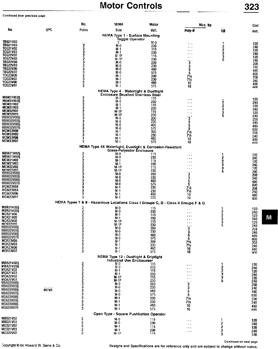
Motor Controls 323
Continued from previous page
No. NEMA Motor ---
Poles Size Volt. Poly-0
NEMA Type 1 - Surface Mounting
Toggle Operator
... 2 M-O ...
2 M-O 230 ...
2 M-1 115 ...
2 M-1 230 ...
2 M-1P 115 ...
2 M-1P 230 ...
3 M-O 200 3
3 M-O 230 3
3 M-O 460 5
3 M-O 575 5
3 M-1 200 7V2
3 M-1 230 71h
3 M-1 460 10
3 M-1 575 10
NEMA Type 4 - Watertight & Dusttight
Enclosure Brushed Stainless Steel
2 M-O 115 ...
2 M-O 230 ...
2 M-1 115 ...
2 M-1 230 . . .
2 M-1P 115 ...
2 M-1P 230 ...
3 M-O 200 3
3 M-O 230 3
3 M-O 460 5
3 M-O 575 5
3 M-1 200 71h
3 M-1 230 71h
3 M-1 460 10
3 M-1 575 10
NEMA Type 4X Watertight, Dusttight & Corrosion-Resistant
Glass-Polyester Enclosure
2 M-O 115 ...
2 M-O 230 . . .
2 M-1 115 ...
2 M-1 230 ...
2 M-1P 115 ...
2 M-1P 230 ...
3 M-O 200 3
3 M-O 230 3
3 M-O 460 5
3 M-O 575 5
3 M-1 200 71h
3 M-1 230 71h
3 M-1 460 10
3 M-1 575 10
NEMA Types 7 & 9 - Hazardous Locations Class I Groups C, D - Class II Groups F & G
2 M-O 115
2 M-O 230 ...
2 M-1 115 ...
2 M-1 230 . . .
2 M-1P 115 ...
2 M-1P 230 ...
3 M-O 200 3
3 M-O 230 3
3 M-O 460 5
3 M-O 575 5
3 M-1 200 71h
3 M-1 230 71h
3 M-1 460 10
3 M-1 575 10
NEMA Type 12 - Dusttight & Driptight
Industrial Use Enclosures.
2 M-O 115 ...
2 M-O 230 ...
2 M-1 115 ...
2 M-1 230 ...
2 M-1P 115 ...
2 M-1P 230 ...
3 M-O 200 3
3 M-O 230 3
3 M-O 460 5
3 M-O 575 5
3 M-1 200 71h
3 M-1 230 71h
3 M-1 460 10
3 M-1 575 10
Open Type - Square Pushbutton Operator
M-O 115 ...
~ M-O 230 . . .
M-1 115 ...
! M-1 230 ...
~ M-1P 115
Max. hp Coil
Volt.
No. UPC 10
TBG21VO2
TBG21VO3
TCG21VO2
TCG21VO3
TCG22VO2
TCG22VO3
TBG22V08
TBG22VO3
TBG22VOO
TBG22VO7
TCG23VO8
TCG23VO3
TCG23VOO
TCG23VO7
1
2
2
3
3
5
120
240
120
240
120
240
208
240
480
600
208
240
480
600
MBW31VO2§
MBW31VO3§
MCW31VO2
MCW31VO3
MCW32VO2
MCW32vn~
120
240
120
240
120
240
208
240
480
600
208
240
480
600
2
2
3
3
5
MCW33VOS'
MCW33VO3
MCW33VOO
MCW33VO7
MBW21VO2§
MBW21VO3§
MCW21VO2
MCW21VO3
MCW22VO2
MCW22Vn3
1
2
2
3
3
5
120
240
120
240
120
240
208
240
480
600
208
240
480
600
MCW23VOO'
MCW23VO3
MCW23V06
MCW23VO7
MBR21 VO2§
MBR21VO3§
MCR21VO2
MCR21VO3
MCR22VO2
MCR22vn~
1
2
2
3
3
5
120
240
120
240
120
240
208
240
480
600
208
240
480
600
MCR23VOS'
MCR23VO3
MCR23VOG
MCR23VO7
MBA21 VO2§
MBA21VO3§
MCA21VO2
MCA21VO3
MCA22VO2
MCA22VO3
1
2
2
3
3
5
120
240
120
240
120
240
208
240
480
600
208
240
480
600
49748
MBO21VO2
MBO21VO3
MCO21VO2
MCO21VO3
MCO22VO2
2
2
2
2
~
1
2
2
3
3
120
240
120
240
120
Continued on next page
Designs and Specifications are for reference only and are subject to change without notice.
:;opyright @ by Howard W. Sams & Co.
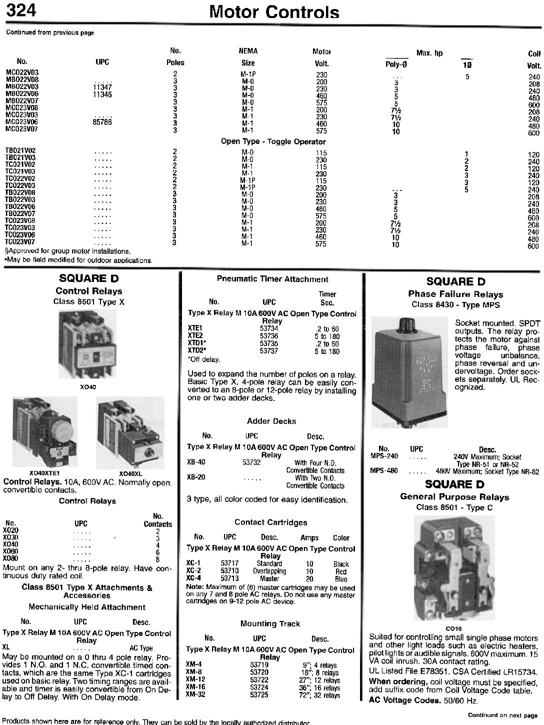
324 Motor Controls
Continued from previous page
No.
Poles
2
3
3
3
3
3
3
3
3
NEMA Motor
Size Volt.
M-1P 230
M-O 200
M-O 230
M-O 460
M-O 575
M-1 200
M-1 230
M-1 460
M-1 575
Open Type - Toggle Operator
M-O 115
M-O 230
M-1 115
M-1 230
M-1P 115
M-1P 230
M-O 200
M-O 230
M-O 460
M-O 575
M-1 200
M-1 230
M-1 460
M-1 575
Max. hp Coil
Volt.
240
208
240
480
600
208
240
480
600
No.
MCO22VO3
MBO22VO8
MBO22VO3
MBO22VOO
MBO22VO7
MCO23VO8
MCO23VO3
MCO23V06
MCO23VO7
UPC -
Poly-0
3
3
5
5
71h
71h
10
10
10
5
11347
11346
85786
2
2
2
2
2
2
3
3
3
3
3
3
3
3
1
2
2
3
3
5
120
240
120
240
120
240
208
240
480
600
208
240
480
600
3
3
5
5
7'h
7V2
10
10
TBO21VO2 . . . . .
TBO21VO3 . . . . .
TCO21VO2 . . . . .
TCO21VO3 . . . . .
TCO22VO2 . . . . .
TCO22VO3 . . . . .
TBO22VO8 . . . . .
TBO22VO3 . . . . .
TBO22VO6 . . . . .
TBO22VO7 . . . . .
TCO23VO8 . . . . .
TCO23VO3 . . . . .
TCO23V06 TCO23VO7 . . . . .
§ApproYed for group motor installations.
-May be field modified for outdoor applications.
SQUARE D
Control Relays
Class 8501 Type X
SQUARE D
Phase Failure Relays
Class 8430 - Type MPS
Socket mounted. SPOT
outputs. The relay pro-
tects the motor against
phase failure, phase
voltage unbalance,
phase reversal and un-
dervoltage. Order sock-
ets separately. UL Rec-
ognized.
Pneumatic Timer Attachment
Timer
No. UPC Sec.
Type X Relay M 10A 600V AC Open Type Control
Relay
XTE1 53734.2 to 60
XTE2 53736 5 to 180
XTD1* 53735 .2 to 60
XTD2* 53737 5 to 180
'Off delay.
Used to expand the number of poles on a relay.
Basic Type X, 4-pole relay can be easily con-
verted to an 8-pole or 12-pole relay by installing
one or two adder decks.
XO40
Adder Decks
No. UPC Desc.
Type X Relay M 1 OA 600V AC Open Type Control
Relay
XB-40 53732 With Four N.D.
Convertible Contacts
XB-20 . . . . . With Two N.D.
Convertible Contacts
3 type, all color coded for easy identification.
No.
MPS-240
MPS-480
UPC Desc.
. . . . . 240V Maximum; Socket
Type NR-51 or NR-52
. . . . . 480V Maximum; Socket Type NR-82
SQUARE D
General Purpose Relays
Class 8501 - Type C
XO40XTE1 XO40XL
Control Relays. 10A, 600V AG. Normally open,
convertible contacts.
Control Relays
Contact Cartridges
No. UPC Desc. Amps Color
Type X Relay M 10A 600V AC Open Type Control
Relay
XC-1 53717 Standard 10 Black
XG-2 53710 Overlapping 10 Red
XG-4 53713 Master 20 Blue
Note: Maximum of (6) master cartridges may be used
on any 7 and 8 pole AC relays. Do not use any master
cartridges on 9-12 pole AC device.
Mounting Track
No. UPC Desc.
Type X Relay M 1 OA 600V AC Open Type Control
Relay
XM-4 53719 9"; 4 relays
XM-8 53720 18"; 8 relays
XM-12 53722 27"; 12 relays
XM-16 53724 36"; 16 relays
XM-32 53725 72"; 32 relays
No.
No. UPC Contacts
X020 . . . 2
X030 . . . . . 3
X040 . . . . . 4
XOOO . . . . . 6
XOBO . . . . . 8
Mount on any 2- thru 8-pole relay. Have con-
tinuous duty rated coil.
Class 8501 Type X Attachments &
Accessories
Mechanically Held Attachment
No. UPC Desc.
Type X Relay M 1 OA 600V AC Open Type Control
Relay
XL .. ACType
May be mounted on a 0 thru 4 pole relay. Pro-
vides 1 N.O. and 1 N.C. convertible timed con-
tacts, which are the same Type XC-1 cartridges
used on basic relay. Two timing ranges are avail-
able and timer is easily convertible from On De-
lay to Off Delay. With On Delay mode.
CO16
Suited for controlling small single phase motors
and other light loads such as electric heaters,
pilot lights or audible signals. 600V maximum. 15
VA coil inrush. 30A contact rating.
ULListed File E78351. CSACertified LR15734.
When ordering, coil voltage must be specified,
add suffix code from Coil Voltage Code table.
AC Voltage Codes. 50/60 Hz.
Continued on next page
Products shown here are for reference only. They can be sold bv the locally authorized di"lrih'linr
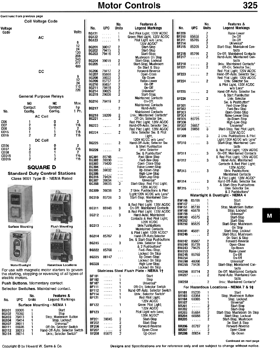
Motor Controls 325
Continued from previous page
Coil Voltage Code No. Features &
No. UPC Units Legend Markings
B6121 . . 1 Red Pilot LiQht; 120V AC/DC
B6122 . 1 Green Pilot Light; 120V AC/DC
B6123 1 Pilot Lightw/o Lens;
120V AC/DC'
BG201 39017 2 Start-Stop
BG202 79415 2 Start-Stop
B6203 79416 2 Start-Stop;
Mushroom On Stop
B6204 39019 2 Start-Stop; Lockout
BG205 ... . . 2 Start-Stop; Mushroom
On Start & Stop
BG206 79417 2 Forward-Reverse
B6207 85666 2 Open-Close
B6208 39022 2 Up-Down
B6209 85737 2 Raise-Lower
B6210 85637 2 On-Off
B6211 79418 2 On-Off
B6214 39025 2 Universal'
BG215 29026 2 Start-Stop;
Maintained Contacts
B6216 79419 2 On-Off;
Maintained Contacts
B6217 ... . . 2 Hand-Auto;
Maintained Contacts
BG218 39209 2 Univ.; Maintained Contacts'
B6221 . . . . . 2 Off-On; Selector Sw.;
Red Pilot Light; 120V AC/DC
B6223 . . . . . 2 Hand-Off-Auto; Selector Sw.;
Red Pilot Light; 120V AC/DC
B6224 . . . . . 2 Univ. Selector Sw. & Pilot
Light,
120V AC/DC w/o Lens'
B6225 . . . . 2 Hand-Off-Auto; Selector Sw.
& Start Pushbutton
B6226 . . . . . 2 Univ. Selector
Sw. & Pushbutton'
B6301 85748 . . . Fast-Slow-Stop
BG302 39030 . . . Fwd-Rev-Stop
B6303 79420 . . . Open-Close-Stop
BG304 . . . . . . . . Raise-Lower-Stop
B6305 39032 ... Up-Down-Stop
B6306 . . . . . . . . Hlgh-Low-Stop
B6316 79424 . . . Start-Jog-Stop
BG307 39034 . . . Universal*
BG308 39035 3 Start-Stop; Red Pilot Light;
120V AC/DC
B6309 39036 3 2 Univ. Push buttons & Pilot
Light;120V AC/DC w/o Lens'
B6310 85726 3 Start-Stop; Maintained Con-
tacts
& Red Pilot Light; 120V AC/DC
BG311 86146 3 On-Off; Maintained Contacts
& Red Pilot Light; 120V AC/DC
B6312 . . . . . 3 Hand-Auto; Maintained
Contacts & Red Pilot Light;
120V AC/DC
BG313 ... . . 3 Univ.Pushbuttons;
Maintained Contacts
& Pilot Light; 120V AC/DC'
B6314 85767 3 Hand-Off-Auto;Selector
Sw. & Start-Stop Pushbuttons
B6315 3 Univ.SelectorSw.
& 2 Pushbuttons'
BG322 85768 . . . Fwd.-Rev.-Stop;
Lockout On Stop
B6325 86147 . . . Up-Down-Stop;
Lockout On Stop
B6326 ... High-Low-Stop;
Lockout On Stop
Stainless Steel Flush Plate - NEMA 1 t
BF101 . . 1 Start
BF102 . . . . . 1 Stop
BF107 . . . . . 1 Universal*
BF111 . . . . . 1 Off-On; Selector Switch
BF112 . . . . . 1 Hand-Off-Auto; Selector Switch
BF114 1 Univ.;SelectorSwitch'
BF121 . . . . . 1 Red Pilot Light;
120V AC/DC
BF122 . . . . . 1 Green Pilot Light;
120V AC/DC
BF123 1 Pilot Lightw/o Lens;
120V AC/DC'
BF201 39045 2 Start-Stop
BF202 . . . . . 2 Start-Stop
BF206 . . . . . 2 Forward-Reverse
BF207 . . . . . 2 Open-Close
BF208 8567~' Iin-nnwn
No. Features &
No. UPC Units legend Markings
BF209 . . . . . 2 Raise-Lower
BF210 85658 2 On-Oft
BF211 85765 2 On-Oft
BF214 . . . . . 2 Universal'
BF215 85205 2 Start-Stop; Maintained Con-
tacts
BF216 85766 2 On-Oft; Maintained Contacts
BF217 . . . . . 2 Hand-Auto; Maintained Con-
tacts
BF218 . . . . . 2 Univ.; Maintained Contacts'
BF221 . . . . . 2 Oft-On; Selector Sw.;
Red Pilot Light; 120V AC/DC
BF223 . . . . . 2 Hand-Oft-Auto; Selector Sw.;
Red Pilot Light; 120V AC/DC
BF224 . . . . . 2 Univ. Selector Sw.
& Pilot Light, 120V AC/DC
w/o lens'
BF225 . . . . . 2 Hand-Oft-Auto; Selector Sw.
& Start Pushbutton
BF226 . . . . . 2 Univ. Selector
Sw. & Pushbutton'
BF301 . . . . . . . . Fast-Slow-Stop
BF302 . . . . . . . . Fwd-Rev-Stop
BF303 . . . . . . . . Open-Close-Stop
BF304 . . . . . . . . Raise-lower-Stop
BF305 85725 ... Up-Down-Stop
BF306 . . . . . . . . High-low-Stop
BF307 39057 . . . Universal*
BF308 39058 3 Start-Stop; Red Pilot Light;
120V AC/DC
BF309 . . . . . 3 2 Univ. Push buttons & Pilot
Light;120V AC/DC w/o lens'
BF310 . . . . . 3 Start-Stop; Maintained Con-
tacts
& Red Pilot Light; 120V AC/DC
BF311 . . . . . 3 On-Oft; Maintained Contacts
& Red Pilot Light; 120V AC/DC
BF312 . . . . . 3 Hand-Auto; Maintained
Contacts & Red Pilot Light;
120V AC/DC
BF313 . . . . . 3 Univ. Pushbuttons;
Maintained Contacts
& Pilot Light; 120V AC/DC'
BF314 . . . . . 3 Hand-Oft-Auto; Selector Sw.
& Start-Stop Pushbuttons
BF315 . . . . . 3 Univ. Selector Sw.
& 2 Pushbuttons'
Watertight & Dusttight - NEMA 4
BW146 85706 1 Start
BW147 1 Stop
BW151 85738 1 Stop; Mushroom Button
BW148 45878 1 Stop; lockout
BW159 1 Universal*
BW240 45875 2 Start-Stop
BW252 2 Start-Stop
BW250 85825 2 Start-Stop; Mushroom
On Stop
BW241 45881 2 Start-Stop; Lockout
BW246 2 Start-Stop; Mushroom
On Start & Stop
BW242 85667 2 Forward-Reverse
BW244 85739 2 Open-Close
BW243 79425 2 Up-Down
BW253 2 Raise-Lower
BW245 85769 2 On-Oft
BW254 2 On-Oft
BW260 46096 2 Universal*
BW255 79426 2 Start-Stop; Maintained Con-
tacts
BW256 85774 2 On-Oft; Maintained Contacts
BW257 2 Hand-Auto; Maintained Con-
tacts
BW258 . . . 2 Univ.; Maintained Contacts'
For Hazardous locations - NEMA 7 & 9*
BR101 85220 1 Start
BR103 60084 1 Stop; Mushroom Button
BR104 60085 1 Stop; lockout
BR107 1 Universal*
BR201 . . . . . 2 Start-Stop
BR202 . . . . . 2 Start-Stop
BR203 85684 2 Start-Stop; Mushroom On Stop
BR204 60088 2 Start-Stop; Lockout
BR205 ... . . 2 Start-Stop; Mushroom
On Start & Stop
BR206 85787 2 Forward-Reverse
J; BR207 . . . . . 2 Open-Close
- - -.. BR2O8 85654 2 Up-Down
Continued on next page
Designs and Specifications are for reference only and are subject to change without notice.
Voltage
Code Volts
AC
6
12
24
120
208
240
277
480
DC
6
12
24
110
220
General Purpose Relays
NO NC
Contact Contact
Config. Config.
Max.
hp
1 Ph.
No.
AC Coil
CO6
CO7
COB
CO15
CO16
0
0
1
1
2
2
11h
2
11h
11h
1
2
0
1
2
DC Coil
COO6 1 0
COOl 2 0
CO08 0 1
CO015 1 1
CO016 2 2
SQUARE D
Standard Duty Control Stations
Class 9001 Type B - NEMA Rated
2
11h
2
11h
11h
Surface Mounting -
Flush Mounting
~ -
Water/Dustight Hazardous Locations
For use with magnetic motor starters to govern
the starting, stopping or reversing of all types of
electric motors.
Push Buttons. Momentary contact.
Selector Switches. Maintained contact.
No. Features &
No. UPC Units Legend Markings
Surface Mounting - NEMA 1
B6101 39005 1 Start
B6102 79392 1 Stop
B6103 79413 1 Stop; Mushroom Button
B6104 79414 1 Stop; Lockout
B6107 39011 1 Universal'
B6111 85695 1 Oft-On; Selector Switch
B6112 39013 1 Hand-Oft-Auto; Selector Switch
B6114 39014 1 Univ.; Selector Switch'
Copyright @ by Howard W. Sams & Co.
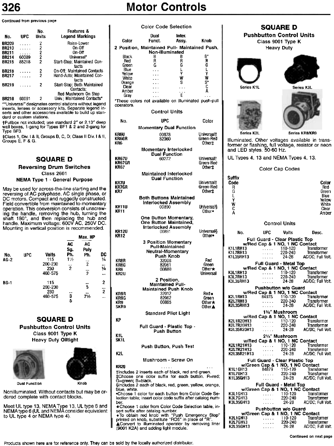
Motor Controls
326
Continued from previous page
SQUARE D
Pushbutton Control Units
Class 9001 Type K
Heavy Duty
No. Features &
No. UPC Units Legend Markings
BR209 . . . 2 Raise-Lower
BR210 2 On-Off
BR211 . . . . . 2 On-Off
BR214 60089 2 Universal'
BR215 85218 2 Start-Stop; Maintained Con-
tacts
BR216 . . . . . 2 On-Off; Maintained Contacts
BR217 . . . . . 2 Hand-Auto; Maintained Con-
tacts
BR219 ... . . 2 Start-Stop; Both Maintained
Contacts;
Red Mushroom On Stop
BR218 60091 2 Univ.; Maintained Contacts'
"'Universal" designates control stations without legend
inserts, lenses or accessory kits. Separate legend in-
serts and other accessories available to build up stan-
dard or custom stations.
tPulibox not included; use standard 2" or 2.13" deep
wall boxes, 1-gang for Types BF1 & 2 and 2-gang for
Type BF3.
:j:Class 1, Div. I & II, Groups B, C, 0; Class II Div. I & II,
Groups E, F & G.
Series K1 L Series K3L
Color Code Selection
Dual Inter.
Color Funct. Assy. Knob
2 Position, Maintained Pull- Maintained Push,
Non-Illuminated
Black B B B.
Red R R R
Green G G G
Blue . . . L L
Yellow... Y Y
White . . . W W
Orange . . . S S'
Clear . . . . . . C
Amber . . . . . . A
Gray . .. E ...
.These colors not available on illuminated push-pull
operators.
No. Color
Control Units
UPC
Momentary Dual Function
00878
82060 Universalt
Green-Red
Other:!:
KR6U
KR6GR
KR6
Momentary Interlocked
Dual Function
60272
--
Series K2L Series KR8/KR9
Illuminated. Other voltages available in trans-
former or flashing, full voltage, resistor or neon
and LED styles. 50-60 Hz.
UL Types 4, 13 and NEMA Types 4, 13.
SQUARE D
Reversing Drum Switches
Class 2601
NEMA Type 1 - General Purpose
May be used for across-the-line starting and the
reversing of AC polyphase, AC single phase, or
DC motors. Compact and ruggedly constructed.
Field convertible from maintained to momentary
operation. This conversion consists of unscrew-
ing the handle, removing the hub, turning the
shaft 180°, and then replacing the hub and
handle. Maximum voltage: 600V AC, 250V DC.
Mounting in vertical position is recommended.
Max. HP
KR67U
KR67GR
KR67
Universalt
Green-Red
Other:!: Color Cap Codes
Maintained Interlocked
Dual Function Suffix
Code
R
G
L
Y
W
C
A
KR7U
KR7GR
KR7
Universalt
Green-Red
Other:!:
Color
Red
Green
Blue
Yellow
White
Clear
Amber
Both Buttons Maintained
Interlocked Assembly
00890 Universal§
Other-
KR11U
KR11
One Button Momentary,
One Button Maintained,
Interlocked Assembly
00891 Universal§
Other-
KR12U
KR12
3 Position Momentary
Pull-Maintained
Neutral-Momentary
Push Knob
32008
82061
00880
AC
SQ.
Ph.
1V2
2
AC
Poly
Ph.
2
2
No.
AG-2 UPC Volts
115
200-230
230
460-575
115
200-230
230
460-575
DC
V.
V.
2
2
Red
Green
Olher*
Universal
KR8R
KR8G
KR8
KR2U
2 Position,
Maintained Pull-
Maintained Push Knob
32012
82062
00885
86-1 5
7% KR9R
KR9G
KR9
SKR9
Red.
Green
Other*
Other..
3
5
Standard Pilot Light
SQUARE D
Pushbutton Control Units
Class 9001 Type K
Heavy Duty Oiltight
KP
Full Guard - Plastic Top -
Push Button
K1L
SK1L
Push Button, Push Test
K2l
Mushroom - Screw On
KR20 ...
tlncludes 2 inserts each of black, red and green.
:j:Choose one color suffix for each button. R=red;
G=green; B=black.
§Includes 2 each of black, red, green, yellow, orange,
blue, white.
-Choose 1 color for each button from Color Code Se-
lection table; insert color code suffix after catalog num-
ber.
*Choose 1 color from Color Code Selection table, in-
sert suffix after catalog number.
. To obtain red knob with "Push Emergency Stop"
printed on knob, substitute "RO5" in place of "R".
.Convert to illuminated operator by removing liner
(9001 K2A) and adding light module.
Dual Function Knob
Nonilluminated. Without contacts but may be or-
dered complete with contact blocks.
Meet UL type 13, NEMA Type 13, UL type 6 and
NEMA type 6 (UL and NEMA consider equivalent
to UL type 4 or NEMA type 4).
Control Units
No. UPC Volts Desc.
Full Guard - Clear Plastic Top
wIRed Cap & 1 NO, 1 NC Contact
K1l1RH13.. . 110-120 Transformer
K1l7RH13 . . . . . 220-240 Transformer
K1l35RH13 . . . 24-28 AC/DC; Full Volt.
Full Guard - Metal Top
wIRed Cap & 1 NO, 1 NC Contact
K3l1RH13 . . . . . 110-120 Transformer
K3l7RH13 . . . . 220-240 Transformer
K3l35RH13 . . 24-28 AC/DC; Full Volt.
Pushbutton w/o Guard
wIRed Cap & 1 NO, 1 NC Contact
K2l1 RH13 84975 110-120 Transformer
K2l7RH13 . . . . . 220-240 Transformer
K2l35RH13 . . . . . 24-28 AC/DC; Full Volt.
13/." Mushroom
wIRed Cap & 1 NO, 1 NC Contact
K2l1R20H13 ... 110-120 Transformer
K2l7R20H13 . . 220-240 Transformer
K2l35R20H13 . . . . . 24-28 AC/DC; Full Volt.
2'/." Mushroom
wIRed Cap & 1 NO, 1 NC Contact
K2l1R21H13 .. . . . 110-120 Transformer
K2l7R21H13 . . . . 220-240 Transformer
K2l35R21 H13 . . . 24-28 AC/DC; Full Volt.
Full Guard - Clear Plastic Top
w/Green Cap & 1 NO, 1 NC Contact
K1l1 GH13 84879 110-120 Transformer
K1l7GH13 . . . . . 220-240 Transformer
K1l35GH13 . . . . . 24-28 AC/DC; Full Volt.
Full Guard - Metal Top
w/Green Cap & 1 NO, 1 NC Contact
K3l1GH13 110-120 Transformer
K3l7GH13 . 220-240 Transformer
K3l35GH13 . 24-28 AC/DC; Full Volt.
Pushbutton w/o Guard
w/Green Cap & 1 NO, 1 NC Contact
K2l1GH13 110-120 Transformer
K2l7GH13 . . . . 220-240 Transformer
K2l35GH13 .. . . . 24-28 AC/DC; Full Volt.
Continued on next page
Products shown here are for reference only. They can be sold by the locally authorized distributor.

Motor Controls 327
Continued from previous page
Knob
No. UPC Desc. Color
KR2RH6 ... Extended Guard Red
KR2GH6 Extended Guard Green
KR2UH6 Extended Guard Universal'
KR2H6 Extended Guard Othert
1%" Dia. Snap-In Mushroom Button
KR4BH6 . . . Mushroom Button Black
KR4RH6 . . . . . Mushroom Button Red
KR4RO5H6 Mushroom Button Red:j:
KR4GH6 Mushroom Button Green
KR4H6 Mushroom Button Other§
13/." Dia. Screw-On Mushroom Button w/Set
Screw Security
KR24BH6 . Mushroom Button Black
KR24RH6 Mushroom Button Red
KR24GH6 Mushroom Button Green
KR24H6 . . Mushroom Button Other§
2'/4" Dia. Snap-In Mushroom Button
KR5BH6 . . . . Mushroom Button Black
KR5RH6 . . . . Mushroom Button Red
KR5RO5H6 Mushroom Button Red:j:
KR5GH6 Mushroom Button Green
KR5H6 Mushroom Button Other§
2'/4" Dia. Screw-On Mushroom Button w/Set
Screw Security
KR25BH6 . . Mushroom Button Black
KR25RH6 Mushroom Button Red
KR25GH6 Mushroom Button Green
KR25H6 . . . . . Mushroom Button Other§
KR25RH13 Mushroom Button Red
KR25RH5 Mushroom Button Red
KR25R . . . . . Mushroom Button Red
'Universal inserts include 1 each of colors: Black, Red,
Green, Yellow, Orange, Blue, & White.
tChoose color and place code in catalog number fol-
lowing KR1, KR2 or KR3: Blue=L, Yellow=Y, White=W,
Orange=S, Gray=E.
:j:Knob has "Emergency Stop" in raised letters high-
lighted in white for easy readability.
§Choose color and place in catalog number following
KR4, KR5, KR24 or KR25: Blue=L, Yellow=L,
Orange=S.
Note: Contact configuration denoted by suffix: 13=1
NO 1 NC, 5=1 NO, 6=1 NC. No suffix indicates no
contacts.
Contact Blocks
No.
KS11C
KS11FB
KS11FR
KS11FG
KS11FY
KS11FS
KS11Fl
KS11FW
KS11FA
KS11FC
KS11TB
KS11TR
KS11TG
KS11TY
KS11Tl
KS11TC
KS11K1*
KS11K2*
KS11K3*
UPC -
Type
Std.
Gloved
Gloved
Gloved
Gloved
Gloved
Gloved
Gloved
Gloved
Gloved
Coin Qp.
Coin Qp.
Coin Qp.
Coin Qp.
Coin Qp.
Coin Qp.
Color
Clear
Black
Red
Green
Yellow
Orange
Blue
White
Amber
Clear
Black
Red
Green
Yellow
Blue
Clear
No. UPC Volts Desc.
13/." Mushroom
w/Green Cap & 1 NO, 1 NC Contact
K2L1G20H13 .. . . 110-120 Transformer
K2L7G20H13 . . . 220-240 Transformer
K2L35G20H13 . . 24-28 AC/DC; Full Volt.
2'/." Mushroom
w/Green Cap & 1 NO, 1 NC Contact
K2L1G21H13 . ... . 110-120 Transformer
K2L7G21H13 . . . . . 220-240 Transformer
K2L35G21 H13 . . . . 24-28 AC/DC; Full Volt.
Full Guard - Clear Plastic Top
w/o Contact'
K1L1t 00560 110-120 Transformer
K1 L7t 85724 220-240 Transformer
K1L35t 24-28 AC/DC;FuIiVolt.
Full Guard - Metal Top
w/o Contact'
K3L1t . . . . 110-120 Transformer
K3L7t . . . 220-240 Transformer
K3L35t . . 24-28 AC/DC; Full Volt.
Pushbutton w/o Guard - w/o Contact'
K2L1t 17854 110-120 Transformer
K2L7t . . . . . 220-240 Transformer
K2L35t . . . . 24-28 AC/DC; Full Volt.
3-Position Momentary Pull, Maintained
Neutral, Momentary Push - w/2 NC Contact
KR8P1TH25 ... 110-120 wIRed Knob
KR8P1 H25t . 110-120 Other Color
3-Position Momentary Pull, Maintained
Neutral, Momentary Push - w/o Contact
KR8P1t 00883 110-120 Other Color
2-Position Maintained Pull, Maintained Push
w/1 NO & 1 NC Contact
KR9P1TH13 110-120 wIRed Knob
KR9P1H13t . 110-120 Other Color
3-Position Momentary Pull, Maintained Push
w/o Contact
KR9P1 t 00888 110-120 Other Color
'Available complete with contact blocks.
tAdd color code from Color Cap Table.
SQUARE D
Pushbutton Control Units
Class 9001 Type K - NEMA Type 13
Heavy Duty - Oiltight No.
KA1
KA2
KA3
Desc.
1 NO 1 NC
1 NO
1 NC
SQUARE D
Selector Switches
Class 9001 Type K - 30.5mm
Spring Return
From Left
KS25 . . . . w/o Knob . . .
KS25B . . . . . Std. Black
KS25R . . . . . Std. Red
KS25G . . . . . Std. Green
KS25Y . . . . . Std. Yellow
KS25S . . . . . Std. Orange
KS25L . . . . . Std. Blue
KS25W . . . . . Std. White
KS25A . . . . . Std. Amber
KS25C . . . . . Std. Clear
KS25FB . . . . . Gloved Black
KS25FR . . . . . Gloved Red
KS25FG . . . . . Gloved Green
KS25FY . . . . . Gloved Yellow
KS25FS . . . . . Gloved Orange
KS25FL . . . . . Gloved Blue
KS25FW . . . . . Gloved White
KS25FA . . . . . Gloved Amber
KS25FC . . . . . Gloved Clear
KS25TB . . . . . Coin Op. Black
KS25TR . . . . . Coin Op. Red
KS25TG . . . . . Coin Op. Green
KS25TY . . . . . Coin Op. Yellow
KS25TL . . . . . Coin Op. Blue
KS25TC . . . . . Coin Op. Clear
KS25K1* . . . . .
'Key operated w/EIO key. Suffixes (1, 2. or 3) drawn
from Key Withdrawal Code table.
Type E Manual Return w/Contact Blocks. With
standard black knob. For other colors, replace
"8" in No. with Color Codes from Selector Switch
Knob Table.
Type E Manual Return w/Contact Blocks
Non-Illuminated
No. Desc.
Spring Return
From Left
KS11BH13 w/one KA1 on side #2; H13
KS11BH1 w/one KA1 on side #1; H1
KS11BH2 w/one KA1 on side #1 & one KA1 on side #2; H2
Type D
Non-Illuminated
~
--~T" JLIEA~
""01
Non-illuminated two position selector switch op-
erators for use in hazardous locations. UL Types
4,13; NEMATypes 4,13.
Type E
Non-Illuminated
No. Desc.
Spring Return
From Left
--
Legend Plate Operator
Non-illuminated momentary push button opera-
tors. UL Types 4, 13 and NEMA Types 4, 13.
Contact blocks and le'1end plate not included
unless otherwise noted-.
Pushbuttons
No. UPC Desc. Color
Standard
KR1BH6 82105 Full Guard
KR1 RH6 06680 Full Guard
KR1 GH6 . . , , . Full Guard
KR1 UH6 . . , , , Full Guard
KR1 H6 . . . , , Full Guard
KR1UH13 Full Guard
KR1 UH5 , . . . , Full Guard
KR1U , . . . . Full Guard
KR3BH6 . , . . . No Guard
KR3RH6 04276 No Guard
KR3GH6 . . , , . No Guard
KR3UH6 . . . . . No Guard
KR3H6 . . . . . No Guard
KR3UH13, No Guard
KR3UH5 . . . . . No Guard
KR3U . . . . . No Guard
KR2BH6 Extended Guard
Black
Red
Green
Universal*
Othert
Universal*
Universal*
Universal*
Black
Red
Green
Universal*
Othert
Universal*
Universal*
Universal*
Black
KS12
KS12B
KS12(1)
KS12K(2)
w/o Knob
w/Std. Black Knob
w/Other Color Knob
Key Operated wIElD Key(3)
Spring Return
From Riaht
Knob -ColorNo. UPC Type
Manual Return
. . wlo Knob
Std.
Std.
Std.
. . . . . Std.
. . . . . Std.
Std.
Std.
Std.
KS34 - wlo Knob
KS34B w/Std. Black Knob
KS34(1) w/Other Color Knob
KS34K1 (2) Key Operated wlEIO Key(3)
Part Number Notes
To obtain the correct part number, follow the cor-
responding directions below for each of the notes
as shown in the tables above. The first product
""'~V' . table has already been expanded.
Continued on next page
Desians and Specifications are for reference onlv and are subject to chanQe without notice.
KS1
KS1
KS1
KS1
KS1
KS1
KS1
KS1
KS1
Black
Red
Green
Yellow
Orange
Blue
White
4mhp,
Coovriah! @ bv Howard W. Sams & Co.
1
18
1R
16
1Y
15
1l
1W
1A
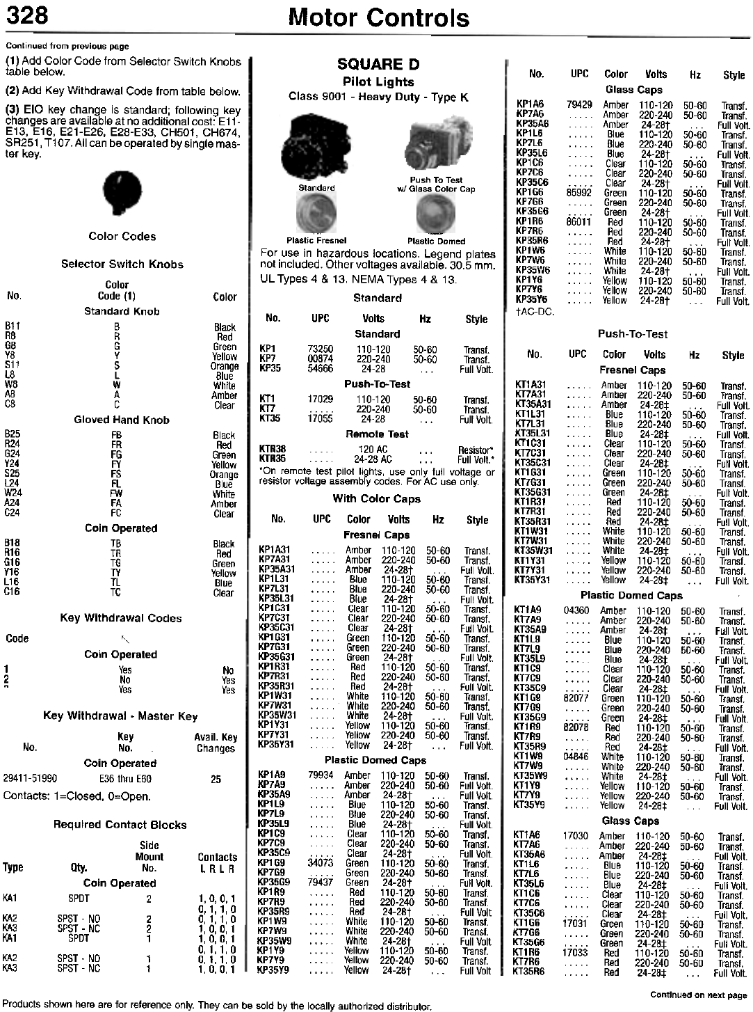
328 Motor Controls
No.
Continued from previous page
(1) Add Color Code from Selector Switch Knobs
table below.
(2) Add Key Withdrawal Code from table below.
(3) EIO key change is standard; following key
changes are available at no additional cost: E11-
E13, E16, E21-E26, E28-E33, CH501, CH674,
SR251, T107.AII can be operated by single mas-
ter key.
SQUARE D
Pilot Lights
Class 9001 - Heavy Duty - Type K
KP1A6
KP7A6
KP35A6
KP1l6
KP7l6
KP35l6
KP1C6
KP7C6
KP35C6
KP1G6
KP7G6
KP35G6
KP1R6
KP7R6
KP35R6
KP1W6
KP7W6
KP35W6
KP1Y6
KP7Y6
KP35Y6
tAC-DC.
UPC Color Volts Hz Style
Glass Caps
79429 Amber 110-120 50-60 Trans!.
. . . .. Amber 220-240 50-60 Trans!.
. . . .. Amber 24-28t . . . Full Volt.
Blue 110-12050-60 Trans!.
. . . . . Blue 220-240 50-60 Trans!.
. . . . . Blue 24-28t . . . Full Volt.
Clear 110-12050-60 Trans!.
. . . . . Clear 220-240 50-60 Trans!.
. . . . . Clear 24-28t . . . Full Volt.
85992 Green 110-120 50-60 Trans!.
. . . .. Green 220-240 50-60 Trans!.
. . . .. Green 24-28t . . . Full Volt.
86011 Red 110-120 50-60 Trans!.
. . . . . Red 220-240 50-60 Trans!.
. . . . . Red 24-28t . . . Full Volt.
White 110-12050-60 Trans!.
. . . .. White 220-240 50-60 Trans!.
. . . .. White 24-28t . . . Full Volt.
Yellow 110-120 50-60 Trans!.
. . . .. Yellow 220-240 50-60 Trans!.
. . . .. Yellow 24-28t . . . Full Volt.
Push To Test
wi Glass Color Cap
Standard
Color Codes
No. Color
B11
R8
68
V8
S11
L8
W8
A8
C8
Black
Red
Green
Yellow
Orange
Blue
White
Amber
Clear
No.
KT1A31
KT7A31
KT35A31
KT1L31
KT7L31
KT35L31
KT1C31
KT7C31
KT35C31
KT1 G31
KT7G31
KT35G31
KT1R31
KT7R31
KT35R31
KT1W31
KT7W31
KT35W31
KT1Y31
KT7Y31
KT35Y31
825
R24
G24
Y24
525
L24
W24
A24
C24
Black
Red
Green
Yellow
Orange
Blue
White
Amber
Clear
Selector Switch Knobs
Color
Code (1)
Standard Knob
B
R
G
Y
S
L
W
A
C
Gloved Hand Knob
FB
FR
FG
FY
FS
FL
FW
FA
FC
Coin Operated
TB
TR
TG
TV
TL
TC
818
R16
G16
Y16
L16
C16
Black
Red
Green
Yellow
Blue
Clear
- -
Plastic Fresnel Plastic Domed
For use in hazardous locations. Legend plates
not included. Other voltages available. 30.5 mm.
UL Types 4 & 13. NEMA Types 4 & 13.
Standard
No. UPG Volts Hz Style
Standard
KP1 73250 110-120 50-60 Trans!.
KP7 00874 220-240 50-60 Trans!.
KP35 54666 24-28 . . . Full Volt.
Push-To-Test
KT1 17029 110-120 50-60 Trans!.
KT7 . . . . . 220-240 50-60 Trans!.
KT35 17055 24-28 . . . Full Volt.
Remote Test
KTR38 120AC ... Resistor'
KTR35 . . . . . 24-28 AC . . . Full Volt.'
'On remote test pilot lights, use only full voltage or
resistor voltage assembly codes. For AC use only.
With Color Caps
No. UPG Color Volts Hz Style
Fresnel Caps
KP1A31 Amber 110-120 50-60 Trans!.
KP7A31 . . . .. Amber 220-240 50-60 Trans!.
KP35A31 . . . .. Amber 24-28t . . . Full Volt.
KP1L31 . . ... Blue 110-120 50-60 Trans!.
KP7L31 . . . . . Blue 220-240 50-60 Trans!.
KP35L31 . . . . . Blue 24-28t . . . Full Volt.
KP1C31 ... .. Clear 110-120 50-60 Trans!.
KP7C31 . . . .. Clear 220-240 50-60 Trans!.
KP35C31 . . . . . Clear 24-28t . . . Full Volt.
KP1G31 .. . .. Green 110-120 50-60 Trans!.
KP7G31 . . . .. Green 220-240 50-60 Trans!.
KP35G31 . . . .. Green 24-28t Full Volt.
KP1R31 Red 110-120 50-60 Trans!.
KP7R31 . . . . . Red 220-240 50-60 Trans!.
KP35R31 . . . . . Red 24-28t . . . Full Volt.
KP1W31 White 110-120 50-60 Trans!.
KP7W31 . . . .. White 220-240 50-60 Trans!.
KP35W31 . . . .. White 24-28t . . . Full Volt.
KP1Y31 .. . .. Yellow 110-120 50-60 Trans!.
KP7Y31 . . . .. Yellow 220-240 50-60 Trans!.
KP35Y31 . . . .. Yellow 24-28t . . . Full Volt.
Plastic Domed Caps
79934 Amber 110-120 50-60 Trans!.
. . . .. Amber 220-240 50-60 Full Volt.
. . . .. Amber 24-28t . . . Full Volt.
Blue 110-120 50-60 Trans!.
. . . . . Blue 220-240 50-60 Trans!.
. . . . . Blue 24-28t . . . Full Volt.
Clear 110-12050-60 Trans!.
. . . .. Clear 220-240 50-60 Trans!.
. . . .. Clear 24-28t . . . Full Volt.
34073 Green 110-120 50-60 Trans!.
. . . .. Green 220-240 50-60 Trans!.
79437 Green 24-28t . . . Full Volt.
Red 110-12050-60 Trans!.
. . . . . Red 220-240 50-60 Trans!.
. . . . . Red 24-28t . . . Full Volt
White 110-120 50-60 Trans!.
. . . .. White 220-240 50-60 Trans!.
. . . .. White 24-28t . . . Full Volt
Yellow 110-12050-60 Trans!.
. . . .. Yellow 220-240 50-60 Trans!.
' . . . .. Yellow 24-28t . . . Full Volt
KT1A9
KT7A9
KT35A9
KT1L9
KT7L9
KT35L9
KT1C9
KT7C9
KT35C9
KT1 G9
KT7G9
KT35G9
KT1R9
KT7R9
KT35R9
KT1W9
KT7W9
KT35W9
KT1Y9
KT7Y9
KT35Y9
Code
Key Withdrawal Codes
""
Coin Operated
Yes
No
Yes
1
2No
Yes
Yes
Key Withdrawal - Master Key
Key Avail. Key
No. No. Changes
Coin Operated
29411-51990 E36 thru E60 25
Contacts: 1 =Closed, O=Open.
KP1A9
KP7A9
KP35A9
KP1l9
KP7l9
KP35l9
KP1C9
KP7C9
KP35C9
KP1G9
KP7G9
KP35G9
KP1R9
KP7R9
KP35R9
KP1W9
KP7W9
KP35W9
KP1Y9
KP7Y9
KP~!iV!l
Required Contact Blocks
Side
Mount
Oty. No.
Coin Operated
SPOT 2
SPST - NO 2
SPST - NC 2
SPOT 1
SPST - NO 1
SPST - NC 1
KT1A6
KT7A6
KT35A6
KT1l6
KT7l6
KT35l6
KT1C6
KT7C6
KT35C6
KT1G6
KT7G6
KT35G6
KT1R6
KT7R6
KT35R6
Contacts
LRLR
Type
KA1
KA2
KA3
KA1
KA2
KA3
1,0,0,1
0,1,1,0
0,1,1,0
1,0,0,1
1,0,0,1
0,1,1,0
0,1,1,0
1,0,0,1
Push-To-Test
UPC Color Volts Hz Style
Fresnel Caps
"... Amber 110-120 50-60 Trans!.
, , . .. Amber 220-240 50-60 Trans!.
, . . .. Amber 24-28:1: . . . Full Volt.
Blue 110-12050-60 Trans!.
. . . . . Blue 220-240 50-60 Trans!.
Blue 24-28:1: ... Full Volt.
Clear 110-12050-60 Trans!.
. , . . . Clear 220-240 50-60 Trans!.
, , . .. Clear 24-28:1: . . . Full Volt.
Green 110-12050-60 Trans!.
, . . .. Green 220-240 50-60 Trans!.
, . . .. Green 24-28:1: . . . Full Volt.
, Red 110-12050-60 Trans!.
, . . . . Red 220-240 50-60 Trans!.
. . . . . Red 24-28:1: Full Volt.
.,... White 110-120 50-60 Trans!.
, , . .. White 220-240 50-60 Trans!.
, , . .. White 24-28:1: . . . Full Volt.
"... Yellow 110-12050-60 Trans!.
, , . .. Yellow 220-240 50-60 Trans!.
. . . .. Yellow 24-28:1: . . . Full Volt.
Plastic Domed Caps
04360 Amber 110-120 50-60 Trans!.
. . . .. Amber 220-240 50-60 Trans!.
. . . .. Amber 24-28:1: . . . Full Volt.
Blue 110-12050-60 Trans!.
. . . . . Blue 220-240 50-60 Trans!.
. . . . . Blue 24-28:1: . . . Full Volt.
"'" Clear 110-120 50-60 Trans!.
. , . .. Clear 220-240 50-60 Trans!.
Clear 24-28:1: ... Full Volt.
82077 Green 110-120 50-60 Trans!.
. . . .. Green 220-240 50-60 Trans!.
. . . .. Green 24-28:1: . . . Full Volt.
82078 Red 110-120 50-60 Trans!.
. . . . . Red 220-240 50-60 Trans!.
. . . . . Red 24-28:1: . . . Full Volt.
04846 White 110-120 50-60 Trans!.
. . . .. White 220-240 50-60 Trans!.
",.. White 24-28:1: ... Full Volt.
"... Yellow 110-120 50-60 Trans!.
, , . .. Yellow 220-240 50-60 Trans!.
, , . .. Yellow 24-28:1: . . . Full Volt.
Glass Caps
17030 Amber 110-120 50-60 Trans!.
. . . .. Amber 220-240 50-60 Trans!.
. . . .. Amber 24-28:1: . . . Full Volt.
Blue 110-12050-60 Trans!.
, , . . . Blue 220-240 50-60 Trans!.
, , . . . Blue 24-28:1: . . . Full Volt.
..,.. Clear 110-12050-60 Trans!.
. , . .. Clear 220-240 50-60 Trans!.
. . , . . Clear 24-28:1: . . . Full Volt.
17031 Green 110-120 50-60 Trans!.
. , . .. Green 220-240 50-60 Trans!.
, . . .. Green 24-28:1: . . . Full Volt.
17033 Red 110-120 50-60 Trans!.
. . . . . Red 220-240 50-60 Trans!.
. . . . . Red 24-28:1: . . . Full Volt.
Continued on next page
Products shown here are for reference only. They can be sold by the locally authorized distributor.
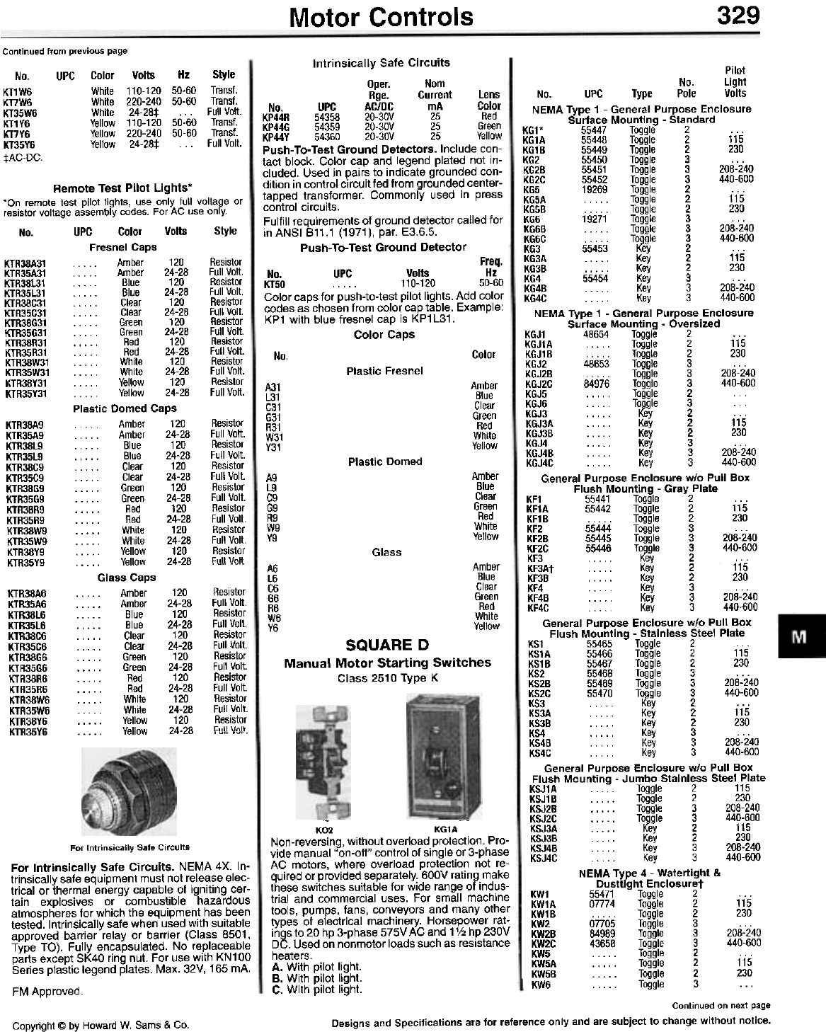
329
Motor Controls
Continued from previous page
Color Volts Hz Style
White 110-120 50-60 Trans!.
White 220-240 50-60 Trans!.
White 24-28:1: . . . Full Volt.
Yellow 110-120 50-60 Trans!.
Yellow 220-240 50-60 Trans!.
Yellow 24-28:1: . . . Full Volt.
No.
KT1W6
KT7W6
KT35W6
KT1Y6
KT7Y6
KT35Y6
tAC-DC.
UPG Intrinsically Safe Circuits
Oper. Nom
Rge. Current Lens
No. UPC AC/DC mA Color
KP44R 54358 20-30V 25 Red
KP44G 54359 20-30V 25 Green
KP44Y 54360 20-30V 25 Yellow
Push- To-Test Ground Detectors. Include con-
tact block. Color cap and legend plated not in-
cluded. Used in pairs to indicate grounded con-
dition in control circuit fed from grounded center-
tapped transformer. Commonly used in press
control circuits.
Fulfill requirements of ground detector called for
in ANSI 811.1 (1971), par. E3.6.5.
Push- To-Test Ground Detector
Freq.
No. UPC Volts Hz
KT50 110-120 50-60
Color caps for push-to-test pilot lights. Add color
codes as chosen from color cap table. Example:
KP1 with blue fresnel cap is KP1 L31.
Color Caps
Remote Test Pilot Lights.
'On remote test pilot lights, use only full voltage or
resistor voltage assembly codes. For AC use only.
No. UPC Color Volts Style
Fresnel Caps
KTR38A31 . . . . . Amber 120 Resistor
KTR35A31 . . . . . Amber 24-28 Full Volt.
KTR38L31 . . . . . Blue 120 Resistor
KTR35L31 . . . . . Blue 24-28 Full Volt.
KTR38C31 . . . .. Clear 120 Resistor
KTR35C31 . . . . . Clear 24-28 Full Volt.
KTR38G31 .. . . . Green 120 Resistor
KTR35G31 . . . . . Green 24-28 Full Volt.
KTR38R31 . . . . . Red 120 Resistor
KTR35R31 . . . . . Red 24-28 Full Volt.
KTR38W31 . . . . . White 120 Resistor
KTR35W31 . . . . . White 24-28 Full Volt.
KTR38Y31 . . . . . Yellow 120 Resistor
KTR35Y31 . . . . . Yellow 24-28 Full Volt.
Plastic Domed Caps
KTR38A9 . Amber 120
KTR35A9 . . . . . Amber 24-28
KTR38L9 . . . . . Blue 120
KTR35L9 Blue 24-28
KTR38C9 . .. . . Clear 120
KTR35C9 . . . . . Clear 24-28
KTR38G9 Green 120
KTR35G9 Green 24-28
KTR38R9 Red 120
KTR35R9 Red 24-28
KTR38W9 . . . .. White 120
KTR35W9 . . . . . White 24-28
KTR38Y9 Yellow 120
KTR35Y9 . . . . . Yellow 24-28 . W" Glass Caps
. . . . Amber 120
Amber 24-28
Blue 120
. . . . . Blue 24-28
Clear 120
. . . . . Clear 24-28
Green 120
. . . . . Green 24-28
. . . . . Red 120
. . . . . Red 24-28
White 120
. . . . . White 24-28
Yellow 120
. . . . . Yellow 24-28 , "" """
Color
No.
Plastic Fresnel
Amber
Blue
Clear
Green
Red
White
Yellow
A31
L31
C31
G31
R31
W31
Y31
Resistor
Full Volt.
Resistor
Full Volt.
Resistor
Full Volt.
Resistor
Full Volt.
Resistor
Full Volt.
Resistor
Full Volt.
Resistor
1=1111 Vnlt
Plastic Domed
Amber
Blue
Clear
Green
Red
White
Yellow
A9
L9
C9
G9
R9
W9
Y9
Pilot
No. Light
No. UPC Type Pole Volts
NEMA Type 1 - General Purpose Enclosure
Surface Mounting - Standard
KG1* 55447 Toggle 2 . . .
KG1A 55448 Toggle 2 115
KG1 B 55449 Toggle 2 230
KG2 55450 Toggle 3 . . .
KG2B 55451 Toggle 3 208-240
KG2C 55452 Toggle 3 440-600
KG5 19269 Toggle 2 . . .
KG5A . . . . . Toggle 2 115
KG5B . . . . . Toggle 2 230
KG6 19271 Toggle 3 . . .
KG6B . . . . . Toggle 3 208-240
KG6C . . . . . Toggle 3 440-600
KG3 55453 Key 2 ...
KG3A Key 2 115
KG3B . . . . . Key 2 230
KG4 55454 Key 3 ...
KG4B Key 3 208-240
KG4C .. Key 3 440-600
NEMA Type 1 - General Purpose Enclosure
Surface Mounting - Oversized
KGJ1 48654 Toggle 2 . . .
KGJ1A Toggle 2 115
KGJ1B Toggle 2 230
KGJ2 48653 Toggle 3 . . .
KGJ2B . . . . . Toggle 3 208-240
KGJ2C 84976 Toggle 3 440-600
KGJ5 . . . . . Toggle 2
KGJ6 Toggle 3 ...
KGJ3 Key 2 ...
KGJ3A . ... . Key 2 115
KGJ3B Key 2 230
KGJ4 Key 3 ...
KGJ4B . . . . . Key 3 208-240
KGJ4C... Key 3 440-600
General Purpose Enclosure w/o Pull Box
Flush Mounting - Gray Plate
KF1 55441 Toggle 2 . . .
KF1A 55442 Toggle 2 115
KF1 B . . . . . Toggle 2 230
KF2 55444 Toggle 3 . . .
KF2B 55445 Toggle 3 208-240
KF2C 55446 Toggle 3 440-600
KF3 Key 2
KF3At Key 2 115
KF3B Key 2 230
KF4 ..'" Key 3 ...
KF4B . . . . . Key 3 208-240
KF4C . Key 3 440-600
General Purpose Enclosure w/o Pull Box
Flush Mounting - Stainless Steel Plate
KS1 55465 Toggle 2 . . .
KS1A 55466 Toggle 2 115
KS1B 55467 Toggle 2 230
KS2 55468 Toggle 3 . . .
KS2B 55469 Toggle 3 208-240
KS2C 55470 Toggle 3 440-600
KS3 Key 2 ...
KS3A . . . .. Key 2 115
KS3B . . . . . Key 2 230
KS4 Key 3 ...
KS4B Key 3 208-240
KS4C... Key 3 440-600
General Purpose Enclosure w/o Pull Box
Flush Mounting - Jumbo Stainless Steel Plate
KSJ1A Toggle 2 115
KSJ1B Toggle 2 230
KSJ2B . . . . . Toggle 3 208-240
KSJ2C . . . . . Toggle 3 440-600
KSJ3A Key 2 115
KSJ3B . . . . . Key 2 230
KSJ4B . . . . . Key 3 208-240
KSJ4C . . . . . Key 3 440-600
NEMA Type 4 - Watertight &
Dusttight Enclosuret
KW1 55471 Toggle 2 . . .
KW1A 07774 Toggle 2 115
KW1B . . . . . Toggle 2 230
KW2 07705 Toggle 3 . . .
KW2B 84989 Toggle 3 208-240
KW2C 43658 Toggle 3 440-600
IKW5 Toggle 2 ...
KW5A .. . . . Toggle 2 115
KW5B . . . . . Toggle 2 230
KW6 Toggle 3 ...
Glass
Amber
Blue
Clear
Green
Red
White
Yellow
A6
L6
C6
G6
R6
W6
V6
Resistor
Full Volt.
Resistor
Full Volt.
Resistor
Full Volt.
Resistor
Full Volt.
Resistor
Full Volt.
Resistor
Full Volt.
Resistor
~ml \lnl!.
KTR38A6
KTR35A6
KTR38l6
KTR35l6
KTR38C6
KTR35C6
KTR38G6
KTR35G6
KTR38R6
KTR35R6
KTR38W6
KTR35W6
KTR38Y6
KTR35Y6
SQUARE D
Manual Motor Starting Switches
Class 2510 Type K
K02 KG1A
Non-reversing, without overload protection. Pro-
vide manual "on-off" control of single or 3-phase
AC motors, where overload protection not re-
quired or provided separately. 600V rating make
these switches suitable for wide range of indus-
trial and commercial uses. For small machine
tools, pumps, fans, conveyors and many other
types of electrical machinery. Horsepower rat-
ings to 20 hp 3-phase 575V AC and 11/2 hp 230V
DC. Used on nonmotor loads such as resistance
heaters.
A. With pilot light.
B. With pilot light.
C. With pilot light.
For Intrinsically Safe Circuits
For Intrinsically Safe Circuits. NEMA 4X. In-
trinsically safe equipment must not release elec-
trical or thermal energy capable of igniting cer-
tain explosives or combustible hazardous
atmospheres for which the equipment has been
tested. Intrinsically safe when used with suitable
approved barrier relay or barrier (Class 8501,
Type TO). Fully encapsulated. No replaceable
parts except SK40 ring nut. For use with KN100
Series plastic legend plates. Max. 32V, 165 mA.
FM Approved.
Continued on next page
Designs and Specifications are for reference only and are subject to change without notice.
Copyright @ by Howard W. Sams & Co.
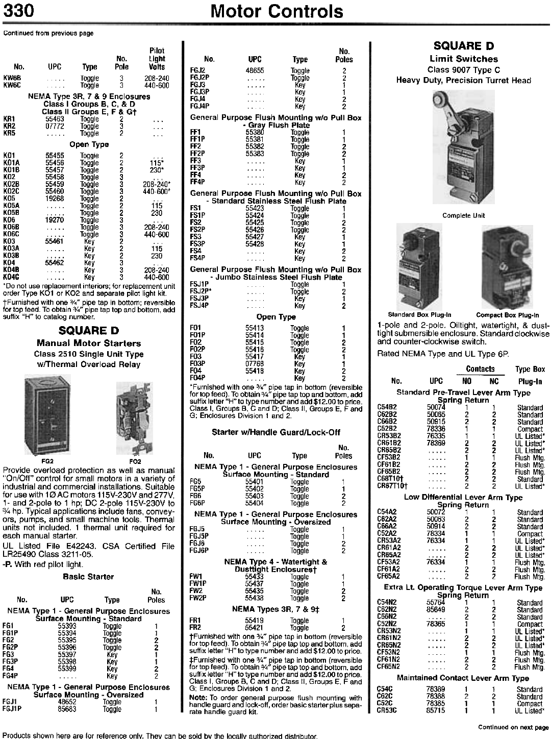
330 Motor Controls
Continued from previous page
SQUARE D
Limit Switches
Class 9007 Type C
Heavy Duty, Precision Turret Head
Pilot
No. light
No. UPC Type Pole Volts
KW6B... Toggle 3 208-240
KW6G . Toggle 3 440-600
NEMA Type 3R, 7 & 9 Enclosures
Class I Groups B, C, & D
Class II Groups E, F & Gt
KR1 55463 Toggle 2 . . .
KR2 07772 Toggle 3 . . .
KR5 Toggle 2 ...
Open Type
K01 55455 Toggle 2 . . .
K01A 55456 Toggle 2 115'
K01B 55457 Toggle 2 230'
K02 55458 Toggle 3 . . .
K02B 55459 Toggle 3 208-240'
K02G 55460 Toggle 3 440-600'
K05 19268 Toggle 2 . . .
K05A Toggle 2 115
K05B . . . . . Toggle 2 230
K06 19270 Toggle 3 . . .
K06B . . . . . Toggle 3 208-240
K06G . . . . . Toggle 3 440-600
K03 55461 Key 2 ...
K03A Key 2 115
K03B . . . . . Key 2 230
K04 55462 Key 3
K04B Key 3 208-240
K04C Key 3 440-600
'Do not use replacement interiors; for replacement unit
order Type KO1 or KO2 and separate pilot light kit.
tFurnished with one 3/4" pipe tap in bottom; reversible
for top feed. To obtain 3/4" pipe tap top and bottom, add
suffix "H" to catalog number.
SQUARE D
Manual Motor Starters
Class 2510 Single Unit Type
wfThermal Overload Relay
Complete Unit
--
Standard Box Plug-In Compact Box Plug-In
1-pole and 2-pole. Oiltight, watertight, & dust-
tight submersible enclosure. Standard clockwise
and counter-clockwise switch.
Rated NEMA Type and UL Type 6P.
Contacts Type Box
No. UPC NO NC Plug-In
Standard Pre-Travel Lever Arm Type
Spring Return
C54B2 50074 1 1 Standard
C62B2 50065 2 2 Standard
C66B2 50915 2 2 Standard
C52B2 78336 1 1 Compact
CR53B2 76335 1 1 UL Listed'
CR61B2 78369 2 2 UL Listed'
CR65B2 . . . . . 2 2 UL Listed'
CF53B2 . . . . . 1 1 Flush Mtg.
CF61 B2 . . . . . 2 2 Flush Mtg.
CF65B2 . . . . . 2 2 Flush Mtg.
C68T1Ot . . . 2 2 Standard
CR67T1Ot . . . . 2 2 UL Listed'
Low Differential Lever Arm Type
Spring Return
C54A2 50072 1 1 Standard
C62A2 50063 2 2 Standard
C66A2 50914 2 2 Standard
C52A2 78334 1 1 Compact
CR53A2 76334 1 1 UL Listed'
CR61A2 . . . . . 2 2 UL Listed'
CR65A2 . . . . . 2 2 UL Listed'
CF53A2 76334 1 1 Flush Mtg.
CF61A2 2 2 Flush Mtg.
CF65A2 . . . . . 2 2 Flush Mtg.
Extra Lt. Operating Torque Lever Arm Type
Spring Return
C54N2 55764 1 1 Standard
C62N2 85649 2 2 Standard
C66N2 . . . . . 2 2 Standard
C52N2 78365 1 1 Compact
CR53N2 . . . . . 1 1 UL Listed'
CR61 N2 . . . . . 2 2 UL Listed'
CR65N2 . . . . . 2 2 UL Listed'
CF53N2 . . . . . 1 1 Flush Mtg.
CF61N2 2 2 Flush Mtg.
CF65N2 . . . . . 2 2 Flush Mtg.
Maintained Contact Lever Arm Type
C54C 78389 1 1 Standard
C62C 78388 2 2 Standard
C52C 78385 1 1 Compact
CR53C 85715 1 1 UL Listed'
Continued on next page
--
FG2 F02
Provide overload protection as well as manual
"On/Off" control for small motors in a variety of
industrial and commercial installations. Suitable
for use with 10 AC motors 115V-230V and 277V,
1- and 2-pole to 1 hp; DC 2-pole 115V-230V to
3/4 hp. Typical applications include fans, convey-
ors, pumps, and small machine tools. Thermal
units not included. 1 thermal unit required for
each manual starter.
UL Listed File E42243. CSA Certified File
LR25490 Class 3211-05.
-Po With red pilot light.
Basic Starter
No.
No. UPC Type Poles
FGJ2 48655 Toggle 2
FGJ2P . . . . . Toggle 2
FGJ3 . . . . . Key 1
FGJ3P . . . Key 1
FGJ4 ... Key 2
FGJ4P ... Key 2
General Purpose Flush Mounting w/o Pull Box
- Gray Flush Plate
FF1 55380 Toggle 1
FF1 P 55381 Toggle 1
FF2 55382 Toggle 2
FF2P 55383 Toggle 2
FF3 Key 1
FF3P . . . . . Key 1
FF4 Key 2
FF4P Key 2
General Purpose Flush Mounting w/o Pull Box
- Standard Stainless Steel Flush Plate
FS1 55423 Toggle 1
FS1P 55424 Toggle 1
FS2 55425 Toggle 2
FS2P 55426 Toggle 2
FS3 55427 Key 1
FS3P 55428 Key 1
FS4 Key 2
FS4P Key 2
General Purpose Flush Mounting w/o Pull Box
- Jumbo Stainless Steel Flush Plate
FSJ1P . Toggle 1
FSJ2P* . . Toggle 2
FSJ3P .. Key 1
FSJ4P . . . . . Key 2
Open Type
F01 55413 Toggle 1
F01P 55414 Toggle 1
F02 55415 Toggle 2
F02P 55416 Toggle 2
F03 55417 Key 1
F03P 07768 Key 1
F04 55418 Key 2
FO4P . . . . . Key 2
'Furnished with one %" pipe tap in bottom (reversible
for top feed). To obtain 3/." pipe tap top and bottom, add
suffix letter "H" to type number and add $12.00 to price.
Class I, Groups B, C and D; Class II, Groups E, F and
G; Enclosures Division 1 and 2.
Starter w/Handle Guard/Lock-Off
No.
No. UPC Type Poles
NEMA Type 1 - General Purpose Enclosures
Surface Mounting - Standard
FG5 55401 Toggle 1
FG5P 55402 Toggle 1
FG6 55403 Toggle 2
FG6P 55404 Toggle 2
NEMA Type 1 - General Purpose Enclosures
Surface Mounting - Oversized
FGJ5 . . Toggle 1
FGJ5P . . . Toggle 1
FGJ6 . . . . . Toggle 2
FGJ6P . . . . . Toggle 2
NEMA Type 4 - Watertight &
Dusttight Enclosurest
FW1 55433 Toggle 1
FW1P 55437 Toggle 1
FW2 55435 Toggle 2
FW2P 55438 Toggle 2
NEMA Types 3R, 7 & 9*
FR1 55419 Toggle 1
FR2 55421 Toggle 2
tFurnished with one 3/." pipe tap in bottom (reversible
for top feed). To obtain 3/." pipe tap top and bottom, add
suffix letter "H" to type number and add $12.00 to price.
:j:Furnished with one 3/." pipe tap in bottom (reversible
for top feed). To obtain 3/." pipe tap top and bottom, add
suffix letter "H" to type number and add $12.00 to price.
Class I, Groups B, C and D; Class II, Groups E, F and
G; Enclosures Division 1 and 2.
Note: To order general purpose flush mounting with
handle guard and lock-off, order basic starter plus sepa-
rate handle guard kit.
No.
No. UPC Type Poles
NEMA Type 1 - General Purpose Enclosures
Surface Mounting - Standard
FG1 55393 Toggle 1
FG1 P 55394 Toggle 1
FG2 55395 Toggle 2
FG2P 55396 Toggle 2
FG3 55397 Key 1
FG3P 55398 Key 1
FG4 55399 Key 2
FG4P . . . . . Key 2
NEMA Type 1 - General Purpose Enclosures
Surface Mounting - Oversized
FGJ1 48652 Toggle 1
FGJ1 P 85683 Toggle 1
Products shown here are for reference only. They can be sold by the locallY authorized distributor.
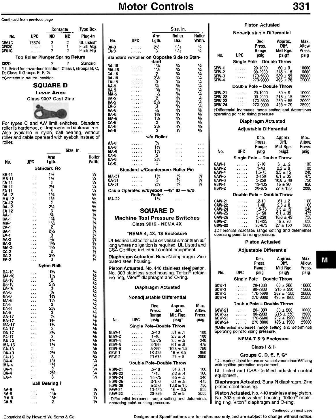
Motor Controls 331
Continued from previous page
Size, In.
Contacts Type Box
No. UPC NO NC Plug-In
CR61C 78374 2 2 UL Listed'
CF53C . . . . . 1 1 Flush Mtg.
CF61 C . . . . . 2 2 Flush Mtg.
Top Roller Plunger Spring Return
C62D . . . . . 2 2 Standard
'UL listed for hazardous location, Class I, Groups B, C,
D; Class II Groups E, F, G.
tContacts in neutral position.
SQUARE D
Lever Arms
Class 9007 Cast Zinc
For types C and AW limit switches. Standard
roller is hardened, oil-impregnated sintered iron.
Also available in nylon, ball bearing, without
roller and cable operated with eyebolt instead of
roller.
Size, In.
Arm
Lgth.
Standard Ro
13/8
1V2
.. 2
.. 2V2
.. 3
1%
11h
2
,. 2V2
3
. . 71e
.. 1%
1V2
.. 2
21h
3
71e
. . 13/8
.. 1V2
2
2V2
3
Nylon Rolli
13/8
1V2
... 2
... 21h
... 3
... 7/S
... 1%
... 1V2
... 2
... 2V2
... 3
. . . 71e
... 1%
... 1V2
... 2
... 21h
... 3
... 1%
... 11h
... 2
... 21h
... 3
. . . 13/s
... 1V2
... 2
... 2V2
3
Ball Bearing F
7/8
13/8
... 1V2
... 2
Roller
Wdth.
No. UPC
V4
V4
V4
V4
V4
0/8
0/8
0/8
%
%
V4
V4
V4
V4
V4
V4
%
0/8
%
0/8
0/8
0/8
BA-11
MA-11
CA-11
DA-11
EA-11
BA-12
MA-12
CA-12
DA-12
EA-12
AA-1
BA-1
MA-1
CA-1
DA-1
EA-1
AA-2
BA-2
MA-2
CA-2
DA-2
EA-2
Arm Roller Roller
No. UPC Lgth. Dia. Wdth.
DA-9 . . . 2V, '1;\6 V4
EA-9 . 3 '1;\6 V4
Standard w/Rolier on Opposite Side to Stan-
dard
BA-15 . . . . . 1% 3/4 V4
MA-15 1V, 3/. 1/.
CA-15 2 3/. 1/.
DA-15 21h 3/. 1/.
EA-15 . . . . . 3 3/. V.
AA-5 . . . . . 7/8 % V.
BA-5 . . . . . 13/8 0/8 V.
MA-5 . . . . . 11h % 1/.
CA-5 2 % V.
DA-5 . . . . . 21h 0/8 V.
EA-5 . . . . . 3 0/8 V.
AA-6 . . . . . 71s 0/8 %
BA-6 . . . . . 13/8 % 0/8
MA-6 . . . . . 11h % 5/8
CA-6 . . . . . 2 0/8 0/8
DA-6 . . . . . 2V2 % 0/8
EA-6 . . . . . 3 % 0/8
w/o Roller
AA-O 7/8 ... ...
BA-O 13/8 ... ...
MA-O 1V2 ... ...
CA-O . . . . . 2 . . . . . .
DA-O 2V2 ...
EA-O . . . . 3 . . . . . .
Standard w/Countersunk Roller Pin
MA-31 . . 1V, 3/4 V.
CA-31 . 2 3/4 V.
DA-31 . 2V, 3/4 V.
Cable Operated w/Eyebolt -3/8" ID - w/o
Roller
MA-22 1V, ... ...
BA-18
MA-18
CA-18
DA-18
EA-18
AA-8
BA-8
MA-8
CA-8
DA-8
EA-8
AA-17
BA-17
MA-17
CA-17
DA-17
EA-17
BA-13
MA-13
CA-13
DA-13
EA-13
BA-4
MA-4
CA-4
DA-4
EA-4
V4
V4
V4
V4
V4
V4
V4
V4
V4
V4
V4
%
%
0/8
0/8
0/8
0/8
5/8
0/8
%
0/8
0/8
V4
V4
V4
V4
V4
Piston Actuated
Nonadjustable Differential
Dec. Approx. Max.
Press. Diff. Allow.
Range Mid Rge. Press.
No. UPC psig psigt psig
Single Pole - Double Throw
GFW-1 . . 20-1000 60 :!: 9 10000
GFW-2 90-2900 215:!: 15 15000
GFW-3 170-5600 289:!: 55 20000
GFW-4 270-9000 495:!: 70 25000
Double Pole - Double Throw
GFW-21 20-1000 60:!: 9 10000
GFW-22 90-2900 215:!:15 15000
GFW-23 170-5600 289:!: 55 20000
GFW-24 , 270-9000 495:!: 70 25000
tDifferential increases range setting and determines
operating point to rising pressure.
Diaphragm Actuated
Adjustable Differential
Dec. Approx. Max.
Press. Diff. Allow.
Range Mid Rge. Press.
No. UPC psig psig:l: psig
Single Pole - Double Throw
GAW-1 .2-10 .61:!:.2 100
GAW-2 1-40 2.3:!:8 100
GAW-4 1.5-75 3.5:!:15 240
GAW-5 3-150 6.1:!:35 475
GAW-6 . . . . . 5-250 10.8 :!: 49 750
GBW-1 13-425 16:!: 90 850
GBW-2 20-675 27:!: 130 2000
Double Pole - Double Throw
GAW-21 .2-10 .61:!:2 100
GAW-22 1-40 2.3:!:8 100
SQUARE D GAW-24 1.5-75 3.5:!: 15 240
GAW-25 . . . . . 3-150 6.1 :!: 35 475
Machine Tool Pressure Switches GAW-26 . .. . 5-250 10.8 :!: 49 750
X GBW-21 13-425 16:!: 90 850
Class 9012 - NEMA 4 GBW-22 . 20-675 27 :!: 130 2000
:j:Differential increases range setting and determines
*NEMA 4, 4X, 13 Enclosure operating point to rising pressure.
UL Marine List~d f.o! us.e on v~ssels mor than 65' Piston Actuated
long where no Ignition is required. UL listed and
CSA Certified industrial control equipment. Adjustable Differential
Diaphragm Actu~ted. Buna-N diaphragm. Zinc Dec. Approx. Max.
plated steel housing. Press. Ditt. Allow.
Piston Actuated. No. 440 stainless steel piston. Range Mid Rge. Press.
No. 303 stainless steel housing. Teflon@ retain- No. UPC psig psig§ psig
ing ring, Viton@ diaphragm and O-ring. Single Pole - Double Throw
Diaphragm Actuated GCW-1. . . .. 20-1000 60 :!: 200 10000
GCW-2 ... 90-2900 215:!: 550 15000
GCW-3 170-5600 289:!: 1200 20000
Nonadjustable Differential GCW-4 . . . . 270-9000 495:!: 1900 25000
Dec. Approx. Max. Double Pole - Double Throw
Press. Ditt. Allow. GCW-21 . . . 20-1000 60:!: 200 10000
Range Mid Rge. Press. GCW-22 90-2900 215:!: 550 15000
No UPC psig psig* psig GCW-23 170-5600 289:!: 1200 20000
. GCW-24 270-9000 495:!: 1900 25000
Single Pole-Double Throw §Differential increases range setting and determines
GDW-1 .2-10 .61:!:.1 100 operating point to rising pressure.
GDW-2 1-40 2.3~.4 100 NEMA7& 9 Enclosure
GDW-4 1.5-75 3.5_.5 240
GDW-5 3-150 6.1~.8 475 Classl&1I
GDW-6 5-250 10.8_1.5 750
GEW-1 . . . . . 13-425 16:!: 3.5 850 G C D E F G*
GEW-2 . . . . . 20-675 27 :!: 5 2000 roups , , , ,
D bl P I Do ble Throw *UL Mar.ine Listed fo! use on vessels more than 65' long
ou e 0 e- u with Ignition protection requirement.
GDW-21 . . . . . .2-10 .61 :!: .1 100 UL Listed and CSA Certified industrial control
GDW-22 1-40 2.3:!:.4 100 equipment.
GDW-24 1.5-75 3.5:!:.5 240
GDW-25 3-150 6.1 :!: .8 475 Diaphragm Actuated. Buna-N diaphragm. Zinc
GDW-26 5-250 10.8:!: 1.5 750 plated steel housing.
GEW-21 . . . . . 13-425 16 :!: 3.5 850
GEW-22 . . . . . 20-675 27 :!: 5 2000 Piston Actuated. No. 440 stainless steel piston.
*Differential increases range setting and determines ~o. ~03 st.ainless. steel housing. Te.flon@ retain-
operating point to rising pressure. - Ing ring, Vlton@ diaphragm and O-ring.
Continued on next page
Designs and Specifications are for reference only and are subject to change without notice.
v.
v.
v.
v.
AA-9
BA-9
MA-9
CA-9
Copyright @ by Howard W. Sams & Co.
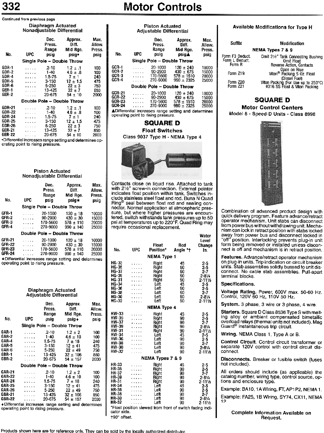
332 Motor Controls
Available Modifications for Type H
Continued from previous page
Diaphragm Actuated
Nonadjustable Differential
Dec. Approx. Max.
Press. Diff. Allow.
Range Mid Rge. Press.
No. UPC psig psigo psig
Single Pole - Double Throw
GDR-1 .2-10 1.2:!:.1 100
GDR-2 . . . . . 1-40 4.6:!: .8 100
GDR-4 1.5-75 7:!:1 240
GDR-5 3-150 12:!:1.5 475
GDR-6 5-250 22:!: 3 750
GER-1 . . . . . 13-425 32 :!: 7 850
GER-2.. 20-675 54:!: 10 2000
Double Pole - Double Throw
GDR-21 .2-10 1.2:!:.1 100
GDR-22 1-40 4.6:!:.8 100
GDR-24 1.5-75 7:!:1 240
GDR-25 3-150 12:!:1.5 475
GDR-26 5-250 22:!: 3 750
GER-21 . . . . . 13-425 32 :!: 7 850
GER-22 20-675 54:!: 10 2000
.Differential increases range setting and determines op-
erating point to rising pressure.
Suffix
Form F3 Deduct.
Form L Deduct.
Form R
Form Z19
Form Z20
Form Z21
Modification
NEMA Types 7 & 9
Omit 2V2" Tank Connecting Bushing
Omit Float
Reverse Action, Contacts
Open on Rise
Viton'"' Packing 5 Oz. Float
(Diesel Fuel)
Viton Packing (For Use up to 250°C)
#316 55 Float & Viton Packing
SQUARE D
Motor Control Centers
Model 5 - Speed-D Units - Class 8998
Piston Actuated
Adjustable Differential
Dec. Approx. Max.
Press. Ditt. Allow.
Range Mid Rge. Press.
No. UPC psig psigj. psig
Single Pole - Double Throw
GCR-1... 20-1000 120:t 240 10000
GCR-2 90-2900 430:t 675 15000
GCR-3 . . . 170-5600 578:t 1510 20000
GCR-4 270-9000 990:t 2325 25000
Double Pole - Double Throw
GCR-21 20-1000 120:t240 10000
GCR-22 90-2900 430:t 675 15000
GCR-23 170-5600 578:t 1510 20000
GCR-24 270-9000 990:t 2325 25000
j.Oifferential increases range setting and determines
operating point to rising pressure.
SQUARE D
Float Switches
Class 9037 Type H - NEMA Type 4
-
Contacts close on liquid rise. Attached to tank
with 2'/2" screw-in connection. External pointer
indicates float position within tank. Switches in-
clude stainless steel float and rod. Buna N Quad
Ring@ seal between float rod and sealing con-
nector. Normal application at atmospheric pres-
sure, but where higher pressures are encoun-
tered, switch withstands tank pressures up to 50
psi at temperatures up to 220°F. Quad Ring may
require occasional replacement.
Piston Actuated
Nonadjustable Differential
Dec. Approx. Max.
Press. Ditt. Allow.
Range Mid Rge. Press.
No. UPC psig psig* psig
Single Pole - Double Throw
GFR-1 20-1000 120:t18 10000
GFR-2 90-2900 430:t 30 15000
GFR-3 170-5600 578:t 110 20000
GFR-4 270-9000 990:t 140 25000
Double Pole - Double Throw
GFR-21 ... 20-1000 120:t 18 10000
GFR-22 90-2900 430:t 30 15000
GFR-23 170-5600 578:t 110 20000
GFR-24 270-9000 990:t 140 25000
*Differential increases range setting and determines
operating point to rising pressure.
Water
Level
Float Rod Change
No. UPC Position* Angle °t In.
NEMA Type 1
: Right 45 2-5
, . . . . . Right 90 2-5
, . . . . . Right 90 2-7
. . . . . Right 90 2-8V4
. . . . . Right 90 2-11V2
. . . . . Left 45 2-5
. . . . . Left 90 2-5
Left 90 2-7
. . . . . Left 90 2-8V4
: Left 90 2-11'h
NEMA Type 4
Right 45 2-5
. . . . . Right 90 2-5
." Right 90 2-7
. . . . . Right 90 2-8V4
. . . .. Right 90 2-11V2
. . . . . Left 45 2-5
. . . . . Left 90 2-5
. . . . . Left 90 2-7
. . . . . Left 90 2-8V4
Left 90 2-11V2
NEMA Types 7 & 9
HR-33 . . . . . Right 45 2-5
HR-35 . . . . . Right 90 2-5
HR-37 . . . . . Right 90 2-7
HR-39 . . . . . Right 90 2-8V4
HR-31 Right 90 2-11V2
HR-34 Left 45 2-5
HR-36 . . . . . Left 90 2-5
HR-38 Left 90 2-7
HR-30 . . . . . Left 90 2-8V4
HR-32 . . . .. Left 90 2-11V2
'Float position viewed from front of switch facing indi-
cator side.
t90° offset.
HG-33
HG-35
HG-37
HG-39
HG-31
HG-34
HG-36
HG-38
HG-30
1Ir;-~7
HW-33
HW-35
HW-37
HW-39
HW-31
HW-34
HW-36
HW-38
HW-30
IIW-~7
Diaphragm Actuated
Adjustable Differential
Dec. Approx. Max.
Press. Ditt. Allow.
Range Mid Rge. Press.
No. UPC psig psig+ psig
Single Pole - Double Throw
GAR-1 . . ... .2-10 1.2 :!: 2 100
GAR-2 1-40 4.6:!: 10 100
GAR-4 1.5-75 7:!:18 240
GAR-5 3-150 12:!:41 475
GAR-6 5-250 22:!: 49 750
GBR-1 13-425 32:!:106 850
GBR-2 20-675 54:!: 157 2000
Double Pole - Double Throw
GAR-21 . .. . .2-10 1.2 :!: 2 100
GAR-22 . . 1-40 4.6:!: 10 100
GAR-24 1.5-75 7:!:18 240
GAR-25 3-150 12:!:41 475
GAR-26 5-250 22:!: 49 750
GBR-21 13-425 32:!:106 850
GBR-22 20-675 54:!: 157 2000
. Differential increases range setting and determines
operating point to rising pressure.
Combination of advanced product design with
quick delivery program. Feature advance/retract
operator mechanism. Unit stabs can disconnect
from power bus without withdrawing unit. Mecha-
nism can lock in retract position with stabs locked
away from power bus and disconnect locked in
"off" position. Interlocking prevents plug-in unit
form being removed or installed unless discon-
nect is off and mechanism is in retract position.
Features. Advance/retract operator mechanism
on plug-in units. Trip indication on circuit breaker
units. Stab assemblies solidly bussed to unit dis-
connect. No cable stab assemblies. Pull-apart
terminal blocks.
Specifications.
Voltage Rating. Power, 600V max. 50-60 Hz.
Control, 120V 60 Hz, 110V 50 Hz.
System. 3 phase, 3 wire or 3 phase, 4 wire.
Starters. Square 0 Class 8536 Type S with melt-
ing alloy or ambient compensated bimetallic
overload relays (thermal units not included). Mag
Guarcf!' instantaneous trip circuit.
Wiring. NEMA Class 1, Type A or B.
Control Circuit. Control circuit transformer or
separate 120V control with control circuit dis-
connect.
Disconnects. Breaker or fusible switch (fuses
not included).
All orders should include (as applicable) the
catalog number, wiring type, control source, op-
tions and enclosure type.
Example: BA 10, 1 A Wiring, FT, AP1 P2, NEMA 1.
Example: FA25, 1B Wiring, SY74 , CX11, NEMA
1?
Complete Information Available on
Request.
Products shown here are for reference only. They can be sold by the locallY authorized distributor
