PG29B01ATU_01_12 79944 Catalog
70733-Catalog 70733-Catalog 70733-Catalog Batch10 unilog cesco-content
109721-Attachment 109721-Attachment 109721-Attachment 782113 Batch5 unilog cesco-content
686803-Catalog 686803-Catalog 686803-Catalog 782116 Batch5 unilog cesco-content
109726-Catalog 109726-Catalog 109726-Catalog 786685 Batch5 unilog cesco-content
109721-Attachment 109721-Attachment 109721-Attachment 786685 Batch5 unilog cesco-content
2014-10-17
: Pdf 79944-Catalog 79944-Catalog 786685 Batch10 unilog
Open the PDF directly: View PDF ![]() .
.
Page Count: 45
- Standards
- General Information
- Electrical Characteristics/Technical Data
- Electronic Trip Units
- Catalogue Numbers/Termination Accessories
- Motor Circuit Protectors
- Frame Sizes G through R
- Handle Mechanisms
- Accessories and Modifications
- Time-Current Curves
- Current Limiting Curves
- Dimensions
- Sales Offices
- Typical Specifications

February 2001
PG.29B.01A.T.U
Cutler-Hammer
Moulded Case Circuit Breakers
16-2500 Amperes for IEC 60947-2 Applications 1
Contents
Page
Standards . . . . . . . . . . . . . . . . . . . . 1
General Information. . . . . . . . . . 2-3
Electrical Characteristics/
Technical Data . . . . . . . . . . . . . . 4-9
Electronic Trip Units. . . . . . . . 10-12
Catalogue Numbers/
Termination Accessories
G-Frame,
16-100 Amperes . . . . . . . . . . 13
E-Frame,
16-225 Amperes . . . . . . . .14-15
J-Frame,
100-250 Amperes . . . . . . . 16-17
K-Frame,
63-400 Amperes . . . . . . . .18-19
L-Frame,
315-800 Amperes . . . . . . . 20-21
N-Frame,
400-1250 Amperes . . . . . . 22-25
R-Frame,
800-2500 Amperes . . . . . . 26-29
Motor Circuit Protectors. . . . . . . . 30
Frame Sizes G through R. . . . 31-32
Handle Mechanisms. . . . . . . . 33-35
Accessories and
Modifications . . . . . . . . . . . . . 36-38
Time-Current Curves . . . . . . . . 39-40
Current Limiting Curves. . . . . . . . 41
Dimensions . . . . . . . . . . . . . . . 42-43
Sales Offices . . . . . . . . . . . . . . . . . 44
Typical
Specifications . . . Inside Back Cover
Standards
Cutler-Hammer Moulded Case Circuit
Breakers are designed to conform
with the following international
standards:
■
Australian Standard AS 2184 and
AS 3947-2 Moulded Case Circuit
Breakers.
■
British Standards Institution
Standard BS 4752:
Part 1, Switchgear and
Control Gear
Part 1, Circuit Breakers.
■
International Electrotechnical
Commission Recommendations
IEC 60947.2 Circuit Breakers.
■
Japanese T-Mark Standard
Moulded Case Circuit Breakers.
■
National Electrical Manufacturers
Association Standards Publication
No. AB1-1975 Moulded Case
Circuit Breakers.
■
South African Bureau of Standards,
Standard SABS 156, Standard
Specification for Moulded Case
Circuit Breakers.
■
Swiss Electro-Technical Associa-
tion Standard SEV 947.2, Safety
Regulations for Circuit Breakers.
■
Union Technique de l’Electricite
Standard NF C 63-120, Low Voltage
Switchgear and Control Gear
Circuit Breaker Requirements.
■
Verband Deutscher Elektrotechnike
(Association of German Electrical
Engineers) Standard VDE 0660,
Low Voltage Switchgear and
Control Gear, Circuit Breakers.
Cutler-Hammer Frame Sizes G through R
Global Third Party
Certification
Certification marks assure product
compliance with the total standard
via the third party witnessing of
tests by globally recognized inde-
pendent certification organizations.
KEMA is a highly recognized, com-
pletely independent international
organization that offers certification
and inspection facilities for equip-
ment in many industries. The KEMA-
KEUR mark is the highest certifica-
tion an electrical product can receive
from KEMA. Our IEC 60947-2
Moulded Case Circuit Breakers are
KEMA tested and certified.
What does the KEMA-KEUR rating
mean for you? It means an inde-
pendent testing house. KEMA Regis-
tered Quality has tested and certified
these products to IEC 60947-2 stand-
ards. In addition, KEMA is conduct-
ing ongoing follow-up witness test
programs to assure IEC 60947-2
compliance to maintain the KEMA
Certification mark, KEMA-KEUR
has been a well-known and highly
respected independent mark for
over 70 years, a symbol of quality
assurance that enjoys the confi-
dence of both manufacturers and
consumers.
Cutler-Hammer also offers a com-
plete line of Moulded Case Circuit
Breakers, UL listed in accordance
with UL 489 as well as CSA C22.2
No. 5.1 certified are also available.
Both UL and CSA are independent
third party testing houses that con-
tinue to assure that Cutler-Hammer
Moulded Case Circuit Breakers meet
their exacting standards through
regularly scheduled follow-up
testing and inspections.
Loading...
Contents
Back To Reference

PG.29B.01A.T.U
Cutler-Hammer
2
February 2001
Moulded Case Circuit Breakers
16-2500 Amperes for IEC 60947-2 Applications
The Most Logically Designed
Contact Assembly
The flexibility and outstanding per-
formance characteristics of Cutler-
Hammer Circuit Breakers are made
possible by one of the most logically
designed contact assemblies in
circuit breaker history. Based on
previously patented Westinghouse
contact conductor designs, the Cutler-
Hammer contact assembly creates a
high-speed “blow-open” action when
it confronts the electromechanical
forces produced by high-level fault
currents.
Cutler-Hammer Circuit Breakers are
operated by a toggle-type handle
that is mechanically trip-free from the
handle so that the contacts cannot
be held closed against short circuit
currents. Tripping due to overload or
short circuits is clearly indicated by
the position on the handle. This
remarkably fast and dependable
contact action is designed to
enhance safety.
Thorough In-Plant Testing
The quality, dependability, and relia-
bility of every Cutler-Hammer Circuit
Breaker is assured by a thorough pro-
gram of in-plant testing. Two calibra-
tion tests are conducted on every
pole of every circuit breaker to verify
the trip mechanism, operating mech-
anism, continuity, and accuracy.
ISO Certification
Cutler-Hammer Circuit Breakers are
manufactured in ISO certified facilities.
More Interrupting Capacity
in Less Space
Cutler-Hammer Circuit Breakers are
physically and electrically inter-
changeable with the “Classic” stand-
ard line of Westinghouse moulded
case circuit breakers. This means
Cutler-Hammer Breakers are ideal
for upgrading equipment designs
and retrofitting existing installations.
Current Limiting Characteristics
All Cutler-Hammer Circuit Breakers
are current limiting because of their
high repulsion contact arrangement
and incorporation of state-of-the-art
arc extinguishing technology.
Operating Mechanisms
Cutler-Hammer Circuit Breakers
have, in their basic version, a toggle
handle operating mechanism, which
also serves as switching position
indicator. As well as ON and OFF, the
further position TRIPPED is possible.
The toggle handle snaps into the
TRIPPED position if the breaker is
tripped by one of its overcurrent,
short circuit, shunt or undervoltage
releases. Before the circuit breaker
can be reclosed following a trip-out,
the toggle handle must be brought
beyond the OFF position (RESET).
The circuit breaker can then be
reclosed.
As an additional switching position
indicator for F- to R-Frame circuit
breakers, there are two windows on
the right and on the left of the toggle
handle, in which the switching state
is indicated by means of the colours
red, green and white corresponding
to the ON, OFF and TRIPPED posi-
tions respectively.
General Information
Cutler-Hammer Moulded Case
Circuit Breakers provide increased
performance in considerably less
space than standard circuit breakers
or comparable fusible devices.
Reduced system costs can also be
realized because Cutler-Hammer
Circuit Breakers are used in series
rated systems, allowing the use of
lower interrupting circuit breakers
downstream.
Cutler-Hammer Circuit Breakers
meet applicable IEC 60947-2 stand-
ards, have been assigned ultimate
and service interrupting ratings per
IEC 60947-2, and employ adjustable
thermal and adjustable magnetic
trips.
The Cutler-Hammer family includes
seven frame sizes in ratings from
100 to 2500 amperes. Each frame
size offers a choice of several inter-
rupting capacities up to 100 kA at
415 volts ac (200 kA at 240 volts ac).
This provides greater design flexibil-
ity than ever before possible while
also helping to save space.
Cutler-Hammer Circuit Breakers vir-
tually eliminate the need for rede-
sign and they can be used to replace
older circuit breakers in the same
panelboards, feeder pillars, busbar
trunking tap-offs, individual enclo-
sures, machine tool control panels,
and motor control centres. In most
cases, the same connecting straps,
studs, and handle mechanisms can
be retained and used.
Standard calibration is 40°C. For
applications in high ambient temper-
ature conditions, 50°C factory cali-
bration is available.
Cutler-Hammer Circuit Breakers are
also provided for dc applications.
Interrupting ratings of 35 kA for
the 600 ampere frame have been
achieved for three-pole breakers
in series at 600 volts dc.
Cutler-Hammer Frame Sizes G through R
Positions of the Toggle Handle Drive
OFF
RESET
ON
Tripped
Contents
Back To Reference
February 2001
PG.29B.01A.T.U
Cutler-Hammer
Moulded Case Circuit Breakers
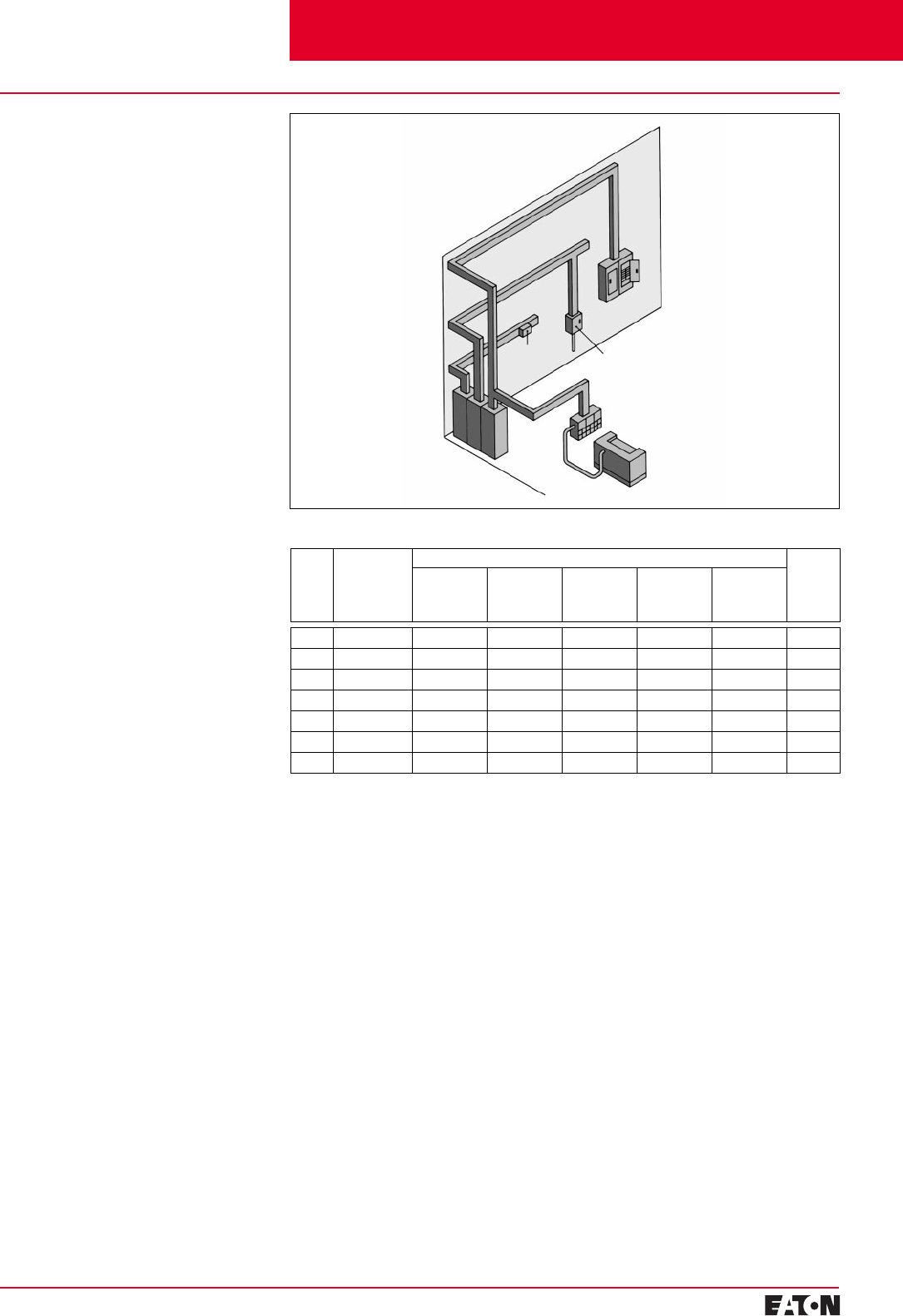
16-2500 Amperes for IEC 60947-2 Applications 3
Switchboard
Machine Tool
Control Panel
Busbar
Trunking
Tap-Off
Individual
Circuit
Breaker
Enclosure
Panelboard
Panelboards
As both main and branch circuit pro-
tection devices (G-, E-, J-, K-, L- and
N-Frames).
Feeder Pillars
In distribution systems to provide
main and branch circuit protection
(E-, J-, K-, L-, N- and R-Frames).
Switchgear
In distribution systems to provide
main and branch circuit protection
up to 2500 amperes (R-Frame).
Busbar Trunking Tap-Offs
In busbar trunking tap-offs to
provide branch circuit protection
(F-Frame); and to provide feeder
or branch circuit protection
(J-, K- and L-Frames).
Individual Enclosures
Completely assembled in enclosures
to meet specific customer require-
ments (G-, E-, J-, K-, L-, N- and
R-Frames).
Machine Tool Control Panels and
Motor Control Centres
Applied for specific equipment
requirements (G-, E-, J-, K-, and
L-Frames).
Additional Applications
Special versions of each Cutler-
Hammer frame are available to
provide safe equipment control and
protection in mining and other appli-
cations. Contact your Cutler-Hammer
agent or distributor for additional
information.
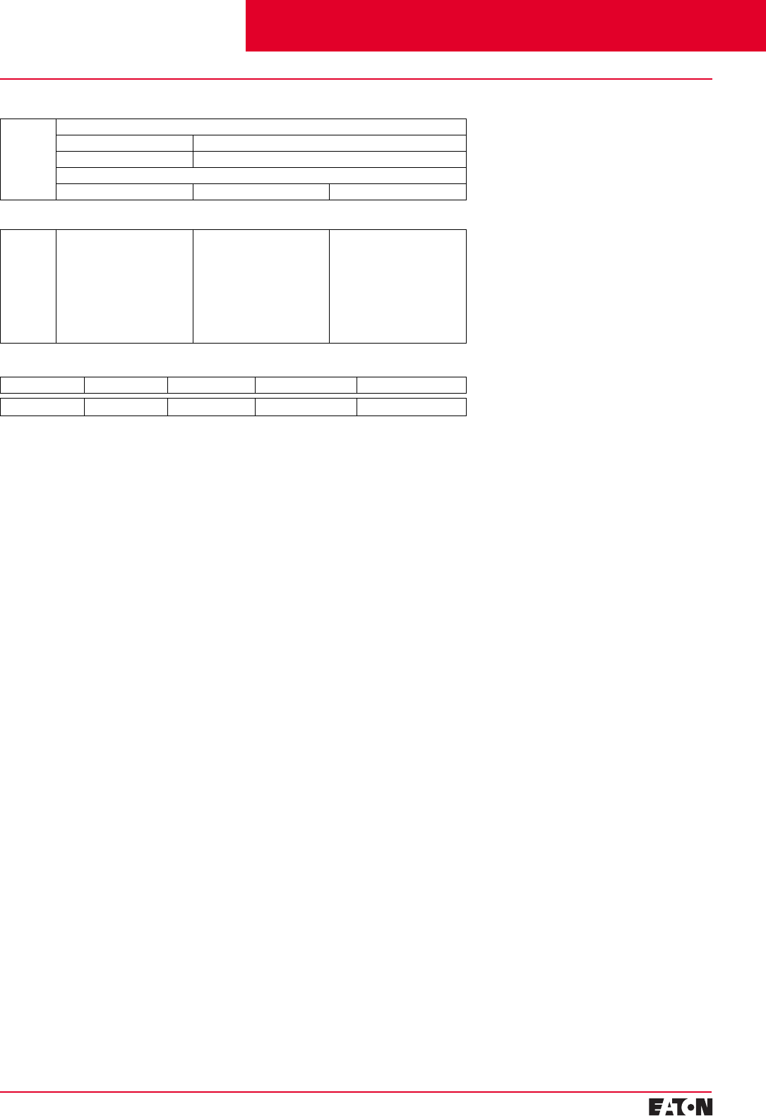
Cutler-Hammer Frame Sizes G through R
Frame Continuous
Ampere Rating
Range
Type of Trip Unit Moulded
Case
Switch
Adjustable
Thermal
Fixed
Magnetic
Fixed Thermal
Fixed
Magnetic
Adjustable
Thermal
Adjustable
Magnetic
Adjustable
Thermal Fixed
Magnetic
Earth Leakage
Digitrip RMS
Electronic
Trip Units
G 16-100 –
■
–––
■
E 16-125
■■
–––
■
J 125-250 – –
■■
–
■
K 63-400 – –
■■■■
L 315-800 – –
■
–
■■
N 400-1250 ––––
■■
R 800-2500 ––––
■■
Typical Cutler-Hammer Applications
Contents
Back To Reference

PG.29B.01A.T.U
Cutler-Hammer
4
February 2001
Moulded Case Circuit Breakers
16-2500 Amperes for IEC 60947-2 Applications
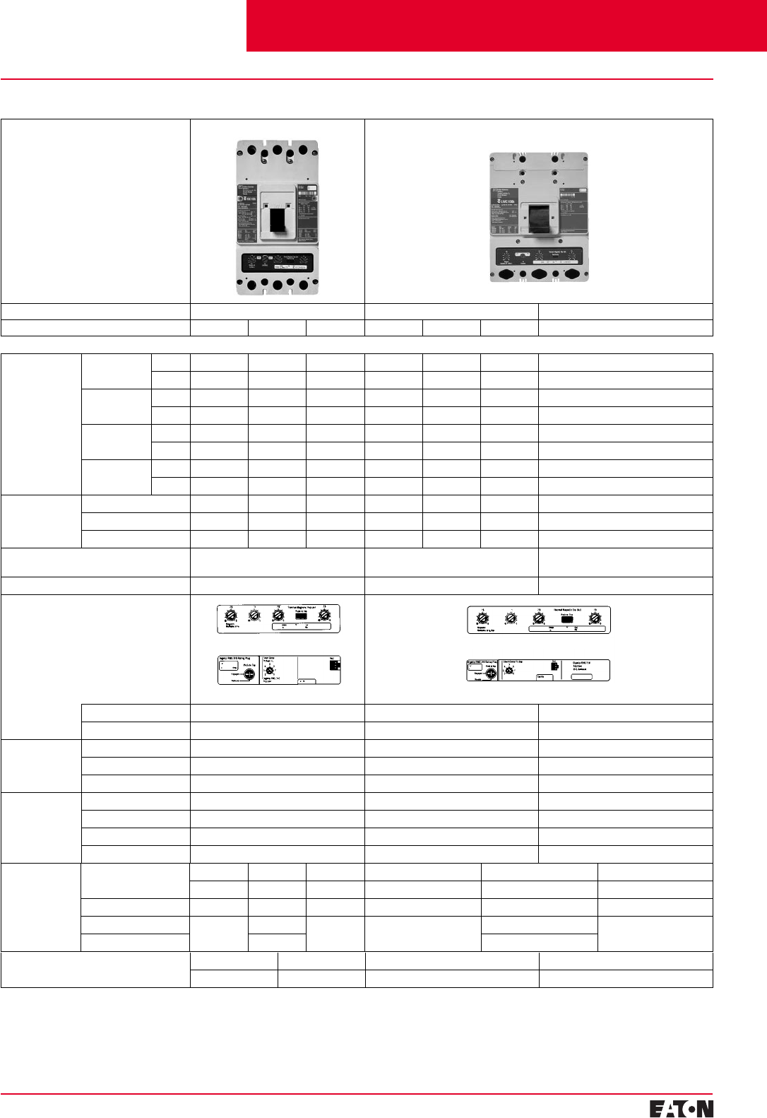
Electrical Characteristics
GE J
Maximum Rated Current (Amperes) 100 125 250
Breaker Type GWF
➁
GWF
➁
BESHESH
Breaker Capacity (kA rms) AC 50-60 Hz
IEC 60947-2 220-240 VAC I
cu
18 65 25 25 35 85 85 100 100 65 85 100
I
cs
9 33 2525 35 4343 5050 65 85 100
380-415 VAC I
cu
– 25 – 18 25 – 40 – 70 25 40 70
I
cs
– 13 – 18 25 – 30 – 35 25 40 70
660-690 VAC I
cu
– – –––––––– 12 12 14
I
cs
– – –––––––– 6 6 7
250 VDC
➀
I
cu
– 10 1010 10 3535 4242 10 22 22
I
cs
– 5 10 10 10 35 35 42 42 10 22 22
NEMA 240 VAC 18 65 25 25 35 85 85 100 100 65 85 100
480 VAC – 22 – 18 25 – 35 – 65 25 35 65
600 VAC – – – – – –––– 18 25 35
Number of Poles 1 2, 3 1 2, 3,
42, 3, 4 1 2, 3,
41 2, 3,
42, 3, 4
Ampere Range 16-125A 16-125A 63-250A
Trip Units
Interchangeable – –
■
Built-in
■■ ■
Thermal
Magnetic Fixed Thermal
■■ ■
Adjustable Thermal Fixed
■■
Magnetic Fixed Fixed Adjustable
Solid State
rms
➂
LS – – –
LSI – – –
LSG – – –
LSIG – – –
➀
2 poles in series.
➁
Not KEMA-KEUR listed. R-frame scheduled
for 2001.
➂
Not suitable for DC application. 4-pole
ground fault not available.
Weight (approximate) Kgs. 1-Pole 2-Pole 3-Pole 1-Pole 2-Pole 3-Pole 4-Pole 2-Pole 3-Pole 4-Pole
0.4 0.7 1 0.45 0.91 1.36 1.81 5.2 5.2 7.0
Cutler-Hammer Frame Sizes G through J
Dimensions
(mm) HWDH W D H W D
1-Pole 123.8 254.4 66.7 139.7 25.4 76 177.8 105 103
2-Pole 50.8 50.8
3-Pole 76.2 76.2
4-Pole – – – 101.6 140
Adjustable Thermal Magnetic
Adjustable Thermal Magnetic
Contents
Back To Reference
February 2001
PG.29B.01A.T.U
Cutler-Hammer
Moulded Case Circuit Breakers
16-2500 Amperes for IEC 60947-2 Applications 5
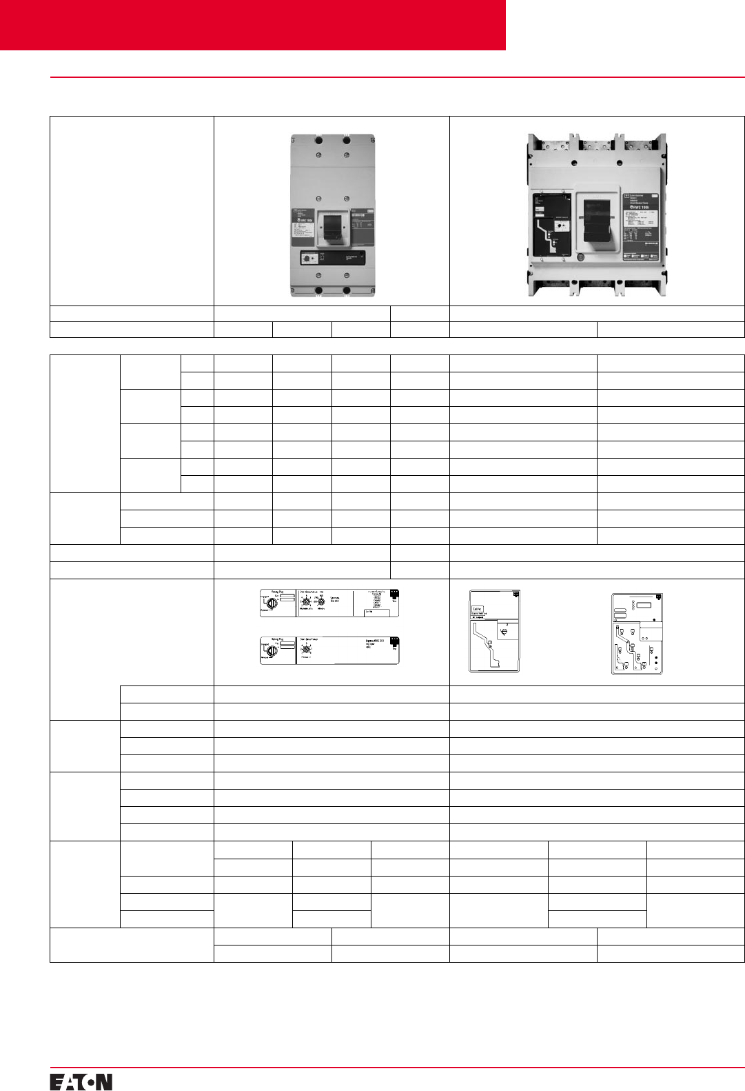
Electrical Characteristics
KL
Maximum Rated Current (Amperes) 400 630 800
Breaker Type KW HKW KWC
➀
LW HLW LWC
➀
LW
Breaker Capacity (kA rms) AC 50-60 Hz
IEC 947-2 220-240 VAC I
cu
85 100 200 85 100 200 65
I
cs
85 100 150 85 100 150 33
380-415 VAC I
cu
45 70 100 45 70 100 50
I
cs
45 70 75 45 70 75 25
660-690 VAC I
cu
20 25 35 20 25 35 20
I
cs
10 13 18 10 13 18 10
250 VDC
➁
I
cu
10 20 20 20 20 20 20
I
cs
51010101010 10
NEMA 240 VAC 65 100 200 65 100 200 65
480 VAC 35 65 100 35 65 100 35
600 VAC 25 35 50 25 35 50 25
Number of Poles 2, 3, 4 2, 3, 4 3
Ampere Range 63-400A 315-630A 700-800A
Trip Units
Interchangeable
■■
–
Built-in
■■■
Thermal
Magnetic Fixed Thermal
■■■
Adjustable Thermal
■■
–
Magnetic Adjustable Adjustable Adjustable
Solid State
rms
➁➂
LS Standard Standard Standard
LSI Optional Optional Optional
LSG Optional
➂
Optional Optional
LSIG Optional
➂
Optional Optional
➀
Not KEMA-KEUR listed. R-frame scheduled
for 2001.
➁
2 poles in series.
➂
Not suitable for DC application. 4-pole
ground fault not available.
Adjustable Thermal Magnetic
Digitrip RMS 310
Digitrip RMS 310
Adjustable Thermal Magnetic
Cutler-Hammer Frame Sizes K through L
Dimensions
(mm) HWDH W D
1-Pole – – – – – –
2-Pole – – – – – –
3-Pole 258 140 104 630A = 273
800A = 406
210 104
4-Pole 183 280
Weight (approximate) Kgs. 3-Pole 4-Pole 3-Pole 4-Pole
6.1 7.3 630A = 9.4/800A = 11.3 630A = 11.1/800A = 14.4
Contents
Back To Reference
PG.29B.01A.T.U
Cutler-Hammer
6
February 2001
Moulded Case Circuit Breakers
16-2500 Amperes for IEC 60947-2 Applications
Digitrip RMS 310
Trip Unit Digitrip RMS
Trip Units
■
RMS 610
■
RMS 910
Dimensions
(mm) HWDH W D
1-Pole – – – – – –
2-Pole – – – – – –
3-Pole 406 210 104 406 394 229
4-Pole 280 508
Weight (approximate) Kgs. 3-Pole 4-Pole 3-Pole 4-Pole
21.3 28.3 47 54
Standard
Digitrip RMS 310
Cutler-Hammer Frame Sizes N and R
Electrical Characteristics
NR
Maximum Rated Current (Amperes) 800, 1250 1600 1600, 2000, 2500
Breaker Type NW HNW NWC
➀
NW RW
➀
RWC
➀
Breaker Capacity (kA rms) AC 50-60 Hz
IEC 947-2 220-240 VAC I
cu
85 100 200 85 135 200
I
cs
85 100 100 85 100 100
380-415 VAC I
cu
50 70 100 50 70 100
I
cs
50 50 50 50 50 50
660-690 VAC I
cu
20
➁
25
➁
35 20
➁
25 35
I
cs
10 13 18 10 13 18
250 VDC
➂
I
cu
–––– – –
I
cs
–––– – –
NEMA 240 VAC 65 100 200 100 125 200
480 VAC 50 65 100 65 65 100
600 VAC 25 35 50 35 50 65
Number of Poles 2, 3, 4 3 3, 4
Ampere Range 400-1250A 1600A 800-2500A
Trip Units
Interchangeable – –
Built-in
■■
Thermal
Magnetic Fixed Thermal – –
Adjustable Thermal – –
Magnetic – –
Solid State
rms
➃
LS Standard Standard (LI is Optional in Digitrip 510, 610, 810 and 910)
LSI Optional Optional
LSG Optional Optional (LIG is Optional in Digitrip 510, 610, 810 and 910)
LSIG Optional Optional
➀
Not KEMA-KEUR listed. R-frame scheduled
for 2001.
➁
IEC 60947-2 H.5 Annex H is not KEMA-KEUR
tested.
➂
2 poles in series.
➃
Not suitable for DC application. 4-pole
ground fault not available.
Contents
Back To Reference
February 2001
PG.29B.01A.T.U
Cutler-Hammer
Moulded Case Circuit Breakers
16-2500 Amperes for IEC 60947-2 Applications 7
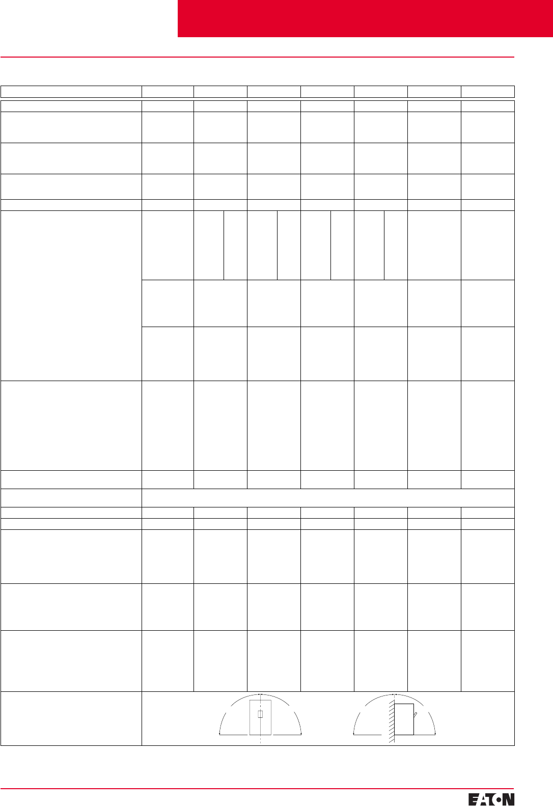
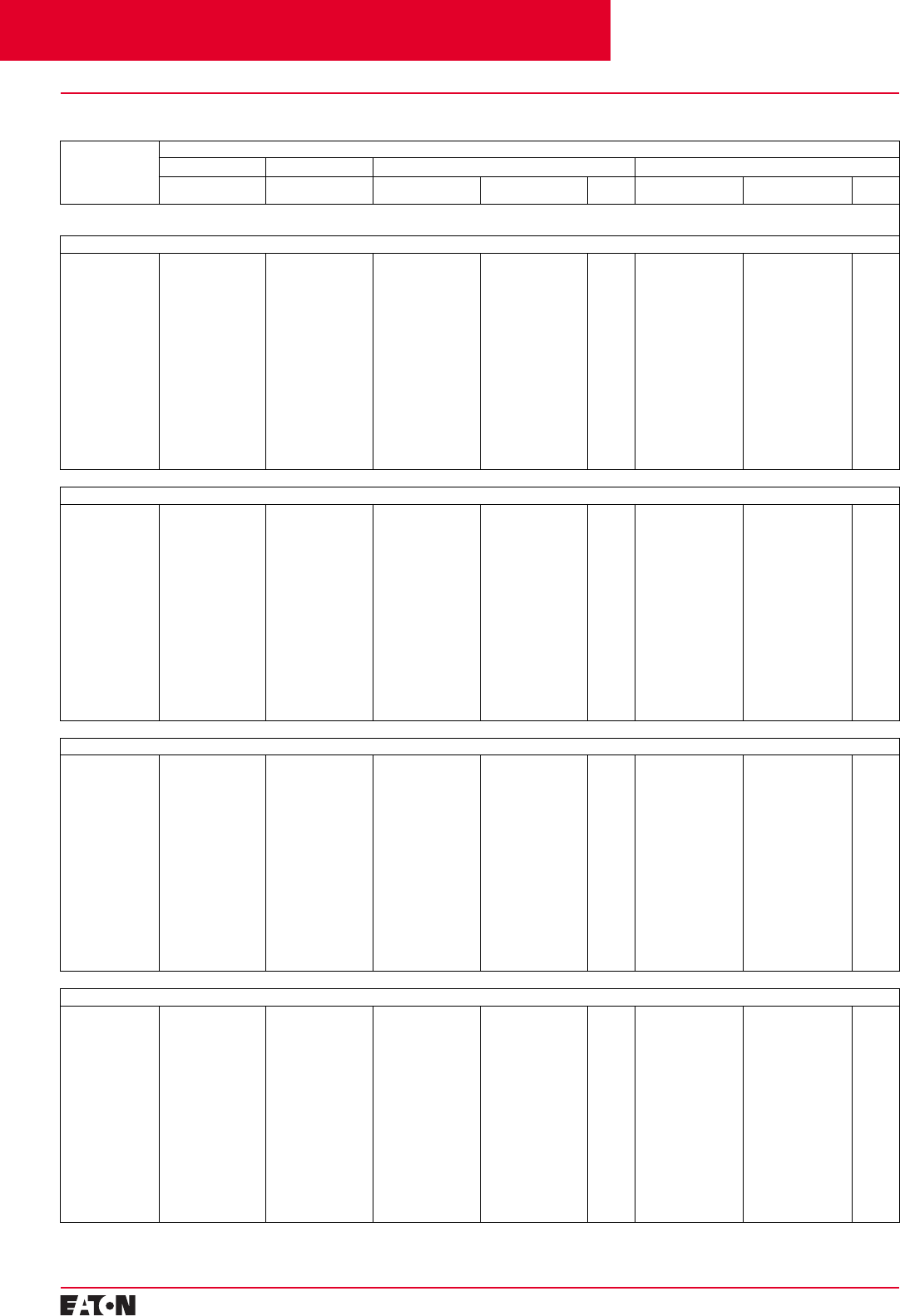
Electrical Characteristics
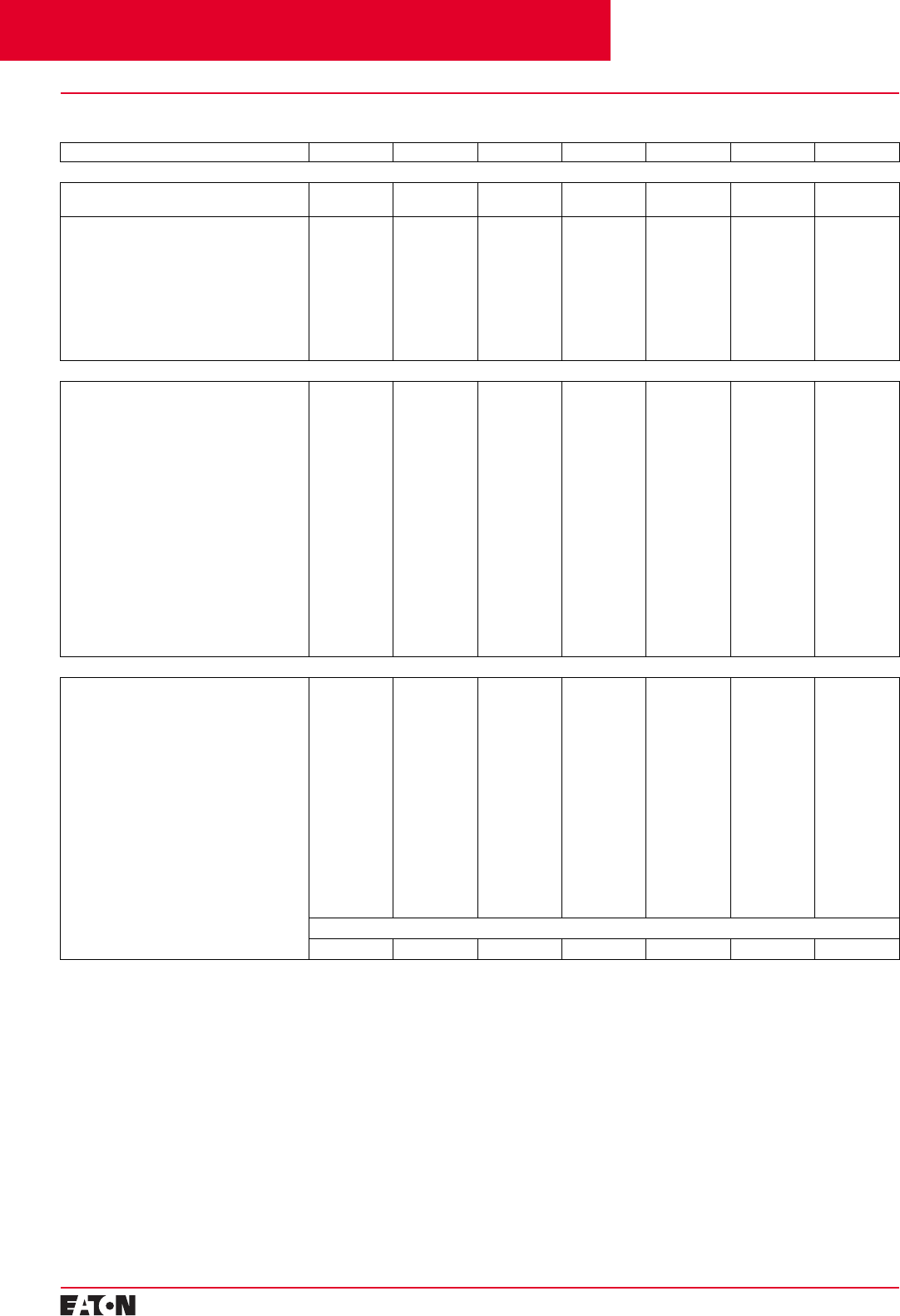
Technical Data G-Frame E125-Frame J250-Frame K-Frame L-Frame N-Frame R-Frame
Maximum Rated Current I
n
Depending on the Version 100A 125A 200/250A 315/400A 500/630/800A 800/1250A 1600/2000/2500A
Rated Insulation Voltage U, According to IEC 947-2
Main Conducting Paths
Auxiliary Circuits 1-Pole = 250 VAC
2,3-Pole = 415 VAC
690 VAC
750 VAC
690 VAC 750 VAC
690 VAC 750 VAC
690 VAC 750 VAC
690 VAC 750 VAC
690 VAC 750 VAC
690 VAC
Rated Impulse Withstand Voltage U
imp
Main Conducting Paths
Auxiliary Circuits 1-Pole = 4 kV
2,3-Pole = 6 kV
4 kV
6 kV
4 kV 8 kV
4 kV 8 kV
4 kV 8 kV
4 kV 8 kV
4 kV 8 kV
4 kV
Rated Operational Voltage U
e
IEC
NEMA 440 VAC
480 VAC 440 VAC
600Y/347 VAC 690 VAC
600 VAC 690 VAC
600 VAC 690 VAC
600 VAC 690 VAC
600 VAC 690 VAC
600 VAC
Permissible Ambient Temperature -20 to +70°C -20 to +70°C -20 to +70°C -20 to +70°C -20 to +70°C -5 to +60°C -5 to +60°C
Permissible Load for Various Ambient Tempera-
tures Close to the Circuit Breaker, Related to the
Rated Current of the Circuit Breaker
■
Circuit Breakers for Plant Protection
– At 40°C
– At 50°C
– At 55°C
– At 60°C
– At 70°C
–
100%
96%
93%
91%
86%
➀
100%
96%
93%
91%
86%
➁
100%
92%
87%
83%
73%
➀
100%
96%
94%
92%
88%
➁
100%
94%
90%
87%
80%
➀
100%
96%
93%
90%
85%
➁
100%
92%
87%
84%
75%
➀
100%
96%
93%
90%
84%
➁
100%
91%
86%
82%
70%
–
100%
91%
85%
81%
–
–
100%
100%
100%
100%
–
■Circuit Breakers for Motor Protection
– At 40°C
– At 50°C
– At 55°C
– At 60°C
– At 70°C
–
–
–
–
–
–
–
–
–
–
–
–
–
–
–
100%
100%
100%
100%
87%
100%
100%
100%
100%
90%
–
–
–
–
–
–
–
–
–
–
■Circuit Breakers for Starter Combinations
and Isolating Circuit Breakers
– At 40°C
– At 50°C
– At 55°C
– At 60°C
– At 70°C
–
–
–
–
–
100%
100%
96%
91%
86%
100%
100%
96%
82%
88%
100%
100%
96%
90%
85%
100%
100%
95%
90%
84%
100%
91%
85%
81%
–
100%
100%
100%
100%
–
Rated Short Circuit Breaking Capacity (DC)
Not for Circuit Breakers for Motor Protection
(Time Constant t = 10 rms)
1 Conducting 2 Conducting 3 Conducting
Path Paths in Series Paths in Series
For F to L up to:
250 VDC 440 VDC 660 VDC
NEMA (Time Constant t = 8 rms)
1 Conducting 2 Conducting
Path Paths in Series
250 VDC –
– 250 VDC
–
–
10 kA (5 rms)
20 kA Max.
10 kA
22 kA
20 kA Max.
10 kA
22 kA
20 kA Max.
10 kA
22 kA
20 kA Max.
10 kA
22 kA
–➂
–➂
–➂
–➂
–➂
–➂
Main Switch Characteristics According to IEC 947-2
in Combination with Lockable Rotary Drives – Yes Yes Yes Yes Yes Yes
Rated Short Circuit Breaking Capacity
According to IEC 947-2 (at AC 50/60 Hz) Rated Short Circuit Breaking Capacity See Table on Pages 4-5-6
Endurance (Operating Cycles) 10,000 10,000 10,000 8,000 8,000 3,000 3,000
Maximum Switching Frequency 300 1/h 300 1/h 240 1/h 240 1/h 240 1/h 60 1/h 20 1/h
Conductor Cross Sections and Terminal Types
for Main Conductors
■Solid or Stranded
■Finely Stranded with End Sleeve
■Busbar
Tightening Torque for Box Terminals
Tightening Torque for Busbar Connection Pieces
Box Terminals
2.5 to 50 mm2
–
–
5.1 Nm
–
Box Terminals
2.5 to 95 mm2
2.5 to 50/70 mm2
–
4/6 Nm
4.5 Nm
Box Terminals
50 to 150 mm2
35 to 120 mm2
–
20 Nm
15 Nm
Box Terminals
95 to 240 mm2
70 to 150 mm2
–
42 Nm
30 Nm
Flat Bar
Terminals
–
–
800A
31 Nm
6 Nm
Flat Bar
Terminals
–
–
Optional
31 Nm
50 Nm
Flat Bar
Terminals
–
–
Optional
–
37 Nm
Conductor Cross Sections for Auxiliary Circuits
with Terminal Connection or Terminal Strip
■Solid
■Finely Stranded with End Sleeve
■With Brought-out Cable Ends
■Tightening Torque for Fitting Screws
0.75 to 2.5 mm2
0.75 to 2.5 mm2
–
–
0.75 to 2.5 mm2
0.75 to 2.5 mm2
–
–
0.75 to 2.5 mm2
0.75 to 2.5 mm2
0.82 (AWG 18) mm
2
0.8 to 1.4 Nm
0.75 to 2.5 mm2
0.75 to 2.5 mm2
0.82 (AWG 18) mm
2
0.8 to 1.4 Nm
0.75 to 2.5 mm2
0.75 to 2.5 mm2
0.82 (AWG 18) mm
2
0.8 to 1.4 Nm
Up to 2x4 mm2
Up to 2x2.5 mm2
0.82 (AWG 18) mm
2
0.8 to 1.4 Nm
Up to 2x4 mm2
Up to 2x2.5 mm2
0.82 (AWG 18) mm
2
0.8 to 1.4 Nm
Power Loss per Circuit Breaker at Maximum Rated
Current ln (The Power Losses of the Undervoltage
Releases (“r” Releases) Must Be Observed if
Necessary) at Three-Phase Symmetrical Load)
■For Plant Protection
■As Isolating Circuit Breaker
■For Starter Combinations
■For Motor Protection
50 W
40 W
40 W
50 W
50 W
40 W
40 W
50 W
75 W
75 W
45 W
–
175 W
107 W
107 W
75 W
255 W
160 W
160 W
120 W
87/210 W
87/210 W
–
–
220/270/400 W
220/270/400 W
–
–
Permissible Mounting Position
➀Thermal overload release set to the
lower value.
➁Thermal overload release set to the upper
value, respecting fixed-setting thermal
overload releases.
➂Not suitable for DC switching.
Cutler-Hammer Frame Sizes G through R
90¡
90¡
90¡
90¡
Contents
Back To Reference
PG.29B.01A.T.U
Cutler-Hammer
8February 2001
Moulded Case Circuit Breakers
16-2500 Amperes for IEC 60947-2 Applications
Electrical Characteristics
Technical Data G-Frame E125-Frame J250-Frame K-Frame L-Frame N-Frame R-Frame
Auxiliary Switches
Rated Thermal Current lth
Rated Making Capacity 6A
10A 6A
20A 6A
20A 6A
20A 6A
20A 6A
20A 6A
20A
AC (AC-15)
– Rated Operational Voltage
– Rated Operational Current
DC (DC-13)
– Rated Operational Voltage
– Rated Operational Current
Back-up Fuse
Miniature Circuit Breaker
240V
6A
24
5
6A
6A
230/400/600V
6/3/0.25A
24/125/250V
6/0.5/0.25A
6/4/4A
6/4A
230/400/690V
6/3/0.25A
24/125/240V
6/0.5/0.15A
4
6/4/4A
6/4A
230/400/690V
6/3/0.25A
24/125/240V
6/0.5/0.15A
4
6/4/4A
6/4A
230/400/690V
6/3/0.25A
24/125/240V
6/0.5/0.15A
4
6/4/4A
6/4A
230/400/690V
6/3/0.25A
24/125/240V
6/0.5/0.15A
4
6/4/4A
6/4A
230/400/690V
6/3/0.25A
24/125/240V
6/0.5/0.15A
4
6/4/4A
6/4A
Releases
Undervoltage Releases (“r” Releases)
Response Voltage:
– Drop (Breaker Tripped) Us
– Pickup (Breaker May Be Switched on) Us
Power Consumption in Continuous Operation at:
– AC 50/60 Hz 12V
– AC 50/60 Hz 24V
– AC 50/60 Hz 48-60V
– AC 50/60 Hz 110-127V
– AC 50/60 Hz 208-240V
– AC 50/60 Hz 380-500V
– DC 12V
– DC 24V
– DC 48-60V
– DC 110-125V
– DC 220-250V
Maximum Opening Time
35-70%
85-110%
–
5.3 VA
1.5 VA
1.8 VA
1.4 VA
4.8 VA
–
–
–
–
–
50 ms
35-70%
85-110%
0.95 VA
0.72 VA
1.15-1.78 VA
0.96 -1.25 VA
1.28 -1.68 VA
2.2 -3.9 VA
0.88 VA
0.70 VA
1.12-1.76 VA
0.94-1.21 VA
1.45-1.86 VA
50 ms
35-70%
85-110%
1.9 VA
3.9 VA
2.5-3.8 VA
1.8 -2.4 VA
2.7-3.8 VA
3.4-5.8 VA
1.6 W
3.1 W
2.0-3.1 W
1.6-2.2 W
3.1-4 W
50 ms
35-70%
85-110%
1.9 VA
3.9 VA
2.5-3.8 VA
1.8 -2.4 VA
2.7-3.8 VA
3.4-5.8 VA
1.6 W
3.1 W
2.0-3.1 W
1.6-2.2 W
3.1-4 W
50 ms
35-70%
85-110%
1.9 VA
3.9 VA
2.5-3.8 VA
1.8-2.4 VA
2.7-3.8 VA
3.4-5.8 VA
1.6 W
3.1 W
2.0-3.1 W
1.6-2.2 W
3.1-4 W
50 ms
35-70%
85-110%
1.9 VA
2.4 VA
2.3-4.1 VA
3.4-4.2 VA
4.8-6.5 VA
6.8-12.0 VA
2.6 W
3.6 W
3.5 -5.5 W
2.9-3.6 W
4.8-6.3 W
80 ms
35-70%
85-110%
2.9 VA
3.1 VA
3.4-6.0 VA
3.3-3.8 VA
4.2-7.2 VA
3.8 10.0 VA
3.4 W
4.3 W
4.8-7.2 W
3.3-3.8 W
6.6-7.5 W
80 ms
Shunt Trips
Shunt Trips (“f” Releases)
Response Voltage:
– Pickup (Breaker Tripped) Us
Power Consumption in (Short Time) at:
– AC 50/60 Hz 12-24V
– AC 50/60 Hz 48-60V
– AC 50/60 Hz 48-127V
– AC 50/60 Hz 110-240V
– AC 50/60 Hz 380-440V
– AC 50/60 Hz 380-600V
– AC 50/60 Hz 480-600V
– DC 12-24V
– DC 48-60V
– DC 110-125V
– DC 220-250V
70-110%
–
–
–
135-500 VA
–
–
–
–
–
–
–
70-110%
10-41 VA
139-210 VA
–
83-360 VA
–
418-1080 VA
–
29-120 W
475-720 W
99-121 W
–
0-110%
87-405 VA
710-1105 VA
–
66-432 VA
127-188 VA
–
34-60 VA
164-631 W
830-1580 W
112-150 W
40-58 W
70-110%
87-405 VA
710-1105 VA
–
66-432 VA
127-188 VA
–
34-60 VA
164-631 W
830-1580 W
112-150 W
40-58 W
70-110%
81-701 VA
58-90 VA
–
118-665 VA
125-181 VA
–
43-79 VA
79-1000 W
18-31 W
112-150 W
38-52 W
70-110%
86-631 VA
48-71 VA
–
81-505 VA
43-68 VA
–
41-69 VA
46-405 W
58-94 W
74-98 W
38-49 W
70-110%
177-1207 VA
443-731 VA
–
323-1466 VA
1193-1641 VA
–
197-312 VA
289-865 W
468-696 W
363-473 W
513-665 W
Maximum Load Duration Interrupts Automatically
Maximum Opening Time 50 ms 50 ms 50 ms 50 ms 50 ms 62 ms 62 ms
Cutler-Hammer Frame Sizes G through R
Contents
Back To Reference
February 2001
PG.29B.01A.T.U
Cutler-Hammer Moulded Case Circuit Breakers
16-2500 Amperes for IEC 60947-2 Applications 9
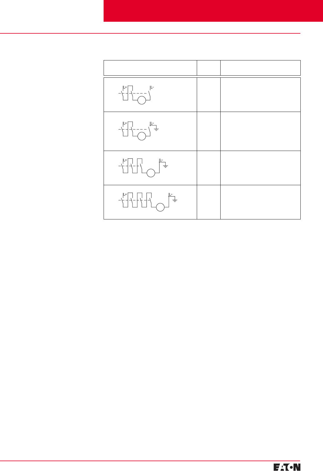
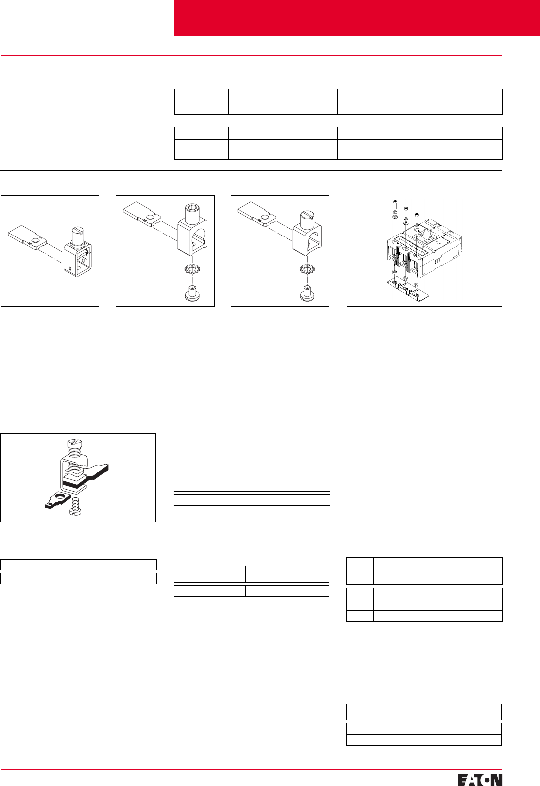
For 3- and 4-Pole Circuit Breakers
Proposed
Circuit Maximum
Permissible
VDC Ue
Remarks
250 VDC Double-pole switching.
If there is no risk of an earth fault, or if any
earth fault which occurs is immediately
eliminated (earth fault monitoring), the
maximum permissible dc voltage can be
600 volts.
440 VDC Double-pole switching (earth system).
The earthed pole must always be assigned
to the individual conducting path, so that
two paths are always in series in the event
of an earth fault.
600 VDC Single-pole switching (earthed system).
Three conducting paths in series. The
earthed pole must be assigned to the
nonswitched conducting path.
750 VDC Single-pole switching (earthed system).
Four conducting paths in series. The
earthed pole must be assigned to the
nonswitched conducting path.
NSI-5178a
M
NSI-5179a
M
NSI-5180
M
NSI-5181
M
Electrical Characteristics
DC Switching Duty
The E- to L-Frame circuit breakers
are also suitable for switching dc
currents.
The N- and R-Frame circuit breakers,
FWMP, KWMP, and LWMP circuit
breakers for motor protection are
not suitable for dc currents due to
the solid state overcurrent release
system.
For switching dc currents, however,
the maximum permissible dc voltage
per conducting path has to be con-
sidered.
For voltages higher than 250 volts,
the series connection of two or three
conducting paths is required.
As the current has to flow through all
conducting paths so as to maintain
the thermal tripping characteristics,
the following circuit arrangements
are recommended. With dc, the trip
values of the instantaneous short
circuit release (“n” release) are
increased by 30 to 40%.
Cutler-Hammer Frame Sizes E through L
Contents
Back To Reference
PG.29B.01A.T.U
Cutler-Hammer
10 February 2001
Moulded Case Circuit Breakers
16-2500 Amperes for IEC 60947-2 Applications
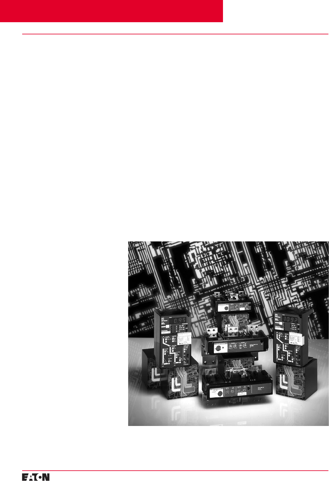
Multi-Function
Electronic Trip Units
for All Applications
Digitrip™ RMS Trip Units
True rms Sensing
Digitrip RMS Trip Units utilize our
proprietary SURE™ Chip and SuRE
Plus™ Chip microprocessor-based
intelligence to provide true rms
sensing, permitting increased accu-
racy and reliable system protection.
True rms sensing is not susceptible
to nuisance tripping when wave-
forms containing high harmonic
currents are present.
Digitrip RMS 310
Digitrip RMS 310 Electronic Trip
Units are available with Cutler-Ham-
mer Circuit Breakers K-, L-, N- and
R-Frames 63 through 2500 amperes.
Digitrip RMS 310 Trip Units are
available in four styles with either
fixed or adjustable rating plugs
which establishes the continuous
ampere rating of the breaker.
Rating Plugs
Digitrip RMS 310 Trip Units incor-
porate rating plugs that are inter-
changeable within a specific circuit
breaker frame. This provides the user
with versatility when establishing the
continuous current rating of a
breaker. Rating plugs are frequency
sensitive and may be specified for
50 / 60 Hz applications. Both fixed
and adjustable rating plugs are avail-
able, providing further flexibility
when applied to selectively coordi-
nated systems.
Note:
Digitrip RMS rating plugs
are not interchangeable with
SELTRONIC™ rating plugs.
Curve Shaping
When selectively coordinated sys-
tems are called for, Digitrip RMS 310
will provide a cost-effective solution
for a variety of applications.
The standard Digitrip RMS 310
includes an adjustable short time
pickup setting encompassing an I2t
ramp function which provides the
basic LS curve shaping function.
The optional Digitrip RMS 310
provides additional flat response
short time delay adjustments on
an instantaneous setting to provide
LSI curve shaping capability.
Both Digitrip RMS 310 Trip Units are
available with ground fault pickup
and flat response ground fault delay
which provide the trip unit with full
function LSG and LSIG curve shap-
ing flexibility.
Digitrip RMS 310 Trip Units can
effectively coordinate with both
sophisticated upstream power
breakers as well as downstream
thermal magnetic breakers…making
Digitrip RMS 310 Trip Units the cost-
effective reliable choice for selec-
tively coordinated systems.
Thermal Memory
All Digitrip RMS Trip Units incorpo-
rate a long delay and, when ordered
with ground, a ground fault thermal
memory feature. Thermal memory
prevents the system from cumula-
tive overheating due to repeated
overcurrent events that may occur
in quick succession.
Digitrip RMS 610 and 910
Digitrip RMS 610, and 910 Trip Units
are available with Cutler-Hammer
R-Frame Circuit Breakers 800
through 2500 amperes. Digitrip 610
and 910 Trip Units provide unparal-
leled system protection with fixed
rating plugs to establish the continu-
ous ampere rating of the breaker.
Curve Shaping
Digitrip RMS 610 and 910 Trip Units
are available with up to nine curve
shaping choices achieved by adjust-
ing up to seven switches on the front
of the unit for optimum system coor-
dination. Maximum curve shaping
flexibility is provided by dependent
long and short delay adjustments
that are long delay pickup (Ir) based,
depicted on the front of the unit by
the blue portion of the time-current
curve.
Additional coordination capability
can be provided by utilizing the short
delay and ground fault zone selec-
tive interlocking features available
on these trip units.
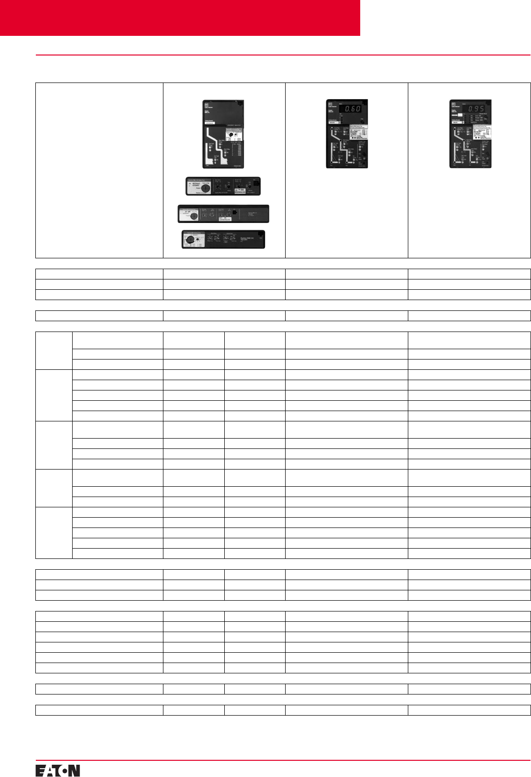
R-Frame Digitrip RMS 310, 610 and 910 Trip Units (Noninterchangeable)
Cutler-Hammer Frame Sizes K through R
Contents
Back To Reference

February 2001
PG.29B.01A.T.U
Cutler-Hammer Moulded Case Circuit Breakers
16-2500 Amperes for IEC 60947-2 Applications 11
System Diagnostics
All four Digitrip RMS models of trip
units provide long delay, short delay,
instantaneous, and ground fault
cause of trip LEDs on the front of the
unit. Digitrip RMS 610 and 910 also
offer a magnitude of trip information
as well as remote signal contacts for
improved system diagnostics.
System Monitoring
Digitrip 610 and 910 Trip Units
have the capability to monitor phase
currents as well as neutral or ground
currents. This information is displayed
on a large digital display mounted
on the unit.
Digitrip RMS 910 Trip Units can also
provide the user with power and
energy monitoring capability. Peak
power demand, present power
Cutler-Hammer Frame Size R
demand, and total energy as well as
forward and reverse energy can be
monitored with this unit.
Digitrip RMS 910 Trip Units have the
additional capability of monitoring
line to line voltage as well as system
power factor. Both parameters are
displayed in the digital display win-
dow and are supported by LEDs to
indicate which parameter is being
displayed.
Harmonics Monitoring
Digitrip RMS 910 Trip Units are
capable of displaying values of cur-
rent harmonics in the digital display
window. Percentage of harmonic
content can be monitored for each
phase, neutral or ground, up to the
27th harmonic. Additionally, a total
harmonic distortion value can be
calculated and displayed.
Communications
Digitrip RMS 810 and 910 have
built-in communications options to
allow all protection, monitoring, and
control information to be transmitted
back to a central location via the
Cutler-Hammer PowerNet System.
Field Testing
Integral field testing capability is
provided on all 610 and 910 Trip
Units. No additional test set is needed
to perform both trip and no trip field
testing.
Contents
Back To Reference
PG.29B.01A.T.U
Cutler-Hammer
12 February 2001
Moulded Case Circuit Breakers
16-2500 Amperes for IEC 60947-2 Applications
Digitrip RMS Electronic Trip Unit Selection Guide
Digitrip RMS 310 RMS 610 RMS 910
Breaker Type
Cutler-Hammer Frame(s) K-, L-, N- and R-Frames R-Frame R-Frame
Ampere Rating 70A-2500A 800A-2500A 800A-2500A
Interrupting Rating at 415V 35, 70, 100 kA 70, 100 kA 70, 100 kA
Trip Unit Sensing
rms Sensing Yes Yes Yes
Protection and Coordination
Protection Ordering Options LS, LSG LSI, LSIG LI, LSI, LIG,
LSG, LSIG LI, LS, LSI, LIG,
LSG, LSIG
Fixed Rating Plug (In) Yes Yes Yes Yes
Overtemperature Trip Yes Yes Yes Yes
Long Delay Adjustable Rating Plug (In) Yes Yes No No
Long Delay Setting 0.5-1.0 (ln)➀0.5-1.0 (ln)➀0.5-1.0 x (ln) 0.5-1.0 x (ln)
Long Delay Time I2t 12 Seconds 12 Seconds 2-24 Seconds 2-24 Seconds
Long Delay Thermal Memory Yes Yes Yes Yes
High Load Alarm No No 0.85 x Ir0.85 x Ir
Short
Delay Short Delay Setting 200-800% x (ln)➄200-800% x (ln)➄200-600% S1 &
S2 x (Ir)200-600% S1 &
S2 x (Ir)
Short Delay Time I2t 100 ms No 100-500 ms 100-500 ms
Short Delay Time Flat No I-300 ms 100-500 ms 100-500 ms
Short Delay Time ZSI No No Yes Yes
Instanta-
neous Instantaneous Setting No 200-800% x (ln) 200-600% M1 &
M2 x (ln)200-600% M1 &
M2 x (ln)
Discriminator No No Yes➃Yes➃
Instantaneous Override Yes Yes Yes Yes
Ground
Fault Ground Fault Setting Var/Frame➂Var/Frame➂25-100% x (ln)➂25-100% x (ln)➂
Fault Delay I2t No No 100-500 ms 100-500 ms
Ground Fault Delay Flat I-500 ms I-500 ms I-500 ms I-500 ms
Ground Fault ZSI No No Yes Yes
Ground Fault Thermal Memory Yes Yes Yes Yes
System Diagnostics
Cause of Trip LEDs No No Yes Yes
Magnitude of Trip Information No No Yes Yes
Remote Signal Contacts No No Yes Yes
System Monitoring
Digital Display No No Yes Yes
Current No No Yes Yes
Voltage No No No Yes
Power and Energy No➁No➁No Yes
Power Quality - Harmonics No No No Yes
Power Factor No No No Yes
System Communications
PowerNet No No No Yes
Field Testing
Testing Method➀Test Set Test Set Integral Integral
➀Set by adjustable rating plug
➁Yes, with addition of Energy Sentinal.
➂Not to exceed 1200A.
In = Rating plug rating.
Ir = LDPU setting.
➃LS, LSG only.
➄2500A R-frame 200-600% x (In)
Cutler-Hammer Frame Sizes K through R
Contents
Back To Reference
February 2001
PG.29B.01A.T.U
Cutler-Hammer
13
Moulded Case Circuit Breakers
16-2500 Amperes for IEC 60947-2 Applications
➀
Special 50°C rating available. Order by
description.
Selection Guide and Ordering Information
Maximum
Continuous
Ampere
Rating
at 40°C
➀
Standard Interrupting Capacity Catalogue Number
U
e
Maximum 240 VAC U
e
Maximum 440 VAC
20 kA I
cu
at 240 VAC 25 kA I
cu
at 415 VAC
Type GWF
➁
1-Pole 2-Pole 3-Pole
Fixed Thermal/Fixed Magnetic Circuit Breakers
Sealed Breakers with Noninterchangeable Trip Units and Line and Load Terminals
16
20
25
32
40
50
63
80
100
GWF1016
GWF1020
GWF1025
GWF1032
GWF1040
GWF1050
GWF1063
GWF1080
GWF1100
GWF2016
GWF2020
GWF2025
GWF2032
GWF2040
GWF2050
GWF2063
GWF2080
GWF2100
GWF3016
GWF3020
GWF3025
GWF3032
GWF3040
GWF3050
GWF3063
GWF3080
GWF3100
Terminals (Factory Fitted Only)
Frame Amperes Terminal Type Wire Type Wire Range
G 16-100 Pressure Type Copper 2.5-50
Cutler-Hammer Frame Size G, 16-100 Amperes
➁
GWF is direct supersedure for GW fixed
thermal magnetic breaker.
Contents
Back To Reference
PG.29B.01A.T.U
Cutler-Hammer
14
February 2001
Moulded Case Circuit Breakers
16-2500 Amperes for IEC 60947-2 Applications
➀
16, 32, 63 A are not UL Listed ratings and
adjustable thermal not UL listed.
Cutler-Hammer Frame Size E, 15-125 Amperes
➁
Two-pole E-Frame breakers available
June 2001.
Selection Guide and Ordering Information
Maximum
Continuous
Ampere
Rating
at 40°C
➀
IC Rating @ 415/480 V
1-Pole 2-Pole
➁
3-Pole 4-Pole
Fixed Thermal
Fixed Magnetic Fixed Thermal
Fixed Magnetic Fixed Thermal
Fixed Magnetic Adjustable Thermal
➀
Fixed Magnetic Thermal
Range Fixed Thermal
Fixed Magnetic Adjustable Thermal
➀
Fixed Magnetic Thermal
Range
Complete Circuit Breaker
Includes Frame, Trip Unit, Standard Terminals, and Mounting Hardware
IEC/CE/UL/CSA 18/18
15
16
20
25
30
32
35
40
45
50
60
63
70
80
90
100
125
125
EGB1015FFG
EGB1016FFG
EGB1020FFG
EGB1025FFG
EGB1030FFG
EGB1032FFG
EGB1035FFG
EGB1040FFG
EGB1045FFG
EGB1050FFG
EGB1060FFG
EGB1063FFG
EGB1070FFG
EGB1080FFG
EGB1090FFG
EGB1100FFG
EGB1125FFG
–
EGB2015FFG
EGB2016FFG
EGB2020FFG
EGB2025FFG
EGB2030FFG
EGB2032FFG
EGB2035FFG
EGB2040FFG
EGB2045FFG
EGB2050FFG
EGB2060FFG
EGB2063FFG
EGB2070FFG
EGB2080FFG
EGB2090FFG
EGB2100FFG
EGB2125FFG
–
EGB3015FFG
EGB3016FFG
EGB3020FFG
EGB3025FFG
EGB3030FFG
EGB3032FFG
EGB3035FFG
EGB3040FFG
EGB3045FFG
EGB3050FFG
EGB3060FFG
EGB3063FFG
EGB3070FFG
EGB3080FFG
EGB3090FFG
EGB3100FFG
EGB3125FFG
EGB3125KSG
–
–
EGB3020AFG
EGB3025AFG
–
EGB3032AFG
–
EGB3040AFG
–
EGB3050AFG
–
EGB3063AFG
–
EGB3080AFG
–
EGB3100AFG
–
EGB3125AFG
–
–
16-20
20-25
–
25-32
–
32-40
–
40-50
–
50-63
–
63-80
–
80-100
–
100-125
EGB4015FFG
EGB4016FFG
EGB4020FFG
EGB4025FFG
EGB4030FFG
EGB4032FFG
EGB4035FFG
EGB4040FFG
EGB4045FFG
EGB4050FFG
EGB4060FFG
EGB4063FFG
EGB4070FFG
EGB4080FFG
EGB4090FFG
EGB4100FFG
EGB4125FFG
EGB4125KSG
–
–
EGB4020AFG
EGB4025AFG
–
EGB4032AFG
–
EGB4040AFG
–
–
–
EGB4063AFG
–
EGB4080AFG
–
EGB4100AFG
EGB4125AFG
–
–
–
16-20
20-25
–
25-32
–
32-40
–
–
–
50-63
–
63-80
–
80-100
100-125
–
IEC/CE/UL/CSA 25/25
15
16
20
25
30
32
35
40
45
50
60
63
70
80
90
100
125
125
–
–
–
–
–
–
–
–
–
–
–
–
–
–
–
–
–
–
EGE2015FFG
EGE2016FFG
EGE2020FFG
EGE2025FFG
EGE2030FFG
EGE2032FFG
EGE2035FFG
EGE2040FFG
EGE2045FFG
EGE2050FFG
EGE2060FFG
EGE2063FFG
EGE2070FFG
EGE2080FFG
EGE2090FFG
EGE2100FFG
EGE2125FFG
–
EGE3015FFG
EGE3016FFG
EGE3020FFG
EGE3025FFG
EGE3030FFG
EGE3032FFG
EGE3035FFG
EGE3040FFG
EGE3045FFG
EGE3050FFG
EGE3060FFG
EGE3063FFG
EGE3070FFG
EGE3080FFG
EGE3090FFG
EGE3100FFG
EGE3125FFG
EGE3125KSG
–
–
EGE3020AFG
EGE3025AFG
–
EGE3032AFG
–
EGE3040AFG
–
EGE3050AFG
–
EGE3063AFG
EGE3080AFG
–
EGE3100AFG
EGE3125AFG
–
–
–
16-20
20-25
–
25-32
–
32-40
–
40-50
–
50-63
–
63-80
–
80-100
100-125
–
EGE4015FFG
EGE4016FFG
EGE4020FFG
EGE4025FFG
EGE4030FFG
EGE4032FFG
EGE4035FFG
EGE4040FFG
EGE4045FFG
EGE4050FFG
EGE4060FFG
EGE4063FFG
EGE4070FFG
EGE4080FFG
EGE4090FFG
EGE4100FFG
EGE4125FFG
EGE4125KSG
–
–
EGB4020AFG
EGB4025AFG
–
EGB4032AFG
–
EGB4040AFG
–
–
–
EGB4063AFG
–
EGB4080AFG
–
EGB4100AFG
EGB4125AFG
–
–
–
16-20
20-25
–
25-32
–
32-40
–
–
–
50-63
–
63-80
–
80-100
100-125
–
IEC/CE/UL/CSA 40/35
15
16
20
25
30
32
35
40
45
50
60
63
70
80
90
100
125
125
EGS1015FFG
EGS1016FFG
EGS1020FFG
EGS1025FFG
EGS1030FFG
EGS1032FFG
EGS1035FFG
EGS1040FFG
EGS1045FFG
EGS1050FFG
EGS1060FFG
EGS1063FFG
EGS1070FFG
EGS1080FFG
EGS1090FFG
EGS1100FFG
EGS1125FFG
–
EGS2015FFG
EGS2016FFG
EGS2020FFG
EGS2025FFG
EGS2030FFG
EGS2032FFG
EGS2035FFG
EGS2040FFG
EGS2045FFG
EGS2050FFG
EGS2060FFG
EGS2063FFG
EGS2070FFG
EGS2080FFG
EGS2090FFG
EGS2100FFG
EGS2125FFG
–
EGS3015FFG
EGS3016FFG
EGS3020FFG
EGS3025FFG
EGS3030FFG
EGS3032FFG
EGS3035FFG
EGS3040FFG
EGS3045FFG
EGS3050FFG
EGS3060FFG
EGS3063FFG
EGS3070FFG
EGS3080FFG
EGS3090FFG
EGS3100FFG
EGS3125FFG
EGS3125KSG
–
–
EGS3020AFG
EGS3025AFG
–
EGS3032AFG
–
EGS3040AFG
–
EGS3050AFG
–
EGS3063AFG
–
EGS3080AFG
–
EGS3100AFG
EGS3125AFG
–
–
–
16-20
20-25
–
25-32
–
32-40
–
40-50
–
50-63
–
63-80
–
80-100
100-125
–
EGS4015FFL
EGS4016FFL
EGS4020FFL
EGS4025FFL
EGS4030FFL
EGS4032FFL
EGS4035FFL
EGS4040FFL
EGS4045FFL
EGS4050FFL
EGS4060FFL
EGS4063FFL
EGS4070FFL
EGS4080FFL
EGS4090FFL
EGS4100FFL
EGS4125FFL
EGS4125KSL
–
–
EGS4020AFG
EGS4025AFG
–
EGS4032AFG
–
EGS4040AFG
–
–
–
EGS4063AFG
–
EGS4080AFG
–
EGS4100AFG
EGS4125AFG
–
–
–
16-20
20-25
–
25-32
–
32-40
–
–
–
50-63
–
63-80
–
80-100
100-125
–
IEC/CE/UL/CSA 70/65
15
16
20
25
30
32
35
40
45
50
60
63
70
80
90
100
125
125
EGH1015FFG
EGH1016FFG
EGH1020FFG
EGH1025FFG
EGH1030FFG
EGH1032FFG
EGH1035FFG
EGH1040FFG
EGH1045FFG
EGH1050FFG
EGH1060FFG
EGH1063FFG
EGH1070FFG
EGH1080FFG
EGH1090FFG
EGH1100FFG
EGH1125FFG
–
EGH2015FFG
EGH2016FFG
EGH2020FFG
EGH2025FFG
EGH2030FFG
EGH2032FFG
EGH2035FFG
EGH2040FFG
EGH2045FFG
EGH2050FFG
EGH2060FFG
EGH2063FFG
EGH2070FFG
EGH2080FFG
EGH2090FFG
EGH2100FFG
EGH2125FFG
–
EGH3015FFG
EGH3016FFG
EGH3020FFG
EGH3025FFG
EGH3030FFG
EGH3032FFG
EGH3035FFG
EGH3040FFG
EGH3045FFG
EGH3050FFG
EGH3060FFG
EGH3063FFG
EGH3070FFG
EGH3080FFG
EGH3090FFG
EGH3100FFG
EGH3125FFG
EGH3125KSG
–
–
EGH3020AFG
EGH3025AFG
–
EGH3032AFG
–
EGH3040AFG
–
EGH3050AFG
–
EGH3063AFG
–
EGH3080AFG
–
EGH3100AFG
EGH3125AFG
–
–
–
16-20
20-25
–
25-32
–
32-40
–
40-50
–
50-63
–
63-80
–
80-100
100-125
–
EGH4015FFG
EGH4016FFG
EGH4020FFG
EGH4025FFG
EGH4030FFG
EGH4032FFG
EGH4035FFG
EGH4040FFG
EGH4045FFG
EGH4050FFG
EGH4060FFG
EGH4063FFG
EGH4070FFG
EGH4080FFG
EGH4090FFG
EGH4100FFG
EGH4125FFG
EGH4125KSG
–
–
EGH4020AFG
EGH4025AFG
–
EGH4032AFG
–
EGH4040AFG
–
EGH4050AFG
–
EGH4063AFG
–
EGH4080AFG
–
EGH4100AFG
EGH4125AFG
–
–
–
16-20
20-25
–
25-32
–
32-40
–
40-50
–
50-63
–
63-80
–
80-100
100-125
–
Contents
Back To Reference
February 2001
PG.29B.01A.T.U
Cutler-Hammer
15
Moulded Case Circuit Breakers
16-2500 Amperes for IEC 60947-2 Applications
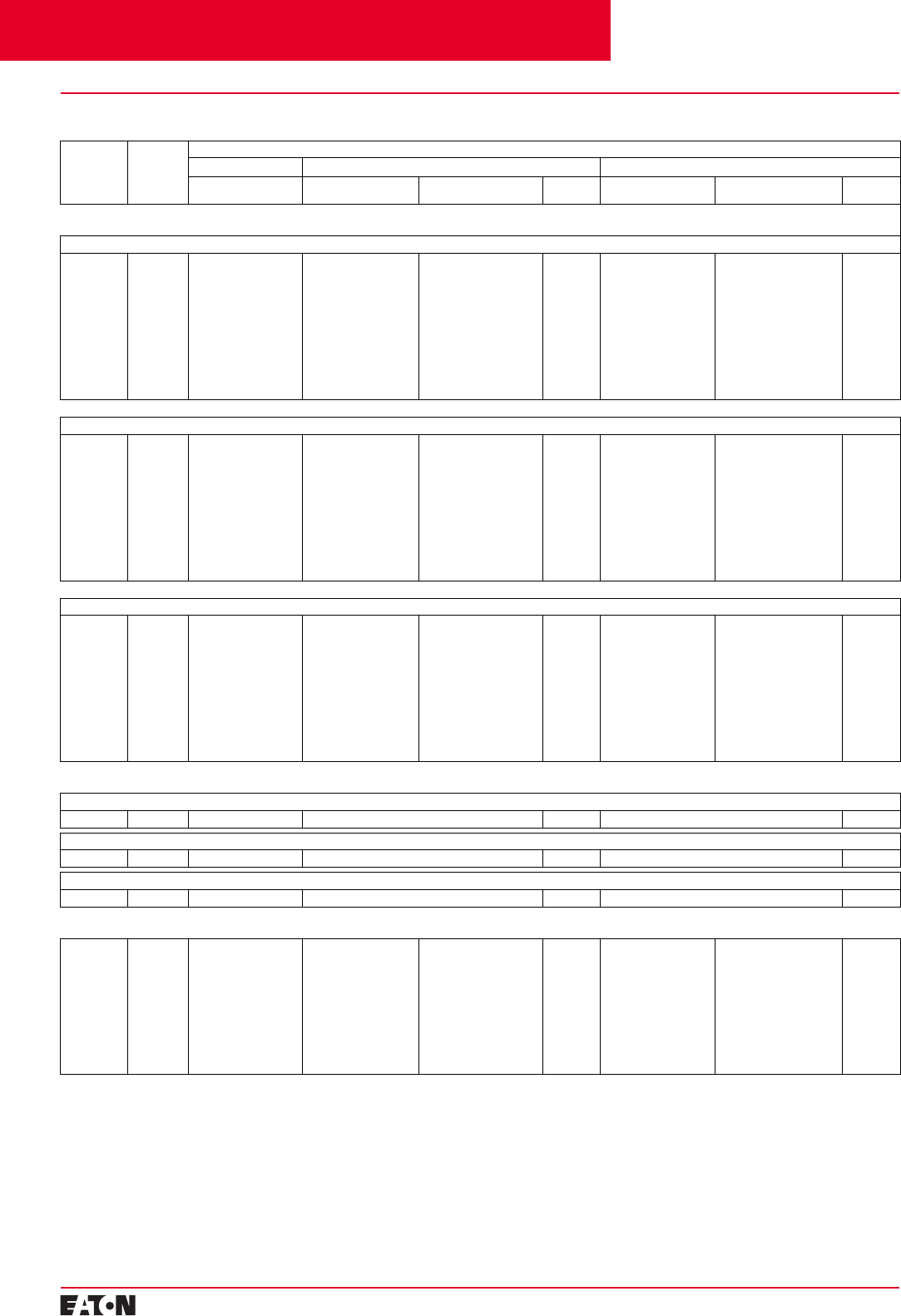
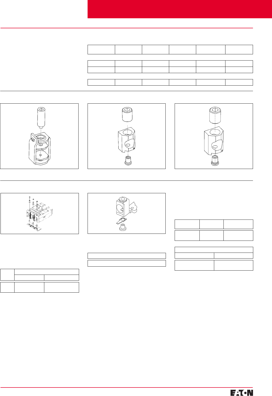
Interphase Barriers
The interphase barrier is available for
extended insulation between circuit
breaker poles. Specify quantity when
ordering.
Package of 2
Catalogue Number – EFIPBK
Control Wire Terminal Kit
For use with steel or stainless
steel
➀
terminals only.
Package of 12 – Priced Individually
Catalogue Number – EFCWTK
➀
Standard line and load terminals.
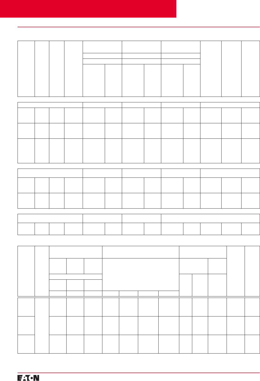
Line and Load Terminals
E-Frame circuit breakers and moulded
case switches have line and load
terminals as standard equipment.
Selection Guide and Ordering Information
Maximum
Breaker
Amperes
Terminal
Body
Material
Wire
Type Metric Wire
Range mm
2
AWG Wire
Range Catalogue Number
Package of
3 Terminals
Standard Cu/Al Pressure Type Terminals
125 Steel Cu 2.5-95 #14-3/0 3T125EF
➀
125
125 Aluminium
Aluminium Cu/Al
Cu/Al 2.5-50
16-70 #14-1/0
#6-3/0 3TA125EF
3TA150EF
Cutler-Hammer Frame Size E, 15-125 Amperes
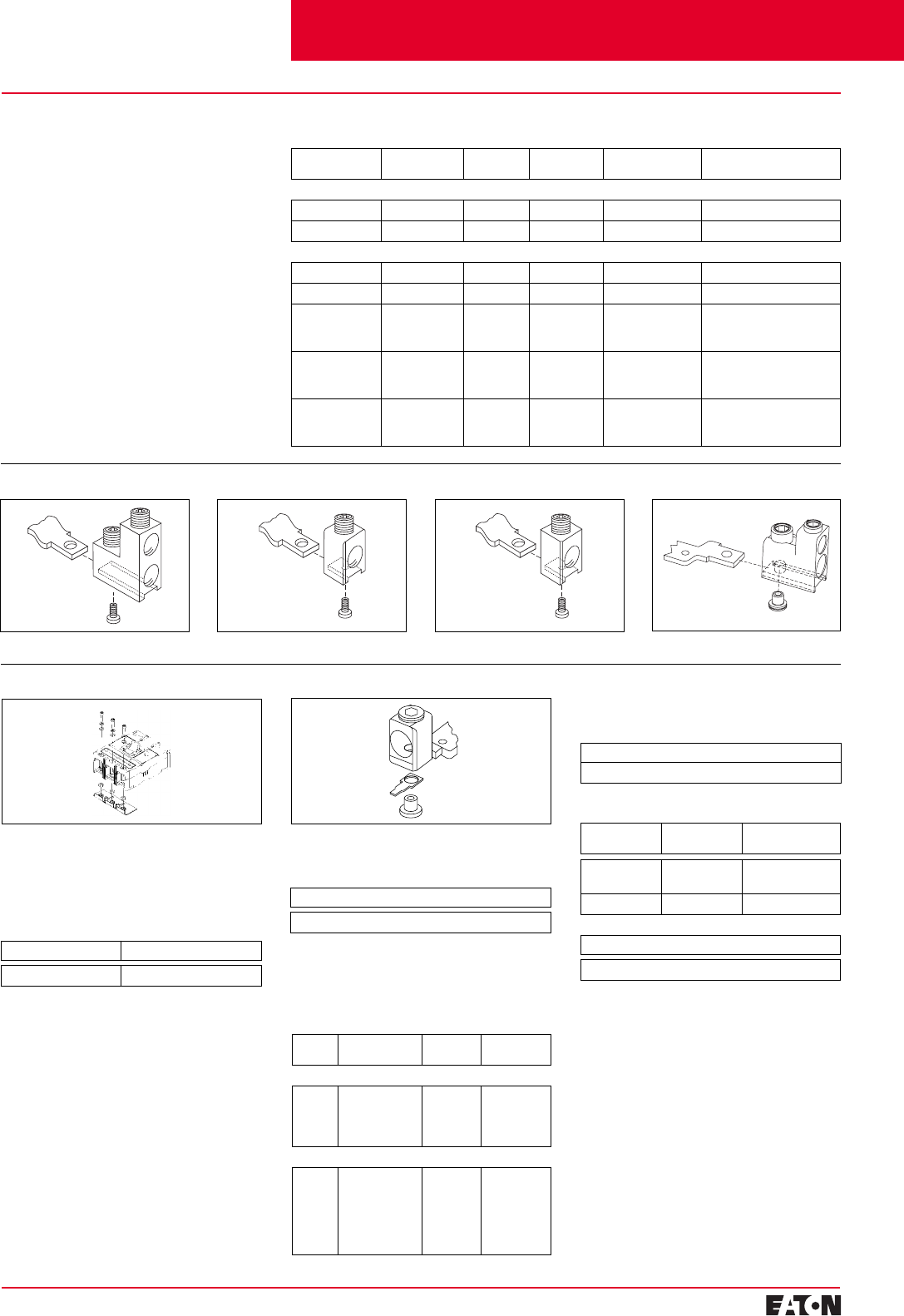
Terminal Shields
The terminal shield is available for
line terminal areas in 2-, 3-, and
4-pole circuit breakers. Special termi-
nal shields are also available for use
when an electrical (solenoid) opera-
tor is mounted on the circuit breaker.
The standard style number by pole
for each terminal shield is for a pack-
age of 10 and is priced per each
package. Special terminal shields are
packaged individually.
Terminal End Covers
The terminal end cover is available
for 3-pole circuit breakers only. Two
conductor opening sizes are availa-
ble. Specify quantity (one per circuit
breaker) when ordering.
Number
of
Poles
Standard
Package of 10 IP30
Protection
Catalogue Numbers – Priced Individually
2 EFTS2K
3 EFTS3K
4 EFTS4K
Conductor Opening
Diameter – mm (Inches) Catalogue
Number
6.35 (0.25) EFTC3K
10.41 (0.41) EFTC4K
Insert collar enclosing conductor as
shown. Locate nut on top of conductor
and tighten securely with screw and
washer. Caution: Collar must
surround conductor.
Insert collar enclosing conductor
and centre on extrusion. Tighten
securely with screw and washer.
EF3RTWK 3-Pole – Metric,
EF4RTWK 4-Pole – Metric,
EF3RTDK 3-Pole – Imperial,
EF4RTDK 4-Pole – Imperial
Endcap kits are used on
E-frame breaker line load to connect
bus bar or similar electrical connec-
tions. Includes hardware.
Catalogue Number
Base Mounting Hardware
Base mounting hardware is included
with a circuit breaker or moulded
case switch. (Included with breaker).
DIN Rail
Adapter Catalogue
Number
3- or 4-Pole EF34DIN
3T125EF
➀
3TA125EF 3TA150EF
Endcap Kit
Contents
Back To Reference
PG.29B.01A.T.U
Cutler-Hammer
16
February 2001
Moulded Case Circuit Breakers
16-2500 Amperes for IEC 60947-2 Applications
Cutler-Hammer Frame Size J, 100-250 Amperes
➀
Change the 4th digit to 8 for adjustable
0-60% neutral protection, 9 for 0-100%
neutral protection.
➁
IEC-EN 60947-2 only.
➂
Use 3-pole MCS.
Selection Guide and Ordering Information
Maximum
Continuous
Ampere
Rating
at 40°C
Magnetic
Range IC Rating @ 415/480 V
2-Pole 3-Pole 4-Pole
➀
Fixed Thermal
Adjustable Magnetic Fixed Thermal
Adjustable Magnetic Adjustable Thermal
Adjustable Magnetic
➁
Thermal
Range Fixed Thermal
Adjustable Magnetic Adjustable Thermal
Adjustable Magnetic
➁
Thermal
Range
Complete Circuit Breaker
Includes Frame, Trip Unit, Standard Terminals, and Mounting Hardware
IEC/CE/UL/CSA 25/25
63
70
90
100
125
150
160
175
200
225
250
250
315-630
350-700
450-900
500-1000
625-1250
750-1500
800-1600
875-1750
1000-2000
1125-2250
1250-2500
1250-2500
–
JGE2070FAG
JGE2090FAG
JGE2100FAG
JGE2125FAG
JGE2150FAG
–
JGE2175FAG
JGE2200FAG
JGE2225FAG
JGE2250FAG
➂
JGE3063FAG
➁
JGE3070FAG
JGE3090FAG
JGE3100FAG
JGE3125FAG
JGE3150FAG
JGE3160FAG
➁
JGE3175FAG
JGE3200FAG
JGE3225FAG
JGE3250FAG
JGE3250KSG
JGE3063AAG
–
–
JGE3100AAG
JGE3125AAG
–
JGE3160AAG
–
JGE3200AAG
–
JGE3250AAG
–
40-63
–
–
63-100
100-125
–
125-160
–
160-200
–
200-250
–
JGE4063FAG
➁
JGE4070FAG
JGE4090FAG
JGE4100FAG
JGE4125FAG
JGE4150FAG
JGE4160FAG
➁
JGE4175FAG
JGE4200FAG
JGE4225FAG
JGE4250FAG
JGE4250KSG
JGE4063AAG
–
–
JGE4100AAG
JGE4125AAG
–
JGE4160AAG
–
JGE4200AAG
–
JGE4250AAG
–
40-63
–
–
63-100
100-125
–
125-160
–
160-200
–
200-250
–
IEC/CE/UL/CSA 40/35
63
70
90
100
125
150
160
175
200
225
250
250
315-630
350-700
450-900
500-1000
625-1250
750-1500
800-1600
875-1750
1000-2000
1125-2250
1250-2500
1250-2500
–
JGS2070FAG
JGS2090FAG
JGS2100FAG
JGS2125FAG
JGS2150FAG
–
JGS2175FAG
JGS2200FAG
JGS2225FAG
JGS2250FAG
➂
JGS3063FAG
➁
JGS3070FAG
JGS3090FAG
JGS3100FAG
JGS3125FAG
JGS3150FAG
JGS3160FAG
➁
JGS3175FAG
JGS3200FAG
JGS3225FAG
JGS3250FAG
JGS3250KSG
JGS3063AAG
–
–
JGS3100AAG
JGS3125AAG
–
JGS3160AAG
–
JGS3200AAG
–
JGS3250AAG
–
40-63
–
–
63-100
100-125
–
125-160
–
160-200
–
200-250
–
JGS4063FAG
➁
JGS4070FAG
JGS4090FAG
JGS4100FAG
JGS4125FAG
JGS4150FAG
JGS4160FAG
➁
JGS4175FAG
JGS4200FAG
JGS4225FAG
JGS4250FAG
JGS4250KSG
JGS4063AAG
–
–
JGS4100AAG
JGS4125AAG
–
JGS4160AAG
–
JGS4200AAG
–
JGS4250AAG
–
40-63
–
–
63-100
100-125
–
125-160
–
160-200
–
200-250
–
IEC/CE/UL/CSA 70/65
63
70
90
100
125
150
160
175
200
225
250
250
315-630
350-700
450-900
500-1000
625-1250
750-1500
800-1600
875-1750
1000-2000
1125-2250
1250-2500
1250-2500
–
JGH2070FAG
JGH2090FAG
JGH2100FAG
JGH2125FAG
JGH2150FAG
–
JGH2175FAG
JGH2200FAG
JGH2225FAG
JGH2250FAG
➂
JGH3063FAG
➁
JGH3070FAG
JGH3090FAG
JGH3100FAG
JGH3125FAG
JGH3150FAG
JGH3160FAG
➁
JGH3175FAG
JGH3200FAG
JGH3225FAG
JGH3250FAG
JGH3250KSG
JGH3063AAG
–
–
JGH3100AAG
JGH3125AAG
–
JGH3160AAG
–
JGH3200AAG
–
JGH3250AAG
–
40-63
–
–
63-100
100-125
–
125-160
–
160-200
–
200-250
–
JGH4063FAG
➁
JGH4070FAG
JGH4090FAG
JGH4100FAG
JGH4125FAG
JGH4150FAG
JGH4160FAG
➁
JGH4175FAG
JGH4200FAG
JGH4225FAG
JGH4250FAG
JGH4250KSG
JGH4063AAG
–
–
JGH4100AAG
JGH4125AAG
–
JGH4160AAG
–
JGH4200AAG
–
JGH4250AAG
–
40-63
–
–
63-100
100-125
–
125-160
–
160-200
–
200-250
–
Components Frame
IEC/CE/UL/CSA 25/25
250 – JGE2250NN JGE3250NN – JGE4250NN –
IEC/CE/UL/CSA 40/35
250 – JGS2250NN JGS3250NN – JGS4250NN –
IEC/CE/UL/CSA 70/65
250 – JGH2250NN JGH3250NN – JGH4250NN –
Trip Unit
63
70
90
100
125
150
160
175
200
225
250
315-630
350-700
450-900
500-1000
625-1250
750-1500
800-1600
875-1750
1000-2000
1125-2250
1250-2500
JT2063FA
➁
JT2070FA
JT2090FA
JT2100FA
JT2125FA
JT2150FA
JT2160FA
➁
JT2175FA
JT2200FA
JT2225FA
J2T250FA
JT3063FA
➁
JT3070FA
JT3090FA
JT3100FA
JT3125FA
JT3150FA
JT3160FA
➁
JT3175FA
JT3200FA
JT3225FA
JT3250FA
JT3063AA
➁
–
–
JT3100AA
➁
JT3125AA
➁
–
JT3160AA
➁
–
JT3200AA
➁
–
JT3250AA
➁
40-63
–
–
63-100
100-125
–
125-160
–
160-200
–
200-250
JT4063FA
➁
JT4070FA
JT4090FA
JT4100FA
JT4125FA
JT4150FA
JT4160FA
➁
JT4175FA
JT4200FA
JT4225FA
JT4250FA
JT4063AA
➁
–
–
JT4100AA
➁
JT4125AA
➁
–
JT4160AA
➁
–
JT4200AA
➁
–
JT4250AA
➁
40-63
–
–
63-100
100-125
–
125-160
–
160-200
–
200-250
Contents
Back To Reference
February 2001
PG.29B.01A.T.U
Cutler-Hammer
17
Moulded Case Circuit Breakers
16-2500 Amperes for IEC 60947-2 Applications
Cutler-Hammer Frame Size J250, 63-250 Amperes
Endcap Kit Control Wire Terminal Kit
Line and Load Terminals
J250-Frame circuit breakers include
Cu terminals, T250FJ as standard.
When optional copper or Cu/1919Al
terminals are required, order by
catalogue number.
Selection Guide and Ordering Information
Catalogue Number
T250FJ
Interphase Barriers
Terminal Shields IP30
Location Number of
Poles Catalogue Number
Package of 10
Line or Load 2, 3
4FJTS3K
FJTS4K
Package of 2
Number of Poles Catalogue Number
3
4FJIPBK
FJIPBK4
Maximum
Breaker Amperes Terminal Body
Material Wire
Type Metric Wire
Range mm
2
AWG Wire Range/
Number Conductors Catalogue
Number
Standard Pressure Type Terminals
250 Stainless Steel Cu 25-185 4-350/(1) T250FJ
➀➁
250 Aluminium Cu/Al 25-185 4-350/(1) TA250FJ
➀
Optional Copper and Cu/Al Pressure Type Terminals
250 Copper Cu/Al 25-185 4-350/(1) TC250FJ
➀
Base Mounting Hardware
Base mounting hardware is included
with a circuit breaker or moulded
case switch. (Included with breaker).
➀
Individually packed.
➁
Standard line and load terminals.
TA250FJ TC250FJ
Endcap kits are used on J250 Frame
breaker line load to connect bus bar
or similar electrical connections.
Includes hardware.
Kit Catalogue Number
Number
of Poles Catalogue Number
Metric Imperial
3
4FJ3RTWK
FJ4RTWK FJ3RTDK
FJ4RTDK
For use with aluminium or copper
terminals only.
Package of 14 - Priced Individually
Catalogue Number – FJCWTK
Contents
Back To Reference
PG.29B.01A.T.U
Cutler-Hammer
18
February 2001
Moulded Case Circuit Breakers
16-2500 Amperes for IEC 60947-2 Applications
Selection Guide and Ordering Information
Maximum
Continu-
ous
Ampere
Rating
at 40°C
➀➁
Number
of Poles Thermal
Range Magnetic
Range Standard Interrupting
Capacity
Catalogue Number
High Interrupting
Capacity
Catalogue Number
Ultra-High Interrupting
Capacity
Catalogue Number
Thermal
Magnetic Trip
Unit Only
For Use with
Standard or
High or Ultra-
High Inter-
rupting Frame
Adjustable
Thermal
Adjustable
Magnetic
Standard
Terminals
Only
Catalogue
Number
Metric
Mounting
Hardware
Catalogue
Number
U
e
Max. 690 VAC U
e
Max. 690 VAC U
e
Max. 690 VAC
45 kA I
cu
at 415 VAC 70 kA I
cu
at 415 VAC 100 kA I
cu
at 415 VAC
Factory
Assembled
Circuit Breaker
Consisting of
Frame, Trip
Unit, and
Terminals
and Mounting
Hardware
Frame
Only Factory
Assembled
Circuit Breaker
Consisting of
Frame, Trip
Unit, and
Terminals
and Mounting
Hardware
Frame
Only Factory
Assembled
Circuit Breaker
Consisting of
Frame, Trip
Unit, and
Terminals
and Mounting
Hardware
Frame
Only
Adjustable Thermal Magnetic Circuit Breakers with Interchangeable Trip Units
–
Type KW Type HKW Type KWC
–
200
250
315
400
2-Pole 160-200
200-250
250-315
315-400
1000-2000
1250-2500
1575-3150
2000-4000
KW2200
KW2250
KW2315
KW2400
KW2400F HKW2200
HKW2250
HKW2315
HKW2400
HKW240F KWC2200
KWC2250
KWC2315
KWC2400
KWC2400F KT2200TA
KT2250TA
KT2315TA
KT2400TA
TA300KM
➀
TA300KM
➀
TA350KM
➀
TA350KM
➀
BMH3M
BMH3M
BMH3M
BMH3M
200
250
315
400
3-Pole 160-200
200-250
250-315
315-400
1000-2000
1250-2500
1575-3150
2000-4000
KW3200
KW3250
KW3315
KW3400
KW3400F HKW3200
HKW3250
HKW3315
HKW3400
HKW3400F KWC3200
KWC3250
KWC3315
KWC3400
KWC3400F KT3200TA
KT3250TA
KT3315TA
KT3400TA
TA300KM
➀
TA300KM
➀
TA350KM
➀
TA350KM
➀
BMH3M
BMH3M
BMH3M
BMH3M
200
250
315
400
315
400
4-Pole 160-200
200-250
250-315
315-400
250-315
315-400
1000-2000
1250-2500
1575-3150
2000-4000
1575-3150
2000-4000
KW4200
KW4250
KW4315
KW4400
KW4315E
➂
KW4400E
➂
KW4400F HKW4200
HKW4250
HKW4315
HKW4400
HKW4315E
➂
HKW4400E
➂
HKW4400F KWC4200
KWC4250
KWC4315
KWC4400
KWC4315E
➂
KWC4400E
➂
KWC4400F KT4200TA
KT4250TA
KT4315TA
KT4400TA
KT4315TEA
➂
KT4400TEA
➂
TA300KM
➀
TA300KM
➀
TA350KM
➀
TA350KM➀
TA350KM➀
TA350KM➀
BMH3M
BMH3M
BMH3M
BMH3M
BMH3M
BMH3M
Adjustable Thermal Magnetic Earth Leakage Circuit Breakers with Line and Load Terminals Included
–Type ELKW
(Ue Max. 415 VAC) Type ELHKW
(Ue Max. 415 VAC) Type ELKWC
(Ue Max. 415 VAC) –
200
250
315
400
3-Pole 160-200
200-250
250-315
315-400
1000-2000
1250-2500
1575-3150
2000-4000
ELKW3200
ELKW3250
ELKW3315
ELKW3400
– ELHKW3200
ELHKW3250
ELHKW3315
ELHKW3400
– ELKWC3200
ELKWC3250
ELKWC3315
ELKWC3400
– – TA350KM
TA350KM
TA350KM
TA350KM
BMH3M
BMH3M
BMH3M
BMH3M
200
250
315
400
4-Pole 160-200
200-250
250-315
315-400
1000-2000
1250-2500
1575-3150
2000-4000
ELKW4200
ELKW4250
ELKW4315
ELKW4400
– ELHKW4200
ELHKW4250
ELHKW4315
ELHKW4400
– ELKWC4200
ELKWC4250
ELKWC4315
ELKWC4400
– – TA350KM
TA350KM
TA350KM
TA350KM
BMH3M
BMH3M
BMH3M
BMH3M
Moulded Case Switches MCS Only without Line and Load Terminals
–Type KW
(Ue Max. 690 VAC) Type HKW
(Ue Max. 690 VAC) –
400 2-Pole
3-Pole
4-Pole
– – KW2400KW
KW3400KW
KW4400KW
– HKW2400KW
HKW3400KW
HKW4400KW
– – – – TA350KM➀
TA350KM➀
TA350KM➀
BMH3M
BMH3M
BMH3M
Electronic Circuit Breakers➃
With Interchangeable Type KES Digitrip RMS Trip Units – Order as Individual Components: Breaker Frame, Trip Unit, Rating Plug, Terminals, Mounting Hardware
Maximum
Continuous
Ampere
Rating
at 40°C➀➁
Number
of Poles Circuit Breaker Frame Only
Catalogue Number Digitrip RMS 310 Trip Unit Only Less Rating Plug
Catalogue Number Digitrip RMS 310 Only
Rating Plug
Order as Individual Component
Standard
Terminals
Only
Catalogue
Number
Metric
Mounting
Hardware
Catalogue
Number
Standard
Interrupt-
ing
Capacity
High
Interrupt-
ing
Capacity
Ultra-High
Interrupting
Capacity
L - Adjustable Long Delay Pickup (By Adjustable
Rating Plug)
S - Adjustable Short Delay Pickup with Fixed Short
Delay Time (I2t Response) or Adjustable Short
Delay Time (Flat Response)
I - Adjustable Instantaneous Pickup by Setting
Short Delay Time to Instantaneous
G - Adjustable Ground Fault Pickup with
Adjustable Ground Fault Delay (Flat Response)
Fixed Rating Plug Adjustable
Rating
Plug
Ue Max. 690 VAC Ampere
Rating Catalogue
Number Ampere
Rating
Catalogue
Number
45 kA Icu
at 415 VAC 70 kA Icu
at 415 VAC 100 kA Icu
at 415 VAC
Type KW Type HKW Type KWC LS LSI LSG LSIG
125 3-Pole KW3400F HKW3400F KWC3400F KES3125LS KES3125LSI KES3125LSG KES3125LSIG 63
70
90
100
125
1KES063T
1KES070T
1KES090T
1KES100T
1KES125T
Adjustable
Settings are:
63/80/
100/125
A1KES125T2
TA300KM➀
TA300KM➀
TA300KM➀
TA300KM➀
TA300KM➀
BMH3M
BMH3M
BMH3M
BMH3M
BMH3M
250 KW3400F HKW3400F KWC3400F KES3250LS KES3250LSI KES3250LSG KES3250LSIG 125
160
200
225
250
2KES125T
2KES160T
2KES200T
2KES225T
2KES250T
Adjustable
Settings are:
125/160/
225/250
A2KES250T2
TA300KM➀
TA300KM➀
TA300KM➀
TA300KM➀
TA300KM➀
BMH3M
BMH3M
BMH3M
BMH3M
BMH3M
400 KW3400F HKW3400F KWC3400F KES3400LS KES3400LSI KES3400LSG KES3400LSIG 200
225
250
315
400
4KES200T
4KES225T
4KES250T
4KES315T
4KES400T
Adjustable
Settings are:
200/250/
315/400
A4KES400T2
TA300KM➀
TA300KM➀
TA300KM➀
TA350KM➀
TA350KM➀
BMH3M
BMH3M
BMH3M
BMH3M
BMH3M
➀Individually packed. ➁Special 50ºC rating available.
Order by description.
➂60% protected neutral - left pole
➃For AC application only.
Cutler-Hammer Frame Size K, 63-400 Amperes
Contents
Back To Reference
February 2001
PG.29B.01A.T.U
Cutler-Hammer 19
Moulded Case Circuit Breakers
16-2500 Amperes for IEC 60947-2 Applications
Handle Extension
Not included with breaker. Must be
purchased separately.
Packaged Individually
Catalogue Number – HEX3
Endcap Kit Control Wire Terminal Kit
For use with aluminium or copper
terminals only.
Package of 14 - Priced Individually
Catalogue Number – KCWTK
Line and Load Terminals
K-Frame circuit breakers include Cu/Al
terminals as standard. When optional
copper or Cu/1919Al terminals are
required, order by catalogue number.
Selection Guide and Ordering Information
Catalogue Number
TA300KM, TA300K, T300K TA350KM, TA350K, T350K TA400K, T400K TA401K
Number
of Poles Description Type of
Mounting Catalogue
Number
Metric Thread
2, 3, 4 M6-0.7 x 38 mm
Pan-Head
Set screws and
Lockwashers
Individual 4218B80G14
Imperial Thread
2, 3, 4 0.250-20 x
1.5 Inch
Pan-Head
Steel Screws
and
Lockwashers
Individual 4218B80G14
Maximum
Breaker Amperes Terminal Body
Material Wire
Type Metric Wire
Range mm2AWG Wire Range/
Number Conductors Catalogue
Number
Standard Pressure Type Terminals
225 Aluminium Cu/Al 35-185 3-350/(1) TA300KM➀➂
400 Aluminium Cu/Al 120-240 250-500/(1) TA350KM➀➂➄
Optional Copper and Cu/Al Pressure Type Terminals
225 Copper Cu 35-185 3-350/(1) T300K➁➂
400 Copper Cu 120-240 250-500/(1) T300K➁➂
400 Aluminium Cu/Al 95-120 3/0-250/(2) 2TA400K - 2-Pole Kit➁➃
3TA400K - 3-Pole Kit➁➃
4TA400K - 4-Pole Kit➁➃
400 Aluminium Cu 95-120 3/0-250/(2) 2T400K - 2-Pole Kit➁➃
3T400K - 3-Pole Kit➁➃
4T400K - 4-Pole Kit➁➃
400 Aluminium Cu/Al 70-240
70-240
70-240
2/0-250/(2)
or
2/0-500/(1)
2TA401K - 2-Pole Kit➁➃
3TA401K - 3-Pole Kit➁➃
4TA401K - 4-Pole Kit➁➃
Base Mounting Hardware
Base mounting hardware is included
with a circuit breaker or moulded
case switch.
➀Metric hardware.
➁Imperial hardware.
➂Individually packed.
➃TA400K, T400K, and TA401K terminal kits
contain one terminal for each pole and one
terminal cover.
➄Standard terminal.
Cutler-Hammer Frame Size K, 63-400 Amperes
Endcap kits are used on K-Frame
breaker line load to connect bus bar
or similar electrical connections.
Includes hardware.
Kit Catalogue Number
Metric Imperial
KPEKM3 KPEK3
Interphase Barriers
Terminal Shields
Location Number of
Poles Catalogue Number
Package of 10
Line End 2, 3
4TS33LN
TS34LN
Load End 3 TS33LD
Package of 2
Catalogue Number – IPB3
Contents
Back To Reference
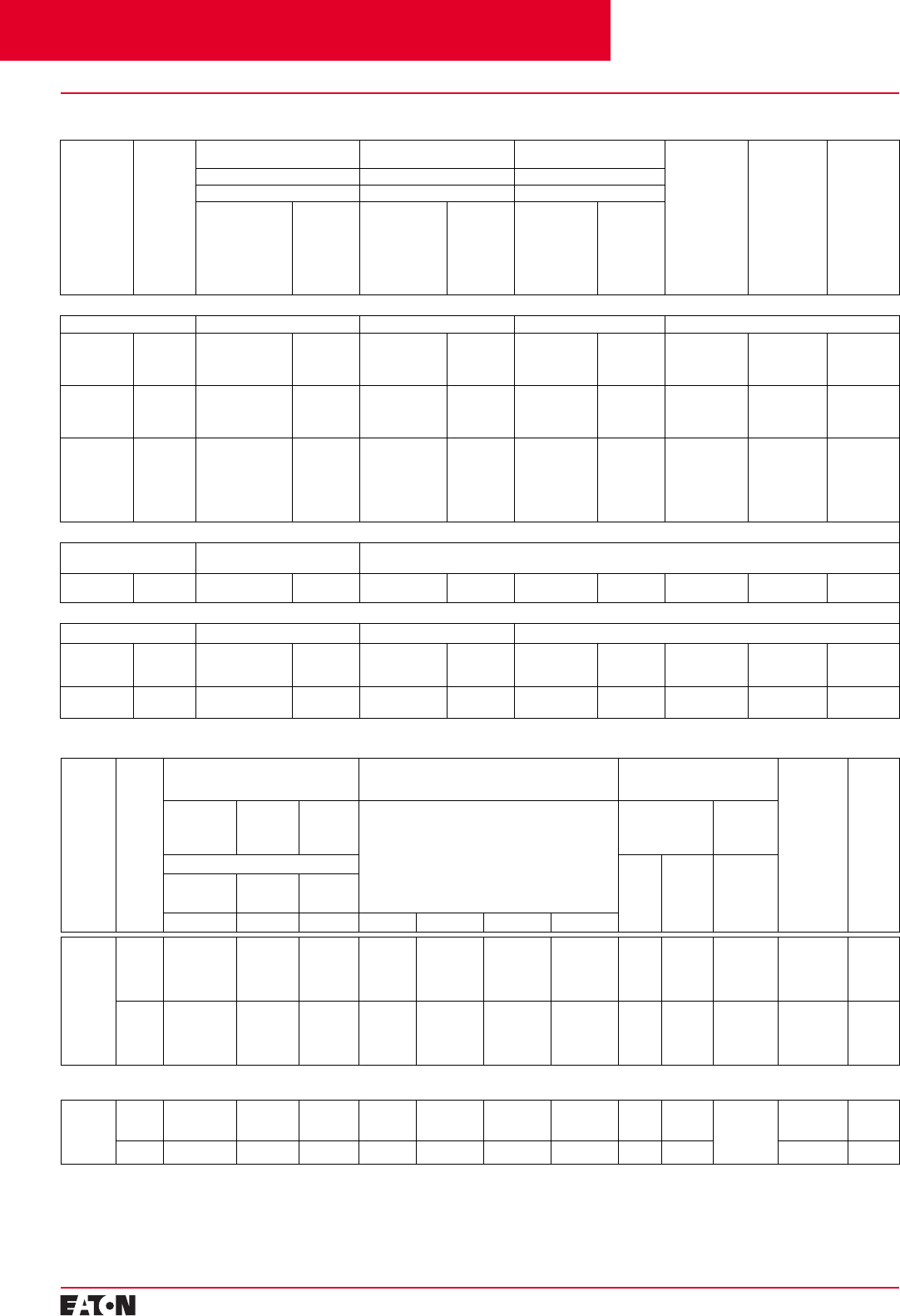
PG.29B.01A.T.U
Cutler-Hammer
20 February 2001
Moulded Case Circuit Breakers
16-2500 Amperes for IEC 60947-2 Applications
➀Individually packed.
➁Special 50ºC rating available.
Order by description.
➂2TA603KM, 3TA603LDKM and
4TA603LDKM terminal kits contain one ter-
minal per each pole and one terminal cover.
➃60% protected neutral – left pole
➄Ampere rating is established by rating plug.
➅For AC application only.
➆3-pole LES trip units are for use in 3-pole
frames only.
➇Trip unit includes unprotected left neutral
pole. For 100% protected left pole neutral
add “P” to catalogue number, i.e.,
LES4630LSP.
Selection Guide and Ordering Information
Maximum
Continuous
Ampere
Rating
at 40°C➀➁
Number of
Poles Standard Interrupting Capacity
Catalogue Number High Interrupting Capacity
Catalogue Number Ultra-High Interrupting Capacity
Catalogue Number Thermal
Magnetic Trip
Unit Only
For Use with
Standard or High
or Ultra-High
Interrupting
Frame
Adjustable
Thermal
Adjustable
Magnetic
Standard
Terminals
Only
Catalogue
Number
Metric
Mounting
Hardware
Catalogue
Number
Ue Max. 690 VAC Ue Max. 690 VAC Ue Max. 690 VAC
45 kA Icu at 415 VAC 70 kA Icu at 415 VAC 100 kA Icu at 415 VAC
Factory
Assembled
Circuit Breaker
Consisting of
Frame, Trip Unit,
and Terminals
Frame Only Factory
Assembled
Circuit Breaker
Consisting of
Frame, Trip Unit,
and Terminals
Frame Only Factory
Assembled
Circuit Breaker
Consisting of
Frame, Trip Unit,
and Terminals
Frame Only
Adjustable Thermal Magnetic Circuit Breakers with Interchangeable Trip Units
–Type LW Type HLW Type LWC –
315
400
500
630
2-Pole LW2315
LW2400
LW2500
LW2630
LW2630F HLW2315
HLW2400
HLW2500
HLW2630
HLW2630F LWC2315
LWC2400
LWC2500
LWC2630
LWC2630F LT2315TA
LT2400TA
LT2500TA
LT2630TA
TA602LDM➀
TA602LDM➀
TA602LDM➀
TA603LDKM➂
BMH4M
BMH4M
BMH4M
BMH4M
315
400
500
630
3-Pole LW3315
LW3400
LW3500
LW3630
LW3630F HLW3315
HLW3400
HLW3500
HLW3630
HLW3630F LWC3315
LWC3400
LWC3500
LWC3630
LWC3630F LT3315TA
LT3400TA
LT3500TA
LT3630TA
TA602LDM➀
TA602LDM➀
TA602LDM➀
TA603LDKM➂
BMH4M
BMH4M
BMH4M
BMH4M
315
400
500
630
500
630
4-Pole LW4315➇
LW4400➇
LW4500➇
LW4630➇
LW4500➃
LW4630➃
LW4630F HLW4315
HLW4400
HLW4500
HLW4630
HLW4500E➃
HLW4630E➃
HLW4630F LWC4315
LWC4400
LWC4500
LWC4630
LWC4500E➃
LWC4630E➃
LWC4630F LT4315TA
LT4400TA
LT4500TA
LT4630TA
LT4500TA➃
LT4630TAE➃
TA602LDM➀
TA602LDM➀
TA602LDM➀
TA603LDKM➂
TA602LDM➀
TA603LDKM➂
BMH4M
BMH4M
BMH4M
BMH4M
BMH4M
BMH4M
Thermal Magnetic Fixed Thermal Circuit Breakers with Noninterchangeable Trip Units and Bus Extension
–Types LW (Ue Max. 690 VAC, 50
kA lcu @ 415 VAC) –
700
800 3-Pole LW3700W
LW3800W – – –––– –BMH4M
BMH4M
Moulded Case Switches MCS Only without Line and Load Terminals
–Type LW (690 VAC Max.) Type HLW (690 VAC Max.) –
630 2-Pole
3-Pole
4-Pole
LW2630KW
LW3630WK
LW4630WK
–HLW2630KW
HLW3630WK
HLW4630WK
––––
TA603LDKM➂
TA603LDKM➂
TA603LDKM➂
BMH4M
BMH4M
BMH4M
800 3-Pole
4-Pole LW3800WK
LW4800WK – – –––– –
BMH4M
BMH4M
Cutler-Hammer Frame Size L, 315-800 Amperes
Electronic Circuit Breakers➅
With Interchangeable Type LES Digitrip RMS Trip Units – Order as Individual Components: Breaker Frame, Trip Unit, Rating Plug, Terminals, Mounting Hardware
Maximum
Continu-
ous
Ampere
Rating
at
40°C➀➁
Number
of Poles Circuit Breaker Frame Only
Catalogue Number Digitrip RMS 310 Trip Unit Only Less Rating Plug
Catalogue Number➄Digitrip RMS 310 Only
Rating Plug
Order as Individual Component
Standard
Terminals
Only
Catalogue
Number
Metric
Mounting
Hardware
Cata-
logue
Number
Standard
Interrupting
Capacity
High
Interrupt-
ing
Capacity
Ultra-High
Interrupt-
ing
Capacity
L - Adjustable Long Delay Pickup (By Adjustable
Rating Plug)
S - Adjustable Short Delay Pickup with Fixed Short
Delay Time (I2t Response) or Adjustable Short
Delay Time (Flat Response)
I - Adjustable Instantaneous Pickup by Setting
Short Delay Time to Instantaneous
G - Adjustable Ground Fault Pickup with
Adjustable Ground Fault Delay (Flat Response)
Fixed Rating Plug Adjustable
Rating
Plug
660 VAC Max. Ampere
Rating Catalogue
Number Ampere
Rating
Catalogue
Number
45 kA Icu
at 415 VAC 70 kA Icu
at 415 VAC 100 kA Icu
at 415 VAC
Type LW Type HLW Type LWC LS LSI LSG LSIG
630 3-Pole➆LW3630F HLW3630F LWC3630F LES3630LS LES3630LSI LES3630LSG LES3630LSIG 315
350
400
500
630
6LES315T
6LES350T
6LES400T
6LES500T
6LES630T
Adjustable
Settings are:
315/400/
500/630
A6LES630T2
TA602LDM➀
TA602LDM➀
TA602LDM➀
TA603LDKM➀
TA603LDKM➂
BMH4M
BMH4M
BMH4M
BMH4M
BMH4M
4-Pole➇LW4630F HLW4630F LWC4630F LES4630LS LES6430LSI LES4630LSG LES4630LSIG 315
350
400
500
630
6LES315T
6LES350T
6LES400T
6LES500T
6LES630T
Adjustable
Settings are:
315/400/
500/630
A6LES630T2
TA602LDM➀
TA602LDM➀
TA602LDM➀
TA603LDKM➀
TA603LDKM➂
BMH4M
BMH4M
BMH4M
BMH4M
BMH4M
Electronic Circuit Breakers
Includes Circuit Breaker Frame, Digitrip RMS 310 Electronic Trip Units with Noninterchangeable Adjustable Rating Plug and Bus Extension
800 3-Pole➆LW3800T33W
LW3800T35W
LW3800T35XW
– – – – – – – – Adjustable
Settings are:
400/500/
630/800
A8LES800T1
– BMH4M
BMH4M
BMH4M
4-Pole➇LW4800T33W –––– – ––– –
BMH4M
Contents
Back To Reference
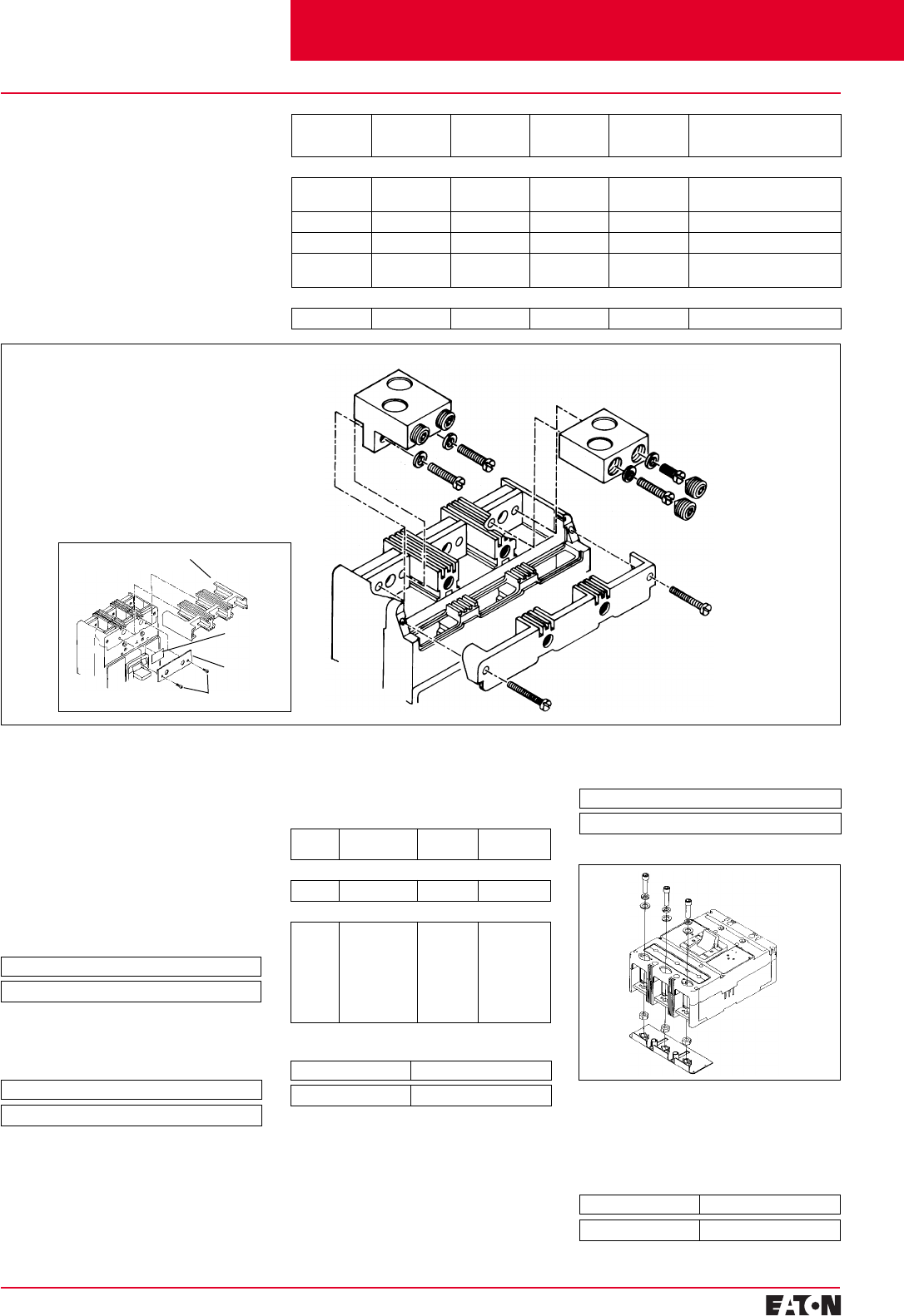
February 2001
PG.29B.01A.T.U
Cutler-Hammer 21
Moulded Case Circuit Breakers
16-2500 Amperes for IEC 60947-2 Applications
Circuit Breaker Line
Terminal Cover
TA401LD or TA603LD
Terminal (Step-Type
Terminal Requires
Terminal Cover and
Warning Label. See
Inset.)
Pan-Head
Screws and
Lockwashers
TA450LD, TA602LD,
or T602LD Terminal
Pan-Head Screws
and Lockwashers
(Installed before
Cable Clamping
Screws)
Selection Guide and
Ordering Information
Line and Load Terminals
L-Frame circuit breakers include
Cu/Al terminals as standard equip-
ment. When optional copper termi-
nals are required, order by catalogue
number. 800 ampere L-Frame circuit
breakers include bus extensions only.
Maximum
Breaker
Amperes
Terminal
Body
Material
Wire
Type Metric
Wire
Range mm2
AWG Wire
Range / No.
Conductors
Catalogue
Number
Standard Cu/Al Pressure Type Terminals
400 Aluminium Cu/AI 120-300 4/0-600 (1) 3TA401LDKM - 3-Pole Kit➁
4TA401LDKM - 4-Pole Kit➁
450 Aluminium Cu/AI 25-95 (2) 4-4/0 (2) TA450LDM➀
500 Aluminium Cu/AI 120-150 250-350 (2) TA602LDM➀
600 Aluminium Cu/AI 185-240 (2) 400-500 (2) 3TA603LDKM - 3-Pole Kit➁
4TA603LDKM - 4-Pole Kit➁
Optional Copper Pressure Type Terminals
600 Copper Copper 120-150 250-350 (2) T602LDM➀
➀Individually packed.
➁Terminal kits contain one terminal for each
pole and one terminal cover.
Terminal Shields
Terminal shields provide protection
against accidental contact with live
line side terminations. Terminal
shields are fabricated from high
dielectric insulating material and
fasten over the front terminal access
openings. Small openings in the
shields provide limited access to the
terminals for tightening connectors.
(Field installation only.)
Handle Extension
Not included with breaker. Must be
purchased separately.
Keeper Nut
Not required on L-Frame. Terminal
is threaded.
Package of 2
Style Number – 314C420G01
Packaged Individually
Catalogue Number – HEX4
Base Mounting Hardware
Base mounting hardware is included
with a circuit breaker or moulded
case switch.
Interphase Barriers
The interphase barriers provide addi-
tional electrical clearance between
circuit breaker poles for special termi-
nation applications. The barriers are
high dielectric insulating plates that
are installed in the moulded slots
Number
of Poles Description Type of
Mounting Style
Number
Metric Thread
2, 3 0.250-20 x Individual 5103A09G01
Imperial Thread
2, 3, 4 0.250-20 x
1.5 Inch
Filister-Head
Steel Screws
and Lock-
washers and
Flat Washers
Individual 21C6782G05
Kit Catalogue Number
Metric Imperial
KPEKM4 KPEK4
between the terminals. (Field installa-
tion only.) Two per package.
Endcap Kit
Endcap kits are used on L-Frame
breaker line load to connect bus bar
or similar electrical connections.
Includes hardware.
Package of 2
Catalogue Number – IPB4
Kit Catalogue Number
Metric Imperial
KPEKM4 KPEK4
Terminal Cover
Warning
Label
Retainer
Screws
Cutler-Hammer Frame Size L, 315-800 Amperes
Contents
Back To Reference
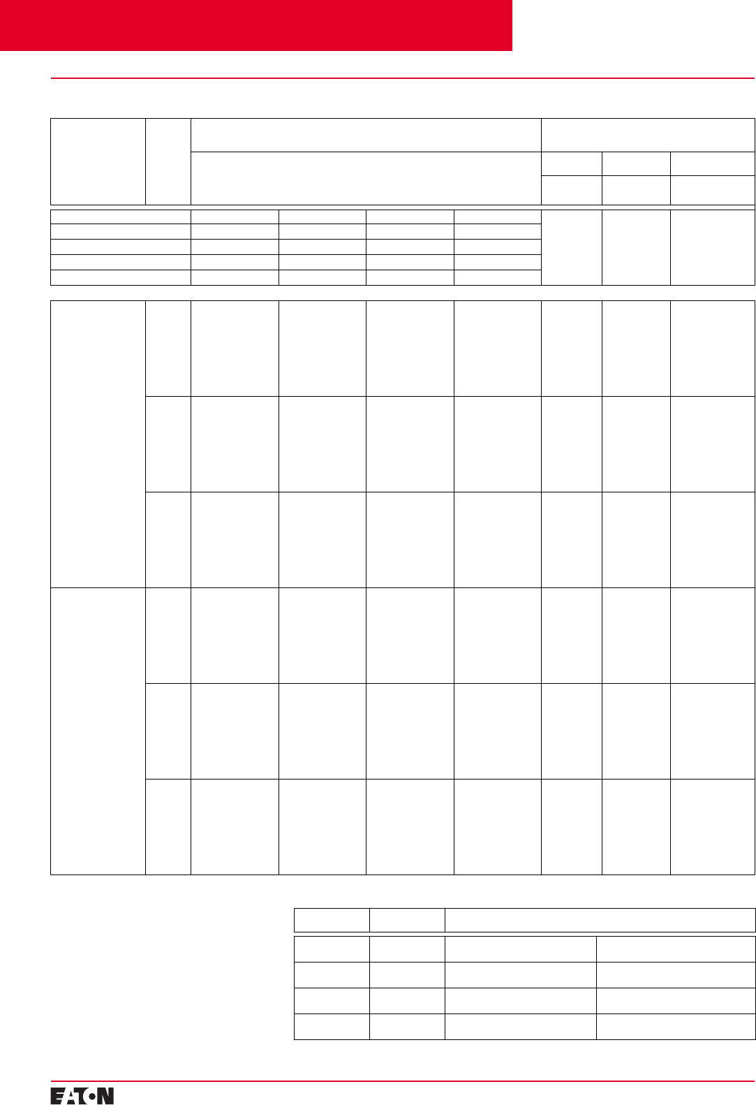
PG.29B.01A.T.U
Cutler-Hammer
22 February 2001
Moulded Case Circuit Breakers
16-2500 Amperes for IEC 60947-2 Applications
➀For AC use only.
➁Special 50ºC rating available. Order by
description.
➂For 2-pole applications, use outer poles of
3-pole moulded case switch.
➃Order rating plug and terminals separately.
Selection Guide and Ordering Information
Maximum Continuous
Ampere Rating at
40°C➀➁
Number
of Poles Circuit Breaker Frame Including Digitrip RMS 310 Electronic Trip Unit Less Rating Plugs
and Terminals
Order as Individual Component – Catalogue Number➃
Digitrip RMS 310
Interchangeable Rating Plugs
Order as Individual Component
L - Adjustable Long Delay Pickup (By Adjustable Rating Plug)
S -Adjustable Short Delay Pickup with Fixed Short Delay Time
(I2t Response) or Adjustable Short Delay Time (Flat Response)
I - Adjustable Instantaneous Pickup by Setting Short Delay Time to Instantaneous
G -Adjustable Ground Fault Pickup with Adjustable Ground Fault Delay (Flat Response)
Fixed
Rating Plug Adjustable
Rating Plug
Ampere
Rating Catalogue
Number Ampere Rating
Catalogue Number
– LS LSI LSG LSIG – – –
Short Time Range 2-8 x In2-8 x In2-8 x In2-8 x In
Short Time Delay – 0-300 ms – 0-300 ms
Ground Fault Pickup – – 200-1200A 200-1200A
Ground Fault Delay – – 0-500 ms 0-500 ms
Type NW Standard Interrupting Capacity – Ue Max. 690 VAC, 50 kA lcu at 415 VAC
800 2-Pole NW2800T33W NW2800T32W NW2800T35W NW2800T36W 400
450
500
550
600
630
700
800
8NES400T
8NES450T
8NES500T
8NES550T
8NES600T
8NES630T
8NES700T
8NES800T
Adjustable
Settings Are:
400/500/630/800
8NES800T2
3-Pole NW3800T33W NW3800T32W NW3800T35W NW3800T36W 400
450
500
550
600
630
700
800
8NES400T
8NES450T
8NES500T
8NES550T
8NES600T
8NES630T
8NES700T
8NES800T
400/500/630/800
8NES800T2
4-Pole NW4800T33W NW4800T32W – – 400
450
500
550
600
630
700
800
8NES400T
8NES450T
8NES500T
8NES550T
8NES600T
8NES630T
8NES700T
8NES800T
400/500/630/800
8NES800T2
1250 2-Pole NW2125T33W NW2125T32W NW2125T35W NW2125T36W 600
630
700
800
900
1000
1200
1250
12NES600T
12NES630T
12NES700T
12NES800T
12NES900T
12NES1000T
12NES1200T
12NES1250T
630/800/1000/1250
A12NES1250T2
3-Pole NW3125T33W NW3125T32W NW3125T35W NW3125T36W 600
630
700
800
900
1000
1200
1250
12NES600T
12NES630T
12NES700T
12NES800T
12NES900T
12NES1000T
12NES1200T
12NES1250T
630/800/1000/1250
A12NES1250T2
4-Pole NW4125T33W NW4125T32W – – 600
630
700
800
900
1000
1200
1250
12NES600T
12NES630T
12NES700T
12NES800T
12NES900T
12NES1000T
12NES1200T
12NES1250T
630/800/1000/1250
A12NES1250T2
Moulded Case Switches➀➂
Ampere
Rating Number
of Poles Ue Max. 690 VAC
Catalogue Number
800 3-Pole
4-Pole NW3800WK
NW4800WK MCS Only without
Line and Load
1250 3-Pole
4-Pole NW3125WK
NW4125WK MCS Only without
Line and Load
800 3-Pole
4-Pole HNW3800WK
HNW4800WK MCS Only without
Line and Load
1250 3-Pole
4-Pole HNW3125WK
HNW4125WK MCS Only without
Line and Load
Cutler-Hammer Frame Size N, 400-1250 Amperes 50 kA at 415 VAC
Contents
Back To Reference
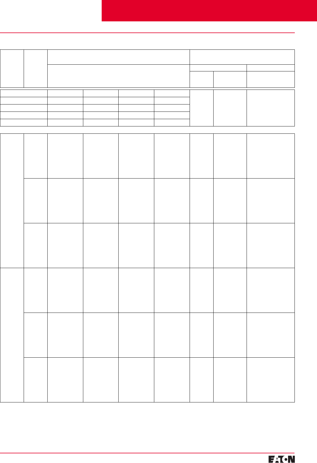
February 2001
PG.29B.01A.T.U
Cutler-Hammer
23
Moulded Case Circuit Breakers
16-2500 Amperes for IEC 60947-2 Applications
Selection Guide and Ordering Information
Maximum
Continuous
Ampere
Rating
at 40°C
➀➁
Number
of
Poles
Circuit Breaker Frame Including Digitrip RMS 310 Electronic Trip Unit Less Rating Plugs
and Terminals
Order as Individual Component – Catalogue Number
➂
Digitrip RMS 310 Interchangeable Rating Plugs
Order as Individual Component
L - Adjustable Long Delay Pickup (By Adjustable Rating Plug)
S - Adjustable Short Delay Pickup with Fixed Short Delay Time
(I
2
t Response) or Adjustable Short Delay Time (Flat Response)
I - Adjustable Instantaneous Pickup by Setting Short Delay Time to Instantaneous
G - Adjustable Ground Fault Pickup with Adjustable Ground Fault Delay (Flat Response)
Fixed Rating Plug Adjustable Rating Plug
Ampere
Rating Catalogue
Number Ampere Rating
Catalogue Number
–
LS LSI LSG LSIG
–– –
Short Time Range 2-8 x I
n
2-8 x I
n
2-8 x I
n
2-8 x I
n
Short Time Delay – 0-300 ms – 0-300 ms
Ground Fault Pickup – – 200-1200A 200-1200A
Ground Fault Delay – – 0-500 ms 0-500 ms
Type HNW Standard Interrupting Capacity – U
e
Max. 690 VAC, 70 kA I
cu
at 415 VAC
800 2-Pole HNW2800T33W HNW2800T32W HNW2800T35W HNW2800T36W 400
450
500
550
600
630
700
800
8NES400T
8NES450T
8NES500T
8NES550T
8NES600T
8NES630T
8NES700T
8NES800T
Adjustable Settings Are:
400/500/630/800
8NES800T2
3-Pole HNW3800T33W HNW3800T32W HNW3800T35W HNW3800T36W 400
450
500
550
600
630
700
800
8NES400T
8NES450T
8NES500T
8NES550T
8NES600T
8NES630T
8NES700T
8NES800T
400/500/630/800
8NES800T2
4-Pole HNW4800T33W HNW4800T32W – – 400
450
500
550
600
630
700
800
8NES400T
8NES450T
8NES500T
8NES550T
8NES600T
8NES630T
8NES700T
8NES800T
400/500/630/800
8NES800T2
1250 2-Pole HNW2125T33W HNW2125T32W HNW2125T35W HNW2125T36W 600
630
700
800
900
1000
1200
1250
12NES600T
12NES630T
12NES700T
12NES800T
12NES900T
12NES1000T
12NES1200T
12NES1250T
630/800/1000/1250
A12NES1250T2
3-Pole HNW3125T33W HNW3125T32W HNW3125T35W HNW3125T36W 600
630
700
800
900
1000
1200
1250
12NES600T
12NES630T
12NES700T
12NES800T
12NES900T
12NES1000T
12NES1200T
12NES1250T
630/800/1000/1250
A12NES1250T2
4-Pole HNW4125T33W HNW4125T32W – – 600
630
700
800
900
1000
1200
1250
12NES600T
12NES630T
12NES700T
12NES800T
12NES900T
12NES1000T
12NES1200T
12NES1250T
630/800/1000/1250
A12NES1250T2
➀
For AC use only.
➁
Special 50ºC rating available.
Order by description.
➂
Order rating plug and terminals separately.
Cutler-Hammer Frame Size N, 400-1250 Amperes 70 kA at 415 VAC
Contents
Back To Reference
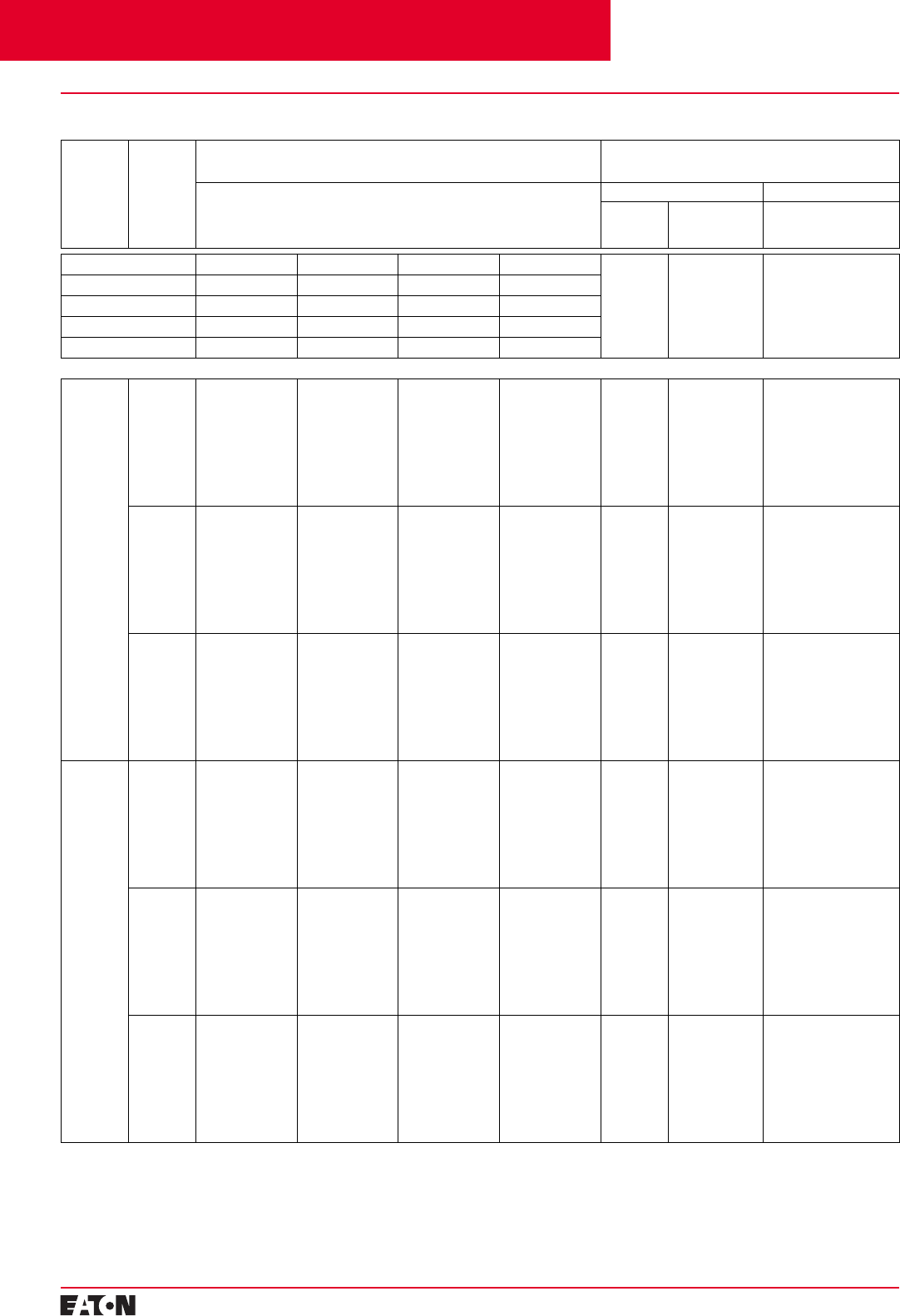
PG.29B.01A.T.U
Cutler-Hammer
24
February 2001
Moulded Case Circuit Breakers
16-2500 Amperes for IEC 60947-2 Applications
Selection Guide and Ordering Information
Maximum
Continuous
Ampere
Rating
at 40°C
➀➁
Number
of
Poles
Circuit Breaker Frame Including Digitrip RMS 310 Electronic Trip Unit Less Rating Plugs
and Terminals
Order as Individual Component – Catalogue Number
➂
Digitrip RMS 310 Interchangeable Rating Plugs
Order as Individual Component
L - Adjustable Long Delay Pickup (By Adjustable Rating Plug)
S - Adjustable Short Delay Pickup with Fixed Short Delay Time
(I
2
t Response) or Adjustable Short Delay Time (Flat Response)
I - Adjustable Instantaneous Pickup by Setting Short Delay Time to Instantaneous
G - Adjustable Ground Fault Pickup with Adjustable Ground Fault Delay (Flat Response)
Fixed Rating Plug Adjustable Rating Plug
Ampere
Rating Catalogue
Number Ampere Rating
Catalogue Number
–
LS LSI LSG LSIG
–– –
Short Time Range 2-8 x I
n
2-8 x I
n
2-8 x I
n
2-8 x I
n
Short Time Delay – 0-300 ms – 0-300 ms
Ground Fault Pickup – – 200-1200A 200-1200A
Ground Fault Delay – – 0-500 ms 0-500 ms
Type NWC Standard Interrupting Capacity – U
e
Max. 690 VAC, 100 kA I
cu
at 415 VAC
800 2-Pole NWC2800T33W NWC2800T32W NWC2800T35W NWC2800T36W 400
450
500
550
600
630
700
800
8NES400T
8NES450T
8NES500T
8NES550T
8NES600T
8NES630T
8NES700T
8NES800T
Adjustable Settings Are:
400/500/630/800
8NES800T2
3-Pole NWC3800T33W NWC3800T32W NWC3800T35W NWC3800T36W 400
450
500
550
600
630
700
800
8NES400T
8NES450T
8NES500T
8NES550T
8NES600T
8NES630T
8NES700T
8NES800T
400/500/630/800
8NES800T2
4-Pole NWC4800T33W NWC4800T32W – – 400
450
500
550
600
630
700
800
8NES400T
8NES450T
8NES500T
8NES550T
8NES600T
8NES630T
8NES700T
8NES800T
400/500/630/800
8NES800T2
1250 2-Pole NWC2125T33W NWC2125T32W NWC2125T35W NWC2125T36W 600
630
700
800
900
1000
1200
1250
12NES600T
12NES630T
12NES700T
12NES800T
12NES900T
12NES1000T
12NES1200T
12NES1250T
630/800/1000/1250
A12NES1250T2
3-Pole NWC3125T33W NWC3125T32W NWC3125T35W NWC3125T36W 600
630
700
800
900
1000
1200
1250
12NES600T
12NES630T
12NES700T
12NES800T
12NES900T
12NES1000T
12NES1200T
12NES1250T
630/800/1000/1250
A12NES1250T2
4-Pole NWC4125T33W NWC4125T32W – – 600
630
700
800
900
1000
1200
1250
12NES600T
12NES630T
12NES700T
12NES800T
12NES900T
12NES1000T
12NES1200T
12NES1250T
630/800/1000/1250
A12NES1250T2
➀
For AC use only.
➁
Special 50ºC rating available.
Order by description.
➂
Order rating plug and terminals separately.
Cutler-Hammer Frame Size N, 400-1250 Amperes 100 kA
Contents
Back To Reference
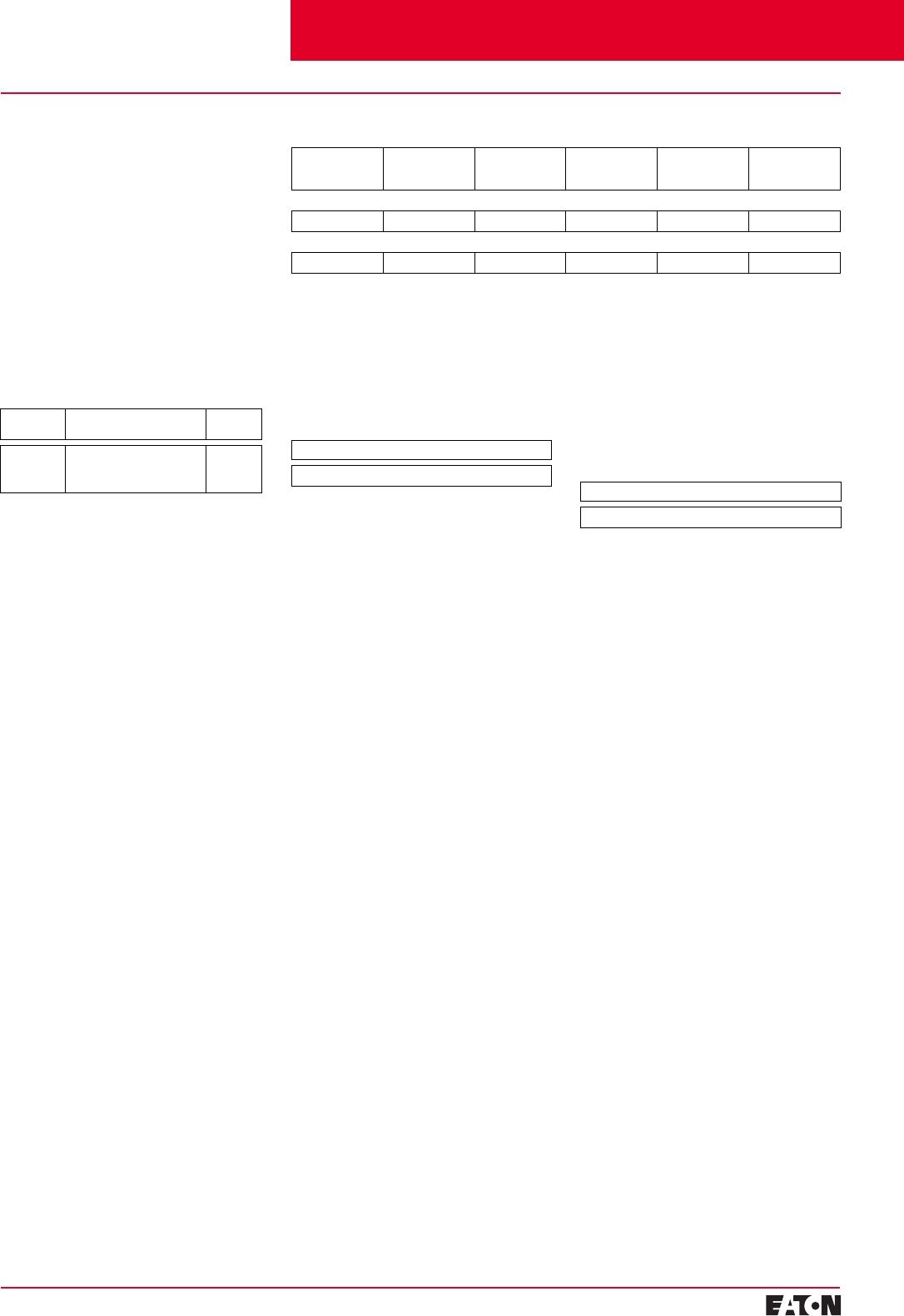
February 2001
PG.29B.01A.T.U
Cutler-Hammer
25
Moulded Case Circuit Breakers
16-2500 Amperes for IEC 60947-2 Applications
Maximum
Breaker
Amperes
Terminal
Body
Material
Wire
Type Metric Wire
Range mm
2
AWG Wire
Number of
Conductors
Catalogue
Number
Standard Cu/Al Pressure-Type Terminals
1250 Aluminium Cu/Al 120-300 4/0-500 (3) TA1200NB3M
Optional Copper and Cu/Al Pressure Type Terminals
1250 Copper Copper 95-185 3/0-400 (4) T1200NB3M
Base Mounting Hardware
Base mounting hardware is included
with a circuit breaker or moulded
case switch.
Keeper Nut
Not required on N-Frame. Terminals
are threaded.
Handle Extension
Included with breaker. Additional
handle extensions are available.
Line and Load Terminals
N-Frame circuit breakers include
Cu/Al terminals as standard.
When optional copper or Cu/Al
terminals are required, order by
catalogue number.
Imperial Thread
Number
of Poles Description Catalogue
Number
2-, 3-,
and 4-pole 0.3125-18 x 1.25 Inch
Pan-Head Steel Screws
and Lock Washers
BMH5M
Single Handle Extension
Catalogue Number – HEX5
Interphase Barriers
Catalogue Number – IPB5
Cutler-Hammer Frame Size N, 400-1250 Amperes
Selection Guide and Ordering Information
Interphase Barriers
The interphase barriers provide
additional electrical clearance
between circuit breaker poles for
special termination applications.
Barriers are high dielectric insulating
plates that are installed in the
Moulded slots between the terminals.
(Field installation only.)
Contents
Back To Reference
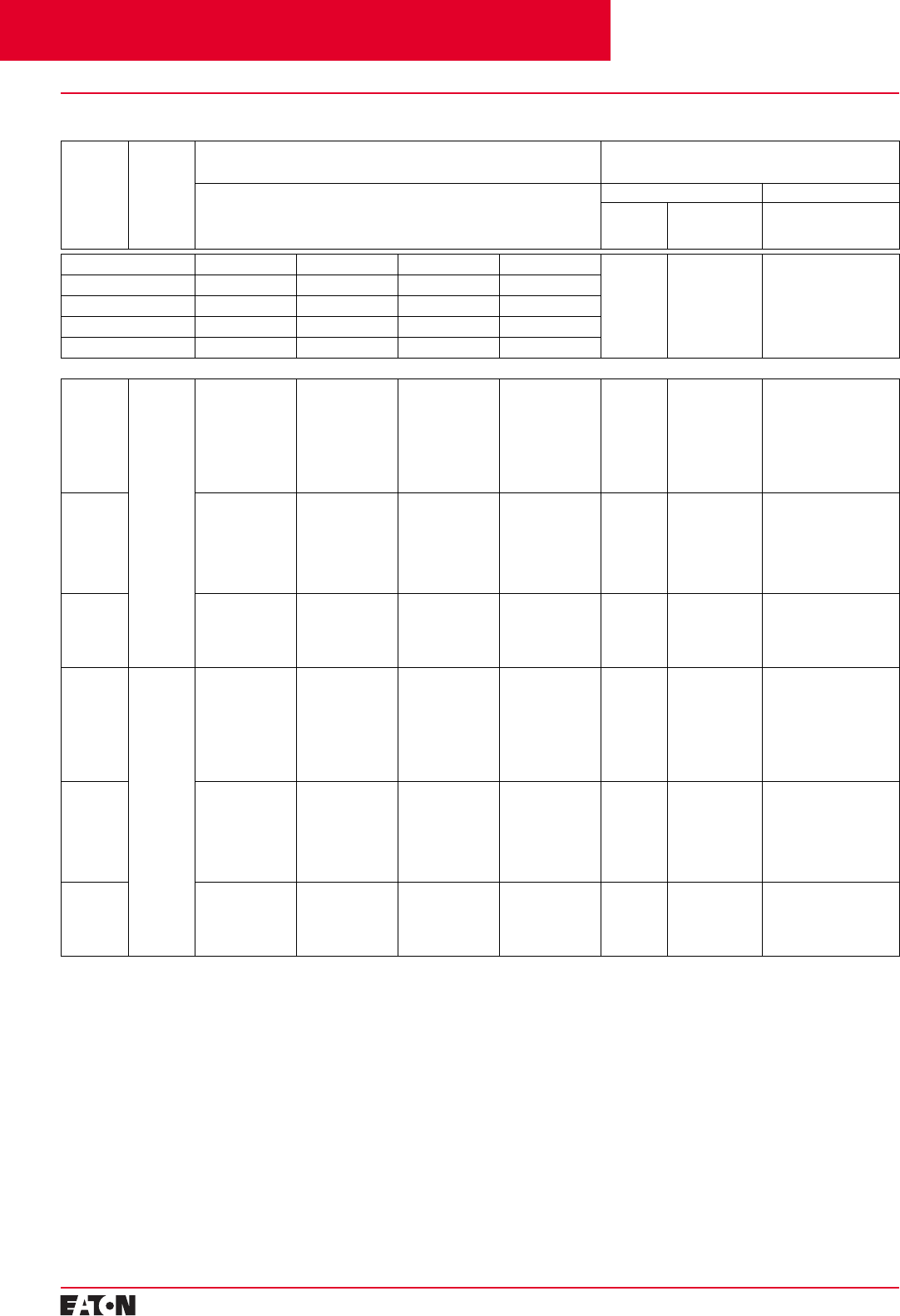
PG.29B.01A.T.U
Cutler-Hammer
26
February 2001
Moulded Case Circuit Breakers
16-2500 Amperes for IEC 60947-2 Applications
Selection Guide and Ordering Information
Maximum
Continuous
Ampere
Rating
at 40°C
➀➁
Number
of
Poles
Circuit Breaker Frame Including Digitrip RMS 310 Electronic Trip Unit Less Rating Plugs
and Terminals
Order as Individual Component – Catalogue Number
➄
Digitrip RMS 310 Interchangeable Rating Plugs
Order as Individual Component
L - Adjustable Long Delay Pickup (By Adjustable Rating Plug)
S - Adjustable Short Delay Pickup with Fixed Short Delay Time
(I
2
t Response) or Adjustable Short Delay Time (Flat Response)
I - Adjustable Instantaneous Pickup by Setting Short Delay Time to Instantaneous
G - Adjustable Ground Fault Pickup with Adjustable Ground Fault Delay (Flat Response)
Fixed Rating Plug Adjustable Rating Plug
Ampere
Rating Catalogue
Number Ampere Rating
Catalogue Number
–
LS LSI LSG
➃
LSIG
➂
–– –
Short Time Range 2-8 x I
n
2-8 x I
n
2-8 x I
n
2-8 x I
n
Short Time Delay – 0-300 ms – 0-300 ms
Ground Fault Pickup – – 200-1200A 200-1200A
Ground Fault Delay – – 0-500 ms 0-500 ms
Type RW with Digitrip 310 Standard Interrupting Capacity – U
e
Max. 690 VAC, 70 kA I
cu
at 415 VAC
1600
➀
3-Pole RW316T33W RW316T32W RW316T35W RW316T36W 800
1000
1200
1250
1400
1500
1600
16RES08T
16RES10T
16RES12T
16RES125T
16RES14T
16RES15T
16RES16T
Adjustable Settings Are:
800/1000/1200/1600
A16RES16T1
800/1000/1250/1600
A16RES16T2
2000 RW320T33W RW320T32W RW320T35W RW320T36W 1000
1200
1250
1400
1600
2000
20RES10T
20RES12T
A20RES125T
A20RES14T
A20RES16T
A20RES20T
1000/1200/1600/2000
A20RES20T1
1000/1250/1600/2000
A20RES20T2
2500 RW325T33W RW325T32W RW325T35W RW325T36W 1200
1250
1600
2000
2500
25RES12T
25RES125T
A25RES16T
A25RES20T
A25RES25T
1200/1600/2000/2500
A25RES25T1
1250/1600/2000/2500
A25RES25T2
1600
➀
4-Pole
➂
RW416T33W RW416T32W – – 800
1000
1200
1250
1400
1500
1600
16RES08T
16RES10T
16RES12T
16RES125T
16RES14T
16RES15T
16RES16T
800/1000/1200/1600
A16RES16T1
800/1000/1250/1600
A16RES16T2
2000 RW420T33W RW420T32W – – 1000
1200
1250
1400
1600
2000
20RES10T
20RES12T
A20RES125T
A20RES14T
A20RES16T
A20RES20T
1000/1200/1600/2000
A20RES20T1
1000/1250/1600/2000
A20RES20T2
2500 RW425T33W RW425T32W – – 1200
1250
1600
2000
2500
25RES12T
25RES125T
A25RES16T
A25RES20T
A25RES25T
1200/1600/2000/2500
A25RES25T1
1250/1600/2000/2500
A25RES25T2
➀
For SCR application, use 2000A frame.
➁
Special 50ºC rating available.
Order by description.
➂
Unprotected left pole neutral. Add “P” to
catalogue number for 100% protected left
pole neutral, add “E” for 60% protected, i.e.,
“RW416T33PW”, “RW416T33EW”.
Cutler-Hammer Frame Size R, 800-2500 Amperes 70 kA at 415 VAC
➃
Ground fault equipped trip units available
with remote indicating panel. Add “R” to
catalogue number, i.e., “RW316T35RW”.
➄
Order rating plug and terminals separately.
Mounting hardware not included.
Contents
Back To Reference
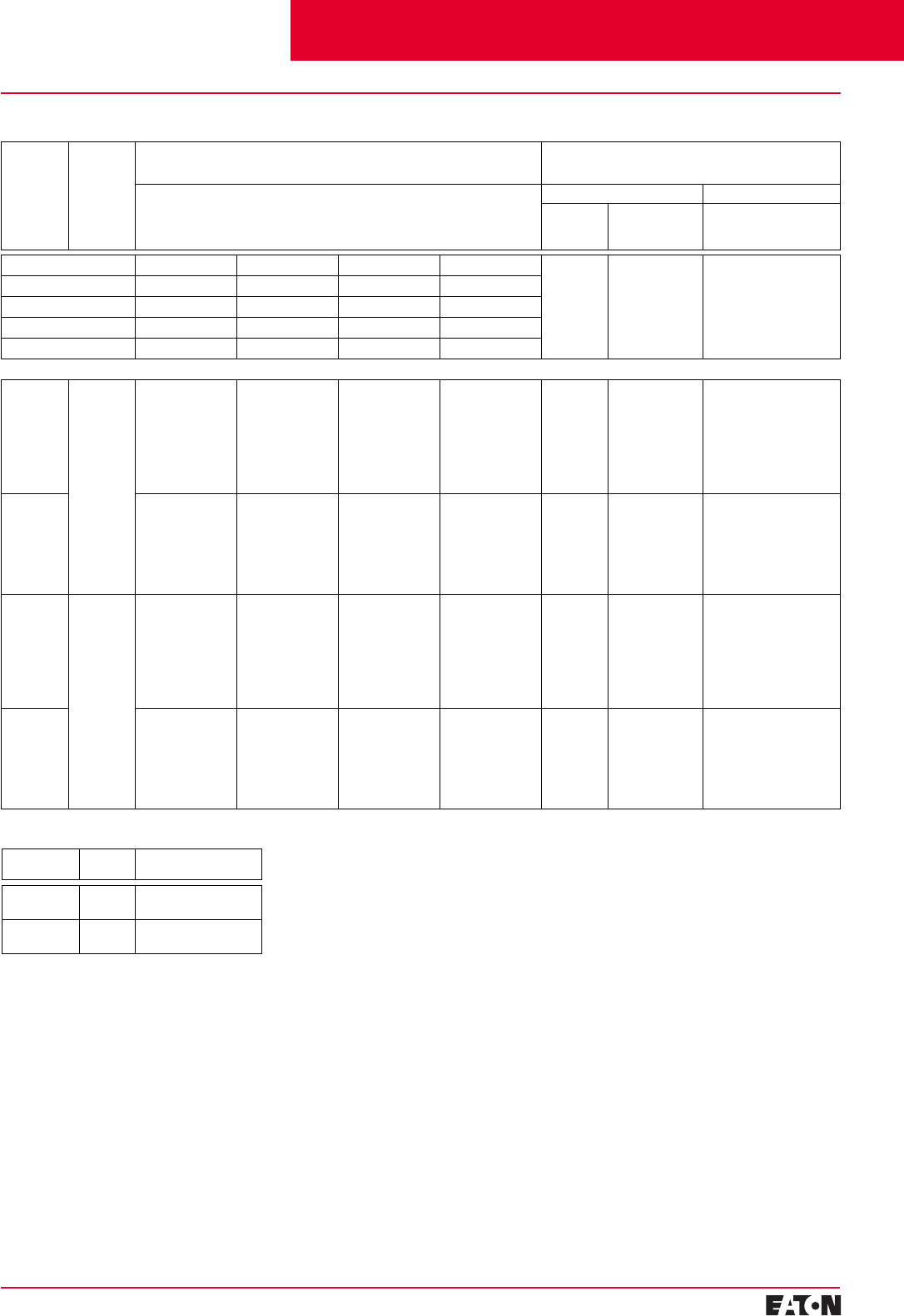
February 2001
PG.29B.01A.T.U
Cutler-Hammer
27
Moulded Case Circuit Breakers
16-2500 Amperes for IEC 60947-2 Applications
➀
For SCR application, use 2000A frame.
➁
Special 50ºC rating available.
Order by description.
➂
Unprotected left pole neutral. Add “P” to
catalogue number for 100% protected left
pole neutral, add “E” for 60% protected, i.e.,
“RW416T33PW”, “RW416T33EW”.
Selection Guide and Ordering Information
Maximum
Continuous
Ampere
Rating
at 40°C
➀➁
Number
of
Poles
Circuit Breaker Frame Including Digitrip RMS 310 Electronic Trip Unit Less Rating Plugs
and Terminals
Order as Individual Component – Catalogue Number
➄
Digitrip RMS 310 Interchangeable Rating Plugs
Order as Individual Component
L - Adjustable Long Delay Pickup (By Adjustable Rating Plug)
S - Adjustable Short Delay Pickup with Fixed Short Delay Time
(I
2
t Response) or Adjustable Short Delay Time (Flat Response)
I - Adjustable Instantaneous Pickup by Setting Short Delay Time to Instantaneous
G - Adjustable Ground Fault Pickup with Adjustable Ground Fault Delay (Flat Response)
Fixed Rating Plug Adjustable Rating Plug
Ampere
Rating Catalogue
Number Ampere Rating
Catalogue Number
–
LS LSI LSG
➃
LSIG
➃
__ _
Short Time Range 2-8 x I
n
2-8 x I
n
2-8 x I
n
2-8 x I
n
Short Time Delay – 0-300 ms – 0-300 ms
Ground Fault Pickup – – 200-1200A 200-1200A
Ground Fault Delay – – 0-500 ms 0-500 ms
Type RWC with Digitrip 310 High Interrupting Capacity – U
e
Max. 690 VAC, 100 kA I
cu
at 415 VAC
1600
➀
3-Pole RWC316T33W RWC316T32W RWC316T35W RWC316T36W 800
1000
1200
1250
1400
1500
1600
16RES08T
16RES10T
16RES12T
16RES125T
16RES14T
16RES15T
16RES16T
Adjustable Settings Are:
800/1000/1200/1600
A16RES16T1
800/1000/1250/1600
A16RES16T2
2000 RWC320T33W RWC320T32W RWC320T35W RWC320T36W 1000
1200
1250
1400
1600
2000
20RES10T
20RES12T
A20RES125T
A20RES14T
A20RES16T
A20RES20T
1000/1200/1600/2000
A20RES20T1
1000/1250/1600/2000
A20RES20T2
1600
➀
4-Pole
➂
RWC416T33W RWC416T32W – – 800
1000
1200
1250
1400
1500
1600
16RES08T
16RES10T
16RES12T
16RES125T
16RES14T
16RES15T
16RES16T
800/1000/1200/1600
A16RES16T1
800/1000/1250/1600
A16RES16T2
2000 RWC420T33W RWC420T32W – – 1000
1200
1250
1400
1600
2000
20RES10T
20RES12T
A20RES125T
A20RES14T
A20RES16T
A20RES20T
1000/1200/1600/2000
A20RES20T1
1000/1250/1600/2000
A20RES20T2
Moulded Case Switches
Ampere
Rating Number
of Poles Catalogue
Number
1600A
2000A 3-Pole RW316WK
RW320WK
1600A
2000A 4-Pole RW416WK
RW420WK
Cutler-Hammer Frame Size R, 800-2500 Amperes 100 kA at 415 VAC
➃
Ground fault equipped trip units available
with remote indicating panel. Add “R” to
catalogue number, i.e., “RW316T35RW”.
➄
Order rating plug and terminals separately.
Mounting hardware not included.
Contents
Back To Reference
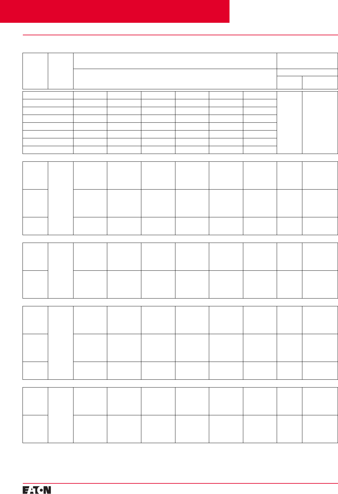
PG.29B.01A.T.U
Cutler-Hammer
28
February 2001
Moulded Case Circuit Breakers
16-2500 Amperes for IEC 60947-2 Applications
Selection Guide and Ordering Information
Maximum
Continuous
Ampere
Rating
at 40°C
➀
Number
of
Poles
Circuit Breaker Frame Including Digitrip 610 and and 910 Electronic Trip Unit Less Rating Plugs and Terminals
Order as Individual Component – Catalogue Number
➁
Digitrip RMS Interchangeable
Rating Plug
Order as Individual Component
L - Adjustable Long Delay Pickup (I
r
) with Adjustable Long Delay Time
S - Adjustable Short Delay Pickup with Adjustable Short Delay Time (I
2
t or Flat Response)
I - Adjustable Instantaneous Pickup
G - Adjustable Ground Fault Pickup with Adjustable Ground Fault Time Delay (I
2
t or Flat Response)
Fixed Rating Plug
Ampere
Rating Catalogue
Number
–
LI LS LSI LIG LSG LSIG
––
Long Delay Pickup 0.5-1.0 x I
n
0.5-1.0 x I
n
0.5-1.0 x I
n
0.5-1.0 x I
n
0.5-1.0 x I
n
0.5-1.0 x I
n
Long Delay Time 2-24 Seconds 2-24 Seconds 2-24 Seconds 2-24 Seconds 2-24 Seconds 2-24 Seconds
Short Time Range 2-6 x I
r
2-6 x I
r
2-6 x I
r
2-6 x I
r
2-6 x I
r
2-6 x I
r
Short Time Delay – 100-500 ms 100-500 ms – 100-500 ms 100-500 ms
Instantaneous 2-6 x M1 & M2 – 2-6 x M1 & M2 2-6 x M1 & M2 – 2-6 x M1 & M2
Ground Fault Pickup – – – 0.25-1.0 x In
➂
0.25-1.0 x In
➂
0.25-1.0 x In
➂
Ground Fault Delay – – – 100-500 ms 100-500 ms 100-500 ms
Type RW with Digitrip 610 Standard Interrupting Capacity – U
e
Max. 690 VAC, 70 kA I
cu
at 415 VAC
1600 3-Pole RW316T61W RW316T63W RW316T62W RW316T64W RW316T65W RW316T66W 800
1000
1200
1250
1600
RP6R16A080
RP6R16A100
RP6R16A120
RP6R16A125
RP6R16A160
2000 RW320T61W RW320T63W RW320T62W RW320T64W RW320T65W RW320T66W 1000
1200
1250
1600
2000
RP6R20A100
RP6R20A120
RP6R20A125
RP6R20A160
RP6R20A200
2500 RW325T61W RW325T63W RW325T62W RW325T64W RW325T65W RW325T66W 1600
2000
2500
RP6R25A160
RP6R25A200
RP6R25A250
Type RWC with Digitrip 610 High Interrupting Capacity – U
e
Max. 690 VAC, 100 kA I
cu
at 415 VAC
1600 3-Pole RWC316T61W RWC316T63W RWC316T62W RWC316T64W RWC316T65W RWC316T66W 800
1000
1200
1250
1600
RP6R16A080
RP6R16A100
RP6R16A120
RP6R16A125
RP6R16A160
2000 RWC320T61W RWC320T63W RWC320T62W RWC320T64W RWC320T65W RWC320T66W 1000
1200
1250
1600
2000
RP6R20A100
RP6R20A120
RP6R20A125
RP6R20A160
RP6R20A200
Type RW with Digitrip 910 Standard Interrupting Capacity – U
e
Max. 690 VAC, 70 kA I
cu
at 415 VAC
1600 3-Pole RW316T91W RW316T93W RW316T92W RW316T94W RW316T95W RW316T96W 800
1000
1200
1250
1600
RP6R16A080
RP6R16A100
RP6R16A120
RP6R16A125
RP6R16A160
2000 RW320T91W RW320T93W RW320T92W RW320T94W RW320T95W RW320T96W 1000
1200
1250
1600
2000
RP6R20A100
RP6R20A120
RP6R20A125
RP6R20A160
RP6R20A200
2500 RW325T91W RW325T93W RW325T92W RW325T94W RW325T95W RW325T96W 1600
2000
2500
RP6R25A160
RP6R25A200
RP6R25A250
Type RWC with Digitrip 910 High Interrupting Capacity – U
e
Max. 690 VAC, 100 kA I
cu
at 415 VAC
1600 3-Pole RWC316T91W RWC316T93W RWC316T92W RWC316T94W RWC316T95W RWC316T96W 800
1000
1200
1250
1600
RP6R16A080
RP6R16A100
RP6R16A120
RP6R16A125
RP6R16A160
2000 RWC320T91W RWC320T93W RWC320T92W RWC320T94W RWC320T95W RWC320T96W 1000
1200
1250
1600
2000
RP6R20A100
RP6R20A120
RP6R20A125
RP6R20A160
RP6R20A200
➀
Special 50ºC rating available.
Order by description.
Cutler-Hammer Frame Size R, 800-1250 Amperes 70 kA at 415 VAC and 100 kA at 415 VAC
➁
Order rating plug and terminals separately.
Mounting hardware not included.
➂
Not to exceed 1200A ground fault pick-up.
Contents
Back To Reference
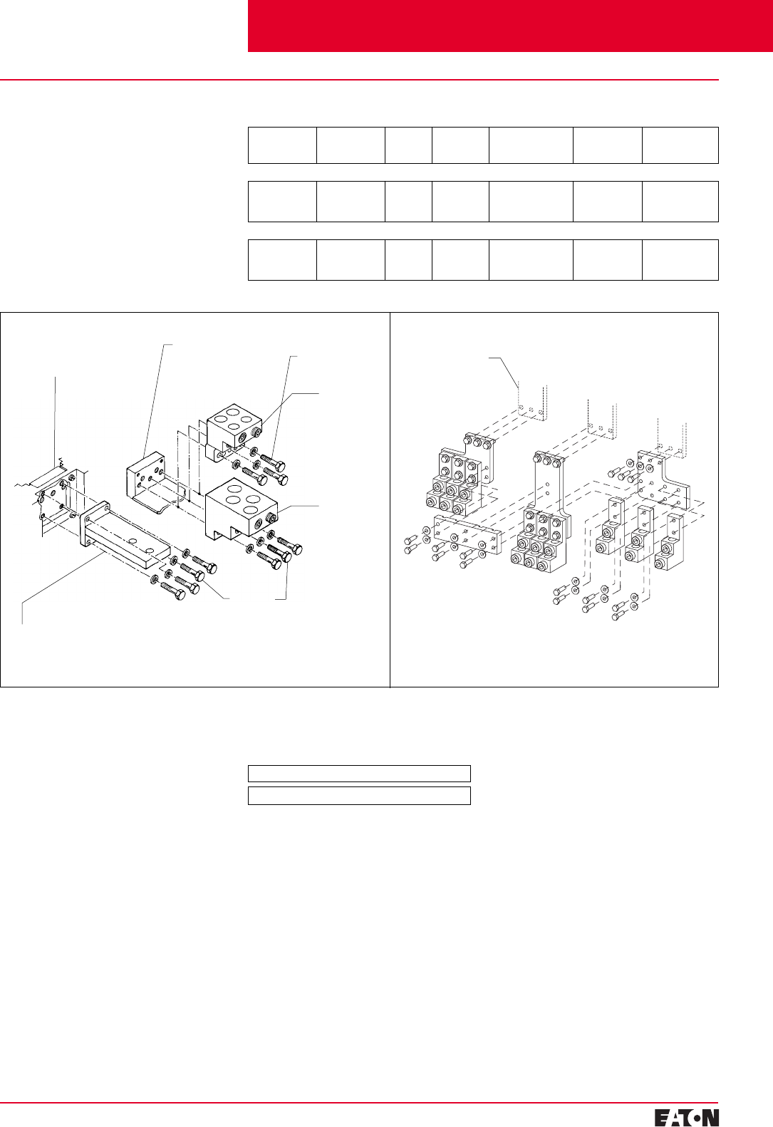
February 2001
PG.29B.01A.T.U
Cutler-Hammer
29
Moulded Case Circuit Breakers
16-2500 Amperes for IEC 60947-2 Applications
Conductor
(Viewed from Front
of Circuit Breaker)
Conductor
(Viewed from Rear
of Circuit Breaker and
Cut Away for Clarity)
Rear Connector (Cu)
B2016RD
B2016RDL (For 100% Application)
(For 1600A and 2000A Frames)
Securing
Hardware
Securing
Hardware
Cu Only
Terminal
Catalogue
Number
T1600RD
(For 1600A
Frame Only)
Al/Cu
Terminal
Catalogue
Number
TA1600RD
(For 1600A
Frame Only)
OR
Maximum
Breaker
Amperes
Terminal
Body
Material
Wire
Type Hardware AWG/kmil Wire
Range/Number
of Conductors
Metric Wire
Range mm
2
Catalogue
Number
Wire Terminals
1600
1600
2000
Aluminium
Copper
Aluminium
Cu/Al
Cu
Cu/Al
English
English
English
500-1000 (4)
1-600 (4)
2-600 (6)
300-500
50-300
35-300
TA1600RD
T1600RD
TA2000RD
Rear Connectors
2000
2000
2500
Copper
Copper
Copper
–
–
–
English
English
English
–
–
–
–
–
–
B2016RD
B2016RDL
B2500RD
Line and Load Terminals
R-Frame circuit breakers have Cu/Al
terminals as standard and copper
only terminals as an option. Specify
if factory installation is required.
➀
Catalogue number includes bus connection,
terminals, and hardware for either line side
or load side of 3-pole breaker.
Base Mounting Hardware
Supplied by customer.
Single Handle Extension
Catalogue Number – HEX6
Handle Extension
Included with breaker. Additional
handle extensions are available.
Selection Guide and Ordering Information
RD Rear Connector Exploded View
Cutler-Hammer Frame Size R, 800-2500 Amperes
Breaker Line/Load
Conductors
TA2000RD➀
Contents
Back To Reference

PG.29B.01A.T.U
Cutler-Hammer
30 February 2001
Moulded Case Circuit Breakers
16-2500 Amperes for IEC 60947-2 Applications
➀Combination ratings with Cutler-Hammer
Freedom® / ADVANTAGE® Control, contact
Cutler-Hammer.
Selection Guide and Ordering Information
Circuit Breakers for Motor Protection
Breaker
Type Rated
Current In
Rated Output of 3-Phase
Motors➀ to Be Protected
at 50 Hz
Setting
Current of
Inverse-Time
Overload
Release Ir
Instantaneous
Short Circuit
Release Ii
Trip Class
Tc
Standard Switching
Capacity
Catalogue
Number
High Switching
Capacity
Catalogue
Number
380/415V
Max. kW 500V
Max. kW
Without Adjustment of the Trip Class, without Phase Unbalance Detection
40 kA at 380/415 VAC 70 kA at 380/415 VAC
FWMP
FWMP
FWMP
FWMP
80
100
160
205
37
45
75
110
55
55
110
132
40-80
80-100
100-160
160-205
15 x Ir
15 x Ir
15 x Ir
13 x Ir
10
10
10
10
FWMP3080L
FWMP3100L
FWMP3160L
FWMP3205L
HFWMP3080L
HFWMP3100L
HFWMP3160L
HFWMP3205L
40 kA at 380/415 VAC
KWMP
LWMP 315
500 160
250 200
355 160-315
250-500 15 x Ir
15 x Ir
20
20 KWMP3315W
LWMP3500W HKWMP3315W
HLWMP3500W
With Adjustment of the Trip Class, with Phase Unbalance Detection
35 kA at 380/415 VAC 65 kA at 380/415 VAC
FWMP-J
FWMP-J
FWMP-J
FWMP-J
80
100
160
205
37
45
75
110
55
55
110
132
40-80
80-100
100-160
160-205
15 x Ir
15 x Ir
15 x Ir
13 x Ir
5/10/15/20
5/10/15/20
5/10/15/20
10
FWMP3080JL
FWMP3100JL
FWMP3160JL
FWMP3205JL
HFWMP3080JL
HFWMP3100JL
HFWMP3160JL
HFWMP3205JL
40 kA at 380/415 VAC
KWMP-J
LWMP-J 315
500 160
250 200
355 160-315
250-500 15 x Ir
15 x Ir
10/15/20/30
20 KWMP3315JW
LWMP3500JW HKWMP3315JW
HLWMP3500JW
Motor Circuit Protectors for Combination Starters
35 kA at 380/415 VAC 65 kA at 380/415 VAC➀
HMCP
HMCP
HMCP
HMCP
HMCP
HMCP
HMCP
HMCP
HMCP
HMCP
HMCP
HMCP
Up to 63
Up to 100
Up to 150
Up to 125
Up to 160
Up to 200
Up to 200
Up to 250
Up to 315
Up to 315
Up to 400
Up to 500
30
45
75
55
75
90
90
110
160
160
200
250
37
55
110
75
110
132
132
160
200
200
250
355
–
–
–
–
–
–
–
–
–
–
–
–
300-1000
450-1500
750-1500
1000-2000
1125-2250
1250-2500
1500-3000
1750-3500
2000-4000
1800-6000
1800-6000
1800-6000
–
–
–
–
–
–
–
–
–
–
–
–
–
–
–
–
–
–
–
–
–
–
–
–
HMCPE100R3
HMCPJ250C5
HMCPJ250G5
HMCPJ250K5
HMCPJ250L5
HMCPJ250W5
HMCP400N5
HMCP400R5
HMCP400X5
HMCP600L6W
HMCP600L6W
HMCP600L6W
Motor Circuit Protectors
Contents
Back To Reference
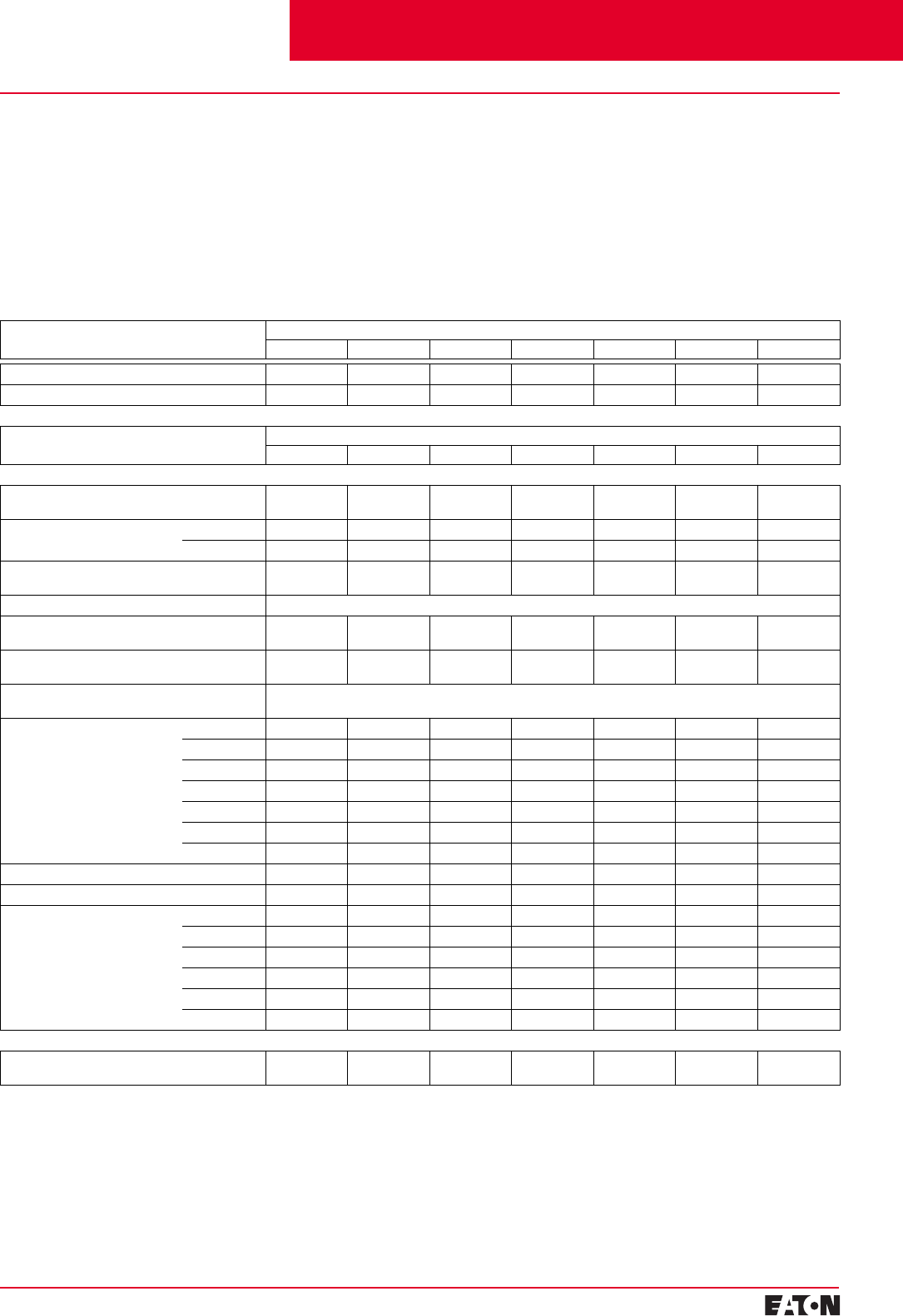
February 2001
PG.29B.01A.T.U
Cutler-Hammer 31
Moulded Case Circuit Breakers
16-2500 Amperes for IEC 60947-2 Applications
Accessory Fit Type Frame
G E125 J250 K L N R
External Accessory Catalogue Numbers
Non-Padlockable
Handle Block Field Fitted 1294C01H01 EFHB – LKD3 LKD4 LKD4 –
Padlockable
Handle Block Field Fitted –––––––
Field Fitted 223C77G03 EFPHB0FF FJPHB0FF PHB3 – – HLK6
Padlockable
Handle Lock Hasp Field Fitted – EFPHL0FF FJPHL0FF PLK3 HLK4 PLK5 –
Cylinder Lock Factory Fitted Order by Description
Key Interlock Kit
(Provision Only) Field Fitted – – KYKFJ KYK3 KYK4 KYK4 KYK6
Slide Bar Interlock –
Requires 2 Breakers Field Fitted – – – SBK3 SBK4 SBK5 –
Walking Beam Interlock –
Requires 2 Breakers Factory Fitted Order by Description
Electrical Operator 120 VAC – – – E0P3T07 E0P4T07 E0P5T07 E0P6T08
240 VAC – – – E0P3T11 E0P4T11 E0P5T11 E0P6T11
120 VDC – – – E0P3T07DC E0P4T26 – –
240 VDC – – – E0P3T11DC – – –
24 VDC – – – MOP3PO3DC E0P4MT21 E0P5T21K E0P6T19K
48 VDC –––––E0P5T22 E0P6T21
125 VDC ––––E0P4T21 E0P5T26 –
Plug-In Adapters➁Field Fitted – ✓✓✓✓✓ –
Rear Connecting Studs➁Field Fitted – ✓✓✓✓✓ –
Handle Mechanism
Field Fitted Only➁Flex Shaft ✓✓✓✓✓✓✓
Type SM – – – ✓✓ ––
Rotary ✓✓✓✓✓✓ –
Type MC – – – ✓✓ ––
Slide Plate – – – ✓✓✓✓
Direct ✓✓✓✓✓✓✓
Test Kit
Electronic Portable Test Kit
(Digitrip 310 Only) – – – STK2 STK2 STK2 STK2
Special Calibration
Special non-UL listed calibrations
are available for certain ambient
temperatures other than 40ºC and
for frequencies other than 50/60 Hz
or dc. Reduced interrupting ratings
will apply for 400 Hz applications.
Selection Guide and Ordering Information
50ºC Calibration➀
Add suffix “V” to catalogue number
for complete breaker when ordering
listed ampere ratings for breakers to
be used in 50ºC ambients.
Contact Cutler-Hammer for
availability.
Moisture-Fungus Treatment
All Cutler-Hammer Circuit Breaker
cases are moulded from glass-poly-
ester which does not support the
growth of fungus. Any parts which
are susceptible to the growth of
fungus will require special treatment.
Order by description.
Accessory Frame
G E125 J250 K L N R
Special Calibration ✓✓✓✓✓✓✓
Moisture-Fungus Treatment ✓✓✓✓✓✓✓
➀K-, L-, N- and R-Frame breakers equipped
with electronic trip units can operate reliably
in ambient temperatures of 50ºC.
➁Contact Cutler-Hammer for catalogue
numbers.
Cutler-Hammer Frame Sizes G through R
Contents
Back To Reference
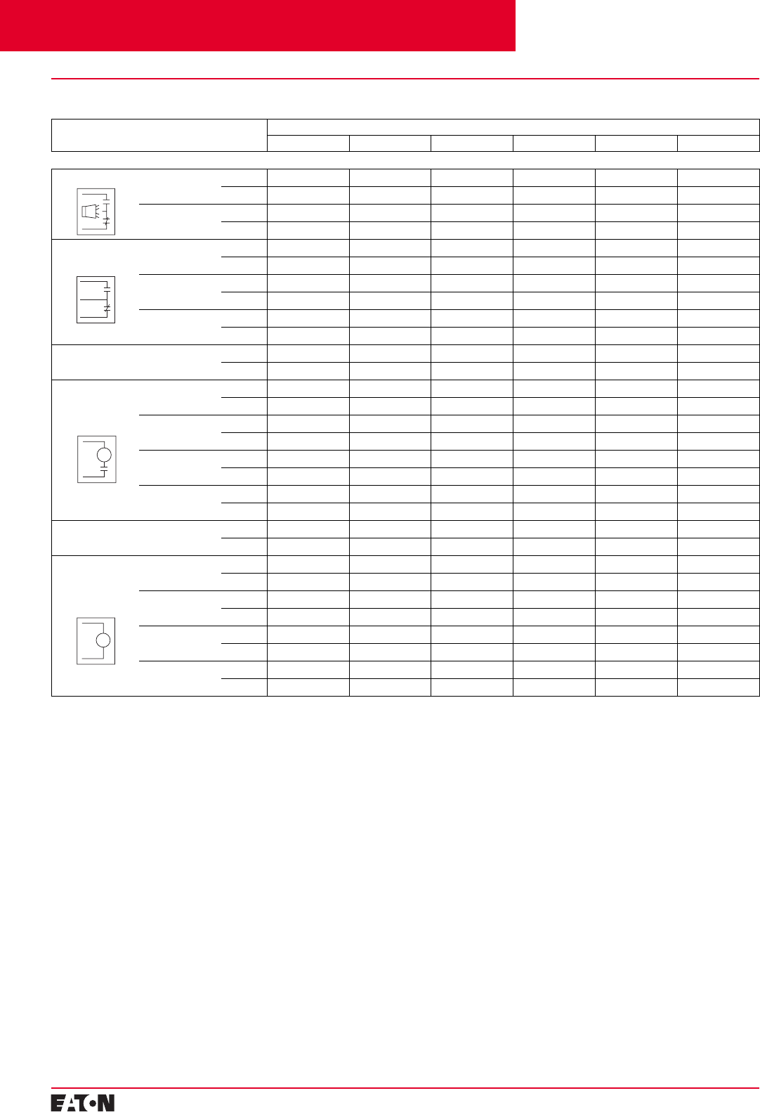
PG.29B.01A.T.U
Cutler-Hammer
32 February 2001
Moulded Case Circuit Breakers
16-2500 Amperes for IEC 60947-2 Applications
Selection Guide and Ordering Information
Accessory Pole
Location Frame
G E125 and J250 K L N R
Field Fit Kit Catalogue Numbers
Alarm Lockout Make/Break Left – – A1L3LPK A1L4LPK A1L5LPK –
Right Factory Fit Only ALM1M1BEPK A1L3RPK A1L4RPK A1L5RPK A1L6RPK
2 Make/2 Break Left – – A2L3LPK A2L4LPK A2L5LPK –
Right – ALM2M2BEPK A2L3RPK A2L4RPK A2L5RPK A2L6RPK
Auxiliary Switch 1A, 1B Left – – A1X3PK A1X4PK A1X5LPK –
Right Factory Fit Only AUX1A1BPK A1X3PK A1X4PK A1X5RP –
2A, 2B Left – – A2X3PK A2X4PK A2X5LPK –
Right Factory Fit Only AUX2A2BPK A2X3PK A2X4PK A2X5RPK A2X6RPK
3A, 3B Left – – A3X3LPK A3X4PK A3X5LPK –
Right – – A3X3RPK A3X4PK A3X5RPK –
Auxiliary Switch/
Alarm Lockout Left – – AAL3LPK AA114LPK AA115LPK –
Right – AUXALRMEPK AAL3RPK AA114RPK AA115RPK –
Shunt Trip –
Standard➀120 VAC Left Factory Fit Only SNT120CPK SNT3P11K SNT4LP11K SNT5LP11K –
Right – – SNT3P11K SNT4RP11K – SNT6P11K
240 VAC Left Factory Fit Only SNT480APK SNT3P11K SNT4LP11K SNT5LP11K –
Right – – SNT3P11K SNT4RP11K – SNT6P11K
24 VDC Left Factory Fit Only SNT060CPK SNT3P04K SNT4LP03K SNT5LP03K –
Right – – SNT3P04K SNT4RP03K – SNT6P03K
48 VDC Left – SNT060CPK SNT3P06K SNT4LP23K SNT5LP23K –
Right – – SNT3P06K SNT4RP23K – SNT6P23K
Shunt Trip –
Low Energy Left – – LST3LPK LST4LPK LST5LPK –
Right – – LST3RPK LST4RPK – LST6RPK
Undervoltage
Release
Mechanism➀
120 VAC Left Factory Fit Only UVR120APK UVH3LP08K UVH4LP08K UVH5LP08K –
Right – – UVH3RP08K UVH4RP08K – UVH6RP08K
240 VAC Left Factory Fit Only UVR480APK UVH3LP11K UVH4LP11K UVH5LP11K –
Right – – UVH3RP11K UVH4RP11R – UVH6RP11K
24 VDC Left – UVR024CPK UVH3LP21K UVH4LP21K UVH5LP21K –
Right – – UVH3RP21K UVH4RP21K – UVH6RP21K
48 VDC Left – UVR048DPK UVH3LP23K UVH4LP23K UVH5LP23K –
Right – – UVH3RP23K UVH4RP23K – UVH6RP23K
a
b
UV
Make
Break
➀Shunt trip and undervoltage release can only
be mounted in left pole of K- and L-Frame
breakers equipped with electronic trip units.
ST
c
Cutler-Hammer Frame Sizes G through R
Contents
Back To Reference
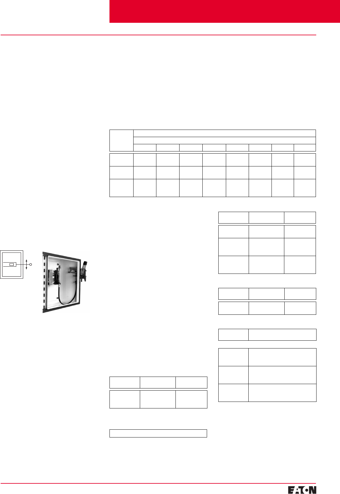
February 2001
PG.29B.01A.T.U
Cutler-Hammer
33
Moulded Case Circuit Breakers
16-2500 Amperes for IEC 60947-2 Applications
Selection Guide and Ordering Information
Handle Mechanisms Overview
Handle Mechanisms are used to
operate moulded case circuit break-
ers, moulded case switches and
motor circuit protectors. They are
available in three basic configura-
tions — Flange Mounted, Through-
the-Door and Direct (Close-Coupled)
— providing safe, dependable oper-
ation and ease of installation.
Flange Mounted
■
Flex Shaft
Through-the-Door
■
Universal Rotary
Direct (Close-Coupled)
■
Universal Direct
■
Euro IEC
■
G Direct
Handle mechanisms are typically
used on enclosed circuit breakers,
control panels and motor control
centres in many different applica-
tions. Cutler-Hammer has a handle
mechanism for virtually any need.
Flange Mounted Handle Mechanisms
Flange Mounted Handle Mecha-
nisms mount on the flange of an
enclosure door. The Flex Shaft™ is
an extra heavy-duty mechanism that
includes a flexible shaft in various
lengths, 0.9 meters (3 feet) through
3 meters (10 feet) for use with
various size enclosures.
The Flex Shaft Handle will accept up
to three padlock shackles, each with
a maximum diameter of 9.5 mm
(3/8-inch). Can be used with NEMA 1,
3R and 12 fabricated enclosures. An
optional handle is available for Flex
Shaft that is suitable for use with
NEMA 4 and 4X environments.
Flex Shaft comes preset from the
factory, requiring only minor field
adjustments on installation, which
takes about 10 minutes — a signifi-
cant time savings compared to
installation of other types of flange
handle mechanisms. The Flex Shaft
mechanism also takes up less interior
enclosure space than competitive
Flex Shaft™
Handle Mechanisms
designs and the handle fits standard
flange cutouts. Flex Shaft handle can
be remotely mounted from breaker,
where an operator can use it by
“funnelling” the cable through
conduit.
Flex Shaft is UL Listed under File
E64893 and meets CSA requirements.
Flex Shaft Ordering Information
Breaker
Frame Flexible Shaft Length Meters (Feet)
Catalogue Number
0.91m (3) 1.22m (4) 1.25m (5) 1.83m (6) 2.13m (7) 2.44m (8) 2.74m (9) 3.05m (10)
EF
FJ EHMFS03I
JHMFS03I EHMFS04I
JHMFS04I EHMFS05I
JHMFS05I EHMFS06I
JHMFS06I EHMFS07I
JHMFS07I EHMFS08I
JHMFS08I EHMFS09
JHMFS09 EHMFS10
JHMFS10
G
KF0S03CI
F3S03CI F0S04CI
F3S04CI F0S05CI
F3S05CI F0S06CI
F3S06CI F0S07CI
F3S07CI F0S08CI
F3S08CI F0S09C
F3S09C F0S10C
F3S10C
L and MDL
N
R
N/A
N/A
N/A
F4S04CI
F5S04CI
F6S04CI
F4S05CI
F5S05CI
F6S05CI
F4S06CI
F5S06CI
F6S06CI
N/A
N/A
N/A
N/A
N/A
N/A
N/A
N/A
N/A
F4S10C
F5S10C
N/A
Note:
Type 4/4X handle mechanisms
are available. Add Suffix X
before the I to complete
Catalogue Number.
Add Suffix L to complete Catalogue
Number for 152.4 mm (6-inch) handle.
Original narrow handle design (No
C
Suffix) is available. Remove
C
from
Catalogue Number.
Note:
When selecting the length
of shaft, ensure minimum
bending radius of 101.6 mm
(4 inches) is maintained to
operate properly.
The standard method of shipment
includes the mechanism preset at
the factory; however, minor field
adjustments may be required.
Flex Shaft Accessories
(E- through R-Frame)
Standard Door Hardware
(Required Adapter Kit)
Latch Panel Height
mm (Inches) Catalogue
Number
2 point
2 point
3 point
Up to 762 (30)
Up to 1016 (40)
Over 1016 (40)
DH1R
DH2R
DH3R
Door Hardware Adapter Kit
(Required on Standard Door Hardware)
Catalogue Number — AMTDHA
Flex Shaft Replacement Door Hardware Kits
Breaker
Frame Flexible
Shaft Catalogue
Number
F
J5108A56G01
5108A56G02 LONR
LH/RH
F
J
K
5108A56G15
5108A56G16
5108A56G17
LONR
LH/RH
LH/RH
F
J
K
5108A56G18
5108A56G19
5108A56G20
LONR
LH/RH
LH/RH
Door Hardware for Hoffman A – 25 Enclosure
➀
Latch Panel Height
mm (Inches) Catalogue
Number
2 point
3 point Up to 1016 (40)
Over 1016 (40) HDH-2R
HDH-3R
Flange Mounted Instruction Leaflets
Breaker
Frame Instruction
Leaflet/FRED Number
Flex Shaft
EF
FJ
G
29C265
29C518
TBD
F
J
K
15609
15605
15604
L and M
N
R
15606
15606
15606
➀
Kit consists of special door hardware and
door interlock pin. Available for right hand
flange mounting only.
Contents
Back To Reference
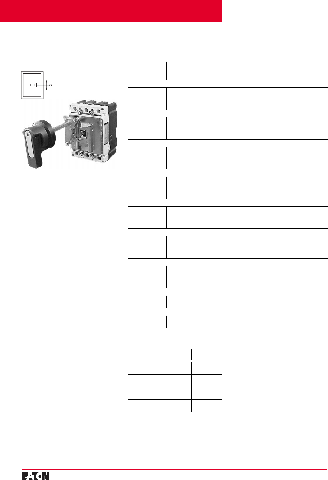
PG.29B.01A.T.U
Cutler-Hammer
34
February 2001
Moulded Case Circuit Breakers
16-2500 Amperes for IEC 60947-2 Applications
Handle Mechanisms
Selection Guide and Ordering Information
Through-the-Door
Handle Mechanisms
Rotary
The Cutler-Hammer Rotary is suita-
ble for use with NEMA 1 and 12
enclosure types. All Rotary handle
mechanisms include a handle “Lock
Off,” to prevent turning the breaker
ON while in the OFF position. All
Rotary handles indicate ON/OFF/
Tripped/Reset positions, however,
Universal Rotary has the added
feature of international markings for
ON (I) and OFF (O). Cutler-Hammer
Rotary handle is metal, Universal
Rotary is made of moulded material.
Cutler-Hammer Rotary handle is
black and Universal Rotary is available
in black or yellow/red.
Universal Rotary Ordering Information
Shaft Length
in mm (Inches) Handle
Colour Complete
Catalogue Number
➀
Cutler-Hammer Rotary
Complete Catalogue Number
➀
IEC IP65 IEC IP66
EF-Frame
152.4 (6)
304.8 (12)
152.4 (6)
304.8 (12)
Black
Black
Red
Red
EHMVD06B
EHMVD12B
EHMVD06R
EHMVD12R
–
–
–
–
–
–
–
–
FJ-Frame
152.4 (6)
304.8 (12)
152.4 (6)
304.8 (12)
Black
Black
Red
Red
FJHMVD06B
FJHMVD12B
FJHMVD06R
FJHMVD12R
–
–
–
–
–
–
–
–
G-Frame
152.4 (6)
304.8 (12)
152.4 (6)
304.8 (12)
Black
Black
Red
Red
GHMVD06B
GHMVD12B
GHMVD06R
GHMVD12R
–
–
–
–
–
–
–
–
F-Frame
152.4 (6)
304.8 (12)
152.4 (6)
304.8 (12)
Black
Black
Red
Red
FHMVD06B
FHMVD12B
FHMVD06R
FHMVD12R
WHM1B06
WHM1B12
WHM1R06
WHM1R12
WHM1B06X
WHM1B12X
WHM1R06X
WHM1R12X
J-Frame
152.4 (6)
304.8 (12)
152.4 (6)
304.8 (12)
Black
Black
Red
Red
JHMVD06B
JHMVD12B
JHMVD06R
JHMVD12R
WHM2B06
WHM2B12
WHM2R06
WHM2R12
WHM2B06X
WHM2B12X
WHM2R06X
WHM2R12X
K-Frame
152.4 (6)
304.8 (12)
152.4 (6)
304.8 (12)
Black
Black
Red
Red
KHMVD06B
KHMVD12B
KHMVD06R
KHMVD12R
WHM3B06
WHM3B12
WHM3R06
WHM3R12
WHM3B06X
WHM3B12X
WHM3R06X
WHM3R12X
L- and MDL-Frames
152.4 (6)
304.8 (12)
152.4 (6)
304.8 (12)
Black
Black
Red
Red
LHMVD06B
LHMVD12B
LHMVD06R
LHMVD12R
WHM4B06
WHM4B12
WHM4R06
WHM4R12
WHM4B06X
WHM4B12X
WHM4R06X
WHM4R12X
N-Frame
152.4 (6)
304.8 (12) Black
Red HMVD15HB + HMCC5W
HMVD15HR + HMCC5W WHM5B06
WHM5R12 WHM5B06X
WHM5R12X
R-Frame
152.4 (6)
304.8 (12) Black
Red HMVD15HB + HMCC6W
HMVD15HR + HMCC6W WHM5B06
WHM5R12 WHM5B06X
WHM5R12X
Through-the-Door Instruction Leaflets/
FRED Number
Breaker
Frame Cutler-Hammer
Rotary Universal
Rotary
EF
FJ –
–29C517
29C519
G
F–
15594 29C250
29C250
J
K15599
15600 29C250
29C250
L & MDL
N15601
15602 29C250
–
➀
Complete catalogue number includes
handle, mechanism, shaft and mounting
hardware.
Contents
Back To Reference
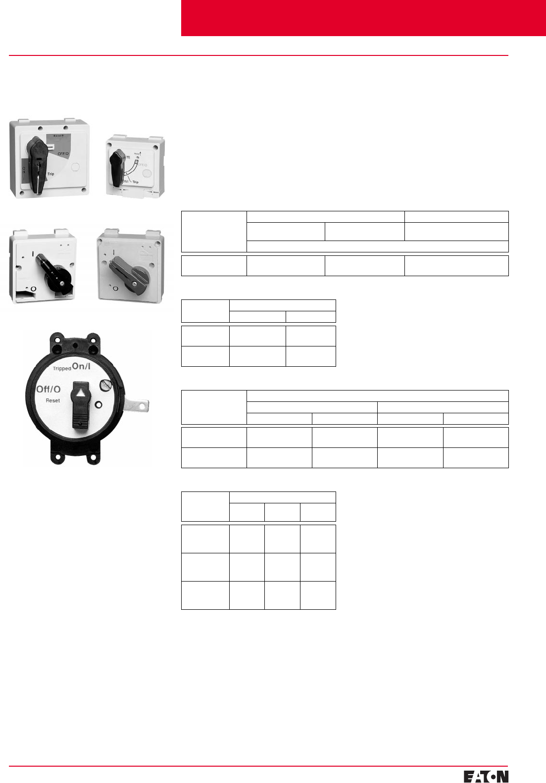
February 2001
PG.29B.01A.T.U
Cutler-Hammer
35
Moulded Case Circuit Breakers
16-2500 Amperes for IEC 60947-2 Applications
Direct (Close-Coupled)
Handle Mechanisms
Universal Direct
Euro IEC Direct
G Direct
Direct (Close-Coupled) Handle Mech-
anisms mount directly to the circuit
breaker. They are used in shallow
enclosures where the standard
variable depth Through-the-Door
type mechanism is not practical or
cannot be used. They are typically
for applications where high volume,
standardized enclosures are being
fabricated.
The Universal Direct handle mecha-
nism is designed exclusively for the
new Cutler-Hammer E125 and J250
circuit breakers. It is available as
standard with a door interlock to
prevent opening the enclosure while
the circuit breaker is in the ON
position. It is also available without
a door interlock.
Handle Mechanisms
Selection Guide and Ordering Information
➀
Suitable for use on 2- or 3-pole G-Frame.
Universal Direct Ordering Information
Frame Universal Direct Domestic Universal Direct International
with Interlock
(white) without Interlock
(white) without Interlock
(charcoal with global label)
Catalogue Number
EF
FJ EHMCCBI
JHMCCBI EHMCCB
JHMCCB EHMCCR
JHMCCR
Euro IEC Direct Ordering Information
Frame Catalogue Number
Black Handle Red Handle
K
L and M HMCC3B
HMCC4B HMCC3R
HMCC4R
N
RHMCC5B
HMCC6B HMCC5R
HMCC6R
G Direct Ordering Information
➀
Frame Catalogue Number
Black Handle Yellow Handle
with Shroud without Shroud with Shroud without Shroud
GD
GC HRGCC1S
HRGCC1S HRGCC10
HRGCC10 HRGCC3S
HRGCC3S HRGCC30
HRGCC30
GHC
GMCP HRGCC1S
HRGMC1S HRGCC10
HRGMC10 HRGCC3S
HRGMC3S HRGCC30
HRGMC30
Direct (Close-Coupled) Instruction Leaflets
Frame Instruction Leaflet/FRED Number
Universal
Direct Euro IEC
Direct G Direct
EF
FJ
G
29C255
29C256
–
–
–
–
–
–
15567
F
J
K
–
–
–
29C288A
29C288A
29C288A
–
–
–
L and MDL
N
R
–
–
–
29C289
29C290
29C291
–
–
–
The Euro IEC Direct handle mecha-
nism can be used on F- through
R-Frames.
G Direct is available with a black or
yellow handle, and with or without a
shroud. It is suitable for use with
NEMA 1 enclosures. It is for use only
with the G-Frame (GD, GC, GHC,
GMCP).
An escutcheon ring and interlock clip
are provided as standard. The stand-
ard design includes a lock-off feature.
The Universal Direct handle mecha-
nism is UL 489 listed, IEC 60947-1/2
and meets CSA requirements. The
Euro IEC Direct handle mechanism is
IEC-240-1. G Direct is UL listed and
meets CSA requirements.
Contents
Back To Reference

PG.29B.01A.T.U
Cutler-Hammer
36
February 2001
Moulded Case Circuit Breakers
16-2500 Amperes for IEC 60947-2 Applications
2 AS
2 AS
1 AS
F-Frame for Motor Protection
4 AUX 4 AUX 4 AUX 4 AUX 4 AUX 4 AUX
U< DI
U< DI
U< DI
U< DI
U< DI
U< DI
U< DI
U< DI
U< DI
1 AUX
2 AUX
1 AS
1 AS + 1 AUX
2 AS
U< 2AS 2AS 2AS U< 2AS 2AS 2AS
2 AS
2 AS
1 AS
U< DI
1 AUX
2 AUX
1 AS
1 AS + 1 AUX
1 AUX
2 AUX
2 AUX
1 AUX
2 AUX
1 AUX
1 AUX
2 AUX
2 AUX
3-Pole
Circuit
Breakers
4-Pole
Circuit
Breakers
left right left right
1 AS
1 AS
AUX
= Shunt Trip or Undervoltage Release or
DI Module (if Built-In)
= Auxiliary Switch
AS = Alarm Switch
= For R-Frame Circuit Breakers Only
Remote Controlled Operating
Mechanisms
Cutler-Hammer Circuit Breakers
(sizes 160 to 2000 amperes) can be
equipped with motorized operating
mechanisms for remote in-service
closing and opening.
For normal remote opening, sole-
noid operating mechanisms F- and
K-Frames are available for circuit
breakers and motorized operating
mechanisms for J to R (sizes 250 to
2500 amperes) solenoid operating
mechanisms and motor operators
are always supplied with a locking
device for padlocks. This device can
be used for electrical and mechanical
blocking of the operating mecha-
nism. All remote operating mecha-
nisms are equipped with a manual
actuator for local operation.
Alarm Lockout
The alarm switches operate when
the circuit breaker is tripped by a
short circuit or overcurrent, but also
when it is tripped by a shunt trip or
undervoltage release.
Auxiliary Switches
Auxiliary switches are used for sig-
nalling and control purposes. The
various functions of the auxiliary
switches (changeover) are shown in
the top table to the right.
Shunt Trips
The shunt trip is used for remote
tripping.
The coil of the shunt trip is rated
only for short-time operation.
It is not permissible with the circuit
breaker open to apply a continuous
opening command to the shunt trip
in order to prevent the breaker from
closing.
This means that interlocking circuits
with continuous commands may
not be set up with shunt trips.
Undervoltage Releases
The circuit breaker cannot be closed
until the undervoltage release is
energized. If the release is not ener-
gized, the circuit breaker can only
perform an idle switching operation.
Frequent idle switching actions
should be avoided as they shorten
the endurance of the circuit breaker.
Possible Equipment of E- and L-Frame Circuit Breakers with Auxiliary and
Alarm Switches
Selection Guide and Ordering Information
Contact making by the auxiliary and
alarm switches as a function of the
switching position of the circuit
breaker
OFF
RESET
ON
Tripped
Position of the
Toggle Handle Drive
(Equivalently
Applicable for
Rotary Drives)
Position of
the Auxiliary
Switch
Position of
the Alarm
Switch
Cutler-Hammer Frame Sizes G through R
E125 and J250 Auxiliary Switch or Alarm Switch in the Right Pole.
E125 and J250 Shunt Trip or UVR in the Left Pole.
Contents
Back To Reference
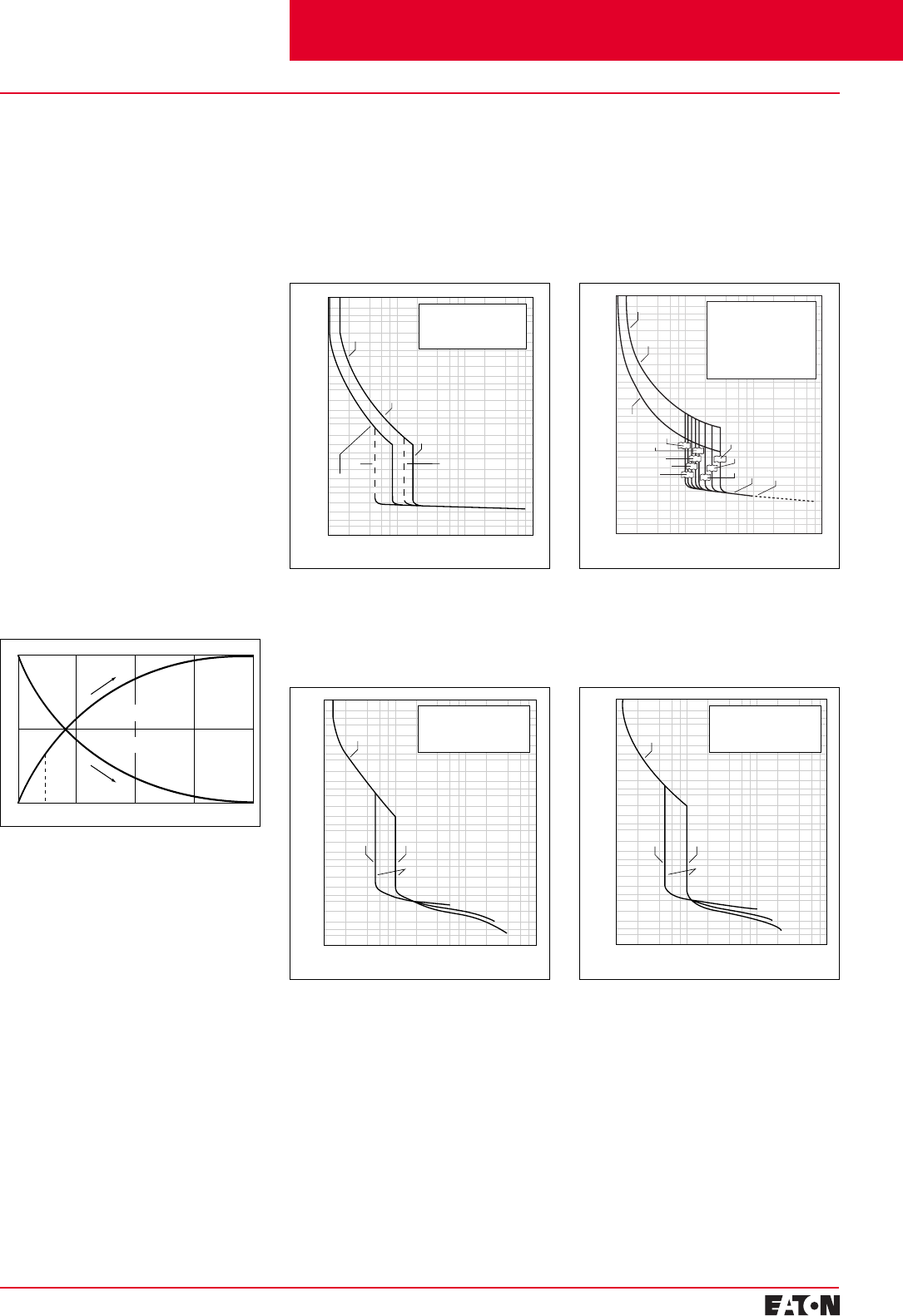
February 2001
PG.29B.01A.T.U
Cutler-Hammer
37
Moulded Case Circuit Breakers
16-2500 Amperes for IEC 60947-2 Applications
100246810124681022468103
10000
5000
3000
2000
1000
500
300
200
100
50
30
20
10
5
3
2
1
.5
.3
.2
.1
.05
.03
.02
.01
.005
.003
.002
.001
TIME IN SECONDS
CURRENT IN MULTIPLES OF I
n
(a)
50-125
Notes:
“a” fixed inverse-time overcurrent
release
“b” fixed electromagnetic release
“c” total operation time
“d” interrupting rating determines
end of curve
20
25
30-3215-16
35
40
45(c)(d)
Max. Trip Time
Min. Trip
Time
100246810
1246810
2246810
3
10000
5000
3000
2000
1000
500
300
200
100
50
30
20
10
5
3
2
1
.5
.3
.2
.1
.05
.03
.02
.01
.005
.003
.002
.001
TIME IN SECONDS
CURRENT IN MULTIPLES OF In
(660/690V)
(n)
10XIn
(a)
(380/415V)
(220/240V)
5XIn
Notes:
“a” thermal overload release
“n” instantaneous (electromagnetic)
short circuit release
102246810
3246810
4246810
5
10000
5000
3000
2000
1000
500
300
200
100
50
30
20
10
5
3
2
1
.5
.3
.2
.1
.05
.03
.02
.01
.005
.003
.002
.001
TIME IN SECONDS
CURRENT IN MULTIPLES OF In
Two Poles in Series
For IEC Use Only
Minimum
Trip
Time
Maximum
Trip
Time
(n)
(a)
Notes:
“a” thermal overload release
“n” instantaneous (electromagnetic)
short circuit release
100246810
1246810
2246810
3
10000
5000
3000
2000
1000
500
300
200
100
50
30
20
10
5
3
2
1
.5
.3
.2
.1
.05
.03
.02
.01
.005
.003
.002
.001
TIME IN SECONDS
CURRENT IN MULTIPLES OF In
(660/690V)
(n)
10XIn
(a)
(380/415V)
(220/240V)
5XIn
Notes:
“a” thermal overload release
“n” instantaneous (electromagnetic)
short circuit release
Time-Current Curves
Tripping Characteristics
The operating values specified for the
inverse time overcurrent releases
(thermal overload releases, “a”
releases) are mean values of the
scatter bands of all setting ranges
from the cold state and with uniform
current loading of the conducting
paths.
The tripping characteristics of the
instantaneous (electromagnetic)
short circuit releases (“n” releases)
are based on the rated phase current
I
n
which in the case of circuit break-
ers with adjustable thermal overload
releases is also the upper value of
the setting range. With a lower
setting current, a correspondingly
higher multiple is obtained for the
operating current of the “n” release.
Individual time-current curves K- and
L-Frame Digitrip 310 Electronic Trip
Curves are available upon request.
Type GWF
Tripping characteristics of GWF
circuit breakers for plant protection,
I
cu
= 25 kA, “n” release fixed setting
n = 500-1300 for breaker 16-63A;
1300-1800 for breaker 70-100A
Type J250
Tripping characteristics of J250
circuit breakers for plant protection,
I
cu
= 25/40/70 kA, “n” release
adjustable
Type KW
Tripping characteristics of KW
circuit breakers for plant protection,
I
cu
= 45/70 kA, “n” release adjustable
Cutler-Hammer Frame Sizes G through K
Tripping time characteristics
(Thermal Memory)
Cold Cold
Warm
Warm
015 min 10
2/3
1
1/3
Cooling Down
Heating Up
Type E125
Tripping characteristics of E125
circuit breakers for plant protection,
I
cu
= 18/25/40/70 kA, “n” release
fixed setting
n = 500-1300 for breaker 16-63A;
1300-1800 for breaker 70-125A
Contents
Back To Reference
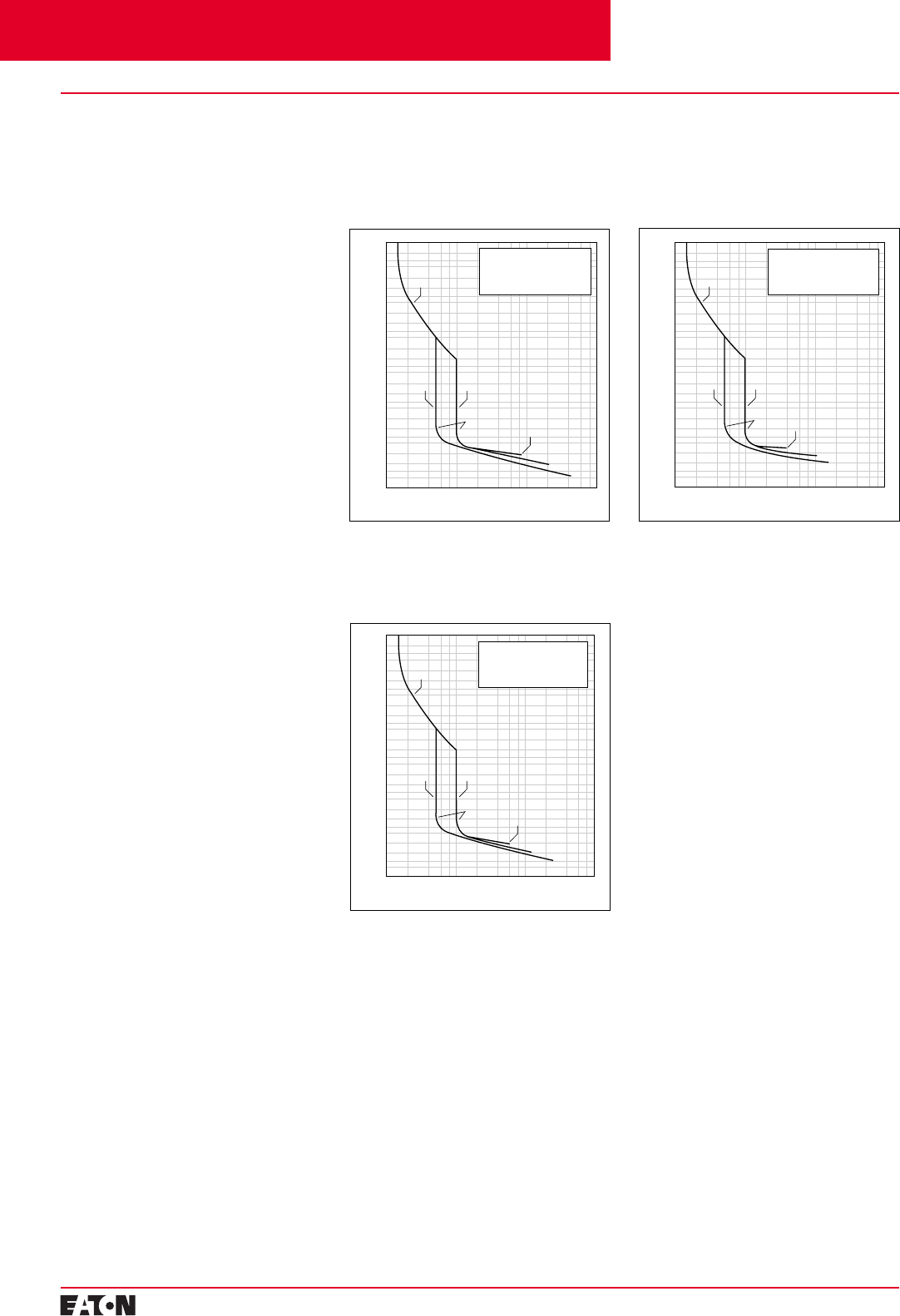
PG.29B.01A.T.U
Cutler-Hammer
38
February 2001
Moulded Case Circuit Breakers
16-2500 Amperes for IEC 60947-2 Applications
100246810
1246810
2246810
3
10000
5000
3000
2000
1000
500
300
200
100
50
30
20
10
5
3
2
1
.5
.3
.2
.1
.05
.03
.02
.01
.005
.003
.002
.001
TIME IN SECONDS
CURRENT IN MULTIPLES OF In
(660/690V)
(n)
10XIn
(a)
(380/415V)
(220/240V)
5XIn
Notes:
“a” thermal overload release
“n” instantaneous (electromagnetic)
short circuit release
Time-Current Curves
Tripping Characteristics
The operating values specified for the
inverse time overcurrent releases
(thermal overload releases, “a”
releases) are mean values of the
scatter bands of all setting ranges
from the cold state and with uniform
current loading of the conducting
paths.
The tripping characteristics of the
instantaneous (electromagnetic)
short circuit releases (“n” releases)
are based on the rated phase current
I
n
which in the case of circuit break-
ers with adjustable thermal overload
releases is also the upper value of
the setting range. With a lower set-
ting current, a correspondingly
higher multiple is obtained for the
operating current of the “n” release.
Type LW
Tripping characteristics of LW circuit
breakers for plant protection, I
cu
=
45/70 kA, “n” release adjustable
Type KW
Tripping characteristics of KW
circuit breakers for plant protection,
I
cu
= 100 kA, “n” release adjustable
Type LW
Tripping characteristics of LW circuit
breakers for plant protection, I
cu
=
100 kA, “n” release adjustable
Cutler-Hammer Frame Sizes K through L
Contents
Back To Reference
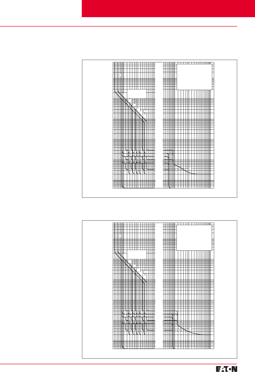
February 2001
PG.29B.01A.T.U
Cutler-Hammer
39
Moulded Case Circuit Breakers
16-2500 Amperes for IEC 60947-2 Applications
123456810
15Xlr
7200
1000
500
200
100
50
20
10
5
2
1
.5
.2
.1
.05
.02
.01
.005
TIME IN SECONDS
CURRENT IN MULTIPLES OF In
1.5 10 15 20 30 40 60 80 100 200
kA
Setting for ld
as Multiples of lr
(7X lr Not Shown)
2X
3X
4X
5X
6X
8X
7 X
td
300 ms
200 ms
100 ms
n
s
a
Notes:
Inverse-time overload release “a”
lr Set current (adjustable)
Short time delayed short circuit release
ld Tripping current (adjustable)
td Delay time (adjustable)
Instantaneous short circuit release “n”
li Tripping current (fixed setting)
123456810
15Xlr
7200
1000
500
200
100
50
20
10
5
2
1
.5
.2
.1
.05
.02
.01
.005
TIME IN SECONDS
CURRENT IN MULTIPLES OF In
1.5 10 15 20 30 40 60 80 100 200
kA
Setting for ld
as Multiples of lr
(7x lr Not Shown)
2X
3X
4X
5X
6X
8X
7 X
Notes:
Inverse-time overload release “a”
lr Set current (adjustable)
Short time delayed short circuit release
ld Tripping current (adjustable)
td Delay time (adjustable)
Instantaneous short circuit release “n”
li Tripping current (fixed setting)
td
300 ms
200 ms
100 ms
n
s
a
Time-Current Curves
Type NW
Tripping characteristics for NW circuit breakers, I
cu
50/70/100 kA,
with solid state overcurrent release
Working Temperature Range
The tolerance bands shown are
applicable to an ambient tempera-
ture range of -5 to +60°C at the
circuit breaker.
Working Temperature Range
The tolerance bands shown are
applicable to an ambient tempera-
ture range of -5 to +60°C at the
circuit breaker.
Type RW
Tripping characteristics for RW circuit breakers, I
cu
70/100 kA,
with solid state overcurrent release
Cutler-Hammer Frame Sizes N and R
Contents
Back To Reference
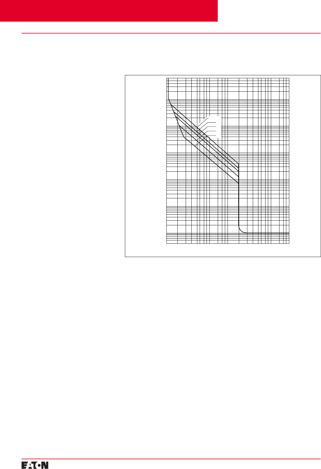
PG.29B.01A.T.U
Cutler-Hammer
40
February 2001
Moulded Case Circuit Breakers
16-2500 Amperes for IEC 60947-2 Applications
110
100Xl
e
7200
1000
100
10
1
.1
.01
TIME IN SECONDS
CURRENT IN MULTIPLES OF I
n
s
Class 30
20
15
10
5
Type FWMP, KWMP, and LWMP
Tripping characteristics for FWMP, KWMP, and LWMP circuit breakers for
motor protection with solid state overcurrent releases
Time-Current Curves
Characteristics of the FWMP,
KWMP, and LWMP Circuit Breakers
for Motor Protection with Solid
State Overcurrent Releases
The tripping times of the inverse-
time delayed overcurrent releases
are only valid for the not preloaded
(cold) state. At operating tempera-
ture (after load with rated current),
the tripping times are reduced to
approximately 33%. After an over-
current trip, the tripping times are
reduced according to the tripping
time characteristics (see figure
below) so that cooling down for
some minutes is required before
restarting the motor. During the first
minute after tripping, reclosing of
the circuit breaker is blocked.
Cutler-Hammer Frame Sizes F through L
Contents
Back To Reference
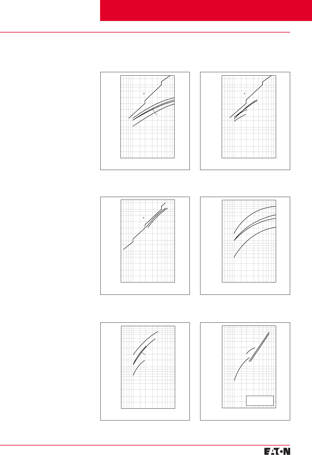
February 2001
PG.29B.01A.T.U
Cutler-Hammer 41
Moulded Case Circuit Breakers
16-2500 Amperes for IEC 60947-2 Applications
5 7 10 20 30 50 kA 100
100
80
60
40
20
10
6
4
2
1
I2t VALUE X105
SHORT CIRCUIT CURRENT ISrms
L
8
A2s
K
J
F
5 7 10 20 30 50 kA 100
100
80
60
40
20
10
6
4
2
1
I2t VALUE X106
SHORT CIRCUIT CURRENT ISrms
8
A2s
N➁
R➁
R➀
N➀
Notes:
➀ 50/60 Hz 380/415 VAC
➁ 50/60 Hz 660/690 VAC
5 7 10 20 30 50 kA 100
200
kA
100
80
60
40
20
10
8
6
4
2
CUT-OFF CURRENT ID
SHORT CIRCUIT CURRENT ISrms
0.3
0.2
R
N
0.5
cos =0.25
5 7 10 20 30 50 kA 100
100
80
60
40
20
10
6
4
2
1
I2t VALUE X105
SHORT CIRCUIT CURRENT ISrms
L
8
K
J
F
5 7 10 20 30 50 kA 100
200
kA
100
80
60
40
20
10
8
6
4
2
CUT-OFF CURRENT ID
SHORT CIRCUIT CURRENT ISrms
0.3
0.2
F
J
K
L
cos =0.25
0.3
5 7 10 20 30 50 kA 100
200
kA
100
80
60
40
20
10
8
6
4
2
CUT-OFF CURRENT ID
SHORT CIRCUIT CURRENT ISrms
0.2
F
J
K
L
cos =0.25
Current Limiting Curves
Current Limiting Characteristics and
Maximum I2t Values
Type E/LW
Current limiting characteristics for
E to LW, 50/60 Hz 380/415 VAC
Type E/LW
Current limiting characteristics for
E to LW, 50/60 Hz 660/690 VAC
Type NW/RW
Current limiting characteristics for
NW to RW, 50/60 Hz 380/415 VAC
Type FW/LW
Maximum I2t values for FW to LW,
50/60 Hz 380/415 VAC
Type FW/LW
Maximum I2t values for FW to LW,
50/60 Hz 660/695 VAC
Type NW/RW
Maximum I2t values for NW to RW
Cutler-Hammer Frame Sizes E through R
Contents
Back To Reference
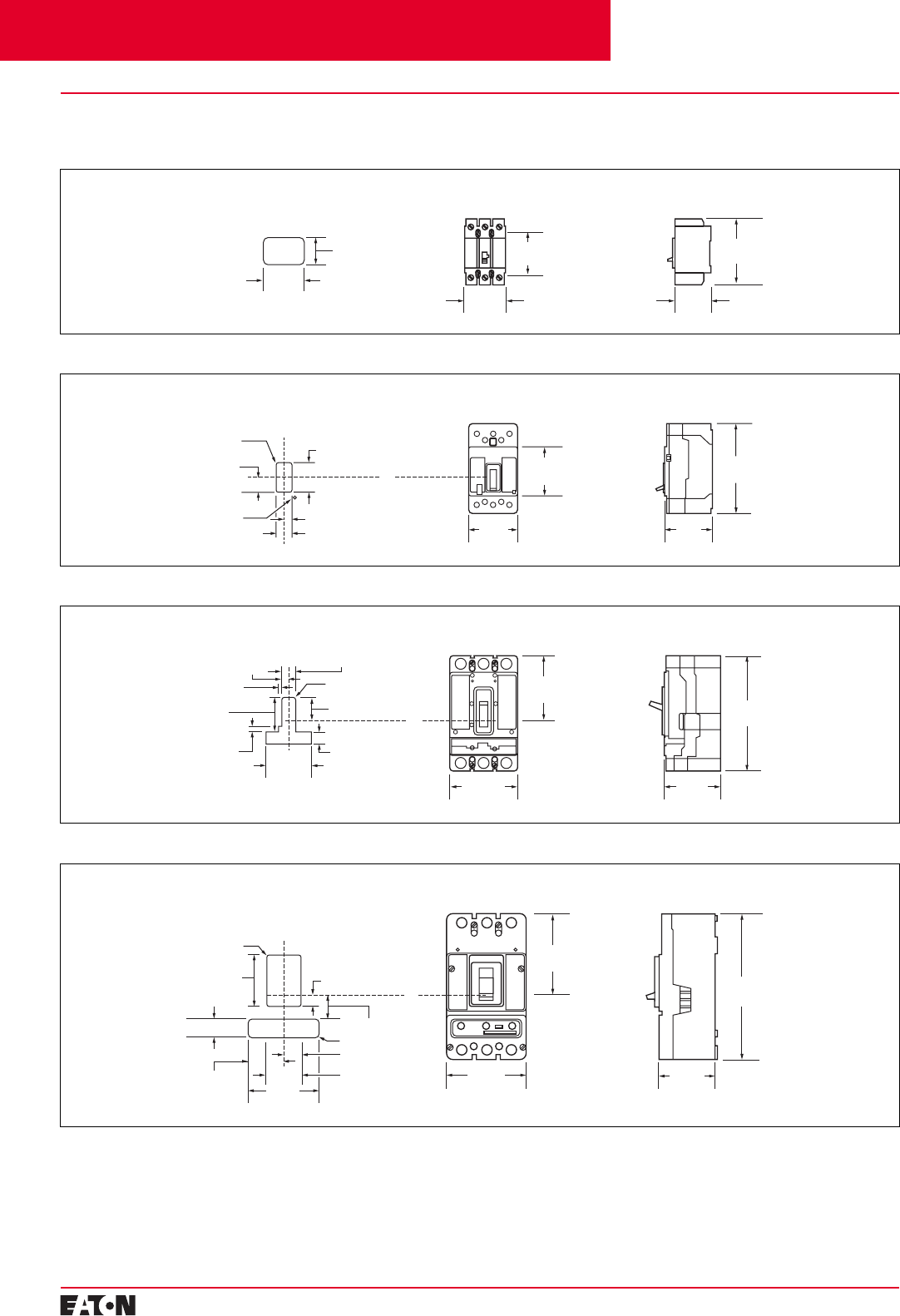
PG.29B.01A.T.U
Cutler-Hammer
42 February 2001
Moulded Case Circuit Breakers
16-2500 Amperes for IEC 60947-2 Applications
Front View 3-PoleFront Cover Cutout Side View
76.20
(3.000)
76.20
(3.000)
56.34
(2.218)
66.67
(2.625)
81.74
(3.218) 123.82
(4.875)
Front View 3-PoleFront Cover Cutout Side View
70.35
(2.770)
76.96
(3.03) 139.70
(5.500)
3.56 (0.14) R 46.99
(1.850)
33.02 Dia.
(1.300) 23.88 (0.94)
22.86
(0.900)
11.94 (0.47)
C
L
76.20
(3.000)
Handle
C
L
Breaker
Front View 3-Pole
Front Cover Cutout Side View
104.77
(4.125)
31.75 (1.250)
15.86 (0.625)
4.75 (0.188) R
87.38
(3.440)
177.80
(7.000)
100.38
(3.952)
101.60
(4.000)
77.80
(3.063) 51.99 (2.047)
C
L
Breaker
26.97 (1.062)
12.70
(0.500)
C
L
Handle
7.137 (0.281)
Front View 3-PoleFront Cover Cutout Side View
139.45
(5.490) 104.00
(4.094)
257.17
(10.125)
151.55
(5.967)
33.35 (1.313)
4.77 (0.188) R
41.66 (1.640)
21.03 (3.750)
95.25 (3.750)
60.73
(2.391) 66.67 (2.625)
121.46
(4.782)
31.75 (1.250)
8.74 (0.344) R
C
L
Breaker
C
L
Handle
Dimensions, mm (inches)
E125-Frame
J250-Frame
K-Frame
Cutler-Hammer Frame Sizes G through K
G-Frame
Dimensions in parentheses in inches.
Contents
Back To Reference
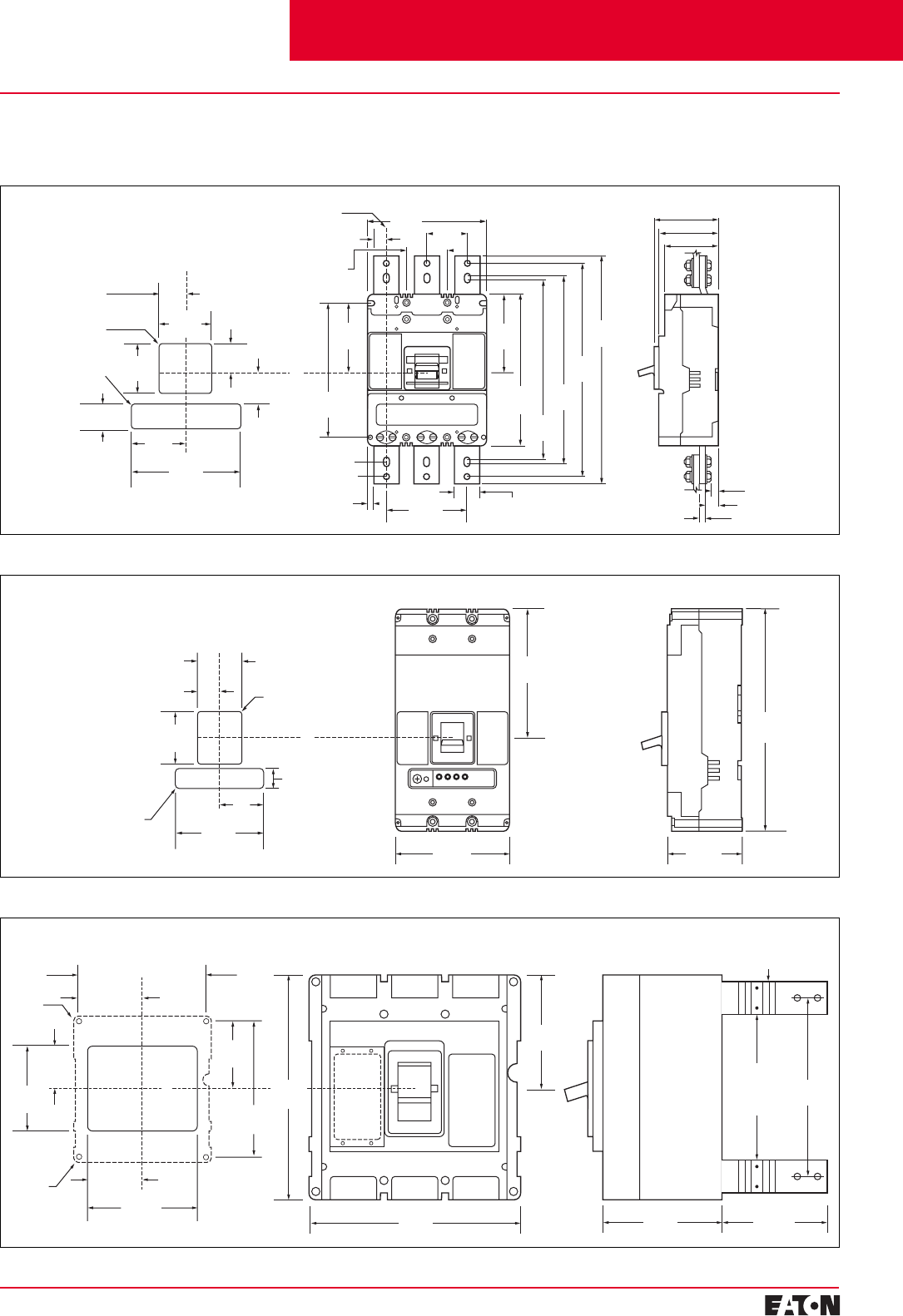
February 2001
PG.29B.01A.T.U
Cutler-Hammer 43
Moulded Case Circuit Breakers
16-2500 Amperes for IEC 60947-2 Applications
Front View 3-Pole
Front Cover Cutout
43.66 (1.719)
63.50 (2.500) R
4.77 (0.188) R
69.90
(2.752)
139.70
(5.500)
184.94
(7.281)
87.32
(3.438)
58.22
(2.292)
33.65
(1.325)
92.48
(3.641)
83.34
(3.281)
142.60
(5.614)
273.10
(10.752)
406.40
(16.00)
38.10
(1.500)
C
L
Handle
209.60
(8.252)
69.90
(2.752)
5.10 R
(0.200)
11.10 Dia.
(0.437)
381.00
(15.000)
333.00
(13.110)
323.00
(12.716)
12.70
(0.500)
120.30
(4.736)
242.30
(9.539)
C
L
Breaker
44.50
(1.752)
Side View
10.00 (0.394)
111.10 (4.374)
13.00 (0.512)
24.60 (0.968)
96.80 (3.811)
103.20 (4.063)
22.25
(0.875)
C
LBus Ext
234.95
(9.250)
C
L
Breaker
Front View 3-Pole
Front Cover Cutout
406.40
(16.000)
87.32 (3.438)
6.35 (0.250) R
Side View
C
L
Handle
139.68
(5.499)
209.55
(8.250)
43.63 (1.718)
96.77
(3.810)
38.10 (1.500)
161.92
(6.375)
80.94 (3.187)
4.77 (0.188) R
368.30
(14.500)
184.15
(7.250)
129.38
(5.094)
196.85
(7.750)
3.96 R
(0.156)
Front View 3-Pole
Front Cover Cutout
C
L
Breaker
406.40
(16.000)
209.55
(8.250)
393.70
(15.500)
327.81
(12.906)
166.70
(6.563)
246.07
(9.688) 381.00
(15.000)
4 Holes
11.12 Dia.
(0.438)
C
L
Handle
330.20
(13.000)
2.25 (0.089)
Tee
Connectors
May Be
Rotated 90°
171.45
(6.750)
228.60
(9.000)
Side View
Dimensions, mm (inches)
L-Frame 630 (Bus extensions not included)
L-Frame 800
N-Frame
R-Frame
Cutler-Hammer Frame Sizes L through R
Dimensions in parentheses in inches.
Contents
Back To Reference
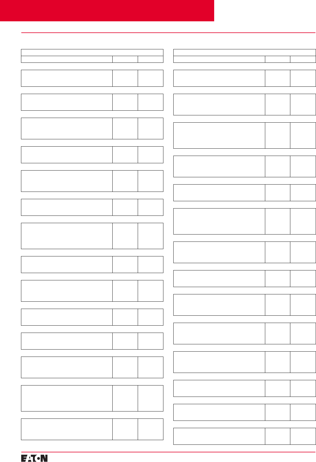
PG.29B.01A.T.U
Cutler-Hammer
44 February 2001
Moulded Case Circuit Breakers
16-2500 Amperes for IEC 60947-2 Applications
Sales Offices
Country
Address Office Phone Office Fax
Argentina
Cutler-Hammer, Inc.
Calle Reconquista 656, Piso 13
(1003) Capital Federal – Buenos Aires, Argentina
(54-11)
4315-4066 (54-11)
4314-8946
Australia
Cutler Hammer Pty Ltd
P.O. Box 85
Rosebery, NSW 1445, Australia
(61-2)
9693-9333 (61-2)
9693-1258
Brazil
Cutler-Hammer, Inc.
Eletromar Plant
Estrada Velha da PaPavuna, 257
21058-900 Rio de Janeiro-RJ-Brazil
(55-21)
865-3912 (55-21)
290-1645
Canada
Cutler-Hammer Canada
3228 South Service Road, Box 5040 Station A
Burlington, Ontario L7R 3Y8
(905)
333-6442 (905)
631-4248
Chile
Cutler-Hammer, Inc.
Neveria 4631, Office 210 /203
Las Condes CP 6761670
Santiago, Chile
(56-2)
207-1695 (56-2)
207-1699
China
Cutler-Hammer China
193 Su Hong Xi Road, Suzhou Industrial Park
Suzhou, 215021, PRC
(86-512)
716-3728 (86-512)
716-9535
Costa Rica
Cutler-Hammer, Inc.
Industrial Control & Power Distribution
Operations-Worldwide Power Distribution Division
Apartado Postal 10156
1000 San Jose, Costa Rica
(506)
235-6022 (506)
235-9156
Egypt
Cutler-Hammer, Inc.
9, Shehab Street- #11, Mohandessin 12411
Cairo, Egypt
(20-2)
338-6170 (20-2)
338-2025
El Salvador
Cutler-Hammer, Inc.
Centro Comercial
Villas Españolas, Local C-1
San Salvador, El Salvador
(503)
263-6557 (503)
264-4144
France
Cutler-Hammer
11 Rue Chataigneraie
73000 Barberaz, France
(33-4)
79604763 (33-4)
79604766
Germany
Eaton GmbH
Oranienpassage, 1
57258 Freudenberg, Germany
(49-2734)
4663-0 (49-2734)
4760-5
Guatemala
Cutler-Hammer, Inc.
Avenida Reforma 7-62 zona 9
Edificio Aristos Reforma, Oficina N°704
Ciudad de Guatemala, Guatemala
(502)
362-9168 (502)
385-0343
Honduras
Cutler-Hammer, Inc.
Honduras Edificio Miramontes
Plaza Apart. Hoteles Continental S.A.
Segundo nivel, local N°10
Tegucigalpa, Honduras
(504)
235-7554 N/A
Indonesia
Cutler-Hammer
Suite 503A Sentra Mulia
JI HR Rasuna Said Kav X-6 No.8
Jakarta 12940, Indonesia
(62-21)
522-2020 (62-21)
522-2110
Country
Address Office Phone Office Fax
Jordan
Cutler-Hammer, Inc.
P.O. Box 510449
Amman 11151, Jordan
(962-6)
474-0660 962-6)
744-660
Korea
Eaton Limited-Korea
7th Floor, Woo Duk Building
832-2, Yeoksam-dong, Kangnam-ku
Seoul, 135-750, Korea
(82-2)
557-0313 (82-2)
557-1634
Malaysia
Eaton Corporation Regional Office
c/o Alpha Executive Business Center
1005 Blk B Level 10 Phileo Tamansara
9 Jin 16/11 Off Jin Tamansara
46350 Petaling Jaya, Selangor, Malaysia
(60-3)
737-2970 (60-3)
737-2960
Mexico
Cutler Hammer, Inc.
Rojo Gomez 1300 Col. Sn.Miguel
Iztapalapa Mexico City
DF 09360 Mexico
(52-5)
804-8230 (525-5)
804-8232
New Zealand
Cutler Hammer
P.O. Box 12648
Penrose, Auckland, New Zealand
(82-2)
557-0313 (82-2)
557-1634
Nicaragua
Cutler-Hammer, Inc.
Edificio Ofiplaza El Retiro Modulo N°5-1.1
De los semaforos de la antrada al antiguo, Nejapa
Country Club o CAS 200 m al sur
Managua, Nicaragua
(505)
270-0920 (505)
270-0900
Panama
Cutler-Hammer, Inc.
Avenida Ricardo J. Alfaro
Edifico Plaza Edison, Segundo Nivel, Oficina N°7
Ciudad de Panama, Panama
(507)
321-0288 /
0289
(507)
321-0290
Saudi Arabia
Cutler-Hammer, Inc.
P.O. Box 19651, Riyadh 11445
Kingdom of Saudi Arabia
(966-1)
460-2275 (966-1)
460-2991
Singapore
Cutler-Hammer Pte Ltd
3 Tai Seng Drive
#03-01 Marconi Building
Singapore 535216
(65)
382-7330 (65)
382-7262
Thailand
Cutler-Hammer (C-H 1254)
Eaton Technologies Limited, 91/1 Chailyo Building,
5th Floor, Rama 1X Road, Huaykwang
Bangkok 10320 Thailand
(66-2)
643-9504-8 (66-2)
643-9509
United Kingdom
Cutler-Hammer
Carina, Sunrise Parkway
Linford Wood
Milton Keynes MK146NR
(44-0-1908)
541600 (44-0-1908)
660527
United States
Cutler-Hammer, Inc.
1000 Cherrington Way
Pittsburgh, PA 15108
(412)
893-3300 N/A
Venezuela
Cutler-Hammer, Inc.
Avda. Libertador, El Rosal, Edificio Lex, Piso 1
Caracas 1060, Venezuela
(58-2)
953-1697 (58-2)
953-2585 /
2841
United Arab Emirates
Cutler-Hammer Inc.
P.O. Box 9398, Dubai World Trade Centre – Level
10 Dubai, United Arab Emirates
(971-4)
331-3938 (971-4)
332-9239
Cutler-Hammer Sales Offices
Contents
Back To Reference

The circuit breakers shall meet or exceed all standards as
defined in IEC 60947-2. Electrical circuits shall be protected
by Cutler-Hammer World Moulded Case Circuit Breakers
as manufactured by Cutler-Hammer.
Each pole of the one-, two-, and three-pole circuit breakers
shall provide complete circuit overcurrrent protection by
having inverse time and instantaneous tripping character-
istics and, where applicable, be current limiting.
The circuit breaker shall be available in interrupting
families that provide 35-65-100 kA at 380-415 volts AC.
The circuit breakers shall be operated by a toggle-type
handle and have a quick-make, quick-break, over-centre
switching mechanism that is mechanically trip-free from
the handle so that the contacts cannot be closed against
short circuit currents. Tripping due to overload or short cir-
cuits shall be clearly indicated by the position of the handle.
The ON and OFF positions shall be clearly marked on the
cover of the circuit breaker along with the international
symbols I for ON and O for OFF on the handle, providing
positive indication of the circuit breaker contact position.
Additionally, a colour-coded indication of the circuit break-
er contact position shall be provided: red for ON, green for
OFF, and white for TRIPPED. An easily accessible Push-To-
Trip button for mechanically exercising the trip unit shall
be provided on the cover of each circuit breaker. All poles
of a multi-pole circuit breaker shall be so constructed as to
ensure simultaneous open, close, and trip operations.
Circuit breakers shall be completely enclosed in a high
strength glass-polyester case.
Noninterchangeable trip circuit breakers shall be factory
sealed; interchangeable trip circuit breakers shall have the
trip unit sealed to prevent tampering. Ampere ratings shall
be clearly visible from the front of the circuit breaker. Con-
tacts shall be nonwelding silver alloy. Arc extinction shall
be accomplished by means of DE-ION
®
arc extinguishers
consisting of metal grids mounted in an insulating support.
The minimum interrupting ratings of the circuit breakers
shall be at least equal to the available short circuit current
at the line terminals.
The circuit breakers can be applied in series rated applica-
tions and subject to test data verification.
Circuit breakers in frame sizes 125 amperes through 250
amperes shall be equipped with thermal-magnetic trip
units. Circuit breakers 400 amperes through 2500 ampere
frame sizes shall be equipped with electronic trip units
that are insensitive to changes in ambient temperature
within the normal operating temperature range of the
circuit breaker. The 400 ampere and 630 ampere frame
sizes shall be designed to accept either thermal-magnetic
or electronic interchangeable trip units.
Electronic trip units shall be rms sensing type and have
unpowered thermal memory.
Circuit breaker ratings and modifications shall be
indicated on the drawings.
Circuit breakers shall be of the inverse time and instan-
taneous trip type as provided by thermal-magnetic or
electronic trip elements with either standard interrupting,
high interrupting, or current limiting characteristics
as required.
Moulded case circuit interrupters (motor circuit protectors)
shall be of the instantaneous (magnetic) only type, providing
instantaneous short circuit protection by means of a front
adjustable trip unit.
Moulded case switches shall be of the same construction
as the related listed circuit breaker and equipped with a
factory sealed, nonadjustable, high instantaneous only
short circuit protection.
Moulded case switches shall have no overload or low level
fault protection provided and shall be marked with a
maximum withstand rating denoting the type and level of
upstream protection required. Moulded case switches
shall be listed per IEC 60947-2.
Internally mounted accessories including alarm (signal)/
lockout switches, auxiliary switches, shunt trips, and
undervoltage released mechanisms shall be of the plug-in
type and shall be listed for field fitting in circuit breakers
which are not factory sealed.
Electrical operators for circuit breakers of the 400 ampere
frame size and below shall be of the solenoid type with
maximum five-cycle closing characteristics. Electrical
operators for circuit breaker frame sizes 630 amperes
through 2500 amperes shall be of the motor driven type.
All electrical operators shall be cover mounted. All
electrical operators shall be listed for field installation
per IEC 60947-2.
Electrical characteristics of accessories shall be as
indicated on the drawings.
Circuit breakers in the 125 amperes rating shall be sup-
plied in one-, two-, three-, and four-pole models, as speci-
fied on the drawings. Circuit breakers in ratings of 225
amperes through 1250 amperes shall be supplied in two-,
three-, or four-pole models. The 2500 ampere circuit
breaker is available in three- and four-pole models as
specified on the drawings.
Accessory wiring shall be brought out through the side or
rear of the circuit breaker, or be connected to a terminal
block mounted on the side of the circuit breaker, as specified.
The ability to route accessory wiring to the opposite side
of the circuit breaker through a trough in the base shall be
provided.
Circuit breakers shall be provided with uniformly designed
nameplates to clearly indicate the type, rating, listing/
recognition/certification marks, accessory details, and
other information defined in IEC 60947-2.
Typical Specifications for
Cutler-Hammer Moulded
Case Circuit Breakers
Contents
Back To Reference
