Local Tone Mapping Feature Description 80 NN684 1 PRESENTATION TUNING GUIDE
User Manual: Pdf
Open the PDF directly: View PDF ![]() .
.
Page Count: 23
- Local Tone Mapping Feature Description
- Contents
- 1 Introduction
- 2 Problem Description and Purpose
- 3 Concept and Algorithm
- 4 Tuning Parameters
- 5 Tuning Procedure
- 6 Scene-Based Tuning Guidelines
- 6.1 I observe more noise when boosting up dark areas with LTM. How can I improve the noise issue?
- 6.2 I observe AE flickering and oscillation issues during AE convergence after enabling LTM. How can I improve this issue?
- 6.3 The saturation looks too high in a color object. How can I reduce color saturation?
- A References

Qualcomm Technologies, Inc.
Confidential and Proprietary – Qualcomm Technologies, Inc.
© 2014–2015 Qualcomm Technologies, Inc. and/or its affiliated companies. All rights reserved.
NO PUBLIC DISCLOSURE PERMITTED: Please report postings of this document on public servers or websites to:
DocCtrlAgent@qualcomm.com.
Restricted Distribution: Not to be distributed to anyone who is not an employee of either Qualcomm Technologies, Inc. or its
affiliated companies without the express approval of Qualcomm Configuration Management.
Not to be used, copied, reproduced, or modified in whole or in part, nor its contents revealed in any manner to others without the
express written permission of Qualcomm Technologies, Inc.
Chromatix is a product of Qualcomm Technologies, Inc. Other Qualcomm products referenced herein are products of Qualcomm
Technologies, Inc. or its subsidiaries.
Local Tone Mapping
Feature Description
80-NN684-1 D
November 25, 2015

Qualcomm and Chromatix are trademarks of Qualcomm Incorporated, registered in the United States and other countries. All
Qualcomm Incorporated trademarks are used with permission. Other product and brand names may be trademarks or registered
trademarks of their respective owners.
This technical data may be subject to U.S. and international export, re-export, or transfer (“export”) laws. Diversion contrary to U.S.
and international law is strictly prohibited.
Qualcomm Technologies, Inc.
5775 Morehouse Drive
San Diego, CA 92121
U.S.A.

80-NN684-1 D Confidential and Proprietary – Qualcomm Technologies, Inc. 3
MAY CONTAIN U.S. AND INTERNATIONAL EXPORT CONTROLLED INFORMATION
Revision history
Revision Date Description
A April 2014 Initial release
B June 2014 Update for tuning parameters
C April 2015 Engineering update and conversion to word
D November 2015 Update to Chromatix headers from 0x307 to 0x308

80-NN684-1 D Confidential and Proprietary – Qualcomm Technologies, Inc. 4
MAY CONTAIN U.S. AND INTERNATIONAL EXPORT CONTROLLED INFORMATION
Contents
1 Introduction ...................................................................................................... 6
1.1 Purpose.......................................................................................................................... 6
1.2 Conventions .................................................................................................................. 6
1.3 Technical assistance ...................................................................................................... 6
2 Problem Description and Purpose ................................................................. 7
3 Concept and Algorithm ................................................................................... 8
3.1 LTM module in VFE .................................................................................................... 8
3.2 Approaches to tone mapping ........................................................................................ 8
3.3 Overview of the concept and algorithm ........................................................................ 9
4 Tuning Parameters ........................................................................................ 11
4.1 Overview of LTM tuning parameters ......................................................................... 11
4.2 Parameters in the Chromatix header (version 0x308) ................................................. 11
4.3 Saturation Curve ......................................................................................................... 13
4.4 Fixed Content Low and Fixed Content High .............................................................. 14
4.5 Global Tone Strength .................................................................................................. 14
4.6 Local Tone Strength and Local Tone Contrast ........................................................... 15
4.7 Reserved parameters ................................................................................................... 15
5 Tuning Procedure .......................................................................................... 16
5.1 Basic tuning procedure ............................................................................................... 16
5.2 Tuning LTM in the Chromatix tool ............................................................................ 16
6 Scene-Based Tuning Guidelines .................................................................. 19
6.1 I observe more noise when boosting up dark areas with LTM. How can I improve the
noise issue? ................................................................................................................. 19
6.1.1 Tune ABF3 for dark area noise reduction ....................................................... 19
6.1.2 Tune 9x9 ASF block for dark areas ................................................................. 20
6.2 I observe AE flickering and oscillation issues during AE convergence after enabling
LTM. How can I improve this issue? ......................................................................... 20
6.2.1 Tune the Local Tone Strength and Local Tone Contrast ................................. 20
6.2.2 Check AEC aggressiveness and update timing ................................................ 21
6.3 The saturation looks too high in a color object. How can I reduce color saturation? . 22
A References ..................................................................................................... 23
A.1 Related documents ..................................................................................................... 23
A.2 Acronyms and terms .................................................................................................. 23

Local Tone Mapping Feature Description Contents
80-NN684-1 D Confidential and Proprietary – Qualcomm Technologies, Inc. 5
MAY CONTAIN U.S. AND INTERNATIONAL EXPORT CONTROLLED INFORMATION
Figures
Figure 3-1 Location of local tone mapping module in Video Front End (VFE) .......................................... 8
Figure 3-2 Comparison of global tone mapping and local tone mapping .................................................... 8
Figure 3-3 Local tone mapping block diagram .......................................................................................... 10
Tables
Table 4-1 LTM_Type parameters .............................................................................................................. 12
Table 4-2 LTM_core_data Parameters ..................................................................................................... 12

80-NN684-1 D Confidential and Proprietary – Qualcomm Technologies, Inc. 6
MAY CONTAIN U.S. AND INTERNATIONAL EXPORT CONTROLLED INFORMATION
1 Introduction
1.1 Purpose
This document describes the use of the Local tone mapping (LTM) module in the Chromatix tool.
It defines the purpose of the module, explains the concept of local tone mapping, defines the
related parameters, and details the tuning procedure.
1.2 Conventions
Function declarations, function names, type declarations, attributes, and code samples appear in a
different font, for example, #include.
Button and key names appear in bold font, for example, click Save or press Enter.
Shading indicates content that has been added or changed in this revision of the document.
1.3 Technical assistance
For assistance or clarification on information in this document, submit a case to Qualcomm
Technologies, Inc. (QTI) at https://createpoint.qti.qualcomm.com/.
If you do not have access to the CDMATech Support website, register for access or send email to
support.cdmatech@qti.qualcomm.com.
80-NN684-1 D Confidential and Proprietary – Qualcomm Technologies, Inc. 7
MAY CONTAIN U.S. AND INTERNATIONAL EXPORT CONTROLLED INFORMATION
2 Problem Description and Purpose
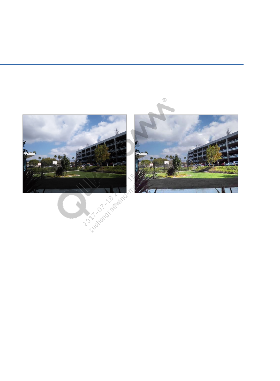
Natural scenes have a wide dynamic range. Images captured by a camera system contain much
information that is not obvious on display devices and not easily visible by viewers.
Original image Ideal image
In the original image, the bright area is already saturated and losing detail, and the dark
area is too dark and invisible.
In the ideal image, the bright area is suppressed and shows more detail, and the dark area
is lightened up and has more visibility.
The ideal image is more pleasant and matched with the response of the human eye. There must be
a more advanced image-processing block to achieve the ideal image from the original image.
80-NN684-1 D Confidential and Proprietary – Qualcomm Technologies, Inc. 8
MAY CONTAIN U.S. AND INTERNATIONAL EXPORT CONTROLLED INFORMATION
3 Concept and Algorithm
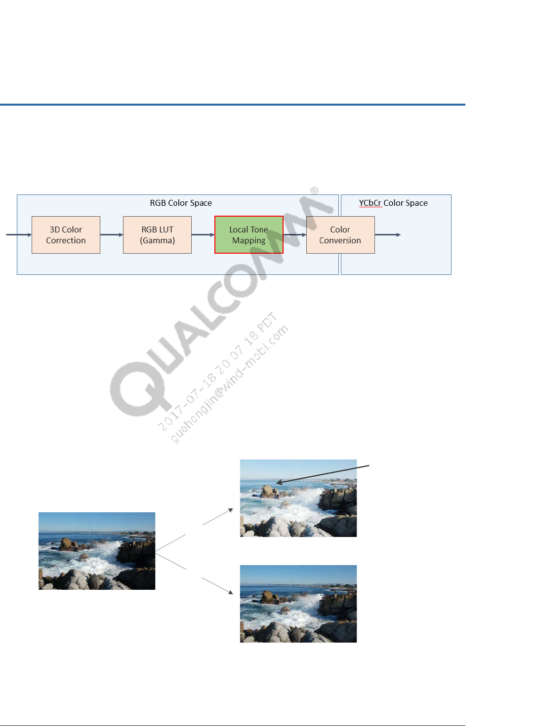
3.1 LTM module in VFE
Figure 3-1 Location of local tone mapping module in video front end (VFE)
3.2 Approaches to tone mapping
Multiple tone mapping approaches can be used to bring details hidden in dark or bright regions to
a more visible data range. The following approaches can be used:
Global tone mapping (GTM) (or luma adaptation (LA) – Adjust all pixels based on their
values by using same tone mapping curve
LTM – Adjust pixels by using a different tone mapping curve and contrast enhancement
based on local brightness
Although GTM can lighten up areas, it reduces contrast in normal light and bright regions. As a
result, the image may look flattened.
Original image with dark area
Normal light area is
also modified by GTM
resulting in contrast
loss or tone change.
With LTM, the dark
area is lightened while
other areas are not
touched.
Local Tone Mapping
Global Tone Mapping
GTM
LTM
Figure 3-2 Comparison of global tone mapping and local tone mapping
Local Tone Mapping Feature Description Concept and Algorithm
80-NN684-1 D Confidential and Proprietary – Qualcomm Technologies, Inc. 9
MAY CONTAIN U.S. AND INTERNATIONAL EXPORT CONTROLLED INFORMATION
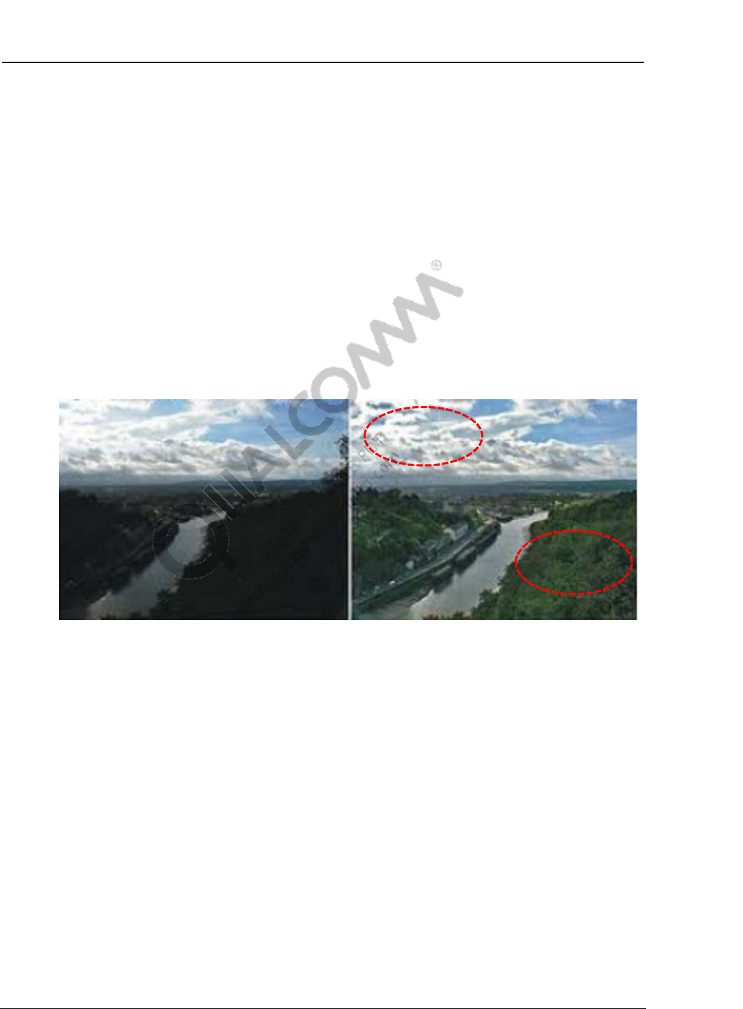
3.3 Overview of the concept and algorithm
LTM is a single-frame single-exposure high dynamic range imaging solution. LTM does the
following:
Lightens up dark (low-tone) regions
Leaves mid-tone regions unchanged
Slightly suppresses bright (high-tone) regions
Increases local contrast
Besides tone mapping, local contrast enhancement (LCE) is conducted to enhance details related
to each pixel’s neighboring average.
These approaches result in reduced global contrast while increasing local contrast. The more
meaningful contents captured by the camera are brought into the limited dynamic range of the
display device.
Before LTM After LTM
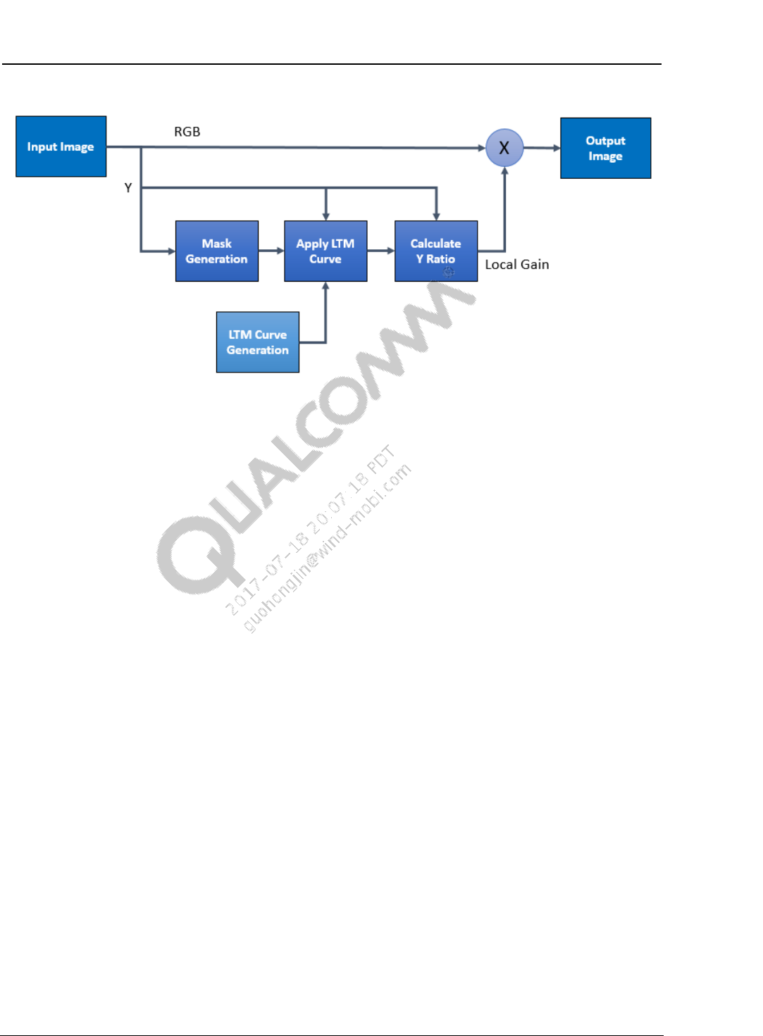
LTM does the following to improve the image and avoid side effects:
Applies a bilateral filter to generate a nonlinear mask
Avoids halo artifacts on the edges
Uses an LTM curve set for local gain adjustment
Uses a combination of LTM and LCE
Local Tone Mapping Feature Description Concept and Algorithm
80-NN684-1 D Confidential and Proprietary – Qualcomm Technologies, Inc. 10
MAY CONTAIN U.S. AND INTERNATIONAL EXPORT CONTROLLED INFORMATION
Figure 3-3 LTM block diagram

80-NN684-1 D Confidential and Proprietary – Qualcomm Technologies, Inc. 11
MAY CONTAIN U.S. AND INTERNATIONAL EXPORT CONTROLLED INFORMATION
4 Tuning Parameters
NOTE: Numerous changes were made in this chapter.
4.1 Overview of LTM tuning parameters
Tuning parameters in the Chromatix header (version 0x308) include:
Trigger control method
Trigger point
Core parameters for each light condition with:
Saturation and maximum gain control
Dark boost and highlight suppression control
Local tone strength and attenuation control
Reserved parameters
RGB to Yp conversion
LTM fixed curve sets
Etc.
4.2 Parameters in the Chromatix header (version 0x308)
The LTM parameters appear as follows in the Chromatix header:
/* Local Tone Mapping */
{
1, /* Enable */
1, /* Control Enable */
0, /* Control Method - 1 = Gain, 0 = Lux Index */
/* Lowlight Trigger Points */
{ },
/* Bright Light Trigger Points */
{ },
/* Core Data */
{
/* Bright Light */
{
/* Sat_curve */
{ },
16.000000f, /* Y Ratio Max */

Local Tone Mapping Feature Description References
80-NN684-1 D Confidential and Proprietary – Qualcomm Technologies, Inc. 12
MAY CONTAIN U.S. AND INTERNATIONAL EXPORT CONTROLLED INFORMATION
/* Unused parameters are collapsed. */
1.000000f, /* Fixed Content Low */
1.000000f, /* Fixed Content High */
20, /* Global Tone Strength */
/* Unused parameters are collapsed. */
5, /* Local Tone Strength, use as ‘low anchor point of AEC based
attenuation’ */
20, /* Local Tone Contrast, use as ‘high anchor point of AEC based
attenuation’*/
{ },
0.250000f, /* Strength Scale */
},
/* Normal Light */
{ },
/* Lowlight */
{ },
},
/* Reserved */
{ }
},
Table 4-1 LTM_Type parameters
Parameter Description Range Default
LTM_control_enable,
control_LTM Enable trigger control and LTM method 1 - Enable
1 – Gain, 0 – Lux index 1
LTM_low_light_trigger,
LTM_bright_light_trigger
Trigger point and criteria for selecting proper
LTM parameter among three light conditions
chromatix_ltm_core_data
[LTM_MAX_LIGHT] Core data for each light condition LTM_MAX_LIGHT = 3
reservedData Reserved data. We recommend that user
does not change this data.
Table 4-2 LTM_core_data parameters
Parameter Description Range Default
sat_curve[129] Control to decrease the saturation caused by
applying gains on the nonlinear domain.
Increase left side of Sat Curve or decrease
right side of Sat Curve to decrease
saturation.
This feature is available in MSM8996 or later
chipset.
129LUT,
[0, 8191]
Y_ratio_max Control the maximum gain applied on a pixel.
Recommend using the default value.
0 to 64 16
fixed_content_low Control the strength of boosting the dark
area.
Increase to boost dark region.
0.0 to 4.0 1.0
Local Tone Mapping Feature Description References
80-NN684-1 D Confidential and Proprietary – Qualcomm Technologies, Inc. 13
MAY CONTAIN U.S. AND INTERNATIONAL EXPORT CONTROLLED INFORMATION
Parameter Description Range Default
fixed_content_high Control the strength of suppressing bright
area.
Increase to suppress highlight region.
0.0 to 4.0 1.0
nGlobalToneStrength Control overall strength of LTM by adjusting
several tables related to generating the LTM
curve set.
Increase to enhance the effect of LTM.
0 to 2048
Q8
256(1x)
for
normal
384(1.5x)
for backlit
nLocalToneStrength,
nLocalToneContrast
Control of LTM attenuation based on AEC
(delta of exp_idx between frames).
Recommend using the default value. If
exposure oscillation is observed, reduce the
parameter values.
0 to 2048 5 for low
anchor
20 for
high
anchor
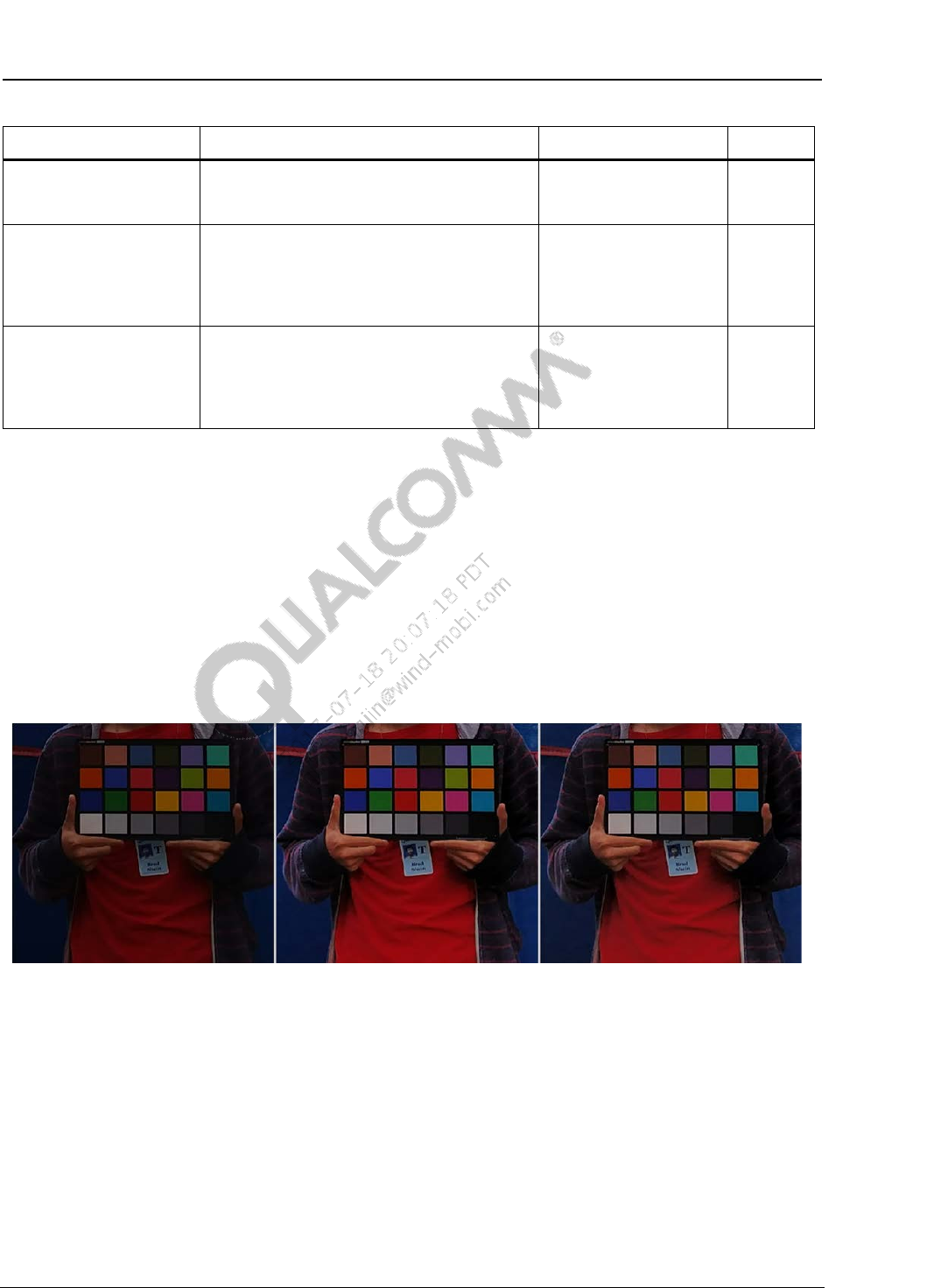
4.3 Saturation Curve
This parameter controls saturation. Decrease saturation caused by applying gains in the nonlinear
domain.
If the saturation curve is a straight line with a nonzero angle, e.g., 45 degrees, the LTM result
is same as that without saturation control.
To reduce saturation in a boosted area, the saturation curve must be bent as a downward
concave curve on the right side and bent as an upward concave curve on the left side.
Under low light conditions, reducing the saturation more can also reduce chroma noise more.
LTM off LTM on without
Sat Curve tuning LTM on with
Sat Curve tuning
Local Tone Mapping Feature Description References
80-NN684-1 D Confidential and Proprietary – Qualcomm Technologies, Inc. 14
MAY CONTAIN U.S. AND INTERNATIONAL EXPORT CONTROLLED INFORMATION
4.4 Fixed Content Low and Fixed Content High
This parameter controls the strength of boosting up dark areas and suppressing bright areas,
separately.
Increase Fixed Content Low parameter to boost up dark areas
Increase Fixed Content High parameter to suppress bright areas
Low: 1.0, High: 1.0 Low: 2.0, High: 4.0
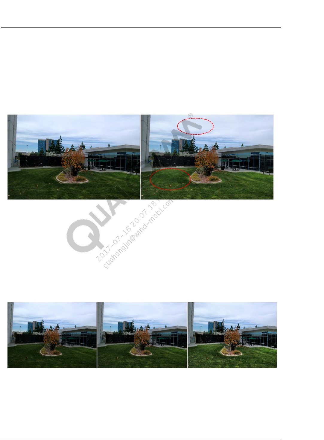
4.5 Global Tone Strength
Control the overall strength of LTM by adjusting several tables related to generating the LTM
curve set
Default value is 256 (1x) for normal scene, 384 (1.5x) for backlit scene
Increase to enhance the effect of LTM
Strength: 128 (0.5x) Strength: 256 (1.0x) Strength: 512 (2x)
Local Tone Mapping Feature Description References
80-NN684-1 D Confidential and Proprietary – Qualcomm Technologies, Inc. 15
MAY CONTAIN U.S. AND INTERNATIONAL EXPORT CONTROLLED INFORMATION
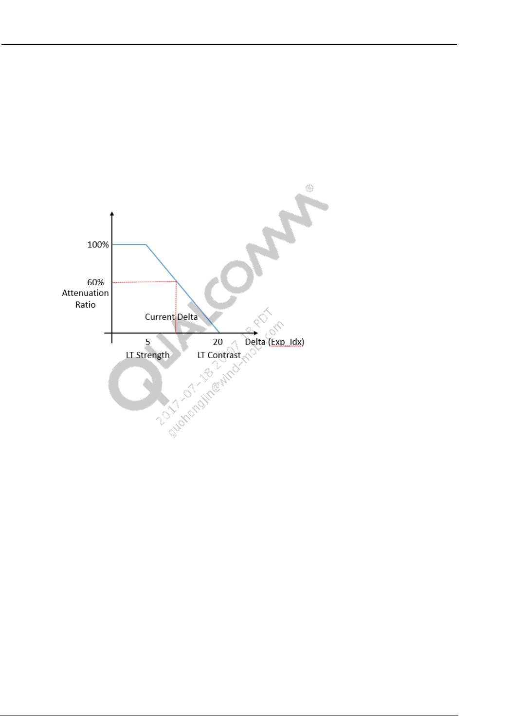
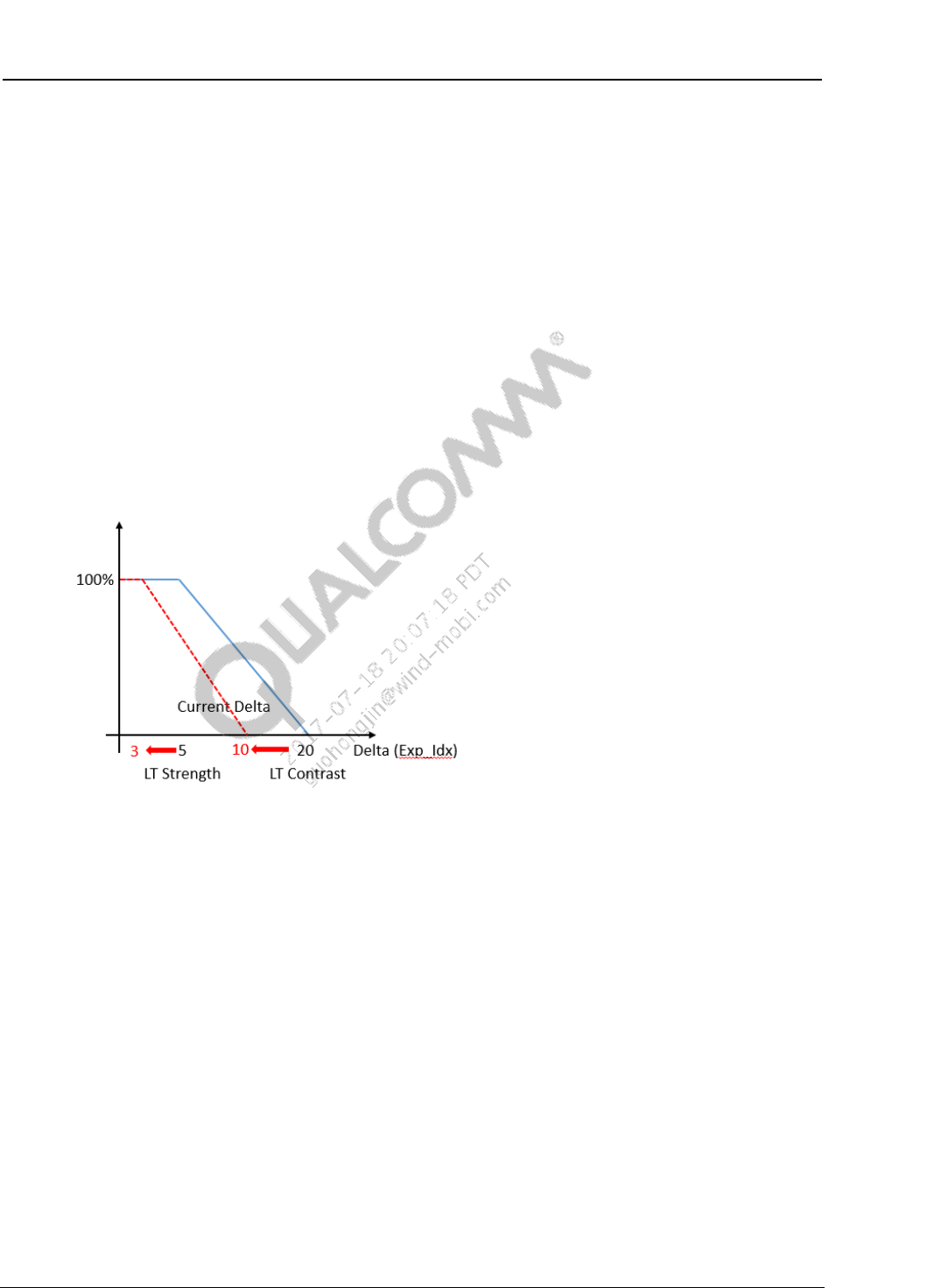
4.6 Local Tone Strength and Local Tone Contrast
These parameters control LTM attenuation based on the delta of exp_idx between frames. Local
Tone Strength is used as the low anchor point. Local Tone Contrast is used as the high anchor
point.
Avoid oscillation or flicking during AE convergence by attenuating the strength of LTM
when delta exp_idx is large. The attenuation ratio is multiplied to Global Tone Strength.
Recommend using the default value. If exposure oscillation is observed, reduce the parameter
values.
4.7 Reserved parameters
Parameters in the LTM reserved section of the Chromatix header include:
RGB to Y conversion
LTM fixed curve sets
It is recommended that you use the default values without manual tweaking and tuning.
80-NN684-1 D Confidential and Proprietary – Qualcomm Technologies, Inc. 16
MAY CONTAIN U.S. AND INTERNATIONAL EXPORT CONTROLLED INFORMATION
5 Tuning Procedure
5.1 Basic tuning procedure
Set all parameters to default values
For each region, tune Global Tone Strength, Fixed Content Low and Fixed Content High
If users need stronger LTM effect, increase Global Tone Strength.
If users need more dark boost, increase Fixed Content Low.
If users need more highlight suppression, increase Fixed Content High.
Check if the noise level is acceptable as increasing dark boost.
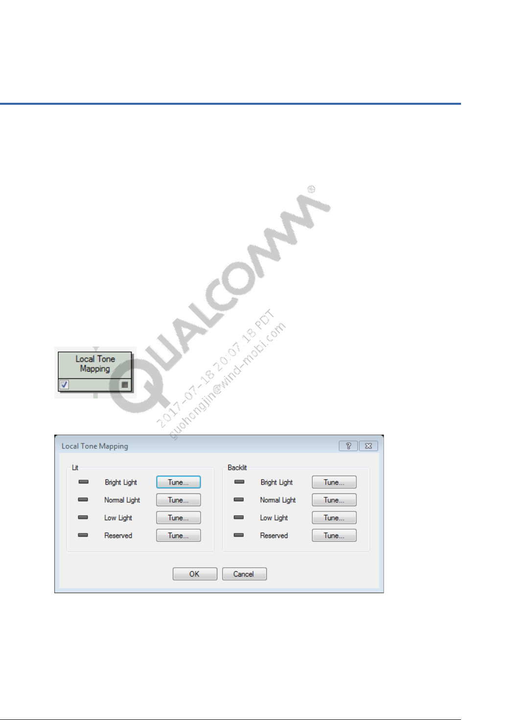
5.2 Tuning LTM in the Chromatix tool
1. On the Chromatix Tuning tab, click the Local Tone Mapping block.
2. Click Tune… next to Bright Light in the Lit section.
3. In the LTM window, click the Open icon, choose an image, select the appropriate color
temperature for the image, and click OK.
Local Tone Mapping Feature Description Tuning Procedure
80-NN684-1 D Confidential and Proprietary – Qualcomm Technologies, Inc. 17
MAY CONTAIN U.S. AND INTERNATIONAL EXPORT CONTROLLED INFORMATION
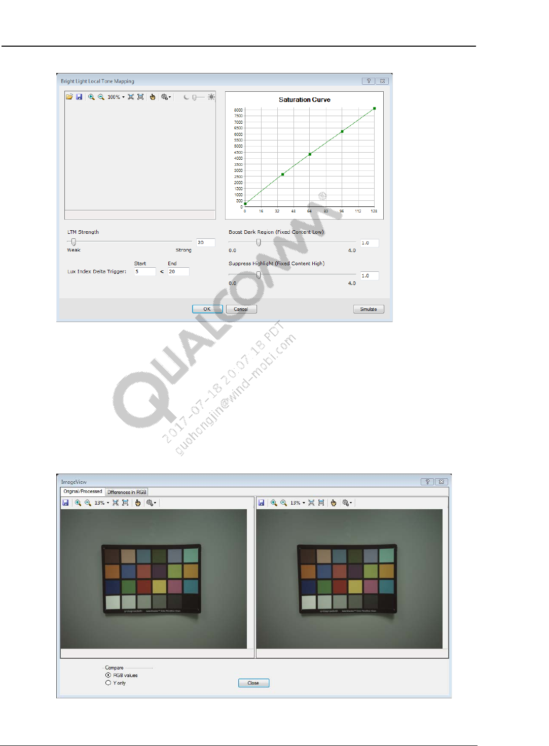
4. Move the LTM Strength slider to define the amount of tone mapping strength to apply to the
overall image.
5. Move the Boost Dark Region slider to define the strength of the dark area boost.
A larger value with the right direction results in more boosting in the dark region.
6. Move the Suppress Highlight slider to define the strength of bright area suppression.
A larger value with the right direction results in more suppression of the bright region.
7. Adjust the Saturation Curve to control color saturation. You can add knee points by right-
clicking the line. Refer to Section 6.3 for detailed instructions.
8. Click Simulate to apply the current settings to the loaded image. A preview image appears.
9. Click Close to dismiss the preview image.

Local Tone Mapping Feature Description Tuning Procedure
80-NN684-1 D Confidential and Proprietary – Qualcomm Technologies, Inc. 18
MAY CONTAIN U.S. AND INTERNATIONAL EXPORT CONTROLLED INFORMATION
10. Continue adjusting the slider until the preview image achieves the expected appearance.
11. Adjust the trigger values for attenuation, if needed.
12. Click OK to save the tuned LTM parameters.
13. Repeat steps 2 through 12 for the remaining light conditions. For the Backlit light condition,
steps 8 through 10 do not apply because simulation is not available for backlit lighting
scenarios. When complete, click OK to preserve the tuned LTM settings.

80-NN684-1 D Confidential and Proprietary – Qualcomm Technologies, Inc. 19
MAY CONTAIN U.S. AND INTERNATIONAL EXPORT CONTROLLED INFORMATION
6 Scene-Based Tuning Guidelines
6.1 I observe more noise when boosting up dark areas with
LTM. How can I improve the noise issue?
6.1.1 Tune ABF3 for dark area noise reduction
Using LTM to enhance local contrast may boost noise in dark regions, so avoid a strong LTM
effect for indoor or low light scenarios. If you need to reduce noise in dark colors, use ABF3.
Noise removal in ABF3 is level-based; therefore, use this module for noise reduction. The
software automatically increases the noise removal strength in ABF3 noise profiles to
dynamically reduce the noise in shadow regions of low-light images.
LTM enabled,
with ABF3 modified LTM disabled,
without ABF3 modified LTM enabled,
without ABF3 modified
Local Tone Mapping Feature Description Scene-Based Tuning Guidelines
80-NN684-1 D Confidential and Proprietary – Qualcomm Technologies, Inc. 20
MAY CONTAIN U.S. AND INTERNATIONAL EXPORT CONTROLLED INFORMATION
6.1.2 Tune 9x9 ASF block for dark areas
Use the 9x9 ASF module to control the strength of sharpness based on pixel intensity level as
well as activity level. This module allows you to tune gain LUT to decrease the strength of
sharpness for dark areas. See MSM8996 Camera Tuning Guide, 80-NK872-9, for 9x9 ASF tuning
procedures.
6.2 I observe AE flickering and oscillation issues during AE
convergence after enabling LTM. How can I improve this
issue?
6.2.1 Tune the Local Tone Strength and Local Tone Contrast
Reduce Local Tone Strength and Local Tone Contrast parameter values to attenuate the strength
of LTM when AE converges with a large difference in the exposure index.
Local Tone Mapping Feature Description Scene-Based Tuning Guidelines
80-NN684-1 D Confidential and Proprietary – Qualcomm Technologies, Inc. 21
MAY CONTAIN U.S. AND INTERNATIONAL EXPORT CONTROLLED INFORMATION
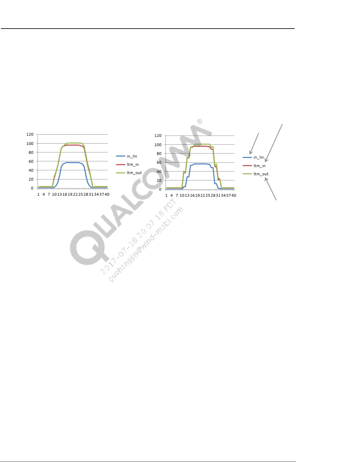
6.2.2 Check AEC aggressiveness and update timing
From the auto exposure adjustment (AEC) side, it is very important that the following occur:
AEC converges smoothly
AEC programming applied to the sensor must be on every frame. Otherwise (for example,
programming the sensor on every other frame), unevenness may occur in video streams. It is
especially critical for the low and regular frame rate scenario.
average lum value before LTM
average lum value in linear domain
average lum value after LTM
AEC programming on every frame AEC programming on every other frame
Figure 6-1 Simulated video stream with varying exposure
Local Tone Mapping Feature Description Scene-Based Tuning Guidelines
80-NN684-1 D Confidential and Proprietary – Qualcomm Technologies, Inc. 22
MAY CONTAIN U.S. AND INTERNATIONAL EXPORT CONTROLLED INFORMATION
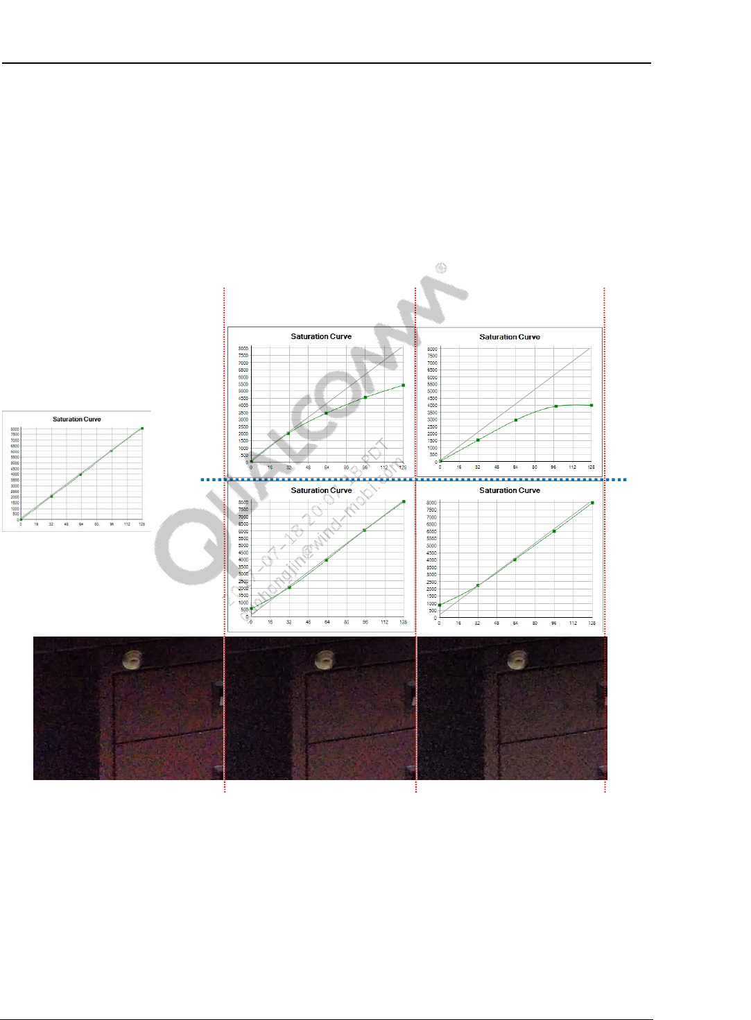
6.3 The saturation looks too high in a color object. How can I
reduce color saturation?
Tune the Saturation Curve.
NOTE: The Saturation Curve feature is available in MSM8996 or later chipsets.
Bend the curve to be concave downward on the right side, as seen in Option 1 below, to decrease
saturation. Increase the left side curve, like option 2 below, to get a similar effect.
Option 2 :
Option 1 :
No desaturation
Strong settingMild setting
80-NN684-1 D Confidential and Proprietary – Qualcomm Technologies, Inc. 23
MAY CONTAIN U.S. AND INTERNATIONAL EXPORT CONTROLLED INFORMATION
A References
A.1 Related documents
Title Number
Qualcomm Technologies, Inc.
Chromatix 6 User Guide 80-NK872-1
MSM8996 Camera Tuning Guide 80-NK872-9
A.2 Acronyms and terms
Acronym or term Definition
AEC Auto exposure adjustrment
GTM Global tone mapping
LA Luma adaptation
LCE Local contrast enhancement
LTM Local tone mapping
VFE Video front end
