PDAF Module Calibration Guide 80 NV125 1
User Manual: Pdf
Open the PDF directly: View PDF ![]() .
.
Page Count: 21
Qualcomm Technologies, Inc.
Confidential and Proprietary – Qualcomm Technologies, Inc.
NO PUBLIC DISCLOSURE PERMITTED: Please report postings of this document on public servers or websites to:
DocCtrlAgent@qualcomm.com.
Restricted Distribution: Not to be distributed to anyone who is not an employee of either Qualcomm Technologies, Inc. or its
affiliated companies without the express approval of Qualcomm Configuration Management.
Not to be used, copied, reproduced, or modified in whole or in part, nor its contents revealed in any manner to others without the
express written permission of Qualcomm Technologies, Inc.
Qualcomm is a trademark of Qualcomm Incorporated, registered in the United States and other countries. Other product and brand
names may be trademarks or registered trademarks of their respective owners.
This technical data may be subject to U.S. and international export, re-export, or transfer (“export”) laws. Diversion contrary to U.S.
and international law is strictly prohibited.
Qualcomm Technologies, Inc.
5775 Morehouse Drive
San Diego, CA 92121
U.S.A.
© 2015-2017 Qualcomm Technologies, Inc. All rights reserved.
PDAF Module Calibration Guide
80-NV125-1 L5
June 23, 2017
80-NV125-1 L5 Confidential and Proprietary – Qualcomm Technologies, Inc. 2
MAY CONTAIN U.S. AND INTERNATIONAL EXPORT CONTROLLED INFORMATION
Revision history
Revision Date Description
A January 2015 Initial release
B January 2015 Updated Sections 3.1.1 and 3.2.1
C February 2015 Updated Section 4.1
D March 2015 Updated Section 4.1
E May 2015 Numerous changes were made to this document. It should be read in its
entirety.
F May 2015 Clarification of OTP output size. Elaborated on actual Gain Map output
size, and the supported maximal possible Gain Map size.
G July 2015 Optimization of 1D gain map
H August 2015 Numerous changes were made to this document. It should be read in its
entirety.
J October 2015 Updated to conform to QTI standards; no technical content has been
changed in this document revision
K June 2016 Numerous changes were made to this document – it should be read in
its entirety.
L July 2016 Updated document attachments
L1 July 2016 Updated module calibration procedures in chapter 3
L2 September 2016 Updated Section 3.2, Section 3.3, Table 3-1, and Chapter 4
L3 September 2016 Updated document attachments
L4 December 2016 Inserted Section 3.4, updated Sections 1.2, 3.1, 3.3, 3.6, and document
attachments
L5 June 2016 Updated document attachments
Note: There is no Rev. I, O, Q, S, X, or Z per Mil. standards.

80-NV125-1 L5 Confidential and Proprietary – Qualcomm Technologies, Inc. 3
MAY CONTAIN U.S. AND INTERNATIONAL EXPORT CONTROLLED INFORMATION
Contents
1 Introduction ...................................................................................................... 5
1.1 Purpose.......................................................................................................................... 5
1.2 Conventions .................................................................................................................. 5
1.3 Technical assistance ...................................................................................................... 7
2 System architecture ........................................................................................ 8
3 Module calibration ........................................................................................... 9
3.1 Sensor configuration parameters ................................................................................... 9
3.2 Gain map calibration ..................................................................................................... 9
3.3 DCC calibration .......................................................................................................... 12
3.4 DCC calibration lens movement range ....................................................................... 14
3.5 DCC calibration validation tolerance .......................................................................... 15
3.6 DCC calibration procedure ......................................................................................... 16
3.7 Calibration Data Format ............................................................................................. 19
4 Verification parameters ................................................................................. 20
A References ..................................................................................................... 21
A.1 Related documents ..................................................................................................... 21
A.2 Acronyms and terms .................................................................................................. 21

PDAF Module Calibration Guide Contents
80-NV125-1 L5 Confidential and Proprietary – Qualcomm Technologies, Inc. 4
MAY CONTAIN U.S. AND INTERNATIONAL EXPORT CONTROLLED INFORMATION
Figures
Figure 1-1 Left and right pixel notation in various PD pixel types ............................................................. 5
Figure 1-2 Positive slope of phase disparity in a camera module using a lens actuator with a positive sign
...................................................................................................................................................................... 6
Figure 2-1 High-level block diagram of PDAF system ............................................................................... 8
Figure 3-1 Photocharge blooming in a dual-photodiode pixel ................................................................... 10
Figure 3-2 Correct DCC with positive sign vs. incorrect DCC with negative sign assuming a positive
actuator ........................................................................................................................................................ 12
Figure 3-3 Correct feature sizes for vertical line and diamond test chart. ................................................. 13
Figure 3-4 Correct test chart usage in DCC calibration. (a) Correct example (b) Test chart is too small (c)
Chart is too large (d) Chart is rotated (e) Chart is tilted (f) Chart is over-exposed ..................................... 14
Figure 3-5 DCC map calibration and integrated validation ....................................................................... 14
Figure 3-6 DCC map calibration and integrated validation ....................................................................... 16
Tables
Table 3-1 Calibration data format version 4 .............................................................................................. 19
80-NV125-1 L5 Confidential and Proprietary – Qualcomm Technologies, Inc. 5
MAY CONTAIN U.S. AND INTERNATIONAL EXPORT CONTROLLED INFORMATION
1 Introduction
1.1 Purpose
This document describes the one-time programmable (OTP) and non-volatile memory (NVM)
calibration procedure for module vendors using sensors supporting phase detection auto focus
(PDAF). Module makers should contact QTI to discuss tool settings.
The software tool and reference code for PDAF calibration are attached to this document. The
files supplied are:
PDAFCalibrationTools_Context.h
PDAFCalibrationTools_Dll.h
PDAFCalibrationTools_EEPROM.h
PDAFCalibrationTools_RevL_Dll.dll
PDAFCalibrationTools_RevL_Dll.exp
PDAFCalibrationTools_RevL_Dll.lib
Testbench.cpp
Testbench_utils.cpp
1.2 Conventions
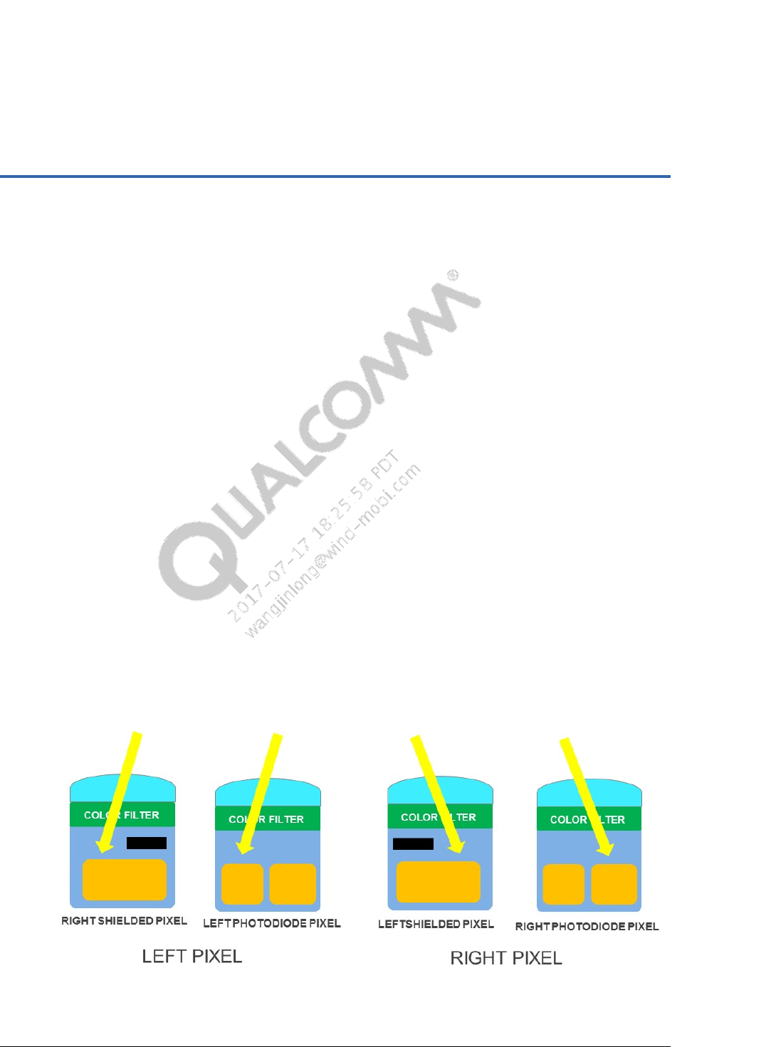
The following naming conventions for phase detection pixels facilitate a uniform calibration
procedure for all PDAF sensor types.
The left gain map is derived from the flat-field response of the left pixels and the right gain map
is that of right pixels.
Figure 1-1 Left and right pixel notation in various PD pixel types
PDAF Module Calibration Guide Introduction
80-NV125-1 L5 Confidential and Proprietary – Qualcomm Technologies, Inc. 6
MAY CONTAIN U.S. AND INTERNATIONAL EXPORT CONTROLLED INFORMATION
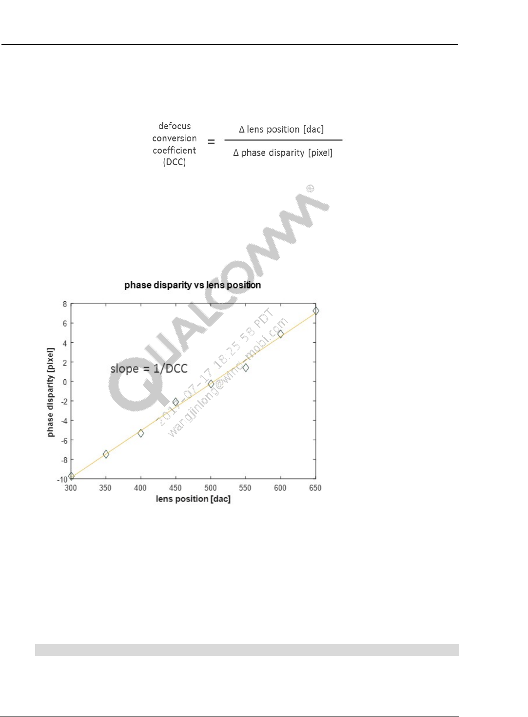
The conversion between phase disparity and lens movement is denoted by the defocus conversion
coefficient (DCC) in units of dac/pixel.
The definition of DCC has been updated to be a signless quantity stored as a positive value in
nonvolatile memory. DCC no longer includes the sign of the actuator as defined in previous
versions of PDAF calibration guideline. If the PDAF calibration tool reports a negative DCC, an
error code will be returned to the user signaling an invalid calibration outcome. A negative DCC
can result from an incorrect ‘LEFT’ and ‘RIGHT’ designation in the customized sensor
configuration file.
Figure 1-2 Positive slope of phase disparity in a camera module using a lens
actuator with a positive sign
Phase disparity is expressed in units of pixels where 1 pixel means the left and the right images
are shifted by 1 pixel. In dual-photodiode sensors, 1 pixel refers to the left and right pixel pair.
For example, IMX362 has dimensions of 3204 x 4032 pixel x pixel.
Function declarations, function names, type declarations, attributes, and code samples appear in a
different font, for example, #include.
Code variables appear in angle brackets, for example, <number>.
Shading indicates content that has been added or changed in this revision of the document.

PDAF Module Calibration Guide Introduction
80-NV125-1 L5 Confidential and Proprietary – Qualcomm Technologies, Inc. 7
MAY CONTAIN U.S. AND INTERNATIONAL EXPORT CONTROLLED INFORMATION
1.3 Technical assistance
For assistance or clarification on information in this document, submit a case to Qualcomm
Technologies, Inc. (QTI) at https://createpoint.qti.qualcomm.com/.
If you do not have access to the CDMATech Support website, register for access or send email to
support.cdmatech@qti.qualcomm.com.
80-NV125-1 L5 Confidential and Proprietary – Qualcomm Technologies, Inc. 8
MAY CONTAIN U.S. AND INTERNATIONAL EXPORT CONTROLLED INFORMATION
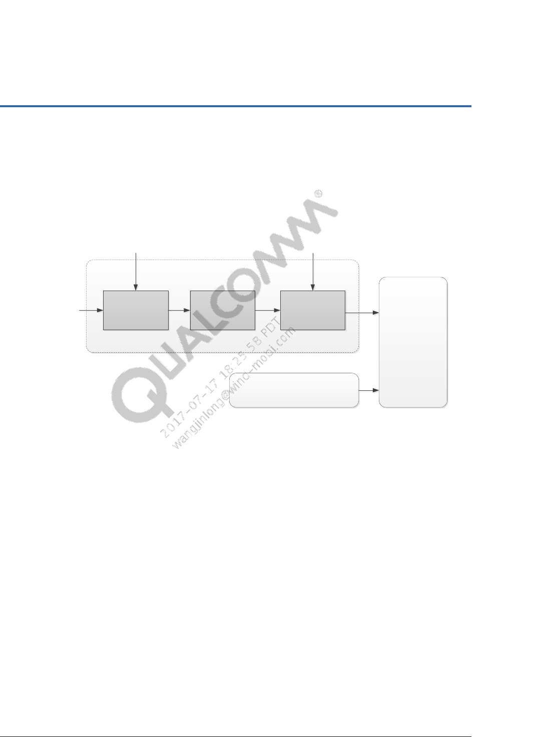
2 System architecture
PDAF relies on the phase detection library (PDLIB) to provide an estimation of lens defocus. To
correctly compute phase disparity and convert to lens defocus (e.g. DAC code by which to move
the lens) PDLIB requires on PDAF calibration parameters such as gain map and DCC map.
PDLIB
Contrast AF
PDAF
apply gain
correction phase disparity
calculation
phase to
defocus
conversion
GAIN MAP
(FROM CALIBRATION) DCC MAP
(FROM CALIBRATION)
PD pixels
Figure 2-1 High-level block diagram of PDAF system
80-NV125-1 L5 Confidential and Proprietary – Qualcomm Technologies, Inc. 9
MAY CONTAIN U.S. AND INTERNATIONAL EXPORT CONTROLLED INFORMATION
3 Module calibration
The PDAF system requires the following calibration parameters:
Sensor configuration
Gain map
DCC
3.1 Sensor configuration parameters
For PDAF sensors employing PD pixels in a repeating pattern, the location of the PD pixels needs
to be specified for the calibration DLL to correctly parse the PD pixel from the raw images.
Obtain the sensor configuration from the sensor vendors (e.g. IMX258 sensor configuration file
from Sony).
In the sensor configuration file, PD pixel coordinates must be sorted by increasing x-coordinate
when devising new sensor configuration file. Automatic sorting of PD pixel coordinates is not
performed in order to reduce calibration initialization time.
The provided sensor configuration must be reviewed and revised to ensure that the information
contained reflects the information of the raw image read from a given sensor. For example, the
size of the captured image and the location of the PD pixel block in a given program may be
slightly different from the sample sensor configuration file obtained from the sensor vendor.
The sensor configuration assumes that the raw image is read in a canonical orientation. That is,
the sensor flip and mirror must both be disabled when raw image is read. To prevent incorrect
results, the PDAF calibration .dll file must always be provided with raw images in canonical
orientation.
3.2 Gain map calibration
The size of the generated gain map generated is 13x17, height x width, for all types of PDAF
sensors. NVM/OTP format, however, allows a gain map of variable size to be specified.
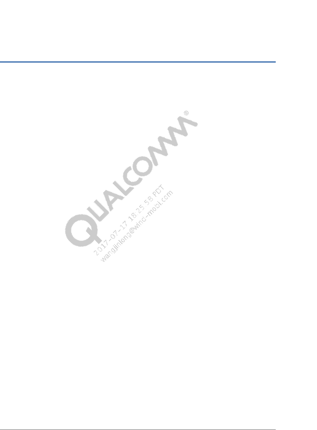
Pixel saturation and blooming can substantially alter the shape of flat-field response of PD pixels
rendering the gain map erroneous and preventing accurate calculation of phase disparity. In dual-
photodiode sensors such as IMX362 and LSI 2L7 the pixel blooming between the left and the
right pixel can occur at sensor gains between 1x and 2x.
PDAF Module Calibration Guide Module calibration
80-NV125-1 L5 Confidential and Proprietary – Qualcomm Technologies, Inc. 10
MAY CONTAIN U.S. AND INTERNATIONAL EXPORT CONTROLLED INFORMATION
Figure 3-1 Photocharge blooming in a dual-photodiode pixel
Set the analog gain of sensor gain to 2X to prevent pixel blooming. This will ensure that pixel
blooming level will reside close to ADC cut-off limit.
To prevent charge blooming between dual-photodiode and to prevent saturation of a regular pixel
whose value is obtained by adding the left and the right pixel of dual-photodiode pair, adjust the
exposure to ensure that the center 10% x10% ROI has average green LEFT and RIGHT pixel
values each reside between 300 LSB and 950 LSB limits assuming 10-bit output.
The same limits also apply to PDAF sensors employing a metal-shield. Regular, non-shielded
pixels have substantially higher sensitivity than shielded PD pixels. By ensuring that PD pixels in
these sensors reside between 300 LSB and 950 LSB in the center 10% x10% ROI, the blooming
from regular pixels into the metal-shielded pixel can be prevented.
Calibrate the gain map
1. Set up the test scene.
The parameters AF_CAL_INF and AF_CAL_MACRO refer to the lens position at infinity focus
and at macro focus (e.g. 10 cm), respectively.
Lens position – Midway between AF_CAL_INF and AF_CAL_MACRO focus position.
If AF calibration results for the given module are not available at the time of gain map
calibration, use typical values for AF_CAL_INF and AF_CAL_MACRO.
Light source – D50 or D65, or the illuminant used during lens shading calibration
Sensor gain:
– For PDAF sensors with metal shield and 2x1 OCL pixel types, analog and digital
sensor gain = 1X.
– For dual-photodiode sensors, analog gain = 2X and digital gain = 1X.
Exposure – The average left and right PD pixel values in center 10% x 10% ROI need to
reside between 100 and 950 LSB for 10-bit output.
The testbench function illustrates how the green left and right image pair may be parsed
from the full-resolution raw image for dual-photodiode sensors.
Frame average – Use the same frame averaging used during lens shading calibration
Verify that neither the green nor the PD pixels are clipped

PDAF Module Calibration Guide Module calibration
80-NV125-1 L5 Confidential and Proprietary – Qualcomm Technologies, Inc. 11
MAY CONTAIN U.S. AND INTERNATIONAL EXPORT CONTROLLED INFORMATION
2. If the camera module is OIS-enabled, calibrate OIS before lens shading and PDAF gain map
calibration. Verify that OIS is configured to place the lens in the reference XY location. This
yields a realistic flat-field image for both lens shading and PDAF gain map calibrations.
3. Capture a flat field image.
In PDAF sensors containing a limited number of PD pixels in a pattern (i.e. a “sparse” PDAF
sensor), take a full resolution raw image. The PD pixels are parsed from the full resolution
image by the calibration DLL.
In dual-photodiode sensors, take either a full resolution image or a tail mode buffer of the
green pixels (e.g. IMX362 Mode 4). If using a tail mode buffer, verify that the content has
first been parsed into a left and right image pair before being sent to the PDAF calibration
DLL.
4. Use the PDAF calibration .dll API PDAF_Cal_get_gainmap(…) to get the gain map.
Required input parameters include image width, height, black level, and pixel bit depth.
If the sensor uses image flip or mirror, reverse each of these operations before using the
image in gain map calibration. Sample functions are provided and their use is
demonstrated in the testbench function.
Gain map verification parameters impose constraints on the raw image used during gain
map calibration as well as the resulting gain map. See Chapter 4 for the list of fields.
Example values are given in reference code.
For sensors with dual-photodiode PD pixels, use PDAF_Cal_get_gainmap_2pd(…).
The CFA pattern provided is used inside the testbench function to demonstrate how the
green pixels must be 2x2 binned to precisely emulate the sensor binning of PD pixels
(e.g. IMX362 mode 4). The 2x2 binning can be bypassed if the tail mode buffer is
directly read from the sensor. However, the buffer must first be parsed into left and right
image pairs in order to use PDAF_Cal_get_gainmap_2pd(…). This DLL API will not
work if tail mode buffer is used without parsing.
The use of luma or Y pixels from tail mode buffer (e.g. IMX362 mode 3) is not allowed
as the PDLIB employs only 2x2 binned green pixels in its phase disparity calculation. If
the tail mode buffer only supports output of Y pixels (e.g. 2L7) then the weights for R
and B pixels must be set to 0 in order to set Y= G.
Gain map verification parameters impose constraints on the raw image used during gain
map calibration as well as the resulting gain map. See Chapter 4 for the list of fields.
Example values are given in reference code.
5. Examine the return code to see if any violations such as pixel saturation or invalid gain map
values are detected. Abort the calibration in the case of an error to avoid programming an
invalid gain map.
6. Write gain map NVM data to the module.
PDAF Module Calibration Guide Module calibration
80-NV125-1 L5 Confidential and Proprietary – Qualcomm Technologies, Inc. 12
MAY CONTAIN U.S. AND INTERNATIONAL EXPORT CONTROLLED INFORMATION
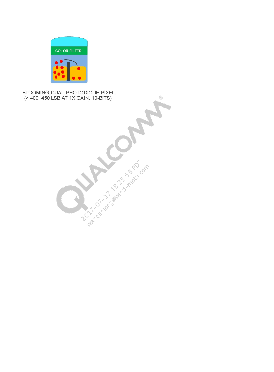
3.3 DCC calibration
DCC is the slope of lens position change (DAC) over PD value change (pixels).
DCC = Δlens DCC position [DAC] / Δ phase disparity [pixel]
DCC has units of DAC/pixel.
The unit of phase disparity can differ from one organization to another, resulting in DCC values
offset by factor of 2X, 4X, 1/2X, etc. See Section 1.2 for a discussion of the QTI definition of
DCC.
Figure 3-2 Correct DCC with positive sign vs. incorrect DCC with negative sign
assuming a positive actuator
DCC calibration can be performed with a vertical line test or diamond test chart. The vertical line
chart is strongly recommended for more uniform phase disparity estimations than the diamond
test chart. DCC calibration chart type is one of the required inputs to the calibration DLL.
The recommended distance between the DCC calibration test chart and the camera module is the
distance whose corresponding lens position is in the middle of AF_CAL_INF and AF_CAL_MACRO
positions. In most camera module designs, this distance is typically 20 cm to 30 cm. In camera
modules that employ telephoto lens this distance may be as large as 2.0 m. The following
example illustrates how to find the recommended test chart distance for DCC calibration.
Median AF_CAL_INF lens position = 100 DAC
Median AF_CAL_MACRO lens position = 500 DAC
Middle lens position = 300 DAC
Test chart distance that corresponds to lens position of 300 DAC
PDAF Module Calibration Guide Module calibration
80-NV125-1 L5 Confidential and Proprietary – Qualcomm Technologies, Inc. 13
MAY CONTAIN U.S. AND INTERNATIONAL EXPORT CONTROLLED INFORMATION
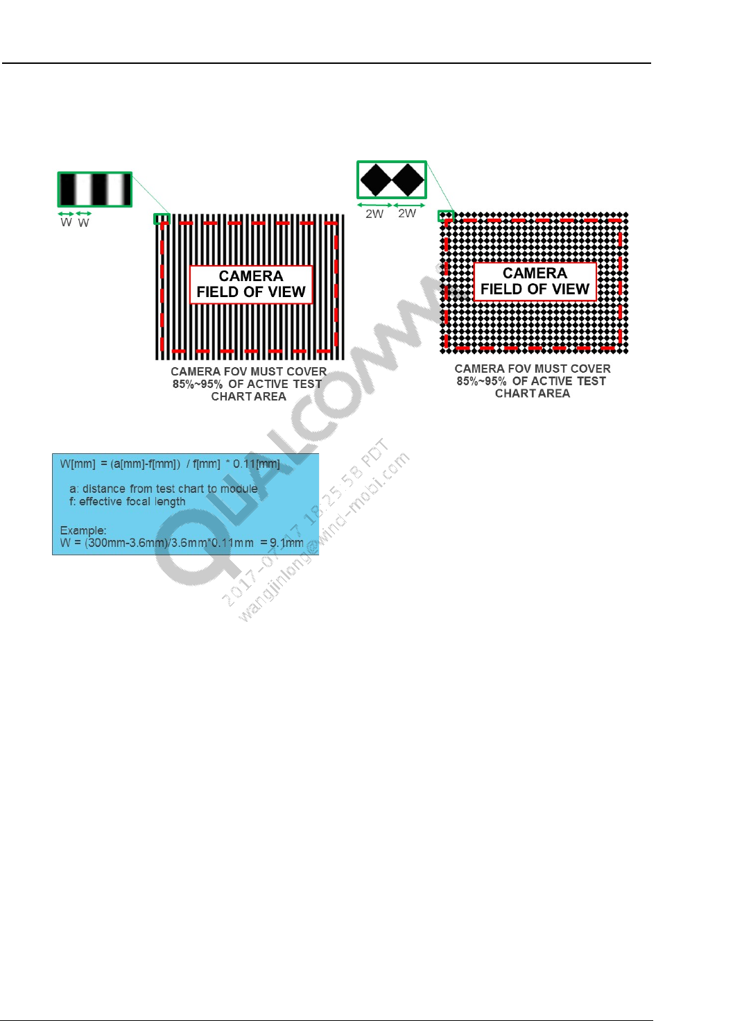
The test chart must be printed and sized according to the chart distance obtained. The correct size
of test chart depends on the field-of-view (FOV) of the camera module. As a rule of thumb, the
camera FOV covers between 85%~95% of the active area of the test chart as shown below.
Figure 3-3 Correct feature sizes for vertical line and diamond test chart.
Use the test chart properly to avoid systematic errors in DCC calibration which can lead to PDAF
performance issues. Improper sizing of test chart, test chart rotation and/or tilt, and over-exposure
lead to common DCC calibration mistakes.
PDAF Module Calibration Guide Module calibration
80-NV125-1 L5 Confidential and Proprietary – Qualcomm Technologies, Inc. 14
MAY CONTAIN U.S. AND INTERNATIONAL EXPORT CONTROLLED INFORMATION
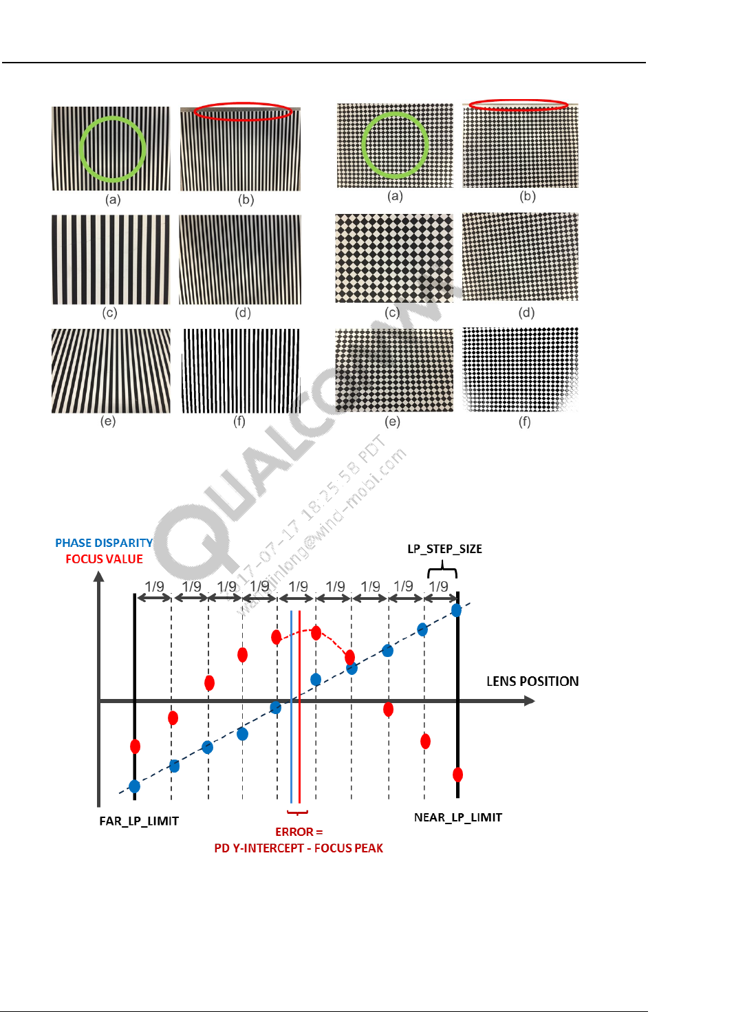
Figure 3-4 Correct test chart usage in DCC calibration. (a) Correct example (b)
Test chart is too small (c) Chart is too large (d) Chart is rotated (e) Chart is tilted (f)
Chart is over-exposed
Figure 3-5 DCC map calibration and integrated validation
3.4 DCC calibration lens movement range
The lens is moved from the FAR_LP_LIMIT to the NEAR_LP_LIMIT in 9 equal steps. During the
lens sweep from, a total of 10 images are captured from which 10 phase disparity values and 10
focus values are computed. From this data, a linear regression is performed to obtain the DCC

PDAF Module Calibration Guide Module calibration
80-NV125-1 L5 Confidential and Proprietary – Qualcomm Technologies, Inc. 15
MAY CONTAIN U.S. AND INTERNATIONAL EXPORT CONTROLLED INFORMATION
value. The image is divided into 6 × 8 (width × height) regions resulting in a 6 × 8 DCC map.
This procedure is illustrated in Figure 3-5.
The calculation of FAR_LP_LIMIT and NEAR_LP_LIMIT is illustrated below. The parameters
AF_CAL_INF and AF_CAL_MACRO refer to the lens position at infinity focus and at macro focus
(e.g. 10 cm), respectively. This information is obtained during AF calibration performed prior to
the PDAF calibration.
FAR_LP_LIMIT = AF_CAL_INF – (AF_CAL_MACRO – AF_CAL_INF ) × CC_LP_FAR_MARGIN
NEAR_LP_LIMIT = AF_CAL_MACRO + (AF_CAL_MACRO – AF_CAL_INF ) ×
DCC_LP_NEAR_MARGIN
LP_STEP_SIZE = | NEAR_LP_LIMIT - FAR_LP_LIMIT | / 9
DCC_LP_FAR_MARGIN and DCC_LP_NEAR_MARGIN are customizable parameters whose default
value is 0.0. These two tunable parameters allow the lens position sweep to extend beyond the
AF_CAL_INF and AF_CAL_MACRO lens positions obtained from AF calibration.
For camera modules with non-telephoto lenses, leave the default values of DCC_LP_FAR_MARGIN
= 0.0 and DCC_LP_NEAR_MARGIN = 0.0 to permit tight sampling of lens positions for accurate
determination of focus peak lens position.
For camera modules with telephoto lenses, use DCC_LP_FAR_MARGIN = 0.10 and
DCC_LP_NEAR_MARGIN = 0.10 in observance of tyical lens field curvature. This causes a
significant difference in lens position corresponding to hyperfocal and macro focus as a function
of ROI position for telephoto lenses.
Camera modules with a lens whose field curvature is more aggressive than 10% should be
screened out before DCC calibration. Perform a sample test to determine if the field curvature is
too extreme by checking if the AF_CAL_INF or AF_CAL_MACRO lens positions at one of the four
corner regions deviates from the center region by more than:
0.10 × | AF_CAL_MACRO – AF_CAL_INF|
If the focus curve obtained during DCC calibration shows a focus peak at either end of the lens
position limits (e.g. AF_CAL_INF or AF_CAL_MACRO) then error code 0x2000 will be returned
with the message Focus peak is out of boundary. Proper screening of telephoto lens with
a field curvature greater than 10% is strongly recommended to avoid the resulting DCC
calibration failure
3.5 DCC calibration validation tolerance
During the lens sweep the focus value is computed to obtain an estimate of the “true” maximum
focus position, which is used for DCC calibration validation. DCC calibration error is estimated
by the difference between the lens position obtained from the y-intercept of the phase disparity
line and the lens position derived with a polynomial regression of the focus curve. DCC
calibration error is then normalized by the lens position range between FAR_LP_LIMIT and
NEAR_LP_LIMIT.
For metal-shielded, 2x1 OCL, and dual-photodiode PDAF sensors, the default DCC validation
tolerances are 20%, 15%, and 10%, respectively. These DCC validation tolerances can be revised
by changing the content of parameters DCC_VAL_TOL_SPARSE, DCC_VAL_TOL_2BY1 and
DCC_VAL_TOL_DPD in the PDAF calibration header file. The tolerance limits should not be
PDAF Module Calibration Guide Module calibration
80-NV125-1 L5 Confidential and Proprietary – Qualcomm Technologies, Inc. 16
MAY CONTAIN U.S. AND INTERNATIONAL EXPORT CONTROLLED INFORMATION
increased above the default recommended value except in cases where relaxed limits are required.
Since the DCC map is defined as an 8 x 6 grid (width x height), the DCC validation tolerance is
also defined as an 8 x 6 grid.
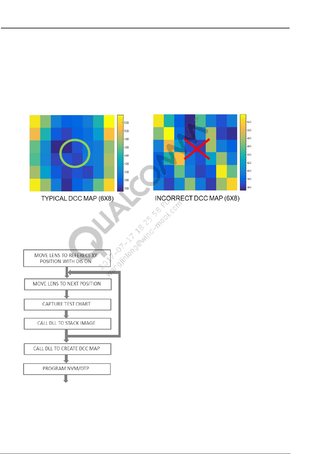
If the DCC calibration proceeds without error then the resulting DCC map manifests as a smooth
surface as shown in Figure 3-6. An incorrect DCC map exhibits numerous local maxima and local
minima. An incorrect DCC map can prevent accurate calculation of phase disparity. If a cali
bration error is detected, uncover the root cause before proceeding.
Figure 3-6 DCC map calibration and integrated validation
3.6 DCC calibration procedure
1. Set up the test scene
DCC calibration chart – Use either the diamond or vertical line test chart. The calibration
test chart needs to be placed at the distance whose corresponding lens focus position is
PDAF Module Calibration Guide Module calibration
80-NV125-1 L5 Confidential and Proprietary – Qualcomm Technologies, Inc. 17
MAY CONTAIN U.S. AND INTERNATIONAL EXPORT CONTROLLED INFORMATION
approximately at the middle between AF_CAL_INF and AF_CAL_MACRO lens
positions. Please see example calculation shown in Section 3.3.
Light source – At least 400 lux
Light source – D50 or D65, or the illuminant used during lens shading calibration
Sensor gain:
– For PDAF sensors with metal shield and 2x1 OCL pixel types, analog and digital
sensor gain = 1X.
– For dual-photodiode sensors, analog gain = 2X and digital gain = 1X.
Exposure – The average left and right PD pixel values in the center 10% x 10% ROI that
corresponds to the white background portion of the test chart should be between 300 and
950 LSB for 10-bit output.
In dual-photodiode sensors the average green left and right pixel value that corresponds
to the white background portion test chart each reside between 300 and 950 LSB limits.
The testbench function illustrates how to parse the green PD pixels values parsed from
the full-resolution raw image for dual-photodiode sensors.
In metal-shielded sensors ensure that non-shielded (i.e. regular) pixels are not saturated.
Charge blooming from non-shielded pixels into shielded pixels can adversely impact the
metal-shielded PD pixel values and cause error in the resulting phase disparity value.
Frame averaging – Utilize frame averaging if test repeatability is poor
2. If the camera module is OIS-enabled, calibrate OIS before to lens shading and PDAF gain
map calibration. Verify that OIS is configured to place the lens in reference XY location. This
yields realistic chief-ray-angle (CRA) characteristic of the lens which impacts the shape of
DCC map.
3. AF calibration must be performed prior to DCC map calibration since DCC calibration
requires knowledge of AF_CAL_INF and AF_CAL_MACRO lens positions, which are
needed in order to calculate FAR_LP_LIMIT and NEAR_LP_LIMIT.
Move the lens to the FAR_LP_LIMIT focus position for the given camera module and
capture a raw image. If only the PAN focus position is available then infer the approximate
INF focus position and move to the lens to the calculated position. In PDAF sensors
containing a limited number of PD pixels in a pattern (i.e. “sparse” PDAF sensor), a full
resolution raw image is required since the parsing of PD pixel from the full resolution image
is performed inside the calibration DLL.
In dual-photodiode sensors, either the full resolution image or the tail mode buffer of green
pixels (e.g. IMX362 Mode 4) can be used. If tail mode buffer is used the content of the tail
mode buffer must be parsed into left and right image pair before it is sent to the PDAF
calibration DLL.
4. Use PDAF calibration DLL API PDAF_Cal_add_raw(…) to add an image to the stack. For
dual-photodiode sensor use DLL API PDAF_Cal_add_raw_2pd(…). Check return code
from the API for errors. DCC map calibration must be aborted if an error code is returned at
this step.
5. Move the lens position by 1/9th of the way toward the NEAR_LP_LIMIT position. After the
lens settles, capture the image.

PDAF Module Calibration Guide Module calibration
80-NV125-1 L5 Confidential and Proprietary – Qualcomm Technologies, Inc. 18
MAY CONTAIN U.S. AND INTERNATIONAL EXPORT CONTROLLED INFORMATION
6. Use DLL API PDAF_Cal_add_raw(…) for “sparse” PDAF sensor (i.e. sensors whose PD
pixels are sparsely distributed) to store the image for the later determination of DCC. Use
PDAF_Cal_add_raw_2pd(…) for dual-photodiode sensor.
7. Repeat steps 5 and 6 until the final image is captured at NEAR_LP_LIMIT focus position and
the stack API is called for the 10th time.
8. Use the PDAF calibration DLL API PDAF_Cal_get_dccmap(…)to obtain the DCC map. This
API is shared between dual-photodiode and sparse PDAF sensors.
9. Check the return code for errors. If an error occurred from PDAF_Cal_get_dccmap(…)then
the calibration process must be aborted and the root cause must be determined.
10. Write DCC map NVM data to the module.
PDAF Module Calibration Guide Module calibration
80-NV125-1 L5 Confidential and Proprietary – Qualcomm Technologies, Inc. 19
MAY CONTAIN U.S. AND INTERNATIONAL EXPORT CONTROLLED INFORMATION
3.7 Calibration Data Format
PDAF calibration data containing both gain and DCC maps is organized in OTP/EEPROM as
shown in Table 3-1. Use the PDAF calibration .dll file API
PDAF_Cal_get_calibration_block(…) to obtain the content of the buffer to be programmed
to OTP/EEPROM. The content of the calibration buffer and its organization can be found in
PDAFCalibrationTools_EEPROM.h. The current calibration version number is 4.
All future updates to the calibration content will be stored in
PDAFCalibrationTools_EEPROM.h.
Table 3-1 Calibration data format version 4
PDAF Calibration Content
Rel. addr
Description
Endian
0x0000
Version number
H
0x0001
Version number
L
0x0002
Gain Map Width
H
0x0003
Gain Map Width
L
0x0004
Gain Map Height
H
0x0005
Gain Map Height
L
0x0006
Left_GainMap[0]
H
0x0007
Left_GainMap[0]
L
..
..
0x01BE
Left_GainMap[220]
H
0x01BF
Left_GainMap[220]
L
0x01C0
Right_GainMap[0]
H
0x01C1
Right_GainMap[0]
L
..
..
0x0378
Right_GainMap[220]
H
0x0379
Right_GainMap[220]
L
0x037A
DCC Q Format
H
0x037B
DCC Q Format
L
0x037C
DCC Map Width
H
0x037D
DCC Map Width
L
0x037E
DCC Map Height
H
0x037F
DCC Map Height
L
0x0380
DccMap[0]
H
0x0381
DccMap[0]
L
.. ..
0x03DE
DccMap[47]
H
0x03DF
DccMap[47]
L
0x03E0
CHECKSUM %256
80-NV125-1 L5 Confidential and Proprietary – Qualcomm Technologies, Inc. 20
MAY CONTAIN U.S. AND INTERNATIONAL EXPORT CONTROLLED INFORMATION
4 Verification parameters
pd_max_limit – Maximum value of the PD pixel after LPF is applied to flat-field image.
The DLL will return an error code if the PD pixel value exceeds this limit.
Recommended value – 950
pd_min_limit – Minimum value of PD pixel after LPF. The DLL will return an error code
if the PD pixel value is below this limit.
Recommended value – 100
gain_max_limit – Maximum value of the gain map. After the gain map is computed, if
one of the gain values is found to be above this limit, the DLL will return an error code but
will still generate a gain map. Do not exceed 7.999 to stay within the limitations of the PDAF
calibration tool.
Recommended value – 7.999 * (1<<GAIN_MAP_Q_FMT)
80-NV125-1 L5 Confidential and Proprietary – Qualcomm Technologies, Inc. 21
MAY CONTAIN U.S. AND INTERNATIONAL EXPORT CONTROLLED INFORMATION
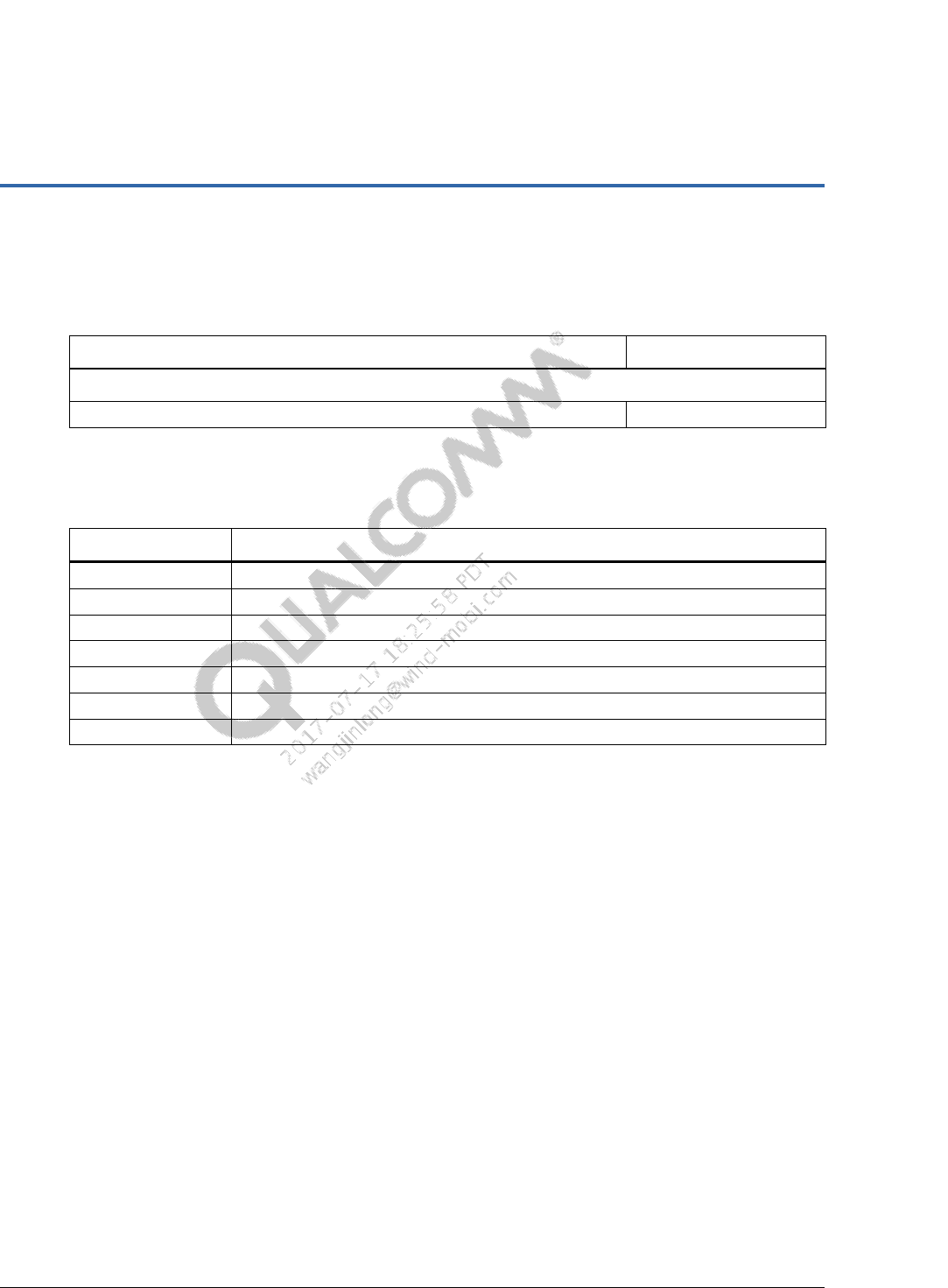
A References
A.1 Related documents
Title Number
Qualcomm Technologies, Inc.
Presentation: Camera Module Selection and Calibration Data 80-N5126-1
A.2 Acronyms and terms
Acronym or term Definition
AF Auto focus
DCC Defocus conversion coefficient
PD Phase difference
PDAF Phase difference auto focus
PDLIB Phase detection library
NVM Non-volatile memory, e.g., OTP, EEPROM, etc.
OTP One-time programmable
