80 NV213 6 Audio Tuning Debugging And Trouble Shooting Guide
User Manual: Pdf
Open the PDF directly: View PDF ![]() .
.
Page Count: 77
- Common Audio Tuning Cases Introduction and Debugging
- Contents
- Figures
- Tables
- 1 Introduction
- 2 Audio EC-VOIP
- 3 Wideband Tuning and Debug
- 4 Call Recording
- 5 Common Echo/DT Issues
- 6 DM NS, Holding Position Robustness
- 7 CMCC Tuning
- 7.1 CMCC Audio Spec
- 7.2 Easy failed cases debugging
- 8 Audio Recording
- 9 Per Vocoder Calibration (PVC)
- 10 Book Lab + Fluence Package
- 11 HW Design Cause Input Signal Distortion Issue
- 12 WB Inside-Speech Noise Tuning
Qualcomm Technologies, Inc.
Confidential and Proprietary – Qualcomm Technologies, Inc.
NO PUBLIC DISCLOSURE PERMITTED: Please report postings of this document on public servers or websites to:
DocCtrlAgent@qualcomm.com.
Restricted Distribution: Not to be distributed to anyone who is not an employee of either Qualcomm Technologies, Inc. or its
affiliated companies without the express approval of Qualcomm Configuration Management.
Not to be used, copied, reproduced, or modified in whole or in part, nor its contents revealed in any manner to others without the
express written permission of Qualcomm Technologies, Inc.
Qualcomm is a trademark of Qualcomm Incorporated, registered in the United States and other countries. Other product and brand
names may be trademarks or registered trademarks of their respective owners.
This technical data may be subject to U.S. and international export, re-export, or transfer (“export”) laws. Diversion contrary to U.S.
and international law is strictly prohibited.
Qualcomm Technologies, Inc.
5775 Morehouse Drive
San Diego, CA 92121
U.S.A.
© 2017 Qualcomm Technologies, Inc. All rights reserved.
Common Audio Tuning Cases Introduction
and Debugging
Debugging Guide
80-NV213-6 Rev. A
January 24, 2017

80-NV213-6 Rev. A Confidential and Proprietary – Qualcomm Technologies, Inc. 2
MAY CONTAIN U.S. AND INTERNATIONAL EXPORT CONTROLLED INFORMATION
Revision history
Revision Date Description
A January 2017 Initial release
Note: There is no Rev. I, O, Q, S, X, or Z per Mil. standards.

80-NV213-6 Rev. A Confidential and Proprietary – Qualcomm Technologies, Inc. 3
MAY CONTAIN U.S. AND INTERNATIONAL EXPORT CONTROLLED INFORMATION
Contents
1 Introduction ...................................................................................................... 7
1.1 Purpose.......................................................................................................................... 7
1.2 Conventions .................................................................................................................. 7
1.3 Technical assistance ...................................................................................................... 7
2 Audio EC-VOIP ................................................................................................. 8
2.1 Audio VOIP RX NS ................................................................................................... 11
3 Wideband Tuning and Debug ....................................................................... 14
3.1 Basic WB tuning requirements ................................................................................... 14
3.2 WB Tuning - FluenceV5 EC ....................................................................................... 14
3.3 WB Tuning – EEC ...................................................................................................... 15
3.4 WB tuning - MBDRC ................................................................................................. 16
3.5 WB tuning - FNS ........................................................................................................ 17
4 Call Recording ............................................................................................... 18
4.1 Call Recording Audio Path ......................................................................................... 18
4.2 Call Recording Tuning ................................................................................................ 19
4.3 FAQs and Debugging ................................................................................................. 20
5 Common Echo/DT Issues ............................................................................. 22
5.1 TCLw Test Failure ...................................................................................................... 22
5.2 Echo vs Time .............................................................................................................. 22
5.3 Echo Spectrum ............................................................................................................ 23
5.4 Double Talk ................................................................................................................ 23
6 DM NS, Holding Position Robustness ......................................................... 24
7 CMCC Tuning ................................................................................................. 27
7.1 CMCC Audio Spec ..................................................................................................... 27
7.2 Easy failed cases debugging ....................................................................................... 30
7.2.1 Tx_Distortion (Handset Mode) ........................................................................ 30
7.2.2 Tx_Distortion (Hands-free Mode) ................................................................... 31
7.2.3 TMOS_Tx (Handset Mode) ............................................................................. 32
7.2.4 TMOS_Tx (Handheld hands-free Mode) ........................................................ 32
7.2.5 TMOS_Rx (Handset Mode)............................................................................. 33
7.2.6 TMOS_Rx (Handheld hands-free Mode) ........................................................ 34
7.2.7 Double Talk - Sending path attenuation .......................................................... 34
7.2.8 3QUEST Tuning .............................................................................................. 35

Common Audio Tuning Cases Introduction and Debugging Debugging Guide Contents
80-NV213-6 Rev. A Confidential and Proprietary – Qualcomm Technologies, Inc. 4
MAY CONTAIN U.S. AND INTERNATIONAL EXPORT CONTROLLED INFORMATION
8 Audio Recording ............................................................................................ 40
8.1 Recording Tuning ....................................................................................................... 40
8.2 Gain Setting of Recording .......................................................................................... 41
8.2.1 ADC_Volume .................................................................................................. 42
8.2.2 MBDRC Gain Setting ...................................................................................... 43
8.2.3 AIG Gain Setting ............................................................................................. 45
8.3 Noise Suppression of Recording ................................................................................. 45
8.3.1 NS Solutions for Audio Recording .................................................................. 45
8.3.2 Voice Recognition and Noise Suppression ...................................................... 48
9 Per Vocoder Calibration (PVC) ..................................................................... 49
10 Book Lab + Fluence Package ..................................................................... 53
10.1 Book QC Audio Lab ................................................................................................. 53
10.2 Fluence Package ....................................................................................................... 54
11 HW Design Cause Input Signal Distortion Issue ...................................... 55
12 WB Inside-Speech Noise Tuning ................................................................ 57
12.1 IIR Tuning ................................................................................................................. 58
12.2 SMECNS NS Tuning ................................................................................................ 59
12.3 Fluence NS Tuning ................................................................................................... 59
12.4 DRC Parameters ....................................................................................................... 60
12.5 FENS Parameters ...................................................................................................... 61
A Audio Tuning Tips ........................................................................................ 63
A.1 Enable/Disable Fluence (SW setting) ........................................................................ 63
A.2 Check DSP version and updated DSP image ............................................................. 64
A.3 Read/Write codec register .......................................................................................... 65
A.4 Codec register Gain setting (Android KK and later) ................................................. 66
A.5 Audio Loopback Configuration ................................................................................. 69
A.6 Location of Audio Issue ............................................................................................. 71
A.8 FM Volume Setting .................................................................................................... 74
A.9 Volume Debugging of Music Playback ..................................................................... 75
B References ..................................................................................................... 76
B.1 Related documents ..................................................................................................... 76
B.2 Acronyms and terms .................................................................................................. 76

Common Audio Tuning Cases Introduction and Debugging Debugging Guide Contents
80-NV213-6 Rev. A Confidential and Proprietary – Qualcomm Technologies, Inc. 5
MAY CONTAIN U.S. AND INTERNATIONAL EXPORT CONTROLLED INFORMATION
Figures
Figure 2-1 VoIPAudio EC ............................................................................................................................ 8
Figure 2-2 Add Audio EC Device Pair ....................................................................................................... 10
Figure 2-3 Modify Topology of Audio COPP ............................................................................................ 10
Figure 2-4 Tune parameter of Audio EC .................................................................................................... 11
Figure 2-5 Create Customized Audio COPP Topology to Add EANS....................................................... 11
Figure 2-6 Add EANS Module ................................................................................................................... 12
Figure 2-7 Add Customized Topology to Audio COPP RX Database ....................................................... 12
Figure 2-8 Choose Customized Topology .................................................................................................. 12
Figure 3-1 Fluence V5 Mode Bits Corresponding to Individual Functionalities ........................................ 14
Figure 3-2 LEC wideband basic parameters can be tuning ......................................................................... 15
Figure 3-3 ECMode setting ......................................................................................................................... 16
Figure 3-4 FNS Function Diagram ............................................................................................................. 17
Figure 3-5 FNS Mode Bits .......................................................................................................................... 17
Figure 4-1 Audio Path for Call Recording (before or pre MSM8996 platforms) ....................................... 18
Figure 4-2 Audio Path for Call Recording (MSM8996,and afterward platforms) ..................................... 19
Figure 4-3 RX-path Gain Setting ................................................................................................................ 20
Figure 4-4 Time-domain Signal Clipping ................................................................................................... 21
Figure 6-1 Different Handset Holding Positions ........................................................................................ 24
Figure 6-2 fp_nr_flags Bits ......................................................................................................................... 26
Figure 7-1 Electrical test cases of CMCC MOS-Headset Electrical mode ................................................. 29
Figure 7-2 Tx-distortion Failure ................................................................................................................. 30
Figure 7-3 3QUEST MOS Metric of Differen ECNS Solutions ................................................................. 35
Figure 8-1 Audio path QXDM pro log codes ............................................................................................. 40
Figure 8-2 Gain settings in audio recording path ........................................................................................ 41
Figure 8-3 Typical Gain Setting Values ..................................................................................................... 41
Figure 8-4 Recording Clipping ................................................................................................................... 41
Figure 8-5 MBDRC Setting ........................................................................................................................ 43
Figure 8-6 MBDRC Function Display ........................................................................................................ 44
Figure 8-7 MBDRC Default Parameters ..................................................................................................... 45
Figure 8-8 Audio Recording NS Solutions ................................................................................................. 46
Figure 8-9 FENS and EANS Parameters Name Comparison ..................................................................... 46
Figure 8-10 Default EANS Parameters for Voice Recording ..................................................................... 47
Figure 8-11 Default EANS Parameters for Music/Video Recording .......................................................... 47
Figure 9-1 PVC Features ............................................................................................................................ 49
Figure 9-2 Module Type and Corresponding Shadow Color ...................................................................... 50
Figure 9-3 WCDMA WB Supported Three Vocoder Types ...................................................................... 50
Figure 9-4 If Select Common Modules, Vocoder Dependent Modules Are Grey ...................................... 51
Figure 10-1 Fluence Packages .................................................................................................................... 54
Figure 11-1 ECFAR_IN and ECNEAR_IN Signals Analysis .................................................................... 55
Figure 12-1 Desired Frequency Response .................................................................................................. 58
Figure 12-2 IIR EQ Setting ......................................................................................................................... 58
Figure 12-3 IIR Response Curve ................................................................................................................ 58

Common Audio Tuning Cases Introduction and Debugging Debugging Guide Contents
80-NV213-6 Rev. A Confidential and Proprietary – Qualcomm Technologies, Inc. 6
MAY CONTAIN U.S. AND INTERNATIONAL EXPORT CONTROLLED INFORMATION
Figure 12-4 DRC Setting – Keep Expander Disable .................................................................................. 61
Figure A-1 Voice Structure ......................................................................................................................... 71
Figure A-2 Voice Call Data Flow ............................................................................................................... 71
Figure A-3 Audio Playback Data Flow ....................................................................................................... 72
Tables
Table 7-1 Acoustics Test Cases of CMCC – Handset ................................................................................ 27
Table 7-2 Acoustic test Cases of CMCC – Handheld hands-free mode ..................................................... 28
Table 9-1 Qualcomm Current BWE Solutions Over NB Network ............................................................. 52
Table 10-1 Project Information ................................................................................................................... 53
Table 10-2 Pre-checking lists before Lab Audio Tuning ............................................................................ 53
Table 12-1 SMECNS Default Parameters .................................................................................................. 59
Table 12-2 DRC Default Parameters .......................................................................................................... 60
Table 12-3 FENS Default Parameters ......................................................................................................... 61

80-NV213-6 Rev. A Confidential and Proprietary – Qualcomm Technologies, Inc. 7
MAY CONTAIN U.S. AND INTERNATIONAL EXPORT CONTROLLED INFORMATION
1 Introduction
1.1 Purpose
This document gives the introduction and debugging guidelines for common audio tuning cases.
Some useful audio SW tips are shared in the document appendix.
1.2 Conventions
Function declarations, function names, type declarations, attributes, and code samples appear in a
different font, for example, #include.
Code variables appear in angle brackets, for example, <number>.
Commands to be entered appear in a different font, for example, copy a:*.* b:.
Button and key names appear in bold font, for example, click Save or press Enter.
Shading indicates content that has been added or changed in this revision of the document.
1.3 Technical assistance
For assistance or clarification on information in this document, submit a case to Qualcomm
Technologies, Inc. (QTI) at https://createpoint.qti.qualcomm.com/.
If you do not have access to the CDMATech Support website, register for access or send email
to support.cdmatech@qti.qualcomm.com.
80-NV213-6 Rev. A Confidential and Proprietary – Qualcomm Technologies, Inc. 8
MAY CONTAIN U.S. AND INTERNATIONAL EXPORT CONTROLLED INFORMATION
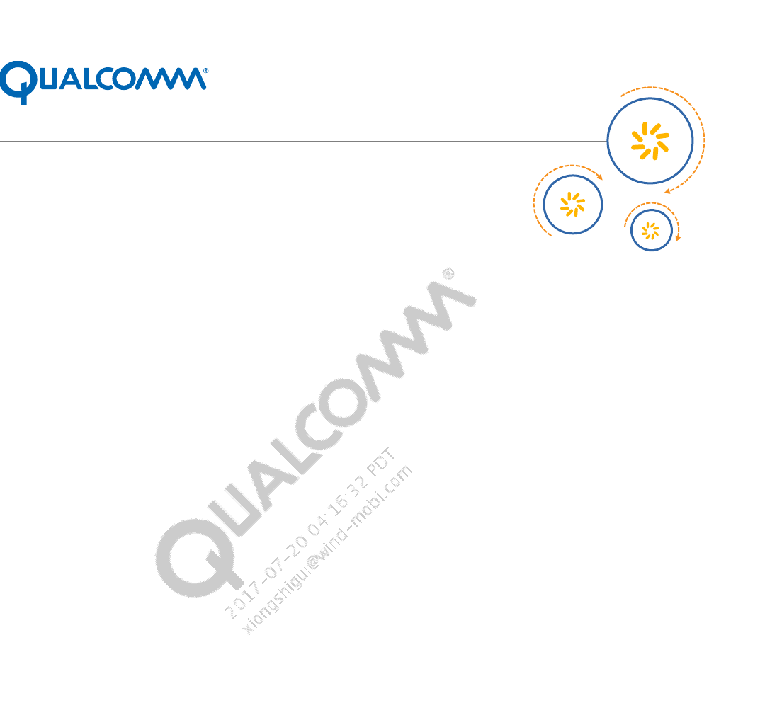
2 Audio EC-VOIP
Background:
Common VoIP application: WeChat, Skype, Gtalk, Google+, LINE, Voice Dialer.
Some VoIP invoke audio playback and audio recording path for PCM signals processing. By
default, the audio recording path does not have EC module. If the VOIP itself does not have
EC function, the VOIP may suffer echo issue, especially for speakerphone mode. For this
case, we can invoke Audio EC to get effect of echo cancellation.
Figure of VoIPAudio EC -See next page
Kernel driver file is msm-pcm-q6-v2.c, but Voice EC of VoIPis msm-pcm-voip-v2.c
Path of DSP is different.
Figure 2-1 VoIPAudio EC

Common Audio Tuning Cases Introduction and Debugging Debugging Guide Audio EC-VOIP
80-NV213-6 Rev. A Confidential and Proprietary – Qualcomm Technologies, Inc. 9
MAY CONTAIN U.S. AND INTERNATIONAL EXPORT CONTROLLED INFORMATION
Audio EC Configuration:
Step of Enable Audio EC
a. Set use.voice.path.for.pcm.voipFALSE
Eg: adbshell setpropuse.voice.path.for.pcm.voipfalse
b. Search acdbID of VoIP: Find acdb_idfrom logcat.
Eg, VoIP in Hand-free mode, find handset_mic4 for TX_pathand
spkrphone_spkr_mono14 for Rx_path.
c. Modify ACDB via QACT
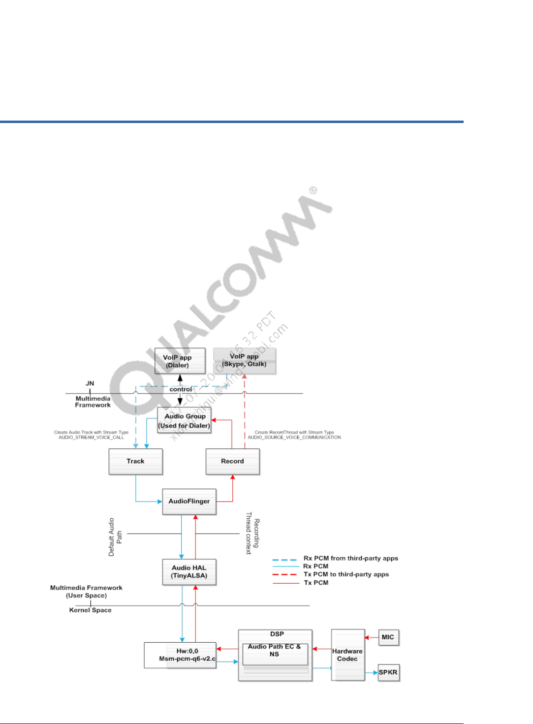
i Add Audio EC pair for TX and RX equipment.
Tools-->Device Designer--> Audio EC Device Pair Designer, refer to Fig.1.
ii Modify Audio COPP TopologyIDof TX equipment
Tools-->Device Designer, select TX equipment, refer to Fig.2.
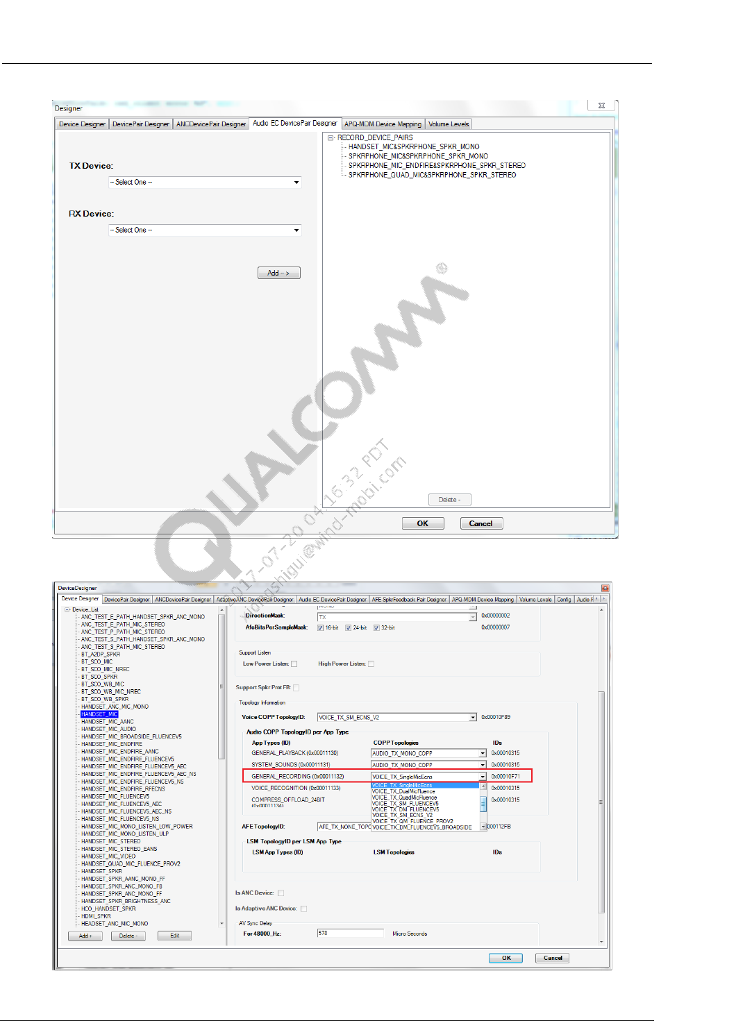
iii Go back to Database view and find this TX equipment to enable EC module, refer to
Fig.3
d. Set signal of EC_REF
i In baseline of KK3.5 or the former KK3.7, assure set_echo_reference,
set_echo_reference(adev->mixer, EC_REF_RX) in platform.cfor Audio HAL.
ii In latest baseline, modify mixer_paths.xml. Add a path and enable EC_REF.
8x16platform:<ctlname="AUDIO_REF_EC_UL1 MUX" value="I2S_RX" />
iii Distingushdifference and check if include CR#717973 -M8916: Echo reference
implementation on M8916, please check if include below patch:
• https://www.codeaurora.org/cgit/quic/la/platform/vendor/qcom/msm8916_32/patc
h/?id=053b88291b33d73fef010eb46c58d182fbb9e068
• https://www.codeaurora.org/cgit/quic/la/platform/hardware/qcom/audio/patch/?id=
0efd94b0755652b5f0f4a12aa58daf27abedb05e
• https://www.codeaurora.org/cgit/quic/la/platform/hardware/qcom/audio/patch/?id=
77508e2ea2e03e86e6d3f9d8e6b214ff06577e58
Key points:
Assure correct acdbID.
Assure ECHOREF signal to DSP, and catch QXDMlog to check PCM.
Platform: 8x26, 8926, 8x10 and 8916/8939/8909
Common Audio Tuning Cases Introduction and Debugging Debugging Guide Audio EC-VOIP
80-NV213-6 Rev. A Confidential and Proprietary – Qualcomm Technologies, Inc. 10
MAY CONTAIN U.S. AND INTERNATIONAL EXPORT CONTROLLED INFORMATION
Figure 2-2 Add Audio EC Device Pair
Figure 2-3 Modify Topology of Audio COPP
Common Audio Tuning Cases Introduction and Debugging Debugging Guide Audio EC-VOIP
80-NV213-6 Rev. A Confidential and Proprietary – Qualcomm Technologies, Inc. 11
MAY CONTAIN U.S. AND INTERNATIONAL EXPORT CONTROLLED INFORMATION
Figure 2-4 Tune parameter of Audio EC
2.1 Audio VOIP RX NS
Some VOIPApps,Rx-path goes through Audio Playbackpath。Audio Playback has no NS
module by default,the background noise or noise from network may impact rx-path voice quality
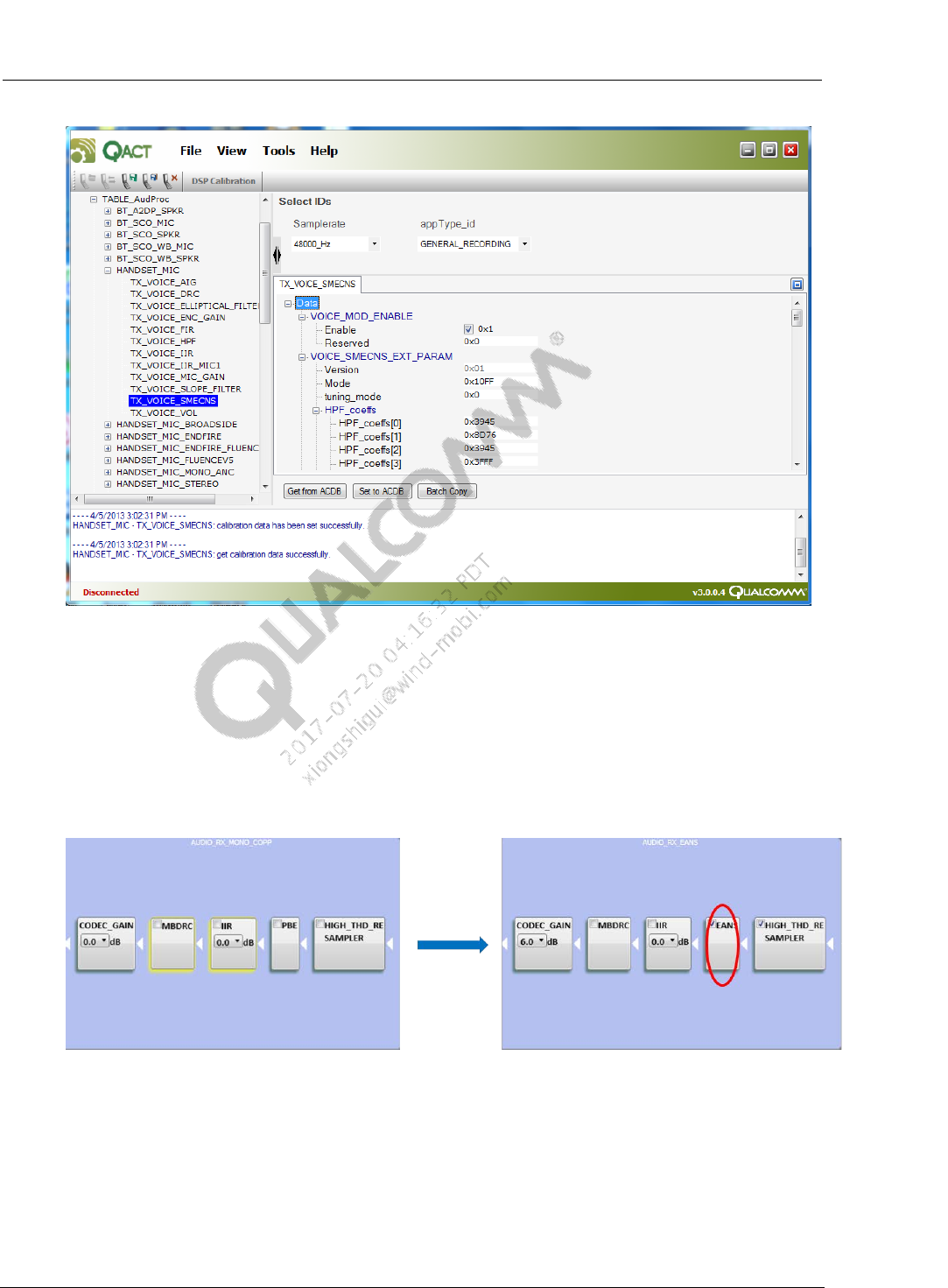
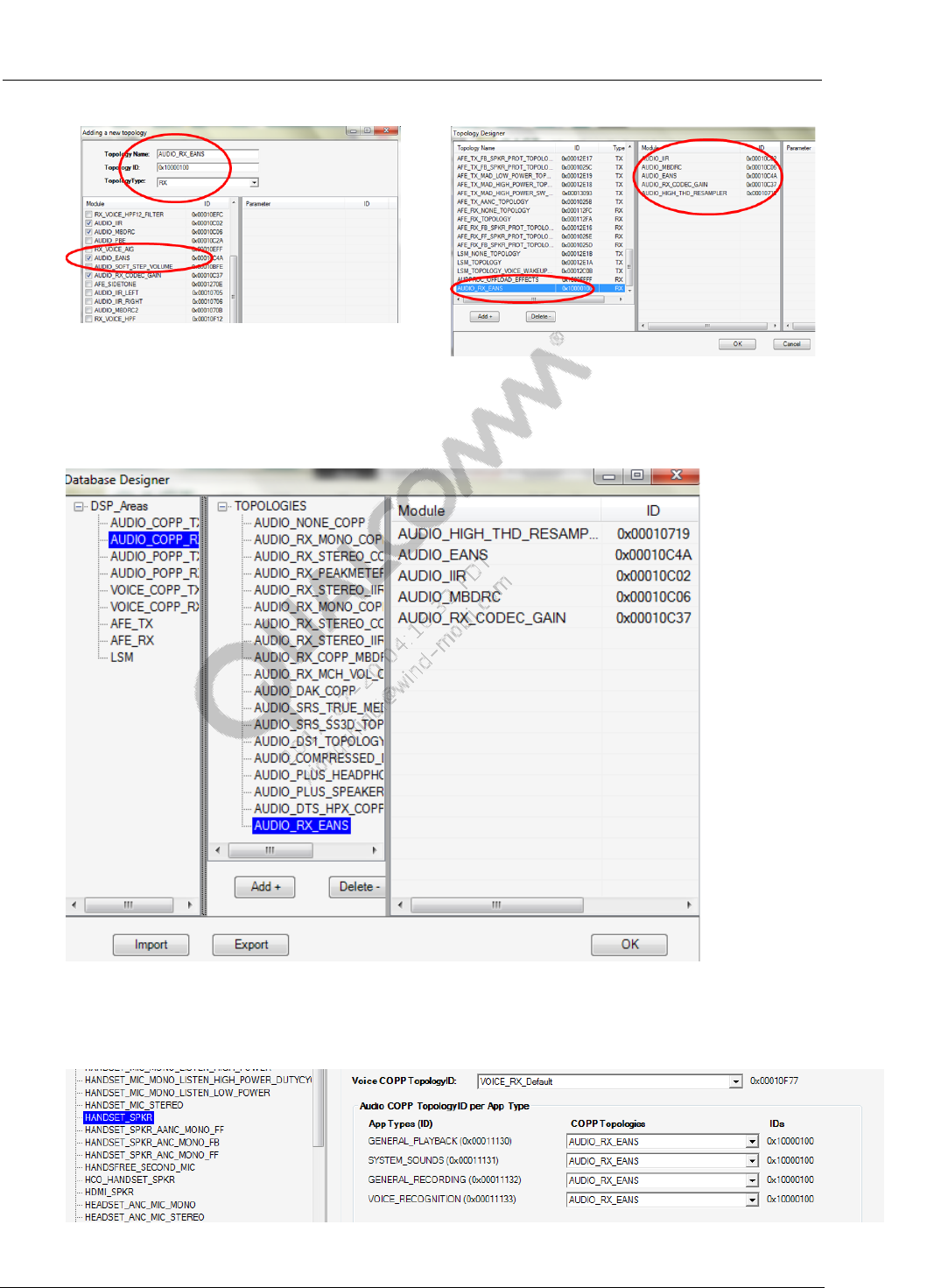
Customized Audio COPP RX Topology can be created,to add EANS to do NS.
Figure 2-5 Create Customized Audio COPP Topology to Add EANS
1. Open QACT->Tools->Topology Designer->click “Add+”
a. Input the new TopologyName、ID,TopologyTypeselect RX
b. Select required audio processing modules,then click “OK
Common Audio Tuning Cases Introduction and Debugging Debugging Guide Audio EC-VOIP
80-NV213-6 Rev. A Confidential and Proprietary – Qualcomm Technologies, Inc. 12
MAY CONTAIN U.S. AND INTERNATIONAL EXPORT CONTROLLED INFORMATION
Figure 2-6 Add EANS Module
2. QACT->Tools->Database Designer-> AUDIO_COPP_RX->click”Add+”->choose the added
topology->click”OK”.
Figure 2-7 Add Customized Topology to Audio COPP RX Database
3. QACT->Tools->Device Designer-> choose device->Choose “AUDIO_RX_EANS” in Audio
COPP Topologies”->click”OK”.
Figure 2-8 Choose Customized Topology

Common Audio Tuning Cases Introduction and Debugging Debugging Guide Audio EC-VOIP
80-NV213-6 Rev. A Confidential and Proprietary – Qualcomm Technologies, Inc. 13
MAY CONTAIN U.S. AND INTERNATIONAL EXPORT CONTROLLED INFORMATION
a. File->Save As->choose d:/acdb/->click”OK”
b. Push all acdb files to phone.
adb root
adb remount
adb push C:\acdb /etc/acdbdata/MTP (folder path is for reference.)
adb shell sync
adb reboot
80-NV213-6 Rev. A Confidential and Proprietary – Qualcomm Technologies, Inc. 14
MAY CONTAIN U.S. AND INTERNATIONAL EXPORT CONTROLLED INFORMATION
3 Wideband Tuning and Debug
3.1 Basic WB tuning requirements
Sprint requirement, pass the lower mask for TX speakerphone (7000hz) and TX handset
(6500Hz) WB, because EVRC_WB will not extend that high, we cannot meet this
requirement;
Wideband calls have much echo compared with narrow band tuning;
Wideband call shave more noise;
Some apps, like WeChat/Miliao/QQ call service use wideband calibration in default, Also if
you support CMCC VoLTE, this also requires Wideband tuning.
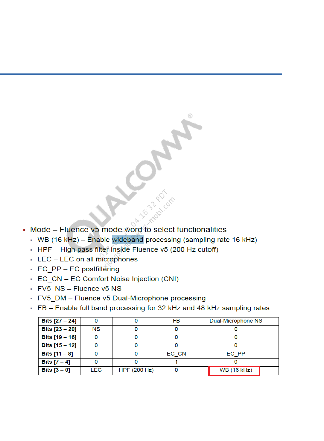
3.2 WB Tuning - FluenceV5 EC
FluenceV5 need enable the mode word to enable the wideband processing, see below
Figure 3-1 Fluence V5 Mode Bits Corresponding to Individual Functionalities
Common Audio Tuning Cases Introduction and Debugging Debugging Guide Wideband Tuning and Debug
80-NV213-6 Rev. A Confidential and Proprietary – Qualcomm Technologies, Inc. 15
MAY CONTAIN U.S. AND INTERNATIONAL EXPORT CONTROLLED INFORMATION
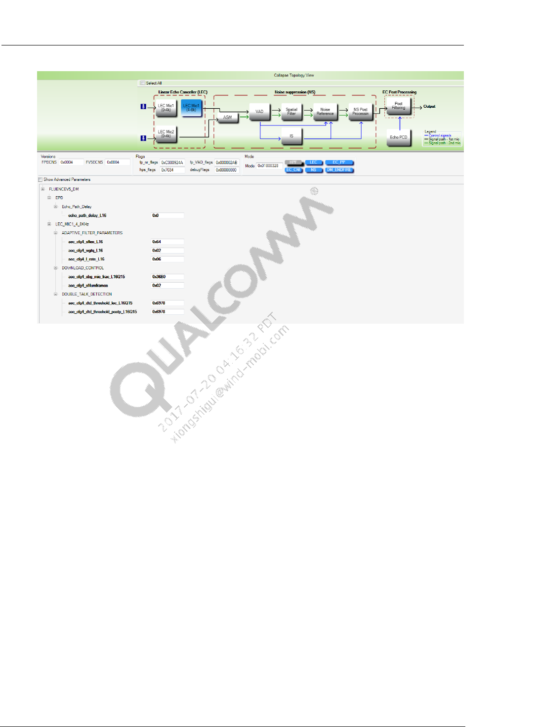
Figure 3-2 LEC wideband basic parameters can be tuning
Usually we see many local OEM have some sealing issue with the wideband, as we pay more
attention on the narrow band signal before, so from now on, OEM need to pay attentions on
wideband too. Usually, wideband echo is bigger, and has non-linear echo. OEM need to make
sure the HW is in good state, ensure echo from earpiece to mic is as small as possible;
For the echo issue, first tuning the LEC, like the narrow band tuning;
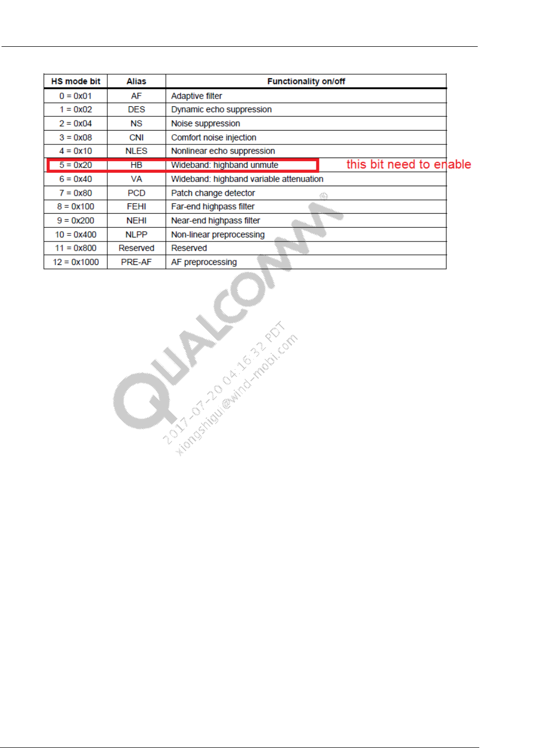
3.3 WB Tuning – EEC
NOTE: For customers who still use EEC, ECMODE needs to configure as below. If it’s set to 0x1497,
wideband is mute.
Common Audio Tuning Cases Introduction and Debugging Debugging Guide Wideband Tuning and Debug
80-NV213-6 Rev. A Confidential and Proprietary – Qualcomm Technologies, Inc. 16
MAY CONTAIN U.S. AND INTERNATIONAL EXPORT CONTROLLED INFORMATION
Figure 3-3 ECMode setting
3.4 WB tuning - MBDRC
Limiter–Very important for Wideband applications; Usually based on signal’s amplitude
envelope, values exceeding a set threshold are suppressed cleverly so that no peaks are above
the threshold at the output. A good limiter design usually comes with very low audible
distortions.16k wideband speech with max peak at -0.05 dBfs, usually we configure this to-
3dB.
Compressor--usually based on signal’s energy envelope (root-mean-square, or RMS),
attenuations are applied to loud passages of audio (downward compressor), or amplifications
are applied to quiet passages of audio (upward compressor). In both cases, the result is that
the dynamic range of the signal is reduced, i.e. compressed. With makeup gains (usually gain
boosts), the overall audio can sound louder than the original, while the high level contents
may remain as before.
Expander--also often based on signal’s energy envelope, attenuations are applied to quiet
passages of audio to expand the overall dynamic range of the signal (downward expander).
Though upward expander exists, its application is more in recording industry instead of noise
reduction in communications.
Noise Gate--zero gains are applied to really quiet passages of audio signals. This will knock
out quiet noise floors if proper thresholds are set. Other than this hard noise gate, the
downward expander can be tuned and functions as a soft noise gate.
Common Audio Tuning Cases Introduction and Debugging Debugging Guide Wideband Tuning and Debug
80-NV213-6 Rev. A Confidential and Proprietary – Qualcomm Technologies, Inc. 17
MAY CONTAIN U.S. AND INTERNATIONAL EXPORT CONTROLLED INFORMATION
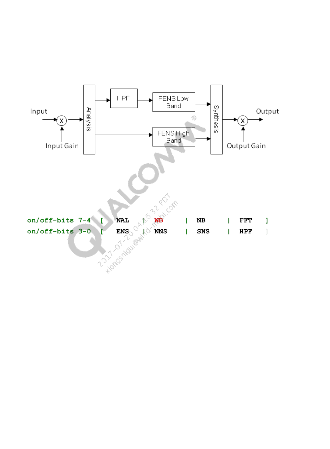
3.5 WB tuning - FNS
Figure 3-4 FNS Function Diagram
Figure 3-5 FNS Mode Bits
WB bit allows enabling the wideband FNS processing, by default this bit should always be
enabled for proper FNS-WB functioning.
FNS Parameters:
fnsNSNRmax Upper bound in dB for SNR estimation
fnsSalphaHB Over-subtraction factor for high-band stationary NS
fnsNalphaMaxHB Maximum over-subtraction factor for high-band nonstationary NS
fnsEalphaHB Scaling factor for high-band excess noise suppression
80-NV213-6 Rev. A Confidential and Proprietary – Qualcomm Technologies, Inc. 18
MAY CONTAIN U.S. AND INTERNATIONAL EXPORT CONTROLLED INFORMATION
4 Call Recording
4.1 Call Recording Audio Path
Figure 4-1 Audio Path for Call Recording (before or pre MSM8996 platforms)
Common Audio Tuning Cases Introduction and Debugging Debugging Guide Call Recording
80-NV213-6 Rev. A Confidential and Proprietary – Qualcomm Technologies, Inc. 19
MAY CONTAIN U.S. AND INTERNATIONAL EXPORT CONTROLLED INFORMATION
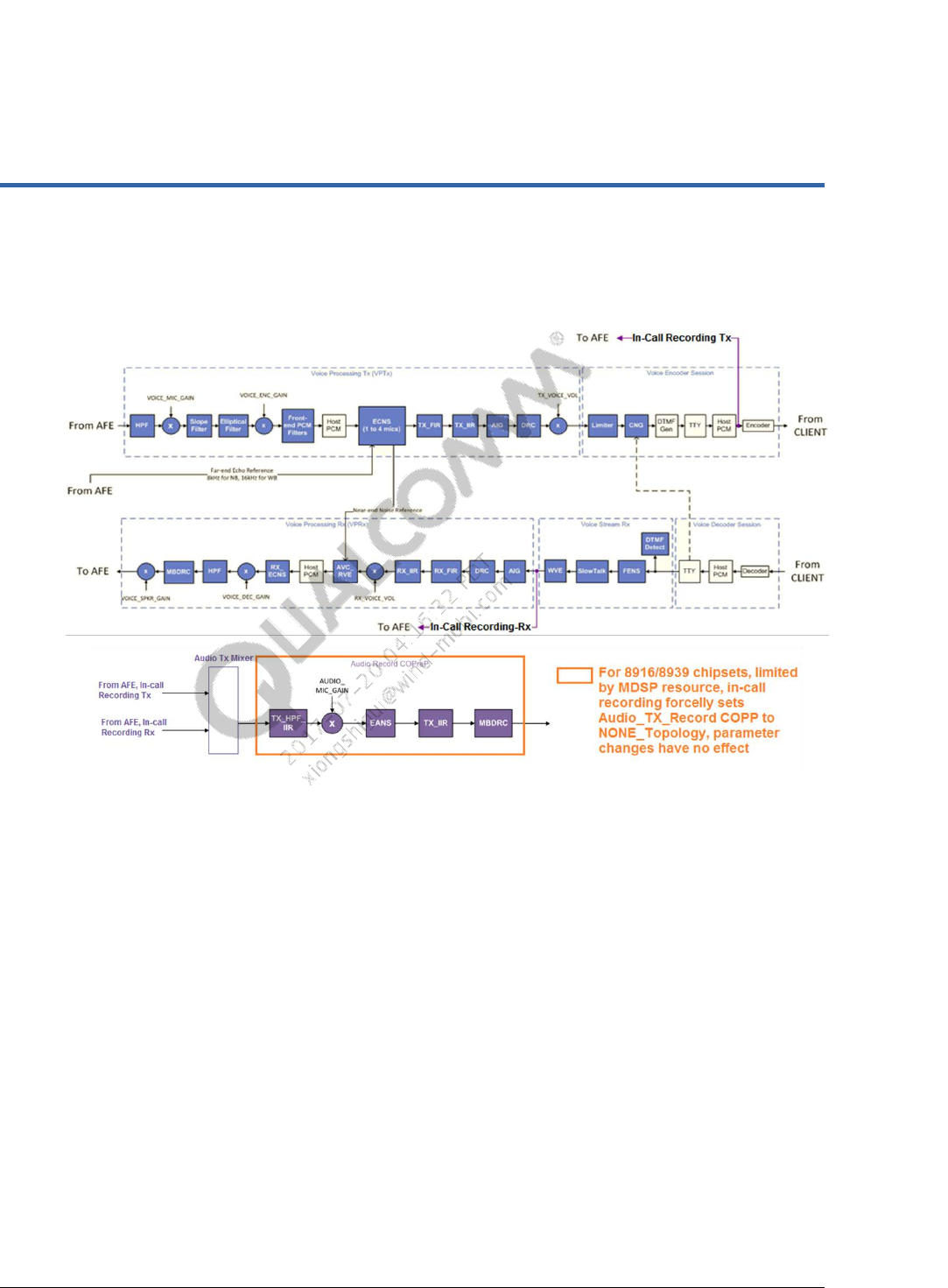
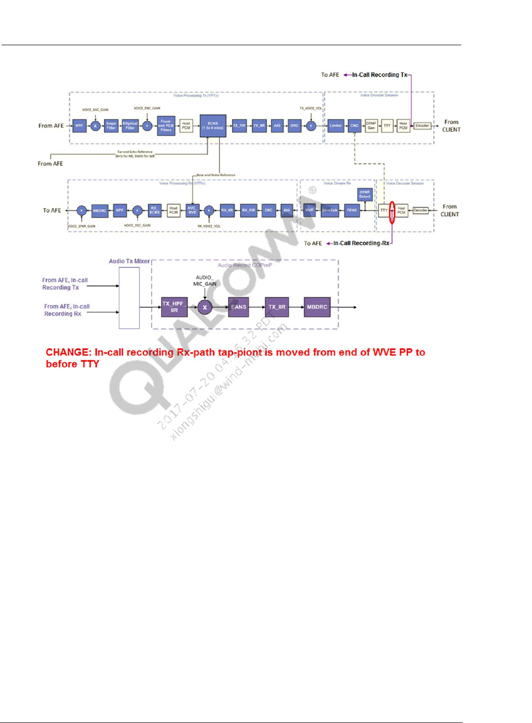
Figure 4-2 Audio Path for Call Recording (MSM8996,and afterward platforms)
4.2 Call Recording Tuning
Signal of call recording on Tx_Path is get from Tx_Encoder. All modules of DSP on Tx_Path
will affect the signal of call recording.
In Rx_path, it has two conditions
For chipsest before MSM8996, signal of call recording is from voice stream, so most of
modules don’t affect signal of call recording. But except FENS, FENS improves SNR of
speech and enhance voice quality.
For MSM8996, and afterwards chipsets, signal of call recording is before TTY, voice-
copp modules has no impact on call-recording.
If voice tuning is completed, call recording works well normally. If quality of call recording
is not perfect, inspect setting of audio Tx Recording and disable all modules. Then measure
again and observe if issue is solved.
In current platforms, by default, the Device_ID in Audio Tx Recording path has two cases:
Handset mode, the Device_ID in Audio Tx Recording path is HANDSET-MIC
Common Audio Tuning Cases Introduction and Debugging Debugging Guide Call Recording
80-NV213-6 Rev. A Confidential and Proprietary – Qualcomm Technologies, Inc. 20
MAY CONTAIN U.S. AND INTERNATIONAL EXPORT CONTROLLED INFORMATION
Headset/Handsfree/BT mode, the Device_ID in Audio Tx Recording path is the same as
voice tx-path. Take Headset mode for example, device pair
HEADSET_MIC&HEADSET_SPKR_STEREO is used. In voice-call recording, the
device for Audio Tx Recording path is also HEADSET_MIC.
Use adb command to check the Device_ID in Audio Tx Recording path
a. Open cmd window, input below command to check audio use-case Device_ID
adb shell
logcat | grep acdb_id
b. After enable voice-call recording,in cmd window, check whether there is new Tx-path
Device_ID is logged,if yes,the new Device_ID is for Audio Tx Recording path;If
not,the Device_ID in Audio Tx Recording path is the same as voice tx-path.
4.3 FAQs and Debugging
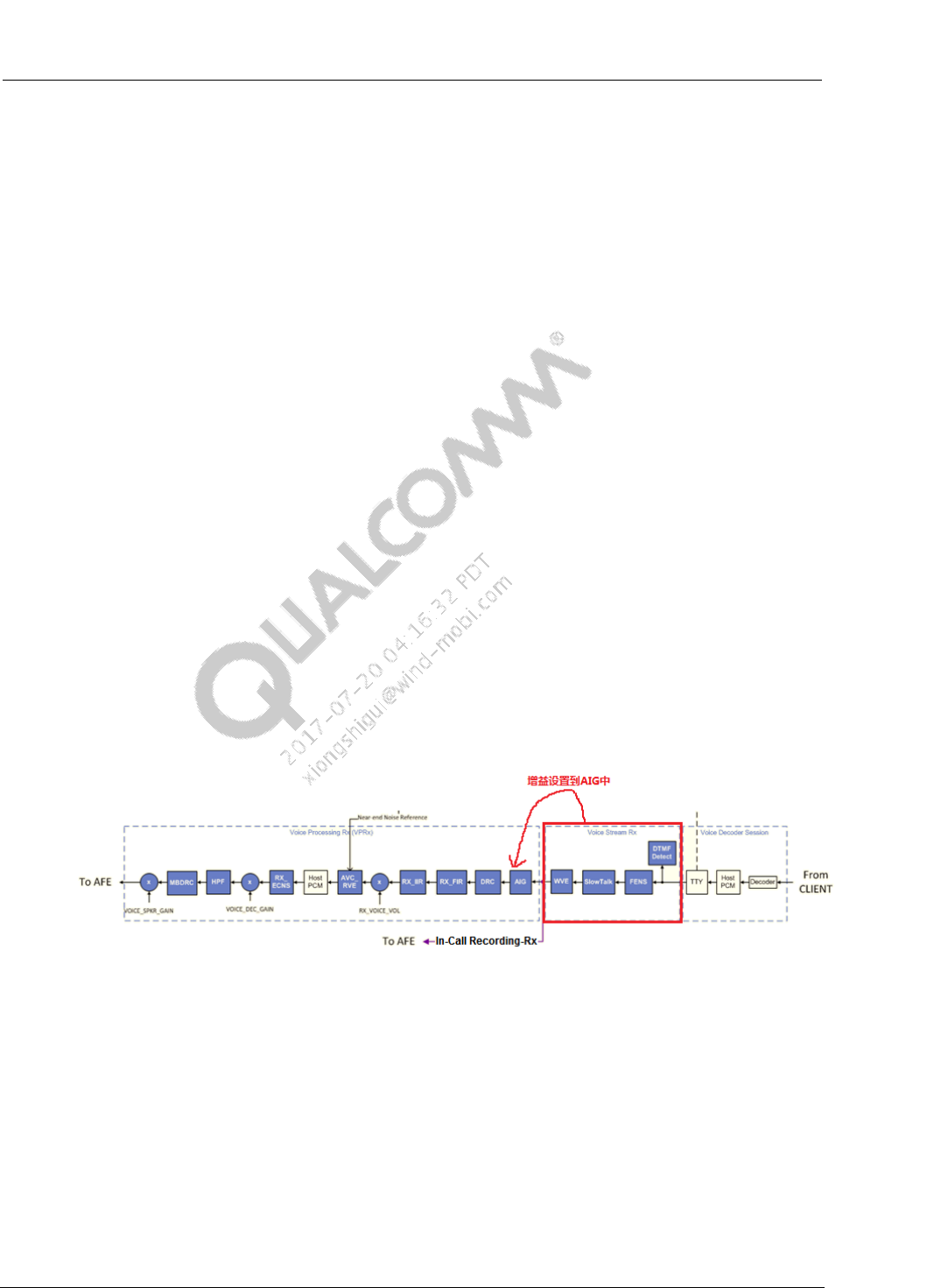
Q1: Loudness in Rx_Path is loud, but loudness in Tx_Path is lower in call recording.
Check FENS/WVE parameter of Rx_Path. If add positive gain in the two modules, it is better
to set these gain to AIG module in Rx_Path(This tuning just works on platforms before/pre
MSM8996;on MSM8996 and afterward platforms,Rx tuning has no effect,need to do
voice Tx path tuning).
Gain parameter in FENS
– fnsInputGain, FENS input gain. 0x2000<->0dB,0x1000<->-6dB,0x4000<->6dB
– fnsOutputGain, FENS output gain. 0x2000<->0dB, 0x1000<->-6dB,0x4000<->6dB
Figure 4-3 RX-path Gain Setting
Adjust AIG in Tx_Path, set aigMode->0x1(Adaptive Input Gain mode).According to AIG
guideline, tune three parameter below. AIG can improve volume of Tx_Path based on
dynamical range of input signal.
idealRMSDBL16Q7
minGainL32Q15, set to 0x8000(0dB)
maxGainL32Q15, set to 0xFF65(6dB). If increase this value, but not exceed to
0x168C1(9dB).
Common Audio Tuning Cases Introduction and Debugging Debugging Guide Call Recording
80-NV213-6 Rev. A Confidential and Proprietary – Qualcomm Technologies, Inc. 21
MAY CONTAIN U.S. AND INTERNATIONAL EXPORT CONTROLLED INFORMATION
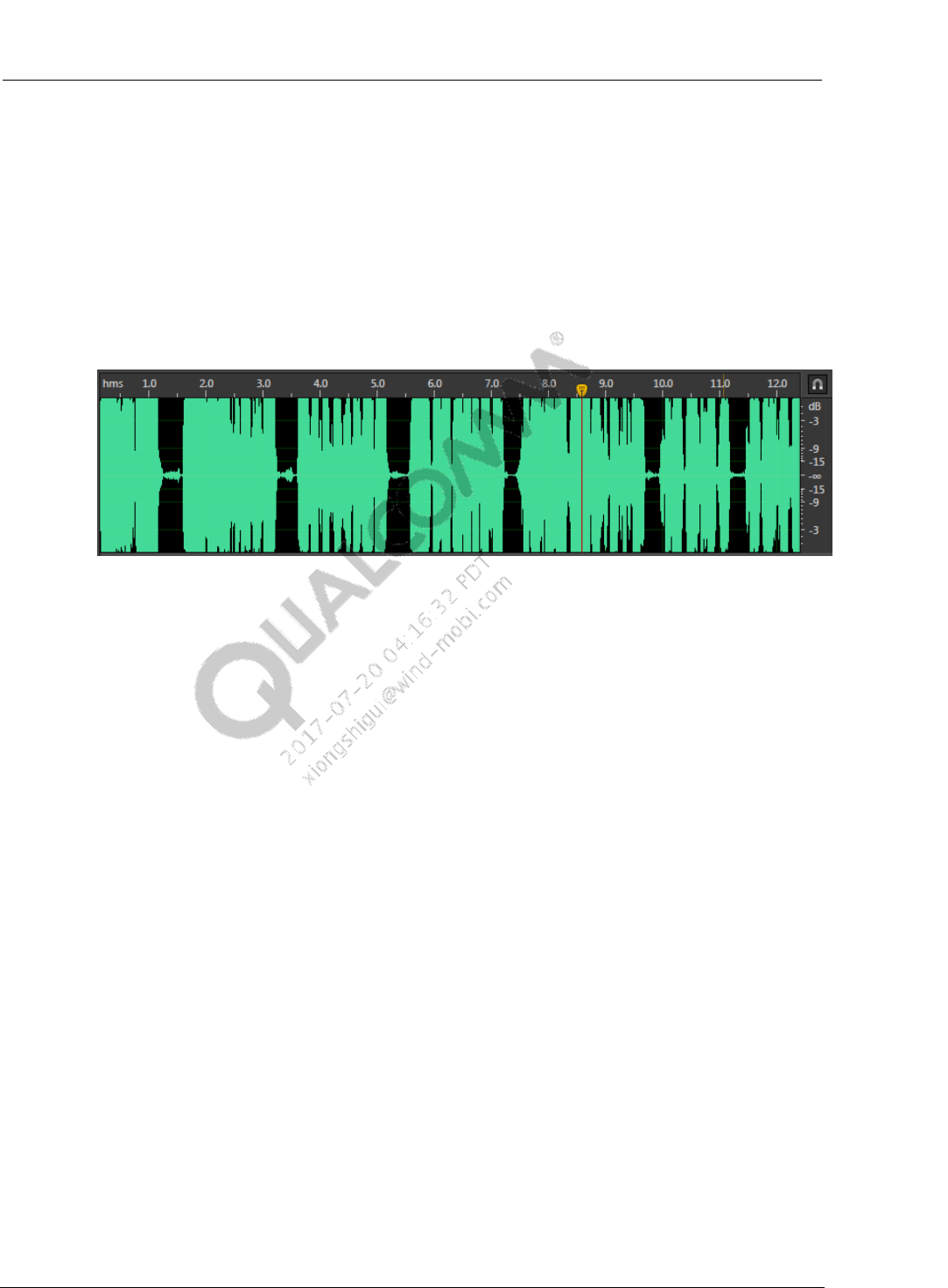
Q2:Noise in call recording but voice quality is good.
Review setting of Audio Tx Recording Path. If voice quality is good, it means voice
parameters work well. And maybe the root cause is in parameter of Audio Tx Recording.
Please inspect if gain is more in Audio Tx Recording.
Sometimes, normally Device_ID in call recording path is same as voice path, such as
HANDSET_MIC. For increasing loudness of recording, set more gain in Audio Tx
Recording. These gain will enlarge signal of call recording so that generate clipping or noise.
The time-domain plot of this symptom is below.
Figure 4-4 Time-domain Signal Clipping
Such this symptom, recommend to add a Device_ID, eg, HANDSET_MIC_REC to save
parameter of recording.
If user didn’t add Device_ID to save audio parameter, user can relocate gain of voice path
and tune parameter of Audio Tx Recording to make voice and call recording work well.

80-NV213-6 Rev. A Confidential and Proprietary – Qualcomm Technologies, Inc. 22
MAY CONTAIN U.S. AND INTERNATIONAL EXPORT CONTROLLED INFORMATION
5 Common Echo/DT Issues
5.1 TCLw Test Failure
Root Cause
Not enough Echo Cancellation
Output Distortion of Rx_Path.
Solution:
SMECNS Algorithm
– Inspect AF_Preset_coefs = 0x2.
– Inspect if echo path delay is correct.
– Review if Rx_Ref is saturation or distortion. If distortion, tune gain setting of
RX_path.
– Tune DENS_gamma_e_high to make EC aggressiveness.
Fluence V5 Algorithm
– Check if echo path delay is correct.
– Review if Rx_Ref is saturation or distortion. If distortion, tune gain setting of
RX_path.
– Increase Aec_pf_nlp_st_agg_L16Q15 and Aec_pf_nlp_st_agg_L16Q15
5.2 Echo vs Time
Root Cause
Echo Cancellation Convergence.
Comfort Noise Not enough
Solution
SMECNS Algorithm
– Tune AF_taps
– Increase DENS_CNI_level for comfort noise injection
Fluence V5 Algorithm
– Tune Aec_cn_norm_const_L16Q15.
– Tune Aec_cn_norm_const_q_L16 and one step is 0x01 to increase.

Common Audio Tuning Cases Introduction and Debugging Debugging Guide Common Echo/DT Issues
80-NV213-6 Rev. A Confidential and Proprietary – Qualcomm Technologies, Inc. 23
MAY CONTAIN U.S. AND INTERNATIONAL EXPORT CONTROLLED INFORMATION
Notice
– Comfort noise injection results in echo vs spectrum worse. So after tune echo vs time,
re-test all echo cases.
5.3 Echo Spectrum
Root Cause
Echo cancellation convergence
Comfort Noise Not enough
Solution
SMECNS Algorithm
– Check if echo path delay is correct.
– Tune DENS_gamma_e_high to make EC aggressiveness.
– Check DENS_CNI_level setting to reduce CNI.
Fluence V5 Algorithm
– Moderately reduce Aec_cn_norm_const_L16Q15
– Moderately reduce Aec_cn_norm_const_q_L16
– Moderately increase Aec_pf_nlp_st_agg_L16Q1 and Aec_pf_nlp_st_agg_L16Q15
5.4 Double Talk
Root Cause
Parameter of SPDET and PCD isn’t reasonable.
Solution
SMECNS Algorithm
– Normally, tune AF_Taps, DENS_spdet_near, DENS_spdet_act,
DENS_gamma_e_dt,PCD_threshold
Fluence V5 Algorithm
– Observe AF coefficients on RTC mode, and set aec_cfg0_sflen_L16
– Observe aec_download_flag in DT mode, and tune aec_cfg0_sbg_mic_frac_L16Q15
to increase download gate of BG to FG.
– Observe status of aec_dtd_lec flag in DT, and check if double talk is inspected
correctly. If no, need to tune setting of aec_cg0_dtd_threshold_lec_L16Q15.
– If DT failed on noise environment, moderately increase
aec_cfg0_dtd_ni_scalefactor_L16.
– Moderately reduce Aec_pf_nlp_dt_agg_L16Q15 to suppress non linear noise in DT.
80-NV213-6 Rev. A Confidential and Proprietary – Qualcomm Technologies, Inc. 24
MAY CONTAIN U.S. AND INTERNATIONAL EXPORT CONTROLLED INFORMATION
6 DM NS, Holding Position Robustness
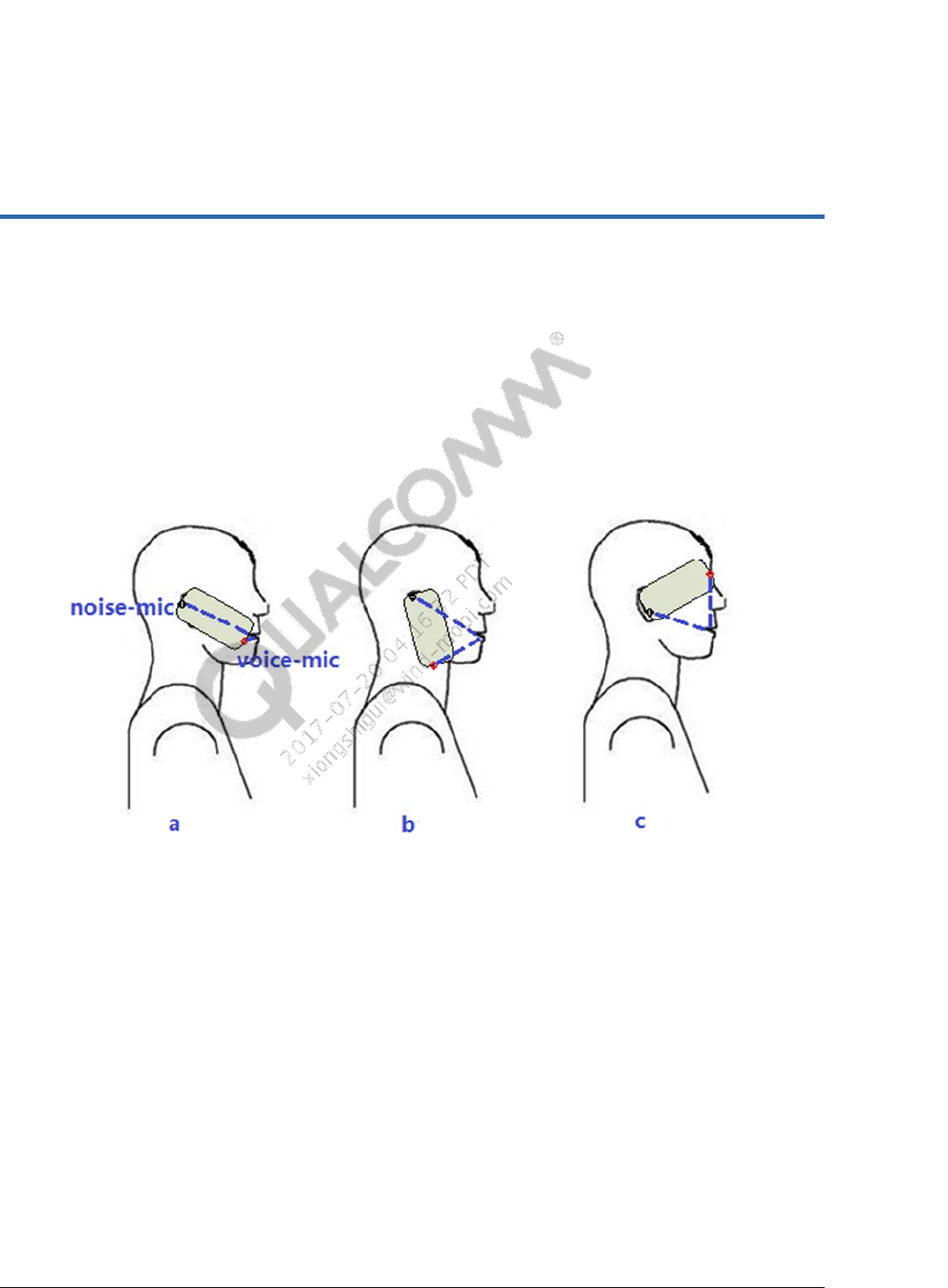
In Fluence Dual-Mic algorithm, based on generated noise reference signal by dual microphone’s
input signals, it can suppress noise signal of speech microphone. According to Fluence dual
microphone design requirement, at standard holding position, eg,Fig.a, the nearend_in signals of
dual mic has difference in phase and amplitude, Fluence can recognize the near-end speech and
noise and achieve the perfect effect of NS. But if holding position is changed, such as Fig.b and
Fig.c, the phase and amplitude differences at nearend_in become small at that time, it is bad for
Fluence to recognize the near-end speech and noise. If generated reference noise including
speech, it results in missed words, chopping, weak voice.
Figure 6-1 Different Handset Holding Positions
If licensees follow 80-VE797-16 to assure HW and sealing performances of microphone and
receiver and use default FV5 parameter we provided, the robustness of phone is usually good.
In debugging, audio engineer check robustness issue according to below steps.
Check if has robustness issue at lab.
1. Place phone to standard position of HATS, disable AIG/DRC, enable Fluence, measure SLR
and SFR, marked SLR1,SFR1.
2. Disable Fluence, measure SLR and SFR, marked SLR2, SFR2.
3. Compared difference of SLR on step1 and step2. If (SLR1-SLR2)>1dB, it means DM NS
parameter need to tune. Firstly, inspect HW of phone works well. If ok, tune DM NS
parameter, and repeat step1 and step2 until (SLR1-SLR2)<1dB.
4. Rotated phone to maximum angle you desired, disable AIG/DRC, enable Fluence, measure
SLR and SFR, marked SLR4,SFR4.

Common Audio Tuning Cases Introduction and Debugging Debugging Guide DM NS, Holding Position Robustness
80-NV213-6 Rev. A Confidential and Proprietary – Qualcomm Technologies, Inc. 25
MAY CONTAIN U.S. AND INTERNATIONAL EXPORT CONTROLLED INFORMATION
5. Disable Fluence, measure SLR and SFR, marked SLR5,SFR5.
6. Compared SLR difference when enable and disable Fluence and phone at maximum angle
position. If |(SLR4-SLR1)-(SLR5-SLR2)|>3dB, it means to has robustness issue.
Check if has robustness issue on subjective test.
1. Make a call at the area of good RF power.
2. Catch QXDM log during test for analysis.
3. User of phone under test speak and phone is at desired holding position, then change holding
position. At the beginning, recommend far end user keep silent
4. If far end user feel missed words, chopping and weak voice, it is possible for the phone under
test to has robustness issue.
Below modules can be tuned to improve holding position robustness,
VAD Tuning:
dmVADThresL16Q12: Dual-mic VAD threshold for detecting desired speech. Lower value
to get more speech. Recommended range: [0x64,0x600]
snrThresDualL16Q8:Single-mic VAD threshold for optimal holding position (dual-mic
mode). When SNR is more than this threshold, signal is as speech; if SNR is lower than this
threshold, signal is as noise. Higher value means less sensitive VAD. Recommended
range:[0x100,0x400]
SNR-PP Tuning:
If VAD tuning isn’t solved issue, try to tune SNR_PP. According to the previous measurement, at
failed holding position, compared SFR when enable and disable Fluence algorithm to know
which frequency bands exist noise attenuation, then adjust the relevant parameter. The below is
SNR-PP parameter.
snrPPMinAggR0L16Q12: Minimum aggressiveness control for the R0 frequency band.
Recommended range: [0x1388,0x4000]
snrPPMaxAggR0L16Q12: Maximum aggressiveness control for the R0 frequency band.
Recommended range: [0x1388,0x4000]
snrPPAggSlopeR0L16Q10: Aggressiveness slope control for the R0 frequency band.
Recommended range: [0x1388,0x4000]
snrPPAggOffsetR0L16Q11: Aggressiveness offset control for the R0 frequency band.
Recommended range: [0xFFFF,0x8000]
snrPPMinAggR1L16Q12: Minimum aggressiveness control for the R1 frequency band.
Recommended range: [0x1388,0x4000]
snrPPMaxAggR1L16Q12: Maximum aggressiveness control for the R1 frequency band.
Recommended range: [0x1388,0x4000]
snrPPAggSlopeR1L16Q10: : Aggressiveness slope control for the R1 frequency band.
Recommended range: [0x1388,0x4000]
Common Audio Tuning Cases Introduction and Debugging Debugging Guide DM NS, Holding Position Robustness
80-NV213-6 Rev. A Confidential and Proprietary – Qualcomm Technologies, Inc. 26
MAY CONTAIN U.S. AND INTERNATIONAL EXPORT CONTROLLED INFORMATION
snrPPMinAggR3L16Q12: Minimum aggressiveness control for the R3 frequency band.
Recommended range: [0x1388,0x4000]
snrPPAggSlopeR3L16Q10: Aggressiveness slope control for the R3 frequency band.
Recommended range: [0x1388,0x4000]
R0/R1/R2/R3 band range :
R0: <500Hz
R1: 500~2030Hz
R2: 2030~4000Hz
R3: >4000Hz
SF Tuning:
Change holding position, if SF didn’t updated, it is possible to lead to speech attenuation. If
VAD/SNR_PP tuning can’t solve this issue, try to adjust SF.
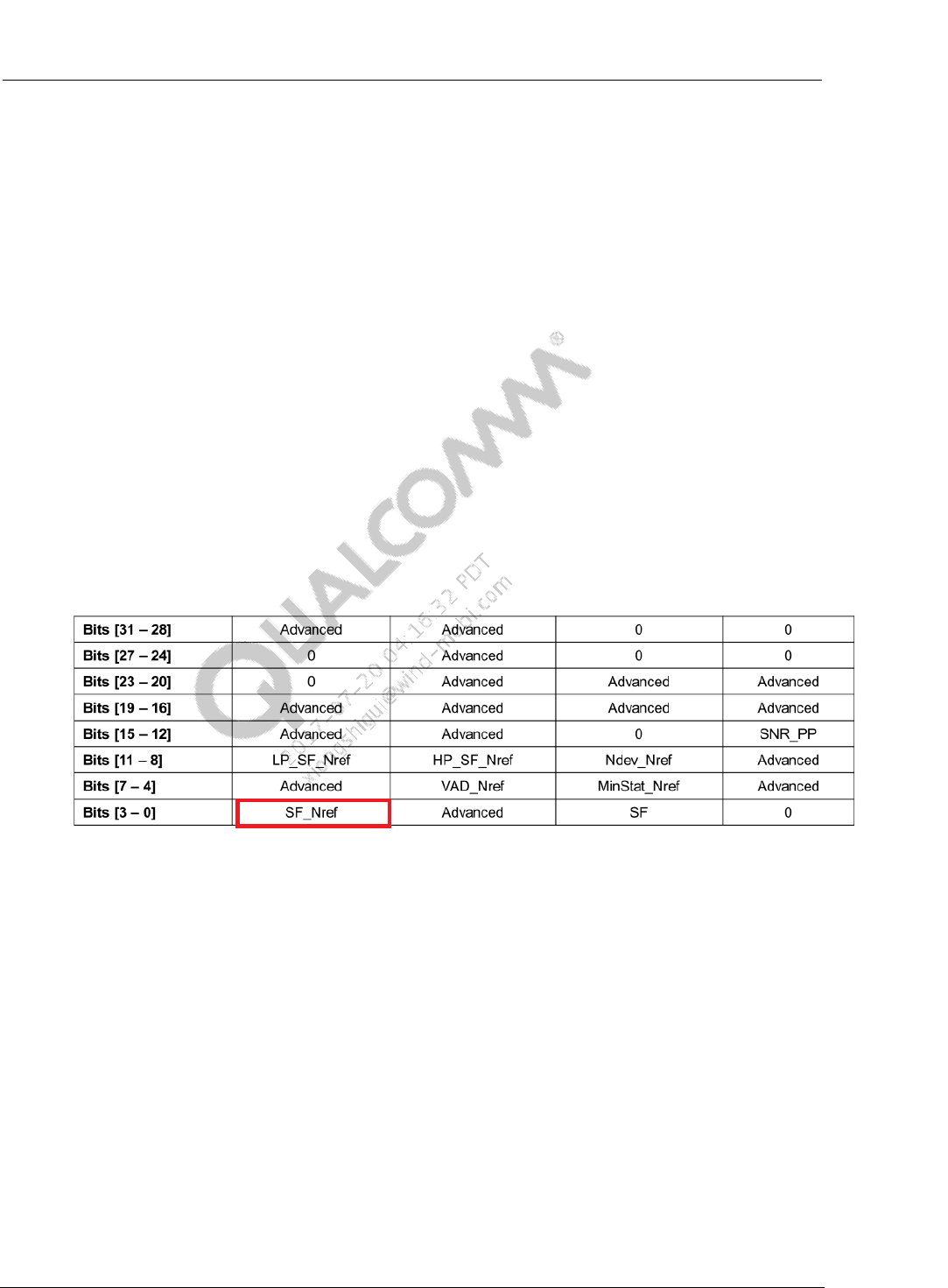
In failed holding position, set to disable SF in fp_nr_flags. Below is shown bit definition of
fp_nr_flags. When fp_nr_flags = 0xC00092E6 and speech quality is improved, it means that need
to tune SF parameter.
Figure 6-2 fp_nr_flags Bits
SF Parameters:
thSmVUpdL16Q8: Single-mic VAD threshold for controlling the adaptive filter updates in
the SF processing. Lower value to make easier to updated SF. It is helpful to improve
robustness.
thDmVUpdL16Q12: DM VAD threshold for controlling the adaptive filter updates in the SF
processing. Lower value to make easier to updated SF. It is helpful to improve robustness.
LP_SF_Nref: Low pass filter . Cut frequency is 2000Hz. If SF results in attenuation for
speech signal above 2KHz, then enable this bit in fp_nr_flags.
HP_SF_Nref : High pass filter. Cut frequency is 500Hz. If speech signal at below 500Hz is
decayed, enable this bit in fp_nr_flags.
80-NV213-6 Rev. A Confidential and Proprietary – Qualcomm Technologies, Inc. 27
MAY CONTAIN U.S. AND INTERNATIONAL EXPORT CONTROLLED INFORMATION
7 CMCC Tuning
7.1 CMCC Audio Spec
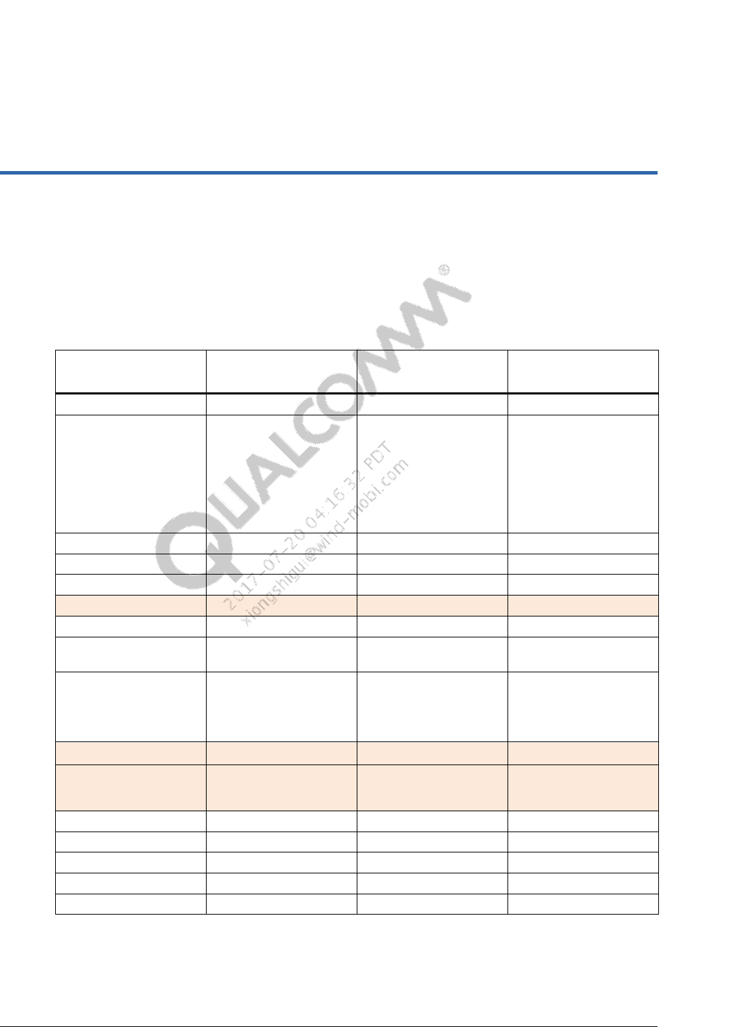
Table 7-1 Acoustics Test Cases of CMCC – Handset
No. Case Name(GSM-
NB/VoLTE-WB) Criteria Type
1.1 SLR SLR=8±3 dB M
1.2 RLR
min:RLR≤18dB,
normal:
RLR=2±3dB,
max:-3dB≥RLR≥-
10dB
M
3.1 SFR O
3.2 RFR O
4.1 STMR ≥13 dB M
5.1 Tx_Distortion M
5.2 Rx_Distortion O
7.1 Sending idle channel
noise ≤-64 dBm0p M
7.2 Receiving idle channel
noise
normal:≤-
57dBPa(A)
max:≤-54dBPa(A)
M
8.1 TMOS_Tx TMOS≥ 3.0 M
8.2 TMOS_Rx 最大音量下,TMOS≥
3.0 M
9.1 Echo loss TCLw≥ 55 dB M
10.1 Echo vs Time O
10.2 Echo vs Spectrum O
11.1 DT_Rx Path M
11.2 DT_Tx Path M
Common Audio Tuning Cases Introduction and Debugging Debugging Guide CMCC Tuning
80-NV213-6 Rev. A Confidential and Proprietary – Qualcomm Technologies, Inc. 28
MAY CONTAIN U.S. AND INTERNATIONAL EXPORT CONTROLLED INFORMATION
No. Case Name(GSM-
NB/VoLTE-WB) Criteria Type
12.1 3QUEST
Single-mic:
Average N-
MOS>2.7
Average S-MOS>3.5
Multi-mic:
Average N-MOS>3.0
Average S-MOS>3.5
mensa: S-MOS>=4.1,
N-MOS>=3.4
cross-road: S-
MO>=3.8, N-
MOS>=3.3
car: S-MOS>=3.8, N-
MOS>=3.3
train-station: S-
MOS>=3.5, N-
MOS>=3.0
M
NOTE: Test cases marked with orange color are easy failed cases
NOTE: Items marked with red color are updated items
Table 7-2 Acoustic test Cases of CMCC – Handheld hands-free mode
No. Case Name(GSM-
NB/VoLTE-WB) Criteria Type
2.1 SLR SLR=13 dB±4 dB M
2.2 RLR RLR=6 dB+12/-4 dB M
6.1 Tx_Distortion M
6.2 Rx_Distortion O
8.1 Tx-TMOS TMOS≥ 3.0 M
8.2 Rx-TMOS
At either 2~18dB
RLR volume level,
TMOS≥ 1.8
M
NOTE: Test cases marked with orange color are easy failed cases
NOTE: Items marked with red color are updated items
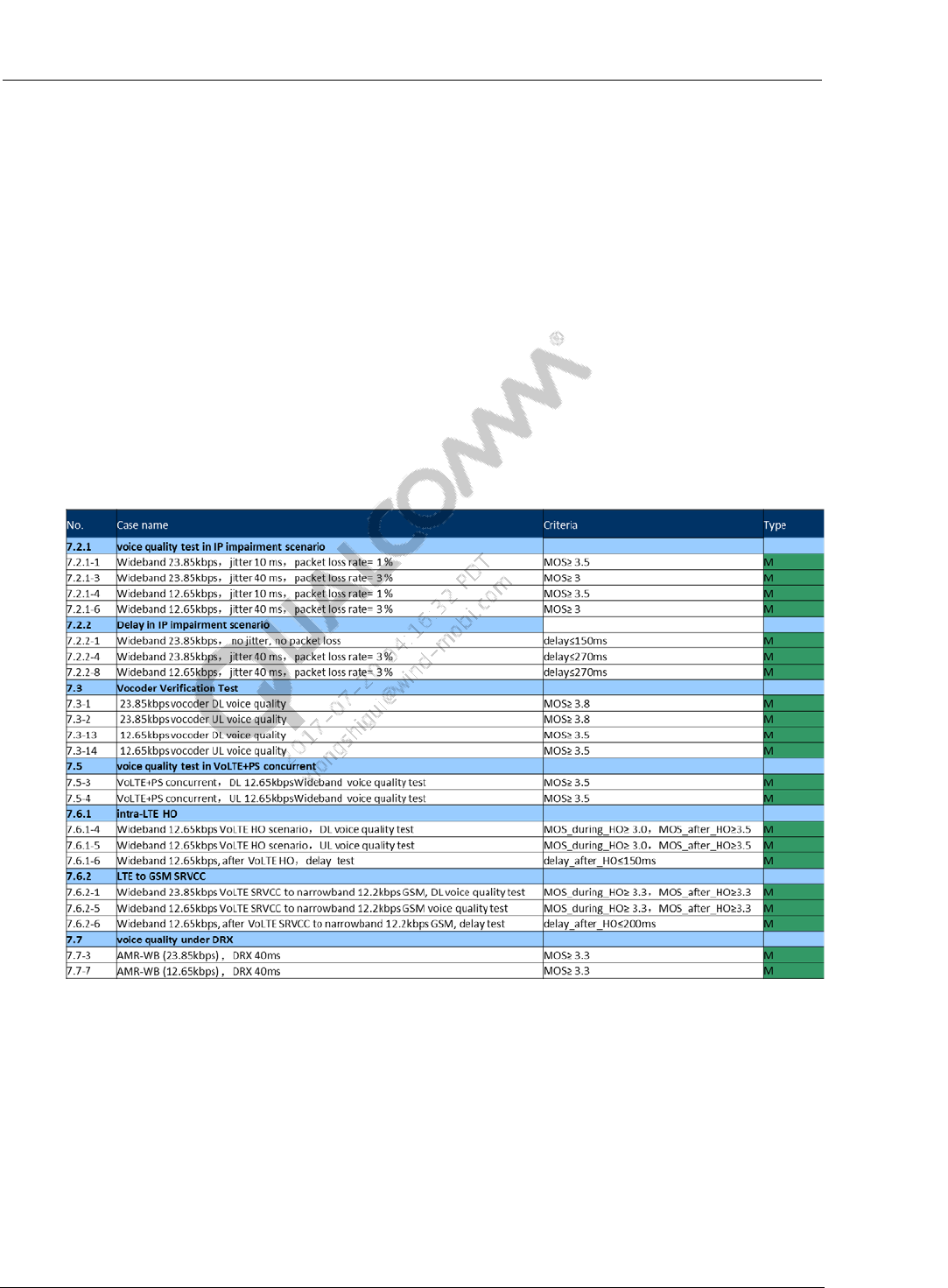
VoLTE-WB requirements are added in current CMCC audio acceptance spec. The test cases
have big updates compared to last version spec. To ensure the test cases and results can better
evaluate user-experience, do the followings:
Handset mode
– Application pressure is changed from 8N to 3N, to match end-user actual holding
habit
Common Audio Tuning Cases Introduction and Debugging Debugging Guide CMCC Tuning
80-NV213-6 Rev. A Confidential and Proprietary – Qualcomm Technologies, Inc. 29
MAY CONTAIN U.S. AND INTERNATIONAL EXPORT CONTROLLED INFORMATION
– DT test cases change to type M,to enhance DT requirement
– Rx-Distortion change to type O,Rx-T-MOS is required at maximum volume level, to
focus on overall voice quality
– For multi-mic terminals,add N-MOS/S-MOS requirements of 4 type noises,to
enhance NS requirements
Handheld hands-free mode
– Rx-Distortion change to type O,add Tx/Rx-T-MOS requirement, to focus on overall
voice quality
– RLR criteria is changed, upping the minimum loudness requirement
Good HW elements and design is basis of the perfect voice quality. In HW design, note to
design acoustic structure and sealing. It is easy to pass CMCC standard after tuning. For
failed cases experiences, you can check more details in the following slides.
Figure 7-1 Electrical test cases of CMCC MOS-Headset Electrical mode
NOTE: Just typical test cases are listed.
Electrical test cases of CMCC MOS-Headset Electrical mode
Test mobile terminals voice quality in different LTE network transmit conditions,
VoLTE-MOS
Common Audio Tuning Cases Introduction and Debugging Debugging Guide CMCC Tuning
80-NV213-6 Rev. A Confidential and Proprietary – Qualcomm Technologies, Inc. 30
MAY CONTAIN U.S. AND INTERNATIONAL EXPORT CONTROLLED INFORMATION
VoLTE-MOS is tested over Headset electrical mode,Headset audio calibration is used
by default. When connecting to test equipment,make sure correct audio calibration is
used. If Tx-MOS is very low, like MOS<2.0,check whether correct HW device is
routed,test signal should be transmitted to device by headset electrical interface.
– If HW device is not correct, please contact SW team to change configurations
– If HW device is correct, please check audio processing modules
VoLTE-MOS is tested over Headset electrical mode, test signal does not go through
electric-sound conversion. Audio tuning guidelines are as below:
– Be careful to enable audio processing modules,to avoid the impact on delay test
cases
– Do not set aggressive filter on frequency response tuning, to avoid the impact on MOS
– Do not set aggressive NS, to avoid the impact on MOS
– Do not set aggressive DRC to avoid the impact on MOS
– Do not set Rx/Tx-HPF cut-off frequency <=150Hz, to avoid the impact on MOS
– Do not set big gain on Rx/Tx path, for example, the overall path gain should be <=9dB
and to avoid signal clipping, which may impact MOS
If you are not confident on the audio calibration,to get default parameters, file cases
or send your acdb files to QC to review.
7.2 Easy failed cases debugging
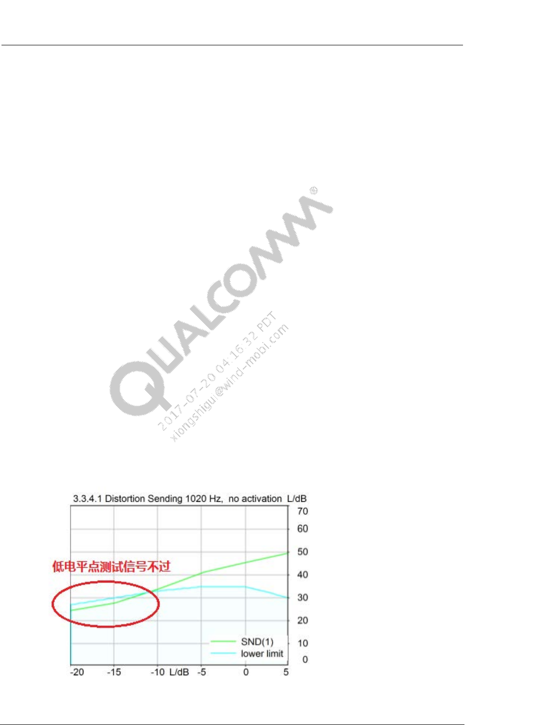
7.2.1 Tx_Distortion (Handset Mode)
If Tx_Distortion is failed and passed SLR&SFR, in most case, low level signal of Tx_Distortion
is failed. Test result is as below:
Figure 7-2 Tx-distortion Failure

Common Audio Tuning Cases Introduction and Debugging Debugging Guide CMCC Tuning
80-NV213-6 Rev. A Confidential and Proprietary – Qualcomm Technologies, Inc. 31
MAY CONTAIN U.S. AND INTERNATIONAL EXPORT CONTROLLED INFORMATION
To debug, disable ECNS and DRC on Tx_Path.
If the case is failed, disable all DSP modules of DSP
If still failed, catch QXDM log, check if existed noise on input of microphone. If you
cannot find root cause, file case to Qualcomm.
If pass, enable modules of DSP one by one and find which module results in failure, then
tune the parameter.
If pass test, enable ECNS and DRC one by one and find which module results are in failure,
then tune the parameter of this module.
DRC Tune: tune DRC Expander
– Reduce dnExpaThresholdL16Q7(Expand Threshold), e.g., set to 0x527(-80 dB); if set
to 0xFD28(-96 dB), expander is similar to closed status.
– Increase dnExpaMinGainDBL32Q23(Expand Min Gain), e.g., set to
0xFD000000(-6 dB)
ECNS Tune: Reduce NS and more tuning parameter is refer to 3QUEST tune
7.2.2 Tx_Distortion (Hands-free Mode)
It is similar with Tx_Distortion on handset mode. If this case is failed, in most of cases, failed at
low level signal. In hand free mode, the distance between artificial mouth and microphone of
phone is large. At low level test signal, input of microphone is low. If DRC and NS parameters is
not suitable, this signal is considered as noise to suppress so that fail. Tuning mothed is as
follows:
Tune Gain.
It is better to set gain before ECNS module on Tx path (e.g., add gain of codec and
increase MIC_Gain). But note that assure Echo is passed when increase gain.
Tune DRC and ECNS, methods are similar to Tx_Distortion tuning on handset mode.
Tune IIR_MIC1. If set high level Gain on Tx_Path to pass this case and SLR become louder,
it is better to tune IIR_MIC1 to only enlarge the relevant frequency signal.
In IIR Designer, select Parametric View
According to failed frequency, select one bands, such as Band2
– Band Type -> Band
– Centre frequency sets to frequency of test signal. Eg, 1020Hz, Center Frequency -
>1020
– Set Q-Factor, eg, Q-Factor -> 100. More Q-Factor, narrower frequency bandwidth.
– Set filter gain to positive value, eg, Gain ->+6 dB. If also failed, continue to increase
filter gain. Recommend not to exceed 9 dB.

Common Audio Tuning Cases Introduction and Debugging Debugging Guide CMCC Tuning
80-NV213-6 Rev. A Confidential and Proprietary – Qualcomm Technologies, Inc. 32
MAY CONTAIN U.S. AND INTERNATIONAL EXPORT CONTROLLED INFORMATION
7.2.3 TMOS_Tx (Handset Mode)
For debugging TMOS_Tx, recommend the step below:
Tune IIR
Disable all modules except IIR, then tune IIR filter and measure TMOS and SFR.
After completed parameter of IIR, it met SFR requirement and TMOS>=4.0. Normally,
flat SFR curve can get more score of TMOS.
Tune all Gain on Tx_Path to meet requirement of SLR.
Tune DRC
Enable/disable, measure TMOS and SLR.
Tune compressor and expansor of DRC to make difference of TMOS with Disable and
enable DRC <=0.2 and difference of SLR <=0.5 under same condition.
– If Dnward Compression Threshold set to lower(eg,<=-35 dB), it make SLR weak and
reduce TMOS score.
– If Upward Compression Threshold set to too high,(eg,<=-55 dB), it leads to low score
of and impacts the result of Tx_Distortion.
Tune NS
Enable/disable ECNS module and measure TMOS.
When enabling ECNS, TMOS is failed. You need to tune parameter of NS to pass
TMOS.
– If use SMECNS algorithm, refer 3QUEST tuning to reduce NS.
– If use DM_VPECNS, tuned parameter is in 3QUEST tuning.
– If ues Fluence V5, check lib_version of Fluence V5 firstly, then ask recommended
parameter from Qualcomm.
• If use default parameter, TMOS is failed, try to reduce NS. Tuned parameter refer
to 3QUEST tuning.
7.2.4 TMOS_Tx (Handheld hands-free Mode)
For debugging TMOS_Tx, recommend the step below:
Tune SLR
On tx-path, disable all copp modules, tune gain to meet SLR requirement
Tune IIR
Test Tx-TMOS, if TMOS<2.0. The terminal may have HW issues, catch QXDM log to
check mic input
Try tune IIR to improve TMOS. Normally, flat SFR curve can get more score of TMOS.
Retest SLR, make sure SLR meet requirement.
Tune DRC

Common Audio Tuning Cases Introduction and Debugging Debugging Guide CMCC Tuning
80-NV213-6 Rev. A Confidential and Proprietary – Qualcomm Technologies, Inc. 33
MAY CONTAIN U.S. AND INTERNATIONAL EXPORT CONTROLLED INFORMATION
Enable/disable, measure TMOS and SLR.
Tune compressor and expansor of DRC to make difference of TMOS with Disable and
enable DRC <=0.1 and difference of SLR <=0.5 under same condition.
– If Dnward Compression Threshold set to lower(eg,<=-35 dB), it make SLR weak and
reduce TMOS score.
– If Upward Compression Threshold set to too high,(eg,<=-55 dB), it leads to low score
of and impacts the result of Tx_Distortion.
Tune NS
Enable/disable ECNS module and measure TMOS.
When enabling ECNS, TMOS is failed. You need to tune parameter of NS to pass
TMOS.
7.2.5 TMOS_Rx (Handset Mode)
For tuning TMOS_Rx, follow steps below.
Tune IIR
In Rx_Path, disable all module except IIR, tune IIR filter, measure TMOS and RFR.
Tuned the parameter of IIR to pass RFR and TMOS>=3.6.
Tune Gain in Rx_Path to meet requirement of RLR
Tune DRC
Enable/disable DRC, measure TMOS and RLR.
Tune DRC to make difference of TMOS <=0.2 and difference of RLR<=0.5 when disable
and enable DRC.
– If set Dnward Compression Threshold to low(eg,<=-35 dB), reduce RLR and score of
TMOS.
– If set Upward Compression Threshold to high(eg,>=-55 dB), reduce score of TMOS
and affect Rx_Distortion.
Tune FENS
Fluence Licensees have right to enable FENS, and suppress noise of Rx_Path to improve
voice quality.
If NS of FENS is aggressive, make low score of TMOS. When enable/disable FENS,
difference of TMOS <=0.3。
When use default FENS parameter provided by Qualcomm and TMOS is failed, reduce
NS level. Set fnsMode to 0xF7.
– Reduce fnsTargetNS, recommended range: [0x600, 0x1200]
– Reduce fnsNalpha, recommended range:[0x800, 0x1400]

Common Audio Tuning Cases Introduction and Debugging Debugging Guide CMCC Tuning
80-NV213-6 Rev. A Confidential and Proprietary – Qualcomm Technologies, Inc. 34
MAY CONTAIN U.S. AND INTERNATIONAL EXPORT CONTROLLED INFORMATION
7.2.6 TMOS_Rx (Handheld hands-free Mode)
For tuning TMOS_Rx, follow steps below.
Tune RLR
On Rx-path, disable all copp modules, tune gain to meet RLR requirement
Tune IIR
Try tuning IIR to improve TMOS. Normally, flat SFR curve can get more score of
TMOS.
Retest RLR, make sure RLR meet requirement.
Tune DRC
Enable/disable DRC, measure TMOS and RLR.
Tune DRC to make difference of TMOS <=0.1 and difference of RLR<=0.5 when disable
and enable DRC.
– If set Dnward Compression Threshold to low(eg,<=-35 dB), reduce RLR and score of
TMOS.
– If set Upward Compression Threshold to high(eg,>=-55 dB), reduce score of TMOS
and affect Rx_Distortion.
Tune FENS
Fluence Licensees have right to enable FENS, and suppress noise of Rx_Path to improve
voice quality.
If NS of FENS is aggressive, make low score of TMOS. When enable/disable FENS,
difference of TMOS <=0.1。
When use default FENS parameter provided by Qualcomm and TMOS is failed, reduce
NS level. fnsMode is set to 0xF7.
– Reduce fnsTargetNS, recommended range: [0x600, 0x1200]
– Reduce fnsNalpha, recommended range:[0x800, 0x1400]
7.2.7 Double Talk - Sending path attenuation
This case is tested at nominal volume level. Follow the Tuning guidelines below:
Check rx-path audio tunings,ensure no distortion on rx-path
Optimized linear EC tuning
Check Echo_Path_Delay
Check the signal level of echo and echo reference,make echo level < echo reference
level,to ensure linear EC module performance. If echo level is big,tx-path analog gain
or MIC_GAIN can be decreased. Compensate the decreasing gain value in the modules
after EC, such as DRC or TX_VOLUME, to ensure not impact on SLR.
Common Audio Tuning Cases Introduction and Debugging Debugging Guide CMCC Tuning
80-NV213-6 Rev. A Confidential and Proprietary – Qualcomm Technologies, Inc. 35
MAY CONTAIN U.S. AND INTERNATIONAL EXPORT CONTROLLED INFORMATION
Refer to chapter 5.4-Common Echo/DT issue, try tuning ECPP parameters and decreasing EC
aggressiveness, to pass DT requirement.
In nominal and maximum volume level, run TCLw test, to ensure no echo leakage.
If the above tuning does not help, file cases to QC with information below to issue debugging
QXDM logs of RLR/TCLw/DT tests
log-cat log of Handset voice call
acdb files
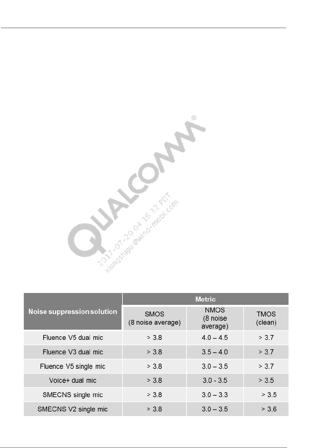
7.2.8 3QUEST Tuning
There are NS modules below in Handset mode.
Fluence V5 Dual Mic NS
Fluence V3 Dual Mic NS
Fluence V5 Single Mic NS
Voice+ Dual Mic NS
SMECNS(EEC+FNS) Single Mic NS
SMECNS V2 Single Mic NS
If you have perfect HW design and no leakage issues, the above algorithms will meet 3QUEST
requirement of CMCC, after tuning. The below forms is listed scores of 3QUEST and TMOS
based on above algorithm.
Figure 7-3 3QUEST MOS Metric of Differen ECNS Solutions

Common Audio Tuning Cases Introduction and Debugging Debugging Guide CMCC Tuning
80-NV213-6 Rev. A Confidential and Proprietary – Qualcomm Technologies, Inc. 36
MAY CONTAIN U.S. AND INTERNATIONAL EXPORT CONTROLLED INFORMATION
For 3QUEST tuning, recommend to do tuning based on default parameter provided by
Qualcomm.
When using Qualcomm’s default parameter, scores of SMOS/NMOS meet requirement. If
SMOS is failed, maybe phone has HW issue. Suggest to catch QXDM log to analyze input
signal of microphone.(Parse log via QCAT and check “ ***.0x1586.pcm.***.tx.wav”).
Inspect if exist floor noise in input signal of microphone
Inspect if input signal of microphone is clipping
– If clipped, check setting of codec gain, eg,ADC,DEC.
Inspect amplitude differences between Mic1&Mic2 when place phone on standard
postion of HATS
– this difference >=6 dB
Due to difference of phone HW, some phone can pass 3QUEST but failed TX_TMOS. At
that time, refer to TMOS tuning in the previous Chapter”TMOS_Tx”
If enable NS module and make TMOS to reduce 0.2, you can set low level NS to improve
score TMOS.
If TMOS score is high and to improve NMOS, you need to make NS aggressive.
List common tuning parameters of NS modules.
7.2.8.1 FluenceV5 Dual MIC NS
FluenceV5_DM common NS parameter
snrPPMinGainL16Q14 : Target minimum gain(negative value) to be achieved with the SNR-
PP module. Lower value is more aggressive. Recommended range: [0x80,0x200]. Reduce it
to improve NMOS but SMOS reduction.
snrPPMinAggR0L16Q12, snrPPMinAggR1L16Q12, snrPPMinAggR3L16Q12: In SNR-PP,
minimum aggressiveness control for R0, R1, R3 bands. Higher value is more aggressive.
Recommended range: [0x2000,0x4000]。Value of R2 is set by average of R1 and R3 bands.
R0: <500 Hz
R1: 500~2030 Hz
R2: 2030~4000 Hz
R3: >4000 Hz
input_gain_L16Q13[2]: gain (over-estimation factor of Noise signal) to be applied on the
second mic signal. Increase this value to improve NMOS but reduce TMOS. Recommended
range: [0x2000,0x32B8].0x2000=0 dB
input_gain_L16Q13[3] : gain to be applied on the noise reference signal generated. Increase
this value to improve NMOS but reduce TMOS. Recommended range: [0x2000,0x4000],
0x2000=0 dB
overEstFactNDevNRefL16Q13: scaling factor for the noise deviation based noise reference.
Higher value is more aggressive. Increase this value to improve NMOS. Recommended
range: [0x2000,0x2666].

Common Audio Tuning Cases Introduction and Debugging Debugging Guide CMCC Tuning
80-NV213-6 Rev. A Confidential and Proprietary – Qualcomm Technologies, Inc. 37
MAY CONTAIN U.S. AND INTERNATIONAL EXPORT CONTROLLED INFORMATION
7.2.8.2 FluenceV5 Single MIC NS
FluenceV5_SM Common Parameter.
snrppAggR0SmL16Q12, snrPPAggR1SmL16Q12, snrPPAggR3SmL16Q12: In SNR-PP,
minimum aggressiveness control for R0, R1, R3 bands. Higher value is more aggressive.
Recommended range: [0x2000,0x4000]. Value of R2 is set by average value of R1 and R3
bands.
R0: <500 Hz
R1: 500~2030 Hz
R2: 2030~4000 Hz
R3: >4000 Hz
snrPPMinGainSmL16Q14: In single microphone algorithm, Minimum gain for post-
processing. Lower value is more aggressive. Recommended range: [0x80,0x200]. Reduce this
parameter to improve NMOS and make SMOS reduction.
overEstFactNDevNRefL16Q13: scaling factor for the noise deviation based noise reference.
Increase this value to get NS aggressiveness and improve NMOS. Recommended range:
[0x2000,0x2666].
smrmt_thrB1, smrmt_thrB2, smrmt_thrB3: SM_RMT is available for FV5.4 and later
version. SM_RMT calculates more optimized stationary noise reference signal. These
parameters are three threshold to generate noise reference signal. Higher value is more
aggressive. Recommended range: [0x5F5E100,0xE4E1C00]
smrmt_overest_factL16Q12: estimation factor for noise reference signal. Higher value is
more aggressive. Recommended range: [0x1000,0x3000]
7.2.8.3 FluenceV3 Dual MIC NS
For older platform, such as 6270/7x27/8x25,etc, Dual MIC NS algorithm is FluenceV3.
Fluence_DM common parameter:
DNNS_NoiseGammaN : non-stationary NS Gain . Higher value is more aggressive.
Recommended range :[0x2000,0x2C00]
DNNS_NoiseGammaS : stationary NS Gain. Higher value is more aggressive.
Recommended range :[0x2000,0x2800]
NS_Fac: gain to be applied on the noise reference signal. Increase this value to improve
NMOS and make TMOS reduction. Recommended range: [0x1800,0x2800], 0x2000=0 dB
Fixed_Over_Est: gain (over-estimation factor of Noise signal) to be applied on the second
mic signal. Increase this value to improve NMOS and make TMOS reduction. Recommended
range: [0x390B,0x5A67], 0x4000=0 dB
7.2.8.4 SMECNS Single MIC NS
SMECNS has two sub-modules, EEC-NS and FNS.
To improve NMOS score, licensee can make EEC-NS and FNS more aggressive;

Common Audio Tuning Cases Introduction and Debugging Debugging Guide CMCC Tuning
80-NV213-6 Rev. A Confidential and Proprietary – Qualcomm Technologies, Inc. 38
MAY CONTAIN U.S. AND INTERNATIONAL EXPORT CONTROLLED INFORMATION
If enable SMECNS to lead to TMOS failed, licensee need to confirm which sub-module results in
the failed. Then tune this sub-module. Licensee can follow steps below to find root cause.
Disable EEC-NS and FNS: Mode->0x0, fnsMode->0x0, measure TMOS1.
Disable EEC-NS and enable FNS: Mode->0x0,fnsMode->0xF3, measure TMOS2. If
TMOS1-TMOS2>0.2, which means to need to tune FNS parameter.
Enable EEC-NS and Disable FNS: Mode->0x30FF, fnsMode->0x0, measure TMOS3. If
TMOS1-TMOS3>0.2, which means to need to tune EEC-NS.
EEC-NS common parameter:
DENS_gamma_n, Control NS aggressiveness, High value is more aggressive. Recommended
range: [0x200,0x320]
DENS_limit_NS, Amplitude of NS. Low value make more aggressive. Recommended
range:[0xC00,0x4000]
DENS_NFE_blockSize, window of noise floor estimation. Low value is more aggressive and
improve score of TMOS but converge time become slowly. Recommended
range:[0x96,0x190]
FNS common parameter
fnsMode: Mode word for enabling/disabling submodules.
fnsMode->0xF3, enables stationary only noise suppression.
fnsMode->0xF7, enables stationary and non-stationary noise suppression.
fnsTargetNS: Target noise suppression level in dB. Higher value is more aggressive.
Recommended ranged: [0x600,0x1400]
fnsSalpha: Over-subtraction factor for stationary NS. Higher value is more aggressive.
Recommended ranged: [0x1000,0x2000]。
fnsNalpha: Over-subtraction factor for non-stationary NS. Higher value is more aggressive.
Recommended ranged: [0x800,0x1400].
fnsSNblock: Quarter block size for stationary NS. Lower value is make converge time slowly
and improve NMOS. Recommended ranged: [0x28,0x4B].
7.2.8.5 SMECNS V2 Single MIC NS
SMECNSV2 common NS tuning parameters,
SM_VAD_ThreshQ8, single-channel VAD threshold, a bigger value cause less speech
detection,then more noise suppression. Recommended value range[0x80,0x800],typical
value is 0x200
PP_Gamma_LF, NS aggressiveness of 0~500Hz frequency, a higher value means more
aggressive NS;a lower value means less aggressive NS. Recommended value range is
[0x2000,0x4000], typical value is 0x34BC

Common Audio Tuning Cases Introduction and Debugging Debugging Guide CMCC Tuning
80-NV213-6 Rev. A Confidential and Proprietary – Qualcomm Technologies, Inc. 39
MAY CONTAIN U.S. AND INTERNATIONAL EXPORT CONTROLLED INFORMATION
PP_Gamma_MF, NS aggressiveness of 500~2000Hz frequency, a higher value means more
aggressive NS;a lower value means less aggressive NS. Recommended value range is
[0x2000,0x4000], typical value is 0x2EE0
PP_Gamma_HF, NS aggressiveness of 2000~4000Hz frequency, a higher value means more
aggressive NS, a lower value means less aggressive NS. Recommended value range is
[0x2000,0x4000], typical value is 0x2AF8.
PP_Min_Gain, Intended overall NS. A lower value means more NS, a higher value means
less NS. Recommended value range is [0x80,0x400], typical value is 0x200
7.2.8.6 Voice+Dual MIC NS
VPECNS_DM Common Parameter
nsGamma_NN : non-stationary NS Gain. Higher value is more aggressive. Recommended
range : [0x2000,0x2C00]
nsGamma_SN : Stationary NS Gain. . Higher value is more aggressive. Recommended
range :[0x2000,0x2800]
nsGain_SN :overall stationary NS level. Higher value is more aggressive. Recommended
range :[[0x800,0x2000]
pp_nsref_factor : Non-stationary noise Reference factor in PP. Higher value is more
aggressive.Recommended ranged: [0x1800,0x2800]. 0x2000=0 dB
80-NV213-6 Rev. A Confidential and Proprietary – Qualcomm Technologies, Inc. 40
MAY CONTAIN U.S. AND INTERNATIONAL EXPORT CONTROLLED INFORMATION
8 Audio Recording
8.1 Recording Tuning
Audio Recording basic performance requirement
The recording is clean, no distortion, no overdrive sound
With some noise suppression function, can get clear recording in common noise
conditions
Support far-field recording
Audio Recording Tuning two main Factors
Gain Setting
Noise Suppression
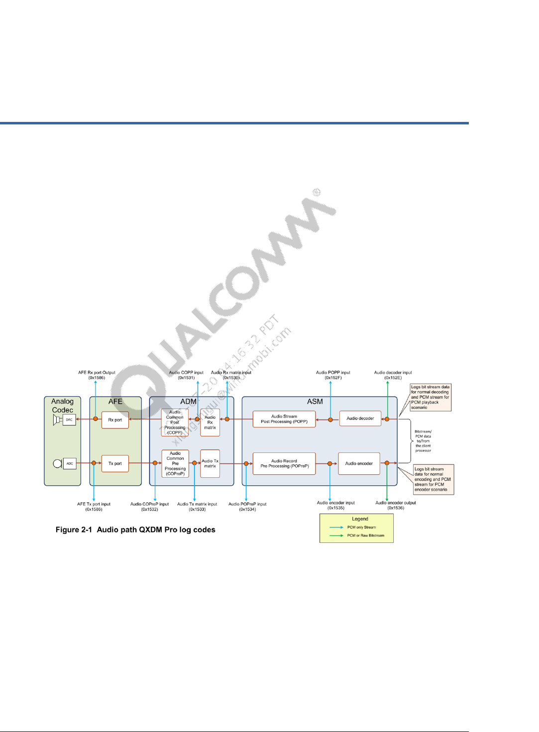
QXDM logging point in Audio Recording Path
Figure 8-1 Audio path QXDM pro log codes
Common Audio Tuning Cases Introduction and Debugging Debugging Guide Audio Recording
80-NV213-6 Rev. A Confidential and Proprietary – Qualcomm Technologies, Inc. 41
MAY CONTAIN U.S. AND INTERNATIONAL EXPORT CONTROLLED INFORMATION
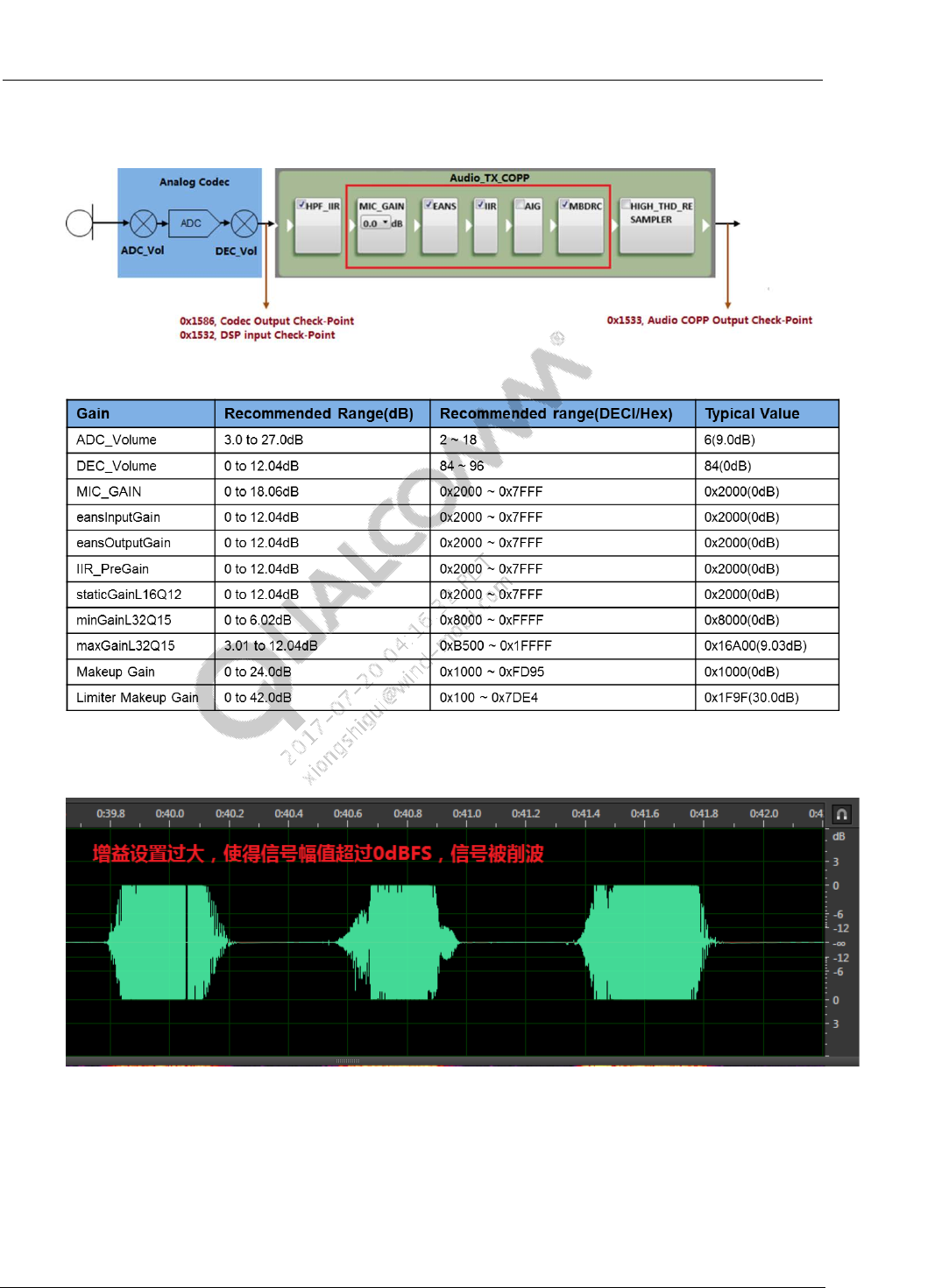
8.2 Gain Setting of Recording
Figure 8-2 Gain settings in audio recording path
Figure 8-3 Typical Gain Setting Values
Gain setting should not cause signal be saturated, cause signal clipping, introduce clipping noise.
Figure 8-4 Recording Clipping
If using analog mic, audio recording tuning can set gain in ADC_Volume, AIG and MBDRC.
0dB is recommended for other gain setting modules.
If using digital mic, audio recording tuning can set gain in AIG and MBDRC. 0dB is
recommended for other gain setting modules.

Common Audio Tuning Cases Introduction and Debugging Debugging Guide Audio Recording
80-NV213-6 Rev. A Confidential and Proprietary – Qualcomm Technologies, Inc. 42
MAY CONTAIN U.S. AND INTERNATIONAL EXPORT CONTROLLED INFORMATION
8.2.1 ADC_Volume
According to audio recording’s signal flow chart, ADC_Volume controls ADC (Analog to
Digital Convertor) input signal level VADC. If VADC is too big, it will cause signal clipping. In
QC common platforms, the ADC conversion is 0dBFS/V,If VADC value is above 1V
(0dBV), it will cause signal clipping.
The mic sensitivity Smic and microphone nearby sound level Paoc also decide mic input
signal level. If ignore mic acoustics structure impact on mic input level, we can get below
formula,
VADC = Paoc * Smic *ADCvol
if converted to dB format,
VADC(dBV) = Paoc(dBSPL)-94 + Smic(dBV/Pa) + ADCvol(dB)
If microphone nearby sound level is bigger, it’s easier to cause clipping. For example, speak
close to mic loudly, or do recording of live concert. To avoid recording clipping, the
ADC_Volume must be decreased.
AOP (Acoustics Overload Point) can be thought as the effect sound’s maximum level that
mic can record. Referring to AOP and above formula, in mic’s normal work range, to not
cause clipping(VADC<=0dBV), the maximum allowable ADC_Volume is,
ADCvol(dB) = 0 - Paop(dBSPL) + 94 - Smic(dBV/Pa)
The microphone sensitivity and AOP usually can be get from mic spec. Take one analog
microphone for example, its sensitivity is -38dBV/Pa,AOP is 124dBSPL. Following above
formula, we can get,
ADCvol(dB)= 0 -124 + 94 - (-38) = 8(dB)
If ADC_Volume is set too small, like set to 0dB. It will absolutely not cause clipping, but the
recording level is small. Although the recording level can be boosted by digital gain setting,
but the signal resolution is small, the recording quality will not be very good.
For audio recording tuning, ADC_Volume can be set to the value which is calculated by
above formula with mic sensitivity and AOP. In calculation of ADCvol, if consider the impact
of mic sensitivity variation, AOP variation and mic acoustics structure, we can compensate
these factors to above formula calculate a more proper and safe ADC_Volume value.
After ADC_Volume is fixed, we can do audio recording test(set DEC_Volum to 0dB).
Playback speech and make mic nearby sound level be about AOP, catch QXDM Log, we can
check 0x1586 log-point signal to verify whether there is clipping.
If digital mic is used, ADC is not used in codec path. We can do audio recording test(set
DEC_Volume to 0dB). Playback speech and make mic nearby sound level be about AOP,
catch QXDM Log, we can check 0x1586 log-point signal to verify whether there is clipping.
If has clipping, the mic internal gain may be too big, we can try tuning the mic internal
gain
Common Audio Tuning Cases Introduction and Debugging Debugging Guide Audio Recording
80-NV213-6 Rev. A Confidential and Proprietary – Qualcomm Technologies, Inc. 43
MAY CONTAIN U.S. AND INTERNATIONAL EXPORT CONTROLLED INFORMATION
If signal level is too small, like the peak level <-15dB, the mic internal gain may be too
small, can try increasing the gain, make AOP output signal level can follow in range of [-
12dBFS, -3dBFS].
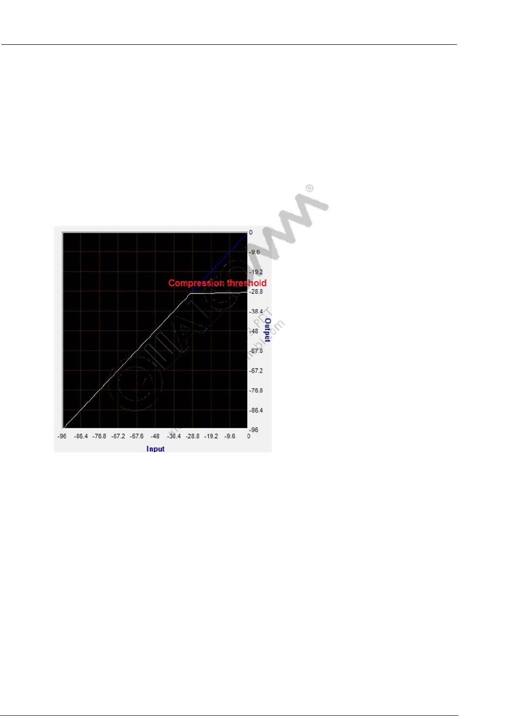
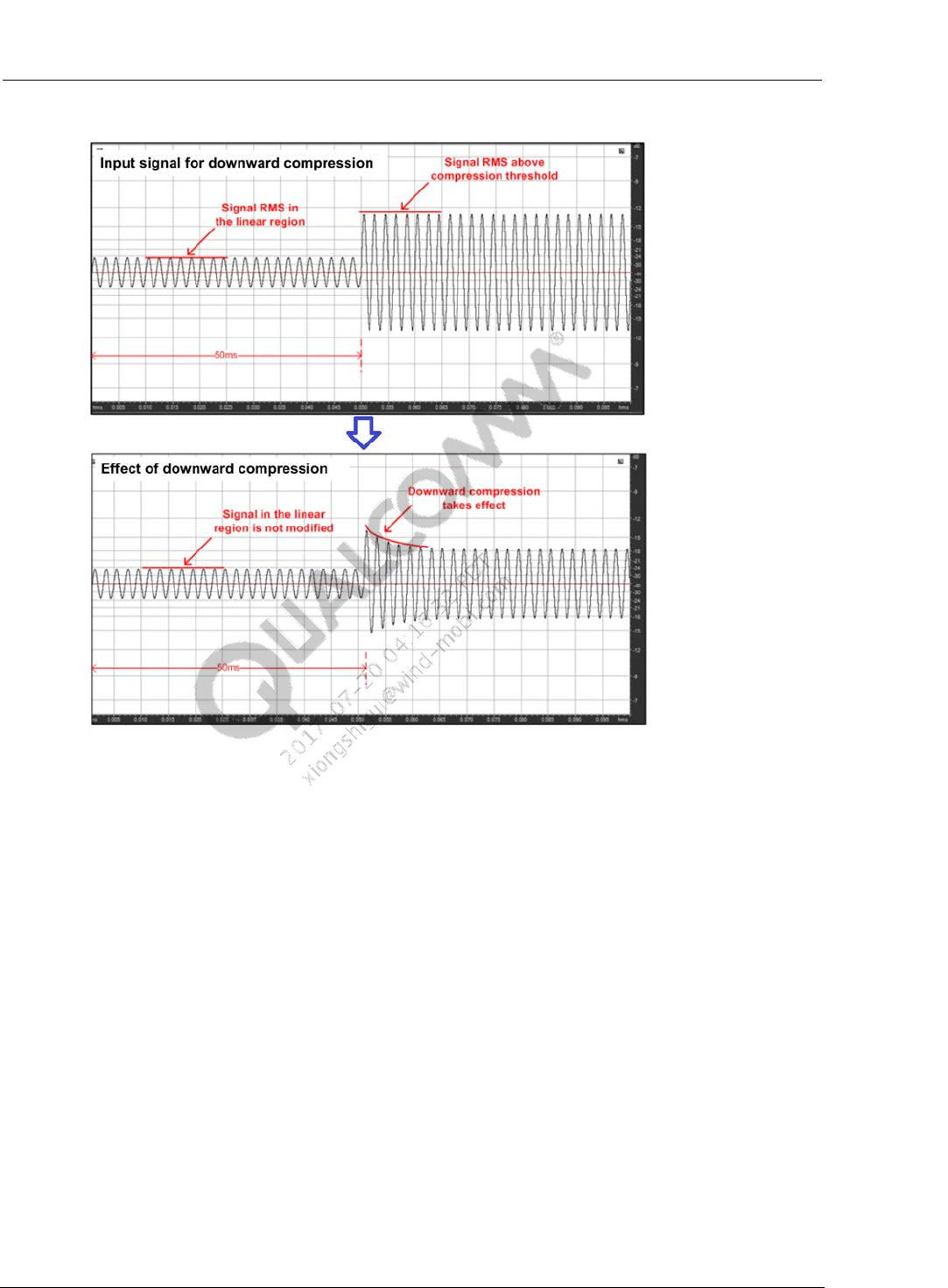
8.2.2 MBDRC Gain Setting
To make sure the DSP gains not cause clipping, the MBDRC compressor and limiter needs to
used, to make signal have enough headroom to add the gain. So MBDRC gain setting is used.
In MBDRC, set band number to 1, only use the compressor and limiter, design MBDRC cure
as below. The right picture shows MBDRC function.
Figure 8-5 MBDRC Setting
Common Audio Tuning Cases Introduction and Debugging Debugging Guide Audio Recording
80-NV213-6 Rev. A Confidential and Proprietary – Qualcomm Technologies, Inc. 44
MAY CONTAIN U.S. AND INTERNATIONAL EXPORT CONTROLLED INFORMATION
Figure 8-6 MBDRC Function Display
Take +24dB gain setting for example, below list MBDRC default parameters,
If not satisfied with the loudness, please try tuning key parameter “Dnward Compression
Threshold”, “Limiter Threshold” and “Limiter Makeup Gain”, tune gain to proper value.
Common Audio Tuning Cases Introduction and Debugging Debugging Guide Audio Recording
80-NV213-6 Rev. A Confidential and Proprietary – Qualcomm Technologies, Inc. 45
MAY CONTAIN U.S. AND INTERNATIONAL EXPORT CONTROLLED INFORMATION
Figure 8-7 MBDRC Default Parameters
8.2.3 AIG Gain Setting
If far-field recording is required, bigger gain setting is needed in DSP, to guarantee recording
level. If only set MBDRC gain, a very small compressor threshold is needed to provide
Headroom for gains, to avoid clipping. However, too small compressor threshold will cause big
non-linear distortion to high level signals, attenuate recording quality. Then we can tune AIG to
share some gain settings. AIG should be set to operate in adaptive gain mode.
Please refer to previous chapter to get AIG default parameters and key-parameters introduction.
For audio recording, after load default parameters, we can tune below two parameters to achieve
gain tuning expectation,
idealRmsDBL16Q7,referring to MBDRC compressor threshold, they can be set to same dB
value
maxGainUL32Q15,tune the maximum gain that AIG can adjust, don’t recommend set this
gain above 12dB。
8.3 Noise Suppression of Recording
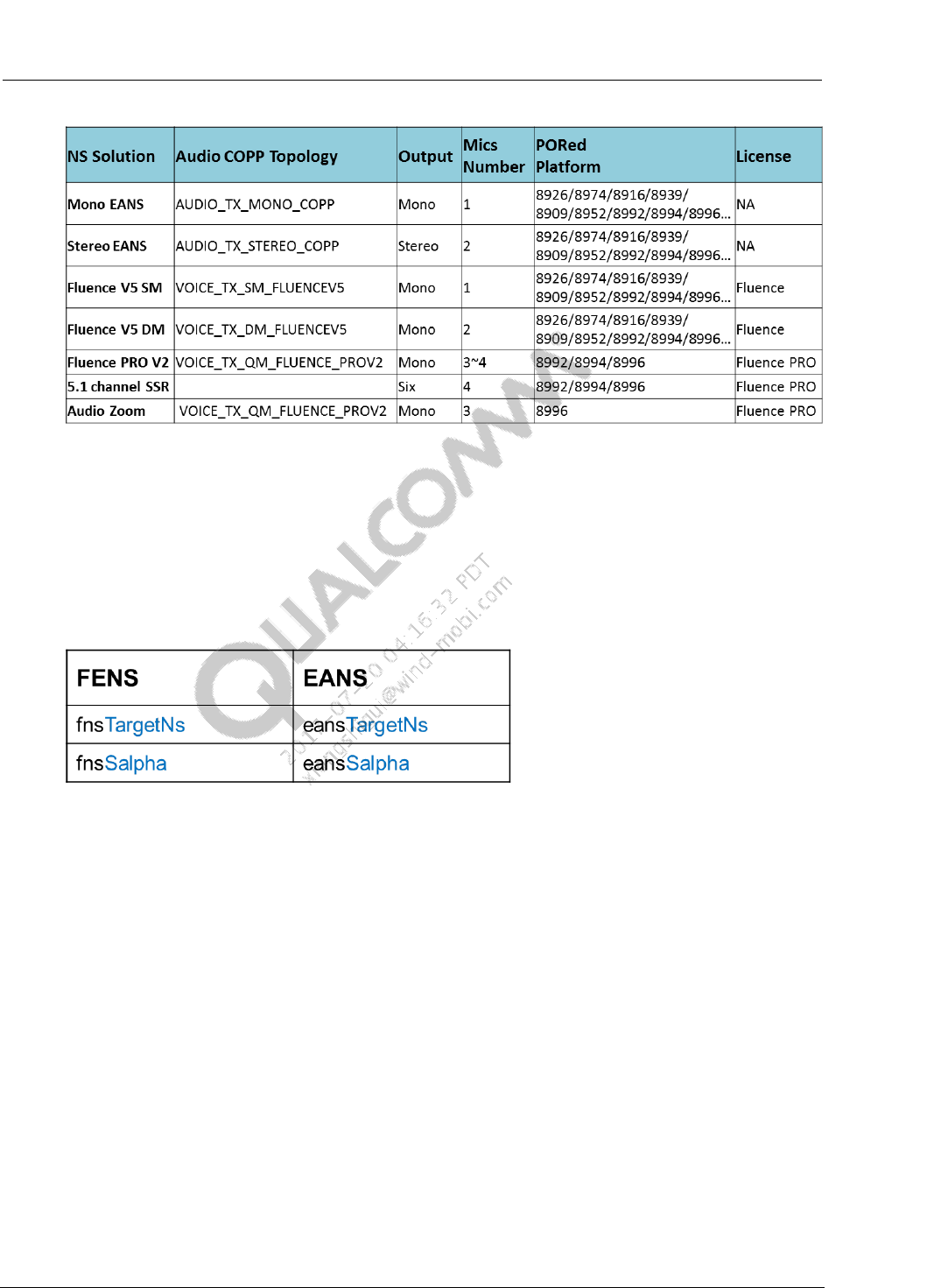
8.3.1 NS Solutions for Audio Recording
Below list selectable NS solutions for audio recording. We can modify audio recording device’s
“Audio COPP TopologyID” to choose proper NS solution,
Common Audio Tuning Cases Introduction and Debugging Debugging Guide Audio Recording
80-NV213-6 Rev. A Confidential and Proprietary – Qualcomm Technologies, Inc. 46
MAY CONTAIN U.S. AND INTERNATIONAL EXPORT CONTROLLED INFORMATION
Figure 8-8 Audio Recording NS Solutions
In current QC platforms, if Stereo Recording is needed, only Stereo EANS can be used.
In general, EANS can meet most audio recording requirement. We can do tuning based on default
parameters, tune key-parameters to meet tuning expectation. Please refer to previous chapter of
FENS for EANS tuning, they are same algorithms. Through comparing the keywords of
parameters name, we can match the two modules’ parameters.
Figure 8-9 FENS and EANS Parameters Name Comparison
If requirement still can’t be met after tuning, please file case to QC for assistance.
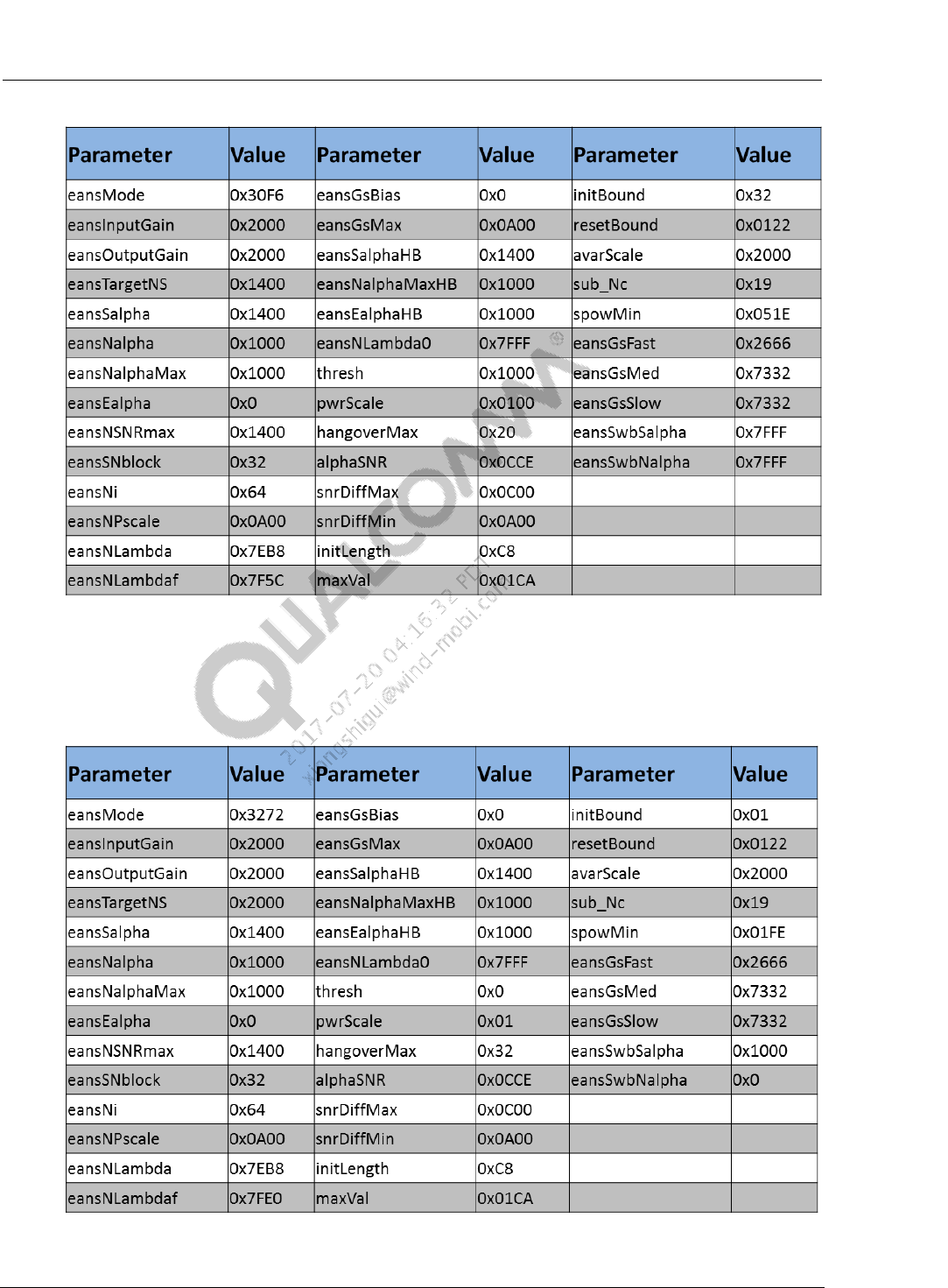
Below lists two types of EANS parameters for your referece,
EANS Default Parameter - Record clear speech
This type EANS parameters have aggressive noise suppression. If record speech, can get
clear speech recording. Based on default parameters, customer can tune key-parameters
eansTargetNs/eansSalpha to acheive expected performance.
Common Audio Tuning Cases Introduction and Debugging Debugging Guide Audio Recording
80-NV213-6 Rev. A Confidential and Proprietary – Qualcomm Technologies, Inc. 47
MAY CONTAIN U.S. AND INTERNATIONAL EXPORT CONTROLLED INFORMATION
Figure 8-10 Default EANS Parameters for Voice Recording
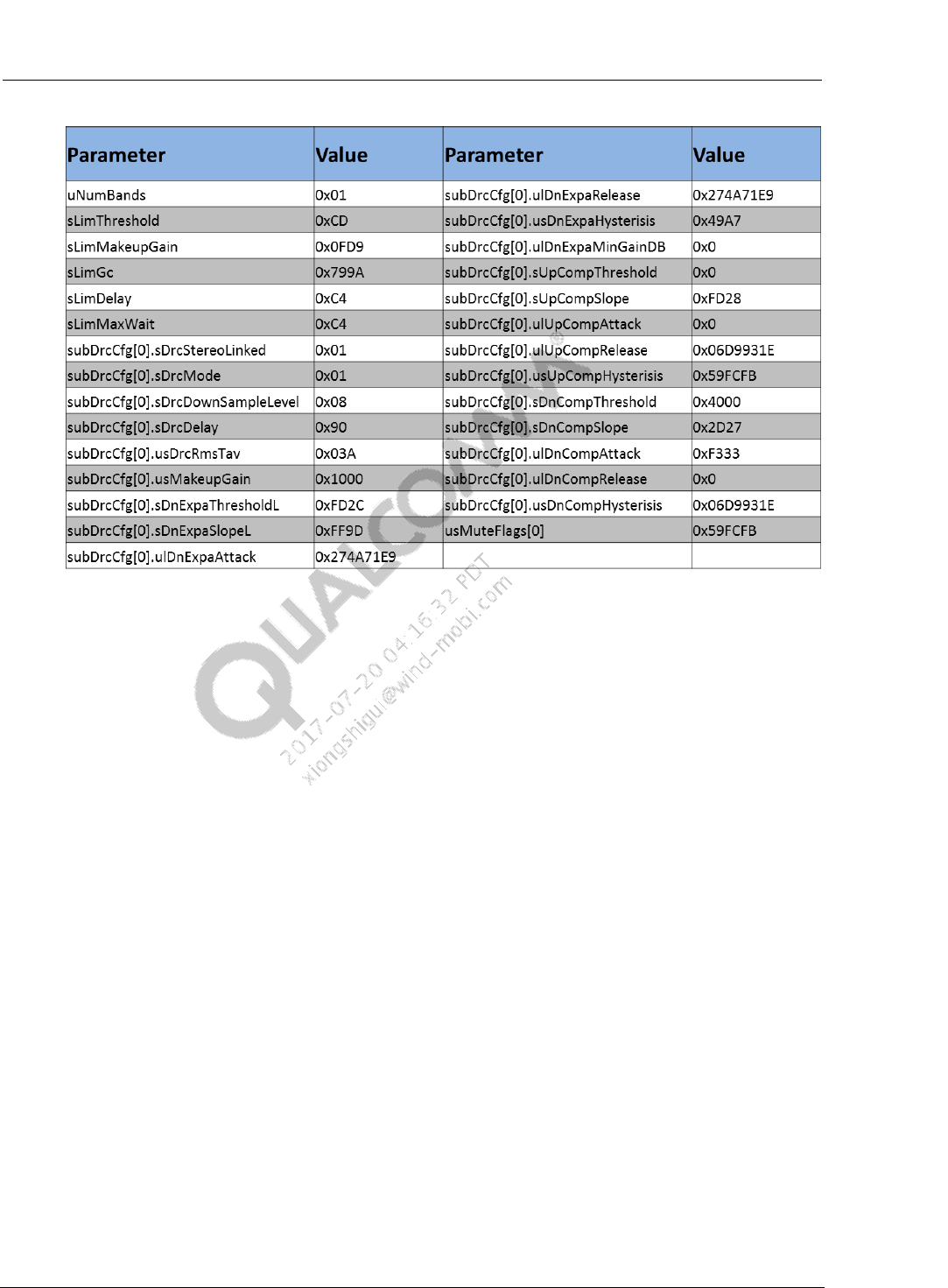
EANS Default Parameter - Record video、music
This type EANS parameter has less aggressive noise suppression, can suppress Hiss noise,
can preserve most surrounding sound content, is proper for music/party recordings.
Figure 8-11 Default EANS Parameters for Music/Video Recording

Common Audio Tuning Cases Introduction and Debugging Debugging Guide Audio Recording
80-NV213-6 Rev. A Confidential and Proprietary – Qualcomm Technologies, Inc. 48
MAY CONTAIN U.S. AND INTERNATIONAL EXPORT CONTROLLED INFORMATION
8.3.2 Voice Recognition and Noise Suppression
SNR(Signal to Noise Ratio) is a key-factor which impact VR performance. In noise conditions,
the SNR of VR input becomes smaller, VR rate usually drops.
With noise suppression modules, the SNR of VR input can be improved, and improve VR
performance. But it’s not absolute that, more aggressive NS or higher SNRi value can definitely
cause improvement to VR. Near-end speech attenuation may impact the VR performance too.
Generally, it needs co-operation tuning of NS and VR engine algorithm, to provide a good co-
working calibration of them.
Some VR algorithm is sensitive to DRC, we need to bypass DRC in audio recording path of VR.
80-NV213-6 Rev. A Confidential and Proprietary – Qualcomm Technologies, Inc. 49
MAY CONTAIN U.S. AND INTERNATIONAL EXPORT CONTROLLED INFORMATION
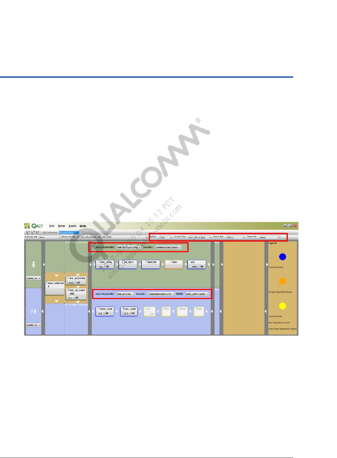
9 Per Vocoder Calibration (PVC)
PVC allows different tuning of newer classes of vocoders and bandwidth extensions, to provide
high quality for voice use cases. PVC is available on MSM8994/MSM8909 and all subsequent
chipsets.
SO73
eAMR
BeAMR
WV2
WV1
PVC feature can be displayed by below red-rectangle marked areas, (these areas are not displayed
in non-PVC acdb files).
Figure 9-1 PVC Features
PVC allows overlap of different vocoder calibration data so that less tuning parameters need to be
placed overall. These modules, whose parameters are shared by the vocoders, are called as
Common Modules.
PVC allows for dynamic switching between vocoders, the vocoder’s specific tuning module
parameters are properly called。These modules can be set specific tunings to different vocoders,
they are called as Vocoder Dependent Modules.
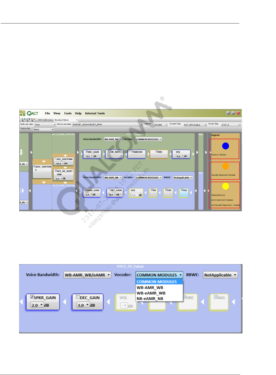
Common Audio Tuning Cases Introduction and Debugging Debugging Guide Per Vocoder Calibration (PVC)
80-NV213-6 Rev. A Confidential and Proprietary – Qualcomm Technologies, Inc. 50
MAY CONTAIN U.S. AND INTERNATIONAL EXPORT CONTROLLED INFORMATION
The ACDB also contain some modules, which can be set different tunings to different volume
level index. These modules are called as Volume Module. In PVC acdb files, the Volume
Modules are also Vocoder Dependent Modules.
In QACT Topology View, the module types can be identified by the shadow color.
Blue color:Common Modules
Orange color:Vocoder Dependent Modules
Yellow color:Volume Modules, also Vocoder Dependent Modules
Figure 9-2 Module Type and Corresponding Shadow Color
Take WCDMA network’s WB tuning for example, explain the tuning differences of these three
module types.
WCDMA WB supports three vocoder types, AMR-WB、eAMR-WB and NB-eAMR-NB。
Figure 9-3 WCDMA WB Supported Three Vocoder Types
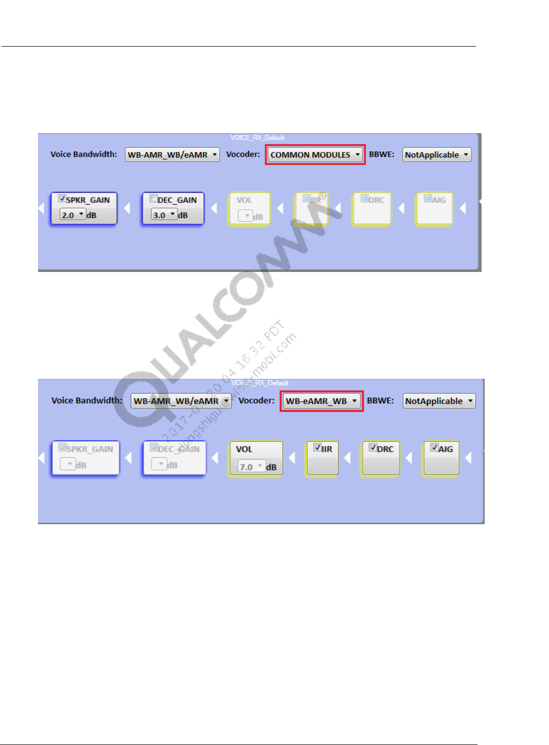
Common Audio Tuning Cases Introduction and Debugging Debugging Guide Per Vocoder Calibration (PVC)
80-NV213-6 Rev. A Confidential and Proprietary – Qualcomm Technologies, Inc. 51
MAY CONTAIN U.S. AND INTERNATIONAL EXPORT CONTROLLED INFORMATION
In the drop-down list of Vocoder, select “COMMON MODULES”, the common modules will
goes to be editable state, while the vocoder dependent modules will become grey, are not
editable. If modify common module calibration, such as, set SPKR_GAIN to 2.0dB,this new
SPKR_GAIN value will take effect for AMR-WB、eAMR-WB and NB-eAMR-NB.
Figure 9-4 If Select Common Modules, Vocoder Dependent Modules Are Grey
In the drop-down list of Vocoder, select a vocoder, like “WB-eAMR_WB”. The vocoder
dependent modules will go to be editable state, while the common modules will become grey, are
not editable. Do vocoder dependent modules tuning, we can get specific tuning for this vocoder.
If do tunings to volume modules, we can use Batch Copy to copy calibration to all volume level
index; or we can do fine tunings for different volume level index.
Figure 9-5 If select Vocoder Dependent Modules, Common Modules are grey
In narrow band(NB) network, Bandwidth Extension Technologies(BWE) can extend rx-path
speech from NB(0.3~4kHz) to WB(0.15~7kHz), increase speech intelligibility and naturality.
PVC allows different tunings for BWE WB and true WB, get good voice tuning quality for both
use-cases。
Below table lists QC’s current BWE solutions over NB network. Customer can select proper
solution for evaluation and implementation.

Common Audio Tuning Cases Introduction and Debugging Debugging Guide Per Vocoder Calibration (PVC)
80-NV213-6 Rev. A Confidential and Proprietary – Qualcomm Technologies, Inc. 52
MAY CONTAIN U.S. AND INTERNATIONAL EXPORT CONTROLLED INFORMATION
Table 9-1 Qualcomm Current BWE Solutions Over NB Network
Solution
Band-width
Extension
Limitations PORed Platform License
eAMR True Wide-
band
1. Only support AMR-NB vocoder
2. MO/MT should both support eAMR
3. The network must be transcoding-free
operation (TrFo)
8926/8974/8916/8939/
8909/8952/8992/8994/8996…
NA
BeAMR
~7.0kHz
Currently, only support AMR-NB vocoder.
8939(LA2.0)/8909/8952/8992/
8994/8996…
Fluence
HD
WVE2.0
~7.0kHz
not limited by vocoder
8939(LA2.0)/8909/8952/8992/
8994/8996…
Fluence
WVE1.0
~5.5kHz
not limited by vocoder
8926/8974/8916/8939/
8909/8952/8992/8994/8996…
Fluence

80-NV213-6 Rev. A Confidential and Proprietary – Qualcomm Technologies, Inc. 53
MAY CONTAIN U.S. AND INTERNATIONAL EXPORT CONTROLLED INFORMATION
10 Book Lab + Fluence Package
10.1 Book QC Audio Lab
In China, QC has audio labs in Shanghai, Beijing and Shenzhen, to provide audio tuning support
for customer terminals. Customers can send mail or file case to book QC audio labs,
Send mail to audiolab.hotline.external@qti.qualcomm.com
In SF system, file case of “audio lab booking”
When booking audio lab, customers need to provide below project information. QC will properly
arrange the lab resource for you based on your tuning requirement,
Table 10-1 Project Information
Vendor
Vendor
Location
Project Device
Type Chipset
Fluence Type
Mic Number
Speaker
PA Target Market
OEM
name
City name OEM
Project
name
Phone/
Wearable/
Automative
...
QCOM
chipset
Fluence
V5/ECNS/
Voice+ Dual-mic
Open Market/
CMCC/AT&T/
Vodafone/Sprint
…
The audio lab resource is busy, based on project schedule, customer had better book audio lab
ahead of the tuning date. The audio lab usually needs to be booked one month ahead of tuning
date.
For subjective related issues, customer can firstly provide issue’s QXDM log and audio
calibration, try resolve it by cases.
To make sure the tuning can be done smoothly, before coming to QC audio lab, customer had
better do below pre-checkings of the device.
Table 10-2 Pre-checking lists before Lab Audio Tuning
Item
Quantities
Review
Result
Comments
Devices
2
USB
cables
2
Batteries
2
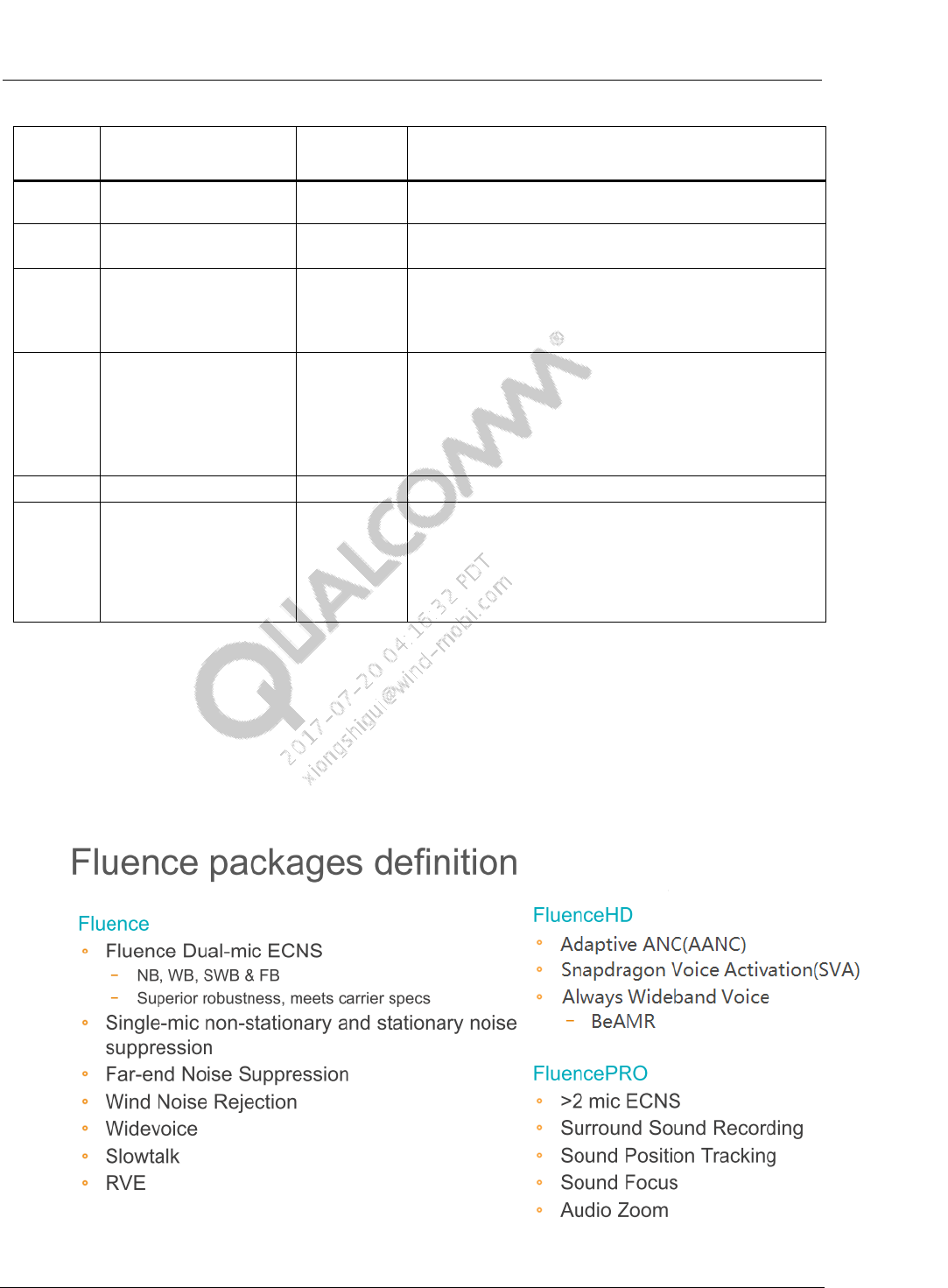
Common Audio Tuning Cases Introduction and Debugging Debugging Guide Book Lab + Fluence Package
80-NV213-6 Rev. A Confidential and Proprietary – Qualcomm Technologies, Inc. 54
MAY CONTAIN U.S. AND INTERNATIONAL EXPORT CONTROLLED INFORMATION
Item
Quantities
Review
Result
Comments
USB
Driver
Installed
Phone has been confirmed to connect through USB to
computer with the sent driver.
Audio
HW
Phone audio components, like mic/receiver/speaker,
have been confirmed to work normally.
Call box
set up call successfully
1. Phone has been connected to a call box such as
CMU200 or CMW500.
2. Phone software is stable enough to hold a call for at
least 30 minutes at one time.
TOOL
QPST/QXDM/QACT/adb/
root mode
1. Phone has been confirmed to connect to QC tools:
QPST, QXDM, and QACT.
2. Phone has been confirmed that adb commands take
effect.
3. Phone can be set to root mode, acdb files can be
updated to the phone.
RF
Calibrated
Phone has been calibrated, the RF works well
VoLTE
set up call successfully
1. For VoLTE test, please provide the RF working mode
(TDD/FDD) and channel.
2. make sure phone can register on IMS of R&S
CMW500 or Spirent VoLTE Network Simulator. The
configuration file of VoLTE Network Simulator is
available through a case or mail.
10.2 Fluence Package
Below lists the Fluence Package definitions. OEM can refer to the table below to choose proper
Fluence license for your project.
“Fluence HD” supports all the features covered by “Fluence”
“Fluence Pro” supports all the features covered by “Fluence HD” and “Fluence”
Figure 10-1 Fluence Packages
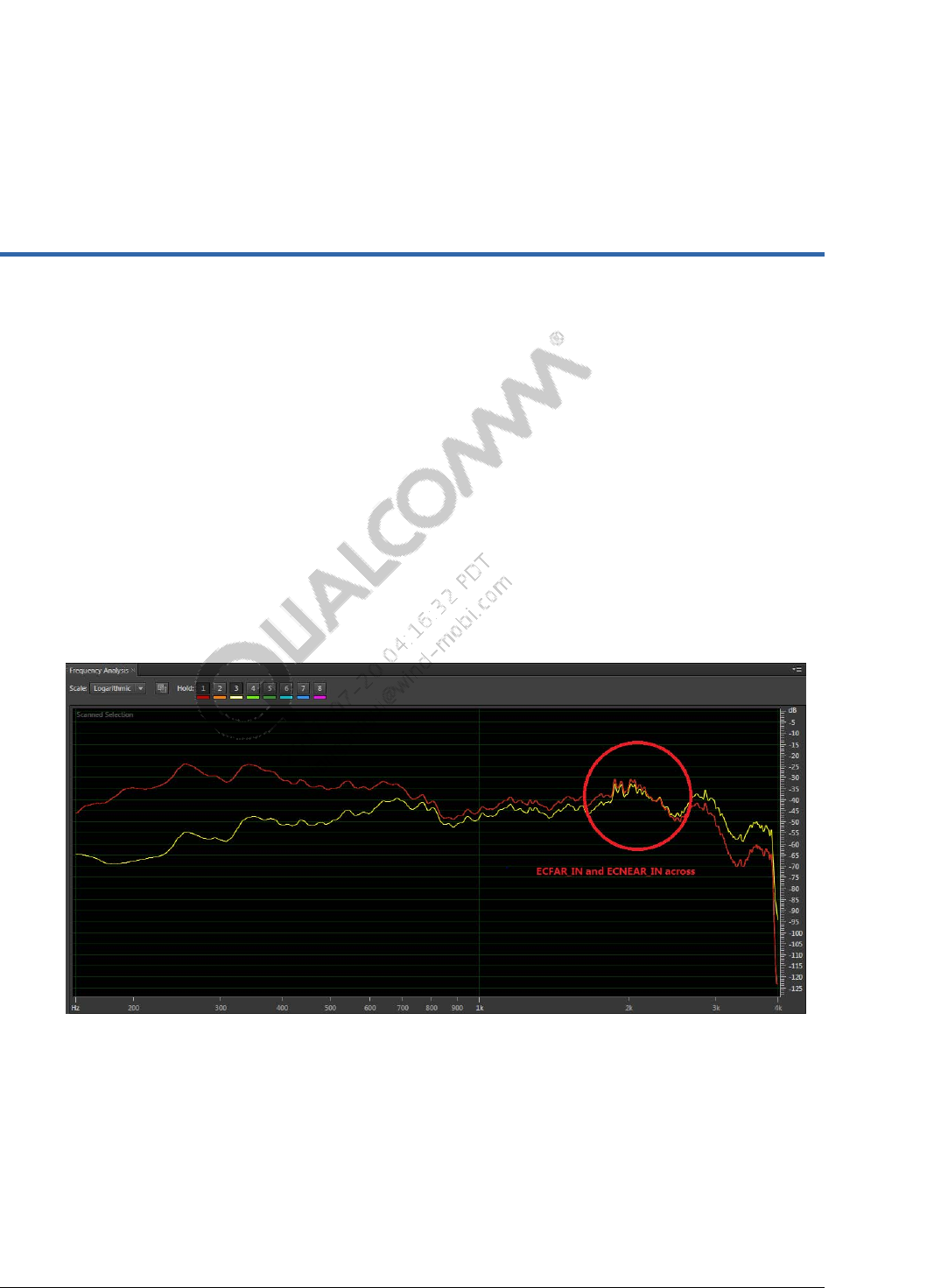
80-NV213-6 Rev. A Confidential and Proprietary – Qualcomm Technologies, Inc. 55
MAY CONTAIN U.S. AND INTERNATIONAL EXPORT CONTROLLED INFORMATION
11 HW Design Cause Input Signal
Distortion Issue
Phenomenon
If input signal is distorted, then EC in Fluence may not work properly hence it will cause
issues like big echo, TMOS very low etc.
Root cause analysis
Mic sound channel is too long
HW designed flaws, like sound hole too small, sharp corner etc.
Debugging
Run TCLw and capture QXDM logs
Do frequency analysis of ECFAR_IN and ECNEAR_IN to check if the frequency
response curve cross each other, as below shown in below picture.
Figure 11-1 ECFAR_IN and ECNEAR_IN Signals Analysis
Fix HW issue from HW perspectives is always the first choice
From tuning perspectives you could try below suggestions:
Fluence V5
– Check if Rx reference signal is saturated: if Rx signal is already saturated and distorted
then adjust Rx path gain setting;

Common Audio Tuning Cases Introduction and Debugging Debugging Guide HW Design Cause Input Signal
Distortion Issue
80-NV213-6 Rev. A Confidential and Proprietary – Qualcomm Technologies, Inc. 56
MAY CONTAIN U.S. AND INTERNATIONAL EXPORT CONTROLLED INFORMATION
– If no saturation but the frequency response curve cross each other, then set
input_gain_L16q13[2] to 0x2000;
– Adjust gain settings before Fluence to after Fluence to make ECNEAR_IN is lower
than -24dBFS;
– Re-capture QXDM logs, if the frequency response of ECNEAR_IN and ECFAR_IN
still cross each other then make up the distortion using IIR_MIC1 and FIR/IIR

80-NV213-6 Rev. A Confidential and Proprietary – Qualcomm Technologies, Inc. 57
MAY CONTAIN U.S. AND INTERNATIONAL EXPORT CONTROLLED INFORMATION
12 WB Inside-Speech Noise Tuning
Issue: In WB voice call, noise can be heard along with speech; while it’s very clean when
there is no speech
There are three aspects for the tuning:
Reduce background noise within the speech.
– This will be done by a combination of pre-emphasis of high frequencies prior to
ECNS and de-emphasis of high frequencies after ECNS;
– Strenghthen noise suppression within ECNS.
Make background noise in speech to match background noise outside of speech.
– Disable expander within DRC to avoid background noise outside speech
– Inject comfort noise to match background noise in speech
Do not create saturation in the progress.
– Keep gains low enough prior to the DRC.
– Negative TX volume is not a good solution due to saturation that can occur prior to the
TX volume.
– This is from the pre-emphasis and de-emphasis of high frequencies, which results in
less saturation.
We use combination of the following algorithms
IIR Mic 1 Filter
NS tuning within SMECNS
FENS tuning within SMECNS
IIR
DRC
Most of these will be default parameters, which will be given on the following pages.
Load and enable the default parameters for:
IIR
SMECNS NS
FENS
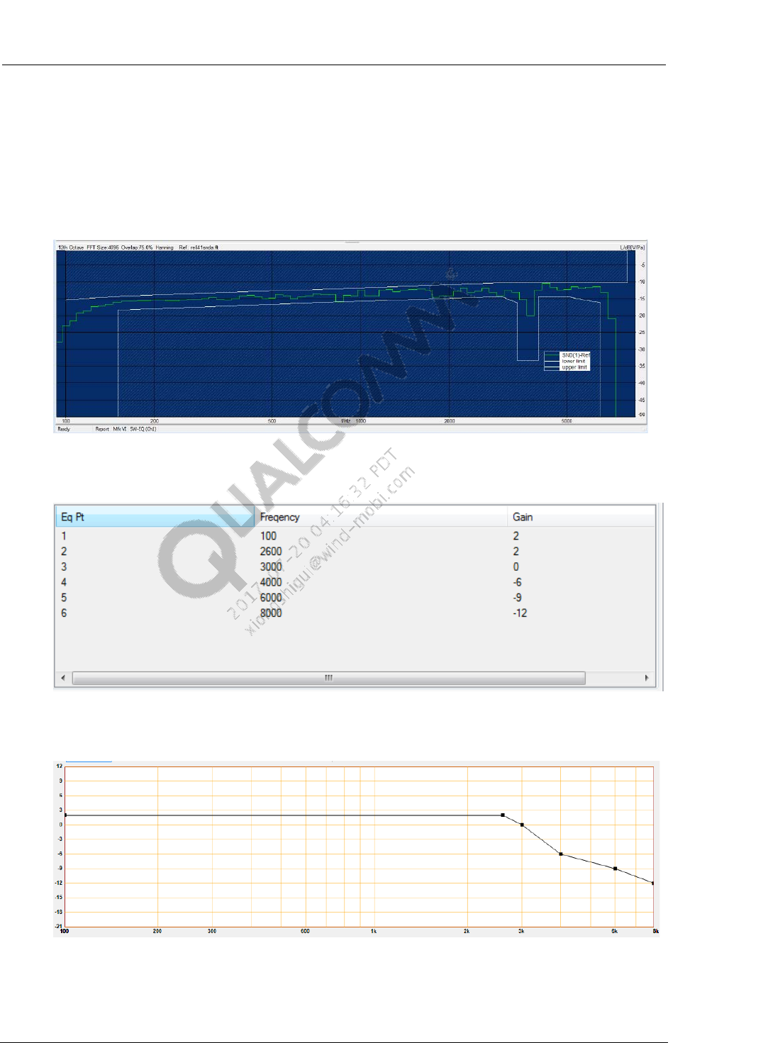
Common Audio Tuning Cases Introduction and Debugging Debugging Guide WB Inside-Speech Noise Tuning
80-NV213-6 Rev. A Confidential and Proprietary – Qualcomm Technologies, Inc. 58
MAY CONTAIN U.S. AND INTERNATIONAL EXPORT CONTROLLED INFORMATION
DRC
12.1 IIR Tuning
Tune IIR MIC1 on the test equipment so that the frequency response is as desired. This is
typically flat, except for a small amount of slope (approximately 3 to 4dB increase from 200Hz
to about 3000Hz).
Figure 12-1 Desired Frequency Response
Use Yulewalker 2 stage 16kHz filter, set value as below:
Figure 12-2 IIR EQ Setting
After set the value as above, IIR is shown as below:
Figure 12-3 IIR Response Curve

Common Audio Tuning Cases Introduction and Debugging Debugging Guide WB Inside-Speech Noise Tuning
80-NV213-6 Rev. A Confidential and Proprietary – Qualcomm Technologies, Inc. 59
MAY CONTAIN U.S. AND INTERNATIONAL EXPORT CONTROLLED INFORMATION
12.2 SMECNS NS Tuning
The only one need to be tuned is VOICE_FNS_PARAM.fnsTargetNS. A good range for it will be
[0x1400, 0x2000].
Table 12-1 SMECNS Default Parameters
Parameter
Value
Parameter
Value
Parameter
Value
Version
0x01
PCD_threshold
0x36B0
WB_echo_ratio
0x4000
Mode
0x30FF
minimum_erl
0x40
WB_gamma_n
0x0300
tuning_mode
0x0
erl_step
0x41A0
WB_gamma_e
0x0400
HPF_coeffs[0]
0x3945
SPDET_far
0x4E20
max_noise_floor
0x0800
HPF_coeffs[1]
0x8D76
SPDET_mic
0x4E20
det_threshold
0x63
HPF_coeffs[2]
0x3945
SPDET_xclip
0x0100
WB_tail_alpha
0x36B0
HPF_coeffs[3]
0x3FFF
DENS_tail_alpha
0x0FA0
WB_tail_portion
0x1FA0
HPF_coeffs[4]
0x8E2B
DENS_tail_portion
0x0FA0
reserved
0x0
HPF_coeffs[5]
0x3340
DENS_gamma_e_alpha
0x0
AF_PostGain
0x0800
AF_limit
0x7FFF
DENS_gamma_e_high
0x0500
AF_High_limit
0x7FFF
echo_path_delay
0x0
DENS_gamma_e_dt
0x32
AF_High_taps
0x64
output_gain
0x0800
DENS_gamma_e_low
0x0100
AF_High_twoalpha
0x2000
input_gain
0x2000
DENS_gamma_e_rescue
0x1E00
AF_High_erl
0x0100
AF_twoalpha
0x2000
DENS_spdet_near
0x0300
AF_High_offset
0x02FF
AF_erl
0xFA
DENS_spdet_act
0x0300
WB_Echo_Scale
0x0
AF_taps
0x64
DENS_gamma_n
0x0100
Rx_Ref_Gain
0x2000
AF_preset_coefs
0x02
DENS_NFE_blocksize
0xC8
NumPresetFilterTaps
0x01
AF_offset
0x02FF
DENS_limit_NS
0x2800
Reserved
0x0
AF_erl_bg
0x40
DENS_NL_atten
0x0258
PresetFilterCoeffs[0]
0x0
AF_taps_bg
0x40
DENS_CNI_level
0x3000
12.3 Fluence NS Tuning
The benefit of Fluence offers is listed below:
Fluence is able to make the residual noise even in term of level to ensure Rx NS solution
does not require reconverge at different time due to empty frames
Fluence has more nobs to tune NS aggressiveness and comfort noise level.
To tackle the WB in-speech noise
out_gain_L16Q11

Common Audio Tuning Cases Introduction and Debugging Debugging Guide WB Inside-Speech Noise Tuning
80-NV213-6 Rev. A Confidential and Proprietary – Qualcomm Technologies, Inc. 60
MAY CONTAIN U.S. AND INTERNATIONAL EXPORT CONTROLLED INFORMATION
– output gain of Fluence V5, recommend range is [0x400, 0x800]
snrThresDualL16Q8
– Single-mic VAD threshold for IS in dual-mic mode, recommend range is [0x200,
0x320]
snrThresSingleL16Q8
– Single-mic VAD threshold for IS in single-mic mode, recommend range is [0x200,
0x320]
targetNoiseFloorL16Q15
– NS CNI level for setting the target noise floor (in frequency domain), recommend rang
is [0x50, 0xA0]
slopeNoiseFloorL16Q15
– Spectral slope (dB/Hz) of the injected comfort noise for NS, recommend rang is
[0x7EA0, 0x7FE4]
snrPPAggR0SmL16Q12
– Minimum aggressiveness control for the R0 frequency band for IS in single-mic mode
or single-mic Fluence V5, recommend rang is [0x2EE0, 0x3A98]
snrPPAggR1SmL16Q12
– Minimum aggressiveness control for the R1 frequency band for IS in single-mic mode
or single-mic Fluence V5, recommend range is [0x2904, 0x32C8]
snrPPAggR3SmL16Q12
– Minimum aggressiveness control for the R3 frequency band for IS in single-mic mode
or single-mic Fluence V5, recommend range is [0x251C, 0x2CEC]
snrPPMinGainSmL16Q14
– Target noise reduction (minimum gain) to be achieved with the SNR-PP module when
IS is in single-mic mode or for single-mic Fluence V5, recommend rang is [0x40,
0x200]
12.4 DRC Parameters
Ensure the Expand Threshold at -96dB so that the expander is disabled.
Table 12-2 DRC Default Parameters
Parameter
Value
Parameter
Value
mode
0x01
upCompThresholdL16Q7
0x0A27
delay
0x30
upCompSlopeUL16Q16
0x0
rmsTavUL16Q16
0x03E1
upCompAttackUL32Q31
0x5FA2F3B3
makeupGainUL16Q12
0x1000
upCompReleaseUL32Q31
0x5FA2F3B3
reserved
0x0
upCompHysterisisUL16Q14
0x4000
dnExpaThresholdL16Q7
0x0A28
dnCompThresholdL16Q7
0x20A7
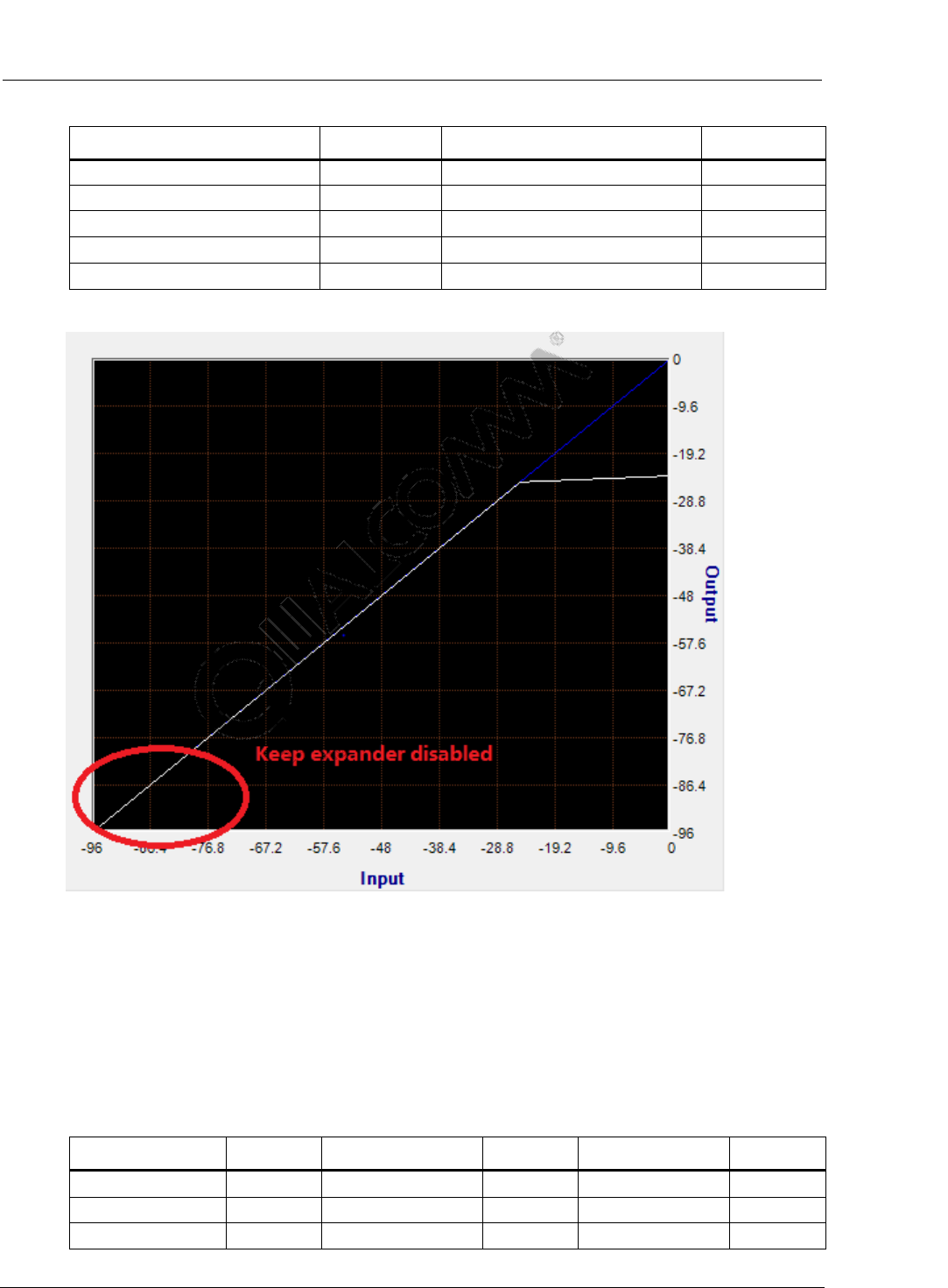
Common Audio Tuning Cases Introduction and Debugging Debugging Guide WB Inside-Speech Noise Tuning
80-NV213-6 Rev. A Confidential and Proprietary – Qualcomm Technologies, Inc. 61
MAY CONTAIN U.S. AND INTERNATIONAL EXPORT CONTROLLED INFORMATION
Parameter
Value
Parameter
Value
dnExpaSlopeL16Q8
0Xff93
dnCompAttackUL32Q31
0x5FA2F3B3
dnExpaHysterisisUL16Q14
0x4000
dnCompReleaseUL32Q31
0x5FA2F3B3
dnExpaAttackUL32Q31
0x5FA2F3B3
dnCompSlopeUL16Q16
0xF333
dnExpaReleaseUL32Q31
0x5FA2F3B3
dnCompHysterisisUL16Q14
0x4000
dnExpaMinGainDBL32Q23
0x0
Figure 12-4 DRC Setting – Keep Expander Disable
12.5 FENS Parameters
The only one that need to be tuned is VOICE_FNS_PARAM.fnsTargetNS. A good range for it is
be [0x1400, 0x2000].
Table 12-3 FENS Default Parameters
Parameter
Value
Parameter
Value
Parameter
Value
fnsMode
0xF6
fnsGsBias
0x0
alphaSNR
0x0CCE
fnsInputGain
0x2000
fnsGsMax
0x07D0
snrDiffMax
0x0C00
fnsOutputGain
0x2000
fnsSalphaHB
0x1800
snrDiffMin
0x0A00

Common Audio Tuning Cases Introduction and Debugging Debugging Guide WB Inside-Speech Noise Tuning
80-NV213-6 Rev. A Confidential and Proprietary – Qualcomm Technologies, Inc. 62
MAY CONTAIN U.S. AND INTERNATIONAL EXPORT CONTROLLED INFORMATION
Parameter
Value
Parameter
Value
Parameter
Value
fnsTargetNS
0x1800
fnsNalphaMaxHB
0x1000
initLength
0x64
fnsSalpha
0x0500
fnsEalphaHB
0x0
maxVal
0x0288
fnsNalpha
0x0500
fnsNLambda0
0x7FFF
initBound
0x0A
fnsNalphaMax
0x0500
fnsGsFast
0x2666
resetBound
0x0122
fnsEalpha
0x0
fnsGsMed
0x599A
avarScale
0x2000
fnsNSNRmax
0x1400
fnsGsSlow
0x7333
sub_Nc
0x19
fnsSNblock
0x32
fnsSwbNalpha
0x0
spowMin
0x051E
fnsNi
0x64
fnsSwbSalpha
0x1000
fnsNPscale
0x0A00
thresh
0x4000
fnsNLambda
0x7EB8
pwrScale
0x0100
fnsNLambdaf
0x7FE0
hangoverMax
0x05

80-NV213-6 Rev. A Confidential and Proprietary – Qualcomm Technologies, Inc. 63
MAY CONTAIN U.S. AND INTERNATIONAL EXPORT CONTROLLED INFORMATION
A Audio Tuning Tips
A.1 Enable/Disable Fluence (SW setting)
Adb commands:
Set to single MIC:
adb shell setprop ro.qc.sdk.audio.fluencetype none
Set to dual MIC:
adb shell setprop ro.qc.sdk.audio.fluencetype fluence
adb shell setprop persist.audio.fluence.voicecall true
adb shell setprop persist.audio.fluence.voicerec true
adb shell setprop persist.audio.fluence.speaker true
Change Code:
/device/qcom/msmxxxx/system.prop
rc.qc.sdk.audio.fluencetype=fluencepro-->select different fluence
type
persist.audio.fluence.voicecall=true select true/false for your
selection
persist.audio.fluence.voicerec=false -> select true/false for your
selection
persist.audio.fluence.speaker=true -> select true/false for your
selection
Recompile and update system.img

Common Audio Tuning Cases Introduction and Debugging Debugging Guide WB Inside-Speech Noise Tuning
80-NV213-6 Rev. A Confidential and Proprietary – Qualcomm Technologies, Inc. 64
MAY CONTAIN U.S. AND INTERNATIONAL EXPORT CONTROLLED INFORMATION
A.2 Check DSP version and updated DSP image
Check adsp version
For platform with ADSP, such as 8x10/8960/8974/8926/8994, getting adsp version is
below:
adb shell
adb pull /firmware/image/adsp.b04
strings adsp.b04 | grep “Q6_BUILD”
If platform without ADSP but with MDSP, such as 8916/8936/8939, getting adsp version
is below:
adb shell
adb pull /firmware/image/modem.b20
strings modem.b20 | grep “MPSS.DPM”
Change adsp image:
Recently we mount the adspso.bin as RO due to SELinux/OTA reason.
Going forward, update the adsp image, please also mount the dsp folder highlighted in
yellow.
adb root
adb wait-for-device
adb remount
adb shell mount -o remount,rw /firmware
adb shell mount -o remount,rw /dsp //// -> this is new
adb shell rm /firmware/image/adsp*
adb shell rm /dsp/*
adb push adsp_proc\obj\qdsp6v5_ReleaseG\LA\system\etc\firmware
/firmware/image
adb push adsp_proc\build\dynamic_signed\shared_obj /dsp
adb shell sync
adb reboot

Common Audio Tuning Cases Introduction and Debugging Debugging Guide WB Inside-Speech Noise Tuning
80-NV213-6 Rev. A Confidential and Proprietary – Qualcomm Technologies, Inc. 65
MAY CONTAIN U.S. AND INTERNATIONAL EXPORT CONTROLLED INFORMATION
A.3 Read/Write codec register
Read/Write codec register via adb commands:
adb root
adb remount
adb shell mount -t debugfs debugfs /sys/kernel/debug
adb shell
cd /sys/kernel/debug/asoc/msm####-xxxx-snd-card/xxxx_codec
Read: cat codec_reg
Write: echo " <Register Address > < value >" > codec_reg
Ex : Register Address : 0x121
Value to written : 0xA0
echo "0x121 0xA0" > codec_reg
Set ADIE Register via adb commands:
Configure ADIE Rigster via adb commands:
adb root
adb remount
adb shell “mount -t debugfs debugfs /sys/kernel/debug”
adb shell “chmod 777 /sys/kernel/debug/asoc/*-snd-
card/*_codec/codec_reg“
Connect with QACT ADIE, then set value.

Common Audio Tuning Cases Introduction and Debugging Debugging Guide WB Inside-Speech Noise Tuning
80-NV213-6 Rev. A Confidential and Proprietary – Qualcomm Technologies, Inc. 66
MAY CONTAIN U.S. AND INTERNATIONAL EXPORT CONTROLLED INFORMATION
A.4 Codec register Gain setting (Android KK and later)
In Android KK and later versions, all codec gains are saved in mixer_paths.xml. At audio tuning,
licensees set these codec gains on real-time mode via tinymix command. If get gain value, then
write to mixer_paths.xml.
1. WCD codec digital Gain settings
“RXn Digital Volume” (CDC_RXn_VOL_CTL_B2_CTL n= [1 -4])
“DECn Volume” (CDC_TXn_VOL_CTL_GAIN n= [1 -4])
“IIRn INPx Volume” (CDC_IIRn_GAIN_Bx_CTL n= [1 -2] x=[1-4])
These GAIN can be set from MIN 0 to MAX 124 as "value". Step size of 1dB. "0" means -
84dB, "84" means 0dB, and "124" means +40dB.
For example,
mixer_paths.xml volume setting
<ctl name="DEC1 Volume" value="84" />
Possible "value" range MIN : 0 (-84dB) MAX : 124 (0 dB) Step size : 1
(1dB)
tinymix Volume Command
tinymix "DEC1 Volume" value
value = 84 means 0dB
value = 0 means -84dB
value =124 means +40dB
2. WCD codec analog Gain settings,
“ADCn Volume” (TX_n_EN n=[1,2])
“LINEOUTn Volum” (RX_LINE_n_GAIN n= [1-2])
“HPHL Volume” (RX_HPH_L_GAIN)
“HPHR Volume” (RX_HPH_R_GAIN)
“EAR PA Gain” (RX_EAR_GAIN)
“SPK DRV Volume” (SPKR_DRV_GAIN)
a. ADC Volume
“ADCn Volume” (TX_n_EN n=[1,2]) Min Gain : 0 dB, Max Gain : +28.5dB
step size : 1.5dB
For example,

Common Audio Tuning Cases Introduction and Debugging Debugging Guide WB Inside-Speech Noise Tuning
80-NV213-6 Rev. A Confidential and Proprietary – Qualcomm Technologies, Inc. 67
MAY CONTAIN U.S. AND INTERNATIONAL EXPORT CONTROLLED INFORMATION
mixer_paths.xml volume setting
<ctl name="ADC1 Volume" value="19" />
Possible "value" range MIN : 0 (0dB) MAX : 19 (+28.5 dB) Step size :
1 (1.5dB)
tinymix Volume Command
tinymix "ADC1 Volume" value
value = 0 means 0dB
value = 19 means +28.5 dB
b. LINEOUT Volume
“LINEOUTn Volum” (RX_LINE_n_GAIN n= [1-2]) Min Gain : -30 dB, Max
Gain : +0 dB step size : 1.5dB
For example,
mixer_paths.xml volume setting
<ctl name="LINEOUT1 Volume" value="20" />
Possible "value" range MIN : 0 (-30dB) MAX : 20 (0 dB) Step size : 1
(1.5dB)
tinymix Volume Command
tinymix "LINEOUT1 Volume" value
value = 0 means -30dB
value = 20 means +0 dB
c. HeadPhone Volume
“HPHL Volume” (RX_HPH_L_GAIN), and “HPHR Volume” (RX_HPH_R_GAIN) Min
Gain : -30 dB, Max Gain : +0 dB step size : 1.5dB
Min Gain : -30 dB, Max Gain : +0 dB step size : 1.5dB
For example,
mixer_paths.xml volume setting
<ctl name="HPHL Volume" value="20" />
Possible "value" range MIN : 0 (-30dB) MAX : 20 (0 dB) Step size : 1
(1.5dB)

Common Audio Tuning Cases Introduction and Debugging Debugging Guide WB Inside-Speech Noise Tuning
80-NV213-6 Rev. A Confidential and Proprietary – Qualcomm Technologies, Inc. 68
MAY CONTAIN U.S. AND INTERNATIONAL EXPORT CONTROLLED INFORMATION
tinymix Volume Command
tinymix "HPHL Volume" value
value = 0 means -30 dB
value = 20 means +0 dB
d. EAR PA Volume
“EAR PA Gain” (RX_EAR_GAIN) Min Gain : 0 dB, Max Gain : 6dB step
size : 1.5dB
For example,
mixer_paths.xml volume setting
<ctl name="EAR PA Gain" value="POS_6_DB" />
Possilble "value" are POS_6_DB, POS_4P5_DB, POS_3_DB, POS_1P5_DB,
POS_0_DB
tinymix Volume Command
tinymix "EAR PA Gain" value
value = POS_6_DB means 6dB
value = POS_0_DB means 0 dB
e. Speaker Drive Volume
“SPK DRV Volume” (SPKR_DRV_GAIN) Min Gain : 0 dB, Max Gain : +28.5dB
step size : 1.5dB
For example,
mixer_paths.xml volume setting
<ctl name="SPK DRV Volume" value="POS_12_DB" />
Possilble "value" are POS_12_DB, POS_10P5_DB, POS_9_DB,
POS_7P5_DB, POS_6_DB, POS_4P5_DB, POS_3_DB, POS_1P5_DB, POS_0_DB
tinymix Volume Command
tinymix "SPK DRV Volume" value
value = POS_6_DB means 6dB
value = POS_0_DB means 0 dB

Common Audio Tuning Cases Introduction and Debugging Debugging Guide WB Inside-Speech Noise Tuning
80-NV213-6 Rev. A Confidential and Proprietary – Qualcomm Technologies, Inc. 69
MAY CONTAIN U.S. AND INTERNATIONAL EXPORT CONTROLLED INFORMATION
A.5 Audio Loopback Configuration
There are three loopbacks: Codec loopback, DSP AFE loopback and ALSA loopback.
Path configuration:
vendor/qcom/proprietary/mm-audio/audio_ftm/config/89xx/ftm_test_config
Before KK verision: used commands: amix/aplay/arec
After KK version: used commands: tinymix/tinyplay/tinycap
Take MSM8996 as an example:
Codec Loopback
Audio Signal Loopback Path :
audio signal input -> WCD93xx (AMIC/DMIC) -> WCD93xx ( IIR) -> Loopback ->
WCD93xx (RX Mixer Chain/DAC) ->audio signal output
Four modes
– Digital MIC1 to Handset
– Analog MIC1 to Handset
– DMIC1 to Speaker
– AMIC1 to Speaker
Example: Codec loopback from Headset Mic to headphone (Sidetone)
#tinymix 'ADC MUX6' 'AMIC'
#tinymix 'AMIC MUX6' 'ADC2'
#tinymix 'IIR0 INP0 MUX' 'DEC6'
#tinymix 'IIR0 INP0 Volume' 75
#tinymix 'ADC2 Volume' 18
#tinymix 'RX INT1 DEM MUX' 'CLSH_DSM_OUT'
#tinymix 'RX INT2 DEM MUX' 'CLSH_DSM_OUT'
#tinymix 'RX INT1 MIX2 INP' 'SRC0'
#tinymix 'RX INT2 MIX2 INP' 'SRC0'
// sidetone gain volume can be changed by chaning the IIR Gain Values.
tinymix 'IIR0 INP0 Volume' X
X Range - 0 to 124 , 0 means -84dB, 124 means +40dB
Max Gain - 40 dB
Min Gain - -84dB

Common Audio Tuning Cases Introduction and Debugging Debugging Guide WB Inside-Speech Noise Tuning
80-NV213-6 Rev. A Confidential and Proprietary – Qualcomm Technologies, Inc. 70
MAY CONTAIN U.S. AND INTERNATIONAL EXPORT CONTROLLED INFORMATION
AFE Loopback
Audio Signal Loopback Path :
audio signal input -> WCD93xx (AMIC/DMIC) -> Slimbus TX -> DSP AFE TX ->
Loopback -> DSP AFE RX -> Slimbus RX-> WCD93xx (RX Mixer Chain/DAC) -
>audio signal output
Steps:
i Enable the TX and RX devices using amixer commands
(a) Enable TX device
(b) Enable RX device
(c) Connect the Front End and Back End.
#tinymix ‘SLIMBUS_DL_HL Switch’ 1
ii Enable the DSP Loopback between SLIMBUS_0_TX and SLIMBUS_0_RX
#tinymix 'SLIMBUS_0_RX Port Mixer SLIM_0_TX' 1
iii Stop the hostless playback and recording
#tinyhostless -D 0 -P 5 -C 5 -p 8 -n 2 -c 1 -r 48000
TinyALSA loopback
Audio Signal Loopback Path :
audio signal input -> WCD93xx (AMIC/DMIC) -> Slimbus TX -> DSP AFE TX ->
ALSA Recording -> Loopback -> ALSA Playback -> DSP AFE RX -> Slimbus RX->
WCD93xx (RX Mixer Chain/DAC) ->audio signal output
For testing the ALSA loopback, Enable the TX and RX devices and run the ALSA loopback
command
adb shell tinyhostless -P 0 -C 0 -p 640 -n 2 -c 2 -r 48000 -L 1
NOTE: Please create a case for getting the tinyhostless source code. in the release builds, tinyhostless not
available.
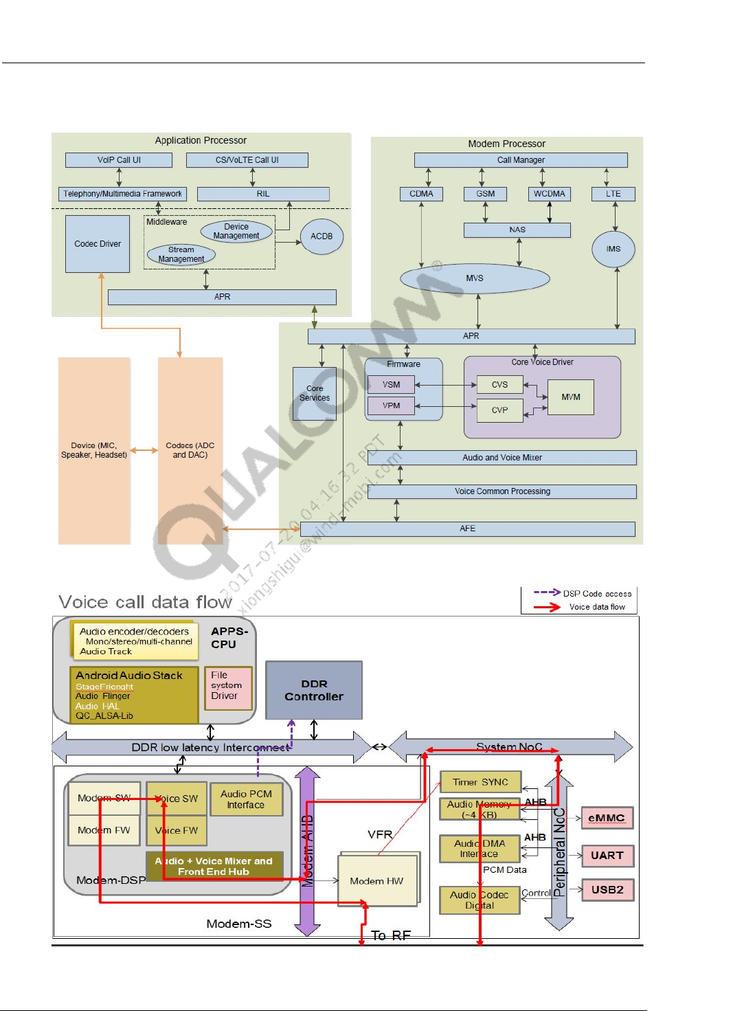
Common Audio Tuning Cases Introduction and Debugging Debugging Guide WB Inside-Speech Noise Tuning
80-NV213-6 Rev. A Confidential and Proprietary – Qualcomm Technologies, Inc. 71
MAY CONTAIN U.S. AND INTERNATIONAL EXPORT CONTROLLED INFORMATION
A.6 Location of Audio Issue
Figure A-1 Voice Structure
Figure A-2 Voice Call Data Flow
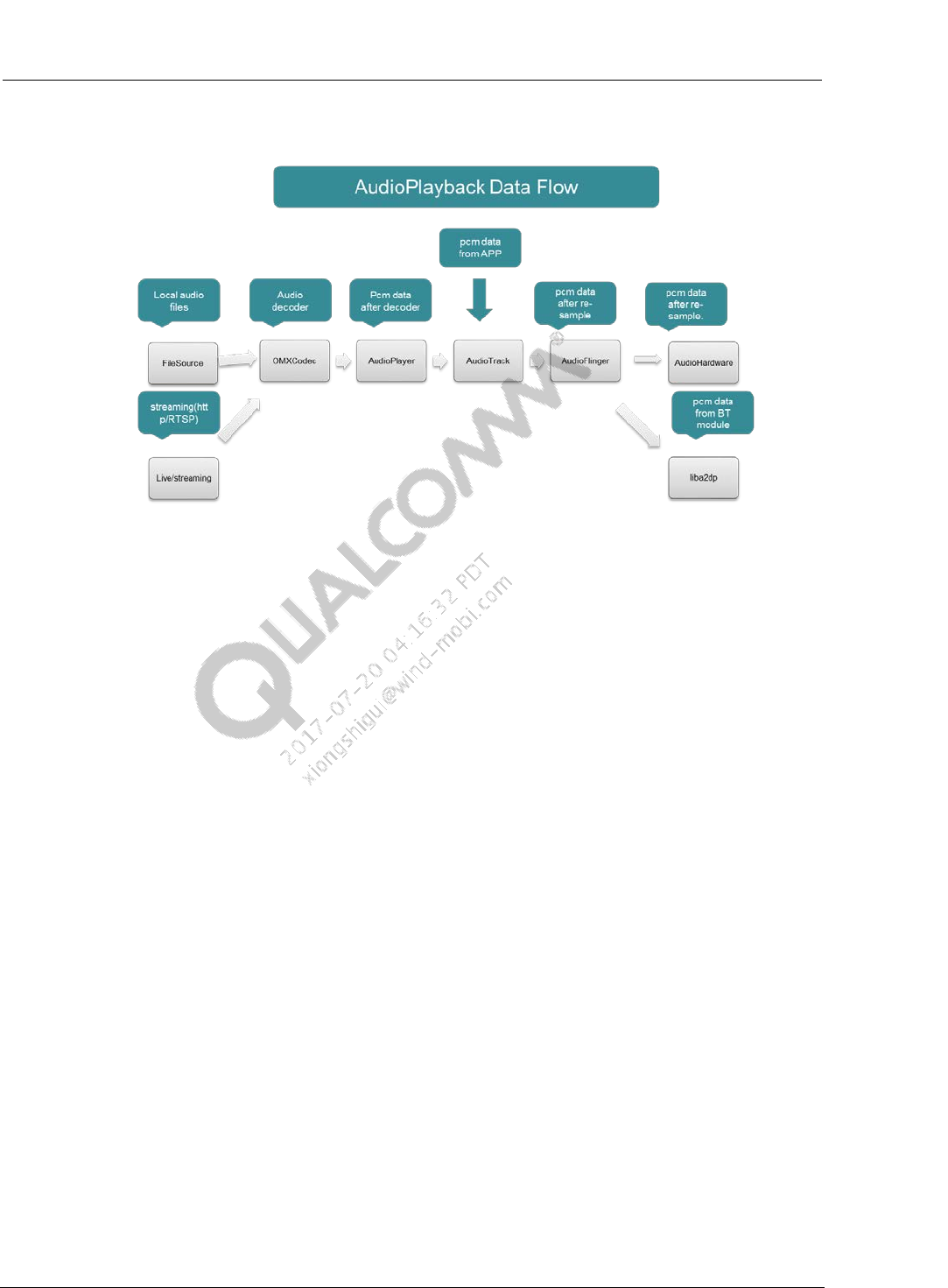
Common Audio Tuning Cases Introduction and Debugging Debugging Guide WB Inside-Speech Noise Tuning
80-NV213-6 Rev. A Confidential and Proprietary – Qualcomm Technologies, Inc. 72
MAY CONTAIN U.S. AND INTERNATIONAL EXPORT CONTROLLED INFORMATION
Figure A-3 Audio Playback Data Flow
Location of Audio SW Issue and Audio Tuning Issue
For Voice:
– Due to different platform, voice structure and data flow have a little differences. Now
give one sample. Voice process flow is below:
• TX_Path: Microphone -> A/D convert(Codec) -> audio (DSP) -> mixer- >
protocol-> RF
• RX_Path:RF -> protocol -> audio splitter(Audio/Voice) -> audio(DSP) -> D/A
convert(Codec) -> Speaker/Receiver
– Location of Voice issue need to combine voice structure and data flow.
For Audio
– After analyze flow of Android Audio Playback, it is helpful to locate issue, such as
playback audio/video, audio chopping, and noise, etc. Locate issue via dump audio
data of each point.
– After dump pcm data of SW AudioHardware, know the issue is belong to audio sw or
audio tuning.
– For speaker, earphones, headset, use below steps to dump data.
(a) #cd /data
(b) #touch dump.pcm
(c) Add patch on next page to code.
(d) Make audio.primary.msmxxxx.so, push to phone;

Common Audio Tuning Cases Introduction and Debugging Debugging Guide WB Inside-Speech Noise Tuning
80-NV213-6 Rev. A Confidential and Proprietary – Qualcomm Technologies, Inc. 73
MAY CONTAIN U.S. AND INTERNATIONAL EXPORT CONTROLLED INFORMATION
(e) Reproduce issue.
(f) Adb pull /data/dump.pcm .
(g) Using Audition/CoolEdit to check pcm file of dump if exist reported symptom. If
have, it is possible for audio sw issue.
Example PCM dump patch:
ssize_t AudioStreamOutALSA::write(const void *buffer, size_t bytes)
{
...
ALOGV("write:: buffer %p, bytes %d", buffer, bytes);
int tmpFd;
size_t count = bytes;
const uint8_t* p = static_cast<const uint8_t*>(buffer);
tmpFd = ::open("/data/dump.pcm", O_WRONLY | O_APPEND );
if ( tmpFd < 0 ) {
ALOGE("No dump file");
} else {
::write(tmpFd, p, count);
::close(tmpFd);
}
...
}

Common Audio Tuning Cases Introduction and Debugging Debugging Guide WB Inside-Speech Noise Tuning
80-NV213-6 Rev. A Confidential and Proprietary – Qualcomm Technologies, Inc. 74
MAY CONTAIN U.S. AND INTERNATIONAL EXPORT CONTROLLED INFORMATION
A.8 FM Volume Setting
Modify CodecRxGain in DSP to change FM volume. Because Audio Record Path also use
CodecRxGain, this change will affect recording volume.
Change code:
In kernel/sound/soc/msm/qdsp6v2/msm-pcm-routing-v2.h,
- #define INT_RX_VOL_MAX_STEPS 0x2000
+ #define INT_RX_VOL_MAX_STEPS 0x4000
- #define INT_RX_VOL_GAIN 0x2000
+ #define INT_RX_VOL_GAIN 0x4000
In hardware/qcom/audio/hal/audio_extn/fm.c,
static int32_t fm_set_volume(struct audio_device *adev, float value, bool persist)
{
...
}
- vol = lrint((value * 0x2000) + 0.5);
+ vol = lrint((value * 0x4000) + 0.5);
if (persist)
fmmod.fm_volume = value;
if (!fmmod.is_fm_running) {
ALOGV("%s: FM not active, ignoring set_fm_volume call",
__func__);
return -EIO;
}
…
}
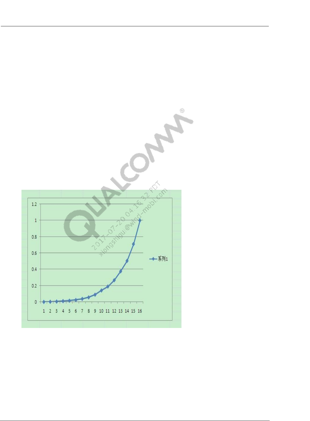
Common Audio Tuning Cases Introduction and Debugging Debugging Guide WB Inside-Speech Noise Tuning
80-NV213-6 Rev. A Confidential and Proprietary – Qualcomm Technologies, Inc. 75
MAY CONTAIN U.S. AND INTERNATIONAL EXPORT CONTROLLED INFORMATION
A.9 Volume Debugging of Music Playback
Change the volume curve to change the volume setting of voice call/system sound/ring
tone/music playback/alarm/notification/Bluetooth SCO/DTMF/TTS.
Take music playback as an example, modify codes as shown in below:
hardware/libhardware_legacy/audio/AudioPolicyManagerBase.cpp
const AudioPolicyManagerBase::VolumeCurvePoint
AudioPolicyManagerBase::sDefaultMediaVolumeCurve
[AudioPolicyManagerBase::VOLCNT] = {
- {1, -58.0f}, {20, -40.0f}, {60, -17.0f}, {100, 0.0f}
//To increase the lowest volume step
+ {1, -29.7f}, {20, -20.1f}, {60, -17.0f}, {100, 0.0f}
};
NOTE: there are 15 levels volume for Music playback, convert to 100 levels:100 levels = 100*index/15,
minimum to maximum is for 6,13,20, 26, 33,40, 46, 53, 60, 66, 73, 80, 86, 93, 100. According to
figure on right, it is easy to find decibel based on index.
Figure Audio Volume Curve

80-NV213-6 Rev. A Confidential and Proprietary – Qualcomm Technologies, Inc. 76
MAY CONTAIN U.S. AND INTERNATIONAL EXPORT CONTROLLED INFORMATION
B References
B.1 Related documents
Title Number
Qualcomm Technologies, Inc.
Audio_Tuning_Handbook_English_and_Simplified_Chinese 80-NV213-1EC
Adaptive Input Gain Audio Tuning Guide 80-N2736-1
DRC_Audio_Tuning_Guide 80-N2719-1
Multiband_Audio_Dynamic_Range_Control 80-VN476-1
Far-End_Noise_Supression 80-VU805-1
EEC_Noice_Suppress_Tuning CL93-V1638-2
Fluence_V5_Acoustic_Echo_Cancellation_Audio_Tuning_Training 80-NK880-2
Fluence_v5_Noise_Suppression_Audio_Tuning_Training 80-NK880-3
Vocoder-Dependent_Tuning_Quick_Start_Guide 80-NV356-1
Hexagon_DSP_Audio_PCM-Bitstream_Logging 80-N3470-4
Single_Mic_Echo_Cancellation_and_Noise_Suppression_v2_Audio_Tuning
_Guide 80-NK910-3
Fluence_Dual-Mic_Echo_Noise_Suppression_Audio_Tuning 80-N3410-2
Wide_Voice_Enhancement 80-VU826-1
eAMR_HD-Voice_over_AMR-NB 80-NA480-1
B.2 Acronyms and terms
Acronym or term Definition
ECNS Echo Cancellation and Noise Suppression
EC Echo Cancellation
EEC Enhanced Echo Cancellation
NS Noise Suppression
DRC Dynamic Range Control
MBDRC Multi-band Dynamic Range Control
RMS Root Mean Square
FNS Far-end Noise Suppression
ADC Analog Digital Converter
AIG Adaptive Input Gain
PVC Per-vocoder Calibration

Debugging Guide References
80-NV213-6 Rev. A Confidential and Proprietary – Qualcomm Technologies, Inc. 77
MAY CONTAIN U.S. AND INTERNATIONAL EXPORT CONTROLLED INFORMATION
Acronym or term Definition
IIR Infinite Impulse Response
SMECNS Single Mic Echo Cancellation and Noise Suppression
MOS Mean Opinion Score
BWE Band Width Extension
