UEFI PMIC Software User Guide 80 P2484 42
User Manual: Pdf
Open the PDF directly: View PDF ![]() .
.
Page Count: 39
- UEFI PMIC Software User Guide
- Revision history
- Contents
- 1 Introduction
- 2 Overview
- 3 UEFI PMIC software drivers
- 4 UEFI QTI charger app LA configuration
- 4.1 QTI charger app configuration file
- 4.2 Debug overwrite feature
- 4.3 Configuration quick reference
- 4.4 Threshold charging configuration
- 4.5 Debug configuration
- 4.6 FG and FG debug configuration
- 4.7 Initial required charger configuration
- 4.7.1 BootToHLOSThresholdInMv
- 4.7.2 OsStandardBootSocThreshold
- 4.7.3 BattVoltLimHighDelta
- 4.7.4 ChgFvMax
- 4.7.5 ChgFccMax
- 4.7.6 ChargingTermCurrent
- 4.7.7 ConservChgFvDelta
- 4.7.8 BATT_THERM coefficients
- 4.7.9 AUX_THERM coefficients
- 4.7.10 Device skin and charger hot thresholds
- 4.7.11 EmergencyShutdownVbatt
- 4.7.12 EnableChargerWdog
- 4.7.13 VBtEmpty threshold
- 4.7.14 VBattEstDiffThreshold
- 4.8 Battery error handling configuration
- 4.9 Jeita configuration
- 4.10 WiPower configuration
- 4.11 Thermal configuration
- 4.12 Example configuration file
- 5 QTI charger app WP configuration
- A References
Qualcomm Technologies, Inc.
Confidential and Proprietary – Qualcomm Technologies, Inc.
NO PUBLIC DISCLOSURE PERMITTED: Please report postings of this document on public servers or websites to:
DocCtrlAgent@qualcomm.com.
Restricted Distribution: Not to be distributed to anyone who is not an employee of either Qualcomm Technologies, Inc. or its
affiliated companies without the express approval of Qualcomm Configuration Management.
Not to be used, copied, reproduced, or modified in whole or in part, nor its contents revealed in any manner to others without the
express written permission of Qualcomm Technologies, Inc.
Qualcomm is a trademark of Qualcomm Incorporated, registered in the United States and other countries. Other product and brand
names may be trademarks or registered trademarks of their respective owners.
This technical data may be subject to U.S. and international export, re-export, or transfer (“export”) laws. Diversion contrary to U.S.
and international law is strictly prohibited.
Qualcomm Technologies, Inc.
5775 Morehouse Drive
San Diego, CA 92121
U.S.A.
© 2016 Qualcomm Technologies, Inc. All rights reserved.
UEFI PMIC Software
User Guide
80-P2484-42 A
December 12, 2016
80-P2484-42 A Confidential and Proprietary – Qualcomm Technologies, Inc. 2
MAY CONTAIN U.S. AND INTERNATIONAL EXPORT CONTROLLED INFORMATION
Revision history
Revision
Date
Description
A
December 2016
Initial release
Note: There is no Rev. I, O, Q, S, X, or Z per Mil. standards.

80-P2484-42 A Confidential and Proprietary – Qualcomm Technologies, Inc. 3
MAY CONTAIN U.S. AND INTERNATIONAL EXPORT CONTROLLED INFORMATION
Contents
1 Introduction ...................................................................................................... 6
1.1 Purpose.......................................................................................................................... 6
1.2 Conventions .................................................................................................................. 6
1.3 Technical assistance ...................................................................................................... 6
2 Overview........................................................................................................... 7
2.1 Protocol ......................................................................................................................... 7
2.1.1 Example – Locate a protocol ............................................................................. 7
2.1.2 Example – Use the located protocol .................................................................. 8
2.2 INF file setting .............................................................................................................. 8
2.2.1 Example – RealTimeClockLib.inf ..................................................................... 8
2.2.2 Example – PmicDxe.inf ..................................................................................... 8
3 UEFI PMIC software drivers ............................................................................ 9
3.1 Core ............................................................................................................................. 12
3.2 User interface .............................................................................................................. 12
3.3 UEFI charger app ........................................................................................................ 13
3.3.1 PmicDxe .......................................................................................................... 13
3.3.2 ChargerLib ....................................................................................................... 14
3.3.3 QTI charger app ............................................................................................... 14
4 UEFI QTI charger app LA configuration ...................................................... 16
4.1 QTI charger app configuration file ............................................................................. 16
4.2 Debug overwrite feature ............................................................................................. 16
4.3 Configuration quick reference .................................................................................... 19
4.4 Threshold charging configuration ............................................................................... 23
4.4.1 SocOrVoltageBaseBoot ................................................................................... 23
4.4.2 LoadBatteryProfile .......................................................................................... 23
4.4.3 DispSignOfLifeMaxThresholdMv................................................................... 23
4.4.4 FgCondRestart ................................................................................................. 23
4.4.5 ChargerLedConfig ........................................................................................... 24
4.5 Debug configuration ................................................................................................... 24
4.5.1 PrintChargerAppDbgMsg ................................................................................ 24
4.5.2 PrintChargerAppDbgMsgToFile ..................................................................... 24
4.5.3 EnableChargerFGDump .................................................................................. 25
4.6 FG and FG debug configuration ................................................................................. 25
4.6.1 BatteryIdTolerance .......................................................................................... 25
4.6.2 DumpSram ....................................................................................................... 25
4.6.3 DumpSramStartAddr ....................................................................................... 25

UEFI PMIC Software User Guide Contents
80-P2484-42 A Confidential and Proprietary – Qualcomm Technologies, Inc. 4
MAY CONTAIN U.S. AND INTERNATIONAL EXPORT CONTROLLED INFORMATION
4.6.4 DumpSramEndAddr ........................................................................................ 25
4.6.5 DumpSramDuration ......................................................................................... 25
4.7 Initial required charger configuration ......................................................................... 26
4.7.1 BootToHLOSThresholdInMv .......................................................................... 26
4.7.2 OsStandardBootSocThreshold ......................................................................... 26
4.7.3 BattVoltLimHighDelta .................................................................................... 26
4.7.4 ChgFvMax ....................................................................................................... 26
4.7.5 ChgFccMax...................................................................................................... 26
4.7.6 ChargingTermCurrent ...................................................................................... 26
4.7.7 ConservChgFvDelta ........................................................................................ 26
4.7.8 BATT_THERM coefficients ........................................................................... 27
4.7.9 AUX_THERM coefficients ............................................................................. 27
4.7.10 Device skin and charger hot thresholds ......................................................... 27
4.7.11 EmergencyShutdownVbatt ............................................................................ 28
4.7.12 EnableChargerWdog ...................................................................................... 28
4.7.13 VBtEmpty threshold ...................................................................................... 28
4.7.14 VBattEstDiffThreshold .................................................................................. 28
4.8 Battery error handling configuration .......................................................................... 28
4.8.1 DebugBoardBatteryIdMin and DebugBoardBatteryIdMax ............................. 28
4.8.2 SmartBatteryIdMin and SmartBatteryIdMax .................................................. 29
4.8.3 RegularBatteryIdMin and RegularBatteryIdMax ............................................ 29
4.8.4 UnknownBatteryBehavior ............................................................................... 29
4.8.5 DebugBoardBehavior ...................................................................................... 29
4.8.6 BattMissingCfg ................................................................................................ 29
4.9 Jeita configuration ....................................................................................................... 30
4.9.1 Jeita zones ........................................................................................................ 30
4.9.2 JeitaCcCompCfg .............................................................................................. 30
4.9.3 JeitaFvCompCfg .............................................................................................. 30
4.9.4 NoChargeAndWait .......................................................................................... 30
4.10 WiPower configuration ............................................................................................. 31
4.10.1 WiPowerSupported ........................................................................................ 31
4.10.2 DCInBootToHLOSThresholdInMv ............................................................... 31
4.10.3 SuspendDCIn ................................................................................................. 31
4.11 Thermal configuration .............................................................................................. 31
4.11.1 SWThermalMitigationEnable ........................................................................ 31
4.11.2 TsensTimeoutMins ........................................................................................ 31
4.11.3 Tsens limits or zone ....................................................................................... 31
4.12 Example configuration file ....................................................................................... 32
5 QTI charger app WP configuration .............................................................. 38
A References ..................................................................................................... 39
A.1 Related documents ..................................................................................................... 39
A.2 Acronyms and terms .................................................................................................. 39

UEFI PMIC Software User Guide Contents
80-P2484-42 A Confidential and Proprietary – Qualcomm Technologies, Inc. 5
MAY CONTAIN U.S. AND INTERNATIONAL EXPORT CONTROLLED INFORMATION
Figures
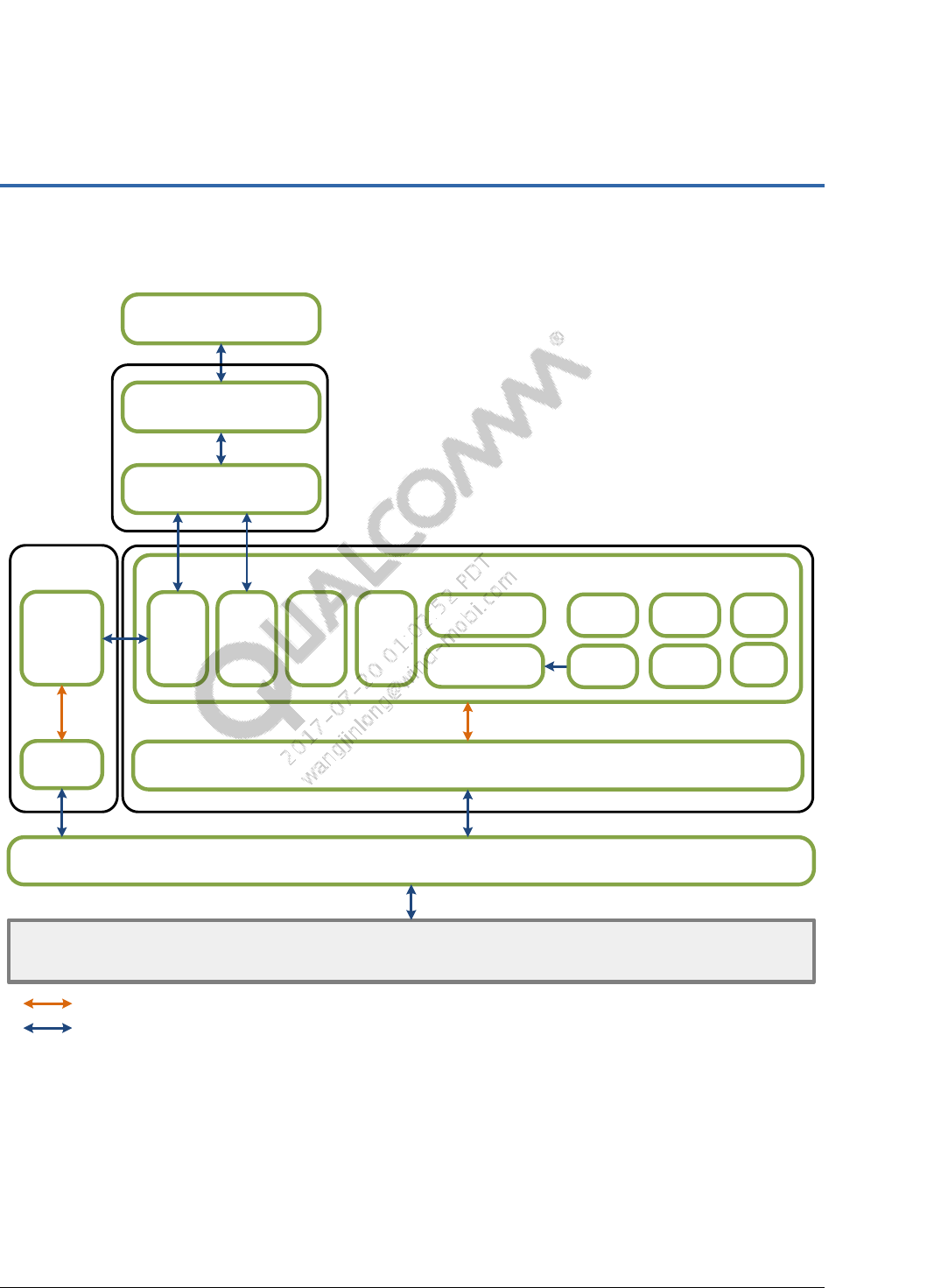
Figure 3-1 PMIC software stack .................................................................................................................. 9
Figure 3-2 Display driver and PMIC driver flow ...................................................................................... 12
Figure 3-3 UEFI charger app design ........................................................................................................... 13
Figure 3-4 QTI charger app call flow ........................................................................................................ 14
Tables
Table 3-1 UEFI PMIC drivers ................................................................................................................... 10
Table 3-2 UEFI PMIC protocols ................................................................................................................ 10
Table 3-3 QTI charger app functions ......................................................................................................... 15
Table 4-1 Configuration quick reference ................................................................................................... 19

80-P2484-42 A Confidential and Proprietary – Qualcomm Technologies, Inc. 6
MAY CONTAIN U.S. AND INTERNATIONAL EXPORT CONTROLLED INFORMATION
1 Introduction
1.1 Purpose
This document provides an overview of unified extensible firmware interface (UEFI) PMIC
software drivers, battery management application, and battery charging configuration.
1.2 Conventions
Function declarations, function names, type declarations, attributes, and code samples appear in a
different font, for example, #include.
Button and key names appear in bold font, for example, click Save or press Enter.
1.3 Technical assistance
For assistance or clarification on information in this document, submit a case to Qualcomm
Technologies, Inc. (QTI) at https://createpoint.qti.qualcomm.com/.
If you do not have access to the CDMATech Support website, register for access or send email to
support.cdmatech@qti.qualcomm.com.

80-P2484-42 A Confidential and Proprietary – Qualcomm Technologies, Inc. 7
MAY CONTAIN U.S. AND INTERNATIONAL EXPORT CONTROLLED INFORMATION
2 Overview
The UEFI specification defines a set of platform-independent APIs to enable the following:
Interaction between the platform firmware and the operating system/OS loader
Loading, installing, and executing drivers in a pre-OS environment
Cross-platform portability for UEFI applications
2.1 Protocol
Protocol is a set of software interfaces used for communication between two binary modules.
NOTE: Each protocol must have a specification that includes the protocol GUID and its interface
structure.
Driver dependencies
Defined in the driver INF file
Loaded and processed during system initialization
Protocol usage
To use the interfaces from other modules, the module must locate the protocols through
GUIDs during module initialization
To expose the interface for other modules, the module must install the protocol during
module initialization
2.1.1 Example – Locate a protocol
The following example demonstrates how to locate the protocol.
/* Interface for the protocol to access the RTC */
EFI_QCOM_PMIC_PWRON_PROTOCOL *pmic_pwron;
…
Status = gBS->LocateProtocol(&gQcomPmicPwrOnProtocolGuid, NULL, (VOID**)
&pmic_pwron);

UEFI PMIC Software User Guide Overview
80-P2484-42 A Confidential and Proprietary – Qualcomm Technologies, Inc. 8
MAY CONTAIN U.S. AND INTERNATIONAL EXPORT CONTROLLED INFORMATION
2.1.2 Example – Use the located protocol
The following example demonstrates how to use the interface after the protocol is located.
EFI_STATUS Status;
…
Status = pmic_pwron->GetPonPblStatus (0,
EFI_PM_PWRON_PON_PBL_STATUS_XVDD_RB_OCCURRED,&pmicWasBatteryRemoved);
2.2 INF file setting
The INF file is used to specify the sources and dependencies for a module.
2.2.1 Example – RealTimeClockLib.inf
For any module requiring a PMIC resource, the related protocol GUID must be included in the
INF file.
…
[Protocols]
gQcomPmicRtcProtocolGuid
gQcomPmicPwrOnProtocolGuid
…
2.2.2 Example – PmicDxe.inf
INF enables linking a module to the library.
…
[LibraryClasses]
BaseMemoryLib
PmicLib
…
80-P2484-42 A Confidential and Proprietary – Qualcomm Technologies, Inc. 9
MAY CONTAIN U.S. AND INTERNATIONAL EXPORT CONTROLLED INFORMATION
3 UEFI PMIC software drivers
PmicDxe
CHGFG
QcomChargerDxe
AdcLib PmicLib
PMIC hardware
SPMIDxe
AdcDxe RGB
LED
Internal library call
MIPI
BIF LPG
RTC
CLK WLED
VREGHaptic
Protocol
PON
GPIO
QcomChargerApp
ChargerLib
Figure 3-1 PMIC software stack

UEFI PMIC Software User Guide Contents
80-P2484-42 A Confidential and Proprietary – Qualcomm Technologies, Inc. 10
MAY CONTAIN U.S. AND INTERNATIONAL EXPORT CONTROLLED INFORMATION
Table 3-1 UEFI PMIC drivers
Driver
Source path
Functionality
AdcDxe
<src root> \uefi\edk2\QcomPkg\
Drivers\AdcDxe
Provides abstraction of ADC functionality through
protocols
Not platform-specific
AdcLib
<src root> \uefi\edk2\QcomPkg\
Library\AdcLibB
Implements register-level access of ADC functionalities
Platform-specific
QcomChargerDxe
<src root> \uefi\edk2\QcomPkg\
Drivers\QcomChargerDxe
Provides abstraction of charging and gauge
functionality of the system
Interface between Microsoft® UEFI charger applications
or other high-level UEFI applications (such as FLASH)
Battery management customization
PmicShutdownLib
<src root> \uefi\edk2\QcomPkg\
Library\PmicShutdownLib
Implementation of boot time and runtime
shutdown/reset functionality
PmicDxe
<src root> \uefi\edk2\QcomPkg\
Drivers\PmicDxe
Provides abstraction of most PMIC functionalities
through protocols (see Section 3.3.1)
Not platform-specific
PmicLib
<src root> \uefi\edk2\QcomPkg\
Library\PmicLib
Implements register-level access of PMIC functionality
Platform-specific
SPMIDxe
<src root> \uefi\edk2\QcomPkg\
Drivers\SPMIDxe
Implementation of SPMI communication with PMIC
Each header file listed in Table 3-2 is located in the following path:
< src root>\uefi\edk2 \QcomPkg\Include\Protocol\
Table 3-2 UEFI PMIC protocols
PMIC protocols
Header file
Usage
PMIC_CLKBUFF_PROTOCOL
EFIPmicClkBuff.h
Protocol for the PMIC CLK buffer
PMIC_GPIO_PROTOCOL
EFIPmicGpio.h
Protocol for PMIC GPIO
PMIC_IBB_PROTOCOL
EFIPmicIbb.h
Protocol for PMIC IBB
PMIC_LAB_PROTOCOL
EFIPmicLab.h
Protocol for PMIC LAB
PMIC_LPG_PROTOCOL
EFIPmicLpg.h
Protocol for PMIC LPG
PMIC_MIPIBIF_PROTOCOL
EFIPmicMipiBif.h
Protocol for PMIC MipiBif
PMIC_MPP_PROTOCOL
EFIPmicMpp.h
Protocol for PMIC MPP
PMIC_PWM_PROTOCOL
EFIPmicPwm.h
Protocol for PMIC PWM
PMIC_PWRON_PROTOCOL
EFIPmicPwrOn.h
Protocol for PMIC PON
PMIC_RGB_LED_PROTOCOL
EFIPmicRgbLed.h
Protocol for PMIC RGB
PMIC_RTC_PROTOCOL
EFIPmicRTC.h
Protocol for PMIC RTC
PMIC_SCHG_PROTOCOL
EFIPmicSchg.h
Protocol for PMIC SCHG
PMIC_FG_PROTOCOL
EFIPmicFg.h
Protocol for PMIC FG
PMIC_VIB_PROTOCOL
EFIPmicVib.h
Protocol for PMIC VIB
PMIC_VREG_PROTOCOL
EFIPmicVreg.h
Protocol for PMIC LPG
PMIC_PWM_PROTOCOL
EFIPmicPwm.h
Protocol for PMIC VREG
PMIC_WLED_PROTOCOL
EFIPmicWled.h
Protocol for PMIC WLED
UEFI PMIC Software User Guide UEFI PMIC software drivers
80-P2484-42 A Confidential and Proprietary – Qualcomm Technologies, Inc. 11
MAY CONTAIN U.S. AND INTERNATIONAL EXPORT CONTROLLED INFORMATION
Sample code – UEFI PMIC driver call flow
@RealTimeLib
@PmicDxe
EFI_QCOM_PMIC_PWRON_PROTOCOL *pmic_pwron;
Status = gBS->LocateProtocol(&gQcomPmicPwrOnProtocolGuid, NULL, (VOID**)
&pmic_pwron;
Status = pmic_pwron->GetPonPblStatus (
RTCInternal.nPmicIndex,
EFI_PM_PWRON_PON_PBL_STATUS_XVDD_RB_OCCURRED,
&pmicWasBatteryRemoved);
EFI_QCOM_PMIC_PWRON_PROTOCOL
PmicPwronProtocolImplementation =
{
PMIC_PWRON_REVISION,
…
EFI_PmicPwronGetPonPblStatus,
};
struct _EFI_QCOM_PMIC_PWRON_PROTOCOL {
UINT32 Revision;
…
EFI_PM_PWRON_GET_PON_PBL_STATUS GetPonPblStatus;
};
EFI_STATUS EFIAPI EFI_PmicPwronGetPonPblStatus
(
IN UINT32 PmicDeviceIndex,
IN EFI_PM_PWRON_PON_PBL_STATUS_TYPE PblStatusType,
OUT BOOLEAN *Status
)
{
…
errFlag = pm_pon_pbl_status_get(PmicDeviceIndex,
(pm_pwron_pon_pbl_status_type)PblStatusType, Status);
…
return EFI_SUCCESS;
}
@PmicLib
pm_err_flag_type pm_pon_pbl_status_get(unsigned pmic_device_index,
pm_pwron_pon_pbl_status_type pbl_status_type, boolean *status)
{
…
return ((pm_pwron_data_type*)mappedResource)->ipwron_get_pon_pbl_status(
mappedResource,
pbl_status_type, status,
(uint8)resourceIndex);
…
}
pmiC_PmicResource* pm_pwron_driver_init( pmiC_PmicDevice *device )
{
...
pmiC_PmicResource_Init(pwron, PWRON_ModuleType, device);
…
((pm_pwron_data_type*)pwron)->ipwron_get_pon_pbl_status
= pm_pwron_get_pon_pbl_status_alg;
...
}

UEFI PMIC Software User Guide Contents
80-P2484-42 A Confidential and Proprietary – Qualcomm Technologies, Inc. 12
MAY CONTAIN U.S. AND INTERNATIONAL EXPORT CONTROLLED INFORMATION
3.1 Core
No OS-level interrupt support
UEFI is a single thread OS
Cannot register the Interrupt service routine for PMIC interrupt
PMIC interrupt can be enabled to detect an event through the latched status bit
Interrupts enabled in UEFI must be disabled before booting to HLOS to prevent unknown
wakeup activities in the HLOS
Timer or timer-callback can be used as alternatives
No XO shutdown or deep sleep
Not supported due to framework limitation
Improves power efficiency during UEFI charging
Low Power mode is supported by reducing the CPU clock speed and number of active cores
Display is on for a limited amount of time during boot and can be turned on when the user
presses the power and volume keys during UEFI low battery charging
VREG is controlled via NPA/RPM instead of direct register access
Do not use the following functions to set the VREG register (these functions cause a device
crash if misused):
PmicVRegProtocol->VregSetLevel
PmicVRegProtocol->VregControl
TZ PMIC SPMI permissions become active when the time device boots up to UEFI
3.2 User interface
Figure 3-2 shows the PMIC drivers used to configure IBB, LAB, and WLED for the display.
PmicDxe
PMIC
hardware
PmicLib
IBB
Driver
WLED
Driver
IBB
Driver
LAB
LAB
WLED
DisplayDxe
Figure 3-2 Display driver and PMIC driver flow
UEFI PMIC Software User Guide Contents
80-P2484-42 A Confidential and Proprietary – Qualcomm Technologies, Inc. 13
MAY CONTAIN U.S. AND INTERNATIONAL EXPORT CONTROLLED INFORMATION
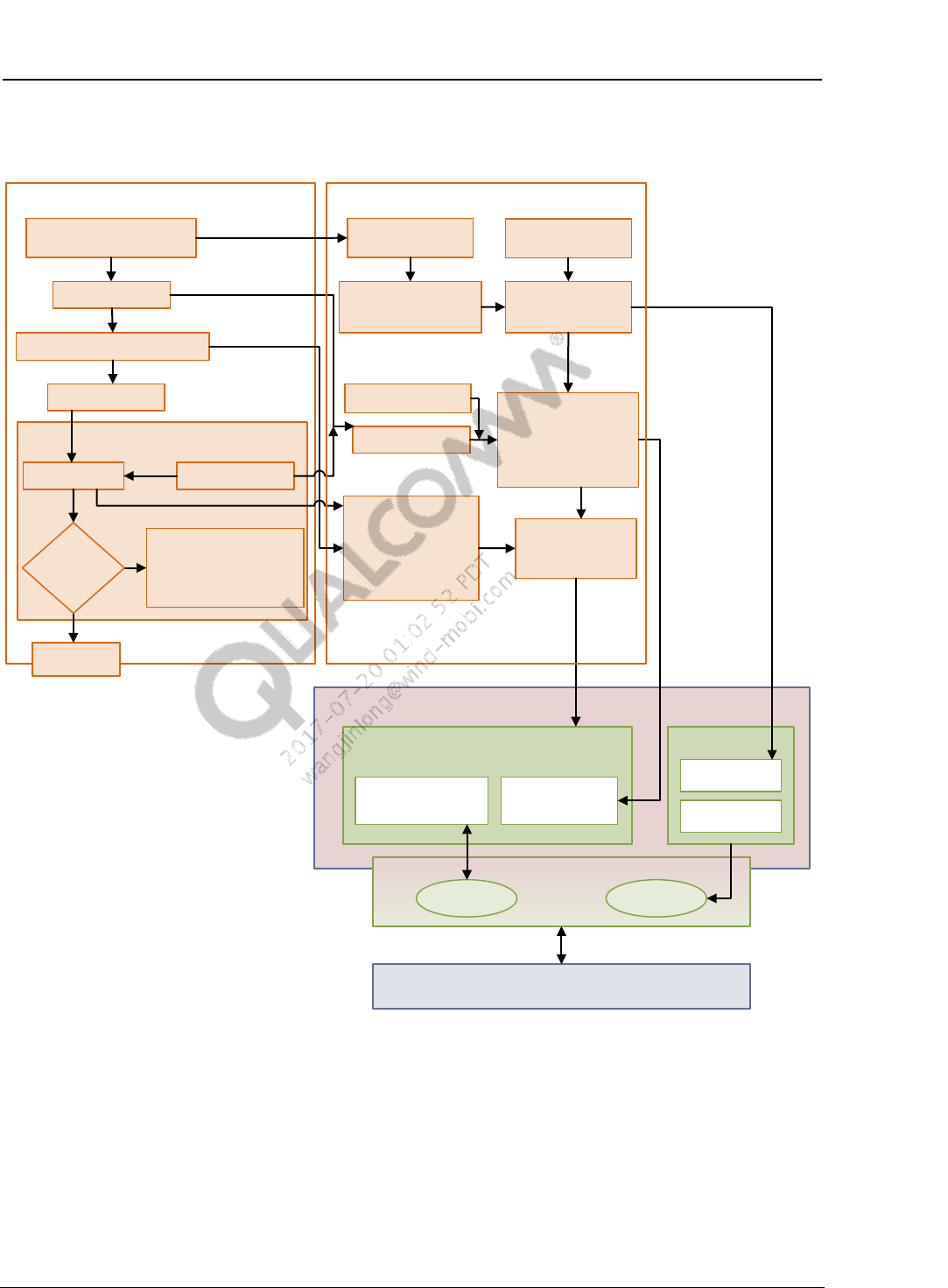
3.3 UEFI charger app
QTI charger app
PmicDxe
SChg
Fuel gauge
Monitor charging
PMIC hardware
PMIC configuration file
FGHwInit(LoadProfile)
Get Soc(),
ChargeCurrent(),
BatteryVoltage
SChgInit
Enable charging
ChargerPlatform_Init()
charger config file
GetNextAction()
GetBatteryStatus
BatteryErrorHandler
Battery missing
Battery temperature
Etc.
Platform dependent
ChargerLibInit()
ChargerApp error
handler
Change needed
action as per
Action
ChargerPlatform ChargerLib
· Enable charging
· Shutdown
· Continue
· Handle Jeita
ChargerAppInitialize()
InitDisplayTimer()
TakeNextAction(profileLoad)
Platform independent
GetNextAction()
GetNextAction()
GetNextAction()TakeAction()
GetNextAction(Battery
ErrorHandler)
GetBatteryStatus()
QcomChargerDxe
PmicLib
Driver-SCHGDriver-FG
TakeAction()
Is Vbatt/
SOC
reached?
Boot to
HLOS
Figure 3-3 UEFI charger app design
3.3.1 PmicDxe
The PmicDxe driver implements functions to program the charger/FG hardware. It also
implements functions such as parsing/load battery profile, FG boot sequence, AICL rerun etc.
UEFI PMIC Software User Guide Contents
80-P2484-42 A Confidential and Proprietary – Qualcomm Technologies, Inc. 14
MAY CONTAIN U.S. AND INTERNATIONAL EXPORT CONTROLLED INFORMATION
3.3.2 ChargerLib
The platform-dependent ChargerLib provides the following functions:
Enable charging, disable charging
Set charger maximum battery current
Float voltage (FV)
Check charger source
Get battery SOC, voltage, and current
Battery error handling and software Jeita
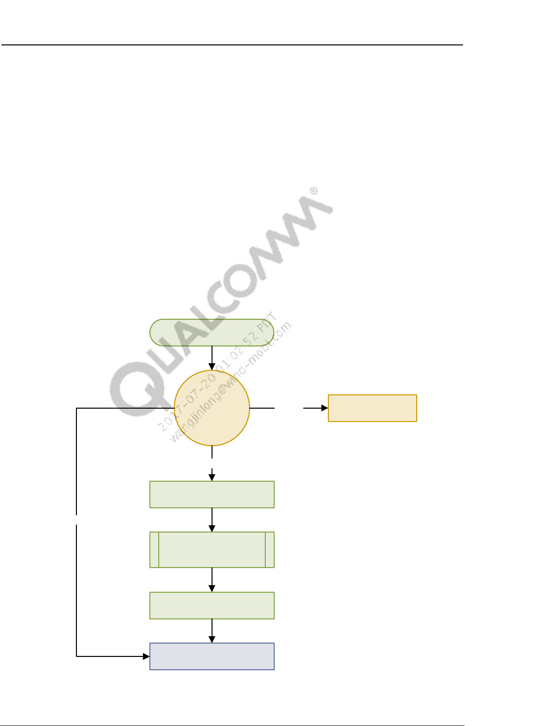
3.3.3 QTI charger app
The QTI charger app supports voltage-based and SOC-based threshold charging. The QTI
charger app calls ChargerLib to determine if it is OK to boot to HLOS or whether to stay in UEFI
charging until the threshold is reached. The QTI charger app has one main loop that keeps the
application running, checking if it is OK to exit.
Entry()
Get charging
status
Initialize()
START_CHARGING
MonitorCharging()
PostProcessing()
Boot to HLOS
Take action
ERROR
GOOD_TO_BOOT
Figure 3-4 QTI charger app call flow

UEFI PMIC Software User Guide Contents
80-P2484-42 A Confidential and Proprietary – Qualcomm Technologies, Inc. 15
MAY CONTAIN U.S. AND INTERNATIONAL EXPORT CONTROLLED INFORMATION
The charger has a timer for the following tasks:
Turn the display On or Off
Display the charging/battery icon
Run the following in a loop every 3 sec until threshold is reached
Check battery status
Manage charging
Error handling
Additional support includes safety features such as thermal mitigation, WiPower, etc.
Table 3-3 QTI charger app functions
Source file
Function
Description
QcomChargerApp.c
Entry()
Initializes the QTI charger app, starts the charging loop, and
cleans up after exiting the charging loop.
Initialize()
Sets the charging parameters and starts the display timer.
MonitorCharging()
Charging loop that monitors battery charging status until
battery status is at a good enough charge to boot to HLOS.
PostProcessing()
Called after exiting the charging loop, this function closes all
the events and timers, and decides whether to boot to HLOS,
stay in UEFI, or shut down.
DeInitialize()
Performs required exit actions before leaving the app.
QcomChargerApp-
EventHandler.c
KeyPressEventHandler()
Turns on the display, starts the display timer, and exits LPM
mode when the volume up/down, power key, or home key is
pressed.
KeyPressControl()
Registers or unregisters volume up, volume down, and home
key press event callback with the keypad driver.
HandleLPMClock()
Signals the Clock driver to enter or exit LPM.
HandleLPMDisplay()
Signals the Display driver to enter or exit LPM to turn the
display ON or OFF.
EnterLPM()
Called when the display is turned off, this function sends an
enter LPM signal to Clock and Display drivers.
ExitLPM()
Called when the display is turned on by key press, this function
sends an exit LPM signal to the Clock and Display drivers.
AnimImgTimer()
Animates image display during charging (display ON).
DisplayTimerEvent()
Displays the battery image during charging (display ON).
See Chapter 4 for QTI charger app configuration details.

80-P2484-42 A Confidential and Proprietary – Qualcomm Technologies, Inc. 16
MAY CONTAIN U.S. AND INTERNATIONAL EXPORT CONTROLLED INFORMATION
4 UEFI QTI charger app LA configuration
The UEFI QTI charger app handles the following:
Charges the battery to a specified level
Determines if the battery is OK to boot to HLOS without UEFI charging
See Section 3.3.3 for an overview of the QTI charger app.
4.1 QTI charger app configuration file
The QTI charger app includes a build-time configuration file with parameters for charger/fuel
gauge (FG) management.
Refer to Section 4.12 for a QTI charger app LA example file.
The QcomChargerConfig_VbattTh_8998.cfg file is located in the following boot build folder:
/QcomPkg/Drivers/QcomChargerDxe/
NOTE: The configuration file must be renamed QcomChargerCfg.cfg to be used.
4.2 Debug overwrite feature
The debug overwrite feature enables debug logs and overwrites UEFI configuration at runtime.
Overwriting configuration at runtime makes it unnecessary to rebuild the core. On debug builds,
the UEFI QTI charger app is built during initialization.
NOTE: This feature only works on debug builds.
Flash tools FV and enable the debug overwrite feature
The QComChargerCfg.cfg file can be copied via mass storage application from the UEFI BDS
menu to mount the LogFS drive on which to copy the file. The FV tool must be flashed to enable
the UEFI BDS menu.
The tools.fv file is located in the following metabuild folder:
..\boot_images\QcomPkg\QcomToolsPkg\Bin\QcomTools\DEBUG
1. Type the following command:
fastboot flash toolsfv ..\boot_images\QcomPkg\QcomToolsPkg\Bin\QcomTools
\DEBUG\tools.fv
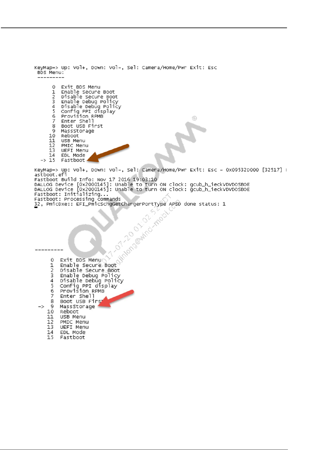
2. During boot, hold down the volume key to display the boot device selection (BDS) menu.
UEFI PMIC Software User Guide UEFI QTI charger app LA configuration
80-P2484-42 A Confidential and Proprietary – Qualcomm Technologies, Inc. 17
MAY CONTAIN U.S. AND INTERNATIONAL EXPORT CONTROLLED INFORMATION
3. Use the volume down key to scroll down the menu, and press the Home/Power key to select
Fastboot.
4. Reboot the device, press and hold down the volume key to open the UEFI BDS menu, and
press volume down to select MassStorage.
5. Press the Home/Power key to launch the UEFI MassStorage app.
UEFI PMIC Software User Guide UEFI QTI charger app LA configuration
80-P2484-42 A Confidential and Proprietary – Qualcomm Technologies, Inc. 18
MAY CONTAIN U.S. AND INTERNATIONAL EXPORT CONTROLLED INFORMATION
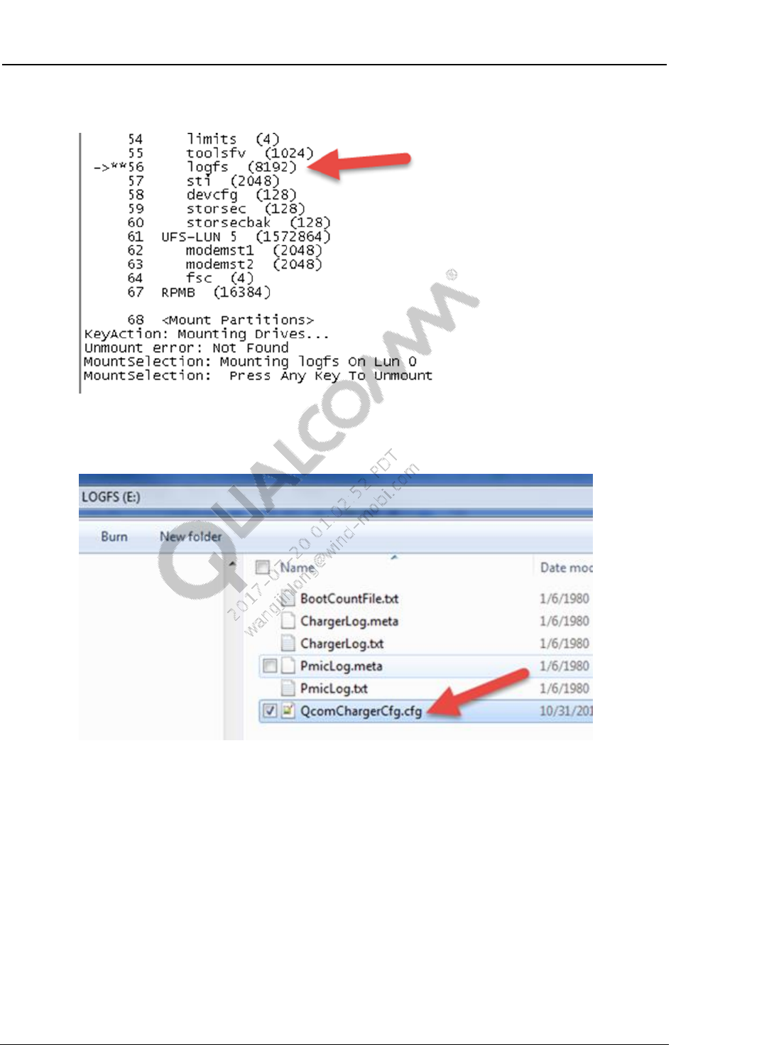
6. Mount the LogFS partition.
7. Copy the QcomChargerCfg.cfg file to the LogFS partition root level with the modified
configuration.
8. Remove LogFS from the task bar.
9. Reboot the device.
The new configuration takes effect and the modified configuration is listed in the LogFS
configuration file, e.g., the configuration file changes to enable the charger.

UEFI PMIC Software User Guide UEFI QTI charger app LA configuration
80-P2484-42 A Confidential and Proprietary – Qualcomm Technologies, Inc. 19
MAY CONTAIN U.S. AND INTERNATIONAL EXPORT CONTROLLED INFORMATION
4.3 Configuration quick reference
Refer to Section 4.12 for a QTI charger app LA example file.
Table 4-1 Configuration quick reference
Entry
Description
Default
Dependency
Data Format
Threshold charging
SocOrVoltageBaseBoot
Sets the thresholds in QTI charger
app to allow boot when the
configured threshold is met.
FALSE
LoadBatteryProfile
Boolean
LoadBatteryProfile
Loads the battery profile for battery
state of charge (SOC) accuracy.
TRUE
DispSignOfLifeMaxThresholdMv
Boolean
DispSignOfLifeMaxThresholdMv
Displays the sign of life during battery
profile load, providing a user
indication for cold boot.
3700 mV
LoadBatteryProfile
mV
FgCondRestart
Decides if the fuel gauge must be
restarted to allow battery accuracy.
TRUE
LoadBatteryProfile
Boolean
ChargerLedConfig
Configures the charger LED status.
1
None
Decimal
Debug
PrintChargerAppDbgMsg
If TRUE, enables QTI charger app
logs and respective pmic.dxe charger
logs and displays them on UART.
FALSE
None
Boolean
PrintChargerAppDbgMsgToFile
If TRUE, enables the QTI charger
app file logs and respective pmic.dxe
charger logs and saves them to a file.
FALSE
LogFS partition availability
Boolean
EnableChargerFGDump
Enables PMIC Charger and Fuel
Gauge peripheral dumps (if TRUE).
FALSE
PrintChargerAppDbgMsg
PrintChargerAppDbgMsgToFile
Boolean

UEFI PMIC Software User Guide UEFI QTI charger app LA configuration
80-P2484-42 A Confidential and Proprietary – Qualcomm Technologies, Inc. 20
MAY CONTAIN U.S. AND INTERNATIONAL EXPORT CONTROLLED INFORMATION
Entry
Description
Default
Dependency
Data Format
FG and FG debug
BatteryIdTolerance
Reads the battery ID to load the
battery profile and set a tolerance
limit.
8%
LoadBatteryProfile
8% +/- on
current battery
ID reading
DumpSram
Enables QTI charger app Fuel Gauge
SRAM dumps.
FALSE
PrintChargerAppDbgMsg
PrintChargerAppDbgMsgToFile
Boolean
DumpSramStartAddr
SRAM dump start address (values in
decimal).
0
DumpSram
Decimal
DumpSramEndAddr
SRAM dump end address (values in
decimal).
124
DumpSram
Decimal
DumpSramDuration
Dump SRAM contents timer duration
in seconds.
90 s
DumpSram
Seconds
Required initially
BootToHLOSThresholdInMv
Configures the QTI charger app
threshold to allow boot.
3600 mV
None
mV
OsStandardBootSocThreshold
Configures the QTI charger app
minimum threshold to allow boot.
7
LoadBatteryProfile
1-100% SOC
BattVoltLimHighDelta
Enables delta float voltage (FV) and
current limit to charge the battery.
30 mV
None
mV
ChgFvMax
Enables battery FV.
4350 mV
None
mV
ChgFccMax
Enables fast charging current.
2000 mA
None
mA
ChargingTermCurrent
Enables charger termination current
to declare 100% SOC.
200 mA
None
mA
ConservChgFvDelta
Enables maximum charger delta FV
maximum for unknown battery
configurations.
200 mV
None
mV
BATT_THERM coefficients
Enables battery thermal coefficients
to read the battery temperature
accuracy.
See Section 4.7.8
ProgramBattThermCoeffs=TRUE
Hexadecimal

UEFI PMIC Software User Guide UEFI QTI charger app LA configuration
80-P2484-42 A Confidential and Proprietary – Qualcomm Technologies, Inc. 21
MAY CONTAIN U.S. AND INTERNATIONAL EXPORT CONTROLLED INFORMATION
Entry
Description
Default
Dependency
Data Format
AUX_THERM coefficients
Enables auxiliary thermal coefficients
to adjust voltage to the temperature
mapping.
See Section 4.7.9
ProgramAuxThermCoeffs=TRUE
Hexadecimal
Device skin and charger hot
thresholds
Enables configuring device skin and
charger hot thresholds.
See Section 4.7.10
ProgramSkinAndChargerHot
Threshold = TRUE
Hexadecimal
EmergencyShutdownVbatt
Configures the device emergency
shutdown limit.
3200 mV
None
mV
EnableChargerWdog
Enables the charger watchdog to
safeguard unintentional charging if
the software gets stuck.
TRUE
None
Boolean
VBtEmpty threshold
Configures the low battery voltage
threshold for the SOC empty
interrupt.
2800 mV
None
mV
VBattEstDiffThreshold
Configures the estimated voltage
difference threshold to restart the FG
if the threshold difference is higher.
30 mV
FgCondRestart
mV
Battery error handling
DebugBoardBatteryIdMin and
DebugBoardBatteryIdMax
Specifies the debug board battery ID
range.
2000-14000
DebugBoardBehavior
Ohms
SmartBatteryIdMin and
SmartBatteryIdMax
Specifies the smart battery ID range.
240000-450000
None
Ohms
RegularBatteryIdMin and
RegularBatteryIdMax
Specifies the regular battery ID
range.
15000-137000
None
Ohms
UnknownBatteryBehavior
Defines unknown battery behavior.
Detects if the battery ID is within the
specified range.
BattID < 2000 and ID
> 450000
Battery error handling
configuration
Ohms
DebugBoardBehavior
Defines debug board battery
behavior.
2
Battery error handling
configuration
Decimal
BattMissingCfg
Configures the battery missing
detection behavior.
0
None
Decimal

UEFI PMIC Software User Guide UEFI QTI charger app LA configuration
80-P2484-42 A Confidential and Proprietary – Qualcomm Technologies, Inc. 22
MAY CONTAIN U.S. AND INTERNATIONAL EXPORT CONTROLLED INFORMATION
Entry
Description
Default
Dependency
Data Format
Jeita
Jeita zones
Enables specified Jeita zones.
See Section 4.9
None
Celsius
JeitaCcCompCfg
Enables configuring Jeita charge
current compensation when the
device is within the battery
temperature soft-limit for hardware
Jeita.
1000 mA
None
mA
JeitaFvCompCfg
Enables configuring Jeita charge
voltage compensation when in device
is in battery temperature soft-limit for
hardware Jeita.
105 mV
None
mV
NoChargeAndWait
Configures device behavior for
temperatures outside of the charging
range but within the operating range.
TRUE
None
Boolean
WiPower
WiPowerSupported
Enables configuring WiPower support
for the QTI charger app charging
device.
TRUE
None
Boolean
DCInBootToHLOSThresholdInMv
Enables configuring the WiPower
threshold for QTI charger app
charging.
3600 mV
None
mV
SuspendDCIn
Enables configuring suspended DCIN
behavior when WiPower is enabled.
FALSE
None
Boolean
Thermal
SWThermalMitigationEnable
Configures thermal safety mitigation
in the QTI charger app charging
device.
FALSE
None
Boolean
TsensTimeoutMins
Configures a thermal safety timer
when the device is in the thermal
zone and not in charger wait state.
30 min
None
Minutes
Tsens limits or zone
Configures thermal safety zones or
limits.
See Section 4.11.3
None
Celsius

UEFI PMIC Software User Guide UEFI QTI charger app LA configuration
80-P2484-42 A Confidential and Proprietary – Qualcomm Technologies, Inc. 23
MAY CONTAIN U.S. AND INTERNATIONAL EXPORT CONTROLLED INFORMATION
4.4 Threshold charging configuration
Refer to Section 4.12 for a QTI charger app LA example file.
4.4.1 SocOrVoltageBaseBoot
Sets the thresholds in QTI charger app to allow boot when the configured threshold is met. The
threshold can be voltage or SOC-based.
Default value – FALSE (indicates the voltage-based thresholds charging).
NOTE: To allow accurate SOC estimates during charging, this parameter must be to set to the
LoadBatteryProfile configuration.
4.4.2 LoadBatteryProfile
Loads the battery profile for battery state of charge (SOC) accuracy. If enabled, QTI charger app
loads profile data to the fuel gauge first.
Default value – TRUE (indicates voltage-based thresholds charging).
NOTE: This configuration might add a delay of ~1.5 sec to boot while the profile loads and the SOC
estimate is calculated. DispSignOfLifeMaxThresholdMv configuration shows sign of life while
loading battery profile. This delay/wait only applies to cold boot or battery removal.
The FG SRAM profile integrity status dedicated register contains the profile load and FG restart
status.
4.4.3 DispSignOfLifeMaxThresholdMv
Displays the sign of life during battery profile load, providing a user indication for cold boot. If
the LoadBatteryProfile parameter is enabled, QTI charger app shows sign of life and loads the
profile first.
Default value – 3700 mV (used to decide on displaying image)
Dependency – LoadBatteryProfile must be set for an accurate SOC estimate during charging.
4.4.4 FgCondRestart
Decides if the fuel gauge must be restarted to allow battery accuracy for the following condition:
If abs(Vbatt_Estimate_diff ) > Vbatt_Estimate_diff_threshold
Default value – TRUE
Dependency – LoadBatteryProfile must be set.

UEFI PMIC Software User Guide UEFI QTI charger app LA configuration
80-P2484-42 A Confidential and Proprietary – Qualcomm Technologies, Inc. 24
MAY CONTAIN U.S. AND INTERNATIONAL EXPORT CONTROLLED INFORMATION
4.4.5 ChargerLedConfig
Configures the charger LED status.
Supported values:
0 = Disable
1 (default) = Solid during charging
2 = LED blinks during charging
NOTE: If enabled, the LED turns off after threshold charging is complete, i.e., when the device boots to
HLOS.
4.5 Debug configuration
Debug configuration only works on non-production builds. Refer to Section 4.12 for a QTI
charger app LA example file.
4.5.1 PrintChargerAppDbgMsg
If TRUE, enables QTI charger app logs and respective pmic.dxe charger logs and displays them
on UART.
Default value – FALSE (excludes extensive charging logs and only displays battery status
information on UART for general users).
Example charger log
-----------------------------
- 0x09C0AD000 [16004] QcomChargerApp.efi
QcomChargerApp:: QcomChargerApp_MonitorCharging
TimeStamp,StateOfCharge,Voltage,ChargeCurrent,Temp
16, ChargerApp:: Battery Status 1,3536,206,25
Waiting for 3 sec
0x2B, ChargerApp: Battery Status 17,3732,-1072,24
Waiting for 3 sec
4.5.2 PrintChargerAppDbgMsgToFile
If TRUE, enables QTI charger app file logs and respective pmic.dxe charger logs and saves them
to a file.
Default value – FALSE (indicates excludes extensive charging logs and only displays battery
status information on UART for general users).
If file log configuration is enabled, the chargerlog.txt and pmiclog.txt files are generated in the
debug LogFS 8 MB partition.
When the file size reaches its limit, this configuration acts as a circular buffer and starts
overwriting old logs.
The chargerlog.txt file has the charger and boot configuration. The pmiclog.txt file has fuel gauge
and charger-related information, e.g., SRAM dumps.

UEFI PMIC Software User Guide UEFI QTI charger app LA configuration
80-P2484-42 A Confidential and Proprietary – Qualcomm Technologies, Inc. 25
MAY CONTAIN U.S. AND INTERNATIONAL EXPORT CONTROLLED INFORMATION
4.5.3 EnableChargerFGDump
Enables PMIC charger and FG peripheral dumps (if TRUE). Dumps also occur during the
Charger app initialization and exit. Dumps are initiated if any key is pressed while charging.
Default value – FALSE
Dependency – PrintChargerAppDbgMsg charger logs must be enabled.
4.6 FG and FG debug configuration
Refer to Section 4.12 for a QTI charger app LA example file.
4.6.1 BatteryIdTolerance
Battery ID tolerance limit to load the battery profile against the battery ID reading.
If the battery ID falls into tolerance range, only the respective profile with that battery ID is
flashed to the fuel gauge. Otherwise, the default profile is loaded from the battery profile file,
which is the first profile. QTI charger app includes eight profile supports.
Default value – 8%
4.6.2 DumpSram
Enables QTI charger app Fuel Gauge SRAM dumps. If enabled (TRUE), QTI charger app
periodically dumps SRAM to get debug information from hardware FG algorithms.
Default value – FALSE
Dependency – PrintChargerAppDbgMsg charger logs must be enabled.
4.6.3 DumpSramStartAddr
SRAM dump start address (values in decimal).
4.6.4 DumpSramEndAddr
SRAM dump end address (values in decimal).
4.6.5 DumpSramDuration
Dump SRAM contents timer duration in seconds.
Default value – 90 sec

UEFI PMIC Software User Guide UEFI QTI charger app LA configuration
80-P2484-42 A Confidential and Proprietary – Qualcomm Technologies, Inc. 26
MAY CONTAIN U.S. AND INTERNATIONAL EXPORT CONTROLLED INFORMATION
4.7 Initial required charger configuration
See Section 4.12 for a QTI charger app LA example file.
4.7.1 BootToHLOSThresholdInMv
Configures the QTI charger app threshold to allow boot. This threshold is also used for
unsupported batteries or battery emulators.
Default value – 3600 in MV
4.7.2 OsStandardBootSocThreshold
Configures the QTI charger app minimum threshold to allow boot. This threshold is not used in
unsupported batteries or battery emulators.
Default value – 7 % SOC
Dependencies:
SocOrVoltageBaseBoot = TRUE
LoadBatteryProfile = TRUE
4.7.3 BattVoltLimHighDelta
Enables delta float voltage (FV) to charge the battery.
Default value – 30 mV
4.7.4 ChgFvMax
Enables battery FV.
Default value – 4350 mV
4.7.5 ChgFccMax
Enables fast charging current.
Default value – 2000 mA
4.7.6 ChargingTermCurrent
Enables charger termination current to declare 100% SOC.
Default value – 200 mA
4.7.7 ConservChgFvDelta
Enables maximum charger delta FV maximum for unknown battery configurations.
Default value – 200 mV

UEFI PMIC Software User Guide UEFI QTI charger app LA configuration
80-P2484-42 A Confidential and Proprietary – Qualcomm Technologies, Inc. 27
MAY CONTAIN U.S. AND INTERNATIONAL EXPORT CONTROLLED INFORMATION
4.7.8 BATT_THERM coefficients
Enables battery thermal coefficients to read the battery temperature accurately. Picked up as per
ThermBias value per device/battery and initial values given are formatted with half-float
encoding. Contact systems if these values must be updated. Refer to the BATT_THERM master
beta coefficient table in Understanding PMI8998 Fuel Gauge (80-VT310-138).
Default values:
BattThermC1 = A1
BattThermC2 = 50
BattThermC3 = FF
Values are based on the following ThermBias and pull up resistor value:
BattThermHalfRangeInC = 25
Dependency – ProgramBattThermCoeffs = TRUE
4.7.9 AUX_THERM coefficients
Enables auxiliary thermal coefficients to adjust voltage to the temperature mapping. Temperature
mapping is based on the beta 3435 of the thermistor in use and the associated temperature to 50%
ratio (dependent on the pull up value). Refer to the AUX_THERM master beta coefficient table in
Understanding PMI8998 Fuel Gauge (80-VT310-138).
Default values:
AuxThermC1 = BF
AuxThermC2 = 36
AuxThermC3 = FF
Values are based on the following ThermBias and pull up resistor value:
AuxThermHalfRangeInC = 25
Dependency – ProgramAuxThermCoeffs = TRUE
4.7.10 Device skin and charger hot thresholds
Enables configuring device skin and charger hot thresholds. Device skin temperature is usually on
device display. Charger hot thresholds are used for thermal mitigation via intelligent negotiation
for optimum voltage (INOV).
Default values:
DeviceSkinHotInC = 70
DeviceSkinTooHotInC = 80
ChargerHotInC = 80
ChargerTooHotInC = 90
Dependency – ProgramSkinAndChargerHotThreshold must be TRUE.

UEFI PMIC Software User Guide UEFI QTI charger app LA configuration
80-P2484-42 A Confidential and Proprietary – Qualcomm Technologies, Inc. 28
MAY CONTAIN U.S. AND INTERNATIONAL EXPORT CONTROLLED INFORMATION
4.7.11 EmergencyShutdownVbatt
Configures the device emergency shutdown limit. QTI charger app monitors charge current (less
than 0 mA) and battery voltage (less than 3.2) for three consecutive reads before initiating
emergency shutdown to safeguard the battery.
Default value – 3200 mV
4.7.12 EnableChargerWdog
Enables the charger watchdog to safeguard unintentional charging if the software gets stuck.
Charging becomes disabled if the watchdog is configured. Software must pet the watchdog based
on its set expiration limit.
Supported values:
0 – Do not enable the charger watchdog.
1 (default) – Enable the charger watchdog during charging and disable before exiting.
2 – Enable the charger watchdog during charging and leave enabled when exiting.
4.7.13 VBtEmpty threshold
Configures the low battery voltage threshold for the SOC empty interrupt.
Default value – 2800 mV
VBtEmpty = 2800
4.7.14 VBattEstDiffThreshold
Configures the estimated voltage difference threshold to restart the FG if the threshold difference
is higher.
Default value – 30 mV (Vbatt_Estimate_diff_threshold)
Dependency – FgCondRestart
4.8 Battery error handling configuration
Refer to Section 4.12 for a QTI charger app LA example file.
4.8.1 DebugBoardBatteryIdMin and DebugBoardBatteryIdMax
Specifies the debug board battery ID range. If the voltage associated with the battery ID falls
below the range, QTI charger app handles the battery as a debug board based on Vbatt > boot
threshold (3.6 V) allow boot to HLOS. Otherwise, shut down.
Default value – 2000-14000
Dependency – DebugBoardBehavior
See also BootToHLOSThresholdInMv

UEFI PMIC Software User Guide UEFI QTI charger app LA configuration
80-P2484-42 A Confidential and Proprietary – Qualcomm Technologies, Inc. 29
MAY CONTAIN U.S. AND INTERNATIONAL EXPORT CONTROLLED INFORMATION
4.8.2 SmartBatteryIdMin and SmartBatteryIdMax
Specifies the smart battery ID range. QTI charger app handles the battery as a smart battery based
on Vbatt > 3.6 V allow boot to HLOS. Otherwise, continue charging until the configured
threshold is reached.
Default value – 240000-450000 Ohms smart battery ID range.
See also BootToHLOSThresholdInMv
4.8.3 RegularBatteryIdMin and RegularBatteryIdMax
Specifies the regular battery ID range. QTI charger app handles the battery as a regular board
based on Vbatt > 3.6 V and allows boot to HLOS. Otherwise continue charging until the
configured threshold is reached.
Default value – 15000-137000 regular battery ID range, value in Ohms
4.8.4 UnknownBatteryBehavior
Defines unknown battery behavior. Detects if the battery ID is within the specified range.
Supported values:
0 – Shuts down the device
1 – Boot to HLOS if battery more than threshold else shutdown
2 – Conservative charging
3 (default) – Regular charging
4.8.5 DebugBoardBehavior
Defines debug board battery behavior.
Supported values:
0 – Show low battery icon, disable PON1/USBIN trigger to prevent reboot and shutdown
1 (default) – Show low battery icon and stay on until device is turned off by user
2 – Boot to HLOS
4.8.6 BattMissingCfg
Configures the battery missing detection behavior.
Supported values:
0 (default) – Use battery ID
1 – Use battery thermistor
2 – Use battery thermistor and ID
UEFI PMIC Software User Guide UEFI QTI charger app LA configuration
80-P2484-42 A Confidential and Proprietary – Qualcomm Technologies, Inc. 30
MAY CONTAIN U.S. AND INTERNATIONAL EXPORT CONTROLLED INFORMATION
4.9 Jeita configuration
Refer to Section 4.12 for a QTI charger app LA example file.
4.9.1 Jeita zones
Enables specified Jeita zones. For negative values, use the negative symbol, e.g., -30.
Default values:
JeitaCriticalTempLowLimit
-20
JeitaHardColdLimit
0
JeitaSoftColdLimit
10
JeitaSoftHotLimit
45
JeitaHardHotLimit
60
JeitaCriticalTempHighLimit
70
4.9.2 JeitaCcCompCfg
Enables configuring Jeita charge current compensation when the device is within the battery
temperature soft-limit for the hardware Jeita.
The Jeita compensation values are as follows:
Minimum value – 0 mA
Maximum value – 1575 mA
Step size – 25 mA
Default value – 1000 mA
4.9.3 JeitaFvCompCfg
Enables configuring Jeita charge voltage compensation when in device is in battery temperature
soft-limit for hardware Jeita.
The Jeita compensation values are as follows:
Minimum value – 0 mV
Maximum value – 472.5 mV
Step size – 7.5 mV
Default value – 105 mV
4.9.4 NoChargeAndWait
Configures device behavior for temperatures outside of the charging range but within the
operating range.
Supported values:
TRUE (default) – Disable charging and wait
FALSE – Shutdown the device if the temperature is outside of the charging range

UEFI PMIC Software User Guide UEFI QTI charger app LA configuration
80-P2484-42 A Confidential and Proprietary – Qualcomm Technologies, Inc. 31
MAY CONTAIN U.S. AND INTERNATIONAL EXPORT CONTROLLED INFORMATION
4.10 WiPower configuration
Refer to Section 4.12 for a QTI charger app LA example file.
4.10.1 WiPowerSupported
Enables configuring WiPower support for the QTI charger app charging device.
Default value – TRUE
4.10.2 DCInBootToHLOSThresholdInMv
Enables configuring the WiPower threshold for QTI charger app charging.
Default value – 3600 mV
4.10.3 SuspendDCIn
Enables configuring suspended DCIN behavior when WiPower is enabled in QTI charger app
charging.
Default value – FALSE
4.11 Thermal configuration
Refer to Section 4.12 for a QTI charger app LA example file.
4.11.1 SWThermalMitigationEnable
Enables configuring thermal safety mitigation in the QTI charger app charging device.
Mitigation is based on the MSM Tsens maximum average temperature reading.
Default value – FALSE
4.11.2 TsensTimeoutMins
Enables configuring a thermal safety timer when the device is in the thermal zone and not in
charger wait state. The device waits for the configured wait time and initiates shutdown if thermal
conditions do not normalize.
Default value – 30 min (give up time in thermal wait for battery disconnect – Max 60 min)
4.11.3 Tsens limits or zone
Enables configuring thermal safety zones or limits. If the temperature is above the extreme
temperature limit, the device performs automatic fault protection (AFP).
If the Tsens temperature limit is within the specified wait range (e.g., 75-90 min), the QTI charger
app waits 30 min (polling every 3 sec) to allow the device to cool down. The device performs
AFP after the 30 min expiration.
Default values:
UEFI PMIC Software User Guide UEFI QTI charger app LA configuration
80-P2484-42 A Confidential and Proprietary – Qualcomm Technologies, Inc. 32
MAY CONTAIN U.S. AND INTERNATIONAL EXPORT CONTROLLED INFORMATION
Parameter
Temp
(°C)
Description
TsensHighTemp
85
High temperature limit for thermal wait
TsensExtremeTemp
90
High temperature limit for battery and device safety on battery disconnect
TsensLowTemp
75
Low Temperature limit for end of thermal wait
4.12 Example configuration file
QTI charger app configuration file for LA is as follows:
#
# Default Charger App Config settings
#
[CHARGER Config]
#
# Version/Information:
# file ChargerApp_VbattTh_8998.cfg
#
# Implements the Qualcomm's Charger application config parameters
#
# Copyright (c) 2016, Qualcomm Technologies Inc. All rights reserved.
#
# 1 : Initial revision
# 2 : Deleting not needed config params and removing dummy battery2
support
# 3: Adding Jeita Compensation params
# 4 : Adding parameters for different battery types and QC 3.0 and QC
2.0 chargergers
# 5 : Added parameter to support enabling watchdog when charging is
enabled
# 6 : Adding parameters for Aux Coffes, SkinHot and Charger Hot
settings
# 7 : Update for Battery profile load
# 8 : Added SupportHostMode
# 9 : Adding Thermal configs
# 10 : Adding support for Charger Fg Peripheral dumps
# 11 : Adding HVDCP Enable control
# 12 : Adding WIPOWER configs
# 13 : Removed config item for setting IUSB_MAX in case of SDP
# 14 : Adding Restarting FG flag
# 15 : Adding Charger led indication config, rasing skin hot to 70-80C,
disabling watchdog as default
# 16 : Added changes for supporting different platforms, MTP, QRD, etc.
CfgVersion = 17

UEFI PMIC Software User Guide UEFI QTI charger app LA configuration
80-P2484-42 A Confidential and Proprietary – Qualcomm Technologies, Inc. 33
MAY CONTAIN U.S. AND INTERNATIONAL EXPORT CONTROLLED INFORMATION
--- Threshold Charging Configurations --
#Use Battery SOC or voltage as threshold charging criteria
#Voltage is default
SocOrVoltageBaseBoot = FALSE
#Load Fuel Gauge Battery Profile profile for SOC estimation and accuracy
LoadBatteryProfile = FALSE
#Below VBAT threshold is used to decide on showing sign of life first
before FG Module Initialization and continuing with threshold charging
DispSignOfLifeMaxThresholdMv = 3700
# FG Conditional Restart on Device reset
FgCondRestart = TRUE
# Charging status indication via led
# 0 = Disable 1 = solid during charging 2 = led blinks during charging
# if turned on LED will be turned off after threhsold charging is completed
i.e. when device boot to HLOS
ChargerLedConfig = 1
--- Threshold Charging Configurations End --
--- Debug Configurations --
# Print Charger DEBUG Messages
PrintChargerAppDbgMsg = FALSE
#Print Charger DEBUG Messages to ULOG File..Default is false
PrintChargerAppDbgMsgToFile = FALSE
#Enable/disable Charger/FG Dump support
EnableChargerFgDump = FALSE
--- ----Debug FG Configurations ------
#dump SRAM contents Default value – FALSE
DumpSram = FALSE
#dump SRAM Start and End Address in Hex Format
#SRAM Block SRAM Address
#System 0x00 - 0x17
#Profile 0x18 - 0x3C
#Scratchpad 0x50 - 0x7C
#values in decimal
DumpSramStartAddr = 0
#values in decimal
DumpSramEndAddr = 124

UEFI PMIC Software User Guide UEFI QTI charger app LA configuration
80-P2484-42 A Confidential and Proprietary – Qualcomm Technologies, Inc. 34
MAY CONTAIN U.S. AND INTERNATIONAL EXPORT CONTROLLED INFORMATION
#dump SRAM contents timer Duration in s
DumpSramDuration = 90
--- ---- Debug FG Configurations End -----
--- Debug Configurations End --
--- Battery Error Handling Configurations --
#Battery ID Tolerance Percentage 8%
BatteryIdTolerance = 8
#Debug board ID range, value in Ohms
DebugBoardBatteryIdMin = 0
DebugBoardBatteryIdMax = 14000
#Regular battery ID range, value in Ohms
RegularBatteryIdMin = 15000
RegularBatteryIdMax = 137000
#Smart battery ID range, value in Ohms
SmartBatteryIdMin = 240000
SmartBatteryIdMax = 450000
#Support unknown battery charging behavior
# 0: Shuts down device, 1: Boot to HLOS if battery more than threshold
else shutdown
# 2: Conservative Charging 3: Regular charging
UnknownBatteryBehavior = 3
#Debug board behavior
# 0: Show low battery icon, disable PON1/USBIN trigger to prevent reboot
and shutdown
# 1: Show low battery icon and stay on until device is turned off by user.
# 2: Boot to HLOS
DebugBoardBehavior = 2
#Battery missing config
# 0 = using batt id 1 = using batt therm 2 = both
BattMissingCfg = 0
--- Battery Error Handling Configurations End --

UEFI PMIC Software User Guide UEFI QTI charger app LA configuration
80-P2484-42 A Confidential and Proprietary – Qualcomm Technologies, Inc. 35
MAY CONTAIN U.S. AND INTERNATIONAL EXPORT CONTROLLED INFORMATION
--- Jeita Configurations --
# Configure limits for Battery Temperature (For negative values, use
negative sign. Ex: -30)
JeitaCriticalTempLowLimit = -20
JeitaHardColdLimit = 0
JeitaSoftColdLimit = 10
JeitaSoftHotLimit = 45
JeitaHardHotLimit = 60
JeitaCriticalTempHighLimit = 70
#JEITA Charge Current Compensation when in battery temperature soft-limit
#JEITA CC = min is 0 ma and max is 1575 ma - step size is 25mA
JeitaCcCompCfg = 1000
#JEITA Float Voltage Compensation when in battery temperature soft-limit
#min is 0 and max .4725 V step size is 7.5 mV - unit is in mV
JeitaFvCompCfg = 105
#device behaviour if temp is outside charging range but within operational
range
# 1= Disable charging and wait. 0 = Shutdown device is temp outside
NoChargeAndWait = TRUE
--- Jeita Configurations End --
--- Initial Configurations --
#Boot device to HLOS in case of unsupported battery or battery emulator. In
millivolt*/
BootToHLOSThresholdInMv = 3600
#Minimum SOC Threshold before allowing to boot to HLOS
#below param is considered only when SocOrVoltageBaseBoot = TRUE and
LoadBatteryProfile = TRUE
OsStandardBootSocThreshold = 7
# Configure Battery Voltage and Current limit
BattVoltLimHighDelta = 30
# Configure VddMax and IbatMax values
# Set to 0 to configure through API
ChgFvMax = 4350
ChgFccMax = 2000
#Charging termination current in milliamps
ChargingTermCurrent = 200
# Voltage (in mV) to be reduced from FV_MAX during conservative charging
ConservChgFvDelta = 200

UEFI PMIC Software User Guide UEFI QTI charger app LA configuration
80-P2484-42 A Confidential and Proprietary – Qualcomm Technologies, Inc. 36
MAY CONTAIN U.S. AND INTERNATIONAL EXPORT CONTROLLED INFORMATION
#Program THERM coeffs ..
#Picked up as per ThermB value per device/battery and initial values are
given in HALF encoded
ProgramAuxThermCoeffs = TRUE
AuxThermC1 = A0
AuxThermC2 = 4F
AuxThermC3 = CF
#based on ThermB and pull up resistor value
AuxThermHalfRangeInC = 25
#Program device Skin and Charger Hot thresholds
ProgramSkinAndChargerHotThreshold = TRUE
DeviceSkinHotInC = 50
DeviceSkinTooHotInC = 60
ChargerHotInC = 80
ChargerTooHotInC = 90
#Lowest Voltage at which device should shutdown gracefully
#value in mV
EmergencyShutdownVbatt = 3200
#Charger WDOG Support options
# 0: Do not enable Charger WDOG
# 1: Enable Charger WDOG during charging and Disable before exiting
# 2: Enable Charger WDOG during charging and leave enabled when exiting
EnableChargerWdog = 1
#Vbat Empty threshold in mv
VBtEmpty = 2800
--- Initial Configurations End --
--- Thermal Configurations --
#Enable SW thermal mitigation during charging by default FALSE
# Mitigation is based on MSM Tsens max avg temp reading
SWThermalMitigationEnable = FALSE
## TSENS ##
#High Temperature limit for thermal wait
TsensHighTemp = 85
#High Temperature limit for battey and device safety (battery disconnect)
TsensExtremeTemp = 90
#Low Temperature limit for end of thermal wait
TsensLowTemp = 75
# Give up time in thermal wait for battery disconnect - support up to 60min
TsensTimeoutMins = 30
--- Thermal Configurations End --

UEFI PMIC Software User Guide UEFI QTI charger app LA configuration
80-P2484-42 A Confidential and Proprietary – Qualcomm Technologies, Inc. 37
MAY CONTAIN U.S. AND INTERNATIONAL EXPORT CONTROLLED INFORMATION
--- WiPower Configurations --
#support wipower or not
WiPowerSupported = FALSE
#Boot device to HLOS in case of wipower charging. In millivolt
DCInBootToHLOSThresholdInMv = 3600
#suspend DCIn or not after exiting UEFI
SuspendDCIn = TRUE
--- WiPower Configurations End --
#
# End of config
# Blank line needed after the last config
#

80-P2484-42 A Confidential and Proprietary – Qualcomm Technologies, Inc. 38
MAY CONTAIN U.S. AND INTERNATIONAL EXPORT CONTROLLED INFORMATION
5 QTI charger app WP configuration
TBD
80-P2484-42 A Confidential and Proprietary – Qualcomm Technologies, Inc. 39
MAY CONTAIN U.S. AND INTERNATIONAL EXPORT CONTROLLED INFORMATION
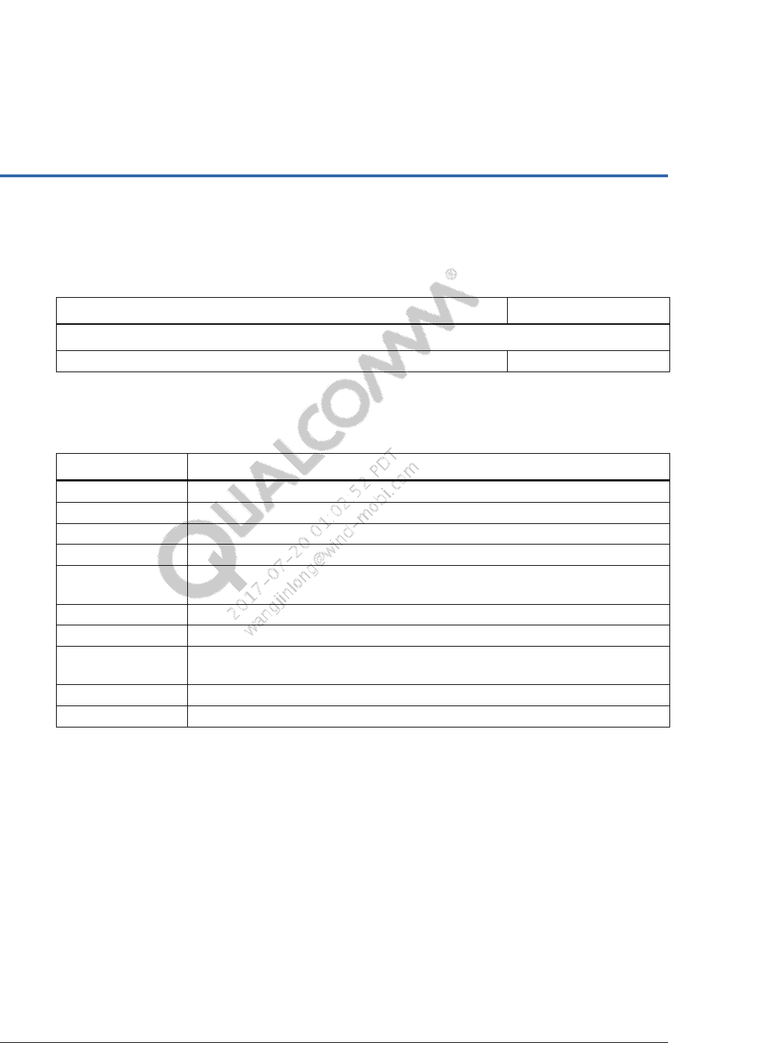
A References
A.1 Related documents
Title
Number
Qualcomm Technologies, Inc.
Understanding PMI8998 Fuel Gauge
80-VT310-138
A.2 Acronyms and terms
Acronym or term
Definition
AFP
automatic fault protection
BDS
Boot device selection
FG
Fuel gauge
FV
Float voltage
GUID
Globally unique identifier (GUID)
128-bit number used to identify an entity (drivers, protocols, files, etc.) within UEFI.
INF
Make file for a module that specifies the sources and dependencies.
INOV
Intelligent negotiation for optimum voltage
Module
Separate compilable code or prebuilt library consisting of INF and source code (or
binary), such as drivers and libraries.
SOC
State of charge
UEFI
Unified extensible firmware interface
