81126201 D _JC SW41AS_ FCC Part 15 B JC SW41AS
2016-04-05
: Pdf 81126201-D Jc-Sw41As Fcc Part 15 B 81126201-D__JC-SW41AS__FCC_Part_15_B CertsReports 162012 ProductFiles
Open the PDF directly: View PDF ![]() .
.
Page Count: 20
Reference No.: 60803207-D
Report No.: 81126201-D
Page 1 / 20
FCC DoC
TEST REPORT
for
USB 2.0 Auto Sharing Switch
MODEL: JC-SW41AS
Test Report Number:
81126201-D
Issued to:
JC PLANETARY Tech. Inc.
2F, No. 536, Jung-
jeng Rd., Sindian City,
Taipei Country 23141, Taiwan.
Issued by:
Compliance Certification Services Inc.
Sindian BU.
No.163-1, Jhongsheng Rd., Sindian City,
Taipei County 23151, Taiwan
TEL: 886-2-22170894
FAX: 886-2-22171029
Issued Date: November 26, 2008
Note: This report shall not be reproduced except in full, without the written approval of Compliance Certification
Services Inc. This document may be altered or revised by Compliance Certification Services Inc. personnel only, and
shall be noted in the revision section of the document. The client should not use it to claim product endorsement by TAF,
A2LA, NVLAP, NIST or any government agencies. The test results in the report only apply to the tested sample.

Reference No.: 60803207-D
Report No.: 81126201-D
Page 2
This report shall not be reproduced except in full, without the written approval of Compliance Certification Services.
TABLE OF CONTENTS
1 TEST RESULT CERTIFICATION...............................................................................................3
2 EUT DESCRIPTION..................................................................................................................4
3 TEST METHODOLOGY............................................................................................................5
3.1. DECISION OF FINAL TEST MODE ............................................................................................5
3.2. EUT SYSTEM OPERATION ......................................................................................................5
4 SETUP OF EQUIPMENT UNDER TEST.....................................................................................6
4.1. DESCRIPTION OF SUPPORT UNITS ........................................................................................6
4.2. CONFIGURATION OF SYSTEM UNDER TEST..........................................................................7
5 FACILITIES AND ACCREDITATIONS .......................................................................................8
5.1. FACILITIES...............................................................................................................................8
5.2. ACCREDITATIONS ...................................................................................................................8
5.3. MEASUREMENT UNCERTAINTY ..............................................................................................8
6 CONDUCTED EMISSION MEASUREMENT...............................................................................9
6.1. LIMITS OF CONDUCTED EMISSION MEASUREMENT..............................................................9
6.2. TEST INSTRUMENTS ...............................................................................................................9
6.3. TEST PROCEDURES ............................................................................................................. 10
6.4. TEST SETUP .......................................................................................................................... 11
6.5. Data Sample: .......................................................................................................................... 11
6.6. TEST RESULTS...................................................................................................................... 12
7 RADIATED EMISSION MEASUREMENT................................................................................. 13
7.1. LIMITS OF RADIATED EMISSION MEASUREMENT................................................................ 13
7.2. TEST INSTRUMENTS ............................................................................................................. 13
7.3. TEST PROCEDURES ............................................................................................................. 14
7.4. TEST SETUP .......................................................................................................................... 16
7.5. Data Sample: .......................................................................................................................... 16
7.6. TEST RESULTS...................................................................................................................... 17
8 PHOTOGRAPHS OF THE TEST CONFIGURATION................................................................. 19
Reference No.: 60803207-D
Report No.: 81126201-D
Page 3
This report shall not be reproduced except in full, without the written approval of Compliance Certification Services.
1 TEST RESULT CERTIFICATION
Product:
USB 2.0 Auto Sharing Switch
Model:
JC-SW41AS
Brand:
N/A
Applicant:
JC PLANETARY Tech. Inc.
2F, No. 536, Jung-jeng Rd., Sindian City,
Taipei Country 23141, Taiwan.
Manufacturer:
Yonville Electronic Ltd (China Factory)
Block1, No.3 Industrial District, Xiang Jiao Tang Village, Xue-Xiang Community,
Bu Ji Town, Shenzhen City, Guang Dong Province, 518129 China.
Tested:
August 4, 2006 & August 7, 2006
EMISSION
Standard Item Result Remarks
Conducted (Main Port) PASS Meet Class B limit
FCC 47 CFR Part 15 Subpart B,
ICES-003 Issue 4
ANSI C63.4-2003 Radiated PASS Meet Class B limit
Note: 1. The test result judgment is decided by the limit of measurement standard.
2. The information of measurement uncertainty is available upon the customer’s request.
Deviation from Applicable Standard
None
The above equipment has been tested by Compliance Certification Services Inc., and found
compliance with the requirements set forth in the technical standards mentioned above. The results of
testing in this report apply only to the product/system, which was tested. Other similar equipment will
not necessarily produce the same results due to production tolerance and measurement uncertainties.

Reference No.: 60803207-D
Report No.: 81126201-D
Page 4
This report shall not be reproduced except in full, without the written approval of Compliance Certification Services.
2 EUT DESCRIPTION
Product USB 2.0 Auto Sharing Switch
Brand Name N/A
Model JC-SW41AS
Applicant JC PLANETARY Tech. Inc.
Housing material Plastic
Serial Number N/A
Received Date August 3, 2006
EUT Power Rating 5VDC from Host PC Power Supply
AC Power During Test 120VAC / 60Hz
AC Power Cord Type Unshielded, 1.8m (Detachable) to Host PC Power Supply
EUT I/O Cable Shielded, 1.8m (Detachable) x4
I/O PORT
I/O PORT TYPES Q’TY TESTED WITH
1. USB Port 5 5
Note: 1. Client consigns only one model sample (Model Number is JC-SW41AS) to test.

Reference No.: 60803207-D
Report No.: 81126201-D
Page 5
This report shall not be reproduced except in full, without the written approval of Compliance Certification Services.
3 TEST METHODOLOGY
3.1. DECISION OF FINAL TEST MODE
The EUT was tested together with the above additional components, and a configuration,
which produced the worst emission levels, was selected and recorded in this report.
The test configuration/ mode is as the following:
Mode:
1 Data Read/ Write Mode
Conduction: Mode 1
Radiation: Mode 1
3.2. EUT SYSTEM OPERATION
1. Windows XP boots system.
2. Run Emctest.exe to activate all peripherals and display “H” pattern on monitor screen.
3. Run Winemc.exe and choose “E:/” to test EUT.
Note: Test program is self-repeating throughout the test.
Reference No.: 60803207-D
Report No.: 81126201-D
Page 6
This report shall not be reproduced except in full, without the written approval of Compliance Certification Services.
4 SETUP OF EQUIPMENT UNDER TEST
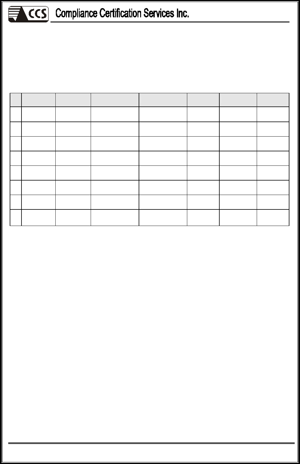
4.1. DESCRIPTION OF SUPPORT UNITS
The EUT has been tested as an independent unit together with other necessary accessories or
support units. The following support units or accessories were used to form a representative test
configuration during the tests.
No.
Equipment
Model No. Serial No. FCC ID/ BSMI ID
Trade Name
Data Cable Power Cord
1
USB 2.0 HDD
F12-U N/A BSMI ID: 4912A002 TeraSys Shielded,
1.8m N/A
2
PS/2
Mouse M071KC N/A DoC
BSMI: R41108 DELL Shielded,
1.8m N/A
3
PS/2
Keyboard SK-8115 N/A DoC
BSMI: T3A002 DELL Shielded,
1.8m N/A
4
Printer C60 N/A BSMI ID: 3902E006 EPSON Shielded,
1.8m Unshielded,
1.8m
5
Host PC P Evo D510C 7308-KN8Z-0010 BSMI ID: 3912Q007 COMPAQ Shielded,
1.8m Unshielded,
1.8m
6
Monitor 710V GS17H9NXA05853A
DoC
BSMI: R33475 SAMSUNG Shielded, 1.8m
with two cores Unshielded,
1.8m
7
Modem 5JEG4033MKO
N/A 5RJTAI-35500-M5-E TOP -
SOLUTION Shielded,
1.4m Unshielded,
1.8m
8
USB
Load X3 N/A N/A N/A N/A Shielded,
1.8m N/A
Note:
1) All the equipment/cables were placed in the worst-case configuration to maximize the emission during the test.
2) Grounding was established in accordance with the manufacturer’s requirements and conditions for the intended
use.
Reference No.: 60803207-D
Report No.: 81126201-D
Page 7
This report shall not be reproduced except in full, without the written approval of Compliance Certification Services.
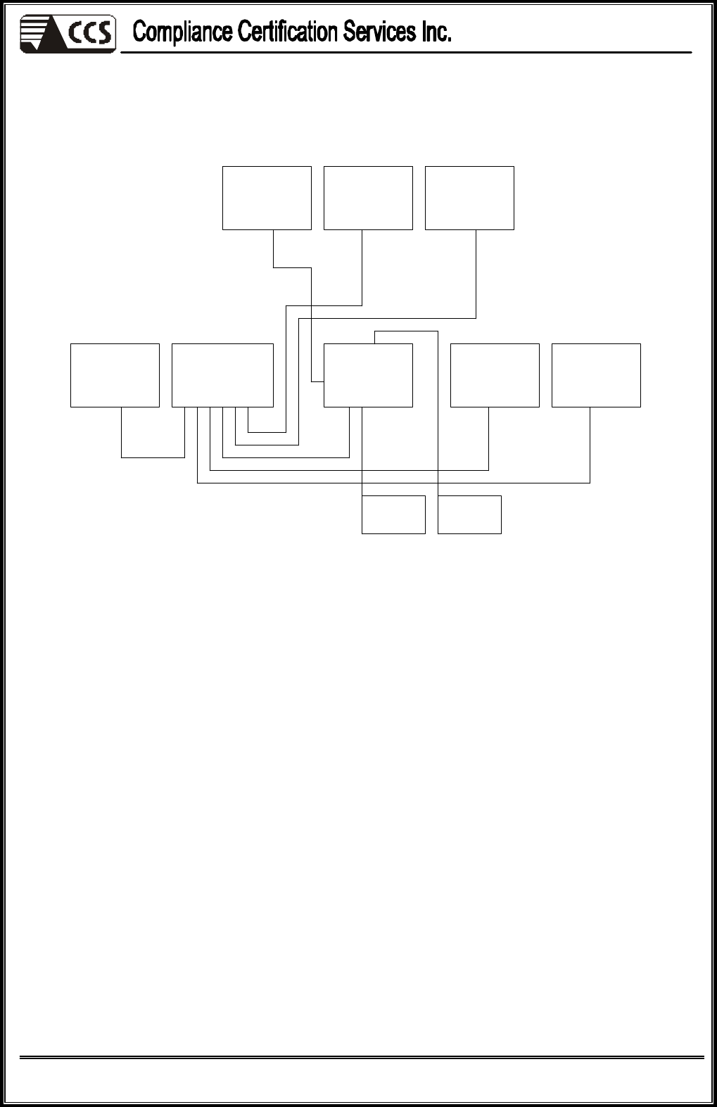
PS/2
Mouse
PS/2
Keyboard
Host PC
EUT
USB
2.0HDD
Printer
Monitor
Modem
4.2. CONFIGURATION OF SYSTEM UNDER TEST
USB
LOADX1
USB
LOADX2
Reference No.: 60803207-D
Report No.: 81126201-D
Page 8
This report shall not be reproduced except in full, without the written approval of Compliance Certification Services.
5 FACILITIES AND ACCREDITATIONS
5.1. FACILITIES
All measurement facilities used to collect the measurement data are located at
CCS Taiwan Sindian BU. at No.163-1, Jhongsheng Rd., Sindian City, Taipei County 23151,
Taiwan.
The sites are constructed in conformance with the requirements of ANSI C63.4 and CISPR
Publication 22. All receiving equipment conforms to CISPR Publication 16-1, “Radio Interference
Measuring Apparatus and Measurement Methods.”
5.2. ACCREDITATIONS
Our laboratories are accredited and approved by the following approval agencies according to
ISO/IEC 17025.
USA FCC, A2LA
Germany TUV Rheinland
Japan VCCI
Norway NEMKO
Canada INDUSTRY CANADA
Taiwan TAF, BSMI
Copies of granted accreditation certificates are available for downloading from our web site,
http://www.ccsemc.com.tw
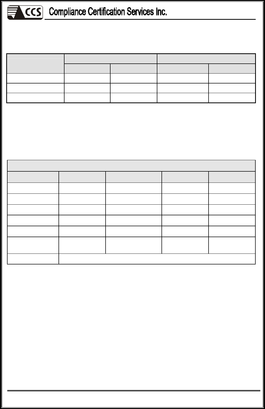
5.3. MEASUREMENT UNCERTAINTY
Where relevant, the following measurement uncertainty levels have been estimated for tests
performed on the EUT as specified in CISPR 16-4-2:
Measurement Frequency Uncertainty
Conducted emissions
9kHz~30MHz ± 3.4510
30MHz ~ 200MHz ± 4.3807
Horizontal 200MHz ~1000MHz
± 4.5149
30MHz ~ 200MHz ± 4.5023
Radiated emissions
Vertical 200MHz ~1000MHz
± 4.5075
This uncertainty represents an expanded uncertainty expressed at approximately the 95%
confidence level using a coverage factor of k=2.
Reference No.: 60803207-D
Report No.: 81126201-D
Page 9
This report shall not be reproduced except in full, without the written approval of Compliance Certification Services.
6 CONDUCTED EMISSION MEASUREMENT
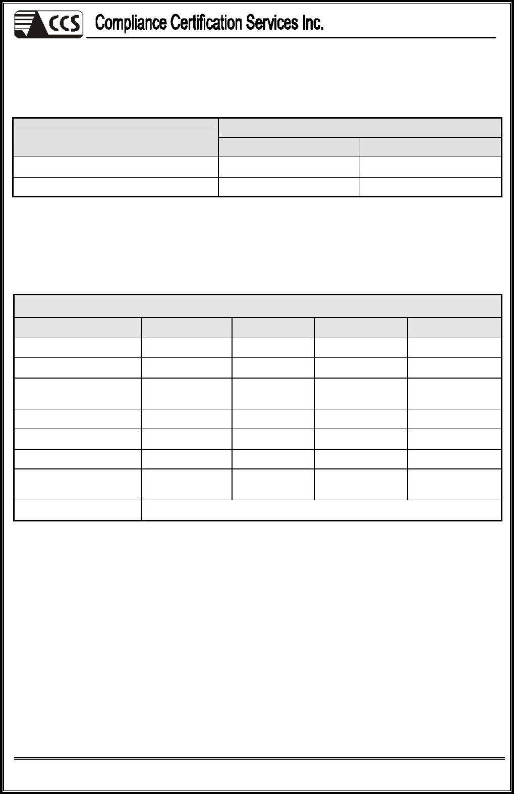
6.1. LIMITS OF CONDUCTED EMISSION MEASUREMENT
Class A (dBuV) Class B (dBuV)
FREQUENCY (MHz)
Quasi-peak Average Quasi-peak Average
0.15 - 0.5 79 66 66 - 56 56 - 46
0.50 - 5.0 73 60 56 46
5.0 - 30.0 73 60 60 50
NOTE:
(1) The lower limit shall apply at the transition frequencies.
(2) The limit decreases in line with the logarithm of the frequency in the range of 0.15 to 0.50 MHz.
(3) All emanations from a class A/B digital device or system, including any network of conductors and apparatus
connected thereto, shall not exceed the level of field strengths specified above.
6.2. TEST INSTRUMENTS
Conducted Emission Room # B
Name of Equipment
Manufacturer Model Serial Number Calibration Due
TEST RECEIVER R&S ESHS10 843743/015 03/28/2007
LISN (EUT) EMCO 3825/2 9106-1810 01/09/2007
LISN EMCO 3825/2 1382 01/09/2007
BNC CABLE MIYAZAKI 5D-FB BNC B1 07/13/2007
Pulse Limiter R&S ESH3-Z2 100374 08/25/2006
THERMO-
HYGRO METER TOP HA-202 9303-3 02/22/2007
Test S/W EMI 32.exe
NOTE: 1. The calibration interval of the above test instruments is 12 months and the calibrations are traceable to
NML/ROC and NIST/USA.
2. N.C.R = No Calibration Request.

Reference No.: 60803207-D
Report No.: 81126201-D
Page 10
This report shall not be reproduced except in full, without the written approval of Compliance Certification Services.
6.3. TEST PROCEDURES
(please refer to measurement standard or CCS SOP PA -031)
Procedure of Preliminary Test
l The EUT and Support equipment, if needed, was set up as per the test configuration to simulate
typical usage per the user’s manual. When the EUT is a tabletop system, a wooden table with a
height of 0.8 meters is used and is placed on the ground plane as per ANSI C63.4 (see Test
Facility for the dimensions of the ground plane used). When the EUT is a floor standing
equipment, it is placed on the ground plane, which has a 12 mm non-conductive covering to
insulate the EUT from the ground plane.
l All I/O cables were positioned to simulate typical actual usage as per ANSI C63.4.
l The test equipment EUT installed received AC main power, through a Line Impedance
Stabilization Network (LISN), which supplied power source and was grounded to the ground
plane.
l All support equipment power received from a second LISN.
l The EUT test program was started. Emissions were measured on each current carrying line of
the EUT using an EMI Test Receiver connected to the LISN powering the EUT.
l The Receiver scanned from 150kHz to 30MHz for emissions in each of the test modes.
l During the above scans, the emissions were maximized by cable manipulation.
l The test mode(s) described in Item 3.1 were scanned during the preliminary test.
l After the preliminary scan, we found the test mode described in Item 3.1 producing the highest
emission level.
l The EUT configuration and cable configuration of the above highest emission levels were
recorded for reference of the final test.
Procedure of Final Test
l EUT and support equipment were set up on the test bench as per the configuration with highest
emission level in the preliminary test.
l A scan was taken on both power lines, Line 1 and Line 2, recording at least the six highest
emissions. Emission frequency and amplitude were recorded into a computer in which
correction factors were used to calculate the emission level and compare reading to the
applicable limit.
l The test data of the worst-case condition(s) was recorded.
Reference No.: 60803207-D
Report No.: 81126201-D
Page 11
This report shall not be reproduced except in full, without the written approval of Compliance Certification Services.
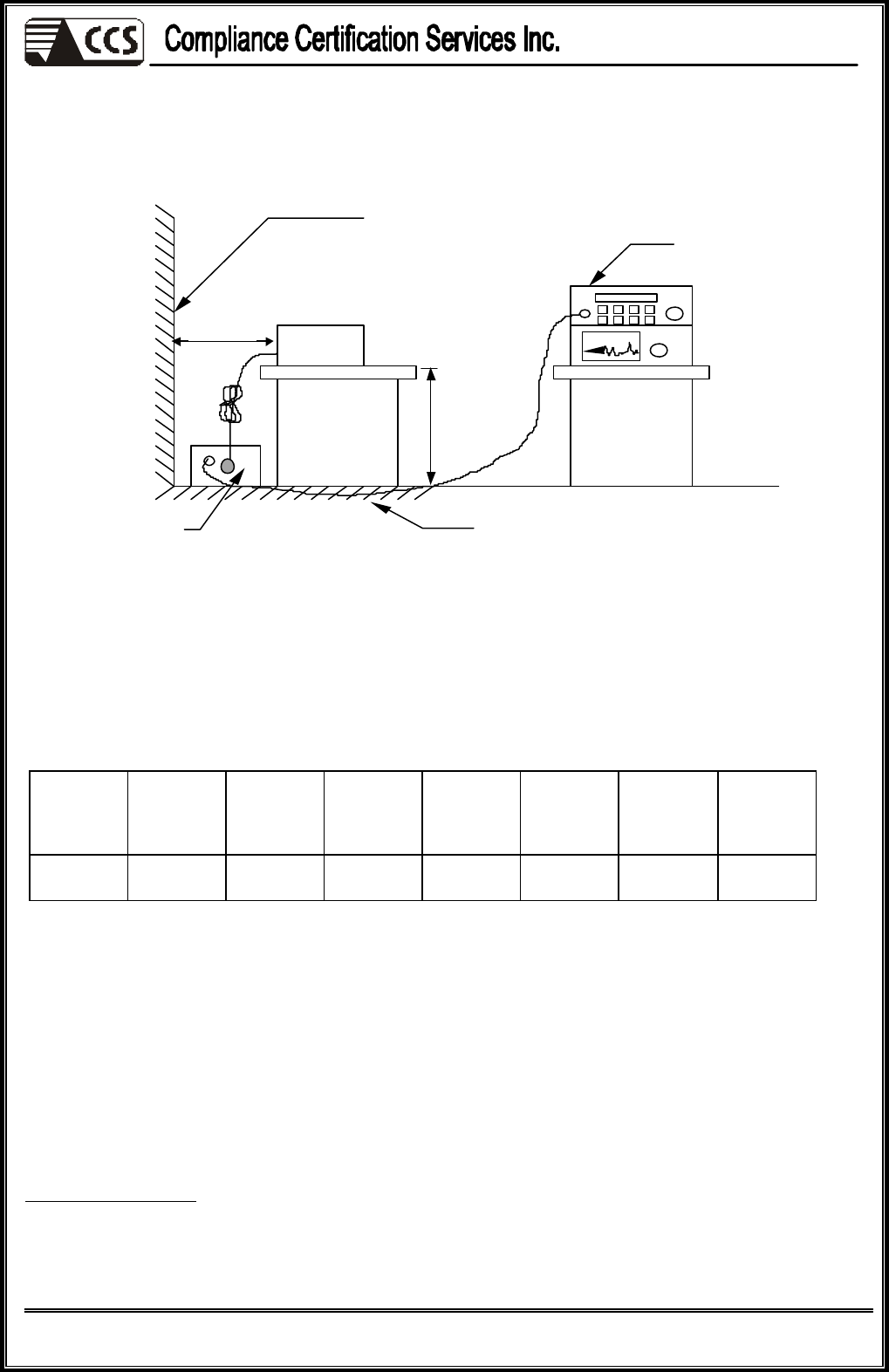
6.4. TEST SETUP
l For the actual test configuration, please refer to the related item – Photographs of the Test
Configuration.
6.5. Data Sample:
Freq.
MHz
Read
Level
dBuV
Factor
dB Level
dBuV Limit
dBuV
Over
Limit
dB
Reading
Type
(P/Q/A)
Line
(L1/L2)
x.xx 42.95 0.55 43.50 56 -12.50 Q L1
Freq. = Emission frequency in MHz
Read Level = Uncorrected Analyzer/Receiver reading
Factor = Insertion loss of LISN + Cable Loss
Level = Read Level + Factor
Limit = Limit stated in standard
Over Limit = Reading in reference to limit
P = Peak Reading
Q = Quasi-peak Reading
A = Average Reading
L1 = Hot side
L2 = Neutral side
Calculation Formula
Over Limit (dB) = Level (dBuV) – Limit (dBuV)
EUT
LISN
EMI receiver
Reference ground plane
Vert. reference plane
40cm
80cm
Reference No.: 60803207-D
Report No.: 81126201-D
Page 12
This report shall not be reproduced except in full, without the written approval of Compliance Certification Services.
6.6. TEST RESULTS
Model No. JC-SW41AS 6dB
BANDWIDTH
10 kHz
Environmental
Conditions 26deg.C, 55% RH, 1010 hPa Test Mode Mode 1
Tested by Alee Shen
(The chart below shows the highest readings taken from the final data.)
Six Highest Conducted Emission Readings
Frequency Range Investigated 150 kHz to 30 MHz
Freq
(MHz)
Read
Level
(dBuV)
Factor
(dB) Level
(dBuV)
Limit
Line
(dBuV)
Over
Limit
(dB)
Reading
Type
(P/Q/A)
Line
(L1/L2)
0.191 43.84 9.93 53.77 63.98 -10.20 P L1
0.336 36.90 9.84 46.74 59.31 -12.58 P L1
0.402 34.57 9.81 44.38 57.81 -13.43 P L1
0.479 34.14 9.83 43.98 56.36 -12.39 P L1
0.190 43.06 9.94 53.00 64.02 -11.02 P L2
0.479 32.45 9.83 42.29 56.36 -14.08 P L2
NOTE: 1. L1 = Line One (Live Line) / L2 = Line Two (Neutral Line)
2. The emission level was or more than 2dB below the Average limit, so no re-check anymore.
Reference No.: 60803207-D
Report No.: 81126201-D
Page 13
This report shall not be reproduced except in full, without the written approval of Compliance Certification Services.
7 RADIATED EMISSION MEASUREMENT
7.1. LIMITS OF RADIATED EMISSION MEASUREMENT
dBuV/m (At 10m)
FREQUENCY (MHz) Class A Class B
30 ~ 230 40 30
230 ~ 1000 47 37
NOTE: (1) The lower limit shall apply at the transition frequencies.
(2) Emission level (dBuV/m) = 20 log Emission level (uV/m).
7.2. TEST INSTRUMENTS
Open Area Test Site # H
Name of Equipment Manufacturer Model Serial Number Calibration Due
SITE NSA CCS H Site N/A 10/ 09/2006
MEASURE RECEIVER SCHAFFNER SCR3501 341 09/07/ 2006
SPECTRUM ANALYZER
ADVANTEST R3132 120900002 No Calibration
Required
ANTENNA SCHAFFNER CBL 6112B 2801 09/23/2006
AMPLIFIER SCHAFFNER CPA9231A 3613 10/ 08/2006
CABLE SUHNER RG 214 N-TYPE#H2 12/02/2006
THERMO-
HYGRO METER TFA N/A NO.1 12/25/2006
Test S/W Lab VIEW 5.1
NOTE: 1. The calibration interval of the above test instruments is 12 months and the calibrations are traceable to
NML/ROC and NIST/USA.
2. N.C.R = No Calibration Request.

Reference No.: 60803207-D
Report No.: 81126201-D
Page 14
This report shall not be reproduced except in full, without the written approval of Compliance Certification Services.
7.3. TEST PROCEDURES
(please refer to measurement standard or CCS SOP PA -031)
Procedure of Preliminary Test
l The equipment was set up as per the test configuration to simulate typical usage per the user’s
manual. When the EUT is a tabletop system, a wooden turntable with a height of 0.8 meters is
used which is placed on the ground plane. When the EUT is a floor standing equipment, it is
placed on the ground plane which has a 12 mm non-conductive covering to insulate the EUT
from the ground plane.
l Support equipment, if needed, was placed as per ANSI C63.4.
l All I/O cables were positioned to simulate typical usage as per ANSI C63.4.
l The EUT received AC power source from the outlet socket under the turntable. All support
equipment power received from another socket under the turntable.
l The antenna was placed at 10 meter away from the EUT as stated in ANSI C63.4. The antenna
connected to the Spectrum Analyzer via a cable and at times a pre-amplifier would be used.
l The Analyzer / Receiver quickly scanned from 30MHz to 1000MHz. The EUT test program was
started. Emissions were scanned and measured rotating the EUT to 360 degrees and positioning
the antenna 1 to 4 meters above the ground plane, in both the vertical and the horizontal
polarization, to maximize the emission reading level.
l The test mode(s) described in Item 3.1 were scanned during the preliminary test:
l After the preliminary scan, we found the test mode described in Item 3.1 producing the highest
emission level.
l The EUT and cable configuration, antenna position, polarization and turntable position of the
above highest emission level were recorded for the final test.

Reference No.: 60803207-D
Report No.: 81126201-D
Page 15
This report shall not be reproduced except in full, without the written approval of Compliance Certification Services.
Procedure of Final Test
l EUT and support equipment were set up on the turntable as per the configuration with highest
emission level in the preliminary test.
l The Analyzer / Receiver scanned from 30MHz to 1000MHz. Emissions were scanned and
measured rotating the EUT to 360 degrees, varying cable placement and positioning the antenna
1 to 4 meters above the ground plane, in both the vertical and the horizontal polarization, to
maximize the emission reading level.
l Recorded at least the six highest emissions. Emission frequency, amplitude, antenna position,
polarization and turntable position were recorded into a computer in which correction factors
were used to calculate the emission level and compare reading to the applicable limit and only
Q.P. reading is presented.
l The test data of the worst-case condition(s) was recorded.
Reference No.: 60803207-D
Report No.: 81126201-D
Page 16
This report shall not be reproduced except in full, without the written approval of Compliance Certification Services.
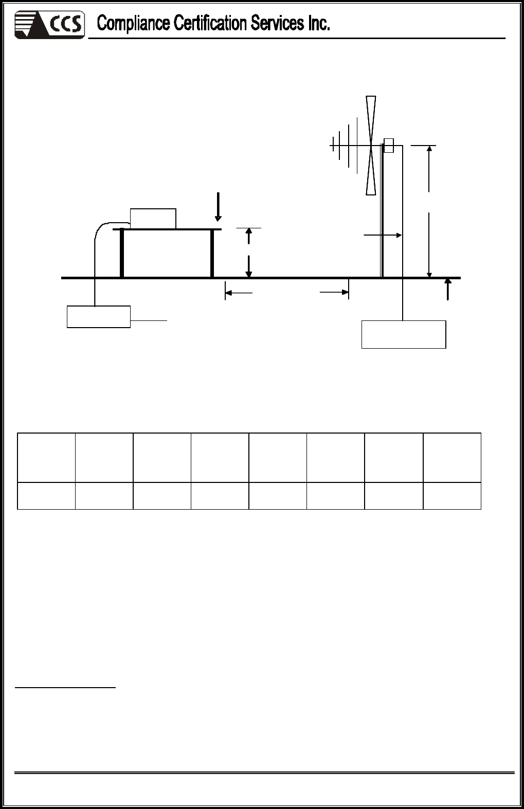
Filter
Filter
Filter
To
Power
EUT
Ground Plane
10 m
0.8 m
Coaxial
Cable
Test table &
Turntable
1m ~ 4m
Power
Cable
EMI
Receiver
Filter
7.4. TEST SETUP
l For the actual test configuration, please refer to the related item – Photographs of the Test
Configuration.
7.5. Data Sample:
Freq.
MHz
Amptd
dBuV/m
Margin
dB
Limit
dBuV/m
Reading
dBuV
Factor
dB/m
Reading
Type
(P/Q/A)
Pol.
(H/V)
x.xx 26.2 -3.8 30 14 12.2 Q H
Freq. = Emission frequency in MHz
Read Level = Uncorrected Analyzer/Receiver reading
Factor = Antenna Factor + Cable Loss + Attenuator (3/6/10dB) – Amplifier Gain
Level = Read Level + Factor
Limit = Limit stated in standard
Over Limit = Reading in reference to limit
P = Peak Reading
Q = Quasi-peak Reading
A = Average Reading
H = Antenna Polarization: Horizontal
V = Antenna Polarization: Vertical
Calculation Formula
Over Limit (dB) = Level (dBuV/m) – Limit (dBuV/m)
Reference No.: 60803207-D
Report No.: 81126201-D
Page 17
This report shall not be reproduced except in full, without the written approval of Compliance Certification Services.
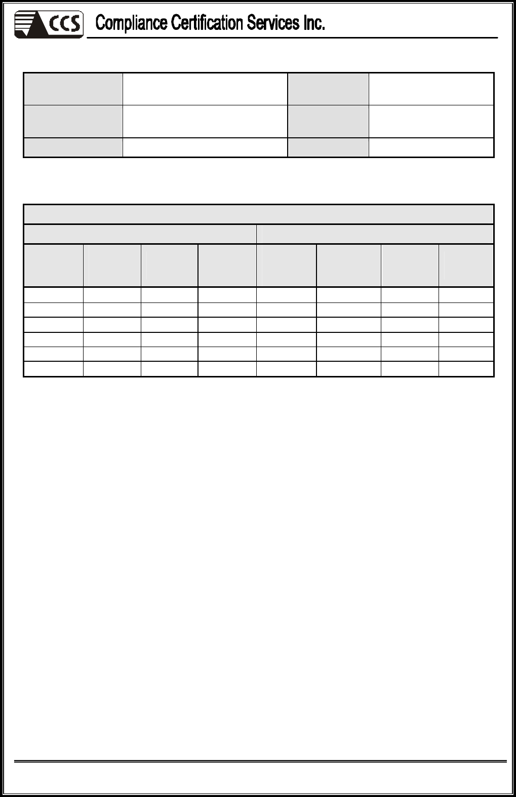
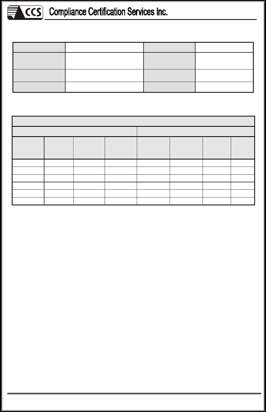
7.6. TEST RESULTS
Model No. JC-SW41AS Test Mode Mode 1
Environmental
Conditions 32deg.C, 58% RH,
1005 hPa 6dB
BANDWIDTH 120 kHz
Antenna Pole Vertical Antenna Distance 10m
Detector Function
Quasi-peak. Tested by James Hsieh
1
(The chart below shows the highest readings taken from the final data.)
Six Highest Radiated Emission Readings
Frequency Range Investigated 30 MHz to 1000 MHz at 10m
Freq.
MHz
Amptd
dBuV/m
Margin
dB
Limit
dBuV/m
Reading
dBuV
Factor
dB/m
Reading
Type
(P/Q/A)
Pol.
(H/V)
119.9800
24.47 -5.53 30.00 38.00 -13.53 Q V
219.1900
23.78 -6.22 30.00 38.00 -14.22 Q V
244.1000
28.07 -8.93 37.00 40.00 -11.93 Q V
299.9100
27.87 -9.13 37.00 38.00 -10.13 Q V
311.4755
26.25 -10.75 37.00 36.00 -9.75 Q V
480.0200
33.26 -3.74 37.00 38.00 -4.74 Q V
REMARKS: 1. 30MHz to 1000MHz test is Applicable CISPR 22 / EN 55022 standard.
2. The other emission levels were very low against the limit.
3. P= Peak Reading; Q= Quasi-peak Reading A= Average Reading
Reference No.: 60803207-D
Report No.: 81126201-D
Page 18
This report shall not be reproduced except in full, without the written approval of Compliance Certification Services.
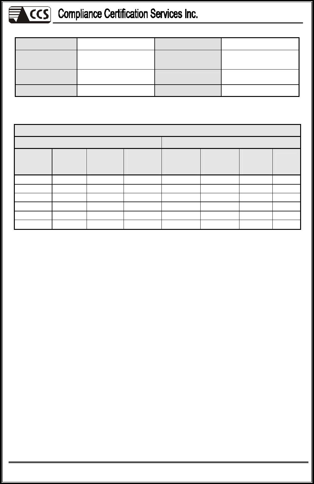
Model No. JC-SW41AS Test Mode Mode 1
Environmental
Conditions 32deg.C, 58% RH,
1005hPa 6dB
BANDWIDTH 120 kHz
Antenna Pole Horizontal Antenna Distance 10m
Detector Function
Quasi-peak. Tested by James Hsieh
(The chart below shows the highest readings taken from the final data.)
Six Highest Radiated Emission Readings
Frequency Range Investigated 30 MHz to 1000 MHz at 10m
Freq.
MHz
Amptd
dBuV/m
Margin
dB
Limit
dBuV/m
Reading
dBuV
Factor
dB/m
Reading
Type
(P/Q/A)
Pol.
(H/V)
61.2400 19.64 -10.36 30.00 40.00 -20.36 Q H
120.0000
21.47 -8.53 30.00 35.00 -13.53 Q H
165.8300
19.90 -10.10 30.00 35.00 -15.10 Q H
239.7700
25.67 -11.33 37.00 38.00 -12.33 Q H
480.0300
33.26 -3.74 37.00 38.00 -4.74 Q H
719.9600
33.99 -3.01 37.00 35.00 -1.01 Q H
REMARKS: 1. 30MHz to 1000MHz test is Applicable CISPR 22 / EN 55022 standard.
2. The other emission levels were very low against the limit.
3. P= Peak Reading; Q= Quasi-peak Reading A= Average Reading
Reference No.: 60803207-D
Report No.: 81126201-D
Page 19
This report shall not be reproduced except in full, without the written approval of Compliance Certification Services.
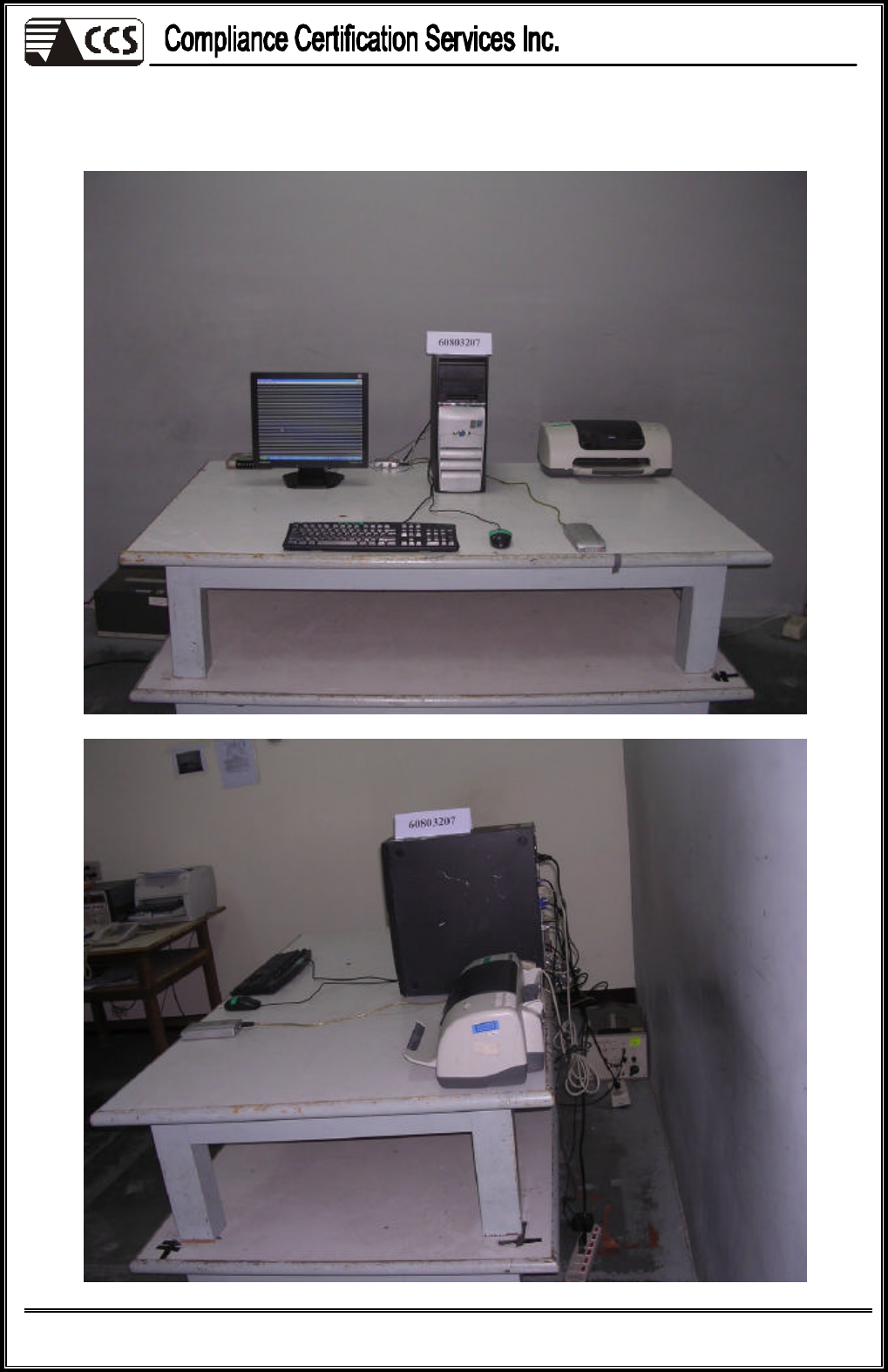
8 PHOTOGRAPHS OF THE TEST CONFIGURATION
CONDUCTED EMISSION TEST
Reference No.: 60803207-D
Report No.: 81126201-D
Page 20
This report shall not be reproduced except in full, without the written approval of Compliance Certification Services.
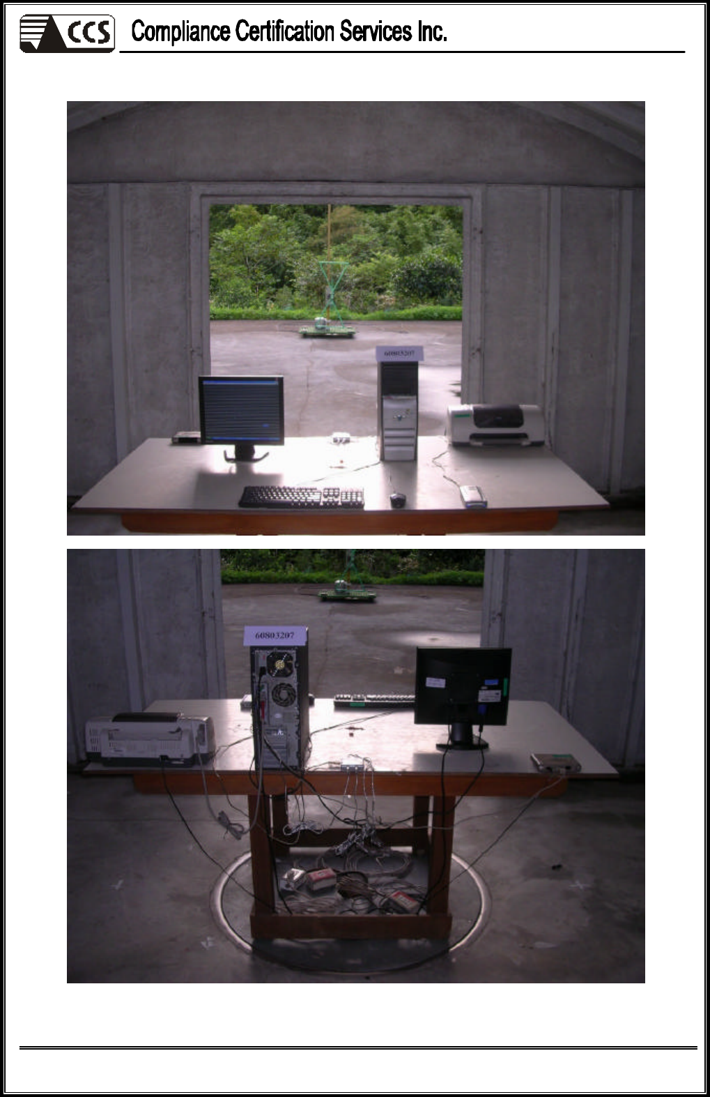
RADIATED EMISSION TEST
