FrontDSD 8178559 Whirlpool Duet Sport Dryer Ser Man
2013-05-09
: Pdf 8178559 - Whirlpool Duet Sport Dryer - Ser Man 8178559 - Whirlpool Duet Sport Dryer - Ser Man dryer may8
Open the PDF directly: View PDF ![]() .
.
Page Count: 96
ELECTRONIC
GAS & ELECTRIC
DRYERS
CONSUMER SERVICES TECHNICAL
EDUCATION GROUP PRESENTS
L-79
JOB AID
Part No. 8178559
MODELS: WED8300SW, WED8500SR
WGD8300SW, WGD8500SR

- ii -
WHIRLPOOL CORPORATION assumes no responsibility for any repairs
made on our products by anyone other than Authorized Service Technicians.
FORWARD
This Whirlpool Job Aid, “Duet Sport™ Electronic Gas & Electric Dryers” (Part No. 8178559),
provides the technician with information on the installation, operation, and service of the Duet
Sport™ Electronic Gas & Electric Dryers. For specific information on the model being serviced,
refer to the “Use and Care Guide,” or “Tech Sheet” provided with the dryer.
The Wiring Diagrams used in this Job Aid are typical and should be used for training purposes
only. Always use the Wiring Diagram supplied with the product when servicing the unit.
GOALS AND OBJECTIVES
The goal of this Job Aid is to provide information that will enable the service technician to prop-
erly diagnose malfunctions and repair the Duet Sport™ Electronic Gas & Electric Dryers.
The objectives of this Job Aid are to:
Understand and follow proper safety precautions.
Successfully troubleshoot and diagnose malfunctions.
Successfully perform necessary repairs.
Successfully return the dryer to its proper operational status.
•
•
•
•
Copyright © 2006, Whirlpool Corporation, Benton Harbor, MI 49022
- iii -
TABLE OF CONTENTS
Page
GENERAL . . . . . . . . . . . . . . . . . . . . . . . . . . . . . . . . . . . . . . . . . . . . . . . . . . . . . . . . . . . . . . 1-1
Dryer Safety . . . . . . . . . . . . . . . . . . . . . . . . . . . . . . . . . . . . . . . . . . . . . . . . . . . . . . . . . . . 1-1
Model & Serial Number Designations . . . . . . . . . . . . . . . . . . . . . . . . . . . . . . . . . . . . . . . . 1-2
Model & Serial Number Label And Tech Sheet Locations . . . . . . . . . . . . . . . . . . . . . . . . . 1-3
Specifications . . . . . . . . . . . . . . . . . . . . . . . . . . . . . . . . . . . . . . . . . . . . . . . . . . . . . . . . . . 1-4
INSTALLATION INFORMATION . . . . . . . . . . . . . . . . . . . . . . . . . . . . . . . . . . . . . . . . . . . . . 2-1
Installation Instructions . . . . . . . . . . . . . . . . . . . . . . . . . . . . . . . . . . . . . . . . . . . . . . . . . . . 2-1
PRODUCT OPERATION . . . . . . . . . . . . . . . . . . . . . . . . . . . . . . . . . . . . . . . . . . . . . . . . . . . 3-1
Dryer Use . . . . . . . . . . . . . . . . . . . . . . . . . . . . . . . . . . . . . . . . . . . . . . . . . . . . . . . . . . . . . 3-1
Dryer Care . . . . . . . . . . . . . . . . . . . . . . . . . . . . . . . . . . . . . . . . . . . . . . . . . . . . . . . . . . . . . 3-9
Troubleshooting . . . . . . . . . . . . . . . . . . . . . . . . . . . . . . . . . . . . . . . . . . . . . . . . . . . . . . . . .3-11
COMPONENT ACCESS . . . . . . . . . . . . . . . . . . . . . . . . . . . . . . . . . . . . . . . . . . . . . . . . . . 4-1
Component Locations . . . . . . . . . . . . . . . . . . . . . . . . . . . . . . . . . . . . . . . . . . . . . . . . . . . . 4-1
Removing The Console And The Console Electronics Assembly . . . . . . . . . . . . . . . . . . . 4-2
Removing The Machine Control Electronics . . . . . . . . . . . . . . . . . . . . . . . . . . . . . . . . . . . 4-4
Removing The Door Switch . . . . . . . . . . . . . . . . . . . . . . . . . . . . . . . . . . . . . . . . . . . . . . . . 4-5
Removing The Moisture Sensor . . . . . . . . . . . . . . . . . . . . . . . . . . . . . . . . . . . . . . . . . . . . 4-6
Removing The Drum Light Socket . . . . . . . . . . . . . . . . . . . . . . . . . . . . . . . . . . . . . . . . . . . 4-7
Removing The Front Panel . . . . . . . . . . . . . . . . . . . . . . . . . . . . . . . . . . . . . . . . . . . . . . . . 4-8
Removing The Thermal Fuse & Exhaust Thermistor . . . . . . . . . . . . . . . . . . . . . . . . . . . . 4-9
Removing The Belt & Drum, And Rollers . . . . . . . . . . . . . . . . . . . . . . . . . . . . . . . . . . . . 4-10
Removing The Drive Motor And Belt Switch . . . . . . . . . . . . . . . . . . . . . . . . . . . . . . . . . . 4-12
Removing The Ignitor, Flame Sensor, High-Limit Thermostat,
And Thermal Cutoff (Gas Models Only) . . . . . . . . . . . . . . . . . . . . . . . . . . . . . . . . . . . . 4-14
Removing The Gas Burner Assembly Coils . . . . . . . . . . . . . . . . . . . . . . . . . . . . . . . . . . 4-16
Removing The Heater, High-Limit Thermostat, And Thermal Cutoff
(Electric Models Only) . . . . . . . . . . . . . . . . . . . . . . . . . . . . . . . . . . . . . . . . . . . . . . . . . 4-17
Removing The Dryer Door . . . . . . . . . . . . . . . . . . . . . . . . . . . . . . . . . . . . . . . . . . . . . . . . 4-18
COMPONENT TESTING . . . . . . . . . . . . . . . . . . . . . . . . . . . . . . . . . . . . . . . . . . . . . . . . . . . 5-1
Moisture Sensor . . . . . . . . . . . . . . . . . . . . . . . . . . . . . . . . . . . . . . . . . . . . . . . . . . . . . . . . 5-1
Door Switch . . . . . . . . . . . . . . . . . . . . . . . . . . . . . . . . . . . . . . . . . . . . . . . . . . . . . . . . . . . . 5-2
Thermal Fuse . . . . . . . . . . . . . . . . . . . . . . . . . . . . . . . . . . . . . . . . . . . . . . . . . . . . . . . . . . 5-3
Exhaust Thermistor . . . . . . . . . . . . . . . . . . . . . . . . . . . . . . . . . . . . . . . . . . . . . . . . . . . . . . 5-4
Drive Motor . . . . . . . . . . . . . . . . . . . . . . . . . . . . . . . . . . . . . . . . . . . . . . . . . . . . . . . . . . . . 5-5
Flame Sensor . . . . . . . . . . . . . . . . . . . . . . . . . . . . . . . . . . . . . . . . . . . . . . . . . . . . . . . . . . 5-6
High-Limit Thermostat & Thermal Cutoff (Gas Dryers Only) . . . . . . . . . . . . . . . . . . . . . . . 5-6
Burner Ignitor . . . . . . . . . . . . . . . . . . . . . . . . . . . . . . . . . . . . . . . . . . . . . . . . . . . . . . . . . . . 5-7
Gas Burner Coils . . . . . . . . . . . . . . . . . . . . . . . . . . . . . . . . . . . . . . . . . . . . . . . . . . . . . . . . 5-7
Thermal Cutoff (Electric Dryers Only) . . . . . . . . . . . . . . . . . . . . . . . . . . . . . . . . . . . . . . . . 5-8
Heater (Electric Dryers Only) . . . . . . . . . . . . . . . . . . . . . . . . . . . . . . . . . . . . . . . . . . . . . . . 5-8
- iv -
Page
DIAGNOSTICS & TROUBLESHOOTING . . . . . . . . . . . . . . . . . . . . . . . . . . . . . . . . . . . . . . 6-1
Diagnostic Guide . . . . . . . . . . . . . . . . . . . . . . . . . . . . . . . . . . . . . . . . . . . . . . . . . . . . . . . . 6-1
Diagnostic Tests . . . . . . . . . . . . . . . . . . . . . . . . . . . . . . . . . . . . . . . . . . . . . . . . . . . . . . . . 6-1
Display Fault Codes . . . . . . . . . . . . . . . . . . . . . . . . . . . . . . . . . . . . . . . . . . . . . . . . . . . . . 6-4
Troubleshooting Guide . . . . . . . . . . . . . . . . . . . . . . . . . . . . . . . . . . . . . . . . . . . . . . . . . . . 6-5
Troubleshooting Tests . . . . . . . . . . . . . . . . . . . . . . . . . . . . . . . . . . . . . . . . . . . . . . . . . . . . 6-6
Removing The Toe Panel . . . . . . . . . . . . . . . . . . . . . . . . . . . . . . . . . . . . . . . . . . . . . . . . 6-15
Accessing & Removing The Electronic Assemblies . . . . . . . . . . . . . . . . . . . . . . . . . . . . . 6-15
Removing The Back Panel . . . . . . . . . . . . . . . . . . . . . . . . . . . . . . . . . . . . . . . . . . . . . . . 6-17
WIRING DIAGRAMS . . . . . . . . . . . . . . . . . . . . . . . . . . . . . . . . . . . . . . . . . . . . . . . . . . . . . . . 7-1
Electric Dryer . . . . . . . . . . . . . . . . . . . . . . . . . . . . . . . . . . . . . . . . . . . . . . . . . . . . . . . . . . . 7-1
Gas Dryer . . . . . . . . . . . . . . . . . . . . . . . . . . . . . . . . . . . . . . . . . . . . . . . . . . . . . . . . . . . . . 7-2
1-1
GENERAL
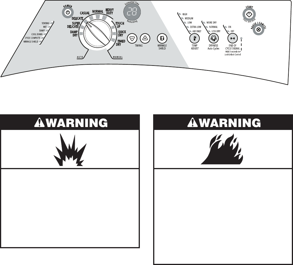
DRYER SAFETY
Your safety and the safety of others is very important.
We have provided many important safety messages in this Job Aid and on the appliance.
Always read and obey all safety messages.
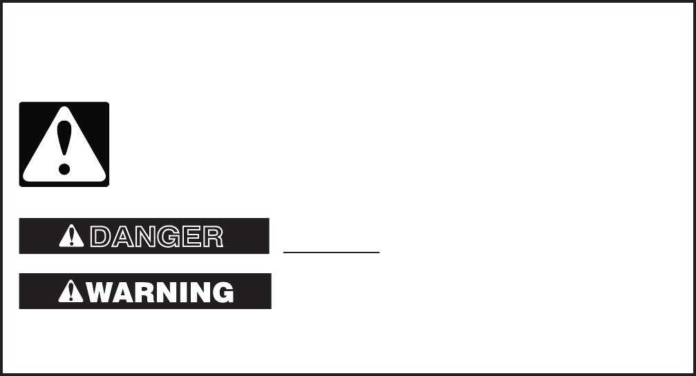
This is the safety alert symbol.
This symbol alerts you to potential hazards that can kill or hurt you and
others.
All safety messages will follow the safety alert symbol and either the word
“DANGER” or “WARNING.” These words mean:
All safety messages will tell you what the potential hazard is, tell you how to reduce the
chance of injury, and tell you what can happen if the instructions are not followed.
You can be killed or seriously injured if you don’t
immediately follow instructions.
You can be killed or seriously injured if you don’t
follow instructions.
DANGER

1-2
MODEL NUMBER W E D 8 3 00 S W 0
BRAND
W = Whirlpool
FUEL
E = Electric G = Gas
PRODUCT
D = Dryer
SERIES
5 = Whirlpool Leap 6 = Oasis
7 = 24˝ Front Load 8 = Mid Line Front Load
9 = Duet Front Load
PRICE POINT LEVELS (1 - 9)
TRADE PARTNER ID (00 = BRANDED)
YEAR OF INTRODUCTION
S = 2006, T = 2007
COLOR CODE
T = Biscuit
Q = White
W = White With Metallic Accent
R = White With Metallic (Sport Only)
ENGINEERING CHANGE (NUMERIC)
MODEL & SERIAL NUMBER DESIGNATIONS
MODEL NUMBER
SERIAL NUMBER
SERIAL NUMBER M T 09 62410
DIVISION RESPONSIBILITY
M = Marion, OH
YEAR OF PRODUCTION
T = 2006
WEEK OF PRODUCTION
09 = 9th Week
PRODUCT SEQUENCE NUMBER
1-3
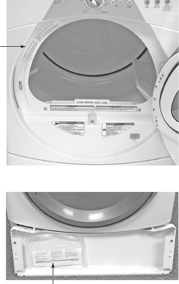
MODEL & SERIAL NUMBER LABEL
AND TECH SHEET LOCATIONS
The Model & Serial Number Label and Tech Sheet locations are shown below.
Model & Serial
Number Label
Tech Sheet
(Behind Lower Access Panel)

1-4
SPECIFICATIONS
Model Number WED8300SW
WGD8300SW
WED8500SR
WGD8500SR
Model Description Matching Dryer For
Front Load Washer
Matching Dryer For
Front Load Washer
Color White with Gray
Accents
White with Sterling
Bright Accents
Capacity (Cu.Ft. IEC) 6.7 6.7
Venting 4 way 4 way
Reversible Door Yes Yes
Lint Screen Location Front Front
Height 36.0" 36.0"
Install Depth: Min - Max 28.90" - 32.90" 28.90" - 32.90"
Width 27" 27"
Product Weight (approx) 122 lbs. 122 lbs.
2-1
INSTALLATION INFORMATION
INSTALLATION INSTRUCTIONS
TOOLS AND PARTS
Gather the required tools and parts before
starting installation. Read and follow the safe-
ty instructions provided with any tools listed
here.
Electric Models
Flat-blade screwdriver
#2 Phillips screwdriver
Adjustable wrench that opens to 1˝ (2.5 cm)
or hex-head socket wrench (for adjusting
dryer feet)
Wire stripper (direct wire installations)
Level
Vent clamps
Caulking gun and compound (for installing
new exhaust vent)
Tin snips (new vent installations)
1/4˝ nut driver or socket wrench
(recommended)
Tape measure
Gas Models
8˝ or 10˝ pipe wrench
8˝ or 10˝ adjustable wrench (for gas
connections)
Flat-blade screwdriver
Adjustable wrench that opens to 1˝
(2.5 cm) or hex-head socket wrench (for
adjusting dryer feet)
1/4˝ nut driver or socket wrench
(recommended)
Level
Vent clamps
Knife
Pipe-joint compound resistant to LP gas
Caulking gun and compound (for installing
new exhaust vent)
Pliers
Tape measure
•
•
•
•
•
•
•
•
•
•
•
•
•
•
•
•
•
•
•
•
•
•
NOTE: Do not use leveling legs if installing
the dryer on a pedestal.
Parts needed
Check local codes and with gas supplier.
Check existing gas supply, electrical supply
and venting. Read “Electrical Requirements,”
“Gas Supply Requirements” and “Venting Re-
quirements” before purchasing parts.
For close-clearance installations between
28.65˝ (72.77 cm) and 34.15˝ (86.74 cm),
see “Plan Vent System” section for venting
requirements.
•
4 Leveling legs
Parts Supplied
Remove parts packages from dryer drum.
Check that all parts are included.
Parts package•
Mobile home installations require special
parts (listed following) that may be ordered by
calling the dealer from whom you purchased
your dryer. For further information, please re-
fer to the “Assistance or Service” section of
the “Use & Care Guide.”
Mobile Home Installation Kit. Ask for Part
Number 346764.
Metal exhaust system hardware.
•
•
34.15"
(86.74 cm)
2-2
LOCATION REQUIREMENTS
Explosion Hazard
Keep flammable materials and vapors,
such as gasoline, away from dryer.
Place dryer at least 18 inches (46 cm)
above the floor for a garage installation.
Failure to do so can result in death,
explosion, or fire.
You will need
A location that allows for proper exhaust in-
stallation. See “Venting Requirements.”
Electric Models Only: A separate 30-amp
circuit.
If you are using a power cord, a grounded
electrical outlet located within 2 ft (61 cm)
of either side of the dryer. See “Electrical
Requirements.”
A sturdy floor to support the total dryer
weight of 127 lbs (57.6 kg). The combined
weight of a companion appliance should
also be considered.
A level floor with a maximum slope of
1˝(2.5 cm) under entire dryer. (If slope is
greater than 1˝ [2.5 cm], install Extended
Dryer Feet Kit, Part No. 279810.) Clothes
may not tumble properly and automatic
sensor cycles may not operate correctly if
dryer is not level.
For a garage installation, you will need to
place the dryer at least 18˝ (46 cm) above
the floor. If using a pedestal, you will need
18˝ (46 cm) to the bottom of the dryer.
Do not operate your dryer at temperatures
below 45°F (7°C). At lower temperatures, the
dryer might not shut off at the end of an auto-
matic cycle. Drying times can be extended.
•
•
•
•
•
•
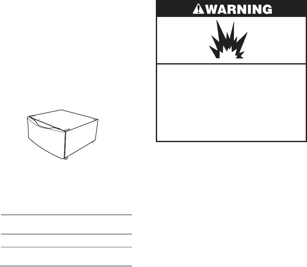
OPTIONS
Pedestal
Are you placing the dryer on a pedestal?
You have the option of purchasing pedestals
of different heights separately for this dryer.
You may select a 10˝ (25.4 cm) pedestal or a
15.5˝ (39.4 cm) pedestal with a shelf and bin
dividers. These pedestals will add to the total
height of the unit for a total height of approxi-
mately 46˝ (116.8 cm) or 51.5˝ (130.8 cm).
For a garage installation, you will need to
place the dryer at least 18˝ (46 cm) above
the floor.
Optional pedestal (15.5˝ [39.4 cm] model shown)
To order, call the dealer from whom you pur-
chased your dryer or refer to the “Assistance or
Service” section of the “Use & Care Guide.”
Pedestal
Height
Color Part Number
10" (25.4 cm)White WHP1000SQ
15.5" (39.4 cm) with
shelf and bin dividers
White WHP1500SQ
Drying Rack
To order a drying rack, call the dealer from
whom you purchased the dryer or refer to the
“Assistance or Service” section of the “Use &
Care Guide.” Ask for Part Number 8563738.
Stack Kit
Are you planning to stack your DUET SPORT™
washer and dryer? To do so, you will need to
purchase a Stack Kit.
To order, call the dealer from whom you pur-
chased your dryer or refer to the “Assistance
or Service” section of the “Use & Care Guide.”
Ask for Part Number 8572546.
2-3
36"
(91.4 cm)
50½"
(128.27 cm)
27"
(68.6 cm)
*28.65"
(72.77 cm)
* Most installations require a minimum 5˝
(12.7 cm) clearance behind the dryer for
the exhaust vent with elbow. See “Venting
Requirements.”
Installation spacing for recessed area or
closet installation
The following spacing dimensions are recom-
mended for this dryer. This dryer has been
tested for spacing of 0˝ (0 cm) clearance on
the sides and rear. Recommended spacing
should be considered for the following rea-
sons:
The dryer must not be installed or stored in an
area where it will be exposed to water and/or
weather.
Check code requirements. Some codes limit,
or do not permit, installation of the dryer in
garages, closets, mobile homes, or sleeping
quarters. Contact your local building inspec-
tor.
NOTE: No other fuel-burning appliance can
be installed in the same closet as a dryer.
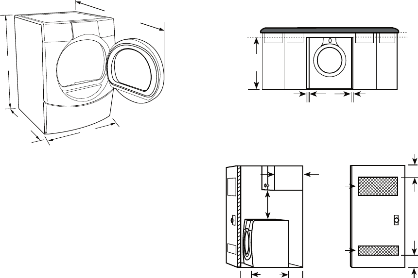
Installation Clearances
The location must be large enough to allow
the dryer door to open fully.
Dryer Dimensions
2"*
(5 cm)
36" min
(91.4 cm)
1"*
(2.5 cm)
1"*
(2.5 cm)
27"
(68.6 cm)
Additional spacing should be considered
for ease of installation and servicing.
Additional clearances might be required for
wall, door and floor moldings.
Additional spacing should be considered
on all sides of the dryer to reduce noise
transfer.
For closet installation, with a door, mini-
mum ventilation openings in the top and
bottom of the door are required. Louvered
doors with equivalent ventilation openings
are acceptable.
Companion appliance spacing should also
be considered.
Custom undercounter installation - Dryer
only
•
•
•
•
•
* Required Spacing
Closet installation - Dryer only
A. Side view - closet or confined area
B. Closet door with vents
AB
14" max.*
(35.6 cm)
15" min.*
(38.1 cm)
1"*
(2.5 cm)
5"**
(12.7 cm)
28.65"
(72.77 cm)
48 in.
2
*
(310 cm
2
)
24 in.
2
*
(155 cm
2
)
3"*
(7.6 cm)
3"*
(7.6 cm)
* Required spacing
** For side or bottom venting, 0˝ (0 cm) spacing is allowed.
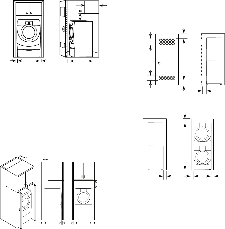
2-4
Recessed or closet installation - Dryer on
pedestal
A. Recessed area
B. Side view - closet or confined area
AB
1"
(2.5 cm)
1"
(2.5 cm)
27"
(68.6 cm) 1"
(2.5 cm)
5
"**
(12.7 cm)
28.65"
(72.77 cm)
15" min.*
(38.1 cm)
14" max.*
(35.6 cm)
Installation spacing for cabinet installation
The dimensions shown are for the recom-
mended spacing.
For cabinet installation, with a door, mini-
mum ventilation openings in the top of the
cabinet are required.
•
•
7"* (17.8 cm)
9"*
(22.9 cm)
7"* (17.8 cm)
5"**
(12.7 cm)
28.65"
(72.77 cm)
27"
(68.6 cm)
1"
(2.5 cm) (2.5 cm)
1"
(2.5 cm)
1"
* Required spacing
** For side or bottom venting, 0˝ (0 cm) spacing is allowed.
48 in.
2
*
(310 cm
2
)
3"* (7.6 cm)
3"* (7.6 cm)
1"* (2.5 cm)
24 in.
2
*
(155 cm
2
)
6"* (15.2 cm)
72"
(182.9 cm)
27"
(68.6 cm)
5"*
(12.7 cm)
1"
(2.5 cm)
1"
(2.5 cm)
* Required spacing
Recommended installation spacing for
recessed or closet installation with
stacked washer and dryer
The dimensions shown are for the recom-
mended spacing
* Required spacing
Mobile home - additional installation require-
ments
This dryer is suitable for mobile home instal-
lations. The installation must conform to the
Manufactured Home Construction and Safety
Standard, Title 24 CFR, Part 3280 (formerly
the Federal Standard for Mobile Home Con-
struction and Safety, Title 24, HUD Part 280).
Mobile home installations require:
Metal exhaust system hardware, which is
available for purchase from your dealer.
Special provisions must be made in mo-
bile homes to introduce outside air into the
dryer. The opening (such as a nearby win-
dow) should be at least twice as large as
the dryer exhaust opening.
•
•
* Required spacing
** For side or bottom venting, 0˝ (0 cm) spacing is allowed.
2-5
ELECTRICAL REQUIREMENTS
Electric Models Only
It is your responsibility
To contact a qualified electrical installer.
To be sure that the electrical connection
is adequate and in conformance with the
National Electrical Code, ANSI/NFPA 70-
latest edition and all local codes and ordi-
nances.
The National Electric Code requires a
4-wire supply connection for homes built
after 1996, dryer circuits involved in re-
modeling after 1996, and all mobile home
installations.
A copy of the above code standards can be
obtained from: National Fire Protection As-
sociation, One Batterymarch Park, Quincy,
MA 02269.
To supply the required 3 or 4 wire, single
phase, 120/240 volt, 60-Hz., AC-only elec-
trical supply (or 3 or 4 wire, 120/208 volt
electrical supply, if specified on the serial/
rating plate) on a separate 30-amp circuit,
fused on both sides of the line. A time-de-
lay fuse or circuit breaker is recommended.
Connect to an individual branch circuit. Do
not have a fuse in the neutral or grounding
circuit.
Do not use an extension cord.
If codes permit and a separate ground wire
is used, it is recommended that a qualified
electrician determine that the ground path
is adequate.
Electrical Connection
To properly install your dryer, you must deter-
mine the type of electrical connection you will
be using and follow the instructions provided
for it here.
•
•
•
•
•
If local codes do not permit the connection
of a neutral ground wire to the neutral wire,
see “Optional 3-wire connection” section.
This dryer is manufactured ready to install
with a 3-wire electrical supply connection.
The neutral ground wire is permanently
connected to the neutral conductor (white
wire) within the dryer. If the dryer is installed
with a 4-wire electrical supply connection,
the neutral ground wire must be removed
from the external ground conductor screw
(green screw), and secured under the neu-
tral terminal (center or white wire) of the
terminal block. When the neutral ground
wire is secured under the neutral terminal
(center or white wire) of the terminal block,
the dryer cabinet is isolated from the neu-
tral conductor.
A 4-wire power supply connection must be
used when the appliance is installed in a lo-
cation where grounding through the neutral
conductor is prohibited. Grounding through
the neutral is prohibited for (1) new branch-
circuit installations,(2) mobile homes, (3)
recreational vehicles, and (4) areas where
local codes prohibit grounding through the
neutral conductors.
If using a power supply cord:
Use a UL listed power supply cord kit marked
for use with clothes dryers. The kit should
contain:
A UL listed 30-amp power supply cord, rat-
ed 120/240-volt minimum. The cord should
be type SRD or SRDT and be at least 4 ft
(1.22 m) long. The wires that connect to the
dryer must end in ring terminals or spade
terminals with upturned ends.
A UL listed strain relief.
•
•
•
•
•
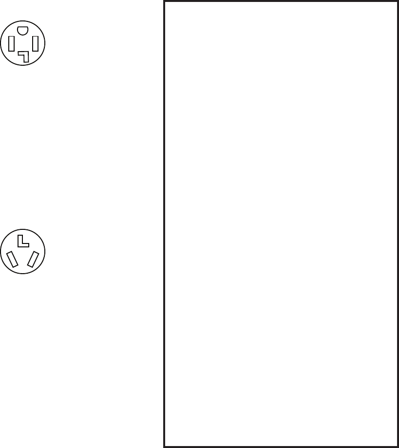
2-6
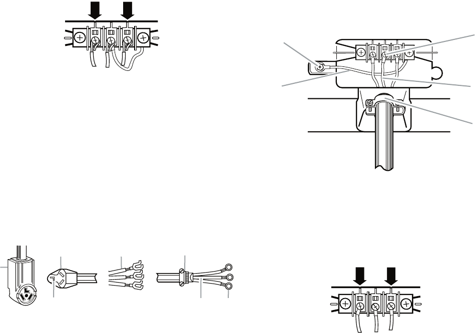
4-wire receptacle (14-30R)
Then choose a 4-wire power supply cord with
ring or spade terminals and UL listed strain
relief. The 4-wire power supply cord, at least
4 ft (1.22 m) long, must have 4, 10-gauge cop-
per wires and match a 4-wire receptacle of
NEMA Type 14-30R. The ground wire (ground
conductor) may be either green or bare. The
neutral conductor must be identified by a
white cover.
If your outlet looks like this:
Then choose a 3-wire power supply cord with
ring or spade terminals and UL listed strain
relief. The 3-wire power supply cord, at least
4 ft (1.22 m) long, must have 3, 10-gauge
copper wires and match a 3-wire receptacle
of NEMA Type 10-30R.
If connecting by direct wire:
Power supply cable must match power supply
(4-wire or 3-wire) and be:
Flexible armored cable or nonmetallic
sheathed copper cable (with ground wire),
protected with flexible metallic conduit. All
current-carrying wires must be insulated.
10-gauge solid copper wire (do not use
aluminum).
At least 5 ft (1.52 m) long.
•
•
•
3-wire receptacle (10-30R)
If your outlet looks like this: GROUNDING INSTRUCTIONS
For a grounded, cord-connected dryer:
This dryer must be grounded. In the event
of malfunction or breakdown, grounding
will reduce the risk of electric shock by
providing a path of least resistance for
electric current. This dryer uses a cord
having an equipment-grounding conduc-
tor and a grounding plug. The plug must
be plugged into an appropriate outlet that
is properly installed and grounded in ac-
cordance with all local codes and ordi-
nances.
For a permanently connected dryer:
This dryer must be connected to a ground-
ed metal, permanent wiring system, or an
equipment-grounding conductor must be
run with the circuit conductors and con-
nected to the equipment-grounding termi-
nal or lead on the dryer.
WARNING: Improper connection of the
equipment-grounding conductor can result
in a risk of electric shock. Check with a
qualified electrician or service representa-
tive or personnel if you are in doubt as to
whether the dryer is properly grounded.
Do not modify the plug on the power sup-
ply cord: if it will not fit the outlet, have a
proper outlet installed by a qualified elec-
trician.
•
•
2-7
ELECTRICAL CONNECTION
Electric Models Only
POWER SUPPLY CORD
Fire Hazard
Use a new UL listed 30 amp power
supply cord.
Use a UL listed strain relief.
Disconnect power before making
electrical connections.
Connect neutral wire (white or center
wire) to center terminal (silver).
Ground wire (green or bare wire)
must be connected to green ground
connector.
Connect remaining 2 supply wires to
remaining 2 terminals (gold).
Securely tighten all electrical
connections.
Failure to do so can result in death, fire,
or electrical shock.
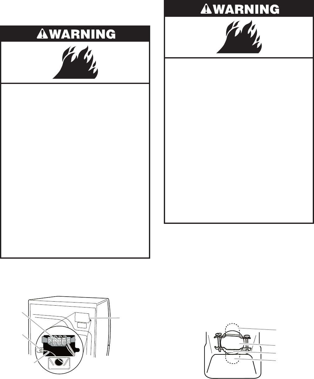
1. Disconnect power.
2. Remove the hold-down screw and termi-
nal block cover.
A. Neutral ground wire
B. External ground conductor screw
C. Center, silver-colored terminal block screw
D. Terminal block cover and hold-down screw
A
B
C
D
3. Install strain relief.
DIRECT WIRE
Fire Hazard
Use 10 gauge solid copper wire.
Use a UL listed strain relief.
Disconnect power before making
electrical connections.
Connect neutral wire (white or center
wire) to center terminal (silver).
Ground wire (green or bare wire)
must be connected to green ground
connector.
Connect remaining 2 supply wires to
remaining 2 terminals (gold).
Securely tighten all electrical
connections.
Failure to do so can result in death, fire,
or electrical shock.
Style 1: Power supply cord strain relief
Remove the screws from a 3/4˝ (1.9 cm)
UL listed strain relief (UL marking on strain
relief). Put the tabs of the two clamp sec-
tions into the hole below the terminal block
opening so that one tab is pointing up
and the other is pointing down, and hold
in place. Tighten strain relief screws just
enough to hold the two clamp sections to-
gether.
•
A. Strain relief tab pointing up
B. Hole below terminal block opening
C. Clamp section
D. Strain relief tab pointing down
A
B
C
D
2-8
Put power supply cord through the strain
relief. Be sure that the wire insulation on
the power supply cord is inside the strain
relief. The strain relief should have a tight
fit with the dryer cabinet and be in a hori-
zontal position. Do not further tighten strain
relief screws at this point.
•
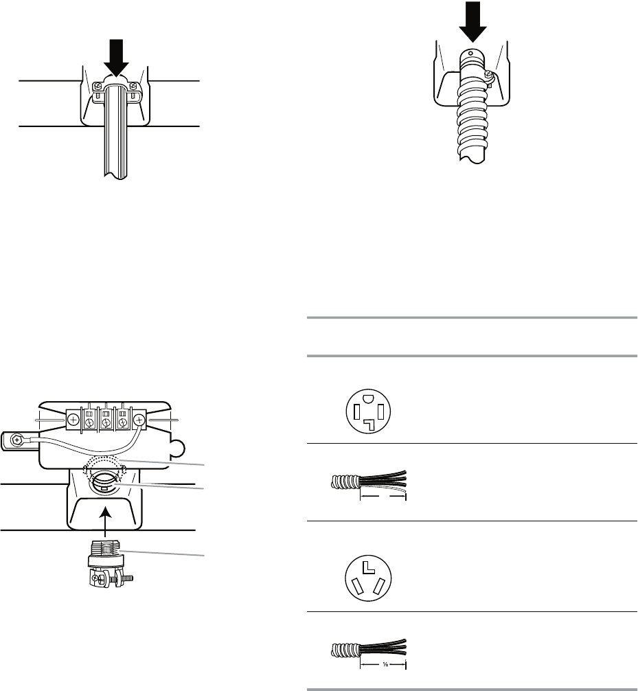
Style 2: Direct wire strain relief
Unscrew the removable conduit connector
and any screws from a 3/4˝ (1.9 cm) UL
listed strain relief (UL marking on strain re-
lief). Put the threaded section of the strain
relief through the hole below the terminal
block opening. Reaching inside the termi-
nal block opening, screw the removable
conduit connector onto the strain relief
threads.
•
A. Removable conduit connector
B. Hole below terminal block opening
C. Strain relief threads
A
B
C
4. Now complete installation following in-
structions for your type of electrical con-
nection:
4-wire (recommended)
3-wire (if 4-wire is not available)
Electrical Connection Options
Put direct wire cable through the strain re-
lief. The strain relief should have a tight fit
with the dryer cabinet and be in a horizontal
position. Tighten strain relief screw against
the direct wire cable.
•
If your home has: And you will be
connecting to:
Go to Section
4-wire receptacle
(NEMA Type 14-30R)
A UL listed,
120/240-volt
minimum,
30-amp, dryer
power supply
cord*
4-wire connection:
Power supply cord
4-wire direct A fused
disconnect or
circuit breaker
box*
4-wire connection:
Direct Wire
3-wire receptacle
(NEMA type 10-30R)
A UL listed,
120/240-volt
minimum,
30-amp, dryer
power supply
cord*
3-wire connection:
Power supply cord
3-wire direct A fused
disconnect or
circuit breaker
box*
3-wire connection:
Direct Wire
5"
(12.7 cm)
3"
(8.9 cm)
* If local codes do not permit the connection
of a cabinet-ground conductor to the neu-
tral wire, go to “Optional 3-wire connection”
section.
2-9
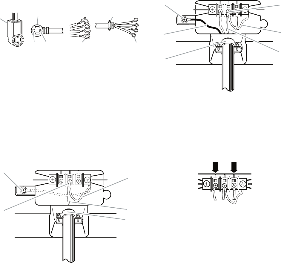
4-wire connection: Power supply cord
IMPORTANT: A 4-wire connection is required
for mobile homes and where local codes do
not permit the use of 3-wire connections.
A. 4-wire receptacle (NEMA type 14-30R)
B. 4-prong plug
C. Ground prong
D. Neutral prong
E. Spade terminals with upturned ends
F. ¾" (1.9 cm) UL listed strain relief
G. Ring terminals
AB F
EG
D
C
1. Remove center silver-colored terminal
block screw.
2. Remove neutral ground wire from external
ground conductor screw. Connect neutral
ground wire and the neutral wire (white or
center wire) of power supply cord under
center, silver-colored terminal block screw.
Tighten screw.
A. External ground conductor screw - Dotted line shows
position of NEUTRAL ground wire before being moved to
center silver-colored terminal block screw
B. Center silver-colored terminal block screw
C. Neutral ground wire
D. Neutral wire (white or center wire)
E. ¾" (1.9 cm) UL listed strain relief
A
C
BD
E
3. Connect ground wire (green or bare) of
power supply cord to external ground con-
ductor screw. Tighten screw.
4. Connect the other wires to outer terminal
block screws. Tighten screws.
A. External ground conductor screw
B. Ground wire (green or bare) of power supply cord
C.
³⁄
4
" (1.9 cm) UL listed strain relief
D. Center silver-colored terminal block screw
E. Neutral ground wire
F. Neutral wire (white or center wire)
A
B
C
D
E
F
5. Tighten strain relief screws.
6. Insert tab of terminal block cover into slot
of dryer rear panel. Secure cover with
hold-down screw.
7. You have completed your electrical con-
nection. Now go to “Venting Require-
ments.”
2-10
When connecting to the terminal block, place
the hooked end of the wire under the screw of
the terminal block (hook facing right), squeeze
hooked end together and tighten screw, as
shown.
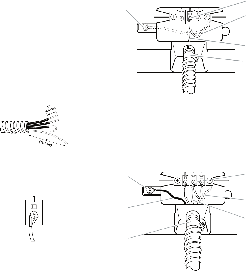
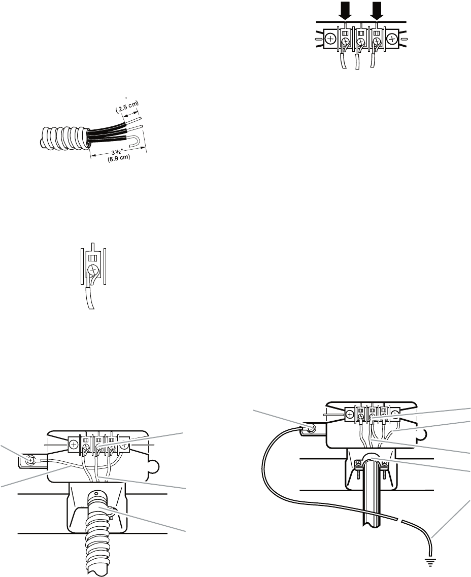
4-wire connection: Direct wire
IMPORTANT: A 4-wire connection is required
for mobile homes and where local codes do
not permit the use of 3-wire connections.
Direct wire cable must have 5 ft (1.52 m) of
extra length so dryer can be moved if need-
ed.
Strip 5˝ (12.7 cm) of outer covering from
end of cable, leaving bare ground wire at 5˝
(12.7 cm). Cut 1-1/2˝ (3.8 cm) from 3 remain-
ing wires. Strip insulation back 1˝(2.5 cm).
Shape ends of wires into a hook shape.
1. Remove center silver-colored terminal
block screw (see top right illustration).
2. Remove neutral ground wire from exter-
nal ground conductor screw. Connect
neutral ground wire and place the hooked
end (hook facing right) of the neutral wire
(white or center wire) of direct wire cable
under the center screw of the terminal
block. Squeeze hooked ends together.
Tighten screw. (See top right illustration.)
A. External ground conductor screw - Dotted line shows
position of NEUTRAL ground wire before being moved
to center silver-colored terminal block screw
B. Center silver-colored terminal block screw
C. Neutral ground wire
D. Neutral wire (white or center wire)
E. ¾" (1.9 cm) UL listed strain relief
A
C
B
D
E
3. Connect ground wire (green or bare) of di-
rect wire cable to external ground conduc-
tor screw. Tighten screw.
A. External ground conductor screw
B. Ground wire (green or bare) of power supply cable
C. ¾" (1.9 cm) UL listed strain relief
D. Center silver-colored terminal block screw
E. Neutral ground wire
F. Neutral wire (white or center wire)
A
B
C
D
E
F
2-11
4. Place the hooked ends of the other direct
wire cable wires under the outer terminal
block screws (hooks facing right). Squeeze
hooked ends together. Tighten screws.
5. Tighten strain relief screw.
6. Insert tab of terminal block cover into slot
of dryer rear panel. Secure cover with
hold-down screw.
7. You have completed your electrical con-
nection. Now go to “Venting Require-
ments.”
3-wire connection: Power supply cord
Use where local codes permit connecting
cabinet-ground conductor to neutral wire.
A. 3-wire receptacle (NEMA type 10-30R)
B. 3-wire plug
C. Neutral prong
D. Spade terminals with up turned ends
E.
³⁄
4
" (1.9 cm) UL listed strain relief
F. Ring terminals
G. Neutral (white or center wire)
A
BD
C
E
F
G
1. Loosen or remove center silver-colored
terminal block screw.
2. Connect neutral wire (white or center wire)
of power supply cord to the center, silver-
colored terminal screw of the terminal
block. Tighten screw.
3. Connect the other wires to outer terminal
block screws. Tighten screws.
A. External ground conductor screw
B. Neutral ground wire
C. Center silver-colored terminal block screw
D. Neutral wire (white or center wire)
E.
³⁄4
" (1.9 cm) UL listed strain relief
A
B
C
D
E
4. Tighten strain relief screws.
5. Insert tab of terminal block cover into slot
of dryer rear panel. Secure cover with
hold-down screw.
6. You have completed your electrical con-
nection. Now go to “Venting Require-
ments.”
2-12
3-wire connection: Direct wire
Use where local codes permit connecting
cabinet-ground conductor to neutral wire.
Direct wire cable must have 5 ft (1.52 m) of ex-
tra length so dryer can be moved if needed.
Strip 3-1/2˝ (8.9 cm) of outer covering from
end of cable. Strip insulation back 1˝ (2.5 cm).
If using 3-wire cable with ground wire, cut bare
wire even with outer covering. Shape ends of
wires into a hook shape.
When connecting to the terminal block, place
the hooked end of the wire under the screw of
the terminal block (hook facing right), squeeze
hooked end together and tighten screw, as
shown.
1
1. Loosen or remove center silver-colored
terminal block screw.
2. Place the hooked end of the neutral wire
(white or center wire) of direct wire cable
under the center screw of terminal block
(hook facing right). Squeeze hooked end
together. Tighten screw.
A. External ground conductor screw
B. Neutral ground wire
C. Center silver-colored terminal block screw
D. Neutral wire (white or center wire)
E.
³⁄4
" (1.9 cm) UL listed strain relief
A
BD
C
E
4. Tighten strain relief screw.
5. Insert tab of terminal block cover into slot
of dryer rear panel. Secure cover with
hold-down screw.
6. You have completed your electrical connec-
tion. Now go to “Venting Requirements.”
3. Place the hooked ends of the other direct
wire cable wires under the outer terminal
block screws (hooks facing right). Squeeze
hooked ends together. Tighten screws.
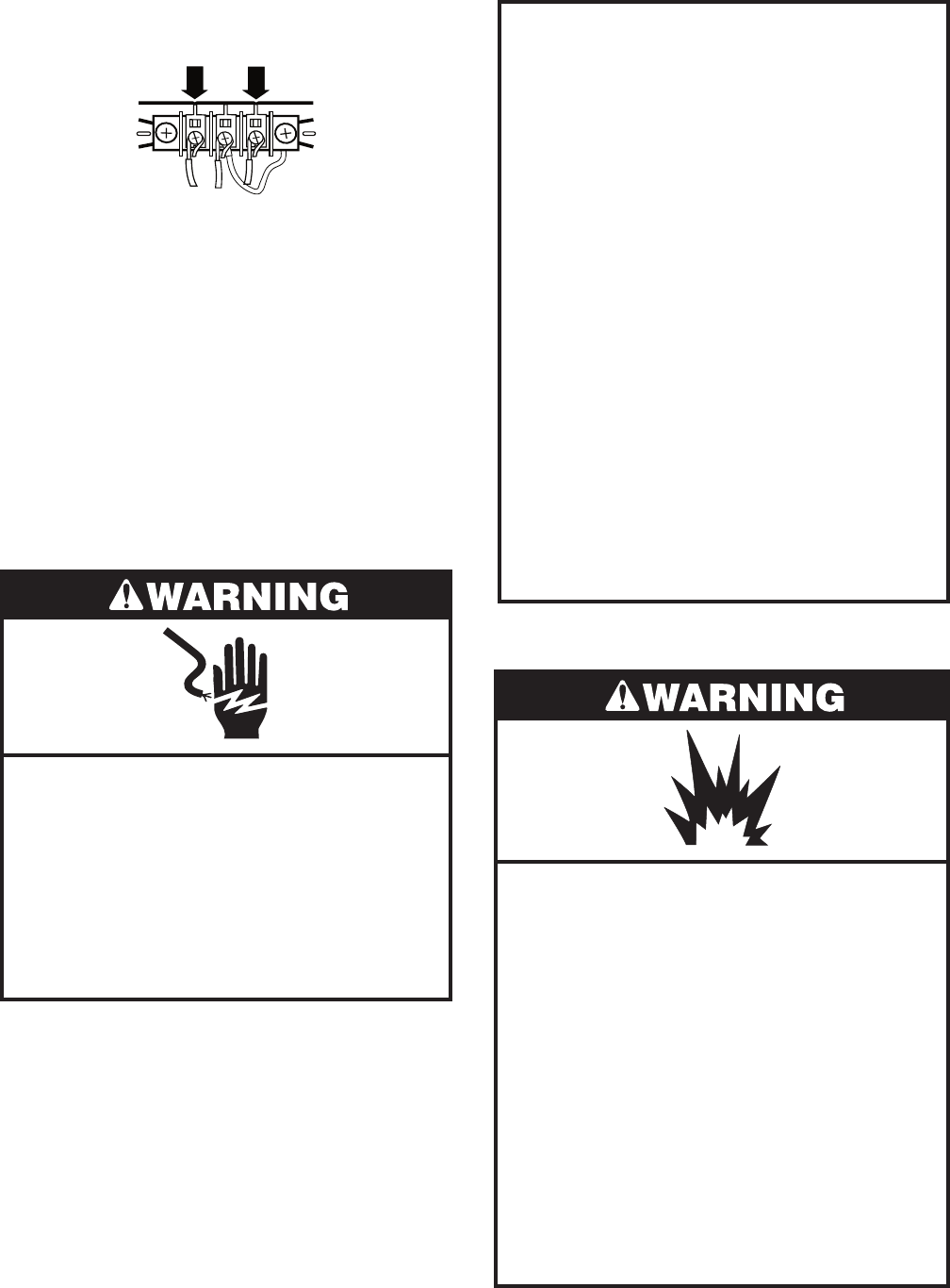
Optional 3-wire connection
Use for direct wire or power supply cord
where local codes do not permit connect-
ing cabinet-ground conductor to neutral
wire.
1. Remove center silver-colored terminal
block screw.
2. Remove neutral ground wire from external
ground conductor screw. Connect neutral
ground wire and the neutral wire (white or
center wire) of power supply cord/cable
under center, silver-colored terminal block
screw. Tighten screw.
A. External ground conductor screw
B. Center silver-colored terminal block screw
C. Neutral ground wire
D. Neutral wire (white or center wire)
E.
³⁄4
" (1.9 cm) UL listed strain relief
F. Grounding path determined by a qualified electrician
AB
C
D
F
E
2-13
3. Connect the other wires to outer terminal
block screws. Tighten screws.
4. Tighten strain relief screws.
5. Insert tab of terminal block cover into slot
of dryer rear panel. Secure cover with
hold-down screw.
6. Connect a separate copper ground wire
from the external ground conductor screw
to an adequate ground.
7. You have completed your electrical connec-
tion. Now go to “Venting Requirements.”
ELECTRICAL REQUIREMENTS
Gas Models Only
GROUNDING INSTRUCTIONS
• For a grounded, cord-connected dryer:
This dryer must be grounded. In the event
of malfunction or breakdown, grounding will
reduce the risk of electric shock by provid-
ing a path of least resistance for electric
current.This dryer is equipped with a cord
having an equipment-grounding conduc-
tor and a grounding plug. The plug must
be plugged into an appropriate outlet that
is properly installed and grounded in accor-
dance with all local codes and ordinances.
WARNING: Improper connection of the
equipment-grounding conductor can re-
sult in a risk of electric shock. Check with a
qualified electrician or service representa-
tive or personnel if you are in doubt as to
whether the dryer is properly grounded. Do
not modify the plug provided with the dryer:
if it will not fit the outlet, have a proper outlet
installed by a qualified electrician.
Electrical Shock Hazard
Plug into a grounded 3 prong outlet.
Do not remove ground prong.
Do not use an adapter.
Do not use an extension cord.
Failure to follow these instructions can
result in death, fire, or electrical shock.
120 Volt, 60 Hz., AC only, 15- or 20-amp
fused electrical supply is required. A time-
delay fuse or circuit breaker is recommend-
ed. It is also recommended that a separate
circuit serving only this dryer be provided.
•
Explosion Hazard
Use a new CSA International approved
gas supply line.
Install a shut-off valve.
Securely tighten all gas connections.
If connected to LP, have a qualified
person make sure gas pressure does
not exceed 13˝ (33 cm) water column.
Examples of a qualified person include:
licensed heating personnel,
authorized gas company personnel, and
authorized service personnel.
Failure to do so can result in death,
explosion, or fire.
GAS SUPPLY REQUIREMENTS
2-14
Gas Type
Natural gas:
This dryer is equipped for use with Natural
gas. It is design-certified by CSA International
for LP (propane or butane) gases with appro-
priate conversion.
This dryer must have the correct burner for
the type of gas in your home. Burner informa-
tion is located on the rating plate in the door
well of your dryer. If this information does not
agree with the type of gas available, contact
your dealer or call the phone numbers refer-
enced in the “Assistance or Service” section
of the “Use & Care Guide.”
LP gas conversion:
Conversion must be made by a qualified
technician.
No attempt shall be made to convert the ap-
pliance from the gas specified on the model/
serial rating plate for use with a different gas
without consulting the gas company.
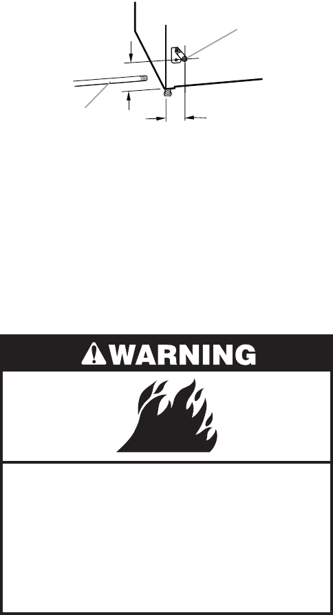
Gas supply line
1/2˝ IPS pipe is recommended.
3/8˝ approved tubing is acceptable for
lengths under 20 ft (6.1 m) if local codes
and gas supplier permit.
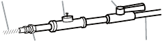
Must include 1/8˝ NPT minimum plugged
tapping accessible for test gauge connec-
tion, immediately upstream of the gas con-
nection to the dryer (see illustration in the
right column).
Must include a shutoff valve:
In the U.S.A.:
An individual manual shutoff valve must be
installed within six (6) feet (1.8 m) of the
dryer in accordance with the National Fuel
Gas Code, ANSI Z223.1.
•
•
•
•
In Canada:
An individual manual shutoff valve must be
installed in accordance with the B149.1,
Natural Gas and Propane Installation
Code. It is recommended that an individual
manual shutoff valve be installed within six
(6) feet (1.8 m) of the dryer.
The location should be easy to reach for
opening and closing.
A. ³⁄8
³⁄8
1⁄8
" flexible gas connector
B. " pipe to flare adapter fitting
C. " NPT minimum plugged tapping
D. ½" NPT gas supply line
E. Gas shutoff valve
A
B
E
D
C
Gas supply connection requirements
For close clearances, a 3/8˝ to 3/8˝ elbow
is recommended to avoid kinking of the
gas line.
Use only pipe-joint compound. Do not use
TEFLON†® tape.
There are many methods by which your gas
dryer can be connected to the gas supply.
Listed here are some guidelines for two differ-
ent methods of connection.
Option 1 (Recommended method)
Flexible stainless steel gas connector:
If local codes permit, use a new flexible
stainless steel gas connector (Design Cer-
tified by CSA International) to connect the
dryer to the rigid gas supply line. Use an
elbow and a 3/8˝flare x 3/8˝ NPT adapter
fitting between the stainless steel gas con-
nector and the dryer gas pipe, as needed
to avoid kinking.
†® TEFLON is a registered trademark of E.I. Du Pont
De Nemours and Company.
•
•
•
2-15
Option 2 (Alternate method)
Approved aluminum or copper tubing:
Lengths under 20 ft (6.1 m) can use 3/8˝
approved tubing (if codes and gas supplier
permit).
If you are using Natural gas, do not use
copper tubing.
3/8˝ flare x 3/8˝ NPT adapter fitting be-
tween dryer pipe and 3/8˝ approved tub-
ing.
Lengths over 20 ft (6.1 m) should use larger
tubing and a different size adapter fitting.
If the dryer has been converted to use LP
gas, 3/8˝ LP compatible copper tubing can
be used. If the total length of the supply
line is more than 20 ft (6.1 m), use larger
tubing.
NOTE: Pipe-joint compounds that resist
the action of LP gas must be used. Do not
use TEFLON®† tape.
†® TEFLON is a registered trademark of E.I. Du Pont
De Nemours and Company.
Burner input requirements
Elevations up to 10,000 ft (3,048 m):
The design of this dryer is certified by
CSA International for use at altitudes up
to 10,000 ft (3,048 m) above sea level at
the Btu rating indicated on the model/serial
number plate. Burner input adjustments
are not required when the dryer is oper-
ated up to this elevation.
Elevations above 10,000 ft (3,048 m):
When installed above 10,000 ft (3,048 m)
a 4% reduction of the burner Btu rating
shown on the model/serial number plate is
required for each 1,000 ft (305 m) increase
in elevation.
Gas supply pressure testing
The dryer must be disconnected from the
gas supply piping system during pressure
testing at pressures greater than 1/2 psi.
•
•
•
•
•
•
•
•
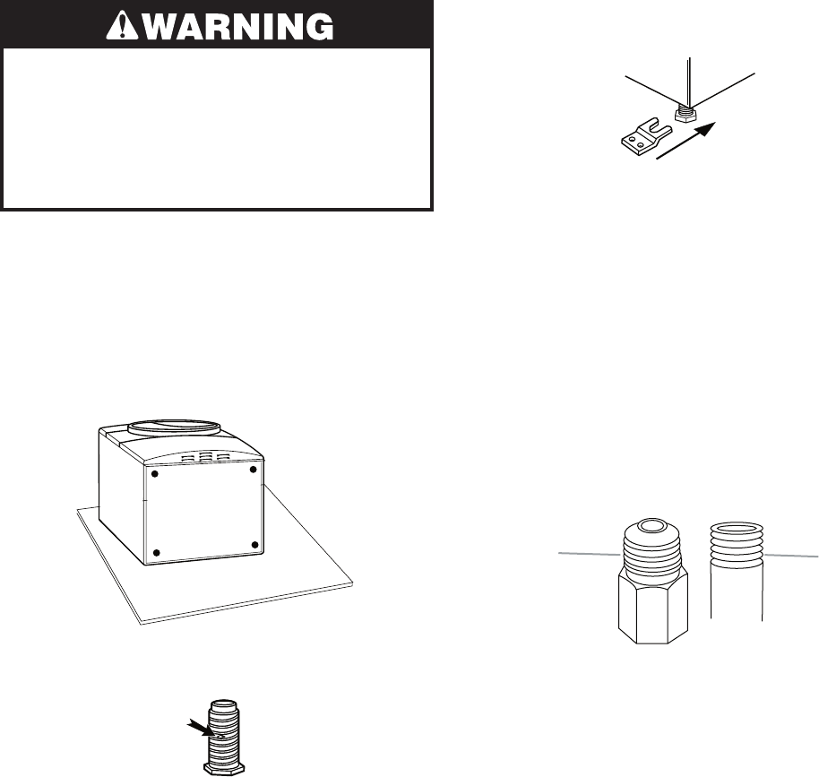
Dryer gas pipe
The gas pipe that comes out through the
rear of your dryer has a 3/8˝ male pipe
thread.
•
Fire Hazard
Use a heavy metal vent.
Do not use a plastic vent.
Do not use a metal foil vent.
Failure to follow these instructions can
result in death or fire.
WARNING: To reduce the risk of fire, this dry-
er MUST BE EXHAUSTED OUTDOORS.
IMPORTANT: Observe all governing codes
and ordinances.
The dryer exhaust must not be connected into
any gas vent, chimney, wall, ceiling, or a con-
cealed space of a building.
A. ½" NPT gas supply line
B.
³⁄
8
" NPT dryer pipe
A
B
*6¼"
(15.9 cm)
1½"
(3.8 cm)
*NOTE: If the dryer is mounted on a pedestal,
the gas pipe height must be an additional 10˝
(25.4 cm) or 15.5˝ (39.4 cm) from the floor,
depending on the pedestal model. For a ga-
rage installation, the gas pipe height must be
an additional 18˝ (46 cm) from the floor.
VENTING REQUIREMENTS
2-16
If using an existing vent system
Clean lint from the entire length of the sys-
tem and make sure exhaust hood is not
plugged with lint.
Replace any plastic or metal foil vent with
rigid or flexible heavy metal vent.
Review Vent system chart. Modify existing
vent system if necessary to achieve the
best drying performance.
If this is a new vent system
Vent Material
Use a heavy metal vent. Do not use plastic
or metal foil vent.
4˝ (10.2 cm) heavy metal exhaust vent
and clamps must be used. DURASAFE™
venting products are recommended.
•
•
•
•
•
DURASAFE™ vent products can be pur-
chased from your dealer or by calling
Whirlpool Parts and Accessories.
Rigid metal vent
For best drying performance, rigid metal
vents are recommended.
Rigid metal vent is recommended to pre-
vent crushing and kinking.
Flexible metal vent
Flexible metal vents are acceptable only if
accessible for cleaning.
Flexible metal vent must be fully extended
and supported when the dryer is in its final
position.
Remove excess flexible metal vent to avoid
sagging and kinking that may result in re-
duced airflow and poor performance.
Do not install flexible metal vent in enclosed
walls, ceilings or floors.
•
•
•
•
•
•
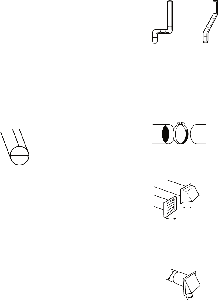
4" (10.2 cm) heavy metal exhaust vent
4"
10.2 cm
Good Better
Clamps
Use clamps to seal all joints.
Exhaust vent must not be connected or se-
cured with screws or other fastening devic-
es that extend into the interior of the duct.
Do not use duct tape.
•
•
Clamp
Exhaust
Recommended hood styles are shown here.
An exhaust hood should cap the vent to
prevent rodents and insects from entering
the home.
Exhaust hood must be at least 12˝ (30.5 cm)
from the ground or any object that may be
in the path of the exhaust (such as flowers,
rocks or bushes, snow line, etc.).
•
•
The angled hood style (shown here) is ac-
ceptable.
A. Louvered hood style
B. Box hood style
4"
(10.2 cm)
4"
(10.2 cm)
B
A
4"
(10.2 cm)
2½"
(6.4 cm)
Elbows
45° elbows provide better airflow than 90° el-
bows
2-17
Improper venting can cause moisture
and lint to collect indoors, which may
result in:
Moisture damage to woodwork, furni-
ture, paint, wallpaper, carpets, etc.
Housecleaning problems and health
problems.
•
•
PLAN VENT SYSTEM
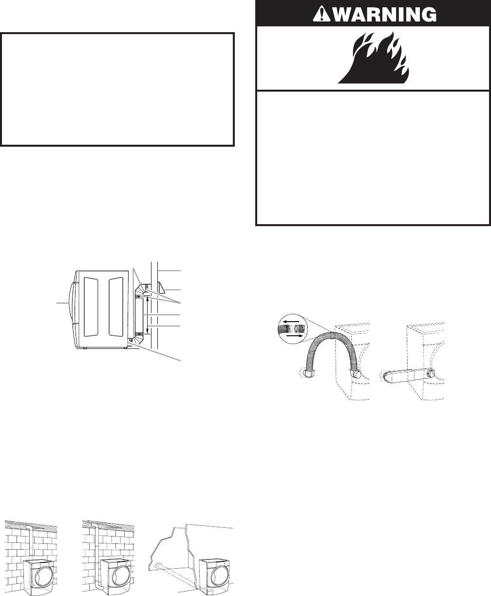
Choose your exhaust installation type
Recommended exhaust installations
Typical installations vent the dryer from the
rear of the dryer. Other installations are pos-
sible.
A. Dryer
B. Elbow
C. Wall
D. Exhaust hood
E. Clamps
F. Rigid metal or flexible metal vent
G. Vent length necessary to connect elbows
H. Exhaust outlet
H
G
F
E
D
C
A
B
Optional exhaust installations
This dryer can be converted to exhaust out
the right side, left side, or through the bottom.
Contact your local dealer to have the dryer
converted.
Fire Hazard
Cover unused exhaust holes with the
following kit:
279818 (white)
Contact your local dealer.
Failure to follow these instructions can
result in death, fire, electrical shock, or
serious injury.
A. Standard rear offset exhaust installation
B. Left or right side exhaust installation
C. Bottom exhaust installation (not an option
with pedestal installations)
ABC
Do not use an exhaust hood with a mag-
netic latch.
•
Alternate installations for close clearances
Venting systems come in many varieties. Se-
lect the type best for your installation. Two
close-clearance installations are shown. Re-
fer to the manufacturer’s instructions.
A. Over-The-Top installation (also available with one
offset elbow)
B. Periscope installation
A B
2-18
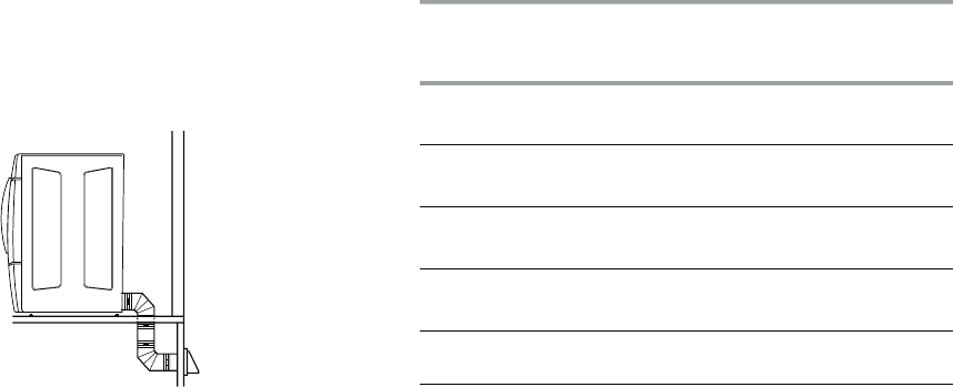
Number of
90º turns
or elbows
Type of
vent
Box or
louvered
hoods
Angled
hoods
0 Rigid metal
Flexible metal
64 ft (20 m)
36 ft (11 m)
58 ft (17.7 m)
28 ft (8.5 m)
1 Rigid metal
Flexible metal
54 ft (16.5 m)
31 ft (9.4 m)
48 ft (14.6 m)
23 ft (7 m)
2 Rigid metal
Flexible metal
44 ft (13.4 m)
27 ft (8.2 m)
38 ft (11.6 m)
19 ft (5.8 m)
3 Rigid metal
Flexible metal
35 ft (10.7 m)
25 ft (7.6 m)
29 ft (8.8 m)
17 ft (5.2 m)
4 Rigid metal
Flexible metal
27 ft (8.2 m)
23 ft (7 m)
21 ft (6.4 m)
15 ft (4.6 m)
INSTALL VENT SYSTEM
1. Install exhaust hood. Use caulking com-
pound to seal exterior wall opening around
exhaust hood.
2. Connect vent to exhaust hood. Vent must
fit inside exhaust hood. Secure vent to ex-
haust hood with 4˝ (10.2 cm) clamp.
3. Run vent to dryer location. Use the straight-
est path possible. See “Determine vent
path.” Avoid 90º turns. Use clamps to seal
all joints. Do not use duct tape, screws or
other fastening devices that extend into
the interior of the vent to secure vent.
NOTE: The following kits for close clearance
alternate installations are available for pur-
chase.
Over-the-top Installation:
Part Number 4396028
Periscope Installation (For use with dryer
vent to wall vent mismatch):
Part Number 4396037 - 0˝ (0 cm) to 18˝
(45.72 cm) mismatch
Part Number 4396011 - 18˝ (45.72 cm) to
29˝ (73.66 cm) mismatch
Part Number 4396014 - 29˝ (73.66 cm) to
50˝ (127 cm) mismatch
Special provisions for mobile home
installations
The exhaust vent must be securely fastened to
a noncombustible portion of the mobile home
structure and must not terminate beneath the
mobile home. Terminate the exhaust vent out-
side.
•
•
NOTE: Do not use vent runs longer than
those specified in the Vent system chart.
Exhaust systems longer than those speci-
fied will:
Shorten the life of the dryer.
Reduce performance, resulting in longer
drying times and increased energy us-
age.
The Vent system chart provides venting re-
quirements that will help to achieve the best
drying performance.
Vent System Chart
NOTE: Side and bottom exhaust installations
have a 90° turn inside the dryer. To determine
maximum exhaust length, add one 90° turn to
the chart.
•
•
Determine vent path
Select the route that will provide the
straightest and most direct path outdoors.
Plan the installation to use the fewest num-
ber of elbows and turns.
When using elbows or making turns, allow
as much room as possible.
Bend vent gradually to avoid kinking.
Use the fewest 90° turns possible.
Determine vent length and elbows needed
for best drying performance
Use the following Vent system chart to
determine type of vent material and hood
combinations acceptable to use.
•
•
•
•
•
•
2-19
Excessive Weight Hazard
Use two or more people to move and
install dryer.
Failure to do so can result in back or
other injury.
INSTALL LEVELING LEGS
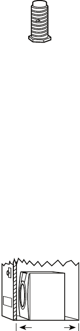
3. Examine the leveling legs. Find the dia-
mond marking.
1. To protect the floor, use a large flat piece
of cardboard from the dryer carton. Place
cardboard under the entire back edge of
the dryer.
2. Firmly grasp the body of the dryer. Gently
lay the dryer on the cardboard. See illus-
tration.
A. Flared male fitting
B. Non-flared male fitting
AB
4. Screw the legs into the leg holes by hand.
Use a wrench to finish turning the legs un-
til the diamond marking is no longer vis-
ible.
5. Place a carton corner post from dryer
packaging under each of the 2 dryer back
corners. Stand the dryer up. Slide the dry-
er on the corner posts until it is close to its
final location. Leave enough room to con-
nect the exhaust vent.
For mobile home use
Gas dryers must be securely fastened to the
floor at the time of installation.
Mobile home installations require a Mobile
Home Installation Kit. For more information,
please reference the service numbers in the
“Assistance or Service” section of the “Use &
Care Guide.”
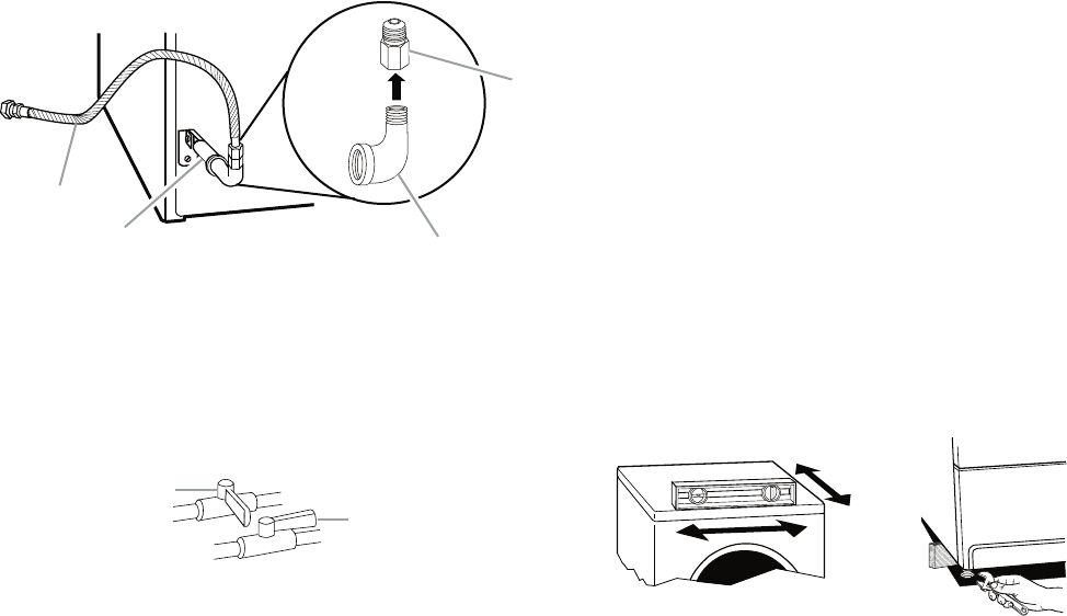
MAKE GAS CONNECTION
1. Remove the red cap from the gas pipe.
2. Using a wrench to tighten, connect the gas
supply to the dryer. Use pipe-joint com-
pound on the threads of all nonflared male
fittings. If flexible metal tubing is used, be
sure there are no kinks.
NOTE: For LP gas connections, you must use
pipe-joint compound resistant to the action of
LP gas. Do not use TEFLON®† tape.
†® TEFLON is a registered trademark of E.I. Du Pont
De Nemours and Company.
2-20
A. Closed valve
B. Open valve
A
B
3. Open the shutoff valve in the supply line.
The valve is open when the handle is par-
allel to the gas pipe.
4. Test all connections by brushing on an ap-
proved noncorrosive leak-detection solu-
tion. Bubbles will show a leak. Correct any
leak found. REVERSE DOOR SWING
You can change your door swing from a right-
side opening to a left-side opening, if de-
sired.
1. Place a towel or soft cloth on top of the
dryer or work space to protect the sur-
face.
CONNECT VENT
1. Using a 4˝ (10.2 cm) clamp, connect vent
to exhaust outlet in dryer. If connecting to
existing vent, make sure the vent is clean.
The dryer vent must fit over the dryer ex-
haust outlet and inside the exhaust hood.
Make sure the vent is secured to exhaust
hood with a 4˝ (10.2 cm) clamp.
2. Move dryer into its final position. Do not
crush or kink vent.
3. (On gas models) Check that there are no
kinks in the flexible gas line.
4. Once exhaust vent connection is made,
remove corner posts and cardboard.
LEVEL DRYER
Check the levelness of the dryer. Check level-
ness first side to side, then front to back.
If the dryer is not level, prop up the dryer using
a wood block. Use a wrench to adjust the legs
up or down and check again for levelness.
³⁄
8
" flexible gas connector
B.
A.
³⁄
8
" dryer pipe
C.
³⁄
8
" to
³⁄
8
" pipe elbow
D.
³⁄
8
" pipe-to-flare adapter fitting
A
BC
D
A combination of pipe fittings must be used
to connect the dryer to the existing gas line.
Shown is a recommended connection. Your
connection may be different, according to the
supply line type, size and location.
2-21
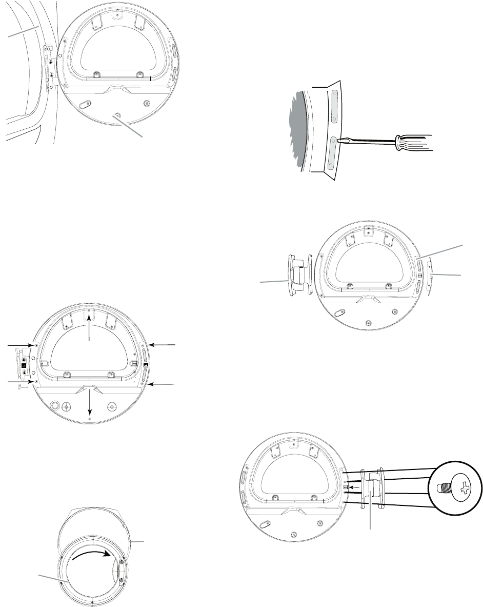
A. Dryer front panel
B. Door assembly
A
B
A. Inner ring
B. Outer ring
A
B
2. Lay the door assembly on a flat, protected
surface with the inside (inner door assem-
bly) facing up.
3. Remove the 6 Phillips head screws to re-
lease the outer door assembly from the
inner door assembly, as indicated below.
See illustration. It is important that you re-
move only the 6 indicated screws.
Remove the door assembly
1. Remove the 4 screws that hold the door
hinge on the front panel of the dryer.
4. Lift the inner door assembly off the outer
door assembly.
5. Disengage locking tabs by rotating inner
ring clockwise. See illustration.
A. Door hinge
B. Plug strips
C. Hinge cover
AC
B
6. Turn inner ring 180° and lock tabs into
place.
Reverse hinge
1. Use a small flat-blade screwdriver to re-
move 2 plug strips from the inner door.
Slide the head of the screwdriver under
the plugs, being certain not to scratch the
inner door surface. Lift up.
2. Remove hinge cover.
3. Remove the 4 screws that attach to the in-
ner door hinge and move the hinge to the
other side. Reinstall the 4 screws.
A. Door hinge
A
2-22
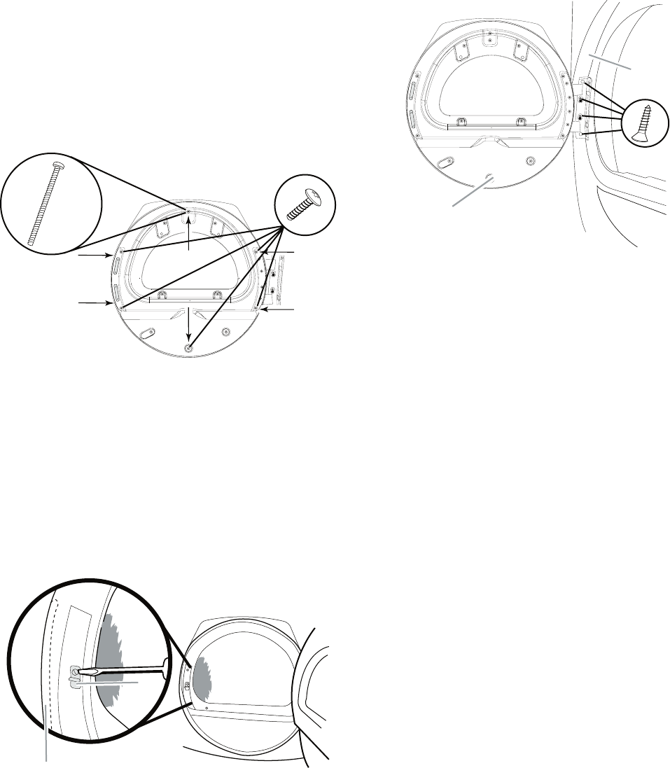
4. Reinstall plug strips on opposite side of
the inner door.
5. Check for fingerprints on the glass. Clean
glass if necessary.
6. Place the inner door assembly inside the
outer door assembly. To fit correctly, the
inner door assembly edge fits completely
inside the outer door assembly edge.
7. Reassemble the inner and outer door as-
semblies with the 6 screws.
Reverse the strike
1. Use a small flat-blade screwdriver to re-
move plug strip from the dryer door open-
ing. Slide the head of the screwdriver un-
der the plugs, being certain not to scratch
the dryer surface. Lift up.
2. Remove the strike.
3. Insert strike and plug strip on the opposite
side.
A. Plug strip (cannot be seen from this angle)
B. Door strike
B
A
Reinstall the door
1. Reattach door to dryer front panel with the
4 screws.
A. Dryer front panel
B. Door assembly
A
B
2. Check for fingerprints on the glass. Clean
the glass if necessary.
3. Close door and check that it latches se-
curely.
COMPLETE INSTALLATION
1. Check that all parts are now installed. If
there is an extra part, go back through the
steps to see which step was skipped.
2. Check that you have all of your tools.
3. Dispose of/recycle all packaging materi-
als.
4. Check the dryer’s final location. Be sure
the vent is not crushed or kinked.
5. Check that the dryer is level. See “Level
Dryer.”
6. For power supply cord installation, plug
into an outlet. For direct wire installation,
reconnect power.
2-23
7. Remove any protective film on the console
and any tape remaining on the dryer.
8. Read “Dryer Use” in the Dryer User In-
structions.
9. Wipe the dryer drum interior thoroughly
with a damp cloth to remove any dust.
For Electric Models Only
10. Select a Timed Dry heated cycle, and start
the dryer. Do not select the Air Only modi-
fier.
If the dryer will not start, check the fol-
lowing:
Controls are set in a running or “On” po-
sition.
Start button has been pushed firmly.
Dryer is plugged into an outlet and/or
electrical supply is connected.
Household fuse is intact and tight, or cir-
cuit breaker has not tripped.
Dryer door is closed.
11. When the dryer has been running for 5
minutes, open the dryer door and feel for
heat. If you feel heat, cancel cycle and
close the door.
If you do not feel heat, turn off the dryer
and check the following:
There may be 2 fuses or circuit breakers
for the dryer. Check that both fuses are
intact and tight, or that both circuit break-
ers have not tripped.
NOTE: You may notice a burning odor when
the dryer is first heated. This odor is common
when the heating element is first used. The
odor will go away.
•
•
•
•
•
•
For Gas Models Only
12. Select a Timed Dry heated cycle, and start
the dryer. Do not select the Air Only modi-
fier.
If the dryer will not start, check the fol-
lowing:
Dryer is plugged into a grounded 3 prong
outlet.
Electrical supply is connected.
Household fuse is intact and tight, or cir-
cuit breaker has not tripped.
Dryer door is closed.
13. When the dryer has been running for 5
minutes, open the dryer door and feel for
heat. If you feel heat, cancel cycle and
close door. If you do not feel heat, turn off
the dryer and check that the gas supply
line shutoff valve is open.
If the gas supply line shutoff valve is
closed, open it, then repeat the 5-minute
test as outlined above.
If the gas supply line shutoff valve is
open, contact a qualified technician.
•
•
•
•
•
•
2-24
— NOTES —
3-1
DRYER USE
PRODUCT OPERATION
Explosion Hazard
Keep flammable materials and vapors,
such as gasoline, away from dryer.
Do not dry anything that has ever had
anything flammable on it (even after
washing).
Failure to follow these instructions can
result in death, explosion, or fire.
WARNING: To reduce the risk of fire, electric
shock, or injury to persons, read the IMPOR-
TANT SAFETY INSTRUCTIONS before operat-
ing this appliance.
STARTING THE DRYER
Fire Hazard
No washer can completely remove oil.
Do not dry anything that has ever had
any type of oil on it (including cooking
oils).
Items containing foam, rubber, or
plastic must be dried on a clothesline
or by using an Air Cycle.
Failure to follow these instructions can
result in death or fire.
3-2
Follow these basic steps to start your dryer.
Please refer to specific sections of this manual
for more detailed information.
1. Clean lint screen before each load. See
“Cleaning the Lint Screen.”
2. Place laundry into dryer and shut door.
3. Press POWER.
4. Point the dial to an Auto or Manual Cycle. The
preset settings for Auto or Manual Cycles
will illuminate. The estimated (auto cycle)
or actual (manual) cycle time (in minutes)
will show in the display.
NOTE: A preset time is displayed when an
automatic cycle is selected. During the first
few minutes of the drying process, the cycle
time may automatically vary from the preset
time based on the size and fabric type of the
load. Toward the end of the drying process,
the estimated time display will adjust again,
showing the final drying time.
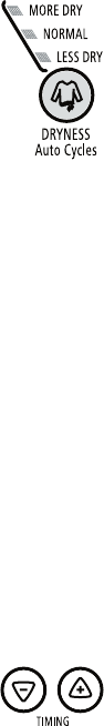
To use an Auto Cycle
Select an Auto Cycle. Auto cycles will de-
fault to the last dryness setting used for that
cycle.
Select DRYNESS to adjust how dry you want
the load. The time displayed is an estimated
length of the cycle based on the Dryness
selected. As the cycle runs, the control
senses the dryness of the load and adjusts
the time automatically for the selected dry-
ness level.
NOTE: Time is not adjustable for Automatic
Cycles. Pressing the Timing Up or Down but-
tons will cause a triple beep, indicating that the
time cannot be changed.
To make changes to the Dryness and/or
Options during an Auto Cycle:
Press PAUSE/CANCEL once.
Adjust Dryness and/or Options.
•
•
•
•
NOTE: Dryness level selections can be made
only while using Auto Cycles. Selecting More
Dry, Normal or Less Dry automatically adjusts
the sensed time needed.
Auto Dry cycles take the guesswork out of dry-
ing time and enhance fabric care. The amount
of time that is displayed is the estimated time
remaining in the cycle.
To use a Manual Cycle
Point the dial to a Manual Cycle.
Press TIMING Up or Down until the desired
drying time is displayed. Tap TIMING Up or
Down, and the time will change by 1-minute
intervals. Press and hold TIMING Up or
Down, and the time will change by 5-minute
intervals.
NOTE: The Timing feature can be used only
with Manual Cycles.
•
•
Press TEMP ADJUST until the desired tem-
perature illuminates.
To make changes to Time, Temperature,
WRINKLE SHIELD™ feature and Cycle
Signal during a Manual Cycle:
Press PAUSE/CANCEL once.
Adjust the Time, Temperature, WRINKLE
SHIELD™ feature and End of Cycle Signal.
5. (OPTIONAL STEP) If desired, select
WRINKLE SHIELD™ feature. For more
details, see “WRINKLE SHIELD™ Feature”
in “Additional Features.”
6. (OPTIONAL STEP) The Cycle Signal is
preset to ON. If desired, you may turn the
Cycle Signal OFF.
•
•
•
3-3
7. Press and hold START for approximately 1
second until dryer starts. Be sure the door
is closed.
If you do not press Start within 5 minutes
of selecting a cycle, the dryer automati-
cally shuts off.
STOPPING OR RESTARTING
THE DRYER
To pause/stop the dryer at any time
Open the door or press PAUSE/CANCEL
once.
To restart the dryer
Close the door. Press and hold START until
dryer starts.
To cancel the dryer at any time
Press PAUSE/CANCEL twice.
NOTE: Drying will continue from where the
cycle was interrupted if you close the door
and press Start within 5 minutes. If the cycle is
interrupted for more than 5 minutes, the dryer
will shut off. Select new cycle settings before
restarting the dryer.
LOCK CONTROLS
This feature allows you to lock your settings
to avoid unintended use of the dryer. You can
also use the control lock feature to avoid un-
intended cycle or option changes during dryer
operation.
To enable the control lock feature:
Press and hold END OF CYCLE SIGNAL but-
ton for 3 seconds. The Lock/Unlock Control
icon lights up, and a single beep tone is heard.
To unlock, press and hold END OF CYCLE
SIGNAL button for 3 seconds. The indicator
light turns off.
DRYING AND CYCLE TIPS
Select the correct cycle and dryness level or
temperature for your load. If an Auto Cycle is
running, the display shows the estimated cycle
•
time when your dryer is automatically sensing
the dryness level of your load. If a Manual Cycle
is running, the display shows the exact number
of minutes remaining in the cycle.
Cool Down tumbles the load without heat during
the last few minutes of all cycles. Cool Down
makes the loads easier to handle and reduces
wrinkling. The length of the Cool Down depends
on the load size and dryness level.
Drying tips
Follow care label directions when they are
available.
If desired, add a fabric softener sheet. Follow
package instructions.
Remove the load from the dryer as soon as
tumbling stops to reduce wrinkling. This is
especially important for permanent press,
knits and synthetic fabrics.
Avoid drying heavy work clothes with lighter
fabrics. This could cause overdrying of lighter
fabrics, leading to increased shrinkage or
wrinkling.
Cycle tips
Dry most loads using the preset cycle set-
tings.
Refer to the Auto or Manual Preset Cycle
Settings chart (in the “Cycles” section) for a
guide to drying various loads.
Drying temperature and Dryness are
preset when you choose an Auto Cycle.
You can choose a different dryness level,
depending on your load by pressing the
DRYNESS button to select MORE DRY
or LESS DRY.
If you wish to adjust the cycle length of a
Manual Cycle, you must press TIMING
Up or Down. Adjust the temperature
of a Manual Cycle by pressing TEMP
ADJUST until the desired temperature
is selected.
NOTE: You cannot choose a Dryness
Level with Manual Cycles.
•
•
•
•
•
•
•
•
3-4
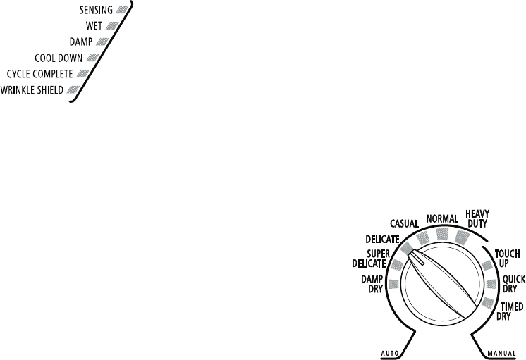
Sensing
When a cycle is first turned on, the SENSING
light illuminates until a wet item is detected.
In an Auto Cycle, if a wet item has not been
detected within 5 minutes, the Sensing light
will turn off.
In a Manual Cycle, if a wet item is not detected
within 5 minutes, the Sensing light will turn
off and the Damp light will turn on.
Wet
The WET light will turn on when a wet item has
been detected in the dryer. The Wet light will
remain on until:
The damp dry point is reached in an Auto
and Manual Cycle.
Damp
The DAMP light indicates that the load has
reached the damp dry level.
Cool Down
The COOL DOWN light illuminates during the
cool down part of the cycle. Laundry is cooling
down for ease in handling.
Cycle Complete
This light illuminates when a drying cycle is
finished. If the WRINKLE SHIELD™ feature has
been selected, the WRINKLE SHIELD™ feature
indicator light will also be illuminated.
The Cycle Complete light turns off 1 hour
after the end of a drying cycle (including the
WRINKLE SHIELD™ cycle of 90 minutes),
when Pause/Cancel is pressed, or when the
door is opened.
•
•
•
STATUS LIGHTS
You may follow the progress of your dryer with
the drying Status indicator lights.
WRINKLE SHIELD™ Feature
The WRINKLE SHIELD™ feature light illumi-
nates when this option is selected. This indicator
stays on with the Cycle Complete light.
Indicator lights
Other indicator lights on the control panel show
when Cycle, Temp Adjust, and End of Cycle
settings are selected.
CYCLES
Select the drying cycle that matches the type of
load you are drying. See Auto Preset or Manual
Preset Cycle Settings charts.
Cycle control knob
AUTO CYCLES
Auto Cycles allow you to match the cycle to
the load you are drying. See the following Auto
Preset Cycle Settings chart. Each cycle dries
certain fabrics at the recommended tempera-
ture. A sensor detects the moisture in the load
and automatically adjusts the drying time for
optimal drying.
Heavy Duty
Use this cycle to get High heat for heavy fabrics
such as cotton towels or bedspreads.
Normal
Use this cycle to get Medium heat for drying
mixed loads and sturdy fabrics such as work
clothes.
Casual
Use this cycle to get Low heat for drying no-iron
fabrics such as sport shirts, casual business
clothes and permanent press blends.

3-5
Delicate
Use this cycle to get Low heat for drying syn-
thetic fabrics, washable knit fabrics and no-iron
finishes.
Super Delicate
Use this cycle to get Extra Low heat to gently
dry items such as lingerie, exercise wear or
sheer curtains.
Damp Dry
Use this cycle to dry items to a damp level, or
to dry items that do not require an entire drying
cycle. Damp dry items such as jeans (to avoid
stiffness) or cotton clothing (to make ironing
easier). Choose a temperature setting based
on the fabrics in your load. Items will have dif-
ferent levels of dampness. At the end of this
cycle, clothes will be damp.
Auto Preset Cycle Settings
Auto Cycles
Load Type
Temp. Time*
(Minutes)
HEAVY DUTY
Heavyweight, towels
High 40
NORMAL
Mixed loads, corduroys, work
clothes, sheets
Medium 35
CASUAL
Permanent press, synthetics
Low 35
DELICATE
Lightweight items, blouses,
synthetics
Low 30
SUPER DELICATE
Lingerie
Extra Low 25
DAMP DRY
Clothes to come out suitable
for ironing
Low 20
MANUAL CYCLES
Use Manual Cycles to select a specific amount
of drying time and a drying temperature. When
a Manual Cycle is selected, the ESTIMATED
TIME REMAINING display shows the actual
time remaining in your cycle. You can change
the actual time in the cycle by pressing TIMING
Up or Down.
Timed Dry
Use this cycle to complete drying if items are
still damp after an Auto Cycle. Timed Dry is also
useful for drying heavyweight and bulky items
such as bedspreads and work clothes.
Quick Dry
Use this cycle for drying small loads or loads
that need a short drying time.
Touch Up
Use this setting to help smooth out wrinkles
from such items as clothes packed in a suit-
case or items wrinkled from being left in the
dryer too long.
Manual Preset Cycle Settings
* Estimated Time with Auto DRYNESS (Normal)
setting.
Time will vary depending on load type and load
size.
Manual Cycles
Load Type
Temp. Default Time
(Minutes)
TIMED DRY
Heavyweight, bulky items,
bedspreads, work clothes
High* 40
QUICK DRY
Small loads
Medium 27
TOUCH UP
Helps smooth out wrinkles
Medium 20
* The Timed Dry cycle will default to the last tem-
perature used for Timed Dry.
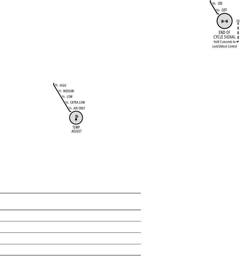
3-6
ADDITIONAL FEATURES
WRINKLE SHIELD™ Feature
The WRINKLE SHIELD™ feature helps smooth
out wrinkles that form when you cannot unload
the dryer promptly at the end of a cycle. During
this option, the dryer stops tumbling and then
tumbles again for a brief period.
Press the WRINKLE SHIELD™ feature to
get up to 90 minutes of heat-free, periodic
tumbling at the end of a cycle.
During the WRINKLE SHIELD™ feature, you
may continue the option after opening and
closing the dryer door by pushing START.
Cancel at any time by pressing the WRINKLE
SHIELD™ feature button.
NOTE: If you do not select the WRINKLE
SHIELD™ feature, the dryer stops after the
cool down period.
Temperature
Temperature settings are used with the Manual
Cycles. Press TEMP ADJUST until the desired
temperature setting illuminates. Tempera-
ture modifiers cannot be used with the Auto
Cycles.
•
•
•
Air Only
Use the Air Only modifier for items that require
drying without heat such as rubber, plastic
and heat-sensitive fabrics. This chart shows
examples of items that can be dried using Air
Only.
Type of Load Time*
(Minutes)
Foam rubber - pillows, padded bras, stuffed toys 20 - 30
Plastic - Shower curtains, tablecloths 20 - 30
Rubber-backed rugs 40 - 50
Olefin, polypropylene, sheer nylon 10 - 20
* Reset time to complete drying, if needed.
When using Air Only
Check that coverings are securely
stitched.
Shake and fluff pillows by hand periodically
during the cycle.
Dry item completely. Foam rubber pillows
are slow to dry.
NOTE: Auto Cycles are not available when you
are using the Air Only setting.
End of Cycle Signal
The End of Cycle Signal produces an au-
dible sound when the drying cycle is finished.
Promptly removing clothes at the end of the
cycle reduces wrinkling.
•
•
•
Press and release the END OF CYCLE SIGNAL
to turn off the signal.
Hold the END OF CYCLE SIGNAL for 3 sec-
onds to lock or unlock this control.
NOTE: When the WRINKLE SHIELD™ feature is
selected and the End of Cycle Signal is on, an
audible sound will be emitted every 5 minutes
until the clothes are removed, or the WRINKLE
SHIELD™ feature is finished.
CHANGING CYCLES, OPTIONS
AND MODIFIERS
You can change Auto Cycles, Timed Cycles,
Modifiers and Options anytime before press-
ing Start.
Three short tones sound if an unavailable
combination is selected. The last selection
will not be accepted.
Changing Cycles after pressing Start
1. Press STOP twice. This ends the current
cycle.
2. Select the desired cycle and options.
3. Press and hold START. The dryer starts at
the beginning of the new cycle.
•
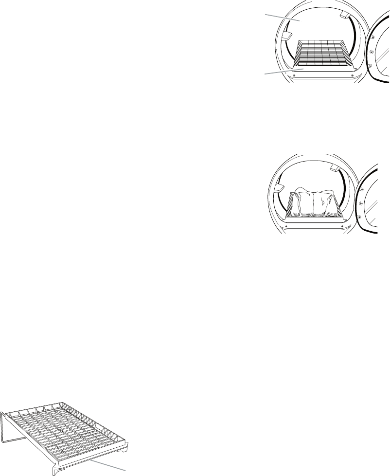
3-7
NOTE: If you do not press Start within 5 minutes
of selecting the cycle, the dryer automatically
shuts off.
Changing Modifiers and Options after
pressing Start
You can change a Modifier or Option anytime be-
fore the selected Modifier or Option begins.
1. Press STOP once.
2. Select the new Modifier and/or Option.
3. Press and hold START to continue the
cycle.
NOTE: If you happen to press Stop twice, the
program clears and the dryer shuts down.
Restart the selection process.
DRYING RACK OPTION
Use the Drying Rack to dry items such as
sweaters and pillows without tumbling. The
drum turns, but the rack does not move.
If your model does not have a drying rack, you
may be able to purchase one for your model. To
find out if your model allows drying rack usage
and for ordering information, please refer to the
“Use & Care Guide,” or contact the dealer from
whom you purchased the dryer.
NOTE: The rack must be removed for normal
tumbling. Do not use the automatic cycle with
the drying rack.
To use the drying rack
Do not remove the lint screen.
1. Open the dryer door.
A. Front edge
A
2. Place drying rack inside dryer drum, posi-
tioning the back wire on the ledge of the
inner dryer back panel. Push down on front
edge of drying rack to secure over the lint
screen.
NOTE: Do not allow items to hang over the
edge of the rack.
4. Close the door.
5. Press the POWER button.
6. Select a timed drying cycle and tempera-
ture (see following chart). Items containing
foam, rubber or plastic must be dried on a
clothesline or by using the Air Only tem-
perature setting.
7. You must select a time by pressing TIM-
ING Up or Down. Reset time as needed
to complete drying. Refer to the following
table.
8. Press (and hold) START button (about 1
second).
A. Dryer rack front edge
B. Dryer back panel
A
B
3. Put the wet items on top of the rack. Leave
space between the items so air can reach
all the surfaces.

3-8
Rack Dry Setting Temp. Time*
Wool Sweaters
Block to shape and lay flat on
the rack.
Timed
Dry
Low 60
Stuffed toys or pillows
Cotton or polyester fiber filled
Timed
Dry
Low 60
Stuffed toys or pillows
Foam rubber filled
Timed
Dry
Air Only
(no
heat)
90
Sneakers or canvas shoes Timed
Dry
Air Only
(no
heat)
90
* (Minutes) Reset time to complete drying, if
needed.
This chart shows examples of items that can
be rack dried and the suggested cycle, tem-
perature setting and drying time. Actual drying
time will depend on the amount of moisture
items hold.
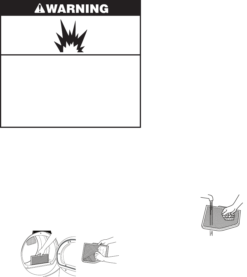
3-9
DRYER CARE
Explosion Hazard
Keep flammable materials and vapors,
such as gasoline, away from dryer.
Place dryer at least 18 inches (46 cm)
above the floor for a garage installation
Failure to follow these instructions can
result in death, explosion, or fire.
CLEANING THE LINT SCREEN
Every load cleaning
The lint screen is located in the door opening
of the dryer. A screen blocked by lint can in-
crease drying time.
To clean
1. Pull the lint screen straight up. Roll lint off
the screen with your fingers. Do not rinse
or wash screen to remove lint. Wet lint is
hard to remove.
CLEANING THE DRYER LOCATION
Keep dryer area clear and free from items that
would obstruct the flow of combustion and
ventilation air.
IMPORTANT:
Do not run the dryer with the lint screen loose,
damaged, blocked, or missing. Doing so can
cause overheating and damage to both the
dryer and fabrics.
If lint falls off the screen into the dryer during
removal, check the exhaust hood and remove
the lint. See “Venting Requirements.”
As needed cleaning
Laundry detergent and fabric softener residue
can build up on the lint screen. This buildup
can cause longer drying times for your clothes,
or cause the dryer to stop before your load is
completely dry. The screen is probably clogged
if lint falls off while the screen is in the dryer.
Clean the lint screen with a nylon brush every
6 months, or more frequently, if it becomes
clogged due to a residue buildup.
To wash
1. Roll lint off the screen with your fingers.
2. Wet both sides of lint screen with hot wa-
ter.
3. Wet a nylon brush with hot water and liquid
detergent. Scrub lint screen with the brush
to remove residue buildup.
•
•
2. Push the lint screen firmly back into
place.
4. Rinse screen with hot water.
5. Thoroughly dry lint screen with a clean
towel. Replace screen in dryer.
3-10
CLEANING THE DRYER INTERIOR
To clean dryer drum
1. Make a paste with powdered laundry de-
tergent and very warm water.
2. Apply paste to a soft cloth.
OR
Apply a liquid, nonflammable household
cleaner to the stained area and rub with a
soft cloth until all excess dye and stains are
removed.
3. Wipe drum thoroughly with a damp cloth.
4. Tumble a load of clean cloths or towels to
dry drum.
NOTE: Garments which contain unstable dyes,
such as denim blue jeans or brightly colored
cotton items, may discolor the dryer interior.
These stains are not harmful to your dryer
and will not stain future loads of clothes. Dry
unstable dye items inside out to prevent dye
transfer.
REMOVING ACCUMULATED LINT
From Inside the Dryer Cabinet
Lint should be removed every 2 years, or more
often, depending on dryer usage. Cleaning
should be done by a qualified person.
From the Exhaust Vent
Lint should be removed every 2 years, or more
often, depending on dryer usage.
VACATION AND MOVING CARE
Vacation care
Operate your dryer only when you are at home.
If you will be on vacation or not using your dryer
for an extended period of time, you should:
1. Unplug dryer or disconnect power.
For direct-wired dryers:
1. Disconnect power.
2. Disconnect wiring.
3. Make sure leveling legs are secure in dryer
base.
4. Use masking tape to secure dryer door.
Electrical Shock Hazard
Disconnect power before servicing.
Replace all parts and panels before
operating.
Failure to do so can result in death or
electrical shock.
2. Close shutoff valve in gas supply line.
3. Clean lint screen. See “Cleaning the Lint
Screen.”
Moving care
For power supply cord-connected dryers:
1. Unplug the power supply cord.
2. Close shutoff valve in gas supply line.
3. Disconnect gas supply line pipe and remove
fittings attached to dryer pipe.
4. Cap the open fuel supply line.
5. Make sure leveling legs are secure in dryer
base.
6. Use masking tape to secure dryer door.

3-11
TROUBLESHOOTING
Dryer will not run
Has a household fuse blown, or has a
circuit breaker tripped?
There may be 2 fuses or circuit breakers for
the dryer. Check that both fuses are intact
and tight, or that both circuit breakers have
not tripped. Replace the fuse or reset the
circuit breaker. If the problem continues, call
an electrician.
Is the correct power supply available?
Electric dryers require 240-volt power supply.
Check with a qualified electrician.
Was a regular fuse used?
Use a time-delay fuse.
Is the dryer door firmly closed?
Was the Power button pressed?
Was the Start button firmly pressed?
Press and hold for 1 second.
No heat
Has a household fuse blown, or has a
circuit breaker tripped?
The drum may be turning, but you may not
have heat. Electric dryers use 2 fuses or
circuit breakers. Replace the fuse or reset
the circuit breaker. If the problem continues,
call an electrician.
Is the valve open on the gas supply
line?
•
•
•
•
•
•
•
•
Unusual sounds
Has the dryer had a period of non-use?
If the dryer hasn’t been used for a while,
there may be a thumping sound during the
first few minutes of operation.
Is a coin, button, or paper clip caught
between the drum and front or rear of
the dryer?
Check the front and rear edges of the drum
for small objects. Clean out pockets before
laundering.
Is it a gas dryer?
The gas valve clicking is a normal operating
sound.
Are the four legs installed, and is the dryer
level front to back and side to side?
The dryer may vibrate if not properly installed.
See the Installation Instructions.
Is the clothing knotted or balled up?
When balled up, the load will bounce, caus-
ing the dryer to vibrate. Separate the load
items and restart the dryer.
Dryer displaying code message
“PF” (power failure), check the follow-
ing:
Was the drying cycle interrupted by a power
failure? Press and hold START to restart the
dryer.
“F-” Variable (F-01, F-22, F-23, F-26) ser-
vice codes (the display alternately flashes
“F-” and then the error code number):
Call for service.
•
•
•
•
•
•
•
DRYER OPERATION
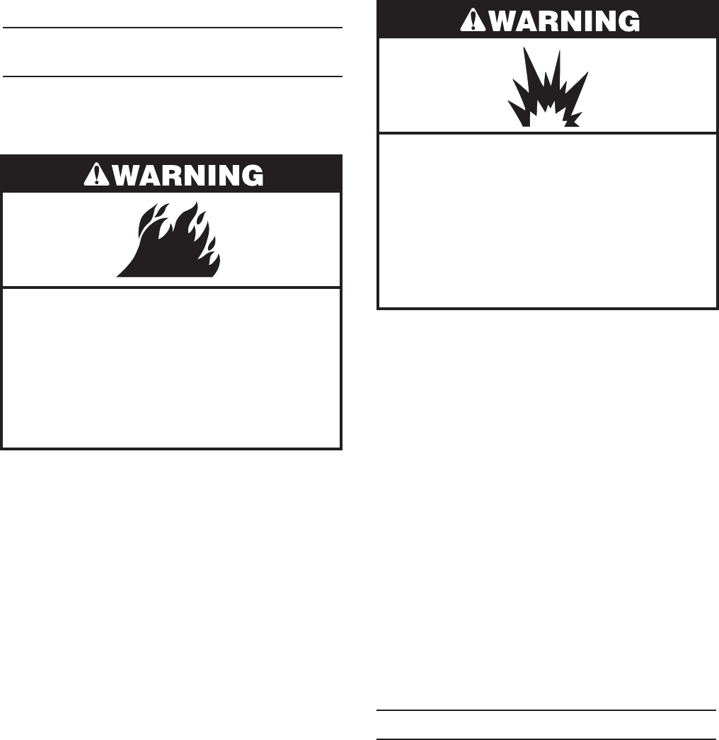
3-12
DRYER RESULTS
Clothes are not drying satisfactorily, drying
times are too long, or load is too hot
Is the lint screen clogged with lint?
Lint screen should be cleaned before each
load.
•
Is the dryer located in a room with tem-
perature below 45°F (7°C)?
Proper operation of dryer cycles requires
temperatures above 45°F (7°C).
Is the dryer located in a closet?
Closet doors must have ventilation openings
at the top and bottom of the door. The front
of the dryer requires a minimum of 1˝ (2.5
cm) of airspace, and, for most installations,
the rear of the dryer requires 5˝ (12.7 cm).
See “Installation Instructions.”
Has the Air Only modifier been select-
ed?
Select the right cycle for the types of gar-
ments being dried. See “Cycles.”
Is the load too large and heavy to dry
quickly?
Separate the load to tumble freely.
Cycle time too short
Is the automatic cycle ending early?
The load may not be contacting the sensor
strips. Level the dryer.
Change the dryness level setting on Auto
Cycles. Increasing or decreasing the dryness
level will change the amount of drying time
in a cycle.
Do not use a drying rack with an Auto
cycle.
•
•
•
•
•
Fire Hazard
Use a heavy metal vent.
Do not use a plastic vent.
Do not use a metal foil vent.
Failure to follow these instructions can
result in death or fire.
Is the exhaust vent or outside exhaust
hood clogged with lint, restricting air
movement?
Run the dryer for 5-10 minutes. Hold your
hand under the outside exhaust hood to
check air movement. If you do not feel air
movement, clean exhaust system of lint or
replace exhaust vent with heavy metal or
flexible metal vent. See “Venting Require-
ments.”
Are fabric softener sheets blocking the
grille?
Use only one fabric softener sheet, and use
it only once.
Is the exhaust vent the correct length?
Check that the exhaust vent is not too long or
has too many turns. Long venting will increase
drying times. See “Plan Vent System.”
Is the exhaust vent diameter the correct
size?
Use 4˝ (10.2 cm) diameter vent material.
•
•
•
•
Explosion Hazard
Keep flammable materials and vapors,
such as gasoline, away from dryer.
Place dryer at least 18 inches (46 cm)
above the floor for a garage installation
Failure to follow these instructions can
result in death, explosion, or fire.

3-13
Lint on load
Is the lint screen clogged?
Clean lint screen. Check for air movement.
Stains on load or drum
Was dryer fabric softener properly
used?
Add dryer fabric softener sheets at the be-
ginning of the cycle. Fabric softener sheets
added to a partially dried load can stain your
garments.
Drum stains are caused by dyes in clothing
(usually blue jeans). This will not transfer to
other clothing.
•
•
Loads are wrinkled
Was the load removed from dryer at the
end of the cycle?
Was the dryer overloaded?
Dry smaller loads that can tumble freely.
Odors
Have you recently been painting, stain-
ing or varnishing in the area where your
dryer is located?
If so, ventilate the area. When the odors or
fumes are gone from the area, rewash and
dry the clothing.
Is the dryer being used for the first
time?
The new electric heating element may have
an odor. The odor will be gone after the first
cycle.
•
•
•
•
3-14
— NOTES —
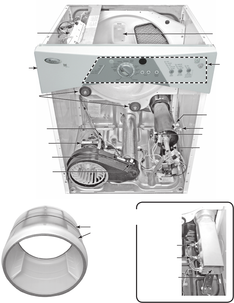
4-1
COMPONENT ACCESS
COMPONENT LOCATIONS
This section instructs you on how to service each component inside the Duet Sport™ Electronic
Gas & Electric Dryers. The components and their locations are shown below.
Flame Sensor
Drum Light
High-Limit
Thermostat
Gas Burner
Rear Drum Rollers
Drive Motor
Thermal Fuse
Exhaust Thermistor
Belt Switch (Mounted
On Drive Motor Bracket)
Machine Control
Electronics Assembly
Not Shown: Moisture
Sensor, & Door Switch
Electric Heater
Assembly
Thermal Cutoff
High-Limit
Thermostat
Heater Element
Belt & Drum
Thermal Cutoff
Console
Electronics
Assembly
Console
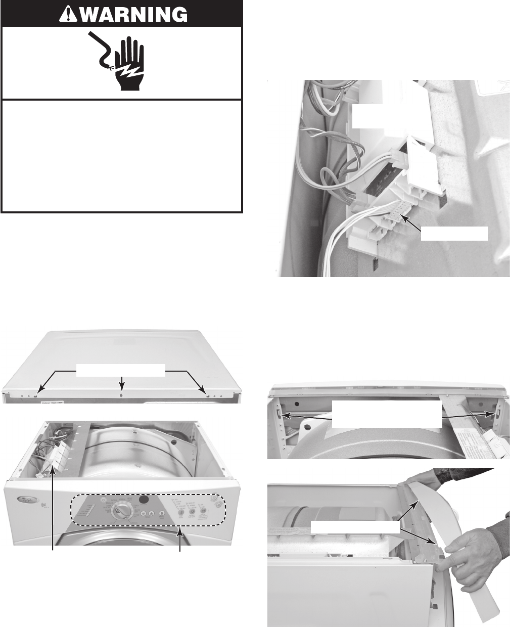
4-2
Electrical Shock Hazard
Disconnect power before servicing.
Replace all parts and panels before
operating.
Failure to do so can result in death or
electrical shock.
1. Unplug dryer or disconnect power.
2. Turn off gas supply to dryer.
3. Remove the rear screws from the top
cover of the dryer.
4. Lift the rear of the cover, pull back, and
remove the cover from the dryer.
REMOVING THE CONSOLE AND
THE CONSOLE ELECTRONICS ASSEMBLY
Top Cover Screws
5. To remove the console:
a) Release the locking tab, and discon-
nect the console electronics board
connector from the machine control
electronics at P5.
b) Press out and unhook the two locking
tabs on the back of the console from
the chassis slots. Pull the bottom of
the console out slightly, then pull and
unhook the top catches from the plas-
tic holder, and remove the console.
Machine Control
Electronics Assembly
Console Electronics
Assembly
Connector P5
Console Locking Tabs
(Rear View)
Pull Out & Unhook
Machine Control
Electronics
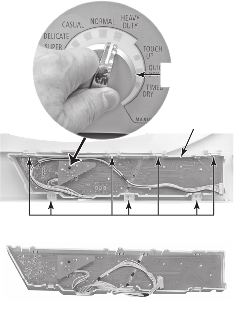
4-3
6. To remove the console electronics as-
sembly:
a) Pull the selector knob off the switch
shaft.
b) Press the seven console locking tabs,
and unsnap the console electronics
assembly, then lift the assembly from
the console and remove it.
Console Locking Tabs
Console Electronics
Assembly
Remove
Selector Knob
Console Electronics Assembly
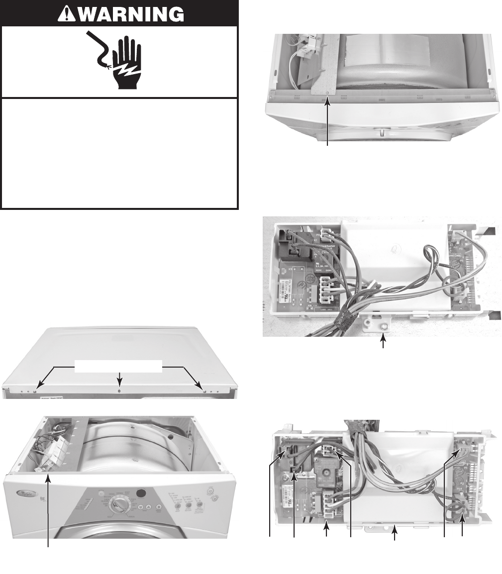
4-4
Electrical Shock Hazard
Disconnect power before servicing.
Replace all parts and panels before
operating.
Failure to do so can result in death or
electrical shock.
1. Unplug dryer or disconnect power.
2. Turn off gas supply to dryer.
3. Remove the rear screws from the top
cover of the dryer.
4. Lift the rear of the cover, pull back, and
remove the cover from the dryer.
REMOVING THE MACHINE CONTROL ELECTRONICS
Machine Control
Electronics Assembly
5. Remove the front machine control elec-
tronics (MCE) bracket screw.
MCE Bracket Screw
6. Remove the screw from the MCE, un-
hook the tabs from the bracket, and re-
move the electronics.
MCE Screw
7. Disconnect the wire connectors from the
MCE board at P8, P9, P13, P14, and the
black and red wires from relay K2.
P8 P9RD BK P13 P14
MCE Board
Top Cover Screws
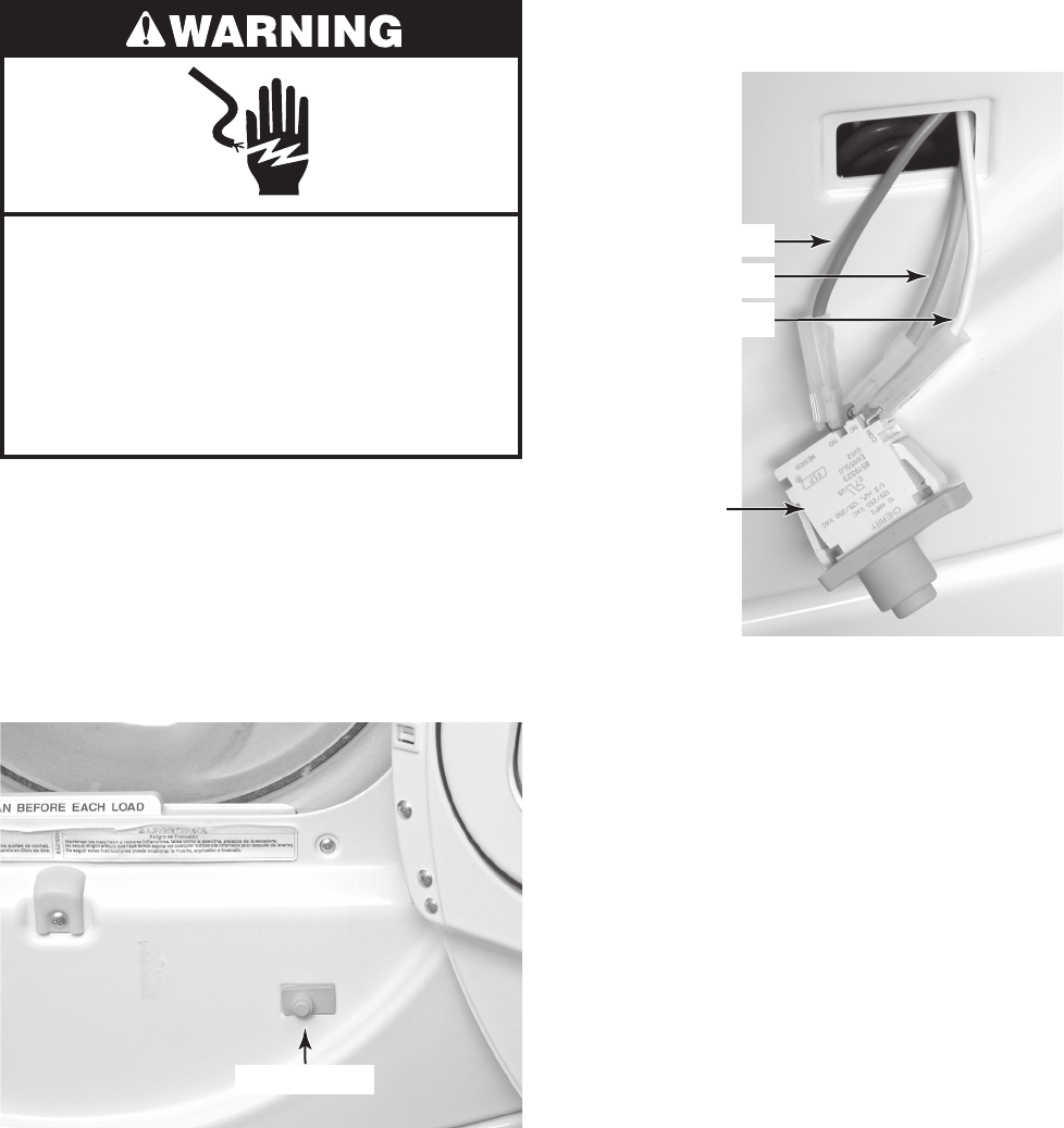
4-5
Electrical Shock Hazard
Disconnect power before servicing.
Replace all parts and panels before
operating.
Failure to do so can result in death or
electrical shock.
1. Unplug dryer or disconnect power.
2. Turn off gas supply to dryer.
3. Pull or pry the door switch out of the front
panel cutout. If necessary, press a small
screwdriver blade against the locking tab
on each end of the switch, and pull out on
the switch.
REMOVING THE DOOR SWITCH
4. Disconnect the wires from the door switch
terminals.
Door Switch
Blue (N.O.)
Brown (N.C.)
White (COM)
Door Switch
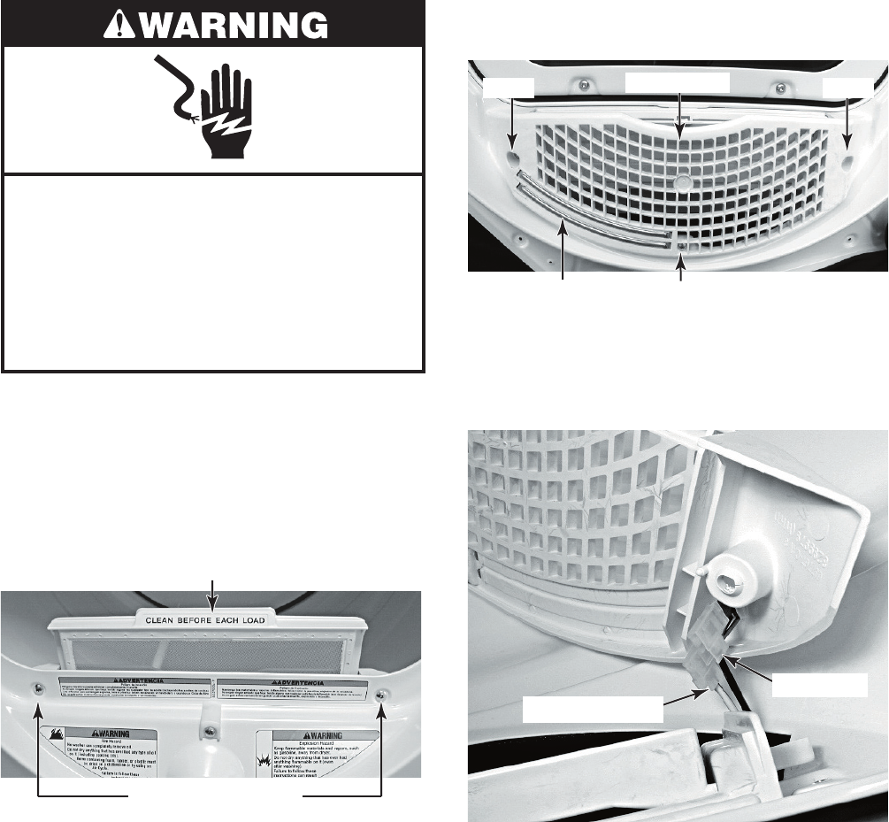
4-6
Electrical Shock Hazard
Disconnect power before servicing.
Replace all parts and panels before
operating.
Failure to do so can result in death or
electrical shock.
1. Unplug dryer or disconnect power.
2. Turn off gas supply to dryer.
3. Open the dryer door, remove the lint fil-
ter, and close the door.
4. Remove the two screws from the outlet
grille.
REMOVING THE MOISTURE SENSOR
5. From inside the drum, remove the three
screws from the outlet grille.
6. Pull the moisture sensor away from the
dryer and disconnect the black and yel-
low-red wires from the moisture sensor
terminals.
Lint Filter
Outlet Grille Screws
Outlet Grille
Screw Screw
Moisture Sensor Screw
Black Wire
Yellow-Red Wire
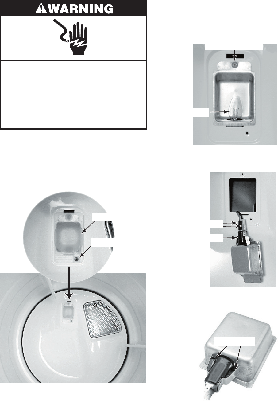
4-7
Electrical Shock Hazard
Disconnect power before servicing.
Replace all parts and panels before
operating.
Failure to do so can result in death or
electrical shock.
1. Unplug dryer or disconnect power.
2. Turn off gas supply to dryer.
3. Open the dryer door.
4. Remove the screw from the drum light
lens and remove the lens.
REMOVING THE DRUM LIGHT SOCKET
5. Remove the bulb from the light socket.
6. Remove the screw from the drum light
holder and pull the holder forward so you
can access the wires.
Lens Screw
Drum Light Lens
Light Holder Screw
Bulb
7. Disconnect the wires from the light holder
terminals.
Light Socket
Wire Connectors
8. Squeeze the locking arms and remove
the socket from the drum light holder.
Locking Arms
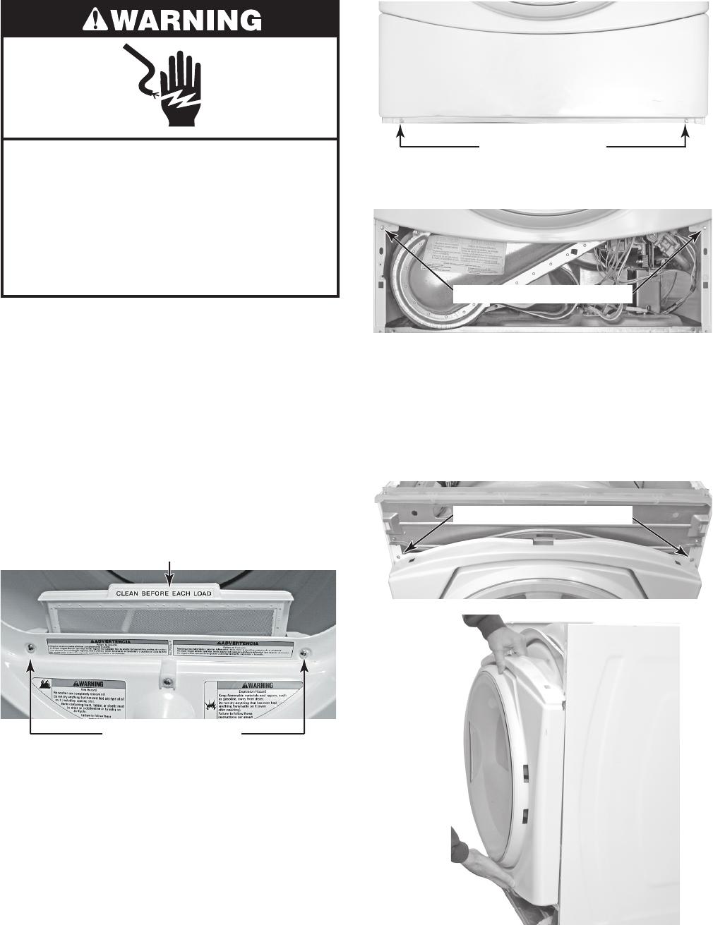
4-8
Electrical Shock Hazard
Disconnect power before servicing.
Replace all parts and panels before
operating.
Failure to do so can result in death or
electrical shock.
1. Unplug dryer or disconnect power.
2. Turn off gas supply to dryer.
3. Remove the console from the dryer (see
page 4-2 for the procedure).
4. Remove the door switch (see page 4-5
for the procedure).
5. Open the dryer door and remove the lint
filter.
6. Remove the two screws from the outlet
grille and then close the dryer door.
REMOVING THE FRONT PANEL
Toe Panel Screws
8. Remove the two screws from the bottom
of the front panel.
Front Panel Bottom Screws
NOTE: When you remove the two screws in
the next step, support the front panel so that
it does not fall.
9. Remove the two screws from the top of
the front panel and remove the panel
from the dryer.
Top Front Panel Screws
7. Remove the screws from the toe panel
and remove the panel (see the top right
photo).
Lint Filter
Outlet Grille Screws Remove
Front
Panel
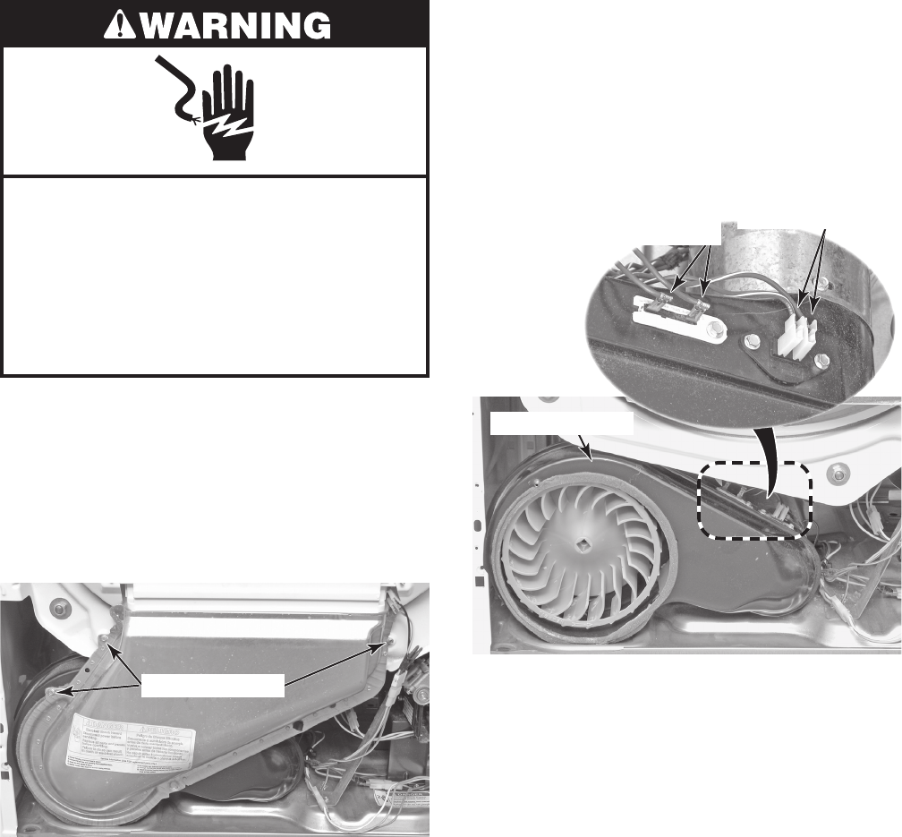
4-9
Electrical Shock Hazard
Disconnect power before servicing.
Replace all parts and panels before
operating.
Failure to do so can result in death or
electrical shock.
1. Unplug dryer or disconnect power.
2. Turn off gas supply to dryer.
3. Remove the front panel from the dryer
(see page 4-8 for the procedure).
4. Remove the three screws from the lint
duct and remove the duct.
REMOVING THE THERMAL FUSE & EXHAUST THERMISTOR
Lint Duct Screws
5. Disconnect the two wire connectors from
the thermal fuse or exhaust thermistor
terminals.
6. Remove the screw(s) from the thermal
fuse or exhaust thermistor and remove
the component from the blower housing.
Blower Housing
Thermal Fuse
2 RD Wires
1 Screw
Exhaust Thermistor
2 RD-WH Wires
2 Screws
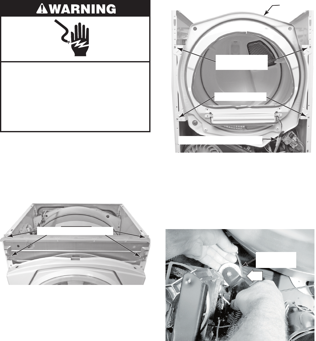
4-10
Electrical Shock Hazard
Disconnect power before servicing.
Replace all parts and panels before
operating.
Failure to do so can result in death or
electrical shock.
1. Unplug dryer or disconnect power.
2. Turn off gas supply to dryer.
3. Remove the front panel from the dryer
(see page 4-8 for the procedure).
4. Remove the four screws from the con-
sole bracket and remove the bracket.
REMOVING THE BELT & DRUM, AND ROLLERS
Top Screws w/
Keyhole Slots
Bottom Screws
Front Panel
8. To remove the belt and drum:
a) Reach under the drum, (raise it as far
as it will go), and push the idler pul-
ley arm, on the back of the drive mo-
tor, to the left to relieve the tension on
the belt, then remove the belt from the
pulley.
Moisture Sensor Connector
5. Disconnect the moisture sensor connec-
tor from the main harness (see the top
right photo).
6. Remove the two bottom screws from the
front support panel.
7. Loosen the two top screws on the front
support panel, then lift the panel and un-
hook the screws from the two keyhole
slots, and remove the panel.
Console Bracket Screws
Remove Belt
From Pulley
Push
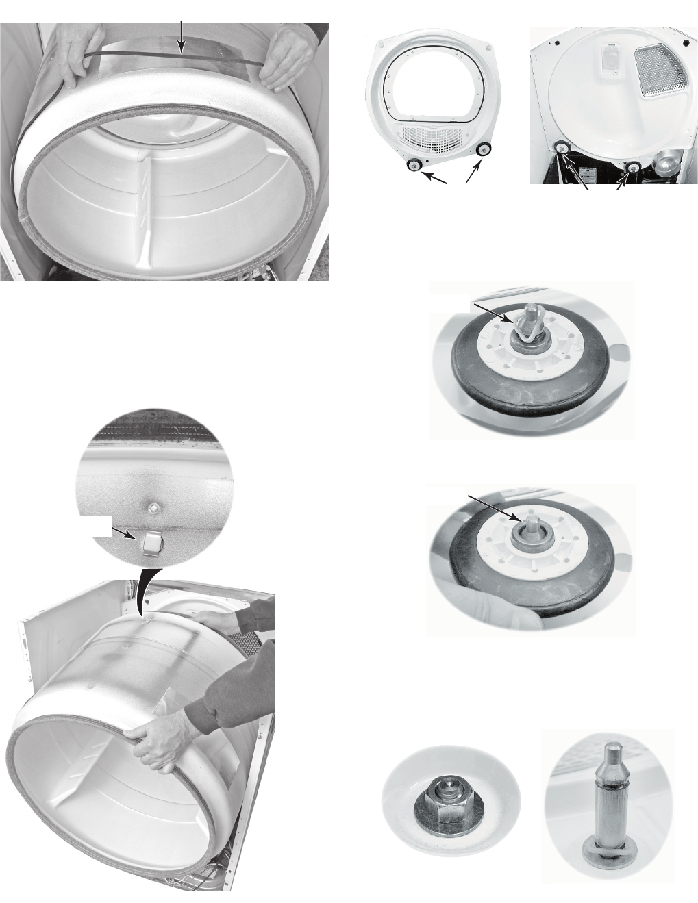
4-11
b) Slide the belt off the front of the drum
and remove it.
Remove Belt
c) Lift the drum and remove it from the
dryer cabinet.
DRUM INSTALLATION NOTE: Be sure to
position the drum in the cabinet with the clip
toward the rear.
Drum Clip
9. To remove a roller:
NOTE: There are two rollers on the front panel
and two on the rear panel, as shown below.
a) Pry the sides of the triangular ring out
of the groove in the roller shaft with a
small screwdriver.
Front Rollers Rear Rollers
Triangular Ring
b) Slide the roller off the roller shaft.
Roller Shaft
c) To remove the roller shaft, remove
the 9/16˝ nut and washer from the
roller support, and remove the support
and remaining triangular ring.
Nut & Washer
Roller Shaft & Ring
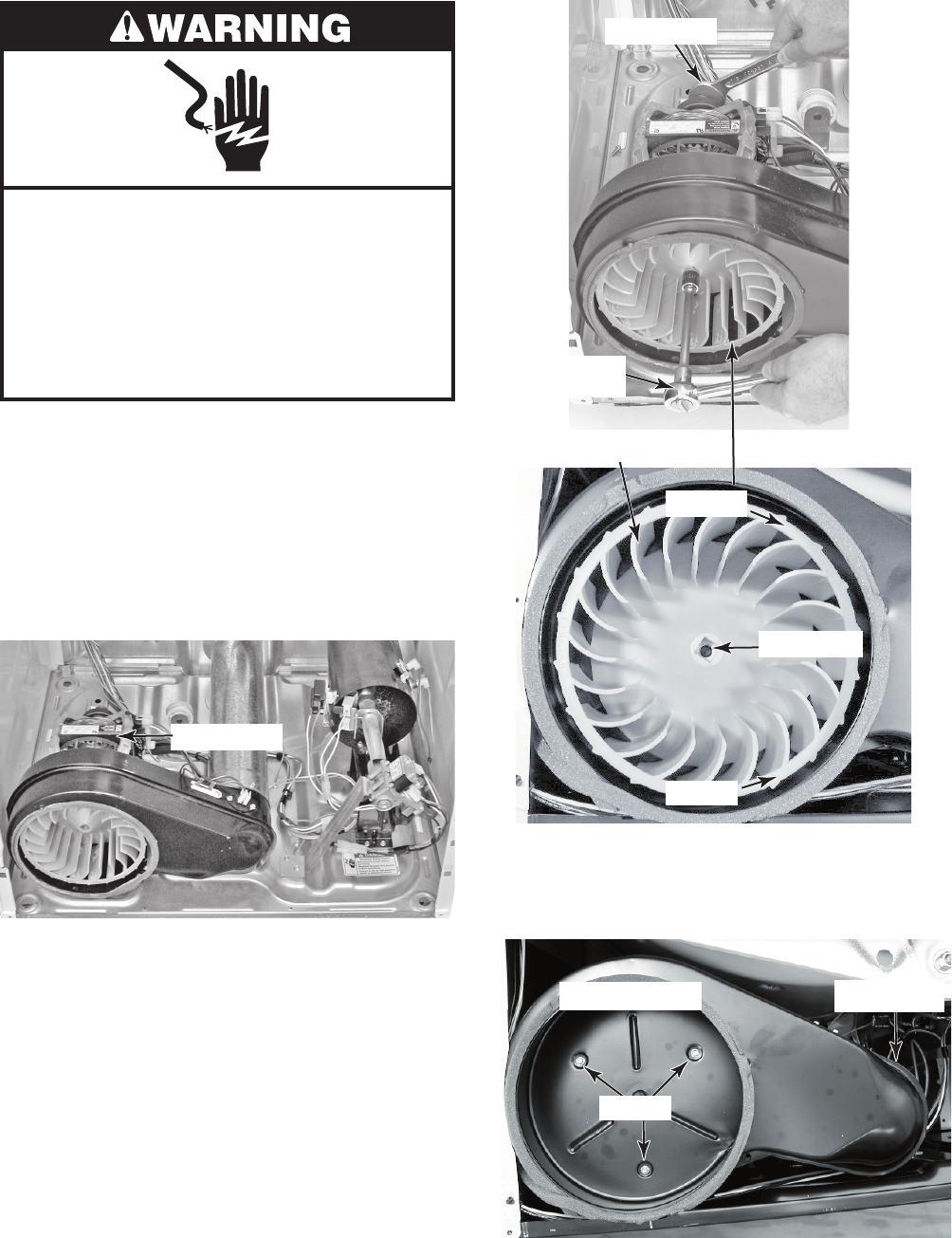
4-12
Electrical Shock Hazard
Disconnect power before servicing.
Replace all parts and panels before
operating.
Failure to do so can result in death or
electrical shock.
1. Unplug dryer or disconnect power.
2. Turn off gas supply to dryer.
3. Remove the drum from the dryer (see
pages 4-10 and 4-11 for the procedure).
4. Remove the thermal fuse and exhaust
thermistor (see page 4-9 for the proce-
dure).
REMOVING THE DRIVE MOTOR AND BELT SWITCH
7/8˝ Wrench
Ratchet w/
1/2˝ Drive
Remove
Tighten
1/2˝ Drive
c) Remove the four screws from the
blower housing and exhaust duct and
remove the housing.
Blower Housing
Screws
Duct Screw
Blower Wheel
5. To remove the drive motor:
a) Reach around to the back of the drive
motor and attach a 7/8˝ open-end
wrench to the hex-end of the motor
shaft, and a ratchet with a 1/2˝ drive
in the blower wheel hub opening.
b) Turn the blower wheel clockwise
(shown by the “REMOVE” arrow that
is embossed on the front of the wheel)
and remove the wheel from the motor
shaft.
Drive Motor
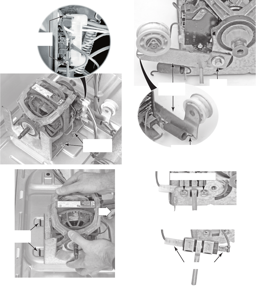
4-13
d) Lift the locking tabs on the top and
bottom of the motor harness plug and
disconnect the plug from the motor
terminals.
e) Remove the two mounting screws from
the drive motor, then pull the motor to
the right until the two motor bracket
tabs are out of the chassis floor slots,
and remove the drive motor.
6. To remove the belt switch:
a) Remove the drive motor from the dryer
(see step 5).
b) Unhook the end of the spring from the
idler pulley arm.
c) Remove the 3/8˝ hex-head screw
from the idler pulley arm and remove
the arm from the motor.
Drive Motor
Plug Tabs
Drive Motor
Screws
Drive Motor
Floor Slots
Unhook Spring
Idler
Pulley Arm
Screw
d) Remove the two screws from the belt
switch and remove it from the motor.
e) Disconnect the two blue wires from
the belt switch terminals.
Wire Connectors
Belt Switch Screws
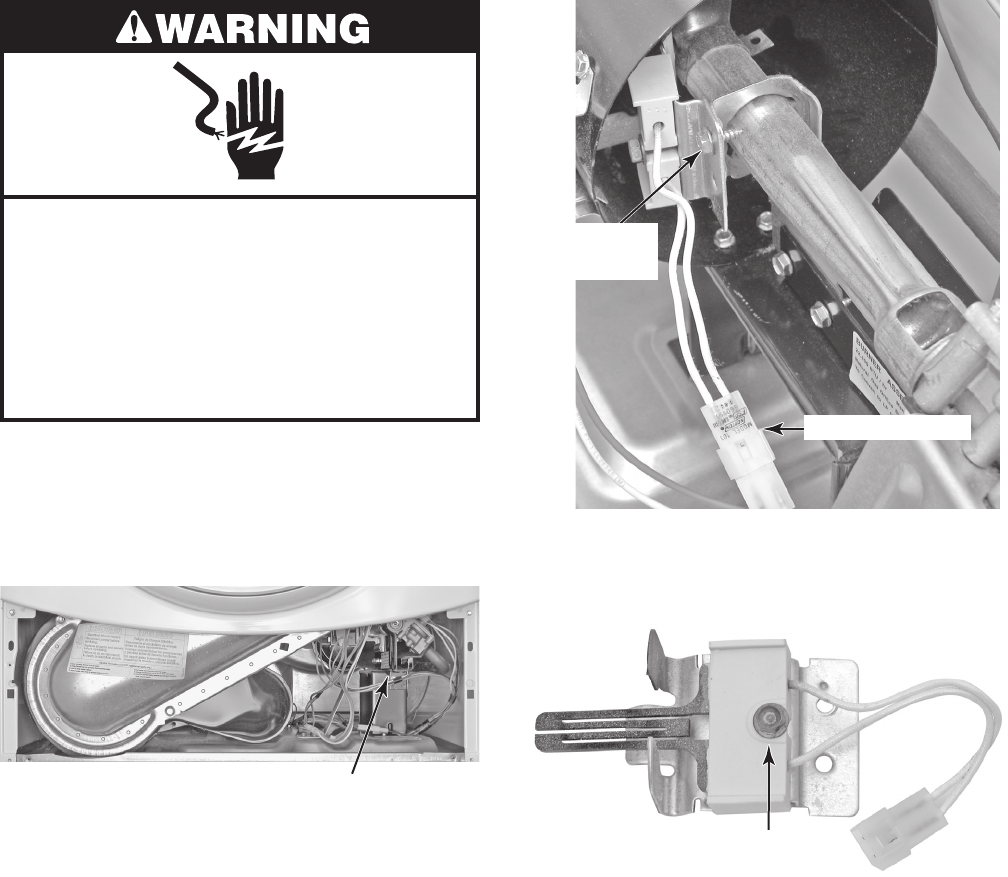
4-14
Electrical Shock Hazard
Disconnect power before servicing.
Replace all parts and panels before
operating.
Failure to do so can result in death or
electrical shock.
1. Unplug dryer or disconnect power.
2. Turn off gas supply to dryer.
3. Remove the toe panel from the dryer (see
page 4-8 for the procedure).
REMOVING THE IGNITOR, FLAME SENSOR, HIGH-LIMIT
THERMOSTAT, AND THERMAL CUTOFF
(GAS MODELS ONLY)
4. To remove the ignitor:
a) Disconnect the ignitor wire connector
from the main harness (see the top
right photo).
b) Remove the 5/16˝ hex-head ignitor
bracket screw from the burner venturi
and remove the ignitor and bracket.
Gas Burner Assembly
Ignitor Connector
Ignitor Bracket
Screw
c) Remove the 5/16˝ hex-head ignitor
screw and remove the ignitor from the
bracket.
Ignitor Screw
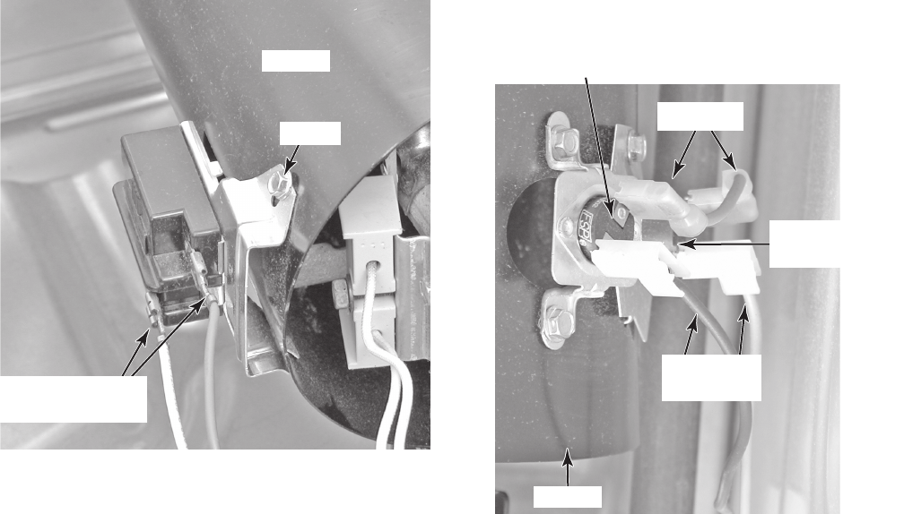
4-15
5. To remove the flame sensor:
a) Disconnect the two wire connectors
from the sensor terminals.
b) Remove the flame sensor screw from
the burner venturi and remove the
sensor.
6. To remove the high-limit thermostat or
the thermal cutoff:
a) Disconnect the two wire connectors
from the component terminals.
b) Remove the two screws from the high-
limit thermostat, or single screw from
the thermal cutoff, and remove the
component from the venturi.
Venturi
Screw
Flame Sensor
Wire Connectors
High-Limit Thermostat (2 Screws)
Pink Wire
Red & Blue
Wires
Thermal Cutoff
(1 Screw)
Venturi
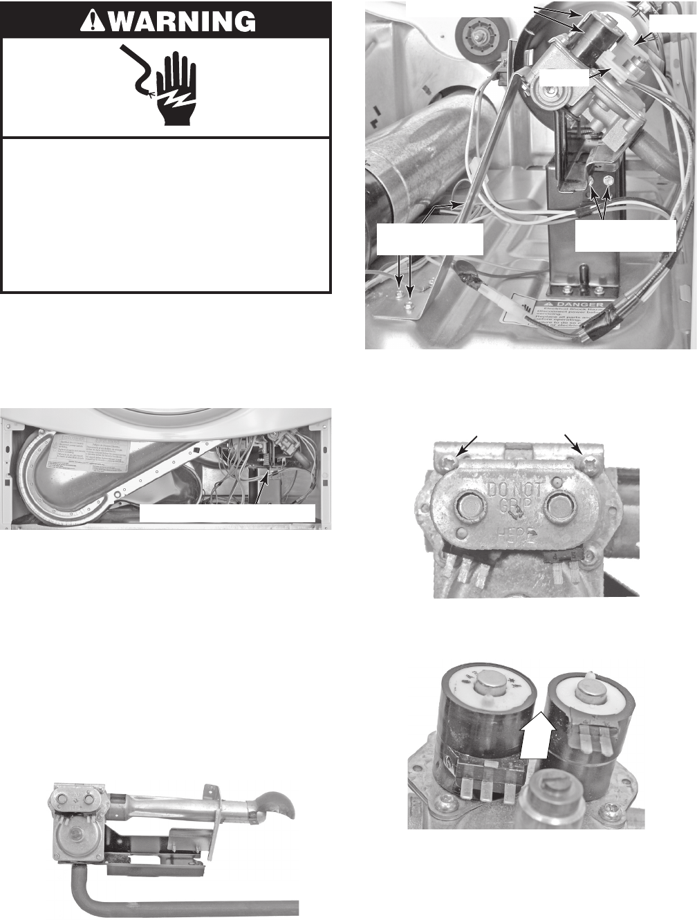
4-16
Electrical Shock Hazard
Disconnect power before servicing.
Replace all parts and panels before
operating.
Failure to do so can result in death or
electrical shock.
1. Unplug dryer or disconnect power.
2. Turn off gas supply to dryer.
3. Remove the toe panel from the dryer (see
page 4-8 for the procedure).
REMOVING THE GAS BURNER ASSEMBLY COILS
4. Remove the ignitor from the burner (see
page 4-14 for the procedure).
5. Disconnect the 2-wire and 3-wire con-
nectors from the burner coil assembly
terminals (see the top right photo).
6. Remove the two screws from the burner
support bracket and remove the bracket
from the burner.
7. Remove the two screws from the front of
the burner bracket and remove the burn-
er assembly from the dryer.
8. Remove the two screws from the coil re-
taining bracket.
Gas Burner Assembly
2-Wire
3-Wire
Coils w/Connectors
Support Bracket
Screws
Burner Bracket
Screws
9. Lift the two coils off their cores and re-
move them.
Retaining Bracket Screws
Gas Burner Assembly
LIFT
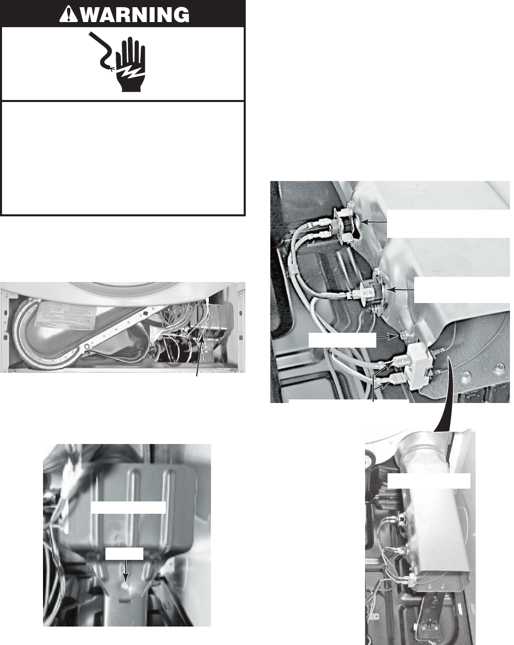
4-17
Electrical Shock Hazard
Disconnect power before servicing.
Replace all parts and panels before
operating.
Failure to do so can result in death or
electrical shock.
1. Unplug dryer or disconnect power.
2. Remove the toe panel from the dryer (see
page 4-8 for the procedure).
REMOVING THE HEATER, HIGH-LIMIT THERMOSTAT,
AND THERMAL CUTOFF (ELECTRIC MODELS ONLY)
High-Limit Thermostat,
Thermal Cutoff, & Heater Area
3. Remove the screw from the heater shield
and remove the shield.
Heater Terminal Block
(Red & Red-White Wires)
Heater Shield
Screw
4. To remove the heater:
a) Remove the two wires from the termi-
nal block.
b) Remove the hex-head screw from the
heater housing, and slide the heater
out of the duct.
5. To remove the high-limit thermostat or
the thermal cutoff:
a) Disconnect the wires from the high-
limit thermostat or the thermal cutoff.
b) Remove the two hex-head screws.
Heater Screw
High-Limit Thermostat
(Red-White & Black Wires)
Thermal Cutoff
(Red & Black Wires)
Heater Assembly
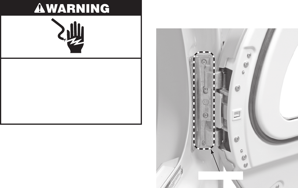
4-18
REMOVING THE DRYER DOOR
Electrical Shock Hazard
Disconnect power before servicing.
Replace all parts and panels before
operating.
Failure to do so can result in death or
electrical shock.
1. Unplug dryer or disconnect power.
2. Turn off gas supply to dryer.
3. Open the dryer door.
4. While supporting the dryer door, remove
the four screws from the hinge, and re-
move the door.
4 Door Screws
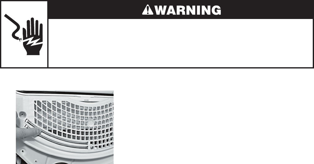
5-1
COMPONENT TESTING
Electrical Shock Hazard
Disconnect power before servicing.
Replace all parts and panels before operating.
Failure to do so can result in death or electrical shock.
Before testing any of the components, perform
the following checks:
Control failure can be the result of corrosion
on connectors. Therefore, disconnecting
and reconnecting wires will be necessary
throughout test procedures.
All tests/checks should be made with a
VOM or DVM having a sensitivity of 20,000
ohms-per-volt DC, or greater.
•
•
Check all connections before replacing
components, looking for broken or loose
wires, failed terminals, or wires not pressed
into connectors far enough.
Resistance checks must be made with pow-
er cord unplugged from outlet, and with wir-
ing harness or connectors disconnected.
Unless stated otherwise, make all resis-
tance checks by disconnecting the compo-
nent connectors either at the terminals, or at
the central control unit.
•
•
•
MOISTURE SENSOR
Refer to page 4-6 for the procedure for ac-
cessing the moisture sensor.
1. Unplug dryer or disconnect power.
2. Turn off gas supply to dryer.
3. Disconnect the wires from the moisture
sensor.
4. Set the ohmmeter to the R X 1 scale.
5. Touch the ohmmeter test leads to the
sensor connector pins. The meter should
indicate an open circuit (infinite).
6. Bridge the two sensor strips with a wet
cloth. The meter should indicate continuity.
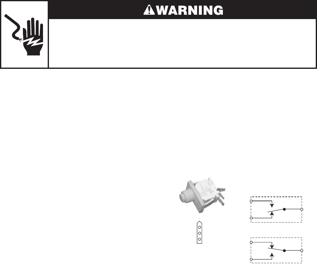
5-2
DOOR SWITCH
Refer to page 4-5 for the procedure for ac-
cessing the door switch.
1. Unplug dryer or disconnect power.
2. Turn off gas supply to dryer.
3. Close the dryer door.
4. Disconnect the 3-wire connector from the
door switch to the machine control elec-
tronics assembly at P8-4.
5. Set the ohmmeter to the R X 1 scale.
6. Touch the black ohmmeter test lead to
the white wire pin in the connector and
leave it there for the remaining tests.
7. Touch the red ohmmeter test lead to the
brown wire pin in the connector. The me-
ter should indicate an open circuit (infi-
nite).
8. Touch the red ohmmeter test lead to the
blue wire pin in the connector. The meter
should indicate a closed circuit (0 Ω).
Brown
Brown (N.C.)
White
White (COM)
Blue
Blue (N.O.)
N.O.
N.C.
COM
DOOR OPEN
Brown
White
Blue N.O.
N.C.
COM
DOOR CLOSED
CONNECTOR
Electrical Shock Hazard
Disconnect power before servicing.
Replace all parts and panels before operating.
Failure to do so can result in death or electrical shock.
9. Open the dryer door.
10. Touch the red ohmmeter test lead to the
blue wire pin in the connector. The meter
should indicate an open circuit (infinite).
11. Touch the red ohmmeter test lead to the
brown wire pin in the connector. The me-
ter should indicate a closed circuit (0 Ω).
12. If the resistance test is incorrect, replace
the wire and door switch assembly, (see
page 4-5 for the procedure), and retest.
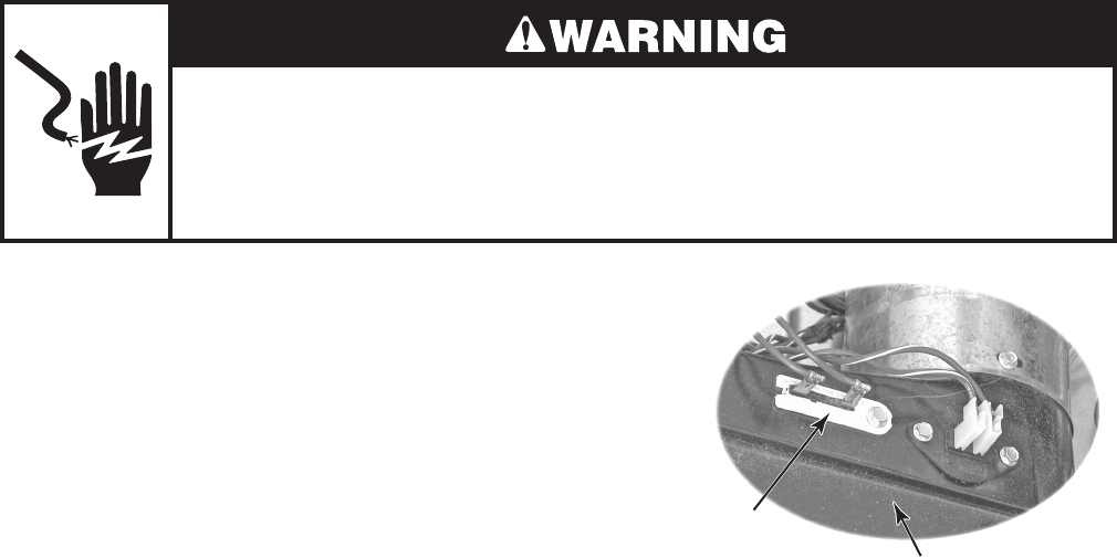
5-3
Electrical Shock Hazard
Disconnect power before servicing.
Replace all parts and panels before operating.
Failure to do so can result in death or electrical shock.
THERMAL FUSE
Refer to page 4-9 for the procedure for ac-
cessing the thermal fuse.
Electric Dryers: The thermal fuse is wired in
series with the drive motor. If the thermal fuse
opens, 91°C (196°F), power to the motor is
turned off. A centrifugal switch on the motor
also opens the heater circuit.
Once the thermal fuse has opened, it will not
reset, and must be replaced. Check for a failed
thermistor, or a shorted heater element.
Gas Dryers: The thermal fuse is wired in
series with the gas valve. If the thermal fuse
opens, 91°C (196°F), power to the valve is
turned off. A centrifugal switch on the motor
also opens the heater circuit.
Once the thermal fuse has opened, it will
not reset, and must be replaced. Check for a
failed thermistor.
Blower Housing
Thermal Fuse
91°C (196°F)
1. Unplug dryer or disconnect power.
2. Turn off gas supply to dryer.
3. Disconnect the wires from the thermal
fuse.
4. Set the ohmmeter to the R X 1 scale.
5. Touch the ohmmeter test leads to the
thermal fuse terminals. The meter should
indicate continuity (0 Ω). If the meter in-
dicates an open circuit (infinite), replace
the thermal fuse.
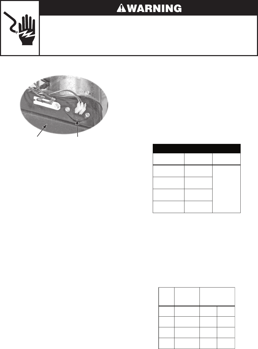
5-4
Electrical Shock Hazard
Disconnect power before servicing.
Replace all parts and panels before operating.
Failure to do so can result in death or electrical shock.
Blower Housing Exhaust Thermistor
Refer to page 4-9 for the procedure for ac-
cessing the exhaust thermistor.
The machine control electronics monitors the
exhaust temperature using the thermistor, and
cycles the heater relay on and off to maintain
the desired temperature.
Begin with an empty dryer and a clean lint
screen.
1. Plug in dryer or reconnect power.
2. Start the Timed Dry cycle.
3. If after 60 seconds, F-22 or F-23 flashes
in the display and the dryer shuts off, the
thermistor or wire harness is either open
or shorted.
Unplug dryer or disconnect power.
Check wire connections at the ma-
chine control electronics and thermis-
tor.
If wire connections are good, remove
the two wires from the thermistor and
replace the thermistor.
Plug in dryer or reconnect power.
•
•
•
•
EXHAUST THERMISTOR 4. If F-22 or F-23 does not flash in the dis-
play, the connections to the thermistor
are good. Therefore, check the thermis-
tor’s resistance value at any or all of the
temperature levels in question, using the
Timed Dry cycle, and the following pro-
cess:
Hold a glass bulb thermometer capable of
reading from 90° to 180°F (32° to 82°C) in
the center of the exhaust outlet. The cor-
rect exhaust temperatures are as follows:
EXHAUST TEMPERATURES
TEMPERATURE
SETTING
HEAT TURNS
OFF*
HEAT TURNS
ON
High 155° ± 5°F
(68° ± 3°C)
10–15°F
(6–8°C)
below the
heat turn off
temperature
Medium 140° ± 5°F
(60° ± 3°C)
Low 125° ± 5°F
(52° ± 3°C)
Extra Low 115° ± 5°F
(46° ± 3°C)
* The measured overshoot using the glass
bulb thermometer in the exhaust outlet can
be 30°F (17°C) higher.
5. If the exhaust temperature is not within
specified limits, check the resistance of
the thermistor.
NOTE: All thermistor resistance measurements
(shown below) must be made while dryer is dis-
connected from power.
TEMP.
SETTING TEMPERATURE
Thermistor resistance
value at heater
shutoff (digital or
analog meter) k Ω
High 155° ± 5°F
(68° ± 3°C) 2.1 1.7
Medium 140° ± 5°F
(60° ± 3°C) 2.8 2.3
Low 125° ± 5°F
(52° ± 3°C) 3.8 3.1
Extra
Low
115° ± 5°F
(46° ± 3°C) 4.7 3.8
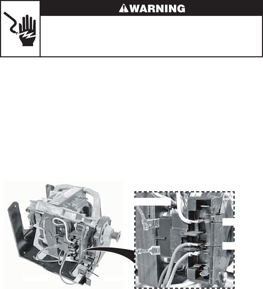
5-5
Electrical Shock Hazard
Disconnect power before servicing.
Replace all parts and panels before operating.
Failure to do so can result in death or electrical shock.
DRIVE MOTOR
Refer to page 4-12 for the procedure for ac-
cessing the drive motor.
1. Unplug dryer or disconnect power.
2. Turn off gas supply to dryer.
3. Disconnect the plug from the motor con-
nector.
4. Set the ohmmeter to the R X 1 scale.
5. Touch one ohmmeter test lead to the blue
motor wire connector, and the other test
lead to connector pin 5 (white-orange
wire). The meter should indicate between
2.4 and 3.6 Ω (main winding).
6. Touch one ohmmeter test lead to the blue
motor wire connector, and the other test
lead to connector pin 3 (violet wire). The
meter should indicate between 2.4 and
3.8 Ω (start winding).
7. If either resistance is much larger than
4 Ω, replace the motor.
If the resistances at the motor are cor-
rect, check for a failed belt switch.
If the belt switch is okay, check for an
open circuit between the motor and the
machine control electronics assembly.
Pin 5 (WH-OR)
Pin 3 (VI)
Blue Motor Wire
Motor Connector
Drive Motor Belt Switch
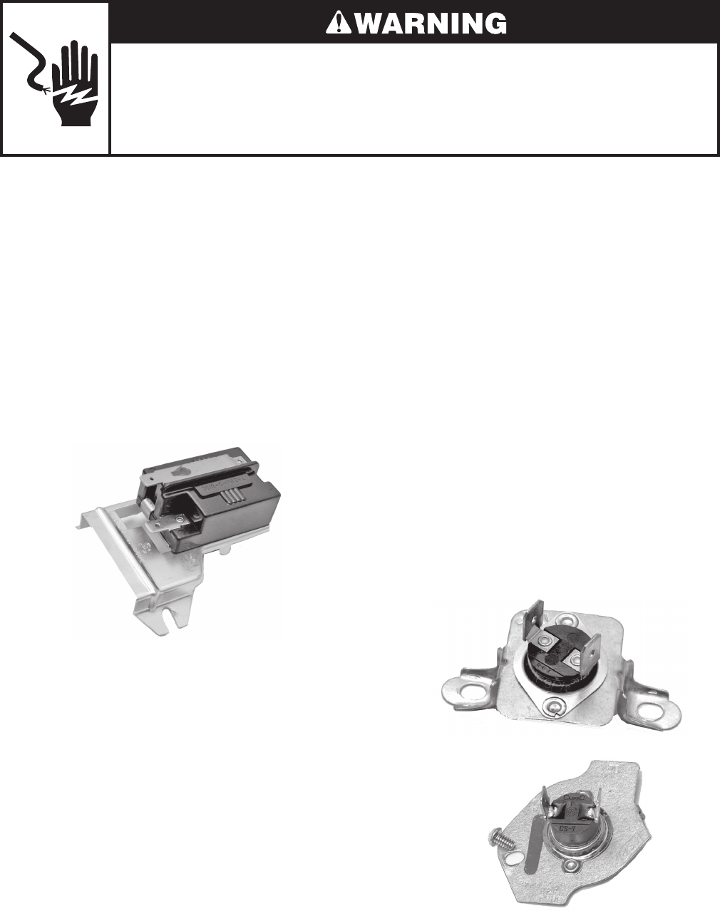
5-6
FLAME SENSOR
Refer to page 4-14 for the procedure for ac-
cessing the flame sensor.
1. Unplug dryer or disconnect power.
2. Turn off gas supply to dryer.
3. Disconnect the wire connectors from the
flame sensor terminals.
4. Set the ohmmeter to the R X 1 scale.
5. Touch the ohmmeter test leads to the
flame sensor terminals. The meter should
indicate a closed circuit (0 Ω).
HIGH-LIMIT THERMOSTAT &
THERMAL CUTOFF
(GAS DRYERS ONLY)
Refer to page 4-14 for the procedure for ac-
cessing the high-limit thermostat or thermal
cutoff.
The thermal cutoff is a non-resettable device.
The cutoff temperature is 178°C (352°F).
1. Unplug dryer or disconnect power.
2. Turn off gas supply to dryer.
3. Disconnect the wire connectors from the
high-limit thermostat and thermal cutoff
terminals.
4. Set the ohmmeter to the R X 1 scale.
5. Touch the ohmmeter test leads to the
high-limit thermostat or thermal cutoff
terminals. The meter should indicate a
closed circuit (0 Ω).
Flame Sensor
Thermal Cutoff
Electrical Shock Hazard
Disconnect power before servicing.
Replace all parts and panels before operating.
Failure to do so can result in death or electrical shock.
High-Limit
Thermostat
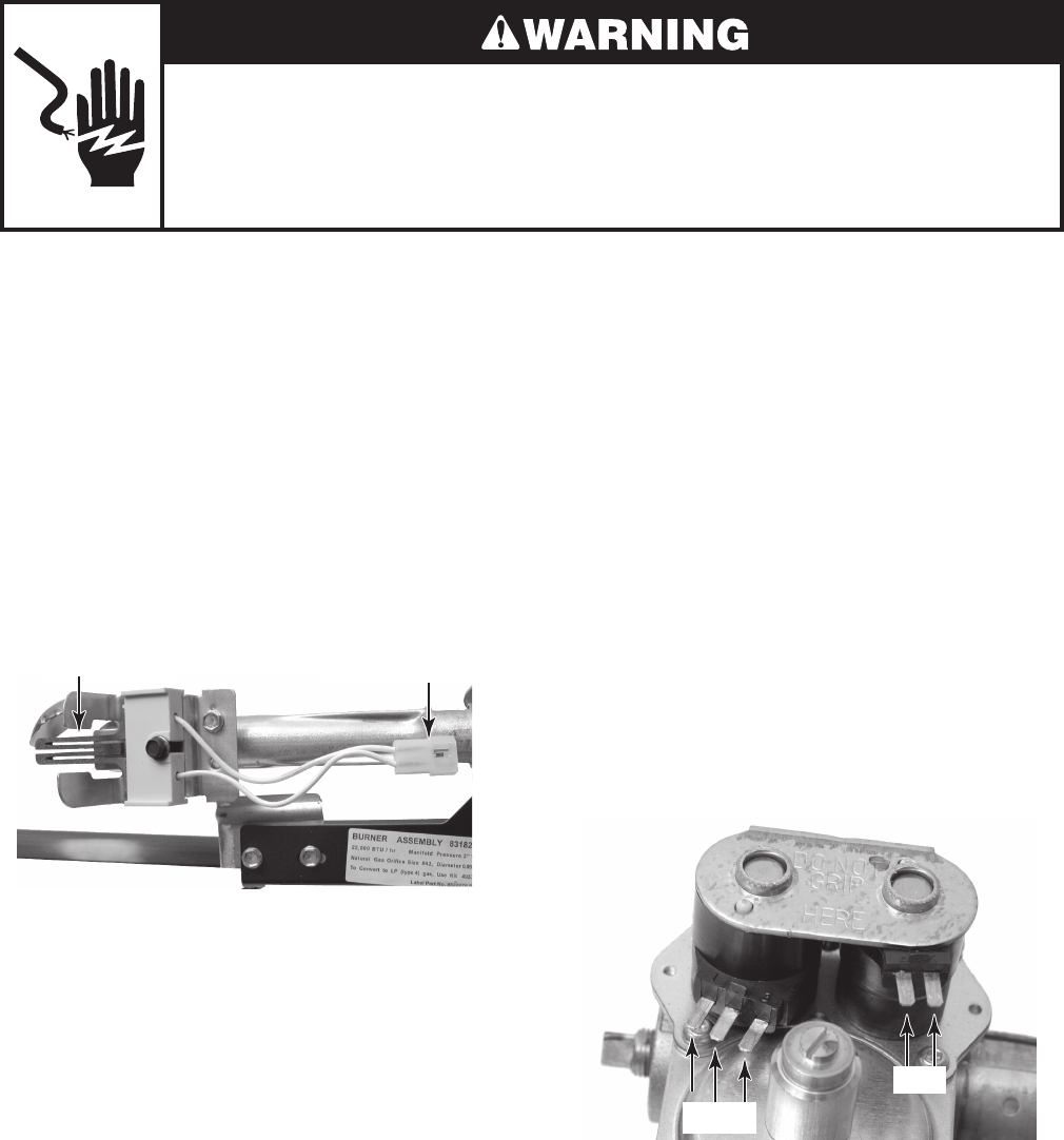
5-7
Electrical Shock Hazard
Disconnect power before servicing.
Replace all parts and panels before operating.
Failure to do so can result in death or electrical shock.
GAS BURNER COILS
Refer to page 4-16 for the procedure for ac-
cessing the gas burner assembly.
1. Unplug dryer or disconnect power.
2. Turn off gas supply to dryer.
3. Disconnect the wire connectors from the
coil terminals.
4. Set the ohmmeter to the R X 100 scale.
5. Touch the ohmmeter test leads to the
2-pin coil. The meter should indicate be-
tween 1000 and 1300 Ω.
6. Touch the ohmmeter test leads to the
3-pin coil. The meter should indicate as
follows:
Pins 1 & 2 = 1300 to 1400 Ω
Pins 1 & 3 = 500 to 600 Ω
BURNER IGNITOR
Refer to page 4-16 for the procedure for ac-
cessing the gas burner assembly.
1. Unplug dryer or disconnect power.
2. Turn off gas supply to dryer.
3. Disconnect the ignitor wire connector
from the main harness connector.
4. Set the ohmmeter to the R X 1 scale.
5. Touch the ohmmeter test leads to the
2-wire connector pins. The meter should
indicate between 50 and 250 Ω.
Burner Ignitor 2-Wire Connector
4 5
1 2 3
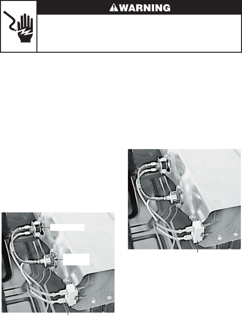
5-8
Electrical Shock Hazard
Disconnect power before servicing.
Replace all parts and panels before operating.
Failure to do so can result in death or electrical shock.
THERMAL CUTOFF
(ELECTRIC DRYERS ONLY)
Refer to page 4-17 for the procedure for ac-
cessing the thermal cutoff.
The thermal cutoff is a non-resettable device.
The cutoff temperature is 178°C (352°F).
If the dryer does not heat and there is 240
VAC to the dryer, perform the following test.
1. Unplug dryer or disconnect power.
2. Disconnect the wires from the thermal
cutoff.
3. Set the ohmmeter to the R X 1 scale.
4. Touch the ohmmeter test leads to the
thermal cutoff terminals. The meter
should indicate continuity (0 Ω). If the
meter indicates an open circuit (infinite),
replace both the thermal cutoff and the
high-limit thermostat. In addition, check
for a failed heater element, or a blocked,
or improper exhaust system.
Heater Terminals
High-Limit
Thermostat
Thermal Cutoff
HEATER
(ELECTRIC DRYERS ONLY)
Refer to page 4-17 for the procedure for ac-
cessing the heater.
1. Unplug dryer or disconnect power.
2. Disconnect one of the wire connectors
from the heater terminal block.
3. Set the ohmmeter to the R X 1 scale.
4. Touch the ohmmeter test leads to the ter-
minals on the heater terminal block. The
meter should indicate between 7 & 12 Ω.
Heater Terminal Block

6-1
DIAGNOSTICS & TROUBLESHOOTING
DIAGNOSTIC GUIDE
Before servicing, check the following:
Make sure there is power at the wall
outlet.
Has a household fuse blown or circuit
breaker tripped? Time delay fuse?
Is dryer vent properly installed and clear of
lint or obstructions?
All tests/checks should be made with a
VOM (volt-ohm-milliammeter) or DVM
(digital-voltmeter) having a sensitivity of
20,000 ohms per volt DC or greater.
Check all connections before replacing
components. Look for broken or loose
wires, failed terminals, or wires not pressed
into connectors far enough.
A potential cause of a control not functioning
is corrosion on connections. Observe
connections and check for continuity with
an ohmmeter.
Connectors: Look at top of connector.
Check for broken or loose wires. Check
for wires not pressed into connector far
enough to engage metal barbs.
Resistance checks must be made with
power cord unplugged from outlet.
DIAGNOSTIC TESTS
These tests allow factory or service personnel
to test and verify all inputs to the machine
control electronics. One may want to do a quick
and overall checkup of the dryer with these
tests before going to specific troubleshooting
tests.
•
•
•
•
•
•
•
•
ACTIVATING THE DIAGNOSTIC TEST MODE
1. Be sure the dryer is in standby mode
(plugged in with all indicators off, or with
only the Cycle Complete indicator on).
2. Select any one button (except PAUSE/
CANCEL) and follow the steps below, using
the same button (remember the button):
3. If this test mode has been entered success-
fully, all indicators on the console are illumi-
nated for 5 seconds with 88 showing in
the “Estimated Time Remaining” two-digit
display. If there are no Saved Fault Codes
or Active Fault Codes, all indicators on the
console will momentarily turn off, then stay
on with 88 displayed.
If entry into diagnostic mode is unsuccess-
ful, refer to the following indications and
actions:
Indication 1: None of the indicators or
display turns on.
Action: Select any cycle. If indicators come
on, try to change the function for the button
used to activate the diagnostic test mode.
If that button fails to change the function,
something is faulty with the button, and it is
not possible to enter the diagnostic mode.
Remove the console electronics and housing
assembly. See Accessing & Removing the
Electronic Assemblies.
If no indicators come on after selecting the
cycle, go to TEST #1.
Indication 2: Fault code flashes from the
display.
Action: Review the Display Fault Codes table
for the recommended procedure.
•
Press/hold
3 seconds g g g g
Release for
3 seconds
Press/hold
3 seconds
Release for
3 seconds
Press/hold
3 seconds

6-2
Diagnostic: Saved Fault Codes
If there are saved fault codes, the most recent
fault code will alternately show “F-” and “XX”
where XX is the fault code, and all the cycle
selector indicators flash.
Diagnostic: Active Fault Codes
If there is an active fault code, it will be flashing
in the display (the cycle indicators do not flash).
Review the Display Fault Codes table for the
recommended procedure.
If there is no active fault code, 88 will be
displayed.
Diagnostic: Console Buttons and Indica-
tors
Pressing buttons and rotating the cycle selector
will turn off the corresponding indicator and
sound a beep as shown in Figure 1, Console
Diagnostics. Pressing more time will toggle
the left digit on the display while sounding a
beep. Pressing less time will toggle the right
digit on the display while sounding a beep.
If indicators fail to come on and beep after
pressing buttons and rotating the cycle sel-
ector, go to TEST #5.
Press and release the
same button used to
activate Diagnostics
g
g
g
g
g
g
g
beep toneSecond most recent fault code is
displayed.
Repeat beep tone Third most recent fault code is
displayed.
Repeat beep toneFourth most recent fault code is
displayed.
Repeat All indicators momentarily turn off, then stay on.
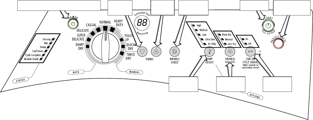
6-3
Power button controls Status indicators at left
and the Lock/Unlock Control indicator
Turns off all
indicators and exits
diagnostic mode
This button
controls the
right digit
Button controls
all
above button
indicators
Start button
turns on dryer
This button
controls the
left digit
Backlit button
controls its own
indicator
Button controls
all
above button
indicators
Button controls
all
above button
indicators
Figure 1. Console Diagnostics.
Diagnostic: Door Switch
Opening the door should cause a beep and an
alphanumeric number to be displayed. Closing
the door should cause a beep and 88 to be
displayed.
If opening the door fails to cause a beep and a
number and letter to be displayed, go to TEST
#6.
Diagnostic: Moisture Sensor
Open the door and locate two metal strips
on the face of the lint screen housing. Bridge
these strips with a wet cloth or a finger. If a
beep is heard and an alphanumeric number is
displayed on the console, the sensor is OK. If
not, or if a beep tone is heard before bridging
the moisture strips, go to TEST #4.
Diagnostic: Motor, Heater, and Console ID
Close the door. Press the START button. The
motor and heater will turn on, and the display
will show one of the following Console IDs: 9b,
9C, 9d, 9E, or 9F.
While running, press the START button again.
The motor and heater will turn off, and the
display will show 88.
If none of the Console IDs are displayed,
replace the console electronics and housing
assembly. See Accessing & Removing the
Electronic Assemblies.
If the motor does not turn on, go to TEST
#2.
If no heat is detected, go to TEST #3.
DE-ACTIVATING THE DIAGNOSTIC
TEST MODE
Press the PAUSE/CANCEL button to exit
diagnostics.
•
•
•
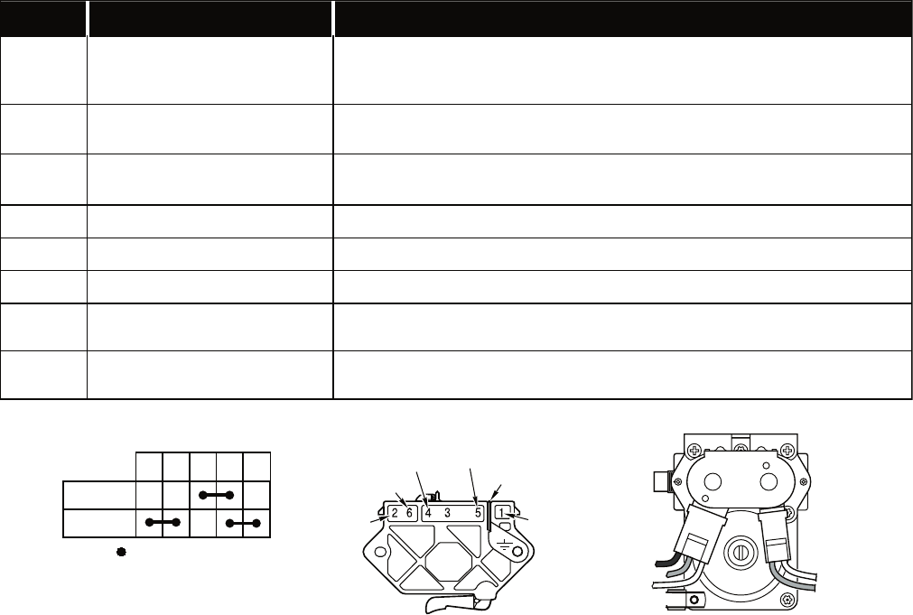
6-4
DISPLAY FAULT CODES
The fault codes below would be indicated when attempting to start a drying cycle, or after activating
the diagnostic test mode.
DISPLAY DESCRIPTION EXPLANATION AND RECOMMENDED PROCEDURE
PF Power Failure
“PF”flashes to indicate that a power failure occurred while the dryer was
running. Press START to continue the cycle, or press PAUSE/CANCEL to
clear the display.
F-01 Primary Control Failure “F-01” flashes when there is a primary control failure. Replace the machine
control electronics. See Accessing & Removing the Electronic Assemblies.
F-02 Keypad/User Interface
Failure
“F-02” flashes when there is a stuck button or user interface mismatch. This
fault code will ONLY appear when in the diagnostic test mode. See TEST #5.
F-22 Exhaust Thermistor Open “F-22” flashes if the thermistor is open. See TEST #3a.
F-23 Exhaust Thermistor Shorted “F-23” flashes if the thermistor has shorted. See TEST #3a.
F-26 Motor Drive System Failure “F-26” flashes if there is a motor drive system failure. See TEST #2.
F-28 Moisture Sensor Open “F-28” flashes if the moisture sensor strip is open. This fault code will ONLY
appear when in the diagnostic test mode. See TEST #4.
F-29 Moisture Sensor Shorted “F-29” flashes if the moisture sensor strip has shorted. This fault code will
ONLY appear when in the diagnostic test mode. See TEST #4.
1M 2M 3M 5M 6M
=
Contacts closed
Contacts
Function
Start
Run
Red
Lt. Blue
Blue-White (Elec)
White (Gas)
Green-Yellow
Red
Black-White
BLACK
BLUE
BLUE
WHITE
WHITE
WHITE
Gas Valve - Gas Dryer
Pluggable Drive Motor Switch
Centrifugal Switch (Motor)
Gas Valve - Gas Dryer
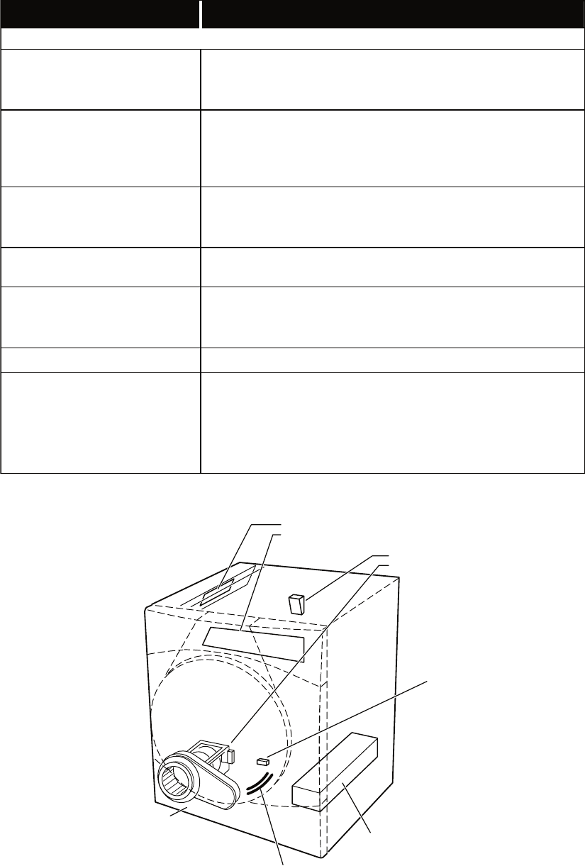
6-5
TROUBLESHOOTING GUIDE
Some tests will require accessing components. See Figure 2 for component locations.
PROBLEM POSSIBLE CAUSE / TEST
NOTE: Possible Cause/Tests MUST be performed in the sequence shown for each problem.
WON’T POWER UP.
(No response when buttons are
pressed.)
1. Supply connections. See TEST #1.
2. Check harness connections.
3. Console electronics and housing assembly. See TEST #5.
WON’T START CYCLE WHEN
START BUTTON IS PRESSED.
1. If number display flashes, check to be sure the door is completely
shut, and press and hold down START for about 1 second.
2. See TEST #2.
3. See TEST #6.
WON’T SHUT OFF WHEN
EXPECTED.
1. Check PAUSE/CANCEL button. See TEST #5.
2. Console electronics and housing assembly. See TEST #5.
3. Moisture sensor. See TEST #4.
CONTROL WON’T ACCEPT
SELECTIONS. Console electronics and housing assembly. See TEST #5.
WON’T HEAT.
1. Heater. See TEST #3.
2. Check harness connections.
3. Check installation.
HEATS IN AIR CYCLE. Heater. See TEST #3.
SHUTS OFF BEFORE CLOTHES
ARE DRY.
1. Check the dryness setting for auto cycles.
2. Check for full lint screen.
3. Check for clogged vent.
4. Moisture sensor. See TEST #4.
5. Dryness adjust. See TEST #4a.
Moisture Sensor
Strips
Heater
Assembly
Door
Switch
See Accessing & Removing the
Electronic Assemblies to access:
See Removing the Back
Panel to access:
See Removing the Toe Panel,
to access:
•
•
Drum Light Assembly
Blower Motor Assembly
•
•
•
•
•
•
Moisture Sensors
Exhaust Thermistor
Thermal Cut-off
High Limit Thermostat
Heater Assembly (Electric or Gas)
Thermal Fuse
•
•
Machine Control Electronics
Console Electronics
and Housing
Figure 2. Component locations.
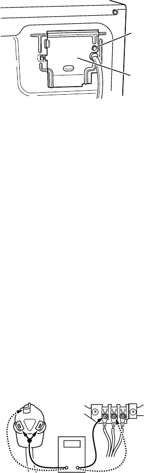
6-6
TROUBLESHOOTING TESTS
NOTE: These checks are done with the dryer
unplugged or disconnected from power.
TEST #1 Supply Connections
This test assumes that proper voltage is present
at the outlet, and visual inspection indicates
that the power cord is securely fastened to the
terminal block (electric dryer) or wire harness
connection (gas dryer).
ELECTRIC DRYER
1. Unplug dryer or disconnect power.
2. Remove the cover plate from the top right
corner of the back of the dryer. See Figure 3.
3. With an ohmmeter, check for continuity
between the neutral (N) terminal of the
plug and the center contact on the terminal
block. See Figure 4.
If there is no continuity, replace the
power cord and test the dryer.
If there is continuity, go to step 4.
4. In a similar way, check which terminal
of the plug is connected to the left-most
contact on the terminal block and make a
note of it. This will be L1 (black wire) in the
wiring diagram. See Figure 4.
•
•
Remove
Screw
Cover
Plate
Figure 3. Remove the cover plate.
When this is found, go to step 5.
If neither of the plug terminals have
continuity with the left-most contact of
the terminal block, replace the power
cord and test the dryer.
5. Access the machine control electronics
without disconnecting any wiring to the
control board. See figure 16.
6. With an ohmmeter, check for continuity
between the L1 terminal of the plug (found
in step 4) and P9-2 (black wire) on the
machine control board. See Figure 17.
If there is continuity, go to step 7.
If there is no continuity, check that wires
to the terminal block are mechanically
secure. If so, replace the main wire
harness and test the dryer.
7. Check for continuity between the neutral
(N) terminal of the plug and P8-3 (white
wire) on the machine control board.
If there is continuity, go to step 8.
If there is no continuity and the mechan-
ical connections of the wire are secure,
replace the main wire harness.
8. Visually check that the P5 connector is
inserted all the way into the machine
control electronics.
9. Visually check that the console electronics
and housing assembly is properly inserted
into the front console.
10. If both visual checks pass, replace
the console electronics and housing
assembly.
11. Plug in dryer or reconnect power.
12. Perform the Console Buttons and Indicators
Diagnostic test to verify repair.
13. If indicators still do not light, the machine
control electronics has failed:
Unplug dryer or disconnect power.
Replace the machine control electronics.
Plug in dryer or reconnect power.
Perform the Console Buttons and
Indicators Diagnostic test to verify repair.
•
•
•
•
•
•
•
•
•
•
COM
NL1
Power Cord
Plug Terminal Block
Figure 4. Plug-to-terminal connections
for electric dryer.
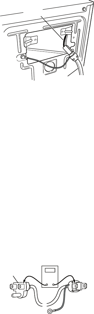
6-7
GAS DRYER
1. Unplug dryer or disconnect power.
2. Remove the cover plate from the top right
corner of the back of the dryer. See Figure 3.
3. Check that the power cord is firmly
connected to the dryer’s wire harness. See
Figure 5.
Power Cord
Wire
Harness
Figure 5. Power cord-to-wire harness
connection for gas dryer.
4. Access the machine control electronics
without disconnecting any wiring to the
control board. See figure 16.
5. With an ohmmeter, check for continuity
between the neutral (N) terminal of the plug
and P8-3 (white wire) on the machine control
board. The left-hand side of figure 6 shows
the position of the neutral terminal (N) on the
power cord plug. Also see Figure 17.
If there is continuity, go to step 6.
If there is no continuity, disconnect the
white wire of the harness from the power
cord at the location illustrated in Figure
5. Test the continuity of the power cord
neutral wire as illustrated in Figure 6.
If an open circuit is found, replace the
power cord. Otherwise, go to step 6.
•
•
6. In a similar way, check the continuity
between the L1 terminal of the plug and
P9-2 (black wire) on the control board. See
Figure 17.
If there is continuity, go to step 8.
If there is no continuity, check the
continuity of the power cord in a similar
way to that illustrated in Figure 6, but for
power cord’s L1 wire.
If an open circuit is found, replace the
power cord. Otherwise, go to step 7.
7. Replace the main harness.
8. Visually check that the P5 connector is
inserted all the way into the machine
control electronics.
9. Visually check that the console electronics
and housing assembly is properly inserted
into the front console.
10. If both visual checks pass, replace the
console electronics and housing assem-
bly.
11. Plug in dryer or reconnect power.
12. Perform the Console Buttons and Indicators
Diagnostic test to verify repair.
13. If indicators still do not light, the machine
control electronics has failed:
Unplug dryer or disconnect power.
Replace the machine control electronics.
Plug in dryer or reconnect power.
Perform the Console Buttons and
Indicators Diagnostic test to verify
repair.
•
•
•
•
•
•
•
COM
N
N
G
G
L1
Power Cord
Plug
L1
Figure 6. Power cord terminals, gas dryer.
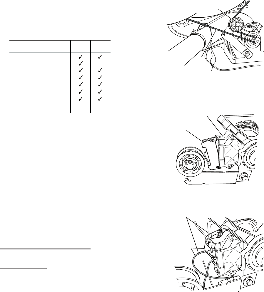
6-8
TEST #2 Motor Circuit Test
This test will check the wiring to the motor and
the motor itself. The following items are part of
this motor system:
1. Unplug dryer or disconnect power.
2. Access the machine control electronics
and measure the resistance across P8-4
and P9-1. See Accessing & Removing the
Electronic Assemblies.
If resistance across P8-4 and P9-1 is in
the range of 1 to 6 ohms, replace the
machine control electronics.
Otherwise, go to step 3.
3. Check the wiring and components in the
path between these measurement points
by referring to the appropriate wiring
diagram (gas or electric).
ELECTRIC DRYER ONLY: Check the
thermal fuse. See TEST #3b.
ALL DRYERS: Continue with step 4 below
to test the remaining components in the
motor circuit.
4. Check the belt switch and drive motor.
Access the belt switch and drive motor by
removing the back panel. Carefully remove
the drum belt from the spring-loaded belt
switch pulley, gently letting the belt switch
pulley down. See Figure 7.
•
•
Part of Motor System Electric
Dryer
Gas
Dryer
–Harness/connection
–Thermal fuse
–Belt/belt switch
–Drive motor
–Centrifugal switch
–Door switch
–Machine control
electronics. See ESD
information.
no
5. Remove the white connector from the drive
motor switch. See Figure 8.
Drum
Belt
Belt Switch Pulley
Figure 7. Carefully remove drum belt.
White
Connector
Drive Motor
Switch
1
5
3
4
6
2
Figure 8. Remove white connector.
Main Winding:
Lt.
and Bare Copper Wire
Blue Wire in Back
Start Winding:
Lt.
and
Bare Copper
Wire
Blue Wire
in Back
1
5
3
4
6
2
Figure 9. Main and start
winding measure points.
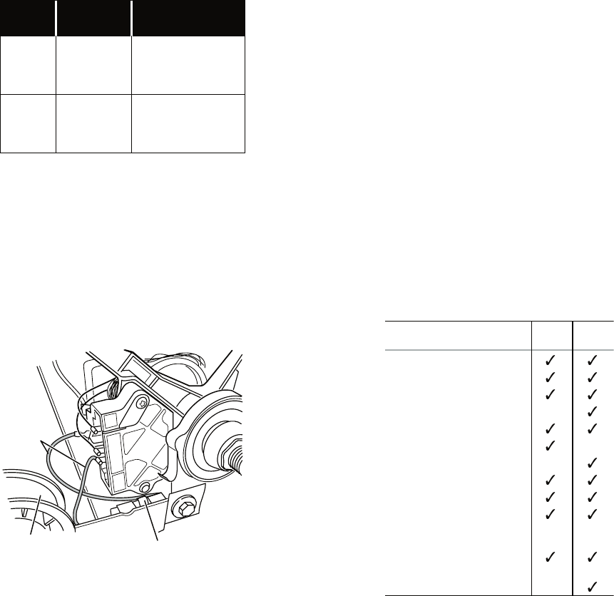
6-9
6. Using Figure 9, check for the resistance
values of the motor’s Main and Start
winding coils as shown below.
NOTE: Main and Start winding coils must
be checked at the motor.
WINDING RESISTANCE
(Ω)
CONTACT POINTS
OF MEASUREMENT
MAIN 2.4–3.6 Ω
Lt. blue wire in back at
pin 4 and bare copper
wire on pin 5 of black
drive motor switch
START 2.4–3.8 Ω
Lt. blue wire in back at
pin 4 and bare copper
wire on pin 3 of black
drive motor switch
If the resistance at the motor is correct,
there is an open circuit between the
motor and machine control electronics.
Check for failed belt switch.
7. Check the belt switch by measuring resis-
tance between the two light blue wires, as
shown in Figure 10, while pushing up the
belt switch pulley.
•
If the resistance reading goes from infinity
to a few ohms as pulley arm closes the
switch, belt switch is OK. If not, replace
the belt switch.
If belt switch is OK and there is still an
open circuit, check and repair the wiring
harness.
If the Start winding is in question and the
resistance is much greater than 4 ohms,
replace the motor.
•
•
•
Lt. Blue
Wires
Belt Switch
Belt Switch
Pulley
1
5
3
4
6
2
Figure 10. Checking the belt switch.
8. Door Switch problems can be uncovered
in the Door Switch Diagnostic Test; how-
ever, if this was not done, the following
can be done without applying power to the
dryer. Connect an ohmmeter across P8-3
(neutral, white wire) and P8-4 (door, tan
wire).
With the door properly closed, the ohm-
meter should indicate a closed circuit
(0–2 ohms).
If not, replace the door switch assembly.
TEST #3 Heater Test
This test is performed when either of the
following situations occur:
Dryer does not heat
Heat will not shut off
This test checks the components making up
the heating circuit. The following items are
part of this system:
•
•
•
•
Part of Heating System Electric
Dryer
Gas
Dryer
–Harness/connection
–Heater relay
–Thermal cut-off
–Thermal fuse
–High limit thermostat
–Heat element assembly
–Gas burner assembly
–Centrifugal switch
–Exhaust thermistor
–Machine control
electronics. See ESD
information.
–Console electronics
and housing assembly
–Gas supply
no
no
no
no
Dryer does not heat:
Locate the components using Figure 11.
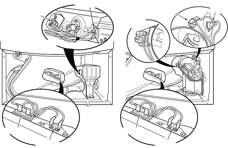
6-10
ELECTRIC DRYER:
1. Unplug dryer or disconnect power.
2. Remove the toe panel to access the
thermal components. See Figure 14.
3. Using an ohmmeter and referring to the
wiring diagram, measure the resistance
from the red wire at the thermal cut-off to
the red wire at the heater.
If the resistance is about 10 ohms, go to
step 5.
If an open circuit is detected, go to step 4.
4. Visually check the wire connections to
the thermal cut-off, high limit thermostat,
and heater. If connections look good,
check for continuity across each of these
components. Replace the heater if it is
electrically open. Replace both the thermal
cut-off and high limit thermostat if either
one is electrically open.
5. If no open circuit is detected, measure
the resistance between P14-3 (red-white
wire) and P14-6 (red-white wire) at the
machine control board. See Figure 17;
and Accessing & Removing the Electronic
Assemblies.
•
•
If 5–15k Ω are measured, replace the
machine control electronics.
If the resistance is less than 1k Ω, replace
the thermistor.
GAS DRYER:
1. Unplug dryer or disconnect power.
2. Remove the toe panel to access the
thermal components. See Figure 14.
3. Perform TEST #3b. If the thermal fuse is
OK, go to step 4.
4. Perform TEST #3c. If the thermal cut-off is
OK, go to step 5.
5. Locate the high limit thermostat. See
Figure 11. Measure the continuity through
it by connecting the meter probes on the
red wire and blue wire.
If there is an open circuit, replace the
high limit thermostat and thermal cut-
off.
Otherwise, go to step 6.
6. Perform TEST #3d (Gas Valve Test). If
this is OK, replace the machine control
electronics.
•
•
•
•
Thermal Cut-Off
High Limit Thermostat
Heater Element
Flame
Sensor
Thermal Fuse
ThermistorThermistor
High Limit
Thermostat
Thermal
Cut-Off
Thermal Fuse
Figure 11. Thermal Components, viewed from front.
Electric Dryer Gas Dryer
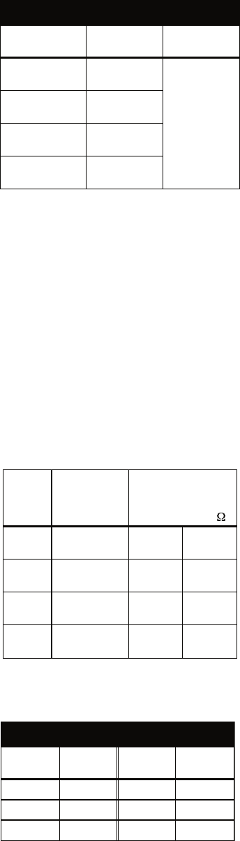
6-11
Heat will not shut off:
1. Unplug dryer or disconnect power.
2. Access the machine control electronics,
and measure the resistance between P14-3
(red-white wire) and P14-6 (red-white wire).
See Accessing & Removing the Electronic
Assemblies.
If 5–15 k ohms are measured, replace
the machine control electronics.
If the resistance is greater than 20 kΩ,
replace the thermistor.
TEST #3a Thermistor Test
The machine control electronics monitors the
exhaust temperature using the thermistor, and
cycles the heater relay on and off to maintain
the desired temperature.
Begin with an empty dryer and a clean lint
screen.
1. Plug in dryer or reconnect power.
2. Start the Timed Dry cycle.
3. If after 60 seconds, F-22 or F-23 flashes
in the display and the dryer shuts off, the
thermistor or wire harness is either open or
shorted.
Unplug dryer or disconnect power.
Check wire connections at the machine
control electronics and thermistor. See
Accessing & Removing the Electronic
Assemblies, and for thermistor location
see Figure 11.
If wire connections are good, remove
the two wires from the thermistor and
replace the thermistor. See Figure 11.
Plug in dryer or reconnect power.
4. If F-22 or F-23 does not flash in the display,
the connections to the thermistor are good.
Therefore, check the thermistor’s resistance
value at any or all of the temperature levels
in question, using the Timed Dry cycle, and
the following process:
•
•
•
•
•
•
* The measured overshoot using the glass
bulb thermometer in the exhaust outlet can
be 30°F (17°C) higher.
5. If the exhaust temperature is not within
specified limits, check the resistance of the
thermistor.
NOTE: All thermistor resistance measurements
must be made while dryer is disconnected
from power.
The table below gives the resistance values
that should be observed for the various
temperature settings.
EXHAUST TEMPERATURES
TEMPERATURE
SETTING
HEAT TURNS
OFF*
HEAT TURNS
ON
High 155° ± 5°F
(68° ± 3°C)
10–15°F
(6–8°C)
below the
heat turn off
temperature
Medium 140° ± 5°F
(60° ± 3°C)
Low 125° ± 5°F
(52° ± 3°C)
Extra Low 115° ± 5°F
(46° ± 3°C)
Hold a glass bulb thermometer capable of
reading from 90° to 180°F (32° to 82°C) in
the center of the exhaust outlet. The correct
exhaust temperatures are as follows:
TEMP.
SETTING TEMPERATURE
Thermistor resistance
value at heater
shutoff (digital or
analog meter) k
High 155° ± 5°F
(68° ± 3°C) 2.1 1.7
Medium 140° ± 5°F
(60° ± 3°C) 2.8 2.3
Low 125° ± 5°F
(52° ± 3°C) 3.8 3.1
Extra
Low
115° ± 5°F
(46° ± 3°C) 4.7 3.8
If needed, the following table gives tempera-
tures and their associated resistance values.
THERMISTOR RESISTANCE
TEMP.
°F (°C)
RES.
kΩ
TEMP.
°F (°C)
RES.
kΩ
50° (10°) 19.9 80° (27°) 9.2
60° (16°) 15.3 90° (32°) 7.4
70° (21°) 11.9 100° (38°) 5.7
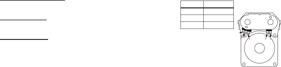
6-12
If the thermistor resistance checks within
normal limits, replace the machine control
electronics.
TEST #3b Thermal Fuse Test
ELECTRIC DRYER: The thermal fuse is wired
in series with the dryer drive motor.
GAS DRYER: The thermal fuse is wired in
series with the dryer gas valve.
ALL DRYERS:
1. Unplug dryer or disconnect power.
2. Access the thermal fuse by first removing
the toe panel. See Removing the Toe
Panel; and for thermal fuse location see
Figure 11.
3. Using an ohmmeter, check the continuity
across the thermal fuse. See Figure 11 for
location.
If the ohmmeter indicates an open circuit,
replace the failed thermal fuse.
TEST #3c Thermal Cut-Off Test
If the dryer does not produce heat, check the
status of the thermal cut-off.
1. Unplug dryer or disconnect power.
2. Access the thermal cut-off by first remov-
ing the toe panel. See Removing the Toe
Panel.
3. Using an ohmmeter, check the continuity
across the thermal cut-off. See Figure 11
for location.
If the ohmmeter indicates an open circuit,
replace the failed thermal cut-off and
high limit thermostat. In addition, check
for blocked or improper exhaust system,
or failed heat element (electric dryer).
TEST #3d Gas Valve Test, Gas Dryer Only
1. Unplug dryer or disconnect power.
2. Access the gas valve by removing the toe
panel. See Removing the Toe Panel.
•
•
•
3. Use an ohmmeter to determine if a gas valve
coil has failed. Remove harness plugs.
Measure resistance across terminals.
Readings should match those shown in
the following chart. If not, replace coil.
Terminals Resistance
1 to 2 1365 Ω ± 25
1 to 3 560 Ω ± 25
4 to 5 1220 Ω ± 50
IMPORTANT:
Be sure all harness
wires are looped back
through the strain
relief after checking or
replacing coils.
1
23 4 5
TEST #4 Moisture Sensor Test
NOTE: This test is started with the machine
completely assembled.
This test is performed when an automatic
cycle stops too soon, or runs much longer
than expected.
NOTE: Dryer will shut down automatically
after 2-1/2 hours.
The following items are part of this system:
Harness/connection
Metal sensor strips
Machine control electronics
1. Activate the diagnostic test mode and
advance past saved fault codes.
2. Open the dryer door. If a beep tone is
heard and an alphanumeric number is
displayed on the console as soon as the
door is opened, a short circuit exists in the
moisture sensor system.
If this doesn’t happen, go to step 3.
Otherwise, go to step 4.
NOTE: Over drying may be caused by a
short circuit in the sensor system.
•
•
•
•
•
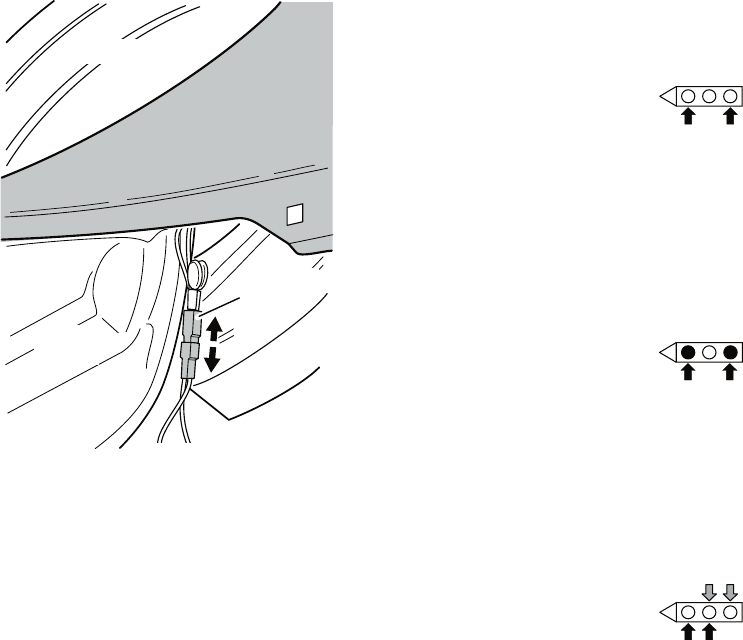
6-13
If the ohmmeter does not indicate (infin-
ity) open circuit, go to step 6.
Otherwise, measure the resistance across
between pins 1 and 2 of connector P13 on
the machine control board. If a resistance
less than 1 megohm is measured (with
analog or digital ohmmeter), inspect the
control board for any debris bridging these
pins. If no debris, replace the machine
control electronics.
6. Access the moisture sensor by removing
the toe panel. See Removing the Toe
Panel. Disconnect the sensor from the
wire harness. See Figure 12.
7. Measure the resistance across the outer-
most contacts of the cable that includes
the two red MOVs.
•
•
3. Locate the two metal sensor strips on the
face of the lint screen housing. Bridge
these strips with a wet cloth or finger.
If a beep tone is heard and a software
revision number is displayed on the
console, the sensor passes the test. Go
to step 4.
If not, unplug dryer or disconnect
power.
Access the moisture sensor wires by
removing the toe panel. See Removing
the Toe Panel. Disconnect the sensor
wires from the harness. See Figure 12.
Go to step 9.
•
•
•
Blower
Housing
Drum
Harness
Connection
FRONT
Figure 12. Disconnect sensor from
wire harness.
4. Unplug dryer or disconnect power.
5. Access the machine control electronics.
See Accessing & Removing the Electronic
Assemblies. Remove the connector P13 from
the circuit board. Measure the resistance
across terminals 1 (yellow-red wire) and 2
(yellow-red wire). See Figure 17.
If a resistance less than infinity is
measured, replace this component (Wire
Harness, Moisture Sensor).
•
If a small resistance is measured, replace
this component (Wire Harness, Moisture
Sensor).
Otherwise, go to step 8.
8. Measure the resistance across the pins of
the mating connector.
•
•
If a small resistance is measured here,
replace this harness (Digital Wire
Harness).
9. Measure the resistance across each of the
outermost contacts and the center terminal
(ground connection).
•
6-14
10. If moisture sensor diagnostic test passes,
check the thermistor: Perform TEST #3a.
If the problem persists after replacing the
moisture sensor and thermistor, replace
the machine control electronics.
TEST #4a Adjusting Customer-Focused
Drying Modes
NOTE: If the customer is complaining about
the clothes being damp and the moisture
sensor passes TEST #4 “Moisture Sensor
Test” step 3, the total dry time for an automatic
cycle can be lengthened by changing from a
“1” or standard auto cycle to a “2” or “3” longer
auto cycle.
1. Activate the diagnostic test mode, and
advance past saved fault codes.
2. In diagnostic test mode, press and hold the
Dryness button for 5 seconds. The dryer
will beep and the current drying mode will
be seen on the display. The factory default
value is “1”.
3. To select a different drying mode, press the
Dryness button again. The dryer display
will flash and show 2, 3, or 1.
4. With the display flashing the selected
drying mode, press the START button to
save the drying mode and exit diagnostics
(the START button in this mode does not
start a drying cycle). The result will be
stored in EEPROM of the control board,
and will be retained after a power loss.
5. Press the PAUSE/CANCEL button at any
time to cancel changes and exit from this
mode.
TEST #5 Button and Indicator Test
This test is performed when any of the following
situations occurs during the Console Buttons
and Indicators Diagnostic Test:
None of the indicators light up
No beep sound is heard
Some buttons do not light indicators
•
•
•
•
None of the indicators light up:
1. See Diagnostic Guide/Before Servicing.
2. Perform Test #1 to verify supply connect-
ions.
3. Perform steps in Accessing and Removing
the Electronic Assemblies, and visually
check that the P5 connector is inserted
all the way into the machine control
electronics.
4. Visually check that the console electronics
and housing assembly is properly inserted
into the front console.
5. If both visual checks pass, replace
the console electronics and housing
assembly.
6. Plug in dryer or reconnect power.
7. Perform the Console Buttons and Indicators
Diagnostic test to verify repair.
8. If indicators still do not light, the machine
control electronics has failed:
Unplug dryer or disconnect power.
Replace the machine control electronics.
Plug in dryer or reconnect power.
Perform the Console Buttons and Indica-
tors Diagnostic test to verify repair.
No beep sound is heard:
1. Perform steps in Accessing and Removing
the Electronic Assemblies, and visually
check that the P5 connector is inserted
all the way into the machine control
electronics.
If visual check passes, replace the con-
sole electronics and housing assembly.
2. Plug in dryer or reconnect power.
3. Perform the Console Buttons and Indicators
Diagnostic test to verify repair.
•
•
•
•
•
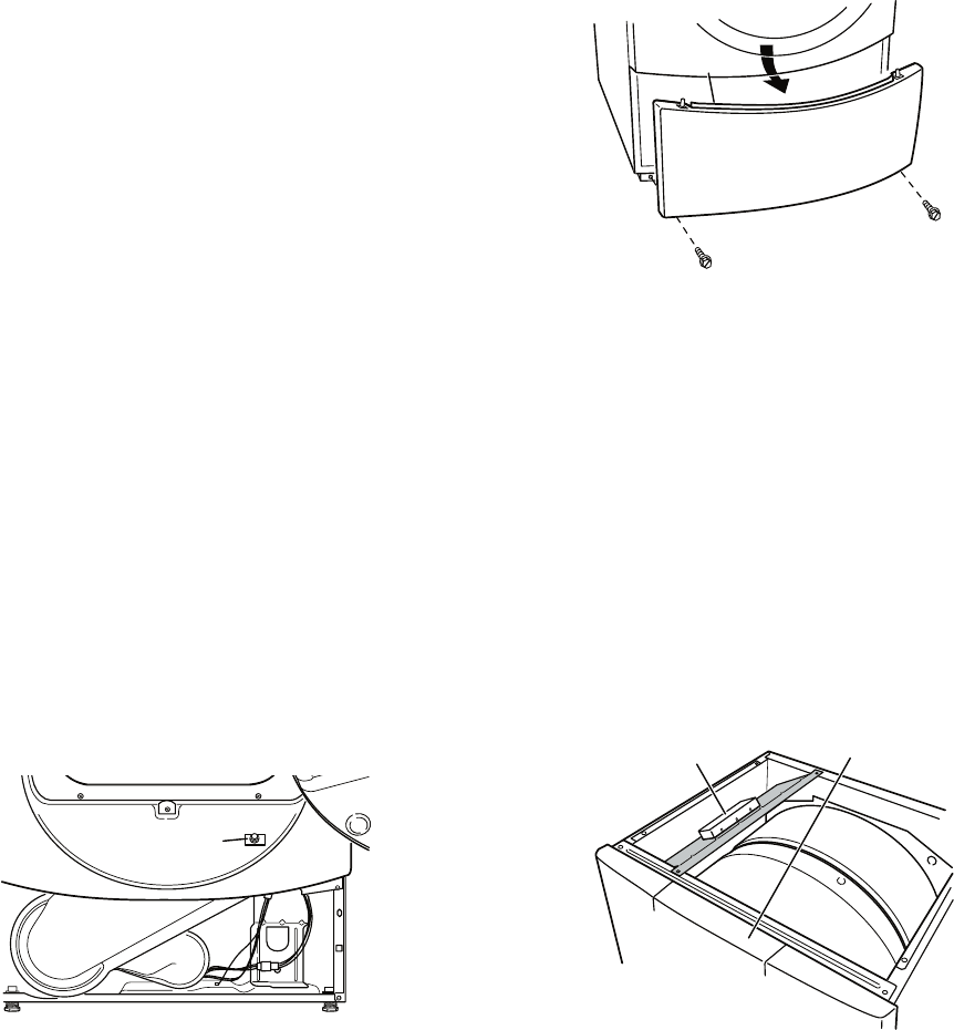
6-15
4. If replacing the console electronics and
housing assembly failed:
Unplug dryer or disconnect power.
Replace the machine control electron-
ics.
Plug in dryer or reconnect power.
Perform the Console Buttons and Indi-
cators Diagnostic test to verify repair.
Some buttons do not light indicators:
1. Perform steps in Accessing and Removing
the Electronic Assemblies, and visually
check that the console electronics and
housing assembly is properly inserted into
the front console.
If visual check passes, replace the con-
sole electronics and housing assembly.
2. Plug in dryer or reconnect power.
3. Perform the Console Buttons and Indicators
Diagnostics test to verify repair.
TEST #6 Door Switch Test
Activate the diagnostic test mode, and perform
the Door Switch Diagnostic test. Functionality
is verified with a beep each time the door is
closed and opened, and a number and letter
appears in the display (i.e., 0E, 09).
If any of the above conditions are not met, or
if one of the dryer model codes listed above is
displayed when the door is closed:
Unplug dryer or disconnect power.
Check that the wires between the door
switch and machine control electronics
are connected. See Figure 13 for switch
location and see Accessing and Remov-
ing the Electronic Assemblies.
•
•
•
•
•
•
•
Door Switch
Figure 13. Door switch location.
If the connections are OK, replace the
wire and door switch assembly and
retest.
If wire and door switch assembly have
been replaced and dryer still does
not start, replace the machine control
electronics.
REMOVING THE TOE PANEL
1. Unplug dryer or disconnect power.
2. Remove two screws below the toe panel.
3. Slide the toe panel down, then pull it out
from the bottom. See Figure 14.
•
•
FRONT
Machine Control
Electronics
Assembly
Console Electronics
and Housing Assembly
(inside)
Figure 15. Locate the electronic
assemblies.
ACCESSING & REMOVING THE
ELECTRONIC ASSEMBLIES
1. Unplug dryer or disconnect power.
2. Remove the two rear screws from the top
panel, and slide the top panel to the rear to
remove.
There are two electronic assemblies; the Con-
sole Electronics and Housing, and the Machine
Control Electronics. See Figure 15.
Flange
Figure 14. Pull the toe panel down to
clear flange, then pull panel out.
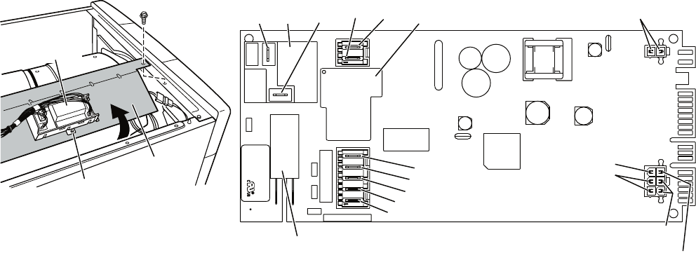
6-16
ACCESSING THE MACHINE
CONTROL ELECTRONICS
1. After locating the machine control electron-
ics, remove the two screws that hold the
machine control electronics bracket in place.
2. Slide the bracket over the top of the drum
to access the machine control electronics
connectors and mounting screw. See Fig-
ure 16.
REMOVING THE MACHINE
CONTROL ELECTRONICS
1. Remove all the wire connections to the ma-
chine control electronics. See Figure 17.
2. Remove the screw holding the machine
control electronics assembly to the mount-
ing bracket. See Figure 16.
3. There are two plastic legs on the front of
the machine control electronics that slide
under the mounting bracket. There is one
plastic leg on the rear of the machine control
electronics that slides under the mounting
bracket. There is a locking tab on the
bottom of the machine control electronics
that snaps into the mounting bracket.
Press the locking tab on the bottom of the
machine control electronics and slide the
assembly to the front, then lift.
FRONT
Machine Control
Electronics
Bracket
Machine Control
Electronics
Assembly
Mounting
Screw
Figure 16. Remove machine control
electronics from mounting bracket.
P9
1
5
1
P8
P14
P2
3
1
1
6
P4
1
1
8
3
P5
P3
1
P13
1
X veR
XXXXXX N/P
xx
-
D
D
DYe
d
o
C
e
t
a
D
XX
X
-
X
XXX
OO
C
N
I
E
DA
M
N.O.
Black
COM
Red
Heater
Relay 1 Motor
Relay
Tan
Black-White
White
Green-Yellow
Open
Lt. Blue Black
Heater Relay 2
Red-White
Open
Red-White
Yellow-Red
Orange (Gas)
Open (Elec.)
Figure 17. Machine control electronics.
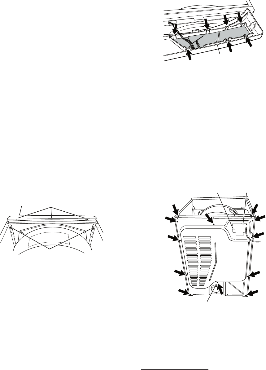
6-17
ACCESSING THE CONSOLE
ELECTRONICS AND HOUSING
ASSEMBLY
1. Access the machine control electronics
(see Accessing the Machine Control
Electronics) and disconnect the P5 ribbon
cable.
2. The console panel must be removed
to access the console electronics and
housing assembly. Remove the knob from
the front of the console panel.
3. The console panel has two locking tabs
on the left and right rear, one locking tab
on the bottom (hidden), and three snap
releases across the top. See Figure 18.
Press the locking tab on the right rear, and
gently rotate the console panel up as you
pull the top free of the three snap releases,
finally pressing the locking tab on the left,
and lift the console panel off.
Locking
Tabs
Snap Releases
Console Electronics
and Housing Assembly
(inside)
Figure 18. Remove the console panel
to access the console electronics and
housing assembly.
REMOVING THE CONSOLE
ELECTRONICS AND HOUSING
ASSEMBLY
The console electronics and housing assembly
is held to the console panel by seven locking
tabs. Press each of the locking tabs while
gently lifting the console electronics and
housing assembly out of the console panel.
See Figure 19.
Console Electronics
and Housing Assembly
Figure 19.
Locate seven locking tabs.
REMOVING THE BACK PANEL
1. Unplug dryer or disconnect power.
2. Remove the two rear screws from the top
panel, and slide the top panel to the rear to
remove.
3. Remove the cover plate, disconnect the
power cord, and remove ground screw.
4. Remove the metal spring clip between the
back panel and the exhaust outlet. See
Figure 20.
Ground Screw Cover Plate
Metal Spring Clip
Figure 20. Remove 12 screws.
5. Remove the ten screws on the rear, and
two screws on the top of the back panel.
Pull the back panel off the machine. See
Figure 20.
ELECTRIC DRYER: In addition to the above,
remove the terminal block from the back
panel.
6-18
— NOTES —
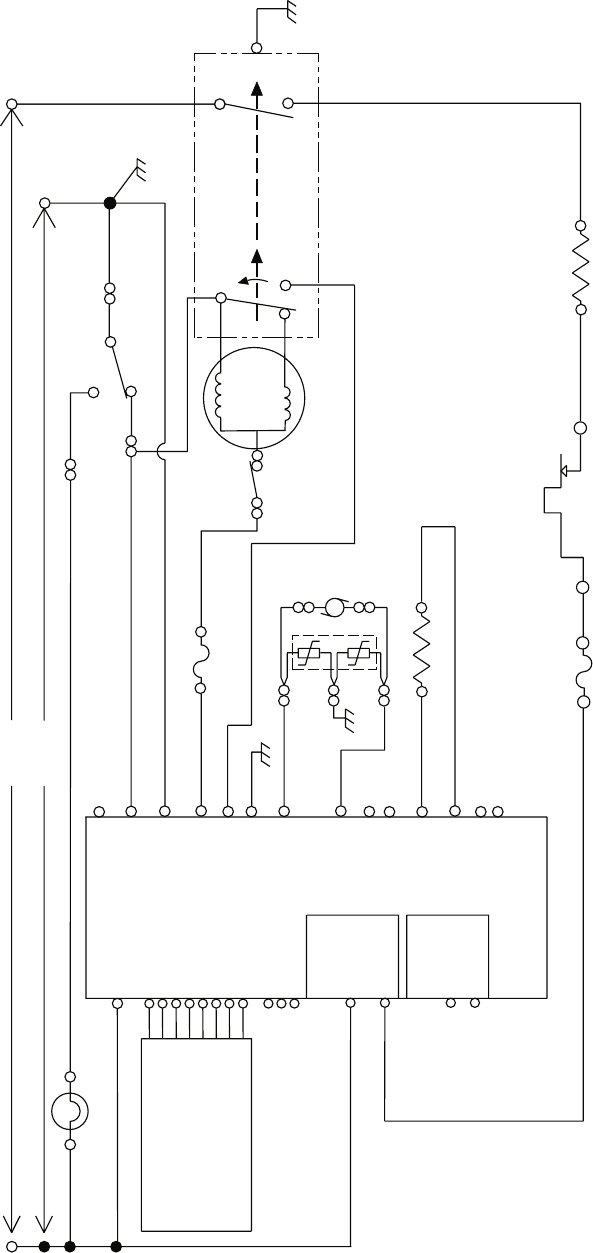
7-1
WIRING DIAGRAMS
ELECTRIC DRYER
P8-2
GND
R
CENTRIFUGAL SWITCH 2M
1M
5M
6M
3M
R – LINE L2
W
DOOR
SWITCH
W – NEUTRAL N
T
LBU
LBU
W
BU-W
P8-4
P8-3 NEUTRAL
P9-1
P8-5 BK-W THERMAL FUSE
196°F 91°C( ) 4M
DRIVE MOTOR
1/3 H.P
.
MAIN
2.4–3.6 Ω
START
2.4–3.8 Ω
SENSOR
DOOR
NEUTRAL
MOTOR
MTR CS
MOIST.
MOIST RTN
MODEL
MODEL RTN
EXHAUST TEMP.
EXHAUST
TEMP RTN
MACHINE CONTROL
ELECTRONICS
Y-R
P13-1
P13-2
P14-4
P14-5
P14-3
P14-6
R-W
R-W
EXHAUST THERMISTOR
10k Ω
P9-2 L1
BR
L1 LINE – BK
HEATER +V
HEATER RTN
N.O.
COM
BK
BK
BK
R BK
NC
R-W
HI LIMIT
THERMOSTAT
295°F (146°C)
THERMAL
CUT-OFF
352°F (178°C)
HEATER
7.8–11.8 Ω
R
DRUM LAMP
G-Y
P14-1
P14-2
N.C.
N.C.
P8-1
LAMP (N.C.) R
240 VOLTS
120 VOLTS
P5-1 VDD
P5-5 DATA OUT
P2-1 VDD
P2-2 DATA
P2-3 VSS
P5-8 +/- 12 VDC
CONSOLE
ELECTRONICS
VDD P1-8
DATA IN P1-7
VSS P1-6
STROBE P1-5
DATA OUT P1-4
+/- 12 VDC P1-1
BUZZER P1-2
CLOCK P1-3
P5-2 DATA IN
P5-3 VSS
P5-4 STROBE
P5-6 CLOCK
P5-7 BUZZER
BELT
SWITCH
HEATER
RELAY 1 G-Y
G-Y
N.O.
COM
HEATER
RELAY 2
SENSOR
MOVS
Y-RY-R
BK
NEUTRAL
TERMINAL
LINKED TO
CABINET
W
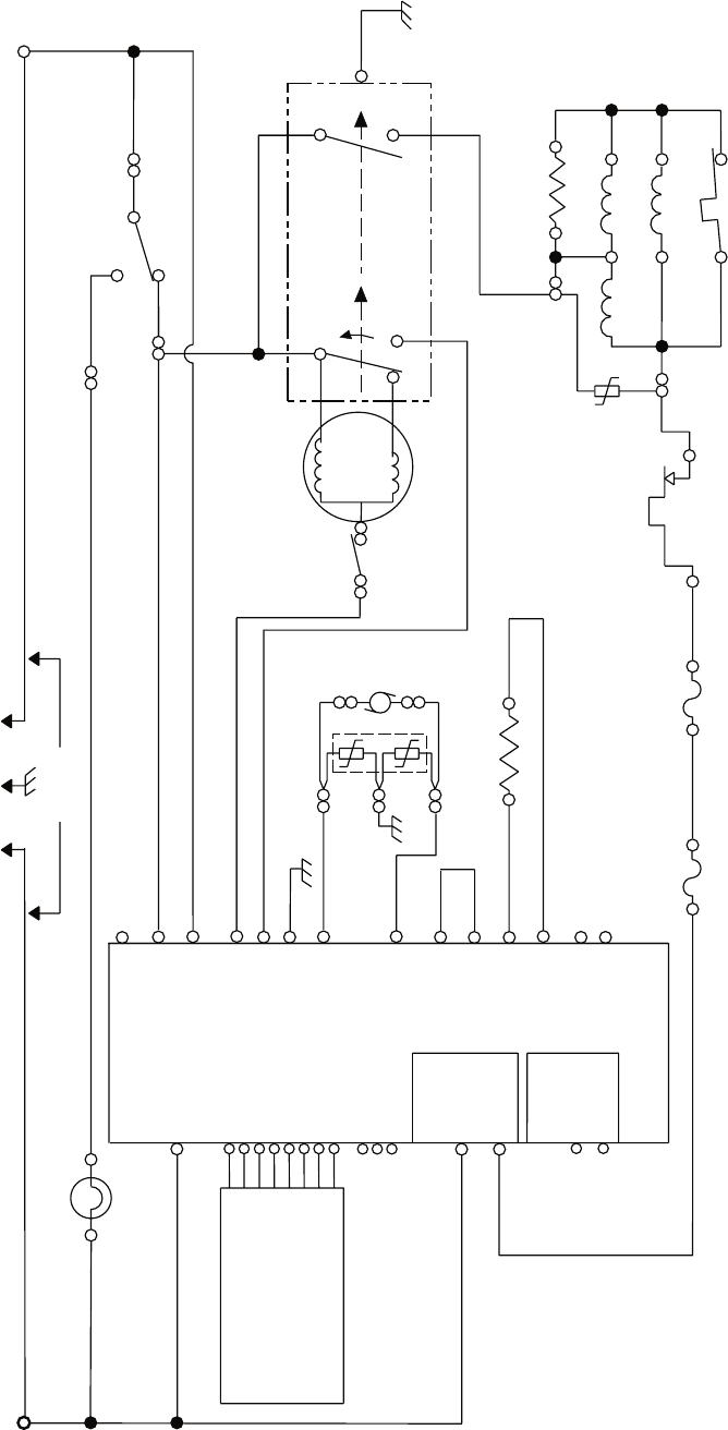
7-2
GAS DRYER
P8-2
GND
L1 LINE – BK
DRUM LAMP
BK BR
LBU
P8-4
P8-3 NEUTRAL
P9-1
P8-5
DOOR
NEUTRAL
MOTOR
MTR CS
MOIST.
MOIST RTN
MODEL
MODEL RTN P14-5
P14-3
P14-6
R-W
R-W
BK-W
HEATER
RELAY 1
HEATER +V
HEATER RTN
N.O.
COM
R
P9-2BK L1
W
W – NEUTRAL N
T
W
CENTRIFUGAL SWITCH
5M
6M
3M
BU
BELT
SWITCH
MAIN
2.4–3.6 Ω
START
2.4–3.8 Ω
EXHAUST THERMISTOR
10k Ω
2M
1M
RRHI LIMIT
THERMOSTAT
205°F 96°C( )
HS1 HS2
NC
3V
1V
21
IG IGR
50–500 Ω
3
4 5
FS1 FS2
VALVE
MOV
HOLD ASSIST
MAIN
IGNITOR
VALVE
NO. 1
VALVE
NO. 2
FLAME SENSOR
O
P2-1 VDD
P2-2 DATA
P2-3 VSS
THERMAL FUSE
196°F 91°C( )
TF1 TF2 R
BK
R
R
G-Y
LAMP (N.C.) P8-1
P14-1
P14-2
N.C.
N.C.
LBU
W
120 VOLTS
4M
DRIVE MOTOR
1/3 H.P
.
P5-1 VDD
P5-5 DATA OUT
P5-8 +/- 12 VDC
VDD P1-8
DATA IN P1-7
VSS P1-6
STROBE P1-5
DATA OUT P1-4
BUZZER P1-2
CLOCK P1-3
P5-2 DATA IN
P5-3 VSS
P5-4 STROBE
P5-6 CLOCK
P5-7 BUZZER
+/- 12 VDC P1-1
DOOR
SWITCH
G-Y
Y-R
P13-1
P13-2
P14-4
Y-R
N.O.
COM
HEATER
RELAY 2
SENSOR
G-Y
SENSOR
MOVS
Y-R
BK
EXHAUST TEMP.
EXHAUST
TEMP RTN
THERMAL
CUT-OFF
352°F (178°C)
MACHINE CONTROL
ELECTRONICS
CONSOLE
ELECTRONICS
7-3
— NOTES —
7-4
— NOTES —

PRODUCT SPECIFICATIONS
AND
WARRANTY INFORMATION SOURCES
IN THE UNITED STATES:
FOR PRODUCT SPECIFICATIONS AND WARANTY INFORMATION CALL:
FOR TECHNICAL ASSISTANCE WHILE AT THE CUSTOMER’S HOME CALL:
THE TECHNICAL ASSISTANCE LINE: 1-800-253-2870
HAVE YOUR STORE NUMBER READY TO IDENTIFY YOU
AS AN AUTHORIZED SERVICER
IN CANADA:
FOR PRODUCT SPECIFICATIONS AND WARRANTY INFORMATION CALL:
1-800-461-5681
FOR TECHNICAL ASSISTANCE WHILE AT THE CUSTOMER’S HOME CALL:
THE TECHNICAL ASSISTANCE LINE: 1-800-488-4791
HAVE YOUR STORE NUMBER READY TO IDENTIFY YOU AS AN
AUTHORIZED SERVICER
FOR WHIRLPOOL PRODUCTS: 1-800-253-1301
FOR KITCHENAID PRODUCTS: 1-800-422-1230
FOR ROPER PRODUCTS: 1-800-447-6737
FOR LITERATURE ORDERS:
PHONE: 1-800-851-4605
FOR TECHNICAL INFORMATION AND SERVICE POINTERS:
www.servicematters.com

CO
RP
O
R
A
T
ION
