8269519 Whrlp Kit Aid Dishwasher KUDS01DJSS0 Tech Sheet
2013-05-09
: Pdf 8269519 - Whrlp Kitaid - Dishwasher - Kuds01Djss0 - Tech Sheet 8269519 - Whrlp KitAid - Dishwasher - KUDS01DJSS0 - Tech Sheet dishwasher may8
Open the PDF directly: View PDF ![]() .
.
Page Count: 2
FOR SERVICE TECHNICIAN'S USE ONLY FOR SERVICE TECHNICIAN'S USE ONLY FOR SERVICE TECHNICIAN'S USE ONLY PAGE 1
FOR SERVICE TECHNICIAN'S USE ONLY FOR SERVICE TECHNICIAN'S USE ONLY FOR SERVICE TECHNICIAN'S USE ONLY
©2000 WHIRLPOOL CORPORATION, ALL RIGHTS RESERVED
PRECAUTIONS TO BE
OBSERVED BEFORE AND
DURING SERVICING OF
DISHWASHER
A. Even with the door open, there is line voltage at
several points in the console and below the tub.
Therefore, be sure to disconnect the power supply
at the fuse box before replacing a component.
B. Always check wiring harness and connectors
before any test procedures.
C. Disconnect power supply before touching the
circuit board or re-seating control connectors.
D. Voltage checks are made by inserting probes
beside wires on the connector with the AC power
source applied and the connector blocks plugged
in.
E. Resistance checks are made on components with
the wiring harness disconnected.
Electrostatic Discharge (ESD)
Sensitive Electronics
ESD problems are present everywhere. ESD may
damage or weaken the electronic board. The new
board may appear to work well after repair is
finished, but failure may occur at a later date due to
ESD stress.
■Use an anti-static wrist strap. Connect wrist
strap to green ground connection point or
unpainted metal in the appliance
-OR-
Touch your finger repeatedly to a green ground
connection point or unpainted metal in the
appliance.
■Before removing the part from its package,
touch the anti-static bag to a green ground
connection point or unpainted metal in the
appliance.
■Avoid touching electronic parts or terminal
contacts; handle electronic board by edges
only.
■When repackaging failed electronic board in
anti-static bag, observe above instructions.
PART NO. 8269519
NOTE: This sheet contains important
Technical Service Data
FOR SERVICE TECHNICIAN ONLY
DO NOT REMOVE OR DESTROY
DENOTES ENERGY
EFFICIENT COMPONENTS.
DO NOT SUBSTITUTE.
*
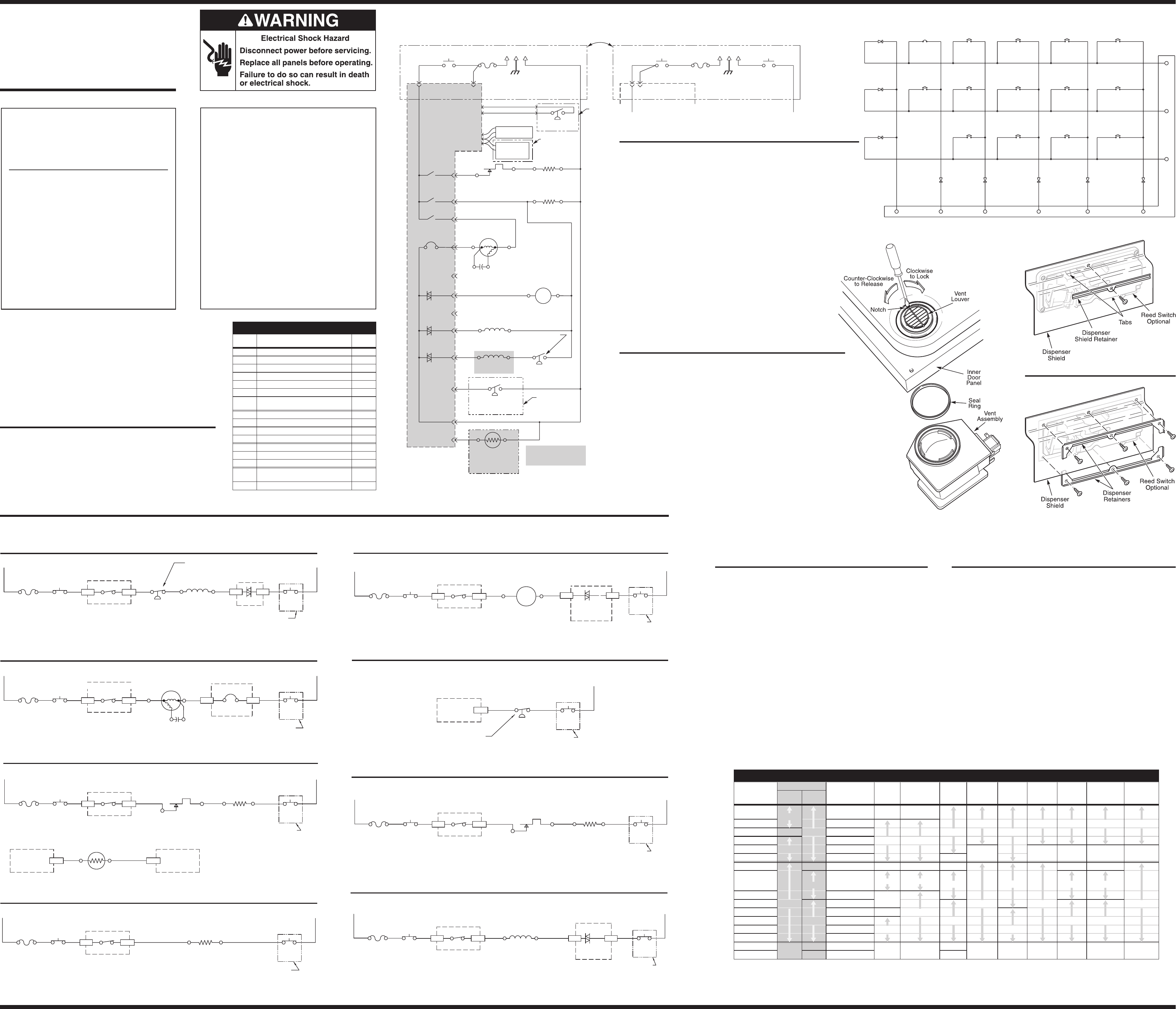
SCHEMATIC SHOWN WITH DOOR SWITCH & ALL OTHER NORMALLY OPEN CONTACTS OPEN.
DOOR SWITCH
8269209
USER INTERFACE
(SEE TABLE)
VENT ACTUATOR ASM
600-1800 Ω
8269257
HI-LIMIT THERMOSTAT
OPENS 77°C-83°C (171°F-181°F)
661566 (3371618)
PRESSURE SWITCH
(SOIL SENSOR)
8268477
FILL VALVE
890 - 1090 Ω
8268572 OVERFILL SW.
8268909
THERMISTOR
48-52K @ 25°C/77°F
12-13K @ 60°C/140°F
8269208
Ω
Ω
NUMERIC
DISPLAY
(SEE TABLE)
USED ONLY ON
SOME MODELS,
OTHERWISE OPEN
(SEE TABLE)
HEATER ASM
8269244
10-35 Ω
DISPENSER
(SEE TABLE)
280-340 Ω
USED ONLY ON
SOME MODELS,
OTHERWISE OPEN
(SEE TABLE)
RINSE AID SENSOR
8269189
USED ONLY ON
SOME MODELS,
OTHERWISE OPEN
(SEE TABLE)
N.O.
N.O.
N.O.
N.O.
FLOAT (IN NORMAL
POSITION) CLOSES
SWITCH
LINE 120 V 60HZ
BK W
G
T
P6 W-R
P10 BU-BK
P9 R-BK
P3
BU
P5
GY
P4
P2-4 LBU
P2-3 BR
P2-1 O-GY
P7
P8
K2
K3
K1
Q6
Q2
Q3
N.C. OR
BR-W
PSC WASH PUMP &
MOTOR ASSEMBLY
(SEE TABLE)
P2-2 Y- B K
T
P2-5
BU-BK
BU-BK
ELECTRONIC
CONTROL
(TRIACS AND
RELAYS SHOWN)
8528172 P1
R
R
N.O.
BU-BK
DRAIN MOTOR
8268411
16.3 Ω
GY
BK-WT
TCO
8269213
P12
23.5 uF
CAPACITOR
8268418
P2-6
*
*
*RINSE AID HARNESS
8269190
TO CONTROL
POWER SUPPLY
DOOR SWITCH
8269209
W-V
DOOR SWITCH
8269209
N.O. N.O.
LINE 120 V 60HZ
BK W
G
T
P8
BK-WT
TCO
8269213
T
P2-6
BK-W
TO CONTROL
POWER SUPPLY
RUN WINDING
3.7 Ω
V
YY
AUX
WINDING
6.25 Ω
(W-V)
W
(W-V)
W
(W-V)
W
(W-V)
W
(W-V)
W
N.O.
N.O.
STAINLESS STEEL TUB PLATFORM
WIRING DIAGRAM
FILL
BK BK-W T
P10
BU-BK P2-3
BR P7
P8
Q3 TRIAC
ELECTRONIC CONTROL
OVERFILL SW.
BR-W W
DOOR
SWITCH
W-V
(W)
FILL VALVE
890 - 1090 Ω
TCO
L1
DOOR
SWITCH
K3 RELAY
ELECTRONIC CONTROL
N
USED ONLY ON
USED ONLY ON
USED ONLY ON
PLASTIC TUB
MODELS, OTHERWISE
CONTINUOUS CIRCUIT &
W-V WIRES REMAIN W
PLASTIC TUB MODELS,
PLASTIC TUB MODELS,
OTHERWISE CONTINUOUS
OTHERWISE CONTINUOUS
CIRCUIT & W-V WIRES
CIRCUIT & W-V WIRES
REMAIN W
REMAIN W
N.O. N.O.
FLOAT (IN NORMAL POSITION)
CLOSES SWITCH
WASH / RINSE
BK BK-W T
P9
R-BK
P5
P7
P8
W
DOOR
SWITCH
W-V
(W)
L1
DOOR
SWITCH
K1 RELAY
ELECTRONIC CONTROL
N
ELECTRONIC CONTROL
PUMP & MOTOR
ASSEMBLY
BU
TCO
N.O.
RUN WINDING
3.7 Ω
AUX
WINDING
6.25Ω
DISPENSER (DETERGENT & RINSE AID)
BK BK-W T P10 P2-4 P7
P8 W
DOOR
SWITCH
W-V
(W)
L1
DOOR
SWITCH
K3 RELAY
ELECTRONIC CONTROL Q2 TRIAC
N
BU-BK
ELECTRONIC CONTROL
DISPENSER
ACTUATOR
280 - 340 Ω
LBU
TCO
N.O.
BK T
BK-W
P10
BU-BK
P8
W
DOOR
SWITCH
W-V
(W)
L1
DOOR
SWITCH K3 RELAY
ELECTRONIC CONTROL
N
VENT
ACTUATOR
600 - 1800 Ω
VENT
USED ONLY ON
PLASTIC TUB MODELS,
OTHERWISE CONTINUOUS
CIRCUIT & W-V WIRES
REMAIN W
TCO
N.O.
DRAIN
BK BK-W T
P10 BU-BK
P8
W
DOOR
SWITCH
W-V
(W)
L1
DOOR
SWITCH
K3 RELAY
ELECTRONIC CONTROL
N
P3 P7
Q6 TRIAC
ELECTRONIC CONTROL
DRAIN
MOTOR
GY
USED ONLY ON
USED ONLY ON
USED ONLY ON
PLASTIC TUB MODELS,
PLASTIC TUB MODELS,
PLASTIC TUB MODELS,
OTHERWISE CONTINUOUS
OTHERWISE CONTINUOUS
OTHERWISE CONTINUOUS
CIRCUIT & W-V WIRES
CIRCUIT & W-V WIRES
CIRCUIT & W-V WIRES
REMAIN W
REMAIN W
REMAIN W
TCO
N.O.
DRAIN
WINDING
16.3 Ω
HEAT DRY
BK BK-W T
P6
W-R
P8
W
DOOR
SWITCH
W-V
(W)
L1
DOOR
SWITCH
K2 RELAY
ELECTRONIC CONTROL
N.C. OR
HI-LIMIT THERMOSTAT
OPENS 77°C - 83°C
(171°F -181°F)
OPENS 77°C - 83°C
(171°F -181°F)
N
N.O.
TCO
SOIL SENSING (USED ONLY ON SOME MODELS, OTHERWISE OPEN. SEE TABLE)
PUMP IS ALSO WASHING DURING SENSING PERIODS (SEE WASH / RINSE)
PRESSURE
SWITCH
(SOIL SENSOR)
O-GY N.O.
ELECTRONIC
CONTROL P2-1
SWITCH CLOSES WHEN
SIGNIFICANT SOILS
ACCUMULATE IN PUMP
WATER HEATING PUMP IS ALSO WASHING DURING WATER HEATING PERIODS (SEE WASH/RINSE)
BK BK-W T
P6
W-R
P8
W
DOOR
SWITCH
W-V
(W)
L1
DOOR
SWITCH
K2 RELAY
ELECTRONIC CONTROL
P2-2 Y-BK
T
THERMISTOR
48-52K Ω@25°C/77°F
12-13K Ω@60°C/140°F
N
N.C. OR
HEATER
10 - 35 Ω
WET - 840 WATTS
DRY - 400 WATTS
HI-LIMIT THERMOSTAT
W-V
(W)
TCO
N.O.
ELECTRONIC
CONTROL
ELECTRONIC
CONTROL
P7
23.5 uF
CAPACITOR
HEATER
10 - 35 Ω
WET - 840 WATTS
DRY - 400 WATTS
W-V
(W)
W
DOOR
SWITCH
N
V
YY
USED ONLY ON
PLASTIC TUB MODELS,
OTHERWISE CONTINUOUS
CIRCUIT & W-V WIRES
REMAIN W
DISHWASHER CIRCUITS
The following individual circuits are for use in diagnosis. Before starting diagnosis, check the line voltage and check for blown fuses.
ELECTRONIC CONTROL CONNECTOR PINS
PIN
NUMBER DESCRIPTION WIRE
COLOR
P1 Ribbon Cable to User Interface —
P2-1 Pressure Switch (Soil Sense) O-GY
P2-2 Thermistor Y-BK
P2-3 Fill Valve BR
P2-4 Dispenser LBU
P2-5 Open —
P2-6 L1 to Control Power Supply Tor
BK-W
P3 Drain Motor GY
P4 Open —
P5 Motor Run Winding BU
P6 Switched L1 to Heater W-R
P7 AC Neutral W-V
P8 Switched L1 from TCO for Loads T
P9 Switched L1 to Motor Common R-BK
P10 Switched L1 to Vent, Fill Valve,
Dispenser, & Pressure Switch BU-BK
P12 Optional Rinse Aid Sensor RED
MANUFACTURED UNDER ONE OR MORE
OF THE FOLLOWING CANADIAN PATENTS:
2,001,663
2,022,831
2,049,828
2,053,752
2,075,251
OTHER PATENTS PENDING
MANUFACTURED UNDER ONE OR MORE OF THE
FOLLOWING UNITED STATES PATENTS:
4,559,959
4,673,441
4,693,526
4,758,057
4,776,620
4,927,033
5,018,550
5,039,828
5,069,360
5,165,433
5,165,435
5,202,582
5,474,378
5,760,493
5,803,100
5,881,906
5,882,739
5,900,070
5,909,743
5,924,433
DES314,256 DES393,333
OTHER PATENTS PENDING
SPECIFICATIONS
Electrical Supply:
(Under load) 60 Hz, 120 VAC.
Supply Water Flow Rate:
To fill 1.9 liters (2 quarts) in
27 seconds, 120 PSI maximum,
20 PSI minimum.
Supply Water Temperature:
49°to 71°C (120°to 160°F)
(Before starting a cycle, run
water from sink faucet until hot.)
Water Charge:
6.8 liters (1.8 gallons) / first fill approx.
6.5 liters (1.7 gallons) / all other fills.
Lower Spray Arm Rotation: 25 to 40 rpm.
Upper Spray Arm Rotation: 25 to 35 rpm.
REPAIR KITS
nVinyl Rack Patch Kit No. 676453
nTine Tip Kit No. 675679
Figure 2 — Stainless Steel Models
Figure 3 — Plastic Models
P1-1 P1-4P1-2
D1
P1-3
D2 D3
P1-5
D4
P1-6
P1-13
D5
ID00
SW1
CANCEL
DRAIN
D8
ID03
D7
ID02
D6
ID01
NORMAL WASH/
NORMAL
ANTI-
BACTERIA/
BAKED-ON
COOKWARE
SW5
DELAY HOURS
SOAK &
SCOUR
SW3
SW8
POTS & PANS/
HEAVY
SW4
START
HI TEMP SCOUR/
HI TEMP SCRUB/
SW6
QUICK WASH/
QUICK CLEANUP/
TIME SAVER
SW14
SW13
CHINA / LIGHT
SW11
SW10
RINSE ONLY/
QUICK RINSE
P1-12
AIR DRY/
ENERGY SAVER DRY/
NO HEAT DRY
SW12
SANI RINSE
SW9
P1-11
SW7
USER INTERFACE SWITCH MATRIX
(Note: Switches may not appear on all models, ID’s vary by model.)
1. Disconnect electrical power from dishwasher.
2. Open dishwasher door and remove six (6) T-15 Torx head screws at the top of
inner door panel to loosen console.
3. Hold console in place to prevent strain on wires or damage to outer door panel.
4. Close door and pull top of console away from door.
FOR PLASTIC TUB MODELS ONLY: Disengage the locking tabs found at the four
(4) arrows on the top of plastic electronics cover. Lift cover off and set aside.
5. Disconnect the ribbon connector and all wiring harness connectors
from console circuit board and door latch assembly.
6. Set console aside.
7. Disconnect electrical connectors from articulated vent wax motor terminals.
8. Open dishwasher door and loosen, but do not remove, four (4) T-15
Torx head screws along left side of inner door panel. This will provide
additional room to remove articulated vent assembly.
9. Insert the end of a screwdriver into the notch in the vent louver. Push
counter-clockwise to rotate louver approximately 1/8 turn to release it.
See Figure 1.
10. Close dishwasher door and pull the articulated vent assembly up and
out from behind the outer door panel.
11. Retain the vent louver for use in reinstallation.
REMOVING THE ARTICULATED VENT ASSEMBLY:
REMOVING THE DETERGENT AND RINSE AID
DISPENSER:
1. Disconnect electrical power from dishwasher.
2. Open dishwasher door and remove eight (8) T-15 Torx head screws from
inner door panel.
3. Hold outer door panel in place and close dishwasher door. Remove outer
door panel by pulling top out approximately 1 inch and then pulling up.
4. Disconnect electrical connections to the detergent dispenser solenoid and
rinse aid dispenser switch.
5. Stainless Steel Tub Models Only:
a) Remove the top center hex head screw from the dispenser assembly
and remove dispenser shield. Set dispenser shield aside. See Figure 2.
b) Remove remaining five (5) hex head screws from dispenser assembly.
c) Lift two (2) locking tabs away from dispenser assembly to free it for re-
moval.
6. Plastic Tub Models Only:
a) Remove the six screws. See Figure 3.
b) Remove the two dispenser retainers and dispenser shield if
present.
7. Open dishwasher door approximately 1/3 of the way and remove the
dispenser assembly from inside the door.
REINSTALLING THE DETERGENT AND RINSE AID
DISPENSER:
1. Open the dishwasher door and insert the dispenser assembly into the cutout in
inner door panel.
2. Stainless Steel Tub Models Only:
a) Reinstall five (5) hex head screws to secure dispenser assembly to inner
door panel.
b) Place dispenser shield in position over dispenser assembly and secure it
with the remaining hex head screw in the top center position. See Figure 2.
3. Plastic Tub Models Only:
a) Install the bottom retainer and the three screws.
b) Install the dispenser shield dispenser (if used), top retainer and screws. See
Figure 3.
4. Reconnect electrical connectors to the detergent dispenser solenoid and rinse
aid dispenser switch.
5. Place outer door panel in position on door frame by sliding panel down into key
slots in door frame and pushing top of panel into place.
6. Hold outer door panel in position and open dishwasher door.
7. Reinstall the eight (8) T-15 Torx head screws in the inner door panel.
8. Reconnect electrical supply to dishwasher.
MODEL SPECIFICS TABLE
MODEL
NUMBER
REFERENCE
USER
INTERFACE
JUMPER
TAILS
INTERCONNECT
CARD
NUMERIC
DISPLAY
PUMP &
MOTOR
ASSEMBLY
PRESSURE
SWITCH DISPENSER RINSE AID
SENSOR
RINSE AID
HARNESS
WIRING
HARNESS
ENERGY
STAR
SPINNING
CLOCK
1x95x (DW3) NO
8269737 (TOP)
8269738 (FRONT) 8269739 8269207
1x93x (DW2) 8269629 8268422 8269121 8269189 8269190 8269191
1x92x (DW1.5) YES NO 8269628 8269205 8268477
1x91x (DW1) 8269627 N/A N/A
1x88x (DF9V) NO 8269626 8268413 8270032 N/A N/A 8269734
1x87x (DF8V) 8269625 N/A
KUDS01FK N/A 8270168 8524447 N/A N/A N/A N/A
KUDS01DJ YES
8269200 or
8524431 (TOP)
8269201 (FRONT)
8269202 8269207 8269206 8268477 8269189 8269190
KUDS01IJ 8269199 N/A
KUDR01TJ YES 8269198 8268422 8269996 8269191
KUDM01FK 8270169 8524447 N/A
KUDM01TJ N/A 8269197 N/A N/A N/A
KUDJ01TJ 8270258 N/A N/A
KUDI01TJ 8269196
GU1500 NO YES 8269330 N/A N/A 8269206 8268413 8268477 8270034 8269189 8269190 8269734
GU1200 N/A 8269332 N/A
REINSTALLING THE ARTICULATED VENT ASSEMBLY:
1. Place a new seal ring in seal ring groove of vent assembly.
2. Close dishwasher door and place vent assembly behind outer door panel and
position vent assembly so seal ring contacts inner door panel.
3. Open dishwasher door and place vent louver over vent assembly, making sure it is
seated. Turn louver clockwise by hand to engage vent assembly.
4. Insert the end of a screwdriver into the notch in vent louver. Push clockwise to rotate
louver approximately 1/8 turn to lock it in position. See Figure 1.
5. Tighten four (4) T-15 Torx head screws along left side of inner door panel.
6. Close dishwasher door and reconnect the wire connectors to the articulated vent wax
motor terminals.
7. Reinstall console by holding it close to top of door and reconnecting the ribbon cable
and all wiring harness connectors to the console circuit board and door latch assembly.
FOR PLASTIC TUB MODELS ONLY: Replace plastic electronics cover. Be sure all
four (4) locking tabs snap into place. Hold console in place on front of dishwasher door.
8. Open dishwasher door and reinstall six (6) T-15 Torx T-15 head screws at top of the inner
door panel.
9. Reconnect electrical power to dishwasher.
Figure 1 — Articulated Vent Assembly
PLASTIC TUB PLATFORM
WIRING DIAGRAM
FOR SERVICE TECHNICIAN'S USE ONLY FOR SERVICE TECHNICIAN'S USE ONLY FOR SERVICE TECHNICIAN'S USE ONLY PAGE 2
FOR SERVICE TECHNICIAN'S USE ONLY FOR SERVICE TECHNICIAN'S USE ONLY FOR SERVICE TECHNICIAN'S USE ONLY
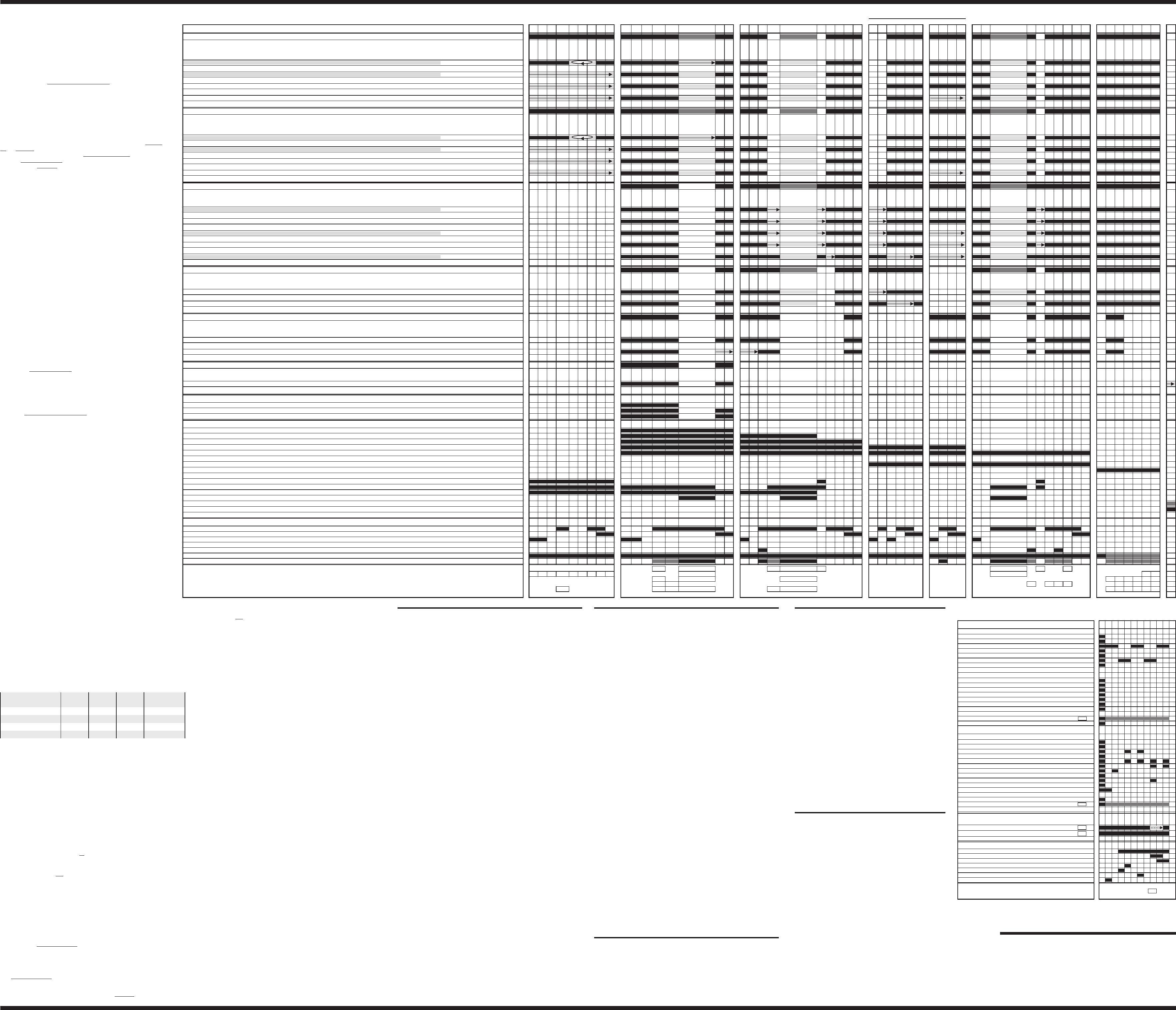
(WITH SOAK&SCOUR OPTION ONLY) PRE-WASH MAIN WASH PURGE/RINSE RINSE FINAL RINSE DRY
45 44 43 42 41 40 39 38 37 36 35 34 33 32 31 30 29 28 27 26 25 24 23 22 21 20 19 18 17 16 15 14 13 12 11 10 9 8 7 6 5 4 3 2 1 0
1:35
0:05
0:05
8:00
8:00
8:00
1:30
1:00
1:00
1:35
0:05
0:05
4:00
2:00
THERMAL HOLD
1:00
1:00
1:35
0:05
0:45
THERMAL HOLD
4:00
1:00
1:00
1:35
6:00
1:00
1:00
1:35
4:00
1:00
1:00
1:35
0:05
THERMAL HOLD
1:00
1:00
1:00
7:00
0:35
1:25
2:00
4H 4H 4H 4H . . . . . . . . . 1H 1H [99] [98] [98] [98] 94 92 92 91 90 88 88 87 87 67 63 62 61 60 54 53 52 50 46 45 44 43 42 42 41 40 39 32 32 30 24 18 16 10 8 2
[99] [98] [98] [98] 94 92 92 91 90 88 88 87 87 67 63 62 61 60 54 53 52 50 46 45 44 43 42 42 41 40 39 32 32 30 24 18 16 10 8 2
[99] [98] [98] [98] 94 92 92 91 90 88 88 87 87 67 63 62 61 60 54 53 52 50 46 45 44 43 42 42 41 40 39 32 32 30 24 18 16 10 8 2
[99] [98] [98] [98] 86 84 84 83 82 81 80 80 80 60 56 55 54 52 46 45 44 43 42 42 41 40 39 32 32 30 24 18 16 10 8 2
THERMAL HOLD THERMAL HOLD THERMAL HOLD
4H 4H 4H 4H . . . . . . . . . 1H 1H [97] [96] [96] [96] 92 90 90 89 88 86 86 85 85 67 63 62 61 60 54 53 52 50 46 45 44 43 42 42 41 40 39 32 32 30 24 18 16 10 8 2
[97] [96] [96] [96] 92 90 90 89 88 86 86 85 85 67 63 62 61 60 54 53 52 50 46 45 44 43 42 42 41 40 39 32 32 30 24 18 16 10 8 2
[97] [96] [96] [96] 92 90 90 89 88 86 86 85 85 67 63 62 61 60 54 53 52 50 46 45 44 43 42 42 41 40 39 32 32 30 24 18 16 10 8 2
[97] [96] [96] [96] 84 82 82 81 80 79 78 78 78 60 56 55 54 52 46 45 44 43 42 42 41 40 39 32 32 30 24 18 16 10 8 2
7:00
THERMAL HOLD
4:00
0:15
0:15
1:35
0:05
THERMAL HOLD
4:00
[95] [94] [94] [94] 90 88 87 86 84 84 83 83 67 63 62 61 60 54 53 52 50 46 45 44 43 42 42 41 40 39 32 32 30 24 18 16 10 8 2
[95] [94] [94] [94] 90 88 87 86 84 84 83 83 67 63 62 61 60 54 53 52 50 46 45 44 43 42 42 41 40 39 32 32 30 24 18 16 10 8 2
[95] [94] [94] [94] 82 80 79 78 77 76 76 76 60 56 55 54 52 46 45 44 43 42 42 41 40 39 32 32 30 24 18 16 10 8 2
[95] [94] [94] [94] 82 80 79 78 77 76 76 76 60 56 55 54 52 46 45 44 43 42 42 41 40 39 32 32 30 24 18 16 10 8 2
[95] [94] [94] [94] 73 71 70 69 67 67 67 60 60 56 52 51 50 49 49 48 47 46 46 45 41 40 39 32 32 30 24 18 16 10 8 2
THERMAL HOLD THERMAL HOLD
[79] [77] [77] [77] 73 71 70 69 68 67 67 60 60 56 55 54 52 46 45 44 43 42 42 41 40 39 32 32 30 24 18 16 10 8 2
[79] [77] [77] [77] 65 63 62 61 59 59 59 52 52 48 47 46 45 45 44 43 42 42 41 40 39 32 32 30 24 18 16 10 8 2
[48] [46] [46] [46] 46 45 44 43 42 41 41 34 33 32 30 29 28 27 26 25 24 23 22 10 10 8 2
[48] [46] [46] [46] 42 41 41 34 33 32 30 29 28 27 26 25 24 23 22 10 10 8 2
[10] [9] [9] [8] 4 2 1
13 439 394
17 17 17 17 17 17 17 17 17 17 15 15 15 15
14 14 14 16 16 16 16 16 16 8
11 11 11 11 11 11 10 10 10
222222 12 12 12 12 12 12 12
NOTES NOTES NOTES NOTES NOTES
4-HOUR PRE-SOAK PERIOD 1 PERIOD 2 PERIOD 3 PERIOD 4 PERIOD 5
20:00
[160°F / 71°C]
[160°F / 71°C]
[160°F / 71°C]
[140°F / 60°C]
[160°F / 71°C]
[140°F / 60°C]
[140°F / 60°C]
[140°F / 60°C]
[140°F / 60°C]
[140°F / 60°C]
[140°F / 60°C]
[140°F / 60°C]
[140°F / 60°C]
[135°F / 57°C]
[135°F / 57°C]
[145°F / 63°C]
[145°F / 63°C]
[145°F / 63°C]
[145°F / 63°C]
[145°F / 63°C]
[145°F / 63°C]
[140°F / 60°C]
[140°F / 60°C]
[140°F / 60°C]
[145°F / 63°C]
[130°F / 54°C]
[120°F / 49°C]
[120°F / 49°C]
[120°F / 49°C]
[130°F / 54°C]
[130°F / 54°C]
[135°F / 57°C]
[130°F / 54°C]
[130°F / 54°C]
[135°F / 57°C]
6:00
2:00
6:00
2:00
6:00
6:00
13x
13x
1:35
0:05
0:05
8:00
8:00
8:00
1:30
1:00
1:00
1:35
0:05
0:05
4:00
2:00
1:00
1:00
1:35
0:05
0:45
4:00
1:00
1:00
18:00
1:35
6:00
1:00
1:00
1:35
4:00
1:00
1:00
1:35
0:05
1:00
1:00
1:00
7:00
0:35
1:25
2:00
6:00
2:00
6:00
2:00
6:00
6:00
1:00
1:00
1:00
7:00
0:35
1:25
2:00
6:00
2:00
6:00
2:00
6:00
6:00
1:35
6:00
1:00
1:00
1:35
4:00
1:00
1:00
4:00
1:00
1:00
16:00
1:00
1:00
1:35
0:05
0:45
1:35
0:05
0:05
4:00
2:00
1:35
0:05
0:05
4:00
2:00
7:00
1:00
1:00
1:35
0:05
0:45
4:00
1:00
1:00
0:15
0:15
1:35
6:00
1:00
1:00
1:35
0:05
1:00
1:00
1:00
7:00
0:35
1:25
2:00
6:00
2:00
6:00
2:00
6:00
6:00
2:00
6:00
1:00
1:00
12:00
0:35
1:25
1:35
0:05
1:00
1:35
1:00
1:00
1:00
1:00
1:00
7:00
0:05
0:45
1:00
1:00
1:35
1:35
0:05
0:05
0:35
0:35
1:35
0:05
0:05
4:00
2:00
1:00
1:00
WITH SOAK&SCOUR OPTION (or “ H.T. SCRUB” options) – ANY SOIL LEVELSOAK&SCOUR and H.T. SCOUR/
LOW SOIL (or Non-Sensor Model) [No soil sensed in Interval 42]
HIGH SOIL [Soil sensed in Interval 42]
NUMERIC DISPLAY CYCLE TIME (spinning “CLOCK” pattern in INTERVALS 45-42 for some models, see NOTE 5)
NUMERIC DISPLAY CYCLE TIME (spinning “CLOCK” pattern in INTERVALS 45-42 for some models, see NOTE 5)
INTERVAL TIME (min:sec)
HIGH SOIL [Soil sensed in Interval 42]
WITH H.T. SCOUR / H.T. SCRUB OPTION – ANY SOIL LEVEL
LOW SOIL (or Non-Sensor Model) [No soil sensed in Interval 42]
ANTI-BACTERIA / BAKED-ON COOKWARE
INTERVAL
POTS & PANS / HEAVY
NORMAL
INTERVAL TIME (min:sec)
INTERVAL TIME (min:sec)
HIGH SOIL WITH H.T. SCOUR / H.T. SCRUB OPTION [Soil sensed in Interval 42]
CHINA/LIGHT
QUICK WASH / QUICK CLEANUP / TIME SAVER
RINSE ONLY/QUICK RINSE
“RINSE ONLY/QUICK RINSE” CYCLE PROGRESSION & STATUS INDICATORS [All other prog./status LED’s off]
INTERVAL TIME (min:sec)
COOL FIRST FILL [Sensed inlet water <135°F in Interval 45]
HOT FIRST FILL [Sensed inlet water >135°F in Interval 45]
WASHING/RINSING (PROG BAR R2) (This LED will be labeled as ‘WASHING’.)used on models with no Rinsing LED and will be
SOAKING/SENSING
RINSING
ALL MODELS & CONDITIONS (No cycle changes based on sensor inputs)
OUTPUT LOADS
PROG BAR W1
PROG BAR W2
WASHING (PROG BAR W3)
PROG BAR R1
DRYING
SOAKING
SOAKING/SENSING
ADD-A-DISH
WATER HEATING (THERMAL HOLD INDICATOR)
SANITIZED
CLEAN
WASH MOTOR (MAIN WINDING)
DRAIN MOTOR
FILL
DETERGENT / RINSE AID DISPENSER
APF ENABLED INTERVALS – Max # of APF Purges (5sec Fill & Drain, then 5sec Fill) allowed in Interval
VENT
HEATER
WITH SOAK&SCOUR OPTION (or “SOAK&SCOUR and H.T. SCOUR/H.T. SCRUB” options) – ANY SOIL LEVEL
NUMERIC DISPLAY CYCLE TIME (spinning “CLOCK” pattern in INTERVALS 45-42 for some models, see NOTE 5)
NUMERIC DISPLAY CYCLE TIME (spinning “CLOCK” pattern in INTERVALS 45-42 for some models, see NOTE 5)
NUMERIC DISPLAY CYCLE TIME (spinning “CLOCK” pattern in INTERVALS 45-42 for some models, see NOTE 5)
NUMERIC DISPLAY CYCLE TIME (spinning “CLOCK” pattern in INTERVALS 45-42 for some models, see NOTE 5)
NUMERIC DISPLAY CYCLE TIME (spinning “CLOCK” pattern in INTERVALS 45-42 for some models, see NOTE 5)
NUMERIC DISPLAY CYCLE TIME (spinning “CLOCK” pattern in INTERVALS 45-42 for some models, see NOTE 5)
WITH H.T. SCRUB OPTION – ANY SOIL LEVELH.T. SCOUR /
NUMERIC DISPLAY CYCLE TIME (spinning “CLOCK” pattern in INTERVALS 45-42 for some models, see NOTE 5)
NUMERIC DISPLAY CYCLE TIME (spinning “CLOCK” pattern in INTERVALS 45-42 for some models, see NOTE 5)
NUMERIC DISPLAY CYCLE TIME (spinning “CLOCK” pattern in INTERVALS 45-42 for some models, see NOTE 5)
HIGH SOIL [Soil sensed in Interval 42]
LOW SOIL (or Non-Sensor Model) WITH H.T. SCOUR / H.T. SCRUB OPTION [No soil sensed in Interval 42]
LOW SOIL (or Non-Sensor Model) [No soil sensed in Interval 42] - ENERGY STAR MODELS
LOW SOIL (or Non-Sensor Model) [No soil sensed in Interval 42]
HIGH SOIL [Soil sensed in Interval 42]
LOW SOIL (or Non-Sensor Model) [No soil sensed in Interval 42]
INTERVAL TIME (min:sec)
INTERVAL TIME (min:sec)
CYCLE PROGRESSION & STATUS INDICATORS
NUMERIC DISPLAY CYCLE TIME (spinning “CLOCK” pattern in INTERVALS 45-42 for some models, see NOTE 5)
NUMERIC DISPLAY CYCLE TIME (spinning “CLOCK” pattern in INTERVALS 45-42 for some models, see NOTE 5)
NUMERIC DISPLAY CYCLE TIME (spinning “CLOCK” pattern in INTERVALS 45-42 for some models, see NOTE 5)
NUMERIC DISPLAY CYCLE TIME (spinning “CLOCK” pattern in INTERVALS 45-42 for some models, see NOTE 5)
NUMERIC DISPLAY CYCLE TIME (spinning “CLOCK” pattern in INTERVALS 45-42 for some models, see NOTE 5)
NUMERIC DISPLAY CYCLE TIME (spinning “CLOCK” pattern in INTERVALS 45-42 for some models, see NOTE 5)
NUMERIC DISPLAY CYCLE TIME (spinning “CLOCK” pattern in INTERVALS 45-42 for some models, see NOTE 5)
WASHING/RINSING (PROG BAR R2) (This LED will be labeled as ‘WASHING’.)used on models with no Rinsing LED and will be
RINSING
NOTES 1A,14A,15,16,17
NOTE 17
NOTE 14A
NOTE 1A
NOTE 1A
NOTES 1A,14A,15,16,17
4hr + 99 : 00 w/o Th.Holds
99 : 00 w/o Th.Holds
99 : 00 w/o Th.Holds
91 : 25 w/o Th.Holds
NOTE 17
NOTE 14A
NOTE 1A
NOTE 1A
4hr + 97 : 00 w/o Th.Holds
97 : 00 w/o Th.Holds
97 : 00 w/o Th.Holds
89 : 25 w/o Th.Holds
NOTES 1A,10,16
NOTE 14B 95 : 00 w/o Th.Holds
NOTE 1A 95 : 00 w/o Th.Holds
NOTE 14B 87 : 25 w/o Th.Holds
NOTE 1A
NOTE 1A
87 : 25 w/o Th.Holds
78 : 20 w/o Th.Holds
NOTE 1A 78 : 25 w/o Th.Holds
NOTE 1A 70 : 20 w/o Th.Holds
NOTES 1B,11,16
NOTE 1B 47 : 35
NOTE 1B 43 : 55
NOTE 1C
NOTE 1C 9:45
NOTE 7
NOTE 7
NOTE 7
NOTE 6
NOTE 8,15
NOTE 8
NOTE 2
NOTE 2
NOTE 2
NOTES 4,10,11,16
APF
APF
max 3
APF
APF
max 3
APF
APF
max 2
APF
APF
max 2
APF
APF
max 3 120°F max 1, else 3
APF
APF
[145°F / 63°C]
NOTES 1A, 9, 14B, 15,16
COMMON CYCLE TIME CHART
PART NO. 8269519
NOTE: This sheet contains important
Technical Service Data
FOR SERVICE TECHNICIAN ONLY
DO NOT REMOVE OR DESTROY
COMMON CYCLE TIME CHART N0TES
NOTE 1 – CYCLE MODIFICATIONS BASED ON SENSOR INPUTS
The control monitors food soil and temperature sensors during the
first four intervals of the cycle (intervals 45-42) to determine what sen-
sor based cycle modifications are appropriate. The modifications
made to the cycle depend on the cycle and options selected as well
as the sensor inputs. Note the interval skip arrows and thermal hold
temperature changes on the time chart for each version of the cycle.
In addition to being able to modify the cycle itself based on soil sen-
sor input, the APF (Automatic Purge Filtration) wash system allows
the control to continuously filter and flush food soil out of the pump
during “APF enabled” intervals scattered throughout each cycle and
do it without interrupting the cycle (see note 2 on APF).
(a) Antibacteria/Cookware, Pots and Pans/Heavy, Normal,
and China/Light Cycles
The control assumes that the worst case cycle (the high soil version)
is going to be required until the true soil level is determined. The soil
level is determined by counting the number of pressure switch (soil
sensor) trips that occur in the first APF interval of the cycle (interval
42). If no trips are detected in interval 42, the control modifies the re-
mainder of the cycle to match the low soil/non-sensor version of the
cycle. If one or more trips are detected in interval 42, the control con-
tinues with the high soil version of the cycle.
Note: Energy Star models have a different low soil/non-sensor ver-
sion of the Normal cycle than other models (see Model Specifics ta-
ble to identify Energy Star models).
Note: Models without pressure switches (soil sensors) never get sen-
sor trips and thus always default to the low soil/non-sensor version of
the cycle and never execute APF purges. (See Model Specifics Table
to identify models without pressure switches).
Note: The H.T. Scour/H.T. Scrub option and/or Soak&Scour option
can override or alter the soil-based cycle modifications (see notes 14
and 17).
(B) Quick Wash/Quick CleanUp/Time Saver Cycles
The control does NOT modify the Q.Wash/Q.CleanUp/Time Saver
cycle based on soil level. Instead, it modifies the cycle based on in-
coming water temperature detected during the first fill interval of the
cycle (interval 45). The control assumes the worst case cycle (Cool
First Fill version) will be required until the end of interval 42. At the
end of interval 42, it modifies the remainder of the cycle based on the
inlet water temperature it actually detected in the first fill. If the water
was >135°F/57°C it changes to the “Hot First Fill” version of the cy-
cle. If the water was less than 135°F, it will continue with the “Cool
First Fill” version of the cycle. The “Cool First Fill” version of the cycle
basically contains an extra drain and fill prior to the main wash to in-
crease the initial water temperature for the main wash and reduce the
time needed to heat the water.
Like other cycles, the Q.Wash/Q.CleanUp/Time Saver cycle does al-
low APF purges to occur (in APF intervals) if pressure switch trips oc-
cur but the Q.Wash/Q.CleanUp/Time Saver cycle timing itself is not
modified based on pressure switch trips or soil level.
(c) Rinse Only/Quick Rinse Cycle
The control does NOT modify the Rinse Only/Quick Rinse cycle
based on sensor inputs. Like other cycles, it does allow APF purges
to occur (in APF intervals) if pressure switch trips occur but the Rinse
Only/Quick Rinse cycle timing itself is not modified based on any
sensor inputs.
NOTE 2 – APF ENABLED INTERVALS
The APF (Automatic Purge Filtration) wash system allows the control
to continuously filter and flush food soil out of the pump during “APF
enabled” intervals scattered throughout each cycle and do it without
interrupting the cycle. The control monitors the pressure switch (soil
sensor) input during each of the APF enabled intervals in the cycle
(see time chart). Whenever a pressure switch trip is detected in one
of these APF intervals, the control executes a 10-second “APF purge”
to clear the pump of soil.
These APF purges occur in parallel with the cycle and do not inter-
rupt or affect the timing of other functions (like washing) that are
called for in the interval. Each APF purge consists of 5 seconds of
Fill and Drain followed immediately by 5 seconds of Fill by itself. If an
APF purge is executed during a heated wash interval, the heater
must be turned off during the first 5-second Fill and Drain portion of
each purge, but cycle timing is not affected and the heater turns
back on mid-way through the purge.
Multiple APF purges can occur within each APF interval of the cycle
but are limited by certain frequency and quantity limits:
nAPF purges must be spaced at least 60 seconds apart within any
given APF interval (the pressure switch will be ignored prior to 60
seconds).
nThe maximum number of APF purges allowed within a given APF
interval is specified on the time chart in that interval (the pressure
switch will be ignored for the duration of an APF interval once the
maximum APF limit for that interval has been exceeded). In inter-
val 33, the limit is “1” for 120°F thermal holds and “3” for all other
thermal hold setpoint temperatures.
Note: Models without pressure switches (soil sensors) never get sen-
sor trips and thus never execute APF purges. (See Model Specifics
Table to identify models without pressure switches).
NOTE 3 – WATER HEATING THERMAL HOLD INTERVALS
During water heating thermal holds (intervals 40, 33, & 15), cycle timing is
interrupted and the dishwasher continues washing while it heats the water
to the setpoint temperatures specified on the time chart for each version of
the cycle. The Water Heating and Sensing indicators are turned on and the
cycle time displayed by models with numeric displays is frozen during ther-
mal hold intervals (see notes 5, 6, & 7). The dishwasher will hold in this sus-
pended, water heating mode until the water reaches the temperature
specified for the thermal hold or a maximum default time limit for the ther-
mal hold (below) expires. At the conclusion of the thermal hold, the control
resumes normal operation and timing and proceeds to the next interval.
The default maximum time limits for all the thermal hold intervals are as
follows (in minutes):
Pre-Wash Main
Wash
Final
Rinse
Final Rinse
with Sani/Rinse
Anti-bacteria/Cookware 30 35 50 (50)
Pots & Pans/Heavy 30 35 30 (50)
Normal – 45 40 (60)
China/Light – 45 30 –
(Q.Wash/Q.CleanUp/Time Saver and Quick Rinse/Rinse Only cycles have no
thermal hold intervals.)
NOTE 4 – THERMALLY CAPPED INTERVALS
Interval 34 is a heated wash interval thermally capped at 150°F/66°C. Interval
10 is only heated for the Q.Wash/Q.CleanUp/Time Saver cycle and is ther-
mally capped in that situation at 150°F/66°C. Anytime the thermal cap temper-
ature is exceeded during one of these intervals, the heater will turn off, but the
dishwasher will continue washing for the duration of the interval.
NOTE 5 – NUMERIC CYCLE TIME DISPLAY
Some models with numeric cycle time displays show an animated spinning
clock pattern during the first four intervals of the cycle (intervals 45-42) while
sensor based cycle modifications (and true time remaining) are being deter-
mined. Other models simply display the worst case cycle time remaining (in
minutes) until the end of interval 42. See the Model Specifics Table to identify
models with numeric displays and which models exhibit the animated clock
pattern. At the end of interval 42, all models with numeric displays will begin
displaying a corrected cycle time (in minutes). From here on, the display
clocks down normally, minute by minute, through the rest of the cycle.
Note: Cycle time does not include time spent in thermal holds; the time on
the display at the start of the thermal hold is frozen until the end of the ther-
mal hold (see notes3&6).
NOTE 6 – WATER HEATING (THERMAL HOLD) STATUS INDICATOR
The Water Heating indicator is turned on during all thermal hold intervals to
signal that cycle timing, display sequencing, and numeric cycle time display
countdown operations have been suspended or frozen while the water is
heated to the proper temperature (see note 3).
NOTE 7 – SOAKING/SENSING & SOAKING STATUS INDICATORS
In general, the Soaking/Sensing indicator is primarily a “sensing” indicator
and is turned on during cycles whenever the control is monitoring sensors
or still making decisions based on sensor inputs. Specifically this includes
all APF intervals, all thermal hold intervals, and the first four intervals of each
cycle (see notes 1, 2, and 3).
The Soaking/Sensing indicator also turns on during “soaking” events like
the “soaking/pause” intervals in the Energy Star low soil/non-sensor version
of the Normal cycle (see note 9) and the 4-hour pre-soak invoked by the
Soak&Scour option (see note 17). A dedicated Soaking indicator is available
for some non-numeric models that will likewise turn on during these “soak-
ing” events but not during “sensing” intervals.
NOTE 8 – ‘END-OF-CYCLE’ STATUS INDICATORS – CLEAN and
SANITIZED
Both end-of-cycle indicators (Clean and Sanitized) turn on at the end of a
cycle and turn off upon pressing any key or opening and closing the door
(note: the indicators stay on as the door is opened but turn off as soon as
the door is closed again).
(a) Clean
Comes on at the end of every cycle except Rinse Only/Quick Rinse.
(b) Sanitized
Comes on at the end of all cycles completed with the Sani Rinse option se-
lected (see note 15). If the Sani Rinse option is completed successfully, the
indicator is turned on steady at the end of the cycle. If the Sani Rinse was
unsuccessful (see below), the indicator will flash ½ second on, ½ second
off, repeatedly, at the end of the cycle. The Sani Rinse will be deemed un-
successful (& flash the indicator) if:
(1) The thermal hold in the final rinse (interval 15) fails to reach the
required 160°F/71°C before timing out on its default time limit.
(2) The door is opened and/or power is interrupted between the end of
the final rinse thermal hold (interval 15) and the end of the cycle.
NOTE 9 – SOAKING/PAUSE INTERVALS – ENERGY STAR NORMAL
CYCLE ONLY
Intervals 13 and 32 are mid-cycle soaking/pause intervals and are only used
in the Energy Star low soil/non-sensor version of the Normal cycle. The con-
trol stops washing and turns all loads off except the vent in these intervals.
The intent is to let the wash water that’s on the dishes soften and loosen the
food soil that’s on the dishes, energy free. The Soaking and Soaking/Sensing
indicators are turned on during these intervals (see note 7).
NOTE 10 – PULSED DRY – CHINA/LIGHT CYCLE ONLY
The China/Light cycle (on all models) turns the heater off in intervals 1, 3,
and 5 of the dry period to create a gentler “pulsed” dry.
NOTE 11 – HEATER ON – QUICK WASH/QUICK CLEANUP/TIME
SAVER CYCLE ONLY
To make up for no water heating thermal holds, the heater is turned on in
intervals 10-12, 14, and 41-42 of the Q.Wash/Q.CleanUp/Time Saver cycle.
The heater in interval 10 of the Q.Wash/Q.CleanUp/Time Saver cycle is
thermally capped at 150°F/66°C (see note 4).
NOTE 12 – SPECIAL VENT & PULSED DRY OPERATION – KUDS01FK
AND KUDM01FK MODELS ONLY
For the KUDS01FK and KUDM01FK fully integrated door models only, the
vent is on top of the door (and thus directly under the countertop), so the
control makes the following special changes:
nKeeps the vent closed for the entire dry period (including intervals 1-6) or
until the door is opened, whichever comes first.
nTurns the heater off in dry intervals 1, 2, 3, and 5 for all cycles with Sani
Rinse selected (see note 15).
nKeeps the vent closed at the end of the cycle for an additional 4 hours or
until the door is opened, whichever comes first. Keeping the vent
closed after the cycle allows the temperature inside the dishwasher to fall
and moisture inside to condense to minimize the steam that exits the
vent when the vent opens.
OPTION NOTES
NOTE 14 – HI TEMP SCOUR/HI TEMP SCRUB OPTION
The H.T. Scour/H.T. Scrub option is not allowed with China/Light,
Q.Wash/Q.CleanUp/Time Saver, or Rinse Only/Quick Rinse cycles.
This option does the following:
(a) Anti-Bacteria/Cookware and Pots&Pans/Heavy cycles
nForces the control to run no less than a 5-fill (Wash-Wash-Rinse-Rinse-
Rinse-Dry) version of the cycle, even if no soil is sensed.
nRaises the pre-wash water heating thermal hold (interval 40) to
135°F/57°C
nRaises the main wash water heating thermal hold (interval 33) to
145°F/63°C (except Anti-Bacteria/Cookware cycle, which is already
145°F/63°C).
(b) Normal cycles
nForces the control to run no less than a 4-fill (Wash-Wash-Rinse-Rinse-
Dry) version of the cycle even if no soil is sensed. Note: the standard
(non-Energy Star) Normal cycle is already a minimum of 4-fills
(Wash-Wash-Rinse-Rinse-Dry) with low/no soil.
nRaises the main wash water heating thermal hold (interval 33) to
145°F/63°C.
NOTE 15 – SANI RINSE OPTION
The Sani Rinse option is not allowed on China/Light, Q.Wash/Q.CleanUp/
Time Saver, and Rinse Only/Quick Rinse cycles. It is “built in” and treated as
an automatic option on the Anti-bacteria/Cookware cycles. This option does
the following:
nRaises final rinse water heating thermal hold (interval 15) to 160°F/71°C
and adds 20 minutes to its default maximum time limit.
nTurns heater off in the last two intervals of the dry period (intervals 1
and 2) for most models. For KUDM01FK & KUDS01FK models only (see
note 12), it turns the heater off in intervals 1, 2, 3, and 5 of the dry period.
nInvokes the Sanitized status indicator at the end of the cycle (see note 8).
NOTE 16 – AIR DRY/NO HEAT DRY/ENERGY SAVER DRY OPTION
The Air Dry/No Heat Dry option is not allowed on the Rinse Only/Quick
Rinse cycle (which has no dry). This option does the following:
nTurns heater off in the dry period (intervals 1-6).
NOTE 17 - SOAK&SCOUR OPTION
The Soak&Scour option is only allowed with the Anti-Bacteria/Cookware and
Pots&Pans cycles. This option does the following:
nRuns a 4-hour pre-soak period before the cycle (see Time Chart). The
pre-soak consists of a standard fill, an initial 8:00 minute wash, then 13
wash "pulses" (each 90 seconds long, spaced 16 minutes apart) to keep
the dishes wet and soaking. At the conclusion of this pre-soak period,
the dishwasher drains and the cycle begins.
nForces the control to run no less than a 5-fill (Wash-Wash-Rinse-Rinse-
Rinse) version of the cycle following the pre-soak, even if no soil is
sensed.
nSkips pre-wash water heating thermal hold (interval 40).
nRaises main wash water heating thermal hold (interval 33) to 145°F/63°C
(except on Anti-Bacteria/Cookware cycle, which is already 145°F/63°C).
Note: The Soak option takes precedence over the H.T. Scour/H.T. Scrub op-
tion if selected together.
RAPID ADVANCE SERVICE
FEATURE AND DIAGNOSTICS
CYCLES
Pressing the following option keys in the sequence shown will
either start the Diagnostics Cycle or turn on the Rapid
Advance feature for stepping through customer selectable
cycles:
HI TEMP SCRUB, AIR DRY, HI TEMP SCRUB, AIR DRY
Or
SANI RINSE, AIR DRY, SANI RINSE, AIR DRY
(Note: HI TEMP SCRUB = HI TEMP SCOUR)
(Note: AIR DRY = NO HEAT DRY = ENERGY SAVER DRY)
If the above key sequence is entered after starting a cycle, the
Rapid Advance feature is turned on, which allows the operator
to manually advance the currently running cycle, interval by
interval, by pressing the Pots&Pans/Heavy or Anti-Bacteria/
Cookware or Start key.
If the above key sequence is entered with the dishwasher in
Standby, the Diagnostics Cycle is started. The Diagnostics Cy-
cle can be rapid-advanced, interval by interval, by pressing
the Pots&Pans/Heavy or Anti-Bacteria/Cookware or Start key.
Note: The door must be closed before the Diagnostics cycle
will run. Likewise, the door must be closed after each rapid
advance selection of the P&P/Heavy, A-Bac/Cookware, or
Start key for the control to advance to the next interval of the
Diagnostics or currently running cycle.
DIAGNOSTICS CYCLE TIME CHART
NOTES
NOTE 1 – R/A SENSOR ASSY CHECK
To help detect a failed or misconnected Rinse Aid level
sensor, the control should operate the Rinse Aid Empty LED
in Diagnostics as it does during any other cycle.
NOTE 2 – THERMISTOR OPEN/SHORT DETECTION
The Diagnostics Test cycle will illuminate the ‘CLEAN’ LED
throughout the operating portion of the cycle that follows the
initial display test interval whenever it detects a “short circuit” or
“open circuit” on the thermistor input.
Note: Warm water must be in the dishwasher when
performing this test. The highest thermistor resistance values
the control can detect as its open circuit criteria are close to
the normal thermistor resistance at room temperature.
Consequently, this indicator is only reliable for “open circuit”
detection if warm water is in the dishwasher.
NOTE 3 – STUCK PRESSURE SWITCH DETECTION
The Diagnostics cycle monitors the normally open
soil-sensing pressure switch input for a “stuck closed”
condition by aborting wash interval 3 and skipping
immediately to drain interval 1 if the control detects a closed
pressure switch.
INTERVAL 11 10 9 8 7 6 5 4 3 2 1 0
CYCLE LED's
ANTIBACTERIA / COOKWARE S
POTS&PANS / HEAVY T
NORMAL A
CHINA/LIGHT N
QUICK WASH / QUICK CLEANUP / TIME SAVER D
RINSEONLY/QUICKRINSE B
CANCEL DRAIN Y
OPTION LED's
H.T. SCOUR / H.T. SCRUB
SOAK&SCOUR
NO HEAT DRY / AIR DRY/ E.SVR.DRY
SANI RINSE
DELAY - 2 HR
DELAY - 4 HR
DELAY - 8 HR
RINSE AID EMPTY NOTE
LOCKOUT
CYCLE PROG/STATUS LED's
W1
W2
WASHING (W3)
R1
WASHING/RINSING (R2) [labeled ‘WASHING’ on models w/o Rinsing LED’s]
RINSING
DRYING
SOAKING
SOAKING/SENSING
ADD-A-DISH
WATER HEATING
SANITIZED
CLEAN NOTE
INTERVAL TIME (min:sec)
DIAG. CYCLE (P.Switch Closed)
DIAG. CYCLE (P.Switch Open) NOTE
NUMERIC DISPLAY (DISPLAYS INTERVAL NUMBER)
OUTPUT LOADS
VENT
WASH MOTOR MAIN
DRAIN MOTOR
FILL VALVE
UNDEFINED EXTRA OUTPUT
DET-R/A DISPENSER
HEATER
3
NOTES
0:03
0:05
0:02
0:05
0:10
0:02
0:05
0:02
1:00
1:00
1:00
S
T
A
N
D
B
Y
S
T
A
N
D
B
Y
3
3
2
1
88 10 9 8 7 6 5 4 3 2 1 0
NOTE
S
T
A
N
D
B
Y
DIAGNOSTICS CYCLE TIME CHART
OTHER CONTROL FEATURES
CANCEL/DRAIN: Terminates current active cycle and clears cycle selec-
tions. Executes 2-minute drain upon first selection if water is likely to be left
in sump. Subsequent selections toggle between 2-minute drains and
going to standby.
CONTROL LOCK: The Control Lock indicator is turned on and all keys of
the keyboard are disabled whenever the Control Lock feature is invoked by
the customer. The Control Lock feature (and indicator) can be turned on or
off by the customer at any time by holding down the Air Dry/No Heat
Dry/Energy Saver Dry option key for 4 seconds.
DELAY START: Allows the customer to delay the start of a cycle. Each
press of the Delay key increases the delay to the next available delay time
selection and then back to no delay.
nFor models with a Start key, the delay will begin clocking down upon
selecting the Start key.
nFor models without a Start key, the delay period will begin upon select-
ing the Cycle key.
The cycle selected will begin automatically upon completing the delay
period.
Note: Models with a numeric cycle time display will display time remaining
in the Delay in hours. Delays of 9 hours or less will display an H after the
number to denote “hours”. Delays of more than 9 hours drop the H due to a
lack of digits.
REPEAT LAST CYCLE / ONE BUTTON START MEMORY: All models re-
member the “last cycle and options ran” so that they may be repeated by
simply pressing the Start key. (Note: models without a Start key will remem-
ber the last options ran and turn them on upon selecting a Cycle key). Cy-
cle and option selections will not be saved to memory until the cycle
completes its final rinse. The Rinse Only/Quick Rinse cycle is never saved
to memory.
Models with cycle and option keys on the top of the door instead of the
front of the door will automatically bring up the last cycle and options ran
from memory and display them as initial cycle selections each time the door
is opened. These initial selections can be changed if desired or left as is
and then started by closing the door and selecting the Start key. If no Start
key is selected, these last ran cycle and option selections will turn back off
and the dishwasher will return to standby after 30 seconds.
ERROR MESSAGES
STUCK KEY: If the control detects that a key is stuck in the depressed posi-
tion, dishwasher operation will be suspended and the control will flash the
light for that key until the condition is corrected. If a key without a light is
stuck or multiple keys are stuck, the control will flash the light for the Rinse
Only/Quick Rinse key.
