86092 Catalog
2014-07-05
: Pdf 86092-Catalog 86092-Catalog 785901 Batch5 unilog
Open the PDF directly: View PDF ![]() .
.
Page Count: 292 [warning: Documents this large are best viewed by clicking the View PDF Link!]

Behavioral Health Building
Operation and Maintenance Manual
Factory Order #: 31751120
12-17-2013
Kansas City, KS
Distributor:
Stanion Wholesale Electric
Contractor / Installer:
Torgeson Electric
Consulting Engineer:
PEC
Isaac Anderson
Sales Representative
Rick Simpson
Project Manager
North American Operating Division
(417) 887-2307
rick.simpson@schneider-electric.com
Make the most of your energy
SM

Table of Contents
GENERAL INFORMATION
TERMS AND CONDITIONS/WARRANTY
Schneider Electric Conditions of Sale
Square D Warranty Surgelogic TVSS Protective Systems
BILL OF MATERIALS
Detailed Bill of Materials for 31751120
SWITCHBOARD
DRAWINGS
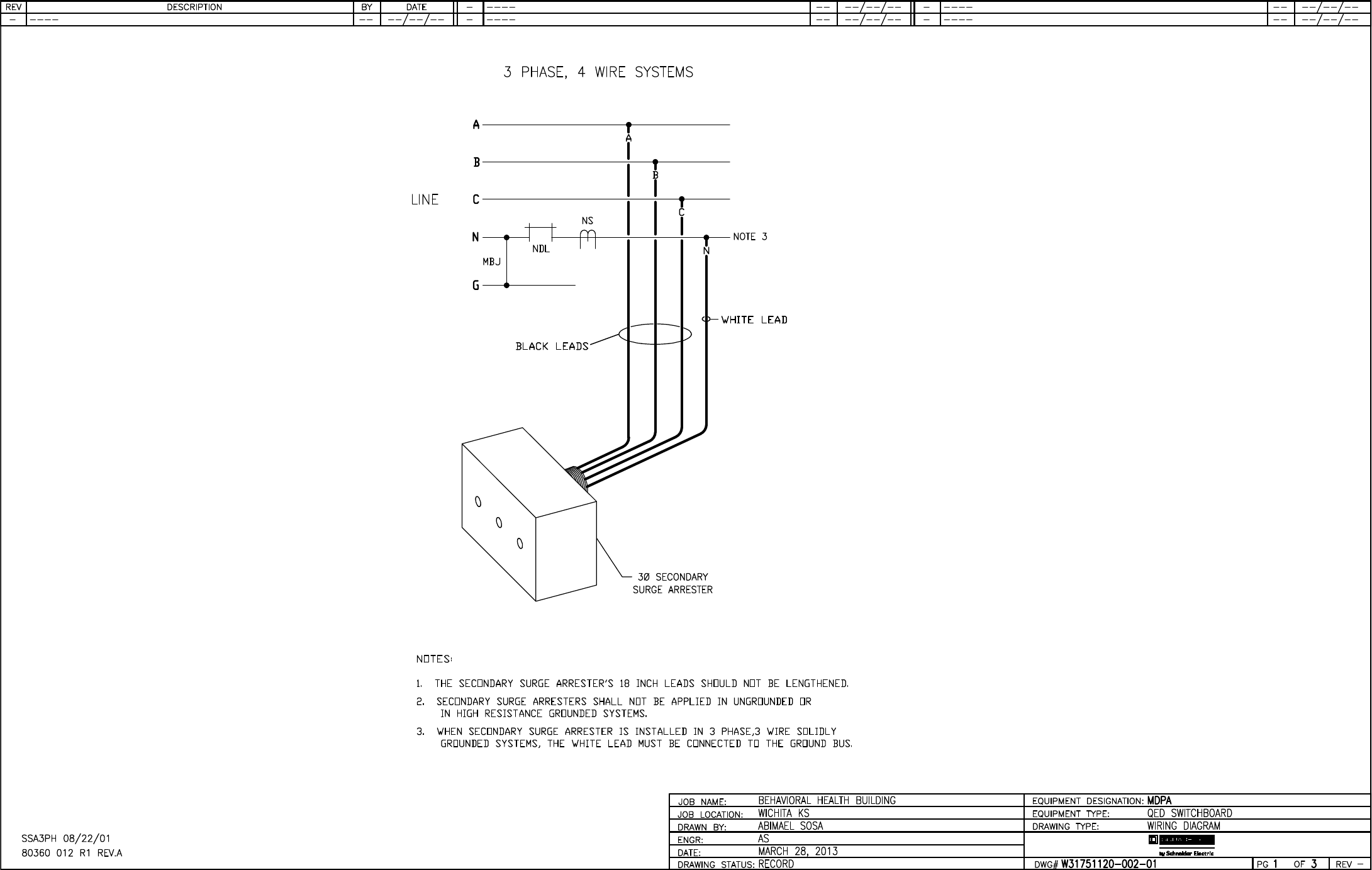
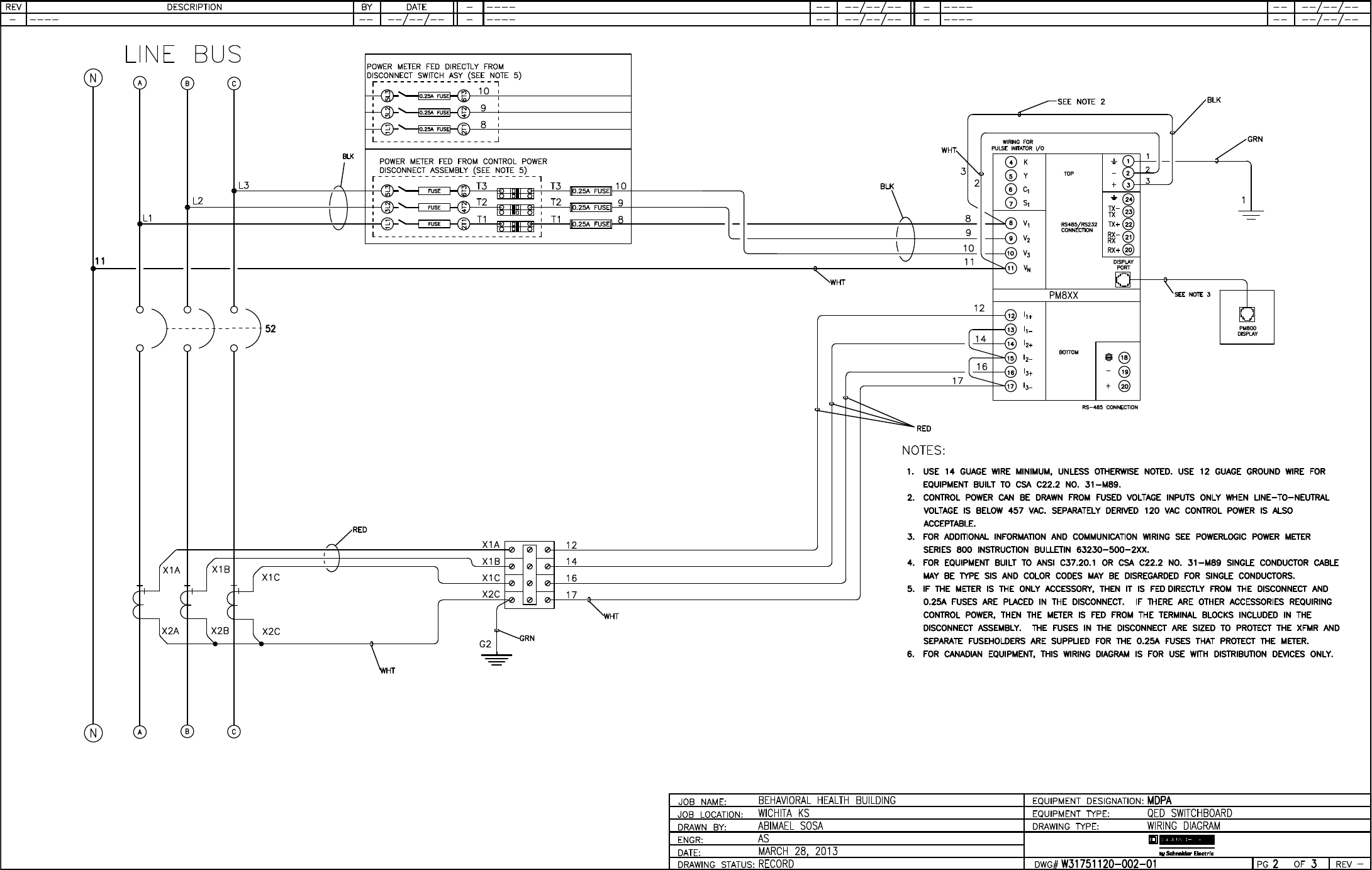
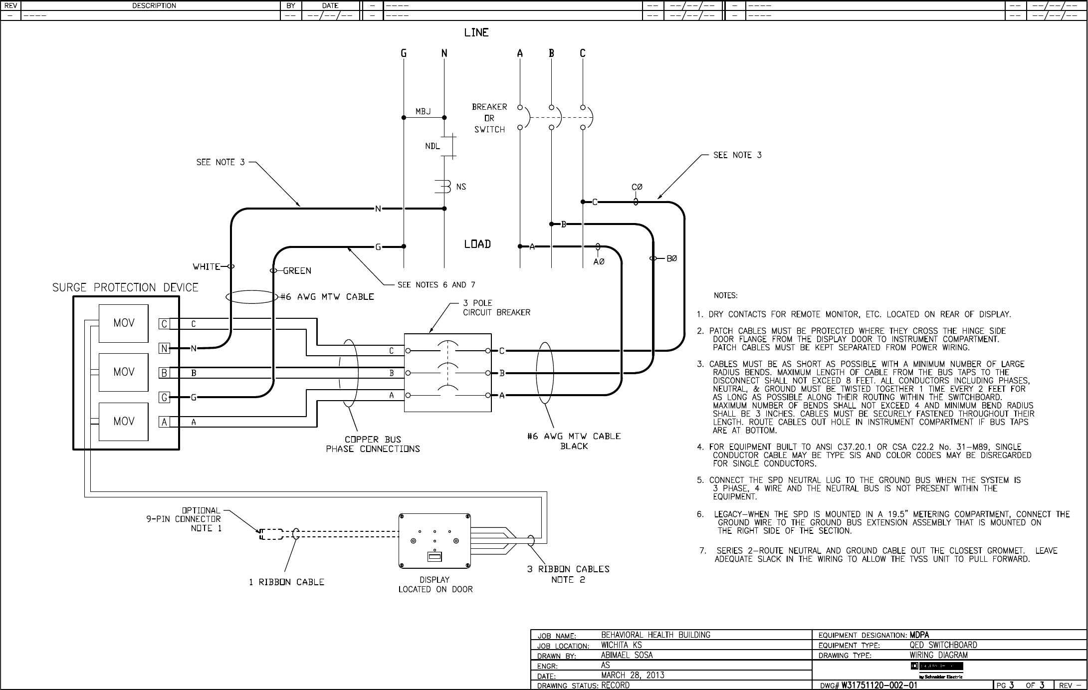
MSB
MDPA
MANUALS
Power-Style QED Switchboards Instruction Bulletin
NEMA - Instructions for Distribution Switchboards Rated 600 Volts or Less
SURGE PROTECTIVE DEVICE
SDSA3650 Surge Protective Device Instruction Bulletin
POWERLOGIC MONITORING
PowerLogic PM800 Series Power Meter Installation Manual
PowerLogic PM800 Quick Reference Manual
MAIN BREAKER
Powerpact R Frame Circuit Breaker Instruction Bulletin
TRIP UNIT
Micrologic’ 2.0, 3.0 and 5.0 Electronic Trip Units
PANELBOARD
DRAWINGS
Panelboards
MANUALS
NQ/NQM Panelboards and QONQ Load Centers Information Manual
NEMA- Instructions for Panelboards Rated 600 Volts or Less

RECOMMENDED SPARE PARTS
NQ PANELBOARD - Recommended Spare Parts
DISCONNECT
MANUALS
General Duty Safety Switches Instruction Bulletin
GTK03 Equipment Grounding Bar Kit - Instruction Bulletin
PKOGTA2 Service/Equipment Grounding Lug - Instruction Bulletin
QO and QOB Circuit Breakers Catalog
SURGE PROTECTIVE DEVICE
MANUALS
IMA Surge Protective Device Instruction Bulletin
IMA Surge Protective Device Display Replacement Instruction Bulletin
IMA Surge Protective Device Module Replacement Instruction Bulletin

0100PL0043R12/12
12/2012
Schneider Electric Conditions of Sale
Proposal-based Projects
© 2012 Schneider Electric USA, Inc. All Rights Reserved
Prices subject to change without notice.
12/2012
™
Note
The following Conditions of Sale are subject to change. All transactions for all products sold by
Schneider Electric USA ("Schneider Electric"), including all Schneider Electric brand products, are
subject to the latest published Conditions of Sale of Schneider Electric and to any Special Conditions of
Sale which may be contained in applicable Schneider Electric quotations and acknowledgments.
Schneider Electric Standard conditions of Sale will apply in all transactions between customers and
Schneider Electric, unless the Proposal-based Project Conditions of Sale, apply as defined in the
following paragraph.
Proposal-based
Projects
Definitions
Transactions that exhibit some or all of the following attributes: Unique customer requirements that are
typically negotiated and quoted, requires approval drawings and project management by Schneider
Electric, and for which there is a specific direct-ship address.
Governing
Provisions and
Acceptance
All quotations are subject to these conditions of sale. Acceptance of an order by Schneider Electric shall
be expressly conditioned on Purchaser's assent to these conditions. Purchaser's direction to proceed
with engineering, manufacture or shipment by Schneider Electric shall be deemed evidence of this
assent. No modified or other conditions will be applicable unless those conditions are so stated in
Schneider Electric's proposal or are specifically agreed to in writing and signed by an authorized official
of Schneider Electric. Failure to object to provisions contained in any Purchase Order or other
communication from the Purchaser (including, without limitation, penalty clauses of any kind) shall not
be construed as a waiver of these Conditions nor an acceptance of any other provisions. These terms
are a complete statement of the parties' agreement and may only be modified in writing signed by both
parties. These terms may not be modified by course of dealing, course of performance or usage of
trade. These terms supersede all previous written or oral quotations, statements or agreements. Any
contract for sale by and between the parties shall be governed by and construed according to the laws
of the State of Illinois without regard to its rules on the conflict of laws. The Convention on the
International Sale of Goods is expressly excluded.
Quotations Quotations shall be valid for no more than thirty (30) days from the date quotation is communicated from
seller to purchaser, unless otherwise stated in the quotation. All quotations are subject to change by
Schneider Electric Company at any time upon notice to Purchaser. Quotations are made based on
Schneider Electric's interpretation of the plans and specifications submitted to Schneider Electric by the
Purchaser. It is Purchaser's obligation to review the quotation carefully and to immediately advise
Schneider Electric of any differing interpretation Purchaser has so any necessary change can be made.
Order Entry A complete, signed purchase order must be received before entry of an order into Schneider Electric's
system. Considerable detail is involved in the manufacture of power equipment. To facilitate timely
shipment, complete details and information, including Purchaser's requested on-site dates must be
provided at the time of order entry. Shipment dates are approximate and are based upon timely receipt
of all necessary information from the Purchaser. Lack of complete information may result in delays of
drawings or manufacture. Such delays shall relieve Schneider Electric from compliance with the quoted
delivery dates and may lead to price escalation. Failure to provide a complete signed purchase order
within twenty (20) days of notification of award may result in renegotiation of price or shipment dates.
4 of 292

2© 2012 Schneider Electric USA, Inc. All Rights Reserved
Prices subject to change without notice.
12/2012
Schneider Electric Conditions of Sale
Proposal-based Projects
Approval
Drawings
When required by a specific Purchase Order, drawings will be submitted for approval per agreed upon
schedules, and price policy, below, to assure Schneider Electric has designed the equipment as
described in Purchaser's specifications, as modified by Schneider Electric's quotation. If at time of drawing
approval Schneider Electric has not designed the equipment to meet the specifications, as modified by
Schneider Electric's quotation, Schneider Electric will make the appropriate changes at no charge to
Purchaser. Where the Purchaser's specification is not definitive, Schneider Electric shall have the right to
design the product in line with good commercial practice, without further obligation to Purchaser. If at
drawing approval, Purchaser makes changes outside the design as stated in the specifications, such
changes shall be treated as a change order as provided below.
Price Policy Quoted prices are firm provided: A) The order is received with complete engineering details and is
released for manufacture within sixty (60) calendar days from the originally anticipated release date. B) All
required approval drawings are returned and equipment released by Purchaser no later than sixty (60)
calendar days from the original date of issuance of approval drawings by Schneider Electric. The returned
drawings must be released for manufacture for shipment on the agreed date. Drawing re-submittals which
are required for any reason other than to correct Schneider Electric errors will not extend the sixty (60) day
deadline. If the Purchaser causes delay of shipment in any way or returns approval drawings beyond the
time stated above, Purchaser may be subject to charges which shall not exceed 2% of the purchase order
price for each full month or fraction thereof that shipment is delayed, as compensation to Schneider
Electric for expenses created by such delay and not as a penalty. In addition to the 2% charge per month,
if shipment is delayed through the fault of Purchaser for more than 180 days from the original date of
issuance of approval drawings, the price may be subject to revision.
Pricing-
Purchaser
Changes
All prices cover a bill of material as described in Schneider Electric specifications or quotations to be
designed and manufactured to Schneider Electric standard designs, unless otherwise agreed in writing
between the parties. Purchaser may make minor changes not affecting the time or cost of performance
without charge prior to the start of manufacture. If any changes are requested by the Purchaser after
submission of the original Purchase Order which affect the cost or time of performance, additional billing
will be made with the amount of price adder dependent on the change and status of the order when the
change is made. Changes may also result in an extension of time for shipment. All changes will be agreed
to by the parties, in writing, prior to implementation. Purchaser's rescheduling shipment will be considered
a change. All expenses incurred by Schneider Electric in connection with the storage of equipment,
including demurrage, packing, storage charges, insurance and handling charges by Schneider Electric will
be paid by the Purchaser upon submission of invoices by Schneider Electric. Schneider Electric will issue
price changes for any change requested by the Purchaser that affects modification of equipment, changes
the bills of material, engineering or drawings or delivery schedule as follows: A) If Purchaser makes a
change to an order prior to being released to engineering, the net price will be adjusted by re-pricing the
equipment with prices in effect at the time of the change. A commensurate delay in the shipping date will
be based on the changes involved. B) For changes made after the order is released to engineering, the
net price and ship date will be adjusted as described in paragraph A above. An additional charge based
on Schneider Electric standard engineering billing charges and cost of parts ($250 minimum) will be made
to cover any extra engineering and drafting, scrap or rework of parts, or cost of modification. C) If during
the drawing approval process, the Purchaser makes changes outside the design covered by the
specifications, Schneider Electric will be reimbursed as described in paragraph A and B above, plus any
additional charges for any extra cost incurred as a direct result of the changes and allowed a
commensurate delay in shipping date based on the changes involved. Changes to the order can not be
processed until a formal signed change order is received from the Purchaser.
Substitutions Schneider Electric may furnish suitable substitutes for material unobtainable because of priorities or
regulations established by governmental authority or non-availability of materials from suppliers, provided
such substitutions do not adversely affect the technical soundness of the equipment. Schneider Electric
assumes no liability for deviation from published dimensions and descriptive information not essential to
proper performance of the product.
5 of 292

© 2012 Schneider Electric USA, Inc. All Rights Reserved
Prices subject to change without notice.
12/2012
3
Schneider Electric Conditions of Sale
Proposal-based Projects
Taxes Any manufacturer's tax, retailer's tax, occupation tax, use tax, sales tax, excise tax, (except federal excise
tax on vehicles), duty, customs, inspecting or testing fee, or other tax, fee or charge of any nature
whatsoever, imposed by any governmental authority or measured by any transaction between Schneider
Electric and Purchaser, shall be paid by the Purchaser in addition to the prices quoted or invoiced, and
such charges will appear as a separate line item on the invoice. In the event Schneider Electric will be
required to pay any such tax, fee, or charge, Purchaser shall reimburse Schneider Electric or, in lieu of
such payment, Purchaser shall supply Schneider Electric at the time the order is submitted with an
exemption certificate or other document acceptable to the tax authority. Purchase Orders must state the
existence and amount of any such tax, fee or charge for which Purchaser claims an exemption.
Terms of
Payment
Acceptance of all Purchase Orders is subject to Purchaser meeting Schneider Electric credit standards.
Terms are subject to change for failure to meet such standards. Terms are net thirty (30) days from date
of invoice of each shipment, unless otherwise stated in Schneider Electric's quotation. For an authorized
distributor or authorized reseller order, applicable terms of payment are stated in the quotation or
applicable discount schedule. Schneider Electric reserves the right at any time to demand full or partial
payment before proceeding with a contract of sale if, in its sole judgment, as a result of changes in the
financial condition of the Purchaser the terms of payment originally specified are no longer justified.
Progress
Payments/
Payment Term
All proposal-based projects are Net 30 days from date of invoice of each shipment. On projects exceeding
$1,000,000 Net, progress payments are payable according to the following milestones:
•30% Release to manufacturing
•70% (balance) due at shipment
Payments If delivery is delayed or deferred by the Purchaser beyond the scheduled date, payment shall be due in full
when Schneider Electric is prepared to ship. The equipment may be stored at the risk and expense of the
Purchaser. If the Purchaser defaults when any payment is due, then the whole contract price shall
become due and payable upon demand, or Schneider Electric at its option, without prejudice to other
lawful remedies, may defer delivery or cancel the contract for sale. If Purchaser become insolvent, or
bankrupt or in the event any proceeding is brought against the Purchaser, voluntarily or involuntarily under
the bankruptcy or any insolvency law, Schneider Electric may cancel any order then outstanding at any
time and recover its proper cancellation charges from the Purchaser or the Purchaser's estate.
Delivery F.O.B. Point of Shipment
When the Schneider Electric quotation is based on delivery F.O.B. point of shipment, freight prepaid and
allowed for delivery within the continental United States, Product is sold F.O.B. point of shipment, freight
prepaid and allowed for orders over $2000 net. Delivery by Schneider Electric to the point of shipment
constitutes delivery to the Purchaser; and title and all risk of loss or damage in transit shall pass to the
Purchaser at time of delivery at the F.O.B. point. Schneider Electric is not responsible for breakage or
delays by carrier after having received "in good order" receipts from the carrier. Purchaser is responsible
for pursuing any damage claims with the carrier. For orders under $2000 net the above terms apply
except freight is prepaid not allowed. No allowance will be made in lieu of transportation if the Purchaser
accepts shipment at factory, warehouse or freight station or otherwise supplies its own transportation.
Freight prepaid is defined as: a) Shipments to destinations within the continental United States to the
accessible common carrier point nearest the first destination. b) Shipments to U.S. destinations outside
the continental United States shall be to the common carrier free delivery point in the United States
nearest the original port of embarkation. All charges associated with F.A.S., C.I.F., or other charges such
as pier transfer, lift, ocean freight, and marine or war insurance shall be paid by the Purchaser, unless
otherwise specifically agreed in a specific Purchase Order. In no event will Schneider Electric be
responsible for demurrage or detention charges.
Delivery: F.O.B. Destination
When the Schneider Electric quotation is based on delivery F.O.B. Destination, for shipments for delivery
within the continental United States, Schneider Electric will retain title and all risk of loss or damage in
transit to the common carrier free delivery point in the United States nearest the first destination for a price
addition of 2% of the net price. If the Purchaser elects this Option, Purchaser's obligations shall be as
follows: a) Purchaser shall have the responsibility of inspecting the equipment for apparent loss or
damage immediately upon its arrival at the free delivery point. b) In the event of apparent shipping loss or
damage, Purchaser shall make written notation of the loss on the carrier's delivery receipt and, within 72
hours of delivery shall notify the Schneider Electric Customer Information Center. Purchaser shall not
remove product from the point of examination and shall retain the shipping container and packing
6 of 292

4© 2012 Schneider Electric USA, Inc. All Rights Reserved
Prices subject to change without notice.
12/2012
Schneider Electric Conditions of Sale
Proposal-based Projects
material. Purchaser shall request the carrier to make an inspection and send Schneider Electric a copy of
the carrier's inspection report. c) In the event of concealed damage which occurred during transit and is
discovered by the Purchaser after delivery, Purchaser shall report such damage immediately, but in no
event later than 15 days after delivery, to the delivering carrier, and within 72 hours of discovery, shall
notify the local Schneider Electric field office. If such notification is not made, Schneider Electric shall not
be liable for loss or damage in transit.
Shipment and Routing
Schneider Electric shall select the point of origin of shipment, the method of transportation and the routing
of the shipment. Purchasers that request expedited or special modes of transportation or routing involving
air, premium or any other non-standard Schneider Electric shipping shall be assessed additional charges
for shipping, handling, freight and expediting. Any rebates, allowances, discounts, or incentives received
by Schneider Electric from its carriers shall be retained by Schneider Electric. All prices include domestic
packaging only. When other than domestic packaging is required, contact your local Schneider Electric
field office. Purchaser specified packaging and marking may be subject to additional charges.
Shortages Claims for shortages or errors must be submitted to Schneider Electric within 30 days after invoice date,
and failure to give such notice shall constitute unqualified acceptance and a waiver of all such claims by
the Purchaser.
Installments Schneider Electric reserves the right to make shipments in installments, unless otherwise expressly
stipulated in a specific Purchase Order; and all such installments when separately invoiced shall be paid
for when due per invoice without regard to subsequent shipments. Delay in shipment of any installment
shall not relieve Purchaser of its obligation to accept remaining shipments.
Force Majeure Schneider Electric shall not be liable for any damages as a result of any delays due to any causes beyond
Schneider Electric's control, including, without limitation, an act of God; act of Purchaser or Schneider
Electric supplier; embargo or other governmental act, regulation or request; fire; accident; strike;
slowdown; flood; fuel or energy shortage; sabotage; war; riot; delay in transportation and inability to obtain
necessary labor, materials or manufacturing facilities from usual sources. In the event of any such delay,
the date of delivery shall be extended for a period of time reasonably necessary to overcome the effect of
such delay.
Standard
Warranty
Schneider Electric warrants equipment manufactured by it and sold through authorized sales channels to
be free from defects in materials and workmanship for 12 months from the issuance of the customer
provisional acceptance letter or 18 months from the invoice date of the last component of the order
whichever occurs first. If within such period, any such equipment shall be proved to Schneider Electric's
satisfaction to be non-conforming, such equipment shall be repaired or replaced at Schneider Electric's
option. This warranty shall not apply (a) to equipment not manufactured by Schneider Electric, (b) to
equipment that has been repaired or altered by other than Schneider Electric so as, in its judgment, to
affect the same adversely, or (c) to equipment that has been subjected to negligence, accident, or
damage by circumstances beyond Schneider Electric's control, or improper operation, maintenance or
storage, or to other than normal use or service. With respect to equipment not manufactured by Schneider
Electric, the warranty obligations of Schneider Electric shall in all respects conform and be limited to the
warranty actually extended to Schneider Electric by its supplier. Non-conforming products must be
returned at Schneider Electric's expense for evaluation unless this is waived in writing. Replacement
products may be new or reconditioned. The foregoing warranties do not cover reimbursement for labor,
transportation, removal, installation, temporary power, or any other expenses that may be incurred in
connection with repair or replacement. Any part or component changed or repaired in the context of the
contractual warranty will itself benefit of a 3 month warranty but shall not cause the warranty duration of
the overall System / Solution to be extended.
Optional
Warranties
(Only available on equipment to be located in the U.S.)
Option 1—Extended: 2 to 5 years from Shipment. If requested by the Purchaser, and specifically accepted
in writing by Schneider Electric, the standard warranty will be extended to two (2) years from date of
invoice for a price addition of 1% of the net face value of the Purchase Order, will be extended to three (3)
years from date of invoice for a price addition of 3% of the net face value of the Purchase Order, will be
extended to four (4) years from date of invoice for a price addition of 5% of the net face value of the
Purchase Order, or will be extended to five (5) years from date of invoice for a price addition of 7% of the
net face value of the Purchase Order.
Option 2—Special Warranty: If requested by the Purchaser, and specifically accepted in writing by
7 of 292

© 2012 Schneider Electric USA, Inc. All Rights Reserved
Prices subject to change without notice.
12/2012
5
Schneider Electric Conditions of Sale
Proposal-based Projects
Schneider Electric, the standard warranty will be extended, for a price addition of 3% of the net face value
of the Purchase Order, to cover reimbursement of the direct costs of: a) Removal of non-conforming
equipment or part thereof; b) Transporting equipment or parts to and from the place of repair;
c) Off-loading of truck and reinstallation at the original site. Such special warranty, which may be chosen
to cover a period not exceeding that of the standard or extended warranty (see above) selected, will not
include the cost of providing temporary power or removing or replacing other apparatus or structures, or
costs of transportation beyond a common carrier free delivery point in the continental United States.
Further, the obligation of Schneider Electric for expenses and costs arising under this special warranty
coverage will not exceed 50% of the net invoice price on the equipment being repaired. This warranty
does not change or affect the allocation of risk or loss during shipment.
Option 3—Extended Warranty: Preventative Maintenance Agreements. If requested by the Purchaser,
and specifically accepted by Schneider Electric, a Preventative Maintenance Agreement is available to
provide preventative maintenance on equipment covered by the agreement. Terms of the preventative
maintenance agreement shall be as defined in a separate Services Agreement agreed to by the parties.
Software Any software or computer information, in whatever form, provided with equipment manufactured by
Schneider Electric is licensed to Purchaser solely pursuant to standard licenses of Schneider Electric or
its supplier of such software or computer information, which licenses are, hereby incorporated by
reference. Schneider Electric does not warrant that such software or computer information will operate
error free or without interruption, and warrants only that during the warranty period applicable to the
equipment that the software will perform its essential functions. If such software or computer information
fails to conform to such warranty, Schneider Electric will, at its option, provide an update to correct the
non-conformance or replace the software or computer information with the latest available version
containing a correction. Schneider Electric shall have no other obligation to provide updates or revisions.
Limitations These disclaimers and limitations of remedies apply to all warranties offered to Purchaser and to all
Purchase Orders. The warranties set forth above are exclusive and in lieu of all other expressed or
implied warranties (except warranties of title), including, but not limited to implied warranties of
merchantability and fitness for a particular purpose. Except as may be expressly provided in an
authorized writing by Schneider Electric, Schneider Electric shall not be subject to any other obligations or
liabilities whatsoever other than as stated above with respect to equipment sold or services rendered by
Schneider Electric. Notwithstanding anything to the contrary herein contained Schneider Electric
Company, its contractors and suppliers of any tier, shall not be liable in contract, in tort (including
negligence or strict liability) or otherwise for lost time, lost profits, or special, indirect, incidental
or consequential damages of any kind whatsoever. The remedies of the Purchaser are exclusive and
the total cumulative liability of Schneider Electric, its contractors and suppliers of any tier, with respect to
this contract or anything done in connection therewith, such as the use of any product covered by or
furnished under the contract, whether in contract, in tort (including negligence or strict liability) or
otherwise, shall not exceed the price of the product, part, or service on which such liability is based.
Intellectual
Property
As to equipment proposed and furnished by Schneider Electric, Schneider Electric shall defend any suit or
proceeding brought against Purchaser so far as based on a claim that such equipment constitutes an
infringement of any copyright, trademark or patent of the United States.
This obligation shall be effective only if Purchaser shall have made all payments then due hereunder and
if Schneider Electric is notified promptly in writing and given authority, information, and assistance at
Schneider Electric's expense for the defense of the same. In the event the use of such equipment by
Purchaser is enjoined in such a suit, Schneider Electric shall, at its expense, and at its sole option, either
(a) procure for the Purchaser the right to continue using such equipment (b) modify such equipment to
render it non-infringing (c) replace such equipment with non-infringing equipment, or (d) refund the
purchase price (less depreciation) and the transportation and installation costs of such equipment.
Schneider Electric will not be responsible for any compromise or settlement made without its written
consent. The foregoing states the entire liability of Schneider Electric for patent, trademark or copyright
infringement, and in no event shall Schneider Electric be liable if any infringement charge is based on the
use of Schneider Electric equipment for a purpose other than that for which it was sold by Schneider
Electric. As to any equipment furnished by Schneider Electric to Purchaser and manufactured in
accordance with designs proposed by Purchaser, the Purchaser shall indemnify Schneider Electric
against any award made against Schneider Electric for patent, trademark, or copyright infringements.
8 of 292

Schneider Electric USA, Inc.
1415 S. Roselle Road
Palatine, IL 60067 USA
1-888-778-2733
www.schneider-electric.us
Square D™ and Schneider Electric™ are trademarks or registered trademarks of Schneider Electric.
0100PL0043R12/12 © 2012 Schneider Electric USA, Inc. All Rights Reserved
Replaces 0100PL0043R11/11
© 2012 Schneider Electric USA, Inc. All Rights Reserved
Prices subject to change without notice.
12/2012
6
Witness of
Tests and
Factory
Inspections
Normal production schedules do not provide the opportunity for Purchaser to witness routine factory tests
on equipment or make factory inspections. Witnessing of tests or factory inspections by the Purchaser
may result in delays of production for which Schneider Electric will not be responsible. Witness testing and
factory inspections must be requested at time of quotation and confirmed at order entry. Standard
Schneider Electric factory testing and inspection will apply. Schneider Electric will notify Purchaser
fourteen (14) calendar days prior to scheduled witness testing or inspection. In the event Purchaser is
unable to attend, the Parties may mutually agree on a rescheduled date. However, Schneider Electric, at
its sole option, may consider the witness tests and/or inspection waived, and ship and invoice the
Products. Purchaser will be responsible for paying for all scheduled witness testing, whether or not
Purchaser attends.
Return of
Equipment
No equipment may be returned without first obtaining Schneider Electric’s written permission and
a returned material identification tag. Returned equipment must be of current manufacture, in the
original packaging, unused, undamaged and in saleable condition, securely packed to reach Schneider
Electric without damage and labeled with the return authorization number. Any cost incurred by Schneider
Electric to put equipment in first class condition will be charged to the Purchaser. Returns will be credited
at price invoiced by Schneider Electric less a restocking fee of 25% invoice price. Special Order and
Custom equipment is not returnable. Schneider Electric shall bear the cost of returns resulting from
Schneider Electric error, and method and route of return will be at the discretion of Schneider Electric.
Costs incurred by failure to follow Schneider Electric direction will be borne by the Purchaser.
Nuclear
Applications
Terms and
Conditions
Unless otherwise agreed in writing by a duly authorized representative of Schneider Electric, products
sold hereunder are not intended for use in or in connection with any nuclear facility or activity. If so used,
Schneider Electric disclaims all liability for any damage, injury or contamination; and Purchaser shall
indemnify Schneider Electric against any such liability, whether arising as a result of breach of contract,
warranty or tort (including negligence) or otherwise.
Patterns and
Tools
Notice will be given if special patterns or tools are required to complete any order. Charges for such
patterns or tools do not convey title thereto or the right to remove them from Schneider Electric's plant. If
patterns or tools are not used for a period of two years, Schneider Electric shall have the right to scrap
them without notice.
Product
Notices
Purchaser shall promptly supply the user (including its employees) of the product with all Schneider
Electric supplied product notices, warnings, instructions, recommendations and similar materials.
Errors Schneider Electric reserves the right to correct errors or omissions in quotations, acknowledgments,
invoices, or other documents.
OSHA
Compliance
Compliance with OSHA or similar federal, state or local laws during the operation or use of the product(s)
is the sole responsibility of the Purchaser.
Termination Any order may be terminated by the Purchaser only upon written notice to Schneider Electric will be
subject the following cancellation schedule:
•20% after issuance of approval drawings
•50% at release to manufacturing
•100% at start of fabrication
Cancellation Schneider Electric shall have the right to cancel any order or contract at any time by written notice for any
material breach of the contract by the Purchaser, including material delays in releasing equipment for
manufacture or approval drawings and excessive changes to specifications or drawings.
Schneider Electric Conditions of Sale
Proposal-based Projects
9 of 292

Warranty to customers purchasing through authorized Square D distributors and customers purchasing directly
from Square D.
Protection Limits
With regard to any Square D Surgelogic TVSS protection system that has been properly installed in compliance
with all applicable electrical code requirements, Square D warrants the Surgelogic TVSS device to be free from
defects in materials and workmanship for a period of ten (10) years from date of invoice from Square D or its
authorized sales channel. If within the applicable warranty period purchaser discovers such item was not as
warranted and promptly notifies Square D in writing, Square D shall repair or replace the items or refund the purchase
price, at Square Dʼs option. This warranty shall not apply (a) to electrical equipment in which the TVSS is
installed, i.e. panelboards, motor control centers, busway, switchboards, switchgear, etc.. (b) to equipment not
manufactured by Square D, (c) to equipment which shall have been repaired or altered by others than Square D,
(d) to equipment which shall have been subjected to negligence, accident, or damage by circumstances beyond
Square Dʼs control, or to improper operation, maintenance or storage, or to other than normal use or service.
The foregoing warranty does not cover reimbursement for labor, transportation, removal, installation, or
other expenses which may be incurred in connection with repair or replacement.
Except as may be expressly provided in an authorized writing by Square D, Square D shall not be subject to any
other obligations or liabilities whatsoever with respect to equipment manufactured by Square D or services
rendered by Square D.
The foregoing warranties are exclusive and in lieu of all other express and implied warranties except warranties
of title, including but not limited to implied warranties of merchantability and fitness for a particular purpose.
Limitation of Liability
Anything to the contrary herein contained notwithstanding, Square D Company, its contractors and
suppliers of any tier shall not be liable in contract, in tort (including negligence or strict liability) or
otherwise for any special, indirect, incidental or consequential damages whatsoever. The remedies of the
purchaser set forth herein are exclusive where so stated and the total cumulative liability of Square D, its
contractors and suppliers of any tier, whether in contract, in tort (including negligence or strict liability) or otherwise,
shall not exceed the price of the product or part on which such is based.
Square D Warranty
Surgelogic TVSS Protection Systems
05/06
10 of 292
11 of 292

Q2C Number: 31751120 Quote Number: 1 Revision Number: 3
Project Name: BEHAVIORAL HEALTH BUILDING Quote Name:
Item
No.
Qty.
Catalog Number / Details
BILL OF MATERIALS
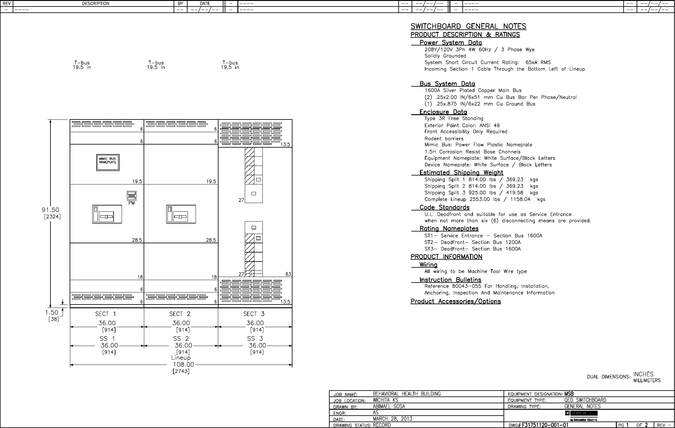
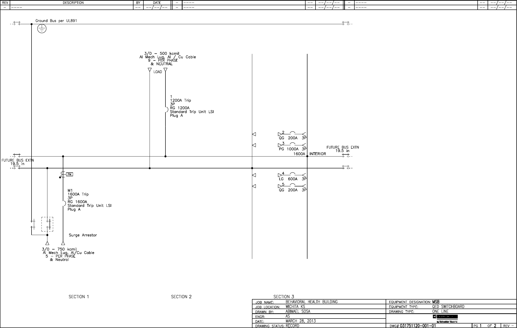
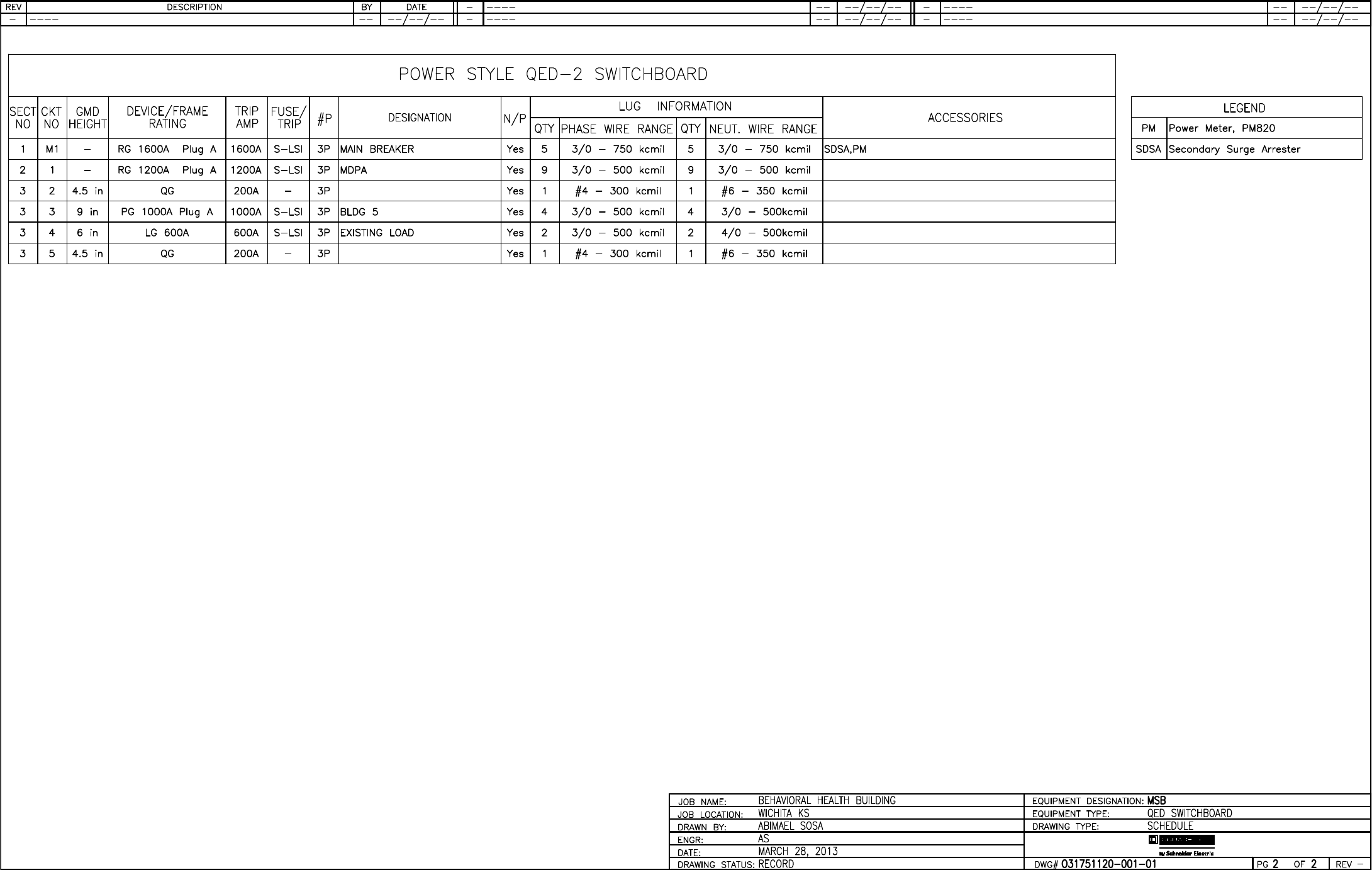
001-00 1 Designation: MSB
SQUARE D CUSTOM QED SWITCHBOARD
QED Switchboard
---------------------------------
Square D Power Style Custom Switchboard
Designed and Tested in accordance with:
UL 891/NATIONAL ELECTRIC CODE/NEMA PB-2
System Voltage - 208Y/120V 3Ph 4W 60Hz
Source Description - Single Main
System Ampacity - 1600A
Bussing - Copper Plated with Silver
Neutral Bus - 100%
Max Available Fault Current (RMS) - 65kA
Enclosure - Type 3R Non-Walk-in
Accessibility: Front Only
Rodent Barrier
Exterior Paint Color - ANSI 49
Mimic Nameplate - Power Flow Plastic
Ground Lug provided for each device
Optional Copper Ground Bus
Lineup 1 BTU: 10448
Dimensions
---------------------------------
3 - 36" Wide Section(s)
1 - Dimensions: 108.00" W X 35.5" D X 91.5"H
3 - 35.5" Deep Enclosure(s)
Approximate Weight: 2553.00
Incoming Requirements
---------------------------------
Suitable for Use As Service Entrance
Entry Point: Left of Lineup, Through the
Bottom
Connection Type: Cable
Surge Arrestor
Power Meter - PM-820RD
3 CTs Power Meter - 3 phase 4 wire wye
208Y/120
Mains
---------------------------------
1 - 1600AS/1600AT 208V 80% Rated 65 kA 3 Pole
UL, Fixed Mounted Micrologic Circuit
Breaker: Type RG
Standard Trip Unit, Long Time, Short
Time, Instantaneous
Nameplate - White Surface / Black Letters
Feeders
---------------------------------
1 - 1200AS/1200AT 208V 80% Rated 65 kA 3 Pole
UL, Fixed Mounted Micrologic Circuit
Breaker: Type RG
Standard Trip Unit, Long Time, Short
Time, Instantaneous
Specials: 9-500MCM/PH&N
Special 9-500MCM/PH&N #: 5673538
2 - 200AT 208V 80% Rated 65 kA 3 Pole UL,
Group Mounted Thermal Magnetic Circuit
Breaker: Type QG
12 of 292

Q2C Number: 31751120 Quote Number: 1 Revision Number: 3
Project Name: BEHAVIORAL HEALTH BUILDING Quote Name:
Item
No.
Qty.
Catalog Number / Details
1 - 1000AS/1000AT 208V 80% Rated 65 kA 3 Pole
UL, Group Mounted Electronic Trip
Circuit Breaker: Type PG
Standard Trip Unit, Long Time, Short
Time, Instantaneous
1 - 600AS/600AT 208V 80% Rated 65 kA 3 Pole
UL, Group Mounted Electronic Trip
Circuit Breaker: Type LG
Standard Trip Unit, Long Time, Short
Time, Instantaneous
Common Feeder Features:
Nameplate - White Surface / Black Letters
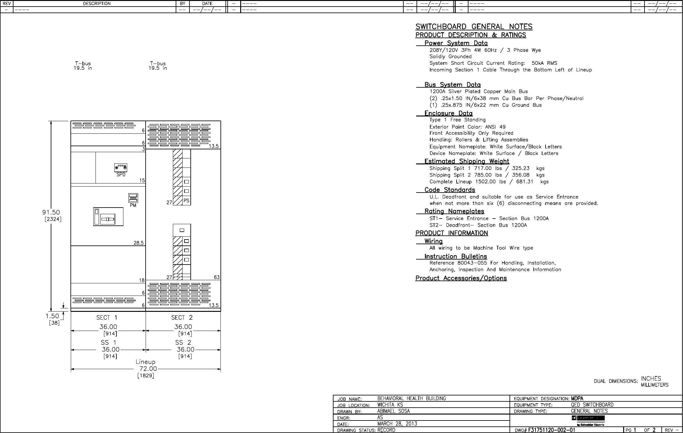
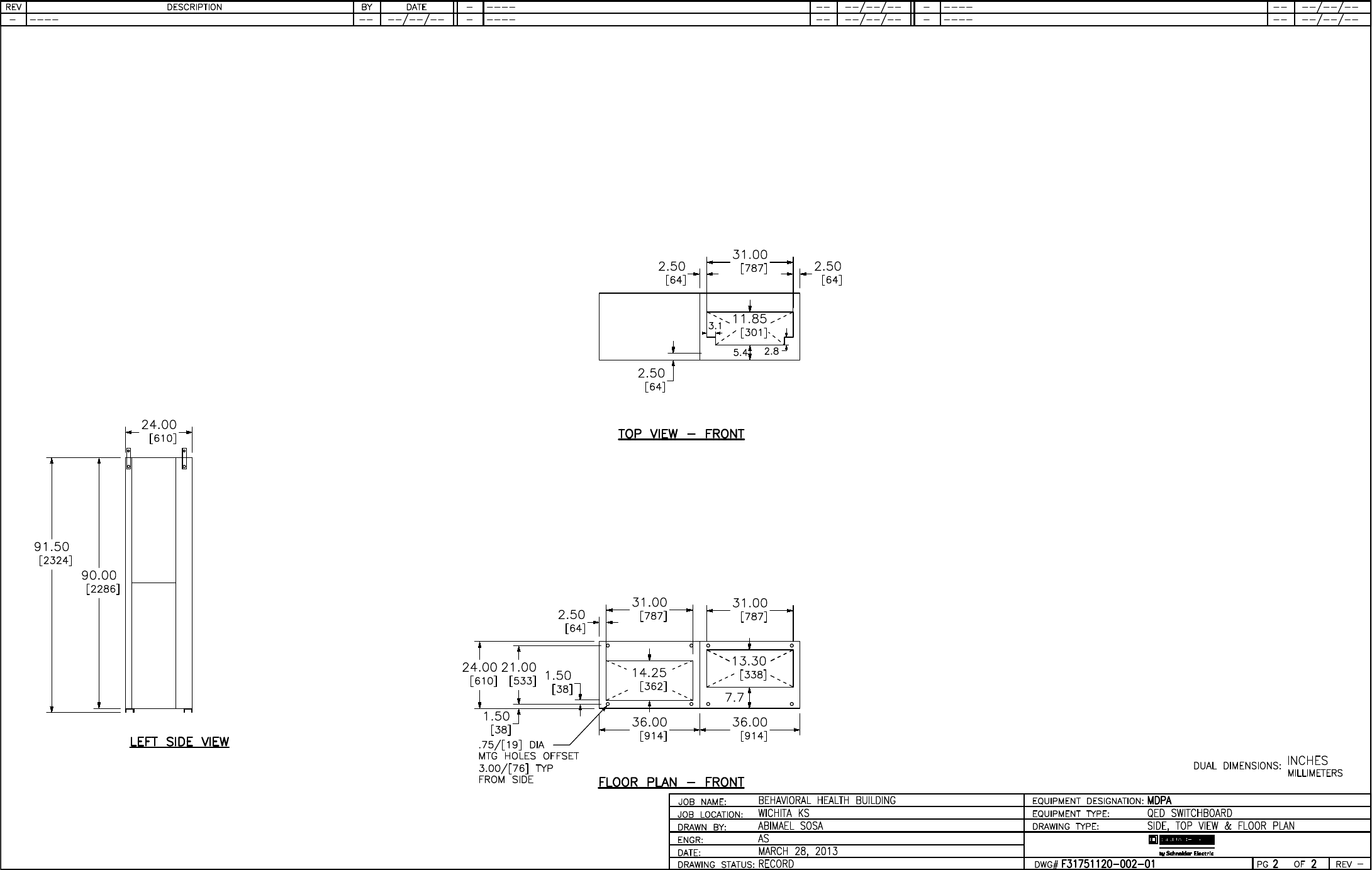
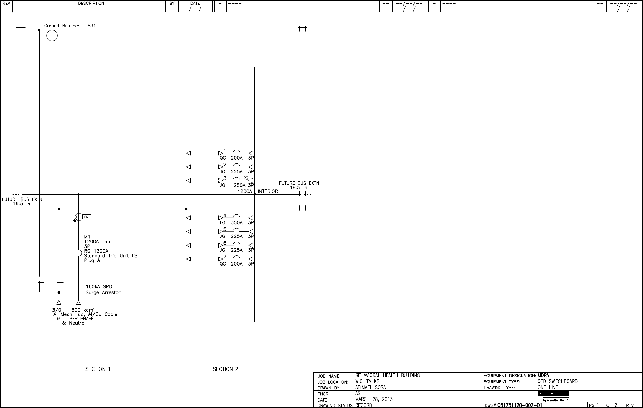
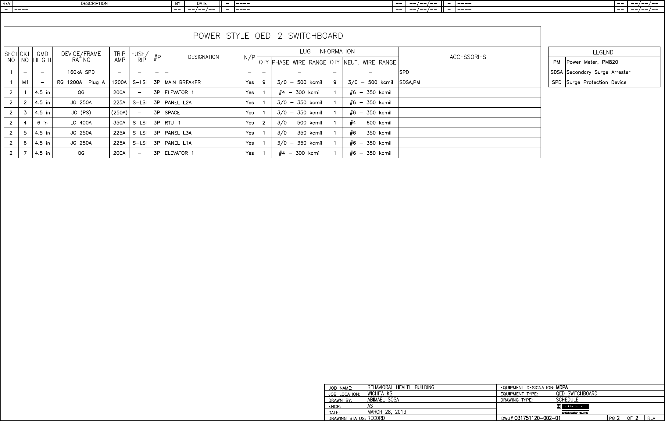
002-00 1 Designation: MDPA
SQUARE D CUSTOM QED SWITCHBOARD
QED Switchboard
---------------------------------
Square D Power Style Custom Switchboard
Designed and Tested in accordance with:
UL 891/NATIONAL ELECTRIC CODE/NEMA PB-2
System Voltage - 208Y/120V 3Ph 4W 60Hz
Source Description - Single Main
System Ampacity - 1200A
Bussing - Copper Plated with Silver
Neutral Bus - 100%
Max Available Fault Current (RMS) - 50kA
Enclosure - Type 1
Accessibility: Front Only
Exterior Paint Color - ANSI 49
Ground Lug provided for each device
Optional Copper Ground Bus
Lineup 1 BTU: 7485
Dimensions
---------------------------------
2 - 36" Wide Section(s)
2 - 24" Deep Enclosure(s)
Dimensions: 72.00" W X 24" Max D X 91.5" H
Approximate Weight: 1502.00
Incoming Requirements
---------------------------------
Suitable for Use As Service Entrance
Entry Point: Left of Lineup, Through the
Bottom
Connection Type: Cable
Surge Arrestor
SPD with Surge Rating 160kA
SPD Dry Contacts
Includes Surge Counter
Power Meter - PM-820RD
3 CTs Power Meter - 3 phase 4 wire wye
208Y/120
Mains
---------------------------------
1 - 1200AS/1200AT 208V 80% Rated 65 kA 3 Pole
UL, Fixed Mounted Micrologic Circuit
Breaker: Type RG
Standard Trip Unit, Long Time, Short
Time, Instantaneous
Nameplate - White Surface / Black Letters
Specials: 9-500MCM/PH&N
13 of 292

Q2C Number: 31751120 Quote Number: 1 Revision Number: 3
Project Name: BEHAVIORAL HEALTH BUILDING Quote Name:
Item
No.
Qty.
Catalog Number / Details
Special 9-500MCM/PH&N #: 5673538
Feeders
---------------------------------
2 - 200AT 208V 80% Rated 65 kA 3 Pole UL,
Group Mounted Thermal Magnetic Circuit
Breaker: Type QG
3 - 250AS/225AT 208V 80% Rated 65 kA 3 Pole
UL, Group Mounted Electronic Trip
Circuit Breaker: Type JG
Standard Trip Unit, Long Time, Short
Time, Instantaneous
1 - 250AT 208V 80% Rated 3 Pole UL, Group
Mounted Thermal Magnetic Prepared
Space: Type JG
1 - 400AS/350AT 208V 80% Rated 65 kA 3 Pole
UL, Group Mounted Electronic Trip
Circuit Breaker: Type LG
Standard Trip Unit, Long Time, Short
Time, Instantaneous
Common Feeder Features:
Nameplate - White Surface / Black Letters
002-01 4 80247-553-64
right splice assembly, 1.5" bus
005-00 1 Designation: PANEL L1A
NQ ML PNLB (INT,BOX,TRIM) - A
NQ Panelboard
Consisting of
208Y/120V 3Ph 4W 60Hz SCCR: 42kA
Series Rated w/ JG Circuit Breaker
TVSS 160kA per Phase/80kA per Mode
SPD line to grd protect
w/TVSS Surge Counter
w/TVSS Dry Contacts
Main Lug Only: 225A
Main Acc: Sub-Feed Lugs
Incoming Conductors: 1 - (2) 1/0 - 350 kcmil
AL Ground Bar
Bus: Aluminum: Tin Plated
42 Circuit Interior
Type 1Box: 62H x 20W x 5.75D
Incoming: Top Trim: Surface - Hinged
Box Cat No: MH62 Front Cat No: NC62SHR
Ref. Drawing: PBA701T
Feeders:
35 - 20A/1P QOB
3 - 20A/1P QOB HPL
4 - 20A/1P QOB-GFI
Optional Features:
Ship Together,Standard Solid
Neutral,Additional Aluminum Isolated
Ground Bar,Standard Ground Bar
Group User Placement
Standard Nameplate:
Engraved as Follows
Line 1: PANEL L1A
Size: 3.50" Wide x 1.00" High (Std)
Color: White Surface / Black Letters
Plastic/Adhesive - Screw-on
018-00 1 Designation: PANEL L1A
NQ ML PNLB (INT,BOX,TRIM) - B
14 of 292

Q2C Number: 31751120 Quote Number: 1 Revision Number: 3
Project Name: BEHAVIORAL HEALTH BUILDING Quote Name:
Item
No.
Qty.
Catalog Number / Details
NQ Panelboard
Consisting of
208Y/120V 3Ph 4W 60Hz SCCR: 42kA
Series Rated w/ JG Circuit Breaker
Main Lug Only: 225A
Incoming Conductors: 1 - (2) 1/0 - 350 kcmil
AL Ground Bar
Bus: Aluminum: Tin Plated
42 Circuit Interior
Type 1Box: 38H x 20W x 5.75D
Incoming: Top Trim: Surface - Hinged
Box Cat No: MH38 Front Cat No: NC38SHR
Ref. Drawing: PBA701T
Feeders:
3 - 20A/1P QOB HPL
36 - 20A/1P QOB
1 - 50A/3P QOB
Optional Features:
Ship Together,Standard Solid
Neutral,Additional Aluminum Isolated
Ground Bar,Standard Ground Bar
Group User Placement
Standard Nameplate:
Engraved as Follows
Line 1: PANEL L1A
Size: 3.50" Wide x 1.00" High (Std)
Color: White Surface / Black Letters
Plastic/Adhesive - Screw-on
006-00 1 Designation: PANEL L2A
NQ ML PNLB (INT,BOX,TRIM) - A
NQ Panelboard
Consisting of
208Y/120V 3Ph 4W 60Hz SCCR: 42kA
Series Rated w/ JG Circuit Breaker
TVSS 160kA per Phase/80kA per Mode
SPD line to grd protect
w/TVSS Surge Counter
w/TVSS Dry Contacts
Main Lug Only: 225A
Main Acc: Sub-Feed Lugs
Incoming Conductors: 1 - (2) 1/0 - 350 kcmil
AL Ground Bar
Bus: Aluminum: Tin Plated
42 Circuit Interior
Type 1Box: 62H x 20W x 5.75D
Incoming: Top Trim: Surface - Hinged
Box Cat No: MH62 Front Cat No: NC62SHR
Ref. Drawing: PBA701T
Feeders:
38 - 20A/1P QOB
4 - 20A/1P QOB-GFI
Optional Features:
Ship Together,Standard Solid
Neutral,Additional Aluminum Isolated
Ground Bar,Standard Ground Bar
Group User Placement
Standard Nameplate:
Engraved as Follows
Line 1: PANEL L2A
Size: 3.50" Wide x 1.00" High (Std)
Color: White Surface / Black Letters
Plastic/Adhesive - Screw-on
15 of 292

Q2C Number: 31751120 Quote Number: 1 Revision Number: 3
Project Name: BEHAVIORAL HEALTH BUILDING Quote Name:
Item
No.
Qty.
Catalog Number / Details
019-00 1 Designation: PANEL L2A
NQ ML PNLB (INT,BOX,TRIM) - B
NQ Panelboard
Consisting of
208Y/120V 3Ph 4W 60Hz SCCR: 42kA
Series Rated w/ JG Circuit Breaker
Main Lug Only: 225A
Incoming Conductors: 1 - (2) 1/0 - 350 kcmil
AL Ground Bar
Bus: Aluminum: Tin Plated
42 Circuit Interior
Type 1Box: 38H x 20W x 5.75D
Incoming: Top Trim: Surface - Hinged
Box Cat No: MH38 Front Cat No: NC38SHR
Ref. Drawing: PBA701T
Feeders:
42 - 20A/1P QOB
Optional Features:
Ship Together,Standard Solid
Neutral,Additional Aluminum Isolated
Ground Bar,Standard Ground Bar
Group User Placement
Standard Nameplate:
Engraved as Follows
Line 1: PANEL L2A
Size: 3.50" Wide x 1.00" High (Std)
Color: White Surface / Black Letters
Plastic/Adhesive - Screw-on
007-00 1 Designation: PANEL L3A
NQ ML PNLB (INT,BOX,TRIM) - A
NQ Panelboard
Consisting of
208Y/120V 3Ph 4W 60Hz SCCR: 42kA
Series Rated w/ JG Circuit Breaker
TVSS 160kA per Phase/80kA per Mode
SPD line to grd protect
w/TVSS Surge Counter
w/TVSS Dry Contacts
Main Lug Only: 225A
Main Acc: Sub-Feed Lugs
Incoming Conductors: 1 - (2) 1/0 - 350 kcmil
AL Ground Bar
Bus: Aluminum: Tin Plated
42 Circuit Interior
Type 1Box: 62H x 20W x 5.75D
Incoming: Top Trim: Surface - Hinged
Box Cat No: MH62 Front Cat No: NC62SHR
Ref. Drawing: PBA701T
Feeders:
38 - 20A/1P QOB
4 - 20A/1P QOB-GFI
Optional Features:
Ship Together,Standard Solid
Neutral,Additional Aluminum Isolated
Ground Bar,Standard Ground Bar
Group User Placement
Standard Nameplate:
Engraved as Follows
Line 1: PANEL L3A
Size: 3.50" Wide x 1.00" High (Std)
Color: White Surface / Black Letters
Plastic/Adhesive - Screw-on
16 of 292

Q2C Number: 31751120 Quote Number: 1 Revision Number: 3
Project Name: BEHAVIORAL HEALTH BUILDING Quote Name:
Item
No.
Qty.
Catalog Number / Details
020-00 1 Designation: PANEL L3A
NQ ML PNLB (INT,BOX,TRIM) - B
NQ Panelboard
Consisting of
208Y/120V 3Ph 4W 60Hz SCCR: 42kA
Series Rated w/ JG Circuit Breaker
Main Lug Only: 225A
Incoming Conductors: 1 - (2) 1/0 - 350 kcmil
AL Ground Bar
Bus: Aluminum: Tin Plated
42 Circuit Interior
Type 1Box: 38H x 20W x 5.75D
Incoming: Top Trim: Surface - Hinged
Box Cat No: MH38 Front Cat No: NC38SHR
Ref. Drawing: PBA701T
Feeders:
40 - 20A/1P QOB
1 - 35A/2P QOB
Optional Features:
Ship Together,Standard Solid
Neutral,Additional Aluminum Isolated
Ground Bar,Standard Ground Bar
Group User Placement
Standard Nameplate:
Engraved as Follows
Line 1: PANEL L3A
Size: 3.50" Wide x 1.00" High (Std)
Color: White Surface / Black Letters
Plastic/Adhesive - Screw-on
008-00 1 Designation: SPARE TVSS MODULE
MA1IMA16
IMA MA Module, 120V, 160kA
009-00 1 Designation: 5-RTU-1
D325NR
SWITCH FUSIBLE GD 240V 400A 3P NEMA3R
010-00 2 Designation: 5-RTU-1
PKOGTA2
EQUIP GRD ASSY 240V + 600V 100-200
011-00 6 Designation: 5-RTU-1 PLUS SPARES
FRNR350
Class RK5 350A 250V Fuse (25413-00530)
012-00 1 Designation: ERV-1
D222NRB
SWITCH FUSIBLE GD 240V 60A 2P NEMA3R
014-00 1 Designation: ERV-1
GTK03
KIT EQUIPMENT GROUND CU/AL
013-00 4 Designation: ERV-1 PLUS SPARES
FRNR30
Class RK5 30A 250V Fuse (25413-00350)
015-00 1 Designation: WH-2
D322N
SWITCH FUSIBLE GD 240V 60A 3P NEMA1
017-00 1 Designation: WH-2
GTK03
KIT EQUIPMENT GROUND CU/AL
17 of 292

Q2C Number: 31751120 Quote Number: 1 Revision Number: 3
Project Name: BEHAVIORAL HEALTH BUILDING Quote Name:
Item
No.
Qty.
Catalog Number / Details
016-00 6 Designation: WH-2 PLUS SPARES
FRNR45
Class RK5 45A 250V Fuse (25413-00380)
021-00 2 Designation: CBS FOR EXT PANEL LB
QOB360VH
MINIATURE CIRCUIT BREAKER 240V 60A
022-00 1 Designation: TRAINING
SQDSERVICE.
Startup Services - Straight Time
CONSISTING OF
Square D will perform the Scope of Work
per Square D document number 0180IB0001 R5/01
"Square D Services Procedures for Startup and
Commissioning of Electrical Equipment".
Work will be performed during
Straight Time (any scheduled 8 hour period
between 06:00 and 18:00 hours Monday
thru Friday)
It is estimated that the service will be
performed using one technician with all
equipment and tests performed in immediate
succession, unless otherwise specified.
If equipment is not available or prepared
to be tested in the number of days specified,
additional travel and expense charges may
apply.
For each hour that SDS is delayed at the job
site due to the unavailability of the
equipment for any reason, a charge at the
applicable T&M rates will be added to the
invoice.
Startup scope of work includes Square D
technician supervision during energization
of equipment. Quoted price is based on
energization during final day of inspection
and testing. If additional trip is required
in order to provide energization supervision,
additional travel, expense and labor charges
will apply.
To schedule date for start of work, call:
1-888-SQUARED
Square D services must be contacted prior
to 2 weeks from required date of service
to avoid additional charges.
Rev: 051207
Jobsite Distance under 50 miles
Services will make up to
1 Trip to the Job Site
General Info
Additional Services
Description:TRAINING
Quantity:8
Number of Students: 1 to 5
Training On
Switchboard
Other Equipment
Number of Students: 1 to 5
18 of 292

Q2C Number: 31751120 Quote Number: 1 Revision Number: 3
Project Name: BEHAVIORAL HEALTH BUILDING Quote Name:
Item
No.
Qty.
Catalog Number / Details
Markings:
If you have any questions about this invoice please contact
Christina Grimm at 636-257-8200 X 16 or email her at
Christina.grimm@schneider-electric.com.
023-00 1 SCB00000012684
GROUND_BUS_W/LUGS
024-00 3 2506504902
025-00 15 2506504902
GROUND LUGS
026-00 1 SCB-00000-12684
GROUND BUS - 36" SECTION
037-00 1 Designation: PANEL EL1
NQ MB Panel (Interior)
NQ Panelboard
Consisting of
208Y/120V 3Ph 4W 60Hz SCCR: 10kA
Fully Rated
Single Main: 150A/3P QB Circuit Breaker
Incoming Conductors: 1 - #4 - 300 kcmil
AL Ground Bar
Bus: Aluminum: Tin Plated
30 Circuit Interior
Type 1,Box: 44H x 20W x 5.75D
Incoming: Bottom Trim: Surface - Hinged
Box Cat No: MH44 Front Cat No: NC44SHR
Ref. Drawing: PBA707HR
Feeders:
30 - 20A/1P QOB
Optional Features:
Standard Panel (Box Ahead),Standard Solid
Neutral,Standard Ground Bar
Standard Nameplate:
Engraved as Follows
Line 1: PANEL EL1
Size: 3.50" Wide x 1.00" High (Std)
Color: White Surface / Black Letters
Plastic/Adhesive - Screw-on
038-00 1 Designation: PANEL EL1
MH44 (Box)
NQ Standard TYPE 1 Box 44 H
039-00 1 Designation: PANEL EL1
NC44SHR (Trim)
Trim Surface Hinged 44"H
040-00 1 DU324
SWITCH NOT FUSIBLE GD 240V 200A 3P NEMA1
Enclosure Type: Type 1
Interrupting Rating (AIR): 10kA
Fuse Capability: Non Fusible
Max System Voltage: 240 VAC
Switch Current Rating: 200 Amp
Number of Switching Poles: 3 Pole No Neutral
Ground Lug: AL/CU
19 of 292

Q2C Number: 31751120 Quote Number: 1 Revision Number: 3
Project Name: BEHAVIORAL HEALTH BUILDING Quote Name:
Item
No.
Qty.
Catalog Number / Details
Ground Lug: Field or Factory Installed: Field
Processed by ACE 2.0 - 030513
041-00 1 PKOGTA2
EQUIP GRD ASSY 240V + 600V 100-200
20 of 292
21 of 292
22 of 292

23 of 292
24 of 292
25 of 292

26 of 292

27 of 292

28 of 292
29 of 292
30 of 292
31 of 292
32 of 292
33 of 292
34 of 292
35 of 292
Power-Style™
QED-2 Switchboards
Class 2700
Instruction Bulletin
80043-055-10
12/2011
Retain for future use.
™
ENGLISH
36 of 292
Hazard Categories and Special
Symbols Read these instructions carefully and look at the equipment to become
familiar with the device before trying to install, operate, service or maintain
it. The following special messages may appear throughout this bulletin or on
the equipment to warn of potential hazards or to call attention to information
that clarifies or simplifies a procedure.
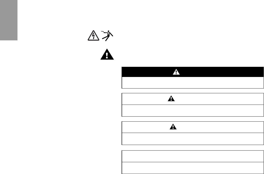
The addition of either symbol to a “Danger” or “Warning” safety label
indicates that an electrical hazard exists which will result in personal injury if
the instructions are not followed.
This is the safety alert symbol. It is used to alert you to potential personal
injury hazards. Obey all safety messages that follow this symbol to avoid
possible injury or death.
NOTE: Provides additional information to clarify or simplify a procedure.
Please Note Electrical equipment should be installed, operated, serviced, and maintained
only by qualified personnel. No responsibility is assumed by Schneider
Electric for any consequences arising out of the use of this material.
DANGER
DANGER indicates an imminently hazardous situation which, if not
avoided, will result in death or serious injury.
WARNING
WARNING indicates a potentially hazardous situation which, if not
avoided, can result in death or serious injury.
CAUTION
CAUTION indicates a potentially hazardous situation which, if not
avoided, can result in minor or moderate injury.
CAUTION
CAUTION, used without the safety alert symbol, indicates a potentially
hazardous situation which, if not avoided, can result in property damage.
ENGLISH
37 of 292

80043-055-10 Power-Style™ QED-2 Switchboards
12/2011 Table of Contents
© 1988–2011 Schneider Electric All Rights Reserved 3
ENGLISH
Table of Contents Section 1—Introduction ...............................................................................5
Inspection and Packaging .....................................................................5
Document Replacement ........................................................................5
Section 2—Safety Precautions ................................................................... 6
Section 3—Receiving, Handling, and Storing .............................................7
Receiving ...............................................................................................7
Handling ................................................................................................7
Handling with Lifting Straps ............................................................. 7
Handling without Lifting Straps ........................................................ 9
Storing .................................................................................................10
Section 4—Installation .............................................................................. 12
Location ...............................................................................................12
Foundation Preparation .......................................................................12
Switchboard Preparation ..................................................................... 12
General Installation .............................................................................13
Joining Shipping Sections—Outdoor Switchboards ............................ 13
Joining Shipping Sections—Indoor Switchboards ...............................14
Anchoring for Seismic Qualifications ...................................................15
Responsibility for Mitigation of Seismic Damage........................... 15
Maintaining Seismic Certification................................................... 15
Anchoring QED-2 Equipment for Seismic Applications ................. 15
Base Anchoring ............................................................................. 16
Top Anchoring/Restraint................................................................ 18
Anchoring the Switchboard .................................................................20
Through Bus Splice Connections ........................................................ 20
Ground Bus Splice Connections .........................................................21
Grounding and Bonding ......................................................................22
Service Equipment—Grounded System........................................ 22
Service Equipment—Ungrounded System .................................... 23
Not Service Equipment.................................................................. 23
High-Impedance Grounded Neutral Systems................................ 23
Busway Connections ...........................................................................24
Busway Connection—NEMA Type 1 (Indoor) Only (Qwik Flange™) 24
Busway Connections—NEMA Type 1 (Non-Qwik Flange) and
NEMA Type 3R.............................................................................. 25
Conduit Area .......................................................................................26
Cable Pulling .......................................................................................26
Cable Terminations .............................................................................27
Section 5—Pre-energizing Checkout Procedure ...................................... 28
Ground Fault Protection Systems .......................................................30
Section 6—Energizing the Switchboard ....................................................30
Section 7—Maintaining the Switchboard .................................................. 31
General Inspection and Cleaning ........................................................ 31
Bus Bar Joints, Lug Terminations, and Insulating Materials ................32
General Lubrication Information .......................................................... 32
Automatic Transfer Switches ............................................................... 32
Bolt-Loc Bolted Pressure Contact Switch Maintenance (800–4,000 A) ... 32
Circuit Breakers ...................................................................................34
QMB/QMJ/QMQB1 Fusible Switches ..................................................35
Switch Maintenance....................................................................... 35
Fuse Replacement (Fusible Switches Only).................................. 35
Installing QMB/QMJ/QMQB1 Fusible Switches............................. 36
Removing QMB/QMJ/QMQB1 Fusible Switches........................... 36
Ground-Fault Protection Systems .......................................................36
Section 8—Adverse Circumstances ..........................................................37
Inspection Following a Short Circuit .................................................... 37
Clean-up Following a Short Circuit ......................................................37
38 of 292

Power-Style™ QED-2 Switchboards 80043-055-10
Table of Contents 12/2011
© 1988–2011 Schneider Electric All Rights Reserved4
ENGLISH
Water-Soaked Switchboards ...............................................................37
Water-Sprayed or Splashed Switchboards (Clean Water Only) ..........38
Inspection and Clean-up of Clean Water Sprayed or Splashed
Switchboards ................................................................................. 38
Section 9—Torque Values for Electrical Connections ...............................39
Section 10—Switchboard Insulation Resistance Chart .............................41
Section 11—Reference Publications .........................................................42
Section 12—Installation and Maintenance Log .........................................43
List of Figures Figure 1: Lifting with an Overhead Crane, Lifting Straps, and Cables or
Chains ....................................................................................7
Figure 2: Warning Label, Rainproof Switchboards ................................8
Figure 3: Handling Instruction Label, Switchboards without Lifting Straps 9
Figure 4: Forklift Safety Label .............................................................11
Figure 5: Joining Adjacent Sections—Outdoor Switchboards .............13
Figure 6: Indoor Switchboards ............................................................14
Figure 7: Belleville Washer .................................................................15
Figure 8: Base Channel Floor Anchor Bolt Locations .........................17
Figure 9: Base Channel Mounting Hardware ......................................18
Figure 10: Top Anchor Hard-Point Locations ........................................19
Figure 11: Top Anchor Mounting Hardware ..........................................19
Figure 12: Switchboard Base Channels ................................................20
Figure 13: Proper Orientation of U-shaped Splice Connector ...............21
Figure 14: Ground Bus Splice Connection ............................................21
Figure 15: Series 2 Ground Bus Splice Connection .............................21
Figure 16: Grounding Electrode Connector ..........................................22
Figure 17: Main Bonding Jumper ..........................................................22
Figure 18: Series 2 Main Bonding Jumper ............................................23
Figure 19: Qwik Flange Installation .......................................................24
Figure 20: Qwik Flange .........................................................................24
Figure 21: Removing the Busway Dummy Flanged End ......................25
Figure 22: Flanged-End Connections ...................................................25
Figure 23: Reinstalling the 1/2-In. (13 mm) Hardware ..........................26
Figure 24: Instantaneous Trip Setting ...................................................28
Figure 25: Type BP Bolt-Loc Fusible Switch .........................................33
Figure 26: PowerPact™ R-Frame Circuit Breaker ................................34
List of Tables Table 1: Enclosure X,Y,Z Dimensions in Inches (mm) ...................... 16
Table 2: I-Line™ Blank Fillers and Extensions .................................. 34
Table 3: QMB/QMJ Fusible Switch Blank Fillers ............................... 36
Table 4: QMQB1 Fusible Switch Blank Fillers ................................... 36
Table 5: Incoming, Branch, and Neutral Lug ..................................... 39
Table 6: Multiple Conductor Neutral and/or Ground Bar.................... 39
39 of 292

80043-055-10 Power-Style™ QED-2 Switchboards
12/2011 Section 1—Introduction
© 1988–2011 Schneider Electric All Rights Reserved 5
ENGLISH
Section 1—Introduction This manual contains instructions for the proper installation, operation, and
maintenance of Power-Style™ QED-2 switchboard equipment
manufactured by Schneider Electric. Engineering, installation, and operating
staff supervisors should familiarize themselves with this manual and
become acquainted with the appearance and characteristics of each piece
of equipment mounted or contained in the switchboard.
These instructions and procedures apply to Power-Style QED-2 switchboard
installations by Schneider Electric. When special features or non-standard
components are incorporated in the switchboard, detailed instructions for
these components are included in the instruction material holder.
NOTE: There are references to Series 2 switchboards in several places in
this instruction bulletin. To determine if the QED-2 switchboard is a Series 2
model, check the rating nameplate located on the front cover. If the
switchboard is a Series 2 model, the nameplate indicates that. If it is not a
Series 2 model, there is not a Series designation.
Inspection and Packaging Every Power-Style QED-2 switchboard is carefully inspected and packaged
at the assembly plant. Construction of the switchboard is checked, both
structurally and electrically, for compliance with all specifications, codes,
and standards. After a complete inspection, the switchboard is prepared for
shipment. Each section is shipped separately for easier handling before
installation. The factory order number, an identification number, and the
shipping weights are plainly marked on each shipping section.
Document Replacement Contact your local Schneider Electric representative to replace lost or
damaged wiring diagrams and instruction sheets. Use the factory order
number as a reference.
40 of 292

ENGLISH
Power-Style™ QED-2 Switchboards 80043-055-10
Section 2—Safety Precautions 12/2011
© 1988–2011 Schneider Electric All Rights Reserved6
Section 2—Safety Precautions DANGER
HAZARD OF ELECTRIC SHOCK, EXPLOSION, OR ARC FLASH
• Apply appropriate personal protective equipment (PPE) and follow safe
electrical work practices. See NFPA 70E.
• This equipment must be installed and serviced only by qualified personnel.
• Perform such work only after reading and understanding all of the
instructions contained in this bulletin.
• Turn off all power supplying this equipment before working on or
inside equipment.
• Before performing visual inspections, tests, or maintenance on this
equipment, disconnect all sources of electric power. Assume all circuits
are live until they are de-energized, tested, and tagged. Pay particular
attention to the design of the power system. Consider all sources of
power, including the possibility of backfeeding.
• Always use a properly rated voltage sensing device to confirm power is off.
• Practice lock-out/tag-out procedures according to OSHA requirements.
• Handle this equipment carefully and install, operate, and maintain it
correctly in order for it to function properly. Neglecting fundamental
installation and maintenance requirements may lead to personal injury,
as well as damage to equipment or other property.
• Carefully inspect your work area and remove any tools and objects left
inside the equipment.
• Replace all devices, doors, and covers before turning on power to
this equipment.
• All instructions in this manual assume that the customer has taken
these measures before performing maintenance or testing.
Failure to follow these instructions will result in death or serious
injury
41 of 292
80043-055-10 Power-Style™ QED-2 Switchboards
12/2011 Section 3—Receiving, Handling, and Storing
© 1988–2011 Schneider Electric All Rights Reserved 7
ENGLISH
Section 3—Receiving, Handling,
and Storing
Receiving Upon receipt, check the packing list against the equipment received to
ensure the order and shipment are complete. Also upon receipt,
immediately inspect switchboard sections for any damage that occurred in
transit. If damage is found or suspected, file a claim with the carrier
immediately and notify the nearest Schneider Electric representative.
Handling
Ensure that proper equipment, such as an overhead crane, is available at
the installation site to handle the switchboard. This equipment helps avoid
injury to personnel and damage to the switchboard.
The shipping weight of each shipping section is marked on the packing list.
Verify the lifting capacity of the equipment being used to handle the
switchboard in accordance with the shipping weight of each shipping
section. Keep the switchboard upright during handling.
Schneider Electric recommends using an overhead crane, lifting straps, and
cables or chains to handle the switchboard. This method and alternative
handling methods are discussed in this section.
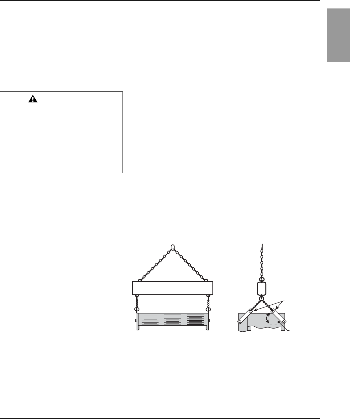
Handling with Lifting Straps Schneider Electric provides lifting straps as standard equipment for
NEMA Type 1 switchboard shipping sections rated 3,000 A or less.
Instruction labels on each shipping section include drawings and written
instructions outlining the proper use of the lifting straps (Figure 1). Use rigid
spreaders or a spanner bar to provide vertical lift on the lifting straps. This
helps avoid damage to the frame or finish.
Follow these instructions to handle the switchboard:
1. Use load-rated cables or chains with safety hooks or shackles. Do not
pass cables or chains through holes in lifting straps.
2. Use a load-rated spreader beam to prevent structure damage. Rig so
that the minimum angle between the lifting cables or chains and
equipment top is 45 degrees.
WARNING
SPECIAL HANDLING REQUIREMENTS
• Do not lay the equipment on its front or sides.
• Lay equipment only on its back when special
handling is required.
• Do not ship the equipment lying down.
Failure to follow these instructions can result
in serious injury or equipment damage.
Figure 1: Lifting with an Overhead Crane, Lifting Straps, and
Cables or Chains
Spreader beam
Front View Side View
Lifting straps
45°Min. angle
42 of 292
ENGLISH
Power-Style™ QED-2 Switchboards 80043-055-10
Section 3—Receiving, Handling, and Storing 12/2011
© 1988–2011 Schneider Electric All Rights Reserved8
Follow these instructions for laying equipment on its back:
1. Remove shipping skid and equipment back covers.
2. Use overhead cranes, lifting straps, and cables or chains for laying
equipment on its back.
3. Rate of drop or pickup for laying equipment on its back is four feet per
minute or less.
4. Reverse the procedure to stand the equipment in its upright position.
5. Reinstall back covers.
The warning label (Figure 2) is attached to both the front and rear of
the switchboard.
Figure 2: Warning Label, Rainproof Switchboards
43 of 292
80043-055-10 Power-Style™ QED-2 Switchboards
12/2011 Section 3—Receiving, Handling, and Storing
© 1988–2011 Schneider Electric All Rights Reserved 9
ENGLISH
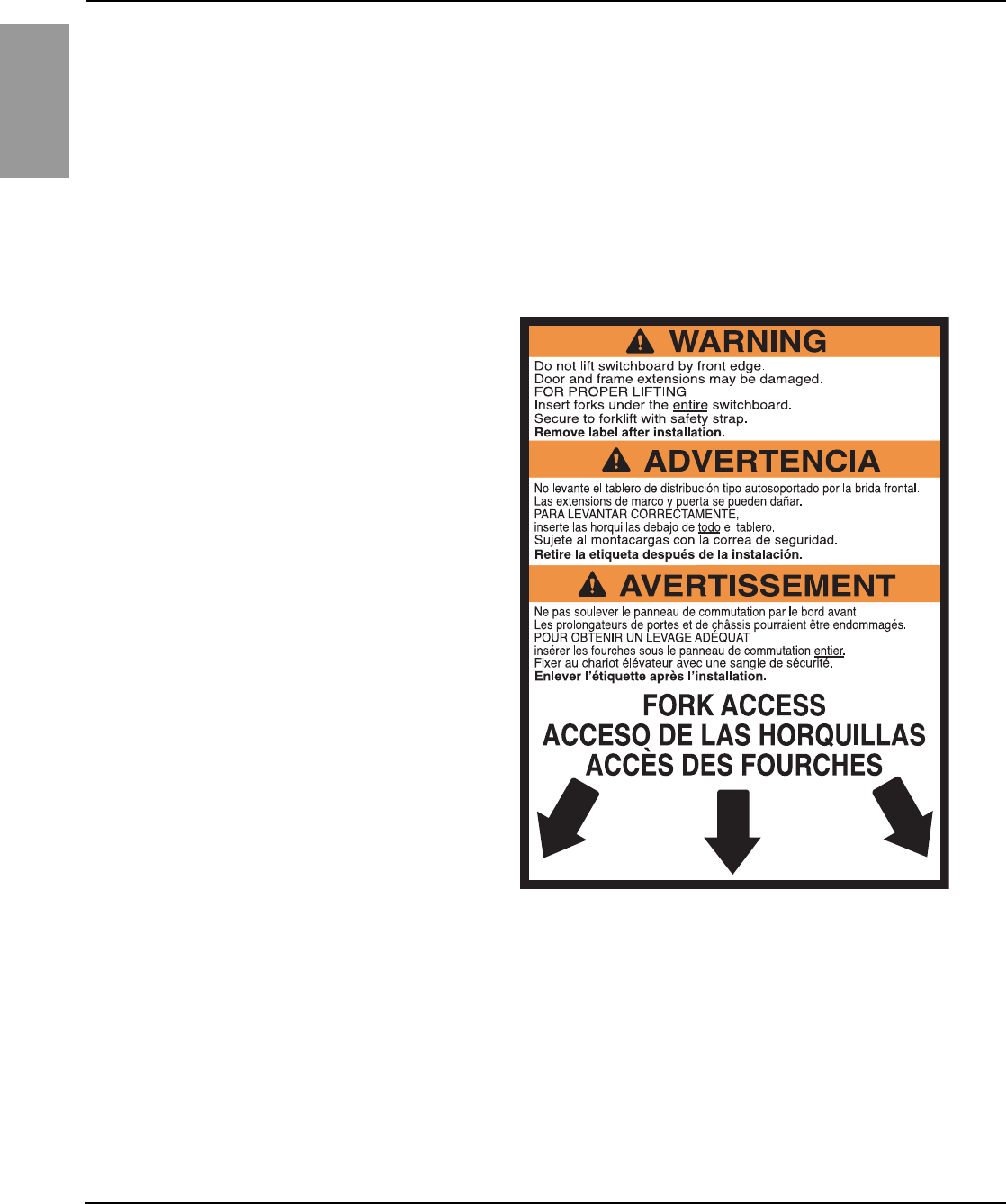
Handling without Lifting Straps Lifting straps are not furnished on shipping sections rated more than
3,000 A, or on rainproof switchboards. Use rollers, slings, or other means to
handle the shipping sections. The handling label (Figure 3) is affixed to each
of these sections.
Figure 3: Handling Instruction Label, Switchboards without
Lifting Straps
44 of 292

ENGLISH
Power-Style™ QED-2 Switchboards 80043-055-10
Section 3—Receiving, Handling, and Storing 12/2011
© 1988–2011 Schneider Electric All Rights Reserved10
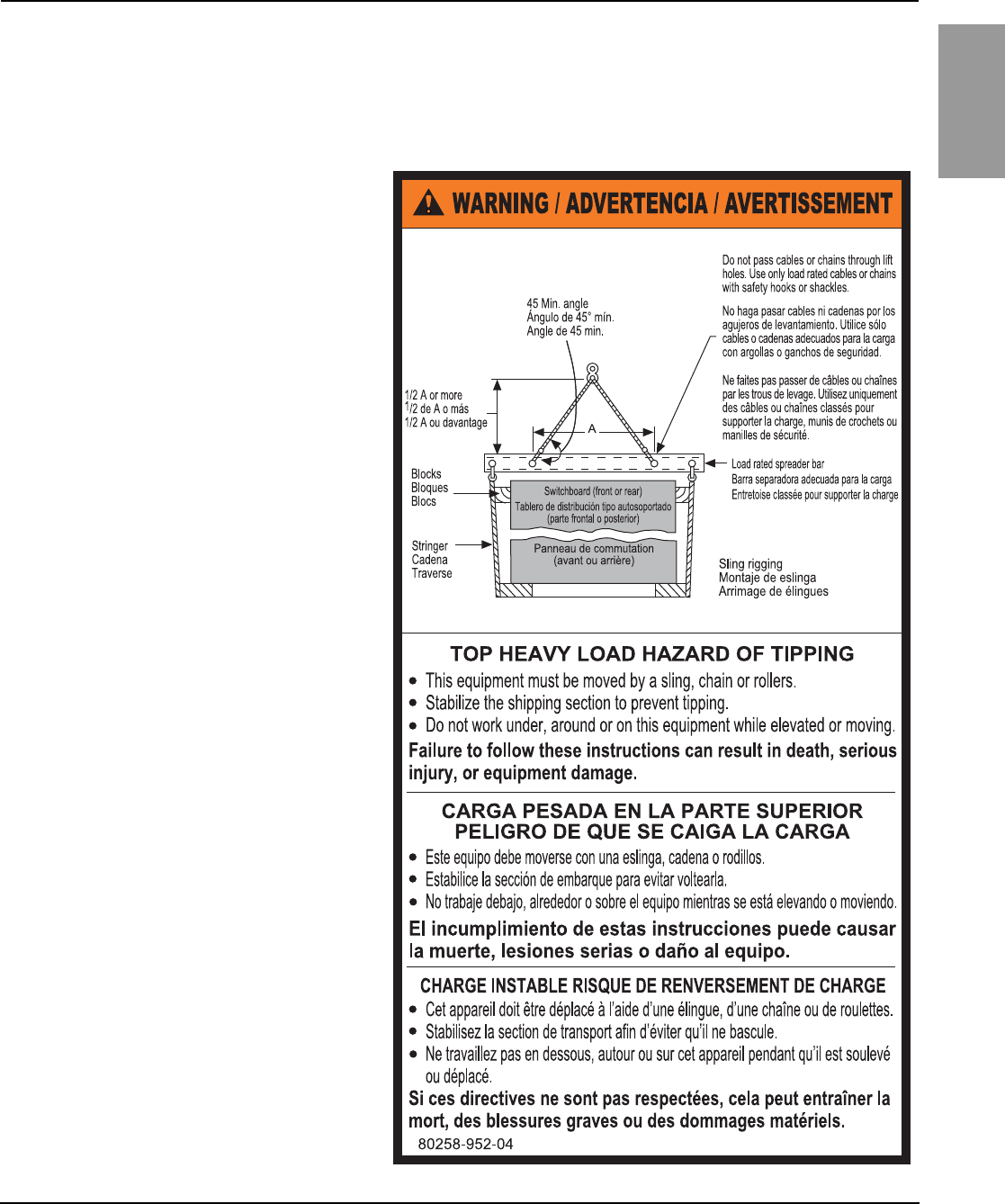
When elevating a shipping section not equipped with lifting straps, use an
overhead crane equipped with either of the following:
•A chain coupled to a sling rigging
•A wire cable with safety hooks and shackles
Wrap the sling completely around the switchboard and shipping stringers.
NOTE: A forklift is an alternative method of handling the switchboard.
Always check the fork lengths to ensure that the forks extend under
the entire switchboard. Carefully balance the load, and always use a
safety strap when handling or moving a switchboard with a forklift
(Figure 4 on page 11).
Storing When storing the switchboard before installation, cover the top and
openings of the equipment during the construction period to protect the
switchboard from dust and debris.
If a switchboard is not installed and energized immediately, store it in a
clean, dry space with a consistent temperature to prevent condensation.
Store the switchboard indoors, if possible. Preferably, store it in a heated
building with adequate air circulation and protect it from dirt, fumes, water,
and physical damage. Storing the switchboard outdoors can cause harmful
condensation inside the switchboard.
NOTE: Install portable electric heaters of approximately 250 watts per
vertical section in both indoor-type and rainproof-type switchboard
enclosures for adequate protection during storage.
Before energizing the space heaters, remove all loose packing or flammable
materials inside the switchboard. Outdoor switchboards are not
weather-resistant until completely and properly installed; treat them the
same as indoor switchboards until after installation.
WARNING
TOP HEAVY LOAD—HAZARD OF TIPPING
Stabilize the shipping section to reduce the
possibility of tipping.
Failure to follow these instructions can
result in death or serious injury.
45 of 292

80043-055-10 Power-Style™ QED-2 Switchboards
12/2011 Section 3—Receiving, Handling, and Storing
© 1988–2011 Schneider Electric All Rights Reserved 11
ENGLISH
Figure 4: Forklift Safety Label
46 of 292

ENGLISH
Power-Style™ QED-2 Switchboards 80043-055-10
Section 4—Installation 12/2011
© 1988–2011 Schneider Electric All Rights Reserved12
Section 4—Installation Correct installation of Power-Style QED-2 switchboards is essential for proper
operation of all switchboard components. Study the associated instruction books
and all drawings carefully. In most cases, all drawings are sent to the purchaser
before a switchboard is shipped to enable adequate planning.
NOTE: While installing switchboards, do not use the top of the switchboard
as a support for the weight of the installer.
Location Find the designated area on the building floor plan where the switchboard will be
installed. The location chosen for installation should provide working clearances
complying with Section 110-26 of the National Electrical Code® (NEC®) or
Section 2-308 of the Canadian Electrical Code (CEC) Part 1. Front-accessible
switchboards require field connections, including mains, branches, ground bus,
and neutral bus, to be accessible and maintainable from the front. For
switchboards having rear ventilation, allow a minimum 1/2-inch (13 mm)
clearance between the rear of the switchboard and the wall for proper ventilation.
Equipment drawings identify switchboards requiring rear or side access.
If in a wet location or outside of the building, enclose the switchboard in an
outdoor enclosure or equipment to prevent moisture or water from entering
and accumulating within the enclosure. Outdoor switchboards drain to the
rear, so there must be at least 1/2-inch (13 mm) clearance between the rear
of the switchboard and a wall or other obstruction for proper drainage.
Foundation Preparation The floor or foundation must be strong enough to support the weight of the
switchboard without sagging. The surrounding floor area should gently
slope toward a drain.
NOTE: For seismic qualifications, read the section “Anchoring for Seismic
Qualifications” on page 15 before pouring the floor or foundation.
Power-Style QED-2 switchboards are assembled on true and level floors at
the assembly plant. To ensure correct bus bar alignment, the mounting pad or
final installation site must be smooth and level. If parallel steel floor channels
are imbedded for mounting the switchboard, take extra care to ensure the
floor channels are level over their entire length to avoid distortion of the
switchboard structure. Each channel should be level with the finished floor.
When pouring the foundation, make provisions for conduits entering the
switchboard from below and carrying the incoming and/or outgoing cables,
control wiring, and ground cable. The bottom view in the equipment drawing
shows the available conduit area for correct layout.
Conduits should project above the finished floor by about 2 in. (51 mm).
However, to simplify moving the shipping sections into place, install the conduits
flush with the concrete and, after the sections are in their final position, add the
appropriate extension sleeves. Otherwise, raising the shipping section on
timbers or lifting it by a crane to clear the conduit hubs will be necessary. Before
pouring the foundation, consider installing additional conduits for future circuits.
Switchboard Preparation Remove dirt and debris from the foundation and surrounding area before
moving the switchboard into final position.
After the switchboard has been moved to its final installation site, take each
shipping section off its shipping stringers. For switchboards greater than
24 in. (610 mm) deep, the center base channel can be removed.
Remove all packing materials. If the switchboard is equipped with a bottom
closure plate in each vertical section, remove and retain the plates for reuse.
When bottom closure plates are furnished, the customer must make any
holes necessary for conduit entering the bottom of the switchboard. After
making the holes, reinstall the closure plate.
47 of 292

80043-055-10 Power-Style™ QED-2 Switchboards
12/2011 Section 4—Installation
© 1988–2011 Schneider Electric All Rights Reserved 13
ENGLISH
General Installation
Install the switchboard into its final position by leveling progressively each
section and bolting the frames together, if separated. Position shipping
sections as follows:
1. Maneuver each shipping section into the desired position using the
procedures under “Handling” on page 7.
2. Carefully lower the section over the conduit stubs to comply with the
“available conduit area” as shown in the bottom view of the equipment
drawings. Otherwise, there might not be sufficient cable bending space.
3. Level the shipping section.
4. After installation of each section is complete, make the through bus splice
connection to the preceding section before installing the next section.
Joining Shipping Sections—Outdoor
Switchboards 1. Remove the center top cap (Figure 5) from the left-hand section, and
retain all hardware for reuse.
CAUTION
HAZARD OF EQUIPMENT DAMAGE
Level and align adjacent shipping sections with
one another. Ensure proper alignment of
horizontal main through bus and proper splice
bus connections.
Failure to follow this instruction can result
in equipment damage.
Figure 5: Joining Adjacent Sections—Outdoor Switchboards
Center top cap
See Detail A
Knockouts
(typically 6 places)
See Detail B
Left-hand
section top
plate
Center
top cap
Right-hand
section top
plate
Typical:
1/4-20 x 1-1/4 in. slotted
pan head screw, 1/4 in.
flat washer, and 1/4-20
hex nut
Gasketing
Typical:
1/4-20 x 5/8 in. slotted
pan head screw,
1/4 in. flat washer, and
1/4-20 hex nut
3/8-16 x1 in.
cap screw
3/8 in. external tooth
lock washer
3/8-16 hex nut
3/8 in. helical
lock washer
Left-hand
section
Right-hand
section
Detail A Detail B
48 of 292
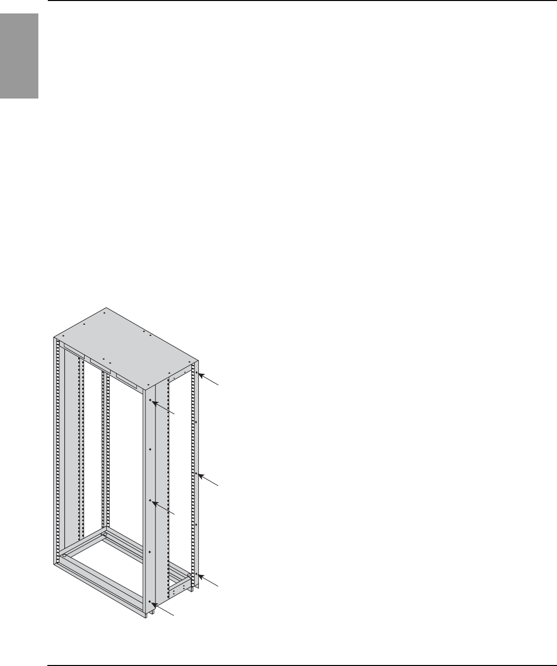
ENGLISH
Power-Style™ QED-2 Switchboards 80043-055-10
Section 4—Installation 12/2011
© 1988–2011 Schneider Electric All Rights Reserved14
2. When possible, open or remove the front and rear doors and panels,
providing access to bolt adjacent shipping sections together.
3. Remove three 0.5-in. (13 mm) diameter knockouts from the front vertical
corner channel and three from the rear vertical corner channel (a total of
six per frame side) as indicated by the arrows in Figure 5.
4. Position each adjacent section, carefully leveling it and aligning it with the
previous section. If lifting straps are provided, completely remove them
from the sides being bolted together so the sections can be joined flush.
NOTE: If lifting strap removal is not required to join sections, leave
the lifting strap on the switchboard. Verify that the bolt is tight to maintain
NEMA Type 3R integrity.
5. Six bolts (3/8-16 x 1 in.) are provided. Place them through the holes
created in step 3 to join adjacent sections.
6. Make the through bus splice connections to the preceding section.
7. Replace the center top cap removed in step 1.
8. Replace and secure the front and rear doors and panels removed in step 2.
Joining Shipping Sections—
Indoor Switchboards 1. Position each adjacent section, carefully leveling and aligning it with the
previous section. If lifting straps are provided, completely remove them
from the sides being bolted together so the sections can be joined flush.
NOTE: Leave the other lifting straps on the switchboard if their removal
is not required to join adjacent sections flush.
2. Open or remove the front and rear doors and panels, providing access
to bolt adjacent shipping sections together.
3. Six bolts (3/8-16 x 1 in.) are provided. Place the bolts through the existing
holes in the front and rear vertical corner channels to join adjacent
sections (Figure 6).
4. Make the through bus splice connections to the preceding section.
5. Replace and secure all front and rear doors and panels removed in step 2.
Figure 6: Indoor Switchboards
Arrows indicate holes
to use in step 3.
49 of 292
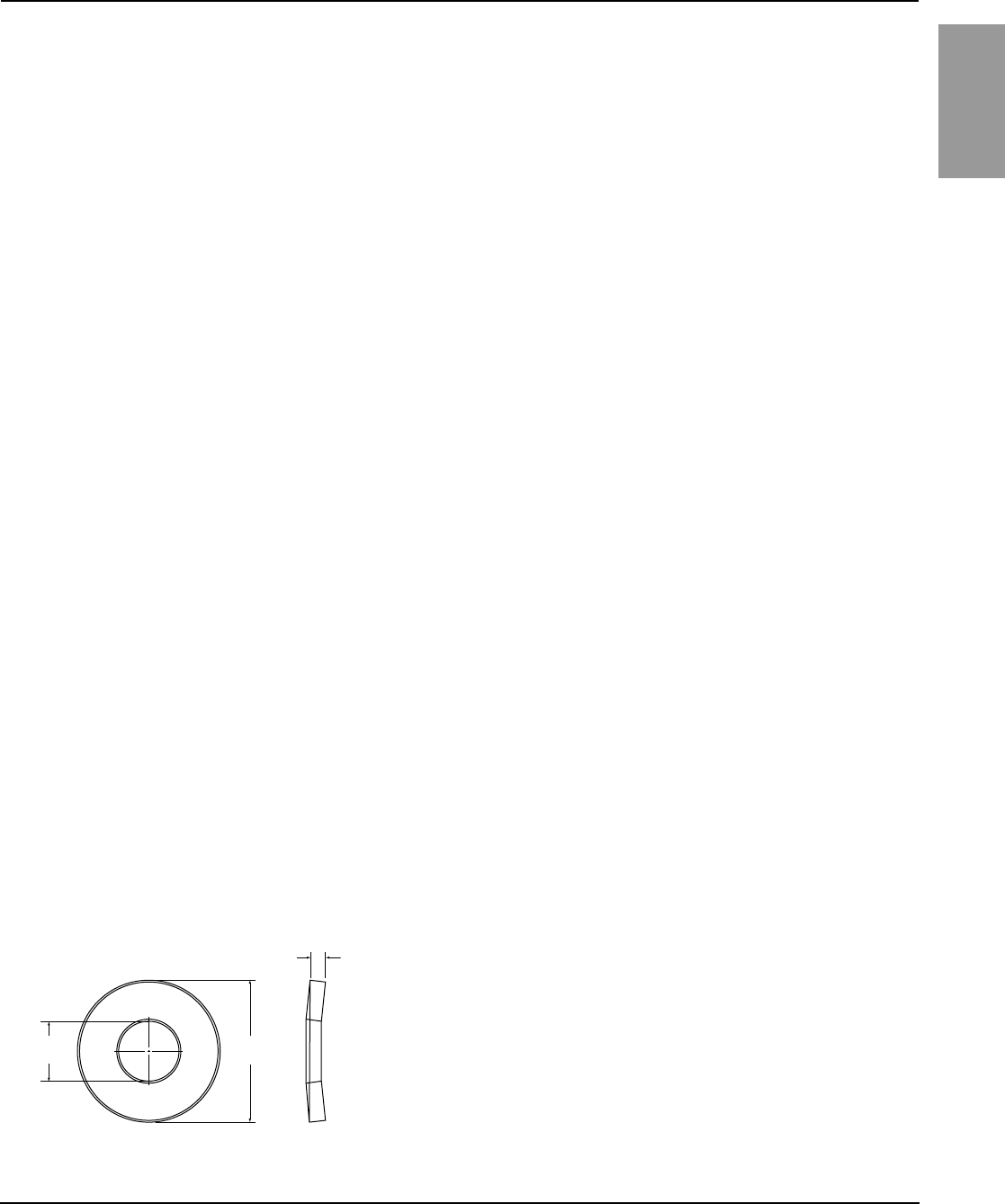
80043-055-10 Power-Style™ QED-2 Switchboards
12/2011 Section 4—Installation
© 1988–2011 Schneider Electric All Rights Reserved 15
ENGLISH
Anchoring for Seismic Qualifications QED-2 equipment that is seismically certified has been qualified to the
site-specific seismic requirements of the listed model building codes and/or
standards. Optional construction features may be required, depending on the
location of the installation and the particular code and/or standard of interest.
Seismic certificates of compliance are provided with all seismically certified
QED-2 equipment. To maintain the validity of this certification, the installation
instructions provided in this bulletin must be followed.
Responsibility for Mitigation of Seismic Damage For the purposes of the model building codes, QED-2 equipment are
considered nonstructural building components. Equipment capacity was
determined from triaxial seismic shake table test results as defined in the
International Code Counsel Evaluation Service (ICCES) Acceptance Criteria for
Seismic Qualification Testing of Nonstructural Components (AC156). Unless
otherwise indicated, an equipment importance factor of 1.5 (Ip = 1.5) was used,
indicating that equipment functionality was verified before and after shaker table
seismic simulation testing. This importance factor is indicative of critical facilities
where maximizing the probability of post event functionality is a priority. The
Building Seismic Safety Council (BSSC) recognizes AC 156 as an appropriate
methodology in the 2003 National Earthquake Hazard Reduction Program
(NEHRP) Commentary (FEMA 450 Part 2). The National Institute of Building
Sciences established the BSSC in 1979 to develop and promote regulatory
provisions for earthquake risk mitigation at the national level.
Incoming and outgoing cable and conduit must also be considered as
related but independent systems. They must be designed and restrained to
withstand the forces generated by the seismic event without increasing the
load transferred to the equipment. For applications where seismic hazard
exists, bottom entry and/or exit of cable and conduit is preferred. This
system must be able to transfer the loads created by a seismic event to the
load-bearing path of the building structural system.
Maintaining Seismic Certification Seismic qualification of nonstructural components by Schneider Electric is just
one link in the total chain of responsibility required to maximize the probability
that the equipment will be intact and functional after a seismic event. During a
seismic event, the equipment must be able to transfer the loads that are
created through the mounting pad and anchorage to the load-bearing path of
the building structural system. The structural civil engineer or design engineer
of record is responsible for detailing the equipment connection and anchorage
requirements for the given installation. The installer and manufacturers of the
anchorage restraint system are responsible for assuring that the mounting
requirements are met. Schneider Electric is not responsible for the
specification and performance of these systems.
Anchoring QED-2 Equipment for Seismic
Applications
Formed base channels run the width of the section. The channels and
connecting braces provide a minimum 0.75-in. (19 mm) diameter hole for
fastening the section to the floor. To anchor the QED-2 switchboard to the
floor properly, use all four mounting locations for NEMA Type 1 enclosures
less than 36 in. deep, all six mounting locations for 36–70 in. deep
enclosures, and six of the eight mounting locations for enclosures greater
than 70-in. deep (see Figure 8 on page 17).
Use 0.5 in. (13 mm) diameter anchor bolts (Grade 5 minimum, provided by
others) for the installation of equipment. Use one 1.25 in. (32 mm) outer
diameter Grade 5 Belleville washer (provided by others; see Figure 7) under
the head of each bolt or anchor nut. To develop the full strength of the anchor,
torque the hardware to the value specified by the anchor manufacturer, or as
recommended in the seismic restraint detailing supplied by the Structural Civil
Engineer of record for the project (see Figure 9 on page 18).
Figure 7: Belleville Washer
0.14 in.
(3.6 mm)
ø 0.545 in.
(14 mm)
ø 1.25 in.
(32 mm)
50 of 292
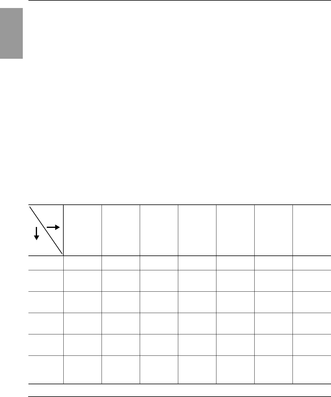
ENGLISH
Power-Style™ QED-2 Switchboards 80043-055-10
Section 4—Installation 12/2011
© 1988–2011 Schneider Electric All Rights Reserved16
Additionally, each NEMA Type 1 enclosed section includes four rear
top-located hard points for attaching two upper lateral braces (braces and
hardware supplied by others) to the QED-2 structure for top structural
restraint (see Figures 10 and 11 on page 19).
Top structural restraint is required for all QED-2 equipment installed:
•where the site-specific 0.2 second spectral ground motion exceeds
2.67 g (as determined from the code-referenced ground motion maps or
the site-specific seismic hazard engineering study), or
•when displacement at the top of the equipment cannot be tolerated, or
•for all QED-2 corner sections used for seismic applications.
To develop the full strength of the upper structural anchor, install and torque
the hardware as specified by the anchor manufacturer or the seismic restraint
detailing supplied by the Structural Civil Engineer of record for the project.
NOTE: Anchoring hardware is not furnished with the QED-2 equipment.
After the QED-2 switchboard and adjacent equipment are properly joined and
the entire structure is bolted to the floor, install the incoming service
conductors and load side cables. During an earthquake, the top of the QED-2
switchboard can move in any direction. Any top incoming cables must
accommodate this motion. Do not use the QED-2 enclosure (particularly the
top) to mount exterior equipment.
Base Anchoring 1. To anchor the switchboard to the floor properly, use all of the designated
0.75 in. (19 mm) diameter mounting hole locations as illustrated in Figure 8
on page 17. The enclosure dimensions corresponding to Figure 8 are listed
in Table 1.
Table 1: Enclosure X,Y,Z Dimensions in Inches (mm)
Enclosure
Width
12 in. 24 in. 30 in. 36 in. 42 in. 48 in. 54 in.
Enclosure
Depth
24 in. X = 6 (152)
Y = 21 (533)
X = 18 (457)
Y = 21 (533)
X = 24 (610)
Y = 21 (533)
X = 30 (762)
Y = 21 (533)
X = 36 (914)
Y = 21 (533)
X = 42 (1067)
Y = 21 (533)
X = 48 (1219)
Y = 21 (533)
36 in.
X = 6 (152)
Z = 16.5 (419)
Y = 33 (838)
X = 18 (457)
Z = 16.5 (419)
Y = 33 (838)
X = 24 (610)
Z = 16.5 (419)
Y = 33 (838)
X = 30 (762)
Z = 16.5 (419)
Y = 33 (838)
X = 36 (914)
Z = 16.5 (419)
Y = 33 (838)
X = 42 (1067)
Z = 16.5 (419)
Y = 33 (838)
X = 48 (1219)
Z = 16.5 (419)
Y = 33 (838)
48 in.
X = 6 (152)
Z = 22.5 (572)
Y = 45 (1143)
X = 18 (457)
Z = 22.5 (572)
Y = 45 (1143)
X = 24 (610)
Z = 22.5 (572)
Y = 45 (1143)
X = 30 (762)
Z = 22.5 (572)
Y = 45 (1143)
X = 36 (914)
Z = 22.5 (572)
Y = 45 (1143)
X = 42 (1067)
Z = 22.5 (572)
Y = 45 (1143)
X = 48 (1219)
Z = 22.5 (572)
Y = 45 (1143)
54 in.
X = 6 (152)
Z = 25.5 (648)
Y = 51 (1295)
X = 18 (457)
Z = 25.5 (648)
Y = 51 (1295)
X = 24 (610)
Z = 25.5 (648)
Y = 51 (1295)
X = 30 (762)
Z = 25.5 (648)
Y = 51 (1295)
X = 36 (914)
Z = 25.5 (648)
Y = 51 (1295)
X = 42 (1067)
Z = 25.5 (648)
Y = 51 (1295)
X = 48 (1219)
Z = 25.5 (648)
Y = 51 (1295)
60 in.
X = 6 (152)
Z = 28.5 (724)
Y = 57 (1448)
X = 18 (457)
Z = 28.5 (724)
Y = 57 (1448)
X = 24 (610)
Z = 28.5 (724)
Y = 57 (1448)
X = 30 (762)
Z = 28.5 (724)
Y = 57 (1448)
X = 36 (914)
Z = 28.5 (724)
Y = 57 (1448)
X = 42 (1067)
Z = 28.5 (724)
Y = 57 (1448)
X = 48 (1219)
Z = 28.5 (724)
Y = 57 (1448)
72 in.
X = 6 (152)
Z1 = 28.5
Z2 = 40.5 (1029)
Y = 69 (1753)
X = 18 (457)
Z1 = 28.5 (724)
Z2 = 40.5 (1029)
Y = 69 (1753)
X = 24 (610)
Z1 = 28.5 (724)
Z2 = 40.5 (1029)
Y = 69 (1753)
X = 30 (762)
Z1 = 28.5 (724)
Z2 = 40.5 (1029)
Y = 69 (1753)
X = 36 (914)
Z1 = 28.5 (724)
Z2 = 40.5 (1029)
Y = 69 (1753)
X = 42 (1067)
Z1 = 28.5 (724)
Z2 = 40.5 (1029)
Y = 69 (1753)
X = 48 (1219)
Z1 = 28.5 (724)
Z2 = 40.5 (1029)
Y = 69 (1753)
51 of 292
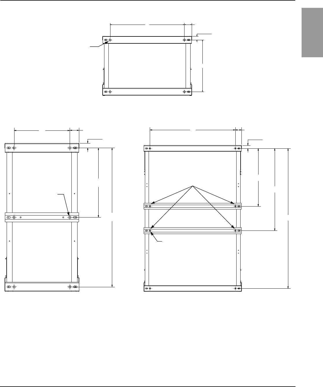
80043-055-10 Power-Style™ QED-2 Switchboards
12/2011 Section 4—Installation
© 1988–2011 Schneider Electric All Rights Reserved 17
ENGLISH
Figure 8: Base Channel Floor Anchor Bolt Locations
X
Y
X
Y
Z
X
Y
Z
Z
1
2
Bottom View of Enclosure
Front of Enclosure
0.75 in. (19 mm) diameter
mounting holes (four places)
Enclosures < 36 in. Deep
3.0 in. (76 mm)
(typical) 1.5 in. (38 mm)
(typical)
Front of Enclosure
Enclosures > 70 in. Deep
3.0 in. (76 mm)
(typical) 1.5 in. (38 mm)
(typical)
Front of Enclosure
0.75 in. (19 mm)
diameter mounting
holes (six places)
Enclosures 36–70 in. Deep
3.0 in. (76 mm)
(typical) 1.5 in. (38 mm)
(typical)
0.75 in. (19 mm) diameter
mounting holes (eight places)
For configurations with two interior
located base channels, select one of
the channels and equip with two
anchor bolts for seismic applications.
Bottom View of Enclosure
Bottom View of Enclosure
NOTE: See Table 1 on page 16
for X, Y, Z dimensional values.
52 of 292
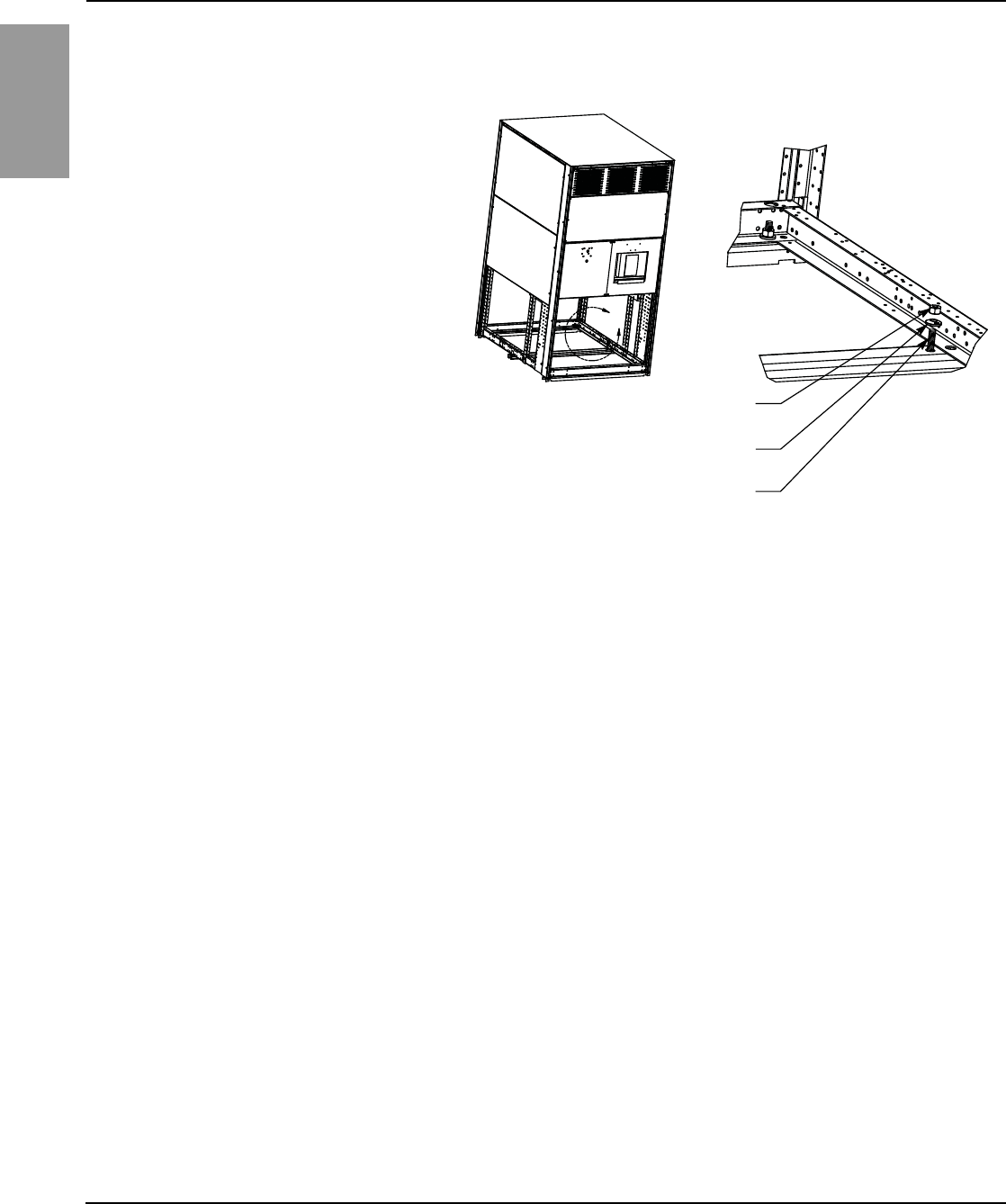
ENGLISH
Power-Style™ QED-2 Switchboards 80043-055-10
Section 4—Installation 12/2011
© 1988–2011 Schneider Electric All Rights Reserved18
2. Depending on the frame size (see Figure 8 on page 17), use either four or
six 1/2-13 Grade 5 bolts in the locations shown in Figure 9.
3. Once the switchboard is in place, secure the base channels to each bolt
using a 1.25 in. (32 mm) diameter Belleville washer between a 1/2-13
hardened nut and the switchboard frame as illustrated in Figure 9.
NOTE: The “TOP” side of the Belleville washer must be facing the nut.
4. Torque each nut to the value recommended by the anchor manufacturer
to develop the full strength of the anchor.
Top Anchoring/Restraint For installation at locations with an Ss greater than 2.67 g (as determined
from the current version of the International Building Code), or where
displacement cannot be tolerated at the top of the switchboard during a
seismic event, use top restraints attached to the equipment hard points.
NOTE: Anchoring hardware is not furnished with the switchboard.
1. The four 0.88-in. (22 mm) diameter mechanical knock-outs shown in
Figure 10 on page 19 serve as hard points for application of a top
restraint system.
NOTE: By code, it is the responsibility of the Building Design
Professional to determine the top restraint methodology for the intended
building application.
Figure 9: Base Channel Mounting Hardware
A
1/2-13 heavy-duty nut, torqued to value
recommended by anchor manufacturer
1.25 in. (32 mm) diameter Belleville washer
(TOP side facing nut)
1/2-13, grade 5 bolt;
2.25 in. (57 mm) in length or longer
Detail A
NOTE: Base channel mounting hardware
detail shown for reference purposes only.
Anchoring hardware is not furnished with the
switchboard. Covers and internal hardware
shown removed for illustration purposes.
53 of 292
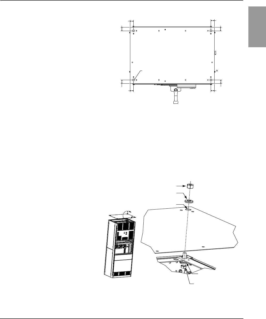
80043-055-10 Power-Style™ QED-2 Switchboards
12/2011 Section 4—Installation
© 1988–2011 Schneider Electric All Rights Reserved 19
ENGLISH
2. Detach the top plate from the main switchboard enclosure. Retain the
screws.
3. Remove the four 0.88 in. (22 mm) diameter mechanical knock-outs as
directed by the Building Design Professional.
4. With the knock-outs removed, reattach and resecure the top plate to the
enclosure using the screws removed in Step 2.
5. Attach the top restraint system using a 1/2-13, Grade 5 bolt,
a 1 in. (25 mm) diameter steel washer, a 1.25 in. (32 mm) diameter
Belleville washer, and a hardened 1/2-13 nut as shown in Figure 11.
6. After all switchboard sections are properly joined and the entire structure
is properly anchored, install the incoming service conductors and load
side cables.
Figure 10: Top Anchor Hard-Point Locations
Figure 11: Top Anchor Mounting Hardware
Top of Switchboard Enclosure
Front
0.88 in. (22 mm)
diameter mechanical
knock-out; four
places, as shown
1.5 in.
(38 mm)
1.5 in.
(38 mm)
1.5 in.
(38 mm)
1.5 in.
(38 mm)
1/2-13 hardened nut
1.25 in. (32 mm) diameter Belleville washer
(TOP side facing nut)
0.88 in. (22 mm) diameter knock-out
1/2-13, grade 5 bolt
1 in. (25 mm) diameter
steel washer
54 of 292
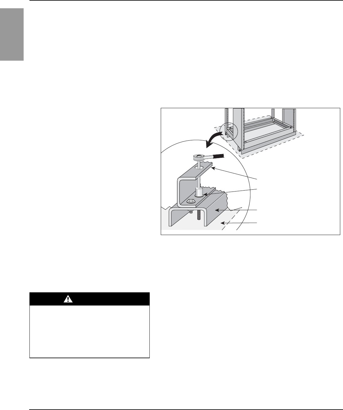
ENGLISH
Power-Style™ QED-2 Switchboards 80043-055-10
Section 4—Installation 12/2011
© 1988–2011 Schneider Electric All Rights Reserved20
7. Do not use the switchboard enclosure (particularly the top) to mount
exterior equipment, except for conduit.
Anchoring the Switchboard Although sections are freestanding, a hard bump or shifting movement can
result in damage to the splice joints between sections and conduit hubs
connected to the sections. Therefore, each vertical section must be
anchored to the floor.
Formed base channels run the width of the shipping section. The channels
have 1.12-in. (28 mm) diameter holes for fastening the section to the floor
(Figure 12). Anchor each section to the floor with 1/2-in. (Grade 2 minimum)
bolts with flat washers and anchors suitable for installation of electrical
equipment (not furnished).
After all switchboard sections are properly joined and the entire structure is
bolted to the floor, install the incoming service conductors and load side cables.
NOTE: If the switchboard consists of only one shipping section, proceed to
“Grounding and Bonding” on page 22.
Through Bus Splice Connections
Through bus splice connectors and/or hardware, along with installation
instructions, are provided with each shipping split. Follow the installation
instructions, and torque splice bolts to the value given in “Section 9—
Torque Values for Electrical Connections” on page 39.
If through bus bars are wrapped with an insulative material, cover the splice
connections with the material provided.
For splice connections with bus on the front and rear of an insulating tube,
ensure the U-shaped, copper connector is centered around the tube.
Figure 13 on page 21 shows the proper orientation of the connector.
NOTE: The U-shaped connector will fit snugly against the insulating tube
when installed correctly. It is pulled away from the insulating tube in
Figure 13 to show the orientation of the connector slot.
Figure 12: Switchboard Base Channels
Switchboard frame
Secure the switchboard to the
mounting surface using the
holes closest to the surface.
Formed base channel
Mounting surface
1.12 in. (28 mm)
Diameter hole in each corner
for anchoring
DANGER
HAZARD OF ELECTRIC SHOCK,
EXPLOSION, OR ARC FLASH
Do not install through bus splice connectors
with the switchboard energized.
Failure to follow this instruction will result
in death or serious injury.
55 of 292
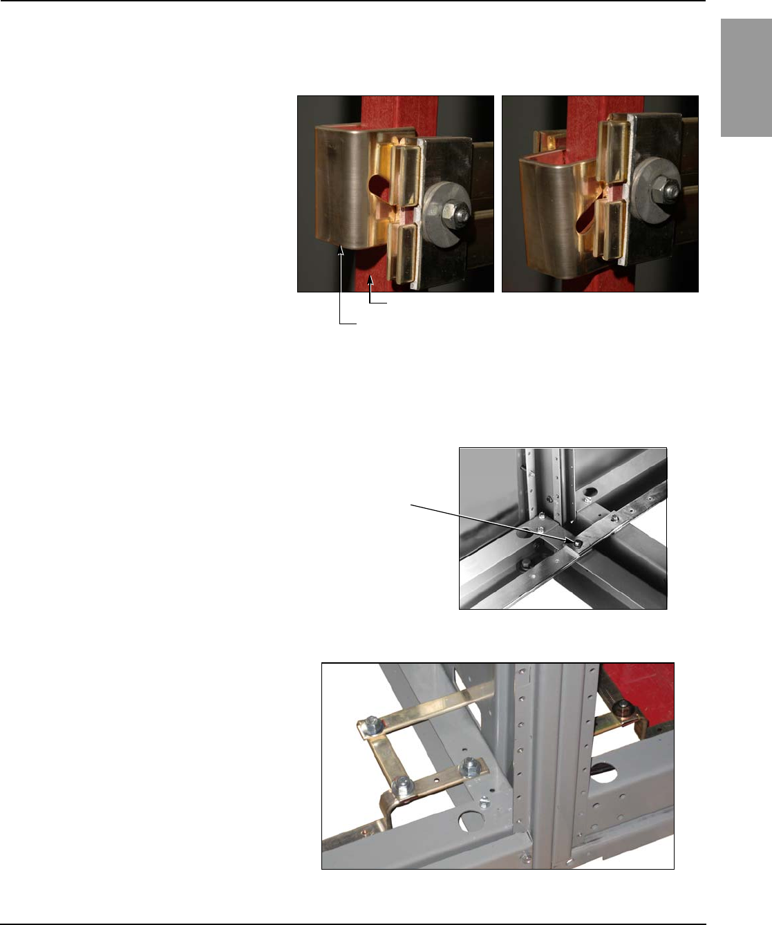
80043-055-10 Power-Style™ QED-2 Switchboards
12/2011 Section 4—Installation
© 1988–2011 Schneider Electric All Rights Reserved 21
ENGLISH
Ground Bus Splice Connections Align and secure the ground bus splice connection between shipping
sections. Torque connections to 100 lb-in (11 N•m) (Figure 14 or 15).
NOTE: Proper installation is essential for equipment ground-fault systems.
Figure 13: Proper Orientation of U-shaped Splice Connector
Correct
Slot in splice connector
points downward.
Incorrect
Slot in splice connector
points upward.
U-shaped splice connector
Insulating tube
Figure 14: Ground Bus Splice Connection
Figure 15: Series 2 Ground Bus Splice Connection
Ground bus splice
(1/4-20 thread-forming
hardware provided)
56 of 292
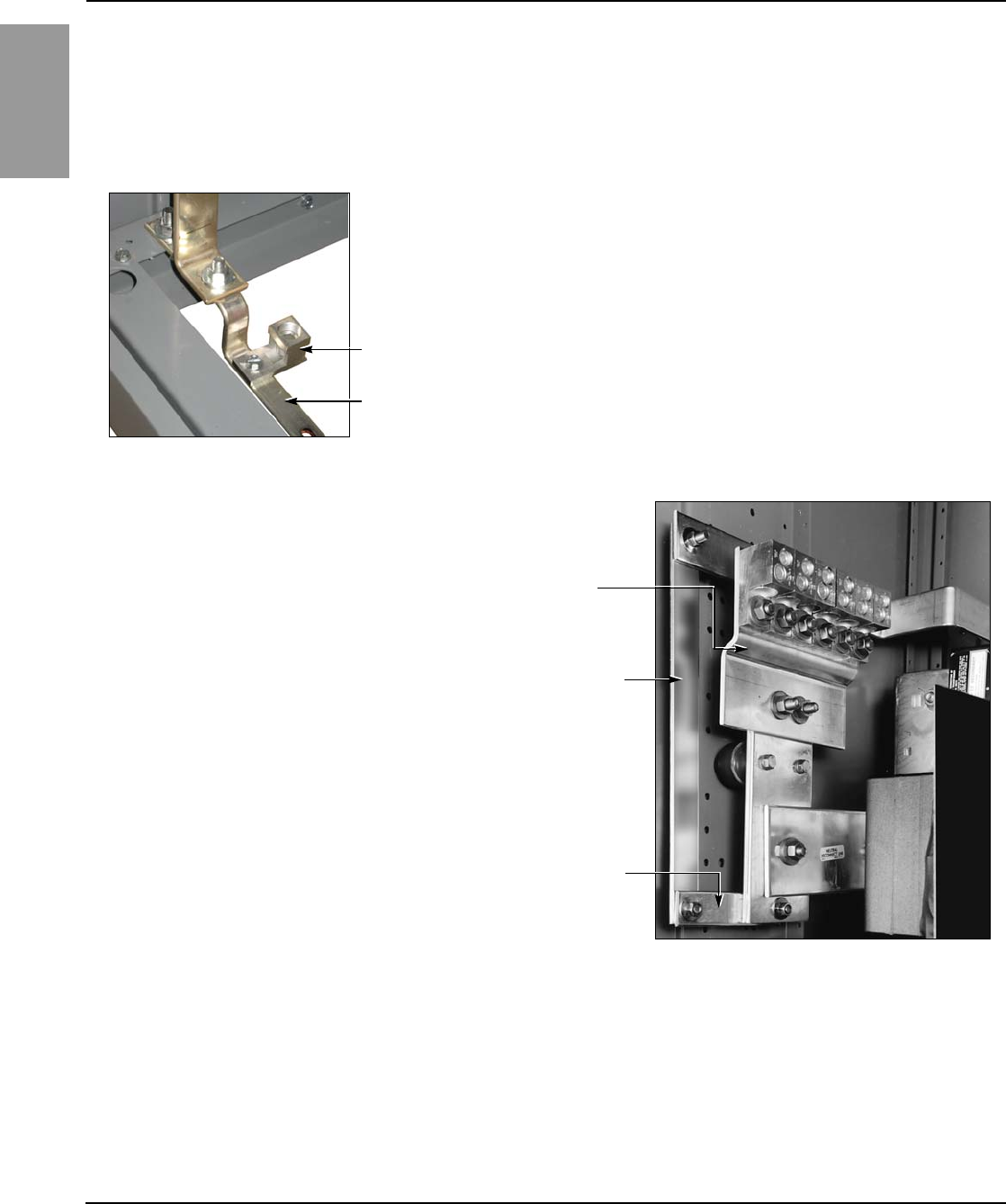
ENGLISH
Power-Style™ QED-2 Switchboards 80043-055-10
Section 4—Installation 12/2011
© 1988–2011 Schneider Electric All Rights Reserved22
Grounding and Bonding NOTE: A system is “grounded” if it is grounded at any point ahead of the
switchboard, whether the grounded conductor (neutral) is carried through to
the loads, or not.
Service Equipment—Grounded System For solidly grounded systems used as either service equipment or as a main
switchboard on a separately derived system:
1. Run a grounding electrode conductor from the grounding electrode at
the installation site to the grounding electrode conductor connector
(ground lug) located on the switchboard ground bus (or on the neutral
bus, if so indicated on the equipment drawing) (Figure 16). Select the
material and size of this grounding electrode conductor to comply with
Sections 250-62 and 250-66 of the NEC or Sections 10-204 and 10-206
of the 1998 CEC, and install it as specified in Section 250-64 of the NEC
or Section 10-908 of the 1998 CEC.
2. Install the main bonding jumper between the neutral bus and the
ground bus (Figure 17 or 18 on page 22). For torque values, refer to
“Section 9—Torque Values for Electrical Connections” on page 39.
NOTE: If the switchboard is fed from multiple sources (for example,
double-ended systems), there may be two or more main bonding
jumpers to install.
Figure 16: Grounding Electrode Connector
Grounding
electrode
conductor
connector
Ground bus
Figure 17: Main Bonding Jumper
Neutral lug pad
Main bonding jumper
Ground bus extension
57 of 292
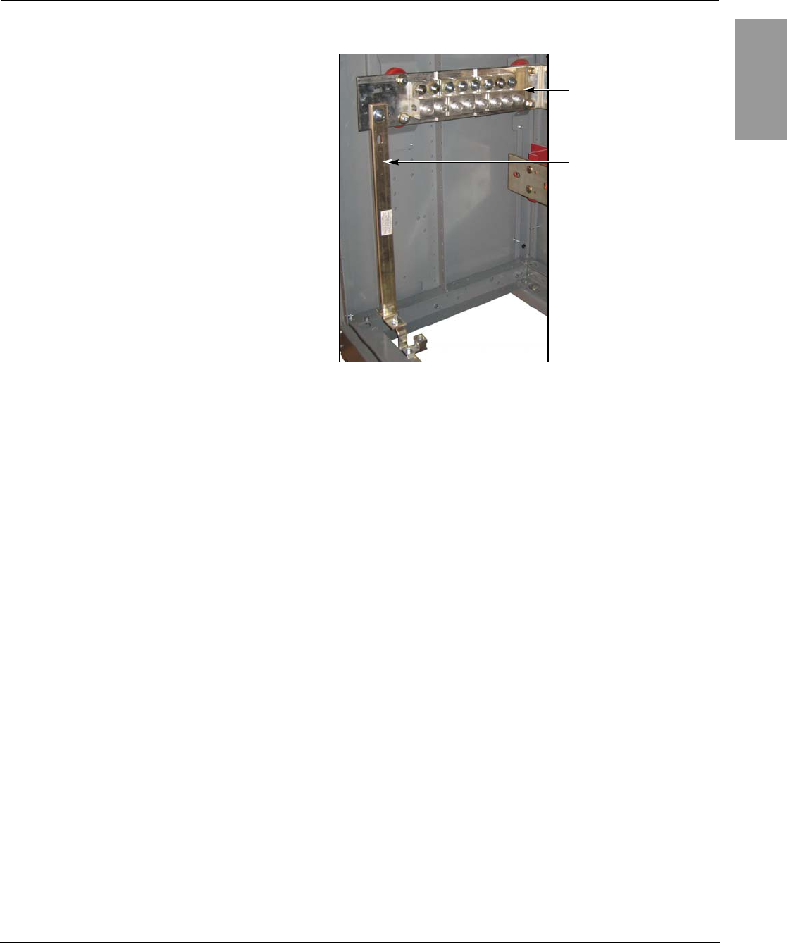
80043-055-10 Power-Style™ QED-2 Switchboards
12/2011 Section 4—Installation
© 1988–2011 Schneider Electric All Rights Reserved 23
ENGLISH
In Canada, a main bonding jumper bus or cable is provided between the
neutral bus and ground bus. When the bonding jumper must be
disconnected (for example, for a Megger® test), remove the main bonding
jumper bus or cable lug with cable from the neutral bus. This is normally
located near the line neutral lugs. Secure the main bonding jumper bus or
cable and lug to maintain the required distance from phases and neutral.
NOTE: If the switchboard is fed from multiple sources (for example, a
double-ended system like a main-tie-main), there may be two or more main
bonding jumpers installed.
Service Equipment—Ungrounded System For ungrounded systems used as either service equipment, or as a main
switchboard on a separately derived system:
1. Run a grounding electrode conductor from the grounding electrode at
the installation site to the grounding electrode conductor connector
(ground lug) located on the switchboard ground bus (Figure 16).
2. Select the material and size of this grounding electrode conductor to
comply with Sections 250-62 and 250-66 of the NEC or Sections 10-700
and 10-702 of the 1998 CEC, and install it as specified in Section 250-64
of the NEC or Section 10-204 of the 1998 CEC.
Not Service Equipment For either grounded or ungrounded systems, when a switchboard is not
used as service equipment nor as a main switchboard on a separately
derived system:
Use equipment grounding conductors sized according to Section 250-122
of the NEC or Section 10-206 of the 1998 CEC to connect the switchboard
frame and ground bus to the service ground.
High-Impedance Grounded Neutral Systems For high-impedance grounded neutral systems:
Ground the system following the instructions provided with the system
grounding equipment and in compliance with Section 250-36 of the NEC.
Confirm that the switchboard frame and ground bus are bonded in
accordance with Section 250-102 of the NEC.
Figure 18: Series 2 Main Bonding Jumper
Neutral lug pad
Main bonding jumper
58 of 292
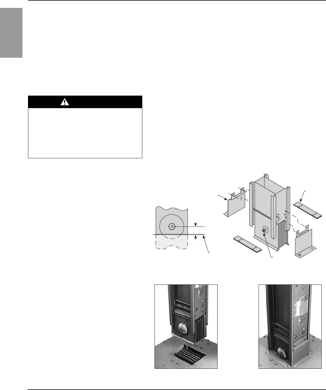
ENGLISH
Power-Style™ QED-2 Switchboards 80043-055-10
Section 4—Installation 12/2011
© 1988–2011 Schneider Electric All Rights Reserved24
Busway Connections Schneider Electric switchboards are manufactured with two different styles
of busway connections. Qwik Flange™ is used on indoor switchboards only.
The other type of busway connection is the “dummy” flanged end. This type
is used on some indoor switchboards, but primarily on outdoor units. The
dummy flanged end must be removed to allow actual busway flanged end
installation. Either the dummy or actual busway flanged end must be in
place before energizing the switchboard.
NOTE: Do not use the switchboard to support the weight of the busway
connection. Support busway independently.
Busway Connection—NEMA Type 1 (Indoor)
Only (Qwik Flange™)
Follow the instructions in this section to make Qwik Flange busway
connections (see Figures 19 and 20):
1. Remove any protective covering from the opening in the switchboard.
2. Slip the busway joint into the switchboard connectors.
3. Check the joint bolt alignment; the center line (C/L) of the joint bolt to the
switchboard surface should be 0.95 in. (24 mm) (Figure 19).
4. Attach the side closing plates using two 5/16-in. bolts (provided). When
installed properly, the holes in the side closing plates align with the holes
in both the switchboard and busway.
DANGER
HAZARD OF ELECTRIC SHOCK,
EXPLOSION, OR ARC FLASH
Turn off all power supplying the switchboard
and busway before installing connections.
Failure to follow this instruction will result
in death or serious injury
Figure 19: Qwik Flange Installation
Figure 20: Qwik Flange
Side closing plate
(2 required)
C/L of joint bolt
connection of busway
Surface Joint bolt
Small
closing
plate
0.95 in. (24 mm)
59 of 292

80043-055-10 Power-Style™ QED-2 Switchboards
12/2011 Section 4—Installation
© 1988–2011 Schneider Electric All Rights Reserved 25
ENGLISH
5. Use an 18-in. (457 mm) or longer wrench to torque the joint bolt until the
outer break-away head twists off. Do not allow the break-away bolt head
or red warning disc to drop into the switchboard.
6. Slip the remaining two small closing plates into position by aligning with
the holes in the switchboard. Use the four 1/4-20 screws provided to
secure the equipment.
7. Confirm proper phasing of the installed busway before energizing.
Busway Connections—NEMA Type 1
(Non-Qwik Flange) and NEMA Type 3R If this style of connection for busway is furnished, the busway “dummy” flanged
end must be removed before installing busway (Figure 21 on page 25).
1. From inside the switchboard, remove the 1/2-in. bolts that fasten the
switchboard bus to the busway dummy nonmetallic flanges. Retain all
hardware for reuse.
2. Remove all screws securing the busway dummy flanged end to the
switchboard enclosure.
3. Remove the busway dummy flanged end (Figure 21).
4. Install the actual busway flanged end to the switchboard bus connectors
provided in the switchboard (Figure 22). Insert the flanges between the
switchboard bus connectors so that the mounting holes in the collar of the
flanged end align with the pre-drilled holes in the switchboard enclosure.
DANGER
HAZARD OF ELECTRIC SHOCK,
EXPLOSION, OR ARC FLASH
Turn off all power supplying the switchboard
and busway before installing connections.
Failure to follow this instruction will result
in death or serious injury. Figure 21: Removing the Busway Dummy Flanged End
Figure 22: Flanged-End Connections
60 of 292
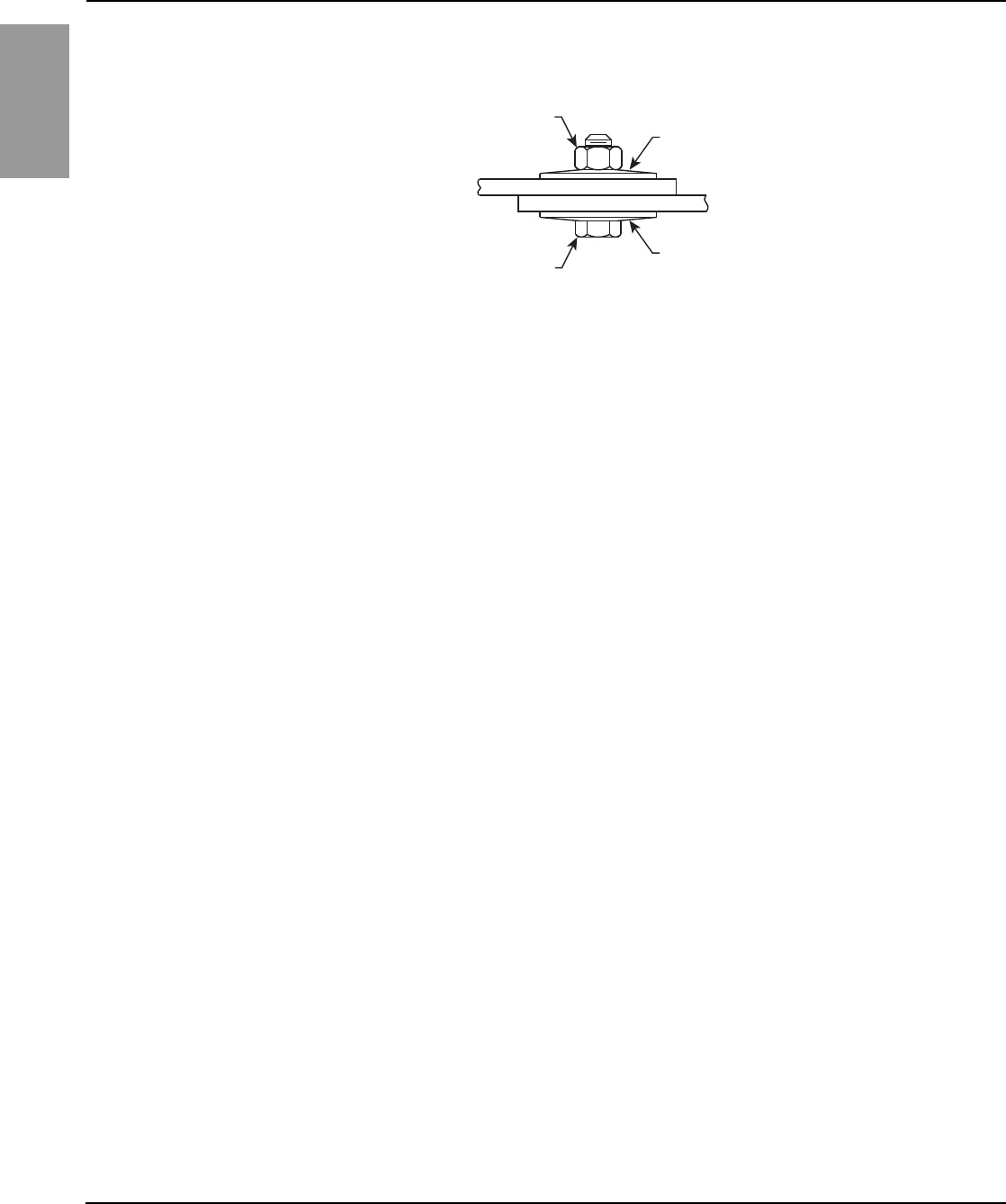
ENGLISH
Power-Style™ QED-2 Switchboards 80043-055-10
Section 4—Installation 12/2011
© 1988–2011 Schneider Electric All Rights Reserved26
5. Line up the holes in the bus bar flanges, and reinstall the 1/2-in. (13 mm)
hardware that was removed in step 1 on page 25 and as shown in Figure 23.
6. Torque the bolts inserted in step 5 as indicated in “Section 9—
Torque Values for Electrical Connections” on page 39.
7. Assemble the busway collar to the switchboard enclosure with the
screws provided.
8. Ensure that the busway integral ground is connected to the switchboard
ground bus.
9. Confirm busway phasing before energizing.
Conduit Area 1. Locate and terminate all conduit in the switchboard enclosure in the
“available conduit area” designated on the equipment drawing.
NOTE: On switchboards greater than 24 in. (610 mm) deep, the center
base channel can be removed for additional conduit area. Exception:
Do not remove any base channels when seismic restraint is required.
2. Install the conduit properly. Use hubs, locknuts, and bushings to protect
the cables and prevent condensation on the conduit from entering
the switchboard.
NOTE: If top entry, do not use the top of the switchboard to support the
weight of the conduit. Support the conduit independently.
If bottom closure plates are furnished, the customer must remove the
plates, make holes in them for any conduit entering the bottom of the
switchboard, and then reinstall the plates.
Under seismic conditions, consider using top restraints if movement of
the top of the switchboard is an issue.
3. Bond all conduit hubs to the switchboard enclosure with approved
electrical connections.
Cable Pulling Power-Style QED-2 switchboards are constructed to customer
specifications for the cable entrance arrangement (for example, top or
bottom feed). Switchboard components are arranged to give proper cable
clearance and bending space for cables entering or exiting the switchboard
as specified on the equipment drawing.
1. Use only cable sizes suitable for a proper fit with the corresponding lugs.
2. Pull the proper number of line side and load side cables according to the
load served and the NEC or CEC.
3. Position the cables inside the switchboard so that they are not subject to
physical damage.
4. Maintain the largest possible bending radii and proper clearance to bus
bars and grounded parts. If any cables are lying or bearing on structural
members, support them to relieve this condition or place suitable
protective material at the bearing point to protect the cable insulation.
Figure 23: Reinstalling the 1/2-In. (13 mm) Hardware
NOTE: The convex side (marked “Top”)
of one conical washer should be against
the bolt head, and the convex side of the
second conical washer should be
against the hex nut.
Washer—
marked “Top”
Washer—
marked “Top”
Hex nut
Bolt head
61 of 292

80043-055-10 Power-Style™ QED-2 Switchboards
12/2011 Section 4—Installation
© 1988–2011 Schneider Electric All Rights Reserved 27
ENGLISH
5. Be certain to run all phase conductors, including the neutral, through the
same opening where cables enter or leave the switchboard, or pass
through any metal that has magnetic properties. Otherwise, overheating
can result. See Section 300-20(a) of NEC.
6. When instructed, brace or cable-lace the conductors.
Cable Terminations 1. Use a proper insulation stripping tool to strip a length of insulation from
the end of the cable sufficient to fit into the full length of the lug barrel. Be
careful not to nick or ring the strands.
2. Thoroughly clean aluminum cable contact surfaces with a wire brush, or
scrub them with an abrasive cloth to remove oxides and foreign matter.
3. Immediately apply an acceptable joint compound to the bare
aluminum surfaces.
4. If compression-type lugs are furnished on any switch or circuit breaker,
or as the main incoming power lugs, unbolt and remove them to create
sufficient room for crimping the lugs to the cables with the crimping tool.
a. Insert the cable into the lug barrel and, using the crimping tool, make the
specified number of crimps per the recommendations of the manufacturer.
b. Wipe excess joint compound from the connector and insulation.
c. With the cables connected, remount the lugs onto the bus bars,
switches, or circuit breakers. Torque the bolts to the values given in
“Section 9—Torque Values for Electrical Connections” on page 39.
5. Set screw-type lugs may be furnished as main incoming lugs and are
standard on molded case circuit breakers and QMB/QMJ/QMQB1
fusible switches. Torque these lugs to, but do not exceed, the specified
values. Torque values for circuit breaker and switch lugs are marked on
these units. Torque values for other switchboard lugs are marked on the
switchboard (Table 6 on page 39).
1QMQB switches are available in Canada only.
62 of 292
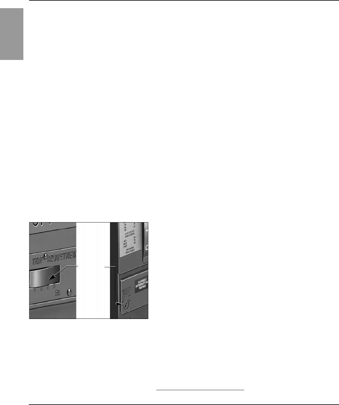
ENGLISH
Power-Style™ QED-2 Switchboards 80043-055-10
Section 5—Pre-energizing Checkout Procedure 12/2011
© 1988–2011 Schneider Electric All Rights Reserved28
Section 5—
Pre-energizing Checkout
Procedure
Conduct a complete inspection before the switchboard is energized to ensure
that all components function and operate properly. Complete every step of
the checkout procedure listed before energizing the switchboard.
1. Check all field-installed bus bar connections. Torque values are listed in
“Section 9—Torque Values for Electrical Connections” on page 39.
2. Check all accessible connections for tightness.
3. Check all factory- and field-installed lug terminations for tightness.
4. Check the rigidity of all bus bar supports.
5. Check the switchboard enclosure for dents or other damage that
reduces electrical clearances inside the switchboard.
6. Remove all foam blocks, or other temporary cushioning or retaining
material, from the electrical devices.
7. Manually open and close all switches, circuit breakers, and other
operating mechanisms, checking for correct alignment and free operation.
8. Operate all electrically operated switches, circuit breakers, and other
devices equipped with remote operators (not under load). An auxiliary
source of control power may be necessary to accomplish this.
9. Check all relays, meters, and instrumentation to verify that all
field- installed wiring connections are made properly and that the
devices function properly.
10. Current transformers (CTs) supplied for customer use require
connection to a metering device load before energizing. Verify that the
metering device load is properly connected, including main switchboard
connections to remote equipment.
11. All CT circuits supplied by Schneider Electric for customer metering use
are shorted for shipment. Remove shorting terminal screws on shorting
terminal blocks or jumpers and store in the block.
12. Factory installed molded case circuit breakers, 250 A frames or larger,
may have an adjustable magnetic trip, which is shipped on the “LO”
setting. The markings between “LO” and “HI” settings represent a range
of instantaneous magnetic trip values of 5–10 times the continuous
current rating of the circuit breaker. To provide coordinated operation
during a fault, adjust the magnetic trip as outlined in the respective
instruction manual. All poles are adjusted simultaneously, using a
screwdriver, by the single setting (Figure 24).
13. On switchboards containing an electronic trip circuit breaker, set the
tripping characteristic curve of the adjustable electronic trip unit per the
job requirements, or as outlined in the respective instruction manual.
14. If ground-fault protection is furnished on type BP switch, adjust the relay
to the desired ground current pickup setting. The relay is shipped from
the factory at the lowest setting of 120 A for the Type GC relay. Relay
pickup range is from 120–1,200 A for the Type GC relay.
NOTE: For molded case circuit breakers, refer to “Section 11—
Reference Publications” on page 42 for circuit breaker information.
15. Check the torque on all bolts of the fuses mounted in Bolt-Loc™
switches, 21–30 lb-ft (28–41 N•m), and in QMB/QMJ/QMQB1 switches
(as marked on the device).
Figure 24: Instantaneous Trip Setting
Magnetic trip
adjustment
1QMQB switches are available in Canada only.
63 of 292
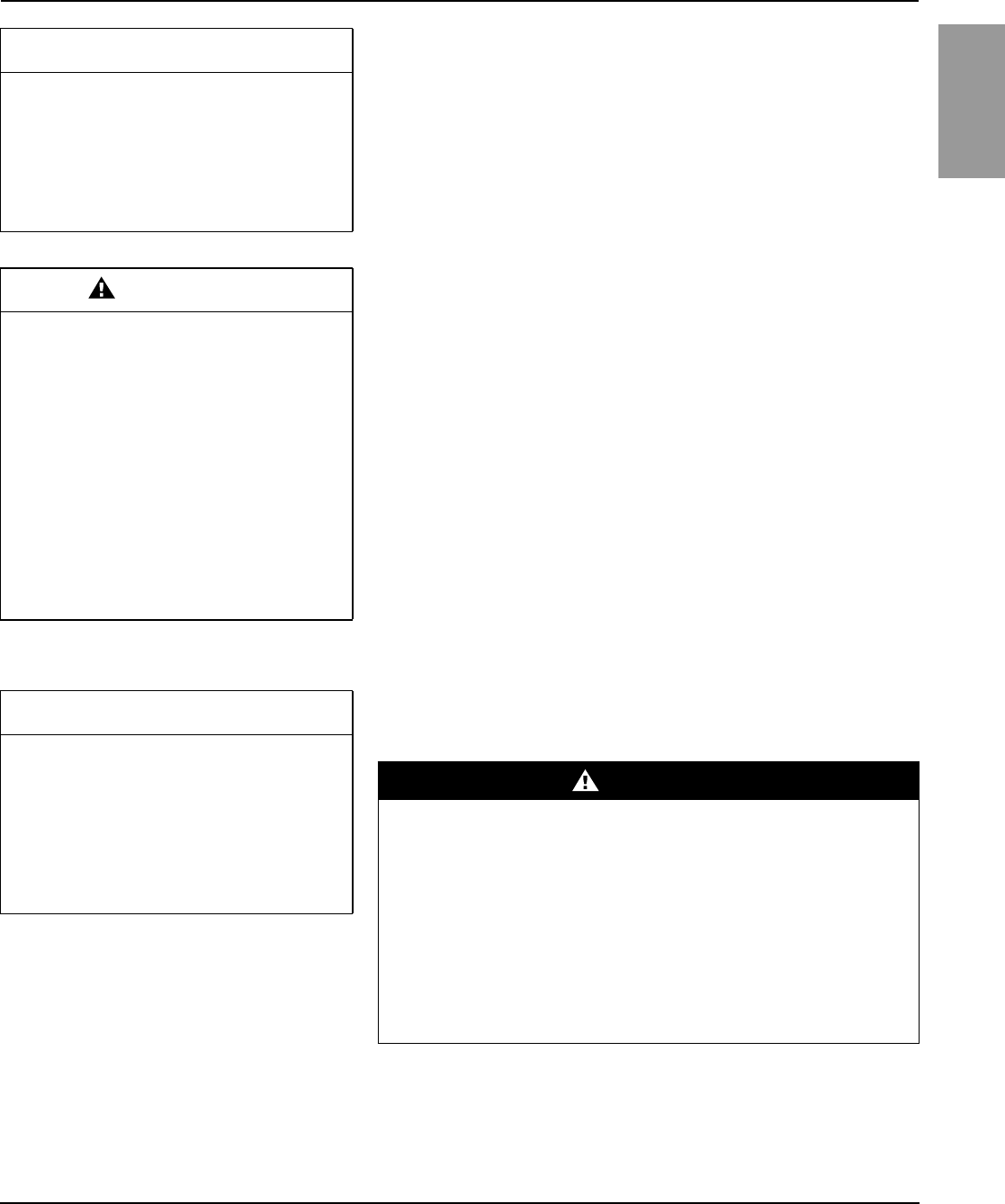
80043-055-10 Power-Style™ QED-2 Switchboards
12/2011 Section 5—Pre-energizing Checkout Procedure
© 1988–2011 Schneider Electric All Rights Reserved 29
ENGLISH
16. Examine fuse clip contact pressure and contact means
(QMB/QMJ/QMQB1 fusible switches). If there is any sign of looseness,
contact Square D Services at 1-888-778-2733 (US) or 1-800-265-3374
(Canada). Loose fuse clips can result in overheating.
17. Check all QMB/QMJ/QMQB1 fusible switches, verifying that the proper
fuses with the required interrupting rating and continuous current rating
are installed. Do not use renewable link fuses in Square D™ brand
fusible switches.
18. Verify that all grounding connections are correctly made. If the
switchboard is used as a service entrance, double check to see that the
main bonding jumper is connected (Figure 17 on page 22).
19. Conduct an electrical insulation resistance (Megger®) test to ensure that
the switchboard is free from short circuits and undesirable grounds.
Open all control power and metering disconnects or remove the fuses
from the control circuits. Disconnect the neutral connection at any surge
protective device or other electronic device before performing the
electrical insulation resistance test; reconnect to the device after the
test. With the neutral isolated from the ground and the power switches
and circuit breakers open, conduct electrical insulation tests from phase-
to-phase, phase-to-ground, phase-to-neutral, and neutral-to-ground. If
the resistance reads less than one megohm while testing with the
branch circuit devices in the open position, the system may be unsafe
and should be investigated. Consult Square D Services at 1-888-778-
2733 (US) or 1-800-265-3374 (Canada) to help correct any problems.
20. After completing the electrical insulation resistance test, replace all
control power fuses that were removed and close power disconnects
that were opened.
21. Check all field-installed wiring. Make certain it is clear of all live parts,
and when instructed, secured to withstand fault currents.
22. Verify that all control wiring between sections is connected.
23. Vacuum to remove any dust, scrap wire, or other debris.
24. Replace all covers and barriers; check for any pinched wires, and close
doors. Make certain all enclosure parts are aligned properly and
securely fastened.
CAUTION
HAZARD OF EQUIPMENT DAMAGE
Do not pry open or spread the fuse mounting
clips. Doing so can cause a loose connection,
resulting in overheating.
Failure to follow this instruction can result
in equipment damage.
CAUTION
HAZARD OF EQUIPMENT DAMAGE
OR INJURY
• Remove the long-time rating plug before
electrical insulation testing a circuit breaker
that has a label stating “Warning: Disconnect
Plug Before Dielectric Test”.
• Some Micrologic™ trip units are not rated for
voltages that would occur during electrical
resistance insulation testing.
• Open all control and metering disconnects
from the control circuits.
Failure to follow these instructions can
result in injury or equipment damage.
CAUTION
HAZARD OF EQUIPMENT DAMAGE
Do not use an air hose to blow out the
switchboard. Dust can settle inside relays and
overcurrent devices, causing overheating and
improper operation.
Failure to follow this instruction can result
in equipment damage.
DANGER
HAZARD OF ELECTRIC SHOCK, EXPLOSION, OR ARC FLASH
• Correct short-circuit conditions detected during the checkout
procedures described in “Section 5—Pre-energizing Checkout
Procedure”, beginning on page 28.
• Qualified electrical personnel must be present when energizing this
equipment for the first time.
• Follow the instructions in this section to energize the switchboard
properly.
Failure to follow these instructions will result in death or serious
injury.
64 of 292

ENGLISH
Power-Style™ QED-2 Switchboards 80043-055-10
Section 6—Energizing the Switchboard 12/2011
© 1988–2011 Schneider Electric All Rights Reserved30
Ground Fault Protection Systems
Paragraph 230-95(c) of the National Electrical Code requires that all equipment
ground-fault protection systems be tested when first installed. If the circuit
breaker has equipment ground-fault protection installed, test it at this time.
1. Make sure the trip unit is powered. The trip unit is powered if:
— The circuit breaker is closed or bottom fed and has more than 100 V
of load voltage on two phases (P or H trip unit only).
— The full-function or hand-held test kit is connected and on.
— The 24 Vdc external power supply is connected.
— An external voltage tap is installed and voltage of more than 100 V is
present on two phases (P or H trip unit only).
2. If the system is a radial (single-ended) system, press the ground-fault
Push-to-Test button. The circuit breaker trips, and the trip unit
ground-fault indicator light comes on.
3. Record results on the ground fault system test log.
NOTE: If a complete check of the ground-fault system is necessary, use
primary injection testing. If the system is multiple source and/or requires
field connections at the job site, use primary injection testing.
NOTE: Some ground fault systems require field connections at the job site.
Consult the switchboard interconnection wiring drawing for details.
Section 6—
Energizing the Switchboard 1. Make sure there is not a load on the switchboard when it is energized.
Turn off all downstream loads.
2. Energize the switchboard in the following sequence:
a. Turn on all control power disconnects before energizing the
switchboard. Refer to the record drawings supplied with equipment
to see if control power disconnects are supplied.
b. Close any open doors and/or covers.
c. Close all main devices.
d. Close each branch circuit breaker or branch fusible switch.
e. Proceed to each panelboard and other downstream load.
3. After all overcurrent protective devices are closed, turn on all loads (for
example, lighting circuits, contactors, heaters, and motors).
65 of 292

80043-055-10 Power-Style™ QED-2 Switchboards
12/2011 Section 7—Maintaining the Switchboard
© 1988–2011 Schneider Electric All Rights Reserved 31
ENGLISH
Section 7—
Maintaining the Switchboard
Periodic maintenance of the switchboard includes cleaning, lubrication, and
exercising component parts. The interval between maintenance checks can
vary depending upon the amount of usage and environmental conditions of
each installation. The maximum recommended inspection interval is one
year. This definition for periodic maintenance applies throughout this
manual, unless otherwise noted.
Always inspect the switchboard after a fault. (Refer to “Section 8—
Adverse Circumstances”, beginning on page 37). Service bulletins for the
various disconnecting and overcurrent devices mounted in the switchboard
are available through your local Schneider Electric representative.
General Inspection and Cleaning 1. Vacuum the switchboard interior to remove any dirt or dust deposits. Wipe
all bus bars, insulators, cables, etc., with a clean, dry, lint-free cloth.
2. Check the switchboard interior carefully for moisture, condensation
build-up, or signs of any previous wetness. Moisture can cause
insulation failures and rapid oxidation of current-carrying parts. Inspect
all conduit entrances and cracks between the enclosure panels for
dripping leaks. Condensation in conduits can be a source of moisture
and must not be allowed to drip onto live parts or insulating material.
Take the necessary steps to eliminate the moisture and seal off all leaks.
3. Inspect the switchboard for any signs of overheating. Discoloration and
flaking of insulation or metal parts are indications of overheating.
NOTE: If overheating occurs, be sure that all conditions that caused the
overheating have been corrected. Loose or contaminated connections
can cause overheating.
4. Check for signs of rodent nesting in the switchboard. If required, use a
good exterminating technique in the general area of the switchboard.
NOTE: Do not place or use exterminating substances and chemicals
inside the switchboard. Some products attract rodents.
5. Carefully inspect all devices for any visibly worn-out, cracked, or
missing parts.
6. Manually open and close switches and circuit breakers several times to
verify they are working properly.
7. Verify that all key interlocks and door interlocking provisions are
working properly.
DANGER
HAZARD OF ELECTRIC SHOCK,
EXPLOSION, OR ARC FLASH
• Inspect and perform preventive maintenance
only on switchboards and equipment that
has been de-energized and electrically
isolated (unless otherwise specified). This
helps ensure that accidental contact cannot
be made with energized parts.
• Follow safety-related work practices as
described in NFPA 70E, Part II at all times.
Failure to follow these instructions will
result in death or serious injury.
CAUTION
HAZARD OF EQUIPMENT DAMAGE
• Do not use an air hose to blow out the
switchboard. Dust can settle inside relays
and overcurrent devices, causing
overheating and improper operation.
• Do not allow paint, chemicals, or
petroleum-based solvents to contact plastics
or insulating materials.
Failure to follow these instructions can
result in equipment damage.
66 of 292

ENGLISH
Power-Style™ QED-2 Switchboards 80043-055-10
Section 7—Maintaining the Switchboard 12/2011
© 1988–2011 Schneider Electric All Rights Reserved32
Bus Bar Joints, Lug Terminations, and
Insulating Materials 1. Bus bar joints are maintenance-free. Do not retighten them after the
pre-energizing checkout procedure is complete.
2. Check all bus bar joints and terminal lugs for any pitting, corrosion, or
discoloration resulting from high temperatures or subjection to high fault
conditions. If any damage has occurred, replace the bus bars or lugs. If
cleaning is required, use Lectra-Clean®, made by CRC.
3. Inspect all insulating materials. Before re-energizing the switchboard,
replace insulators with any visible damage (such as cracks).
General Lubrication Information For field maintenance relubrication of blade/jaw components in switches
600 V and below, use BG20 High Performance Synthetic Grease from Dow
Corning (Schneider Electric catalog number SWLUB). This grease is
applicable for the following switches:
•Bolt-Loc
•QMB Main and Branch
•QMJ Branch
•QMQB1 Main and Branch
For bus/plug-on connections, use electric joint compound,
Schneider Electric catalog number PJC7201.
For SED and NED circuit breaker drawout connections, Schneider Electric
catalog number PJC8311 Electric Joint Compound must be used.
For Masterpact™ NW drawout connections, use only Schneider Electric
catalog number S48899 Electric Joint Compound.
Automatic Transfer Switches Consult the documentation provided by the manufacturer for all installation,
operation, and maintenance instructions for these devices.
Bolt-Loc Bolted Pressure Contact Switch
Maintenance (800–4,000 A) Refer to the Bolt-Loc switch installation and maintenance manual for
complete information (manual is shipped with the switchboard). If the
manual is not available, refer to “Section 11—Reference Publications” on
page 42, and contact your local Schneider Electric representative to obtain
the appropriate manuals.
1. Exercise the operating mechanism at least once a year to ensure
proper operation.
2. The Bolt-Loc switch is shipped from the factory properly lubricated.
Periodic cleaning and lubrication of the switch is required. The
maintenance interval between lubrications depends on factors such as
usage and ambient conditions. The maximum recommended
maintenance interval is one year for current-carrying parts and five years
for operating mechanisms.
CAUTION
HAZARD OF EQUIPMENT DAMAGE
• Do not sand or remove plating on any bus
bar, splice bar, or terminal lug.
• Damage to plating can result in overheating.
Replace damaged part. Contact Square D
Services at 1-888-778-2733 (US) or
1-800-265-3374 (Canada).
Failure to follow these instructions can
result in equipment damage.
1QMQB switches are available in Canada only.
67 of 292
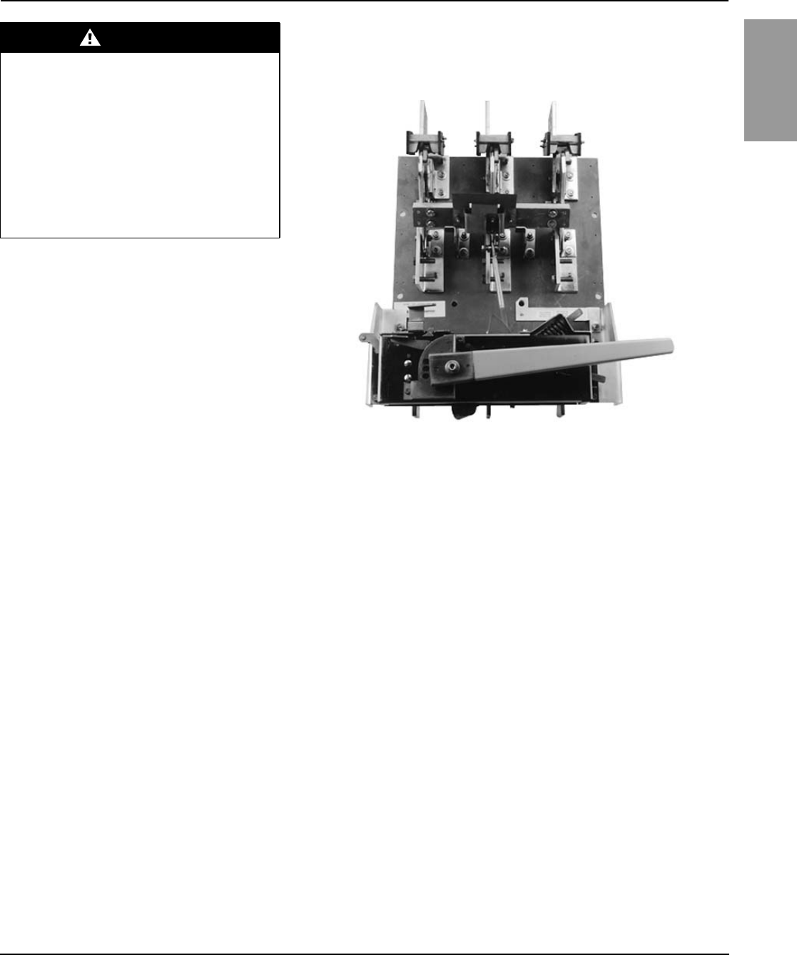
80043-055-10 Power-Style™ QED-2 Switchboards
12/2011 Section 7—Maintaining the Switchboard
© 1988–2011 Schneider Electric All Rights Reserved 33
ENGLISH
3. To replace the fuse:
a. Open the switch before opening the fuse door.
b. Open the fuse door, releasing the interlock as described in the
instructions on the door.
c. Observe the switch blades to confirm the switch is “open.”
d. Check the line and load ends of fuses for voltage using a properly
rated voltage sensing device. No voltage should be present.
e. Remove all fuses. Retain the hardware for reuse.
f. Using a non-abrasive cleaner such as Lectra-Clean, made by CRC,
wipe clean the fuse mounting pads on the switch and the terminals of
each new fuse. Check the alignment of fuse terminals before
installing new fuses.
g. Install new fuses using the same hardware removed in Step e.
Tighten to 21–30 lb-ft (28–41 N•m).
4. Close the fuse door, and check the fuse door interlock with the switch in
the ON position. The fuse doors should not open using normal hand force.
DANGER
HAZARD OF ELECTRIC SHOCK,
EXPLOSION, OR ARC FLASH
Always check line and load ends of the fuses
for voltage before starting the replacement
procedure. The Bolt-Loc switch can be part of
a multiple source system in which the fuses
can be energized when the Bolt-Loc switch is
in the “open” position.
Failure to follow this instruction will result
in death or serious injury.
Figure 25: Type BP Bolt-Loc Fusible Switch
68 of 292
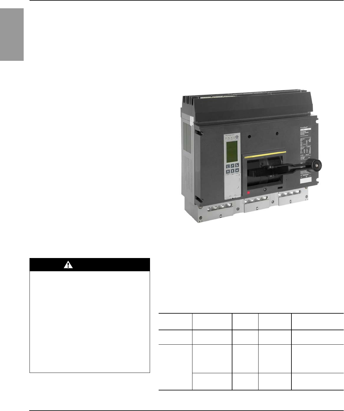
ENGLISH
Power-Style™ QED-2 Switchboards 80043-055-10
Section 7—Maintaining the Switchboard 12/2011
© 1988–2011 Schneider Electric All Rights Reserved34
Circuit Breakers Schneider Electric circuit breakers are designed and manufactured as
sealed units requiring minimal periodic maintenance.
Exercise circuit breakers at least once a year to ensure proper operation.
For general maintenance:
1. Trip the circuit breaker by pushing the Push-To-Trip or “Open” button
located on the face of the circuit breaker. Refer to the appropriate circuit
breaker manual for the specific location of this button.
2. Manually open and close the circuit breaker two to three times.
NOTE: Schneider Electric instruction bulletin 48049-900-0x, Field Testing
and Maintenance Guide for Thermal-Magnetic and Micrologic™ Electronic
Trip Molded Case Circuit Breakers, provides more in-depth information.
Refer to individual circuit breaker instruction manuals shipped with the
switchboard for additional maintenance information, such as changing
rating plugs, sensor plugs, or adjustable settings and removing circuit
breakers. If the instruction manual is not available, refer to “Section 11—
Reference Publications” on page 42 for the appropriate number, or contact
your local Schneider Electric representative.
Figure 26: PowerPact™ R-Frame Circuit Breaker
DANGER
HAZARD OF ELECTRIC SHOCK,
EXPLOSION, OR ARC FLASH
• If adjusting circuit breaker settings, do not
set the long-time trip rating at a higher
ampacity than the rating of the bus bar or
load cables it supplies; overheating
can occur.
• Before energizing the switchboard, fill all
unused I-Line circuit breaker mounting
spaces with blank fillers and/or extensions
as listed in Table 2.
Failure to follow these instructions will
result in death or serious injury.
Table 2: I-Line™ Blank Fillers and Extensions
Item Height Catalog
No. Branch
Circuit Side Circuit Breaker
Frame
Blank Fillers 1.50 in. (38 mm)
4.50 in. (114 mm)
HNM1BL
HNM4BL
Both Sides
Both Sides Not applicable
Blank
Extensions
1.50 in. (38 mm)
4.50 in. (114 mm)
1.50 in. (38 mm)
4.50 in. (114 mm)
HLW1BL
HLW4BL
HLN1BL
HLN4BL
Wide Side
Wide Side
Narrow Side
Narrow Side
All applications except
PowerPact H/J circuit
breakers with Micrologic
trip unit 5/6.
4.50 in. (114 mm)
4.50 in. (114 mm)
HLN4EBL
HLW4EBL
Narrow Side
Wide Side
Only PowerPact H/J
circuit breakers with
Micrologic trip unit 5/6.
69 of 292
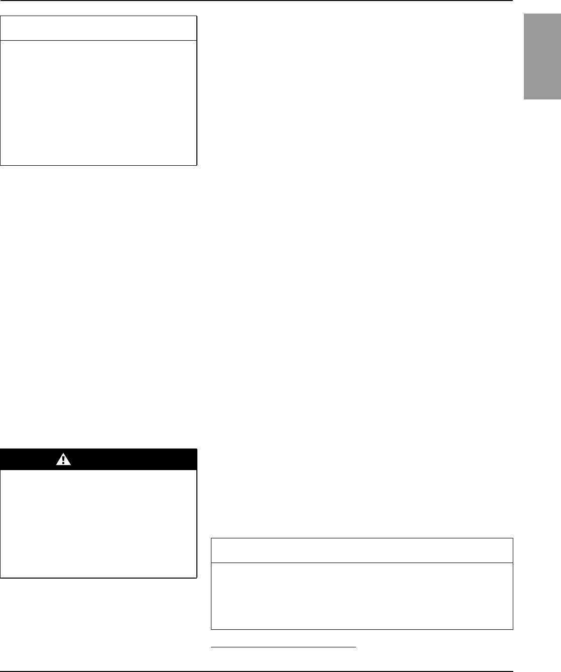
80043-055-10 Power-Style™ QED-2 Switchboards
12/2011 Section 7—Maintaining the Switchboard
© 1988–2011 Schneider Electric All Rights Reserved 35
ENGLISH
3. The universal test set, catalog number UTS3, is available to test
Schneider Electric Powerpact P and R circuit breakers equipped with
Micrologic trip units. It runs trip unit tests automatically, with prompts to the
user for initial information. Test modules for each circuit breaker frame are
used to store data necessary for automatic tests. Series B Micrologic trip
units require test module CBTMB, which is included in UTS3.
A pocket tester, catalog number S434206, or UTA tester, catalog
number STRV00910, are available for Schneider Electric Powerpact H,
J, and L circuit breakers with Micrologic trip units. These testers supply
power to the Micrologic trip units and allow for settings to be adjusted
through the keypad located on the circuit breaker or through a PC using
the USB interface.
Masterpact NW trip units require the full-function test set, catalog
number S33595, or the hand-held test set, catalog number S33594.
NOTE: Tests can be conducted with a circuit breaker installed in the
switchboard; circuit breaker removal is not required. The switchboard
must be de-energized.
QMB/QMJ/QMQB1 Fusible Switches Refer to the QMB/QMJ/QMQB1 instruction manual for complete
maintenance information. If the instruction manual is not available, refer to
“Section 11—Reference Publications” on page 42 of this manual for the
appropriate number. Contact your local Schneider Electric representative to
obtain the manual.
Switch Maintenance 1. Periodically exercise the switch to ensure proper operation. This period
should not exceed one year.
2. Check the cover interlock with the switch in the ON position. The cover
should not open using normal hand force.
3. Inspect the switch interior for any damaged or cracked parts, and
replace as necessary.
4. For fusible switch units, check the fuse mounting clips or bolted contact
area for corrosion or discoloration (indicating overheating). Replace
them if necessary.
5. For additional maintenance instructions, see the label on the inside of
the door.
Fuse Replacement (Fusible Switches Only) 1. Turn the switch to the OFF position before opening the door.
2. Observe the switch blades to confirm that the switch is in the OFF position.
3. Using a properly rated voltage sensing device, verify that line and load
ends of the fuse are not energized.
4. Observe all warning labels specifying the type of fuse to use. Do not
substitute a non-current limiting fuse, or attempt in any way to defeat the
rejection feature of the fuse clips furnished with the switch. Do not use
renewable link fuses in Schneider Electric fusible switches.
CAUTION
HAZARD OF EQUIPMENT DAMAGE
• Do not remove the protective lubricant on the
plug-on connectors.
• If additional lubrication is required, apply a
coating of electrical joint compound, catalog
number PJC7201, to the contact surfaces of
the plug-on connector.
Failure to follow these instructions can
result in equipment damage.
1QMQB switches are available in Canada only.
DANGER
HAZARD OF ELECTRIC SHOCK,
EXPLOSION, OR ARC FLASH
Always check line and load ends of the fuses
for voltage before starting the fuse
replacement procedure with a properly rated
voltage sensing device.
Failure to follow this instruction will result
in death or serious injury.
CAUTION
HAZARD OF EQUIPMENT DAMAGE
Do not pry open or spread the fuse mounting clips. Doing so can cause a
loose connection, resulting in overheating and nuisance fuse blowing.
Failure to follow this instruction can result in equipment damage.
70 of 292
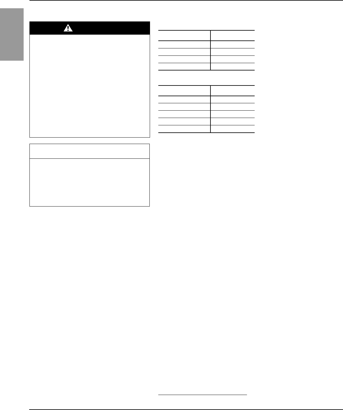
ENGLISH
Power-Style™ QED-2 Switchboards 80043-055-10
Section 7—Maintaining the Switchboard 12/2011
© 1988–2011 Schneider Electric All Rights Reserved36
Installing QMB/QMJ/QMQB1 Fusible Switches
1. Turn off the main power.
2. Turn the switch handle(s) to the OFF position. Align switch plug-on
connectors with QMB panel vertical bus, and plug switch onto panel.
3. Place and partially tighten all unit mounting screws that mount to the
QMB panel mounting rails.
4. Tighten all screws evenly. The unit mounting flange and plug-on
connectors must be seated securely.
Removing QMB/QMJ/QMQB1 Fusible Switches 1. Turn off the main power.
2. Turn switch handle(s) to the OFF position.
3. Disconnect the load wires.
4. For QMB and QMJ switches, remove mounting screws holding the
switch to the mounting rail. For QMQB1 switches, remove the bolts
holding the switch to the line terminal.
5. Unplug the switch.
Ground-Fault Protection Systems Check the terminal connections on the ground-fault protection system at
least once a year for tightness and corrosion. If the system can be tested
without tripping the main or branch device, directions for testing the system
are in the device manual. Otherwise, testing the ground-fault protection
system will trip the main or branch device to which it is connected. If the
ground-fault sensor or relay is physically or electrically damaged, replace it.
If the ground-fault protection system does not operate properly and
additional equipment has been connected to the installation since the last
maintenance test/check, de-energize the entire system, and check for
grounds on the neutral downstream from the main bonding jumper. If no
downstream grounds are detected and the ground fault system is not
operating properly, contact Square D Services at 1-888-778-2733 (US) or
1-800-265-3374 (Canada).
If no additions have been made to the installation and the ground-fault
protection system does not operate properly, contact Square D Services at
1-888-778-2733 (US) or 1-800-265-3374 (Canada).
DANGER
HAZARD OF ELECTRIC SHOCK,
EXPLOSION, OR ARC FLASH
• Remove power for these sections before
installing or removing QMB/QMJ/QMQB1
switches.
• Do not use a main as a branch unit or a
branch as a main.
• All unused spaces must be filled with blank
fillers before energizing the switchboard.
Refer to Tables 3 and 4 for sizes and catalog
numbers.
Failure to follow these instructions will
result in death or serious injury.
Table 3: QMB/QMJ Fusible Switch Blank Fillers
Height Catalog No.
1.50 in. (38 mm) QMB1BLW
3.00 in. (76 mm) QMB3BLW
6.00 in. (152 mm) QMB6BLW
15.00 in. (381 mm) QMB15BLW
Table 4: QMQB1 Fusible Switch Blank Fillers
Height Catalog No.
2x: 1.375 in. (35 mm) QFS1
8x: 5.50 in. (140 mm) QFS5
10x: 6.875 in. (175 mm) QFS6
14x: 9.625 in. (244 mm) QFS9
24x: 16.50 in. (419 mm) QFS16
CAUTION
HAZARD OF EQUIPMENT DAMAGE
Do not remove the protective lubricant on the
plug-on connectors.
Failure to follow this instruction can result
in equipment damage.
1QMQB switches are available in Canada only.
71 of 292

80043-055-10 Power-Style™ QED-2 Switchboards
12/2011 Section 8—Adverse Circumstances
© 1988–2011 Schneider Electric All Rights Reserved 37
ENGLISH
Refer to the ground-fault field test instruction manual for additional testing
information. If the manual is not available, refer to “Section 11—
Reference Publications” on page 42 of this manual to obtain the appropriate
number. Contact your local Schneider Electric representative to obtain
this manual.
Section 8—
Adverse Circumstances This section includes, but is not limited to, all electrical components of
the switchboard.
NOTE: Before attempting to re-energize the switchboard following adverse
circumstances, contact Square D Services at 1-888-778-2733 (US) or
1-800-265-3374 (Canada) for special instructions.
Inspection Following a Short Circuit If a short circuit occurs, make a thorough inspection of the entire system,
and verify that no damage to conductors or insulation has occurred. High
mechanical and thermal stresses developed by short-circuit currents can
damage conductors and insulation. Check the overcurrent-protection device
that interrupted the short-circuit current for possible arcing damage.
Do not open sealed devices, such as molded case circuit breakers. Replace
these devices if they are damaged. Before energizing the switchboard, all
unused circuit breaker mounting spaces must be filled. For more information
about these devices, refer to the appropriate instruction manual listed in
“Section 11—Reference Publications” on page 42.
Clean-up Following a Short Circuit The insulating properties of some organic insulating materials can
deteriorate during an electrical arc. If so:
1. Remove any soot or debris.
2. Replace carbon-tracked insulation.
Water-Soaked Switchboards Do not clean or repair a switchboard that has been exposed to large
volumes of water or submerged at any time. Current-carrying parts,
insulation systems, and electrical components may be damaged beyond
repair. Do not energize the switchboard. Contact Square D Services.
DANGER
HAZARD OF ELECTRIC SHOCK, EXPLOSION, OR ARC FLASH
• Turn off all power supplying the switchboard before cleaning.
• Always use a properly rated voltage sensing device to confirm all power
is off.
• Before energizing the switchboard, all unused circuit breaker mounting
spaces must be filled.
Failure to follow these instructions will result in death or serious
injury.
72 of 292

ENGLISH
Power-Style™ QED-2 Switchboards 80043-055-10
Section 8—Adverse Circumstances 12/2011
© 1988–2011 Schneider Electric All Rights Reserved38
Water-Sprayed or Splashed Switchboards
(Clean Water Only)
If the switchboard has been sprayed or splashed with small amounts of
clean water, make a thorough inspection of the entire system, and verify
that no damage to conductors or insulation has occurred. Do not open
sealed devices such as molded case circuit breakers or fuses. Replace
these devices if they are damaged. For more information about these
devices, refer to the appropriate instruction manual listed in “Section 11—
Reference Publications”.
Inspection and Clean-up of Clean Water Sprayed
or Splashed Switchboards Follow steps 1–10 only if:
•No signs of physical damage to the equipment are present.
•The switchboard has not been submerged or exposed to water for long
periods of time.
•The water that has been in contact with the switchboard has not been
contaminated with sewage, chemicals, or other substances that can
negatively affect the integrity of the electrical equipment.
•The water that has been in contact with the switchboard has not entered
any area of the enclosure that may contain wiring installed as intended
and located above any live part. Specifically, inspect for water entering
through conduits located above live parts.
If any one or more of these conditions have not been met, contact Square D
Services at 1-888-778-2733 (US) or 1-800-265-3374 (Canada).
If ALL of the conditions listed have been met, proceed as follows:
1. Turn off all power supplying this equipment before working on or inside
the equipment.
2. Always use a properly rated voltage sensing device to confirm all power
is off.
3. Disconnect and electrically isolate the switchboard so that no contact
can be made with energized parts.
4. Wipe off all moisture from the bus bars, insulators, and insulating
material with a clean, dry, lint-free cloth. Do not use cleaning agents or
water displacement sprays.
5. Prepare the switchboard for insulation resistance (Megger®) testing by
disconnecting all line side supply connections and all load side cable
connections to isolate the switchboard from the wiring system.
DANGER
HAZARD OF ELECTRIC SHOCK,
EXPLOSION, OR ARC FLASH
Turn off all power supplying this equipment
before working on it.
Failure to follow this instruction will result
in death or serious injury.
73 of 292
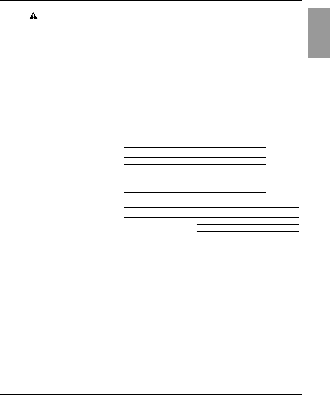
80043-055-10 Power-Style™ QED-2 Switchboards
12/2011 Section 9—Torque Values for Electrical Connections
© 1988–2011 Schneider Electric All Rights Reserved 39
ENGLISH
6. Turn all circuit breakers or switches to their ON position. The
switchboard must remain de-energized.
7. Use a megohmmeter with a capacity of 500–1,000 Vdc and apply
voltage from:
a. Each phase-to-ground with circuit breaker on.
b. Phase-to-phase with circuit breaker on.
8. Record resistance values. Refer to “Section 10—Switchboard Insulation
Resistance Chart” on page 41.
9. If resistance measurements are less than 0.5 megohm, call Square D
Services at 1-888-778-2733 (US) or 1-800-265-3374 (Canada) for
recommendations.
10. If resistance measurements are greater than 0.5 megohm, the
equipment can be energized using the procedures listed in “Section 6—
Energizing the Switchboard” on page 30.
Section 9—
Torque Values for Electrical
Connections
CAUTION
HAZARD OF EQUIPMENT DAMAGE OR
INJURY
• Remove the long-time rating plug before
electrical insulation testing a circuit breaker
that has a label stating “Warning: Disconnect
Plug Before Dielectric Test.”
• Some Micrologic trip units are not rated for
voltages that would occur during electrical
resistance insulation testing.
• Open all control and metering disconnects
from the control circuits.
Failure to follow these instructions can
result in injury or equipment damage.
Table 5: Incoming, Branch, and Neutral Lug
Socket Size Across Flats Torque Value
1/4 in. 180 lb-in (20 N•m)
5/16 in. 250 lb-in (28 N•m)
3/8 in. 340 lb-in (38 N•m)
1/2 in. ★450 lb-in (51 N•m)
★ Certain lugs require 620 lb-in (70 N•m) and are marked as such.
Table 6: Multiple Conductor Neutral and/or Ground Bar
Screw Type Lug Wire Range Conductor Size Torque Value
Slotted Head
14–4
14-10 Cu, 12-10 Al 20 lb-in (2 N•m)
8 Cu-Al 25 lb-in (3 N•m)
6-4 Cu-Al 35 lb-in (4 N•m)
14–1/0 14-8 Cu-Al 36 lb-in (4 N•m)
6-1/0 Cu-Al 45 lb-in (5 N•m)
Socket Head 14–1/0 All 100 lb-in (11 N•m)
6–300 kcmil All 275 lb-in (31 N•m)
74 of 292

ENGLISH
Power-Style™ QED-2 Switchboards 80043-055-10
Section 9—Torque Values for Electrical Connections 12/2011
© 1988–2011 Schneider Electric All Rights Reserved40
Hardware
Description Torque Value
1/2 in. 720–840 lb-in (81–95 N•m)
Hardware
Description Torque Value
1/4 in. 50–75 lb-in (6–8 N•m)
3/8 in. 175–225 lb-in (20–25 N•m)
1/2 in. 250–350 lb-in (28–40 N•m)
Hardware
Description
Torque Value
Conical Washer OD Square Head (Tee) Bolt
Conical Washer
3/8 in. 0.87 in. (22 mm) 250–280 lb-in (28–32 N•m)
1.00 in. (25 mm) 130–150 lb-in (15–17 N•m)
1/2 in. 1.25 in. (32 mm)
2.25 in. (57 mm) 450–550 lb-in (51–62 N•m)
Hardware
Description
Torque Value
Conical Washer OD Hex Head Bolt
(2) Conical Washers
5/16 in. 0.90 in. (23 mm) 145–160 lb-in (16–18 N•m)
3/8 in. 0.87 in. (22 mm) 250–280 lb-in (28–32 N•m)
1.00 in. (25 mm) 130–150 lb-in (15–17 N•m)
1/2 in.
1.25 in. (32 mm)
2.25 in. (57 mm)
3.00 in. (76 mm)
720–840 lb-in (81–95 N•m)
Carriage bolt
Hex nut
Conical washer
Carriage bolt
Conical washer assembly
(Keps nut)
Hex head bolt
Conical washer assembly
(Keps nut)
Square head (Tee) bolt
Conical washer assembly
(Keps nut)
Square head (Tee) bolt
Conical washer
Hex head bolt
(2) Conical washers
Hardware
Description Torque Value
1/4 in. 50–75 lb-in (6–8 N•m)
5/16 in. 80–125 lb-in (9–14 N•m)
3/8 in. 175–225 lb-in (20–25 N•m)
1/2 in. 250–350 lb-in (28–40 N•m)
75 of 292
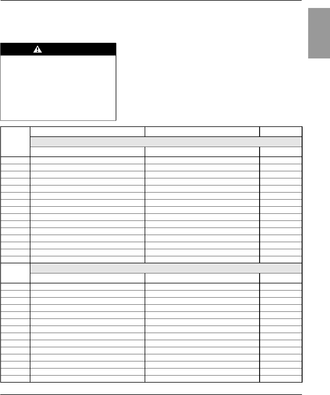
80043-055-10 Power-Style™ QED-2 Switchboards
12/2011 Section 10—Switchboard Insulation Resistance Chart
© 1988–2011 Schneider Electric All Rights Reserved 41
ENGLISH
Section 10—Switchboard
Insulation Resistance Chart Always use a 500 or 1,000 Vdc megohmmeter when testing insulation
resistance.
NOTE: The Neutral–Ground column is provided to record the results of the
pre-energizing checkout procedure only.
DANGER
HAZARD OF ELECTRIC SHOCK,
EXPLOSION, OR ARC FLASH
• Turn off all power to the switchboard before
testing.
• Always use a properly rated voltage sensing
device to confirm power is off.
Failure to follow these instructions will
result in death or serious injury.
Date
Phase–Phase Phase–Ground Neutral–Ground
All Disconnects Open
a-b b-c c-a a-ground b-ground c-ground Neutral–Ground
Date All Disconnects Closed
a-b b-c c-a a-ground b-ground c-ground Neutral–Ground
76 of 292

ENGLISH
Power-Style™ QED-2 Switchboards 80043-055-10
Section 11—Reference Publications 12/2011
© 1988–2011 Schneider Electric All Rights Reserved42
Section 11—
Reference Publications Schneider Electric publications are available through your local
Schneider Electric representative. These publications include device replacement
procedures and listings of spare parts to make ordering and servicing of
replacement parts quick and convenient. Any maintenance procedure or device
not listed, such as an I-Line interior, is not customer serviceable.
Contact your local Schneider Electric representative for information at
1-888-778-2733 in the US, or at 1-800-265-3374 in Canada. Or, refer to the
Technical Library at http://www.schneider-electric.us/ to obtain the
appropriate publications.
For information about obtaining NEMA documents, write to:
National Electrical Manufacturers Association (NEMA)
Attention: Customer Service
1300 North 17th Street
Suite 1847
Rosslyn, VA 22209
Other Reference Publications Publication Number
General Instructions for Proper Installation, Operation, and
Maintenance of Switchboards Rated 600 V or Less NEMA Publication PB2.1
Application Guide for Ground Fault Protective Devices
for Equipment NEMA Publication PB2.2
Circuit Breakers NEMA Publication AB-4
Enclosed and Miscellaneous Distribution Switches NEMA Publication KS-1
Electrical Equipment Maintenance NFPA 70B-1999
77 of 292

80043-055-10 Power-Style™ QED-2 Switchboards
12/2011 Section 12—Installation and Maintenance Log
© 1988–2011 Schneider Electric All Rights Reserved 43
ENGLISH
Section 12—Installation and
Maintenance Log
DATE INITIALS MAINTENANCE PERFORMED
78 of 292

Electrical equipment should be installed, operated, serviced, and maintained only by qualified
personnel. No responsibility is assumed by Schneider Electric for any consequences arising out of
the use of this material.
80043-055-10 12/2011
Replaces 80043-055-09 05/2010
© 1988–2011 Schneider Electric All Rights Reserved
Schneider Electric USA, Inc.
8821 Garners Ferry Road
Hopkins, SC 29061 USA
1-888-778-2733
www.schneider-electric.us
Power-Style™ QED-2 Switchboards
Instruction Bulletin
Bolt-Loc™, I-LIne™, Masterpact™, Micrologic™, PowerPact™, Power-Style™, Qwik Flange™,
Square D™, and Schneider Electric™ are trademarks or registered trademarks of
Schneider Electric. Other trademarks used herein are the property of their respective owners.
ENGLISH
79 of 292

Approved as an American National Standard
ANSI Approval Date: June 14, 2010
ANSI/NEMA PB 2.1-2007
General Instructions for Proper Handling, Installation, Operation, and Maintenance
of Deadfront Distribution Switchboards Rated 600 Volts or Less
Published by
National Electrical Manufacturers Association
1300 North 17th Street, Suite 1752
Rosslyn, Virginia 22209
www.nema.org
© Copyright 2007 by the National Electrical Manufacturers Association. All rights including translation into
other languages, reserved under the Universal Copyright Convention, the Berne Convention for the
Protection of Literary and Artistic Works, and the International and Pan American Copyright Conventions.
80 of 292

NOTICE AND DISCLAIMER
The information in this publication was considered technically sound by the consensus of persons
engaged in the development and approval of the document at the time it was developed.
Consensus does not necessarily mean that there is unanimous agreement among every person
participating in the development of this document.
The National Electrical Manufacturers Association (NEMA) standards and guideline publications, of
which the document contained herein is one, are developed through a voluntary consensus
standards development process. This process brings together volunteers and/or seeks out the
views of persons who have an interest in the topic covered by this publication. While NEMA
administers the process and establishes rules to promote fairness in the development of
consensus, it does not write the document and it does not independently test, evaluate, or verify
the accuracy or completeness of any information or the soundness of any judgments contained in
its standards and guideline publications.
NEMA disclaims liability for any personal injury, property, or other damages of any nature
whatsoever, whether special, indirect, consequential, or compensatory, directly or indirectly
resulting from the publication, use of, application, or reliance on this document. NEMA disclaims
and makes no guaranty or warranty, expressed or implied, as to the accuracy or completeness of
any information published herein, and disclaims and makes no warranty that the information in this
document will fulfill any of your particular purposes or needs. NEMA does not undertake to
guarantee the performance of any individual manufacturer or seller’s products or services by virtue
of this standard or guide.
In publishing and making this document available, NEMA is not undertaking to render professional
or other services for or on behalf of any person or entity, nor is NEMA undertaking to perform any
duty owed by any person or entity to someone else. Anyone using this document should rely on
his or her own independent judgment or, as appropriate, seek the advice of a competent
professional in determining the exercise of reasonable care in any given circumstances.
Information and other standards on the topic covered by this publication may be available from
other sources, which the user may wish to consult for additional views or information not covered
by this publication.
NEMA has no power, nor does it undertake to police or enforce compliance with the contents of
this document. NEMA does not certify, test, or inspect products, designs, or installations for safety
or health purposes. Any certification or other statement of compliance with any health or safety–
related information in this document shall not be attributable to NEMA and is solely the
responsibility of the certifier or maker of the statement.
81 of 292

PB 2.1-2007
Page i
CONTENTS Page
Foreword ...................................................................................................................................iii
Section 1 GENERAL 1
1.1 Scope......................................................................................................................................... 1
1.2 References ................................................................................................................................1
1.3 General...................................................................................................................................... 1
1.3.1 Successful Operation.................................................................................................... 2
1.3.2 Qualified Personnel....................................................................................................... 2
1.3.3 Definition of Qualified Personnel................................................................................... 2
Section 2 HANDLING................................................................................................................................3
2.1 Manufacturer's Handling Instructions........................................................................................ 3
2.2 Care to Avoid Damage .............................................................................................................. 3
2.3 Upright Position ......................................................................................................................... 3
2.4 Equipment Capacity .................................................................................................................. 3
2.5 Concealed Damage................................................................................................................... 3
2.6 Storage Prior to Installation ....................................................................................................... 3
2.7 Shipping Skid............................................................................................................................. 3
2.8 Rod or Pipe Rollers ................................................................................................................... 3
2.9 Forklift Truck.............................................................................................................................. 3
2.10 Overhead Hoisting..................................................................................................................... 4
2.10.1 Rigid Spreaders or Spanner Bars............................................................................... 4
2.10.2 Rigging Lengths .......................................................................................................... 4
2.10.3 Angle Between Lifting Cables and Vertical................................................................. 4
2.10.4 Slings With Safety Hooks or Shackles........................................................................ 4
2.10.5 Removal of Switchboard Top Covers ......................................................................... 4
Section 3 STORAGE................................................................................................................................. 7
3.1 Clean, Dry Space Having Uniform Temperature....................................................................... 7
3.2 Protection from Weather and Dirt.............................................................................................. 7
3.3 Outdoor Switchboards are Not Weather Resistant Until Installed ............................................ 7
3.4 Un-Energized Outdoor Switchboard Should Be Kept Dry Internally......................................... 7
Section 4 INSTALLATION OF SWITCHBOARD OR ENCLOSURE ....................................................... 8
4.1 Manufacturer's Installation Instructions..................................................................................... 8
4.2 Location ..................................................................................................................................... 8
4.2.1 Clearance from Walls.................................................................................................... 8
4.2.2 Working Clearances...................................................................................................... 8
4.3 Channel Sills.............................................................................................................................. 8
4.4 Conduit and Other Raceways ................................................................................................... 8
4.5 Leveling and Securing............................................................................................................... 8
4.6 Splice Bus.................................................................................................................................. 8
4.7 Grounding and Bonding ............................................................................................................ 9
4.7.1 Grounded Systems ....................................................................................................... 9
4.7.2 Ungrounded Systems—Service Equipment or Separately Derived System Main ....... 9
4.7.3 Grounded or Ungrounded Systems .............................................................................. 9
4.8 Unused Openings.................................................................................................................... 10
4.9 Damp Indoor Locations ........................................................................................................... 10
4.10 Unusual Service Conditions .................................................................................................... 10
Section 5 INSTALLATION OF CONDUIT AND CONDUCTORS........................................................... 11
5.1 Prevent Moisture or Water from Entering................................................................................ 11
5.2 Temperature Ratings............................................................................................................... 11
5.3 Compression (Crimp) Terminals ............................................................................................. 11
5.4 Stripping Insulation from Conductors ...................................................................................... 11
© Copyright 2007 by the National Electrical Manufacturers Association.
82 of 292

PB 2.1-2007
Page ii
5.5 Proper Wiring Methods............................................................................................................ 11
5.6 Conductor Location in Switchboard......................................................................................... 11
5.7 Conductors 1/0 AWG in Size and Larger ................................................................................ 11
5.8 Incoming and Outgoing Control Connections ......................................................................... 12
5.9 Prevent Conductor Insulation from Cracking or Splitting ........................................................ 12
5.10 National Electrical Code, Section 725.54................................................................................ 12
Section 6 INSTALLATION OF SWITCHBOARD INTERIOR ................................................................. 13
6.1 Instructions if Switchboard Interior Was Not Factory-Mounted............................................... 13
6.2 Unpacking................................................................................................................................13
6.3 Inspection ................................................................................................................................13
6.4 Storage .................................................................................................................................... 13
6.5 Cleaning................................................................................................................................... 13
6.6 Manufacturer's Instructions ..................................................................................................... 13
6.7 Interior Installation ................................................................................................................... 13
Section 7 STEPS TO BE TAKEN BEFORE ENERGIZING.................................................................... 14
7.1 Accessible Electrical Connections........................................................................................... 14
7.2 Blocks or Other Temporary Holding Means............................................................................ 14
7.3 Integrity of All Bus Mounting Means........................................................................................ 14
7.4 Enclosure................................................................................................................................. 14
7.5 Operating Mechanisms ........................................................................................................... 14
7.6 Electrical Insulation Resistance Test....................................................................................... 14
7.7 Electrical Relays, Meters, and Instrumentation....................................................................... 14
7.8 Electrically Operated Switches, Circuit Breakers, and Other Mechanisms ............................ 14
7.9 Ground Fault Protection System ............................................................................................. 15
7.10 Adjustable Time Current Trip Device Settings ........................................................................ 15
7.11 Field Wiring.............................................................................................................................. 15
7.12 Grounding Connections........................................................................................................... 15
7.13 Foreign Material....................................................................................................................... 15
7.14 Covers and Doors.................................................................................................................... 15
Section 8 ENERGIZING EQUIPMENT.................................................................................................... 16
8.1 Qualified Personnel Present.................................................................................................... 16
8.2 No Load on Switchboard ......................................................................................................... 16
8.3 Energized in Sequence ........................................................................................................... 16
8.4 After All Main, Feeder, and Branch Circuit Devices Have Been Closed................................. 16
Section 9 MAINTENANCE...................................................................................................................... 17
9.1 Maintenance Program for Switchboards ................................................................................. 17
9.2 Field Test................................................................................................................................. 17
9.3 Switchboard Inspection Once Each Year................................................................................ 17
9.4 Accumulation of Dust and Dirt................................................................................................. 17
9.4.1 All Visible Electrical Joints and Terminals................................................................... 17
9.4.2 All Conductors and Connections................................................................................. 17
9.4.3 Fuse Clip Contact Pressure and Contact Means........................................................ 18
9.4.4 All Conditions Which Caused Overheating................................................................. 18
9.5 Proper Ampere, Voltage, and Interrupting Ratings ................................................................. 18
9.5.1 All Mechanisms Are Free and in Proper Working Order ............................................ 18
9.6 Operation of All Mechanical Components............................................................................... 18
9.6.1 Full On and Off Positions ............................................................................................ 18
9.6.2 Integrity of Electrical and Mechanical Interlocks......................................................... 18
9.6.3 Missing or Broken Parts.............................................................................................. 18
9.6.4 Manufacturer’s Instructions......................................................................................... 18
9.6.5 Readily Accessible Copper Electrical Contacts, Blades, and Jaws............................ 19
9.7 Deteriorated Insulating Material and Assemblies.................................................................... 19
9.8 Moisture or Signs of Previous Wetness .................................................................................. 19
© Copyright 2007 by the National Electrical Manufacturers Association.
83 of 292

PB 2.1-2007
Page iii
9.8.1 Conduits Which Have Dripped Condensate ............................................................... 19
9.8.2 Cracks or Openings .................................................................................................... 19
9.8.3 Insulating Material Which is Damp.............................................................................. 19
9.8.4 Moisture Damaged Component Device...................................................................... 19
9.9 Water Damage ........................................................................................................................ 19
9.10 Severe Electrical Short Circuit................................................................................................. 19
9.11 Ground Fault Protection System ............................................................................................. 20
9.12 Insulation Resistance .............................................................................................................. 20
Section 10 PERMISSIBLE LOADING OF SWITCHBOARDS ................................................................. 21
10.1 Switchboards Without Main Overcurrent Protective Devices.................................................. 21
10.2 Switchboards With a Single Main Overcurrent Protective Device .......................................... 21
10.3 Switchboards With a Multiple Main Overcurrent Protective Device........................................ 21
10.4 Feeder and Branch Circuit Overcurrent Protective Devices in Switchboards......................... 21
10.5 Harmonics in the Electrical System......................................................................................... 21
Figures
2-1 LIFTING WITH EYE BOLTS......................................................................................................5
2-2 LIFTING WITH INTEGRAL LIFT ANGLE.................................................................................. 5
2-3 LIFTING WITH SLING RIGGING.............................................................................................. 6
© Copyright 2007 by the National Electrical Manufacturers Association.
84 of 292

PB 2.1-2007
Page iv
© Copyright 2007 by the National Electrical Manufacturers Association.
Foreword
This publication is a guide of practical information containing instructions for the proper handling,
installation, operation, and maintenance of deadfront distribution switchboards rated 600 Volts or less.
These instructions do not purport to cover all details or variations in equipment, nor to provide for every
possible contingency regarding handling, installation, operation, or maintenance.
It is recommended that work described in this set of instructions be performed only by qualified personnel
familiar with the construction and operation of switchboards and that such work be performed only after
reading this complete set of instructions. For specific information not covered by these instructions, you
are urged to contact the manufacturer of the switchboard directly.
PB 2.1-2007 revises and supersedes PB 2.1-2002.
In the preparation of this Standards Publication input of users and other interested parties has been
sought and evaluated. Inquiries, comments, and proposed or recommended revisions should be
submitted to the concerned NEMA product section by contacting the following:
Vice President, Technical Services
National Electrical Manufacturers Association
1300 North 17th Street
Rosslyn, Virginia, 22209
This Standards Publication was developed by the Panelboard and Distribution Board Section. Section
approval of the standard does not necessarily imply that all section members voted for its approval or
participated in its development. At the time it was approved, the Panelboard and Distribution Board Section
was composed of the following members:
Eaton Electrical Inc.—Pittsburgh, PA
GE—Plainville, CT
Hubbell, Inc.—Bridgeport, CT
Milbank Manufacturing Company—Kansas City, MO
Penn Panel & Box Company—Collingdale, PA
Reliance Controls Corporation—Racine, WI
Siemens Industry, Inc.—Norcross, GA
Square D Company—Palatine, IL
85 of 292

PB 2.1-2007
Page 1
Section 1
GENERAL
1.1 SCOPE
This publication covers floor-mounted deadfront switchboards which consist of an enclosure, molded
case and low-voltage power circuit breakers, fusible or non-fusible switches, instruments, and metering,
monitoring, or control equipment, with associated interconnections and supporting structures. These
units are used in the distribution of electricity at:
a. 600 volts and less
b. 6000 amperes or less
1.2 REFERENCES
National Electrical Manufacturers Association
1300 North 17th Street
Rosslyn, Virginia 22209
AB 4- 2003 Guidelines for Inspection and Preventive Maintenance of Molded Case Circuit
Breakers Used in Commercial and Industrial Applications
PB 2.2- 2004 Application Guide for Ground Fault Protective Devices for Equipment
Guidelines for Handling Water Damaged Electrical Equipment
National Fire Protection Association
Batterymarch Park
Quincy, MA 02269
NFPA 70- 2005 National Electrical Code
NFPA 70E- 2004 Safety Related Work Practices
1.3 GENERAL
WARNING—HAZARDOUS VOLTAGES IN ELECTRICAL EQUIPMENT CAN CAUSE SEVERE
PERSONAL INJURY OR DEATH. UNLESS OTHERWISE SPECIFIED, INSPECTION AND
MAINTENANCE SHOULD ONLY BE PERFORMED ON SWITCHBOARDS AND EQUIPMENT TO
WHICH POWER HAS BEEN TURNED OFF, DISCONNECTED, AND ELECTRICALLY ISOLATED SO
THAT NO ACCIDENTAL CONTACT CAN BE MADE WITH ENERGIZED PARTS. FOLLOW ALL
MANUFACTURER'S WARNINGS AND INSTRUCTIONS.
Safety related work practices, as described in NFPA 70E, should be followed at all times.
CAUTION—Hydrocarbon spray propellants and hydrocarbon based sprays or compounds will cause
degradation of certain plastics. Contact the switchboard manufacturer before using these products to clean,
dry, or lubricate switchboard components during installation or maintenance.
© Copyright 2007 by the National Electrical Manufacturers Association.
86 of 292

PB 2.1-2007
Page 2
1.3.1 Successful Operation
The successful operation of switchboards is dependent upon proper handling, installation, operation, and
maintenance. Neglecting fundamental installation and maintenance requirements may lead to severe
personal injury, death, or damage to electrical equipment or other property.
1.3.2 Qualified Personnel
Installation, operation, and maintenance of switchboards should be conducted only by qualified personnel.
1.3.3 Definition of Qualified Personnel
For purposes of these guidelines, a qualified person is one who is familiar with the installation, construction,
and operation of the equipment and the hazards involved. In addition, the person is:
1.3.3.1 Knowledgeable of Requirements
Knowledgeable of the requirements of the National Electrical Code and of all other applicable codes, laws,
and standards.
1.3.3.2 Trained and Authorized to Test, Energize, Clear, Ground, Tag, and Lockout
Trained and authorized to test, energize, clear, ground, tag, and lockout circuits and equipment in
accordance with established safety practices.
1.3.3.3 Trained in Proper Care and Use of Protective Equipment
Trained in the proper care and use of protective equipment such as rubber gloves, hard hat, safety glasses
or face shields, and flash resistant clothing in accordance with established safety practices.
1.3.3.4 Trained in Rendering First Aid
Trained in rendering first aid.
© Copyright 2007 by the National Electrical Manufacturers Association.
87 of 292

PB 2.1-2007
Page 3
Section 2
HANDLING
NOTE—These guidelines are provided to help avoid personal injury and equipment damage during handling and to facilitate moving the
switchboard at the job site.
2.1 MANUFACTURER'S HANDLING INSTRUCTIONS
Follow the manufacturer's handling instructions for the specific equipment, if available.
2.2 CARE TO AVOID DAMAGE
Handle the switchboard with care to avoid damage to components, the frame or finish.
2.3 UPRIGHT POSITION
Keep the switchboard in an upright position unless otherwise indicated by the manufacturer.
2.4 EQUIPMENT CAPACITY
Verify that handling equipment capacity is sufficient for the switchboard weight.
2.5 CONCEALED DAMAGE
When the switchboard is received, unpack it sufficiently to inspect it for concealed damage and to determine
that the shipment is complete and correct.
2.6 STORAGE PRIOR TO INSTALLATION
If the switchboard is to be stored prior to installation, replace the packing for protection during that period.
When conditions permit, leave the packing intact until the switchboard or sections are at their final
installation location. If the packing is removed, cover the top and any openings to protect the equipment
against dust and debris during the construction period. (See section 3).
2.7 SHIPPING SKID
The switchboard should remain secured to the shipping skid to prevent distortion of the bottom of the frame
during moving.
2.8 ROD OR PIPE ROLLERS
Rod or pipe rollers, with the aid of pinch bars, provide a simple method of moving the switchboard on one
floor level if there is little or no incline. Steady the load to prevent tipping.
2.9 FORKLIFT TRUCK
A forklift truck may offer a more convenient method of handling the switchboard and has the added
advantage of permitting it to be hoisted between levels. Balance the load carefully and use a safety strap
when handling or moving switchboards with a forklift.
© Copyright 2007 by the National Electrical Manufacturers Association.
88 of 292

PB 2.1-2007
Page 4
2.10 OVERHEAD HOISTING
When it is necessary to move the switchboard between elevations without a suitable platform elevator,
overhead hoisting may be required. Lifting plates and eye bolts (Figure 2-1), or channels, angles, or bars
with lift holes (Figure 2-2) may be provided as a permanent or removable part of the switchboard. If they are
not, cable, chain, or band slings (Figure 2-3) may be rigged around the switchboard.
2.10.1 Rigid Spreaders or Spanner Bars
Use rigid spreaders (Figure 2-1) or spanner bars (Figure 2-3) to provide the vertical lift on eye bolts and
lifting slings to avoid crushing or otherwise damaging the frame or its finish. Lifting bars on long lineups may
require additional spreaders to reduce the horizontal compressive force.
2.10.2 Rigging Lengths
Select or adjust the rigging lengths to compensate for any unequal weight distribution of load and to maintain
the switchboard in an upright position.
2.10.3 Angle between Lifting Cables and Vertical
Do not allow the angle between the lifting cables and vertical to exceed 45 degrees in order to reduce the
tension on the rigging and the compressive load on the lifting or spanner bars and spreaders.
2.10.4 Slings with Safety Hooks or Shackles
Do not pass ropes or cables through the lift holes in bars, angles, or channels. Use slings with safety hooks
or shackles.
2.10.5 Removal of Switchboard Top Covers
The switchboard may contain a heavy transformer with overhead lifting means. Consult the manufacturer
regarding the removal of the switchboard top covers and the utilization of such internal lifting means.
© Copyright 2007 by the National Electrical Manufacturers Association.
89 of 292
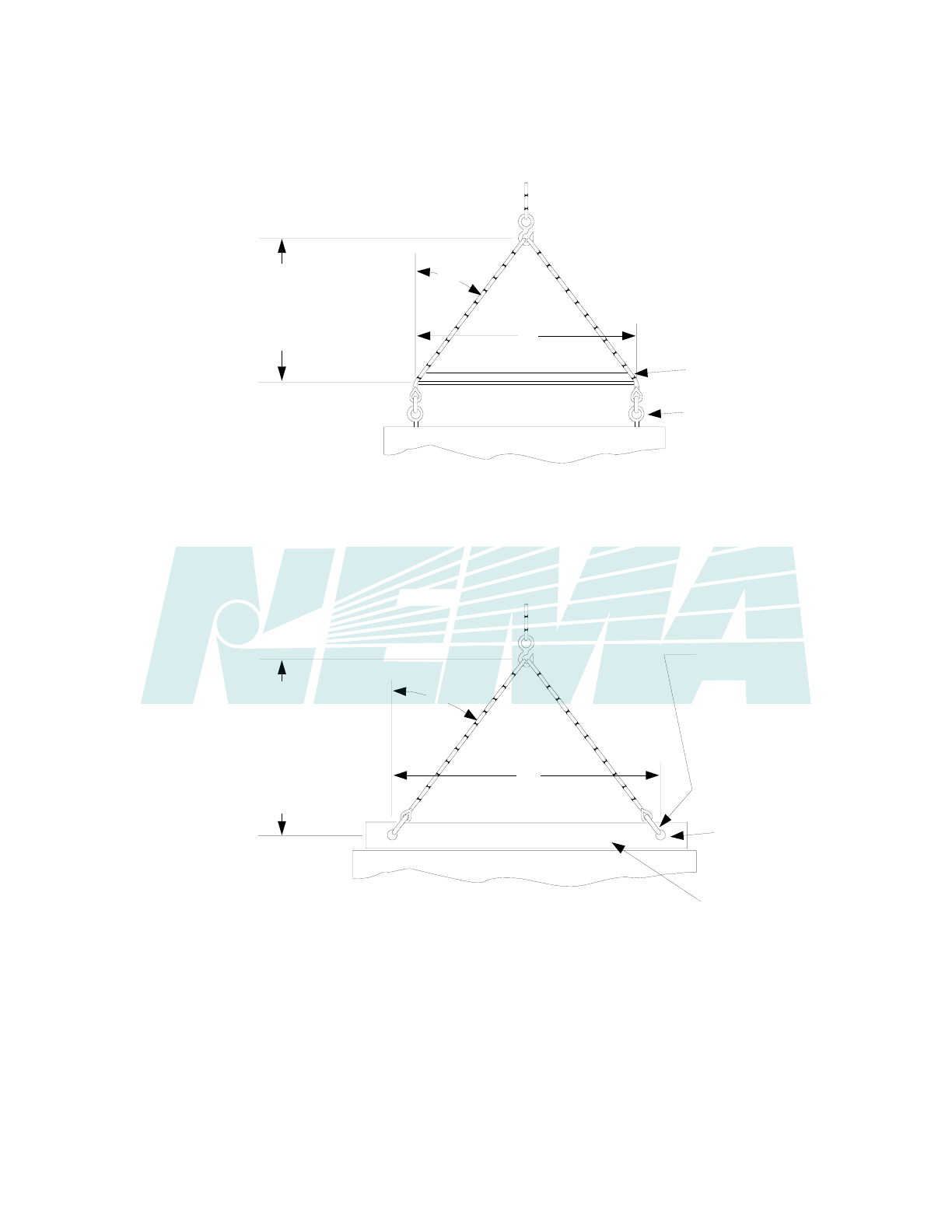
PB 2.1-2007
Page 5
© Copyright 2007 by the National Electrical Manufacturers Association.
MAX
45
o
MAX
45
o
A
A
DON'T PASS
ROPES OR CABLES
THROUGH LIFT
HOLES; USE
SLINGS WITH
SAFETY HOOKS
OR SHACKLES
SWITCHBOARD
SWITCHBOARD
THEHEIGHTOFTHE
LIFT POINT ABOVE
THE LIFT ANGLE
SHOULD BE AT LEAST
1/2 OF "A" (THE
DISTANCE BETWEEN
LIFT HOLES). THIS
ASSURES A MAXI-
MUM ANGLE OF
45 AS SHOWN
o
THE HEIGHT OF THE LIFT POINT
ABOVE THE SPREADER SHOULD
BE AT LEAST 1/2 OF "A"
(THE DISTANCE BETWEEN EYE-
BOLTS). THIS ASSURES A MAXI-
MUM ANGLE OF 45 AS SHOWN
o
LIFT HOLE
EYE BOLTS
LIFT ANGLE
SPREADER
LIFT POINT
LIFT POINT
Figure 1 Lifting with Eye Bolts
Fi
g
ure 2 Liftin
g
with Inte
g
ral Lift
A
n
g
le
Figure 2-2
LIFTING WITH INTEGRAL LIFT ANGLE
Figure 2-1
LIFTING WITH EYE BOLTS
90 of 292
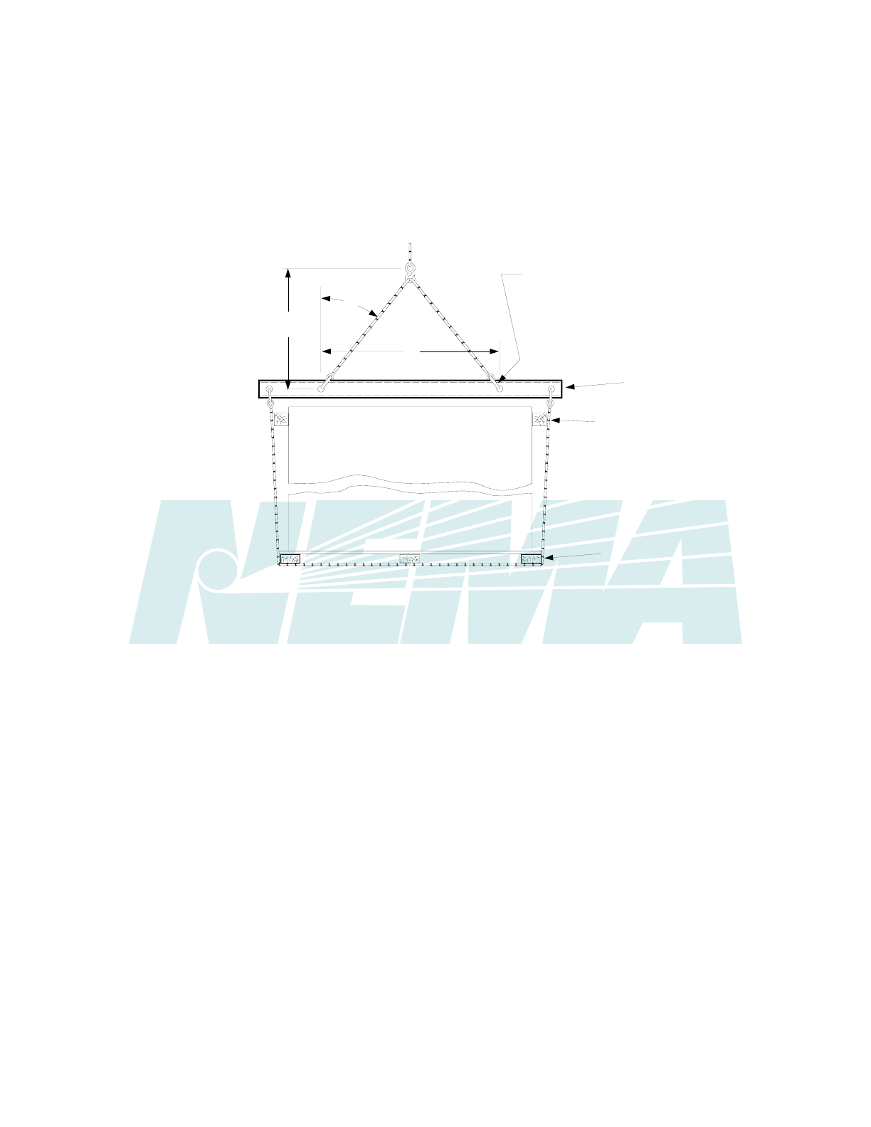
PB 2.1-2007
Page 6
MAX
45
o
A
1/2 A
OR MORE
DON'T PASS
ROPES OR CABLES
THROUGH LIFT
HOLES; USE
SLINGS WITH
SAFETY HOOKS
OR SHACKLES
SPANNER BA
R
(CHANNEL)
BLOCKS
SWITCHBOARD
SHIPPING SKID
Figure 3 Lifting h ing Riggingwit Sl
Figure 2-3
LIFTING WITH SLING RIGGING
© Copyright 2007 by the National Electrical Manufacturers Association.
91 of 292

PB 2.1-2007
Page 7
Section 3
STORAGE
3.1 CLEAN, DRY SPACE HAVING UNIFORM TEMPERATURE
A switchboard that is not installed and energized immediately should be stored in a clean, dry space having
a uniform temperature to prevent condensation. Preferably, it should be stored in a heated building having
adequate air circulation and protected from dirt, fumes, water, and physical damage.
3.2 PROTECTION FROM WEATHER AND DIRT
It is recommended that switchboards should not be stored outdoors. However, if it must be stored outdoors,
cover it securely to provide protection from weather and dirt. Temporary electrical heating should be
installed to prevent condensation; approximately 250 watts per section is adequate for the average
switchboard size and environment. All loose packing or flammable materials inside the switchboard should
be removed before energizing space heaters.
3.3 OUTDOOR SWITCHBOARDS ARE NOT WEATHER RESISTANT UNTIL INSTALLED
Outdoor switchboards are not weather resistant until completely and properly installed and should be treated
exactly the same as indoor switchboards until after they are installed.
3.4 UN-ENERGIZED OUTDOOR SWITCHBOARD SHOULD BE KEPT DRY INTERNALLY
An un-energized outdoor switchboard should be kept dry internally by installing temporary heating (see 3.2)
or by energizing any self-contained space heaters.
© Copyright 2007 by the National Electrical Manufacturers Association.
92 of 292

PB 2.1-2007
Page 8
Section 4
INSTALLATION OF SWITCHBOARD OR ENCLOSURE
4.1 MANUFACTURER'S INSTALLATION INSTRUCTIONS
Install the switchboard in a neat and workmanlike manner following the manufacturer's installation
instructions, if available.
4.2 LOCATION
Locate the switchboard in the area indicated on the building plans. The switchboard enclosure should be
suitable for the environment or protected by other means. Additional precautions may be necessary, during
installation, to prevent moisture, water, or other contaminants from entering and accumulating within the
enclosures. Clearances or working spaces are as follows:
4.2.1 Clearance from Walls
Clearance from walls (not rear accessible)—minimum of 1/2 inch
4.2.2 Working Clearances
Working clearances vary substantially depending on voltage and specific applications. See Section 110.26
of the National Electrical Code.
NOTE—Spaces for working clearances and clearances from walls should not be used for storage. Working spaces should have
adequate lighting.
4.3 CHANNEL SILLS
When channel sills are used, they should be embedded in the concrete floor or grouted on the surface. In
either case, they should be installed in an aligned position and be level over the entire length prior to
installing the switchboard.
4.4 CONDUIT AND OTHER RACEWAYS
Position the switchboard so that the raceway stubs or floor openings are located in the area specified on the
manufacturer's drawing. In the absence of drawings, locate the switchboard over the raceways or floor
openings so as to provide cable bending space and clearances to energized parts or other obstructions.
See Section 408.10 of the National Electrical Code.
4.5 LEVELING AND SECURING
Install the switchboard in its final position, progressively leveling each section and bolting the frames
together if they are separated. If necessary, secure the switchboard to walls or other supporting surfaces.
Security should not depend on wooden plugs driven into holes in masonry, concrete, plaster, or similar
materials.
4.6 SPLICE BUS
Connect all through and ground bus at shipping breaks, using the splice bus and hardware supplied with the
switchboard. Tighten bolted connections in accordance with the manufacturer's torque specifications. If not
furnished, consult the manufacturer.
© Copyright 2007 by the National Electrical Manufacturers Association.
93 of 292

PB 2.1-2007
Page 9
4.7 GROUNDING AND BONDING
Ground and bond the switchboard as follows:
4.7.1 Grounded Systems
Switchboard used as service equipment for a grounded system or as a main switchboard for a separately
derived system.
4.7.1.1 Grounding Electrode System in Switchboard
If the connection for the grounding electrode system is to be in the switchboard, install a grounding electrode
conductor sized in accordance with Sections 250.66 or 250.166 of the National Electrical Code from the
grounding electrode to the switchboard ground bus or ground terminal designated by the manufacturer. See
Sections 250.62 and 250.64 of the National Electrical Code.
4.7.1.2 Switchboards Used as Service Equipment on Grounded Systems
Switchboards used as service equipment on systems that are grounded at any point are required to have a
grounded conductor brought to the switchboard in accordance with Section 250.24(C) of the National
Electrical Code. This conductor is required even if the switchboard is supplying loads that are only phase-to-
phase connected.
4.7.1.3 Installation of Main Bonding Jumper
Unless already done at the factory, install the main bonding jumper from the incoming grounded conductor
bus (neutral) to the ground bus or other location designated by the manufacturer.
4.7.1.4 Steps 4.7.1.1 Through 4.7.1.3
Steps 4.7.1.1 through 4.7.1.3 must effectively connect together the grounding electrode, the switchboard
frame, all outgoing equipment grounding conductors, and the grounded conductor bus (neutral) of the
system on the supply side of any neutral disconnecting link.
4.7.1.5 Neutral Disconnecting Link
Do not connect any grounding conductors to the load side of any neutral disconnecting link or any sensor
used for ground fault protection. Do not connect equipment grounding conductors directly to the grounded
conductor bus (neutral).
4.7.1.6 Dual Fed Switchboard or System
Where the switchboard or system is dual fed (double-ended) and has ground fault protection, special
precautions are necessary to accomplish proper grounding and bonding. Follow the manufacturer's
instructions.
4.7.2 Ungrounded Systems—Service Equipment or Separately Derived System Main
4.7.2.1 Conductor Sized in Accordance with National Electrical Code
Install a grounding electrode conductor sized in accordance with Sections 250.66 or 250.166 of the National
Electrical Code from the grounding electrode to the switchboard ground bus or ground terminal designated
by the manufacturer. See Sections 250.62 and 250.64 of the National Electrical Code. This should
effectively connect together the grounding electrode, the switchboard frame, and all outgoing equipment
grounding conductors.
4.7.3 Grounded or Ungrounded Systems
Applications other than service equipment or other than main for separately derived systems.
© Copyright 2007 by the National Electrical Manufacturers Association.
94 of 292

PB 2.1-2007
Page 10
4.7.3.1 Grounding Conductor Size in Accordance with National Electrical Code
Ground the switchboard frame and any ground bus by means of an equipment grounding conductor having
a size in accordance with Section 250.122 of the National Electrical Code and run with the main supply
conductors or by bonding to the raceway enclosing the main supply conductors in accordance with Sections
250.118 and 250.120 of the National Electrical Code.
4.8 UNUSED OPENINGS
Effectively close all unused openings in the switchboard enclosure.
4.9 DAMP INDOOR LOCATIONS
In damp indoor locations, shield the switchboard so as to prevent moisture and water from entering and
accumulating therein.
4.10 UNUSUAL SERVICE CONDITIONS
Unless the switchboard has been designed for unusual service conditions, it should not be located where it
will be exposed to ambient temperatures above 40°C (104°F), high humidity, corrosive or explosive fumes,
dust, vapors, dripping or standing water, abnormal vibration, mechanical shock, tilting, or other unusual
operating conditions.
© Copyright 2007 by the National Electrical Manufacturers Association.
95 of 292

PB 2.1-2007
Page 11
Section 5
INSTALLATION OF CONDUIT AND CONDUCTORS
5.1 PREVENT MOISTURE OR WATER FROM ENTERING
Conduits and other raceways should be installed to prevent moisture or water from entering and
accumulating within the enclosure. All metallic raceways (including stubs) should be bonded to the
switchboard. All raceways should be located in the areas recommended by the manufacturer to avoid
conductor interference with structural members and live parts. Before pulling any conductors into the
switchboard, verify that their size, temperature rating, and conductor insulation comply with the switchboard
markings. See Section 110.14(C) of the National Electrical Code.
5.2 TEMPERATURE RATINGS
Care should be exercised to ensure that the types and temperature ratings of conductors being installed
in the switchboard are suitable for use with the terminals which have been provided.
5.3 COMPRESSION (CRIMP) TERMINALS
If compression (crimp) terminals are used, crimp with the tool(s) recommended by the manufacturer.
5.4 STRIPPING INSULATION FROM CONDUCTORS
Care should be exercised in stripping insulation from the conductors so as not to nick or ring the conductor.
For aluminum, clean all oxide from the stripped portion and apply an oxide inhibiting compound. All
mechanical terminals should be tightened per the manufacturer's torque specifications. If not furnished,
consult the manufacturer.
5.5 PROPER WIRING METHODS
Refer to Article 300 of the National Electrical Code for proper wiring methods. Conductors should enter the
switchboard in the section in which they are to be terminated, except as noted in Section 408.3(A)(3) of the
National Electrical Code.
5.6 CONDUCTOR LOCATION IN SWITCHBOARD
Provision should be made to locate conductors in the switchboard so that they will be free from physical
damage and to avoid overheating. If required by the manufacturer's instructions, secure the conductors as
necessary in order to withstand short-circuit forces. The largest practical bending radii should be maintained
to avoid damaging the insulation and causing terminals to loosen. Exercise care so that the conductors will
not interfere with any moving parts.
5.7 CONDUCTORS 1/0 AWG IN SIZE AND LARGER
Conductors 1/0 AWG in size and larger may be run in parallel. All parallel conductors should be of the same
size, length, and material to assure the equal division of current, as required by Section 310.4 of the National
Electrical Code. If conductors pass through metal having magnetic properties, all of the circuit conductors,
including the neutral, should be run through the same opening, as specified by Section 300.20(A) of the
National Electrical Code.
© Copyright 2007 by the National Electrical Manufacturers Association.
96 of 292

PB 2.1-2007
Page 12
5.8 INCOMING AND OUTGOING CONTROL CONNECTIONS
All incoming and outgoing control connections should be made in accordance with the switchboard
manufacturer's schematic and wiring diagrams.
5.9 PREVENT CONDUCTOR INSULATION FROM CRACKING OR SPLITTING
Installation of conductors should be done at temperatures above freezing to prevent conductor insulation
from cracking or splitting, unless the conductor insulation is suitable for installation at temperatures below
freezing.
5.10 NATIONAL ELECTRICAL CODE, SECTION 725.54
Refer to the National Electrical Code, Section 725.54 for the separation requirements for conductors of
Class 2 and Class 3 remote control, signaling and power-limited circuits.
© Copyright 2007 by the National Electrical Manufacturers Association.
97 of 292

PB 2.1-2007
Page 13
Section 6
INSTALLATION OF SWITCHBOARD INTERIOR
6.1 INSTRUCTIONS IF SWITCHBOARD INTERIOR WAS NOT FACTORY–MOUNTED
Follow these instructions if the switchboard interior(s) was not mounted at the factory.
6.2 UNPACKING
Exercise care in unpacking the switchboard interior to prevent damage.
6.3 INSPECTION
Check for shipping damage and check to make sure the interior is the correct one for the installation.
6.4 STORAGE
Store the switchboard interior in a clean dry place where it will not be subject to physical damage.
6.5 CLEANING
Clean the switchboard enclosure of all foreign material prior to the installation of the interior. If parts at
connection points are splattered with cement, plaster, paint, or other foreign material, remove the foreign
material with great care to avoid damage to the plating.
CAUTION—Hydrocarbon spray propellants and hydrocarbon based sprays or compounds will cause
degradation of certain plastics. Contact the switchboard manufacturer before using these products to clean,
dry, or lubricate switchboard components during installation or maintenance.
6.6 MANUFACTURER'S INSTRUCTIONS
Carefully follow the switchboard manufacturer's instructions.
6.7 INTERIOR INSTALLATION
Install the interior and tighten it securely in the enclosure. Install the section bus connection to the through
bus, if needed.
© Copyright 2007 by the National Electrical Manufacturers Association.
98 of 292

PB 2.1-2007
Page 14
Section 7
STEPS TO BE TAKEN BEFORE ENERGIZING
7.1 ACCESSIBLE ELECTRICAL CONNECTIONS
Tighten all accessible electrical connections to the manufacturer's torque specifications. If such information
is not provided with the equipment, consult the manufacturer.
7.2 BLOCKS OR OTHER TEMPORARY HOLDING MEANS
Remove all blocks or other temporary holding means used for shipment from all component devices and the
switchboard interior.
7.3 INTEGRITY OF ALL BUS MOUNTING MEANS
Check the integrity of all bus mounting means.
7.4 ENCLOSURE
Check the enclosure to see that it has not been damaged in such a manner as to reduce electrical spacings.
7.5 OPERATING MECHANISMS
Manually exercise all switches, circuit breakers, and other operating mechanisms to make certain that they
operate freely.
Check the integrity of all electrical and mechanical interlocks and padlocking mechanisms. For key
interlocked systems, assure that only the required number of keys are accessible to the operator
7.6 ELECTRICAL INSULATION RESISTANCE TEST
Conduct an electrical insulation resistance test to ensure that the switchboard is free from short circuit or
ground fault conditions. With the neutral isolated from ground and the switches and circuit breakers open,
conduct electrical insulation resistance tests from phase to phase, phase to ground, phase to neutral, and
neutral to ground. If the resistance reads less than 1 megohm while testing with the branch circuit devices in
the open position, the system may be unsafe and should be investigated. If after the investigation and
possible corrections, low readings are still observed, the manufacturer should be contacted. Some
electronic equipment (metering, TVSS, etc.) may be damaged by this testing. Refer to the manufacturer’s
equipment markings for guidelines.
7.7 ELECTRICAL RELAYS, METERS, AND INSTRUMENTATION
Check electrical relays, meters, and instrumentation to determine that connections are made properly and
that the devices function properly.
7.8 ELECTRICALLY OPERATED SWITCHES, CIRCUIT BREAKERS, AND OTHER
MECHANISMS
With loads disconnected, electrically exercise all electrically operated switches, circuit breakers, and other
mechanisms to determine that the devices operate properly. An auxiliary source of control power may be
necessary to provide power to the electrical operators.
© Copyright 2007 by the National Electrical Manufacturers Association.
99 of 292

PB 2.1-2007
Page 15
7.9 GROUND FAULT PROTECTION SYSTEM
Test the ground fault protection system (if furnished) in accordance with the manufacturer's instructions. See
Section 230.95 of the National Electrical Code and NEMA Standards Publication PB 2.2.
7.10 ADJUSTABLE TIME CURRENT TRIP DEVICE SETTINGS
Set any adjustable time current trip device settings to the proper values.
NOTE—Experience has indicated that damage from overcurrent can be reduced if the devices used for overload and short-circuit
protection are set to operate instantaneously (that is, without intentional time delay) at 115 percent of the highest value of phase current
which is likely to occur as the result of any anticipated motor starting or welding currents.
7.11 FIELD WIRING
Make certain that field wiring is clear of live parts and, when specified by the manufacturer, physically
secured to withstand the effects of short circuits.
7.12 GROUNDING CONNECTIONS
Check to determine that all grounding connections are properly made. If the switchboard is used as service
equipment, make certain that the neutral, if present, is properly bonded to the cabinet. If there is no ground
bus, make certain that the sections of the switchboard which are shipped separately are connected in such
a way as to ensure a continuous grounding path.
7.13 FOREIGN MATERIAL
Remove all foreign material from the inside of the switchboard before closing the enclosure.
7.14 COVERS AND DOORS
Install covers, close doors, and make certain that no conductors are pinched and that all enclosure parts are
properly aligned and tightened.
© Copyright 2007 by the National Electrical Manufacturers Association.
100 of 292

PB 2.1-2007
Page 16
Section 8
ENERGIZING EQUIPMENT
WARNING—HAZARDOUS VOLTAGES IN ELECTRICAL EQUIPMENT CAN CAUSE SEVERE
PERSONAL INJURY OR DEATH. ENERGIZING A SWITCHBOARD FOR THE FIRST TIME AFTER
INITIAL INSTALLATION OR MAINTENANCE IS POTENTIALLY DANGEROUS.
8.1 QUALIFIED PERSONNEL PRESENT
Only qualified personnel should energize equipment for the first time. If short circuit conditions caused by
damage or poor installation practices have not been detected in the checkout procedure specified in Section
7, serious personal injury and damage can occur when the power is turned on.
8.2 NO LOAD ON SWITCHBOARD
There should be no load on the switchboard while it is being energized. Turn off all the downstream loads.
8.3 ENERGIZED IN SEQUENCE
The equipment should be energized in sequence by starting at the source end of the system and working
towards the load end. In other words, energize the main devices, then the feeder devices, and then the
branch-circuit devices. Turn the devices on with a firm positive motion.
8.4 AFTER ALL MAIN, FEEDER, AND BRANCH CIRCUIT DEVICES HAVE BEEN CLOSED
After all main, feeder, and branch circuit devices have been closed, loads such as lighting circuits,
contactors, heaters, and motors may be turned on.
© Copyright 2007 by the National Electrical Manufacturers Association.
101 of 292

PB 2.1-2007
Page 17
© Copyright 2007 by the National Electrical Manufacturers Association.
Section 9
MAINTENANCE
9.1 MAINTENANCE PROGRAM FOR SWITCHBOARDS
A maintenance program for switchboards should be conducted on a regularly scheduled basis in
accordance with the following:
9.2 FIELD TEST
A switchboard which has been carrying its regular load for at least 3 hours just prior to inspection should
be field tested by feeling the deadfront surfaces of circuit breakers, switches, interior trims, doors, and
enclosure sides with the palm of the hand. If the temperature of these surfaces does not permit you to
maintain contact for at least 3 seconds, this may be an indication of trouble and investigation is necessary.
Thermographic (infrared) scanning has become a useful method of investigating thermal performance.
WARNING—HAZARDOUS VOLTAGES IN ELECTRICAL EQUIPMENT CAN CAUSE SEVERE
PERSONAL INJURY OR DEATH. UNLESS OTHERWISE SPECIFIED, INSPECTION AND
MAINTENANCE SHOULD ONLY BE PERFORMED ON SWITCHBOARDS TO WHICH POWER HAS
BEEN TURNED OFF, DISCONNECTED AND ELECTRICALLY ISOLATED SO THAT NO ACCIDENTAL
CONTACT CAN BE MADE WITH ENERGIZED PARTS. FOLLOW ALL MANUFACTURER’S
WARNINGS AND INSTRUCTIONS.
Safety related work practices, as described in NFPA 70E, should be followed at all times.
CAUTION—Hydrocarbon spray propellants and hydrocarbon based sprays or compounds will cause
degradation of certain plastics. Contact the switchboard manufacturer before using these products to clean,
dry, or lubricate switchboard components during installation or maintenance.
9.3 SWITCHBOARD INSPECTION ONCE EACH YEAR
Inspect the switchboard once each year or after any severe short circuit.
9.4 ACCUMULATION OF DUST AND DIRT
If there is an accumulation of dust and dirt, clean out the switchboard by using a brush, vacuum cleaner, or
clean lint-free rags. Avoid blowing dust into circuit breakers or other components. Do not use a blower or
compressed air.
9.4.1 All Visible Electrical Joints and Terminals
Carefully inspect all visible electrical joints and terminals in the bus and wiring system.
9.4.2 All Conductors and Connections
Visually check all conductors and connections to be certain that they are clean and secure. Loose and/or
contaminated connections increase electrical resistance which can cause overheating. Such overheating
is indicated by discoloration or flaking of insulation and/or metal parts. Pitting or melting of connecting
surfaces is a sign of arcing due to a loose, or otherwise poor connection. Parts which show evidence of
overheating or looseness should be cleaned and re-torqued or replaced if damaged. Tighten bolts and
nuts at bus joints to manufacturer’s torque specifications.
102 of 292

PB 2.1-2007
Page 18
CAUTION—Do not remove plating from aluminum parts in joints or terminations. Damage to plating can
result in overheating. Replace damaged aluminum parts.
9.4.3 Fuse Clip Contact Pressure and Contact Means
Examine fuse clip contact pressure and contact means. If there is any sign of overheating or looseness
follow the manufacturer’s maintenance instructions or replace the fuse clips. Loose fuse clips can result in
overheating.
9.4.4 All Conditions Which Caused Overheating
Be sure that all conditions which caused the overheating have been corrected.
9.5 PROPER AMPERE, VOLTAGE, AND INTERRUPTING RATINGS
Check circuit breakers, switches, and fuses to ensure they have the proper ampere, voltage, and
interrupting ratings. Ensure that non-current-limiting devices are not used as replacements for
current-limiting devices. Never attempt to defeat rejection mechanisms which are provided to prevent the
installation of the incorrect class of fuse.
9.5.1 All Mechanisms Are Free and in Proper Working Order
Operate each switch or circuit breaker several times to ensure that all mechanisms are free and in proper
working order. Replace as required. See NEMA AB 4 for maintenance of molded case circuit breakers.
9.6 OPERATION OF ALL MECHANICAL COMPONENTS
Check the operation of all mechanical components. Replace as required.
9.6.1 Full On and Off Positions
Exercise switch operating mechanisms and external operators for circuit breakers to determine that they
operate freely to their full on and off positions.
9.6.2 Integrity of Electrical and Mechanical Interlocks
Check the integrity of all electrical and mechanical interlocks and padlocking mechanisms. For key
interlocked systems, assure that only the required number of keys are accessible to the operator.
9.6.3 Missing or Broken Parts
Whenever practical, check all devices for missing or broken parts, proper spring tension, free movement,
corrosion, dirt, and excessive wear.
9.6.4 Manufacturer’s Instructions
Adjust, clean, and lubricate or replace parts according to the manufacturer’s instructions.
9.6.4.1 Clean, Nonmetallic, Light, Grease or Oil
Use clean, nonmetallic, light grease or oil as instructed.
9.6.4.2 Molded Case Circuit Breakers
Do not oil or grease parts of molded case circuit breakers.
9.6.4.3 Lubrication with Clean, Light Grease
If no instructions are given on the devices, sliding copper contacts, operating mechanisms, and interlocks,
they may be lubricated with clean, light grease.
© Copyright 2007 by the National Electrical Manufacturers Association.
103 of 292

PB 2.1-2007
Page 19
9.6.4.4 Excess Lubrication
Wipe off excess lubrication to avoid contamination.
CAUTION—Hydrocarbon spray propellants and hydrocarbon based sprays or compounds will cause
degradation of certain plastics. Contact the switchboard manufacturer before using these products to clean,
dry, or lubricate switchboard components during installation or maintenance.
9.6.5 Readily Accessible Copper Electrical Contacts, Blades, and Jaws
Clean and dress readily accessible copper electrical contacts, blades, and jaws according to the
manufacturer's instructions when inspection indicates the need.
9.7 DETERIORATED INSULATING MATERIAL AND ASSEMBLIES
Look for and replace deteriorated insulating material and assemblies where sealing compounds have
melted.
9.8 MOISTURE OR SIGNS OF PREVIOUS WETNESS
Look for any moisture or signs of previous wetness or dripping inside the switchboard.
NOTE—Condensation in conduits or dripping from outside sources is one known cause of switchboard malfunction.
9.8.1 Conduits Which Have Dripped Condensate
Seal off any conduits which have dripped condensate, and provide means for further condensate to drain
away from the switchboard.
9.8.2 Cracks or Openings
Seal off any cracks or openings which have allowed moisture to enter the enclosure. Eliminate the source
of any dripping on the enclosure and any other source of moisture.
9.8.3 Insulating Material Which is Damp
Replace or thoroughly dry and clean any insulating material which is damp or wet or shows an
accumulation of deposited material from previous wettings.
9.8.4 Moisture Damaged Component Device
Inspect all component devices. Replace any component device which shows evidence of moisture
damage or has been subjected to water damage or flooding. Additional information may be found in the
NEMA document Guidelines for Handling Water Damaged Electrical Equipment.
9.9 WATER DAMAGE
In the event of water damage, e.g., flooding or sprinkler discharge, the manufacturer should be consulted
before clean up and corrective action is attempted.
9.10 SEVERE ELECTRICAL SHORT CIRCUIT
If a severe electrical short circuit has occurred, the excessive currents may have resulted in structural
component and/or bus and conductor damage due to mechanical distortion, thermal damage, metal
deposits, or smoke. Examine all devices and bus supports for cracks or breakage. The manufacturer
should be consulted before clean up and correction is attempted.
© Copyright 2007 by the National Electrical Manufacturers Association.
104 of 292

PB 2.1-2007
Page 20
9.11 GROUND FAULT PROTECTION SYSTEM
Test the ground fault protection system (if furnished) in accordance with the manufacturer's instructions.
See Section 230.95 of the National Electrical Code and NEMA Standards Publication PB 2.2.
9.12 INSULATION RESISTANCE
Check insulation resistance (See 7.6) under any of the following conditions:
a. If a severe short circuit has occurred. (See 9.10)
b. If it has been necessary to replace parts or clean insulating surfaces
c. If the switchboard has been exposed to high humidity, condensation, or dripping moisture.
© Copyright 2007 by the National Electrical Manufacturers Association.
105 of 292

PB 2.1-2007
Page 21
Section 10
PERMISSIBLE LOADING OF SWITCHBOARDS
10.1 SWITCHBOARDS WITHOUT MAIN OVERCURRENT PROTECTIVE DEVICES
For switchboards without main overcurrent protective devices (main lug switchboard), the total continuous
load current through the supply bus should not exceed the current rating of the switchboard.
10.2 SWITCHBOARDS WITH A SINGLE MAIN OVERCURRENT PROTECTIVE DEVICE
For switchboards with a single main overcurrent protective device, the total continuous load current on the
protective device should not exceed 80 percent of its ampere rating unless the device is rated to carry 100
percent of its ampere rating.
10.3 SWITCHBOARDS WITH A MULTIPLE MAIN OVERCURRENT PROTECTIVE DEVICE
For switchboards with a multiple main overcurrent protective devices, the total continuous current through
the supply bus should not exceed the current rating of the switchboard. The total continuous load current on
each main overcurrent protective device should not exceed 80 percent of its ampere rating unless the device
is rated to carry 100 percent of its ampere rating.
10.4 FEEDER AND BRANCH CIRCUIT OVERCURRENT PROTECTIVE DEVICES IN
SWITCHBOARDS
For feeder and branch circuit overcurrent protective devices in switchboards, the total continuous load
current on the overcurrent protective device should not exceed 80 percent of its ampere rating unless the
device is rated to carry 100 percent of its ampere rating.
10.5 HARMONICS IN THE ELECTRICAL SYSTEM
Some types of electrical equipment cause harmonics in the electrical system which may result in
overheating. This condition should be considered when determining switchboard loading.
§
© Copyright 2007 by the National Electrical Manufacturers Association.
106 of 292

PB 2.1-2007
Page 22
< This page is intentionally left blank. >
© Copyright 2007 by the National Electrical Manufacturers Association.
107 of 292
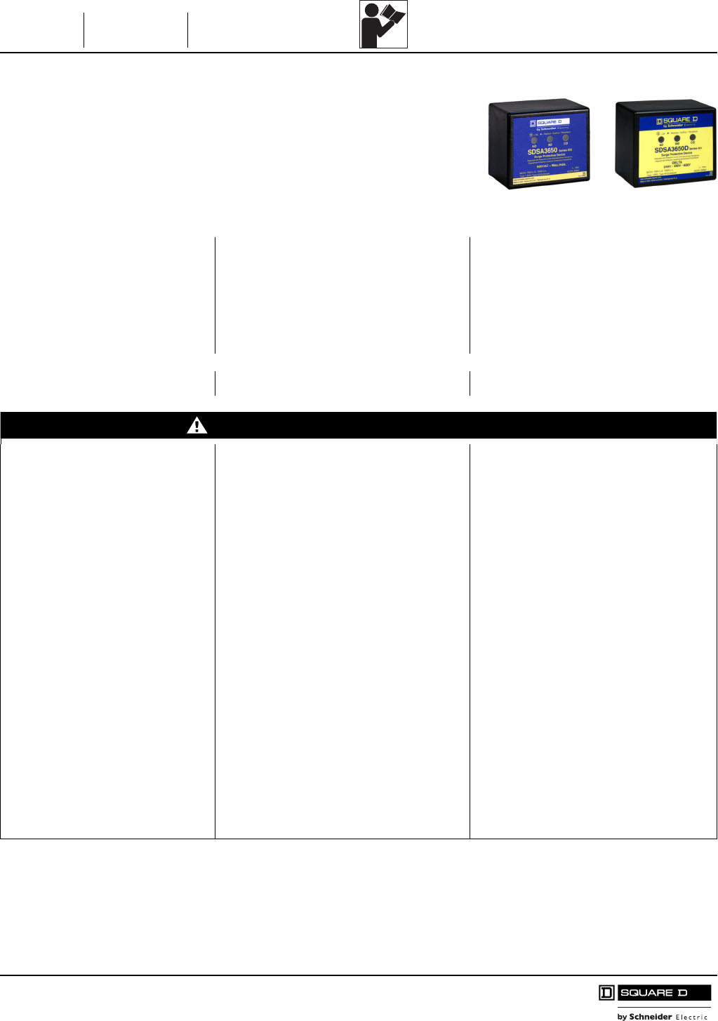
Instruction
Bulletin
Boletín de
instrucciones
Directives
d'utilisation 8291-0068D
11/2011
SDSA3650 Surge Protective Device (SPD)
Dispositivo de protección contra sobretensiones
transitorias (SPD) SDSA3650
Dispositif de protection contre les surtensions
transitoires (SPD) SDSA3650
Replaces / Reemplaza / Remplace 8291-0068C 10/2010
Retain for future use. / Conservar para uso futuro. / À conserver pour usage ultérieur.
Introduction Introducción Introduction
The SDSA3650 Surge Protective Device
(SPD) is designed to provide surge
suppression for three-phase services up
to 600 Vac, including delta (SDSA3650D).
El dispositivo de protección contra
sobretensiones transitorias SDSA3650 ha sido
diseñado para proporcionar supresión de
sobretensiones a acometidas de tres fases
hasta un máximo de 600 V~, incluyendo los
sistemas en delta (SDSA3650D).
Le dispositif de protection contre les surtensions
transitoires SDSA3650 est conçu pour fournir la
suppression des surtensions transitoires pour
des services triphasés jusqu'à 600 V~, y
compris le dispositif en triangle (SDSA3650D).
Precautions Precauciones Précautions
DANGER / PELIGRO / DANGER
HAZARD OF ELECTRIC SHOCK,
EXPLOSION, OR ARC FLASH
• Apply appropriate personal protective
equipment (PPE) and follow safe
electrical work practices. See NFPA
70E.
• This equipment must only be installed
and serviced by qualified electrical
personnel.
• Turn off all power supplying this
equipment before working on or inside
equipment.
• Always use a properly rated voltage
sensing device to confirm power is off.
• Replace all devices, doors and covers
before turning on power to this
equipment.
• This equipment must be effectively
grounded per all applicable codes.
Use an equipment-grounding
conductor to connect this equipment
to the power system ground.
PELIGRO DE DESCARGA ELÉCTRICA,
EXPLOSIÓN O DESTELLO POR ARQUEO
• Utilice equipo de protección personal (EPP)
apropiado y siga las prácticas de seguridad en
trabajos eléctricos establecidas por su
Compañía, consulte la norma 70E de NFPA y
NOM-029-STPS.
• Solamente el personal eléctrico especializado
deberá instalar y prestar servicio de
mantenimiento a este equipo.
• Desenergice el equipo antes de realizar
cualquier trabajo dentro o fuera de él.
• Siempre utilice un dispositivo detector de
tensión nominal adecuado para confirmar la
desenergización del equipo.
• Vuelva a colocar todos los dispositivos, las
puertas y las cubiertas antes de volver a
energizar el equipo.
• Este equipo deberá estar correctamente
conectado a tierra de acuerdo con los códigos
aplicables. Utilice un conductor de conexión a
tierra del equipo para conectar este último a la
tierra del sistema de alimentación.
RISQUE D'ÉLECTROCUTION,
D'EXPLOSION OU D'ÉCLAIR D'ARC
• Portez un équipement de protection
personnelle (ÉPP) approprié et observez les
méthodes de travail électrique sécuritaire.
Voir NFPA 70E.
• Seul un personnel qualifié doit effectuer
l'installation et l'entretien de cet appareil.
• Coupez toutes les alimentations de l'appareil
avant d'y travailler.
• Utilisez toujours un dispositif de détection de
tension à valeur nominale appropriée pour
vous assurer que l'alimentation est coupée.
• Replacez tous les dispositifs, les portes et
les couvercles avant de mettre l'appareil
sous tension.
• Cet appareil doit être effectivement mis à la
terre selon tous les codes en vigueur.
Utilisez un conducteur de m.à.l.t. d'appareil
pour raccorder celui-ci à la terre du système
d'alimentation.
Failure to follow these instructions
will result in death or serious injury.
El incumplimiento de estas instrucciones
podrá causar la muerte o lesiones serias.
Si ces directives ne sont pas respectées,
cela entraînera la mort ou des blessures
graves.
™
SDSA3650 SDSA3650D
108 of 292
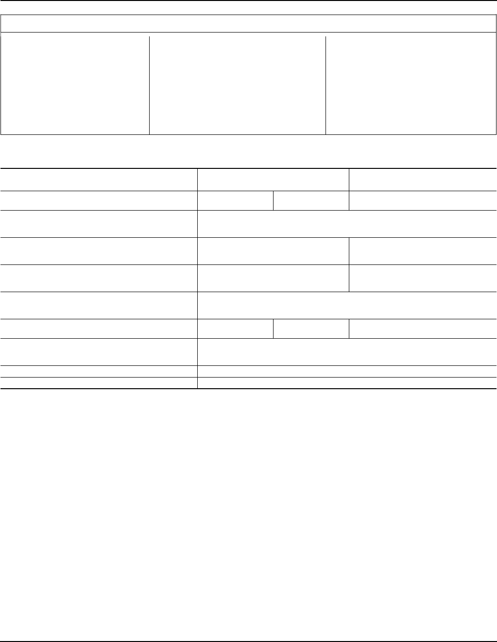
SDSA3650 Surge Protective Device (SPD)
Dispositivo de protección contra sobretensiones transitorias (SPD) SDSA3650 8291-0068D
Dispositif de protection contre les surtensions transitoires (SPD) SDSA3650 11/2011
© 2010–2011 Schneider Electric All Rights Reserved / Reservados todos los derechos / Tous droits réservés2
CAUTION / PRECAUCIÓN / ATTENTION
LOSS OF SURGE SUPPRESSION
Turn off all power supplying the
equipment and isolate the Surge
Protective Device before Megger® or
hi-potential testing.
PÉRDIDA DE SUPRESIÓN DE
SOBRETENSIONES TRANSITORIAS
Desenergice el equipo y aísle el dispositivo de
protección contra sobretensiones transitorias
antes de realizar cualquier prueba de rigidez
dieléctrica o con Megger®.
PERTE DE LA SUPPRESSION DES
SURTENSIONS TRANSITOIRES
Coupez toute alimentation de cet appareil et
isolez le dispositif de protection contre les
surtensions transitoires avant de procéder à
l'essai de rupture diélectrique ou avec Megger®.
Failure to follow these instructions
can result in equipment damage.
El incumplimiento de estas instrucciones
puede causar daño al equipo.
Si ces directives ne sont pas respectées,
cela peut entraîner des dommages
matériels.
Table / Tabla / Tableau 1 : General Specifications / Especificaciones generales / Spécifications générales 1 2
1Contains no serviceable parts / Contiene piezas libres de mantenimiento / Ne contient aucune pièce à réparer ou entretenir
2Suitable for use on a circuit capable of delivering not more than 200 kA rms symmetrical amperes. / Se puede usar en un circuito capaz de suministrar no más
de 200 kA simétricos rcm. / Convient à un circuit capable de fournir pas plus de 200 kA RMS symétriques.
Description / Descripción / Description Wye / Conexión en estrella /
Raccordement en étoile
Delta / Conexión en delta /
Raccordement en triangle
Product Catalog Number / No. de catálogo del producto /
No de catalogue de produit SDSA3650 SDSA3650E SDSA3650D
Maximum Surge Current /
Corriente transitoria máx. /
Courant max. de surtension
40 kA/Phase / 40 kA/fase / 40 kA/phase
System Voltage (Uo) /
Tensión del sistema (Uo) /
Tension du système (Uo)
208Y/120 V, 380Y/220 V,
400Y/230 V, 480Y/277 V,
600Y/347 V
240 V, 480 V, 600 V, 240/120 V
High-Leg Delta / extremo alto de una instalación
en delta / sommet du triangle
Maximum Continuous Operating Voltage (MCOV), (Uc) /
Tensión máxima de funcionamiento continuo (MCOV), (Uc) /
Tension de fonctionnement continu maximale (MCOV), (Uc)
L-N 750 V, L-L 1500 V L-L 1500 V
Connection Method /
Método de conexión /
Méthode de raccordement
Parallel, 12 AWG Wire /
Conductor sólido calibre 3,31 mm2 (12 AWG), paralelo /
En parallèle, fil rigide de calibre 12 AWG
Lead Length / Longitud de los conductores /
Longueur des conducteurs 20 ±1 in. / pulg / po 36 ±1 in. / pulg / po 20 ±1 in. / pulg / po
Operating and Storage Temperature /
Temperatura de funcionamiento y almacenamiento /
Température de fonctionnement et d'entreposage
-40 °F to +160 °F (-40 °C to +70 °C) /
-40 °C a +70 °C (-40 °F a +160 °F) /
-40 °C a +70 °C (-40 °F a +160 °F)
Frequency / Frecuencia / Fréquence 50/60 Hz
Diagnostics / Diagnóstico / Diagnostics Green Status LEDs / LED de estado verde / DÉL d'état verte
For troubleshooting, call the Surgelogic Technical Assistance Group at 1-800-577-7353.
109 of 292
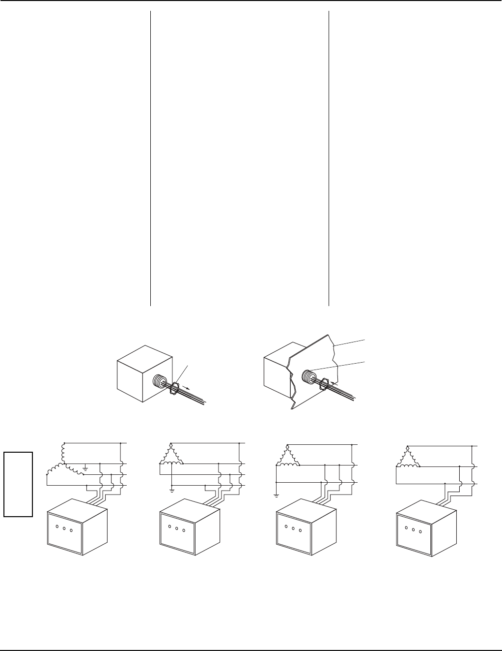
SDSA3650 Surge Protective Device (SPD)
8291-0068D Dispositivo de protección contra sobretensiones transitorias (SPD) SDSA3650
11/2011 Dispositif de protection contre les surtensions transitoires (SPD) SDSA3650
© 2010–2011 Schneider Electric All Rights Reserved / Reservados todos los derechos / Tous droits réservés 3
Installation Instalación Installation
1. Turn off all power supplying this
equipment before working on or
inside equipment.
1. Desenergice el equipo antes de realizar
cualquier trabajo dentro o fuera de él.
1. Couper toutes les alimentations de l'appareil
avant d'y travailler.
2. For mounting, see Figure 1. 2. Para obtener detalles de montaje, vea la
figura 1.
2. Pour le montage voir la figure 1.
3. Confirm SPD is rated for the system
by comparing voltage measurements
to the Line Voltage (L-L, L-N) on the
product label (see Figure 2).
3. Asegúrese de que el SPD sea adecuado
para su sistema comparando las
mediciones de tensión en la tensión de
línea (L-L, L-N), especificadas en la etiqueta
del producto (vea la figura 2).
3. S'assurer que le SPD est de la valeur
nominale convenant à votre système en
comparant les mesures de tension à la
tension de ligne (L-L, L-N) sur l'étiquette du
produit (voir la figure 2).
4. Confirm the black wires are
connected to the line wires and the
neutral wire is connected to the white
wire (see Figure 2).
NOTE: Delta model SDSA3650D does
not include or require a white wire.
4. Asegúrese de que los conductores negros
estén conectados a los conductores de
línea y el conductor blanco al conductor
neutro (vea la figura 2).
NOTA: El modelo SDSA3650D en delta no
incluye ni requiere conductor blanco.
4. S’assurer que les fils noirs sont raccordés
aux fils de ligne et que le fil blanc est
raccordé au fil du neutre (voir la figure 2).
REMARQUE : Le modèle SDSA3650D en
triangle (delta) n'inclut pas ou n'exige pas un fil
blanc.
5. Twist wires 1/2 turn every 12 in.
(30 cm) of length.
5. Tuerza los conductores ½ vuelta o más por
cada 305 mm (12 pulgadas) de longitud.
5. Torsader les conducteurs de 1/2 tour ou
plus par 305 mm (12 po) de longueur.
6. Keep conductor length as short as
possible with no sharp bends.
6. Mantenga la longitud de los conductores lo
más corta posible evitando doblarlos en
ángulo recto.
6. Maintenir la longueur des conducteurs aussi
courte que possible et sans courbures
accentuées.
NOTE: Do not loop or coil wires. NOTA: No haga bucles o enrolle los cables. REMARQUE : Ne pas faire de boucles et
ne pas enrouler les fils.
7. Install cover and/or close door on
equipment.
7. Instale la cubierta y/o cierre la puerta del
equipo.
7. Installer le couvercle ou fermer la porte de
l'appareil.
Figure / Figura / Figure 1 : Mounting and Wiring / Montaje y alambrado / Montage et câblage
Figure / Figura / Figure 2 : Wiring / Alambrado / Câblage
Nut / Tuerca
/ Écrou
Panel / Tablero / Panneau
Knockout /
Disco removible /
Débouchure
Black
Black
White
Black
White
Black
Black
Black
White
BlackBlack
Black
Black
Black
Black
SDSA3650/SDSA3650E
3-phase, 4-wire
208Y/120 Vac, or 480Y/277 Vac,
or 600Y/347 Vac
3 fases, 4 hilos de 208Y/120 V~ (ca),
o 480Y/277 V~ (ca) o 600/347 V~ (ca)
Triphasé à 4-fils de 208Y/120 Vca,
ou 480Y/277 Vca, ou 600Y/347 Vca
Black
Negro
Noir
White
Blanco
Blanc
SDSA3650/SDSA3650E
3-phase, 4-wire 240/120 Vac
High-Leg Delta
3 fases, 4 hilos de 240/120 V~ (ca)
extremo alto de una instalación
en delta
Triphasé à 4-fils 240/120 Vca
sommet du triangle
SDSA3650/SDSA3650E
3-phase, 4-wire (corner grounded)
240 Vac, or 480 Vac, or 600 Vac
3 fases, 4 hilos (puesto a tierra en
esquina) de 240 V~ (ca), o 480 V~ (ca),
o 600 V~ (ca)
Triphasé à 4-fils (mis à la terre par le
coin) 240 Vca, ou 480 Vca, ou 600 Vca
SDSA3650D
3-phase, 3-wire (ungrounded)
240 Vac, or 480 Vac, or 600 Vac
3 fases, 3 hilos (sin conexión a
tierra) de 240 V~ (ca), o
480 V~ (ca), o 600 V~ (ca)
Triphasé à 3-fils (non mis à la
terre) 240 Vca, ou 480 Vca, ou
600 Vca
For troubleshooting, call the Surgelogic Technical Assistance Group at 1-800-577-7353.
110 of 292
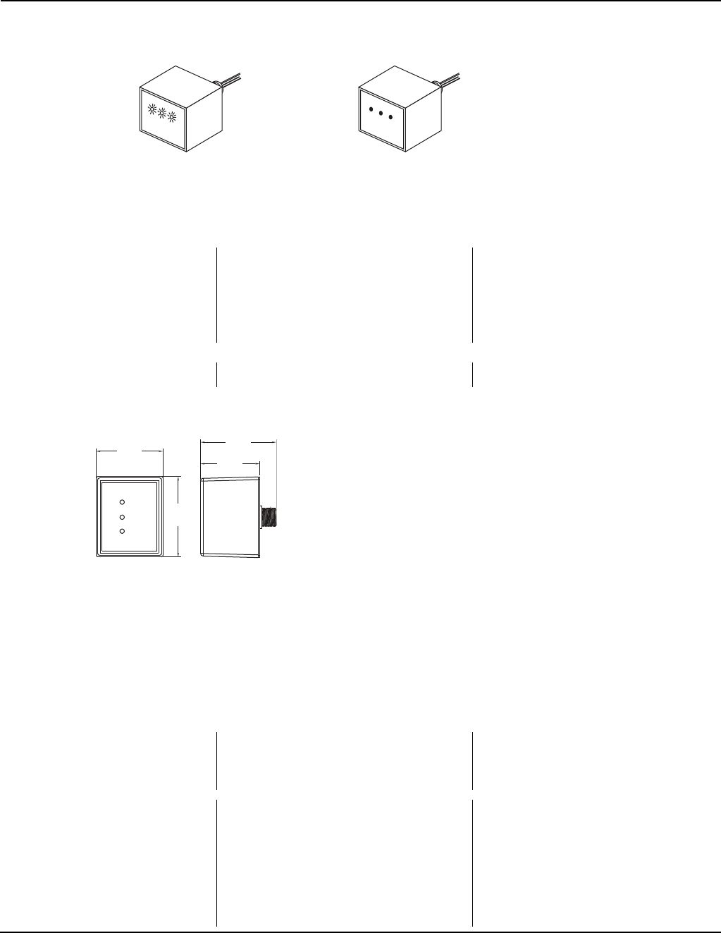
SDSA3650 Surge Protective Device (SPD)
Dispositivo de protección contra sobretensiones transitorias (SPD) SDSA3650 8291-0068D
Dispositif de protection contre les surtensions transitoires (SPD) SDSA3650 11/2011
Square D™ and Schneider Electric™ are
trademarks or registered trademarks of
Schneider Electric. Other trademarks
used herein are the property of their
respective owners.
Square D™ y Schneider Electric™ son marcas
comerciales o marcas registradas de Schneider Electric.
Cualquier otra marca comercial utilizada en este
documento pertenece a sus respectivos propietarios.
Square DMC et Schneider ElectricMC sont marques
commerciales ou marques déposées de Schneider
Electric. Toutes autres marques commerciales utilisées
dans ce document sont la propriété de leurs
propriétaires respectifs.
Schneider Electric USA
1751 S. 4800 W.
Salt Lake City, UT 84104 USA
1-888-778-2733
www.schneider-electric.us
Importado en México por:
Schneider Electric México, S.A. de C.V.
Calz. J. Rojo Gómez 1121-A
Col. Gpe. del Moral 09300 México, D.F.
Tel. 55-5804-5000
www.schneider-electric.com.mx
Schneider Electric Canada, Inc.
5985 McLaughlin Road
Mississauga On, L5R 1B8
Tel: 1-800-565-6699
www.schneider-electric.ca
© 2010–2011 Schneider Electric All Rights Reserved / Reservados todos los derechos / Tous droits réservés
4
Electrical equipment should be installed,
operated, serviced, and maintained only by
qualified personnel. No responsibility is assumed
by Schneider Electric for any consequences
arising out of the use of this material.
Solamente el personal especializado deberá instalar,
hacer funcionar y prestar servicios de mantenimiento al
equipo eléctrico. Schneider Electric no asume
responsabilidad alguna por las consecuencias
emergentes de la utilización de este material.
Seul un personnel qualifié doit effectuer l’installation,
l’utilisation, l’entretien et la maintenance du matériel
électrique. Schneider Electric n’assume aucune
responsabilité des conséquences éventuelles
découlant de l’utilisation de cette documentation.
Figure / Figura / Figure 3 : Diagnostic Operation / Diagnóstico del funcionamiento del equipo /
Diagnostic de fonctionnement
•LED ON = Normal Operation
•LED OFF = Check circuit breakers
and connections. Verify line voltage at
point of connection; if all correct,
replace unit.
•LED ENCENDIDO = funcionamiento normal
•LED APAGADO = Revise los interruptores
automáticos y las conexiones. Verifique la
tensión de línea en el punto de conexión; si
todo se encuentra en órden, sustituya el
SPD.
•DÉL ALLUMÉE = Fonctionnement normal
•DÉL ÉTEINTE = Vérifier les disjoncteurs et
les raccordements. Vérifier la tension de
ligne au point de raccordement; si tout est
correct, remplacer le SPD.
Dimensions Dimensiones Dimensions
Figure / Figura / Figure 4 : Dimensions / Dimensiones / Dimensions
LED ON = OK /
LED ENCENDIDO =
funcionamiento normal /
DÉL ALLUMÉE = OK
LED OFF = Loss of surge suppression /
LED APAGADO = pérdida de supresión de sobretensiones transitorias /
DÉL ÉTEINTE = Perte de suppression des surtensions transitoires /
3.00
[76]
3.60
[92]
3.39
[86]
2.64
[67]
in. / pulg / po
[mm]
NOTE: Knockout trade size is 0.5 in. (13 mm).
Actual hole size is 0.875 in. (22 mm).
NOTA: El tamaño estándar del disco
desprendible es de 13 mm (0,5 pulg). El tamaño
real del agujero es de 22 mm (0,875 pulg).
REMARQUE: La taille commerciale des
débouchures est de 13 mm (0,5 po). Taille
réelle du trou : 22 mm [0,875 po].
For troubleshooting, call the Surgelogic Technical Assistance Group at 1-800-577-7353.
111 of 292
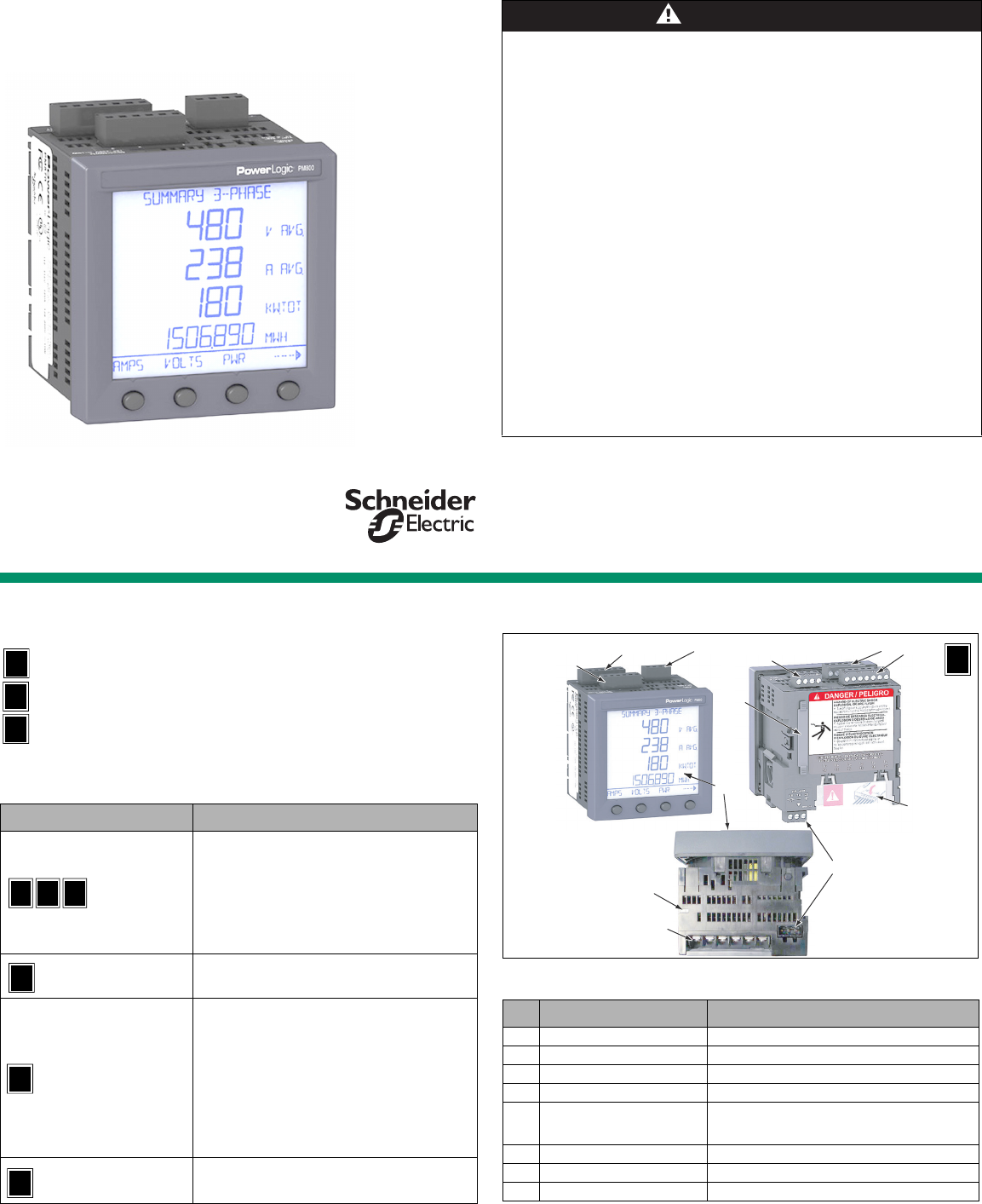
1
PowerLogic™ Series 800 Power Meter
Installation Guide
63230-500-282A1
English
Safety Precautions
Read and follow all safety precautions and instructions before installing and working with
this equipment.
Additional Resources
The Series 800 Power Meter User Guide provides additional information and is available
online. Go to http://www.schneider-electric.com > in the Search window enter PM800 > in
the drop-down box click PM800 - Power meter > On PM800 screen, click the Downloads
tab, then click the Tech publications tab > click on the document name to download or
read the document file. Firmware updates can also be downloaded at this Web site.
DANGER
HAZARD OF ELECTRIC SHOCK, EXPLOSION, OR ARC FLASH
• Apply appropriate personal protective equipment (PPE) and follow safe electrical work
practices. In the USA, see NFPA 70E.
• Only qualified electrical workers should install this equipment. Such work should be
performed only after reading this entire set of instructions.
• NEVER work alone.
• Before performing visual inspections, tests, or maintenance on this equipment, disconnect
all sources of electric power. Assume that all circuits are live until they have been completely
de-energized, tested, and tagged. Pay particular attention to the design of the power system.
Consider all sources of power, including the possibility of backfeeding.
• Turn off all power supplying the power meter and the equipment in which it is installed before
working on it.
• Always use a properly rated voltage sensing device to confirm that all power is off.
• Before closing all covers and doors, carefully inspect the work area for tools and objects that
may have been left inside the equipment.
• Use caution while removing or installing panels so that they do not extend into the energized
bus; avoid handling the panels, which could cause personal injury.
• The successful operation of this equipment depends upon proper handling, installation, and
operation. Neglecting fundamental installation requirements may lead to personal injury as
well as damage to electrical equipment or other property.
• NEVER bypass external fusing.
• NEVER short the secondary of a PT.
• NEVER open circuit a CT; use a shorting block to short circuit the leads of the CT before
removing the connection from the power meter.
• Before performing Dielectric (Hi-Pot) or Megger testing on any equipment in which the power
meter is installed, disconnect all input and output wires to the power meter. High voltage
testing may damage electronic components contained in the power meter.
• The power meter should be installed in a suitable electrical enclosure.
Failure to follow this instruction will result in death or serious injury
Introduction
The Series 800 Power Meter ships in three different configurations. The following icons are
used in this document to highlight features specific to each of these configurations:
Box Contents
Power Meter Hardware
Power meter with integrated display
Power meter unit only
Power meter unit with remote display
Table 1: Box contents based on model
Model Description Box Contents
•1 power meter
•1 hardware kit (63230-500-16) containing:
— 4 connectors
—9 lugs
— 2 mounting clips
— 1 terminator (MCT2W)
— 1 template
•1 installation guide
Additionally includes: •1 display integrated with the power meter (PM8D(MG))
Additionally includes:
•1 remote display (63230-500-120(MG))
•1 remote display adapter (PM8RDA)
•1 hardware kit (63230-500-96) containing:
— 1 communications cable (CAB3M)
— 4 screws
— 2 display retainers
•1 hardware kit (633230-500-163):
— 1 4-wire RS485 Comm 2 connector
— 1 crimp connector
•1 DIN slide (installed on unit)
•1 remote display installation guide
Additionally includes: •1 DIN slide (installed on unit)
I
U
R
D
IU
R
D
I
R
D
U
Figure 1: Series 800 Power Meter with integrated display
Table 2: Parts of the power meter with integrated display
No. Part Description
1 Control power supply connector Connection for control power to the power meter.
2 Voltage inputs Voltage metering connections.
3 I/O connector KY pulse output/digital input connections.
4 Heartbeat LED A green flashing LED indicates the power meter is ON.
5 RS485 port (COM1)
The RS485 port is used for communications with a
monitoring and control system. This port can be daisy-
chained to multiple devices.
6 Option module connector Used to connect option modules to the power meter.
7 Current inputs Current metering connections.
8 Integrated display Visual interface to configure and operate the power meter.
123
6
7
5
4
8
32
7
1
Bottom View
Back View
I
Front View
112 of 292
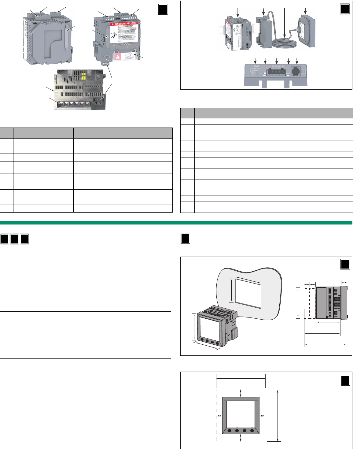
2
Figure 2: Series 800 Power Meter without display
Table 3: Parts of the Power Meter without display
No. Part Description
1 Control power supply connector Connection for control power to the power meter.
2 Voltage inputs Voltage metering connections.
3 I/O connector KY pulse output/digital input connections.
4 Display connector Used to connect an integrated display or a Remote Display
Adapter (PM8RDA).
5 RS485 port (COM1)
The RS485 port is used for communications with a
monitoring and control system. This port can be daisy-
chained to multiple devices.
6 Option module connector Used to connect option modules to the power meter.
7 Current inputs Current metering connections.
8 Heartbeat LED A green flashing LED indicates the power meter is ON.
23
6
7
5
4
1
7
32
8
1
Bottom View
Back View
U
Front View
Figure 3: Series 800 Power Meter with Remote Display and Adapter
Table 4: Parts of the Power Meter with Remote Display and Adapter (see
Figure 2 for connector detail)
No. Part Description
1 Power meter unit
2 Remote display adapter (PM8RDA)
Provides the connection between the remote display and
the power meter, and provides an additional RS232/
RS485 connection (2- or 4-wire).
3 Remote display cable Connects the remote display to the remote display adapter
(meter).
4 Remote display Visual interface to configure and operate the power meter.
5 Communications mode button Use to select the communications mode (RS232 or
RS485).
6 Communications mode LED When lit, the LED indicates the communications port is in
RS232 mode.
7 RS232/RS485 port
The RS485 port is used for communications with a
monitoring and control system. This port can be daisy-
chained to multiple devices.
8 Tx/Rx Activity LED The LED flashes to indicate communications activity.
9 Remote display connector Connects the remote display to the remote display
adapter (meter).
2314
56 7 98
PM8RDA Top View
R
D
Installation
Installation Considerations
When choosing a mounting location, consider the following points:
• Allow for easy access to all parts of the power meter. Allow extra space for wiring, fuse
disconnects, shorting blocks, accessories, or other components. Make sure to route the
wires so they do not cover the back of the unit or cooling vents on the power meter.
• Install the power meter in a protective enclosure (for example, in the USA use a Type 1
rated enclosure or better).
• For European Community (CE) compliance, the disconnect circuit breaker must be
placed within reach of the power meter and labeled: Disconnect Circuit Breaker for
Power Meter.
NOTE: The disconnect circuit breaker must be rated for the short circuit current at the
connection points.
• Locate the power meter in an area where immediate environmental conditions fall within
the acceptable range. For control power voltages above 300 Vac, the temperature range
for the meter block is -25°C to +65°C. The front display has a range of -10°C to +50°C.
Wire Specifications
Voltage inputs up to 600 Vac L-L / 347 Vac L-N and control power up to 415 Vac / 250 Vdc
complies with metering category III (refer to online documentation for detailed specs). Also,
terminal wiring insulation should have a minimum temperature rating of 80°C. Polarity
marks (■) must be followed as shown for CTs and PTs.
Dimensions and Mounting
Power Meter with Integrated Display
CAUTION
IMPROPER VENTILATION
• Mount the power meter only as described in this document.
• Provide clearances around the power meter as illustrated in Figure 4, Figure 5, and Figure 6.
Failure to follow this instruction can result in equipment damage.
IU
R
D
Figure 4: Power meter with integrated display dimensions
Figure 5: Clearances for mounting a single power meter
I
96
(3.78)
96
(3.78)
69.4
(2.73)
17.8
(0.70)
90.5
(3.56)
20 (0.78)
for each
option module
127.2
(5.01)
109.4
(4.31)
92 +0.8
–0.0
(3.62)
92 +0.8
–0.0 (3.62)
mm (in.)
I
20 (0.787)
20 (0.787)
5
(0.197)
5
(0.197)
106 (4.174)
136
(5.354)
I
mm (in)
113 of 292
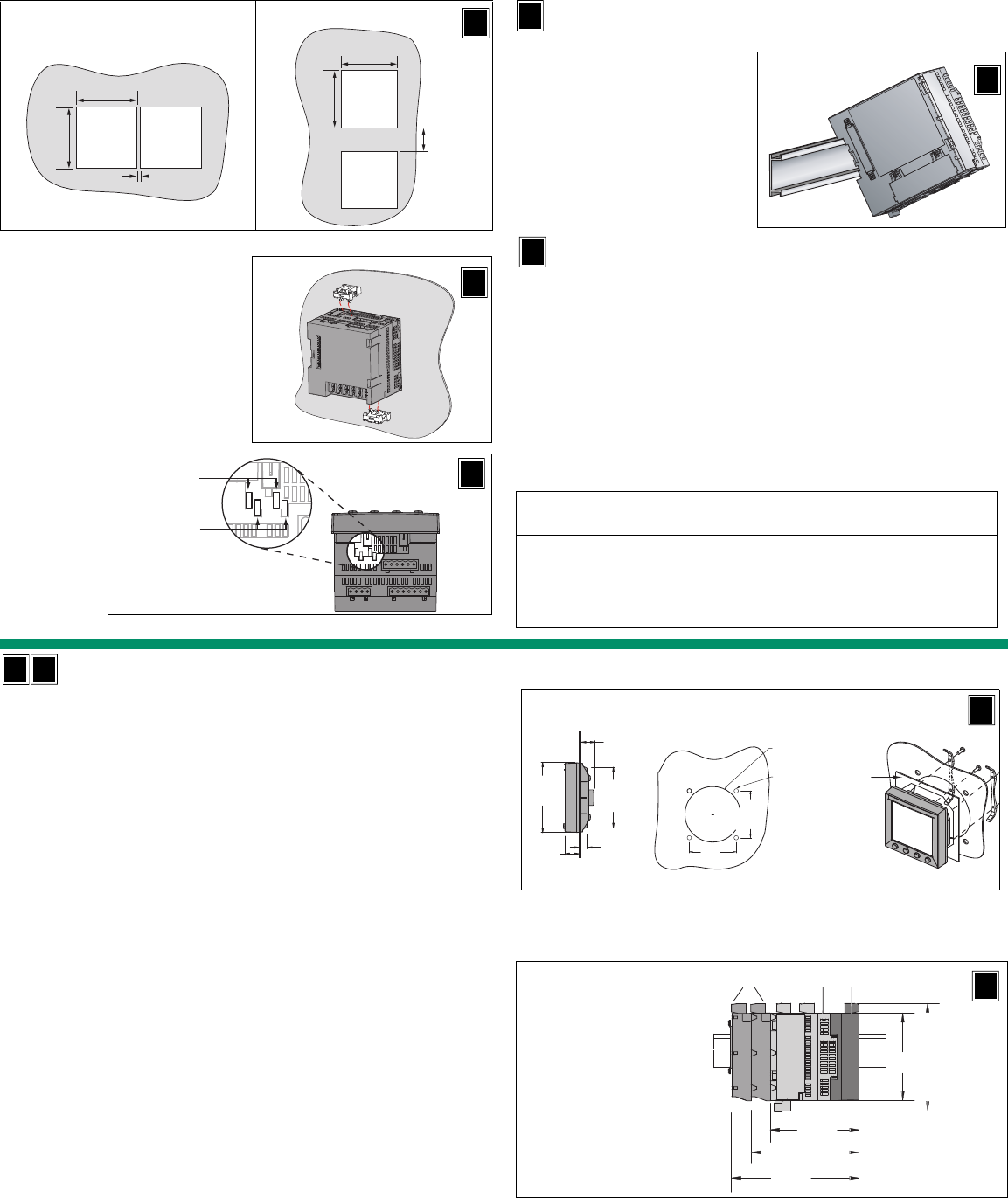
3
Figure 6: Clearances for mounting multiple power meters
Figure 7: Mounting the power meter into the panel
Power Meter Without Display
DIN Rail Mounting
Figure 8: DIN Rail Mounting
Power Meter With Remote Display
The PM8XXRD ships with a remote display and a remote display adapter (PM8RDA)
already installed (see Figure 3). For detailed mounting instructions, refer to the installation
guide that ships with the remote display models. To mount, do the following:
1. Place the power meter unit behind the round or square cutout (see Figures 9 and 11).
2. Position the remote display on the front of the panel and attach the two retainers and
screws (see Figures 9 and 11).
NOTE: If you have a 4-inch diameter cutout, you will need the PM8G mounting adapter.
3. Mount the assembled power meter unit, the PM8RD, and option modules (see
Figure 10).
4. Use the remote display cable to connect the PM8RDA to the remote display.
PM8XXU models can be used with a remote display kit (PM8RD). The power meter units of
the remote display models mount on a DIN rail as shown in Figure 10. The power meter
units are exactly the same in the RD, U, and I models.
1. Using the template included with the power
meter, make a square cutout 92 mm x 92 mm
(3.62 in. x 3.62 in.).
2. Insert the power meter through the cutout.
3. Attach the two mounting clips to the power
meter as shown.
There are two sets of mounting slots. The
first set is for installation locations thinner
than 3 mm (1/8 in.); the second is for
installation locations 3 to 6 mm (1/8 to 1/4 in.).
NOTE: Use on a flat surface of a protective
enclosure (for example, in the USA use a Type 1
rated enclosure or better).
mm (in.)
10 (0.39)
92
(3.62)
+0.8
–0.0
92
(3.62)
+0.8
–0.0
HORIZONTAL
mm (in)
40
(1.57)
92
(3.62)
+0.8
–0.0
92
(3.62)
+0.8
–0.0
VERTICAL
I
3
(<1/8)
3 to 6
(1/8 to 1/4)
mm (in.)
I
1. Refer to the section on Installation
Considerations.
2. Place the power meter so that the slot
in the base rests on one edge of the
35 mm DIN rail, and snap it securely
into place.
NOTE: DIN rail mounting is used to install
power meters that do not include an
integrated display.
CAUTION
ESD-SENSITIVE EQUIPMENT
You must ground yourself and discharge any static charge before removing or
attaching the display.
Failure to follow this instruction can result in equipment damage.
U
U
R
D
Replacing Analog Meters
You can replace an analog meter using a PM800 with an integrated display or a PM800
with a remote display.
To replace an analog meter with an integrated display model, complete the following steps:
1. Remove the original meter. Refer to the meter’s documentation for instructions.
NOTE: After removing the original meter, if you have a 4-inch diameter cutout, you will
need the PM8G mounting adapter.
2. Ground yourself and discharge any static charge.
3. If you have a PM800 with Integrated Display, remove the display from the power meter.
a. Insert a screwdriver into the engraved slot of one of the clips on the display.
b. Gently, but firmly, pull the screwdriver towards the front of the power meter display
until the clip releases. Be sure to hold the display to keep the clip from reattaching.
c. Repeat steps 3a and 3b to release the adjacent clip and the clips on the other side.
d. Gently pull the display off of the power meter.
4. Place the power meter behind the round cut-out.
5. Replace the display onto the power meter through the cut-out. The clips on the top and
bottom of the display will securely snap into place.
6. Attach the two mounting clips to the power meter (see Figure 7).
7. If you have a PM800 with Remote Display, refer to the product’s installation guide, and
see also the previous section titled, Power Meter With Remote Display.
I
R
D
Figure 9: Replacing analog meters with PM800 Remote Display models
Figure 10: PM8RDA dimensions and mounting
mm
[in]
4 x Ø4
[Ø0.157]
86
[3.376]
86
[3.376]
Ø102
[Ø4.000]
12 [0.457]
96
[3.780]
21
[0.839]
82
[3.230]
19
[0.751]
PM8G
(not included)
R
D
111
[4.382]
132
[5.236]
91
[3.600]
112
[4.409]
91
[3.569]
A
B DC
mm
[in]
A. 35 mm DIN rail
B. Option modules
C. Power Meter without
display
D. Remote display
adapter (PM8RDA)
R
D
I
I
114 of 292
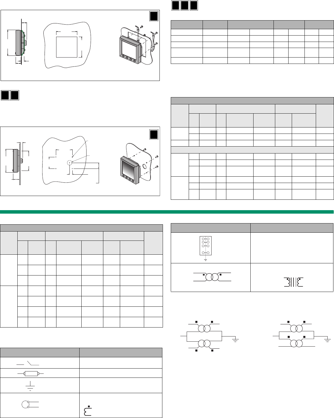
4
PM800 Remote Display Dimensions and Mounting Options
Surface Mount for CM3000/CM4000 Display Retrofit with
a PM800 Remote Display
Refer to section titled Power Meter With Remote Display, and see Figure 12.
Wiring
Supported System Types
NOTE: *Current inputs (CTs) must have spade or ring terminal connections.
NOTE: For replacement connectors, order hardware kit 63230-500-16.
Figure 11: Square cutout and mounting for Remote Display
Figure 12: Surface Mount for CM3000/CM4000 Display Retrofit with a PM800
Remote Display Model
92
(3.62)
92
(3.62)
12
(0.457)
96
(3.780)
21
(0.839)
19
(0.751)
mm
(in)
R
D
I
R
D
76
[3.000]
54
[2.125]
27
[1.063]
13 [0.500]
4 x Ø4
[Ø0.157]
Ø22 (Ø32 max)
[Ø0.880]
96
[3.780]
10
[0.394]
82
[3.230]
31
[1.220]
mm
[in]
R
D
Table 5: Wire Connection Specifications for PM800
Description Connection
Numbers Wire Dimensions Torque Insulation
Strip Length
Power supply 1 to 3 12 to 24 AWG 2.5 to 0.2 mm25 lb·in 0.56 N·m 1/4 in 6.35 mm
Voltage inputs (PTs) 8 to 11 12 to 24 AWG 2.5 to 0.2 mm25 lb·in 0.56 N·m 1/4 in 6.35 mm
Current inputs (CTs)
*
12 to 17 12 to 24 AWG 2.5 to 0.2 mm212 lb·in 1.35 N·m 5/16 in*8.0 mm*
RS485
communications 18 to 20 12 to 24 AWG 2.5 to 0.2 mm25 lb·in 0.56 N·m 1/4 in 6.35 mm
I/Os 4 to 7 12 to 24 AWG 2.5 to 0.2 mm25 lb·in 0.56 N·m 1/4 in 6.35 mm
Table 6: Voltages Less Than or Equal to 347Vac L-N/600Vac L-L, Direct
Connect, No PTs
Single- or Two-Phase Wiring
Number
of
Wires
CTs Voltage Connections Meter Configuration
Figure
Number
Qty. ID Qty. ID Type System
Type
PT Primary
Scale
21 I1 2 V1, Vn L-N 10 No PT 1
1 I1 2 V1, V2 L-L 11 No PT 2
3 2 I1, I2 3 V1, V2, Vn L-L with N 12 No PT 3
Three-Phase Wiring
3
2 I1, I3 3 V1, V2, V3 Delta 30 No PT 4
3 I1, I2, I3 3 V1, V2, V3 Delta 31 No PT 5
1 I1 3 V1, V2, V3 Delta
(balanced) 32 No PT 6
4
3 I1, I2, I3 3 V1, V2, V3, Vn 4-wire Delta 40 No PT 7
3 I1, I2, I3 3 V1, V2, V3, Vn Wye 40 No PT 7
1 I1 3 V1, V2, V3, Vn Wye
(balanced) 44 No PT 8
IU
R
D
The following symbols are used in the wiring diagrams:
NOTE: The disconnect circuit breaker must be placed within reach of the power meter and
labeled: Disconnect Circuit Breaker for Power Meter.
NOTE: In 2 PT systems, these connections are equivalent.
NOTE: The direction in which current and voltages flow affects measurements. Therefore,
pay close attention to the polarity marks when connecting CTs and PTs (X1=S1= ).
Table 7: Voltages Greater Than 347 Vac L-N/600 Vac L-L
Three-Phase Wiring
Number
of
Wires
CTs Voltage Connections Meter Configuration
Figure
Number
Qty. ID Qty. ID Type System
Type
PT Primary
Scale
3
2I1, I32 V1, V3
(V2 to Ground) Delta 30 Based on
voltage 9
3 I1, I2, I3 2 V1, V3
(V2 to Ground) Delta 31 Based on
voltage 10
1I12 V1, V3
(V2 to Ground)
Delta
(balanced) 32 Based on
voltage 11
4
3 I1, I2, I3 3 V1, V2, V3,
(Vn to Ground) Wye 40 Based on
voltage 12
2 I1, I2, I3 3 V1, V2, V3,
(Vn to Ground)
Wye
(balanced) 40 Based on
voltage 13
3 I1, I2, I3 2 V1, V3
(Vn to Ground) Wye 42 Based on
voltage 14
1I13
V1, V2, V3,
(Vn to Ground)
Wye
(balanced) 44 Based on
voltage 15
Table 8: Wiring Diagram Symbols
Symbol Description
Voltage disconnect
Fuse
Earth ground
Current transformer
US equivalent:
S2=X2
S1=X1= ■
Shorting block
Potential transformer
US equivalent:
Table 8: Wiring Diagram Symbols (continued)
Symbol Description
L1
L2
L3
V1
V2
V3
L1
L2
L3
V1
V2
V3
115 of 292
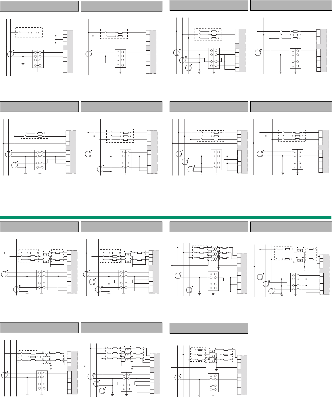
5
Figure 1: 1-Phase Line-to-Neutral 2-Wire
System 1 CT
Figure 2: 2-Phase Line-to-Line 2-Wire
+System 1 CT
NOTES:
•Use system type 10.
NOTES:
•Use system type 11
Figure 3: 2-Phase 3-Wire Direct Voltage
Connection 2 CT
Figure 4: 3-Phase 3-Wire 2 CT no PT
NOTES:
•Use system type 12.
NOTES:
•Use system type 30.
NL1
V1
V2
V3
VN
I1+
I1–
I2+
I2–
I3+
I3–
V ≤ 347 Vac
L-N
8
9
10
11
12
13
14
15
16
17
L
1
L
2
V1
V2
V3
VN
I1+
I1–
I2+
I2–
I3+
I3–
V ≤ 600 Vac
L-L
8
9
10
11
12
13
14
15
16
17
L1 L2
V1
V2
V3
VN
I1+
I1–
I2+
I2–
I3+
I3–
N
V ≤ 600 Vac
L-L
V ≤ 347 Vac
L-N
8
9
10
11
12
13
14
15
16
17
L
2
L
3
L
1
V1
V2
V3
VN
I1+
I1–
I2+
I2–
I3+
I3–
V ≤ 600 Vac
L-L
8
9
10
11
12
13
14
15
16
17
Figure 5: 3-Phase 3-Wire 3 CT no PT Figure 6: 3-Phase 3-Wire Direct Voltage Input
Connection 1 CT (balanced)
NOTES:
•Use system type 31.
•The meter displays “Ig” (ground current).
NOTES:
•Use system type 32.
•
Neutral current readings will be reported as zero.
Figure 7: 3-Phase 4-Wire Wye Direct Voltage
Input Connection 3 CT
Figure 8: 3-Phase 4-Wire Direct Voltage Input
Connection 1 CT (balanced)
NOTES:
•Use with 480Y/277 V and 208Y/120 V
systems.
•Use system type 40.
NOTES:
•Use system type 44.
•Neutral current readings will be reported as
zero.
L2 L3 L1
V1
V2
V3
VN
I1+
I1–
I2+
I2–
I3+
I3–
V ≤ 600 Vac
L-L
8
9
10
11
12
13
14
15
16
17
L
2
L
3
L
1
V1
V2
V3
VN
I1+
I1–
I2+
I2–
I3+
I3–
V ≤ 600 Vac
L-L
8
9
10
11
12
13
14
15
16
17
L
2
L
3
L
1
N
V1
V2
V3
VN
I1+
I1–
I2+
I2–
I3+
I3–
V ≤ 600 Vac
L-L
V ≤ 347 Vac
L-N
8
9
10
11
12
13
14
15
16
17
L2 L3 L1 N
V1
V2
V3
VN
I1+
I1–
I2+
I2–
I3+
I3–
V ≤ 600 Vac
L-L
V ≤ 347 Vac
L-N
8
9
10
11
12
13
14
15
16
17
Figure 9: 3-Phase 3-Wire Delta Connection
2CT 2 PT
Figure 10: 3-Phase 3-Wire Delta Connection
3CT 2PT
NOTES:
•For an open delta PT connection with 120 V
L-L secondaries, use system type 30.
NOTES:
•Use System type 31.
•The meter displays “Ig” (ground current).
•For an open delta PT connection with 120 V L-L
secondaries, use system type 31.
Figure 11: 3-Phase 3-Wire 1CT 2PT
(balanced)
Figure 12: 3-Phase 4-Wire Wye Connection
3 CT 3 PT
NOTES:
•Use system type 32.
•Neutral current readings will be reported as
zero.
NOTES:
•Use system type 40.
L
2
L
3
L
1
V1
V2
V3
VN
I1+
I1–
I2+
I2–
I3+
I3–
8
9
10
11
12
13
14
15
16
17
V ≤ 600 Vac
L-L
L2 L3 L1
V1
V2
V3
VN
I1+
I1–
I2+
I2–
I3+
I3–
8
9
10
11
12
13
14
15
16
17
V ≤ 600 Vac
L-L
L
2
L
3
L
1
V ≤ 600 Vac
L-L
V1
V2
V3
VN
I1+
I1–
I2+
I2–
I3+
I3–
8
9
10
11
12
13
14
15
16
17
L2 L3 L1 N
V1
V2
V3
VN
I1+
I1–
I2+
I2–
I3+
I3–
8
9
10
11
12
13
14
15
16
17
V ≤ 600 Vac
L-L
V ≤ 347 Vac
L-N
Figure 13: 3-Phase 4-Wire Wye 3-wire
3 PT 2 CT
Figure 14: 3-Phase 4-Wire Wye 3CT 2PT
NOTES:
•Use system type 40.
•
Neutral current readings will be reported as
zero.
NOTES:
•Use system type 42.
Figure 15: 3-Phase 4-Wire Wye 3PT 1CT
(balanced)
NOTES:
•Use system type 44.
•Neutral current readings will be reported as
zero.
L2 L3 L1 N
V ≤ 600 Vac
L-L
V ≤ 347 Vac
L-N
V1
V2
V3
VN
I1+
I1–
I2+
I2–
I3+
I3–
8
9
10
11
12
13
14
15
16
17
L2 L3 L1 N
V ≤ 600 Vac
L-L
V ≤ 347 Vac
L-N
V1
V2
V3
VN
I1+
I1–
I2+
I2–
I3+
I3–
8
9
10
11
12
13
14
15
16
17
L2 L3 L1 N
V ≤ 600 Vac
L-L
V ≤ 347 Vac
L-N
V1
V2
V3
VN
I1+
I1–
I2+
I2–
I3+
I3–
8
9
10
11
12
13
14
15
16
17
116 of 292
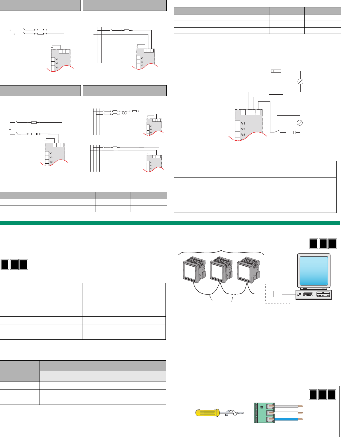
6
Figure 16: Direct Connect Control Power
(Phase to Phase)
Figure 17: Direct Connect Control Power
(Phase to Neutral)
Figure 18: Direct Connect Control Power
(DC Control Power)
Figure 19: Control Power Transformer
Connection
Table 9: Fuse Recommendation
Control Power Source Source Voltage (Vs)Fuse Fuse Amperage
CPT Vs125 V FNM or MDL 250 mA
CPT 125 < Vs240 V FNQ or FNQ-R 250 mA
L1 L2 L3
8
9
10
11
123
PM800
Phase to Phase only when voltage<415
±10 % VAC max.
L1 L2 L3N
8
9
10
11
123
PM800
Phase to Neutral only when voltage<415
±10 % VAC max.
8
9
10
11
123
PM800
DC Control Power
100 Vdc < V < 300 Vdc
L1 L2 L3N
CPT
8
9
10
11
123
PM800
L1 L2 L3N
8
9
10
11
123
PM800
Control Power Transformer
120 or 240 Vac Secondary 50 Va max.
Line Voltage Vs240 V FNQ-R 250 mA
Line Voltage Vs> 240 V FNQ-R 250 mA
DC Vs 300 V LP-CC 500 mA
The voltage input protection devices must be rated for the short circuit current at the connection points.
Figure 13: Standard Input/Output Wiring
CAUTION
VOLTAGE TRANSIENTS OVER 500 V CAN DAMAGE DIGITAL INPUTS
• Do not use digital inputs to directly monitor circuits with highly inductive loads.
• Use auxiliary contacts and isolated power supply when monitoring inductive loads.
Failure to follow this instruction will result in equipment damage.
Table 9: Fuse Recommendation (continued)
Control Power Source Source Voltage (Vs)Fuse Fuse Amperage
8
9
10
11
YC
PM800
K
1
S
1
Load
≤ 100 mA
~
=
≤ 100 mA
Power Source
3 - 250 Vdc
6 - 220 Vac
Power Source
24 - 125 Vdc / Vac
Status Switch or
Auxiliary Contact
Digital Output / Pulse Output
KY is a solid state pulse output
rated for 250 VDC max. or
220 Vac max.
Maximum load current is 100 mA
at 25°C. Derate 0.56 mA per °C
above 25°C.
Digital Input / Status Input / Pulse Input
C1 is the common or voltage reference.
S1 is the status input signal.
Overcurrent Protective Device
(not supplied)
~
=
NOTE: The overcurrent protective device
must be rated for the short circuit current
at the connection point.
45 67
Switching of inductive devices such as relay coils and motors results in high voltage
transients from back electromotive force (EMF). To monitor this type of circuit, use an
isolated power supply, such as the 24 Vdc power supply included with the PM8M26, and an
auxiliary contact on the circuit breaker or switch.
Communications
Power Meter Communications Capabilities
Figure 14: Power meters with integrated displays connected to a PC serial port
through the onboard 2-wire RS485 port
Daisy-chaining Devices to the Power Meter
The RS485 port allows the power meter to be connected in a daisy chain with up to 32,
2-wire devices. In this document, communications link refers to a chain of devices that are
connected by a communications cable.
To daisy-chain devices to the power meter, use communications cable containing a
twisted-shielded pair (Belden 9841 or equivalent) and the three-terminal connector of the
RS485 port on the power meter.To connect to the power meter, follow these steps:
1. Strip 6 mm (0.25 in.) of insulation from both ends of the cable wires and insert one end
into the holes in the connector.
2. On the top of the connector, torque the wire binding screws 0.56–0.79 N•m ( 5–7 lb•in).
Table 10: COM1 2-wire, RS485 Port Capabilities
Communications port
RS485:
•2-wire with shield
•EIA compliant
•Allows the power meter to be connected to a
daisy chain of up to 31 devices
Baud rate 9600*, 19200, 38400
Communications distances See Table 11.
Protocols Modbus RTU*, Jbus, Modbus ASCII
Parity ODD, EVEN*, NONE
*default
Table 11: 2-wire, RS485 Communications Distances
Baud Rate
Maximum Communication Distances
1 to 32 Devices
9600 2,438 m (8,000 ft.)
19200 1,829 m (6,000 ft)
38400 914 m (3,000 ft)
NOTES:
•Distances are for 2-wire devices and 4-wire devices configured for 2-wire operation.
•Distances listed should be used as a guide only and cannot be guaranteed for non-PowerLogic
devices. Refer to the master device’s documentation for any additional distance limitations.
IU
R
D
Figure 15: RS485 connection
Belden 9841 (or
equivalent cable)
1 to 32 power meters
Host
RS232/485 Modbus
RTU 2-wire converter
IU
R
D
20
19
18
D0
D1+
_
Silver
White with blue
stripe
Blue with white
stripe
IU
R
D
0.56–0.79 N•m
(5-7 lb•in)
117 of 292
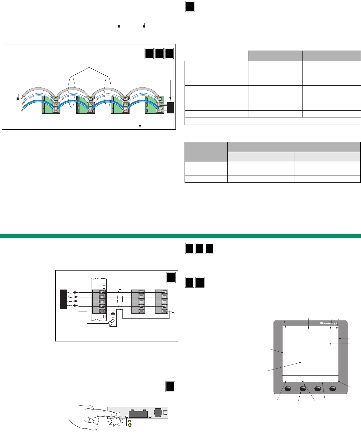
7
2-wire Devices
To daisy-chain the power meter to another 2-wire PowerLogic device, wire the power
meter’s RS485 communications terminals to the matching communications terminals of the
next device. In other words, wire the D1 (+) terminal of the power meter to the D1 (+)
terminal of the next device, wire D0 (–) to D0 (–), and shield ( ) to shield ( ) as shown in
Figure 16.
• If the power meter is the first device on the daisy chain, connect it to the host device
using the MCI-101 kit (or equivalent RS232 to RS422/RS485 converter).
• If the power meter is the last device on the daisy chain, terminate it. See below.
• See Table 11 for the maximum daisy-chain communications distances for 2-wire
devices.
Terminating the Communications Link
For proper RS485 communications performance, you must use the MCT2W terminator to
terminate the last device on the communications link. To terminate the power meter using
the MCT2W terminator, insert the wires of the terminator directly into terminals 19 and 20 of
the RS485 communications connector on the power meter.
NOTES:
•Terminate only the last device on the link. If a link has only one device, terminate that
device.
• Some PowerLogic devices use a removable communications connector. If the last
device on the communications link is not a power meter, refer to the instruction bulletin
for that device for termination instructions.
Power Meter With Remote Display Communications
The communications port on the remote display adapter can be configured to operate as a
2-wire, RS485 port; a 4-wire, RS485 port; or an RS232 port.
NOTE: The 4-wire, RS485 configuration is useful for integrating power meters into existing
4-wire, RS485 daisy chains. Figure 16: Daisy-chaining 2-wire devices
L- (D )
0
L+ (D )
1
–
+
Power Meter 800 or other PowerLogic 2-wire compatible devices
Belden 9841 or equivalent
Belden 9841 wire colors: blue with white stripe (D1), white with blue stripe (D0), and silver (shield )
MCT2W terminator on the last
device of the daisy chain
IU
R
D
Table 12: COM2 RS485 Port Capabilities
2-wire 4-wire
Communications Port
•2-wire with shield
•EIA compliant
•Allows the power meter to
be connected to a daisy
chain of up to 32 devices
•4-wire with shield
•EIA compliant
•Allows the power meter to be
connected to a daisy chain of
up to 32 devices
Baud Rate 9600*, 19200, 38400 9600*, 19200, 38400
Communications Distances See Table 11. See Table 13.
Protocols Modbus RTU*, Jbus, Modbus,
ASCII
Modbus RTU*, Jbus, Modbus,
ASCII
Parity ODD, EVEN*, NONE ODD, EVEN*, NONE
*default
Table 13: COM2 4-wire, RS485 Communications Distances
Baud Rate
Maximum Communication Distances
1 to 16 Devices 17 to 32 Devices
9600 3,048 m (10,000 ft.) 1,219 m (4,000 ft.)
19200 1,548 m (5,000 ft.) 762 m (2,500 ft.)
38400 1,524 m (5,000 ft.) 762 m (2,500 ft.)
NOTE: Distances listed should be used as a guide only and cannot be guaranteed for
non-POWERLOGIC devices. Refer to the master device’s documentation for any
additional distance limitations.
R
D
Power Meter With Remote Display Connections
COM2 RS485, 4-wire
NOTE: To learn more about the 2-wire or RS232 configurations of COM2 on the PM8RDA,
refer to the installation guide for the Remote Display Kit for PM800 meters (document
number 63230-500-221).
Ethernet Communications
Ethernet communication is available by adding a PM8ECC Module to the power meter.
Installation instructions are included with the module.
Operation
Operating the Display
Power meters are equipped with large, back-lit LCD displays. They can show up to five
lines of information plus a sixth row of menu options. Figure 19 shows the different parts of
the power meter display.
How the Buttons Work
The buttons are used to select menu items, display more menu items in a menu list, and
return to previous menus. A menu item appears over one of the four buttons. Pressing a
button selects the menu item and displays the menu item’s screen. When you have
reached the highest menu level, a black triangle appears beneath the selected menu item.
To return to the previous menu level, press the button below 1;. To cycle through the
menu items in a menu list, press the button below ###: (see Figure 19).
NOTE: Each time you read “press” in this document, press and release the appropriate
button beneath the menu item. For example, if you are asked to “Press PHASE,” you would
press and release the button below the PHASE menu item.
Figure 17: COM2 RS485, 4-wire
•Use Belden 8723, 9842, or
equivalent
— RX+ Green, RX- White
— TX+ Red, TX- Black
— Shield Silver (use crimp
connector)
•For Belden 9842
— RX+ Blue/White stripe
— RX- White/Blue stripe
TX+ Orange/White
stripe
— TX- White/Orange
stripe
•Connect shield to earth
ground at the master port
only.
•If the meter is the last
device, terminate it with
3090MCTAS485 terminator
(not included).
Figure 18: PM8RDA 4-wire RS485 and RS232 selection
To change to RS232
mode, press and hold
the mode button until
the LED is lit. LED is lit
in RS232 mode.
NOTE: Communications
mode default is RS485.
The LED is unlit.
TX–
RX–
TX+
TX / RX
RX+
TX–
RX–
TX+
RX+
TX–
RX–
TX+
RX+
3090
MCTAS485
24 23 22 21 20
Terminal
block
Crimp connector
Master port
PM8RDA
R
D
TX/RX
RS485
RS232
Click
PM8RDA
LED is lit in RS232
mode
R
D
Figure 19: Power meter display
A. Type of measurement
B. Screen title
C. Alarm indicator
D. Maintenance icon
E. Bar chart (%)
F. Units
G. Display more menu items
H. Menu item
I. Selected menu indicator
J. Button
K. Return to previous menu
L. Values
M. Phase
IU
R
D
I
R
D
ABCD
E
G
HIK
L
M
J
F
118 of 292
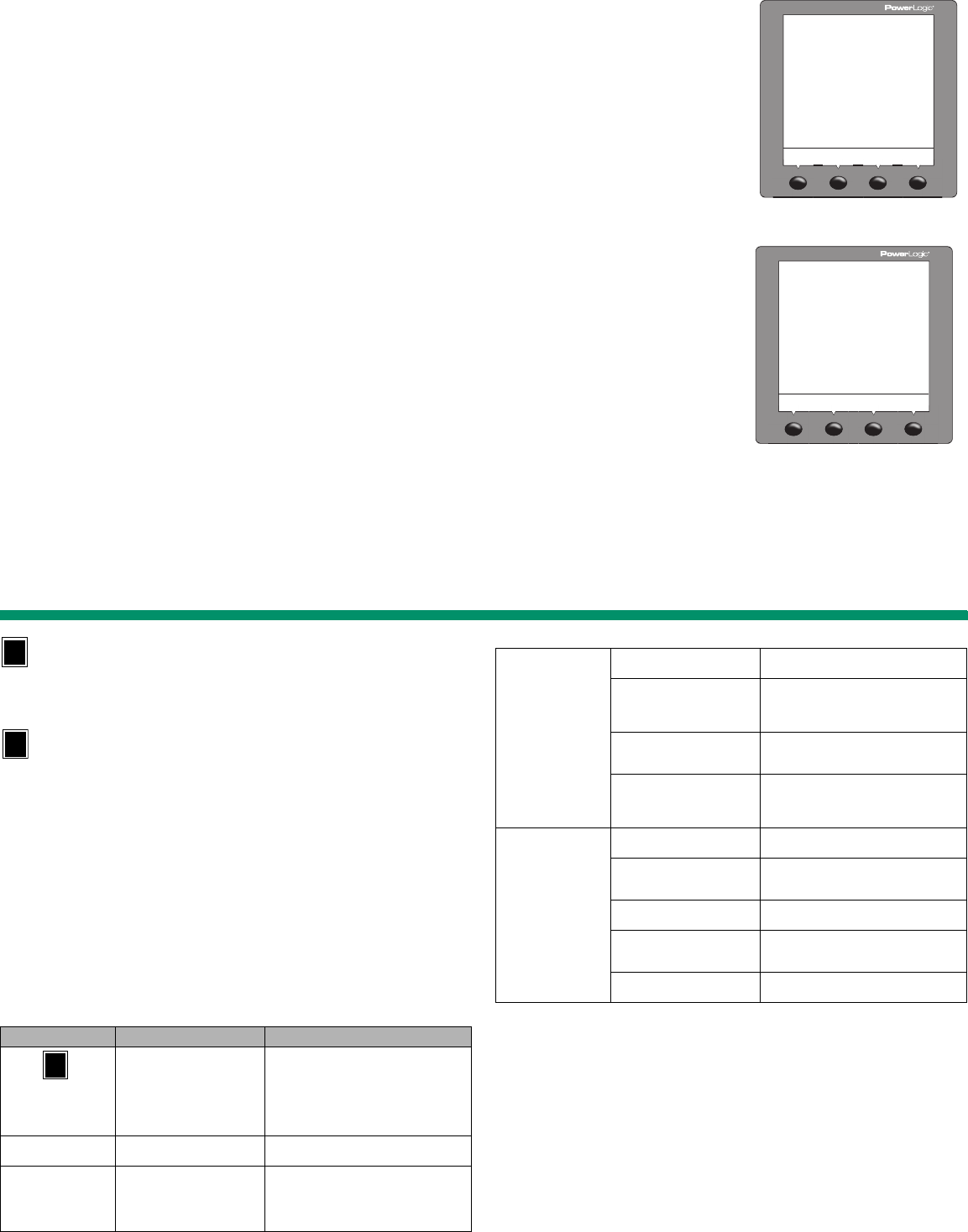
8
Changing Values
When a value is selected, it flashes to indicate that it can be modified. A value is changed
by doing the following:
• Press + or – to change numbers or scroll through available options.
• If you are entering more than one number, press <- to move to the next number in the
sequence.
• To save your changes and move to the next field, press OK.
Basic Setup
A basic setup for the power meter includes:
•CTs ratios.
• PTs ratios.
• Nominal frequency.
• System type.
• Communication. (Note that RD models include two communications ports, COM1 and
COM2.)
To begin power meter setup, do the following:
1. Scroll through the Level 1 menu list until you see MAINT.
2. Press MAINT.
3. Press SETUP.
4. Enter your password.
NOTE: The default password is 0000.
Use the following examples as models to set up the power meter for first time use:
CTs Ratios Setup
Communications Setup
For Power Meters with Remote Displays, use the same communication setup procedure as
above, but go to COM2.
1. Press ###: until METER is visible.
2. Press METER.
3. Press CT.
4. Enter the PRIM (primary CT) number.
5. Press OK.
6. Enter the SEC. (secondary CT) number.
7. Press OK.
8. Press1; until you are asked to save your
changes.
9. Press YES to save the changes.
1. Press ###: until COMMS (communications)
is visible.
2. Press COMMS (communications).
3. Select the protocol: MB.RTU (Modbus RTU),
Jbus, MB. A.8 (Modbus ASCII 8 bits),
MB. A.7 (Modbus ASCII 7 bits).
4. Press OK.
5. Enter the ADDR (power meter address).
6. Press OK.
7. Select the BAUD (baud rate).
8. Press OK.
9. Select the parity: EVEN, ODD, or NONE.
10. Press OK.
11. Press1; until you are asked to save your
changes.
12. Press YES to save the changes.
!"#
$%
Power Meters without Display Setup
To set up a power meter without a display (see Figure 2), you will need a means of
communication between the power meter and your computer. Additionally, you will need to
install Schneider Electric Meter Configuration software on your computer. This
configuration software can be downloaded at no cost from www.powerlogic.com.
Troubleshooting
Refer to Table 14 for information on potential problems and their possible causes. Contact
your local Schneider Electric sales representative for further assistance.
Heartbeat LED
The heartbeat LED helps to troubleshoot the power meter. The LED works as follows:
•Normal operation — the LED flashes at a steady rate during normal operation.
•Communications — the LED flash rate changes as the communications port transmits
and receives data. If the LED flash rate does not change when data is sent from the host
computer, the power meter is not receiving requests from the host computer.
•Hardware — if the heartbeat LED remains lit and does not flash ON and OFF, there is a
hardware problem. Do a hard reset of the power meter (turn OFF power to the power
meter, then restore power to the power meter). If the heartbeat LED remains lit, contact
your local sales representative.
•Control power and display — if the heartbeat LED flashes, but the display is blank, the
display is not functioning properly. If the display is blank and the LED is not lit, verify that
control power is connected to the power meter.
Getting Technical Support
Please refer to the Technical Support Contacts provided in the power meter shipping carton
or go to www.powerlogic.com, select your country > tech support for support phone
numbers by country.
Table 14: Troubleshooting
Potential Problem Possible Cause Possible Solution
The maintenance icon is
illuminated on the power
meter display.
When the maintenance icon is
illuminated, it indicates a
potential hardware or firmware
problem in the power meter.
When the maintenance icon is illuminated,
go to MAINT (MAINTENANCE) >DIAG
(DIAGNOSTICS). Error messages display to
indicate the reason the icon is illuminated.
Note these error messages and call
Technical Support or contact your local sales
representative for assistance.
The display shows error
code 3. (PM810)
Loss of control power or meter
configuration has changed. Set date and time.
The display is blank
after applying control
power to the power
meter.
The power meter may not be
receiving the necessary power.
•Verify that the power meter line (L) and
neutral (N) terminals (terminals 2 and 3)
are receiving the necessary power.
•Verify that the heartbeat LED is blinking.
•Check the fuse.
U
The data being
displayed is inaccurate
or not what you expect.
Power meter is grounded
incorrectly. Verify that the power meter is grounded.
Incorrect setup values.
Check that the correct values have been
entered for power meter setup parameters
(CT and PT ratings, System Type, Nominal
Frequency, and so on).
Incorrect voltage inputs.
Check power meter voltage input terminals
L (8, 9, 10, 11) to verify that adequate
voltage is present.
Power meter is wired
improperly.
Check that all CTs and PTs are connected
correctly (proper polarity is observed) and
that they are energized. Check shorting
terminals.
Cannot communicate
with power meter from a
remote personal
computer.
Power meter address is
incorrect.
Check to see that the power meter is
correctly addressed.
Power meter baud rate is
incorrect.
Verify that the baud rate of the power meter
matches the baud rate of all other devices on
its communications link.
Communications lines are
improperly connected.
Verify the power meter communications
connections.
Communications lines are
improperly terminated.
Check to see that a multipoint
communications terminator is properly
installed.
Incorrect route statement to
power meter. Check the route statement.
Table 14: Troubleshooting (continued)
Schneider Electric
295 Tech Park Drive,
Suite 100
LaVergne, TN 37086 USA
Tel: +1 (615) 287-3400
www.powerlogic.com
www.schneider-electric.com
This product must be installed, connected, and used in compliance
with prevailing standards and/or installation regulations. As
standards, specifications, and designs change from time to time,
please ask for confirmation of the information given in this
publication.
63230-500-282A1
Replaces 63230-500-200A4 and 63230-500-224A1
© 2010 Schneider Electric. All Rights Reserved.
119 of 292
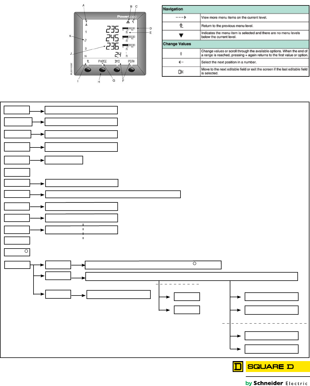
PowerLogic® PM800 series
Quick Reference Guide
AMPS (1)
VOLTS (U-V)
PWR (PQS)
ENERG (E)
HZ (F)
THD
MINMX
TIMER
PHASE DMD UNBAIL.
VL-L VL-N
PWR PHASE DMD
WH VAH VARH INC
MINMX I V POS PF F THD V THD I
RESET
SETUP
DIAGN
METER E DMD MINMX MODE TIMER
DATE TIME LANG COMMS (COM) METER ALRAM I/O PASSW TIMER ADVAN
METER REG CLOCK
VL-L (U) VL-N (V) I
Abbreviated List of IEC Power Meter Menu Items:
Display Buttons
PF TRUE DISPL
HARM VL-L (U) VL-N (V) I
ALARM ACTIV HIST
I/O D OUT D IN A OUT A IN
CONTR
MAINT
COMM2
COMM1
PM8RD
D IN (Digital In)
D OUT (Digital KY Out)
PM8M2222, PM8M26, AND PM8M22
PM8M2222
A IN (Analog In)
A OUT (Analog Out)
PM8M222
1
2
Power Meter Display
A. Type of measurement
B. Screen Title
C. Alarm Indicator
D. Maintenance icon
E. Bar Chart (%)
F. Units
G. Display more menu items
H. Menu item
I. Selected menu indicator
J. Button
K. Return to previous menu
L. Values
M. Phase
Parts of the Display
120 of 292
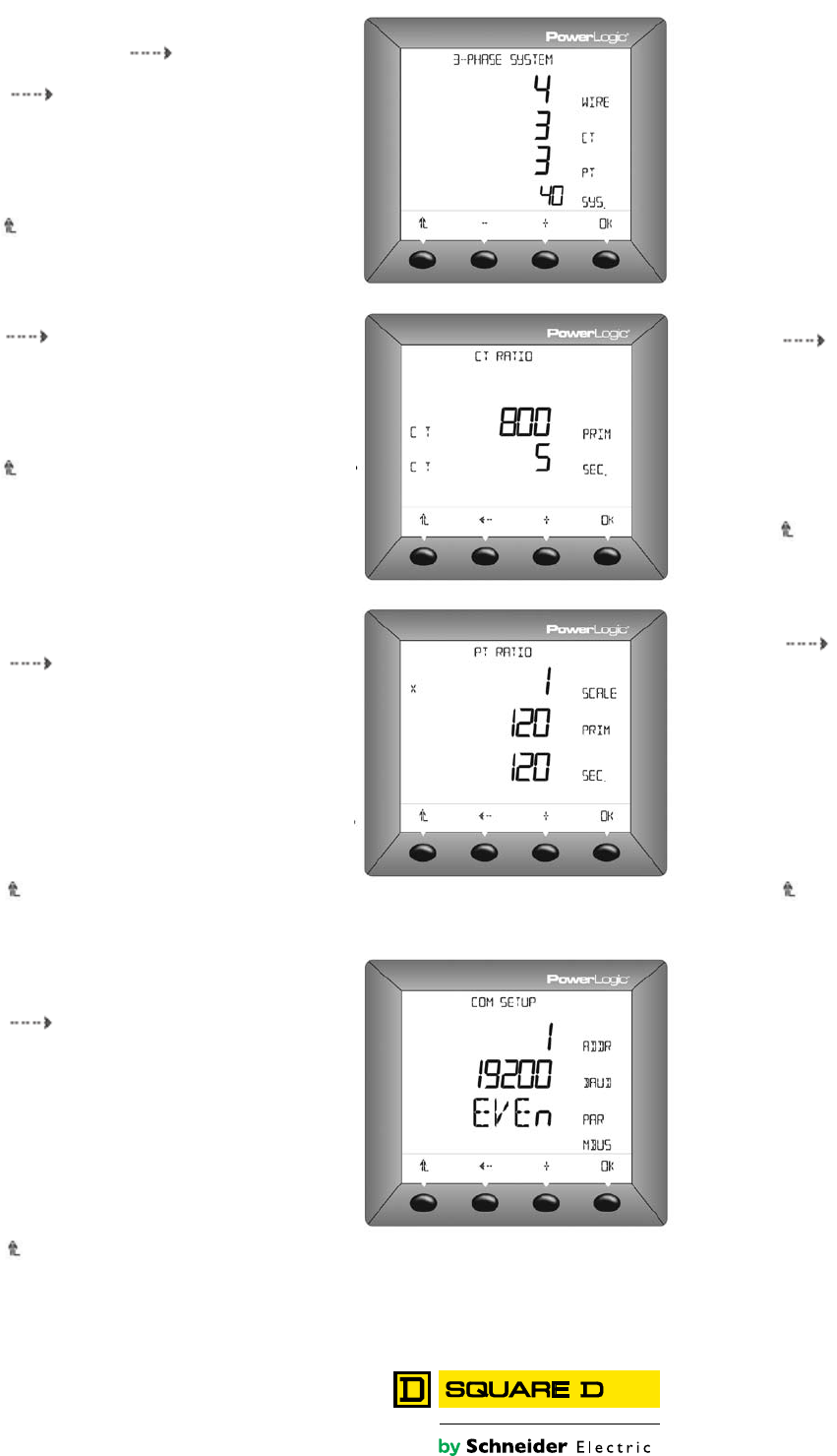
Schneider Electric - North America
295 Tech Park Drive, LaVergne, TN 37086
Ph: 866-466-7627
PowerLogic.com
04-2008
Document#3000DB0808 April 2008
© 2008- Schneider Electric - All rights reserved
1. In SETUP mode, press until METER is visible
2. Press METER.
3. Press until SYS (sytem type) is visible.
4. Press SYS.
5. Select your system type based on the (A) number
of wires. (B) number of CTs, (C) the number of
volatage connections (either direct connect or with
PT), and (D) the SMS system type.
6. Press OK.
7. Press until you are asked to save your changes.
8. Press YES to save the changes.
Setup Meter System Type
1. Press uuntil COMMS (communications) is visible.
2. Press COMM1 (communications).
3. Select the protocol: MB.RTU (Modbus RTU). Jbus,
MB, A.8 (Modbus ASCII 8 bits), MB, A.7
(Modbus ASCII 7 bits).
4. Press OK.
5. Enter the ADDR (power meter address).
6. Press OK.
7. Select the BAUD (baud rate).
8. Press OK.
9. Select the parity: EVEN, ODD, or NON.
10. Press OK.
11. Press until you are asked to save your changes.
12. Press YES to save the changes.
Power Meter With Remote
Display Communications Setup:
1. Press uuntil METER is visible
2. Press METER.
3. Press PT.
4. Enter the SCALE value: x1, x10, x100.
No PT (for direct connect).
5. Press OK
6. Enter the PRIM (primary CT) value.
7. Press OK
8. Enter the SEC. (secondary CT) value.
9. Press OK.
10. Press until you are asked to save
your changes.
11. Press YES to save the changes.
Setup PT Ratio:
1. Press uuntil METER is visible
2. Press METER.
3. Press CT.
4. Enter the PRIM (primary CT) number.
5. Press OK
6. Enter the SEC. (secondary CT) number.
7. Press OK
8. Press until you are asked to save your changes
9. Press YES to save the changes.
Setup CT Ratio:
1. Press uuntil COMMS
(communications) is visible.
2. Press COMM2 (communications).
3. Select the protocol: MB.RTU (Modbus RTU).
Jbus, MB, A.8 (Modbus ASCII 8 bits),
MB, A.7 (Modbus ASCII 7 bits).
4. Press OK.
5. Enter the ADDR (power meter address).
6. Press OK.
7. Select the BAUD (baud rate).
8. Press OK.
9. Select the parity: EVEN, ODD, or NON.
10. Press OK.
11. Press until you are asked to
save your changes.
12. Press YES to save the changes.
Comm2 Setup:
1. Press uuntil COMMS (communications) is visible.
2. Press COMMS (communications).
3. Select the protocol: MB.RTU (Modbus RTU). Jbus,
MB, A.8 (Modbus ASCII 8 bits), MB, A.7
(Modbus ASCII 7 bits).
4. Press OK.
5. Enter the ADDR (power meter address).
6. Press OK.
7. Select the BAUD (baud rate).
8. Press OK.
9. Select the parity: EVEN, ODD, or NON.
10. Press OK.
11. Press until you are asked to save your changes.
12. Press YES to save the changes.
Power Meter With Integrated
Display Communications Setup:
121 of 292

Instruction Bulletin 48049-243-04
Rev. 01, 09/2012
Replaces 48049-243-04 ECN 681C, 03/2006
PowerPact™ R-Frame and NS1600b–NS3200 Circuit Breakers
Retain for future use.
© 2004–2012 Schneider Electric All Rights Reserved ™
ENGLISH
Necessary Tools Screwdriver, Pozidriv® #2 or #3, or slotted
Socket Wrench
Screwdrivers, long-shanked slotted (2)
Additional Information This bulletin provides installation instructions for PowerPact R-frame and
NS1600b–NS3200 circuit breakers. Tripping functions are controlled by the
Micrologic™ trip unit.
For additional information see the following user guides available on the
Schneider Electric™ website:
•Bulletin 0612IB1201: PowerPact™ Circuit Breakers Dimensional
Drawings
•Bulletin 48049-136-05: Micrologic 2.0A, 3.0A, 5.0A, and 6.0A Electronic
Trip Units
•Bulletin 48049-330-03: Micrologic 5.0H and 6.0H Electronic Trip Units
•Bulletin 48049-137-05: Micrologic 5.0P and 6.0P Electronic Trip Unit
•Bulletin 48049-207-05: Micrologic 2.0, 3.0 and 5.0 Electronic Trip Units
To access the website go to:
http://www.schneider-electric.com
1. Select “United States” in the country pull-down menu. Click “OK”
2. Under “Popular Links” on the left side of the page, select “Technical
Library”.
3. Use the Advanced Search option to search by document number.
For application assistance, please call 1-888-778-2733.
122 of 292

PowerPact™ R-Frame and NS1600b–NS3200 Circuit Breakers 48049-243-04
Rev. 01, 09/2012
© 2004–2012 Schneider Electric All Rights Reserved2-EN
ENGLISH
Installation
Individually-Mounted Circuit Breaker
Installation
1. Turn off all power supplying this equipment
before working on or inside equipment.
2. Turn off or trip circuit breaker before
installation.
DANGER
HAZARD OF ELECTRIC SHOCK, EXPLOSION OR ARC FLASH
• Apply appropriate personal protective equipment (PPE) and follow safe
electrical work practices. See NFPA 70E or CSA Z462.
• This equipment must only be installed and serviced by qualified electrical
personnel.
• Turn off all power supplying this equipment before working on or inside
equipment.
• Always use a properly rated voltage sensing device to confirm power is off.
• Replace all devices, doors and covers before turning on power to this
equipment.
• Lift circuit breaker by case using lifting equipment. Do not remove lifting
equipment until all mounting hardware is securely tightened. Never lift
circuit breaker by its handle.
Failure to follow these instructions will result in death or serious injury.
DANGER
HAZARD OF ELECTRIC SHOCK,
EXPLOSION OR ARC FLASH
Clearance requirements must be met for
proper operation of the equipment.
Failure to follow these instructions will
result in death or serious injury.
1. Check enclosure clearances, see Figure 1.
2. Prepare enclosure for circuit breaker (See
Figure 22 for mounting hole and cover cutout
dimensions).
— Drill mounting holes.
— Cut opening in cover for circuit breaker
handle escutcheon.
Figure 1: Minimum Clearance Requirement
1.02
[25,9] Min.
06123048
1.02
[25,9] Min.
Dimensions: in.
[mm]
Minimum enclosure size:
3P: 30 x 21 x 7 in. (762 x 533 x 176 mm)
4P: 30 x 25.5 x 7 in. (762 x 648 x 178 mm)
Minimum ventilation (100% Rated Circuit Breakers Only):
40.25 in.2 (260 cm2) on top and bottom of enclosure
123 of 292
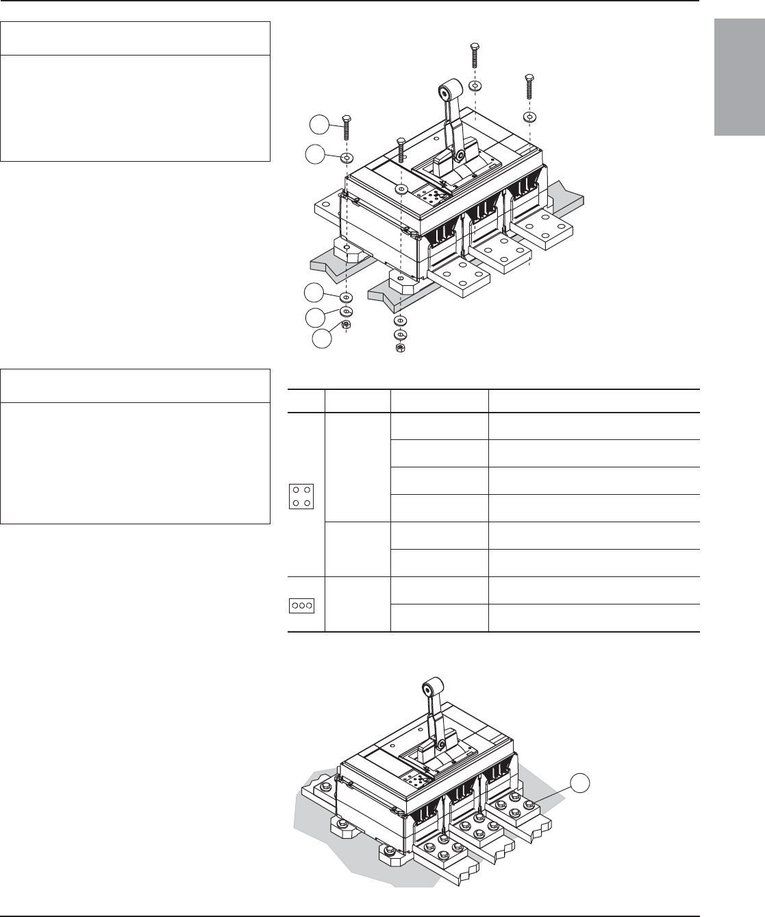
48049-243-04 PowerPact™ R-Frame and NS1600b–NS3200 Circuit Breakers
Rev. 01, 09/2012
© 2004–2012 Schneider Electric All Rights Reserved 3-EN
ENGLISH
((
NOTIC
E
HAZARD OF OVERHEATING
Do not mount circuit breaker on ferrous
material.
Failure to follow these instructions can
result in equipment damage.
3. Mount circuit breaker on 3/4 in. (19 mm)
Glastic™ or equivalent non-ferrous material,
using one 3/8 in. Grade 5 bolt (A), two flat
washers (B), one split lockwasher (C) and one
nut (D) per mounting foot (provided). Torque
bolts (A) to 180 lb-in (20 Nxm).
Figure 2: Mount Circuit Breaker
06123010
D
C
B
B
A
NOTIC
E
HAZARD OF OVERHEATING
For cable connection, lugs must be mounted on
RLTB or RLTBE terminal pads. Do not mount
lugs directly on circuit breaker terminal.
Failure to follow these instructions can
result in equipment damage.
If using RLTB or RLTBE terminal pads, see RLTB
or RTLBE terminal pad instructions.
For dimensional information refer to the
Schneider Electric website (see page 1).
Table 1: Individually-Mounted Circuit Breaker Connection
Type Connection Rated Connection Mounting
UL/IEC Bus
2500 A,
100% rated
Bus to RLTB (3P) or RLTB4 (4P) terminal pad
kits (provided) or equivalent bus structure.
3000 A,
80% rated
Bus to RL3TB (3P) or RL3TB4 (4P) terminal pad
kits (provided) or equivalent bus structure.
3000 A,
100% rated
Bus to RL3TB (3P) or RL3TB4 (4P) terminal pad
kits (provided) or equivalent bus structure.
All other bussed
circuit breakers
Bus directly to circuit breaker or to optional RLTB
terminal pad mounting kits.
Cable
3000 A,
80% and 100% rated
Cable to lugs mounted on RL3TB terminal pad
kits.
All other cabled
circuit breakers
Cable to lugs mounted on RLTB terminal pad
kits.
IEC
Bus
3200 A Bus to RLTBE terminal pad kits (provided) or
equivalent bus structure.
Less than 3200 A Bus directly to circuit breaker or to optional
RLTBE terminal pad mounting kits.
4. For direct bussing, secure bus directly to
circuit breaker using four 1/2 in. Grade 5
bolts (A) per terminal for UL/IEC circuit
breakers and three 10 mm Grade 8.8 bolts
per terminal for IEC circuit breakers. Finger
tighten all bolts, then torque them to
900 lb-in (100 Nxm).
NOTE: Make sure that circuit breaker
terminals are flat against bus bars.
5. Tighten equipment bus connections and
supports.
Figure 3: Direct Bus Installation
06123012
A
124 of 292
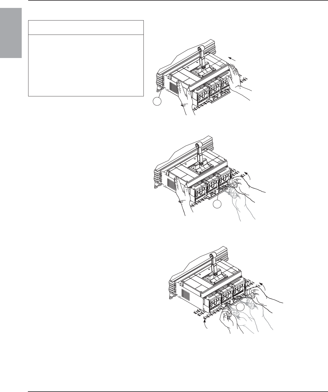
PowerPact™ R-Frame and NS1600b–NS3200 Circuit Breakers 48049-243-04
Rev. 01, 09/2012
© 2004–2012 Schneider Electric All Rights Reserved4-EN
ENGLISH
I-Line™ Circuit Breaker Installation
NOTICE
HAZARD OF EQUIPMENT DAMAGE
• Do not adjust jaws.
• Do not remove joint compound.
• If necessary, use Square D™ joint
compound PJC7201.
Failure to follow these instructions can
result in equipment damage.
1. Place circuit breaker on I-Line pan with jaws
(A) pushed against bus.
Figure 4: Place Circuit Breaker on Pan
06123000
A
2. Insert long-shanked screwdriver (A) into slot.
Rack circuit breaker onto bus.
Figure 5: Start Racking Circuit Breaker onto Bus
3. Insert second screwdriver (A) into bottom
slot. Rack circuit breaker onto bus, using
alternate screwdrivers until circuit breaker
jaws completely engage bus bars.
Figure 6: Continue Racking Circuit Breaker onto Bus
06123001
A
06123002
A
125 of 292

48049-243-04 PowerPact™ R-Frame and NS1600b–NS3200 Circuit Breakers
Rev. 01, 09/2012
© 2004–2012 Schneider Electric All Rights Reserved 5-EN
ENGLISH
4. Tighten four screws (A) firmly without
bending mounting bracket.
Figure 7: Tighten Mounting Bracket Screws
Cable Installation
Square off conductor ends and preform
conductors to final configuration. Using a proper
insulation stripping tool, strip conductor ends as
recommended in Table 2 below. Do not nick
strands.
For field-installable lug kits, see instruction
bulletin shipped with each lug kit.
Figure 8: Install Cables
Table 2: Circuit Breaker Lug Information
Catalog
Number
Conductors Wire Binding
Screw Torque
Lug Mounting
Screw Torque)
Qty. Size Strip Length1
1Conductors must be cut square for secure termination.
AL1200R53K2
2For version with tapped hole for control wire order AL1200R53TK.
4 #3/0–600 kcmil (95–300 mm2) Al/Cu 1-3/16 in. (30 mm) 450 lb-in (50 Nxm) 180 lb-in (20 Nxm)
CU1200R53K 4 #3/0–600 kcmil (95–300 mm2) Cu 1-3/16 in. (30 mm) 450 lb-in (50 Nxm) 180 lb-in (20 Nxm)
06123003
A
06123014
Strip
Length
AL1200R53TK Lug Only
Install control wire using 6-32 x 5/16 in. screw.
Figure 9: AL1200R53TK Lug
06123072
9-12 lb-in
(1-1.3 Nxm)
126 of 292
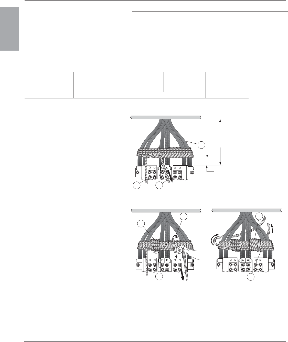
PowerPact™ R-Frame and NS1600b–NS3200 Circuit Breakers 48049-243-04
Rev. 01, 09/2012
© 2004–2012 Schneider Electric All Rights Reserved6-EN
ENGLISH
Cable Restraint
Restrain circuit breaker conductors as indicated
in Table 3.
Wrap conductors using 30 ft. (10 m) of 1/2 in.
(12 mm) sisal rope or equivalent.
NOTIC
E
HAZARD OF CONDUCTOR MOVEMENT UNDER SHORT-CIRCUIT
CONDITIONS
Restrain circuit breaker conductors as required in Table 3.
Failure to follow these instructions can result in equipment damage.
Table 3: Cable Restraint Recommendations
Circuit Breaker
Installation
Available Fault
Current Conductors Used Unsupported Cable
Length
Restraint
Recommended
Individually-mounted d65 kA Six 600 kcmil or larger d24 in. (610 mm) No
All other cases Yes
1. Begin wrapping conductors (A) 6 in.
(152 mm) above circuit breaker. Wrap
conductors four times, leaving 3 ft. (1 m) of
excess rope at the first end (B). Pull rope (C)
taut.
Figure 10: Wrap Conductors
2. Wrap rope (A) several times until space
between first two sets of conductors is
completely filled. Weave final rope loop
underneath previous loop (B). Bring rope (C)
through right-hand space. Pull rope taut.
3. Wrap rope (D) several times until space
between second and third set of conductors
is completely filled. Weave final rope loop (E)
underneath previous loop as shown. Pull
rope taut.
Figure 11: Wrap Rope
06123004
C
B
A
6 in.
[152 mm]
Unsupported
Cable
Length
06123005
B
A
C
06123006
D
E
127 of 292
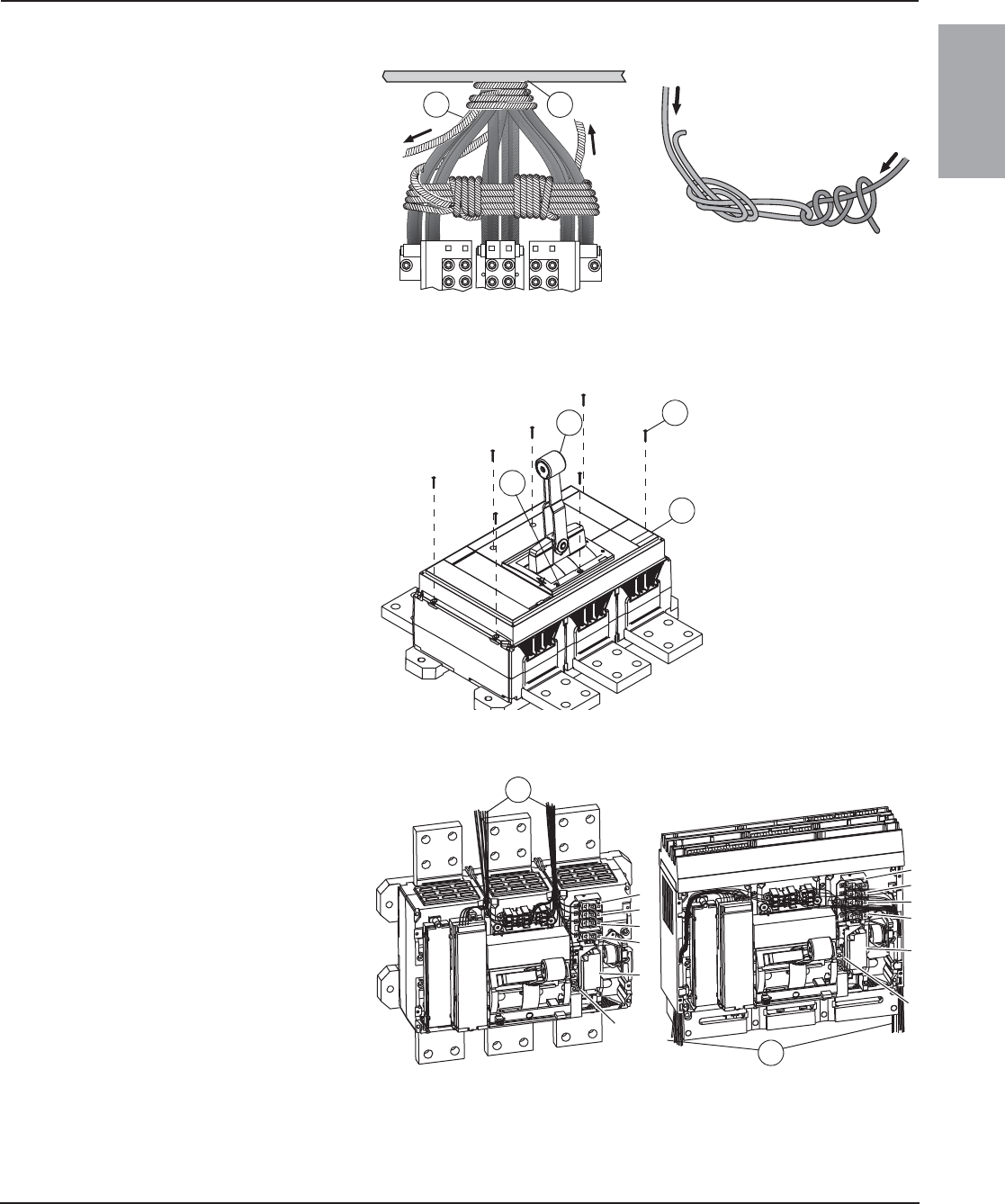
48049-243-04 PowerPact™ R-Frame and NS1600b–NS3200 Circuit Breakers
Rev. 01, 09/2012
© 2004–2012 Schneider Electric All Rights Reserved 7-EN
ENGLISH
Accessory Installation
4. Wrap rope several times around conductors
where conductors exit enclosure (A). Weave
final rope loop (B) underneath previous loop
as shown. Pull rope taut.
5. Tie rope End 1 and End 2 together as
shown. Rope must be taut. Cut off excess
rope and tape ends to prevent fraying.
Figure 12: Wrap Conductors
06123008
06123007
BA
End 1
End 2
End 1
End 2
This subsection applies if circuit breaker has
factory-installed or field-installed accessories
1. Make sure circuit breaker handle (A) is in
tripped position by moving handle to ON (I)
position, then pushing push-to-trip button (B).
2. Loosen the seven accessory cover screws
(C) and remove accessory cover (D).
Figure 13: Remove Accessory Cover
3. Install field-installable circuit breaker
accessories as instructed in the instructions
packed with each accessory.
4. Install control wiring (A) to accessories.
Torque screws to 10 lb-in (1.2 Nxm).
Figure 14: Install Accessory Control Wiring
06123013
AC
B
D
06123018
06123019
A
A
1–OF1
2–OF2
3–OF3
4–SD
5–MX/MN
6–SDE
1
2
3
4
5
1
2
3
4
5
6
6
128 of 292
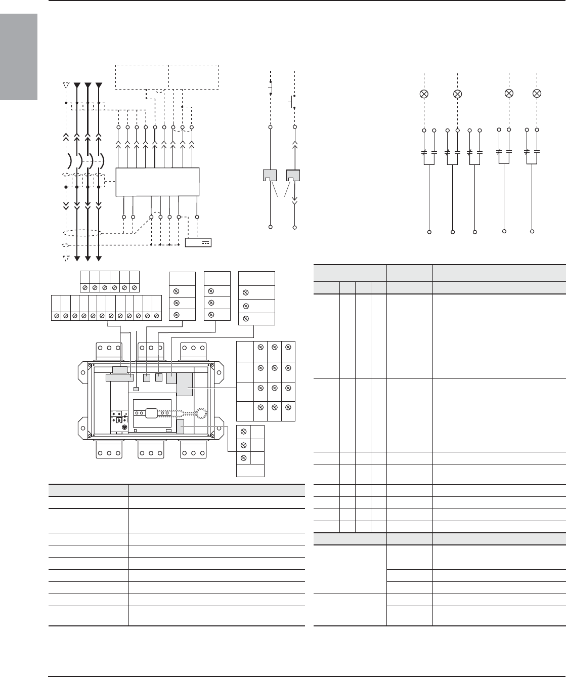
PowerPact™ R-Frame and NS1600b–NS3200 Circuit Breakers 48049-243-04
Rev. 01, 09/2012
© 2004–2012 Schneider Electric All Rights Reserved8-EN
ENGLISH
Accessory Control Wiring Diagrams NOTE: All diagrams show circuit breaker in tripped position.
Figure 15: Accessory Control Wiring Diagrams
Trip Unit
Basic A P H Connector Description
– •••Com: E1-E6Circuit breaker communication module
E1 = + 24 Vdc
E2 = Common
E3 = Out -
E4 = Out +
E5 = In -
E6 = In +
– •••Z Zone-selective Interlocking (ZSI)
Z1 = ZSI OUT signal
Z2 = ZSI OUT
Z3 = ZSI IN signal
Z4 = ZSI IN short-time delay
Z5 = ZSI IN ground fault
– • • • T External neutral sensor
––••
M6C:
Q1, Q2, Q3
6 programmable contacts
24 Vdc external power supply required
Connector Recommended Wire Size – • • • M Modified differential ground fault (MDGF)
V1, V2, V3, Vn 22–16 AWG (0.3–1.5 mm2) – • • • F 24 Vdc external power supply
E1–E2 22 AWG (0.3 mm2) min. shielded pair cable or twisted
pair copper wires
––••Vn
3External neutral voltage takeoff
– – • • V1, V2, V3 External phase voltage takeoff
T 22 AWG (0.3 mm2) stranded shielded cable Function Connector Description
M Refer to MDGF instructions
Auxiliary Contacts
OF Open/Closed circuit breaker or switch
position contacts
Z1–Z5 22–18 AWG (0.3–0.8 mm2)
OF, SD, SDE 18–16 AWG (0.8–1.5 mm2) SD Bell alarm
MN, MX 18–14 AWG (0.8–2.5 mm2) SDE Electrical fault alarm contact
F Size per aux 24 Vdc power supply
Remote Operation
MN Undervoltage trip device
E3–E6, Q1, Q2, Q3 22 AWG (0.3 mm2) shielded twisted pairs with sheild
grouned at one end (Belden 8723 or equal) MX Shunt trip
1 Remove factory jumpers between Z3, Z4 and Z5 if ZSI is connected. Remove factory jumper between T1 and T2 if neutral CT is connected.
2C3 terminal is used only for communicating shunt trip
3 Neutral voltage takeoff supplied as flying lead.
or
D2
D1
MN MX
C2
C1
06123255
T4
T3
T2
T1 Z3
Z4
T3
T2
Trip Unit
Z4
Z3
Z2
Z1 Z5
Z2
Z1
NCBA
Z5
VN
V1
V2
V3
M2
M1
F2+
Upstream Downstream
24 V
06123031
T1/M3
T4/F1-
22
24
21
OF2
Closed
06123033
OF3
32
34
31
Open
12
14
11
OF1
92
94
91
SD
Tripped
82
84
81
SDE
Fault
Power Trip Unit1Remote Operation Alarm Contacts
32 34
E1 E2 E3 E4 E5 E6
Z1 Z2 Z3 Z4 Z5
M1M2 M3
T1 T2 T3
F1
T4
F2
MN/MX
C3
D1/C1
OF1 11 12 14
OF2 21 22 24
OF3 31
SD 91 92 94
84
SDE
82
81
VN
M6C
Q1
Q3
Q2
Vext
V3
V1
V2
06123256
D2/C2
129 of 292
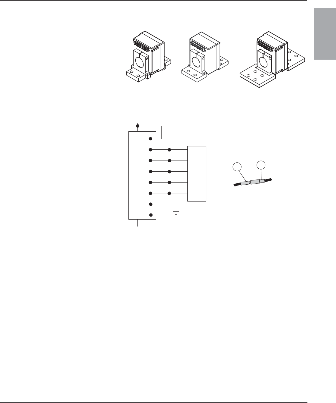
48049-243-04 PowerPact™ R-Frame and NS1600b–NS3200 Circuit Breakers
Rev. 01, 09/2012
© 2004–2012 Schneider Electric All Rights Reserved 9-EN
ENGLISH
Ground-Fault Protection for Equipment
If circuit breaker does not have integral ground-
fault tripping or alarm, skip this subsection.
A three-phase, four-wire circuit requires an
external neutral current transformer (CT).
Connect neutral CT to circuit breaker according
to wiring diagrams in Figure 17.
1. Connect the primary:
— If load is connected to lower end of circuit
breaker, connect load neutral to H1
terminal of neutral CT.
— If supply power is connected to lower end
of circuit breaker, connect supply neutral
to H1 terminal of neutral CT.
NOTE: The equipment grounding connection
must be upstream (line side) of the neutral CT
and a neutral connection must exist from the
supply transformer to the equipment.
2. For circuit breakers using Micrologic 5.0P,
6.0P, 5.0H or 6.0H trip units, connect the Vn
voltage measurement connector plug (A) into
Vn connector shipped with the circuit
breaker (B). Connect this wire to the Vn
terminal of the neutral current transformer.
(This is necessary to allow the trip unit to
make voltage measurements.) Terminals Vc
and Vn are internally connected.
3. Connect T1, T2, T3 and T4, as shown, to the
control wiring terminals as described in the
accessory wiring sections which follow.
4. Ground terminal GND of the neutral current
transformers only if no other ground exists in
the control system. (Check NEC
requirements and connect ground to
equipment ground bus.)
NOTE: The following terminals are internally
connected:
•Vc and Vn
•T4 and GND
NOTE: Modified differential ground-fault circuitry
and ground-source return ground-fault circuitry
require the use of a modified differential ground-
fault module (MDGF) and special current
transformers. For wiring of those systems, see
the instructions with the MDGF.
Figure 16: Neutral Current Transformers
Figure 17: Wiring for Ground-Fault Sensing
06133237
06133239
06133241
600–1600 A 2000 A 2500–3200 A
Vc
Vn
T1
T2
T3
Neutral CT
H1
T2
T3
Vn
T1
N
Trip Unit
Earth Ground*
H2
T4
Source
Load
Shield
06123169
NOTE: If load is connected to the off
end of the circuit breaker, then Vc of
the neutral current transformer (CT) is
connected to the load neutral.
*Check NEC requirements.
AB
T4
GND
A Trip unit
B To Vn or neutral CT
130 of 292
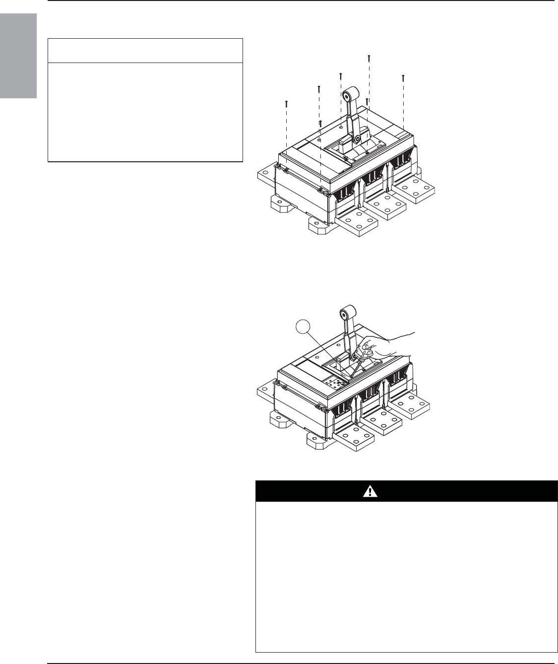
PowerPact™ R-Frame and NS1600b–NS3200 Circuit Breakers 48049-243-04
Rev. 01, 09/2012
© 2004–2012 Schneider Electric All Rights Reserved10-EN
ENGLISH
Replace Accessory Cover
Operation
Circuit Breaker Removal
NOTICE
HAZARD OF EQUIPMENT DAMAGE
Accessory cover must be secured with all
seven screws tightened to stated torque. Do
not overtorque screws. Do not use power
equipment to torque screws.
Failure to follow these instructions can
result in equipment damage.
Replace accessory cover. Replace all seven
accessory cover screws. Hand tighten screws to
11–13 lb-in (1.2–1.5 N•m). Do not exceed torque
specification of screws.
Figure 18: Accessory Cover Replacement
06123013
Press push-to-trip button (A) at installation to
check operation and then once a year to
exercise circuit breaker.
NOTE: Push-to-trip button will not trip circuit
breaker if it is in the OFF (O) position.
Figure 19: Push-to-Trip Button
06123009
A
Turn off all power supplying this equipment
before working on or inside equipment.
Remove circuit breaker in reverse order of
installation.
DANGER
HAZARD OF ELECTRIC SHOCK, EXPLOSION OR ARC FLASH
• Apply appropriate personal protective equipment (PPE) and follow safe
electrical work practices. See NFPA 70E or CSA Z462.
• This equipment must only be installed and serviced by qualified electrical
personnel.
• Turn off all power supplying this equipment before working on or inside
equipment.
• Always use a properly rated voltage sensing device to confirm power is off.
• Replace all devices, doors and covers before turning on power to this
equipment.
Failure to follow these instructions will result in death or serious injury.
131 of 292
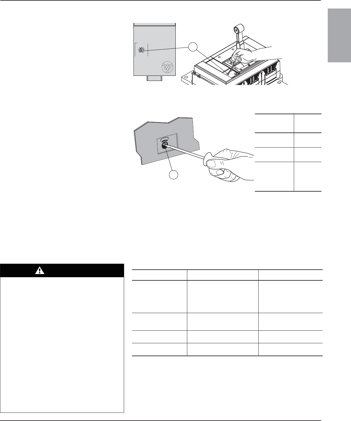
48049-243-04 PowerPact™ R-Frame and NS1600b–NS3200 Circuit Breakers
Rev. 01, 09/2012
© 2004–2012 Schneider Electric All Rights Reserved 11-EN
ENGLISH
Testing Circuit breaker trip unit operation can be tested using the Hand-held Test Kit
or the Full-function Test Kit.
TROUBLESHOOTING If problems occur during installation, refer to information below. If trouble
persists, contact the field office.
Trip Unit Adjustment
For ET1.0I Electronic Trip Units: Adjust
instantaneous trip (Ii) by adjusting switch (A).
For Micrologic™ Trip Units refer to the trip unit
user guide available on the Schneider Electric
website (see page 1).
Figure 20: Instantaneous Trip Switch Adjustment
Neutral Protection Adjustment
NOTE: Applies to four-pole circuit breakers only
A. For ET electronic trip units and Micrologic
2.0, 3.0, 5.0, 2.0A, 3.0A and 5.0A electronic
trip units:
— Remove fourth pole lens cover.
— Use a slotted screwdriver to adjust
neutral setting on circuit breaker (A).
— Replace fourth pole lens cover. Torque
screw to 5.3 in-lb (0.6 N•m).
B. For Micrologic 5.0P, 6.0P, 5.0H and 6.0H
electronic trip units refer to the trip unit user
guide available on the Schneider Electric
website (see page 1).
Figure 21: Adjust Circuit Breaker System Type Switch
(on Four-Pole Circuit Breaker)
Circuit Breaker
Switch Setting
Neutral
Protection
4P 3D No neutral
protection
3P N/2 1/2 neutral
protection
4P 4D
Full neutral
protection
(Factory
default
setting)
06123170
A
x In
2
3
456
10
12
1.5
setting
Ii
instantaneous
8
06123009 06123023
4
4
D
P
06134824
A
DANGER
HAZARD OF ELECTRIC SHOCK,
EXPLOSION OR ARC FLASH
• Apply appropriate personal protective
equipment (PPE) and follow safe electrical
work practices. See NFPA 70ENFPA 70E or
CSA Z462.
• This equipment must only be installed and
serviced by qualified electrical personnel.
• Troubleshooting may require energizing
auxiliary devices with a test power supply.
Make sure that the power supply is off before
connecting or disconnecting it to the auxiliary
device.
• Do not touch the terminals of the device
during the test.
Failure to follow these instructions will
result in death or serious injury.
Condition Possible Causes Solution
Circuit breaker fails to stay
closed.
1. Trip adjustment set too low.
2. Undervoltage trip not
energized.
3. Shunt trip energized.
4. Short circuit or overload on
system.
1. Adjust trip setting.
2. Energize undervoltage trip.
3. De-energize shunt trip.
4. Check system for short
circuit or overload.
Circuit breaker trips, but no
short circuit or overload is
evident.
1. Trip adjustment set too low.
2. Voltage is below undervoltage
trip setting.
1. Adjust trip setting.
2. Check system for low
voltage.
Push-to-trip button will not
trip circuit breaker.
Circuit breaker already tripped or
off (O).
Move circuit breaker handle to
reset, then to on (I).
Circuit breaker cannot be
opened manually. Damage to current path. Contact local field office.
132 of 292
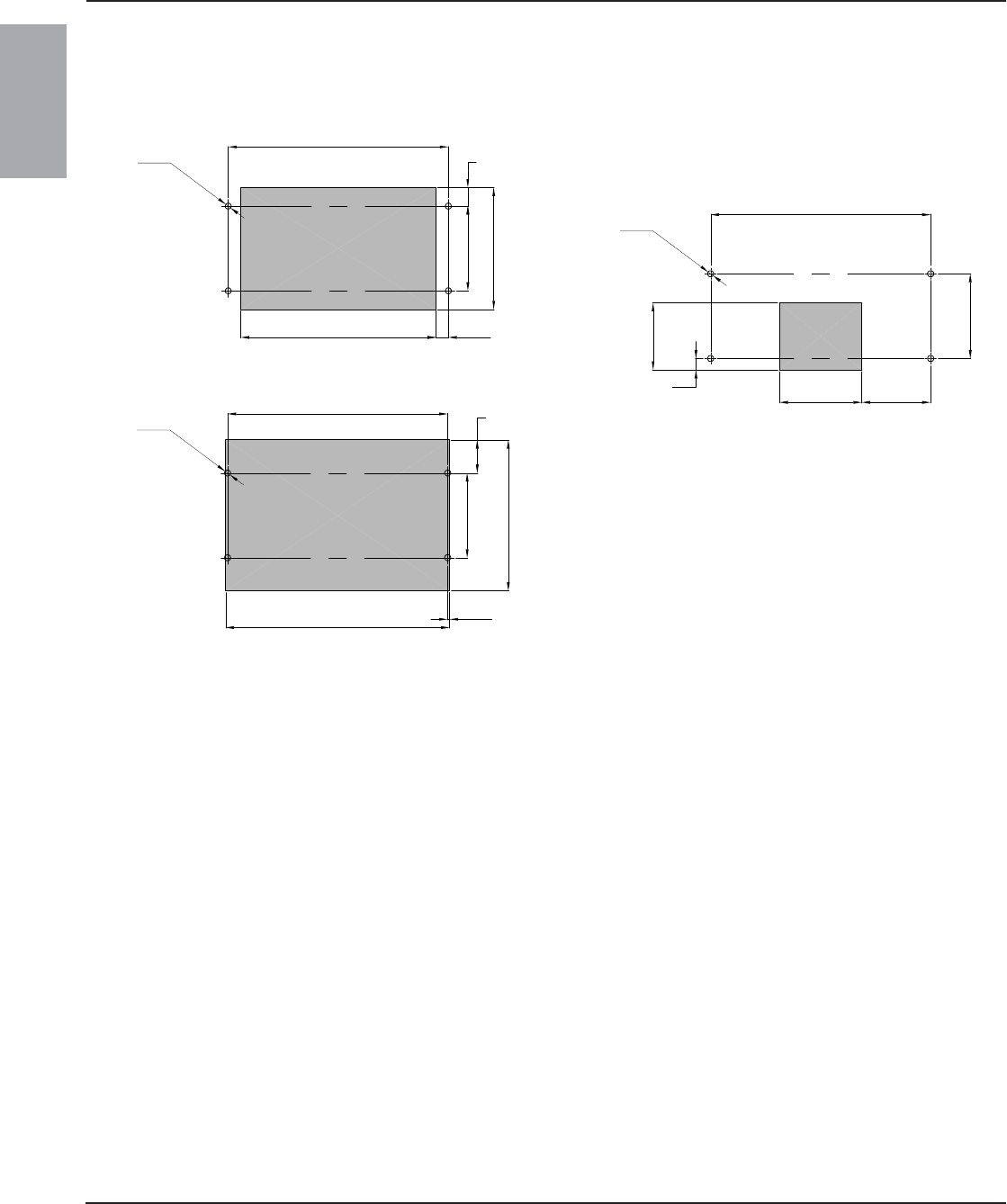
PowerPact™ R-Frame and NS1600b–NS3200 Circuit Breakers 48049-243-04
Instruction Bulletin Rev. 01, 09/2012
Electrical equipment should be installed, operated, serviced, and maintained only by
qualified personnel. No responsibility is assumed by Schneider Electric for any
consequences arising out of the use of this material.
Square D™, Schneider Electric™ and PowerPact™ are trademarks or registered
trademarks of Schneider Electric. Other trademarks used herein are the property of
their respective owners.
Schneider Electric
3700 Sixth St. SW
Cedar Rapids, IA 52404 USA
1-888-778-2733
www.schneider-electric.us
© 2004–2012 Schneider Electric All Rights Reserved12-EN
ENGLISH
Dimensions For dimensional information refer to the Schneider Electric website (see
page 1).
Figure 22: Mounting Hole and Enclosure Cover Cutouts Dimensions
Ø0.43
[11,0]
15.35 3-pole
19.88
[505,0] 4-pole
4x
5.91
15.35
[390,0] 3-pole
19.88
[505,0] 4-pole
Ø0.43
[11,0]
4x
Ø0.43
[11,0]
15.35
[390,0] 3-pole
4x
5.91
13.62 0.87
8.50
1.30
2.30
10.51
15.63 0.14
[346,0] [22,0]
[33,0]
[216,0]
[150,0]
[390,0]
[58,5]
[3,5]
[397,0]
[267,0]
[150,0]
5.75 4.80
0.80
4.69
5.91
[146,0] [122,0]
[20,4]
[119,0]
[150,0]
Accessory Cover Cutout
Handle Cutout
Accessory Cover Escutcheon Cutout
Dimensions: in.
[mm]
48096-380-01
133 of 292
Micrologic™ 2.0, 3.0 and 5.0 Electronic Trip Units
Instruction Bulletin
48049-207-05
Rev. 01, 07/2012
Retain for future use.
ENGLISH
134 of 292
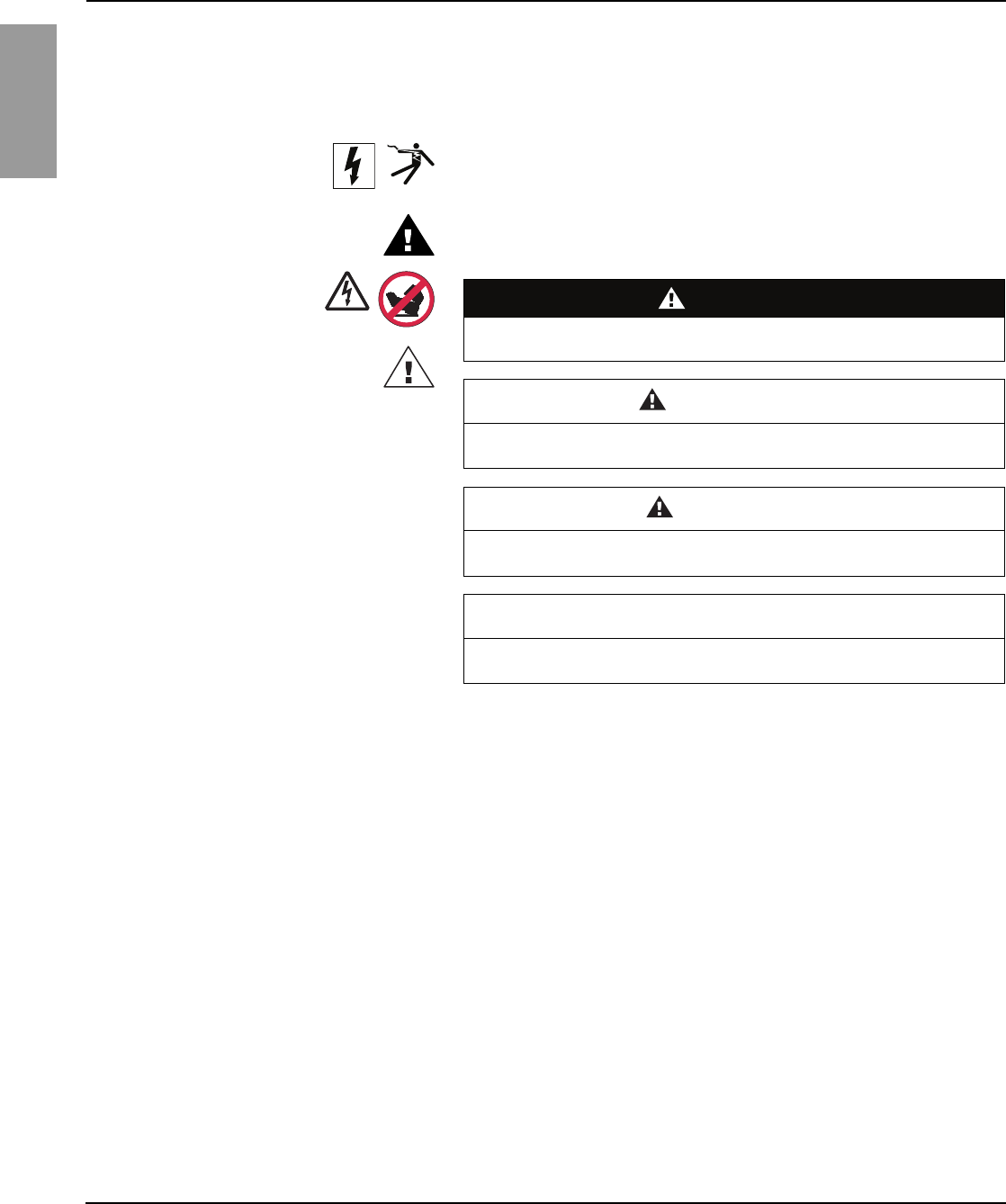
Micrologic™ 2.0, 3.0 and 5.0 Electronic Trip Units 48049-207-05
Rev. 01, 07/2012
© 1999–2012 Schneider Electric All Rights Reserved.2-EN
ENGLISH
Hazard Categories and Special
Symbols Read these instructions carefully and look at the equipment to become
familiar with the device before trying to install, operate, service, or maintain
it. The following special messages may appear throughout this bulletin or on
the equipment to warn of hazards or to call attention to information that
clarifies or simplifies a procedure.
The addition of either symbol to a “Danger” or “Warning” safety label
indicates that an electrical hazard exists which will result in personal injury if
the instructions are not followed.
This is the safety alert symbol. It is used to alert you to personal injury
hazards. Obey all safety messages that follow this symbol to avoid possible
injury or death.
NOTE: Provides additional information to clarify or simplify a procedure.
Please Note Electrical equipment should be installed, operated, serviced, and maintained
only by qualified personnel. No responsibility is assumed by Schneider
Electric for any consequences arising out of the use of this material.
FCC Notice This equipment has been tested and found to comply with the limits for a
Class A digital device, pursuant to part 15 of the FCC Rules. These limits
are designed to provide reasonable protection against harmful interference
when the equipment is operated in a commercial environment. This
equipment generates, uses, and can radiate radio frequency energy and, if
not installed and used in accordance with the instruction manual, may cause
harmful interference to radio communications. Operation of this equipment
in a residential area is likely to cause harmful interference in which case the
user will be required to correct the interference at his own expense. This
Class A digital apparatus complies with Canadian ICES-003.
DANGER
DANGER indicates a hazardous situation which, if not avoided, will result
in death or serious injury.
WARNING
WARNING indicates a hazardous situation which, if not avoided, can
result in death or serious injury.
CAUTION
CAUTION indicates a hazardous situation which, if not avoided, can
result in minor or moderate injury.
NOTIC
E
NOTICE is used to address practices not related to physical injury. The
safety alert symbol is not used with this signal word.
IEC
ANSI
135 of 292

© 1999–2012 Schneider Electric All Rights Reserved 3-EN
48049-207-05 Micrologic™ 2.0, 3.0 and 5.0 Electronic Trip Units
Rev. 01, 07/2012 Table of Contents
ENGLISH
Table of Contents
SECTION 1: GENERAL INFORMATION ...................................................................................................................... 5
Introduction ................................................................................................. 5
Trip Unit Settings ........................................................................................ 5
Micrologic 2.0 Trip Unit ......................................................................... 5
Micrologic 3.0 Trip Unit .......................................................................... 6
Micrologic 5.0 Trip Unit .......................................................................... 6
Trip Unit Switches ....................................................................................... 7
Long-Time Protection ............................................................................ 7
Short-Time Protection ........................................................................... 8
Instantaneous Protection ....................................................................... 9
Overload Indicator Light .............................................................................. 9
Trip Unit Testing .......................................................................................... 9
SECTION 2: OPERATION .................................................................................................................... 10
Switch Adjustment .................................................................................... 10
Examples .................................................................................................. 10
Micrologic 2.0 Trip Unit ........................................................................ 10
Micrologic 3.0 Trip Unit ........................................................................ 11
Micrologic 5.0 Trip Unit ........................................................................ 12
Trip Unit Operation Verification ................................................................. 12
SECTION 3: TRIP UNIT REPLACEMENT .................................................................................................................... 13
Required Tools .......................................................................................... 13
Preparation ............................................................................................... 13
Record Switch Settings ....................................................................... 13
Circuit Breaker Disconnection ............................................................. 13
Circuit Breaker Accessory Cover Removal ......................................... 13
Rating Plug Removal ........................................................................... 14
Trip Unit Removal ................................................................................ 14
Trip Unit Replacement .............................................................................. 14
Trip Unit Installation ............................................................................. 14
Circuit Breaker Accessory Cover Replacement ........................................ 15
Trip Unit Installation Check ....................................................................... 16
Secondary Injection Testing ................................................................ 16
Primary Injection Testing ..................................................................... 16
Trip Unit Setup .......................................................................................... 16
Circuit Breaker Reconnection ................................................................... 16
SECTION 4: ADJUSTABLE RATING PLUG REPLACEMENT .............................................................................................. 17
Rating Plug Removal ................................................................................ 17
New Rating Plug Installation ..................................................................... 17
136 of 292

Micrologic® 2.0, 3.0 and 5.0 Electronic Trip Units 48049-207-05
Table of Contents Rev. 01, 07/2012
© 1999–2012 Schneider Electric All Rights Reserved4-EN
ENGLISH
137 of 292
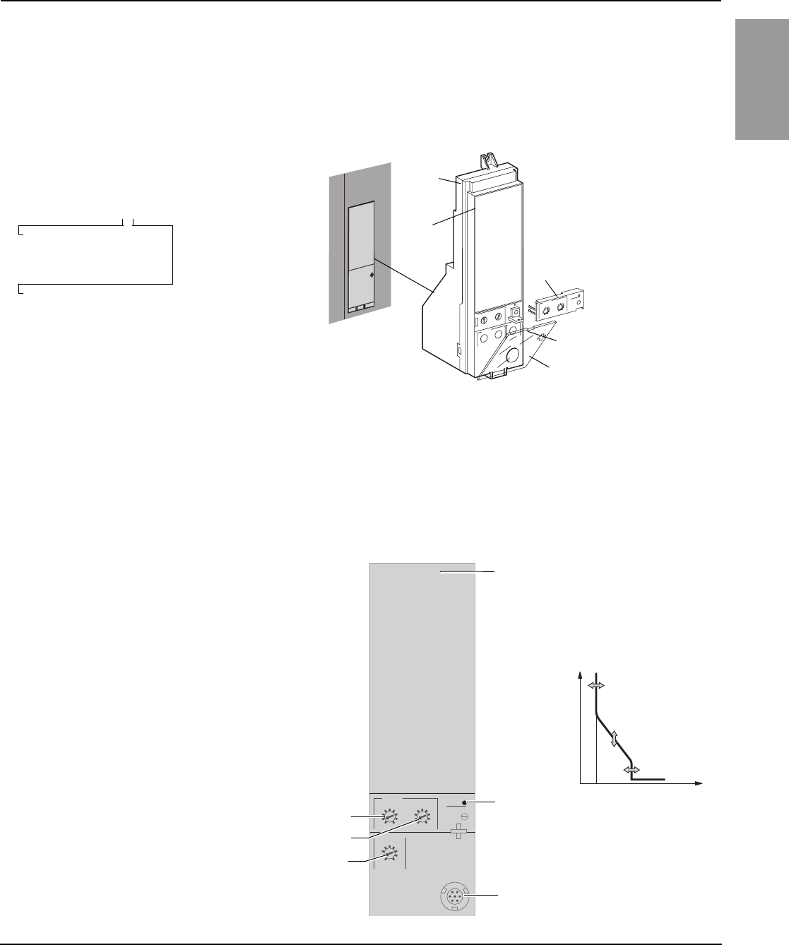
48049-207-05 Micrologic™ 2.0, 3.0 and 5.0 Electronic Trip Units
Rev. 01, 07/2012 Section 1—General Information
© 1999–2012 Schneider Electric All Rights Reserved 5-EN
ENGLISH
Section 1—General Information
Introduction
Trip Unit Settings On the face of the trip unit are adjustable switches to allow changing of trip
characteristics. Trip units are shipped with the long-time pickup switch set at
1.0 and all other trip unit adjustments set at their lowest settings.
Micrologic 2.0 Trip Unit
Micrologic™ trip units (A) provide adjustable
tripping functions on electronic trip circuit
breakers. The product name (B) specifies the
level of protection provided by the trip unit.
Micrologic trip units are field replaceable to allow
for upgrading of the trip unit in the field. For
complete information on available circuit breaker
models, frame sizes, interrupting ratings, sensor
plugs, rating plugs and trip units, see the product
catalog.
Figure 1: Micrologic Trip Unit
Micrologic 3.0 Trip Unit
Type of protection
2—Basic IEC protection (LS0)
5—Selective protection (LSI)
Trip uni t se r ies
0—Indicates the first version
3—Basic UL protection (LI)
Micrologic 2.0
06133198
06134242
A
B
D
E
C
A—Micrologic Trip Unit
B—Product Name
C—Switch Cover
D—Switch Cover Opening Slot
E—Adjustable Rating Plug
NOTE: For use with IEC circuit breakers only.
The Micrologic 2.0 trip unit provides basic IEC
(LS0) protection.
A. Long-time pickup (Ir) switch
B. Long-time delay (tr) switch
C. Short-time pickup (Isd) switch*
D. Test plug receptacle
E. Overload indicator light
F. Trip unit name
Figure 2: Micrologic 2.0 Trip Unit
*Short-time delay is factory set at 0 (no delay), thus short-time
pickup provides instantaneous protection.
Micrologic 2.0
.98
instantaneous
long time alarm
.5
1
2
4812
16
20
tr
(s)
@ 6 Ir24
.4
.5
.6
.7 .8 .9
.95
1
Ir
x In
x Ir
2
2.53456
8
10
1.5
setting
Isd
06134239
0 Ir Isd I
t
06134245
B
A
F
C
E
D
A
B
C
138 of 292
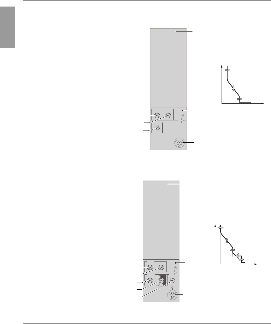
Micrologic™ 2.0, 3.0 and 5.0 Electronic Trip Units 48049-207-05
Section 1—General Information Rev. 01, 07/2012
© 1999–2012 Schneider Electric All Rights Reserved6-EN
ENGLISH
Micrologic 3.0 Trip Unit
Micrologic 5.0 Trip Unit
The Micrologic 3.0 trip unit provides basic (LI)
protection.
A. Long-time pickup (Ir) switch
B. Long-time delay (tr) switch
C. Instantaneous pickup (Ii) switch
D. Test plug receptacle
E. Overload indicator light
F. Trip unit name
Figure 3: Micrologic 3.0 Trip Unit
Micrologic 3.0
.98
instantaneous
long timealarm
.5
1
2
4812
16
20
tr
(s)
@ 6 Ir24
.4
.5
.6
.7 .8 .9
.95
1
Ir
x In
x In
2
34568
10
12
1.5
setting
Ii
06134240
B
A
0 Ir Ii I
t
06133201
F
C
E
D
A
B
C
The Micrologic 5.0 trip unit provides selective
(LSI) protection.
A. Long-time pickup (Ir) switch
B. Long-time delay (tr) switch
C. Short-time pickup (Isd) switch
D. Short-time delay (tsd) switch
E. Instantaneous pickup (Ii) switch
F. Test plug receptacle
G. Overload indicator light
H. Trip unit name
Figure 4: Micrologic 5.0 Trip Unit
Micrologic 5.0
setting delay
short timeinstantaneous
long time alarm
4
test
.4
.5
.6
.7 .8 .9
.95
.98
1
Ir
x In .5
1
2
4812
16
20
tr
(s)
@ 6 Ir24
I i
x In
3
6810
12
15
off
2
tsd
(s)
on
I2t
.2
.3
.4.4
.1
.2
.3
.1
0off
x Ir
2
2.53456
8
10
Isd
1.5
06134241
0 Ir Isd I
t
Ii
06133202
A
H
C
D
E
B
F
G
B
A
CD
E
139 of 292
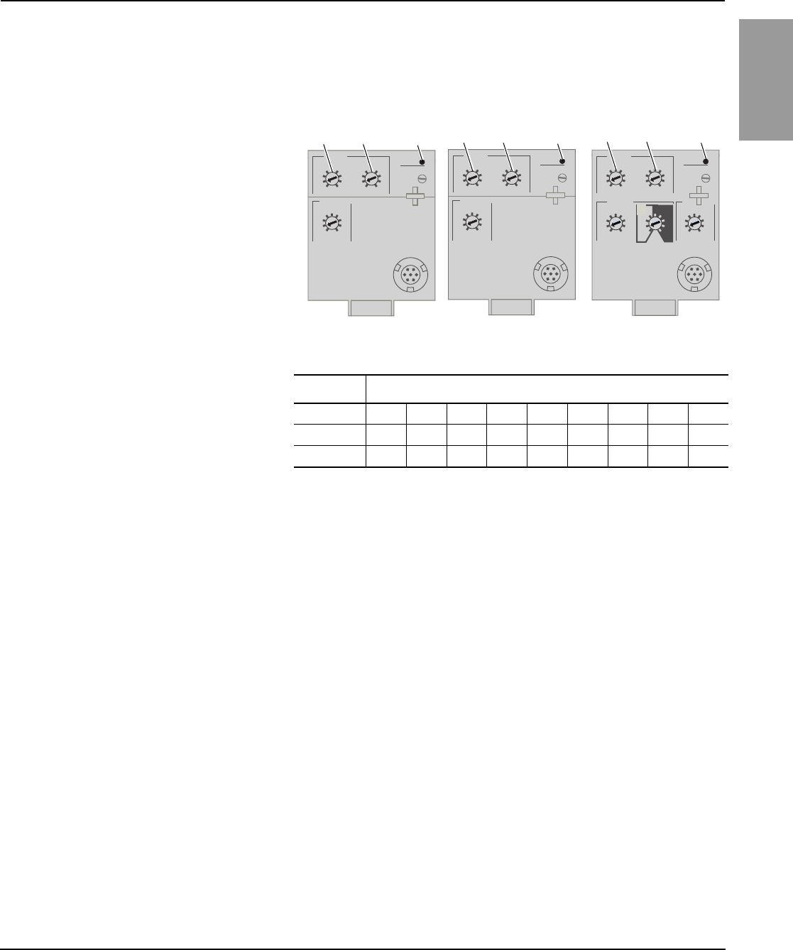
48049-207-05 Micrologic™ 2.0, 3.0 and 5.0 Electronic Trip Units
Rev. 01, 07/2012 Section 1—General Information
© 1999–2012 Schneider Electric All Rights Reserved 7-EN
ENGLISH
Trip Unit Switches
Long-Time Protection
Long-time protection protects equipment against
overloads.
•Long-time protection is standard on all trip
units.
•The long-time pickup (Ir) (A) sets maximum
current level (based on sensor plug rating In)
which circuit breaker will carry continuously.
If current exceeds this value, circuit breaker
will trip after the preset time delay. The long-
time pickup (Ir) is adjustable from 0.4–1.0
times the sensor plug rating (In).
•The long-time delay (tr) (B) sets the length of
time that the circuit breaker will carry an
overcurrent below the short-time or
instantaneous pickup current level before
tripping. See Table 1 for long-time delay
settings.
•The overload indicator light (C) indicates that
the Ir long-time pickup threshold has been
exceeded.
•Both long-time pickup and long-time delay
are on the field-replaceable adjustable rating
plug. To change settings to more precisely
match the application, various rating plugs
are available. For instructions on replacing
the rating plug, see Section 4—Adjustable
Rating Plug Replacement.
Figure 5: Long-Time Protection Switches
Table 1: Micrologic Trip Unit Long-Time Delay Values
Setting1Long-Time Delay in Seconds2
tr at 1.5 x Ir 12.5 25 50 100 200 300 400 500 600
tr at 6 x Ir 0.5 1 2 4 8 12 16 20 24
tr at 7.2 x Ir 0.3430.69 1.38 2.7 5.5 8.3 11 13.8 16.6
1In = sensor rating. Ir = In x long-time pickup. Trip threshold between 1.05 and 1.20 Ir.
2Time-delay accuracy +0/-20%
3For Micrologic 5.0 trip units, when tsd is set to 0.4 off or 0.4 on, then tr = 0.5 instead of 0.34.
•The In value can be changed by replacing
the sensor plug below the trip unit. For
further information, see the instructions
packed with the sensor plug replacement kit.
•Long-time protection uses true RMS
measurement.
Thermal imaging provides continuous
temperature rise status of the wiring, both before
and after the device trips. This allows the circuit
breaker to respond to a series of overload
conditions which could cause conductor
overheating, but would go undetected if the
long-time circuit was cleared every time the load
dropped below the pickup setting or after every
tripping event.
NOTE: If checking trip times, wait a minimum of
15 minutes after circuit breaker trips before
resetting to allow the thermal imaging to reset
completely to zero.
.4
.5
.6
.7 .8 .9
.95
.98
1
delay
short timeI itsd
(s)
on I2t
.2
.3
.4.4
.1
.2
.3
.1
0off
instantaneous
long time alarm
Ir
x In .5
1
2
4812
16
20
tr
(s)
@ 6 Ir24
setting
x Ir
2
2.53456
8
10
Isd
1.5x In
3
46810
12
15
off
2
06133204
x Ir
2
2.53456
8
10
1.5
setting
Isd
instantaneous
long time alarm
tr
(s)
.4
.5
.6
.7 .8 .9
.95
.98
1
Ir
x In .5
1
2
4812
16
20
@ 6 Ir
24
06134243
x In
2
34568
10
12
1.5
setting
Ii
instantaneous
long time alarm
tr
(s)
.4
.5
.6
.7 .8 .9
.95
.98
1
Ir
x In .5
1
2
4812
16
20
@ 6 Ir
24
06133203
ABC
Micrologic 2.0 Trip Unit Micrologic 3.0 Trip Unit Micrologic 5.0 Trip Unit
ABCABC
140 of 292
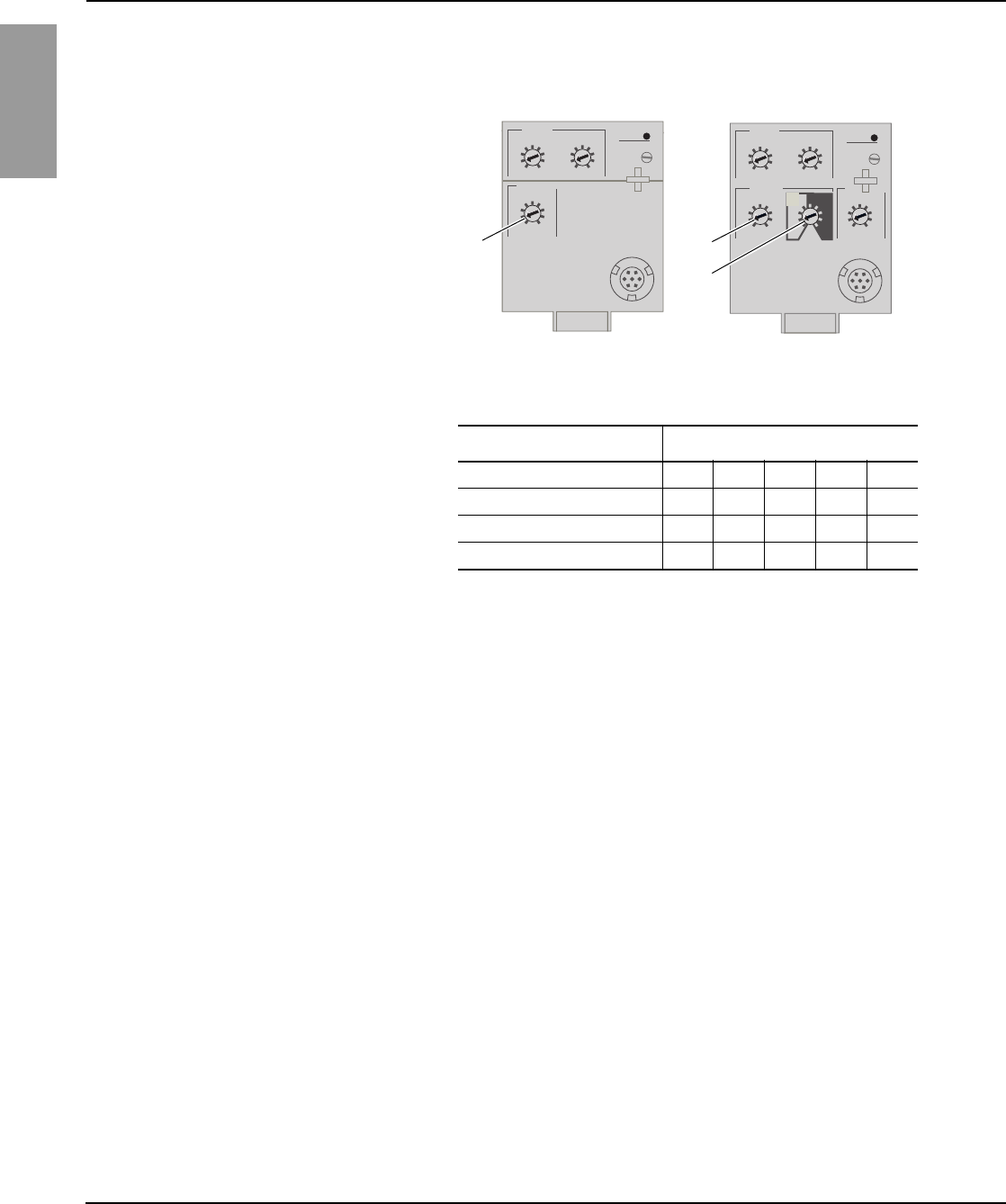
Micrologic™ 2.0, 3.0 and 5.0 Electronic Trip Units 48049-207-05
Section 1—General Information Rev. 01, 07/2012
© 1999–2012 Schneider Electric All Rights Reserved8-EN
ENGLISH
Short-Time Protection
Short-time protection protects equipment
against short circuits.
•Short-time protection is standard on 2.0 and
5.0 trip units. It is not available on 3.0 trip
units.
•Short-time protection is based on the long-
time pickup (Ir)
•The short-time pickup (Isd) (A) sets the
current level (below instantaneous trip level)
where the circuit breaker will trip after the
preset time delay.
•The short-time delay (tsd) (B) sets the length
of time that the circuit breaker will carry an
overcurrent above the short-time pickup
current level before tripping. It is adjustable
on the 5.0 trip unit and factory set to zero on
the 2.0 trip unit.
•The I2t on/I2t off option provides improved
selectivity with downstream protective
devices:
•With I2t off selected, fixed time delay is
provided.
—With I
2t on selected, inverse time I2t
protection is provided up to 10 x Ir.
Above 10 x Ir, a fixed time delay is
provided.
— Intermittent currents in the short-time
tripping range which do not last
sufficiently long to trigger a trip are
accumulated and shorten the trip delay
appropriately.
•Setting tsd to the 0 setting turns off time-
delay features.
•Short-time protection uses true RMS
measurement.
•Short-time delay can be adjusted to provide
selectivity with a downstream circuit breaker.
Figure 6: Short-Time Protection Switches
Table 2: Micrologic Trip Unit Short-Time Delay Values
Setting Short-Time Delay
I2t off (Isd at 10 Ir) (seconds) 00.1 0.2 0.3 0.4
I2t on (Isd at 10 Ir) (seconds) –0.1 0.2 0.3 0.4
tsd (min. trip) (milliseconds) 20 80 140 230 350
tsd (max. trip) (milliseconds) 80 140 200 320 500
.4
.5
.6
.7 .8 .9
.95
.98
1
delay
short timeI itsd
(s)
on I2t
.2
.3
.4.4
.1
.2
.3
.1
0off
instantaneous
long time alarm
Ir
x In .5
1
2
4812
16
20
tr
(s)
@ 6 Ir24
setting
x Ir
2
2.53456
8
10
Isd
1.5x In
3
46810
12
15
off
2
06133204
A
B
Micrologic 5.0 Trip Unit
x Ir
2
2.53456
8
10
1.5
setting
Isd
instantaneous
long time alarm
tr
(s)
.4
.5
.6
.7 .8 .9
.95
.98
1
Ir
x In .5
1
2
4812
16
20
@ 6 Ir
24
06134243
Micrologic 2.0 Trip Unit
A
141 of 292
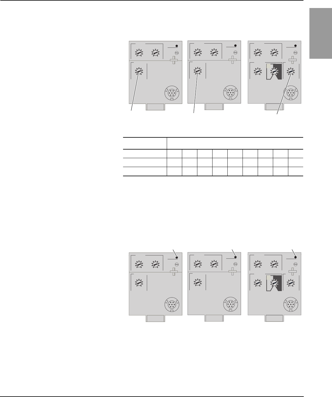
48049-207-05 Micrologic™ 2.0, 3.0 and 5.0 Electronic Trip Units
Rev. 01, 07/2012 Section 1—General Information
© 1999–2012 Schneider Electric All Rights Reserved 9-EN
ENGLISH
Instantaneous Protection
Overload Indicator Light
Trip Unit Testing Trip unit functions can be tested using primary injection testing or secondary
injection testing.
Instantaneous protection protects equipment
against short circuits with no intentional time
delay.
•Instantaneous protection (Ii) (A) is standard
on 3.0 and 5.0 trip units.*
•Instantaneous protection for 2.0 trip units is
based on the circuit breaker sensor rating
(Ir).
•Instantaneous protection for 3.0 and 5.0 trip
units is based on the long-time delay pickup
(In).
•Circuit breaker open command is issued as
soon as threshold current is exceeded.
•Instantaneous protection for 3.0 and 5.0 trip
units use peak current measurement.
Instantaneous protection for 2.0 trip units
use RMS current measurement.
•When instantaneous protection switch is set
to off, the instantaneous protection is
disabled.
Figure 7: Instantaneous Protection Switches
Table 3: Micrologic Instantaneous Values
Setting Interruption Current
2.0 Isd (= Ir x..) 1.5 22.5 3456810
3.0 Ii (= In x..) 1.5 23456810 12
5.0 Ii (= In x..) 2346810 12 15 off
*Instantaneous protection on 2.0 trip units is achieved by
using short-time protection (Isd) with short-time delay factory
set to 0 (zero).
Ii = UL and ANSI instantaneous
Isd = IEC instantaneous (short-time with zero delay)
In = sensor rating
Ir = long-time pickup
x Ir
2
2.53456
8
10
1.5
setting
Isd
instantaneous
long time alarm
tr
(s)
.4
.5
.6
.7 .8 .9
.95
.98
1
Ir
x In .5
1
2
4812
16
20
@ 6 Ir
24
06134243
x In
2
34568
10
12
1.5
setting
Ii
instantaneous
long time alarm
tr
(s)
.4
.5
.6
.7 .8 .9
.95
.98
1
Ir
x In .5
1
2
4812
16
20
@ 6 Ir
24
06133203
.4
.5
.6
.7 .8 .9
.95
.98
1
delay
short timeI itsd
(s)
on I2t
.2
.3
.4.4
.1
.2
.3
.1
0off
instantaneous
long time alarm
Ir
x In .5
1
2
4812
16
20
tr
(s)
@ 6 Ir24
setting
x Ir
2
2.53456
8
10
Isd
1.5x In
3
46810
12
15
off
2
06133204
AA
A
Micrologic 2.0 Trip Unit Micrologic 3.0 Trip Unit Micrologic 5.0 Trip Unit
The overload indicator light (A) lights when the Ir
long-time pickup level has been exceeded. Figure 8: Overload Indicator Lights
x In
2
34568
10
12
1.5
setting
Ii
instantaneous
long time alarm
tr
(s)
.4
.5
.6
.7 .8 .9
.95
.98
1
Ir
x In .5
1
2
4812
16
20
@ 6 Ir
24
06133203
.4
.5
.6
.7 .8 .9
.95
.98
1
delay
short timeI itsd
(s)
on I2t
.2
.3
.4.4
.1
.2
.3
.1
0off
instantaneous
long time alarm
Ir
x In .5
1
2
4812
16
20
tr
(s)
@ 6 Ir24
setting
x Ir
2
2.53456
8
10
Isd
1.5x In
3
46810
12
15
off
2
06133204
x Ir
2
2.53456
8
10
1.5
setting
Isd
instantaneous
long time alarm
tr
(s)
.4
.5
.6
.7 .8 .9
.95
.98
1
Ir
x In .5
1
2
4812
16
20
@ 6 Ir
24
06134243
A
Micrologic 2.0 Trip Unit Micrologic 3.0 Trip Unit Micrologic 5.0 Trip Unit
A
A
142 of 292
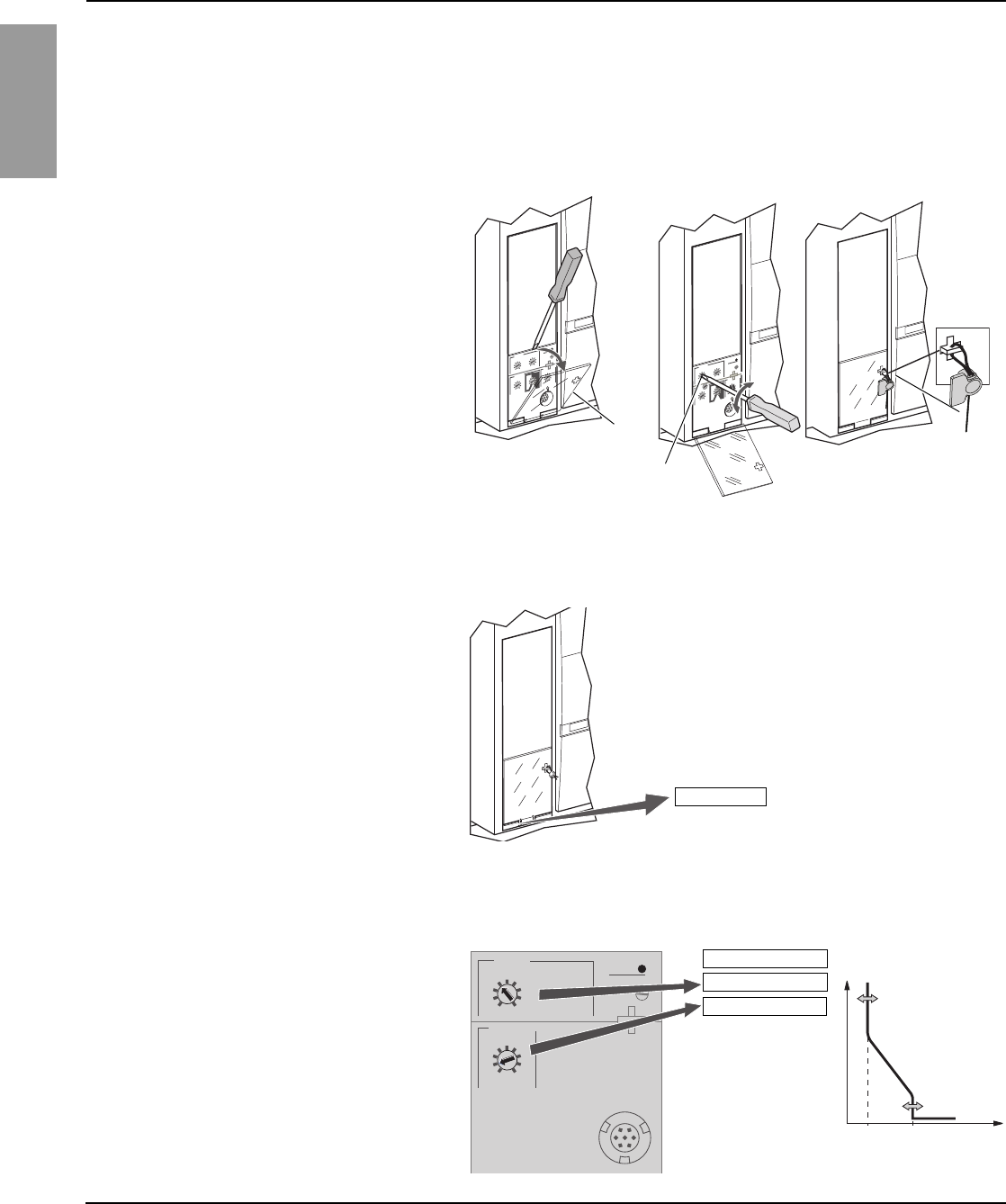
Micrologic™ 2.0, 3.0 and 5.0 Electronic Trip Units 48049-207-05
Section 2—Operation Rev. 01, 07/2012
© 1999–2012 Schneider Electric All Rights Reserved10-EN
ENGLISH
Section 2—Operation
Switch Adjustment
Examples
Micrologic 2.0 Trip Unit
1. Open switch cover (A).
2. Adjust the appropriate switches (B) to
desired values.
3. Replace switch cover. Use wire seal
MICROTUSEAL (C), if necessary, to provide
tamper evidence.
Figure 9: Adjust Switch Settings
06133207
06133206
06133205
A
B
C
Circuit breaker is rated 2000 A. Figure 10: Circuit Breaker Rating
06133208
In = 2000 A
1. Set pickup levels. Figure 11: Set Pickup Levels
0 I
tIr
Isd
06134252
1400 A
2800 A
alarm
x Ir
2
2.53456
8
10
1.5
setting
Isd
instantaneous
.4
.5
.6
.7 .8 .9
.95
.98
1
long time
Ir
x In
06134251
Isd = 2 x Ir = 2800 A
In = 2000 A
Ir = 0.7 x In = 1400 A
143 of 292
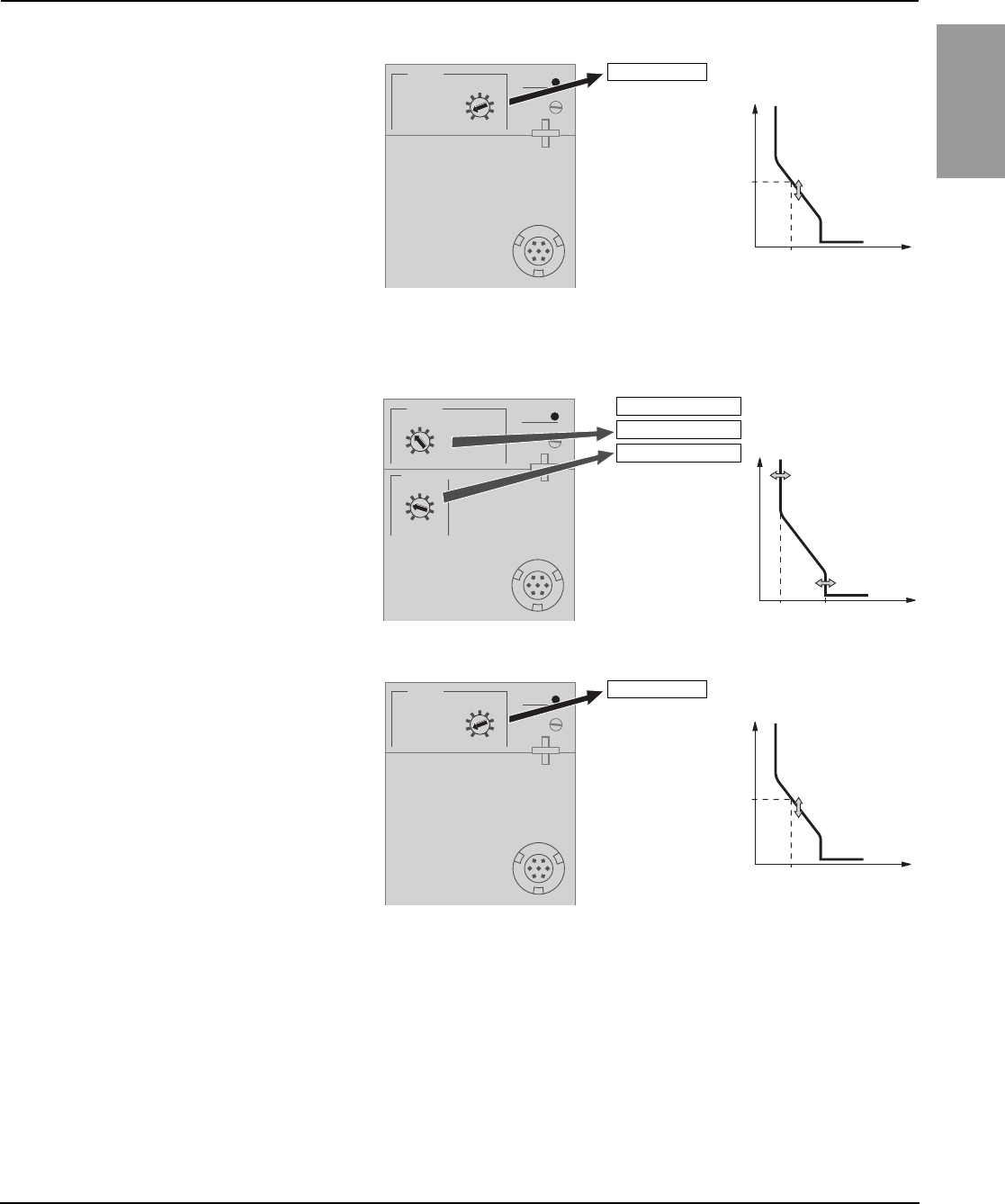
48049-207-05 Micrologic™ 2.0, 3.0 and 5.0 Electronic Trip Units
Rev. 01, 07/2012 Section 2—Operation
© 1999–2012 Schneider Electric All Rights Reserved 11-EN
ENGLISH
Micrologic 3.0 Trip Unit
2. Set time delay. Figure 12: Set Time Delay
long time alarm
.5
1
2
4812
16
20
tr
(s)
@ 6 Ir24
06133211
0 I
t
tr
06133212
6 x Ir
1 s
tr = 1 s (at 6 x Ir)
1. Set pickup levels. Figure 13: Set Pickup Levels
2. Set time delay. Figure 14: Set Time Delay
0 I
tIr
Ii
06133210
Ii = 3 x In = 6000 A
alarm
x In
2
34568
10
12
1.5
setting
Ii instantaneous
.4
.5
.6
.7 .8 .9
.95
.98
1
long time
Ir
x In
06133209
In = 2000 A
Ir = 0.7 x In = 1400 A
long time alarm
.5
1
2
4812
16
20
tr
(s)
@ 6 Ir24
06133211
0 I
t
tr
06133212
6 x Ir
1 s
tr = 1 s (at 6 x Ir)
144 of 292
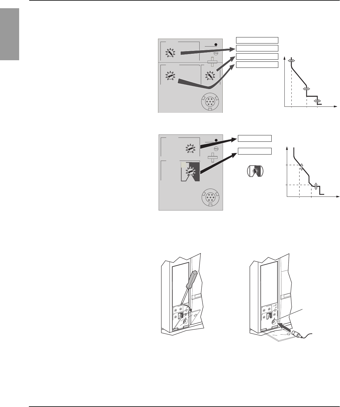
Micrologic™ 2.0, 3.0 and 5.0 Electronic Trip Units 48049-207-05
Section 2—Operation Rev. 01, 07/2012
© 1999–2012 Schneider Electric All Rights Reserved12-EN
ENGLISH
Micrologic 5.0 Trip Unit
Trip Unit Operation Verification
1. Set pickup levels. Figure 15: Set Pickup Levels
2. Set time delay. Figure 16: Set Time Delay
06133213
.4
.5
.6
.7 .8 .9
.95
.98
1
setting
short time
I i
x Ir
2
2.5345
6
8
10
Isd
1.5 off
instantaneous
long time alarm
Ir
x In
x In
3
46810
12
15
off
2
Ir
Isd
Ii
0I
t
06133214
Ii = 3 x In = 6000 A
In = 2000 A
Ir = 0.7 x In = 1400 A
Isd = 2 x Ir = 2800 A
short time
long time alarm
.5
1
2
4812
16
20
tr
(s)
@ 6 Ir24
delay
tsd
on I2t
.
2
.
3
.
4
.
4
.
1
.
2
.
3
.
1
0
I2t on I2t off
06133215
tr
tsd
0I
t
06133217
6 x Ir
1 s
10 x Ir
0.2 s
tr = 1 s (at 6 x Ir)
tsd = 0.2 s I2t on
Use a test kit connected to the trip unit test plug
receptacle (A) to verify trip unit is functioning as
desired. See instructions shipped with test kit to
perform verification tests.
Figure 17: Verify Trip Unit Operation
06133218
06133205
A
145 of 292

48049-207-05 Micrologic™ 2.0, 3.0 and 5.0 Electronic Trip Units
Rev. 01, 07/2012 Section 3—Trip Unit Replacement
© 1999–2012 Schneider Electric All Rights Reserved 13-EN
ENGLISH
Section 3—Trip Unit Replacement
Required Tools •Torque-controlled screwdriver, set at 7 in-lbs (0.8 N•m) ± 10%
(Lindstrom torque driver MAL500-2 or equivalent)
•Micrologic Full-Function Test Kit (part number S33595)
Preparation
Record Switch Settings Record all trip unit switch setting for later use.
Circuit Breaker Disconnection Disconnect circuit breaker as directed in the circuit breaker instruction
bulletin shipped with the circuit breaker. The circuit breaker must be
completely isolated. (For a drawout circuit breaker, place circuit breaker in
the disconnected position. For a fixed-mounted circuit breaker, all voltage
sources, including auxiliary power, must be disconnected.)
Circuit Breaker Accessory Cover
Removal Remove circuit breaker accessory cover as directed in the Install Accessories
section of the circuit breaker instruction bulletin shipped with the circuit breaker.
Trip unit replacement must be done by qualified
persons, as defined by the National Electric
Code, who are familiar with the installation and
maintenance of power circuit breakers.
Before replacing trip unit, confirm that the circuit
breaker is in good working condition. If the
condition of the circuit breaker is unknown, do
not proceed. For assistance in evaluating the
condition of the circuit breaker, call Technical
Support.
Read this entire section before starting the
replacement procedure.
DANGER
HAZARD OF ELECTRIC SHOCK, EXPLOSION OR ARC FLASH
• Failure to follow these instructions for installation, trip test and primary
injection testing may result in the failure of some or all protective function.
• Apply appropriate personal protective equipment (PPE) and follow safe
electrical work practices. See NFPA 70E or CSA Z462.
• Replacement/upgrading of a trip unit in the field must be done by
qualified persons, as defined by the National Electric Code, who are
familiar with the installation and maintenance of power circuit breakers.
• Before replacing/upgrading trip unit, confirm that the circuit breaker is in
good working condition. If the condition of the circuit breaker is unknown,
do not proceed. For assistance in evaluating the condition of the circuit
breaker, call Technical Support.
• If the circuit breaker fails to function properly in any manner upon
completion of the trip unit installation, immediately remove the circuit
breaker from service and call Field Services.
• Turn off all power supplying this equipment before working on or inside
equipment. Follow instructions shipped with circuit breaker to disconnect
and reconnect circuit breaker.
• Replace all devices, doors and covers before returning equipment to
service.
Failure to follow this instruction will result in death or serious injury.
146 of 292
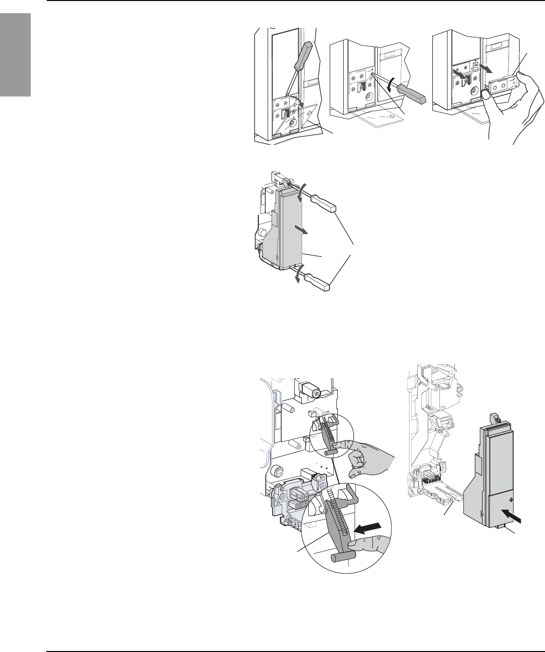
Micrologic™ 2.0, 3.0 and 5.0 Electronic Trip Units 48049-207-05
Section 3—Trip Unit Replacement Rev. 01, 07/2012
© 1999–2012 Schneider Electric All Rights Reserved14-EN
ENGLISH
Trip Unit Replacement
Rating Plug Removal
A small Phillips screwdriver is needed to remove
the adjustable rating plug.
1. Open switch cover (A).
2. Unscrew adjustable rating plug mounting
screw (B).
3. Remove adjustable rating plug (C). Save for
installation in replacement trip unit.
Figure 18: Remove Adjustable Rating Plug
Trip Unit Removal
1. Loosen two trip unit screws (A).
2. Slide out trip unit (B).
Figure 19: Remove Existing Trip Unit
06133205
setting delay
short time
I i
x Ir
2
2.53456
8
10
Isd
1.5
tsd
on
I
2
t
.
2
.
3
.
4
.
4
.
1
.
2
.
3
.
1
0
instantaneous
x In
2
2.53456
8
10
1.5
.4
.5
.6
.7 .8 .9
.95
.98
1
long timealarm
Ir
x In .5
1
2
4812
16
20
tr
(s)
@ 6 Ir
24
06133222
.4
.5
.6
.7.8.9
.95
.98
1
settingdelay
short time
I i
x Ir
2
2.53456
8
10
Isd
1.5
tsd
on
I
2
t
.
2
.
3
.
4
.
4
.
1
.
2
.
3
.
1
0
instantaneous
long timealarm
Ir
x In.5
1
2
4812
16
20
tr
(s)
@ 6 Ir
24
x In
2
2.53456
8
10
1.5
06133221
A
B
C
06134854
A
B
Trip Unit Installation
1. Inspect trip unit connector pins and surfaces.
If there is any damage, misaligned pins, or
contamination, stop installation and contact
the local sales office for factory authorized
service.
2. Inspect trip unit mounting base on the circuit
breaker. Clear any debris from area and
check that all accessory wiring is properly
routed for the trip unit being installed. If there
is any damage or contamination, stop
installation and contact the local sales office
for factory authorized service.
3. For Masterpact NW circuit breaker only:
Manually depress trip unit interlock (A) and
hold it in place during steps 4–6 below.
4. Align guide rail (B) on bottom of trip unit with
guide rail slot (C) on trip unit mounting base
in circuit breaker and gently slide the trip unit
in until it stops.
NOTE: The Masterpact NT and NW trip unit
mounting bases are shock mounted and
therefore can flex slightly.
Figure 20: Install Trip Unit
06135453
06135451
Masterpact NW Circuit Breaker
C
B
A
147 of 292
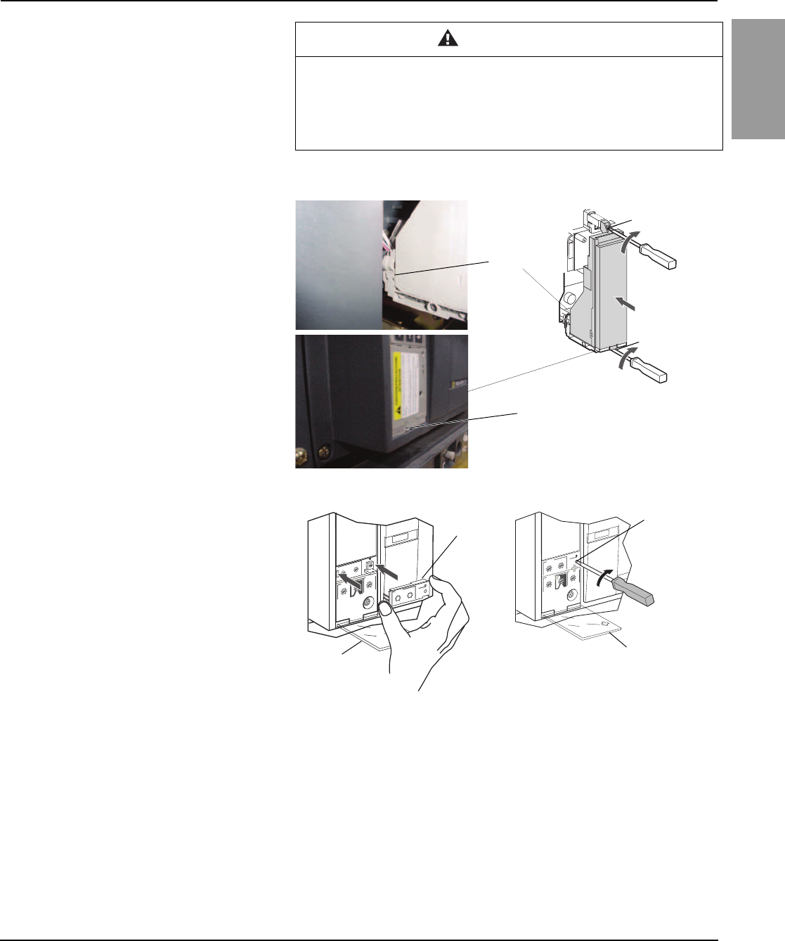
48049-207-05 Micrologic™ 2.0, 3.0 and 5.0 Electronic Trip Units
Rev. 01, 07/2012 Section 3—Trip Unit Replacement
© 1999–2012 Schneider Electric All Rights Reserved 15-EN
ENGLISH
Circuit Breaker Accessory Cover
Replacement Replace circuit breaker accessory cover as directed in the Install
Accessories section of the circuit breaker instruction bulletin shipped with
the circuit breaker.
CAUTION
HAZARD OF EQUIPMENT DAMAGE
Check installation of trip unit to assure proper connections and seating.
Failure to follow this instruction can result in equipment damage or
improper circuit breaker tripping.
5. Align the trip unit so top mounting screw (B)
aligns with the top threaded insert and start
the screw by turning the screw two full
rotations.
6. Use a torque-controlled screwdriver to drive
the bottom screw to 7 in-lbs (0.8 N•m) ± 10%.
The back of the trip unit must be flush with the
trip unit mounting base.
7. Use a torque-controlled screwdriver to drive
the top screw to 7 in-lbs (0.8 N•m) ± 10%.
Mounting tab must be flush with the
mounting standoff and sensor plug.
NOTE: The face of the closed switch cover must
be flush with adjoining mounting base surfaces.
If these surfaces are not flush, stop installation
and contact the local sales office for factory
authorized service.
Figure 21: Install Trip Unit
8. Install adjustable rating plug into the trip unit.
a. Open switch cover (A) on new trip unit.
b. Inspect mounting area for debris and
contamination.
c. Gently push adjustable rating plug (B)
into new trip unit.
d. Tighten adjustable rating plug mounting
screw (C). The plug will be drawn into
position flush with front face as screw is
tightened.
9. Set trip unit switches to values recorded
above or per coordination study results.
10. Close switch cover (A).
Figure 22: Install Adjustable Rating Plug
06134855
B
A
7 lb-in
[0.8 N•m]
Must be seated
Must be flush
settingdelay
short time
I i
x Ir
2
2.53456
8
10
Isd
1.5
tsd
on
I
2
t
.
2
.
3
.
4
.
4
.
1
.
2
.
3
.
1
0
instantaneous
x In
2
2.53456
8
10
1.5
test
.4
.5
.6
.7 .8 .9
.95
.98
1
long timealarm
Ir
x In .5
1
2
4812
16
20
tr
(s)
@ 6 Ir
24
06133223
.4
.5
.6
.7.8.9
.95
.98
1
settingdelay
short time
I i
x Ir
2
2.53456
8
10
Isd
1.5
tsd
on
I
2
t
.
2
.
3
.
4
.
4
.
1
.
2
.
3
.
1
0
instantaneous
long timealarm
Ir
x In.5
1
2
4812
16
20
tr
(s)
@ 6 Ir
24
x In
2
2.53456
8
101.5
06134244
BC
A
A
7 lb-in
[0.8 N•m]
148 of 292

Micrologic™ 2.0, 3.0 and 5.0 Electronic Trip Units 48049-207-05
Section 3—Trip Unit Replacement Rev. 01, 07/2012
© 1999–2012 Schneider Electric All Rights Reserved16-EN
ENGLISH
Trip Unit Installation Check
Trip Unit Setup Reset the trip unit switches to original values, as recorded at the beginning
of this section.
Circuit Breaker Reconnection Reconnect circuit breaker as directed in the circuit breaker instruction
bulletin shipped with the circuit breaker.
Secondary Injection Testing
Field installation of a trip unit requires secondary
injection testing with a Full-Function Test Kit.
This will ensure that the newly-installed trip unit
is functioning properly. The test will require
opening and closing the circuit breaker. Follow
the procedures outlined in the instruction
bulletins shipped with the circuit breaker and the
Full-Function Test Kit.
1. Make sure the circuit breaker is isolated from
all upstream and downstream devices.
2. Perform secondary injection testing as
outlined in the instruction bulletin shipped
with the Full-Function Test Kit. Verify that all
applicable trip unit functions are operating
properly.
3. Repeat step 2 with the circuit breaker in the
open position.
NOTE: The test kit will state that the circuit
breaker should be closed when performing
the test. Do not close the circuit breaker for
this step.
4. If any test fails, do not put the circuit breaker
into service and contact the local sales office
for factory authorization service.
Primary Injection Testing
Primary injection testing is recommended to
ensure that all trip system connections have
been correctly made. Perform primary injection
testing per the instructions in the Field Testing
and Maintenance Guide, bulletin 0600IB1201.
149 of 292
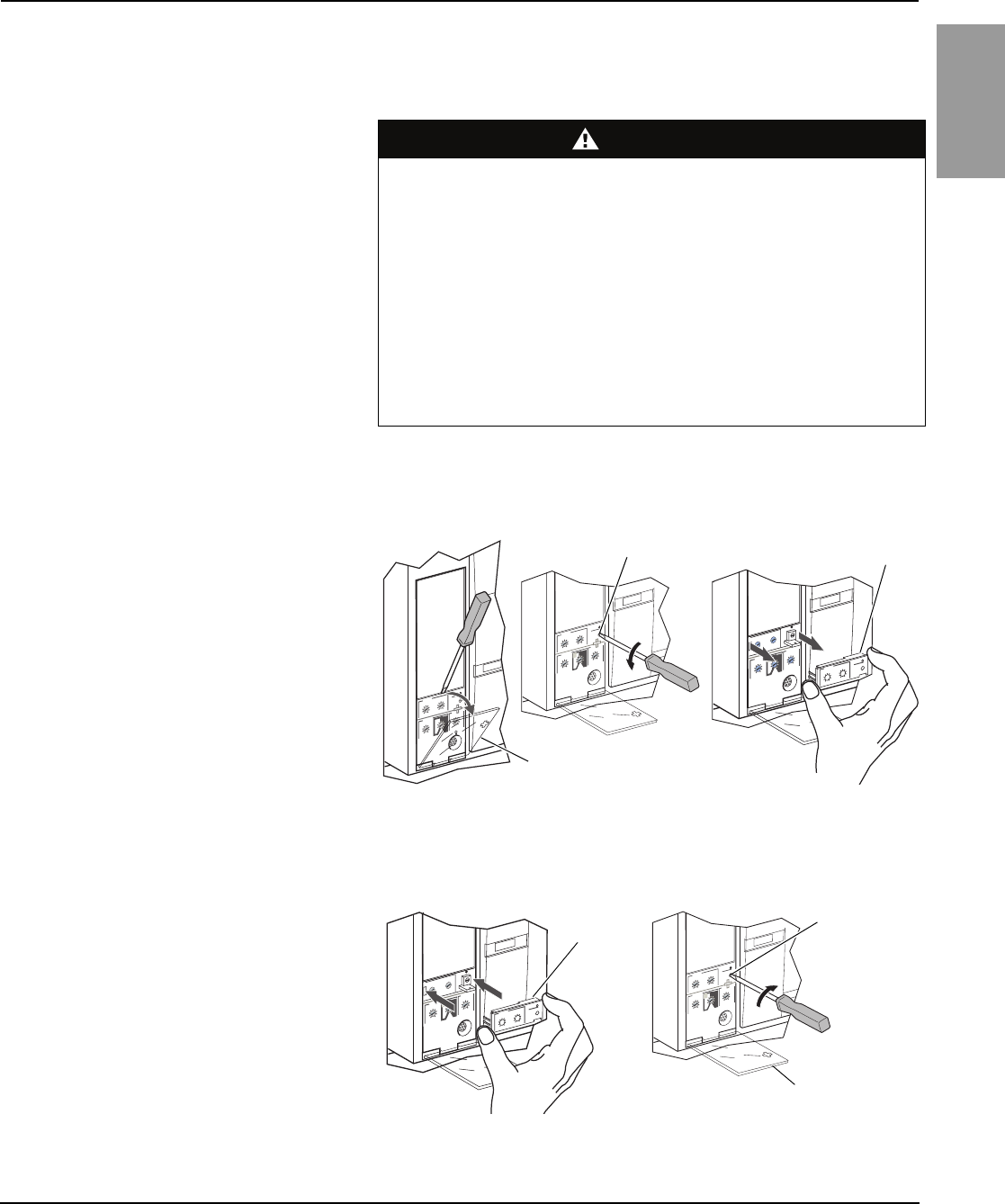
48049-207-05 Micrologic™ 2.0, 3.0 and 5.0 Electronic Trip Units
Rev. 01, 07/2012 Section 4—Adjustable Rating Plug Replacement
© 1999–2012 Schneider Electric All Rights Reserved 17-EN
ENGLISH
Section 4—Adjustable Rating Plug Replacement
Rating Plug Removal
New Rating Plug Installation
NOTE: To select correct replacement rating
plug, see the product catalog.
NOTE: If adjustable rating plug is removed, the
circuit breaker will default to a long-time pickup
rating of 0.4 x In and a long-time delay at
whatever setting was selected before the rating
plug was removed.
DANGER
HAZARD OF ELECTRIC SHOCK, EXPLOSION OR ARC FLASH
• Apply appropriate personal protective equipment (PPE) and follow safe
electrical work practices. See NFPA 70E or CSA Z462.
• This equipment must be installed and serviced only by qualified electrical
personnel.
• Turn off all power supplying this equipment before working on or inside
equipment. Follow instructions shipped with circuit breaker to disconnect
and reconnect circuit breaker.
• Replace all devices, doors and covers before returning equipment to
service.
Failure to follow this instruction will result in death or serious injury.
1. Open circuit breaker contacts:
— For NT and NW circuit breakers, press
the “Push to open” button on the circuit
breaker.
— For other circuit breakers, move handle
to the off (O) position.
2. Open switch cover (A).
3. Unscrew adjustable rating plug mounting
screw (B).
4. Remove adjustable rating plug (C).
Figure 23: Remove Adjustable Rating Plug
setting delay
short time
I i
x Ir
2
2.53456
8
10
Isd
1.5
tsd
on
I
2
t
.
2
.
3
.
4
.
4
.
1
.
2
.
3
.
1
0
instantaneous
x In
2
2.53456
8
10
1.5
.4
.5
.6
.7 .8 .9
.95
.98
1
long timealarm
Ir
x In .5
1
2
4812
16
20
tr
(s)
@ 6 Ir
24
06133222
.4
.5
.6
.7.8.9
.95
.98
1
settingdelay
short time
I i
x Ir
2
2.53456
8
10
Isd
1.5
tsd
on
I
2
t
.
2
.
3
.
4
.
4
.
1
.
2
.
3
.
1
0
instantaneous
long timealarm
Ir
x In.5
1
2
4812
16
20
tr
(s)
@ 6 Ir
24
x In
2
2.53456
8
101.5
06133221
06133205
A
BC
1. Inspect mounting area for debris and
contamination.
2. Gently push in new rating plug (A).
3. Tighten adjustable rating plug mounting
screw (B).
4. Set the switches on the trip unit (see Section
2—Operation).
5. Close switch cover (C).
Figure 24: Install New Adjustable Rating Plug
.4
.5
.6
.7.8.9
.95
.98
1
settingdelay
short time
I i
x Ir
2
2.53456
8
10
Isd
1.5
tsd
on
I
2
t
.
2
.
3
.
4
.
4
.
1
.
2
.
3
.
1
0
instantaneous
long timealarm
Ir
x In.5
1
2
4812
16
20
tr
(s)
@ 6 Ir
24
x In
2
2.53456
8
10
1.5
06134244
settingdelay
short time
I i
x Ir
2
2.53456
8
10
Isd
1.5
tsd
on
I
2
t
.
2
.
3
.
4
.
4
.
1
.
2
.
3
.
1
0
instantaneous
x In
2
2.53456
8
10
1.5
test
.4
.5
.6
.7 .8 .9
.95
.98
1
long timealarm
Ir
x In .5
1
2
4812
16
20
tr
(s)
@ 6 Ir
24
06133223
AB
C
150 of 292

Electrical equipment should be installed, operated, serviced, and maintained only by qualified
personnel. No responsibility is assumed by Schneider Electric for any consequences arising out of
the use of this material.
Square D™, Schneider Electric™, Micrologic™, and Masterpact™ are trademarks or registered
trademarks of Schneider Electric. Other trademarks used herein are the property of their
respective owners.
48049-207-05 Rev. 01, 07/2012
Replaces 48049-207-05 10/2007
© 1999–2012 Schneider Electric All Rights Reserved
3700 Sixth St. SW
Cedar Rapids, IA 52404 USA
1-888-778-2733
www.schneider-electric.us
Micrologic™ 2.0, 3.0 and 5.0 Electronic Trip Units
Instruction Bulletin
ENGLISH
151 of 292

THIS SECTION CONTAINS DETAILED DRAWINGS ON THE FOLLOWING PANELS:
DESIGNATION TYPE VOLTAGE AIC MOUNTING PBA NOTES AND REMARKS
PANEL L1A NQ 208Y/120V 3Ph 4W 60Hz 42kA Top Trim: Surface - Hinged 701T Ship Together,Standard Solid Neutral,Additional
Aluminum Isolated Ground Bar,Standard Ground Bar
Group User Placement Standard Nameplate: Engraved
as Follows Line 1: PANEL L1A Size: 3.50" Wide x 1.00"
High (Std) Color: White Surface / Black Letters
Plastic/Adhesive - Screw-on
PANEL L2A NQ 208Y/120V 3Ph 4W 60Hz 42kA Top Trim: Surface - Hinged 701T Ship Together,Standard Solid Neutral,Additional
Aluminum Isolated Ground Bar,Standard Ground Bar
Group User Placement Standard Nameplate: Engraved
as Follows Line 1: PANEL L2A Size: 3.50" Wide x 1.00"
High (Std) Color: White Surface / Black Letters
Plastic/Adhesive - Screw-on
PANEL L3A NQ 208Y/120V 3Ph 4W 60Hz 42kA Top Trim: Surface - Hinged 701T Ship Together,Standard Solid Neutral,Additional
Aluminum Isolated Ground Bar,Standard Ground Bar
Group User Placement Standard Nameplate: Engraved
as Follows Line 1: PANEL L3A Size: 3.50" Wide x 1.00"
High (Std) Color: White Surface / Black Letters
Pl ti /Adh i S
PANELBOARDS
Pl
as
ti
c
/Adh
es
i
ve
-
S
crew-on
PANEL L3A NQ 208Y/120V 3Ph 4W 60Hz 42kA Top Trim: Surface - Hinged 701T Ship Together,Standard Solid Neutral,Additional
Aluminum Isolated Ground Bar,Standard Ground Bar
Group User Placement Standard Nameplate: Engraved
as Follows Line 1: PANEL L3A Size: 3.50" Wide x 1.00"
High (Std) Color: White Surface / Black Letters
Plastic/Adhesive - Screw-on
PANEL EL1 NQ 208Y/120V 3Ph 4W 60Hz 10kA Bottom Trim: Surface -
Hinged 707HR Standard Panel (Box Ahead),Standard Solid
Neutral,Standard Ground Bar Standard Nameplate:
Engraved as Follows Line 1: PANEL EL1 Size: 3.50" Wide
x 1.00" High (Std) Color: White Surface / Black Letters
Plastic/Adhesive - Screw-on
PLEASE CONFIRM THAT THE PANEL DETAILS MATCHES THE PLANS AND SPECIFICATIONS.
ALL LUGS ON PANELBOARDS AND CIRCUIT BREAKERS ARE RATED AT 75 DEGR C.
ALL LUGS ARE SIZED PER UL STANDARDS. PLEASE CONFIRM THAT THEY ARE APPROPRIATE FOR THE QUANTITY
AND SIZE OF THE CABLE BEING CONNECTED.
PLEASE CONFIRM TOP OR BOTTOM FEED, AND SURFACE OR FLUSH COVERS.
152 of 292
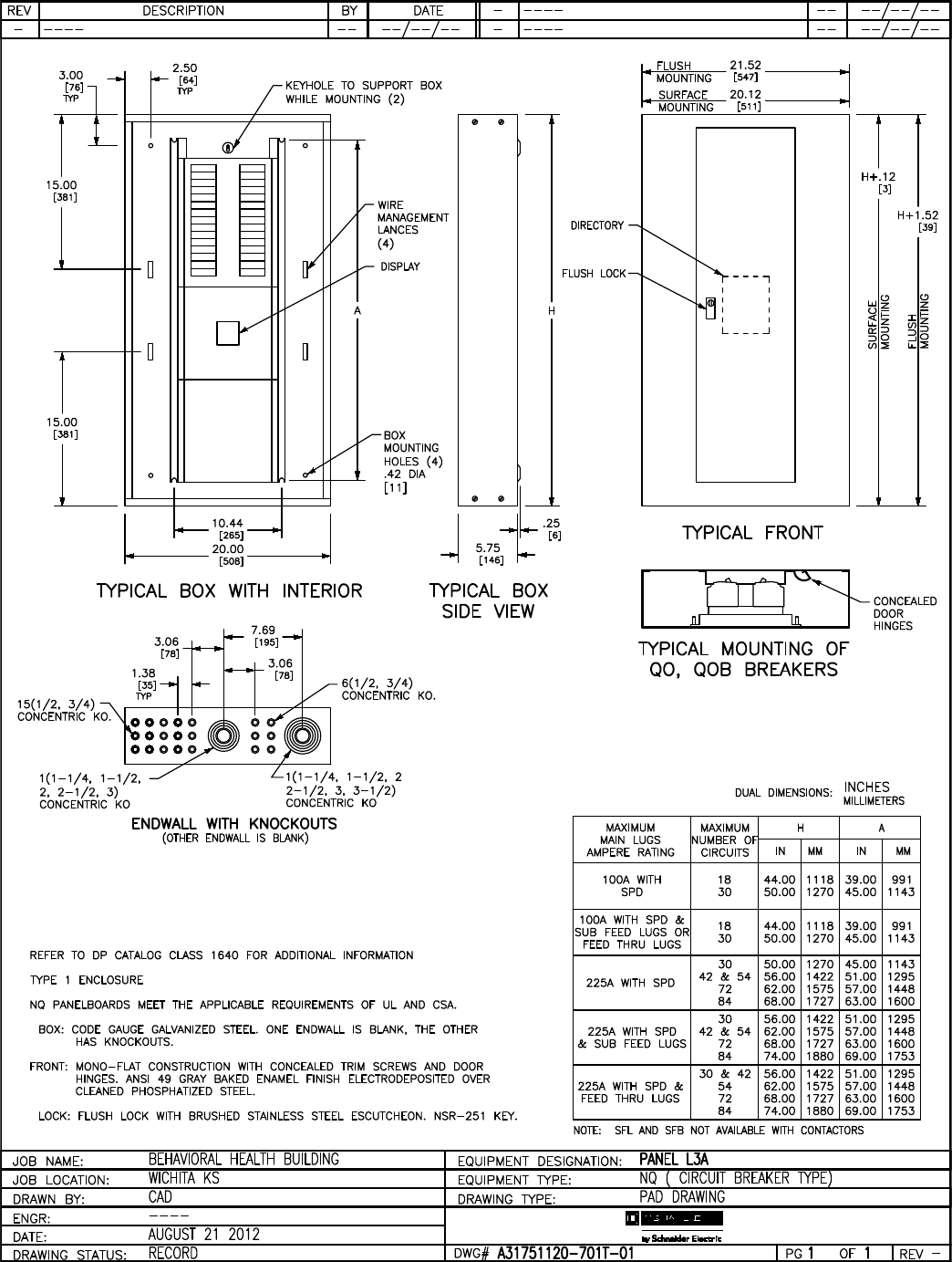
153 of 292
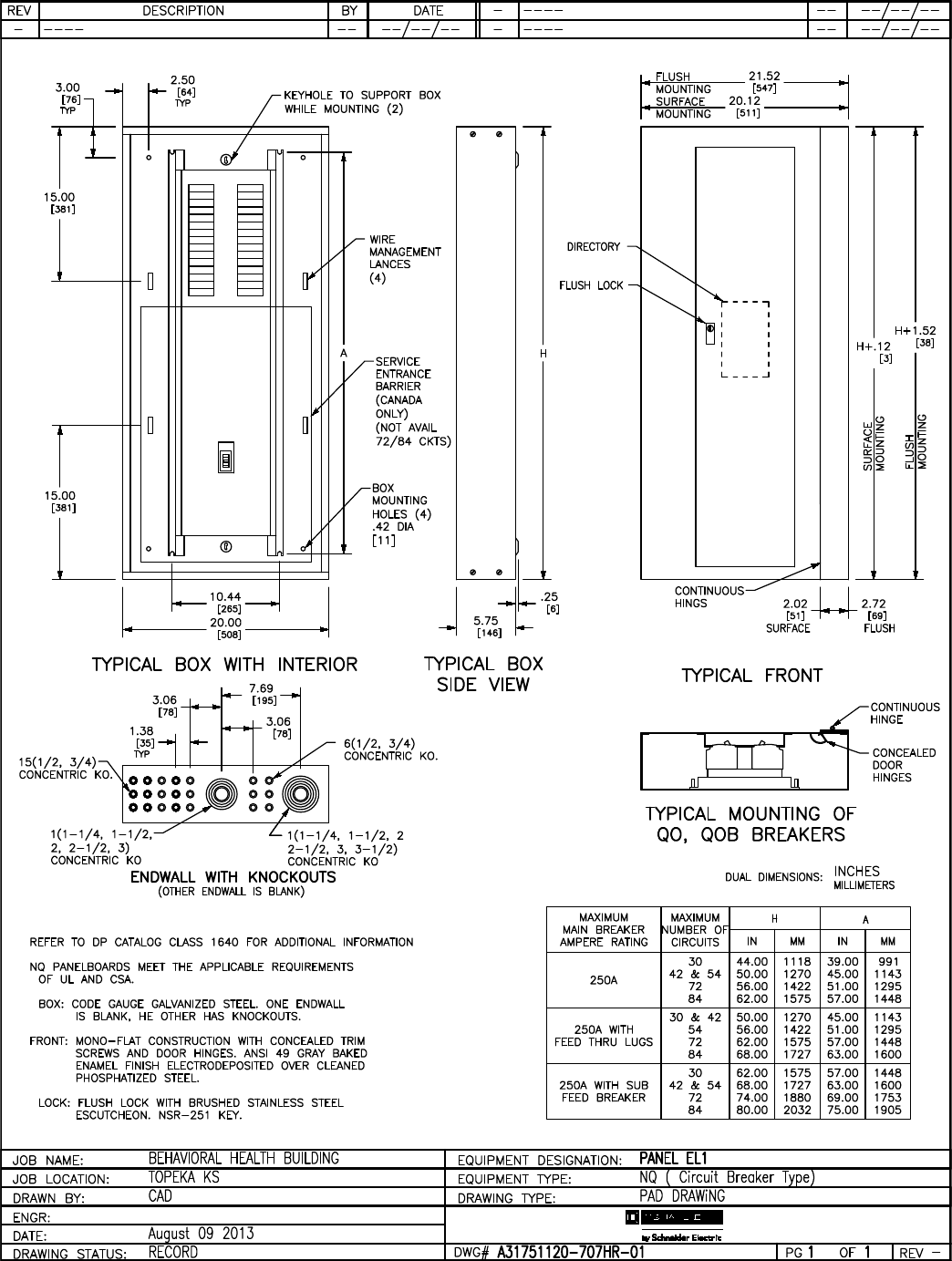
154 of 292
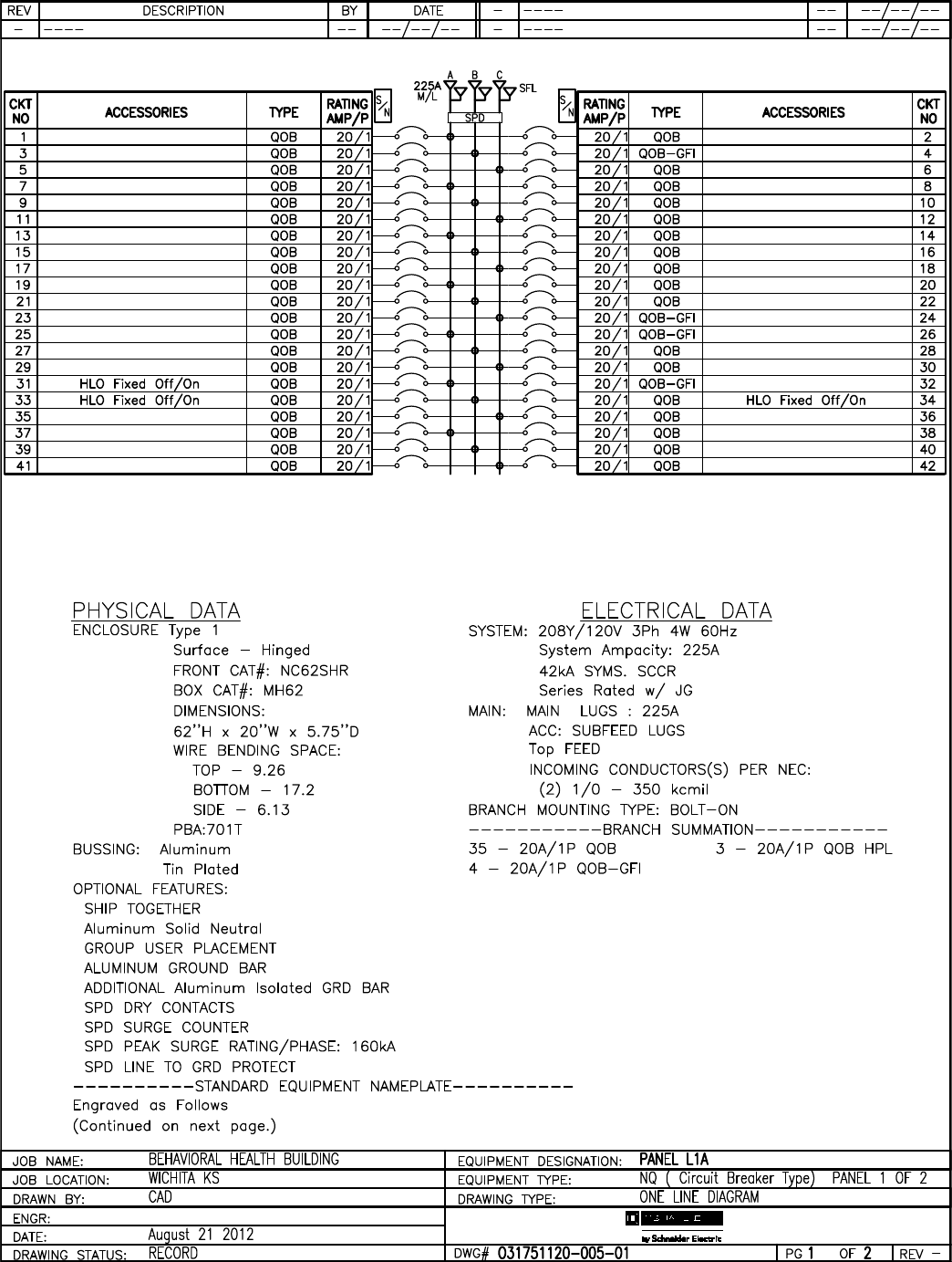
155 of 292

156 of 292
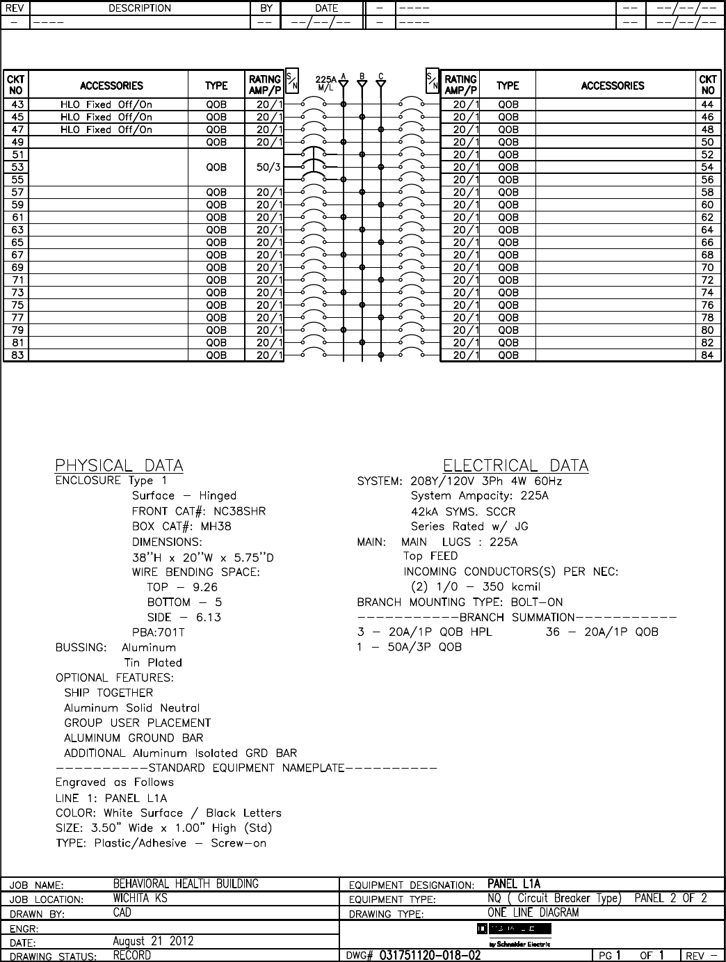
157 of 292
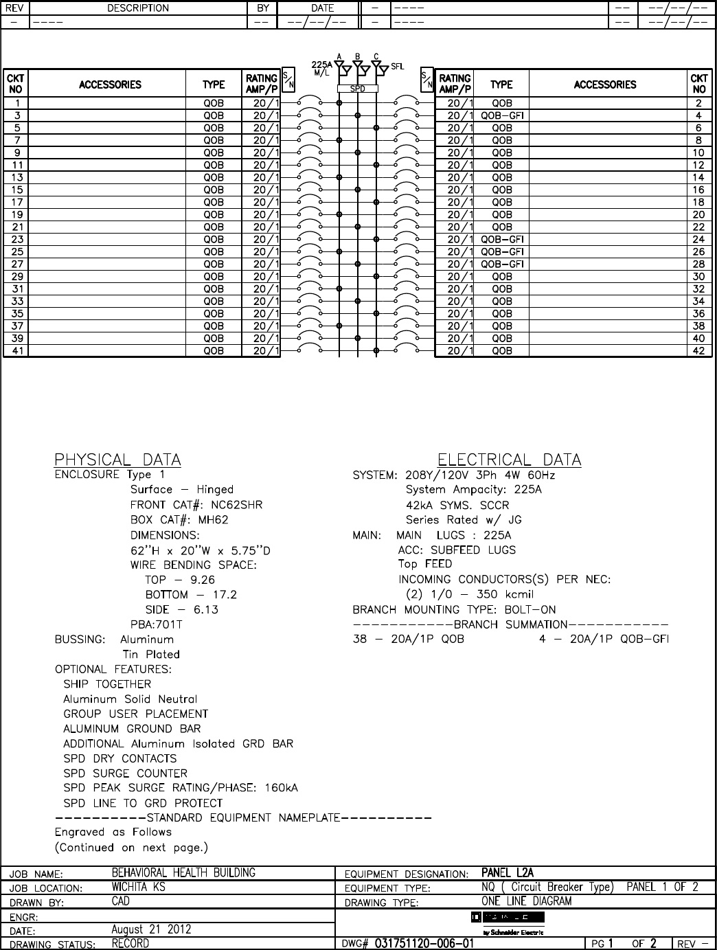
158 of 292
159 of 292

160 of 292

161 of 292

162 of 292
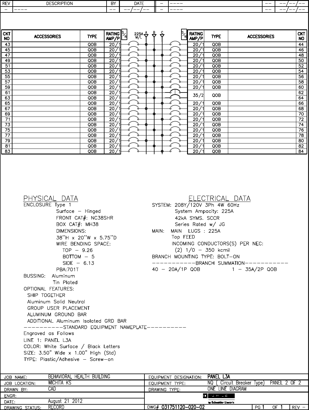
163 of 292
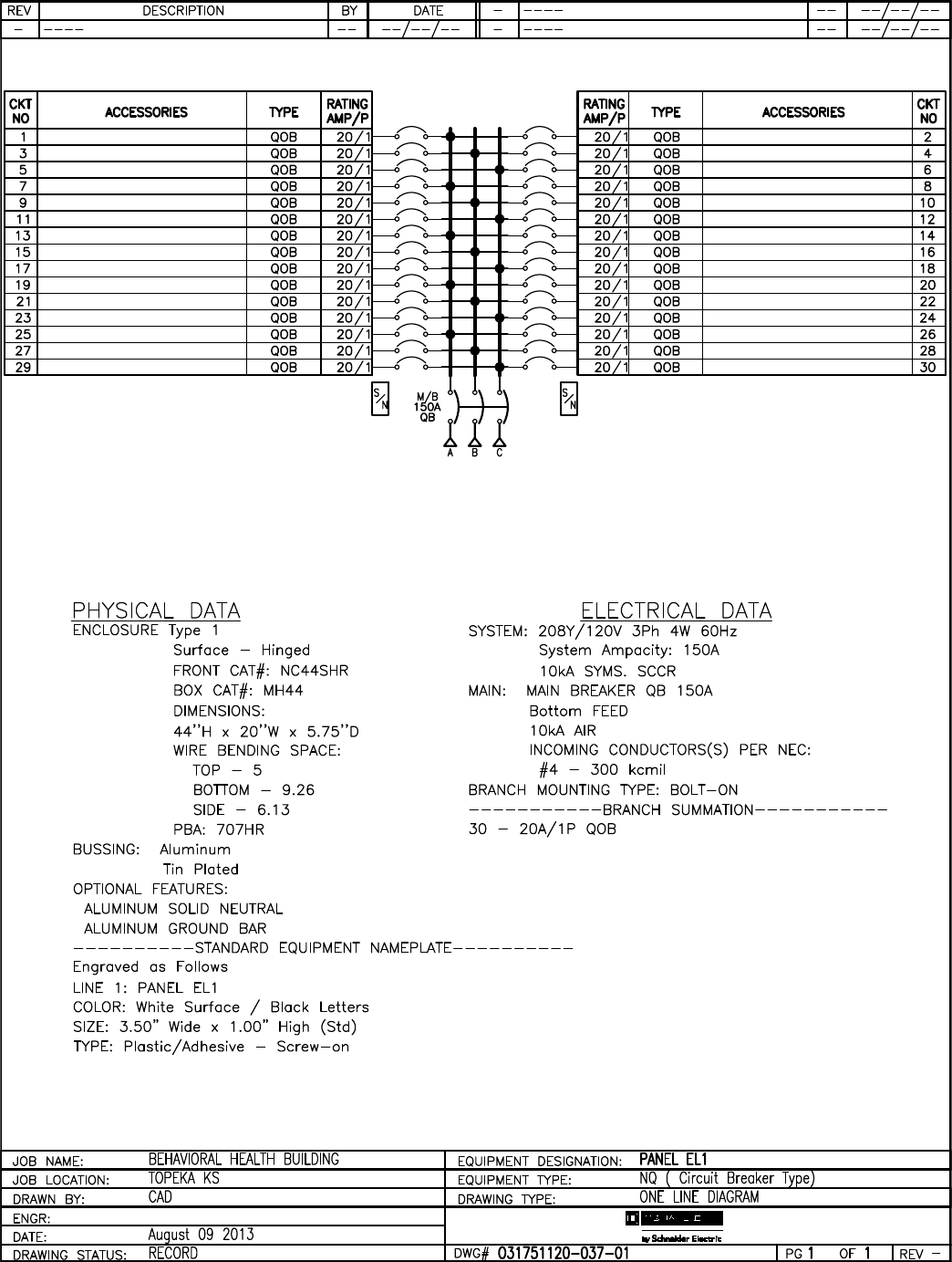
164 of 292
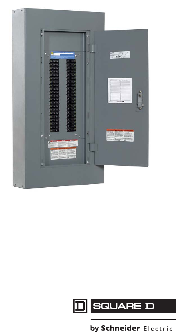
NQ/NQM Panelboards and
QONQ Load Centers
Information Manual
Class 1640
Instruction Bulletin
80043-712-04
Retain in the directory card
pocket for future use.
165 of 292
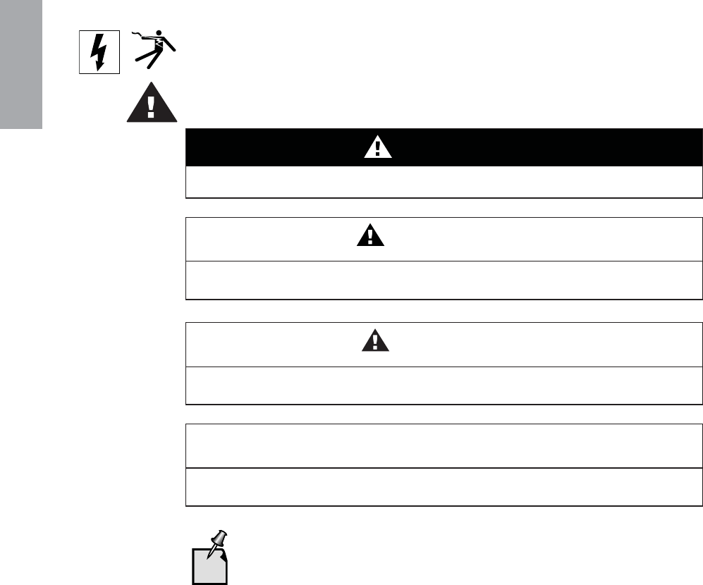
ENGLISH
HAZARD CATEGORIES AND SPECIAL SYMBOLS
Read these instructions carefully and look at the equipment to become familiar with the
device before trying to install, operate, service, or maintain it. The following special
messages may appear throughout this bulletin or on the equipment to warn of potential
hazards or to call attention to information that clarifies or simplifies a procedure.
The addition of either symbol to a “Danger” or “Warning” safety label indicates that an
electrical hazard exists which will result in personal injury if the instructions are not
followed.
This is the safety alert symbol. It is used to alert you to potential personal injury hazards.
Obey all safety messages that follow this symbol to avoid possible injury or death.
PLEASE NOTE Electrical equipment should be installed, operated, serviced, and maintained only by
qualified personnel. No responsibility is assumed by Schneider Electric for any
consequences arising out of the use of this material.
DANGER
DANGER indicates an imminently hazardous situation which, if not avoided, will result
in death or serious injury.
WARNING
WARNING indicates a potentially hazardous situation which, if not avoided, can result
in death or serious injury.
CAUTION
CAUTION indicates a potentially hazardous situation which, if not avoided, can result
in minor or moderate injury.
CAUTION
CAUTION, used without the safety alert symbol, indicates a potentially hazardous
situation which, if not avoided, can result in property damage.
Provides additional information to clarify or simplify a procedure.
166 of 292

80043-712-04 NQ/NQM Panelboards and QONQ Load Centers Information Manual
10/2009 Table of Contents
© 2007–2009 Schneider Electric All Rights Reserved 3
ENGLISH
TABLE OF CONTENTS
Introduction . . . . . . . . . . . . . . . . . . . . . . . . . . . . . . . . . . . . . . . . . . . . . . . . . . . . . . . 7
Safety Precautions . . . . . . . . . . . . . . . . . . . . . . . . . . . . . . . . . . . . . . . . . . . . . . . . . 7
Installation . . . . . . . . . . . . . . . . . . . . . . . . . . . . . . . . . . . . . . . . . . . . . . . . . . . . . . . . 8
Interior Mounting for Square D Brand Enclosures . . . . . . . . . . . . . . . . . . . . . . 8
Surface Mounting (Enclosure Mounted on Wall) . . . . . . . . . . . . . . . . . . . . . 9
Flush Mounting (Enclosure Recessed in Wall) . . . . . . . . . . . . . . . . . . . . . . 9
Neutral Bonding Strap/Cable Installation . . . . . . . . . . . . . . . . . . . . . . . . . . . . 11
100 or 250 A Maximum NQ Panelboards . . . . . . . . . . . . . . . . . . . . . . . . . 11
400 or 600 A Maximum NQ Panelboards and QONQ Load Centers . . . . 13
QO and QOB Circuit Breaker Installation and Removal . . . . . . . . . . . . . . . . . 14
QO and QOB Breaker Installation . . . . . . . . . . . . . . . . . . . . . . . . . . . . . . . 15
QO and QOB Breaker Removal . . . . . . . . . . . . . . . . . . . . . . . . . . . . . . . . 15
Circuit Breaker Reset Instructions . . . . . . . . . . . . . . . . . . . . . . . . . . . . . . . . . . 17
Interior Trim Preparation . . . . . . . . . . . . . . . . . . . . . . . . . . . . . . . . . . . . . . . . . 18
Appendix 1: Specifications . . . . . . . . . . . . . . . . . . . . . . . . . . . . . . . . . . . . . . . . . . 19
Typical Wiring . . . . . . . . . . . . . . . . . . . . . . . . . . . . . . . . . . . . . . . . . . . . . . . . . 19
Integral Main or Sub-Feed:
DJ, FI, KI, H, J, LA, LC, LH, QB, QD, QG, QJ, QO(B)VH . . . . . . . . . . . . . 20
Panelboard Ratings . . . . . . . . . . . . . . . . . . . . . . . . . . . . . . . . . . . . . . . . . . . . . 24
CE Marking . . . . . . . . . . . . . . . . . . . . . . . . . . . . . . . . . . . . . . . . . . . . . . . . . . . 29
Appendix 2: Accessory Kits . . . . . . . . . . . . . . . . . . . . . . . . . . . . . . . . . . . . . . . . . 30
Equipment Ground Bar Kits . . . . . . . . . . . . . . . . . . . . . . . . . . . . . . . . . . . . . . 30
Oversized Lug Kits for 100–250 A Panelboards . . . . . . . . . . . . . . . . . . . . . . . 31
Sub-Feed Lug Kits for 100–400 A Panelboards . . . . . . . . . . . . . . . . . . . . . . . 31
Main Lug Kits . . . . . . . . . . . . . . . . . . . . . . . . . . . . . . . . . . . . . . . . . . . . . . . . . 32
167 of 292

© 2007–2009 Schneider Electric All Rights Reserved
4
NQ/NQM Panelboards and QONQ Load Centers Information Manual 80043-712-04
Table of Contents 10/2009
ENGLISH
168 of 292

80043-712-04 NQ/NQM Panelboards and QONQ Load Centers Information Manual
10/2009 List of Figures and List of Tables
© 2007–2009 Schneider Electric All Rights Reserved 5
ENGLISH
LIST OF FIGURES
Figure 1: Interior Mounting of Square D Brand Enclosures . . . . . . . . . . . . . . . . . 10
Figure 2: Bonding Strap Installation — 100 or 250 A Maximum NQ Panelboards 12
Figure 3: Bonding Cable Installation — 400 or 600 A Maximum NQ Panelboards
and QONQ Load Centers . . . . . . . . . . . . . . . . . . . . . . . . . . . . . . . . . . . 13
Figure 4: QO and QOB Circuit Breaker Installation and Removal . . . . . . . . . . . . 16
Figure 5: Circuit Breaker Handle Positions . . . . . . . . . . . . . . . . . . . . . . . . . . . . . . 17
Figure 6: Interior Trim Diagram . . . . . . . . . . . . . . . . . . . . . . . . . . . . . . . . . . . . . . . 18
Figure 7: NQ/NQM 100–225 A Main Lugs or 100–250 A Main Breaker Diagram. 20
Figure 8: NQ 400–600 A Main Lugs or Main Circuit Breaker
with or without Feed-Through Lugs Diagram. . . . . . . . . . . . . . . . . . . . . 21
Figure 9: NQ 400–600 A Main Circuit Breaker
with Feed-Through Lugs or Sub-Feed Circuit Breakers Diagram . . . . . 22
Figure 10: Typical NQ Panelboard with Split Bus Diagram. . . . . . . . . . . . . . . . . . . 23
169 of 292

© 2007–2009 Schneider Electric All Rights Reserved
6
NQ/NQM Panelboards and QONQ Load Centers Information Manual 80043-712-04
List of Figures and List of Tables 10/2009
ENGLISH
LIST OF TABLES
Table 1: Panelboard Typical Wiring . . . . . . . . . . . . . . . . . . . . . . . . . . . . . . . . . . . . . . 19
Table 2: Series Connected Breaker Ratings (RMS Symmetrical) . . . . . . . . . . . . . . . 24
Table 3: Short Circuit Current Rating for Main Lug Interiors with Sub-Feed or
Feed-Through Lugs . . . . . . . . . . . . . . . . . . . . . . . . . . . . . . . . . . . . . . . . 29
Table 4: Equipment Ground Bar Kits Specifications . . . . . . . . . . . . . . . . . . . . . . . . . . 30
Table 5: Oversized Lug Kits for 100–250 A Panelboards Specifications . . . . . . . . . . 31
Table 6: Sub-Feed Lug Kits for 100–400 A Panelboards Specifications . . . . . . . . . . 31
Table 7: Mechanical Lug Kits — Aluminum . . . . . . . . . . . . . . . . . . . . . . . . . . . . . . . . 32
Table 8: Mechanical Lug Kits — Copper . . . . . . . . . . . . . . . . . . . . . . . . . . . . . . . . . . 32
Table 9: Versa-Crimp® Compression Lug Kits — Aluminum . . . . . . . . . . . . . . . . . . . 33
Table 10: Versa-Crimp® Compression Lug Kits — Copper . . . . . . . . . . . . . . . . . . . . 33
170 of 292

© 2007–2009 Schneider Electric All Rights Reserved
80043-712-04 NQ/NQM Panelboards and QONQ Load Centers Information Manual
10/2009 Introduction
7
ENGLISH
Introduction
This bulletin contains instructions for installing Square D® brand NQ
circuit breaker panelboards and QONQ load centers. These
panelboards and load centers are Underwriters Laboratories (cULus)
listed and accept QO® and QOB branch circuit breakers.
Safety Precautions
For technical support on the installation of this
panelboard, contact the Square D/Schneider Electric
Customer Information Center at 1-888-SquareD
(1-888-778-2733).
See the labels on the equipment for rating and safety
information. Additional equipment labels are provided with
this document.
DANGER
HAZARD OF ELECTRIC SHOCK, EXPLOSION, OR ARC FLASH
• Read and understand this entire instruction bulletin and the included NEMA PB 1.1
standards publication before installing, operating, or maintaining this equipment.
• Local codes vary, but are adopted and enforced to promote safe electrical
installations. A permit may be needed to do electrical work, and some codes may
require an inspection of the electrical work.
• Apply appropriate personal protective equipment (PPE) and follow safe electrical
work practices. See NFPA 70E.
• This equipment must only be installed and serviced by qualified
electrical personnel.
• Turn OFF all power supplying this equipment before working on or inside
the equipment.
• Always use a properly-rated voltage sensing device to confirm all power is OFF.
• Replace all devices, doors and covers before turning ON power to this equipment.
Failure to follow these instructions will result in death or serious injury.
171 of 292

© 2007–2009 Schneider Electric All Rights Reserved
NQ/NQM Panelboards and QONQ Load Centers Information Manual 80043-712-04
Installation 10/2009
8
ENGLISH
Installation
This section provides instructions for the following NQ panelboard
and QONQ load center procedures:
•“Interior Mounting for Square D Brand Enclosures” on page 8
•“Neutral Bonding Strap/Cable Installation” on page 11
•“QO and QOB Circuit Breaker Installation and Removal”
on page 14
•“Circuit Breaker Reset Instructions” on page 17
•“Interior Trim Preparation” on page 18
Interior Mounting for Square D Brand Enclosures
A separate standards publication, titled “General Instructions for
Proper Installation, Operation, and Maintenance of Panelboards
Rated 600 Volts or Less” (NEMA PB1.1), has been provided with this
equipment. Familiarize yourself with the content of this document
before proceeding with any of the following procedures.
If you did not receive a copy of this document, or if you have any
questions regarding this equipment, contact your local distributor or
Schneider Electric representative.
To properly mount and install the NQ panelboard or QONQ load
center interior, please refer to the NEMA PB 1.1 standards
publication, and follow the instructions below for either “Surface
Mounting (Enclosure Mounted on Wall)” or “Flush Mounting
(Enclosure Recessed in Wall).”
CAUTION
HAZARD OF EQUIPMENT DAMAGE
• Ensure all connections are properly tightened.
• Refer to the torque information label provided on the panelboard
before tightening the connections.
Failure to follow these instructions can result in
equipment damage.
172 of 292

© 2007–2009 Schneider Electric All Rights Reserved
80043-712-04 NQ/NQM Panelboards and QONQ Load Centers Information Manual
10/2009 Installation
9
ENGLISH
Surface Mounting (Enclosure Mounted on Wall)
1. Mount the enclosure as instructed in the NEMA PB 1.1
standards publication.
2. Remove the interior trim from the trim brackets.
3. Install the interior as described below:
a. Set the interior on the enclosure studs. An elevating screw is
not required (See Figure 1 on page 10).
b. Tighten the keps nuts against the interior side rails until the
rails are against the back of the enclosure.
c. Remount the interior trim after wiring.
4. If used as service entrance equipment, neutral bonding is
required. See the “Neutral Bonding Strap/Cable Installation”
instructions on page 11.
5. Apply equipment labels (located in the bag assembly) as directed
by the instructions on the back of the equipment label sheet.
Flush Mounting (Enclosure Recessed in Wall)
1. Mount the enclosure as instructed in the NEMA PB 1.1
standards publication.
2. Remove the interior trim from the trim brackets.
3. Install the interior as described below:
a. Thread the (4) 10-32 x .875 in. self-tapping, elevating screws
provided with the flush trim into the side rails.
b. Set the interior on the enclosure studs (see Figure 1 on
page 10). Place the keps nuts onto the enclosure studs, but
do not tighten.
c. Adjust the screws so that the lip of the interior trim is
approximately 0.25 inches (6.35 mm) from wall line.
d. Tighten the keps nuts against the side rails.
e. Remount the interior trim after wiring.
4. If used as service entrance equipment, neutral bonding is
required. See the “Neutral Bonding Strap/Cable Installation”
instructions on page 11.
5. Apply equipment labels (located in the bag assembly) as directed
by the instructions on the back of the equipment label sheet.
173 of 292
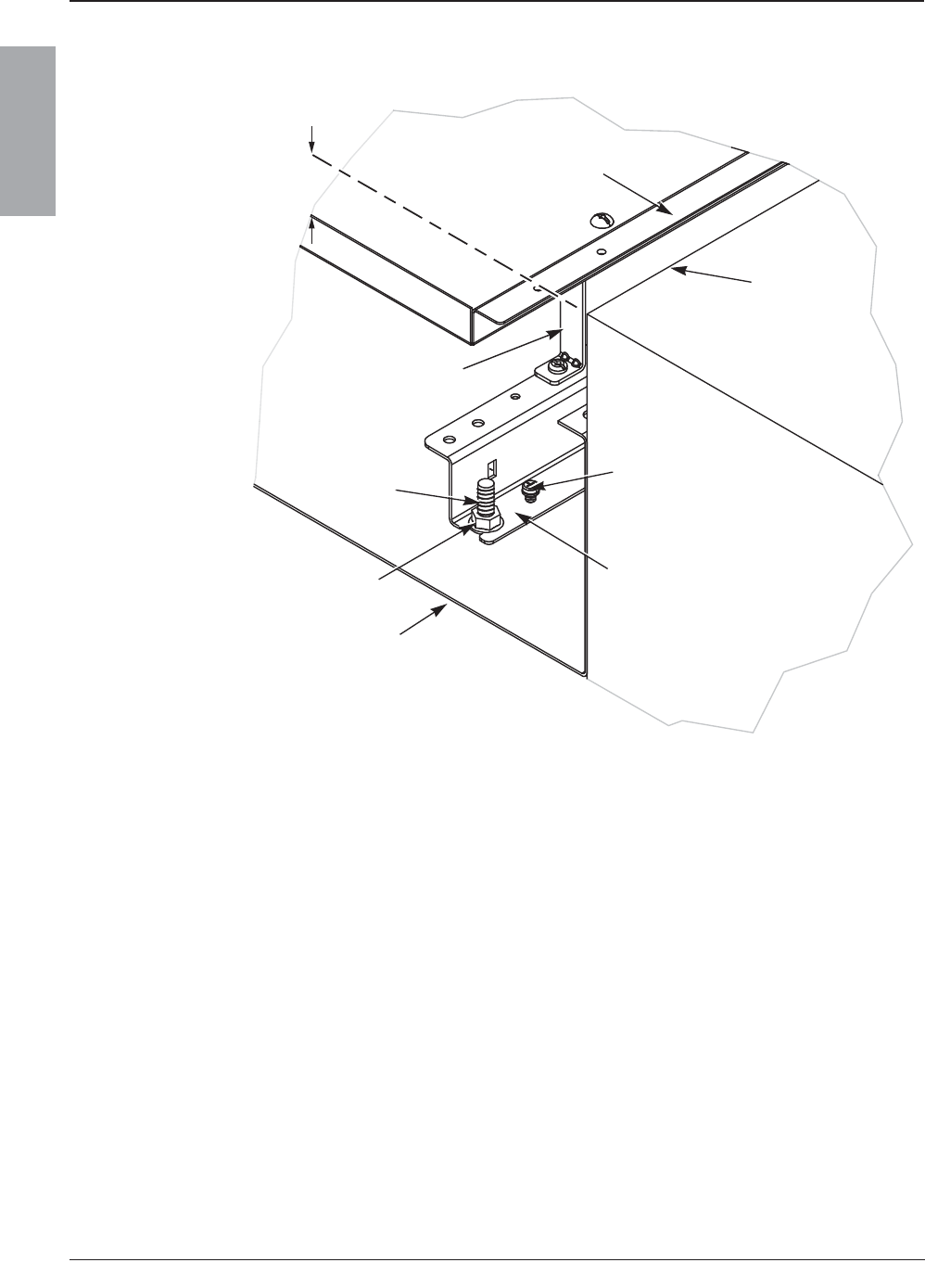
© 2007–2009 Schneider Electric All Rights Reserved
NQ/NQM Panelboards and QONQ Load Centers Information Manual 80043-712-04
Installation 10/2009
10
ENGLISH
Figure 1: Interior Mounting of Square D Brand Enclosures
0.25 in.
(6.35 mm)
Trim Bracket
Enclosure Stud
Keps Nut
Enclosure
Interior Trim
Wall
Elevating Screw
Side Rail
174 of 292

© 2007–2009 Schneider Electric All Rights Reserved
80043-712-04 NQ/NQM Panelboards and QONQ Load Centers Information Manual
10/2009 Installation
11
ENGLISH
Neutral Bonding Strap/Cable Installation
The neutral bonding strap/cable should be used only when the
panelboard is installed as service equipment.
To properly bond the neutral to the panelboard, follow the instructions
for either “100 or 250 A Maximum NQ Panelboards” or “400 or 600 A
Maximum NQ Panelboards and QONQ Load Centers” below and on
page 13, respectively.
NOTE: The bonding strap/cable parts are found in the bag assembly
provided with the interior.
100 or 250 A Maximum NQ Panelboards
To install a neutral bonding strap on a 100 or 250 A maximum
NQ panelboard, refer to Figure 2 and follow the instructions below.
1. Align the bonding strap on the side rail, as pictured.
NOTE: For some applications, it may be necessary to remove the
lug (not pictured) before installing the bonding strap.
DANGER
HAZARD OF ELECTRIC SHOCK, EXPLOSION, OR ARC FLASH
• Turn OFF all power supplying this equipment before working on
or inside the equipment.
• The main bonding strap/cable should be used only when the
panelboard is installed as service equipment.
• Do not mix the mounting screws with the interior trim screws.
Failure to follow these instructions will result in death or
serious injury.
175 of 292

© 2007–2009 Schneider Electric All Rights Reserved
NQ/NQM Panelboards and QONQ Load Centers Information Manual 80043-712-04
Installation 10/2009
12
ENGLISH
2. Insert the two mounting screws, as pictured. Tighten the 10-32
screw to 10–12 lb-in (1.1–1.4 N•m) and the 1/4-20 to 25–30 lb-in
(2.8–3.4 N•m).
NOTE: If the lug was removed in Step 1 above, reinstall it on top
of the bonding strap. Use the 1/4-20 x 11/16 in. mounting screw
with feed-through lug, sub-feed lug, sub-feed breaker, or 200%
neutral applications. Use the 1/4-20 x 7/8 in. lug mounting screw
with 200% neutral on 225 A applications with feed-through lug,
sub-feed lug, or sub-feed breaker applications. Lug mounting
screws are provided in the bonding strap bag assembly.
Figure 2: Bonding Strap Installation —
100 or 250 A Maximum NQ Panelboards
10-32 x 5/16 in.
1/4-20 x 9/16 in.
Mounting Screws
Bonding Strap
Side Rail
Neutral Bus
176 of 292
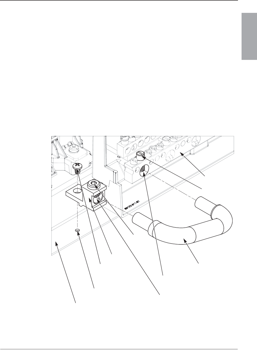
© 2007–2009 Schneider Electric All Rights Reserved
80043-712-04 NQ/NQM Panelboards and QONQ Load Centers Information Manual
10/2009 Installation
13
ENGLISH
400 or 600 A Maximum NQ Panelboards and QONQ Load Centers
To install a neutral bonding cable on a 400 or 600 A maximum
NQ panelboard and QONQ load center, refer to Figure 3 and follow
the instructions below.
1. Align the lug on the side rail mounting hole, as pictured.
2. Tighten the lug mounting screw against the side rail to
10–12 lb-in (1.1–1.4 N•m).
3. Align the bonding cable, as pictured, and insert it into the lug and
neutral mounting holes.
4. Tighten both the lug wire binding screw and the neutral wire
binding screw to 45–50 lb-in (5.1–5.6 N•m).
Figure 3: Bonding Cable Installation — 400 or 600 A
Maximum NQ Panelboards and QONQ Load Centers
Neutral
Lug Mounting
Screw
Bonding Cable
Bonding Cable Mounting Hole
Side Rail
Lug
Side Rail
Mounting Hole
Neutral Wire
Binding Screw
Lug
Wire
Binding
Screw
Bonding Cable Mounting Hole
177 of 292

© 2007–2009 Schneider Electric All Rights Reserved
NQ/NQM Panelboards and QONQ Load Centers Information Manual 80043-712-04
Installation 10/2009
14
ENGLISH
QO and QOB Circuit Breaker Installation and Removal
DANGER
HAZARD OF ELECTRIC SHOCK, EXPLOSION, OR ARC FLASH
• Apply appropriate personal protective equipment (PPE) and
follow safe electrical work practices. See NFPA 70E.
• This equipment must only be installed and serviced by qualified
electrical personnel.
• Turn OFF all power supplying this equipment before working on
or inside equipment.
• Always use a properly-rated voltage sensing device to confirm
that all power is OFF.
• All unused spaces must be filled with blank fillers.
• Replace all devices, doors and covers before turning ON power
to this equipment.
Failure to follow these instructions will result in death or
serious injury.
178 of 292

© 2007–2009 Schneider Electric All Rights Reserved
80043-712-04 NQ/NQM Panelboards and QONQ Load Centers Information Manual
10/2009 Installation
15
ENGLISH
QO and QOB Breaker Installation
Refer to Figure 4 on page 16 for the following instructions:
1. Turn OFF all power to the panelboard.
2. Turn the breaker OFF.
3. Remove the interior trim.
4. Snap the wire terminal end of the circuit breaker onto the
mounting rail.
5. Engage the branch connector.
For QO Circuit Breakers:
a. Push inward until the plug-on jaws fully engage the
branch connector.
For QOB Circuit Breakers:
a. Push inward until the breaker connector is centered on the
branch connector mounting hole. Engage the screw into the
branch connector hole and tighten it to the torque values
shown on the interior wiring and torque diagram.
6. Install the load wire.
7. Reinstall the interior trim.
QO and QOB Breaker Removal
Refer to Figure 4 on page 16 for the following instructions:
1. Turn OFF all power to the panelboard.
2. Remove the load wire.
3. Remove the interior trim.
4. Disengage the branch connector.
For QO Circuit Breakers:
a. Pull outward until the plug-on jaws fully disengage the
branch connector.
For QOB Circuit Breakers:
a. Loosen the screw in the breaker connector and pull the
breaker off of the branch connector.
5. Snap the wire terminal end of the circuit breaker off of the
mounting rail.
6. Reinstall the interior trim.
179 of 292
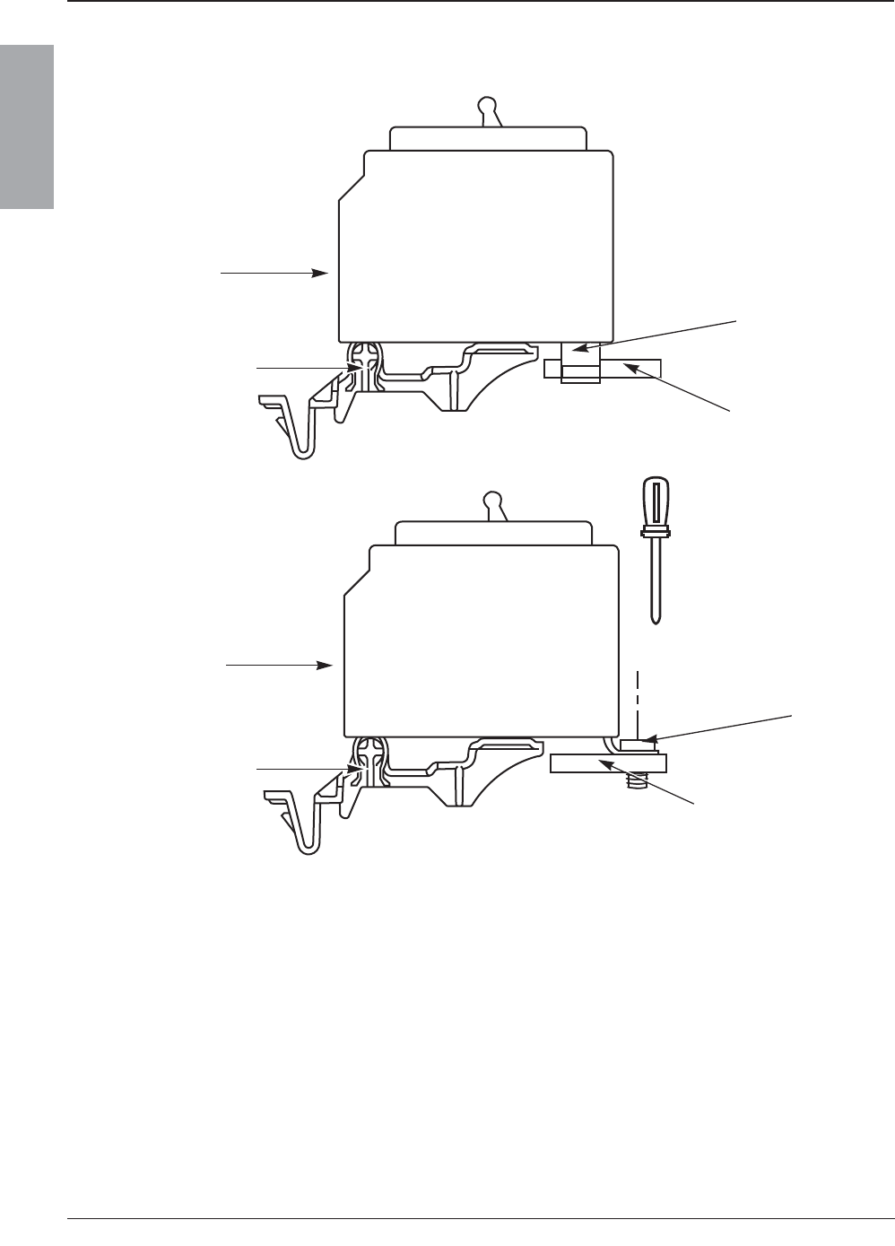
© 2007–2009 Schneider Electric All Rights Reserved
NQ/NQM Panelboards and QONQ Load Centers Information Manual 80043-712-04
Installation 10/2009
16
ENGLISH
Figure 4: QO and QOB Circuit Breaker Installation and Removal
C
L
QOB
QO
Plug-On Jaw
Branch Connector
Branch Connector
Bolt-On
Connector
Screw
Rail
Wire
Terminal
Wire
Terminal
Rail
180 of 292
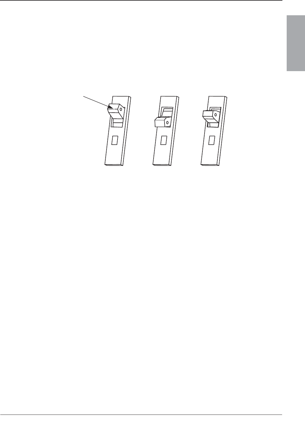
© 2007–2009 Schneider Electric All Rights Reserved
80043-712-04 NQ/NQM Panelboards and QONQ Load Centers Information Manual
10/2009 Installation
17
ENGLISH
Circuit Breaker Reset Instructions
If the circuit breaker is tripped, the handle will be at the mid-position
between ON and OFF. To reset the circuit breaker, push the handle
to the OFF position, then to the ON position.
Figure 5: Circuit Breaker Handle Positions
ON
OFF
ON
OFF
ON
OFF
ON OFF Tripped
Handle
181 of 292
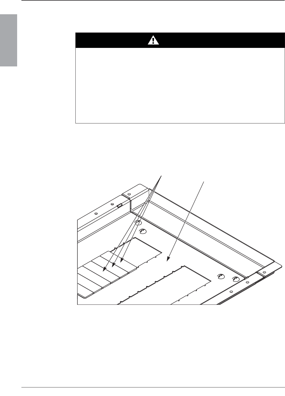
© 2007–2009 Schneider Electric All Rights Reserved
NQ/NQM Panelboards and QONQ Load Centers Information Manual 80043-712-04
Installation 10/2009
18
ENGLISH
Interior Trim Preparation
NOTE: The back of the interior trim lists the catalog number for its
corresponding compatible blank fillers.
DANGER
HAZARD OF ELECTRIC SHOCK, EXPLOSION, OR ARC FLASH
• Before energizing the panelboard, all unused spaces must be
filled with blank fillers.
• Replace all devices, doors, and covers before energizing
this equipment.
Failure to follow this instruction will result in death or
serious injury.
Figure 6: Interior Trim Diagram
Blank Fillers
Interior Trim
182 of 292
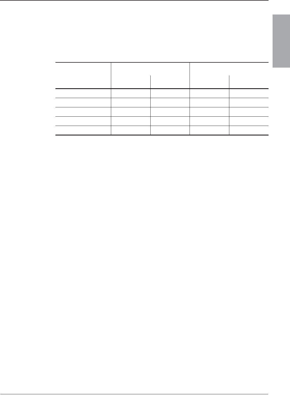
© 2007–2009 Schneider Electric All Rights Reserved
80043-712-04 NQ/NQM Panelboards and QONQ Load Centers Information Manual
10/2009 Appendix 1: Specifications
19
ENGLISH
Appendix 1: Specifications
Typical Wiring
Table 1: Panelboard Typical Wiring1
1Additional information is provided on the panelboard. See the main circuit breaker
rating, if used.
1-Phase Panelboards 3-Phase Panelboards
Voltage AC Phase Wires Phase Wires
208Y/120 — — 3 4
120/240 1 3 — —
2402
2For this system, the neutral is not used and only circuit breakers rated 240 V AC
minimum should be used. Do not use circuit breakers rated 120 V or 120/240 V AC.
1233
2403
3For a grounded “B” phase system, only circuit breakers rated 240 V AC minimum
should be used. Do not use circuit breakers rated 120 V or 120/240 V AC.
33——
240/1204
4When wiring for a delta system, phases “A” and “C” must be 120 V to neutral, phase “B”
208 V to neutral. Connect only circuit breakers rated 240 V AC minimum. Do not use
circuit breakers rated 120 V or 120/240 V to “B” phase.
— — 3 4 Delta
183 of 292
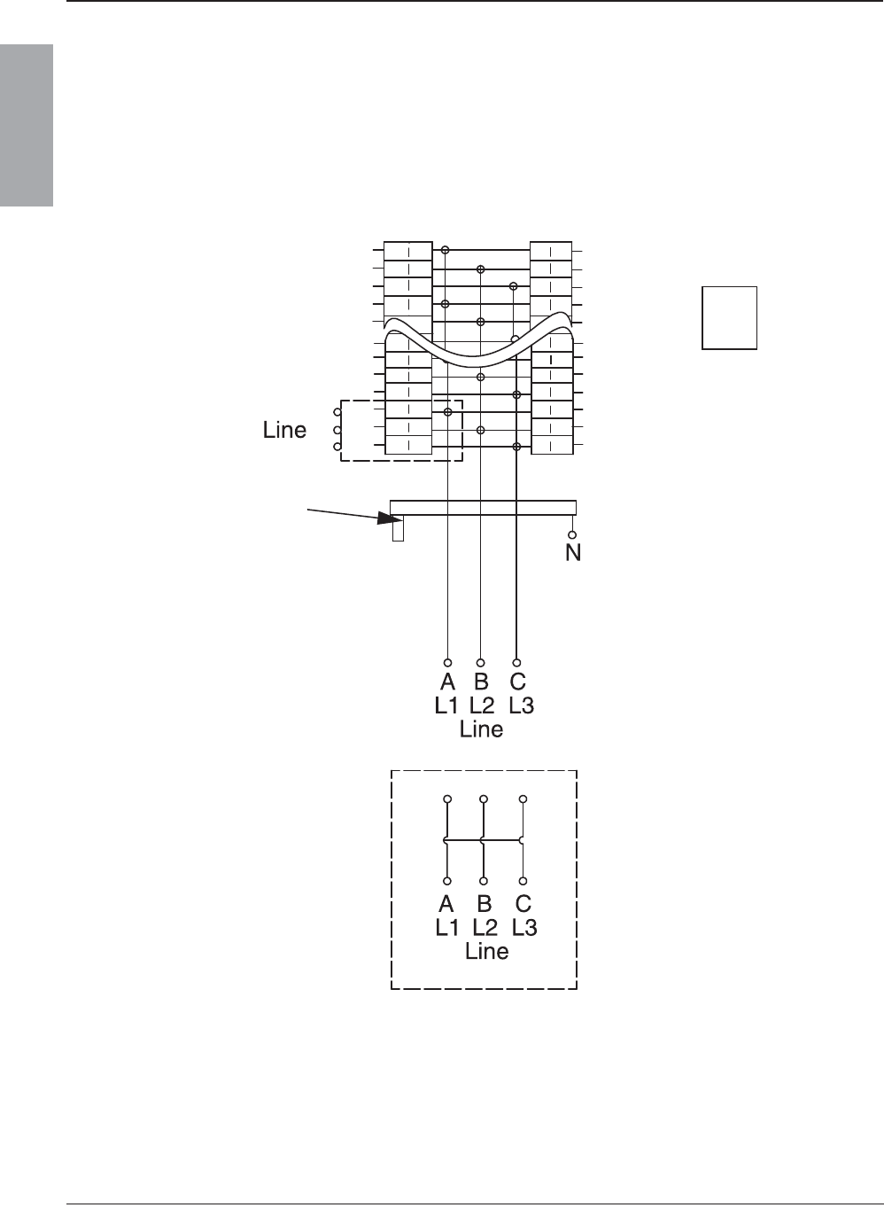
© 2007–2009 Schneider Electric All Rights Reserved
NQ/NQM Panelboards and QONQ Load Centers Information Manual 80043-712-04
Appendix 1: Specifications 10/2009
20
ENGLISH
Integral Main or Sub-Feed:
DJ, FI, KI, H, J, LA, LC, LH, QB, QD, QG, QJ, QO(B)VH
Figure 7: NQ/NQM 100–225 A Main Lugs or 100–250 A Main Breaker Diagram
Backfed Main
Circuit Breaker
(must be bolt-on, if used)
Integral Main
Circuit Breaker
(when installed)
Isolated Ground
(when installed)
Enclosure Bonding
(when required)
Ground
(when required)
Neutral
184 of 292
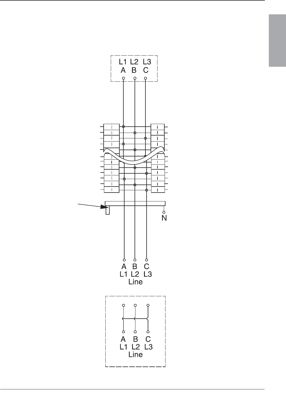
© 2007–2009 Schneider Electric All Rights Reserved
80043-712-04 NQ/NQM Panelboards and QONQ Load Centers Information Manual
10/2009 Appendix 1: Specifications
21
ENGLISH
Figure 8: NQ Panelboard or QONQ Load Center 400–600 A Main Lugs or Main
Circuit Breaker with or without Feed-Through Lugs Diagram
Load
Feed-Through Lugs
(when installed)
Integral Main
Circuit Breaker
(when installed)
Enclosure Bonding
(when required)
Neutral
Ground
(when required)
185 of 292
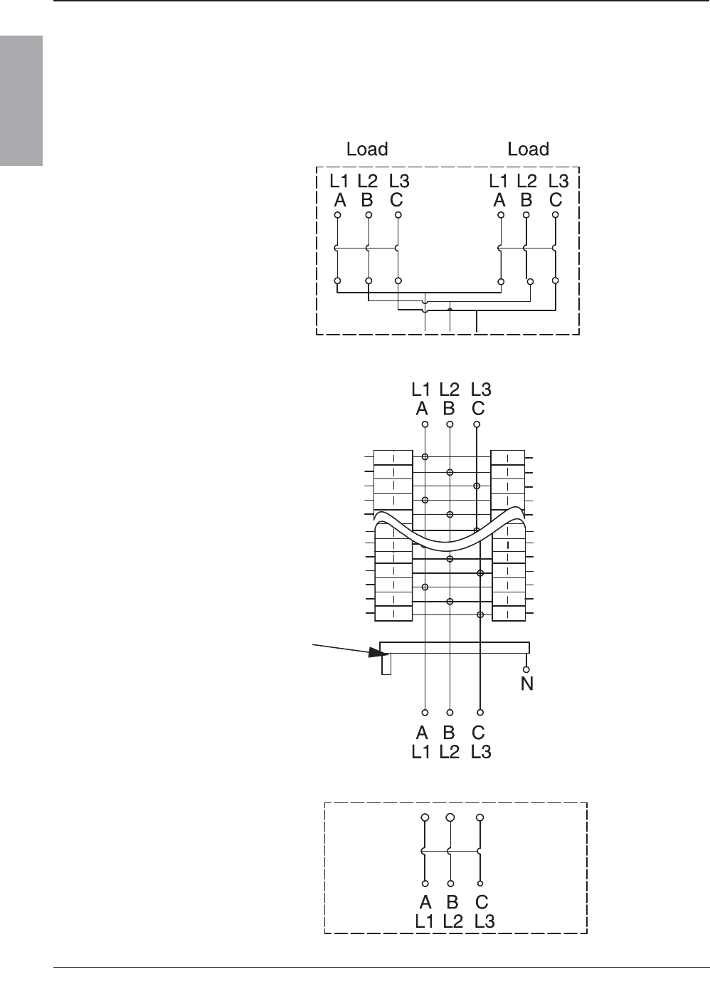
© 2007–2009 Schneider Electric All Rights Reserved
NQ/NQM Panelboards and QONQ Load Centers Information Manual 80043-712-04
Appendix 1: Specifications 10/2009
22
ENGLISH
Figure 9: NQ Panelboard or QONQ Load Center 400–600 A Main
Circuit Breaker with Feed-Through Lugs or Sub-Feed
Circuit Breakers Diagram
Subfeed
Circuit Breaker(s)
(when installed)
Load
Enclosure Bonding
(when required)
Neutral
Ground
(when required)
Integral Main
Circuit Breaker
(when installed)
Line
186 of 292
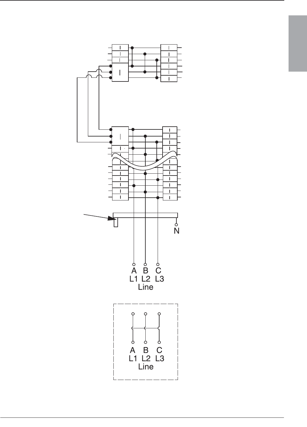
© 2007–2009 Schneider Electric All Rights Reserved
80043-712-04 NQ/NQM Panelboards and QONQ Load Centers Information Manual
10/2009 Appendix 1: Specifications
23
ENGLISH
Figure 10: Typical NQ Panelboard with Split Bus Diagram
Integral Main
Circuit Breaker
(when installed)
Enclosure Bonding
(when required)
Neutral
Ground
(when required)
187 of 292

© 2007–2009 Schneider Electric All Rights Reserved
NQ/NQM Panelboards and QONQ Load Centers Information Manual 80043-712-04
Appendix 1: Specifications 10/2009
24
ENGLISH
Panelboard Ratings
Refer to NEC section 110-22 and CEC rule 14-014 for more
information. The series rated system label is located in the
bag assembly.
Table 2: Series Connected Breaker Ratings (RMS Symmetrical)
Max. System
Voltage AC 1 2
Max. Short
Circuit
Current
Rating
Square D
Brand
Integral or
Remote
Main Circuit
Breakers
and Remote
Main Fuses
Square D Brand Branch Circuit Breaker Catalog
Designation and Allowable Ampere Ranges3 4 5 6
Type 1 Pole 2 Pole 3 Pole
120/240 1PH
22,000 MG QO (B)
15–30A
——
25,000 HD, JD QO (B) PL
15–60 A 15–30 A
65,000 HG, JG QO (B) PL
100,000 HJ, JJ QO (B) PL
125,000 HL, JL QO (B) PL
120/240 1PH
208Y/120
100,000
DJ 400A
QO (B) 15–70 A 15–125 A —
QO (B) GFI 15–30 A 40–60 A —
QO (B) AFI 15–20 A — —
QO (B) VH — 150 A 15–150 A
QJ
QO (B) 15–70 A 15–125 A 15–30 A
QO (B) AS 15–30 A 15–30 A 15–30 A
QO (B) GFI 15–30 A 15–60 A 15–50 A
QO (B) VH — 150 A 35–150 A
QO (B) PL 15–30 A 15–60 A 15–30 A
QO (B) AFI 15–20 A — —
208Y/120 18,000
LA/LH (L)
34200MC
QO (B) 15–30A 15–30 A 15–30 A
LA/LH (L)
34225MC
LA/LH (L)
34250MC
LA/LH (L)
34400MC
Continued on next page
188 of 292

© 2007–2009 Schneider Electric All Rights Reserved
80043-712-04 NQ/NQM Panelboards and QONQ Load Centers Information Manual
10/2009 Appendix 1: Specifications
25
ENGLISH
240
22,000
QO (B) VH
QO (B) 15–70 A 15–125 A 15–100 A
QO (B) AS 15–30 A 15–30 A 15–30 A
QO (B) GFI 15–30 A 15–60 A 15–50 A
QO (B) PL 15–30 A 15–30 A —
QO (B) AFI 15–20 A — —
Q2-H
QO (B) 15–70 A 15–100 A 15–30 A
QO (B) GFI 15–30 A 15–30 A —
QO (B) AFI 15–20 A — —
25,000
QD
QO (B) 15–70 A 15–125 A 15–30 A
QO (B) AS 15–30 A 15–30 A 15–30 A
QO (B) GFI 15–30 A 15–60 A 15–50 A
QO (B) VH — 150 A 35–150 A
QO (B) PL 15–30 A 15–60 A 15–30 A
QO (B) AFI 15–20 A — —
ED, FD
QO (B) 15–70 A 15–125 A 15–100 A
QO (B) GFI 15–30 A 15–60 A 15–50 A
QO (B) AFI 15–20 A — —
KD
QO (B) 15–70 A 15–125 A 15–100 A
QO (B) AS 15–30 A 15–30 A 15–30 A
QO (B) GFI 15–30 A 15–60 A —
QO (B) AFI 15–20 A — —
HD, JD
QO (B) 15–70 A 15–125 A 15–100 A
QO (B) VH — — 35–150 A
QO (B) GFI 15–30 A 15–60 A 15–50 A
QO (B) AFI 15–20 A — —
QO (B) H — 15–100 A —
QO (B) PL 15–30 A 15–60 A 15–30 A
QOB 2150VH — 150 A —
Continued on next page
Table 2: Series Connected Breaker Ratings (RMS Symmetrical) (continued)
Max. System
Voltage AC 1 2
Max. Short
Circuit
Current
Rating
Square D
Brand
Integral or
Remote
Main Circuit
Breakers
and Remote
Main Fuses
Square D Brand Branch Circuit Breaker Catalog
Designation and Allowable Ampere Ranges3 4 5 6
Type 1 Pole 2 Pole 3 Pole
189 of 292

© 2007–2009 Schneider Electric All Rights Reserved
NQ/NQM Panelboards and QONQ Load Centers Information Manual 80043-712-04
Appendix 1: Specifications 10/2009
26
ENGLISH
240
42,000
LA, MA Q2L-H — 100–225 A 100–225 A
QDL — 70–225 A 70–225 A
LC400A
QO (B) 15–70 A — —
QO (B) VH 15–30 A 15–125 A 15–100 A
QOBVH — 150 A —
QO (B) GFI 15–30 A 15–60 A —
QO (B) AFI 15–20 A — —
LC600A
QO (B) VH 15–30 A 15–125 A 15–100 A
QOBVH — 150 A —
QO (B) GFI — 15–60 A —
QO (B) AFI 15–20 A — —
MG QO (B) VH 15–30 A 15–30 A 15–30 A
65,000
LC400A
QO (B) 15–30 A — —
QO (B) VH 15–30 A 15–125 A 15–100 A
QOBVH — 150 A —
QO (B) GFI 15–30 A — 15–50 A
QO (B) AFI 15–20 A — —
LC600A
QO (B) VH 15–30 A 15–125 A
35–100 A
(3P208 V max)
15–30 A
(3P240 V max)
QOBVH — 150 A —
QO (B) GFI — — 15–50 A
QO (B) AFI 15–20 A — —
DJ 400A
QO (B) 15–70 A 15–125 A —
QO (B) VH — 150 A 15–150 A
QO (B) H — 15–100 A —
Continued on next page
Table 2: Series Connected Breaker Ratings (RMS Symmetrical) (continued)
Max. System
Voltage AC 1 2
Max. Short
Circuit
Current
Rating
Square D
Brand
Integral or
Remote
Main Circuit
Breakers
and Remote
Main Fuses
Square D Brand Branch Circuit Breaker Catalog
Designation and Allowable Ampere Ranges3 4 5 6
Type 1 Pole 2 Pole 3 Pole
190 of 292

© 2007–2009 Schneider Electric All Rights Reserved
80043-712-04 NQ/NQM Panelboards and QONQ Load Centers Information Manual
10/2009 Appendix 1: Specifications
27
ENGLISH
240
65,000
DJ__W
QO (B) 15–70 A 15–150 A —
QO (B)-AFI 15–20 A — —
QO (B)-GFI 15–30 A 15–60 A —
QO (B)-VH — 110–125 A 15–150 A
EG, FG, KG
QO (B) 15–70 A 15–125 A 15–100 A
QO (B) GFI 15–30 A 15–60 A 15–50 A
QO (B) AFI 15–20 A — —
QG
QO (B) 15–70 A 15–125 A 15–30 A
QO (B) AS 15–30 A 15–30 A 15–30 A
QO (B) VH — 150 A 35–150 A
QG, HG, JG
QO (B) GFI 15–30 A 15–60 A 15–50 A
QO (B) PL 15–30 A 15–60 A 15–30 A
QO (B) AFI 15–20 A — —
HG, JG
QO (B) 15–70 A 15–125 A 15–100 A
QO (B) VH — — 35–150 A
QO (B) H — 15–100 A —
QO B2150VH — 150 A —
FC_ or
KC_22___ QO (B) 15–70 A 15–100 A 15–100 A
FC_ or
KC_32___ QO (B) AS 15–30 A 15–30 A 15–30 A
100,000
FC_ or
KC_24___ QO (B) GFI 15–30 A 15–30 A —
FC_ or
KC_34___ QO (B) AFI 15–20 A — —
EJ, FJ
QO (B) 15–70 A 15–125 A 15–100 A
QO (B) GFI 15–30 A 15–60 A 15–50 A
QO (B) AFI 15–20 A — —
Continued on next page
Table 2: Series Connected Breaker Ratings (RMS Symmetrical) (continued)
Max. System
Voltage AC 1 2
Max. Short
Circuit
Current
Rating
Square D
Brand
Integral or
Remote
Main Circuit
Breakers
and Remote
Main Fuses
Square D Brand Branch Circuit Breaker Catalog
Designation and Allowable Ampere Ranges3 4 5 6
Type 1 Pole 2 Pole 3 Pole
191 of 292
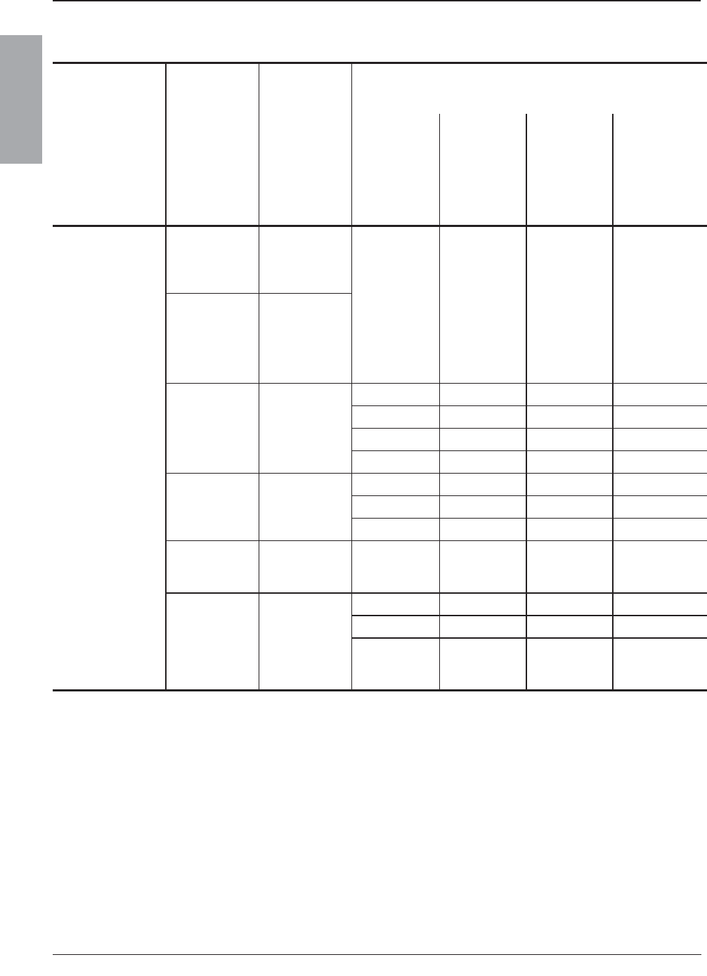
© 2007–2009 Schneider Electric All Rights Reserved
NQ/NQM Panelboards and QONQ Load Centers Information Manual 80043-712-04
Appendix 1: Specifications 10/2009
28
ENGLISH
240
100,000 HJ, JJ
QO (B) 15–70 A 15–125 A 15–100 A
QO (B) VH — — 35–150 A
QO (B) GFI 15–30 A 15–60 A 15–50 A
125,000 HL, JL
QO (B) PL 15–30 A 15–60 A 15–30 A
QO (B) AFI 15–20 A — —
QO (B) H — 15–100 A —
QOB 2150VH — 150 A —
200,000 FI, KI
QO (B) 15–70 A 15–125 A 15–100 A
QO (B) AS 15–30 A 15–30 A 15–30 A
QO (B) GFI 15–30 A 15–60 A —
QO (B) AFI 15–20 A — —
65,000
400 A Max.
Class J or T6
Fuses
QO (B) VH 15–30 A 15–125 A 15–100 A
QOB-VH — 150 A —
QO (B) AFI 15–20 A — —
100,000
200 A Max.
Class
T3 Fuses
QO (B) AFI 15–20 A — —
200,000
200 A Max.
Class J or T6
Fuses and
400 A Max.
Class
T3 Fuses
QO (B) 15–70 A 15–125 A 15–100 A
QO (B) AS 15–30 A 15–30 A 15–30 A
QO (B) GFI 15–30 A 15–60 A 15–50 A
1For shown circuit breakers rated less than this maximum voltage, the indicated short circuit current rating also
applies, but at the voltage rating of the circuit breaker.
2Short circuit tests are conducted at 100–105% of the maximum rated voltage of the panelboard.
3Suffixes HID, SWD, and SWN may also be applied to the applicable branch circuit breakers shown above. Suffix
SWN may not be applied in combination with LC main breakers.
4Where QO (B) circuit breakers are shown above, QO (B) H, QO (B) VH, and QH (B) circuit breakers may also
be used.
5Where QO (B) GFI circuit breakers are shown above, QO (B) EPD and/or QO (B) EPE circuit breakers may also
be used.
6Where QO (B) AFI circuit breakers are shown above, QO (B) CAFI circuit breakers may also be used.
Table 2: Series Connected Breaker Ratings (RMS Symmetrical) (continued)
Max. System
Voltage AC 1 2
Max. Short
Circuit
Current
Rating
Square D
Brand
Integral or
Remote
Main Circuit
Breakers
and Remote
Main Fuses
Square D Brand Branch Circuit Breaker Catalog
Designation and Allowable Ampere Ranges3 4 5 6
Type 1 Pole 2 Pole 3 Pole
192 of 292
© 2007–2009 Schneider Electric All Rights Reserved
80043-712-04 NQ/NQM Panelboards and QONQ Load Centers Information Manual
10/2009 Appendix 1: Specifications
29
ENGLISH
CE Marking
Interiors with the “CE” mark meet the IEC 60439-1 standard.
Table 3: Short Circuit Current Rating1 for Main Lug Interiors
with Sub-Feed or Feed-Through Lugs
1This rating applies to main lug interiors, equipped with sub-feed or feed-through lugs, where the device feeding
the interior is unknown or not a Square D brand device. Use of a Square D brand main circuit breaker ahead
of these lugs will result in a rating equal to the rating of the breaker. Short circuit tests are conducted at
100–105% of the maximum rated voltage of the panelboard.
Maximum
System
Voltage AC
Maximum
Current
Rating
Branch Circuits Application Adder2
2The adder is the additional length of the enclosure.
Maximum Short
Circuit Current
Rating3
3RMS symmetrical amperes, for three cycles.
240
100 18, 30 SFL and FTL —
10,000
225
30, 42, 54, 72, 84 SFL 6 inches
(152.4 mm)
42
FTL
—
30, 54, 72, 84 6 inches
(152.4 mm)
400
30, 42, 54, 72, 84 SFL —
25,000
30, 84
FTL
—
42, 54, 72 6 inches
(152.4 mm)
600 30, 42, 54, 72, 84 FTL 12 inches
(304.8 mm)
193 of 292

© 2007–2009 Schneider Electric All Rights Reserved
NQ/NQM Panelboards and QONQ Load Centers Information Manual 80043-712-04
Appendix 2: Accessory Kits 10/2009
30
ENGLISH
Appendix 2: Accessory Kits
An assortment of field-installable accessory kits are available for
NQ panelboards:
•Equipment Ground Bar Kits
•Oversized Lug Kits for 100–250 A Panelboards
•Sub-Feed Lug Kits for 100–400 A Panelboards
•Main Lug Kits
— Mechanical Lug Kits — Aluminum
— Mechanical Lug Kits — Copper
— Versa-Crimp® Compression Lug Kits — Aluminum
— Versa-Crimp Compression Lug Kits — Copper
Equipment Ground Bar Kits
Equipment ground bar kits, suitable for copper or aluminum wire, meet
the grounding needs of NQ panelboards and QONQ load centers.
NOTE: Ground bar mounting locations are identified by the ground symbol stamped
into the backwall of the enclosure.
Table 4: Equipment Ground Bar Kits Specifications
Panelboard Use Ground Bar Kit Catalog Number
Branch Circuit Mains Rating Aluminum1
1Aluminum bars suitable for 60° C or 75° C Copper or Aluminum conductors.
Copper2
2Copper bars suitable for 60° C or 75° C Copper conductors.
1–42 600 A Maximum (1) PK27GTA (1) PK27GTACU
54–84 (2) PK27GTA (2) PK27GTACU
194 of 292
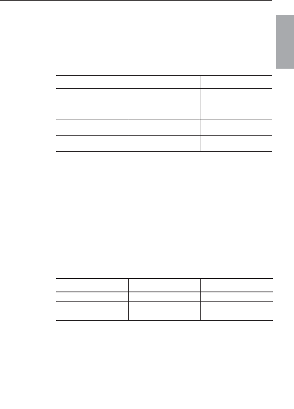
© 2007–2009 Schneider Electric All Rights Reserved
80043-712-04 NQ/NQM Panelboards and QONQ Load Centers Information Manual
10/2009 Appendix 2: Accessory Kits
31
ENGLISH
Oversized Lug Kits for 100–250 A Panelboards
Oversized lug kits are available for applications where termination
conductors of 3 AWG or larger are required for the neutral.
Sub-Feed Lug Kits for 100–400 A Panelboards
Sub-feed main lugs are available for 100, 225, or 400 A applications.
Table 5: Oversized Lug Kits for 100–250 A
Panelboards Specifications
Circuit Breaker Rating Kit Catalog Number Wire Range
70 A QO70AN
(1) 10–2 Al
(1) 5.76–33.6 mm2
(1)14–4 Cu
(1) 2.08–21.1 mm2
80–125 A Q1100AN (1) 4–1/0 Al/Cu
(1) 42.4–53.5 mm2
125–150 A Q1150AN (1) 1–4/0 Al/Cu
(1) 42.4–107 mm2
Table 6: Sub-Feed Lug Kits for 100–400 A
Panelboards Specifications
Main Amps Kit Catalog Number Maximum Circuits
100 NQSFL1 18, 30
225 NQSFL2 301, 421, 541, 721, 841
1These panels require an additional 6 inches (152.4 mm) for the box and trim, for proper
wire bending space.
400 NQSFL4 30, 42, 54, 72, 84
195 of 292
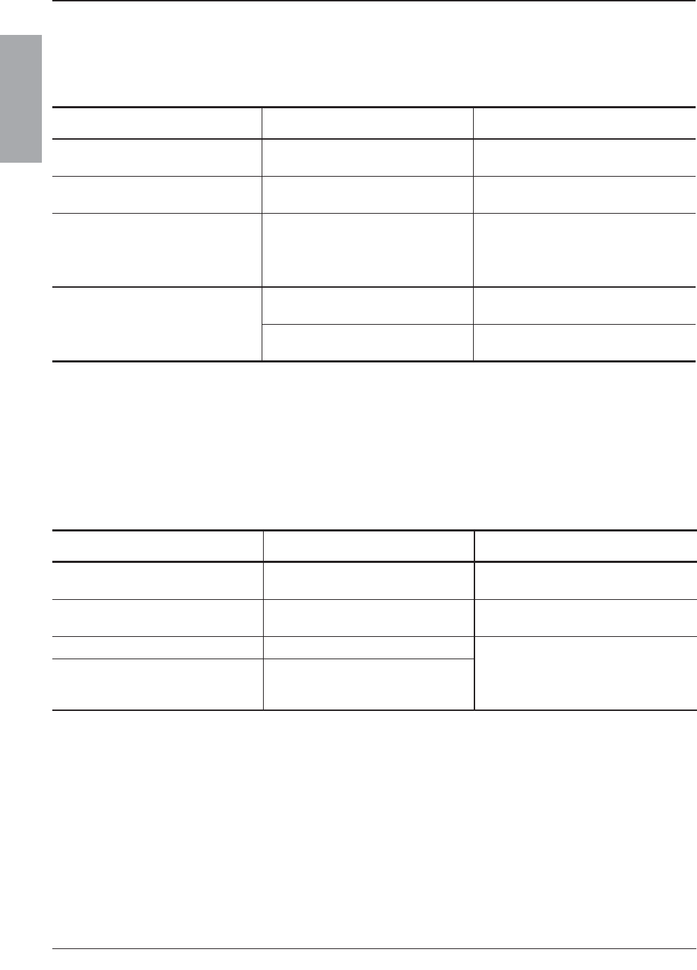
© 2007–2009 Schneider Electric All Rights Reserved
NQ/NQM Panelboards and QONQ Load Centers Information Manual 80043-712-04
Appendix 2: Accessory Kits 10/2009
32
ENGLISH
Main Lug Kits
Table 7: Mechanical Lug Kits — Aluminum
Panelboard Amps Kit Catalog Number Wire Range
100 Standard #6–2/0 AWG
13.3–67.43 mm2
225 Standard #6–350 kcmil
13.3–177.3 mm2
400 Standard
(1) 1/0–750 kcmil
(2) 1/0–350 kcmil
(1) 53.48–380 mm2
(2) 53.48–177.3 mm2
600
Standard (2) 1/0–750 kcmil
(2) 53.48–380 mm2
NQALM6A (3) #6–250 kcmil
(3) 13.3–127 mm2
Table 8: Mechanical Lug Kits — Copper
Panelboard Amps Kit Catalog Number Wire Range
100 NQCUM1 #6–2/0 AWG
13.3–67.43 mm2
225 NQCUM2 #6–250 kcmil
13.3–127 mm2
400 NQCUM4 (1) 1/0–750 kcmil
(2) 1/0–350 kcmil
(1) 53.48–380 mm2
(2) 53.48–177.3 mm2
600 NQCUM6
196 of 292
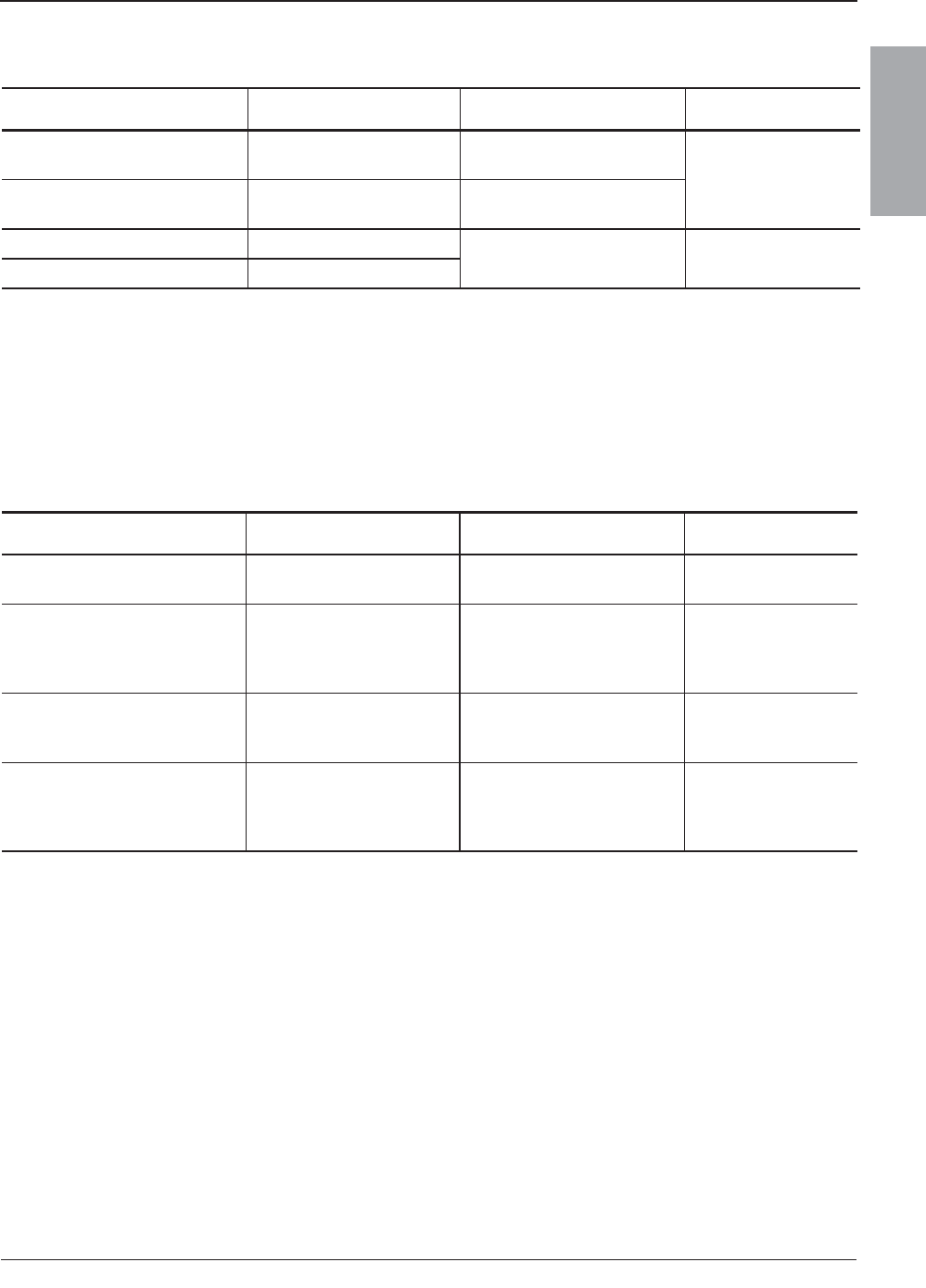
© 2007–2009 Schneider Electric All Rights Reserved
80043-712-04 NQ/NQM Panelboards and QONQ Load Centers Information Manual
10/2009 Appendix 2: Accessory Kits
33
ENGLISH
Table 9: Versa-Crimp® Compression Lug Kits — Aluminum
Panelboard Amps Kit Catalog Number Wire Range Crimp Tool
100 NQALV1 #8–1/0 AWG
8.36–53.48 mm2
VC6 (All)
225 NQALV2 #4–300 kcmil
21.15–152 mm2
400 NQALV4 (2) 2/0–500 kcmil
(2) 67.43–253.4 mm2VC6-3,
VC6-FT
600 NQALV6
Table 10: Versa-Crimp® Compression Lug Kits — Copper
Panelboard Amps Kit Catalog Number Wire Range Crimp Tool
100 NQCUV1 #6–1/0 AWG
13.30–53.48 mm2VC6 (All),
VC7 (All)
225 NQCUV2 2/0–300 kcmil
67.43–152 mm2
VC6-3,
VC7,
VC6-FT,
VC7-FT
400 NQCUV4 400–750 kcmil
202.7–380 mm2
VC6-FT,
VC7-FT,
VC8
600 NQCUV6 (2) 250–500 kcmil
(2) 126.7–253.4 mm2
VC6-3,
VC7,
VC6-FT,
VC7-FT
197 of 292

© 2007–2009 Schneider Electric All Rights Reserved
NQ/NQM Panelboards and QONQ Load Centers Information Manual 80043-712-04
Appendix 2: Accessory Kits 10/2009
34
ENGLISH
198 of 292
NQ/NQM Panelboards and QONQ Load Centers Information Manual
Instruction Bulletin
Schneider Electric USA
252 North Tippecanoe
Peru, IN 46970 USA
1-888-SquareD (1-888-778-2733)
www.us.SquareD.com
Electrical equipment should be installed, operated, serviced, and
maintained only by qualified personnel. No responsibility is assumed
by Schneider Electric for any consequences arising out of the use of
this material.
80043-712-04
© 2007–2009 Schneider Electric All Rights Reserved
Replaces 80043-712-03 08/2008
10/2009
199 of 292

THIS PAGE WAS INTENTIONALLY LEFT BLANK
200 of 292
NEMA Standards Publication PB 1.1-2007
General Instructions
for
Proper Installation, Operation, and Maintenance
of
Panelboards Rated 600 Volts or Less
Published by
National Electrical Manufacturers Association
1300 North 17th Street
Rosslyn, Virginia 22209
www.nema.org
© Copyright 2007 by the National Electrical Manufacturers Association. All rights including translation into
other languages, reserved under the Universal Copyright Convention, the Berne Convention for the
Protection of Literary and Artistic Works, and the International and Pan American Copyright Conventions.
201 of 292

NOTICE AND DISCLAIMER
The information in this publication was considered technically sound by the consensus of persons
engaged in the development and approval of the document at the time it was developed.
Consensus does not necessarily mean that there is unanimous agreement among every person
participating in the development of this document.
The National Electrical Manufacturers Association (NEMA) standards and guideline publications, of
which the document contained herein is one, are developed through a voluntary consensus
standards development process. This process brings together volunteers and/or seeks out the
views of persons who have an interest in the topic covered by this publication. While NEMA
administers the process and establishes rules to promote fairness in the development of
consensus, it does not write the document and it does not independently test, evaluate, or verify
the accuracy or completeness of any information or the soundness of any judgments contained in
its standards and guideline publications.
NEMA disclaims liability for any personal injury, property, or other damages of any nature
whatsoever, whether special, indirect, consequential, or compensatory, directly or indirectly
resulting from the publication, use of, application, or reliance on this document. NEMA disclaims
and makes no guaranty or warranty, expressed or implied, as to the accuracy or completeness of
any information published herein, and disclaims and makes no warranty that the information in this
document will fulfill any of your particular purposes or needs. NEMA does not undertake to
guarantee the performance of any individual manufacturer or seller’s products or services by virtue
of this standard or guide.
In publishing and making this document available, NEMA is not undertaking to render professional
or other services for or on behalf of any person or entity, nor is NEMA undertaking to perform any
duty owed by any person or entity to someone else. Anyone using this document should rely on
his or her own independent judgment or, as appropriate, seek the advice of a competent
professional in determining the exercise of reasonable care in any given circumstances.
Information and other standards on the topic covered by this publication may be available from
other sources, which the user may wish to consult for additional views or information not covered
by this publication.
NEMA has no power, nor does it undertake to police or enforce compliance with the contents of
this document. NEMA does not certify, test, or inspect products, designs, or installations for safety
or health purposes. Any certification or other statement of compliance with any health or safety–
related information in this document shall not be attributable to NEMA and is solely the
responsibility of the certifier or maker of the statement.
202 of 292

PB 1.1-2007
Page i
CONTENTS
Page
Foreword ...................................................................................................................................iv
Section 1 SCOPE ...................................................................................................................................... 1
Section 2 REFERENCES .......................................................................................................................... 2
Section 3 GENERAL ................................................................................................................................. 3
3.1 Successful Operation of Panelboards....................................................................................... 3
3.2 Qualified Personnel ................................................................................................................... 3
3.3 Definition of Qualified Personnel ............................................................................................... 3
3.3.1 Requirements................................................................................................................ 3
3.3.2 Established Safety Practices......................................................................................... 3
3.3.3 Protective Equipment .................................................................................................... 3
3.3.4 First Aid ......................................................................................................................... 3
3.4 Suitable Ratings ........................................................................................................................ 3
Section 4 INSTALLATION OF PANELBOARD CABINETS (BOXES).................................................... 4
4.1 Installation Instructions.............................................................................................................. 4
4.2 Location in Building ................................................................................................................... 4
4.3 Flammable Material................................................................................................................... 4
4.4 Unusual Service Conditions ...................................................................................................... 4
4.5 Indoor Damp Locations ............................................................................................................. 4
4.6 Wet Locations............................................................................................................................ 4
4.7 Clearance from Ceiling.............................................................................................................. 4
4.8 Space around the Cabinet......................................................................................................... 4
4.9 Mounting of Cabinet .................................................................................................................. 4
4.10 Flush Mounting in Wall .............................................................................................................. 5
4.11 Unused Openings in Cabinet .................................................................................................... 5
4.12 Grounding of Panelboard Cabinets ........................................................................................... 5
Section 5 INSTALLATION OF CONDUIT AND CONDUCTORS............................................................. 6
5.1 Conduits Installation .................................................................................................................. 6
5.2 Knockouts Removal................................................................................................................... 6
5.2.1 First Step—Remove Center Knockout.......................................................................... 6
5.2.2 Next Step—Remove Rings ........................................................................................... 6
5.3 National Electrical Code, Article 300......................................................................................... 6
5.4 Conductor Length ...................................................................................................................... 6
5.5 Exercise Care ............................................................................................................................ 6
5.6 National Electrical Code, Section 725.54.................................................................................. 7
Section 6 INSTALLATION OF PANELBOARD...................................................................................... 11
6.1 Proper Storage ........................................................................................................................ 11
6.2 Unpacking................................................................................................................................ 11
6.3 Inspection ................................................................................................................................ 11
6.4 Care......................................................................................................................................... 11
6.4.1 Cleaning ...................................................................................................................... 11
6.5 Manufacturer's Instructions ..................................................................................................... 11
6.6 Installation................................................................................................................................ 11
6.6.1 Alignment Devices ...................................................................................................... 11
6.6.2 Panelboard.................................................................................................................. 11
6.6.3 Flange of Deadfront Shield ......................................................................................... 11
6.7 Line And Branch Conductors .................................................................................................. 12
6.7.1 Conductors.................................................................................................................. 12
6.8 Panelboard Grounding ............................................................................................................ 12
6.8.1 Equipment Grounding Conductors.............................................................................. 12
6.9 Proper Type Or Class And Rating........................................................................................... 12
© Copyright 2007 by the National Electrical Manufacturers Association.
203 of 292

PB 1.1-2007
Page ii
6.10 Debris ...................................................................................................................................... 12
6.11 Steps In Section 7 ................................................................................................................... 12
Section 7 STEPS TO BE TAKEN BEFORE ENERGIZING.................................................................... 13
7.1 Accessible Electrical Connections........................................................................................... 13
7.2 Blocks and Packing Materials .................................................................................................13
7.3 Switches, Circuit Breakers, and Other Operating Mechanisms.............................................. 13
7.4 Short Circuits and Ground Faults ............................................................................................ 13
7.5 Ground Fault Protection System ............................................................................................. 13
7.6 Adjustable Time Current Trip Device Settings ........................................................................ 13
7.7 Grounding Connections........................................................................................................... 13
7.8 Foreign Material....................................................................................................................... 14
Section 8 INSTALLATION OF CABINET FRONT.................................................................................. 15
8.1 Cabinet Front or Trim Package ............................................................................................... 15
8.2 Unpacking................................................................................................................................ 15
8.3 Covers and Doors.................................................................................................................... 15
8.4 Touch-Up................................................................................................................................. 15
8.5 Front Alignment ....................................................................................................................... 15
Section 9 ENERGIZING EQUIPMENT.................................................................................................... 16
9.1 Qualified Personnel ................................................................................................................. 16
9.2 Load on the Panelboard .......................................................................................................... 16
9.3 Energized in Sequence ........................................................................................................... 16
9.4 Loads Such as Lighting Circuits, Contactors, Heaters, and Motors ....................................... 16
Section 10 MAINTENANCE ...................................................................................................................... 17
10.1 Maintenance Program ............................................................................................................. 17
10.2 Panelboard Which Has Been Carrying Its Regular Load for at Least 3 Hours ....................... 17
10.3 Inspect Panelboard Once Each Year ...................................................................................... 17
10.4 Accumulation of Dust and Dirt................................................................................................. 17
10.4.1 Visible Electrical Joints and Terminals...................................................................... 17
10.4.2 Conductors and Connections.................................................................................... 17
10.4.3 Fuse Clip Contact Pressure and Contact Means...................................................... 18
10.4.4 Plug Fuses ................................................................................................................18
10.4.5 Conditions Which Caused Overheating.................................................................... 18
10.5 Proper Ampere, Voltage, and Interrupting Ratings ................................................................. 18
10.5.1 Mechanisms Free and in Proper Working Order ...................................................... 18
10.6 Operation of all Mechanical Components ............................................................................... 18
10.6.1 Switch Operating Mechanisms ................................................................................. 18
10.6.2 Integrity of Electrical and Mechanical Interlocks....................................................... 18
10.6.3 Missing or Broken Parts............................................................................................ 18
10.6.4 Manufacturer’s Instructions....................................................................................... 18
10.6.5 Accessible Copper Electrical Contacts, Blades, and Jaws....................................... 19
10.7 Damaged Insulating Material and Assemblies ........................................................................ 19
10.8 Moisture or Signs of Previous Wetness or Dripping................................................................ 19
10.8.1 Conduits Which Have Dripped Condensate ............................................................. 19
10.8.2 Cracks or Openings .................................................................................................. 19
10.8.3 Insulating Material Which is Damp or Wet................................................................ 19
10.8.4 Component Devices Which Show Evidence of Moisture Damage........................... 19
10.9 Before Cleanup and Corrective Action is Attempted............................................................... 19
10.10 Severe Electrical Short Circuit................................................................................................. 20
10.11 Ground Fault Protection System .............................................................................................20
10.12 Insulation Resistance .............................................................................................................. 20
10.12.1 Severe Short Circuit ................................................................................................ 20
10.12.2 Parts Replaced........................................................................................................ 20
10.12.3 Panelboard Exposed to High Humidity ................................................................... 20
© Copyright 2007 by the National Electrical Manufacturers Association.
204 of 292

PB 1.1-2007
Page iii
Section 11 PERMISSIBLE LOADING OF PANELBOARDS ................................................................... 21
11.1 National Electrical Code .......................................................................................................... 21
11.2 Harmonics in Electrical System............................................................................................... 21
Figures
5–1 Knockout Removal—Step 1 ...................................................................................................... 8
5–2 Knockout Removal—Step 2 ......................................................................................................9
5–3 Knockout Removal—Step 3 .................................................................................................... 10
© Copyright 2007 by the National Electrical Manufacturers Association.
205 of 292

PB 1.1-2007
Page iv
Foreword
This publication is a guide of practical information containing instructions for the proper installation,
operation, and maintenance of panelboards rated 600 volts or less.
These instructions do not purport to cover all details or variations in equipment, nor to provide for every
possible contingency regarding installation, operation, or maintenance.
It is recommended that work described in this set of instructions be performed only by qualified personnel
familiar with the construction and operation of panelboards and that such work be performed only after
reading this complete set of instructions. For specific information not covered by these instructions, you
are urged to contact the manufacturer of the panelboard directly.
In the preparation of this Standards Publication input of users and other interested parties has been
sought and evaluated. Inquiries, comments, and proposed or recommended revisions should be
submitted to the concerned NEMA product section by contacting the following: These recommendations
will be reviewed periodically and updated as necessary.
Vice President, Engineering
National Electrical Manufacturers Association
1300 North 17th Street, Suite 1752
Rosslyn, Virginia 22209
Publication No. PB 1.1- 2007 revises and supersedes PB 1.1- 2002.
This Standards Publication was developed by the Panelboard and Distribution Board Product Group of the
LVDE Section. Product Group approval of the standard does not necessarily imply that all Product Group
members voted for its approval or participated in its development. At the time it was approved, the Product
Group was composed of the following members:
Eaton Electrical Inc.—Pittsburgh, PA
GE—Plainville, CT
Hubbell, Inc.—Orange, CT
Milbank Manufacturing Company—Kansas City, MO
Penn Panel & Box Company—Collingdale, PA
Reliance Controls Corporation—Racine, WI
Siemens Energy & Automation, Inc.—Alpharetta, GA
Square D Company—Palatine, IL
© Copyright 2007 by the National Electrical Manufacturers Association.
206 of 292

PB 1.1-2007
Page 1
Section 1
SCOPE
This publication covers single panelboards or groups of panel units suitable for assembly in the form of
single panelboards, including buses, and with or without switches or automatic overload protective
devices (fuses or circuit breakers), or both. These units are used in the distribution of electricity at 600
volts and less with:
1600—ampere mains or less
1200—ampere branch circuits or less
Specifically excluded are live-front panelboards, panelboards employing cast enclosures for special
service conditions, and panelboards designed primarily for residential and light commercial service
equipment.
© Copyright 2007 by the National Electrical Manufacturers Association.
207 of 292

PB 1.1-2007
Page 2
Section 2
REFERENCES
National Fire Protection Association (NFPA)
Batterymarch Park
Quincy, MA 02269
NFPA 70 2005 National Electrical Code
NFPA 70E 2004 Safety Related Work Practices
National Electrical Manufacturers Association (NEMA)
1300 North 17th Street, Suite 1752
Rosslyn, Virginia 22209
AB 4- 2003 Guidelines for Inspection and Preventative Maintenance of Molded Case Circuit
Breakers Used in Commercial and Industrial Applications
PB 2.2- 2004 Application Guide for Ground Fault Protective Devices for Equipment
Guidelines for Handling Water Damaged Electrical Products
© Copyright 2007 by the National Electrical Manufacturers Association.
208 of 292

PB 1.1-2007
Page 3
Section 3
GENERAL
WARNING—HAZARDOUS VOLTAGES IN ELECTRICAL EQUIPMENT CAN CAUSE SEVERE
PERSONAL INJURY OR DEATH. UNLESS OTHERWISE SPECIFIED, INSPECTION AND
MAINTENANCE SHOULD ONLY BE PERFORMED ON PANELBOARDS AND EQUIPMENT TO WHICH
POWER HAS BEEN TURNED OFF, DISCONNECTED AND ELECTRICALLY ISOLATED SO THAT NO
ACCIDENTAL CONTACT CAN BE MADE WITH ENERGIZED PARTS. FOLLOW ALL
MANUFACTURER'S WARNINGS AND INSTRUCTIONS.
Safety-related work practices, as described in NFPA 70E, should be followed at all times.
CAUTION—Hydrocarbon spray propellants and hydrocarbon based sprays or compounds will cause
degradation of certain plastics. Contact the panelboard manufacturer before using these products to clean,
dry, or lubricate components during installation or maintenance.
3.1 SUCCESSFUL OPERATION OF PANELBOARDS
The successful operation of panelboards is dependent upon proper installation, operation, and maintenance.
Neglecting fundamental installation and maintenance requirements may lead to personal injury, death, or
damage to electrical equipment or other property.
3.2 QUALIFIED PERSONNEL
Installation, operation, and maintenance of panelboards should be conducted only by qualified personnel.
3.3 DEFINITION OF QUALIFIED PERSONNEL
For purposes of these guidelines, a qualified person is one who is familiar with the installation, construction,
and operation of the equipment and the hazards involved. In addition, the person is:
3.3.1 Requirements
Knowledgeable of the requirements of the National Electrical Code and of all other applicable codes, laws,
and standards.
3.3.2 Established Safety Practices
Trained and authorized to test, energize, clear, ground, tag, and lockout circuits and equipment in
accordance with established safety practices.
3.3.3 Protective Equipment
Trained in the proper care and use of protective equipment such as rubber gloves, hard hat, safety glasses
or face shields, and flash resistant clothing in accordance with established safety practices.
3.3.4 First Aid
Trained in rendering first aid.
3.4 SUITABLE RATINGS
Verify that all equipment being installed has ratings suitable for the installation.
© Copyright 2007 by the National Electrical Manufacturers Association.
209 of 292
PB 1.1-2007
Page 4
Section 4
INSTALLATION OF PANELBOARD CABINETS (BOXES)
4.1 INSTALLATION INSTRUCTIONS
Installation of the cabinet in a neat and workmanlike manner. Follow the manufacturer's installation
instructions.
4.2 LOCATION IN BUILDING
Locate the cabinet so that it is readily accessible and not exposed to physical damage.
4.3 FLAMMABLE MATERIAL
Locate the cabinet well away from flammable material.
4.4 UNUSUAL SERVICE CONDITIONS
Do not locate the cabinet where it will be exposed to ambient temperatures above 40°C (104°F), corrosive
or explosive fumes, dust, vapors, dripping or standing water, abnormal vibration, mechanical shock, high
humidity, tilting, or unusual operating conditions, unless the cabinet/panelboard combination has been
designed and so identified by the manufacturer for these conditions.
4.5 INDOOR DAMP LOCATIONS
Locate or shield the cabinet so as to prevent moisture and water from entering and accumulating therein.
Mount the cabinet so that there is at least 1/4 inch of air space between the cabinet and the wall or other
supporting surface.
4.6 WET LOCATIONS
Cabinets should be specifically approved for wet locations. Mount the cabinet so that there is at least 1/4
inch of air space between the cabinet and the wall or other supporting surface.
4.7 CLEARANCE FROM CEILING
Do not locate the cabinet against a non-fireproof ceiling; allow a space of 3 feet between the ceiling and
cabinet unless an adequate fireproof shield is provided.
4.8 SPACE AROUND THE CABINET
When selecting a location, provide sufficient access and working space around the cabinet (See Section
110.26 of the National Electrical Code). The width of the working space in front of the panelboard should be
at least 30 inches and this space should not be used as storage. The working space should have adequate
lighting and a minimum head room of 6 feet 6 inches.
4.9 MOUNTING OF CABINET
The cabinet should be reliably secured to the mounting surface. Do not depend on wooden plugs driven into
holes in masonry, concrete, plaster, or similar materials. (See Section 110.13 of the National Electrical
Code.)
© Copyright 2007 by the National Electrical Manufacturers Association.
210 of 292

PB 1.1-2007
Page 5
4.10 FLUSH MOUNTING IN WALL
In walls of concrete, tile, or other noncombustible material, install the cabinet so that its front edge will not set
back more than 1/4 inch from the finished surface. In walls of wood or other combustible material, cabinets
should be flush with or project beyond the finished surface. (See Section 312.3 of the National Electrical
Code.)
4.11 UNUSED OPENINGS IN CABINET
Effectively close unused openings in the cabinet to provide protection which is substantially equivalent to
that afforded by the wall of the cabinet.
4.12 GROUNDING OF PANELBOARD CABINETS
Ground the cabinet as specified in Article 250 of the National Electrical Code. When the cabinet contains
service equipment, it is necessary to bond the cabinet to the grounded (neutral) service conductor.
© Copyright 2007 by the National Electrical Manufacturers Association.
211 of 292

PB 1.1-2007
Page 6
Section 5
INSTALLATION OF CONDUIT AND CONDUCTORS
5.1 CONDUITS INSTALLATION
Conduits should be installed so as to prevent moisture or water from entering and accumulating within the
enclosure. Provision should be made to protect conductors from abrasion in accordance with Article 312 of
the National Electrical Code.
5.2 KNOCKOUTS REMOVAL
Knockouts should be removed as follows:
IMPORTANT—Remove knockouts, ONE AT A TIME, alternating INWARD and OUTWARD.
5.2.1 First Step—Remove Center Knockout
Remove center knockout INWARD.
5.2.1.1 Screwdriver Blade
Place screwdriver blade against point farthest from tie and strike INWARD (Figure 1). Bend back and
forth to break tie.
5.2.2 Next Step—Remove Rings
Remove rings ONE AT A TIME without straining remaining rings.
5.2.2.1 Pry First Ring
Pry first ring OUTWARD with screwdriver midway between ties, using pliers flat against box under
screwdriver (Figure 2). Bend ring sections OUTWARD with pliers, then back and forth to break ties
(Figure 5-3).
5.2.2.2 Second Ring
Remove second ring INWARD by striking screwdriver (with blade against point midway between ties)
then breaking ring sections inward and back and forth to break ties.
5.3 NATIONAL ELECTRICAL CODE, ARTICLE 300
Refer to the National Electrical Code, Article 300 for proper wiring methods. See 6.7 for making proper
connections.
5.4 CONDUCTOR LENGTH
Keep conductor length to a minimum within the wiring gutter. Excessive conductor length will result in
additional heating and may result in overheating. However, conductors should be long enough to reach
the terminal location in a manner that avoids strain on the terminal.
5.5 EXERCISE CARE
Exercise care to maintain the largest practical bending radius of conductors; otherwise the insulation may
be damaged and terminal connections may become loosened. Deflection of conductors shall comply with
NEC Section 312.6.
© Copyright 2007 by the National Electrical Manufacturers Association.
212 of 292

PB 1.1-2007
Page 7
5.6 NATIONAL ELECTRICAL CODE, SECTION 725.54
Refer to the National Electrical Code, Section 725.54 for the separation requirements for conductors of
Class 2 and Class 3 remote-control, signaling and power-limited circuits.
© Copyright 2007 by the National Electrical Manufacturers Association.
213 of 292
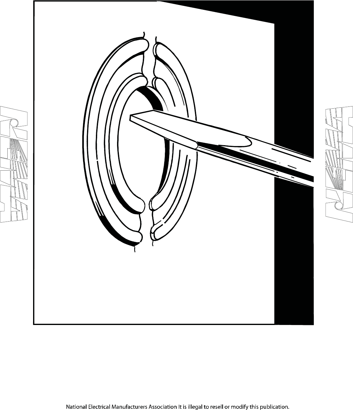
PB 1.1-2007
Page 8
Figure 5–1
KNOCKOUT REMOVAL—STEP 1
© Copyright 2007 by the National Electrical Manufacturers Association.
214 of 292
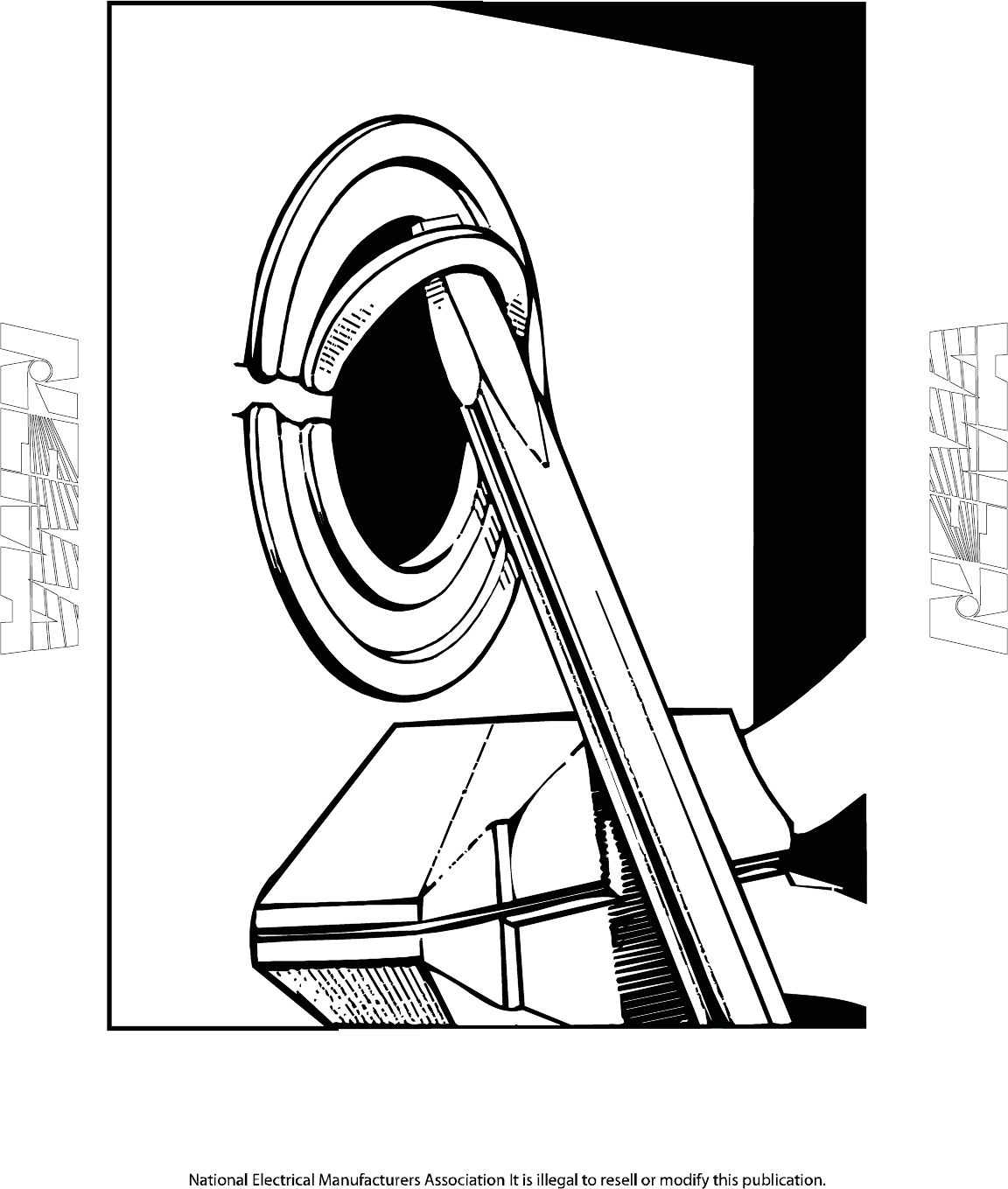
PB 1.1-2007
Page 9
Figure 5–2
KNOCKOUT REMOVAL—STEP 2
© Copyright 2007 by the National Electrical Manufacturers Association.
215 of 292
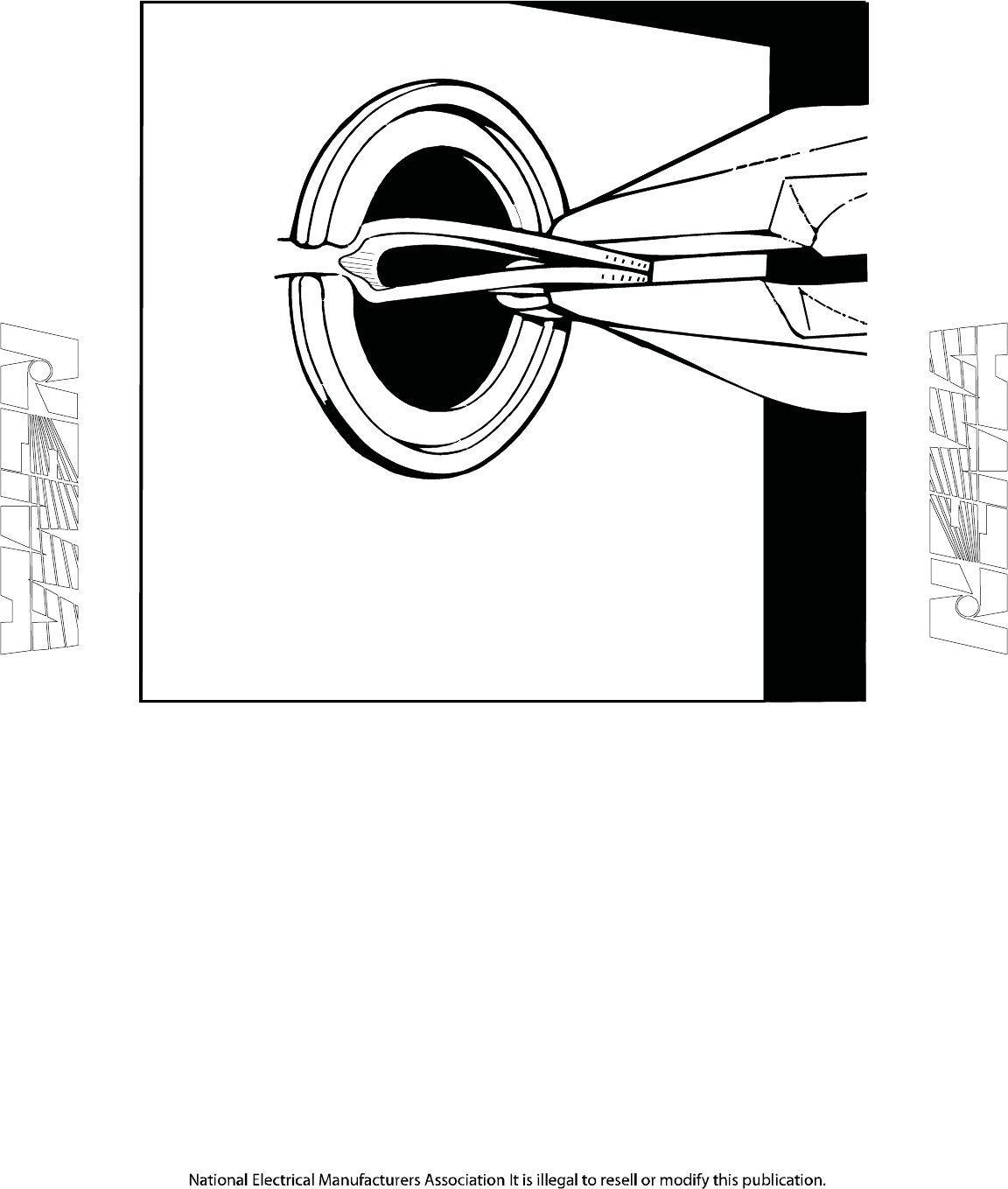
PB 1.1-2007
Page 10
Figure 5–3
KNOCKOUT REMOVAL—STEP 3
© Copyright 2007 by the National Electrical Manufacturers Association.
216 of 292

PB 1.1-2007
Page 11
Section 6
INSTALLATION OF PANELBOARD
6.1 PROPER STORAGE
Store the panelboard in a clean, dry place located so that mechanical damage from work personnel in the
area is not likely to happen.
6.2 UNPACKING
Care should be exercised in unpacking the panelboard to prevent damage and loss of instruction
materials and loose parts.
6.3 INSPECTION
Check for shipping damage and check to make sure that the panelboard is the correct one for installation
in the cabinet.
6.4 CARE
Care should be taken to protect the panelboard internal parts from contamination during the installation
process.
6.4.1 Cleaning
Clean the cabinet of all foreign materials. If parts at connection points are spattered with cement, plaster,
paint, or other foreign material, remove the foreign materials with great care to avoid damage to the
plating.
CAUTION—Hydrocarbon spray propellants and hydrocarbon based sprays or compounds will cause
degradation of certain plastics. Contact the panelboard manufacturer before using these products to clean,
dry, or lubricate panelboard components during installation or maintenance.
6.5 MANUFACTURER'S INSTRUCTIONS
Carefully follow the manufacturer's instructions and labels.
6.6 INSTALLATION
6.6.1 Alignment Devices
Adjust the alignment devices where provided.
6.6.2 Panelboard
Install the panelboard, finalize its alignment, and tighten it securely in the cabinet.
6.6.3 Flange of Deadfront Shield
Unless otherwise instructed by the manufacturer, adjust the panelboard so that the flange of the
deadfront shield is no more than 3/16 inch from (1) the front of the cabinet for surface mounting or (2) the
surrounding wall surfaces for flush mounting.
© Copyright 2007 by the National Electrical Manufacturers Association.
217 of 292

PB 1.1-2007
Page 12
6.7 LINE AND BRANCH CONDUCTORS
Connect Line and Branch Conductors
6.7.1 Conductors
Use care in stripping insulation from conductors so as not to nick or ring the conductor. For aluminum,
clean all oxide from the stripped portion and apply an antioxide compound.
6.7.1.1 Wiring Gutters
Distribute and arrange conductors neatly in the wiring gutters. (See Section 5.)
6.7.1.2 Types and Temperature Ratings
Care should be exercised to ensure that the types and temperature ratings of conductors being installed
in the panelboard are suitable for use with the terminals, which have been provided.
6.7.1.3 Tighten All Terminals
Use the manufacturer's torque values. (See 7.1).
6.8 PANELBOARD GROUNDING
Ground the panelboard cabinet in accordance with 4.12. (See Section 408.40 of the National Electrical
Code.)
6.8.1 Equipment Grounding Conductors
Where separate equipment grounding conductors are used, prepare equipment grounding conductors in
accordance with 6.7.1 and connect them to the equipment grounding terminal bar. Check to be sure that the
terminal bar is securely bonded to the cabinet or panelboard frame and that it is not connected to the neutral
bar except at service equipment (as permitted in Section 250.28 of the National Electrical Code) or at
separately derived systems (as permitted in Section 250.30 of the National Electrical Code).
NOTE—An equipment grounding terminal bar is not always required. For example, when a properly installed metallic raceway is used as
the equipment grounding path or when the grounded conductor terminals (neutral bar) complies with the conditions of the last sentence
of Section 408.40 of the National Electrical Code.
6.9 PROPER TYPE OR CLASS AND RATING
When installing circuit breakers or fuses, ensure that they are of the proper type or class and rating.
6.10 DEBRIS
Clean the cabinet of all debris, which has accumulated during the panelboard installation (see 6.4.1).
6.11 STEPS IN SECTION 7
If the job is complete, perform the steps in Section 7 and then install the cabinet front (see Section 8).
© Copyright 2007 by the National Electrical Manufacturers Association.
218 of 292

PB 1.1-2007
Page 13
Section 7
STEPS TO BE TAKEN BEFORE ENERGIZING
7.1 ACCESSIBLE ELECTRICAL CONNECTIONS
Tighten all accessible electrical connections to the manufacturer's torque specifications. If such information
is not provided with the equipment, consult the manufacturer.
7.2 BLOCKS AND PACKING MATERIALS
Make certain that all blocks and packing materials used for shipment have been removed from all
component devices and the panelboard.
7.3 SWITCHES, CIRCUIT BREAKERS, AND OTHER OPERATING MECHANISMS
Manually exercise all switches, circuit breakers, and other operating mechanisms to make certain they
operate freely.
Check the integrity of all electrical and mechanical interlocks and padlocking mechanisms. For key
interlocked systems, assure that only the required number of keys are accessible to the operator.
7.4 SHORT CIRCUITS AND GROUND FAULTS
To make sure that the system is free from short circuits and ground faults, conduct an insulation resistance
test phase to ground and phase to phase with the switches or circuit breakers in both the open and closed
positions. If the resistance reads less than 1 megohm while testing with the branch circuit devices in the
open position, the system may be unsafe and should be investigated. If after investigation and possible
correction, low readings are still observed, the manufacturer should be contacted. Some electronic
equipment (metering, TVSS, etc.) may be damaged by this testing. Refer to the manufacturers equipment
markings for guidelines.
7.5 GROUND FAULT PROTECTION SYSTEM
Test the ground fault protection system (if furnished) in accordance with the manufacturer's instructions. See
Section 230.95 of the National Electrical Code and NEMA Standards Publication PB 2.2, Application Guide
for Ground Fault Protective Devices for Equipment.
7.6 ADJUSTABLE TIME CURRENT TRIP DEVICE SETTINGS
Set any adjustable time current trip device settings to the proper values.
NOTE—Experience has indicated that damage from overcurrent can be reduced if the devices used for overload and short-circuit
protection are set to operate instantaneously (that is, without intentional time delay) at 115 percent of the highest value of phase current
which is likely to occur as the result of any anticipated motor starting or welding currents.
7.7 GROUNDING CONNECTIONS
Check to determine that all grounding connections are properly made. If the panelboard is used as service
equipment, make certain that the neutral, if present, is properly bonded to the cabinet.
© Copyright 2007 by the National Electrical Manufacturers Association.
219 of 292

PB 1.1-2007
Page 14
7.8 FOREIGN MATERIAL
Remove all foreign material from the panelboard and cabinet before installing the cabinet front. Make certain
that all deadfront shields are properly aligned and tightened. Install the cabinet front in accordance with
Section 8.
© Copyright 2007 by the National Electrical Manufacturers Association.
220 of 292

PB 1.1-2007
Page 15
Section 8
INSTALLATION OF CABINET FRONT
8.1 CABINET FRONT OR TRIM PACKAGE
The cabinet front or trim package is designed to prevent damage to the front during shipment and handling.
8.2 UNPACKING
Care should be used when unpacking and handling the cabinet front.
8.3 COVERS AND DOORS
Install covers, close doors, and make certain that no conductors are pinched and that all enclosure parts are
properly aligned and tightened.
8.4 TOUCH-UP
A suitable paint or other corrosion-resistant finish should be applied to those places where the finish is
damaged.
8.5 FRONT ALIGNMENT
The cabinet front may be provided with an adjusting means to align it squarely with the building even though
the cabinet may be slightly out of plumb with the building.
© Copyright 2007 by the National Electrical Manufacturers Association.
221 of 292

PB 1.1-2007
Page 16
Section 9
ENERGIZING EQUIPMENT
WARNING—HAZARDOUS VOLTAGES IN ELECTRICAL EQUIPMENT CAN CAUSE SEVERE
PERSONAL INJURY OR DEATH. ENERGIZING A PANELBOARD FOR THE FIRST TIME AFTER
INITIAL INSTALLATION OR MAINTENANCE IS POTENTIALLY DANGEROUS.
9.1 QUALIFIED PERSONNEL
Only qualified personnel should energize equipment for the first time. If short circuit conditions caused by
damage or poor installation practices have not been detected in the procedures specified in Section 7,
serious personal injury and damage can occur when the power is turned on.
9.2 LOAD ON THE PANELBOARD
There should be no load on the panelboard when it is energized. Turn off all of the downstream loads.
9.3 ENERGIZED IN SEQUENCE
The equipment should be energized in sequence by starting at the source end of the system and working
towards the load end. In other words, energize the main devices, then the feeder devices, and then the
branch-circuit devices. Turn the devices on with a firm positive motion.
9.4 LOADS SUCH AS LIGHTING CIRCUITS, CONTACTORS, HEATERS, AND MOTORS
After all main, feeder, and branch circuit devices have been closed, loads such as lighting circuits,
contactors, heaters, and motors may be turned on.
© Copyright 2007 by the National Electrical Manufacturers Association.
222 of 292

PB 1.1-2007
Page 17
Section 10
MAINTENANCE
10.1 MAINTENANCE PROGRAM
A maintenance program for panelboards should be conducted on a regularly scheduled basis in accordance
with the following:
10.2 PANELBOARD WHICH HAS BEEN CARRYING ITS REGULAR LOAD FOR AT LEAST 3
HOURS
A panelboard which has been carrying its regular load for at least 3 hours just prior to inspection should be
field tested by feeling the deadfront surfaces of circuit breakers, switches, interior trims, doors, and
enclosure sides with the palm of the hand. If the temperature of these surfaces does not permit you to
maintain contact for at least 3 seconds, this may be an indication of trouble and investigation is necessary.
Thermographic (infrared) scanning has become a useful method of investigating thermal performance.
WARNING—HAZARDOUS VOLTAGES IN ELECTRICAL EQUIPMENT CAN CAUSE SEVERE
PERSONAL INJURY OR DEATH. UNLESS OTHERWISE SPECIFIED, INSPECTION AND
MAINTENANCE SHOULD ONLY BE PERFORMED ON PANELBOARDS TO WHICH POWER HAS
BEEN TURNED OFF, DISCONNECTED AND ELECTRICALLY ISOLATED SO THAT NO ACCIDENTAL
CONTACT CAN BE MADE WITH ENERGIZED PARTS. FOLLOW ALL MANUFACTURER’S
WARNINGS AND INSTRUCTIONS.
Safety related work practices, as described in NFPA 70E, should be followed at all times.
CAUTION—Hydrocarbon spray propellants and hydrocarbon based sprays or compounds will cause
degradation of certain plastics. Contact the panelboard manufacturer before using these products to clean,
dry, or lubricate panelboard components during installation or maintenance.
10.3 INSPECT PANELBOARD ONCE EACH YEAR
Inspect the panelboard once each year or after any severe short circuit.
10.4 ACCUMULATION OF DUST AND DIRT
If there is an accumulation of dust and dirt, clean out the panelboard by using a brush, vacuum cleaner, or
clean lint-free rags. Avoid blowing dust into circuit breakers or other components. Do not use a blower or
compressed air.
10.4.1 Visible Electrical Joints and Terminals
Carefully inspect all visible electrical joints and terminals in the bus and wiring system.
10.4.2 Conductors and Connections
Visually check all conductors and connections to be certain that they are clean and secure. Loose and/or
contaminated connections increase electrical resistance which can cause overheating. Such overheating is
indicated by discoloration or flaking of insulation and/or metal parts. Pitting or melting of connecting surfaces
is a sign of arcing due to a loose or otherwise poor connection. Parts which show evidence of overheating
or looseness should be cleaned and re-torqued or replaced if damaged. Tighten bolts and nuts at bus joints
to manufacturer’s torque specifications.
© Copyright 2007 by the National Electrical Manufacturers Association.
223 of 292

PB 1.1-2007
Page 18
CAUTION—Do not remove plating from aluminum parts in joints or terminations. Damage to plating can
result in overheating. Replace damaged aluminum parts.
10.4.3 Fuse Clip Contact Pressure and Contact Means
Examine fuse clip contact pressure and contact means. If there is any sign of overheating or looseness,
follow the manufacturer’s maintenance instructions or replace the fuse clips. Loose fuse clips can result in
overheating.
10.4.4 Plug Fuses
Re-tighten plug fuses.
10.4.5 Conditions Which Caused Overheating
Be sure that all conditions which caused the overheating have been corrected.
10.5 PROPER AMPERE, VOLTAGE, AND INTERRUPTING RATINGS
Check circuit breakers, switches, and fuses to ensure they have the proper ampere, voltage, and
interrupting ratings. Ensure that non-current-limiting devices are not used as replacements for current-
limiting devices. Never attempt to defeat rejection mechanisms which are provided to prevent the installation
of the incorrect class of fuse.
10.5.1 Mechanisms Free and in Proper Working Order
Operate each switch or circuit breaker several times to ensure that all mechanisms are free and in proper
working order. Replace as required. See NEMA AB-4 for maintenance of molded case circuit breakers.
10.6 OPERATION OF ALL MECHANICAL COMPONENTS
Check the operation of all mechanical components. Replace as required.
10.6.1 Switch Operating Mechanisms
Exercise switch operating mechanisms and external operators for circuit breakers to determine that they
operate freely to their full on and off positions.
10.6.2 Integrity of Electrical and Mechanical Interlocks
Check the integrity of all electrical and mechanical interlocks and padlocking mechanisms. For key
interlocked systems, assure that only the required number of keys are accessible to the operator.
10.6.3 Missing or Broken Parts
Whenever practical, check all devices for missing or broken parts, proper spring tension, free movement,
corrosion, dirt, and excessive wear.
10.6.4 Manufacturer’s Instructions
Adjust, clean, and lubricate or replace parts according to the manufacturer’s instructions.
10.6.4.1 Clean Nonmetallic Light Grease or Oil
Use clean nonmetallic light grease or oil as instructed.
10.6.4.2 Molded Case Circuit Breakers
Do not oil or grease parts of molded case circuit breakers.
© Copyright 2007 by the National Electrical Manufacturers Association.
224 of 292

PB 1.1-2007
Page 19
10.6.4.3 Clean, Light Grease
If no instructions are given on the devices, sliding copper contacts, operating mechanisms, and interlocks
may be lubricated with clean, light grease.
10.6.4.4 Excess Lubrication
Wipe off excess lubrication to avoid contamination.
CAUTION—Hydrocarbon spray propellants and hydrocarbon based sprays or compounds will cause
degradation of certain plastics. Contact the panelboard manufacturer before using these products to clean,
dry, or lubricate panelboard components during installation or maintenance.
10.6.5 Accessible Copper Electrical Contacts, Blades, and Jaws
Clean and dress readily accessible copper electrical contacts, blades, and jaws according to the
manufacturer's instructions when inspection indicates the need.
10.7 DAMAGED INSULATING MATERIAL AND ASSEMBLIES
Look for and replace damaged insulating material and assemblies where sealing compounds have
deteriorated.
10.8 MOISTURE OR SIGNS OF PREVIOUS WETNESS OR DRIPPING
Look for any moisture or signs of previous wetness or dripping inside the cabinet.
NOTE—Condensation in conduits or dripping from outside sources is one known cause of panelboard malfunction.
10.8.1 Conduits Which Have Dripped Condensate
Seal off any conduits which have dripped condensate, and provide means for further condensate to drain
away from the panelboard.
10.8.2 Cracks or Openings
Seal off any cracks or openings which have allowed moisture to enter the enclosure. Eliminate the source of
any dripping on the enclosure and any other source of moisture.
10.8.3 Insulating Material Which is Damp or Wet
Replace or thoroughly dry and clean any insulating material, which is damp or wet or shows an
accumulation of deposited material from previous wettings.
10.8.4 Component Devices Which Show Evidence of Moisture Damage
Inspect all component devices. Replace any component device which shows evidence of moisture damage
or has been subjected to water damage or flooding. Additional information may be found in the NEMA
document “Guidelines for Handling Water Damaged Electrical Products.”
10.9 BEFORE CLEANUP AND CORRECTIVE ACTION IS ATTEMPTED
In the event of water damage, e.g., flooding or sprinkler discharge, the manufacturer should be consulted
before clean up and corrective action is attempted.
© Copyright 2007 by the National Electrical Manufacturers Association.
225 of 292

PB 1.1-2007
Page 20
10.10 SEVERE ELECTRICAL SHORT CIRCUIT
If a severe electrical short circuit has occurred, the excessive currents may have resulted in structural
component and/or bus and conductor damage due to mechanical distortion, thermal damage, metal
deposits, or smoke. Examine all devices and bus supports for cracks or breakage. The manufacturer should
be consulted before cleanup and correction is attempted.
10.11 GROUND FAULT PROTECTION SYSTEM
Test the ground fault protection system (if furnished) in accordance with the manufacturer's instructions. See
Section 230.95 of the National Electrical Code and NEMA Standards Publication PB 2.2, Application Guide
for Ground Fault Protective Devices for Equipment.
10.12 INSULATION RESISTANCE
Check insulation resistance (see 7.4) under any of the following conditions:
10.12.1 Severe Short Circuit
If a severe short circuit has occurred (see 10.10);
10.12.2 Parts Replaced
If it has been necessary to replace parts or clean insulating surfaces;
10.12.3 Panelboard Exposed to High Humidity
If the panelboard has been exposed to high humidity, condensation, or dripping moisture.
© Copyright 2007 by the National Electrical Manufacturers Association.
226 of 292

PB 1.1-2007
Page 21
Section 11
PERMISSIBLE LOADING OF PANELBOARDS
11.1 NATIONAL ELECTRICAL CODE
In compliance with the National Electrical Code, the normal continuous loads (3 hours or more) of
panelboard circuits should be not more than 80 percent of the rating of the overcurrent protective device,
unless the marking of the device indicates that it is suitable for continuous duty at 100 percent of its
rating.
11.2 HARMONICS IN ELECTRICAL SYSTEM
Some types of electrical equipment cause harmonics in the electrical system, which may result in
overheating. This condition should be considered when determining panelboard loading.
§
© Copyright 2007 by the National Electrical Manufacturers Association.
227 of 292

PB 1.1-2007
Page 22
<This page is intentionally left blank.>
© Copyright 2007 by the National Electrical Manufacturers Association.
228 of 292
Data Bulletin
1640DB0803
09/2008
Peru, IN, USA
Replacement Parts
NQ Panelboards Main Lugs and Main Circuit Breaker
Class 1640
Retain for future use.
© 2008 Schneider Electric All Rights Reserved
Overview
This data bulletin lists the replacement parts for NQ panelboards. Do not
replace a part not specifically listed in this bulletin. Instead, replace the
entire assembly with the appropriate interior or kit. The following parts
are replaceable:
•Panelboard Installation Bag Assembly
— Contains the parts that come in the bag assembly with the interior
•Interior Parts
— Standard main lugs (Al/Cu mechanical lugs)
— Branch connectors and hardware
— Bus covers
— Neutral bonding strap and hardware
•Deadfronts
— Complete deadfronts (individual sections not available)
Panelboard Installation Bag Assembly A replacement bag assembly (part number 80122-272-50) is available for
100–600 A NQ factory-assembled panelboards, with the following contents:
•Information Manual and NEMA installation manual
•Panelboard mounting hardware
•Circuit numbering strips
•French & Spanish language wire & torque labels
NOTE: A neutral bonding strap is not included in the panelboard
installation bag assembly.
Miscellaneous hardware and commonly used
lighting panelboard parts (manuals, directory
cards, labels, elevating hardware, circuit
numbering strips, keys, mounting screws/nuts,
rail splice screws, and filler plates) can be found
in the lighting panelboard repair parts kit.
To order a lighting panelboard repair parts kit
In the USA, use catalog number TBPANEL
In Canada, use catalog number TBCPANEL
229 of 292
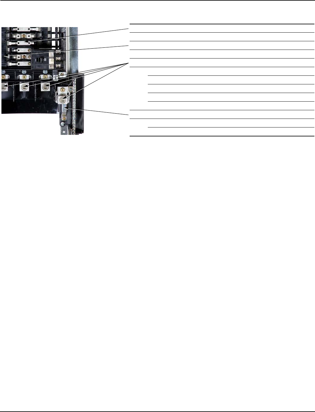
Replacement Parts 1640DB0803
Interior Parts 09/2008
© 2008 Schneider Electric All Rights Reserved2
Interior Parts
Deadfronts and Filler Plates
Main Lug Interiors For main lug interiors the entire deadfront is supplied as a replacement.
Individual components are not available. Hardware is shipped with the
deadfront. Deadfronts come without plastic filler plates. Filler plates are
available as NQFP15.
Branch Connectors1
1Kit includes two each A, B, and C phase and installation hardware.
NQ Branch Connectors SKNQBC
Bus covers2
2Depending on circuit count, various combinations of 6-circuit bus covers and 9-circuit bus covers are used in construction of an interior. This kit contains two (2) of each.
NQ Bus Cover Kit (all amperages) NQBCK
Aluminum Mechanical Main Lugs3
3Kit includes four lugs, insulators where required, and hardware.
100 A NQALM1
225 A NQALM2
400 A NQALM4
600 A NQALM6
600 A (3-cables per lug) NQALM6A
Neutral bonding provisions and hardware4
4Includes lugs and required screws.
100/225 80122-269-50
400/600 80122-270-50
230 of 292
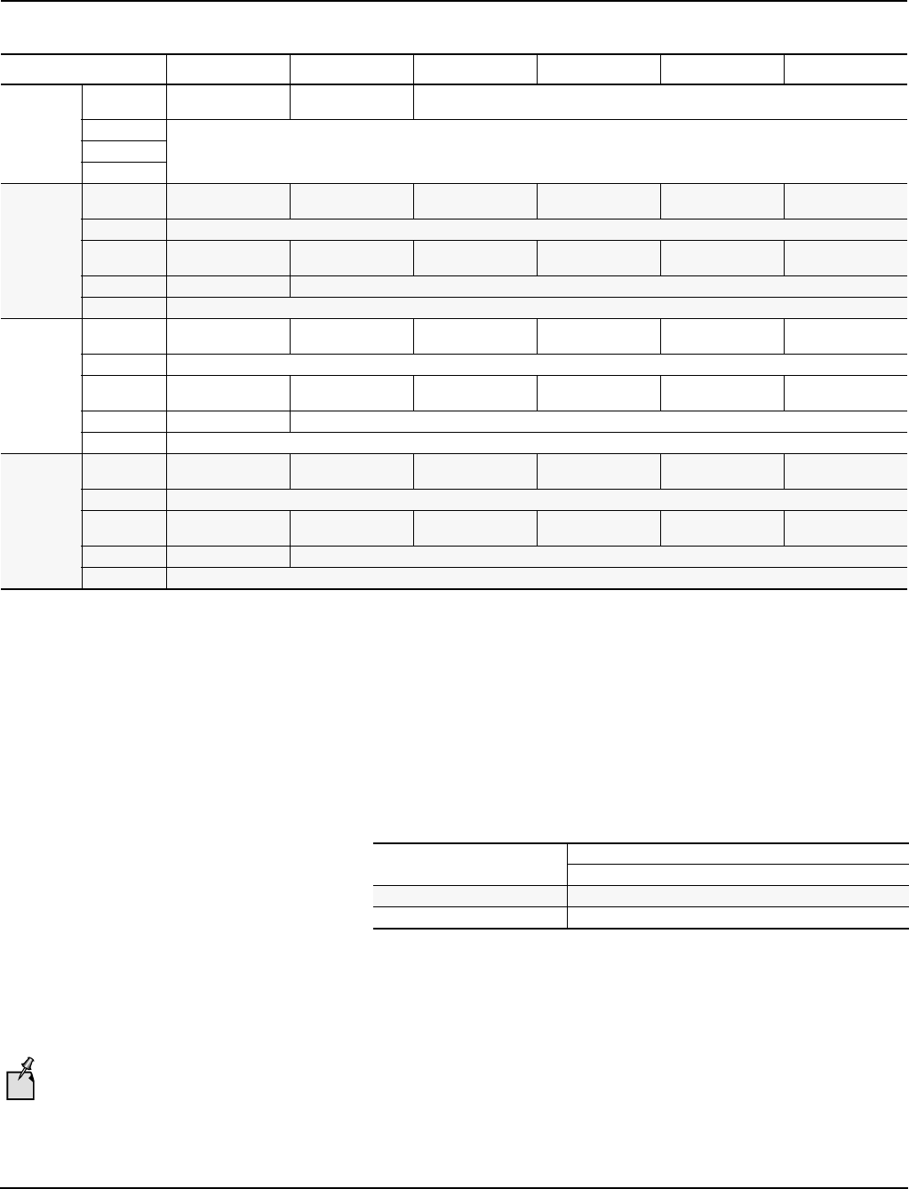
1640DB0803 Replacement Parts
09/2008 Deadfronts and Filler Plates
© 2008 Schneider Electric All Rights Reserved 3
Main Circuit Breaker Interiors For replacement of main circuit breaker interior deadfronts, only the main
breaker section of the deadfront is listed below. To order an entire main
circuit breaker interior deadfront, please order the appropriate Main Lug
Interior deadfront from the table above, and a Main Circuit Breaker Interior
deadfront from the table below.
Table 1: Replacement Deadfronts for Main Lug Interiors
Interior Pole Spaces 18 30 42 54 72 84
100 A
No Options NQRPL18L1
NQRPL418L1 NQRPL30L1
NQRPL430L1 N/A
With SFL
N/AWith FTL
With TVSS
225 A
No Options N/A NQRPL30L2
NQRPL430L2 NQRPL42L2
NQRPL442L2 NQRPL54L2
NQRPL454L2 NQRPL72L2
NQRPL472L2 NQRPL84L2
NQRPL484L2
With SFL N/A
With FTL N/A NQRPL30L2TFL
NQRPL430L2TFL NQRPL42L2TFL
NQRPL442L2TFL NQRPL54L2TFL
NQRPL454L2TFL NQRPL72L2TFL
NQRPL472L2TFL NQRPL84L2TFL
NQRPL484L2TFL
With SFB N/A NQRPLSFB2HJ or NQRPLSFB2Q
With TVSS N/A
400 A
No Options N/A NQRPL30L4
NQRPL430L4 NQRPL42L4
NQRPL442L4 NQRPL54L4
NQRPL454L4 NQRPL72L4
NQRPL472L4 NQRPL84L4
NQRPL484L4
With SFL N/A
With FTL N/A NQRPL30L4TFL
NQRPL430L4TFL NQRPL42L4TFL
NQRPL442L4TFL NQRPL54L4TFL
NQRPL454L4TFL NQRPL72L4TFL
NQRPL472L4TFL NQRPL84L4TFL
NQRPL484L4TFL
With SFB N/A NQRPLSFB6HJ or NQRPLSFB6Q
With TVSS N/A
600 A
No Options N/A NQRPL30L6
NQRPL430L6 NQRPL42L6
NQRPL442L6 NQRPL54L6
NQRPL454L6 NQRPL72L6
NQRPL472L6 NQRPL84L6
NQRPL484L6
With SFL N/A
With FTL N/A NQRPL30L6TFL
NQRPL430L6TFL NQRPL42L6TFL
NQRPL442L6TFL NQRPL54L6TFL
NQRPL454L6TFL NQRPL72L6TFL
NQRPL472L6TFL NQRPL84L6TFL
NQRPL484L6TFL
With SFB N/A NQRPLSFB6HJ or NQRPLSFB6Q
With TVSS N/A
Table 2: Replacement Main Circuit Breaker Deadfront Sections1
1These do not vary by circuit count.
100 A and 225 A NQRPLMB1F (for F-frame mains)
NQRPLMB2HJ (for H- and J-frame mains)
400 A NQRPLMB4LA (for LA/LH mains)
600 A Contact the Customer Information Center
For repairs not involving the service parts addressed in this document, please call the
Square D / Schneider Electric Customer Information Center:
In the USA, 1-888-SquareD (1-888-778-2733)
In Canada, 1-800-565-6699
231 of 292

Replacement Parts 1640DB0803
Data Bulletin 09/2008
1640DB0803 © 2008 Schneider Electric All Rights Reserved
Schneider Electric USA
252 North Tippecanoe
Peru, IN 46970 USA
1-888-SquareD
(1-888-778-2733)
www.schneider-electric.us
Schneider Electric Canada
19 Waterman Avenue,
M4B 1Y2
Toronto, Ontario
1-800-565-6699
www.schneider-electric.ca
09/2008
232 of 292
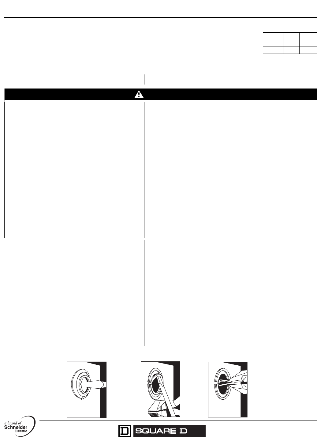
1
Instruction
Bulletin
Directives
d'utilisation
40905-002-02
09/2006
Lexington, KY, USA
30 A General Duty Safety Switches
Interrupteurs de sécurité universels de 30 A
Replaces / Remplace 40905-002-01 02/2003
Class
Classe
Type
Type
Series
Série
3130 1 E02
Retain for future use. / À conserver pour usage ultérieur.
PRECAUTIONS MESURES DE SÉCURITÉ
DANGER
HAZARD OF ELECTRIC SHOCK, EXPLOSION, OR
ARC FLASH
• Apply appropriate personal protective equipment
(PPE) and follow safe electrical work practices. See
NFPA 70E.
• This equipment must only be installed and serviced
by qualified electrical personnel.
• Never operate energized switch with door open.
• Turn off switch before removing or installing fuses or
making load side connections.
• Always use a properly rated voltage sensing device
at all line and load fuse clips to confirm switch is off.
• Turn off power supplying switch before doing any
other work on or inside switch.
• Do not use renewable link fuses in fused switches.
RISQUE D'ÉLECTROCUTION, D'EXPLOSION OU D'ÉCLAIR D'ARC
• Portez un équipement de protection personnelle (ÉPP) approprié et
observez les méthodes de travail électrique sécuritaire.
Voir NFPA 70E.
• Seul un personnel qualifié doit effectuer l'installation et l'entretien de
cet appareil.
• Ne faites jamais fonctionner l'interrupteur sous tension avec la porte
ouverte.
• Mettez l'interrupteur hors tension avant d'enlever ou d'installer des
fusibles ou de faire des raccordements sur le côté charge.
• Utilisez toujours un dispositif de détection de tension ayant une valeur
nominale appropriée sur tous les porte-fusibles du côté ligne et charge
pour s'assurer que l'interrupteur soit hors tension.
• Coupez l'alimentation de l'interrupteur avant d'y faire tout autre travail.
• N'utilisez pas de fusibles renouvelables dans les interrupteurs à
fusibles.
Failure to follow these instructions will result in
death or serious injury.
Si ces directives ne sont pas respectées, cela entraînera la mort
ou des blessures graves.
PREPARING THE ENCLOSURE PRÉPARATION DU COFFRET
1. Select the wire size for the line, load, and neutral
circuits. (Refer to the local codes.)
1. Sélectionner le calibre de fil pour les circuits de ligne, de charge et
du neutre (consulter les codes locaux).
2. Select the proper wire clamp or use other approved
methods to hold the wire to the enclosure wall.
2. Sélectionner le serre-fils approprié ou utiliser d'autres méthodes
autorisées pour maintenir le fil contre la paroi du coffret.
3. Remove only those knockouts required for
installation of the wire clamps or conduit.
3. Retirer les débouchures appropriées nécessaires pour
l'installation des serres-fils ou du conduit.
4. To remove knockouts, see Figure 1.
a. Drive center knockout inward.
b. Alternately drive in or pry up outer rings, one at a
time.
c. Remove all loose knockout slugs or rings and all
traces of metal shavings within the enclosure.
4. Pour retirer les débouchures, voir la figure 1.
a. Pousser la débouchure centrale vers l'intérieur.
b. Pousser ou relever alternativement les anneaux extérieurs, un
par un.
c. Retirer du coffret les chutes de débouchures ou anneaux et
toutes traces de rognures métalliques.
Figure / Figure 1 : Removing the Knockouts / Retrait des débouchures
233 of 292
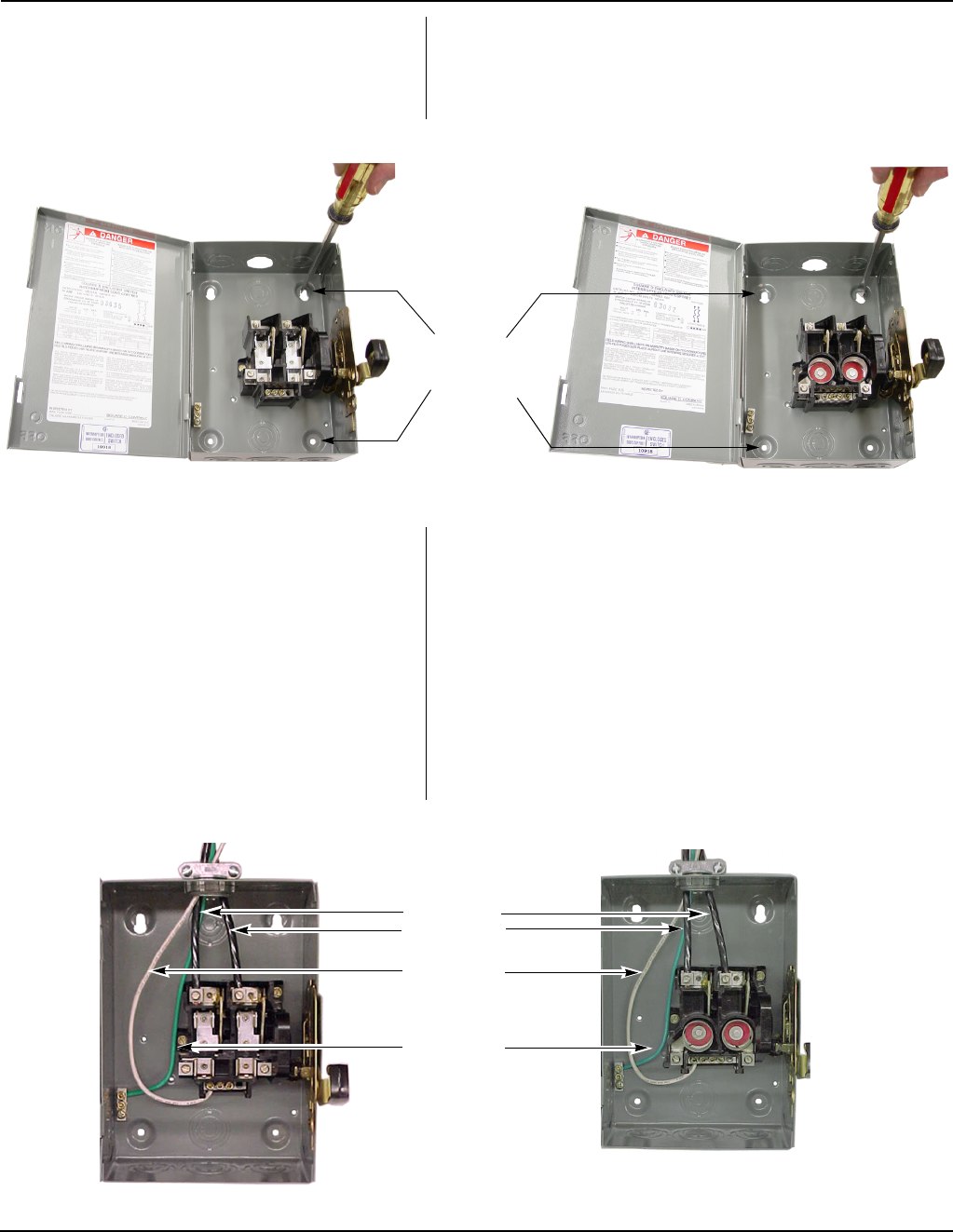
30 A General Duty Safety Switches 40905-002-02
Interrupteurs de sécurité universels de 30 A 09/2006
© 2006 Schneider Electric All Rights Reserved / Tous droits réservés2
INSTALLING THE SWITCH INSTALLATION DE L'INTERRUPTEUR
1. Mount the switch to the wall with screws or nails.
Use the precut holes in the back of the enclosure.
See Figure 2.
1. Monter l'interrupteur sur le mur à l'aide de vis ou de clous. Utiliser
les trous pré-découpés à l'arrière du coffret. Voir la figure 2.
Figure / Figure 2 : Mounting the Switch / Montage de l’interrupteur
2. Pull the conductors into the enclosure. 2. Tirer les conducteurs à l'intérieur du coffret.
NOTE: To avoid damage to the conductor insulation, use
approved wire clamps, conduit, and bushings, or other
methods approved for this purpose.
REMARQUE : Pour éviter d'abîmer l'isolation des conducteurs, utiliser
des serre-fils, conduits et traversées approuvés, ou d'autres méthodes
autorisées pour ce faire.
3. Following the wiring diagram on the cover, install the
main and neutral wires. If the equipment ground
wire (green wire or bare copper) is used, install the
wire in the ground connector on the enclosure. See
Figure 3.
3. En suivant le schéma de câblage sur le couvercle, installer les fils
principaux et de neutre. Si le fil de m.à.l.t. des appareils (fil vert ou
de cuivre à nu) est utilisé, installer le fil dans le connecteur de
terre du coffret. Voir la figure 3.
4. Torque all the wire binding screws per the
instructions provided on the enclosure wiring
diagram.
4. Serrer toutes les vis de fixation des fils selon les directives
fournies sur le schéma de câblage du coffret.
Figure / Figure 3 : Wiring the Switch / Câblage de l'interrupteur
Pre-cut holes
(4 total) /
Trous pré-
découpés
(4 au total)
Cartridge Fuse Switch / Interrupteur à fusibles à cartouche Plug Fuse Switch / Interrupteur à fusibles vissés
Equipment
grounding wire /
Fil de m.à.l.t. des
appareils
Main wires /
Fils principaux
Cartridge Fuse Switch / Interrupteur à fusibles à cartouche Plug Fuse Switch / Interrupteur à fusibles vissés
Neutral wire /
Fil du neutre
234 of 292
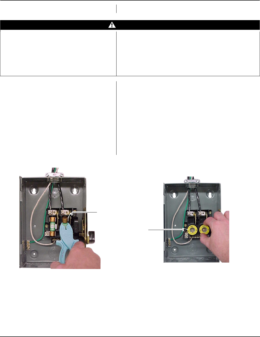
40905-002-02 30 A General Duty Safety Switches
09/2006 Interrupteurs de sécurité universels de 30 A
© 2006 Schneider Electric All Rights Reserved / Tous droits réservés 3
INSTALLING THE FUSES INSTALLATION DES FUSIBLES
DANGER
HAZARD OF ELECTRIC SHOCK, EXPLOSION, OR
ARC FLASH
• Turn off power supplying switch before installing or
replacing fuses.
• Close cover before turning on power.
RISQUE D'ÉLECTROCUTION, D'EXPLOSION OU D'ÉCLAIR D'ARC
• Coupez l'alimentation de l'interrupteur avant d'installer ou de
remplacer les fusibles.
• Fermez le couvercle avant de mettre sous tension.
Failure to follow these instructions will result in
death or serious injury.
Si ces directives ne sont pas respectées, cela entraînera la mort
ou des blessures graves.
1. Turn the switch OFF (O). 1. Mettre l'interrupteur hors tension (OFF).
2. Open the cover. 2. Ouvrir le couvercle.
3. Install the fuses. See Figure 4. 3. Installer les fusibles. Voir la figure 4.
4. Mark the maximum replacement fuse size on the
label inside the door.
4. Marquer le calibre maximum des fusibles de rechange sur
l'étiquette à l'intérieur de la porte.
5. Exercise the operating mechanism to ensure proper
operation. This is done by opening and closing the
switch several times. The mechanism should be
exercised at least once a year.
5. Manœuvrer le mécanisme de fonctionnement pour s'assurer de
son bon fonctionnement. Cela s'effectue en ouvrant et fermant
l'interrupteur plusieurs fois. Le mécanisme doit être manœuvré au
moins une fois par an.
NOTE: Ensure that the fuse clips are not damaged
during fuse removal or replacement.
REMARQUE : S'assurer que les porte-fusibles ne sont pas
endommagés pendant le retrait ou le remplacement des fusibles.
Figure / Figure 4 : Installing the Fuses / Installation des fusibles
Cartridge Fuse Switch / Interrupteur à fusibles à cartouche Plug Fuse Switch / Interrupteur à fusibles vissés
Cartridge fuse /
Fusible à cartouche
Plug fuse /
Fusible vissé
235 of 292

30 A General Duty Safety Switches 40905-002-02
Interrupteurs de sécurité universels de 30 A 09/2006
Electrical equipment should be installed, operated, serviced, and
maintained only by qualified personnel. No responsibility is assumed by
Schneider Electric for any consequences arising out of the use of this
material.
Seul un personnel qualifié doit effectuer l’installation, l’utilisation, l’entretien et la
maintenance du matériel électrique. Schneider Electric n’assume aucune responsabilité
des conséquences éventuelles découlant de l’utilisation de cette documentation.
Schneider Electric USA
1601 Mercer Road
Lexington, KY 40511 USA
1-888-SquareD (1-888-778-2733)
www.us.SquareD.com
Schneider Electric Canada
19 Waterman Avenue, M4B 1 Y2
Toronto, Ontario
1-800-565-6699
www.schneider-electric.ca
Square D, a brand of Schneider Electric / une marque de Schneider Electric
© 2006 Schneider Electric All Rights Reserved / Tous droits réservés
4
ENERGIZING THE SWITCH MISE DE L'INTERRUPTEUR SOUS TENSION
1. Close the cover. 1. Fermer le couvercle.
2. Turn OFF (O) the switch. 2. Mettre l'interrupteur hors tension (O).
3. Turn OFF (O) all of the downstream loads. 3. Mettre hors tension (O) toutes les charges en aval.
4. Turn ON (I) the power to the equipment in
sequence; start at the source end of the system and
work toward the load end.
4. Mettre les appareils sous tension (I) l'un après l'autre; commencer
par l'extrémité source du système et continuer vers l'extrémité
charge.
236 of 292
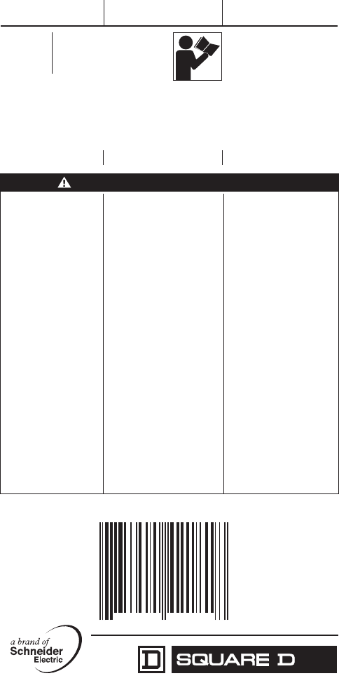
Square D, a brand of Schneider Electric. / una marca de Schneider Electric. /
une marque de Schneider Electric.
Instruction
Bulletin Boletín de
instrucciones Directives
d'utilisation
Series
Serie
Série
F01
Replaces
Reemplaza
Remplace
40272-266-03 11/2006
40272-266-04
05/2007
Lexington, KY, USA
GTK03 Equipment Grounding Bar Kit
Accesorio de barra de puesta a tierra del equipo
Kit de barre de m.à.l.t. de l’appareil
Retain for future use. / Conservar para uso futuro. / À conserver pour usage ultérieur.
Precautions Precauciones Précautions
DANGER / PELIGRO / DANGER
HAZARD OF ELECTRIC
SHOCK, EXPLOSION,
OR ARC FLASH
• Apply appropriate
personal protective
equipment (PPE) and
follow safe electrical
work practices. See
NFPA 70E.
• This equipment must
only be installed and
serviced by qualified
electrical personnel.
• Turn off all power
supplying this equipment
before working on or
inside equipment.
• Always use a properly
rated voltage sensing
device to confirm power
is off.
• Replace all devices,
doors and covers
before turning on power
to this equipment.
PELIGRO DE DESCARGA
ELÉCTRICA, EXPLOSIÓN O
DESTELLO POR ARQUEO
• Utilice equipo de protección
personal (EPP) apropiado y
siga las prácticas de
seguridad eléctrica
establecidas por su
Compañía, consulte la norma
NFPA 70E.
• Solamente el personal
eléctrico especializado
deberá instalar y prestar
servicio de mantenimiento a
este equipo.
• Desenergice el equipo antes
de realizar cualquier trabajo
en él.
• Siempre utilice un dispositivo
detector de tensión nominal
adecuado para confirmar la
desenergización del equipo.
• Vuelva a colocar todos los
dispositivos, las puertas y
las cubiertas antes de volver
a energizar el equipo.
RISQUE
D'ÉLECTROCUTION,
D'EXPLOSION OU
D’ÉCLAIR D’ARC
• Portez un équipement de
protection personnel (ÉPP)
approprié et observez les
méthodes de travail
électrique sécuritaire. Voir
NFPA 70E.
• Seul un personnel qualifié
doit effectuer l'installation
et l'entretien de cet
appareil.
• Coupez l'alimentation de
l'appareil avant d'y
travailler.
• Utilisez toujours un dispositif
de détection de tension à
valeur nominale appropriée
pour s'assurer que
l'alimentation est coupée.
• Replacez tous les
dispositifs, les portes et les
couvercles avant de mettre
l'appareil sous tension.
Failure to follow these
instructions will result
in death or serious
injury.
El incumplimiento de estas
instrucciones podrá causar
la muerte o lesiones serias.
Si ces directives ne sont
pas respectées, cela
entraînera la mort ou des
blessures graves.
7
85901 42181
8
42181
237 of 292

Made in USA Hecho en EUA Fabriqué aux É.-U.
Electrical equipment should be installed, operated, serviced, and maintained only by qualified
personnel. No responsibility is assumed by Schneider Electric for any consequences arising
out of the use of this material.
Solamente el personal especializado deberá instalar, hacer funcionar y prestar servicios de
mantenimiento al equipo eléctrico. Schneider Electric no asume responsabilidad alguna por
las consecuencias emergentes de la utilización de este material.
Seul un personnel qualifié doit effectuer l’installation, l’utilisation, l’entretien et la
maintenance du matériel électrique. Schneider Electric n’assume aucune responsabilité
des conséquences éventuelles découlant de l’utilisation de cette documentation.
Schneider Electric USA
1601 Mercer Road
Lexington, KY 40511 USA
1-888-778-2733
www.us.SquareD.com
40272-266-04
Importado en México por:
Schneider Electric México,
S.A. de C.V.
Calz. J. Rojo Gómez 1121-A
Col. Gpe. del Moral 09300
México, D.F.
Tel. 55-5804-5000
www.schneider-electric.com.mx
Schneider Electric Canada
19 Waterman Avenue,
M4B 1 Y2
Toronto, Ontario
1-800-565-6699
www.schneider-electric.ca
© 2006–2007 Schneider Electric
All Rights Reserved / Reservados todos los derechos / Tous droits réservés
Contents Contenido Contenu
1 Grounding Bar
1 Mounting Screw
1 Equipment Grounding
Label
1 barra de puesta a tierra
1 tornillo de montaje
1 etiqueta de puesta a tierra
del equipo
1 barre de m.à.l.t.
1 vis de montage
1 étiquette de m.à.l.t. de
l’appareil
Installation Instalación Installation
1. Turn off all power
supplying the
equipment where kit
will be installed.
1. Desenergice el gabinete
en el que se instalará este
accesorio.
1. Couper l’alimentation vers
le coffret sur lequel ce kit
doit être installé.
NOTE: Three mounting
locations are provided on
bottom of enclosure,
adjacent to ground
symbol.
2. Mount grounding bar to
bottom of enclosure ,
using mounting screw.
NOTA: Se proporcionan tres
ubicaciones de montaje en la
parte inferior del gabinete,
adyacentes al símbolo de
tierra.
2. Monte la barra de puesta a
tierra en la parte inferior del
gabinete, utilizando el
tornillo de montaje.
REMARQUE : Trois
emplacements de montage
sont fournis au fond du
coffret, à côté du symbole de
m.à.l.t.
2. Monter la barre de m.à.l.t.
au fond du coffret, à l’aide
de la vis de montage.
3. Tighten mounting
screw to 20 lb-in.
(2.3 N•m) after
overcoming starting
torque.
3. Apriete el tornillo de
montaje a 2,3 N•m
(20 lbs-pulg) una vez
realizado el apriete inicial.
3. Serrer la vis de montage á
2,3 N•m (20 lb-po) après
le serrage de départ.
4. Apply equipment
grounding label to
enclosure beside
grounding bar.
4. Adhiera la etiqueta de
puesta a tierra del equipo
al gabinete, junto a la
barra de puesta a tierra.
4. Placer l'étiquette de
m.à.l.t. de l'appareil sur le
coffret, à côté de la barre
de m.à.l.t.
5. Install wiring to
grounding bar. See
equipment grounding
label for wire size and
binding screw torque.
5. Instale los cables en la
barra de puesta a tierra.
Consulte la etiqueta de
puesta a tierra del equipo
para obtenir el tamaña de
los conductores y el valor
de par de apriete del
tornillos de sujeción.
5. Installer le câblage sur la
barre de m.à.l.t. Consulter
l'étiquette de m.à.l.t. de
l'appareil pour obtenir le
calibre des fils ainsi que le
couple de serrage de la vis
de fixation.
238 of 292
a brand of Schneider Electric. / una marca de Schneider Electric. /
une marque de Schneider Electric.
PKOGTA2 Service / Equipment Grounding Lug
Barra de puesta a tierra del equipo / tierra de
acometida
Barre de m.à.l.t. de l'apparei / m.à.l.t. de service
Instruction
Bulletin Boletín de
instrucciones Directives
d'utilisation
Series A01
Serie A01
Série A01
Replaces
Reemplaza
Remplace
40272-068-01
11/1996
40272-068-02
05/2007
Lexington, KY, USA
Retain for future use. / Conservar para uso futuro. / À conserver pour usage ultérieur.
DANGER / PELIGRO / DANGER
HAZARD OF ELECTRIC
SHOCK, EXPLOSION,
OR ARC FLASH
• Apply appropriate
personal protective
equipment (PPE) and
follow safe electrical
work practices. See
NFPA 70E.
• This equipment must
only be installed and
serviced by qualified
electrical personnel.
• Turn off all power
supplying this equipment
before working on or
inside equipment.
• Always use a properly
rated voltage sensing
device to confirm power
is off.
• Replace all devices,
doors and covers before
turning on power to this
equipment.
PELIGRO DE DESCARGA
ELÉCTRICA, EXPLOSIÓN O
DESTELLO POR ARQUEO
• Utilice equipo de protección
personal (EPP) apropiado y
siga las prácticas de
seguridad eléctrica
establecidas por su
Compañía, consulte la
norma 70E de NFPA.
• Solamente el personal
eléctrico especializado
deberá instalar y prestar
servicio de mantenimiento a
este equipo.
• Desenergice el equipo antes
de realizar cualquier trabajo
en él.
• Siempre utilice un dispositivo
detector de tensión nominal
adecuado para confirmar la
desenergización del equipo.
• Vuelva a colocar todos los
dispositivos, las puertas y
las cubiertas antes de
volver a energizar el equipo.
RISQUE D’ÉLECTROCUTION,
D’EXPLOSION OU D’ÉCLAIR
D’ARC
• Portez un équipement de
protection personnelle
(ÉPP) approprié et
observez les méthodes de
travail élecrique sécuritaire.
Voir NFPA 70E.
• Seul un personnel qualifié
doit effectuer l’installation et
l’entretien de cet appareil.
• Coupez l'alimentation de
l'appareil avant d'y travailler.
• Utilisez toujours un dispositif
de détection de tension
ayant une valeur nominale
appropriée pour vous
assurer que l'alimentation
est coupée.
• Replacez tous les
dispositifs, les portes et les
couvercles avant de mettre
l'appareil sous tension.
Failure to follow these
instructions will result in
death or serious injury.
El incumplimiento de estas
instrucciones podrá causar
la muerte o lesiones serias.
Si ces directives ne sont
pas respectées, cela
entraînera la mort ou des
blessures graves.
785901 43267 8
43267
239 of 292

Made in USA Hecho en EUA Fabriqué aux É.-U.
Electrical equipment should be installed, operated, serviced, and maintained only by qualified
personnel. No responsibility is assumed by Schneider Electric for any consequences arising
out of the use of this material.
Solamente el personal especializado deberá instalar, hacer funcionar y prestar servicios de
mantenimiento al equipo eléctrico. Schneider Electric no asume responsabilidad alguna por
las consecuencias emergentes de la utilización de este material.
Seul un personnel qualifié doit effectuer l’installation, l’utilisation, l’entretien et la
maintenance du matériel électrique. Schneider Electric n’assume aucune responsabilité
des conséquences éventuelles découlant de l’utilisation de cette documentation.
Schneider Electric USA
1601 Mercer Road
Lexington, KY 40511 USA
(1-888-778-2733)
www.us.SquareD.com
Importado en México por:
Schneider Electric México,
S.A. de C.V.
Calz. J. Rojo Gómez 1121-A
Col. Gpe. del Moral 09300
México, D.F.
Tel. 55-5804-5000
www.schneider-electric.com.mx
Schneider Electric Canada
19 Waterman Avenue,
M4B 1 Y2
Toronto, Ontario
1-800-565-6699
www.schneider-electric.ca
© 2007 Schneider Electric
All Rights Reserved / Reservados todos los derechos / Tous droits réservés
40272-068-02
Contents Contenido Contenu
2 Lugs
1 Mounting screw
2 Labels
2 Zapatas
1 Tornillo de montaje
2 Etiquetas
2 Cosses
1 Vis de montage
2 Étiquettes
Mounting Montaje Montage
1. Turn off all power
supplying this equipment
before working on or
inside equipment.
1. Desenergice el equipo
antes de realizar cualquier
trabajo en él.
1. Couper l'alimentation de
cet appareil avant d'y
travailler.
2. Mount lugs to back of
box where hole is
provided.
2. Monte las zapatas en la
parte posterior de la caja
en el agujero provisto.
2. Monter les cosses sur
l'arrière du coffret en
utilisant le trou fourni.
3. Torque mounting lug
screw to 25–45 lb-in.
(2.8–5.0 N•m).
3. Apriete el tornillo de
montaje de la zapata de
2,8 a 5,0 N•m (25 a 45 lbs-
pulg).
3. Serrer la vis de montage
de la cosse entre 2,8 et
5,0 N•m (25 et 45 lb-po).
NOTE: When used for
equipment grounding,
place marker “Equipment
Grounding Terminal” near
lugs after installation.
Attach torque label to box
adjacent to grounding
lugs.
NOTA: Cuando se utiliza
como puesta a tierra del
equipo, coloque la etiqueta
"terminal de puesta a tierra
del equipo" junto a las
zapatas después de la
instalación. Adhiera la
etiqueta de par de apriete en
la caja junto a las zapatas de
tierra.
REMARQUE : Lorsqu'il est
utilisé comme m.à.l.t. de
l'appareil, placer le repère
" Borne de m.à.l.t. de
l'appareil " près des cosses
après l'installation. Fixer
l'étiquette de couple de
serrage adjacent aux cosses
de m.à.l.t.
240 of 292

QO® and QOB Miniature Circuit
Breakers
Catalog
0730CT9801R1/08
2008
Class 730
CONTENTS
Description . . . . . . . . . . . . . . . . . . . . . . . . . . . . . . . . . . . . . . . . . . . . . Page
General Information . . . . . . . . . . . . . . . . . . . . . . . . . . . . . . . . . . . . . . Page 3
Special Application Circuit Breakers. . . . . . . . . . . . . . . . . . . . . . . . . . Page 7
Accessories . . . . . . . . . . . . . . . . . . . . . . . . . . . . . . . . . . . . . . . . . . . Page 15
Trip Curves. . . . . . . . . . . . . . . . . . . . . . . . . . . . . . . . . . . . . . . . . . . . Page 19
Dimensions. . . . . . . . . . . . . . . . . . . . . . . . . . . . . . . . . . . . . . . . . . . . Page 36
241 of 292
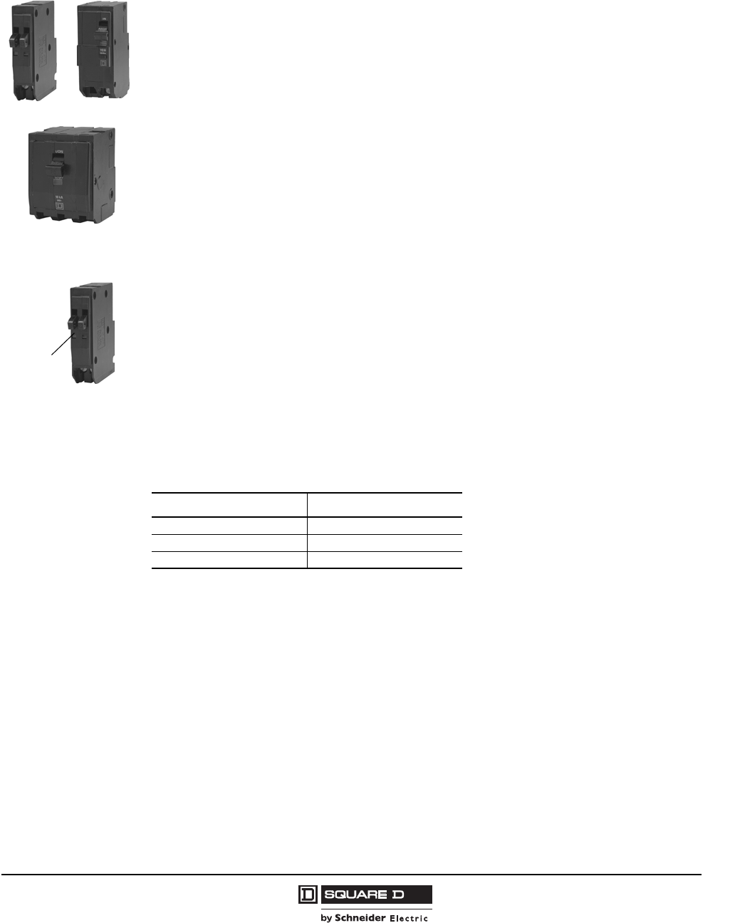
QO® and QOB Miniature Circuit Breakers
General Information
3
07/2008
© 1998–2008 Schneider Electric
All Rights Reserved
General Information
QO® and QOB Circuit Breakers
QO® (plug-on) and QOB (bolt-on) one-, two- and three-pole thermal-magnetic circuit breakers provide
overcurrent protection and switching on ac and dc systems. Plug-on QO circuit breakers are for use in
QO load centers, NQ and NQOD panelboards, OEM mounting bases, and Speed-D®switchboard
distribution panels. Bolt-on QOB circuit breakers are for use in NQO and NQOD panelboards.
Operating mechanism
QO and QOB circuit breakers have an overcenter, trip-free toggle mechanism with quick-make, quick-
break action and positive handle indication. The tripping mechanisms in two-and three-pole circuit
breakers operate such that an overcurrent on any pole of the circuit breaker will cause all poles of the
circuit breaker to open simultaneously. Each pole has an individual thermal-magnetic trip element
calibrated for 40°C ambient temperature.
Trip Indication
QO and QOB circuit breakers have Visi-Trip® trip indication, which provides a visual indication that the
circuit breaker has tripped and interrupted the circuit. When the circuit breaker has tripped, the handle
assumes a center position and the red Visi-Trip indicator appears in a window in the circuit breaker
case. The Visi-Trip indicator is only visible when the circuit breaker has tripped. Trip indication
immediately distinguishes the circuit from any other circuit which is merely in the on or off position. The
circuit breaker can be reset by pushing the handle to OFF and then to ON.
Construction Standards
QO and QOB circuit breakers are built to comply with UL Standard 489, CSA 22.2 No. 5, NOM/ANCE
and NEMA Standard AB1 and to meet Federal Specification W-C-375B/GEN. QO circuit breakers are
UL Listed under UL File E84967 and are CSA Certified under CSA Master Contract 153555.
1 Pole
07303095
2 Pole
07303090
3 Pole
07303091
QO Circuit Breakers
Visi-Trip®
Window
07303095
QO Circuit Breaker UL Type
QO280–QO210 QOA, QOB
QO2110–QO2125 QOC, QOCB
QO2150–QO2200 QOC (no bolt-on version)
242 of 292

© 1998–2008 Schneider Electric
All Rights Reserved
QO® and QOB Miniature Circuit Breakers
General Information
4
07/2008
Ratings
When designing an electrical distribution system, overcurrent protective devices are generally selected
based on performance requirements. Factors influencing this selection include system voltage,
continuous current, interrupting rating, and frequency.
Voltage Rating
The circuit breaker must have a voltage rating greater than, or equal to, the system voltage. When a
circuit breaker clears an overcurrent, it is done in two steps. First, the current sensing system identifies
the overcurrent and releases the tripping mechanism. This results in a parting of the contacts. The
circuit breaker must then extinguish the voltage arc across the contacts. If the circuit breaker has the
correct voltage rating, it can efficiently extinguish this voltage arc. QO and QOB circuit breakers are
rated for use in the following voltage systems:
•120 Vac
•208/120 Vac
•120/240 Vac
•240 Vac
•48 Vdc (10–70 A for 1 and 2 pole circuit breakers, 10–60 A for 3 pole circuit breakers)
Continuous Current Rating
The continuous current rating of a circuit breaker is the maximum current in amperes (dc or rms ac at
rated frequency) which a device will carry continuously without exceeding the specified allowable
temperature rise. Sometimes referred to as the ampere rating or handle rating of the circuit breaker,
the continuous current rating relates to the system current flow under normal conditions.
UL and CSA require that circuit breakers must be able to carry their continuous current rating
indefinitely at 40°C in free air in order to achieve a UL Listing/CSA Certification. The National Electrical
Code (NEC) and the Canadian Electrical Code (CEC) recognize that devices applied in end-use
equipment can be affected by heat build up during normal operating conditions. For this reason, the
codes require that circuit breakers be selected based on the characteristics of the load (particularly,
the portion of the load which will be on continuously for three hours or more at a time).
Frequency Rating
The standard rated frequency for circuit breakers is 60 Hz. Circuit breakers are also rated for dc
applications as shown in Table 1. Many Square D circuit breakers can also be applied on 50 Hz systems
without derating. GFCI, AFCI and EPD devices are rated for 60 Hz operation only. Frequencies can affect
the thermal, magnetic and short-circuit characteristics of circuit breakers. See Data Bulletin 0100DB0101
Determining Current Carrying Capacity in Special Applications. Contact the Field Sales office before
applying circuit breakers on systems at frequencies other than 50/60 Hz.
243 of 292
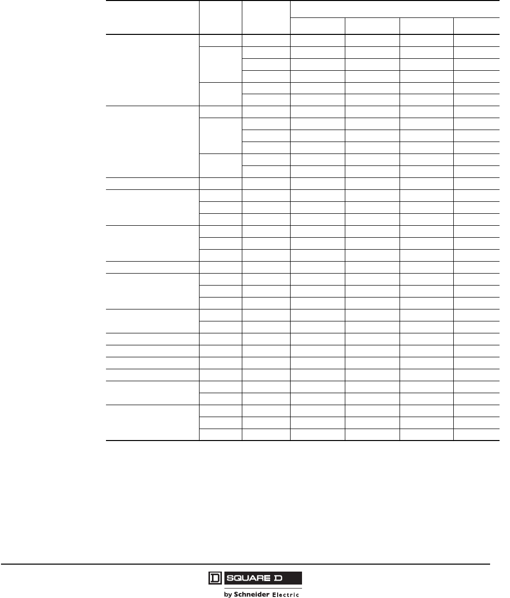
QO® and QOB Miniature Circuit Breakers
General Information
5
07/2008
© 1998–2008 Schneider Electric
All Rights Reserved
Interrupting Rating
The interrupting rating of a circuit breaker is the highest current at rated voltage that the circuit breaker
is intended to interrupt under standard test conditions. A circuit breaker must be chosen so that the
interrupting rating is equal to or greater than the maximum available short-circuit current at the point
where the circuit breaker is applied in the system.
DC Voltage Rating
QO and QOB circuit breakers are available with a UL Listed 48 Vdc rating. See Table 1. Refer to
Square D Data Bulletin 0601DB0401 for additional information on dc-rated circuit breakers.
Table 1: Interrupting Ratings
Circuit Breaker Type Number
of Poles
Ampere
Rating
UL Listed Interrupting Rating1
110 kA and 5 kA are 1Ø-3Ø.
120 Vac 120/240 Vac 240 Vac 48 Vdc2
2DC ratings do not apply to circuit breakers rated 10 A.
QO
1 10–70 A 10 kA 10 kA — 5 kA
2
10–70 A 10 kA 10 kA 10 kA 5 kA
80–100 A 10 kA 10 kA 10 kA —
110—200 A 10 kA 10 kA — —
315–60 A 10 kA 10 kA 10 kA 5 kA
70–100 A 10 kA 10 kA 10 kA —
QOB
1 10–70 A 10 kA 10 kA — 5 kA
2
10–70 A 10 kA 10 kA 10 kA 5 kA
80–100 A 10 kA 10 kA 10 kA —
110—125 A 10 kA 10 kA — —
315–60 A 10 kA 10 kA 10 kA 5 kA
70–100 A 10 kA 10 kA 10 kA —
QO-H, QOB-H 2 15–100 A 10 kA3
3UL Listed 5,000 AIR on 3Ø grounded B-Phase Delta system.
10 kA310 kA3—
QO-VH
1 15–30 A 22 kA 22 kA — —
2 15–200 A 22 kA 22 kA — —
3 15–100 A 22 kA 22 kA 22 kA —
QOB-VH
1 15–30 A 22 kA 22 kA — —
2 15–125 A 22 kA 22 kA — —
3 15–150 A 22 kA 22 kA 22 kA —
QOH 1 40–125 A 42 kA 42 kA — —
QH, QHB
1 15–30 A 65 kA 65 kA — —
2 15–30 A 65 kA 65 kA — —
3 15–30 A 65 kA 65 kA 65 kA —
QO-GFI, QOB-GFI 1 15–30 A 10 kA — — —
2 15–60 A 10 kA 10 kA — —
QO-VHGFI, QOB-GFI 1 15–30 A 22 kA — — —
QO-AFI, QOB-AFI 1 15–30 A 10 kA — — —
QO-CAFI, QOB-CAFI 1 15–30 A 10 kA — — —
QO-VHCAFI, QOB-VHCAFI 1 15–30 A 22 kA — — —
QO-EPD, QOB-EPD 1 15–30 A 10 kA — — —
2 15–60 A 10 kA 10 kA — —
QO-PL
1 15–30 A 10 kA 10 kA 10 kA —
2 15–30 A 10 kA 10 kA 10 kA —
3 15–30 A 10 kA 10 kA 10 kA —
244 of 292
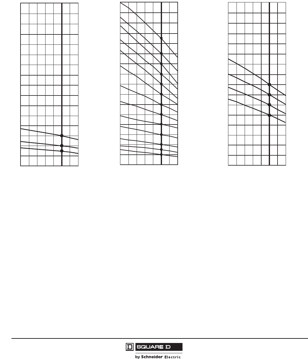
© 1998–2008 Schneider Electric
All Rights Reserved
QO® and QOB Miniature Circuit Breakers
General Information
6
07/2008
Temperature Rating
To meet the requirements of Underwriters Laboratories Standard 489, molded case circuit breakers
are designed, built, and calibrated for us on 60 Hz ac systems in 40°C (104°F) ambient temperature.
When applied at ambient temperatures other than 40°C, the current-carrying capacity and/or trip
charasteristics of the circuit breaker may vary.
IEC Rating
IEC rated QO circuit breakers are available. For further information contact the Field Sales office.
Terminology
HACR
HACR is a term used to designate circuit breakers which have been certified to be used on multi-motor
and combination loads such as are found in heating, air conditioning and refrigeration equipment. QO
circuit breakers meet the UL requirements for HACR circuit breakers and are suitable for group motor
applications requiring HACR listing.
This means that QO and QOB circuit breakers meet the code requirements that HACR circuit breaker
must be of the inverse time type and be approved for group installation. QO and QOB circuit breakers,
except for GFI, AFI and EPD, are Listed with UL as HACR Type and are labeled accordingly.
Figure 1: Ambient Rerating Curves
10
20
30
40
50
60
Current Carrying Capacity (A)
30 A
20 A
15 A
-10
(14)
0
(32)
20
(68)
40
(104)
60
(140)
Ambient Temperature ˚C
(˚F)
QOT Circuit Breakers
Circuit Breaker Handle Rating
10
20
30
40
50
60
70
80
90
100
110
120
130
140
150
160
Current Carrying Capacity (A)
100 A
90 A
80 A
70 A
15 A
10 A
30 A
20 A
40 A
60 A
50 A
110 A
125 A
-10
(14)
0
(32)
20
(68)
40
(104)
60
(140)
Ambient Temperature ˚C
(˚F)
QO, QOB Circuit Breakers
Circuit Breaker Handle Rating
25
50
75
100
125
150
175
200
225
250
275
Current Carrying Capacity (A)
200 A
175 A
150 A
125 A
-10
(14)
0
(32)
20
(68)
40
(104)
60
(140)
Ambient Temperature ˚C
(˚F)
Circuit Breaker Handle Rating
QE Circuit Breakers
245 of 292
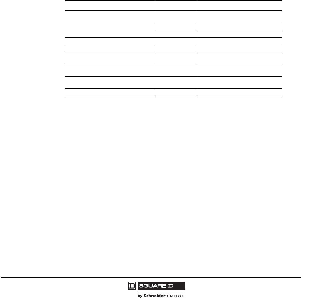
QO® and QOB Miniature Circuit Breakers
Special Application Circuit Breakers
7
07/2008
© 1998–2008 Schneider Electric
All Rights Reserved
Switching Duty (SWD) Circuit Breakers
QO and QOB circuit breakers are suitable for switching 120 Vac fluorescent lighting loads. The
switching duty (SWD) listing applies only to one-pole 15 and 20 A circuit breakers rated at 347 Vac or
less. The circuit breakers are subjected to specified temperature rise tests at predetermined periods
during the endurance operations.
Terminations
The 10–30 A circuit breakers have pressure plate terminals suitable for single or two-wire terminations.
Copper or aluminum conductors may be used as outlined in Table 2. QO-GFI 15–30 A and QO-AFI
circuit breakers have pressure plate terminals suitable for single-wire terminations. These circuit
breakers are suitable for use with 60°C or 75°C conductors.
The QO 35–200 A and all QO-PL and QOT tandem circuit breakers have box-type lugs suitable for
single-wire terminations. These circuit breakers are suitable for use with 75°C conductors.
Special Application Circuit Breakers
There are several special application circuit breakers in the QO family:
•QO-HM and QOB-HM High-Magnetic Circuit Breakers
•QO-HID and QOB-HID Circuit Breakers
•QO and QOB Miniature Switches
•QOK and QOBK Key-Operated Circuit Breakers
•QO-GFI and QOB-GFI Qwik-Gard® Circuit Breakers
•QO-EPD and QOB-EPD Equipment Protection Devices
•QO-SWN and QOB-SWN Switch Neutral Circuit Breakers
•QOT Tandem Circuit Breakers
•QO-PL and QOB-PL Powerlink® Circuit Breakers
•QO-AFI and QOB-AFI Branch Feeder Arc-Fault Circuit Interrupters (AFCI)
•QO-CAFI, QOB-CAFI Combination Arc-Fault Circuit Interrupters (AFCI)
This following sections describe the special application circuit breakers and provides application
information for their use.
Table 2: Terminations
Circuit Breaker Types Rating Wire Size
QO, QOB, QO-VH, QOB-VH
10–30 A (1) 14–8 AWG (1.5–3.3 mm2) Al/Cu
(2) 14–10 AWG (1.5–2.6 mm2) Cu
35–70 A (1) 8–2 AWG (3.3–6.5 mm2) Al/Cu
80–125 A (1) 4–2/0 AWG (5.2–9.3 mm2) Al/Cu
QO, QOB, QO-VH 150–200 A (1) 4 AWG–300 kcmil (5.2–50 mm2) Al/Cu
QOB-VH 110–175 A (1) 4 AWG–300 kcmil (5.2–50 mm2) Al/Cu
QOT 15–20 A (1) 12–8 AWG (2.0–3.3 mm2) Al
(1) 14–8 AWG (1.6–3.3 mm2) Cu
QO-CAFI, QO-AFI, QO-GFI, QO-EPD,
QOB-CAFI, QOB-AFI, QOB-GFI, QOB-EPD 15–30 A (1) 12–8 AWG (2.0–3.3 mm2) Al
(1) 14–8 AWG (1.6–3.3 mm2) Cu
QO-GFI, QO-EPD,
QOB-GFI, QOB-EPD 40–60 A (1) 12–4 AWG (2.0–4.1 mm2) Al
(1) 14–6 AWG (1.6–4.1 mm2) Cu
QO-PL 10–60 A (1) 12–2 AWG (2.0–6.5 mm2) Al
246 of 292
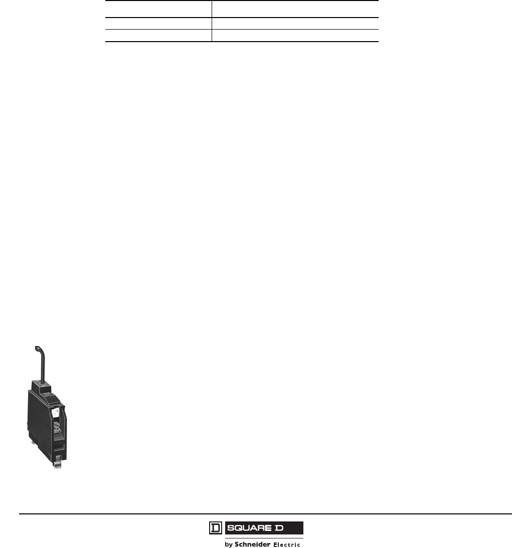
© 1998–2008 Schneider Electric
All Rights Reserved
QO® and QOB Miniature Circuit Breakers
Special Application Circuit Breakers
8
07/2008
QO-HM and QOB-HM High Magnetic Circuit Breakers
QO-HM and QOB-HM high-magnetic circuit breakers are recommended for area lighting (such as
athletic fields, parking lots, and outdoor signs), when using lamps of inherent high inrush current,
individual dimmer applications or other applications where high inrush currents exceed standard
tripping conditions. These circuit breakers are available in one-pole 15 and 20 A ratings only. QO-HM
and QOB-HM circuit breakers are physically interchangeable with standard QO and QOB circuit
breakers and accommodate the complete range of QO accessories.
QO-HM and QOB-HM circuit breakers are manufactured with the magnetic trip point calibrated at a
much higher level than standard QO and QOB circuit beakers, as shown in Table 3.
QO-HID and QOB-HID High Intensity Discharge Circuit Breakers
QO-HID and QOB-HID circuit breakers are for use in high intensity discharge (HID) lighting systems,
such as systems using mercury vapor, metal halide or high-pressure sodium lighting units. These
circuit breakers are designed to handle the high inductive loads, harmonic currents and cycling which
are inherent in HID lighting systems. QO-HID and QOB-HID circuit breakers are physically
interchangeable with standard QO circuit breakers and accommodate the complete range of QO
accessories.
QO-HID and QOB-HID circuit breakers are manufactured with larger contacts than standard QO and
QOB circuit breakers to allow switching of high inductive loads. They also have magnetic
characteristics similar to QO-HM and QOB-HM high-magnetic circuit breakers to allow the circuit
breaker to hold in against the high starting inrush currents which are typical in HID lighting systems.
QO and QOB Miniature Switches
Miniature switches are intended for use as disconnecting devices only. They provide no overcurrent
protection. QO and QOB switches are UL Certified for use on circuits capable of delivering not more
than 10 kA when protected by an equivalent rated circuit breaker or fuse. These switches are available
in 60 and 100 A rating.
QO and QOB switches are available with auxiliary switches only. (Shunt trip and bell alarm electrical
accessories are not available on QO and QOB miniature switches.) QO and QOB switches are
available with the complete range of handle accessories.
QOK and QOBK Key-Operated Circuit Breakers
Key-operated QOK and QOBK circuit breakers provide an alternative means for turning a circuit
breaker ON or OFF, as well as for resetting a tripped circuit breaker. The circuit breaker is turned on,
off or reset with a special key included with the circuit breaker. Key-operated circuit breakers are
available in one-pole construction only and can be mounted in any one-pole space which will accept a
standard QO circuit breaker. These circuit breakers are available in 10–30 A ratings, with interrupting
ratings of 10 kA at 120 Vac.
Replacement keys are available separately. Factory-installed or field-installable accessories are not
available on key-operated circuit breakers.
Table 3: QO-HM and QOB-HM Circuit Breaker Magnetic Hold Levels
Continuous Current Rating Maximum Full Cycle Magnetic Hold Level
15 A 315–525 A
20 A 322–537 A
07303099
1P QOK
Circuit Breaker
247 of 292
QO® and QOB Miniature Circuit Breakers
Special Application Circuit Breakers
9
07/2008
© 1998–2008 Schneider Electric
All Rights Reserved
QO-GFI and QOB-GFI Qwik-Gard® Ground-Fault Circuit Interrupters
Qwik-Gard® Ground-Fault Circuit Interrupters offer a means of providing ground-fault protection for
people. Qwik-Gard “people protection” ground-fault circuit interrupters are built as Class A devices in
accordance with UL Standard 489 and CSA C22.2 #144 for ground-fault circuit interrupters (GFCIs).
Class A devices must trip at 6 milliamperes of ground-fault current and above, and hold below 4
milliamperes of ground-fault current.
Qwik-Gard GFCIs provide the same branch circuit protection as standard QO circuit breakers. They
are longer than standard QO circuit breakers, and thus require more gutter space. All QO electrical
accessories except shunt trip and all QO mechanical accessories are available for QO-GFI and QOB-
GFI circuit breakers.
Qwik-Gard circuit breakers are UL Listed and CSA Certified and available in both one- and two-pole
constructions.
Qwik-Gard Ground-Fault Circuit Interrupter Operation
The ground-fault sensor in a Qwik-Gard GFCI continuously monitors the current flow in the load and
neutral conductors. The sensor compares the current flow in all directions. If the current flowing back to
the source is less than the current flowing out to the load, a ground fault exists. When the difference in
current flow exceeds 6 milliamperes, the sensor sends a signal to trip the GFCI. The trip will be
indicated by the Visi-Trip® indicator and the operating handle will move to the center tripped position.
Qwik-Gard Class A GFCIs include a self-contained means of testing the ground-fault circuitry. If the
GFCI is connected correctly, with the pigtail connected to the neutral assembly in the load center or
panelboard, pressing the test button will trip the GFCI and show a trip indication. UL requires that
GFCIs must be operational at 85% of the rated voltage.
07303093
07303092
2P QO-GFI
Circuit Breaker
1P QO-GFI
Circuit Breaker
BLine
N
Ground
Trip
Solenoid
B
NLoad Terminals
Sensor
18,000 Ohm Resistor
Tes t
Button
B–"HOT" or Power Connection
N–Neutral Connection
Solid
State
Circuitry
07303101
Line
A
B
N
Sensor
Tes t
Button
Solid
State
Circuitry
Ground
Trip
Solenoid
Ground
Trip
Solenoid 18,808 Ohm
Resistor
Load
Terminals
A and B–"HOT" or Power Connection
N–Neutral Connection
A
B
N
07303101
One-Pole Qwik-Gard Circuit Breaker
Two-Pole Qwik-Gard Circuit Breaker
248 of 292
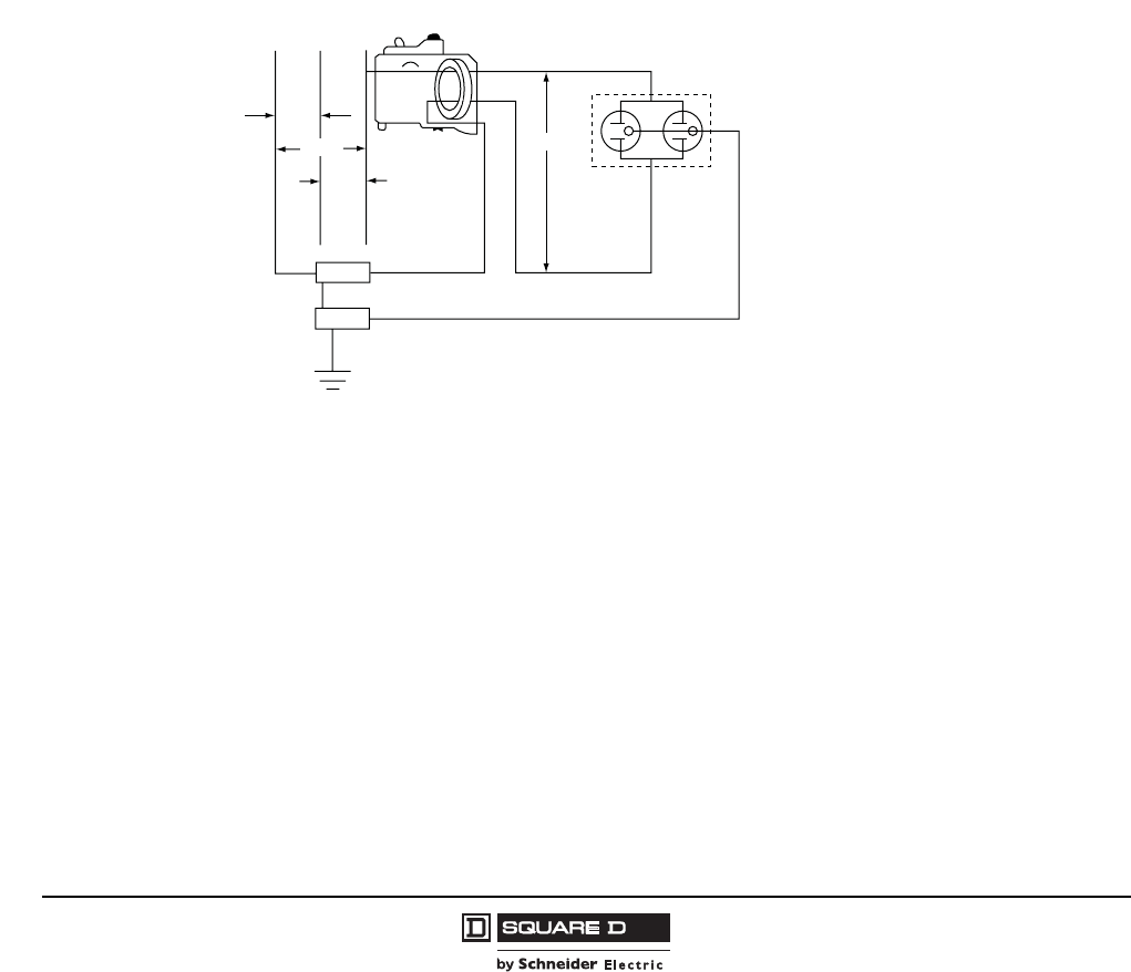
© 1998–2008 Schneider Electric
All Rights Reserved
QO® and QOB Miniature Circuit Breakers
Special Application Circuit Breakers
10
07/2008
Proper Application of Qwik-Gard GFCIs
•Do not connect to swimming pool equipment installed before adoption of the 1965 National Electric
Code
•Do not connect to electrical ranges or clothes dryers whose frames are grounded by a connection
to the grounded circuit conductor.
•Do not use as a main circuit breaker in a panelboard or in reverse connected (backfed)
applications.
•Do not megger, high-voltage or hi-pot test. Any voltage in excess of 240 Vac will damage the GFCI
electronics so that the circuit breaker will not protect against low-level ground faults.
•Must be located no more than 250 ft. (76 m) from the load being served.
•RequiresS the same mounting space as standard QO circuit breakers.
One-Pole Qwik-Gard Ground-Fault Circuit Interrupters
One-pole Qwik-Gard GFCIs must be installed on independent circuits. Circuits which have a neutral
common to more than one panel circuit conductor cannot be protected against ground faults by a one-
pole GFCI because the current returning to the source through the neutral cannot be effectively split to
prevent the Qwik-Gard GFCI from tripping under normal use.
Figure 2: Typical One-Pole Qwik-Gard GFCI Wiring
NAB
120/240 Vac Source
Hot Duplex
Receptacle
Neutral
Equipment Ground
S/N
GND
120 V
240 V
One-Pole
Circuit
Breaker
with
GFCI or EPD
120 V 120 V
07303106
249 of 292
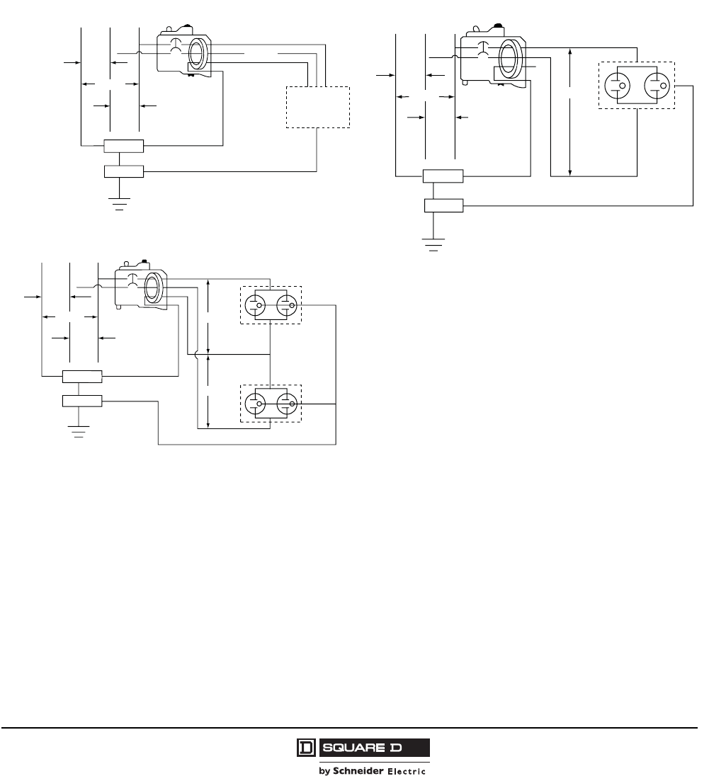
QO® and QOB Miniature Circuit Breakers
Special Application Circuit Breakers
11
07/2008
© 1998–2008 Schneider Electric
All Rights Reserved
Two-Pole Qwik-Gard GFCIs
Two-pole Qwik-Gard GFCIs can be installed on a 120/240 Vac 1Ø3W system, the 120/240 Vac portion
of a 120/240 Vac 3Ø4W system, or two phases and neutral of a 208Y/120 Vac 3Ø4W system.
Regardless of the application, connections must be made to two “hot” busses and the panel neutral
assembly. When installed on these systems, protection is provided for two-wire 240 Vac or 208 Vac
circuit, three-wire 120/240 Vac or 208Y/120 Vac circuits and 120 Vac multiwire circuits.
The 60 A QO260GFI and QOB260GFI GFCIs are limited for use on 208 Vac and 240 Vac two-wire
systems. These GFCIs require the panel neutral connection to provide the 120 Vac power necessary
for testing the ground-fault circuitry.
Figure 3: Typical Two-Pole Qwik-Gard GFCI Wiring
NAB
120/240 Vac Source
Hot B
Hot A
Equipment Ground
S/N
GND
120 V
240 V
Two-Pole
Circuit Breaker
with
GFCI or EPD
120 V 240 V
250 V Duplex
Receptacle
07303103
Two-Wire 240 Vac or 208 Vac
Equipment Ground
GND
S/N
120 V
NAB
120/208 Vac or
120/240 Vac Source
Two-Pole
Circuit Breaker
with
GFCI or EPD
Hot B
Neutral
Load
Hot A
120 V
240 V
Three-Wire 120/240 Vac or 208Y/120 Vac Circuits
15–50 A Only
07303104
NB
120 V
120 V
Neutral
Duplex
Receptacle
Duplex
Receptacle
Two-Pole
Circuit Breaker
with
GFCI or EPD
240 V
120 V
A
120/208 Vac or
120/240 Vac Source
Equipment Ground
Hot A
Hot B
S/N
GND
120 V
120 Vac Multiwire Circuits
15–50 A Only
07303105
250 of 292
© 1998–2008 Schneider Electric
All Rights Reserved
QO® and QOB Miniature Circuit Breakers
Special Application Circuit Breakers
12
07/2008
QO-EPD and QOB-EPD Equipment Protection Devices
QO-EPD and QOB-EPD circuit breakers are one- and two-pole thermal-magnetic circuit breakers with
integral equipment ground-fault protection. These circuit breakers are rated for use on 120/240 Vac
and 120/208 Vac electrical systems to provide overcurrent protection, short-circuit protections and
equipment ground-fault protection.
EPD circuit breakers are built in accordance with UL Standard 489. QO-EPD and QOB-EPD circuit
breakers are not designed to protect people from the hazards of electrical shock. The ground-fault
protection level is 30 milliamperes to protect electrical equipment such as heat trace tape.
QO-EPD and QOB-EPD circuit breakers include a self-contained means of testing the ground-fault
circuitry. If the circuit breaker is connected correctly, with the pigtail connected to the neutral assembly
in the load center or panelboard, pressing the test button will trip the circuit breaker and show a trip
indication. EPD circuit breakers must be operational at 85% of the rated voltage.
EPD circuit breakers provide the same branch circuit protection as standard QO and QOB circuit
breakers. They are longer than standard QO circuit breakers, and thus require more gutter space. All
QO electrical accessories except shunt trip and all QO mechanical accessories are available for QO-
EPD and QOB-EPD circuit breakers.
QO-SWN and QOB-SWN Switch Neutral Circuit Breakers
The QO-SWN and QOB-SWN switch neutral circuit breakers are designed to protect gas pump
assemblies.These circuit breakers have provisions for switching the grounded conductor as outlined in
the National Electrical Code.
The QO-SWN and QOB-SWN circuit breakers are designed to simultaneously open all grounded and
ungrounded conductors. All branch circuit wiring is terminated on the load side of the circuit breaker.
The panel neutral connection is made using the pigtail lead built into the circuit breaker. Two-wire
circuit breakers require two pole spaces; three-wire circuit breaker require three pole spaces.
QO-SWN and QOB-SWN circuit breakers are available with the complete range of QO accessories.
QOT Tandem Circuit Breakers
QOT tandem circuit breakers are manufactured so two one-pole, thermal-magnetic circuit breakers
occupy only one QO pole space. They are used in applications where circuit loading is light and/or
noncontinuous, as in residential applications. QOT circuit breakers are available in 15/15 ampere,
15/20 ampere and 20/20 ampere construction.
QOT circuit breakers have a mounting cam to limit their installation in QO load centers to only those
positions having a mounting rail slot. This physically limits the total number of circuit beakers permitted
in the panelboard for safe operation.
Each one-pole QOT circuit breaker provides individual switching and tripping action. Individual trip,
two-pole circuit with common switching may be assembled by using a handle tie (kit QOTHT) between
two adjacent QOT circuit breakers.
07303099
2 Wire and 3 Wire
QO-SWN Circuit Breaker
07303095
1P QOT Tandem
Circuit Breaker
Mounting
Cam
251 of 292
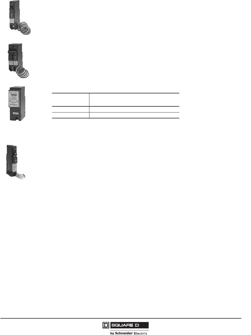
QO® and QOB Miniature Circuit Breakers
Special Application Circuit Breakers
13
07/2008
© 1998–2008 Schneider Electric
All Rights Reserved
QO-PL and QOB-PL Powerlink® Remotely Operated CIrcuit Breakers
QO-PL and QOB-PL circuit breakers combine overcurrent and short-circuit protection with remote
switching. These circuit breakers are ideal for lighting loads or wherever power switching is required.
These circuit breakers are designed to be used with many types of control devices, from simple push
buttons to programmable controllers and energy management systems. QO-PL and QOB-PL circuit
breakers have all of the features of standard QO circuit breakers including Visi-Trip®, plus the added
ability to be remotely switched on and off. They are rated for a minimum of 30,000 remote operations.
Remote switching is accomplished using a 24 Vdc power supply. Square D offers QOPLPS and
QOBPLPS power supplies. These power supplies mount directly in any QO load center or NQ or
NQOD panelboard just like a QO circuit breaker. They provide power to switch up to three QO-PL or
QOB-PL circuit breakers simultaneously. A minimum of two seconds recharge time must be allowed
between operation for non-simultaneous operations of circuit breakers being supplied by a power
supply.
QO Arc-Fault Circuit Interrupter Circuit Breakers
QO arc-fault circuit interrupters (AFCI) quickly detects a wide range of arc-fault conditions, recognizes
the nature and specific wave-form of an arc fault and trips the circuit breaker. Traditional circuit
breakers and fuses are designed to detect overloads and short circuits. Arc-fault circuit breakers are
designed to detect overloads, short circuits and arc faults.
An arc-fault circuit breaker opens the circuit and stops the arcing and high intensity heat before a fire is
likely to ignite. It is designed with the same quick-open and Visi-Trip® features and reliability of other
QO circuit breaker products, fits into most existing Square D load centers, and can generally be used
as a direct replacement for a standard Square D circuit breakers. The AFCI overall size is larger than
an equivalent QO circuit breaker.
Arc-fault circuit breakers:
•Have special microprocessor-based arc identification to differentiate necessary operational arcs
(associated with loads such as electric motors, switches and receptacles) from actual arc faults
which can cause damage and fires.
•Differentiate true arc faults from chopped wave-forms associated with switched-mode power
supplies on electrical appliances, computers and lamp dimmers.
QO AFCI's are available as Branch Feeder Type and Combination Type. Branch AFCI circuit breakers
provide arc-fault protection of the branch circuit wiring. Combination AFCI circuit breakers provide arc-
fault protection for the branch circuit and also provides protection of cord sets and power-supply cords.
The AFCI type required for an installation is generally governed by the installation codes which are
adopted by local inspection authorities. Consult local building codes and inspection authorities to
determine which type is required in your area.
07303097
1P QO-PL
Circuit Breaker
07303096
2P QO-PL
Circuit Breaker
07303098
QOPLPS
Power Supply
Table 4: Maximum Circuit Breakers per Power Supply
Voltage Maximum QO-PL and QOB-PL Circuit Breakers
Recommended per QOPLPS1
1At ambient temperature of -25° through 40°C.
208Y/120 Vac 2
240 Vac 3
07303100
1P QO-AFI
Circuit Breaker
252 of 292
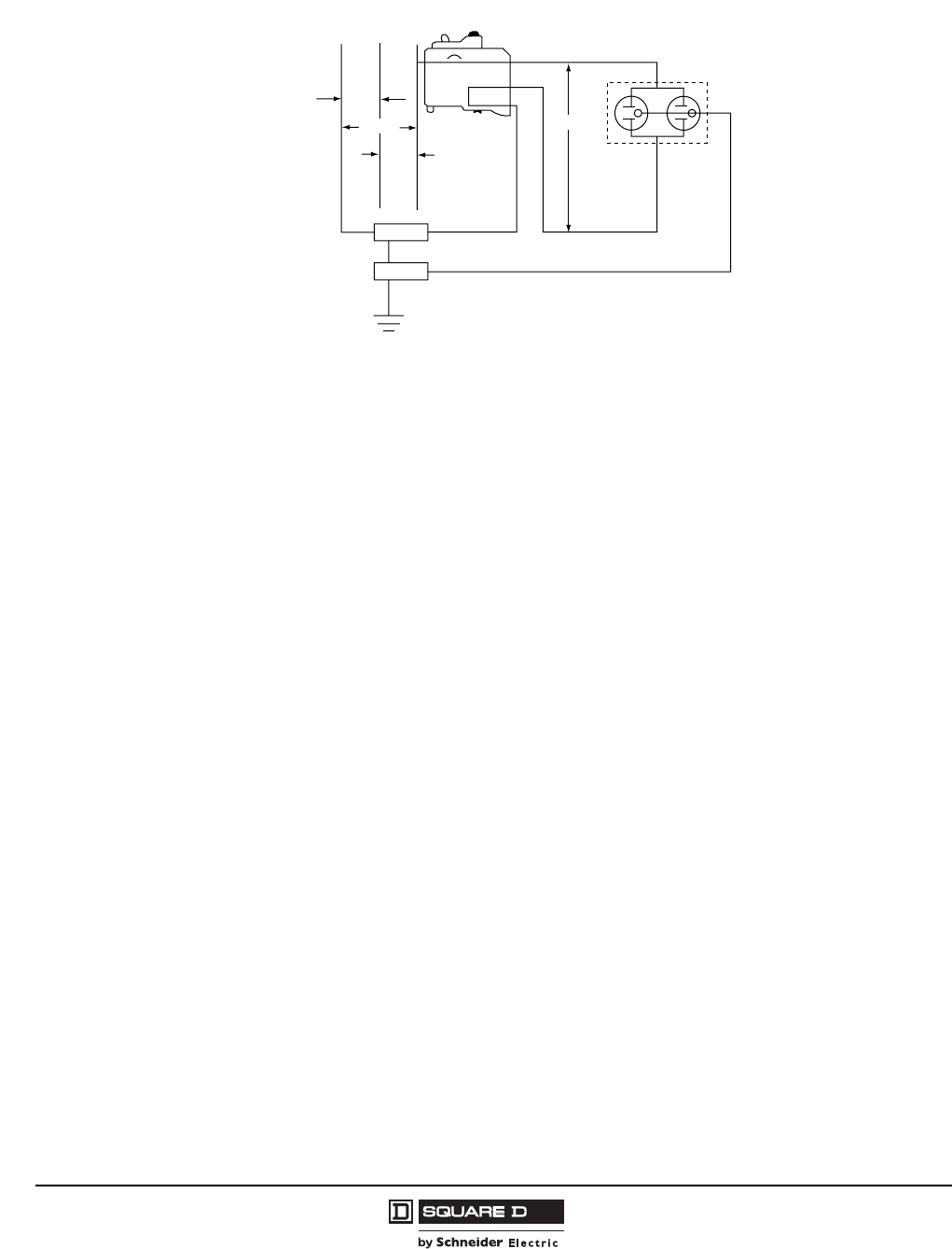
© 1998–2008 Schneider Electric
All Rights Reserved
QO® and QOB Miniature Circuit Breakers
Special Application Circuit Breakers
14
07/2008
Figure 4: Typical AFCI Circuit Breaker Installation
NA
120/240 Vac Source
Hot Duplex
Receptacle
Neutral
Equipment Ground
S/N
GND
120 V
240 V
One-pole
AFCI
Circuit
Breaker
120 V 120 V
07303107
AFCI Circuit Breaker Installation
B
253 of 292
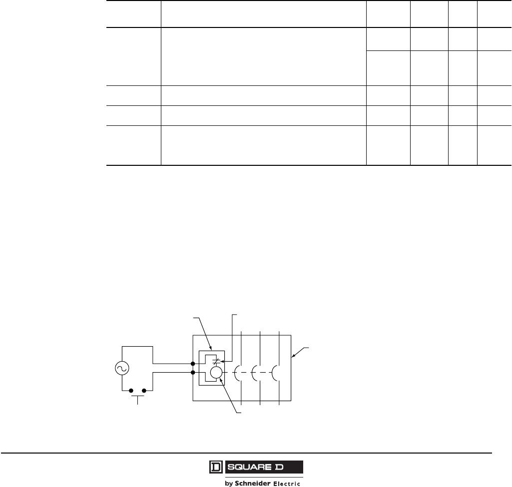
QO® and QOB Miniature Circuit Breakers
Accessories
15
07/2008
© 1998–2008 Schneider Electric
All Rights Reserved
Accessories
Most QO and QOB circuit breakers can be supplied with electrical accessories factory-installed on
one-, two- or three-pole circuit breakers. Electrical accessories are not available on AFCI circuit
breakers.
Handle accessories are also available for field installation on QO and QOB circuit breakers. All field-
installed handle accessories must be ordered separately.
Electrical Accessories
Only one electrical accessory can be installed per circuit breaker, and are factory-installed only. All
electrical accessories occupy one additional pole space. The proper suffix number must be added to
the circuit breaker catalog number to order an accessory. No field modification or field installation is
possible on electrical accessories.
Shunt Trip
The shunt trip is used to trip the circuit breaker from a remote location by using a tripping coil energized
from a separate circuit. When energized by a push-button or other pilot device, the shunt trip caused
the circuit breaker to trip. The handle moves to the tripped position and the Visi-Trip® indicator
appears. The trip coil has a coil clearing contact to break the coil circuit when the circuit breaker trips.
Shunt trips are available for QO and QOB circuit breakers only with standard control voltage ratings up
to 240 Vac or 24 Vdc. (Shunt trips are not available on QO and QOB GFCI, AFCI, EPD and miniature
switches.) Shunt trips operate at 75% or more of rated voltage.
Table 5: Factory-Installed Electrical Accessory Suffix Numbers
Accessory Description Voltage Coil
Burden
Max.
Load
Catalog
Suffix
Shunt Trip
Trips the circuit breaker from a remote location by means of a trip
coil energized from a separate circuit. All shunt trips will operate
at 75% or more of rated voltage.
• For use with momentary or maintained push button.
• Not available on QO-GF or QO-EPD circuit breakers.
• Shunt trip terminals accept (2) 14–12 AWG Cu leads.
12 Vac/dc
24 Vac/dc
60 VA
168 VA —1042
120 Vac
208 Vac
240 Vac
72 VA
228 VA
288 VA
—1021
Auxiliary Switch
“A” Contact
Circuit breaker open—One contact only, opens when circuit
breaker is off or tripped. 5 A max at 120 Vac. 120 Vac — 5 A 1200
Auxiliary Switch
“B” Contact
Circuit breaker open—One contact only, closed when circuit
breaker is off or tripped. 5 A max at 120 Vac. 120 Vac — 5 A 1201
Alarm Switch
Used with control circuits and is actuated only when the circuit
breaker has tripped. Standard construction includes a normally-
open contact.
• Alarm switch terminals accept (2) 14–12 AWG Cu leads.
120 Vac — 5 A 2100
Figure 5: Shunt Trip Wiring Diagram
S
Accessory
Terminals
Shunt Trip
Housing
Coil Clearing Switch
(opens when circuit breaker
is shunt-tripped)
Circuit
Breaker
Shunt Trip Coil
07303108
254 of 292

© 1998–2008 Schneider Electric
All Rights Reserved
QO® and QOB Miniature Circuit Breakers
Accessories
16
07/2008
Auxiliary Switch
The auxiliary switch accessory monitors the circuit breaker contact status and provides a remote signal
indicating whether the circuit breaker contacts are open or closed. When the circuit breaker is off or
tripped, the auxiliary switch with an “A” contact is open and the auxiliary switch with a “B” contact is
closed. When the circuit breaker is on, the auxiliary switch with an “A” contact is closed and the
auxiliary switch with a “B” contact is open.
Auxiliary switches are available for QO and QOB circuit breakers and miniature switches. (Auxiliary
switches are not available on QO and QOB AFI and CAFI products.)
Alarm Switch
The alarm switch accessory monitors the circuit breaker trip status and is used to provide a remote
warning signal indicating that the circuit breaker has tripped. This signal can be used in conjunction
with a horn, pilot light, or some other indicator.
The contact on the standard alarm switch is open when the circuit breaker is in the off or on position
and is closed when the circuit breaker is in the tripped position.
Alarm switches are actuated when the circuit breaker has tripped as a result of an overload, short
circuit or shunt trip operation. Alarm switches are available for QO and QOB circuit breakers and
miniature switches. (Alarm switches are not available on QO and QOB AFI and CAFI products.)
Figure 6: Auxiliary Switch Wiring Diagrams
Figure 7: Alarm Switch Wiring Diagram
"A" Contact "B" Contact
"A" Contact "B" Contact
A
A
Com
AB
Power
BCom
B
Power
A
07303109
Circuit Breaker OFF or Tripped Circuit Breaker OFF or Tripped—Light B “On”
Circuit Breaker ON—Light A “On”
Circuit Breaker ON
C
BC
07303110
Circuit Breaker OFF or ON
Normally-open Alarm Switch Circuit Breaker Tripped
255 of 292
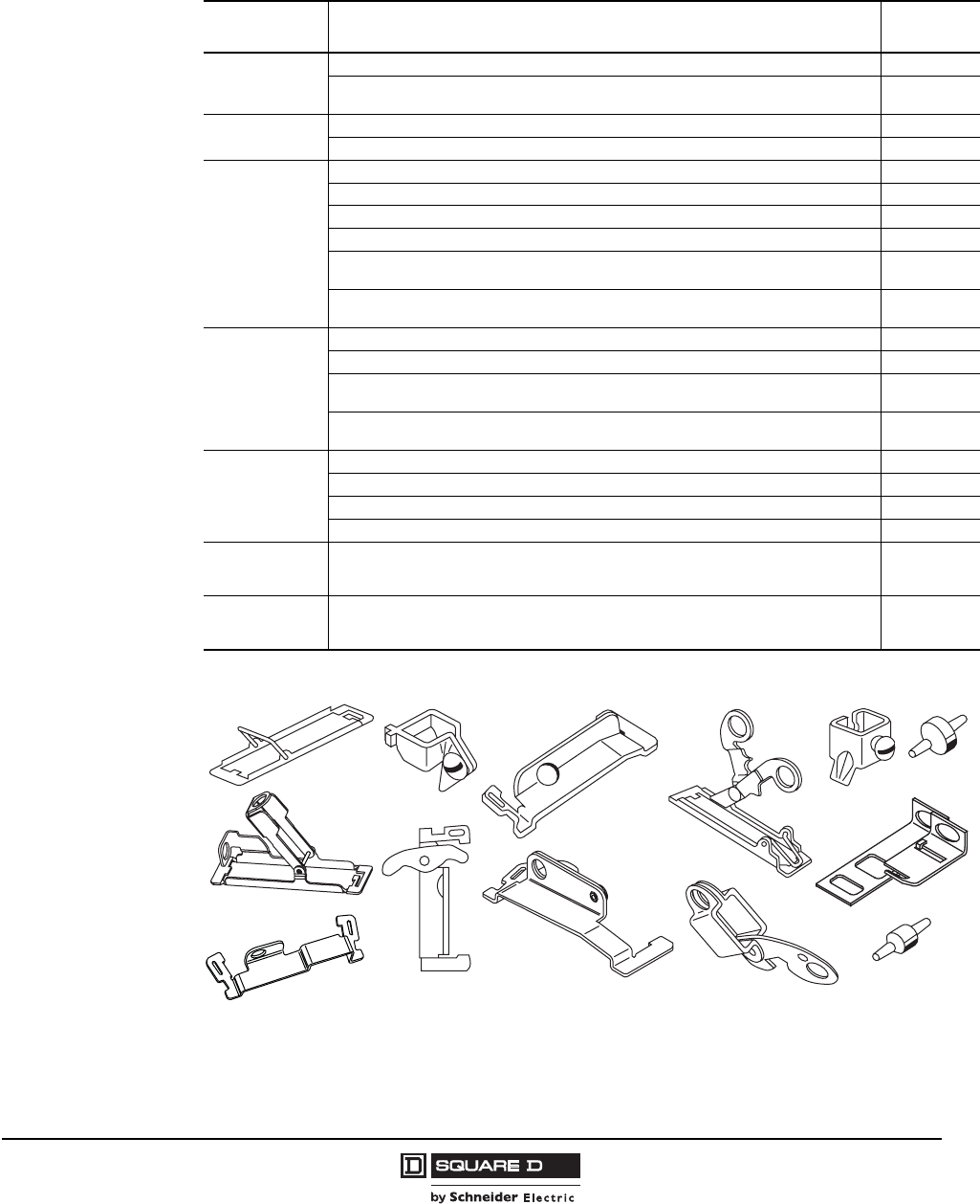
QO® and QOB Miniature Circuit Breakers
Accessories
17
07/2008
© 1998–2008 Schneider Electric
All Rights Reserved
Handle Accessories
Field-installed handle accessories are also available.
Table 6: Field-Installable Handle Accessories
Accessory Description Catalog
Number
Handle Tie
Converts any two adjacent 120/240 Vac 1P QO circuit breakers to independent trip 2P. QO1HT
Converts any two adjacent 120/240 Vac 1P side-by-side QOT circuit breakers to
independent trip 2P. QOTHT
Handle Clamp Clamp for holding QO 1P handle in ON or OFF position. QO1LO
Clamp for holding QO or Q1 (1P, 2P, or 3P) circuit breaker handle in ON or OFF position. HLO1
Handle Padlock
Attachment for
Padlocking in ON
or OFF Position
Loose attachment for padlocking 1P QO circuit breaker in ON or OFF position. QOHPL
Fixed attachment for padlocking 1P QO circuit breaker in ON or OFF position. QO1PA
Attachment for padlocking 1P side-by-side QOT circuit breaker in ON or OFF position. QOTHPA
Fixed attachment for padlocking 2P QO-GFI circuit breaker in ON or OFF position. GF12PA
Loose attachment for padlocking 2P and 3P standard QO circuit breaker in ON or OFF
position. QO1HPL
Fixed attachment for padlocking 2P and 3P standard QO circuit breaker in ON or OFF
position. QO1PL
Handle Padlock
Attachment for
Padlocking in OFF
Position
Fixed attachment for padlocking 1P QO circuit breaker in OFF position only. QO1PAF
Fixed attachment for padlocking 2P and 3P QO circuit breakers in OFF position only. QO2PAF
Fixed attachment for padlocking 1P QO-GFI, QO-AFCI and QO-EPD circuit breakers in OFF
position only. QOGFI1PAF
Fixed attachment for padlocking 2P QO-GFI and QO-EPD circuit breakers in OFF position
only. QOGFI12PAF
Sub-Feed Lugs
60 A 2P plug-on—2 spaces required (6–2 Al/Cu) QO60SL
125 A 2P plug-on—2 spaces required (12–2/0 Al/Cu) QO2125SL
225 A 2P plug-on—4 spaces required (4–300 Al/Cu) QO2225SL
125 A 3P plug-on—3 spaces required (12–2/0 Al/Cu) QO3125SL
Mechanical
Interlock
Attachment
For interlocking the handles of two 2P or one 2P and one 1P QO and Q1 circuit breaker
mounted side-by-side so that only one circuit breaker can be ON at a time (Not for QOU) QO2DTI
Mechanical
Interlock with
Retaining Kit
For securing two adjacent back-fed circuit breakers in dual power supply applications. Can
be used with two 2P or one 2P and one 1P QO circuit breaker in QO816L100 load center. QO2DTIM
Figure 8: Handle Accessories
QO2PAF
07303129
QO1PA
07303119
QO1PL
07303120
QO1HT
07303121
QO1LO
07303122
QO1PAF
07303123
QO2DTI
07303124
QO1HPL
07303125
QOTHPA
07303126
HLO1
07303127
QOHPL
07303128
QOGFI2PAF
07303119
QOTHT
07303131
256 of 292

© 1998–2008 Schneider Electric
All Rights Reserved
QO® and QOB Miniature Circuit Breakers
Accessories
18
07/2008
Handle Tie
The handle tie accessory converts any two adjacent one-pole QO circuit breakers to one independent
trip multi-pole circuit breaker.
Handle Lock-Off (Clamp)
The handle lock-off accessories fasten the handle in the ON or OFF position. These handle lock-offs
cannot be padlocked.
Handle Padlock Attachment
The handle padlock attachment allows padlocking the circuit breaker handles in either the ON or OFF
position or in the OFF only position. Handle padlock attachments are available in two styles: removable
and fixed.
The removable style is intended to be a temporary device. Once work on the circuit breaker has been
completed, the attachment can be removed from the circuit breaker to resume normal operation.
The fixed style is intended to be a permanent device. Once the work on the circuit has been
completed, the padlock can be removed for the circuit breaker to resume normal operation, but the
attachment stays in place.
Mechanical Interlock Attachment
The mechanical interlock attachment locks the handles of two adjacent circuit breakers to prevent both
circuit breakers from being on at the same time. Both circuit breakers may be switched to the off
position with the mechanical interlock in place.
Mechanical Interlock Attachment with Retaining Kit
The mechanical interlock attachment locks the handles of two adjacent back-fed circuit breakers in
dual power supply applications.
257 of 292
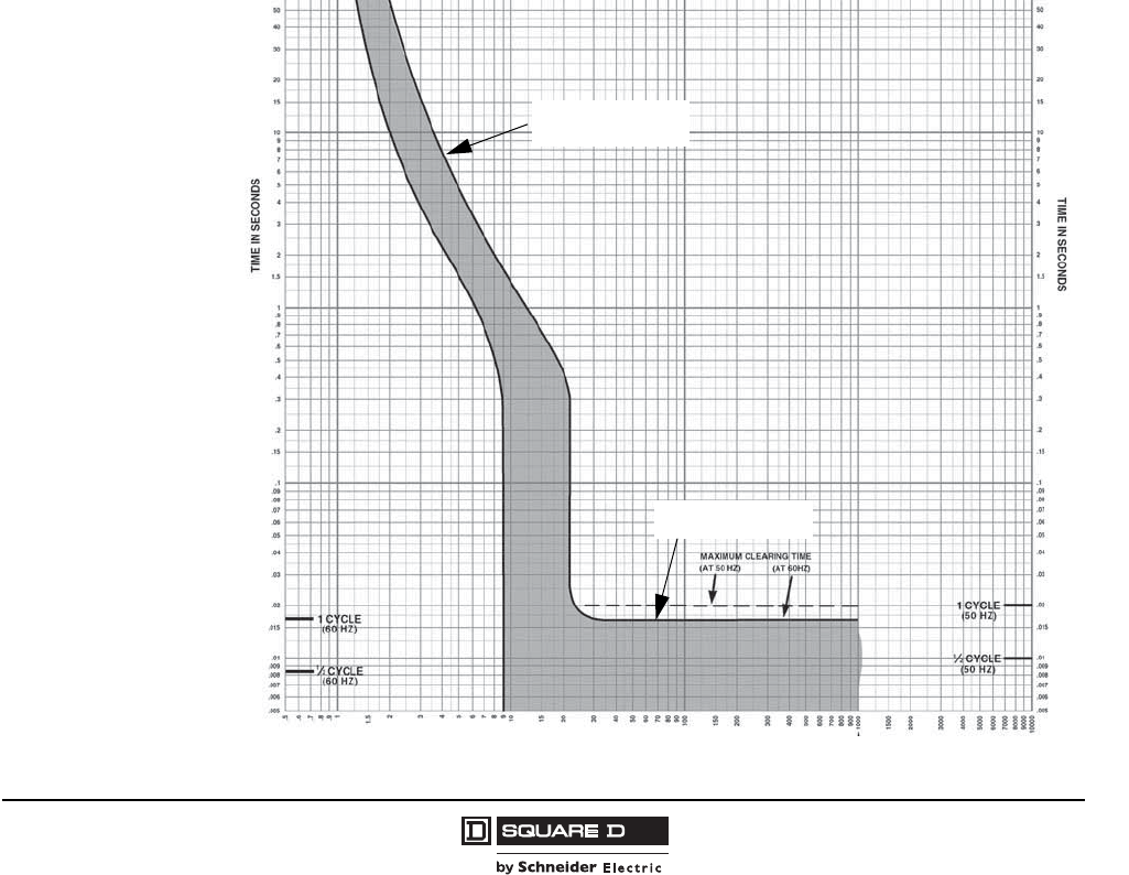
QO® and QOB Miniature Circuit Breakers
Trip Curves
19
07/2008
© 1998–2008 Schneider Electric
All Rights Reserved
Trip Curves
The tripping characteristics of QO and QOB circuit breakers can be represented by a characteristic
tripping curve that plots tripping time versus current level. The curve shows the amount of time
required by a circuit breaker to trip at a given overcurrent level. The curve has a performance band that
is bound by a minimum and a maximum value of clearing time. Total clearing time is the sum of the
sensing time, unlatching time, mechanical operating time and arcing time of the circuit breaker. For
currents in excess of 135% of the circuit breaker rating at rated ambient temperature (40°C), the circuit
breaker will automatically open the circuit within limits specified by the band.
Thermal Tripping Characteristics
The upper left portion of each trip curve displays the thermal response of the circuit breaker. On low-
fault current levels, up to the magnetic tripping level, thermal tripping occurs when a bimetal in the
circuit breaker responds to heat associated with the overcurrent. The bimetal deflects, unlatching the
mechanism and mechanically causing the circuit breaker to trip and open the circuit. The greater the
overcurrent, the faster the circuit breaker will operate to clear the circuit.
Magnetic Tripping Characteristics
The lower right portion of each trip curve displays the magnetic tripping response of the circuit breaker.
This takes place when overcurrents of sufficient magnitude operate in an internal magnetic armature
which unlatches the mechanism. Magnetic tripping occurs with no intentional time delay.
Figure 9: Typical QO Trip Curve
Thermal Tripping
Magnetic Tripping
258 of 292
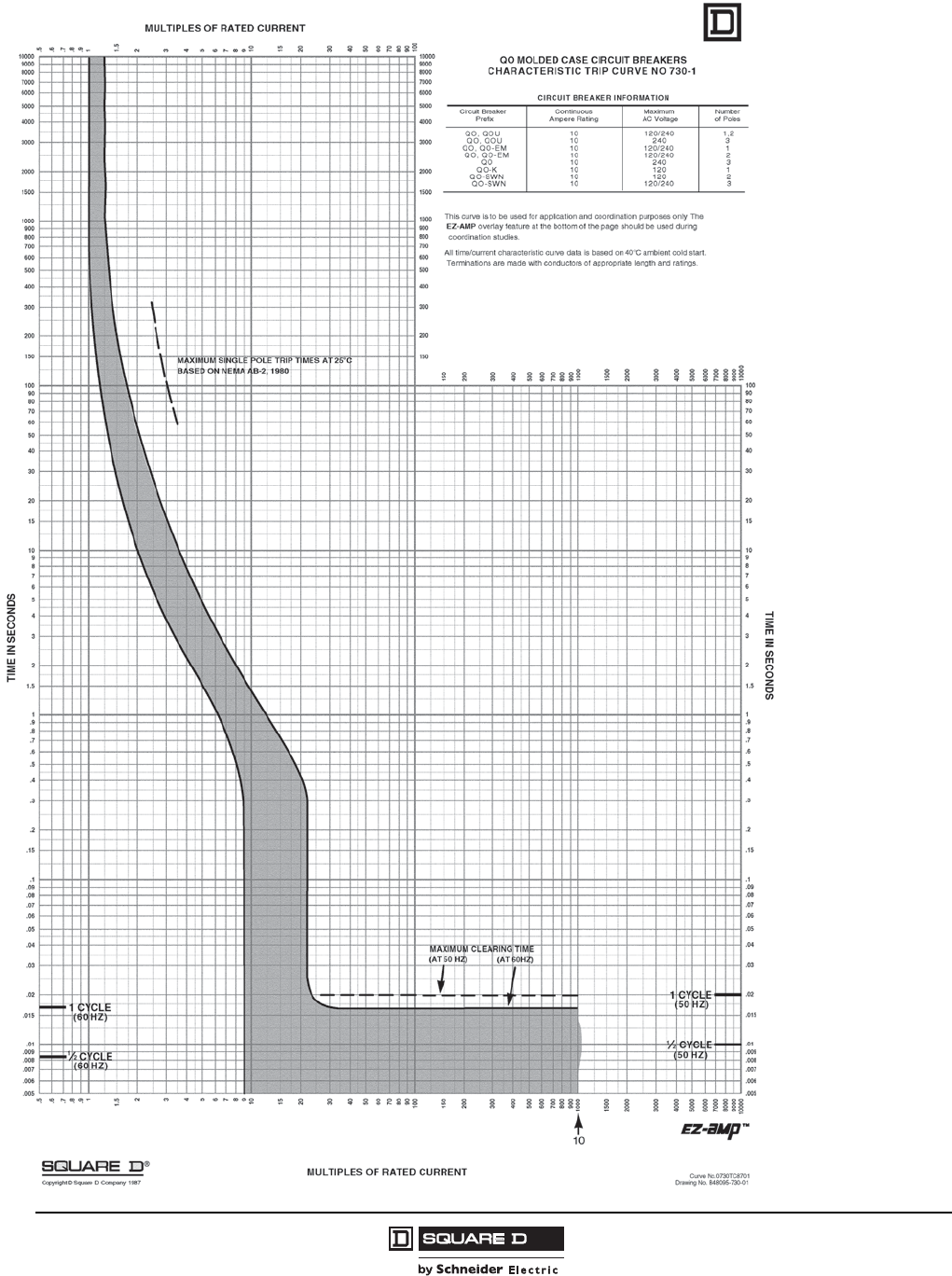
© 1998–2008 Schneider Electric
All Rights Reserved
QO® and QOB Miniature Circuit Breakers
Trip Curves
20
07/2008
259 of 292
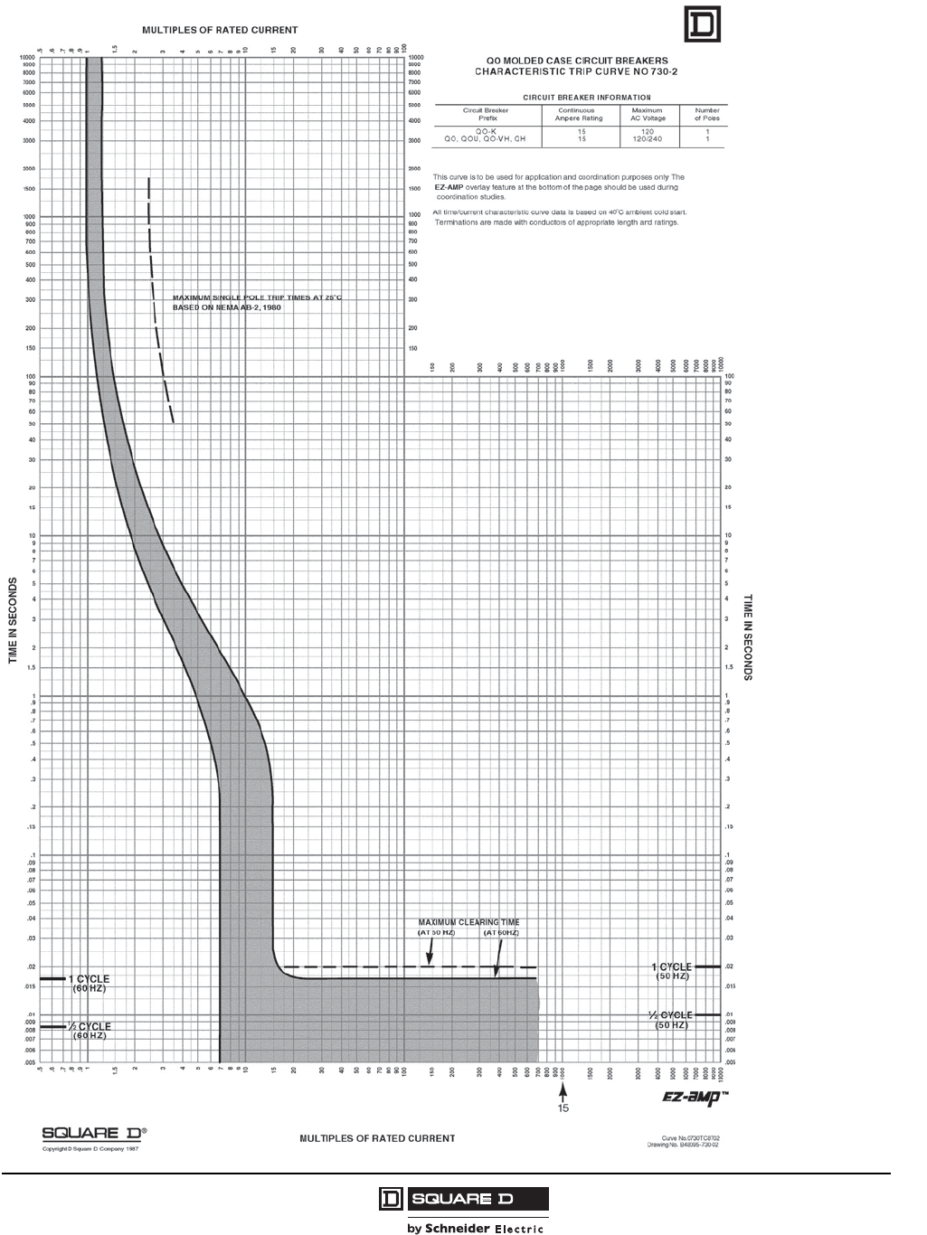
QO® and QOB Miniature Circuit Breakers
Trip Curves
21
07/2008
© 1998–2008 Schneider Electric
All Rights Reserved
260 of 292
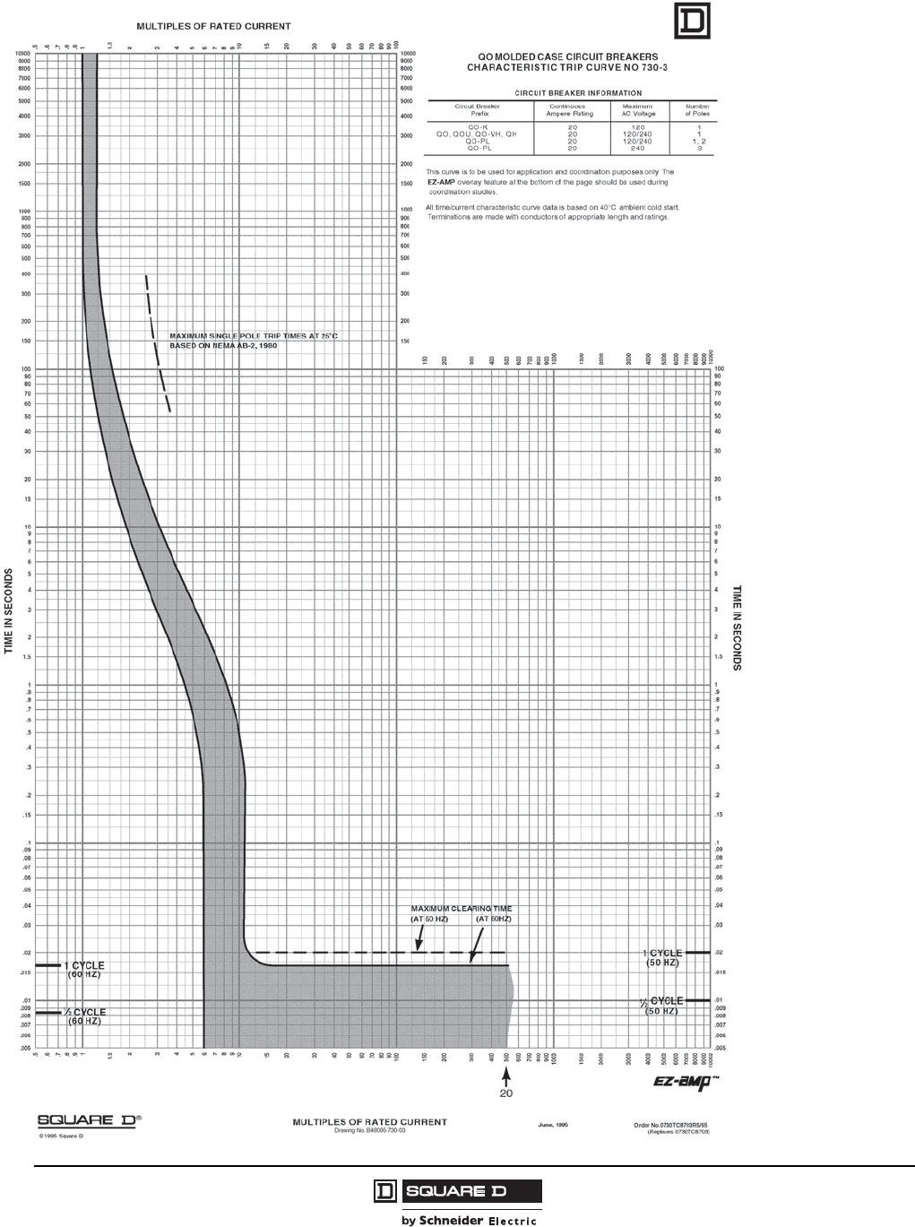
© 1998–2008 Schneider Electric
All Rights Reserved
QO® and QOB Miniature Circuit Breakers
Trip Curves
22
07/2008
261 of 292
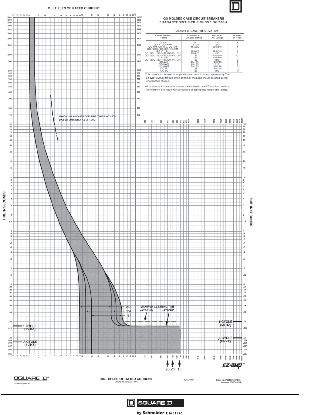
QO® and QOB Miniature Circuit Breakers
Trip Curves
23
07/2008
© 1998–2008 Schneider Electric
All Rights Reserved
262 of 292

© 1998–2008 Schneider Electric
All Rights Reserved
QO® and QOB Miniature Circuit Breakers
Trip Curves
24
07/2008
1.5
700
150
200
300
400
600
800
900
2000
3000
4000
5000
7000
8000
9000
10000
.5
.6
.7
.8
.9
1
2
3
4
5
6
7
8
9
10
15
20
30
40
50
60
70
80
90
100
6000
1500
1000
500
.005
.006
.007
.008
.009
.01
.015
.02
.03
.04
.05
.06
.07
.08
.09
.1
.15
.2
.3
.4
.5
.6
.7
.8
.9
1
1.5
2
3
4
5
6
7
8
9
10
20
30
40
50
60
70
80
90
100
15
200
300
400
500
600
700
800
900
1000
1500
2000
3000
4000
6000
7000
8000
9000
5000
10000
1
.5
.6
.7
.8
.9
1.5
2
3
4
5
6
7
8
9
10
15
20
30
40
50
60
70
80
90
100
MULTIPLES OF RATED CURRENT
TIME IN SECONDS
.005
.006
.007
.008
.009
.01
.015
.02
.03
.04
.05
.06
.07
.08
.09
.1
.15
.2
.3
.4
.5
.6
.7
.8
.9
1
1.5
2
3
4
5
6
7
8
9
10
15
20
30
40
50
60
70
80
90
100
150
200
300
400
500
600
700
800
900
1000
1500
2000
3000
4000
5000
6000
7000
8000
9000
10000
TIME IN SECONDS
1/2 CYCLE
(60 Hz)
1/2 CYCLE
(50 Hz)
150
200
300
400
500
600
700
800
900
1000
1500
2000
3000
4000
5000
6000
7000
8000
9000
10000
150
MULTIPLES OF RATED CURRENT
1 CYCLE
(60 Hz)
1 CYCLE
(50 Hz)
MAXIMUM INDIVIDUAL POLE TRIP TIMES
AT 25°C BASED ON NEMA AB-4, 1991
40 A
35 A
30 A MAXIMUM CLEARING TIME
(AT 50 Hz) (AT 60 Hz)
4035
30
QO
®
MOLDED CASE CIRCUIT BREAKERS
CHARACTERISTIC TRIP CURVE NO. 730-5
CIRCUIT BREAKER INFORMATION
Circuit Breaker Continuous Maximum Number
Prex Ampere Rating AC Voltage of Poles
102103K-OQ
2 ,1042/02103HQ ,HV-OQ
204203H-OQ
QO-HID, QO-VH, QH 30 240 3
QO, QOU, QO-HID 30–40 120/240 2
2042/02104–03LP-OQ
304204–03UOQ ,OQ
202104 & 03NWS-OQ
3042/02104 & 03NWS-OQ
This curve is to be used for application and coordination purposes only. The
EZ-AMP overlay feature at the bottom of the page should be used during
coordination studies.
All time/current characteristic curve data is based on 40°C ambient cold start.
Terminations are made with conductors of appropriate length and ratings.
®
© 2001 Schneider Electric all rights reserved
Curve No. 0730TC0105
January 2001
Drawing No. B48095-730-05
(Replaces 0730TC8705)
TM
263 of 292
QO® and QOB Miniature Circuit Breakers
Trip Curves
25
07/2008
© 1998–2008 Schneider Electric
All Rights Reserved
1.5
700
150
200
300
400
600
800
900
2000
3000
4000
5000
7000
8000
9000
10000
.5
.6
.7
.8
.9
1
2
3
4
5
6
7
8
9
10
15
20
30
40
50
60
70
80
90
100
6000
1500
1000
500
.005
.006
.007
.008
.009
.01
.015
.02
.03
.04
.05
.06
.07
.08
.09
.1
.15
.2
.3
.4
.5
.6
.7
.8
.9
1
1.5
2
3
4
5
6
7
8
9
10
20
30
40
50
60
70
80
90
100
15
200
300
400
500
600
700
800
900
1000
1500
2000
3000
4000
6000
7000
8000
9000
5000
10000
1
.5
.6
.7
.8
.9
1.5
2
3
4
5
6
7
8
9
10
15
20
30
40
50
60
70
80
90
100
MULTIPLES OF RATED CURRENT
TIME IN SECONDS
.005
.006
.007
.008
.009
.01
.015
.02
.03
.04
.05
.06
.07
.08
.09
.1
.15
.2
.3
.4
.5
.6
.7
.8
.9
1
1.5
2
3
4
5
6
7
8
9
10
15
20
30
40
50
60
70
80
90
100
150
200
300
400
500
600
700
800
900
1000
1500
2000
3000
4000
5000
6000
7000
8000
9000
10000
TIME IN SECONDS
1/2 CYCLE
(60 Hz)
1/2 CYCLE
(50 Hz)
150
200
300
400
500
600
700
800
900
1000
1500
2000
3000
4000
5000
6000
7000
8000
9000
10000
150
MULTIPLES OF RATED CURRENT
1 CYCLE
(60 Hz)
1 CYCLE
(50 Hz)
MAXIMUM INDIVIDUAL POLE TRIP TIMES
AT 25°C BASED ON NEMA AB-4, 1991
60 A
70 A
50 A
45 A
MAXIMUM CLEARING TIME
(AT 50 Hz) (AT 60 Hz)
70 60
50
45
QO ®MOLDED CASE CIRCUIT BREAKERS
CHARACTERISTIC TRIP CURVE NO. 730-6
CIRCUIT BREAKER INFORMATION
Circuit Breaker Continuous Maximum Number
Prex Ampere Rating AC Voltage of Poles
QO-HID 45–50 120/240 1, 2
QOU 45–50 240 3
QO-PL 45–60 120/240 2
QO, QOU 45–70 120/240 1, 2
304207–54OQ
202105NWS-OQ
QO-SWN 50 120/240 3
QOM 50–60 120/240 2
QOM-VH 50–60 120/240 2
This curve is to be used for application and coordination purposes only. The
EZ-AMP overlay feature at the bottom of the page should be used during
coordination studies.
All time/current characteristic curve data is based on 40°C ambient cold start.
Terminations are made with conductors of appropriate length and ratings.
®
© 2001 Schneider Electric all rights reserved
Curve No. 0730TC0106
January 2001
Drawing No. B48095-730-06
(Replaces 730-6, dated May, 1987)
TM
264 of 292
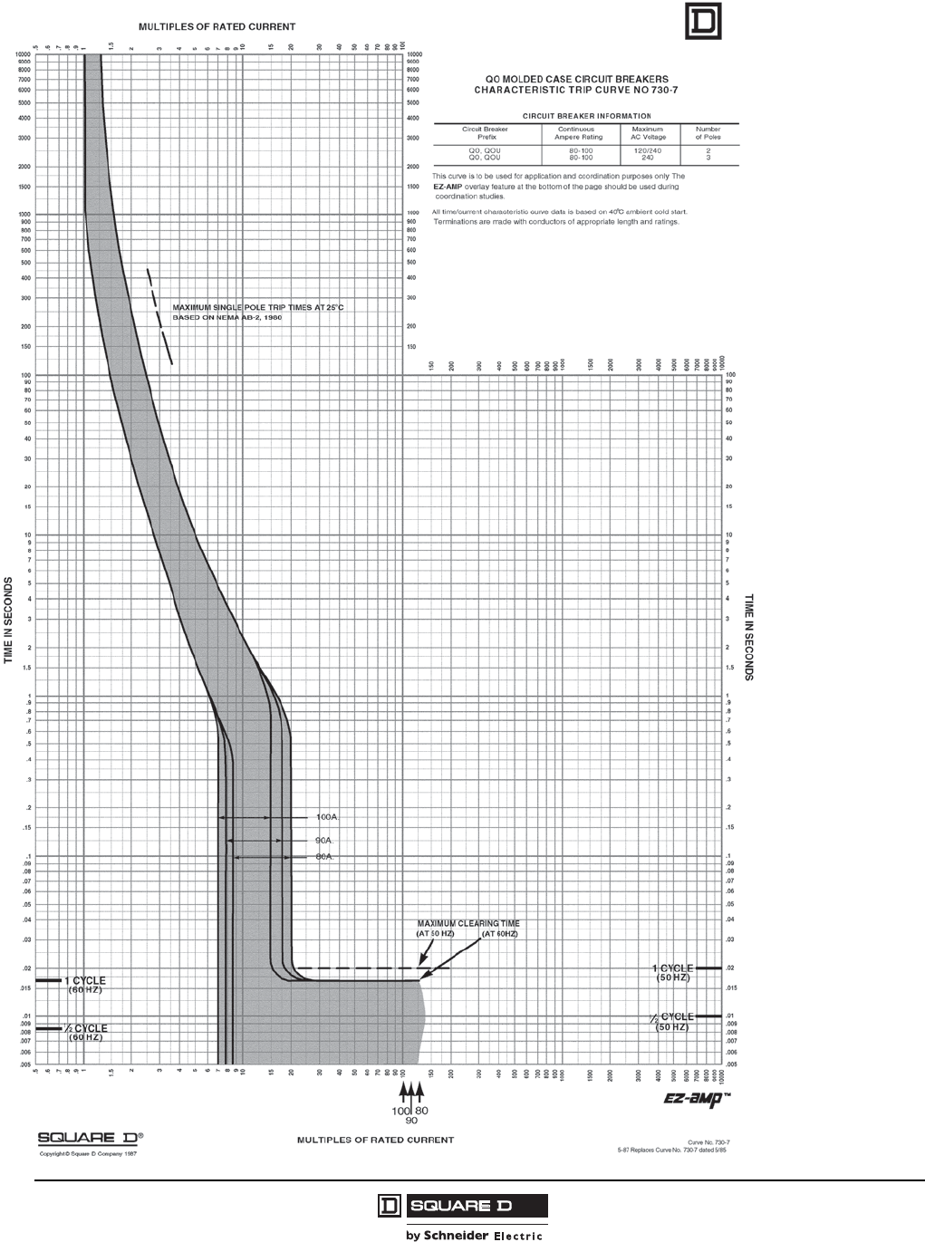
© 1998–2008 Schneider Electric
All Rights Reserved
QO® and QOB Miniature Circuit Breakers
Trip Curves
26
07/2008
265 of 292
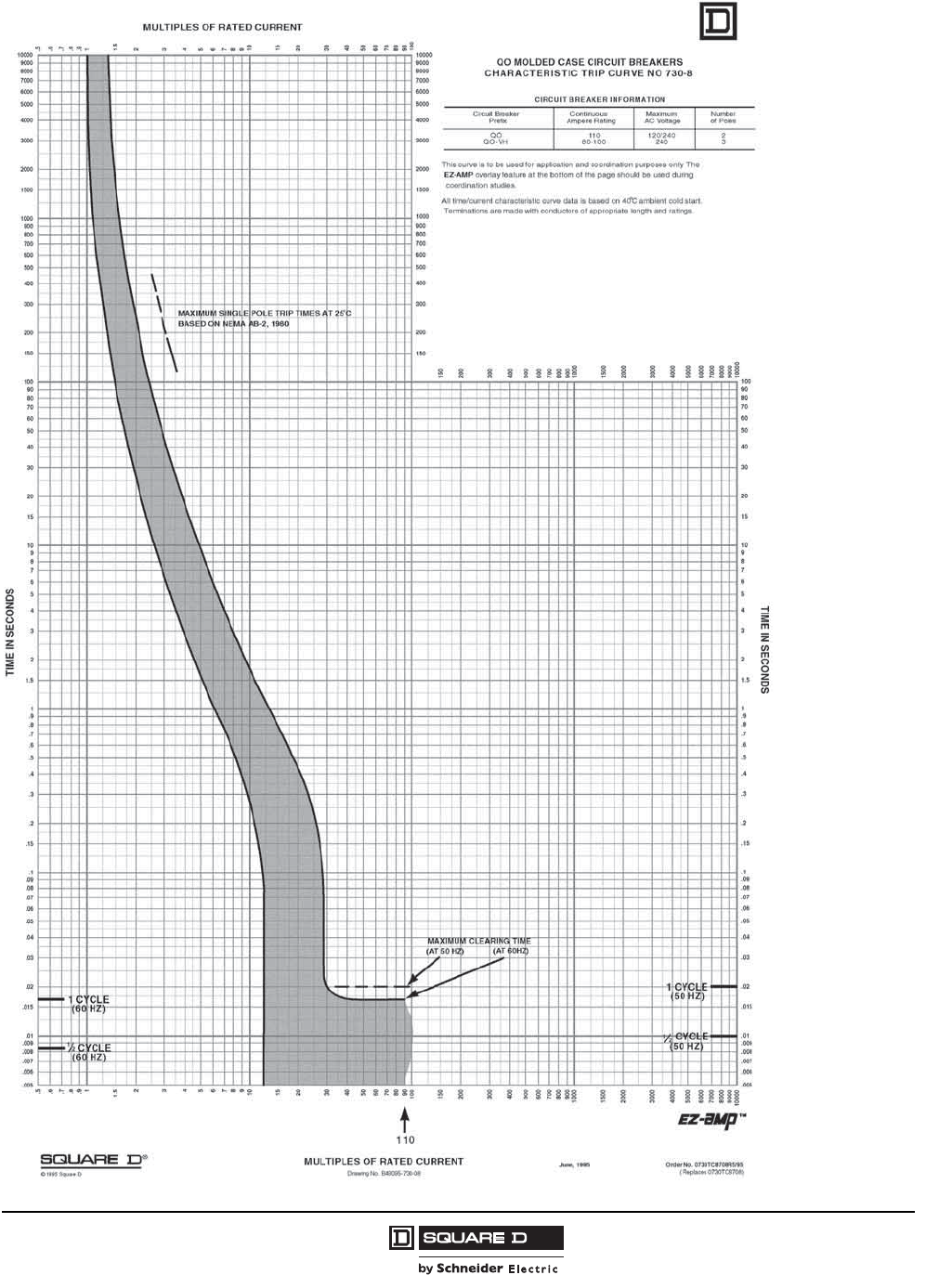
QO® and QOB Miniature Circuit Breakers
Trip Curves
27
07/2008
© 1998–2008 Schneider Electric
All Rights Reserved
266 of 292
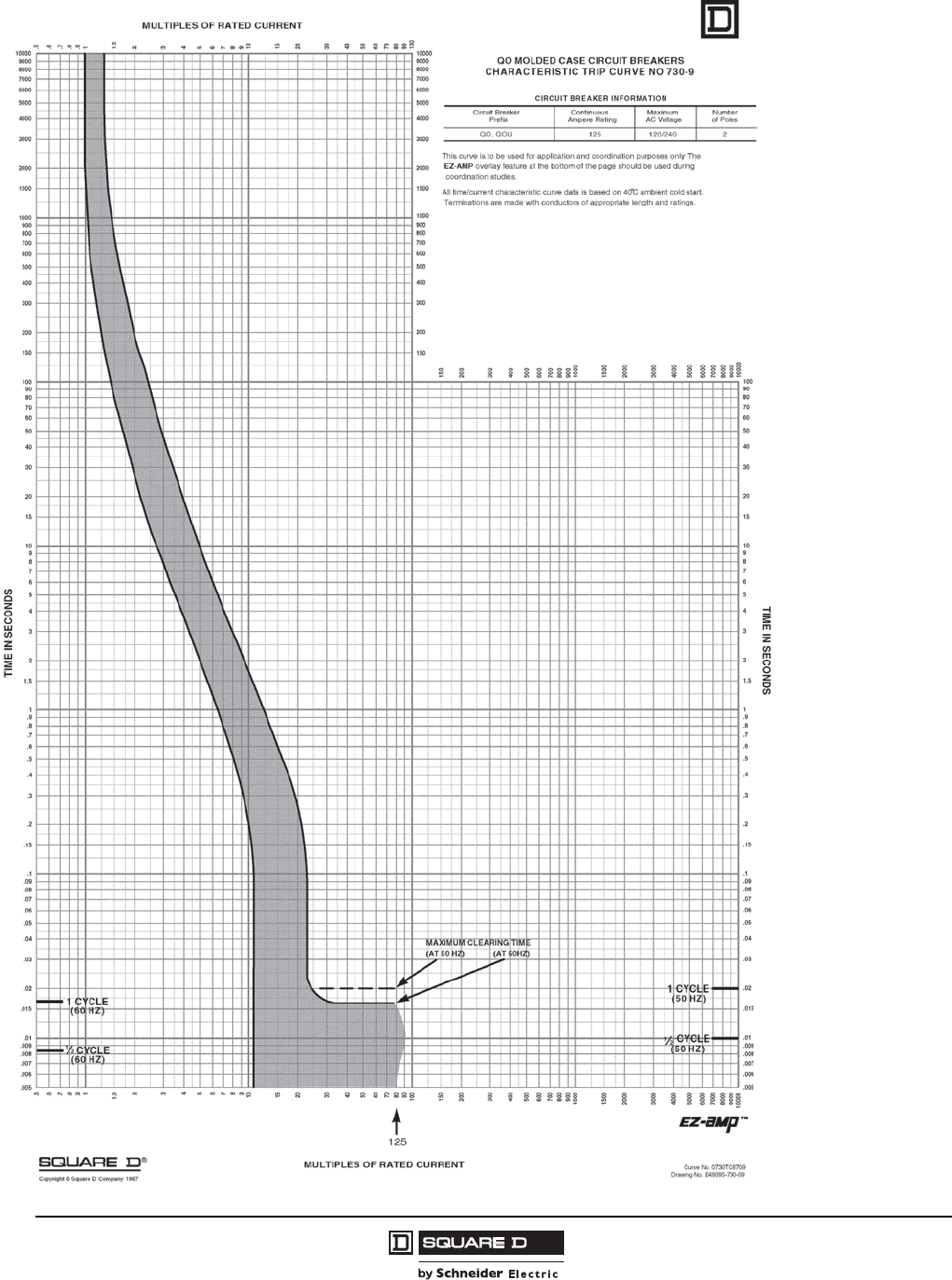
© 1998–2008 Schneider Electric
All Rights Reserved
QO® and QOB Miniature Circuit Breakers
Trip Curves
28
07/2008
267 of 292
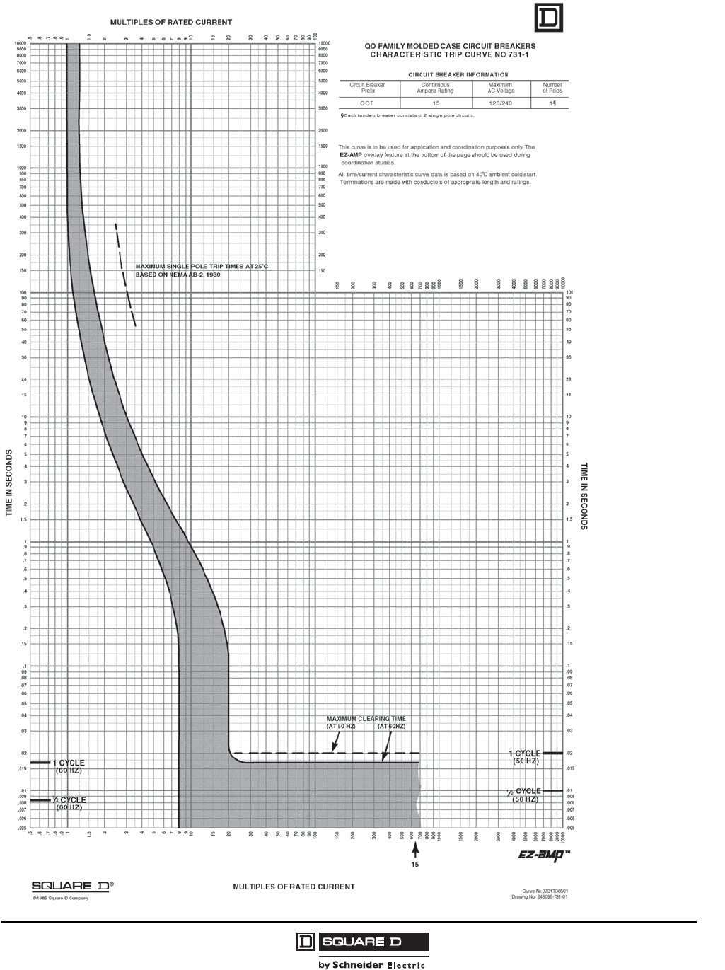
QO® and QOB Miniature Circuit Breakers
Trip Curves
29
07/2008
© 1998–2008 Schneider Electric
All Rights Reserved
268 of 292
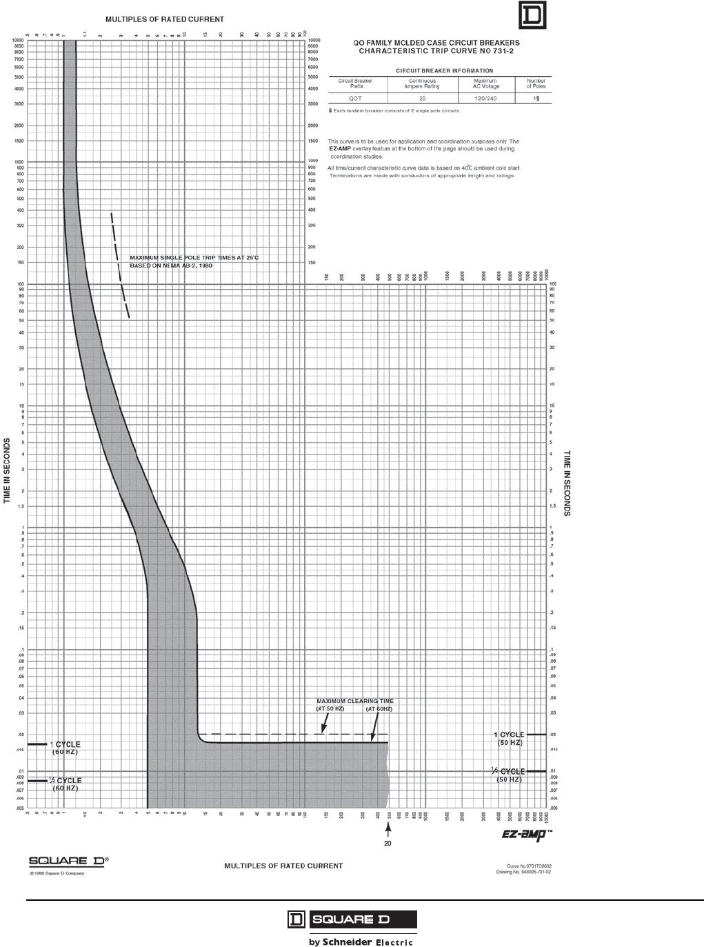
© 1998–2008 Schneider Electric
All Rights Reserved
QO® and QOB Miniature Circuit Breakers
Trip Curves
30
07/2008
269 of 292
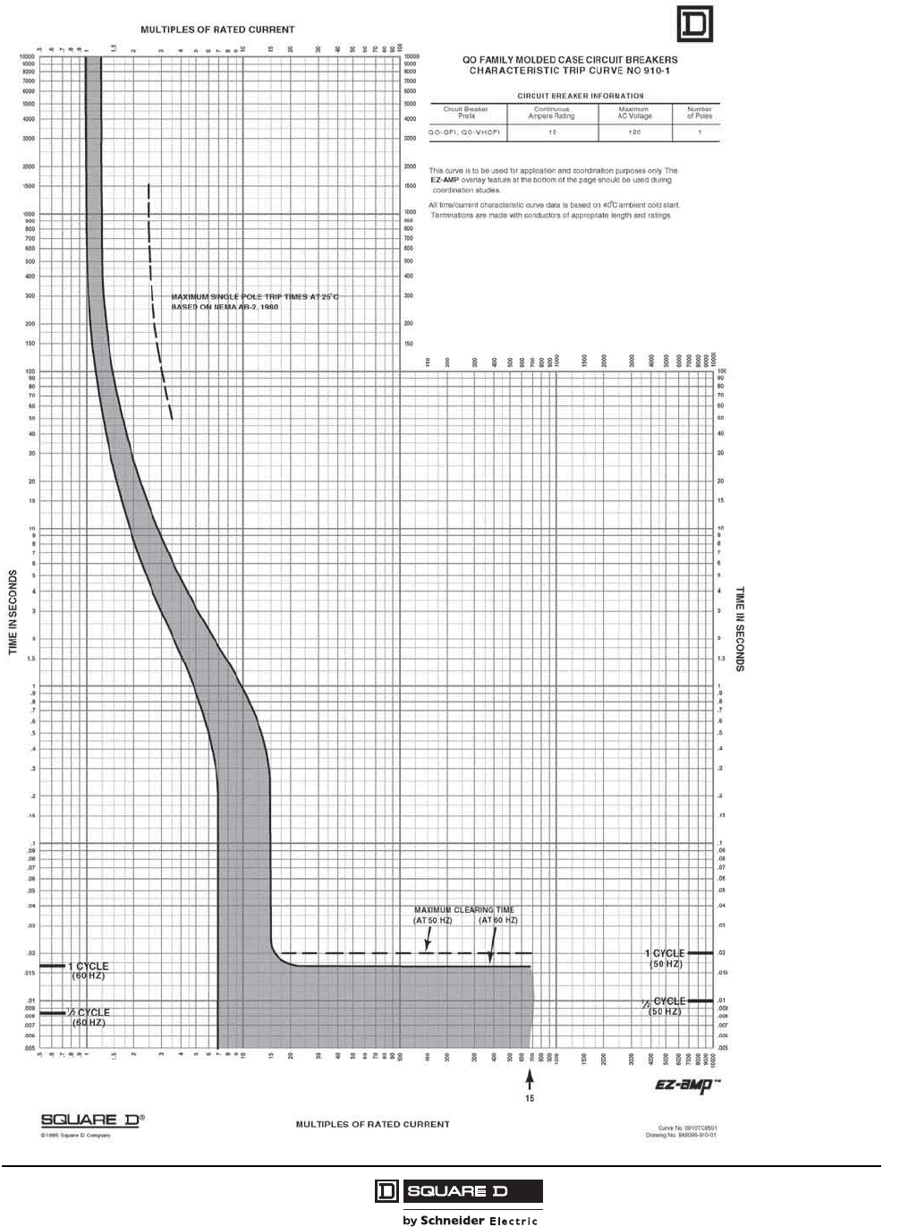
QO® and QOB Miniature Circuit Breakers
Trip Curves
31
07/2008
© 1998–2008 Schneider Electric
All Rights Reserved
270 of 292
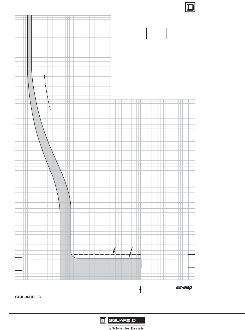
© 1998–2008 Schneider Electric
All Rights Reserved
QO® and QOB Miniature Circuit Breakers
Trip Curves
32
07/2008
1.5
700
150
200
300
400
600
800
900
2000
3000
4000
5000
7000
8000
9000
10000
.5
.6
.7
.8
.9
1
2
3
4
5
6
7
8
9
10
15
20
30
40
50
60
70
80
90
100
6000
1500
1000
500
.005
.006
.007
.008
.009
.01
.015
.02
.03
.04
.05
.06
.07
.08
.09
.1
.15
.2
.3
.4
.5
.6
.7
.8
.9
1
1.5
2
3
4
5
6
7
8
9
10
20
30
40
50
60
70
80
90
100
15
200
300
400
500
600
700
800
900
1000
1500
2000
3000
4000
6000
7000
8000
9000
5000
10000
1
.5
.6
.7
.8
.9
1.5
2
3
4
5
6
7
8
9
10
15
20
30
40
50
60
70
80
90
100
MULTIPLES OF RATED CURRENT
TIME IN SECONDS
.005
.006
.007
.008
.009
.01
.015
.02
.03
.04
.05
.06
.07
.08
.09
.1
.15
.2
.3
.4
.5
.6
.7
.8
.9
1
1.5
2
3
4
5
6
7
8
9
10
15
20
30
40
50
60
70
80
90
100
150
200
300
400
500
600
700
800
900
1000
1500
2000
3000
4000
5000
6000
7000
8000
9000
10000
TIME IN SECONDS
1/2 CYCLE
(60 Hz)
1/2 CYCLE
(50 Hz)
150
200
300
400
500
600
700
800
900
1000
1500
2000
3000
4000
5000
6000
7000
8000
9000
10000
150
MULTIPLES OF RATED CURRENT
1 CYCLE
(60 Hz)
1 CYCLE
(50 Hz)
20
MAXIMUM SINGLE-POLE TRIP TIMES
AT 25°C BASED ON NEMA AB-4 1991
MAXIMUM CLEARING TIME
(AT 50 Hz) (AT 60 Hz)
QO
®
FAMILY MOLDED CASE CIRCUIT BREAKERS
CHARACTERISTIC TRIP CURVE NO. 910-2
CIRCUIT BREAKER INFORMATION
Circuit Breaker Continuous Maximum Number
Prex Ampere Rating AC Voltage of Poles
QO/B-GFI, QO/B-VHGFI,
QO/B-AFI, QO/B-VHAFI 20 120 1
This curve is to be used for application and coordination purposes only. The
EZ-AMP overlay feature at the bottom of the page should be used during
coordination studies.
All time/current characteristic curve data is based on 40°C ambient cold start.
Te rminations are made with conductors of appropriate length and ratings.
®
© 2003 Schneider Electric all rights reserved
Curve No. 0910TC0302
January 2003
Drawing No. B48095-910-02
(Replaces 0910TC0102)
TM
271 of 292

QO® and QOB Miniature Circuit Breakers
Trip Curves
33
07/2008
© 1998–2008 Schneider Electric
All Rights Reserved
1.5
700
150
200
300
400
600
800
900
2000
3000
4000
5000
7000
8000
9000
10000
.5
.6
.7
.8
.9
1
2
3
4
5
6
7
8
9
10
15
20
30
40
50
60
70
80
90
100
6000
1500
1000
500
.005
.006
.007
.008
.009
.01
.015
.02
.03
.04
.05
.06
.07
.08
.09
.1
.15
.2
.3
.4
.5
.6
.7
.8
.9
1
1.5
2
3
4
5
6
7
8
9
10
20
30
40
50
60
70
80
90
100
15
200
300
400
500
600
700
800
900
1000
1500
2000
3000
4000
6000
7000
8000
9000
5000
10000
1
.5
.6
.7
.8
.9
1.5
2
3
4
5
6
7
8
9
10
15
20
30
40
50
60
70
80
90
100
MULTIPLES OF RATED CURRENT
TIME IN SECONDS
.005
.006
.007
.008
.009
.01
.015
.02
.03
.04
.05
.06
.07
.08
.09
.1
.15
.2
.3
.4
.5
.6
.7
.8
.9
1
1.5
2
3
4
5
6
7
8
9
10
15
20
30
40
50
60
70
80
90
100
150
200
300
400
500
600
700
800
900
1000
1500
2000
3000
4000
5000
6000
7000
8000
9000
10000
TIME IN SECONDS
1/2 CYCLE
(60 Hz)
1/2 CYCLE
(50 Hz)
150
200
300
400
500
600
700
800
900
1000
1500
2000
3000
4000
5000
6000
7000
8000
9000
10000
150
MULTIPLES OF RATED CURRENT
1 CYCLE
(60 Hz)
1 CYCLE
(50 Hz)
15 A
20 A
25 A
MAXIMUM CLEARING TIME
(AT 50 Hz) (AT 60 Hz)
20 1525
MAXIMUM SINGLE-POLE TRIP TIMES
AT 25°C BASED ON NEMA AB-4 1991
QO
®
FAMILY MOLDED CASE CIRCUIT BREAKERS
CHARACTERISTIC TRIP CURVE NO. 910-3
CIRCUIT BREAKER INFORMATION
Circuit Breaker Continuous Maximum Number
Prex Ampere Rating AC Voltage of Poles
QO-EPD, QO-GFI 15 120/240 2
QO-EPD, QO-GFI 20 & 25 120/240 2
QO-EPD, QO-GFI, QO-VHGFI 25 120 1
This curve is to be used for application and coordination purposes only. The
EZ-AMP overlay feature at the bottom of the page should be used during
coordination studies.
All time/current characteristic curve data is based on 40°C ambient cold start.
Terminations are made with conductors of appropriate length and ratings.
®
© 2001 Schneider Electric all rights reserved
Curve No. 0910TC0103
November 2001
Drawing No. B48095-910-03
(Replaces 0910TC8503)
TM
272 of 292
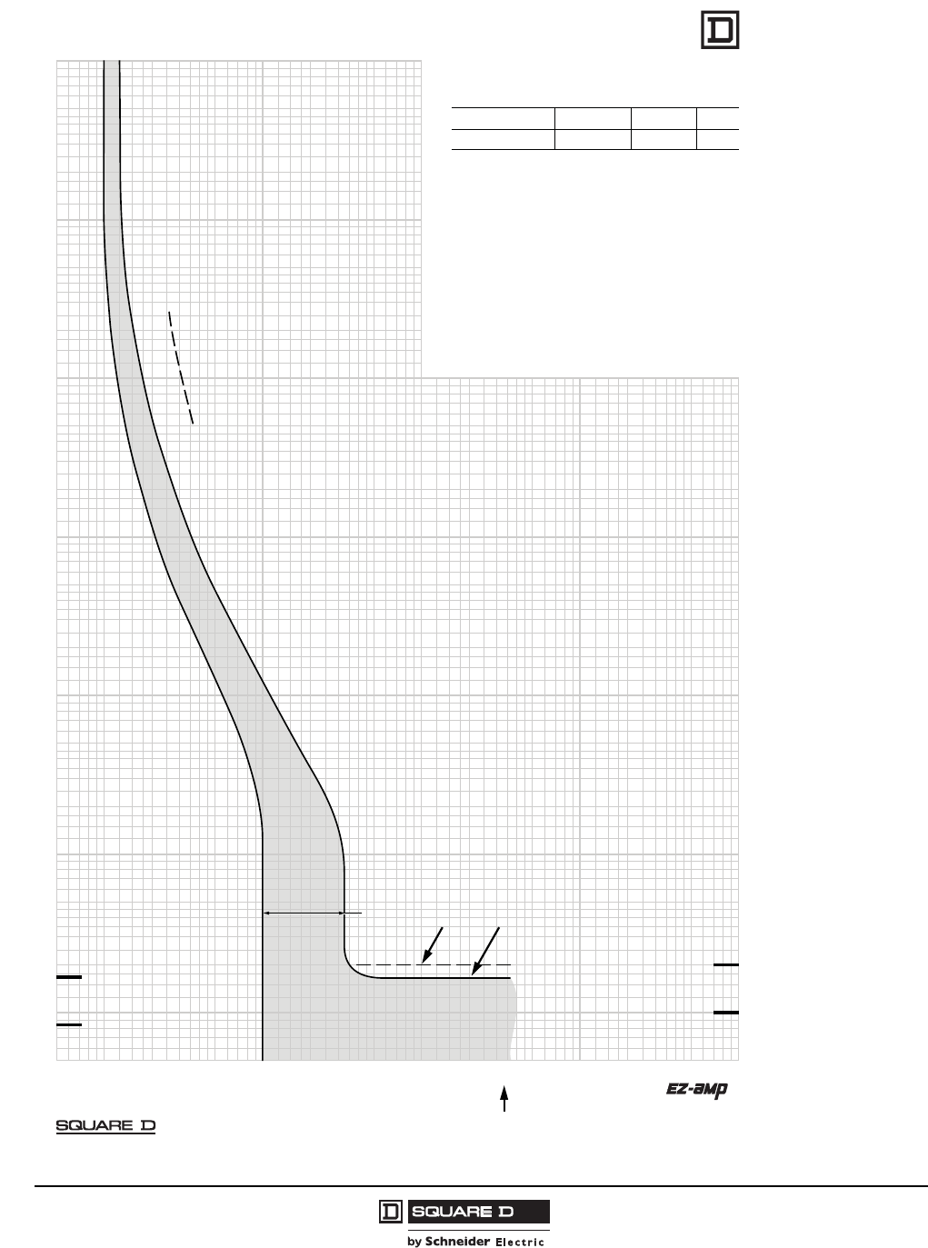
© 1998–2008 Schneider Electric
All Rights Reserved
QO® and QOB Miniature Circuit Breakers
Trip Curves
34
07/2008
1.5
700
150
200
300
400
600
800
900
2000
3000
4000
5000
7000
8000
9000
10000
.5
.6
.7
.8
.9
1
2
3
4
5
6
7
8
9
10
15
20
30
40
50
60
70
80
90
100
6000
1500
1000
500
.005
.006
.007
.008
.009
.01
.015
.02
.03
.04
.05
.06
.07
.08
.09
.1
.15
.2
.3
.4
.5
.6
.7
.8
.9
1
1.5
2
3
4
5
6
7
8
9
10
20
30
40
50
60
70
80
90
100
15
200
300
400
500
600
700
800
900
1000
1500
2000
3000
4000
6000
7000
8000
9000
5000
10000
1
.5
.6
.7
.8
.9
1.5
2
3
4
5
6
7
8
9
10
15
20
30
40
50
60
70
80
90
100
MULTIPLES OF RATED CURRENT
TIME IN SECONDS
.005
.006
.007
.008
.009
.01
.015
.02
.03
.04
.05
.06
.07
.08
.09
.1
.15
.2
.3
.4
.5
.6
.7
.8
.9
1
1.5
2
3
4
5
6
7
8
9
10
15
20
30
40
50
60
70
80
90
100
150
200
300
400
500
600
700
800
900
1000
1500
2000
3000
4000
5000
6000
7000
8000
9000
10000
TIME IN SECONDS
1/2 CYCLE
(60 Hz)
1/2 CYCLE
(50 Hz)
150
200
300
400
500
600
700
800
900
1000
1500
2000
3000
4000
5000
6000
7000
8000
9000
10000
150
MULTIPLES OF RATED CURRENT
1 CYCLE
(60 Hz)
1 CYCLE
(50 Hz)
30 A MAXIMUM CLEARING TIME
(AT 50 Hz) (AT 60 Hz)
30
MAXIMUM SINGLE-POLE TRIP TIMES
AT 25°C BASED ON NEMA AB-4 1991
QO
®
FAMILY MOLDED CASE CIRCUIT BREAKERS
CHARACTERISTIC TRIP CURVE NO. 910-4
CIRCUIT BREAKER INFORMATION
Circuit Breaker Continuous Maximum Number
Prex Ampere Rating AC Voltage of Poles
QO-EPD, QO-GFI, QO-VHGFI 30 120 1
QO-EPD, QO-GFI 30 120/240 2
This curve is to be used for application and coordination purposes only. The
EZ-AMP overlay feature at the bottom of the page should be used during
coordination studies.
All time/current characteristic curve data is based on 40°C ambient cold start.
Terminations are made with conductors of appropriate length and ratings.
®
© 2001 Schneider Electric all rights reserved
Curve No. 0910TC0104
November 2001
Drawing No. B48095-910-04
(Replaces 0910TC8504)
TM
273 of 292
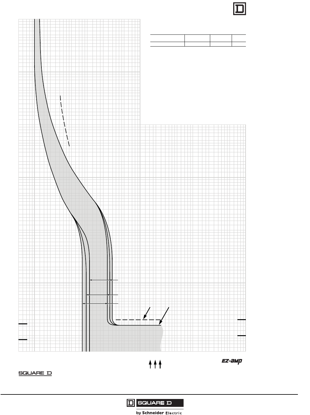
QO® and QOB Miniature Circuit Breakers
Trip Curves
35
07/2008
© 1998–2008 Schneider Electric
All Rights Reserved
1.5
700
150
200
300
400
600
800
900
2000
3000
4000
5000
7000
8000
9000
10000
.5
.6
.7
.8
.9
1
2
3
4
5
6
7
8
9
10
15
20
30
40
50
60
70
80
90
100
6000
1500
1000
500
.005
.006
.007
.008
.009
.01
.015
.02
.03
.04
.05
.06
.07
.08
.09
.1
.15
.2
.3
.4
.5
.6
.7
.8
.9
1
1.5
2
3
4
5
6
7
8
9
10
20
30
40
50
60
70
80
90
100
15
200
300
400
500
600
700
800
900
1000
1500
2000
3000
4000
6000
7000
8000
9000
5000
10000
1
.5
.6
.7
.8
.9
1.5
2
3
4
5
6
7
8
9
10
15
20
30
40
50
60
70
80
90
100
MULTIPLES OF RATED CURRENT
TIME IN SECONDS
.005
.006
.007
.008
.009
.01
.015
.02
.03
.04
.05
.06
.07
.08
.09
.1
.15
.2
.3
.4
.5
.6
.7
.8
.9
1
1.5
2
3
4
5
6
7
8
9
10
15
20
30
40
50
60
70
80
90
100
150
200
300
400
500
600
700
800
900
1000
1500
2000
3000
4000
5000
6000
7000
8000
9000
10000
TIME IN SECONDS
1/2 CYCLE
(60 Hz)
1/2 CYCLE
(50 Hz)
150
200
300
400
500
600
700
800
900
1000
1500
2000
3000
4000
5000
6000
7000
8000
9000
10000
150
MULTIPLES OF RATED CURRENT
1 CYCLE
(60 Hz)
1 CYCLE
(50 Hz)
60 A
50 A
40 A
MAXIMUM CLEARING TIME
(AT 50 Hz) (AT 60 Hz)
50 4060
MAXIMUM SINGLE-POLE TRIP TIMES
AT 25°C BASED ON NEMA AB-4 1991
QO
®
FAMILY MOLDED CASE CIRCUIT BREAKERS
CHARACTERISTIC TRIP CURVE NO. 910-5
CIRCUIT BREAKER INFORMATION
Circuit Breaker Continuous Maximum Number
Prex Ampere Rating AC Voltage of Poles
QO-EPD, QO-GFI 40–60 a120/240 2
a60 A suitable only for feeding 240 Vac, 2 wire loads on 120/240 Vac, 1 φ3W systems.
This curve is to be used for application and coordination purposes only. The
EZ-AMP overlay feature at the bottom of the page should be used during
coordination studies.
All time/current characteristic curve data is based on 40°C ambient cold start.
Terminations are made with conductors of appropriate length and ratings.
®
© 2001 Schneider Electric all rights reserved
Curve No. 0910TC0105
November 2001
Drawing No. B48095-910-05
(Replaces 0910TC8705)
TM
274 of 292
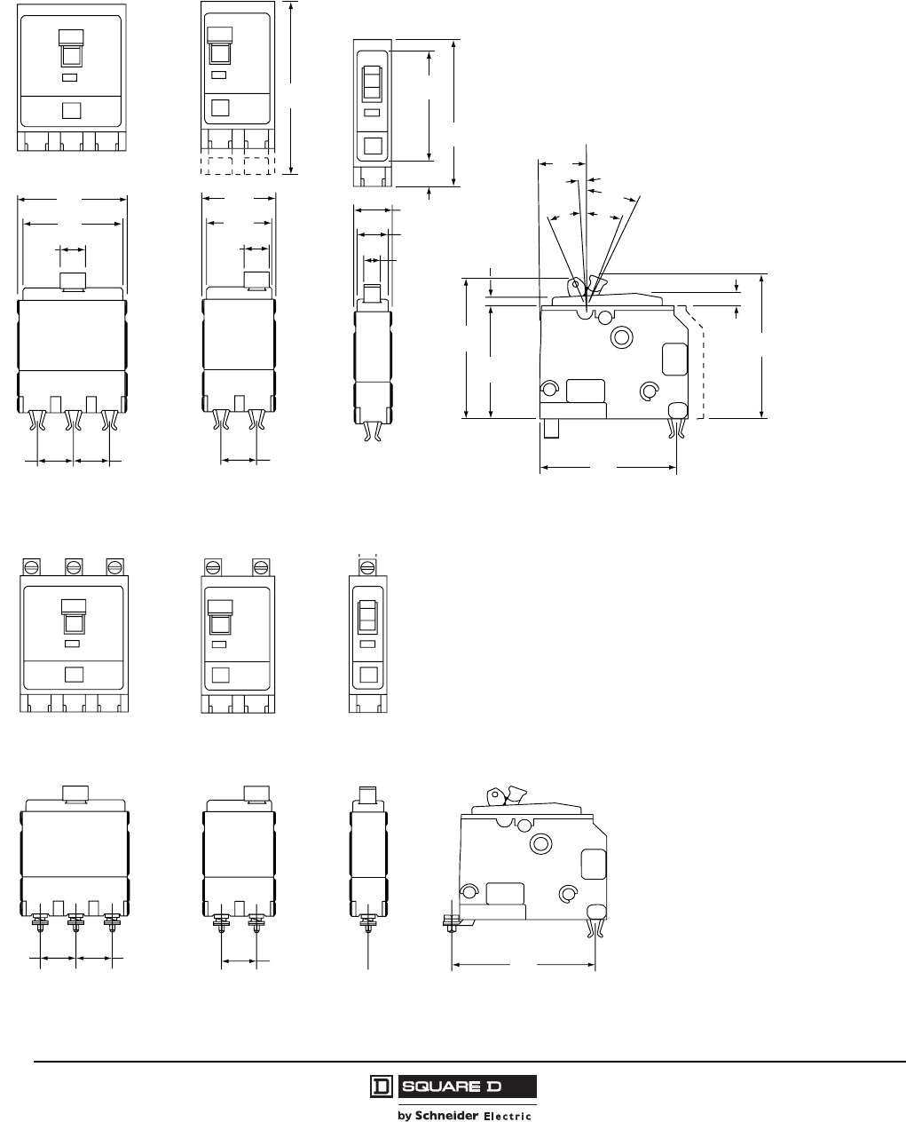
© 1998–2008 Schneider Electric
All Rights Reserved
QO® and QOB Miniature Circuit Breakers
Dimensions
36
07/2008
Dimensions
Figure 10: Type QO Plug-On Circuit Breaker
2.23
57
2.09
53
0.53
13
0.75
19 0.75
19
3.5
89
0.75
19
0.53
13
1.34
34
1.48
38
0.38
10
0.59
15
0.73
19
3.00
76
2.25
57
2.75
70
2.92
74
0.25
6
21°
0.16
4
2.91
74
2.31
59
26°
3°
0.94
24
22°
ON
Tripped
OFF
Reset
07303114
Figure 11: Type QOB Bolt-On Circuit Breaker
0.75
19
0.75
19
0.75
19 2.94
75
07303115
275 of 292
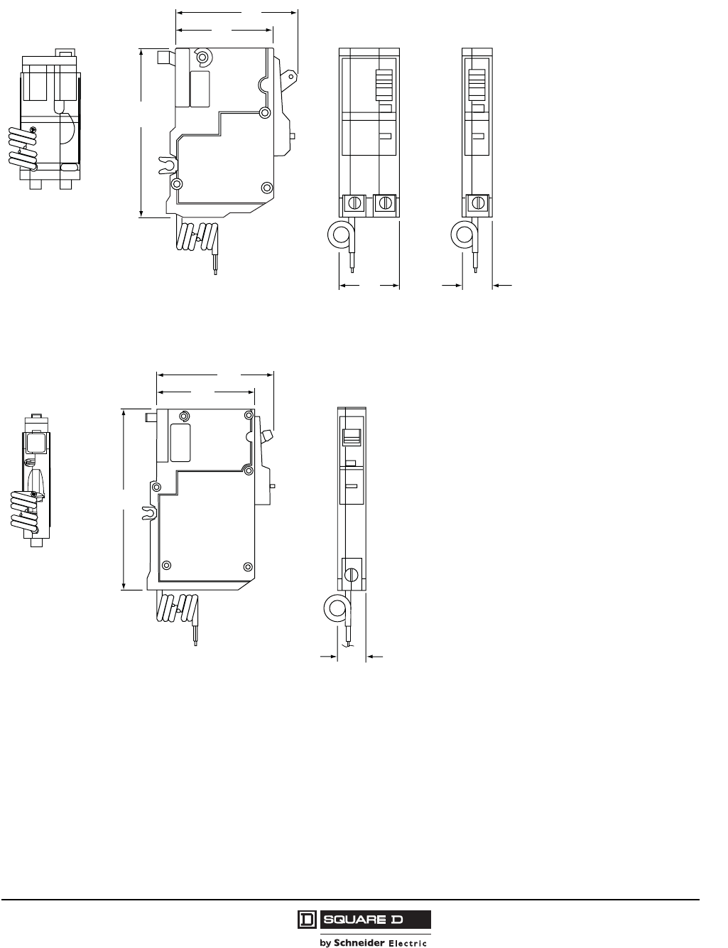
QO® and QOB Miniature Circuit Breakers
Dimensions
37
07/2008
© 1998–2008 Schneider Electric
All Rights Reserved
Figure 12: Type QO-GFI Circuit Breaker
1.49
38
2.31
59
4.12
103
2.91
74
18
457
Pigtail: 0.744
19
07303116
Figure 13: Type QO-AFI and QO-AFCI Circuit Breakers
4.75
121
18
457
2.31
59
2.90
74
Pigtail:
20
0.744
19
073033117
276 of 292
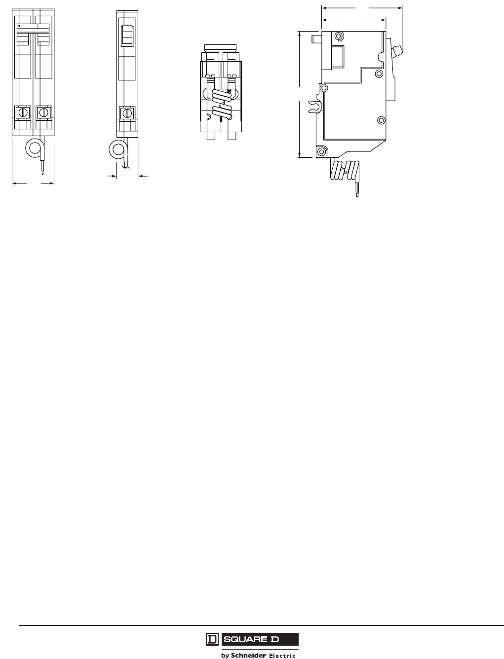
© 1998–2008 Schneider Electric
All Rights Reserved
QO® and QOB Miniature Circuit Breakers
Dimensions
38
07/2008
Figure 14: Type QO-PL Remote Control Circuit Breaker
Common Trip 30
1.49
38
20
0.744
19
2.31
59
4.55
116
18
457
2.95
75
Pigtail:
07303118
277 of 292

0730CT9801R1/08 © 1998–2008 Schneider Electric All Rights Reserved
Replaces 0730CT9801
07/2008
Schneider Electric USA
3700 Sixth St. SW
Cedar Rapids, IA 52404 USA
1-888-Square D
1-888-778-2733
www.schneider-electric.us
278 of 292
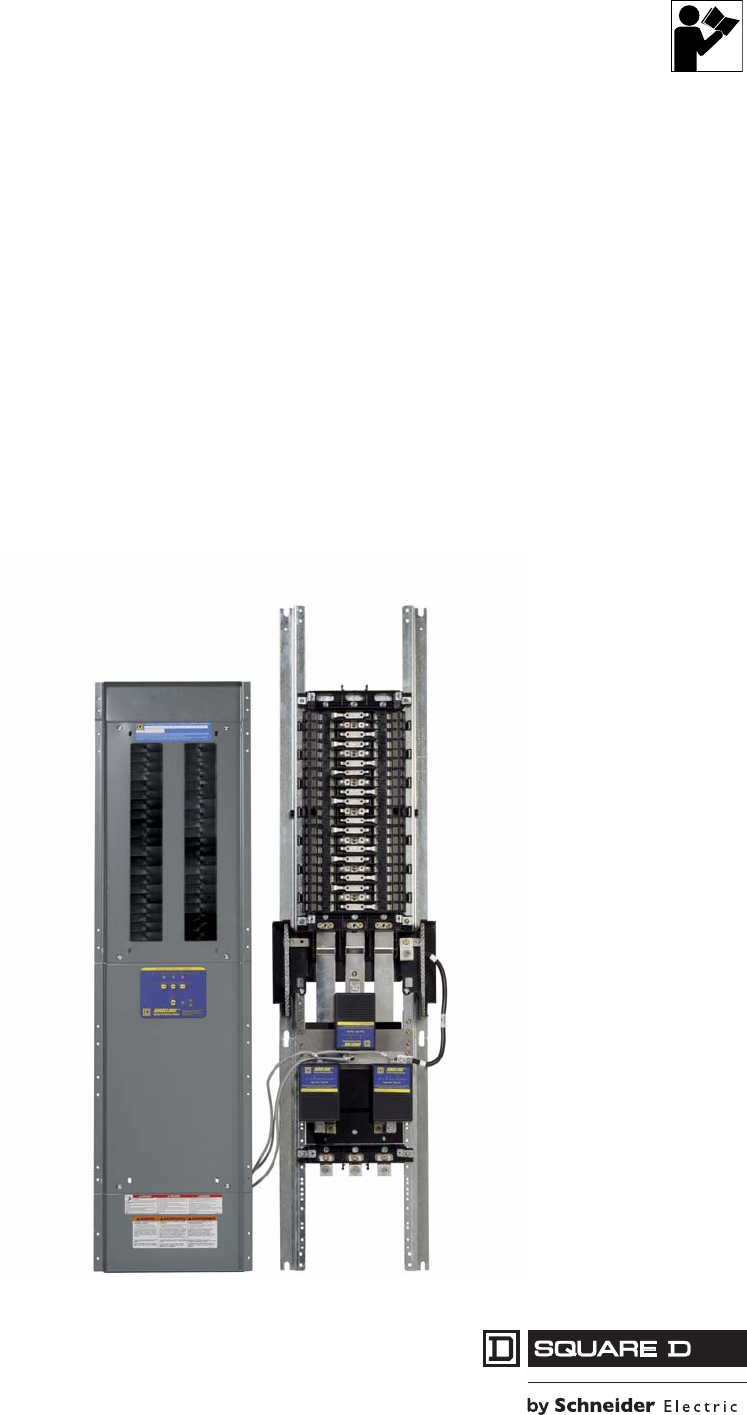
Surgelogic®
IMA Surge Protective Device (SPD)
Dispositivo de protección contra sobretensiones
transitorias IMA
Dispositif de protection contre les surtensions
transitoires IMA
Instruction Bulletin
Boletín de instrucciones
Directives d'utilisation
8222-0050E
Retain for Future Use. /
Conservar para uso futuro. /
À conserver pour usage ultérieur.
279 of 292
ENGLISH
Surgelogic® IMA SPD 8222-0050E
Precautions 11/2009
© 2002–2009 Schneider Electric All Rights Reserved2
For troubleshooting, call the Surgelogic Technical Assistance Group at 1-800-577-7353.
Precautions
Surge Protective Devices (SPDs) can lose their ability to block power system
voltage and attempt to draw excessive current from the line.This SPD is
equipped with overcurrent and overtemperature components that will
automatically disconnect the surge suppression elements from the mains should
the surge suppression elements reach end of life. Tripping of the branch circuit
breaker or fuse feeding the SPD can occur when the surge suppression
elements reach end of life. Mitigate the tripping of the branch circuit breaker or
fuse feeding the SPD by coordinating the surge suppression elements with the
branch circuits.
For the purposes of coordination, the SPD is equipped with overcurrent
components that will limit the per phase I2t, Iapparent, Ip, and Ith values to those
listed in tables 1 and 2 when connected to a power system with a short-circuit
current rating not exceeding 200,000 A.
DANGER
HAZARD OF ELECTRIC SHOCK, EXPLOSION, OR ARC FLASH
• Apply appropriate personal protective equipment (PPE) and follow safe
electrical work practices. See NFPA 70E.
• This equipment must only be installed and serviced by qualified
electrical personnel.
• Turn off all power supplying this equipment before working on or inside
equipment.
• Always use a properly rated voltage sensing device to confirm power is off.
• Replace all devices, doors and covers before turning on power to this
equipment.
• This equipment must be effectively grounded per all applicable codes.
Use an equipment-grounding conductor to connect this equipment to
the power system ground.
Failure to follow these instructions will result in death or serious injury.
CAUTION
LOSS OF BRANCH CIRCUIT POWER/LOSS OF SURGE
SUPPRESSION
• Ensure that the branch circuit breaker or fuse trip characteristic has
been coordinated with the overcurrent components inside the SPD
(See Tables 1 and 2).
• Perform periodic inspection of the SPD status indicator lights as part of
the preventative maintenance schedule.
• Promptly service the SPD when an alarm state exists.
• Use dry contacts to signal an alarm state to the central supervisory
system for unmanned, inaccessible, or critical installations.
• Use multiple SPDs to achieve redundancy for critical applications.
Failure to follow these instructions can result in injury or equipment
damage.
280 of 292
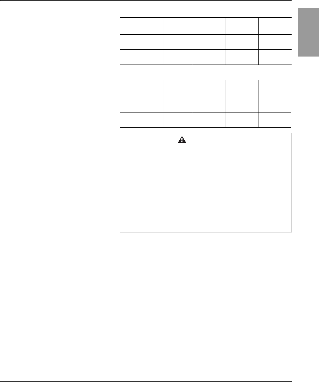
8222-0050E Surgelogic® IMA SPD
11/2009 Precautions
© 2002–2009 Schneider Electric All Rights Reserved 3
ENGLISH
For troubleshooting, call the Surgelogic Technical Assistance Group at 1-800-577-7353.
Table 1: SPD Without Optional Sine Wave Tracking Module
SPD Device Per Phase
I2tIapparent IpIth
TVS_IMA12 through
TVS_IMA24
175 kA2
seconds 17,000 A RMS 40,000 A RMS 220 A
TVS_IMA32 through
TVS_IMA48
700 kA2
seconds 34,000 A RMS 80,000 A RMS 440 A
Table 2: SPD With Optional Sine Wave Tracking Module
SPD Device Per Phase
I2tIapparent IpIth
TVS_IMA12 through
TVS_IMA24 and
240 kA2
seconds 21,500 A RMS 48,000 A RMS 260 A
TVS_IMA32 through
TVS_IMA48
825 kA2
seconds 37,500 A RMS 88,000 A RMS 480 A
CAUTION
LOSS OF SURGE SUPPRESSION
• Do not energize the SPDs until the electrical system is completely
installed, inspected, tested, and all conductors connected and
functional, including the neutral.
• Verify the voltage rating of the device and system before energizing the
surge protective device.
• Perform high-potential insulation testing, or any other tests where SPD
components will be subjected to voltages higher than their rated turn-on
voltage, with the neutral and SPD disconnected from the power source.
Failure to follow these instructions can result in injury or equipment
damage.
281 of 292
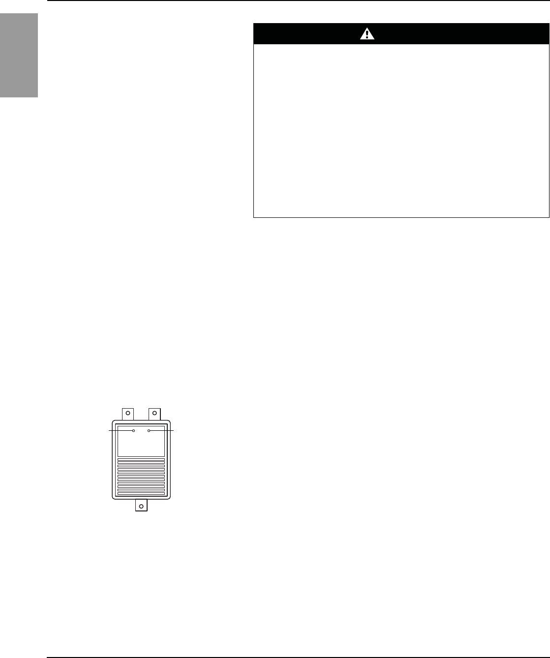
ENGLISH
Surgelogic® IMA SPD 8222-0050E
Operation 11/2009
© 2002–2009 Schneider Electric All Rights Reserved4
For troubleshooting, call the Surgelogic Technical Assistance Group at 1-800-577-7353.
Operation
LED Status Indicators The SPD diagnostic display panel shows the status of each MA module with
diagnostically controlled green/red LEDs. If a unit is operating correctly, all the
phase LEDs will be illuminated green. To test the integrity of the diagnostics for
each phase, push the button below the phase LEDs on the diagnostic display
panel. The green LED will turn red and the alarm will sound, if the alarm is
enabled. Releasing the test button will complete the test; the red LED will turn
green and the alarm will shut off.
If an inoperable condition occurs on any phase, the audible alarm sounds and
the corresponding phase LED on the diagnostic display panel is illuminated red.
This indicates that the device needs service by qualified electrical personnel.
The audible alarm can be silenced, until a qualified person is able to evaluate
and service the SPD, by pressing the alarm enable/disable button. The alarm
will silence and the green alarm LED will not be lit. The red phase LED will
continue to be illuminated until the inoperative condition has been cleared.
On an MA module (see Figure 1), if either LED is not lit, the module should be
replaced. If both green LEDs are not lit and the diagnostic display panel has
power, then power has been lost to that phase or the module should be replaced
(refer to Table 4 on page 7). Refer to the final equipment instruction bulletin for
MA module disconnection and access instructions.
When power is applied to the SPD and one or more of the diagnostic display
panel LEDs are red, and one or more MA module LEDs are out, the appropriate
MA module should be replaced. Refer to “Troubleshooting” on page 8 for proper
troubleshooting procedures.
Surge Counter The surge counter displays the number of transient voltage surges since the
counter was last reset. The counter is battery powered to retain memory in the
event of a power loss to the diagnostic display panel.
To reset the surge counter to zero:
1. Remove all power from this equipment.
2. Remove covers as necessary to gain access to the diagnostic circuit board.
3. Press the small switch located on the underside of the diagnostic circuit
board (near the RJ45 connectors; see Figure 3:). This will reset the counter
to zero.
DANGER
HAZARD OF ELECTRIC SHOCK, EXPLOSION, OR ARC FLASH
• Apply appropriate personal protective equipment (PPE) and follow safe
electrical work practices. See NFPA 70E.
• This equipment must only be installed and serviced by qualified electrical
personnel.
• Turn off all power supplying this equipment before working on or inside
equipment.
• Always use a properly rated voltage sensing device to confirm power is off.
• Replace all devices, doors and covers before turning on power to this
equipment.
• This equipment must be effectively grounded per all applicable codes. Use
an equipment-grounding conductor to connect this equipment to the power
system ground.
Failure to follow these instructions will result in death or serious injury.
Figure 1: MA Module LEDs
Left green LED lit:
L-G suppression
is operating.
Left green LED
not lit:
Loss of surge
suppression from
L-G
Right green LED lit:
L-N suppression is
operating.
Right green LED
not lit:
Loss of surge
suppression from
L-N
282 of 292
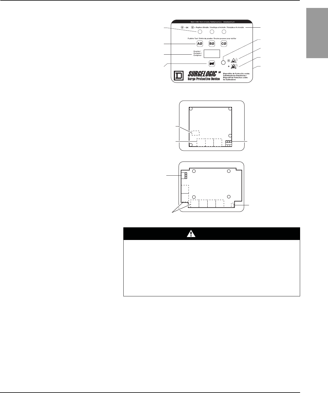
8222-0050E Surgelogic® IMA SPD
11/2009 Operation
© 2002–2009 Schneider Electric All Rights Reserved 5
ENGLISH
For troubleshooting, call the Surgelogic Technical Assistance Group at 1-800-577-7353.
Dry Contacts
The IMA series SPD is provided with dry contacts. The connection for the dry
contacts is located on the back of the diagnostic display panel (lower right
corner). The dry contacts are 3-position, Form “C” type with Normally Open,
Normally Closed and Common connections. The unpowered state shall be
closed between terminals NC and COM. This is also the alarm condition. The
opposite state, closed between terminals NO and COM, indicates that power is
on to the unit and that no alarm condition exists (See Table 3).
Figure 2: Three-Phase Diagnostic Display Panel with Surge Counter
=
=
Phase LEDs
On-Line diagnostic
push buttons
Surge counter
Alarm enable/disable
push button
Description of
phase LEDs
Alarm LED
Enable alarm
Disable alarm
Surge counter
reset switch
(on diagnostic
circuit board)
NOTE: Phase B is not present on single-phase
applications.
Figure 3: Rear of Diagnostic Circuit Board
Dry contacts
RJ45 Connectors
Surge counter
reset switch
(white)
Surge counter
reset switch (white)
Dry contacts
RJ45 Connectors
TVS3DSPHC
TVS6DSPHC
DANGER
HAZARD OF ELECTRIC SHOCK, EXPLOSION, OR ARC FLASH
• Use 600 Vac rated dry contact wiring.
• Dry contact wiring must have less than 1/16 in. (1.6 mm) exposed wire from
the dry contact block.
• Maintain at least 1.0 in. (25 mm) separation between dry contact wiring and
the power wiring in the enclosure.
Failure to follow these instructions will result in death or serious injury.
283 of 292
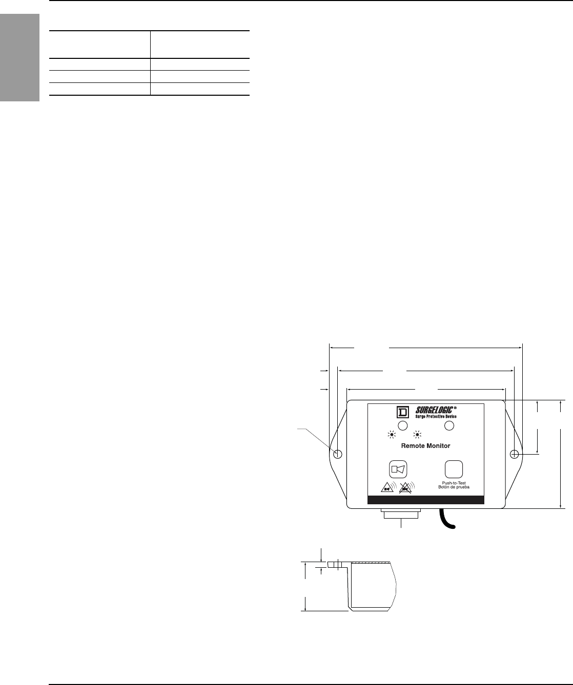
ENGLISH
Surgelogic® IMA SPD 8222-0050E
Operation 11/2009
© 2002–2009 Schneider Electric All Rights Reserved6
For troubleshooting, call the Surgelogic Technical Assistance Group at 1-800-577-7353.
These contacts can be used for remote indication of the SPD device’s operating
status to a computer interface board or emergency management system. Also,
these contacts are designed to work with the SPD remote monitor option
described below.
The contacts are designed for a maximum voltage of 24 Vdc / 24 Vac and a
maximum current of 2 A. Higher energy applications may require additional relay
implementation outside the SPD. Damage to the SPD’s relay caused by use with
energy levels in excess of those discussed in this instruction bulletin are not
covered by warranty. For application questions, contact the Surgelogic
Technical Assistance Group at 1-800-577-7353.
Remote Monitor Option The option has two LEDs, one red and one green, and an audible alarm with an
enable/disable switch. Normal status is a lit green LED, and no audible alarm.
To test the integrity of the remote monitor, press the push-to-test switch.
The green LED will turn off, the red LED will turn on, and the alarm will sound, if
the alarm is enabled. Releasing the switch will complete the test; the red LED
will turn off, the green LED will turn on and the alarm will shut off. If suppression
on any phase is lost, the green LED will turn off, the red LED will turn on and an
alarm sounds. The audible alarm can be silenced by moving the alarm
enable/disable switch to the disable position. The alarm will silence and the
green alarm LED will not be lit. The red LED will continue to be illuminated until
the inoperative condition had been cleared.
The remote monitor includes a 120 Vac to 12 Vdc adapter with a six-foot power
cord. Connections are made to the SPD diagnostic display panel with Form “C”,
3-position dry contacts (provided) and the appropriate length of solid or stranded
30 to 14 AWG wire (not provided).
Table 3: Dry Contact Configuration
Alarm Contact
Terminals Contact State with
Power Removed
NC Normally closed
COM Common
NO Normally open
Figure 4: Remote Monitor Option (TVS12RMU)
= OK = Fault / Falla / Défaut
www.SquareD.com • 8220-0037A • Made in USA / Hecho en E.U.A. / Fabriqué aux É.-U.
Bouton pousser pour vérifier
Monitor Remoto / Moniteur À Distance
[63,5]
2.500
[31,8]
1.25
[88,9]
3.500
[100,3]
3.950
[5,86]
0.230
[5,86]
0.460
[4,75]
2x Ø 0.187
[111,76]
4.400
[3,3]
0.130
[28,58]
1.125
in.
[mm]
120 V power cord
Dry contacts
284 of 292
8222-0050E Surgelogic® IMA SPD
11/2009 Maintenance and Troubleshooting
© 2002–2009 Schneider Electric All Rights Reserved 7
ENGLISH
For troubleshooting, call the Surgelogic Technical Assistance Group at 1-800-577-7353.
Maintenance and
Troubleshooting
Preventive Maintenance Inspect the SPD periodically to maintain reliable system performance and
continued transient voltage surge suppression. Periodically check the state of
the diagnostic display panel LED status indicators. Routinely use the built-in
diagnostics to inspect for inoperative modules.
Replacement Modules
DANGER
HAZARD OF ELECTRIC SHOCK, EXPLOSION, OR ARC FLASH
• Apply appropriate personal protective equipment (PPE) and follow safe
electrical work practices. See NFPA 70E.
• This equipment must only be installed and serviced by qualified electrical
personnel.
• Turn off all power supplying this equipment before working on or inside
equipment.
• Always use a properly rated voltage sensing device to confirm power is off.
• Replace all devices, doors and covers before turning on power to this
equipment.
• This equipment must be effectively grounded per all applicable codes. Use
an equipment-grounding conductor to connect this equipment to the power
system ground.
Failure to follow these instructions will result in death or serious injury.
Table 4: EMA Series Replacement Modules
System
Voltage
Peak Surge
Current Rating
(kA) Phase A Phase B Phase C
120/240 V,
1-phase,
3-wire
120 MA1IMA12 — MA1IMA12
160 MA1IMA16 — MA1IMA16
240 MA1IMA24 — MA1IMA24
208Y/120 V,
3-phase,
4-wire 1
1208Y/120 series also applies to the following voltage 220Y/127.
120 MA1IMA12 MA1IMA12 MA1IMA12
160 MA1IMA16 MA1IMA16 MA1IMA16
240 MA1IMA24 MA1IMA24 MA1IMA24
120/240 V,
3-phase,
4-wire 2
2High-leg delta (Phase B modules are different than Phase A and Phase C modules).
120 MA1IMA12 MA3IMA12 MA1IMA12
160 MA1IMA16 MA3IMA16 MA1IMA16
240 MA1IMA24 MA3IMA24 MA1IMA24
480Y/277 V,
3-phase,
4-wire 3
3480Y/277 series applies to the following voltages 380Y/220, 400Y/230, and 415Y/240.
120 MA4IMA12 MA4IMA12 MA4IMA12
160 MA4IMA16 MA4IMA16 MA4IMA16
240 MA4IMA24 MA4IMA24 MA4IMA24
600/347 V,
3-phase,
4-wire
120 MA8IMA12 MA8IMA12 MA8IMA12
160 MA8IMA16 MA8IMA16 MA8IMA16
240 MA8IMA24 MA8IMA24 MA8IMA24
285 of 292
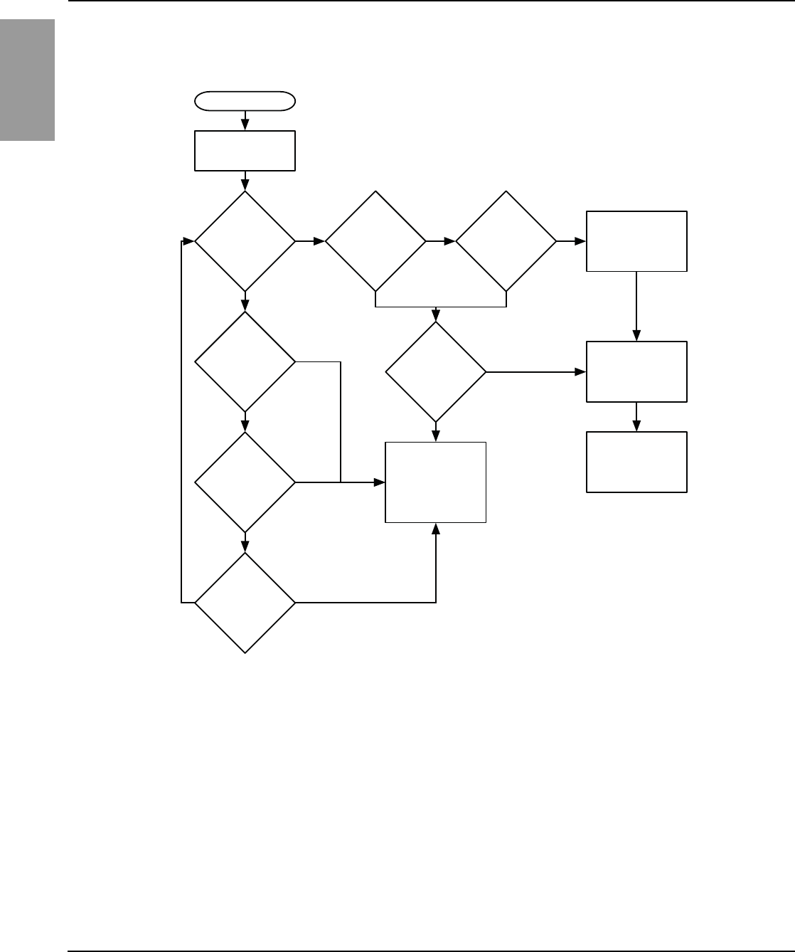
ENGLISH
Surgelogic® IMA SPD 8222-0050E
Maintenance and Troubleshooting 11/2009
© 2002–2009 Schneider Electric All Rights Reserved8
For troubleshooting, call the Surgelogic Technical Assistance Group at 1-800-577-7353.
Troubleshooting If a module shows two green indicator lights and the display panel shows a red
phase indicator light, follow the Troubleshooting Flow Chart in Figure 5 below.
Replacement Parts The following replacement parts are available. For ordering information please
contact your local distributor or refer to the product catalog.
•MA modules. Replacement instructions are included with the replacement
parts.
•Diagnostic display panel assemblies. Replacement instructions are included
with the replacement parts.
Figure 5: Troubleshooting Flow Chart
START
Red phase
LED(s) lit.
Alarm on?
Is alarm
Enable/Disable
LED on?
Press alarm
Enable/Disable
switch. Is
alarm on?
Is alarm LED
on?
NO
NO
YES
YES
Check
patch cable
connections. Is
Red LED(s)
on?
Check the
voltage on
each phase. Is
the voltage
correct?
All modules
LEDs on?
Possible diagnostic
display board failure.
Contact Technical
Assistance at
1-800-577-7353 for
troubleshooting.
NO
YES
YES YES
NO
YES
YES
NO
Check the power
utility feed and
verify voltage levels.
NO
Replace module(s)
that do not have
LEDs lit.
Energize SPD and
verify proper
connection.
NO
NOTE: For further assistance, call the Surgelogic
Technical Assistance Group at 1-800-577-7353.
286 of 292

Electrical equipment should be installed, operated, serviced, and maintained only by qualified
personnel. No responsibility is assumed by Schneider Electric for any consequences arising out of
the use of this material.
8222-0050E 11/2009
Replaces 8222-0050D, 10/2002
© 2002–2009 Schneider Electric All Rights Reserved
Schneider Electric
1751 S. 4800 W.
Salt Lake City, UT 84104 USA
1-888-SquareD
(1-888-778-2733)
www.schneider-electric.us
8222-0050E Surgelogic® IMA SPD
11/2009
Square D® is a trademark or registered trademark of Schneider Electric. Other trademarks used
herein are the property of their respective owners.
ENGLISH
287 of 292
288 of 292
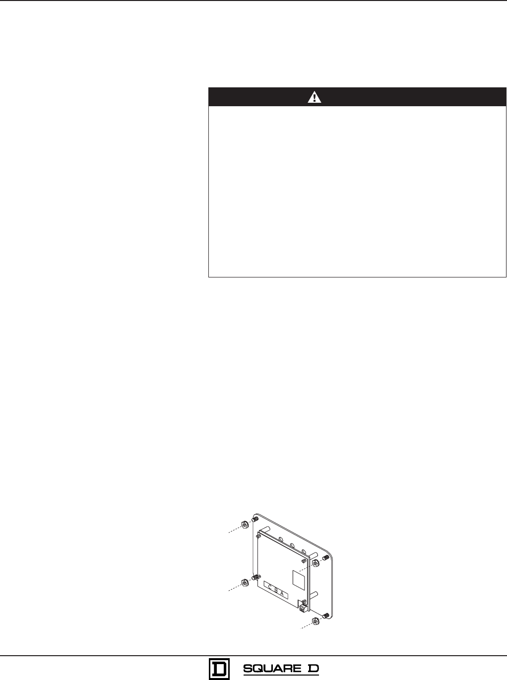
Bulletin No. 8222-0071A
12/02
Raleigh, NC, USA
Diagnostic Display Panel Replacement
IMA Series Transient Voltage Surge Suppressors (TVSS)
Class 1310
1
Instruction Bulletin
© 2002 Schneider Electric All Rights Reserved
1. Verify that the replacement diagnostic display has the correct catalog
number. The catalog number is found on the back of the diagnostic
display assembly. (See Table 1)
2. Mark the RJ45 patch cables (if they are not already marked) with the
appropriate A, B and C phase. Unplug the RJ45 patch cables from the
diagnostic display assembly (and dry contact wires if used).
3. Remove the 4 nuts holding the diagnostic display panel to the cover/door.
4. Carefully remove the old diagnostic display assembly.
5. Install the new diagnostic display assembly, using the new nuts that are
provided. (See Figure 1)
6. Plug the RJ45 patch cables into the new diagnostic display assembly.
Make sure that the patch cables labeled A, B and C are connected to the
correct RJ45 jacks.
7. Check that all connections are secure.
8. Replace the barrier, cover/door, and/or trim to the equipment.
9. Equipment may be re-energized after all of the above steps are complete.
Figure 1: Diagnostic Display Assembly Installation
PRECAUTIONS
HAZARDOUS VOLTAGE
• This equipment must be installed and serviced only by qualified
electrical personnel.
• This equipment must be effectively grounded per all applicable
codes. Use an equipment-grounding conductor to connect this
equipment to the power system ground.
• Disconnect all power supplying this equipment before working on or
inside it.
•Always use a properly rated voltage sensing device to confirm power
is off.
• Replace the barrier and the door/cover before energizing.
Failure to follow these instructions will result in death or serious
injury.
DANGER
INSTALLATION
8220-0071-01
289 of 292

Electrical equipment should be installed, operated, serviced, and maintained only by
qualified personnel. No responsibility is assumed by Schneider Electric for any
consequences arising out of the use of this material.
Diagnostic Display Panel Replacement Bulletin No. 8222-0071A
IMA Series Transient Voltage Surge Suppressors (TVSS) 12/02
Square D Company
8001 Highway 64 East
Knightdale, NC 27545
1-800-577-7353
www.squared.com
© 2002 Schneider Electric All Rights Reserved
2
Table 1: Diagnostic Display Replacements
Catalog Number System Voltage Peak Surge
Current/Phase Option Applications
TVS1DSPH 120/240 V, 1 phase, 3 wire 120 kA
160 kA
240 kA None Panelboards
Switchboards
Busway
TVS1DSPHC 120/240 V, 1 phase, 3 wire 120 kA
160 kA
240 kA Surge Counter Panelboards
Switchboards
Busway
TVS3DSPH
208Y/120 V, 3 phase, 4 wire
120/240 V, 1 phase, 3 wire high leg delta
480Y/277 V, 3 phase, 4 wire
347Y/600 V, 3 phase, 4 wire
120 kA
160 kA
240 kA None
Panelboards
Switchboards
PZ4 Switchgear
Busway
TVS3DSPHC
208Y/120 V, 3 phase, 4 wire
120/240 V, 1 phase, 3 wire high leg delta
480Y/277 V, 3 phase, 4 wire
347Y/600 V, 3 phase, 4 wire
120 kA
160 kA
240 kA Surge Counter
Panelboards
Switchboards
PZ4 Switchgear
Busway
TVS4DSPH 120/240 V, 1 phase, 3 wire 320 kA
480 kA None Switchboards
TVS4DSPHC 120/240 V, 1 phase, 3 wire 320 kA
480 kA Surge Counter Switchboards
TVS6DSPH
208Y/120 V, 3 phase, 4 wire
120/240 V, 1 phase, 3 wire high leg delta
480Y/277 V, 3 phase, 4 wire
347Y/600 V, 3 phase, 4 wire
320 kA
480 kA None Switchboards
PZ4 Switchgear
TVS6DSPHC
208Y/120 V, 3 phase, 4 wire
120/240 V, 1 phase, 3 wire high leg delta
480Y/277 V, 3 phase, 4 wire
347Y/600 V, 3 phase, 4 wire
320 kA
480 kA Surge Counter Switchboards
PZ4 Switchgear
TVS1DSPV 120/240 V, 1 phase, 3 wire 120 kA
160 kA
240 kA None I-LINE Plug-on Unit
MCC
TVS1DSPVC 120/240 V, 1 phase, 3 wire 120 kA
160 kA
240 kA Surge Counter I-LINE Plug-on Unit
MCC
TVS3DSPV
208Y/120 V, 3 phase, 4 wire
120/240 V, 1 phase, 3 wire high leg delta
480Y/277 V, 3 phase, 4 wire
347Y/600 V, 3 phase, 4 wire
120 kA
160 kA
240 kA None I-LINE Plug-on Unit
MCC
TVS3DSPVC
208Y/120 V, 3 phase, 4 wire
120/240 V, 1 phase, 3 wire high leg delta
480Y/277 V, 3 phase, 4 wire
347Y/600 V, 3 phase, 4 wire
120 kA
160 kA
240 kA Surge Counter I-LINE Plug-on Unit
MCC
290 of 292
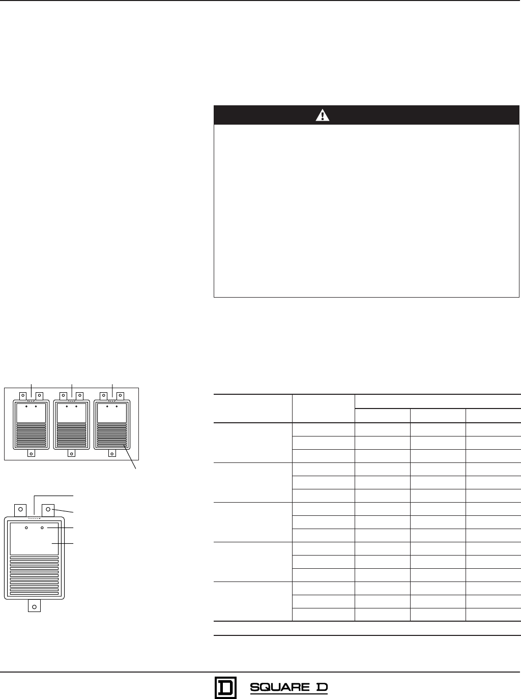
Bulletin No. 8222-0010A
August 2002
Raleigh, NC, USA
MA Module Replacement
IMA Transient Voltage Surge Suppressor (TVSS)
Class 1310
1
Instruction Bulletin
© 2002 Schneider Electric All Rights Reserved
1. Verify that all replacement modules have the correct catalog number. The
catalog number is found on the nameplate of each existing and
replacement module (see Figure 1) and on the TVSS device nameplate.
Use Table 1 to determine the correct replacement catalog number based
on the existing IMA TVSS system voltage and peak surge current rating.
Table 1: MA Module Replacements
System Voltage Peak Surge
Current Rating
Catalog Number
Phase A Phase B Phase C
120/240 V, 1 phase,
3 wire
120 kA MA1IMA12 empty MA1IMA12
160 kA MA1IMA16 empty MA1IMA16
240 kA MA1IMA24 empty MA1IMA24
208Y/120 V, 3 phase,
4 wire
120 kA MA1IMA12 MA1IMA12 MA1IMA12
160 kA MA1IMA16 MA1IMA16 MA1IMA16
240 kA MA1IMA24 MA1IMA24 MA1IMA24
120/240 V, 3 phase,
4 wire, high-leg delta
[1]
120 kA MA1IMA12 MA3IMA12 MA1IMA12
160 kA MA1IMA16 MA3IMA16 MA1IMA16
240 kA MA1IMA24 MA3IMA24 MA1IMA24
480Y/277 V, 3 phase,
4 wire
120 kA MA4IMA12 MA4IMA12 MA4IMA12
160 kA MA4IMA16 MA4IMA16 MA4IMA16
240 kA MA4IMA24 MA4IMA24 MA4IMA24
600Y/347 V, 3 phase,
4 wire
120 kA MA8IMA12 MA8IMA12 MA8IMA12
160 kA MA8IMA16 MA8IMA16 MA8IMA16
240 kA MA8IMA24 MA8IMA24 MA8IMA24
[1]
Phase B modules are different than Phase A and Phase C modules.
PRECAUTIONS
HAZARDOUS VOLTAGE
• This equipment must be installed and serviced only by qualified
electrical personnel.
• This equipment must be effectively grounded per all applicable
codes. Use an equipment-grounding conductor to connect this
equipment to the power system ground.
• Disconnect all power supplying this equipment before working on or
inside it.
•Always use a properly rated voltage sensing device to confirm power
is off.
• Replace the barrier and the door/cover before energizing.
Failure to follow these instructions will result in death or serious
injury.
DANGER
INSTALLATION
8222-0010-01
RJ45 patch cable connector
7/16 in. socket wrench
Phase A Phase B Phase C
Module
LEDs
Module nameplate
Figure 1: TVSS Device and Modules, Top View
291 of 292
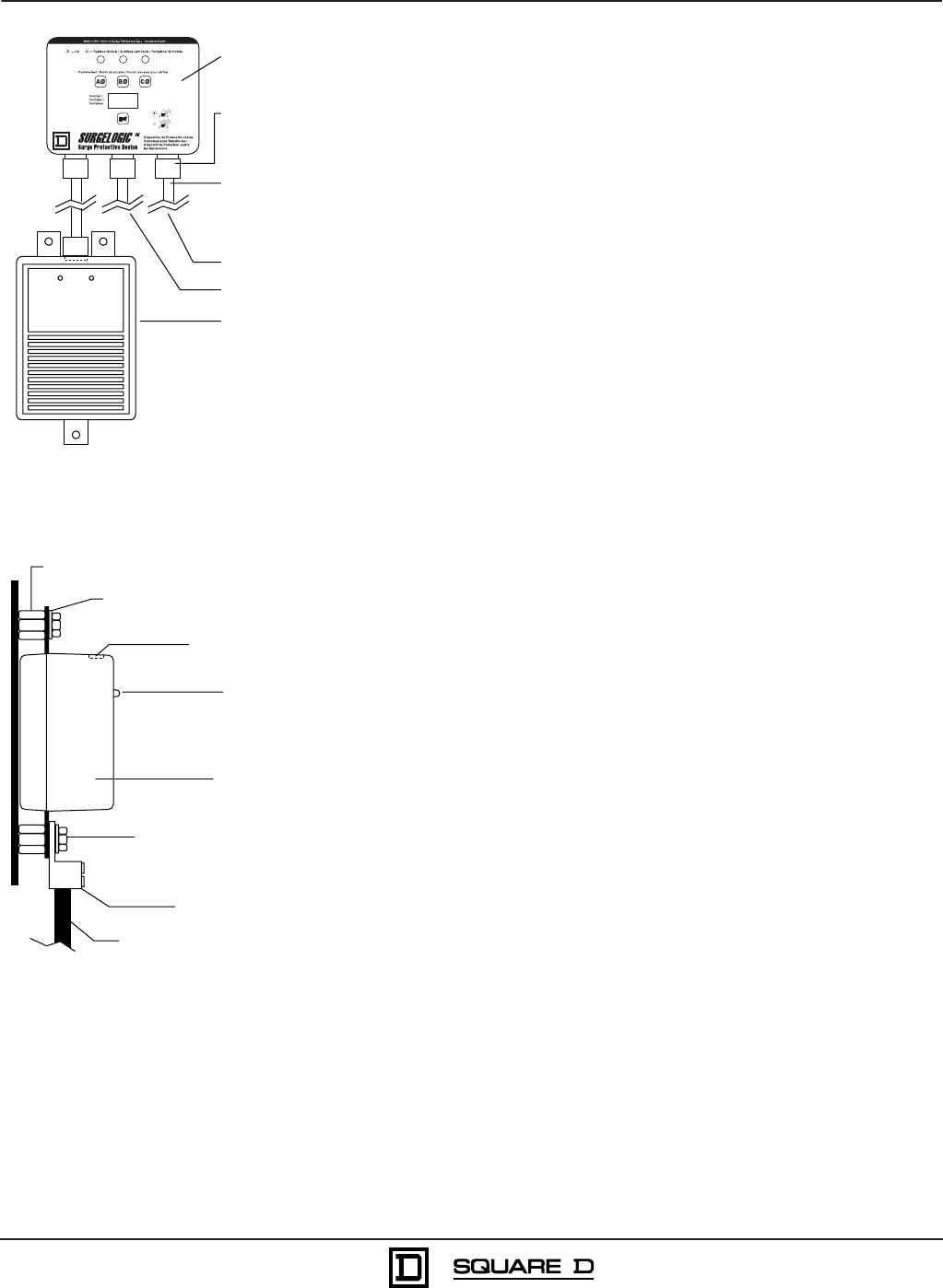
Electrical equipment should be installed, operated, serviced, and maintained only by
qualified personnel. No responsibility is assumed by Schneider Electric for any
consequences arising out of the use of this material.
MA Module Replacement Bulletin No. 8222-0010A
IMA Transient Voltage Surge Suppressor (TVSS) August 2002
Square D Company
8001 Highway 64 East
Knightdale, NC 27545
1-800-577-7353
www.squared.com
© 2002 Schneider Electric All Rights Reserved
2
2. Mark the RJ45 patch cable and the phase cable for the module to be
replaced (if it is not already marked) with the appropriate A, B, or C
phase. Unplug the module RJ45 patch cable from the module.
3. Use a suitable tool to prevent each 1/2 in. hex standoff from turning (see
Figure 3) and remove and discard the three 1/4-20 hex head bolts and
the three corresponding internal tooth lock washers of the module. It is
not necessary to remove the connecting phase cables from the lugs.
4. Carefully remove the module.
5. Install the new module, using the new hardware kit supplied (see Figure
3). Torque each 1/4-20 hex head bolt to 70 lb-in (8 N•m).
6. Attach the phase cable lug to the replacement module (A, B, or C phase
as marked in step 4).
7. Plug the RJ45 patch cable into the new module. Make sure that the
correct RJ45 patch cable labeled A, B, or C is connected.
8. Check that all connections are secure. Remove all tools and discarded
hardware from the unit.
9. Ensure that the RJ45 patch cables are not touching any internal
components.
10. Replace the barrier, cover/door, and/or trim to the equipment.
11. Equipment may be re-energized after all of the above steps are complete.
Display
panel
RJ45
connector
jacks
8222-0010-02
To module B
To module C
Module A
Module
patch cables
=
=
Figure 2: Display Panel and RJ45 Patch Cables
Internal-tooth lock washers
(typical 3 places)
Module
Connecting phase cable
LEDs
1/2 in. hex standoffs (typical 3 places)
1/4-20 hex head bolts
(typical 3 places)
Lug set screw
RJ45 patch
cable connector
8222-0010-03
Figure 3: Module, Side View
292 of 292
