Product Detail Manual
391479-Catalog 391479-Catalog 391479-Catalog 804325 Batch7 unilog cesco-content
391479-Catalog 391479-Catalog 391479-Catalog 662019 Batch7 unilog cesco-content
2014-09-04
: Pdf 86422-Attachment 86422-Attachment 662019 Batch7 unilog
Open the PDF directly: View PDF ![]() .
.
Page Count: 94
Low Voltage Products & Systems 19.A
ABB Inc. • 888-385-1221 • www.abb.us/lowvoltage 1SXU000023C0202 Rev. A
Disconnect
switches
19 19
Revised January 2014 Revised January 2014
Disconnect switches
Index
19 - Disconnect switches
Non-fusible and fusible disconnect switches ..........19.1 - 19.6
General information
Versatility, broad range, compact size ...............................................................................19.1
International acceptance, installation options, broad range of accessories .......................19.2
Mounting, mounting positions, incoming power feeds, terminal connections .................... 19.3
Finger proof, door interlock, padlockable, positive opening operation ............................... 19.4
Welded contact protection, clear position indication, visible blades, constant control .......19.5
High performance, superior short circuit protection, fuse isolation ....................................19.6
Non-fusible disconnect switches ...........................19.7 - 19.18
Approvals and ratings ............................................................................................................... 19.7
Ordering details guide .....................................................................................................19.8 - 19.9
Ordering details information ....................................................................................................19.10
Base and DIN rail mounted, 16 - 3150A .................................................................................19.11
Door mounted, 16 - 100A.......................................................................................................19.12
Side operated ......................................................................................................................... 19.13
Flange & double throw ................................................................................................19.14 - 19.17
OTDC Disconnect switches ....................................................................................................19.18
Fusible disconnect switches ................................19.19 - 19.28
Approvals and ratings ............................................................................................................. 19.19
Ordering details guide ............................................................................................................. 19.20
Ordering details information ....................................................................................................19.21
Base & DIN rail mounted.........................................................................................................19.22
Side operated and flange ............................................................................................19.23 - 19.26
High speed fuse pattern .............................................................................................19.27 - 19.28
Accessories ...........................................................19.29 - 19.40
Standard handles & shafts ..........................................................................................19.30 - 19.32
Auxiliary contacts ....................................................................................................................19.33
Terminal lugs...........................................................................................................................19.34
Terminal shrouds ....................................................................................................................19.35
Additional poles ...................................................................................................................... 19.36
Fuse monitors & carriers ......................................................................................................... 19.37
Miscellaneous accessories & replacement parts .....................................................................19.38
Conversion, transfer & bypass mechanisms............................................................................19.39
Enclosed disconnect switches .............................19.41 - 19.48
General information ....................................................................................................19.42 - 19.44
Non-fusible
3 pole, 16A - 3150A ..........................................................................................................19.45
6 pole, 16A - 1200A ..........................................................................................................19.46
Fusible
3 pole, 30A - 800A ............................................................................................................19.47
Accessories ............................................................................................................................ 19.48
Technical data ........................................................19.49 - 19.66
Technical data ............................................................................................................19.49 - 19.59
Auxiliary contact timing diagrams ................................................................................19.60 - 19.63
NEMA Environmental ratings ......................................................................................19.64 - 19.65
Definitions ...............................................................................................................................19.66
Approximate dimensions ......................................19.67 - 19.91

19.B Low Voltage Products & Systems
1SXU000023C0202 Rev. A ABB Inc. • 888-385-1221 • www.abb.us/lowvoltage
Disconnect
switches
19 19
Revised January 2014 Revised January 2014
Notes
Disconnect
switches
Low Voltage Products & Systems 19.1
ABB Inc. • 888-385-1221 • www.abb.us/lowvoltage 1SXU000023C0202 Rev. A
19 19
Revised January 2014 Revised January 2014
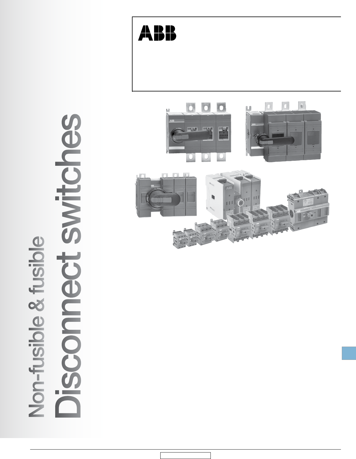
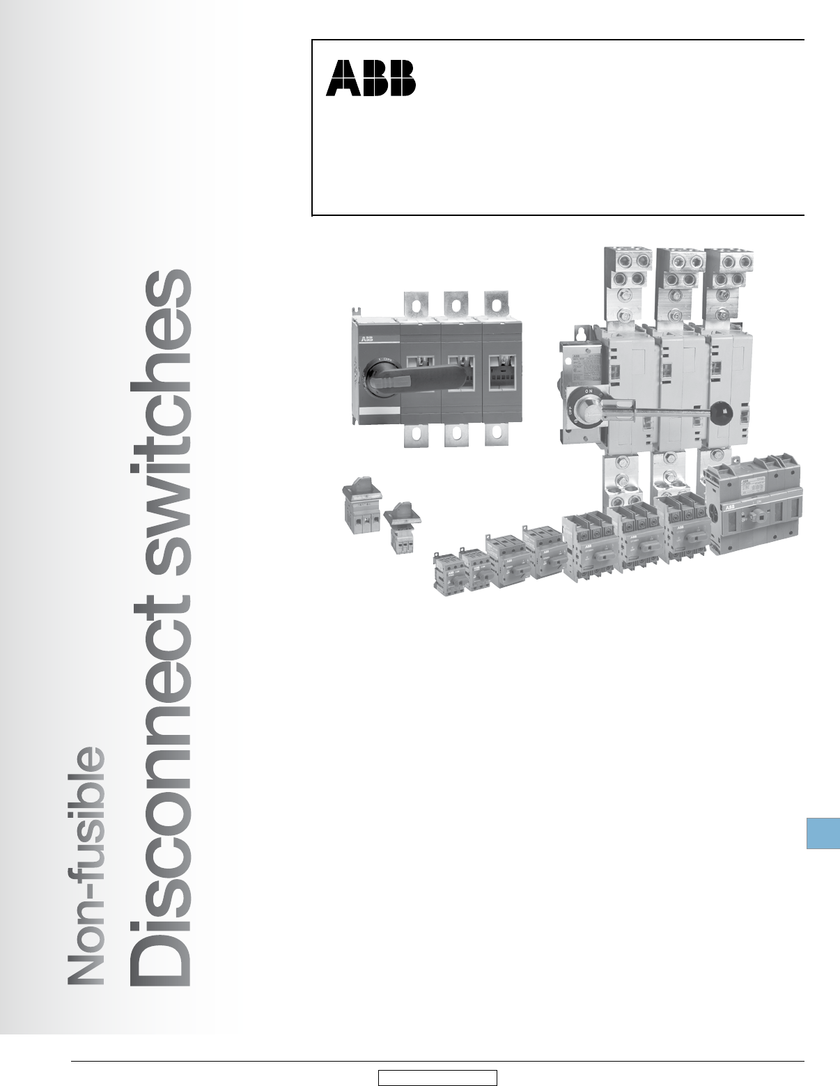
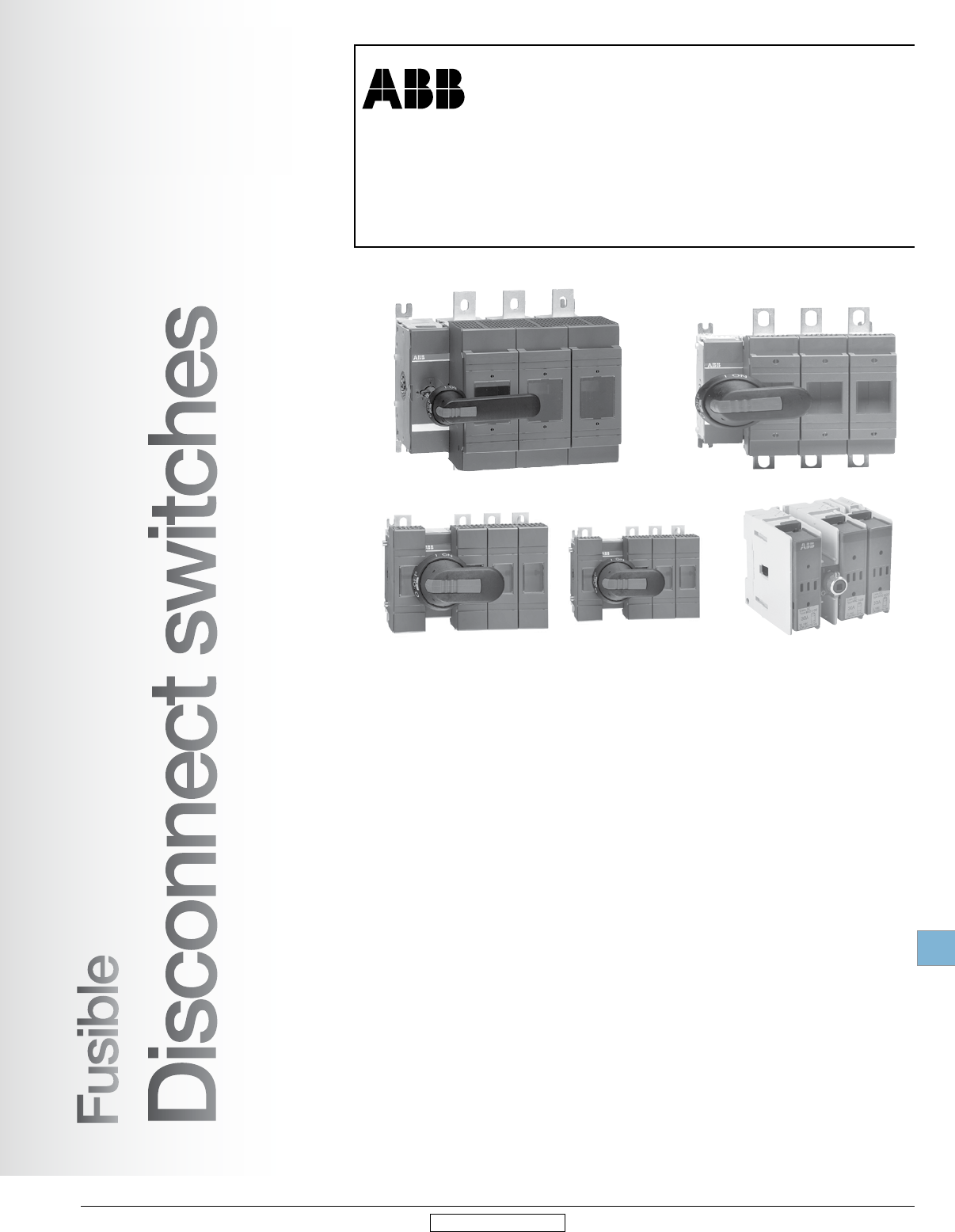
Non-fusible & fusible
disconnect switches
General information
Non-fusible & fusible
Disconnect switches
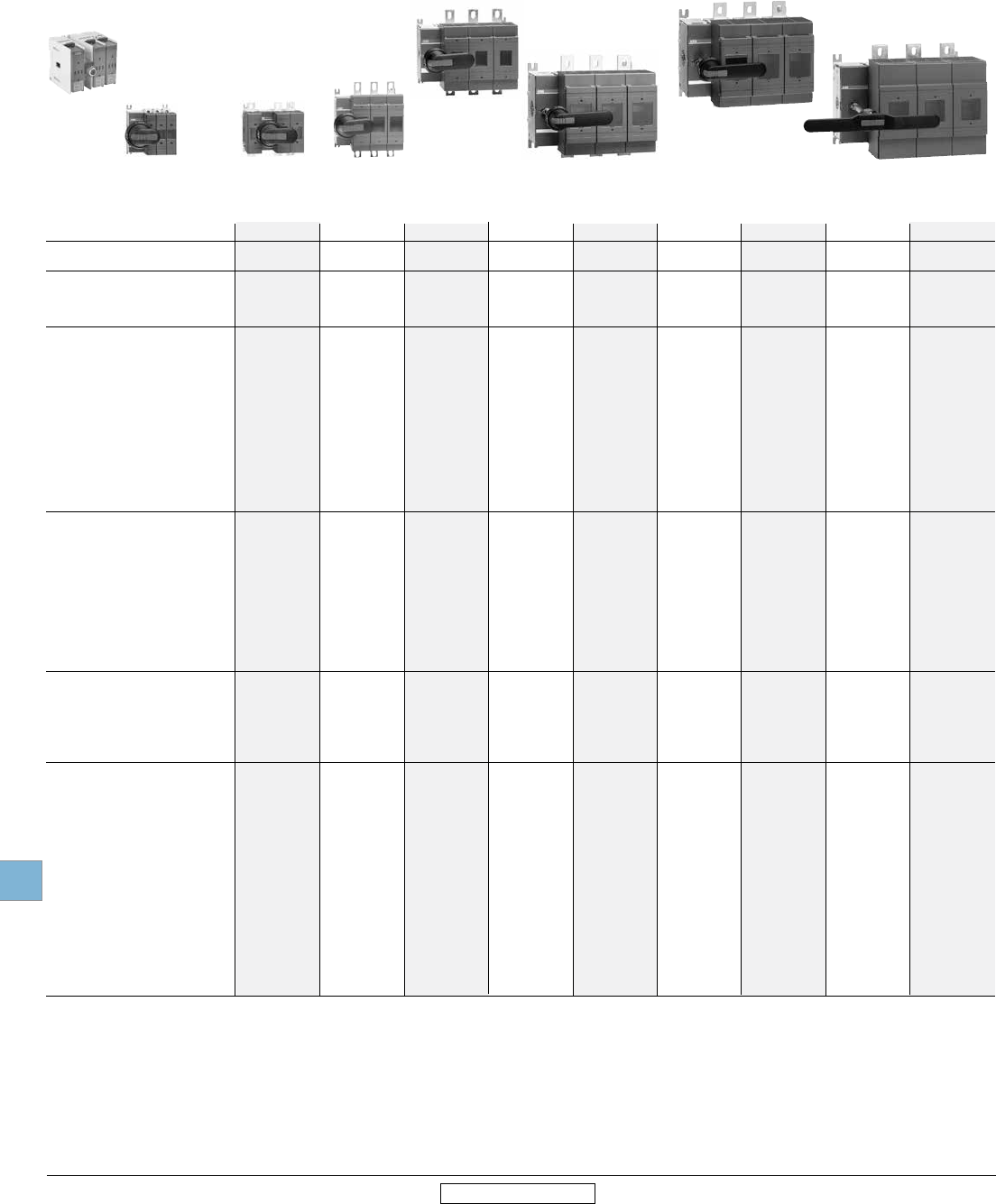
Versatility
ABB disconnect switches are designed to offer maximum versatility in many ways.
Broad range
ABB's open style non-fusible switches have seventeen amperage sizes from 16A –
3150A. The fusible range is 30A - 1200A. All sizes are compact, heavy duty, 600V
disconnect switches. Many sizes are available in 2, 3, 4, 6, and 8 pole configurations.
Compact size
The non-fusible disconnect switches' compact dimensions allow panel size reduction in
new applications or easily retrofit into space-sensitive existing installations. The fusible
switch occupies little more panel space than the appropriate fuses.
Disconnect
switches
19.2 Low Voltage Products & Systems
1SXU000023C0202 Rev. A ABB Inc. • 888-385-1221 • www.abb.us/lowvoltage
19 19
Revised January 2014 Revised January 2014
Installation options
Rotary through the door: available in all sizes, non-fusible 16A – 3150A; fusible 30A -
1200A.
Flange: versions available in 30A - 1200A sizes.
A rotary disconnect switch may be installed nearly anywhere in a control panel — mounting
is not limited to the upper right hand corner of the panel.
Mount the switch where it conveniently fits in your panel and simply install the handle on
the door, in line with the switch. The switch and handle are mechanically linked through an
easily adjusted shaft. This allows fast and easy installation into panels of different depths
and layouts.
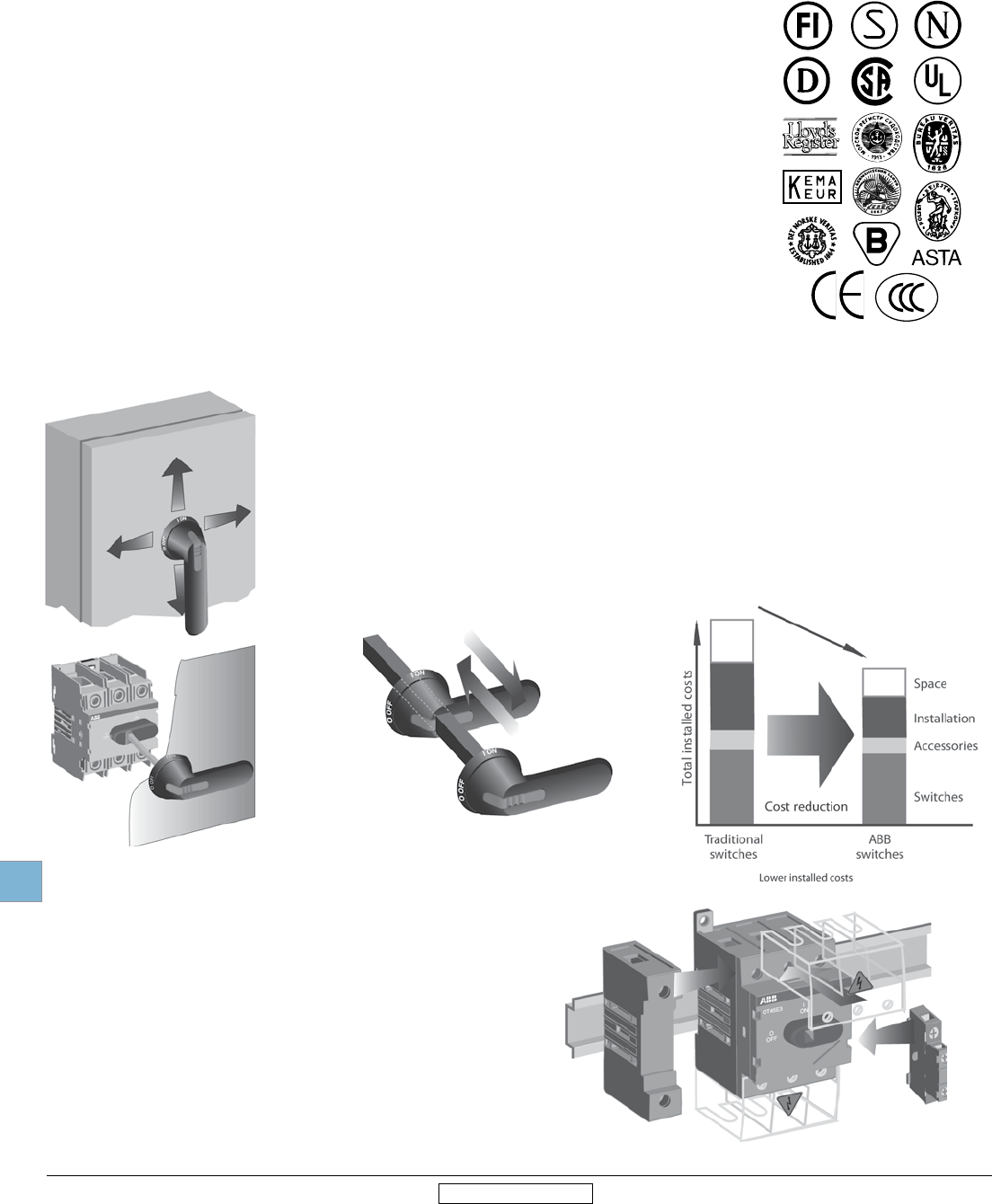
International acceptance
UL listed, CSA approved, IEC rated, CE marked, and most other international standards.
UL98 (CSA 22.2 No.4) — UL File # E101914, CSA File #LR58077
For OT30 - OT1200, OS30A - 1200A switches with OT/OS OH_pistol grip handles
Suitable for use as motor disconnects or industrial control panel disconnects on service
entrance equipment, panelboards, switchboards, industrial control equipment, motor
control centers, etc. and are horsepower and ampere rated.
UL508 (CSA 22.2 No. 14) — UL File # E63822, CSA File #LR58247
For OT16 – OT80 switches, OH_ selector handles
Suitable for use in equipment or machinery as motor controllers & motor disconnects and
are horsepower and ampere rated.
IEC
Tested in accordance to IEC 947-1 and 3, IEC 664, IEC 269, and IEC 204.
CE
Compliance with the European Machine Directive IEC 204 (EN 60204).
General information
Broad range of accessories
• Handles — UL/NEMA type 1, 3R, 4, 4X, 12; IP54, 65, 66
• Auxiliary contacts available for every switch size
• Additional power poles
• Additional terminal poles (neutrals & grounds)
• Terminal shrouds
• 6 & 8 pole mechanisms
• Transfer mechanisms
• Bypass mechanisms
• Mechanical interlock mechanisms
• Electro-mechanical interlock mechanisms
Disconnect
switches
Low Voltage Products & Systems 19.3
ABB Inc. • 888-385-1221 • www.abb.us/lowvoltage 1SXU000023C0202 Rev. A
19 19
Revised January 2014 Revised January 2014
General information
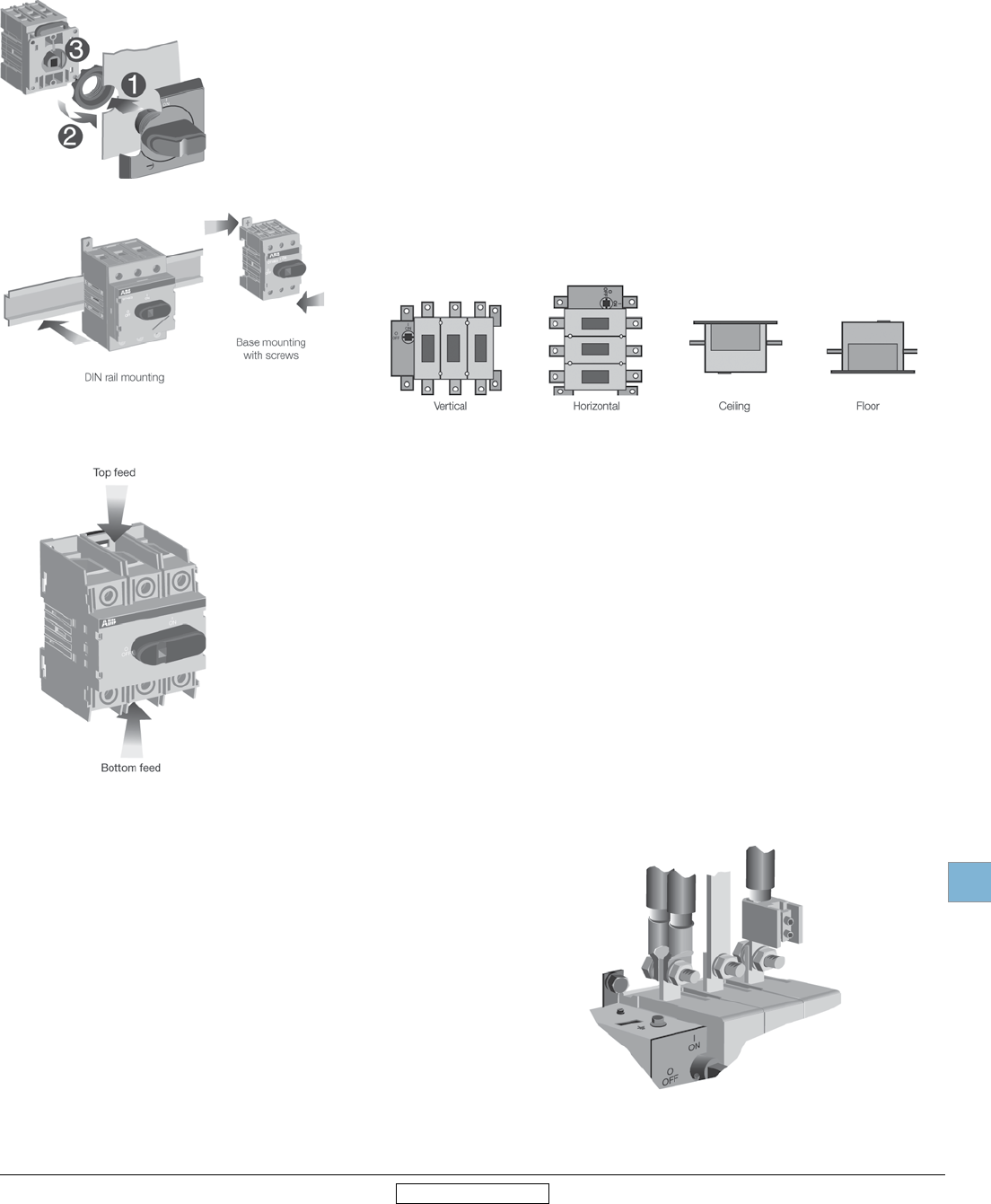
Mounting
Disconnect switches offer several mounting possibilities:
• Door mounting on an enclosure door or sidewall for non-fusible, 16A – 100A
• DIN rail mounting for non-fusible, 16A – 100A; and fusible, OS30 - OS100
• Base mounting with screws for all switch sizes
Mounting positions
Disconnect switches offer several mounting possibilities:
Incoming power feeds
Disconnect switches can be used equally well with either top or bottom
incoming power feeds.
Terminal connections
Versatile connecting possibilities for non-fusible and fusible switches
• Ring tongue crimp on lugs
• Direct bus
• Terminal lugs
Disconnect
switches
19.4 Low Voltage Products & Systems
1SXU000023C0202 Rev. A ABB Inc. • 888-385-1221 • www.abb.us/lowvoltage
19 19
Revised January 2014 Revised January 2014
General information
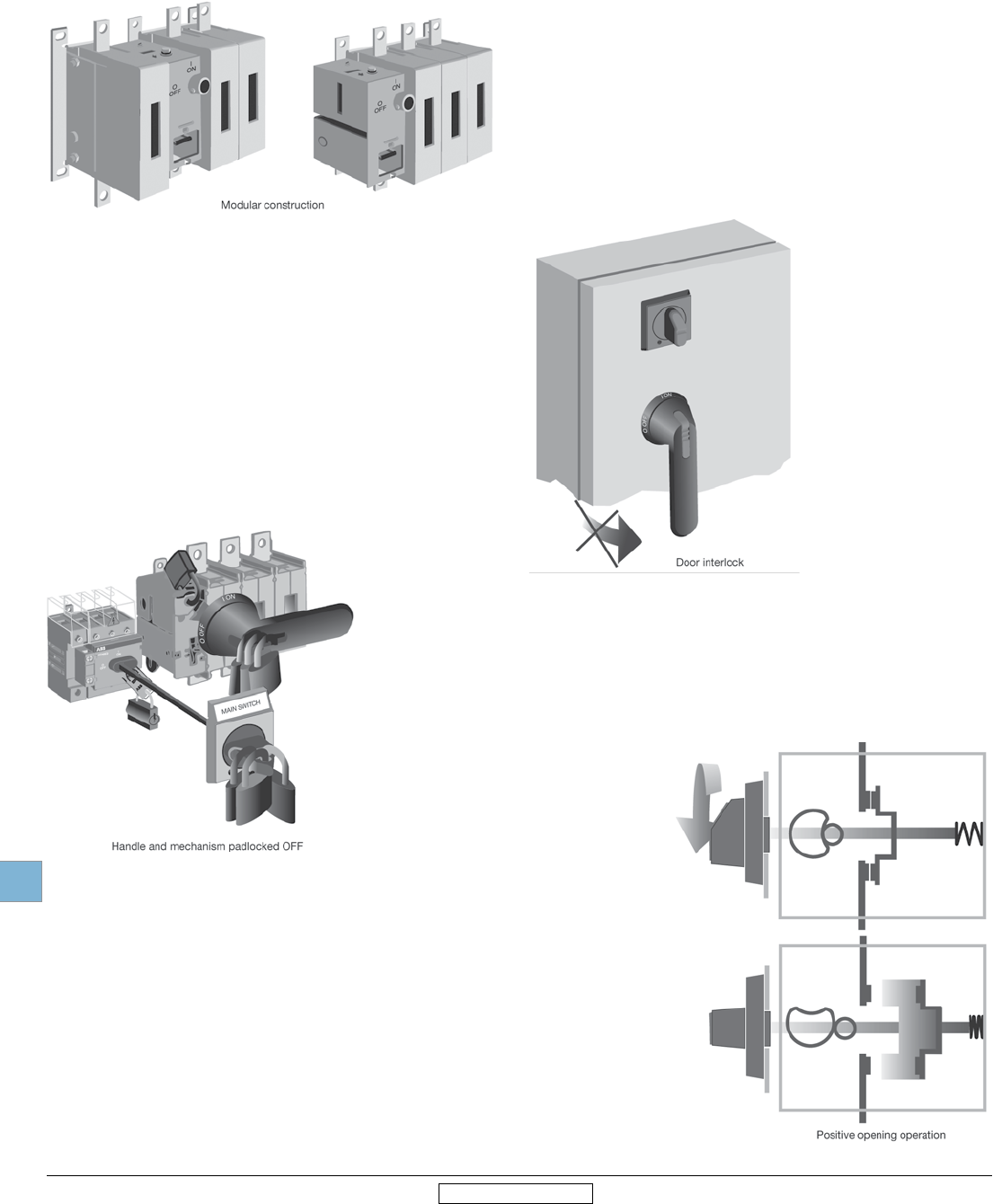
Finger proof
Dead-front construction plus terminal shrouds reduce the
risk of touching live parts, improving the safety and reliability
of the installation.
Door interlock
The handle and shaft provide a door interlock; the
door can not be opened when the switch is in the
“ON” position. NOTE: Some handles provide a
method for qualified personnel to circumvent the door
interlock. This is commonly referred to as a “defeater”
mechanism.
Padlockable
Handles can be padlocked in the “OFF” position with up to three padlocks. Ad-
ditionally, the switch mechanism can be directly padlocked in the “OFF” position
when the door is open. NOTE: Some handles can be ordered with the ability to
padlock in both the “ON” & “OFF” positions, please consult your ABB sales of-
fice.
Positive opening operation
All switches operate according to the
“positive opening operation” principle.
This means the contacts are opened
and closed by a driven mechanism,
a solid moving bridge, not merely
springs. This provides reliable position
indication to the user; if the switch is
in the “OFF” position, the contacts are
open.
Disconnect
switches
Low Voltage Products & Systems 19.5
ABB Inc. • 888-385-1221 • www.abb.us/lowvoltage 1SXU000023C0202 Rev. A
19 19
Revised January 2014 Revised January 2014
General information
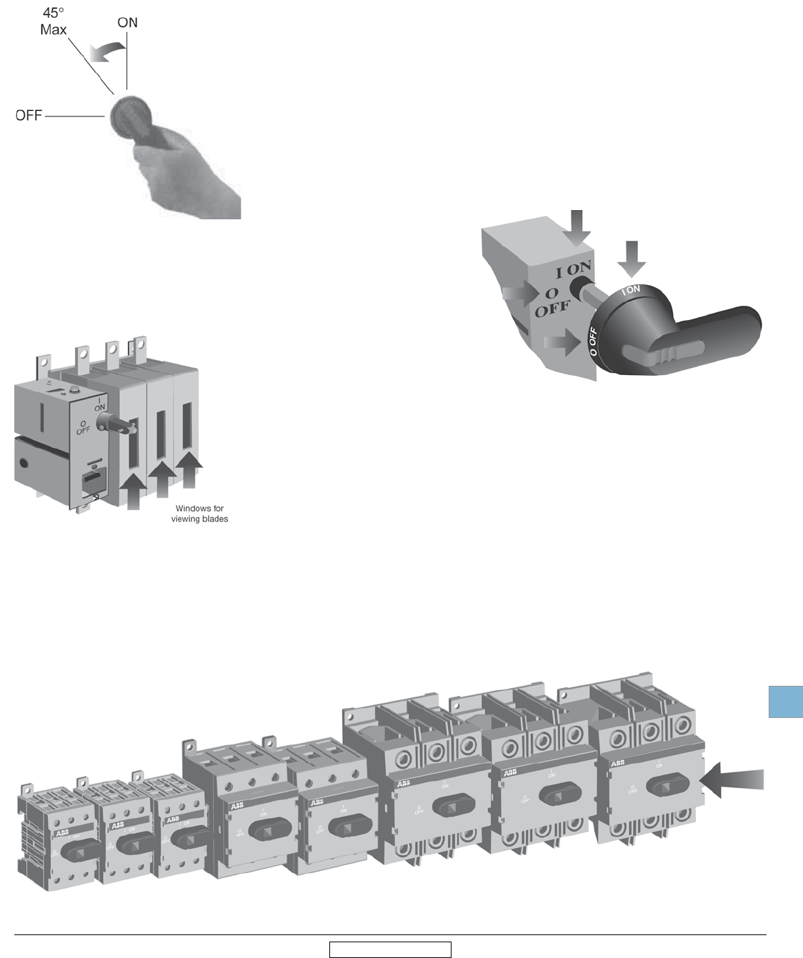
Welded contact protection
Positive opening operation safeguards users in case of welded contacts due to an
overload or short circuit. The switch can not reach the “OFF” position unless the
contacts are truly open. If any or all of the contacts are welded shut, the switch
mechanism will only allow the handle to operate a maximum of 45°. This safeguards
personnel by:
• Alerting them a problem has occurred
• Maintaining the door interlock and
• Not allowing a padlock to be inserted
Clear position indication
All switches and handles have clear “ON” and “OFF” designations.
Whether the door is open or closed, it is possible to simply look at the
switch and determine if the switch is “ON” or “OFF”.
Visible blades
Visible blades offer additional safety for non-fusible switches, 100A — 1200A
Track resistant material
Excellent track resistant material, CTI > 600V, IEC 112, reduces the risk of flash-
over between phases in even the most severe circumstances.
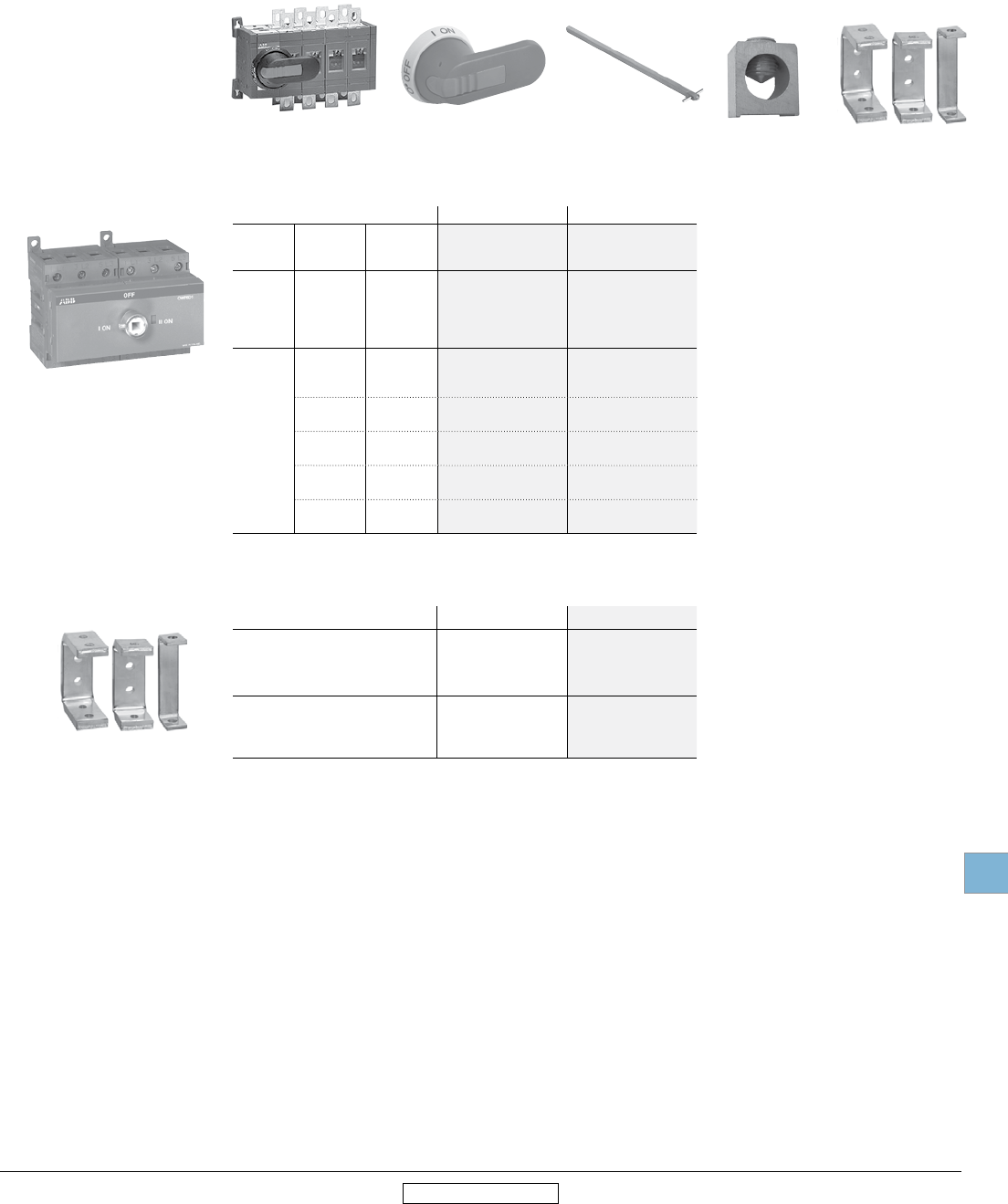
Constant control for non-fusible disconnect switches
The OT16F3 to OT100F3 provide the user with constant control over the power circuit. Whether the enclosure door is
open or closed, qualified personnel have the ability to manually operate the switch. This is most meaningful when qualified
personnel are working with the enclosure door open: In case of an emergency down-stream, the main three phase power
can be disconnected immediately using the black, direct mounted handle.
Disconnect
switches
19.6 Low Voltage Products & Systems
1SXU000023C0202 Rev. A ABB Inc. • 888-385-1221 • www.abb.us/lowvoltage
19 19
Revised January 2014 Revised January 2014
General information
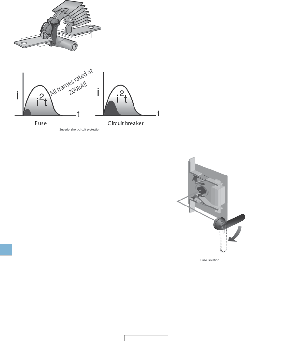
Superior short circuit protection
Fuses efficiently limit the peak let-through current,
i2t, during a fault better than any other product,
contributing to safety and reliability. Selectivity and
coordination are easily accomplished with fused pro-
tection. Fusible disconnect switches accept a wide
range of fuses:
Class CC 30A
Class J 30A – 600A
Class L 800A – 1200A
Fuse isolation
Fused switches contain contacts on both sides of the fuse.
The fuses are totally isolated in the “OFF” position, reduc-
ing the risk of shock to authorized personnel — even if the
switch has been back fed.
High performance
The mechanism is quick-make/quick-break, meaning the contacts oper-
ate independently of the speed and force at which the handle is oper-
ated. This, in combination with unique, patented self-cleaning contacts,
provides a long, reliable, electrical life.
Disconnect
switches
Non-fusible
Low Voltage Products & Systems 19.7
ABB Inc. • 888-385-1221 • www.abb.us/lowvoltage 1SXU000023C0202 Rev. A
19
Revised January 2014 Revised January 2014
Non-fusible disconnect switches
16A – 3150A, 600VAC
100-200A, 1000VDC
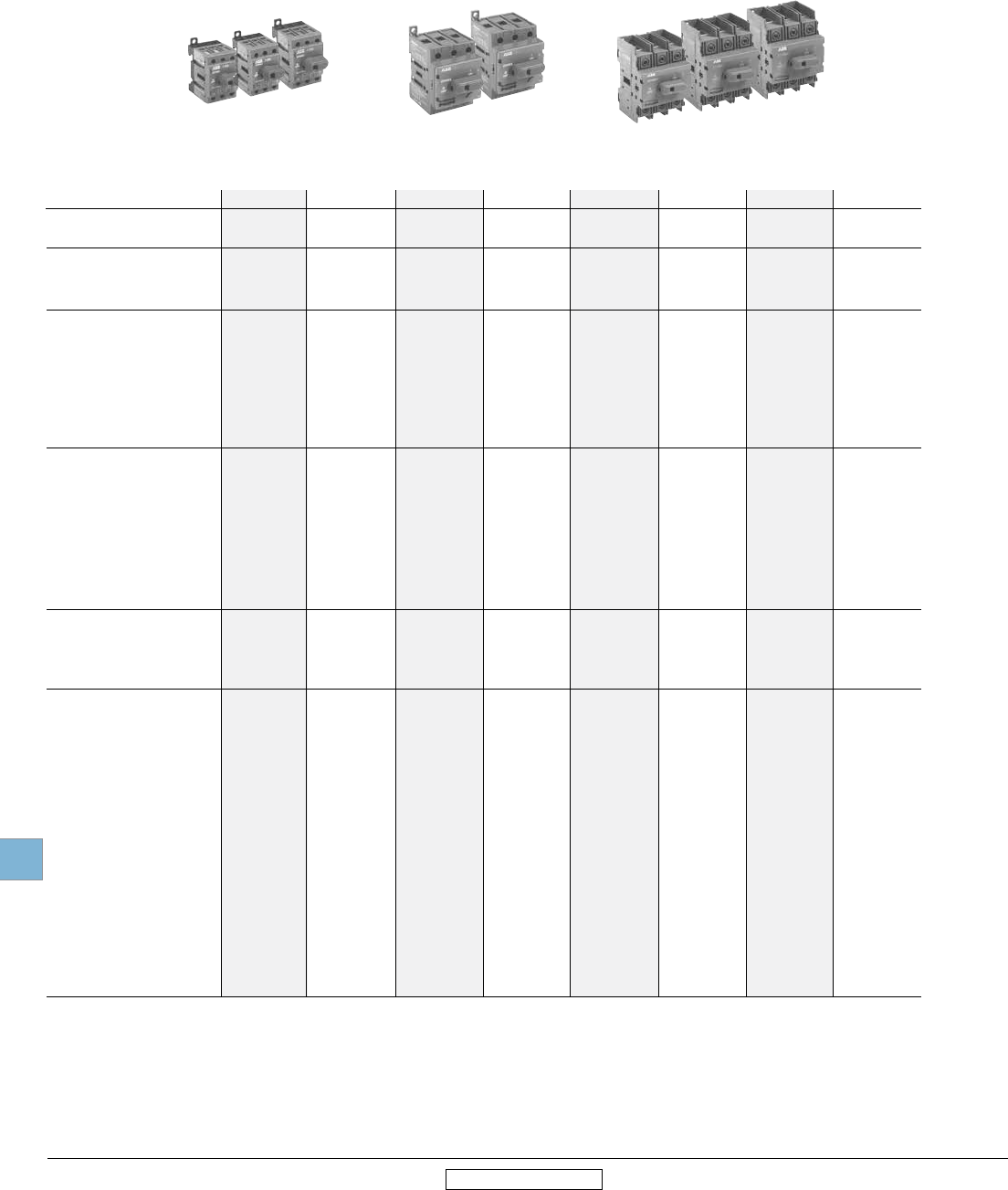
ABB SwitchLine includes 16 different amperage sizes from 16A to 3150A. The basic
construction provides flexibility, safety, and high performance in an extremely compact
size. ABB SwitchLine is a perfect choice for all switching applications from industrial motor
control to construction safety switches.
Non-fusible
Disconnect switches
International acceptance
UL listed, CSA approved, IEC rated, CE marked, and most other international standards.
UL98 (CSA 22.2 No.4) — UL File # E101914, CSA File #LR58077
For OT30, OT60, OT100, OT200, OT400, OT600, OT800, OT1200
OETL-NF1600 – OETL-NF2000 switches, OH_ pistol grip handles
Suitable for use as motor disconnects or industrial control panel disconnects on service
entrance equipment, panelboards, switchboards, industrial control equipment, motor
control centers, etc. and are horsepower rated and ampere rated.
UL508 (CSA 22.2 No. 14) — UL File # E63822, CSA File #LR58247
For OT16 – OT80 switches, OH_ selector handles
Suitable for use in equipment or machinery as motor controllers & motor disconnects and
are horsepower and ampere rated.
IEC
Tested in accordance to IEC 947-1 and 3, IEC 664, IEC 269, and IEC 204
CE
Compliance with the European Machine Directive IEC 204 (EN 60204)
Disconnect
switches
Non-fusible
19.8 Low Voltage Products & Systems
1SXU000023C0202 Rev. A ABB Inc. • 888-385-1221 • www.abb.us/lowvoltage
19
Revised January 2014 Revised January 2014
General information
Selection guide
OT16F3 – OT100F3
1 UL listed switches are also CSA approved.
2 For complete technical information please see page 19.49-19.66.
3 Switch only.
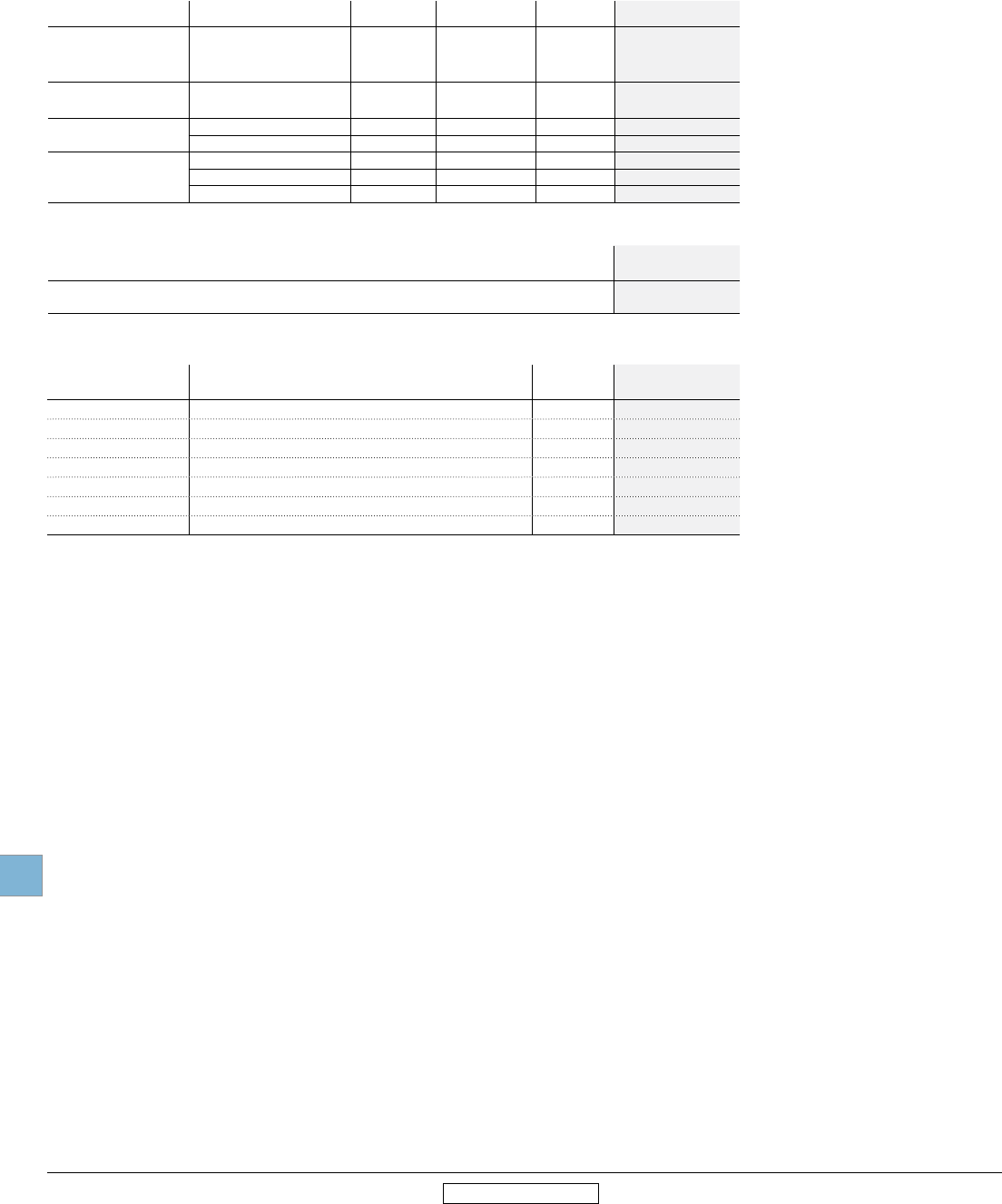
Catalog number 3 pole OT16F3 OT25F3 OT40F3 OT63F3 OT80F3 OT30F3 OT60F3 OT100F3
OT16F3 OT25F3 OT40F3 OT63F3 OT80F3 OT30F3 OT60F3 OT100F3
General purpose A 20 30 40 60 80 30 60 100
amp rating
Approvals 1
2 pole N/A N/A N/A N/A N/A N/A N/A N/A
3 pole UL508 & IEC UL508 & IEC UL508 & IEC UL508 & IEC UL508 & IEC UL98 & IEC UL98 & IEC UL98 & IEC
4 pole UL508 & IEC UL508 & IEC UL508 & IEC UL508 & IEC UL508 & IEC UL98 & IEC UL98 & IEC UL98 & IEC
Technical ratings – UL,CSA 2
Max operating voltage V 600 600 600 600 600 600 600 600
Max horsepower rating
Three phase
240V HP 5 7.5 10 15 20 10 20 30
480V HP 10 15 20 30 40 20 40 50
600V HP 10 20 25 30 40 30 40 50
Single phase
120V HP 1 1.5 2 2 2 2 3 5
240V HP 2 3 5 5 5 5 7.5 15
Technical ratings – IEC2
Rated insulation and operational
voltage. AC20 and DC20 V 750 750 750 750 750 750 750 750
Rated thermal current, Ith
AC 20/DC 20 open A 25 32 40 63 80 40 63 115
AC 20/DC 20 enclosed A 25 32 40 63 80 40 63 115
AC 21A ≤500V A 16 25 32 63 80 40 63 100
≤690V A 16 25 32 63 80 40 63 100
Rated operational power AC23
400/415V kW 7.5 9 11 22 37 15 18.5 37
690V kW 7.5 9 11 15 18.5 15 15 37
Physical characteristics
Weight 3 3 pole lb 0.24 0.24 0.24 0.59 0.59 0.79 0.79 0.79
Dimension 3 pole H in 2.68 2.68 2.68 3.60 3.60 3.94 3.94 3.94
W in 1.38 1.38 1.38 2.07 2.07 2.76 2.76 2.76
D in 2.20 2.20 2.20 2.85 2.85 2.95 2.95 2.95
Accessories
Terminal lug kit Integral Integral Integral Integral Integral Integral Integral Integral
Terminal shroud • • • • • • • •
Auxiliary contact • • • • • • • •
Shaft/handle diameter
6mm 6mm 6mm 6mm 6mm 6mm 6mm 6mm
.24" x .24" .24" x .24" .24" x .24" .24" x .24" .24" x .24" .24" x .24" .24" x .24" .24" x .24"
Handle UL/NEMA type
Type 1, 3R, 12 • • • • • • • •
Type 1, 3R, 4, 4X, 12 • • • • • • • •
Handle type
Selector • • • • • — — —
Pistol • • • • • • • •
Recommended pistol handle length 45 - 65
mm
45 - 65
mm
45 - 65
mm
45 - 65
mm
45 - 65
mm
45 - 65
mm
45 - 65
mm
45 - 65
mm
Maximum recommended shaft length 290
mm
290
mm
290
mm
290
mm
290
mm
290
mm
290
mm
290
mm
Conversion kits
6 pole • • • • • • • •
Transfer • • • • • • • •
Bypass • • • • • • • •
Mechanical interlock • • • • • • • •
Electrical interlock — — — — — — — —
• = Available
— = Not available
Disconnect
switches
Non-fusible
Low Voltage Products & Systems 19.9
ABB Inc. • 888-385-1221 • www.abb.us/lowvoltage 1SXU000023C0202 Rev. A
19
Revised January 2014 Revised January 2014
General information
Selection guide
OT200 – OT1200 & OETL-NF1600 – OETL-NF3150
1 UL listed switches are also CSA approved.
2 For complete technical information please see page 19.49-19.66.
3 Switch only
4 IEC 947-3 Utilization Category B, Infrequent operation
S = Standard feature
• = Available
— = Not available
OT200U03 OT400U03 OT600U03 OT800U03 OT1200U03 OETL-NF1600SW OETL-NF2000SW OETL-NF3150SW
Catalog number 3 pole OT200U03 OT400U03 OT600U03 OT800U03 OT1200U03 OETL-NF1600 OETL-NF2000 OETL-NF3150
General purpose A 200 400 600 800 1200 1600 2000 3150
amp rating
Approvals 1
2 pole UL98 & IEC UL98 & IEC UL98 & IEC UL98 & IEC UL98 & IEC UL98 & IEC UL98 & IEC IEC
3 pole UL98 & IEC UL98 & IEC UL98 & IEC UL98 & IEC UL98 & IEC UL98 & IEC UL98 & IEC IEC
4 pole UL98 & IEC UL98 & IEC UL98 & IEC IEC IEC IEC IEC IEC
Technical ratings – UL,CSA 2
Max operating voltage V 600 600 600 600 600 600 480 600
Max horsepower rating
Three phase
240V HP 75 125 200 250 — — — —
480V HP 150 250 450 500 — — — —
600V HP 200 350 500 600 — — — —
Single phase
120V HP — — — — — — — —
240V HP — — — — — — — —
Technical ratings – IEC 2
Rated insulation and operational
voltage. AC20 and DC20 V 1000 1000 1000 1000 1000 1000 1000 1000
Rated thermal current, Ith
AC 20/DC 20 open A 250 400 800 1250 1600 2500 2500 3150
AC 20/DC 20 enclosed A 250 400 800 1250 1600 2300 2300 2600
AC 21A ≤500V A 250 400 800 1250 1600 25004 25004 31504
≤690V A 250 400 800 1250 1600 25004 25004 31504
Rated operational power AC23
400/415V kW 132 220 400 400 400 400 400 400
690V kW 240 355 800 — — — — —
Physical characteristics
Weight 3 3 pole lb 2.9 5.7 11.4 35.9 38.55 127.7 127.7 127.7
Dimension 3 pole H in 6.69 8.66 10 19.09 19.09 25.04 25.04 25.04
W in 6.67 8.7 10.64 14.29 14.29 18.43 18.43 18.43
D in 3.30 3.35 5.56 4.92 4.92 10.67 10.67 10.67
Accessories
Terminal lug kit OZXA-200 OZXA-400 OZXA-800 OZXA-1200 OZXA-1200 OZXA-28 OZXA-28/2 OZXA-28/2
Terminal shroud • • • • • — — —
Auxiliary contact • • • • • • • •
Shaft/handle diameter 6mm 12mm 12mm 12mm 12mm 12mm 12mm 12mm
.24" x .24" .47" x .47" .47" x .47" .47" x .47" .47" x .47" .47" x .47" .47" x .47" .47" x .47"
Handle UL/NEMA type
Type 1, 3R, 12 • • • • • • • •
Type 1, 3R, 4, 4X, 12 • • • • • • • •
Handle type
Selector — — — — — — — —
Pistol • • • • • • • •
Recommended pistol handle length 65 - 80
mm
125 - 175
mm
125 - 175
mm
125 - 175
mm
125 - 175
mm
125 - 175
mm
125 - 175
mm
125 - 175
mm
Maximum recommended shaft length 290
mm
595
mm
595
mm
595
mm
595
mm
595
mm
595
mm
595
mm
Conversion kits
6 pole • • • • •
— — —
Transfer • • • • •
— — —
Bypass • • • • •
— — —
Mechanical interlock • • • • • • • •
Electrical interlock • • • • • • • •
Disconnect
switches
Non-fusible
19.10 Low Voltage Products & Systems
1SXU000023C0202 Rev. A ABB Inc. • 888-385-1221 • www.abb.us/lowvoltage
19
Revised January 2014 Revised January 2014
Selection information
Standard part number designation 1
Non-Fusible OT Switches (16 to 100A)
OT 16 F 3 C
Amperage
16 = 20 amps* 63 = 60 amps* 60 = 60 amps
25 = 30 amps* 80 = 80 amps* 100 = 100 amps
40 = 40 amps* 30 = 30 amps 160 = 125 amps
Number of Poles
3 = 3 poles 4 = 4 poles 6 = 6 poles
Special Configuration
C = Double throw switch
* UL508 listed switches. OT30_, OT60_ and OT100_ are cUL98 listed
Non-Fusible OT Switches (200A and above)
OT 200 U 03 C
Amperage
200 = 200 amps 400 = 400 amps 600 = 600 amps 800 = 800 amps 1200 = 1200 amps
Number of Poles & Placement of Mechanism
02 = 2 poles to right of mechanism 04 = 4 poles to right of mechanism
03 = 3 poles to right of mechanism 40 = 4 poles to left of mechanism
30 = 3 poles to left of mechanism 22 = 2 poles to left, 2 poles to right of mechanism
12 = 1 pole to left, 2 poles to right of mechanism 13 = 1 pole to left, 3 poles to right of mechanism
Special Configuration
C = Double throw switch
All OT200__, OT400_, OT600_ , _OT800_ and OT1200_ switches are cUL98 listed.
Selector Handles
OHB S 1 P H
Handle Color
B = black Y = Red/Yellow
Physical Size
Connection to Switch
A = external shaft P = snap on R = screw
Protection Class
H = 1 J= 1, 3R, 12
Pistol Handles
O H B 65 J 6 E011
Handle Color
B = Black Y = Red/Yellow M = Stainless Steel
Handle Length
65 = 65mm 80 = 80mm 125 = 125mm 145 = 145mm 274 = 274mm 330 = 330mm
Environmental Rating
J = 1, 3R, 12 L = 1, 3R, 12, 4, 4X
Shaft Diameter
6 = 6mm 12 = 12mm
Special Configuration
E011 = 3 position double throw handle
EH = Stainless steel hasp
1 Part designation keys are provided for reference only. Not all variations or configurations are available.
Disconnect
switches
Non-fusible
Low Voltage Products & Systems 19.11
ABB Inc. • 888-385-1221 • www.abb.us/lowvoltage 1SXU000023C0202 Rev. A
19
Revised January 2014 Revised January 2014
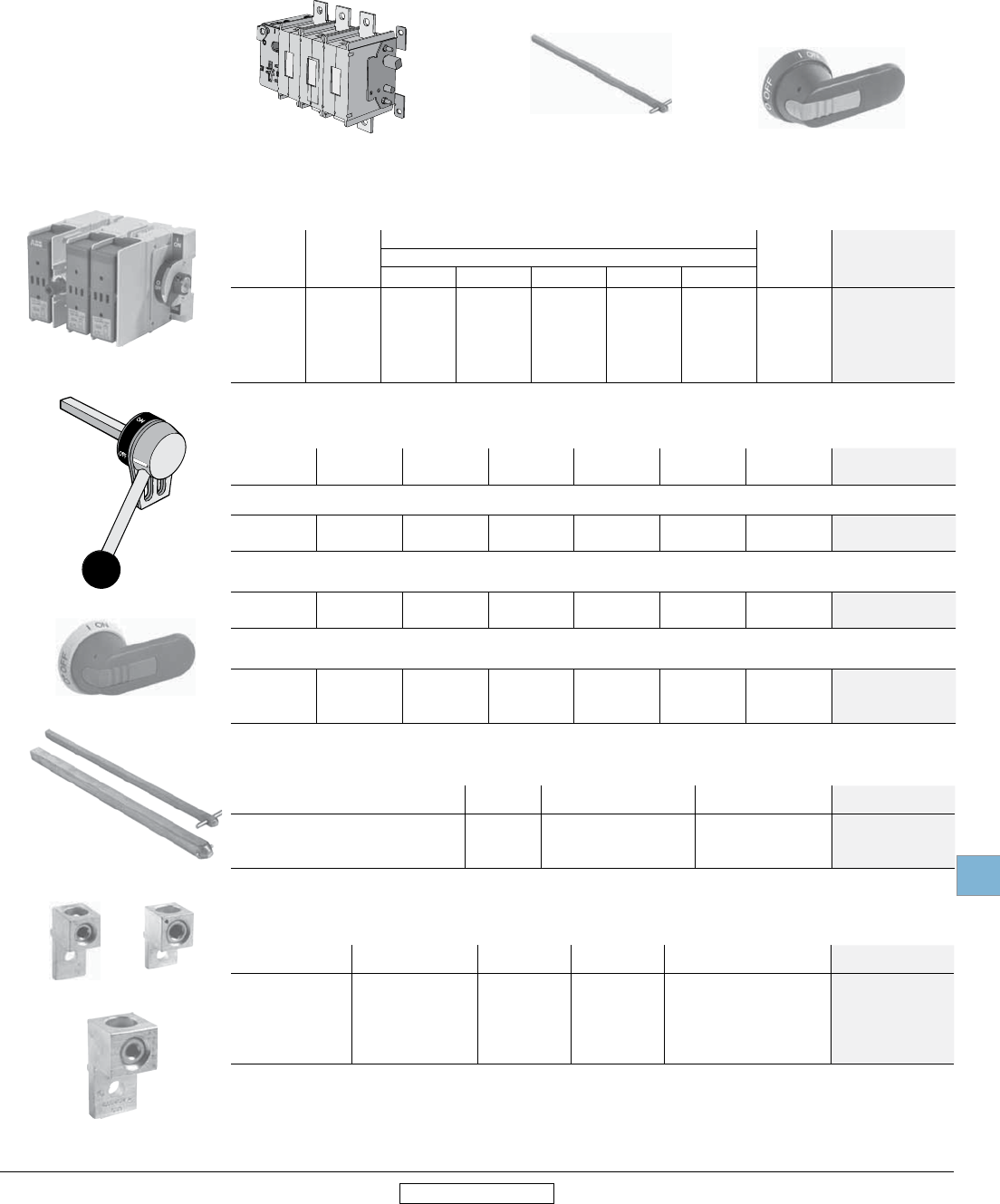
Base & DIN rail mounted 1
16A - 3150A
2 Pole 3 Pole 4 Pole 26 Pole 3
UL
only
UL general purpose
amp rating IEC AC21 amp rating Catalog number Catalog number Catalog number Catalog number
UL 508
20
30
40
60
80
16
25
40
63
80
—
—
—
—
—
OT16F3
OT25F3
OT40F3
OT63F3
OT80F3
—
—
—
—
—
OT16F6
OT25F6
OT40F6
OT63F6
OT80F6
UL 98
30
60
100
40
63
115
—
—
—
OT30F3
OT60F3
OT100F3
—
—
—
OT30F6
OT60F6
OT100F6
200 250 OT200U02
OT200U03
OT200U30
OT200U12
OT200U04
OT200U40
OT200U22
—
—
—
400 630 OT400U02
OT400U03
OT400U30
OT400U12
OT400U04
OT400U40
OT400U22
—
—
—
600 800 OT600U02
OT600U03
OT600U30
OT600U12
OT600U04
OT600U40
OT600U22
—
—
—
800 1250 OT800U02 OT800U03 OT800U04 —
1200 1600 OT1200U02 OT1200U03 OT1200U04 —
1600 2500 4OETL-NF16002SW OETL-NF1600SW OETL-NF16004SW —
2000 2500 4OETL-NF20002SW OETL-NF2000SW OETL-NF20004SW —
-3150 4OETL-NF31502SW OETL-NF3150SW OETL-NF31504SW —
Bulk packed 3 Pole, 600V Switches 5
UL
only
UL general purpose
amp rating IEC AC21 amp rating Bulk pack Quantity Catalog number
UL508
20
30
40
60
80
16
25
40
63
80
50
50
50
50
50
OT16F3/B50
OT25F3/B50
OT40F3/B50
OT63F3/B50
OT80F3/B50
UL98
30
60
100
40
63
115
25
25
25
OT30F3/B25
OT60F3/B25
OT100F3/B25
1 Above 100A, base mount with screws only.
2 A snap on fourth pole may be added on 16-100A switches.
3 For a 6 or 8 pole switch 200 amp and above, a conversion mechanism accessory kit can be used with two 3 or 4 pole switches. See page 19.40.
4 Vertical busbar provided as standard on OETL-NF1600-OETL-NF3150 switches. For alternate back or edgewise mounting busbar, see page 19.38.
5 Order quantity is 1.
For a complete assembly,
please select one of each:
1 switch (page 19.11)
1 handle (page 19.30)
1 shaft (page 19.32)
1 terminal lug kit (page 19.34)
NOTE: For additional accessories, see
pages 19.29 - 19.40.
(Lug kits only necessary on switches 200A and above)
OT200U03 + OXP6X210 + OHB80J6 + OZXA-200
Disconnect
switches
Non-fusible
19.12 Low Voltage Products & Systems
1SXU000023C0202 Rev. A ABB Inc. • 888-385-1221 • www.abb.us/lowvoltage
19
Revised January 2014 Revised January 2014
Door mounted 1
16 - 100A
For a complete assembly,
please select one of each:2
1 switch (page 19.12)
1 handle (page 19.30)
NOTE: For additional accessories, see
pages 19.29 - 19.40.
OT63FT3 OHBS2RJ
3 Pole 3Bulk packs
UL only UL general purpose
amp rating
IEC AC21
amp rating
Catalog
number
Bulk pack
quantity
Bulk pack
Catalog number
UL508
20
30
40
60
80
16
25
40
63
80
OT16FT3
OT25FT3
OT40FT3
OT63FT3
OT80FT3
50
50
50
50
50
OT16FT3/B50
OT25FT3/B50
OT40FT3/B50
OT63FT3/B50
OT80FT3/B50
UL98
30
60
100
40
63
115
OT30FT3
OT60FT3
OT100FT3
25
25
25
OT30FT3/B25
OT60FT3/B25
OT100FT3/B25
1 Door mounted switches do not provide door interlock
2 Door mounted switches do not require shafts
3 A snap on fourth pole may be added
4 The environmental rating of the pistol handle derates to NEMA 1 when used in conjunction with the OHZX6 adapter.
+
Disconnect
switches
Non-fusible
Low Voltage Products & Systems 19.13
ABB Inc. • 888-385-1221 • www.abb.us/lowvoltage 1SXU000023C0202 Rev. A
19
Revised January 2014 Revised January 2014
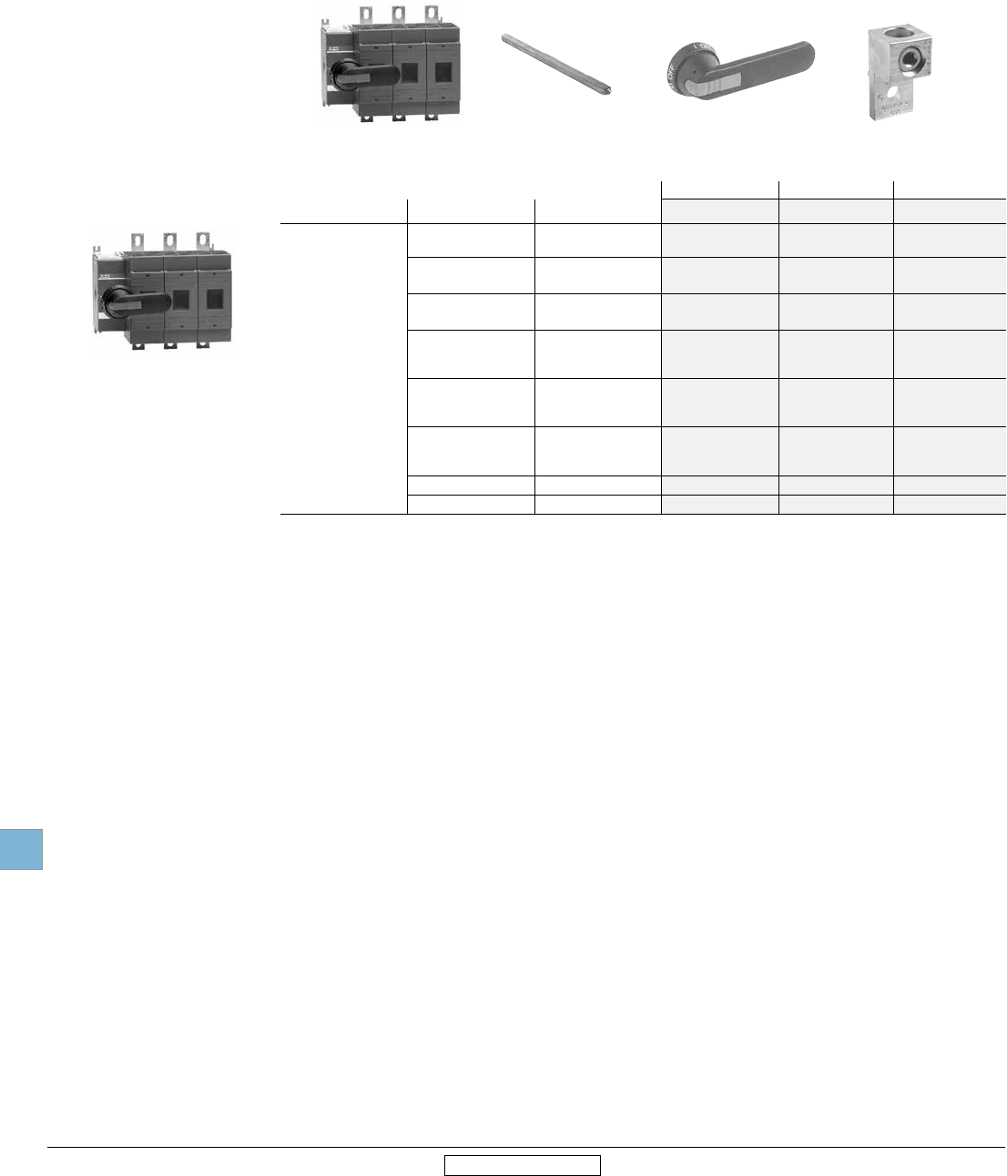
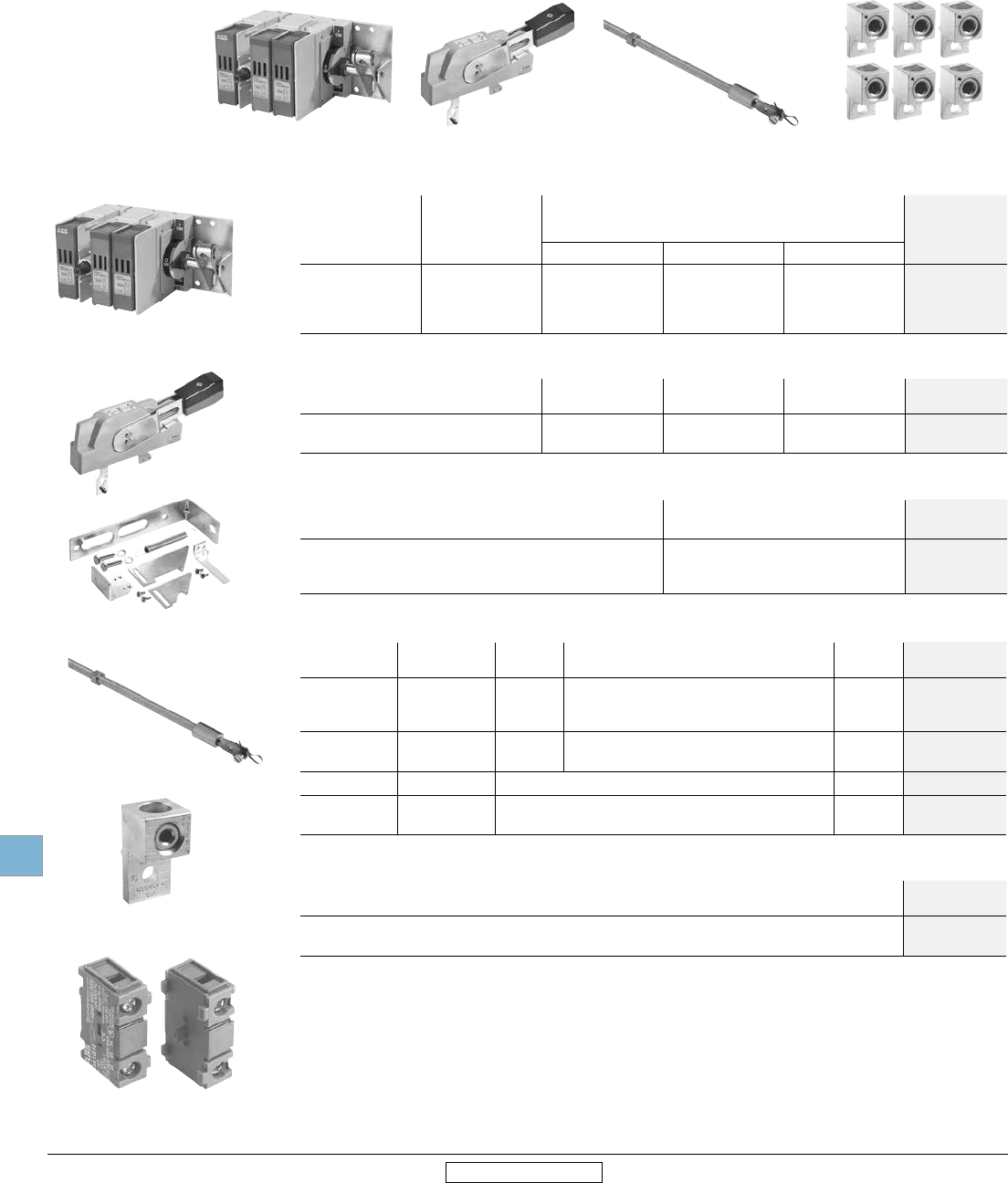
Other configurations
Side operated
30 - 600A
For a complete assembly,
please select one of each:
1 switch
1 handle
1 shaft
1 terminal lug kit
Side operated switches — 3 pole
UL
general
purpose
amp rating
IEC
AC21
amp rating
Maximum horsepower rating
Weight
(Lbs.)
Catalog
number
Three phase
200V 208V 240V 480V 600V
30 32 5 7.5 7.5 15 20 1.90 OSNF30-S 1
60 63 15 15 15 30 50 3.90 OSNF60-S 1
100 125 25 25 30 60 75 4.50 OSNF100-S
400 630 100 100 125 250 350 13.66 OETL-NF400-S
600 800 150 150 200 400 500 13.66 OETL-NF600A-S
Handles
UL/NEMA type Color Length
inches/mm Marking Defeatable Padlockable Weight
(Lbs.)
Catalog
number
For use with OSNF30-S
1, 12, 3R Black 2.65/65 O/I & Off/On Yes Ye s Yes OHB65J6E00S
Red/Yel OHY65J6E00S
For use with OSNF60-S — OSNF100-S
1, 12, 3R Black 3.1/80 O/I & Off/On Yes Yes Ye s OHB80J6E00S
Red/Yel OHY80J6E00S
For use with OETL-NF400-S — OETL-NF600A-S
1, 12, 3R
Black
4.9/145
O/I & Off/On
Yes Yes Yes
OHB145J12E00S
Red/Yel O/I & Off/On OHY145J12E00S
Metal Off/On OETL-ZX74
Shaft
For use with: Length
(Inches/mm) Description Weight
(Lbs.)
Catalog
number
OSNF30-S 6.7/170 .20 x .20” (5 x 5mm) 0.08 OXP6X170
OSNF60-S – OSNF100-S 8.3/210 .24 x .24” (6 x 6mm) 0.10 OXP6X210
OETL-NF400-S – OETL-NF600A-S 12.8/325 .47 X .47” (12 X 12mm) 0.90 OXP12X325
Terminal lug kits
For use with: Wire
size Weight Wire
type
Lugs
per kit
Catalog
number
OSNF30-S #18 – 8 — Cu — Integral
OSNF60-S #14 – 4 — Cu — Integral
OSNF100-S #14 – 2/0 0.43 Cu/Al 6 OZXA-24
OETL-NF400-S #2 – 600 kcmil 3.520 Cu/Al 6 OZXA-26
OETL-NF600A-S (2) #2 – 600 kcmil 4.62 Cu/Al 6 OZXA-27
OETL-NF400-S OXP12x325 OHB145J12E00S
OSNF30-S
OHY__J__
OETL-ZX74
OXP6X170
OXP12X325
OZXA-24 OZXA-25
OZXA-26
+ +
1 Fused switches with solid links installed.
Disconnect
switches
Non-fusible
19.14 Low Voltage Products & Systems
1SXU000023C0202 Rev. A ABB Inc. • 888-385-1221 • www.abb.us/lowvoltage
19
Revised January 2014 Revised January 2014
DSFHN-HS12
DSFHS-12
OT100F3 Flange handles — for use with OT30_, OT60_, OT100
UL/ NEMA type Marking Defeatable Padlockable Catalog
number
1, 3R, 12
4, 4X
OFF/ON
OFF/ON
Yes
Yes
Yes
Yes
DSFHN-HS12
DSFHN-HS4
Shafts
For use with: Maximum enclosure
depth (inches)
Catalog
number
OT30_ - OT100_
OT30_ - OT100_
16
24
OTFS-16
OTFS-24
Special configurations
Shaft operated flange
30A - 100A
Switch Handle Shaft
Flange operated fusible and non-fusible disconnect switches
ABB’s solution for complying with the new NFPA79 requirements is Flange Operated Fusible and Non-fusible Disconnect
Switches.
NFPA 79 changes requires main disconnecting means to be operable without the use of accessory tools or devices, independent
of door position. This code also includes an interlocking provision to prevent the closing of disconnects while the enclosure door
is open, unless an interlock is operated by a deliberate action.
The flange operated disconnect switches are available as ridged shaft or flexible cable operated versions. The cable operated
version allows you to install the disconnect switch virtually anywhere in the enclosure depending on the length of the cable.
Cables are available in lengths up to 84 inches.
The designs are cost-effective NFPA 79 solutions offering quick and easy installation.
30A -100A Flange operated — non fusible switches (Shaft)
- 3 pole
UL general
purpose amp rating
Catalog
number
30
60
100
OT30F3-F
OT60F3-F
OT100F3-F
Door hardware NEMA 12
Item Catalog
number
Safety door latch, 2 point, door less than 40" high KDH2R
Safety door latch, 2 point, door greater than 40" high KDH3R
+ +
Disconnect
switches
Non-fusible
Low Voltage Products & Systems 19.15
ABB Inc. • 888-385-1221 • www.abb.us/lowvoltage 1SXU000023C0202 Rev. A
19
Revised January 2014 Revised January 2014
Flange handles — UL98; UL file #E101914
For use with: Environmental
rating
Catalog
number
OT30 - 100F3, OT160E3, OT200U30 NEMA 1, 3R, 12 OHF1C12
NEMA 4, 4X OHF1C4
OETL-NF400_, OETL-NF600_, OETL-NF800_, OETL-NF1200_ NEMA 1, 3R, 12 K7FCH
NEMA 4, 4X K7FCH4
Flexible cables
For use with: Cable length (inches) Catalog
number
OT30 - 100F3, OT160E3,
OT200U30
36
48
60
72
84
OXC1L36
OXC1L48
OXC1L60
OXC1L72
OXC1L84
OETL-NF400_, OETL-NF600_, OETL-NF800_, OETL-NF1200_
48
60
72
84
K7C048
K7C060
K7C072
K7C084
Operating mechanisms
For use with: Catalog
number
OT30 - 100F3 MKCS1
OT160E3 MKCS3
OT200U30 MKCS4
OETL-NF400-FC, OETL-NF800_, OETL-NF1200-FC Included
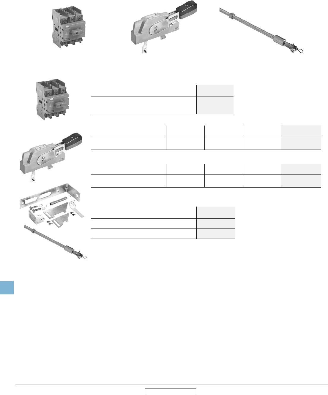
Special configurations
Cable operated flange
30A - 1200A
Non-fusible
UL general purpose
amp rating
Catalog
number
UL general purpose
amp rating
Catalog
number
30
60
100
200
OT30F3
OT60F3
OT100F3
OT200U30
400
600
800
1200
OETL-NF400-FC 2
OETL-NF600A-FC
2
OETL-NF800A-FC
2
OETL-NF1200-FC
2
Switch Handle Cable Lug kit (as required) Operating mechanism 1
OT100F3
OHF1C12
OXC1L36-
OXC1L84
+ + + +
1 Operating mechanism required for OT30 - OT200
2 Operating mechanism is included.
Disconnect
switches
Non-fusible
19.16 Low Voltage Products & Systems
1SXU000023C0202 Rev. A ABB Inc. • 888-385-1221 • www.abb.us/lowvoltage
19
Revised January 2014 Revised January 2014
Special configurations
Cable operated flange
30A - 1200A
Door hardware — NEMA 12
Item Catalog
number
Safety door latch, 2 point, door less than 40” high KDH2R
Safety door latch, 3 point, door greater than 40” high KDH3R
Terminal lug kits
For use
with
Wire
size
Wire
type Description Lugs per kit Catalog
number
#4 – 300 kcmil Cu/Al — 6 OZXA-200
OT200U30 #4 – 300 kcmil Cu/Al — 3 OZXA-200/3
(6) #4-6 AWG Cu/Al Distribution lug 3 OZXA-206S
OETL-NF400-FC #2 - 600 kcmil Cu/Al - 6 OZXA-26
OETL-NF600 - #2 - 600 kcmil Cu/Al - 6 OZXA-27
OETL-NF800 #2 - 600 kcmil Cu/Al - 3 OZXA-27/3P
(6) 14-6 AWG Cu/Al Distribution lug 3 OZXA-175/400
OETL-NF1200
(4) #2-600 kcmil Cu/Al - 6 OZXA-28
(8) 2/0 + (2) #2-600 kcmil Cu/Al - 3 OZXA-28/3P
(8) 2/0 + (2) #2-600 kcmil Cu/Al Distribution lug 3 OZXA-32
Terminal shrouds
For use on Description Weight
(lbs.)
Catalog
number
OT30 - OT100 3 Pole 0.02 OTS125T3
OT200 3 Pole Long Type Shroud 0.2 OTS250G1L/3
OT200 3 Pole Short Type Shroud 0.13 OTs250G1S/3
OETL-NF400 3 Pole (includes one shroud for line and load side) 0.62 OETL-ZX111
OETL-NF600 3 Pole (includes one shroud for line and load side) 0.66 OETL-ZX94
OETL-NF800 3 Pole (includes one shroud for line and load side) 0.88 OETL-2X800A
OETL-NF1200 3 Pole (includes one shroud for line and load side) 1.2 OETL-2X119
Disconnect
switches
Non-fusible
Low Voltage Products & Systems 19.17
ABB Inc. • 888-385-1221 • www.abb.us/lowvoltage 1SXU000023C0202 Rev. A
19
Revised January 2014 Revised January 2014
For a complete assembly,
please select one of each:
1 switch (page 19.17)
1 handle (page 19.30)
1 shaft (page 19.32)
1 terminal lug kit (page 19.34)
1 bridging bar (page 19.17)
NOTE: For additional accessories, see
pages 19.29 - 19.40
(Lug kits only necessary on switches 200A and above)
OT63F3C
OXS6X__
OHY__J6E011 Lug kit (as required)
3 Pole 4 Pole 1
UL
only
UL general
purpose amp
rating
IEC AC21
amp rating Catalog number Catalog number
UL508
20
30
40
60
80
16
25
40
63
80
OT16F3C
OT25F3C
OT40F3C
OT63F3C
OT80F3C
—
—
—
—
—
UL98
30
60
100
40
63
115
OT30F3C
OT60F3C
OT100F3C
—
—
—
200 250 OT200U03C
OT200U30C
OT200U04C
OT200U40C
400 630 OT400U03C
OT400U30C
OT400U04C
OT400U40C
600 800 OT600U03C
OT600U30C
OT600U04C
OT600U40C
800 1250 OT800U03C
OT800U30C
OT800U04C
OT800U40C
Bridging busbar kits — required for OT200_C through
OT600_C 2
Description For Use On: Catalog number
3 Pole Kit
OT200_C
OT400_C
OT600_C
OT800_C
OTZC13
OTZC23
OTZC33
OTZC53
4 Pole kit
OT200_C
OT400_C
OT600_C
OT800_C
OTZC14
OTZC24
OTZC34
OTZC54
Bridging bars are required on 200-600A double throw switches to operate as standard double
throw switches.
Otherwise, they will operate as two mechanically interlocked switches.
1 A snap on power pole may be added to build a 4 pole 16-100A double throw switch.
2 For 16-100A double throw switches, jumpers are not provided.
Special configurations
Double throw switches
16A - 600A
Bridging bars
OT200U04C
+ + ++
OTZC13
Disconnect
switches
Non-fusible
19.18 Low Voltage Products & Systems
1SXU000023C0202 Rev. A ABB Inc. • 888-385-1221 • www.abb.us/lowvoltage
19
Revised January 2014 Revised January 2014
OTDC Disconnect switches
28A - 55A, 600VDC
100A - 200A, 1000VDC
UL Category UL General purpose
amp rating
IEC DC21B
amp rating
Number
of circuits
Number
of poles
Catalog number
w/jumper installed
Catalog number
w/o jumper
28A - 55A, 600VDC
UL508 28 28 1 8 +1 – OT40FD9N2
55 55 1 8 – OT80FD8
100A - 200A, 1000VDC
UL98B
100 100 1 2 OTDC100US11 OTDC100U11
100 100 1 2 OTDC100US02 OTDC100U02
100 100 2 4 OTDC100US22 OTDC100U22
200 250 1 2 OTDC200US11 OTDC200U11
200 250 1 2 OTDC200US02 OTDC200U02
180 250 2 4 OTDC180US22 OTDC180U22
250 315 1 2 OTDC250US11 OTDC250U11
250 315 1 2 OTDC250US02 OTDC250U02
250 315 2 4 OTDC250US22 OTDC250U22
320 400 1 2 OTDC320US11 OTDC320U11
320 400 1 2 OTDC320US02 OTDC320U02
320 400 2 3 OTDC320US22 OTDC320U22
400 500 1 2 OTDC400US11 OTDC400U11
400 500 1 2 OTDC400US02 OTDC400U02
400 500 2 2 OTDC400US22 OTDC400U22
1 "S" indicates jumpers installed. Jumpers are installed on line side, connecting 2 poles in series
OTDC200U11 OTDC200U02
L
o
a
d
+
OTDC200U11
Load
1000 V DC
+ -
Factory jumper
1000 V DC1000 V DC
OTDC_US11
1000 V DC
OTDC_U22
+ -
1000 V DC + -
1000 V DC
Load Load
OTDC_US22
Jumper Jumper
L
o
a
d
L
o
a
d
+
1000 V DC
+
1000 V DC
Wiring diagrams
2 Pole 4 Pole
Phase separators
Switch
size
Units
type
(pcs)
Weight/
unit
(lbs.)
Catalog
number
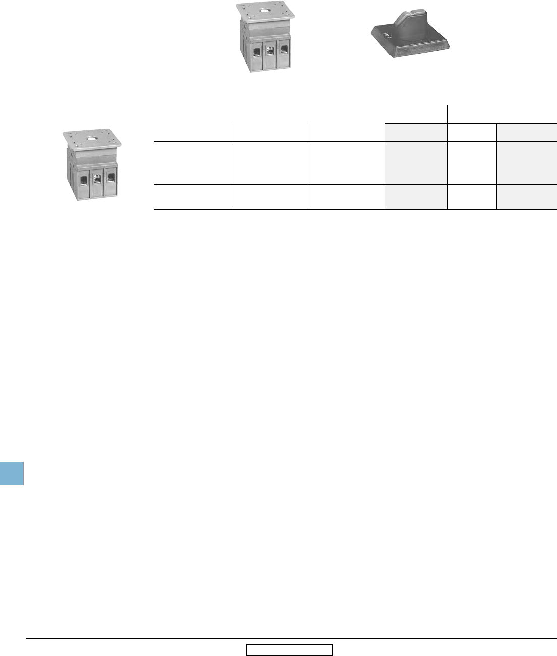
100...200 6 0.04 OTDCB250/6
250...400 6 0.05 OTDCB400/2
Grey plastic plate for maintaining 1" clearance between the phases without terminal
shrouds. Snap on mounting. Includes as standard in OTDC100...200U_types.
Jumper / heat sink
Switch
size
Units
type
(pcs)
Weight/
unit
(lbs.)
Catalog
number
100...200 1 0.04 OEZXY91
250...400 1 0.08 OEZXY96
Terminal lugs
Switch
size
Catalog
number
100...200 OZXA-200
250...400 OZXA-400
Disconnect
switches
Fusible
Low Voltage Products & Systems 19.19
ABB Inc. • 888-385-1221 • www.abb.us/lowvoltage 1SXU000023C0202 Rev. A
19
Revised January 2014 Revised January 2014
Fusible disconnect switches
30A – 1200A, 600VAC
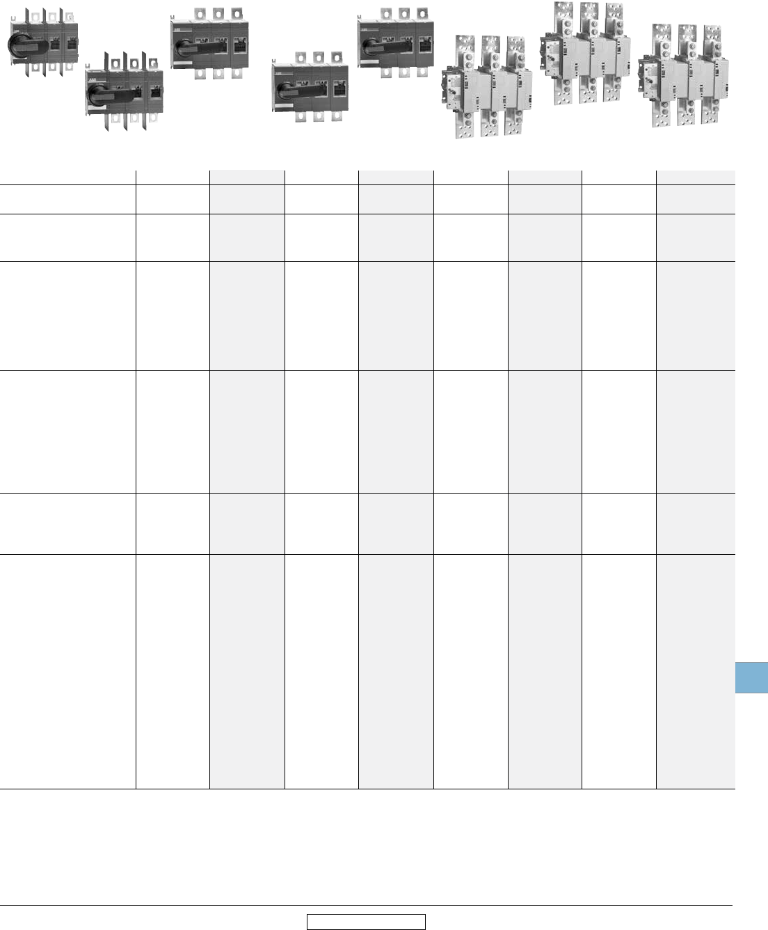
ABB PowerLine includes seven different amperage sizes from 30A to 1200A. All ABB
fusible switches are designed to meet customer requirements in terms of high interrupting
capacity and long electrical life while occupying little more panel space than the
appropriate fuses. The basic construction provides flexibility and high performance in an
extremely compact size. ABB PowerLine switches are a perfect choice to withstand the
heat and humidity of the tropics, the extreme cold of the arctic and any rugged industrial
environment you may have.
Fusible
Disconnect switches
International acceptance
ABB fusible switches are available with a wide range of fuse clip options:
UL USA CSA Canada
DIN Europe BS United Kingdom
NFC France Ultra-rapid
As well as the corresponding approvals: UL listed, CSA approved, IEC rated, CE marked,
and most other international standards.
UL98 (CSA 22.2 No.4) — UL File # E101914, CSA File #LR58077
For 30A – 1200A switches, OH__ pistol grip handles
Suitable for use as motor disconnects or industrial control panel disconnects on service
entrance equipment, panelboards, switchboards, industrial control equipment, motor
control centers, etc. and are horsepower rated and ampere rated.
IEC
Tested in accordance to IEC 947-1 and 3, IEC 664, IEC 269, and IEC 204
CE
Compliance with the European Machine Directive IEC 204 (EN 60204)
Disconnect
switches
Fusible
19.20 Low Voltage Products & Systems
1SXU000023C0202 Rev. A ABB Inc. • 888-385-1221 • www.abb.us/lowvoltage
19
Revised January 2014 Revised January 2014
Selection guide
OS30FACC12 – OS1200L03
S = Standard
• = Available
— = Not available
Catalog number 3 pole OS30FACC12 OS30FAJ12 OS60GJ12 OS100GJ03 OS200J03 OS400J03 OS600J03 OS800L3 OS1200L03
General purpose
amp rating A 30 30 60 100 200 400 600 800 1200
Approvals 1
2 pole N/A N/A N/A UL98 & IEC UL98 & IEC UL98 & IEC UL98 & IEC UL98 & IEC UL98 & IEC
3 pole UL98 & IEC UL98 & IEC UL98 & IEC UL98 & IEC UL98 & IEC UL98 & IEC UL98 & IEC UL98 & IEC UL98 & IEC
4 pole UL98 & IEC UL98 & IEC UL98 & IEC UL98 & IEC UL98 & IEC UL98 & IEC UL98 & IEC UL98 & IEC IEC
Technical ratings
(UL,CSA)
Max operating voltage V 600 600 600 600 600 600 600 600 600
Max horsepower rating
Three phase
240V HP 7.5 7.5 15 30 60 125 200 250 —
480V HP 15 15 30 60 125 250 400 500 —
600V HP 20 20 50 75 150 350 500 600 —
Single phase
120V HP 2 2 — — — — — — —
240V HP 3 3 — — — — — — —
UL fuse class CC J J J J J J L L
Technical ratings (IEC)
Rated insulation and operational
voltage. AC20 and DC20 V 1000 1000 1000 1000 1000 1000 1000 1000 1000
Rated thermal current, Ith
AC 20/DC 20 open A 32 32 63 160 200 400 630 800 1250
AC 20/DC 20 enclosed A 32 32 63 160 200 400 600 720 1250
AC 21A ≤500V A 32 32 63 160 200 400 630 800 1250
≤690V A 32 32 63 160 200 400 630 800 1250
Rated operational power AC23
400/415V kW 14/15 14/15 30 80/90 110 220/230 355 350/380 560
690V kW 25 25 60 132 200 400 560 600 1000
Physical characteristics
Weight 3 pole switch lb 1.54 1.54 2.86 3.30 5.9 12.56 28.66 37.44 63.93
4 pole lb 1.98 1.98 3.52 3.96 7.5 15.21 37.48 46.26 —
Dimension 3 pole H in 3.66 3.60 3.94 5.67 6.5 9.29 12.03 12.03 16.7
W in 4.15 4.15 5.63 7.07 7.1 10.04 13.86 13.86 16.42
D in 4.10 4.10 5.04 5.10 5.2 6.93 9.18 9.18 11.62
Accessories
Double break contacts S S S S S S S S S
Fuse cover S S S S S S S S S
Terminal lug kit Integral Integral Integral OZXA-24 OZXA-200 OZXA-400 OZXA-800 OZXA-1200 OZXA-1200
Terminal shroud Not required Not required Not required • • • • • •
Auxiliary contact • • • • • • • • •
Shaft/handle diameter
6mm 6mm 6mm 6mm 6mm 12mm 12mm 12mm 12mm
.24 x .24" .24 x .24" .24 x .24" .24 x .24" .24 x .24" .47 x .47" .47 x .47" .47 x .47" .47 x .47"
Handle UL/NEMA type
Type 1, 3R, 12 • • • • • • • • •
Type 1, 3R, 4, 4X, 12
• • • • • • • • •
Recommended pistol handle length 45 - 65mm 45 - 65mm 45 - 65mm 45 - 65mm 65 - 80mm 125 - 175mm 125 - 175mm 125 - 175mm 125 - 175mm
Maximum recommended shaft length 290mm 290mm 290mm 290mm 290mm 595mm 595mm 595mm 595mm
Electrical interlock — — — — — • • • •
OS30FA_12 OS60GJ03 OS100GJ03 OS200J03 OS400J03 OS600J03 OS800L3 OS1200L03
1 UL listed switches are also CSA approved.
Disconnect
switches
Fusible
Low Voltage Products & Systems 19.21
ABB Inc. • 888-385-1221 • www.abb.us/lowvoltage 1SXU000023C0202 Rev. A
19
Revised January 2014 Revised January 2014
Selection information
Standard part number designation 1
Fusible OS Switches (30A)
OS 30 F A J 22 F
Amperage
30 = 30 amps
Fuse Type/Class
J = Class J fuse compatible CC= Class CC fuse compatible
Number of poles and placement of the mechanism
12 = 1 Pole to the left of mechanism, 2 poles to the right of mechanism
22 = 2 Poles to the left of mechanism, 2 poles to the right of mechanism
Fusible OS Switches (60 to 100A)
OS 100G J 03
Amperage
60 = 60 amps 100 = 100 amps
Fuse Type/Class
J = Class J fuse compatible
Number of poles and placement of the mechanism
03 = 3 Poles to the right of mechanism 04 = 4 poles to the right of mechanism
Pistol Handles
O H B 65 J 6 E011
Handle Color
B = Black Y = Red/Yellow M = Stainless Steel
Handle Length
65 = 65mm 80 = 80mm 125 = 125mm 145 = 145m 175 = 175mm 274 = 274mm 275 = 275mm 330 = 330mm
Environmental Rating
J = 1, 3R, 12 L = 1, 3R, 12, 4, 4X
Shaft Diameter
6 = 6mm 12 = 12mm
Special Configuration
E011 = 3 position transfer switch handle
EH = Stainless Steel Hasp
1 Part designation keys are provided for reference only. Not all variations or configurations are available.
Fusible OS Switches (200A and above)
OS 200 J 04 F
Amperage
200 = 200 amps 400 = 400 amps 600 = 600 amps 800 = 800 amps 1200 = 1200 amps
Fuse Type/Class
J = Class J fuse compatible
Number of poles and placement of the mechanism
03 = 3 Poles to the right of mechanism 04 = 4 poles to the right of mechanism
12 = 1 Pole to left of mechanism, 2 poles to right 22 = 2 Poles to left of mechanism, 2 poles to right
30 = 3 Poles to the left of mechanism 40 = 4 Poles to the left of mechanism
Disconnect
switches
Fusible
19.22 Low Voltage Products & Systems
1SXU000023C0202 Rev. A ABB Inc. • 888-385-1221 • www.abb.us/lowvoltage
19
Revised January 2014 Revised January 2014
Base & DIN rail mounted
30 – 1200A
OS400J03 + OXP12X280 + OHB145J12 + OZXA-24
2 Pole 3 Pole 4 Pole
UL general purpose amp
rating UL Fuse Type 600V Catalog number Catalog number Catalog number
UL 98
30 J
CC 1
—
—
OS30FAJ12
OS30FACC12
OS30FAJ22F
OS30FACC22F
60 J — OS60GJ12 2
OS60GJ03 OS60GJ22F
100 J — OS100GJ12 2
OS100GJ03 2 OS100GJ04F
200 J OS200J02
OS200J03
OS200J30
OS200J12
OS200J04F
OS200J13F
OS200J22F
400 J OS400J02
OS400J03
OS400J30
OS400J12
OS400J04F
600 J OS600J02
OS600J03
OS600J30
OS600J12
OS600J04F
800 L OS800L02 OS800L03 OS800L04F
1200 L OS1200L02 OS1200L03 OS1200L04F
1 Rejection style fuses only.
2 Din Rail Mountable: 60A & 100A requires Din Rail Adapter OSGZD1
For a complete assembly, please select
one of each:
1 switch (page 19.22)
1 handle (page 19.30)
1 shaft (page 19.32)
1 terminal lug kit (page 19.34)
NOTE: For additional accessories, see
pages 19.29 - 19.40.
(Only required for 100A & above.)
OS30FAJ12
+ + +
Disconnect
switches
Fusible
Low Voltage Products & Systems 19.23
ABB Inc. • 888-385-1221 • www.abb.us/lowvoltage 1SXU000023C0202 Rev. A
19
Revised January 2014 Revised January 2014
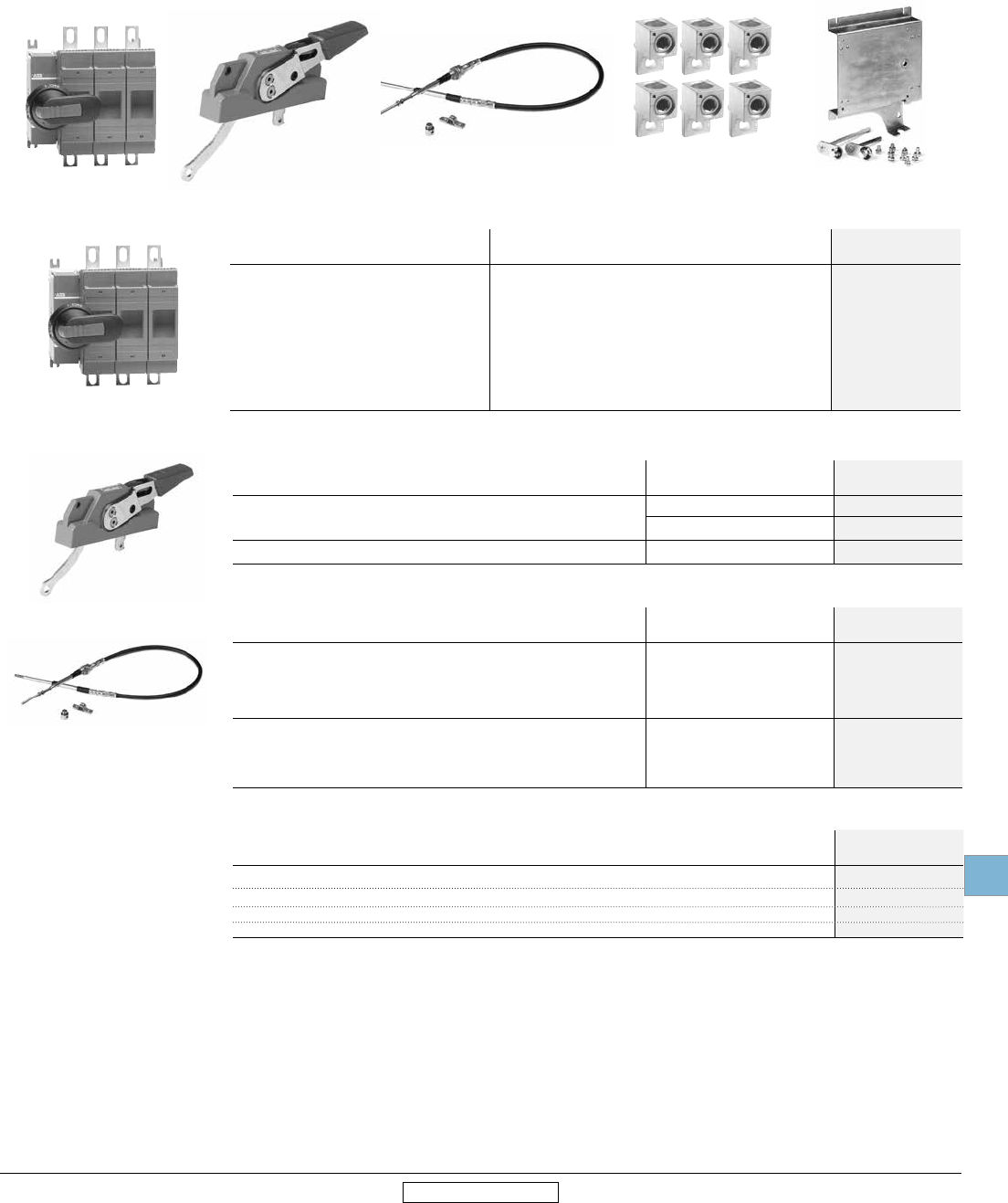
Other configurations
Side operated
30A – 400A, UL fuse class J,CC
For a complete assembly,
please select one of each:
1 switch
1 handle
1 shaft
1 terminal lug
Side operated switches — 3 pole
UL
general
purpose
amp rating
UL
fuse
type
600V
Maximum horsepower rating
Weight
(Lbs.)
Catalog
number
Three phase
200V 208V 240V 480V 600V
30 J 5 7.5 7.5 15 20 1.54 OS30FAJS30
30 CC 5 7.5 7.5 15 20 1.54 OS30FACCS30
60 J 15 15 15 30 50 3.52 OS60GJS30
100 J1 25 25 30 60 75 3.97 OS100GJS30
200 J1 50 50 60 125 150 15.21 OES200J3-S
400 J1 100 100 125 250 350 17.20 OES400J3-S
Handles
UL/NEMA
type IEC type Color Length
(Inches/mm) Marking Defeatable Padlockable Weight Catalog
number
For use with OS30A_S30
1, 3R, 12 IP65 Black 2.6/65 OFF/ON Yes Ye s 0.29 OHB65J6E00S
Red/Yel OHY65L6E00S
For use with OS60GJ30, OS60JS30 & OS100GJ30
1, 3R, 12 IP65 Black
Red/Yel 3.1/80 OFF/ON Yes Ye s 0.30 OHB80J6E00S
For use with OES200J3-S & OES400J3-S
1, 3R, 12 IP65
Black
4.9/145 OFF/ON Yes Yes 0.39 OHB145J12E00S
Red/Yel OHY145J12E00S
Metal No Yes 1.50 OETL-ZX74
Shaft
For use with: Length
(Inches/mm) Description Weight
(Lbs.)
Catalog
number
OS30AJS30 & OS30ACCS30 6.7/170 .20 x .20” (5 x 5mm) 0.08 OXP6X170
OS60GJS30 & OS100GJS30 8.3/210 .24 x .24” (6 x 6mm) 0.10 OXP6X210
OES200J3-S & OES400J3- 12.8/325 .47 X .47” (12 X 12mm) 0.90 OXP12X325
Terminal lug kits
For use with: Wire
size Weight Wire
type
Lugs
per kit
Catalog
number
OS30AJS30 & OS30ACCS30 #18 – 8 — Cu — Integral
OS60GJS30 #14 – 4 — Cu — Integral
OS100GJS30 #14 – 2/0 0.43 Cu/Al 6 OZXA-24
OES200J3-S #6 – 300 kcmil 0.93 Cu/Al 6 OZXA-25
OES400J3-S #2 – 600 kcmil 3.50 Cu/Al 6 OZXA-26
OS30FAJS30 OXP6X170 OHY65L6E00S
OS60GJS30
OS100GJS30
OETL-ZX74
OZXA-24
++
Disconnect
switches
Fusible
19.24 Low Voltage Products & Systems
1SXU000023C0202 Rev. A ABB Inc. • 888-385-1221 • www.abb.us/lowvoltage
19
Revised January 2014 Revised January 2014
Flange handles
UL/ NEMA type Marking Defeatable Padlockable Catalog
number
1, 3R, 12
4, 4X
OFF/ON
OFF/ON
Yes
Yes
Yes
Yes
DSFHN-HS12
DSFHN-HS4
Shafts
For use with: Maximum enclosure depth (inches) Catalog
number
OS30_ - OS100_
16
21
26.5
DSFHS-12
DSFHS-17
DSFHS-22
Special configurations
Shaft operated flange
30A - 100A
Switch Handle Shaft Lug kit (as required)
DSFHN-HS__
DSFHS-__
OS30FAJF30
Flange operated fusible and non-fusible disconnect switches
ABB’s solution for complying with the NFPA79 requirements is Flange Operated Fusible and Non-fusible Disconnect Switches.
NFPA 79 changes requires main disconnecting means to be operable without the use of accessory tools or devices, independent
of door position. This code also includes an interlocking provision to prevent the closing of disconnects while the enclosure door
is open, unless an interlock is operated by a deliberate action.
The flange operated disconnect switches are available as ridged shaft or flexible cable operated versions. The cable operated
version allows you to install the disconnect switch virtually anywhere in the enclosure depending on the length of the cable.
Cables are available in lengths up to 84 inches.
The designs are cost-effective NFPA 79 solutions offering quick and easy installation.
30A -100A Flange operated fusible switches (Shaft) — 3 pole
UL general
purpose amp rating
A
UL fuse type
600V
Maximum horsepower rating
Catalog
number
Three phase
240V 480V 600V
30
30
60
100
J
CC
J
J
7.5
7.5
15
30
15
15
30
60
20
20
50
75
OS30FAJF30
OS30FACCF30
OS60GJF30
OS100GJF30
OZXA-24
OA1G__
Terminal lug kits and accessories
For use on: Description Wire size Wire type Qty. Catalog
number
OS30_
OS60_
OS100_
Lug
Lug
Lug
#18 - #8
#14 - #4
#14 - 2/0
Cu
Cu
Cu/Al
--
--
6
Integral
Integral
OZXA-24
OS30_- OS100_ Aux. Contact
Aux. Contact
1 NO
1 NC
1
1
OA1G10
OA3G01
OS30_ Adapter Needed for mounting aux. Contacts on OS30_ 1 OSZ4
OS100_ Shroud Includes one set of 3 for use on line or load side 1 OSS160GG1L/3
OSS160GG1S/3
Door hardware NEMA 12
Item Catalog
number
Safety door latch, 2 point, door less than 40” high
Safety door latch, 3 point, door greater than 40” high
KDH2R
KDH3R
For a complete assembly, please select one of each.
+++
Disconnect
switches
Fusible
Low Voltage Products & Systems 19.25
ABB Inc. • 888-385-1221 • www.abb.us/lowvoltage 1SXU000023C0202 Rev. A
19
Revised January 2014 Revised January 2014
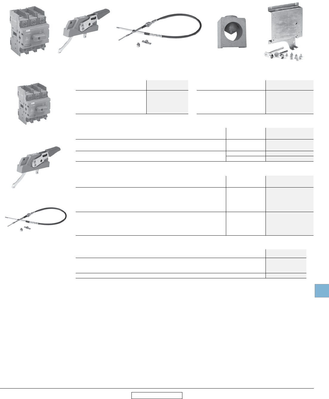
Special configurations
Cable operated flange
30A - 800A
OXC1L36-
OXC1L84
OHF1C12
OS200J03
Switch Handle Cable Lug kit (as required) Operating mechanism
Fusible
UL general
purpose amp rating
UL fuse type
600V
Catalog
number
30
30
60
60
100
200
400
600
800
J
CC
J
J
J
J
J
J
L
OS30FAJ12
OS30FACC12
OS60GJ12
OS60GJ30
OS100GJ30
OS200J30
OES400J3-FC 1
OES600J3-FC 1
OES800L3-FC 1
For a complete assembly, please select one each of the following:
++ + +
1 Operating mechanism is included.
Flange handles — UL98; File #E101914
For use with: Environmental
rating
Catalog
number
OS30_12, OS60GJ12, OS60GJ30, OS100GJ30, OS200J30
NEMA 1, 3R, 12 OHF1C12
NEMA 4, 4X OHF1C4
OES400_, OES600_, OES800_ NEMA 4, 4X K7FCH4
Flexible cables
For use with: Cable length (inches) Catalog
number
OS30_12, OS60GJ12, OS60GJ30, OS100GJ30, OS200J30
36
48
60
72
84
OXC1L36
OXC1L48
OXC1L60
OXC1L72
OXC1L84
OES400_, OES600_, OES800_
48 K7C048
60 K7C060
72 K7C072
84 K7C084
Operating mechanisms
For use with: Catalog
number
OS30AFJ12, OS30AFCC12 MKCS2
OS60GJ12 MKCS3
OS60GJ30, OS100GJ30 , OS200J30 MKCS4
OES400 - OES800 Included
Disconnect
switches
Fusible
19.26 Low Voltage Products & Systems
1SXU000023C0202 Rev. A ABB Inc. • 888-385-1221 • www.abb.us/lowvoltage
19
Revised January 2014 Revised January 2014
Door hardware NEMA 12
Item Catalog
number
Safety door latch, 2 point, door less than 40” high
Safety door latch, 3 point, door greater than 40” high
KDH2R
KDH3R
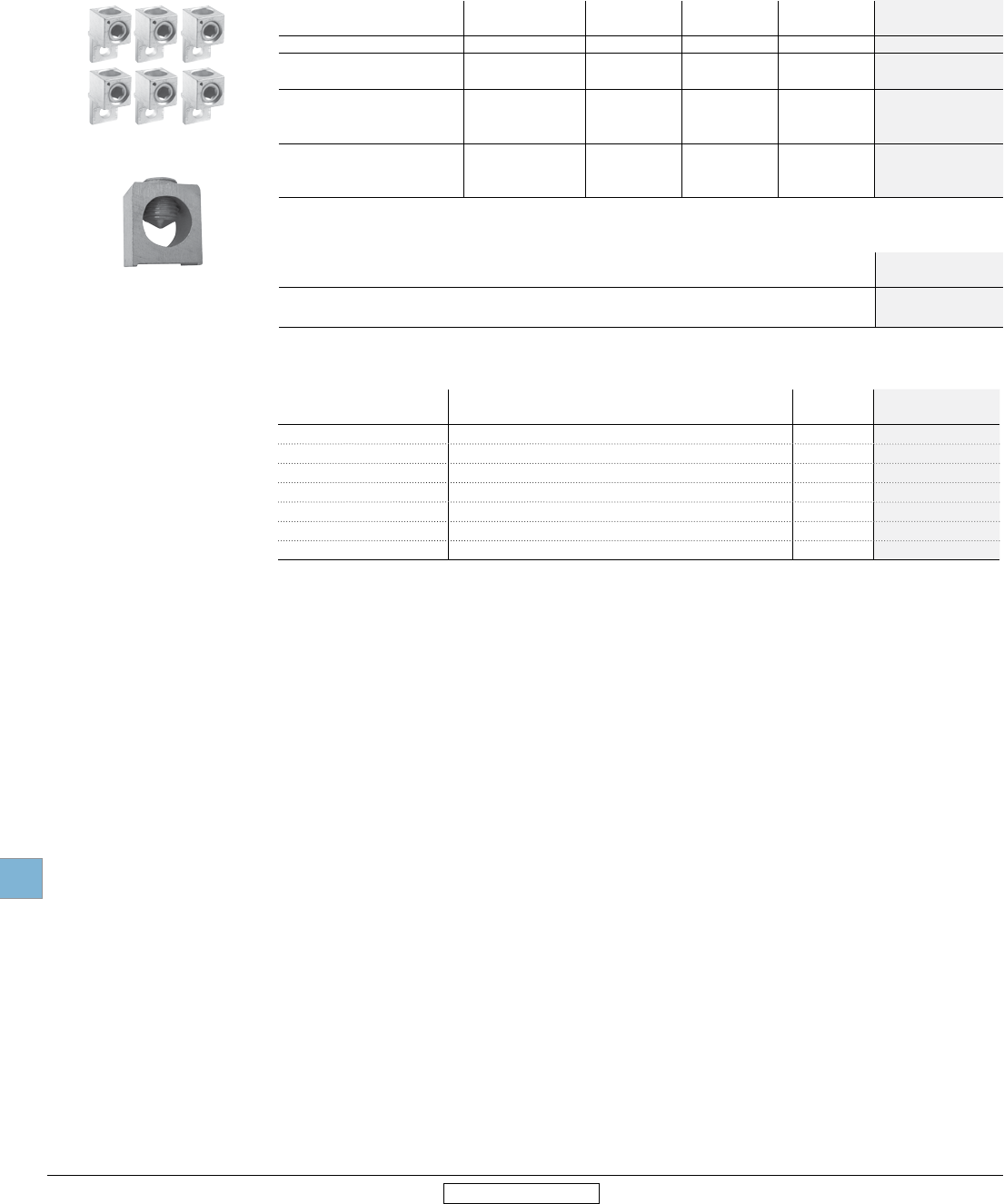
OZXA-200
Lug Kit
Terminal lug kits
For use
with
Wire
size
Wire
type Description Lugs
per kit
Catalog
number
OS100GJ30 #4 – 300 kcmil Cu/Al - 6 OZXA-24
OS200J30 #4 – 300 kcmil Cu/Al - 3 OZXA-200/3
(6) #4-6 AWG Cu/Al Distribution lug 3 OZXA-206S
OES400
#2 - 600 kcmil Cu/Al - 6 OZXA-26
#2 - 600 kcmil Cu/Al - 3 OZXA-26/3P
(2) #2 - 500 kcmil Cu/Al Distribution lug 6 OZXA-33
OES600 - OES800
(12) #14 - 6 kcmil Cu/Al - 3 OZXA-175/400
(2) #2 - 600 kcmil Cu/Al - 6 OZXA-27
(2) #2 - 600 kcmil Cu/Al Distribution lug 3 OZXA-27/3P
Special configurations
Cable operated flange
30A - 800A
Terminal shrouds
For use on Description Weight
(lbs.)
Catalog
number
OS100 1 Pole 0.04 OSS160T1
OS100 3 Pole 0.12 OSS160T3
OS200 3 Pole Long Type Shroud 0.2 OSS200G1L/3
OS200 3 Pole Short Type Shroud 0.13 OSS200G1S/3
OES400 3 Pole (includes one shroud for line and load side) 0.13 OESA-ZX123
OES600 3 Pole (includes one shroud for line and load side) 0.13 OESA-ZX125
OES800 3 Pole (includes one shroud for line and load side) 0.11 OESA-ZX125
Disconnect
switches
Fusible
Low Voltage Products & Systems 19.27
ABB Inc. • 888-385-1221 • www.abb.us/lowvoltage 1SXU000023C0202 Rev. A
19
Revised January 2014 Revised January 2014
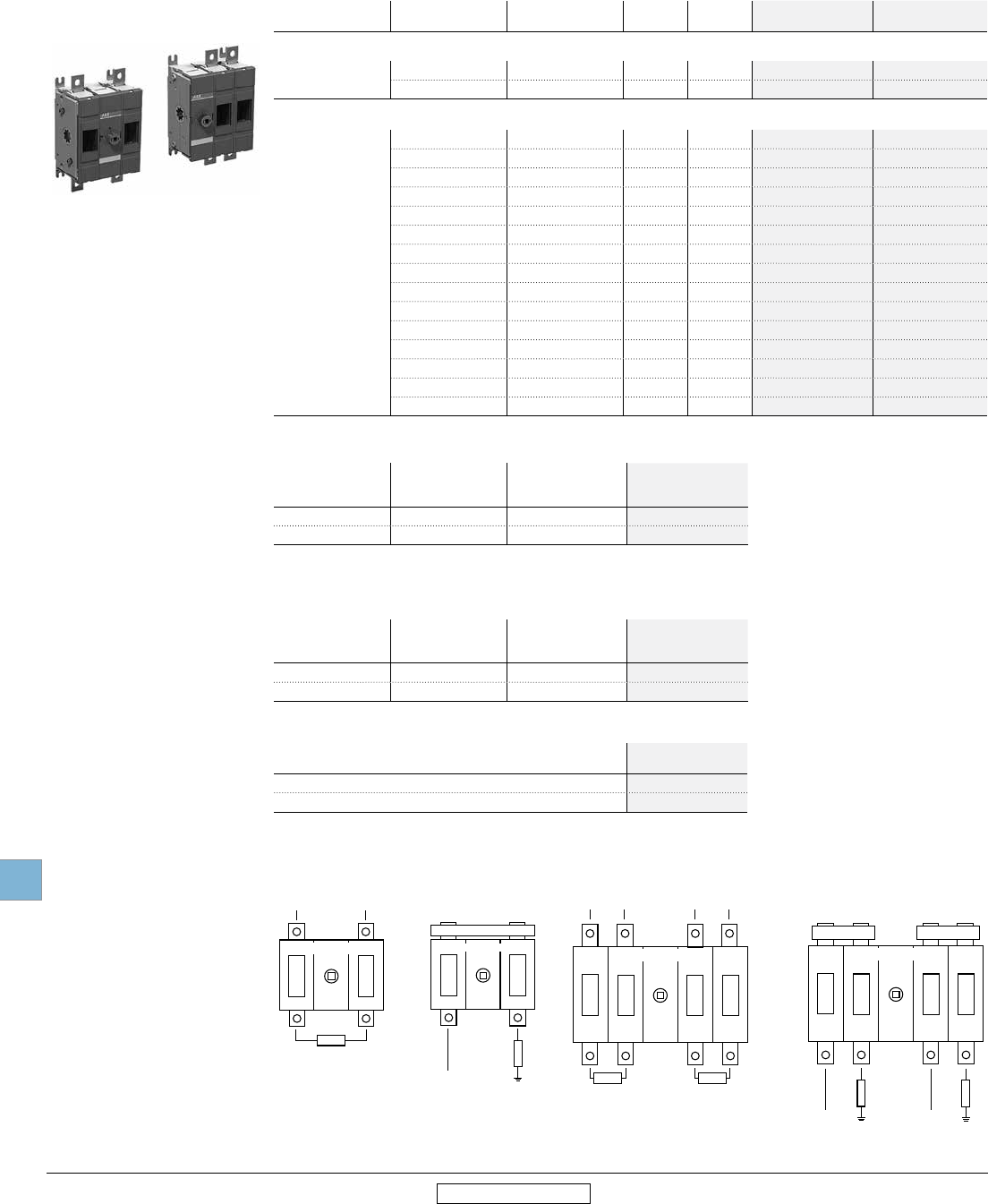
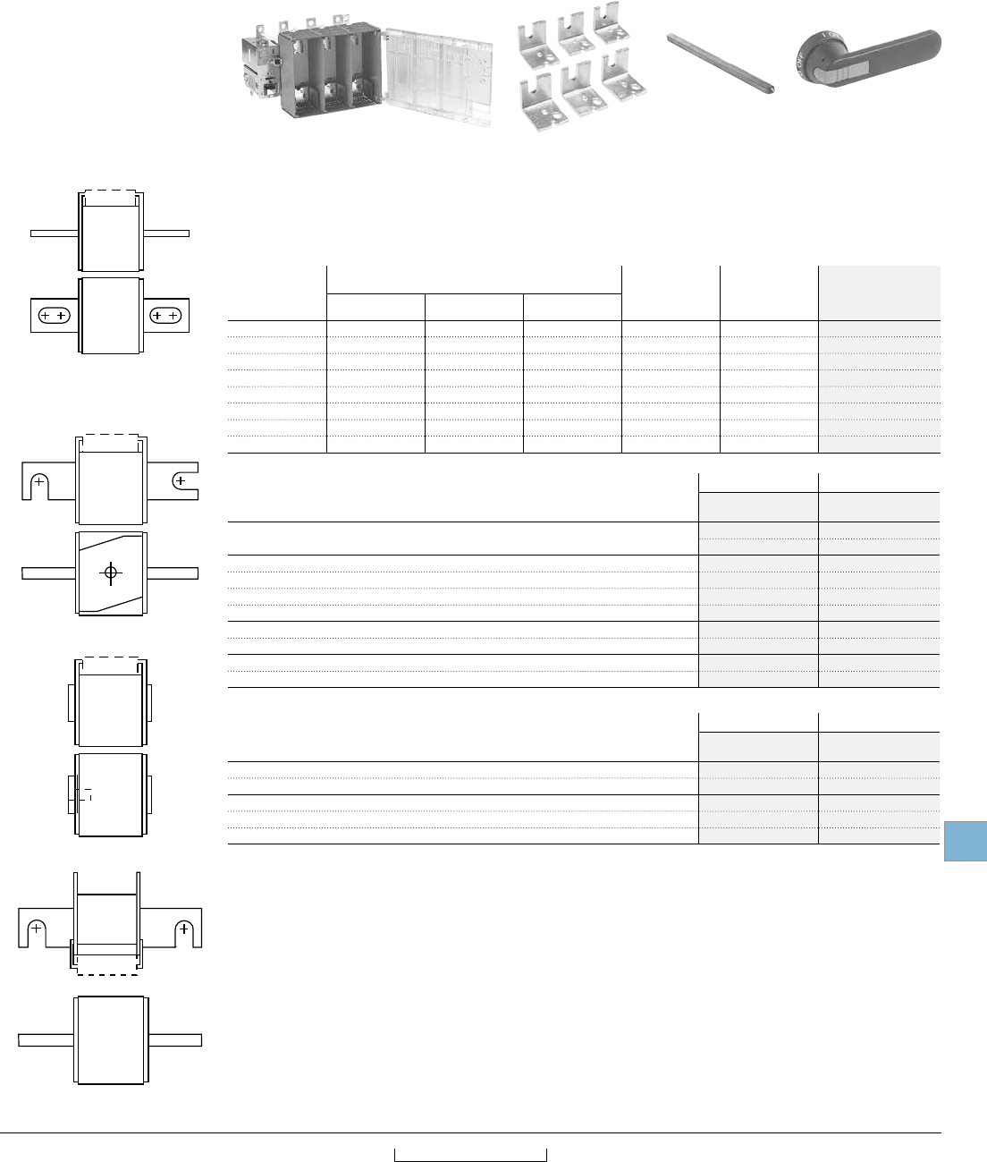
Switch bodies – 200 A through 800 A
UL
general purpose
amp rating
Maximum horsepower rating
three phase
Max. allowed
fuse power
dissipation at
rated current
Weight Catalog
number
240 V 480 V 600 V
200 60 125 150 22W 15.21 OES200R03
400 125 250 350 45W 17.20 OES400R03
600 200 400 500 60W 37.48 OES600R03
800 250 500 600 65W 37.48 OES800R03
200 60 125 150 22W 17.4 OES200R04
400 125 250 350 45W 19.4 OES400R04
600 200 400 500 60W 46.3 OES600R04
800 250 500 600 65W 46.3 OES800R04
Handles and shafts — see pages 19.30 - 19.32.
Selecting the right fusible disconnect for HSF fuses may be difficult. Due to UL restrictions it is not possible to give a general
fuse selection table for your use. Therefore we ask you to contact ABB Inc., in application issues. Information needed is nominal
current of the application and catalog number of the fuse.
Selecting switch bodies and adapter kits
Please select switch body and adapter kit according to your fuses. Switch body alone can not be used — an adapter kit is always
needed.
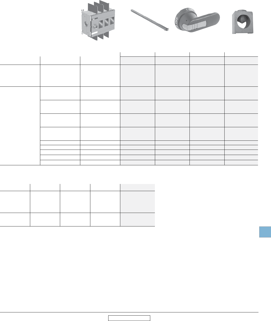
For a complete assembly,
please select one of each:
1 switch body
1 adapter kit
1 shaft
1 handle OESA_R_ OESAZX_ OXP_ OH_
Other configurations
High speed fuse pattern
Special type fuses
DIN 43653
Flush end
French style
American standard
1 Consult Factory.
+ + +
Fuse adapter kits — for switches OES200 – OES400 For 3 pole switch For 4 pole switch
Fuse standard Catalog
number
Catalog
number
American standard OESAZX1-S4 OESAZX1-S4/4
OESAZX1-S5 OESAZX1-S5/4
DIN80 (DIN43653) OESAZX1-S7 OESAZX1-S7/4
DIN80 sizes 00 and 000 (DIN 43653) OESAZX1-S9 OESAZX1-S9/4
DIN110 (DIN43653) OESAZX1-S2 OESAZX1-S2/4
DIN140 (DIN43653) OESAZX1-S6 OESAZX1-S6/4
Flush-end, 70mm body OESAZX1-S8 OESAZX1-S8/4
Flush-end, 50mm body OESAZX1-S3 OESAZX1-S3/4
French OESAZX1-S10 OESAZX1-S10/4
French with micro switches OESAZX1-S11 OESAZX1-S11/4
Fuse adapter kits — for switches OES600 – OES800 For 3 pole switch For 4 pole switch
Fuse standard Catalog
number
Catalog
number
American standard OESAZX2-S4 OESAZX2-S4/4
DIN80, DIN 110, DIN 140 (DIN43653) OESAZX2-S2 OESAZX2-S2/4
Flush-end, 50mm and 70mm body OESAZX2-S3 OESAZX2-S3/4
French OESAZX2-S5 OESAZX2-S5/4
French with micro switches OESAZX2-S6 OESAZX2-S6/4
Disconnect
switches
Fusible
19.28 Low Voltage Products & Systems
1SXU000023C0202 Rev. A ABB Inc. • 888-385-1221 • www.abb.us/lowvoltage
19
Revised January 2014 Revised January 2014
Other configurations
High speed fuse pattern
Standard switches
Selecting switch bodies
There are some HSF fuses that fit in standard pattern fusible disconnects, no adapter kits needed.
For a complete assembly,
please select one switch
catalog number which
includes:
DIN 43620
NFC Style
Switch body + shaft + handle
DIN-type fusible disconnects – 32-1200A
IEC Amp rating AC23A operational power in kW Fuse Type Weight (kg) 3 Pole
Catalog number
4 Pole
Catalog number
400V 500V
32 15 18.5 DIN 000 1.3 OS32GD03 OS32GD04F
63 30 37 DIN 000 1.3 OS63GD03 OS63GD04F
160 75 90 DIN 000, 00 1.5 OS160GD03 OS160GD04F
250 145 170 DIN 0, 1 4.3 OS200D03 OS200D04F
400 230 280 DIN 0, 1, 2 7.1 OS400D03 OS400D04F
630 355 450 DIN 3 13.6 OS630D03 OS630D04F
800 450 560 DIN 3 13.6 OS800D03 OS800D04F
1200 560 710 DIN 4 46 OS1250D03 OS1250D04F
NFC-style Fusible disconnects – 25-125A
IEC Amp rating AC23A operational power in kW Fuse Type Weight (kg) 3 Pole
Catalog number
4 Pole
Catalog number
400V 500V
25 11 15 NFC 10x38 0.7 OS25FF1210 OS25FF2210F
32 15 18.5 NFC 14x51 0.7 OS32FF1214 OS32FF2214F
50 22 30 NFC 14x51 1.3 OS50GF12 OS50GF22F
125 55 75 NFC 22x58 1.5 OS125GF12 OS125GF22F
BS-types fusible disconnects – 32-1200A
IEC Amp rating AC23A operational power in kW Fuse Type Weight (kg) 3 Pole
Catalog number
4 Pole
Catalog number
400V 500V
32 15 18.5 A2,A3 1.3 OS32GB03 OS32GB04N1
63 30 37 A2,A3 1.3 OS63GB03 OS63GB04N1
100 55 55 A2, A3, A4 1.5 OS100GB03 OS100GB04N1
160 75 90 A2, A3, A4 1.5 OS160GB03 OS160GB04N1
200 145 170 B1-B2 3.3 OS200B03 OS200B04N2
400 230 280 B1-B4 7.1 OS400B03 OS400B04N2
630 355 450 C1-C2 13.6 OS630B03 OS630B04N2
800 450 560 C1-C3 13.6 OS800B03 OS800B04N2
1250 560 710 D1 46 OS1250B03 OS1250B04N2
Disconnect
switches
Accessories
Low Voltage Products & Systems 19.29
ABB Inc. • 888-385-1221 • www.abb.us/lowvoltage 1SXU000023C0202 Rev. A
19
Revised January 2014 Revised January 2014
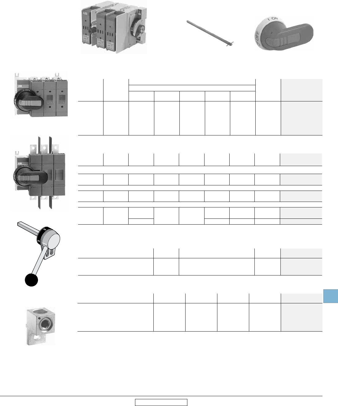
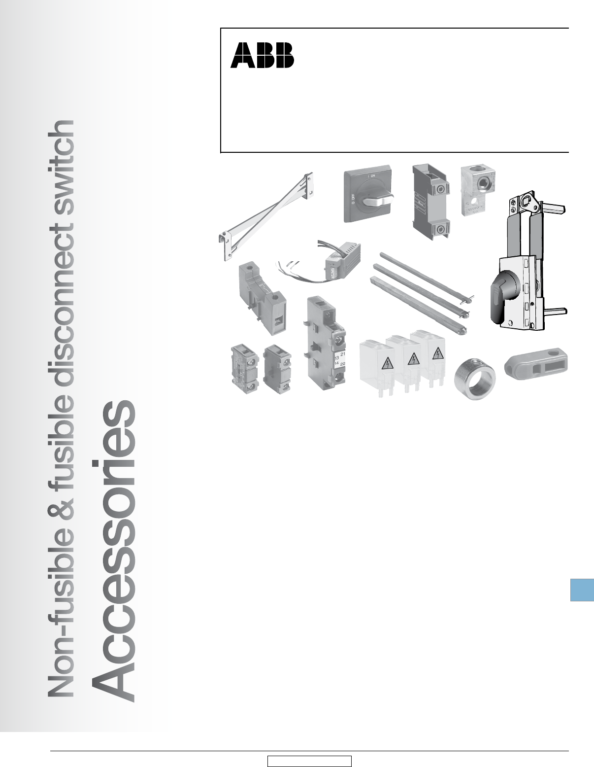
Disconnect switch accessories
Non-fusible & fusible
Non-fusible & fusible disconnect switch
Accessories
I
O
N
Disconnect
switches
Accessories
19.30 Low Voltage Products & Systems
1SXU000023C0202 Rev. A ABB Inc. • 888-385-1221 • www.abb.us/lowvoltage
19
Revised January 2014 Revised January 2014
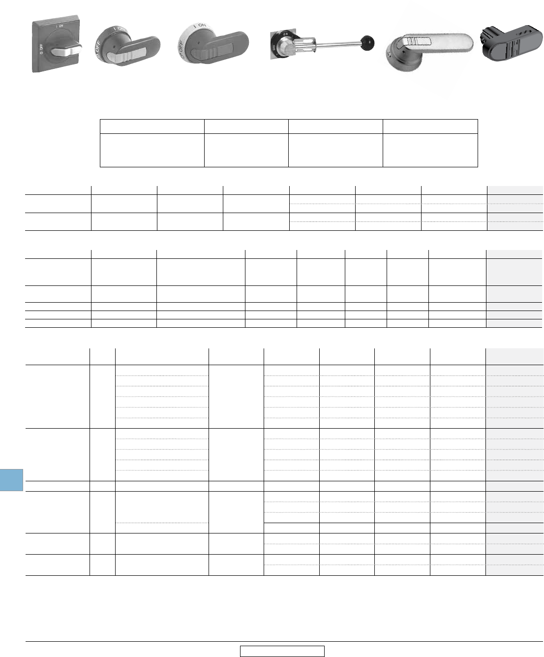
Standard handles & shafts 12
Selector handles — for use with .24 x .24" (6mm) OXS6X_shafts
UL/NEMA Type IEC type Color Marking Defeatable Padlockable Weight (lbs) Catalog number
1 IP54 Black O/I & Off/On — — 0.09 OHBS1AH1 3
—Yes 0.12 OHBS3AH1 3
1, 3R, 12 IP65 Black O/I & Off/On —Yes 0.16 OHBS2AJ1 3
Yes Yes 0.16 OHBS2AJ 3
Pistol handles — for use with .24 x .24" (6mm) OXP6X_ shafts
UL/NEMA Type IEC type Color Marking Length in/mm Defeatable Padlockable Weight (lbs) Catalog number
1, 3R, 12 IP65 Black
O/I & Off/On
Off/On/Test
O/I & Off/On
2.6/65
2.6/65
3.1/80
Yes
Yes
Yes
Yes
Yes
Yes
0.29
0.29
0.30
OHB65J6
OHB65J6T 4
OHB80J6
1, 3R, 12, 4, 4X IP66 Black O/I & Off/On 2.6/65 Yes Yes 0.29 OHB65L6
3.1/80 Yes Yes 0.30 OHB80L6
1, 3R, 12, 4, 4X IP66 316L Stainless steel O/I & Off/On 2.6/65 Yes Ye s 1.60 OHM65L6
1, 3R, 12 IP65 Black w/ 316 stainless hasp O/I & Off/On 2.6/65 Yes Yes 0.31 OHB65J6EH
1, 3R, 12, 4, 4X IP66 Black w/ 316 stainless hasp O/I & Off/On 2.6/65 Yes Yes 0.31 OHB65L6EH
1 Red/Yellow handles are available by substituting the OHB prefix with OHY.
2 All handles are plastic unless otherwise noted as metal or stainless steel.
3 Not recommended for use on OT30/60/100.
4 The OS30_ switch has a TEST position, accessed by rotating the mechanism 45 degrees counterclockwise from the OFF position. In the TEST position, optional auxiliary contacts, OA4B1C, are
actuated but the main switch contacts are not.
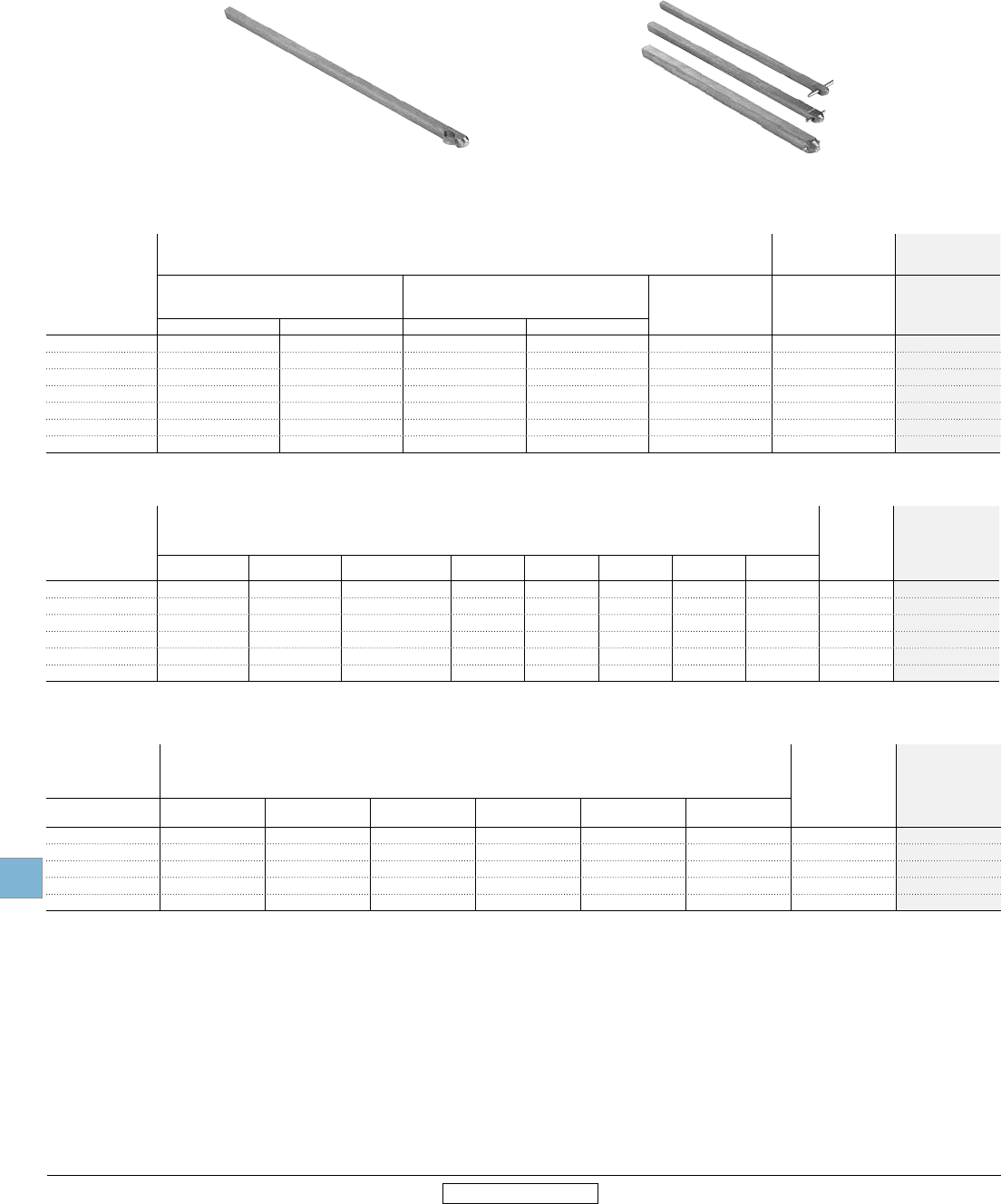
Recommended handles & shafts
Amperes Shaft diameter Recommended standard pistol
handle length
Maximum recommended
shaft length
16 - 100 6x6 mm - .24 x .24" 45 - 65 mm 290 mm
200 6x6 mm - .24 x .24" 65 - 80 mm 290 mm
400 - 1200 12x12 mm - .47 x .47" 125 - 274 mm 595 mm
1600 - 3150 12x12 mm - .47 x .47" 175 - 330 mm 595 mm
Pistol handles — for use with .47 x .47" (12mm) OXP12X_ shafts
UL/NEMA Type IEC
type Color Marking Length in/mm Defeatable Padlockable Weight (lbs) Catalog number
1, 3R, 12
IP65
Black
O/I & Off/On
4.9/125 Yes Yes 0.39 OHB125J12
Black 5.7/145 Yes Yes 0.39 OHB145J12
Black 6.9/175 Yes Yes 0.41 OHB175J12
Black T-Handle 7.9/200 Yes Yes 0.88 OHB200J12P
Black Steel Reinforced 10.8/274 Yes Yes 1.19 OHB274J12
Black Steel Reinforced 13/330 Yes Yes 1.28 OHB330J12
1, 3R, 12, 4, 4X IP66
Black
O/I & Off/On
5.7/145 Yes Yes 0.39 OHB145L12
Black 6.9/175 Yes Yes 0.41 OHB175L12
Black T-Handle 7.9/200 Yes Yes 0.88 OHB200L12P
Black Steel Reinforced 10.8/274 Yes Yes 1.19 OHB274L12
Black Steel Reinforced 13/330 Yes Yes 1.28 OHB330L12
1, 3R, 12, 4, 4X IP65 Metal Off/On 8.7/220 -- Yes 1.50 YASDA-8
1, 3R, 12, 4, 4X IP66 316L Stainless Steel O/I & Off/On
4.9/125 Yes Yes 1.7 OHM125L12
6.9/175 Yes Yes 1.8 OHM175L12
10.8/275 Yes Yes 2.1 OHM275L12
T-Handle 7.9/200 Yes Yes 0.88 OHM200L12P
1, 3R, 12 IP65 Black w/ 316 stainless hasp O/I & Off/On 4.9/125 Yes Yes 0.44 OHB125J12EH
6.9/175 Yes Yes 0.76 OHB175J12EH
1, 3R, 12, 4, 4X IP66 Black w/ 316 stainless hasp O/I & Off/On 4.9/125 Yes Yes 0.44 OHB125L12EH
6.9/175 Yes Yes 0.76 OHB175L12EH
OHBS2AJ1 OHB__J6 OHY__J6 YASDA-8 OHM125L12 OHB4
Disconnect
switches
Accessories
Low Voltage Products & Systems 19.31
ABB Inc. • 888-385-1221 • www.abb.us/lowvoltage 1SXU000023C0202 Rev. A
19
Revised January 2014 Revised January 2014
Direct mount handle for non-fusible switches
Description For use on Color Padlockable Shaft
through handle Weight Shaft
catalog number
Switch
catalog number
Mounts directly on switch.
No shaft necessary
OT16-40 Black Yes Yes 0.05 OHBS12 3
CXBY68989
OT63-80
Black
Yes
No
Yes
Yes 0.05
OHBS23
OT30/60/100 CXBY68998
CXBY68419/6/2M
Up to 3 padlocks in OFF-position,
includes shaft and mechanism
OT200 Black Yes No 0.22 OTV250EK
OT400 Black Yes Yes 0.44 OTV400EK
OT600 Black Yes Yes 0.66 OTV800EK
OT800 Black Yes Yes 0.30 OTV1000EK
OT1200 Black Yes Yes 0.30 OTV1000EK
Mounts on shaft OETL-NF1600-OETL-NF3150 Metal No Ye s 0.80 YASDA-34
Standard handles & shafts 2
Direct mount handle for fusible switches
For use on Description Marking Color Padlockable Weight Catalog number
OS30 No shaft required O/I/Test Black Yes 0.10 OHBS5
OS60 - OS200 No shaft required O/I Black Yes 0.30 OSV200BK
OS400 No shaft required O/I Black Yes 0.30 OSV400BK
OS600 No shaft required O/I Black Yes 0.30 OSV800BK
OS400-600, OES800 Mounts on 12mm shaft — Metal No 0.78 YASDA-33
3 Position selector handles for double throw switches
UL/NEMA Type IEC Type Markings Color Defeatable Padlockable Weight
(Lbs.)
Catalog
number
1, 3R, 12 IP65 I/0/II, ON/OFF/ON Black Yes Yes 0.16 OHBS2AJE011
3 Position pistol handles for double throw switches
UL/NEMA Type IEC Type Markings Color Defeatable Padlockable Weight
(Lbs.)
Catalog
number
Catalog
number
1, 3R, 12 IP65 Black Yes Yes 0.29 OHB65J6E011 OHB145J12E011
1, 3R, 12, 4, 4X IP66 I/0/II, ON/OFF/ON Black Yes Yes 0.29 OHB65L6E011 OHB145L12E011
1, 3R, 12 IP65 Black Yes Ye s 0.3 OHB80J6E011 OHB175J12E011
1, 3R, 12, 4, 4X IP66 Black Ye s Yes 0.3 OHB80L6E011 OHB175L12E011
1 Red/Yellow handles are available by substituting the OHB prefix with OHY.
2 All handles are plastic unless otherwise noted as metal or stainless steel.
3 Suitable for 3 & 4 pole versions only. Not for use with 6 or 8 pole or double throw configurations.
Selector handles for door mounted switches 1
UL/NEMA Type IEC Type Color Defeatable Padlockable Weight (lbs) Catalog
number
Snap-on mounting - for use on OT16FT3 - OT40FT3
1 IP54 Black — — 0.10 OHBS1PH
1 IP54 Black — Yes 0.13 OHBS3PH
1, 3R, 12 IP65 Black — Yes 0.17 OHBS2PJ
Screw mounting - for use on OT16FT3 - OT100FT3. For OT30, OT60, and OT100 use OH_ _2_ only
1 IP54 Black — — 0.11 OHBS1RH
1 IP54 Black — Yes 0.14 OHBS3RH
1, 3R, 12 IP65 Black — Yes 0.18 OHBS2RJ
Disconnect
switches
Accessories
19.32 Low Voltage Products & Systems
1SXU000023C0202 Rev. A ABB Inc. • 888-385-1221 • www.abb.us/lowvoltage
19
Revised January 2014 Revised January 2014
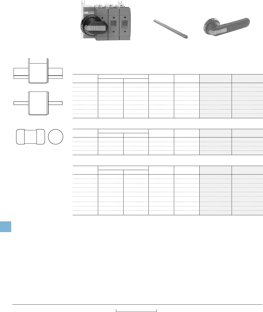
Standard handles & shafts
Shafts for use with selector handles – .24 x .24" (6x6 mm)
Shaft length (in/mm)
Maximum Mounting Depth (inches) 1
OT16F3, OT25F3, OT40F3 OT63F3, OT80F3 OS30 2Weight Catalog
number
OH_1_ & OH_3_ OH_2_ OH_1_ & OH_3_ OH_2_
3.3/85 5.0 4.3 5.6 5.0 – 0.07 OXS6X85
4.1/105 5.8 5.1 6.4 5.8 – 0.07 OXS6X105
4.7/120 6.4 5.8 7.0 6.4 – 0.08 OXS6X120
5.1/130 6.7 6.1 7.4 6.8 5.6 0.08 OXS6X130
7.1/180 8.7 8.1 9.4 8.7 6.1 0.11 OXS6X180
9.8/250 11.5 10.8 12.1 11.5 10.3 0.13 OXS6X250
13/330 14.6 14.0 15.3 14.7 13.4 0.17 OXS6X330
Shafts for use with pistol handles – .24 x .24" (6x6 mm)
Shaft length (in/mm)
Maximum Mounting Depth (inches)
Weight Catalog
number
OT16F3 - OT40F3 OT63F3 - OT80F3 OT30F3/60F3/100F3 OT200 OS30 OS60 OS100 OS200
5.2/130 5.9 6.4 6.7 6.5 – – – – 0.08 OXP6X130
5.9/150 6.7 7.4 7.0 7.2 8.9 9.7 9.8 9.9 0.09 OXP6X150
8.3/210 9.1 9.7 9.8 9.6 9.7 12.1 12.2 13.0 0.13 OXP6X210
11.4/290 12.2 12.8 12.9 12.7 13.4 15.2 15.3 – 0.18 OXP6X290
14.2/360 14.9 13.8 15.6 15.5 18.7 12.9 18.0 – 0.23 OXP6X360
16.9/430 17.6 18.3 18.3 18.2 22.6 20.6 20.7 – 0.27 OXP6X430
Shafts for use with pistol handles – .47 x .47" (12x12 mm)
Shaft length (in/mm) Maximum Mounting Depth (inches)
Weight Catalog
number
OT400 OT600 OT800 - OT1200 OETL-NF1600 -
OETL-NF3150 OS400 OS600 - OS1200
11.0/280 13.3 14.6 14.5 — 13.8 14.9 0.77 OXP12X280
12.8/325 15.0 16.4 16.3 20.9 15.6 16.7 0.90 OXP12X325
15.6/395 20.5 19.1 19.1 23.6 18.3 19.4 1.10 OXP12X395
18.3/465 21.9 21.8 21.9 26.3 21.0 22.1 1.32 OXP12X465
21.1/535 22.8 24.6 24.6 29.1 23.8 24.8 1.54 OXP12X535
1 Mounting depth is distance from the outside of the door to the disconnect switch mounting plate. Shaft can be cut to desired length.
2 Selector handles and shafts are not recommended for use with fusible switches over 30A.
OXS6X__
OXP6X
OXP12X_
Disconnect
switches
Accessories
Low Voltage Products & Systems 19.33
ABB Inc. • 888-385-1221 • www.abb.us/lowvoltage 1SXU000023C0202 Rev. A
19
Revised January 2014 Revised January 2014
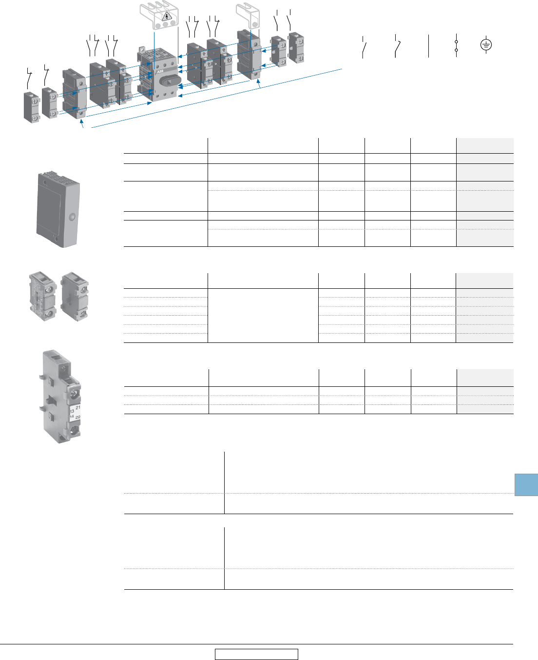
Auxiliary contacts
Auxiliary contacts — snap-on mounting 1
Description For Use On Weight AC Thermal
amp rating AC rated voltage Catalog number
Form C 1 N.O. & 1 N.C. OS30 20.04 6 250 OA4B1C
1 N.O. OT16-100, OT200-1200
OS30-OS1200 0.07 10 600 OA1G10
1 N.C.
OT16-100 0.07 10 600 OA1G01
OT200-1200
OS30-OS1200 0.07 10 600 OA3G01
1 N.O. & 1 N.C. OT16-100 0.07 10 600 OA2G11
Module for auxiliary
contacts
OS30 0.09 – – OSZA
OT200-1200
OS200-OS1200 0.1 – – OEA28 4
Auxiliary contacts — front mounting 3
Description For Use On Weight AC Thermal
amp rating AC rated voltage Catalog number
1 N.O. + 1 N.C.
OETL-NF1600
through
OETL-NF3150
0.2 10 600 OZXK-1
2 N.O. + 2 N.C. 0.26 10 600 OZXK-2
4 N.O. + 4 N.C. 0.4 10 600 OZXK-3
2 N.O. 0.18 10 600 OZXK-4
4 N.O. 0.25 10 600 OZXK-5
8 N.O. 0.4 10 600 OZXK-6
Mounting & installation considerations
Non-Fusible
OT16-100
OA1G10 (1 N.O.) mounts on right side of switch only
OA1G01 (1 N.C.) mounts on left side of switch only
OA2G11 (1 N.O. & 1 N.C.) mounts on left of right side of switch
Maximum two contacts on each side of switch
OT200-1200 Maximum 8 auxiliary contact blocks with the OEA28 module
Maximum 4 auxiliary contact blocks mounting under the mechanisms
Fusible
OS30
Form C contacts mount directly to switch
Maximum two Form C contacts
OA1G10 (1 N.O.) + OA3G01 (1 N.C.) require mounting base
Maximum 6 OA1G10 + OA3G01 contacts with mounting base OSZ4
OS60-1200 Mounting to left side of switch with OEA28 module: Maximum 8 contact blocks
Mounting under mechanism cover: Maximum 4 contact blocks
1 UL file #E83510
2 Not suitable for use on cable operated flange version of OS100
3 UL File #E5707
4 Maximum 8 contact blocks (N.O. or N.C.) with the OEA28 module.
I
ON
O
OFF
OT16E3
(N)7
L4
(N)8
T4
N
N
N
N
N
N
PE
PE
OA2G11
OA1G__
OEA28
Auxiliary contacts — snap-on mounting for double throw
Description For Use On Weight
(Lbs.)
AC Thermal
amp rating
AC rated
voltage Catalog number
1 N.O. OT16-100_C 0.7 10 600 OA7G10
1 N.C. OT16-800_C 0.7 10 600 OA3G01
1 N.O. OT200-800_C 0.7 10 600 OA1G10
Disconnect
switches
Accessories
19.34 Low Voltage Products & Systems
1SXU000023C0202 Rev. A ABB Inc. • 888-385-1221 • www.abb.us/lowvoltage
19
Revised January 2014 Revised January 2014
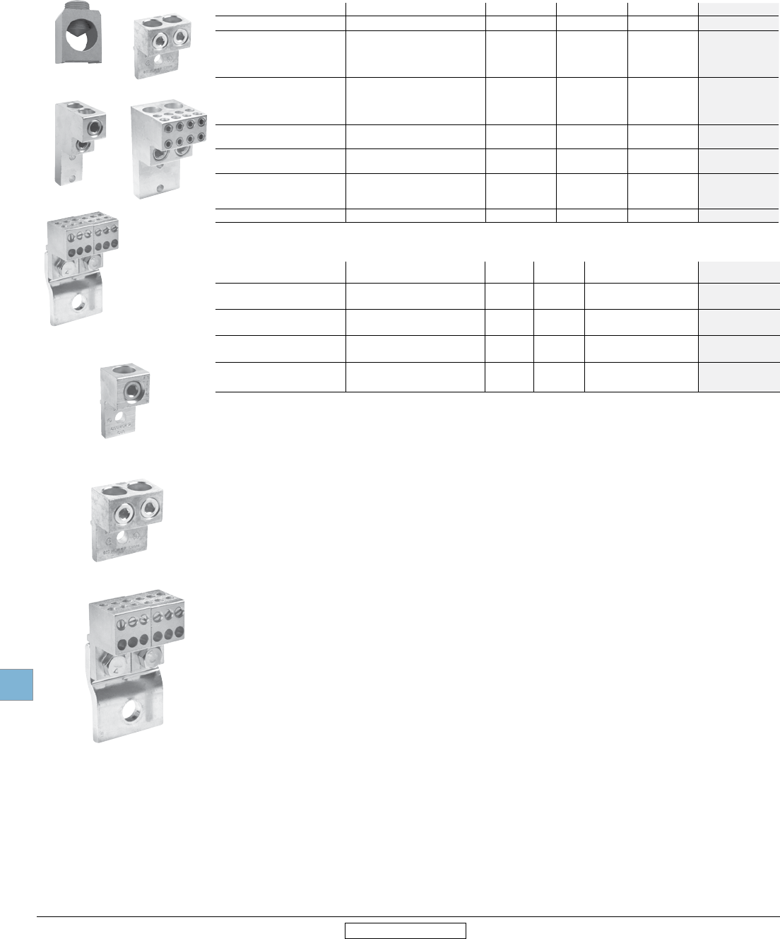
Terminal lugs
OZXA-27
OZXA-24
OZXA-175/400
Terminal lug kits for double throw switches
For Use On Wire Size Wire Type Lugs/Kit Weight
(Lbs)
Catalog
number
OT200_C #4 - 300kcmil
#4 - 300kcmil Cu/Al 9
12
0.5
0.25
OZXA-200/9
OZXA-200/12
OT400_C #2 - 600kcmil
#2 - 600kcmil Cu/Al 9
12
0.5
0.25
OZXA-400/9
OZXA-400/12
OT600_C (2) #2 - 600kcmil
(2) #2 - 600kcmil Cu/Al 9
12
0.5
0.5
OZXA-800/9
OZXA-800/12
OT800_C (4) #2 - 600 kcmil
(2) #2 - 600 kcmil Cu/Al Cu/Al 9
12
0.5
0.5
OZXA-1200/9
OZXA-1200/12
Terminal lugs 1
For Use On Wire Size Wire Type Lugs/Kit Weight (lbs) Catalog number
OS100 #14-2/0 Cu/Al 6 0.50 OZXA-24 2
OT200/OS200
#4 - 300 kcmil
#4 - 300 kcmil
(6) 14-6 AWG
(6) 14-6 AWG
Cu/Al
6
3
3
3
0.50
0.25
0.25
0.25
OZXA-200
OZXA-200/3
OZXA-206T 4
OZXA-206S 4
OT/OS400
#2 - 600 kcmil
#2 - 600 kcmil
(2) #4 - 300 kcmil
(6) #14 - 6 AWG
Cu/Al
6
3
6
3
0.50
0.25
0.50
0.50
OZXA-400
OZXA-400/3P
OZXA-402
OZXA-406
OT600 , OS600 - OS800 (2) #2 - 600 kcmil
(2) #2 - 600 kcmil Cu/Al 6
3
0.50
0.50
OZXA-800
OZXA-800/3
OT800, OT1200 & OS1200 (4) #2 - 600 kcmil
(4) #2 - 600 kcmil Cu/Al 6
3
6.90
3.45
OZXA-1200
OZXA-1200/3
OETL-NF1600
(4) #2 - 600 kcmil
(4) #2 - 600 kcmil
(8) 2/0 + (2) #2 - 600 kcmil 3
Cu/Al
6
3
3
10.44
5.22
10.44
OZXA-28
OZXA-28/3
OZXA-32
OETL-NF2000-3150 (8) #2 - 600 kcmil Cu/Al 12 20.88 OZXA-28/2
OZXA-400
OZXA-30
OZXA-27
OZXA-175/400
OZXA-32
1 Lugs are integral to the switch for 16-125A. No separate lug kit accessory is required.
2 Not suitable for use on cable operated flange version OS100.
3 A load side distribution lug eliminates the need to purchase, install and wire a separate distribution block.
4 Comes with OZXA-175 terminal lugs and shrouds.
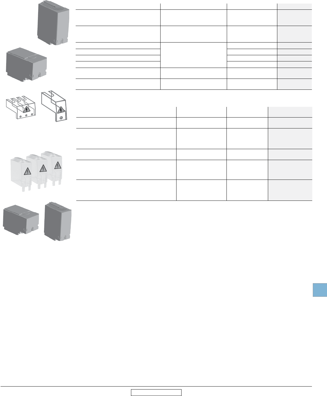
Disconnect
switches
Accessories
Low Voltage Products & Systems 19.35
ABB Inc. • 888-385-1221 • www.abb.us/lowvoltage 1SXU000023C0202 Rev. A
19
Revised January 2014 Revised January 2014
Terminal shrouds for non-fusible
Description For Use On Weight Catalog number
3 pole
includes one shroud for line or load side
OT16-OT40 2
OT63-OT80 2
OT30-OT100 2
0.02
0.02
0.02
OTS40T3
OTS63T3
OTS125T3
4th pole
includes one shroud for line or load side
OTPS40FPN1 2
OTPS80FP 2
OTPS125FP 2
0.03
0.03
0.03
OTS40T1
OTS80T1
OTS125T1
3 pole long type shrouds
OT200
0.12 OTS250G1L/3
3 pole short type shrouds 0.13 OTS250G1S/3
4 pole long type shrouds 0.26 OTS250G1L/4
4 pole short type shrouds 3.18 OTS250G1S/4
3 pole
includes one shroud for line or load side 1
OT400
OT600
0.33
0.33
OTS403
OTS603
3 pole
includes one shroud for line or load side 1
OT800
OT1200
0.88
1.2
OTS803
OTS1203
OTS250G1S/3
OTS250G1L/3
OTS40T3 OTS40T1
OTS80T3 OTS80T1
OTS125T3 OTS125T1
Terminal shrouds
1 For 4 pole shrouds, please consult factory.
2 ABB OT16 - OT100 switches are IP20 touchsafe as standard. Terminal shrouds provide an extra degree of protection.
OSS160T3
OSS200G1L/3
OSS200G1S/3
Terminal shrouds for fusible
Description For Use On Weight
(Lbs.)
Catalog
number
Terminal shroud for one pole
Terminal shroud for 3 poles
OS100
OS100
0.04
0.04
OSS160GG1L/3
OSS160GG1S/3
3 pole long type shrouds
3 pole short type shrouds
4 Pole long type shrouds
4 pole Short type shrouds
OS200
OS200
OS200
OS200
0.20
0.13
0.26
0.18
OSS200G1L/3
OSS200G1S/3
OSS200G1L/4
OSS200G1S/4
3 Pole includes one shroud for line or load side 1OS400
OS600
0.13
0.11
OSS403
OSS603
3 pole short type shrouds
OS800
0.47 OSS800G1S/3
3 pole long type shrouds 1.54 OSS800G1L/3
4 pole short type shrouds 0.62 OSS800G1S/4
4 pole long type shrouds 1.54 OSS800G1L/4
3 pole short type shrouds
OS1200
0.88 OSS1250G1S/3
3 pole long type shrouds 2.12 OSS1250G1L/3
4 pole short type shrouds 1.15 OSS1250G1S/4
4 pole long type shrouds 2.2 OSS1250G1L/4
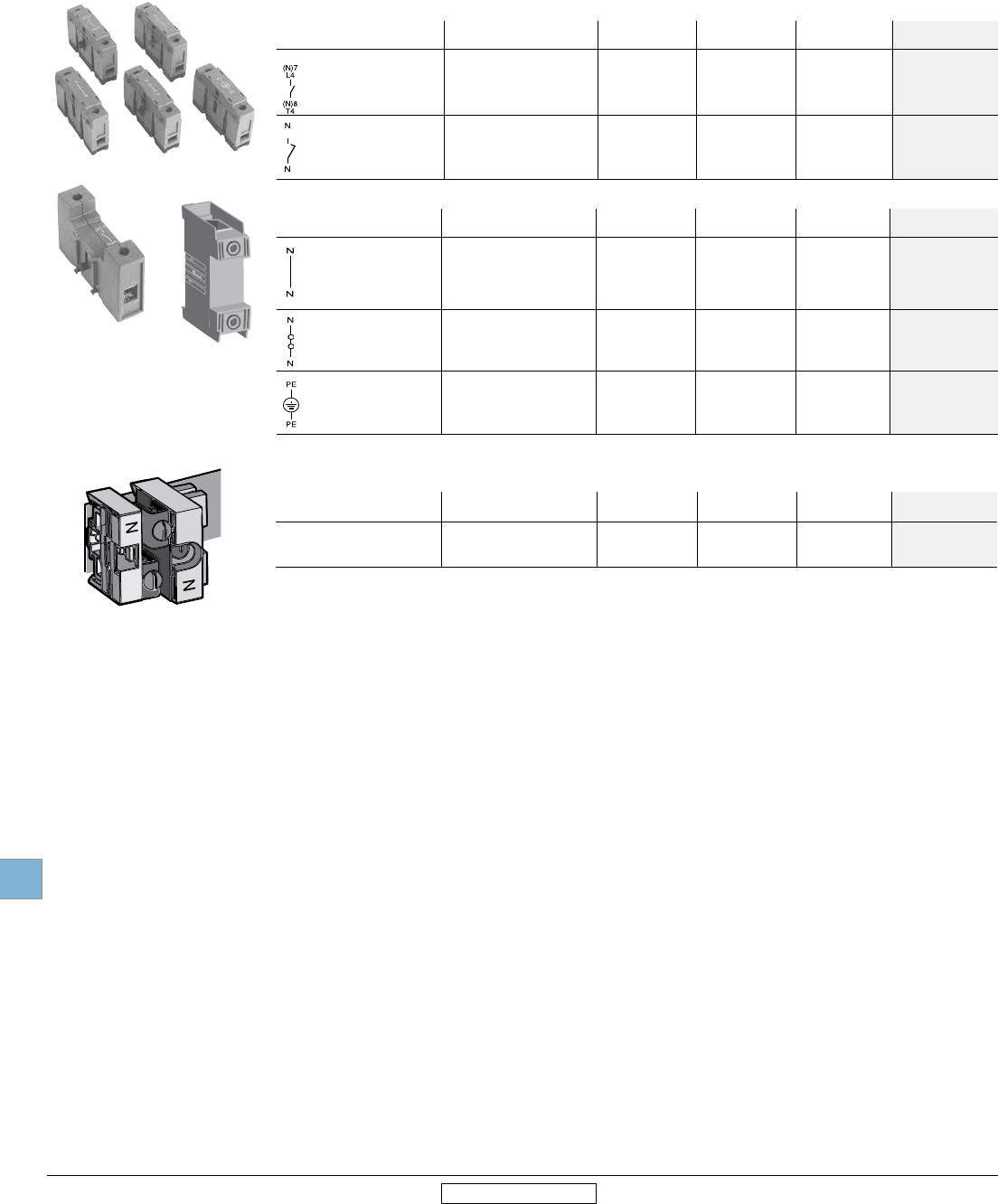
Disconnect
switches
Accessories
19.36 Low Voltage Products & Systems
1SXU000023C0202 Rev. A ABB Inc. • 888-385-1221 • www.abb.us/lowvoltage
19
Revised January 2014 Revised January 2014
Additional poles
OTP_80FP
OTP_40FP
OTP_125FP
1 Switches accept only one power pole or one terminal pole per side. Only one power pole per switch.
Additional poles for non-fusible 1
Power poles - Only one power pole per switch: mounts on left or right side of switch. (OTPS40FPN1 mounts to left side only.)
Description For use on Weight AC Thermal
amp rating
AC rated
voltage Catalog number
Fourth Pole
OT16-OT40
OT30-OT60
OT63-OT80
OT100
0.07
0.13
0.13
0.31
40
60
80
100
600
OTPS40FPN1
OTPS60FP
OTPS80FP
OTPS125FP
Late-break/
early-make
OT16-OT40
OT30-OT60
OT63-OT80
OT100
0.07
0.13
0.13
0.31
40
60
80
100
600
OTPL40FP
OTPL60FP
OTPL80FP
OTPL125FP
Terminal poles - Switch accepts one terminal pole per side: mounts on left or right side of switch
Description For use on Weight AC Thermal
amp rating
AC rated
voltage Catalog number
Solid neutral
OT16-OT40
OT30-OT60
OT63-OT80
OT30-OT100
0.07
0.13
0.13
0.31
40
60
80
100
600
OTPN40FP
OTPN60FD
OTPN80FP
OTPN125FP
Detachable Neutral
OT16-OT40
OT30-OT60
OT63-OT80
OT100
0.07
0.13
0.13
0.31
40
60
80
60
600
OTPD40FP
OTPD60FP
OTPD80FP
OTPD125FP
Ground Terminal
OT16-OT40
OT30-OT60
OT63-OT80
OT100
0.07
0.13
0.13
0.31
40
60
80
100
600
OTPE40FP
OTPE60FP
OTPE80FP
OTPE125FP
OESA-ZX171
Additional poles for fusible
Description For use on Weight
(Lbs.)
AC Thermal amp
rating AC rated voltage Catalog
number
Detachable neutral mounts
on side of switch or DIN rail
OS30
OS60
OS100
0.45
0.13
0.31
30
63
125
600
600
600
OESA-ZX171
OSZ1
OSZ2
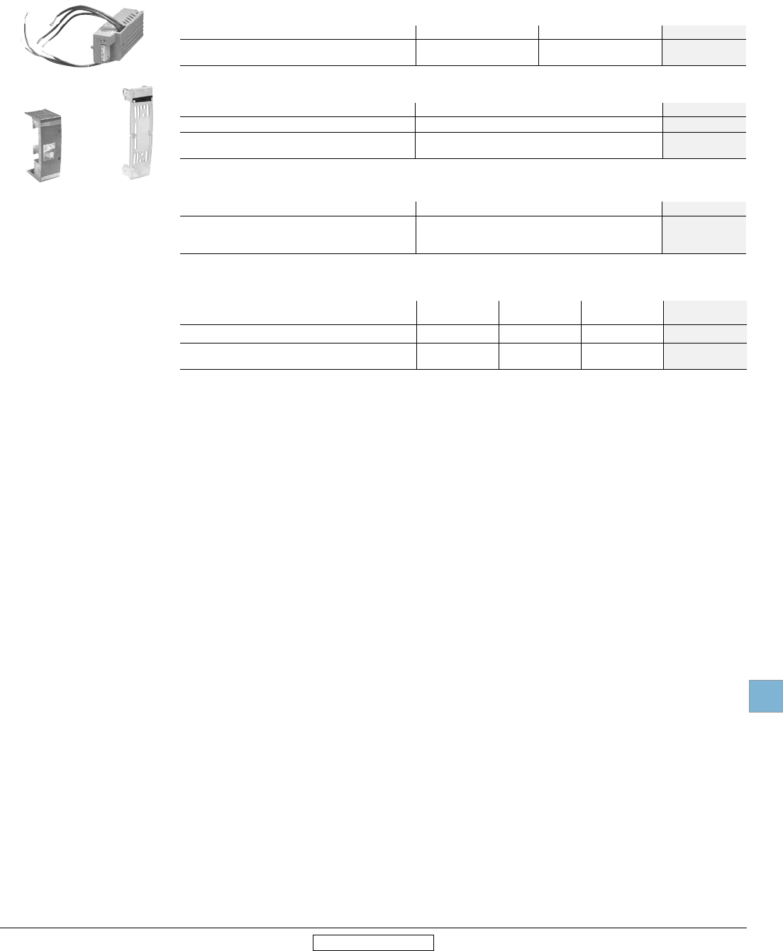
Disconnect
switches
Accessories
Low Voltage Products & Systems 19.37
ABB Inc. • 888-385-1221 • www.abb.us/lowvoltage 1SXU000023C0202 Rev. A
19
Revised January 2014 Revised January 2014
Fuse monitors & carriers
OSC60J_ CXBY68362
OFM_
Fuse monitors
Blown fuse indicators/monitors
For Use With Rated Voltage Weight (lbs) Catalog number
OS30-1200 100-240
380-600
0.31
0.31
OFM240
OFM600
Suitable for 1 or 3 phase circuits. Includes 1 N.O. and 1 N.C. auxiliary contacts and red & green LED lights for indication.
Fuse Monitor Mounting Accessories
For Use With Crimp Terminal size (mm) Catalog number
OS30-200 2.8-0.8 OFMZX2
OS400-1200
Includes 6 crimp terminals 6.3-0.8 OFMZX4
Fuse carriers/covers
Description For Use on Catalog number
CC fuse carrier (Qty. 1)
J fuse carrier (Qty. 1)
Solid link carrier (Qty. 1)
OS30AFCC_
OS30AFJ_
OS30_
OESAZD48
OESAZD28
OESAZD55
Shorting bars for fusible switches
Description For Use On AC thermal amp
rating AC rated voltage Catalog number
Dummy Fuse OS60 60 600 OESA-ZD54
Solid links: metal strap OS100
OS200
100
400
600
600
OESA-ZS36
OESA-ZK98
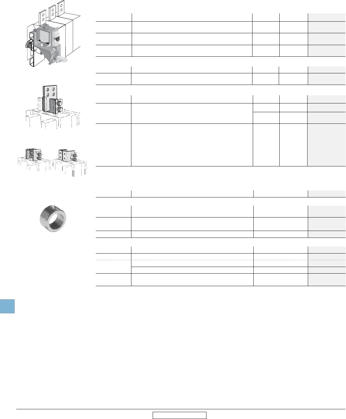
Disconnect
switches
Accessories
19.38 Low Voltage Products & Systems
1SXU000023C0202 Rev. A ABB Inc. • 888-385-1221 • www.abb.us/lowvoltage
19
Revised January 2014 Revised January 2014
Miscellaneous accessories
Replacement parts
OTZS2
OETL-ZT80_
OETL-ZX115
OETLZX114
Miscellaneous accessories
Shaft accessories
Accessory Type Description For Use On Weight Catalog number
Shaft Adapter Adapts one end of a 6mm shaft to 12mm
(use with shaft extension coupler) 6mm shafts 0.20 OETL-ZK19
Shaft Extension
Coupler
Joins two shafts together for applications where extended
length is required
6mm shafts
12mm shafts
0.26
0.26
OESA-ZX167
OETL-ZX95
Shaft Guide Fits all pistol grip handles, mounts on the inside of the
enclosure door with provided hardware pistol handles - OHZX10
Busbar connections
Accessory Type Description For Use On Weight Catalog number
Busbar
Connections Vertical, back or edgewise mounting 1
OETL-NF1600
– 3150
46.2
31.0
OETL-ZX115
OETL-ZX114
Locking accessories
Accessory Type Description For Use On Weight Catalog number
Cam Attachment For Kirk Key, Castell, Low & Fletcher and Ronis interlock. For
adapting to the interlock system. The interlock is not included.
OS60-OS200 0.25 OETL-ZW16
OS400-
OS1200 0.29 OETL-ZW5
Electrical Interlock
Closed circuit principle for interlocking the switch movement.
When the coil circuit is dead, A-types cannot be operated to
O-position and L-types cannot be operated to ON- or OFF-
position. Coil voltages 110VAC, 220 VAC, 24VDC, 48VDC,
60VDC, 110VDC, 220VDC, P - 15W U = 0.7 - 1.1 Un
(U = coil voltage, Un = nominal voltage)
OETL-NF800
– 3150A,
OES800
2.42 OETL-ZT80A∆
OETL-ZT80L∆
∆ = Coil Voltage
Replacement parts
Accessory Type Description For Use On Catalog number
Non-fusible
Metal collar Replaces original black knob
for locking shaft in place OT16-200, OS30-200 OTZS2
Set screw Set screw for use with knob or collar OT16-200 FLSWM5X8AX
OS30-200
Shaft set screw Shaft set screw, bag of 10 OT400-1200 OZX1
Fusible
Terminal cover Covers terminal below fuse carrier OS30 CXBY67121
Phase barrier – OS200 CXBY68794
Shaft Set Screw – OS30_ FLSWM5X8AX
Bag of 10 OS400-1200 OZX1
Fuse covers – OS100GJ_ CXBY69058
CXBY69072
1 Vertical busbar is provided as standard on OETL-NF1600 through OETL-NF3150 switches.
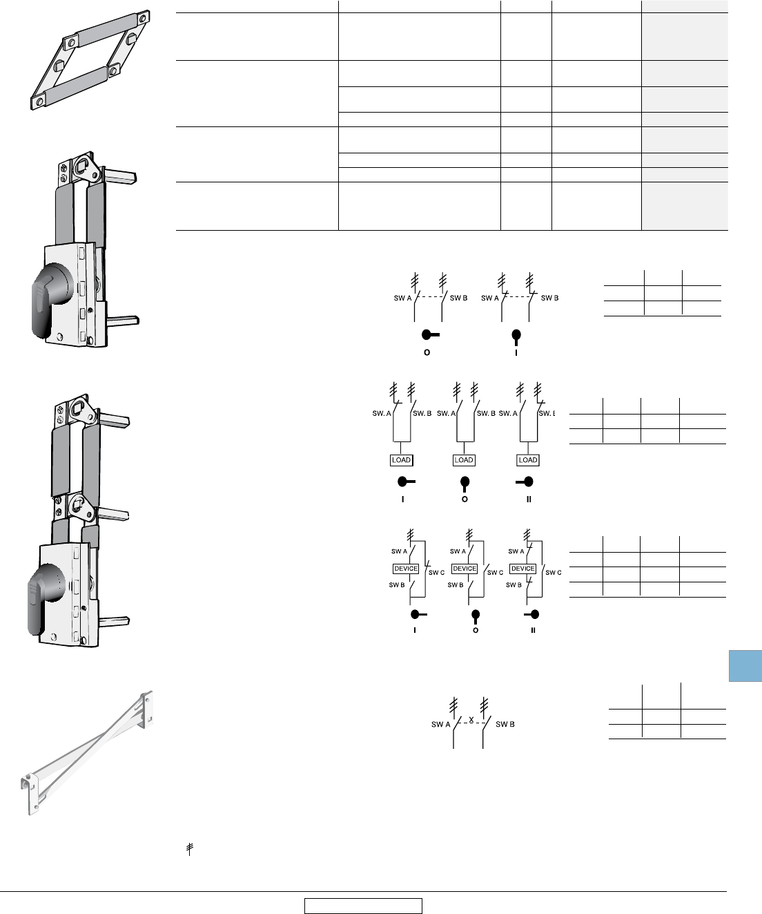
Disconnect
switches
Accessories
Low Voltage Products & Systems 19.39
ABB Inc. • 888-385-1221 • www.abb.us/lowvoltage 1SXU000023C0202 Rev. A
19
Revised January 2014 Revised January 2014
Conversion, transfer & bypass mechanisms
Mechanical interlocks
6 or 8 pole
6 (8) pole mechanism allows two switches
controlled by one handle to open or close
simultaneously.
Equipment required for a complete installation:
• One conversion mechanism
• Two disconnect switches (see page 19.11)
• One handle1 (see page 19.30)
• Two shafts (see page 19.32)
Transfer
Transfer mechanism manually transfers
between two power sources using two
switches and a center OFF position.
A 3-position handle is included.
Shafts included. Equipment required for
a complete installation:
• One conversion mechanism
• Two disconnect switches (see page 19.11.)
Bypass
Bypass mechanism operates three switches:
Two switches in series and one changeover
switch to allow power bypass.
A 3-position handle is included.
Shafts included.Equipment required for a
complete installation:
• One conversion mechanism
• Three disconnect switches (see page 19.11.)
Mechanical interlock
Mechanical interlock mechanism prevents both
switches from being in the ON position at the
same time.
Equipment required for a complete installation:
• One conversion mechanism
• Two disconnect switches (see page 19.11)
• Two handles (see page 19.30)
• Two shafts (see page 19.32)
1 OT16E3 – OT32E3 can use a selector or pistol handle. All other sizes must use a pistol handle.
2 = Three poles
OTZW8
I
O
N
OTZW6
OTZW17
OETL-ZW24
POS. O POS. I
SW. A O X
SW. B O X
X = Closed
O = Open
2
POS. I POS. O POS. II
SW. A X O O
SW. B O O X
X = Closed
O = Open
2
POS. I POS. O POS. II
SW. A O O X
SW. B O O X
SW. C X O O
X = Closed
O = Open
2
SW. A SW. B
POS. I POS. I
SW. A X O
SW. B O X
X = Closed
O = Open
1
Conversion mechanisms
Mechanism Type For use on Weight UL/Nema Type Catalog number
6 or 8 pole mechanisms
OT16-100
OT160
OS30-200, OT200
OT400 – OETL-NF1200
0.33
1.52
1.52
2.42
-
-
-
-
OTZW8
OETL-ZK19
OESA-ZW2
OETL-ZW9
Double throw mechanisms
OT16 - 160 2.20 1, 3R, 12
1, 3R, 12, 4, 4X
OESA-ZW1
OESA-ZW1X
OT200
OS30-200 2.20 1, 3R, 12
1, 3R, 12, 4, 4X
OTZW25
OTZW25X
OT400 – OETL-NF1200 10.10 1, 3R, 12, 4, 4X OETL-ZW12
Bypass mechanisms
OT16-OT100 1.54 1, 3R, 12
1, 3R, 12, 4, 4X
OTZW17
OTZW17X
OT200, OS30-200 7.28 1, 3R, 12 OTZW26
OT400 – OETL-NF1200 8.81 1, 3R, 12, 4, 4X OETL-ZW13
Mechanical interlock mechanisms
OT16-OT100
OT160-200, OS30-200
OT400 – OETL-NF800
OETL-NF1200 – OETL-NF3150
0.33
0.55
1.26
2.64
-
-
-
-
OTZW24
OTZW10
OETL-ZW3
OETL-ZW15

Disconnect
switches
Accessories
19.40 Low Voltage Products & Systems
1SXU000023C0202 Rev. A ABB Inc. • 888-385-1221 • www.abb.us/lowvoltage
19
Revised January 2014 Revised January 2014
Notes
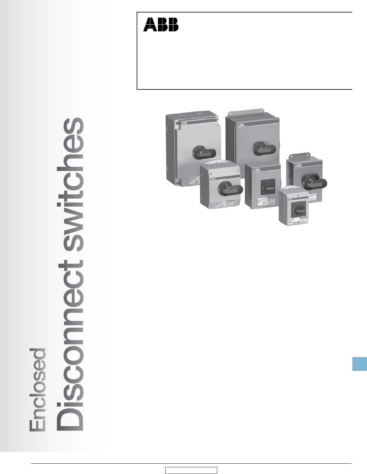
Disconnect
switches
Enclosed
Low Voltage Products & Systems 19.41
ABB Inc. • 888-385-1221 • www.abb.us/lowvoltage 1SXU000023C0202 Rev. A
19
Revised January 2014 Revised January 2014
Enclosed disconnect switches
16A – 3150A Non-fusible
30A – 1200A Fusible
eOT, NF and FJ's meet customer requirements in terms of safety, ease of
installation, space savings and operational convenience. They are available in
a wide range of amperage ratings, are UL approved and NEMA rated to satisfy
rugged industrial environments.
Enclosed
Disconnect switches
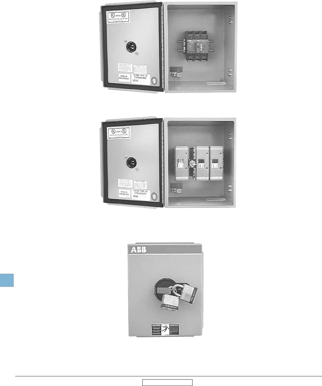
Disconnect
switches
Enclosed
19.42 Low Voltage Products & Systems
1SXU000023C0202 Rev. A ABB Inc. • 888-385-1221 • www.abb.us/lowvoltage
19
Revised January 2014 Revised January 2014
General information
Non-fusible, fusible & lockable
Clear position indications:
I-ON
O-OFF
Door interlocked when handle pad-
locked to OFF position
Handle padlockable with up to three
padlocks
Door interlocked when handle is in
ON position. Door interlock can be
defeated by authorized personnel.
Pilot devices can be added
Lockable
Modern appearance
Quick make, quick brake
mechanism
Heavy duty disconnect, 600VAC
Extremely compact size
Finger-proof construction. No haz-
ardous exposed parts
3/4/6/8 pole constructions; transfer
switches and by-pass switches
available
Snap on accessories include addi-
tional poles, auxiliary contacts, etc.
Enclosures available in plastic, metal,
or stainless steel in NEMA 1, 3R, 12,
4X, 7 & 9 environmental categories
Non-fusible
Fusible
Snap on accessories include fuse
monitors, auxiliary contacts, etc.
Enclosures available in plastic, metal,
or stainless steel in NEMA 1, 3R, 12,
4X, 7 & 9 environmental categories
3/4/6/8 pole constructions; transfer
switches and by-pass switches
available
Finger-proof construction. No haz-
ardous exposed parts
Modern appearance
Quick make, quick brake
mechanism
Heavy duty disconnect, 600VAC,
200kA, Isc
Extreme compact size as fuse carri-
ers are decked above contacts
Double contacts enabling feed from
any direction and preventing back
feed
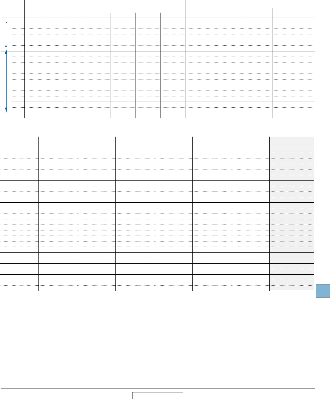
Disconnect
switches
Enclosed
Low Voltage Products & Systems 19.43
ABB Inc. • 888-385-1221 • www.abb.us/lowvoltage 1SXU000023C0202 Rev. A
19
Revised January 2014 Revised January 2014
1 IEC rated only.
2 Switches are for double throw.
Switch ratings, 16 – 3150 Amps, 600V
General information
Non-fusible, 16A - 3150A
Fusible, 30-1200A
Single phase Three phase Wire size for terminal lugs For wire type Approval
120V 200V 240V 200V – 208V 240V 480V 600V
UL
General
purpose
amp rating
Handle ratings
Catalog number
suffix
Style
type NEMA Color Marking Defeatable Padlockable Catalog
number
S Selector 1,3R,12 Black O/I & OFF/ON Yes Yes OHBS2AJ
S1 Selector 1,3R,12 Red/Yel O/I & OFF/ON Ye s Yes OHYS2AJ
P Pistol 1,3R,12 Black O/I & OFF/ON Yes Yes OHBS65J6
P Pistol 1,3R,4,4X,12 Black O/I & OFF/ON Ye s Ye s OHBS65L6
P1 Pistol 1,3R,12 Red/Yel O/I & OFF/ON Yes Yes OHYS65J6
P1 Pistol 1,3R,4,4X,12 Red/Yel O/I & OFF/ON Yes Ye s OHYS65L6
BJ Selector 1,3R,12 Black O/I & OFF/ON Yes Yes OHBS2AJ
YJ Selector 1,3R,12 Red/Yel O/I & OFF/ON Ye s Ye s OHYS2AJ
B4 Pistol 1,3R,12 Black O/I & OFF/ON Yes Ye s OHB145J12
B4 Pistol 1,3R,12 Black I/O/II Yes Yes OHB145J12E011
B4 Pistol 1,3R,4,4X,12 Black I/O/II Yes Ye s OHB145L12E011
Y4 Pistol 1,3R,12 Red/Yel O/I & OFF/ON Yes Yes OHY145J12
B6 Pistol 1,3R,4,4X,12 Black O/I & OFF/ON Yes Yes OHBS65J6
Y6 Pistol 1,3R,4,4X,12 Red/Yel O/I & OFF/ON Ye s Ye s OHYS65L6
B7 Pistol 1,3R,4,4X,12 Black O/I & OFF/ON Yes Yes OHB175J12
B7 Pistol 1,3R,12 Black I/O/II Yes Yes OHB175J12E011
B7 Pistol 1,3R,4,4X,12 Black I/O/II Yes Ye s OHB175L12E011
Y7 Pistol 1,3R,4,4X,12 Red/Yel O/I & OFF/ON Ye s Ye s OHY175L12
B8 Pistol 1,3R,4,4X,12 Black O/I & OFF/ON Yes Yes OHB80L6
B8 Pistol 1,3R,12 Black I/O/II Yes Yes OHB80J6E011
B8 Pistol 1,3R,4,4X,12 Black I/O/II Yes Ye s OHB80L6E011
Y8 Pistol 1,3R,4,4X,12 Red/Yel O/I & OFF/ON Ye s Ye s OHY80L6
6 Pistol 1,3R,4,4X,12 Black I/O/II No Yes OHB174L12E011
8 Pistol 1,3R,4,4X,12 Metal O/I & OFF/ON No Ye s YASDA-8
21 Pistol 1,3R,4,4X,12 Metal I/O/II No Yes YASDA-21
21 Pistol 1,3R,4,4X,12 Black I/O/II No Yes OHB274L12E011
16 1 2 2 3 5 10 10 #18 – 8 Cu UL
25 1.5 3 3 7.5 7.5 15 20 #18 – 8 Cu UL
40 2 5 5 10 10 20 25 #18 – 8 Cu UL
60 2 5 5 15 15 30 30 #14 – 1 Cu UL
80 2 5 5 20 20 40 40 #14 – 1 Cu UL
30 2 5 5 10 10 20 30 #14 – 4 Cu UL
60 3 7.5 7.5 20 20 40 40 #14 – 4 Cu UL
100 5 15 15 25 30 50 50 #8 – 1/0 Cu UL
125 7.5 20 20 30 30 75 100 #8 – 1/0 Cu UL
200 –– –– –– 60 75 150 200
#6 – 300 kcmil Cu UL
400 –– –– –– 100 125 250 350
#2 – 600 kcmil Cu UL
600 –– –– –– 150 200 400 500
(2) #2 – 600 kcmil Cu UL
800 –– –– –– 200 250 500 600
(2) #2 – 600 kcmil Cu/Al UL
1200 –– –– –– –– –– –– ––
(4) #2 – 600 kcmil Cu/Al UL
1600 –– –– –– –– –– –– ––
(4) #2 – 600 kcmil Cu/Al UL
2000 –– –– –– –– –– –– ––
(8) #2 – 600 kcmil Cu/Al UL
3150 1 –– –– –– –– –– –– ––
(8) #2 – 600 kcmil Cu/Al IEC
Maximum horsepower rating
UL 98 UL 508
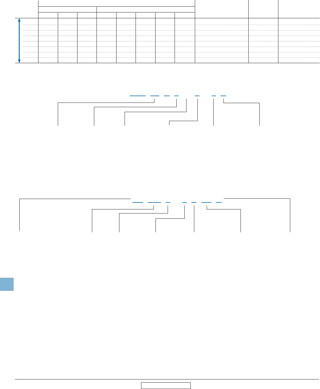
Disconnect
switches
Enclosed
19.44 Low Voltage Products & Systems
1SXU000023C0202 Rev. A ABB Inc. • 888-385-1221 • www.abb.us/lowvoltage
19
Revised January 2014 Revised January 2014
General information
Fusible, 30A – 1200A
30 2 3 5 5 7.5 7.5 15 20 #18 – 8 Cu CSA, UL
60 3 7.5 10 15 15 15 30 50 #14 – 4 Cu CSA, UL
100 5 10 15 25 25 30 60 75 #14 – 2/0 Cu/Al CSA, UL
200 — — — 50 50 60 125 150 #6 – 300 kcmil Cu/Al CSA, UL
400 — — — 100 125 125 250 350 #2 – 600 kcmil Cu/Al CSA, UL
600 — — — 150 150 200 400 500 (2) #2 – 600 kcmil Cu/Al CSA, UL
800 — — — 200 200 250 500 600 (2) #2 – 600 kcmil Cu/Al CSA, UL
1200 — — — — — — — — (4) #2 – 600 kcmil Cu/Al CSA, UL
Switch ratings
UL general Maximum horsepower rating
purpose Single phase Three phase Wire size for terminal lugs For wire type Approval 1
amp rating 120V 200V 240V 200V 208V 240V 480V 600V
1 Fusible switches are UL listed to the UL98 standard.
EOT 16 U 3 M 1 - 1 P
Enclosed non-fused, 3 poles, 16 to 100 A
Size and Amps
16 = 16A
30 = 30A
32 = 40A
45 = 60A
60 = 60A
63 = 80
100 = 100A
Poles
3
Enclosure
P = Plastic
S = Stainless steel
M = Sheet steel
Type
1 = Type 1
3 = Type 3R/12
4 = Type 4/4X
Auxiliary contact
[Blank] – None
0 = 1 N.C.
1 = 1 N.O.
Handle
P = Pistol Black
S = Selector Black
M = Metal (OHM...)
Enclosed non-fusible, 200 - 1200 A and specialty configurations
NF 200 1 - 6 P B6 C
Amps
200
400
600
800
1200
1600
2000
Poles
3
6
Configuration
P = Standard
T = Double Throw
Type
1 = Type 1
3 = Type 3R/12
4 = Type 4
X = Type 4X
Handle
B = Black 1
Y = Red/Yellow 1
Custom versions or other versions of enclosed products are available
upon request... please consult factory.
UL 98
Style
EOT - Non-fused (16-100A)
NF - Non-fused (200-1200A)
FJ - Fused "J" type fuses (30-800A)
FC -Fused "CC" type fuses (30-800A)
Revision
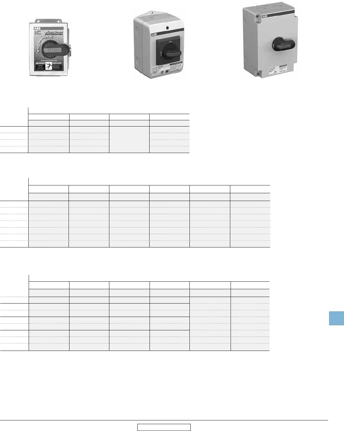
Disconnect
switches
Enclosed
Low Voltage Products & Systems 19.45
ABB Inc. • 888-385-1221 • www.abb.us/lowvoltage 1SXU000023C0202 Rev. A
19
Revised January 2014 Revised January 2014
3 pole
Non-fusible, 16A – 3150A
NF32X-3PB6C EOT16U3P3-S EOT63U3M1-P
1 IEC rated only.
2 New Washdown.
3 Pole, 600V, 200A – 3150A
Pistol handle
UL general
purpose amp
rating
UL/NEMA Enclosure Type
1 3R/12 4 4X Stainless 4X Plastic 7 & 9
Catalog number Catalog number Catalog number Catalog number Catalog number Catalog number
200 NF2001-3PB8B NF2003-3PB8B NF2004-3PB8B NF200X-3PB8B NF200P-3PB8B —
400 NF4001-3PB4B NF4003-3PB4B NF4004-3PB4B NF400X-3PB4B NF400P-3PB4B —
600 NF6001-3PB7B NF6003-3PB7B NF6004-3PB7B NF600X-3PB7B NF600P-3PB7B —
800 NF8001-3PB4A NF8003-3PB4A NF8004-3PB4A NF800X-3PB4A NF800P-3PB4A —
1200 NF12001-3PB4A NF12003-3PB4A NF12004-3PB4A NF1200X-3PB4A NF1200P-3PB4A —
1600 NF16001-3P8A NF16003-3P8A NF16004-3P8A NF1600X-3P8A — —
2000 NF20001-3P8A NF20003-3P8A NF20004-3P8A NF2000X-3P8A — —
3150 1NF31501-3P8A NF31503-3P8A NF31504-3P8A NF3150X-3P8A — —
3 pole, 600V, 16-80A
Selector handle
UL general
purpose amp
rating
UL/NEMA Enclosure Type
1 3R/12 4/4X 3R/12 Plastic
Catalog number Catalog number Catalog number Catalog number
16 EOT16U3M1-S EOT16U3M3-S Not available
with selector
handles
EOT16U3P3-S
40 EOT32U3M1-S EOT32U3M3-S EOT32U3P3-S
60 EOT45U3M1-S EOT45U3M3-S EOT45U3P3-S
80 EOT63U3M1-S EOT63U3M3-S EOT63U3P3-P
3 pole, 600V, 16-100A
Pistol handle
UL general
purpose amp
rating
UL/NEMA Enclosure Type
1 3R/12 4 4X Stainless 4X Plastic 7 & 9
Catalog number Catalog number Catalog number Catalog number Catalog number Catalog number
16 EOT16U3M1-P EOT16U3M3-P - EOT16U3S4-P EOT16U3P4-P NF167-3P
40 EOT32U3M1-P EOT32U3M3-P - EOT32U3S4-P EOT32U3P4-P NF327-3P
60 EOT45U3M1-P EOT45U3M3-P - EOT45U3S4-P EOT45U3P4-P NF457-3P
80 EOT63U3M1-P EOT63U3M3-P - EOT63U3S4-P EOT63U3P4-P NF637-3P
30 EOT30U3M1-P EOT30U3M3-P - EOT30U3S4-P NF30P-3PB6C NF307-3P
60 EOT60U3M1-P EOT60U3M3-P - EOT60U3S4-P NF60P-3PB6C NF607-3P
100 EOT100U3M1-P EOT100U3M3-P - EOT100U3S4-P NF100P-3PB8C NF1007-3P
NOTE: All enclosed switches are provided with a black handle; however, most handles can be
substituted with a red and yellow handle if desired.
EXAMPLE: A red/yellow selector handle for an EOT16U3M1-S can be substituted for the
black selector handle by using the "S1" suffix instead of the "S" suffix, new catalog
#EOT16U3M1-S1.
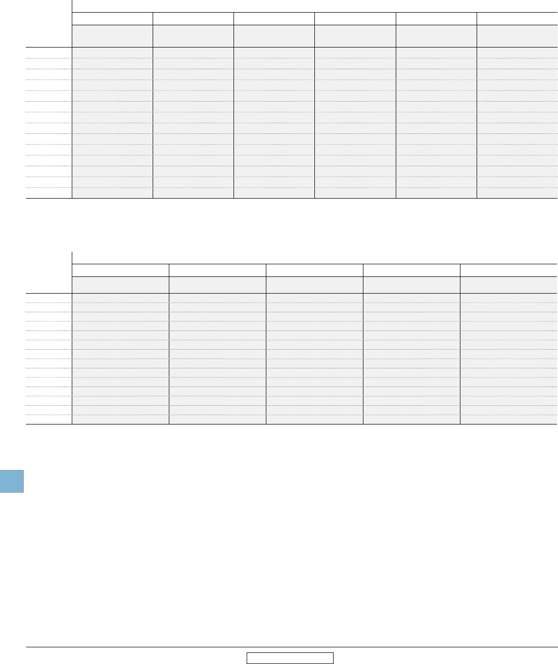
Disconnect
switches
Enclosed
19.46 Low Voltage Products & Systems
1SXU000023C0202 Rev. A ABB Inc. • 888-385-1221 • www.abb.us/lowvoltage
19
Revised January 2014 Revised January 2014
6 pole
Non-fusible, 16A – 1200A
6 pole, 600V, 16-1200A
Pistol handle
UL general
purpose amp
rating
UL/NEMA Enclosure Type
1 3R/12 4 4X Stainless 4X Plastic 7
Catalog number Catalog number Catalog number Catalog number Catalog number Catalog number
16 NF161-6PB6C NF163-6PB6C NF164-6PB6A NF16X-6PB6C NF16P-6PB6A NF167-6P
25 NF251-6PB6C NF253-6PB6C NF254-6PB6A NF25X-6PB6C NF25P-6PB6A NF257-6P
40 NF321-6PB6C NF323-6PB6C NF324-6PB6A NF32X-6PB6C NF32P-6PB6A NF327-6P
60 NF451-6PB6B NF453-6PB6B NF454-6PB6B NF45X-6PB6B NF45P-6PB6B NF457-6P
80 NF631-6PB6A NF633-6PB6A NF634-6PB6A NF63X-6PB6A NF63P-6PB6A NF637-6P
30 NF301-6PB6B NF303-6PB6B NF304-6PB6B NF30X-6PB6B NF30P-6PB6B –
60 NF601-6PB6C NF603-6PB6B NF604-6PB6B NF60X-6PB6B NF60P-6PB6B –
100 NF1001-6PB6B NF1003-6PB6B NF1004-6PB6B NF100X-6PB6B NF100P-6PB6B –
125 NF1251-6PB2A NF1253-6PB2A NF1254-6PB4A NF125X-6PB4A NF125P-6PB4A –
200 NF2001-6PB4B NF2003-6PB4B NF2004-6PB4B NF200X-6PB4B NF200P-6PB4B –
400 NF4001-6PB8B NF4003-6PB8B NF4004-6PB8B NF400X-6P8B NF400P-6P8B –
600 NF6001-6PB8B NF6003-6PB8B NF6004-6PB8B NF600X-6P8B NF600P-6P8B –
800 NF8001-6PB8A NF8003-6PB4A NF8004-6PB4A NF800X-6P8A NF800P-6P8A –
1200 NF12001-6P8A NF12003-6PB4A NF12004-6P8A NF1200X-6P8A NF1200P-6P8A –
3 Pole double throw
3 pole, 600V, 16-1200A
Pistol handle
UL general
purpose amp
rating
UL/NEMA Enclosure Type
1 3R/12 4 4X Stainless 4X Plastic
Catalog number Catalog number Catalog number Catalog number Catalog number
16 NF161-3TB8C NF163-3TB8C NF164-3TB8C NF16X-3TB8C NF16P-3TB8A
25 NF251-3TB8C NF253-3TB8C NF254-3TB8C NF25X-3TB8C NF25P-3TB8A
40 NF321-3TB8C NF323-3TB8C NF324-3TB8C NF32X-3TB8C NF32P-3TB8A
60 NF451-3TB8B NF453-3TB8B NF454-3TB8B NF45X-3TB8B NF45P-3TB8B
80 NF631-3TB8A NF633-3TB8A NF634-3TB8A NF63X-3TB8A NF63P-3TB8A
30 NF301-3TB8B NF303-3TB8B NF304-3TB8B NF30X-3TB8B NF30P-3TB8B
60 NF601-3TB8B NF603-3TB8B NF604-3TB8B NF60X-3TB8B NF60P-3TB8B
100 NF1001-3TB8B NF1003-3TB8B NF1004-3TB8B NF100X-3TB8B NF100P-3TB8B
125 NF1251-3TB8A NF1253-3TB8A NF1254-3TB8A NF125X-3TB8A NF125P-3TB8A
200 NF2001-3TB4B NF2003-3TB4B NF2004-3TB4B NF200X-3TB4B NF200P-3TB4B
400 NF4001-3TB4B NF4003-3TB4B NF4004-3TB4B NF400X-3TB4B NF400P-3TB4B
600 NF6001-3TB4A NF6003-3TB4B NF6004-3TB4A NF600X-3TB4A NF600P-3TB4A
800 NF8001-3TB4A NF8003-3TB4A NF8004-3TB4A NF800X-3TB4A NF800P-3TB4A
1200 NF12001-3TB4A NF12003-3TB4A NF12004-3TB4A NF1200X-3TB4A NF1200P-3TB4A
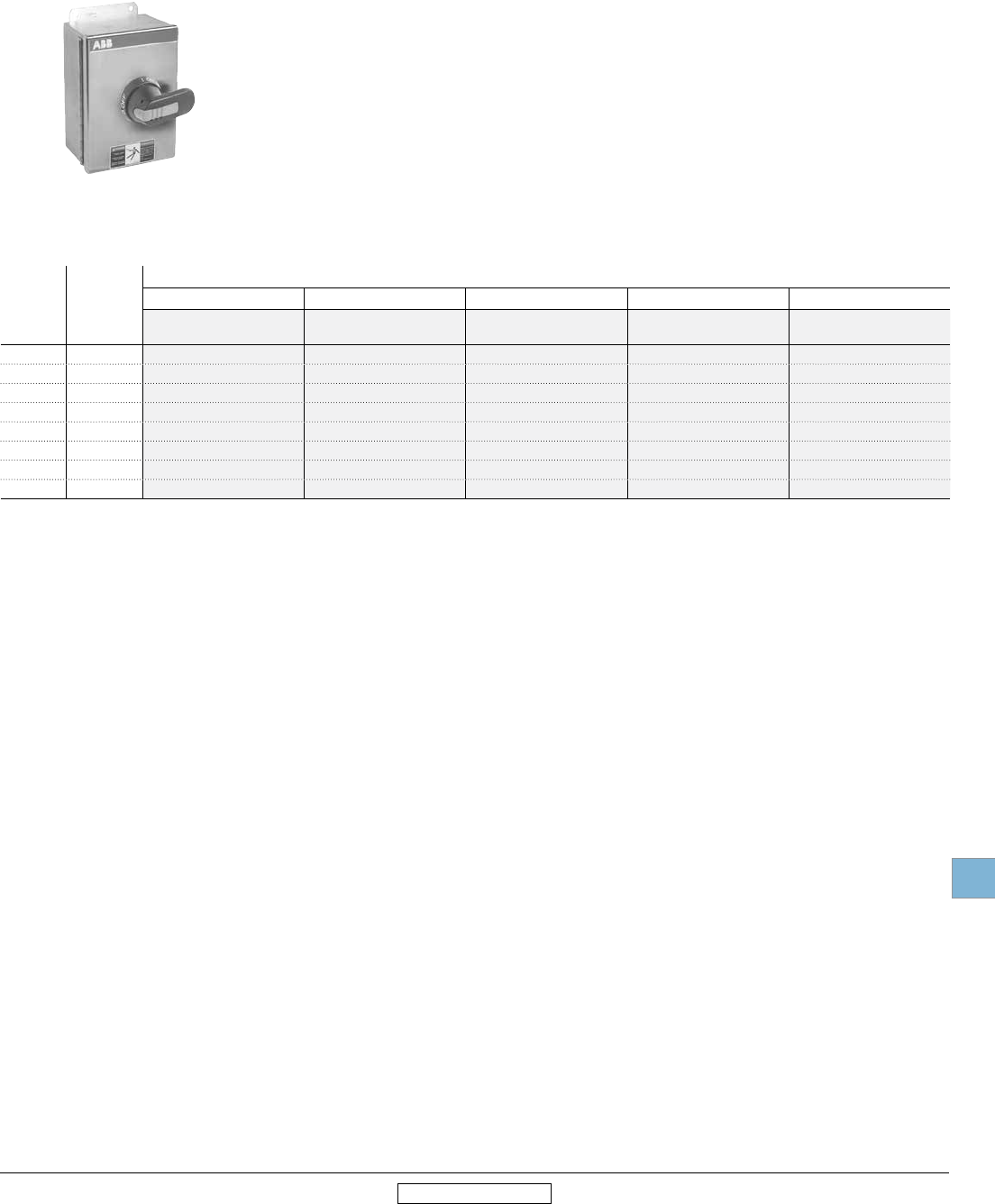
Disconnect
switches
Enclosed
Low Voltage Products & Systems 19.47
ABB Inc. • 888-385-1221 • www.abb.us/lowvoltage 1SXU000023C0202 Rev. A
19
Revised January 2014 Revised January 2014
FJ30X-3PB6B
3 Pole
Fusible, 30A – 800A
3 pole, 600V, 30-800A
Pistol handle
UL general
purpose
amp rating
Fuse Type
UL/NEMA Enclosure Type
1 3R/12 4 4X Stainless 4X Plastic
Catalog
number
Catalog
number
Catalog
number
Catalog
number
Catalog
number
30 J FJ301-3PB6B FJ303-3PB6B FJ304-3PB6B FJ30X-3PB6B FJ30P-3PB6B
30 CC FC301-3PB6B FC303-3PB6B FC304-3PB6B FC30X-3PB6B FC30P-3PB6B
60 J FJ601-3PB6B FJ603-3PB6B FJ604-3PB8B FJ60X-3PB8B FJ60P-3PB8B
100 J FJ1001-3PB8B FJ1003-3PB8B FJ1004-3PB8B FJ100X-3PB8B FJ100P-3PB8B
200 J FJ2001-3PB8C FJ2003-3PB8C FJ2004-3PB8C FJ200X-3PB8C FJ200P-3PB8C
400 J FJ4001-3PB4C FJ4003-3PB4C FJ4004-3PB4C FJ400X-3PB4C FJ400P-3PB4C
600 J FJ6001-3PB7C FJ6003-3PB7C FJ6004-3PB7C FJ600X-3PB7C FJ600P-3PB7C
800 L FL8001-3PB4B FL8003-3PB4B FL8004-3PB4B FL800X-3PB4B FL800P-3PB4
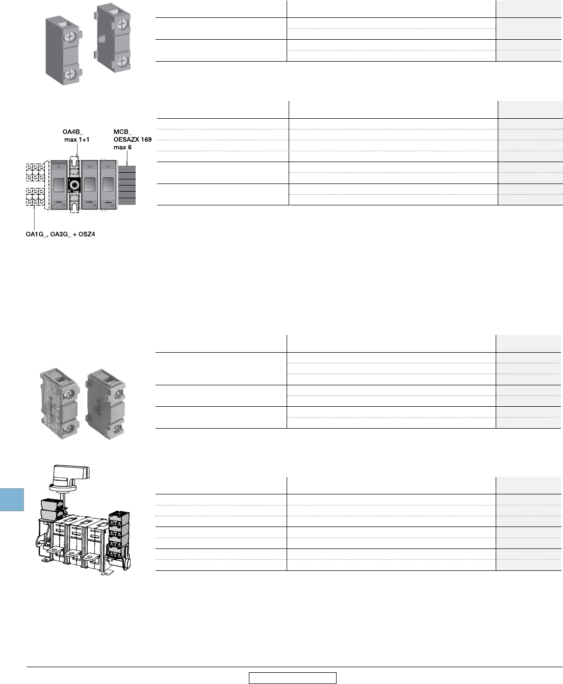
Disconnect
switches
Enclosed
19.48 Low Voltage Products & Systems
1SXU000023C0202 Rev. A ABB Inc. • 888-385-1221 • www.abb.us/lowvoltage
19
Revised January 2014 Revised January 2014
Accessories
Fusible
OA1G10
OA4B1C
Auxiliary contacts
For use on: Contact
configuration
Catalog
number
30A 1 N.O. + 1 N. C. OA4B1C
2 N.O. + 2 N.C.
60-1200 1 N.O. OA1G10
1 N.C. OA3G01
Accessories
For use on: Description Installation
suffix code
30A Neutral block N
60A – 100A Neutral block N
200A – 400A Neutral block N
600A – 800A Neutral block N
30A – 200A Service entrance, 3 wire U
Service entrance, 4 wire V
400A – 800A Service entrance, 3 wire U
Service entrance, 4 wire V
OA1G_
OZXK_
Auxiliary contacts
For use on: Contact
configuration
Catalog
number
16A – 100A
1 N.O. OA1G10
1 N.C. OA1G01
1 N.O. & 1 N.C. OA2G11
200A - 1200A 1 N.O. OA1G10
1 N.C. OA3G01
1600A – 3150A 1 N.O. & 1 N.C. OZXK-1
2 N.O. & 2 N.C. OZXK-2
Accessories
For use on: Description Installation
suffix code
EOT16, 32 Neutral or isolated ground block N or G
EOT45, 63 Neutral or isolated ground block N or G
OT30, 60, 100 Neutral or isolated ground block N or G
NF200 – 1200A Neutral block N
NF1600 – 3150A Neutral block N
NF200 – 1200A Service entrance, 3 wire U
NF200 – 1200A Service entrance, 4 wire V
Accessories
Non -fusible
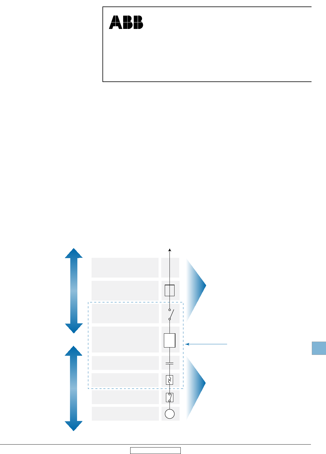
Disconnect
switches
Technical
data
Low Voltage Products & Systems 19.49
ABB Inc. • 888-385-1221 • www.abb.us/lowvoltage 1SXU000023C0202 Rev. A
19
Revised January 2014 Revised January 2014
Technical data
Approximate dimensions
Selecting switches per NEC
Article 430 of the US National Electric Code includes two methods for properly sizing disconnect switches:
Selecting switches per NEC
1. Single motor application
A properly sized disconnect switch for a single motor will:
a) have an ampere rating greater than or equal to 115 percent of
the rated motor full load current; or,
b) have a HP rating greater than or equal to the rated motor
HP (at applied voltage) if the disconnect switch under
consideration is HP rated.
2. Combination load application
A properly sized disconnect switch for a combination load will
be selected by adding all the simultaneous individual loads in the
circuit under consideration.
Using motor nameplate information, load information, and tables
from section 430 of the NEC, determine one equivalent full load
current and one equivalent locked rotor current. The equivalent
locked rotor current can be used with table 430-151 to determine
an equivalent HP rating. Select a disconnect switch:
a) greater than or equal to 115 percent of the equivalent full load
current; and,
b) greater than or equal to the equivalent HP rating.
Motor feeder
Motor feeder short circuit and
ground fault protection
Motor disconnecting means
(NEC
®
430.101 - 430.113)
UL98
UL508
Motor controller
(NEC
®
430.81 - 4.30.91)
Motor overload protection
(NEC
®
430.31 - 4.30.44)
OSHA Lockout/tagout disconnect
(NEC
®
430.81 - 430.91)
Motor
Motor branch-circuit
short-circuit
protection
(NEC
®
430.51 - 430.58)
To supply
UL98
Fusible Switches
OS30, OS60, OS100,
OS200, OS400, OS600
OS800, OS1200
UL98
Non-Fusible Switches
OT30, OT60
OT100 OT200,
OT400, OT600, OT800, OT1200
OETL-NF1600 thru
OETL-NF2000
UL508
Non-Fusible Switches
OT16, OT25, OT40,
OT63, OT80
(UL98 switches can also
be applied)
Typical control panel
Feeder Circuit
Branch Circuit
OL
M
Use of UL98 & UL508 Disconnects
According to
NEC ®
Article 430
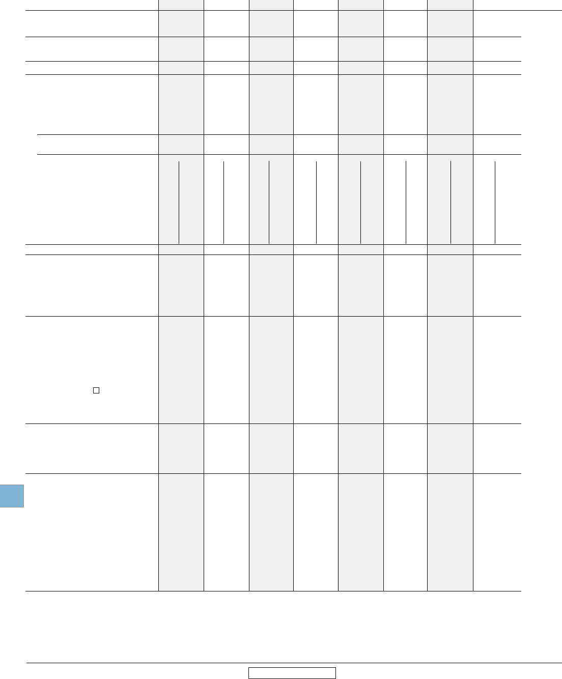
Disconnect
switches
Technical
data
19.50 Low Voltage Products & Systems
1SXU000023C0202 Rev. A ABB Inc. • 888-385-1221 • www.abb.us/lowvoltage
19
Revised January 2014 Revised January 2014
Technical data
OT16F3 – OT100F3
UL & CSA
Catalog number 3 pole OT16F3 OT25F3 OT40F3 OT63F3 OT80F3 OT30F3 OT60F3 OT100F3
1 UL Listed switches are also CSA Approved.
2 UL98 overload test, 50 operations, pf 0.40 – 0.50 at 2x FLA.
3 Multi-tap lug available, please see page 19.34.
4 Fuse size 70A for RK5
5 When protected by any Listed fuse or Listed circuit breaker whose current rating does not exceed the maximum thermal current rating of the switch.
UL & CSA
Approvals1 2 pole N/A N/A N/A N/A N/A N/A N/A N/A
3 pole UL508 & IEC UL508 & IEC UL508 & IEC UL508 & IEC UL508 & IEC UL98 & IEC UL98 & IEC UL98 & IEC
4 pole UL508 & IEC UL508 & IEC UL508 & IEC UL508 & IEC UL508 & IEC UL98 & IEC UL98 & IEC UL98 & IEC
General purpose amp rating -40° to 40°C
pf = 0.7 – 0.8 A 20 30 40 60 80 30 60 100
Max. operating voltage V 600 600 600 600 600 600 600 600
Max. horsepower rating/motor FLA current,
pf = 0.4 – 0.5
Three phase
240V HP/A 5/15.2 7.5/22.0 10/28.0 15/42.0 20/54.0 10/28.0 20/54.0 30/80.0
480V HP/A 10/14.0 15/21.0 20/27.0 30/40.0 40/52.0 20/27.0 40/52.0 50/65.0
600V HP/A 10/11.0 20/22.0 25/27.0 30/32.0 40/41.0 30/32.0 40/41.0 50/52.0
Single phase 120V HP/A 1/16 1.5/20 3/24 2/24.0 2/24.0 2/24.0 3/34.0 5/56.0
240V HP/A 2/13.2 3/18.7 5/30.8 7.5/40.0 10/57.5 5/28.0 7.5/40.0 15/68.0
Short circuit rating with fuse
Fuse type CC kA 10 — 10 —- 10 —- — — — — — — — — — —
Fuse type J kA 10 10 10 10 10 10 100 — 100 — 200 — 200 — 200 —
Fuse type T kA 10 10 10 10 10 10 100 — 100 — 200 — 200 — 200 —
Fuse type RK1 kA 10 — 10 — 10 — — — — — — — — — — —
Fuse type RK5 kA 5 5 5 5 5 5 10 5 10 5 — — — — — —
Fuse type L kA — — — — — — — — — — — — — — — —
Fuse type H kA — — — — — — — 5 — 5 — — — — — —
Maximum fuse size A 30 60 4 30 60 4 30 60 4 100 150 100 150 60 — 150 — 150 —
3 cycle short circuit current withstand rating 5
kA — — — — — — — —
Endurances
Min. Electrical endurance,
pf = 0.75 – 0.80 operation cycles 6000 6000 6000 6000 6000 6000 6000 6000
Min. Electrical endurance,
pf = 0.40 – 0.50 operation cycles 1000 1000 1000 1000 1000 2 2 2
Mechanical endurance
operations 20,000 20,000 20,000 20,000 20,000 20,000 20,000 20,000
Physical characteristics
Weight, switches 3 pole lb 0.24 0.24 0.24 0.59 0.59 0.79 0.79 0.79
4 pole lb 0.33 0.33 0.33 0.77 0.77 1.10 1.10 1.10
Dimension, switches 3 pole H in 2.68 2.68 2.68 3.60 3.60 3.94 3.94 3.94
W in 1.38 1.38 1.38 2.07 2.07 2.76 2.76 2.76
D in 2.20 2.20 2.20 2.85 2.85 2.95 2.95 2.95
Shaft set screw tightening torque lb. in. 8.9 8.9 8.9 8.9 8.9 8.9 8.9 8.9
Shaft size — square in .24 x .24 .24 x .24 .24 x .24 .24 x .24 .24 x .24 .24 x .24 .24 x .24 .24 x .24
mm 6 x 6 6 x 6 6 x 6 6 x 6 6 x 6 6 x 6 6 x 6 6 x 6
Switch operating torque for lb. in. 8.8 8.8 8.8 10.5 10.5 17.5 17.5 17.5
rotary 3 pole switches
Terminal lug kits
Not required Not required Not required Not required Not required Not required Not required Not required
Wire range AWG #18 – 8 #18 – 8 #18 – 8 #14 – 4 #14 – 4 #14 – 4 #14 – 4 #8 – 1/0
Torque:
Wire tightening lb. in. 7 7 7 18 18 55 55 55
Lug mounting lb. in. Integral Integral Integral Integral Integral Integral Integral Integral
Auxiliary contacts OA1G_ _ OA1G_ _ OA1G_ _ OA1G_ _ OA1G_ _ OA1G_ _ OA1G_ _ OA1G_ _
NEMA ratings, AC A600 A600 A600 A600 A600 A600 A600 A600
AC rated voltage VAC 600 600 600 600 600 600 600 600
AC thermal rated current A 10 10 10 10 10 10 10 10
AC maximum volt-ampere making VA 7200 7200 7200 7200 7200 7200 7200 7200
AC maximum volt-ampere breaking VA 720 720 720 720 720 720 720 720
NEMA ratings, DC R300 R300 R300 R300 R300 R300 R300 R300
DC rated voltage VDC 300 300 300 300 300 300 300 300
DC thermal rated current A 1 1 1 1 1 1 1 1
DC maximum make-break VA 28 28 28 28 28 28 28 28
Torque: Wire tightening lb. in 7 7 7 7 7 7 7 7
Wire range AWG #18 – 14 #18 – 14 #18 – 14 #18 – 14 #18 – 14 #18 – 14 #18 – 14 #18 – 14

Disconnect
switches
Technical
data
Low Voltage Products & Systems 19.51
ABB Inc. • 888-385-1221 • www.abb.us/lowvoltage 1SXU000023C0202 Rev. A
19
Revised January 2014 Revised January 2014
Technical data
OT200U03 – OETL-NF3150
UL & CSA
Catalog number 3 pole OT200U03 OT400U03 OT600U03 OT800U03 OT1200U03 OETL-NF1600 OETL-NF2000 OETL-NF3150 5
1 UL Listed switches are also CSA Approved.
2 UL98 overload test, 50 operations, pf 0.40 – 0.50 at 2x FLA.
3 Multi-tap lug available, please see page 19.34.
4 Fuse size 70A for RK5
5 IEC rated only.
6 When protected by any Listed fuse or Listed circuit breaker whose current rating does not exceed the maximum thermal current rating of the switch.
UL & CSA
Approvals1 2 pole UL98 & IEC UL98 & IEC UL98 & IEC UL98 & IEC UL98 & IEC UL98 & IEC UL98 & IEC IEC
3 pole UL98 & IEC UL98 & IEC UL98 & IEC UL98 & IEC UL98 & IEC UL98 & IEC UL98 & IEC IEC
4 pole UL98 & IEC UL98 & IEC UL98 & IEC IEC IEC IEC IEC IEC
General purpose amp rating -40° to 40°C
pf = 0.7 – 0.8 A 200 400 600 800 1200 1600 2000 3150
Max. operating voltage V 600 600 600 600 600 600 480 —
Max. horsepower rating/Max. motor FLA current,
pf = 0.4 – 0.5
Three phase
240V HP/A 75/192.0 125/312.0 200/480.0 200/602 — — — —
480V HP/A 150/180.0 250/302.0 450/515 500/590 — — — —
600V HP/A 200/192.0 350/336.0 500/472.0 500/472 — — — —
Single phase 120V HP/A — — — — — — — —
240V HP/A — — — — — — — —
Short circuit rating with fuse
Fuse type CC kA — — — — — — — —
Fuse type J kA 200 100 —/100 — — — — —
Fuse type T kA — — 100/— — — — — —
Fuse type RK1 kA — — — — — — — —
Fuse type RK5 kA — — 100 — — — — —
Fuse type L kA — — —/100 100 100 100 100 —
Fuse type H kA — — —/100 — — — — —
Maximum fuse size A 200 600 600/800 1200 1200 2000 2000 —
3 cycle short circuit current withstand rating 6
kA 14 30 50 50 50 65 65 —
Endurances
Min. Electrical endurance,
pf = 0.75 – 0.80 operation cycles 6000 1000 1000 500 500 500 500 400
Min. Electrical endurance,
pf = 0.40 – 0.50 operation cycles 2 2 2 2 2 2 2 2
Mechanical endurance operations 20,000 20,000 10,000 6,000 6,000 6000 6000 6000
Physical characteristics
Weight, switches 3 pole lb 2.9 5.7 11.4 33.5 33.5 127.7 127.7 127.7
4 pole lb 3.5 6.8 14.3 42.9 42.9 149.7 149.7 149.7
Dimension, switches 3 pole H in 6.69 8.66 9.84 14.65 14.65 21.5 21.5 21.5
W in 6.67 8.70 10.48 13.78 13.78 18.11 18.11 18.11
D in 3.27 4.15 5.47 5.20 5.20 10.67 10.67 10.67
Shaft set screw tightening torque lb. in. 14 - 17.7 — — — — — — —
Shaft size — square in .24 x .24 .47 x .47 .47 x .47 .47 x .47 .47 x .47 .47 x .47 .47 x .47 .47 x .47
mm 6 x 6 12 x 12 12 x 12 12 x 12 12 x 12 12 x 12 12 x 12 12 x 12
Switch operating torque for lb. in. 62 142 184 575 575 438 438 438
rotary 3 pole switches
Terminal lug kits OZXA-200 OZXA-400 OZXA-800 OZXA-1200 OZXA-1200 OZXA-28 OZXA-28/2 OZXA-28/2
Wire range AWG #4-300kcmil3 #2-600kcmil3 (2)#2-600kcmil3 (4)#2-600kcmil3 (4)#2-600kcmil (4)#2-600kcmil (8)#2-600kcmil (8)#2-600kcmil
Torque:
Wire tightening lb. in. 200 375 375 500 500 375 375 375
Lug mounting lb. in. 72 240 240 450-670 450-670 230 230 230
Auxiliary contacts OA_G_ OA_G_ OA_G_ OA_G_ OA_G_ OZXK-_ _ OZXK-_ _ OZXK-_ _
NEMA ratings, AC A600 A600 A600 A600 A600 A600 A600 A600
AC rated voltage VAC 600 600 600 600 600 600 600 600
AC thermal rated current A 10 10 10 10 10 10 10 10
AC maximum volt-ampere making VA 7200 7200 7200 7200 7200 7200 7200 7200
AC maximum volt-ampere breaking VA 720 720 720 720 720 720 720 720
NEMA ratings, DC P600 P600 P600 P600 P600 P600 P600 P600
DC rated voltage VDC 600 600 600 600 600 600 600 600
DC thermal rated current A 5 5 5 5 5 5 5 5
DC maximum make-break VA 138 138 138 138 138 138 138 138
Torque: Wire tightening lb. in 7 7 7 7 7 7 7 7
Wire range AWG #22 – #14 #22 – #14 #22 – #14 #22 – #14 #22 – #14 #22 – #14 #22 – #14 #22 – #14
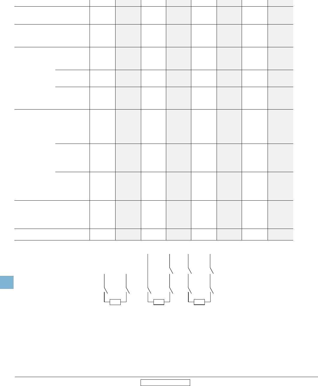
Disconnect
switches
Technical
data
19.52 Low Voltage Products & Systems
1SXU000023C0202 Rev. A ABB Inc. • 888-385-1221 • www.abb.us/lowvoltage
19
Revised January 2014 Revised January 2014
Catalog number 3 pole OT16F3 OT25F3 OT40F3 OT63F3 OT80F3 OT30F3 OT60F3 OT100F3
Technical data
OT16F3 – OT100F3
IEC
1 The ambient air temperature does not exceed +40°C and its average over a
period of 24 hours does not exceed +35°C according to IEC 947.
2 IEC 947-3, utilization category B, infrequent operation.
3 Not available at time of printing, please consult factory.
IEC
Rated insulation and operation 40°C
voltage, AC20 and DC20 V 750 750 750 750 750 750 750 750
Rated impulse withstand voltage kV 8 8 8 8 8 8 8 8
Rated thermal current, Ith
AC 20/DC 20 open 1 A 25 32 40 63 80 40 63 115
40°C enclosed A 25 32 40 63 80 40 63 115
60°C enclosed A 25 32 40 63 80 40 63 115
Rated operational currents
AC 21A ≤500V A 16 25 40 63 80 30 60 100
≤690V A 16 25 40 63 80 40 63 100
≤1000V A — — — — — — — —
AC 22A ≤500V A 16 25 40 63 80 40 63 100
≤690V A 16 25 40 63 80 40 63 100
≤1000V A — — — — — — — —
AC 23A ≤415V A 16 20 23 45 75 40 63 80
≤500V A 16 20 23 45 58 40 60 60
≤690V A 10 11 12 20 20 40 40 40
≤1000V A — — — — — — — —
Rated operational currents/poles in series
DC21A 48V A 16/1 25/1 32/1 45/1 63/1 40/1 63/1 100/1
110V A 16/2 25/2 32/2 45/2 63/2 40/2 63/2 100/2
220V A 16/3 25/3 32/3 45/4 63/4 40/4 63/4 100/4
440V A 16/4 25/6 32/6 3 3 3 3 3
750V A 16/8 25/8 32/8 3 3 3 3 3
DC22A 48V A 16/1 25/1 32/1 45/1 63/1 40/1 63/1 100/1
110V A 16/2 25/2 32/2 45/2 63/2 40/2 63/2 100/2
220V A 16/3 25/3 32/4 45/4 63/4 40/4 63/4 63/4
440V A 16/6 25/8 3 3 3 3 3 3
750V A 16/8 25/8 3 3 3 3 3 3
DC23A 48V A 16/1 25/1 32/1 45/1 63/1 40/1 63/1 100/1
110V A 16/2 25/2 32/2 45/2 63/2 40/2 63/2 100/2
220V A 16/4 25/4 32/4 45/4 63/4 40/4 63/4 63/4
440V A 10/4 3 3 3 3 3 3 3
750V A 16/8 3 3 3 3 3 3 3
Rated operational power
AC23A 230V kW 3 4 5.5 11 22 7.5 11 22
400/415V kW 7.5 9 11 22 37 15 18.5 37
500V kW 7.5 9 11 22 37 15 18.5 37
690V kW 7.5 9 11 15 18.5 15 15 37
Short-circuit current kA 50 50 50 50 50 50 50 50
with back-up fuses of size A 25 32 40 63 80 100 100 100
2 poles
in series
Load
3 poles
in series
4 poles
in series
Load Load
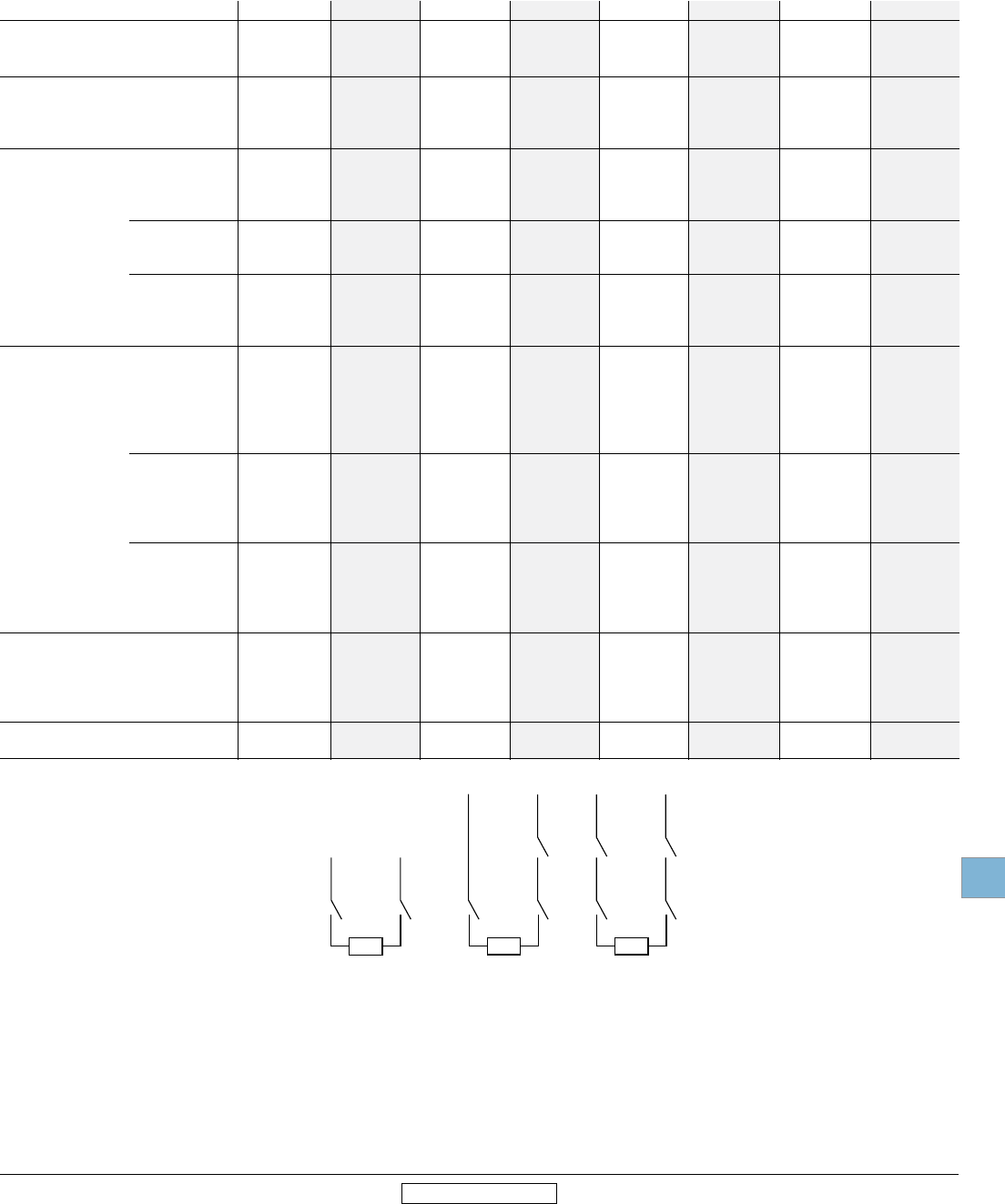
Disconnect
switches
Technical
data
Low Voltage Products & Systems 19.53
ABB Inc. • 888-385-1221 • www.abb.us/lowvoltage 1SXU000023C0202 Rev. A
19
Revised January 2014 Revised January 2014
Technical data
OT200U03 – OETL-NF3150
IEC
Catalog number 3 pole OT200U03 OT400U03 OT600U03 OT800U03 OT1200U03 OETL-NF1600 OETL-NF2000 OETL-NF3150
1 The ambient air temperature does not exceed +40°C and its average over a
period of 24 hours does not exceed +35°C according to IEC 947.
2 IEC 947-3, utilization category B, infrequent operation.
3 Not available at time of printing, please consult factory.
4 690V / 500V
IEC
Rated insulation and operational 40°C
voltage, AC20 and DC20 V 1000 1000 1000 1000 1000 1000 1000 1000
Rated impulse withstand voltage kV 12 12 12 8 8 8 8 8
Rated thermal current, Ith
AC 20/DC 20 open1 A 250 400 800 1600 1600 2500 3150
40°C enclosed A 250 400 800 1600 1600 2300 2300 2600
60°C enclosed A — — — — — 1950 1950 2300
Rated operational currents
AC 21A ≤500V A 250 400 800 1600 1600 25002 25002 31502
≤690V A 250 400 800 1600 1600 25002 25002 31502
≤1000V A — — 800 1600 1600 — — —
AC 22A ≤500V A 250 400 800 1600 1600 16002 16002 16002
≤690V A 250 400 800 1600 1600 — — —
≤1000V A — — 800 — — — — —
AC 23A ≤415V A 250 400 800 1250 1250 8002 8002 8002
≤500V A 250 400 800 1250 1250 8002 8002 8002
≤690V A 250 400 800 1250 1250 — — —
≤1000V A — — 800 — — — — —
Rated operational currents/poles in series
DC21A 48V A 250/1 630/2 800/2 — — 2500/2 2500/2 3150/2
110V A 250/2 630/2 800/2 — — 2500/2 2500/2 3150/2
220V A 250/2 630/2 800/2 — — 2500/2 2500/2 3150/2
440V A 250/3 630/3 800/3 — — 2500/3 2500/3 3150/2
750V A 250/4 — — — — — — —
DC22A 48V A 250/1 630/2 800/2 — — 2500/2 2500/2 3150/2
110V A 250/2 630/2 800/2 — — 2500/2 2500/2 3150/2
220V A 250/2 630/2 800/2 — — 2500/2 2500/2 3150/2
440V A 250/3 630/3 800/3 — — — — —
750V A 250/4 — — — — — — —
DC23A 48V A 250/1 630/2 — — — — — —
110V A 250/2 630/2 — — — — — —
220V A 250/2 630/2 — — — — — —
440V A 250/3 — — — — — — —
750V A 250/4 — — — — — — —
Rated operational power
AC23A 230V kW 75 110 — — — 250 250 250
400/415V kW 132/140 220/230 450 710 710 400 400 400
500V kW 170 280 560 900 900 450 450 450
690V kW 240 355 800 1200 1200 — — —
Short-circuit current kA 100 100 100 50/504 50/504 50/634 50/634 50/634
with back-up fuses of size A 400 800 800 — — — — —
2 poles
in series
Load
3 poles
in series
4 poles
in series
Load Load
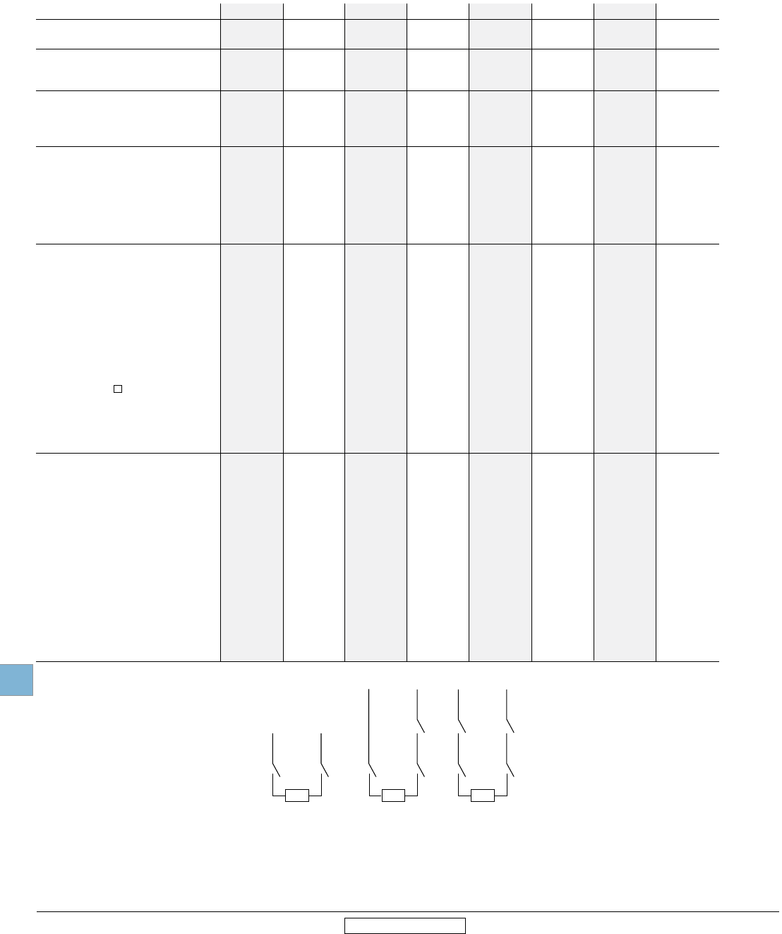
Disconnect
switches
Technical
data
19.54 Low Voltage Products & Systems
1SXU000023C0202 Rev. A ABB Inc. • 888-385-1221 • www.abb.us/lowvoltage
19
Revised January 2014 Revised January 2014
Catalog number 3 pole OT16F3 OT25F3 OT40F3 OT63F3 OT80F3 OT30F3 OT60F3 OT100F3
Technical data
OT16F3 – OT100F3
IEC
1 Not available at time of printing, please consult factory.
2 AC15, according to IEC947-5-1.
Rated short-circuit making capacity,
prospective peak value, Icm kA 0.7 0.7 0.7 1.4 1.4 3.6 3.6 3.6
Rated short time withstand current,
RMS lcw 0.2s kA — — — — — — — —
RMS lcw 1.0s kA 0.5 0.5 0.5 1 1 2.5 2.5 2.5
AC breaking capacity
pf = 0.35 ≤415V A 128 160 184 240 304 320 504 640
≤500V A 128 160 184 240 256 320 480 480
≤690V A 80 88 96 160 160 320 320 320
DC breaking capacity/poles in series
L/R = 15ms
≤48V A 64/1 100/1 128/1 180/1 252/1 160/1 252/1 400/1
≤110V A 64/2 100/2 128/2 180/2 252/2 160/2 252/2 400/2
≤220V A 64/3 100/4 128/4 180/4 180/4 160/4 252/4 252/4
≤440V A 1 1 1 1 1 1 1 1
≤750V A 1 1 1 1 1 1 1 1
Physical characteristics
Electrical endurance at rated operational
current, pf = 0.65 operation cycles 3000 3000 3000 3000 3000 3000 3000 3000
Mechanical endurance operations 20,000 20,000 20,000 20,000 20,000 20,000 20,000 20,000
Weight 3 pole kg 0.11 0.11 0.11 0.27 0.27 0.36 0.36 0.36
4 pole kg 0.15 0.15 0.15 0.35 0.35 0.5 0.5 0.5
Dimension 3 pole H mm 68 68 68 91.5 91.5 100 100 100
W mm 35 35 35 52.5 52.5 70 70 70
D mm 56 56 56 72.5 72.5 75 75 75
Power loss per pole W 0.3 0.6 1 1.4 2.8 1 1.6 4
Shaft size — square mm 6 x 6 6 x 6 6 x 6 6 x 6 6 x 6 6 x 6 6 x 6 6 x 6
Switch operating torque for
rotary 3 pole switches Nm 1 1 1 1.2 1.2 2 2 2
Suitable conductor cross section Cu mm2 0.75 – 10 0.75 – 10 0.75 – 10 1.5 – 25 1.5 – 25 1.5 – 25 1.5 – 25 10 – 70
Bolt size — — — — — — — —
Auxiliary contacts OA1G_ _ OA1G_ _ OA1G_ _ OA1G_ _ OA1G_ _ OA1G_ _ OA1G_ _ OA1G_ _
Ratings according to IEC 947-5-1
Rated voltage, Ui VAC 690 690 690 690 690 690 690 690
Thermal current, Ith A 16 16 16 16 16 16 16 16
AC12/DC12 Ie, A Ue =120V A — — — — — — — —
125V A — — — — — — — —
240V A 6 2 6 2 6 2 6 2 6 2 6 2 6 2 6 2
250V A — — — — — — — —
400V A 4 2 4 2 4 2 4 2 4 2 4 2 4 2 4 2
415V A — — — — — — — —
440V A — — — — — — — —
480V A — — — — — — — —
500V A — — — — — — — —
600V A — — — — — — — —
690V A 2
2 2
2 2
2 2
2 2
2 2
2 2
2 2 2
IEC
2 poles
in series
Load
3 poles
in series
4 poles
in series
Load Load
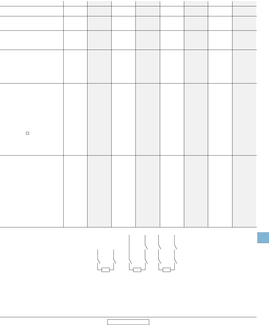
Disconnect
switches
Technical
data
Low Voltage Products & Systems 19.55
ABB Inc. • 888-385-1221 • www.abb.us/lowvoltage 1SXU000023C0202 Rev. A
19
Revised January 2014 Revised January 2014
Technical data
OT200U03 – OETL-NF3150
IEC
Catalog number 3 pole OT200U03 OT400U03 OT600U03 OT800U03 OT1200U03 OETL-NF1600 OETL-NF2000 OETL-NF3150
IEC
1 Not available at time of printing, please consult factory.
2 Maximum distance between busbar support and switch terminal 70mm.
3 pf 0.95.
4 pf 0.65.
5 IEC 947-3, utilization category B, infrequent operation.
Rated short-circuit making capacity,
prospective peak value, Icm500/690V kA 30 65 80 110 110 140/105 140/105 140/105
Rated short time withstand current,
RMS lcw 0.25s, 690V kA 15 28 36 50 50 — — —
RMS lcw 1.0s, 690V kA 8 15 20 50 2 50 2 80 2 80 2 80 2
AC breaking capacity
pf = 0.35 ≤415V A 2000 3200 5760 10,000 10,000 6400 6400 6400
≤500V A 2000 3200 5600 10,000 10,000 6400 6400 6400
≤690V A 2000 3200 5600 10,000 3 10,000 3 4800 4 4800 4 4800 4
DC breaking capacity/poles in series
L/R = 15ms, 3 pole in series
48V A 1000/2 1 1 1 1 1 1 1
110V A 1000/2 1 1 1 1 1 1 1
220V A 1000/2 1600/2 2000/2 – – 2600/2 2600/2 2600/2
440V A 1000/3 1600 2000/3 1 1 1 1 1
750V A 1000/4 1 1 1 1 1 1 1
Physical characteristics
Electrical endurance at rated operational
current, pf = 0.65 operation cycles 1000 1000 1000 500 500 100 5 100 5 100 5
Mechanical endurance operations 20,000 16,000 10,000 6000 6000 6000 6000 6000
Weight 3 pole kg 1.2 2.2 5.2 15.2 15.2 37 37 37
4 pole kg 1.6 2.6 6.5 19.5 19.5 47 47 47
Dimension 3 pole H mm 162 216 250 372 372 372 546 546
W mm 219 260 266 350 350 468 468 468
D mm 92.5 130 139 132 132 271 271 271
Power loss per one pole W 6.5 10 40 29 48 90 90 140
Shaft size — square mm 6 x 6 12 x 12 12 x 12 12 x 12 12 x 12 12 x 12 12 x 12 12 x 12
Switch operating torque for
rotary 3 pole switches Nm 7 16 21 21 21 50 50 50
Suitable conductor cross section Cu mm2 — — — — — — — —
Bolt size 8 x 25 10 x 30 12 x 40 12 x 60 12 x 60 12 x 60 12 x 60 12 x 60
Auxiliary contacts OA_G_ OA_G_ OA_G_ OA_G_ OA_G_ OZXK-_ _ OZXK-_ _ OZXK-_ _
Ratings according to IEC 947-5-1
Rated voltage, Ui VAC 690 690 690 690 690 690 690 690
Thermal rated current, Ith A 16 16 10 10 10 10 10 10
AC12/DC12 Ie, A Ue = 120V A — — 8/— 8/— 8/— 8/— 8/— 8/—
125V A — — —/1.1 —/1.1 —/1.1 —/1.1 —/1.1 —/1.1
240V A 6/— 6/— 6/— 6/— 6/— 6/— 6/— 6/—
250V A — — —/0.55 —/0.55 —/0.55 —/0.55 —/0.55 —/0.55
400V A 4/— 4/— 4/— 4/— 4/— 4/— 4/— 4/—
415V A — — 4/— 4/— 4/— 4/— 4/— 4/—
440V A — — —/0.31 —/0.31 —/0.31 —/0.31 —/0.31 —/0.31
480V A — — 3/— 3/— 3/— 3/— 3/— 3/—
500V A — — 3/0.27 3/0.27 3/0.27 3/0.27 3/0.27 3/0.27
600V A — — —/0.2 —/0.2 —/0.2 —/0.2 —/0. 2—/0.2
690V A 2/— 2/— 2/— 2/— 2/— 2/— 2/— 2/—
2 poles
in series
Load
3 poles
in series
4 poles
in series
Load Load

Disconnect
switches
Technical
data
19.56 Low Voltage Products & Systems
1SXU000023C0202 Rev. A ABB Inc. • 888-385-1221 • www.abb.us/lowvoltage
19
Revised January 2014 Revised January 2014
Technical data
OTDC Disconnect switches
100A - 200A, 1000VDC
Technical data in accordance to UL98B for disconnect switches OTDC100 and OTDC200
Suitable for use in photovoltaic systems in accordance with Article 690 of NEC
Catalog number OTDC100 OTDC180 OTDC200
Approvals UL98B & IEC UL98B & IEC UL98B & IEC
General purpose amp rating (-20° – +50° C) A 100 180 200
Maximum operating voltage V 1000 1000 1000
Short circuit current rating at 1000 VDC kA 5 5 5
SCCR with: Circuit breaker Circuit breaker Circuit breaker
Endurances Oper 4000 4000 4000
Wiring range MCM #4-300 #4-300 #4-300

Disconnect
switches
Technical
data
Low Voltage Products & Systems 19.57
ABB Inc. • 888-385-1221 • www.abb.us/lowvoltage 1SXU000023C0202 Rev. A
19
Revised January 2014 Revised January 2014
Catalog number 3 pole
OS30FA_12 OS60GJ12 OS100GJ03 OS200J03 OS400J03 OS600J03 OS800L03 0S1200U03
Technical data
OS30FA_12 – OS1200L03
UL & CSA
UL & CSA
1 The following UL Listed switches are also CSA approved.
Approvals 1
2 pole N/A N/A IEC UL98 & IEC UL98 & IEC UL98 & IEC UL98 & IEC UL98 & IEC
3 pole UL98 & IEC UL98 & IEC UL98 & IEC UL98 & IEC UL98 & IEC UL98 & IEC UL98 & IEC UL98 & IEC
4 pole UL98 & IEC UL98 & IEC UL98 & IEC UL98 & IEC UL98 & IEC UL98 & IEC UL98 & IEC UL98 & IEC
Technical ratings -40° to 40°C
General purpose amp rating A 30 60 100 200 400 600 800 1200
pf = 0.7 – 0.8
Max operating voltage V 600 600 600 600 600 600 600 600
Max horsepower rating/
Max motor FLA current
pf = 0.4 – 0.5
Three phase
240V HP/A 7.5/22.0 15/42.0 30/80.0 60/145.0 125/312.0 200/480.0 250/602.0 —
480V HP/A 15/21.0 30/40.0 60/77.0 125/156.0 250/302.0 400/477.0 500/590.0 —
600V HP/A 20/22.0 50/52.0 75/77.0 150/144.0 350/336.0 500/472.0 500/472.0 —
Single phase
120V HP/A 2/24.0 — — — — — — —
240V HP/A 3/17.0 — — — — — — —
Short circuit rating with fuse kA 200 200 200 200 200 200 200 200
UL Fuse size A 30 60 100 200 400 600 800 1200
UL Fuse type J/CC J J/T J/T J J L L
Endurances
Min. Electrical endurance,
pf = 0.75 – 0.80 operation cycles 6000 6000 6000 6000 1000 1000 500 500
Mechanical endurance
operation 20,000 20,000 20,000 16,000 12,000 4,000 3000 2000
Physical characteristics
Weight 3 pole lb 1.54 2.86 3.30 5.9 12.56 28.66 28.66 63.93
4 pole lb 1.98 3.52 3.96 7.5 15.21 37.48 37.48 –
Dimension 3 pole H in 3.66 3.94 5.67 6.5 9.29 12.04 12.04 16.7
W in 4.15 5.63 7.07 7.1 10.04 13.50 13.50 16.42
D in 4.10 5.04 5.10 5.2 6.93 9.17 9.17 11.62
Shaft size square in .24 x .24 .24 x .24 .24 x .24 .24 x .24 .47 x .47 .47 x .47 .47 x .47 .47 x .47
mm 6 x 6 6 x 6 6 x 6 6 x 6 12 x 12 12 x 12 12 x 12 12 x 12
Switch operating torque lb. in. 26.6 35.5 70.9 195 195 336 336 575
for rotary 3 pole switches
Terminal lug kits
Integral Integral OZXA-24 OZXA-200 OZXA-400 OZXA-800 OZXA-800 OZXA-1200
Wire range AWG #18 – 8 #14 – 4 #14 – 2/0
#4 – 300kcmil #2 – 600kcmil (2) #2 – 600 kcmil (2) #2 – 600 kcmil (4)#2-600kcmil
Torque:
Wire tightening lb. in. 17 30 120 200 500 500 500 500
Lug mounting lb. in. N/A N/A 50 72 480 480 480 480
Auxiliary contacts
OA4G_ OA1/3G_
OA_G_
OA_G_
OA_G_
OA_G_
OA_G_
OA_G_ OA_G_
NEMA ratings, AC — A600 A600 A600 A600 A600 A600 A600 A600
AC rated voltage VAC 250 600 600 600 600 600 600 600 600
AC thermal rated current A 6 10 10 10 10 10 10 10 10
AC
maximum volt ampere making
VA
— 7200 7200 7200 7200 7200 7200 7200 7200
AC
maximum volt ampere breaking VA
— 720 720 720 720 720 720 720 720
NEMA ratings, DC — P300 R300 R300 R300 P600 P600 P600 P600
DC rated voltage VDC — 300 300 300 300 600 600 600 600
DC thermal rated current A — 1 1 1 1 1 1 1 1
DC maximum make break current A
— 28 28 28 28 28 28 28 28
Torque:
Wire tightening lb. in. 7 7 7 7 7 7 7 7
Wire range AWG #22 – 14/#18 – 14 #18 – 14 #18 – 14 #18 – 14 #18 – 14 #18 – 14 #20 – 12 #20 – 12
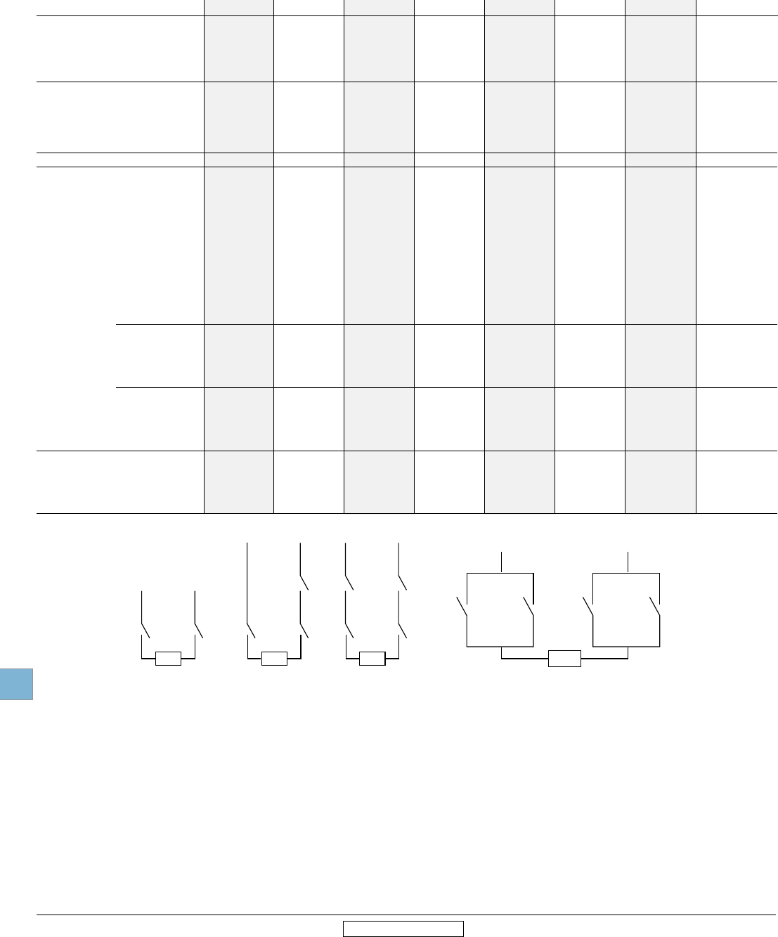
Disconnect
switches
Technical
data
19.58 Low Voltage Products & Systems
1SXU000023C0202 Rev. A ABB Inc. • 888-385-1221 • www.abb.us/lowvoltage
19
Revised January 2014 Revised January 2014
Technical data
OS30FA_12 – OS1200L03
IEC
1 Ambient temperature 60°C: derating 20 percent. Mounting on ceiling: derating 10 percent. Mounting on wall, horizontal fuses: derating 8 percent.
2 The ambient air temperature does not exceed +40°C and its average over a period of 24h does not exceed +35°C according to IEC 947.
3 For 30A switches, use 2 + 2 parallel contacts in series.
4 Available on request.
5 IEC 947-3, utilization category B, infrequent operation.
6 Pollution degree 3: Conductive pollution occurs, or dry, non-conductive pollution occurs, which becomes conductive due to condensation.
Catalog number 3 pole
OS30FA_12 OS60GJ12 OS100GJ03 OS200J03 OS400J03 OS600J03 OS800L03 OS1200L03
IEC
Technical ratings -40° to 40°C
Rated insulation voltage
Pollution degree 3 6 V 1000 1000 1000 1000 1000 1000 1000 1000
Dielectric strength 50Hz/60Hz, 1 min kV 10 10 10 10 10 10 10 10
Rated impulse withstand voltage kV 12 12 12 12 12 12 12 12
Rated thermal current, Ith/
max. fuse power dissipation 1
AC 20/DC 20 open 2 A/W 32/3.5 63/7.5 160/12 200/17 400/45 630/60 800/65 1250/110
40°C enclosed A/W 32/3.5 63/7.5 160/12 200/15 400/30 570/50 720/55 1000/85
Enclosed with solid links A/W 32 – – – – – – –
with minimum cable cross section Cu mm2 6 16 70 95 240 2 x 185 2 x 240 1250/2 x 400
Rated operational voltage AC 20 and DC 20V 1000 1000 1000 1000 1000 1000 1000 1000
AC Rated operational currents
AC 21A ≤500V A 32 63 160 200 400 630 800 1250 Cat. B
≤690V A 32 63 160 200 400 630 800 1250 Cat. B
AC 22A ≤500V A 32 63 160 200 400 630 800 1250 Cat. B
≤690V A 32 63 160 200 400 630 800 1250 Cat. B
AC 23A ≤500V A 32 63 5 160 5 200 400 630 800 1000 Cat. B
≤690V A 32 63 5 160 5 200 400 630 800 1000 Cat. B
DC Rated operational currents/poles in series
DC21A 48V A 32/2 3 63/2 160/2 200/1 400/2 630/1 CAT. B 800/1 CAT. B –
110V A 32/2 63/2 125/2 200/1 400/2 630/1 CAT. B 800/1 CAT. B –
220V A 32/2 63/2 125/2 200/1 400/2 630/1 CAT. B 800/1 CAT. B –
440V A 32/4 50/4 125/4 200/2 400/3 CAT. B 630/2 CAT. B 800/2 CAT. B –
750V A — 4 4 180/4 400/4 CAT. B 630/4 CAT. B 720/4 CAT. B –
880V A — 4 4 180/4 – 630/4 CAT. B 720/4 CAT. B –
DC22A 48V A 32/2 3 63/2 160/2 200/1 400/2 — 800/1 CAT. B –
110V A 32/2 63/2 125/2 200/1 400/2 — 800/1 CAT. B –
220V A 32/2 63/2 125/2 200/1 400/2 — 800/1 CAT. B –
440V A 32/4 – – 200/2 400/3 CAT. B — 800/2 CAT. B –
750V A — 4 4 180/4 400/4 CAT. B — 800/4 CAT. B –
880V A — 4 4 180/4 – — 800/4 CAT. B –
DC23A 48V A 32/2 3 63/2 160/2 200/1 400/2 — 800/1 CAT. B –
110V A 32/2 63/2 125/2 200/1 400/2 — 800/1 CAT. B –
220V A 32/2 63/2 125/2 200/1 400/2 — 800/1 CAT. B –
440V A 32/4 – – 200/2 400/3 CAT B — 800/2 CAT. B –
750V A — – – 180/4 400/4 CAT. B — 720/4 CAT. B –
880V A — – – 180/4 — — 720/4 CAT. B –
Rated operational power AC23A
230V kW 7.5 18.5 45 60 132 200 250 315
400V kW 15 30 75 110 220 355 450 560
415V kW 15 30 75 110 230 355 450 560
500V kW 18.5 37 90 132 280 450 560 710
690V kW 22 55 132 200 400 630 710 1000
2 poles
in series
Load
3 poles
in series
4 poles
in series
Load Load
Load
2 + 2 parallel contacts in series
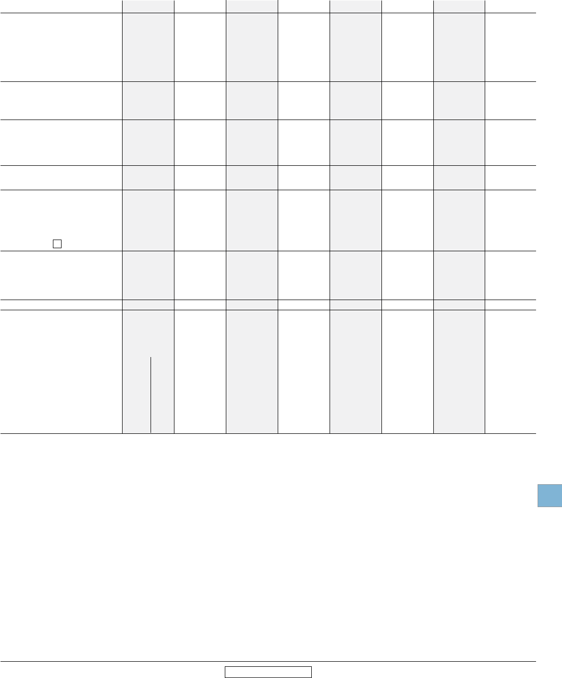
Disconnect
switches
Technical
data
Low Voltage Products & Systems 19.59
ABB Inc. • 888-385-1221 • www.abb.us/lowvoltage 1SXU000023C0202 Rev. A
19
Revised January 2014 Revised January 2014
Technical data
OS30FA_12 – OS1200L03
IEC
Catalog number 3 pole
OS30FA_12 OS60GJ12 OS100GJ03 OS200J03 OS400J03 OS600J03 OS800L03 OS1200L03
IEC
1 AC15 / DC12, according to IEC 947-5-1
2 AC15, according to IEC 947-5-1
3 Values shown are corresponding max. allowed cut-off current, peak-values per single phase fuse tests.
Rated breaking capacity
in category AC-23A 500V A 256 504 1280 1600 3200 5760 5760 8000
690V A 256 504 1280 1600 3200 5760 5760 8000
Rated breaking capacity/poles in series
in category DC-23 <220V A 128/2 252/2 640/2 — — – – –
440V A 128/4 — — — — – – –
500 – 750V A — — — — — – – –
1000V A — — — — — – – –
Rated conditional short-circuit current r.m.s. 3
80 kA, 415V kA 9 13.5 22 35 40 75 75 89
100 kA, 500 V kA 8 12.5 22 37.5 40 75 75 105
50 kA, 690 V kA 7 9.5 15 – – – – –
Rated short time withstand current, 1s. kA 1 2.5 5 8 14 18 18 40
Rated capacitor power
The capacitor rating of the fusible
disconnect switch is limited by the fuse link
400 V kVar 15 30 60 90 180 250 310 440
415V kVar 15 32 65 100 200 270 340 460
690V kVar 25 50 100 160 325 450 550 750
Power loss/pole
with rated current, without fuse W 2 4 9 8 30 46 75 75
Mechanical endurance operations 20,000 20,000 20,000 20,000 16,000 10,000 10,000 6000
Physical characteristics
Weight 3 pole kg 0.7 1.1 1.5 2.6 5.7 11.5 11.5 29.00
4 pole kg 0.9 1.3 1.8 – – – – –
Dimension 3 pole H mm 93 100 144 198.5 236 306 282 424.18
W mm 106 143 179 181.5 255 343 376 417.07
D mm 104 120 129 132 176 233 233 295.14
Shaft size square mm 6 x 6 6 x 6 6 x 6 6 x 6 12 x 12 12 x 12 12 x 12 12 x 12
Terminals
Built-in terminal size mm2 0.5 – 10 2.5 – 25 — — — — — —
Terminal bolt size, metric thread
diameter x length mm — — — M8 x 25 M8 x 25 M10 x 30 M12 x 40 M12 x 40 M12 x 40
Terminal bolt tightening torque Nm 2 3.5 15-22 15 – 22 30 – 44 50 – 75 50 – 75 50 – 75
Fuse-links bolts tightening torque Nm 2 3.5 M5:3.5 M8:5 4 20 M10:30 M12:40 M10:30 M12:40 M12:40
Operating torque Nm 3 5 7 7 19 38 38 65
Auxiliary contacts OA4G_ OA1/3G OA_G_ OA_G_ OA_G_ OA_G_ OA_G_ OA_G_ OA_G
1 2 2 2 2
Ratings according to IEC 947-5-1
Rated voltage, Ui VAC 690 690 690 690 690 690 690 690 690
Thermal current, Ith
A 10 16 16 16 16 16 16 16 16
AC12 / DC12, Ie Ue=24V A — / 6 — — — — — — — —
120V A — / 6 — — — — — — — —
125V A — — — — — — — — —
230V A — 6 / — 6 / — 6 / — 6 / — — — 6 / — 6 / —
250V A 3 / 0.1 — — — — — — — —
400V A — 4 / — 4 / — 4 / — 4 / — — — 4 / — 4 / —
415V A — — — — — — — — —
440V A 2 / — — — — — — — — —
480V A — — — — — — — — —
500V A — — — — — — — — —
600V A — — — — — — — — —
690V A — 2 / — 2 / — 2 / — 2 / — 2 / — 2 / — 2 / — 2 / —
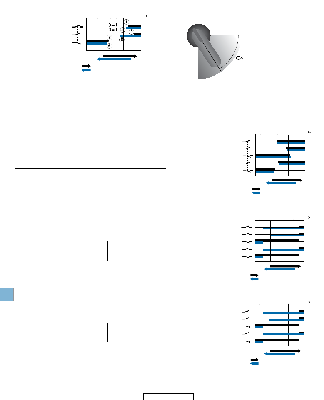
Disconnect
switches
Technical
data
19.60 Low Voltage Products & Systems
1SXU000023C0202 Rev. A ABB Inc. • 888-385-1221 • www.abb.us/lowvoltage
19
Revised January 2014 Revised January 2014
OFF
0
ON
I
= Contacts in closed position
= Contacts in closed position
Main contacts
N.O. auxiliary contact
N.C. auxiliary contact
0° 30° 60° 90°
O OFF
I ON
ON
OFF
Auxiliary contact timing diagrams
OT16 – OT100
Contacts closing Contacts opening
1 Main contacts close 4 Main contacts open
2 N.O. auxiliary contacts close 5 N.O. auxiliary contacts open
3 N.C. auxiliary contacts open 6 N.C. auxiliary contacts close
Legend
OT16, OT25, OT40
Catalog number Auxiliary contact Contact configuration
OA1G10 1 N.O.
OT16, OT25, OT40 OA1G01 1 N.C.
OA2G11 1 N.O. & 1 N.C.
OT63, OT80
Catalog number Auxiliary contact Contact configuration
OA1G10 1 N.O.
OT63, OT80 OA1G01 1 N.C.
OA2G11 1 N.O. & 1 N.C.
OT30, OT60, OT100
Catalog number Auxiliary contact Contact configuration
OA1G10 1 N.O.
OT30, OT60, OT100 OA1G01 1 N.C.
OA2G11 1 N.O. & 1 N.C.
OA1G10
OA1G01
OA2G11
OFF
0
ON
I
= Contacts in closed position
= Contacts in closed position
Main contacts
N.O. auxiliary contact
N.C. auxiliary contact
N.O. auxiliary contact
N.C. auxiliary contact
0° 30° 60° 90°
OA1G10
OA1G01
OA2G11
OFF
0
ON
I
= Contacts in closed position
= Contacts in closed position
Main contacts
N.O. auxiliary contact
N.C. auxiliary contact
N.O. auxiliary contact
N.C. auxiliary contact
0° 30° 60° 90°
OA1G10
OA1G01
OA2G11
OFF
0
ON
I
= Contacts in closed position
= Contacts in closed position
Main contacts
N.O. auxiliary contact
N.C. auxiliary contact
N.O. auxiliary contact
N.C. auxiliary contact
0° 30° 60° 90°
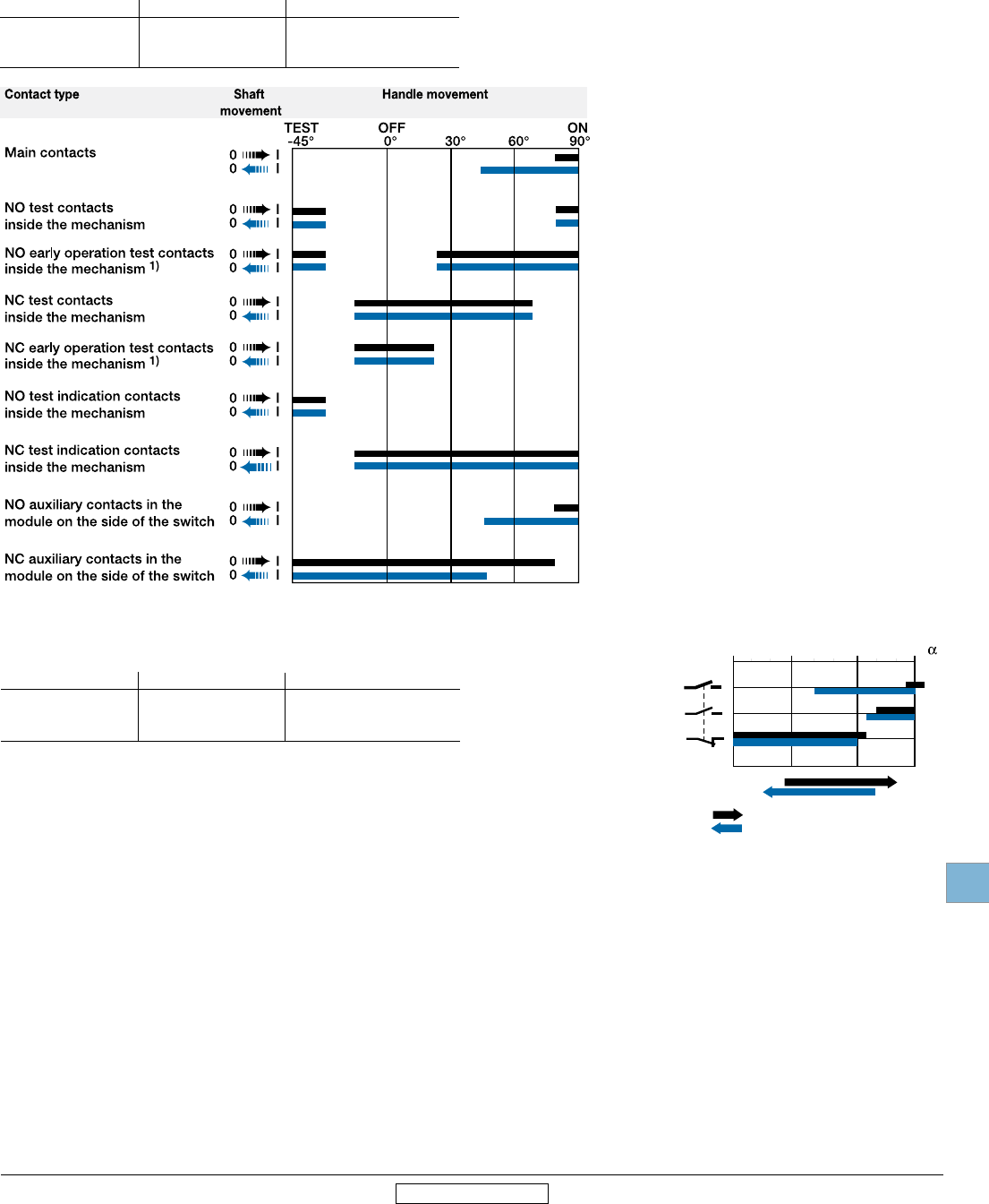
Disconnect
switches
Technical
data
Low Voltage Products & Systems 19.61
ABB Inc. • 888-385-1221 • www.abb.us/lowvoltage 1SXU000023C0202 Rev. A
19
Revised January 2014 Revised January 2014
Auxiliary contact timing diagrams
OT200U – OETL-NF3150
Catalog number Auxiliary contact Contact configuration
OA1G10 1 N.O.
OT200U03 – OA3G01 1 N.C.
OT1200U03
OT200U03 – OT1200U03
1) OT800 - 1200 only
OETL-NF1600 – OETL-NF3150
OETL-NF1600A – OZXK-1 1 N.O. & 1 N.C.
OETL-NF3150 OZXK-2 2 N.O. & 2 N.C.
OZXK-3 4 N.O. & 4 N.C.
Catalog number Auxiliary contact Contact configuration
OFF
0
ON
I
= Contacts in closed position
= Contacts in closed position
Main contacts
N.O. auxiliary contact
N.C. auxiliary contact
0° 30° 60° 90°
OZXK-1
OZXK-2
OZXK-3
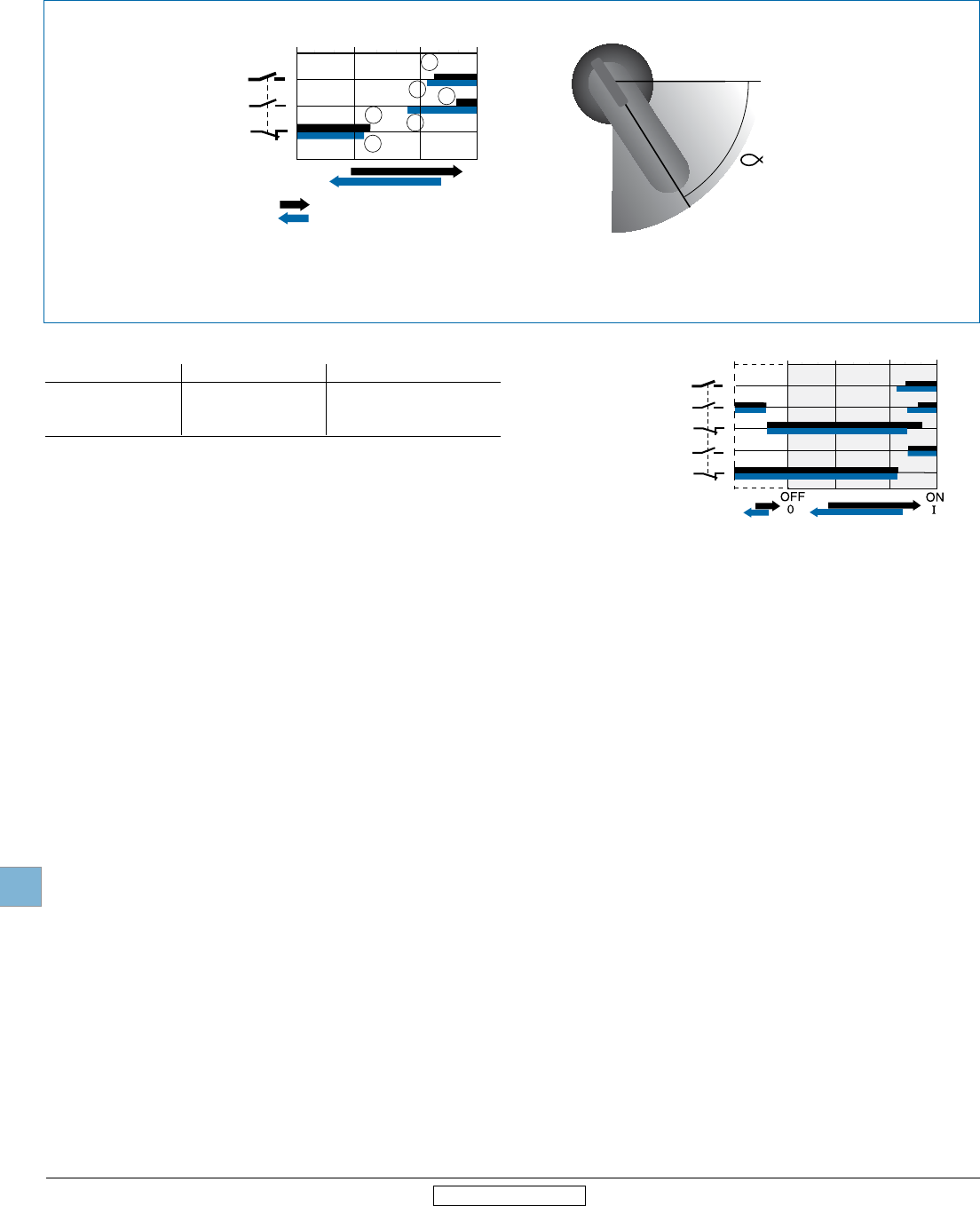
Disconnect
switches
Technical
data
19.62 Low Voltage Products & Systems
1SXU000023C0202 Rev. A ABB Inc. • 888-385-1221 • www.abb.us/lowvoltage
19
Revised January 2014 Revised January 2014
‡
‡
0
0
I
I
OFF
0
ON
I
1
2
3
4
5
6
= Contacts in closed position
= Contacts in closed position
Main contacts
N.O. auxiliary contact
N.C. auxiliary contact
0° 30° 60° 90° a
Auxiliary contact timing diagrams
OS30_
OS30_
Catalog number Auxiliary contact Contact configuration
OA4B1C 1 N.O. & 1 N.C.
OS30_ OA1G10 1 N.O.
OA3G01 1 N.C.
Contacts closing Contacts opening
1 Main contacts close 4 Main contacts open
2 N.O. auxiliary contacts close 5 N.O. auxiliary contacts open
3 N.C. auxiliary contacts open 6 N.C. auxiliary contacts close
Legend
O OFF
I ON
ON
OFF
OA4B1C
OA4B1C
OA1G10
Test
OA3G01
Main contacts
N.O. auxiliary contact
N.C. auxiliary contact
N.O. auxiliary contact
N.C. auxiliary contact
-45° 0° 30° 60° 90° a
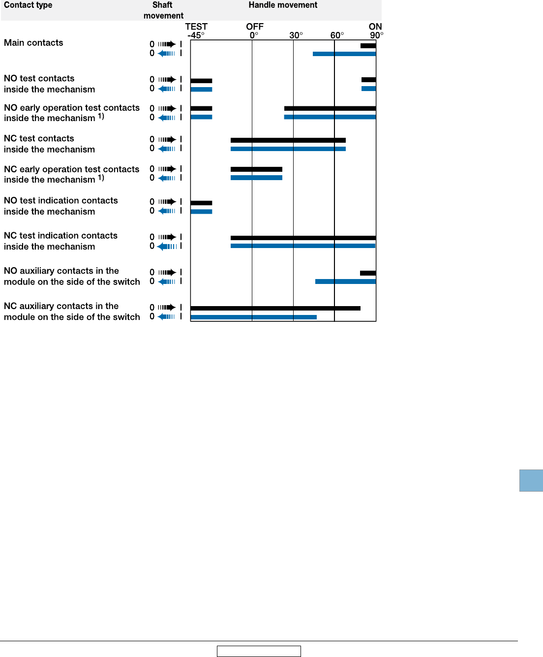
Disconnect
switches
Technical
data
Low Voltage Products & Systems 19.63
ABB Inc. • 888-385-1221 • www.abb.us/lowvoltage 1SXU000023C0202 Rev. A
19
Revised January 2014 Revised January 2014
Auxiliary contact timing diagrams
OS60 - OS1200
OS60-OS1200
OS1200 only
1)
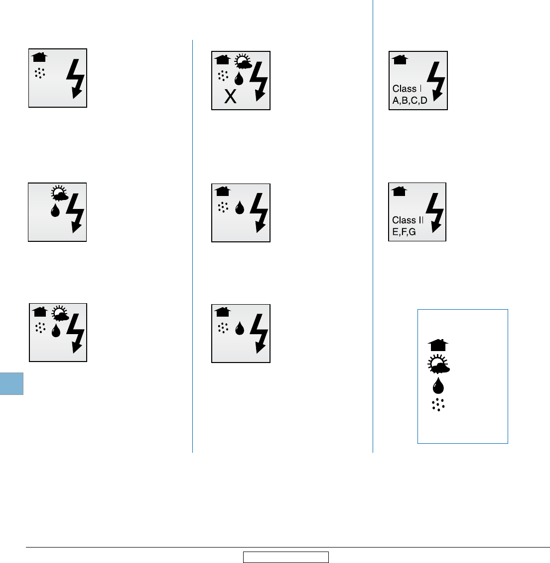
Disconnect
switches
Technical
data
19.64 Low Voltage Products & Systems
1SXU000023C0202 Rev. A ABB Inc. • 888-385-1221 • www.abb.us/lowvoltage
19
Revised January 2014 Revised January 2014
NEMA Environmental ratings
X
– Indoors
– Outdoors
– Water
– Dirt/dust
– Corrosion
Legend
Type 1
Enclosures are intended for indoor use
primarily to provide a degree of protection
against limited amounts of falling dirt.
(NEMA Standard 7-15-1991.)
Type 3R
Enclosures are intended for outdoor use
primarily to provide a degree of protection
against rain, sleet and damage from external ice
formation. (NEMA Standard 7-15-1991.)
Type 4
Enclosures are intended for indoor or
outdoor use primarily to provide a degree
of protection against windblown dust and
rain, splashing water, hose-directed water
and damage from external ice formation.
(NEMA Standard 1-10-1979.)
Type 4X
Enclosures are intended for indoor or outdoor
use primarily to provide a degree of protection
against corrosion, windblown dust and
rain, splashing water, hose-directed water
and damage from external ice formation.
(NEMA Standard 1-10-1979)
Type 12
Enclosures are intended for indoor
use primarily to provide a degree of
protection against circulating dust, falling
dirt, and dripping noncorrosive liquids.
(NEMA Standard 7-15-1991.)
Type 13
Enclosures are intended for indoor use primarily
to provide a degree of protection against dust,
spraying of water, oil and noncorrosive coolant.
(NEMA Standard 1-10-1979.)
Type 7
Enclosures are intended for indoor use in
locations classified as Class I, Groups, A, B, C,
or D, as defined in the National Electrical Code.
(NEMA Standard 7-15-1991.)
Type 9
Enclosures are intended for indoor use in
locations classified as Class II, Groups E, F, or
G, as defined in the National Electrical Code.
(NEMA Standard 7-15-1991.)
Definitions pertaining to nonhazardous locations Definitions pertaining to hazardous locations
Introduction
An enclosure is a surrounding case constructed to provide a
degree of protection to personnel against accidental contact with
the enclosed equipment and to provide a degree of protection
to the enclosed equipment against specified environmental
conditions.
A brief description of the more common types of enclosures used
by the electrical industry relating to their environmental capabilities
follows. Refer to NEMA Standards Publication for more
information regarding applications, features and design tests.
Individual NEMA product Standards Publications or third party
certification standards may contain additional requirements for
product testing and performance.
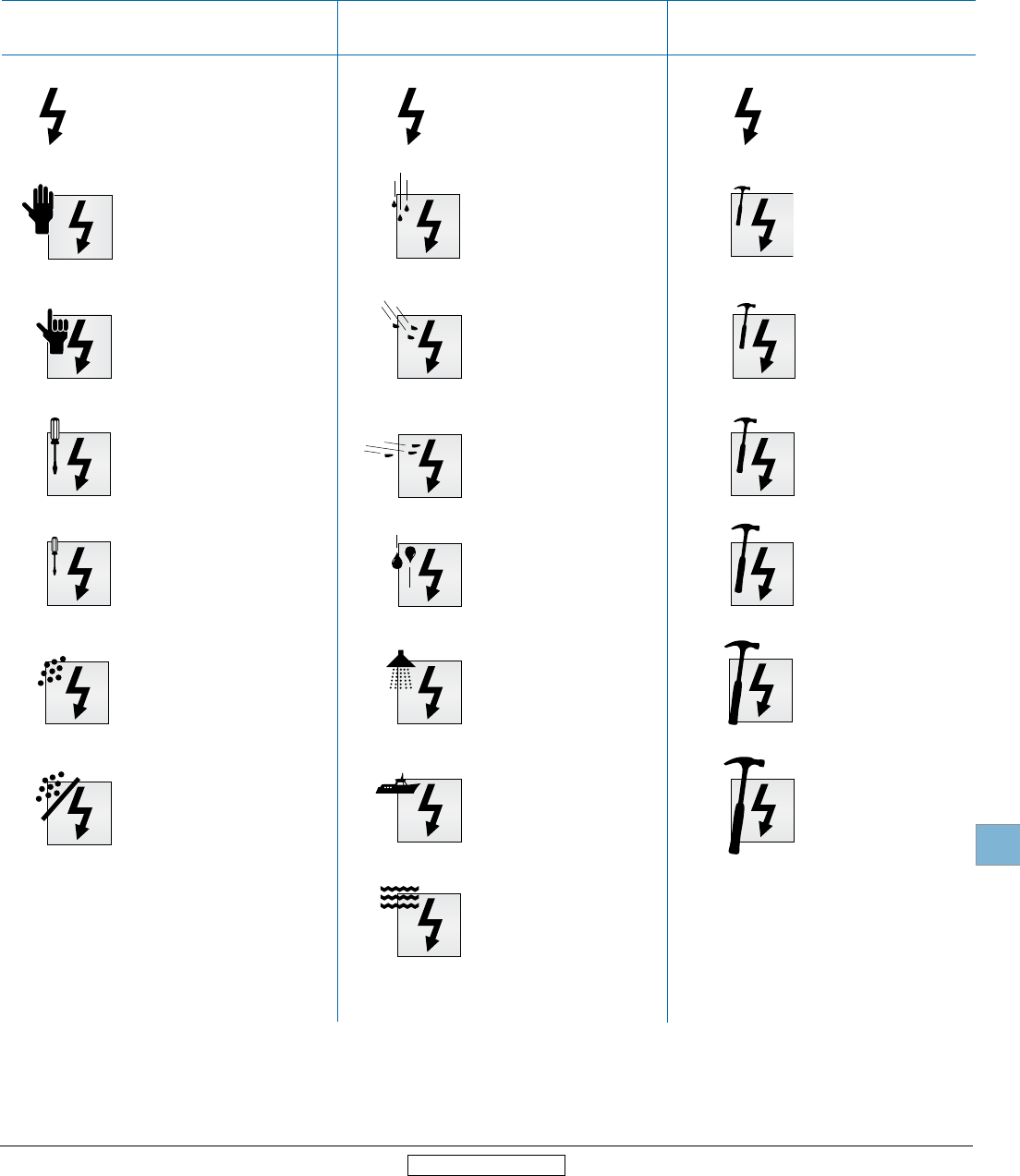
Disconnect
switches
Technical
data
Low Voltage Products & Systems 19.65
ABB Inc. • 888-385-1221 • www.abb.us/lowvoltage 1SXU000023C0202 Rev. A
19
Revised January 2014 Revised January 2014
IP
0
1
2
3
4
5
6
7
no protection
protected against vertically
falling rain or condensation
protected against direct
sprays of water up to 15°
from vertical
protected against sprays to
60° from vertical
protected against water
sprayed from all directions
protected against low
pressure jets of water from
all directions
protected from strong jets of
water (e.g. for use on ship
decks)
protected against the effects
of immersion between 15cm
and 1m
no protection
protected against solid
objects over 50mm (e.g.
accidental touch by hands.)
protected against solid
objects over 12 mm
(e.g. fingers)
protected against solid
objects over 2.5 mm (tools &
wires)
protected against solid
objects over 1mm (small
tools & small wires)
protected against dust (no
harmful deposit)
totally protected against dust
no protection
impact 0,225 joule
150g falling from 15 cm
impact 0,375 joule
250g falling from15 cm
impact 0,50 joule
250g falling from 20cm
impact 2,00 joule
500g falling from 40 cm
impact 6,00 joule
1.5kg falling from 40 cm
impact 20,00 joule
5 kg falling from 40 cm
IEC Environmental ratings
IP ratings indicate the degree of protection against dust, liquids and impacts. The IP degrees of protection are defined by the
French standard NFC 20-010. To rate a device's degrees of protection, the letters IP are followed by up to three
numbers. These numbers are defined as follows:
IP
0
1
2
3
4
5
6
IP
0
1
2
3
5
7
9
first number second number third number
protection against solid objects protection against liquids protection against mechanical impacts

Disconnect
switches
Technical
data
19.66 Low Voltage Products & Systems
1SXU000023C0202 Rev. A ABB Inc. • 888-385-1221 • www.abb.us/lowvoltage
19
Revised January 2014 Revised January 2014
Definitions
AC – Alternating current — Current that reverses its direction of
flow twice per cycle.
Ambient temperature — Temperature of the air surrounding the
unit.
Amp rating — The basic unit of measurement for electric current
(columbs / seconds).
Conventional thermal current Ith — Value of the current the
disconnect switch can withstand with poles in closed position, in
free air for an eight hour duty, without the temperature rise of its
various parts exceeding the limits specified by the standards.
Cycle duration — Total time of the on-load + off-load period.
DC – Direct current — Current that flows in only one direction.
Electrical endurance — Number of on-load operating cycles.
IEC environmental protection type — see page 19.48.
Full load amp current FLA — The current required by a motor to
produce full-load torque at the motor's rated speed.
Inductive load — An electrical load characterized by having
significant inrush (5 to 6 times FLA for typical design-B AC
induction motors).
kW — Kilowatts (1000 watts)
Lockout/Tagout — Means of removing power from electrical
equipment during inspection, service or repair.
Make / Break — ON / OFF
Mechanical endurance — Number of off-load operating cycles.
Poles in series — Means of connection poles using wires or bus
bars to increase breaking capacity of load.
Power factor — The relationship between working power and
total power consumed. Power factor measures how effectively
electrical power is being used.
Rated insulation Ui — Voltage value which designates the unit
and to which dielectric tests, clearance and creepage distances
are referred.
Rated operating current Ie —Current value stated by the
manufacturer and taking into account the rated operating voltage
Ue, the rated frequency, the rated duty, the utilization category, the
electrical contact life and the type of protective enclosure.
Rated operating voltage Ue — Voltage value to which utilization
characteristics of the disconnect switch are referred, i.e. phase-to-
phase voltage in 3 phase circuits.
Rated short circuit making capacity Icm— The rated short-
circuit making capacity of a disconnect switch, a disconnector or
a switch-disconnector is the value assigned to equipment at the
rated operational voltage, frequency (if any) and specified power-
factor for AC or time constant for DC. It is expressed as the
maximum prospective peak current under prescribed conditions.
Rated short time withstand current Icw — The rated short-
time withstand current of a disconnect switch, a disconnector or
a switch-disconnector is the value that the equipment can carry
without damage, under the test conditions specified in the relevant
product standard. The value of the rated short-time withstand
current shall be not less than twelve times the maximum rated
operational current unless otherwise stated by manufacturer and
the duration of the current shall be 1 s.
Resistive load — An electrical load characterized by not having
any significant inrush current.
Short circuit protection coordination — Co-ordination types "1"
and "2" are defined in IEC 947-4-1.
Type 1 coordination — There has to be no discharge of parts
beyond the enclosure. Damage to the contactor and the overload
is acceptable.
Type 2 coordination — No damage to the overload relay or other
parts has occurred, except that welding of contactor or starter
contacts is permitted, if they are easily separated.
Time constant — Ratio of inductance to the resistance:
L/R = mH/Ohm = ms.
Torque — The force that produces rotation. It is commonly
measured in pound-feet (lb-ft). Torque applies to such things as
motor operations, handle rotations, wire tightening.
NEMA environmental protection type — see page 19.47.
Volt — The unit of electrical potential difference and electromotive
force.
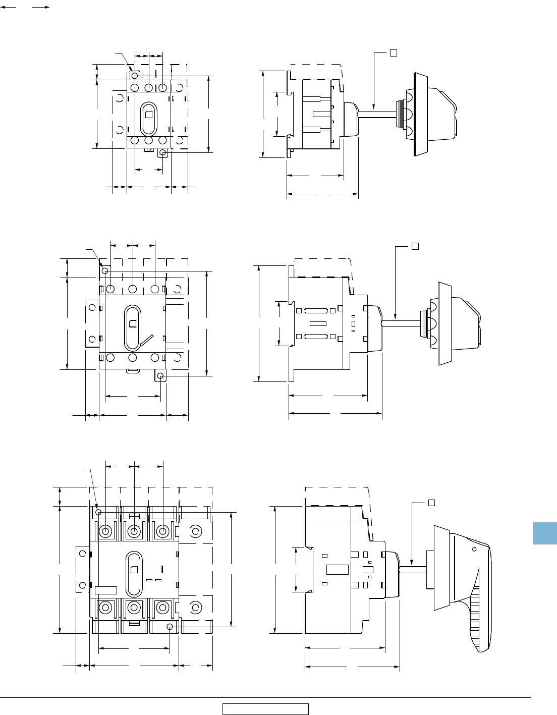
Disconnect
switches
Dimensions
Low Voltage Products & Systems 19.67
ABB Inc. • 888-385-1221 • www.abb.us/lowvoltage 1SXU000023C0202 Rev. A
00.00
00.00
Inches
[Millimeters]
19
Revised January 2014 Revised January 2014
OT16,25,32
2.68
68
1.77
45
2.20
56
1.38
35
0.20
5
2.36
60
1.38
35
0.43
11
2.13
54
0.47
12
0.43
11
0.87
22
0.18
4.5
DIA.
0.51
13
0.43
11
OT45,63
2.85
72.5
0.59
15
3.25
82.5
1.71
43.5
2.07
52.5
0.69
17.5
0.69
17.5
0.69
17.5
0.18
4.5
DIA.
2.47
63
2.89
73.5
1.38
35
3.60
91.5
0.20
5
0.43
11
OT100E3
0.20
5
2.76
70
1.04
26.5
0.88
22.5
0.88
22.5
2.20
56
3.94
100
3.54
90
0.59
15
0.18
4.5 DIA.
2.48
63
2.93
74.5
1.38
35
3.94
100
0.43
11
Approximate dimensions
OT16F3 – OT100F3
Base & DIN rail mounted switches
OT16F3, OT25F3, OT40F3 — base & DIN rail mounted switch
OT63F3, OT80F3 — base & DIN rail mounted switch
OT30F3, OT60F3, OT100F3 — base & DIN rail mounted switch
0.24
6
0.24
6
0.24
6
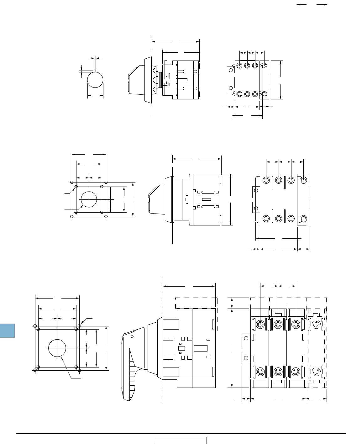
Disconnect
switches
Dimensions
19.68 Low Voltage Products & Systems
1SXU000023C0202 Rev. A ABB Inc. • 888-385-1221 • www.abb.us/lowvoltage
00.00
00.00
Inches
[Millimeters]
19
Revised January 2014 Revised January 2014
0.43
11
0.43
11
2.13
54
1.38
35
1.69
43
0.51
13
2.64
67
2.05
52
0.88
22
0.08
2
0.06
1.5
MOUNTING HOLE
DETAIL
0.51
13
0.43
11
OT 16 & 32ET
2.72
69
0.69
17.5
0.69
17.5
0.69
17.5
0.69
17.5
2.07
52.5
2.56
65
2.85
72.5
0.43
11
1.42
36
1.89
48
0.71
18
0.71
18
0.16
4
D
0.88
22
D
MOUNTING HOLE
DETAIL
1.42
36
1.89
48
0.71
18
0.71
18
OT63ET3
OT100ET3
2.76
70
1.04
26.5
3.94
100
0.43
11
0.88
22.5
0.88
22.5
0.88
66.5
MOUNTING HOLE
DETAIL
0.16
4
D
0.88
22
D
0.94
24
0.94
24
1.89
48
2.20
56
0.94
24
0.94
24
1.89
48
2.20
56
0.55
14
Approximate dimensions
OT16FT3 – OT100FT3
Door mounted switches
OT16FT3, OT25FT3, OT40FT3 — door mounted switch
OT63FT3, OT80FT3 — door mounted switch
OT30FT3, OT60FT3, OT100FT3 — door mounted switch
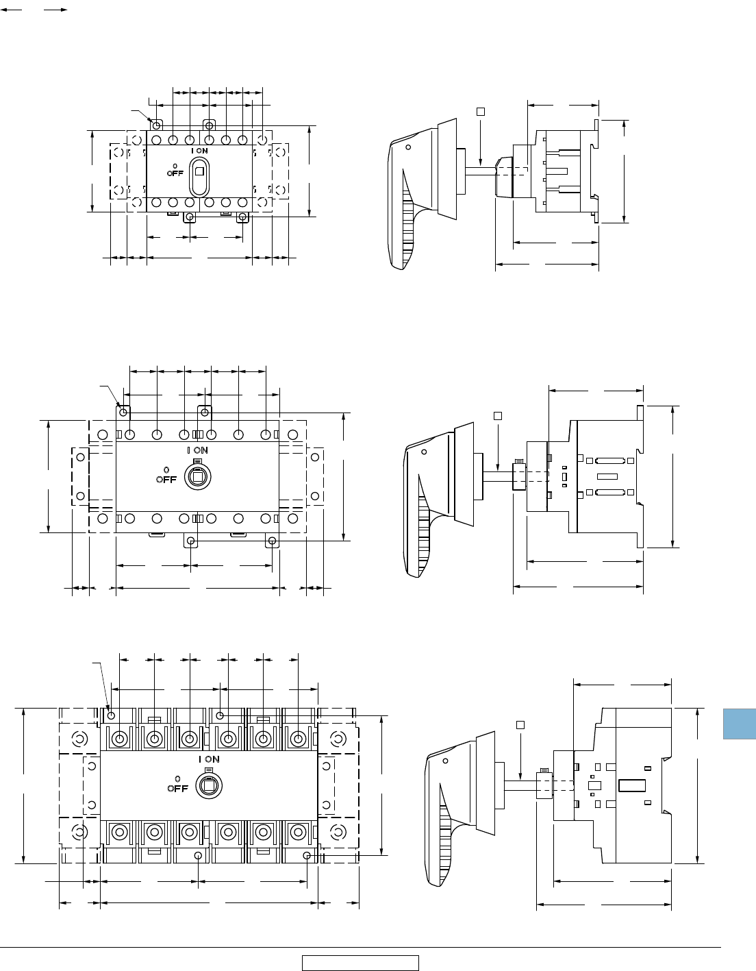
Disconnect
switches
Dimensions
Low Voltage Products & Systems 19.69
ABB Inc. • 888-385-1221 • www.abb.us/lowvoltage 1SXU000023C0202 Rev. A
00.00
00.00
Inches
[Millimeters]
19
Revised January 2014 Revised January 2014
2.36
60
2.76
70
2.13
54
0.18
4.5 DIA.
0.51
13
0.51
13
0.43
11
0.43
11
0.43
11
0.43
11
0.43
11
0.51
13
0.51
13
1.12
28.5
1.38
35
1.12
28.5
1.38
35
2.68
68
2.22
56.5
2.68
68
35mm
DIN rail
1.85
47
shaft depth
0.24
6
2.85
72.5
3.25
82.5
0.18
4.5 DIA.
2.95
75
3.31
84
3.60
91.5
4.13
105
0.69
17.5
0.69
17.5
0.69
17.5
0.69
17.5
0.69
17.5
0.69
17.5
0.69
17.5
1.89
48
2.07
52.5
1.89
48
2.07
52.5
0.43
11
0.43
11
35mm
DIN rail
2.40
61
shaft depth
0.24
6
0.88
22.5
0.88
22.5
0.88
22.5
0.88
22.5
0.98
25.0
2.76
70
3.94
100
3.54
90
5.51
140
1.04
26.5
1.04
26.5
2.76
70
2.48
63
2.76
70
2.48
63
0.43
11
0.18
4.5 DIA.
2.99
76
3.43
87
3.94
100
35mm
DIN rail
2.50
63.5
shaft depth
0.24
6
Approximate dimensions
OT16F6 – OT100F6
6-pole switches
OT16, 25, 40F6 — 6 Pole switches
OT63, OT80F6 — 6 Pole switches
OT30, OT60, OT100F6 — 6 Pole switches
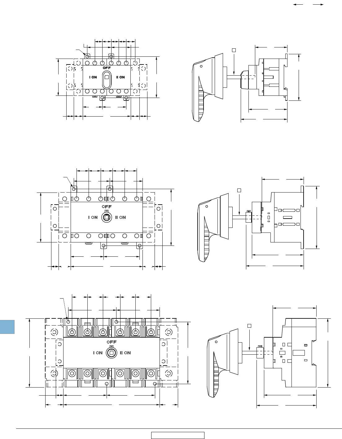
Disconnect
switches
Dimensions
19.70 Low Voltage Products & Systems
1SXU000023C0202 Rev. A ABB Inc. • 888-385-1221 • www.abb.us/lowvoltage
00.00
00.00
Inches
[Millimeters]
19
Revised January 2014 Revised January 2014
2.36
60
2.76
70
2.13
54
0.18
4.5 DIA.
0.51
13
0.51
13
0.43
11
0.43
11
0.43
11
0.43
11
0.43
11
0.51
13
0.51
13
1.12
28.5
1.38
35
1.12
28.5
1.38
35
2.68
68
2.22
56.5
2.68
68
35mm
DIN rail
1.85
47
shaft depth
0.24
6
2.85
72.5
3.25
82.5
0.18
4.5 DIA.
2.95
75
3.31
84
3.60
91.5
4.13
105
0.69
17.5
0.69
17.5
0.69
17.5
0.69
17.5
0.69
17.5
0.69
17.5
0.69
17.5
1.89
48
2.07
52.5
1.89
48
2.07
52.5
0.43
11
0.43
11
35mm
DIN rail
2.40
61
shaft depth
0.24
6
0.88
22.5
0.88
22.5
0.88
22.5
0.88
22.5
0.98
25.0
2.76
70
3.94
100
3.54
90
5.51
140
1.04
26.5
1.04
26.5
2.76
70
2.48
63
2.76
70
2.48
63
0.43
11
0.18
4.5 DIA.
2.99
76
3.43
87
3.94
100
35mm
DIN rail
2.50
63.5
shaft depth
0.24
6
Approximate dimensions
OT16 – OT100F3C
Double throw switches
OT16, OT25, OT40F3C – Double throw switches
OT45, OT63, OT80F3C – Double throw switches
OT30, OT60, OT100F3C – Double throw switches
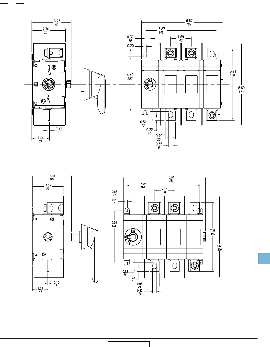
Disconnect
switches
Dimensions
Low Voltage Products & Systems 19.71
ABB Inc. • 888-385-1221 • www.abb.us/lowvoltage 1SXU000023C0202 Rev. A
00.00
00.00
Inches
[Millimeters]
19
Revised January 2014 Revised January 2014
OT400U03
Approximate dimensions
OT200_ — OT400_
OT200U03
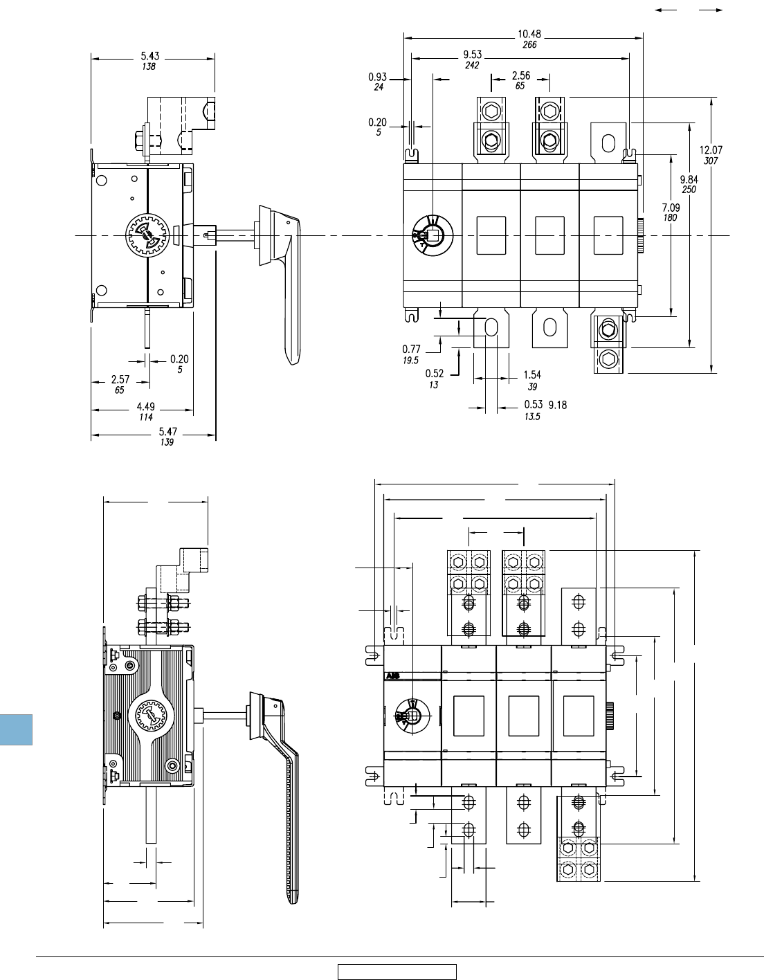
Disconnect
switches
Dimensions
19.72 Low Voltage Products & Systems
1SXU000023C0202 Rev. A ABB Inc. • 888-385-1221 • www.abb.us/lowvoltage
00.00
00.00
Inches
[Millimeters]
19
Revised January 2014 Revised January 2014
OT800U03
Approximate dimensions
OT600U03 – OT800U03
OT600U03
12.76
[324]
11.57
[294]
0.35
[9]
13.78
[350]
9.13
[232]
14.65
[372]
18.99
[482]
6.93
[176]
1.06
[27]
3.15
[80]
0.77
[20]
0.80
[20]
0.40
[10]
1.97
[50]
0.54
[14]
6.01
[153]
3.05
[78]
0.59
[15]
5.20
[132]
5.74
[146]
OT800
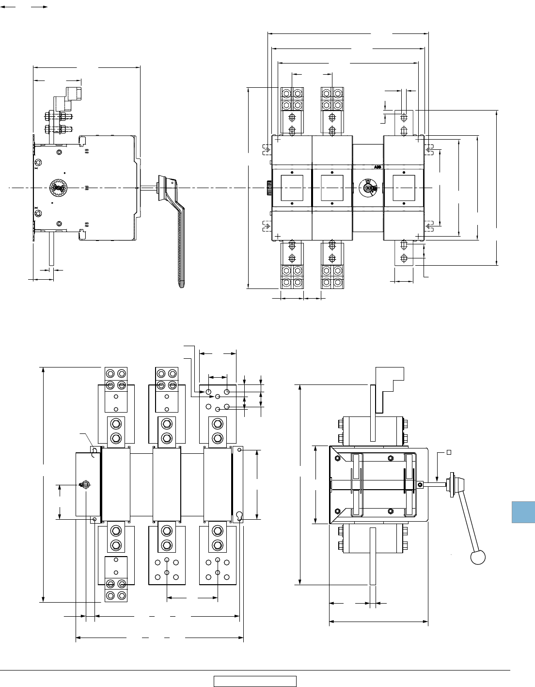
Disconnect
switches
Dimensions
Low Voltage Products & Systems 19.73
ABB Inc. • 888-385-1221 • www.abb.us/lowvoltage 1SXU000023C0202 Rev. A
00.00
00.00
Inches
[Millimeters]
19
Revised January 2014 Revised January 2014
15.59
396
3-pole
5.47
139
1.38
35
1.58
40
0.79
20
1.28
32.5
3.94
100
1.58
40
7.48
190
3.74
95
25.28
642
0.94
24
0.55
14
0.47
12
DIA.
DIA.
0.35
9
DIA.
8.35
212
21.50
546
4.41
112
0.59
15
10.67
0.47
12
OETL-NF1600
10.12
257
2-pole
21.06
535
4-pole
18.11
460
3-pole
23.58
599
4-pole
12.63
321
2-pole
271
Approximate dimensions
OT1200U03 – OETL-NF1600
OT1200U03
OETL-NF1600
2.47
[62.71]
17.40
[442.00]
16.54
[420.00]
15.20
[386.00]
11.30
[287.00]
10.47
[266.00]
8.27
[210.00]
1.86
[47.29]
4.33
[110.00]
21.75
[552.38]
16.77
[426.00]
5.20
[132.18]
0.47
[12.00]
2.24
[57.00]
11.62
[295.23]
1.53
[38.88]
1.97
[50.00]
OS1200
0.40
[10.13]
0.54
[13.63]
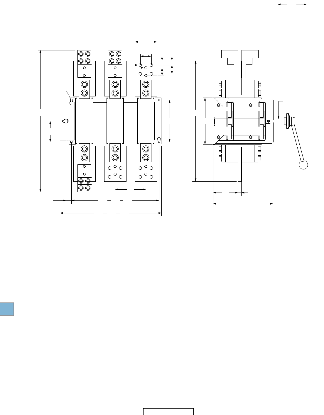
Disconnect
switches
Dimensions
19.74 Low Voltage Products & Systems
1SXU000023C0202 Rev. A ABB Inc. • 888-385-1221 • www.abb.us/lowvoltage
00.00
00.00
Inches
[Millimeters]
19
Revised January 2014 Revised January 2014
Approximate dimensions
OETL-NF2000 – OETL-NF3150
OETL-NF2000 – OETL-NF3150
OETL-NF2000,3150
5.47
139
1.38
35
1.58
40
0.79
20
1.28
32.5
3.94
100
1.58
40
7.48
190
3.74
95
25.28
642
0.94
24
8.35
212
21.50
546
4.41
112
0.59
15
10.67
271
0.35
9
DIA.
0.47
12
0.55
14
0.47
12
DIA.
DIA.
15.59
396
3-pole
10.12
257
2-pole
21.06
535
4-pole
12.63
321
2-pole
18.11
460
3-pole
23.58
599
4-pole
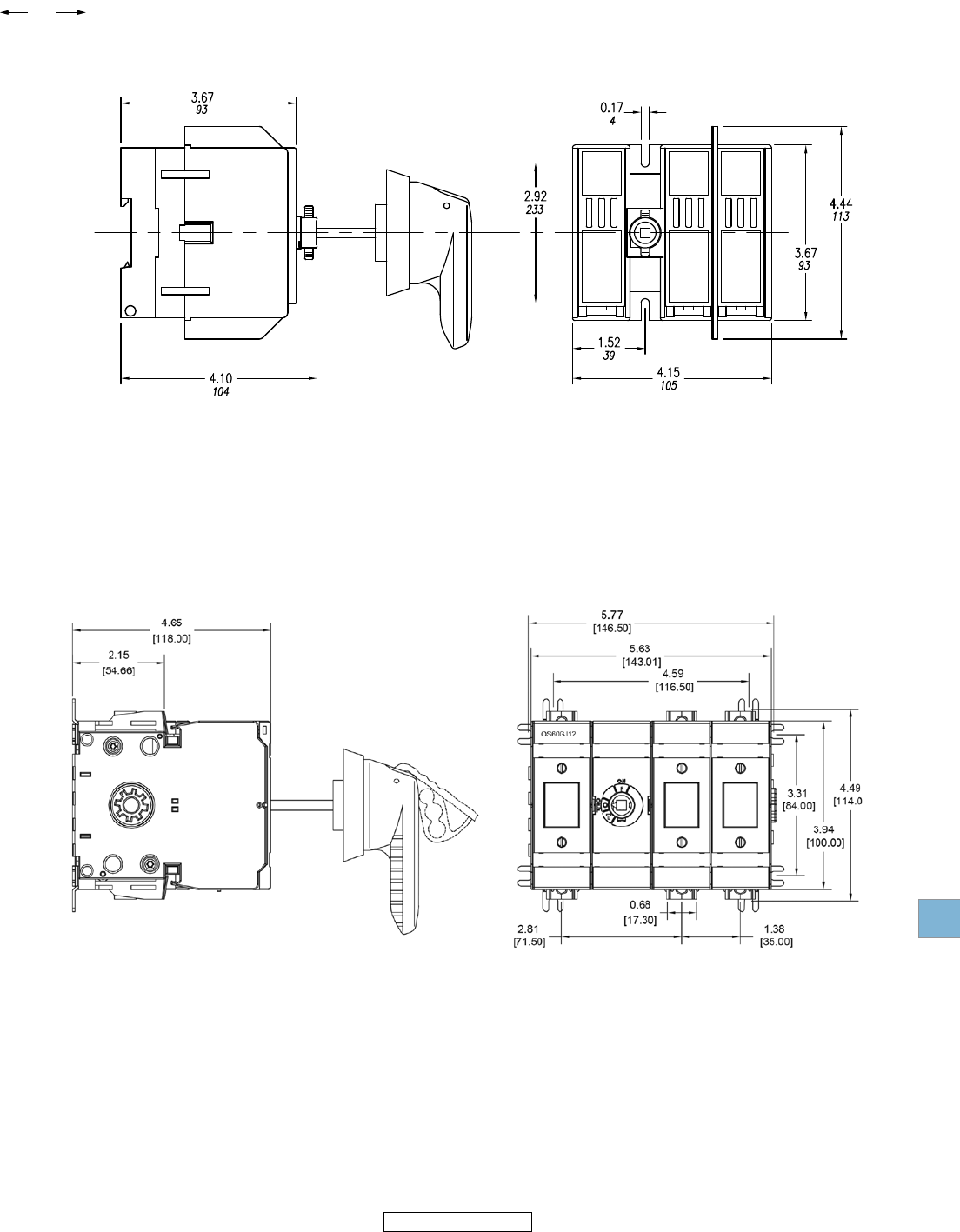
Disconnect
switches
Dimensions
Low Voltage Products & Systems 19.75
ABB Inc. • 888-385-1221 • www.abb.us/lowvoltage 1SXU000023C0202 Rev. A
00.00
00.00
Inches
[Millimeters]
19
Revised January 2014 Revised January 2014
Approximate dimensions
OS30FA_12 — OS60GJ12
OS30FA_12
OS60GJ12

Disconnect
switches
Dimensions
19.76 Low Voltage Products & Systems
1SXU000023C0202 Rev. A ABB Inc. • 888-385-1221 • www.abb.us/lowvoltage
00.00
00.00
Inches
[Millimeters]
19
Revised January 2014 Revised January 2014
1.38
[35.00]
1.38
[35.00]
7.91
[201.01
4.49
[114.01]
3.31
[84.00]
8.66
[220.00]
[155.00]
4.92
[125.00]
0.79
[20.00]
3.94
[100.00]
1.50
[38.00]
0.10
[2.50]
4.11
[104.46]
6.77
[172.00]
OS100GJ30
OS100GJ30
6.10
Approximate dimensions
OS100GJ03 — OS200J03
OS100GJ03
OS200J03
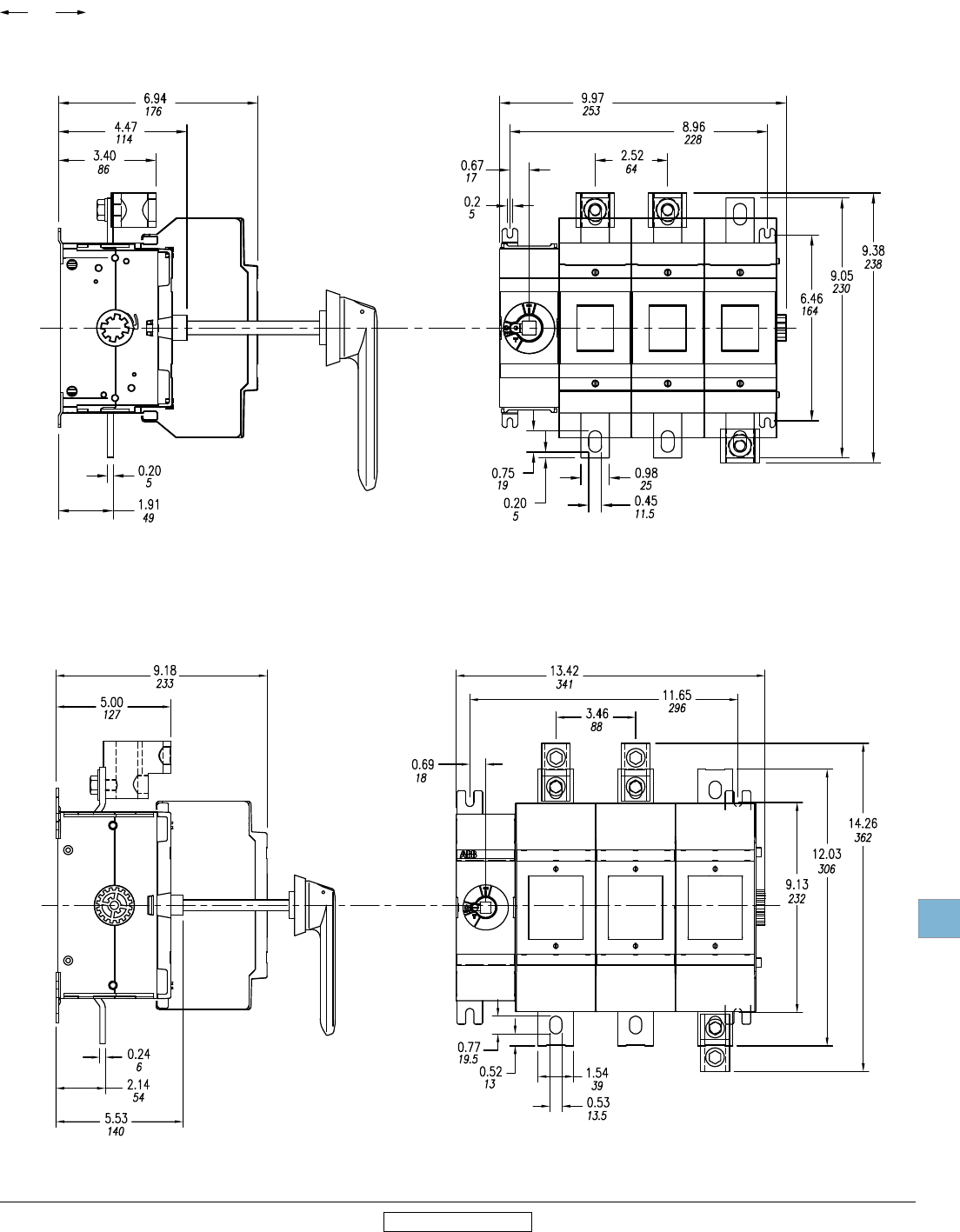
Disconnect
switches
Dimensions
Low Voltage Products & Systems 19.77
ABB Inc. • 888-385-1221 • www.abb.us/lowvoltage 1SXU000023C0202 Rev. A
00.00
00.00
Inches
[Millimeters]
19
Revised January 2014 Revised January 2014
Approximate dimensions
OS400J03 — OS600J03
OS400J03
OS600J03
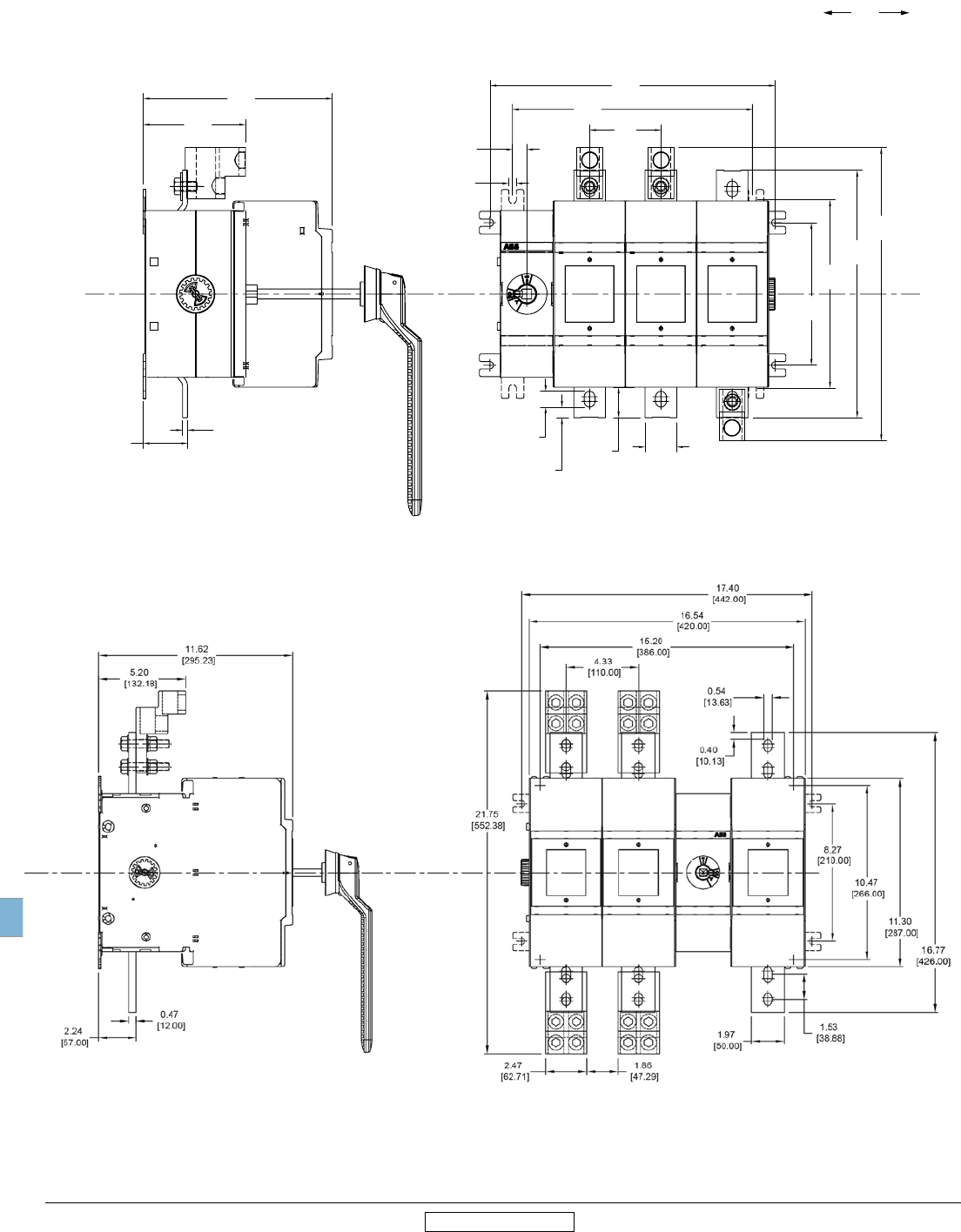
Disconnect
switches
Dimensions
19.78 Low Voltage Products & Systems
1SXU000023C0202 Rev. A ABB Inc. • 888-385-1221 • www.abb.us/lowvoltage
00.00
00.00
Inches
[Millimeters]
19
Revised January 2014 Revised January 2014
Approximate dimensions
OS800L03 — OS1200L03
OS800L03
OS1200L03
11.65
[296]
13.86
[352]
12.03
[306]
9.13
[232]
14.26
[362]
0.77
[19]
3.46
[88]
6.93
[176]
1.54
[39]
1.49
[38]
2.14
[54]
0.24
[6]
4.97
[126]
0.52
[13]
0.35
[9]
0.69
[17]
9.18
[233]
OS800
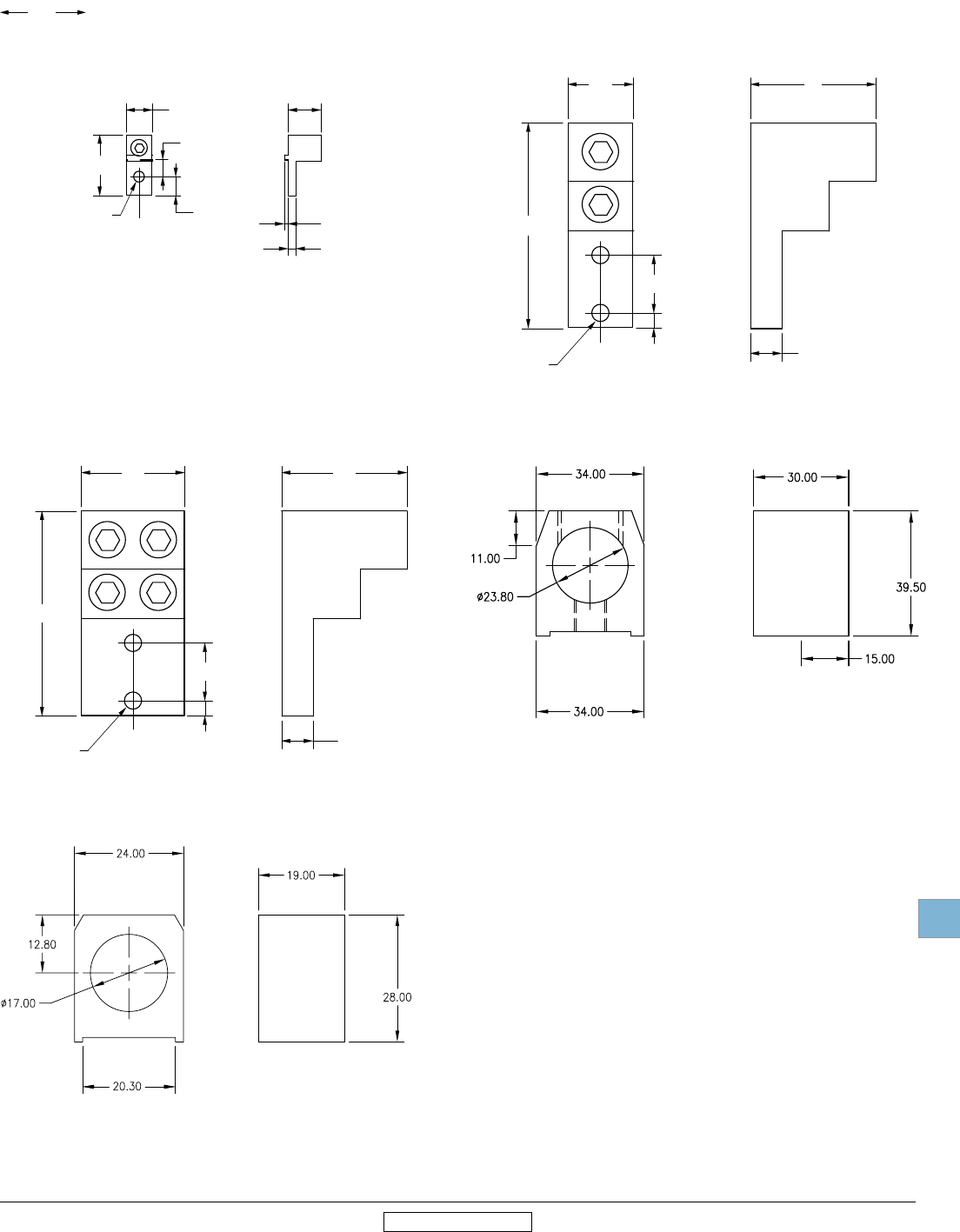
Disconnect
switches
Dimensions
Low Voltage Products & Systems 19.79
ABB Inc. • 888-385-1221 • www.abb.us/lowvoltage 1SXU000023C0202 Rev. A
00.00
00.00
Inches
[Millimeters]
19
Revised January 2014 Revised January 2014
0.63
16
0.45
11.5
0.41
10.5
1.46
37
C.L.
0.18
4.5
0.10
2.5
0.79
20
0.26
6.5
OZXA-24
Approximate dimensions
for Terminal lugs
OZXA-24
1.57
40
4.92
125
0.37
9.5
1.38
35
C.L. 0.75
19
3.00
76
0.41
10.3
OZXA-30
0.75
19
3.00
76
4.92
125
2.47
63
0.37
9.5
1.38
35
C.L.
0.41
10.3
OZXA-28
C.L.
OZXA-200
OZXA-400
OZXA-30
OZXA-28 & OZXA-28/2
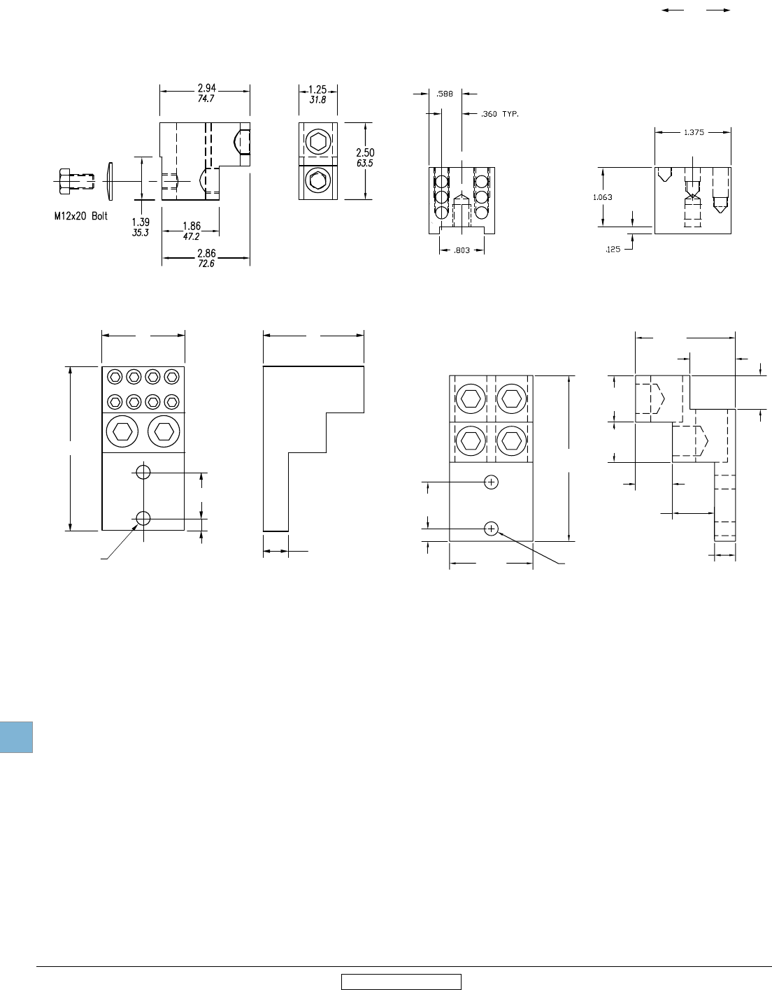
Disconnect
switches
Dimensions
19.80 Low Voltage Products & Systems
1SXU000023C0202 Rev. A ABB Inc. • 888-385-1221 • www.abb.us/lowvoltage
00.00
00.00
Inches
[Millimeters]
19
Revised January 2014 Revised January 2014
Approximate dimensions
for Terminal lugs
OZXA-800
OZXA-32
OZXA-406
OZXA-32
0.75
19
3.00
76
4.92
125
2.47
63
0.37
9.5
1.38
35
C.L.
0.41
10.3
C.L.
OZXA-1200
2.47
[62.74]
4.91
[124.71]
0.37
[9.40]
1.38
[35.05]
Ø0.41
[Ø10.41]
1.38
[35.05]
1.19
[30.23]
1.00
[25.40]
1.35
[34.29]
1.09
[27.69]
1.25
[31.75]
0.62
[15.75]
2.96
[75.18]
OZXA-1200
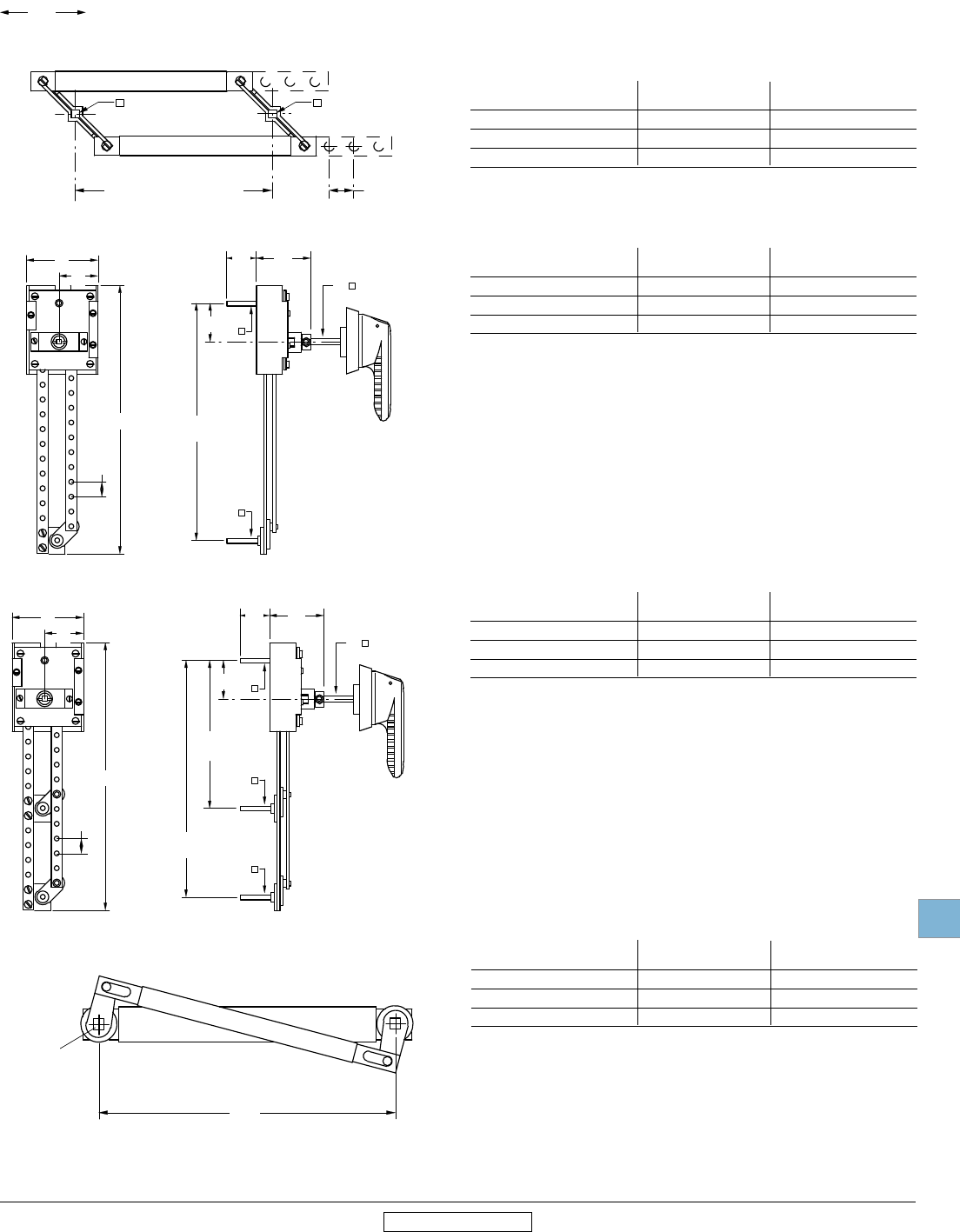
Disconnect
switches
Dimensions
Low Voltage Products & Systems 19.81
ABB Inc. • 888-385-1221 • www.abb.us/lowvoltage 1SXU000023C0202 Rev. A
00.00
00.00
Inches
[Millimeters]
19
Revised January 2014 Revised January 2014
2.83
72
10.71
272
0.59
15
1.54
39
2.17
55
1.18
30
1.54
39
3.54...9.45
90...240
15mm STEPS
0.24
6
0.24
6
0.24
6
OTZW6
0.59
15
+
1.18
30
0.59
15
(0...13) STEPS
0.24
6
0.24
6
OTZW8
2.83
72
10.71
272
0.59
15
1.54
39
2.17
55
1.18
30
1.54
39
3.54...8.27
90...210
15mm STEPS
0.24
6
0.24
6
0.24
6
0.24
6
4.72...9.45
120...240
15mm STEPS
OTZW17
3.94
100
0.24
6
Approximate dimensions
for 16A – 100A conversion mechanisms
6 or 8 pole — OTZW8
Double throw switch — OTZW6, OTZW6X
Bypass switch — OTZW17, OTZW17X
For installation of 6 or 8 pole, transfer and bypass mechanisms, the following
minimum and maximum mounting dimensions are given below.
1 Deeper enclosures will require a longer shaft. Please select a 6mm shaft from page 19.5.
OTZW8 Minimum Maximum
in combination with: inches/mm inches/mm
OT16F3, OT25F3, OT40F3 3.07/78 N/A
OT63F3, OT80F3 3.74/95 N/A
OT30F3, OT60F3, OT100F3 3.82/97 N/A
OESA-ZW1, OESA-ZW1X Minimum Maximum1
in combination with: inches/mm inches/mm
OT16F3, OT25F3, OT40F3 4.61/117 6.57/167
OT63F3, OT80F3 5.31/135 7.28/185
OT30F3, OT60F3, OT100F3 4.84/123 6.81/173
OTZW17, OTZW17X Minimum Maximum1
in combination with: inches/mm inches/mm
OT16F3, OT25F3, OT40F3 4.61/117 6.57/167
OT63F3, OT80F3 5.31/135 7.28/185
OT30F3, OT60F3, OT100F3 4.84/123 6.81/173
Mechanical interlock — OETL-ZW24 OETL-ZW24 Minimum Maximum1
in combination with: inches/mm inches/mm
OT16F3, OT25F3, OT40F3 3.39 / 86 —
OT63F3, OT80F3 4.09 / 104 —
OT30F3, OT60F3, OT100F3 4.13 / 105 —
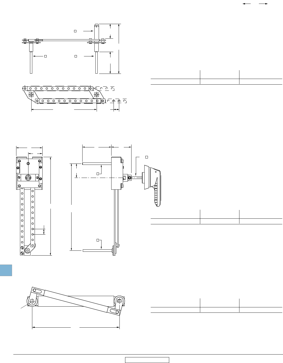
Disconnect
switches
Dimensions
19.82 Low Voltage Products & Systems
1SXU000023C0202 Rev. A ABB Inc. • 888-385-1221 • www.abb.us/lowvoltage
00.00
00.00
Inches
[Millimeters]
19
Revised January 2014 Revised January 2014
7.48
190
0.24
5
1.77...9.49
45...240
(15mm Steps)
0.59
15
0.24
6
0.24
6
0.47
12
4.72
120
7.72
196
1.57
40
OESA-ZW2
2.83
72
10.71
272
0.59
15
2.17
55
4.57
116
1.54
39 0.24
6
0.24
6
0.24
6
1.54
39
3.54...9.45
90...240
15mm STEPS
OESA-ZW1
Approximate dimensions
for 125 – 200A conversion mechanisms
6 or 8 pole — OESA-ZW2
Double throw switch — OESA-ZW1, OESA-ZW1X
For installation of 6 or 8 pole, transfer and bypass mechanisms, the following
minimum and maximum mounting dimensions are given below.
OESA-ZW2 Minimum Maximum
in combination with: inches/mm inches/mm
OT160 - OT200 5.35/136 9.49/241
NOTE: Deeper enclosures will require a longer shaft. Please select a 12mm shaft from page
19.7 and an OETL-ZX95 shaft extension coupler from page 19.10.
OTZW10 Minimum Maximum
in combination with: inches/mm inches/mm
OT160 - OT200 4.13 / 105 —
NOTE: Deeper enclosures will require a longer shaft. Please select a 6mm shaft from page 19.7
Mechanical interlock — OTZW10
OESA-ZW1, OESA-ZW1X Minimum Maximum
in combination with: inches/mm inches/mm
OT160 - OT200 4.61/117 6.57/167
NOTE: Deeper enclosures will require a longer shaft. Please select a 6mm shaft from page 19.7
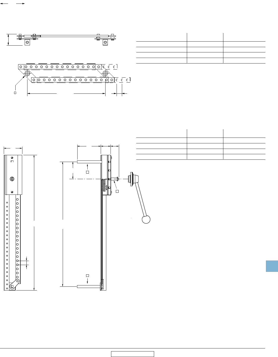
Disconnect
switches
Dimensions
Low Voltage Products & Systems 19.83
ABB Inc. • 888-385-1221 • www.abb.us/lowvoltage 1SXU000023C0202 Rev. A
00.00
00.00
Inches
[Millimeters]
19
Revised January 2014 Revised January 2014
2.36...17.32
60...240
20mm Steps
0.79
20
0.47
12
1.46
37
OETL-ZW9
4.53
115
1.89
48
1.57
40
3.31
84
0.47
12
3.54
90
0.79
20
8.27...24.02
210...610
20mm steps
0.47
12
0.47
12
26.06
662
OETL-ZW12
Approximate dimensions
for 400A – 1200A conversion mechanisms
6 or 8 pole — OETL-ZW9
Double throw — OETL-ZW12
1 Deeper enclosures will require a longer shaft. Please select a 12mm shaft from page 19.7 and an OETL-ZX95 shaft extension coupler from pg. 18.10.
For installation of 6 or 8 pole, transfer and bypass mechanisms, the following
minimum and maximum mounting dimensions are given below.
OETL-ZW9 Minimum Maximum
in combination with: inches/mm inches/mm
OT400 7.52/191 N/A
OT600 7.52/191 N/A
OETL-NF800A 7.52/191 N/A
OETL-NF1200 7.52/191 N/A
NOTE: Handle not included
OETL-ZW12 Minimum Maximum1
in combination with: inches/mm inches/mm
OT400 8.19/208 11.73/298
OT600 8.19/208 11.73/298
OETL-NF800A 8.19/208 11.73/298
OETL-NF1200 8.19/208 11.73/298
NOTE: Includes YASDA-21 handle
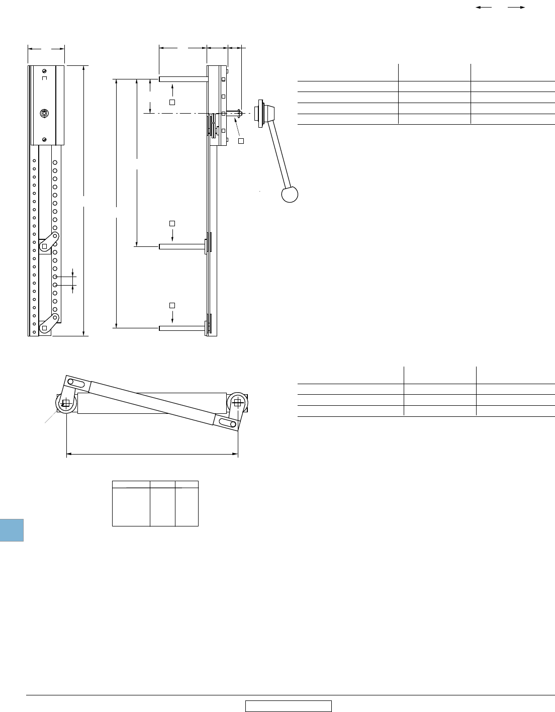
Disconnect
switches
Dimensions
19.84 Low Voltage Products & Systems
1SXU000023C0202 Rev. A ABB Inc. • 888-385-1221 • www.abb.us/lowvoltage
00.00
00.00
Inches
[Millimeters]
19
Revised January 2014 Revised January 2014
4.53
115
2.07
52.5
1.32
33.5
3.31
84
8.27...22.44
210...570
0.47
12
9.84...24.02
250...610
0.47
12
0.47
12
0.47
12
OETL-ZW13
3.54
90
26.06
662
0.79
20
Dimensions in Inches
& mm
OETL-ZW3 11.81 0.47
300.0 12.0
OETL-ZW14 9.84 0.47
250.0 12.0
OETL-ZW15 19.69 0.47
500.0 12.0
BA
OETL-ZW3, 14, 15
A
B
Bypass switch — OETL-ZW13
Approximate dimensions
for 400A – 3150A conversion mechanisms
1 Deeper enclosures will require a longer shaft. Please select a 12mm shaft from page 19.7 and an OETL-ZX95 shaft extension coupler from page 19.10.
For installation of 6 or 8 pole, transfer and bypass mechanisms, the following
minimum and maximum mounting dimensions are given below.
OETL-ZW12 Minimum Maximum1
in combination with: inches/mm inches/mm
OT400 8.19/208 11.73/298
OT600 8.19/208 11.73/298
OETL-NF800A 8.19/208 11.73/298
OETL-NF1200 8.19/208 11.73/298
NOTE: Includes YASDA-21 handle
OETL-ZW3, 14 & 15 Minimum Maximum1
in combination with: inches/mm inches/mm
OT400 & OT600 6.50/165 —
OETL-NF800 – OETL-NF1200 6.30/160 —
OETL-NF1600 – OETL-NF3150 12.00/305 —
NOTE: Handle(s) not included.
NOTE: OETL-ZW15 is the only mechnical interlock
OETL-NF1200 – OETL-NF3150 can use.
Mechanical interlock — OETL-ZW3, OETL-ZW14, OETL-ZW15
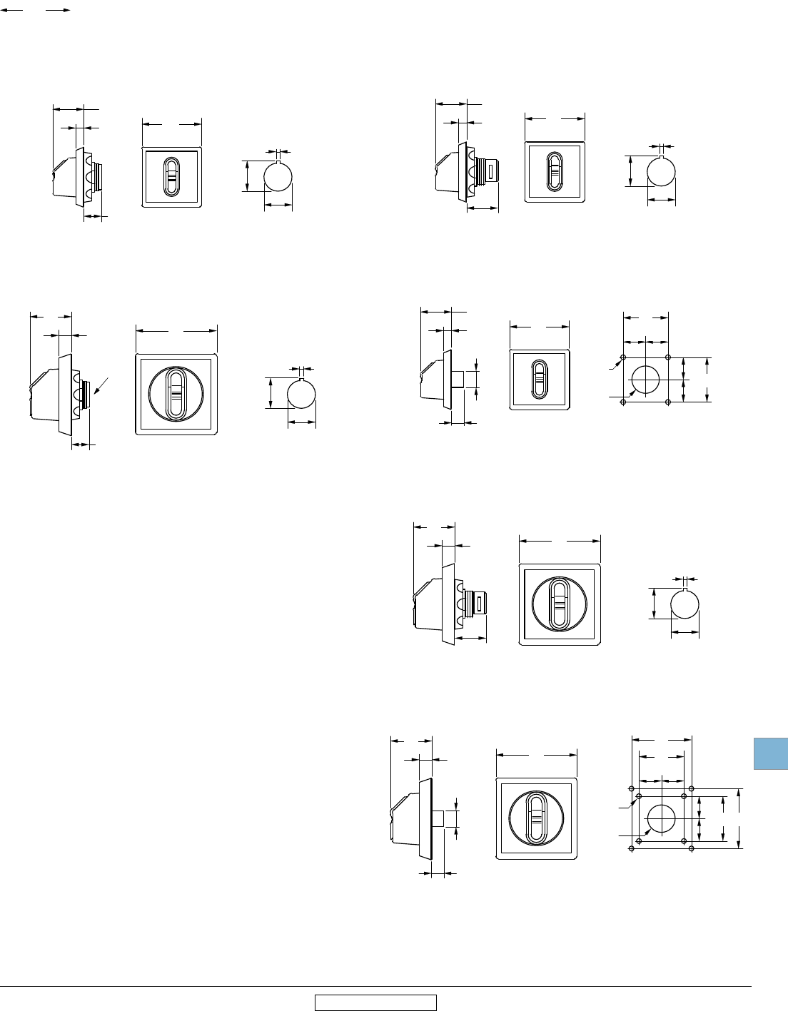
Disconnect
switches
Dimensions
Low Voltage Products & Systems 19.85
ABB Inc. • 888-385-1221 • www.abb.us/lowvoltage 1SXU000023C0202 Rev. A
00.00
00.00
Inches
[Millimeters]
19
Revised January 2014 Revised January 2014
0.125
3.2
0.88
22.5
0.96
24.5
MOUNTING HOLE
DETAIL
1.89
48
0.98
25
0.26
6.5
0.55
14
OH_1A,3A
0.125
3.2
0.88
22.5
0.96
24.5
MOUNTING HOLE
DETAIL
2.56
65
1.30
33
0.39
10
0.55
14
OH_2A_
B
0.125
3.2
0.88
22.5
0.96
24.5
MOUNTING HOLE
DETAIL
1.89
48
0.98
25
0.26
6.5
0.98
25
OH_1P, 3P
1.42
36
1.42
36
0.71
18
0.71
18
0.71
18
0.71
18
1.89
48
0.98
25
0.26
6.5
0.16
4
D
0.88
22
D
0.39
10
0.53
13.5
MOUNTING HOLE
DETAIL
OH_1R, 3R
0.125
3.2
0.88
22.5
0.96
24.5
MOUNTING HOLE
DETAIL
2.56
65
1.30
33
0.39
10
0.98
25
OH_2P_
1.42
36
1.89
48
MOUNTING HOLE
DETAIL
1.42
36
1.89
48
0.71
18
0.71
18
0.71
18
0.71
18
2.56
65
1.30
33
0.39
10
0.16
4
D
0.88
22
D
0.39
10
0.53
13.5
OH_2R_
Approximate dimensions
for Handles
Selector handles for base and DIN rail mounted switches Selector handles for door mounted switches
OH_S1AH1 & OH_S3AH1
OH_S2A_
OH_S1P_ & OH_S3P_
OH_S2P_
OH_S2R_
OH_S1R_ & OH_S3R_
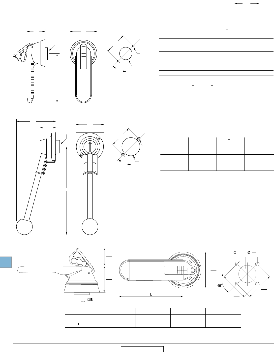
Disconnect
switches
Dimensions
19.86 Low Voltage Products & Systems
1SXU000023C0202 Rev. A ABB Inc. • 888-385-1221 • www.abb.us/lowvoltage
Ø
1.46
37
2.01
51
2.72
69
1.22
31
.20
5
2.09
53
2.09
53
Handle type OHM45L5 OHM65L5 OHM65L6 OHM125L12 OHM175L12 OHM275L12
L 1.8/45 2.6/65 2.6/65 4.9/125 6.9/175 10.8/275
B .2/5 .2/5 .2/6 .5/12 .5/12 .5/12
Handle type OHM65L6 OHM125L12 OHM175L12 OHM275L12
L 2.6/65 4.9/125 6.9/175 10.8/225
B .24/6 .47/12 .47/12 .47/12
00.00
00.00
Inches
[Millimeters]
19
Revised January 2014 Revised January 2014
METAL HANDLE
L
1.57
40
3.94
100
B
2.20
56
45°
1.77
45
D
0.28
7
D
MOUNTING HOLE
DETAIL
2.76
70.0
2.66
67.5
L
1.77
45
B2.09
53
45°
MOUNTING HOLE
DETAIL
1.22
31
D
0.20
5
D
Approximate dimensions
for Handles
Pistol handles
B
A L Shaft size NEMA Type
catalog number inches/mm inches/mm
YASDA-7 8.66/220 0.47/12 1, 3R, 4, 4X, 12
YASDA-8 8.66/220 0.47/12 1, 3R, 4, 4X, 12
YASDA-21 8.66/220 0.47/12 1, 3R, 4, 4X, 12
YASDA-6 12.60/320 0.47/12 1, 3R, 4, 4X, 12
B
A L Shaft size NEMA / UL Type
Catalog number Inches/ mm Inches/ mm
OH_45J6 1.8/45 0.24/6 1, 3R, 12
OH_65J6 2.6/65 0.24/6 1, 3R, 12
OH_80J6 3.1/80 0.24/6 1, 3R, 12
OH_125J12 4.9/125 0.47/12 1, 3R, 12
OH_145J12 5.7/145 0.47/12 1, 3R, 12
OH_175J12 6.9/175 0.47/12 1, 3R, 12
OH_80L6 3.1/80 0.24/6 1, 3R, 4, 4X, 12
OH_145L12 5.7/145 0.47/12 1, 3R, 4, 4X, 12
OH_175L12 6.9/175 0.47/12 1, 3R, 4, 4X, 12
__ = Handle color, B (Black) or Y (Red/Yellow)
0.24
6
0.24
6

Disconnect
switches
Dimensions
Low Voltage Products & Systems 19.87
ABB Inc. • 888-385-1221 • www.abb.us/lowvoltage 1SXU000023C0202 Rev. A
00.00
00.00
Inches
[Millimeters]
19
Revised January 2014 Revised January 2014
Approximate dimensions
for Handles
OH_274_12
OH-274J12
Ø69,4
274
54
71
OH_330_12
329,00
70,7
53,9
A Catalog
number L inches/mm B shaft size
inches/mm NEMA Type
OHB274-330 10.75/274 0.47/12 1, 3R, 4, 4X, 12
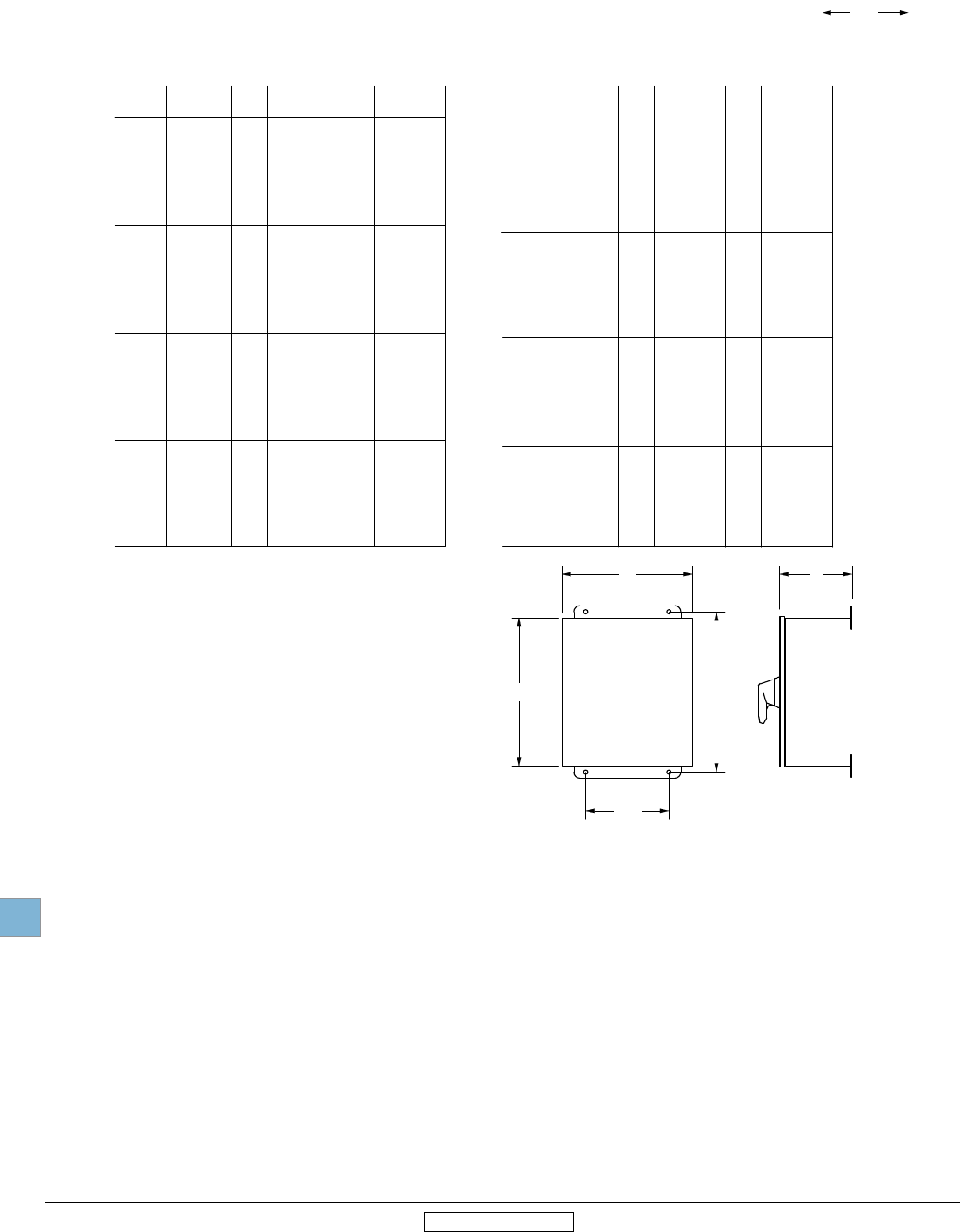
Disconnect
switches
Dimensions
19.88 Low Voltage Products & Systems
1SXU000023C0202 Rev. A ABB Inc. • 888-385-1221 • www.abb.us/lowvoltage
Approximate dimensions
2, 3 & 4 Pole 2
30A – 1200A Fusible
1
3R
4
4X SS
4X Plastic
H
Enclosure
type
OS30_
12
W
width
D
depth
MH
mtg.
height
MW
mtg.
width Weight
1
3R
4
4X SS
4X Plastic
OS60_
12
1
3R
4
4X SS
4X Plastic
12
1
3R
4
4X SS
4X Plastic
OS200_
12
10.0 8.0 6.0 7.0
10.75
10.75
10.75
10.75
7.0
6.0
6.0
6.0
6.0
12
14.0 12.0 8.0 7.0
10.75
10.75
10.75
10.75
7.0
6.0
6.0
6.0
6.0
13
14.0 12.0 8.0 11.0
14.75
14.75
14.75
14.75
14.75
9.0
10.0
10.0
10.0
10.0
10.0
22
24.0 16.0 8.0 25.5
25.5
25.5
25.5
1
25.5
14.5
14.5
14.5
14.5
1
14.5
75
10.0 8.0 6.0
10.0 8.0 6.0
10.0 8.0 6.0
10.0 8.0 8.0
10.0 8.0 6.0
14.0 12.0 8.0
14.0 12.0 8.0
14.0 12.0 8.0
10.0 8.0 8.0
14.0 12.0 8.0
14.0 12.0 8.0
14.0 12.0 8.0
14.0 12.0 8.0
14.0 12.0 8.0
14.0 12.0 8.0
24.0 16.0 8.0
24.0 16.0 8.0
24.0 16.0 8.0
1 1 1
24.0 16.0 8.0
75
75
75
1
75
12
12
12
8.0
12
13
13
13
9.0
13
22
22
22
16
22
10.75 6.0
10.75 6.0
D
H MH
W
MW
Frame
size
OS100_
Fusible
1
3R
4
4X SS
4X Plastic
12
1
3R
4
4X SS
4X Plastic
OS400_
12
44.0 22.0 11.0 37.5
37.5
37.5
37.5
1
37.5
22.5
22.5
22.5
22.5
1
22.5
150
42.0 36.0 12.0 43.5
43.5
43.5
43.5
1
43.5
34.5
34.5
34.5
34.5
1
34.5
150
44.0 22.0 11.0
44.0 22.0 11.0
44.0 22.0 11.0
1 1 1
44.0 22.0 11.0
42.0 36.0 12.0
42.0 36.0 12.0
42.0 36.0 12.0
1 1 1
42.0 36.0 12.0
150
150
150
1
150
150
150
150
1
150
1 Please consult factory, enclosures are sized to suit specic customer needs.
2 Some 4-pole switches require larger enclosures. Please consult factory.
OS600_
Enclosure
type width
D
depth mtg.
height
MW
mtg.
width Weight
Frame
size
HW
height height
1
3R
4
4X SS
4X Plastic
12
48.0 24.0 12.0 49.5
49.5
49.5
49.5
1
49.5
22.5
22.5
22.5
22.5
1
22.5
170
48.0 24.0 12.0
48.0 24.0 12.0
48.0 24.0 12.0
1 1 1
48.0 24.0 12.0
170
170
170
1
170
OS800_
1
3R
4
4X SS
4X Plastic
12
OS1200_
60.0 36.0 12.8 62
62
62
62
1
62
38
38
38
38
1
38
200
60.0 36.0 12.8
60.0 36.0 12.8
60.0 36.0 12.8
1 1 1
60.0 36.0 12.8
200
200
200
1
200
00.00
00.00
Inches
[Millimeters]
19
Revised January 2014 Revised January 2014
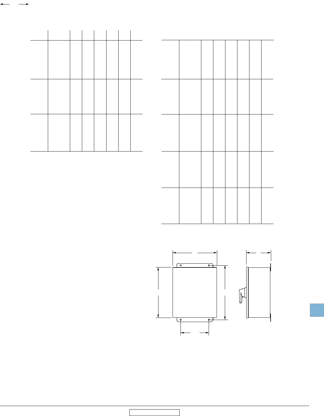
Disconnect
switches
Dimensions
Low Voltage Products & Systems 19.89
ABB Inc. • 888-385-1221 • www.abb.us/lowvoltage 1SXU000023C0202 Rev. A
Approximate dimensions
2, 3 & 4 Pole 3
16A – 3150A, Non-fusible
1
3R
4
4X SS
4X Plastic
H
Enclosure
type
OT16_
OT25_
OT40_
12
W
width
D
depth
MH
mtg.
height
MW
mtg.
width Weight
1
3R
4
4X SS
4X Plastic
OT63_
OT80_
12
1
3R
4
4X SS
4X Plastic
12
6.0 6.0 4.0 4.0
7.75
6.75
7.75
7.75
4.0
3.0
4.0
3.0
3.0
4.0
8.0 6.0 4.0 7.0
8.75
8.75
8.75
8.75
5.0
4.0
4.0
4.0
4.0
6.0
10.0 8.0 5.0 7.0
10.75
10.75
10.75
10.75
10.75
7.0
6.0
6.0
6.0
6.0
6.0
9.0
6.0 6.0 4.0
6.0 6.0 4.0
6.0 6.0 4.0
6.0 6.0 5.9
6.0 6.0 4.0
8.0 6.0 4.0
8.0 6.0 4.0
8.0 6.0 4.0
8.0 6.0 5.9
8.0 6.0 4.0
10.0 8.0 5.0
10.0 8.0 5.0
10.0 8.0 5.0
10.0 8.0 5.9
10.0 8.0 5.0
4.0
4.0
4.0
4.0
4.0
6.0
6.0
6.0
6.0
6.0
9.0
9.0
9.0
9.0
9.0
6.75 4.0
8.75 4.0
600V, 16A - 3150A
2, 3 and 4-pole switches
Enclosure dimensions
D
H MH
W
MW
Frame
size
OT30
OT60
OT100
Non-Fusible
1
3R
4
4X SS
4X Plastic
12
1
3R
4
4X SS
4X Plastic
OT200
12
1
3R
4
4X SS
4X Plastic
OT800 -
OT1200
12
1
3R
4
4X SS
4X Plastic
12
24.0 16.0 8.0 25.5
25.5
25.5
25.5
25.5
25.5
14.5
14.5
14.5
14.5
14.5
14.5
50
44.0 22.0 11.0 37.5
37.5
1
37.5
1
37.5
22.5
22.5
1
22.5
1
22.5
120
60.0 36.0 12.0 61.5
61.5
61.5
61.5
1
61.5
34.5
34.5
34.5
34.5
1
34.5
200
90.0
1
1
1
36.0
1
1
1
24.0
1
1
1
2
1
1
1
2
1
1
1
600
1
1
1
90.0 36.0 24.0 2 2 600
90.0 36.0 24.0 2 2 600
24.0 16.0 8.0
24.0 16.0 8.0
24.0 16.0 8.0
25.0 17.0 10.0
24.0 16.0 8.0
60.0 36.0 12.0
60.0 36.0 12.0
60.0 36.0 12.0
1 1 1
60.0 36.0 12.0
44.0 22.0 11.0
1 1 1
36.0 24.0 12.0
1 1 1
36.0 24.0 8.0
200
200
200
1
200
120
1
130
1
120
50
50
50
40
50
1 Please consult factory, enclosures are sized to suit specic customer needs.
2 Enclosure is free standing.
3 Some 4-pole switches require larger enclosures. Please consult factory.
OT400
OETL-NF1600
OETL-NF2000
OETL-NF3150
Enclosure
type width
D
depth mtg.
height
MW
mtg.
width Weight
Frame
size
HW
height height
1
3R
4
4X SS
4X Plastic
12
44.0 22.0 11.0 37.5
37.5
37.5
37.5
41.2
37.5
22.5
22.5
22.5
22.5
30.2
22.5
120
36.0 24.0 12.0
36.0 24.0 12.0
36.0 24.0 12.0
40.0 32.0 13.0
36.0 24.0 12.0
120
120
120
120
120
OT600
00.00
00.00
Inches
[Millimeters]
19
Revised January 2014 Revised January 2014
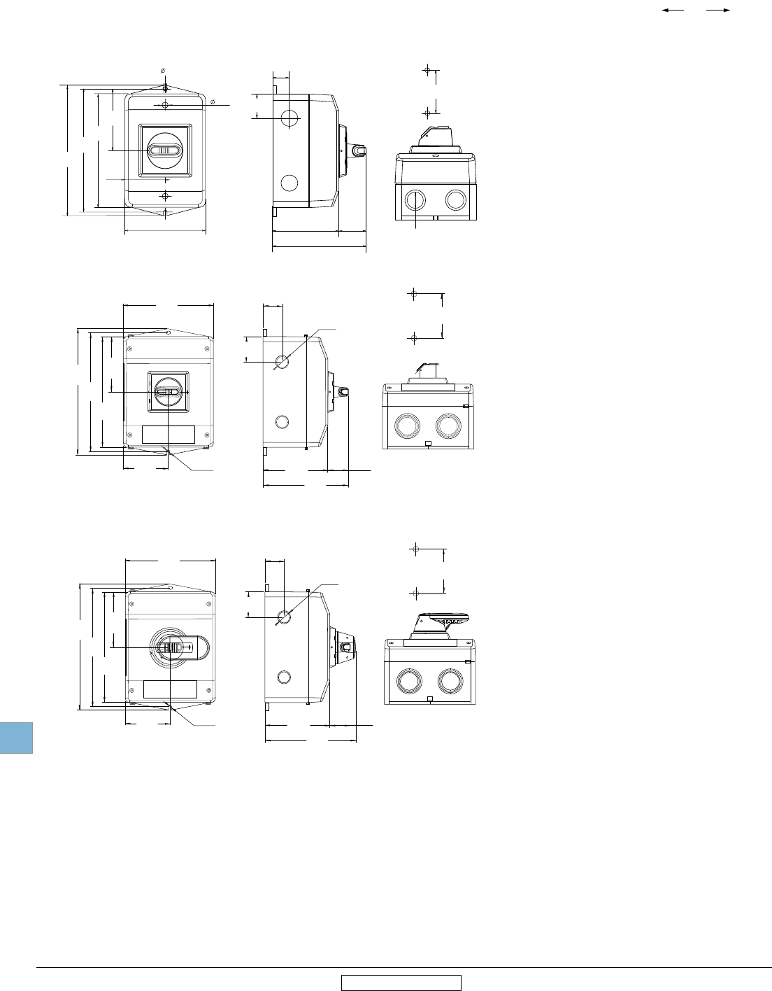
Disconnect
switches
Dimensions
19.90 Low Voltage Products & Systems
1SXU000023C0202 Rev. A ABB Inc. • 888-385-1221 • www.abb.us/lowvoltage
00.00
00.00
Inches
[Millimeters]
19
Revised January 2014 Revised January 2014
eOT16_, eOT32_ (enclosure size 1)
200
7.87
188
7.40
176
6.93
88
3.46
73
2.87
146
5.75
Ø 4.5
0.18 103.5
4.07 34.5
1.36
138
5.43
40.3
1.59
30.5
1.20
188
7.40
mm
in
EOT32U_ , EOT45U_
20
0.79
140
152
50
76
7,40
4,5
5,98
1,97
161,4
6,35
152
5,98
in
mm
5,51
2,99
0,18
0,29
3,94
34,5
1,36
81
3,19
115,5
4,55
Handle OHB 2AJ
Knock-outs
on top and bottom
30
1,18
1/2 "
3/4 "
0,79
Knock-outs M20
M25
0,09
R2,25
200
7.87
188
7.40
176
6.93
88
3.46
73
2.87
146
5.75
Ø 4.5
0.18 103.5
4.07 45
1.77
148.5
5.84
40.3
1.59
30.5
1.20
3/4 " 1 "
188
7.40
mm
in
3/4 " 1 "
EOT32U_ , EOT45U_
20
0.79
eOT Enclosed switches
Approximate dimensions
eOT16_ - eOT45U
eOT45U_ (enclosure size 2 with selector handle)
eOT45U_ (enclosure size 2 with pistol grip handle)
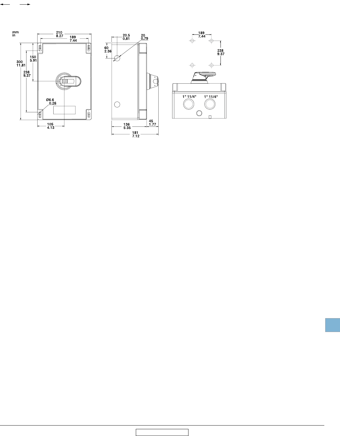
Disconnect
switches
Dimensions
Low Voltage Products & Systems 19.91
ABB Inc. • 888-385-1221 • www.abb.us/lowvoltage 1SXU000023C0202 Rev. A
00.00
00.00
Inches
[Millimeters]
19
Revised January 2014 Revised January 2014
eOT63_ (enclosure size 3 with pistol grip handle)
eOT Enclosed manual motor controllers
Approximate dimensions
eOT63_

Disconnect
switches
Dimensions
19.92 Low Voltage Products & Systems
1SXU000023C0202 Rev. A ABB Inc. • 888-385-1221 • www.abb.us/lowvoltage
00.00
00.00
Inches
[Millimeters]
19
Revised January 2014 Revised January 2014
Notes
