Volume 03—Power Distribution And Control Assemblies
2014-10-17
: Pdf 86658-Attachment 86658-Attachment 786685 Batch10 unilog
Open the PDF directly: View PDF ![]() .
.
Page Count: 552 [warning: Documents this large are best viewed by clicking the View PDF Link!]

Electrical Sector Solutions
Volume 3 Power Distribution and Control Assemblies
Eaton Corporation
Electrical Sector
1111 Superior Ave.
Cleveland, OH 44114
United States
877-ETN-CARE (877-386-2273)
Eaton.com
© 2010 Eaton Corporation
All other trademarks are property
of their respective owners.
All Rights Reserved
Printed in USA
Publication No. CA08100004E / MSC
December 2010
Volume 3:
Power
Distribution
and Control
Assemblies
Volume 3—Power Distribution and Control Assemblies
Tab 1—Medium Voltage Busway . . . . . . . . . . . . . . . . . . . . . V3-T1-1
Tab 2—SPD, Power Conditioning,
PF Capacitors and Harmonic Filters . . . . . . . . . . . V3-T2-1
Tab 3—Motor Control Centers. . . . . . . . . . . . . . . . . . . . . . . . V3-T3-1
Tab 4—Low Voltage Switchgear . . . . . . . . . . . . . . . . . . . . . . V3-T4-1
Tab 5—Medium Voltage Motor Control Assemblies . . . . . . V3-T5-1
Tab 6—Medium Voltage Metal-Enclosed Switches. . . . . . . V3-T6-1
Tab 7—Medium Voltage Switchgear . . . . . . . . . . . . . . . . . . V3-T7-1
Tab 8—Network Protectors . . . . . . . . . . . . . . . . . . . . . . . . . . V3-T8-1
Tab 9—Metering Devices, Protective Relays,
Software and Connectivity . . . . . . . . . . . . . . . . . . V3-T9-1
Tab 10—Power System Studies, Field Services
and Conversion . . . . . . . . . . . . . . . . . . . . . . . . . . . . V3-T10-1
Appendix 1—Eaton Terms & Conditions . . . . . . . . . . . . . . . V3-A1-1
Appendix 2—Catalog Parent Number Index . . . . . . . . . . . . V3-A2-1
Appendix 3—Alphabetical Product Index . . . . . . . . . . . . . . V3-A3-1
3

Copyright
Dimensions, Weights and Ratings
Dimensions, weights and ratings given in this catalog are approximate and should not
be used for construction purposes. Drawings containing exact dimensions are available
upon request. All listed product specifications and ratings are subject to change without
notice. Photographs are representative of production units.
Terms and Conditions
All prices and discounts are subject to change without notice. When price changes
occur, they are published in Eaton’s Price and Availability Digest (PAD). All orders
accepted by Eaton’s Electrical Sector are subject to the general terms and conditions
as set forth in Appendix 1—Eaton Terms & Conditions.
Technical and Descriptive Publications
This catalog contains brief technical data for proper selection of products. Further
information is available in the form of technical information publications and illustrated
brochures. If additional product information is required, contact your local Eaton
Products Distributor, call 1-800-525-2000 or visit our website at www.eaton.com.
Compliance with Nuclear Regulation 10 CFR 21
Eaton products are sold as commercial grade products not intended for application in
facilities or activities licensed by the United States Nuclear Regulatory Commission
for atomic purposes, under 10 CFR 21. Further certification will be required for use of
these products in a safety-related application in any nuclear facility licensed by the
U.S. Nuclear Regulatory Commission.
WARNING
The installation and use of Eaton products should be in accordance with the provisions
of the U.S. National Electrical Code® and/or other local codes or industry standards that
are pertinent to the particular end use. Installation or use not in accordance with these
codes and standards could be hazardous to personnel and/or equipment.
Copyright ©2014 Eaton, All Rights Reserved.
These catalog pages do not purport to cover all details or variations in equipment, nor to provide for
every possible contingency to be met in connection with installation, operation or maintenance.
Should further information be desired or should particular problems arise which are not covered
sufficiently for the purchaser’s purposes, the matter should be referred to the local Eaton Products
Distributor or Sales Office. The contents of this catalog shall not become part of or modify any prior
or existing agreement, commitment or relationship. The sales contract contains the entire
obligation of Eaton’s Electrical Sector. The warranty contained in the contract between the parties
is the sole warranty of Eaton. Any statements contained herein do not create new warranties or
modify the existing warranty.

Volume 3—Power Distribution and Control Assemblies CA08100004E—April 2014 www.eaton.com i
Introduction
Eaton is a global leader in power distribution, power quality,
control and automation, and monitoring products.
At Eaton, we believe a reliable, efficient and safe power system is the foundation of every
successful enterprise. Through innovative technologies, cutting-edge products and our highly
skilled services team, we empower businesses around the world to achieve a powerful advantage.
In addition, Eaton is committed to creating and maintaining powerful customer relationships built
on a foundation of excellence. From the products we manufacture to our dedicated customer
service and support, we know what’s important to you.
Solutions
Eaton takes the complexity out of power systems management with a holistic and strategic
approach, leveraging our industry-leading technology, solutions and services. We focus on
the following three areas in all we do:
●Reliability—maintain the
appropriate level of power
continuity without
disruption or unexpected
downtime
●Efficiency—minimize
energy usage, operating
costs, equipment footprint
and environmental impact
●Safety—identify and
mitigate electrical hazards
to protect what you value
most
Using the Eaton Catalog Library
As we grow, it becomes increasingly difficult to include all products in one or two comprehensive
catalogs. Knowing that each user has their specific needs, we have created a library of catalogs for our
products that when complete, will contain 15 volumes. Since the volumes will continuously be a work
in progress and updated, each volume will stand alone. Refer to our volume directory, MZ08100001E,
for a quick glance of where to look for the products you need. The 15 volumes include:
●Volume 1—Residential
and Light Commercial
(CA08100002E)
●Volume 2—Commercial
Distribution (CA08100003E)
●Volume 3—Power
Distribution and Control
Assemblies (CA08100004E)
●Volume 4—Circuit
Protection (CA08100005E)
●Volume 5—Motor Control
and Protection
(CA08100006E)
●Volume 6—Solid-State
Motor Control
(CA08100007E)
●Volume 7—Logic Control,
Operator Interface and
Connectivity Solutions
(CA08100008E)
●Volume 8—Sensing
Solutions (CA08100010E)
●Volume 9—Original
Equipment Manufacturer
(CA08100011E)
●Volume 10—Enclosed
Control (CA08100012E)
●Volume 11—Vehicle and
Commercial Controls
(CA08100013E)
●Volume 12—Aftermarket,
Renewal Parts and Life
Extension Solutions
(CA08100014E)
●Volume 13—Counters,
Timers and Tachometers
(CA08100015E)—Available
in electronic format only
●Volume 14—Fuses
(CA08100016E)—Available
in electronic format only
●Volume 15—Solar Inverters
and Electrical Balance of
System (CA08100018E)
These volumes are not all-inclusive of every product, but they are meant to be an overview
of our product lines. For our full range of product solutions and additional product information,
consult Eaton.com/electrical and other catalogs and product guides in our literature library.
These references include:
●The Consulting Application
Guide (CA08104001E)
●The Eaton Power Quality
Product Guide (COR01FYA)
If you don’t have the volume that contains the product or information that you are looking for,
not to worry. You can access every volume of the catalog library at Eaton.com/electrical in the
Literature Library.
By installing our Automatic Tab Updater (ATU), you can be sure you always have the most recent
version of each volume and tab.

ii Volume 3—Power Distribution and Control Assemblies CA08100004E—April 2014 www.eaton.com
Introduction
Icons
Green Leaf
Eaton Green Solutions are products, systems or solutions that represent Eaton
benchmarks for environmental performance. The green leaf symbol is our
promise that the solution has been reviewed and documented as offering
exceptional, industry-leading environmental benefits to customers, consumers
and our communities. Though all of Eaton's products and solutions are
designed to meet or exceed applicable government standards related to
protecting the environment, our products with the Green Leaf designation
further provide “exceptional environmental benefit”.
Learn Online
When you see the Learn Online icon, go to Eaton.com/electrical and search for
the product or training page. There you will find 100-level training courses,
podcasts, webcasts or games and puzzles to learn more.
Drawings Online
When you see the Drawings Online icon, go to Eaton.com/electrical and find the
products page. There you will find a tab that includes helpful product drawings
and illustrations.
Contact Us
If you need additional help, you can find contact information
under the Customer Care heading of Eaton.com/electrical.
Volume 3—Power Distribution and Control Assemblies CA08100004E—February 2012 www.eaton.com V3-T1-1
1
1
1
1
1
1
1
1
1
1
1
1
1
1
1
1
1
1
1
1
1
1
1
1
1
1
1
1
1
1
Medium Voltage Busway
Nonsegregated Phase 600V—
Bus Run Section
End View
1.1 Medium Voltage Busway—Nonsegregated Phase Bus
Application Description. . . . . . . . . . . . . . . . . . . . . . . . . . . . . . . . . . . . . V3-T1-2
Features, Benefits and Functions . . . . . . . . . . . . . . . . . . . . . . . . . . . . . V3-T1-2
Standards and Certifications. . . . . . . . . . . . . . . . . . . . . . . . . . . . . . . . . V3-T1-3
Additional Information. . . . . . . . . . . . . . . . . . . . . . . . . . . . . . . . . . . . . . V3-T1-3
Technical Data and Specifications. . . . . . . . . . . . . . . . . . . . . . . . . . . . . V3-T1-3
Learn
Online
V3-T1-2 Volume 3—Power Distribution and Control Assemblies CA08100004E—February 2012 www.eaton.com
1
1
1
1
1
1
1
1
1
1
1
1
1
1
1
1
1
1
1
1
1
1
1
1
1
1
1
1
1
1
1.1
Medium Voltage Busway
Medium Voltage Busway—Nonsegregated Phase Bus
Nonsegregated Phase 600V, 10 kV BIL–5 kV, 60 kV BIL–15 kV,
95 kV BIL–38 kV, 170 kV BIL
Typical 5/15 kV Bus Run Section End View
Contents
Description Page
Standards and Certifications . . . . . . . . . . . . . . . . . V3-T1-3
Additional Information . . . . . . . . . . . . . . . . . . . . . . V3-T1-3
Technical Data and Specifications . . . . . . . . . . . . . V3-T1-3
Application Description
Eaton’s nonsegregated phase
bus runs are designed for use
on circuits whose importance
requires greater reliability
than power cables provide.
Typical of such applications
are the connections from
transformers to switchgear
assemblies in unit
substations, connections
from switchgear assemblies
to rotating apparatus, and
tie connections between
switchgear assemblies.
Nonsegregated phase
bus is an assembly of bus
conductors with associated
connections, joints and
insulating supports confined
within a metal enclosure
without interphase barriers.
The conductors are adequately
separated and insulated from
each other and ground by
insulating bus supports. Each
conductor for 2400V service
and above is insulated with a
fluidized bed epoxy coating
throughout that reduces the
possibility of corona and
electrical tracking.
Features, Benefits and Functions
Ease of Installation
Because of its compact
dimensions, relative light
weight and user-friendly
design, nonsegregated phase
bus is easily installed. The
inherent rigidity of the design
permits hanging rods to be
spaced approximately every
4 ft (1.2m) for indoor bus
runs, and allows supporting
frames to be spaced
approximately every 8 ft
(2.4m) for outdoor runs.
Standard length of bus
run sections is 100 inches
(2540 mm) or less.
Short-Circuit Force
Withstand Ability
Nonsegregated phase
bus runs in 600V, 5 kV
and 15 kV are designed
to withstand three-phase
and phase-to-ground short-
circuit current of 78 kA rms
asymmetrical (132 kA peak)
for 10 cycles and 50 kA rms
symmetrical for 2 seconds.
Momentary 4-cycle withstand
ratings up to 158 kA peak
(98.8 kA rms asymmetrical)
are also available. For 27 kV
nonsegregated phase bus
runs, short-circuit withstand
ratings of 64 kA rms
asymmetrical (108 kA peak)
for 10 cycles and 40 kA rms
symmetrical for 2 seconds
are standard.
Construction
E
nclosures are fabricated from
11-gauge
aluminum, and are
welded for maximum
rigidity.
11-gauge steel and stainless
steel are options. Removable
covers are secured with bolts
for ease of access when
making joints and subsequent
and periodic inspection.
Enclosures are painted with
a baked-on polyester powder
coat paint system resulting
in a very durable finish with
uniform thickness and
gloss. This cosmetically
pleasing finish minimizes
the risk of problems in harsh
environments. The standard
color is ANSI-61 light gray,
and special paint colors are
available upon request.
Stainless steel hardware
option is available.
Expansion joints are supplied
in all straight bus runs at
approximately 50 ft (15.2m)
intervals to allow for the
expected expansion when the
conductors are energized and
are carrying rated current.
A variety of terminations is
available to accommodate
most termination
requirements. Bus runs can
be terminated with flexible
shunts, potheads, porcelain
bushings, or conductor stub
ends for connection to riser
bars in switchgear assemblies.
Conductors
All conductors are 100%
conductivity copper bars.
Bus joints are made by solidly
bolting the bus bars together
with splice plates on each
side. All joint surfaces are
silver-plated to ensure
maximum conductivity
through the joint. Tin-plating
is also available. After bolting,
each standard joint is covered
by a preformed, flame-
retardant insulating boot,
providing full insulation for
bus conductors. These
boots are easily removable
for inspection of the joints at
any future time.
Temperature Rise
The bus will be capable
of carrying rated current
continuously without
exceeding a conductor
temperature rise of 65°C
above an outside ambient
temperature of 40°C, as
required by ANSI Standard
C37.23.

Volume 3—Power Distribution and Control Assemblies CA08100004E—February 2012 www.eaton.com V3-T1-3
1
1
1
1
1
1
1
1
1
1
1
1
1
1
1
1
1
1
1
1
1
1
1
1
1
1
1
1
1
1
1.1
Medium Voltage Busway
Medium Voltage Busway—Nonsegregated Phase Bus
Standards and
Certifications
The metal-enclosed bus
runs are designed for 600V,
5 kV, 15 kV, 27 kV and 38 kV
service in accordance with
ANSI C37.23. 600V, 5 kV and
15 kV bus is available with
continuous current ratings of
1200, 2000, 3000, 3200 or
4000A. 27 kV and 38 kV bus
is available in 1200 and
2000A continuous ratings.
Tests
The design of nonsegregated
bus runs has been tested per
ANSI C37.23. Certification of
momentary current testing,
impulse testing and heat rise
are available upon request.
Seismic Application
Bus run assemblies are
designed to meet Uniform
Building Code (UBC) and
California Code Title 24 for
Seismic Zones 4, 3, 2A, 2B,
1 and 0. Complete guidelines
for proper supports are
provided on each seismic
specified order.
Additional Information
●Te ch n i c a l D a t a :
TD01702001E
●Brochure: BR01702001E
●Final Fit Program:
SA01702001E
●Consulting Application
Guide, CA08104001E
Technical Data and Specifications
Available Nonsegregated Bus Ratings per ANSI/IEEE Standard C37.23-1987
Notes
1This is a value calculated from 2 second short-circuit current withstand rating based on relationship l2t = constant.
2For 600V application, 4-cycle momentary current withstand rating up to 158 kA peak (98.8 kA rms asymmetrical) is also available.
Rated
Maximum
Voltage
kV rms
Rated
Power
Frequency
Hz
Power
Frequency
Withstand 1 Min.
Dry kV rms
Impulse
Withstand
(1.2 x 50 microsec)
kV Peak
Rated
Continuous
Current
Amperes
Rated Short-Time
Short-Circuit
Withstand Current
(kA rms Symmetrical)
Rated Momentary
Short-Circuit
Withstand Current
10 Cycle
2 Sec. 1 Sec. 1kA Peak
kA rms
Asym.
0.635 60 2.2 10 1200
2000
3000
4000
5000
49 69 132 278 2
0.635 60 2.2 10 1200
2000
3000
3200
63 89 170 100.8
4.76 60 19 60 1200
2000
3000
4000
5000
49 — 132 78
4.76 60 19 60 1200
2000
3000
3200
63 — 170 100.8
8.25 60 36 95 1200
2000
3000
4000
5000
41 — 111 66
8.25 60 36 95 1200
2000
3000
3200
63 — 170 100.8
15 60 36 95 1200
2000
3000
4000
5000
48 — 130 77
15 60 36 95 1200
2000
3000
3200
63 — 170 100.8
27 60 60 125 1200
2000
40 — 108 64
38 60 80 170 1200
2000
3000
3200
4000
5000
40 — 104 64
V3-T1-4 Volume 3—Power Distribution and Control Assemblies CA08100004E—February 2012 www.eaton.com
1
1
1
1
1
1
1
1
1
1
1
1
1
1
1
1
1
1
1
1
1
1
1
1
1
1
1
1
1
1
1.1
Medium Voltage Busway
Medium Voltage Busway—Nonsegregated Phase Bus
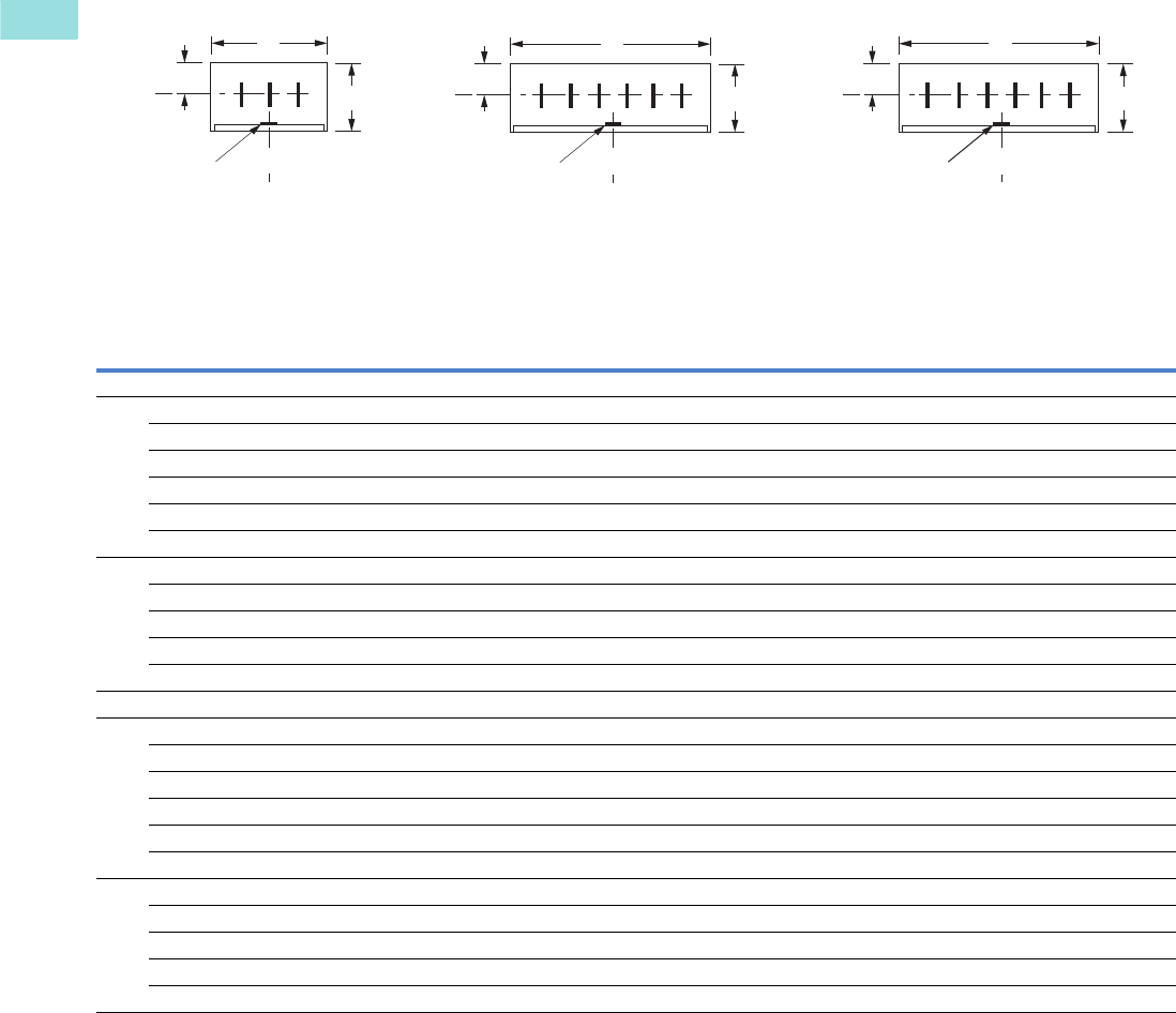
Medium Voltage Nonsegregated Phase Bus—Standard Configurations
Bus Duct Rated 49 kA rms Symmetrical 2 Seconds
Notes
1All phase conductors above 635V are fully insulated with epoxy insulation for the rated maximum voltage. Epoxy insulation is available at 600V as an option.
2Optional poly/porcelain or poly/epoxy bracing supports are available. Consult factory.
3Add 3 lbs to the weights shown when using poly/porcelain or poly/epoxy support bracing.
For dimensions in mm, multiply inches by 25.4.
Wire
Voltage
(kV) 1
Ampere
Rating
Layout
Number Width Height
Conductor
Centerline
Conductor
Size
Phase-Phase
Conductor
Spacing
Bracing
Supports 2
Optional
Ground
Bus
Average
Weight
Per Foot
Lbs (kg) 3
Standards
Listing
Aluminum Enclosures
3 0.635/5/15 1200 1 20.00 17.38 8.13 (1) 0.5 x 3 5.38 Glass polyester 0.25 x 2 38 (17) CSA
0.635/5/15 2000 1 20.00 17.38 8.13 (1) 0.375 x 6 5.38 Glass polyester 0.25 x 2 47 (21) CSA
0.635/5/15 3000 1 20.00 17.38 8.13 (1) 0.5 x 8 5.38 Glass polyester 0.25 x 2 68 (31) CSA
0.635/5/15 3200 1 20.00 17.38 8.13 (1) 0.5 x 8 5.38 Glass polyester 0.25 x 2 68 (31) —
0.635/5/15 4000 2 35.75 17.38 8.13 (2) 0.5 x 6 5.38 Glass polyester 0.25 x 2 101 (46) CSA
0.635/5/15 5000 2 35.75 17.38 8.13 (2) 0.5 x 8 5.38 Glass polyester 0.25 x 2 118 (54) CSA
4 0.635/5/15 1200 4 26.00 17.38 8.13 (1) 0.5 x 3 5.38 Glass polyester 0.25 x 2 48 (22) CSA
0.635/5/15 2000 4 26.00 17.38 8.13 (1) 0.375 x 6 5.38 Glass polyester 0.25 x 2 60 (27) CSA
0.635/5/15 3000 4 26.00 17.38 8.13 (1) 0.5 x 8 5.38 Glass polyester 0.25 x 2 88 (40) —
0.635/5/15 3200 4 26.00 17.38 8.13 (1) 0.5 x 8 5.38 Glass polyester 0.25 x 2 88 (40) —
0.635 4000 5 35.75 17.38 8.13 (2) 0.5 x 6 4.00 Glass polyester 0.25 x 2 127 (58) —
Steel Enclosures (Steel, Stainless Steel and Galvanized Steel)
3 0.635/5/15 1200 1 20.00 17.38 8.13 (1) 0.5 x 3 5.38 Glass polyester 0.25 x 2 58 (26) CSA
0.635/5/15 2000 1 20.00 17.38 8.13 (1) 0.375 x 6 5.38 Glass polyester 0.25 x 2 67 (30) CSA
0.635/5/15 3000 1 20.00 17.38 8.13 (1) 0.5 x 8 5.38 Glass polyester 0.25 x 2 106 (48) —
0.635/5/15 3200 1 20.00 17.38 8.13 (1) 0.5 x 8 5.38 Glass polyester 0.25 x 2 106 (48) —
0.635/5/15 4000 2 35.75 17.38 8.13 (2) 0.5 x 8 5.38 Glass polyester 0.25 x 2 154 (70) —
0.635/5/15 5000 3 35.75 17.38 8.13 (2) 0.5 x 8 5.38 Glass polyester 0.25 x 2 154 (70) —
4 0.635/5/15 1200 4 26.00 17.38 8.13 (1) 0.5 x 3 5.38 Glass polyester 0.25 x 2 72 (33) CSA
0.635/5/15 2000 4 26.00 17.38 8.13 (1) 0.375 x 6 5.38 Glass polyester 0.25 x 2 84 (38) CSA
0.635/5/15 3000 4 26.00 17.38 8.13 (1) 0.5 x 8 5.38 Glass polyester 0.25 x 2 124 (56) —
0.635/5/15 3200 4 26.00 17.38 8.13 (1) 0.5 x 8 5.38 Glass polyester 0.25 x 2 124 (56) —
0.635 4000 5 35.75 17.38 8.13 (2) 0.5 x 8 4.00 Glass polyester 0.25 x 2 188 (85) —
Bus
Optional
Ground Bus
Layout 1
C
W
H
123
Bus
Layout 2
11 2233
Bus
Layout 3
12 1332
C
LH
C
LOptional
Ground Bus
Optional
Ground Bus
C
C
L
W
C
L
W
H
C
L
C
C
L
Volume 3—Power Distribution and Control Assemblies CA08100004E—February 2012 www.eaton.com V3-T1-5
1
1
1
1
1
1
1
1
1
1
1
1
1
1
1
1
1
1
1
1
1
1
1
1
1
1
1
1
1
1
1.1
Medium Voltage Busway
Medium Voltage Busway—Nonsegregated Phase Bus
Medium Voltage Nonsegregated Phase Bus—Standard Configurations
Bus Duct Rated 63 kA rms Symmetrical 2 Seconds
Notes
1All phase conductors above 635V are fully insulated with epoxy insulation for the rated maximum voltage. Epoxy insulation is available at 600V as an option.
2Optional poly/porcelain or poly/epoxy bracing supports are available. Consult factory.
3Add 3 lbs to the weights shown when using poly/porcelain or poly/epoxy support bracing.
For dimensions in mm, multiply inches by 25.4.
Wire
Voltage
(kV) 1
Ampere
Rating
Layout
Number Width Height
Conductor
Centerline
Conductor
Size
Phase-Phase
Conductor
Spacing
Bracing
Supports 2
Ground
Bus
Average
Weight
Per Foot
Lbs (kg) 3
Standards
Listing
Aluminum Enclosures
3 0.635/5/15 1200 1 20.00 17.38 8.13 (1) 0.375 x 6 5.38 Glass polyester 0.25 x 3 48 (22) CSA
0.635/5/15 2000 1 20.00 17.38 8.13 (1) 0.375 x 6 5.38 Glass polyester 0.25 x 3 48 (22) CSA
0.635/5/15 3000 1 20.00 17.38 8.13 (1) 0.5 x 8 5.38 Glass polyester 0.25 x 3 78 (35) CSA
0.635/5/15 3200 1 20.00 17.38 8.13 (1) 0.5 x 8 5.38 Glass polyester 0.25 x 3 78 (35) —
0.635/5/15 4000 2 35.75 17.38 8.13 (2) 0.5 x 6 5.38 Glass polyester 0.25 x 3 105 (48) —
0.635/5/15 5000 2 35.75 17.38 8.13 (2) 0.5 x 8 5.38 Glass polyester 0.25 x 3 121 (55) —
4 0.635/5/15 1200 4 26.00 17.38 8.13 (1) 0.375 x 6 5.38 Glass polyester 0.25 x 3 61 (28) —
0.635/5/15 2000 4 26.00 17.38 8.13 (1) 0.375 x 6 5.38 Glass polyester 0.25 x 3 61 (28) —
0.635/5/15 3000 4 26.00 17.38 8.13 (1) 0.5 x 8 5.38 Glass polyester 0.25 x 3 101 (46) —
0.635/5/15 3200 4 26.00 17.38 8.13 (1) 0.5 x 8 5.38 Glass polyester 0.25 x 3 101 (46) —
0.635 4000 5 35.75 17.38 8.13 (2) 0.5 x 6 4.00 Glass polyester 0.25 x 3 128 (58) —
Steel Enclosures (Steel, Stainless Steel and Galvanized Steel)
3 0.635/5/15 1200 1 20.00 17.38 8.13 (1) 0.375 x 6 5.38 Glass polyester 0.25 x 3 68 (31) —
0.635/5/15 2000 1 20.00 17.38 8.13 (1) 0.375 x 6 5.38 Glass polyester 0.25 x 3 68 (31) —
0.635/5/15 3000 1 20.00 17.38 8.13 (1) 0.5 x 8 5.38 Glass polyester 0.25 x 3 89 (40) —
0.635/5/15 3200 1 20.00 17.38 8.13 (1) 0.5 x 8 5.38 Glass polyester 0.25 x 3 89 (40) —
0.635/5/15 4000 2 35.75 17.38 8.13 (2) 0.5 x 6 5.38 Glass polyester 0.25 x 3 134 (61) —
0.635/5/15 5000 3 35.75 17.38 8.13 (2) 0.5 x 8 5.38 Glass polyester 0.25 x 3 160 (73) —
4 0.635/5/15 1200 4 26.00 17.38 8.13 (1) 0.375 x 6 5.38 Glass polyester 0.25 x 3 85 (39) —
0.635/5/15 2000 4 26.00 17.38 8.13 (1) 0.375 x 6 5.38 Glass polyester 0.25 x 3 85 (39) —
0.635/5/15 3000 4 26.00 17.38 8.13 (1) 0.5 x 8 5.38 Glass polyester 0.25 x 3 115 (52) —
0.635/5/15 3200 4 26.00 17.38 8.13 (1) 0.5 x 8 5.38 Glass polyester 0.25 x 3 115 (52) —
0.635 4000 5 35.75 17.38 8.13 (2) 0.5 x 6 4.00 Glass polyester 0.25 x 3 188 (85) —
Optional
Ground Bus
W
Bus
Layout 4
123
N
Bus
Layout 5
11 2233NN
C
C
L
Optional
Ground Bus
C
L
H
C
C
L
W
C
L
H
V3-T1-6 Volume 3—Power Distribution and Control Assemblies CA08100004E—February 2012 www.eaton.com
1
1
1
1
1
1
1
1
1
1
1
1
1
1
1
1
1
1
1
1
1
1
1
1
1
1
1
1
1
1
1.1
Medium Voltage Busway
Medium Voltage Busway—Nonsegregated Phase Bus
27 kV/38 kV Nonsegregated Phase Bus—–Standard Configurations
27 kV Bus Rated up to 108 kA Peak Momentary, 40 kA rms Symmetrical 2 Second
38 kV Bus Rated up to 104 kA Peak Momentary, 40 kA rms Symmetrical 2 Second
Notes
1All bus bars for applications above 600V are fully insulated with fluidized epoxy coating for the rated maximum voltage.
2Check with Eaton for availability.
3Add 3 lbs to the weights shown when using poly/porcelain or epoxy insulating supports in place of glass polyester.
4Glass polyester.
5Polyester/porcelain.
6Epoxy.
For dimensions in mm, multiply inches by 25.4.
Wire
Type
Rated
Maximum
Voltage
kV 1
Rated
Cont.
Current
Amperes
Layout
No.
Enclosure
Material
Enclosure
Size (Inches)
Number
of Bars
Ph and
Size, Cu
(Inches) 1
Ph-Ph
Bus
Spacing
(Inches)
Insulating
Supports Optional
Ground
Bus, Cu
(Inches)
Approx.
Average
Weight
per Foot
Lbs (kg) 3
Listing
Std. Opt. W H C Std. Opt. 2CSA UL
3 27 1200 8 Aluminum — 30.00 21.13 10.00 (1) 0.25 x 4 7.00 456
0.25 x 2 37 (17) Yes No
27 2000 8 Aluminum — 30.00 21.13 10.00 (1) 0.50 x 4 7.00 456
0.25 x 2 49 (22) Yes No
27 1200 8 — Steel 30.00 21.13 10.00 (1) 0.25 x 4 7.00 456
0.25 x 2 37 (17) Yes No
27 2000 8 — Steel 30.00 21.13 10.00 (1) 0.50 x 4 7.00 456
0.25 x 2 49 (22) Yes No
Wire
Type
Rated
Maximum
Voltage
kV 1
Rated
Cont.
Current
Amperes
Layout
No.
Enclosure
Material
Enclosure
Size (Inches)
Number
of Bars
Ph and
Size, Cu
(Inches)
Ph-Ph
Bus
Spacing
(Inches)
Insulating
Supports Optional
Ground
Bus, Cu
(Inches)
Approx.
Average
Weight
per Foot
Lbs (kg) 3
Listing
Std. Opt. W H C Std. Opt. 2CSA UL
3 38 1200 9 Aluminum — 40.25 21.50 11.00 (1) 0.25 x 4 10.50 Epoxy — — 0.25 x 3 61 (28) Yes No
38 2000 10 Aluminum — 40.25 21.50 11.00 (1) 0.38 x 4 10.50 Epoxy — — 0.25 x 3 89 (40.4) Yes No
38 1200 9 — Steel 40.25 21.50 11.00 (1) 0.25 x 4 10.50 Epoxy — — 0.25 x 3 88 (40) No No
38 2000 10 — Steel 40.25 21.50 11.00 (1) 0.38 x 4 10.50 Epoxy — — 0.25 x 3 116 (53) No No
Ground Bus
Layout 8 Layout 9
123
Ground Bus
123
Layout 10
Ground Bus
123
W
Bus C
C
LHH H
C
L
C
L
Bus C
L
WW
Bus C
L
C
L

Volume 3—Power Distribution and Control Assemblies CA08100004E—February 2012 www.eaton.com V3-T1-7
1
1
1
1
1
1
1
1
1
1
1
1
1
1
1
1
1
1
1
1
1
1
1
1
1
1
1
1
1
1
1.1
Medium Voltage Busway
Medium Voltage Busway—Nonsegregated Phase Bus
Nonsegregated Phase Bus Electrical Properties and Watt Loss Data
Note
For dimensions in mm, multiply inches by 25.4.
Wire
Type
Rated
Max.
Voltage
Cont.
Rated
Current
Conductor (Copper) Enclosure
Electrical Properties
μOHM/PH/FT μμF/PH/FT
No./Ph
Thick Width
Phase Arrang. Material
Size DC 60 Hz Cap to Grd
kV Ampere Inch Inch W x H (Inches) R 20°C R XLZ = R+jXLCg
3 0.635/5/15 1200 1 0.50 3.00 1-2-3 Aluminum 20.00 x 17.38 5.5 7.1 49.8 50.3 2.2
0.635/5/15 2000 1 0.38 6.00 1-2-3 Aluminum 20.00 x 17.38 3.7 4.7 37.0 37.3 4.4
0.635/5/15 3000 1 0.50 8.00 1-2-3 Aluminum 20.00 x 17.38 2.1 2. 31.1 31.3 5.9
0.635/5/15 3200 1 0.50 8.00 1-2-3 Aluminum 20.00 x 17.38 2.1 2.7 31.1 31.3 5.9
3 0.635/5/15 4000 2 0.50 6.00 1-1-2-2-3-3 Aluminum 35.75 x 17.38 1.4 1.8 35.6 35.6 5.9
0.635/5/15 5000 2 0.50 8.00 1-1-2-2-3-3 Aluminum 35.75 x 17.38 1.0 1.3 32.9 32.9 7.8
0.635/5/15 1200 1 0.50 3.00 1-2-3 Steel 20.00 x 17.38 5.5 7.1 49.8 50.3 2.2
0.635/5/15 2000 1 0.38 6.00 1-2-3 Steel 20.00 x 17.38 3.7 4.7 37.0 37.3 4.4
3 0.635/5/15 3000 1 0.50 8.00 1-2-3 Steel 20.00 x 17.38 2.1 2.7 31.1 31.3 5.9
0.635/5/15 3200 1 0.50 8.00 1-2-3 Steel 20.00 x 17.38 2.1 2.7 31. 31. 5.9
0.635/5/15 4000 2 0.50 8.00 1-1-2-2-3-3 Steel 35.75 x 17.38 1.0 1.3 32.9 32.9 7.8
0.635/5/15 5000 2 0.50 8.00 1-2-3-1-2-3 Steel 35.75 x 17.38 1.0 1.3 14.6 14.6 7.4
4 0.635/5/15 1200 1 0.50 3.00 1-2-3-N Aluminum 26.00 x 17.38 5.5 7.1 49.8 50.3 1.5
0.635/5/15 2000 1 0.38 6.00 1-2-3-N Aluminum 26.00 x 17.38 3.7 4.7 37.0 37.3 3.1
0.635/5/15 3000 1 0.50 8.00 1-2-3-N Aluminum 26.00 x 17.38 2.1 2.7 31.1 31.3 4.1
0.635/5/15 3200 1 0.50 8.00 1-2-3-N Aluminum 26.00 x 17.38 2.1 2.7 31.1 31.3 4.1
0.635 4000 2 0.50 6.00 1-1-2-2-3-3-N-N Aluminum 35.75 x 17.38 1.4 1.8 35.6 35.6 4.9
4 0.635/5/15 1200 1 0.50 3.00 1-2-3-N Steel 26.00 x 17.38 5.5 7.1 49.8 50.3 1.5
0.635/5/15 2000 1 0.38 6.00 1-2-3-N Steel 26.00 x 17.38 3.7 4.7 37.0 37.3 3.1
0.635/5/15 3000 1 0.50 8.00 1-2-3-N Steel 26.00 x 17.38 2.1 2.7 41.1 41.2 4.1
0.635 3200 1 0.50 8.00 1-2-3-N Steel 26.00 x 17.38 2.1 2.7 41.1 41.2 4.1
0.635 4000 2 0.50 8.00 1-1-2-2-3-3-N-N Steel 35.75 x 17.38 1.0 1.3 32.9 32.9 6.6
3 27 1200 1 0.25 4.00 1-2-3 Aluminum 30.00 x 21.00 8.3 10.6 51.6 52.7 1.7
27 2000 1 0.50 4.00 1-2-3 Aluminum 30.00 x 21.00 4.1 5.3 24.8 25.4 1.7
27 1200 1 0.25 4.00 1-2-3 Steel 30.00 x 21.00 8.3 10.6 51.6 52.7 1.7
27 2000 1 0.50 4.00 1-2-3 Steel 30.00 x 21.00 4.1 5.3 24.8 25.4 1.7
3 38 1200 1 0.25 4.00 1-2-3 Aluminum 40.25 x 21.50 8.3 10.6 61.3 62.3 2.0
38 2000 2 0.38 4.00 1-2-3 Aluminum 40.25 x 21.50 4.1 5.3 59.0 59.2 2.0
38 1200 1 0.25 4.00 1-2-3 Steel 40.25 x 21.50 8.3 10.6 61.3 62.3 2.0
38 2000 2 0.38 4.00 1-2-3 Steel 40.25 x 21.50 4.1 5.3 59.0 59.2 2.0

Volume 3—Power Distribution and Control Assemblies CA08100004E—April 2014 www.eaton.com V3-T2-1
2
2
2
2
2
2
2
2
2
2
2
2
2
2
2
2
2
2
2
2
2
2
2
2
2
2
2
2
2
2
SPD, Power Conditioning, PF Capacitors
and Harmonic Filters
Industrial Surge Protection Products
2.1 Surge Protection and Power Conditioning
Introduction . . . . . . . . . . . . . . . . . . . . . . . . . . . . . . . . . . . . . . . . . . . . . V3-T2-2
Product Overview . . . . . . . . . . . . . . . . . . . . . . . . . . . . . . . . . . . . . . . . . V3-T2-5
SPD Series for Integration into Electrical Distribution Equipment . . . . V3-T2-7
SPD Series for Mounting External to Electrical Distribution Equipment V3-T2-11
SPV Surge Protective Device . . . . . . . . . . . . . . . . . . . . . . . . . . . . . . . . V3-T2-16
CVX050/100 . . . . . . . . . . . . . . . . . . . . . . . . . . . . . . . . . . . . . . . . . . . . . V3-T2-18
SP1 Surge Protective Device . . . . . . . . . . . . . . . . . . . . . . . . . . . . . . . . V3-T2-21
SP2 Surge Protective Device . . . . . . . . . . . . . . . . . . . . . . . . . . . . . . . . V3-T2-23
AEGIS Powerline Filters . . . . . . . . . . . . . . . . . . . . . . . . . . . . . . . . . . . . V3-T2-25
Sag Ride-Through (SRT) . . . . . . . . . . . . . . . . . . . . . . . . . . . . . . . . . . . . V3-T2-30
Electronic Voltage Regulator (EVR). . . . . . . . . . . . . . . . . . . . . . . . . . . . V3-T2-36
2.2 Power Factor Correction and Harmonic Filtering
Product Overview . . . . . . . . . . . . . . . . . . . . . . . . . . . . . . . . . . . . . . . . V3-T2-38
UNIPUMP . . . . . . . . . . . . . . . . . . . . . . . . . . . . . . . . . . . . . . . . . . . . . . V3-T2-41
UNIPAK . . . . . . . . . . . . . . . . . . . . . . . . . . . . . . . . . . . . . . . . . . . . . . . . . V3-T2-44
AUTOVAR 300 Automatic Power Factor Correction Capacitor Systems V3-T2-55
AUTOVAR 600 Automatic Power Factor Correction Capacitor Systems V3-T2-58
AUTOVAR Filter—LV Automatic Harmonic Filter. . . . . . . . . . . . . . . . . . V3-T2-63
Transient-Free Static Switching Power Factor Correction Units . . . . . . V3-T2-67
Active-Harmonic Filter-Harmonic Correction Unit—NEMA 1 Enclosure V3-T2-71
V3-T2-2 Volume 3—Power Distribution and Control Assemblies CA08100004E—April 2014 www.eaton.com
2
2
2
2
2
2
2
2
2
2
2
2
2
2
2
2
2
2
2
2
2
2
2
2
2
2
2
2
2
2
2.1
SPD, Power Conditioning, PF Capacitors and Harmonic Filters
Surge Protection and Power Conditioning
Industrial and Commercial Surge Protection
Contents
Description Page
Introduction
Product Overview . . . . . . . . . . . . . . . . . . . . . . . . . . . V3-T2-5
SPD Series for Integration into Electrical
Distribution Equipment . . . . . . . . . . . . . . . . . . . . . V3-T2-7
SPD Series for Mounting External to
Electrical Distribution Equipment . . . . . . . . . . . . . . V3-T2-11
SPV Surge Protective Device . . . . . . . . . . . . . . . . . . V3-T2-16
CVX050/100 . . . . . . . . . . . . . . . . . . . . . . . . . . . . . . . V3-T2-18
SP1 Surge Protective Device . . . . . . . . . . . . . . . . . . V3-T2-21
SP2 Surge Protective Device . . . . . . . . . . . . . . . . . . V3-T2-23
AEGIS Powerline Filters . . . . . . . . . . . . . . . . . . . . . . V3-T2-25
Sag Ride-Through (SRT) . . . . . . . . . . . . . . . . . . . . . . V3-T2-30
Electronic Voltage Regulator (EVR). . . . . . . . . . . . . . V3-T2-36
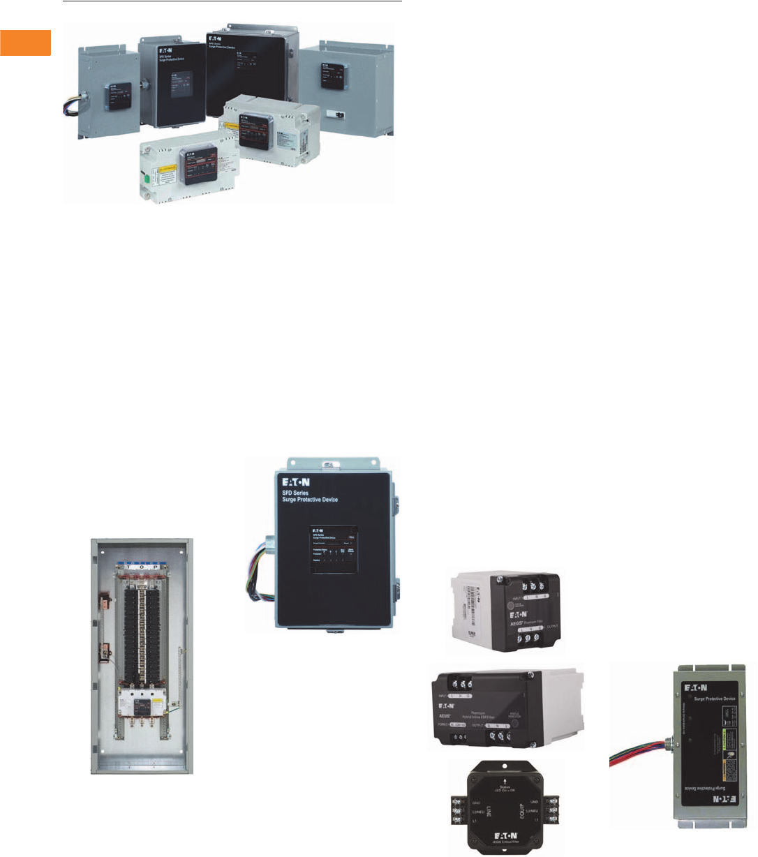
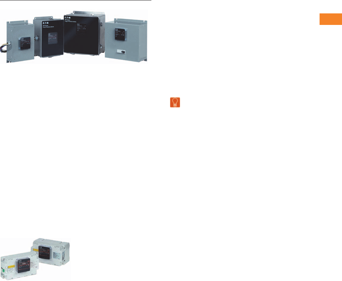
Introduction
Industrial and Commercial Surge Protection
●SPD Series for Integration
into Electrical Distribution
Equipment
●SPD Series for Mounting
External to Electrical
Distribution Equipment
SPD Series Integrated Units
Specification grade surge
protective devices installed
within Eaton’s electrical
assemblies.
SPD Series Integrated Unit
SPD Series Sidemount Units
Specification grade surge
protective devices for
installation external to
electrical distribution
equipment.
SPD Series Sidemount Unit
Critical Load Protection
Series filtering and surge
protection for critical single-
phase loads.
●Current ratings up to 60A
●120 and 240 Vac units
●24 and 48 Vdc units
●DIN mounting available on
some models
●Up to 80 kA of peak surge
protection
●Most AC units are UL 1449
3rd Edition and UL 1283
5th Edition listed
AEGIS Products
Commercial and Light
Industrial Surge Protection
Eaton’s SPV series is a
commercial grade and light
industrial surge protective
device (SPD) that combines
surge suppression
components and EMI/RFI
filtering, providing effective
protection for sensitive
electronic loads.
Surges (also known as
transients), due to lightning,
utility grid switching,
switching of external/internal
inductive or capacitive loads,
and other sources, travel on
power line conductors
throughout the electrical
distribution system, causing
system operating problems
and equipment downtime.
SPV Series
Volume 3—Power Distribution and Control Assemblies CA08100004E—April 2014 www.eaton.com V3-T2-3
2
2
2
2
2
2
2
2
2
2
2
2
2
2
2
2
2
2
2
2
2
2
2
2
2
2
2
2
2
2
2.1
SPD, Power Conditioning, PF Capacitors and Harmonic Filters
Surge Protection and Power Conditioning
Surge Protection for Sub-Panel and OEM Applications
In today’s business
environment that calls for 24
hours a day, 7 days a week
uptime and reliability, Eaton’s
CVX050 and CVX100 surge
protective devices (SPDs)
ensure that a customer’s
investment in equipment and
processes is protected from
the damaging effects of
voltage transients. Designed
for installation on service
entrance, branch panels or
individual equipment
disconnects, the CVX050/100
provides enhanced surge
protection for mission-critical
applications.
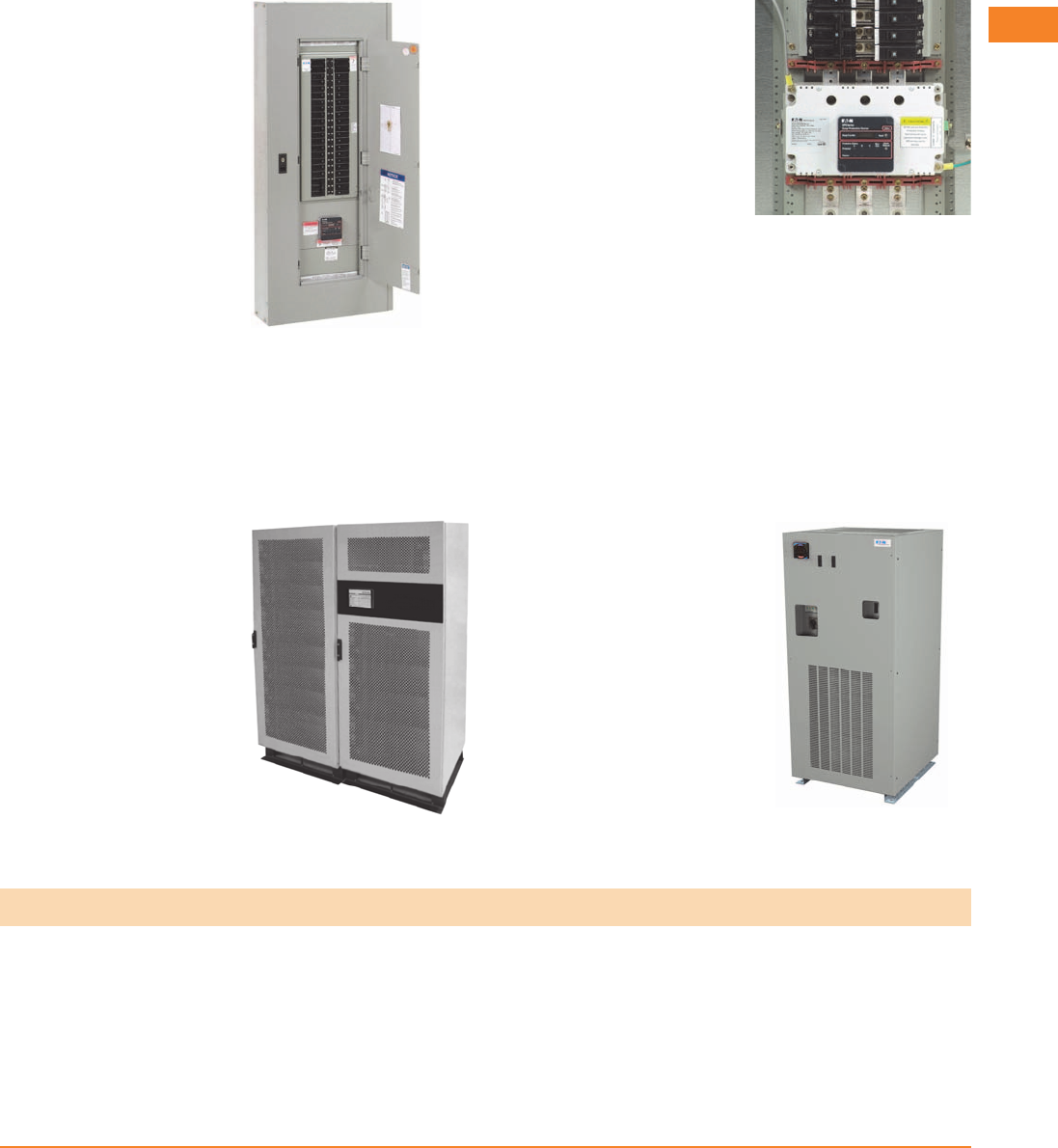
Panelboards with Integrated
Surge Protective Devices
●Available in standard and
custom configurations
●Ratings:
●120/240 Vac, single-
phase, three-wire
●208Y/120 Vac, three-
phase, four-wire
●480Y/277 Vac, three-
phase, four-wire
●600Y/347 Vac, three-
phase, four-wire (other
voltage configurations
are available)
●Copper bus
●12, 18, 24, 30, 36 and
42 circuits
●Bolt-on branch breakers
●A full range of factory
installed modifications
and accessories
●Fully rated or series rated
Surge Protective Devices can be
Integrated within a variety of Eaton
Electrical Assemblies
Power Conditioning
Sag Ride-Through (SRT)
The sag ride-through (SRT)
is a power conditioner that
corrects voltage sags to
maintain uptime and
productivity.
Electronic Voltage
Regulator (EVR)
The electronic voltage
regulator (EVR) is designed
to meet the needs of
customers who experience
voltage regulation problems
due to brownout conditions
from their electric utilities.
Electronic Voltage Regulator (EVR)
Sag Ride-Through (SRT)
Facility-Wide Power Protection Solutions
A facility-wide protection
approach should be
employed to address power
quality issues. This approach
minimizes overall lifecycle
costs and optimizes facility
uptime. The following is a
recommended design
approach for implementing
facility-wide Eaton power
protection solutions.
The most accepted design methodology is based on two concepts:
1. Ensure proper grounding conditions exist.
All forms of power protection/conditioning
rely on good grounding, bonding and
earthing practices.
2. Surge protection should be installed
at key distribution panels and
critical loads.

V3-T2-4 Volume 3—Power Distribution and Control Assemblies CA08100004E—April 2014 www.eaton.com
2
2
2
2
2
2
2
2
2
2
2
2
2
2
2
2
2
2
2
2
2
2
2
2
2
2
2
2
2
2
2.1
SPD, Power Conditioning, PF Capacitors and Harmonic Filters
Surge Protection and Power Conditioning
Application Description
Application Recommendations for Surge Products
Application Type Eaton’s Surge Product Features and Competitive Advantages
Light Commercial
Design build
Chain stores
Small facilities
SPD Series integrated units
SPD Series sidemount units
SPV units
SP1 units
CVX units
Ideal package for any commercial facility
Cost-effective, reliable protection using the SPD Series or SPV units
Large Projects
Including:
Commercial
Government
Schools
Institution
Military
SPD Series integrated units in panelboards, switchboards,
MCCs, switchgear, busway and automatic transfer switches
SPD Series sidemount units
SPV units
AEGIS units for critical load applications
Power conditioners (EVR and SRT units)
Able to meet competitors’ surge protection specifications
Increased surge protection performance by using integrated SPD Series units
Wall space savings by using integrated SPD Series units
Quick-ship capabilities from Eaton assembly satellites and service centers
Power conditioning capability for a wide variety of applications
Industrial
Including:
Small and large facilities
WWTP
SPD Series integrated units in panelboards, switchboards,
MCCs, switchgear, busway and automatic transfer switches
SPD Series sidemount units
SPV units
AEGIS units for critical load applications such as PLCs,
robotics applications, etc.
Power conditioners (EVR and SRT units)
Increased surge protection performance by using integrated SPD Series units
Wall space savings by using integrated SPD Series units
MCCs with SPD Series units installed protect drives from damage
AEGIS products protect expensive critical loads from harmful damage
EVR units correct voltage regulation problems
SRT units correct voltage sag problems
OEM
Any OEM customer including:
Integrators
Medical equipment
Automation and control
SPD Series integrated units
SPD Series sidemount units
SPV units
SP1 units
CVX units
AEGIS units for critical load applications
Years of experience in a variety of OEM applications
Application assistance and recommendations
Small footprint enables integration in a variety of applications
Ability to meet customized requirements
Telecommunications
Including:
Cellular sites
Microwave
PCS
Paging systems
Panelboards and automatic transfer switches with integrated SPD Series units
SPD Series sidemount units
SPV units
SP1 units
CVX units
Ability to meet customized requirements
Application assistance and recommendations
Volume 3—Power Distribution and Control Assemblies CA08100004E—April 2014 www.eaton.com V3-T2-5
2
2
2
2
2
2
2
2
2
2
2
2
2
2
2
2
2
2
2
2
2
2
2
2
2
2
2
2
2
2
2.1
SPD, Power Conditioning, PF Capacitors and Harmonic Filters
Surge Protection and Power Conditioning
SPD Series Sidemount Units
Contents
Description Page
Introduction. . . . . . . . . . . . . . . . . . . . . . . . . . . . . . . V3-T2-2
Product Overview
SPD Series for Integration into Electrical
Distribution Equipment . . . . . . . . . . . . . . . . . . . . V3-T2-7
SPD Series for Mounting External to
Electrical Distribution Equipment . . . . . . . . . . . . . V3-T2-11
SPV Surge Protective Device . . . . . . . . . . . . . . . . . V3-T2-16
CVX050/100 . . . . . . . . . . . . . . . . . . . . . . . . . . . . . . V3-T2-18
SP1 Surge Protective Device . . . . . . . . . . . . . . . . . V3-T2-21
SP2 Surge Protective Device . . . . . . . . . . . . . . . . . V3-T2-23
AEGIS Powerline Filters . . . . . . . . . . . . . . . . . . . . . V3-T2-25
Sag Ride-Through (SRT) . . . . . . . . . . . . . . . . . . . . . V3-T2-30
Electronic Voltage Regulator (EVR) . . . . . . . . . . . . . V3-T2-36
Learn
Online
Product Overview
Product Description
Eaton’s SPD series surge
protective devices are the
latest and most advanced
UL® 1449 3rd Edition certified
surge protectors. Units are
available integrated within
Eaton electrical assemblies,
including panelboards,
switchboards, motor
control centers, switchgear,
automatic transfer switches
and bus plugs.
SPD Series Integrated Units
A complete offering of
sidemount units designed
for mounting external to
electrical distribution
equipment is also available.
Application of SPD Series
units throughout a facility
will ensure that equipment
is protected with the safest
and most reliable surge
protective devices available.
SPD Series units are available
in all common voltages and
configurations and also
in a variety of surge current
capacity ratings from 50
through 400 kA. Three
feature package options are
also available to choose from,
ensuring the proper unit is
available for a variety of
applications.
Features, Benefits and Functions
●Uses self-protected metal
oxide varistor (MOV)
technology
●Three feature package
options
●True protection status
indicators report the status
of the protection elements,
not the status of the
applied power
●Available integrated
within the following
Eaton electrical assemblies:
panelboards, switchboards,
motor control centers,
switchgear, automatic
transfer switches and
bus plugs
●10-year warranty (15-year
warranty with registration)
Safety Features
●All units use self-protected
metal oxide varistor
technology (MOV) as their
core surge suppression
component. Usage of this
technology ensures safe
operation when the unit is
subjected to abnormal
conditions such as
temporary overvoltage or
high fault current
conditions. Under such
conditions, the self-
protected MOVs are
removed from the circuit
quickly and safely before a
potentially unsafe condition
can occur
●SPD Series units contain
no replaceable parts such
as surge modules, fuses,
or surge counter memory
backup batteries. This
prevents potential arc flash
and shock hazards, as the
units require no periodic
service or user intervention
after installation
●Integrated versions of the
unit are factory installed
and sidemount versions
are factory sealed. These
important safety measures
further enhance user
safety

V3-T2-6 Volume 3—Power Distribution and Control Assemblies CA08100004E—April 2014 www.eaton.com
2
2
2
2
2
2
2
2
2
2
2
2
2
2
2
2
2
2
2
2
2
2
2
2
2
2
2
2
2
2
2.1
SPD, Power Conditioning, PF Capacitors and Harmonic Filters
Surge Protection and Power Conditioning
Three Feature Package
Options Available
The SPD Series provides
users with the option of
selecting between three
feature packages. These
feature packages are the
basic, standard and standard
with surge counter. The
proper feature package
can be selected based on
the requirements of the
application or specification.
A side by side comparison of
the individual features found
in each package is below.
Basic Feature Package
The basic feature package is
perfect for applications where
basic, cost-effective, safe and
reliable surge protection is
required, but budgets don’t
allow for extra, additional
features. Rather than
sacrifice performance or
safety due to cost, SPD
Series units with the basic
feature package provide you
with high-performing surge
protection without sacrificing
safety or reliability. The basic
feature package provides
the same level of surge
protection and safety
provided by the standard and
standard with surge counter
feature packages minus
some of the features found in
them. The package contains
dual-colored protection status
LEDs that report the true
status of the protection in
each phase/mode. All four-
wire plus ground units also
contain an additional set of
dual-colored protection status
LEDs that report the status
of the protection in the
neutral/ground mode.
Standard Feature Package
The standard feature package
includes all of the features
found in the basic feature
package, plus an audible alarm
with silence button, EMI/RFI
filtering, and a form ‘C’ relay
contact that can be used for
remote annunciation of the
SPD’s status. The audible
alarm activates and the form
‘C’ relay contact changes state
when any loss of protection is
detected or a fault condition
exists with the unit. Should
such a condition occur, the
audible alarm can be silenced
by pressing the silence button.
The EMI/RFI filter provides up
to 50 dB of noise attenuation
over the range of 10 kHz
through 100 MHz.
Standard with Surge
Counter Feature Package
The standard with surge
counter feature package
includes all of the features
found in the standard feature
package plus a six-digit surge
counter with a reset button.
The surge counter indicates
the ongoing count of the
number of surges the unit has
been exposed to and stores
them in nonvolatile memory.
Should power to the SPD
Series unit be completely
interrupted, the surge counter
will recall and display the
surge count prior to the
interruption when power is
restored. Unlike many surge
protectors, the SPD Series’
surge counter memory
feature does not require a
backup battery that would
require periodic replacement
in order to achieve its
memory functionality.
Side-By-Side Comparison of the SPD Series’ Available
Feature Packages
Standards and Certifications
●Integrated versions of
the unit are UL 1449
3rd Edition recognized
components for the
United States and Canada,
covered by Underwriters
Laboratories certification
and follow-up service
●Sidemount versions are
UL 1449 3rd Edition listed
devices and are also
CSA approved
Technical Data
and Specifications
●20 kA nominal discharge
current (In) rating
(maximum rating
assigned by UL)
●50 through 400 kA surge
current capacity ratings
●200 kA short-circuit current
rating (SCCR)
Feature Package Comparison Basic Standard
Standard with
Surge Counter
Surge protection using self-protected
MOV technology
■■ ■
Dual-colored protection status indicators
for each phase
■■ ■
Dual-colored protection status indicators
for the N-G protection mode
■■ ■
Audible alarm with silence button ■■
Form ‘C’ relay contact ■■
EMI/RFI filtering, providing up to 50 dB of
noise attenuation from 10 kHz to 100 MHz
■■
Surge counter with reset button ■
Volume 3—Power Distribution and Control Assemblies CA08100004E—April 2014 www.eaton.com V3-T2-7
2
2
2
2
2
2
2
2
2
2
2
2
2
2
2
2
2
2
2
2
2
2
2
2
2
2
2
2
2
2
2.1
SPD, Power Conditioning, PF Capacitors and Harmonic Filters
Surge Protection and Power Conditioning
SPD Series Unit Integrated within an Eaton Panelboard
Contents
Description Page
Introduction. . . . . . . . . . . . . . . . . . . . . . . . . . . . . . . V3-T2-2
Product Overview . . . . . . . . . . . . . . . . . . . . . . . . . . V3-T2-5
SPD Series for Integration into Electrical
Distribution Equipment
Standards and Certifications . . . . . . . . . . . . . . . V3-T2-8
Catalog Number Selection. . . . . . . . . . . . . . . . . V3-T2-8
Technical Data and Specifications . . . . . . . . . . . V3-T2-9
Dimensions . . . . . . . . . . . . . . . . . . . . . . . . . . . . V3-T2-10
SPD Series for Mounting External to
Electrical Distribution Equipment . . . . . . . . . . . . . V3-T2-11
SPV Surge Protective Device . . . . . . . . . . . . . . . . . V3-T2-16
CVX050/100 . . . . . . . . . . . . . . . . . . . . . . . . . . . . . . V3-T2-18
SP1 Surge Protective Device . . . . . . . . . . . . . . . . . V3-T2-21
SP2 Surge Protective Device . . . . . . . . . . . . . . . . . V3-T2-23
AEGIS Powerline Filters . . . . . . . . . . . . . . . . . . . . . V3-T2-25
Sag Ride-Through (SRT) . . . . . . . . . . . . . . . . . . . . . V3-T2-30
Electronic Voltage Regulator (EVR) . . . . . . . . . . . . . V3-T2-36
SPD Series for Integration into Electrical Distribution Equipment
Product Description
Eaton’s SPD Series surge
protective devices are the
latest and most advanced
UL 1449 3rd Edition certified
surge protectors. SPD Series
units are available in all
common voltages and
configurations, and also in
a variety of surge current
capacity ratings from
50 to 400 kA.
Application Description
The SPD Series is available as
an integrated device within
the following Eaton electrical
assemblies:
●Panelboards
●Switchboards
●Motor control centers
●Switchgear
●Automatic transfer
switches
●Bus plugs
Features, Benefits
and Functions
●Uses thermally protected
metal oxide varistor (MOV)
technology
●Three feature package
options
●10-year warrant y
The Integrated SPD
Performance Advantage
Installation conductor length
is the single most important
factor related to an SPD’s
performance. Performance
decreases as the connected
conductor length increases.
Integrating the SPD within the
electrical assembly provides
the best possible surge
protection by keeping
installation conductor lead
lengths as short as possible.
Integrating the SPD within
an electrical assembly can
decrease let-through
voltages by hundreds of volts,
providing you with the best
possible surge protection for
sensitive electronic loads.
Remote Display Mounting
Option Available
The SPD Series offers the
option of mounting its display
remotely from the device.
This is useful for applications
where OEMs or other
integrators would like to
embed the unit within a piece
of equipment and still be able
to view its display.
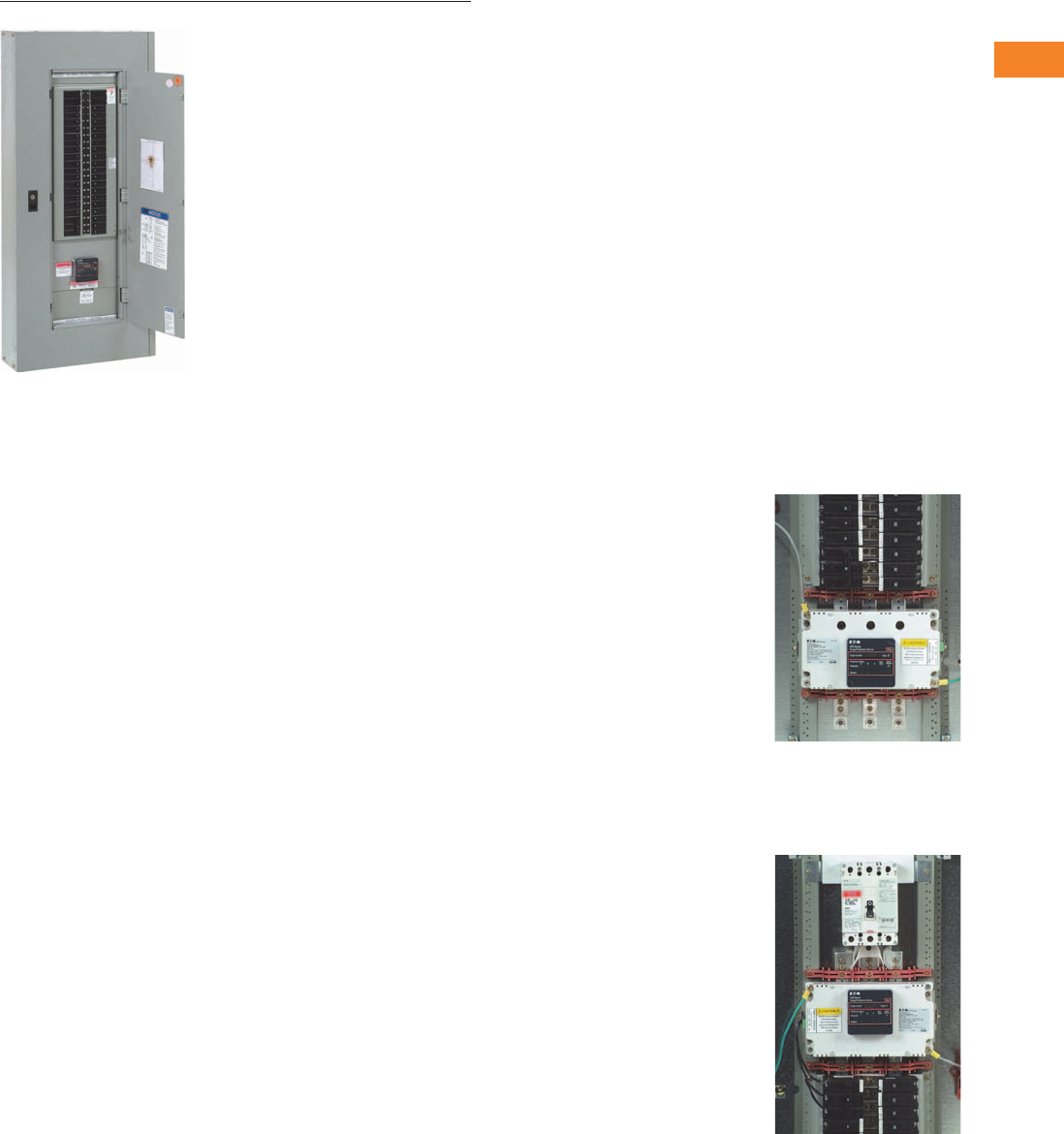
In this installation, the SPD Series
is mounted directly to the panelboard’s
bus bars. This type of installation
will provide the best possible surge
protection by minimizing the
connected lead length.
The SPD Series is also available as an
integrated unit interfaced via a circuit
breaker resident in the electrical
assembly. This installation keeps
connected lead lengths short while
providing a means of disconnecting
power to the unit quickly and easily.
V3-T2-8 Volume 3—Power Distribution and Control Assemblies CA08100004E—April 2014 www.eaton.com
2
2
2
2
2
2
2
2
2
2
2
2
2
2
2
2
2
2
2
2
2
2
2
2
2
2
2
2
2
2
2.1
SPD, Power Conditioning, PF Capacitors and Harmonic Filters
Surge Protection and Power Conditioning
Standards and Certifications
●UL 1449 3rd Edition
recognized component
for the United States
and Canada, covered by
Underwriters Laboratories
certification and follow-up
service
●UL 1283 (Type 2
SPDs only)
Catalog Number Selection
SPD Series Units Mounted Internal to Electrical Distribution Equipment
Notes
1Please consult the factory for 240 high-leg delta (4W+G) applications with high leg on ‘C’ phase.
2Units used in PRL1a, 2a, 3a and 3E panelboard applications are available in 50–200 kA ratings only. Use the ‘C’ option for
PRL1a, 2a, 3a and 3E panelboard applications when unit is connected through a circuit breaker.
Example: SPD250480D2J = SPD Series, 250 kA per phase, 480D voltage, standard feature package, motor control center application.
Series
SPD = Surge protective device kA Rating
050 = 50 kA per phase
080 = 80 kA per phase
100 = 100 kA per phase
120 = 120 kA per phase
160 = 160 kA per phase
200 = 200 kA per phase
250 = 250 kA per phase
300 = 300 kA per phase
400 = 400 kA per phase
Voltage Code
240S = 120/240 single split-phase
208Y = 120/208 wye (4W+G)
220Y = 127/220 wye (4W+G)
400Y = 230/400 wye (4W+G)
480Y = 277/480 wye (4W+G)
600Y = 347/600 wye (4W+G)
240D = 240 delta (3W+G)
480D = 480 delta (3W+G)
600D = 600 delta (4W+G)
240H = 240 high-leg delta (4W+G) on ‘B’ phase 1
Application—Integrated Units 2
A = Panelboards (PRL1a, 2a, 3a, 3E), direct bus mounted
B = Switchgear (includes remote display)
C = Panelboards (PRL1a, 2a, 3a, 3E, 4), switchboards,
busway
J = Motor control centers
Feature Package
1 = Basic
2 = Standard
3 = Standard + surge counter
SPD 250 480D 2 J

Volume 3—Power Distribution and Control Assemblies CA08100004E—April 2014 www.eaton.com V3-T2-9
2
2
2
2
2
2
2
2
2
2
2
2
2
2
2
2
2
2
2
2
2
2
2
2
2
2
2
2
2
2
2.1
SPD, Power Conditioning, PF Capacitors and Harmonic Filters
Surge Protection and Power Conditioning
Technical Data and Specifications
SPD Series Specifications
Description Specification
Surge capacity ratings available 50, 80, 100, 120, 160, 200, 250, 300, 400 kA per phase
Nominal discharge current (In) 20 kA (maximum rating assigned by UL)
Short-circuit current rating (SCCR) 200 kA
SPD type Basic feature package = Type 1 (can also be used in Type 2 applications)
Standard and standard with surge counter feature packages = Type 2
Single split-phase voltages available 120/240
Three-phase wye system voltages available 120/208, 127/220, 230/400, 277/480, 347/600
Three-phase delta system voltages available 240, 480, 600
Input power frequency 50/60 Hz
Power consumption (basic units):
208Y, 220Y, 240S, 240D and 240H voltage codes 0.5W
400Y, 480Y and 480D voltage codes 1.1W
600Y and 600D voltage codes 1.3W
Power consumption (standard and standard with surge counter units):
208Y, 220Y, 240S, 240D and 240H voltage codes 0.6W
400Y, 480Y and 480D basic voltage codes 1.7W
600Y and 600D voltage codes 2.1W
Protection modes Single split-phase L-N, L-G, N-G, L-L
Three-phase wye L-N, L-G, N-G, L-L
Three-phase delta L-G, L-L
Three-phase high-leg delta L-N, L-G, N-G, L-L
Maximum continuous operating voltage (MCOV):
240S, 208Y, 220Y and 240H MCOV 150 L-N, 150 L-G, 150 N-G, 300 L-L
400Y and 480Y MCOV 320 L-N, 320 L-G, 320 N-G, 640 L-L
600Y MCOV 420 L-N, 420 L-G, 420 N-G, 840 L-L
240D MCOV 320 L-G, 320 L-L
480D MCOV 640 L-G, 640 L-L
600D MCOV 840 L-G, 840 L-L
Ports 1
Operating temperature –40°F through 122°F (–40°C through 50°C)
Operating humidity 5% through 95%, noncondensing
Operating altitude Up to 16,000 ft (5000m)
Seismic withstand capability Meets or exceeds the requirements specified in IBC 2006, CBC 2007 and UBC Zone 4
Form C relay contact ratings 150 Vdc or 125 Vac, 1A maximum
Form C relay contact logic Power ON, normal state—NO contact = open, NC contact = closed
Power OFF or fault state—NO contact = closed, NC contact = open
EMI/RFI filtering attenuation Up to 50 dB from 10 kHz to 100 MHz
V3-T2-10 Volume 3—Power Distribution and Control Assemblies CA08100004E—April 2014 www.eaton.com
2
2
2
2
2
2
2
2
2
2
2
2
2
2
2
2
2
2
2
2
2
2
2
2
2
2
2
2
2
2
2.1
SPD, Power Conditioning, PF Capacitors and Harmonic Filters
Surge Protection and Power Conditioning
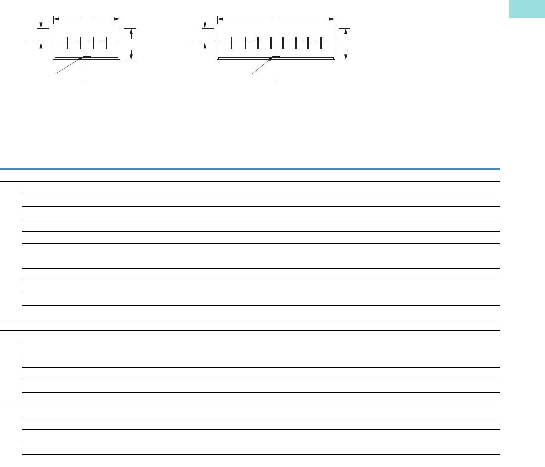
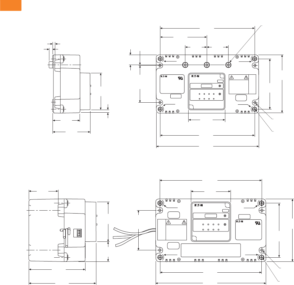
Dimensions
Approximate Dimensions in Inches (mm)
50–200 kA Integrated Units
250–400 kA Integrated Units
Weights
●50–200 kA units
approximately 3.5 lbs
(1.6 kg)
●250–400 kA units
approximately 7.0 lbs
(3.2 kg)
0.19
(4.8) 4x Mounting
Bus 0.34
(8.6)
3.42
(86.9)
2.52
(64.0)
3.45
(87
.6)
0.95
(24.1)
Mounting
8.80
(223.5)
4.40
(1
11.8)
0.04
(1.0)
5.40
(137.2)
4.66
(118.4)
0.22
(5.6) 4x Mounting
4x #10–32 x 0.38 DP
Brass Terminals
3.42
(86.9)
Terminals
8.74
(222.0)
9.50
(241.3)
0.26
(6.6)
0.22
(5.6) 3x Bus Mounting
Mounting
3.42
(86.9)
2.02
(51.2)
2.02
(51.2)
FORM “C” CONTACTS
CAUTION
SURGE GROUND
NEUTRAL
SURGE GROUND
NEUTRAL
NEUTRAL
NEUTRAL
TORQUE
NEU/GND
36 IN. LBS.
SURGE
GROUND
SURGE
GROUND
SPD Series
Surge Protective Device
5.78
(146.8)
4.85
(123.2)
1.71
(43.4)
3.42
(86.9)
4x Mounting
2.52
(64.0)
9.50
(241.3)
Terminals
8.74
(222.0)
Mounting
8.80
(223.5)
3.42
(86.9)
5.40
(137.2)
4.66
(118.4)
0.22
(5.6) 4x Mounting
4x #10–32 x 0.38 DP
Brass Terminals
Mounting
3.42
(86.9)
FORM “C” CONTACTS
CAUTION
SURGE GROUND
NEUTRAL
SURGE
GROUND
NEUTRAL
NEUTRAL
NEUTRAL
TORQUE
NEU/GND
36 IN. LBS.
TORQUE
NEU/GND
36 IN. LBS.
SURGE
GROUND
SURGE
GROUND
SPD Series
Surge Protective Device
Volume 3—Power Distribution and Control Assemblies CA08100004E—April 2014 www.eaton.com V3-T2-11
2
2
2
2
2
2
2
2
2
2
2
2
2
2
2
2
2
2
2
2
2
2
2
2
2
2
2
2
2
2
2.1
SPD, Power Conditioning, PF Capacitors and Harmonic Filters
Surge Protection and Power Conditioning
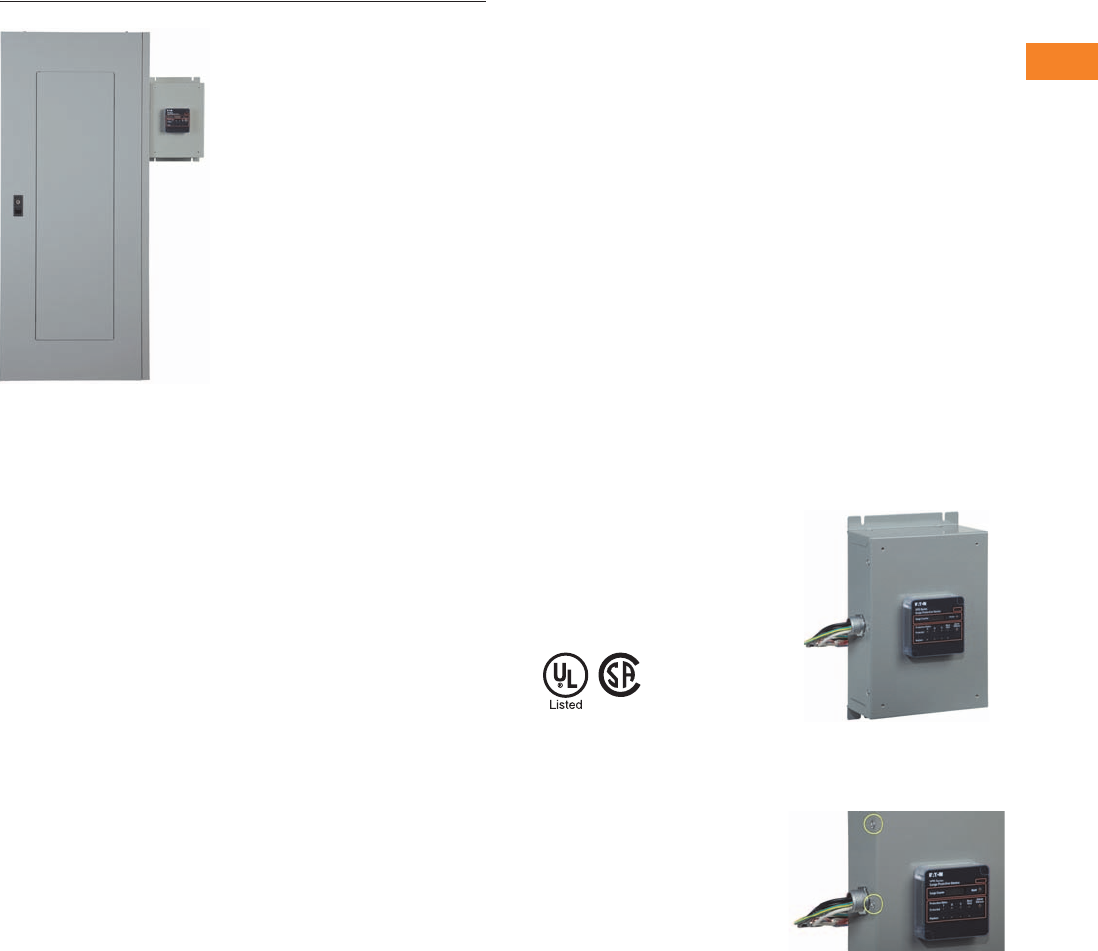
Eaton SPD Series Sidemount Unit Mounted Externally to an Eaton Panelboard
Contents
Description Page
Introduction. . . . . . . . . . . . . . . . . . . . . . . . . . . . . . . V3-T2-2
Product Overview . . . . . . . . . . . . . . . . . . . . . . . . . . V3-T2-5
SPD Series for Integration into Electrical
Distribution Equipment . . . . . . . . . . . . . . . . . . . . V3-T2-7
SPD Series for Mounting External to
Electrical Distribution Equipment
Catalog Number Selection. . . . . . . . . . . . . . . . . V3-T2-12
Technical Data and Specifications . . . . . . . . . . . V3-T2-13
Dimensions . . . . . . . . . . . . . . . . . . . . . . . . . . . . V3-T2-14
SPV Surge Protective Device . . . . . . . . . . . . . . . . . V3-T2-16
CVX050/100 . . . . . . . . . . . . . . . . . . . . . . . . . . . . . . V3-T2-18
SP1 Surge Protective Device . . . . . . . . . . . . . . . . . V3-T2-21
SP2 Surge Protective Device . . . . . . . . . . . . . . . . . V3-T2-23
AEGIS Powerline Filters . . . . . . . . . . . . . . . . . . . . . V3-T2-25
Sag Ride-Through (SRT) . . . . . . . . . . . . . . . . . . . . . V3-T2-30
Electronic Voltage Regulator (EVR) . . . . . . . . . . . . . V3-T2-36
SPD Series for Mounting External to Electrical Distribution Equipment
Product Description
Eaton’s sidemount versions
of the SPD Series surge
protective devices are the
latest and most advanced
UL 1449 3rd Edition listed
surge protectors. Application
of SPD Series units
throughout a facility will
ensure that equipment is
protected with the safest and
most reliable surge protective
devices available. Units are
available in all common
voltages and configurations,
and also in a variety of surge
current capacity ratings from
50 through 400 kA. Three
feature package options are
also available to choose from.
Features, Benefits
and Functions
●Uses self-protected metal
oxide varistor (MOV)
technology
●Three feature package
options
●15-year warranty
Standards and Certifications
●UL 1449 3rd Edition
listed device
●Canadian Standards
Association (CSA)
●UL 1283 (Type 2
SPDs only)
All SPD Series sidemount units come
prewired and include a factory-
installed conduit interface,
making installation very easy.
All SPD Series units are factory sealed,
ensuring that the user/installer has
no potential of coming into contact
with harmful voltages present
inside the unit.
V3-T2-12 Volume 3—Power Distribution and Control Assemblies CA08100004E—April 2014 www.eaton.com
2
2
2
2
2
2
2
2
2
2
2
2
2
2
2
2
2
2
2
2
2
2
2
2
2
2
2
2
2
2
2.1
SPD, Power Conditioning, PF Capacitors and Harmonic Filters
Surge Protection and Power Conditioning
Catalog Number Selection
SPD Series Units for Mounting External to Electrical Distribution Equipment
Notes
1Please consult the factory for 240 high-leg delta (4W+G) applications with high leg on ‘C’ phase.
2NEMA 1 flushmount units are available in 50–200 kA ratings only.
Example: SPD250480D2K = SPD Series, 250 kA per phase, 480D voltage, standard feature package, housed in NEMA 1 enclosure.
Series
SPD = Surge protective device kA Rating
050 = 50 kA per phase
080 = 80 kA per phase
100 = 100 kA per phase
120 = 120 kA per phase
160 = 160 kA per phase
200 = 200 kA per phase
250 = 250 kA per phase
300 = 300 kA per phase
400 = 400 kA per phase
Voltage Code
240S = 120/240 single split-phase
208Y = 120/208 wye (4W+G)
220Y = 127/220 wye (4W+G)
400Y = 230/400 wye (4W+G)
480Y = 277/480 wye (4W+G)
600Y = 347/600 wye (4W+G)
240D = 240 delta (3W+G)
480D = 480 delta (3W+G)
600D = 600 delta (4W+G)
240H = 240 high-leg delta (4W+G) on ‘B’ phase 1
Application—Sidemount Units
K = NEMA 1 enclosure
L = NEMA 1 flushmount enclosure 2
M = NEMA 1 enclosure with internal disconnect
N = NEMA 4 enclosure
O= NEMA 4 enclosure with internal disconnect
P= NEMA 4X enclosure (stainless steel)
Q= NEMA 4X enclosure with internal disconnect
(stainless steel)
Feature Package
1 = Basic
2 = Standard
3 = Standard + surge counter
SPD 250 480D 2 K

Volume 3—Power Distribution and Control Assemblies CA08100004E—April 2014 www.eaton.com V3-T2-13
2
2
2
2
2
2
2
2
2
2
2
2
2
2
2
2
2
2
2
2
2
2
2
2
2
2
2
2
2
2
2.1
SPD, Power Conditioning, PF Capacitors and Harmonic Filters
Surge Protection and Power Conditioning
Technical Data and Specifications
SPD Series Specifications
Description Specification
Surge capacity ratings available 50, 80, 100, 120, 160, 200, 250, 300, 400 kA per phase
Nominal discharge current (In) 20 kA (maximum rating assigned by UL)
Short-circuit current rating (SCCR) 200 kA
SPD type Basic feature package = Type 1 (can also be used in Type 2 applications)
Standard and standard with surge counter feature packages = Type 2
Single split-phase voltages available 120/240
Three-phase wye system voltages available 120/208, 127/220, 230/400, 277/480, 347/600
Three-phase delta system voltages available 240, 480, 600
Input power frequency 50/60 Hz
Power consumption (basic units):
208Y, 220Y, 240S, 240D and 240H voltage codes 0.5W
400Y, 480Y and 480D voltage codes 1.1W
600Y and 600D voltage codes 1.3W
Power consumption (standard and standard with surge counter units):
208Y, 220Y, 240S, 240D and 240H voltage codes 0.6W
400Y, 480Y and 480D basic voltage codes 1.7W
600Y and 600D voltage codes 2.1W
Protection modes Single split-phase L-N, L-G, N-G, L-L
Three-phase wye L-N, L-G, N-G, L-L
Three-phase delta L-G, L-L
Three-phase high-leg delta L-N, L-G, N-G, L-L
Maximum continuous operating voltage (MCOV):
240S, 208Y, 220Y and 240H MCOV 150 L-N, 150 L-G, 150 N-G, 300 L-L
400Y and 480Y MCOV 320 L-N, 320 L-G, 320 N-G, 640 L-L
600Y MCOV 420 L-N, 420 L-G, 420 N-G, 840 L-L
240D MCOV 320 L-G, 320 L-L
480D MCOV 640 L-G, 640 L-L
600D MCOV 840 L-G, 840 L-L
Ports 1
Operating temperature –40°F to 122°F (–40°C to 50°C)
Operating humidity 5% through 95%, noncondensing
Operating altitude Up to 16,000 ft (5000m)
Seismic withstand capability Meets or exceeds the requirements specified in IBC 2006, CBC 2007 and UBC Zone 4
Enclosure dimensions and weights Refer to figures on Pages V3-T2-14–V3-T2-15 for enclosure dimensions and weights
Form C relay contact ratings 150 Vdc or 125 Vac, 1A maximum
Form C relay contact logic Power ON, normal state—NO contact = open, NC contact = closed
Power OFF or fault state—NO contact = closed, NC contact = open
EMI/RFI filtering attenuation Up to 50 dB from 10 kHz to 100 MHz
V3-T2-14 Volume 3—Power Distribution and Control Assemblies CA08100004E—April 2014 www.eaton.com
2
2
2
2
2
2
2
2
2
2
2
2
2
2
2
2
2
2
2
2
2
2
2
2
2
2
2
2
2
2
2.1
SPD, Power Conditioning, PF Capacitors and Harmonic Filters
Surge Protection and Power Conditioning
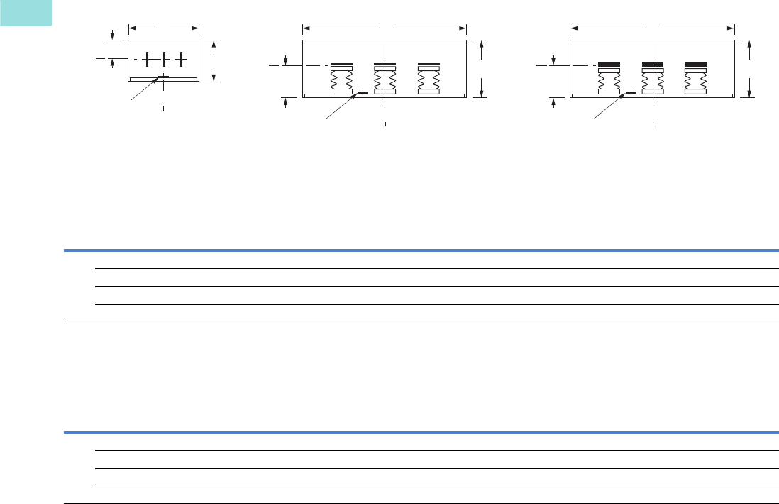
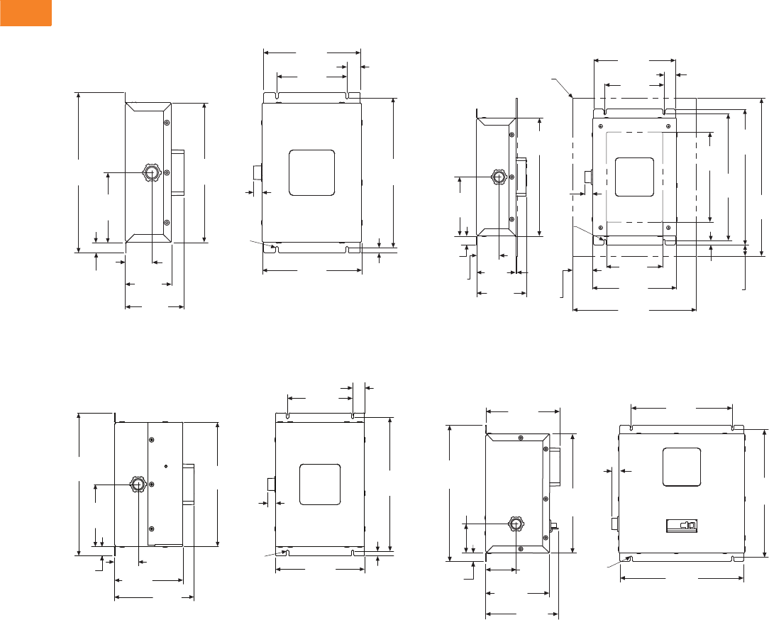
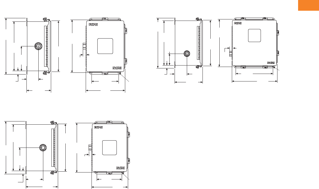
Dimensions
Approximate Dimensions in Inches (mm)
50–200 kA Units in a NEMA 1 Rated Enclosure,
Weight = 6.8 lbs
250–400 kA Units in a NEMA 1 Rated Enclosure,
Weight = 13.5 lbs
12.05
(306.1)
5.24
(133.1)
0.78
(19.8)
2.00
(50.8)
3.48
(88.4)
4.41
(112.0)
Ø0.20
(Ø5.1)
10.48
(266.2)
0.68
(17.3)
7.28
(184.9)
5.27
(133.9)
1.0 0
(25.4)
11.25
(285.8)
7.47
(189.7) 0.40
(10.2)
12.05
(306.1)
5.24
(133.1)
0.78
(19.8)
2.00
(50.8)
5.76
(146.3) 6.69
(169.9)
0.40
(10.2)
7.47
(189.7)
Ø0.20
(Ø5.1)
10.48
(266.2)
0.67
(17.0)
5.47
(138.9)
1.0 0
(25.4)
11.25
(285.8)
50–200 kA Units in a NEMA 1 Rated Flushmount Enclosure,
Weight = 6.8 lbs
50–400 kA Units in a NEMA 1 Rated Enclosure with Internal
Disconnect, Weight = 14.7 lbs
Flushmount Panel
(4) #8–32 Flat Hd Screws
5.24
(133.1)
0.78
(19.8)
2.00
(50.8)
3.48
(88.4)
4.41
(112.0)
0.11
(2.8)
10.48
(266.2)
0.68
(17.3)
Ø0.20
(Ø5.1)
1.76
(44.7)
5.00
(127.0)
7.47
(189.7)
11.00
(279.4)
0.40
(10.2)
0.98
(24.9)
8.00
(203.2)
11.25
(285.8)
12.05
(306.1)
14.00
(355.6)
1.0 0
(25.4)
7.28
(184.9)
5.27
(133.9)
6.69
(169.9)
12.30
(312.4)
2.61
(66.3)
0.78
(19.8)
2.75
(69.9)
5.76
(146.3)
6.55
(166.4)
10.73
(272.5)
0.66
(16.8)
Ø0.20
(Ø5.1) 11.14
(283.0)
11.50
(292.1)
9.14
(232.2)
Volume 3—Power Distribution and Control Assemblies CA08100004E—April 2014 www.eaton.com V3-T2-15
2
2
2
2
2
2
2
2
2
2
2
2
2
2
2
2
2
2
2
2
2
2
2
2
2
2
2
2
2
2
2.1
SPD, Power Conditioning, PF Capacitors and Harmonic Filters
Surge Protection and Power Conditioning
Approximate Dimensions in Inches (mm)
50–200 kA Units in a NEMA 4 or 4X Rated Enclosure,
Weight = 14.6 lbs
250–400 kA Units in a NEMA 4 or 4X Rated Enclosure,
Weight = 14.6 lbs
50–400 kA Units in a NEMA 4 or 4X Rated Enclosure with
Internal Disconnect, Weight = 27.5 lbs
12.50
(317.5)
10.98
(278.9)
5.49
(139.4)
0.76
(19.3)
2.60
(66.0)
5.39
(136.9)
11.28
(286.5)
11.75
(298.5)
0.65
(16.5)
6.00
(152.4)
8.65
(219.7)
Ø0.33
(Ø8.4)
SPD Series
Surge Protective Device
SPD Series
Surge Protective Device
12.50
(317.5)
10.98
(278.9)
5.49
(139.4)
0.76
(19.3)
4.10
(104.1) 7.68
(195.1)
11.28
(286.5)
11.75
(298.5)
6.00
(152.4)
0.65
(16.5)
8.65
(219.7)
Ø0.33
(8.4)
SPD Series
Surge Protective Device
SPD Series
Surge Protective Device
13.50
(342.9)
11.98
(304.3)
3.12
(79.2)
0.76
(19.3)
3.36
(85.3)
7.68
(195.1)
12.28
(311.9)
12.75
(323.9)
0.65
(16.5)
10.18
(258.6) 12.47
(316.7)
Ø0.33
(Ø8.4)
SPD Series
Surge Protective Device
SPD Series
Surge Protective Device
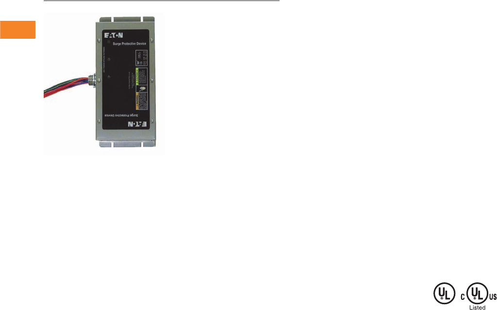
V3-T2-16 Volume 3—Power Distribution and Control Assemblies CA08100004E—April 2014 www.eaton.com
2
2
2
2
2
2
2
2
2
2
2
2
2
2
2
2
2
2
2
2
2
2
2
2
2
2
2
2
2
2
2.1
SPD, Power Conditioning, PF Capacitors and Harmonic Filters
Surge Protection and Power Conditioning
SPV
Contents
Description Page
Introduction . . . . . . . . . . . . . . . . . . . . . . . . . . . . . . . V3-T2-2
Product Overview . . . . . . . . . . . . . . . . . . . . . . . . . . . V3-T2-5
SPD Series for Integration into Electrical
Distribution Equipment . . . . . . . . . . . . . . . . . . . . . V3-T2-7
SPD Series for Mounting External to
Electrical Distribution Equipment . . . . . . . . . . . . . . V3-T2-11
SPV Surge Protective Device
Catalog Number Selection. . . . . . . . . . . . . . . . . . V3-T2-17
Technical Data and Specifications . . . . . . . . . . . . V3-T2-17
Dimensions . . . . . . . . . . . . . . . . . . . . . . . . . . . . . V3-T2-17
CVX050/100 . . . . . . . . . . . . . . . . . . . . . . . . . . . . . . . V3-T2-18
SP1 Surge Protective Device . . . . . . . . . . . . . . . . . . V3-T2-21
SP2 Surge Protective Device . . . . . . . . . . . . . . . . . . V3-T2-23
AEGIS Powerline Filters . . . . . . . . . . . . . . . . . . . . . . V3-T2-25
Sag Ride-Through (SRT) . . . . . . . . . . . . . . . . . . . . . . V3-T2-30
Electronic Voltage Regulator (EVR). . . . . . . . . . . . . . V3-T2-36
SPV Surge Protective Device
Product Description
Eaton’s SPV series is a
commercial grade and light
industrial surge protective
device (SPD) that combines
surge suppression
components and EMI/RFI
filtering, providing effective
protection for sensitive
electronic loads. Surges (also
known as transients), due to
lightning, utility grid
switching, switching of
external/internal inductive or
capacitive loads, and other
sources, travel on power line
conductors throughout the
electrical distribution system,
causing system operating
problems and equipment
downtime. Use of the SPV
units can prevent these costly
occurrences and equipment
damage. Available with six
surge current capacity
ratings, the SPV can be
installed on the main of light
commercial buildings, on any
subpanel in a facility and in
any control panel to protect
sensitive electronic
equipment.
Application Description
The ever-increasing use of
microprocessors and other
sensitive electronic
equipment has increased the
necessity for facility-wide
surge protection. These
sensitive electronic
components are used within
many pieces of equipment,
including computers,
programmable logic
controllers, and other
commonly used electrical and
electronic equipment. Surges
can wreak havoc on
equipment, causing
catastrophic failures, process
interruptions and premature
aging leading to failure. The
application of SPDs can
mitigate problems with
sensitive electronic
equipment, keeping the
equipment and the related
processes up and running
reliably without disruption
or damage due to surge-
related events.
In addition to externally
generated surge events, such
as lightning and grid switching,
equipment is also susceptible
to damage by internally
generated surges. In fact, the
majority of surges are
generated internally by
commonly used items, such
as fluorescent lighting ballasts,
light dimmers, photocopiers,
fax machines and variable
frequency drives. This further
reinforces the necessity for
facility-wide surge protection
applied at all stages of the
electrical distribution system,
from the electrical service
entrance down to the single-
phase loads.
Features
●SurgePlane™ technology
to ensure reliability and
performance by using a
low impedance copper
platform
●Compact design to enable
close mounting to
electrical distribution
equipment
●Parallel hybrid filter
technology
●Individually fused surge
suppression components
●Status indicator lights to
monitor supply power,
surge suppression
component status
and fusing
●Can be remotely monitored
using Form C contacts
●Audible alarm
●Ideal for OEM panel
applications
●50 through 200 kA surge
current capacity ratings
●Contains no replaceable
parts or items that require
periodic maintenance
●10-year warrant y
Eaton is the leading supplier
of power protection
technology to a number of
Fortune 500 companies. We
have applied our extensive
experience in power quality
and have included a number
of innovative features in the
development of the Eaton
SPV series.
Standards and Certifications
●UL 1449 3rd Edition Listed
●UL 1283 Listed
●CSA TIL I-11B
●CSA C22.2 No.8
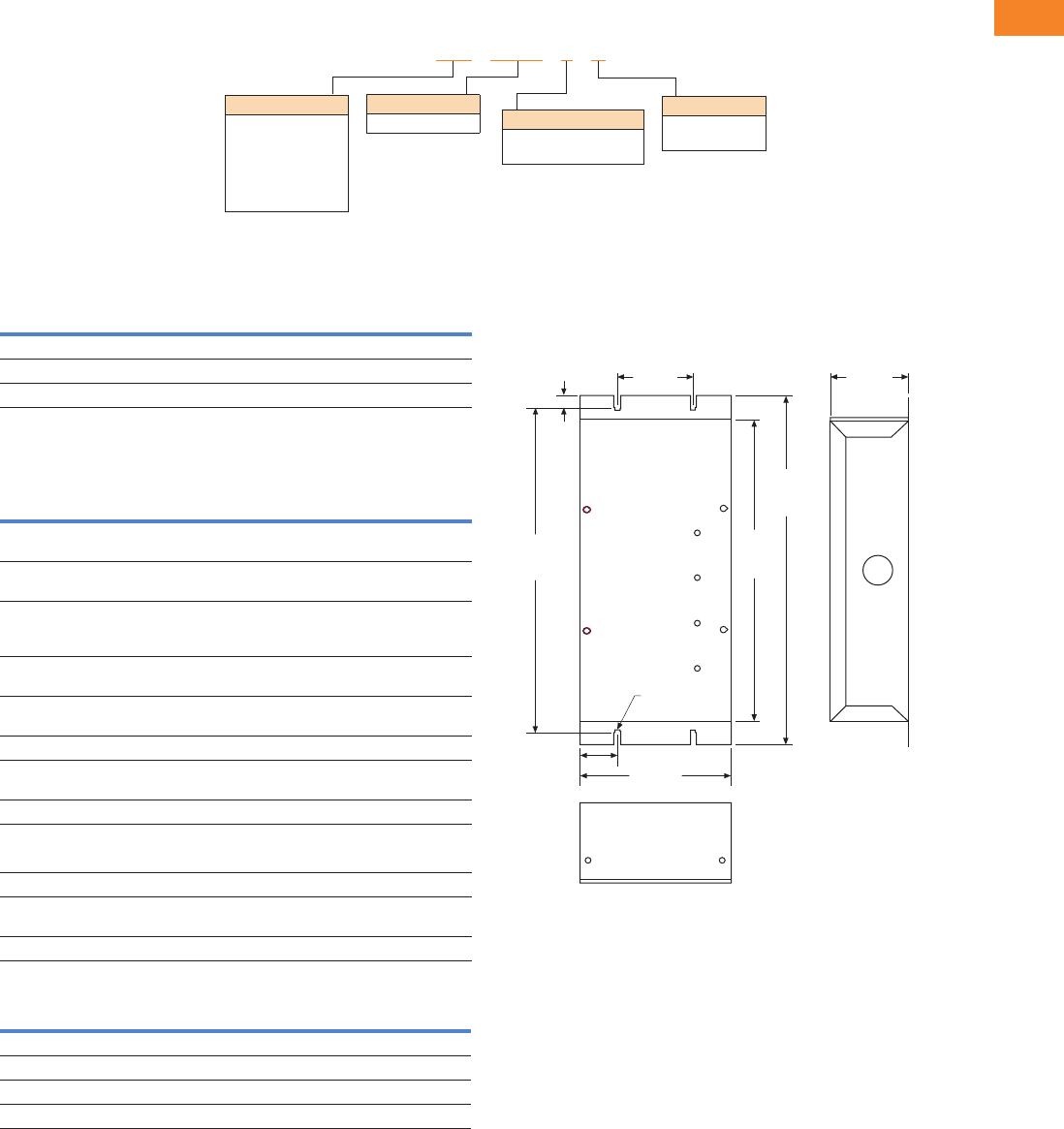
Volume 3—Power Distribution and Control Assemblies CA08100004E—April 2014 www.eaton.com V3-T2-17
2
2
2
2
2
2
2
2
2
2
2
2
2
2
2
2
2
2
2
2
2
2
2
2
2
2
2
2
2
2
2.1
SPD, Power Conditioning, PF Capacitors and Harmonic Filters
Surge Protection and Power Conditioning
Catalog Number Selection
SPV
SPV Voltage Codes
Technical Data and Specifications
SPV
Physical Specifications
Nominal Voltages
(Use These Codes to
Complete the Model Number)
Voltage Code
120/208
240V
230/400
499V 1
277/480
480V
120/240 single/split-phase (3W plus G) 240S — —
Three-phase wye (4W plus G) 208Y 400Y 480Y
Three-phase delta (3W plus G) 240D 400D 480D
Surge Rating
050 = 50 kA/phase
080 = 80 kA/phase
100 = 100 kA/phase
120 = 120 kA/phase
160 = 160 kA/phase
200 = 200 kA/phase
Enclosure
K= NEMA 1
R= NEMA 3R
Voltage Code
See table below Display
2= Standard
(LED/audible alarm)
SPV 050 400D 2 K
Description SPV050 SPV080 SPV100 SPV120 SPV160 SPV200
Surge current
per phase
50 kA 80 kA 100 kA 120 kA 160 kA 200 kA
Surge current
per mode
25 kA 40 kA 50 kA 60 kA 80 kA 100 kA
Filter attenuation
(MIL-STD-220A
at 100 kHz)
0–40 dB 0–40 dB 0–40 dB 0–40 dB 0–40 dB 0–40 dB
Circuit
construction
Surge-
Plane
Surge-
Plane
Surge-
Plane
Surge-
Plane
Surge-
Plane
Surge-
Plane
UL 1449 3rd
Edition Listed
Yes Yes Yes Yes Yes Yes
UL 1283 Listed Yes Yes Yes Yes Yes Yes
Nominal discharge
current (ln) 2
20 kA 20 kA 20 kA 20 kA 20 kA 20 kA
cUL Listed Yes Yes Yes Yes Yes Yes
Enclosure
NEMA 1 Standard Standard Standard Standard Standard Standard
NEMA 3R Optional Optional Optional Optional Optional Optional
Short-circuit current
rating (SCCR) 3
42 kA 42 kA 42 kA 42 kA 42 kA 42 kA
Warranty 10 years 10 years 10 years 10 years 10 years 10 years
Description Specification
Operating temp range –40ºC to +60ºC
Altitude < 13,000 ft (4000m)
Dimensions 5.00 x 11.55 x 2.60 inches (127.0 x 293.4 x 66.0 mm)
Weight 3.5 lbs (1.6 kg)
Dimensions
Approximate Dimensions in Inches (mm)
SPV—NEMA 1
Notes
1Contact factory for other configurations: Applicable for 220/380 and 240/415 system voltages.
2208Y, 240S, 240D, 400Y and 480Y units rated 10 kA In.
35 kA SCCR for 400D and 480D.
1.25
(31.8) 5.00
(127.0)
2.60
(66.0)
2.60
(66.0)
10.75
(273.0)
11.55
(293.4)
10.00
(254.0)
0.40
(10.2)
R.0.10
(2.54)
4 Pls.
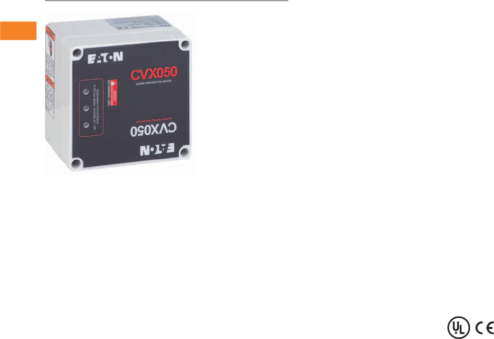
V3-T2-18 Volume 3—Power Distribution and Control Assemblies CA08100004E—April 2014 www.eaton.com
2
2
2
2
2
2
2
2
2
2
2
2
2
2
2
2
2
2
2
2
2
2
2
2
2
2
2
2
2
2
2.1
SPD, Power Conditioning, PF Capacitors and Harmonic Filters
Surge Protection and Power Conditioning
CVX050/100
Contents
Description Page
Introduction . . . . . . . . . . . . . . . . . . . . . . . . . . . . . . . V3-T2-2
Product Overview . . . . . . . . . . . . . . . . . . . . . . . . . . . V3-T2-5
SPD Series for Integration into Electrical
Distribution Equipment . . . . . . . . . . . . . . . . . . . . . V3-T2-7
SPD Series for Mounting External to
Electrical Distribution Equipment . . . . . . . . . . . . . . V3-T2-11
SPV Surge Protective Device . . . . . . . . . . . . . . . . . . V3-T2-16
CVX050/100
Catalog Number Selection . . . . . . . . . . . . . . . . . V3-T2-19
Technical Data and Specifications . . . . . . . . . . . . V3-T2-19
Dimensions . . . . . . . . . . . . . . . . . . . . . . . . . . . . V3-T2-20
SP1 Surge Protective Device . . . . . . . . . . . . . . . . . . V3-T2-21
SP2 Surge Protective Device . . . . . . . . . . . . . . . . . . V3-T2-23
AEGIS Powerline Filters . . . . . . . . . . . . . . . . . . . . . . V3-T2-25
Sag Ride-Through (SRT) . . . . . . . . . . . . . . . . . . . . . . V3-T2-30
Electronic Voltage Regulator (EVR). . . . . . . . . . . . . . V3-T2-36
CVX050/100
Product Description
With over two decades of
experience in the surge
suppression industry and
extensive R&D initiatives,
Eaton is considered a world
leader in surge protective
device (SPD) manufacturing.
All of Eaton’s products are
manufactured in an ISO®
9001:2000 and ISO 14001
certified facility.
Eaton’s CVX050/100 models
are rugged, cost-effective,
high-quality SPDs that feature
self-protected MOVs that
eliminate the failure
characteristics of standard
metal oxide varistors. This
technology results in a fail-safe
device that monitors the
status of the metal oxide disk
and disconnects itself from the
power system when the disk
is approaching breakdown.
The CVX050/100 is easy
to install adjacent or even
internal to electrical
equipment. When installing an
SPD in a retrofit environment,
it is important to mount the
device as close to the
electrical equipment as
possible. Keep the wiring (lead
length) between the electrical
equipment and SPD as short
as possible, and twist or wire
tie the conductors together
to reduce the wire’s
impedance factor.
Application Description
Eaton’s CVX050 and CVX100
SPDs protect electronic
equipment from damaging
transients. These units are
suitable for medium and low
exposure level applications
that require cost-effective,
high quality system
protection including:
●Residential/small business
●Light industrial
●Light commercial
●Branch panel protection
●OEM applications
Features, Benefits
and Functions
●Advanced surge path
technology for high fault
current capacity, low
impedance, high frequency
design
●Rugged NEMA® 4X (IP65)
enclosure
●Large diameter, self-
protected metal oxide
varistors provide long life
and fail-safe operation
●LED monitoring of each
phase
●Wide range of voltage
applications from
100 to 600 Vac and
48 and 125 Vdc
●5-year free replacement
warranty
Optional Features
●External mounting feet
Standards and Certifications
●UL 1449 3rd Edition for
surge protective devices
●CE marked
●Vibration tested IEC
60255-21-1 and -2
Note: CE, CSA and UL on
AC unit only.
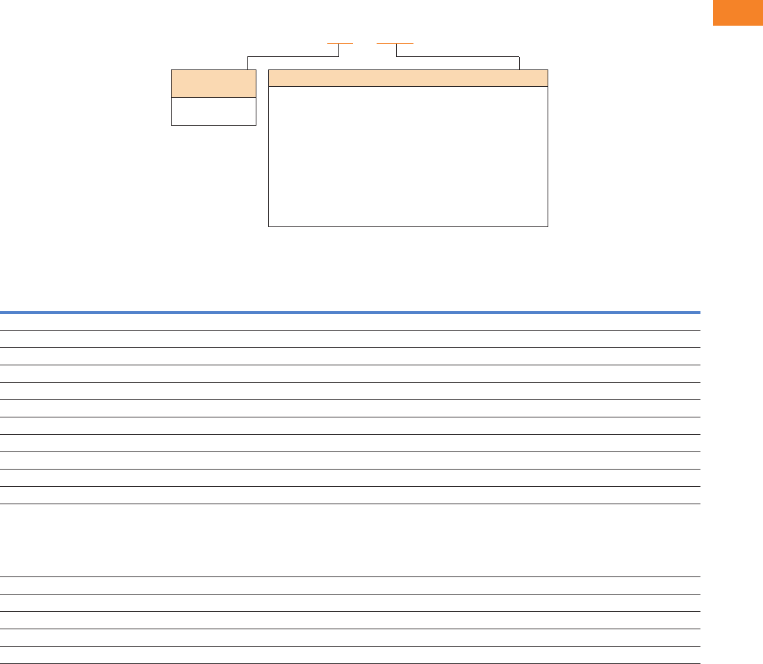
Volume 3—Power Distribution and Control Assemblies CA08100004E—April 2014 www.eaton.com V3-T2-19
2
2
2
2
2
2
2
2
2
2
2
2
2
2
2
2
2
2
2
2
2
2
2
2
2
2
2
2
2
2
2.1
SPD, Power Conditioning, PF Capacitors and Harmonic Filters
Surge Protection and Power Conditioning
Catalog Number Selection
CVX050/100
Technical Data and Specifications
CVX050/100 Model Specifications
Notes
1480L, 600D and 600Y units rated 10 kA In.
2DC models only available in 50 kA.
Description Specification
Peak kA per phase 50, 100
Peak kA per mode 50
Nominal discharge current 20 kA 1
Short-circuit current rating 100 kA
Single-phase voltages 200, 208, 220, 230, 240, 277, 380, 400, 440, 460, 480 Vac
Split-phase voltages 100/200, 110/220/ 120/240 Vac
High leg delta voltages 240 Vac
Wye system voltages 100/175, 110/190, 120/208, 127/220, 220/380, 230/400, 240/415, 277/480, 305/525, 347/600 Vac
Delta system voltages 200, 208, 220, 230, 240, 380, 400, 415, 440, 480, 525, 600 Vac
Direct current Voltage 248 Vdc, 125 Vdc
Input power frequency 47–420 Hz (50/60 Hz typical)
Protection modes Single-phase: L-N, N-G, L-G
Split-phase: L-N, N-G, L-G, L-L
High leg delta: L-N, N-G, L-G, L-L, H-N, H-G, H-L
Wye: L-N, N-G, L-G, L-L
Delta: L-G, L-L
Direct current 1 (DC): L-L, L-G
Number of ports 1
Specific energy 100 kJ/Ohm
Weight ≈2.0 lbs (1.0 kg)
Operating temperature –13°F (–25°C) to +140°F (+60°C)
Vibration tested IEC 60255-21-1 and IEC 60255-21-2
Per Phase Peak
Surge Current
050 = 50 kA
100 = 100 kA
Configuration and Voltage Ranges
230L = Single-phase—200, 208, 220, 230, 240, 277 Vac
480L = Single-phase—480 Vac
240S = Split-phase—100/200, 110/220, 120/240 Vac
240H = Three-phase high leg delta—120/240 Vac
208Y = Three-phase wye (star)—100/174, 110/190, 120/208, 127/220 Vac
480Y = Three-phase wye (star)—220/380, 230/400, 240/415, 277/480 Vac
600Y = Three-phase wye (star)—305/525, 347/600 Vac
240D = Three-phase delta—200, 208, 220, 230, 240 Vac
480D = Three-phase delta—380, 400, 415, 440, 480 Vac
600D = Three-phase delta—525, 600 Vac (600D available in 50 kA only)
048DC = Direct current—48 Vdc 1
125DC = Direct current—125 Vdc 1
CVX 050 - 240S
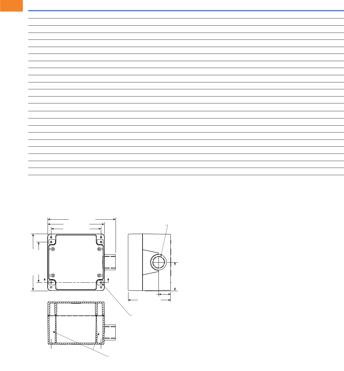
V3-T2-20 Volume 3—Power Distribution and Control Assemblies CA08100004E—April 2014 www.eaton.com
2
2
2
2
2
2
2
2
2
2
2
2
2
2
2
2
2
2
2
2
2
2
2
2
2
2
2
2
2
2
2.1
SPD, Power Conditioning, PF Capacitors and Harmonic Filters
Surge Protection and Power Conditioning
CVX050/100 Voltage Ratings
Dimensions
Approximate Dimensions in Inches (mm)
CVX050/100 Standard Dimensions
Notes
1UL 1449 3rd Edition VPR (voltage protection rating) test environment: All tests performed with 6-inch lead length, positive polarity.
2DC units available in 50 kA only. Voltages shown are the maximum suggested operating voltages and are not UL certified.
Model
System
Configuration
Nominal
System Voltage
MCOV UL 1449-3 VPR 1
L-L L-N L-G N-G L-L L-N L-G N-G
CVX050
230L Single-phase two-wire + ground 200, 208, 220, 230, 240, 277 — 320 640 320 — 1200 1200 1200
480L Single-phase two-wire + ground 380, 400, 440, 460, 480 — 550 1100 550 — 1800 4000 1800
240S Split-phase three-wire + ground 100/200, 110/220, 120/240 300 150 300 150 1200 700 1200 800
208Y Three-phase wye (star) four-wire + ground 100/175, 110/190, 120/208, 127/220 300 150 300 150 1200 700 1200 800
480Y Three-phase wye (star) four-wire + ground 220/380, 230/400, 240/415, 277/480 640 320 640 320 2500 1200 2000 1200
600Y Three-phase wye (star) four-wire + ground 305/525, 347/600 840 420 840 420 2500 1500 2500 1500
240D Three-phase delta three-wire + ground 200, 208, 220, 230, 240 640 — 320 — 2000 — 1200 —
240H Three-phase high leg delta 240 300 150 150 640 1500 700 1200 700
480D Three-phase delta three-wire + ground 380, 400, 415, 440, 480 1100 — 550 — 3000 — 1800 —
600D Three-phase delta three-wire + ground 525, 600 1100 — 700 — 3000 — 2500 —
048DC Direct current 48 Vdc 2130—65— ————
125DC Direct current 125 Vdc
2288— 144— — — — —
CVX100
230L Single-phase two-wire + ground 200, 208, 220, 230, 240, 277 — 320 320 320 — 1200 1200 1200
480L Single-phase two-wire + ground 380, 400, 440, 460, 480 — 550 550 550 — 1800 1800 1800
240S Split-phase three-wire + ground 100/200, 110/220, 120/240 300 150 150 150 1200 700 800 700
208Y Three-phase wye (star) four-wire + ground 100/175, 110/190, 120/208, 127/220 300 150 150 150 1000 600 700 700
480Y Three-phase wye (star) four-wire + ground 220/380, 230/400, 240/415, 277/480 640 320 320 320 1800 1200 1200 1200
600Y Three-phase wye (star) four-wire + ground 305/525, 347/600 840 420 420 420 2500 1500 1500 1500
240D Three-phase delta three-wire + ground 200, 208, 220, 230, 240 640 — 320 — 1800 — 1200 —
240H Three-phase high leg delta 240 300 150 150 150 1200 700 700 700
480D Three-phase delta three-wire + ground 380, 400, 415, 440, 480 1100 — 550 — 3000 — 1800 —
A
A
Mounting Hole Shafts
5.67 (144.0)
4.75 (120.6)
2.37 (60.2)
1.00 (25.4)
3.55 (90.2)
3.39 (86.1)
4.75 (120.6)
4.17 (106.0)
Conduit Fitting
0.75 (19.0) Internal
Taper Pipe Threads
0.17 (4.3)
(4) Mounting Holes
Under Lid
Lid Removed
Section A-A
Dimensions are in Inches (mm)
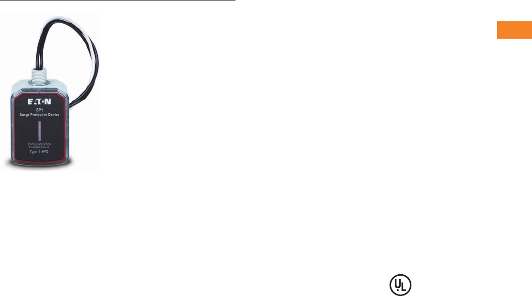
Volume 3—Power Distribution and Control Assemblies CA08100004E—April 2014 www.eaton.com V3-T2-21
2
2
2
2
2
2
2
2
2
2
2
2
2
2
2
2
2
2
2
2
2
2
2
2
2
2
2
2
2
2
2.1
SPD, Power Conditioning, PF Capacitors and Harmonic Filters
Surge Protection and Power Conditioning
SP1 Surge Protective Device
Contents
Description Page
Introduction. . . . . . . . . . . . . . . . . . . . . . . . . . . . . . . V3-T2-2
Product Overview . . . . . . . . . . . . . . . . . . . . . . . . . . V3-T2-5
SPD Series for Integration into Electrical
Distribution Equipment . . . . . . . . . . . . . . . . . . . . V3-T2-7
SPD Series for Mounting External to
Electrical Distribution Equipment . . . . . . . . . . . . . V3-T2-11
SPV Surge Protective Device . . . . . . . . . . . . . . . . . V3-T2-16
CVX050/100 . . . . . . . . . . . . . . . . . . . . . . . . . . . . . . V3-T2-18
SP1 Surge Protective Device
Catalog Number Selection. . . . . . . . . . . . . . . . . V3-T2-22
Technical Data and Specifications . . . . . . . . . . . V3-T2-22
Dimensions . . . . . . . . . . . . . . . . . . . . . . . . . . . . V3-T2-22
SP2 Surge Protective Device . . . . . . . . . . . . . . . . . V3-T2-23
AEGIS Powerline Filters . . . . . . . . . . . . . . . . . . . . . V3-T2-25
Sag Ride-Through (SRT) . . . . . . . . . . . . . . . . . . . . . V3-T2-30
Electronic Voltage Regulator (EVR) . . . . . . . . . . . . . V3-T2-36
SP1 Surge Protective Device
Product Description
Eaton‘s SP1 is a UL 1449 3rd
Edition-listed surge protective
device that provides reliable,
cost-effective surge
protection. This Type 1 SPD
is capable of being installed
on either the line or the load
side of the service entrance
disconnect, and can be used
as a replacement for devices
formerly known as secondary
surge arresters or lightning
arresters, which could not be
manufactured after UL 1449
3rd Edition went into effect
on September 29, 2009. The
unit is available in many
common voltages and
configurations. Multiple
mounting options coupled
with a compact footprint
enables installation of the
SP1 in a wide range of
applications, including panel-
boards, loadcenters, pump
panels, control cabinets, and
other electrical assemblies
and applications.
Installation and operation of
the SP1 is simple. The unit
comes pre-wired with 24.00
inches of 10-gauge wire and
is mounted via the half-inch
nipple that is molded into its
enclosure. Wall or DIN rail
mounting can also be
accomplished with the
addition of an optional kit.
When powered, the unit‘s
light-emitting diode (LED)
indicator reports the status of
the protection elements and
is active when all of them are
intact and providing
protection. Any loss of
protection is signaled when
the LED extinguishes.
Features
●Type 1 SPD capable of
installation on either the
line or the load side of the
service entrance
disconnect
● 20 kA nominal discharge
current rating (In) on most
models
●50 kA per phase surge
current capacity
●Compact footprint—
4.80-inch L x 2.90-inch W x
2.50-inch D
●Pre-wired with 24.00
inches of 10-gauge wire
●Half-inch nipple molded
into enclosure enables
quick and easy mounting
●Optional kit enables wall or
DIN rail mounting
●Two - ye a r w a rr a n t y
Standards and Certifications
●UL 1449 3rd Edition-listed
device
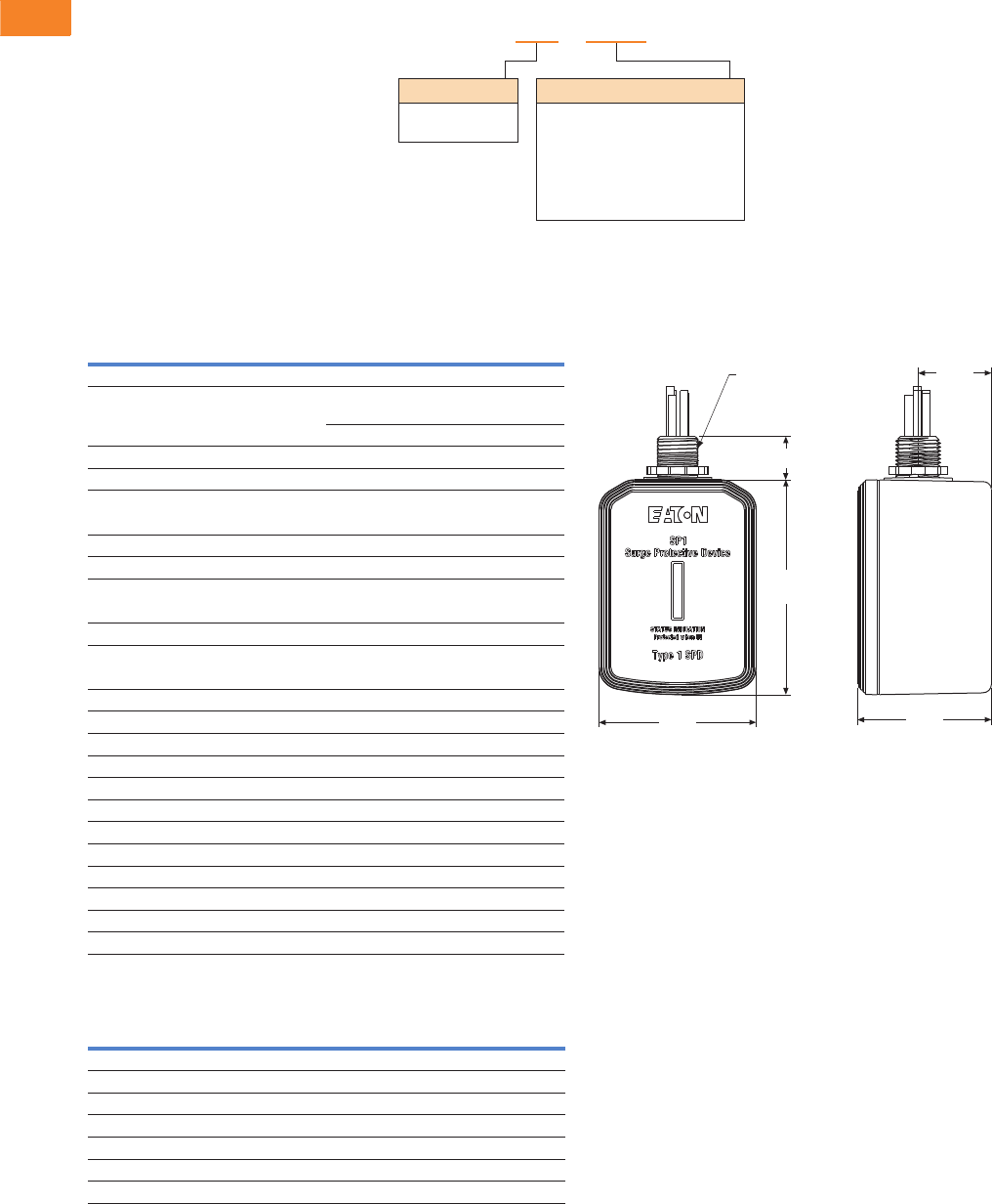
V3-T2-22 Volume 3—Power Distribution and Control Assemblies CA08100004E—April 2014 www.eaton.com
2
2
2
2
2
2
2
2
2
2
2
2
2
2
2
2
2
2
2
2
2
2
2
2
2
2
2
2
2
2
2.1
SPD, Power Conditioning, PF Capacitors and Harmonic Filters
Surge Protection and Power Conditioning
Catalog Number Selection
SP1
Technical Data and Specifications
SP1
ANSI/UL 1449 3rd Edition Voltage Protection Ratings
Series
050 = 50 kA
100 = 100 kA
Voltage Code
240S = 120/240V single split-phase
208Y = 120/208 wye
480Y = 277/480 wye
600Y = 347/600Y wye
240D = 240 delta
480D = 480 delta
600D = 600 delta
SP1 - XXXX
SP1MNTGKIT = optional wall or DIN rail mounting kit
(order separately—not included with SP1 unit)
Description Ratings
Surge current capacity per phase 50 kA
Nominal discharge current (In) 20 kA for SP1-240S, 208Y, 480Y,
240D and 480D
10 kA for SP1-600Y and 600D
Short-circuit current rating (SCCR) 200 kA
SPD type Type 1 (can also be used in Type 2 applications)
System voltages available (Vac)
Single split-phase 120/240
Three-phase wye 120/208, 277/480, 347/600
Three-phase delta 240, 480, 600
Protection modes
Single split-phase and three-phase wye L-N, L-L
Three-phase delta L-G, L-L
Maximum continuous operating voltage (MCOV)
SP1-240S and SP1-208Y 150 L-N, 300 L-L
SP1-480Y 320 L-N, 640 L-G
SP1-600Y 420 L-N, 840 L-G
SP1-240D 300 L-G, 300 L-L
SP1-480D 640 L-G, 640 L-L
SP1-600D 840 L-G, 840 L-L
Input power frequency 50/60 Hz
Enclosure rating NEMA 4
Operating temperature –20°C to 50°C (–4°F to 122°F)
Operating humidity 5–95%, noncondensing
Operating altitude Up to 16,000 ft (5000m)
Agency certification and approvals UL 1449 3rd Edition Listed device
Warranty 2 years
Catalog Number
Protection Mode
L-N L-G L-L
SP1-240S 600 N/A 1000
SP1-208Y 600 N/A 1000
SP1-480Y 1200 N/A 2000
SP1-600Y 1500 N/A 2500
SP1-240D N/A 1000 1000
SP1-480D N/A 2000 2000
SP1-600D N/A 2500 2500
Dimensions
Approximate Dimensions in Inches (mm)
SP1
1/2" (12.7)
Straight Pipe Thread
1.35
(34.3)
.79 (20.1)
3.95
(100.3)
2.89
(73.4)
2.46
(62.5)
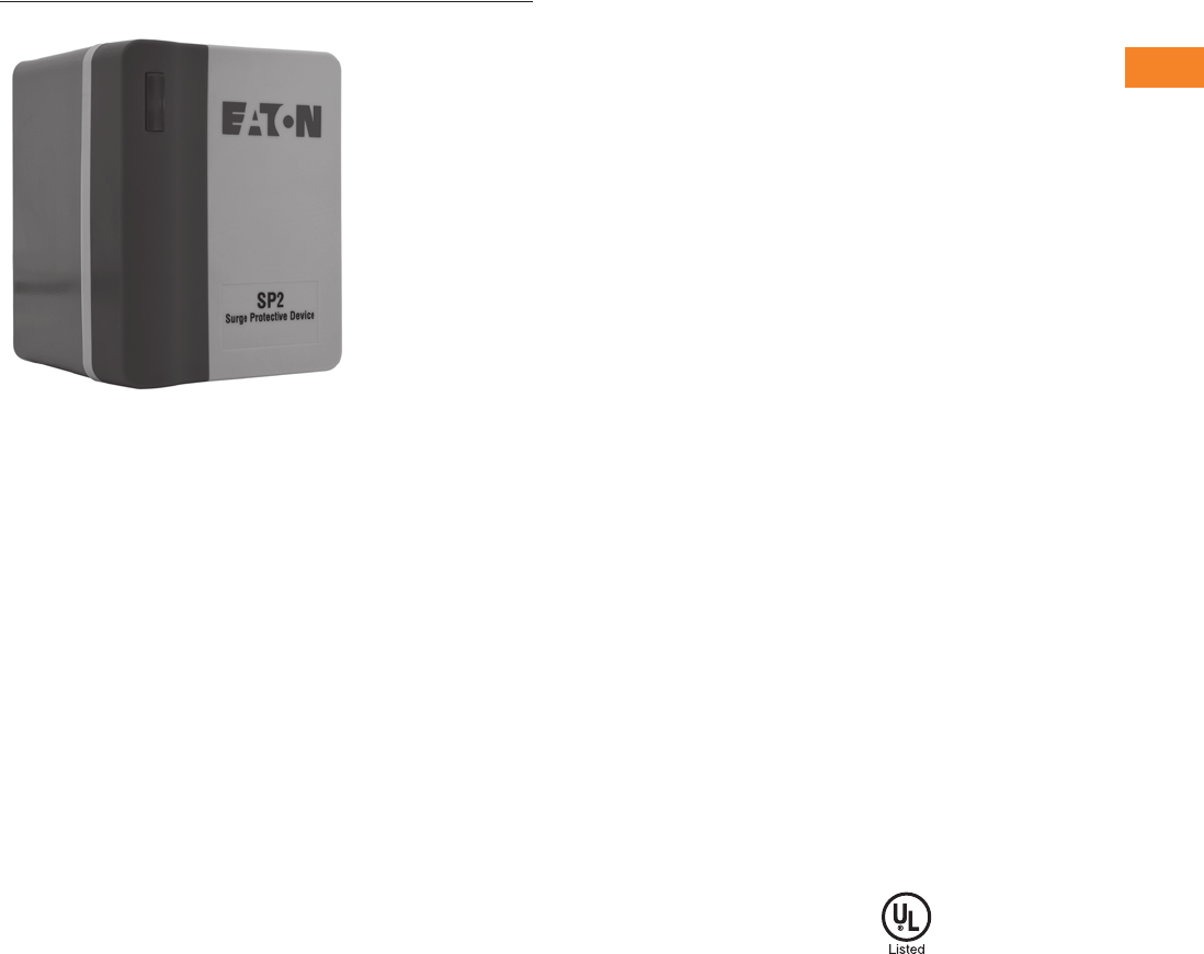
Volume 3—Power Distribution and Control Assemblies CA08100004E—April 2014 www.eaton.com V3-T2-23
2
2
2
2
2
2
2
2
2
2
2
2
2
2
2
2
2
2
2
2
2
2
2
2
2
2
2
2
2
2
2.1
SPD, Power Conditioning, PF Capacitors and Harmonic Filters
Surge Protection and Power Conditioning
Surge Protection for Light Commercial and
UL 508A Panel Applications
SP2 Surge Protective Device
Contents
Description Page
Introduction. . . . . . . . . . . . . . . . . . . . . . . . . . . . . . . V3-T2-2
Product Overview . . . . . . . . . . . . . . . . . . . . . . . . . . V3-T2-5
SPD Series for Integration into Electrical
Distribution Equipment . . . . . . . . . . . . . . . . . . . . V3-T2-7
SPD Series for Mounting External to
Electrical Distribution Equipment . . . . . . . . . . . . . V3-T2-11
SPV Surge Protective Device . . . . . . . . . . . . . . . . . V3-T2-16
CVX050/100 . . . . . . . . . . . . . . . . . . . . . . . . . . . . . . V3-T2-18
SP1 Surge Protective Device . . . . . . . . . . . . . . . . . V3-T2-21
SP2 Surge Protective Device
Product Selection. . . . . . . . . . . . . . . . . . . . . . . . V3-T2-24
Technical Data and Specifications . . . . . . . . . . . V3-T2-24
Dimensions . . . . . . . . . . . . . . . . . . . . . . . . . . . . V3-T2-24
AEGIS Powerline Filters . . . . . . . . . . . . . . . . . . . . . V3-T2-25
Sag Ride-Through (SRT) . . . . . . . . . . . . . . . . . . . . . V3-T2-30
Electronic Voltage Regulator (EVR) . . . . . . . . . . . . . V3-T2-36
SP2 Surge Protective Device
Product Description
The SP2 provides basic
surge protection for light
commercial electrical
systems and OEM equipment
requirements. The SP2 is
available in the most popular
voltage and system
configurations and delivers
superior surge protection
using MOV thermal
disconnect technology
that eliminates the need
for additional overcurrent
protection.
Application Description
By providing surge
protection, the SP2 can
suppress the transients that
are prevalent throughout the
power distribution system to
support reliable operations in
applications including:
●HVAC systems
●Control panels
●Automation cabinets
●Pumping systems
●Lighting systems
●Commercial facilities
●Food processing
●Warehouses
●Retail facilities
●Manufacturing operations
Features, Benefits and
Functions
●Ease of installation—
Compact design allows
for easy installation on an
electrical panel or meter
socket, or integrated into
control cabinets
●Type 1 UL 1449 Third
Edition listed SP2s are
easily selected and
installed on the loadside
or lineside of the service
entrance overcurrent
protective device
●Thermal disconnect
technology eliminates the
need for additional
overcurrent protection
●Compact UV-resistant
NEMA 4X enclosure for
indoor or outdoor
applications
●LED status indicators
provide surge protection
status at a glance—green
when good, red to replace
●Voltage-specific models
protect electrical systems
and equipment, improving
performance by more than
110% over “one-size-fits-
all” economy surge
arresters
●Compact enclosure takes
up less space and can be
installed in tight spaces
●Can be used on single-
phase, split-phase, wye,
delta, and high-leg delta
systems
●All SP2 devices are
individually marked with a
serial number for easy
tracking and identification
●Two - ye a r w a rr a n t y
Standards and Certifications
●UL 1449 Third Edition Type
1 SPD File No. E109835,
cULus
●Built in an ISO 9001 facility
●
Flammability rating UL 94VO
●Designed and tested in
accordance with:
●IEEE C62.41.1
●IEEE C62.41.2
●IEEE C62.43-2005
●IEEE C62.45-2002
●IEEE C62.48-2005
●IEEE C62.62-2010
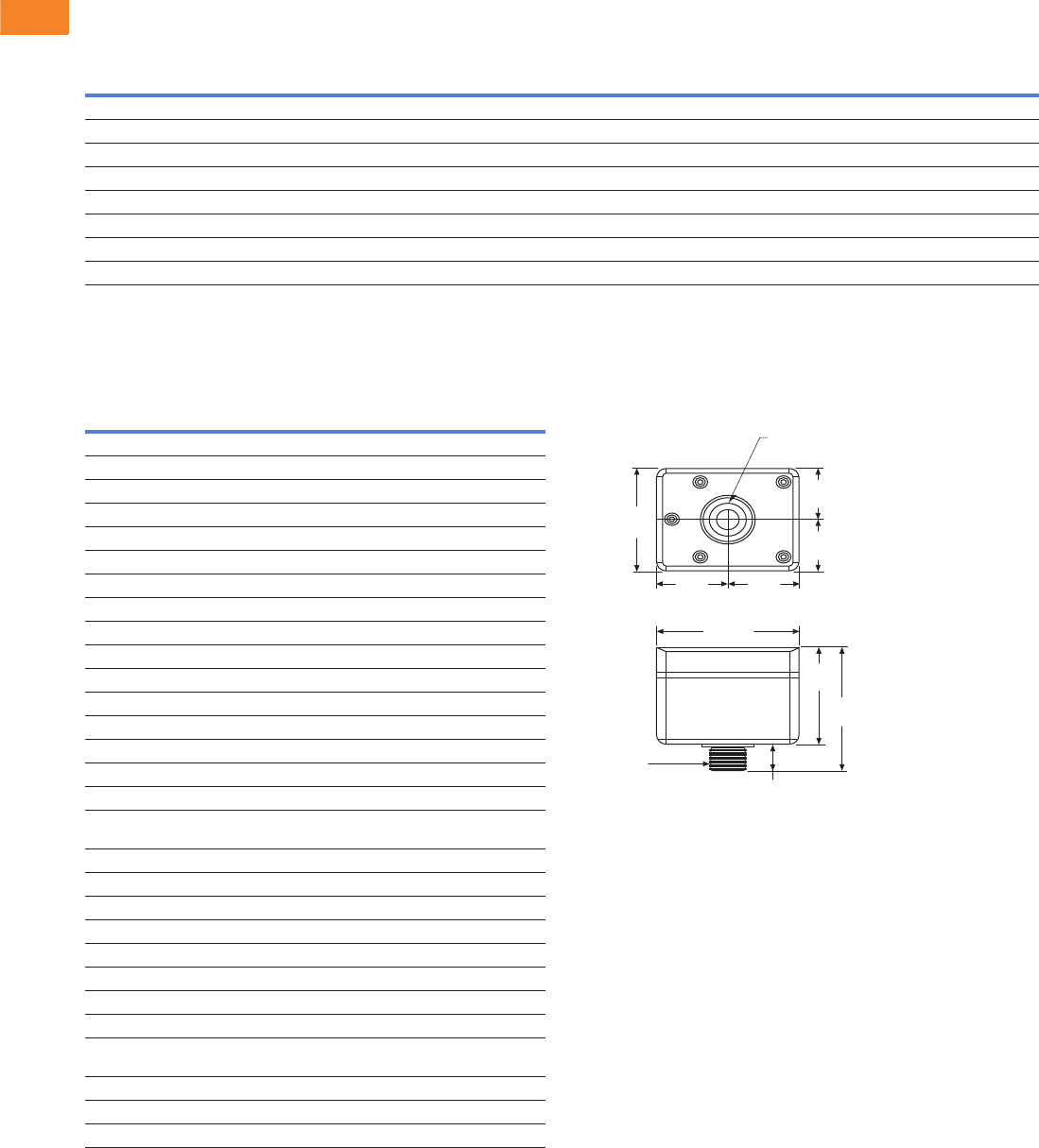
V3-T2-24 Volume 3—Power Distribution and Control Assemblies CA08100004E—April 2014 www.eaton.com
2
2
2
2
2
2
2
2
2
2
2
2
2
2
2
2
2
2
2
2
2
2
2
2
2
2
2
2
2
2
2.1
SPD, Power Conditioning, PF Capacitors and Harmonic Filters
Surge Protection and Power Conditioning
Product Selection
SP2
Technical Data and Specifications
SP2
Dimensions
Approximate Dimensions in Inches (mm)
SP2 Enclosure
Nominal
System
Voltage
Maximum Continuous
Operating AC Voltage
(MCOV)
System
Type
Voltage
Protection
Ratings (VPR)
Connection
Points
Catalog
Number
120 150 Single-phase, two-wire 700 L–N 2 SP2-120
240 320 Single-phase, two-wire 1200 L–N 2 SP2-240
120/240 150 Split-phase, three-wire 700 L–N, 1200 L–L 3 SP2-240S
240 320 Three-phase delta, three-wire + ground 1200 L–G, 2500 L–L 4 SP2-240D
480 550 Three-phase delta, three-wire + ground 1800 L–G, 3000 L–L 4 SP2-480D
120/208 150 Three-phase wye, three-wire + ground 700 L–G, 1200 L–L 4 SP2-208Y
277/480 320 Three-phase wye, three-wire + ground 1200 L–G, 2500 L–L 4 SP2-480Y
347/600 420 Three-phase wye, three-wire + ground 1500 L–G, 2500 L–L 4 SP2-600Y
Description Specification
Markets Light commercial and UL 508A panels
Product warranty 2 years
System types Single, split, delta, and wye
Nominal system voltage 120, 208, 240, 480, 600 Vac
Installation Two-, three-, four-wire
Maximum continuous operating AC voltage Matched to nominal voltage
MCOV 150–550 Vac (see table above)
L–N protection Yes (single-phase units)
L–L protection Yes
L–G protection Yes (three-phase units)
Protection Surges and transients
SCCR 200 kA
Nominal discharge current (8 x 20 μs) In 10 kA
Maximum discharge current (8 x 20 μs) Imax 45 kA per phase
Response time tA <25 ns
Voltage protection ratings (VPRs) See table above
Overcurrent device (if required by local code) Circuit breaker or fuse sized to protect wires per
local codes
Frequency 50/60 Hz
Operating status / fault indication One bi-color LED—green (good) / red (replace)
Conductor gauge/length 10 AWG stranded copper / 18 inches
Mounting Chase nipple (¾” NPS)
Enclosure rating NEMA 4X—UL 94-5VA
Degree of protection (installed state) IP20 (finger-safe)
Install location Indoor/outdoor
Circuit location Lineside/loadside
Standards / agency information UL 1449 Third Edition Type 1 Listed SPD—
cULus, RoHS compliant
Operating temperature –40°C to +65°C
Maximum operating altitude 12,000 feet
Weight 17 oz (476g)
3.38
(85.9)
1.69
(42.9)
1.69
(42.9)
3.19
(81.0)
4.06
(103.1)
0.87
(22.1)
4.13
(104.9)
2.06
(52.3)
2.06
(52.3)
1.06 (26.9)
Diameter
¾" NPS

Volume 3—Power Distribution and Control Assemblies CA08100004E—April 2014 www.eaton.com V3-T2-25
2
2
2
2
2
2
2
2
2
2
2
2
2
2
2
2
2
2
2
2
2
2
2
2
2
2
2
2
2
2
2.1
SPD, Power Conditioning, PF Capacitors and Harmonic Filters
Surge Protection and Power Conditioning
AEGIS Solutions
Contents
Description Page
Introduction. . . . . . . . . . . . . . . . . . . . . . . . . . . . . . . V3-T2-2
Product Overview . . . . . . . . . . . . . . . . . . . . . . . . . . V3-T2-5
SPD Series for Integration into Electrical
Distribution Equipment . . . . . . . . . . . . . . . . . . . . V3-T2-7
SPD Series for Mounting External to
Electrical Distribution Equipment . . . . . . . . . . . . . V3-T2-11
SPV Surge Protective Device . . . . . . . . . . . . . . . . . V3-T2-16
CVX050/100 . . . . . . . . . . . . . . . . . . . . . . . . . . . . . . V3-T2-18
SP1 Surge Protective Device . . . . . . . . . . . . . . . . . V3-T2-21
SP2 Surge Protective Device . . . . . . . . . . . . . . . . . V3-T2-23
AEGIS Powerline Filters
Features, Benefits and Functions . . . . . . . . . . . V3-T2-26
Standards and Certifications . . . . . . . . . . . . . . . V3-T2-27
Catalog Number Selection. . . . . . . . . . . . . . . . . V3-T2-27
Technical Data and Specifications . . . . . . . . . . . V3-T2-28
Sag Ride-Through (SRT) . . . . . . . . . . . . . . . . . . . . . V3-T2-30
Electronic Voltage Regulator (EVR) . . . . . . . . . . . . . V3-T2-36
AEGIS Powerline Filters
Product Description
Eaton AEGIS™ Series line
filters and surge protectors
are specifically designed to
protect sensitive electronics
from hazards that exist within
a facility. The AEGIS Series
hybrid filter reacts instantly to
changes in voltage regardless
of phase angle or polarity. In
comparison to other line
filters, this technology
provides a higher level of
suppression, reliability and
life expectancy.
Application Description
By providing surge protection
and line filtering, AEGIS
devices can suppress the
noise and transients
prevalent throughout the
power distribution system to
support reliable operations in
applications including:
●Instrumentation
●Water treatment facilities
●Pulp and paper operations
●Refrigeration and heating
plants
●Petrochemical and refinery
●Food processing
●Te x t i le s
●Automotive assembly
●Manufacturing operations
No matter where transients
originate, the application of
AEGIS Series devices will
help protect sensitive
electronic equipment
including:
●Programmable logic
controllers (PLCs)
●Scanning devices
●Automatic teller machines
(ATMs)
●Cash registers
●Alarm systems
●Microprocessor-controlled
●OEM products
●Robotics
●CAD/CAM systems
●Control equipment
●Medical electronics and
devices
AEGIS Series devices are
available in a variety of
common voltages and
configurations.
Why Should Sensitive Electronic
Loads be Protected?
PLC manufacturers and
service technicians
recommend the use of power
line filters and surge
suppressors to prevent
downtime and equipment
damage due to surges and
electrical line noise. Studies
have shown that failure to
protect sensitive electronic
loads costs American
manufacturing and
commercial and service
industries over $39 billion per
year in lost time and revenue.
Preventing these losses is a
major cost-saving
opportunity.
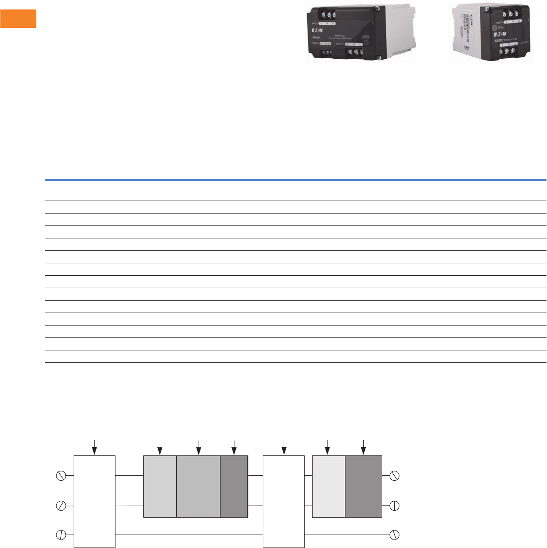
V3-T2-26 Volume 3—Power Distribution and Control Assemblies CA08100004E—April 2014 www.eaton.com
2
2
2
2
2
2
2
2
2
2
2
2
2
2
2
2
2
2
2
2
2
2
2
2
2
2
2
2
2
2
2.1
SPD, Power Conditioning, PF Capacitors and Harmonic Filters
Surge Protection and Power Conditioning
Features, Benefits and Functions
●Compact design with
multiple mounting options
●Meets new UL safety
standards for surge and
filtering protection
●AC models available with
up to 80 kA surge current
capacity ratings
●DIN rail mounting available
on most models
●Contains no replaceable
parts or items that require
periodic maintenance
●Alarm contact available
●Five- to ten-year warranty
standard dependent on
model; warranty extended
an additional five years if
registered
The breadth of the AEGIS
Series’ features, options and
configurations ensures that
the correct unit is available
for all critical electrical
applications, including control
panels, security systems,
measurement systems,
lab equipment and other
point-of-use applications.
The AEGIS PH Series Protects Critical
Loads up to 20A The AEGIS PV Series Protects Critical
Loads up to 5A
AEGIS Summary
AEGIS PH and PV Series Hybrid Powerline Filters
Three-Wire Design has Normal and Common Mode Protection (L-N, L-G, N-G)
Notes
1Optional on 10A and 30A models only.
2120 Vac models only.
3Ratings shown for 120 Vac models, other voltages listed in Technical Data.
4Optional on 30A and 60A models only.
5Available on the PH Series only.
Specifications PH PV CF CN
Voltage 120/240 Vac 120/240 Vac 120/240 Vac
24/48 Vdc
120/240 Vac
24/48 Vdc
Current range 3–20A 1–5A 10–60A 30A
DIN mounting Yes Yes Yes 1No
UL 1283 5th Edition & UL 1449 3rd Edition Yes Yes Yes 2Yes 2
Filtering Yes Yes Yes No
EMI/RFI filtering attenuation at 100 kHz 75 dB 50 dB 40 dB N/A
L to G, L to N & N to G protection modes Yes Yes Yes Yes
Peak kA per phase / mode 60/30 40/20 80/40 80/40
UL nominal discharge current (In) 5 kA 5 kA 5 kA 5 kA
UL voltage protection rating (VPR) L–G / L–N 3330/400 330/400 500/500 500/500
Short-circuit current rating (SCCR) 5 kA 5 kA 10 kA 10 kA
Alarm contacts Yes No Yes 4No
Standard warranty / registered warranty (years) 10/15 10/15 5/10 5/10
Communication line protection (UL 497A) No No Yes 4No
Power
Input
Primary
Surge
Protection
High
Frequency
Capacitor
Series
Blocking
Inductors
High
Performance
Trac king Filter
Secondary
Surge
Protection
Status
Indicator
Lights
Power
Output
Optional
Form C
Contacts 5
L
N
G
L
N
G
Normal
Mode
Common
Mode
Normal
Mode
Common
Mode
LED Form C
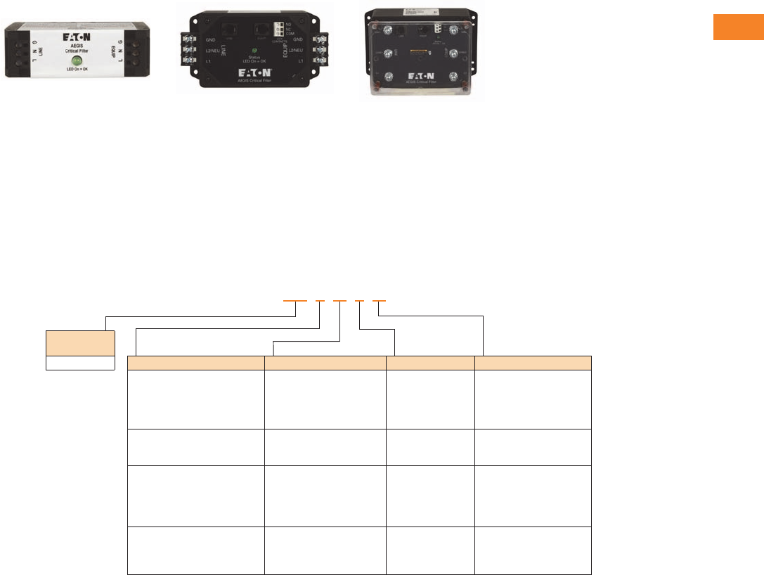
Volume 3—Power Distribution and Control Assemblies CA08100004E—April 2014 www.eaton.com V3-T2-27
2
2
2
2
2
2
2
2
2
2
2
2
2
2
2
2
2
2
2
2
2
2
2
2
2
2
2
2
2
2
2.1
SPD, Power Conditioning, PF Capacitors and Harmonic Filters
Surge Protection and Power Conditioning
AEGIS Products
Standards and Certifications
●UL 1449 Third Edition
●UL 1283 Fifth Edition
●Built in an ISO® 9001
facility
●Designed and tested in
accordance with:
●IEEE® C62.41.1
●IEEE C62.41.2
●IEEE C62.43-2005
●IEEE C62.45-2002
●IEEE C62.48-2005
IEEE C62.62-2010
Catalog Number Selection
AEGIS
Notes
1Only available for 10A CF version.
2Only available for 10A, 120V CF version.
3Only available for 30A and 60A CF version.
Protection/Filtering Voltage Amperage Options
PH = Premium hybrid
protection with filtering
120 = 120 Vac
240 = 240 Vac
03 = 3A
05 = 5A
10 = 10A
15 = 15A
20 = 20A
DIN mount standard
PV = Premium protection
with filtering
120 = 120 Vac
240 = 240 Vac
01 = 1A
03 = 3A
05 = 5A
DIN mount standard
CF = Critical protection
with filtering
120 = 120 Vac
240 = 240 Vac
024 = 24 Vdc
048 = 48 Vdc
10 = 10A
30 = 30A
60 = 60A
DIN = DIN mount 1
CP =Compact
2
RJ = Telcom protection
and Form C status
contacts 3
CN = Critical protection
without filtering
120 = 120 Vac
240 = 240 Vac
024 = 24 Vdc
048 = 48 Vdc
30 = 30A
Product
Family/OEM
AG
AG

V3-T2-28 Volume 3—Power Distribution and Control Assemblies CA08100004E—April 2014 www.eaton.com
2
2
2
2
2
2
2
2
2
2
2
2
2
2
2
2
2
2
2
2
2
2
2
2
2
2
2
2
2
2
2.1
SPD, Power Conditioning, PF Capacitors and Harmonic Filters
Surge Protection and Power Conditioning
Technical Data and Specifications
AEGIS PH and PV
AEGIS CF
Note
1Optional.
PH 120 Vac PH 240 Vac PV 120 Vac PV 240 Vac
Specifications 3, 5, 10, 15, 20A 3, 5, 10, 15, 20A 1, 3, 5A 1, 3, 5A
DIN mounting Yes Yes Yes Yes
UL 1283 5th Edition and UL 1449 3rd Edition Yes Yes Yes Yes
Filtering Yes Yes Yes Yes
EMI/RFI filtering attenuation at 100 kHz 75 dB 75 dB 50 dB 50 dB
L–G, L–N and N–G protection modes Yes Yes Yes Yes
Peak kA per phase/mode 60/30 60/30 40/20 40/20
UL nominal discharge current (In) 5 kA 5 kA 5 kA 5 kA
UL voltage protection rating (VPR) L–G / L–N / N–G 330/400/330 600/700/600 330/400/330 600/700/600
MCOV 150 275 150 275
Short-circuit current rating (SCCR) 5 kA 5 kA 5 kA 5 kA
Alarm contacts Yes Yes No No
Standard warranty / registered warranty (years) 10/15 10/15 10/15 10/15
Communication line protection (UL 497A) No No No No
Specifications
CF 24 Vdc CF 48 Vdc CF 120 Vac CF 240 Vac
10A 10A 10A 10A 10A 10A 30A 60A 10A 10A 30A 60A
DIN mounting Yes No Yes No Yes No Yes 1Yes 1Yes No No Yes 1
UL 1283 5th Edition and
UL 1449 3rd Edition
— — — — Yes Yes Yes Yes Yes — — —
UL 1283 4th Edition — — — — — — — — — Yes Yes Yes
Filtering Yes Yes Yes Yes Yes Yes Yes Yes Yes Yes Yes Yes
EMI/RFI filtering attenuation
at 100 kHz
40 dB 40 dB 40 dB 40 dB 40 dB 40 dB 40 dB 40 dB 40 dB 40 dB 40 dB 40 dB
L–G, L–N and N–G
protection modes
Yes Yes Yes Yes Yes Yes Yes Yes Yes Yes Yes Yes
Peak kA per phase/mode 6/2 6/2 20/6 20/6 30/10 40/20 80/40 80/40 30/10 24/8 56/24 56/24
UL nominal discharge
current (In)
N/A N/A N/A N/A 3 kA 5 kA 5 kA 5 kA 3 kA N/A N/A N/A
UL voltage protection rating
(VPR) L–G / L–N / N–G
N/A N/A N/A N/A 500/500/500 500/500/500 500/500/500 500/500/500 900/800/900 N/A N/A N/A
MCOV 30 30 50 50 150 150 150 150 275 275 275 275
Short-circuit current
rating (SCCR)
10 kA 10 kA 10 kA 10 kA 10 kA 10 kA 10 kA 10 kA 10 kA 10 kA 10 kA 10 kA
Alarm contacts No No No No No No No No No No No No
Standard warranty /
registered warranty (years)
5/10 5/10 5/10 5/10 5/10 5/10 5/10 5/10 5/10 5/10 5/10 5/10
Communication line
protection (UL 497A)
No No No No No No Yes 1Yes 1No No Yes 1Yes 1

Volume 3—Power Distribution and Control Assemblies CA08100004E—April 2014 www.eaton.com V3-T2-29
2
2
2
2
2
2
2
2
2
2
2
2
2
2
2
2
2
2
2
2
2
2
2
2
2
2
2
2
2
2
2.1
SPD, Power Conditioning, PF Capacitors and Harmonic Filters
Surge Protection and Power Conditioning
AEGIS CN
Maximum EMI/RFI Attenuation—MIL-STD-220
Let-Through Voltages Based on IEEE Std. C62.62-2010 Testing Waveforms 1
Note
1All tests conducted on 120 Vac units.
Specifications
24 Vdc 48 Vdc 120 Vac 240 Vac
30A 30A 30A 30A
DIN mounting No No No No
UL 1283 5th Edition and UL 1449 3rd Edition — — Yes —
UL 1283 4th Edition — — — Yes
Filtering No No No No
EMI/RFI filtering attenuation at 100 kHz N/A N/A N/A N/A
L–G, L–N and N–G protection modes Yes Yes Yes Yes
Peak kA per phase/mode 20/6 46/20 80/40 56/24
UL nominal discharge current (In) N/A N/A 5 kA N/A
UL voltage protection rating (VPR) L–G / L–N / N–G N/A N/A 500/500/500 N/A
MCOV 30 50 150 275
Short-circuit current rating (SCCR) 10 kA 10 kA 10 kA 10 kA
Alarm contacts No No No No
Standard warranty / registered warranty (years) 5/10 5/10 5/10 5/10
Communication line protection (UL 497A) No No No No
Model 10 kHz 100 kHz 1 MHz 10 MHz 100 MHz
Maximum
Attenuation
Frequency
AGPH120AG 30 dB 74 dB 76 dB 37 dB 36 dB 101 dB at 0.5 MHz
AGPV120AG 27 dB 56 dB 55 dB 36 dB 28 dB 66 dB at 0.085 MHz
AGCF12010-CP 16 dB 35 dB 62 dB 40 dB 50 dB 68 dB at 1.25 MHz
AGCF12010-DIN 16 dB 35 dB 56 dB 29 dB 51 dB 66 dB at 0.7 MHz
AGCF12010 17 dB 35 dB 64 dB 33 dB 51 dB 64 dB at 1.0 MHz
AGCF12030 24 dB 44 dB 58 dB 42 dB 53 dB 67 dB at 0.6 MHz
AGCF12060 20 dB 48 dB 53 dB 29 dB 46 dB 69 dB at 0.4 MHz
AEGIS Series
Test Impulse AGPH120AG AGPV120AG AGCF12010 AGCF12010-DIN AGCF12010-CP AGCF12030AGx AGCF12060AGx AGCN12030
IEEE Category A
100 kHz ring wave
6000V, 200A
25V 30V 150V 300V 300V 150V 90V 400V
IEEE Category B
100 kHz ring wave
6000V, 500A
35V 40V 330V 400V 400V 330V 230V 500V
IEEE Category B
combination wave
6000V, 3000A
(UL 1449-3 VPR)
360V 370V 470V 480V 460V 460V 450V 460V
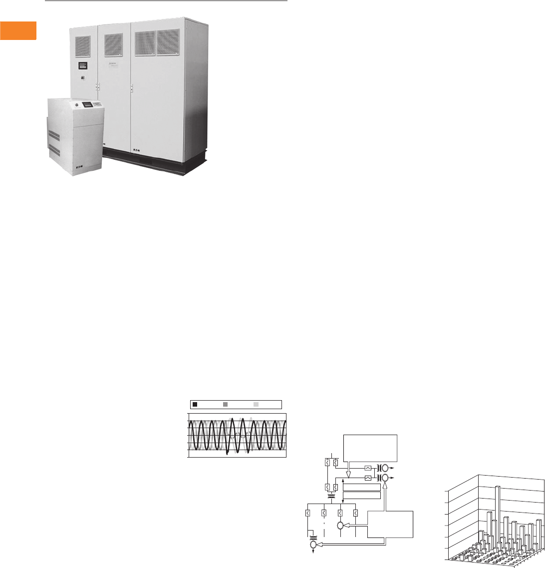
V3-T2-30 Volume 3—Power Distribution and Control Assemblies CA08100004E—April 2014 www.eaton.com
2
2
2
2
2
2
2
2
2
2
2
2
2
2
2
2
2
2
2
2
2
2
2
2
2
2
2
2
2
2
2.1
SPD, Power Conditioning, PF Capacitors and Harmonic Filters
Surge Protection and Power Conditioning
Sag Ride-Through (SRT)
Contents
Description Page
Introduction . . . . . . . . . . . . . . . . . . . . . . . . . . . . . . . V3-T2-2
Product Overview . . . . . . . . . . . . . . . . . . . . . . . . . . . V3-T2-5
SPD Series for Integration into Electrical
Distribution Equipment . . . . . . . . . . . . . . . . . . . . . V3-T2-7
SPD Series for Mounting External to
Electrical Distribution Equipment . . . . . . . . . . . . . . V3-T2-11
SPV Surge Protective Device . . . . . . . . . . . . . . . . . . V3-T2-16
CVX050/100 . . . . . . . . . . . . . . . . . . . . . . . . . . . . . . . V3-T2-18
SP1 Surge Protective Device . . . . . . . . . . . . . . . . . . V3-T2-21
SP2 Surge Protective Device . . . . . . . . . . . . . . . . . . V3-T2-23
AEGIS Powerline Filters . . . . . . . . . . . . . . . . . . . . . . V3-T2-25
Sag Ride-Through (SRT)
Application Description . . . . . . . . . . . . . . . . . . . . V3-T2-31
Features, Benefits and Functions . . . . . . . . . . . . V3-T2-31
Catalog Number Selection. . . . . . . . . . . . . . . . . . V3-T2-32
Technical Data and Specifications . . . . . . . . . . . . V3-T2-33
Dimensions . . . . . . . . . . . . . . . . . . . . . . . . . . . . . V3-T2-35
Electronic Voltage Regulator (EVR). . . . . . . . . . . . . . V3-T2-36
Sag Ride-Through (SRT)
Product Description
Eaton’s sag ride-through is
the first of its kind.
The SRT power conditioner
prevents expensive
electrical downtime. The
SRT represents Eaton’s
state-of-the-art solution to
today’s power conditioning
challenges.
The Problem—Voltage Sags
and Brownouts
The ability of a plant to
ride-through voltage sags
can have a significant
impact on operations and
competitiveness. In the
United States, voltage sags
cost billions of dollars in
lost production, interruption,
damaged materials, retooling
and scrap. In addition,
sags can cause: increased
operating costs, the need
for product reworks, safety
hazards, equipment damage
and/or failure, reduced
product quality, increased
clean-up, additional labor
costs, increased scrap
material and costs associated
with investigations into
the problem.
Today’s industrial and large
commercial electricity
customers are becoming
more sensitive to power
disturbances and are
demanding better electric
quality. However, the quality
of power grids is not
significantly improving.
Customers still experience
power quality problems
that affect plant operations
and profitability.
Deep, Single-Phase Sag
Definition of Voltage Sag
A voltage sag is a sudden,
momentary decrease in
supply voltage. It can last
from a cycle to several
seconds. Voltage sags are
most often caused by faults
on the electrical transmission
or distribution system. They
can be caused by lightning
strikes, animal contact,
starting of large motors
or an internal fault within
a customer’s facility.
Depending on the proximity
to the fault, which can be
hundreds of miles away,
the voltage during the sag
is typically 40%–90% of
nominal utility voltage. The
operation of circuit breakers,
fuses and reclosers limits
most sags to less than
15 cycles.
Voltage sags are experienced
10 to 20 times more
frequently than complete
outages. However, voltage
sags are equally disruptive
to sensitive equipment.
Voltage Sags
Regularity of Voltage Sags
EPRI conducted a two-year
study of power quality levels
on distribution systems in the
United States. A variation
event was recorded every
time the voltage dropped
below 90% of the nominal.
The results are shown below.
A typical distribution system
customer experiences about
50 events per year when the
voltage drops below 90%,
and only about two events
per year when the voltage
drops below 30% of nominal.
The utility study concluded
that sags represented almost
all of the events experienced
at a typical facility.
Events per Year
600
400
200
0
-200
-400
-600
Input A Input A Input A
End
Users
Transmission
Generation
Distribution
End User
End
User
Feeder
Breakers
1. Fault occurs on
the transmission
or distribution
system
2. Creates a sag
event for all
users on the
system
6
5
4
3
2
1
0
20 – 50
10 – 20
6 – 10 5
4
3
2
1
60 – 70
30 – 40
6 – 10
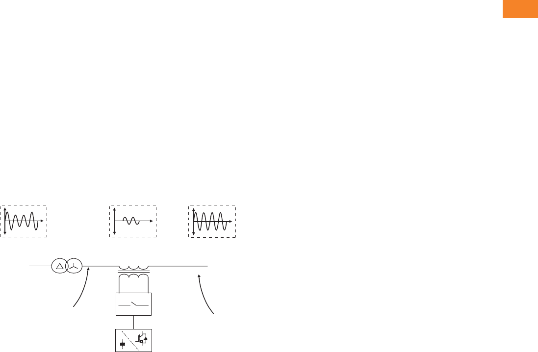
Volume 3—Power Distribution and Control Assemblies CA08100004E—April 2014 www.eaton.com V3-T2-31
2
2
2
2
2
2
2
2
2
2
2
2
2
2
2
2
2
2
2
2
2
2
2
2
2
2
2
2
2
2
2.1
SPD, Power Conditioning, PF Capacitors and Harmonic Filters
Surge Protection and Power Conditioning
Application Description
Industries and Applications
Affected by Sags
Key industries:
●Semi-conductor
manufacturers
●Communications
●Steel mills
●Petroleum and chemical
processing
●Health care
●Paper mills
●Automotives
●Te x t i l e
●Printing
●Plastics
●Other manufacturing
Equipment or processes:
●Manufacturing process
controllers
●Variable speed drives
●Robotics
●Motor conductor
●Telephone systems
●HID lighting
●HVAC controls
●Medical equipment
●Computers
Block Diagram of the SRT Active Voltage Conditioner
3-Phase
Utility
Supply
3-Phase
Load
Voltage
Voltage Source
Inverter
Injection
Transformer
Bypass Circuit
Secondary
Primary
Distribution
Transformer
SRT Input
3-Phase Compensating
Voltage
SRT Output
Features, Benefits and Functions
Sag Correction Using the SRT
The SRT is a high
performance, inverter-
based voltage conditioning
device developed to provide
protection to sensitive loads
against commonly occurring
voltage sags.
The SRT monitors the
incoming supply voltage and
when it deviates from the
nominal voltage level, the
SRT achieves voltage
conditioning by injecting the
appropriate correction voltage
in series with the power
supply. The SRT provides an
extremely fast reaction time
and subcycle response to sag
events that would otherwise
cause loads to drop out.
The SRT is designed for low
voltage systems (600 to 208,
three-phase) and is also
offered in medium voltage
applications from up to 50
MVA. Installation is simple
and the SRT provides
customers with a new
solution to improve
productivity and reduce
downtime for sag related
problems.
The SRT meets the
stringent requirements
of the Semi-F47 standard;
a key requirement for SAG
correction in the semi-
conductor industry.
●Complete correction
of single-phase voltage
sags down to 63% for
30 seconds
●Partial correction of three-
phase sags down to 50%
for 30 seconds
●Correction of utility voltage
unbalance (from network
side of transformer)
●Attenuation of voltage
flicker
Continuous Regulation
The Sag Ride-Through is an
active voltage conditioner.
This means it will constantly
respond to voltage sags and
swells in the +/–10% range
with a regulated output in the
+/–1% range. The SRT can be
applied to the main service
entrance, at branch locations
or in front critical loads. The
SRT provides an outstanding
return on investment. It
delivers operation productivity
that is just not possible with
traditional tap switching or
ferroresonant technologies.
The SRT consists of a voltage
source inverter, bypass circuit
and an injection transformer
connected in series between
the incoming utility supply
and the load, as shown in
the figure below. For the
standard sag correcting
model, the injection
transformer consists of a
boost component. The SRT
monitors the incoming supply
voltage and when it deviates
from the nominal voltage
level the SRT inserts an
appropriate compensating
voltage using the IGBT
inverter and series injection
transformer. Energy is
sourced from the supply
during this time. This
regulates the load voltage
to its nominal value,
thus eliminating voltage
disturbances from the utility
supply affecting the load.

V3-T2-32 Volume 3—Power Distribution and Control Assemblies CA08100004E—April 2014 www.eaton.com
2
2
2
2
2
2
2
2
2
2
2
2
2
2
2
2
2
2
2
2
2
2
2
2
2
2
2
2
2
2
2.1
SPD, Power Conditioning, PF Capacitors and Harmonic Filters
Surge Protection and Power Conditioning
Catalog Number Selection
SRT2
Notes
1For 50 Hz international applications, consult factory.
2Terminal cabinet required on all units 200 kVA and larger except when a bypass is required.
Frequency
A = 60 Hz
B = 50 Hz 1
Load kVA, 30% Load kVA, 40%
0150
0200
0300
0400
0600
0800
1000
1200
1500
2000
2400
0150
0225
0300
0450
0600
0750
0900
1200
1500
1800
Options
Blank = None
TC = Terminal cabinet 2
Voltage
208
480
600
Three-phase/three-wire
Correction
A = 40% (+10/–40%)
B = 30% (+10/–30%)
SRT2 1200 480 A A – TC

Volume 3—Power Distribution and Control Assemblies CA08100004E—April 2014 www.eaton.com V3-T2-33
2
2
2
2
2
2
2
2
2
2
2
2
2
2
2
2
2
2
2
2
2
2
2
2
2
2
2
2
2
2
2.1
SPD, Power Conditioning, PF Capacitors and Harmonic Filters
Surge Protection and Power Conditioning
Technical Data and Specifications
SRT Specifications
Notes
1If SRT has tripped (offline) due to below threshold input voltages, it cannot be restarted until the system voltage is at least this % of the nominal.
2Single-phase-to-ground fault occurring on the utility side of a delta-wye distribution transformer.
3The SRT provides continuous correction and only transitions to and from bypass when manually starting and stopping or under fault or overload conditions. The transition from bypass to inverter
takes up to 750 ms. The autoresettable bypass mode of operation includes an additional 5-second delay allowing time for the fault to clear.
Description Specifications
Load Capacity
Capacity (kVA) 150 kVA to 50 MVA (as specified per model)
Displacement power factor of connected load 0–1, leading or lagging
Crest factor for rated kVA 2.0 at 100% of rated load for continuous operation (including up to 10% voltage correction)
Overload—30 seconds 150% with up to 10% of voltage correction
Input Supply
Nominal supply voltage 208/480/600V, 60 Hz three-phase, three-wire plus ground (higher system voltages supplied to requirement up to 36 kV)
Maximum supply voltage 110% of nominal supply voltage
Minimum three-phase supply voltage
Running 50% of nominal supply voltage
Starting 175% of nominal supply voltage
Minimum single-phase-to-ground supply voltage 2
Running 25% of nominal supply voltage
Starting 163% of nominal supply voltage
Efficiency of system 98–99%
Output Supply
Nominal voltage (V) 208/480/600V, 60 Hz; three-phase, three-wire plus ground (higher system voltages supplied to requirement)
Three-phase balanced correction +30% for at least 30 seconds for 100% correction
Single-phase-to-ground correction 2+45% for at least 30 seconds; +10% continuous three-phase correction (all models). Consult factory for specialist correction requirements.
Voltage regulation ±1% up to 10% continuous three-phase correction ±2.5% at 30% three-phase correction
Response (to sag event) Initial sag correction applied within 1 ms, remainder over the next cycle
Response to swell event ±1% up to a 10% continuous three-phase correction with initial swell correction applied within 1 ms, remainder over the next cycle
Bypass
Nominal power SRT rating (kVA)
Maximum overload capacity (in bypass):
For 10 minutes (%) 125
For 1 minute (%) 150
For 600 milliseconds (%) 700
For 100 milliseconds (%) 1000
Transfer time 3
Inverter to bypass (ms) <0.5
Bypass to inverter (ms) <40–750
Environmental
Operating temperature 32°F to 104°F (0 to 40°C); 122°F (50°C) maximum with 20% load derating
Cooling Forced ventilation
Capacity derating with elevation –1.2% every 100m above 1000m
Humidity <95%, noncondensing
Warranty 1 year

V3-T2-34 Volume 3—Power Distribution and Control Assemblies CA08100004E—April 2014 www.eaton.com
2
2
2
2
2
2
2
2
2
2
2
2
2
2
2
2
2
2
2
2
2
2
2
2
2
2
2
2
2
2
2.1
SPD, Power Conditioning, PF Capacitors and Harmonic Filters
Surge Protection and Power Conditioning
System Capacities
Model Number
Load Capacity at Normal
Voltage 480V (kVA)
Fault
Capacity (kVA)
System
Efficiency (%)
System Dissipation
(Worst Case) (kW)
Airflow
(mm3/min)
40% Correction
SRT20150480AA 150 40 97.55 3.8 18
SRT20225480AA 225 40 97.77 5.2 18
SRT20300480AA 300 40 98.00 6.1 18
SRT20450480AA 450 40 98.22 8.0 36
SRT20600480AA 600 40 98.44 9.8 36
SRT20750480AA 750 40 98.44 12.2 54
SRT20900480AA 900 40 98.55 13.2 54
SRT21200480AA 1200 40 98.55 18.1 72
SRT21500480AA 1500 50 98.77 20.22 90
SRT21800480AA 1800 50 98.88 22.11 108
30% Correction
SRT20150480AB 150 40 98.55 2.85 18
SRT20200480AB 200 40 98.55 3.80 18
SRT20300480AB 300 40 98.66 5.20 18
SRT20400480AB 400 40 98.88 6.10 18
SRT20600480AB 600 40 99.00 8.00 36
SRT20800480AB 800 40 99.11 9.80 36
SRT21000480AB 1000 40 99.11 12.20 54
SRT21200480AB 1200 40 99.33 13.20 54
SRT21500480AB 1500 40 99.22 18.10 72
SRT22000480AB 2000 50 99.33 20.20 90
SRT22400480AB 2400 50 99.44 22.11 108

Volume 3—Power Distribution and Control Assemblies CA08100004E—April 2014 www.eaton.com V3-T2-35
2
2
2
2
2
2
2
2
2
2
2
2
2
2
2
2
2
2
2
2
2
2
2
2
2
2
2
2
2
2
2.1
SPD, Power Conditioning, PF Capacitors and Harmonic Filters
Surge Protection and Power Conditioning
Dimensions
Approximate Dimensions in Inches (mm)
SRT2, SRT and SRTS
Model Number
Cabinet Dimensions
Height Width Depth
SRT2 40% Correction
SRT20150480AA 85.00 (2159.0) 64.00 (1625.6) 32.00 (812.8)
SRT20225480AA 85.00 (2159.0) 64.00 (1625.6) 32.00 (812.8)
SRT20300480AA 85.00 (2159.0) 64.00 (1625.6) 32.00 (812.8)
SRT20450480AA 85.00 (2159.0) 64.00 (1625.6) 32.00 (812.8)
SRT20600480AA 85.00 (2159.0) 64.00 (1625.6) 32.00 (812.8)
SRT20750480AA 85.00 (2159.0) 96.00 (2438.4) 96.00 (2438.4)
SRT20900480AA 85.00 (2159.0) 96.00 (2438.4) 96.00 (2438.4)
SRT21200480AA 85.00 (2159.0) 126.00 (3200.4) 96.00 (2438.4)
SRT21500480AA 85.00 (2159.0) 126.00 (3200.4) 96.00 (2438.4)
SRT21800480AA 85.00 (2159.0) 126.00 (3200.4) 96.00 (2438.4)
SRT2 30% Correction
SRT20150480AB 85.00 (2159.0) 64.00 (1625.6) 32.00 (812.8)
SRT20200480AB 85.00 (2159.0) 64.00 (1625.6) 32.00 (812.8)
SRT20300480AB 85.00 (2159.0) 64.00 (1625.6) 32.00 (812.8)
SRT20400480AB 85.00 (2159.0) 64.00 (1625.6) 32.00 (812.8)
SRT20600480AB 85.00 (2159.0) 64.00 (1625.6) 32.00 (812.8)
SRT20800480AB 85.00 (2159.0) 64.00 (1625.6) 32.00 (812.8)
SRT21000480AB 85.00 (2159.0) 96.00 (2438.4) 32.00 (812.8)
SRT21200480AB 85.00 (2159.0) 96.00 (2438.4) 32.00 (812.8)
SRT21500480AB 85.00 (2159.0) 126.00 (3200.4) 96.00 (2438.4)
SRT22000480AB 85.00 (2159.0) 126.00 (3200.4) 96.00 (2438.4)
SRT22400480AB 85.00 (2159.0) 126.00 (3200.4) 96.00 (2438.4)
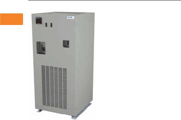
V3-T2-36 Volume 3—Power Distribution and Control Assemblies CA08100004E—April 2014 www.eaton.com
2
2
2
2
2
2
2
2
2
2
2
2
2
2
2
2
2
2
2
2
2
2
2
2
2
2
2
2
2
2
2.1
SPD, Power Conditioning, PF Capacitors and Harmonic Filters
Surge Protection and Power Conditioning
Electronic Voltage Regulator (EVR) Tap Changer
Contents
Description Page
Introduction . . . . . . . . . . . . . . . . . . . . . . . . . . . . . . . V3-T2-2
Product Overview . . . . . . . . . . . . . . . . . . . . . . . . . . . V3-T2-5
SPD Series for Integration into Electrical
Distribution Equipment . . . . . . . . . . . . . . . . . . . . . V3-T2-7
SPD Series for Mounting External to
Electrical Distribution Equipment . . . . . . . . . . . . . . V3-T2-11
SPV Surge Protective Device . . . . . . . . . . . . . . . . . . V3-T2-16
CVX050/100 . . . . . . . . . . . . . . . . . . . . . . . . . . . . . . . V3-T2-18
SP1 Surge Protective Device . . . . . . . . . . . . . . . . . . V3-T2-21
SP2 Surge Protective Device . . . . . . . . . . . . . . . . . . V3-T2-23
AEGIS Powerline Filters . . . . . . . . . . . . . . . . . . . . . . V3-T2-25
Sag Ride-Through (SRT) . . . . . . . . . . . . . . . . . . . . . . V3-T2-30
Electronic Voltage Regulator (EVR)
Catalog Number Selection. . . . . . . . . . . . . . . . . . V3-T2-37
Technical Data and Specifications . . . . . . . . . . . . V3-T2-37
Electronic Voltage Regulator (EVR)
Product Description
Eaton’s Electronic Voltage
Regulator (EVR) is the ideal
solution for keeping your
facility and equipment up and
running during brownouts,
undervoltage conditions and
other power problems. The
EVR can significantly reduce
the costs of equipment
damage and downtime
when these situations occur.
The state-of-the-art design
provides rapid response time,
high efficiency, high inrush
current capability, and
operating advantages
exclusive to Eaton.
The EVR maintains a tightly
regulated output voltage by
automatically activating the
appropriate transformer tap
through a silicone controlled
rectifier (SCR). Tap changer
response time is initiated at
one cycle, ensuring rapid
and precise regulation.
Switching at zero current
enables noise reduction
during tap transitions.
Brownouts
In the United States, most
facilities have sufficient
voltage regulation. However,
in some U.S. locations and
many developing countries,
regulation problems occur
because of overstressed
utility distribution systems.
In some cases, due to the
excessive demand on the
utility system, voltage may
be below 10% of nominal
(–10%) during the day. This
condition is called a voltage
regulation or brownout.
Customers may notice dim
lights and reduced power.
During the evening, voltage
may rise above 10% of
nominal (+10%) because
large facilities and loads are
shut down. This shutdown
reduces the power demand
on the grid and results in a
voltage increase.
The IEEE defines voltage
regulation as overvoltage
or undervoltage. Voltage
regulation events last from
a few minutes to many
hours with voltage varying
by ±20%. Long-term
regulation problems differ
from short duration sags and
dips, which are much deeper
voltage drops.
The Solution
Prior to installing an expensive
solution, Eaton encourages
customers to monitor
incoming voltage to
determine if voltage
regulation is a problem.
The local utility may also be
able to provide information
on voltage expected at
the facility.
Using a meter, it can quickly
be determined if a voltage
regulation problem or
brownout condition exists.
The appropriate solution
would be an EVR. EVRs can
be installed at the service
entrance, branch panel or
at critical loads.
Eaton’s EVR is a solid-state
tap changing power
conditioner designed to
protect against brownouts
and long duration voltage
regulation problems.
Features and Benefits
●Coordinated with standard
thermal-magnetic breakers
to allow motor starts
●Optional 50 kA or 100 kA
per phase surge protection
●Input frequency range
operation from 57–63 Hz
●Integral manual rotary
maintenance bypass
switch standard on 50 to
500 kVA units and optional
on smaller units
●Not affected by load power
factor. Can operate
effectively in low-load
applications due to “unique
leakage reactance”
technology
●Fail-safe bypass circuit,
isolation transformer
and overtemperature
protection
●Less than 1% THD
●Optional Standard and
Premium metering to
monitor voltage, current,
frequency, power, energy,
PF with minimum
and
maximum, and
communication
capabilities
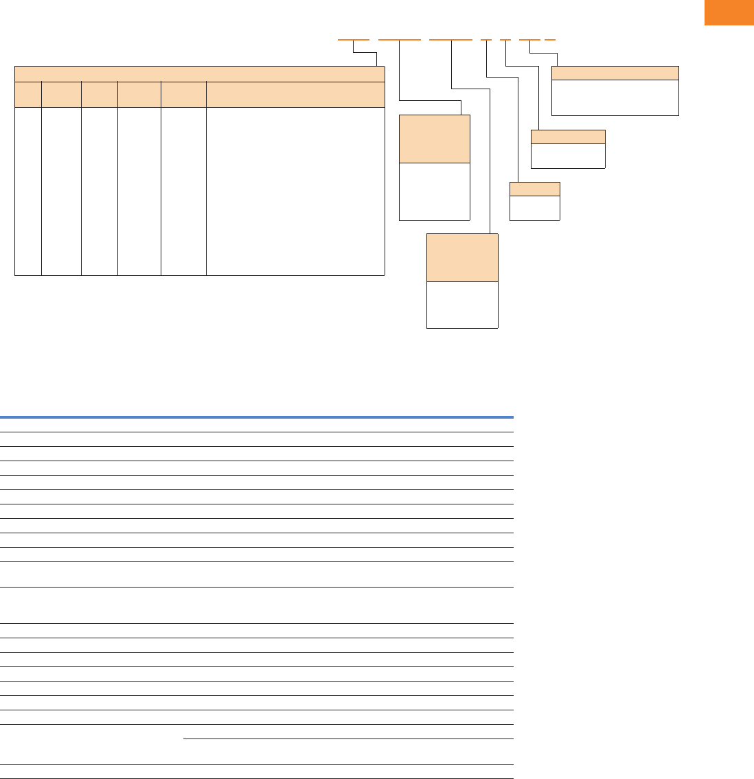
Volume 3—Power Distribution and Control Assemblies CA08100004E—April 2014 www.eaton.com V3-T2-37
2
2
2
2
2
2
2
2
2
2
2
2
2
2
2
2
2
2
2
2
2
2
2
2
2
2
2
2
2
2
2.1
SPD, Power Conditioning, PF Capacitors and Harmonic Filters
Surge Protection and Power Conditioning
Catalog Number Selection
EVR
Technical Data and Specifications
EVR Specification (10 to 500 kVA)
Notes
1Bypass is standard on 50 kVA and larger units and an option on 45 kVA and smaller units. The ‘B’ is not included in the part number for
units 50 kVA and larger.
All weights are approximate. Monitor option includes main input circuit breaker.
Refer to PAD for pricing and availability.
Feature Description
Technology Electronic tap changer
Input voltages 208–600V, three-phase (three-wire)
Input voltage range +10% to –23% of nominal rated input
Output voltage ±3% of nominal
Response time 1/2 cycle
Frequency 60 Hz, ±3%
Efficiency 97% typical
Line regulation Output is ±3% of nominal for input variations of +10% to –23% of nominal
Load regulation Output is maintained within 3% of nominal from no load to full load
Correction time Output will be corrected to within ±3% of nominal in 1.5 cycles or less
Harmonic distortion Less than 1.0% added to the output waveform under any dynamic linear loading conditions
presented to the line regulator
Noise attenuation
Common mode
Normal mode
146 dB
3 dB down at 1000 Hz, 40 dB/decade to below 50 dB with resistive load
Turn-on characteristics When energized, voltage overshoot will be less than 5% of nominal for 1 cycle or less
Overload rating 1000% for 1 cycle and 200% for 10 seconds
Ambient rating –10° to 40°C
Monitoring Three green LEDs (phase power on indication), one red LED (alert indication)
Surge protection (optional) CVX 50 kA SPD device 50 kVA and below, CVX 100 kA SPD device 75 kVA and above
Input breaker MCCB rated 125% of full rated current
Bypass switch Normal and bypass selector
Metering (optional) Standard metering (IQ 130)—voltage and current with minimum and maximum
Premium metering (IQ 150)—voltage, current, frequency, power, energy, PF, with minimum
and maximum, communications capabilities
Warranty 1-year parts
Surge Protection
X = No
S = Yes
Frequency
A = 60 Hz
B = 50 Hz
Options
B= Bypass switch 1
M1 = Standard metering (IQ 130)
M2 = Premium metering (IQ 150)
Nominal Output
Voltage
(Wye Output:
L, L, L, N, G)
208Y = 120/208
400Y = 230/400
480Y = 277/480
600Y = 347/600
kVA Ratings and Dimensions
kVA
Weight
Lbs
BTUs/
hr Bypass Metering
Dimensions in Inches (mm)
(W x D x H)
010
010
015
015
025
030
045
050
075
100
125
150
225
300
500
440
520
465
700
700
720
950
1,176
1,575
2,014
2,137
2,240
3,300
4,000
5,500
1,025
1,205
1,540
1,540
2,560
3,090
4,600
7,332
9,514
11,833
14,748
17,698
23,000
30,750
51,250
Optional
Optional
Optional
Optional
Optional
Optional
Optional
Yes
Yes
Yes
Yes
Yes
Yes
Yes
Yes
No
Yes
No
Yes
Yes
Yes
Yes
Yes
Yes
Yes
Yes
Yes
Yes
Yes
Yes
30.20 x 22.20 x 29.00 (767.1 x 563.9 x 736.6)
44.20 x 22.20 x 29.00 (1122.7 x 563.9 x 736.6)
30.20 x 22.20 x 29.00 (767.1 x 563.9 x 736.6)
44.20 x 22.20 x 29.00 (1122.7 x 563.9 x 736.6)
44.20 x 22.20 x 29.00 (1122.7 x 563.9 x 736.6)
44.20 x 22.20 x 29.00 (1122.7 x 563.9 x 736.6)
44.30 x 45.90 x 29.00 (1125.2 x 1165.9 x 736.6)
66.00 x 29.00 x 35.50 (1676.4 x 736.6 x 901.7)
76.00 x 34.40 x 35.50 (1930.4 x 873.8 x 901.7)
76.00 x 34.40 x 35.50 (1930.4 x 873.8 x 901.7)
76.00 x 34.40 x 35.50 (1930.4 x 873.8 x 901.7)
76.00 x 34.40 x 35.50 (1930.4 x 873.8 x 901.7)
77.40 x 56.00 x 41.50 (1966.0 x 1422.4 x 1054.1)
77.40 x 56.00 x 41.50 (1966.0 x 1422.4 x 1054.1)
77.00 x 72.40 x 48.40 (1955.8 x 1839.0 x 1229.4)
EVR XXX XXXX XXXX XXXX X
Nominal Input
Voltage
(Delta Input:
L, L, L, G)
208D = 208
240D = 240
400D = 400
480D = 480
600D = 600
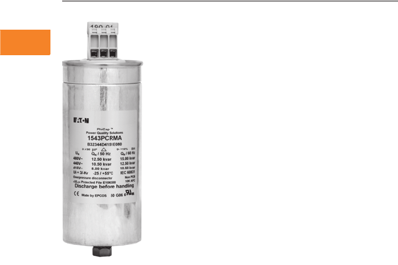
V3-T2-38 Volume 3—Power Distribution and Control Assemblies CA08100004E—April 2014 www.eaton.com
2
2
2
2
2
2
2
2
2
2
2
2
2
2
2
2
2
2
2
2
2
2
2
2
2
2
2
2
2
2
2.2
SPD, Power Conditioning, PF Capacitors and Harmonic Filters
Power Factor Correction and Harmonic Filtering
Capacitor Cell With M12 Threaded Mounting Bolt, Washer, Nut
Contents
Description Page
Product Overview
Product Selection . . . . . . . . . . . . . . . . . . . . . . . V3-T2-39
Dimensions . . . . . . . . . . . . . . . . . . . . . . . . . . . V3-T2-40
UNIPUMP . . . . . . . . . . . . . . . . . . . . . . . . . . . . . . . V3-T2-41
UNIPAK . . . . . . . . . . . . . . . . . . . . . . . . . . . . . . . . . V3-T2-44
AUTOVAR 300 Automatic Power Factor Correction
Capacitor Systems. . . . . . . . . . . . . . . . . . . . . . . . V3-T2-55
AUTOVAR 600 Automatic Power Factor Correction
Capacitor Systems. . . . . . . . . . . . . . . . . . . . . . . . V3-T2-58
AUTOVAR Filter—LV Automatic Harmonic Filter . . V3-T2-63
Transient-Free Static Switching Power Factor
Correction Units. . . . . . . . . . . . . . . . . . . . . . . . . . V3-T2-67
Active-Harmonic Filter-Harmonic Correction Unit—
NEMA 1 Enclosure . . . . . . . . . . . . . . . . . . . . . . . V3-T2-71
Product Overview
Product Description
Eaton’s power factor
correction capacitors and
harmonic filters are an
essential part of modern
electric power systems.
Power factor correction
capacitors are the simplest
and most economical
means of increasing the
capacity of any power
system, minimizing energy
losses and correcting load
power factor. In addition,
power factor penalties can
be reduced and power quality
can be greatly enhanced.
There are several reasons
to correct poor power factor.
The first is to reduce or
eliminate a power factor
penalty charged by the utility.
Another reason is that your
existing transformer is, or
shortly will be, at full capacity
and installing power factor
correction capacitors can
be a very cost-effective
solution to installing a brand
new service. Depending on
the amount of power factor
correction (kVAR that needs
to be injected into the
electrical system to improve
the power factor) and the
dynamic nature of the load,
a fixed or switched capacitor
bank may be the best
solution.
When capacity becomes a
problem, the choice of a
solution will be dependent
upon the size of the increase
needed. Like all power
quality solutions, there
are many factors that need
to be considered when
determining which solution
will be best to solve your
power factor problem.
Harmonic Filtering
As the world becomes more
dependent on electric and
electronic equipment, the
likelihood that the negative
impact of harmonic distortion
increases dramatically. The
efficiency and productivity
gains from these increasingly
sophisticated pieces of
equipment have a negative
side effect…increased
harmonic distortion in the
power lines. The difficult
thing about harmonic
distortion is determining the
cause. Once this has been
determined, the solution
can be easy. Passive and
active harmonic filtering
equipment will mitigate
specific harmonic issues,
and correct poor power
factor as well.

Volume 3—Power Distribution and Control Assemblies CA08100004E—April 2014 www.eaton.com V3-T2-39
2
2
2
2
2
2
2
2
2
2
2
2
2
2
2
2
2
2
2
2
2
2
2
2
2
2
2
2
2
2
2.2
SPD, Power Conditioning, PF Capacitors and Harmonic Filters
Power Factor Correction and Harmonic Filtering
Product Selection
Capacitor Cell Chart Harmonic Rated Capacitor Cell Chart
Note
kVAR rating standard. NEMA kVAR tolerance is +15% to 0%. Part number shown is for
three-phase units. Up to 5 kVAR at 480V—fast-on terminals are standard. Above 5 kVAR at 480V
(and on all other voltages)—sigut terminals are standard. For dimensions and weights,
see following page.
Voltage kVAR Part Number
240 1.5 643PCRMA
240 2 8B43PCRMA
240 2.5 1043PCRMA
240 3 12X43PCRMA
240 4 423PCRMA
240 5 2043PCRMA
240 6.3 6B23PCRMA
240 7.5 7X23PCRMA
240 8.3 8B23PCRMA
240 10 1023PCRMA
240 12.5 12X23PCRMA
240 15 1523PCRMA
240 16.7 16S23PCRMA
240 17.5 17X23PCRMA
480 1.5 1X43PCRMA
480 2 243PCRMA
480 2.5 2X43PCRMA
480 3 343PCRMA
480 4 443PCRMA
480 5 543PCRMA
480 6 643PCRMA
480 7.5 7X43PCRMA
480 8.3 8B43PCRMA
480 9 943PCRMA
480 10 1043PCRMA
480 12.5 12X43PCRMA
480 15 1543PCRMA
480 18 1843PCRMA
480 20 2043PCRMA
480 25 2543PCRMA
480 30 3043PCRMA
600 5 563PCRMA
600 7.5 7X63PCRMA
600 10 1063PCRMA
600 12.5 12X63PCRMA
600 15 1563PCRMA
600 17.5 2063PCRMA
600 20 2563PCRMA
1543PCRMA
Voltage kVAR Part Number
240 12.5 12X23PHRMA
480 15.0 1543PHRMA
480 25.0 2543PHRMA
600 12.3 12A63PHRMA
600 14.7 14S63PHRMA
600 16.7 16S63PHRMA
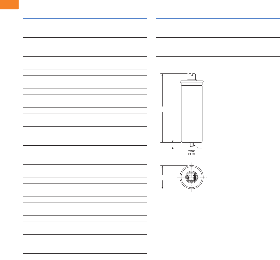
V3-T2-40 Volume 3—Power Distribution and Control Assemblies CA08100004E—April 2014 www.eaton.com
2
2
2
2
2
2
2
2
2
2
2
2
2
2
2
2
2
2
2
2
2
2
2
2
2
2
2
2
2
2
2.2
SPD, Power Conditioning, PF Capacitors and Harmonic Filters
Power Factor Correction and Harmonic Filtering
Dimensions
Approximate Dimensions in Inches (mm)
Capacitor Cell Chart Harmonic Rated Capacitor Cell Chart
Capacitor Cell
Part Number Depth Height Weight in Lbs (kg)
643PCRMA 3.10 (78.7) 7.90 (200.7) 1.1 (0.5)
8B43PCRMA 3.10 (78.7) 9.40 (238.8) 1.3 (0.6)
1043PCRMA 3.10 (78.7) 9.40 (238.8) 1.3 (0.6)
12X43PCRMA 3.50 (88.9) 9.40 (238.8) 1.8 (0.8)
423PCRMA 3.10 (78.7) 7.90 (200.7) 1.1 (0.5)
2043PCRMA 3.50 (88.9) 12.30 (312.4) 2.6 (1.2)
6B23PCRMA 3.10 (78.7) 9.40 (238.8) 1.3 (0.6)
7X23PCRMA 3.10 (78.7) 9.40 (238.8) 1.3 (0.6)
8B23PCRMA 3.50 (88.9) 9.40 (238.8) 1.8 (0.8)
1023PCRMA 3.50 (88.9) 9.40 (238.8) 1.3 (0.6)
12X23PCRMA 3.50 (88.9) 12.30 (312.4) 2.6 (1.2)
1523PCRMA 3.50 (88.9) 12.30 (312.4) 2.6 (1.2)
16S23PCRMA 3.50 (88.9) 15.30 (388.6) 3.3 (1.5)
17X23PCRMA 3.50 (88.9) 15.30 (388.6) 3.3 (1.5)
1X43PCRMA 2.10 (53.3) 5.00 (127.0) 0.7 (0.3)
243PCRMA 2.50 (63.5) 5.50 (139.7) 0.9 (0.4)
2X43PCRMA 2.50 (63.5) 5.50 (139.7) 0.9 (0.4)
343PCRMA 2.50 (63.5) 5.50 (139.7) 0.9 (0.4)
443PCRMA 2.50 (63.5) 6.50 (165.1) 0.9 (0.4)
543PCRMA 2.50 (63.5) 6.50 (165.1) 0.9 (0.4)
643PCRMA 3.10 (78.7) 7.90 (200.7) 1.1 (0.5)
7X43PCRMA 3.10 (78.7) 7.90 (200.7) 1.1 (0.5)
8B43PCRMA 3.10 (78.7) 9.40 (238.8) 1.3 (0.6)
943PCRMA 3.10 (78.7) 9.40 (238.8) 1.3 (0.6)
1043PCRMA 3.10 (78.7) 9.40 (238.8) 1.3 (0.6)
12X43PCRMA 3.50 (88.9) 9.40 (238.8) 1.8 (0.8)
1543PCRMA 3.50 (88.9) 9.40 (238.8) 1.8 (0.8)
1843PCRMA 3.50 (88.9) 12.30 (312.4) 2.6 (1.2)
2043PCRMA 3.50 (88.9) 12.30 (312.4) 2.6 (1.2)
2543PCRMA 3.50 (88.9) 12.30 (312.4) 2.6 (1.2)
3043PCRMA 3.50 (88.9) 15.30 (388.6) 3.3 (1.5)
563PCRMA 3.10 (78.7) 9.40 (238.8) 1.3 (0.6)
7X63PCRMA 3.10 (78.7) 9.40 (238.8) 1.3 (0.6)
1063PCRMA 3.10 (78.7) 9.40 (238.8) 1.3 (0.6)
12X63PCRMA 3.50 (88.9) 9.40 (238.8) 1.8 (0.8)
1563PCRMA 3.50 (88.9) 12.30 (312.4) 2.6 (1.2)
2063PCRMA 3.50 (88.9) 12.30 (312.4) 2.6 (1.2)
2563PCRMA 3.50 (88.9) 15.30 (388.6) 3.3 (1.5)
Part Number Depth Height Weight in Lbs (kg)
12X23PHRMA 3.50 (88.9) 15.30 (388.6) 3.3 (1.5)
1543PHRMA 3.50 (88.9) 12.30 (312.4) 2.6 (1.2)
2543PHRMA 3.50 (88.9) 15.30 (388.6) 3.3 (1.5)
12A63PHRMA 3.50 (88.9) 12.30 (312.4) 2.6 (1.2)
14S63PHRMA 3.50 (88.9) 15.30 (388.6) 3.3 (1.5)
16S63PHRMA 3.50 (88.9) 15.30 (388.6) 3.3 (1.5)
Height
M12
16+1
Depth

Volume 3—Power Distribution and Control Assemblies CA08100004E—April 2014 www.eaton.com V3-T2-41
2
2
2
2
2
2
2
2
2
2
2
2
2
2
2
2
2
2
2
2
2
2
2
2
2
2
2
2
2
2
2.2
SPD, Power Conditioning, PF Capacitors and Harmonic Filters
Power Factor Correction and Harmonic Filtering
UNIPUMP
Contents
Description Page
Product Overview. . . . . . . . . . . . . . . . . . . . . . . . . . V3-T2-38
UNIPUMP
Product Selection . . . . . . . . . . . . . . . . . . . . . . . V3-T2-42
Dimensions . . . . . . . . . . . . . . . . . . . . . . . . . . . V3-T2-43
UNIPAK. . . . . . . . . . . . . . . . . . . . . . . . . . . . . . . . . . V3-T2-44
AUTOVAR 300 Automatic Power Factor Correction
Capacitor Systems . . . . . . . . . . . . . . . . . . . . . . . . V3-T2-55
AUTOVAR 600 Automatic Power Factor Correction
Capacitor Systems . . . . . . . . . . . . . . . . . . . . . . . . V3-T2-58
AUTOVAR Filter—LV Automatic Harmonic Filter . . V3-T2-63
Transient-Free Static Switching Power Factor
Correction Units. . . . . . . . . . . . . . . . . . . . . . . . . . V3-T2-67
Active-Harmonic Filter-Harmonic Correction Unit—
NEMA 1 Enclosure . . . . . . . . . . . . . . . . . . . . . . . V3-T2-71
UNIPUMP
Product Description
Non-fused capacitors for
outdoor irrigation and oil field
installations.
●Designed expressly for
outdoor pumping
applications
●Pole or wall mounting
●Small, light-weight
enclosure for easy
installation
●SO-WA type flexible cable
facilitates installation
(4-conductor)
●Gland-type weatherproof
bushings
●Strong outer case
Application Description
Outdoor irrigation and oil
and gas field pumping.
Features, Benefits and Functions
Configuration
●Outer case: Heavy, No. 14
gauge steel finished with
durable powder coat finish.
Integral strap mounting
bracket with keyhole at top
for pole or wall installation.
No knockouts
Capacitor Cells
●Te rm i n a l s : Insulated
finger-safe terminals rated
for 3 kVAC withstand
●Dielectric fill: Dry-type
cells use soft organic
polymer resin—Resinol
●Eliminates potential for
corona/partial discharge/
electrochemical oxidation
●Excellent heat dissipation
●Flash point: +444°F
(+229°C)
●Fire point: +840°F
(+449°C)
●Design: Self-healing
metallized high crystalline
polypropylene with ramp
metallization film. Total
losses less than 0.45 watt
per kVAR. (Dielectric
losses less than 0.2 watt
per kVAR)
●Ramp metallization:
Provides thicker film at
higher current density
areas, allowing for reduced
internal losses, lower
operating temperatures
and longer life expectancy.
Also prevents chain
reaction breakdown by
limiting propagation of
film vaporization
●Pressure sensitive
interrupter: Built-in, three-
phase pop-up interrupter
design. UL recognized.
Removes capacitor from
line before internal
pressure can cause case
rupture. Bulged capacitor
cell top provides easy
visual indication of
interrupter operation
●Ceramic discharge
resistors: Reduce residual
voltage to less than 50 volts
within one minute of
de-energization. Selected
for 20-year nominal life.
Exceeds NEC requirements
●Capacitor operating
temperature: -40°F
(–40°C) to +115°F (+46°C)
●Case: Weatherproof
aluminum housing
●Warranty: The longest
in the industry—five full
years of warranty on
capacitor cells
Standards and Certifications
●UL and CSA listed

V3-T2-42 Volume 3—Power Distribution and Control Assemblies CA08100004E—April 2014 www.eaton.com
2
2
2
2
2
2
2
2
2
2
2
2
2
2
2
2
2
2
2
2
2
2
2
2
2
2
2
2
2
2
2.2
SPD, Power Conditioning, PF Capacitors and Harmonic Filters
Power Factor Correction and Harmonic Filtering
Product Selection
UNIPUMP
kVAR
Rated
Current
Case
Size
Cable
Size
Shipping Weight
in Lbs (kg)
Catalog
Number
240 Vac
2 4.8 AA 14.0 10.0 (4.5) 223JMR
2.5 6.0 AA 14.0 10.0 (4.5) 2X23JMR
3 7.2 AA 14.0 10.0 (4.5) 323JMR
4 9.6 AA 14.0 11.0 (5.0) 423JMR
5 12.0 AA 14.0 11.0 (5.0) 523JMR
6 14.4 BB 12.0 15.0 (6.8) 623JMR
7.5 18.0 BB 12.0 15.0 (6.8) 7X23JMR
480 Vac
2 2.4 AA 14.0 10.4 (4.7) 243JMR
2.5 3.0 AA 14.0 10.4 (4.7) 2X43JMR
3 3.6 AA 14.0 10.4 (4.7) 343JMR
4 4.8 AA 14.0 10.4 (4.7) 443JMR
5 6.0 AA 14.0 10.4 (4.7) 543JMR
6 7.2 AA 14.0 10.6 (4.8) 643JMR
7.5 9.0 AA 14.0 10.6 (4.8) 7X43JMR
10 12.0 AA 14.0 10.8 (4.9) 1043JMR
12.5 15.0 BB 12.0 15.0 (6.8) 12X43JMR
15 18.0 BB 12.0 15.0 (6.8) 1543JMR
17.5 21.0 BB 8.0 15.8 (7.2) 17X43JMR
20 24.0 BB 8.0 16.8 (7.6) 2043JMR
25 30.0 BB 8.0 16.8 (7.6) 2543JMR
600 Vac
5 4.9 AA 14.0 10.8 (4.9) 563JMR
7.5 7.4 AA 14.0 10.8 (4.9) 7X63JMR
10 9.8 AA 14.0 10.8 (4.9) 1063JMR
12.5 12.3 AA 12.0 15.0 (6.8) 12X63JMR
15 14.7 BB 12.0 15.8 (7.2) 1563JMR
17.5 17.2 BB 8.0 16.8 (7.6) 17X63JMR
20 19.6 BB 8.0 16.8 (7.6) 2063JMR
UNIPUMP
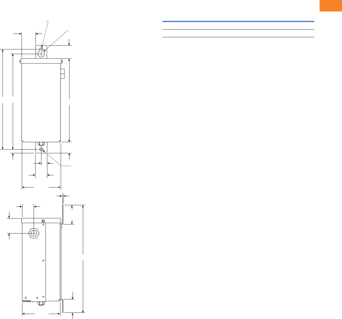
Volume 3—Power Distribution and Control Assemblies CA08100004E—April 2014 www.eaton.com V3-T2-43
2
2
2
2
2
2
2
2
2
2
2
2
2
2
2
2
2
2
2
2
2
2
2
2
2
2
2
2
2
2
2.2
SPD, Power Conditioning, PF Capacitors and Harmonic Filters
Power Factor Correction and Harmonic Filtering
Dimensions
Approximate Dimensions in Inches (mm)
UNIPUMP UNIPUMP Dimension Chart
Ø 0.44
(11.2)
1.84
(46.7)
DC
Ø 0.88
(22.4)
1.75
(44.5)
A
Ø 0.44
(11.2)
1.45
(36.8)
5.00
(127.0)
1.50
(38.1)
5.15
(130.8)
0.75
(19.1)
0.50
(12.7)
0.07
(1.8)
1.55
(39.4)
1.98
(50.3)
2.56
(65.0)
B
1.75
(44.5)
Size Code A B C D
AA 11.00 (279.4) 14.20 (360.7) 12.60 (320.0) 13.20 (335.3)
BB 14.00 (355.6) 17.10 (434.3) 15.50 (393.7) 16.10 (408.9)
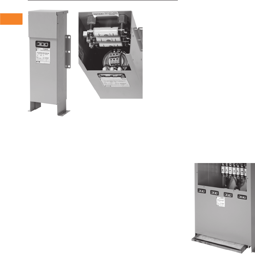
V3-T2-44 Volume 3—Power Distribution and Control Assemblies CA08100004E—April 2014 www.eaton.com
2
2
2
2
2
2
2
2
2
2
2
2
2
2
2
2
2
2
2
2
2
2
2
2
2
2
2
2
2
2
2.2
SPD, Power Conditioning, PF Capacitors and Harmonic Filters
Power Factor Correction and Harmonic Filtering
UNIPAK
Contents
Description Page
Product Overview . . . . . . . . . . . . . . . . . . . . . . . . . V3-T2-38
UNIPUMP . . . . . . . . . . . . . . . . . . . . . . . . . . . . . . . V3-T2-41
UNIPAK
Features, Benefits and Functions . . . . . . . . . . . V3-T2-45
Standards and Certifications . . . . . . . . . . . . . . V3-T2-45
Product Selection . . . . . . . . . . . . . . . . . . . . . . . V3-T2-46
Wiring Diagram . . . . . . . . . . . . . . . . . . . . . . . . . V3-T2-52
Dimensions . . . . . . . . . . . . . . . . . . . . . . . . . . . V3-T2-53
AUTOVAR 300 Automatic Power Factor Correction
Capacitor Systems. . . . . . . . . . . . . . . . . . . . . . . . V3-T2-55
AUTOVAR 600 Automatic Power Factor Correction
Capacitor Systems. . . . . . . . . . . . . . . . . . . . . . . . V3-T2-58
AUTOVAR Filter—LV Automatic Harmonic Filter . . V3-T2-63
Transient-Free Static Switching Power Factor
Correction Units. . . . . . . . . . . . . . . . . . . . . . . . . . V3-T2-67
Active-Harmonic Filter-Harmonic Correction Unit—
NEMA 1 Enclosure . . . . . . . . . . . . . . . . . . . . . . . V3-T2-71
UNIPAK
Product Description
UNIPAK Filter—
Harmonic Filtering
Harmonic filter systems for
low voltage, heavy-duty
applications.
●Reduce harmonics and
correct power factor
●Tuned for maximum
efficiency in reducing
harmonic currents
associated with nonlinear
load environments (such as
VFDs)
●Two-enclosure design
isolates capacitors from
high-temperature operating
reactors, and allows for
flexible installation
●Twenty-year life design
●Five-year cell warranty/one-
year reactor warranty
●Three-phase cell capacitor
construction. Three-phase
interrupter system
Harmonic Rated Capacitor Cells
●Standard voltage rated
capacitor cells designed for
higher dielectric strength
and with added ability to
withstand stress caused
by dv/dt voltage transients
caused by harmonics
●Better suited for harmonic
applications than higher
voltage rated cells
UNIPAK with Harmonic Rated
Capacitor Cells
●Standard capacitor
systems using harmonic
rated capacitor cells
●For use in moderate
harmonic environments
where engineering
supervision allows in place
of harmonic filter designs
●Provides future conversion
capability into a harmonic
filter design due to facility
growth or increased
nonlinear load levels
UNIPAK with Optional Air Filter
Application Description
Designed for power factor
correction in plants
experiencing harmonics
problems due to high
amounts of nonlinear loads.

Volume 3—Power Distribution and Control Assemblies CA08100004E—April 2014 www.eaton.com V3-T2-45
2
2
2
2
2
2
2
2
2
2
2
2
2
2
2
2
2
2
2
2
2
2
2
2
2
2
2
2
2
2
2.2
SPD, Power Conditioning, PF Capacitors and Harmonic Filters
Power Factor Correction and Harmonic Filtering
Features, Benefits and Functions
●Five-year warranty
on capacitor cells
●Designed for heavy-duty
applications
●Twenty-year life design
●Indoor/outdoor service
●Wall (up to 180 kVAR)
and floor-mounted
units available
●Fuse protection standard
●Blown-fuse indicating
lights standard
●Quick lead-times
●Harmonic filters available
●Slim profile allows reduced
footprint, conserving
valuable floor space
●New capacitor
configuration leads
to cooler operating
conditions, extending
capacitor life
Configuration
●Outer case: Heavy, No. 14
gauge steel finished with
durable powder coat finish.
Wall mounting flanges
and floor mounting feet.
Elimination of knockouts
permits indoor/outdoor
use. Manufactured to
NEMA requirements 1,
3R and 12
●Elevated floor mounting
feet allow access for
easy maintenance
Note: NEMA 12 enclosure
standard for enclosure sizes
A1 to C1.
●Cover: “L” shaped
gasketed cover with
multiple fasteners provides
front opening for ease of
installation and service
●Ground terminal:
Furnished inside case
●Power terminal lugs:
Large size provided for
easy connection
●Fusing:
●Size Code A1: Three
midget-type fuses
with 100,000 ampere
interrupting capacity
●Size Code A2 and
larger: Three slotted-
blade type fuses with
200,000 ampere
interrupting capacity;
Fuses mounted on
stand-off bushings or
fuse blocks; solderless
connectors for easy
hookup of incoming line
conductors
●Fuse indicating lights:
Red, neon blown-fuse
indicating lights are
protected by transparent
weatherproof guard
●Options:
●No fuses
●Air filters for units
with enclosure
sizes C2, D1 and E1
Capacitor cells
●Te rm i n a l s : Insulated finger-
safe terminals rated for 3
kVAC withstand
●Dielectric fill: Dry-type
cells use soft organic
polymer resin—Resinol
●Eliminates potential for
corona/partial discharge/
electrochemical
oxidation
●Excellent heat
dissipation
●Flash point: +444°F
(+229°C)
●Fire point: +840°F
(+449°C)
●Design: Self-healing
metallized high crystalline
polypropylene with ramp
metallization film. Total
losses less than 0.45 watt
per kVAR. (Dielectric
losses less than 0.2 watt
per kVAR)
●Ramp metallization:
Provides thicker film at
higher current density
areas, allowing for reduced
internal losses, lower
operating temperatures
and longer life expectancy.
Also prevents chain
reaction breakdown by
limiting propagation of
film vaporization
●Pressure sensitive
interrupter: Built-in, three-
phase pop-up interrupter
design. UL recognized.
Removes capacitor from
line before internal
pressure can cause case
rupture. Bulged capacitor
cell top provides easy
visual indication of
interrupter operation
●Ceramic discharge
resistors: Reduce residual
voltage to less than 50 volts
within one minute of
de-energization. Selected
for 20-year nominal life.
Exceeds NEC requirements
●Capacitor operating
temperature: -40°F (-40°C)
to +115°F (+46°C)
●Case: Weatherproof
aluminum housing
●Warranty: The longest
in the industry—five full
years of warranty on
capacitor cells
Reactors
●Tuning: Tuned to 4.7
harmonic order
●Detuning: Reactor
designs can be detuned
upon request to 4.2nd to
protect capacitors against
alternate harmonics
●Construction: 100%
copper windings for cool
operating temperatures;
designed operating
temperature rise less
than 80ºC. Open frame
construction with 220ºC
insulation system
●Thermal sensors: One
per phase, self-resetting
thermistors provide
reactor over-temperature
protection and indication
●Reactor indicating light:
Thermal overload indicating
light activates when
reactor temperature
reaches 180ºC
●Warranty: One-year
replacement of reactors
Standards and Certifications
●UL and CSA listed

V3-T2-46 Volume 3—Power Distribution and Control Assemblies CA08100004E—April 2014 www.eaton.com
2
2
2
2
2
2
2
2
2
2
2
2
2
2
2
2
2
2
2
2
2
2
2
2
2
2
2
2
2
2
2.2
SPD, Power Conditioning, PF Capacitors and Harmonic Filters
Power Factor Correction and Harmonic Filtering
Product Selection
UNIPAK Low Voltage Fixed Capacitor Banks
240 Vac UNIPAK
Notes
Multiply the 240 Vac kVAR rating by 0.75 to calculate the kVAR value at 208 Vac.
Fused with blown-fuse indication available standard. Non-fused and no lights also available—please consult the factory.
Other ratings available, consult factory.
For dimensional information, refer to Page V3-T2-53.
Part Numbers:
PMURF—three fuses + three lights
PMURN—non-fused
kVAR
Rated
Current Enclosure
Shipping Weight
in Lbs (kg)
Part
Number
1 2.4 A1 18 (8) 123PMURF
1.5 3.6 A1 18 (8) 1X23PMURF
2 4.8 A1 19 (9) 223PMURF
2.5 6 A1 19 (9) 2X23PMURF
3 7.2 A1 19 (9) 323PMURF
4 9.6 A1 20 (9) 423PMURF
5 12 A2 29 (13) 523PMURF
6 14.4 A2 29 (13) 623PMURF
7.5 18 A2 30 (14) 7X23PMURF
8 19.2 A2 31 (14) 823PMURF
10 24 A2 31 (14) 1023PMURF
12.5 30 A2 32 (14) 12X23PMURF
15 36 A2 33 (15) 1523PMURF
17.5 42 B1 44 (20) 17X23PMURF
20 48 B1 45 (20) 2023PMURF
22.5 54 B1 46 (21) 22X23PMURF
25 60 B1 46 (21) 2523PMURF
30 72 B1 47 (21) 3023PMURF
32.5 78 B1 47 (22) 32X23PMURF
35 84 B1 48 (22) 3523PMURF
40 96 C1 64 (29) 4023PMURF
42.5 102 C1 65 (30) 42X23PMURF
45 108 C1 66 (30) 4523PMURF
50 120 C1 68 (31) 5023PMURF
60 144 C1 69 (31) 6023PMURF
70 168 C2 99 (45) 7023PMURF
75 180 C2 100 (46) 7523PMURF
80 192 C2 101 (46) 8023PMURF
90 216 C2 103 (47) 9023PMURF
100 240 C2 104 (47) 10023PMURF
120 288 D1 133 (60) 12023PMURF
140 336 D1 137 (62) 14023PMURF
150 360 D1 140 (64) 15023PMURF
160 384 E1 175 (80) 16023PMURF
180 432 E1 182 (83) 18023PMURF
200 480 E1 189 (86) 20023PMURF
UNIPAK

Volume 3—Power Distribution and Control Assemblies CA08100004E—April 2014 www.eaton.com V3-T2-47
2
2
2
2
2
2
2
2
2
2
2
2
2
2
2
2
2
2
2
2
2
2
2
2
2
2
2
2
2
2
2.2
SPD, Power Conditioning, PF Capacitors and Harmonic Filters
Power Factor Correction and Harmonic Filtering
480 Vac UNIPAK
Notes
Fused with blown-fuse indication available standard.
Non-fused and no lights also available—please consult the factory.
Other ratings available, consult factory.
For dimensional information, refer to Page V3-T2-53.
Part Number
PMURF—three fuses + three lights
PMURN—non-fused
kVAR Enclosure
Rated
Current
Shipping Weight
in Lbs (kg)
Part
Number
1.5 A1 1.8 17 (8) 1X43PMURF
2 A1 2.4 18 (8) 243PMURF
2.5 A1 3 18 (8) 2X43PMURF
3 A1 3.6 19 (9) 343PMURF
4 A1 4.8 19 (9) 443PMURF
5 A1 6 19 (9) 543PMURF
6 A1 7.2 19 (9) 643PMURF
7.5 A1 9 20 (9) 7X43PMURF
8 A1 9.6 20 (9) 843PMURF
9 A1 10.8 20 (9) 943PMURF
10 A1 12 20 (9) 1043PMURF
12.5 A2 15 29 (13) 12X43PMURF
15 A2 18 29 (13) 1543PMURF
17.5 A2 21 30 (14) 17X43PMURF
20 A2 24 31 (14) 2043PMURF
22.5 B1 27 44 (20) 22X43PMURF
25 A2 30 32 (15) 2543PMURF
27.5 B1 33 44 (20) 27X43PMURF
30 B1 36 44 (20) 3043PMURF
32.5 B1 39 45 (20) 32X43PMURF
35 B1 42 45 (20) 3543PMURF
37.5 B1 45 46 (21) 37X43PMURF
40 B1 48 46 (21) 4043PMURF
42.5 B1 51 47 (21) 42X43PMURF
45 B1 54 47 (22) 4543PMURF
50 B1 60 48 (22) 5043PMURF
55 B1 66 48 (22) 5543PMURF
60 B1 72 48 (22) 6043PMURF
65 C1 78 64 (29) 6543PMURF
70 C1 84 65 (30) 7043PMURF
75 C1 90 65 (30) 7543PMURF
80 C1 96 66 (30) 8043PMURF
85 C1 102 68 (31) 8543PMURF
90 C1 108 68 (31) 9043PMURF
100 C1 120 68 (31) 10043PMURF
120 C1 144 68 (31) 12043PMURF
125 C2 150 99 (45) 12543PMURF
140 C2 168 100 (46) 14043PMURF
150 C2 180 101 (46) 15043PMURF
160 C2 192 103 (47) 16043PMURF
180 C2 216 104 (47) 18043PMURF
UNIPAK
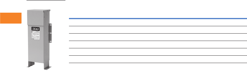
V3-T2-48 Volume 3—Power Distribution and Control Assemblies CA08100004E—April 2014 www.eaton.com
2
2
2
2
2
2
2
2
2
2
2
2
2
2
2
2
2
2
2
2
2
2
2
2
2
2
2
2
2
2
2.2
SPD, Power Conditioning, PF Capacitors and Harmonic Filters
Power Factor Correction and Harmonic Filtering
480 Vac UNIPAK, continued
Notes
Fused with blown-fuse indication available standard.
Non-fused and no lights also available—please consult the factory.
Other ratings available, consult factory.
For dimensional information, refer to Page V3-T2-53.
Part Number
PMURF—three fuses + three lights
PMURN—non-fused
kVAR Enclosure
Rated
Current
Shipping Weight
in Lbs (kg)
Part
Number
200 D1 240 137 (62) 20043PMURF
225 D1 270 140 (64) 22543PMURF
250 E1 300 170 (77) 25043PMURF
300 E1 360 175 (80) 30043PMURF
350 E1 420 182 (83) 35043PMURF
400 E1 480 189 (86) 40043PMURF
UNIPAK

Volume 3—Power Distribution and Control Assemblies CA08100004E—April 2014 www.eaton.com V3-T2-49
2
2
2
2
2
2
2
2
2
2
2
2
2
2
2
2
2
2
2
2
2
2
2
2
2
2
2
2
2
2
2.2
SPD, Power Conditioning, PF Capacitors and Harmonic Filters
Power Factor Correction and Harmonic Filtering
600 Vac UNIPAK
Notes
Fused with blown-fuse indication available standard. Non-fused and no lights also available—please consult the factory
Other ratings available, consult factory
For dimensional information, refer to Page V3-T2-53.
Part Numbers:
PMURF—three fuses + three lights
PMURN—non-fused
kVAR Enclosure
Rated
Current
Shipping Weight
in Lbs (kg)
Part
Number
5 A1 4.9 19 (9) 563PMURF
7.5 A1 7.4 19 (9) 7X63PMURF
10 A1 9.8 20 (9) 1063PMURF
12.5 A1 12.3 20 (9) 12X63PMURF
15 A2 14.7 29 (13) 1563PMURF
17.5 A2 17.2 29 (13) 17X63PMURF
20 A2 19.6 30 (14) 2063PMURF
22.5 B1 22.1 44 (20) 22X63PMURF
25 A2 24.5 31 (14) 2563PMURF
27.5 B1 27.0 44 (20) 27X63PMURF
30 B1 29.4 45 (20) 3063PMURF
32.5 B1 31.9 45 (20) 32X63PMURF
35 B1 34.3 46 (21) 3563PMURF
37.5 B1 36.8 46 (21) 37X63PMURF
40 B1 39.2 47 (21) 4063PMURF
42.5 B1 41.7 47 (22) 42X63PMURF
45 B1 44.1 48 (22) 4563PMURF
50 B1 49.0 48 (22) 5063PMURF
55 C1 53.9 64 (29) 5563PMURF
60 C1 58.8 64 (29) 6063PMURF
65 C1 63.7 65 (30) 6563PMURF
70 C1 68.6 65 (30) 7063PMURF
75 C1 73.5 66 (30) 7563PMURF
80 C1 78.4 68 (31) 8063PMURF
85 C1 83.3 68 (31) 8563PMURF
90 C1 88.2 68 (31) 9063PMURF
100 C1 98.0 68 (31) 10063PMURF
120 C2 117.6 99 (45) 12063PMURF
125 C2 122.5 100 (46) 12563PMURF
140 C2 137.2 101 (46) 14063PMURF
150 C2 147.0 103 (47) 15063PMURF
160 D1 156.8 135 (61) 16063PMURF
180 D1 176.4 137 (62) 18063PMURF
200 D1 196.0 140 (64) 20063PMURF
225 D1 220.5 143 (65) 22563PMURF
250 E1 245.0 170 (77) 25063PMURF
300 E1 294.0 175 (80) 30063PMURF
350 E1 343.0 182 (83) 35063PMURF
400 E1 392.0 189 (86) 40063PMURF
UNIPAK

V3-T2-50 Volume 3—Power Distribution and Control Assemblies CA08100004E—April 2014 www.eaton.com
2
2
2
2
2
2
2
2
2
2
2
2
2
2
2
2
2
2
2
2
2
2
2
2
2
2
2
2
2
2
2.2
SPD, Power Conditioning, PF Capacitors and Harmonic Filters
Power Factor Correction and Harmonic Filtering
UNIPAK—with Harmonic Cells
Low Voltage Fixed Capacitor Systems with Harmonic Cells
Notes
Fused with blown-fuse indication standard.
Other ratings available, consult factory.
kVAR
Rated
Current
Case
Size
Shipping Weight
in Lbs (kg)
Catalog
Number
240V
15 36 B1 38.4 (17) 1523HURF
25 60 B1 38.4 (17) 2523HURF
30 72 C1 55.2 (25) 3023HURF
50 120 C1 57.6 (26) 5023HURF
60 144 C2 100.8 (46) 6023HURF
75 180 C2 104.4 (47) 7523HURF
100 240 D1 136.8 (62) 10023HURF
125 300 E1 189.6 (86) 12523HURF
480V
15 18 A2 25.2 (11) 1543HURF
25 30 B1 37.2 (17) 2543HURF
30 36 B1 38.4 (17) 3043HURF
50 60 B1 39.6 (18) 5043HURF
60 72 C1 52.8 (24) 6043HURF
75 90 C1 55.2 (25) 7543HURF
100 120 C1 57.6 (26) 10043HURF
125 150 C2 100.8 (46) 12543HURF
150 180 C2 104.4 (47) 15043HURF
200 240 D1 136.8 (62) 20043HURF
250 300 E1 186.0 (84) 25043HURF
300 360 E1 189.6 (86) 30043HURF
600V
15 14.7 B1 37.2 (17) 1563HURF
25 24.5 B1 38.4 (17) 2563HURF
30 29.4 B1 39.6 (18) 3063HURF
50 49 C1 55.2 (25) 5063HURF
60 58.8 C1 57.6 (26) 6063HURF
75 73.5 C2 100.8 (46) 7563HURF
100 98 C2 104.4 (47) 10063HURF
125 122.5 D1 136.8 (62) 12563HURF
150 147 D1 136.8 (62) 15063HURF
200 196 E1 186.0 (84) 20063HURF
250 245 E1 189.6 (86) 25063HURF
Harmonic Cells

Volume 3—Power Distribution and Control Assemblies CA08100004E—April 2014 www.eaton.com V3-T2-51
2
2
2
2
2
2
2
2
2
2
2
2
2
2
2
2
2
2
2
2
2
2
2
2
2
2
2
2
2
2
2.2
SPD, Power Conditioning, PF Capacitors and Harmonic Filters
Power Factor Correction and Harmonic Filtering
UNIPAK Low Voltage Fixed Harmonic Filters
Fixed UNIPAK Harmonic Filters
Notes
Other ratings available, consult factory.
Fused with blown-fuse indication standard.
kVAR
Rated
Current
Case
Size
Shipping Weight
in Lbs (kg)
Reactor
Cabinet
Case Size
Reactor
Shipping Weight
in Lbs (kg)
Combined
Shipping Weight
in Lbs (kg)
Catalog
Number
240V
15 36 B1 48.4 (22.0) R 90.0 (40.9) 138.4 (62.8) 15232HMURF
25 60 B1 48.4 (22.0) R 105.0 (47.7) 153.4 (69.6) 25232HMURF
30 72 C1 65.2 (29.6) R 110.0 (49.9) 175.2 (79.5) 30232HMURF
50 120 C1 67.6 (30.7) R 130.0 (59.0) 197.6 (89.7) 50232HMURF
60 144 C2 110.8 (50.3) R 160.0 (72.6) 270.8 (122.9) 60232HMURF
75 180 C2 114.4 (51.9) R 185.0 (84.0) 299.4 (135.9) 75232HMURF
100 240 D1 146.8 (66.6) R 240.0 (109.0) 386.8 (175.6) 100232HMURF
125 300 E1 199.6 (90.6) S 280.0 (127.1) 479.6 (217.7) 125232HMURF
150 360 E1 220.0 (99.9) S 280.0 (127.1) 500.0 (227.0) 150232HMURF
480V
15 18 A2 35.2 (16.0) R 90.0 (40.9) 125.2 (56.8) 15432HMURF
25 30 B1 47.2 (21.4) R 105.0 (47.7) 152.2 (69.1) 25432HMURF
30 36 B1 48.4 (22.0) R 110.0 (49.9) 158.4 (71.9) 30432HMURF
50 60 B1 49.6 (22.5) R 130.0 (59.0) 179.6 (81.5) 50432HMURF
60 72 C1 62.8 (28.5) R 160.0 (72.6) 222.8 (101.2) 60432HMURF
75 90 C1 65.2 (29.6) R 185.0 (84.0) 250.2 (113.6) 75432HMURF
100 120 C1 67.6 (30.7) R 240.0 (109.0) 307.6 (139.7) 100432HMURF
125 150 C2 110.8 (50.3) R 280.0 (127.1) 390.8 (177.4) 125432HMURF
150 180 C2 114.4 (51.9) S 280.0 (127.1) 394.4 (179.1) 150432HMURF
200 240 D1 146.8 (66.6) S 330.0 (149.8) 476.8 (216.5) 200432HMURF
250 300 E1 196.0 (89.0) T 570.0 (258.8) 766.0 (347.8) 250432HMURF
300 360 E1 199.6 (90.6) T 575.0 (261.1) 774.6 (351.7) 300432HMURF
600V
15 14.7 B1 47.2 (21.4) R 90.0 (40.9) 137.2 (62.3) 15632HMURF
25 24.5 B1 48.4 (22.0) R 90.0 (47.7) 153.4 (69.6) 25632HMURF
30 29.4 B1 49.6 (22.5) R 105.0 (49.9) 159.6 (72.5) 30632HMURF
50 49 C1 65.2 (29.6) R 110.0 (59.0) 195.2 (88.6) 50632HMURF
60 58.8 C1 67.6 (30.7) R 130.0 (72.6) 227.6 (103.3) 60632HMURF
75 73.5 C2 110.8 (50.3) R 160.0 (84.0) 295.8 (134.3) 75632HMURF
100 98 C2 114.4 (51.9) R 185.0 (109.0) 354.4 (160.9) 100632HMURF
125 122.5 D1 146.8 (66.6) S 240.0 (127.1) 426.8 (193.8) 125632HMURF
150 147 D1 146.8 (66.6) S 280.0 (127.1) 426.8 (193.8) 150632HMURF
200 196 E1 196.0 (89.0) T 330.0 (149.8) 526.0 (238.8) 200632HMURF
250 245 E1 199.6 (90.6) T 570.0 (258.8) 769.6 (349.4) 250632HMURF
Harmonic Filters
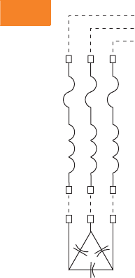
V3-T2-52 Volume 3—Power Distribution and Control Assemblies CA08100004E—April 2014 www.eaton.com
2
2
2
2
2
2
2
2
2
2
2
2
2
2
2
2
2
2
2
2
2
2
2
2
2
2
2
2
2
2
2.2
SPD, Power Conditioning, PF Capacitors and Harmonic Filters
Power Factor Correction and Harmonic Filtering
Wiring Diagram
Filter Schematic with Wiring Interconnects
Note
1Refer to NEC.
Power Lines from Disconnect
Lugs
Fuses
Reactor
Lugs
Lugs
Interconnects (Provided by Customer)
a
Capacitor Bank
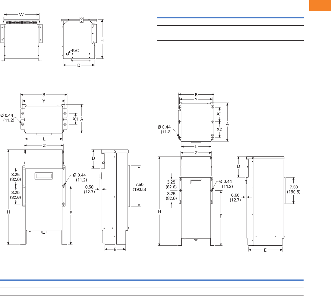
Volume 3—Power Distribution and Control Assemblies CA08100004E—April 2014 www.eaton.com V3-T2-53
2
2
2
2
2
2
2
2
2
2
2
2
2
2
2
2
2
2
2
2
2
2
2
2
2
2
2
2
2
2
2.2
SPD, Power Conditioning, PF Capacitors and Harmonic Filters
Power Factor Correction and Harmonic Filtering
Dimensions
Approximate Dimensions in Inches (mm)
Reactor Cabinet Reactor Cabinet
Low Voltage Fixed Capacitor Banks and Fixed Harmonic Filters
Case A1, A2 Case B1
UNIPAK Enclosures
Legend:
A = Total depth
B = Total width
D = Height of removable front cover
E = Depth of feet
F = Height of middle mounting hole in wall bracket
H = Total height
L = Width without feet and brackets
X = Depth between front and rear mounting holes in inches
Y = Width between floor mounting holes
Z = Width between wall bracket mounting holes
Case Size Height Width Depth
R 24.75 (628.7) 20.00 (508.0) 18.13 (460.5)
S 25.00 (635.0) 24.25 (616.0) 20.25 (514.4)
T 31.00 (787.4) 25.00 (635.0) 32.75 (831.9)
Case Size A B D E F H L X1 X2 X3 Y Z
A1 5.30 (134.6) 8.50 (215.9) 3.50 (88.9) 3.80 (96.5) 10.60 (269.2) 17.30 (439.4) 6.80 (172.7) 2.00 (50.8) N/A N/A 7.70 (195.6) 7.20 (182.9)
A2 6.00 (152.4) 8.50 (215.9) 5.60 (142.2) 4.50 (114.3) 13.30 (337.8) 22.30 (566.4) 6.80 (172.7) 2.30 (58.4) N/A N/A 7.70 (195.6) 7.20 (182.9)
B1 11.10 (281.9) 10.10 (256.5) 5.80 (147.3) 9.60 (243.8) 15.70 (398.8) 25.30 (642.6) 8.50 (215.9) 4.10 (104.1) 4.50 (114.3) N/A 9.30 (236.2) 8.80 (223.5)
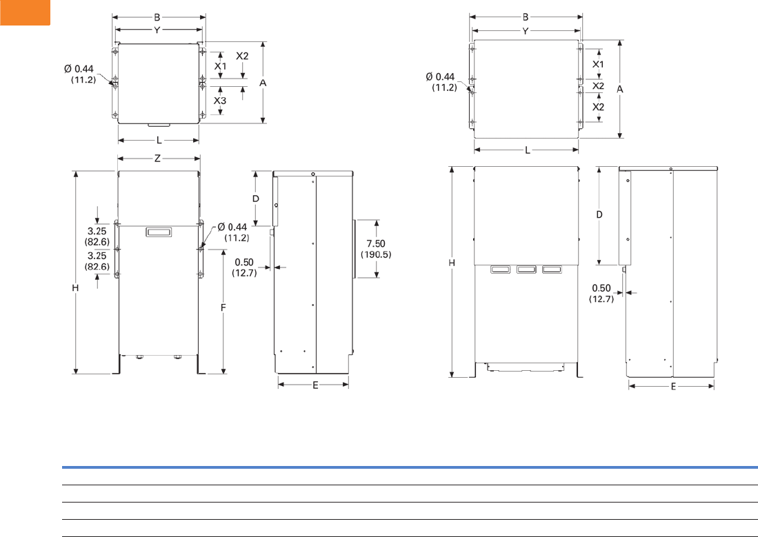
V3-T2-54 Volume 3—Power Distribution and Control Assemblies CA08100004E—April 2014 www.eaton.com
2
2
2
2
2
2
2
2
2
2
2
2
2
2
2
2
2
2
2
2
2
2
2
2
2
2
2
2
2
2
2.2
SPD, Power Conditioning, PF Capacitors and Harmonic Filters
Power Factor Correction and Harmonic Filtering
Approximate Dimensions in Inches (mm)
Case C1, C2 Case D1, E1
UNIPAK Enclosures
Legend:
A = Total depth
B = Total width
D = Height of removable front cover
E = Depth of feet
F = Height of middle mounting hole in wall bracket
H = Total height
L = Width without feet and brackets
X = Depth between front and rear mounting holes in inches
Y = Width between floor mounting holes
Z = Width between wall bracket mounting holes
Case
SizeABDEF HL X1X2X3YZ
C1 10.60 (269.2) 12.10 (307.3) 7.10 (180.3) 9.10 (231.1) 16.20 (411.5) 26.30 (668.0) 10.40 (264.2) 3.40 (86.4) 1.10 (27.9) 3.60 (91.4) 11.30 (287.0) 10.70 (271.8)
C2 12.00 (304.8) 19.30 (490.2) 16.90 (429.3) 9.50 (241.3) 16.30 (414.0) 36.00 (914.4) 17.70 (449.6) 3.00 (76.2) 1.50 (38.1) 3.80 (96.5) 18.30 (464.8) 18.00 (457.2)
D1 16.80 (426.7) 19.30 (490.2) 16.90 (429.3) 14.60 (370.8) N/A 36.00 (914.4) 17.70 (449.6) 5.10 (129.5) 2.40 (61.0) 5.00 (127.0) 18.30 (464.8) N/A
E1 22.30 (566.4) 24.40 (619.8) 16.80 (426.7) 19.50 (495.3) N/A 36.00 (914.4) 22.70 (576.6) 6.50 (165.1) 4.40 (111.8) 5.00 (127.0) 22.40 (569.0) N/A
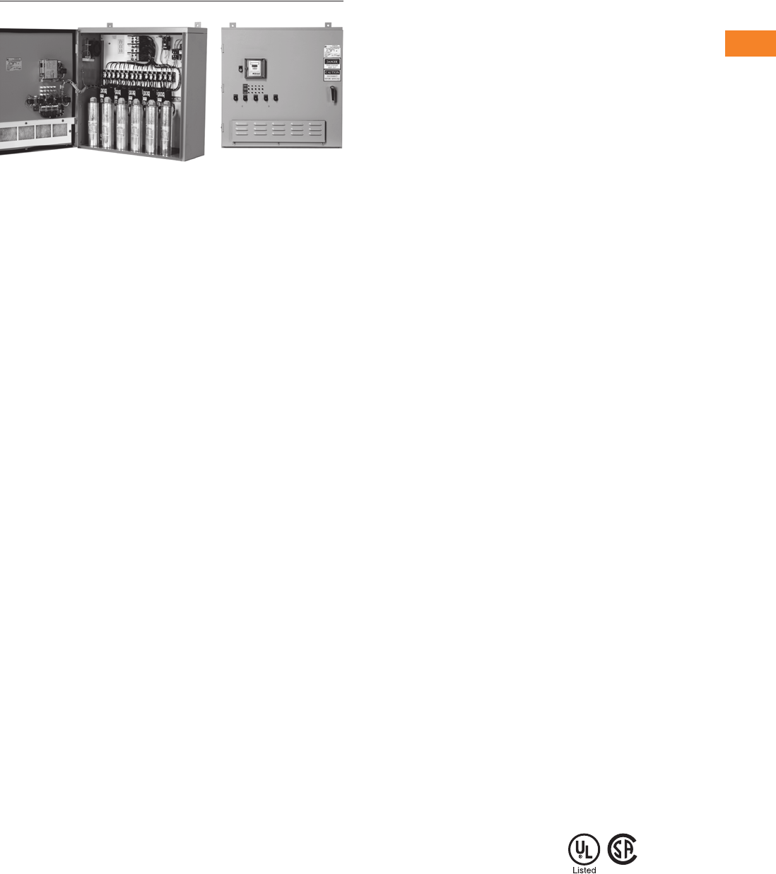
Volume 3—Power Distribution and Control Assemblies CA08100004E—April 2014 www.eaton.com V3-T2-55
2
2
2
2
2
2
2
2
2
2
2
2
2
2
2
2
2
2
2
2
2
2
2
2
2
2
2
2
2
2
2.2
SPD, Power Conditioning, PF Capacitors and Harmonic Filters
Power Factor Correction and Harmonic Filtering
AUTOVAR 300
Contents
Description Page
Product Overview. . . . . . . . . . . . . . . . . . . . . . . . . . V3-T2-38
UNIPUMP. . . . . . . . . . . . . . . . . . . . . . . . . . . . . . . . V3-T2-41
UNIPAK. . . . . . . . . . . . . . . . . . . . . . . . . . . . . . . . . . V3-T2-44
AUTOVAR 300 Automatic Power Factor Correction
Capacitor Systems
Product Selection . . . . . . . . . . . . . . . . . . . . . . . V3-T2-56
Options . . . . . . . . . . . . . . . . . . . . . . . . . . . . . . . V3-T2-56
Dimensions . . . . . . . . . . . . . . . . . . . . . . . . . . . V3-T2-57
AUTOVAR 600 Automatic Power Factor Correction
Capacitor Systems . . . . . . . . . . . . . . . . . . . . . . . . V3-T2-58
AUTOVAR Filter—LV Automatic Harmonic Filter . . V3-T2-63
Transient-Free Static Switching Power Factor
Correction Units. . . . . . . . . . . . . . . . . . . . . . . . . . V3-T2-67
Active-Harmonic Filter-Harmonic Correction Unit—
NEMA 1 Enclosure . . . . . . . . . . . . . . . . . . . . . . . V3-T2-71
AUTOVAR 300 Automatic Power Factor Correction Capacitor Systems
Product Description
Automatically switched
power factor correction
systems for low voltage
applications.
●Wallmount design is
ideal for minimum space
requirements
●Programmable to
automatically add/subtract
capacitor banks to maintain
preset target power factor
●Heavy-duty, three-phase
capacitor construction
●Five-year warranty of cells
Application Description
Service entrance power
factor correction installations
requiring precise
maintenance of target
power factor in a very
small footprint.
Features
Configuration
●Cabinet: Wall mounting 12
gauge steel with ANSI 61
gray, NEMA 1 (gasketed)
●Power line interconnect:
Rugged, power distribution
block connection
●Fusing: 200,000 ampere
interrupting capacity
provided on all three phases
of each bank. Blade-type
fuses mounted on insulator
stand-offs with blown-fuse
indicating lights
●Blown-fuse lights: Blown-
fuse indicating lights for
each phase and stage
located on the door
●Door interlock: Door
interlock automatically
disengages capacitors.
Power continues to be
provided to the unit until
the disconnect is open
●Exhaust fans: Provide
ventilation. Dust filtering
included
Controller
●Digital display of power
factor and number of
energized banks
●Visual indication of
insufficient kVAR to reach
target power factor
●LCD backlight display
●Capacitors disabled in
steps within 35 ms of main
power interruption
●Harmonic measurement
up to 19 harmonic and
alarm (THDV)
●Automatic detection and
correction of CT and phase
polarity
●Automatic detection of
connected steps
●Maximum 14 output steps
●Provides protection
against overvoltage,
overtemperature and
harmonic overload events
●Advanced control features
available
●
Optional communications
capability (C option controller)
●
Standard metering capability
●Voltage
●Current (sensed phase
only)
●Frequency
●Active power (kW)
●Reactive power (kVAR)
●Apparent power (kVA)
Contactor
●Fully rated for capacitor
switching up to 60 kVAR
at 600V
●Integral pre-charge/pre-
insertion module standard.
The contactor reduces
damaging switching
transients. This provides
safety and durability for
the system:
●Lessens the chance
of disrupting sensitive
electronic equipment
●Reduced inrush current
extends the life of the
capacitor cells
Additional Features
●Optional molded case
circuit breaker rated
65 kAIC at 480V and 600V
●Personnel ground fault
interruption provides
protection in case of
accidental contact with
control power and ground
●NEMA 3R weatherproofing
Standards and Certifications
●UL/CSA listed
and recognized

V3-T2-56 Volume 3—Power Distribution and Control Assemblies CA08100004E—April 2014 www.eaton.com
2
2
2
2
2
2
2
2
2
2
2
2
2
2
2
2
2
2
2
2
2
2
2
2
2
2
2
2
2
2
2.2
SPD, Power Conditioning, PF Capacitors and Harmonic Filters
Power Factor Correction and Harmonic Filtering
Product Selection
Wallmounted Switched Capacitor Banks—Low Voltage Applications 1
Options
Notes
1 Other ratings available, please consult factory.
2 For dimensional information, refer to Page V3-T2-57.
3 A current transformer with a 5 ampere secondary is required to operate an automatic capacitor bank. Rating based on service entrance ampacity.
For other ratios, please consult factory.
kVAR
Step x
kVAR
Rated Current
Amperes
Case
Size 2
Shipping Weight
in Lbs (kg)
Catalog
Number
240 Volt
25 5 x 5 60 J 217 (98.5) 25MCSR2313
50 5 x 10 120 J 255 (115.8) 50MCSR2313
75 5 x 15 180 J 260 (118.0) 75MCSR2313
100 5 x 20 240 J 270 (122.6) 100MCSR231
125 5 x 25 300 J 292 (132.6) 125MCSR231
150 5 x 30 361 J 314 (142.6) 150MCSR231
480 Volt
50 5 x 10 60 J 200 (90.8) 50MCSR4313
75 5 x 15 90 J 210 (95.3) 75MCSR4313
100 5 x 20 120 J 210 (95.3) 100MCSR4313
125 5 x 25 150 J 240 (109.0) 125MCSR4313
150 5 x 30 180 J 240 (109.0) 150MCSR4313
175 5 x 35 210 J 260 (118.0) 175MCSR431
200 5 x 40 241 J 270 (122.6) 200MCSR431
225 5 x 45 270 J 290 (131.7) 225MCSR431
250 5 x 50 300 J 292 (132.6) 250MCSR431
300 5 x 60 361 J 310 (140.7) 300MCSR431
600 Volt
50 5 x 10 48 J 200 (90.8) 50MCSR6313
75 5 x 15 72 J 210 (95.3) 75MCSR6313
100 5 x 20 96 J 210 (95.3) 100MCSR6313
125 5 x 25 120 J 240 (109.0) 125MCSR6313
150 5 x 30 144 J 240 (109.0) 150MCSR6313
175 5 x 35 168 J 260 (118.0) 175MCSR631
200 5 x 40 192 J 270 (122.6) 200MCSR631
225 5 x 45 216 J 290 (131.7) 225MCSR631
250 5 x 50 240 J 292 (132.6) 250MCSR631
300 5 x 60 288 J 310 (140.7) 300MCSD631
Description Option Code
Current transformer—multi-tap, split core current transformer (3000:5A) 3TX2
Hands-off auto switch—provides manual control to connect or disconnect capacitor stages regardless of controller output H
Remote alarm relay—relay for a remote alarm to indicate inability to reach target power factor A
Molded case circuit breaker (65 kAIC at 480V) M
Weatherproofing (NEMA 3R) W
Communicating controller C
Wallmounted
Switched Capacitor
Bank
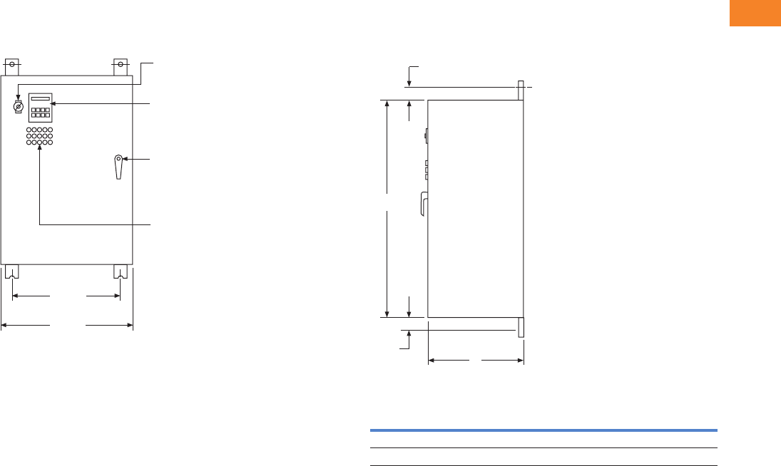
Volume 3—Power Distribution and Control Assemblies CA08100004E—April 2014 www.eaton.com V3-T2-57
2
2
2
2
2
2
2
2
2
2
2
2
2
2
2
2
2
2
2
2
2
2
2
2
2
2
2
2
2
2
2.2
SPD, Power Conditioning, PF Capacitors and Harmonic Filters
Power Factor Correction and Harmonic Filtering
Dimensions
Approximate Dimensions in Inches (mm)
Enclosure J
Front View Side View
Enclosure J
36.00
(914.4)
29.88
(759.0)
On/Off
Switch
Power
Factor
Controller
Keylock
Handle
Blown
Fuse
Lights
Description Height A Depth B
Without MCCB 36.00 (914.4) 14.00 (355.6)
With MCCB 60.00 (1524.0) 14.00 (355.6)
A
B
0.63
(16.0)
0.63
(16.0)
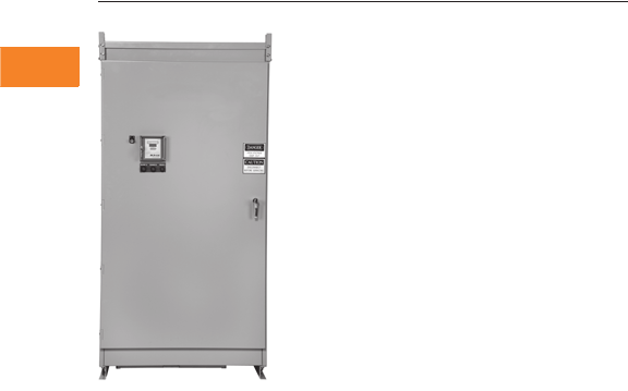
V3-T2-58 Volume 3—Power Distribution and Control Assemblies CA08100004E—April 2014 www.eaton.com
2
2
2
2
2
2
2
2
2
2
2
2
2
2
2
2
2
2
2
2
2
2
2
2
2
2
2
2
2
2
2.2
SPD, Power Conditioning, PF Capacitors and Harmonic Filters
Power Factor Correction and Harmonic Filtering
AUTOVAR 600
Contents
Description Page
Product Overview . . . . . . . . . . . . . . . . . . . . . . . . . V3-T2-38
UNIPUMP . . . . . . . . . . . . . . . . . . . . . . . . . . . . . . . V3-T2-41
UNIPAK . . . . . . . . . . . . . . . . . . . . . . . . . . . . . . . . . V3-T2-44
AUTOVAR 300 Automatic Power Factor Correction
Capacitor Systems. . . . . . . . . . . . . . . . . . . . . . . . V3-T2-55
AUTOVAR 600 Automatic Power Factor Correction
Capacitor Systems
Standards and Certifications . . . . . . . . . . . . . . V3-T2-59
Product Selection . . . . . . . . . . . . . . . . . . . . . . . V3-T2-60
Options . . . . . . . . . . . . . . . . . . . . . . . . . . . . . . V3-T2-61
Dimensions . . . . . . . . . . . . . . . . . . . . . . . . . . . V3-T2-62
AUTOVAR Filter—LV Automatic Harmonic Filter . . V3-T2-63
Transient-Free Static Switching Power Factor
Correction Units. . . . . . . . . . . . . . . . . . . . . . . . . . V3-T2-67
Active-Harmonic Filter-Harmonic Correction Unit—
NEMA 1 Enclosure . . . . . . . . . . . . . . . . . . . . . . . V3-T2-71
AUTOVAR 600 Automatic Power Factor Correction Capacitor Systems
Product Description
Programmable to
automatically add/subtract
capacitor banks to maintain
preset target power factor.
Application Description
Service entrance power
factor correction installations
requiring precise
maintenance of target
power factor.
Features
●Heavy-duty, three-phase
capacitor construction
●Five-year warranty of cells
Configuration
●Cabinet: 12 gauge steel
with ANSI 61 gray, powder
coat finish. Lift bolts
standard, NEMA 1
●Power line interconnect:
Rugged, copper bus bar
connection with access
provided for top or bottom
entry. Bus bars are braced
for 65 kAIC at 480V. All
internal power wiring
connections from bus are
laid out on a most direct
basis with minimum
bends for ease of
troubleshooting. Clear
barrier limiting access to
live parts included standard
●Modular tray design:
Capacitor banks arranged
in modular trays with
capacitors, fuses, blown-
fuse indicating lights, and
contactors grouped in a
logical, easily understood
layout. This permits easy
access, quick identification
of operating problems and
ease of expandability
●Fusing: UL recognized,
200,000 ampere
interrupting capacity
provided on all three
phases of each bank.
Blade-type fuses mounted
on insulator stand-offs
●Blown-fuse lights: Blown-
fuse indicating lights are on
the door located close to
individual fuses
to facilitate
tracing of cleared fuses
●Push-to-test: Allows
testing of door-mounted
blown fuse indicating lights
●AutoLocate: When door is
open and bus energized,
fuse circuit automatically
checks for cleared fuses.
If a fuse has cleared, the
light at the fuse comes on
for easy troubleshooting
●Door interlock: Door
interlock automatically
turns off control circuit
when engaged. Power
continues to be provided
to the unit until disconnect
is open
●Exhaust fans: Two fans
per cabinet provide thermal
protection. Dust filtering
provided
●Ease of expansion:
Capacitor stage nests are
self-contained and can be
added in the field. Two
bolts mount the nest in the
field. Control wire plugs
connect to factory
standard wire harness on
the left side of the cabinet
●Ease of replacement:
Cells can be easily
individually replaced by
removing the mounting
bolt and lifting out of the
nest without removal of
any other components
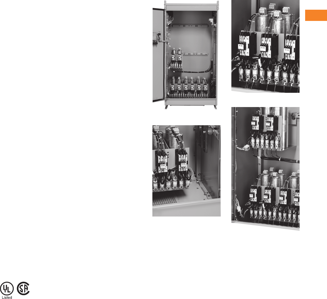
Volume 3—Power Distribution and Control Assemblies CA08100004E—April 2014 www.eaton.com V3-T2-59
2
2
2
2
2
2
2
2
2
2
2
2
2
2
2
2
2
2
2
2
2
2
2
2
2
2
2
2
2
2
2.2
SPD, Power Conditioning, PF Capacitors and Harmonic Filters
Power Factor Correction and Harmonic Filtering
Controller
●Digital display of power
factor and number of
energized banks
●Visual indication of
insufficient kVAR to reach
target power factor
●LCD backlight display
●Capacitors disabled in
steps within 35 ms of main
power interruption
●Harmonic measurement
up to 19 harmonic and
alarm (THDV)
●Automatic detection and
correction of CT and phase
polarity
●Automatic detection of
connected steps
●Maximum 14 output steps
●Provides protection
against overvoltage,
overtemperature and
harmonic overload events
●Advanced control features
available
●
Optional communications
capability (C option controller)
●
Standard metering capability
●Voltage
●Current (sensed phase
only)
●Frequency
●Active power (kW)
●Reactive power (kVAR)
●Apparent power (kVA)
Contactor
●Fully rated for capacitor
switching up to 60 kVAR
at 600V
●Integral pre-charge/pre-
insertion module standard.
The contactor reduces
damaging switching
transients. This provides
safety and durability for
the system:
●Lessens the chance of
disrupting sensitive
electronic equipment
●Reduced inrush current
extends the life of the
capacitor cells
Additional Features
●Optional molded case
circuit breaker, rated 65
kAIC at 48V and 600V
●Personnel ground fault
interruption provides
protection in case of
accidental contact with
control power and ground
●Control wiring—standard
NEC color-coded modular
bundles with quick
disconnect feature for ease
of troubleshooting or ease
of expendability
●Optional digital metering
AUTOVAR 600—Interior View
Bottom Entry Location
Modular Step Nest Assembly
Factory Pre-Wired for Future Expansion
Standards and Certifications
●UL/CSA listed
and recognized
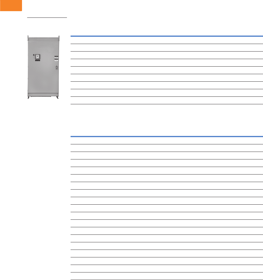
V3-T2-60 Volume 3—Power Distribution and Control Assemblies CA08100004E—April 2014 www.eaton.com
2
2
2
2
2
2
2
2
2
2
2
2
2
2
2
2
2
2
2
2
2
2
2
2
2
2
2
2
2
2
2.2
SPD, Power Conditioning, PF Capacitors and Harmonic Filters
Power Factor Correction and Harmonic Filtering
Product Selection
Floor-Mounted Switched Capacitor Banks—Low Voltage Applications
240 Vac
480 Vac
Notes
Other ratings and step configurations available, please consult factory.
For dimensional information, refer to Page V3-T2-62.
kVAR
Step x
kVAR
Rated Current
Amperes
Enclosure
Size
Shipping Weight
in Lbs (kg)
Catalog
Number
75 3 x 25 180 L 644 (292.4) 75TPCSR231
100 4 x 25 214 L 692 (314.2) 100TPCSR231
125 5 x 25 300 L 740 (336.0) 125TPCSR231
150 6 x 25 316 L 788 (357.8) 150TPCSR231
200 8 x 25 481 L 884 (401.3) 200TPCSR231
250 10 x 25 600 L 944 (428.6) 250TPCSR231
300 12 x 25 720 L 1022 (464.0) 300TPCSR231
350 7 x 50 844 KK 1616 (734.0) 350TPCSR231
400 8 x 50 965 KK 1704 (774.0) 400TPCSR231
kVAR
Step x
kVAR
Rated Current
Amperes
Enclosure
Size
Shipping Weight
in Lbs (kg)
Catalog
Number
150 3 x 50 180 L 632 (287.0) 150TPCSR431
200 4 x 50 240 L 676 (306.9) 200TPCSR431
250 5 x 50 300 L 720 (326.9) 250TPCSR431
300 6 x 50 360 L 764 (346.9) 300TPCSR431
350 7 x 50 420 L 808 (366.8) 350TPCSR431
400 8 x 50 480 L 852 (386.8) 400TPCSR431
450 9 x 50 540 L 896 (406.8) 450TPCSR431
500 10 x 50 600 L 944 (428.6) 500TPCSR431
550 11 x 50 660 L 984 (446.7) 550TPCSR431
600 12 x 50 720 L 1022 (464.0) 600TPCSR431
660 11 x 60 792 L 1010 (458.5) 660TPCSR431
700 7 x 100 840 L 1616 (734.0) 700TPCSR431
720 12 x 60 864 L 1050 (476.7) 720TPCSR431
800 8 x 100 960 KK 1704 (774.0) 800TPCSR431
840 14 x 60 1008 L 1690 (767.7) 840TPCSR431
900 9 x 100 1080 KK 1792 (814.0) 900TPCSR431
1000 10 x 100 1200 KK 1888 (857.0) 1000TPCSR431
1100 11 x 100 1320 KK 1966 (893.0) 1100TPCSR431
1200 12 x 100 1440 KK 2044 (928.0) 1200TPCSR431
Floor-Mounted
Switched Capacitor
Bank

Volume 3—Power Distribution and Control Assemblies CA08100004E—April 2014 www.eaton.com V3-T2-61
2
2
2
2
2
2
2
2
2
2
2
2
2
2
2
2
2
2
2
2
2
2
2
2
2
2
2
2
2
2
2.2
SPD, Power Conditioning, PF Capacitors and Harmonic Filters
Power Factor Correction and Harmonic Filtering
600 Vac
Options
Notes
1 Other ratings and step sizes available, please consult factory.
2 A current transformer with a 5 ampere secondary is required to operate an automatic capacitor bank. Rating based on service entrance ampacity.
For other ratios, please consult factory.
3 Not available with weatherproofing option.
For dimensional information, refer to Page V3-T2-62.
kVAR
Step x
kVAR
Rated Current
Amperes 1
Enclosure
Size
Shipping Weight
in Lbs (kg)
Catalog
Number
150 3 x 50 144 L 632 (287.0) 150TPCSR631
200 4 x 50 192 L 676 (306.9) 200TPCSR631
250 5 x 50 240 L 720 (326.9) 250TPCSR631
300 6 x 50 288 L 764 (346.9) 300TPCSR631
350 7 x 50 336 L 808 (366.8) 350TPCSR631
400 8 x 50 384 L 852 (386.8) 400TPCSR631
450 9 x 50 432 L 896 (406.8) 450TPCSR631
500 10 x 50 480 L 944 (428.6) 500TPCSR631
550 11 x 60 528 L 984 (446.7) 550TPCSR631
600 12 x 50 576 L 1022 (464.0) 600TPCSR631
660 11 x 60 634 L 1010 (458.5) 660TPCSR631
700 7 x 100 672 L 1616 (734.0) 700TPCSR631
720 12 x 60 692 L 1050 (476.7) 720TPCSR631
800 8 x 100 768 KK 1704 (774.0) 800TPCSR631
840 14 x 60 1008 L 1690 (767.7) 840TPCSR631
900 9 x 100 864 KK 1792 (814.0) 900TPCSR631
1000 10 x 100 960 KK 1888 (857.0) 1000TPCSR631
1100 11 x 100 1056 KK 1966 (893.0) 1100TPCSR631
1200 12 x 100 1152 KK 2044 (928.0) 1200TPCSR631
Description Option Code
Current transformer—multi-tap, split core current transformer (3000:5A) 2TX2
Hands-off auto switch—provides manual control to connect or disconnect capacitor stages regardless of controller output H
Remote alarm relay—relay for a remote alarm to indicate inability to reach target power factor A
Molded case circuit breaker (65 kAIC at 480V) M
Weatherproofing (NEMA 3R) W
Communicating controller C
IQ 250 solid-state meter 3Q
Floor-Mounted
Capacitor Bank
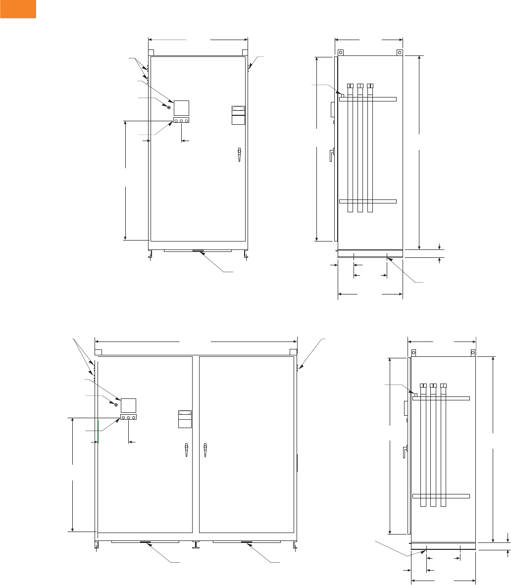
V3-T2-62 Volume 3—Power Distribution and Control Assemblies CA08100004E—April 2014 www.eaton.com
2
2
2
2
2
2
2
2
2
2
2
2
2
2
2
2
2
2
2
2
2
2
2
2
2
2
2
2
2
2
2.2
SPD, Power Conditioning, PF Capacitors and Harmonic Filters
Power Factor Correction and Harmonic Filtering
Dimensions
Approximate Dimensions in Inches (mm)
Enclosure L Front View
Enclosure KK Front and Side Views
Fans Fans
46.00
(1168.4)
11.75
(298.5)
(Note: Fans are
Side by Side)
PHASE A PHASE B PHASE C
1
2
3
Filter Tray
BEFORE SERVICING
CAUTION
DISCONNECT
HIGH VOLTAGE
DANGER
75.00
(1905.0)
6.00
(152.4) 13.00
(330.2)
25.00
(635.0)
38.50
(977.9) 26.25
(666.8)
71.25
(1809.8)
3.00
(76.2)
Ground
Lug
0.438 ø Mounting Holes
2 per Channel
Legend
1. Controller
2. On/Off Switch
3. Blown Fuse Indicator Lights
(Note: Fans are
Vertical Toward
Back of Enclosure)
Fans Fans
(Note: Fans are
Side by Side)
46.00
(1168.4)
11.75
(298.5)
1
2
3
78.25
(1987.6)
Filter Tray
25.00
(635.0)
13.00
(330.2)
0.438 ø
Mounting Holes
2 per Channel
Filter Tray 6.00
(152.4)
3.00
(76.2)
71.25
(1809.8) 75.00
(1905.0)
26.25
(666.8)
Ground
Lug
(Note: Fans are
Vertical Towards
Back of Enclosure)
Legend
1. Controller
2. On/Off Switch
3. Blown Fuse Indicating Light
BEFORE SERVICING
CAUTION
DISCONNECT
HIGH VOLTAGE
DANGER
PHASE A PHASE B PHASE C

Volume 3—Power Distribution and Control Assemblies CA08100004E—April 2014 www.eaton.com V3-T2-63
2
2
2
2
2
2
2
2
2
2
2
2
2
2
2
2
2
2
2
2
2
2
2
2
2
2
2
2
2
2
2.2
SPD, Power Conditioning, PF Capacitors and Harmonic Filters
Power Factor Correction and Harmonic Filtering
AUTOVAR Filter
Contents
Description Page
Product Overview. . . . . . . . . . . . . . . . . . . . . . . . . . V3-T2-38
UNIPUMP. . . . . . . . . . . . . . . . . . . . . . . . . . . . . . . . V3-T2-41
UNIPAK. . . . . . . . . . . . . . . . . . . . . . . . . . . . . . . . . . V3-T2-44
AUTOVAR 300 Automatic Power Factor Correction
Capacitor Systems . . . . . . . . . . . . . . . . . . . . . . . . V3-T2-55
AUTOVAR 600 Automatic Power Factor Correction
Capacitor Systems . . . . . . . . . . . . . . . . . . . . . . . . V3-T2-58
AUTOVAR Filter—LV Automatic Harmonic Filter
Standards and Certifications . . . . . . . . . . . . . . V3-T2-64
Product Selection . . . . . . . . . . . . . . . . . . . . . . . V3-T2-65
Options . . . . . . . . . . . . . . . . . . . . . . . . . . . . . . . V3-T2-65
Dimensions . . . . . . . . . . . . . . . . . . . . . . . . . . . V3-T2-66
Transient-Free Static Switching Power Factor
Correction Units. . . . . . . . . . . . . . . . . . . . . . . . . . V3-T2-67
Active-Harmonic Filter-Harmonic Correction Unit—
NEMA 1 Enclosure . . . . . . . . . . . . . . . . . . . . . . . V3-T2-71
AUTOVAR Filter—LV Automatic Harmonic Filter
Product Description
Automatically switched
harmonic filter/ power
factor corrections systems.
●Programmable to
automatically add/subtract
filter banks to maintain
preset target power factor
●Filter steps tuned for
maximum efficiency in
reducing harmonic
currents in three-phase
environments with heavy
nonlinear loads
Application Description
Service entrance power
factor correction installations
requiring precise maintenance
of target power factor in
three-phase, nonlinear, high
harmonic environments.
Features
●Efficient modular design
for short lead-times, ease
of maintenance and ease
of future expansion
●Heavy-duty, three-phase
capacitor construction with
reliable, threaded terminal
connections
●Cool operating, 100%
copper wound, thermal
protected reactors are
sized up to 150% of rated
capacitor current
Configuration
●Operation: AUTOVAR
harmonic filters are
designed to be sized the
same as any power factor
correction unit. In most low
voltage applications where
harmonics are generated
by nonlinear loads,
no harmonic audit is
necessary to design the
AUTOVAR filter because
it is already designed
for typical harmonic
spectrums at the kVAR
size specified
●Cabinet: 12 gauge steel
with ANSI 61 gray, powder
coat finish. Lift bolts
standard, NEMA 1
●Power line interconnect:
Rugged, copper bus bar
connection with access
provided for top or bottom
entry. Bus bars are braced
for 65 kAIC at 480V. All
internal power wiring
connections from bus are
laid out on a most direct
basis with minimum bends
for ease of troubleshooting.
Clear barrier limiting
access to live parts included
standard
●Modular tray design:
Capacitor banks arranged
in modular trays with
capacitors, fuses, blown-
fuse indicating lights, and
contactors grouped in a
logical, easily understood
layout. This permits easy
access, quick identification
of operating problems and
ease of expandability
●Fusing: UL recognized,
200,000 ampere
interrupting capacity
provided on all three
phases of each bank.
Blade-type fuses mounted
on insulator stand-offs
●Blown-fuse lights: Blown-
fuse indicating lights are on
the door located close to
individual fuses
to facilitate
tracing of cleared fuses
●Push-to-test: Allows
testing of door-mounted
blown fuse indicating lights.
●AutoLocate: When door is
open and bus energized,
fuse circuit automatically
checks for cleared fuses.
If a fuse has cleared, the
light at the fuse comes on
for easy troubleshooting
●Door interlock: Door
interlock automatically
turns off control circuit
when engaged. Power
continues to be provided
to the unit until disconnect
is open
●Exhaust fans: Two
fans per cabinet provide
thermal protection.
Dust filtering provided
●Ease of expansion:
Capacitor stage nests are
self-contained and can be
added in the field. Control
wire plugs connect to
factory standard wire
harness on the left side
of the cabinet
●Ease of replacement:
Cells can be easily
individually replaced by
removing the mounting
bolt and lifting out of the
nest without removal of
any other components
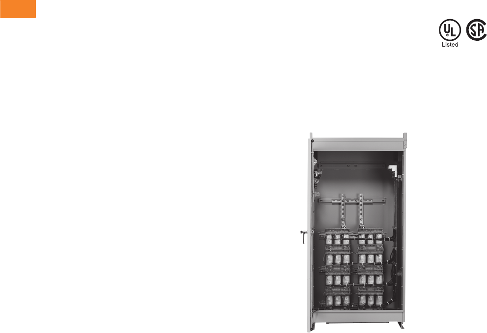
V3-T2-64 Volume 3—Power Distribution and Control Assemblies CA08100004E—April 2014 www.eaton.com
2
2
2
2
2
2
2
2
2
2
2
2
2
2
2
2
2
2
2
2
2
2
2
2
2
2
2
2
2
2
2.2
SPD, Power Conditioning, PF Capacitors and Harmonic Filters
Power Factor Correction and Harmonic Filtering
Controller
●Digital display of power
factor and number of
energized banks
●Visual indication of
insufficient kVAR to reach
target power factor
●LCD backlight display
●Capacitors disabled in
steps within 35 ms of main
power interruption
●Harmonic measurement
up to 19 harmonic and
alarm (THDV)
●Automatic detection and
correction of CT and phase
polarity
●Automatic detection of
connected steps
●Maximum 14 output steps
●Provides protection
against overvoltage,
overtemperature and
harmonic overload events
●Advanced control features
available
●
Optional communications
capability (C option controller)
●
Standard metering capability
●Voltage
●Current (sensed phase
only)
●Frequency
●Active power (kW)
●Reactive power (kVAR)
●Apparent power (kVA)
Contactor
●Fully rated for capacitor
switching up to 60 kVAR
at 600V
●Integral pre-charge/pre-
insertion module standard.
The contactor reduces
damaging switching
transients. This provides
safety and durability for
the system:
●Lessens the chance of
disrupting sensitive
electronic equipment
●Reduced inrush current
extends the life of the
capacitor cells
Reactors
●Tuning: Reactors tuned
to the 4.7th harmonic
order (nominal 5th).
This provides maximum
effectiveness in reducing
harmonic currents in
three-phase systems
with harmonics caused
by six-pulse devices
●Detuning: Reactor
designs can be detuned
upon request to 4.2nd to
protect capacitors against
alternate harmonics
●Windings: 100% copper
windings for minimal
temperature rise under
load
●Thermal overload
protection: Each reactor
includes three normally
closed, auto reset
thermostats that
open at 180°C. When
thermostats engage,
the contactor opens
●Insulation: 220°C
insulation system
●Warranty: One-year
replacement of reactors
Additional Features
●Optional molded case
circuit breaker rated
65 kAIC at 480V and 600V
●Personnel ground fault
interruption provides
protection in case of
accidental contact with
control power and ground
●Control wiring—standard
NEC color-coded modular
bundles with quick
disconnect feature for
ease of troubleshooting
or ease of expendability
AUTOVAR Filter—Reactor Cabinet
Standards and Certifications
●UL/CSA listed
and recognized

Volume 3—Power Distribution and Control Assemblies CA08100004E—April 2014 www.eaton.com V3-T2-65
2
2
2
2
2
2
2
2
2
2
2
2
2
2
2
2
2
2
2
2
2
2
2
2
2
2
2
2
2
2
2.2
SPD, Power Conditioning, PF Capacitors and Harmonic Filters
Power Factor Correction and Harmonic Filtering
Product Selection
Low Voltage Switched Harmonic Filters
Floor-Mounted Switched Harmonic Filters—Low Voltage
Options
Notes
1 Enclosures for 550 and 600 kVAR at 480 and 600V will be one double-door section wide if circuit breakers are required (enclosure size KK). Enclosure for 250 kVAR at
480V will be one double-door section wide if a circuit breaker is required.
2 Other ratings available, please consult factory.
3 L + L under enclosure size denotes two size L enclosures—one for the capacitors, one for the reactor case.
4 For KK enclosure design, change the last digit of the catalog number to 1. For example, 500THFSR431.
5 A current transformer with a 5 ampere secondary is required to operate an automatic capacitor bank. Rating based on service entrance ampacity.
For other ratios, please consult factory.
6 Not available with weatherproofing option.
For dimensional information, refer to Page V3-T2-66.
kVAR
Step x
kVAR
Rated Current
Amperes 2
Enclosure
Size 34
Shipping Weight
in Lbs (kg)
Catalog
Number
480 Vac
200 4 x 50 240 L 1438 (652.9) 200THFSR431
250 15 x 50 300 L 1634 (741.8) 250THFSR431
300 6 x 50 360 KK or L + L 1830 (830.8) 300THFSR432
350 7 x 50 420 KK or L + L 2026 (919.8) 350THFSR432
400 8 x 50 480 KK or L + L 2222 (1008.8) 400THFSR432
450 9 x 50 540 KK or L + L 2371 (1076.4) 450THFSR432
500 10 x 50 600 KK or L + L 2525 (1146.4) 500THFSR432
550 111 x 50 660 KK or L + L 2750 (1248.5) 550THFSR432
600 112 x 50 720 KK or L + L 2830 (1284.8) 600THFSR432
600 Vac
300 6 x 50 288 KK or L + L 1830 (830.8) 300THFSR632
350 7 x 50 336 KK or L + L 2026 (919.8) 350THFSR632
400 8 x 50 384 KK or L + L 2222 (1008.8) 400THFSR632
450 9 x 50 432 KK or L + L 2371 (1076.4) 450THFSR632
500 10 x 50 480 KK or L + L 2525 (1146.4) 500THFSR632
550 111 x 50 528 KK or L + L 2750 (1248.5) 550THFSR632
600 112 x 50 576 KK or L + L 2830 (1284.8) 600THFSR632
Description Option Code
Current transformer—multi-tap, split core current transformer 5TX2
Hands-off auto switch—provides manual control to connect or disconnect capacitor stages regardless of controller output H
Remote alarm relay—relay for a remote alarm to indicate inability to reach target power factor A
Molded case circuit breaker (65 kAIC at 480V) M
Weatherproofing (NEMA 3R) W
Communicating controller C
IQ 250 solid-state meter 6Q
Floor-Mounted
Switched Harmonic
Filter
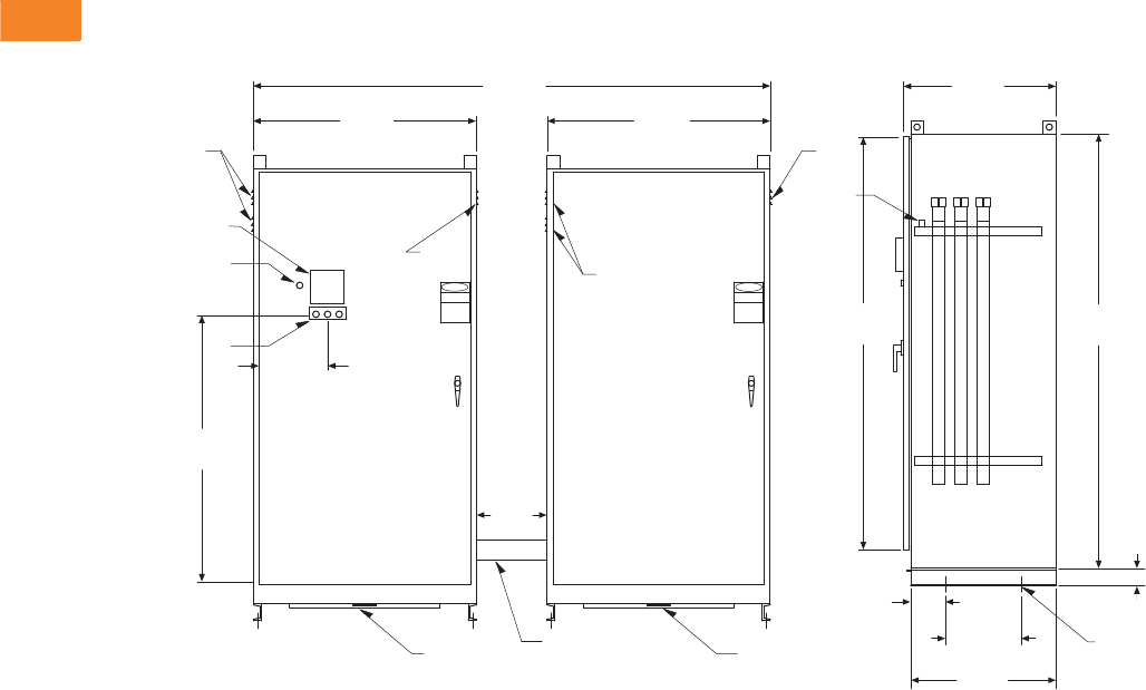
V3-T2-66 Volume 3—Power Distribution and Control Assemblies CA08100004E—April 2014 www.eaton.com
2
2
2
2
2
2
2
2
2
2
2
2
2
2
2
2
2
2
2
2
2
2
2
2
2
2
2
2
2
2
2.2
SPD, Power Conditioning, PF Capacitors and Harmonic Filters
Power Factor Correction and Harmonic Filtering
Dimensions
Approximate Dimensions in Inches (mm)
Enclosures L + L Front and Side Views
46.00
(1168.4)
11.75
(298.5)
89.00
(2260.6)
12.00
(304.8)
3
2
1
PHASE CPHASE BPHASE A
38.50
(977.9)
38.50
(977.9)
DISCONNECT
BEFORE SERVICING
HIGH VOLTAGE
CAUTION
DANGER
CAUTION
DISCONNECT
HIGH VOLTAGE
DANGER
BEFORE SERVICING
6.00
(152.4)
25.00
(635.0)
13.00
(330.2)
3.00
(76.2)
71.25
(1809.8)
75.00
(1905.0)
26.25
(666.8)
(Note: Fans are
Vertical Toward
Back of Enclosure)
(Note: Fans are
Vertical Towards
Back of Enclosure)
0.438 ø
Mounting Holes
2 per Channel
Power Wire
Interconnect
Conduit
(Note: Fans are
Side by Side)
(Note: Fans are
Side by Side)
Ground
Lug
Legend
1. Controller
2. On/Off Switch
3. Phase A, B and C Blown
Fuse Indicating Lights
Fans
Fans
Fans
Fans
Filter Tray Filter Tray
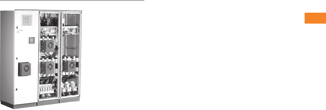
Volume 3—Power Distribution and Control Assemblies CA08100004E—April 2014 www.eaton.com V3-T2-67
2
2
2
2
2
2
2
2
2
2
2
2
2
2
2
2
2
2
2
2
2
2
2
2
2
2
2
2
2
2
2.2
SPD, Power Conditioning, PF Capacitors and Harmonic Filters
Power Factor Correction and Harmonic Filtering
Transient-Free Power Factor Correction System
Contents
Description Page
Product Overview. . . . . . . . . . . . . . . . . . . . . . . . . . V3-T2-38
UNIPUMP. . . . . . . . . . . . . . . . . . . . . . . . . . . . . . . . V3-T2-41
UNIPAK. . . . . . . . . . . . . . . . . . . . . . . . . . . . . . . . . . V3-T2-44
AUTOVAR 300 Automatic Power Factor Correction
Capacitor Systems . . . . . . . . . . . . . . . . . . . . . . . . V3-T2-55
AUTOVAR 600 Automatic Power Factor Correction
Capacitor Systems . . . . . . . . . . . . . . . . . . . . . . . . V3-T2-58
AUTOVAR Filter—LV Automatic Harmonic Filter . . V3-T2-63
Transient-Free Static Switching Power Factor
Correction Units. . . . . . . . . . . . . . . . . . . . . . . . . .
Features, Benefits and Functions . . . . . . . . . . . V3-T2-68
Standards and Certifications . . . . . . . . . . . . . . V3-T2-68
Catalog Number Selection . . . . . . . . . . . . . . . . V3-T2-69
Technical Data and Specifications . . . . . . . . . . V3-T2-69
Dimensions . . . . . . . . . . . . . . . . . . . . . . . . . . . V3-T2-70
Active-Harmonic Filter-Harmonic Correction Unit—
NEMA 1 Enclosure . . . . . . . . . . . . . . . . . . . . . . . V3-T2-71
Transient-Free Static Switching Power Factor Correction Units
Product Description
Transient-free statically
switch capacitor units are
available in two models.
The FTE model is a real-time
transient-free system, used
to compensate extremely
rapid loads within one
cycle of operation (typically
5–20 msec).
The FTA model is a fast
transient-free system, used
to compensate any loads
within 3–4 seconds.
The FTA and FTE units
employ a fast or real-time
response, and include the
ability to switch larger steps
without creating significant
line noise. These relatively
maintenance-free units reside
in a smaller footprint and are
ideal for use in applications
such as flicker control, large
motor starting, bus voltage
stabilization, fault ride-
through solutions, power
factor correction and
many more.
Application Description
●Motor starting
●On-site generation support
●Spot welding
●Wind turbines
●Other dynamic loads
Three current transformers
with a 5 ampere secondary
are required to operate this
capacitor bank.
Rating based on Service
Entrance Ampacity. For other
ratios, please consult factory.
●Startup and
Commissioning by
factory trained personnel
is required for proper
operation and warranty
of this system
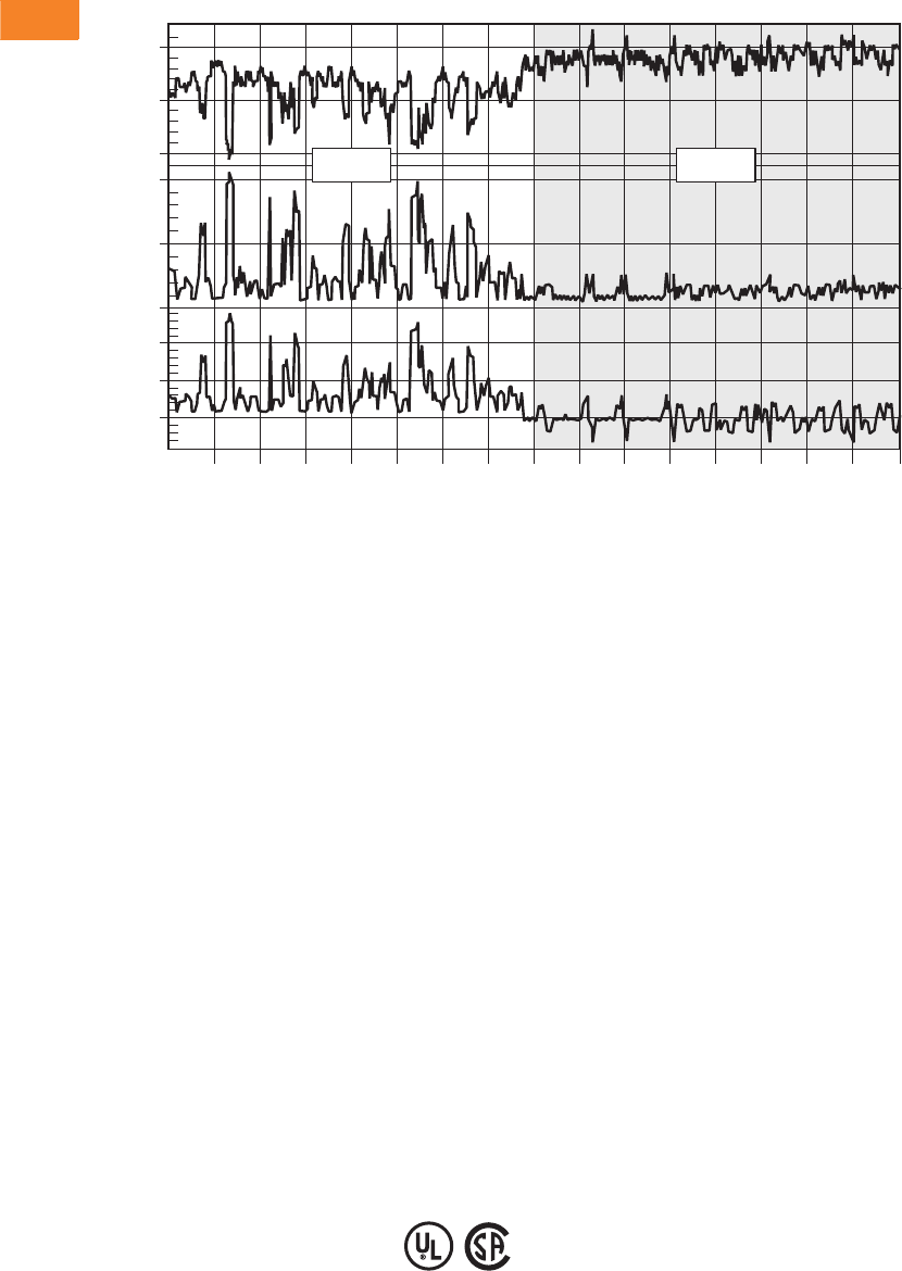
V3-T2-68 Volume 3—Power Distribution and Control Assemblies CA08100004E—April 2014 www.eaton.com
2
2
2
2
2
2
2
2
2
2
2
2
2
2
2
2
2
2
2
2
2
2
2
2
2
2
2
2
2
2
2.2
SPD, Power Conditioning, PF Capacitors and Harmonic Filters
Power Factor Correction and Harmonic Filtering
Application Example—Spot Welding
Features, Benefits and Functions
●Transient-free capacitor
group switching, using
electronic switching
elements
●Simultaneous connection/
disconnection of all
required steps
●Consistent capacitor values
and stable filter
characteristics
●Harmonic filtration
●Three independent
control modes:
●Power factor control
●Voltage control
●Load sharing with
another compensation
system connected to
the same transformer
●Unique SCAN feature
reduces capacitor
duty cycles
●Remote control of
compensation systems
available via LAN
or Ethernet
●Integrated three-phase
network analyzer:
●Measures all power
parameters on each
phase (V, I, kW,
kVAR, kVA)
●Measures voltage and
current harmonics to
the 63rd harmonic
FTE unit includes all of the
above, plus:
●Reduces voltage flicker and
voltage sag
●Provides network reactive
power support
●Offers voltage control
options
Standards and Certifications
Enclosure
●EMC—EN50081-2,
EN50082-2, EN55011,
EN61000-4-2/3/4/5,
ENV50204, ENV50141
●CE Mark—73/23/EEC am.
93/68, 98/37/EC art. 4(2)
●Safety—EN61010-1,
EN60439-1, EN60204
●UL 508
●CSA
21:33:38
0
150
300
1000
1400
1800
210
220
230
L1-Q (kVAR) L1-Current (A) L1-Voltage (V)
Spot Welding (Auto Manufacturer)
:40 :42 :44 :46 :48 :50 :52 :54 :56 :58 :00 :02 :04 :06 :08
Without With
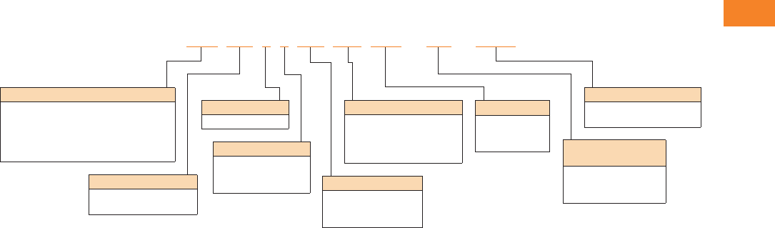
Volume 3—Power Distribution and Control Assemblies CA08100004E—April 2014 www.eaton.com V3-T2-69
2
2
2
2
2
2
2
2
2
2
2
2
2
2
2
2
2
2
2
2
2
2
2
2
2
2
2
2
2
2
2.2
SPD, Power Conditioning, PF Capacitors and Harmonic Filters
Power Factor Correction and Harmonic Filtering
Catalog Number Selection
TFSS
Technical Data and Specifications
Product Configurations
Network voltage
●210–690V
●Engineered solutions
up to 15 kV
Frequency
●45–55 Hz for 50 Hz
network
●55–65 Hz for 60 Hz
network
Capacitor group
configurations
●Up to 12 groups per
one controller
●Switching sequence:
●1:1:1:1 (all equal)
●1:2:2:2 (half group)
●1:2:4:4 (quarter, half
groups)
Acquisition time
●FTE—5–20 ms for a
50 Hz network
●FTE—4–16 ms for a
60 Hz network
●FTA—1–4 second
maximum
Notes
1All models are CE approved. Please notify if UL or cUL is required.
2MV units require:
A correctly sized and specified step-up transformer
MV and LV interconnection, switching and protection
3All systems are offered with Measurement Level 1 (f, I, V, kW, kVAR, kVA, PF) and no communications card. The measurement levels can be upgraded to Measurement Level 2 (adds THD I and THDV),
Measurement Level 3 (adds waveforms, I and V harmonics) and Measurement Level 4 (adds event log).
4Balanced system employs two-phase switching, unbalanced system employs individual three-phase switching.
5For motor start and grid fault ride-through solutions, please consult factory.
Optional
Measurement Levels 3
M2
M3
M4
Enclosure 1
N1 = NEMA 1
N12 = NEMA 12
N3R = NEMA 3R
Optional
COM = Communications Card
RS-485/Modbus
Percent Reactory (Tuning)
P14 = 14% (2.67th order)
P7 = 7% (3.8th order)
P567 = 5.67% (4.2nd order)
P49 = 4.9% (4.5th order)
Model
FTE = Real-time balanced
FTEUN 4= Real-time unbalanced
FTA = Fast acting
FTES = Motor starting systems
FTER 5= Grid fault ride-through systems
Total Power in kVAR
Typical in steps of 50 kVAR
beginning with 100 kVAR
Number of Groups
Maximum 12
Switching Sequence
1 = 1:1:1:1
2 = 1:2:2:2
3 = 1:2:4:4 System Voltage
480 = 480V
600 = 600V
690V or above = MV 2
FTA 100 62480 P14 N12 -M3-COM

V3-T2-70 Volume 3—Power Distribution and Control Assemblies CA08100004E—April 2014 www.eaton.com
2
2
2
2
2
2
2
2
2
2
2
2
2
2
2
2
2
2
2
2
2
2
2
2
2
2
2
2
2
2
2.2
SPD, Power Conditioning, PF Capacitors and Harmonic Filters
Power Factor Correction and Harmonic Filtering
Dimensions
Approximate Dimensions in Inches (mm)
Transient-Free Reactive Power Compensation Systems—
Real-Time Transient-Free Systems—480 Vac
Compensate Rapid Loads Within One Cycle
(Typically 5–20 ms)—Standard 6% Inductors—
Detuned to 245 Hz (4.08th Harmonic)
Compensate Rapid Loads Within One Cycle
(Typically 5–20 ms)—4.5% Inductors—
Tuned to 282 Hz (4.7th Harmonic)
Transient-Free Reactive Power Compensation Systems—
Fast Transient-Free Switching Systems—480 Vac
Compensate Any Load Within 3–4 Seconds—Standard 6%
Inductors—Detuned to 245 Hz (4.08th Harmonic)
Compensate Any Load Within 3–4 Seconds—4.5%
Inductors—Tuned to 282 Hz (4.7th Harmonic)
Catalog
Number Width Depth Height
FTE15652480 31.50 (800.1) 23.60 (599.4) 82.70 (2100.6)
FTE18752480 31.50 (800.1) 23.60 (599.4) 82.70 (2100.6)
FTE21974480 31.50 (800.1) 23.60 (599.4) 82.70 (2100.6)
FTE25052480 31.50 (800.1) 23.60 (599.4) 82.70 (2100.6)
FTE26274480 31.50 (800.1) 23.60 (599.4) 82.70 (2100.6)
FTE31252480 31.50 (800.1) 23.60 (599.4) 82.70 (2100.6)
FTE37552480 31.50 (800.1) 23.60 (599.4) 82.70 (2100.6)
FTE43774480 31.50 (800.1) 23.60 (599.4) 82.70 (2100.6)
FTE45031480 31.50 (800.1) 23.60 (599.4) 82.70 (2100.6)
FTE60661480 63.00 (1600.2) 23.60 (599.4) 82.70 (2100.6)
FTE687112480 63.00 (1600.2) 23.60 (599.4) 82.70 (2100.6)
FTE75061480 63.00 (1600.2) 23.60 (599.4) 82.70 (2100.6)
FTE825112480 63.00 (1600.2) 23.60 (599.4) 82.70 (2100.6)
FTE90061480 63.00 (1600.2) 23.60 (599.4) 82.70 (2100.6)
FTE112591480 94.50 (2400.3) 23.60 (599.4) 82.70 (2100.6)
FTE135091480 94.50 (2400.3) 23.60 (599.4) 82.70 (2100.6)
FTE1500121480 126.00 (3200.4) 23.60 (599.4) 82.70 (2100.6)
FTE1800121480 126.00 (3200.4) 23.60 (599.4) 82.70 (2100.6)
Catalog
Number Width Depth Height
FTE15652480T 31.50 (800.1) 23.60 (599.4) 82.70 (2100.6)
FTE18752480T 31.50 (800.1) 23.60 (599.4) 82.70 (2100.6)
FTE21974480T 31.50 (800.1) 23.60 (599.4) 82.70 (2100.6)
FTE25052480T 31.50 (800.1) 23.60 (599.4) 82.70 (2100.6)
FTE26274480T 31.50 (800.1) 23.60 (599.4) 82.70 (2100.6)
FTE31252480T 31.50 (800.1) 23.60 (599.4) 82.70 (2100.6)
FTE37552480T 31.50 (800.1) 23.60 (599.4) 82.07 (2100.6)
FTE43774480T 31.50 (800.1) 23.60 (599.4) 82.70 (2100.6)
FTE45031480T 31.50 (800.1) 23.60 (599.4) 82.70 (2100.6)
FTE60661480T 63.00 (1600.2) 23.60 (599.4) 82.70 (2100.6)
FTE687112480T 63.00 (1600.2) 23.60 (599.4) 82.70 (2100.6)
FTE75061480T 63.00 (1600.2) 23.60 (599.4) 82.70 (2100.6)
FTE825112480T 63.00 (1600.2) 23.60 (599.4) 82.70 (2100.6)
FTE90061480T 63.00 (1600.2) 23.60 (599.4) 82.70 (2100.6)
FTE112591480T 94.50 (2400.3) 23.60 (599.4) 82.70 (2100.6)
FTE135091480T 94.50 (2400.3) 23.60 (599.4) 82.70 (2100.6)
FTE1500121480T 126.00 (3200.4) 23.60 (599.4) 82.70 (2100.6)
FTE1800121480T 126.00 (3200.4) 23.60 (599.4) 82.70 (2100.6)
Catalog
Number Width Depth Height
FTA15652480 31.50 (800.1) 23.60 (599.4) 82.70 (2100.6)
FTA18752480 31.50 (800.1) 23.60 (599.4) 82.70 (2100.6)
FTA21974480 31.50 (800.1) 23.60 (599.4) 82.70 (2100.6)
FTA25052480 31.50 (800.1) 23.60 (599.4) 82.70 (2100.6)
FTA26274480 31.50 (800.1) 23.60 (599.4) 82.70 (2100.6)
FTA31252480 31.50 (800.1) 23.60 (599.4) 82.70 (2100.6)
FTA37552480 31.50 (800.1) 23.60 (599.4) 82.70 (2100.6)
FTA43774480 31.50 (800.1) 23.60 (599.4) 82.70 (2100.6)
FTA45031480 31.50 (800.1) 23.60 (599.4) 82.70 (2100.6)
FTA60661480 63.00 (1600.2) 23.60 (599.4) 82.70 (2100.6)
FTA687112480 63.00 (1600.2) 23.60 (599.4) 82.70 (2100.6)
FTA75061480 63.00 (1600.2) 23.60 (599.4) 82.70 (2100.6)
FTA825112480 63.00 (1600.2) 23.60 (599.4) 82.70 (2100.6)
FTA90061480 63.00 (1600.2) 23.60 (599.4) 82.70 (2100.6)
FTA112591480 94.50 (2400.3) 23.60 (599.4) 82.70 (2100.6)
FTA135091480 94.50 (2400.3) 23.60 (599.4) 82.70 (2100.6)
FTA1500121480 126.00 (3200.4) 23.60 (599.4) 82.70 (2100.6)
FTA1800121480 126.00 (3200.4) 23.60 (599.4) 82.70 (2100.6)
Catalog
Number Width Depth Height
FTA15652480T 31.50 (800.1) 23.60 (599.4) 82.70 (2100.6)
FTA18752480T 31.50 (800.1) 23.60 (599.4) 82.70 (2100.6)
FTA21974480T 31.50 (800.1) 23.60 (599.4) 82.70 (2100.6)
FTA25052480T 31.50 (800.1) 23.60 (599.4) 82.70 (2100.6)
FTA26274480T 31.50 (800.1) 23.60 (599.4) 82.70 (2100.6)
FTA31252480T 31.50 (800.1) 23.60 (599.4) 82.70 (2100.6)
FTA37552480T 31.50 (800.1) 23.60 (599.4) 82.70 (2100.6)
FTA43774480T 31.50 (800.1) 23.60 (599.4) 82.70 (2100.6)
FTA45031480T 31.50 (800.1) 23.60 (599.4) 82.70 (2100.6)
FTA60661480T 63.00 (1600.2) 23.60 (599.4) 82.07 (2100.6)
FTA687112480T 63.00 (1600.2) 23.60 (599.4) 82.70 (2100.6)
FTA75061480T 63.00 (1600.2) 23.60 (599.4) 82.70 (2100.6)
FTA825112480T 63.00 (1600.2) 23.60 (599.4) 82.70 (2100.6)
FTA90061480T 63.00 (1600.2) 23.60 (599.4) 82.70 (2100.6)
FTA112591480T 94.50 (2400.3) 23.60 (599.4) 82.70 (2100.6)
FTA135091480T 94.50 (2400.3) 23.60 (599.4) 82.70 (2100.6)
FTA1500121480T 126.00 (3200.4) 23.60 (599.4) 82.70 (2100.6)
FTA1800121480T 126.00 (3200.4) 23.60 (599.4) 82.70 (2100.6)

Volume 3—Power Distribution and Control Assemblies CA08100004E—April 2014 www.eaton.com V3-T2-71
2
2
2
2
2
2
2
2
2
2
2
2
2
2
2
2
2
2
2
2
2
2
2
2
2
2
2
2
2
2
2.2
SPD, Power Conditioning, PF Capacitors and Harmonic Filters
Power Factor Correction and Harmonic Filtering
Harmonic Correction Units—NEMA 1 Enclosure
Contents
Description Page
Product Overview. . . . . . . . . . . . . . . . . . . . . . . . . . V3-T2-38
UNIPUMP. . . . . . . . . . . . . . . . . . . . . . . . . . . . . . . . V3-T2-41
UNIPAK. . . . . . . . . . . . . . . . . . . . . . . . . . . . . . . . . . V3-T2-44
AUTOVAR 300 Automatic Power Factor Correction
Capacitor Systems . . . . . . . . . . . . . . . . . . . . . . . . V3-T2-55
AUTOVAR 600 Automatic Power Factor Correction
Capacitor Systems . . . . . . . . . . . . . . . . . . . . . . . . V3-T2-58
AUTOVAR Filter—LV Automatic Harmonic Filter . . V3-T2-63
Transient-Free Static Switching Power Factor
Correction Units. . . . . . . . . . . . . . . . . . . . . . . . . . V3-T2-67
Active-Harmonic Filter-Harmonic Correction Unit—
NEMA 1 Enclosure
Technical Data and Specifications . . . . . . . . . . V3-T2-72
Wiring Diagrams . . . . . . . . . . . . . . . . . . . . . . . . V3-T2-72
Dimensions . . . . . . . . . . . . . . . . . . . . . . . . . . . V3-T2-74
Active-Harmonic Filter-Harmonic Correction Unit—NEMA 1 Enclosure
Product Description
Active Harmonic Filters
(Harmonic Correction Units—
HCUEs) provide dynamic
harmonic correction by
actively injecting equal and
opposite currents into the
customer’s electrical
distribution system that
cancel the entire spectrum
of harmonic currents at the
point of connection.
Application Description
Typical applications include
locations with large amounts
of nonlinear loads including
6- and 12-pulse PWM AC
variable frequency drives,
DC drives, as well as other
switch-mode power supply
equipment. This equipment
can be found in water and
wastewater treatment
facilities, industrial
manufacturing and
warehousing plants, military
bases, and commercial
(HVAC) locations.
Features, Benefits
and Functions
Unlike passive filters, by
providing dynamic correction,
HCUEs can provide effective
harmonic correction for
varying load conditions and
harmonic spectrums up to
their rated capacity. HCUEs
also have the secondary
benefit of providing power
factor correction with any
excess capacity after
correcting all harmonic
conditions.
●Fast action
●NEMA 1 and NEMA 12
enclosures available:
●Wallmount (50 and
100 ampere designs)
●Floor-standing
(300 ampere design)
●Touchscreen HMI
●Modbus and Ethernet
connectivity
Note: Requires at least 3% series
input line reactor or equivalent
6% DC bus choke
in each AC drive for optimum
performance.
Advantages
●Can be sized to guarantee
specific levels of harmonic
correction, such as
meeting IEEE 519
recommended levels
●Cannot be overloaded
●Can be expanded without
affecting performance
●Broad spectrum of
cancellation (2nd to
50th harmonic)
●Power factor improvement
●Easier and less expensive
installation
●Comprehensive control
Standards and Certifications
●UL/CSA approved
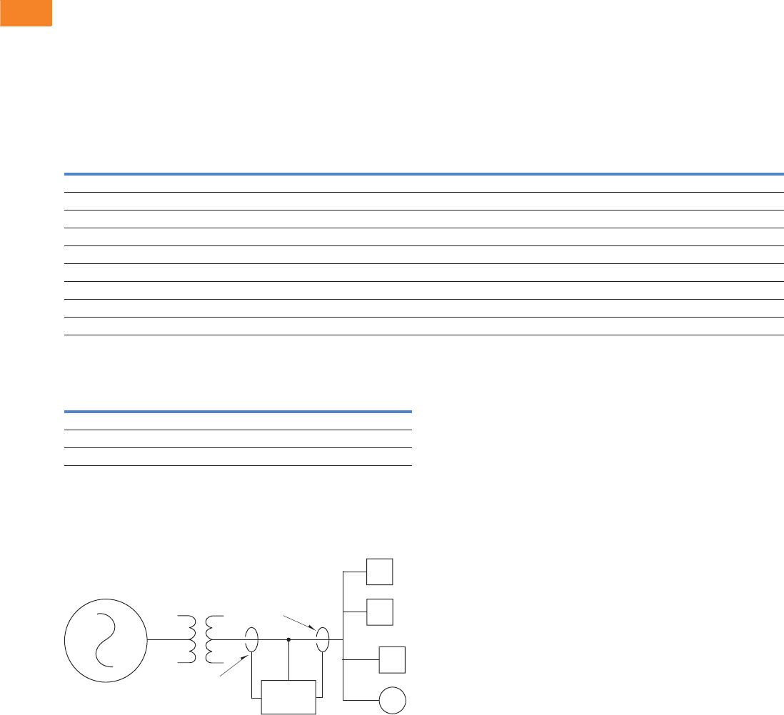
V3-T2-72 Volume 3—Power Distribution and Control Assemblies CA08100004E—April 2014 www.eaton.com
2
2
2
2
2
2
2
2
2
2
2
2
2
2
2
2
2
2
2
2
2
2
2
2
2
2
2
2
2
2
2.2
SPD, Power Conditioning, PF Capacitors and Harmonic Filters
Power Factor Correction and Harmonic Filtering
Technical Data and Specifications
●20 kHz switching carrier frequency
●208–480V ±10%, 600V and 690V with autotransformer
●50/60 Hz +/–3 Hz frequency
●Ambient temperature 0°C to +40°C enclosed
●Seismic Zone 4
●Output capacity—self limited to 100% current rated
●Corrective capability—<5% TDD and near unity
displacement power factor
Harmonic Control Unit Ratings—NEMA 1 Enclosed
Current Transformer Ratings 1
Wiring Diagrams
Installation Diagram
Note
1Current transformers are rated for 400 Hz. Two current transformers are required for three-
phase loads. Three current transformers are required when single-phase loads are present.
Rating based on service entrance ampacity and optional parallel operation. For other ratios,
please consult factory.
Startup and commissioning by factory trained personnel is required for proper operation and
warranty of this system.
Model Voltage Frequency
Total Current
Amperes (rms)
Watt Losses
(kw) Enclosure Type Disconnect
HCUE050D5N1 208–480 50/60 Hz 50 1.8 Wallmount/NEMA 1 —
HCUE100D5N1 208–480 50/60 Hz 100 3.0 Wallmount/NEMA 1 —
HCUE300D5N1 208–480 50/60 Hz 300 8.0 Free-standing/NEMA 1 X
HCUE050D6N1 600 50/60 Hz 39 1.8 Free-standing/NEMA 1 —
HCUE050D7N1 690 50/60 Hz 33 1.8 Free-standing/NEMA 1 —
HCUE100D6N1 600 50/60 Hz 78 3.0 Free-standing/NEMA 1 —
HCUE100D7N1 690 50/60 Hz 65 3.0 Free-standing/NEMA 1 —
HCUE300D6N1 600 50/60 Hz 235 8.0 Free-standing/NEMA 1 —
HCUE300D7N1 690 50/60 Hz 200 8.0 Free-standing/NEMA 1 —
Model
AC Line
Current Rating Type
HCUCT1000SC 1000 Split
HCUCT3000SC 3000 Split
HCUCT5000SC 5000 Split
Source
Transformer
Alternate CT
Placement
Typical CT
Placement
HCU
Load(s)
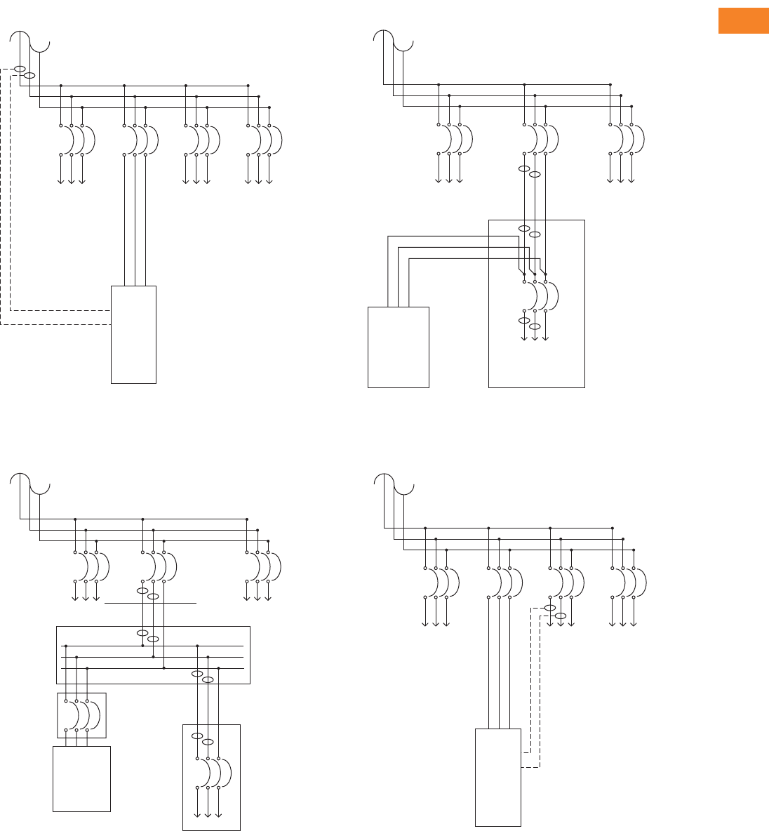
Volume 3—Power Distribution and Control Assemblies CA08100004E—April 2014 www.eaton.com V3-T2-73
2
2
2
2
2
2
2
2
2
2
2
2
2
2
2
2
2
2
2
2
2
2
2
2
2
2
2
2
2
2
2.2
SPD, Power Conditioning, PF Capacitors and Harmonic Filters
Power Factor Correction and Harmonic Filtering
Source CT Location
Source or Load CT Location
Source or Load CT Location
Load CT Location
Utility Transformer
or Upstream Panel
Distribution Panel or
Motor Control Center
Corrected
Load
HCU
Harmonic Cancellation
and/or Power-Factor
Correction of all Loads
on Panel
Corrected
Load
Corrected
Load
Utility Transformer
or Upstream Panel
Distribution Panel or
Motor Control Center
Other Loads Other Loads
More than
25 Feet per
NEC 240-21
HCU
Corrected
Load
Four Possible
CT Locations
Shown
Breaker
or Fused
Disconnect
Junction Box
–
Utility Transformer or
Upstream Panel
Distribution Panel or
Motor Control Center
Other
Loads
Other
Loads
Less than
25 Feet per
NEC 240-21
HCU
Corrected
Load
Three Possible
CT Locations
Shown
Utility Transformer
or Upstream Panel
Distribution Panel or
Motor Control Center
Other
Loads
HCU
Harmonic Cancellation
and/or Power-Factor
Correction of a Selected
Load on Panel
Corrected
Load
Other
Loads

V3-T2-74 Volume 3—Power Distribution and Control Assemblies CA08100004E—April 2014 www.eaton.com
2
2
2
2
2
2
2
2
2
2
2
2
2
2
2
2
2
2
2
2
2
2
2
2
2
2
2
2
2
2
2.2
SPD, Power Conditioning, PF Capacitors and Harmonic Filters
Power Factor Correction and Harmonic Filtering
Dimensions
Approximate Dimensions in Inches (mm)
Harmonic Control—NEMA 1 Enclosed Current Transformer
Auxiliary Current Transformers 2
Notes
1Consult factory.
2Required for parallel operation of HCU and for units with transformers. Use the same number
of auxiliary CTs as main sensing CTs.
Model
Exterior Unit Weight
in Lbs (kg)Height Weight Depth
HCUE050D5N1 51.80 (1315.7) 20.70 (525.8) 18.50 (469.9) 250 (113.5)
HCUE100D5N1 68.70 (1745.0) 20.70 (525.8) 18.50 (469.9) 350 (158.9)
HCUE300D5N1 74.90 (1902.5) 32.20 (817.9) 19.50 (495.3) 775 (351.9)
HCUE050D6N1 1 111
HCUE050D7N1 1 111
HCUE100D6N1 1 111
HCUE100D7N1 1 111
HCUE300D6N1 1 111
HCUE300D7N1 1 111
Model Internal Diameter
HCUCT1000SC 4.65 (118.1)
HCUCT3000SC 6.50 (165.1)
HCUCT5000SC 7.50 (190.5)
Model Ratio Type
HCUCT7RL6011 600/1 Solid round core
HCUCT7RL1021 1000/1 Solid round core
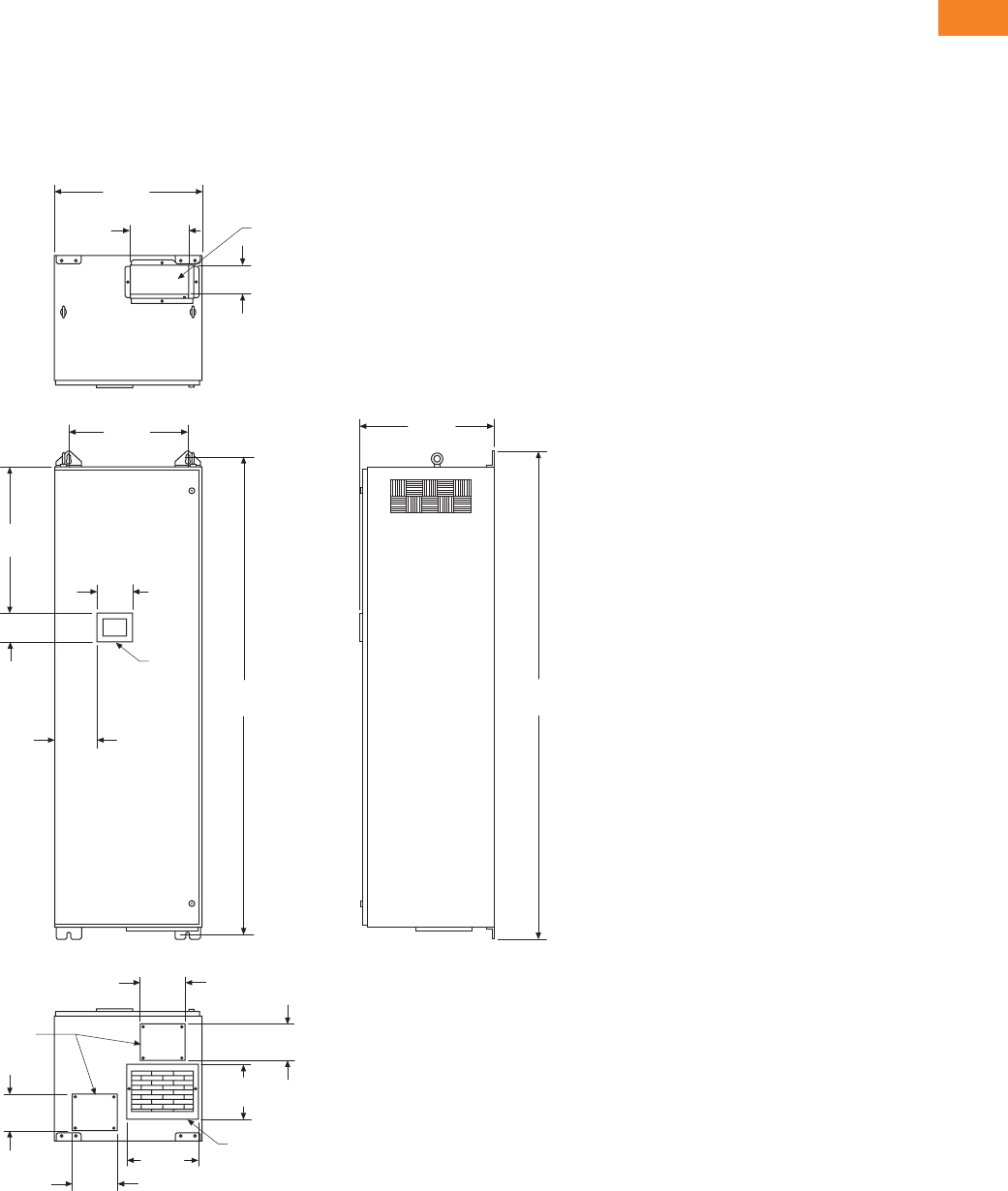
Volume 3—Power Distribution and Control Assemblies CA08100004E—April 2014 www.eaton.com V3-T2-75
2
2
2
2
2
2
2
2
2
2
2
2
2
2
2
2
2
2
2
2
2
2
2
2
2
2
2
2
2
2
2.2
SPD, Power Conditioning, PF Capacitors and Harmonic Filters
Power Factor Correction and Harmonic Filtering
Approximate Dimensions in Inches (mm)
Drawings—NEMA 1 Enclosure
HCUE050 Layout Dimensions
The HCUE050 series offers 50 amperes of corrective current in a
convenient package. The enclosed model comes standard with a
digital interface panel for control diagnostics and programming.
Input fuses are included. The enclosed unit includes a removable
panel for bottom conduit entry.
HCUE050—50 Amperes, 208–480V
20.70
(525.8)
Heat Sink Opening
4.60
(116.8)
9.80
(249.0)
16.70
(424.2)
HMI
4.00
(101.6)
5.10
(129.5)
20.60
(523.2)
67.20
(1706.9)
18.70
(475.0)
68.70
(1745.0)
Inlet Air Opening
6.30
(160.0)
5.30
(134.6)
6.30
(160.0)
5.30
(134.6)
5.70
(144.8)
8.90
(226.1)
Conduit Plate
5.90
(149.9)
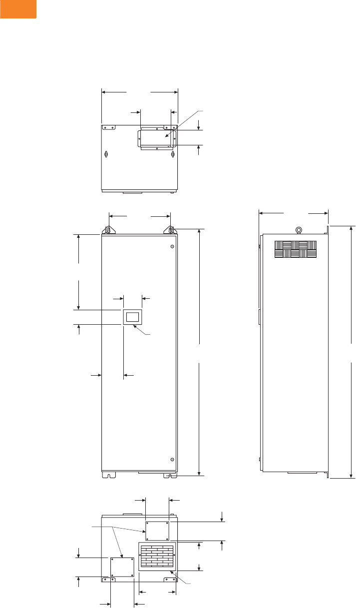
V3-T2-76 Volume 3—Power Distribution and Control Assemblies CA08100004E—April 2014 www.eaton.com
2
2
2
2
2
2
2
2
2
2
2
2
2
2
2
2
2
2
2
2
2
2
2
2
2
2
2
2
2
2
2.2
SPD, Power Conditioning, PF Capacitors and Harmonic Filters
Power Factor Correction and Harmonic Filtering
Approximate Dimensions in Inches (mm)
HCUE100 Layout Dimensions
The HCUE100 series offers 100 amperes of corrective current in
a wallmounted NEMA 1 enclosure. The enclosed model comes
standard with a digital interface module for control, diagnostics
and programming. Input fuses are included. The enclosed unit
includes a removable panel for bottom conduit entry.
HCUE100—100 Amperes 208–480V
20.70
(525.8)
Heat Sink Opening
4.60
(116.8)
9.80
(249.0)
16.70
(424.2)
HMI
4.00
(101.6)
5.10
(129.5)
20.60
(523.2)
67.20
(1706.9)
18.70
(475.0)
68.70
(1745.0)
Inlet Air Opening
6.30
(160.0)
5.30
(134.6)
6.30
(160.0)
5.30
(134.6)
5.70
(144.8)
8.90
(226.1)
Conduit Plate
5.90
(149.9)
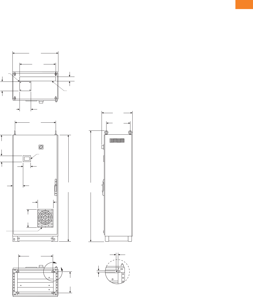
Volume 3—Power Distribution and Control Assemblies CA08100004E—April 2014 www.eaton.com V3-T2-77
2
2
2
2
2
2
2
2
2
2
2
2
2
2
2
2
2
2
2
2
2
2
2
2
2
2
2
2
2
2
2.2
SPD, Power Conditioning, PF Capacitors and Harmonic Filters
Power Factor Correction and Harmonic Filtering
Approximate Dimensions in Inches (mm)
HCUE300 Layout Dimensions
The HCUE300 series offers 300 amperes of corrective current
for large capacity applications. It is available in a floor-standing
NEMA 1 enclosure (including a door-interlocking disconnect). The
enclosed model comes standard with digital interface module
for control, diagnostics and programming. Input fuses are
included. The enclosed unit includes a removable panel for
top conduit entry.
HCUE300—300 Amperes 208–480V
32.00
(812.8)
Heat Sink Opening
6.50
(165.1)
23.20
(589.3)
28.90
(734.1)
HMI
4.00
(101.6)
5.10
(129.5)
14.80
(375.9)
74.80
(1899.9)
17.10
(434.3)
77.10
(1958.3)
Inlet
Air Opening
10.80
(274.3)
12.50
(317.5)
14.70
(373.4)
7.40
(188.0)
8.00
(203.2)
Conduit Plate
3.10
(78.7)
”A“
24.30
(617.2)
Detail ”A“
Scale 1:12
4X 0.40
(10.2)
4X 0.60
(15.2)
21.80
(553.7)
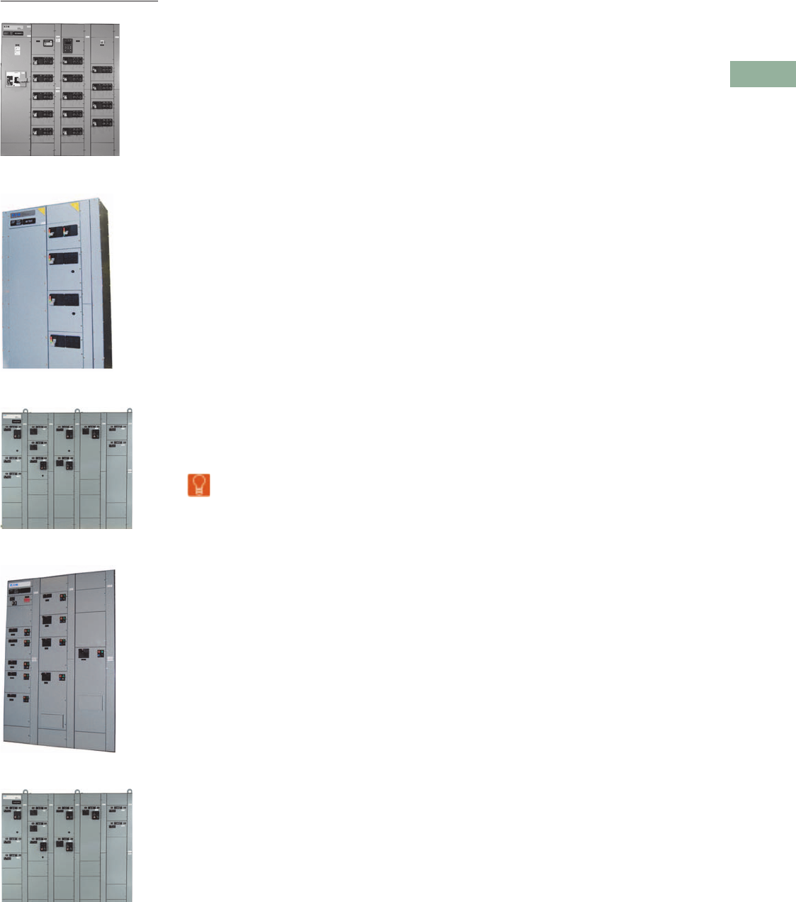
Volume 3—Power Distribution and Control Assemblies CA08100004E—June 2014 www.eaton.com V3-T3-1
3
3
3
3
3
3
3
3
3
3
3
3
3
3
3
3
3
3
3
3
3
3
3
3
3
3
3
3
3
3
Motor Control Centers
Freedom
Freedom FlashGard
XT MCC
XT FlashGard MCC
Freedom Arc-Resistant MCC
3.1 MCC Product Offering
Product Overview . . . . . . . . . . . . . . . . . . . . . . . . . . . . . . . . . . . . . . . . V3-T3-2
Aftermarket Products . . . . . . . . . . . . . . . . . . . . . . . . . . . . . . . . . . . . . V3-T3-3
Product Description. . . . . . . . . . . . . . . . . . . . . . . . . . . . . . . . . . . . . . . V3-T3-4
Application Description . . . . . . . . . . . . . . . . . . . . . . . . . . . . . . . . . . . . V3-T3-4
Features, Benefits and Functions . . . . . . . . . . . . . . . . . . . . . . . . . . . . V3-T3-4
Standards and Certifications . . . . . . . . . . . . . . . . . . . . . . . . . . . . . . . . V3-T3-4
Accessories and Options. . . . . . . . . . . . . . . . . . . . . . . . . . . . . . . . . . . V3-T3-7
3.2 Freedom, Freedom Arc-Resistant and Freedom FlashGard®
Product Description. . . . . . . . . . . . . . . . . . . . . . . . . . . . . . . . . . . . . . . V3-T3-8
Features and Benefits . . . . . . . . . . . . . . . . . . . . . . . . . . . . . . . . . . . . . V3-T3-9
Standards and Certifications . . . . . . . . . . . . . . . . . . . . . . . . . . . . . . . . V3-T3-10
Technical Data and Specifications . . . . . . . . . . . . . . . . . . . . . . . . . . . . V3-T3-10
3.3 Freedom and Freedom FlashGard Check Sheets
Check Sheets . . . . . . . . . . . . . . . . . . . . . . . . . . . . . . . . . . . . . . . . . . . V3-T3-20
3.4 Freedom Arc-Resistant MCC Check Sheets
Check Sheets . . . . . . . . . . . . . . . . . . . . . . . . . . . . . . . . . . . . . . . . . . . V3-T3-24
3.5 XT and XT FlashGard
Technical Data and Specifications
Technical Data and Specifications . . . . . . . . . . . . . . . . . . . . . . . . . . . . V3-T3-28
3.6 XT and XT FlashGard Check Sheets
Check Sheets . . . . . . . . . . . . . . . . . . . . . . . . . . . . . . . . . . . . . . . . . . . V3-T3-36
Learn
Online
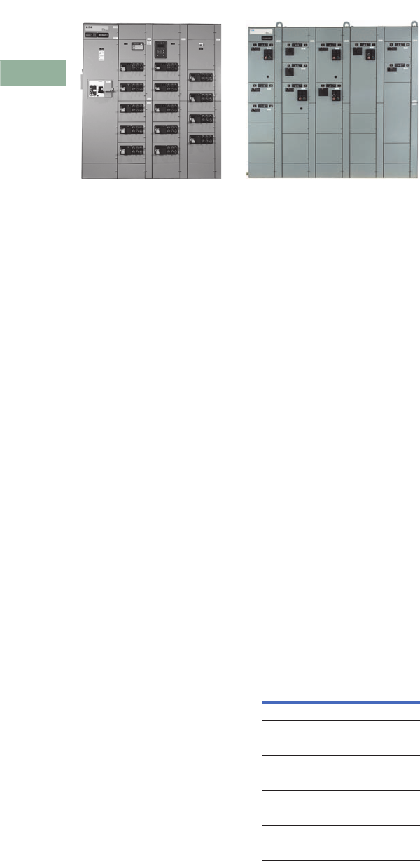
V3-T3-2 Volume 3—Power Distribution and Control Assemblies CA08100004E—June 2014 www.eaton.com
3
3
3
3
3
3
3
3
3
3
3
3
3
3
3
3
3
3
3
3
3
3
3
3
3
3
3
3
3
3
3.1
Motor Control Centers
Freedom, Freedom Arc-Resistant and Freedom FlashGard
Contents
Description Page
Aftermarket Products . . . . . . . . . . . . . . . . . . . . . . V3-T3-3
Product Description . . . . . . . . . . . . . . . . . . . . . . . V3-T3-4
Application Description . . . . . . . . . . . . . . . . . . . . . V3-T3-4
Features, Benefits and Functions . . . . . . . . . . . . . V3-T3-4
Standards and Certifications . . . . . . . . . . . . . . . . . V3-T3-4
Accessories and Options . . . . . . . . . . . . . . . . . . . V3-T3-7
Product Overview
MCC Operation
Eaton’s motor control center
(MCC) product line is
headquartered in Fayetteville,
NC. At Fayetteville, the most
progressive engineering in the
industry can custom design
motor control for the most
demanding applications.
Most MCCs can be shipped
six to eight weeks after
receipt of a released order.
The MCC product line also
offers a FAST motor control
center (MCC) quick shipment
program. The program
includes integration of a
number of commonly used
components and assemblies
in MCC applications as well
as configuration options for
each. The FAST program also
includes expedited delivery of
customer approval drawings
when predefined pilot/control
device configurations for unit
assemblies are selected.
MCCs meeting the FAST
criteria are shipped within
4 weeks after receipt of a
released order.
Customer Manufacturing
Solution Centers
One of the most unique
aspects of the Eaton MCC
operation is the ability to
provide customized product to
meet delivery requirements
through a Customer
Manufacturing Solution
Center (CMSC). There are
nine of these facilities located
throughout the U.S. serving
key geographic markets.
Each CMSC has the ability to
provide standard NEMA® 1B
wired product in as little as
one to three days. Please
contact the facility in your
area to discuss customer
opportunities and MCC
support for your specific
marketplace.
Customer Manufacturing
Solution Centers
Seismic Qualification
The Freedom and
XT
MCC
families
have been qualified
to meet the seismic
requirements of both the
Uniform Building Code®
(UBC) and the California
Building Code (CBC) for
equipment operation after
seismic activity. This
equipment, along with Eaton’s
low and medium voltage
switchgear assemblies,
medium voltage starter
assemblies and low voltage
switchboards, which meet
seismic requirements,
provide the user with a
complete seismic qualified
assemblies package
that meet CBC and IBC
requirements. Please contact
your Eaton sales engineer for
more details.
Bid Manager™
One of the most exciting
new tools developed for
the MCC product line is
the Bid Manager program.
Bid Manager is a PC-based
pricing program that is
capable of providing complete
bills of material, front views
and prices for MCCs. This
program can configure an
MCC to meet a multitude
of specific applications and
provide accurate bills of
material and front view
drawings in a matter of
moments. The program
operates on a user-friendly,
Windows®-based format that
offers the most extensive
product selection found in
the industry. A complete
line of adjustable frequency
drives and reduced voltage
solid-state control, along
with insulated case breakers,
high ampacity molded case
breakers and automatic
transfer switches are featured
in the program. Control and
distribution product can be
packaged in a multitude of
variations. Please contact
your Eaton sales engineer
for more details.
Location Telephone
Atlanta 678-309-4270
Chicago 630-260-6304
Cleveland 216-433-0616
Dallas 817-251-6700
Denver 303-366-9949
Hartford 860-683-4221
Houston 713-939-9696
Los Angeles 562-944-6413
Portland 503-582-2700

Volume 3—Power Distribution and Control Assemblies CA08100004E—June 2014 www.eaton.com V3-T3-3
3
3
3
3
3
3
3
3
3
3
3
3
3
3
3
3
3
3
3
3
3
3
3
3
3
3
3
3
3
3
3.1
Motor Control Centers
Aftermarket Products
Background
Over 50 years ago, Cutler-
Hammer® and Westinghouse®
low voltage motor control
centers were introduced,
enabling the group mounting
of low voltage (600 V class)
electrical controls. This
allowed for supervision
and safe operation of motor
starter units, feeder tap
units and auxiliary equipment
in a flexible structure
arrangement at a
centralized location.
The foundation for today’s
MCCs is a modular plug-in
combination motor controller
assembly with components
of proven electrical and
mechanical integrity. These
assemblies are enclosed
in metal structures that
prevent accidental contact
with live electrical parts.
The MCC structure consists
of structural steel, horizontal
and vertical wireways for
conduit and load cable entry
and exit, and vertical and
horizontal bus systems for
distributing power throughout
the MCC. The starter unit
consists of a rugged steel
shell (wrapper) for mounting
the unit components, a
combination motor starter
with factory wired control, a
handle mechanism for ON/
OFF operation, and a rigid
unit door.
Aftermarket Service
Eaton’s MCCs are
manufactured with high
quality structural parts
designed to provide many
years of service.
Eaton is dedicated to
providing replacement units
or add-on units to handle
additional loads for motor
control centers manufactured
since 1935 for both the
Westinghouse and Cutler-
Hammer product lines.
The following descriptions
and needed order entry
information will be useful in
identifying and processing a
vintage MCC aftermarket
unit.
1. Motor control center
type: (11-300, Type W,
5-Star, Advantage, 9800,
F-10, Freedom FlashGard,
Freedom, Freedom arc-
resistant IT., XT and
XT FlashGard)
2. Class of unit
(Non-reversing,
Reversing, Two Speed)
3. Service voltage
4. Control voltage
5. Starter size or
horsepower rating
6. Disconnect type
(HMCP, Fusible)
7. Clip size and type
(if Fusible)
8. Unit modifications
(Lights, Pushbuttons,
etc.)
9. Catalog Number
(if available)
XT IT. Freedom Advantage
Series 2100/
5 Star
Freedom
Unitrol F10 Unitrol Type W 9800 Unitrol 11-300
Motor Control Center Production Years
2012–Present 2002–2011 1995–present 1992–2010 1987–1995/
1975–1987
1988–1994 1972–1989 1965–1975 1956–1974 1935–1965
Product Availability
Replacement units for
the 5-Star, Series 2100,
Advantage, 11-300, 9800,
Type W, F-10, F2100,
Freedom FlashGard,
Freedom, Freedom arc-
resistant IT., IT. FlashGard,
XT and XT FlashGard motor
control center lines may be
obtained from
the Fayetteville
manufacturing plant
or any
of the regionally located
Customer Manufacturing and
Solution Centers (CMSCs).
Competitive MCC units
can be obtained from the
Fayetteville manufacturing
plant or CMSCs.
They are located in:
Customer Manufacturing
Solution Centers
MCC Renewal Parts
Location Telephone
Atlanta 678-309-4270
Chicago 630-260-6304
Cleveland 216-433-0616
Dallas 817-251-6700
Denver 303-366-9949
Hartford 860-683-4221
Houston 713-939-9696
Los Angeles 562-944-6413
Portland 503-582-2700
MCC
Type Dates
Eaton’s Cutler-Hammer
Renewal Parts Publication
XT 2012–present —
XT FlashGard 2012–present —
IT. 2002–2011 —
IT. FlashGard 2007–2011 —
Freedom 1995–present RP04304001E
Freedom FlashGard 2008–present —
Advantage 1992–2011 RP04304002E
Series 2100 1987–1995 RP04304003E
5 Star 1975–1987 RP04304003E
Freedom Unitrol 1988–1994 RP04304004E
F10 Unitrol 1972–1989 RP04304005E
Type W 1965–1975 RP04304006E
9800 Unitrol 1956–1974 RP04304007E
11-300 1935–1965 RP04304008E

V3-T3-4 Volume 3—Power Distribution and Control Assemblies CA08100004E—June 2014 www.eaton.com
3
3
3
3
3
3
3
3
3
3
3
3
3
3
3
3
3
3
3
3
3
3
3
3
3
3
3
3
3
3
3.1
Motor Control Centers
Product Description
Eaton’s offering of motor
control centers (MCCs)
features the Freedom,
Freedom arc-resistant,
Freedom FlashGard, XT and
XT FlashGard. These MCCs
incorporate the newest
NEMA electromechanical
starters in the industry along
with the most complete,
NEMA rated package of
distribution and control
equipment. The FlashGard
MCCs are the industry’s first
and only MCCs designed for
comprehensive arc flash
prevention.
Application Description
Eaton’s MCCs are custom-
made assemblies of
conveniently grouped control
equipment primarily used for
control of motors and for
distribution of power. MCCs
are designed for three-phase,
230 V applications up to
300 hp, or three-phase,
480 V applications up to 600 hp.
The Freedom FlashGard and
XT FlashGard MCCs are
equipped with a state-of-
the-art stab racking
mechanism (RotoTract™) that
provides bus isolation, stab
indication and lockout
features that proactively
prevent the initiation of
arc flash.
Features, Benefits and
Functions
Structure Design
Eaton’s MCCs are
20.00 inches (508.0 mm)
wide and 90.00 inches
(2286.0 mm) high with
vertical compartments having
72.00 inches (1828.8 mm)
of unit mounting space in
6.00-inch (152.4 mm)
increments.
Structure depth is
16.00 inches (406.4 mm)
or 21.00 inches (533.4 mm)
deep front-mounted only
and 21.00 inches (533.4 mm)
deep for back-to-back
mounted units.
The unique framed design
permits the highest flexibility
in component and structure
configuration.
Accessibility
All parts and wiring are front
accessible. Terminal blocks
are side mounted in each
unit. 4.00-inch (101.6 mm) or
8.00-inch (203.2 mm) vertical
wireways separate from
control units provide safe and
convenient access to wiring
and conduits without de-
energizing any equipment.
Flexibility
Modular, framed design
permits structure arrangement
to be tailored to exactly meet
any control requirements
with a minimum of unusable
space. Vertical compartments
are incremented for
maximum space utilization
and unit interchangeability.
Compact starter and feeder
units provide users with the
ability to solve demanding
space requirements and still
meet all NEMA and UL®
standards.
Safety
Design tested at Eaton’s
power laboratory to ensure
maximum protection for
control equipment. The
FlashGard option ensures
maximum safety for
personnel working on or
around the equipment.
Hardwired Control
With choices for 1A to 2C
wiring schemes, the Eaton
MCC offers many options for
traditional or supervisory
control schemes.
Industrial Communications
Eaton MCCs come with the
most advanced and flexible
industrial factory installed and
tested communication
connectivity in the
marketplace with protocols
that include DeviceNet,
Modbus and Modbus TCP,
EtherNet/IP and PROFIBUS.
Eaton smart MCCs facilitate
faster startup, safer working
conditions and enhanced
diagnostics and monitoring.
Intelligent Products
Eaton MCCs include
intelligent starters, soft
starters, VFDs, meters and
feeder breakers that can
all be connected to an
embedded PLC and
operator interface.
Standards and
Certifications
UL Listing
Standard structures and units
are provided with UL label.
Contact Eaton for details
and part numbers for CSA
approved units.
Comparison of Key MCC Features and Attributes by MCC Type/Family
Notes
1Compact offering has size 1 and 2 FVNR starter units in 1X and size 3 and 4 in 2X. Add 1X to each for FVR versions.
2FlashGard technology enables stabs to be retracted from and engaged onto the vertical bus while the unit's door is closed.
3FlashGard test position enables control power to be delivered to the unit while its stabs are removed from the vertical bus
(no line power present within unit).
MCC Type/
Family
Serves
Applications
480 V and Below
Serves
600 V
Applications
Compact
Unit
Offering
Standard
1
Compact
Unit
Offering
Optional
1
120 Vac
Control
Power
24 Vdc
Control
Power
Tested and
Certified
Per Arc-
Resistant
Guidelines
FlashGard
Technology
2
FlashGard
Technology
with Test
Position
23
Optional
Communications
Capability
Freedom ■■ ■■ ■
Freedom Arc-Resistant ■■ ■■ ■ ■
Freedom FlashGard ■■ ■ ■ ■
XT ■■ ■ ■
XT FlashGard ■■■■■
Volume 3—Power Distribution and Control Assemblies CA08100004E—June 2014 www.eaton.com V3-T3-5
3
3
3
3
3
3
3
3
3
3
3
3
3
3
3
3
3
3
3
3
3
3
3
3
3
3
3
3
3
3
3.1
Motor Control Centers
Catalog Number Selection
Aftermarket MCC Starter Buckets
Aftermarket MCC Feeder Buckets/Units
Aftermarket Service
Eaton’s MCCs are
manufactured with high
quality structural parts
designed to provide many
years of service.
Eaton is dedicated to
providing replacement units
or add-on units to handle
additional loads for motor
control centers manufactured
since1935 for both the
Westinghouse and Cutler-
Hammer product lines.
The following descriptions
and needed order entry
information will be useful in
identifying and processing a
vintage MCC aftermarket
unit.
1. Motor control center
type (refer to MCC types
listed above for both
starter and feeder units)
2. Class of unit (non-
reversing, reversing,
two speed)
3. Service voltage
4. Control voltage
5. Starter size or
horsepower rating
6. Disconnect type
(HMCP, Fusible)
7. Clip size and type
(if fusible)
8. Unit modifications (lights,
pushbuttons, etc.)
9. Catalog number
(if available)
Note
1Fusible disconnect sizes.
MCC Type
Catalog Codes
F= Free-standing NEMA 1
FZ = Freedom
FK = Advantage
FS = Series 2100/5 Star
FD = Freedom Unitrol
FR = F10 Unitrol
FT = Type W
FN = 9800 Unitrol
FJ = 11-300
FM = IT.
SZ = FlashGard
GD = ITE 5600
GE = GE 7700/8000
AB = Allen-Bradley Centerline
SQ = Square D Model 6
SS = Furnas 89
Starter Type
See tables on Page V3-T3-6
Control
Voltage
A= 120 V
B= 208 V
C= 240 V
D= 380 V
E= 480 V
F= 575 V
Space
Option Code
S= Standard
height
C= Compact
X= Oversized
CPT
C10 = Separate source
control fuse
C12 = 100 VA for sz. 1–2
C13 = 150 VA for sz. 3–4
Modification Codes
See tables on Page V3-T3-6
Service
Voltage
A= 120 V
B= 208 V
C= 240 V
D= 380 V
E= 480 V
F= 575 V
FZ 206E E A S C12 P57
MCC Type
Catalog Codes
FZ = Freedom
FK = Advantage
FS = Series 2100/5 Star
FD = Freedom Unitrol
FR = F10 Unitrol
FT = Type W
FN = 9800 Unitrol
FJ = 11-300
FM = IT.
SZ = FlashGard
GD = ITE 5600
GE = GE 7700/8000
AB = Allen-Bradley Centerline
SQ = Square D Model 6
SS = Furnas 89
Trip or Clip
Rating (Left
Feeder)
A= 15
B= 20
C= 25
D= 30 1
E= 40
F= 50
G= 60 1
H= 70
J= 80
K= 90
L= 100 1
Device Type
F= HFD
J= HJD
K= HKD
L= HLD
Z= Fusible
Switch
FZ F 1 D S 12
Unit Type
1= Single
Disconnect
2= Dual Disconnect
Trip or Clip
Rating (Right
Feeder) Dual
Unit Only
M= 125
N= 150
P= 175
Q= 200 1
R= 225
S= 250
T= 300 1
W= 350
X= 400
Y= 500
Z= 600 1
Unit Size
12 = 12”
14 = 14”
18 = 18” or 18-2/3”
24 = 24”
28 = 28”
30 = 30”
36 = 36”
48 = 48”

V3-T3-6 Volume 3—Power Distribution and Control Assemblies CA08100004E—June 2014 www.eaton.com
3
3
3
3
3
3
3
3
3
3
3
3
3
3
3
3
3
3
3
3
3
3
3
3
3
3
3
3
3
3
3.1
Motor Control Centers
Aftermarket MCC Starter types
Full-Voltage Non-Reversing Combination Starter—
HMCP Disconnect
Full-Voltage Reversing Combination Starter—
HMCP Disconnect
Full-Voltage Non-Reversing Combination Starter—
Fusible Disconnect
Full-Voltage Reversing Combination Starter—
Fusible Disconnect
Common Modifications
Abbreviated list of common modification codes
Note: Please contact your local Service Center for all available
modifications and to learn which modifications will work for your
aftermarket needs.
NEMA
Size
Maximum Horsepower HMCP
Ampere
Size
Starter
Class
Code208 V 240 V 380 V 480 V 600 V
1 0.50 0.33 1 1 1.50 3 206A
1112337 206B
1 3 3 5 7.50 7.50 15 206C
1 7.50 7.50 10 10 15 30 206D
2101525253050 206E
32530505050100 206H
4 40 50 75 100 100 150 206L
NEMA
Size
Maximum Horsepower HMCP
Ampere
Size
Starter
Class
Code208 V 240 V 380 V 480 V 600 V
1 0.50 0.33 1 1 1.50 3 216A
111233 7 216B
1 3 3 5 7.50 7.50 15 216C
1 7.50 7.50 10 10 15 30 216D
2101525253050 216E
3 25 30 50 50 50 100 216H
4 40 50 75 100 100 150 216L
NEMA
Size
Maximum Horsepower Fuse
Ampere
Size
Starter
Class
Code208 V 240 V 380 V 480 V 600 V
1 7.50 7.50 10 10 15 30 204D
2101525253050 204E
3 25 30 50 50 50 100 204H
4 40 50 75 100 100 150 204L
NEMA
Size
Maximum Horsepower Fuse
Ampere
Size
Starter
Class
Code208 V 240 V 380 V 480 V 600 V
1 7.50 7.50 10 10 15 30 214D
2101525253050 214E
32530505050100 214H
4 40 50 75 100 100 150 214L
Modification
Codes
Option
Description
B10 Breaker shunt trip—120 V
B11 Breaker auxiliary switch—1NO/1NC
B19 Breaker auxiliary switch—2NO/2NC
C10 Control fuse wired for separate source in lieu of CPT
C11 Control fuse/disconnect for separate source in lieu of CPT
C12 CPT 100 VA for size 1 and 2 starters, fused
C13 CPT 150 VA for size 3 and 4 starters, fused
C18 Full capacity CPT for size 5 starters, fused
M12 Mini elapsed time meter
M16 IQ 200 Meter with three CTs
O19 Overload relay heater/heater pack
O20 CEP7 solid-state overload relay—size 1
P10 Red ‘RUN’ light
P11 Green ‘STOPPED’ light
P15 Red ‘RUN’ Push-to-Test light
P16 Green ‘STOPPED’ Push-to-Test light
P20 Special function light
P32 ‘START/STOP’ pushbutton
P35 ‘ON/OFF’ pushbutton
P36 ‘FORWARD/REVERSE/STOP’ pushbutton
P38 ‘FAST/OFF/SLOW’ pushbutton
P41 Special function pushbutton
P50 ‘ON-OFF’ selector switch
P53 ‘START-STOP’ selector switch
P55 ‘FORWARD-REVERSE’ selector switch
P56 Special function 2-position selector switch
P57 ‘HAND-OFF-AUTO’ selector switch
P58 ‘LOCAL-OFF-REMOTE’ selector switch
P59 ‘FAST-OFF-SLOW’ selector switch
P60 ‘HIGH-OFF-LOW’ selector switch
P61 Special function 3-position selector switch
R24 D15 four-pole control relay
S11 1NO-1NC starter auxiliary contacts
S22 2NO-2NC starter auxiliary contacts
T10 Pull-apart type terminal blocks (standard on all vintages except Type W
and 11-300)
U10 Surge suppressor on coil
U11 Type SIS control wire
U14 Wiremarkers—sleeve type on all control wire
U17 Wiring diagram inside starter unit door
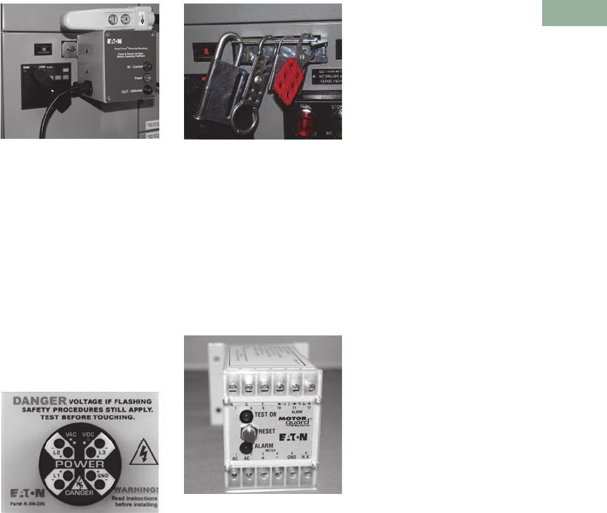
Volume 3—Power Distribution and Control Assemblies CA08100004E—June 2014 www.eaton.com V3-T3-7
3
3
3
3
3
3
3
3
3
3
3
3
3
3
3
3
3
3
3
3
3
3
3
3
3
3
3
3
3
3
3.1
Motor Control Centers
Accessories and Options
Control and Distribution
Equipment Packaging
Eaton’s MCCs provide the
best packaged solutions for
the control needs of today’s
users. Structural characteristics
allow the user to select a
complete package of control
and distribution equipment in
a minimum amount of space.
The ability to package a wide
range of solid-state products,
including SVX9000 drives,
S811+ soft starters and PLCs
meet the most demanding
user process needs. The
option to provide high
ampacity molded case
breakers gives the user
the flexibility to minimize
switchboard or switchgear
structures and thereby saves
valuable space and reduces
design costs. Additional
safety accessories are
available such as Motorguard
(automatic insulation tester),
Voltage Vision (voltage
presence indicator),
FlashGard remote racking
accessory and FlashGard
locking accessory. Other
packaged products, including
automatic transfer switches
and panelboards, again
reduce space requirements
and save time and money on
equipment and installation
costs. A motor load terminal
block that enables quick
connect/disconnect of 480 V
power is available as standard
on the Freedom FlashGard as
well as the XT and XT
FlashGard MCCs. This
feature is optional on the
Freedom and Freedom arc-
resistant MCCs.
FlashGard Remote
Racking Accessory
Remote Racking Accessory
●Performs RotoTract racking
safely behind NFPA arc
flash boundaries
●120 Vac motor driven
●Mounts to RotoTract
mechanism
●Wired pendant station
for “rack-in”/”rack-out”
operation
●Momentary jog
●Mounting offset bracket
to clear device panel
Voltage Presence Indicator
(VoltageVision™)
Voltage Presence Indicator
(VoltageVision)
●Hardwired voltage detector
connected to load side
of disconnect
●Enables operator to
“pre-verify” voltage
presence with unit
door closed
●Installable in a 30 mm
pilot device knockout
●Dual redundant circuitry
for reliability
●Phase insensitive
FlashGard Locking
Accessory
FlashGard Locking Accessory
●Locks out RotoTract
operation during
maintenance
●Allows operation of
FlashGard units by
authorized personnel only
●Heavy-gauge steel
construction
Automatic Insulation
Tester (Motorguard)
Automatic Insulation Tester
(Motorguard)
●“Meggers” equipment
motor insulation to
continuously monitor
integrity of insulation for
the period that the
equipment is de-energized
●Applies 500 Vdc potential
at current-limited, operator-
safe maximum amperage
of 200 microamperes
●Alarms upon detection
of a threshold leakage
to ground current
●Visual alarm indication and
lockout; Form C contact
available for remote
alarm status
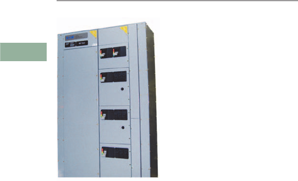
V3-T3-8 Volume 3—Power Distribution and Control Assemblies CA08100004E—June 2014 www.eaton.com
3
3
3
3
3
3
3
3
3
3
3
3
3
3
3
3
3
3
3
3
3
3
3
3
3
3
3
3
3
3
3.2
Motor Control Centers
Freedom, Freedom Arc-Resistant and Freedom FlashGard Technical Data and Specifications
Freedom Arc-Resistant Motor Control Center
Contents
Description Page
Features and Benefits . . . . . . . . . . . . . . . . . . . . . . V3-T3-9
Standards and Certifications . . . . . . . . . . . . . . . . . V3-T3-10
Application Guide . . . . . . . . . . . . . . . . . . . . . . . . . V3-T3-18
Product Specifications . . . . . . . . . . . . . . . . . . . . . V3-T3-19
Freedom Arc-Resistant Motor Control Center
Product Description
An arc flash is a dangerous
condition associated with the
explosive release of energy
caused by an electrical arc
due to either a phase-to-
ground or a phase-to-phase
fault. This fault can result
from many factors, including
dropped tools, accidental
contact with electrical
systems, buildup of
conductive dust, corrosion
and improper work
procedure. An arc-flash event
releases a tremendous
amount of energy in the form
of thermal heat, toxic fumes,
pressure waves, blinding
light, sound waves and
explosions that can result in
serious injury, including
critical burns, collapsed lungs,
loss of vision, ruptured
eardrums, puncture wounds
and even death.
Temperatures can reach
35,000 °F, which is three
times hotter than the
temperature of the sun.
These excessive
temperatures cause the air
and metal in the path of the
arc to expand and explode,
creating an arc blast.
Throughout the world, arc
flash threatens personnel
safety, and companies face
lost man-hours, lawsuits,
fines, equipment damage,
facility downtime and lost
production.
In continuation with the
legacy of Eaton’s leadership
in arc flash safety products,
the Freedom arc-resistant
motor control center (MCC)
is designed to provide
personnel with increased
protection from the dangers
of arc flash hazards. This
enhanced version of Eaton’s
flagship Freedom MCC
includes additional features
specifically designed to
contain the arc blast energy
should an arc flash event
be triggered within the
assembly. The Freedom arc-
resistant MCC has a Type 2
accessibility rating, meaning
that arc-resistant designs or
features are present on the
front, back and sides of the
assembly. This Type 2 rating
translates to enhanced safety
around the entire perimeter
of the MCC should an arc
flash event occur.
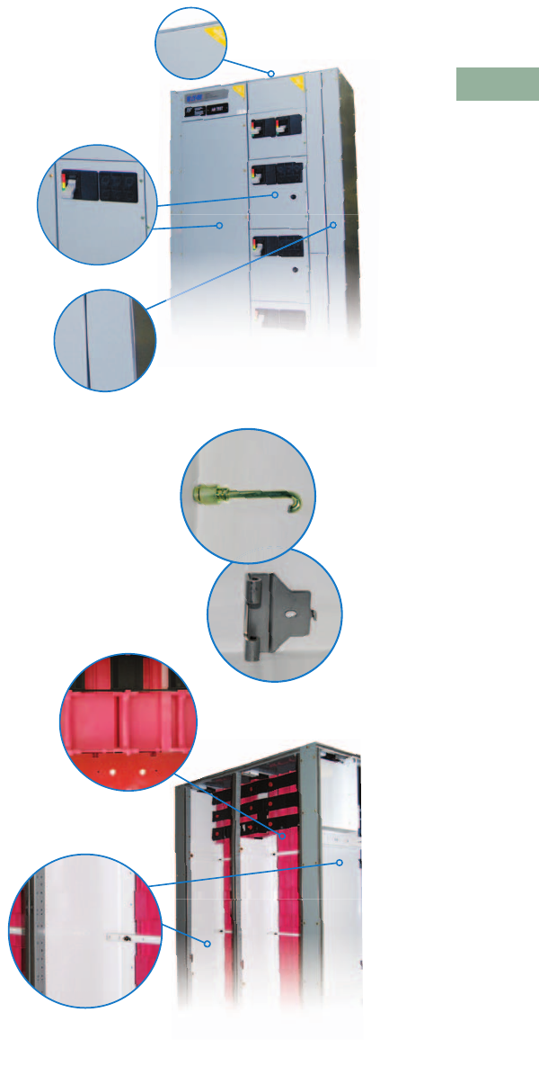
Volume 3—Power Distribution and Control Assemblies CA08100004E—June 2014 www.eaton.com V3-T3-9
3
3
3
3
3
3
3
3
3
3
3
3
3
3
3
3
3
3
3
3
3
3
3
3
3
3
3
3
3
3
3.2
Motor Control Centers
Freedom, Freedom Arc-Resistant and Freedom FlashGard Technical Data and Specifications
Features and Benefits
No Exhaust Plenums or Roof Flaps Required
Eaton’s arc-resistant Freedom MCC requires no exhaust
plenums or roof flaps. This aids in the ease of installation, as
additional clearance or venting ductwork is not required above
the assembly.
12 Gauge Steel Doors, Side Sheets and Back Sheets
Usage of 12 gauge steel on all MCC doors, side sheets and back
sheets serve to increase the structural integrity of the MCC and
aid in the containment of arc blast energy, further enhancing
personnel safety should an arc flash event occur.
4 Inch Sections
A four-inch section is added to the first and last structures of the
MCC lineup, regardless of the number of structures. These
sections increase the structural integrity of the MCC lineup,
further ensuring it can withstand the arc blast energy.
Enhanced Door Hinges and Latches
Hinges and door latches play a vital role in the containment of
arc blast energy during an arc flash event. The design and
implementation of enhanced door hinges and latches on the
Freedom arc-resistant MCC serves to keep doors closed and
latched securely during an arc flash event, further preventing the
propagation of arc blast energy toward personnel. As an
additional measure, the quantity of door hinges and latches
applied to the MCC unit doors has also been increased.
Insulated Horizontal and Vertical Buses
Insulation of the horizontal and vertical buses aids in the
prevention of arc flash incidents. When an arc flash incident
does occur, the insulation serves to prevent further propagation
of the arc fault throughout the entire MCC. Automatic vertical
bus shutters are included.
Isolation Barriers Between Adjacent Structures
Isolation barriers placed between adjacent structures serve to
isolate the arc blast energy to a single area within the MCC.
Rear View of Structure with
Back and Side Sheets Removed
Front View of Structure

V3-T3-10 Volume 3—Power Distribution and Control Assemblies CA08100004E—June 2014 www.eaton.com
3
3
3
3
3
3
3
3
3
3
3
3
3
3
3
3
3
3
3
3
3
3
3
3
3
3
3
3
3
3
3.2
Motor Control Centers
Freedom, Freedom Arc-Resistant and Freedom FlashGard Technical Data and Specifications
Standards and Certifications
Eaton’s Freedom arc-
resistant MCC has been
tested and verified per the
criteria found in the Institute
of Electrical and Electronics
Engineers (IEEE) guideline
C37.20.7 titled “IEEE Guide
for Testing Metal-Enclosed
Switchgear Rated Up to 38 kV
for Internal Arcing Faults.”
The MCC also meets the
criteria found in Canadian
Standards Association (CSA)
standard C22.2 No. 0.22-11,
titled “Evaluation Methods
for Arc Resistance Ratings of
Enclosed Electrical
Equipment.” This standard
was originally published in
2012 and is currently the only
official North American
standard or guideline that
contains low voltage MCCs
within the scope of coverage.
CSA C22.2 No. 0.22-11 was
based in large part on the
guidelines and testing criteria
found in IEEE C37.20.7.
Technical Data and Specifications
Specifications
Notes
1Freedom arc-resistant MCCs containing clean power drives carry a Type 1 accessibility type (contains arc-resistant protection designs
on the front).
22500 A maximum with 65 °C temperature rise bus, 2000 A maximum with 50 °C temperature rise bus.
3Fused switches and air circuit breakers not available.
4An incoming main breaker is required to be configured in the lineup. Incoming main lugs, fused switches and air circuit breakers not available
as main devices.
Item Description
Freedom Arc-Resistant MCC
Applicable guidelines and standards Tested and verified per IEEE guideline C37.20.7 and CSA standard 22.2 No. 0.22-11
Agency approvals UL and cUL per UL 845
Voltage rating 600 V maximum
Interrupting rating Maximum 65 kA at 480 V and 600 V
Arc duration rating 100 mS
Accessibility type 1Type 2 (contains arc-resistant protection designs or features on the front, sides, and rear of the equipment)
Main incoming breaker (required) 2500 A frame
1200 A–2500 A trip range), 80% rated
1200 A frame
(400 A–1200 A trip range), 80% rated
Structure environmental ratings NEMA 1, 2, 12 and 3R available
Structure depth 21 inches
Horizontal bus Minimum 800 A, maximum 2500 A 2
Vertical bus Maximum 1200 A
Bus insulation Horizontal and vertical buses both insulated
Available Units, Assemblies and Options
Interrupting devices 3Thermal-magnetic circuit breakers and motor circuit protectors
Main breakers 42500 A frame (800 A–2500 A range)
1200 A frame (320 A–1200 A range)
Starters NEMA size 1–5 full voltage non-reversing (FVNR), full voltage reversing (FVR) and multi-speed
All overload options available, including bimetallic and solid-state
Feeders Maximum 400 A, 80% rated
Variable frequency drives (VFDs) Maximum 200 hp
Clean power drives 1Maximum 200 hp
Soft starters Maximum 200 hp
Other units and
assemblies available
Relay panels
Relay structures
Meters
Transformers
Panelboards
Transfer switches
Surge protective devices
Power factor correction capacitors
Active harmonic correction units
Communications Communications on all major fieldbus protocols, including Modbus, Modbus TCP, EtherNet/IP, DeviceNet,
and PROFIBUS

Volume 3—Power Distribution and Control Assemblies CA08100004E—June 2014 www.eaton.com V3-T3-11
3
3
3
3
3
3
3
3
3
3
3
3
3
3
3
3
3
3
3
3
3
3
3
3
3
3
3
3
3
3
3.2
Motor Control Centers
Freedom, Freedom Arc-Resistant and Freedom FlashGard Technical Data and Specifications
Incoming Line
Incoming Line—
Main Lugs Only 12
Bus
Rating X-Space
600 2
3
4
800 3
4
6
1000 4
6
8
1200 5
6
1600 12
2000 12
2500 12
3200 312
Incoming Line—Main Circuit Breaker 14
Notes
1Table common to Freedom, Freedom arc-resistant and Freedom FlashGard.
2Not available in Freedom arc-resistant MCC.
3NEMA 1 gasketed only.
4An NGH or RGH main breaker is required in the Freedom arc-resistant MCC. The NGH requires a complete vertical section (72 inches) in the
Freedom arc-resistant MCC only.
5100% rated when 90° cable applied at 75° ampacity for 100% rating. Digitrip™ 310 LS is required and included in the price.
6Digitrip 310+ LSI is standard and included in the pricing.
7Arcflash Reduction Maintenance System (ARMS) available. Requires Digitrip 310+ ALSI or ALSIG.
8100% rated when 90° cable applied at 75° ampacity for 100% rating.
9Fixed assembly. Not available with FlashGard RotoTract assembly.
jAdd 6.00 inches (152.4 mm) for top entry of incoming cables.
kInstall at top for cable top entry or at bottom for bottom cable entry.
lThe main breaker requires the complete vertical section. The rear is unusable.
Dimensions in Inches (mm)
Frame Size
(Amperes)
Circuit
Breaker Type
Freedom, Freedom Arc-Resistant
and Freedom FlashGard
Unit Size
Enclosure
Width
150 HFD 218.00 (457.2) 20.00 (508.0)
FDC 218.00 (457.2) 20.00 (508.0)
225 HFD 218.00 (457.2) 20.00 (508.0)
FDC 218.00 (457.2) 20.00 (508.0)
250 HJD 230.00 (762.0) 20.00 (508.0)
JDC 230.00 (762.0) 20.00 (508.0)
400 HKD 230.00 (762.0) 20.00 (508.0)
KDC 230.00 (762.0) 20.00 (508.0)
CHKD 25 30.00 (762.0) 20.00 (508.0)
CKDC 25 30.00 (762.0) 20.00 (508.0)
600 HLD 224.00 (609.6) 9jk 20.00 (508.0)
LDC 224.00 (609.6) 9jk 20.00 (508.0)
CHLD 235 24.00 (609.6) 9jk 20.00 (508.0)
CLDC 235 24.00 (609.6) 9jk 20.00 (508.0)
800 HMDL 230.00 (762.0) 9k20.00 (508.0)
CHMDL 235 48.00 (1219.2) 9k20.00 (508.0)
NGH 467 42.00 (1066.8) 9k20.00 (508.0)
NGC 267 42.00 (1066.8) 9k20.00 (508.0)
NGH-C 3678 72.00 (1828.8) 920.00 (508.0)
NGC-C 267 72.00 (1828.8) 920.00 (508.0)
1200 NGH 467 42.00 (1066.8) 9k20.00 (508.0)
NGC 267 42.00 (1066.8) 9k20.00 (508.0)
NGH-C 234678 72.00 (1828.8) 920.00 (508.0)
NGC-C 2367 72.00 (1828.8) 920.00 (508.0)
1600 RGH 467 72.00 (1828.8) 9l20.00 (508.0)
RGC 267 72.00 (1828.8) 9l20.00 (508.0)
RGH-C 24678 72.00 (1828.8) 9l20.00 (508.0)
RGC-C 2678 72.00 (1828.8) 9l20.00 (508.0)
2000 RGH 467 72.00 (1828.8) 9l20.00 (508.0)
RGC 267 72.00 (1828.8) 9l20.00 (508.0)
RGH-C 24678 72.00 (1828.8) 9l20.00 (508.0)
RGC-C 2678 72.00 (1828.8) 9l20.00 (508.0)
2500 RGH 467 72.00 (1828.8) 9kl 24.00 (609.6)
RGC 267 72.00 (1828.8) 9kl 24.00 (609.6)

V3-T3-12 Volume 3—Power Distribution and Control Assemblies CA08100004E—June 2014 www.eaton.com
3
3
3
3
3
3
3
3
3
3
3
3
3
3
3
3
3
3
3
3
3
3
3
3
3
3
3
3
3
3
3.2
Motor Control Centers
Freedom, Freedom Arc-Resistant and Freedom FlashGard Technical Data and Specifications
Structure Modifications
Structure Modifications Neutral Bus (Bottom) Incoming Line Metering Surge Protective Device—
Units with Circuit Breaker
Disconnect
Three feature packages are
available to choose from.
Individual features vary by
package.
Notes
1Not available in Freedom arc-resistant
MCC.
2Labyrinth barrier with automatic shutter
is standard on the Freedom arc-resistant
MCC.
3Available NEMA 1 gasketed
enclosures only.
4Optional integral IQ 200 Meter in 3X unit
for 100 kA–200 kA.
5Recommended for branch entrance.
6Recommended for service entrance.
Description
Enclosure
NEMA 1 gasketed
NEMA 12—dust-tight
NEMA 3R front-mounted only
NEMA 3R front and rear 1
NEMA 3R walk-in 1
NEMA 3R tunnel 1
Space heater
Thermostat
Bottom plate
Channel sills
12.00-inch (304.8 mm) pull box
100 kA bus bracing 1
Vertical Bus
600 A
800 A
1200 A
Horizontal Ground Bus
300 A copper
600 A copper
800 A copper
Standard Structures
16.00-inch (406.4 mm) front-mounted only
1
21.00-inch (533.4 mm) front-mounted only
21.00-inch (533.4 mm) front and rear 1
Main Horizontal Bus—65°C Rise 1
600 A copper 1
800 A copper
1200 A copper
1600 A copper
2000 A copper
2500 A copper
3200 A copper 1
Vertical Bus Barrier
Labyrinth barrier with shutters 2
Ampere Rating
300
600 or 800
1000
1200
1600
2000
2500
3200 13
Meter
X-Space
Freedom,
Freedom
Arc-Resistant
and Freedom
FlashGard
IQ 130/140/150 2
IQ 250/260 2
IQ DP-4130 2
IQ Analyzer 2
Power Xpert
2250/2260/2270
2
Power Xpert
4000/6000/8000
3
X-Space
Surge Current
Per Phase
Freedom,
Freedom
Arc-Resistant
and Freedom
FlashGard
100 kA
Model SPD 4
3
120 kA
Model SPD 45
3
160 kA
Model SPD 4
3
200 kA
Model SPD 4
3
250 kA
Model SPD 6
3
300 kA
Model SPD
3
400 kA
Model SPD
3

Volume 3—Power Distribution and Control Assemblies CA08100004E—June 2014 www.eaton.com V3-T3-13
3
3
3
3
3
3
3
3
3
3
3
3
3
3
3
3
3
3
3
3
3
3
3
3
3
3
3
3
3
3
3.2
Motor Control Centers
Freedom, Freedom Arc-Resistant and Freedom FlashGard Technical Data and Specifications
Combination Starters
Circuit Breaker Starters
(HMCP) Non-Reversing
(F206) 1
Compact Circuit Breaker
Starters (HMCP)
Non-Reversing (F206)
Compact Circuit Breaker
Starters (HMCP) Reversing
(F216)
X-Space
Size
Freedom and
Freedom Arc-
Resistant
Freedom
FlashGard
122
222
333
434
567
699
X-Space
Size
Freedom and
Freedom Arc-Resistant
11
21
32
42
X-Space
Size
Freedom and
Freedom Arc-Resistant
12
22
33
43
Circuit Breaker Starters 1
Fusible Disconnect Starters
1Contactor Only Units
Notes
1All starter configurations use the
Freedom contactor as standard.
It is possible to order the starter
configuration with the A200 contactor,
which may affect X space.
2Must be located at bottom.
324.00 inches (609.6 mm) wide.
428.00 inches (711.2 mm) wide.
5Not available in Freedom arc-
resistant MCC.
X-Space
Size
Freedom and
Freedom Arc-
Resistant
Freedom
FlashGard
Full Voltage Reversing (F216)
133
233
344
455
2S1W (F946)
144
245
367
468
2S2W (F956)
144
244
355
457
Reduce Voltage Auto
Transformer (F606) 2
389
489
5 312 12
6 412 12
Vacuum Starters (V206)
Non-Reversing
434
567
689
X-Space
Size
Freedom and
Freedom Arc-
Resistant
Freedom
FlashGard
Full Voltage
Non-Reversing (F204)
123
223
344
466
51011
Full Voltage Reversing (F214)
144
244
355
4810
Fusible Non-Reversing
2S 1W (F944)
144
245
366
41010
Fusible Non-Reversing
2S 2W (F954)
144
245
356
4810
X-Space
Size
Freedom and
Freedom Arc-
Resistant
Freedom
FlashGard
Circuit Breaker (F208)
122
222
333
434
567
699
Fusible (F209) 5
123
223
344
466
51011

V3-T3-14 Volume 3—Power Distribution and Control Assemblies CA08100004E—June 2014 www.eaton.com
3
3
3
3
3
3
3
3
3
3
3
3
3
3
3
3
3
3
3
3
3
3
3
3
3
3
3
3
3
3
3.2
Motor Control Centers
Freedom, Freedom Arc-Resistant and Freedom FlashGard Technical Data and Specifications
Starter Modifications
Control Options
Description
Selector switch 2/3—Pos.
Push-to-test light 6 V transformer
Tx indicating light—standard
Auxiliary switch—in breaker
Mini meters
AMM
VMM
ETM
Relay surge suppressor
Timer—pneumatic
Timer—solid-state
Relay—AR—600 V two-pole
Relay—general purpose 300 V
Standard solid-state overload relay 12
NEMA size 1–3
NEMA size 4–6
Industrial Communications 3
Networked-enabled
components in MCCs
eliminate up to 90% of the
control wiring versus
traditional hardwired designs.
The industrial network is
prewired throughout the
MCC and factory tested for
conformance.
Motor Control Communication Options
S811+ Soft Starters with Integral Bypass
S811+ Control Options 6 S811+ Power Options 6 Notes
1Feature Overload provides same features
as standard model plus ground fault,
stall/jam protection, selectable trip class
—10, 15 and 20.
2Size 4 units require additional 6-inch
(152.4 mm) (1X) space.
3This table is common for Freedom,
Freedom arc-resistant and Freedom
FlashGard MCCs.
4Not available in Freedom arc-resistant
MCC.
5Requires 24.00-inch (609.6 mm) wide,
rear is unusable, bottom exit only.
6Options apply to both HMCP and
breaker models.
Device DeviceNet Modbus PROFIBUS EtherNet/IP Modbus TCP
C306 Over Load C441K C441N C441S C441R C441R
C440 Over Load C441K C441N C441S C441R C441R
C441 Over Load C441K C441N C441S C441R C441R
SVX Drives OPTC7 OPTC2 OPTC3 OPTCI OPTCI
Feeders C441K C441N C441S C441R C441R
S811+ Soft Starter Via gateway Resident in S811+ Via gateway C441V C441V
Maximum hp
X-Space X-Space
Freedom
and Freedom Arc-Resistant
Freedom
FlashGard Maximum hp Freedom
Freedom
FlashGard
1.15 Service Factor—Standard Duty 1.15 Service Factor—Severe Duty
20 2 3 10 2 3
40 2 3 25 2 3
60 3 4 40 3 4
75 3 4 50 3 4
125 6 7 75 6 7
150 6 7 100 6 7
200 6 7 125 6 9
300 499 150910
350 499 200910
450 412 12 250 4910
500 412 12 300 4910
600 412 12 350 4910
700 412 512 450 412 512
Description
Pump control
MOV protection
NEMA Bypass Contactor
Size 1
Size 2
Size 3
Size 4
Size 5
Size 6
Size 7

Volume 3—Power Distribution and Control Assemblies CA08100004E—June 2014 www.eaton.com V3-T3-15
3
3
3
3
3
3
3
3
3
3
3
3
3
3
3
3
3
3
3
3
3
3
3
3
3
3
3
3
3
3
3.2
Motor Control Centers
Freedom, Freedom Arc-Resistant and Freedom FlashGard Technical Data and Specifications
Motor Isolation Contactors
MMX Adjustable
Frequency
Drives—NEMA 1
(480 V Maximum)
MMX Drive Options
SVX9000 Adjustable
Frequency Drives—
Plug-in Units NEMA 1
(480 V Maximum) Constant/
Variable Torque Rated 1
SVX9000 Options
SVX9000 Adjustable
Frequency Drives—
Non-Plug-in Units NEMA 1
(480 V Maximum) Constant/
Variable Torque R ate d
Note: Consult Eaton’s Consulting
Application Guide for complete
details on Drive/ Option Assembly
Dimensions.
Note: SVX9000 Non-Plug-in Units
with HMCP disconnect, 3% input
line reactor, 3% output line
reactor, door mounted Keypad,
CPT.
Note: VT—Variable Torque drives
are capable of producing 200%
starting torque for 10 seconds
and are rated for 10 seconds,
and are rated 110% overload
for 1 minute.
Note: CT—Variable Torque drives
are capable of producing 200%
starting torque for 10 seconds
and are rated for 10 seconds,
and are rated 150% overload
for 1 minute.
SVX9000 Options
Active Harmonic Correction
for AC Drives
18-Pulse Clean Power
Drives—NEMA 1, (480 V
Maximum) Variable Torque
Rated 5
Notes
1SVX9000 plug-in units with HMCP
disconnect, 3% input line reactor,
3% output line reactor, door-mounted
keypad, CPT.
2X-space for 75 hp CT rated drive is 12X.
3Not available in Freedom arc-resistant
MCC.
4Requires 24.00-inch (609.6 mm)
wide structure.
5Includes 5% input line reactor, 18-pulse
rectifier, delta differential transformer.
6X-space shown is common for both
Freedom and Freedom FlashGard MCCs.
7Extra space required for bypass
contactor, consult factory.
Sizes
1
2
3
4
5
6
7
hp
X-Space
Freedom, Freedom Arc-
Resistant and Freedom
FlashGard
12
22
33
53
7.5 3
10 3
Description
3% load reactor
5% load reactor
Three contactor bypass
hp
X-Space
Freedom and
Freedom Arc-
Resistant
Freedom
FlashGard
33 6
54 7
7.5 4 7
10 4 7
15 4 7
20 6 10
25 6 10
30 6 10
Description
DeviceNet communications
PROFIBUS communications
Modbus RTU
Modbus TCP
EtherNet/IP
2000-foot (609.6m) dV/dT filter (3 hp)
2000-foot (609.6m) dV/dT filter
(5–15 hp)
2000-foot (609.6m) dV/dT filter
(20–30 hp)
Input line fuses (3–30 hp)
RFI filter (3–30 hp)
hp
X-Space
Freedom and
Freedom Arc-
Resistant
Freedom
FlashGard
40 9 9
50 9 9
60 9 9
75 299
100 12 12
125 12 12
150 12 12
200 12 12
250 312 12
300 312 12
400 312 12
500 312 12
600 312 12
700 312 12
Description
DeviceNet communications
PROFIBUS communications
Modbus RTU
Modbus TCP
EtherNet/IP
2000-foot (609.6m) dV/dT filter
(40–75 VT hp)
2000-foot (609.6m) dV/dT filter
(100–150 VT hp)
2000-foot (609.6m) dV/dT filter
(200–250 VT hp)
2000-foot (609.6m) dV/dT filter
(300–400 VT hp) 3
2000-foot (609.6m) dV/dT filter
(500–600 VT hp) 3
Input line fuses (40–150 VT hp) 3
Input line fuses (200–250 hp) 3
Input line fuses (300–400 hp) 3
Description
X-Space
Freedom and
Freedom Arc-
Resistant
Freedom
FlashGard
50 A harmonic
correction
12 412 4
100 A harmonic
correction
12 412 4
hp
X-Space
Inches (mm) Wide 6
100 12, 40.00 (1016.0)
150 12, 40.00 (1016.0)
200 12, 60.00 (1524.0)
250 312, 60.00 (1524.0)
300 37 12, 60.00 (1524.0) 7
400 312, 60.00 (1524.0) 7
500 37 12, 106.00 (2692.4) 7

V3-T3-16 Volume 3—Power Distribution and Control Assemblies CA08100004E—June 2014 www.eaton.com
3
3
3
3
3
3
3
3
3
3
3
3
3
3
3
3
3
3
3
3
3
3
3
3
3
3
3
3
3
3
3.2
Motor Control Centers
Freedom, Freedom Arc-Resistant and Freedom FlashGard Technical Data and Specifications
Feeders
Note: FlashGard RotoTract
assembly available on circuit
breakers 400 A and below.
Circuit Breaker
X-Space
Amperes
Freedom and
Freedom Arc-
Resistant
Freedom
FlashGard
Standard Circuit Breakers
HFD 50 122
HFD 100 122
HFD 150 122
HJD 250 3 3
HKD 400 4 5
HLD 600 4 4 2
NGH 1200 7 37 2
6.00-Inch (152.4 mm)
Circuit Breakers
EG125 1 N/A
JG250 1 N/A
Dual HFD Circuit Breakers
50/50 2 4
50/100 2 4
100/100 2 4
100/150 2 4
150/150 2 4
Fusible Disconnect—
Fusible Switch 5
Fusible Disconnect—
Dual Fusible Switch 45
Notes
1HFDE breakers with RMS 310+ electronic
trip unit available in 80 AF and 225 AF in
2X space.
2Fixed assembly, no RotoTract.
3NGH breaker requires a full structure
(12X) in the Freedom arc-resistant MCC.
4Not available in Freedom FlashGard.
5Not available in Freedom arc-resistant
MCC.
Amperes
X-Space
Freedom
Freedom
FlashGard
30 or 60 2 3
100 3 3
200 6 5
400 6 7
600 8 8
Amperes Freedom X-Space
30 2
60 3
30 2

Volume 3—Power Distribution and Control Assemblies CA08100004E—June 2014 www.eaton.com V3-T3-17
3
3
3
3
3
3
3
3
3
3
3
3
3
3
3
3
3
3
3
3
3
3
3
3
3
3
3
3
3
3
3.2
Motor Control Centers
Freedom, Freedom Arc-Resistant and Freedom FlashGard Technical Data and Specifications
NEMA 3R Drives
Constant/Variable Torque
Rated (480 V Maximum)
Transformers
Tr a n s f o r m e r s 13
Horsepower X-Space, Width 1
1.5 5X, 24.00 (609.6)
2 5X, 24.00 (609.6)
3 5X, 24.00 (609.6)
5 5X, 24.00 (609.6)
7.5 12X, 24.00 (609.6)
10 12X, 24.00 (609.6)
15 12X, 24.00 (609.6)
20 12X, 24.00 (609.6)
25 12X, 24.00 (609.6)
30 12X, 24.00 (609.6)
40 12X, 24.00 (609.6)
50 12X, 32.00 (812.8)
60 12X, 32.00 (812.8)
75 12X, 32.00 (812.8)
100 12X, 32.00 (812.8)
125 12X, 32.00 (812.8)
150 12X, 32.00 (812.8)
200 12X, 32.00 (812.8) 2
kVA
Primary
Breaker Only
X-Space
Primary and
Secondary
Breakers
X-Space
Single-Phase
34 4
54 4
7.5 4 4
10 4 4
15 666
20 666
25 666
30 666
45 678
Three-Phase
9 666
15 666
25 666
30 666
45 666
Panelboards
Panelboards
(240 V Maximum) 14
Panelboards
(480 V Maximum) 14
Automatic Transfer Switches
Open Transition Three-Pole Only
Notes
1X-space shown is common for Freedom, Freedom arc-resistant and Freedom FlashGard MCCs.
2Extra space required for bypass section. Consult factory.
3Must have primary breaker. Must be located at bottom of structure.
4Space for MLO. Branch breakers included.
5Manually operated switch:
NTVS = Electronically operated non-automatic.
MTVX = Single handle manual operation.
6Requires 21.00-inch (533.4 mm) deep structure.
7Requires 37.00-inch (939.8 mm) deep structure, flush at the rear. 4.00-inch (101.6 mm) filler required.
8Requires 42.00-inch (1066.8 mm) deep structure. 4.00-inch (101.6 mm) filler required.
Circuits X-Space
18 4
30 5
42 6
Circuits X-Space
14 6
26 8
32 8
42 10
Ampere Rating Unit Width Inches (mm) X-Space 1
100 520.00 (508.0) 6
150 520.00 (508.0) 6
100 20.00 (508.0) 8
150 20.00 (508.0) 8
225 20.00 (508.0) 8
300 20.00 (508.0) 8
400 24.00 (609.6) 612
600 24.00 (609.6) 612
800 24.00 (609.6) 612
1000 24.00 (609.6) 612
1000 44.00 (1117.6) 712
1200 44.00 (1117.6) 712
1600 44.00 (1117.6) 812
2000 44.00 (1117.6) 812

V3-T3-18 Volume 3—Power Distribution and Control Assemblies CA08100004E—June 2014 www.eaton.com
3
3
3
3
3
3
3
3
3
3
3
3
3
3
3
3
3
3
3
3
3
3
3
3
3
3
3
3
3
3
3.2
Motor Control Centers
Freedom, Freedom Arc-Resistant and Freedom FlashGard Technical Data and Specifications
Application Guide
Motor Circuit Protector Selection Guide 1Circuit Breaker Application Chart
Notes
1Suitable for use with NEMA Design B and D (high efficiency) motors.
Circuit breakers can be supplied with optional CPT and optional shunt trip.
Maximum Horsepower
NEMA 200 V 208 V 230 V 380 V 460 V 575 V HMCP
1 ———3/43/41 3
3/4112237
222357-1/215
55510101030
7-1/27-1/27-1/2———50
2 —————1530
10 10 10 15 20 25 50
——152525—70
3 —————3050
15 20 20 30 40 50 100
25 25 30 50 50 — 150
4 40 40 40 60 100 100 150
——5075——250
5 50 50 60 — 125 150 250
75 75 75 150 200 200 400
——100———600
6 150 150 200 300 350 400 600
————400—1200
Interrupting Rating (kA Symmetrical Amperes)
Frame Frame Rating (Amperes) 208/240 V 480 V 600 V
Standard Rating Molded Case Circuit Breakers
HFD 150 65 65 25
HJD 250 65 65 25
HKD 400 65 65 35
HLD 600 65 65 35
NGH 1200 65 65 35
RGH 2500 65 65 50
High Interrupting Rating Molded Case Circuit Breakers
FDC 150 100 100 35
JDC 250 100 100 35
KDC 400 100 100 50
LDC 600 100 100 50
NGC 1200 100 100 50
RGC 2500 100 100 65
Current Limiting Molded Case Circuit Breakers
HFD/CL 150 100 100 100
HFD/CL 225 100 100 100
NBTRIPAC 300–800 100 100 100
Magnum DS Air Circuit Breakers
MDS-608 800 65 65 65
MDS-C08 800 100 100 100
MDS-616 1600 65 65 65
MDS-C16 1600 100 100 100
MDS-620 2000 65 65 65
MDS-C20 2000 100 100 100
MDS-632 3200 65 65 65
MDS-C32 3200 100 100 100

Volume 3—Power Distribution and Control Assemblies CA08100004E—June 2014 www.eaton.com V3-T3-19
3
3
3
3
3
3
3
3
3
3
3
3
3
3
3
3
3
3
3
3
3
3
3
3
3
3
3
3
3
3
3.2
Motor Control Centers
Freedom, Freedom Arc-Resistant and Freedom FlashGard Technical Data and Specifications
Individual CPT Sizes
Product Specifications
Structure
●NEMA 1, 2, 3R or
12 enclosure
●Copper horizontal bus
600–3200 A 1
●Fully rated copper vertical
bus 600–1200 A
●Isolated vertical bus barrier
standard on Freedom
MCCs
●Optional insulated
horizontal bus and/or
insulated labyrinth
vertical bus on Freedom
MCCs
●Optional isolating barriers
between structures 2
●Insulated horizontal bus
and insulated labyrinth
vertical bus is standard on
Freedom arc-resistant and
Freedom FlashGard MCCs
●Heavy-duty spring
operated quarter-turn
door latches
●65 kA and 100 kA bus
bracing 3
Units
●Freedom Motor Starters:
●NEMA size 1–7 4
●Bimetallic overload relay
●Single-phase protection
●Class 10 and 20
protection
●Widest heater range
with fewest styles in
the industry
●Optional solid-state
overload relays
●HMCP with combination
starter ratings of 65 kAIC
and 100 kAIC at 480 V 5
●Plug-in units up to 400 A
●Handle mechanism with
positive trip indication
●Side-mounted positive
latch terminal block
●Motor load terminal block
is standard on FlashGard
MCC and optional on
Freedom and Freedom
arc-resistant
●Compact units available
●Soft Starters:
●S811+ (20–800 hp) 6
●Adjustable Frequency
Drives:
●MMX (1–10 hp)
●SVX9000 (2–700 hp) 7
●K-Switch visible blade
fused disconnect: 8
●30–800 A
●100 kAIC at 600 V
●10250T 30.5 mm heavy-
duty oiltight pushbuttons
●Surge protection:
●SPD Series
(100–400 kA)
●Energy monitoring:
●IQ 100 (amperes, volts)
●IQ 250 (adds, Hz,
watts, PF)
●IQ 260 (adds THD,
Contact I/O)
●IQ Analyzer (adds
trending, waveform
display)
●Power Xpert (adds high-
end metering, power
quality analysis, open
communications and
Web server gateway)
Notes
1800–2500 A copper horizontal bus
available in Freedom arc-resistant MCC.
2Isolating barriers standard in Freedom
arc-resistant MCC.
365 kA bus bracing available in Freedom
arc-resistant MCC. 100 kA not available.
4NEMA size 1–5 motor starters available
in Freedom arc-resistant MCC.
5Starter combination ratings 65 kAIC
maximum in Freedom arc-resistant MCC.
620–200 hp S811+ soft starters available
in Freedom arc-resistant MCC.
72–200 hp SVX9000 drives available in
Freedom arc-resistant MCC.
8Fused disconnects not available in
Freedom arc-resistant MCC
Starter Size Standard Transformer (VA) Maximum Size in Standard Unit (VA)
FVNR, FVR, 2S2W
1, 2 100 150
1, 2–6 100 100
3, 4 150 250
5, 6 500 500
4 150 250
5 150 250
6 250 350
RVAT
3, 4 150 250
5, 6 500 500
2S1W
1, 2, 3, 4 200 250
5, 6 500 500
Vacuum
4 150 250
5 150 250
6 250 350
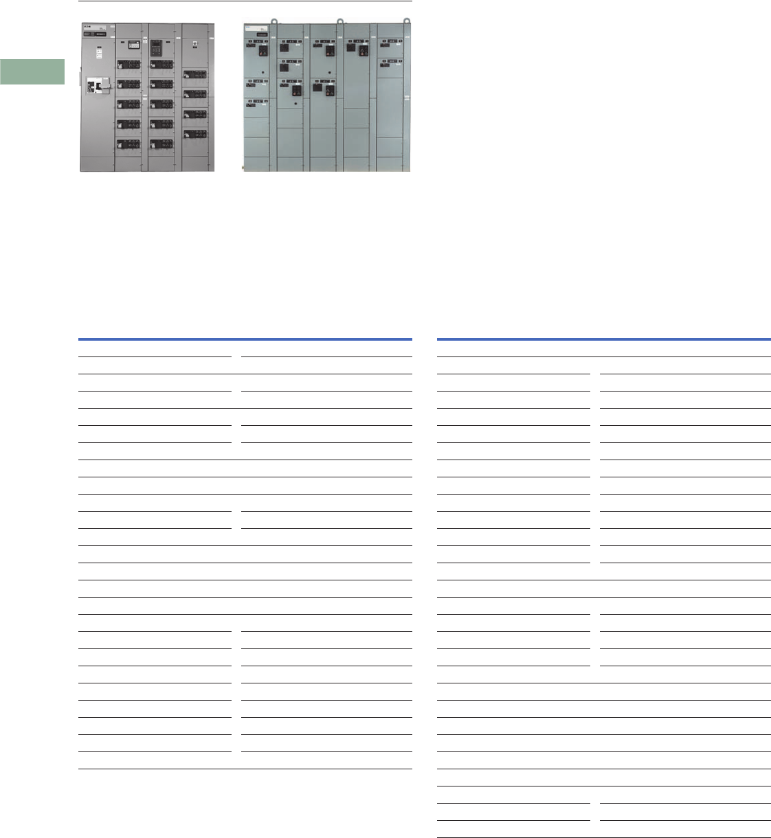
V3-T3-20 Volume 3—Power Distribution and Control Assemblies CA08100004E—June 2014 www.eaton.com
3
3
3
3
3
3
3
3
3
3
3
3
3
3
3
3
3
3
3
3
3
3
3
3
3
3
3
3
3
3
3.3
Motor Control Centers
Freedom and Freedom FlashGard Check Sheets
Freedom and Freedom FlashGard
Contents
Description
Freedom and Freedom FlashGard Check Sheets
Motor Control Center Takeoff Check Sheet
Customer/Job Name Neg No.
MCC Model
Freedom Freedom FlashGard
Service 60 Hz 208 V/230 V/480 V/575 V
Service 50 Hz 380 V/415 V
DC 125 V/250 V
Three-wire/four-wire
Structure Configuration
16-inch front mount 21-inch front mount
21-inch front and rear mount
42-inch front mount back-to-back
32-inch front mount back-to-back
NEMA 1A/2DP/12/3RNWI/3R aisle/3R tunnel
Enclosure Modifications
Space heaters (150 W) 120 V/240 V
Channel sills CBC/IBC seismic qualified
Thermostat Split proof
Bottom plates Split rear cover
Corner structure Vertical section barrier
8-inch vertical wireway Special paint color (adder)
ABS Certification
Handle extensions (“two meter rule”)
Top hat (certain sections) 12-inch/18-inch/24-inch
Top hat (all sections) 12-inch/18-inch/24-inch
Bus Rating and Options
Horizontal bus 600/800/1200/1600
21-inch deep structure only 2000/2500/3200
Bus plating Silver (AG)/tin (SN)
Bus temp rise 50 °C/65 °C
Insulated horizontal bus
Vertical bus 600/800/1200
Ground bus 300/600/800
Location Top/bottom
Vertical ground bus Lugs: incoming/each end
Neutral bus (4 W only) Half/full/lug pad
Bus bracing 42K/65K/100K
Vertical bus barrier STD Glastic sheet
Labyrinth with/without shutter
Incoming Line Metering
IQ 130/140/150
IQ 250/260
IQ DP-4130
IQ Analyzer
Power Xpert 2250/2260/2270
Power Xpert 4000/6000/8000
Incoming Protection
SPD Series surge protective device
Incoming Line MLO/Breaker/Switch
Cable—top/bottom/bus duct
Main trip: LS/LSI/LSG/LSIG/other
Crimp lugs Screw type lugs
Main tie main (MTM) Auto throw over
Kirk key Service entrance (SUSE)

Volume 3—Power Distribution and Control Assemblies CA08100004E—June 2014 www.eaton.com V3-T3-21
3
3
3
3
3
3
3
3
3
3
3
3
3
3
3
3
3
3
3
3
3
3
3
3
3
3
3
3
3
3
3.3
Motor Control Centers
Freedom and Freedom FlashGard Check Sheets
MCC Spec Review Checklist, continued
Breaker Options
Aux. contacts (1NO 1NC) (2NO 2NC)
LS/LSI/LSIG/LSG trip units
Under voltage release Shunt trip
Panelboards
14/18/26/30/32/42 count 1-pole/2-pole/3-pole
Starter Disconnect Type
HMCP/TM. bkr./fusible
NEMA wiring class
1A/1B/2B/1C/2C/1S/2S
If any type “C” choose MTB location:
Master terminal blocks (MTBs) top/bottom/relay structure
Terminal Blocks
Side latch pull apart (Std) (2x7-point)
Spare points = ______% (call DSE) Front utility (call DSE)
Nameplates: Black with White Letters / White with Black Letters
Starter OL Types
Bimetallic (C306) Advanced solid-state (C441)
Solid-state (C440)
Plug-In Starter Bucket Unit Features
# 16 MTW wire Coil surge suppression
# 14 SIS wire Blown fuse indicators
# 14 MTW Ground fault relays
Wiremarkers each end
Ring wire lugs control Riley current sensor
Spade wire lugs Heater packs
Ring power wire lugs
Wiring diagram on door
SIS power wire Vacuum contactors
Control Power
Size 1 100 VA (Std)/150 VA max.
Size 2 100 VA (Std)/150 VA max.
Size 3 150 VA (Std)/250 VA max.
Size 4 150 VA (Std)/250 VA max.
Size 5 250 VA (Std)/300 VA max.
Size 6 250 VA (Std)/300 VA max.
Separate source power
Auxiliary Starter Contacts
NO 1/2/3/4 NC 1/2/3/4
Control Devices
Pushbutton 1 unit/2 unit/reset VoltageVision
Selector switch 2pos/3pos/4pos Motorguard
Light—Std Xfmr/PTT/LED bulb Motor load block
On/off run/stop
Mini ETM Panel ETM
AMM (mini/panel) VM (mini/panel)
Riley transducer (Loop/Self Pwr)
CTs for remote metering
Ground fault
IP relay—size 1/2/3/4/5/6 Voltage
Relays 300 V or 600 V Timers
Communications
DeviceNet direct Modbus RTU
EtherNet/IP Power Xpert Gateway
Modbus TCP PROFIBUS DP
S811+ Soft Starters
Isolation contactor MOVs
Pump control software Bypass starter
VFDs SVX/MMX/CPX
EMI/RFI Line fuses
dV/dT filter 600 ft or 1000 ft 3-contactor bypass
Harmonic Correction Unit
50 A/100 A

V3-T3-22 Volume 3—Power Distribution and Control Assemblies CA08100004E—June 2014 www.eaton.com
3
3
3
3
3
3
3
3
3
3
3
3
3
3
3
3
3
3
3
3
3
3
3
3
3
3
3
3
3
3
3.3
Motor Control Centers
Freedom and Freedom FlashGard Check Sheets
Component Count Sheet
FVNR Starters FVR Starters
Size Quantity Size Quantity
11
22
33
44
55
66
7
Feeder Breakers
Single Quantity Dual Quantity
50 A 50/50
100 A 100/50
150 A 100/100
225 A 150/100
250 A 150/150
400 A
600 A
800 A
1200 A
1600 A
2000 A
2500 A
3200 A
VFDs
HP Quantity Type
1.5 CT/VT
2CT/VT
3CT/VT
5CT/VT
7.5 CT/VT
10 CT/VT
20 CT/VT
25 CT/VT
30 CT/VT
40 CT/VT
50 CT/VT
60 CT/VT
75 CT/VT
100 CT/VT
125 CT/VT
150 CT/VT
200 CT/VT
250 CT/VT
300 CT/VT
400 CT/VT
500 CT/VT
600 CT/VT
700 CT/VT
Two Speed, One Winding Two Speed, Two Winding
Size Quantity Size Quantity
11
22
33
44
Fusible Feeders
Single Quantity Dual Quantity
30 A 30/30
60 A 60/60
100 A
200 A
400 A
600 A
800 A
1200 A
Future Space
Starter Circuit Protection Size Quantity
HMCP Thermal Magnetic 2X
HMCPE 3X
Fusible 4X
Relay Panels
Size Quantity
2X
3X
4X
5X
6X
7X
8X
9X
10X
11X
12X

Volume 3—Power Distribution and Control Assemblies CA08100004E—June 2014 www.eaton.com V3-T3-23
3
3
3
3
3
3
3
3
3
3
3
3
3
3
3
3
3
3
3
3
3
3
3
3
3
3
3
3
3
3
3.3
Motor Control Centers
Freedom and Freedom FlashGard Check Sheets
Component Count Sheet, continued
Soft Starters
HP Quantity Duty Cable Exit
20 Std/severe
40 Std/severe
60 Std/severe
75 Std/severe
125 Std/severe
200 Std/severe
300 Std/severe Top/bottom
350 Std/severe Top/bottom
450 Std/severe Top/bottom
500 Std/severe Top/bottom
600 Std/severe Top/bottom
700 Std/severe Top/bottom
Transformers
Single-Phase Quantity Three-Phase Quantity
3 kVA 9 kVA
5 kVA 15 kVA
7.5 kVA 25 kVA
10 kVA 30 kVA
15 kVA 45 kVA
20 kVA
25 kVA
30 kVA
45 kVA
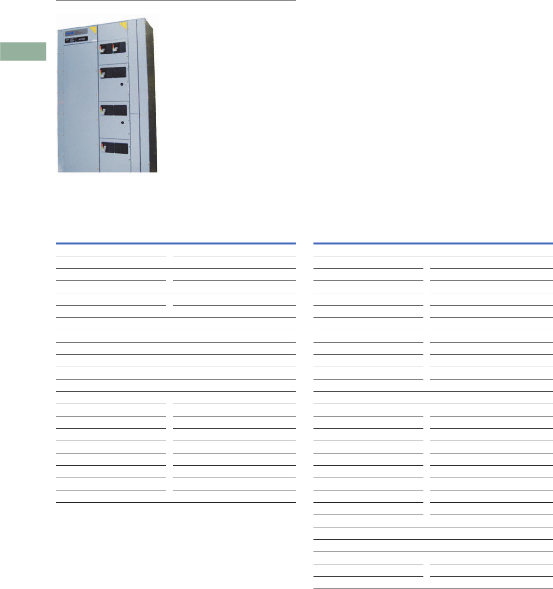
V3-T3-24 Volume 3—Power Distribution and Control Assemblies CA08100004E—June 2014 www.eaton.com
3
3
3
3
3
3
3
3
3
3
3
3
3
3
3
3
3
3
3
3
3
3
3
3
3
3
3
3
3
3
3.4
Motor Control Centers
Freedom Arc-Resistant MCC Check Sheets
Freedom Arc-Resistant MCC
Contents
Description
Freedom Arc-Resistant MCC Check Sheets
Motor Control Center Takeoff Check Sheet
Customer/Job Name Neg No.
MCC Model
Freedom Arc-Resistant
Service 60 Hz 208 V/230 V/480 V/575 V
Service 50 Hz 380 V/415 V
Three-wire/four-wire
Structure Configuration
42-inch front mount back-to-back 21-inch front mount
NEMA 1A/2DP/12/3RNWI
Enclosure Modifications
Space heaters (150 W) 120 V/240 V
Channel sills CBC/IBC seismic qualified
Thermostat Split proof
Bottom plates Split rear cover
Corner structure Vertical section barrier
8-inch vertical wireway Special paint color (adder)
ABS Certification
Handle extensions (“two meter rule”)
Top hat (certain sections) 12-inch/18-inch/24-inch
Top hat (all sections) 12-inch/18-inch/24-inch
Bus Rating and Options
Horizontal bus 800/1200/1600/2000/2500
Bus plating Silver (AG)/tin (SN)
Bus temp rise 50 °C/65 °C
Insulated horizontal bus
Vertical bus 600/800/1200
Ground bus 300/600/800
Location Top/bottom
Vertical ground bus Lugs: incoming/each end
Neutral bus (4W only) Half/full/lug pad
Bus bracing 65K
Vertical bus barrier Labyrinth with shutter
Incoming Line Metering
IQ 130/140/150
IQ 250/260
IQ DP-4130
IQ Analyzer
Power Xpert 2250/2260/2270
Power Xpert 4000/6000/8000
Incoming Protection
SPD Series surge protective device
Incoming Line
Breaker
Cable—top/bottom
Main trip: LS/LSI/LSG/LSIG/other
Crimp lugs Screw type lugs
Main tie main (MTM) Auto throw over
Kirk key Service entrance (SUSE)

Volume 3—Power Distribution and Control Assemblies CA08100004E—June 2014 www.eaton.com V3-T3-25
3
3
3
3
3
3
3
3
3
3
3
3
3
3
3
3
3
3
3
3
3
3
3
3
3
3
3
3
3
3
3.4
Motor Control Centers
Freedom Arc-Resistant MCC Check Sheets
MCC Spec Review Checklist, continued
Breaker Options
Aux. contacts (1NO 1NC) (2NO 2NC)
LS/LSI/LSIG/LSG trip units
Under voltage release Shunt trip
Panelboards
14/18/26/30/32/42 count 1-pole/2-pole/3-pole
Starter Disconnect Type
HMCP/TM. bkr.
NEMA wiring class
1A/1B/2B/1C/2C/1S/2S
If any type “C” choose MTB location:
Master terminal blocks (MTBs) top/bottom/relay structure
Terminal Blocks
Side latch pull apart (Std) (2x7-point)
Spare points = ______% (call DSE) Front utility (call DSE)
Nameplates: Black with White Letters / White with Black Letters
Starter OL Types
Bimetallic (C306) Advanced solid-state (C441)
Solid-state (C440)
Plug-In Starter Bucket Unit Features
# 16 MTW wire Coil surge suppression
# 14 SIS wire Blown fuse indicators
# 14 MTW Ground fault relays
Wiremarkers each end
Ring wire lugs control Riley current sensor
Spade wire lugs Heater packs
Ring power wire lugs
Wiring diagram on door
SIS power wire Vacuum contactors
Control Power
Size 1 100 VA (Std)/150 VA max.
Size 2 100 VA (Std)/150 VA max.
Size 3 150 VA (Std)/250 VA max.
Size 4 150 VA (Std)/250 VA max.
Size 5 250 VA (Std)/300 VA max.
Separate source power
Auxiliary Starter Contacts
NO 1/2/3/4 NC 1/2/3/4
Control Devices
Pushbutton 1 unit/2 unit/reset VoltageVision
Selector switch 2pos/3pos/4pos Motorguard
Light—Std Xfmr/PTT/LED bulb Motor load block
On/off run/stop
Mini ETM Panel ETM
AMM (mini/panel) VM (mini/panel)
Riley transducer (Loop/Self Pwr)
CTs for remote metering
Ground fault
IP relay—size 1/2/3/4/5/6 Voltage
Relays 300 V or 600 V Timers
Communications
DeviceNet direct Modbus RTU
EtherNet/IP Power Xpert Gateway
Modbus TCP PROFIBUS DP
S811+ Soft Starters
Isolation contactor MOVs
Pump control software Bypass starter
VFDs SVX/MMX/CPX
EMI/RFI
dV/dT filter 600 ft or 1000 ft 3-contactor bypass
Harmonic Correction Unit
50 A/100 A

V3-T3-26 Volume 3—Power Distribution and Control Assemblies CA08100004E—June 2014 www.eaton.com
3
3
3
3
3
3
3
3
3
3
3
3
3
3
3
3
3
3
3
3
3
3
3
3
3
3
3
3
3
3
3.4
Motor Control Centers
Freedom Arc-Resistant MCC Check Sheets
Component Count Sheet
FVNR Starters FVR Starters
Size Quantity Size Quantity
11
22
33
44
55
Feeder Breakers
Single Quantity Dual Quantity
50 A 50/50
100 A 100/50
150 A 100/100
225 A 150/100
250 A 150/150
400 A
600 A
800 A
1200 A
1600 A
2000 A
2500 A
VFDs
HP Quantity Type
1.5 CT/VT
2CT/VT
3CT/VT
5CT/VT
7.5 CT/VT
10 CT/VT
20 CT/VT
25 CT/VT
30 CT/VT
40 CT/VT
50 CT/VT
60 CT/VT
75 CT/VT
100 CT/VT
125 CT/VT
150 CT/VT
200 CT/VT
Two Speed, One Winding Two Speed, Two Winding
Size Quantity Size Quantity
11
22
33
44
Future Space
Starter Circuit Protection Size Quantity
HMCP Thermal Magnetic 2X
HMCPE 3X
4X
Relay Panels
Size Quantity
2X
3X
4X
5X
6X
7X
8X
9X
10X
11X
12X

Volume 3—Power Distribution and Control Assemblies CA08100004E—June 2014 www.eaton.com V3-T3-27
3
3
3
3
3
3
3
3
3
3
3
3
3
3
3
3
3
3
3
3
3
3
3
3
3
3
3
3
3
3
3.4
Motor Control Centers
Freedom Arc-Resistant MCC Check Sheets
Component Count Sheet, continued
Soft Starters
HP Quantity Duty Cable Exit
20 Std/severe
40 Std/severe
60 Std/severe
75 Std/severe
125 Std/severe
200 Std/severe
Transformers
Single-Phase Quantity Three-Phase Quantity
3 kVA 9 kVA
5 kVA 15 kVA
7.5 kVA 25 kVA
10 kVA 30 kVA
15 kVA 45 kVA
20 kVA
25 kVA
30 kVA
45 kVA

V3-T3-28 Volume 3—Power Distribution and Control Assemblies CA08100004E—June 2014 www.eaton.com
3
3
3
3
3
3
3
3
3
3
3
3
3
3
3
3
3
3
3
3
3
3
3
3
3
3
3
3
3
3
3.5
Motor Control Centers
XT and XT FlashGard Technical Data and Specifications
Technical Data
and Specifications
Incoming Line
Incoming Line—
Main Lugs Only 1
Bus
Rating X-Space
600 2
3
4
800 3
4
6
1000 4
6
8
1200 5
6
1600 12
2000 12
2500 12
3200 212
Incoming Line—Main Circuit Breaker 1
Notes
1Table common to XT and XT FlashGard.
2NEMA 1 gasketed only.
3100% rated when 90° cable applied at 75° ampacity for 100% rating. Digitrip™ 310 LS is required and included in the price.
4Digitrip 310+ LSI is standard and included in the pricing.
5Arcflash Reduction Maintenance System (ARMS) available. Requires Digitrip 310+ ALSI or ALSIG.
6Fixed assembly. Not available with FlashGard RotoTract assembly.
7100% rated when 90° cable applied at 75° ampacity for 100% rating.
8Add 6.00 inches (152.4 mm) for top entry of incoming cables.
9Install at top for cable top entry or at bottom for bottom cable entry.
jThe main breaker requires the complete vertical section. The rear is unusable.
Dimensions in Inches (mm)
Frame Size
(Amperes)
Circuit
Breaker Type
XT and XT FlashGard
Unit Size
Enclosure
Width
150 HFD 18.00 (457.2) 20.00 (508.0)
FDC 18.00 (457.2) 20.00 (508.0)
225 HFD 18.00 (457.2) 20.00 (508.0)
FDC 18.00 (457.2) 20.00 (508.0)
250 HJD 30.00 (762.0) 20.00 (508.0)
JDC 30.00 (762.0) 20.00 (508.0)
400 HKD 30.00 (762.0) 20.00 (508.0)
KDC 30.00 (762.0) 20.00 (508.0)
CHKD 330.00 (762.0) 20.00 (508.0)
CKDC 330.00 (762.0) 20.00 (508.0)
600 HLD 24.00 (609.6) 689 20.00 (508.0)
LDC 24.00 (609.6) 689 20.00 (508.0)
CHLD 23 24.00 (609.6) 689 20.00 (508.0)
CLDC 23 24.00 (609.6) 689 20.00 (508.0)
800 HMDL 30.00 (762.0) 69 20.00 (508.0)
CHMDL 23 48.00 (1219.2) 69 20.00 (508.0)
NGH 45 42.00 (1066.8) 69 20.00 (508.0)
NGC 45 42.00 (1066.8) 69 20.00 (508.0)
NGH-C 2457 72.00 (1828.8) 620.00 (508.0)
NGC-C 245 72.00 (1828.8) 620.00 (508.0)
1200 NGH 45 42.00 (1066.8) 69 20.00 (508.0)
NGC 45 42.00 (1066.8) 69 20.00 (508.0)
NGH-C 2457 72.00 (1828.8) 620.00 (508.0)
NGC-C 245 72.00 (1828.8) 620.00 (508.0)
1600 RGH 45 72.00 (1828.8) 6j20.00 (508.0)
RGC 45 72.00 (1828.8) 6j20.00 (508.0)
RGH-C 457 72.00 (1828.8) 6j20.00 (508.0)
RGC-C 457 72.00 (1828.8) 6j20.00 (508.0)
2000 RGH 45 72.00 (1828.8) 6j20.00 (508.0)
RGC 45 72.00 (1828.8) 6j20.00 (508.0)
RGH-C 457 72.00 (1828.8) 6j20.00 (508.0)
RGC-C 457 72.00 (1828.8) 6j20.00 (508.0)
2500 RGH 45 72.00 (1828.8) 69j24.00 (609.6)
RGC 45 72.00 (1828.8) 69j24.00 (609.6)

Volume 3—Power Distribution and Control Assemblies CA08100004E—June 2014 www.eaton.com V3-T3-29
3
3
3
3
3
3
3
3
3
3
3
3
3
3
3
3
3
3
3
3
3
3
3
3
3
3
3
3
3
3
3.5
Motor Control Centers
XT and XT FlashGard Technical Data and Specifications
Structure Modifications
Structure Modifications Neutral Bus (Bottom) Incoming Line Metering Surge Protective Device—
Units with Circuit Breaker
Disconnect
Three feature packages are
available to choose from.
Individual features vary by
package.
Notes
1Available NEMA 1 gasketed
enclosures only.
2Optional integral IQ 200 meter in 3X unit
for 100 kA–200 kA.
3Recommended for branch entrance.
4Recommended for service entrance.
Description
Enclosure
NEMA 1 gasketed
NEMA 12—dust-tight
NEMA 3R front-mounted only
NEMA 3R front and rear
NEMA 3R walk-in
NEMA 3R tunnel
Space heater
Thermostat
Bottom plate
Channel sills
12.00-inch (304.8 mm) pull box
100 kA bus bracing
Vertical Bus
600 A
800 A
1200 A
Horizontal Ground Bus
300 A copper
600 A copper
800 A copper
Standard Structures
16.00-inch (406.4 mm) front-mounted only
21.00-inch (533.4 mm) front-mounted only
21.00-inch (533.4 mm) front and rear
Main Horizontal Bus—65°C Rise
600 A copper
800 A copper
1200 A copper
1600 A copper
2000 A copper
2500 A copper
3200 A copper
Ampere Rating
300
600 or 800
1000
1200
1600
2000
2500
3200 1
Meter
X-Space
XT and
XT FlashGard
IQ 130/140/150 2
IQ 250/260 2
IQ DP-4130 2
IQ Analyzer 2
Power Xpert
2250/2260/2270
2
Power Xpert
4000/6000/8000
3
X-Space
Surge Current
Per Phase
XT and
XT FlashGard
100 kA
Model SPD 2
3
120 kA
Model SPD 23
3
160 kA
Model SPD 2
3
200 kA
Model SPD 2
3
250 kA
Model SPD 4
3
300 kA
Model SPD
3
400 kA
Model SPD
3

V3-T3-30 Volume 3—Power Distribution and Control Assemblies CA08100004E—June 2014 www.eaton.com
3
3
3
3
3
3
3
3
3
3
3
3
3
3
3
3
3
3
3
3
3
3
3
3
3
3
3
3
3
3
3.5
Motor Control Centers
XT and XT FlashGard Technical Data and Specifications
Combination Starters
Circuit Breaker Starters Fusible Disconnect Starters
Contactor Only Units
X-Space
Size XT XT FlashGard
Full Voltage Non-Reversing
112
212
323
424
556
Full Voltage Reversing
123
223
334
434
578
2S1W Non-Reversing
134
234
345
445
2S2W Non-Reversing
134
234
334
445
X-Space
Size XT XT FlashGard
Full Voltage Non-Reversing
123
223
344
456
5910
Full Voltage Reversing
134
234
356
489
51212
2S1W Non-Reversing
134
234
345
456
2S2W Non-Reversing
134
234
356
467
X-Space
Size XT XT FlashGard
Circuit Breaker
11 2
21 2
32 3
42 4
55 6
Fusible Disconnect
12 3
22 3
34 4
45 6
59 10
Starter Modifications
Control Configurations Available with XT and
XT FlashGard FVNR Starters 1
Control Configurations Available with XT and
XT FlashGard FVR Starters 1
Notes
1Additional configurations available. The device panel on XT MCC starter units can support
up to three pilot/control devices plus an overload trip light/reset button. The device panel on
XT FlashGard starter units can support up to five pilot/control devices plus an overload trip
light/reset button.
2Configuration available on XT FlashGard only.
Configuration Control Devices
1 2Hand/off/auto selector switch
Start and stop pushbuttons
Running and stopped lights
Overload trip light/reset button
2 2Hand/off/auto selector switch
Start and stop pushbuttons
Running light
Overload trip light/reset button
3 Hand/off/auto selector switch
Running and stopped lights
Overload trip light/reset button
4 Hand/off/auto selector switch
Running light
Overload trip light/reset button
5 Hand/off/auto selector switch
Overload trip light/reset button
6 2Start and stop pushbuttons
Running and stopped lights
Overload trip light/reset button
7 Start and stop pushbuttons
Running light
Overload trip light/reset button
8 Start and stop pushbuttons
Overload trip light/reset button
Configuration Control Devices
1 2Forward/reverse/off/auto selector switch
Forward, reverse, and stopped lights
Overload trip light/reset button
2 Forward/reverse/off/auto selector switch
Forward and reverse lights
Overload trip light/reset button
3 Forward/reverse/off/auto selector switch
Overload trip light/reset button
5 2Forward, reverse, and stop pushbuttons
Forward and reverse lights
Overload trip light/reset button
4 Forward, reverse, and stop pushbuttons
Overload trip light/reset button

Volume 3—Power Distribution and Control Assemblies CA08100004E—June 2014 www.eaton.com V3-T3-31
3
3
3
3
3
3
3
3
3
3
3
3
3
3
3
3
3
3
3
3
3
3
3
3
3
3
3
3
3
3
3.5
Motor Control Centers
XT and XT FlashGard Technical Data and Specifications
Industrial Communications 1
Networked-enabled
components in MCCs
eliminate up to 90% of the
control wiring versus
traditional hardwired designs.
The industrial network is
prewired throughout the
MCC and factory tested
for conformance.
In the XT and XT FlashGard
MCCs, the base
communications protocols
available are Modbus TCP
or EtherNet/IP. If a different
protocol is required to link the
MCC with an external device
such as a DCS, SCADA
system or PLC, a gateway
will be installed within
the MCC.
Motor Control Communication Options
S811+ Soft Starters with Integral Bypass
S811+ Control Options 3 S811+ Power Options 3 Notes
1This table is common for both XT and
XT FlashGard MCCs.
2Requires 24.00-inch (609.6 mm) wide,
rear is unusable, bottom exit only.
3Options apply to both HMCP and
breaker models.
Device EtherNet/IP Modbus TCP
C440 Overload C441V C441V
SVX Drives OPTCI OPTCI
Feeders C441V C441V
S811+ Soft Starters C441V C441V
X-Space X-Space
Maximum hp XT XT FlashGard Maximum hp XT XT FlashGard
1.15 Service Factor—Standard Duty 1.15 Service Factor—Severe Duty
20 2 3 10 2 3
40 2 3 25 2 3
60 3 4 40 3 4
75 3 4 50 3 4
125 6 7 75 6 7
150 6 7 100 6 7
200 6 7 125 6 9
300 9 9 150 9 10
350 9 9 200 9 10
450 12 12 250 9 10
500 12 12 300 9 10
600 12 12 350 9 10
700 12 212 450 12 212
Description
Pump control
MOV protection
NEMA Bypass Contactor
Size 1
Size 2
Size 3
Size 4
Size 5
Size 6
Size 7

V3-T3-32 Volume 3—Power Distribution and Control Assemblies CA08100004E—June 2014 www.eaton.com
3
3
3
3
3
3
3
3
3
3
3
3
3
3
3
3
3
3
3
3
3
3
3
3
3
3
3
3
3
3
3.5
Motor Control Centers
XT and XT FlashGard Technical Data and Specifications
Motor Isolation Contactors
MMX Adjustable
Frequency Drives—NEMA 1
480 V Maximum
MMX Drive Options
SVX9000 Adjustable
Frequency Drives—
Plug-in Units NEMA 1
480 V Maximum Constant/
Variable Torque Rated 1
SVX9000 Options
SVX9000 Adjustable
Frequency Drives—
Non-Plug-in Units NEMA 1
480 V Maximum Constant/
Variable Torque R ate d
Note: Consult Eaton’s Consulting
Application Guide for complete
details on Drive/ Option Assembly
Dimensions.
Note: SVX9000 Non-Plug-in Units
with HMCP disconnect, 3% input
line reactor, 3% output line
reactor, door mounted Keypad,
CPT.
Note: VT—Variable Torque drives
are capable of producing 200%
starting torque for 10 seconds
and are rated for 10 seconds,
and are rated 110% overload
for 1 minute.
Note: CT—Variable Torque drives
are capable of producing 200%
starting torque for 10 seconds
and are rated for 10 seconds,
and are rated 150% overload
for 1 minute.
Note:
In the
XT
and
XT
FlashGard
MCCs, the base communications
protocols available are Modbus
TCP or EtherNet/IP. If a different
protocol is required to link the
MCC with an external device such
as a DCS, SCADA or PLC, a
gateway will be installed within
the MCC.
SVX9000 Options
Active Harmonic Correction
for AC Drives
18-Pulse Clean Power
Drives—NEMA 1, 480 V
Maximum Variable Torque
Rated 4
Feeders
Note: FlashGard RotoTract
assembly available on circuit
breakers 400 A and below.
Circuit Breaker
Fusible Disconnect—
Fusible Switch
Notes
1SVX9000 plug-in units with HMCP
disconnect, 3% input line reactor,
3% output line reactor, door-mounted
keypad, CPT.
2X-space for 75 hp CT rated drive is 12X.
3Requires 24.00-inch (609.6 mm)
wide structure.
4Includes 5% input line reactor, 18-pulse
rectifier, delta differential transformer.
5X-space shown is common for both XT
and XT FlashGard MCCs.
6Extra space required for bypass
contactor, consult factory.
7Fixed assembly, no RotoTract.
Sizes
1
2
3
4
5
X-Space
hp
XT and XT
FlashGard
12
22
33
53
7.5 3
10 3
Description
3% load reactor
5% load reactor
Three contactor bypass
X-Space
hp XT
XT
FlashGard
336
547
7.5 4 7
10 4 7
15 4 7
20 6 10
25 6 10
30 6 10
Description
Modbus TCP
EtherNet/IP
2000-foot (609.6m) dV/dT filter (3 hp)
2000-foot (609.6m) dV/dT filter
(5–15 hp)
2000-foot (609.6m) dV/dT filter
(20–30 hp)
Input line fuses (3–30 hp)
RFI filter (3–30 hp)
X-Space
hp XT
XT
FlashGard
40 9 9
50 9 9
60 9 9
75 299
100 12 12
125 12 12
150 12 12
200 12 12
250 12 12
300 12 12
400 12 12
500 12 12
600 12 12
700 12 12
Description
Modbus TCP
EtherNet/IP
2000-foot (609.6m) dV/dT filter
(40–75 VT hp)
2000-foot (609.6m) dV/dT filter
(100–150 VT hp)
2000-foot (609.6m) dV/dT filter
(200–250 VT hp)
2000-foot (609.6m) dV/dT filter
(300–400 VT hp)
2000-foot (609.6m) dV/dT filter
(500–600 VT hp)
Input line fuses (40–150 VT hp)
Input line fuses (200–250 hp)
Input line fuses (300–400 hp)
X-Space
Description XT
XT
FlashGard
50 A harmonic
correction
12 312 3
100 A harmonic
correction
12 312 3
hp
X-Space
Inches (mm) Wide 5
100 12, 40.00 (1016.0)
150 12, 40.00 (1016.0)
200 12, 60.00 (1524.0)
250 12, 60.00 (1524.0)
300 12, 60.00 (1524.0) 6
400 12, 60.00 (1524.0) 6
500 12, 106.00 (2692.4) 6
X-Space
Amperes XT XT FlashGard
Standard Circuit Breakers
HFD 50 2 2
HFD 100 2 2
HFD 150 2 2
HJD 250 3 3
HKD 400 4 5
HLD 600 4 4 7
NGH 1200 7 7 7
EGH 125 1 2
JGH 250 1 2
HKD 400 4 5
HLD 600 5 5 7
Amperes
X-Space
XT XT FlashGard
30 or 60 2 3
100 3 3
200 6 5
400 6 7
600 8 8 7

Volume 3—Power Distribution and Control Assemblies CA08100004E—June 2014 www.eaton.com V3-T3-33
3
3
3
3
3
3
3
3
3
3
3
3
3
3
3
3
3
3
3
3
3
3
3
3
3
3
3
3
3
3
3.5
Motor Control Centers
XT and XT FlashGard Technical Data and Specifications
NEMA 3R Drives
Constant/Variable Torque
Rated (480 V Maximum)
Transformers
Tr a n s f o r m e r s 3
Horsepower
X-Space, Width
Inches (mm) 1
1.5 5X, 24.00 (609.6)
2 5X, 24.00 (609.6)
3 5X, 24.00 (609.6)
5 5X, 24.00 (609.6)
7.5 12X, 24.00 (609.6)
10 12X, 24.00 (609.6)
15 12X, 24.00 (609.6)
20 12X, 24.00 (609.6)
25 12X, 24.00 (609.6)
30 12X, 24.00 (609.6)
40 12X, 24.00 (609.6)
50 12X, 32.00 (812.8)
60 12X, 32.00 (812.8)
75 12X, 32.00 (812.8)
100 12X, 32.00 (812.8)
125 12X, 32.00 (812.8)
150 12X, 32.00 (812.8)
200 12X, 32.00 (812.8) 2
kVA
Primary
Breaker Only
X-Space
Primary and
Secondary
Breakers
X-Space
Single-Phase
34 4
54 4
7.5 4 4
10 4 4
15 666
20 666
25 666
30 666
45 678
Three-Phase
9 666
15 666
25 666
30 666
45 666
Panelboards
Panelboards
(240 V Maximum) 14
Panelboards
(480 V Maximum) 14
Automatic Transfer Switches
Open Transition Three-Pole Only
Notes
1X-space shown is common for both XT and XT FlashGard MCCs.
2Extra space required for bypass section. Consult factory.
3Must have primary breaker. Must be located at bottom of structure.
4Space for MLO. Branch breakers included.
5Manually operated switch:
NTVS = Electronically operated non-automatic.
MTVX = Single handle manual operation.
6Requires 21.00-inch (533.4 mm) deep structure.
7Requires 37.00-inch (939.8 mm) deep structure, flush at the rear. 4.00-inch (101.6 mm) filler required.
8Requires 42.00-inch (1066.8 mm) deep structure. 4.00-inch (101.6 mm) filler required.
Circuits X-Space
18 4
30 5
42 6
Circuits X-Space
14 6
26 8
32 8
42 10
Ampere Rating Unit Width Inches (mm) XT and XT FlashGard X-Space
100 520.00 (508.0) 6
150 520.00 (508.0) 6
100 20.00 (508.0) 8
150 20.00 (508.0) 8
225 20.00 (508.0) 8
300 20.00 (508.0) 8
400 24.00 (609.6) 612
600 24.00 (609.6) 612
800 24.00 (609.6) 612
1000 24.00 (609.6) 612
1000 44.00 (1117.6) 712
1200 44.00 (1117.6) 712
1600 44.00 (1117.6) 812
2000 44.00 (1117.6) 812

V3-T3-34 Volume 3—Power Distribution and Control Assemblies CA08100004E—June 2014 www.eaton.com
3
3
3
3
3
3
3
3
3
3
3
3
3
3
3
3
3
3
3
3
3
3
3
3
3
3
3
3
3
3
3.5
Motor Control Centers
XT and XT FlashGard Technical Data and Specifications
Application Guide
Motor Circuit Protector Selection Guide 1Circuit Breaker Application Chart
Notes
1Suitable for use with NEMA Design B and D (high efficiency) motors.
Circuit breakers can be supplied with optional shunt trip.
Maximum Horsepower
NEMA 200 V 208 V 230 V 380 V 460 V HMCP
1 ———3/43/43
3/411227
2223515
5 5 5 101030
7-1/2 7-1/2 7-1/2 — — 50
2 —————30
10 10 10 15 20 50
— — 15 25 25 70
3 —————50
15 20 20 30 40 100
25 25 30 50 50 150
4 40404060100150
— — 50 75 — 250
5 505060—125250
75 75 75 150 200 400
——100——600
Frame
Frame Rating
(Amperes)
Interrupting Rating
(kA Symmetrical Amperes)
208/240 V 480 V
Standard Rating Molded Case Circuit Breakers
E125H 125 65 65
J250H 250 65 65
HKD 400 65 65
HLD 600 65 65
NGH 1200 65 65
RGH 2500 65 65
High Interrupting Rating Molded Case Circuit Breakers
FDC 150 100 100
JDC 250 100 100
KDC 400 100 100
LDC 600 100 100
NGC 1200 100 100
RGC 2500 100 100
Magnum DS Air Circuit Breakers
MDS-608 800 65 65
MDS-C08 800 100 100
MDS-616 1600 65 65
MDS-C16 1600 100 100
MDS-620 2000 65 65
MDS-C20 2000 100 100
MDS-632 3200 65 65
MDS-C32 3200 100 100

Volume 3—Power Distribution and Control Assemblies CA08100004E—June 2014 www.eaton.com V3-T3-35
3
3
3
3
3
3
3
3
3
3
3
3
3
3
3
3
3
3
3
3
3
3
3
3
3
3
3
3
3
3
3.5
Motor Control Centers
XT and XT FlashGard Technical Data and Specifications
Product Specifications
Structure
●NEMA 1, 2, 3R or
12 enclosure
●Copper horizontal bus
600–3200 A
●Fully rated copper
vertical bus 600–1200 A
●Optional isolating barriers
between structures
●Insulated labyrinth vertical
bus is standard on the
XT MCC
●Insulated horizontal bus
and insulated labyrinth
vertical bus is standard
on XT FlashGard MCCs
●Heavy-duty spring
operated quarter-turn
door latches
●65 kA and 100 kA bus
bracing
Units
●XT and XT FlashGard
motor starters:
●NEMA size 1–5
●NEMA rated XT
contactor
●C440 overload relay
●Single-phase protection
●Class 10 and 20
protection
●HMCP with combination
starter ratings of 65 kAIC
and 100 kAIC at 480 V
●Plug-in units up to 400 A
●Handle mechanism with
positive trip indication
●Side-mounted positive
latch terminal block
●Motor load terminal block
is standard on both the XT
and XT FlashGard MCCs
●6.00-inch (1X) size 1 and 2
FVNR starters, 12.00-inch
(2X) size 3 and 4 FVNR
starters, add 1X for
FVR versions
●Optional communications
without increasing unit
footprint
●Soft Starters:
●S811+ (20–700 hp)
●Adjustable Frequency
Drives:
●MMX (1–10 hp)
●SVX9000 (2–700 hp)
●K-Switch visible blade
disconnect:
●30–800 A
●Surge protection:
●SPD Series
(100–400 kA)
●Energy monitoring:
●IQ 100 (amperes, volts)
●IQ 250 (adds, Hz,
watts, PF)
●IQ 260 (adds THD,
Contact I/O)
●IQ Analyzer (adds
trending, waveform
display)
●Power Xpert (adds high-
end metering, power
quality analysis, open
communications and
Web server gateway)
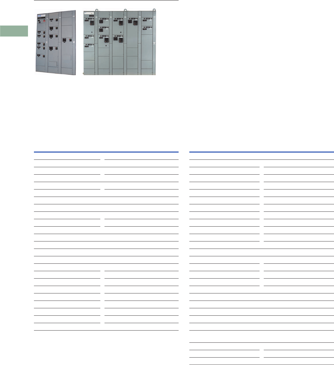
V3-T3-36 Volume 3—Power Distribution and Control Assemblies CA08100004E—June 2014 www.eaton.com
3
3
3
3
3
3
3
3
3
3
3
3
3
3
3
3
3
3
3
3
3
3
3
3
3
3
3
3
3
3
3.6
Motor Control Centers
XT and XT FlashGard Check Sheets
XT and Freedom XT FlashGard
Contents
Description
XT and XT FlashGard Check Sheets
XT and XT FlashGard Motor Control Center
Takeoff Check Sheet
Customer/Job Name Neg No.
MCC Model
XT XT FlashGard
Service 60 Hz 208 V/230 V/480 V
Service 50 Hz 380 V/415 V
Three-wire/four-wire
Structure Configuration
16-inch front mount 21-inch front mount
21-inch front and rear mount
42-inch front mount back-to-back
32-inch front mount back-to-back
NEMA 1/2DP/12/3RNWI/3R aisle/3R tunnel
Enclosure Modifications
Space heaters (150 W) 120 V/240 V
Channel sills CBC/IBC seismic qualified
Thermostat Split proof
Bottom plates Split rear cover
Corner structure Vertical section barrier
8-inch vertical wireway Special paint color (adder)
ABS Certification
Handle extensions (“two meter rule”)
Top hat (certain sections) 12-inch/18-inch/24-inch
Top hat (all sections) 12-inch/18-inch/24-inch
Bus Rating and Options
Horizontal bus 600/800/1200/1600
21-inch deep structure only 2000/2500/3200
Bus plating Silver (AG)/tin (SN)
Bus temp rise 50 °C/65 °C
Insulated horizontal bus
Vertical bus 600/800/1200
Ground bus 300/600/800
Location Top/bottom
Vertical ground bus Lugs: incoming/each end
Neutral bus (4W only) Half/full/lug pad
Bus bracing 42K/65K/100K
Vertical bus barrier STD labyrinth with shutter
Incoming Line Metering
IQ 130/140/150
IQ 250/260
IQ DP-4130
IQ Analyzer
Power Xpert 2250/2260/2270
Power Xpert 4000/6000/8000
Incoming Protection
SPD Series surge protective device
Incoming Line MLO/Breaker/Switch
Cable—top/bottom/bus duct
Main trip: LS/LSI/LSG/LSIG/ALSI, ALSIG/
other
Crimp lugs Screw type lugs
Main tie main (MTM) Auto throw over
Kirk key Service entrance (SUSE)

Volume 3—Power Distribution and Control Assemblies CA08100004E—June 2014 www.eaton.com V3-T3-37
3
3
3
3
3
3
3
3
3
3
3
3
3
3
3
3
3
3
3
3
3
3
3
3
3
3
3
3
3
3
3.6
Motor Control Centers
XT and XT FlashGard Check Sheets
XT and XT FlashGard Motor Control Center
Takeoff Check Sheet, continued
Breaker Options
Aux. contacts (1NO 1NC) (2NO 2NC)
LS/LSI/LSIG/LSG trip units
Under voltage release Shunt trip
Panelboards
14/18/26/30/32/42 count 1-pole/2-pole/3-pole
Starter Disconnect Type
HMCP/fusible
NEMA wiring class
1A/1B/2B/1C/2C/1S/2S
HMCP/TM. Bkr./fusible
If any type “C” choose MTB location:
Master terminal blocks (MTBs) top/bottom/relay structure
Terminal Blocks
Side latch pull apart (Std) (2x6-point)
Spare points = ______% (call DSE) Front utility (call DSE)
Nameplates: Black with White Letters / White with Black Letters
Starter OL Types
Solid-state (C440)
Solid-state (C440) with ground fault
Control Power Source
Single 24 Vdc power supply per 3 structure
shipping split
Dual redundant 24 Vdc power supplies per
3 structure shipping split
External 24 Vdc power supply
Auxiliary Starter Contacts
NO 1/2/3/4 NC 1/2/3/4
Communications
EtherNet/IP Other protocol via gateway
Modbus TCP
S811+ Soft Starters
Isolation contactor MOVs
Pump control software Bypass starter
VFDs SVX/MMX/CPX
EMI/RFI Line fuses
dV/dT filter 600 ft or 1000 ft 3-contactor bypass
Harmonic Correction Unit
50 A/100 A

V3-T3-38 Volume 3—Power Distribution and Control Assemblies CA08100004E—June 2014 www.eaton.com
3
3
3
3
3
3
3
3
3
3
3
3
3
3
3
3
3
3
3
3
3
3
3
3
3
3
3
3
3
3
3.6
Motor Control Centers
XT and XT FlashGard Check Sheets
Component Count Sheet
FVNR Starters FVR Starters
Size Quantity Size Quantity
11
22
33
44
55
Feeder Breakers
Single Quantity
50 A
100 A
150 A
225 A
250 A
400 A
600 A
800 A
1200 A
1600 A
2000 A
2500 A
3200 A
VFDs
HP Quantity Type
1.5 CT/VT
2CT/VT
3CT/VT
5CT/VT
7.5 CT/VT
10 CT/VT
20 CT/VT
25 CT/VT
30 CT/VT
40 CT/VT
50 CT/VT
60 CT/VT
75 CT/VT
100 CT/VT
125 CT/VT
150 CT/VT
200 CT/VT
250 CT/VT
300 CT/VT
350 CT/VT
400 CT/VT
450 CT/VT
500 CT/VT
600 CT/VT
700 CT/VT
Two Speed, One Winding Two Speed, Two Winding
Size Quantity Size Quantity
11
22
33
44
Fusible Feeders
Single Quantity
30 A
60 A
100 A
200 A
400 A
600 A
800 A
1200 A
Future Space
Starter Circuit Protection Size Quantity
HMCP 2X
Fusible 3X
4X
Relay Panels
Size Quantity
2X
3X
4X
5X
6X
7X
8X
9X
10X
11X
12X

Volume 3—Power Distribution and Control Assemblies CA08100004E—June 2014 www.eaton.com V3-T3-39
3
3
3
3
3
3
3
3
3
3
3
3
3
3
3
3
3
3
3
3
3
3
3
3
3
3
3
3
3
3
3.6
Motor Control Centers
XT and XT FlashGard Check Sheets
Component Count Sheet, continued
Soft Starters
hp Quantity Duty Cable Exit
20 Std/severe
40 Std/severe
60 Std/severe
75 Std/severe
125 Std/severe
200 Std/severe
300 Std/severe Top/bottom
350 Std/severe Top/bottom
450 Std/severe Top/bottom
500 Std/severe Top/bottom
600 Std/severe Top/bottom
700 Std/severe Top/bottom
Transformers
Single-Phase Quantity Three-Phase Quantity
3 kVA 9 kVA
5 kVA 15 kVA
7.5 kVA 25 kVA
10 kVA 30 kVA
15 kVA 45 kVA
20 kVA
25 kVA
30 kVA
45 kVA

Volume 3—Power Distribution and Control Assemblies CA08100004E—February 2012 www.eaton.com V3-T4-1
4
4
4
4
4
4
4
4
4
4
4
4
4
4
4
4
4
4
4
4
4
4
4
4
4
4
4
4
4
4
Low Voltage Switchgear
Magnum DS Switchgear
4.1 Magnum DS Metal-Enclosed
Cross-Reference . . . . . . . . . . . . . . . . . . . . . . . . . . . . . . . . . . . . . . . . . . V3-T4-2
Product Description . . . . . . . . . . . . . . . . . . . . . . . . . . . . . . . . . . . . . . . V3-T4-2
Application Description. . . . . . . . . . . . . . . . . . . . . . . . . . . . . . . . . . . . . V3-T4-2
Features, Benefits and Functions . . . . . . . . . . . . . . . . . . . . . . . . . . . . . V3-T4-2
Options . . . . . . . . . . . . . . . . . . . . . . . . . . . . . . . . . . . . . . . . . . . . . . . . . V3-T4-5
Standards and Certifications. . . . . . . . . . . . . . . . . . . . . . . . . . . . . . . . . V3-T4-5
Product Selection . . . . . . . . . . . . . . . . . . . . . . . . . . . . . . . . . . . . . . . . . V3-T4-5
Technical Data and Specifications. . . . . . . . . . . . . . . . . . . . . . . . . . . . . V3-T4-6
4.2 Primary and Secondary Unit Substations
Product Description . . . . . . . . . . . . . . . . . . . . . . . . . . . . . . . . . . . . . . . V3-T4-7
Application Description. . . . . . . . . . . . . . . . . . . . . . . . . . . . . . . . . . . . . V3-T4-7
Features, Benefits and Functions . . . . . . . . . . . . . . . . . . . . . . . . . . . . . V3-T4-7
Options . . . . . . . . . . . . . . . . . . . . . . . . . . . . . . . . . . . . . . . . . . . . . . . . . V3-T4-7
Standards and Certifications. . . . . . . . . . . . . . . . . . . . . . . . . . . . . . . . . V3-T4-8
Product Selection . . . . . . . . . . . . . . . . . . . . . . . . . . . . . . . . . . . . . . . . . V3-T4-8
Technical Data and Specifications. . . . . . . . . . . . . . . . . . . . . . . . . . . . . V3-T4-8
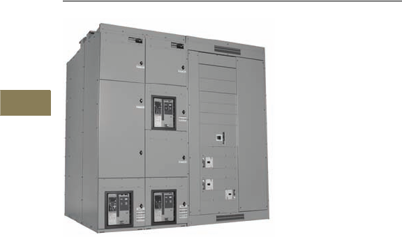
V3-T4-2 Volume 3—Power Distribution and Control Assemblies CA08100004E—February 2012 www.eaton.com
4
4
4
4
4
4
4
4
4
4
4
4
4
4
4
4
4
4
4
4
4
4
4
4
4
4
4
4
4
4
4.1
Low Voltage Switchgear
Magnum DS Metal-Enclosed
Magnum DS Switchgear with Molded Case Circuit Breaker Feeder Section
Contents
Description Page
Magnum DS Metal-Enclosed
Features—Bus . . . . . . . . . . . . . . . . . . . . . . . . . V3-T4-3
Features—Wiring . . . . . . . . . . . . . . . . . . . . . . . V3-T4-3
Features—Breaker . . . . . . . . . . . . . . . . . . . . . . V3-T4-4
Magnum DS Switchgear—Trip Units . . . . . . . . V3-T4-5
Options . . . . . . . . . . . . . . . . . . . . . . . . . . . . . . . V3-T4-5
Standards and Certifications . . . . . . . . . . . . . . . V3-T4-5
Product Selection . . . . . . . . . . . . . . . . . . . . . . . V3-T4-5
Technical Data and Specifications . . . . . . . . . . . V3-T4-6
Cross-Reference
Eaton’s Electrical Sector has
an organization dedicated to
the support of current and
vintage switchgear breakers
and parts that date as far back
as the 1950s. These include
the Magnum™ DS, DSII, DS
and DB families.
For more information,
refer to YES Catalog No.
CA08105000E or call
1-800-BKR-FAST (257-3278).
Available in NEMA® 3R
walk-in and non-walk-in
configurations.
Product Description
Eaton’s Magnum DS
Switchgear is backed by
50 years of power circuit
breaker and switchgear
development that have set
industry standards for quality,
reliability, maintainability and
extended operating life.
Magnum DS Switchgear is an
assembly of metal enclosures
housing power circuit
breakers, and normally
include control and
measuring devices such as
relays, instruments, meters
and the necessary power bus
work and control wiring for
AC systems applications up
to 600 volts.
Application Description
Switchgear is used in the
protection, controlling and
monitoring of low voltage
distribution systems. Although
used as “standalone”
distribution assemblies, they
are quite often incorporated
into secondary unit
substations so that the
equipment can be located
more closely to the point of
power usage. Magnum DS
Switchgear is ideally suited
to applications calling for
all types of industrial,
commercial and utility users
having distribution systems
rated 600 volts or below,
200,000 amperes or below
bus bracing, and 10,000
amperes or below
continuous loads.
Features, Benefits
and Functions
Standard Finish—The light
gray paint finish (ANSI 61)
uses a modern, completely
automated and continuously
monitored electrostatic
powder coating. This
continuously monitored
system includes spray
de-grease and clean, spray
rinse, iron phosphate spray
coating spray rinse, non-
chemical seal, oven drying,
electrostatic powder spray
paint coating and oven curing.
Integral Base—The rugged
formed base greatly increases
the rigidity of the structure
and reduces the possibility
of damage during the
installation of the equipment
and is suitable for rolling,
jacking and handling. A lifting
angle is permanently welded
into the bus compartment
structure for increased
strength.
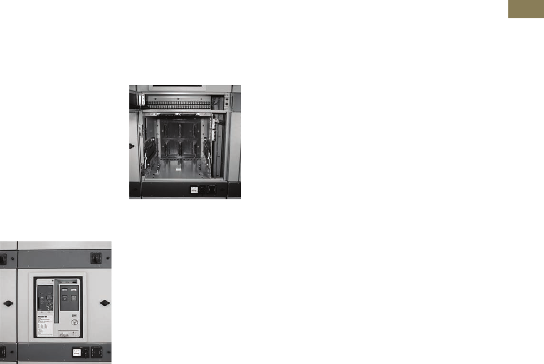
Volume 3—Power Distribution and Control Assemblies CA08100004E—February 2012 www.eaton.com V3-T4-3
4
4
4
4
4
4
4
4
4
4
4
4
4
4
4
4
4
4
4
4
4
4
4
4
4
4
4
4
4
4
4.1
Low Voltage Switchgear
Magnum DS Metal-Enclosed
Heavy-Duty Door Hinges—
Each breaker door is mounted
with hinge pins. Removal of
the door is easily
accomplished by just lifting
the hinge pin. This allows
easy access to the breaker
internal compartment for
inspection and maintenance.
Rear Cover/Doors—
In Magnum DS Switchgear,
standard rear covers with
captive hardware are the
bolt-on type. They are split
into two sections to facilitate
handling during removal and
installation. Optional rear
doors are also available.
Through-the-Door Design—
The following functions may
be performed without the
need to open the circuit
breaker door: levering the
breaker between positions,
operate manual charging
system and view the spring
charge status flag, close
and open breaker, view and
adjust trip unit, and read the
breaker rating nameplate.
Through-the-Door Design
Front Accessible—When
the door is open or removed,
each breaker compartment
provides front access to
isolated, vertical wireways,
primary disconnects, cell
current transformers and
other breaker compartment
accessories for ease of field
wiring and troubleshooting
field connections.
Four-Position Drawout—
Breakers can be in connected,
test, disconnected or
removed position. The
breaker compartment
door can be closed in
the connected, test and
disconnected positions.
Closing Spring Automatic
Discharge—Mechanical
interlocking automatically
discharges the closing springs
when the breaker is removed
from its compartment.
Breaker Cell
Breaker Inspection—
When withdrawn on the
rails, breaker is completely
accessible for visual
inspection; tilting is not
necessary. The rails are
permanent parts of every
breaker compartment.
Interference interlocks are
supplied on breakers and
in compartments where the
compartments are of the
same physical size to ensure
that an incorrect breaker
cannot be inserted.
Features—Bus
Buses and Connections—
Vertical and cross bus ratings
in Magnum DS Switchgear
are based on a UL® and ANSI
standard temperature rise
of 65°C above a maximum
ambient air temperature
of 40°C.
Bus Ampacities—Vertical
and cross bus ratings in
Magnum DS are 2000,
3200, 4000, 5000 and
6000 amperes. In addition,
8000 and 10,000 amperes
continuous cross bus ratings
are also available.
Bus Bracing—Unique
vertical bus configuration
provides an optional short-
circuit withstand rating of
150,000 amperes without the
need for preceding current
limiting fuses. Standard
bracing is 100,000 amperes.
The U-shaped bar is the heart
of the Magnum DS vertical
bus. This configuration
provides a much higher
mechanical strength. To
further demonstrate the
strength and rigidity of this
bus system, it has been
verified through testing to
withstand 85,000 amperes
short-circuit for a full
60 cycles.
Silver Plating—Bolted,
silver-plated copper main
buses are standard. The
plating is over the entire
length of the bar, not just at
the joints. Optional tin-plated
copper buses are available.
Bus Joints—All joints are
bolted and secured with
Belleville-type spring washers
for maximum joint integrity.
These washers reduce the
potential of joint hardware
loosening during the
change of joint temperature
associated with variations
of the loads. As an option,
maintenance-free hardware
can be provided.
Full Neutral—For four-wire
applications, the neutral bus
is rated 100% of main bus
rating as standard.
Ground—A ground bus is
furnished for the full length of
the switchgear assembly and
is fitted with terminals for
purchaser’s connections.
Glass-Reinforced Polyester
Stand-Off Insulation
System—Glass-reinforced
polyester has been used on
both low and medium voltage
switchgear for decades.
By combining this industry-
proven material with our
other insulation materials,
a total system providing
exceptional mechanical and
dielectric withstand strength,
as well as high resistance to
heat, flame and moisture, is
produced. Substantial testing
to demonstrate accelerated
effects of heating and cooling
on the mechanical and
dielectric properties of this
system prove it to provide
superior performance for
decades of trouble-free
operation.
Features—Wiring
Cable Compartment—
The cable compartment gives
ample room for terminating
the power cables. Removable
top roof sheets allow for easy
conduit hub installation. The
floor of the cable compartment
is open to allow cable entry
from underground duct
banks. Optional floor plates
are available.
Lug Pad—The lugs are
located on the breaker run-
backs to accommodate lug
orientations at a 45° angle
to reduce the bending radius
of the cable needed for
making the connections,
thus reducing installation
and maintenance time.
Mechanical setscrew
type lugs are standard.
Optional NEMA two-hole
compression lugs are
available as an option.
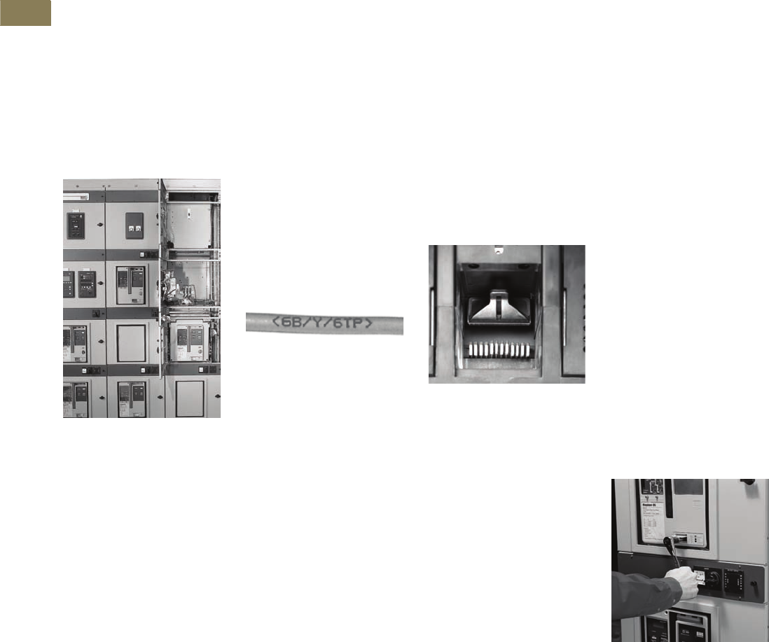
V3-T4-4 Volume 3—Power Distribution and Control Assemblies CA08100004E—February 2012 www.eaton.com
4
4
4
4
4
4
4
4
4
4
4
4
4
4
4
4
4
4
4
4
4
4
4
4
4
4
4
4
4
4
4.1
Low Voltage Switchgear
Magnum DS Metal-Enclosed
Control Wireway—
An isolated vertical wireway
is provided for routing of
factory and field wiring in
each switchgear section.
Breaker secondary terminal
blocks are mounted as
standard above each circuit
breaker. The terminal blocks
are rated 30 amperes and
will accept bare wire, ring
or spade terminals for wire
size ranges of #22 to #10.
Extruded loops are punched
in side sheets of the vertical
wireway to allow securing
of customer control wiring
without the use of adhesive
wire anchors.
Control Wireway
Control Wire—Standard
wire is Type SIS insulated
stranded copper, extra
flexible No. 14 AWG
minimum.
Control Wire Marking—
Each wire is imprinted with
ink cured under ultraviolet
light for durability and for
easy identification by the
user. The enhanced solvent
resistance and durability
of the aerospace-grade UV
cure ink has been tested
for severe environments.
The imprinting is made
periodically along the length
of the wire, with the ends
being imprinted more
frequently. The point of
origin, wire designation
and point of destination are
imprinted in the following
format: <origin zone/wire
name/destination zone>.
Each device has a uniquely
designated zone. “<”
indicates the direction of
the wire origination and “>”
indicates the direction of
the wire destination. As an
option, wire marking can be
made using sleeve type or
heat shrink sleeve type.
Control Wire Marking
Secondary Terminal
Compartment Door—
The customer’s secondary
terminal connections are
located behind a separate
door providing access to
these connections without
the need to open the breaker
compartment door.
Shipping Split Connection—
At each shipping split, the
control connections are made
with plug-in terminal blocks
rated 600 volts, 40 amperes.
The terminal blocks interlock
mechanically without
removing the line or load
connections. This method
of making the shipping split
control connections increases
the speed of installation and
reduces the potential of
incorrect connections.
Features—Breaker
Contacts—The Magnum DS
has silver tungsten moving
contacts and silver graphite
stationary contacts. The
contacts provide a long-
wearing, low-resistance joint.
The contacts are protected
from arcing damage even
after repeated interruptions
by the “heel-toe” action that
causes the integral arcing
contacts to mate before the
main contacts part. The
arcing contacts then part last,
striking the arc away from
the main contacts.
The main contacts are of the
butt type and are composed
of a multiplicity of fingers to
give many points of contact
without alignment being
critical.
Magnum DS Breaker Contacts
(Arc Chutes Removed)
Stored-Energy Mechanism—
A cam-type closing mechanism
closes the breaker. It receives
its energy from a spring that
can be charged by a manual
handle on the front of the
breaker or by a universal
electric motor.
Release of the stored energy
is accomplished by manually
depressing a button on
the front of the breaker or
electrically energizing a
releasing solenoid.
Arc Chute—There are three
basic means of extinguishing
an arc: lengthening the arc
path; cooling by gas blast or
contraction; and deionizing or
physically removing the
conduction particles from
the arc path.
The DE-ION® principle is
incorporated in all Magnum
DS circuit breakers. This
makes possible faster arc
extinction for a given contact
travel, and ensures positive
interruption and minimum
contact burning.
Levering Mechanism—
The worm gear levering
mechanism is self-contained
on the breaker drawout
element and engages slots
in the breaker compartment.
A removable crank is used to
lever the breaker between
the connected, test and
disconnected positions.
Mechanical interlocking is
arranged so that levering
cannot be accomplished
unless the breaker is in
the opened position.
Protection During Levering
Operation—When levering
the breaker between
the connected, test and
disconnected positions, the
operator is protected from
contact with live parts by
the breaker door.
Levering Magnum DS Breaker
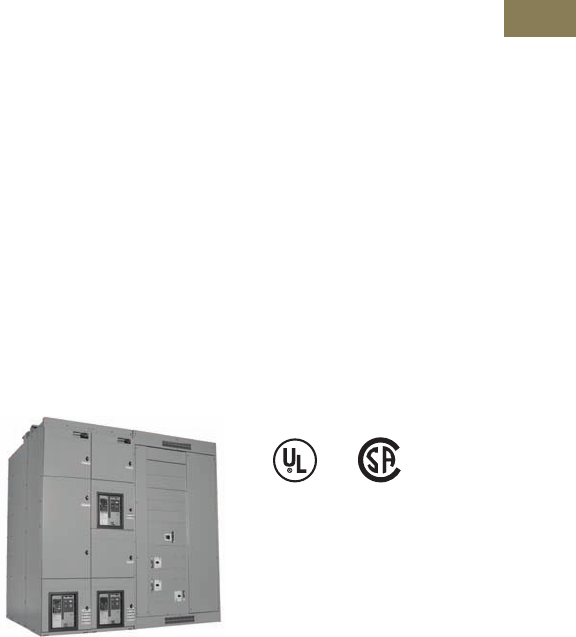
Volume 3—Power Distribution and Control Assemblies CA08100004E—February 2012 www.eaton.com V3-T4-5
4
4
4
4
4
4
4
4
4
4
4
4
4
4
4
4
4
4
4
4
4
4
4
4
4
4
4
4
4
4
4.1
Low Voltage Switchgear
Magnum DS Metal-Enclosed
True Two-Step Stored
Energy Closing—
This sequence is required to
charge and close the breaker.
The breaker closing springs
are charged either through
the manual-charging handle
or by the optional charging
motor. The breaker is
mechanically interlocked to
prevent closing of the breaker
until the closing springs are
fully charged.
With the closing springs fully
charged, the breaker can then
be closed by pressing the
manual close pushbutton on
the breaker, or by the optional
spring release coil through a
remote electrical signal.
This means that the energy
required to open the breaker
is always prestored following
a closing operation.
“Stored energy” is energy
held in waiting, ready to open
or close the breaker within
five cycles or less. The
unique cam and spring design
provides necessary energy
for a single close-open
sequence, as well as the
energy for multiple charge-
close operations such as
this possible sequence:
charge-close-recharge-open-
close-open.
The closing springs are
interlocked with the breaker
racking mechanism to ensure
that the closing springs
are discharged before the
breaker can be removed
from the compartment.
Manually Operated
Breakers—Manually operated
breakers are equipped with a
manual charging handle to
charge the closing springs.
Manual closing and tripping
pushbuttons are utilized to
operate the breaker. Remote
closing and tripping can be
accomplished by installing
optional electric spring
release and shunt trip coils.
The breaker closing springs
must be charged manually,
then remote closing and
tripping signals can be sent
to the breaker.
Electrically Operated
Breakers—Electrically
operated breakers are
equipped with a spring
charging motor and
electrically operated spring
release and shunt trip coils.
The breaker manual charging
handle can be used to charge
the closing springs when
power is not available to the
charging motor.
Provisions for Padlocking—
All breakers include provision
for padlocking open to
prevent electrical or manual
closing. This padlocking
can secure the breaker
in the connected, test or
disconnected position
by preventing levering of
the breaker.
Ease of Inspection and
Maintenance—Magnum DS
breakers are designed for
maximum accessibility and
the utmost ease of inspection
and maintenance.
Magnum DS Switchgear—
Trip Units
Digitrip® RMS Trip Unit—
The Digitrip RMS trip units
feature a dependent curve
that is depicted in the
nameplate by a blue shaded
area of the trip curve. The
dependent curve affords
better protection flexibility.
Additionally, all of the trip
units have, as standard,
thermal memory, 50/60 Hz
operation and thermal
self-protection at 90°C.
Digitrip RMS Integral
Microprocessor-Based
Breaker Overcurrent Trip
Systems—These systems
provide maximum reliability
with true rms sensing as
standard, gives excellent
repeatability, and requires
minimum maintenance.
No external control source
is required for its protective
functions.
Trip Functions—Magnum
DS trip units provide the
maximum in flexibility and
are available in the following
configurations: LSI, LSIG
and LSIA (ground fault alarm
only). In each case, either
the short delay or the
instantaneous function (not
both) may be defeated. This
reduces the need for spare
breaker inventories and
provides maximum utilization
of interchangeable breakers.
Options
Special Designs
The Magnum DS design
allows Eaton to provide
special solutions to meet
our customer’s needs. For
example, as shown below,
here we embedded molded
case circuit breakers into a
switchgear lineup for a
customer.
Magnum DS Switchgear with Molded
Case Circuit Breaker Feeder Section
Refer to TD01901001E for
application data.
Standards and
Certifications
Magnum DS Switchgear
assemblies have undergone
an extensive seismic
qualification program. The
test program utilized ANSI
standard C37.81, the Uniform
Building Code® (UBC) and
the California Building Code
(CBC) as a basis for the test
program. The assemblies
have been tested and
qualified to exceed these
requirements.
Magnum DS Switchgear
conforms to the following
standards: CSA®, ANSI
C37.20.1, C37.51, and UL
Standard 1558, and is built
in an ISO® certified facility.
American Bureau of Shipping
(ABS) certification is also
available.
Contact Eaton for details
and part numbers for
CSA-approved units.
Product Selection
Refer to TD01901001E
for application data.
Contact Eaton for
configurations, pricing
and availability.

V3-T4-6 Volume 3—Power Distribution and Control Assemblies CA08100004E—February 2012 www.eaton.com
4
4
4
4
4
4
4
4
4
4
4
4
4
4
4
4
4
4
4
4
4
4
4
4
4
4
4
4
4
4
4.1
Low Voltage Switchgear
Magnum DS Metal-Enclosed
Technical Data and Specifications
Product Specifications
Refer to Section 16426A of the
Product Specification Guide.
Available Bus Ratings
Vertical section bus is sized
per main cross bus maximum
rating or by ANSI C37.20.1
Section 7.4.13 Table 11 to a
maximum of 5000 amperes.
Note: In addition to the available
bus bracings shown above, the
bus has been tested for short-
circuit values of 85,000 amperes
for a full 60 cycles.
Ratings of Magnum DS Breakers
Note
1200 kA available; contact Eaton.
Cross Bus
Ampacity
Bus Bracing
kA
Vertical Bus
Ampacity
2000 100, 150, 200 2000
3200 100, 150, 200 3200
4000 100, 150, 200 4000
5000 100, 150, 200 5000
6000 100, 150, 200 —
8000 100, 150, 200 —
10,000 100, 150, 200 —
Ratings, rms Symmetrical Amperes
Interrupting Rating 1Short-Time Rating
Breaker Type Frame Amperes 208–240 Volts 480 Volts 600 Volts 208–240 Volts 480 Volts 600 Volts
MDS-408 800 42,000 42,000 42,000 42,000 42,000 42,000
MDS-608 800 65,000 65,000 65,000 65,000 65,000 65,000
MDS-808 800 85,000 85,000 85,000 85,000 85,000 85,000
MDS-C08 800 100,000 100,000 100,000 85,000 85,000 85,000
MDS-616 1600 65,000 65,000 65,000 65,000 65,000 65,000
MDS-816 1600 85,000 85,000 85,000 85,000 85,000 85,000
MDS-C16 1600 100,000 100,000 100,000 85,000 85,000 85,000
MDS-620 2000 65,000 65,000 65,000 65,000 65,000 65,000
MDS-820 2000 85,000 85,000 85,000 85,000 85,000 85,000
MDS-C20 2000 100,000 100,000 100,000 85,000 85,000 85,000
MDS-632 3200 65,000 65,000 65,000 65,000 65,000 65,000
MDS-832 3200 85,000 85,000 85,000 85,000 85,000 85,000
MDS-C32 3200 100,000 100,000 100,000 85,000 85,000 85,000
MDS-840 4000 85,000 85,000 85,000 85,000 85,000 85,000
MDS-C40 4000 100,000 100,000 100,000 100,000 100,000 100,000
MDS-850 5000 85,000 85,000 85,000 85,000 85,000 85,000
MDS-C50 5000 100,000 100,000 100,000 100,000 100,000 100,000
MDS-860 6000 85,000 85,000 85,000 85,000 85,000 85,000
MDS-C60 6000 100,000 100,000 100,000 100,000 100,000 100,000

Volume 3—Power Distribution and Control Assemblies CA08100004E—February 2012 www.eaton.com V3-T4-7
4
4
4
4
4
4
4
4
4
4
4
4
4
4
4
4
4
4
4
4
4
4
4
4
4
4
4
4
4
4
4.2
Low Voltage Switchgear
Primary and Secondary Unit Substations
MVS Primary Switch and Low Voltage Metal-Enclosed Switchgear
Contents
Description Page
Primary and Secondary Unit Substations
Standards and Certifications . . . . . . . . . . . . . . . V3-T4-8
Product Selection . . . . . . . . . . . . . . . . . . . . . . . V3-T4-8
Technical Data and Specifications . . . . . . . . . . . V3-T4-8
Product Description
Unit Substations
Most switchgear assemblies
are configured as unit
substations.
A unit substation, as referred
to in this publication, is
defined as a coordinated
assembly consisting of
three-phase transformers
with high-voltage incoming
line sections and an assembly
of low voltage distribution
sections.
Liquid-Filled Transformers
●Mineral oil
●FR3
●BIOTEMP®
●Silicon
Dry-Type Transformers
●VPI
●VPE
●RESIBLOC®
●Cast coil
Secondary Unit Substations
●Liquid-filled or dry-type
transformer
●Transformer kVA 112.5
through 3750
●Low voltage—208, 240,
480 or 600V
Primary Unit Substations
●Liquid-filled or dry-type
transformer
●Transformer kVA 500
through 20 MVA
●
Low voltage—2400V
through 24.5 kV
Unit substations may be
indoor or outdoor, with a
selection of high voltage
incoming sections, a choice
of transformer types and an
arrangement of switchgear to
suit the application.
Eaton’s unit substations
follow the system concept
of locating transformers as
close as practicable to areas of
load concentration at usage
voltages, thus minimizing
the lengths of secondary
distribution cables and buses.
This concept provides several
basic advantages, such as:
●Reduced power losses
●Improved voltage
regulation
●Improved service
continuity
●Reduced likelihood of
faults
●Increased flexibility
●Minimized installation
expense
●Elimination of the need for
vaults due to availability of
non-flammable types of
transformers
●Efficient space utilization
Application Description
Advantages of Unit Substations
●Complete coordination,
both mechanical and
electrical
●Extreme flexibility with wide
choice of components and
ratings to meet exact
application requirements
●Optimum safety to
operators
●Modern design
●Meets all applicable ANSI,
IEEE®, NEMA and UL
standards
Features, Benefits
and Functions
Refer to TD.49A.01.T.E for
primary unit substations and
TD.49A.02.T.E for secondary
unit substations.
Options
Refer to TD.49A.01.T.E for
primary unit substations and
TD.49A.02.T.E for secondary
unit substations.

V3-T4-8 Volume 3—Power Distribution and Control Assemblies CA08100004E—February 2012 www.eaton.com
4
4
4
4
4
4
4
4
4
4
4
4
4
4
4
4
4
4
4
4
4
4
4
4
4
4
4
4
4
4
4.2
Low Voltage Switchgear
Primary and Secondary Unit Substations
Standards and
Certifications
Refer to TD.49A.01.T.E for
primary unit substations and
TD.49A.02.T.E for secondary
unit substations.
Contact Eaton for details
and part numbers for
CSA-approved units.
Product Selection
Unit substations are
engineered to order and
have multiple configurations.
Contact Eaton for
configurations, pricing
and availability.
Technical Data
and Specifications
Refer to TD.49A.01.T.E for
primary unit substations and
TD.49A.02.T.E for secondary
unit substations.
Product Specifications
Refer to Section 16312 of the
Product Specification Guide
for primary unit substations
and Section 16311 of
the Product Specification
Guide for secondary unit
substations.

Volume 3—Power Distribution and Control Assemblies CA08100004E—February 2012 www.eaton.com V3-T5-1
5
5
5
5
5
5
5
5
5
5
5
5
5
5
5
5
5
5
5
5
5
5
5
5
5
5
5
5
5
5
Medium Voltage Motor
Control
Assemblies
Arc Resistant AMPGARD
5.1 AMPGARD Motor Control
Product Description . . . . . . . . . . . . . . . . . . . . . . . . . . . . . . . . . . . . . . . V3-T5-2
Application Description. . . . . . . . . . . . . . . . . . . . . . . . . . . . . . . . . . . . . V3-T5-2
Features, Benefits and Functions . . . . . . . . . . . . . . . . . . . . . . . . . . . . . V3-T5-3
Standards and Certifications. . . . . . . . . . . . . . . . . . . . . . . . . . . . . . . . . V3-T5-4
Product Selection . . . . . . . . . . . . . . . . . . . . . . . . . . . . . . . . . . . . . . . . . V3-T5-5
Technical Data and Specifications. . . . . . . . . . . . . . . . . . . . . . . . . . . . . V3-T5-6
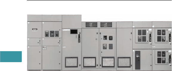
V3-T5-2 Volume 3—Power Distribution and Control Assemblies CA08100004E—February 2012 www.eaton.com
5
5
5
5
5
5
5
5
5
5
5
5
5
5
5
5
5
5
5
5
5
5
5
5
5
5
5
5
5
5
5.1
Medium Voltage Motor Control Assemblies
AMPGARD Motor Control
AMPGARD Motor Control Assembly with Main Breaker, SC 9000 AFD,
RVSS and Two-High FVNR
Contents
Description Page
Features, Benefits and Functions. . . . . . . . . . . . . . V3-T5-3
Standards and Certifications . . . . . . . . . . . . . . . . . V3-T5-4
Product Selection . . . . . . . . . . . . . . . . . . . . . . . . . . V3-T5-5
Technical Data and Specifications . . . . . . . . . . . . . V3-T5-6
Product Description
Eaton’s AMPGARD® medium
voltage starter family provides
flexibility never before
available. Rated at 2200–
15,000 volts up to 8000 hp,
they are the first starters
designed as integrated,
complete units precisely
matched to motor ratings,
and engineered to provide
component-to-component
circuitry and front accessi-
bility of all components
and terminals. AMPGARD
starters are used in a variety of
industrial process applications,
such as pulp and paper,
petrochemical, HVAC (chillers),
where proper control and
protection of the motor and
system are critical to the
user. AMPGARD has been
the industry leader in medium
voltage motor control for over
60 years in these applications,
and our starters
have been
designed with that experience
behind them.
Application Description
AMPGARD starters are
equipped with current limiting
power fuses to interrupt the
short-circuit faults shown
below. The contactor and
fuses are completely
coordinated.
Squirrel Cage Motor Starters:
Starters for squirrel cage
motors are available in full or
reduced voltage designs in all
ratings. Full voltage starters
are available one-high or two-
high in a factory-assembled
structure. Electromechanical
reduced voltage starters are
available in either reactor or
autotransformer type. Both
provide closed transition
from reduced to full voltage.
See table on Page V3-T5-6
for application data.
SC 9000 Adjustable Frequency Drive (AFD)
This newest member of
the AMPGARD family was
designed for maximum
flexibility in the control of
medium voltage motors.
The SC 9000™ combines
innovative technology with
the reliable design and
construction the industry
has come to expect of the
AMPGARD products. Rated
at 2400 volts up to 2500 hp
and 4160 volts up to 4500 hp,
the SC 9000 delivers the
smallest footprint in the
industry. The standard
24-pulse phase shifting
isolating transformer and
rectifier minimizes any
harmonic noise sent back
on to the supply.
The SC 9000 is a fully
integrated, three-line-in—
three-line-out, plug-and-play
product that includes highly
reliable AMPGARD medium
voltage components on
the input (isolation switch,
power fuses and SL vacuum
contactor), isolating
transformer, rectifier, inverter
and controls. The SC 9000
uses the same keypad and
programming software as the
Eaton SVX9000 line of low
voltage drives for a reliable,
easy-to-use system that
does not require time spent
in learning new software.
In addition, the SC 9000
can interface with many
control systems, such
as Modbus®, Ethernet,
DeviceNet™, CANbus®
and PROFIBUS® DP.
In an industry first, the
SC 9000 can be placed in a
lineup with other AMPGARD
and Eaton motor control
products on a common bus
known as AMPGARD
Medium Voltage Integrated
Control Gear. Now, all types
of motor starters, load break
switches, integrated AFDs,
AFD synchronous transfer
control, AFD bypasses, and
main and feeder breakers can
be integrated into a single line.
The Integrated Control Gear
capabilities and reliable
design make the SC 9000
the perfect choice for speed
control in industries such as
petrochemical, water/waste
water, utility, HVAC, pulp and
paper, and many more.

Volume 3—Power Distribution and Control Assemblies CA08100004E—February 2012 www.eaton.com V3-T5-3
5
5
5
5
5
5
5
5
5
5
5
5
5
5
5
5
5
5
5
5
5
5
5
5
5
5
5
5
5
5
5.1
Medium Voltage Motor Control Assemblies
AMPGARD Motor Control
Reduced Voltage Solid-State
Starters: Offered as an
alternative to traditional
reactor or auto-transformer
type reduced voltage starter,
the AMPGARD RVSS allows
the user to fine-tune starting
parameters to meet a wide
variety of unique load
conditions. The onboard
user-friendly microprocessor
provides the ability to select
the proper combination of
initial current, maximum
current and ramp time,
resulting in smooth, stepless
load acceleration while
minimizing mechanical shock
to system components.
The AMPGARD RVSS is
available as a standalone
starter or can be incorporated
into a lineup with other
AMPGARD starters. Adding
to an existing AMPGARD
installation is easy via a
simple splice kit. Starters are
available in 400 ampere and
720 ampere frame sizes.
Arc-Resistant AMPGARD:
When specified, AMPGARD
is available in special arc-
resistant construction. Two
ratings are available: 30 kA
and 50 kA. Both designs have
been tested and verified to
meet the requirements of
IEEE® C37.20.7 for Type 2B
construction. Type 2B
construction is defined as
arc-resistant at front, back
and sides of the enclosure
with the low voltage
compartment door open.
All types of 400 ampere and
800 ampere starters, as well
as 24-inch wide incoming
cable sections are available
in arc-resistant construction.
Main Breaker AMPGARD,
SC 9000 AFD, LBS Load
Break Switches are not
available in arc-resistant
construction. Consult Eaton
for more details.
Main Breaker AMPGARD
(MBA): The MBA is the
industry’s first truly
integrated medium voltage
metal-enclosed main breaker
and starter assembly
combination.
The MBA comprises a metal-
enclosed drawout vacuum
circuit breaker section that is
integrally connected via main
bus to the balance of the
AMPGARD starter assembly
it protects.
The main bus configuration
is in the same top-mounted
location as on all AMPGARD
assemblies, allowing for ease
of installation with adjacent
sections and addition for
future sections.
Front aligned, rear aligned,
or front and rear aligned with
back-to-back starters are
available.
The main breaker is the
industry-leading Type VCP-W
drawout vacuum circuit
breaker, which provides the
performance our customers
expect.
Lead-time is dramatically
reduced, typically 50% less
than the industry norm.
Our single-source approach
has cut delivery time from
months to weeks. The
extended waiting period
between order placement
and delivery has been
eliminated.
Other Motor Starters:
Starters for wound rotor
and multispeed motors are
available. However, each
application must be reviewed
for proper motor protection
and operation. Refer to
the
factory for pricing and
equipment details.
Features, Benefits
and Functions
Personnel Safety: A positive
mechanical isolating switch
with visible disconnect
completely grounds and
isolates the starter from
the line connectors with a
mechanically driven isolating
shutter, leaving no exposed
high voltage. Additional
safety features include:
●Isolated cable entry for
added safety. The starters
and cables are completely
isolated from each other
by steel barriers
●All new low voltage
wireway. Low voltage
wire is isolated from
the medium voltage
compartment, and
customer terminal blocks
are accessible through the
low voltage control panel
●Easily accessible low
voltage panel completely
isolated from the medium
voltage compartment that
offers generous device
mounting space
●Standard viewing window
for visual verification of
isolation switch operation
●Optional remote operator
for isolation switch allows
user to open and close
switch while remaining
outside the equipment
flash boundary
Ease of Installation: Current
limiting fuses, contactor
assembly and isolating switch
assembly are easily removed
from the enclosure; line and
load terminals are completely
accessible from the front.
Standard structures are 36.00
W x 92.00 H x 30.00 in D
(914.4 W x 2336.8 H x 762.0
mm D) including a 12.00 in
(304.8 mm) top-mounted
main bus compartment. The
main bus compartment is
top, side and front accessible,
making maintenance and
lineup extensions easy.
Ease of Maintenance:
All components are front
accessible, facilitating
routine inspection or parts
replacement. Isolation switch
life is 10,000 operations.
Vacuum Contactor:
The Type SL vacuum
contactors were designed
and engineered specifically for
use in AMPGARD starters.
They are self-supporting,
compact, bolt-in or stab-in
three-pole contactors. The
contactors utilize a solid-state
control board, allowing the
user maximum flexibility to
change control voltages and
dropout times in the field,
simply by adjusting DIP
switch settings. To permit
application matching of the
starter to the motor rating,
contactors are available for
2200–7200 volts at ratings
of 400 and 800 amperes,
and 15 kV at 250 amperes.
The 400 ampere contactor
interrupting rating is the
highest in the industry at
8500 amperes, allowing for
higher levels of coordination
with power fuses. The
800 ampere contactor has
an interrupting rating of
12,500 amperes,
also the
highest in the industry.
Note: For full starter/contactor
horsepower ratings and other
technical data (including power
fuse coordination), refer to Tab 13,
Medium Voltage Power
Contactors.
Motor Protective Relay:
When a motor protective
relay is required, the
AMPGARD starters are
provided with the MP-3000
or MP-4000 microprocessor-
based motor protective relay
as standard. This package
offers benefits like a 20-cycle
voltage sag ride-through,
UL 1053 certification for
ground fault sensing that is
internal to the relay, arm/
disarm capability, a drawout
case option, Intel-I-Trip
overload protection for
custom curve setting to
precisely match your motor’s
requirements, and optional
PowerNet™ or Modbus
communications capability.
15 kV Starter: A 15 kV rated
AMPGARD starter is available
with the same features and
capabilities as described
for the 7.2 kV rated starter.
The starter is supplied with
a 250 ampere vacuum
contactor and three power
fuses (maximum 250E)
for motors rated to 5000
horsepower. These starters
may be supplied with the
Eaton InsulGard™ relay for
partial discharge detection.
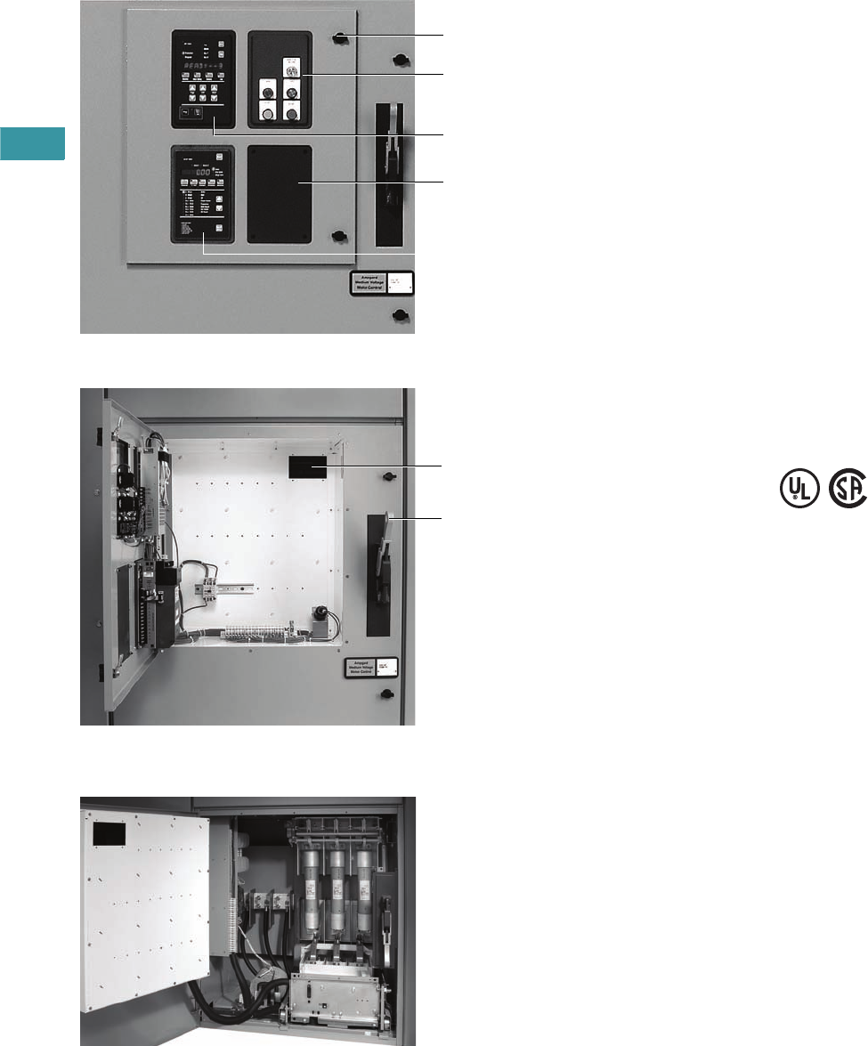
V3-T5-4 Volume 3—Power Distribution and Control Assemblies CA08100004E—February 2012 www.eaton.com
5
5
5
5
5
5
5
5
5
5
5
5
5
5
5
5
5
5
5
5
5
5
5
5
5
5
5
5
5
5
5.1
Medium Voltage Motor Control Assemblies
AMPGARD Motor Control
Low Voltage and High Voltage Compartments
Isolated Low Voltage Control Panel
Optional Stab-In Contactor, Bolted Main Fuses
and Optional Blown Fuse Indicator
MP-3000
(when specified)
1/4-Turn Door Latch
Top a n d B o t t o m
Low Voltage
Access Door
DP-4000 Meter
(when specified)
Indicating Lights Start/Stop Pushbutton
(when specified)
Note: Isolation Switch Mechanism
Locks Medium Voltage Door
Closed in ON Position
Isolation Switch
Viewing Window
Standards and
Certifications
UL and CSA Certification
AMPGARD starters are
designed, assembled and
tested to meet all applicable
standards. AMPGARD meets
ANSI, NEMA® and IEC
standards, and is UL, CSA,
cUL® and KEMA third-party
certified. The major
components, i.e., contactor,
isolating switch, fuses,
MP-3000, MP-4000,
IQ DP-4000 and IQ Analyzer,
are UL recognized.
UL or CSA labeling of a
specific starter requires
review to ensure that all
requested modifications and
auxiliary devices meet the
appropriate standards. Refer
to factory when specified.
Contact Eaton for details
and part numbers for
CSA-approved units.
Seismic Certification
AMPGARD starters are
seismically tested and
seismically qualified, and
exceed requirements of both
the International Building
Code (IBC) and California
Building Code Title 24.
Reference Information
●AMPGARD Brochure
BR02003002E
●AMPGARD RVSS Brochure
BR02003001E
●Technical Data
TD02003001E
●Renewal Parts
RP.48J.01.T.E
●AMPGARD Main Breaker
PA4 8D 01S E
●15 kV AMPGARD
Technical Data
TD02003002E
●Remote Operator
PA02003002E
●Arc-Resistant AMPGARD
SA02003003E
●720A RVSS
PA02000001E

Volume 3—Power Distribution and Control Assemblies CA08100004E—February 2012 www.eaton.com V3-T5-5
5
5
5
5
5
5
5
5
5
5
5
5
5
5
5
5
5
5
5
5
5
5
5
5
5
5
5
5
5
5
5.1
Medium Voltage Motor Control Assemblies
AMPGARD Motor Control
Product Selection
AMPGARD RVSS
Main Breaker AMPGARD
15 kV Starter
Description
Catalog
Number
400 ampere RVSS SP10B4B
720 ampere RVSS SP10B8S
Description
Catalog
Number
1200A, 250 MVA Main Breaker BLR12
2000A, 350 MVA Main Breaker BLR23
3000A, 350 MVA Main Breaker BLR33
Description
Catalog
Number
13.8 kV FVNR Starter S210B2SBB
13.8 kV Autotransformer Starter S610B2SBB
AMPGARD RVSS
Main Breaker
AMPGARD
15 kV Starter with
InsulGard

V3-T5-6 Volume 3—Power Distribution and Control Assemblies CA08100004E—February 2012 www.eaton.com
5
5
5
5
5
5
5
5
5
5
5
5
5
5
5
5
5
5
5
5
5
5
5
5
5
5
5
5
5
5
5.1
Medium Voltage Motor Control Assemblies
AMPGARD Motor Control
Technical Data and Specifications
Main Breaker AMPGARD
Starting Characteristics
Interrupting Capacity—kVA
Note
1Factory set on 65% tap.
Ratings
Description Amperes Volts Horsepower
Main breaker 1200, 2000 and 3000 2200 to 7200 —
Starters 400 and 800 2200 to 7200 Up to 8000
Starters 250 10,000–15,000 Up to 5000
Starter
Type
% Motor
Voltage
% Motor
Current
% Line
Current % Torque
Reactor Reduced Voltage
80% tap 80808064
65% tap ➀65 65 65 42
50% tap 50505025
Autotransformer Reduced Voltage
80% tap 80806764
65% tap 165 65 45 42
50% tap 50502825
NEMA Class E2
Starter Maximum
Horsepower 2300 Volt 4600 Volt 6600 Volt
3000 200,000 — —
5000 1,190,000 — —
5500 — 400,000 —
8000 — — 570,000
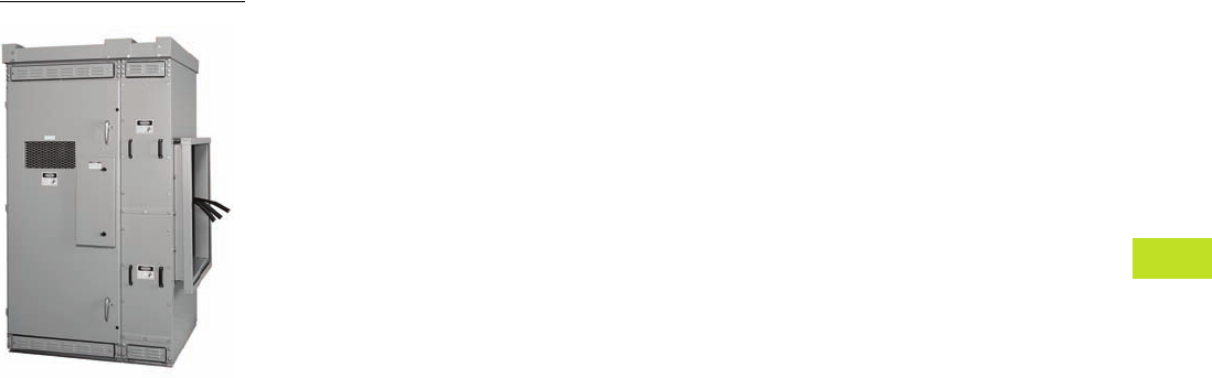
Volume 3—Power Distribution and Control Assemblies CA08100004E—February 2012 www.eaton.com V3-T6-1
6
6
6
6
6
6
6
6
6
6
6
6
6
6
6
6
6
6
6
6
6
6
6
6
6
6
6
6
6
6
Medium Voltage Metal-Enclosed Switches
Outdoor Medium Voltage Switch
6.1 Medium Voltage Switch—MVS
Product Description . . . . . . . . . . . . . . . . . . . . . . . . . . . . . . . . . . . . . . . V3-T6-2
Application Description . . . . . . . . . . . . . . . . . . . . . . . . . . . . . . . . . . . . V3-T6-2
Features, Benefits and Functions . . . . . . . . . . . . . . . . . . . . . . . . . . . . V3-T6-2
Standards and Certifications . . . . . . . . . . . . . . . . . . . . . . . . . . . . . . . . V3-T6-3
Reference Information . . . . . . . . . . . . . . . . . . . . . . . . . . . . . . . . . . . . . V3-T6-3
Product Selection . . . . . . . . . . . . . . . . . . . . . . . . . . . . . . . . . . . . . . . . . V3-T6-3
Technical Data and Specifications . . . . . . . . . . . . . . . . . . . . . . . . . . . . V3-T6-3
6.2 Medium Voltage Switch and Breaker—MSB
Product Description . . . . . . . . . . . . . . . . . . . . . . . . . . . . . . . . . . . . . . . V3-T6-4
Application Description . . . . . . . . . . . . . . . . . . . . . . . . . . . . . . . . . . . . V3-T6-4
Features, Benefits and Functions . . . . . . . . . . . . . . . . . . . . . . . . . . . . V3-T6-4
Standards and Certifications . . . . . . . . . . . . . . . . . . . . . . . . . . . . . . . . V3-T6-5
Reference Information . . . . . . . . . . . . . . . . . . . . . . . . . . . . . . . . . . . . . V3-T6-5
Product Selection . . . . . . . . . . . . . . . . . . . . . . . . . . . . . . . . . . . . . . . . . V3-T6-5
Technical Data and Specifications . . . . . . . . . . . . . . . . . . . . . . . . . . . . V3-T6-5
6.3 Metal-Enclosed Breaker—MEB
Product Description . . . . . . . . . . . . . . . . . . . . . . . . . . . . . . . . . . . . . . . V3-T6-6
Application Description . . . . . . . . . . . . . . . . . . . . . . . . . . . . . . . . . . . . V3-T6-6
Features, Benefits and Functions . . . . . . . . . . . . . . . . . . . . . . . . . . . . V3-T6-6
Standards and Certifications . . . . . . . . . . . . . . . . . . . . . . . . . . . . . . . . V3-T6-7
Reference Information . . . . . . . . . . . . . . . . . . . . . . . . . . . . . . . . . . . . . V3-T6-7
Product Selection . . . . . . . . . . . . . . . . . . . . . . . . . . . . . . . . . . . . . . . . . V3-T6-7
Technical Data and Specifications . . . . . . . . . . . . . . . . . . . . . . . . . . . . V3-T6-7
6.4 Unitized Power Centers—UPC
Product Description . . . . . . . . . . . . . . . . . . . . . . . . . . . . . . . . . . . . . . . V3-T6-8
Features, Benefits and Functions . . . . . . . . . . . . . . . . . . . . . . . . . . . . V3-T6-8
Standards and Certifications . . . . . . . . . . . . . . . . . . . . . . . . . . . . . . . . V3-T6-8
Reference Information . . . . . . . . . . . . . . . . . . . . . . . . . . . . . . . . . . . . . V3-T6-8
Product Selection . . . . . . . . . . . . . . . . . . . . . . . . . . . . . . . . . . . . . . . . . V3-T6-8
Technical Data and Specifications . . . . . . . . . . . . . . . . . . . . . . . . . . . . V3-T6-9
6.5 OEM Medium Voltage Switch Components—MVS-C
Product Description . . . . . . . . . . . . . . . . . . . . . . . . . . . . . . . . . . . . . . . V3-T6-10
Application Description . . . . . . . . . . . . . . . . . . . . . . . . . . . . . . . . . . . . V3-T6-10
Features, Benefits and Functions . . . . . . . . . . . . . . . . . . . . . . . . . . . . V3-T6-10
Standards and Certifications . . . . . . . . . . . . . . . . . . . . . . . . . . . . . . . . V3-T6-11
Reference Information . . . . . . . . . . . . . . . . . . . . . . . . . . . . . . . . . . . . . V3-T6-11
Product Selection . . . . . . . . . . . . . . . . . . . . . . . . . . . . . . . . . . . . . . . . . V3-T6-11
Technical Data and Specifications . . . . . . . . . . . . . . . . . . . . . . . . . . . . V3-T6-11

V3-T6-2 Volume 3—Power Distribution and Control Assemblies CA08100004E—February 2012 www.eaton.com
6
6
6
6
6
6
6
6
6
6
6
6
6
6
6
6
6
6
6
6
6
6
6
6
6
6
6
6
6
6
6.1
Medium Voltage Metal-Enclosed Switches
Medium Voltage Switch—MVS
Outdoor Medium Voltage Switch—MVS Cable Connection to
Liquid-Filled Transformer
Contents
Description Page
Medium Voltage Switch—MVS
Standards and Certifications . . . . . . . . . . . . . . V3-T6-3
Reference Information . . . . . . . . . . . . . . . . . . . V3-T6-3
Product Selection . . . . . . . . . . . . . . . . . . . . . . . V3-T6-3
Technical Data and Specifications . . . . . . . . . . V3-T6-3
An Eaton
Green Solution
Product Description
Eaton’s MVS load interrupter
switchgear is a metal-
enclosed assembly consisting
of a switch, bus and fuses.
MVS switchgear is available
in one or more vertical
section assemblies. The
three-pole switch will
interrupt its rated load current
with its quick-make, quick-
break mechanism. Optional
fuses ensure short-circuit
protection at all times.
Application Description
MVS switchgear provides
safe, reliable switching and
fault protection for medium
voltage circuits where high
duty cycle operation is
not needed.
●Single switch and
transformer primary
●Duplex switch
●Selector switch
●Automatic transfer control
Features, Benefits and Functions
Quick-make, quick-break
mechanism: A reliable heavy-
duty coil spring mechanism
drives the switch blades at
high speed into either the
open or the closed position.
The speed of operation is
independent of the person
operating the switch.
Direct drive mechanism:
A metal-to-metal direct drive
mechanism eliminates chains
or cables that may break or
need adjusting.
DE-ION® arc interruption:
DE-ION arc chambers and
spring-loaded auxiliary blades
ensure fast load current
interruption and eliminate
arcing damage to the
main contacts.
Positive switch position
indication: Red and green
multilingual (English/Spanish/
French) labels located directly
on the switch operating
mechanism give visual
indication of switch position.
Interlocked for safety:
Mechanical interlocks prevent
closing the switch when the
compartment door is open, or
the opening of the door when
the switch is closed.
Safety under fault
conditions: The switch,
depending upon the rated
voltage, is available with
three or four fault-closing
operations with ratings
up to 61,000 amperes rms
asymmetrical, exceeding
the industry standards one
time operation.
Safety barrier: A hinged
solid metal barrier with a
perforated metal viewing area
shields the disconnect switch
when the compartment door
is opened.
Short-circuit protection:
A full range of Eaton fusing
options is available for short-
circuit protection.
Eaton's SF6-free
switchgear: Eaton medium
voltage switchgear use
vacuum switches combined
with solid insulation material.
This environmentally-friendly
technology avoids the use of
SF6 as an insulation gas.
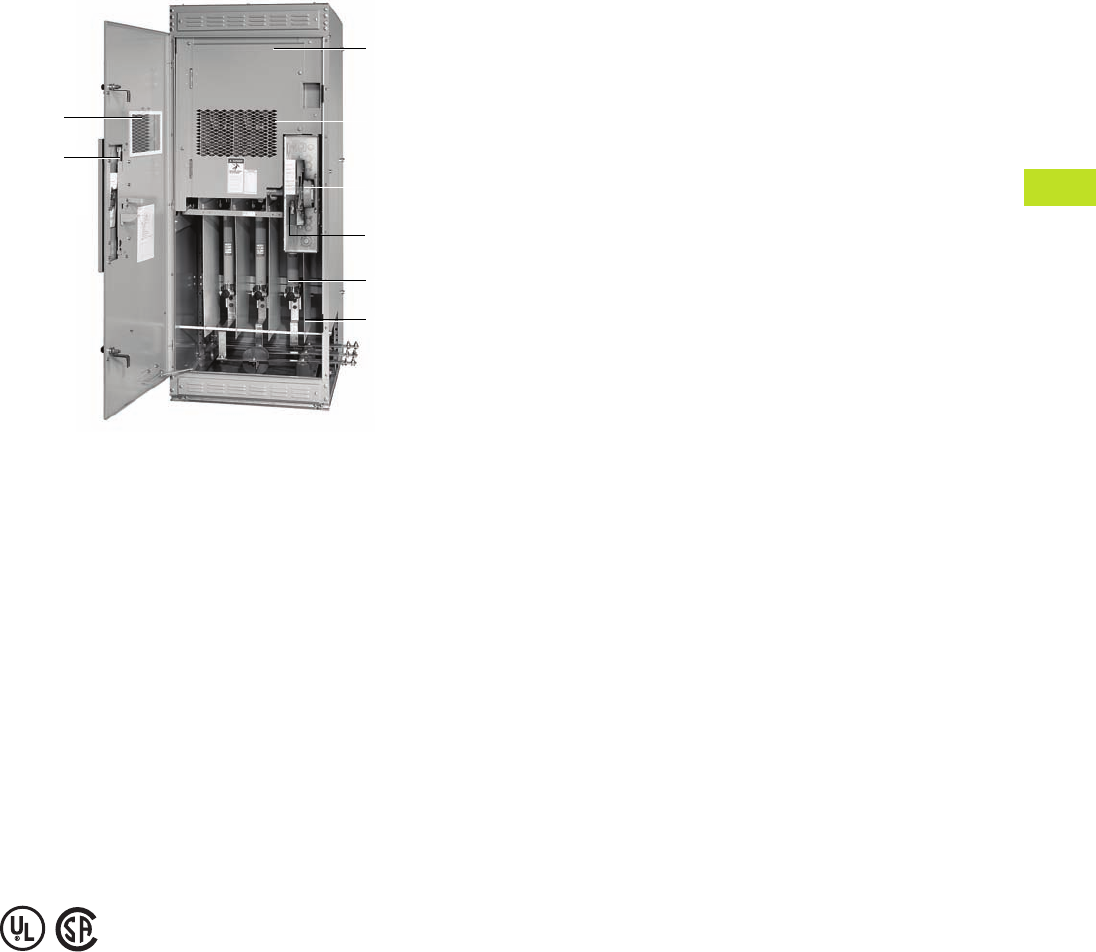
Volume 3—Power Distribution and Control Assemblies CA08100004E—February 2012 www.eaton.com V3-T6-3
6
6
6
6
6
6
6
6
6
6
6
6
6
6
6
6
6
6
6
6
6
6
6
6
6
6
6
6
6
6
6.1
Medium Voltage Metal-Enclosed Switches
Medium Voltage Switch—MVS
Indoor Medium Voltage Switch—MVS Bus Connection to
D r y - Ty p e Tr a n s f o rm e r
Standards and
Certifications
MVS switchgear meets or
exceeds IEEE® C37.20.3 as it
applies to metal-enclosed
switchgear.
Either Underwriters
Laboratories® (UL) or
Canadian Standards
Association® (CSA) listing is
available for MVS switchgear in
many configurations, with a
number of options.
MVS switchgear is available
seismically qualified to meet
the requirements of the
Uniform Building Code®
(UBC), California Title 24 and
BOCA® requirements in many
configurations with a number
of options.
Reference Information
See Consulting Application
Guide for detailed list of ratings
and options. For renewal parts,
see CA08105001E.
Product Selection
Contact Eaton for pricing.
Technical Data
and Specifications
●Rated maximum voltage
classes of 5, 15, 27 and
38 kV
●Rated impulse levels, kV
BIL: 60, 95, 125, 150
●Continuous and load-break
ratings: 600 amperes
available at all voltage
classes; 1200 amperes
available at 5 and 15 kV
●Designs available in indoor
and outdoor non-walk-in
configurations
●Manual or motor operated
Inspection
Window
Switch Drive
Mechanism
Operating
Handle
(Mounted in
Access Door)
DE-ION Arc
Interrupters
Located Behind
Switch Barrier
Interlock
Fuses
High Dielectric
Insulation Used
Between Switch
Phases and
Ground on
15 kV Only
Hinged Internal
Switch Barrier
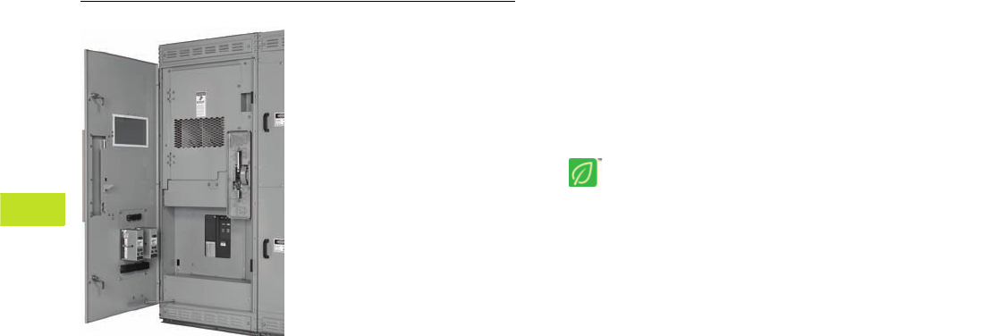
V3-T6-4 Volume 3—Power Distribution and Control Assemblies CA08100004E—February 2012 www.eaton.com
6
6
6
6
6
6
6
6
6
6
6
6
6
6
6
6
6
6
6
6
6
6
6
6
6
6
6
6
6
6
6.2
Medium Voltage Metal-Enclosed Switches
Medium Voltage Switch and Breaker—MSB
Indoor Medium Voltage Switch and Fixed Breaker—MSB
Contents
Description Page
Medium Voltage Switch and Breaker—MSB
Standards and Certifications . . . . . . . . . . . . . . V3-T6-5
Reference Information . . . . . . . . . . . . . . . . . . . V3-T6-5
Product Selection . . . . . . . . . . . . . . . . . . . . . . . V3-T6-5
Technical Data and Specifications . . . . . . . . . . V3-T6-5
An Eaton
Green Solution
Product Description
Eaton’s MSB switchgear
is an integrated assembly
of a visible load-break
disconnect switch, fixed-
mounted vacuum circuit
breaker, and control devices
that are integrated electrically
and mechanically for
circuit protection. All
major components are
manufactured by Eaton,
establishing one source
of responsibility for the
equipment and ensuring
high standards in quality,
coordination, reliability and
service. MSB switchgear
would typically be used
where both cost and
protection are important
design parameters.
Application Description
Applications include ground
fault protection, primary and/
or secondary switching, and
protection on unit substations,
automatic transfer switching
at medium voltage levels,
capacitor switching, high
duty cycle and tight system
coordination protection.
MSB switchgear can also be
an economic benefit in single-
ended substations because
it may allow the customer
to eliminate the secondary
main protection and
switching device.
●Low resistance ground
schemes
●Single-ended substation
designs
●Overcurrent protection
Features, Benefits
and Functions
●Visible isolation
●Fully rated fixed vacuum
circuit breaker
●Electrical operation
●No fuses
●Improved coordination
capability
●Improved transformer
protection
●Ground fault protection
●Capacitor switching
●High switching duty cycle
●Integral overcurrent
protection
Eaton's SF6-free
switchgear: Eaton medium
voltage switchgear use
vacuum switches combined
with solid insulation material.
This environmentally-friendly
technology avoids the use of
SF6 as an insulation gas.

Volume 3—Power Distribution and Control Assemblies CA08100004E—February 2012 www.eaton.com V3-T6-5
6
6
6
6
6
6
6
6
6
6
6
6
6
6
6
6
6
6
6
6
6
6
6
6
6
6
6
6
6
6
6.2
Medium Voltage Metal-Enclosed Switches
Medium Voltage Switch and Breaker—MSB
Standards and
Certifications
MSB switchgear meets or
exceeds IEEE C37.20.3 as it
applies to metal-enclosed
switchgear.
CSA listing is available for
MSB switchgear in many
configurations with a number
of options.
MSB switchgear is available
seismically qualified to meet
the requirements of the
Uniform Building Code,
California Title 24 and
BOCA requirements in
many configurations with
a number of options.
Reference Information
See Consulting Application
Guide for detailed list of ratings
and options. For renewal parts,
see CA08105001E.
Product Selection
Contact Eaton for pricing.
Technical Data
and Specifications
●Rated maximum voltages
of 4.76–15 kV
●Continuous current ratings
up to 1200 amperes
●25 and 40 kA rms
symmetrical short-circuit
interrupting capacity
●Designs available in indoor
and outdoor non-walk-in
configurations
●Single vertical section and
transformer primary
configurations
●Lineups consisting of MSB
and MVS vertical sections
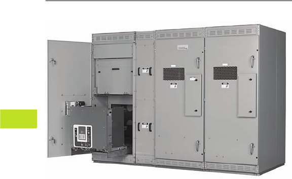
V3-T6-6 Volume 3—Power Distribution and Control Assemblies CA08100004E—February 2012 www.eaton.com
6
6
6
6
6
6
6
6
6
6
6
6
6
6
6
6
6
6
6
6
6
6
6
6
6
6
6
6
6
6
6.3
Medium Voltage Metal-Enclosed Switches
Metal-Enclosed Breaker—MEB
Indoor Metal-Enclosed Drawout Vacuum Breaker—MEB
Used as Main for Two Fused Switches
Contents
Description Page
Metal-Enclosed Breaker—MEB
Standards and Certifications . . . . . . . . . . . . . . V3-T6-7
Reference Information . . . . . . . . . . . . . . . . . . . V3-T6-7
Product Selection . . . . . . . . . . . . . . . . . . . . . . . V3-T6-7
Technical Data and Specifications . . . . . . . . . . V3-T6-7
Product Description
Eaton’s MEB switchgear is
a metal-enclosed assembly
of single high drawout VCP-W
vacuum circuit breakers and
control devices that are
integrated electrically for
circuit protection. (For
drawout vacuum breaker
metal-clad switchgear,
type VacClad-W, see
Volume 3, Tab 7) All
major components are
manufactured by Eaton,
establishing one source
of responsibility for the
equipment and ensuring
high standards in quality,
coordination, reliability and
service.
Application Description
MEB can be applied as the
primary main device and
integrated with fused feeder
switches in a lineup of fused
MVS switchgear.
Applications include ground
fault protection, primary
and/or secondary switching,
and protection on unit
substations, automatic
transfer switching at medium
voltage levels, capacitor
switching, high duty
cycle and tight system
coordination protection.
MEB switchgear can also
be an economic benefit in
single-ended substations
because it may allow the
customer to eliminate the
secondary main protection
and switching device.
●Low resistance ground
schemes
●Single-ended substation
designs
●Overcurrent protection
Features, Benefits
and Functions
●Fully rated drawout
vacuum circuit breaker
●Electrical operation
●Improved coordination
capability
●Improved transformer
protection
●Ground fault protection
●Capacitor switching
●High switching duty cycle
●Integral overcurrent
protection

Volume 3—Power Distribution and Control Assemblies CA08100004E—February 2012 www.eaton.com V3-T6-7
6
6
6
6
6
6
6
6
6
6
6
6
6
6
6
6
6
6
6
6
6
6
6
6
6
6
6
6
6
6
6.3
Medium Voltage Metal-Enclosed Switches
Metal-Enclosed Breaker—MEB
Standards and
Certifications
MEB switchgear meets or
exceeds IEEE C37.20.3 as it
applies to metal-enclosed
switchgear.
CSA listing is available for
MEB switchgear in many
configurations with a number
of options.
MEB switchgear is available
seismically qualified to meet
the requirements of the
Uniform Building Code,
California Title 24 and
BOCA requirements in
many configurations with
a number of options.
Reference Information
See Consulting Application
Guide for detailed list of ratings
and options. For renewal parts,
see CA08105001E.
Product Selection
Contact Eaton for pricing.
Technical Data
and Specifications
●Rated maximum voltages
of 4.76 and 15 kV
●Continuous current rating
of 1200 or 2000 amperes
●Short-circuit current
ratings up to 38 kA rms
symmetrical
●Designs available in indoor
and outdoor non-walk-in
configurations
●Single vertical section and
transformer primary
configurations
●Lineups consisting of
MEB vertical sections and
MVS vertical sections
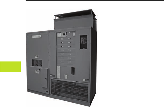
V3-T6-8 Volume 3—Power Distribution and Control Assemblies CA08100004E—February 2012 www.eaton.com
6
6
6
6
6
6
6
6
6
6
6
6
6
6
6
6
6
6
6
6
6
6
6
6
6
6
6
6
6
6
6.4
Medium Voltage Metal-Enclosed Switches
Unitized Power Centers—UPC
Bottom Cable Entry and Top Cable Entry
Indoor Unitized Power Centers
Contents
Description Page
Unitized Power Centers—UPC
Technical Data and Specifications . . . . . . . . . . V3-T6-9
Product Description
Eaton’s Unitized Power
Centers combine an MVS
primary disconnect switch,
a ventilated dry-type
transformer and Pow-R-Line 4
secondary distribution
devices in a compact,
factory-assembled integral
unit. These self-contained
units provide maximum kVA
in minimum space, and
their unitized construction
simplifies installation.
Other advantages include:
●Front accessibility
●Against-the-wall mounting
●Dimensions consistent
with standard doorways
●Liberal space for primary
and secondary cables
●Molded case circuit
breaker or fusible switch
secondary distribution
Features, Benefits
and Functions
The primary disconnect
switch is a manually
operated, two-position,
quick-make, quick-break
type MVS. Distribution class
surge arresters protect the
transformer from surge
voltages, and current limiting
fuses protect against fault
currents. Insulated cable
passes through a steel
barrier to connect the switch
to the transformer.
The power transformer is of a
ventilated, dry-type, core-
form construction. Standard
Class 220°C insulation allows
normal operation at 150°C
temperature rise above a
30°C nominal ambient and
a 40°C peak ambient.
The secondary distribution
section consists of group
mounted Series C® molded
case circuit breakers or FDP-
W fusible switches separated
from the transformer by steel
barriers. Additional vertical
sections may be added for
additional low voltage
distribution.
Standards and
Certifications
Power transformer core and
coil assemblies meet all
applicable IEEE/ANSI/NEMA®
standards.
Reference Information
See Consulting Application
Guide for detailed list of ratings
and options.
Product Selection
Contact Eaton for pricing.

Volume 3—Power Distribution and Control Assemblies CA08100004E—February 2012 www.eaton.com V3-T6-9
6
6
6
6
6
6
6
6
6
6
6
6
6
6
6
6
6
6
6
6
6
6
6
6
6
6
6
6
6
6
6.4
Medium Voltage Metal-Enclosed Switches
Unitized Power Centers—UPC
Technical Data and Specifications
●Indoor enclosure only
●Maximum primary
voltages:
●3 kV through 15 kV
●Three-phase, 60 Hz,
delta primary
●Primary BIL:
●Voltages not exceeding
2.5 kV maximum—
20 kV BIL
●Voltages above 2.5 kV
up to 7.2 kV maximum—
30 kV BIL
●Voltages above 7.2 kV up
to 15 kV maximum—
60 kV BIL
●Transformer:
●12.5–1000 kVA
●Winding material,
copper type,
ventilated dry
●Insulation:
●Class H 220°C rise
(standard)
●150°C, 115ºC and 80°C
rise available
●Fan cooling available
to increase kVA rating
by 331/3%
●Taps: ±(2) 2.5% FCAN
and FCBN
●Secondary voltages:
●208Y/120 volts—
four-wire
●240 volts—three-wire
●480Y/277 volts—
four-wire
●575 volts—four-wire
●Secondary BIL: 10 kV BIL
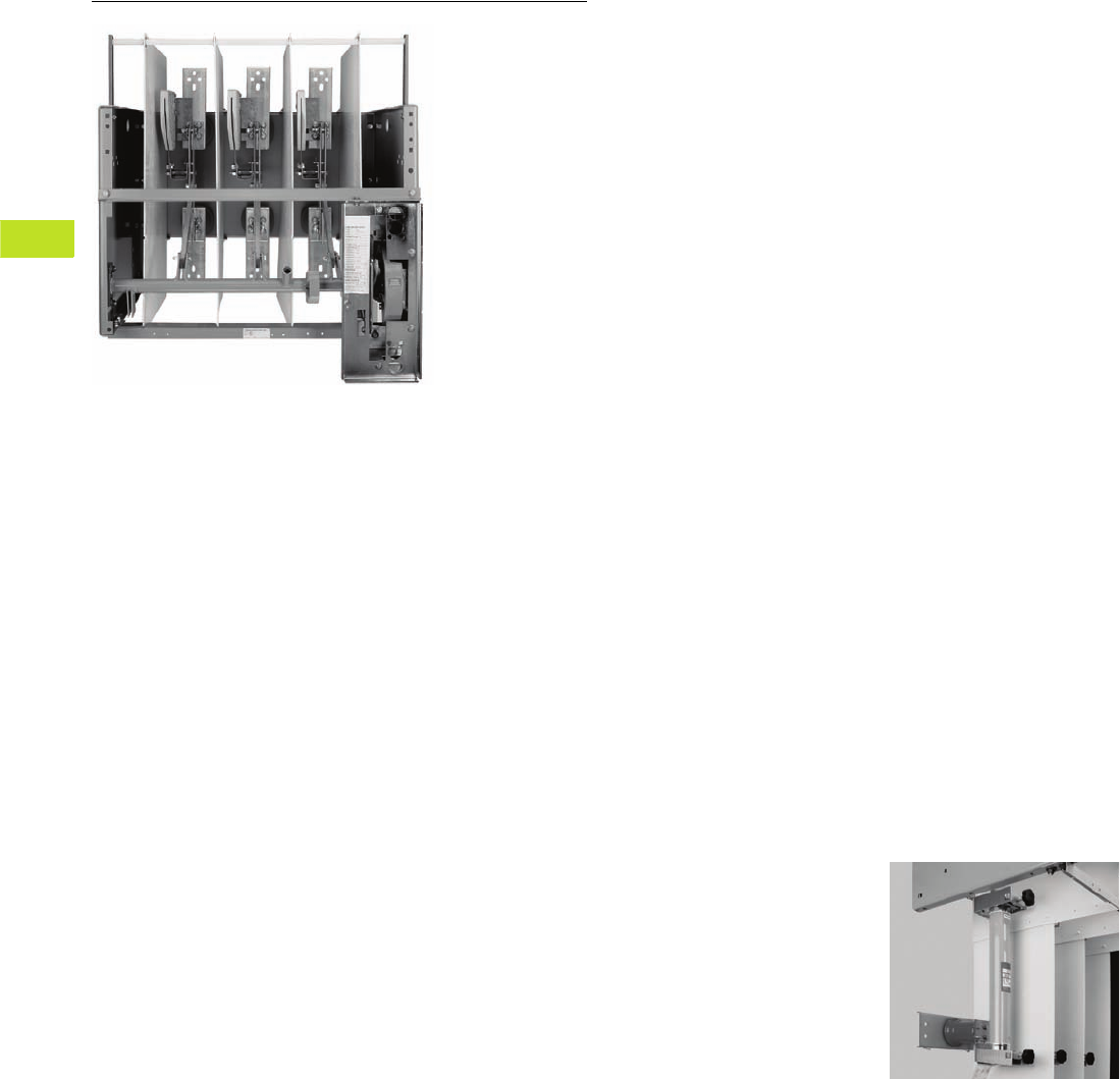
V3-T6-10 Volume 3—Power Distribution and Control Assemblies CA08100004E—February 2012 www.eaton.com
6
6
6
6
6
6
6
6
6
6
6
6
6
6
6
6
6
6
6
6
6
6
6
6
6
6
6
6
6
6
6.5
Medium Voltage Metal-Enclosed Switches
OEM Medium Voltage Switch Components—MVS-C
MVS-C Switch
OEM Fusible Switches
Contents
Description Page
OEM Medium Voltage Switch Components—MVS-C
Standards and Certifications . . . . . . . . . . . . . . V3-T6-11
Reference Information . . . . . . . . . . . . . . . . . . . V3-T6-11
Product Selection . . . . . . . . . . . . . . . . . . . . . . . V3-T6-11
Technical Data and Specifications . . . . . . . . . . V3-T6-11
Product Description
MVS-C switches are open
frame switches that must
be mounted in a suitable
enclosure for the OEM
market. Eaton’s MVS-C load
interrupter switches are
available in many ratings.
When properly applied, they
will provide safe, low-cost
switching where occasional
or infrequent disconnecting
means is desired. The
three-pole switch, with its
quick-make, quick-break
mechanism, will interrupt
its rated load current.
Application Description
MVS-C switches can be
applied in suitable enclosures
for many switching duties
whether manual or automatic
operation is specified:
●Transformer primary
switching
●Transformer secondary
switching
●Power distribution
switching
Features, Benefits and Functions
Plug & Play™: The switch
and operating mechanism
install as a single entity. No
handle and chains or cables to
mount and adjust. Improves
productivity in assembly
reducing overall cost.
Quick-make, quick-break
mechanism: A reliable heavy-
duty coil spring mechanism
drives the switch blades at
high speed into either
the open
or the closed position.
DE-ION arc interruption:
DE-ION arc chambers and
spring-loaded auxiliary blades
ensure safe, fast load current
interruption and eliminate
arcing damage to the
main contacts.
Positive switch position
indication: Red and Green
multilingual (English/Spanish/
French) labels located directly
on the switch operating
mechanism give visual
indication of switch position.
Interlocked for safety:
When properly installed to
utilize the built-in design
feature, mechanical interlocks
prevent closing the switch
when the enclosure door is
open, or opening the door
when the switch is closed.
As an alternate interlock
method, key interlock
provisions are included.
Safety under fault
conditions: The switch,
depending upon the rated
voltage, is available with
three or four fault-closing
operations with ratings up
to 61,000 amperes rms
asymmetrical, exceeding
the industry standards
one-time operation.
Fuse mountings: Complete
three-phase fuse mounting
assemblies or fuse live
parts are available that
are fully compatible with
MVS-C switches. The fuse
mountings are intended for
use with Eaton’s fuses.
MVS-C Fuse Mounting
Direct drive mechanism:
A metal-to-metal direct drive
mechanism eliminates chains
or cables that need adjusting
or break.

Volume 3—Power Distribution and Control Assemblies CA08100004E—February 2012 www.eaton.com V3-T6-11
6
6
6
6
6
6
6
6
6
6
6
6
6
6
6
6
6
6
6
6
6
6
6
6
6
6
6
6
6
6
6.5
Medium Voltage Metal-Enclosed Switches
OEM Medium Voltage Switch Components—MVS-C
Standards and
Certifications
●MVS-C switches meet or
exceed ANSI C37.22
ratings
●UL and CSA recognized
component listing services
are available for 5 and
15 kV manual and motor
operated MVS-C switches
Reference Information
For renewal parts, see
CA08105001E.
Product Selection
Contact Eaton for pricing.
Technical Data
and Specifications
●Rated maximum voltage
classes of 5, 15, 27 and
38 kV
●Rated impulse levels, kV
BIL: 60, 95, 125, 150
●Continuous and load-break
ratings: 600 amperes
available at all voltage
classes; 1200 amperes
available at 5 and 15 kV
●Rated momentary and fault
close currents, 40 and
61 kA rms asymmetrical;
40 kA available at all voltage
classes; 61 kA available at
5, 15 and 27 kV
●Manual, motor or shunt-trip
operated

Volume 3—Power Distribution and Control Assemblies CA08100004E—February 2012 www.eaton.com V3-T7-1
7
7
7
7
7
7
7
7
7
7
7
7
7
7
7
7
7
7
7
7
7
7
7
7
7
7
7
7
7
7
Medium Voltage Switchgear
Indoor Type VCP-W Metal-Clad
Switchgear Assembly (5/15 kV shown)
7.1 Introduction
Product Selection Guide . . . . . . . . . . . . . . . . . . . . . . . . . . . . . . . . . . . V3-T7-2
7.2 Metal-Clad Vacuum Switchgear
Product Overview
Product Description . . . . . . . . . . . . . . . . . . . . . . . . . . . . . . . . . . . . V3-T7-4
Application Description . . . . . . . . . . . . . . . . . . . . . . . . . . . . . . . . . . V3-T7-4
Features, Benefits and Functions . . . . . . . . . . . . . . . . . . . . . . . . . . V3-T7-5
Options and Accessories . . . . . . . . . . . . . . . . . . . . . . . . . . . . . . . . V3-T7-6
Technical Data and Specifications . . . . . . . . . . . . . . . . . . . . . . . . . . V3-T7-6
26-Inch Wide, 5 kV, 250 MVA, 1200A Switchgear
Product Description . . . . . . . . . . . . . . . . . . . . . . . . . . . . . . . . . . . . V3-T7-7
Application Description . . . . . . . . . . . . . . . . . . . . . . . . . . . . . . . . . . V3-T7-7
Features, Benefits and Functions . . . . . . . . . . . . . . . . . . . . . . . . . . V3-T7-7
Standards and Certifications . . . . . . . . . . . . . . . . . . . . . . . . . . . . . . V3-T7-7
38 kV Metal-Clad Switchgear
Product Description . . . . . . . . . . . . . . . . . . . . . . . . . . . . . . . . . . . . V3-T7-8
Application Description . . . . . . . . . . . . . . . . . . . . . . . . . . . . . . . . . . V3-T7-8
Features, Benefits and Functions . . . . . . . . . . . . . . . . . . . . . . . . . . V3-T7-8
Standards and Certifications . . . . . . . . . . . . . . . . . . . . . . . . . . . . . . V3-T7-8
Technical Data and Specifications . . . . . . . . . . . . . . . . . . . . . . . . . . V3-T7-9
7.3 High Resistance Grounding System
Product Description . . . . . . . . . . . . . . . . . . . . . . . . . . . . . . . . . . . . . . . V3-T7-18
Application Description . . . . . . . . . . . . . . . . . . . . . . . . . . . . . . . . . . . . V3-T7-18
Features, Benefits and Functions . . . . . . . . . . . . . . . . . . . . . . . . . . . . . V3-T7-21
Standards and Certifications . . . . . . . . . . . . . . . . . . . . . . . . . . . . . . . . V3-T7-21
Catalog Number Selection . . . . . . . . . . . . . . . . . . . . . . . . . . . . . . . . . . V3-T7-22
Technical Data and Specifications . . . . . . . . . . . . . . . . . . . . . . . . . . . . V3-T7-23
Dimensions . . . . . . . . . . . . . . . . . . . . . . . . . . . . . . . . . . . . . . . . . . . . . V3-T7-26
Learn
Online
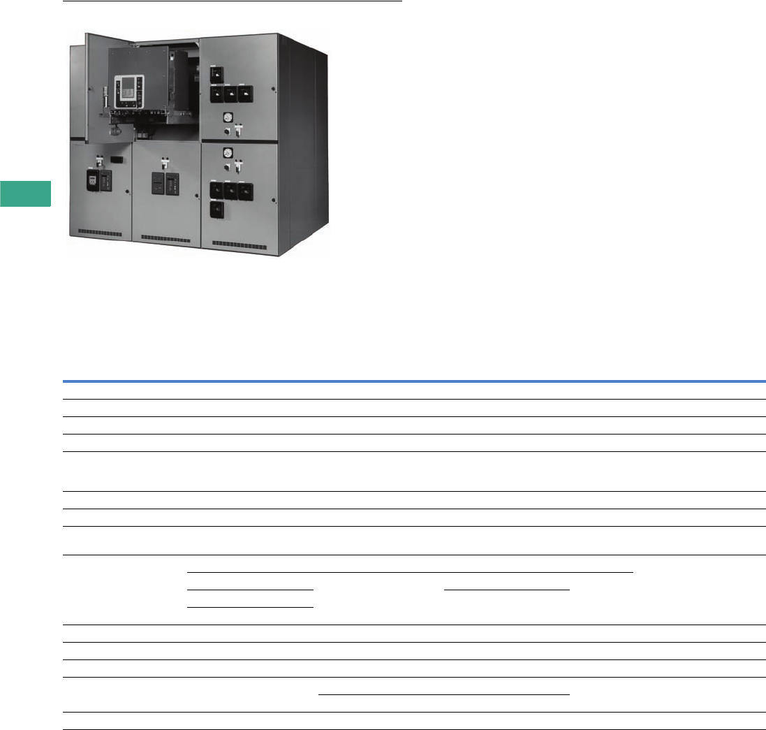
V3-T7-2 Volume 3—Power Distribution and Control Assemblies CA08100004E—February 2012 www.eaton.com
7
7
7
7
7
7
7
7
7
7
7
7
7
7
7
7
7
7
7
7
7
7
7
7
7
7
7
7
7
7
7.1
Medium Voltage Switchgear
Introduction
Indoor Type VCP-W Metal-Clad Switchgear Assembly (5/15 kV shown)
Contents
Description
Product Selection Guide
Product Selection Guide
Product Offering Chart—Metal-Enclosed 1
Notes
1Additional products not shown include medium voltage transfer, high resistance ground and low profile switchgear.
2Listings are voltage dependant. See individual product sheets for detail.
Description MVS MEB MSB UPC Mini-MVS
Voltage 5, 15, 27, 38 kV 5, 15 kV 5, 15 kV 5, 15 kV 5 kV only
Operation duty cycle Low High High Low Low
Enclosure Indoor, outdoor aisleless Indoor, outdoor aisleless Indoor, outdoor aisleless Indoor only Indoor, outdoor aisleless
Listed UL®, CSA®— — — UL, CSA
Assembly standards ANSI/IEEE®, C37.30.3, C37.20.4,
C37.22, C37.57, C37.58,
CSA 22.2 #31 2
ANSI/IEEE, C37.30.3, C37.20.4,
C37.22, C37.57, C37.58,
CSA 22.2 #31
ANSI/IEEE, C37.30.3, C37.20.4,
C37.22, C37.57, C37.58,
CSA 22.2 #31
— ANSI/IEEE, C37.30.3, C37.20.4,
C37.22, C37.57, C37.58,
CSA 22.2 #31 2
Circuit breaker type N/A VCP-W VCP-TR (5, 15 kV), VCP-W 27 kV N/A N/A
Circuit breaker mounted N/A Drawout Fixed N/A N/A
Seismically rated Zone 4 to
California Building Code Title 24
Yes Yes Yes Yes Yes
BIL ratings 60 kV (5 kV) 60 kV (5 kV) 60 kV (5 kV) 60 kV (5 kV) 60 kV (5 kV)
95 kV (15 kV) 95 kV (15 kV) 95 kV (15 kV) 95 kV (15 kV)
125 kV (27 kV) 125 kV (27 kV)
150 kV (38 kV)
Main bus ratings 800, 1200A (5/15/27/38 kV) 800, 1200A (5/15 kV) 800, 1200A (5/15/27 kV) N/A N/A, cable in, cable out application
Breaker ratings N/A 1200A (5/15 kV) 600, 800, 1200A (5/15/27 kV) N/A N/A
Overcurrent protective device Yes (fused) Yes Yes Yes (fused) Yes (fused)
Short-circuit
interrupting capacity
Per fuse IC 29, 41, 63 kA (5 kV) 16, 20, 25, 40 kA (5/15 kV) Per fuse IC Per fuse IC
18, 28, 37, 63 kA (15 kV) 25 kA (27 kV)
Conduit entry Top or bottom Top or bottom Top or bottom Top or bottom Top or bottom

Volume 3—Power Distribution and Control Assemblies CA08100004E—February 2012 www.eaton.com V3-T7-3
7
7
7
7
7
7
7
7
7
7
7
7
7
7
7
7
7
7
7
7
7
7
7
7
7
7
7
7
7
7
7.1
Medium Voltage Switchgear
Introduction
Product Offering Chart—Metal-Clad 1
Notes
1Additional products not shown include medium voltage transfer, high resistance ground and low profile switchgear.
2Listings are voltage dependant. See individual product sheets for detail.
3Ratings are arc ratings, not interrupting capacity.
Description MVA Standard Narrow Design MVA Arc Resistant
Voltage 5, 15, 27, 38 kV 5 kV 5, 15, 27, 38 kV
Operation duty cycle High High High
Enclosure Indoor (5–38 kV) Indoor only Indoor only
Outdoor aisleless (5–27 kV) Outdoor aisle
Outdoor aisle (5–15 kV)
Outdoor common aisle (5–15 kV)
Listed UL, CSA UL, CSA CSA only
Assembly standards ANSI/IEEE, C37.04, C37.06, C37.54,
C37.20.2, C37.55, CSA 22.2 #31 2
ANSI/IEEE, C37.04, C37.06, C37.54,
C37.20.2, C37.55, CSA 22.2 #31 2
ANSI/IEEE, C37.04, C37.06, C37.54,
C37.20.2, C37.20.7, C37.55, CSA 22.2 #31 2
Circuit breaker type VCP-W VCP-W ND VCP-W
Circuit breaker mounted 5 kV drawout, direct roll-in breaker option Drawout 5 kV only 5 kV drawout, direct roll-in breaker option
15 kV drawout, direct roll-in breaker option 15 kV drawout, direct roll-in breaker option
27 kV drawout, direct roll-in breaker option 27 kV drawout, direct roll-in breaker option
38 kV direct roll-in breakers 38 kV direct roll-in breakers
Seismically rated Zone 4 to
California Building Code Title 24
Yes Yes Yes
BIL ratings 60 kV (5 kV) 60 kV (5 kV only) 60 kV (5 kV)
95 kV (15 kV) 95 kV (15 kV)
125 kV (27 kV) 125 kV (27 kV)
170 kV (38 kV) 170 kV (38 kV)
Main bus ratings 1200, 2000, 3000, 4000A (5 kV) 1200A (5 kV only) 1200, 2000, 3000A (5 kV)
1200, 2000, 3000, 4000A (15 kV) 2000A, 3000A 1200, 2000, 3000A (15 kV)
1200, 2000A (27 kV) 1200, 2000A (27 kV)
1200, 2000, 3000A depending on kA rating (38 kV) 1200, 2000, 3000A (38 kV)
Breaker ratings 1200, 2000, 3000A (5 kV) 1200A (5 kV only) 1200, 2000, 3000A (5 kV)
1200, 2000, 3000A (15 kV) 1200, 2000, 3000A (15 kV)
1200, 2000A (27 kV) 1200, 2000A (27 kV)
1200, 1600, 2500A depending on kA rating (38 kV) 1200A (38 kV)
Overcurrent protective device Yes Yes Yes
Short-circuit interrupting capacity 29, 41, 63 kA (5 kV) 29 kA (5 kV) 37 kA (5 kV) 3
33 kA (8.25 kV) —
18, 28, 37, 63 kA 37 kA (15 kV) 3
16, 22, 25, 40 kA 25 kA (27 kV) 3
16, 21, 25, 32, 40 kA (38 kV) 25 kA (38 kV) 3
40, 50, 63 kA (5 kV) 3
40, 50, 63 kA (15 kV) 3
25, 40 kA (27 kV) 3
25, 40 kA (38 kV) 3
Conduit Entry Top or bottom Top or bottom Top or bottom
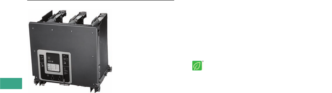
V3-T7-4 Volume 3—Power Distribution and Control Assemblies CA08100004E—February 2012 www.eaton.com
7
7
7
7
7
7
7
7
7
7
7
7
7
7
7
7
7
7
7
7
7
7
7
7
7
7
7
7
7
7
7.2
Medium Voltage Switchgear
Metal-Clad Vacuum Switchgear
VCP-W Breaker
Contents
Description Page
Product Overview
Features, Benefits and Functions . . . . . . . . . . . V3-T7-5
Options and Accessories . . . . . . . . . . . . . . . . . V3-T7-6
Technical Data and Specifications . . . . . . . . . . V3-T7-6
26-Inch Wide, 5 kV, 250 MVA, 1200A Switchgear . V3-T7-7
38 kV Metal-Clad Switchgear . . . . . . . . . . . . . . . . V3-T7-8
An Eaton
Green Solution
Product Overview
Product Description
Eaton has been manufacturing
metal-clad switchgear for over
50 years, and vacuum circuit
breakers for over 30 years.
Tens of thousands of Eaton
vacuum circuit breakers,
used in a wide variety of
applications, have been
setting industry performance
standards for years.
With reliability as a
fundamental goal, Eaton’s
engineers have simplified the
VCP-W switchgear design to
minimize problems and gain
trouble-free performance.
Special attention was given to
material quality and
maximum possible use
was made of components
proven over the years in
Eaton switchgear.
Maintenance requirements
are minimized by the use
of enclosed long-life
vacuum interrupters. When
maintenance or inspection
is required, the component
arrangements and drawers
allow easy access. The
VCP-W’s light weight
simplifies handling and
relocation of the breakers.
The VCP-W meets or
exceeds all applicable ANSI,
NEMA® and IEEE design
standards, and additionally
offers many outstanding
safety features.To ensure
reliability and quality,
the testing of VCP-W
switchgears has been
extensive. UL and CSA listed
switchgear is available for
5 and 15 kV. CSA is available
for 27 and 38 kV.
Application Description
Eaton’s VCP-W metal-clad
switchgear with type VCP-W
vacuum breakers provides
centralized control and
protection of medium voltage
power equipment and circuits
in industrial, commercial and
utility installations involving
generators, motors, feeder
circuits, and transmission
and distribution lines.
VCP-W switchgear is
available in maximum voltage
ratings from 4.76 kV through
38 kV, and interrupting ratings
as shown on Page V3-T7-11.
VCP-W offers a total design
concept of cell, breaker and
auxiliary equipment, which
can be assembled in various
combinations to satisfy user
application requirements.
Two-high breaker
arrangements are standard
up to 15 kV. One-high
arrangements can be
furnished when required.

Volume 3—Power Distribution and Control Assemblies CA08100004E—February 2012 www.eaton.com V3-T7-5
7
7
7
7
7
7
7
7
7
7
7
7
7
7
7
7
7
7
7
7
7
7
7
7
7
7
7
7
7
7
7.2
Medium Voltage Switchgear
Metal-Clad Vacuum Switchgear
Features, Benefits and Functions
Endurance
High power laboratory tests
prove VCP-W breakers are
capable of 50 to 200 full fault
current interruptions.
Space Savings
Up to 50% floor space
reduction over previous
designs.
Vacuum Interrupter,
Current Transfer Conductor
Eaton’s stiff-flexible design
eliminates sliding/rolling
contacts in the main
conductor, which provides
excellent electrical and
thermal transfer, and long
vacuum interrupter life.
Grounded Steel Safety Shutters
Prevents accidental contact
with live primary voltage
connections when breaker
is withdrawn.
Breaker Rails
On 5–27 kV units, the breaker
can be withdrawn on rails for
inspection and maintenance
without the need for a
separate lifting device.
Direct Roll-In Beakers
5–27 kV switchgear is
available with direct roll-in
breakers. Direct roll-in
breakers can be supplied
in two-high configurations
with fully interchangeable
breakers. Rails or a special
direct roll-in lift pan can
be used if desired to
withdraw upper breakers
for inspection.
Reduced Breaker Weight
525 Ibs (238 kg) maximum
through 27 kV vs. 2450 Ibs
(1112 kg) in a comparable
air-magnetic design for ease
of handling.
Reduced Breaker Maintenance
Vacuum interrupter requires
only periodic check for
contact erosion. Integral wear
indicator provided. No contact
adjustments are required.
Front Accessible Mechanism
Front accessible mechanism
is standard on all VCP-W
breakers.
Front Accessible CTs (5–38 kV)
Up to 12 CTs per breaker can
be mounted for easy access.
Drawout Auxiliary
Compartments
Up to four drawers per
vertical section can be
equipped with CPTs or VTs
up to 15 kV. Primary isolation
shutters are standard.
Fluidized Bed Epoxy
Bus Insulation
Excellent track resistant and
flame retardant properties.
Standardized
Functional Designs
Shortens order cycle time.
Protective Relays
A full scope of protective
relays designed to meet all
application requirements is
available to provide the
utmost in system and
component protection. One
such multipurpose relay
system is Eaton’s Digitrip™
FP-5000. FP-5000 enhanced
capabilities include auto-
throwover schemes, voltage
and current protection,
and communication. This
microprocessor-based
circuit protective, control
and monitoring relay system
includes devices 50, 51,
50N, 51N, 50G, 51G and
86, plus cause and magnitude
of trip, integral test and
programming, ampere
demand, high load alarm,
non-volatile set points, self-
testing and communications
capabilities. The Digitrip is
capable of being monitored
and controlled through
PowerNet™, DeviceNet™,
Ethernet and Web PONIs.
Refer to Volume 3, Tab 9 for
further information.
PowerNet—Integrated
Monitoring Protection and
Control Communications System
Medium voltage VCP-W
switchgear is ideally
suited for Eaton’s unique
PowerNet system.
PowerNet is the unique
system that, for the first time,
ties together multiple devices
in electrical distribution
systems in a wide variety
of buildings and plants.
PowerNet uses the
proven, INCOM™ chip for
highly reliable, two-way
communications (even in
noisy industrial environments)
between the master control
unit and system devices via
a twisted pair of conductors.
Communications wires
can be extended up to
10,000 feet (3.04m) from
the master control unit
without repeaters...and as
many as 1000 compatible
devices, installed in various
assemblies, can be on the
PowerNet system.
Easy Installation
Installation is uncomplicated
and devices are connected,
daisy chain style, via the
twisted pair conductors. All
assemblies and devices are
standard Eaton equipment
when PowerNet compatible
devices are ordered as part of
an assembly. The assemblies
(with compatible devices built
in) are prewired, pretested
and delivered complete.
Flexibility
PowerNet is flexible in
that it can include those
assemblies, such as VCP-W
switchgear, that are desired
in a distribution system...
but PowerNet can be easily
upgraded as new assemblies
are added. In essence, a
customer determines the
requirements for a building’s
electrical distribution system,
and Eaton provides the
PowerNet system to fit
those specific requirements.
Environmentally-Friendly
Eaton’s medium voltage
switchgear uses vacuum
switches combined with
solid insulation material.
This environmentally-friendly
technology avoids the use of
SF6 as an insulation gas, and
can offer a lower total cost of
ownership over the complete
life cycle of your medium
voltage equipment.
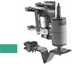
V3-T7-6 Volume 3—Power Distribution and Control Assemblies CA08100004E—February 2012 www.eaton.com
7
7
7
7
7
7
7
7
7
7
7
7
7
7
7
7
7
7
7
7
7
7
7
7
7
7
7
7
7
7
7.2
Medium Voltage Switchgear
Metal-Clad Vacuum Switchgear
Options and Accessories
Supplemental Devices
World-Class VCP-W Vacuum Circuit
Breakers are Designed with a V-Flex
Nonsliding Current Transfer System
Ground and Test Device
The ground and test device is
a drawout element that may
be inserted into a metal-clad
switchgear housing in place
of a circuit breaker to provide
access to the primary circuits
to permit the temporary
connection of grounds or
testing equipment to the
high voltage circuits. High
potential testing of cable or
phase checking of circuits
are typical tests that may be
performed. The devices are
insulated to suit the voltage
rating of the switchgear and
will carry required levels of
short-circuit current.
Before using ground and test
devices, it is recommended
that each user develop
detailed operating procedures
consistent with safe
operating practices. Only
qualified personnel should
be authorized to use ground
and test devices.
Manual and electrical ground
and test devices are available.
These devices include six
studs for connection to
primary circuits. On the
manual device, selection and
grounding is accomplished
by cable connection. On
the electrical-type device,
grounding is accomplished
by an electrically operated
grounding switch.
Standard Accessories
●One test jumper
●One levering crank
●One maintenance tool
●One lifting yoke (5–38 kV)
●Two sets of rails (5–27 kV)
●One turning handle
(5th wheel, 38 kV)
Optional Accessories
●One transport dolly
(5–27 kV)
●One portable lifter
(5–27 kV)
●One test cabinet
●One electrical levering
device (5–27 kV)
●One ramp for lower
breaker (5–27 kV)
●One manual or electrical
ground and test device.
Electrical ground up to
15 kV only
●One hi-pot tester
●One offset manual
racking device
Technical Data
and Specifications
●Maximum voltages:
●4.76 kV, 8.25 kV, 15 kV,
27 kV, 38 kV
●Interrupting ratings:
●4.76 kV:
250 MVA (29 kA)
350 MVA (41 kA)
500 MVA (63 kA)
●8.25 kV:
500 MVA (33 kA)
●15 kV:
500 MVA (18 kA)
750 MVA (28 kA)
1000 MVA (37 kA)
1500 MVA (63 kA)
●27 kV:
16 kA, 22 kA,
25 kA, 40 kA
●38 kV:
16 kA, 25 kA,
31.5 kA, 40 kA
2300 MVA (35 kA)
●Continuous current:
circuit breakers
●1200A, 2000A, 3000A
(5 and 15 kV)
●4000A forced cooled
(5 and 15 kV)
●1200A, 2000A, (27 kV)
●600A, 1200A, 1600A,
200A, 2500A (38 kV)
●3000A forced cooled
(38 kV)
●Continuous current:
main bus
●1200A, 2000A, 3000A,
4000A (5 and 15 kV)
●1200A, 2000A, (27 kV)
●1200A, 2000A, 2500A,
3000A (38 kV)
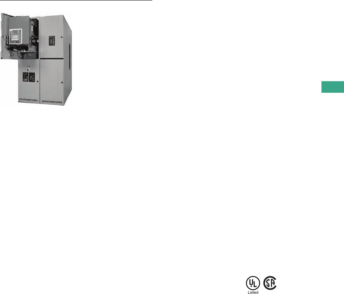
Volume 3—Power Distribution and Control Assemblies CA08100004E—February 2012 www.eaton.com V3-T7-7
7
7
7
7
7
7
7
7
7
7
7
7
7
7
7
7
7
7
7
7
7
7
7
7
7
7
7
7
7
7
7.2
Medium Voltage Switchgear
Metal-Clad Vacuum Switchgear
Typical Indoor Assembly with a Breaker Withdrawn on Rails
Contents
Description Page
Product Overview. . . . . . . . . . . . . . . . . . . . . . . . . . V3-T7-4
26-Inch Wide, 5 kV, 250 MVA, 1200A Switchgear
38 kV Metal-Clad Switchgear . . . . . . . . . . . . . . . . V3-T7-8
26-Inch Wide, 5 kV, 250 MVA, 1200A Switchgear
Product Description
26-inch wide VCP-W
switchgear was designed for
use in instances where floor
space requirements would
not allow the industry
standard 36-inch (914.4 mm)
wide switchgear.
Application Description
Typical applications include
not only new construction,
but also replacement
switchgear for installations
previously equipped with
26-inch (660.4 mm) wide
airbreak devices. This new
line of switchgear has also
proven very popular
among Generator Control
manufacturers where 5 kV,
250 MVA, 1200A applications
are commonplace.
Features, Benefits
and Functions
Functionality is the name
of the game. Available
configurations include
breaker over breaker,
one or two auxiliaries over
breaker, breaker over one
or two auxiliaries, or up
to four auxiliaries in one
vertical section.
In addition to the tremendous
floor space saving offered by
the 26-inch (660.4 mm) wide
design, a savings in the
height of the switchgear is
also available. Where height
is an issue, such as an
outdoor powerhouse or in a
mobile power container, the
standard 95-inch (2413 mm)
height can be reduced to an
80-inch (2032 mm) tall model
with a single-high breaker
with one auxiliary and/or
control cubical. In addition,
the low-profile structure is
designed to accommodate
Voltage Transformers that
are front mounted. Shallow-
depth versions are also
available for applications
where depth is an issue.
Contact your local Eaton
representative for more
information on special
dimensional requirements.
For installations requiring
2000A main breakers with
1200A feeders, lineups can be
built with standard 36-inch
(914.4 mm) wide main breaker
cubicles and 26-inch (660.4
mm) wide feeders.
The main bus connections
are 100% compatible with
standard 36-inch (914.4 mm)
wide vertical sections. As a
result, add-ons to existing
installations can be simply and
rapidly performed without
costly system modifications
and transition sections.
Standards and Certifications
At the heart of the new
switchgear line is Eaton’s
world-class VCPW-ND
“Narrow Design” vacuum
circuit breaker. The 26-inch
(660.4 mm) wide offering
includes breakers and gear
that are rated for use on 5 kV,
250 MVA, 1200A, 60 kV BIL
maximum systems. Main
bus ratings of up to 2000A
are available.
The 26-inch (660.4 mm) wide
VCP-W switchgear meets or
exceeds ANSI, NEMA and
IEEE design standards. UL
and CSA listed switchgear is
also available.
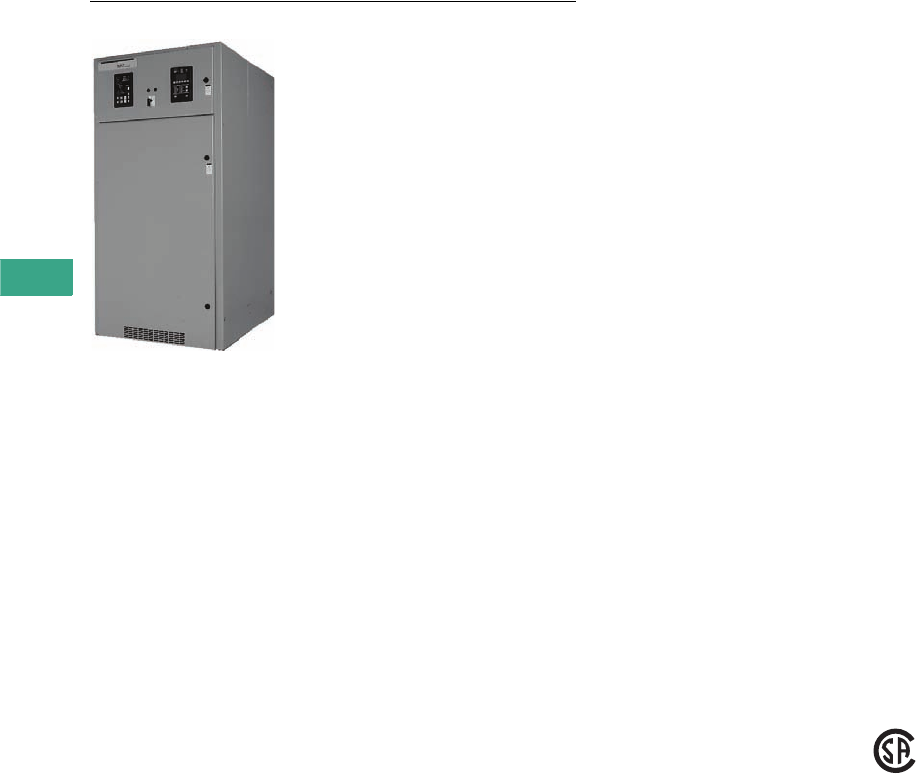
V3-T7-8 Volume 3—Power Distribution and Control Assemblies CA08100004E—February 2012 www.eaton.com
7
7
7
7
7
7
7
7
7
7
7
7
7
7
7
7
7
7
7
7
7
7
7
7
7
7
7
7
7
7
7.2
Medium Voltage Switchgear
Metal-Clad Vacuum Switchgear
Typical Indoor Switchgear Unit
Contents
Description Page
Product Overview . . . . . . . . . . . . . . . . . . . . . . . . . V3-T7-4
26-Inch Wide, 5 kV, 250 MVA, 1200A Switchgear . V3-T7-7
38 kV Metal-Clad Switchgear
Technical Data and Specifications . . . . . . . . . . . V3-T7-9
38 kV Metal-Clad Switchgear
Product Description
This member of the Eaton’s
VCP-W switchgear family
was designed for use in
applications with distribution
voltages at 38 kV maximum.
Application Description
Typical applications include
not only new construction,
but also replacement for older
airbreak, minimum oil or
SF6 switchgear. This line is
available in two basic versions:
one designed specifically for
domestic and export ANSI
applications (VCP-W), with a
continuous current range of
600–2500A; and one built for
export only IEC applications
(W-VAC) for continuous
current ranges of 630–2500A.
Features, Benefits
and Functions
Both ANSI and IEC versions
offer 40 kA rms symmetrical
momentary short-circuit,
80 kV 1 minute withstand,
170 kV BIL ratings as
standard, and both feature a
revolutionary interface design
that permits crossover and
transition bus connections
to adjacent sections without
the need for a transition
section. Standard dimensions
of this 170 kV BIL gear is
42 inches wide x 100 inches
tall x 128.8 inches deep
(1066.8 mm wide x 2540 mm
tall x 3270.3 mm deep),
making the VCP-W offering
the smallest in its class.
Safety has been thoroughly
addressed in the design of the
38 kV VCP-W. On all standard
units, shutters can be
independently padlocked to
prevent inadvertent energizing
during maintenance. Where
needed, fully rated feeder
earthing switches are also
available.
Ease of service is another
benefit. All 38 kV switchgear
units are equipped with roll-
on-the-floor vacuum circuit
breakers that provide both
unprecedented mobility and
ready accessibility to the
breaker cell. Levering-in
mechanisms for breaker
installation employ an
innovative ball-screw bearing
drive that can be operated
by a single technician.
The 38 kV line can be
equipped with a variety of
optional features to enhance
system protection and
monitoring. Eaton’s Digitrip
FP-5000 microprocessor-
based trip system, IQ
Analyzer and the PowerNet
communications system are all
available with the 38 kV metal-
clad switchgear.
Standards and Certifications
Both ANSI and IEC designs
are designed and tested at
the factory to be corona-free.
In addition, optional arc-
resistant designs can
be specified to comply
with EEMAC G-14-1 for
Accessibility Types A and B.
CSA listed switchgear is
also available.

Volume 3—Power Distribution and Control Assemblies CA08100004E—February 2012 www.eaton.com V3-T7-9
7
7
7
7
7
7
7
7
7
7
7
7
7
7
7
7
7
7
7
7
7
7
7
7
7
7
7
7
7
7
7.2
Medium Voltage Switchgear
Metal-Clad Vacuum Switchgear
Technical Data and Specifications
Available Type VCP-W Vacuum Circuit Breakers Rated on Symmetrical Current Basis, Per ANSI Standards (Rated K=1)
Notes
1All circuit breakers are tested at 60 Hz, however, they can also be applied at 50 Hz with no
de-rating.
24000A fan cooled rating is available for 3000A circuit breakers.
3These circuit breakers were tested to the preferred TRV ratings specified in C37.06-2000.
4Because the voltage range factor K=1, the short-time withstand current and the maximum
symmetrical interrupting current are equal to the rated symmetrical interrupting current.
5Based on the standard DC TIME constant of 45 ms (corresponding to X/R of 17 for 60 Hz) and
the minimum contact parting time as determined from the minimum opening time plus the
assumed minimum relay time of 1/2 cycle (8.33 ms for 60 Hz).
6The asymmetrical interrupting current, I total, is given by (It) = I x Sqrt (1 + 2 x %DC x %DC) kA
rms asym total.
7Duration of short-time current and maximum permissible tripping delay are both two seconds
for all circuit breakers listed in this table, as required in C37.04-1999, C37.06-2000 and
C37.06-2009.
8RRRV can also be calculated as = 1.137 x E2/T2.
9Each operation consists of one closing plus one opening.
jAll 40 and 50 kA circuit breakers exceed required 5000 no-load operations; all 63 kA circuit
breakers exceed the required 2000 no-load ANSI operations.
Rated Values
Drawout Circuit Breaker Type
50 VCP-W
25
50 VCP-W
40
50 VCP-W
50
50 VCP-W
63
75 VCP-W
40
Maximum voltage (V) (kV rms) 4.76 4.76 4.76 4.76 8.25
Power frequency (Hz) 160 60 60 60 60
Insulation level
Power frequency withstand voltage (1 min.) (kV rms) 19 19 19 19 36
Lightning impulse withstand voltage (1.2 x 50 ms) (kV peak)6060606095
Continuous current (A rms) 21200
2000
3000
1200
2000
3000
1200
2000
3000
1200
2000
3000
1200
2000
3000
Short-circuit ratings (reference C37.04-1999 and C37.06-2009
except as noted 3)
Symmetrical interrupting circuit (l) (kA rms sym) 425 40 50 63 40
DC component (%DC) (%) 550 50 44 55 50
Asymmetrical interrupting current (lt) (kA rms asym total) 631 49 59 80 49
Closing and latching current (2.6 x l) (kA peak) 65 104 130 164 104
Short-time withstand current (rms) 725 40 50 63 40
Transient recovery voltage parameters are based on TD-4
Peak voltage (E2) = (uc) (kV peak) 8.2 8.2 8.2 8.2 14
Time to peak (T2 = t3 x 1.137) (msec) 50 50 50 50 59
TRV rise time (t3) (msec) 44 44 44 44 52
RRRV = uc/t3 (kV/msec) 80.19 0.19 0.19 0.19 0.27
Interrupting time (ms, cycles (60 Hz)) 50, 3 50, 3 50, 3 50, 3 50, 3
Operating duty (duty cycle) O-0.3s-CO-3m-CO O-0.3s-CO-3m-CO O-0.3s-CO-3m-CO O-0.3s-CO-3m-CO O-0.3s-CO-3m-CO
Mechanical endurance (no-load operations) 9j10,000 10,000 10,000 10,000 10,000
Capacitance current switching capability
(reference C47.04a-2003, C37.06-2009 and C37.09a-2005)
Cable-charging current (class, A rms) C2, 3–10 C2, 3–10 C2, 3–10 C2, 7.5–25 C2, 7.5–25
Isolated shunt capacitor bank current (class, A rms) C2, 75–630
75–1000
75–1600
C2, 75–630
75–1000
75–1600
C2, 75–630
75–1000
75–1600
C2, 75–630
75–1000
75–1600
C2, 75–630
75–1000
75–1600
Back-to-back capacitor switching
Capacitor bank current (class, A rms) C2, 75–630
75–1000
75–1600
C2, 75–630
75–1000
75–1600
C2, 75–630
75–1000
75–1600
C2, 75–630
75–1000
75–1600
C2, 75–630
75–1000
75–1600
Inrush current (kA peak) 66666
Inrush frequency (kHz) 0.8
0.5
0.3
0.8
0.5
0.3
0.8
0.5
0.3
0.8
0.5
0.3
0.8
0.5
0.3
Out-of-phase switching
Voltage = 1.44 x V (kV rms) 777712
Current = 0.25 x l (kA rms) 6.3 10 12.5 15.8 10

V3-T7-10 Volume 3—Power Distribution and Control Assemblies CA08100004E—February 2012 www.eaton.com
7
7
7
7
7
7
7
7
7
7
7
7
7
7
7
7
7
7
7
7
7
7
7
7
7
7
7
7
7
7
7.2
Medium Voltage Switchgear
Metal-Clad Vacuum Switchgear
Available Type VCP-W Vacuum Circuit Breakers Rated on Symmetrical Current Basis, Per ANSI Standards (Rated K=1), continued
Notes
1All circuit breakers are tested at 60 Hz, however, they can also be applied at 50 Hz with no
de-rating.
24000A fan cooled rating is available for 3000A circuit breakers.
3These circuit breakers were tested to the preferred TRV ratings specified in C37.06-2000.
4Because the voltage range factor K=1, the short-time withstand current and the maximum
symmetrical interrupting current are equal to the rated symmetrical interrupting current.
5Based on the standard DC time constant of 45 ms (corresponding to X/R of 17 for 60 Hz) and
the minimum contact parting time as determined from the minimum opening time plus the
assumed minimum relay time of 1/2 cycle (8.33 ms for 60 Hz).
6The asymmetrical interrupting current, I total, is given by (It) = I x Sqrt (1 + 2 x %DC x %DC) kA
rms asym total.
7Duration of short-time current and maximum permissible tripping delay are both two seconds
for all circuit breakers listed in this table, as required in C37.04-1999, C37.06-2000 and
C37.06-2009.
8RRRV can also be calculated as = 1.137 x E2/T2.
9Each operation consists of one closing plus one opening.
jAll 40 and 50 kA circuit breakers exceed required 5000 no-load operations; all 63 kA circuit
breakers exceed the required 2000 no-load ANSI operations.
Rated Values
Drawout Circuit Breaker Type
75 VCP-W
50
150 VCP-W
25
150 VCP-W
40
150 VCP-W
50
150 VCP-W
63
Maximum voltage (V) (kV rms) 8.25 15 15 15 15
Power frequency (Hz) 160 60 60 60 60
Insulation level
Power frequency withstand voltage (1 min.) (kV rms) 36 36 36 36 36
Lightning impulse withstand voltage (1.2 x 50 ms) (kV peak)9595959595
Continuous current (A rms) 21200
2000
3000
1200 3
2000
3000
1200
2000
3000
1200
2000
3000
1200 3
2000 3
3000 3
Short-circuit ratings (reference C37.04-1999 and
C37.06-2009 except as noted 3)
Symmetrical interrupting circuit (l) (kA rms sym) 450 25 40 50 63
DC component (%DC) (%) 544 50 50 44 55
Asymmetrical interrupting current (lt) (kA rms asym total) 659 31 49 59 80
Closing and latching current (2.6 x l) (kA peak) 130 65 104 130 164
Short-time withstand current (rms) 750 25 40 50 63
Transient recovery voltage parameters are based on TD-4
Peak voltage (E2) = (uc) (kV peak) 14 28 3
25.7
25.7 25.7 28 3
Time to peak (T2 = t3 x 1.137) (msec) 59 75 75 75 75
TRV rise time (t3) (msec) 52 66 66 66 66
RRRV = uc/t3 (kV/msec) 80.27 0.42
0.39
0.39 0.39 0.42
Interrupting time (ms, cycles (60 Hz)) 50, 3 50, 3 50, 3 50, 3 50, 3
Operating duty (duty cycle) O-0.3s-CO-3m-CO O-0.3s-CO-3m-CO O-0.3s-CO-3m-CO O-0.3s-CO-3m-CO O-0.3s-CO-3m-CO
Mechanical endurance (no-load operations) 9j10,000 10,000 10,000 10,000 10,000
Capacitance current switching capability
(reference C47.04a-2003, C37.06-2009 and C37.09a-2005)
Cable-charging current (class, A rms) C2, 7.5–25 C2, 7.5–25 C2, 7.5–25 C2, 7.5–25 C2, 7.5–25
Isolated shunt capacitor bank current (class, A rms) C2, 75–630
75–1000
75–1600
C2, 75–630
C2, 75–1000
C1, 75–1000
C2, 75–630
C2, 75–1000
C1, 75–1600
C2, 75–630
C2, 75–1000
C1, 75–1600
C2, 75–630
75–1000
75–1600
Back-to-back capacitor switching
Capacitor bank current (class, A rms) C2, 75–630
75–1000
75–1600
C2, 75–630
C2, 75–1000
C1, 75–1000
C2, 75–630
C2, 75–1000
C1, 75–1600
C2, 75–630
C2, 75–1000
C1, 75–1600
C2, 75–630
75–1000
75–1600
Inrush current (kA peak) 6 6 6 6 6
Inrush frequency (kHz) 0.8
0.5
0.3
0.8
0.5
0.3
0.8
0.5
0.3
0.8
0.5
0.3
0.8
0.5
0.3
Out-of-phase switching
Voltage = 1.44 x V (kV rms) 12 22 22 22 22
Current = 0.25 x l (kA rms) 12.5 6.3 10 12.5 15.8

Volume 3—Power Distribution and Control Assemblies CA08100004E—February 2012 www.eaton.com V3-T7-11
7
7
7
7
7
7
7
7
7
7
7
7
7
7
7
7
7
7
7
7
7
7
7
7
7
7
7
7
7
7
7.2
Medium Voltage Switchgear
Metal-Clad Vacuum Switchgear
Available VCP-W Vacuum Circuit Breaker Types Rated on Symmetrical Current Rating Basis, Per ANSI Standards 12
Notes
1For capacitor switching, refer to Page V3-T7-14.
25 and 15 kV circuit breakers are UL listed. 27 and 38 kV breakers are not UL listed.
3For three-phase and line-to-line faults, the symmetrical interrupting capability at an
operating voltage
Isc = (Rated Short-Circuit Current)
But not to exceed KI.
Single line-to-ground fault capability at an operating voltage
Isc = 1.15 (Rated Short-Circuit Current)
But not to exceed KI.
The above apply on predominately inductive or resistive three-phase circuits with
normal-frequency line-to-line recovery voltage equal to the operating voltage.
44000A continuous rating is available for 5/15 kV. 3000A continuous rating is
available for 38 kV. Contact Eaton for details.
5RRRV = 1.137
6Three-cycle rating available, refer to Page V3-T7-14.
7Tripping may be delayed beyond the rated permissible tripping delay at lower values of
current in accordance with the following formula:
T (seconds) = Y
The aggregate tripping delay on all operations within any 30-minute period must not exceed
the time obtained from the above formula.
8For reclosing service, there is No De-Rating necessary Eaton’s VCP-W family of circuit
breakers. R = 100%. Type VCP-W breaker can perform the O-C-O per ANSI C37.09; O-0.3s-
CO-15s-CO per IEC 56; and some VCP-Ws have performed O-0.3s-CO-15s-CO-15s-CO-15s-CO;
all with no derating. Contact Eaton for special reclosing requirements.
9For higher close and latch ratings, refer to Page V3-T7-14.
jIncluded for reference only.
kAsymmetrical interrupting capability = “S” times symmetrical interrupting capability,
both at specified operating voltage.
Circuit Breaker Type
50 VCP-WND
250
50 VCP-W
250
50 VCP-W
350
50 VCP-W
63
75 VCP-W
500
150 VCP-W
500
150 VCP-W
750
150 VCP-W
1000
Identification
Nominal voltage class kV 4.16 4.16 4.16 4.16 7.2 13.8 13.8 13.8
Nominal three-phase MVA class 250 250 350 — 500 500 750 1000
Rated Values
Voltage
Rated maximum voltage V kV rms 4.76 4.76 4.76 4.76 8.25 15 15 15
Rated voltage range factor K 31.24 1.24 1.19 1.0 1.25 1.30 1.30 1.30
Insulation level—rated withstand test voltage
Normal frequency kV rms 19 19 19 19 36 36 36 36
1.2 x 50 μsec. impulse kV crest 60 60 60 60 95 95 95 95
Current
Rated continuous current at 60 Hz amp 41200 1200 1200 1200 1200 1200 1200 1200
— 2000 2000 2000 2000 2000 2000 2000
— 3000 3000 3000 3000 3000 3000 3000
Rated short-circuit current (at rated maximum kV)—I kA rms 329 29 41 63 33 18 28 37
Rated transient recovery voltage
Rated crest voltage —E2 kV crest 8.9 8.9 8.9 8.9 15.5 28 28 28
Rated time to crest—T2 μs 50 50 50 50 60 75 75 75
Rate of rise of recovery voltage kV/μs 50.2 0.2 0.2 0.2 0.29 0.42 0.42 0.42
Rated interrupting time cycles 65 5 5 5 5 5 5 5
Rated permissible tripping delay—Y sec. 72 2 2 2 2 2 2 2
Rated reclosing time ms 8300 300 300 300 300 300 300 300
Related Required Capabilities
Rated maximum voltage divided by K—V/K kV rms 3.85 3.85 4.0 4.76 6.6 11.5 11.5 11.5
Current values
K times rated short-circuit current 3
Maximum sym. interrupting capability—KI kA rms 36 36 49 63 41 23 36 48
Three-second short-time current carrying capability—KI kA rms 36 36 49 63 41 23 36 48
Closing and latching capability (momentary) 9
2.7K times rated short-circuit current—2.7 KI kA crest 97 97 132 170 111 62 97 130
1.6K times rated short-circuit current—1.6 KI kA rms asym. j58 58 78 101 66 37 58 77
Asymmetry Factor for VCP-W Breakers (S) k1.2 1.2 1.2 1.27 1.2 1.2 1.2 1.2
V
Vo
V
Vo
E2
T2
------
(K Times Rated Short-Circuit Current)
Short-Circuit Current Through Breaker
()
2

V3-T7-12 Volume 3—Power Distribution and Control Assemblies CA08100004E—February 2012 www.eaton.com
7
7
7
7
7
7
7
7
7
7
7
7
7
7
7
7
7
7
7
7
7
7
7
7
7
7
7
7
7
7
7.2
Medium Voltage Switchgear
Metal-Clad Vacuum Switchgear
Available VCP-W Vacuum Circuit Breaker Types Rated on Symmetrical Current Rating Basis, Per ANSI Standards, continued 12
Notes
1For capacitor switching, refer to Page V3-T7-14.
25 and 15 kV circuit breakers are UL listed. 27 and 38 kV breakers are not UL listed.
3For three-phase and line-to-line faults, the symmetrical interrupting capability at an
operating voltage
Isc = (Rated Short-Circuit Current)
But not to exceed KI.
Single line-to-ground fault capability at an operating voltage
Isc = 1.15 (Rated Short-Circuit Current)
But not to exceed KI.
The above apply on predominately inductive or resistive three-phase circuits with
normal-frequency line-to-line recovery voltage equal to the operating voltage.
44000A continuous rating is available for 5/15 kV. 3000A continuous rating is
available for 38 kV. Contact Eaton for details.
5RRRV = 1.137
6Three-cycle rating available, refer to Page V3-T7-14.
7Tripping may be delayed beyond the rated permissible tripping delay at lower values of
current in accordance with the following formula:
T (seconds) = Y
The aggregate tripping delay on all operations within any 30-minute period must not exceed
the time obtained from the above formula.
8For reclosing service, there is No De-Rating necessary for Eaton’s VCP-W family of circuit
breakers. R = 100%. Type VCP-W breaker can perform the O-C-O per ANSI C37.09; O-0.3s-
CO-15s-CO per IEC 56; and some VCP-Ws have performed O-0.3s-CO-15s-CO-15s-CO-15s-CO;
all with no derating. Contact Eaton for special reclosing requirements.
9For higher close and latch ratings, refer to Page V3-T7-14.
jIncluded for reference only.
kAsymmetrical interrupting capability = “S” times symmetrical interrupting capability,
both at specified operating voltage.
Circuit Breaker Type
150 VCP-W
63
270 VCP-W
750
270 VCP-W
1000
270 VCP-W
1250
270 VCP-W
40
Identification
Nominal voltage class
kV 13.8 27 27 27 27
Nominal three-phase MVA class — ————
Rated Values
Voltage
Rated maximum voltage kV rms
15 27 27 27 27
Rated voltage range factor K 3
1.0 1.0 1.0 1.0 1.0
Insulation level—rated withstand test voltage
Normal frequency kV rms
36 60 60 60 60
1.2 x 50 μsec. impulse kV crest 95 125 125 125 125
Current
Rated continuous current at 60 Hz amp 41200 600 600 600 1200
2000 1200 1200 1200 2000
3000 2000 2000 2000 —
Rated short-circuit current (at rated maximum kV)—I kA rms 363 16 22 25 40
Rated transient recovery voltage
Rated crest voltage —E2 kV crest 28 51 51 51 51
Rated time to crest—T2 μs 75 105 105 105 105
Rate of rise of recovery voltage kV/μs 50.42 0.55 0.55 0.55 0.55
Rated interrupting time cycles
65 5 5 5 5
Rated permissible tripping delay—Y sec. 72 2 2 2 2
Rated reclosing time
ms
8
300 300 300 300 300
Related Required Capabilities
Rated maximum voltage divided by K—V/K kV rms 15 27 27 27 27
Current values
K times rated short-circuit current 3
Maximum sym. interrupting capability—KI kA rms 63 16 22 25 40
Three-second short-time current carrying capability—KI kA rms 63 16 22 25 40
Closing and latching capability (momentary) 9
2.7K times rated short-circuit current—2.7 KI kA crest 170 43 60 68 108
1.6K times rated short-circuit current—1.6 KI kA rms asym. j100 26 35 40 64
Asymmetry Factor for VCP-W Breakers (S) k
1.27 1.2 1.2 1.2 1.2
V
Vo
V
Vo
E2
T2
------
(K Times Rated Short-Circuit Current)
Short-Circuit Current Through Breaker
()
2

Volume 3—Power Distribution and Control Assemblies CA08100004E—February 2012 www.eaton.com V3-T7-13
7
7
7
7
7
7
7
7
7
7
7
7
7
7
7
7
7
7
7
7
7
7
7
7
7
7
7
7
7
7
7.2
Medium Voltage Switchgear
Metal-Clad Vacuum Switchgear
Available VCP-W Vacuum Circuit Breaker Types Rated on Symmetrical Current Rating Basis, Per ANSI Standards, continued 12
Notes
1For capacitor switching, refer to Page V3-T7-14.
25 and 15 kV circuit breakers are UL listed. 27 and 38 kV breakers are not UL listed.
3For three-phase and line-to-line faults, the symmetrical interrupting capability at an
operating voltage
Isc = (Rated Short-Circuit Current)
But not to exceed KI.
Single line-to-ground fault capability at an operating voltage
Isc = 1.15 (Rated Short-Circuit Current)
But not to exceed KI.
The above apply on predominately inductive or resistive three-phase circuits with
normal-frequency line-to-line recovery voltage equal to the operating voltage.
44000A continuous rating is available for 5/15 kV. 3000A continuous rating is
available for 38 kV. Contact Eaton for details.
5RRRV = 1.137
6Three-cycle rating available, refer to Page V3-T7-14.
7Tripping may be delayed beyond the rated permissible tripping delay at lower values of
current in accordance with the following formula:
T (seconds) = Y
The aggregate tripping delay on all operations within any 30-minute period must not exceed
the time obtained from the above formula.
8For reclosing service, there is No De-Rating necessary for Eaton’s VCP-W family of circuit
breakers. R = 100%. Type VCP-W breaker can perform the O-C-O per ANSI C37.09; O-0.3s-
CO-15s-CO per IEC 56; and some VCP-Ws have performed O-0.3s-CO-15s-CO-15s-CO-15s-CO;
all with no derating. Contact Eaton for special reclosing requirements.
9For higher close and latch ratings, refer to Page V3-T7-14.
jIncluded for reference only.
kAsymmetrical interrupting capability = “S” times symmetrical interrupting capability,
both at specified operating voltage.
lANSI standard requires 150 kV BIL. All 38 kV ratings are tested to 170 kV BIL.
mType 380 VCP-2 40 circuit breaker is not rated for rapid reclosing.
Circuit Breaker Type
380 VCP-W
16
380 VCP-W
21
380 VCP-W
25
380 VCP-W
32
380 VCP-W
40
Identification
Nominal voltage class
kV 34.5 34.5 34.5 34.5 34.5
Nominal three-phase MVA class —————
Rated Values
Voltage
Rated maximum voltage kV rms
38 38 38 38 38
Rated voltage range factor K 3
1.0 1.65 1.0 1.0 1.0
Insulation level—rated withstand test voltage
Normal frequency
kV rms 80 80 80 80 80
1.2 x 50 μsec. impulse kV crest l170 l170 l170 l170 l170 l
Current
Rated continuous current at 60 Hz amp 4600 1200 600 600 600
1200 2000 1200 1200 1200
1600 — 1600 1600 1600
2000 — 2000 2000 2000
— — — 2500 2500
Rated short-circuit current (at rated maximum kV)—I kA rms 316 21 25 31.5 40
Rated transient recovery voltage
Rated crest voltage —E2 kV crest 71 71 71 71 71
Rated time to crest—T2 μs 125 125 125 125 125
Rate of rise of recovery voltage kV/μs 50.64 0.64 0.64 0.64 0.64
Rated interrupting time cycles 65 5 5 5 5
Rated permissible tripping delay—Y sec. 72 2 2 2 2
Rated reclosing time
ms
8
300 300 300 300
m
Related Required Capabilities
Rated maximum voltage divided by K—V/K kV rms 38 23 38 38 38
Current values
K times rated short-circuit current 3
Maximum sym. interrupting capability—KI kA rms 16 35 25 31.5 40
Three-second short-time current carrying capability—KI kA rms 16 35 25 31.5 40
Closing and latching capability (momentary) 9
2.7K times rated short-circuit current—2.7 KI kA crest 43 95 68 85 108
1.6K times rated short-circuit current—1.6 KI kA rms asym. j26 56 40 51 64
Asymmetry Factor for VCP-W Breakers (S) k
1.2 1.2 1.2 1.2 1.2
V
Vo
V
Vo
E2
T2
------
(K Times Rated Short-Circuit Current)
Short-Circuit Current Through Breaker
()
2

V3-T7-14 Volume 3—Power Distribution and Control Assemblies CA08100004E—February 2012 www.eaton.com
7
7
7
7
7
7
7
7
7
7
7
7
7
7
7
7
7
7
7
7
7
7
7
7
7
7
7
7
7
7
7.2
Medium Voltage Switchgear
Metal-Clad Vacuum Switchgear
Extra Capability Type VCP-WC Ratings (Symmetrical Current Basis)
Notes
1Except as noted.
2Three cycles.
3Contact Eaton for higher RRRV or for more information.
44000A FC rating available.
5Breaker tested to 2700A single bank switching for momentary load
(thermal de-rating must consider harmonic content of current waveform).
6Breaker tested to 1270A back-to-back switching for momentary load
(thermal de-rating must consider harmonic content of current waveform).
7C37.04.a-2003 Class C2 at 15 kV.
38 kV, 2500A and 3000A WC breakers are not rated for rapid reclosing.
Circuit Breaker Type
50 VCP-W 25C 50 VCP-W 40C 50 VCP-W 50C 50 VCP-W 63C 75 VCP-W 50C
Rated Values
Voltage
Maximum voltage V kV rms 5.95 5.95 5.95 5.95 10.3
Voltage range factor K 1 1 1 1 1
Insulation level—withstand test
Power frequency (1 min.) kA rms
total
24 24 24 24 42
Lighting impulse 1.2 x 50 μs kV peak 75 75 75 75 95
Continuous current at 60 Hz A rms 1200 1200 1200 1200 1200
2000 2000 2000 2000 2000
3000 43000 43000 43000 43000 4
Short-circuit current
Sym. interrupting at voltage (Isc) kA rms total
25 40 50 63 50
% DC component (Idc) 50 75 57 62 57
75 — 57 — 57
75 — 52 — 52
Asym. interrupting (It) kA rms 31 58 64 83 64
36 — 64 — 64
36 — 62 — 62
Closing and latching capability kA peak 97 139 139 175 139
Short-time current for 3 seconds kA rms 125 40 50 63 50
Interrupting time ms 250 50 50 50 50
Maximum permissible tripping delay sec. 2.0 2.0 2.0 2.0 2.0
Rate of rise of recovery voltage (RRRV) kV/μs 30.9 0.9 0.9 1.1 0.9
0.9 0.9 0.9 — 0.9
0.8 0.8 0.8 — 0.8
Capacitor switching ratings
General purpose—isolated shunt capacitor bank current A rms 400 and 630 630 5630 5250 630 5
1000 51000 51000 5— 1000 5
250 250 250 — 250
Definite purpose—back-to-back capacitor switching
Capacitor bank current A rms 400 and 630 630 6630 6200, 1600 7630 6
1000 61000 61000 6200, 1600 71000 6
— — — 200, 1600 7—
Inrush current kA peak 20 and 20 15 15 7.7 15
18 18 18 7.7 18
———7.7—
Inrush frequency kHz 6.5 and 5.5 3.5 3.5 465 3.5
2.7 2.7 2.7 465 2.7
———465—
Mechanical Endurance—No-Load Operations 10,000 10,000 10,000 10,000 10,000
10,000 10,000 10,000 10,000 10,000
5000 5000 5000 5000 5000

Volume 3—Power Distribution and Control Assemblies CA08100004E—February 2012 www.eaton.com V3-T7-15
7
7
7
7
7
7
7
7
7
7
7
7
7
7
7
7
7
7
7
7
7
7
7
7
7
7
7
7
7
7
7.2
Medium Voltage Switchgear
Metal-Clad Vacuum Switchgear
Extra Capability Type VCP-WC Ratings (Symmetrical Current Basis), continued
Notes
1Except as noted.
2Three cycles.
3Contact Eaton for higher RRRV or for more information.
44000A FC rating available.
5Close and latch current for 1200A Type 150 VCP-W 25C is proven at 15 kV.
For sealed interrupters at high altitudes, switching voltage is not de-rated.
62.5 seconds.
7Capacitor switching ratings are proven at 15 kV. For sealed interrupters at high altitudes,
switching voltage is not de-rated.
8Breaker tested to 2700A single bank switching for momentary load
(thermal de-rating must consider harmonic content of current waveform).
9Breaker tested to 1270A back-to-back switching for momentary load
(thermal de-rating must consider harmonic content of current waveform).
jC37.04.a-2003 Class C2 at 15 kV.
38 kV, 2500A and 3000A WC breakers are not rated for rapid reclosing.
Circuit Breaker Type
150 VCP-W 25C 150 VCP-W 40C 150 VCP-W 50C 150 VCP-W 63C 270 VCP-W 25C
Rated Values
Voltage
Maximum voltage V kV rms 17.5 17.5 17.5 15 27
Voltage range factor K 11111
Insulation level—withstand test
Power frequency (1 min.) kA rms total 42 42 42 42 60
Lighting impulse 1.2 x 50 μs kV peak 95 96 95 95 125
Continuous current at 60 Hz A rms 1200 1200 1200 1200 1200
2000 2000 2000 2000 1600
3000 43000 43000 43000 4—
Short-circuit current
Sym. interrupting at voltage (Isc)
kA rms total 25 40 50 63 25
% DC component (Idc) 50 75 57 62 75
75 — 57 — —
75 — 52 — —
Asym. interrupting (It) kA rms 31 58 64 83 36
36 —64 ——
36 —62 ——
Closing and latching capability kA peak 97 5139 139 175 85
Short-time current for 3 seconds kA rms 125 40 50 63 25
6
Interrupting time ms 250 50 50 50 50
Maximum permissible tripping delay sec. 2.0 2.0 2.0 2.0 2.0
Rate of rise of recovery voltage (RRRV) kV/μs 30.9 0.9 0.9 1.1 1.1
0.9 0.9 0.9 — —
0.8 0.8 0.8 — —
Capacitor switching ratings
General purpose—isolated shunt capacitor bank current A rms 400A and 630 7630 78 630 78 250 400
1000 78 1000 78 1000 78 ——
250 7250 7250 7——
Definite purpose—back-to-back capacitor switching
Capacitor bank current A rms 400 and 600 7630 79 630 79 200, 1600 j400
1000 79 1000 79 1000 79 200, 1600 j—
———200, 1600 j—
Inrush current kA peak 20 and 20 15 15 7.7 20
18 18 18 7.7 —
———7.7 —
Inrush frequency kHz 6.5 and 5.5 3.5 3.5 465 4.2
2.7 2.7 2.7 465 —
———465 —
Mechanical Endurance—No-Load Operations 10,000 10,000 10,000 10,000 5000
10,000 10,000 10,000 10,000 —
5000 5000 5000 5000 —

V3-T7-16 Volume 3—Power Distribution and Control Assemblies CA08100004E—February 2012 www.eaton.com
7
7
7
7
7
7
7
7
7
7
7
7
7
7
7
7
7
7
7
7
7
7
7
7
7
7
7
7
7
7
7.3
Medium Voltage Switchgear
Metal-Clad Vacuum Switchgear
Extra Capability Type VCP-WC Ratings (Symmetrical Current Basis), continued
Notes
1Except as noted.
2Three cycles.
3Contact Eaton for higher RRRV or for more information.
42500A FC to 3000A.
52000A FC to 3000A.
f1.6 seconds.
g1 second.
82.5 seconds.
38 kV, 2500A and 3000A WC breakers are not rated for rapid reclosing.
Circuit Breaker Type
270 VCP-W 32C 270 VCP-W 40C 380 VCP-W 16C 380 VCP-W 25C 380 VCP-W 32C 380 VCP-W 40C
Rated Values
Voltage
Maximum voltage V kV rms 27 27 38 38 38 38
Voltage range factor K 1 1 1 1 1 1
Insulation level—withstand test
Power frequency (1 min.) kA rms total 60 60 80 80 80 80
Lighting impulse 1.2 x 50 μs kV peak 125 125 170 170 170 170
Continuous current at 60 Hz A rms 1200 1200 600 600 600 1200
1600 1600 1200 1200 1200 2000
— — 1600 1600 1600 2500
— — 2000 2000 2000 3000FC 4
————2500—
————3000FC
5—
Short-circuit current
Sym. interrupting at voltage (Isc)
kA rms total 31.5 40 16 25 33.1 40
% DC component (Idc) 55 50 75 65 57 63
Asym. interrupting (It) kA rms 40 49 23.3 34.0 42.5 53.5
Closing and latching capability kA peak 100 112 50 75 91 107
Short-time current for 3 seconds kA rms 131.5 f40 g16 25 31.5
840
Interrupting time rms 250 50 50 50 50 50
Maximum permissible tripping delay sec. 2.0 2.0 2.0 2.0 2.0 2.0
Rate of rise of recovery voltage (RRRV) kV/μs 31.1 1.1 0.7 0.7 0.7 0.7
— — 0.7 0.7 0.7 —
— — 1.3 1.3 0.7 —
————1.3 —
————0.7 —
————1.3 —

Volume 3—Power Distribution and Control Assemblies CA08100004E—February 2012 www.eaton.com V3-T7-17
7
7
7
7
7
7
7
7
7
7
7
7
7
7
7
7
7
7
7
7
7
7
7
7
7
7
7
7
7
7
7.3
Medium Voltage Switchgear
Metal-Clad Vacuum Switchgear
Extra Capability Type VCP-WC Ratings (Symmetrical Current Basis), continued
Note
38 kV, 2500A and 3000A WC breakers are not rated for rapid reclosing.
Circuit Breaker Type
270 VCP-W 32C 270 VCP-W 40C 380 VCP-W 16C 380 VCP-W 25C 380 VCP-W 32C 380 VCP-W 40C
Rated Values, continued
Capacitor switching ratings
General purpose—isolated shunt capacitor bank current A rms 400 400 250 250 250 —
— — 250 250 250 —
— — 250 250 250 —
— — 250 and 1000 250 and 1000 250 and 1000 —
——————
— — — — 250 and 1000 —
Definite purpose—back-to-back capacitor switching
Capacitor bank current A rms 400 400 250 250 250 —
— — 250 250 250 —
— — 250 250 250 —
— — 250 and 1000 250 and 1000 250 and 1000 —
——————
— — — — 250 and 1000 —
Inrush current kA peak 20 20 20 20 20 —
— — 20 20 20 —
— — 20 and 20 20 and 20 20 and 20 —
——————
————20 and 20 —
Inrush frequency kHz 4.2 4.2 4.4 4.4 4.4 —
— — 4.4 4.4 4.4 —
— — 4.4 4.4 4.4 —
— — 5 and 5 5 and 5 5 and 5 —
——————
————5 and 5 —
Mechanical Endurance—No-Load Operations 5000 5000 10,000 10,000 10,000 10,000
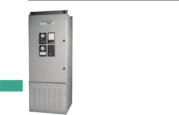
V3-T7-18 Volume 3—Power Distribution and Control Assemblies CA08100004E—February 2012 www.eaton.com
7
7
7
7
7
7
7
7
7
7
7
7
7
7
7
7
7
7
7
7
7
7
7
7
7
7
7
7
7
7
7.3
Medium Voltage Switchgear
High Resistance Grounding System
C-HRG Free-Standing NEMA 1 Unit
Contents
Description Page
High Resistance Grounding System
Features, Benefits and Functions . . . . . . . . . . . V3-T7-21
Standards and Certifications . . . . . . . . . . . . . . . V3-T7-21
Catalog Number Selection . . . . . . . . . . . . . . . . V3-T7-22
Technical Data and Specifications . . . . . . . . . . . V3-T7-23
Dimensions. . . . . . . . . . . . . . . . . . . . . . . . . . . . V3-T7-26
Product Description
Where continuity of service is
a high priority, high resistance
grounding can add the safety
of a grounded system while
minimizing the risk of service
interruptions due to grounds.
The concept is a simple one:
provide a path for ground
current via a grounding
transformer (with adjustable
resistance across its
secondary) that limits the
current magnitude and a
monitor to determine when
an abnormal condition exists.
The ground current path is
provided at the point where
the service begins, by placing
a predominantly resistive
impedance in the connection
from system neutral to
ground. Control equipment
continuously measures
ground current; a relay detects
when the current exceeds a
predetermined level. An alarm
alerts building personnel that a
ground exists. The system
has built-in fault tracing means
to assist in finding the source
of the ground. A 120 Vac
supply (remote) is required for
control power for the system.
Application Description
This member of Eaton’s MV
metal-clad switchgear family
has actually been around
for many years. The free-
standing C-HRG provides
a standalone unit that
can be added to existing
installations. The C-HRG is
used to protect an electrical
distribution system from
damaging transient
overvoltages caused by
ground faults. It also provides
a means to locate the ground
fault, therefore extending the
life of the distribution system.
Ratings and Configurations
The C-HRG MV is offered
at the 5 kV class rating. It
can be applied to delta or
wye ungrouped three-wire
distribution systems.
4200V (Maximum)
Delta Systems
To add high resistance
grounding to an ungrounded
delta-connected system,
a neutral point must be
created. Three single-
phase transformers can be
interconnected in a wye-
broken delta configuration
to provide such a neutral
point. The transformers
and grounding resistors are
chosen to limit the ground
current to a maximum value
of 6A.
Note: The neutral point may not
be used to serve phase-to-neutral
loads. Also, this technique may
be applied on wye-connected
sources when the neutral point is
not conveniently accessible from
the service entrance location.
This method is shown in the
illustration shown on Page V3-T7-
24. One delta high resistance
grounding would ground the 5 kV
system.
4200V (Maximum)
Wye Systems
To add high resistance
grounding to a wye-
connected system, resistors
are placed across the
secondary of a grounding
transformer whose primary
is placed in series with the
neutral-to-ground connection
of the power source. The
resistors are chosen to limit
the current to a maximum
value of 6A.
Note: Per 1993 NEC® 250.5b,
exception No. 5, line-to-neutral
loads may not be connected to
a system in which the neutral
is resistance grounded. Also, if
the system has two switchable
sources not permanently
connected to the bus, two
wye-type grounding systems
are required as shown on
Page V3-T7-24.

Volume 3—Power Distribution and Control Assemblies CA08100004E—February 2012 www.eaton.com V3-T7-19
7
7
7
7
7
7
7
7
7
7
7
7
7
7
7
7
7
7
7
7
7
7
7
7
7
7
7
7
7
7
7.3
Medium Voltage Switchgear
High Resistance Grounding System
Ground Current Detection
Any time a system is
energized, a small ground
current called the “capacitive
charging current” will be
observed. For medium
voltage (4200V and below)
systems, this naturally
occurring current is typically
3A or less.
When one phase becomes
grounded, additional current
above the charging level will
flow. As all ground current
must flow through the
grounding resistor/grounding
transformer assembly, an
ammeter in this circuit will
read the total amount of
ground current. By placing
a current-sensing relay in
series with the ammeter, the
current relay can be adjusted
to pick up at a level in excess
of the capacitive charging
current, thus indicating the
abnormal condition.
Alternatively, an optional
voltmeter-relay can be
connected across the
grounding resistors. The
voltage across the resistors
is proportional to the amount
of ground current. The
voltmeter-relay’s pickup
adjustment is set above the
capacitive charging current,
to the desired detection level.
In both current and voltage
detection methods, the
ground current ammeter
provides a direct reading of
the total actual ground
current present in the system
at that time. It will be helpful
to periodically note the
ammeter’s reading: a trend
toward higher values may
indicate the need for
equipment maintenance, and
hence reduce the occurrence
of unplanned shutdowns.
Indication and Alarm Circuits
When a fault is detected,
an adjustable time delay is
provided to override
transients. When the time
delay has been exceeded,
the green “normal” light will
turn off, the red “ground
fault” light will turn on, and
the ground alarm contacts
will transfer. If equipped
with the optional alarm horn,
it will sound.
The grounding transformer
secondary breaker must be
closed for the system to be
operational. Should this
breaker be opened at any
time, the system will signal
a ground fault condition as a
fail-safe feature. The breaker
must be closed to clear the
alarm signal.
When the fault is cleared,
the current/voltage relay will
reset. If the reset control is
set on “auto,” the lights will
return to “normal” on,
“ground fault” off, and the
ground alarm contacts will
re-transfer. If the reset
control is set on “manual,”
the lights and relay contacts
will remain latched until the
operator turns the reset
control to “reset.” The lights
and ground alarm contacts
will then return to normal.
The system can be reset only
if the fault has been cleared.
During a fault, the optional
alarm horn can be silenced at
any time by using the “alarm
silence” pushbutton. It will
not re-sound until either the
system is reset, or the re-
alarm timer expires. The re-
alarm timer is activated by
the “alarm silence” control. If
the horn has been silenced
but the fault has not been
cleared, the timer will run.
It has a range of 2–48 hours.
When the timer times out,
the horn will re-sound,
alerting maintenance
personnel that the fault
has not been cleared.
Test Circuit
A test circuit is provided to
allow the user to quickly
determine that the system
is working properly. The test
circuit will operate only under
normal conditions—it will not
allow testing if the system is
sensing a fault. The test
operation does not simulate
an actual system ground
fault. It does, however, test
the complete controls of the
fault indication and pulsing
circuitry. The system then
reacts as it would under
actual system ground
conditions —lights transfer,
alarm contacts transfer and
the (optional) horn sounds.
Pulser Circuit
The pulser circuit offers a
convenient means to locate
the faulted feeder and trace
the fault to its origin. The
pulser is available any time
a fault has been detected.
The pulse intervals are
controlled by an adjustable
recycle timer. The “pulse”
light flashes on and off,
corresponding to the
on-off cycles of the pulser
contactor. The pulser
contactor switches a bank
of resistors on and off,
thus allowing a momentary
increase in the ground current
(approximately a
4A current pulse above the
ground current).
Locating a Ground Fault
The current pulses can be
noted with a clamp-on
ammeter when the ammeter
is placed around the cables or
conduit feeding the fault. The
operator tests each conduit or
set of cables until the pulsing
current is noted. By moving
the ammeter along the
conduit, or checking the
conduit periodically along its
length, the fault can be traced
to its origin. The fault may be
located at the point where
the pulsing current drops off
or stops.
If little or no change in the
pulsing current is noted along
the entire length of a conduit,
then the fault may be in the
connected load. If the load is
a panelboard, distribution
switchboard or motor control
center, repeat the process of
checking all outgoing cable
groups and conduits to find
the faulted feeder. If the fault
is not found in an outgoing
feeder, the fault may be
internal to that equipment.
Note: It may not be possible to
precisely locate faults within a
conduit. The ground current may
divide into many components,
depending on the number of
cables per phase, number of
conduits per feeder, and the
number and resistance of each
ground point along the conduits.
The resulting currents may be too
small to allow detection or may
take a path that the ammeter
cannot trace. An important note
to keep in mind is that while the
pulser can greatly aid in locating
a fault, there may be certain
conditions under which the
pulses cannot be readily traced,
and other test procedures
(megohm, high-potential, etc.)
may be needed.

V3-T7-20 Volume 3—Power Distribution and Control Assemblies CA08100004E—February 2012 www.eaton.com
7
7
7
7
7
7
7
7
7
7
7
7
7
7
7
7
7
7
7
7
7
7
7
7
7
7
7
7
7
7
7.3
Medium Voltage Switchgear
High Resistance Grounding System
Sequence of Operations
Normal
●Green “normal” light on
●Red “ground fault” light off
●White “pulse” light off
●System control switch in
“normal” position
●Reset control switch in
either “auto” or “manual”
Test
Turn and hold the system
control switch in the “test”
position. This mode will test
the control circuitry only.
It will bypass the sensing
circuit and cause the green
“normal” light to turn off and
the red “ground fault” light
to turn on. The pulser will be
activated as well. The white
“pulse” light will turn on and
off as the pulser contactor
closes and opens. However,
the ground current ammeter
will not display the total
ground current, including the
incremental pulse current.
When ready, return the
system control switch to
“normal.” The pulser will
stop. If the reset control is in
the “manual” position, turn it
to “reset” to reset the fault
sensing circuit. The red
“ground fault” light will turn
off, and the green “normal”
light will turn on. Test mode
is not available if the system
is detecting a ground. The
sensing circuit will disable
the test circuit.
Ground Fault
When the sensing circuit
detects a fault, the green
“normal” light will turn off
and the red “ground fault”
light will turn on. The ground
current ammeter will indicate
the total ground current.
To use the pulser, turn the
system control switch to
“pulse.” The pulser contactor
will cycle on and off as
controlled by the recycle
timer relay. Use the clamp-on
ammeter to locate the faulted
feeder. Open the feeder and
clear the fault. If the reset
control switch is in the
“manual” position, turn it to
“reset” to reset the sensing
circuit. (If reset control is in
“auto,” it will reset itself.)
When ready to restore service
to the load, close the feeder.
Return the system control
to “normal.”

Volume 3—Power Distribution and Control Assemblies CA08100004E—February 2012 www.eaton.com V3-T7-21
7
7
7
7
7
7
7
7
7
7
7
7
7
7
7
7
7
7
7
7
7
7
7
7
7
7
7
7
7
7
7.3
Medium Voltage Switchgear
High Resistance Grounding System
Features, Benefits and Functions
When a ground fault occurs
on an ungrounded system,
high transient voltages can
occur, which may cause more
frequent equipment failures
than if the equipment were
grounded. These transient
overvoltages, as high as four
times the normal voltage,
reduce the life of the system’s
insulation resulting in:
●Motor failure
●Transformer failure
●Coil failure
●Electronic equipment
failure
●Cable insulation failure
By using a high resistance
ground system, many
facilities can gain the benefit
of a grounded system
without impairing the
continuity of service to their
equipment. The concept
behind high resistance
grounding is to provide a path
for the ground current to flow
while limiting its magnitude
by using a resistor. The
ground current path is
provided at the point where
service begins. Control
equipment continuously
monitors the magnitude
of the ground current.
When the ground current
exceeds a predetermined level,
the built-in alarm relay alerts
building personnel that a
ground fault exists. In
addition, the C-HRG MV
“safe ground” system has
a built-in fault pulsing as a
means to assist in finding the
source of the ground fault
without interrupting service.
●Current sensing
ground fault detection
(2–10A pickup/
0.5–20 second delay)
●Ground current
transformer (10/10 ratio)
●Control circuit pull
fuseblock
●Ground current ammeter
(0–10A, 1% accuracy)
●Indicating lights:
●Red (ground fault)
●Green (normal)
●White (pulse)
●Adjustable pulsing timer
(0–10 seconds)
●Tapped resistors
(limits primary current
to 3–6A)
●Three-position selector
switch (normal, pulse, test)
●Control switch for manual
or automatic reset
●Ground fault contacts
(1NO/1NC)
●Shorting terminal block
for ground current CT
●UL label
●Wiremarkers
Standards and
Certifications
The system shall be
completely assembled, wired
and tested at the factory in
accordance with NEMA and
UL requirements. A certified
production test report shall be
shipped with the unit.
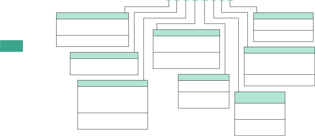
V3-T7-22 Volume 3—Power Distribution and Control Assemblies CA08100004E—February 2012 www.eaton.com
7
7
7
7
7
7
7
7
7
7
7
7
7
7
7
7
7
7
7
7
7
7
7
7
7
7
7
7
7
7
7.3
Medium Voltage Switchgear
High Resistance Grounding System
Catalog Number Selection
A C-HRG High Resistance Grounding Assembly can be completely described by an 8-digit catalog number: MVRG-_ _ _ _ _ _ _ _
High Resistance Grounding Systems
Example: MVRG-FWWCLLTS defines a free-standing NEMA 1 enclosure, 4200V/60 Hz, wye-connected system,
current-sensing control scheme, alarm horn with re-alarm timer, alarm relay with 1NO and 1NC, transformer type
incandescent lights, wrap-on wiremarkers.
Service Voltage
W= 4200V, 60 Hz
X= 2400V, 60 Hz
Y= 3300V, 60 Hz
System Neutral Point
Choose wye when the neutral point of
the power source is accessible for direct
connection to grounding transformer.
Choose delta when there is no neutral or
when neutral is not accessible.
W=Wye
D= D (wye broken delta
grounding transformer)
Fault Sensing
Current sensing
Voltage sensing
Voltage sensing
C= Overcurrent relay
V= Single set point voltmeter relay
D= Indicating voltmeter only
Enclosure Type
Free-standing enclosure for mounting
grounding transformer and resistors
internally.
F= Free-standing NEMA 1
R= Free-standing NEMA 3R outdoor
Wiremarkers
Marks all internal wiring for ease
of maintenance.
S= Standard wrap-on
T= Tube/heat shrink type
Indicating Lamps
Standard lights are industrial, oil-tight,
transformer type. Optional are the same
type lights except with a push-to-test
feature.
T= Transformer type incandescent lamps
X= Push-to-test transformer type
Loss of Control
Power Alarm
A relay is connected across
the customer’s 120 Vac
supply.
N=No relay
L= Alarm relay with
1NO and 1NC
Audible Alarm
Alarm contacts are standard
on all assemblies.
N= No audible alarm
L= Alarm horn with
re-alarm timer
MVRG F X D D N L T S

Volume 3—Power Distribution and Control Assemblies CA08100004E—February 2012 www.eaton.com V3-T7-23
7
7
7
7
7
7
7
7
7
7
7
7
7
7
7
7
7
7
7
7
7
7
7
7
7
7
7
7
7
7
7.3
Medium Voltage Switchgear
High Resistance Grounding System
Technical Data and Specifications
General
Provide a high resistance
grounding system as a means
to provide a path
for ground current via a
resistance that limits the
current magnitude. While
monitoring the ground
current, the system must be
able to determine when an
abnormal condition exists.
Once the abnormality is
detected, the system shall
alert building personnel that
a ground exists. The system
shall be suitable for 5000V
maximum service, and
designed and tested for that
voltage class in accordance
with the latest standards of
NEMA and UL.
●Tapped resistors supply
primary ground current
between 3 and 6A in
1A increments
●Pulse current is an
additional 4A. (pulse
currents of a lower
magnitude may be difficult
to detect)
●Pulse timer is adjustable
from 3 to 60 pulses
per minute
●Time delay for current
sensing relay is 0.5 to
20 seconds with a 2 to
10A pickup. Time delay
for voltage sensing relay is
1 to 60 seconds
●“Pull-type” fuse
disconnects are supplied
for control equipment
protection
●All exterior nameplates are
fastened with stainless
steel screws
●Nameplates are 2-ply
with 3/16-inch (4.8 mm)
lettering. The nameplate
size is 1-inch (25.4 mm)
x 2-1/2-inch (63.5 mm).
White background with
black lettering is standard
●Top and bottom cable
entry areas
●Phase and neutral
terminals accept #4 AWG
to 500 kcmil
●Ground terminal accepts
wire sizes from #4 AWG
to 500 kcmil. Ground bus is
1/4-inch (6.35 mm) x 2-inch
(50.8 mm) copper
●The powder paint is applied
to the parts
electrostatically. Metal
surfaces are prepared by
spray cleaning and
phosphatizing. The powder
paint is a polyester
urethane. The standard
color is ANSI 61, light gray.
The paint is applied to a
thickness of 1.5 mil
●Appropriate current limit
drawout type fuses are
provided. The chassis is
mechanically interlocked
with a secondary circuit
breaker to prevent its
withdrawal under
load conditions
●Resistors are grid type to
provide the maximum area
for heat dissipation
●No. 4 AWG wire is used for
internal connections from
the neutral point to ground.
Control connections are a
minimum of #14 gauge.
All control wires insulation
is type SIS
●Recommended spare
parts list
●Steel pocket on the inside
of the door is provided to
hold drawings and manuals
Note: The C-HRG units can
be applied on any three-wire
distribution system, regardless
of the manufacturer of the
distribution equipment or
source power transformer.
System Ratings and Features
Provide a UL-labeled high-
resistance grounding system
equal to Eaton catalog
number _________ for use on
a system with a short-circuit
capacity of __kA at ____ volts.
The structure shall be a [free-
standing NEMA 1] [free-
standing NEMA 3R]. The
system neutral point shall
be provided by [the power
transformer’s wye neutral
point] [wye-broken delta
grounding transformers].
The ground current shall be
detected with [an overcurrent
relay] [a single set point
voltmeter relay]. [An alarm
horn with re-alarm timer is
required.] [An alarm to
indicate the loss of control
power is required.] The
indicating lights shall
be [transformer-type
incandescent lamps] [push-to-
test transformer type lamps].
Control wiring shall be
marked using [wrap-on type]
[heat-shrink sleeve type]
wiremarkers. [A portable
clamp on detector with 1/2/5/
10/20A scales, a shorting
switch and a storage case is
required].
In addition to the components
specified, the following shall
be supplied with each
system:
●Ground current
transformer (10/10 ratio)
●Control circuit disconnect
switch (fused)
●Ground current ammeter
(0–10A, 1% accuracy)
●Control switch for manual
or automatic reset
●Ground fault contacts
(1NO/1NC) for
customer use
●Shorting terminal block
for ground current CT
●Adjustable pulsing timer
(0–10 seconds)
●Tapped resistors
(across neutral forming
transformer secondary,
limiting primary current
to 3–6A)
●Three-position selector
switch (normal, pulse, test)
●Indicating lights:
Red (ground fault)
Green (normal)
White (pulse)
Components and
Connections
Phase and neutral terminals
shall accept #4 AWG to 500
kcmil wire. Ground terminals
shall accept wire sizes from
#8 AWG to 500 kcmil. Ground
bus shall be 1/4-inch (6.35 mm)
x 2-inch (50.8 mm) copper.
#4 AWG wire shall be used for
all internal connections from
the neutral point to ground.
Control connections shall be
a minimum of #14 gauge. All
control wire insulation shall
be type SIS. All control wiring
shall be labeled at each end.
Wiring within the resistor
assembly shall be rated for
200°C service.
Structure
The unit shall be free-
standing and house the
resistor bank within an
isolated section of the
structure. Access to the
resistor shall be via a bolted-
on cover. The rear cover shall
be removable. The structure
shall provide top and bottom
cable entry points. Lifting
angles shall be provided to
facilitate the installation of the
unit. The structure shall be
suitable for moving on rollers
and shall be skidded for
shipment in a manner
suitable for handling by
a forklift.
All steel parts (except for
plated parts) shall be
thoroughly cleaned and
phosphatized prior to the
application of the light gray
ANSI No. 61 finish. A pocket
is required on the inside of
the control compartment
door to store drawings
and manuals.
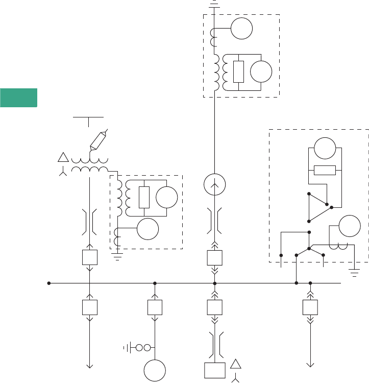
V3-T7-24 Volume 3—Power Distribution and Control Assemblies CA08100004E—February 2012 www.eaton.com
7
7
7
7
7
7
7
7
7
7
7
7
7
7
7
7
7
7
7
7
7
7
7
7
7
7
7
7
7
7
7.3
Medium Voltage Switchgear
High Resistance Grounding System
Wiring Diagram
HRG—High Resistance Grounding System
Wye HRG
51N
59
Delta HRG
59
51
Generator
Bus
Duct
Bus
Duct
To Power
Circuit
Conduit
5 kV Switchgear
To MCC
Cable
Bus
Duct
Wye HRG
51N
59
Utility
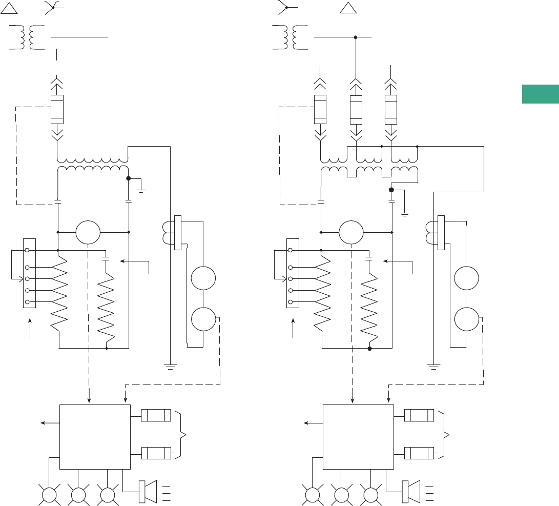
Volume 3—Power Distribution and Control Assemblies CA08100004E—February 2012 www.eaton.com V3-T7-25
7
7
7
7
7
7
7
7
7
7
7
7
7
7
7
7
7
7
7
7
7
7
7
7
7
7
7
7
7
7
7.3
Medium Voltage Switchgear
High Resistance Grounding System
Circuit Diagrams
Ungrounded Wye System (with standard current and
optional voltage relay fault detectors)
Ungrounded Delta System (with standard current and
optional voltage relay fault detectors)
Detector
Current
Detector
Voltage
Mechanical
H3
H2 H1
X3
X2
X1
X0
Ungrounded
Wye
To
Distribution
Circuits
X0
5 kV - CLE
Fuses
Interlock
[1]
Control
Power
Transformer
Secondary
Circuit
Breaker
BB
59
Short
Circuit
T.B.
AM
5IN
CT 10/10A
Pulsing Resistor
Pulsing Contactor
Grounding Resistor
Ground
Current
Adjustment
T.B.
To
Remote
Alarm
GRW
Control
Circuit
Normal Alarm Pulsing Audible
Alarm
Optional
20A
20A
Fuses 120V
60 Hz
Supply
Optional
C
3A
4A
5A
6A
4
Option
Current
Detector
Detector
Voltage
H3
Mechanical
H2
H1
Ungrounded
Delta To
Distribution
Circuits
5 kV - CLE
Fuses
Interlock
3-Auxiliary
Control
Power
Transformers
Secondary
Circuit
Breaker
BB
59
Short-Circuit
T.B .
AM
5IN
CT 10/10A
Pulsing Resistor
Pulsing Contactor
Grounding Resistor
Ground
Current
Adjustment
T.B.
To
Remote
Alarm
GRW
Control
Circuit
Normal Alarm Pulsing Audible
Alarm
Optional
20A
20A
Fuses 120V
60 Hz
Supply
Optional
C
3A
4A
5A
6A
4
X3
X2 X1
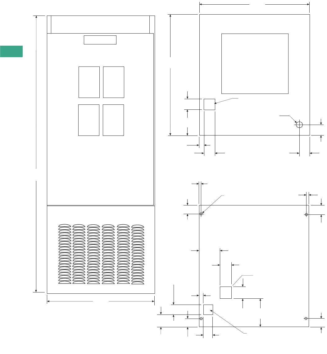
V3-T7-26 Volume 3—Power Distribution and Control Assemblies CA08100004E—February 2012 www.eaton.com
7
7
7
7
7
7
7
7
7
7
7
7
7
7
7
7
7
7
7
7
7
7
7
7
7
7
7
7
7
7
7.3
Medium Voltage Switchgear
High Resistance Grounding System
Dimensions
Approximate Dimensions in Inches (mm)
NEMA 1 Free-Standing
Primary Conduit
Entrance
Vent
92.00
(2336.8)
36.00
(914.4)
36.00
(914.4)
40.00
(1016)
3.50
(88.9)
8.50
(215.9)
1.50
(38.1) 3.76
(95.6)
3.62
(91.9)
3.25
(82.6)
7. 1 2
(180.9)
9.38
(238.3)
3.50
(88.9)
3.75
(95.3)
3.00
(76.2)
2.75
(69.9)
1.75
(44.5)
0.81
(20.6)
0.562 (14.3) Diameter (4)
Primary Conduit
Conduit Entrance
Secondary Conduit
Entrance
2.00 (50.8) Diameter
Knockout
for Secondary
Conduit Entrance
Plan View
Front View
Floor Plan
3.75
(95.3)
3.75
(95.3)
2.75
(69.9)
2.75
(69.9)
0.81
(20.6)
2.75
(69.9)

Volume 3—Power Distribution and Control Assemblies CA08100004E—February 2012 www.eaton.com V3-T8-1
8
8
8
8
8
8
8
8
8
8
8
8
8
8
8
8
8
8
8
8
8
8
8
8
8
8
8
8
8
8
Network Protectors
CM52 Network Protector
8.1 Drawout Air Circuit Breaker Design
Network Protectors—CM52. . . . . . . . . . . . . . . . . . . . . . . . . . . . . . . . . V3-T8-2
Product Description . . . . . . . . . . . . . . . . . . . . . . . . . . . . . . . . . . . . . V3-T8-2
Application Description . . . . . . . . . . . . . . . . . . . . . . . . . . . . . . . . . . V3-T8-2
Features, Benefits and Functions. . . . . . . . . . . . . . . . . . . . . . . . . . . V3-T8-2
Standards and Certifications . . . . . . . . . . . . . . . . . . . . . . . . . . . . . . V3-T8-3
Technical Data and Specifications . . . . . . . . . . . . . . . . . . . . . . . . . . V3-T8-3
8.2 Network Relay
Network Relay—MPCV . . . . . . . . . . . . . . . . . . . . . . . . . . . . . . . . . . . . V3-T8-4
Product Description . . . . . . . . . . . . . . . . . . . . . . . . . . . . . . . . . . . . V3-T8-4
Application Description . . . . . . . . . . . . . . . . . . . . . . . . . . . . . . . . . . V3-T8-4
Features, Benefits and Functions . . . . . . . . . . . . . . . . . . . . . . . . . . V3-T8-4
8.3 Network Protector Aftermarket
Network Protector Rebuild and Parts Program . . . . . . . . . . . . . . . . . . V3-T8-5
Parts . . . . . . . . . . . . . . . . . . . . . . . . . . . . . . . . . . . . . . . . . . . . . . . . V3-T8-5
Rebuild Services . . . . . . . . . . . . . . . . . . . . . . . . . . . . . . . . . . . . . . . V3-T8-5
Quick Ship . . . . . . . . . . . . . . . . . . . . . . . . . . . . . . . . . . . . . . . . . . . . V3-T8-5
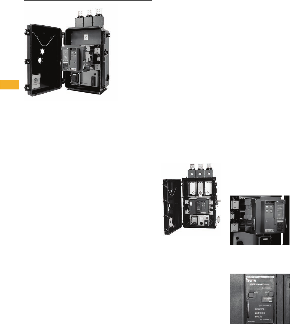
V3-T8-2 Volume 3—Power Distribution and Control Assemblies CA08100004E—February 2012 www.eaton.com
8
8
8
8
8
8
8
8
8
8
8
8
8
8
8
8
8
8
8
8
8
8
8
8
8
8
8
8
8
8
8.1
Network Protectors
Drawout Air Circuit Breaker Design
CM52 Network Protector
Contents
Description Page
Network Protectors—CM52
Standards and Certifications . . . . . . . . . . . . . . . V3-T8-3
Technical Data and Specifications . . . . . . . . . . . V3-T8-3
Network Protectors—CM52
Product Description
Network protectors are
special self-contained air
power breaker units having
a full complement of current,
potential and control
transformers, as well as
relay functions to protect the
integrity of the low voltage
network bus. The network
protector can be in NEMA®
housing, submersible
housing, or suitable for
mounting within a low
voltage switchgear assembly.
Several network protector
models exist including the
CM52, CMD and CM-22.
The most recent model, the
CM52 network protector, is
highlighted in the following
paragraphs.
Application Description
Network protectors are
mainly used by utilities
around the world. They are
configured in either a spot
or grid network. Most
installations of network
protectors are in under-
ground vaults and require
a submersible enclosure.
Commercial applications
also exist for customers that
require highly reliable, stable
power. These applications
typically use a NEMA
enclosure and are configured
in a spot network. Some
examples of commercial
users are government
buildings, hospitals,
universities and industrial
plants.
Features, Benefits and Functions
Eaton’s Type CM52 is
designed for improved safety,
higher quality, ease of
maintenance and inventory
reduction.
CM52—Highlight of Relay Module
●Standardized breaker
elements throughout
entire electrical ratings
allow for the use of
common parts and
accessories
●Smaller breaker element is
less than half the weight of
existing network designs
●The CM52 is the first
network protector to pass
10 kV BIL, giving an
additional measure of
safety and performance
●Ratings of 800–6200A,
216–600V, internal or
external fuses and NEMA
or submersible enclosures,
completely cover the
needs of the network
protector industry
●Deadfront 4-position
drawout breaker helps
protect the user from
accidental contact with live
circuits and makes
maintenance and
troubleshooting easier
Deadfront, Drawout Breaker
●More diagnostics through
the Indicating Diagnostic
Module (IDM)
Indicating Diagnostic Module (IDM)
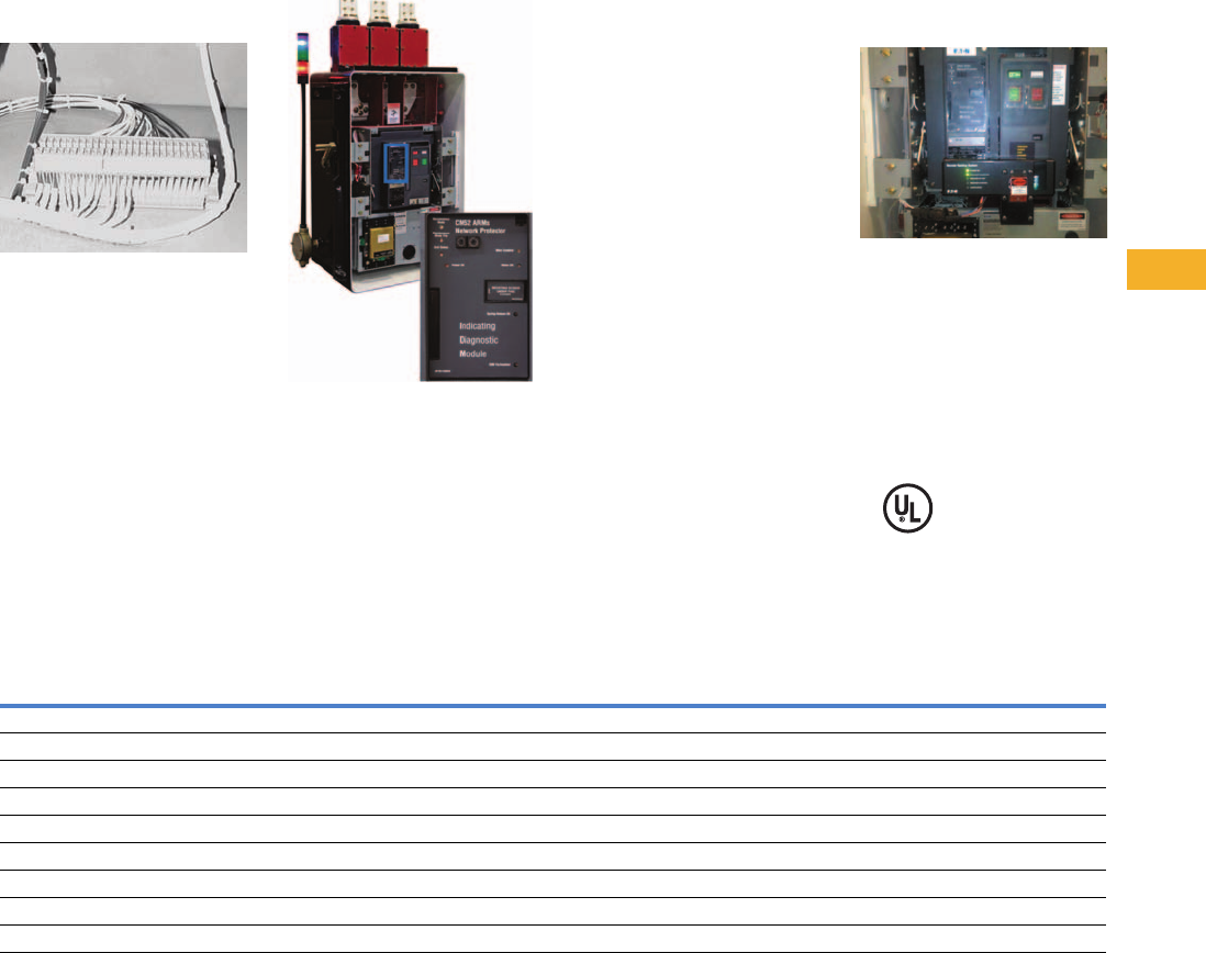
Volume 3—Power Distribution and Control Assemblies CA08100004E—February 2012 www.eaton.com V3-T8-3
8
8
8
8
8
8
8
8
8
8
8
8
8
8
8
8
8
8
8
8
8
8
8
8
8
8
8
8
8
8
8.1
Network Protectors
Drawout Air Circuit Breaker Design
●Front-mounted test points
give easy access and quick
test cable connection
●Color-coded Teflon® wiring
for easier troubleshooting
Color-Coded Wiring
●The CM52 breakers are all
wired the same regardless
of system voltage (216V,
480V and 600V)
●3NO and 3NC dry contacts
are standard as spare
Options
Arc Flash
VaultGard™ Arcflash Reduction
Maintenance System™ Indicating
Diagnostic Module
The CM52 Network Protector
is available with the NPARMs
module (Arcflash Reduction
Maintenance System).
This device is internal to the
Network Protector and can be
remotely activated usually
through a switch mounted at
the vault entrance or through
communications. This will
enable the “ARMS” device
on all CM52s in a spot
network. Once activated,
the NPARMs places the
protectors in a sensitive
mode, sensing both forward
and reverse current
directions. This device will
actuate in 3–4 ms and call for
all CM52 breakers to trip if a
fault is sensed on an adjacent
network protector or collector
bus. It has been shown that
this device limits the total
incident energy to less than
8 cal/cm2.
Remote Racking System
The CM52 Network Protector
is also available with an
integral remote racking
system. The system remotely
racks the breaker off the
energized bus work while
the door is still closed to the
“test” position either through
an external pendant or
through communications.
Remote Racking System
Standards and Certifications
●Meets or exceeds the
standards in IEEE®
C57.12.44
●The CM52 Network
Protector is UL labeled and
approved in the NEMA
housing at all ratings
Technical Data and Specifications
CM52 Ratings Comparison Table—Ratings Tested at 600V
Notes
1Close and latch ratings apply only to spring close and stored energy mechanisms. The CM22 does not have a close and latch rating.
2Open frame only, tested at 500V.
Continuous Current
Rating (Amperes)
Breaker Element
Width in Inches (mm)
CM52 Interrupting
Rating (kA)
CM52 Close and
Latch Rating (kA)
IEEE/ANSI Interrupting
Rating (kA)
IEEE/ANSI 1 Close and
Latch Rating (kA)
800 17.00 (431.8) 42 35 30 25
1200 17.00 (431.8) 42 35 30 25
1600/1875 17.00 (431.8) 42 35 30 25
2000 17.00 (431.8) 42 35 35 35
2500/2825 22.00 (558.8) 65 45 60 40
3000 22.00 (558.8) 65 45 60 40
3500 35.00 (889.0) 85 65 60 40
4500 35.00 (889.0) 85 65 60 40
6200 235.00 (889.0) 85 65 Product not defined Product not defined
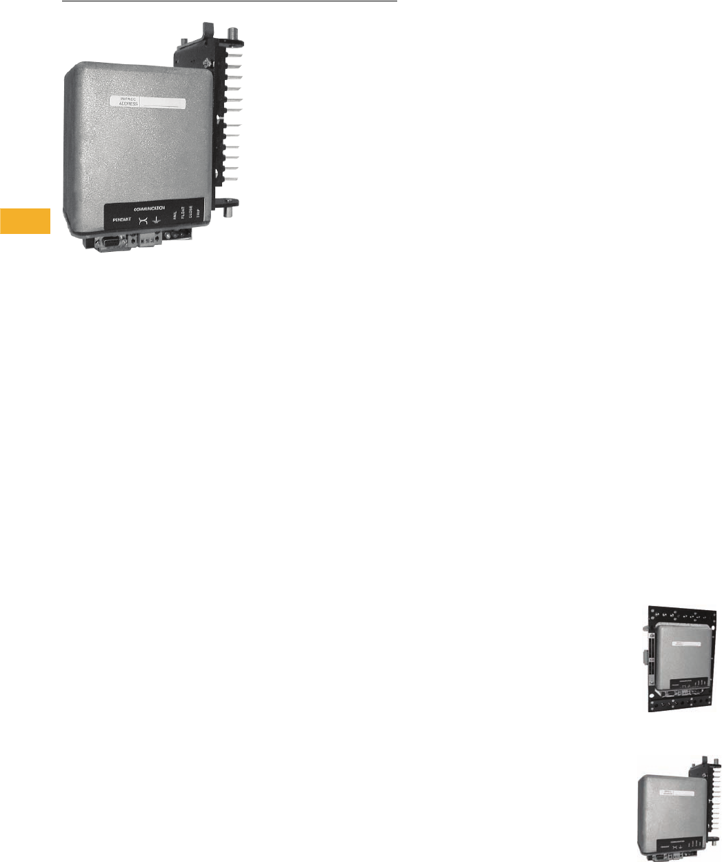
V3-T8-4 Volume 3—Power Distribution and Control Assemblies CA08100004E—February 2012 www.eaton.com
8
8
8
8
8
8
8
8
8
8
8
8
8
8
8
8
8
8
8
8
8
8
8
8
8
8
8
8
8
8
8.2
Network Protectors
Network Relay
MPCV Communications Relay
Contents
Description
Network Relay—MPCV
Network Relay—MPCV
Product Description
Type MPCV Network Protector
Communications Relays for
216V and 480V Systems
●Eaton’s programmable
MPCV network relay brings
the proven performance
of microprocessor-based
technology to new network
protectors...or those
already in service
regardless of age
or manufacturer
●The MPCV contains
industry exclusive features
such as:
●Gull Wing Trip
Characteristic
●Remote Protective
Close
●Anti-Pumping Algorithm
●With the MPCV, you can
select the characteristic
curves to monitor and
control the network
protector through Eaton
products such as the
VaultGard, DNPMINT
and NPView
Application Description
Factory or Field Installation
Eaton can factory mount
MPCV relays on new network
protectors...or personnel can
easily field mount them on
these existing network
protectors:
●Eaton Types CM52, CMD,
CM-22 or CMR-8
●General Electric® Type s
MG-8, MG-9 or MG-14
Field installation is
accomplished without breaker
modification or any rewiring of
the breaker control harness.
MPCV relays operate on 216V
and 480V systems. Relay
potential transformers are
required for 480V applications.
Features, Benefits and Functions
Communications Capability
Each MPCV relay has the
capability of communicating
information and allowing
control over a shielded twisted
pair communications wire.
Communications can be
provided by a Web-enabled
interface or direct DNP 3.O
to SCADA systems. Eaton
has multiple choices for
communication interfaces
such as VaultGard for total
vault communications,
NPView- simple Web server
or DNPMINT.
For localized access, the
MPCV relay has the capability
of wireless communication,
monitoring and control with
the Eaton wireless products.
●The MPCV is built for the
harshest environments,
with an operation
temperature of –40°F
(–40°C) up to 257°F
(125°C). The MPCV is
housed in a 0.25-inch
(6.35 mm) thick solid cast
brass can
●Access and display
information from the MPCV
such as: voltage, current,
power, power factor,
date and time stamped
trip events, internal
temperature and operations
counter of breaker
●Through auxiliary inputs on
the MPCV relay, operators
can monitor other vault
environment parameters
such as transformer top oil
temperature, water in the
network vault, fire alarm or
network enclosure pressure
●Event trending, threshold
alarms and e-mail
forwarding
●Multiple MPCVs can
be connected together
either as a daisy chain,
T-configuration or a
combination.
MPCV Communications Relay
for Eaton Network Protectors
MPCV Communications Relay for
General Electric Network Protectors
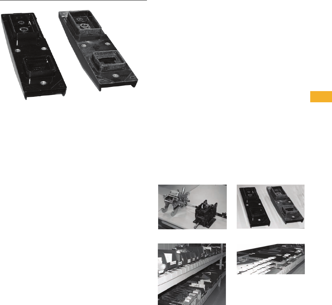
Volume 3—Power Distribution and Control Assemblies CA08100004E—February 2012 www.eaton.com V3-T8-5
8
8
8
8
8
8
8
8
8
8
8
8
8
8
8
8
8
8
8
8
8
8
8
8
8
8
8
8
8
8
8.3
Network Protectors
Network Protector Aftermarket
Rebuild Program
Contents
Description
Network Protector Rebuild and Parts Program
Network Protector Rebuild and Parts Program
Parts
●Renewal parts for all
network protector models:
●Eaton, Westinghouse®:
CM-22, CMD, CM52 and
CMR-8
●General Electric: MG-8,
MG-9 and MG-14
●24-hour shipment when
required for parts in stock
Rebuild Services
Eaton’s Electrical Sector
is setting the standard of
reliability with a reconditioning
process that involves total
breaker and enclosure
disassembly, material
specific component cleaning,
detailed inspection and state-
of-the-art testing, all done to
uniform documented
specifications.
Eaton offers a CM52 retrofit
breaker for legacy CMD and
GE Network Protectors. The
breaker can be installed in
existing network protector
enclosures without having to
remove the enclosure from
the vault or having to remove
the secondary cable
connections, saving both
time and money.
Quick Ship
Eaton can build and ship
brand new CM-22 or CMD
network protectors in 4 to
6 weeks.
Retrobuild Before
Parts
Retrobuild After
Parts

Volume 3—Power Distribution and Control Assemblies CA08100004E—November 2013 www.eaton.com V3-T9-1
9
9
9
9
9
9
9
9
9
9
9
9
9
9
9
9
9
9
9
9
9
9
9
9
9
9
9
9
9
9
Metering Devices, Protective Relays,
Software and Connectivity
9.1 Power Xpert Architecture
Introduction . . . . . . . . . . . . . . . . . . . . . . . . . . . . . . . . . . . . . . . . . . . . . V3-T9-2
9.2 Monitoring Software and Reporting
Power Xpert® Software. . . . . . . . . . . . . . . . . . . . . . . . . . . . . . . . . . . . . V3-T9-14
9.3 Metering Devices
Product Overview . . . . . . . . . . . . . . . . . . . . . . . . . . . . . . . . . . . . . . . . . V3-T9-21
Power Xpert Meter 4000/6000/8000 Series. . . . . . . . . . . . . . . . . . . . . V3-T9-30
Power Xpert Meter 2000 Series . . . . . . . . . . . . . . . . . . . . . . . . . . . . . . V3-T9-49
IQ 250/260 Series Electronic Power Meters . . . . . . . . . . . . . . . . . . . . V3-T9-60
IQ 130/140/150 Series Electronic Power Meters . . . . . . . . . . . . . . . . . V3-T9-66
IQ 150S/250S Self-Enclosed Electronic Meters . . . . . . . . . . . . . . . . . . V3-T9-71
IQ 35M . . . . . . . . . . . . . . . . . . . . . . . . . . . . . . . . . . . . . . . . . . . . . . . . . V3-T9-76
IQ Analyzer 6400/6600 Series . . . . . . . . . . . . . . . . . . . . . . . . . . . . . . . V3-T9-79
IQ DP-4000 Series . . . . . . . . . . . . . . . . . . . . . . . . . . . . . . . . . . . . . . . . V3-T9-87
IQ 230 Meters . . . . . . . . . . . . . . . . . . . . . . . . . . . . . . . . . . . . . . . . . . . V3-T9-93
Power Xpert Multi-Point Meter . . . . . . . . . . . . . . . . . . . . . . . . . . . . . . . V3-T9-100
IQ Energy Sentinel™ . . . . . . . . . . . . . . . . . . . . . . . . . . . . . . . . . . . . . . V3-T9-112
PM3 Monitoring and Metering Module . . . . . . . . . . . . . . . . . . . . . . . . V3-T9-121
Current Transformers (CTs). . . . . . . . . . . . . . . . . . . . . . . . . . . . . . . . . . V3-T9-122
Clamp-On Current Transformers. . . . . . . . . . . . . . . . . . . . . . . . . . . . . . V3-T9-131
IQ Flange . . . . . . . . . . . . . . . . . . . . . . . . . . . . . . . . . . . . . . . . . . . . . . . V3-T9-134
Enclosed Meters . . . . . . . . . . . . . . . . . . . . . . . . . . . . . . . . . . . . . . . . . V3-T9-136
9.4 Protective Relays
Product Selection Guide . . . . . . . . . . . . . . . . . . . . . . . . . . . . . . . . . . . . V3-T9-158
FP-6000 Feeder Protection . . . . . . . . . . . . . . . . . . . . . . . . . . . . . . . . . . V3-T9-162
FP-5000 Feeder Protection . . . . . . . . . . . . . . . . . . . . . . . . . . . . . . . . . . V3-T9-172
FP-4000 Feeder Protection . . . . . . . . . . . . . . . . . . . . . . . . . . . . . . . . . . V3-T9-180
MP-3000 Motor Protection. . . . . . . . . . . . . . . . . . . . . . . . . . . . . . . . . . V3-T9-188
MP-4000 Motor Protection. . . . . . . . . . . . . . . . . . . . . . . . . . . . . . . . . . V3-T9-198
MD-3000 Motor/Generator Differential Relay. . . . . . . . . . . . . . . . . . . . V3-T9-204
Digitrip 3000 . . . . . . . . . . . . . . . . . . . . . . . . . . . . . . . . . . . . . . . . . . . . . V3-T9-207
VR-300 Multifunctional Voltage Relay. . . . . . . . . . . . . . . . . . . . . . . . . . V3-T9-217
DP-300 Current Differential Protection Relay . . . . . . . . . . . . . . . . . . . . V3-T9-221
EDR-3000 Feeder Protection . . . . . . . . . . . . . . . . . . . . . . . . . . . . . . . . V3-T9-226
ETR-4000 Transformer Protection Relay. . . . . . . . . . . . . . . . . . . . . . . . V3-T9-237
Ground Fault Relay . . . . . . . . . . . . . . . . . . . . . . . . . . . . . . . . . . . . . . . . V3-T9-250
Universal RTD Module . . . . . . . . . . . . . . . . . . . . . . . . . . . . . . . . . . . . . V3-T9-254
IQ 125 Volt DC Power Supply . . . . . . . . . . . . . . . . . . . . . . . . . . . . . . . . V3-T9-258
9.5 Connectivity Options
Power Xpert Gateways . . . . . . . . . . . . . . . . . . . . . . . . . . . . . . . . . . . . . V3-T9-259
Power Xpert Ethernet Switches . . . . . . . . . . . . . . . . . . . . . . . . . . . . . . V3-T9-272
Power Xpert Gateway Series 1000 Card—Power Distribution Unit . . . V3-T9-276
Power Xpert Gateway Series 2000 Card—Uninterruptible Power
Supplies . . . . . . . . . . . . . . . . . . . . . . . . . . . . . . . . . . . . . . . . . . . . . . . V3-T9-279
mMINT . . . . . . . . . . . . . . . . . . . . . . . . . . . . . . . . . . . . . . . . . . . . . . . . . V3-T9-282
MINTII RS-232 Converter . . . . . . . . . . . . . . . . . . . . . . . . . . . . . . . . . . . V3-T9-284
IPONI . . . . . . . . . . . . . . . . . . . . . . . . . . . . . . . . . . . . . . . . . . . . . . . . . . V3-T9-285
DPONI . . . . . . . . . . . . . . . . . . . . . . . . . . . . . . . . . . . . . . . . . . . . . . . . . V3-T9-286
MPONI . . . . . . . . . . . . . . . . . . . . . . . . . . . . . . . . . . . . . . . . . . . . . . . . . V3-T9-287
I/O Devices Digital Input Module (DIM) . . . . . . . . . . . . . . . . . . . . . . . . V3-T9-288
Addressable Relay II . . . . . . . . . . . . . . . . . . . . . . . . . . . . . . . . . . . . . . . V3-T9-290
Breaker Interface Module II (BIM II) . . . . . . . . . . . . . . . . . . . . . . . . . . V3-T9-293
Sub-Network Master Local Display (SMLD) . . . . . . . . . . . . . . . . . . . . . V3-T9-297
IMPCABLE . . . . . . . . . . . . . . . . . . . . . . . . . . . . . . . . . . . . . . . . . . . . . . V3-T9-299

V3-T9-2 Volume 3—Power Distribution and Control Assemblies CA08100004E—November 2013 www.eaton.com
9
9
9
9
9
9
9
9
9
9
9
9
9
9
9
9
9
9
9
9
9
9
9
9
9
9
9
9
9
9
9.1
Metering Devices, Protective Relays, Software and Connectivity
Power Xpert Architecture
Power Xpert Architecture
Contents
Description Page
Power Xpert System . . . . . . . . . . . . . . . . . . . . . . . V3-T9-3
Power Xpert Architecture . . . . . . . . . . . . . . . . . . . . V3-T9-4
Level 0—Small System with Smart Hardware . V3-T9-8
Level 1—Using Power Xpert Gateways . . . . . . V3-T9-9
Level 2—Power Xpert Software . . . . . . . . . . . . V3-T9-11
Level 3—Eaton’s Electrical Services & Systems (EESS)
Customized Software Solutions . . . . . . . . . . . V3-T9-13
An Eaton
Green Solution
Introduction
Enabling Power
System Management
Eaton’s Power Xpert
Architecture (PXA) provides a
complete hardware/software
solution to manage your
entire power system. Power
Xpert Architecture consists
of Power Xpert Meters,
Gateways, Switches
and Software.
Power Xpert devices are
devices that can provide by
themselves, or facilitate for
others, Ethernet network
protocols to communicate
with your critical infrastructure
components. Power Xpert
devices provide the intelligent
hardware connectivity layer
to allow Web-enabled
communications throughout
the power system.
Power Xpert Meters
Power Xpert Meters provide
measurement of the critical
elements found in power
systems, including voltage,
power, current, transients,
harmonics or even time.
Power Xpert Meters
provide Web-enabled
communications for use
through a Web browser or
with the Power Xpert
Software or third-party
monitoring systems.
Power Xpert Gateways
Power Xpert Gateways are
capable of Web-enabling
electrical devices contained in
electrical gear via a standard
Web-browser on the Ethernet
network. Standard on-board
Web pages eliminate the
need for any customer
programming or software.
Power Xpert Software
Power Xpert Software is a
comprehensive solution for
system-level management of
your power infrastructure via
a Web-browser. Power Xpert
Software provides a clear
picture of what is happening
at a component, device and
system level.
Because no two organiza-
tion’s needs are the same,
Power Xpert Software is
available in two editions:
Power Xpert Software
Professional Edition
Geared toward end users,
with built-in support for Eaton
power distribution products
such as switchgear, UPSs,
breakers, PDUs, RPPs,
meters, relays, VFDs and
MCCs among others.
Eaton products connect with
the software directly via an
Ethernet connection, while
legacy devices use a Power
Xpert Gateway to Web-
enable their communications.
A subset of third-party meters
and devices are supported as
standard via the gateway
connection.
Power Xpert Software
Enterprise Edition
Geared toward advanced
power users, system
integrators and enterprises
with heterogeneous device
spectrum and system
developers who can take
advantage of the included
SNMP and Modbus®
integration development
utilities.
●Extensive support for
third-party devices via
standard SNMP and
Modbus TCP protocols
●Large variety of ready
made third-party drop
in drivers
Support for Existing
PowerNet Systems
Power Xpert is directly
compatible with existing
PowerNet™ systems
v.3.32 and higher. All
communications hardware
devices such as NetLink,
EMINT, MINT II and EPONI
can be connected to Power
Xpert Software through the
PowerNet server for
configuration of the INCOM™
communication devices.
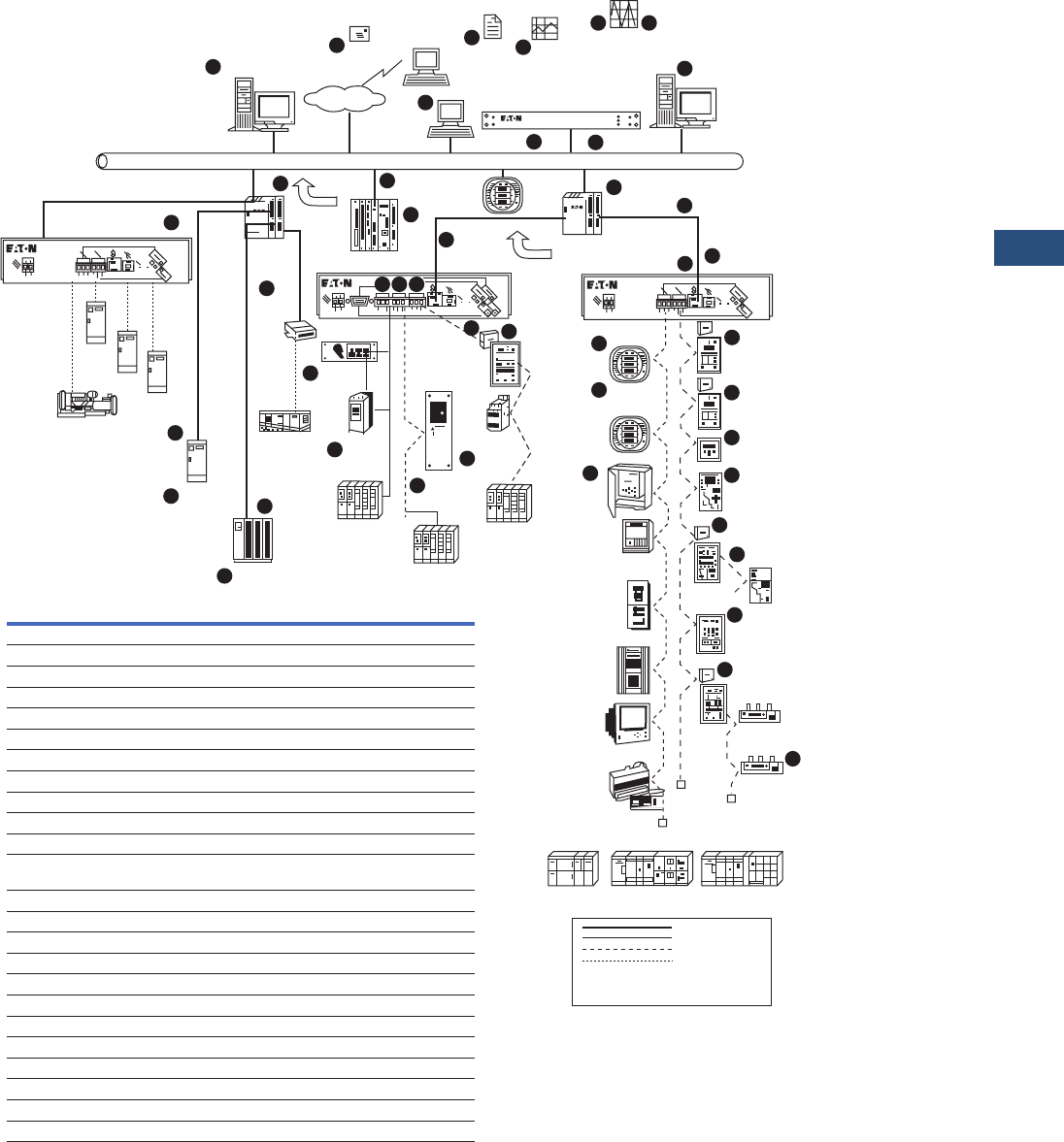
Volume 3—Power Distribution and Control Assemblies CA08100004E—November 2013 www.eaton.com V3-T9-3
9
9
9
9
9
9
9
9
9
9
9
9
9
9
9
9
9
9
9
9
9
9
9
9
9
9
9
9
9
9
9.1
Metering Devices, Protective Relays, Software and Connectivity
Power Xpert Architecture
Power Xpert System
See Notes on Page V3-T9-4.
Power Xpert System Overview
PXG 400
PXG 400
Power Xpert Software
Email
(SMTP)
Web Browser
(WAN)
Data
Export
(csv)
Data
Trending
Web Browser
(LAN)
HTTP
Internet
Waveform
Capture and Acquisition
3rd Party HMI
Software
Modbus TCP/IP
NTP
Power Xpert
Meter
4000/6000/8000
BACnet/WS+
Motor Controls
Power Xpert
Gateway 600
BACnet/WS+
Power Distribution
Power Xpert
Ethernet Switch
Power Xpert
Gateway 400
IQ Analyzer
Meter w/PONI Card
IQ 250/250
Meters
IQ 130/140/150
Meters
Advantage
Central
Monitoring
Unit
w/WPONI
IT. Cover
Controls
Single
Port
Device
Server
Power Xpert
Gateway
ATS
STS
PDU
GEN & CTRL CRAC
Critical Power
Distribution & Cooling
Eaton
PDU
IT. MCC
IT. S811
Soft
Starter
EOLR
Freedom
MCC
EOLTR
Advantage
MCC
SVX9000
MVX9000
Drive
Advantage
Starter
InsulGard
Relays
IQ DP-4000
Meter w/PONI Card
IQ 220/230
Meters
DT-1150
Trip Unit
Breaker Interface
Module w/PONI Card
OPTIM
Trip Unit
MP-3000/4000
FP-4000/5000
Motor/Protection
Relays
Central Energy Dislay
w/PONI Display
Power
Sentinel Meter
Energy
Sentinel Meter
EOLR
EOLR
EOLRT
EOLRT
LV Switchgear
MV Switchgear
MV Starter
Eaton
UPS
3rd Party Motor
Relays
3rd Party
Protective
Relays
3rd Party
PQ Meters
Ethernet Network
QC Port Network
INCOM Network
RS-485 Network
EOLR
EOLTR End of line termination resistor
End of line resistor
24
23
t
u
22
20
21
n
19
j
k
l
2
4
opq
18
s
17
16
15 6
7
8
9
10
11
12
13
14
r5
m
3
gh
i
1
Network Time Server
a
b
cd
e
f
PXG 400
Power
Xpert
Meter
2000
Power
Xpert
Ethernet
Switch
# Product Name Page Reference
1 Power Xpert Software V3-T9-14
2 Power Xpert Meter 4000/6000/8000 V3-T9-30, V3-T9-49
3 Power Xpert 6-Port Ethernet Switch V3-T9-272
4 Power Xpert Gateway 600 V3-T9-259
5 Power Xpert Gateway 400 V3-T9-259
6 IQ Analyzer V3-T9-79
7 IQ DP-4000 V3-T9-87
8 IQ 220/230 Series Meters V3-T9-93
9 Digitrip DT1150 V3-T9-260
10 Breaker Interface Module V3-T9-293
11 OPTIM Trip Unit V3-T9-263
12 MP-3000/MP-4000/MD-3000
DT-3000/FP-4000/FP-5000
V3-T9-188, V3-T9-198, V3-T9-204,
V3-T9-207, V3-T9-180, V3-T9-172
13 Central Energy Display V3-T9-5
14 Energy/Power Sentinel V3-T9-112
15 IQ 130/140/150 Meter V3-T9-66
16 IQ 250/260 Meter V3-T9-60
17 InsulGard™ Relay V3-T9-264
18 Advantage Central Monitoring Unit V3-T9-5
19 Advantage Starter w/WPONI —
20 SVX9000/MVX9000 Drive —
21 IT. Cover Control —
22 IT. S811 Soft Start —
23 Eaton PDU w/PXGX1000 Card V3-T9-276
24 Eaton PDU w/PXGX2000 Card V3-T9-279

V3-T9-4 Volume 3—Power Distribution and Control Assemblies CA08100004E—November 2013 www.eaton.com
9
9
9
9
9
9
9
9
9
9
9
9
9
9
9
9
9
9
9
9
9
9
9
9
9
9
9
9
9
9
9.1
Metering Devices, Protective Relays, Software and Connectivity
Power Xpert Architecture
Power Xpert Architecture—Notes
a. Simple Mail Transfer
Protocol (SMTP)—
Device events and
periodic data log file
attachments are sent
to users in the form of
an e-mail from the
following Power Xpert
products: Power
Xpert Software,
Power Xpert Meters
2000/4000/6000/
8000, Power Xpert
Gateway 600 and
Power Xpert Gateway
Cards 1000/2000
Series.
b. Hyper Text Transfer
Protocol (HTTP)—
Web browser access
is available on the
following Power Xpert
products: Power
Xpert Software,
Power Xpert Meters
2000/4000/6000/
8000, Power Xpert
Gateway 600 and
Power Xpert Gateway
Cards 1000/2000
Series.
c. Network Time Server
(NTP)—Network Time
Protocol (Client-side)
is available on the
following Power Xpert
products: Power
Xpert Software,
Power Xpert Meters
2000/4000/6000/
8000, Power Xpert
Gateway 600 and
Power Xpert Gateway
Cards 1000/2000
Series.
d. Modbus TCP/IP—
Modbus TCP/IP over
Ethernet is available
on the following
Power Xpert
products: Power
Xpert Software,
Power Xpert Server
Core Software, Power
Xpert Meters 2000/
4000/6000/8000,
Power Xpert Gateway
600 and Power Xpert
Gateway Cards 1000/
2000 Series. Modbus
register maps are
available online at
www.eaton.com/
powerxpert.
e. Data Export—Data
files consist of
metered data and
event log information
that is exported from
the meter, gateway or
software in the form
of a .csv (comma
separated variable)
file. Supported
products are: Power
Xpert Gateway
PXG600, PXGX1000,
PXGX2000, Power
Xpert Meters 2000/
4000/6000/8000
and Power Xpert
Software.
f. Data Trending—
Viewing trended data
in a standard Web
browser interface in
the form of a graphed
line for one or more
data points is available
for the following
products: Power
Xpert Gateway
PXG600, PXGX1000,
PXGX2000, Power
Xpert Meters 2000/
4000/6000/8000
and Power Xpert
Software.
g. Waveform Capture—
The ability to capture
a waveform and/or
export the waveform
as a standard
comtrade file format
is available on the
following products:
Power Xpert Meters
4000/6000/8000.
h. Waveform Acquisition
and Export—The
ability to acquire a
waveform from
another device that
natively captures a
waveform internally
and then export that
waveform in a
standard comtrade
file format is
supported by the
following devices:
PXG600 (provides
data acquisition and
comtrade conversion
for: IQ Analyzer,
DT1150 and FP5000).
Note: The Power Xpert Meters
4000/6000/8000 also export
natively captured waveforms as
comtrade file format.
i. Third-Party HMI
Software Integration—
Is achieved through
the Modbus TCP/IP
interface on all Power
Xpert devices. If
PowerNet software is
utilized in the system,
then an OPC Server
is available.
j. Proprietary Serial
Device Protocols over
Ethernet—The ability
to communicate with
third-party equipment
is achieved through a
Power Xpert Gateway
via Modbus 485 or
Modbus Serial.
k. BACnet/WS+ —
Is based upon the
protocol specification
developed by the
ASHRAE standards
group as an
Addendum c to
Standard 135-2004.
Reference: [BACnet—
A Data
Communication
Protocol for Building
Automation and
Control Networks.
Public Review Draft,
ASHRAE Standard.
BSR/ASHRAE
Addendum c to ANSI/
ASHRAE Standard
135-2004. First Public
Review. Released:
October 22, 2004.
32 pages. Copyright
(c) American
Society of Heating,
Refrigerating and
Air-Conditioning
Engineers, Inc.
August 30, 2004.]
This draft shows proposed
changes to the current
BACnet standard.
Note: Eaton has extended this
protocol addendum with a (+) to
signify the addition of an “event-
driven” behavior to the existing
“polled” data acquisition model.
This allows optimization in
communications between Power
Xpert devices and Power Xpert
Software.

Volume 3—Power Distribution and Control Assemblies CA08100004E—November 2013 www.eaton.com V3-T9-5
9
9
9
9
9
9
9
9
9
9
9
9
9
9
9
9
9
9
9
9
9
9
9
9
9
9
9
9
9
9
9.1
Metering Devices, Protective Relays, Software and Connectivity
Power Xpert Architecture
l. CEC
(Communications
Expansion Card
PXMCE-B)—This card
must be ordered as
an option on the
Power Xpert Meters
4000/6000/8000 to
provide Ethernet
connectivity for use
with a Web browser,
interface to Power
Xpert Software or
third-party HMI
software.
m. Ethernet Switch—
The Eaton Ethernet
Switch provides
connectivity between
Power Xpert devices
on a common
subnetwork. The
6-port version of
the switch shown
provides (6) RJ-45
network ports. As
an option, 1 or 2 of
these ports can be
substituted to be
ST-Type Fiber
connections.
n. Single-port Device
Server—Is a device
that is used to add
network connectivity
to a single serial
device. These device
servers offer a single
RS-232/485 serial port
to connect a variety
of serial devices
including meter
devices, UPS, PDU,
Static Switch,
Automatic Transfer
Switch, generators,
Computer Room Air
Conditioners, and
other commercial,
industrial or business
automation
equipment. The
serial ports use
standard RJ-45 or
DB-9 connectors for
convenient cabling,
and optional adapters
are available as well.
o. PXG600A COM2
Port—Is used to
communicate on a
Modbus RS-232/485
network or on an
Eaton QC-Port (IT)
bus. The user may
choose between a
DB-9 or terminal strip
connector to connect
up to 32, RS-45 serial
devices.
p. PXG600A COM1
Port—Is used
to communicate on a
Modbus RS-232/485
network or on an
Eaton QC-Port (IT)
bus. A terminal strip
connector is provided
for this interface. Up
to 32 devices may
be connected to
this port.
q. PXG600A INCOM
Port—Is used to
communicate on an
Eaton INCOM device
network only. Up to
64 devices may
be connected to
this port.
r. PXG400 Ports—The
ports on the PXG400
operate the same as
on the PXG600;
however, there is
only one RS-232/485
port to be used for
Modbus or QC-Port.
s. PONI (Product
Oriented Network
Interface)—Is used
to connect the
Advantage Central
Monitoring Unit (18),
the Breaker Interface
Module (10), and the
Central Energy
Display (13),an IQ
Analyzer (6),and the
IQ DP-4000 (7) to an
INCOM network.
t. PXGX1000 Card—
Is used to connect
an Eaton PDU (Power
Distribution Unit) or
RPP (Remote Power
Panel) to an Ethernet
network. Available
interfaces are: HTTP
(Web) SNMP, SMTP
(e-mail), Modbus TCP/
IP and BACnet/WS+.
u. PXGX2000 Card—
Is used to connect
an Eaton UPS to an
Ethernet network.
Available interfaces
are: HTTP (Web)
SNMP, SMTP (e-mail),
Modbus TCP/IP and
BACnet/WS+.
Important Note: When
connecting multiple Modbus
RTU devices to either a
multiport terminal server or
a Power Xpert Gateway 400/
600 over an RS-485 daisy
chain network, the baud rate,
data frame (stop bits, data
bits and parity), byte order
(standard or reversed) and
physical wiring (two-wire or
four-wire) must be the same
for all devices connected.

V3-T9-6 Volume 3—Power Distribution and Control Assemblies CA08100004E—November 2013 www.eaton.com
9
9
9
9
9
9
9
9
9
9
9
9
9
9
9
9
9
9
9
9
9
9
9
9
9
9
9
9
9
9
9.1
Metering Devices, Protective Relays, Software and Connectivity
Power Xpert Architecture
Power Xpert Architecture
Deployment Levels
1. Web Browser monitoring
for a single device
2. Web Browser monitoring
for multiple devices
3. Web Browser monitoring
with centralized
management
4. Customized Web-based
graphics and third-party
device support
Power Xpert Architecture
Hardware/Software
Products
Power Xpert hardware/
software products were
developed to provide a highly
intuitive local user interface
that simplifies complex real-
time data into meaningful
information. At a glance, a
user can quickly determine
if a critical parameter in their
power system, (such as
voltage, current or kWH),
falls within or outside of an
acceptable operational range.
Power Xpert devices provide
the intelligent hardware
connectivity layer to
allow Web-enabled
communications over an
Ethernet TCP/IP network.
These devices can act as
standalone Web servers or as
part of a coordinated system
with Power Xpert Software
consolidating and analyzing
the combined system data.
The Power Xpert Meter family
and the Power Xpert Gateway
family are microprocessor-
based, Web-enabled,
communicating devices
from Eaton that make up the
Power Xpert Architecture.
Power Xpert Meters
Power Xpert Meters 2000/
4000/6000/8000 offer Eaton
customers a new level of
accessibility to the critical
information required to
manage their electrical
distribution system. The
meter’s embedded Web
server includes real-time
circuit information in both
numeric and graphical visual
formats that can be viewed
on its local display or through
a Web browser via the
Internet or a customer’s
intranet.
The Power Xpert Meters
4000/6000/8000 are the
benchmark for intelligent
Web-enabled power quality
metering instruments. The
meters include high-speed
sampling and measurement
of the critical elements,
(i.e., voltage, power, current,
transients or harmonics),
in a facility’s power system.
See Page V3-T9-21 for
detailed information on the
Power Xpert Meters.
All Power Xpert Meters
provide a standard
communications protocol
for easy integration into
other systems.
Power Xpert Gateways
Power Xpert Gateways are
intelligent communication
devices that Web-enable one
or more electrical devices
so they become visible to
a browser on an Ethernet
network. The Power Xpert
Gateways are capable of
providing communications
conversion from one network
field bus protocol to an
other—for example, INCOM
to Ethernet.
Power Xpert Gateway
devices are a key component
in the Power Xpert
Architecture. They allow a
user to optimize their existing
investment in Eaton’s
communicating devices such
as IQ Meters, Digitrip™
Breaker Trip Units, Protective
and Overload Relays and IT.
Motor Starters. They can
also extend state-of-the-art
connectivity to third-party
devices that communicate
using Modbus RTU protocol
over an RS-485 field bus.
See Page V3-T9-259 for
detailed information on the
Power Xpert Gateways.
Power Xpert Software
Power Xpert Software, an
integral part of the overall
Power Xpert Architecture, is a
comprehensive solution for
system-level management
of your power infrastructure
via a Web-browser, from
any desktop, on one screen.
Power Xpert Software is
designed to take the
complexity out of managing
your power system and
provides a clear picture of
what is happening at a
component, device and
system level. Power Xpert
Software provides insight into
cost savings and downtime
prevention. For detailed
information on Power
Xpert Software, see
Page V3-T9-14.

Volume 3—Power Distribution and Control Assemblies CA08100004E—November 2013 www.eaton.com V3-T9-7
9
9
9
9
9
9
9
9
9
9
9
9
9
9
9
9
9
9
9
9
9
9
9
9
9
9
9
9
9
9
9.1
Metering Devices, Protective Relays, Software and Connectivity
Power Xpert Architecture
Power Xpert Architecture
Configuration Guidelines
With Power Xpert devices
(sophisticated, Web-
enabled, high-definition
communications) and a
simple Web browser,
users can interrogate single
devices directly, groups of
devices connected through
gateways, or connect
through software managing
multiple devices and
gateways. Using the Eaton
system, users are free to
combine ways in which
they view their devices.
Applications generally fall
into four primary categories.
Eaton has developed an easy
way to provide the preferred
solution, using the following
configuration deployment
strategies as example
application categories.
See Page V3-T9-8.
Configuration Guidelines
Application
Categories Level Description
Implementation
Details
Small/Smart
Hardware
installation
0Web browser access directly to an individual Power
Xpert device, i.e., Power Xpert Meter or Eaton UPS w/
optional Power Xpert Gateway Series 2000 card
installed.
Easy configuration to enable Web browser monitoring
for a single or small amount of Eaton devices, without
coordination between devices.
Medium
installation 1Web browser access to multiple Eaton devices and
third-party Modbus RTU devices through the Power
Xpert Gateway and/or Power Xpert Gateway Cards.
Easy setup to enable Web browser monitoring for
multiple Eaton devices, as well as third-party devices
that support Modbus RTU. Each Power Xpert Gateway/
Gateway Card acts as a standalone Web server.
Sophisticated
installation
2Web browser access to multiple Eaton and third-party
devices through Power Xpert Software. Devices
connect to Power Xpert Software by means of either
direct Web-enabled cards installed inside or via Power
Xpert Gateways. Includes device views for Eaton
equipment as standard.
Full suite of tools available to monitor overall system
health. Power Xpert provides complete control over
centralized alarm notification, reporting and escalation.
Tailored
solution
3Custom Web interface design using Eaton Electrical
Services group.
Integration of third-party devices and custom screens.
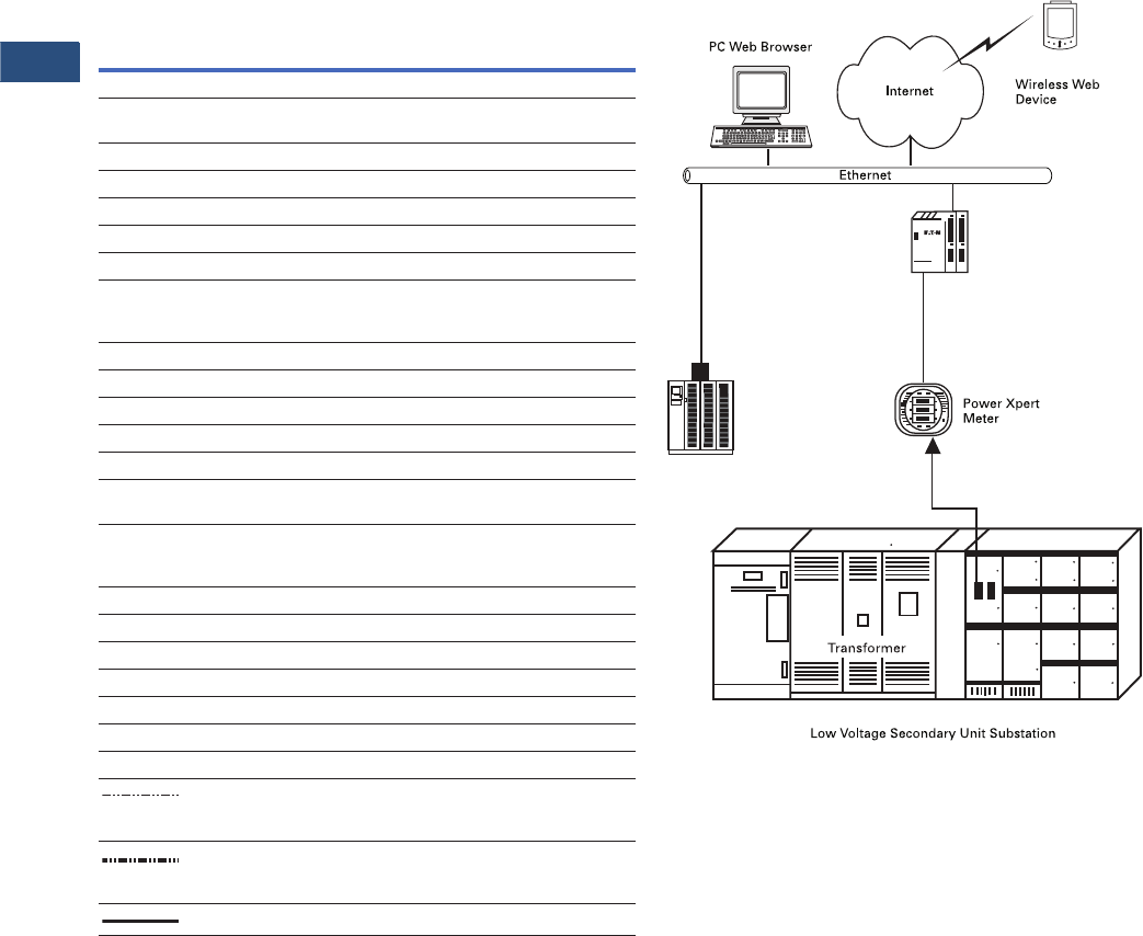
V3-T9-8 Volume 3—Power Distribution and Control Assemblies CA08100004E—November 2013 www.eaton.com
9
9
9
9
9
9
9
9
9
9
9
9
9
9
9
9
9
9
9
9
9
9
9
9
9
9
9
9
9
9
9.1
Metering Devices, Protective Relays, Software and Connectivity
Power Xpert Architecture
Power Xpert Architecture
Level 0—Small System with Smart Hardware
Example Applications
Power Xpert Meter in low
voltage switchgear and UPS.
Description
Configuration Level 0 offers
an easy means to Web-
enable a single Eaton device
provided that it is supported
by an optional Web
communications card that
can be installed directly into
the device.
Standard Features
●Real-time monitoring of
metered and alarm points
●Alarm history
●E-mail notification
●Communications settings
via the Web
Small Installation with Smart Hardware
UPS
w/Power Xpert Gateway
Series 2000 Card
Power Xpert
Ethernet Switch
Functions/Devices
Drawing
Symbol
Function
Description
Eaton
Device
Monitoring Equipment
MM6GWP
Power Quality Meter Analyzer Power Xpert Meter
4000/6000/8000
MM4&P
Meter Monitor and Protection
IQ DP-4000
MM Meter Monitor IQ 100/IQ 200
SMM Sub-Metering Module IQ Energy Sentinel
Overcurrent/Short Circuit Protection
MVTU Medium Voltage Relay (> 600V) DT-3000, FP-5000
LVTU Low Voltage Trip Unit (d 600V) Digitrip RMS-810, 910,
520 MC or 1150
Digitrip OPTIM 750 or 1050
Motor Protection and Control
MPR Motor Protective Relay MP-3000
MMS Microprocessor Motor Starter IT. Starter
VFD Variable Frequency Drive SVX9000
Central Monitoring Panels
BIM II Breaker Interface Module II BIM II (used with Digitrip
OPTIM or Digitrip RMS)
LDISP Local Display and Sub-network
Master
Used with IQ Multipoint Energy
Submeter II or with
Energy/Power Sentinels
Other Devices
ATS Automatic Transfer Switch IQ Transfer
RTD Resistance Temperature Universal RTD Module
ADR Addressable Relay ADRII
C Product Communication Device IPONI
R Resistor-End of Line Resistor
■Terminal Block
IP, IN, IS Terminal Designation
Factory Twisted Pair Wiring IMPCABLE or
Belden YR29090 or
Belden 9463 Family
Field Twisted Pair Wiring IMPCABLE or
Belden YR29090 or
Belden 9463 Family
Field Ethernet Backbone CAT5 or multimode fiber

Volume 3—Power Distribution and Control Assemblies CA08100004E—November 2013 www.eaton.com V3-T9-9
9
9
9
9
9
9
9
9
9
9
9
9
9
9
9
9
9
9
9
9
9
9
9
9
9
9
9
9
9
9
9.1
Metering Devices, Protective Relays, Software and Connectivity
Power Xpert Architecture
Level 1—Using Power Xpert Gateways
Example Applications
Low and medium voltage
switchgear, motor control
centers and third-party
equipment via Modbus RTU.
Recommendation: Use one
Power Xpert Gateway device
per electrical assembly or
switchgear sub-section.
Description
Configuration Level 1 offers
an easy means to Web-
enable multiple Eaton devices
and third-party devices that
support Modbus RTU.
Standard Features
●Real-time monitoring of
metered and alarm points
●Communications settings
via the Web
●Alarm history
●E-mail notification
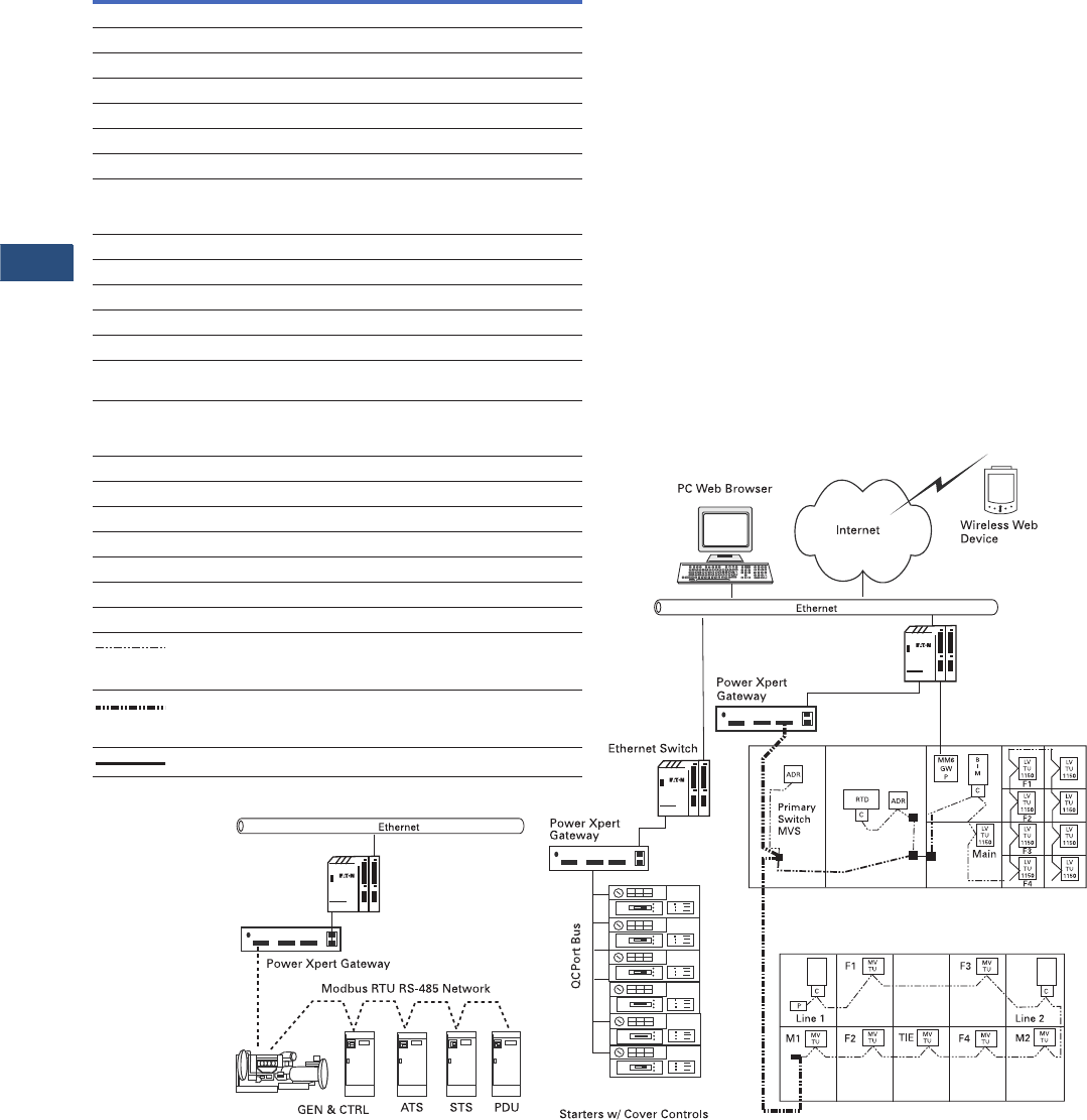
V3-T9-10 Volume 3—Power Distribution and Control Assemblies CA08100004E—November 2013 www.eaton.com
9
9
9
9
9
9
9
9
9
9
9
9
9
9
9
9
9
9
9
9
9
9
9
9
9
9
9
9
9
9
9.1
Metering Devices, Protective Relays, Software and Connectivity
Power Xpert Architecture
Power Xpert Gateway
IT.
LV Secondary Unit Substation
MV VacClad-W Metal-Clad Switchgear
II
F5
F6
F7
F8
MM
4&P
MM
4&P
INCOM
Power Xpert
Ethernet Switch
Power Xpert
Ethernet Switch
Functions/Devices
Drawing
Symbol
Function
Description
Eaton
Device
Monitoring Equipment
MM6GWP
Power Quality Meter Analyzer Power Xpert Meter 4000/6000/8000
MM4&P
Meter Monitor and Protection
IQ DP-4000
MM Meter Monitor IQ 100/IQ 200
SMM Sub-Metering Module IQ Energy Sentinel
Overcurrent/Short Circuit Protection
MVTU Medium Voltage Relay (> 600V) DT-3000, FP-5000
LVTU Low Voltage Trip Unit (d 600V) Digitrip RMS-810, 910,
520 MC or 1150
Digitrip OPTIM 750 or 1050
Motor Protection and Control
MPR Motor Protective Relay MP-3000
MMS Microprocessor Motor Starter IT. Starter
VFD Variable Frequency Drive SVX9000
Central Monitoring Panels
BIM II Breaker Interface Module II BIM II (used with Digitrip
OPTIM or Digitrip RMS)
LDISP Local Display and Sub-network
Master Used with IQ Multipoint Energy
Submeter II or with
Energy/Power Sentinels
Other Devices
ATS Automatic Transfer Switch IQ Transfer
RTD Resistance Temperature Universal RTD Module
ADR Addressable Relay ADRII
C Product Communication Device IPONI
R Resistor-End of Line Resistor
■Terminal Block
IP, IN, IS Terminal Designation
Factory Twisted Pair Wiring IMPCABLE or
Belden YR29090 or
Belden 9463 Family
Field Twisted Pair Wiring IMPCABLE or
Belden YR29090 or
Belden 9463 Family
Field Ethernet Backbone CAT5 or multimode fiber

Volume 3—Power Distribution and Control Assemblies CA08100004E—November 2013 www.eaton.com V3-T9-11
9
9
9
9
9
9
9
9
9
9
9
9
9
9
9
9
9
9
9
9
9
9
9
9
9
9
9
9
9
9
9.1
Metering Devices, Protective Relays, Software and Connectivity
Power Xpert Architecture
Level 2—Power Xpert Software
Example Applications
All Eaton devices and third-
party devices that support
Modbus TCP and SNMP in
addition to third-party Modbus
RTU devices via the Power
Xpert Gateway.
Description
Configuration Level 2 offers
an easy means to Web-
enable and centrally manage
all Eaton devices that can
be connected directly to an
Ethernet network or via
a Power Xpert Gateway
device. Power Xpert
Software provides a rich
set of standard features,
as well as premier value
add-on option modules.
Standard Features
●Real-time monitoring of
metered and alarm points
●Full color Web-based
graphics package with
standard views for all
Eaton devices
●E-mail notification
●Data trending and graphing
Optional Add-on Features
●Web-based graphics editor
to design floor plan and
third-party device views
●Energy consumption
analysis and tenant billing
●Power quality analysis and
waveform viewing
●Modbus TCP tool to import
register maps from various
third-party devices
●SNMP tool to compile
SNMP MIB (Management
Information Base) files
from various third-party
devices
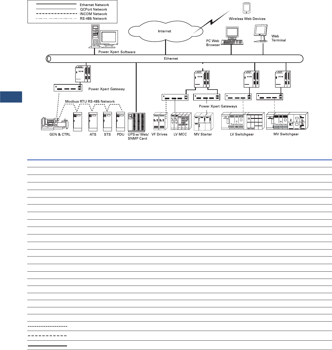
V3-T9-12 Volume 3—Power Distribution and Control Assemblies CA08100004E—November 2013 www.eaton.com
9
9
9
9
9
9
9
9
9
9
9
9
9
9
9
9
9
9
9
9
9
9
9
9
9
9
9
9
9
9
9.1
Metering Devices, Protective Relays, Software and Connectivity
Power Xpert Architecture
Power Xpert Software
Power Xpert
Ethernet Switch
Power Xpert Ethernet Switches
Functions/Devices
Drawing Symbol Function Description Eaton Device
Monitoring Equipment
MM6GWP
Power Quality Meter Analyzer Power Xpert Meter 4000/6000/8000
MM4&P
Meter Monitor and Protection
IQ DP-4000
MM Meter Monitor IQ 100/IQ 200
SMM Sub-Metering Module IQ Energy Sentinel
Overcurrent/Short Circuit Protection
MVTU Medium Voltage Relay (> 600V) DT-3000, FP-5000
LVTU Low Voltage Trip Unit (d 600V) Digitrip RMS-810, 910, 520 MC or 1150/Digitrip OPTIM 750 or 1050
Motor Protection and Control
MPR Motor Protective Relay MP-3000
MMS Microprocessor Motor Starter IT. Starter
VFD Variable Frequency Drive SVX9000
Central Monitoring Panels
BIM II Breaker Interface Module II BIM II (used with Digitrip OPTIM or Digitrip RMS)
LDISP Local Display and Sub-network Master Used with IQ Multipoint Energy Submeter II or with Energy/Power Sentinels
Other Devices
ATS Automatic Transfer Switch IQ Transfer
RTD Resistance Temperature Universal RTD Module
ADR Addressable Relay ADRII
C Product Communication Device IPONI
R Resistor-End of Line Resistor
■Terminal Block
IP, IN, IS Terminal Designation
Factory Twisted Pair Wiring IMPCABLE or Belden YR29090 or Belden 9463 Family
Field Twisted Pair Wiring IMPCABLE or Belden YR29090 or Belden 9463 Family
Field Ethernet Backbone CAT5 or multimode fiber
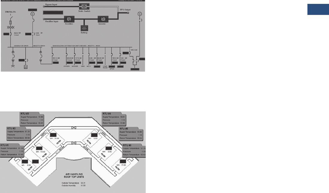
Volume 3—Power Distribution and Control Assemblies CA08100004E—November 2013 www.eaton.com V3-T9-13
9
9
9
9
9
9
9
9
9
9
9
9
9
9
9
9
9
9
9
9
9
9
9
9
9
9
9
9
9
9
9.1
Metering Devices, Protective Relays, Software and Connectivity
Power Xpert Architecture
Level 3—Eaton’s Electrical Services & Systems (EESS)
Customized Software Solutions
Available Applications
Any manufacturer’s equipment that is supported by the
EESS extensive device driver support list or request a custom
quotation to obtain support.
Description
Configuration Level 3 offers an extensive service offering for
the delivery of customized graphics and support for third-party
proprietary device driver support.
Enhanced Features
●Customized one-line diagrams to portray realistic operation
of the complete power distribution system
Power Distribution System One-Line Diagram
●Customized navigation systems to allow the operator to
navigate the software in a similar paradigm that is consistent
with the way they would describe their organization from a
functional or departmental standpoint
Customized Navigation System

V3-T9-14 Volume 3—Power Distribution and Control Assemblies CA08100004E—November 2013 www.eaton.com
9
9
9
9
9
9
9
9
9
9
9
9
9
9
9
9
9
9
9
9
9
9
9
9
9
9
9
9
9
9
9.2
Metering Devices, Protective Relays, Software and Connectivity
Monitoring Software and Reporting
Power Xpert Software
Contents
Description Page
Power Xpert Software
Product Selection Guide . . . . . . . . . . . . . . . . . . V3-T9-15
Features and Benefits . . . . . . . . . . . . . . . . . . . . V3-T9-16
Product Selection . . . . . . . . . . . . . . . . . . . . . . . V3-T9-19
An Eaton
Green Solution
Power Xpert Software
Product Description
Power Xpert Software is the
fusion of key components of
PowerNet and PowerVision
Software into a single
power monitoring package,
which includes ease of
interconnectivity to a wide
range of Eaton and third-party
communicating devices.
Power Xpert Software
provides an easy upgrade
path to allow existing
PowerNet users to enjoy the
benefits of power monitoring
through a simple Web
browser interface. It provides
a complete software solution
to manage your power
system. Critical components
such as metering devices,
protective relays, circuit
breaker trip units, motor
starters and uninterruptible
power supplies communicate
vital information about the
health and status of critical
infrastructure devices.

Volume 3—Power Distribution and Control Assemblies CA08100004E—November 2013 www.eaton.com V3-T9-15
9
9
9
9
9
9
9
9
9
9
9
9
9
9
9
9
9
9
9
9
9
9
9
9
9
9
9
9
9
9
9.2
Metering Devices, Protective Relays, Software and Connectivity
Monitoring Software and Reporting
Product Selection Guide
Power Xpert Software Professional Edition
●Geared toward end users, with built-in support for Eaton
power distribution products such as switchgear, UPSs,
breakers, PDUs, RPPs, meters, relays, VFDs and MCCs,
among others
●Eaton products connect with the software directly via an
Ethernet connection, while legacy devices use a Power Xpert
Gateway to Web-enable their communications
●A subset of third-party meters and devices are supported as
standard via the gateway connection
Power Xpert Software Enterprise Edition
●Geared toward advanced power users, system integrators and
enterprises with heterogeneous device spectrum and system
developers who can take advantage of the included SNMP
and Modbus integration development utilities
●Extensive support for third-party devices via standard SNMP
and Modbus TCP protocols
●Large variety of ready made, optional third-party drop in
drivers available
Power Xpert Software Features
Feature Sets
Power Xpert Software
Professional Edition
Power Xpert Software
Enterprise Edition
Server module ■■
Trend viewer module ■■
Layout manager module ■■
Quality manager module ■■
Eaton device support (switchgear, UPSs, breakers, ePDUs, meters,
relays, VDFs, MCCs, etc.)
■■
Power Xpert Gateway third-party device support ■■
SNMP connector ■
Modbus connector ■
Optional third-party driver support ■
Custom third-party device driver support ■

V3-T9-16 Volume 3—Power Distribution and Control Assemblies CA08100004E—November 2013 www.eaton.com
9
9
9
9
9
9
9
9
9
9
9
9
9
9
9
9
9
9
9
9
9
9
9
9
9
9
9
9
9
9
9.2
Metering Devices, Protective Relays, Software and Connectivity
Monitoring Software and Reporting
Features and Benefits
Power Xpert Software
Feature Benefit
General
Web browser user interface There is no need to install a separate client piece of software on your computer. Simple and easy access via Web browser from any location in
the world.
Web-based monitoring capabilities Monitor all power system equipment through the Internet.
Downloadable software version updates Receive the latest enhancements and versions via downloads available from Eaton’s Web site.
Event Notification
Event notification via e-mail notification Receive automatic e-mails when events are triggered.
Event notification via pagers, text message or third-
party interfaces
Receive alarms on event changes via pagers, text message or third-party interfaces.
Alarm state management Acknowledge, clear and close alarms through Power Xpert Software.
Event indicator displayed without Web page active The Web page you are on does not need to be active to display the event indicator.
Alarm/event searching and filtering Conveniently search and filter alarms and events to quickly find what you are looking for.
Waveform attached to applicable power event Waveforms captured by meters are attached to actual power events, making them easy to understand and interpret.
Web browser based waveform viewing There is no need to install a separate waveform viewer on your computer. Waveforms can be easily reviewed right in your Web browser.
Alarm capabilities based on device driven events Alarms and triggered events come to the software directly from the associated devices, eliminating false alarms.
Analysis and Trending
Graphic Trend Viewer Displays power system device measurements in an easy-to-understand graphical chart format.
Chart or data option selection Conveniently view the data in either spreadsheet type data format or a graphic line chart plot.
Multiple trends display Displaying multiple trends at a time helps analyze event ramifications and impact in more detail.
Multiple axis support Multiple trends can be plotted on multiple x and y axis, displaying pertinent time and scale information.
View multiple variables (i.e., Ia, Ib, Ic, Vab, Vbc, etc.)
for a single waveform
Multiple waveform variables can be viewed at a time, eliminating the need of changing views frequently.
Standard COMTRADE file format support View, import and open any waveform captures in standard IEEE® (C37.111-1999) COMTRADE file format.
Customizable Trend Viewer look and feel The formatting of the data, and the look and feel of it can be easily customized according to user preferences.
Fixed or custom time frames Information displayed in the Trend Viewer can have either system-defined fixed or user-selected custom time frames.
Trend analysis capabilities Trends can be easily spotted and analyzed on screen or exported to third-party software for further analysis if necessary.
Data export Trend data can be easily exported to Excel for further analysis.
Custom Graphics and Layouts
Custom graphics development via Web browser Customized Web pages can be easily developed using a plain Web browser, eliminating the need to install a separate application
to be installed, learned and utilized.
Four user view example templates included as standard Easily use ‘as is’ or modify as necessary: data center, plant, hospital and geographical layout templates.
iFrame capability iFrames enable embedding browser portals into custom Web page layouts.
Browser Portal Widget support Browser Portal Widgets can be embedded in iFrames to accommodate streaming media feeds.
Streaming media support Multiple streaming media feeds can be embedded into a single Web page, utilizing iFrames technology.
Graphic object library included as standard A large object library including most common power devices is embedded within the system, enabling the user to develop mimic
screens from the start.
ISO® standard electrical picture objects available Add ISO standard compliant graphics to one-line diagrams or other layouts for ISO compatibility.
Graphic files import capability Import floor plans, street maps or photographs to be used as background images or mimic objects in Web pages.
Graphic object animation capability Graphics can be animated based on event and threshold changes. An object could change color, for example, when a threshold is reached.
Gauge object library support A multitude of gauges are provided in the standard object library to enable easy Web page custom measurement gauges design.
External Web links support Add Web links to Power Xpert Software pages, which link to any device, Web page on the Internet and network around the globe with a
Web user interface.
Alarm bubble-up support through several page layers Alarms can be easily bubbled-up through multiple Web pages with the folder link feature. Event can be seen on the topmost page and the
user can drill down for more information.
Trend object support Trend objects can be embedded into the layout, enabling viewing the data directly in the Trend Viewer.

Volume 3—Power Distribution and Control Assemblies CA08100004E—November 2013 www.eaton.com V3-T9-17
9
9
9
9
9
9
9
9
9
9
9
9
9
9
9
9
9
9
9
9
9
9
9
9
9
9
9
9
9
9
9.2
Metering Devices, Protective Relays, Software and Connectivity
Monitoring Software and Reporting
Power Xpert Software, continued
Note: These specifications are subject to change without notice and represent the maximum capabilities of the product with all options installed. This is not a complete feature list. Features and
functionality may vary depending on selected options and product model. Please refer to the technical data sheet and user manual for detailed specifications.
Communication Protocol Support
Feature Benefit
UPS Shutdown
File saving during shutdown During an emergency shutdown due to an extended power failure outlasting the UPS battery, open files on the computer systems
are closed and saved in an orderly fashion.
Automatic, orderly and sequential shutdown All operating systems running Power Xpert Software Shutdown Agent will be shut down in an orderly and sequential fashion to
prevent data loss.
Parallel redundant UPS shutdown capability Built-in software logic will initiate shutdown only after UPS redundancy has been lost and the last UPS is out of runtime.
Security and Administration
Windows Authentication Security Control access to Power Xpert Software via Windows® Authentication Service.
Two-tier secure system access support Access the Power Xpert Software with read or write privileges to prevent unauthorized tampering.
SSL Supported via OpenSSL.
Secure Web browser access (support for HTTPS) Supported via OpenSSL.
Time Synchronization
Time synchronization support for connected devices
with 1 millisecond time resolution
Millisecond-based timestamp support (when supported by connected device) enables understanding the sequence of rapidly occurring events.
Export and Integration
Extended Excel® spreadsheet support Open report files directly in Excel.
SQL database query support Power Xpert uses standard SQL database format that can be queried by third-party applications for system integration and data exchange.
Logs
System Log The System Log gathers information on system-level events for error and security purposes.
Error Log The Error Log gathers information on errors occurred for diagnostic purposes.
Service
Eaton help desk services (1-877-ETN-CARE) Call Eaton to speak directly to a product specialist providing support for the software.
Turnkey startup service Purchase a 1, 2 or 5-day startup service package from Eaton for turnkey system installation and configuration.
System Backup
Power Xpert Software system backup Easily back up Power Xpert software including configurations, user views and device setups.
Documentation and Training Videos
System Administrator’s Guide Guides users on how to administer Power Xpert Software.
Power Xpert Software User’s Guide Detailed information of Power Xpert Software features and functionality along with screenshots and references.
Layout Manager Guide Detailed information on how to use Layout Manager’s features and functionality to create custom graphic system pages.
Quick Start Guide Takes the guesswork out of initial software installation and configuration with clear step-by-step instructions on how to get started.
Power Xpert Software Introduction and Training Video Learn the main features and functionality of Power Xpert Software by watching a hands-on video showing you how to install, configure
and use the software.
Power Xpert Reporting Introduction and Training Video Learn the main features and functionality of Power Xpert Reporting by watching a hands-on video showing you how to install and configure
reporting. Included are step-by-step instructions on how create reporting hierarchies and pull data out of different databases.
Communication Protocol Description
Dry-contact/contact closure/relay Contact closure support is enabled via various Eaton Gateway devices. Please refer to Power Xpert Software Hardware Compatibility List for details.
BACnet WS+ BACnet WS+
Modbus RTU Modbus RTU
Modbus TCP Modbus Protocol over TCP
TCP/IP Transmission Control Protocol
SNMP Simple Network Management Protocol
SMTP Simple Mail Transfer Protocol
INCOM Eaton Legacy Protocol
HTTP Hypertext Transfer Protocol
HTTPS Hypertext Transfer Protocol with SSL
SSL Secure Sockets Layer
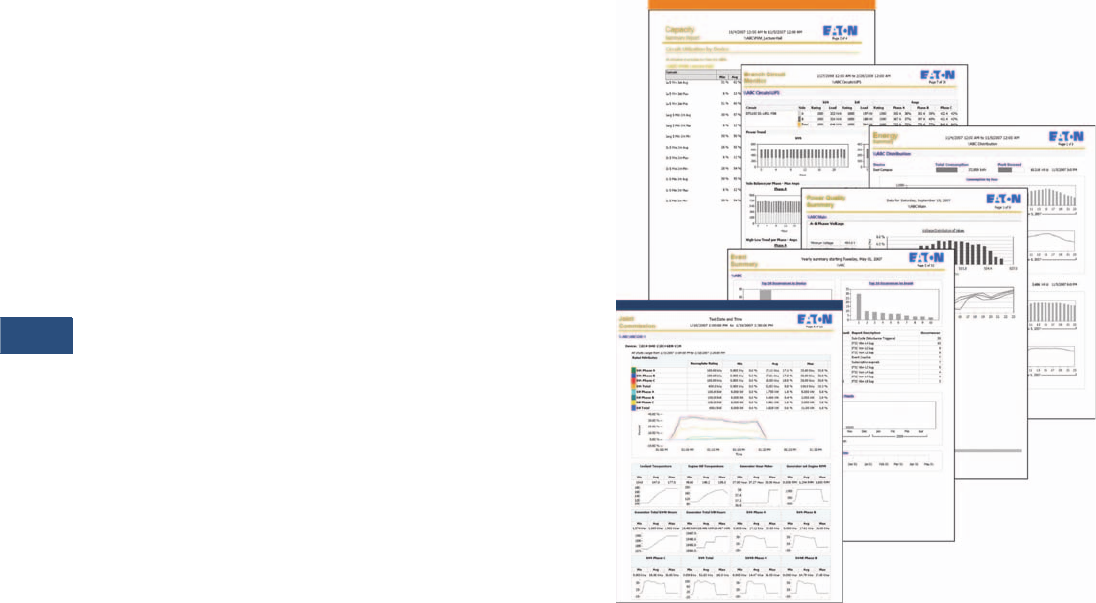
V3-T9-18 Volume 3—Power Distribution and Control Assemblies CA08100004E—November 2013 www.eaton.com
9
9
9
9
9
9
9
9
9
9
9
9
9
9
9
9
9
9
9
9
9
9
9
9
9
9
9
9
9
9
9.2
Metering Devices, Protective Relays, Software and Connectivity
Monitoring Software and Reporting
Power Xpert Reporting—the perfect complement
Power Xpert Reporting helps bring information from the
software together. Power Xpert Software brings together your
power system information from around the floor to around the
world—data and information that is invaluable. Power Xpert
Reporting brings all the power system information together to
compare, contrast and generally give you the big picture. Power
Xpert Reporting provides a standard set of reports, including:
●Data Center Efficiency Report: A summary of data center
infrastructure efficiency and power usage effectiveness,
including such information as temperature and humidity, and
energy consumption
●Greenhouse Gas Report: Captures the six offensive
greenhouse gasses: Carbon Dioxide, Sulfur Dioxide, Nitrogen
Oxide, Mercury, Methane and Nitrous Oxide broken down by
selected locations within a facility
●Utilities Report: Captures consumption of water, air, gas,
electricity and steam (WAGES)
●Capacity Summary Report: The summary of top- and
bottom-loaded circuits, as well as loading details for each
circuit according to user-defined date/time range and facility
hierarchy location
●Branch Circuit Monitoring Report: Determine branch circuit
loading levels at a glance with color-coded graphics indicating
loading status against capacity. Redundant sources can be
reviewed, as well as single source loads
●Energy Summary Report: The summary of consumption
(kWh) and demand (kW) for a user-defined date/time range
and facility hierarchy location
●Energy Cost Allocation Report: The total energy bill dollar
value or a cost per kWh across a facility hierarchy for a user-
defined date/time range
●Power Quality Report: The distribution and trend for amps,
volts and THD according to user-defined date/time ranges and
facility hierarchy location
●Event Summary Report: Provides a Pareto chart of events
according to user-defined date/time ranges and facility
hierarchy location
●Joint Commission Report: Standard Joint Commission
compliant report supports hospital power test requirements.
It checks events, key metrics of generators and automatic
transfer switches (ATS) during generator testing at user-
defined date/time ranges and facility hierarchy location

Volume 3—Power Distribution and Control Assemblies CA08100004E—November 2013 www.eaton.com V3-T9-19
9
9
9
9
9
9
9
9
9
9
9
9
9
9
9
9
9
9
9
9
9
9
9
9
9
9
9
9
9
9
9.2
Metering Devices, Protective Relays, Software and Connectivity
Monitoring Software and Reporting
Product Selection
Power Xpert Software
Description
Catalog
Number
Power Xpert Software Professional Edition
Power Xpert Software Professional Edition PXS-PRO
Power Xpert Software Professional Edition w/ 1-day startup PXS-PROn1S
Power Xpert Software Professional Edition w/ 2-day startup PXS-PROn2S
Power Xpert Software Professional Edition w/ 5-day startup PXS-PROn5S
Power Xpert Software Professional Edition and Power Xpert Reporting PXS-PROnPXR
Power Xpert Software Enterprise Edition
Power Xpert Software Enterprise Edition PXS-ENT
Power Xpert Software Enterprise Edition w/ 1-day startup PXS-ENTn1S
Power Xpert Software Enterprise Edition w/ 2-day startup PXS-ENTn2S
Power Xpert Software Enterprise Edition w/ 5-day startup PXS-ENTn5S
Power Xpert Reporting
Power Xpert Reporting—single source DB connection PXR
Power Xpert Reporting—up to 2 source DB connections PXR-2DB
Power Xpert Reporting—up to 5 source DB connections PXR-5DB
Power Xpert Reporting—up to 10 source DB connections PXR-10DB
Power Xpert Reporting—up to 25 source DB connections PXR-25DB
Power Xpert Reporting—up to 50 source DB connections PXR-50DB
Service Packs
Power Xpert 1-day startup Service Pack PX-1S
Power Xpert 2-day startup Service Pack PX-2S
Power Xpert 5-day startup Service Pack PX-5S

V3-T9-20 Volume 3—Power Distribution and Control Assemblies CA08100004E—November 2013 www.eaton.com
9
9
9
9
9
9
9
9
9
9
9
9
9
9
9
9
9
9
9
9
9
9
9
9
9
9
9
9
9
9
9.2
Metering Devices, Protective Relays, Software and Connectivity
Monitoring Software and Reporting
Technical Data and Specifications
Hardware Requirements
Power Xpert Software (PXS) requires a server-class machine
with the following minimum hardware specifications:
You may wish to add the following hardware as well:
●Local printer
●Sound card (if sounds are assigned to specific
alarm conditions)
●Modem (for remote alarm notification to machines
not available via your network)
Software Requirements
Supported operating systems
●Microsoft® Windows Server 2003 R2 (Standard or Enterprise)
32-bit edition
●Microsoft Windows XP Professional (32-bit) with
Service Pack 3, 32-bit
●Windows Server 2008 (Standard or Enterprise),
32-bit or 64-bit
●Windows Server 2008 R2 (Server or Enterprise),
32-bit or 64-bit
●Windows 7 Professional, Ultimate or Enterprise editions,
either 32-bit or 64-bit
Software components
●IIS 5.0 or higher (must be installed prior to installing PXS; for
Windows 7 and Windows Server 2008, this is installed
automatically)
●Microsoft Internet Explorer® 7.0 or 8.0
Third-Party Software Installed
The following Microsoft software is also installed during the
PXS installation.
●.NET Framework 3.5 SP1
●Windows Installer 4.5
●C++ Runtime Library 2008
●Microsoft Data Access 2.8
●SQL Server 2008 Express SP2
●SQL Server 2005 Express Management Studio SP2
Hardware Specification
Processor 2.8 GHz, dual-core processor
Memory 2 GB allocated for PXS (allocate 3 GB
of memory to a virtual machine session
running PXS)
Disk space required for application The PXS application itself requires 190 MB of
disk storage
Disk space required for database A typical database will grow to 2 GB within a
year. If you have a large number of devices,
reserve additional storage space
Video resolution 1280 by 1024 pixels or higher
Removable media DVD RO driv

Volume 3—Power Distribution and Control Assemblies CA08100004E—November 2013 www.eaton.com V3-T9-21
9
9
9
9
9
9
9
9
9
9
9
9
9
9
9
9
9
9
9
9
9
9
9
9
9
9
9
9
9
9
9.3
Metering Devices, Protective Relays, Software and Connectivity
Metering Devices
Metering Products Family
Contents
Description Page
Metering Products Family
Power Xpert Meter 4000/6000/8000 Series . . . . . . V3-T9-30
Power Xpert Meter 2000 Series . . . . . . . . . . . . . . . V3-T9-49
IQ 250/260 Series Electronic Power Meters. . . . . . V3-T9-60
IQ 130/140/150 Series Electronic Power Meters . . V3-T9-66
IQ 150S/250S Self-Enclosed Electronic Meters . . . V3-T9-71
IQ 35M . . . . . . . . . . . . . . . . . . . . . . . . . . . . . . . . . . V3-T9-76
IQ Analyzer 6400/6600 Series . . . . . . . . . . . . . . . . V3-T9-79
IQ DP-4000 Series . . . . . . . . . . . . . . . . . . . . . . . . . V3-T9-87
IQ 230 Meters . . . . . . . . . . . . . . . . . . . . . . . . . . . . V3-T9-93
Power Xpert Multi-Point Meter . . . . . . . . . . . . . . . . V3-T9-100
IQ Energy Sentinel™ . . . . . . . . . . . . . . . . . . . . . . . V3-T9-112
PM3 Monitoring and Metering Module . . . . . . . . . V3-T9-121
Current Transformers (CTs). . . . . . . . . . . . . . . . . . . V3-T9-122
Clamp-On Current Transformers . . . . . . . . . . . . . . . V3-T9-131
IQ Flange . . . . . . . . . . . . . . . . . . . . . . . . . . . . . . . . V3-T9-134
Panel Mounting Adapter Kit . . . . . . . . . . . . . . . . . . V3-T9-135
Enclosed Meters. . . . . . . . . . . . . . . . . . . . . . . . . . . V3-T9-136
Product Overview
Eaton’s metering products
provide solutions needed
to monitor and manage all
aspects of an electrical
distribution system.
When greater reliability,
increased productivity and
significant cost savings
are called for to remain
competitive in today’s
market, Eaton’s metering
products fit the bill. These
innovative meters and
communications systems,
along with Power
Management software, make
it possible to successfully
take control of the electrical
distribution system.
Power Xpert Meters
Power Xpert Meters are
the benchmark for intelligent
Web-enabled top-quality
metering devices for the
power system. Power Xpert
Meters provide measurement
of the critical elements found
in the power system, whether
that be voltage, power,
current, transients, harmonics
or even time. Power Xpert
Meters provide Web-enabled
communications for use with
the Power Xpert Software.
All Power Xpert Meters
provide a standard
communications protocol
for easy integration into
other systems.
Features and Benefits
Greater Reliability
Eaton’s metering products
give the ability to receive an
early warning of potential
problems, eliminate
unnecessary trips, isolate
faults to ensure minimum
downtime and shed or
equalize loads while a
problem is being corrected.
Increased Productivity
Equipment downtime
resulting from voltage or
frequency variations can be
very costly to an operation.
Monitoring power quality
with Eaton’s metering
products throughout the
electrical distribution system
provides data to identify,
isolate and correct problems
quickly and efficiently.
Reduced Energy and
Operating Costs
When we think about meters
and power quality, the
common thread throughout
the basket of solutions is
information. Collecting,
monitoring and managing data
from the electrical distribution
system can help reduce costs
for those facilities prepared to
define and analyze present
electrical energy usage levels
and patterns. Data provided by
Eaton’s metering products
comprise the data for verifying
utility bills for energy
management and lowering
operating costs. Deregulation
in some geographical
locations permits energy
users to select a utility
provider and negotiate rate
structures. For large users
with heavy utility bills, this
may be an incentive to verify
the utility bill, identify an
opportunity for savings,
negotiate a better utility rate
and apply the savings directly
to the bottom line. Users are
also empowered to decrease
energy consumption, thereby
lowering peak demand
charges and decreasing
operating costs.
When an Eaton meter is used
with Eaton trip units and
relays incorporating built-in
metering capabilities, the
entire electrical distribution
system can be cost-
effectively managed.
Eaton is an industry
leader offering a complete
integrated solution to oversee
your entire electrical
distribution system. As a
global manufacturer of
low and medium voltage
electrical distribution system
equipment and components,
Eaton is an experienced
innovator of metering
products that incorporate
cutting-edge technology.
These innovations result
from our scientific and
engineering expertise,
physical resources and the
ongoing R&D programs at
our technology centers.
V3-T9-22 Volume 3—Power Distribution and Control Assemblies CA08100004E—November 2013 www.eaton.com
9
9
9
9
9
9
9
9
9
9
9
9
9
9
9
9
9
9
9
9
9
9
9
9
9
9
9
9
9
9
9.3
Metering Devices, Protective Relays, Software and Connectivity
Metering Devices
Product Selection Guide
Metering Selection Chart
Notes
1Under typical operating conditions.
2PXM 2260 only.
3PXM 2270 only.
4PXM 2280 only.
5PXM 2290 only.
6IQ 260 only.
7Individual values reported to 85th
harmonic; anti-alias filtering prevents
higher frequencies from distorting
readings (see IEC 61000-4-7).
8PMX 6000 only.
9PXM 8000 only.
jOptional.
kAt computer only.
Device Name
Accessories
See Page V3-T9-131
Power Xpert Meter 4000/6000/8000 Series Power Xpert Meter 2000 Series IQ 250/260 Series
Section Page Number V3-T9-30 V3-T9-49 V3-T9-60
Electrical Parameters
Volts 0.1% of RV + 0.02% FS 0.1% of RV 0.1% of RV
Amperes 0.05% of RV + 0.01% FS 0.1% of RV 0.1% of RV
Current range (% of nominal) 0.005–20A (400%) 0.1–200% 0.1–200%
Watts 0.1% of RV + 0.0025% FS 0.2% of RV 0.2% of RV
VARs 0.1% of RV + 0.0025% FS 0.2% of RV 0.2% of RV
VA 0.1% of RV + 0.0025% FS 0.2% of RV 0.2% of RV
PF-apparent 0.1% 0.2% of RV 0.2% of RV
PF-displacement 0.1% — —
Frequency ±0.01 Hz ±0.03 Hz ±0.03 Hz
THD-voltage 127th 40th 2345 40th 6
THD-current 127th 40th 2345 40th 6
Watthours ±0.2% per ANSI C12.20 0.2 Class 1±0.2% per ANSI C12.20 0.2 Class 1±0.2% per ANSI C12.20 0.2 Class 1
VAR-hours ±0.2% per ANSI C12.20 0.2 Class 1±0.2% per ANSI C12.20 0.2 Class 1±0.2% per ANSI C12.20 0.2 Class 1
VA-hours ±0.2% per ANSI C12.20 0.2 Class 1±0.2% per ANSI C12.20 0.2 Class 1±0.2% per ANSI C12.20 0.2 Class 1
Ampere-demand 0.05% of RV + 0.01% FS ±0.1% per ANSI C12.20 0.2 Class ±0.1% per ANSI C12.20 0.2 Class
Watt-demand ±0.2% per ANSI C12.20 0.2 Class 1±0.2% per ANSI C12.20 0.2 Class 1±0.2% per ANSI C12.20 0.2 Class 1
VAR-demand ±0.2% per ANSI C12.20 0.2 Class 1±0.2% per ANSI C12.20 0.2 Class 1±0.2% per ANSI C12.20 0.2 Class 1
VA-demand ±0.2% per ANSI C12.20 0.2 Class 1±0.2% per ANSI C12.20 0.2 Class 1±0.2% per ANSI C12.20 0.2 Class 1
Revenue accuracy ±0.2% per ANSI C12.20 0.2 Class 1ANSI C12.20 (0.2%) ANSI C12.20 (0.2%)
Individual ampere harmonics 85th 740th 345 —
Individual voltage harmonics 85th 740th 345 —
Interharmonics Yes — —
Minimum and/or Maximum Values
Volts L-L, L-N, N-G, VAUX L-L L-L, L-N L-L, L-N
Current A, B, C, N, G A, B, C, N A, B, C
Power Watt, VAR, VA Watt, VAR, VA Watt, VAR, VA
Power Factor Apparent/displacement Apparent Apparent
Frequency Hertz Hertz Hertz
THD Amperes/volts (L-L, L-N, AUX L-L) Amperes/volts 2345 Amperes/volts 6
Demand values kW, kVAR, kVA, amperes kW, kVAR, kVA, amperes kW, kVAR, kVA, amperes
Trend analysis 2 / 4 8 / 8 9 GB 256 / 512 2 / 768 345 MB 128 KB
j
Event logging 2 / 4 8 / 8 9 GB 100,000 alarms/events with timestamp k
Disturbance recording 2 / 4 8 / 8 9 GB
60 cycles per event
768 MB 45
up to 64 cycles per event 45
—
Legend: PG = Programmable
FS = Full scale
RV = Read value
Auxiliary voltage
(optional) = Provides three additional voltage inputs to the
meter: Va2, Vb2, Vc2.
Interharmonics = Power Xpert Meter 6000/8000 supported.
Volume 3—Power Distribution and Control Assemblies CA08100004E—November 2013 www.eaton.com V3-T9-23
9
9
9
9
9
9
9
9
9
9
9
9
9
9
9
9
9
9
9
9
9
9
9
9
9
9
9
9
9
9
9.3
Metering Devices, Protective Relays, Software and Connectivity
Metering Devices
Metering Selection Chart, continued
Notes
1PXM 6000 only.
2PXM 8000 only.
3PXM 2260 only.
4PXM 2270 only.
5The auxiliary voltage option adds three additional voltage
input channels to Power Xpert Meters.
6At computer only.
7PXM 2280 only.
8PXM 2290 only.
9Optional
Legend: PG = Programmable
FS = Full scale
RV = Read value
Auxiliary voltage
(optional) = Provides three additional voltage inputs to the
meter: Va2, Vb2, Vc2.
Interharmonics = Power Xpert Meter 6000/8000 supported.
Device Name
Accessories
See Page V3-T9-131
Power Xpert Meter 4000/6000/8000 Series Power Xpert Meter 2000 Series IQ 250/260 Series
Section Page Number V3-T9-30 V3-T9-49 V3-T9-60
Other Features
Storage 2 / 4 1 / 8 2 GB 256 / 512 3 / 768 4 MB Standard 128 KB for logging, up to 8 parameters every 15
minutes for 30 days
PG output relays 5 maximum Optional (2) Form C, 5A or (4) Form A, 120 mA Optional (2) Form C, 5A or (4) Form A, 120 mA
PG analog outputs — Optional (4) 4–20 mA or (4) 0–1 mA Optional (4) 4–20 mA or (4) 0–1 mA
Discrete contact inputs 8 Optional (2) or (4) Optional (2) or (4)
Analog inputs — — —
Synch-input kW utility Via status input Via end of interval pulse with optional digital inputs Via end of interval pulse with optional digital inputs
Auxiliary voltage 5Yes — —
kWh pulse initiator Yes Yes Yes
Waveform display Local/computer 6—
Waveform capture, samples/cycle Yes, 512 (4096 oversampling) Yes, up to 64 7, up to 512 8—
Frequency distribution display — — —
Display type LCD 9Red LED Red LED
Display lines/character Graphic (320 x 240 pixels) 3 lines, 4 characters 3 lines, 4 characters
Display character height 5.5 mm H x 4 mm W 0.56 (14.2) H 0.56 (14.2) H
Communications Serial: Modbus RTU, Modbus ASCII
9 Network: Modbus TCP, Ethernet TCP/IP,
HTTP, SNMP, SMTP, FTP, DNP 3.0
Serial: Modbus RTU, Modbus ASCII, DNP 3.0
Network: Modbus TCP, BACnet/IP, Ethernet TCP/IP,
HTTP, HTTPS, SNMP, SMTP, 78 Waveform FTP
Serial: Modbus RTU, Modbus ASCII, DNP 3.0
Network: Modbus TCP via Power Xpert Gateway
Setup configuration Via Web browser/display Via Web browser/display Via configuration software/display
Dimensions Refer to TD02601007E Refer to TD02601017E Refer to TD02601016E
Operating temperature range –20° to 60°C display unit
–20° to 70°C meter base unit
–20° to 70°C –20° to 70°C
Reference literature TD02601007E TD02601017E TD02601016E

V3-T9-24 Volume 3—Power Distribution and Control Assemblies CA08100004E—November 2013 www.eaton.com
9
9
9
9
9
9
9
9
9
9
9
9
9
9
9
9
9
9
9
9
9
9
9
9
9
9
9
9
9
9
9.3
Metering Devices, Protective Relays, Software and Connectivity
Metering Devices
Metering Selection Chart, continued
Notes
1IQ 140 and IQ 150.
2IQ 150 only.
3At computer only.
4Optional.
5IQ 250S only.
Legend: PG = Programmable
FS = Full scale
RV = Read value
Device Name
Accessories
See Page V3-T9-131
IQ 130/140/150 Series IQ 150S/250S Series IQ 35M Series
Section Page Number V3-T9-66 V3-T9-71 V3-T9-76
Electrical Parameters
Volts ±0.25% of RV 0.1% of RV 0.4% +0.015% per °C deviation from 25°C
Amperes ±0.25% of RV 0.1% of RV 0.4% (5–100%), 0.8% (1–5%) +0.015% per °C from 25°C
Current range (% of nominal) 0.1–200% 0.1–200% 1–120%
Watts 0.5% of RV 10.2% of RV 0.5% per ANSI C12.20 and IEC 62053-22 Class 0.5S
VARs 0.5% of RV 10.2% of RV 2.0% per IEC 62053-23 Class 2
VA 0.5% of RV 10.2% of RV Calculated: vector sum of watts and VARs
PF-apparent 0.5% of RV 10.2% of RV Calculated: Watts / VAs
PF-displacement — — —
Frequency ±0.03% Hz 1±0.03 Hz ±0.02 Hz
THD-voltage — — —
THD-current — — —
Watthours ±0.5% per ANSI C12.20 0.5 Class 2±0.2% per ANSI C12.20 0.2 Class 0.5% per ANSI C12.20 and IEC 62053-22 Class 0.5S
Varhours ±0.5% per ANSI C12.20 0.5 Class 2±0.2% per ANSI C12.20 0.2 Class ±2.0% per IEC 62053-23 Class 2
VA-hours ±0.5% per ANSI C12.20 0.5 Class 2±0.2% per ANSI C12.20 0.2 Class —
Ampere-demand ±0.5% per ANSI C12.20 0.5 Class 2±0.1% per ANSI C12.20 0.2 Class —
Watt-demand ±0.5% per ANSI C12.20 0.5 Class 2±0.2% per ANSI C12.20 0.2 Class 0.5% per ANSI C12.20 and IEC 62053-22
Class 0.5S
VAR-demand ±0.5% per ANSI C12.20 0.5 Class 2±0.2% per ANSI C12.20 0.2 Class 2.0% per IEC 62053-23 Class 2
VA-demand ±0.5% per ANSI C12.20 0.5 Class 2±0.2% per ANSI C12.20 0.2 Class Calculated: vector sum of watts and VARs
Revenue accuracy ANSI C12.20 (0.5%) ANSI C12.20 (0.2%) 0.5% per ANSI C12.20 and IEC 62053-22 Class 0.5S
Individual ampere harmonics — — —
Individual voltage harmonics — — —
Interharmonics — — —
Minimum and/or Maximum Values
Volts L-L, L-N L-L, L-N —
Current A, B, C A, B, C —
Power Watt, VAR, VA Watt, VAR, VA —
Power factor Apparent 1Apparent Apparent (low alert)
Frequency Hertz 1Hertz Hertz (out of range alert)
THD Ampere/Volts — —
Demand values kW, kVAR, kVA, amperes 1kW, kVAR, kVA, amperes kW, kVAR, kVA; Maximum kW, kVAR, kVA
Trend analysis 32 MB 5—
Event logging 32 MB 5Logging on demand interval or Modbus command 4
Disturbance recording — — —
Volume 3—Power Distribution and Control Assemblies CA08100004E—November 2013 www.eaton.com V3-T9-25
9
9
9
9
9
9
9
9
9
9
9
9
9
9
9
9
9
9
9
9
9
9
9
9
9
9
9
9
9
9
9.3
Metering Devices, Protective Relays, Software and Connectivity
Metering Devices
Metering Selection Chart, continued
Notes
1Optional.
2IQ 250S only.
3The auxiliary voltage option adds three additional voltage input channels to
Power Xpert Meters.
Legend: PG = Programmable
FS = Full scale
RV = Read value
Device Name
Accessories
See Page V3-T9-131
IQ 130/140/150 Series IQ 150S/250S Series IQ 35M Series
Section Page Number V3-T9-66 V3-T9-71 V3-T9-76
Other Features
Storage — 2 MB 210 registers (16 bit) by 5760 entries each (115 KB) 1
PG output relays — — —
PG analog outputs — — —
Discrete contact inputs — — 2 pulse inputs with BACnet
Analog inputs — — —
Synch-input kW Utility — — Optional demand synchronization via Modbus
Auxiliary voltage 3—— —
kWh pulse initiator 1Yes Yes
Waveform display — — —
Waveform capture — — —
Frequency distribution display — — —
Display type Red LED Red LED Backlit LCD
Display lines/character 3 lines, 4 characters 3 lines, 4 characters 2 lines by 5 characters ea (full alphanumeric top row)
Display character height 0.56 (14.2) H 0.56 (14.2) H 7.5 mm
Communications Serial: Modbus RTU, Modbus ASCII 1
Network: Modbus TCP 1
Serial: Modbus RTU, Modbus ASCII, DNP 3.0
Network: Modbus TCP, wired or wireless
Serial: Modbus RTU 1, BACnet MS/TP 1
Network: Modbus TCP via Power Xpert Gateway
Setup configuration Via configuration software/display Via configuration software/display Via display/configuration software
Dimensions 4.85 (123.2) H x 4.85 (123.2) W x 4.97 (126.2) D 7.90 (200.7) H x 7.50 (190.5) W x 3.10 (78.7) D 3.60 (91.4) H x 4.20 (106.7) W x 2.30 (58.4) D
Operating temperature range –20 to 70°C –20 to 70°C –20 to 70°C
Reference literature TD02601015E TD02601019E TD02601015E
V3-T9-26 Volume 3—Power Distribution and Control Assemblies CA08100004E—November 2013 www.eaton.com
9
9
9
9
9
9
9
9
9
9
9
9
9
9
9
9
9
9
9
9
9
9
9
9
9
9
9
9
9
9
9.3
Metering Devices, Protective Relays, Software and Connectivity
Metering Devices
Metering Selection Chart, continued
Notes
1From 3–300% of FS.
2At unity power factory and 5–300% of FS.
3At a power factor <±0.5 and 5–300% of FS.
4At computer only.
Legend: PG = Programmable
FS = Full scale
RV = Read value
Device Name
Accessories
See Page V3-T9-131
IQ Analyzer 6000 Series IQ DP-4000 Series IQ 230 Series
Section Page Number V3-T9-79 V3-T9-87 V3-T9-93
Electrical Parameters
Volts ±0.2% FS 1±0.3% FS ±0.5% FS
Amperes ±0.2% FS 1±0.3% FS ±0.5% FS
Current range (% of nominal) 3–800% 10–250% 1–200%
Watts 0.4% FS, 6 RV 2±0.6% FS ±1.0% FS
VARs 0.4% FS, 6 RV 3±0.6% FS ±1.0% FS
VA 0.4% FS, 6 RV 2±0.6% FS ±1.0% FS
PF-apparent 0.8% FS 1±1.0% FS ±2.0% FS
PF-displacement 0.8% FS 1±1.0% FS ±2.0% FS
Frequency 0.04% 1 or 0.01 Hz ±0.17% FS ±0.1% Hz
THD-voltage 50th 31st —
THD-current 50th 31st —
Watthours 0.5% RV 2±0.6% FS ±1.0% per ANSI C12
Varhours 1% RV 3±0.6% FS ±1.0% per ANSI C12
VA-hours 0.5% RV 2±0.6% FS ±1.0% per ANSI C12
Ampere-demand ±0.2% FS 1±0.3% ±0.5% per ANSI C12
Watt-demand ±0.4% FS 1±0.6% ±1.0% per ANSI C12
VAR-demand ±0.4% FS 1±0.6% ±1.0% per ANSI C12
VA-demand ±0.4% FS 1±0.6% ±1.0% per ANSI C12
Revenue accuracy ANSI C12.20 (0.5%) — ANSI C12.1 (1%)
Individual ampere harmonics 50th — —
Individual voltage harmonics 50th — —
Interharmonics — — —
Minimum and/or Maximum Values
Volts L-L, L-N L-L, L-N L-L, L-N
Current A, B, C, N, G A, B, C A, B, C
Power Watt, VAR, VA Watt, VAR, VA Watt, VAR, VA
Power factor Apparent/displacement Apparent/displacement Apparent/displacement
Frequency Hertz Hertz Hertz
THD Amperes/volts Amperes/volts —
Demand values All All All
Trend analysis Time/date 2 alarms 4
Event logging 504 events w/timestamp 44
Disturbance recording 10 waveform events — —
Volume 3—Power Distribution and Control Assemblies CA08100004E—November 2013 www.eaton.com V3-T9-27
9
9
9
9
9
9
9
9
9
9
9
9
9
9
9
9
9
9
9
9
9
9
9
9
9
9
9
9
9
9
9.3
Metering Devices, Protective Relays, Software and Connectivity
Metering Devices
Metering Selection Chart, continued
Notes
1Relays programmable to operate on any measured function.
2Optional.
3An IPONI is required.
4IQ 230M only.
Legend: PG = Programmable
FS = Full scale
RV = Read value
Device Name
Accessories
See Page V3-T9-131
IQ Analyzer 6000 Series IQ DP-4000 Series IQ 230 Series
Section Page Number V3-T9-79 V3-T9-87 V3-T9-93
Other Features
Storage 90 KB 15 parameters —
PG output relays (4) 10A Form C 1(3) 10A Form C 2(2) 100 mA Form A
PG analog outputs (4) 0–10/4–20 mA — —
Discrete contact inputs (3) + 30 Vdc differential (1) kW Demand 2(2) +30 Vdc differential
Analog inputs (1) 0–20/4–20 mA — (1) 4–20 mA
Synch-input kW Utility At device or via communications At device or via communications 2Via communications only
Auxiliary voltage — — —
kWh pulse initiator Yes Yes 2Yes
Waveform display Local 2/computer — —
Waveform capture, samples/cycle Yes, 128 — —
Frequency distribution display Local 2/computer — —
Display type Graphic LCD with LED backlight 7 Segment LED Backlit LCD
Display lines/character 7 lines, 147 characters 1 line, 7 characters 4 lines, 20 characters
Display character height Up to 7 lines 1 line 1.60 (40.6) H x.09 (2.3) W
Communications Serial: INCOM 3
Network: via Power Xpert Gateway 3
Serial: INCOM 3
Network: via Power Xpert Gateway 3
Serial: INCOM, Modbus RTU 4
Network: via Power Xpert Gateway
Setup configuration Via configuration software/display Via configuration software/display Via configuration software/display
Dimensions Refer to TD1702BTE Refer to TD1703ATE Refer to TD1706ATE
Operating temperature range –20° to 70°C –20° to 70°C 0° to 50°C
Reference literature — — —
V3-T9-28 Volume 3—Power Distribution and Control Assemblies CA08100004E—November 2013 www.eaton.com
9
9
9
9
9
9
9
9
9
9
9
9
9
9
9
9
9
9
9
9
9
9
9
9
9
9
9
9
9
9
9.3
Metering Devices, Protective Relays, Software and Connectivity
Metering Devices
Metering Selection Chart, continued
Note
1At computer only.
Legend: PG = Programmable
FS = Full scale
RV = Read value
Device Name
Accessories
See Page V3-T9-131
Power Xpert
Multi-Point Meter
IQ Energy
Sentinel
Section Page Number V3-T9-100 V3-T9-112
Electrical Parameters
Volts ±0.2% RV —
Amperes ±0.2% RV —
Current range (% of nominal) — —
Watts ±0.5% RV ±1.0% FS
VARs ±0.5% RV —
VA ±0.5% RV —
PF-apparent ±0.5% RV —
PF-displacement — —
Frequency ±0.1 Hz —
THD-voltage — —
THD-current — —
Watthours ±0.5% per ANSI C12.20 0.5 class ±1.0% FS
VAR-hours ±0.5% per ANSI C12.20 0.5 class —
VA-hours ±0.5% per ANSI C12.20 0.5 class —
Ampere-demand — —
Watt-demand ±0.5% per ANSI C12.20 0.5 class ±1.0% FS
VAR-demand ±0.5% per ANSI C12.20 0.5 class —
VA-demand ±0.5% per ANSI C12.20 0.5 class —
Revenue accuracy ANSI C12.20 (0.5%) —
Individual ampere harmonics — —
Individual voltage harmonics — —
Interharmonics — —
Minimum and/or Maximum Values
Volts L-L, L-N —
Current A, B, C —
Power Watts, VAR, VA —
Power factor Apparent —
Frequency Hertz —
THD — —
Demand values Watts (Delivered & Received), Watts (Q1–Q4), VA (Q1,
Q4), VA (Q2, Q3)
—
Trend analysis Interval data 1
Event logging 20 latest events and historical 1
Disturbance recording — —
Volume 3—Power Distribution and Control Assemblies CA08100004E—November 2013 www.eaton.com V3-T9-29
9
9
9
9
9
9
9
9
9
9
9
9
9
9
9
9
9
9
9
9
9
9
9
9
9
9
9
9
9
9
9.3
Metering Devices, Protective Relays, Software and Connectivity
Metering Devices
Metering Selection Chart, continued
Note
1Optional.
Legend: PG = Programmable
FS = Full scale
RV = Read value
Device Name
Accessories
See Page V3-T9-131
Power Xpert
Multi-Point Meter
IQ Energy
Sentinel
Section Page Number V3-T9-100 V3-T9-112
Other Features
Storage 256 MB standard, 2 GB optional —
PG output relays 1 standard, 8 each module 1—
Discrete contact inputs 3 standard, 8 each module 1—
Analog inputs — —
Synch-input kW utility Via communications and digital input Via communications only
Auxiliary voltage — —
kWh pulse initiator Aggregate or main-digital output, LED output on meter
modules (accuracy check)
—
Waveform display — —
Waveform capture — —
Frequency distribution display — —
Display type LCD color touchscreen 1—
Display lines/character 6-inch diagonal —
Display character height Graphics —
Communications Serial: Modbus RTU
1 Network: Modbus TCP, BACnet/IP, Ethernet TCP/IP,
HTTP, HTTPS, SNMP, SMTP, SFTP
Serial: INCOM
Network: via Power Xpert Gateway
Setup configuration Via PXMP configuration software Via configuration software
Dimensions Refer to TD150006EN (see Page V3-T9-110) Refer to TD1707TE
Operating temperature range –20° to 70°C –25° to 70°C
Reference literature TD150006EN —
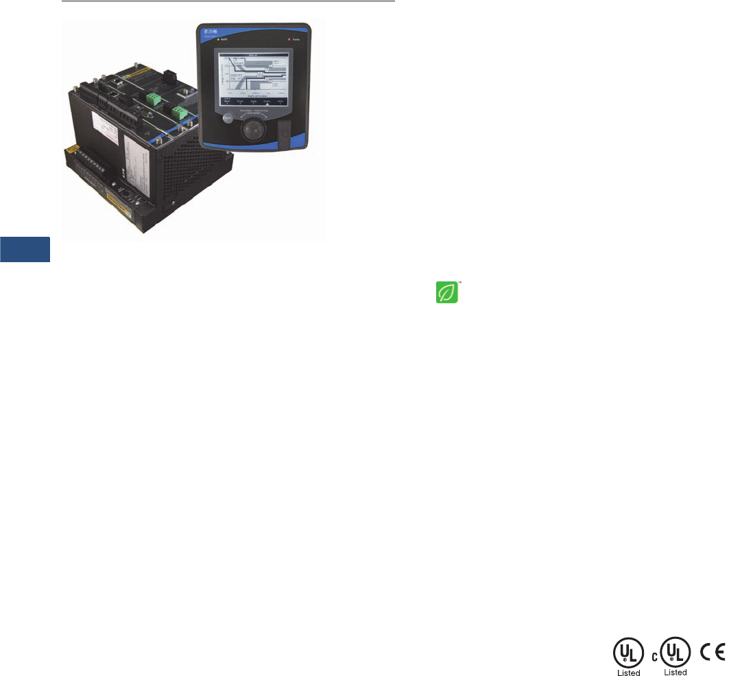
V3-T9-30 Volume 3—Power Distribution and Control Assemblies CA08100004E—November 2013 www.eaton.com
9
9
9
9
9
9
9
9
9
9
9
9
9
9
9
9
9
9
9
9
9
9
9
9
9
9
9
9
9
9
9.3
Metering Devices, Protective Relays, Software and Connectivity
Metering Devices
Power Xpert 4000/6000/8000 Series Display and Meter
Contents
Description Page
Metering Products Family. . . . . . . . . . . . . . . . . . . . . V3-T9-21
Power Xpert Meter 4000/6000/8000 Series
Power Xpert Meter 2000 Series . . . . . . . . . . . . . . . . V3-T9-49
IQ 250/260 Series Electronic Power Meters . . . . . . V3-T9-60
IQ 130/140/150 Series Electronic Power Meters . . . V3-T9-66
IQ 150S/250S Self-Enclosed Electronic Meters . . . . V3-T9-71
IQ 35M . . . . . . . . . . . . . . . . . . . . . . . . . . . . . . . . . . . V3-T9-76
IQ Analyzer 6400/6600 Series . . . . . . . . . . . . . . . . . V3-T9-79
IQ DP-4000 Series . . . . . . . . . . . . . . . . . . . . . . . . . . V3-T9-87
IQ 230 Meters . . . . . . . . . . . . . . . . . . . . . . . . . . . . . V3-T9-93
Power Xpert Multi-Point Meter . . . . . . . . . . . . . . . . . V3-T9-100
IQ Energy Sentinel™ . . . . . . . . . . . . . . . . . . . . . . . . V3-T9-112
PM3 Monitoring and Metering Module . . . . . . . . . . V3-T9-121
Current Transformers (CTs). . . . . . . . . . . . . . . . . . . . V3-T9-122
Clamp-On Current Transformers. . . . . . . . . . . . . . . . V3-T9-131
IQ Flange . . . . . . . . . . . . . . . . . . . . . . . . . . . . . . . . . V3-T9-134
Panel Mounting Adapter Kit . . . . . . . . . . . . . . . . . . . V3-T9-135
Enclosed Meters . . . . . . . . . . . . . . . . . . . . . . . . . . . V3-T9-136
An Eaton
Green Solution
Power Xpert Meter 4000/6000/8000 Series
Product Description
The Power Xpert Meter 4000/
6000/8000 Series monitors
the critical aspects of an
electrical distribution system.
This premier power quality
metering instrument is
simple to use, powerful,
scalable and highly flexible.
The Power Xpert Meter 4000/
6000/8000 offers a new level
of intuitive user interface
design, presenting critical
electrical distribution system
information in simple-to-
navigate and easy-to-
understand information
architecture. The Power
Xpert Meter 4000/6000/8000
graphic display visualizes
the information from up
to 16 meter modules. The
embedded Web server
displays complex power
quality data using standard
Internet browsers and allows
for device configuration from
the browser.
Both the local graphic display
and the embedded Web
server present real time,
historical and event
information in a browser-style
graphical format to help the
user interpret key circuit
information, such as:
●Current loading
●Voltage and power levels
●Power factor
●Energy usage
●I/O status
●Power quality
measurements
●Harmonic plots
●Disturbance and transient
waveforms
●ITIC disturbance summary
screen
The Power Xpert Meter 4000/
6000/8000 graphic display
uses a simple “twist and
click” navigation control dial
to easily navigate the menus
and drill down into increasing
levels of important detail.
A “back” key enhances the
browser-like navigation of the
graphic display.
The Web server provides the
energy and demand readings
required to help manage
the cost of energy. It also
provides critical information
regarding power quality,
such as harmonic distortion,
flicker, crest factor, K-factor
and more.
Note: Features and functionality
may vary depending on the meter
model and options being used.
Review the Features and Benefits
chart on Page V3-T9-35 for
details.
Standards and Certifications
●Safety: EN61010-1,
UL/cUL 61010-1
●Accuracy: IEC/EN60687
0.2 Class, ANSI C12.20
0.2 Class
●EMC: FCC Part 15
Subpart B Class A EN55011
Class A
●Measurement Canada
Approval No. AE-1898
(4000/6000 meters)
●Immunity IEC 61326
●CE Mark

Volume 3—Power Distribution and Control Assemblies CA08100004E—November 2013 www.eaton.com V3-T9-31
9
9
9
9
9
9
9
9
9
9
9
9
9
9
9
9
9
9
9
9
9
9
9
9
9
9
9
9
9
9
9.3
Metering Devices, Protective Relays, Software and Connectivity
Metering Devices
Application Description
Identify Power Quality
Problems to Help:
●Identify harmonics, sags,
swells and transients
damaging or disrupting
sensitive, mission-critical
IT equipment
●Boost IT equipment’s
service life to the
maximum
●Analyze sequence of
events up to 1 millisecond
time resolution
●Protect motors from
damage
●Preserve the integrity of
processes and batches
●Prevent blown capacitor
bank fuses
●Protect transformers and
conductors from
overheating
Detect and Record High-
Speed Transients to Help:
●Avoid equipment damage
and disruption
●Identify equipment
malfunction
Monitor Circuit Loading
to Help:
●Avoid overloads and
nuisance overload trips
●Maximize equipment
utilization
●Manage emergency
overloads
Manage Energy Utilization
to Help:
●Reduce peak demand
charges and power
factor penalties
●Identify excessive energy
consumption
Metered/Monitored Parameters
Note: See Page V3-T9-35.
●V o l t s : L- L , L- N , A v g . L- L ,
Avg. L-N, N-G
●Phase neutral and
ground currents
●Power: real, reactive
and apparent
●Frequency
●Power factor: apparent
and displacement
●Energy
●Demand
●% THD
●Minimum and maximum
values
●Harmonics
●Flicker
●Individual harmonics
●Interharmonics
●% TDD
●ITIC events plot, duration,
magnitude
●Energy comparisons
●Demand comparisons
●Event calendar
●Event timeline and
sequence
●Number of 9s of availability
●Phasors
●Sequence components
●Crest factor
●K-factor
●PQ Index
Accuracy
●Currents: 0.05% RV
+ 0.025%FS
●Voltage: 0.1% RV
+ 0.025% FS
●Energy and demand
power:
0.2% in accordance
with ANSI C12.20
●Frequency: ±0.01 Hertz
●Power factor:
●0.10% at Unity PF
●0.30% at 0.5 PF
Communications
Multiple communications
ports including:
Standard
●RS-485 remote display port
●RS-485 Modbus RTU
slave port
●RJ-45 10/100Base-T local
configuration port (local
Web server connection)
●HTTP (local), FTP,
COMTRADE
Optional
●Communications
Expansion Card (CEC
●Selectable 100FX or
10/100Base-T Ethernet
network port
●RS-485 Modbus RTU
selectable master/
slave port
●RS-232 Modbus RTU
slave port
For Optional Graphic Display
Note: Display ports provide access
to up to 16 Power Xpert 4000/6000/
8000 Meter modules located on
the display RS-485 network.
●RS-485 meter display
network port
●RJ-45 10/100Base-T for
access to Local Display
Power Xpert network
Communication Protocols
Supported
●Modbus RTU
●Modbus TCP
●Ethernet TCP/IP
●HTML
●NTP (Network Time
Protocol)
●FTP (File Transfer Protocol)
●SMTP (Simple Mail
Transfer Protocol)
●SNMP (Simple Network
Management Protocol)
●COMTRADE (IEEE
C37.111-1999)
●DNP 3.0 over Ethernet
(Distributed Network
Protocol)
Physical Characteristics
Two-Piece Design
●Power Xpert 4000/6000/
8000 Meter modules
●Power Xpert Meter 4000/
6000/8000 Graphic Display
320 x 240 pixel backlight
LCD remote graphics
display (supports up to 16
Power Xpert 4000/6000/
8000 Meter
module
s)
Display/Meter
Mounting Options
●Display remotely mounted
up to 2000 ft (1219m) away
from up to 16 Power Xpert
Meter
modules
●Display and Power Xpert
Meter modules mounted
together on opposite sides
of a panel (15 additional
meter modules can still
be remotely mounted).
Meter Base Unit Characteristics
●NEMA rating: NEMA 1,
IP30
Display Unit Characteristics
●NEMA rating: NEMA 12,
IP42 front of panel rating
Ease of Use—Power Xpert
Meter 4000/6000/8000 Graphic
Display (Option)
The Power Xpert Meter 4000/
6000/8000 display features
a large easy-to-read white
backlit graphic LCD. The
information presented by
the display is organized into
an information architecture
that is easy-to-navigate and
organized for simplicity.
Screen navigation is
accomplished using a
navigation control dial and
a “back” button. The user
simply twists the knob on
the navigation control dial
to move between menu
selections and drill down
links on the screen. When
the selection is highlighted,
pressing the dial makes the
selection. Information is
displayed from a single meter
or an RS-485 daisychain of
up to 16 meters. The display
features a rich set of screens
including real-time data, trend
plots, waveform views and an
ITIC Plot. The graphic display
allows basic device setup and
password protected resets.
An audible alarm is available
to annunciate alarm
conditions.

V3-T9-32 Volume 3—Power Distribution and Control Assemblies CA08100004E—November 2013 www.eaton.com
9
9
9
9
9
9
9
9
9
9
9
9
9
9
9
9
9
9
9
9
9
9
9
9
9
9
9
9
9
9
9.3
Metering Devices, Protective Relays, Software and Connectivity
Metering Devices
Power Xpert Meter 4000/6000/
8000 Embedded Web Server
The Power Xpert Meter 4000/
6000/8000 embedded Web
server offers Eaton
customers a new level of
accessibility to the critical
information required to
manage their electrical
distribution system. The Web
server includes real-time
circuit information in both
numeric and graphical visual
formats to help monitor
circuit parameters such as
current loading, voltage and
power levels, power factor,
THD, Flicker and more. The
Web server also provides
energy and demand readings
with graphic usage plots to
help analyze energy usage
patterns. Energy readings
include kWh, kVARh,
delivered and received and
kVAh with time of use and
RTP displays. The interval
energy usage plot includes
the ability to do week-to-
week and month-to-month
energy consumption
graphical comparisons for
benchmarking purposes. The
embedded Web server will
also display in simplified
Chinese if connected to a
computer configured for
Chinese language.
Both the Power Xpert Meter
4000/6000/8000 embedded
Web server and the local
graphic display support
graphical trend charts of key
circuit measurements such
as current, voltage, power
and energy. The trend chart
supports a zoom feature that
allows the user to view data
over a short period of 16
hours up to 4 years. The trend
chart includes zoom in/out
buttons and a horizontal slider
bar control to manage
scrolling forward and backward
through the data. Trend charts
of basic readings include
minimum, maximum and
average readings. Trend
charts of interval by interval
energy data also display
peak demand.
Note: For remote access and
networking capabilities such as
connecting to a LAN/WAN, use
the optional Communications
Expansion Card (CEC).
Sag/Swell/Transient Capture
and Recording
60 cycles of waveform are
oversampled at 4096 samples
per cycle (Power Xpert Meter
4000/6000), filtered through
anti-aliasing and recorded at
512 samples per cycle and
post event data. The Power
Xpert Meter 8000 samples at
a rate of 100,000 samples per
cycle. Embedded Web server
supports viewing of triggered
waveforms one channel at a
time and includes the ability to
zoom and to scroll horizontally
using a slider bar.
The Power Xpert Meter
6000/8000 Series have
preconfigured (600 volts and
below) trigger settings for
sags, swells and transients,
and do not require additional
setup by the user. Waveforms
are stored in non-volatile flash
memory using an industry
standard COMTRADE
format. Waveforms can be
automatically sent out as
COMTRADE attachments to
an e-mail following an event,
or can be retrieved from an
FTP (File Transfer Protocol)
directory structure in
the Power Xpert meter
module’s memory.
Historical Trend Logging
The Power Xpert Meter 4000/
6000/8000 records historical
data for graphical viewing
from the Local display or
the embedded Web server.
Graphical views of historical
data support pan and zoom.
145 standard metering
parameters are logged as
part of the standard meter
functionality including min./
max. and average for each
parameter. The averages are
calculated over the interval
period. The minimum and
maximum readings are based
on 200 ms calculations.
Storage capacity for standard
trend plots includes all of the
following intervals:
●Every 5 minutes for
48 hours (2 days)
●Every 15 minutes for
192 hours (4 days)
●Every hour for 28 days
(4 weeks)
●Every 8 hours for
56 weeks
●Every week for 44 months
Note: Trend plot data can be
easily exported to third-party
applications, such as Microsoft
Excel in csv-file format.
In addition, metered
parameters are automatically
stored on the built-in FTP
Servers, where they can be
easily copied and imported
into third-party applications
for benchmarking and
analysis. Logs on the FTP
Server include the min./max.
and average for 145 standard
metering parameters at
5-minute intervals.
Storage capacity for
trend data:
●6 days of 5-minute
interval trend data
●Capacity=18,144 intervals
Energy Profile Data
The Power Xpert Meter 4000/
6000/8000 records Real and
Reactive energy forward,
reverse, net and absolute
sum, as well as Apparent
energy (kVAH). Up to 8 status
inputs can be configured as
energy accumulators for
counting KYZ pulse inputs
(option). These readings are
stored over a configurable
interval from 1 to 60 minutes,
as well as in daily and
weekly totals.
With the optional LAN/WAN
Ethernet Communication
Expansion Card (CEC), users
can easily configure the
meters to send periodic
e-mails at user-defined
intervals of energy
consumption and power
demand. E-mails contain
a summary of readings per
rate structures and also have
the actual measurements
attached to the E-mail’s
body as a CSV file in a
ZIP container.
In addition, metered
parameters are automatically
stored on the built-in FTP
Server, where they can be
easily copied and imported
into third-party applications
for benchmarking and
analysis. Logs on the FTP
Server include energy
consumption logs, one
for every month in CSV
file format, trended
measurement logs also
in CSV file format and
waveform captures in
COMTRADE file format.
Storage capacity for energy
profile data:
●62 days of 15 minute
interval energy and pulse
interval data.
●Fixed interval capacity
= 5952 intervals.
Configurable intervals
from 1 to 60 min
●372 days of 1 day
accumulated energy and
pulse interval data
●208 weeks of 1 week
accumulated energy
and pulse interval data
Energy and Demand
Comparisons
Energy and demand usage
patterns can be analyzed with
the month-to-month, week-
to-week comparison chart
built into the meter. Raw
data can be exported with
the “Save Table” option to
other applications, such as
Excel, for further analysis
and graphing.
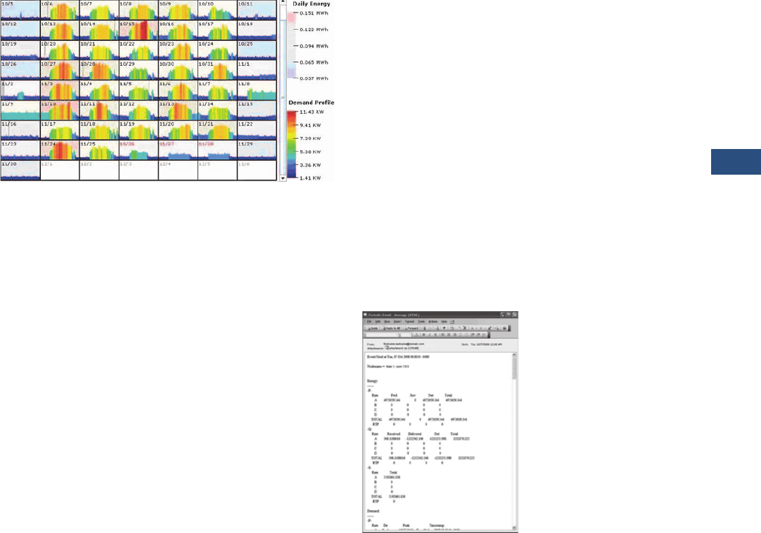
Volume 3—Power Distribution and Control Assemblies CA08100004E—November 2013 www.eaton.com V3-T9-33
9
9
9
9
9
9
9
9
9
9
9
9
9
9
9
9
9
9
9
9
9
9
9
9
9
9
9
9
9
9
9.3
Metering Devices, Protective Relays, Software and Connectivity
Metering Devices
Power Xpert Meter Profiler—Free Download
The Power Xpert Meter
Profiler software allows you
to compare “expected”
energy consumption patterns
to present usage and flag
areas of concern. It is also a
predictor. It can predict what
energy consumption would
be expected later in a day.
Event Triggers
The Power Xpert Meter
4000/6000/8000 supports
five types of configurable
event triggers:
●Out of limits (4000/6000/
8000)
●Demand overload (4000/
6000/8000)
●Sub-cycle disturbance
(4000/6000/8000)
●ITIC (6000/8000)
●Fast transient (8000)
These triggers permit pickup,
reset and pickup delay to
be configured by the user.
When a trigger occurs,
actions include Performance
Monitoring (#9’s analysis),
Capturing Waveform, Capture
Parameters, Send Email and
Operate a Relay Output. The
Graphic Display flashes an
LED to annunciate the alarm
condition. An audible alarm is
also available.
Trigger options include:
●Out of limits: over
100 triggers
●Demand overload:
10 triggers
●ITIC: 8 triggers
●Fast transient: dV/dT and
absolute per phase
●Sub-cycle disturbance—
dV/dt and absolute
Event Logging
The optional Power Xpert
Meter 4000/6000/8000
Local graphic display or the
embedded Web server both
allow the user to view a list of
triggered events along with
any captured parameters,
event details and triggered
waveforms. In addition, a
separate event log includes a
variety of activities including
acknowledged triggers, new
min. and max. events, and
system operations such as
resets. The size of the event
log is virtually unlimited based
only on the memory option
selected.
E-mail Notification
With the optional LAN/WAN
Ethernet Communication
Expansion Card (CEC)
attached to the Power Xpert
Meter 4000/6000/8000’s, the
users can easily configure
the meters to send periodic
emails at user-defined
intervals for energy
consumption and power
demand. Emails contain a
summary of readings per
rate structures and also have
the actual measurements
attached to the email’s
body as a CSV file in a ZIP
container. Prompt alarm
emails can also be sent for
any event condition either
standard in the meter or ones
set up by the user based on
thresholds, dV/dt triggers or
IO status changes with the
optional IO Card. Alarm
emails can be configured
to have the COMTRADE
waveform capture attached
to the e-mail’s body.
Periodic Email Message

V3-T9-34 Volume 3—Power Distribution and Control Assemblies CA08100004E—November 2013 www.eaton.com
9
9
9
9
9
9
9
9
9
9
9
9
9
9
9
9
9
9
9
9
9
9
9
9
9
9
9
9
9
9
9.3
Metering Devices, Protective Relays, Software and Connectivity
Metering Devices
ITIC Analysis Plot
The Power Xpert Meter
graphic display (option) and
Web server include a graphic
representation of the ITIC plot
(Power Xpert Meter 6000/
8000) with counts of
disturbances and transients
that have occurred. The ITIC
plot organizes events into
8 distinct disturbance zones
corresponding to severity and
a 9th zone for transients. A
pass/fail count is displayed
to indicate how many events
are outside the ITIC limits.
Clicking on any counter in the
ITIC Web page will link the
user to the event view and
display all triggered events
in the selected zone.
This makes it simple to view
disturbance waveforms
associated with the ITIC plot.
A separate ITIC graph is
available to review individual
ITIC events. This graph will
show the user the event
hit position on the graph
and the event duration
and magnitude.
Inputs and Outputs
Power Xpert Meter 4000/
6000/8000 is available with
an optional digital I/O card,
which includes:
●Eight digital inputs—
self sourced 24 Vdc
●Three relay outputs—
5A max. continuous,
240 Vac max., 30 Vdc max.
●Two solid-state outputs—
80 mA max. continuous,
30 Vdc max.
Each of the 8 inputs are
interrupt driven, allowing
for 1 ms accuracy of digital
events time stamps (1 ms
accuracy requires local NTP
TimeServer). Inputs can also
be configured for demand
synch and pulse counting.
Inputs selected for pulse
counting can be scaled.
Interval by interval pulse
recordings are maintained in
profile memory and can be
displayed graphically. Outputs
can be used for KYZ, or alarm
annunciation.
Ratings
●Application to 500 kV,
no PTs to 600V
●CT ratios selectable from
standard 120/600 Vac line
●CT inputs accept 5A
secondary
●Power supply:
●Standard 120/240 Vac
or 110/250 Vdc
Storage Capacity
Power Xpert Meter 4000/6000/8000 Estimated Memory and Storage Capacity with 2/4/8 GB Memory Capacity
Notes
1The typical and server power quality event occurrences are estimates and may vary depending on the electrical environment.
2Memory is not allocated by event category; memory is used first come, first served.
Model Memory Event File Size (KB)
Occurrence Per Month 1Memory Usage (MB) Months of Capacity 2
Typical Severe Typical Severe Typical Severe
PXM 4000 2 GB Subcycle Disturbance 1260 10 60 12.3 73.8 166 28
PXM 6000 4 GB ITIC Event 1260 5 20 6.2 24.6 666 166
Subcycle Disturbance 1260 10 60 12.3 73.8 333 55
ITIC + Subcycle Disturbance Total---> 15 80 18.5 98.4 222 42
PXM 8000 8 GB ITIC Event 1260 5 20 6.2 24.6 1332 333
Subcycle Disturbance 1260 10 60 12.3 73.8 666 111
Transients 2048 3 30 6.0 60.0 1365 137
ITIC + Subcycle Disturbance + Transients Total---> 18 110 24.5 158.4 335 52

Volume 3—Power Distribution and Control Assemblies CA08100004E—November 2013 www.eaton.com V3-T9-35
9
9
9
9
9
9
9
9
9
9
9
9
9
9
9
9
9
9
9
9
9
9
9
9
9
9
9
9
9
9
9.3
Metering Devices, Protective Relays, Software and Connectivity
Metering Devices
Features and Benefits
Power Xpert Meter 4000
●Harmonics, including
individual harmonics
●Disturbance capture
●Low frequency transient
detection and capture
●Standard power
quality index
Power Xpert Meter 6000
●Interharmonics
●Flicker calculations
●ITIC performance curve
●Event calendar view
●Events timeline view
●Sequence of events
waveform plot
●Enhanced power
quality index
Power Xpert Meter 8000
●Impulsive transient
capture at 6 MHz
●100,000 samples
per cycle
●Premium power
quality index
Power Xpert Meter 4000/6000/8000
Notes
These specifications are subject to change without notice and represent the maximum capabilities of the product with all options installed. This is not a complete feature list. Features and functionality
may vary depending on selected options, firmware version and product model. Please refer to the technical data sheet and User Manual for detailed specifications.
1Delta-Sigma A/D oversampling rate.
Power Xpert Meter
Feature 4000 6000 8000 Benefit
General
Embedded Web server ■■■Use a standard Web browser to monitor and manage the meter over the network, Internet
TOU metering support ■■■Time of usage can be set up to support 4 different schedules
Firmware flash update support ■■■Enables you to flash the meter with the latest firmware updates
Self-learning capability (characterizes “normal” per circuit) ■■■The meter can automatically adjust to the environment and alarm only when
“real” events occur
Power, Energy and Demand
Voltage, current: per phase minimum, maximum, average, trend graph analysis,
export, print
■■■Review voltage and current trends, export, print and analyze parameters right on the meter
or external software
Energy and demand plot comparisons month-to-month, week-to-week ■ ■ ■ Plot two months or two weeks for vivid energy or demand comparison
Power: power factor, apparent, real, reactive, frequency ■■■Review power usage and power factor and avoid potential PF penalties
Energy, demand: forward, reverse, net, sum, tou, profile, previous month
comparison, graph analysis, export, print
■■■Keep track of your energy usage, compare time of usage and usage against previous month,
identify peaks to conserve energy usage
Power Quality Analysis
Statistical analysis (min., max., average) ■■■Review statistical trends, identify past and future problem areas
Sag and swell monitoring, management and recording ■■■Capture electrical sags and swells and analyze the waveforms
Symmetrical Components: Zero, Negative, Positive ■■■Analyze possibly unbalanced three-phase power systems
Low frequency transient detection and capture ■■■Capture lower frequency transient waveforms for retrospective analysis or e-mailing
Sampling rate, maximum samples/cycle 4096 14096 1100,000 Extremely high sampling rate will effectively capture impulsive transients
“Number of Nines” uptime data (e.g., 6 nines = 99.9999%) ■■■Review uptime availability per cent
K-factor ■ ■■Review the ratio of eddy current losses, e.g., when driving nonlinear and linear loads
Crest factor ■ ■■Review the peak-to-average ratio of the waveform
Security
Secure 5 level user access privileges ■■■Define appropriate security access level per user
Communications and I/O
Modbus TCP ■■■Easy integration with standard protocol to power management and other software
Modbus RTU ■■■Integrate meters to existing Modbus networks, daisy chain several (1–16) meters together
HTML ■■■Communicate to the meter over the Internet via standard Web browser
SNMP (simple network management protocol) ■■■Communicate with the meter via Simple Network Protocol; hook to existing NMS system
SMTP (simple mail transfer protocol) ■■■Send e-mail messages via standard Simple Mail Transfer Protocol
FTP (file transfer protocol) ■■■Access, copy, paste, cut waveform capture files on the meter with an FTP Client
NTP (network time protocol) ■■■Network Time Protocol support enables the meter to synchronize time over the network up
to the 1 millisecond resolution
COMTRADE, open IEEE Standard file format for
Waveform capture export
■■■Import waveform captures in standard IEEE (C37.111-1999) COMTRADE file format to third-
party software
DNP 3.0 over Ethernet (Distributed Network Protocol) ■■■Communicate with the meter via DNP 3.0 over Ethernet; hook to existing utility systems

V3-T9-36 Volume 3—Power Distribution and Control Assemblies CA08100004E—November 2013 www.eaton.com
9
9
9
9
9
9
9
9
9
9
9
9
9
9
9
9
9
9
9
9
9
9
9
9
9
9
9
9
9
9
9.3
Metering Devices, Protective Relays, Software and Connectivity
Metering Devices
Power Xpert Meter 4000/6000/8000, continued
Notes
These specifications are subject to change without notice and represent the maximum capabilities of the product with all options installed. This is not a complete feature list. Features and functionality
may vary depending on selected options, firmware version and product model. Please refer to the technical data sheet and User Manual for detailed specifications.
1When used with third-party device and I/O option.
Power Xpert Meter
Feature 4000 6000 8000 Benefit
Communications and I/O, continued)
Trend measurements CSV file export ■■■Easily export trend measurements to third-party applications, e.g., Microsoft Excel in
standard CSV file format
I/O (8 digital inputs, 3 relay outputs, 2 solid-state KYZ outputs) ■■■The Power Xpert I/O Card is extremely flexible and can be used in a large variety of
different applications. Digital inputs and relay outputs can be programmed to interact
during various conditions defined by the user. Various third-party devices, such as
alarm, pulse meters, trip units, sensors can be easily integrated to the Power Xpert
Meter. Triggers and events can be tied to the meters standard functions such as e-mail,
logs and trends
Time Synchronization
NTP time synchronization up to 1 millisecond accuracy ■■■Network Time Protocol support enables the meter to synchronize time over the network up
to the 1 millisecond resolution
GPS time synchronization up to 1 millisecond accuracy ■ 1■ 1■ 1The GPS option allows the meter to synchronize time over the GPS satellite positioning
system up to the 1 millisecond resolution
Logs
Trend logging ■■■Log trend information for easy statistical analysis
Load profile ■■■Review the load profile graph to get a better understanding of your electrical load
versus time
Event logging ■■■Log events for retrospective event analysis
Memory and Storage
Standard memory, GB 248Store large amounts of waveform captures and events for historical analysis
Harmonics
Harmonic levels 127 127 127 Provides extremely fast, high resolution D/A conversion
Total harmonic distortion (THD) ■■■Review the total harmonic distortion level directly on the meter
Delta-Sigma D/A conversion technology ■■■Provides extremely fast, high resolution D/A conversion
Harmonics over-sampling (4096 samples per cycle) ■■■Over-sampling enables the usage of Anti-Aliasing technology, increasing accuracy
Anti-alias filtering ■■■Technology to remove out-of-band signal components resulting in more accurate data
Individual harmonics ■ ■■Review individual harmonic levels directly on the meter
Total demand distortion (TDD) ■ ■■Identify harmful harmonics in e.g. lightly loaded variable-speed drive environments where
THD may be high but not relative
Interharmonics ■ ■ Interharmonics allow you to see what is going on between the integer multiples of the
fundamental. Zoom in on the harmonics trend graph and review frequency content every
5 Hz instead of every 60 Hz
Highlights
Sub-cycle disturbance capturing ■■■Capture fast voltage changes/low frequency transient (e.g. capacitor switching transient)
dV/dt triggers for sub-cycle oscillatory transients ■■■Detect and record a large magnitude oscillation transient resulting in equipment damage
Absolute threshold and dV/dt triggering ■■■Detect and record if a surge suppressor is necessary
Power quality index—standard (includes dv/dt count, %TDDi and %THDv) ■ ■■Complex power quality data put into simple graphic format
Power quality index—enhanced (includes Standard Index plus Sag level,
Swell level and Flicker)
■ ■ Complex power quality data put into simple graphic format (includes ITIC events
and flicker calculations)
Flicker calculations ■■Detect and quantify low frequency rms voltage variations causing incandescent
lighting flicker
Automatic trigger setting ■■Trigger thresholds are automatically set according to ITIC (CBEMA) standard, no need to
figure this out by yourself
Automatic event severity analysis ■■Automatically analyze the severity of the event with the ITIC (CBEMA) performance curve
plot, see where the event actually hit

Volume 3—Power Distribution and Control Assemblies CA08100004E—November 2013 www.eaton.com V3-T9-37
9
9
9
9
9
9
9
9
9
9
9
9
9
9
9
9
9
9
9
9
9
9
9
9
9
9
9
9
9
9
9.3
Metering Devices, Protective Relays, Software and Connectivity
Metering Devices
Power Xpert Meter 4000/6000/8000, continued
Notes
These specifications are subject to change without notice and represent the maximum capabilities of the product with all options installed. This is not a complete feature list. Features and functionality
may vary depending on selected options, firmware version and product model. Please refer to the technical data sheet and User Manual for detailed specifications.
Power Xpert Meter
Feature 4000 6000 8000 Benefit
Highlights, continued
Event severity counters ■■An ITIC (CBEMA) event counter keeps track of the number of all sags, swells and
transients
ITIC (Information Technology Industry Council), previously CBEMA
performance curve
■■ITIC (Information Technology Industry Council), previously CBEMA performance curve for
easy power problem evaluation
Custom ITIC (CBEMA) plot with individual event magnitude and duration ■■Review custom ITIC (CBEMA) plots of individual events showing you the actual
magnitude, duration and hit are in a simple graphical representation
Event calendar view ■ ■ The Events Timeline calendar view provides instant insight to the frequency of power
events and helps detect reoccurring problems
Events timeline view ■ ■ View and understand the sequence of events that have occurred during a period of time
Sequence of events and events plot on waveform ■ ■ Plot color-coded events on a captured waveform to gain insight into the sequence of
events cycle per cycle
Power quality index—premium (at-a-glance “thermometer” view of
power quality)
■ Complex power quality data put into simple graphic format (includes ITIC events and
flicker calculations)
High-Speed Transient Capture and Detection
6 MHz capture of impulsive transients ■Capture impulsive transients by taking 6 samples every millionth of a second
Transient Capture Duration: ~20 ms/6 MHz ~120 ms/1 MHz ■Record and analyze transients during a longer timeframe
Waveform recorded at 100,000 samples per cycle ■High-speed ensures impulsive transients are correctly captured (fast rise time)
Three-phase voltage and neutral-to-ground fast transient capture ■Capture impulsive transients on all 4 channels
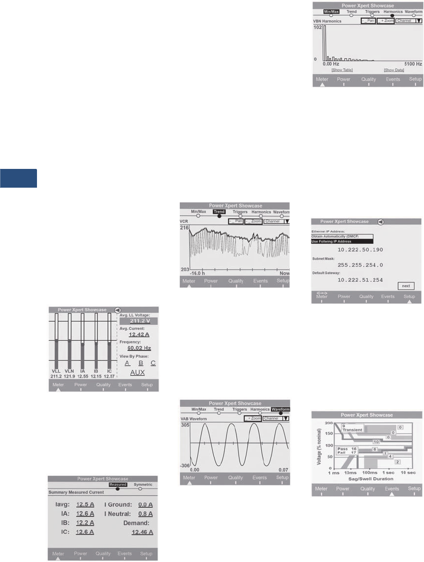
V3-T9-38 Volume 3—Power Distribution and Control Assemblies CA08100004E—November 2013 www.eaton.com
9
9
9
9
9
9
9
9
9
9
9
9
9
9
9
9
9
9
9
9
9
9
9
9
9
9
9
9
9
9
9.3
Metering Devices, Protective Relays, Software and Connectivity
Metering Devices
Power Xpert 4000/6000/8000 Graphic Display (Option) Features
A menu-driven graphical
display with information
organized into a user-friendly
information architecture.
The homepage (see below)
offers:
●Graphical level indicator
based on a statistical
analysis for three-phase
line-to-line and line-to-
neutral voltage and per
phase currents to quickly
indicate out of normal
readings
●Large easy-to-read average
L-L voltage average phase
currents and system
frequency can be
highlighted and selected
using the navigation
control dial to drill down
for additional detail
●Menu selections for meter,
power, quality, events and
setup are shown for ease
of navigation into display
for more detail, or basic
device setup
Homepage
Highlighting a field such as
the avg. current value and
pressing the navigation control
dial brings up a detail screen
like the one below.
Current Summary
Highlighting an individual
reading on the detail
summary level screen and
selecting it drills down to a
level including links to min./
max., historical trend plots,
triggers, harmonic spectral
data and waveform viewing.
Selecting the trend plot for
a given parameter displays
a historical graph of the
selected parameter over
the last 16 hours. The zoom
buttons change the time
scale to one of several data
views based on historical
averages with min./max. The
Pan button allows scrolling
within the selected view.
Trend Plot
Waveforms can be displayed
for currents and voltages.
The waveforms can be
viewed on demand for
steady-state conditions.
Triggered waveforms can
also be displayed to view
sag/swell or transient data.
Waveform Viewer
Harmonic Spectrum
The harmonic spectral plot
displays both harmonics and
interharmonics up to the
85th order. A detailed table
also includes individual
magnitudes and angles
of current and voltage
harmonics, as well as a
harmonic power calculation
at each frequency.
Ethernet Settings
Ethernet and other settings
can be input or verified via
the Power Xpert Meter
LCD display.
Note: Some of the other settings
are specific only to the Web
Browser GUI.
ITIC Plot (Power Xpert 6000/8000)
The Power Xpert Meter
classifies disturbances and
summarizes the results
graphically using the ITIC plot.
The number of ITIC sags and
swells are indicated for each
of nine severity levels.
A pass/fail summary is
shown to indicate how many
events are outside the ITIC
pass zone.
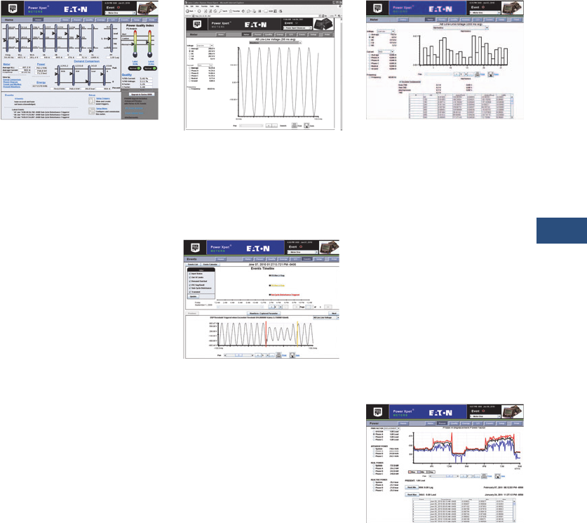
Volume 3—Power Distribution and Control Assemblies CA08100004E—November 2013 www.eaton.com V3-T9-39
9
9
9
9
9
9
9
9
9
9
9
9
9
9
9
9
9
9
9
9
9
9
9
9
9
9
9
9
9
9
9.3
Metering Devices, Protective Relays, Software and Connectivity
Metering Devices
Power Xpert Graphic Display
(Option) Screens
Meter Top Level Screen
V-LL avg, V-LN avg, IA, IB, IC,
Iavg, freq.
Meter Detail Screens
Per phase detail L-L, L-N,
Symmetrical Comp, Aux.
Channels, Min./Max. with
date/time of occurrence,
Trend Plots, Triggers,
Phasors.
Power Top Level Screen
Three-Phase Power Factor,
kWHr, kWd, Real-Time kW,
kVAR, kVA, Load Profile Link.
Power Detail Screens
Per phase detail, kVA, kVAR,
kW, Min./Max. with date/
time of occurrence, Trend
Plots, Triggers.
Quality Top Level Screen
10 min. and 24 hr. PQIndex,
THDI, THDV, K-factor, Crest
Factor, Flicker Pst,%9’s of
Reliability.
Quality Detail Screens
Per phase detail L-L,
L-N,V aux, Odd, Even,
Interharmonics, Present,
Min/Max, Trend Plots,
Harmonic spectrum plots,
waveform plots.
Events Top Level Screen
Active/Acknowledged Event
list, Trigger List, System Log,
ITIC Curve Link.
Event Detail Screens
Event List, Condition,
Acknowledge Button,
Trigger Date/Time, Trigger
description.
Setup Top Level Screen
View setup, Edit setup,
Login, Logout.
Setup Detail Screens
Quick Setup, Trigger setup,
Detail setting.
Power Xpert 4000/6000/8000 Web Browser Views
Power Xpert 4000/6000/8000 Web
Browser Homepage (Note: 4000 does
not include flicker, ITIC)
Power Xpert Meter 4000/
6000/8000’s embedded
Web server offers Eaton
customers a new level of
accessibility to the critical
information required to
manage the electrical
distribution system. The
embedded Web server
includes real-time circuit
information in both numeric
and graphical formats to help
monitor circuit parameters
such as current loading,
voltage and power levels,
power factor.
The Web server also provides
the energy and demand
readings required to help
manage the cost of energy.
Readings include kWh,
kVARh, delivered and
received and kVAh with
time-of-use and separate
status input controlled energy
accumulation to account for
energy during special times
such as rate alert periods
or stand-by generator times
of operation.
The Web server also includes
critical information regarding
Power Quality such as
harmonic distortion, flicker
(Power Xpert Meter 6000/
8000), crest factor, K-Factor
and more.
Steady-State Waveform
The Web server allows the
user to view waveforms of
the voltage and current to
spot power quality problems
such as notching.
Events Timeline
(Power Xpert 6000/8000)
View and understand the
sequence of events that have
occurred during a period
of time. Plot color-coded
events on captured
waveforms to gain insight
into the sequence of events
from one single cycle to the
next one. This provides the
user an excellent vantage
point to review and compare
multiple events at an
unprecedented resolution.
Harmonic Spectral Plot
The harmonic spectral plot
displays both harmonics and
interharmonics up to the
85th order. A detailed table
also includes individual
magnitudes and angles of
current and voltage
harmonics, as well as a
harmonic power calculation
at each frequency. Even, odd
and total THD are displayed
for diagnostic purposes. In
addition, the Power Xpert
6000/8000 provides
interharmonics, which allow
users to see what is going
on between the integer
multiples of the fundamental.
Historical Trend Plot
Graphical Trending of Data
The Power Xpert Meter 4000/
6000/8000 embedded Web
server supports graphical
trend charts of key circuit
measurements such as
current, voltage, power and
energy. The trend chart
supports a zoom feature
that allows the user to view
data over a short period of
16 hours or a longer period of
48 months. The trend chart
has a horizontal slider bar
control to manage scrolling
forward and backward
through the data. Trend
charts of basic readings
include minimum, maximum
and average readings. Trend
charts of energy data also
display demand values.
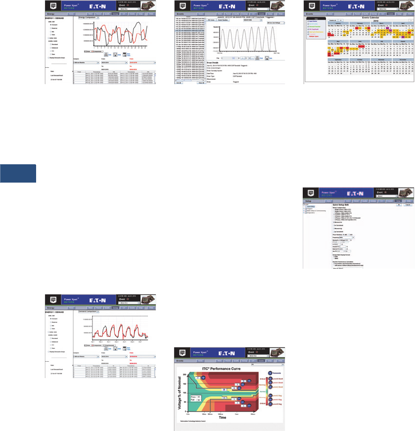
V3-T9-40 Volume 3—Power Distribution and Control Assemblies CA08100004E—November 2013 www.eaton.com
9
9
9
9
9
9
9
9
9
9
9
9
9
9
9
9
9
9
9
9
9
9
9
9
9
9
9
9
9
9
9.3
Metering Devices, Protective Relays, Software and Connectivity
Metering Devices
Energy Comparison
Energy usage patterns can be
effortlessly analyzed with the
month-to-month, week-to-
week comparison chart. Raw
data can be easily exported
with the “Save Table” option
to other applications such as
Excel for further analysis or
graphing (firmware version
12.x.x and higher only).
Note: All data logging for
trend plotting is automatically
preconfigured in all of the Power
Xpert Meter 4000/6000/8000
meters. In addition, the 6000
and 8000 Series meters have
sag, swell and transient triggers
built-in according to the ITIC
(CBEMA) standard.
Demand Comparison
Demand comparison
compares power
consumption day-to-day,
month-to-month or week-to-
week. Power Xpert Meters
can set to measure demand
at 1 to 60 minute intervals.
Both sliding and fixed interval
windows are supported for
maximum flexibility.
Disturbance Recording
Sag/Swell Recording
60 cycles of waveform are
recorded at 256 samples per
cycle including 30 cycles of
pre- and post-trigger data.
The Power Xpert Meter 4000/
6000/8000 embedded Web
server supports viewing of
triggered waveforms one
channel at a time including
the ability to zoom and to
scroll horizontally using a
slider bar. Waveforms are
stored in Power Xpert
Meter’s 4000/6000/8000
non-volatile flash memory
using an industry standard
Comtrade format.
Waveforms can be
automatically sent out by
e-mail following an event,
or can be retrieved from an
FTP directory structure in the
meter module’s memory.
ITIC Analysis Plot
(Power Xpert Meter 6000/8000)
The ITIC Web page includes
counters to track the
occurrence of disturbances
and a pass/fail summary.
In addition, selecting any
disturbance counter links to
a detailed event view of the
disturbances in that ITIC
category. Disturbance
waveforms can be viewed
from the browser.
Events Calendar
(Power Xpert 6000/8000)
The Events Timeline calendar
view provides instant insight
to the frequency of power
events and helps detect
reoccurring problems. Color-
coded events can be filtered
to detect specific issues.
Configuration Page
Web Server Device
Configuration
Special software is not
required to configure a Power
Xpert Meter 4000/6000/8000.
The embedded Web server
includes comprehensive
device set-up capability.
Discrete Contact Inputs
The optional PXIO-B
expansion card offers 8 digital
inputs that are useful for a
variety of applications such as:
●Status indication with time
stamping of transitions
(1 ms precision).
●Pulse counting of KYZ or
other utility pulses such
as air, water or gas.
●High-speed triggering of
waveforms based on
events such as breaker
trips or static transfers
●Demand interval timing
taken from a master utility
meter end of interval pulse
Status inputs are self sourced
providing a nominal 24 Vdc
(20–30 Vdc) across the circuit.
Names can be configured for
each input for ease of use.
Relay Outputs
The optional PXIO-B card
includes three 5A form C
relay outputs rated for
240 Vac or 30 Vdc. These
outputs can be used for
applications such as:
●Alarm annunciation
●KYZ pulse output
Alarm outputs can be driven
from triggers based on
metering values. Output
modes include:
●Normal—relay energized
during alarm condition
●Latched—relay energized
by event trigger,
de-energized by
acknowledgement
●Timed—relay energized by
event trigger, maintained
for a programmed interval.
Communications Expansion
Card (CEC)
The optional CEC Card offers
two Ethernet connection
options, 10/100Base-T and
a fiber-optic port that can
be used for the following
applications:
●Monitoring, managing and
configuring the meter
remotely using a standard
Web browser interface like
Microsoft Internet Explorer
●Alarm notifications via
e-mail, SMTP
●Enabling access to the
meter’s FTP server
(energy, trend and
waveform logs)
●Providing Modbus TCP/IP
or RTU communications
to BMS systems
●Providing DNP 3.0 over
Ethernet to utility systems
●Providing SNMP
communications to
NMS systems
●Synchronizing with an
NTP server for 1ms
timestamping resolution
●Asset management
via SNMP to Network
Management Systems
●Updating firmware on
the meter

Volume 3—Power Distribution and Control Assemblies CA08100004E—November 2013 www.eaton.com V3-T9-41
9
9
9
9
9
9
9
9
9
9
9
9
9
9
9
9
9
9
9
9
9
9
9
9
9
9
9
9
9
9
9.3
Metering Devices, Protective Relays, Software and Connectivity
Metering Devices
Flicker (EN61000-4-15; Power Xpert Meter 6000/8000)
Flicker values for
perceptibility, PST and PLT
are calculated based on
EN61000-4-15 guidelines.
Power at a Glance
Easily Upgrade Your Power
Xpert Meter 4000 to a 6000
Eaton understands that our
customers’ needs change
over time. That’s why we’ve
developed meters that can
grow with you. Once a Power
Xpert Meter is purchased,
you have the ability to
upgrade to a Power Xpert
Meter 6000, with no
intervention from Eaton,
when needed. All the
features of the Power Xpert
Meter 4000 that you have
been using and depend on
remain, however, once
updated, all the additional
features of the Power Xpert
Meter 6000 are available. The
self-upgrade is available on
Eaton’s website. You’ll need
a credit card, your Power
Xpert Meter 4000 serial
number and data code (you
will be presented with this
information if you are using
the upgrade link directly from
your Power Xpert Meter)
and your e-mail address.
Once you have completed
the purchase, we will send
you your new license key
information via e-mail that
will allow you to complete
the upgrade.
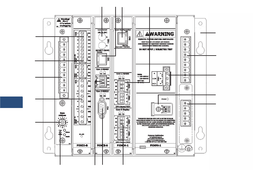
V3-T9-42 Volume 3—Power Distribution and Control Assemblies CA08100004E—November 2013 www.eaton.com
9
9
9
9
9
9
9
9
9
9
9
9
9
9
9
9
9
9
9
9
9
9
9
9
9
9
9
9
9
9
9.3
Metering Devices, Protective Relays, Software and Connectivity
Metering Devices
Power Xpert Meter 4000/6000/8000 Module Layout
I/O Card
aDigital inputs 1–8 (option)
bSolid-state outputs 1–2 (option)
cRelay outputs 1–3 (option)
CT and Voltage Connections
dCT input connections
eStandard three-phase voltage phase inputs
fAux. channel voltage inputs (option)
Communication Expansion Card (LAN/WAN Ethernet Networking)
g100FX ST-type Ethernet (multi-mode) (option)
h10/100Base-T Ethernet (option)
iRS-485 (two-wire w/shield)—24V accessory power (com 2)
Standard Features
jLocal RJ-45 config. port (non-networkable Ethernet)
kRS-485 (two-wire w/shield) Modbus RTU (com 1)
lMeter mounting brackets
mSealable mode switch cover
nControl power (100–240 Vac and 110–250 Vdc) (±20%)
oDisplay RS-485 Network port (up to 15 meters)—24V accessory power (com 0)
pRS-232 (Tx Rx) Modbus RTU (com (3) (option)
qMeter base address
rCom Reset Button
a
b
c
d
q
ghj k
e
n
f
m
l
oip
r
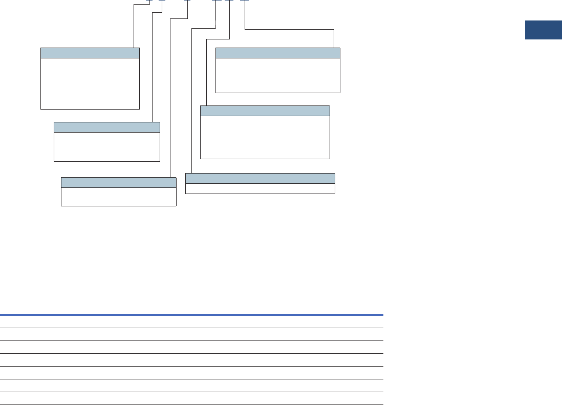
Volume 3—Power Distribution and Control Assemblies CA08100004E—November 2013 www.eaton.com V3-T9-43
9
9
9
9
9
9
9
9
9
9
9
9
9
9
9
9
9
9
9
9
9
9
9
9
9
9
9
9
9
9
9.3
Metering Devices, Protective Relays, Software and Connectivity
Metering Devices
Catalog Number Selection
To order a Power Xpert
Meter 4000/6000/8000, the
catalog number should be
determined using the chart
shown below. The chart
illustrates how to include the
desired factory options as
part of a catalog number.
Option cards that are
selected at time of order
entry will be installed at the
factory. Option cards are
also field installable for
field upgrades.
If a display is required, it
should be ordered separately.
The multi-meter graphic
display is capable of
displaying data from an
RS-485 daisychain of up to
16 Power Xpert Meter 4000/
6000/8000 modules over a
distance of up to 1000 ft.
Power Xpert Meter modules
include panel mounting
brackets. The multi-meter
graphic display is designed to
mount separately. If back-to-
back meter to display panel
mounting is desired, a
mounting bracket kit is
available (PX-PMBA).
Example 1: PXM8251A1BB
(PXM 8000 Meter, w/ VAUX,
Std. Pwr, Com. Exp. &
I/O Cards)
Example 2: PXM6251A1BA
(PXM 6000 Meter, w/ VAUX,
Std. Pwr, Com. Exp. Card)
Power Xpert Meter 4000/6000/8000
Accessories
Power Xpert Meter 4000/6000/8000
Notes
1These items can be ordered separately or preinstalled in the meter by selecting option B in the model number.
Communication cable (standard Modbus RTU) is not included in the package for meter module connection.
Description
Catalog
Number
Graphic display module PXD-MMG
Communication expansion card for LAN/WAN Ethernet networking: 100FX fiber-optic, 10/100T, RS-485, RS-232 PXMCE-B 1
Digital I/O card: eight digital input, two solid-state output, three relay output PXMIO-B 1
Panel mounting bracket assembly for back-to-back meter to graphic display mounting PX-PMBA
Panel mounting bracket assembly for retrofitting a graphic display to an IQ Analyzer cutout PX-PMBB
Panel mounting bracket assembly for reduced graphic display rear clearance PX-PMBC
Power Xpert Meter 4000 to 6000 license upgrade key PXM-4KUPG
PXM 8 0 5 1 A 1 B B
Model Series
4 = 4000 (Standard
power quality, 2 GB)
6 = 6000 (Enhanced
power quality, 4 GB)
8 = 8000 (Premium PQ
w/ transient capture, 8 GB)
Power Supply Configuration
1 = Standard 100–240 Vac or
110–250 Vdc power supply
Card Slot 1 Configuration
1 = Standard Communications Module with RS-485
Card Slot 2 Configuration
A = No card option
B = Communication expansion card
for LAN/WAN Ethernet
networking w/10/100Base-T,
100F, RS-485, RS-232 ports
Card Slot 3 Configuration
A = No card option
B = I/O option card
(8 digital inputs, 2 solid-state
outputs, 3 relay outputs)
Voltage Input Configuration
0 = Standard (V1, V2, V3, V4)
2 = Standard plus auxiliary
(V6, V7, V8)
Example 1: PXM8251A5BB (PXM 8000 meter, w/ VAUX, std. pwr., com. exp. and I/O cards)
Example 2: PXM6251A6BA (PXM 6000 meter, w/ VAUX, std. pwr., com. exp.card)

V3-T9-44 Volume 3—Power Distribution and Control Assemblies CA08100004E—November 2013 www.eaton.com
9
9
9
9
9
9
9
9
9
9
9
9
9
9
9
9
9
9
9
9
9
9
9
9
9
9
9
9
9
9
9.3
Metering Devices, Protective Relays, Software and Connectivity
Metering Devices
Technical Data and Specifications
Environmental Conditions
●Operating temperature:
●Meter: –20 to +70°C
●Display: –20 to +60°C
operating
●Storage temperature:
–40 to +85°C
●Operating humidity:
5% to 95% condensing
●Device weight: 7.1 lbs—
meter 2.1 lbs—display
●Meter and back of
display are pollution
degree 2
●Elevation to 6562 ft
(2000m)
Current Inputs (Each Channel)
●Conversion: 4096 samples
per cycle delta-sigma
converter digitally filtered
down to 512 samples
per cycle
●CT Input: 4096 rms
samples per cycle delta-
sigma converter digitally
filtered down to 512
samples per cycle for
anti-aliasing
●Burden: less than
10 milliohms
●Overload withstand:
500A for 1 second,
non-repeating
●Range: 0.005–20A
continuous
●Accuracy: 0.05% or
reading plus 0.01%
of full scale (from
50 milliamps to 20A)
Voltage Inputs (Each Channel)
●Conversion: 4096 rms
samples per cycle delta-
sigma converter digitally
filtered down to 512
samples per cycle for
anti-aliasing
●PT input: 120V–500,000V
primary
●Input range: 600V L-L,
347 L-N direct connect
●Nominal full scale:
1000V rms
●Input impedance:
2 megohms
Frequency Range
●47–63 Hz
Harmonic Response
(Voltage, Current)
●127th harmonic
Accuracy
●ANSI C12.20 0.2 Class
●IEC 687 0.2 Class
Discrete Inputs
●Self sourced: 24 Vdc
Relay Output Contacts
●5A maximum, 240 Vac
maximum, 30 Vdc
maximum
●Lifetime: 1,000,000 no
load operations
●100,000 under rated
voltage and load
Solid-State Outputs
●Maximum load:
100 milliamps
●Maximum voltage: 30V
(externally sourced)
Control Power Input
●Input range AC:
100–240 Vac (±20%)
●Frequency range:
47–63 Hz
●Input range DC:
110–250 Vdc ±20%
●Burden 50 VA
●Ride-through: 1–5s
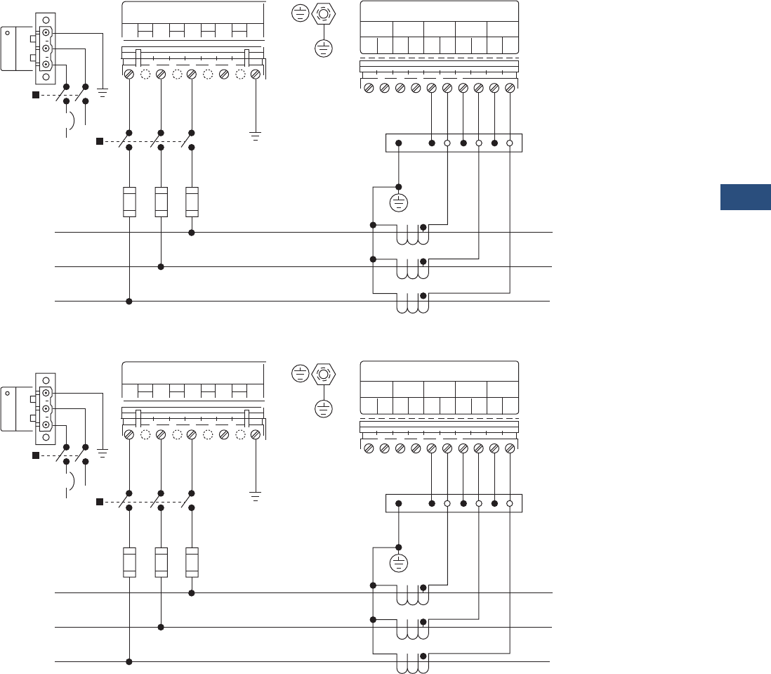
Volume 3—Power Distribution and Control Assemblies CA08100004E—November 2013 www.eaton.com V3-T9-45
9
9
9
9
9
9
9
9
9
9
9
9
9
9
9
9
9
9
9
9
9
9
9
9
9
9
9
9
9
9
9.3
Metering Devices, Protective Relays, Software and Connectivity
Metering Devices
Wiring Diagrams
Three-Phase, Three-Wire Delta (Up to 600 Volts)
Three-Phase, Three-Wire Delta (Above 600 Volts)
Note
Based upon the voltage rating, you may need a control power transformer for the control power.
Voltage Inputs
V1 V2 V3 V4 VR
Disconnect
Switch
Disconnect
Switch
Breaker
(+) L
(–) N
123
Control
Power
L3
L2
L1
Load
Line
Shorting
Block
Protective
Earth /
Chassis
Ground
Current Inputs
5 4 3 2 1
52 51 42 41 32 31 22 21 12 11
PSI-
Voltage Inputs
V1 V2 V3 V4 VR
Disconnect
Switch
Disconnect
Switch
Breaker
(+) L
(–) N
123
Control
Power
L3
L2
L1
Load
Line
Shorting
Block
Protective
Earth /
Chassis
Ground
Current Inputs
5 4 3 2 1
52 51 42 41 32 31 22 21 12 11
PSI-
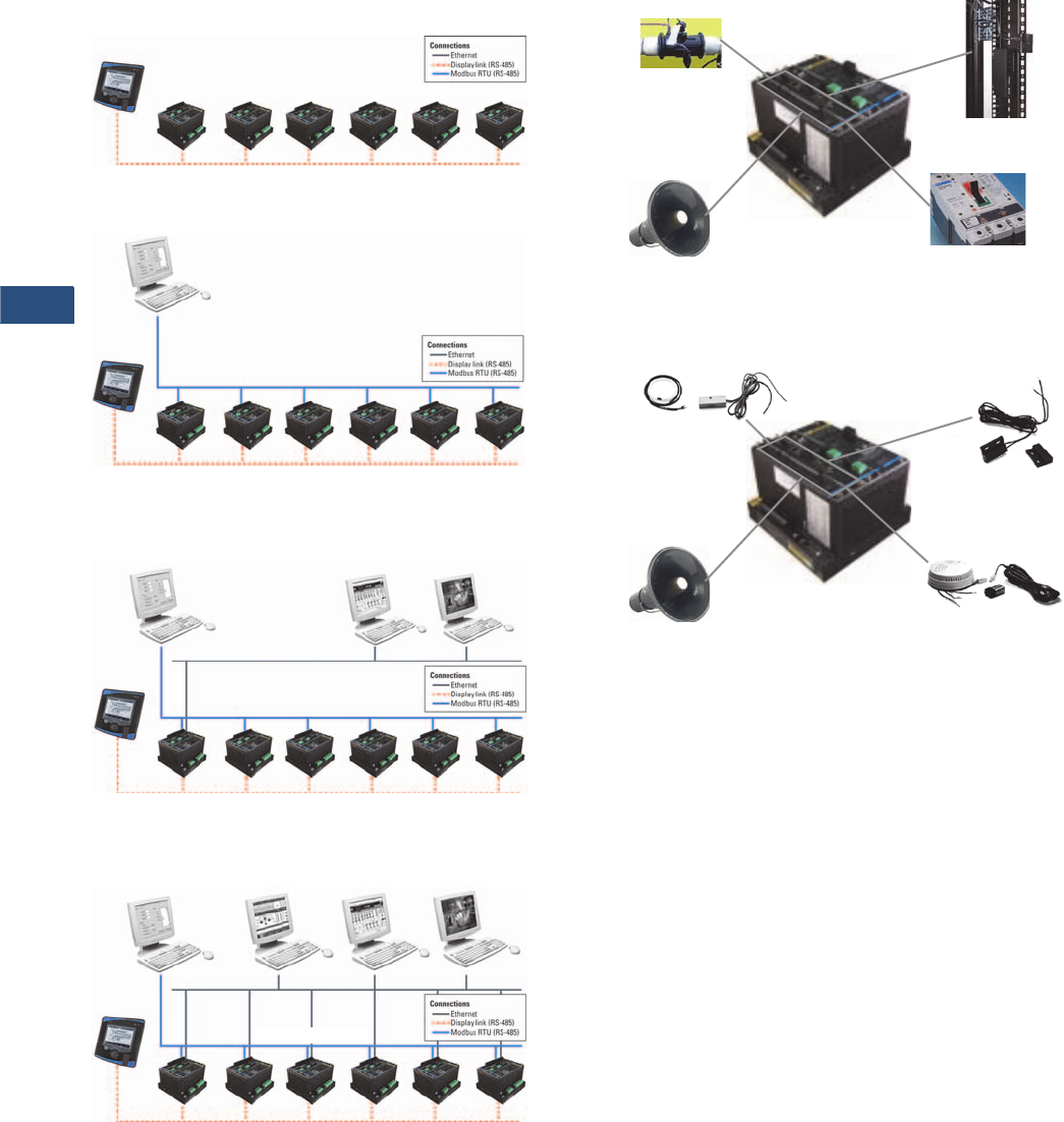
V3-T9-46 Volume 3—Power Distribution and Control Assemblies CA08100004E—November 2013 www.eaton.com
9
9
9
9
9
9
9
9
9
9
9
9
9
9
9
9
9
9
9
9
9
9
9
9
9
9
9
9
9
9
9.3
Metering Devices, Protective Relays, Software and Connectivity
Metering Devices
Power Xpert Meters Configuration and Wiring Examples
Display Link
Modbus RTU (RS-485)—Non-Web Enabled
Web Enabled—Browser and Modbus TCP
Web Enabled—Advanced System Functionality
Accessories—I/O Card (Option)
IT Configuration Examples—Accessories—I/O Card (Option
Display Link (RS-485)
Up to 16 Meters can be Daisy-Chained to a Single
Power Xpert Meter LCD Display
…Up to 16
Display Link (RS-485)
Modbus RTU (RS-485)
Modbus RTU (RS-485)
Master
…Up to 16
Display Link (RS-485)
Modbus RTU (RS-485)
Modbus RTU (RS-485)
Master
…Up to 16
Modbus TCP
Master
Web
Browser
Display Link (RS-485)
Modbus RTU (RS-485)
Modbus RTU (RS-485)
Master
Modbus TCP
Master
Web
Browser
Power Xpert
Software
Alarm
Flow Meter
(Pulse Count)
• Eight Programmable Digital Inputs
• Two Solid-State Programmable Outputs
• Three Relay Programmable Outputs
Trip and Sequence
of Events
Rack Monitoring—
Open Door/Tamper Switch
Smoke Alarm
Alarm
Water Leak and
Vibration Sensors
Rack Monitoring
— Open Door/
Ta m p e r Sw it c h
• 8 Programmable Digital Inputs
• 2 Solid-State Programmable Outputs
• 3 Relay Programmable Outputs
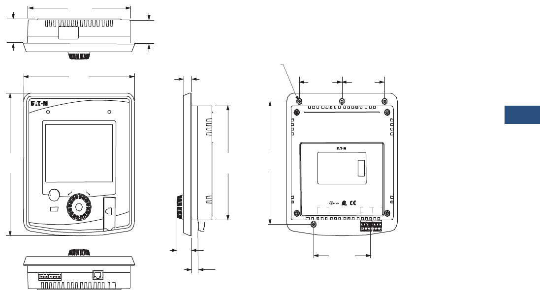
Volume 3—Power Distribution and Control Assemblies CA08100004E—November 2013 www.eaton.com V3-T9-47
9
9
9
9
9
9
9
9
9
9
9
9
9
9
9
9
9
9
9
9
9
9
9
9
9
9
9
9
9
9
9.3
Metering Devices, Protective Relays, Software and Connectivity
Metering Devices
Dimensions
Approximate Dimensions in Inches (mm)
Power Xpert Meter 4000/6000/8000 Multimeter Graphic Display (PXD-MMG)—Sold Separately,
Supports up to 16 Power Xpert Meter 4000/6000/8000 Modules
CW
10/100 T
Li
nk
T
X
D
R
X
DG3
-
Power
Com 0
3
SH
1
23
4
S
H
C
O24
+
DG2
-
1
2
D
B
D
A
DG1
-
Display Link
24VDC Input
Customer Satisfaction for Techni cal Support
www.EatonElectrical or
htt // E t El t i l
1-800 -809-2772 or 1 -414-
E18555
9
F
ac
t
ory
S
ea
l
e
d
CW
G.O.#: XXXXXXXXXX
Catalog#: PX8054A1CB
Model#: PX8000
Serial#: 000042
Style#: 65D8054G010
Power Supply: 24 VDC (+/ -20%)
SELV, 8W MAX.
MADE
IN
CANADA
Date Code: C050131
Rev: 1
O
per
T
emp: -
20
TO
60°C
4.00 Ref.
(101.6)
3.00 Ref.
(76.2)
3.00 Ref.
(76.2)
1.45
(36.8)
1.50
(38.1)
5X #8 – 32 Thread
Thread Depth 0.31
7.22
(183.5)
7.80
(198.0)
9.02
(229.0)
0.57
(14.5)
7.22
(183.5)
7. 7 6 R e f .
(197.1)
1.04
(26.3)
0.46
(11.6)
Health Events
Push to Select • Hold for Help
BACK
Turn to Highlight
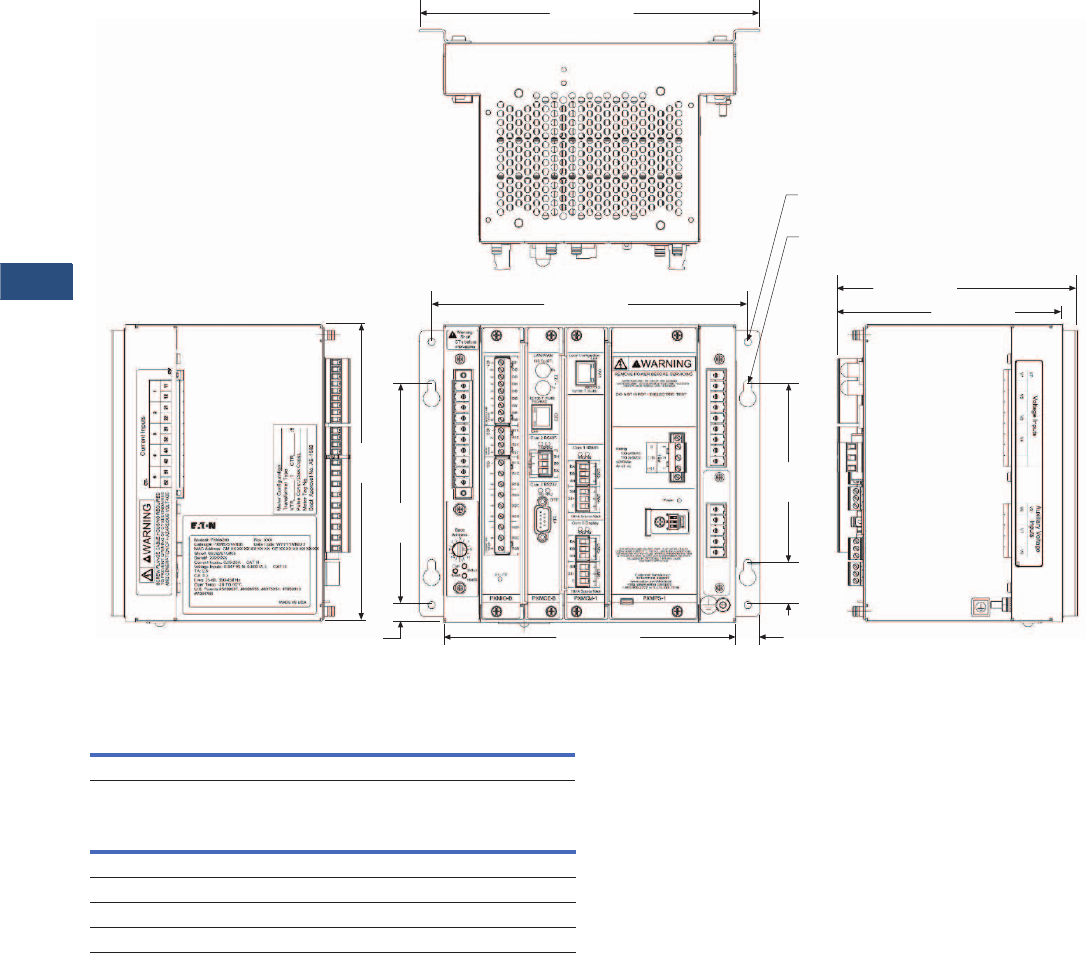
V3-T9-48 Volume 3—Power Distribution and Control Assemblies CA08100004E—November 2013 www.eaton.com
9
9
9
9
9
9
9
9
9
9
9
9
9
9
9
9
9
9
9
9
9
9
9
9
9
9
9
9
9
9
9.3
Metering Devices, Protective Relays, Software and Connectivity
Metering Devices
Approximate Dimensions in Inches (mm)
Power Xpert Meter 4000/6000/8000 Module
Meter Base Unit
Display Unit
Note
1Including optional wall mounting brackets.
Width Height Depth
9.56 (242.8) 8.88 (225.6) 6.72 (170.8) 1
Height Width Depth
Projection In Front of Panel Surface
9.02 (229.0) 7.80 (198.1) 1.04 (26.3)
Behind Panel Surface
9.02 (229.0) 7.80 (198.1) 1.45 (36.8)
8.88 (255.6)
8.20 (208.3)
8.32
(211.3)
7.36
(186.9)
0.42 (10.7) 0.34
(8.6)
1.60
(40.6)
5.00
(127.0)
6.72 (208.3)
6.33 (160.8)
4x R0.11
(R2.8)
4x Ø 0.20
(Ø 5.2)
9.56 (242.8)

Volume 3—Power Distribution and Control Assemblies CA08100004E—November 2013 www.eaton.com V3-T9-49
9
9
9
9
9
9
9
9
9
9
9
9
9
9
9
9
9
9
9
9
9
9
9
9
9
9
9
9
9
9
9.3
Metering Devices, Protective Relays, Software and Connectivity
Metering Devices
Power Xpert Meter 2000 Series
Contents
Description Page
Metering Products Family. . . . . . . . . . . . . . . . . . . . V3-T9-21
Power Xpert Meter 4000/6000/8000 Series . . . . . . V3-T9-30
Power Xpert Meter 2000 Series
IQ 250/260 Series Electronic Power Meters. . . . . . V3-T9-60
IQ 130/140/150 Series Electronic Power Meters . . V3-T9-66
IQ 150S/250S Self-Enclosed Electronic Meters . . . V3-T9-71
IQ 35M . . . . . . . . . . . . . . . . . . . . . . . . . . . . . . . . . . V3-T9-76
IQ Analyzer 6400/6600 Series . . . . . . . . . . . . . . . . V3-T9-79
IQ DP-4000 Series . . . . . . . . . . . . . . . . . . . . . . . . . V3-T9-87
IQ 230 Meters . . . . . . . . . . . . . . . . . . . . . . . . . . . . V3-T9-93
Power Xpert Multi-Point Meter . . . . . . . . . . . . . . . . V3-T9-100
IQ Energy Sentinel™ . . . . . . . . . . . . . . . . . . . . . . . V3-T9-112
PM3 Monitoring and Metering Module . . . . . . . . . V3-T9-121
Current Transformers (CTs). . . . . . . . . . . . . . . . . . . V3-T9-122
Clamp-On Current Transformers . . . . . . . . . . . . . . . V3-T9-131
IQ Flange . . . . . . . . . . . . . . . . . . . . . . . . . . . . . . . . V3-T9-134
Panel Mounting Adapter Kit . . . . . . . . . . . . . . . . . . V3-T9-135
Enclosed Meters. . . . . . . . . . . . . . . . . . . . . . . . . . . V3-T9-136
An Eaton
Green Solution
Power Xpert Meter 2000 Series
Product Description
The Power Xpert Meter 2000
Series power quality
instrument monitors the
most critical aspects of an
electrical distribution system.
This premier power quality
metering instrument uses the
latest in advanced technology
to make it simple to use,
powerful, scalable and highly
flexible. The Power Xpert
Meter 2000 offers the
same level of intuitive user
interface design as the Power
Xpert Meter 4000/6000/8000,
presenting critical electrical
distribution system
information in a simple
to navigate and easy-to-
understand information
architecture.
The embedded Web server
displays comprehensive
power quality data using
standard Internet browsers
and allows for device
configuration from the
browser. The embedded
Web server presents real
time, historical and event
information in a browser-style
graphical format to help the
user interpret information
such as current loading,
voltage and power levels,
power factor, energy usage,
I/O status, power quality
measurements, as well
as harmonic plots. The
embedded Web server also
allows for waveform capture
and for visualizing steady-
state harmonic content that is
critical for power quality
analysis.
The Web server provides the
energy and demand readings
required to help manage the
cost of energy.
Application Description
Identify Power Quality Problems
to Help:
●Protect motors from
damage
●Preserve the integrity of
processes and batches
●Prevent blown capacitor
bank fuses
●Protect transformers and
conductors from
overheating
Monitor Circuit Loading
to Help:
●Avoid overloads and
nuisance overload trips
●Maximize equipment
utilization
●Manage emergency
overloads
Manage Energy Utilization
to Help:
●Reduce peak demand
charges and power
factor penalties
●Identify excessive energy
consumption

V3-T9-50 Volume 3—Power Distribution and Control Assemblies CA08100004E—November 2013 www.eaton.com
9
9
9
9
9
9
9
9
9
9
9
9
9
9
9
9
9
9
9
9
9
9
9
9
9
9
9
9
9
9
9.3
Metering Devices, Protective Relays, Software and Connectivity
Metering Devices
Features, Benefits and
Functions
Metered/Monitored Parameters
Note: See Table on
Page V3-T9-53.
●V o l t s : L- L , L- N , A v g . L- L ,
Avg. L-N
●Phase and neutral currents
●Power: real, reactive
and apparent
●Frequency
●Power factor: apparent
●Energy: real, forward,
reverse, sum
●Demand: peak with date
and time
●% THD
●Minimum and maximum
values
●Harmonics
●Individual harmonics
●Demand comparisons
●Phasors
Accuracy
Note: Under typical operating
conditions.
●Currents: 0.1% RV
●Voltage: 0.1% RV
●Energy and demand
power:
0.2% in accordance
with ANSI C12.20
●Frequency: ±0.03 Hz
●Power factor: 0.2% RV
Communications
Multiple communications
ports including:
Standard
■RS-485 Modbus RTU
slave port
●10/100Base-T Ethernet
network port
Communication Protocols
Supported
●Modbus RTU
●Modbus TCP
●BACnet/IP
●Ethernet TCP/IP
●HTTP, HTTPS
●NTP (Network Time
Protocol)
●SMTP (Simple Mail
Transfer Protocol)
●SNMP (Simple Network
Management Protocol)
v1, v3
●DNP 3.0
Physical Characteristics
Format
●Power Xpert Meter 2000
with integral display
●Power Xpert Meter 2000
transducer only (no display)
meter
module
●NEMA rating: NEMA 12,
IP42 front of panel rating
Power Xpert 2000 Embedded
Web Server
The Power Xpert Meter 2000
embedded Web server offers
Eaton customers a new level
of accessibility to the critical
information required to
manage their electrical
distribution system. The
Web server includes real-time
information in both numeric
and graphical visual formats
to help monitor parameters
such as current loading,
voltage and power levels,
power factor, THD and more.
The Web server also provides
energy and demand readings
with graphic usage plots to
help analyze energy usage
patterns. Energy readings
include kWh, kVARh, delivered
and received and kVAh
with time.
The Power Xpert Meter 2000
embedded Web server
supports graphical trend charts
of key measurements such as
current, voltage, power and
energy. The trend chart
supports a zoom feature that
allows the user to view data
over predefined ranges from
as little as 16 hours to as much
as 4 years. The trend chart
includes zoom in/out buttons
and a horizontal slider bar
control to manage scrolling
forward and backward through
the data. Trend charts of basic
readings include minimum,
maximum and average
readings. Trend charts of
interval by interval energy data
also display peak demand.
Waveform Display
The Power Xpert Meter 2000
can record waveforms at up to
512 samples per cycle.
Waveform captures are
automatically stored on the
FTP server in the IEEE
standard COMTRADE file
format. This allows users to
view and analyze the
waveforms in any standard
free-of-charge or commercial
COMTRADE file viewer.
Historical Trend Logging
The Power Xpert Meter 2000
records historical data for
graphical viewing from the
embedded Web server.
Graphical views of historical
data support pan and zoom.
Over 100 standard metering
parameters are logged as
part of the standard meter
functionality including min./
max. and average for each
parameter. The averages
are calculated over the
interval period.
Energy Profile Data
The Power Xpert Meter 2000
records Real and Reactive
energy forward, reverse, net
and absolute sum, as well
as apparent energy (kVAH).
These readings are stored
on a fixed 5 minute interval.
Up to 4 status inputs can
be configured as energy
accumulators for counting
KYZ pulse inputs.
Demand Comparisons
Demand usage patterns can
be analyzed with the month-
to-month, week-to-week
comparison chart built into
the meter. Raw data can be
exported as a.csv file with the
“Save Table” option to other
applications for further
analysis and graphing.
Event Triggers
The Power Xpert Meter 2000
has two levels of configurable
event triggers:
●On-board meter limits
(PXM 2260/2270/2280/
2290)
●On-board gateway
card limits
The on-board meter limits
can be set for any measured
parameter, for up to 16 limits.
If either of the 16 limits are
exceeded, an alarm condition
will be present and illuminate
one of the LEDs on the meter
faceplate. The on-board
meter out of limits can also
be used to energize a relay
output, if so equipped.
The on-board gateway limits
can trigger an alarm off of any
measured parameter on any
of the PXM 2000 model
series. These triggers permit
pickup, reset and pickup
delay to be configured by
the user.
Event Logging
The Power Xpert Meter
2000 embedded Web server
allows the user to view a
list of triggered events. In
addition, a separate system
log records system operations
such as resets.
E-mail
The Power Xpert Meter 2000
contains the ability to send
e-mails based on an event
that has been triggered or
cleared along with the option
to send an event or data log
file. The Power Xpert Meter
2000 also has the ability to
send a configurable periodic
e-mail with meter
information.
Inputs and Outputs
Power Xpert Meter 2000 is
available with a standard KYZ
output and optional digital I/O
cards that includes:
●Two relay outputs/two
status inputs
●Four KYZ pulses/four
status inputs
●Four analog outputs
0–1 mA
●Four analog outputs
4–20 mA
Inputs can also be configured
for demand synch and pulse
counting. Inputs selected for
pulse counting can be scaled.
Accumulated pulse recordings
are maintained in profile
memory. Outputs can be
used for alarm annunciation.
Ratings
●Application to any PT ratio,
no PTs required to 600 Vac
●CT ratios to any CT ratio
●CT inputs available as 5 or
1A secondary
●Separate source control
power input:
●90–265 Vac or
100–370 Vdc
●Low voltage 18–60 Vdc
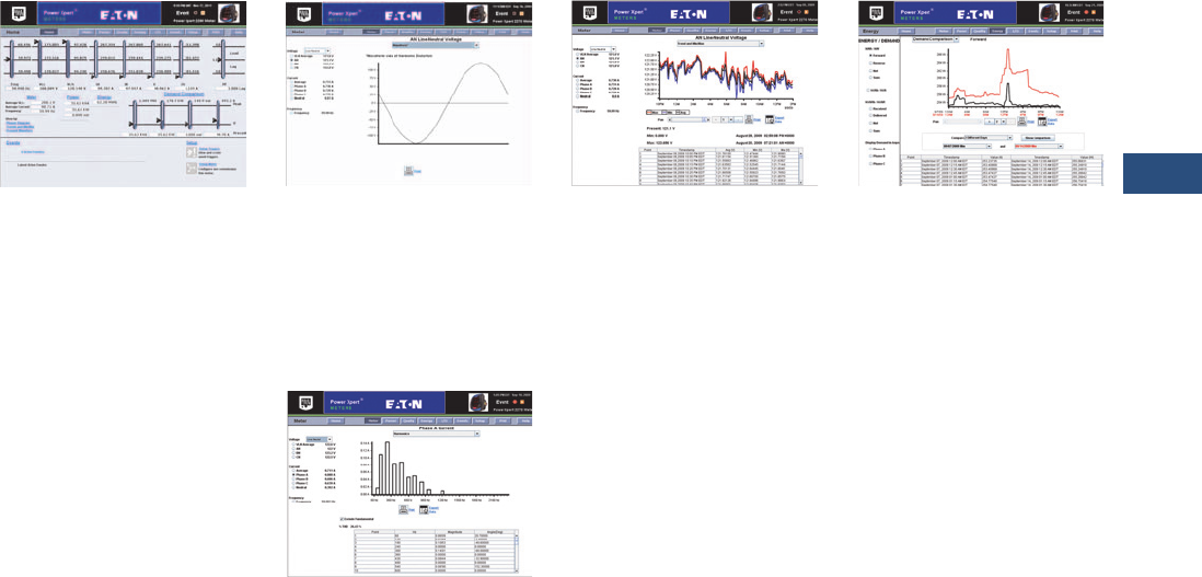
Volume 3—Power Distribution and Control Assemblies CA08100004E—November 2013 www.eaton.com V3-T9-51
9
9
9
9
9
9
9
9
9
9
9
9
9
9
9
9
9
9
9
9
9
9
9
9
9
9
9
9
9
9
9.3
Metering Devices, Protective Relays, Software and Connectivity
Metering Devices
Displayed Information
●Monitored information is
available locally through the
display, the Web browser
or system power
management software
●True rms values through
40th harmonic
●ANSI C12.20 Class.2%
revenue metering
specification
Power Xpert 2000 Web Browser Views
Power Xpert Meter 2000 Web Browser
Power Xpert Meter 2000’s
embedded Web server offers
Eaton customers a new level
of accessibility to the critical
information required to
manage the electrical
distribution system. The
embedded Web server
includes real time circuit
information in both numeric
and graphical formats to help
monitor parameters such as
current loading, voltage and
power levels and power
factor. The Web server also
provides the energy and
demand readings required to
help manage the cost of
energy. Readings include
kWh, kVARh, delivered and
received and kVAh. The Web
server also includes critical
information regarding power
quality such as harmonic
distortion.
Real-Time Visualization of Harmonic
Content
The Web server offers a
waveform view to visualize
steady-state harmonic
content of the voltage
and current to spot power
quality problems.
Harmonic Spectral Plot
The harmonic spectral plot
displays harmonics up to the
40th order. A detailed table
also includes individual
magnitudes and angles of
current and voltage
harmonics, at each
frequency. Individual and
total THD are displayed for
diagnostic purposes.
Historical Trend Plot
Graphical Trending of Data
The Power Xpert Meter 2000
embedded Web server
supports graphical trend
charts of key circuit
measurements such as
current, voltage, power and
energy. The trend chart
supports a zoom feature
that allows the user to view
data over a short period of
16 hours or a longer period of
48 months. The trend chart
has a horizontal slider bar
control to manage scrolling
forward and backward
through the data. Trend
charts of basic readings
include minimum, maximum
and average readings. Trend
charts of energy data also
display demand values.
Energy Demand Profile
Energy managers can view
load profile data compared
against the peak demand.
The plot allows comparison
of present and past months’
usage.
Web Server Device
Configuration
Special software is not
required to configure a
Power Xpert Meter 2000.
The embedded Web server
includes a comprehensive
device configuration engine.
Discrete Contact Inputs
The optional I/O expansion
cards offers two or four
digital inputs that are useful
for a variety of applications
such as:
●Pulse counting of KYZ or
other utility pulses such as
air, water or gas
●Demand interval timing
taken from a master utility
meter end of interval pulse
Names can be configured for
each input for ease of use.
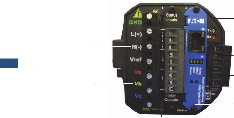
V3-T9-52 Volume 3—Power Distribution and Control Assemblies CA08100004E—November 2013 www.eaton.com
9
9
9
9
9
9
9
9
9
9
9
9
9
9
9
9
9
9
9
9
9
9
9
9
9
9
9
9
9
9
9.3
Metering Devices, Protective Relays, Software and Connectivity
Metering Devices
Relay Outputs
The optional I/O card
includes two 5A Form C relay
outputs rated for 240 Vac or
30 Vdc or four Form A solid-
state outputs. These outputs
can be used for applications
such as:
●Alarm annunciation
●KYZ pulse output
Alarm outputs can be driven
from triggers based on
metering values.
Analog Outputs
The optional IO card includes
either four 4–20 mA outputs
or 0–1 mA outputs. These
outputs can be used for
applications such as:
●Input to BMS or PLC
systems for tracking a
measured meter
parameter
Standard Communications Card
The standard communications
card provides one Ethernet
connection and 10/100Base-
T port (copper only) that can
be used for the following
applications:
●Monitoring, managing and
configuring the meter
remotely using a standard
Web browser interface
●Alarm notifications via
email, SMTP
●Providing Modbus TCP/IP,
RTU and BACnet/IP
communications to
BMS systems
●Providing SNMP
communications to
NMS systems
●Synchronizing with an
NTP server
●Asset management
●Updating firmware on
the meter
PXM 2000 Rear View
aPower supply inputs
bSystem voltage inputs
cNEMA 12 gasket
dRS-485
eKYZ out
fMeter gateway card
gI/O slot
a
b
c
d
e
f
g

Volume 3—Power Distribution and Control Assemblies CA08100004E—November 2013 www.eaton.com V3-T9-53
9
9
9
9
9
9
9
9
9
9
9
9
9
9
9
9
9
9
9
9
9
9
9
9
9
9
9
9
9
9
9.3
Metering Devices, Protective Relays, Software and Connectivity
Metering Devices
Power Xpert Meter 2250
●Measures basic meter
parameters
●256 MB for data logging
●Ethernet
●On-board gateway card
limits/alarms
Power Xpert Meter 2260
Features of PXM 2250 plus:
●Harmonics
●On-board meter hardware
limits to activate optional
relay outputs
●Visual indication of limits
exceeded at meter face
●512 MB for data logging
Power Xpert Meter 2270
Features of PXM 2260 plus:
●Harmonics, including
individual
●Waveform view to visualize
steady-state harmonic
content
●768 MB for data logging
The Power Xpert Meter 2280
Features of PXM 2270 plus:
●Records waveforms at up
to 64 samples per cycles
●Configures the total, pre-
and post-event cycles
Power Xpert Meter 2290
Features of PXM 2280 plus:
●Records waveforms at up
to 512 samples per cycles
Power Xpert Meters 2250/2260/2270/2280/2290
Note
These specifications are subject to change without notice and represent the maximum capabilities of the product with all options installed. This is not a complete feature list. Features and functionality
may vary depending on selected options, firmware version and product model. Please refer to the technical data sheet and User Manual for detailed specifications.
Power Xpert Meter
Feature 2250 2260 2270 2280 2290 Benefit
General
Embedded Web server ■■■■■Use a standard Web browser to monitor and manage the meter over the network
Firmware flash upgrade support ■■■■■Enables you to flash the meter with the latest firmware upgrades
Power, Energy and Demand
Voltage, current: per phase minimum, maximum, average, trend graph
analysis, export, print
■■■■■Review voltage and current trends, export, print and analyze parameters right on the
meter or external software
Demand: forward, reverse, net sum, profile, export, print, plot comparisons
month-to-month, week-to-week
■■■■■Plot two months or two weeks for vivid demand comparison, receive e-mails with
trend logs
Power, apparent, real, reactive, power factor ■■■■■Review power usage and power factor and avoid potential PF penalties
Energy: forward, reverse, net, sum ■■■■■Keep track of your energy usage, identify peaks to conserve energy usage, receive e-mails
with trend logs
Power Quality Analysis
Statistical analysis (min., max., average) ■■■■■Review statistical trends, identify past and future problem areas
Sampling rate, maximum samples/cycle 400 400 400 400 400 High sampling rate resulting in high accuracy
Security
Secure two level user access privileges ■■■■■Define appropriate security access level per user
Communications
Modbus TCP ■■■■■Easy integration with standard protocol to power management and other software
Modbus RTU ■■■■■Integrate meters to existing Modbus networks, daisy chain several (1–32)
meters together
BACnet/IP ■■■■■Easily integrate into existing building management systems without the need for external
protocol adapters
HTTP, HTTPS ■■■■■Communicate to the meter over the Internet via standard Web browser
SNMP (Simple Network Management Protocol) ■■■■■Communicate with the meter via Simple Network Protocol; hook to existing NMS system
SMTP (Simple Mail Transfer Protocol) ■■■■■Send e-mail messages via standard Simple Mail Transfer Protocol
NTP (Network Time Protocol) ■■■■■Network Time Protocol support enables the meter to synchronize time over the network
DNP 3.0 ■■■■■Easy integration with DNP networks (serial)
Trend measurements CSV file export ■■■■■Easily export trend measurements to third-party applications, in standard CSV file format
V3-T9-54 Volume 3—Power Distribution and Control Assemblies CA08100004E—November 2013 www.eaton.com
9
9
9
9
9
9
9
9
9
9
9
9
9
9
9
9
9
9
9
9
9
9
9
9
9
9
9
9
9
9
9.3
Metering Devices, Protective Relays, Software and Connectivity
Metering Devices
Power Xpert Meters 2250/2260/2270, continued
Note
These specifications are subject to change without notice and represent the maximum capabilities of the product with all options installed. This is not a complete feature list. Features and functionality
may vary depending on selected options, firmware version and product model. Please refer to the technical data sheet and User Manual for detailed specifications.
Standards and Certifications
●UL/cUL Electrical and
Electronic Measuring and
Test Equipment 22CZ
●Accuracy: IEC/EN60687
0.2 Class, ANSI C12.20
0.2 Class
●ANSI C62.41 Burst
●CE Mark
Power Xpert Meter
Feature 2250 2260 2270 2280 2290 Benefit
Logs
Trend logging ■■■■■Log trend information for easy statistical analysis
Load profile ■■■■■Review the load profile graph to get a better understanding of your electrical load
versus time
Event logging ■■■■■Log events for retrospective event analysis
Memory and Storage
Memory, MB 256 512 768 768 768 Store trend data and events for historical analysis
Harmonics
Harmonic levels 40th 40th 40th 40th Allows you to identify potential harmful harmonics
Total harmonic distortion (THD) ■■■■Review the total harmonic distortion level directly on the meter
Individual harmonics ■■■Provides simple metric for power quality viewable from the embedded Web server
Waveform
Waveform display ■■■A single-cycle waveform view on a PC, through embedded Web server, to visualize steady-
state harmonic content to identify power quality issues
Waveform recording 64 512 Ability to record waveforms up to specified samples/cycle
I/O
I/O (two relay outputs/two status inputs,
four KYZ pulses/four status inputs,
four analog outputs 0–1 mA,
four analog outputs 4–20 mA)
Opt Opt Opt Opt Opt The Power Xpert meter 2000 I/O Cards are extremely flexible and can be used in a large
variety of different applications. Digital inputs and relay outputs can be programmed to
interact during various conditions defined by the user. Various third-party devices, such as
alarms, pulse meters, trip units and sensors, can be easily integrated to the Power Xpert
Meter 2000. Triggers and events can be tied to the meter’s standard functions such as
e-mail, logs and trends. Analog outputs can be programmed to output meter parameters
to BMS or PLC systems
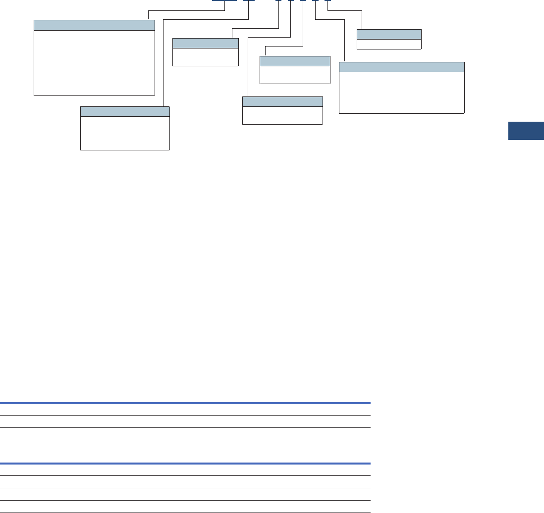
Volume 3—Power Distribution and Control Assemblies CA08100004E—November 2013 www.eaton.com V3-T9-55
9
9
9
9
9
9
9
9
9
9
9
9
9
9
9
9
9
9
9
9
9
9
9
9
9
9
9
9
9
9
9.3
Metering Devices, Protective Relays, Software and Connectivity
Metering Devices
Catalog Number Selection
Power Xpert Meter 2000
Note
1Refer to Page V3-T9-54 for model-specific features.
To order a Power Xpert Meter
2000, the catalog number
should be determined using
the chart shown above.
The chart illustrates how to
include the desired factory
options as part of a catalog
number. Option cards that are
selected at time of order
entry will be installed at the
factory. Option cards are
also field installable for
future upgrades.
Power Xpert meter modules
include panel mounting
brackets.
Example 1:
PXM2270MA65145 (PXM
2270 Meter/Display 60 Hz, 5A,
90–265 Vac/Vdc W/4AO).
Example 2:
PXM2250MA65105 (PXM
2250 Meter/Display 60 Hz, 5A,
90–265 Vac/Vdc).
Accessories
Power Xpert Meter 2000
Power Xpert Meter 2000 I/O Cards
PXM 2250 M A 6 5 1 0 5
Frequency
5 = 50 Hz system
6 = 60 Hz system
I/O Slot 2
5 = Gateway card
I/O Slot 1
0 = None
1 = 2 Relay outputs/2 status inputs
2 = 4 KYZ pulses/4 status inputs
3 = 4 Analog outputs: 0–1 mA
4 = 4 Analog outputs: 4–20 mA
Model Series 1
2250 = Energy meter
2260 = Power quality meter
2270 = Power quality plus meter
2280 = Power quality plus with up to 64
samples/cycle waveform recording
meter
2290 = Power quality plus with up to 512
samples/cycle recording meter
Example 1:PXM2270MA65145 (PXM 2270 Meter/Display 60 Hz, 5A, 90–265 Vac/Vdc W/4AO)
Example 2:PXM2250MA65105 (PXM 2250 Meter/Display 60 Hz, 5A, 90–265 Vac/Vdc)
Current Input
1 = 1 amp secondary
5 = 5 amp secondary
Power Supply
1 = 90–265 Vac/Vdc
4 = 24–60 Vdc
Meter Type
M= Meter (with integral
display)
T= Transducer only
(no display)
Description Catalog Number
Panel mounting bracket assembly for retrofitting a PXM 2000 to an IQ analyzer/IQ DP4000/IQ data cutout IQ250-PMAK
PXM 2000 Gateway card kit to upgrade an IQ 250/260 to a PXM 2000 PXM2000-GCK
Description Catalog Number
PXM 2000 I/O card—2 relay outputs/2 status inputs IQ250/260-IO1
PXM 2000 I/O card—4 KYZ Pulses/4 status inputs IQ250/260-IO2
PXM 2000 I/O card—4 analog outputs—0–1 mA IQ250/260-IO3
PXM 2000 I/O card—4 analog outputs—4–20 mA IQ250/260-IO4

V3-T9-56 Volume 3—Power Distribution and Control Assemblies CA08100004E—November 2013 www.eaton.com
9
9
9
9
9
9
9
9
9
9
9
9
9
9
9
9
9
9
9
9
9
9
9
9
9
9
9
9
9
9
9.3
Metering Devices, Protective Relays, Software and Connectivity
Metering Devices
Technical Data and Specifications
PXM 2250/2260/2270 Electronic Power Meter Technical Information
Current Inputs
●Class 10: 5 amp nominal,
10 amp maximum
●Class 2: 1 amp nominal,
2 amp maximum
●Fault current withstand:
●100 amps for
10 seconds
●300 amps for 3 seconds
●500 amps for 1 second
●Continuous current
withstand: 20 amps for
screw terminated or pass-
through connections
●Programmable current:
full scale to any CT ratio
●Burden: 0.005 VA per
phase maximum at
11 a m p s
●Pickup current: 0.1% of
nominal
●Class 10: 5 mA
●Class 2: 1 mA
●Connections:
●Pass-through wire gauge
dimension: 0.177 inches
(4.5 mm)
●Quick connect: 0.25-inch
(6.35 mm) male tab
Voltage Inputs
●Range:
●Line-to-neutral
20–576 Vac
●Line-to-Line 0–721 Vac
●Programmable voltage
range: full scale to any
PT ratio
●Supported systems:
●Three element wye,
2.5 element wye
●Two element delta, four-
wire delta systems
●Input impedance:
1 megohm/phase.
●Burden: 0.36 VA/phase
maximum at 600V;
0.014 VA at 120V
●Connection: 7-pin
0.400-inch pluggable
terminal block, AWG
#12–26 (0.129–3.31 mm2)
Isolation
●All inputs and outputs are
galvanically isolated to
2500 volts
Environmental Ratings
●Operating temperature:
–20ºC to +70°C
●Storage temperature:
–20ºC to +70°C
●Operating humidity: to
95% RH noncondensing
●Faceplate rating:
●NEMA 12
●Mounting gasket
included
Sensing Method
●Voltage, current: true rms
●Power: sampling at over
400 samples per cycle on
all channels
●Harmonics resolution:
40th order
Update Rate
●Watts, VAR and VA:
100 msec at 60 Hz
●All other parameters:
1 second at 60 Hz
Power Supply
●AC/DC voltage option:
90–265 Vac at 50/60 Hz or
100–370 Vdc, universal AC/
DC supply
●DC voltage option:
18–60 Vdc
●Burden: 10 VA maximum
Serial Communications Format
●Connection type: RS-485
(through back plate)
●Com port baud rate:
9600–57,600 bauds
●Com port address: 01–247
●Data format: 8-bit, no parity
●Protocols: Modbus ASCII,
RTU or DNP 3.0
Network Communications
Format
●Connection type: RJ-45
10/100Base-T Ethernet
network port
●Protocols: Ethernet TCP/IP,
Modbus TCP, BACnet/IP,
HTTP, HTTPS, NTP, SMTP,
SNMP
KYZ Pulse
●Contacts: one Form A
●On resistance, maximum:
35 ohms
●Peak switching voltage:
350 Vdc
●Continuous load current:
120 mA
●Peak load current: 350 mA
(10 ms)
●Off-state leakage current at
350 Vdc: 1 uA
●Opto-isolation: 3750 Vac
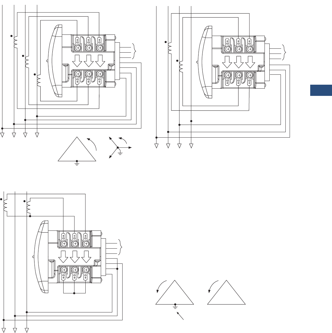
Volume 3—Power Distribution and Control Assemblies CA08100004E—November 2013 www.eaton.com V3-T9-57
9
9
9
9
9
9
9
9
9
9
9
9
9
9
9
9
9
9
9
9
9
9
9
9
9
9
9
9
9
9
9.3
Metering Devices, Protective Relays, Software and Connectivity
Metering Devices
Wiring Diagrams
Service: Wye or Delta, Four-Wire with No PTs, Two or Three CTs
Service: Delta, Three-Wire with No PTs, 2 CTs
Note: Based upon the voltage rating, you may need a control power transformer for the control power.
GND
L (+)
N (–)
VRef
A
B
C
HI
LO
Ic
HI
LO
Ib
HI
LO
Ia
AB C
AB C
Power
Supply
N
N
GND
L (+)
N (–)
VRef
A
B
x
HI
LO
Ic
HI
LO
Ib
HI
LO
Ia
AB C
AB C
Power
Supply
N
N
C
BA
C
B
A
GND
L (+)
N (–)
VRef
A
B
C
HI
LO
Ic
HI
LO
Ib
HI
LO
Ia
AB C
AB C
Power
Supply
C
BA
or
C
BA
Not Connected to Meter
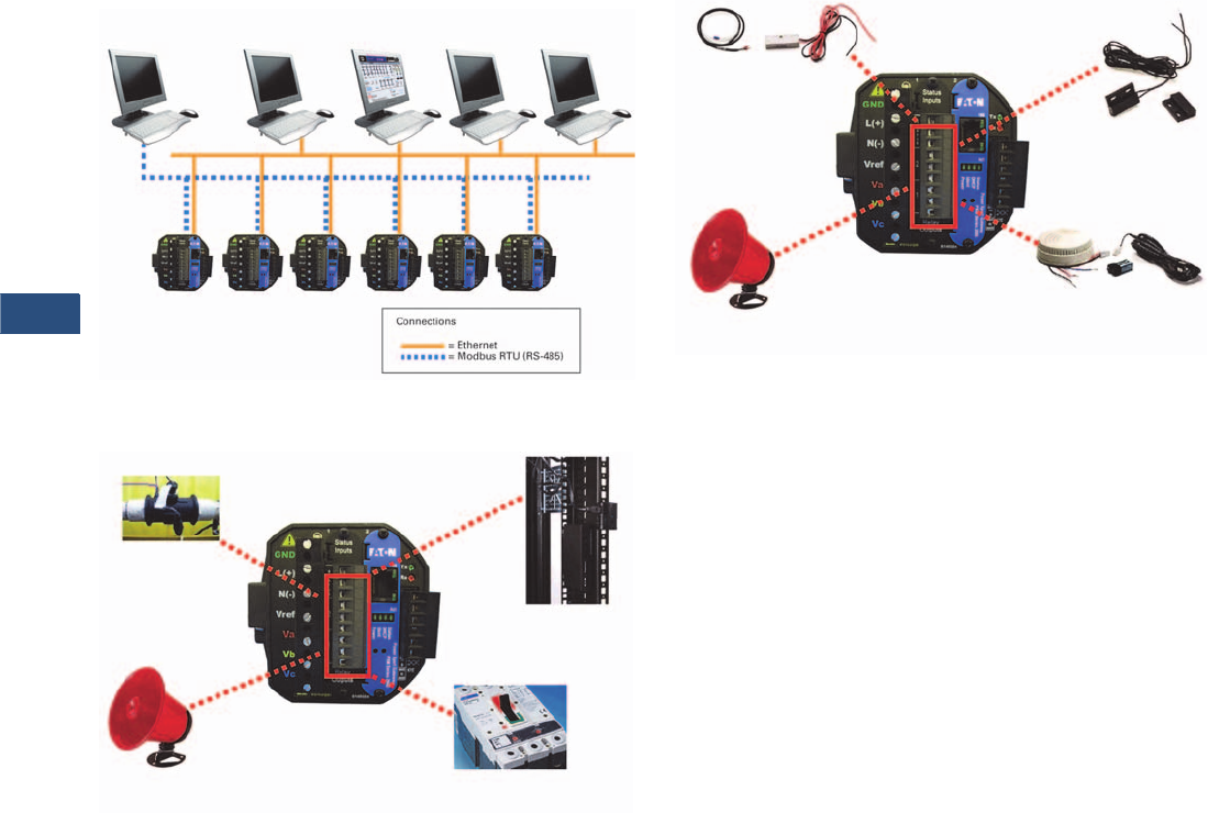
V3-T9-58 Volume 3—Power Distribution and Control Assemblies CA08100004E—November 2013 www.eaton.com
9
9
9
9
9
9
9
9
9
9
9
9
9
9
9
9
9
9
9
9
9
9
9
9
9
9
9
9
9
9
9.3
Metering Devices, Protective Relays, Software and Connectivity
Metering Devices
Power Xpert Meters Configuration and Wiring Examples
PXM 2000 Display Front View
Accessories—I/O Cards (Option)
IT Configuration Examples—Accessories—I/O Cards
(Option)
Modbus RTU
(RS-485)
Modbus RTU
(RS-485) Master
Modbus TCP
Master
Web
Browser
Power Xpert
Software
Building
Automation
System
Alarm
Flow Meter
(Pulse Count)
• Two relay programmable outputs/two programmable inputs
• Four KYZ pulses/four programmable inputs
• Four programmable analog outputs
Trip and Sequence
of Events
Rack Monitoring
— Open Door/
Ta m p e r Sw it c h
Smoke Alarm
Alarm
Water Leak and
Vibration Sensors
Rack Monitoring
— Open Door/
Ta mp e r Sw i tc h
• Two relay programmable outputs/two programmable inputs
• Four KYZ pulses/four programmable inputs
• Four programmable analog outputs
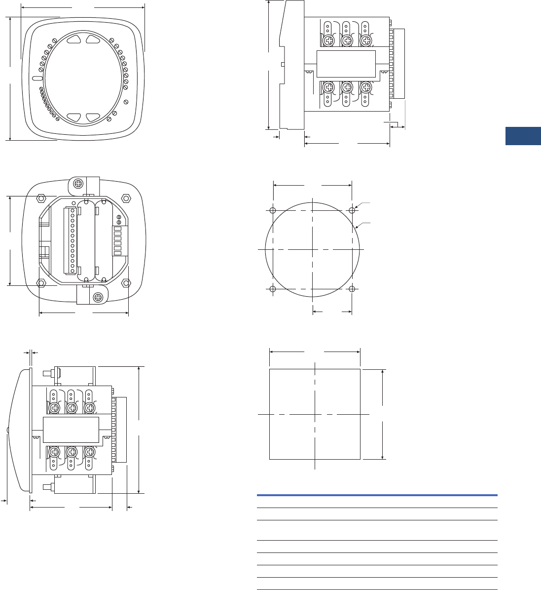
Volume 3—Power Distribution and Control Assemblies CA08100004E—November 2013 www.eaton.com V3-T9-59
9
9
9
9
9
9
9
9
9
9
9
9
9
9
9
9
9
9
9
9
9
9
9
9
9
9
9
9
9
9
9.3
Metering Devices, Protective Relays, Software and Connectivity
Metering Devices
Dimensions
Approximate Dimensions in Inches (mm)
PXM 2000 Display Front View
PXM 2000 Rear View
PXM 2000 Meter/Display Side View
4.85
(123.2)
4.85
(123.2)
3.54
(89.9)
3.54
(89.9)
5.02
(127.5)
0.95
(24.0) 3.25
(82.6)
0.08
(2.0)
0.77
(19.6)
PXM 2000 Transducer Only Side View
ANSI Mounting Panel Cutout
DIN Mounting Cutout
4.85
(123.2)
0.91
(23.1) 3.25
(82.6)
0.77
(19.6)
4.00
(101.6)
3.38
(85.9)
1.69
(42.9)
4 x .02
(0.5)
3.62
(92.0)
3.62
(92.0)
Description Specifications
Weight 2 lbs (0.9 kg)
Basic unit 5.00 (127.0) H x 4.90 (124.5) W x 5.00 (127.0) L
PXM 2250/2260/2270 Mounts in 3.62-inch (92.0) mm DIN and ANSI C39.1
round cut-outs
Shipping container dimensions 6-inch cube
Tolerance ±0.1 inches (2.54 mm)
Projection in front of panel surface 4.85 (123.2) H x 4.85 (123.2) W x 1.01 (25.6) L
Projection behind panel surface 4.85 (123.2) H x 4.85 (123.2) W x 1.01 (25.6) L
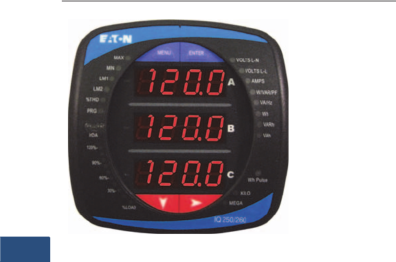
V3-T9-60 Volume 3—Power Distribution and Control Assemblies CA08100004E—November 2013 www.eaton.com
9
9
9
9
9
9
9
9
9
9
9
9
9
9
9
9
9
9
9
9
9
9
9
9
9
9
9
9
9
9
9.3
Metering Devices, Protective Relays, Software and Connectivity
Metering Devices
IQ 250 and 260 Electronic Power Meters
Contents
Description Page
Metering Products Family. . . . . . . . . . . . . . . . . . . . . V3-T9-21
Power Xpert Meter 4000/6000/8000 Series. . . . . . . V3-T9-30
Power Xpert Meter 2000 Series . . . . . . . . . . . . . . . . V3-T9-49
IQ 250/260 Series Electronic Power Meters
Standards and Certifications . . . . . . . . . . . . . . . . V3-T9-61
Catalog Number Selection. . . . . . . . . . . . . . . . . . V3-T9-62
Accessories . . . . . . . . . . . . . . . . . . . . . . . . . . . . . V3-T9-62
Technical Data and Specifications . . . . . . . . . . . . V3-T9-63
Dimensions . . . . . . . . . . . . . . . . . . . . . . . . . . . . . V3-T9-65
IQ 130/140/150 Series Electronic Power Meters . . . V3-T9-66
IQ 150S/250S Self-Enclosed Electronic Meters . . . . V3-T9-71
IQ 35M . . . . . . . . . . . . . . . . . . . . . . . . . . . . . . . . . . . V3-T9-76
IQ Analyzer 6400/6600 Series . . . . . . . . . . . . . . . . . V3-T9-79
IQ DP-4000 Series . . . . . . . . . . . . . . . . . . . . . . . . . . V3-T9-87
IQ 230 Meters . . . . . . . . . . . . . . . . . . . . . . . . . . . . . V3-T9-93
Power Xpert Multi-Point Meter . . . . . . . . . . . . . . . . . V3-T9-100
IQ Energy Sentinel™ . . . . . . . . . . . . . . . . . . . . . . . . V3-T9-112
PM3 Monitoring and Metering Module . . . . . . . . . . V3-T9-121
Current Transformers (CTs). . . . . . . . . . . . . . . . . . . . V3-T9-122
Clamp-On Current Transformers. . . . . . . . . . . . . . . . V3-T9-131
IQ Flange . . . . . . . . . . . . . . . . . . . . . . . . . . . . . . . . . V3-T9-134
Panel Mounting Adapter Kit . . . . . . . . . . . . . . . . . . . V3-T9-135
Enclosed Meters . . . . . . . . . . . . . . . . . . . . . . . . . . . V3-T9-136
IQ 250/260 Series Electronic Power Meters
Product Description
The IQ 250 and IQ 260
Meters provide capabilities
you would not normally
expect in affordable, ultra-
compact meters, such as fast
sampling rate and accurate
metering for a full range of
power attributes. Providing
the first line of defense
against costly power
problems, Eaton’s IQ 250
and IQ 260 electronic power
meters can perform the work
of an entire wall of legacy
metering equipment using
today’s technology.
When space is at a premium,
yet you need ANSI C12.20
accuracy, the IQ 250/ 260
series fit the bill. These
meters are ideal for electrical
equipment assemblies,
machine control panels,
such as panelboard and
switchboard mains and
feeders, low voltage metal-
enclosed switchgear feeders
and motor control centers.
Requiring far less space than
other meters with similar
functionality, IQ 250/260
series fit into a standard ANSI
or IEC cutout on a panelboard
or other electrical equipment,
and therefore fit easily into
retrofit applications.
Application Description
●Utility and commercial
metering
●Substations, industrial
facilities, p
ower generation
sites and campuses
●Sub-metering
●Load studies and voltage
recording
●Analog meter replacement
Features and Benefits
●Measure and display real-
time information about
critical power parameters
with a sampling rate of 400
samples per cycle
●Monitor power utilization
and quality with ANSI
C12.20 accuracy
(0.2 percent)
●Optional 128 KB for data
logging, which guards
against loss of historical
data
●Verify meter accuracy
with KYZ test pulse self-
certification capabilities
●Standard Modbus RTU
communications
●Available as transducer
only or with display
●Designed to accommodate
upgrades
●Integrate into Eaton’s
Power Xpert architecture
for a holistic system-
level view
Volume 3—Power Distribution and Control Assemblies CA08100004E—November 2013 www.eaton.com V3-T9-61
9
9
9
9
9
9
9
9
9
9
9
9
9
9
9
9
9
9
9
9
9
9
9
9
9
9
9
9
9
9
9.3
Metering Devices, Protective Relays, Software and Connectivity
Metering Devices
Additional Features
Features of IQ 250 and IQ 260 Electronic Power Meters
Notes
1Digital out with IQ 250 requires external command.
2Requires external power supply.
Standards and Certifications
●IEC 687: 0.2% accuracy
●ANSI C12.20: 0.2% accuracy
●ANSI C62.41: Burst
●UL/cUL: Electrical and
electronic measuring and
test equipment 22CZ
Features IQ 250 IQ 260
Instrumentation
Current, per phase ■■
Current demand ■■
Calculated neutral current ■■
Voltage, per phase (L-L, L-N) ■■
Frequency ■■
Power, Energy and Demand
Real, reactive and apparent power, total and per phase (kW, kVAR, kVA) ■■
Real, reactive and apparent energy, total and per phase (kWh, kVARh, kVAh) ■■
Real, reactive and apparent power demand ■■
Power factor, total and per phase ■■
Min./max. readings, I, V, PF, F, THD (IQ 260), kW, kVAR, kVA ■■
Demand Methods
Block interval (sliding, fixed) ■■
Communications
RS-485 ■■
KYZ output ■■
Modbus RTU ■■
Modbus ASCII ■■
DNP 3.0 ■■
Data Logging
128 KB for data logging Opt. Opt.
I/O
Two digital in /two digital out 1Opt. Opt.
Four digital in/four KYZ out Opt. Opt.
Four analog output (4–20 mA) 2Opt. Opt.
Four analog output (0–1 mA) Opt. Opt.
Power Quality Analysis
Total harmonic distortion (THD) voltage and current per phase ■
Alarming
Set point driven alarm ■
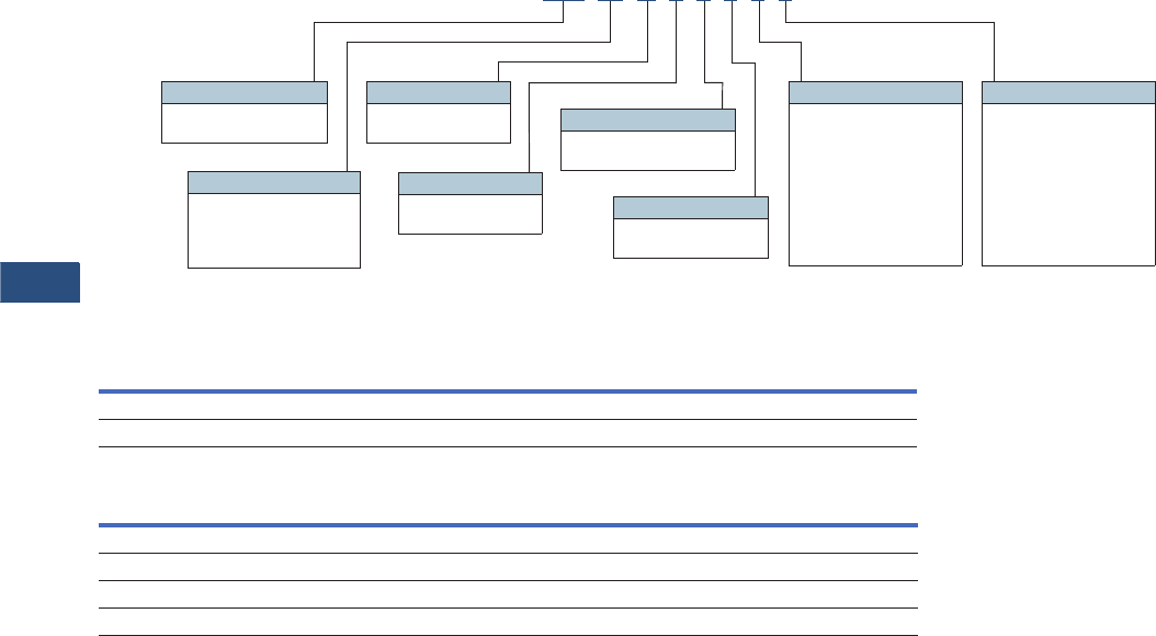
V3-T9-62 Volume 3—Power Distribution and Control Assemblies CA08100004E—November 2013 www.eaton.com
9
9
9
9
9
9
9
9
9
9
9
9
9
9
9
9
9
9
9
9
9
9
9
9
9
9
9
9
9
9
9.3
Metering Devices, Protective Relays, Software and Connectivity
Metering Devices
Catalog Number Selection
IQ 250/260 Meter
Accessories
IQ 250/260 Meter
IQ 250/260 Meter I/O Cards
IQ 250 MA65110
Model Series
250 = Energy
260 = Power quality
Frequency
5 = 50 Hz system
6 = 60 Hz system
I/O Slot 2
0 = None
1 = Two relay outputs/
two status inputs
2 = Four KYZ pulses/
four status inputs
3 = Four analog outputs:
0–1 mA
4 = Four analog outputs:
4–20 mA
Power Supply
1 = 90–265 Vac/Vdc
4 = 24–48 Vdc
Current Input
1 = 1 amp secondary
5 = 5 amp secondary
Meter Type
M= Meter (with
integral display)
T= Transducer only
(no display)
I/O Slot 1
0 = None
1 = Two relay outputs/
two status inputs
2 = Four KYZ pulses/
four status inputs
3 = Four analog outputs:
0–1 mA
4 = Four analog outputs:
4–20 mA
Data Logging
A = None
L = Data logging
Description Catalog Number
Panel mounting adapter for retrofitting an IQ 250/260 to an IQ Analyzer/IQ DP-4000/IQ data cutout IQ250-PMAK
PXM 2000 Gateway card kit to upgrade an IQ 250/260 to a PXM 2000 PXM2000-GCK
Description Catalog Number
IQ 250/260 I/O card—2 relay outputs/2 status inputs IQ250/260-IO1
IQ 250/260 I/O card—4 KYZ pulses/4 status inputs IQ250/260-IO2
IQ 250/260 I/O card—4 analog outputs—0–1 mA IQ250/260-IO3
IQ 250/260 I/O card—4 analog outputs—4–20 mA IQ250/260-IO4

Volume 3—Power Distribution and Control Assemblies CA08100004E—November 2013 www.eaton.com V3-T9-63
9
9
9
9
9
9
9
9
9
9
9
9
9
9
9
9
9
9
9
9
9
9
9
9
9
9
9
9
9
9
9.3
Metering Devices, Protective Relays, Software and Connectivity
Metering Devices
Technical Data and Specifications
IQ 250/260 Electronic Power Meter
Description Specifications
Current Inputs
Class 10 5 amp nominal, 10 amp max.
Class 2 1 amp nominal, 2 amp max.
Fault current withstand
100 amps for:
300 amps for:
500 amps for:
10 seconds
3 seconds
1 second
Continuous current withstand 20 amps for screw terminated or pass-
through connections
Programmable current Full scale to any CT ratio
Burden 0.005 VA per phase max. at 11 amps
Pickup current
Class 10
Class 2
0.1% of nominal
5 mA
1 mA
Connections
Pass-through wire gauge dimension
Quick connect
0.177 inches (4.5 mm)
0.25-inch male tab
Voltage Inputs
Range
Line-to-neutral
Line-to-line
20–576 Vac
0–721 Vac
Programmable voltage range Full scale to any PT ratio
Supported systems 3 element wye, 2.5 element wye,
2 element delta, four-wire delta systems
Input impedance 1 meg ohm/phase
Burden 0.36 VA/phase max. at 600V;
0.014 VA at 120V
Connection 7-pin 0.400-inch pluggable terminal block,
AWG #12–26 (0.129–3.31 mm2)
Isolation
All inputs and outputs are galvanically isolated to 2500 volts.
Environmental Ratings
Operating temperature –20ºC to +70°C
Storage temperature –20ºC to +70°C
Operating humidity To 95% RH noncondensing
Faceplate rating NEMA 12
Water-resistant
Mounting gasket included
Description Specifications
Sensing Method
Voltage, current True rms
Power Sampling at over 400 samples per cycle on
all channels
Harmonics resolution 40th order
Update Rate
Watts, VAR and VA 100 msec at 60 Hz
All other parameters 1 second at 60 Hz
Power Supply
AC/DC voltage option 90–265 Vac at 50/60 Hz or 100–370 Vdc,
universal AC/DC supply
DC voltage option 18–60 Vdc
Burden 10 VA max.
Standard Communications Format
Connection type RS-485 (through back plate)
Com port baud rate 9600–57,600 bauds
Com port address 01–247
Data format 8-bit, no parity
Protocols Modbus ASCII, RTU or DNP 3.0
KYZ Pulse
Contacts 1 Form A
On resistance, max. 35 ohms
Peak switching voltage 350 Vdc
Continuous load current 120 mA
Peak load current 350 mA (10 ms)
Off-state leakage current at 350 Vdc 1 uA
Opto-isolation 3750 Vac
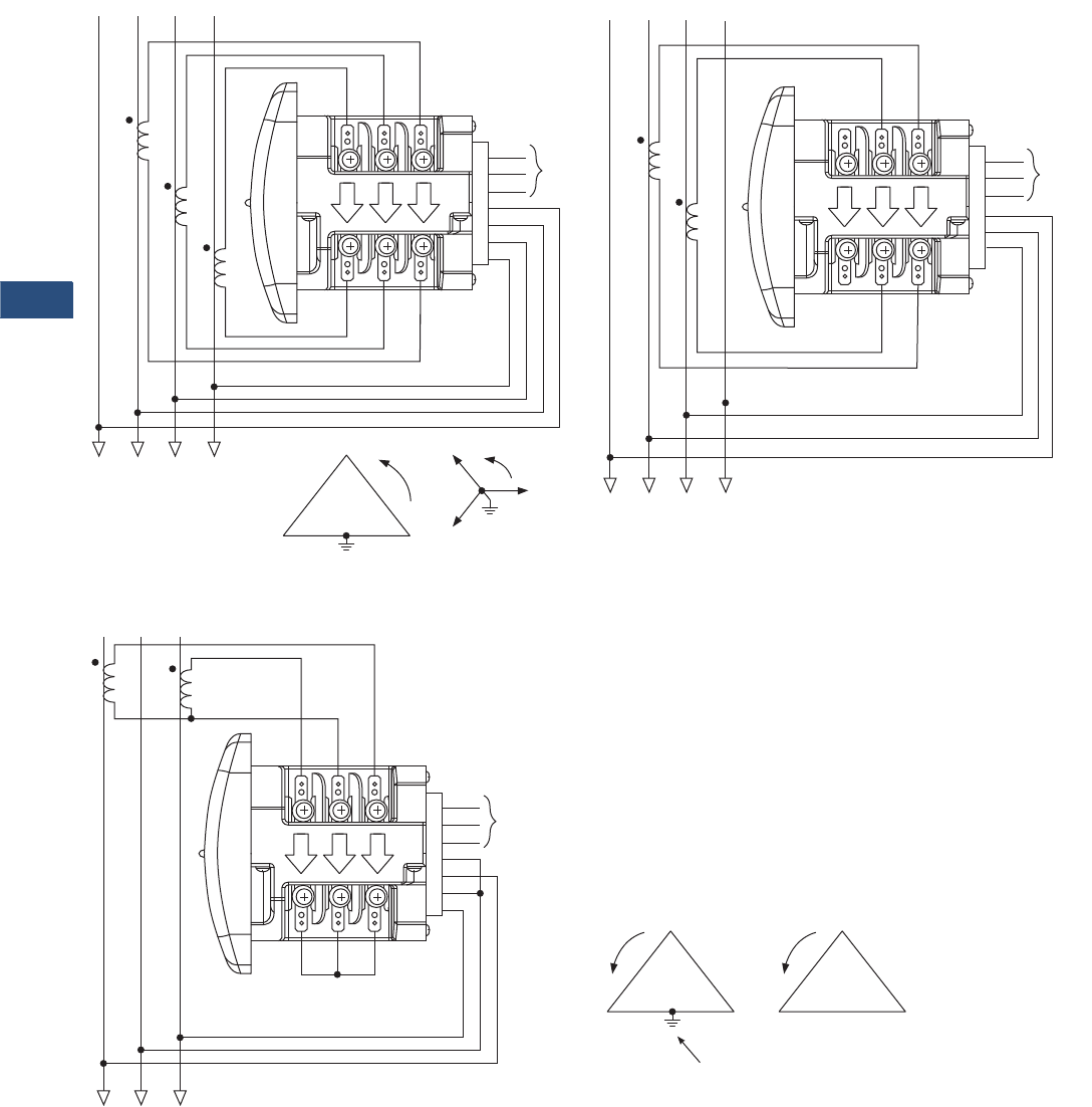
V3-T9-64 Volume 3—Power Distribution and Control Assemblies CA08100004E—November 2013 www.eaton.com
9
9
9
9
9
9
9
9
9
9
9
9
9
9
9
9
9
9
9
9
9
9
9
9
9
9
9
9
9
9
9.3
Metering Devices, Protective Relays, Software and Connectivity
Metering Devices
Wiring Diagrams
Service: Wye or Delta, Four-Wire with No PTs, Two or Three CTs
Service: Delta, Three-Wire with No PTs, 2 CTs
Note: Based upon the voltage rating, you may need a control power transformer for the control power.
GND
L (+)
N (–)
VRef
A
B
C
HI
LO
Ic
HI
LO
Ib
HI
LO
Ia
AB C
AB C
Power
Supply
N
N
GND
L (+)
N (–)
VRef
A
B
x
HI
LO
Ic
HI
LO
Ib
HI
LO
Ia
AB C
AB C
Power
Supply
N
N
C
BA
C
B
A
GND
L (+)
N (–)
VRef
A
B
C
HI
LO
Ic
HI
LO
Ib
HI
LO
Ia
AB C
AB C
Power
Supply
C
BA
or
C
BA
Not Connected to Meter
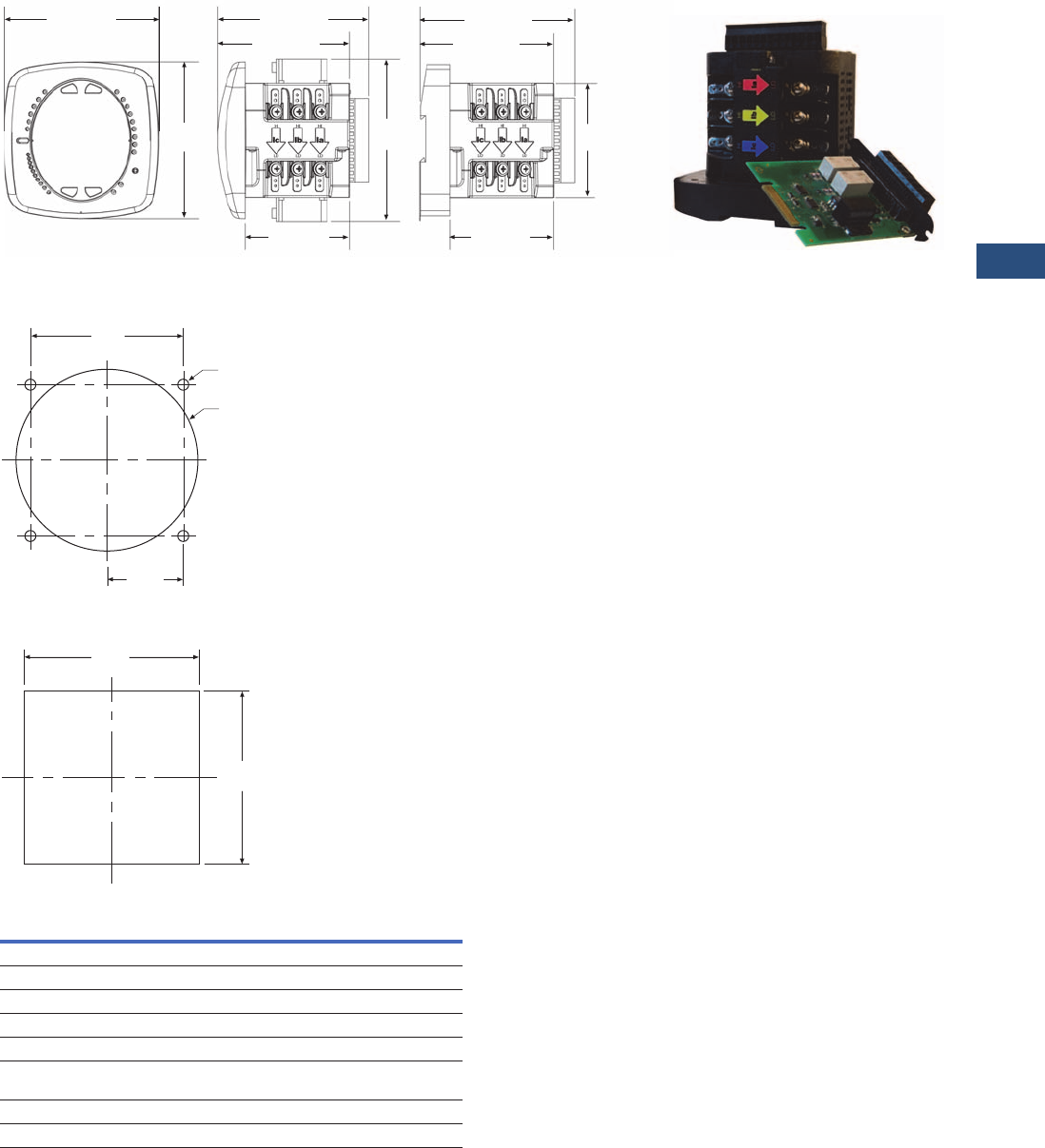
Volume 3—Power Distribution and Control Assemblies CA08100004E—November 2013 www.eaton.com V3-T9-65
9
9
9
9
9
9
9
9
9
9
9
9
9
9
9
9
9
9
9
9
9
9
9
9
9
9
9
9
9
9
9.3
Metering Devices, Protective Relays, Software and Connectivity
Metering Devices
Dimensions
Approximate Dimensions in Inches (mm)
IQ 250/260 Meter—Face and Side Views
ANSI Mounting Panel Cutout
DIN Mounting Cutout
4.85 (123.2)
4.85
(123.2)
IQ 250/260M Side IQ 250/260T Side
4.97 (126.2)
4.20 (106.7)
5.02
(127.5)
3.25 (82.6) 3.25 (82.6)
3.54
(89.9)
4.93 (125.2)
4.16 (105.7)
IQ 250/260 Face
Expandable I\Q Componentry
4.00
(101.6)
3.38
(85.9)
1.69
(42.9)
4 x .02
(0.5)
3.62
(92.0)
3.62
(92.0)
Description Specifications
Weight 2 lbs (0.9 kg)
Basic unit 5.00 (127.0) H x 4.90 (124.5) W x 5.00 (127.0) L
IQ 250/260 Mounts in 92 mm DIN and ANSI C39.1 round cut-outs
Shipping container dimensions 6-inch cube
Tolerance ±0.1 inches (2.54 mm)
PXM 2250/2260/2270 Mounts in 3.62-inch (92.0) mm DIN and ANSI C39.1
round cut-outs
Projection in front of panel surface 4.85 (123.2) H x 4.85 (123.2) W x 1.01 (25.6) L
Projection behind panel surface 4.85 (123.2) H x 4.85 (123.2) W x 1.01 (25.6) L
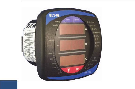
V3-T9-66 Volume 3—Power Distribution and Control Assemblies CA08100004E—November 2013 www.eaton.com
9
9
9
9
9
9
9
9
9
9
9
9
9
9
9
9
9
9
9
9
9
9
9
9
9
9
9
9
9
9
9.3
Metering Devices, Protective Relays, Software and Connectivity
Metering Devices
IQ 100
Contents
Description Page
Metering Products Family. . . . . . . . . . . . . . . . . . . . . V3-T9-21
Power Xpert Meter 4000/6000/8000 Series. . . . . . . V3-T9-30
Power Xpert Meter 2000 Series . . . . . . . . . . . . . . . . V3-T9-49
IQ 250/260 Series Electronic Power Meters . . . . . . V3-T9-60
IQ 130/140/150 Series Electronic Power Meters
Standards and Certifications . . . . . . . . . . . . . . . . V3-T9-67
Catalog Number Selection. . . . . . . . . . . . . . . . . . V3-T9-67
Accessories . . . . . . . . . . . . . . . . . . . . . . . . . . . . . V3-T9-67
Technical Data and Specifications . . . . . . . . . . . . V3-T9-68
Dimensions . . . . . . . . . . . . . . . . . . . . . . . . . . . . . V3-T9-70
IQ 150S/250S Self-Enclosed Electronic Meters . . . . V3-T9-71
IQ 35M . . . . . . . . . . . . . . . . . . . . . . . . . . . . . . . . . . . V3-T9-76
IQ Analyzer 6400/6600 Series . . . . . . . . . . . . . . . . . V3-T9-79
IQ DP-4000 Series . . . . . . . . . . . . . . . . . . . . . . . . . . V3-T9-87
IQ 230 Meters . . . . . . . . . . . . . . . . . . . . . . . . . . . . . V3-T9-93
Power Xpert Multi-Point Meter . . . . . . . . . . . . . . . . . V3-T9-100
IQ Energy Sentinel™ . . . . . . . . . . . . . . . . . . . . . . . . V3-T9-112
PM3 Monitoring and Metering Module . . . . . . . . . . V3-T9-121
Current Transformers (CTs). . . . . . . . . . . . . . . . . . . . V3-T9-122
Clamp-On Current Transformers. . . . . . . . . . . . . . . . V3-T9-131
IQ Flange . . . . . . . . . . . . . . . . . . . . . . . . . . . . . . . . . V3-T9-134
Panel Mounting Adapter Kit . . . . . . . . . . . . . . . . . . . V3-T9-135
Enclosed Meters . . . . . . . . . . . . . . . . . . . . . . . . . . . V3-T9-136
IQ 130/140/150 Series Electronic Power Meters
Product Description
The IQ 100 Meter family
provides capabilities you
would not normally expect in
affordable, compact meters,
such as fast sampling rate
and accurate metering for a
full range of power attributes.
Providing the first line of
defense against costly power
problems, Eaton’s IQ 100
series electronic power
meters can perform the work
of an entire wall of legacy
metering equipment utilizing
today’s technology.
When space is at a premium,
yet you need ANSI C12.20
accuracy, the IQ 100 series fit
the bill. These meters are
ideal for electrical equipment
assemblies, machine control
panels, such as panelboard
and switchboard mains and
feeders, low voltage metal-
enclosed switchgear feeders
and motor control centers.
Requiring far less space than
other meters with similar
functionality, IQ 100 series fit
into a standard ANSI or IEC
cutout on a panelboard or
other electrical equipment,
and therefore fit easily into
retrofit applications.
Application Description
●Utility and commercial
metering
●Substations, industrial
facilities, power generation
sites and campuses
●Sub-metering
●Load studies and voltage
recording
●Analog meter replacement
Features and Benefits
●Measure and display real-
time information about
critical power parameters
with a sampling rate of 400
samples per cycle
●Monitor power utilization
and quality with ANSI
C12.20 accuracy (0.5%)
●Verify meter accuracy with
KYZ test pulse self-
certification capabilities
●Optional Modbus RTU or
TCP communications
●Available as transducer
only or with display
●Designed to accommodate
upgrades
●Integrate into Eaton’s
Power Xpert Architecture
for a holistic system-
level view
Volume 3—Power Distribution and Control Assemblies CA08100004E—November 2013 www.eaton.com V3-T9-67
9
9
9
9
9
9
9
9
9
9
9
9
9
9
9
9
9
9
9
9
9
9
9
9
9
9
9
9
9
9
9.3
Metering Devices, Protective Relays, Software and Connectivity
Metering Devices
IQ 100 Electronic Power Meters
Standards and Certifications
●IEC 687: 0.5% accuracy
●ANSI C12.20:
0.5% accuracy
●ANSI C62.41: Burst
●CE
●UL/cUL: Electrical and
Electronic Measuring and
Test Equipment 22CZ
Catalog Number Selection
IQ 100 Meter
Accessories
IQ 100 Meter
Features IQ 130 IQ 140 IQ 150
Instrumentation
Current, per phase ■■■
Current demand ■■■
Calculated neutral current ■■■
Voltage, per phase (L-L, L-N) ■■■
Min/max. readings, I, V ■■■
Min./max. readings, I, V, PF, F, W, VAR, VA ■■
Frequency ■■
Power
Real, reactive and apparent power, total (W, VAR, VA) ■■
Power factor, total ■■
Real, reactive and apparent power demand ■■
Demand Methods
Block interval (sliding, fixed) ■■
Energy
Real, reactive and apparent energy, total (Wh, VAR, VAh) ■
Communications
RS-485, Modbus RTU, Modbus ASCII, KYZ output Opt. Opt. Opt.
RJ45, Modbus TCP, KYZ output Opt. Opt. Opt.
Frequency
5 = 50 Hz system
6 = 60 Hz system Communications
0 = None
1 = Modbus RTU and KYZ pulse
2 = Modbus TCP and KYZ output (RJ45)
Model Series
130 = Volts/amps
140 = Power
150 = Energy
Current Input
1 = 1A secondary
5 = 5A secondary
Power Supply
1 = 90–265 Vac/dc
4 = 24–48 Vdc
Meter Type
M= Meter (with integral
display)
T= Transducer only
(no display)
IQ 150 M A 6 5 1 1
Description Catalog Number
Panel Mounting Adapter for retrofitting an IQ 100 to an IQ Analyzer/IQ DP-4000/IQ Data Cutout IQ250-PMAK

V3-T9-68 Volume 3—Power Distribution and Control Assemblies CA08100004E—November 2013 www.eaton.com
9
9
9
9
9
9
9
9
9
9
9
9
9
9
9
9
9
9
9
9
9
9
9
9
9
9
9
9
9
9
9.3
Metering Devices, Protective Relays, Software and Connectivity
Metering Devices
Technical Data and Specifications
IQ 100 Electronic Power Meters
Description Specifications
Current Inputs
Class 10 5A nominal, 10A max.
Class 2 1A nominal, 2A max.
Fault current withstand
100A for:
300A for:
500A for:
10 seconds
3 seconds
1 second
Continuous current withstand 20A for screw terminated or pass-through
connections
Programmable current Full scale to any CT ratio
Burden 0.005 VA per phase max. at 11A
Pickup current
Class 10
Class 2
0.1% of nominal
5 mA
1 mA
Connections
Pass-through wire gauge dimension
Quick connect
0.177-inch (4.5 mm)
0.25-inch male tab
Voltage Inputs
Range
Line-to-neutral
Line-to-line
20–416 Vac
20–721 Vac
Programmable voltage range Full scale to any PT ratio
Supported systems 3 element wye, 2.5 element wye,
2 element delta, four-wire delta systems
Input impedance 1 megohm/phase
Burden 0.36 VA/phase max. at 600V;
0.014 VA at 120 volts
Connection 7-pin 0.400-inch pluggable terminal block,
AWG #12–26 (0.129–3.31 mm2)
Isolation
All inputs and outputs are galvanically isolated to 2500 volts.
Environmental Ratings
Operating temperature –20ºC to +70ºC
Storage temperature –40ºC to +85ºC
Operating humidity To 95% RH noncondensing
Faceplate rating NEMA 12 water-resistant mounting gasket
included
IQ 100 Electronic Power Meters, continued
Note
These specifications are subject to change without notice and represent the maximum
capabilities of the product with all options installed. This is not a complete feature list. Features
and functionality may vary depending on selected options, firmware version and product model.
Please refer to the technical data sheet and User Manual for detailed specifications.
Description Specifications
Sensing Method
Voltage, current True RMS
Power Sampling at over 400 samples per cycle on all
channels
Update Rate
Watts, VAR and VA 100 msec at 60 Hz
All other parameters 1 second at 60 Hz
Power Supply
AC/DC voltage option 90–265 Vac at 50/60 Hz or
100–370 Vdc, Universal AC/DC supply
DC voltage option 18–60 Vdc
Burden 10 VA max.
Optional Communications Format
Connection type RS-485 or RJ45 (through back plate)
Com port baud rate 9600–57,600 bauds
Com port address 01–247
Data format 8-bit, no parity
Protocols Modbus ASCII, RTU, TCP
Optional KYZ Pulse
Contacts 1 Form A
On resistance, max. 35 ohms
Peak switching voltage 350 Vdc
Continuous load current 350 mA (10 ms)
Off-state leakage current at 350 Vdc 1 uA
Opto-isolation 3750 Vac

Volume 3—Power Distribution and Control Assemblies CA08100004E—November 2013 www.eaton.com V3-T9-69
9
9
9
9
9
9
9
9
9
9
9
9
9
9
9
9
9
9
9
9
9
9
9
9
9
9
9
9
9
9
9.3
Metering Devices, Protective Relays, Software and Connectivity
Metering Devices
Wiring Diagrams
Service: Wye or Delta, Four-Wire with No PTs, Two or Three CTs
Service: Delta, Three-Wire with No PTs, 2 CTs
Note: Based upon the voltage rating, you may need a control power transformer for the control power.
GND
L (+)
N (–)
VRef
A
B
C
HI
LO
Ic
HI
LO
Ib
HI
LO
Ia
AB C
AB C
Power
Supply
N
N
GND
L (+)
N (–)
VRef
A
B
x
HI
LO
Ic
HI
LO
Ib
HI
LO
Ia
AB C
AB C
Power
Supply
N
N
C
BA
C
B
A
GND
L (+)
N (–)
VRef
A
B
C
HI
LO
Ic
HI
LO
Ib
HI
LO
Ia
AB C
AB C
Power
Supply
C
BA
or
C
BA
Not Connected to Meter
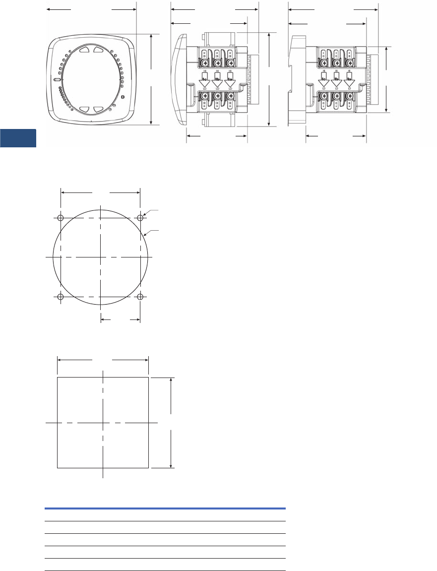
V3-T9-70 Volume 3—Power Distribution and Control Assemblies CA08100004E—November 2013 www.eaton.com
9
9
9
9
9
9
9
9
9
9
9
9
9
9
9
9
9
9
9
9
9
9
9
9
9
9
9
9
9
9
9.3
Metering Devices, Protective Relays, Software and Connectivity
Meter ing Devices
Dimensions
Approximate Dimensions in Inches (mm)
IQ 100 Meter—Face and Side Views
ANSI Mounting Panel Cutout
DIN Mounting Cutout
4.85 (123.2)
4.85
(123.2)
IQ 100 Side IQ 100 Side
4.97 (126.2)
4.20 (106.7)
5.02
(127.5)
3.25 (82.6) 3.25 (82.6)
3.54
(89.9)
4.93 (125.2)
4.16 (105.7)
IQ 100 Face
4.00
(101.6)
3.38
(85.9)
1.69
(42.9)
4 x .02
(0.5)
3.62
(92.0)
3.62
(92.0)
Description Specifications
Weight 2 lbs (0.9 kg)
Basic unit 5.00 (127.0) H x 4.90 (124.5) W x 5.00 (127.0) L
IQ 100 Mounts in 92 mm DIN and ANSI C39.1 round cut-outs
Shipping container dimensions 6-inch cube
Tolerance ±0.1 inches (2.54 mm)

Volume 3—Power Distribution and Control Assemblies CA08100004E—November 2013 www.eaton.com V3-T9-71
9
9
9
9
9
9
9
9
9
9
9
9
9
9
9
9
9
9
9
9
9
9
9
9
9
9
9
9
9
9
9.3
Metering Devices, Protective Relays, Software and Connectivity
Metering Devices
IQ 150S/250S Self-Enclosed Electronic Meters
Contents
Description
Metering Products Family. . . . . . . . . . . . . . . . . . . . V3-T9-21
Power Xpert Meter 4000/6000/8000 Series . . . . . . V3-T9-30
Power Xpert Meter 2000 Series . . . . . . . . . . . . . . . V3-T9-49
IQ 250/260 Series Electronic Power Meters. . . . . . V3-T9-60
IQ 130/140/150 Series Electronic Power Meters . . V3-T9-66
IQ 150S/250S Self-Enclosed Electronic Meters
Catalog Number Selection. . . . . . . . . . . . . . . . . V3-T9-73
Technical Data and Specifications . . . . . . . . . . . V3-T9-74
Wiring Diagrams . . . . . . . . . . . . . . . . . . . . . . . . V3-T9-75
Dimensions . . . . . . . . . . . . . . . . . . . . . . . . . . . . V3-T9-75
IQ 35M . . . . . . . . . . . . . . . . . . . . . . . . . . . . . . . . . . V3-T9-76
IQ Analyzer 6400/6600 Series . . . . . . . . . . . . . . . . V3-T9-79
IQ DP-4000 Series . . . . . . . . . . . . . . . . . . . . . . . . . V3-T9-87
IQ 230 Meters . . . . . . . . . . . . . . . . . . . . . . . . . . . . V3-T9-93
Power Xpert Multi-Point Meter . . . . . . . . . . . . . . . . V3-T9-100
IQ Energy Sentinel™ . . . . . . . . . . . . . . . . . . . . . . . V3-T9-112
PM3 Monitoring and Metering Module . . . . . . . . . V3-T9-121
Current Transformers (CTs). . . . . . . . . . . . . . . . . . . V3-T9-122
Clamp-On Current Transformers . . . . . . . . . . . . . . . V3-T9-131
IQ Flange . . . . . . . . . . . . . . . . . . . . . . . . . . . . . . . . V3-T9-134
Panel Mounting Adapter Kit . . . . . . . . . . . . . . . . . . V3-T9-135
Enclosed Meters. . . . . . . . . . . . . . . . . . . . . . . . . . . V3-T9-136
IQ 150S/250S Self-Enclosed Electronic Meters
Product Description
With energy costs
skyrocketing, you need the
ability to verify the accuracy
of utility billing and allocation
of energy costs among
business units, different
manufacturing areas or
facilities, and tenants.
Production equipment and IT
systems are vulnerable to
power anomalies; therefore,
you must ensure that power
is always up to specifications.
If your infrastructure is an
established facility, you may
not currently have metering
or may have addressed these
concerns by deploying a
variety of analog gauges and
meters—one for volts, one
for amperes and so on, with
separate meters for each
measurement.
If you’re planning an upgrade
or a new power infrastructure,
no doubt you would like to
capitalize on the latest
technology to improve upon
that cumbersome
architecture and its
patchwork view.
Application Description
●Industrial and commercial
buildings, metering and
submetering
●Government facilities and
military
●Universities and airports
●Load studies and voltage
recording
Features and Benefits
●Self-enclosed, these
meters are an ideal
solution for surface
mounting next to a
selected piece of
equipment for energy
monitoring
●NEMA 12 enclosure with a
large, easy-to-read faceplate,
consistent with other
Eaton meter models,
designed with “knockouts”
for easy installation
●Ethernet communications
option for either wired or
wireless setup, allowing for
additional ease of
installation and integration
into existing networks
●Available data and alarm
recording for historical
records/trending
●Integrate into Eaton’s
Power Xpert® Architecture
for a holistic system-level
view
Wireless and High-End
Capabilities you would not
Expect from a Self-Enclosed,
Compact Meter
Providing the first line of
defense against costly power
problems, Eaton’s IQ 150S/
250S electronic self-enclosed
meters can perform the work
of an entire wall of legacy
metering equipment using
today’s secure wireless
technology. Eaton’s IQ 150S/
250S meters use 24-bit AD
converters that sample at
more than 400 samples per
cycle and meet IEC 687
(0.2% accuracy) and ANSI
C12.20 (0.2% accuracy)
standards. With such high-
performance measurement
capability, these meters can
be confidently used for
primary revenue metering
and submetering applications.
Either model will help you
monitor energy demand,
while the IQ 250S provides
the extra benefit of also
monitoring and recording the
changes in the characteristics
of your power.
Eaton’s IQ 150S/250S
meters provide direct-reading
metered values for the most
critical power aspects, such
as watts, watt demand,
watthours, voltage amperes
(VA), VA-hours, VARs, VAR-
hours and power factor. They
have high sampling speed
and accuracy.
These meters are self-
enclosed in a NEMA 12
enclosure with “knockouts”
on the bottom for
communication and power,
providing for an easy
installation.
Perhaps you don’t have
network drops in all the
right places. The IQ 150S/
250S offers a wireless
communications option.
The transmissions are
encrypted using 128-bit
Wired Equivalent Privacy
(WEP) for security.

V3-T9-72 Volume 3—Power Distribution and Control Assemblies CA08100004E—November 2013 www.eaton.com
9
9
9
9
9
9
9
9
9
9
9
9
9
9
9
9
9
9
9
9
9
9
9
9
9
9
9
9
9
9
9.3
Metering Devices, Protective Relays, Software and Connectivity
Metering Devices
Industry-Standard
Communication Protocols
Standard Modbus RS-485
Communication
Standard communication
includes an RS-485 output
speaking Modbus protocol.
This allows the unit to be
connected to any serial RS-
485 bus using the Modbus
interface. The unit
communicates easily with
most building automation,
Power Xpert Software or
other software systems.
Baud rates are up to
57.6K baud to provide
fast update times.
Wi-Fi or Land-Based
Ethernet
The unit offers an Ethernet
option—configured either as
an RJ45 or Wi-Fi connection.
The Wi-Fi configuration
allows the 150S/250S to be
used on standard Wi-Fi base
stations. The unit is assigned
an IP address; it
communicates Modbus
protocol over Ethernet TCP/
IP. Wireless Ethernet is
reliable and easy to integrate,
making it the superior
solution for mass meter
deployment.
KYZ Pulse
For applications in which a
pulse is needed, the unit also
provides a KYZ output that
pulses proportional to the
amount of energy consumed.
This feature is used for pulse
counting applications into
building management
systems where serial or
Ethernet protocol is not
available.
Verify Energy Bills
The IQ 150S/250S models
provide a traceable watthour
test pulse (used with a
watthour pulse recorder or
totalizer), so you can verify
the accuracy of your meter
and in turn, the accuracy of
billing from your utility
company and to internal
customers.
Integrated with Eaton’s
Power Xpert Architecture
IQ 150S/250S meters
integrate into Eaton’s Power
Xpert Architecture, where
meters, gateways and
monitoring devices
collaborate to create a
unified, centralized view of
the end-to-end power and
facility infrastructure.
When used in this
architecture, either with a
Power Xpert Gateway or
directly via Ethernet, the
meters with the Modbus RTU
option can provide Web-
based graphics of current
power conditions. Simply
connect your meter to a
Power Xpert Gateway to
translate Modbus-based
information from the meter
into HTML-based Web pages
that are accessible from any
standard Web browser. If you
select a model with the
Ethernet option, the meter
can easily be monitored
remotely via Power Xpert
Software or another third-
party monitoring system.
With access to accurate, real-
time information from IQ
150S/250S meters, Power
Xpert Architecture can
transform your power system
into an integrated, agile
system, and an easily
managed entity that performs
better and costs less.
Designed for the User
When space is at a premium,
yet you need ANSI C12.20
accuracy, Eaton IQ 150S/
250S meters fit the bill.
These ultra-compact meters
are ideal for surface mounting
next to a selected piece of
equipment for energy
monitoring. Requiring far less
space than other meters with
similar functionality, and
offering a NEMA 12
enclosure and a large, easy-
to-read faceplate, consistent
with other Eaton meter
models, these meters are
designed with “knockouts”
for easy retrofit installation.
Most meters in this class
have small or dark displays
that can be hard to see,
especially from a distance.
Eaton’s IQ 150S/250S meters
have a large, bright red, three-
line LED display, each line
more than a half-inch tall. This
display is very easy to read,
even if the meter is installed at
a height or distance. Using the
keypad and menus on the
local display, users can
display a variety of electrical
system values or program
the meter.
Installation Diagram
IQ 150S/250S Installation
O
Closed
Lockable
Revenue Seal
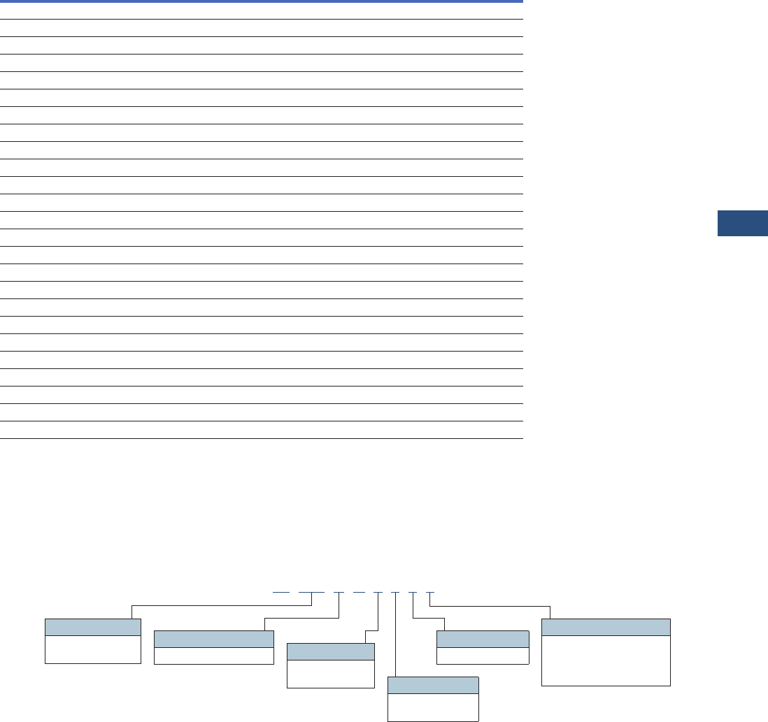
Volume 3—Power Distribution and Control Assemblies CA08100004E—November 2013 www.eaton.com V3-T9-73
9
9
9
9
9
9
9
9
9
9
9
9
9
9
9
9
9
9
9
9
9
9
9
9
9
9
9
9
9
9
9.3
Metering Devices, Protective Relays, Software and Connectivity
Metering Devices
Features of IQ 150S/250S Electronic Power Meters
Notes
1Per phase only.
2If configured for Ethernet, RS-485 not available.
Catalog Number Selection
IQ 150S/250S Meter
Features IQ 150S IQ 250S
Instrumentation
Current, per phase ■■
Calculated neutral current ■■
Voltage, per phase (L-L, L-N) ■■
Frequency ■■
Minimum/maximum readings, I 1, V 1, PF, F, W, VAR, VA Total Total and per phase
Power
Real, reactive and apparent power (W, VAR, VA) Total Total and per phase
Power factor Average Average and per phase
Demand Methods
Block interval (fixed, sliding) ■■
Current demand ■■
Real, reactive and apparent power demand Total Total and per phase
Energy
Real, reactive and apparent energy (Wh, VARh, VAh) Total Total and per phase
Real and reactive, net and positive and negative (Wh, VARh) Total Total and per phase
I/O
Pulse output ■■
Communications
RS-485, Modbus RTU, DNP 3.0 ■■
RJ45 or 802.11b, Modbus TCP 2Optional Optional
Data Logging
2 MB for data logging ■
Alarming
Set point driven alarm ■
IQ 150 S A 6 5 1 1
Model Series
150 = Energy
250 = Energy plus Frequency
5 = 50 Hz system
6 = 60 Hz system
Power Supply
1 = 90–400 Vac/Vdc
Current Input
1 = 1A secondary
5 = 5A secondary
Meter Type
S = Self-enclosed meter
Communication
1 = Modbus RTU (RS-485)
2 = Modbus RTU (RS-485)
or TCP—(RJ45)
or 802.11b (Wi-Fi)

V3-T9-74 Volume 3—Power Distribution and Control Assemblies CA08100004E—November 2013 www.eaton.com
9
9
9
9
9
9
9
9
9
9
9
9
9
9
9
9
9
9
9
9
9
9
9
9
9
9
9
9
9
9
9.3
Metering Devices, Protective Relays, Software and Connectivity
Metering Devices
Technical Data and Specifications
IQ 150S/250S Electronic Meter Technical Information
Note: Specifications are subject to change without notice and represent
the maximum capabilities of the product with all options installed. This is not
a complete feature list. Features and functionality may vary depending on
selected options, firmware version and product model. Please refer to
User Manual for detailed specifications.
Description Specifications
Current Inputs
Class 10 5A nominal, 10A maximum
Class 2 1A nominal, 2A maximum
Fault Current Withstand
20A for:
60A for:
100A for:
10 seconds
3 seconds
1 second
Programmable current Full scale to any CT ratio
Burden 0.005 VA per phase maximum at 11A
Pickup Current
Class 10
Class 2
0.1% of nominal
5 mA
1 mA
Connections
Screw terminal #6–32 screws
Voltage Inputs
Range
Line-to-neutral 20–416 Vac (IQ150S), 20–576 Vac (IQ250S)
Line-to-line 20–721 Vac
Programmable voltage range Full scale to any PT ratio
Supported systems 3 element wye, 2.5 element wye, 2 element delta,
four-wire delta systems
Input impedance 1 megohm/phase
Burden 0.36 VA/phase maximum at 600V; 0.014 VA at 120V
Connection 7-pin, 0.400-inch screw
terminal block, AWG #12–26 (0.129–3.31 mm2)
Isolation
All inputs and outputs are galvanically isolated to 2500V
Environmental Ratings
Operating temperature –20º to +70°C
Storage temperature –20º to +70°C
Operating humidity To 95% RH noncondensing
Faceplate rating NEMA 12
Sensing Method
Voltage, current rms
Power Sampling at over 400 samples per cycle on all
channels
Description Specifications
Update Rate
Watts, VAR and VA 100 msec at 60 Hz
All other parameters 1 second at 60 Hz
Power Supply
AC/DC voltage option 90–400 Vac at 50/60 Hz or
100–370 Vdc, universal AC/DC supply
Burden 16 VA maximum
Standard Serial Communications Format
Connection type RS-485
Communications port baud rate 9600–57,600 Bauds
Communications port address 01–247
Data format 8-bit, no parity
Protocols Modbus ASCII, RTU, DNP 3.0
Optional Ethernet Communications Format
Connection type RJ45 or 802.11b (wireless)
Protocols Modbus TCP
KYZ Pulse
Contacts 1 Form A
On resistance, maximum 35 Ohms
Peak switching voltage 350 Vdc
Continuous load current 120 mA
Peak load current 350 mA (10 ms)
Off-state leakage current at 350 Vdc 1 uA
Opto-isolation 3750 Vac
Dimensions and Shipping
Weight 4 lbs
Basic unit H 7.90 x W 7.50 x D 3.10 inches
Compliance
IEC 687 0.2% accuracy
ANSI C12.20 0.2% accuracy
ANSI C62.41 Burst
ANSI (IEEE) C37.90.1 Surge withstand
UL/cUL Electrical and electronic
measuring and test equipment 22CZ
Volume 3—Power Distribution and Control Assemblies CA08100004E—November 2013 www.eaton.com V3-T9-75
9
9
9
9
9
9
9
9
9
9
9
9
9
9
9
9
9
9
9
9
9
9
9
9
9
9
9
9
9
9
9.3
Metering Devices, Protective Relays, Software and Connectivity
Metering Devices
Wiring Diagrams
IQ 150S/250S Electronic Meter
Dimensions
Approximate Dimensions in Inches (mm)
IQ 150S/250S Electronic Meter
Three-Phase Four-Wire WYE Direct Three-Phase Four-Wire WYE with PTS
Three-Phase Three-Wire DELTA Direct Three-Phase Three-Wire DELTA Direct
3
.1
1
(
79.0
)
7.
90
(
200.7
)
7.
90
(
200.7
)
5
.
60
(
142.2
)
Antenna Len
g
th:
4.40
(
111.8
)
7.
53
(
191.3
)
3
.7
0
(
94.0
)
5
.
95
(
151.1
)
0
.
50
(
12.7
)
Mountin
g
Plat
e
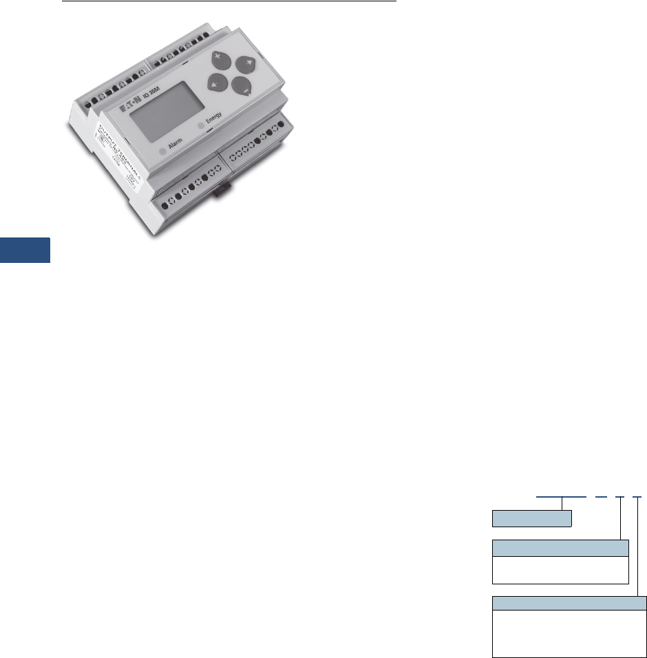
V3-T9-76 Volume 3—Power Distribution and Control Assemblies CA08100004E—November 2013 www.eaton.com
9
9
9
9
9
9
9
9
9
9
9
9
9
9
9
9
9
9
9
9
9
9
9
9
9
9
9
9
9
9
9.3
Metering Devices, Protective Relays, Software and Connectivity
Metering Devices
IQ 35M
Contents
Description
Metering Products Family. . . . . . . . . . . . . . . . . . . . . V3-T9-21
Power Xpert Meter 4000/6000/8000 Series. . . . . . . V3-T9-30
Power Xpert Meter 2000 Series . . . . . . . . . . . . . . . . V3-T9-49
IQ 250/260 Series Electronic Power Meters . . . . . . V3-T9-60
IQ 130/140/150 Series Electronic Power Meters . . . V3-T9-66
IQ 150S/250S Self-Enclosed Electronic Meters . . . . V3-T9-71
IQ 35M
Product Selection . . . . . . . . . . . . . . . . . . . . . . . . V3-T9-77
Accessories . . . . . . . . . . . . . . . . . . . . . . . . . . . . . V3-T9-77
Technical Data and Specifications . . . . . . . . . . . . V3-T9-77
Dimensions . . . . . . . . . . . . . . . . . . . . . . . . . . . . . V3-T9-78
IQ Analyzer 6400/6600 Series . . . . . . . . . . . . . . . . . V3-T9-79
IQ DP-4000 Series . . . . . . . . . . . . . . . . . . . . . . . . . . V3-T9-87
IQ 230 Meters . . . . . . . . . . . . . . . . . . . . . . . . . . . . . V3-T9-93
Power Xpert Multi-Point Meter . . . . . . . . . . . . . . . . . V3-T9-100
IQ Energy Sentinel™ . . . . . . . . . . . . . . . . . . . . . . . . V3-T9-112
PM3 Monitoring and Metering Module . . . . . . . . . . V3-T9-121
Current Transformers (CTs). . . . . . . . . . . . . . . . . . . . V3-T9-122
Clamp-On Current Transformers. . . . . . . . . . . . . . . . V3-T9-131
IQ Flange . . . . . . . . . . . . . . . . . . . . . . . . . . . . . . . . . V3-T9-134
Panel Mounting Adapter Kit . . . . . . . . . . . . . . . . . . . V3-T9-135
Enclosed Meters . . . . . . . . . . . . . . . . . . . . . . . . . . . V3-T9-136
IQ 35M
Product Description
The Eaton IQ 35M Meter is a
DIN rail meter that combines
exceptional performance and
easy installation to deliver a
cost-effective solution for
energy and power monitoring
applications, as well as sub-
metering applications. Most
models include pulse output,
alarm contact and phase alarms
for true versatility. The BACnet
version offers two digital inputs
for accumulating other meter
pulses in place of the digital
output and alarm contact.
The Modbus output options
offer added flexibility for
configuration and data analysis.
The IQ 35M allows you to:
●Verify energy bills
●Make informed load
shifting and shedding
decisions
●Fairly and accurately
allocate energy costs to
users
●Identify wasteful practices
●Decrease unnecessary
usage
●Produce an energy profile
●Secure the optimum utility
rate structure
Application Description
●Commercial submetering
●Energy management
●Industrial monitoring
●Cost allocation
Features
●
Economical and compact
watthour meter with
demand
●
Backlit LCD display for local
reading
●
Compatible with the Power
Xpert Gateway for remote
monitoring
●
Monitors
●
Voltage, current, power
factor, frequency
●
Power and energy: real,
reactive and apparent
●
Optional data logging
capability
●
Optional serial
communications (Modbus-
RTU or BACnet)
●
Revenue grade, ANSI
C12.20 0.5% accuracy, IEC
62053-22 Class 0.5S
●
Compatible with economical
solid-core and split-core CTs
●
User-enabled password
protection
●
On-board diagnostics
Catalog Number Selection
IQ 35M Meter
IQ35M A 1 1
Meter Series
Energy Type
1= Standard energy
2= Four quadrant energy
Output Option
1= Pulse output only
2= Pulse output + Modbus
3= Pulse output + Modbus + data logging
5= Pulse inputs + BACnet + data logging

Volume 3—Power Distribution and Control Assemblies CA08100004E—November 2013 www.eaton.com V3-T9-77
9
9
9
9
9
9
9
9
9
9
9
9
9
9
9
9
9
9
9
9
9
9
9
9
9
9
9
9
9
9
9.3
Metering Devices, Protective Relays, Software and Connectivity
Metering Devices
Product Selection
IQ 35M Current Transformers
Accessories
IQ 35M Accessories
Note: Specifications are subject to change without notice and represent
the maximum capabilities of the product with all options installed. This is
not a complete feature list. Features and functionality may vary
depending on selected options, firmware version and product model.
Please refer to User Manual for detailed specifications.
Description
Catalog
Number
Solid Core
IQ35M CT, solid core, 5A:0.33 Vac, 0.30 inch IQ35M-SO-030-5
IQ35M CT, solid core, 20A:0.33 Vac, 0.30 inch IQ35M-SO-030-20
IQ35M CT, solid core, 50A:0.33 Vac, 0.50 inch IQ35M-SO-050-50
IQ35M CT, solid core, 50A:0.33 Vac, 0.75 inch IQ35M-SO-075-50
IQ35M CT, solid core, 100A:0.33 Vac, 1.25 inch IQ35M-SO-125-100
IQ35M CT, solid core, 200A:0.33 Vac, 1.25 inch IQ35M-SO-125-200
IQ35M CT, solid core, 250A:0.33 Vac, 1.25 inch IQ35M-SO-125-250
IQ35M CT, solid core, 300A:0.33 Vac, 1.25 inch IQ35M-SO-125-300
IQ35M CT, solid core, 400A:0.33 Vac, 1.25 inch IQ35M-SO-125-400
Split Core
IQ35M CT, split core, 5A:0.33 Vac, 0.75 inch IQ35M-SP-075-5
IQ35M CT, split core, 30A:0.33 Vac, 0.75 inch IQ35M-SP-075-30
IQ35M CT, split core, 50A:0.33 Vac, 0.75 inch IQ35M-SP-075-50
IQ35M CT, split core, 100A:0.33 Vac, 0.75 inch IQ35M-SP-075-100
IQ35M CT, split core, 200A:0.33 Vac, 0.75 inch IQ35M-SP-075-200
IQ35M CT, split core, 250A:0.33 Vac, 1.25 inch IQ35M-SP-125-250
IQ35M CT, split core, 300A:0.33 Vac, 1.25 inch IQ35M-SP-125-300
IQ35M CT, split core, 400A:0.33 Vac, 1.25 inch IQ35M-SP-125-400
IQ35M CT, split core, 600A:0.33 Vac, 1.25 inch IQ35M-SP-125-600
IQ35M CT, split core, 800A:0.33 Vac, 2.50 inch IQ35M-SP-253-800
IQ35M CT, split core, 1000A:0.33 Vac, 2.50 inch IQ35M-SP-255-1000
IQ35M CT, split core, 1200A:0.33 Vac, 2.50 inch IQ35M-SP-255-1200
IQ35M CT, split core, 1600A:0.33 Vac, 2.50 inch IQ35M-SP-255-1600
IQ35M CT, split core, 2000A:0.33 Vac, 2.50 inch IQ35M-SP-255-2000
IQ35M CT, split core, 2400A:0.33 Vac, 2.50 inch IQ35M-SP-255-2400
Description
Catalog
Number
IQ35M enclosure, NEMA 4X IQ35M-ENC
IQ35M fuse pack, single, 1/2A slow-blow IQ35M-FP1
IQ35M fuse pack, double, 1/2A slow-blow IQ35M-FP2
IQ35M fuse pack, triple, 1/2A slow-blow IQ35M-FP3
IQ35M replacement mounting clips IQ35M-RMC
IQ35M DIN rail IQ35M-DR
IQ35M DIN rail stop clips (10 pack) IQ35M-DRSC
Technical Data and Specifications
●Voltage input
UL: 90V (L-N) to 600V (L-L)
CE: 90V (L-N) to 300V (L-L)
●Current input
Scaling: 5–32,767A
Input range: 0–0.333V or
0–1V (selectable)
●Control power
UL: 90V (L-N) to 600V (L-L)
CE: 90V (L-N) to 300V (L-L)
Accuracy
●Real power and energy
0.5% (ANSI C12.20, IEC 62053-22 Class 0.5S)
Outputs
●IQ35MAx1 thru 3:
Real energy pulse: NO static; alarm contacts: NC static
●IQ35MA11
Reactive energy pulse 30 Vac/Vdc
●IQ35MAx2, IQ35MAx3
RS-485 two-wire Modbus RTU
●IQ35MA15 RS-485 two-wire BACnet MS/TP
Inputs
●IQ35MA15
Two pulse accumulators
Mechanical
●Mounting
DIN rail or 3-point screwmount
Environmental
●Operating temperature range
Meter: –30° to 70°C (–22° to 158°F)
Display: –10° to 50°C (14° to 122°F)
●Storage temperature range
Meter: –40° to 85°C (–40° to 185°F)
Display: –10° to 60°C (14° to 140°F)
●Humidity range
<95% RH noncondensing
Data Outputs
●kW, kWh: Total
●Current: Three-phase average and per phase
●Voltage: Three-phase average, per phase, and line-line and
line-neutral
●Power: Real, reactive and apparent;
Three-phase total and per phase
●Power factor: Three-phase average and per phase
●Frequency
●Power demand: most recent and peak
●Demand configuration: fixed, rolling block and external sync
●Data logging (IQ35MAx3)
10 configurable data buffers;
configurable demand subinterval (when set at a 15-minute
interval, buffers store data for 60 days)
●Data logging (IQ35MA15)
6 configurable data buffers;
configurable demand subinterval (when set at a 15-minute
interval, buffers store data for 60 days)
●Trending requires communication network to retrieve data
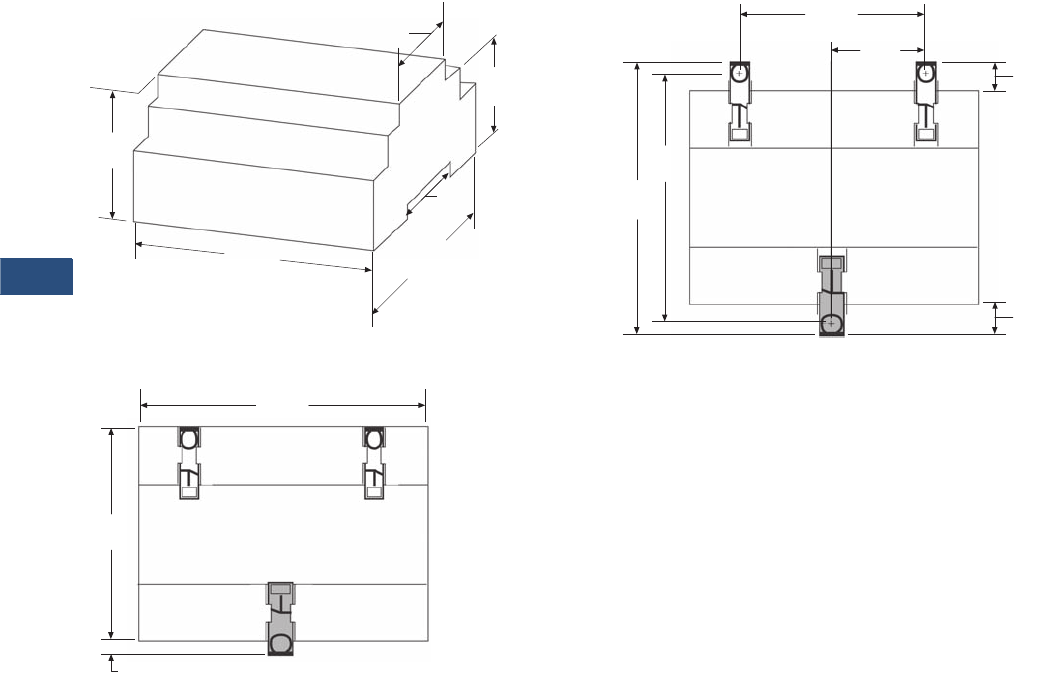
V3-T9-78 Volume 3—Power Distribution and Control Assemblies CA08100004E—November 2013 www.eaton.com
9
9
9
9
9
9
9
9
9
9
9
9
9
9
9
9
9
9
9
9
9
9
9
9
9
9
9
9
9
9
9.3
Metering Devices, Protective Relays, Software and Connectivity
Metering Devices
Dimensions
Approximate Dimensions in Inches (mm)
IQ 35M Dimensional Drawing
IQ 35M DIN Mount Configuration
1.80 (45.7)
2.30
(58.4)
4.20
(106.7)
1.50
(38.1)
3.60
(91.4)
1.90
(48.3)
4.20
(106.7)
3.60
(91.4)
0.20
(5.1)
IQ 35M Wall Mount Configuration
2.40
(60.1)
4.30
(109.2)
3.90
(99.1)
1.20
(30.5) 0.30
(7.61)
0.40
(10.2)

Volume 3—Power Distribution and Control Assemblies CA08100004E—November 2013 www.eaton.com V3-T9-79
9
9
9
9
9
9
9
9
9
9
9
9
9
9
9
9
9
9
9
9
9
9
9
9
9
9
9
9
9
9
9.3
Metering Devices, Protective Relays, Software and Connectivity
Metering Devices
IQ Analyzer—
Comprehensive Electrical
Distribution Monitoring
IQ Analyzer 6400/6600 Series
Contents
Description Page
Metering Products Family. . . . . . . . . . . . . . . . . . . . V3-T9-21
Power Xpert Meter 4000/6000/8000 Series . . . . . . V3-T9-30
Power Xpert Meter 2000 Series . . . . . . . . . . . . . . . V3-T9-49
IQ 250/260 Series Electronic Power Meters. . . . . . V3-T9-60
IQ 130/140/150 Series Electronic Power Meters . . V3-T9-66
IQ 150S/250S Self-Enclosed Electronic Meters . . . V3-T9-71
IQ 35M . . . . . . . . . . . . . . . . . . . . . . . . . . . . . . . . . . V3-T9-76
IQ Analyzer 6400/6600 Series
Standards and Certifications . . . . . . . . . . . . . . . V3-T9-82
Product Selection. . . . . . . . . . . . . . . . . . . . . . . . V3-T9-83
Accessories . . . . . . . . . . . . . . . . . . . . . . . . . . . . V3-T9-83
Technical Data and Specifications . . . . . . . . . . . V3-T9-84
Dimensions . . . . . . . . . . . . . . . . . . . . . . . . . . . . V3-T9-85
IQ DP-4000 Series . . . . . . . . . . . . . . . . . . . . . . . . . V3-T9-87
IQ 230 Meters . . . . . . . . . . . . . . . . . . . . . . . . . . . . V3-T9-93
Power Xpert Multi-Point Meter . . . . . . . . . . . . . . . . V3-T9-100
IQ Energy Sentinel™ . . . . . . . . . . . . . . . . . . . . . . . V3-T9-112
PM3 Monitoring and Metering Module . . . . . . . . . V3-T9-121
Current Transformers (CTs). . . . . . . . . . . . . . . . . . . V3-T9-122
Clamp-On Current Transformers . . . . . . . . . . . . . . . V3-T9-131
IQ Flange . . . . . . . . . . . . . . . . . . . . . . . . . . . . . . . . V3-T9-134
Panel Mounting Adapter Kit . . . . . . . . . . . . . . . . . . V3-T9-135
Enclosed Meters. . . . . . . . . . . . . . . . . . . . . . . . . . . V3-T9-136
IQ Analyzer 6400/6600 Series
Product Description
Eaton’s IQ Analyzer is a
complete solution for users
who want to monitor and
manage all aspects of their
electrical distribution system.
Based on input from
customers and consultants,
it provides extensive
metering, power quality
analysis, remote input
monitoring, control relaying,
analog input/outputs and
communications capability.
Its high performance
metering exceeds ANSI
C12.16 (1%) specification for
revenue meters and meets
ANSI C12.20 Class 0.5%,
provides quality true rms
readings through the 50th
harmonic, accurately
measures nonsinusoidal
waveforms up to a 3.0 crest
factor, and displays even
and odd multiples of the
fundamental current and
voltage through the 50th
harmonic. Both magnitude
and phase angle of the
harmonics are displayed.
The unique operator
interface, which includes a
reverse mode LCD display,
easy to use Meter Menu
screens and detailed Analysis
screens, is designed to allow
a wealth of real-time and
recorded information to be
accessed easily by an
operator. All programming
can be accomplished through
the faceplate or the
communications port. The
comprehensive on-line Help
feature provides useful
information on device
operation, programming and
troubleshooting.
Application Description
●Monitoring of over 150
electrical parameters
●Power quality management
●Energy management
Features, Benefits and Functions
Metered and Monitored
Parameters
●rms sensing
●Phase neutral, and
ground currents
●V o l t s : L- L , L- N , A v g . L- L ,
Avg. L-N, N-G
●Power: real, reactive,
apparent (system and
per phase)
●Frequency
●Power factor: apparent and
displacement (system and
per phase)
●Energy and demand
(forward, reverse, net) real,
reactive apparent at four
different utility rates
●Individual current and
voltage harmonics:
magnitude, phase angle
●% THD: current and
voltage
●Waveform capture
●Minimum and maximum
values
●Event logging/disturbance
recording
●ANSI C12.20 Class 0.5%
revenue metering accuracy,
IEC687 Class 0.5%
●Industry Canada 0.5%
revenue accuracy
Communications
●Optional interface
capability to computer
network for data collection,
storage and/or printout
via Eaton’s Power
Management Software
Physical Characteristics
●Graphical reverse mode
LCD display with LED
backlight
●Up to seven lines of
information
●Membrane faceplate
NEMA 3R and 12 rated

V3-T9-80 Volume 3—Power Distribution and Control Assemblies CA08100004E—November 2013 www.eaton.com
9
9
9
9
9
9
9
9
9
9
9
9
9
9
9
9
9
9
9
9
9
9
9
9
9
9
9
9
9
9
9.3
Metering Devices, Protective Relays, Software and Connectivity
Metering Devices
Disturbance Information
With the communications
option and Eaton’s Power
Management Software and
Waveform Display software,
a Waveform Analysis will
construct waveforms of up to
56 cycles of all currents and
voltages (including neutral
and ground) to help
troubleshoot undervoltage/
sag and overvoltage/swell
conditions. (See CBEMA
Trend Logging section.)
By programming a reset
threshold, the duration of the
voltage disturbance can also
be indicated.
The IQ Analyzer 6600 series
with Graphic Waveform
Display offers the ability to
view the captured waveform
right at the device. The 6600
series also offers the ability to
detect and capture sub-cycle
voltage disturbances.
Extensive Harmonic
Distortion Analysis
Current and voltage distortion
data are displayed at the
device and accessible
through the communications
port. This includes % THD,
K-Factor, Crest Factor,
CBEMA factor, and both
magnitudes and phase angles
of all harmonics through the
50th. A snapshot sample
of this information may
be activated by user
commands, discrete inputs
or programmable thresholds
to capture distortion data
during conditions of real
interest. To help eliminate
nuisance alarms, harmonic
distortion information can be
captured and relay outputs
activated when THD exceeds
a programmable percentage
of fundamental or a
programmable magnitude
(e.g., amperes) threshold.
Time-of-Use Metering
The IQ Analyzer offers
the ability to store energy
usage data for time of use
revenue metering. It can
be programmed for any
combination of weekday,
Saturday, Sunday,
22 holidays, 8 seasons,
32 schedules and 10 time
periods per schedule. The IQ
Analyzer will keep track of the
following parameters for four
different utility rates:
●Watthours
●VAR hours
●VA hours
●Current demand
●Watt demand
●VA demand
●VAR demand
Historical Trend Logging
The IQ Analyzer is equipped
with onboard logging
capability, which includes
the ability to log a total of
24 parameters with intervals
ranging from 0.13 seconds
(every eight cycles) to twice
a week (5040 minutes). The
trending function can begin
immediately or can be
triggered upon receipt of a
discrete input into the IQ
Analyzer. Onboard logging
provides a cost-effective
means of distributed data
storage where real-time
communications may not be
feasible or for applications
where data storage
redundancy is desired. Four
trend data logs are stored in
non-volatile memory aboard
the IQ Analyzer and can be
retrieved at the display or
via communications for
viewing using Eaton’s Power
Management Software.
●Up to 24 parameters with
storage capacity for up to
90,000 data points
●Up to 234 days of data
can be stored when
recording a parameter
every 15 minutes
●Trends 1, 2 and 3 can
save data on a discrete
contact input
●Trend 4 can save data
on a power quality or
meter event
●Minimum and maximum
recording (minimum and
maximum three-phase
average current, maximum
IG, minimum and
maximum three-phase
average VLL and VLN,
maximum VNG, maximum
system watts, VARs and
VA, minimum and
maximum apparent and
displacement PF). Using
this feature, minimum
and maximums reached
during each trend interval
are recorded.
CBEMA Trend Logging
The IQ Analyzer can be
configured to store the
necessary data so that the
software can display a sag or
swell voltage event on the
industry standard CBEMA
(now ITIC) curve for
predictive maintenance
and troubleshooting. This
application utilizes the IQ
Analyzer waveform capture
for high-0speed events along
with historical trend logging
for longer term voltage
disturbances. Once this data
is uploaded to a PC running
the Power Management
Software’s Event Viewer
the information is analyzed,
displayed and stored.
Automatic uploading of
CBEMA events can be
selected in the software.
A three-phase event will be
correctly displayed as a single
point on the CBEMA curve.
Event Logging
The IQ Analyzer will store
in non-volatile memory the
time and reason for last 504
events. These events can be
viewed from the graphical
display or accessed via
communications. In addition
to all of the meter events
listed in the Event Conditions
section (Page V3-T9-81), the
following events are entered
into the event log:
Time and date of:
●Alarms
●Meter power up
●All resets
●All setting changes
●Communications
established or lost
Event logging is another
powerful troubleshooting tool
within the IQ Analyzer.
Extensive I/O and
Communications Capability
One analog and three digital
inputs are provided to
interface with sensors and
transducers. Three analog
outputs and four relay
contacts are furnished to
share data with PLCs and
control systems and to
actuate alarms and control
relays. Terminals are captive
clamp type and finger safe.
With the communications
option, the device can be
remotely monitored,
controlled and programmed.
Ratings
●Application to 500 kV,
no PTs to 600 volts
●CT ratios selectable from
5:5A to 10,000:5A
●Standard 120/600 Vac line
●Three-phase power supply
module, 100–600 Vac.
Separate source power
supply module available,
100–240 Vac or
100–250 Vdc
●DC only separate source
power module also
available, 24–48 Vdc
Displayed Information Features
●All information accessible
at device or through
communications port
via Eaton’s Power
Management Software
●Quality true rms readings
through 50th harmonic
●Complies with the
accuracy portion of
ANSI C12.20 Class 0.5%
revenue metering
specification
●Accurate readings for
nonsinusoidal waveforms
with up to 3.0 crest factor
●Screens display auto
ranging units, kilo units,
mega units as needed
●10-digit energy readings
●Displays multiple
parameters at the
same time
●Programmable custom
screens
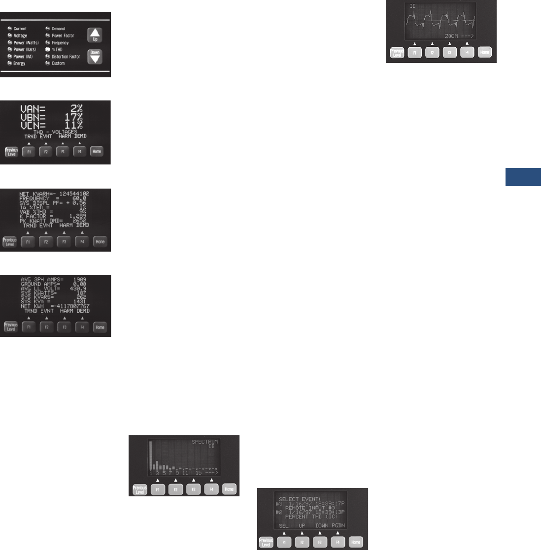
Volume 3—Power Distribution and Control Assemblies CA08100004E—November 2013 www.eaton.com V3-T9-81
9
9
9
9
9
9
9
9
9
9
9
9
9
9
9
9
9
9
9
9
9
9
9
9
9
9
9
9
9
9
9.3
Metering Devices, Protective Relays, Software and Connectivity
Metering Devices
Meter Menu Screens
Meter Menu
Examples of Meter Menu
Custom Screen
Custom Screen
The IQ Analyzer allows a user
to view commonly used
parameters by scrolling
through its LED indicator
Meter Menu.
Meter Menu Displayed
Information
●Current
●Phases A, B, C, average
●Neutral
●Ground (separate CT)
●Voltage
●Phases A-B, B-C, C-A,
average
●Phases A-N, B-N, C-N,
average
●Neutral-ground
●Power
●Real (watts)
●Reactive (VARs)
●Apparent (VA)
●Phases A, B, C and
system
●Energy (forward, reverse
and net)
●Real (kWh)
●Reactive (kVARh)
●
Apparent (kVAh)—no
reverse or net
●Frequency, time and date
●Demand
●System current
(amperes)
●Systems real power
(kW)
●System reactive power
(kVAR)
●System apparent power
(kVA)
●Power factor (Phases A, B,
C and system)
●Displacement
●Apparent
●%THD current
●Phases A, B, C, N
●%THD voltage
●Phases A-B, B-C, C-A
●Phases A-N, B-N, C-N
●K-factor
●CBEMA (ITIC) derating
factor (displayed as “Z”)
●Crest Factor
●Discrete input and
output status
●Analog input reading
●Custom—user may
program four screens to
show any combination of
seven Meter Menu
parameters per screen
Harmonic Analysis Screens
Harmonic Spectrum Available with
Model 6600
Minimum and Maximum Values
●Current
●Phases A, B, C, N, G
●Voltage
●Phases A-B, B-C, C-A
●Phases A-N, B-N,
C-N, N-G
●Power
●Real (Watts)
●Reactive (VARs)
●Apparent (VA)
●Phases A, B, C and
System
●Power factor
●Apparent and
Displacement (three-
phase and system)
●Frequency
●THD (amperes, volts
and %):
●Current (Phases A, B, C, N)
●Voltage (Phases A-B, B-
C, C-A, A-N, B-N, C-N)
All minimum/maximum
values may be reset via reset
pushbutton on faceplate,
discrete input or
communications command.
Values are updated at least
once every 16 line cycles.
The F3 function key accesses
the Harmonic Analysis
screens. Two cycles of data
sampled at 128 samples/
cycle are simultaneously
recorded for:
●Current
●Phases A, B, C, N, G
●Voltage
●Phases A-B, B-C, C-A
●Phases A-N, B-N, C-N
●Neutral to Ground
Magnitudes (or % of
fundamental) of odd and
even multiples of the
fundamental from 2nd–50th
are displayed. The phase
angle associated with each
multiple of the fundamental
is also displayed.
Event/Alarm Analysis Screens
Example of Event Analysis Screens
Waveform Screen Available with
Model 6600
Pressing the F2 function key
accesses the Event Analysis
screens. These display the
following data for up to ten
event/alarm conditions:
●Description, date and
time of event/alarm with 10
millisecond resolution
●Current, voltages, power
readings, demand
readings, frequency and %
THD at time of event/alarm
●Current and voltage
distortion information
available on Harmonic
Analysis screens
Event data is stored in non-
volatile memory. If a reset
threshold is programmed,
the duration of the event
(e.g., undervoltage) is also
displayed. With Eaton’s
communications option and
software, waveforms and
harmonic profiles may be
displayed on a PC.
Event Conditions
Events may be triggered by
up to seven of any of the
following conditions:
Voltage Disturbances
●Undervoltage/sag—
any VL- L , VL- N (40–100%)
Note: 60% minimum for self-
powered unit.
●Overvoltage/swell—
any VL- L , VL- N (100–750%)

V3-T9-82 Volume 3—Power Distribution and Control Assemblies CA08100004E—November 2013 www.eaton.com
9
9
9
9
9
9
9
9
9
9
9
9
9
9
9
9
9
9
9
9
9
9
9
9
9
9
9
9
9
9
9.3
Metering Devices, Protective Relays, Software and Connectivity
Metering Devices
If zero time delay is
programmed, any disturbance
lasting two cycles (less if
magnitude is sufficient to
effect rms readings) will
trigger a voltage disturbance
event/alarm.
●Sub-cycle transient
capture/excess dv/dt on
VA-N, VB-N, VC-N
Note: 6600 series only.
●Sub-cycle voltage
interruption on VA-N,
VB-N, VC-N
Note: 6600 series only.
Maximum Threshold Exceeded
●Currents —þphases A, B,
C, Neutral and Ground
●Voltage—Neutral to
Ground
●System Power—Watts,
VA, VARs
●System Power Factor—
Displacement and
Apparent
●Demand
●Currents—Phase A, B, C
and AVG
●System Power—Watts,
VARs, VA
●Frequency
●Percent Total Harmonic
Distortion or Magnitude
Total Harmonic Distortion:
●Currents—Phases A, B,
C, Neutral
●Voltage—VA-N, VB-N,
VC-N, VA-B, VB-C, VC-A
Minimum Threshold Exceeded
●Currents—Phases A, B, C
●System Power—Watts,
Vars, VA
●System Power Factor—
Displacement and
Apparent
●Frequency
Voltage Phase Unbalance
●V o l t a g e L- L , L- N
Current Phase Unbalance
●Current—Phases A, B, C
Discrete Input Energized
●Input 1, 2, 3
●Remote command through
communications port or
front panel
All trigger conditions have
programmable time delays
from 0.1–60 seconds in
0.1 second increments
(except Voltage Disturbances
—programmable from
2–3600 cycles in two-cycle
increments, and Eaton’s
Power Management
Software commands—no
programmable delay).
Demand Recording
Peak Demands are date and
time stamped for:
●Current Phases A, B, C
and Average
●System Power:
●Real (watts)
●Reactive (VARs)
●Apparent (VA)
Input/Output
Extensive input/output
capability is standard on the
IQ Analyzer. In addition to
monitoring three-phase
currents and voltages,
separate inputs
are provided
for both ground and neutral
currents. Voltage of neutral-
to-ground is also monitored to
indicate the presence of
harmonics and potential
downstream grounding
problems. Analog and digital
I/O provide interfaces for
transducers, relays, PLCs
and control systems.
Current Inputs
Five ampere secondary CT
connections for:
●Phases A, B, C
●Ground
●Neutral
●Separate ground and
neutral CT inputs
●
CT range 5:5–10,000: 5
(any integer)
Voltage Inputs
●Phases A, B, C (from
120 Vac–500 kV AC)
●120/240 Vac control power
input standard—not
required with optional line
power module
●Separate ground-to-neutral
voltage reference
●PT range 120:120–
500,000:120 (any integer)
External 120-volt secondary
PTs are required above
600 Vac, optional from
120–600 Vac.
Discrete Contact Inputs
Three dry contact discrete
inputs may be programmed
by the user to:
●Trigger Event Analysis—
the information described
in “Event Analysis
Screens,” including
Harmonic Analysis
information, can be
recorded when external
devices trip or change state
by wiring their auxiliary
contacts into these inputs
●Act as a synch.-pulse
input to synchronize
power demand windows
with utility provided
synch. pulse
●Actuate a relay output
●Reset relay output, peak
demands, Trend Analysis
records and Event
Analysis records
●With communications
option, provide remote
status indication on Eaton’s
communication network
●Status of input contacts is
displayed in the Meter
Menu Custom screen
Relay Output Contacts
Four Form-C (NO/NC)
relay contacts may
be independently
programmed to:
●Act as a kWh, kVARh or
kVAh pulse initiator output
●Actuate on one or more
event conditions—including
discrete input software
commands (through
communications port)
●Reverse sequence alarm
Each relay may be set for
Auto or Manual Reset with
0–30 minute release delay
(one second increments).
Relays are Form-C NO/NC.
Relay(s) programmed to
actuate on undervoltage
also have a programmable
0–30 minute delay on power-
up for transfer applications.
Analog Input and Outputs
One analog input and four
analog outputs may be
configured as 0–20 or
4–20 mA. The analog input is
displayed at the device as a
percentage and is accessible
through the communications
port. The analog input
provides an interface with gas
flow meters, temperature
transducers or other analog
devices.
The analog outputs may be
programmed
to reflect any of
the following:
●Current—Phases A, B, C,
Average, N, G
●Voltage—L-L, L-N, N-G
●Power:
●Real (watts)
●Reactive (VARs)
●Apparent (VA)
●Phases A, B, C and
System
●% THD:
●Current (Phases A, B, C, N)
●Voltage (L-L, L-N)
●Frequency–System
●Power Factor:
●System Displacement PF
●System Apparent PF
Standards and Certifications
●UL listed, File E62791,
NKCR File E185559
(CE versions)
●cUL listed #1010.1 C22.2
●CE mark EN61010-1 (1993)
EN50082-2 (1994)
●Measurement Canada
Electricity Meter AE-0782
●CSA approved
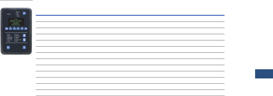
Volume 3—Power Distribution and Control Assemblies CA08100004E—November 2013 www.eaton.com V3-T9-83
9
9
9
9
9
9
9
9
9
9
9
9
9
9
9
9
9
9
9
9
9
9
9
9
9
9
9
9
9
9
9.3
Metering Devices, Protective Relays, Software and Connectivity
Metering Devices
Product Selection
IQ Analyzer
Accessories
IQ Analyzer Auxiliary
Power Supply
The optional IQ Analyzer
Auxiliary Power Supply allows
set point programming of the
IQ meter while the monitored
line power is turned off and
locked out, thus eliminating
the presence of dangerous
line voltages. The Auxiliary
Power Supply is easy to
install and has been
specifically designed to
connect to the power supply
connector on the IQ meter
and then plug into a standard
electrical wall outlet.
Description
Catalog
Number
IQ Analyzer, separate source power module IQA6410
IQ Analyzer, 24–48 Vdc power module IQA6420
IQ Analyzer, three-phase power module IQA6430
IQ Analyzer, separate source power module with waveform display and sub-cycle voltage disturbance capture IQA6610
IQ Analyzer, 24–48 Vdc power module with waveform display and sub-cycle voltage disturbance capture IQA6620
IQ Analyzer, three-phase power module with waveform display and sub-cycle voltage disturbance capture IQA6630
IQ Flange, to provide extra clearance when mounting IQFLANGE
45-inch (1143.0 mm) extension cable for remote mounting of power module IQA45CABLE
24–48 Vdc separate source power module IQMDCPM
100–240 Vac and 100–250 Vdc separate source power module IQMSSPM
Three-phase, self-powered power module IQM3PPM
INCOM communication module IPONI
RS-485 communication module with Modbus protocol MPONI
IQ Analyzer

V3-T9-84 Volume 3—Power Distribution and Control Assemblies CA08100004E—November 2013 www.eaton.com
9
9
9
9
9
9
9
9
9
9
9
9
9
9
9
9
9
9
9
9
9
9
9
9
9
9
9
9
9
9
9.3
Metering Devices, Protective Relays, Software and Connectivity
Metering Devices
Technical Data and Specifications
IQ Analyzer 6400/6600 Series
Fuses
●Self-powered units
with IQMSSPM have
3/4 ampere, 600 volts
Bus Type KTK-R-3/4 fuses
(three required).
●Separate source dual-
voltage units with
IQMSSPM have a single
5 x 20 mm 1/4 ampere fuse
●Separate source DC units
with IQMDCPM do not
have user replaceable
fuses
Environmental Conditions
●Operating temperature:
–20°–70°C
●Storage temperature:
–30°–85°C
●Operating humidity:
5–95% relative humidity
Current Inputs
(Each Channel)
●Conversion: true rms, 32
sample/cycle (all samples
used in all rms calculations)
●CT input: 5 ampere
secondary (any integer
5:5 to10,000:5)
●Burden: 0.05 VA
●Overload withstand:
40 amperes AC continuous,
300 amperes AC 1 second
●Range: 8 x CT continuous
●Accuracy: 0.1% of CT
primary rating, 0.2% of
reading above 150% of
rating, sinusoidal (see
accuracy below for non-
sinusoidal specifications)
●Input impedance:
0.002 ohm
Voltage Inputs
(Each Channel)
●Conversion: True rms, 32
sample/cycle (all samples
used in all rms calculations)
●PT input: direct or any
integer 120:120–
500,000:120
●Range: 30–660 Vac
(separate source and
DC source)
●Nominal full scale:
100–600 Vac
●Burden: 21 VA (self-
powered only)
●Overload withstand:
635 Vac, continuous
700 Vac, 1 second
●Input impedance:
1 megohm
Frequency Range
●20–66 Hz fundamental
(up to 50th harmonic)
Harmonic Response
(Voltages, Currents)
●50th harmonic
Accuracy (in Percent
Full Scale)
Accuracy from 3–300% of Full
Scale and
from –0.5. to 1.00
to 0.5 power factor
●Current and voltage:
±0.20%
●Power, energy and
demand: 0.40%
●Frequency: 0.04%
●Power factor: 0.80%
●THD: 1.00%
Specific Current Accuracies
●±0.20% of full scale to
200% of full scale and
150% crest factor
●±0.20% of full scale to
150% of full scale and
200% crest factor
●±0.20% of full scale to
100% of full scale and
300% crest factor
●±0.40% of reading for
currents to 800% of full
scale
●Power and energy: Start
recording with an average
of 3 mA secondary current
Discrete Inputs
(Dry Contact)
●+30 Vdc differential across
each discrete input pair of
terminals. Minimum pulse
width: 1.6 msec
●Optically isolated inputs
to protect IQ Analyzer
circuitry
Analog Outputs (4)
●0–20 mA/4–20 mA into
maximum 750 ohm load.
Accuracy: 1%
Analog Input (1)
●0–20 mA/4–20 mA into
200 ohm load.
Accuracy: 1%
Relay Output Contacts (4)
●Form C Dry Contact:
10 amperes at 120/240 Vac
(Resistive) 10A at 30 Vdc
(Resistive) 30A make
(50 mS) at 240 Vac/240 Vdc
●Minimum pulse width:
4 cycles (68 mS)
●Withstand rating: 1000 Vac,
1 minute across contacts
5000 Vac (contacts to coil,
1 minute) 10,000 Vac
(contacts to coil, surge
voltage)
Relay Response Time
(Excluding programmed
time delays):
●Two line cycles for Discrete
Input, Eaton’s software
commands
(communications port)
●Four to five line cycles for
Voltage Disturbance,
Voltage Unbalance
●Nine to 10 line cycles for
all others
IQ Analyzer Auxiliary
Power Supply
●Input voltage: 100–250 Vac
●Input frequency: 50/60 Hz
●Output voltage/current:
+24 Vdc at 0–0.45A
●Output ripple: 100 mV
maximum (peak to peak)
●Rated output power:
10.8 watts
●Turn on/turn off overshoot
5% maximum
●Turn on delay: 0.5 second
maximum
●Operating temperature:
0°–40°C
●Storage temperature:
–40°–80°C
Control Power Input
Note
1When directly wired to 480 Vac, IQ Analyzer can ride through a continuous sag that is 20% of rated voltage.
Description Separate Source Self Powered 1DC Source
Input range, AC
Frequency range
110–240 Vac ±10%
45–66 Hz
110–600 Vac ±10%
45–66 Hz
N/A
N/A
Input range, DC
Burden
110–250 Vdc ±10%
21 VA
N/A
21 VA
24–48 Vdc ±20%
21 VA
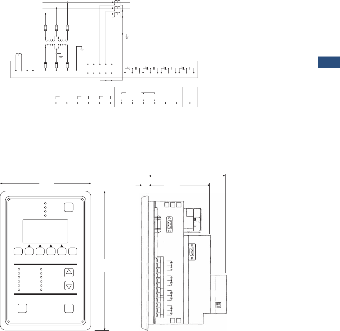
Volume 3—Power Distribution and Control Assemblies CA08100004E—November 2013 www.eaton.com V3-T9-85
9
9
9
9
9
9
9
9
9
9
9
9
9
9
9
9
9
9
9
9
9
9
9
9
9
9
9
9
9
9
9.3
Metering Devices, Protective Relays, Software and Connectivity
Metering Devices
Wiring Diagram
Field Wiring Connections—Separate Source Power Supply Shown Here
(For Three-Phase Power Supply, No Separate Control Power is Required)
Dimensions
Approximate Dimensions in Inches (mm)
IQ Analyzer 6000 Series
Line
L3
A
B
C
Load
3CT
2CT
1CT
IQ Analyzer
Discrete Contact Inputs Analog I/O
Outputs
123
123
Neutral
Term.
AB C
Control Power
Separate Source Power Supply Module
(See Label for
Vac/dc Connections)
1234
13 14
(+) (-)
15 16
(+) (-)
17 18
(+) (-)
19 20 21 22 23 24 25
H1G
H2G
H1N
H2N
H1C
H2C
H1B
H2B
H1A
H2A
123456789101112
Relay No. 1 Relay No. 2 Relay No. 3 Relay No. 4
GND
Analog
Input Earth
Ground
Fuse
Open Delta
PT Connection
Note: External PTs
Optional Under 600 V
L2
L1
Fuse
4
Three-Phase Three-Wire (Above 600 Volts)
External Potential Transformers and Current Transformers
10.25
(260.4
Progra Help
Down
Up
Reset
RES
Normal
Event
Relay
Program
IQ Analyzer
F1
Previous
Level F2 F3 F4 Home
Current
Voltage
Power (Watts)
Power (Vars)
Power (VA)
Energy
Demand
Power Factor
Frequency
% THD
Distortion Factor
Custom
6.72
(170.7)
5.83
(148.1)
With Communication Module
0.50
(12.7)
Faceplate Without Communication
Module
4.70
(119.4)
J2
POWER
MODULE
RELAY NO. 1 RELAY NO. 2 RELAY NO. 3 RELAY NO. 4
1
2
3
Power Supply
PONI
1
2
3
1
2
3
1
2
3
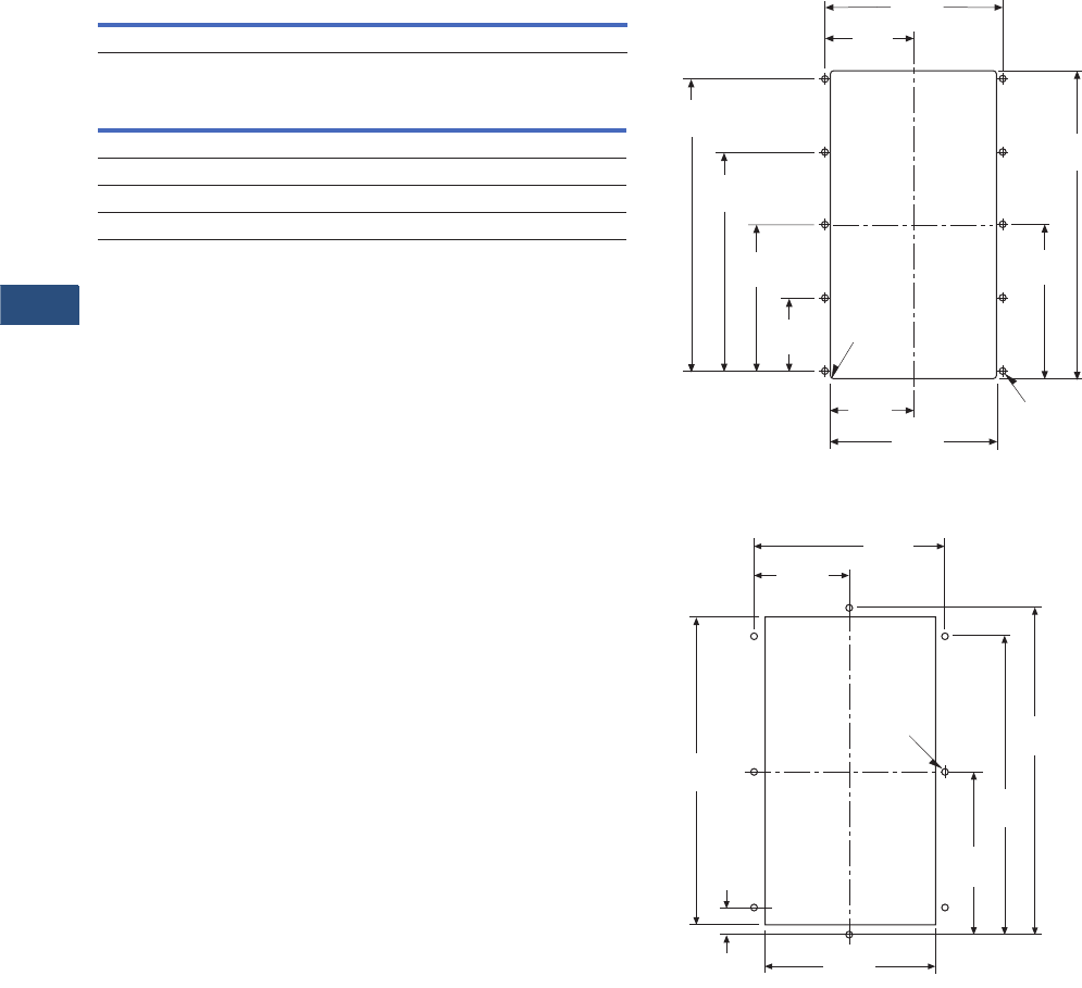
V3-T9-86 Volume 3—Power Distribution and Control Assemblies CA08100004E—November 2013 www.eaton.com
9
9
9
9
9
9
9
9
9
9
9
9
9
9
9
9
9
9
9
9
9
9
9
9
9
9
9
9
9
9
9.3
Metering Devices, Protective Relays, Software and Connectivity
Metering Devices
Approximate Dimensions in Inches (mm)
IQ Analyzer Auxiliary Power Supply
IQ Analyzer 6000 Series
Width Height Depth
Shipping Weight
Lbs (kg)
2.40 (61.0) 4.00 (101.6) 1.11 (28.2) 5.8 (3.6)
Height Width Depth
Without PONI
10.25 (260.4) 6.72 (170.7) 4.70 (119.4)
With PONI
10.25 (260.4) 6.72 (170.7) 5.83 (148.1)
Drilling Pattern
Drilling Pattern for Flange Mounting
5.38
(136.7)
9.38
(238.3)
4.69
(119.1)
2.53
(64.3) 5.06
(128.5)
2.23
(56.7)
4.45
(113.0)
6.68
(169.7)
8.90
(226.1)
.06
(1.5) RAD
4 Places
2.69
(68.3)
.218
(5.5) DIA 10 Places
4.06
(103.1)
10.41
(264.4)
8.11
(206.0)
.213
(5.4)
Typ. for 8 11.03
(280.2)
10.09
(256.3)
5.52
(140.2)
.94
(23.9)
7.41
(188.2)
C
L
C
L

Volume 3—Power Distribution and Control Assemblies CA08100004E—November 2013 www.eaton.com V3-T9-87
9
9
9
9
9
9
9
9
9
9
9
9
9
9
9
9
9
9
9
9
9
9
9
9
9
9
9
9
9
9
9.3
Metering Devices, Protective Relays, Software and Connectivity
Metering Devices
IQ DP-4000
Contents
Description Page
Metering Products Family. . . . . . . . . . . . . . . . . . . . V3-T9-21
Power Xpert Meter 4000/6000/8000 Series . . . . . . V3-T9-30
Power Xpert Meter 2000 Series . . . . . . . . . . . . . . . V3-T9-49
IQ 250/260 Series Electronic Power Meters. . . . . . V3-T9-60
IQ 130/140/150 Series Electronic Power Meters . . V3-T9-66
IQ 150S/250S Self-Enclosed Electronic Meters . . . V3-T9-71
IQ 35M . . . . . . . . . . . . . . . . . . . . . . . . . . . . . . . . . . V3-T9-76
IQ Analyzer 6400/6600 Series . . . . . . . . . . . . . . . . V3-T9-79
IQ DP-4000 Series
Features, Benefits and Functions . . . . . . . . . . . V3-T9-88
Standards and Certifications . . . . . . . . . . . . . . . V3-T9-88
Product Selection. . . . . . . . . . . . . . . . . . . . . . . . V3-T9-89
Accessories . . . . . . . . . . . . . . . . . . . . . . . . . . . . V3-T9-89
Technical Data and Specifications . . . . . . . . . . . V3-T9-90
Dimensions . . . . . . . . . . . . . . . . . . . . . . . . . . . . V3-T9-92
IQ 230 Meters . . . . . . . . . . . . . . . . . . . . . . . . . . . . V3-T9-93
Power Xpert Multi-Point Meter . . . . . . . . . . . . . . . . V3-T9-100
IQ Energy Sentinel™ . . . . . . . . . . . . . . . . . . . . . . . V3-T9-112
PM3 Monitoring and Metering Module . . . . . . . . . V3-T9-121
Current Transformers (CTs). . . . . . . . . . . . . . . . . . . V3-T9-122
Clamp-On Current Transformers . . . . . . . . . . . . . . . V3-T9-131
IQ Flange . . . . . . . . . . . . . . . . . . . . . . . . . . . . . . . . V3-T9-134
Panel Mounting Adapter Kit . . . . . . . . . . . . . . . . . . V3-T9-135
Enclosed Meters. . . . . . . . . . . . . . . . . . . . . . . . . . . V3-T9-136
IQ DP-4000 Series
Product Description
Eaton’s IQ DP-4000 is a
microprocessor-based
monitoring and protective
device that provides
complete electrical metering
and system voltage
protection. In one compact,
standard package, the IQ
DP-4000 will provide an
alternative to individually
mounted and wired
conventional meters and
switches. The DP-4000 also
monitors Apparent Power
(VA), Reactive Energy
(VAR-hours), Apparent
Energy (VA-hours) and
percent THD to provide the
user with basic power quality
information. The IQ DP-4000
meets and surpasses
UL/CSA/CE standards.
The IQ DP-4000’s rugged
construction is designed to
withstand harsh conditions
such as temperature
variations, outdoor
applications and industrial
environments. The membrane
faceplate pushbuttons are
easy to use and both the
parameter LED and window
displays are easily visible.
Application Description
●Monitoring of all common
electrical parameters
●Optional protective
alarm functions
Retrofit Opportunities
●Retrofit of existing
electrical distribution
systems with the IQ
DP-4000 for power, quality,
load and energy monitoring
●Mounting flange option
for application where
additional door mounting
space is required; see
Page V3-T9-134

V3-T9-88 Volume 3—Power Distribution and Control Assemblies CA08100004E—November 2013 www.eaton.com
9
9
9
9
9
9
9
9
9
9
9
9
9
9
9
9
9
9
9
9
9
9
9
9
9
9
9
9
9
9
9.3
Metering Devices, Protective Relays, Software and Connectivity
Metering Devices
Features, Benefits and Functions
Historical Values
●Present demand current
(per phase) 5, 10, 15, 20,
25, 30, 45 or 60 minute
windows
●Present demand watts,
VARs and VA 5, 10, 15, 20,
25, 30, 45 or 60 minute
windows:
●Sliding or fixed window
for power Sync pulse
input (Model 4100)
Eaton’s PowerNet
broadcast demand sync
●Minimum and maximum
values current (per phase):
●Voltage (per phase,
L- L , L- N )
●Watts, VARs and VA
●Power factor
(displacement and
apparent)
●Frequency
●Peak values:
●Percent THD parameters
●Demand parameters
Protective and Event Alarming
●Undervoltage
●Overvoltage
●Current phase loss
●Voltage phase loss
●Phase reversal
●Phase unbalance
●Optional current and
powerdemand threshold
Metered and Monitored
Parameters
●rms sensing
●Phase currents
●V o l t s : L- L , L- N
●Power: real, reactive,
apparent
●Energy: real, reactive,
apparent
●Frequency
●Power factor
●% THD: current and
voltage
●Minimum and maximum
values
●Fixed or sliding demand
windows
Communications
●Optional interface
capability to computer
network for data collection,
storage and/or printout
via Eaton’s Power
Management Software
Physical Characteristics
●Large visible LED display
●Membrane Faceplate
NEMA 3R and 12 rated
Alarm and Protective Functions
●Alarm/Protective functions
(all models) include:
●Overvoltage
●Undervoltage
●Current phase loss
●Voltage phase loss
●Phase unbalance
●Phase reversal
●User-programmable alarm
and reset threshold levels
and delay intervals
●Optional current and power
demand threshold
Description of Protection
Functions
Overvoltage
Range 105–140%
(5% increments).
Undervoltage
Range 60–95%
(5% increments).
Phase Unbalance
Deviation between any
two phases percentage of
nominal line voltage preset by
DIP switches. Range 5–40%
(5% increments).
Phase Reversal
Any two phases become
reversed for the selected
delay.
Voltage Phase Loss
Less than 50% of the
nominal line voltage
detected.
Current Phase Loss
Smallest phase current is
less than1/16 of the largest
phase current.
Delay
Allows a delay before an alarm
occurs. (Range 1–20 seconds
in 1 second increments.)
Note: Unit must be powered for
this to occur.
Inputs and Outputs
(4100 Model)
●Three Form C relay outputs
selectable: Trip, Alarm,
kWh pulse initiator
●One synch input for kW
utility demand sync
Standards and Certifications
Listings and Certifications
●UL/cUL/CSA listed
●CE mark EN61010-1,
EN50082-2

Volume 3—Power Distribution and Control Assemblies CA08100004E—November 2013 www.eaton.com V3-T9-89
9
9
9
9
9
9
9
9
9
9
9
9
9
9
9
9
9
9
9
9
9
9
9
9
9
9
9
9
9
9
9.3
Metering Devices, Protective Relays, Software and Connectivity
Metering Devices
Product Selection
IQ DP-4000
Accessories
IQ DP-4000 I/O Module
For applications where field
modification to add or change
Input/Output (I/O) capability
to the IQ DP-4000 is required,
Eaton offers I/O cards. These
field-installable modules can
be easily inserted into an
existing IQ DP-4000 where
input/output application
needs change.
●Power requirements:
10 VA
●Frequency: 50/60 Hz
●Operating temperature:
25°–70°C
●Operating humidity:
0–95% noncondensing
●Dry contact input: 24 Vdc
differential across input pair
of terminals; minimum
pulse width, 50 mS
Description
Catalog
Number
4 indicates an IQ DP-4000 model
x = 0 indicates no I/O; x = 1 indicates I/O
y = 1 indicates separate source supply, 110–240 Vac and 110–250 Vdc
y = 2 indicates 24–48 Vdc power supply,
y = 3 indicates three-phase power supply, 110–600 Vac
IQDP4XY0
Separate source control power without I/O IQDP4010
Separate source control power without I/O, DC supply IQDP4020
Three-phase power supply without I/O IQDP4030
Separate source control power with three Form C relay output contacts and one sync pulse input IQDP4110
Separate source control power with three Form C relay output contacts and one sync pulse input, DC supply IQDP4120
Three-phase power supply with three Form C relay output contacts and one sync pulse input IQDP4130
2 Form C relay outputs for protective alarming functions, 1 Form C relay output selectable for KYZ pulse output or load shedding,
1 demand sync pulse input
DP4IOMOD
IQ flange, to provide extra clearance when mounting IQFLANGE
45-inch (1143.0 mm) extension cable for remote mounting of power module IQA45CABLE
24–48 Vdc separate source power module IQMDCPM
100–240 Vac and 100–250 Vdc separate source power module IQMSSPM
Three-phase, self-powered power module IQM3PPM
INCOM communication module IPONI
RS-485 communication module with Modbus protocol MPONI
IQ DP-4000

V3-T9-90 Volume 3—Power Distribution and Control Assemblies CA08100004E—November 2013 www.eaton.com
9
9
9
9
9
9
9
9
9
9
9
9
9
9
9
9
9
9
9
9
9
9
9
9
9
9
9
9
9
9
9.3
Metering Devices, Protective Relays, Software and Connectivity
Metering Devices
Technical Data and Specifications
Accuracy
●Maintained from 10–250%
of CT primary rating
Current Inputs (Each Channel)
●Nominal full scale current:
5 amperes AC
●Current range for rated
accuracy: 0–15 amperes AC
●Overload withstand:
15 amperes ac continuous
300 amperes AC 1 second
●Burden: 0.003 VA
Voltage Inputs (Each Channel)
●Voltage range (nominal):
90–600 Vac
●Nominal full scale voltage:
120–600 Vac
●Overload withstand:
660 Vac continuous 4 kV
1.2/50 μs
●Burden: three-phase power
module 10 VA
Fuses
Supplied with three-phase
power module only. 3/4
ampere, 600 volt bus type
KTK-R-3/4 (three required).
Contact Rating (Model 4100)
●10 amperes at 120/240 Vac
(resistive)
●10 amperes at 30 Vdc
(resistive)
Compatible with the
Following Systems
●Three-phase, three-wire
●Three-phase, four-wire
Ratings
●Application to 500 kV,
no PTs to 600 volts
●CT ratios selectable from
5:5 A to 12800: 5A
●Standard 120/600 Vac line
three-phase power supply
module. Two separate
source power supply
modules available. One
module from 110– 240 Vac
and 110–250 Vdc; the other
module 24–48 Vdc only
Model 4100 Input and Output
Control Power Input
Displayed Values
Note
All accuracy is measured as a percentage of full scale.
Model Input Output
4000 0 0
4100 1 digital (dry contact) 3 relays
Description Separate Source Self Powered DC Source
Input range, AC
Frequency range
110–240 Vac ±10%
45–66 Hz
110–600 Vac ±10%
45–66 Hz
N/A
N/A
Input range, DC
Burden
110–250 Vac ±10%
10 VA
N/A
10 VA
24–48 Vdc ±20%
10 VA
Description
Displayed Through Eaton’s
PowerNet System Local Display
AC amperes, phases A, B, C ±0.3% ±0.3% ±1 digit
AC voltage, phase A-B, B-C, C-A ±0.3% ±0.3% ±1 digit
Phase A-N, B-N, C-N ±0.3% ±0.3% ±1 digit
Watts ±0.6% ±0.6% ±1 digit
Vars ±0.6% ±0.6% ±1 digit
VA ±0.6% ±0.6% ±1 digit
Watt-hours ±0.6% ±0.6% ±1 digit
VAR-hours ±0.6% ±0.6% ±1 digit
VA-hours ±0.6% ±0.6% ±1 digit
Power factor ±1% ±1%
Frequency ±0.1 Hz ±0.1 Hz
% THD Through 31st harmonic Through 31st harmonic
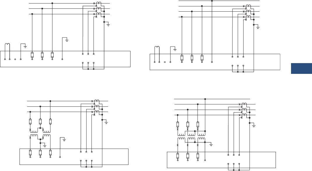
Volume 3—Power Distribution and Control Assemblies CA08100004E—November 2013 www.eaton.com V3-T9-91
9
9
9
9
9
9
9
9
9
9
9
9
9
9
9
9
9
9
9
9
9
9
9
9
9
9
9
9
9
9
9.3
Metering Devices, Protective Relays, Software and Connectivity
Metering Devices
Wiring Diagrams
Field Wiring Connections
H2C
Line Load
C
B
A
L3
L2
L1
Fuse
ABCNeutral
Ter m .
Open Delta
VT Connection
Self-Powered Power Supply Module
HIC HIB HIA
H2B H2A
IQ DP-4000
1CT
2CT
3CT
Fuse
H2C
Line Load
C
B
A
L3
L2
L1
Fuse
ABC
WYE
Connection
Self-Powered Power Supply Module
HIC HIB HIA
H2B H2A
IQ DP-4000
1CT
2CT
3CT
Fuse
Neutral
Term.
N
H2C
Line Load
C
B
A
L3
L2
L1
Fuse
ABC1234
Separate Source Power Supply Module
HIC HIB HIA
H2B H2A
IQ DP-4000
1CT
2CT
3CT
Neutral
Term .
(99 – 275 Vdc)
(99 – 264 Vac)
(24 – 48 Vdc)
Control Power
H2C
Line Load
C
B
A
L3
L2
L1
Fuse
ABC1234 Neutral
Ter m .
(99 – 275 Vdc)
(99 – 264 Vac)
(24 – 48 Vdc)
Control Power
Separate Source Power Supply Module
HIC HIB HIA
H2B H2A
IQ DP-4000
1CT
2CT
3CT
N
Three-Phase Three-Wire (Up to 600 Volts)
Direct Voltage Connection and External Current Transformers
Three-Phase Four-Wire (Up to 600 Volts)
Direct Voltage Connection and External Current Transformers
Three-Phase Three-Wire (Above 600 Volts)
External Voltage Transformers and Current Transformers
Three-Phase Four-Wire (Above 600 Volts)
External Voltage Transformers and Current Transformers
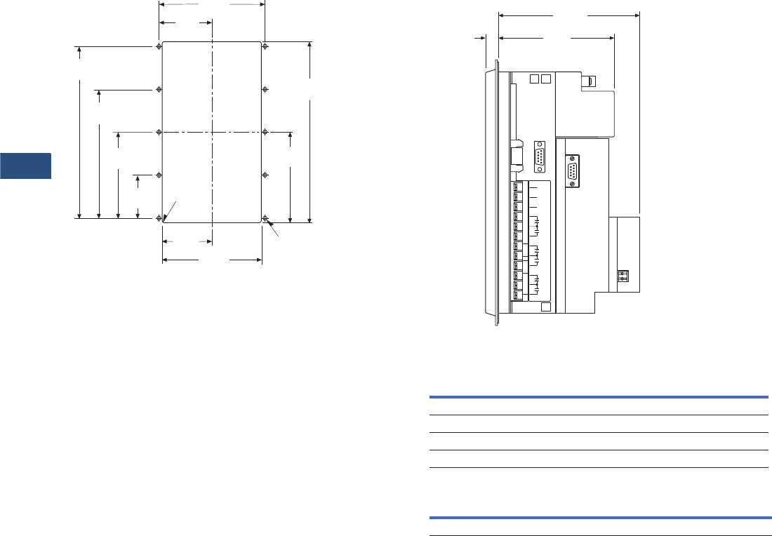
V3-T9-92 Volume 3—Power Distribution and Control Assemblies CA08100004E—November 2013 www.eaton.com
9
9
9
9
9
9
9
9
9
9
9
9
9
9
9
9
9
9
9
9
9
9
9
9
9
9
9
9
9
9
9.3
Metering Devices, Protective Relays, Software and Connectivity
Metering Devices
Dimensions
Approximate Dimensions in Inches (mm)
Drilling Pattern
5.38
(136.7)
9.38
(238.3)
4.69
(119.1)
2.53
(64.3) 5.06
(128.5)
2.23
(56.7)
4.45
(113.0)
6.68
(169.7)
8.90
(226.1)
.06
(1.5) RAD
4 Places
2.69
(68.3)
.218
(5.5) DIA 10 Places
IQ DP-4000 Side View
LED Display
IQ DP-4000 Auxiliary Power Supply
Height Width Depth
Shipping Weight
Lbs (kg)
PONI
10.25 (260.4) 6.72 (170.7) 5.40 (137.2) 6.50 (3.0)
Without PONI
9.02 (229.0) 7.80 (198.1) 4.42 (112.3) 12.5 (5.7)
Width Height Depth
2.40 (61.0) 4.00 (101.6) 1.11 (28.2)
1
2
3
4
5
6
7
8
9
10
11
0.50
(12.7)
Faceplate
With Communication Module
5.40
(137.1)
4.42
(112.3)
Power
Module
P3
Without Communication
Module
Power Module
PONI
Sync. 1/2 Hp @ 240 Vac 1/3 Hp @ 120 Vac
GND Pulse Alarm 1 Alarm 2 MWH Pulse

Volume 3—Power Distribution and Control Assemblies CA08100004E—November 2013 www.eaton.com V3-T9-93
9
9
9
9
9
9
9
9
9
9
9
9
9
9
9
9
9
9
9
9
9
9
9
9
9
9
9
9
9
9
9.3
Metering Devices, Protective Relays, Software and Connectivity
Metering Devices
IQ 230 Digital Meter
Contents
Description Page
Metering Products Family. . . . . . . . . . . . . . . . . . . . V3-T9-21
Power Xpert Meter 4000/6000/8000 Series . . . . . . V3-T9-30
Power Xpert Meter 2000 Series . . . . . . . . . . . . . . . V3-T9-49
IQ 250/260 Series Electronic Power Meters. . . . . . V3-T9-60
IQ 130/140/150 Series Electronic Power Meters . . V3-T9-66
IQ 150S/250S Self-Enclosed Electronic Meters . . . V3-T9-71
IQ 35M . . . . . . . . . . . . . . . . . . . . . . . . . . . . . . . . . . V3-T9-76
IQ Analyzer 6400/6600 Series . . . . . . . . . . . . . . . . V3-T9-79
IQ DP-4000 Series . . . . . . . . . . . . . . . . . . . . . . . . . V3-T9-87
IQ 230 Meters
Features. . . . . . . . . . . . . . . . . . . . . . . . . . . . . . . V3-T9-94
Standards and Certifications . . . . . . . . . . . . . . . V3-T9-94
Product Selection. . . . . . . . . . . . . . . . . . . . . . . . V3-T9-95
Technical Data and Specifications . . . . . . . . . . . V3-T9-96
Dimensions . . . . . . . . . . . . . . . . . . . . . . . . . . . . V3-T9-99
Power Xpert Multi-Point Meter . . . . . . . . . . . . . . . . V3-T9-100
IQ Energy Sentinel™ . . . . . . . . . . . . . . . . . . . . . . . V3-T9-112
PM3 Monitoring and Metering Module . . . . . . . . . V3-T9-121
Current Transformers (CTs). . . . . . . . . . . . . . . . . . . V3-T9-122
Clamp-On Current Transformers . . . . . . . . . . . . . . . V3-T9-131
IQ Flange . . . . . . . . . . . . . . . . . . . . . . . . . . . . . . . . V3-T9-134
Panel Mounting Adapter Kit . . . . . . . . . . . . . . . . . . V3-T9-135
Enclosed Meters. . . . . . . . . . . . . . . . . . . . . . . . . . . V3-T9-136
IQ 230 Meters
Product Description
The IQ 230 is a
microprocessor-
based
metering and monitoring
device. Its compact size and
flexible mounting capabilities
make it suitable for machine
control panels such as
panelboard and switchboard
mains and feeders, low
voltage metal-enclosed
switchgear feeders and
motor control centers. The IQ
230 series meter includes a
base module and a display
module. The IQ 230 base
module has the flexibility to
be directly mounted to the
display or separately panel
mounted. The display is
integrally designed to fit a
standard 1/4 DIN or a
100 mm ANSI cutout for
new retrofit applications.
Application Description
The IQ 230 is ideal for
individual load monitoring
or provides an alternative
to multiple ammeters,
voltmeters, ammeter and
voltmeter switches,
wattmeters, varmeters,
power factor meters,
frequency meters, watthour
and demand meters. ANSI
C12 Class 10 revenue
metering accuracy makes the
IQ 230 ideal for sub-metering
and sub-billing applications.

V3-T9-94 Volume 3—Power Distribution and Control Assemblies CA08100004E—November 2013 www.eaton.com
9
9
9
9
9
9
9
9
9
9
9
9
9
9
9
9
9
9
9
9
9
9
9
9
9
9
9
9
9
9
9.3
Metering Devices, Protective Relays, Software and Connectivity
Metering Devices
Features
The IQ 230 can be easily
programmed from the display
keypad, which features a
4 line x 20 character LED
backlit LCD display. This
menu driven device displays a
variety of selectable electrical
system values and may be
programmed for password
protection.
The IQ 230 series includes
two variations all containing
the same display module.
The IQ 230 has built-in
INCOM communications,
KYZ pulse output, digital
inputs, digital outputs and an
analog input. The IQ 230M
includes all the benefits of
the IQ 230 but replaces
INCOM communication with
Modbus®
●Five different mounting
options
●1/4 DIN standard
3.60 inches (91.4 mm) x
3.60 inches (91.4 mm)
cutout that meets global
standards
●One meter style with
multiple mounting
choices—mount on panel,
DIN rail or back of meter
●Autoranging power supply;
one style for any voltage
up to 600 Vac
●Direct connection up to
600 Vac. PTs are not
required
●AC or DC powered
●Polarity sensing for errors
such as improper wiring
or forward and reverse
power flow
●Membrane faceplate
designed and tested to
meet NEMA® 12 and IP52
●Nonvolatile storage of all
set points and recorded
peaks and minimums
●Built-in INCOM or Modbus
communications capability
●Digital and analog I/O
●Utility seal provision
Monitored Values
●Phase currents
●Voltage, L-L, L-N
●System and per-phase
power including watthours,
varhours and VA-hours
●System demand including
watt demand, VA demand
and VAR demand
●Apparent and
displacement power factor
●Frequency
●KYZ pulse output is
available for use with a
watthour pulse recorder
or totalizer
●Recorded minimums and
maximums of most values
Standards and Certifications
●UL and cUL listed
●UL file number E185559
●CSA certified (not ANSI
revenue certified as a
single-phase meter)
●CE mark for applications
where European
compliance is required
●IEC 1010-1 (1990) incl.
amend. 1 and 2 (1995)
●EN61010-1 (1993)
●CSA C22.2 #1010.1 (1992)
●UL 3111
Volume 3—Power Distribution and Control Assemblies CA08100004E—November 2013 www.eaton.com V3-T9-95
9
9
9
9
9
9
9
9
9
9
9
9
9
9
9
9
9
9
9
9
9
9
9
9
9
9
9
9
9
9
9.3
Metering Devices, Protective Relays, Software and Connectivity
Metering Devices
Product Selection
IQ 230 Meters
Description
Catalog
Number
IQ 230 complete meter
Includes base, display and 14-inch cable with INCOM Communications, KYZ output, digital inputs,
digital outputs, analog input and utility seal provision
IQ230
IQ 230M complete meter
Includes base, display and 14-inch cable with Modbus communications, KYZ output, digital inputs,
digital outputs, analog input and utility seal provision
IQ230M
IQ 230 base module IQ230TRAN
IQ 230M base module IQ230MTRAN
IQ 200D IQ 210/220 display module IQ200D
3-foot (0.9 m) category 5 cable IQ23CABLE
6-foot (1.8 m) category 5 cable IQ26CABLE
10-foot (3.0 m) category 5 cable IQ210CABLE
IQ 230 Meters

V3-T9-96 Volume 3—Power Distribution and Control Assemblies CA08100004E—November 2013 www.eaton.com
9
9
9
9
9
9
9
9
9
9
9
9
9
9
9
9
9
9
9
9
9
9
9
9
9
9
9
9
9
9
9.3
Metering Devices, Protective Relays, Software and Connectivity
Metering Devices
Technical Data and Specifications
Compatible with the Following Systems:
●Three-phase, three-wire
●Three-phase, four-wire
●Single-phase, two-wire
●Single-phase, three-wire
Current Input (Each Channel)
●Current range: 2 times
●Nominal full scale current: 5 amperes AC
●Overload withstand:10 amperes AC continuous
150 amperes AC, 1 second
●Input impedance: 0.01 ohms
●Burden: 0.025 VA
Voltage Input (Each Channel)
●Voltage range (nominal): 90–600/347 Vac
●Nominal full scale voltage: 120–600/347 Vac
●Overload withstand: 660 Vac continuous,
800 Vac 1 second
●Input impedance: 2 megohm
CT (Primary) Settings
Select from 256 values ranging from 5–8000 amperes
●PT Primary 256 values with ratios up to 200 kV
Environmental Conditions
Frequency Range
50/60 Hz
Control Power Input
EMC
●Emissions
FCC Part 15 Class A
CISPR 11 (1990)/EN55011 (1991) Group 1 Class A
●Immunity
Electrostatic discharge
EN61000-4-2 (1995)/EN50082-2 (1995)
4 kV contact discharge
8 kV air discharge
Electrical fast transient
EN61000-4-4 (1995)/EN50082-2 (1995)
2 kV power lines
2 kV signal lines
Radiated immunity
EN61000-4-3 (1997)/EN50082-2 (1995)
10V/m
Conducted immunity
EN61000-4-6 (1996)/EN50082-2 (1995)
10V rms
Power frequency magnetic field
EN61000-4-8 (1995)
30 A/m
Metered Values and Accuracies at Full Scale
Communications
INCOM compatible 1200/9600 baud
●(IQ 230 only—does not require IPONI)
Modbus compatible 9600/19200 baud
●(IQ 230M only—does not require PONI)
Input/Output
KYZ solid-state relay output
●96 mA at 240 Vac/300 Vdc
●Digital input 96 mA at 12–48 Vdc
●Digital output 96 mA at 125 Vac/176 Vdc
●Analog input 4–20 mA
Base Display
Operating temperature –20°C to 50°C 0°C to 50°C
Storage temperature –30°C to 85°C –20°C to 60°C
Operating humidity 0.0% to 95% noncondensing —
Maximum relative humidity 80% up to 31°C —
Vac Vdc
IQ 230 100–600 ±10% 48–250 ±10%
Frequency range 50–60 Hz ±10% —
Burden 180 mA 700W
Accuracy
AC ampere Phase A
Phase B
Phase C
±0.5%
AC voltage
Phase A-B
Phase B-C
Phase C-A
Phase A
Phase B
Phase C
±0.5%
Watts ±1.0%
VARs ±1.0%
VA ±1.0%
Watthours ±1.0%
VAR-hours ±1.0%
VA-hours ±1.0%
Power factor ±2.0%
Frequency ±0.1%
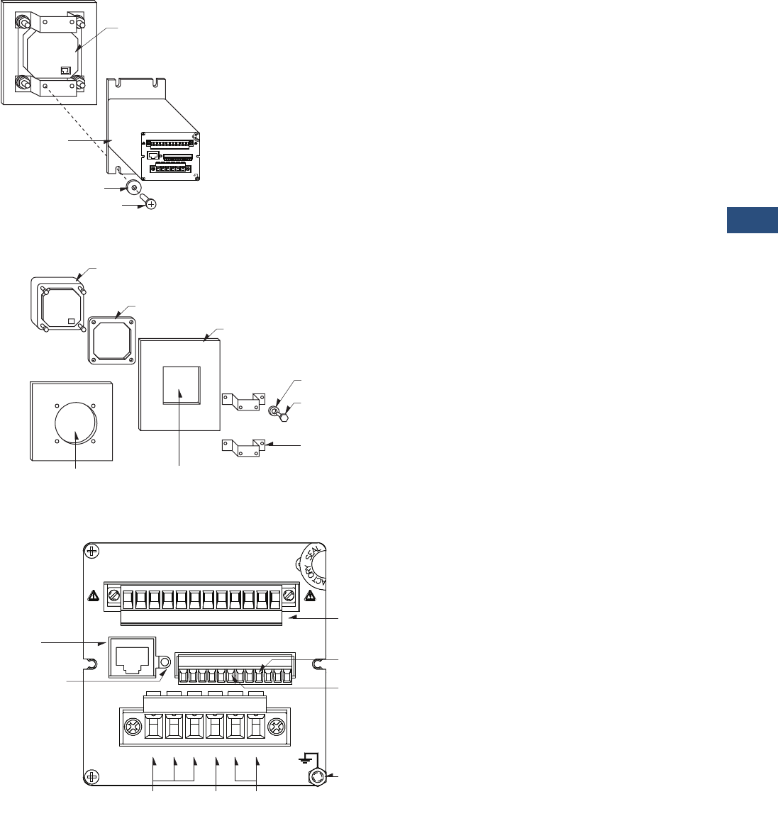
Volume 3—Power Distribution and Control Assemblies CA08100004E—November 2013 www.eaton.com V3-T9-97
9
9
9
9
9
9
9
9
9
9
9
9
9
9
9
9
9
9
9
9
9
9
9
9
9
9
9
9
9
9
9.3
Metering Devices, Protective Relays, Software and Connectivity
Metering Devices
Mounting the IQ 230 Base Module
to the IQ 230 Display Module
Display Mounting Options
IQ 230 Base Connections
#10 Screw
Lock Washer
IQ 230
Base Module
IQ 230 Display
Module—
Mounted in
a Panel
1
A2
A
H
IN2IN1 AN1
DISPLAY
R
TX
A1
121
IIRRI
NEUVBVA VC PS1 PS2
12122
MOD
2
INCOM
1
PULSE
Y2K Z 321
BAB CC
HHH HH
3.9 Inches (100 mm)
ANSI Cutout
.25 Inches (6.4 mm)
Diameter Cutout
or
Mounting Bracket
Hex Nut
Locking Washer
Panel
Gasket
IQ 230 Display Module
1
A2
A
H
IN2IN1 AN1
DISPLAY
R
A1
121
IIRRI
NEUVBVA VC PS1 PS2
12122
MOD
2
INCOM
1
PULSE
Y2K Z 321
BAB CC
HHH HH
1
A2
A
H
IN2IN1 AN1
DISPLAY
R
TX
A1
121
IIRRI
NEUVBVA VC PS1 PS2
12122
MOD
2
INCOM
1
PULSE
Y2K Z 321
BAB CC
HHH HH
TX
Ground Lug
Connect to
IQ 230 Display
Module
System Current
Transformer Input
IQ 230
Power Supply
Neutral
INCOM™
Transmit LED
INCOM™ Port
System
Voltage Input
K-Y-Z Pulse
Output
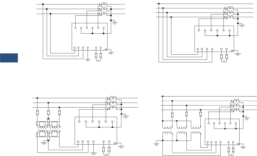
V3-T9-98 Volume 3—Power Distribution and Control Assemblies CA08100004E—November 2013 www.eaton.com
9
9
9
9
9
9
9
9
9
9
9
9
9
9
9
9
9
9
9
9
9
9
9
9
9
9
9
9
9
9
9.3
Metering Devices, Protective Relays, Software and Connectivity
Metering Devices
Wiring Diagrams
Typical Field Wiring Connections
H1A H1B H1C
Line
L3
L2
L1
Control Power
PS1 PS2
VA VB VC NEU
H2A H2B H2C
IQ 230
Load
Open
Delta
PT
Connec-
tion
Case
Ground
must be
connected
for proper
operation
Fuse
Fuse
IQ 230
90–600 Vac
48–250 Vdc
H1A H1B H1C
N
L3
L2
L1
Control Power
PS1 PS2
VA VB VC NEU
H2A H2B H2C
IQ 230
Load
Case
Ground
must be
connected
for proper
operation
Fuse
Line
IQ 230
90–600 Vac
48–250 Vdc
H1A H1B H1C
N
L3
L2
L1
Control Power
PS1 PS2
VA VB VC NEU
H2A H2B H2C
IQ 230
Load
Case
Ground
must be
connected
for proper
operation
Fuse
Line
IQ 230
90–600 Vac
48–250 Vdc
WYE
Connection
Three-Phase Three-Wire (up to 600 Volts)
Proper CT polarity is critical to the proper operation of the meter
Three-Phase Three-Wire (above 600 Volts)
Proper CT polarity is critical to the proper operation of the meter
Three-Phase Four-Wire (up to 600 Volts)
(Line Powered) Proper CT polarity is critical to the proper operation of the meter
Three-Phase Four-Wire (above 600 Volts)
Proper CT polarity is critical to the proper operation of the meter
H1A H1B H1C
L3
L2
L1
Control Power
PS1 PS2
VA VB VC NEU
H2A H2B H2C
IQ 230
Load
Case
Ground
must be
connected
for proper
operation
Fuse
Line
IQ 230
90–600 Vac
48–250 Vdc
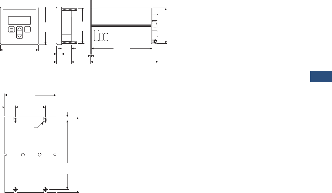
Volume 3—Power Distribution and Control Assemblies CA08100004E—November 2013 www.eaton.com V3-T9-99
9
9
9
9
9
9
9
9
9
9
9
9
9
9
9
9
9
9
9
9
9
9
9
9
9
9
9
9
9
9
9.3
Metering Devices, Protective Relays, Software and Connectivity
Metering Devices
Dimensions
Approximate Dimensions in Inches (mm)
IQ 230
Mounting Hole Pattern for the IQ 230 Base Module
0.97
(24.6)
1.84
(46.7)
0.50
(12.7) 0.06
(1.5)
4.33
(110.0)
4.33
(110.0)
6.74
(171.2)
6.06
(154)
3.62
(92.0)
IQ 200
Scroll
Menu Enter
3.62
(92.0)
4.55
(115.6)
5.05
(128.3)
2.00
(50.8)
3.55
(90.2)
.78
(19.8)
Slot Size
.125 (3.2) Radius
(4 places)
.25
(6.35)
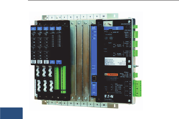
V3-T9-100 Volume 3—Power Distribution and Control Assemblies CA08100004E—November 2013 www.eaton.com
9
9
9
9
9
9
9
9
9
9
9
9
9
9
9
9
9
9
9
9
9
9
9
9
9
9
9
9
9
9
9.3
Metering Devices, Protective Relays, Software and Connectivity
Metering Devices
Power Xpert Multi-Point Meter
Contents
Description Page
Metering Products Family. . . . . . . . . . . . . . . . . . . . . V3-T9-21
Power Xpert Meter 4000/6000/8000 Series. . . . . . . V3-T9-30
Power Xpert Meter 2000 Series . . . . . . . . . . . . . . . . V3-T9-49
IQ 250/260 Series Electronic Power Meters . . . . . . V3-T9-60
IQ 130/140/150 Series Electronic Power Meters . . . V3-T9-66
IQ 150S/250S Self-Enclosed Electronic Meters . . . . V3-T9-71
IQ 35M . . . . . . . . . . . . . . . . . . . . . . . . . . . . . . . . . . . V3-T9-76
IQ Analyzer 6400/6600 Series . . . . . . . . . . . . . . . . . V3-T9-79
IQ DP-4000 Series . . . . . . . . . . . . . . . . . . . . . . . . . . V3-T9-87
IQ 230 Meters . . . . . . . . . . . . . . . . . . . . . . . . . . . . . V3-T9-93
Power Xpert Multi-Point Meter
IQ Energy Sentinel™ . . . . . . . . . . . . . . . . . . . . . . . . V3-T9-112
PM3 Monitoring and Metering Module . . . . . . . . . . V3-T9-121
Current Transformers (CTs). . . . . . . . . . . . . . . . . . . . V3-T9-122
Clamp-On Current Transformers. . . . . . . . . . . . . . . . V3-T9-131
IQ Flange . . . . . . . . . . . . . . . . . . . . . . . . . . . . . . . . . V3-T9-134
Panel Mounting Adapter Kit . . . . . . . . . . . . . . . . . . . V3-T9-135
Enclosed Meters . . . . . . . . . . . . . . . . . . . . . . . . . . . V3-T9-136
Power Xpert Multi-Point Meter
Product Overview
Eaton’s Power Xpert™ Multi-
Point Meter is an ANSI
C12.20 revenue class Web-
enabled electronic
submetering device that can
be mounted in panelboards
switchboards or enclosures.
When mounted in a
panelboard or a switchboard,
the Power Xpert Multi-Point
Meter provides customers
with an integrated power
distribution and energy
metering solution that saves
space, reduces installation
labor and lowers total cost.
The Eaton Power Xpert Multi-
Point Meter (PXMP Meter)
offers a highly modular
approach to high-density
metering applications in
electrical power distribution
systems. The PXMP Meter is
compatible with most three-
phase industrial, commercial
and single-phase residential
low voltage electrical power
systems. The PXMP is
equipped with two Modbus®
RTU communication ports for
local display and remote serial
communications. The PXMP
also has optional pulse input
and digital output modules
along with one standard
digital output and three digital
inputs. The PXMP Energy
Portal Module is Web
enabled, making it suitable for
use with Ethernet networks
and modems.
Product Description
The Power Xpert Multi-Point
Meter can measure up to any
of the following number of
circuits:
●Sixty single-phase,
two-wire (single-pole)
●Thirty single-phase,
three-wire (two-pole)
●Twenty three-phase,
four-wire (three-pole)
The circuits listed above can
be mixed provided that the
total number of current
sensors does not exceed 60.
The meter provides current;
voltage; power factor;
demand and active, reactive,
and real power (VA, VAR, kW);
and active, reactive, and real
energy (VA, VAR, kWh)
measurements for each load.
The unit also provides up to
two years at 15-minute
intervals or eight years at one-
hour intervals of demand data
logging storage in non-volatile
memory for up to 60
submeters.
The Power Xpert Multi-Point
Meter can be used with three
different ratings of current
sensors: 100 mA, 10 mA or
333 mV. Switchboard/
panelboard applications will
use the 100 mA current
sensors, which are highly
accurate, self-protecting in the
event of an open circuit
condition under load and are
supplied with an integral plug-
in connector. The PXMP
automatically detects the
rating of the current sensor
that is connected.
The PXMP can also use 10 mA
current sensors that were
previously installed for
IQMESII retrofit applications.
Additionally, the PXMP can
use 333 mV split core current
sensors for retrofit
applications where metering
has not previously existed.
The 10 mA and 333 mV
current sensors are also self-
protecting in the event of an
open circuit condition under
load.

Volume 3—Power Distribution and Control Assemblies CA08100004E—November 2013 www.eaton.com V3-T9-101
9
9
9
9
9
9
9
9
9
9
9
9
9
9
9
9
9
9
9
9
9
9
9
9
9
9
9
9
9
9
9.3
Metering Devices, Protective Relays, Software and Connectivity
Metering Devices
Application Description
The Power Xpert Multi-Point
Meter is ideally suited to
handle submetering in low
voltage power distribution
equipment applications such
as distribution boards in
multi-tenant buildings,
comprehensive main and
feeder metering in
commercial/industrial
switchboards or medium
voltage distribution
equipment with the use of
voltage and current
transformers.
The Power Xpert Multi-Point
Meter provides a cost-
effective solution for
residential or commercial
metering installations. Typical
installations include:
●High-rise buildings
●Government institutions
●K–12, universities and
campuses
●Office buildings
●Medical facilities
●Apartment and
condominium complexes
●Airports
●Shopping malls
●Industrial sites
●Mixed-use facilities
Features
●Monitors power and
energy for up to 60 current
sensors; space-saving
modular design allows
measurement from 1 to 60
circuits
●Built-in communication
interfaces
●Monitors single-phase and
three-phase loads from 120
to 600 Vac
●Monitors current, voltage,
power factor, frequency,
power and energy
●Stores extensive energy
profile data for each
metering point; can be
used to identify
coincidental peak
demand contribution
●LEDs provide status of unit
communication activity and
verify sensor connections
●Meets rigid ANSI C12.20
accuracy specifications for
revenue meters
●Three standard digital
inputs and eight pulse
inputs per optional module
to monitor WAGES (water,
air, gas, electric, or steam)
●One standard digital output
and eight digital outputs
per optional module for
alarm indication
●Three types of meter
modules to support 10 mA,
100 mA or 333 mV sensors
●Can be directly mounted in
a UL Listed panelboard,
switchboard or enclosure
●256 MB of memory in
meter base for up to two
years of 15-minute interval
data (eight years of one-
hour interval data) for eight
demand values up to
60 submeters
Communication Capabilities
With the Power Xpert Multi-
Point Meter’s built-in
communication capabilities,
remote meter reading and
monitoring functions can be
integrated into both new and
retrofit applications.
●Standard Modbus RTU
●Optional Modbus TCP /
BACnet/IP / SNMP / HTTP /
SMTP / NTP /SFTP
communications
Software Compatibility
The Power Xpert Multi-Point
Meter:
●Can be used as part of
an electrical energy
monitoring and cost
allocation system
●Can be remotely monitored
via onboard Web pages
with Eaton’s optional
Energy Portal Module
●Is compatible with third-
party software platforms
and interface devices
Configuration
●The Power Xpert Multi-
Point Meter is fully
configurable using Power
Xpert Multi-Point
configuration software that
can be down-loaded free
from the Eaton website at
www.eaton.com/meters
●Each Power Xpert Multi-
Point Meter module can be
configured for up to six
metering points in any
combination of single-
phase and three-phase
metering points
corresponding to the
voltage wiring of the meter
base
●Power Xpert Multi-Point
configuration software
simplifies system
commissioning and
startup; PXMP
configuration software
supports both online and
offline configurations
Easy to Install
●UL Listed for mounting
inside panelboards (e.g.,
PRL4), switchboards, and
NEMA 12 enclosures
●Quick connect terminals
for current sensors,
Modbus communications,
and bus voltages make
wiring the unit quick
and easy
Features
Note
1Main only.
Description Main/Aggregate Channel Data Tenant
Instrumentation
Current, per phase ■ 1■—
Voltage, per phase (L-L, L-N) ■■—
Frequency — ■■
Minimum/maximum readings, V Per phase — —
Minimum/maximum readings, W, VAR, VA Total and per phase — —
Minimum/maximum readings, PF, F Total — —
Power
Real, reactive, and apparent power (W, VAR, VA) Total and per phase Total and per phase Total
Power factor — Average Average
Demand
Block interval (fixed, sliding) ■——
Real, reactive and apparent power demand Total and per phase — —
Minimum/maximum readings, PF, W, VAR, VA Total and per phase Total —
Energy
Real, reactive and apparent energy (Wh, VARh, VAh) Total — Total
Real, forward and reverse, and total (Wh) ■—■

V3-T9-102 Volume 3—Power Distribution and Control Assemblies CA08100004E—November 2013 www.eaton.com
9
9
9
9
9
9
9
9
9
9
9
9
9
9
9
9
9
9
9
9
9
9
9
9
9
9
9
9
9
9
9.3
Metering Devices, Protective Relays, Software and Connectivity
Metering Devices
Standards and Certifications
Environmental
The PXMP Meter and current sensors must be housed in a
NEMA or UL enclosure that keeps the internal environment
within the PXMP’s environmental specification ranges and
provides suitable fire and mechanical protection in the end
product installation.
●Temperature range: –20 to +70°C (–4 to +158°F)
●Storage temperature range: –40 to 85°C
●Humidity: 5–95% noncondensing environment
●Pollution degree: II
●Elevation: 0 to 9843 ft
(0 to 3000m)
●Housing: IP20
●CE Mark
●EMC EN61326
Emissions Conducted and Radiated
●FCC part 15 Class B
●CISPR 11 Class B
Electromagnetic Immunity
Product Safety
●IEC/EN61010-1
●UL 61010-1 File E185559
●CNL evaluation to CAN/C22.2 No 1010.1.92
Accuracy
●ANSI C12.20—Accuracy Class 0.5% with either CSXXX or
PXMP-CSXXX sensors
●Measurement Canada Approval Pending
Standard Description Level
EN61000-4-2 ESD 3
EN61000-4-3 RF radiated 3
EN61000-4-4 Electrical fast transient 3
EN61000-4-5 Surge 3 1
EN61000-4-6 RF conducted 3
EN61000-4-11 Volt sag/swell/variation —
Product Selection
The Power Xpert Multi-Point Meter, current sensors, and other
accessories can be ordered from Eaton distributors. Refer to the
following catalog numbers when ordering.
Power Xpert Multi-Point Meter Products
Note
Total sensor lead length must not exceed 28 ft (8.5m).
Product Description Catalog Number
Meter Bases and Meter Modules with ABCN Voltage Inputs
PXMP meter base—three-phase with ABCN voltage inputs PXMP-MB
PXMP meter module with six 100 mA inputs
for use with PXMP current sensors
PXMP-MM100MA
PXMP meter module with six 10 mA inputs
for use with IQMESII current sensors
PXMP-MM10MA
PXMP meter module with six 333 mV inputs
for use with 333 mV current sensors
PXMP-MM333MV
Meter Bases and Meter Modules with ABN Voltage Inputs
PXMP meter base—single-phase, three-wire
with ABN voltage inputs
PXMP-MB-AB
PXMP meter module with six 100 mA inputs
for use with PXMP current sensors
PXMP-MM100MA-AB
PXMP meter module with six 10 mA inputs for use with IQMESII
current sensors
PXMP-MM10MA-AB
PXMP meter module with six 333 mV inputs for use with
333 mV current sensors
PXMP-MM333MV-AB
IO Modules
PXMP meter pulse input module with eight inputs PXMP-PIM
PXMP meter digital output module with eight outputs PXMP-DOM
Communication Module
PXMP meter energy portal module PXMP-EPM
Current Sensor Kits
KIT, PXMP CS125 sensor, quantity of 3 PXMP-CS125-3
KIT, PXMP CS250 sensor, quantity of 3 PXMP-CS250-3
KIT, PXMP CS400 sensor, quantity of 3 PXMP-CS400-3
Current Sensor Cable Kits
KIT, PXMP sensor cable, 4 ft (1.2m), quantity of 3 PXMP-SC4-3
KIT, PXMP sensor cable, 6 ft (1.8m), quantity of 3 PXMP-SC6-3
KIT, PXMP sensor cable, 8 ft (2.4m), quantity of 3 PXMP-SC8-3
KIT, PXMP sensor cable, 12 ft (3.7m), quantity of 3 PXMP-SC12-3
Current Sensor Extension Cable Kits
KIT, PXMP sensor extension cable, 8 ft (2.4m), quantity of 3 PXMP-SCE-8-3
KIT, PXMP sensor extension cable, 16 ft (4.9m), quantity of 3 PXMP-SCE-16-3
Interface Modules
PXMP current sensor interface module for 333 mV, kit X 3 PXMP-IM333MV-3

Volume 3—Power Distribution and Control Assemblies CA08100004E—November 2013 www.eaton.com V3-T9-103
9
9
9
9
9
9
9
9
9
9
9
9
9
9
9
9
9
9
9
9
9
9
9
9
9
9
9
9
9
9
9.3
Metering Devices, Protective Relays, Software and Connectivity
Metering Devices
The Pulse Input Module (PXMP-PIM) can be used to totalize
pulse outputs from water meters, gas meters, steam meters or
even old electrical meters with KZ pulse outputs. The PXMP-PIM
can also be used for status monitoring in applications where
status indication updates of 6 seconds over Modbus satisfies
the application requirement.
Support products for the Power Xpert Multi-Point Meter include
the HMI display, IMPCABLE and power supplies as described in
the table below.
Power Xpert Multi-Point Meter Support Products
Meter Selection
Note
1For applications requiring more than 2000A current sensors, use a CS005 with 5A CT in conjunction with PXMP-MM10MA.
Product Description Catalog Number
Communication cable, 1000 ft (305m), 600V insulation IMPCABLE
PXMP meter display—6-inch color touchscreen (with cable) PXMP-DISP-6
Power supply—single-phase 90–264 Vac, 24 Vdc at 2.5A PSG60E
Power supply—three-phase 360–575 Vac, 24 Vdc at 2.5A PSG60F
Power supply—three-phase 600 Vac, 24 Vdc PSS55D
Meter Base Typical Applications
Meter Module
Three-Phase
Application or
Single-Phase
with ABCN
Single-Phase
Application
with ABN
New Switchboards
PXMP Current
Sensors,
Solid Core,
PXMP-CSXXX, Ampere
Ratings
Retrofit Existing
IQMESII
Sensors,
Solid Core,
CS-XXX,
Ampere Ratings
Enclosed PXMP
333MV
Sensors,
Split Core,
CS-SP-X-XXXX-333MV,
Ampere Ratings
Enclosed PXMP
Interface
Modules
PXMP-MM100MA PXMP-MB — 125, 250, 400 — — —
PXMP-MM333MV PXMP-MB — — — 100, 200, 300, 400, 600, 800, 1000, 1200,
1600, 2000 1
PXMP-IM333MV
PXMP-MM10MA PXMP-MB — — 5, 50, 70, 125, 200, 400 — —
PXMP-MM100MA-AB — PXMP-MB-AB 125, 250, 400 — — —
PXMP-MM333MV-AB — PXMP-MB-AB — — 100, 200, 300, 400, 600, 800, 1000, 1200,
1600, 2000 1
PXMP-IM333MV
PXMP-MM10MA-AB — PXMP-MB-AB — 5, 50, 70, 125, 200, 400 — —

V3-T9-104 Volume 3—Power Distribution and Control Assemblies CA08100004E—November 2013 www.eaton.com
9
9
9
9
9
9
9
9
9
9
9
9
9
9
9
9
9
9
9
9
9
9
9
9
9
9
9
9
9
9
9.3
Metering Devices, Protective Relays, Software and Connectivity
Metering Devices
Technical data and Specifications
External Circuit Group Specifications
PXMP-MB (-AB) Meter base
Discrete Output
●Quantity 1—solid-state relay Form A NO Bidirectional FET
●Polarity of external source is not important
●Isolation circuit to ground 2 kV/1 min.
●Maximum external source voltage 28 Vdc
●Line-to-line TVS clamp across switching element at 32 Vdc
●Solid-state relay on resistance 35 ohms maximum
●Maximum load current 80 mA
●Minimum pulse width 20 milliseconds
●Fixed 25 milliseconds for pulse initiator function
●Maximum pulse rate 25 Hz
●Wiring to two-position removable terminal plug
●12–18 AWG (3.31–0.82 mm2), wire ferrules recommended
●T1 (polarity not important)
●T2 (polarity not important)
Discrete Inputs
●Quantity 3, common circuits inputs 1–3
●Group isolation 2 kV
●No input-to-input circuit isolation
●All inputs per module share a common external
24V (±10%) supply
●24V externally sourced between common and inputs
●Design to interface with external dry contact
●Input impedance ~2.2K ohms
●Input current draw ~10 mA per input
●Minimum pulse width 10 milliseconds
●Maximum pulse rate 20 Hz
●Wiring to four-position removable terminal plug
●12–18 AWG (3.31–0.82 mm2), wire ferrules recommended
●T3—Common (connect ext. 24 common here)
●T4—Input 1 (dry contact to 24V hot)
●T5—Input 2 (dry contact to 24V hot)
●T6—Input 3 (dry contact to 24V hot)
COM1 and COM2 RS-485 Serial Ports
●No D+/D– biasing reliance on fail-safe driver and biasing at
Master
●Baud rate configurable between 9600–115K baud (default)
●Use cable designed for RS-485 communications
●Low L:L capacitance
●Impedance of ~100–120 ohms
●Shield—Mylar for high frequency; Braid for low frequency
●Separate common and shield for best noise immunity
●Maximum cable length is 4000 ft (1219.2m) with 32 nodes
at 19.2K baud increased data rates will reduce maximum
cable distance
●2000 ft (609.6m) with 32 total nodes at 115.2K baud
●Isolation 300V to ground due to TVS diode clamps
●Modbus RTU slave protocol, address defined by rotary switch
●Green Rx and Red Tx LEDs per channel
●Data + > Data—during idle marked, logic 1 state
●End of Line Termination resistance should match cable
impedance (typ. 100–120 ohms)
●Four-position removable terminal plug 18–22 AWG (0.82–0.33
mm2) typical, wire ferrules recommended
●COM1
– T7—Shield
– T8—RS-485 common
– T9—Data –
– T10—Data +
●COM2
– T11—Shield
– T12—RS-485 common
– T13—Data –
– T14—Data +
PXMP-MB Power Supply Input
●24 Vdc ±20%
●15W maximum load
●1 kV isolation barrier internal to PXMP-MB
●Externally fuse circuit to protect wire
●Green power OK LED
●Three-position terminal block 16–12 AWG (1.31–3.31 mm2),
wire ferrules recommended
●T15—24 Vdc – (common)
●T16—24 Vdc + (Hot)
●T17—Shield (optional) capacitively referenced to chassis
ground for enhanced EMC performance
Meter Voltage Inputs
●Overvoltage CAT III
●Maximum voltage rating
●480VL:G (corner grounded delta)
●347VL:N
●600VL:L
●Frequency rating 47–63 Hz
●Metering range (temporary transitions)
●30–700VL:N
●30–700VL:L
●Abuse withstand rating 1000V sustained
●High pot withstand rating 2500V/1min
●Input impedance 4M ohms
●Fuse inputs rated to protect wiring to mains. External fuses
●must be installed between the meter voltage terminal and the
mains disconnect switch to the main lines to protect the lines.
600V 1 A BUSS type KTK-R-1 Fast Acting or equivalent fuses
●are recommended.
●Wiring to removable terminal plug 10–18 AWG (5.26–0.82
mm2), wire ferrules recommended
●T18—N (VR)
●T19—C (V3)
●T20—B (V2)
●T21—A (V1)

Volume 3—Power Distribution and Control Assemblies CA08100004E—November 2013 www.eaton.com V3-T9-105
9
9
9
9
9
9
9
9
9
9
9
9
9
9
9
9
9
9
9
9
9
9
9
9
9
9
9
9
9
9
9.3
Metering Devices, Protective Relays, Software and Connectivity
Metering Devices
PXMP meter modules (PXMP-MMs)
Compatible with all PXMP Meter Base slots 1–10 LED
indicators:
●Health and status green, blink to show activity
●Pulse energy output one red per group of three loads
●Load energy direction red/green pair per load
All variations support six load inputs.
Current sensor connection is one 2 x 2 connector per load.
Compatible with PXMP-SCXX sensor cables, total cable length
to the sensor should not exceed 28 ft (8.5m).
Note that -AB suffix only affects what voltage channels the loads
are paired with for metering purposes.
PXMP-MM10MA supports the CSXXX series of 10 mA
maximum secondary output current transformers.
PXMP-MM100MA supports the PXMP-CSXXX series of 100 mA
maximum secondary output current transformers.
PXMP-MM333MV supports 333 mV maximum secondary
output current transformers with the use of the PXMP-
IM333MV interface module.
PXMP digital output module (PXMP-DOM)
●Compatible with all PXMP-MB slots 1–10
●LED indicators
●Health and status green, blink to show activity
●Output On/Off status one green per output
●Eight individual solid-state relay outputs
●Each circuit rated for 24 Vdc (±20%) with an 80 mA load
maximum
●24 Vdc is externally sourced
●Group isolation to ground 2 kV
●Each circuit has its own separate common, circuit-to-circuit
isolation 120V
●16-position removable terminal plug
●12–18 AWG (3.31–0.82 mm2), wire ferrules recommended
PXMP pulse input modules (PXMP-PIMs)
●Compatible with all PXMP-MB slots 1–10
●LED indicators
●Health and status green, blink to show activity
●Input On/Off status one green per pulse input
●Eight pulse inputs to external dry contacts
●Maximum pulse rate is 20 Hz
●Minimum pulse width is 20 milliseconds
●External circuit groups rated for 24 Vdc (±20%)
●All circuits share the same electrical common
●External supply connects to the module with a two-position
removable terminal plug
●The supply is internally fanned out to all circuits
●Group isolation limited to 300V to ground due to TVS diode
clamp
●Input impedance ~2.2K causing a 10 mA load per input when
energized
●External circuit groups connect with a 16-position removable
terminal plug
●Terminals support 12–18 AWG (3.31–0.82 mm2), wire
ferrules recommended
PXMP energy portal module (PXMP-EPM)
●Only functionally compatible with PXMP-MB slot 10
●LED indicators
●Top health and status green, blink to show activity
●Com. reset button—reset to defaults
●Local IP 192/10
●RJ45 front-facing Ethernet configuration port LEDs
– Link (Tx/Rx blink)
– 10/100 speed
●LED four-stack for bottom LAN/WAN Ethernet port
●Link (Tx/Rx blink)
●10/100 speed
●DHCP/Fixed
●TX active
●Config. Ethernet RJ45 Cat5 STP/UTP
●10Base-T/100Base-Tx
●Auto crossover capability supported
●Java Web browser interface
●Bottom facing LAN/WAN Ethernet port
●RJ45 Cat5 STP/UTP 10Base-T/100Base-Tx
●STP required for full electromagnetic immunity
●Auto crossover capability supported
●Supports Modbus TCP and Java Web browser interface
●Bottom-facing telephone modem interface
●Modem type V92/56K baud
●RJ11 field interface

V3-T9-106 Volume 3—Power Distribution and Control Assemblies CA08100004E—November 2013 www.eaton.com
9
9
9
9
9
9
9
9
9
9
9
9
9
9
9
9
9
9
9
9
9
9
9
9
9
9
9
9
9
9
9.3
Metering Devices, Protective Relays, Software and Connectivity
Metering Devices
Power Xpert Multi-Point Meter System—Hardware Specifications
Notes
1DC.
2AC RMS.
Components
Field
Circuit
Power
Source
Rated
Voltage
Rated
Current
Circuit
Impedance Isolation Note 1 Note 2
PXMP-MB
PXMP-MB-AB
Digital output External 24 ±20% 10.080A
maximum
35 ohms
maximum
2.0 kV — —
Digital input External 24 ±20% 10.01A 2.22K 2.0 kV Opto drops supply by 2V Group are electrically common
COM1 RS-485 Internal 5V 1— 50–60 ohms 300V TVS diode clamped to PE —
COM2 RS-485 Internal 5V 1— 50–60 ohms 300V TVS diode clamped to PE —
Power supply
input
External 24 ±20% 10.7A
maximum
N/A 1.0 kV Installation Class II input 15W maximum
Voltage inputs
A (V1)/ B (V2)/
C (V3)/ N (VR)
External
mains
480V L:G 20.12 mA 4M ohms N/A Installation Class III High pot 2500V/1 minimum
347V L:N 20.09 mA 4M ohms N/A Installation Class III High pot 2500V/1 minimum
600V L:L 20.09 mA 4M ohms N/A Installation Class III High pot 2500V/1 minimum
PXMP-MM100MA CT secondary External N/A 100 mA 14.6 ohms N/A 20% over-range See sensor for primary isolation
PXMP-MM10MA CT secondary External N/A 10 mA 67 ohms N/A 20% over-range See sensor for primary isolation
PXMP-MM333MV CT secondary External 0.333V 2N/A 50,000 ohms N/A 20% over-range See sensor for primary isolation
PXMP-DOM Digital output External 24 ±20% 10.080A
maximum
10 ohms
maximum
2 kV group 120V isolation
circuit-to-circuit
Isolation dependent on
external source
PXMP-PIM Pulse input External 24 ±20% 10.01A 2.22K ohms 300V to ground TVS diode clamped to PE;
group isolated, all circuits common
to 24V external source
Note: Opto creates 2.2V drop
sourced by 2.2K ohms; isolation
dependent on external source
PXMP-EPM Ethernet 100 Bt Internal — N/A N/A 1 kV — —
POT modem Internal — N/A N/A — — —
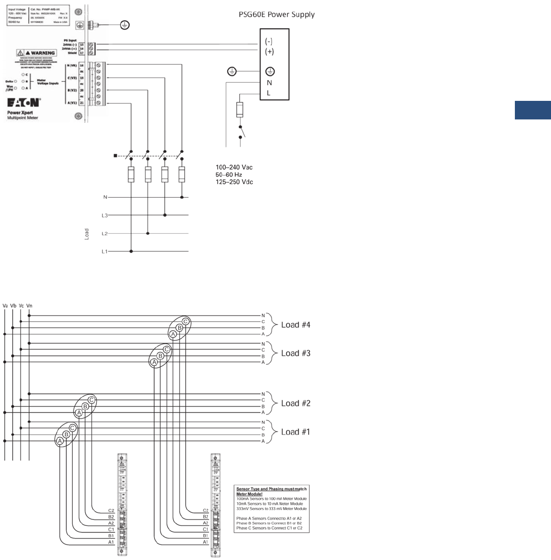
Volume 3—Power Distribution and Control Assemblies CA08100004E—November 2013 www.eaton.com V3-T9-107
9
9
9
9
9
9
9
9
9
9
9
9
9
9
9
9
9
9
9
9
9
9
9
9
9
9
9
9
9
9
9.3
Metering Devices, Protective Relays, Software and Connectivity
Metering Devices
Wiring Diagrams
Wiring for PXMB-MB
Note: For all voltage connections—fuses should be sized in accordance with best practices to protect the instrumentation wire.
Four-Wire Wye Voltage Connection Inputs
Three-Phase, Four-Wire Service Current Sensor Connections
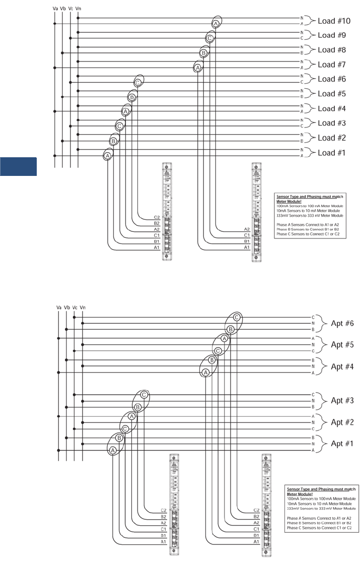
V3-T9-108 Volume 3—Power Distribution and Control Assemblies CA08100004E—November 2013 www.eaton.com
9
9
9
9
9
9
9
9
9
9
9
9
9
9
9
9
9
9
9
9
9
9
9
9
9
9
9
9
9
9
9.3
Metering Devices, Protective Relays, Software and Connectivity
Metering Devices
Three-Phase, Four-Wire Service (Ten Single-Phase, Single-Pole) Current Sensor Connections
Network 120/208 Three-Wire Apartment Service Current Sensor Connections
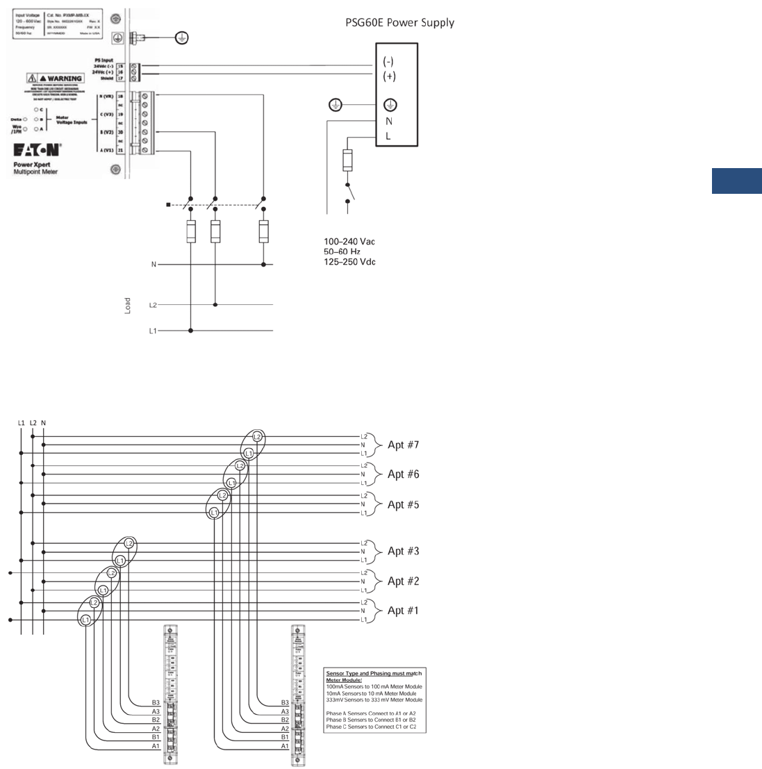
Volume 3—Power Distribution and Control Assemblies CA08100004E—November 2013 www.eaton.com V3-T9-109
9
9
9
9
9
9
9
9
9
9
9
9
9
9
9
9
9
9
9
9
9
9
9
9
9
9
9
9
9
9
9.3
Metering Devices, Protective Relays, Software and Connectivity
Metering Devices
Wiring for PXMB-MB-AB
Note: For all voltage connections—fuses should be sized in accordance with best practices to protect the instrumentation wire.
Single-Phase, Three-Wire 120/240 Voltage Connection Inputs
120/240 Single-Phase, Three-Wire Service Current Sensor Connections
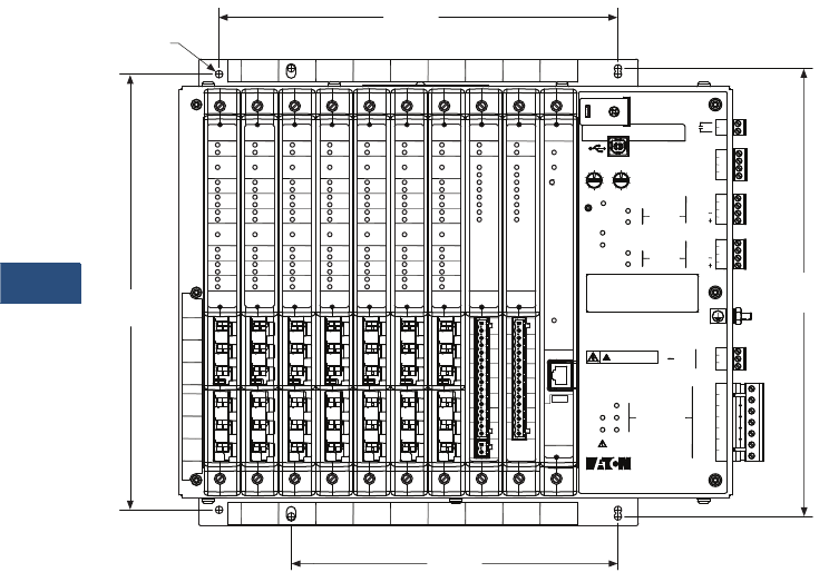
V3-T9-110 Volume 3—Power Distribution and Control Assemblies CA08100004E—November 2013 www.eaton.com
9
9
9
9
9
9
9
9
9
9
9
9
9
9
9
9
9
9
9
9
9
9
9
9
9
9
9
9
9
9
9.3
Metering Devices, Protective Relays, Software and Connectivity
Metering Devices
Dimensions
Approximate Dimensions in Inches (mm)
Single Unit—Front View
2 4567891013
2 4567891013
B1
XX
XX
XX
XX
CT
Inputs
A1
RX
TX
RX
TX
7
8
9
10
11
12
13
14
Shield
Common
Shield
Common
A
B
C
15
16
17
18
nc
19
nc
20
nc
21
-Vdc
+Vdc
Shld
N (VR)
C (V3)
B (V2)
A (V1)
PS Input
64
91
0
3
28
7
5
Slave Address
64
3
28
7
5
901
WARNING
REMOVE POWER BEFORE SERVICING
DO NOT HIPOT / DIELECTRIC TEST
MORE THAN ONE LIVE CIRCUIT. SEE DIAGRAM.
CIRCUITS SOUS TENSION. VOIR LE SCHEMA.
AVERTISSEMENT: CET EQUIPEMENT RENFERME PLUSIEURS
Mode
1
2
3
4
5
6
Common
Input 1
Input 2
Input 3
24Vdc Inputs
24Vdc 80mA Output
Delta
Status
Power
Wye
/1PH
Health
Config. Port
Meter
Base
Voltage Inputs
Meter
(Com 2)
RS-485
(Com 1)
RS-485
D
D
D
D
Rating
24Vdc
15W Max
b
Power Xpert
Multipoint Meter
480V~ L:G Max.
347V~ L:N Max.
600V~ L:L Max.
CAT III
Freq. 47-63 Hz
See manual for complete ratings
11.67
(296.4)
10.67
(271.0)
0.20
(5.1)
Cat. No. PXMP-MB-XX
Style No. 66D2261GXX
FW Version X.X
Date Code: WYYMMDD
Rev. X
SN: XXXXXX
Made in USA
Com
Health
Module
Meter
1
-
+A1
100mA
Sensor
Pulse
-
+B1
-
+XX
-
+XX
-
+XX
-
+XX
2
Pulse
Com
Health
Module
Meter
1
-
+A1
100mA
Sensor
Pulse
-
+B1
-
+XX
-
+XX
-
+XX
-
+XX
2
Pulse
Com
Health
Module
Meter
1
-
+A1
100mA
Sensor
Pulse
-
+B1
-
+XX
-
+XX
-
+XX
-
+XX
2
Pulse
Com
Health
Module
Meter
1
-
+A1
100mA
Sensor
Pulse
-
+B1
-
+XX
-
+XX
-
+XX
-
+XX
2
Pulse
Com
Health
Module
Meter
1
-
+A1
100mA
Sensor
Pulse
-
+B1
-
+XX
-
+XX
-
+XX
-
+XX
2
Pulse
Com
Health
Module
Meter
1
-
+A1
100mA
Sensor
Pulse
-
+B1
-
+XX
-
+XX
-
+XX
-
+XX
2
Pulse
Com
Health
Module
Meter
1
-
+A1
100mA
Sensor
Pulse
-
+B1
-
+XX
-
+XX
-
+XX
-
+XX
2
Pulse
Module
Pulse In
PI1
PI2
PI3
PI4
PI5
PI6
PI7
PI8
Com
Health
PI1 PI2
+
-
PI3 PI4 PI5 PI6 PI7 PI8 24V
1 2 3 4 5 6 7 8 9 101112 1314 1516
24Vdc
O1 O2 O3 O4 O5 O6 O7 O8
Module
Output
O1
O2
O3
O4
O5
O6
O7
O8
Com
Health
12345678910111213141516
24Vdc
80mA Max
Status
Health
Com
Reset
Module
Portal
Modem
LAN
Link
10/100
DHCP
TX ST
LAN
Local IP
192/10
10/100
Link
Local
12.00
(304.8)
8.74
(222.0)
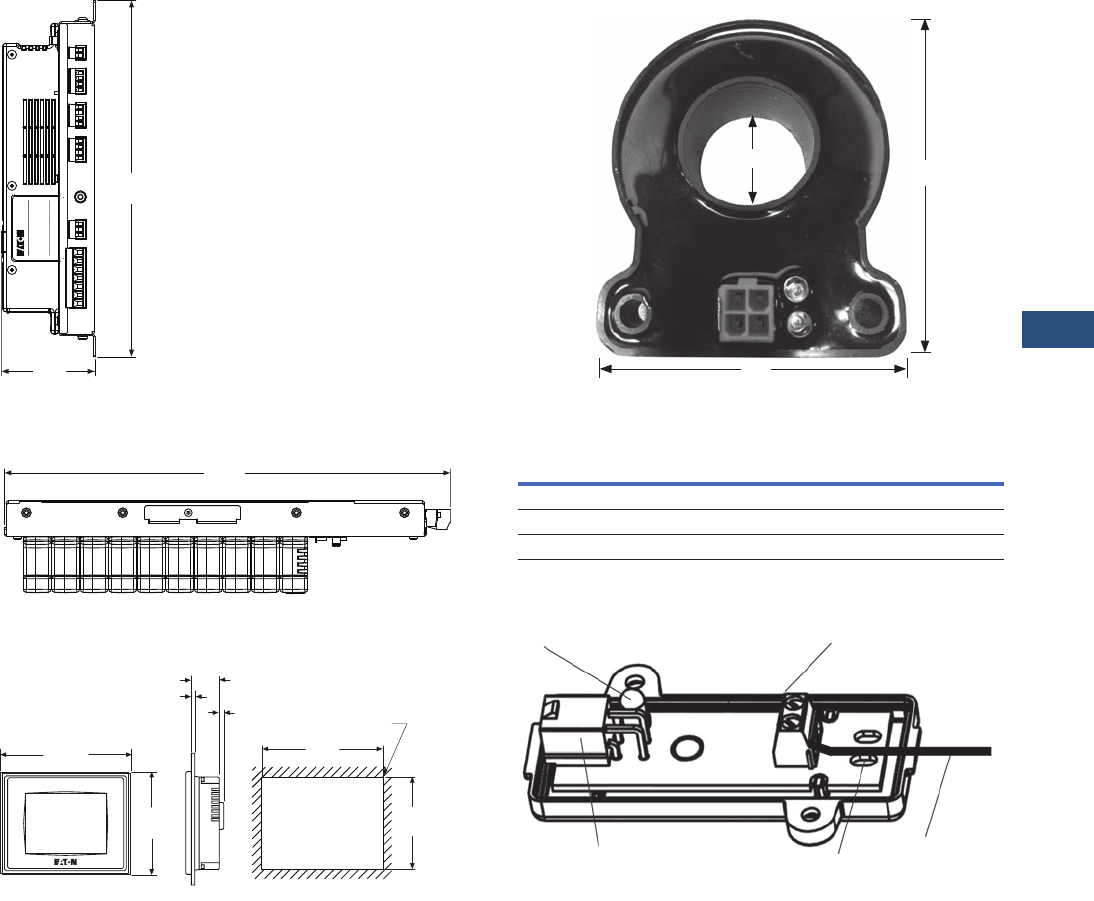
Volume 3—Power Distribution and Control Assemblies CA08100004E—November 2013 www.eaton.com V3-T9-111
9
9
9
9
9
9
9
9
9
9
9
9
9
9
9
9
9
9
9
9
9
9
9
9
9
9
9
9
9
9
9.3
Metering Devices, Protective Relays, Software and Connectivity
Metering Devices
Single Unit—Side View
Single Unit—Top View
PXMP Color Touchscreen Display
3.27
(83.1)
12.50
(317.5)
Cat. No. PXMP-EPM-X
Serial No. XXXXXX FW X.XX
Technical Support 1-800-809-2772
http://www.Eaton.com
Style No. 66D2250G0X Rev. X
Power Xpert
Multipoint Meter
WYYMMDD
Made in USA
15.63
(397.0)
5.21
(132.4)
Cut-Out Dimensions
6.79
(172.4)
0.12 (3.0) R Typ.
6.10
(0.24)
1.54
(39.0)
0.06~0.12
(1.6~3.0)
Outer
7.25
(184.1)
5.67
(144.1)
Current Sensor Dimensions
Current Sensor Dimensions
Open Interface Module (PXMP-IM333MV)
Sensor H W D
PXMP-CS125 2.66 (67.6) 1.66 (42.1) 0.53 (13.5)
PXMP-CS250 2.96 (75.2) 2.42 (61.5) 1.12 (28.4)
PXMP-CS400 3.64 (92.5) 3.03 (73.2) 1.74 (44.2)
H
W
ID
Terminal Block
Blue Locator LED
PXMP-SCX Cable
Connection Strain Relief
Strap Holes
333 mV
Sensor
Secondary
Leads
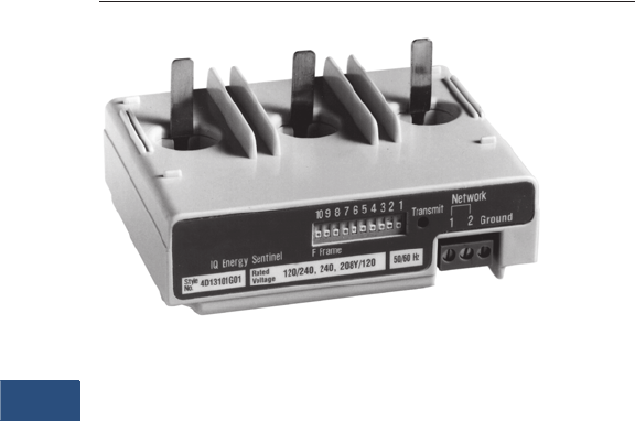
V3-T9-112 Volume 3—Power Distribution and Control Assemblies CA08100004E—November 2013 www.eaton.com
9
9
9
9
9
9
9
9
9
9
9
9
9
9
9
9
9
9
9
9
9
9
9
9
9
9
9
9
9
9
9.3
Metering Devices, Protective Relays, Software and Connectivity
Metering Devices
IQ Energy Sentinel
Contents
Description Page
Metering Products Family. . . . . . . . . . . . . . . . . . . . . V3-T9-21
Power Xpert Meter 4000/6000/8000 Series. . . . . . . V3-T9-30
Power Xpert Meter 2000 Series . . . . . . . . . . . . . . . . V3-T9-49
IQ 250/260 Series Electronic Power Meters . . . . . . V3-T9-60
IQ 130/140/150 Series Electronic Power Meters . . . V3-T9-66
IQ 150S/250S Self-Enclosed Electronic Meters . . . . V3-T9-71
IQ 35M . . . . . . . . . . . . . . . . . . . . . . . . . . . . . . . . . . . V3-T9-76
IQ Analyzer 6400/6600 Series . . . . . . . . . . . . . . . . . V3-T9-79
IQ DP-4000 Series . . . . . . . . . . . . . . . . . . . . . . . . . . V3-T9-87
IQ 230 Meters . . . . . . . . . . . . . . . . . . . . . . . . . . . . . V3-T9-93
Power Xpert Multi-Point Meter . . . . . . . . . . . . . . . . . V3-T9-100
IQ Energy Sentinel™
Application Description . . . . . . . . . . . . . . . . . . . . V3-T9-113
Features. . . . . . . . . . . . . . . . . . . . . . . . . . . . . . . . V3-T9-114
Standards and Certifications . . . . . . . . . . . . . . . . V3-T9-115
Product Selection . . . . . . . . . . . . . . . . . . . . . . . . V3-T9-116
Technical Data and Specifications . . . . . . . . . . . . V3-T9-116
Dimensions . . . . . . . . . . . . . . . . . . . . . . . . . . . . . V3-T9-119
PM3 Monitoring and Metering Module . . . . . . . . . . V3-T9-121
Current Transformers (CTs). . . . . . . . . . . . . . . . . . . . V3-T9-122
Clamp-On Current Transformers. . . . . . . . . . . . . . . . V3-T9-131
IQ Flange . . . . . . . . . . . . . . . . . . . . . . . . . . . . . . . . . V3-T9-134
Panel Mounting Adapter Kit . . . . . . . . . . . . . . . . . . . V3-T9-135
Enclosed Meters . . . . . . . . . . . . . . . . . . . . . . . . . . . V3-T9-136
IQ Energy Sentinel™
Product Description
IQ Sentinels
IQ Sentinels are
microprocessor-based
submeters, designed to
monitor power and energy.
They represent an alternative
to installing separate
wattmeters, watthour meters
and watt demand meters.
The Energy Sentinel monitors
watts, watthour and watt
demand.
Key advantages include
unmatched savings in
space, lower installation
costs and the capability to
communicate data readings
in a variety of ways.
IQ Sentinels with built-in CTs
and communications have
the added benefit of greater
overall system accuracy.
Conventional metering often
is less accurate since external
CTs and separate transducers
may each have inaccuracies
of 1% or more.
Eaton’s IQ Sentinels provide a
unique cost-effective method
to implement energy
submetering at lower levels
in the distribution system.
The ability to monitor power
distribution systems down to
the machine or process level at
an industrial facility has
become essential to provide
key benefits such as to verify
the accuracy of the utility bill,
identify and track energy usage
to the loads that consume it,
develop a facility energy profile
to establish a baseline, allocate
energy costs to create
accountability, etc.
An optional door-mounted
interface, the Subnetwork
Master Local Display, is
available to display the energy
parameters monitored by the
IQ Sentinels.
Submetering application
examples for the IQ Sentinels
include energy demand
monitoring, product cost
analysis, process machine
tool efficiency and
productivity improvement,
and energy cost allocation or
tenant billing for commercial,
industrial, recreational and
residential facilities.
Note: For customer billing
applications, consult local utility
for metering requirements.
Commercial applications
include energy cost allocation
within convention halls, office
buildings, shopping malls,
hospitals, warehouses and
storage facilities.
Industrial applications include
departmental billing and
process/assembly line energy
cost analysis. IQ Energy
Sentinels may be substituted
for watt transducers when
monitoring machine tool and
equipment performance
within plants.
Recreational facilities include
sports arenas, camping
grounds, trailer parks and
marinas.
The IQ Sentinel may be
applied on three-phase
(three- or four-wire), as well
as single-phase (three-wire)
systems.
IQ Sentinels may be
applied on either 50 or
60 Hz systems.

Volume 3—Power Distribution and Control Assemblies CA08100004E—November 2013 www.eaton.com V3-T9-113
9
9
9
9
9
9
9
9
9
9
9
9
9
9
9
9
9
9
9
9
9
9
9
9
9
9
9
9
9
9
9.3
Metering Devices, Protective Relays, Software and Connectivity
Metering Devices
Application Description
The IQ Energy Sentinel is
available in three different
package versions: breaker
mounted, universal breaker
with internal CTs, and
universal breaker with
external CTs.
Designed for mounting on
Eaton’s Series C® Circuit
Breakers utilized in Eaton
assemblies such as:
●Pow-R-Line four
panelboards—feeder
circuits
●Pow-R-Line C™
switchboards—feeder
circuits
●Motor control centers and
enclosed control with
circuit breaker
disconnects—starter or
feeder circuits
●Enclosed Motor Control
●Enclosed circuit breakers
●Pow-R-Way III® bus plugs
with circuit breaker
disconnects
Breaker Mount Applications
New Equipment
F-Frame Breaker with IQ Sentinel
Retrofitting
The space-saving design
characteristics of the breaker
mount IQ Energy Sentinels
allow them to be added to
existing Eaton circuit breakers
at any time, often with no
additional space or
modifications required.
Or they may be installed
when upgrading from older
circuit breakers, often with
no additional space or
modifications required.
Universal Mount Applications
Universal Mount with Internal CTs
The universal mount IQ Energy
Sentinel with internal CTs
includes integral 400A CTs and
may be applied on loads up to
400A. The universal mount IQ
Energy Sentinels with internal
CTs may be utilized wherever
breaker mounting is not
feasible or possible.
The universal mount IQ Energy
Sentinel with provisions for
external CTs may be applied on
loads up to 4000A. They are
usually utilized for monitoring
loads larger than 400 amperes,
on power cable sizes larger
than 500 kcmil or on circuits
containing more than one
conductor per phase.
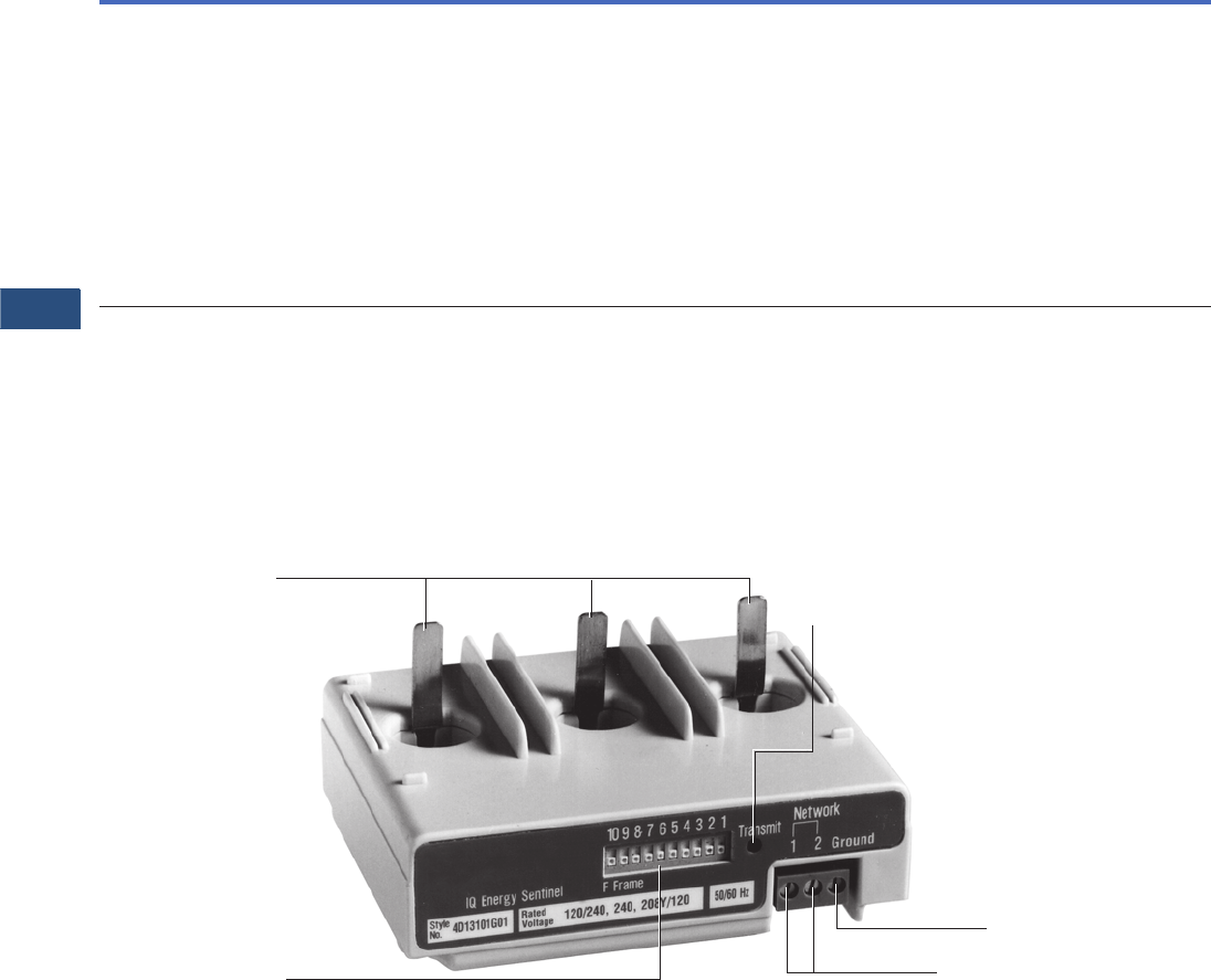
V3-T9-114 Volume 3—Power Distribution and Control Assemblies CA08100004E—November 2013 www.eaton.com
9
9
9
9
9
9
9
9
9
9
9
9
9
9
9
9
9
9
9
9
9
9
9
9
9
9
9
9
9
9
9.3
Metering Devices, Protective Relays, Software and Connectivity
Metering Devices
Features
IQ Energy Sentinel Features
.
Eaton’s Breaker Mount
Eaton’s breaker mount
IQ Energy Sentinel installs
in less than 10 minutes on
the load side of an Eaton
F-Frame (150A),
J-Frame (250A), or
K-Frame (400A) circuit
breaker.
Energy Sentinel Features
Features Benefits
■Monitors (accuracy stated full scale)
Kilowatts ±1.0%
Kilowatts demand ±1.0%
Kilowatt Hour ±1.0%
■Built-in CTs version up to 400A or external CTs version up to 4000A
■Breaker, panel or DIN rail mounted
■Powered directly off the line
■Built-in communication capability
Address set by DIP switches
Communication at 9600 baud
Noise immune INCOM protocol
■Choice of operator interfaces
Subnetwork Master Local Display
Breaker Interface Module (BIM)
Power Management Energy Billing software
Power Management Software
■One device replaces multiple meters and/or transducers
■Improved system accuracy
■Savings in product cost
■Savings in space
■Savings in installation cost
■No external power source is needed
■Permits remote monitoring and interconnection with programmable logic controllers
and building management systems. For further information see section on Power
Management Software Systems
■Designed to interface directly with Power Management Software Energy Billing software
■Flexibility—displays what is needed where it is needed
■Power Management Software
DIP Switch
Address
Communications
Connections
Ground/Neutral
Connection
Voltage
Ta n g s Transmit
LED
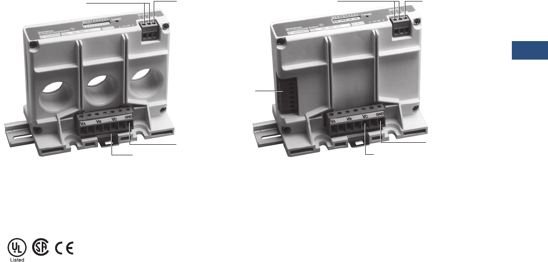
Volume 3—Power Distribution and Control Assemblies CA08100004E—November 2013 www.eaton.com V3-T9-115
9
9
9
9
9
9
9
9
9
9
9
9
9
9
9
9
9
9
9
9
9
9
9
9
9
9
9
9
9
9
9.3
Metering Devices, Protective Relays, Software and Connectivity
Metering Devices
Universal Mount with
Internal CTs—(UI)
The Universal Mount IQ
Energy Sentinel with internal
CTs may be panel-mounted
or DIN rail mounted on
disconnects or other circuits
up to 400 amperes. A pull-
apart terminal block is
provided on the device for
connection of the system
voltage reference wiring.
The location of the ground/
neutral connection differs on
Breaker Mount IQ Energy
Sentinels from the location of
the ground/neutral
connection on Universal
Mount IQ Sentinels. Incorrect
wiring to the
ground/neutral
and communications
connections may result in
accuracy and communication
errors.
Universal Mount for
External CTs—(UE)
The Universal Mount IQ
Energy Sentinel for external
CTs may be panel-mounted
or DIN rail mounted on
circuits up to 4000 amperes.
A pull-apart terminal block is
provided on the device for
connection of the system
voltage reference wiring as
well as another terminal block
for connection to the user’s
existing 5-ampere secondary
CTs that may range in
standard ratios from 25:5 up
to 4000:5.
Note: If the device will be
disconnected without interruption
of the monitored load, the use of
a CT shorting block is advised.
Energy Sentinel Features
Standards and Certifications
●UL listed, File E64983
●CSA approved, File
LR106359-1
Communications
Connections
Communications
Shield
Connection
Voltage Terminal Block
Ground/Neutral
Connection
Communications
Connections
Communications
Shield
Connection
Voltage Terminal Block
Ground/Neutral
Connection
CT
Te r m i n a l
Block
V3-T9-116 Volume 3—Power Distribution and Control Assemblies CA08100004E—November 2013 www.eaton.com
9
9
9
9
9
9
9
9
9
9
9
9
9
9
9
9
9
9
9
9
9
9
9
9
9
9
9
9
9
9
9.3
Metering Devices, Protective Relays, Software and Connectivity
Metering Devices
Product Selection
IQ Energy Sentinels
Technical Data and Specifications
Terminal, Cable and Wiring Guidelines
Description Voltage Rating—Vac
Current Rating
Maximum Amperes
Catalog
Number
For F-Frame breakers 120/240, 240, 208Y/120 150 IQESF208
For F-Frame breakers 220/380, 230/400, 240/415 150 IQESF400
For F-Frame breakers 480, 480Y/277 150 IQESF480
For F-Frame breakers 600, 600Y/347 150 IQESF600
For J-Frame breakers 120/240, 240, 208Y/120 250 IQESJ208
For J-Frame breakers 220/380, 230/400, 240/415 250 IQESJ400
For J-Frame breakers 480, 480Y/277 250 IQESJ480
For J-Frame breakers 600, 600Y/347 250 IQESJ600
For K-Frame breakers 120/240, 240, 208Y/120 400 IQESK208
For K-Frame breakers 220/380, 230/400, 240/415 400 IQESK400
For K-Frame breakers 480, 480Y/277 400 IQESK480
For K-Frame breakers 600, 600Y/347 400 IQESK600
Universal with internal CTs 120/240, 240, 208Y/120 400 IQESUI208
Universal with internal CTs 220/380, 230/400, 240/415 400 IQESUI400
Universal with internal CTs 480, 480Y/277 400 IQESUI480
Universal with internal CTs 600, 600Y/347 400 IQESUI600
Universal for external CTs 120/240, 240, 208Y/120 4000 IQESUE208
Universal for external CTs 220/380, 230/400, 240/415 4000 IQESUE400
Universal for external CTs 480, 480Y/277 4000 IQESUE480
Universal for external CTs 600, 600Y/347 4000 IQESUE600
IQ Energy Sentinels
Sentinel
Eaton’s
Series C Terminal
Wire Size
(Single Conductor)
Wire
Types
F-Frame 624B100G02, G17, G18, G19 #14–1/0, #4–4/0, #4–4/01, #14–1/0 AWG THW, THHN, XHHW
J-Frame T250KB, TA250KB #4–350 kcmil THW, THHN, XHHW
K-Frame T350K, TA350KB #250–500 kcmil THW, THHN, XHHW
Universal Energy Sentinel with internal CTs T350K, TA350KB #250–500 kcmil THW, THHN, XHHW
System Voltage Reference Wiring
Energy Sentinel with internal or external CTs #24–#10 AWG
Current Transformer Wiring
Universal with external CTs #12 AWG (maximum)
Ground Reference Wiring
Energy Sentinel with internal or external CTs #22–#12 AWG (minimum 600 volt rated)
Communications Wiring
Energy Sentinel with internal or external CTs Eaton’s IMPCABLE or Belden 9463 family
F-Frame Eaton’s IMPCABLE or Belden 9463 family
J-Frame Eaton’s IMPCABLE or Belden 9463 family
K-Frame Eaton’s IMPCABLE or Belden 9463 family

Volume 3—Power Distribution and Control Assemblies CA08100004E—November 2013 www.eaton.com V3-T9-117
9
9
9
9
9
9
9
9
9
9
9
9
9
9
9
9
9
9
9
9
9
9
9
9
9
9
9
9
9
9
9.3
Metering Devices, Protective Relays, Software and Connectivity
Metering Devices
Energy Sentinel
Current Input
Current range: 1% to 125% of current rating
Burden: 1 VA
Voltage Input
Voltage Range: ±20% of voltage rating
Frequency
50 or 60 Hz
Power Factor Range
All (–1 to +1)
Communications
Protocol: INCOM
Speed: 9600 baud
Compatibility: Power Management Software compatible
Environmental Conditions
Operating temperature: –25°C to 70°C 1
(–13°F to 158°F)
Storage temperature: –40°C to 85°C 1
(–40°F to 185°F)
Operating humidity: 5% to 95% relative humidity noncondensing
System Voltage Considerations (Application Note)
The Ground (GND) terminal of the IQ Energy Sentinel should
be connected to the ground bus or other non-current carrying
ground with 600V rated wire to ensure accuracy.
Note
140ºC (standard) maximum for Series C circuit breakers.
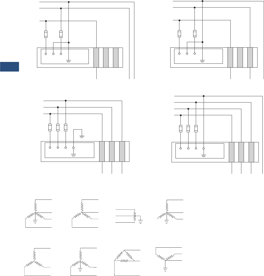
V3-T9-118 Volume 3—Power Distribution and Control Assemblies CA08100004E—November 2013 www.eaton.com
9
9
9
9
9
9
9
9
9
9
9
9
9
9
9
9
9
9
9
9
9
9
9
9
9
9
9
9
9
9
9.3
Metering Devices, Protective Relays, Software and Connectivity
Metering Devices
Wiring Diagrams
Field Wiring—IQ Universal Energy Sentinel with Internal CTs
Acceptable System Configurations
IA IB IC
N
L2
L1
Line
Fuses
Reference
Ground
VA VB VC
Load
IQ Universal Energy Sentinel
with Internal CTs
N
L2
L1
Line
Fuses
Reference
Ground
VA VB VC
Load
IQ Universal Energy Sentinel
with Internal CTs
IA IB IC
IA IB IC
L3
L1
Line
Fuses
Reference
Ground
VA VB VC
Load
IQ Universal Energy Sentinel
with Internal CTs
L2
IA IB IC
L3
L1
Line
Fuses
Reference
Ground
VA VB VC
Load
IQ Universal Energy Sentinel
with Internal CTs
L2
N
Single-Phase Three-Wire Two-Phase Three-Wire
Three-Phase Three-Wire Three-Phase Four-Wire
Phase A
Phase C
Phase A
Phase C
Neutral
Three-Phase Star, Four-
Wire, Earthed Neutral.
Three-Phase Star, Four-
Wire, Non-Earthed
Neutral.
Single-Phase, Three-
Wire, Earthed Mid-Point
(Connect to A and C
Phases).
Two-Phase Star, Three-
Wire, Earthed Neutral
(Connect to A and C
Phases).
Three-Phase Star,
Three-Wire
Three-Phase Star,
Three-Wire, Earthed
Neutral Point.
Three-Phase Delta,
Three-Wire
Three-Phase Open
Delta, Four-Wire,
Earthed Junction.
Note: Acceptable for Universal IQ Energy Sentinels only.

Volume 3—Power Distribution and Control Assemblies CA08100004E—November 2013 www.eaton.com V3-T9-119
9
9
9
9
9
9
9
9
9
9
9
9
9
9
9
9
9
9
9
9
9
9
9
9
9
9
9
9
9
9
9.3
Metering Devices, Protective Relays, Software and Connectivity
Metering Devices
Dimensions
Approximate Dimensions in Inches (mm)
Energy Sentinel
Note
1Acceptable for Universal IQ Energy Sentinels only.
Frame Type D W H CT Window Size 1Hole Clearance
Weight
Lbs (kg)
F 3.20 (81.3) 4.12 (104.6) 1.30 (33.0) 0.59 (15.0) — 0.65 (0.3)
J 4.04 (102.6) 4.12 (104.6) 1.28 (32.5) 0.77 (19.6) — 0.69 (0.3)
K 4.04 (102.6) 5.31 (134.9) 1.25 (31.8) 0.96 (24.4) — 0.87 (0.4)
UI 4.36 (110.7) 5.31 (134.9) 3.00 (76.2) — 1.17 (29.7) 1.10 (0.5)
UE 4.36 (110.7) 5.31 (134.9) 3.00 (76.2) — — 1.10 (0.5)
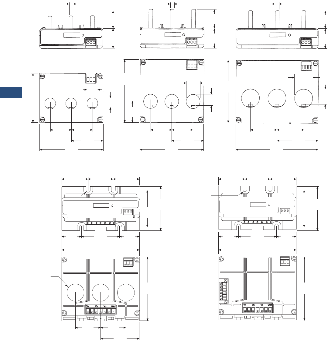
V3-T9-120 Volume 3—Power Distribution and Control Assemblies CA08100004E—November 2013 www.eaton.com
9
9
9
9
9
9
9
9
9
9
9
9
9
9
9
9
9
9
9
9
9
9
9
9
9
9
9
9
9
9
9.3
Metering Devices, Protective Relays, Software and Connectivity
Metering Devices
IQ Sentinel
Radius
1.17
(29.7)
Diameter
0.25
(6.4) Typical
0.25
(6.4)Typical
0.25
(6.4) Typical
1.10
(27.9)
1.25
(31.8)
1.25
(31.8)
1.28
(32.5)
0.75
(19.1)
1.30
(33.0)
1.17
(29.7)Typical
1.17
(29.7)Typical
0.96
(24.4)
4.04
(102.6)
1.72
(43.7)
1.72
(43.7)
2.66
(67.5)
5.31
(134.9)
0.77
(19.6)
0.90
(22.9)Typical
1.38
(34.9)
1.38
(34.9)
2.06
(52.3)
4.12
(104.6)
0.59
(15.0)
1.38
(34.9)
4.04
(102.6)
3.20
(81.3)
1.38
(34.9)
1.38
(34.9)
2.06
(52.3)
4.12
(104.6)
1.80
(45.7)
1.71
(43.4)
1.80
(45.7)
0.14
(3.6)
2.50
(63.5)
3.00
(76.2)
2.60
(66.0)
1.36
(34.5)
1.36
(34.5)
5.31
(134.9)
1.72
(43.7)
2.66
(67.5)
4.36
(110.7)
1.72
(43.7)
Radius
1.80
(45.7)
1.71
(43.4)
1.80
(45.7)
0.14
(3.6)
2.50
(63.5)
3.00
(76.2)
2.60
(66.0)
1.36
(34.5)
1.36
(34.5)
5.31
(134.9)
4.36
(110.7)
F-Frame Energy Sentinels J-Frame Energy Sentinels K-Frame Energy Sentinels
Universal with Internal CTs
Energy Sentinels
Universal with External CTs
Energy Sentinels

Volume 3—Power Distribution and Control Assemblies CA08100004E—November 2013 www.eaton.com V3-T9-121
9
9
9
9
9
9
9
9
9
9
9
9
9
9
9
9
9
9
9
9
9
9
9
9
9
9
9
9
9
9
9.3
Metering Devices, Protective Relays, Software and Connectivity
Metering Devices
Power Monitoring and Metering with Modbus RTU
PM3 Modules
Contents
Description Page
Metering Products Family. . . . . . . . . . . . . . . . . . . . V3-T9-21
Power Xpert Meter 4000/6000/8000 Series . . . . . . V3-T9-30
Power Xpert Meter 2000 Series . . . . . . . . . . . . . . . V3-T9-49
IQ 250/260 Series Electronic Power Meters. . . . . . V3-T9-60
IQ 130/140/150 Series Electronic Power Meters . . V3-T9-66
IQ 150S/250S Self-Enclosed Electronic Meters . . . V3-T9-71
IQ 35M . . . . . . . . . . . . . . . . . . . . . . . . . . . . . . . . . . V3-T9-76
IQ Analyzer 6400/6600 Series . . . . . . . . . . . . . . . . V3-T9-79
IQ DP-4000 Series . . . . . . . . . . . . . . . . . . . . . . . . . V3-T9-87
IQ 230 Meters . . . . . . . . . . . . . . . . . . . . . . . . . . . . V3-T9-93
Power Xpert Multi-Point Meter . . . . . . . . . . . . . . . . V3-T9-100
IQ Energy Sentinel™ . . . . . . . . . . . . . . . . . . . . . . . V3-T9-112
PM3 Monitoring and Metering Module
Current Transformers (CTs). . . . . . . . . . . . . . . . . . . V3-T9-122
Clamp-On Current Transformers . . . . . . . . . . . . . . . V3-T9-131
IQ Flange . . . . . . . . . . . . . . . . . . . . . . . . . . . . . . . . V3-T9-134
Panel Mounting Adapter Kit . . . . . . . . . . . . . . . . . . V3-T9-135
Enclosed Meters. . . . . . . . . . . . . . . . . . . . . . . . . . . V3-T9-136
PM3 Monitoring and Metering Module
Product Description
For information on our PM3
product, please refer to
Volume 4, Tab 2.
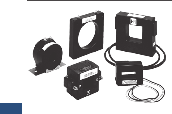
V3-T9-122 Volume 3—Power Distribution and Control Assemblies CA08100004E—November 2013 www.eaton.com
9
9
9
9
9
9
9
9
9
9
9
9
9
9
9
9
9
9
9
9
9
9
9
9
9
9
9
9
9
9
9.3
Metering Devices, Protective Relays, Software and Connectivity
Metering Devices
Current Transformers (CTs)
Contents
Description Page
Metering Products Family. . . . . . . . . . . . . . . . . . . . . V3-T9-21
Power Xpert Meter 4000/6000/8000 Series. . . . . . . V3-T9-30
Power Xpert Meter 2000 Series . . . . . . . . . . . . . . . . V3-T9-49
IQ 250/260 Series Electronic Power Meters . . . . . . V3-T9-60
IQ 130/140/150 Series Electronic Power Meters . . . V3-T9-66
IQ 150S/250S Self-Enclosed Electronic Meters . . . . V3-T9-71
IQ 35M . . . . . . . . . . . . . . . . . . . . . . . . . . . . . . . . . . . V3-T9-76
IQ Analyzer 6400/6600 Series . . . . . . . . . . . . . . . . . V3-T9-79
IQ DP-4000 Series . . . . . . . . . . . . . . . . . . . . . . . . . . V3-T9-87
IQ 230 Meters . . . . . . . . . . . . . . . . . . . . . . . . . . . . . V3-T9-93
Power Xpert Multi-Point Meter . . . . . . . . . . . . . . . . . V3-T9-100
IQ Energy Sentinel™ . . . . . . . . . . . . . . . . . . . . . . . . V3-T9-112
PM3 Monitoring and Metering Module . . . . . . . . . . V3-T9-121
Current Transformers (CTs)
Product Selection . . . . . . . . . . . . . . . . . . . . . . . . V3-T9-123
Dimensions . . . . . . . . . . . . . . . . . . . . . . . . . . . . . V3-T9-126
Clamp-On Current Transformers. . . . . . . . . . . . . . . . V3-T9-131
IQ Flange . . . . . . . . . . . . . . . . . . . . . . . . . . . . . . . . . V3-T9-134
Panel Mounting Adapter Kit . . . . . . . . . . . . . . . . . . . V3-T9-135
Enclosed Meters . . . . . . . . . . . . . . . . . . . . . . . . . . . V3-T9-136
Current Transformers (CTs)
Product Description
Eaton’s low voltage current
transformers are available in
both solid core and split core
designs. Engineered for
electronic metering
applications, all solid core
designs and selected split
core designs offer ANSI
metering quality accuracy.
The solid core designs also
meet ANSI C57.13 relay
accuracy requirements
including over-ranging
capabilities. The current
transformer offering has a
5 ampere secondary at the
rated primary current.
Split core CTs are specifically
designed to be installed
around primary conductors
without disconnecting wires
or breaking the circuit to be
monitored. These current
transformers are perfect
solutions for energy
management applications
and are manufactured for
installation ease.
Application Description
For new construction and
retrofit applications where
no current transformer exists,
Eaton offers a complete
selection of low voltage
(up to 600V) current
transformers. These current
transformers can be used
in commercial-grade
applications, such as control
panels and panelboards.
Additionally, they can be used
for most industrial metering
and relaying applications in
switchboards, switchgear and
motor control centers. These
CTs are intended for use with
the Power Xpert Meter 2000/
4000/6000/8000, IQ 250/260,
IQ 130/140/150, IQ Analyzer
6400/6600, IQ DP-4000 and
IQ 230 series.

Volume 3—Power Distribution and Control Assemblies CA08100004E—November 2013 www.eaton.com V3-T9-123
9
9
9
9
9
9
9
9
9
9
9
9
9
9
9
9
9
9
9
9
9
9
9
9
9
9
9
9
9
9
9.3
Metering Devices, Protective Relays, Software and Connectivity
Metering Devices
Product Selection
Solid Core ANSI Metering Accuracy
Note
1 Contact Eaton for further information.
Primary
Current
Rating
ANSI B0.1
Metering Class at 60 Hz
(Accuracy in %)
Window Size
in Inches (mm)
Diameter
Catalog
Number
Mounting Bracket
Catalog
Number
1.25 (31.8) Window
50 1.2 1.25 (31.8) S060-500 1
100 0.6 1.25 (31.8) S060-101 1
150 0.3 1.25 (31.8) S060-151 1
200 0.3 1.25 (31.8) S060-201 1
1.56 (39.6) Window
300 0.3 1.56 (39.6) S050-301 S050BRAC
400 0.3 1.56 (39.6) S050-401 S050BRAC
500 0.3 1.56 (39.6) S050-501 S050BRAC
600 0.3 1.56 (39.6) S050-601 S050BRAC
750 0.3 1.56 (39.6) S050-751 S050BRAC
800 0.3 1.56 (39.6) S050-801 S050BRAC
1000 0.3 1.56 (39.6) S050-102 S050BRAC
1200 0.3 1.56 (39.6) S050-122 S050BRAC
3.25 (82.6) Window
400 0.3 3.25 (82.6) S080-401 S080BRAC
500 0.3 3.25 (82.6) S080-501 S080BRAC
600 0.3 3.25 (82.6) S080-601 S080BRAC
750 0.3 3.25 (82.6) S080-751 S080BRAC
800 0.3 3.25 (82.6) S080-801 S080BRAC
1000 0.3 3.25 (82.6) S080-102 S080BRAC
1200 0.3 3.25 (82.6) S080-122 S080BRAC
4.25 (108.0) Window
500 0.3 4.25 (108.0) S090-501 S090BRAC
600 0.3 4.25 (108.0) S090-601 S090BRAC
750 0.3 4.25 (108.0) S090-751 S090BRAC
800 0.3 4.25 (108.0) S090-801 S090BRAC
1000 0.3 4.25 (108.0) S090-102 S090BRAC
1200 0.3 4.25 (108.0) S090-122 S090BRAC
1500 0.3 4.25 (108.0) S090-152 S090BRAC
1600 0.3 4.25 (108.0) S090-162 S090BRAC
2000 0.3 4.25 (108.0) S090-202 S090BRAC
2500 0.3 4.25 (108.0) S090-252 S090BRAC
3000 0.3 4.25 (108.0) S090-302 S090BRAC
6.31 (160.3) Window
600 0.3 6.31 (160.3) S025-601 S025BRAC
750 0.3 6.31 (160.3) S025-751 S025BRAC
800 0.3 6.31 (160.3) S025-801 S025BRAC
1000 0.3 6.31 (160.3) S025-102 S025BRAC
1200 0.3 6.31 (160.3) S025-122 S025BRAC
1500 0.3 6.31 (160.3) S025-152 S025BRAC
1600 0.3 6.31 (160.3) S025-162 S025BRAC
2000 0.3 6.31 (160.3) S025-202 S025BRAC
2500 0.3 6.31 (160.3) S025-252 S025BRAC
3000 0.3 6.31 (160.3) S025-302 S025BRAC
3500 0.3 6.31 (160.3) S025-352 S025BRAC
4000 0.3 6.31 (160.3) S025-402 S025BRAC
S060
H1
X1
S050
H1
X1
LABEL
S080
H1
X1
LABEL
S090
H1
X10
LABEL
S025
H1
X10
LABEL
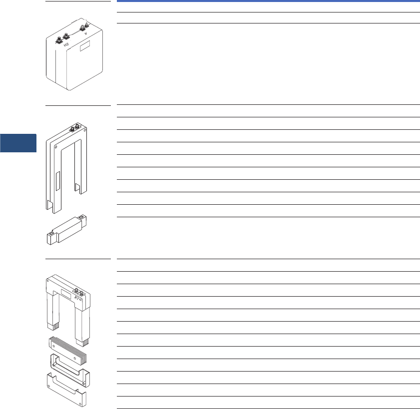
V3-T9-124 Volume 3—Power Distribution and Control Assemblies CA08100004E—November 2013 www.eaton.com
9
9
9
9
9
9
9
9
9
9
9
9
9
9
9
9
9
9
9
9
9
9
9
9
9
9
9
9
9
9
9.3
Metering Devices, Protective Relays, Software and Connectivity
Metering Devices
Split Core ANSI Metering Accuracy
Primary
Current Rating
ANSI B0.1
Metering Class at 60 Hz
(Accuracy in %)
Window Size
in Inches (mm)
Catalog
Number
Wound and Primary CTs
25 0.3 Wound W190-025
50 0.3 Primary W190-050
2.00 x 5.50 (50.8 x 139.7)
400 2.4 2.00 x 5.50 (50.8 x 139.7) M000-401
500 2.4 2.00 x 5.50 (50.8 x 139.7) M000-501
600 2.4 2.00 x 5.50 (50.8 x 139.7) M000-601
800 1.2 2.00 x 5.50 (50.8 x 139.7) M000-801
1000 1.2 2.00 x 5.50 (50.8 x 139.7) M000-102
1200 0.6 2.00 x 5.50 (50.8 x 139.7) M000-122
1500 0.6 2.00 x 5.50 (50.8 x 139.7) M000-152
1600 0.6 2.00 x 5.50 (50.8 x 139.7) M000-162
2000 0.6 2.00 x 5.50 (50.8 x 139.7) M000-202
4.10 x 7.10 (104.1 x 180.3)
600 4.8 4.10 x 7.10 (104.1 x 180.3) M050-601
750 4.8 4.10 x 7.10 (104.1 x 180.3) M050-751
800 2.4 4.10 x 7.10 (104.1 x 180.3) M050-801
1000 2.4 4.10 x 7.10 (104.1 x 180.3) M050-102
1200 1.2 4.10 x 7.10 (104.1 x 180.3) M050-122
1500 1.2 4.10 x 7.10 (104.1 x 180.3) M050-152
2000 0.6 4.10 x 7.10 (104.1 x 180.3) M050-202
2500 0.6 4.10 x 7.10 (104.1 x 180.3) M050-252
3000 0.6 4.10 x 7.10 (104.1 x 180.3) M050-302
3500 0.6 4.10 x 7.10 (104.1 x 180.3) M050-352
4000 0.3 4.10 x 7.10 (104.1 x 180.3) M050-402
W190
LABEL
H1
X2
X1
M000
H1
X1 X2
This End
Removable
M050
LABEL
This End Removable
H1

Volume 3—Power Distribution and Control Assemblies CA08100004E—November 2013 www.eaton.com V3-T9-125
9
9
9
9
9
9
9
9
9
9
9
9
9
9
9
9
9
9
9
9
9
9
9
9
9
9
9
9
9
9
9.3
Metering Devices, Protective Relays, Software and Connectivity
Metering Devices
Split Core Current Transformers
Primary
Current Rating
Accuracy
at 60 Hz (in %)
Window Size
in Inches (mm)
Catalog
Number
0.80 x 1.95 (20.3 x 49.5)
100 5.0 0.80 x 1.95 (20.3 x 49.5) M030-101
150 5.0 0.80 x 1.95 (20.3 x 49.5) M030-151
200 4.0 0.80 x 1.95 (20.3 x 49.5) M030-201
300 2.0 0.80 x 1.95 (20.3 x 49.5) M030-301
400 2.0 0.80 x 1.95 (20.3 x 49.5) M030-401
1.42 x 1.53 (36.1 x 38.9)
100 5.0 1.42 x 1.53 (36.1 x 38.9) M040-101
150 4.0 1.42 x 1.53 (36.1 x 38.9) M040-151
200 1.5 1.42 x 1.53 (36.1 x 38.9) M040-201
300 1.5 1.42 x 1.53 (36.1 x 38.9) M040-301
400 1.5 1.42 x 1.53 (36.1 x 38.9) M040-401
2.60 x 2.75 (66.0 x 69.9)
200 1.0 2.60 x 2.75 (66.0 x 69.9) M060-201
300 1.0 2.60 x 2.75 (66.0 x 69.9) M060-301
400 1.0 2.60 x 2.75 (66.0 x 69.9) M060-401
500 1.0 2.60 x 2.75 (66.0 x 69.9) M060-501
600 1.0 2.60 x 2.75 (66.0 x 69.9) M060-601
750 1.0 2.60 x 2.75 (66.0 x 69.9) M060-751
800 1.0 2.60 x 2.75 (66.0 x 69.9) M060-801
1000 1.0 2.60 x 2.75 (66.0 x 69.9) M060-102
1200 1.0 2.60 x 2.75 (66.0 x 69.9) M060-122
2.60 x 6.25 (66.0 x 158.8)
500 1.0 2.60 x 6.25 (66.0 x 158.8) M080-501
600 1.0 2.60 x 6.25 (66.0 x 158.8) M080-601
800 1.0 2.60 x 6.25 (66.0 x 158.8) M080-801
1000 1.0 2.60 x 6.25 (66.0 x 158.8) M080-102
1200 1.0 2.60 x 6.25 (66.0 x 158.8) M080-122
1500 1.0 2.60 x 6.25 (66.0 x 158.8) M080-152
1600 1.0 2.60 x 6.25 (66.0 x 158.8) M080-162
2000 1.0 2.60 x 6.25 (66.0 x 158.8) M080-202
2500 1.0 2.60 x 6.25 (66.0 x 158.8) M080-252
3000 1.0 2.60 x 6.25 (66.0 x 158.8) M080-302
M030
M040
M060
M080
LEBAL
X2
H1
H1
H1
LABEL
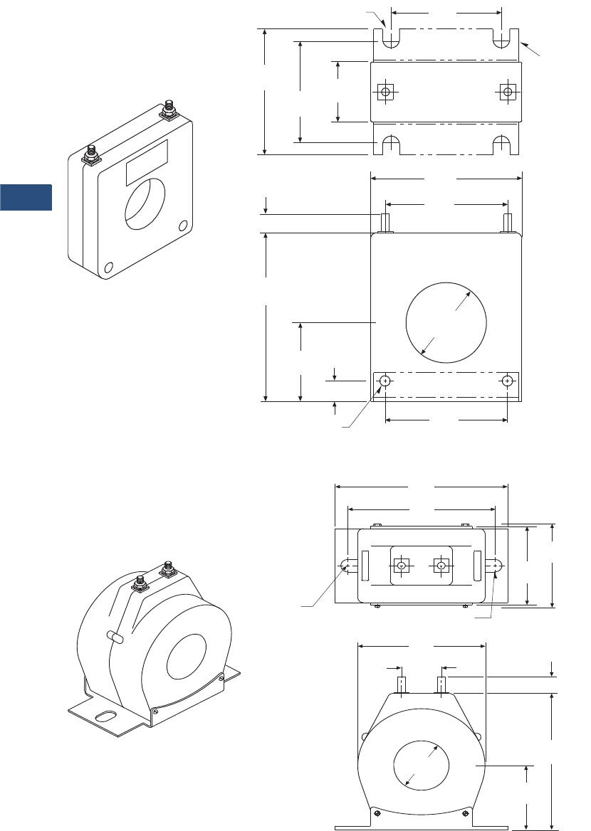
V3-T9-126 Volume 3—Power Distribution and Control Assemblies CA08100004E—November 2013 www.eaton.com
9
9
9
9
9
9
9
9
9
9
9
9
9
9
9
9
9
9
9
9
9
9
9
9
9
9
9
9
9
9
9.3
Metering Devices, Protective Relays, Software and Connectivity
Metering Devices
Dimensions
Approximate dimensions in inches (mm)
S050
S060
H1
X1
LABEL
(4) Open Slots 0.22 x 0.34
(5.6 x 8.6)
2.23
(56.6)
1.67
(42.4)
1.10
(27.9)
2.75
(69.9)
3.53
(90.0)
3.00
(76.2)
0.44
(11.2)
3.70
(94.0)
1.88
(47.8)
0.31
(7.9)
2.25
(57.2)
1.56 Dia.
(39.6)
H1
X1
(2) Holes 0.20 (5.1) Diameter
S050BRAC
H1
X1
0.88
(22.4)
3.62
(91.9)
(2) 0.28 x 0.50 Slots
(7.1 x 12.7)
2.88
(73.2)
3.10
(78.7)
4.00
(101.6)
5.25
(133.4)
H1
X1
0.44 (11.2)
4.00
(101.6)
1.95
(49.5)
See Tables
(2) Slots
0.28 x 0.50
(7.1 x 12.7)
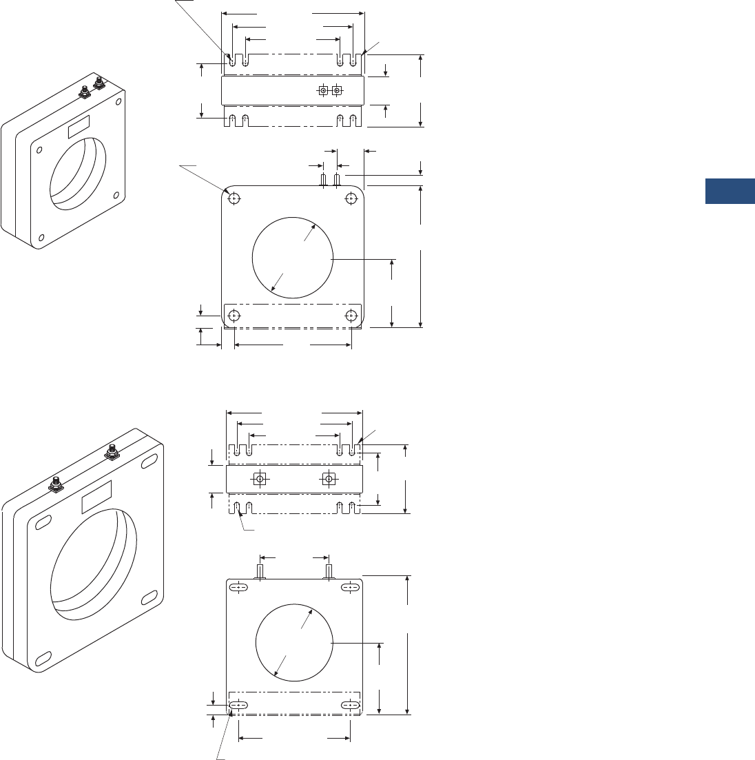
Volume 3—Power Distribution and Control Assemblies CA08100004E—November 2013 www.eaton.com V3-T9-127
9
9
9
9
9
9
9
9
9
9
9
9
9
9
9
9
9
9
9
9
9
9
9
9
9
9
9
9
9
9
9.3
Metering Devices, Protective Relays, Software and Connectivity
Metering Devices
Approximate dimensions in inches (mm)
S080
S090
(8) Open Slots
0.47 x 0.22 (11.9 x 5.6)
5.73 (145.5)
4.85 (123.2)
3.81 (96.8)
2.19
(55.6)
H1
X1
LABEL
2.91
(73.9)
1.15
(29.2)
0.44
(11.2)
5.73
(145.5)
2.84
(72.1)
4.70
(119.4)
0.51
(13.0)
3.25 (82.6) Dia.
H1
X1
0.42 (10.7) Dia.
(4) Holes 1.09
(27.7)
0.55
(14.0)
S080BRAC
H1
X10
LABEL
5.92 (150.4)
4.85 (123.2)
3.81 (96.8)
1.15
(29.2)
2.91
(73.9)
3.50
(88.9)
6.17
(156.7)
X1
4.25 (108.0) Dia.
H1
0.42
(10.7)
4.86 (123.4)
2.97
(75.4)
(4) 0.28 x 0.63 (7.1 x 16.0) Slots
(8) Open Slots 0.47 x 0.22 (11.9 x 5.6)
2.19
(55.6)
S090BRAC
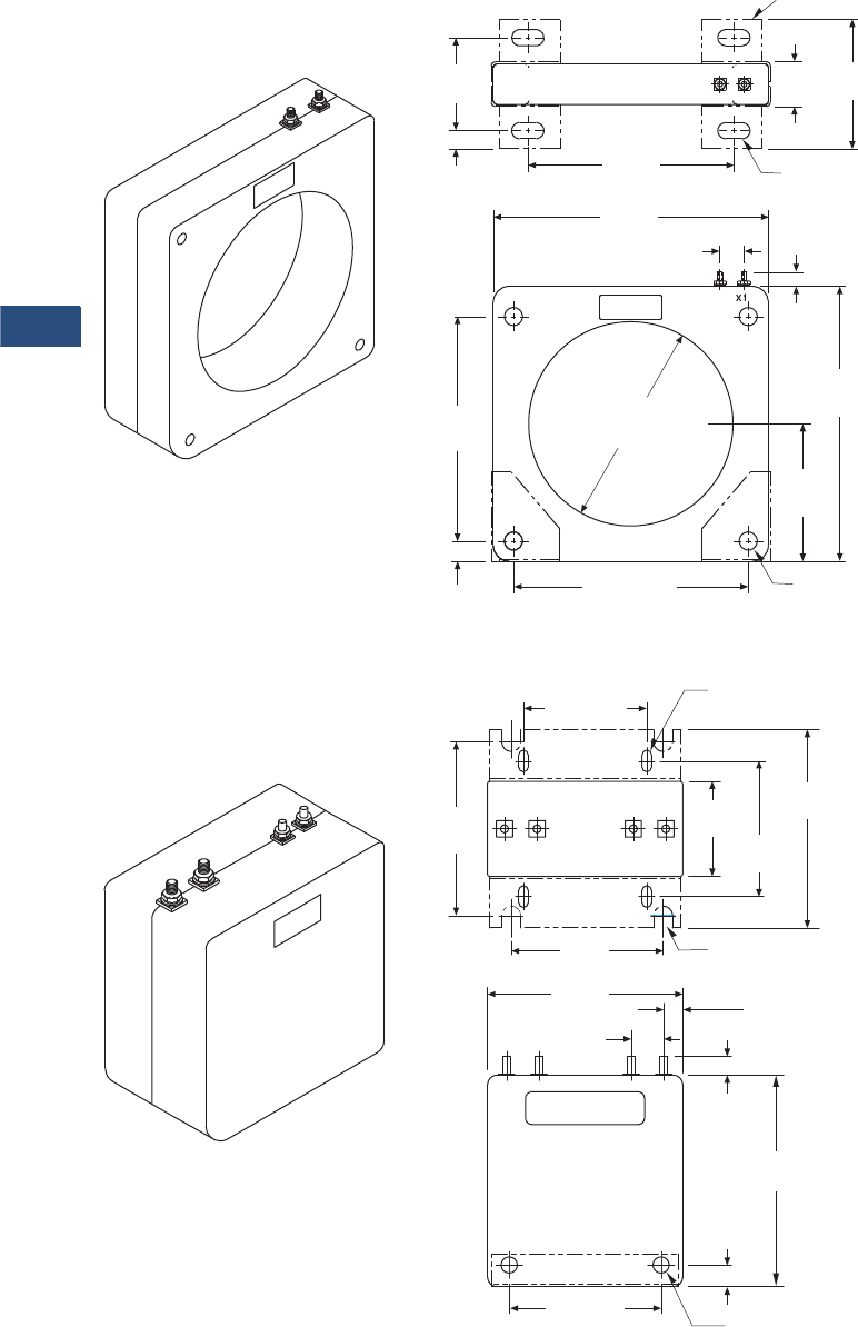
V3-T9-128 Volume 3—Power Distribution and Control Assemblies CA08100004E—November 2013 www.eaton.com
9
9
9
9
9
9
9
9
9
9
9
9
9
9
9
9
9
9
9
9
9
9
9
9
9
9
9
9
9
9
9.3
Metering Devices, Protective Relays, Software and Connectivity
Metering Devices
Approximate dimensions in inches (mm)
S025
W190
H1
X10
LABEL
4.10
(104.1)
1.28
(32.5)
6.37
(161.8)
2.98
(75.7)
0.56
(14.2) 8.50
(215.9)
0.75
(19.1)
0.44
(11.2)
8.50
(215.9)
6.31
(160.3)
H1
6.75
(171.5)
4.25
(108.0)
0.88 (22.4) 6.75 (171.5) (4) 0.56 (14.2)
Diameter Holes
(4) Slots 0.44 x 1.00
(11.2 x 25.4)
S025BRAC
H2 X2
0.38
(9.7)
0.50
(12.7)
2.75 (69.9)
(4) Closed Slots
0.21 x 0.50 (5.3 x 12.7)
(4) Open Slots
0.44 x 0.50 (11.2 x 12.7)
3.25
(82.6)
2.19
(55.6)
4.69
(119.1)
4.12
(104.6)
LABEL
3.50
(88.9)
4.50
(114.3)
0.75
(19.1)
0.44
(11.2)
4.88
(124.0)
(2) Mounting Holes
0.38 (9.7) Diameter
3.48 (88.4)
H1 X1
LABEL
H1
H2 X2 X1
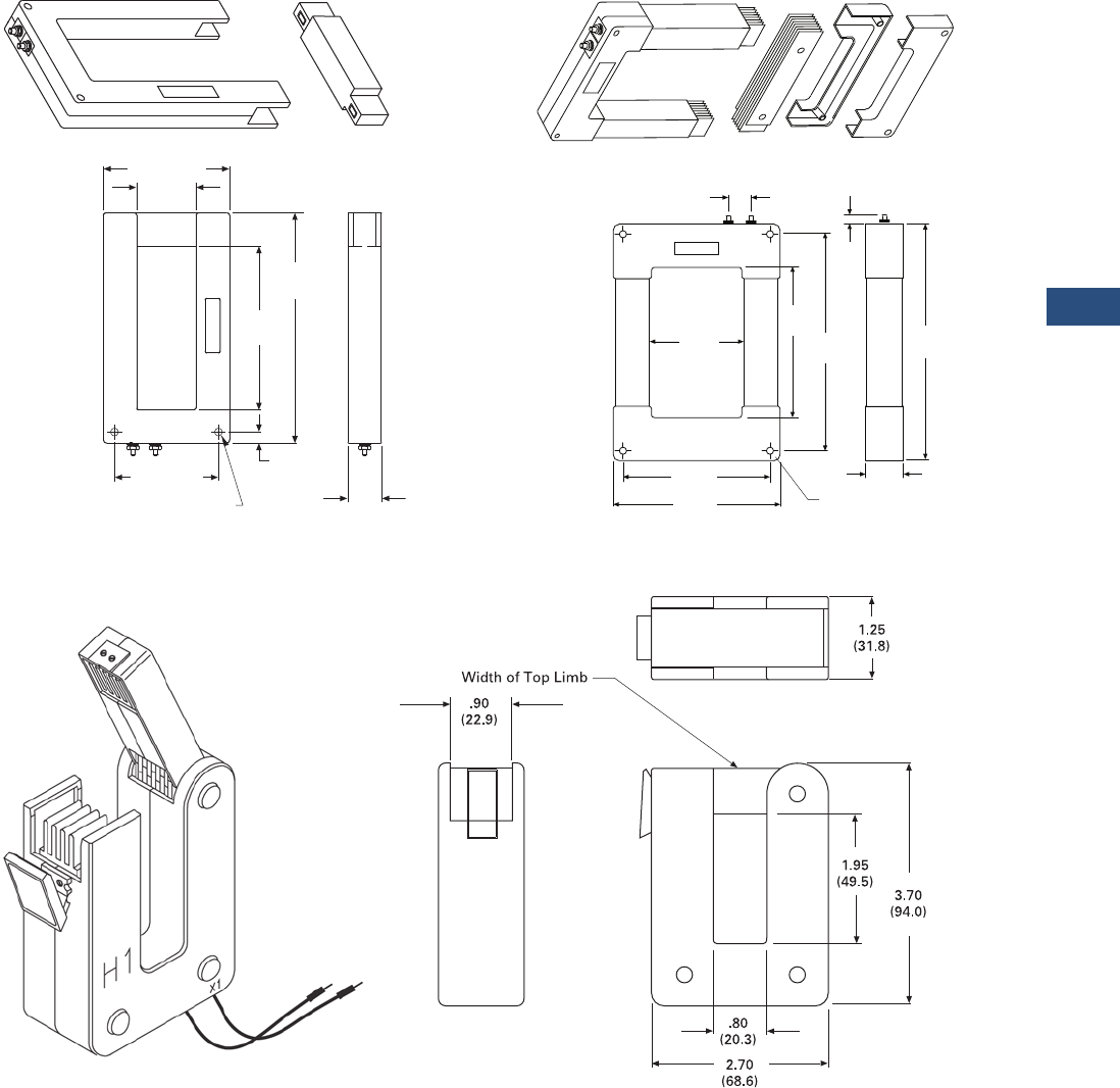
Volume 3—Power Distribution and Control Assemblies CA08100004E—November 2013 www.eaton.com V3-T9-129
9
9
9
9
9
9
9
9
9
9
9
9
9
9
9
9
9
9
9
9
9
9
9
9
9
9
9
9
9
9
9.3
Metering Devices, Protective Relays, Software and Connectivity
Metering Devices
Approximate dimensions in inches (mm)
M000 M050
M030
H1
X1 X2
This End
Removable
2.00
(50.8)
This End
Removable
LABEL
4.25 (108.0)
5.50
(139.7)
H1
X1 X2
3.50 (88.9)
0.38
(9.7)
1.13
(28.7)
(2) 0.19 (4.8) Diameter Holes
7.75
(196.9)
0.75
(19.1)
(4) 0.31 (7.9) Dia. Holes
This End Removable
LABEL
4.10
(104.1)
H1
X1
1.63
(41.4)
0.44
(11.2)
LABEL
X1
This End Removable
H1
7.10
(180.3)
10.00
(254.0)
10.90
(276.9)
6.40
(162.6)
7.30
(185.4)
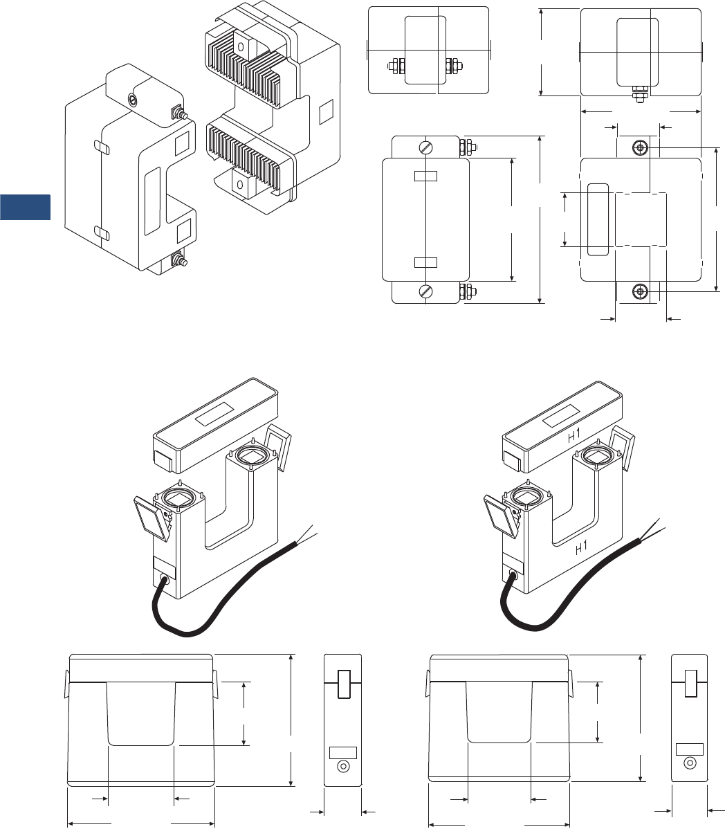
V3-T9-130 Volume 3—Power Distribution and Control Assemblies CA08100004E—November 2013 www.eaton.com
9
9
9
9
9
9
9
9
9
9
9
9
9
9
9
9
9
9
9
9
9
9
9
9
9
9
9
9
9
9
9.3
Metering Devices, Protective Relays, Software and Connectivity
Metering Devices
Approximate dimensions in inches (mm)
M040
M060 M080
1.42
(36.1)
1.20
(30.5)
3.38 (85.9)
1.53
(38.9)
4.12
(104.6)
3.52
(89.4)
4.78
(121.4)
2.50
(63.5)
X2
H1
LABEL
X1
Terminal Arrangement for
Ratios 250:5 through 400:5
Terminal Arrangement for
Ratios 100:5 through 200:5
LABEL
X1
X2
H1
H1
H1
H1
H1
2.75 (69.9)
2.70 (68.6)
5.80 (147.3)
1.75
(44.5)
X1 - WHITE
X2 - BLACK
6.05 (153.7)
LABEL
H1
H1
6.25 (158.8)
9.25 (235.0)
2.60 (66.0)
6.05 (153.7)
1.75
(44.5)
X1 - WHITE
X2 - BLACK
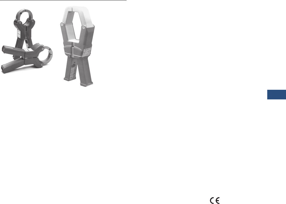
Volume 3—Power Distribution and Control Assemblies CA08100004E—November 2013 www.eaton.com V3-T9-131
9
9
9
9
9
9
9
9
9
9
9
9
9
9
9
9
9
9
9
9
9
9
9
9
9
9
9
9
9
9
9.3
Metering Devices, Protective Relays, Software and Connectivity
Metering Devices
IQ Accessories—Clamp-On CTs
Contents
Description Page
Metering Products Family. . . . . . . . . . . . . . . . . . . . V3-T9-21
Power Xpert Meter 4000/6000/8000 Series . . . . . . V3-T9-30
Power Xpert Meter 2000 Series . . . . . . . . . . . . . . . V3-T9-49
IQ 250/260 Series Electronic Power Meters. . . . . . V3-T9-60
IQ 130/140/150 Series Electronic Power Meters . . V3-T9-66
IQ 150S/250S Self-Enclosed Electronic Meters . . . V3-T9-71
IQ 35M . . . . . . . . . . . . . . . . . . . . . . . . . . . . . . . . . . V3-T9-76
IQ Analyzer 6400/6600 Series . . . . . . . . . . . . . . . . V3-T9-79
IQ DP-4000 Series . . . . . . . . . . . . . . . . . . . . . . . . . V3-T9-87
IQ 230 Meters . . . . . . . . . . . . . . . . . . . . . . . . . . . . V3-T9-93
Power Xpert Multi-Point Meter . . . . . . . . . . . . . . . . V3-T9-100
IQ Energy Sentinel™ . . . . . . . . . . . . . . . . . . . . . . . V3-T9-112
PM3 Monitoring and Metering Module . . . . . . . . . V3-T9-121
Current Transformers (CTs). . . . . . . . . . . . . . . . . . . V3-T9-122
Clamp-On Current Transformers
Product Selection. . . . . . . . . . . . . . . . . . . . . . . . V3-T9-132
Technical Data and Specifications . . . . . . . . . . . V3-T9-132
Dimensions . . . . . . . . . . . . . . . . . . . . . . . . . . . . V3-T9-133
IQ Flange . . . . . . . . . . . . . . . . . . . . . . . . . . . . . . . . V3-T9-134
Panel Mounting Adapter Kit . . . . . . . . . . . . . . . . . . V3-T9-135
Enclosed Meters. . . . . . . . . . . . . . . . . . . . . . . . . . . V3-T9-136
Clamp-On Current Transformers
Product Description
Eaton’s optional Clamp-on
Current Transformers (CTs)
are designed to be used in
cases where there are no
existing CTs or the existing
CTs cannot be accessed,
these clamp-on CTs can
be used.
These clamp-on CTs are
packaged individually. Most
applications will require at
least three clamp-on CTs,
one for each phase.
Application Description
●There are two models that
cover current ranges from
150 to 1500 amperes
●These clamp-on CTs are
designed to fit around
600 volt insulated cable
and bus bar
Features, Benefits
and Functions
●Each clamp-on CT comes
with a 12-foot (3.7m) cable
and twist lock connector
●All models have a
5 ampere output at
three different primary
current ratings
Standards and Certifications
●Meets IEC 1010-1
Category III
●CE mark for applications
where European
compliance is required

V3-T9-132 Volume 3—Power Distribution and Control Assemblies CA08100004E—November 2013 www.eaton.com
9
9
9
9
9
9
9
9
9
9
9
9
9
9
9
9
9
9
9
9
9
9
9
9
9
9
9
9
9
9
9.3
Metering Devices, Protective Relays, Software and Connectivity
Metering Devices
Product Selection
Ordering Information
Current
Ranges
Catalog
Number
150–300–600A IQAPORT0600CT
500–1000–1500A IQAPORT1500CT
150–300–600A
500–1000–1500A
Technical Data and Specifications
●Operating temperature: 14ºF to 122ºF (–10ºC to 50ºC)
●Operating humidity: 5 to 90% maximum noncondensing
●Altitude: 10,000 ft (3048m)
●Environment: indoor use only
●Operating voltage: 600 Vac maximum
●Isolation test: 5.55 kV for 1 minute
●Current over range: 200% for 3 minutes
●Connector: twist-lock
Current Ranges
Each of the two models of clamp-on CTs has three primary
current ranges. The primary current range is selected at the
clamp-on by connecting to the indicated terminals.
150A/300A/600A Clamp-On CT Specifications
●Current ratings:
●150 to 5 amperes
●300 to 5 amperes
●600 to 5 amperes
500A/1000A/1500A Clamp-On CT Specifications
●Current ratings:
●500 to 5 amperes
●1000 to 5 amperes
●1500 to 5 amperes
Electrical Characteristics
Current
Ranges
Load
(Ohms)
Phase Shift
(Degree)
Frequency
Range (3%)
Frequency
Range (–3 db)
150–600A 0.10–1.0 0.5–1.0 40–5000 30–10,000
500–1500A 0.01–4.0 0.5–1.0 40–2000 30–5000
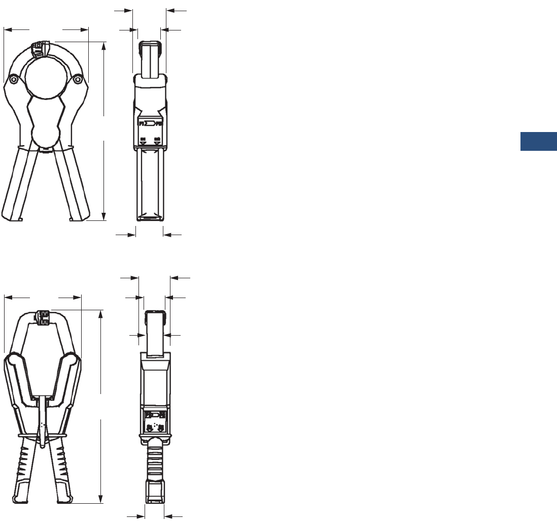
Volume 3—Power Distribution and Control Assemblies CA08100004E—November 2013 www.eaton.com V3-T9-133
9
9
9
9
9
9
9
9
9
9
9
9
9
9
9
9
9
9
9
9
9
9
9
9
9
9
9
9
9
9
9.3
Metering Devices, Protective Relays, Software and Connectivity
Metering Devices
Dimensions
Approximate Dimensions in Inches (mm)
150A/300A/600A Clamp-On CT
500A/1000A/1500A Clamp-On CT
150A/300A/600A Clamp-On CT
●Maximum cable size:
●2.00 inches (50.8 mm)
●Maximum bus bar size:
●2.00 x 0.47 inches (50.8 x 12.0 mm)
●1.60 x 1.40 inches (40.6 x 35.6 mm)
●Dimensions (without cable):
●4.00 x 8.50 x 1.60 inches (101.6 x 215.9 x 40.6 mm)
●Weight (with cable):
●2.0 lbs (0.9 kg)
500A/1000A/1500A Clamp-On CT
●Maximum cable size:
●2.68 inches (68.1 mm)
●Maximum bus bar size:
●4.84 x 1.40 (122.9 x 35.6 mm)
●4.00 x 1.70 inches (101.6 x 43.2 mm)
●Dimensions (without cable):
●5.20 x 13.20 x 2.00 inches (132.1 x 335.3 x 50.8 mm)
●Weight (with cable):
●6.0 lbs (2.7 kg)
8.50
(215.9)
1.26
(32.0)
4.01
(101.9)
1.58
(40.1)
0.79
(20.1)
8.50
(215.9)
1.30
(33.0)
5.24
(133.1)
2.04
(51.8)
1.40
(35.6)
1.10
(27.9)
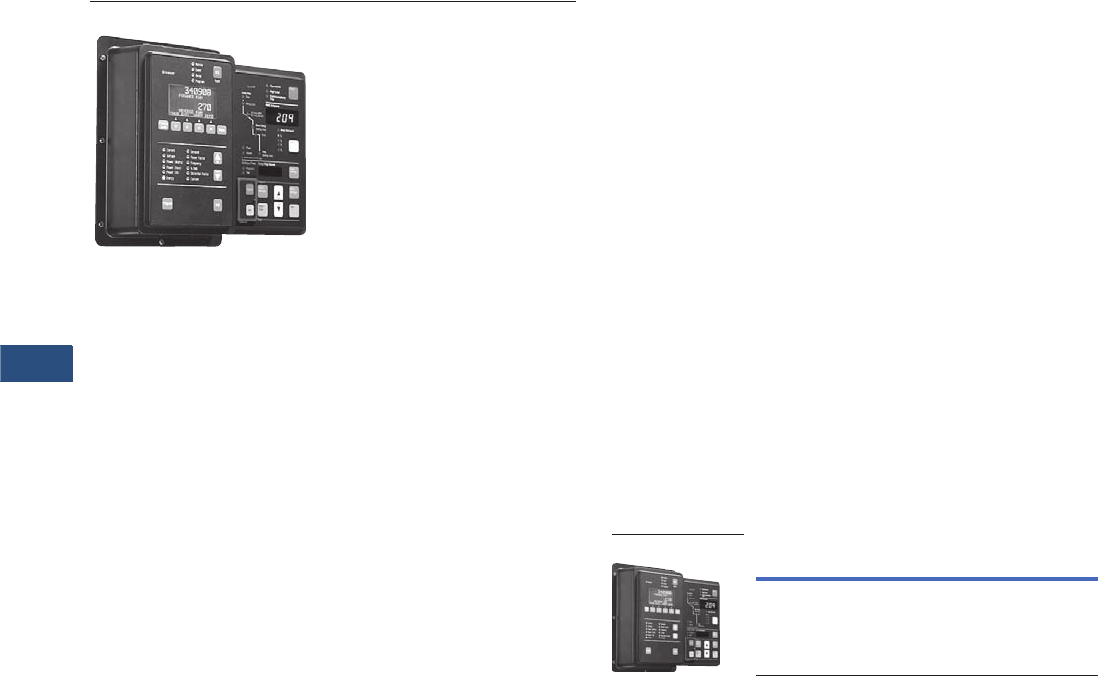
V3-T9-134 Volume 3—Power Distribution and Control Assemblies CA08100004E—November 2013 www.eaton.com
9
9
9
9
9
9
9
9
9
9
9
9
9
9
9
9
9
9
9
9
9
9
9
9
9
9
9
9
9
9
9.3
Metering Devices, Protective Relays, Software and Connectivity
Metering Devices
IQ Accessories—IQ Flange
Contents
Description
Metering Products Family. . . . . . . . . . . . . . . . . . . . . V3-T9-21
Power Xpert Meter 4000/6000/8000 Series. . . . . . . V3-T9-30
Power Xpert Meter 2000 Series . . . . . . . . . . . . . . . . V3-T9-49
IQ 250/260 Series Electronic Power Meters . . . . . . V3-T9-60
IQ 130/140/150 Series Electronic Power Meters . . . V3-T9-66
IQ 150S/250S Self-Enclosed Electronic Meters . . . . V3-T9-71
IQ 35M . . . . . . . . . . . . . . . . . . . . . . . . . . . . . . . . . . . V3-T9-76
IQ Analyzer 6400/6600 Series . . . . . . . . . . . . . . . . . V3-T9-79
IQ DP-4000 Series . . . . . . . . . . . . . . . . . . . . . . . . . . V3-T9-87
IQ 230 Meters . . . . . . . . . . . . . . . . . . . . . . . . . . . . . V3-T9-93
Power Xpert Multi-Point Meter . . . . . . . . . . . . . . . . . V3-T9-100
IQ Energy Sentinel™ . . . . . . . . . . . . . . . . . . . . . . . . V3-T9-112
PM3 Monitoring and Metering Module . . . . . . . . . . V3-T9-121
Current Transformers (CTs). . . . . . . . . . . . . . . . . . . . V3-T9-122
Clamp-On Current Transformers. . . . . . . . . . . . . . . . V3-T9-131
IQ Flange
Panel Mounting Adapter Kit . . . . . . . . . . . . . . . . . . . V3-T9-135
Enclosed Meters . . . . . . . . . . . . . . . . . . . . . . . . . . . V3-T9-136
IQ Flange
Product Description
Eaton’s IQ Flange is intended
for use with the IQ Data,
IQ Generator, IQ Data Plus II,
IQ Analyzer and any other
such device sharing the same
mounting dimensions.
The door mounting flange
provides extra depth behind a
panel if there is not enough
clearance to accommodate
the device.
Application Description
Retrofit Applications
For applications where extra
door mounting space is
required, a flange-mounting
unit is available. The IQ
Flange provides an extra
2.5 inches (63.5 mm) of
clearance for the device.
The IQ Flange can be used
with any IQ device with
a 5.38-inch (136.7 mm) x
9.38-inch (238.0 mm) cutout.
Product Selection
IQ Flange
Description Catalog Number
IQ Flange IQFLANGE
IQ Flange
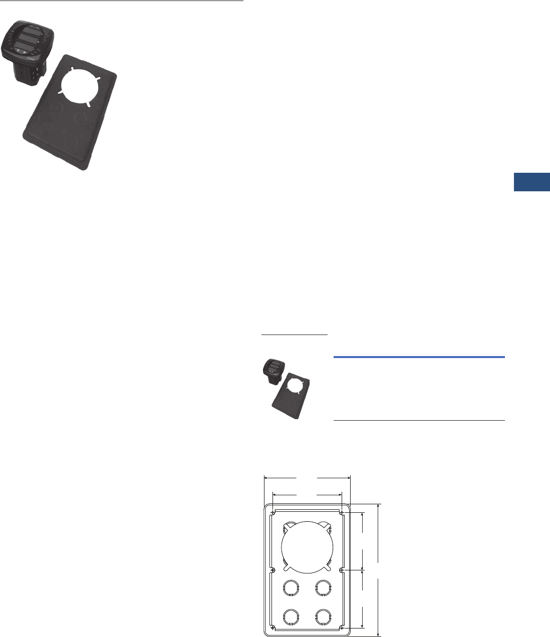
Volume 3—Power Distribution and Control Assemblies CA08100004E—November 2013 www.eaton.com V3-T9-135
9
9
9
9
9
9
9
9
9
9
9
9
9
9
9
9
9
9
9
9
9
9
9
9
9
9
9
9
9
9
9.3
Metering Devices, Protective Relays, Software and Connectivity
Metering Devices
Panel Mounting Adapter Kit for IQ 100/200 Series and PXM 2000 Meters
Contents
Description
Metering Products Family. . . . . . . . . . . . . . . . . . . . V3-T9-21
Power Xpert Meter 4000/6000/8000 Series . . . . . . V3-T9-30
Power Xpert Meter 2000 Series . . . . . . . . . . . . . . . V3-T9-49
IQ 250/260 Series Electronic Power Meters. . . . . . V3-T9-60
IQ 130/140/150 Series Electronic Power Meters . . V3-T9-66
IQ 150S/250S Self-Enclosed Electronic Meters . . . V3-T9-71
IQ 35M . . . . . . . . . . . . . . . . . . . . . . . . . . . . . . . . . . V3-T9-76
IQ Analyzer 6400/6600 Series . . . . . . . . . . . . . . . . V3-T9-79
IQ DP-4000 Series . . . . . . . . . . . . . . . . . . . . . . . . . V3-T9-87
IQ 230 Meters . . . . . . . . . . . . . . . . . . . . . . . . . . . . V3-T9-93
Power Xpert Multi-Point Meter . . . . . . . . . . . . . . . . V3-T9-100
IQ Energy Sentinel™ . . . . . . . . . . . . . . . . . . . . . . . V3-T9-112
PM3 Monitoring and Metering Module . . . . . . . . . V3-T9-121
Current Transformers (CTs). . . . . . . . . . . . . . . . . . . V3-T9-122
Clamp-On Current Transformers . . . . . . . . . . . . . . . V3-T9-131
IQ Flange . . . . . . . . . . . . . . . . . . . . . . . . . . . . . . . . V3-T9-134
Panel Mounting Adapter Kit
Enclosed Meters. . . . . . . . . . . . . . . . . . . . . . . . . . . V3-T9-136
Panel Mounting Adapter Kit for IQ 100/200 Series
and PXM 2000 Meters
Product Description
The flange adapter plate can
be installed as follows:
1. Remove the old meter
from the panel or door.
Many IQ metering
products use the typical
IQ drilling pattern shown
at right for mounting
2. Install the flange adapter
plate. Mount it from the
rear using the six screws
provided in the kit. The
flange adapter plate
screw hole pattern
shown at right should
match the typical IQ
drilling pattern. If not,
perform the next step
3. Drill six holes in the panel
or the door to mount the
flange adapter plate.
Follow the typical IQ
drilling pattern. You need
only the top, center and
bottom sets of holes
4. Install the new IQ 100/
200 Series or PXM 2000
meter in the flange
adapter plate. Secure it
from behind with four flat
washers, lock washers
and nuts provided with
the meter
Product Selection
Panel Mounting Adapter Kit
Dimensions
Flange Adapter Plate Screw Hole Pattern
Description Catalog Number
Panel mounting adapter kit
IQ 100/200 and PXM 2000 Series
adapter kit to IQ Analyzer/
IQ DP-4000/IQ Data
IQ250-PMAK
Panel Mounting
Adapter Kit
6.72
(170.7)
5.38
(136.7)
4.45
(113.0)
10.25
(260.4)
4.45
(113.0)
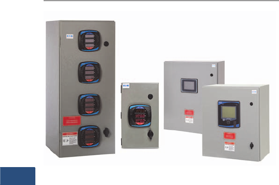
V3-T9-136 Volume 3—Power Distribution and Control Assemblies CA08100004E—November 2013 www.eaton.com
9
9
9
9
9
9
9
9
9
9
9
9
9
9
9
9
9
9
9
9
9
9
9
9
9
9
9
9
9
9
9.3
Metering Devices, Protective Relays, Software and Connectivity
Metering Devices
NEMA 12 Single- and Multi-Unit Enclosed Meters
Contents
Description
Metering Products Family. . . . . . . . . . . . . . . . . . . . . V3-T9-21
Power Xpert Meter 4000/6000/8000 Series. . . . . . . V3-T9-30
Power Xpert Meter 2000 Series . . . . . . . . . . . . . . . . V3-T9-49
IQ 250/260 Series Electronic Power Meters . . . . . . V3-T9-60
IQ 130/140/150 Series Electronic Power Meters . . . V3-T9-66
IQ 150S/250S Self-Enclosed Electronic Meters . . . . V3-T9-71
IQ 35M . . . . . . . . . . . . . . . . . . . . . . . . . . . . . . . . . . . V3-T9-76
IQ Analyzer 6400/6600 Series . . . . . . . . . . . . . . . . . V3-T9-79
IQ DP-4000 Series . . . . . . . . . . . . . . . . . . . . . . . . . . V3-T9-87
IQ 230 Meters . . . . . . . . . . . . . . . . . . . . . . . . . . . . . V3-T9-93
Power Xpert Multi-Point Meter . . . . . . . . . . . . . . . . . V3-T9-100
IQ Energy Sentinel™ . . . . . . . . . . . . . . . . . . . . . . . . V3-T9-112
PM3 Monitoring and Metering Module . . . . . . . . . . V3-T9-121
Current Transformers (CTs). . . . . . . . . . . . . . . . . . . . V3-T9-122
Clamp-On Current Transformers. . . . . . . . . . . . . . . . V3-T9-131
IQ Flange . . . . . . . . . . . . . . . . . . . . . . . . . . . . . . . . . V3-T9-134
Panel Mounting Adapter Kit . . . . . . . . . . . . . . . . . . . V3-T9-135
Enclosed Meters
Features and Benefits . . . . . . . . . . . . . . . . . . . . . V3-T9-137
Catalog Number Selection. . . . . . . . . . . . . . . . . . V3-T9-139
Product Selection . . . . . . . . . . . . . . . . . . . . . . . . V3-T9-139
Technical Data and Specifications . . . . . . . . . . . . V3-T9-140
Wiring Diagrams . . . . . . . . . . . . . . . . . . . . . . . . . V3-T9-141
Dimensions . . . . . . . . . . . . . . . . . . . . . . . . . . . . . V3-T9-151
Enclosed Meters
Product Description
The Eaton enclosed meter
line provides a complete
energy metering and data
acquisition solution in a single
enclosure. Designed for
Eaton’s IQ 35M, IQ 150, IQ
250/260, and Power Xpert®
2000/4000/6000/8000 and
Multi-Point Meters, Eaton’s
enclosed meter line offers
mounting and installation
flexibility, especially in retrofit
applications where no
metering compartment or
mounting space is available in
the existing electrical
distribution equipment or
where installation time is a
premium. Factory designed
and wired, Eaton’s enclosed
meter line offers savings in
labor and installation costs
because input current and
voltage wiring as well as I/O
wiring is prewired to terminal
blocks inside the enclosure.
The enclosed meter line has
two standard offerings:
single-, prewired unit (specific
IQ 150, IQ 250/260, PXM
2000, PXM 4000/6000/8000
or PXMP) and a multi-unit
(specific IQ 150, IQ 250/260
or IQ 35M models). Because
the multi-unit automatically
includes Eaton’s Power Xpert
Gateway 200E, it facilitates
measurement and verification
of the energy usage on
processes and in buildings.
This provides a convenient
way to monitor energy usage
from multiple points, collect
and log specific energy use
parameters, and display and
generate logs for historical
energy usage reports. Simply
put, Eaton’s multi-unit
enclosed meter solution
helps meet any
measurement and verification
requirement to show energy
efficiency improvements and
results. In addition to the
standard offering, Eaton can
also provide an enclosed
metering solution tailored
around your project needs.
Application Description
Factory designed and wired
to fit various Eaton power and
energy meters at varying
price points, Eaton’s
enclosed meter line offers
savings in labor and
installation costs because
input current and voltage
wiring, as well as I/O wiring,
is prewired to terminal blocks
inside the enclosure.
Standalone, enclosed meters
are ideal for new metering
applications where no
metering existed previously,
for retrofit installations where
energy monitoring is a must
or where ease of installation
is required.
●Health care facilities
●Educational facilities and
campuses
●Industrial facilities
●Commercial facilities
●Government facilities
The multi-unit offering
consolidates energy-related
data available from the
meters in the enclosure, but
also allows for external
meters to be added to the
embedded Power Xpert
Gateway 200E. Through the
Power Xpert Gateway 200E’s
embedded Web server,
information can be presented
in a variety of ways; a
standard Web browser being
the most widely used
method.
The enclosed product is a
standalone solution that is
ideal for many infrastructure
designs. Further, as needs
change and grow, the
enclosed product can be
integrated through Power
Xpert Software into a broader
solution that encompasses
other intelligent hardware and
can integrate with third-party
network management
systems (NMS) or building
management systems (BMS)
for system-wide monitoring
and reporting of energy
and power.
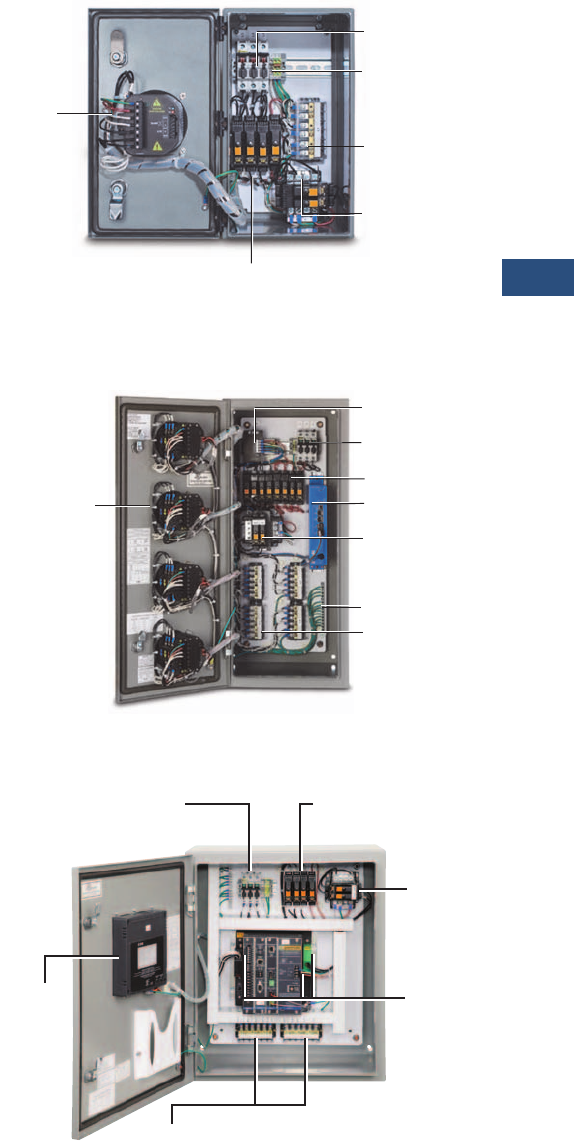
Volume 3—Power Distribution and Control Assemblies CA08100004E—November 2013 www.eaton.com V3-T9-137
9
9
9
9
9
9
9
9
9
9
9
9
9
9
9
9
9
9
9
9
9
9
9
9
9
9
9
9
9
9
9.3
Metering Devices, Protective Relays, Software and Connectivity
Metering Devices
Features and Benefits
●Saves installation time
and cost
●One part number to order;
no need to worry that any
part has been left out
●Pick the meter or meters
you need as it is designed
to fit various Eaton power
and energy meters, at
varying price points
Factory Wired
Most electrical contractors
are very familiar with wiring
meters. However, it does
take time to place the
disconnect, the CT shorting
blocks, the terminal blocks,
the control power
transformer and so on, and
the associated wiring. It is not
uncommon for errors to be
introduced during the
installation of multiple
meters; it’s just inherent in
wiring. With Eaton’s enclosed
meter line, everything is
wired at the factory—the
shorting block, the terminal
blocks and so on—assuring
that it’s done right. Further, to
ensure safety, Eaton’s
enclosed meter line includes
a primary fusible disconnect
for line voltage, which can be
turned off during meter
maintenance.
For applications with line
voltages above the rated
power supply of the meter,
an optional control power
transformer is supplied in the
enclosure. Control voltage
can also be supplied via a
separate source that is wired
to the field installation
terminal block. CT inputs for
the meter are wired directly
to the shorting terminal
blocks for easy field
installation.
Factory-wired products also
save on installation time and
costs. The meters are flush
mounted on the enclosure
door with all inputs/outputs
factory wired to the terminal
blocks.
A meter subpanel assembly
is also available, which
includes all the internal
components of the single-unit
enclosed meter for the IQ
150/250/260 and PXM 2000
Meters wired and mounted
on a subpanel to be installed
into an existing electrical
structure. It comes with a 48-
inch lead for flexibility in
mounting the meters at
various distances.
NEMA Rated
NEMA 12 enclosure prevents
dust and other materials from
entering the equipment.
Internal gaskets also prevent
air irritants from harming the
vital equipment inside. This
quality enclosure meets most
indoor application needs.
NEMA 3R enclosure is
constructed for either indoor
or outdoor use. It helps to
protect personnel from
access to hazardous parts
and provides a degree of
protection for equipment
inside the enclosure against
ingress of solid foreign
objects (falling dirt), harmful
effects of water (rain, sleet,
snow) and external formation
of ice on the enclosure.
NEMA 4X enclosure provides
the same degree of
protection as the NEMA 3R
with the additional protection
against windblown dust,
splashing and hose-directed
water, and corrosion.
NEMA 12 Front View, Door Open, Prewired and Tested
NEMA 12 Multi-Unit View, Door Open, Prewired and Tested
NEMA 12 Single-Unit Enclosed Meter Inside View,
PXM 4000/6000/8000 Series
Control
Power,
Voltage
and CT
Inputs
Fused
Disconnect
Neutral, Ground
and Input/Output
(not shown)
Ter m i n a l B l o c k s
Prewired Control
Power Transformer
Meter Fusing
CT Shorting
Te r m i n al
Block
Control power,
voltage, CT and
Communications
Inputs
Gateway Power
Supply
Fused Control
Power Transformer
Fused Disconnect
Meter Fusing
PX Gateway
Ground
CT Shorting Blocks
Display
Fused
Disconnect
Prewired
Control
Power
Transformer
Meter
Control
Power,
Voltage
and CT
Inputs
CT Shorting Terminal Blocks
Meter
Fusing
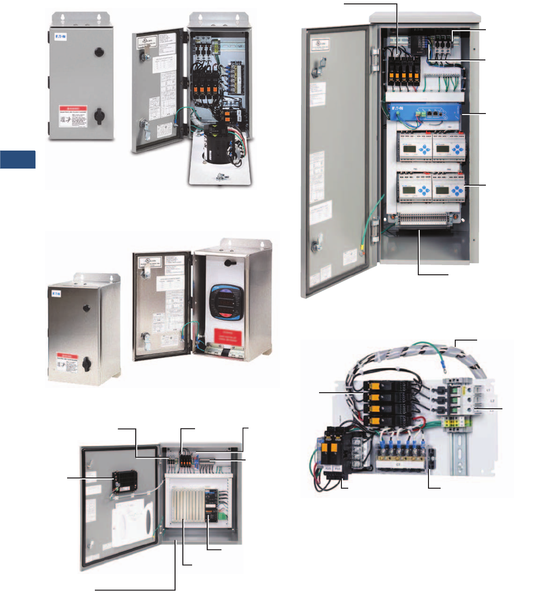
V3-T9-138 Volume 3—Power Distribution and Control Assemblies CA08100004E—November 2013 www.eaton.com
9
9
9
9
9
9
9
9
9
9
9
9
9
9
9
9
9
9
9
9
9
9
9
9
9
9
9
9
9
9
9.3
Metering Devices, Protective Relays, Software and Connectivity
Metering Devices
NEMA 3R Single-Unit Closed and Open, IQ 150/250/260
and PXM 2000 Series
NEMA 4X Single-Unit Closed and Open, IQ 150/250/260
and PXM 2000 Series
Enclosed Power Xpert Multi-Point Meter
PXMP Meter Modules
(not shown—sold separately)
PXMP Meter Base
6-Inch
Color
Touchscreen
Fused
Disconnect
Fuses PXMP
Power
Supply
PXMP
Meter
Base
Connection
s
NEMA 12
Enclosure
(30H x 24W x 12D Inches)
Multi-Unit Enclosed Meter, Inside View of IQ 35M
Prewired Meter Backpan, Single Unit
●Prewired panel to save installation time and cost for retrofits
into existing equipment
●Designed for Eaton’s:
●IQ 100 Meter Series
●IQ 250/260
●Power Xpert Meter 2000 Series
●With or without CPT, depending on voltage
●Order meters separately
Meter
Fusing
Fused
Disconnect
Gateway
Power
Supply
Control Power,
Voltage Current
Sensor and
Communications
Inputs
PX Gateway
Current Sensor
Terminal Strip
Meter
Fusing
48-Inch Meter
Harness
Fused
Disconnec
t
CT Shorting
Block
Optional
CPT
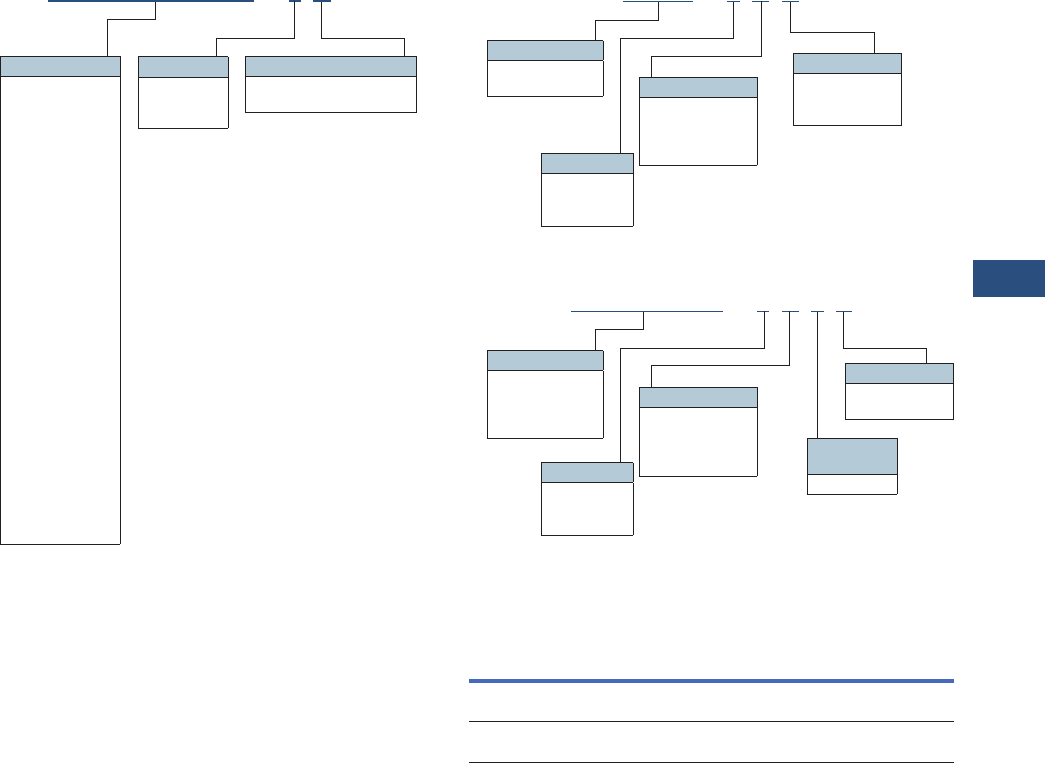
Volume 3—Power Distribution and Control Assemblies CA08100004E—November 2013 www.eaton.com V3-T9-139
9
9
9
9
9
9
9
9
9
9
9
9
9
9
9
9
9
9
9
9
9
9
9
9
9
9
9
9
9
9
9.3
Metering Devices, Protective Relays, Software and Connectivity
Metering Devices
Catalog Number Selection
Single Unit Enclosed Meter
PXM2250MA65105 -2B
Meter Type
PXM4051A1BA
PXM4051A1BB
PXM6051A1BA
PXM6051A1BB
PXM8051A1BA
PXM8051A1BB
PXM2250MA65105
PXM2250MA65115
PXM2250MA65145
PXM2260MA65105
PXM2260MA65115
PXM2260MA65145
PXM2270MA65105
PXM2270MA65115
PXM2270MA65145
PXM2280MA65105
PXM2280MA65115
PXM2280MA65145
PXM2290MA65105
PXM2290MA65115
PXM2290MA65145
IQ250MA65100
IQ250MA65110
IQ250MA65114
IQ260MA65100
IQ260MA65110
IQ260MA65114
IQ150MA6511
IQ150MA6512
NEMA Rating
2 = NEMA 12
3 = NEMA 3R
4 = NEMA 4X
CPT Option
A= 120/240 Vac (no CPT)
B= 480 Vac (CPT)
Enclosed PXMP Meter
Multi Unit Enclosed Meter
Product Selection
Meter Subpanel Assembly
Notes
1Not available with IQ 35M.
Other meter models available upon request in single- and multi-unit enclosed versions.
Description Catalog Number
Meter subpanel assembly for PXM 2000
and IQ 150/250/260 Meters
PXM2K-MSPA-A
Meter subpanel assembly with CPT for PXM 2000
and IQ 150/250/260 Meters
PXM2K-MSPA-B
PXMP -2B D
Meter Type
PXMP-MB
PXMP-MB-AB
NEMA Rating
2 = NEMA 12
3 = NEMA 3R
4 = NEMA 4X
Display
A= None
D= 6-inch color
touchscreen
CPT Option
A=None
B= 120/240 Vac
C= 480 Vac
D= 600 Vac
IQ150MA6511 -2B 4 C
Meter Type
IQ35MA12
IQ150MA6511
IQ250MA65100
IQ260MA65100
NEMA Rating
2 = NEMA 12 1
3 = NEMA 3R
4 = NEMA 4X
Communications
C= Includes
PXG-200E
CPT Option
A= 120/240 Vac
No CPT
B= 480 Vac
CPT 1
Number of
Meters
4 = 4 meters

V3-T9-140 Volume 3—Power Distribution and Control Assemblies CA08100004E—November 2013 www.eaton.com
9
9
9
9
9
9
9
9
9
9
9
9
9
9
9
9
9
9
9
9
9
9
9
9
9
9
9
9
9
9
9.3
Metering Devices, Protective Relays, Software and Connectivity
Metering Devices
Technical Data and Specifications
Enclosed Meters
Note: Specifications are subject to change without notice and represent
the maximum capabilities of the product with all options installed. This is
not a complete feature list. Features and functionality may vary depending
on selected options, firmware version and product model. Please refer to
the technical data sheet and the user manual for detailed specifications.
Description Specification
Enclosure rating NEMA 12, 3R, 4X
Enclosure operating temperature –20°C to +40°C
Note: Temperature range of meter is
–20°C to +70°C. If applied outside, proper
precautions should be taken to avoid exceeding
the maximum and minimum temperature ratings
of the meter.
Dimensions Single unit (IQ 150/250/260 and PXM 2000):
NEMA 12 (8.00W x 16.30H x 10.40D inches),
NEMA 3R/4X (8.00W x 16.30H x 9.60D inches)
Single unit (PXMP):
NEMA 12/3R/4X (24.00W x 30.00H x 12.00D inches)
Single unit (PXM 4000/6000/8000):
NEMA 12 (20.00W x 24.00H x 14.10D inches)
NEMA 3R/4X (20.20W x 24.00H x 13.90D inches)
Multi unit:
NEMA 12 (13.00W x 30.00H x 15.20D inches)
NEMA 3R (13.20W x 30.10H x 14.60D inches)
NEMA 4X (13.00W x 30.00H x 14.00D inches)
Meters Single unit: IQ 150, IQ 250/260, PXM 2000/4000/6000/8000
and PXMP models
Multi unit: IQ 35M, IQ 150 and IQ 250/260
Communications (multi unit only) Power Xpert Gateway 200E
Control voltage 120V–600V (PXMP)—power supply required
Up to 240V (IQ 35M/150/250/260 and PXM 2000/4000/
6000/8000)—no CPT required
Greater than 240V (IQ 150/250/260 and
PXM 2000)—CPT required
Separate source control—no CPT required
Basic model Fusible disconnect—primary voltage
Shorting block(s)—not required for IQ 35M or PXMP
Ground terminal block
Neutral terminal block
Eight-point terminal block(s) for input/output
modules for IQ 250/260 and PXM 2000
Wiring Wired for three-phase, four-wire applications. Three-phase,
three-wire applications—
will need to change the wiring for both the voltage and the
current per the wiring diagram in the meter instruction
manual.
Certifications UL® 508A and cUL®
Source control No separate source control voltage required for applications
below 240 Vac (except PXMP)
Prewired Prewired current transformer, shorting terminal block(s),
neutral, ground, voltage, control
power, fusible disconnect and input/output
terminal block(s)
Latch Padlocking latch provision
Optional features Control power transformer—single unit: 50 VA (IQ150/250/
260) and 150 VA (PXM 4000/6000/8000); multi unit: 250 VA
control power supply for meter where monitored voltage is
480 Vac (IQ150/250/260 and PXM 2000/4000/6000/8000)
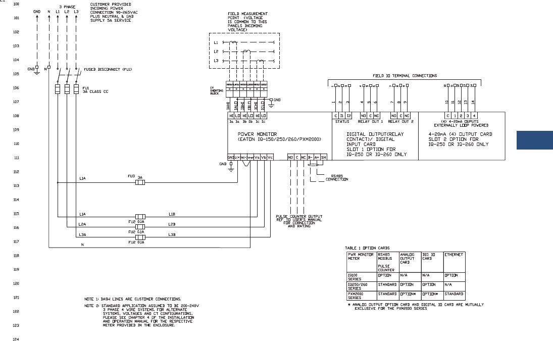
Volume 3—Power Distribution and Control Assemblies CA08100004E—November 2013 www.eaton.com V3-T9-141
9
9
9
9
9
9
9
9
9
9
9
9
9
9
9
9
9
9
9
9
9
9
9
9
9
9
9
9
9
9
9.3
Metering Devices, Protective Relays, Software and Connectivity
Metering Devices
Wiring Diagrams
Single Unit Enclosure—200/240 Vac 50/60 Hz, Three-Phase, Four-Wire System with IQ 150/250/260 or PXM 2000 Meter
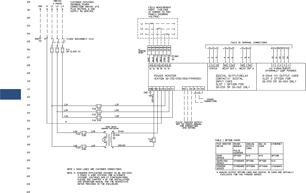
V3-T9-142 Volume 3—Power Distribution and Control Assemblies CA08100004E—November 2013 www.eaton.com
9
9
9
9
9
9
9
9
9
9
9
9
9
9
9
9
9
9
9
9
9
9
9
9
9
9
9
9
9
9
9.3
Metering Devices, Protective Relays, Software and Connectivity
Metering Devices
Single Unit Enclosure—480 Vac 50/60 Hz, Three-Phase, Four-Wire System with IQ 150/250/260 or PXM 2000 Meter
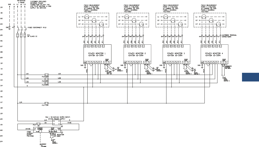
Volume 3—Power Distribution and Control Assemblies CA08100004E—November 2013 www.eaton.com V3-T9-143
9
9
9
9
9
9
9
9
9
9
9
9
9
9
9
9
9
9
9
9
9
9
9
9
9
9
9
9
9
9
9.3
Metering Devices, Protective Relays, Software and Connectivity
Metering Devices
Multi Unit Enclosure—200–240 Vac 50/60 Hz, Three-Phase, Four-Wire System with IQ 35M Meters
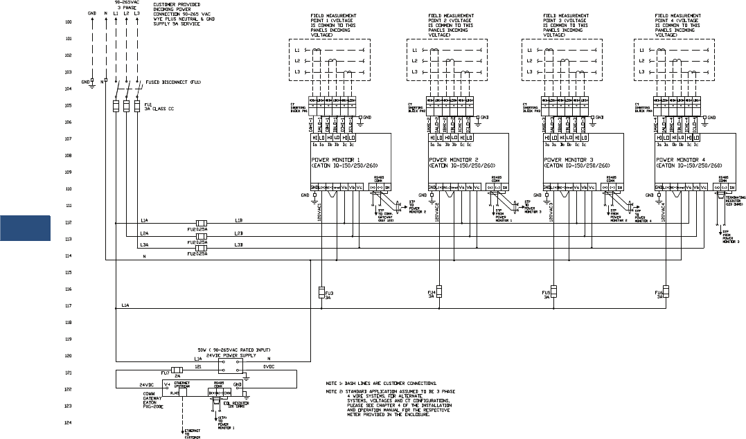
V3-T9-144 Volume 3—Power Distribution and Control Assemblies CA08100004E—November 2013 www.eaton.com
9
9
9
9
9
9
9
9
9
9
9
9
9
9
9
9
9
9
9
9
9
9
9
9
9
9
9
9
9
9
9.3
Metering Devices, Protective Relays, Software and Connectivity
Metering Devices
Multi Unit Enclosure—200–240 Vac 50/60 Hz, Three-Phase, Four-Wire System with IQ 150/250/260 Meters
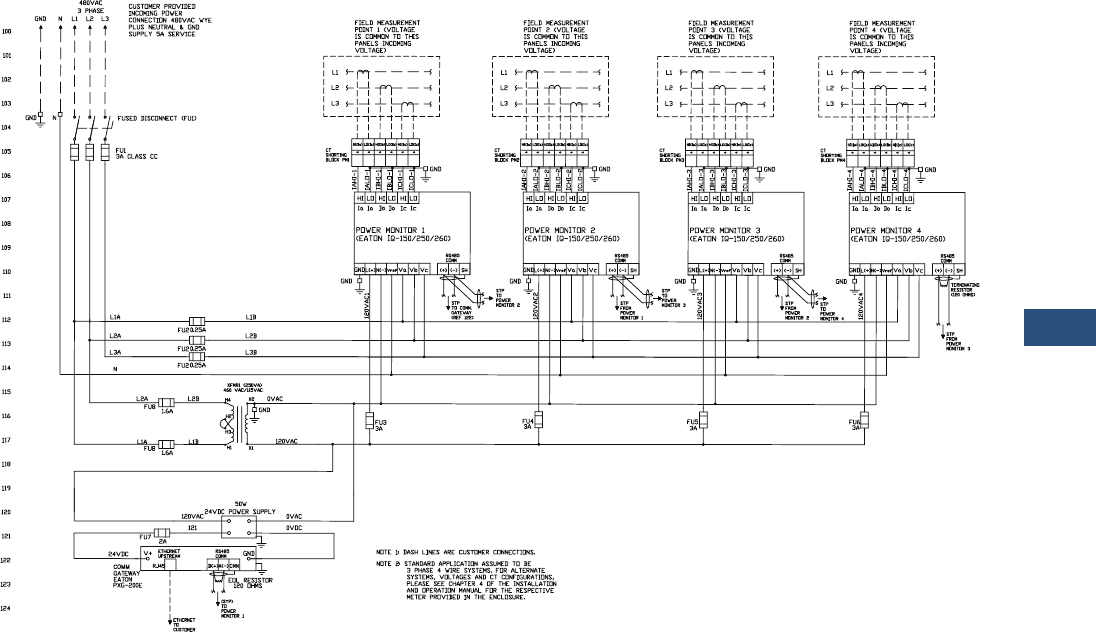
Volume 3—Power Distribution and Control Assemblies CA08100004E—November 2013 www.eaton.com V3-T9-145
9
9
9
9
9
9
9
9
9
9
9
9
9
9
9
9
9
9
9
9
9
9
9
9
9
9
9
9
9
9
9.3
Metering Devices, Protective Relays, Software and Connectivity
Metering Devices
Multi Unit Enclosure—480 Vac 50/60 Hz, Three-Phase, Four-Wire System with IQ 150/250/260 Meters
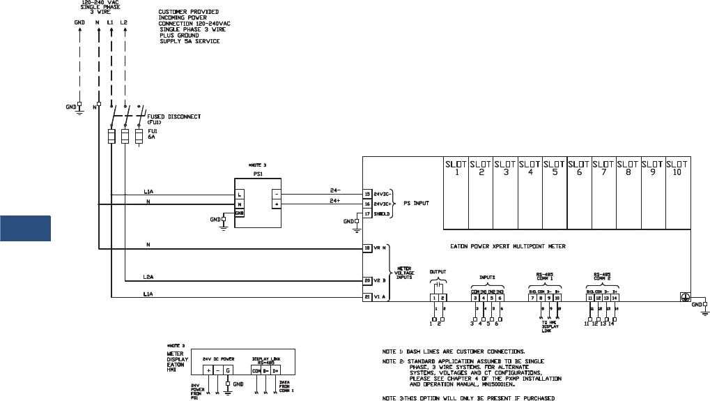
V3-T9-146 Volume 3—Power Distribution and Control Assemblies CA08100004E—November 2013 www.eaton.com
9
9
9
9
9
9
9
9
9
9
9
9
9
9
9
9
9
9
9
9
9
9
9
9
9
9
9
9
9
9
9.3
Metering Devices, Protective Relays, Software and Connectivity
Metering Devices
Single Unit Enclosure—120–240 Vac 50/60 Hz, Three-Wire System with PXMP Meter
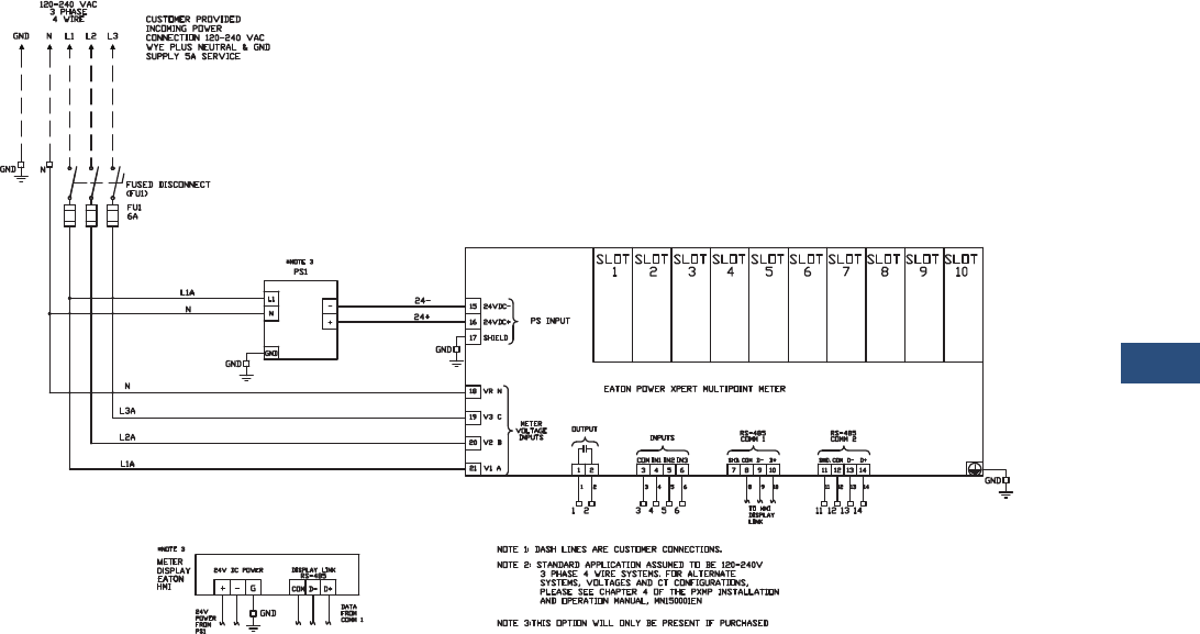
Volume 3—Power Distribution and Control Assemblies CA08100004E—November 2013 www.eaton.com V3-T9-147
9
9
9
9
9
9
9
9
9
9
9
9
9
9
9
9
9
9
9
9
9
9
9
9
9
9
9
9
9
9
9.3
Metering Devices, Protective Relays, Software and Connectivity
Metering Devices
Single Unit Enclosure—120–240 Vac 50/60 Hz, Three-Phase, Four-Wire Wye System with PXMP Meter
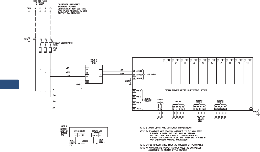
V3-T9-148 Volume 3—Power Distribution and Control Assemblies CA08100004E—November 2013 www.eaton.com
9
9
9
9
9
9
9
9
9
9
9
9
9
9
9
9
9
9
9
9
9
9
9
9
9
9
9
9
9
9
9.3
Metering Devices, Protective Relays, Software and Connectivity
Metering Devices
Single Unit Enclosure—480–600 Vac 50/60 Hz, Three-Phase, Four-Wire Wye System with PXMP Meter
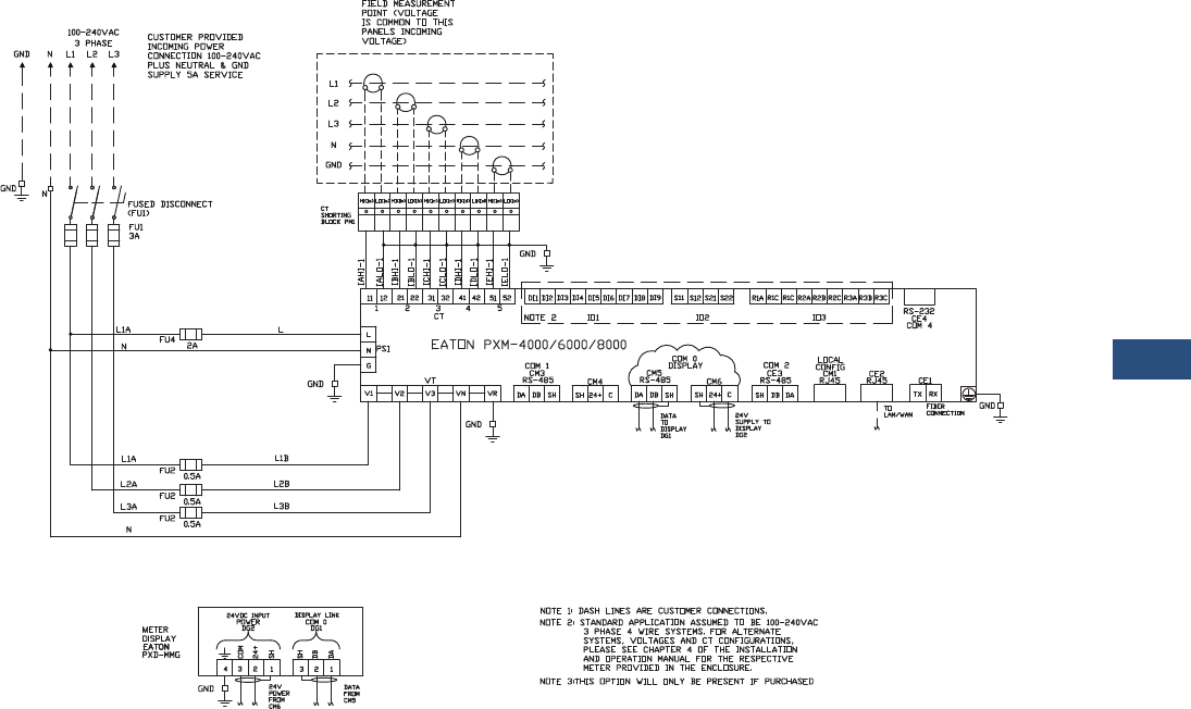
Volume 3—Power Distribution and Control Assemblies CA08100004E—November 2013 www.eaton.com V3-T9-149
9
9
9
9
9
9
9
9
9
9
9
9
9
9
9
9
9
9
9
9
9
9
9
9
9
9
9
9
9
9
9.3
Metering Devices, Protective Relays, Software and Connectivity
Metering Devices
Single Unit Enclosure—200–240 Vac 50/60 Hz, Three-Phase, Four-Wire System with PXM 4000/6000/8000 Meter
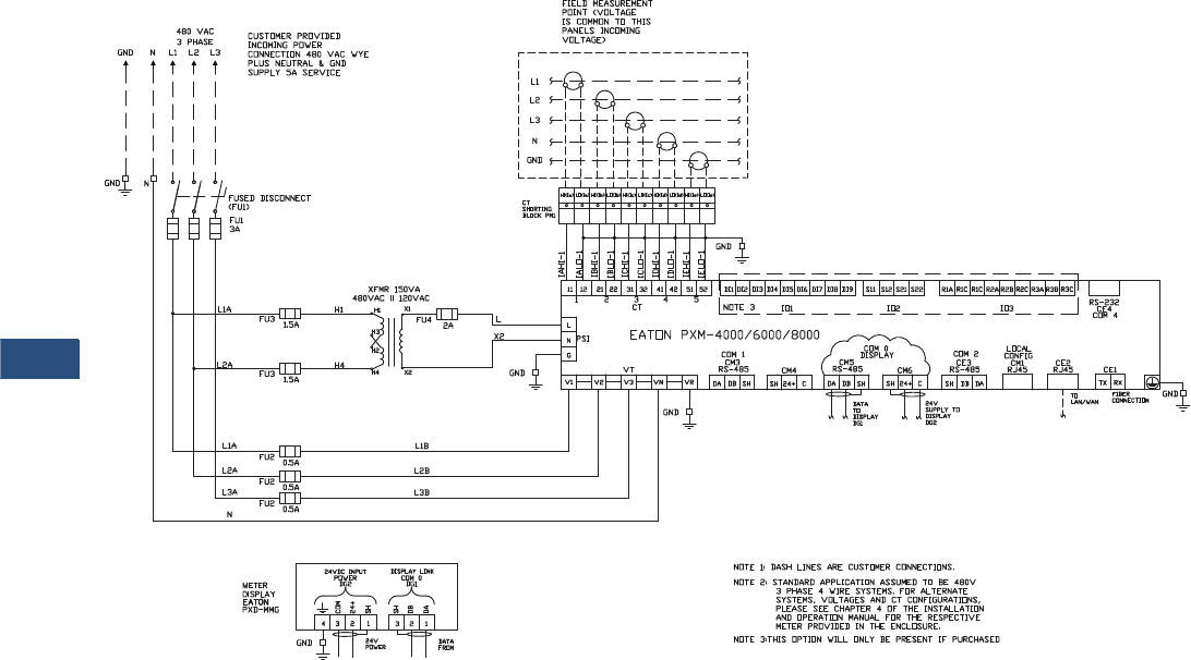
V3-T9-150 Volume 3—Power Distribution and Control Assemblies CA08100004E—November 2013 www.eaton.com
9
9
9
9
9
9
9
9
9
9
9
9
9
9
9
9
9
9
9
9
9
9
9
9
9
9
9
9
9
9
9.3
Metering Devices, Protective Relays, Software and Connectivity
Metering Devices
Single Unit Enclosure—480 Vac 50/60 Hz, Three-Phase, Four-Wire System with PXM 4000/6000/8000 Meter
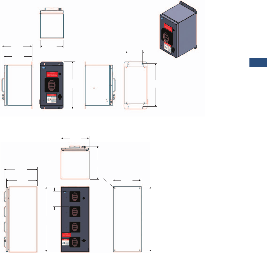
Volume 3—Power Distribution and Control Assemblies CA08100004E—November 2013 www.eaton.com V3-T9-151
9
9
9
9
9
9
9
9
9
9
9
9
9
9
9
9
9
9
9
9
9
9
9
9
9
9
9
9
9
9
9.3
Metering Devices, Protective Relays, Software and Connectivity
Metering Devices
Dimensions
Approximate Dimensions in Inches (mm)
NEMA 12 Single Unit Enclosure
NEMA 12 Multi Unit Enclosure
Rear View
10.39
(263.9) 5.00
(127.0)
14.99
(380.7)
16.30
(414.0)
9.60
(243.8)
Left Side ViewRight Side View Front View
(203.2)
To p
View
8.00
Rear View
15.19
(385.8)
30.00
(762.0)
28.50
(723.9)
14.07
(357.4)
Right Side View Front View
To p
View
15.19
(385.8)
6.97
(177.0)
Typ.
13.00
(330.2)
11.50
(292.1)
ø0.44
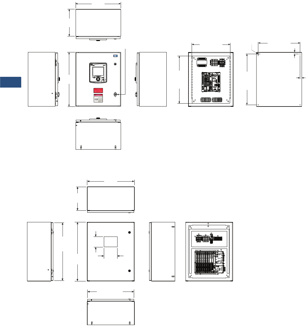
V3-T9-152 Volume 3—Power Distribution and Control Assemblies CA08100004E—November 2013 www.eaton.com
9
9
9
9
9
9
9
9
9
9
9
9
9
9
9
9
9
9
9
9
9
9
9
9
9
9
9
9
9
9
9.3
Metering Devices, Protective Relays, Software and Connectivity
Metering Devices
Approximate Dimensions in Inches (mm)
NEMA 12 PXM 4000/6000/8000 Enclosure
NEMA 12 PXMP Enclosure
Top View
20.00
(508.0)
12.00
(304.8)
Left Side View Front View
Bottom View
Right Side View External Rear ViewFront View (Door Removed)
1/4-Turn
Padlocking Latch
22.50
(571.5)
Mounting
Height
18.50 (469.9)
Mounting Width
0.75
(19.1)
0.75
(19.1)
4xø0.44
24.00
(609.6)
21.00
(533.4)
Subpanel
Height
16.94 (430.3)
Subpanel Width
HMI
Cutout
Top View
12.00
(304.8)
Left Side View Front View
Bottom View
Right Side
View
Front View
(Door Removed)
29.50
(749.3)
Door
30.00
(762.0)
24.00
(609.6)
23.63 (600.2)
Door
5.25
(133.4)
6.79
(172.4)
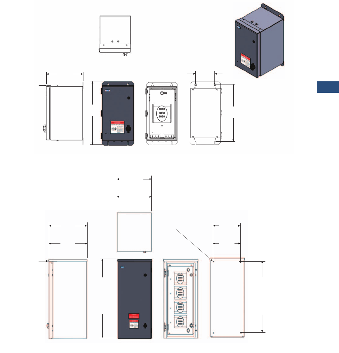
Volume 3—Power Distribution and Control Assemblies CA08100004E—November 2013 www.eaton.com V3-T9-153
9
9
9
9
9
9
9
9
9
9
9
9
9
9
9
9
9
9
9
9
9
9
9
9
9
9
9
9
9
9
9.3
Metering Devices, Protective Relays, Software and Connectivity
Metering Devices
Approximate Dimensions in Inches (mm)
NEMA 3R/4X Single Unit Enclosure
NEMA 3R/4X Multi Unit Enclosure
Rear View
5.00
(127.0)
14.99
(380.7)
16.30
(414.0)
9.58
(243.3)
Front ViewRight Side View Front View
To p
View
This Drip Cap is
on NEMA 3R Only
Rear View
27.00
(685.8)
(NEMA 3R)
28.50
(723.9)
(NEMA 4X)
Right Side View Front View
ø0.34 (NEMA 3R)
ø0.41 (NEMA 4X)
Front View
(no door)
10.50
(266.7)
(NEMA 3R)
11.50
(292.1)
(NEMA 4X)
30.07
(763.8)
(NEMA 3R)
30.00
(762.0)
(NEMA 4X)
To p
View
This Drip Cap is
on NEMA 3R Only
14.64
(371.9)
(NEMA 3R)
14.03
(356.4)
(NEMA 4X)
13.20
(335.3)
(NEMA 3R)
13.00
(330.2)
(NEMA 4X)
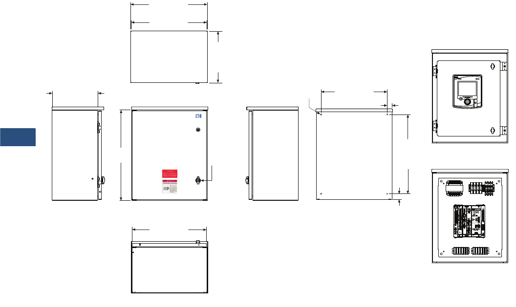
V3-T9-154 Volume 3—Power Distribution and Control Assemblies CA08100004E—November 2013 www.eaton.com
9
9
9
9
9
9
9
9
9
9
9
9
9
9
9
9
9
9
9
9
9
9
9
9
9
9
9
9
9
9
9.3
Metering Devices, Protective Relays, Software and Connectivity
Metering Devices
Approximate Dimensions in Inches (mm)
NEMA 3R PXM 4000/6000/8000 Unit Enclosure
Top View
20.20 (513.1)
Top Width
20.00 (508.0)
Enclosure Width
13.70
(348.0)
Top
Depth
Left Side View Front View
Bottom View
Right Side View External Rear View
12.00 (304.8)
Enclosure
Depth
Front View (Door Removed)
Front View (Subpanel Only)
19.63 (498.6)
Door
24.00
(609.6)
1/4-Turn
Padlocking
Latch
21.00
(533.4)
Mounting
Height
4xø0.34 1.25
(31.8)
17.50 (444.5)
Mounting Width
1.50
(38.1)
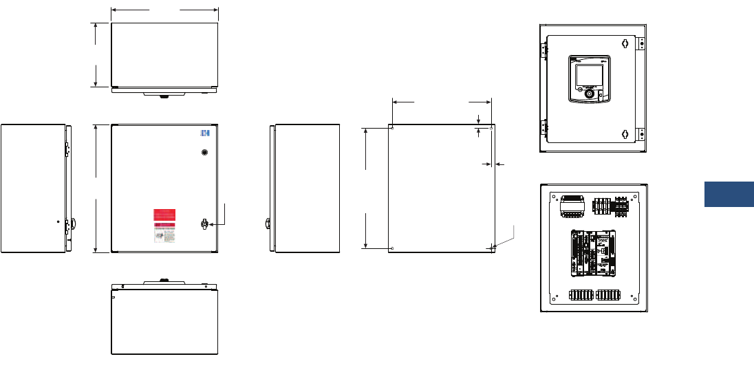
Volume 3—Power Distribution and Control Assemblies CA08100004E—November 2013 www.eaton.com V3-T9-155
9
9
9
9
9
9
9
9
9
9
9
9
9
9
9
9
9
9
9
9
9
9
9
9
9
9
9
9
9
9
9.3
Metering Devices, Protective Relays, Software and Connectivity
Metering Devices
Approximate Dimensions in Inches (mm)
NEMA 4X PXM 4000/6000/8000 Unit Enclosure
Top View
20.00
(508.0)
12.00
(304.8)
Left Side View Front View
Bottom View
Right Side View External Rear View
Front View (Door Removed)
Front View (Subpanel Only)
24.00
(609.6)
1/4-Turn
Padlocking
Latch
22.50
(571.5)
Mounting
Height
4xø0.44
0.75
(19.1)
18.50 (469.9)
Mounting Width
0.75
(19.1)
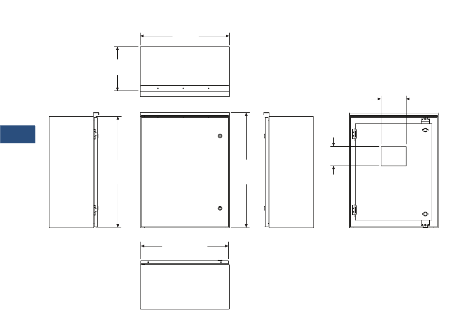
V3-T9-156 Volume 3—Power Distribution and Control Assemblies CA08100004E—November 2013 www.eaton.com
9
9
9
9
9
9
9
9
9
9
9
9
9
9
9
9
9
9
9
9
9
9
9
9
9
9
9
9
9
9
9.3
Metering Devices, Protective Relays, Software and Connectivity
Metering Devices
Approximate Dimensions in Inches (mm)
NEMA 3R PXMP Multi Unit Enclosure
Right Side ViewFront ViewLeft Side View
Top View
Bottom View
12.00
(304.8)
24.00
(609.6)
23.63 (600.2)
Door
30.00
(762.0)
Enclosure
30.80
(782.3)
Overall
5.25
(133.4)
6.79
(172.5)
HMI
Cutout
Front View
(Door Removed)
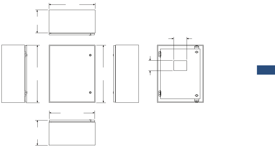
Volume 3—Power Distribution and Control Assemblies CA08100004E—November 2013 www.eaton.com V3-T9-157
9
9
9
9
9
9
9
9
9
9
9
9
9
9
9
9
9
9
9
9
9
9
9
9
9
9
9
9
9
9
9.3
Metering Devices, Protective Relays, Software and Connectivity
Metering Devices
Approximate Dimensions in Inches (mm)
NEMA 4X PXMP Multi Unit Enclosure
30.00
(762.0)
Enclosure
Front View
(Door Removed)
Right Side ViewFront ViewLeft Side View
Top View
Bottom View
5.25
(133.4)
6.79
(172.5)
HMI
Cutout
12.00
(304.8)
24.00
(609.6)
13.07
(332.0)
Overall
23.63 (600.2)
Door
30.00
(762.0)
Overall

V3-T9-158 Volume 3—Power Distribution and Control Assemblies CA08100004E—November 2013 www.eaton.com
9
9
9
9
9
9
9
9
9
9
9
9
9
9
9
9
9
9
9
9
9
9
9
9
9
9
9
9
9
9
9.4
Metering Devices, Protective Relays, Software and Connectivity
Protective Relays
Contents
Description Page
Product Selection Guide
FP-6000 Feeder Protection . . . . . . . . . . . . . . . . . . V3-T9-162
FP-5000 Feeder Protection . . . . . . . . . . . . . . . . . . V3-T9-172
FP-4000 Feeder Protection . . . . . . . . . . . . . . . . . . V3-T9-180
MP-3000 Motor Protection . . . . . . . . . . . . . . . . . . V3-T9-188
MP-4000 Motor Protection . . . . . . . . . . . . . . . . . . V3-T9-198
MD-3000 Motor/Generator Differential Relay . . . . V3-T9-204
Digitrip 3000 . . . . . . . . . . . . . . . . . . . . . . . . . . . . . V3-T9-207
VR-300 Multifunctional Voltage Relay . . . . . . . . . . V3-T9-217
DP-300 Current Differential Protection Relay . . . . . V3-T9-221
EDR-3000 Feeder Protection . . . . . . . . . . . . . . . . . V3-T9-226
ETR-4000 Transformer Protection Relay . . . . . . . . V3-T9-237
Ground Fault Relay. . . . . . . . . . . . . . . . . . . . . . . . . V3-T9-250
Universal RTD Module . . . . . . . . . . . . . . . . . . . . . . V3-T9-254
IQ 125 Volt DC Power Supply. . . . . . . . . . . . . . . . . V3-T9-258
Product Selection Guide
Protective Relay Selection Chart
Protection Functions
Notes
1The 50 and 51 protective functions can be controlled for reverse, forward or both directional protection.
2The 50N, 51N, 50G and 51G protective functions can be controlled for reverse, forward or both directional protection.
IEEE
Device
Number
Feeder
Protection
Motor
Protection
Voltage
Protection
Transformer
Protection
Description DT-3000 EDR-3000 FP-4000 FP-5000 FP-6000 MP-3000 MP-4000 MD-3000 VR-300 DP-300 ETR-4000
Section Page Number V3-T9-207 V3-T9-226 V3-T9-180 V3-T9-172 V3-T9-162 V3-T9-188 V3-T9-198 V3-T9-204 V3-T9-217 V3-T9-221 V3-T9-237
Phase inst. OC 50 ■■ ■■■■ ■ ■
Phase TOC 51 ■■ ■■■■ ■ ■
Ground inst. OC (measured) 50G ■■ ■■■ ■
Ground TOC (measured) 51G ■■ ■■■■ ■ ■
Phase directional control 167 ■■
Ground directional control 267N ■■
Phase voltage restrained OC 51VR ■■
No. of curves (ANSI/IEC/thermal) 11 11 10 10 10 11
Zone interlocking ■■ ■■■ ■
Thermal overload 49 ■■ ■ ■
Locked rotor 49S/51 ■■ ■
Jam/stall 51R ■■ ■
Undervoltage 27 ■■■ ■ ■
Current unbalance 46 ■■■■ ■
Negative sequence voltage 47 ■■■ ■ ■
Power factor 55 ■■■ ■
Overvoltage 59 ■■■ ■ ■
Frequency (over/under) 81 ■■■ ■ ■
Forward/reverse VARs 32V ■■

Volume 3—Power Distribution and Control Assemblies CA08100004E—November 2013 www.eaton.com V3-T9-159
9
9
9
9
9
9
9
9
9
9
9
9
9
9
9
9
9
9
9
9
9
9
9
9
9
9
9
9
9
9
9.4
Metering Devices, Protective Relays, Software and Connectivity
Protective Relays
Protection Functions, continued
Control Functions
Notes
187B using zone selective interlocking.
287M or 87G (motor or generator differential).
387M, 87T or 87G (motor, transformer or generator differential).
487T (transformer differential).
IEEE
Device
Number
Feeder
Protection
Motor
Protection
Voltage
Protection
Transformer
Protection
Description DT-3000 EDR-3000 FP-4000 FP-5000 FP-6000 MP-3000 MP-4000 MD-3000 VR-300 DP-300 ETR-4000
Section Page Number V3-T9-207 V3-T9-226 V3-T9-180 V3-T9-172 V3-T9-162 V3-T9-188 V3-T9-198 V3-T9-204 V3-T9-217 V3-T9-221 V3-T9-237
Differential 87 ■ 1■ 1■ 1■ 1■ 2■ 3■ 4
Forward/reverse power 32 ■■ ■
Sync check 25 ■■ ■
Reclosing 79 ■
Loss of potential block LOP ■■
Cold load pickup ■■ ■
Breaker failure 50BF ■■■■ ■
2nd harmonic restrain ■■
5th harmonic restrain ■■
4th harmonic restrain ■
87 GD ground differential ■
IEEE
Device
Number
Feeder
Protection
Motor
Protection
Voltage
Protection
Transformer
Protection
Description DT-3000 EDR-3000 FP-4000 FP-5000 FP-6000 MP-3000 MP-4000 MD-3000 VR-300 DP-300 ETR-4000
Section Page Number V3-T9-207 V3-T9-226 V3-T9-180 V3-T9-172 V3-T9-162 V3-T9-188 V3-T9-198 V3-T9-204 V3-T9-217 V3-T9-221 V3-T9-237
Remote open/close ■■ ■■■(Trip only) ■■ ■
Programmable I/O ■■ ■■■■ ■ ■ ■
Programmable logic control ■■■
Multiple settings groups 4 4 4 4 4
Number of starts limit ■■
Starts per hour ■■
Time between starts ■■
Emergency override ■■
Reduced voltage starting ■■
Trip lock out ■■ ■■■■ ■ ■

V3-T9-160 Volume 3—Power Distribution and Control Assemblies CA08100004E—November 2013 www.eaton.com
9
9
9
9
9
9
9
9
9
9
9
9
9
9
9
9
9
9
9
9
9
9
9
9
9
9
9
9
9
9
9.4
Metering Devices, Protective Relays, Software and Connectivity
Protective Relays
Metering Functions
Monitoring Functions
Note
1Differential and restrain current only.
IEEE
Device
Number
Feeder
Protection
Motor
Protection
Voltage
Protection
Transformer
Protection
Description DT-3000 EDR-3000 FP-4000 FP-5000 FP-6000 MP-3000 MP-4000 MD-3000 VR-300 DP-300 ETR-4000
Section Page Number V3-T9-207 V3-T9-226 V3-T9-180 V3-T9-172 V3-T9-162 V3-T9-188 V3-T9-198 V3-T9-204 V3-T9-217 V3-T9-221 V3-T9-237
Amperes ■■ ■■■■ ■ ■ ■ 1■
Ampere demand ■■ ■■■ ■ ■
Volts ■■■ ■ ■
Phase angle (current and voltage) ■■■ ■ Current only
Positive, negative and zero sequence ■■■■ ■ ■
Watts ■■■ ■
Watt Demand ■■■ ■
Watthour ■■■ ■
VARs ■■■ ■
VAR demand ■■■ ■
VAR-hour ■■■ ■
VA ■■■ ■
VA Demand ■■■ ■
VA-hour ■■■ ■
Frequency ■■■ ■ ■
Trending (load profile) ■■■
Minimum/maximum recording ■■■■
Max. only ■■
IEEE
Device
Number
Feeder
Protection
Motor
Protection
Voltage
Protection
Transformer
Protection
Description DT-3000 EDR-3000 FP-4000 FP-5000 FP-6000 MP-3000 MP-4000 MD-3000 VR-300 DP-300 ETR-4000
Section Page Number V3-T9-207 V3-T9-226 V3-T9-180 V3-T9-172 V3-T9-162 V3-T9-188 V3-T9-198 V3-T9-204 V3-T9-217 V3-T9-221 V3-T9-237
Trip circuit monitor ■■■■ ■
Breaker wear ■■■■ ■
Failure to close ■■■■ ■
Oscillography ■■■■ ■
Sequence of events ■■■■■ ■ ■
Trip target data ■■ ■■■■ ■ ■ ■
Clock ■■■■■ ■ ■
Number of starts ■■ ■
Acceleration time ■■ ■
RTD temperature ■■ ■ ■
Hottest RTD ■■ ■ ■

Volume 3—Power Distribution and Control Assemblies CA08100004E—November 2013 www.eaton.com V3-T9-161
9
9
9
9
9
9
9
9
9
9
9
9
9
9
9
9
9
9
9
9
9
9
9
9
9
9
9
9
9
9
9.4
Metering Devices, Protective Relays, Software and Connectivity
Protective Relays
Communications
Construction
Standards
IEEE
Device
Number
Feeder
Protection
Motor
Protection
Voltage
Protection
Transformer
Protection
Description DT-3000 EDR-3000 FP-4000 FP-5000 FP-6000 MP-3000 MP-4000 MD-3000 VR-300 DP-300 ETR-4000
Section Page Number V3-T9-207 V3-T9-226 V3-T9-180 V3-T9-172 V3-T9-162 V3-T9-204 V3-T9-198 V3-T9-204 V3-T9-217 V3-T9-221 V3-T9-237
Local human machine
interface
■ ■■■■■ ■■ ■
Remote
communication port
RS-232 ■■■■ ■
RS-485 ■■■■ ■
Ethernet copper ■ ■
Frequency shift key ■■■■
Optional
Addressable
Protocols
■■■■■■
INCOM ■■■■■■
Modbus-RTU ■ ■■■■■ ■ ■
Modbus-TCP ■ ■
IEEE
Device
Number
Feeder
Protection
Motor
Protection
Voltage
Protection
Transformer
Protection
Description DT-3000 EDR-3000 FP-4000 FP-5000 FP-6000 MP-3000 MP-4000 MD-3000 VR-300 DP-300 ETR-4000
Section Page Number V3-T9-207 V3-T9-226 V3-T9-180 V3-T9-172 V3-T9-162 V3-T9-188 V3-T9-198 V3-T9-204 V3-T9-217 V3-T9-221 V3-T9-237
Panel mount case ■ ■■■■■ ■■■ ■
Drawout Optional Removable
terminals
■Optional Optional Optional Optional Optional Removable
terminals
Operating
temperature range
–30°–55°C –40°– 60°C –40°– 60°C –40°– 60°C –40°–60°C –20°–60°C –20°–60°C –30°–55°C –20°–70°C 20°–70°C –40°– 60°C
Power supply options 120–
240 Vac
19–
300 Vdc
48–
125 Vac/Vdc
48–
125 Vac/Vdc
48–
125 Vac/Vdc
120–
240 Vac
120–
240 Vac
120–
240 Vac
40–
250 Vac
40–
250 Vac
19–
300 Vdc
24–250
Vdc
40–250
Vac
100–240
Vac/Vdc
100–240
Vac/Vdc
100–240
Vac/Vdc
24–
250 Vdc
90–
250 Vdc
90–
250 Vdc
40–
250 Vac
AC current inputs ■ ■■■■■ ■■■ ■
AC voltage inputs ■■■ ■ ■
Wye PTs ■■■ ■ ■
Delta/open delta PTs ■■■ ■ ■
Binary inputs ■ ■■■ ■■ ■■■ ■■
Alarm outputs 2 Form C 1 Form C 2 Form C 2 Form C 2 Form C 3 ■2 Form C 1 Form C 1 NO 1 Form C
Trip outputs 2 3 5 5 5 ■■■■ ■■
Analog outputs ■■ ■
Local display ■ ■■■ ■■ ■■■ ■■
LEDs (local targets) ■ ■■■ ■■ ■■■ ■■
IEEE
Device
Number
Feeder
Protection
Motor
Protection
Voltage
Protection
Transformer
Protection
Description DT-3000 EDR-3000 FP-4000 FP-5000 FP-6000 MP-3000 MP-4000 MD-3000 VR-300 DP-300 ETR-4000
Section Page Number V3-T9-207 V3-T9-226 V3-T9-180 V3-T9-172 V3-T9-162 V3-T9-188 V3-T9-198 V3-T9-204 V3-T9-217 V3-T9-221 V3-T9-237
ANSI ■ ■■■■■ ■■■ ■■
IEC ■ ■■■■■ ■■■ ■■
UL ■ ■■■■■ ■■■ ■■
CE DT-3030 only ■■■■ ■
CSA ■ ■■■■■ ■■ ■
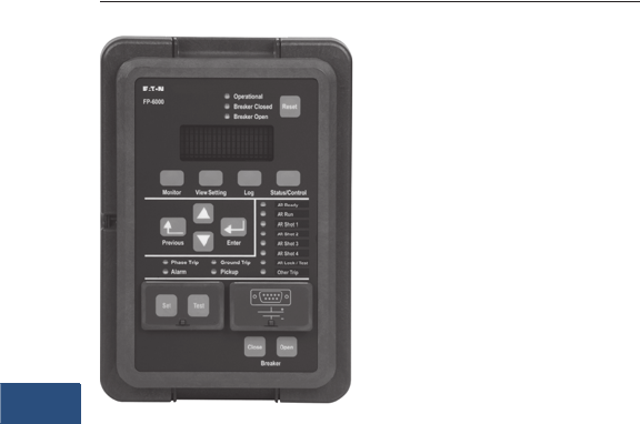
V3-T9-162 Volume 3—Power Distribution and Control Assemblies CA08100004E—November 2013 www.eaton.com
9
9
9
9
9
9
9
9
9
9
9
9
9
9
9
9
9
9
9
9
9
9
9
9
9
9
9
9
9
9
9.4
Metering Devices, Protective Relays, Software and Connectivity
Protective Relays
Feeder Protection FP-6000
Contents
Description Page
Product Selection Guide . . . . . . . . . . . . . . . . . . . . V3-T9-158
FP-6000 Feeder Protection
Features, Benefits and Functions . . . . . . . . . . . V3-T9-163
Standards and Certifications . . . . . . . . . . . . . . . V3-T9-164
Catalog Number Selection . . . . . . . . . . . . . . . . V3-T9-165
Product Selection . . . . . . . . . . . . . . . . . . . . . . . V3-T9-165
Technical Data and Specifications . . . . . . . . . . . V3-T9-166
Dimensions. . . . . . . . . . . . . . . . . . . . . . . . . . . . V3-T9-171
FP-5000 Feeder Protection . . . . . . . . . . . . . . . . . . V3-T9-172
FP-4000 Feeder Protection . . . . . . . . . . . . . . . . . . V3-T9-180
MP-3000 Motor Protection . . . . . . . . . . . . . . . . . . V3-T9-188
MP-4000 Motor Protection . . . . . . . . . . . . . . . . . . V3-T9-198
MD-3000 Motor/Generator Differential Relay . . . . V3-T9-204
Digitrip 3000 . . . . . . . . . . . . . . . . . . . . . . . . . . . . . V3-T9-207
VR-300 Multifunctional Voltage Relay . . . . . . . . . . V3-T9-217
DP-300 Current Differential Protection Relay . . . . . V3-T9-221
EDR-3000 Feeder Protection . . . . . . . . . . . . . . . . . V3-T9-226
ETR-4000 Transformer Protection Relay . . . . . . . . V3-T9-237
Ground Fault Relay. . . . . . . . . . . . . . . . . . . . . . . . . V3-T9-250
Universal RTD Module . . . . . . . . . . . . . . . . . . . . . . V3-T9-254
IQ 125 Volt DC Power Supply. . . . . . . . . . . . . . . . . V3-T9-258
FP-6000 Feeder Protection
Product Description
●Microprocessor-based
protection with monitoring
and control for medium
voltage main and feeder
applications
●Current, voltage, frequency
and power protection for
electric power distribution
systems
●Complete metering of
voltage, currents, power,
energy, minimum/
maximum and demand
functions
●Programmable logic control
functions for main-tie-main
and main-main transfer
schemes
●Trip logs, event logs and
waveform capture for
better fault analysis and
system restoration
●Data Logger to provide
energy usage profiles for
better planning, utilization
and energy usage
●Compact, drawout case
design or fixed case design
●Meets ANSI and UL
Application Description
Eaton’s FP-6000 Protection
Relay provides complete three-
phase and ground overcurrent,
voltage, frequency and power
protection plus metering in
a single, compact drawout
case. It may be used as a
reclosing relay; primary
protection on feeders; mains
and tie circuit breaker
applications; or as backup
protection for transformers,
high voltage lines and
differential protection.
The FP-6000 takes full
advantage of its
microprocessor technology,
providing the user new
freedom and a wealth of data-
gathering features. The relay
performs self-checking of all
major hardware and firmware
protection elements to ensure
their operation in the event of a
system or component electrical
failure or fault. Protection
functions are well suited for
main and distribution feeder
circuit applications.
Programmable logic control
functions make the FP-6000
relay ideally suited for main-tie-
main and main 1/main two
transfer schemes.
The FP-6000 is the only relay in
its class that offers a flexible,
yet simple reclosing control. Its
compact design makes it ideal
for polemounted recloser
controls. The zone interlocking
feature can be utilized for bus
protection instead of an
expensive and complicated bus
differential (87B) scheme. The
FP-6000 works directly with
the FP-5000, FP-4000, Digitrip®
3000 and Digitrip MV relays.
The breaker failure protection
provides faster remote backup
clearing times for stuck breaker
operation. In addition to the
breaker failure protection, the
FP-6000 can be programmed to
detect residual current when
the breaker is open to detect
flashover conditions. The
FP-6000 provides trip circuit
monitoring and alarming
features. It continually monitors
the trip circuit for continuity
and readiness to trip. Open
and close pushbuttons are
conveniently located on the
front of the relay for local
breaker operation.
When an electrical fault
or disturbance occurs, the
FP-6000 begins to store the
following in non-volatile
memory:
●Voltage and current
sampled data
●Calculated values
●Status of internal protection
functions, logic, contact
inputs and outputs
Retrieval and viewing of the
data is easy, aiding in the quick
analysis and restoration of your
electric power system.
When the FP-6000 isn’t
responding to disturbances in
the power system, it’s
providing valuable metering
information at the relay and
remotely. It provides energy
usage and demand reading,
and can alarm when usage
reaches a set value. Power
factor measurements can be
used for cap bank switching
to control kVAR demand.
Onboard data trending can
provide load profiles for up
to 40 days.

Volume 3—Power Distribution and Control Assemblies CA08100004E—November 2013 www.eaton.com V3-T9-163
9
9
9
9
9
9
9
9
9
9
9
9
9
9
9
9
9
9
9
9
9
9
9
9
9
9
9
9
9
9
9.4
Metering Devices, Protective Relays, Software and Connectivity
Protective Relays
Features, Benefits and Functions
●Complete protection,
metering and control in
a single compact case to
reduce panel space,
wiring and costs
●Flexible current, voltage
and frequency protection
and programmability to
cover a broad range of
applications while
simplifying relay ordering
and reducing inventory
●Integral test function
reduces maintenance
time and expense
●Relay self-diagnostics and
reporting improves uptime
and troubleshooting
●Breaker trip circuit
monitoring improves the
reliability of the breaker
operation
●Programmable LEDs and
logic control features that
can replace and eliminate
external auxiliary relays,
timers, light and wiring
●Zone selective interlocking
improves coordination and
tripping times and saves
money compared to a
traditional bus differential
scheme
●Trip and event recording
in non-volatile memory
provides detailed
information for analysis
and system restoration
●256 cycles of waveform
capture aids in post fault
analysis (viewable using
PowerNet and
NPWAVEFORM
component
●Front RS-232 port and
PowerPort software
provides local computer
access and a user-friendly,
Windows-based interface
for relay settings, and
configuration and data
retrieval
●Drawout case design
for quick and easy relay
removal and replacement
●Breaker open/close
control from relay
faceplate or remotely
via communications
●Remote communications
to Eaton PowerNet
monitoring system or PC
●Free PowerPort utility
software for local PC
interface to the FP-6000 for
relay settings, monitoring
and control
The protection functions are
listed below and shown on
Page V3-T9-168.
The FP-6000 provides phase
overcurrent (forward, reverse
or both):
●Two-stage instantaneous
with timers (50P-1 and
50P-2)
●Inverse time overcurrent
(51P)
●Directional control (67P)
●10 standard curves
●Instantaneous or time
delay reset
●Voltage restrained inverse
time overcurrent (51P2)
The FP-6000 provides two
ground overcurrent elements,
one measured (IX) and one
calculated (IR):
●Independent measured
ground or neutral
directional overcurrent
elements:
●Two-stage
instantaneous with
timers (50X-1 and 50X-2)
●Inverse time overcurrent
(51X)
●Ground directional
polarizing (67N) -3vo and
negative sequence
●10 standard curves
●Instantaneous or time
delay reset
●Independent calculated
ground or neutral
directional overcurrent
elements:
●Two-stage
instantaneous with
timers (50R-1 and
50R-2)
●Inverse time overcurrent
(51R)
●Ground directional
polarizing (67N) –3vo,
I pol and negative
sequence
●10 standard curves
●Instantaneous or time
delay reset
The FP-6000 also provides
the following protective
features:
●Breaker failure (50BF)
●Phase unbalance negative
sequence overcurrent
(46-1, 46-2)
●Phase voltage unbalance
and sequence protection
(47-1, 47-2)
●Main 3-phase under/
overvoltage (27M-1,
27M-2, 59M-1, 59M-2)
●Under/overfrequency
(81U-1, 81U-2, 81O-1,
81O-2)
●Auxiliary single-phase
under/overvoltage (27A-1,
27A-2, 59A-1, 59A-2)
●Neutral voltage (59N-1,
59N-2)
●Apparent and
displacement power factor
(55A, 55D)
●Forward/reverse power
protection (32-1, 32-2,
32-3)
●Forward/reverse VAR
protection (32V-1, 32V-2,
32V-3)
●Thermal Protection (49DT,
49MT, 49DA, 49MA)
●Sync check (25)
●Zone interlocking for bus
protection (87B). The
FP-6000 feeder relay
includes a zone selective
interlocking feature that can
be used with other Eaton
devices like the Digitrip
3000 overcurrent relay
The FP-6000 provides the
following metering functions:
●Amperes (rms, phasor
and sequence)
●Amperes demand and
peak demand.
●Volts (rms, phasor and
sequence).
●VA and VA demand
●Watts and kW demand and
peak demand.
●Forward/reverse/net kWh
●Vars and kVAR demand
and peak demand
●Lead/lag/net kVARh
●Power factor
●Frequency
●Voltage and current %THD
and magnitude THD
●RTD
●Minimum/maximum
recording with date/
time stamp
●Trending (load profile
over time)
The FP-6000 provides the
following monitoring and data
recording functions that
enhance the security of the
protection system and
provides useful information
for scheduling maintenance:
●Trip circuit monitoring
●Breaker wear (accumulated
interrupted current)
●Waveform capture
(256 cycles total, up to
16 events)
●Fault data logs (up to
16 events).
●Sequence of events report
(up to 100 events)
●Clock (1ms stamping)
The FP-6000 provides
standard control functions
plus userconfigurable custom
control capabilities. This logic
can be used for applications
such as main-tie-main
transfer schemes.
●Remote open/close.
●Optional local open/close
●Programmable I/O
●Programmable logic gates
and timers
●Multiple setting groups
(up to four)
●Bus transfer logic
●Cold load pickup
●Loss of potential
(PT blown fuses)
●Autoreclose Function (79)
●Auto Zone Coordination
The FP-6000 supports the
following communication
options:
●Local HMI
●Password protected
●Addressable
●Front RS-232 port
●Rear RS-485 port
●Rear FSK port
●Protocols:
●INCOM
●Modbus RTU
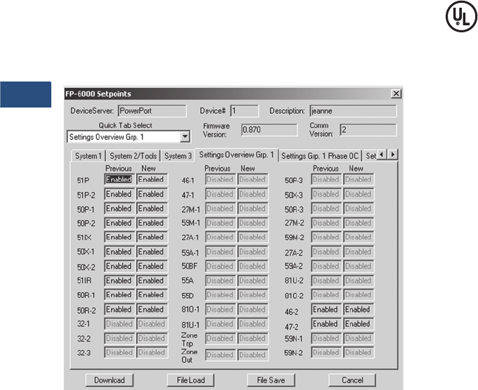
V3-T9-164 Volume 3—Power Distribution and Control Assemblies CA08100004E—November 2013 www.eaton.com
9
9
9
9
9
9
9
9
9
9
9
9
9
9
9
9
9
9
9
9
9
9
9
9
9
9
9
9
9
9
9.4
Metering Devices, Protective Relays, Software and Connectivity
Protective Relays
Communication Software
Eaton provides two types
of communication software.
The first is PowerPort. It runs
on a PC or laptop for easy
access to a single relay
to change set points or
configuration and to view
metered values and stored
data. PowerPort is free and
can be downloaded from
the Eaton Web site at
the following URL:
www.eaton.com; search
for “PowerPort.”
The second package is
PowerNet. PowerNet is a
power management software
package that is designed
for continuous, remote
monitoring of many devices.
It provides all the functionality
of PowerPort plus additional
functions such as billing,
trending and graphics.
Contact your local Eaton
representative for more
information on PowerNet
software.
PowerPort and PowerNet Protection Overview Screen
Standards and Certifications
Compliance
●UL recognized, File #
E154862 (FP6200-00 5A
CT model only)
●UL 1053 (1994) recognized
●ANSI C37.90 (1989)
●EN 55011 (1991)
●EN 61000-6-2 (1999)
Emission Tests
●EN 55011 (1991): Group 1
Class A (CISPR-11,
Class A)
●FCC 47 CFR Chapter 1:
Part 15 Subpart b Class A
Immunity Tests
●ANSI C37.90.1 (1989):
surge withstand capability
●ANSI C37.90.2 (1995):
EMI immunity to 35 V/m
●EN 61000-4-2 (1995):
ESD Rating of 8 kV
●EN 61000-4-3 (1997):
radiated EM field at 10 V/m
●EN 61000-4-4 (1995): fast
transient burst at 2 kV
●EN 61000-4-5 (1995):
surge immunity test
●EN 61000-4-6 (1996):
conducted RF at 10 V/m
●EN 61000-4-8: power
frequency magnetic
field immunity
●EN 61000-4-11 (1994):
voltage dips and variations
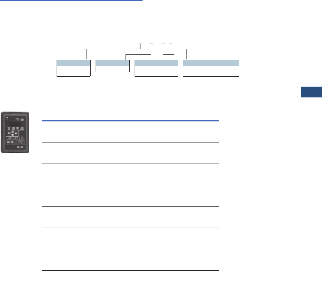
Volume 3—Power Distribution and Control Assemblies CA08100004E—November 2013 www.eaton.com V3-T9-165
9
9
9
9
9
9
9
9
9
9
9
9
9
9
9
9
9
9
9
9
9
9
9
9
9
9
9
9
9
9
9.4
Metering Devices, Protective Relays, Software and Connectivity
Protective Relays
Reference Information
Catalog Number Selection
FP-6000 Feeder Protection
Product Selection
FP-6000 Catalog Numbers
Description Style Number Pub Number
Instruction booklet 66A2347H01 IB02602004E
Current Range
2 = 5 Amperes
3 = 1 Ampere
Communications Protocol
0 = INCOM
1 = Modbus RTU
Control Voltage
0 = 48–125 Vac/Vdc
1 = 100–240 Vac/Vdc
Packaging
0 = Drawout
FP6 2 00 - 0 1
Option
Description
Style
Number
Catalog
Number
5A CT
48–125 Vdc,
100–120 Vac power supply
Standard communication board
66D2167G01 FP6200-00
1A CT
48–125 Vdc,
100–120 Vac power supply
Standard communication board
66D2167G02 FP6300-00
5A CT
100–250 Vdc,
100–240 Vac power supply
Standard communication board
66D2167G04 FP6200-10
1A CT
100–250 Vdc,
100–240 Vac power supply
Standard communication board
66D2167G05 FP6300-10
5A CT
100–250 Vdc,
100–240 Vac power supply
Modbus communication board
66D2167G06 FP6200-11
1A CT
100–250 Vdc,
100–240 Vac power supply
Modbus communication board
66D2167G07 FP6300-11
5A CT
48–125 Vdc,
100–120 Vac power supply
Modbus communication board
66D2167G08 FP6200-01
1A CT
48–125 Vdc,
100–120 Vac power supply
Modbus communication board
66D2167G09 FP6300-01
FP-6000

V3-T9-166 Volume 3—Power Distribution and Control Assemblies CA08100004E—November 2013 www.eaton.com
9
9
9
9
9
9
9
9
9
9
9
9
9
9
9
9
9
9
9
9
9
9
9
9
9
9
9
9
9
9
9.4
Metering Devices, Protective Relays, Software and Connectivity
Protective Relays
Technical Data and Specifications
Protective Functions
Phase and Ground
Overcurrent Protection
●Inverse characteristics:
Mod, Very, Extremely,
IECA, IECB, IECC, It, I2t,
I4t, Flat
●TOC (51) pickup range:
0.02 to 4.0 per unit in
0.01 steps
●Time multipliers: 0.05 to
10.0 in 0.01 steps
●IOC (50) pickup range:
0.1 to 20.0 per unit in
0.01 steps
●Pickup accuracy: ±1%
(at 0.1 to 2 per unit)
●Time delay: 0 to 9999
cycles in 1 cycle steps
●Time accuracy: ±3% or
±30 ms
●Directional (67, 67N, 67G):
forward, reverse or both
Voltage Unbalance (47)
●Threshold (minimum
voltage) 1 to 100 volts in
1 volt steps
●% V2/V1: 2 to 40% in
1% steps
●Time delay: 0 to 9999
cycles in 1 cycle steps
Current Unbalance (46)
●Threshold (minimum
current) 0.1 to 20.0 per
unit in 0.01 steps
●% I2/I1: 2 to 40% in
1% steps
●Time delay: 0 to 9999
cycles in 1 cycle steps
Under/Overvoltage
Protection (27/59)
●Pickup range: 10 to
150 volts in 1 volt steps
●Time delay: 0 to 9999
cycles in 1 cycle steps
Neutral Voltage Protection (59N)
●Source: calculated,
measure
●Criterion: phasor, rms
●Pickup range: 5 to
250 volts in 1 volt steps
●Time delay: 0 to 9999
cycles in 1 cycle steps
Under/Over Frequency
Protection (81U/O)
●Pickup range: 45 to 65 Hz
in 0.01 Hz steps
●Time delay: 0 to 9999
cycles in 1 cycle steps
Breaker Failure
Protection (50BF)
●Pickup range: 0.02 to
5.0 per unit in 0.01 steps
●Time delay: 0 to 9999
cycles in 1 cycle steps
Power Factor (55)
●Trigger/reset threshold:
–0.5 to 1 lag; 0.5 to 0.99
lead in 0.01 steps
●Time delay: 0 to 1000
seconds in 1 second steps
Power Protection (32)
●Direction: forward/reverse
●Criterion: over/under
●Pickup range: 0.02 to 4 pu
Note: 1pu = 3 x CT secondary
rating x VT secondary rating for
wye; the square root of 3 x VT
secondary rating x CT secondary
rating for open delta.
●Pickup accuracy: ±1.0%
●Trip time accuracy:
0 to 2 cycles or 0.1%,
whichever is greater
VAR Protection (32V)
●Direction: forward/reverse
●Criterion: over/under
●Pickup range: 0.02 to 4 pu
Note: 1pu = 3 x CT secondary
rating x VT secondary rating for
wye; the square root of 3 x VT
secondary rating x CT secondary
rating for open delta.
●Pickup accuracy: ±1.0%
●Trip time accuracy:
0 to 2 cycles or 0.1%,
whichever is greater
Thermal Protection (49)
●Pickup range: 0ºF to 390°F
or 0ºC to 199°C
●Time delay: 0.1 to
3600 seg
Sync Check (25)
●Phase angle: 1 to 60°
●Slip frequency: 0.1 to 2 Hz
●Voltage differential: 1 to
100 volts
●Breaker close time: 0 to
9999 cycles
Discrete Inputs
●Number of contact
inputs: 8
●Rating: 48 Vdc wetting
voltage provided with
internal ground only
Output Contacts
●Number of output
contacts: Five Form A
and two Form C
Rating of Output Contacts
●Momentary:
●Make 30A AC/DC for
0.25
seconds
●Break 0.25A at 250 Vdc
(resistive)
●Break 5A at 120/
240 Vac
●Continuous:
●5A at 120/240 Vac
●5A at 30 Vdc
Logic and Control Functions
●Six programmable logic
gates for AND, OR, NAND,
NOR operation
●Two latching (flip/flop)
gates
●Six timer gates provide
on/off delays
INCOM Communications
●Baud rate: 9600 fixed
●Maximum distance:
10,000 feet (3,048 m)
●Protocol: INCOM
RS-232 Communications,
Front Panel
●Baud rate: 38.4K, 19.2K,
9.6K
●Connector standard 9-pin
subminiature, three-wire
●Protocol: INCOM
RS-485 Communications,
Rear Panel
●Baud rate: 19.2K, 9.6K
●Protocol: Modbus RTU
Environmental Ratings
●Operating temperature:
–40ºF to +140ºF (
–40ºC to +60ºC)
●Storage temperature:
–40ºF to +185ºF
(–40ºC to +85ºC)
●Humidity: 5% to 95%
relative humidity
(noncondensing)
●Altitude: 0 to 6,350 feet
(0 to 1,935 m) above Mean
Sea Level

Volume 3—Power Distribution and Control Assemblies CA08100004E—November 2013 www.eaton.com V3-T9-167
9
9
9
9
9
9
9
9
9
9
9
9
9
9
9
9
9
9
9
9
9
9
9
9
9
9
9
9
9
9
9.4
Metering Devices, Protective Relays, Software and Connectivity
Protective Relays
Control Power
●Control voltage:
●48–125 Vdc/100–
120 Vac
●100–250 Vdc/100–
240 Vac
●Operating voltage:
●38–150 Vdc/55–132 Vac
●80–308 Vdc/55–264 Vac
●Interruption ride-through
time:
●83 ms at 120V, 60 Hz AC
●250 ms at 110 Vdc/
300 ms at Vac
●
Power consumption:
●20 VA maximum
●22 VA maximum
Current Inputs
●CT rating:
●2 x ln at 5 amperes
continuous
●3 x ln at 1 ampere
continuous
●80 x ln at 5 amperes
for 1 second
●100 x ln at 1 ampere
for 1 second
●CT burdens:
●< 0.25 VA at 5A
(nominal)
●< 0.05 VA at 1A
(nominal)
Voltage Transformer Inputs
●Nominal: 0–120 Vac line
to common
●Operating range:
0–144 Vac (+20%) line
to common
●Burden: 1 mega ohm input
impedance
Metering Accuracy
●Input signal frequency
necessary for accurate
operation:
●60 Hz Nominal,
57–63 Hz (5%)
●50 Hz Nominal,
47–53 Hz (5%)
●Frequency measurement
accuracy:
● ±0.02 Hz
●Clock accuracy:
●Free running ±1 minute/
month at 77°F (25°C)
●Automatically updated
by PowerNet host
when present
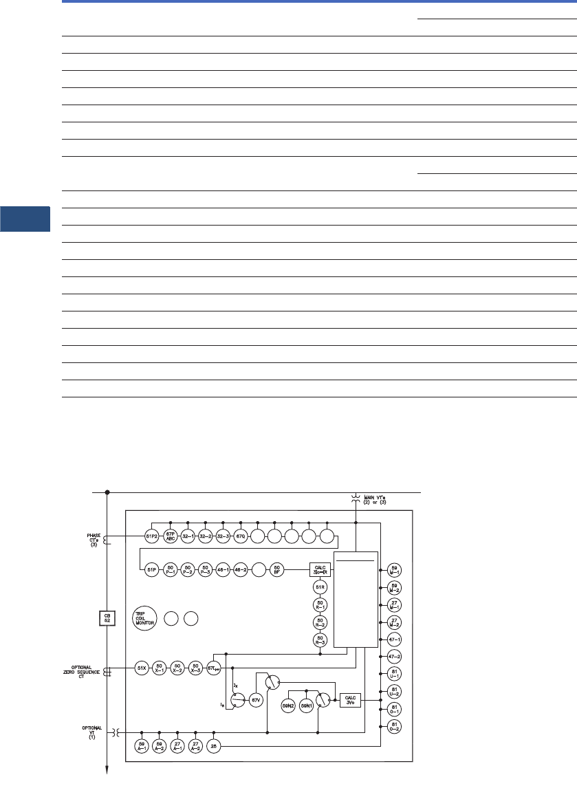
V3-T9-168 Volume 3—Power Distribution and Control Assemblies CA08100004E—November 2013 www.eaton.com
9
9
9
9
9
9
9
9
9
9
9
9
9
9
9
9
9
9
9
9
9
9
9
9
9
9
9
9
9
9
9.4
Metering Devices, Protective Relays, Software and Connectivity
Protective Relays
FP-6000 Specifications
Note
1FS (Full Scale) = 3 x CT Rating x Nominal L-N Voltage.
Wiring Diagrams
FP-6000 One-Line Drawing
Principal Parameters Range Accuracy
Current (amperes) Ia, Ib, Ic, Ir, Ix 0.02 to 20 per unit at < 2 + CT rating: ±0.5% of CT rating
at > 2 + CT rating: ±0.5% of reading
Sequence currents 0.02 to 20 per unit ±1% of nominal
Main voltage 0 to 160V ±0.5% of nominal ±0.2V
Sequence voltages 0 to 160V ±1% of nominal
Auxiliary voltage 0 to 250V ±1% of nominal
Phase angle for I and V 0 to 360° ±1° at nominal voltage
System frequency 45 to 65 Hz ±0.02 Hz
Ampere demand 0.02 to 20 per Unit ±0.5%
Watt demand 0 to 4000 MW ±1.0% FS for PF = unity 1
±1.5% FS for PF = –0.5 to 0.5 1
Watts 0 to 4000 MW —
Watthours 0 to 999.999 MWh —
VAR demand 0 to 4000 MVAR ±1.5% FS for PF = –0.5 to 0.5 1
VARs 0 to 4000 MVAR —
VAR-hours 0 to 999.999 Mvarh —
VA demand 0 to 4000 MVA ±1% FS 1
VA 0 to 4000 MVA —
VA-hours 0 to 999,999 MVAh —
Apparent power factor –1 to +1 ±0.02 for load currents above 20% rated
Displacement power factor –1 to +1 ±0.02 for load currents above 20% rated
Total harmonic distortion 0 to 9999 ±1%
Other metering accuracy ±1%
Metering
FP-6000
Load
V, I, F, PF,
W, VARS, VA
Energy
Demand
Min./Max.
% THD
Phasors
Data Logger
Waveform
SER
Fault Records
RTDs
55A 55O 32V
-1
32V
-2 32V
-3
42M
79 49D
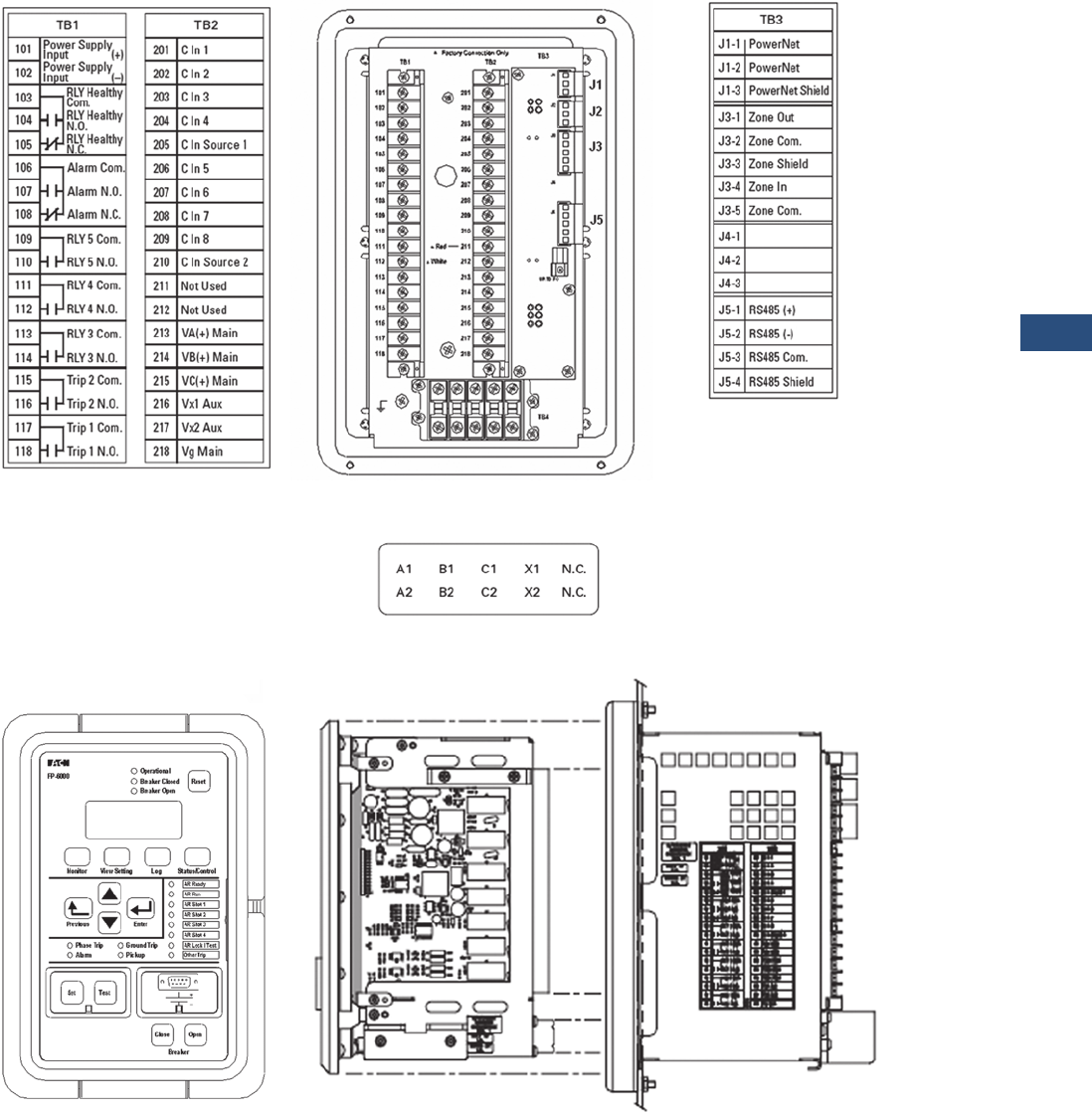
Volume 3—Power Distribution and Control Assemblies CA08100004E—November 2013 www.eaton.com V3-T9-169
9
9
9
9
9
9
9
9
9
9
9
9
9
9
9
9
9
9
9
9
9
9
9
9
9
9
9
9
9
9
9.4
Metering Devices, Protective Relays, Software and Connectivity
Protective Relays
FP-6000 Rear View and Terminal Designations
FP-6000 Front View and Drawout Case Side View
Note
1Available with Modbus-RTU communications.
1
1
1
1
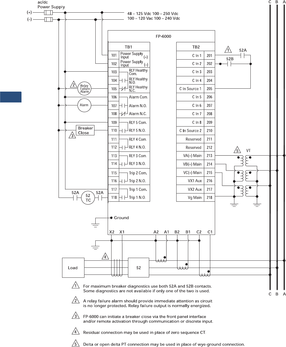
V3-T9-170 Volume 3—Power Distribution and Control Assemblies CA08100004E—November 2013 www.eaton.com
9
9
9
9
9
9
9
9
9
9
9
9
9
9
9
9
9
9
9
9
9
9
9
9
9
9
9
9
9
9
9.4
Metering Devices, Protective Relays, Software and Connectivity
Protective Relays
FP-6000 Typical Connection Drawing Using Wye PTs

Volume 3—Power Distribution and Control Assemblies CA08100004E—November 2013 www.eaton.com V3-T9-171
9
9
9
9
9
9
9
9
9
9
9
9
9
9
9
9
9
9
9
9
9
9
9
9
9
9
9
9
9
9
9.4
Metering Devices, Protective Relays, Software and Connectivity
Protective Relays
Dimensions
Approximate Dimensions in Inches (mm)
FP-6000 Feeder Protection Relay
Height Width Depth
Shipping Weight
Lbs (kg)
In Front of Panel
11.34 (288.0) 7.72 (196.1) 0.80 (20.3) 12.5 (5.7)
Behind Panel
6.70 (170.2) 5.30 (134.6) 6.90 (175.3) 12.5 (5.7)
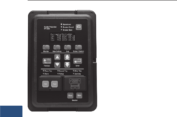
V3-T9-172 Volume 3—Power Distribution and Control Assemblies CA08100004E—November 2013 www.eaton.com
9
9
9
9
9
9
9
9
9
9
9
9
9
9
9
9
9
9
9
9
9
9
9
9
9
9
9
9
9
9
9.4
Metering Devices, Protective Relays, Software and Connectivity
Protective Relays
Feeder Protection FP-5000
Contents
Description Page
Product Selection Guide . . . . . . . . . . . . . . . . . . . . V3-T9-158
FP-6000 Feeder Protection . . . . . . . . . . . . . . . . . . V3-T9-162
FP-5000 Feeder Protection
Features, Benefits and Functions . . . . . . . . . . . V3-T9-173
Standards and Certifications . . . . . . . . . . . . . . . V3-T9-175
Catalog Number Selection . . . . . . . . . . . . . . . . V3-T9-175
Technical Data and Specifications . . . . . . . . . . . V3-T9-176
Dimensions. . . . . . . . . . . . . . . . . . . . . . . . . . . . V3-T9-179
FP-4000 Feeder Protection . . . . . . . . . . . . . . . . . . V3-T9-180
MP-3000 Motor Protection . . . . . . . . . . . . . . . . . . V3-T9-188
MP-4000 Motor Protection . . . . . . . . . . . . . . . . . . V3-T9-198
MD-3000 Motor/Generator Differential Relay . . . . V3-T9-204
Digitrip 3000 . . . . . . . . . . . . . . . . . . . . . . . . . . . . . V3-T9-207
VR-300 Multifunctional Voltage Relay . . . . . . . . . . V3-T9-217
DP-300 Current Differential Protection Relay . . . . . V3-T9-221
EDR-3000 Feeder Protection . . . . . . . . . . . . . . . . . V3-T9-226
ETR-4000 Transformer Protection Relay . . . . . . . . V3-T9-237
Ground Fault Relay. . . . . . . . . . . . . . . . . . . . . . . . . V3-T9-250
Universal RTD Module . . . . . . . . . . . . . . . . . . . . . . V3-T9-254
IQ 125 Volt DC Power Supply. . . . . . . . . . . . . . . . . V3-T9-258
FP-5000 Feeder Protection
Product Description
●Microprocessor-based
protection with monitoring
and control for medium
voltage main and feeder
applications
●Current, voltage, frequency
and power protection for
electric power distribution
systems
●Complete metering of
voltage, currents, power,
energy, minimum/
maximum and
demand functions
●Programmable logic control
functions for main-tie-main
transfer schemes
●Trip logs, event logs and
waveform capture for
better fault analysis and
system restoration
●Data Logger to provide
energy usage profiles for
better planning, utilization
and energy usage
●Compact, drawout
case design
●Meets ANSI, CE and
CSA standards
●Multiple settings groups
●ANSI, IEC and thermal
protection curves for
greater flexibility
Application Description
Eaton’s FP-5000 Feeder
Protection relay provides
complete three-phase and
ground overcurrent and
voltage protection plus
metering in a single, compact
drawout case. It may be
used as primary protection
on feeders, mains and tie
circuit breaker applications,
and as backup protection
for transformers, high
voltage lines and differential
protection. The relay is most
commonly used on medium
voltage switchgear
applications.
The FP-5000 takes
full advantage of its
microprocessor technology
providing the user new
freedoms and a wealth of
data-gathering features. The
relay performs self-checking
of all major hardware and
firmware protection elements
to ensure their operation in
the event of a system or
component electrical failure
or fault. Protection functions
are well suited for main and
distribution feeder circuit
applications. Programmable
logic control functions make
the FP-5000 relay ideally
suited for main-tie-main
and main 1/main 2 transfer
schemes.
The Zone Interlocking feature
can be utilized for bus
protection instead of an
expensive and complicated
bus differential (87B)
scheme. The FP-5000 works
directly with Eaton’s Digitrip
3000 and Digitrip MV relays.
New breaker failure logic
provides faster remote
backup clearing times for
stuck breaker operation.
The multiple settings
groups can be utilized for
arc flash mitigation when
an alternative setting group,
set to have instantaneous
elements only is activated
using a selector switch and
the programmable I/O in the
FP-5000.
The FP-5000 provides trip
and close circuit monitoring
and alarming features. It
continually monitors the
complete trip and close
circuits for continuity and
readiness to trip. Open
and close pushbuttons are
conveniently located on the
front of the relay for local
breaker operation.
Loss-of-vacuum monitoring
is activated when the breaker
is open. Residual current
is monitored and alarmed
if detected.
When an electrical fault
or disturbance occurs, the
FP-5000 begins to store the
following in non-volatile
memory:
●Voltage and current
sampled data
●Calculated values
●
Status of internal protection
functions,
logic, contact
inputs and outputs
Retrieval and viewing of the
data is easy, aiding in the quick
analysis and restoration of your
electric power system.

Volume 3—Power Distribution and Control Assemblies CA08100004E—November 2013 www.eaton.com V3-T9-173
9
9
9
9
9
9
9
9
9
9
9
9
9
9
9
9
9
9
9
9
9
9
9
9
9
9
9
9
9
9
9.4
Metering Devices, Protective Relays, Software and Connectivity
Protective Relays
Features, Benefits and Functions
When the FP-5000 isn’t
responding to disturbances
in the power system, it’s
providing valuable metering
information at the relay and
remotely. It provides energy
usage and demand reading,
and can alarm when usage
reaches a set value. Power
factor measurements can be
used for cap bank switching
to control kVAR demand.
Onboard data trending can
provide load profiles for up
to 40 days.
The protection functions are
listed below and shown on
Page V3-T9-177.
●Complete protection,
metering and control in a
single compact case to
reduce panel space, wiring
and costs
●Flexible current, voltage
and frequency protection
and programmability to
cover a broad range of
applications while
simplifying relay ordering
and reducing inventory
●Integral test function
reduces maintenance time
and expense
●Relay self-diagnostics and
reporting improves uptime
and troubleshooting
●Breaker trip circuit
monitoring improves the
reliability of the breaker
operation
●Programmable logic control
features that can replace
and eliminate external
auxiliary relays, timers
and wiring
●Zone-selective interlocking
improves coordination and
tripping times and saves
money compared to a
traditional bus differential
scheme
●Trip and event recording
in non-volatile memory
provides detailed
information for analysis and
system restoration
●256 cycles of waveform
capture aids in post fault
analysis
●Front RS-232 port and
PowerPort software
provides local computer
access and a user-friendly,
Windows®-based interface
for relay settings, and
configuration and data
retrieval
●Drawout case design for
quick and easy relay
removal and replacement
●Breaker open/close control
from relay faceplate or
remotely via
communications
●Remote communications
to Eaton’s PowerNet
monitoring system or PC
●Free PowerPort utility
software for local PC
interface to the FP-5000 for
relay settings, monitoring
and control
Phase Overcurrent (Forward,
Reverse or Both)
●Two-stage instantaneous
with timers (50P-1 and
50P-2)
●Two inverse time
overcurrent (51P-1 and
51P-2)
●Directional control
●10 standard curves
●Instantaneous or time
delay reset
●Voltage restrained time
overcurrent (51VR)
●Two independent ground
directional overcurrent
elements, one measured
(IX) and one calculated (IR)
●Two-Stage
instantaneous with
timers (50X-1 and 50X-2)
(50R-1 and 50R-2)
●Inverse time overcurrent
(51X and 51R)
●Ground directional
polarizing (67N) –3vo, Ipol,
negative sequence
●10 standard curves
●Instantaneous or time
delay reset
●Voltage restrained time
overcurrent (51VR)
●Breaker failure (50BF)
●Phase unbalance negative
sequence overcurrent
(46-1, 46-2)
●Phase voltage unbalance
and sequence protection
(47-1, 47-2)
●Main three-phase under/
overvoltage (27M-1,
27M-2, 59M-1, 59M-2)
●Auxiliary single-phase
under/over-voltage (27A-1,
27A-2, 59A-1, 59A-2)
●Under/over frequency
(81U-1, 81U-2, 81O-1,
81O-2)
●Reverse/forward power
(32-1, 32-2)
●Sync check (25)
●Power factor (55)
●Zone interlocking for bus
protection (87B). The
FP-5000 feeder relay
includes a zone selective
interlocking feature that
can be used with other
Eaton devices like the
Digitrip 3000 overcurrent
relay
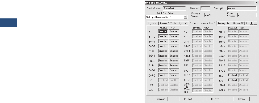
V3-T9-174 Volume 3—Power Distribution and Control Assemblies CA08100004E—November 2013 www.eaton.com
9
9
9
9
9
9
9
9
9
9
9
9
9
9
9
9
9
9
9
9
9
9
9
9
9
9
9
9
9
9
9.4
Metering Devices, Protective Relays, Software and Connectivity
Protective Relays
The FP-5000 provides the
following metering functions:
●
Amperes (rms, phasor and
sequence)
●Amperes demand and
peak demand
●Volts (rms, phasor and
sequence)
●VA and VA demand
●Watts and kW demand and
peak demand
●Forward/reverse/net kWh
●VARs and kVAR demand
and peak demand
●Lead/lag/net kVARh
●Power factor
●Frequency
●Voltage and current
●%THD and magnitude THD
●Minimum/maximum
recording with date/
time stamp
●Trending (load profile
over time)
The FP-5000 provides the
following monitoring and data
recording functions that
enhance the security of the
protection system and
provides useful
information
for scheduling maintenance:
●Trip circuit monitoring
●Close circuit monitoring
●Loss-of-vacuum monitoring
●Breaker wear (accumulated
interrupted current)
●Waveform capture
(256 cycles total, up to
16 events)
●Fault data logs (up to
16 events)
●Sequence of events report
(up to 100 events)
●Clock
The FP-5000 provides
standard control functions
plus user-configurable
custom control capabilities.
This logic can be used for
applications such as main-tie-
main transfer schemes.
●Remote open/close
●Programmable I/O
●Programmable logic gates
and timers
●Multiple setting groups
(up to four)
●Bus transfer logic
●Cold load pickup
●Loss of potential
(PT blown fuses)
The FP-5000 supports the
following communication
options:
●Local HMI
●Password protected
●Addressable
●Local communication port
●Remote communication
port:
●FSK
●RS-232
●RS-485
●Protocols:
●INCOM
●Modbus
●Configuration software
Communication Software
Eaton provides two types of
communication software. The
first is PowerPort. It runs on a
PC or laptop for easy access to
a single relay to change set
points or configuration and to
view metered values and
stored data. PowerPort is free
and can be downloaded from
www.eaton.com; search for
‘PowerPort,’ then click the
download search result.
The second package is
PowerNet. PowerNet is a
power management software
package that is designed for
continuous, remote monitoring
of many devices. It provides all
the functionality of PowerPort
plus additional functions such
as billing, trending and
graphics. Contact your local
Eaton representative for more
information on PowerNet
software.
PowerPort and PowerNet Protection Overview Screen
Volume 3—Power Distribution and Control Assemblies CA08100004E—November 2013 www.eaton.com V3-T9-175
9
9
9
9
9
9
9
9
9
9
9
9
9
9
9
9
9
9
9
9
9
9
9
9
9
9
9
9
9
9
9.4
Metering Devices, Protective Relays, Software and Connectivity
Protective Relays
Standards and Certifications
Compliance
●UL Recognized,
File # E154862
●UL 1053 (1994) recognized
●ANSI C37.90 (1989)
●EN 55011 (1991)
●EN 61000-6-2 (1999)
Emission Tests
●EN 55011 (1991)—Group 1
Class A (CISPR-11,
Class A)
●FCC 47 CFR Chapter 1—
Part 15 Subpart b Class A
Immunity Tests
●ANSI C37.90.1 (1989)—
Surge Withstand Capability
●ANSI C37.90.2 (1995)—
EMI Immunity to 35V/m
●EN 61000-4-2 (1995)—
ESD Rating of 8 kV
●EN 61000-4-3 (1997)—
Radiated EM Field at
10V/m
●EN 61000-4-4 (1995)—Fast
Transient Burst at 2 kV
●EN 61000-4-5 (1995)—
Surge Immunity Test
●EN 61000-4-6 (1996)—
Conducted RF at 10V/m
●EN 61000-4-11 (1994)—
Voltage Dips and Variations
●EN 61000-4-8—Power
Frequency Magnetic
Field Immunity
Catalog Number Selection
FP-5000 Feeder Protection
Current Range
2 = 5 Amperes
3 = 1 Ampere
Communications Protocol
0 = INCOM
1 = Modbus
FP5 2 00 - 0 1
Control Voltage
0 = 48–125 Vac/Vdc
1 = 100–240 Vac/Vdc
Packaging
0 = Drawout
1 = Fixed case

V3-T9-176 Volume 3—Power Distribution and Control Assemblies CA08100004E—November 2013 www.eaton.com
9
9
9
9
9
9
9
9
9
9
9
9
9
9
9
9
9
9
9
9
9
9
9
9
9
9
9
9
9
9
9.4
Metering Devices, Protective Relays, Software and Connectivity
Protective Relays
Technical Data and Specifications
Control Power
●Control voltage:
●48–125 Vac/Vdc
●100–240 Vac/Vdc
●Operating voltage:
●55–264 Vac
●38–300 Vdc
●Interruption ride-through
time: 20 cycle interruption
of nominal ac supply
●
Power consumption: 20 VA
maximum
Current Inputs
●Nominal (In): 1A or 5A
●CT rating:
●2 x In continuous
●80 x In for 1 second
●CT burdens:
●< 0.25 VA at 5A
(nominal)
●< 0.05 VA at 1A
(nominal)
Voltage Transformer Inputs
●Nominal: 120 Vac
●Operating range: 69–
150 Vac
●Burden:
●<0.015 at 120 Vac
●1 megaohm
Metering Accuracy
●Phase current:
●±0.5% or ±0.025A from
0.02–20 per unit fully
offset current waveform
●Ground current:
●±0.5% of full scale (In)
from 0.02–2.0 per unit
fully offset current
waveform
●Phase voltage: ±0.5% or
±0.2V from 0–160 Vac
●Frequency measurement
accuracy: ±0.02 Hz
●Phase angle: ±1ºC
●Power metering accuracy:
±1.5%
●
Metering accuracy
temperature range: 32ºF to
122ºF (0ºC to 50ºC)
●Temperature range: ±5%
for operation below 32ºF
(0ºC) and above 122ºF
(50ºC)
●Relay outputs:
●2 Form C, NO and NC
●5 Form A, NO only
●Input signal frequency
necessary for accurate
operation:
●60 Hz nominal, 57–63 Hz
(±5%)
●50 Hz nominal, 47–53 Hz
(±5%)
●Clock accuracy:
●Free running ±1 minute/
month at 25ºC
●Clock automatically
updated by PowerNet
host when present
Protective Functions
Phase and Ground
Overcurrent Protection
●Inverse characteristics:
Mod, Very, Extremely,
IECA, IECB, IECC, It, I2t,
I4t, Flat
●TOC (51) pickup range:
0.1–4.0 per unit in 0.01
steps
●Time multipliers: 0.05–10.0
in 0.01 steps
●IOC (50) pickup range: 0.1–
20.0 per unit in 0.01 steps
●Pickup accuracy: ±1%
(at 0.1–2 per unit)
●Time delay: 0–9999 cycles
in 1 cycle steps
●Time accuracy: ±3% or
±30 ms
●Directional (67, 67N, 67G):
forward, reverse or both
Voltage Unbalance (47)
●Threshold (minimum
voltage) 1–100 volts in
1 volt steps
●% V2/V1: 4–40% in
1% steps
●Time delay: 0–9999 cycles
in 1 cycle steps
Current Unbalance
●Threshold (minimum
current) 0.1–20.0 per unit
in 0.01 steps
●% I2/I1: 4–40% in
1% steps
●Time delay: 0–9999 cycles
in 1 cycle steps
Under/Overvoltage Protection
●Pickup range: 10–150 volts
in 1 volt steps
●Time delay: 0–9999 cycles
in 1 cycle steps
Under/Over Frequency
Protection
●Pickup range: 45–65 Hz in
0.01 Hz steps
●Time delay: 0–9999 cycles
in 1 cycle steps
Breaker Failure Protection
●Pickup range: 0.1–5.0 per
unit in 0.01 steps
●Time delay: 0–9999 cycles
in 1 cycle steps
Power Protection (32)
●Forward/reverse:
over/under
●Pickup accuracy: ±1.0%
●Trip time accuracy:
0 to 12 cycles or 0.1%,
whichever is greater
Sync Check (25)
●Phase angle: 1 to 60°C
●Slip frequency: 0.1 to 2 Hz
●Voltage differential: 1 to
100 volts
●Breaker close time: 0 to
9999 cycles
Power Factor
●Trigger/reset threshold: 0.5
lag to 0.5 lead in 0.01 steps
●Time delay: 0–1000
seconds in 1 second steps
Discrete Inputs
●Number of contact
inputs: 8
●Rating: 48 Vdc wetting
voltage provided with
internal ground only
Output Contacts
●Number of output
contacts: Five Form A and
two Form C
Rating of Output Contacts
●Momentary:
●Make 30A AC/DC for
0.25
seconds
●Break 0.25A at 250 Vdc
(resistive)
●Break 5A at 120/240 Vac
●Continuous:
●5A at 120/240 Vac
●5A at 30 Vdc
Logic and Control Functions
●Six programmable logic
gates for AND, OR, NAND,
NOR operation
●Two latching (flip/flop)
gates
●Six timer gates provide
on/off delays
INCOM Communications
●Baud rate: 9600 fixed
●Maximum distance:
10,000 feet (3,048m)
●Protocol: INCOM
RS-485 Communications,
Rear Panel
●Baud rate: 19.2K, 9.6K
●Protocol: Modbus RTU
RS-232 Communications,
Front Panel
●Baud rate: 38.4K, 19.2K,
9.6K
●Connector standard 9-pin
subminiature, three-wire
●Protocol: INCOM
Environmental Ratings
●Operating temperature:
–0ºF to +140ºF (–40ºC to
+60ºC) Product tested to
+185ºF (+85ºC)
●Storage temperature:
–40ºF to +185ºF (–40ºC to
+85ºC)
●Humidity: 5–95% relative
humidity (noncondensing)
●Altitude: 0–6350 feet
(0–1935m) above Mean Sea
Level
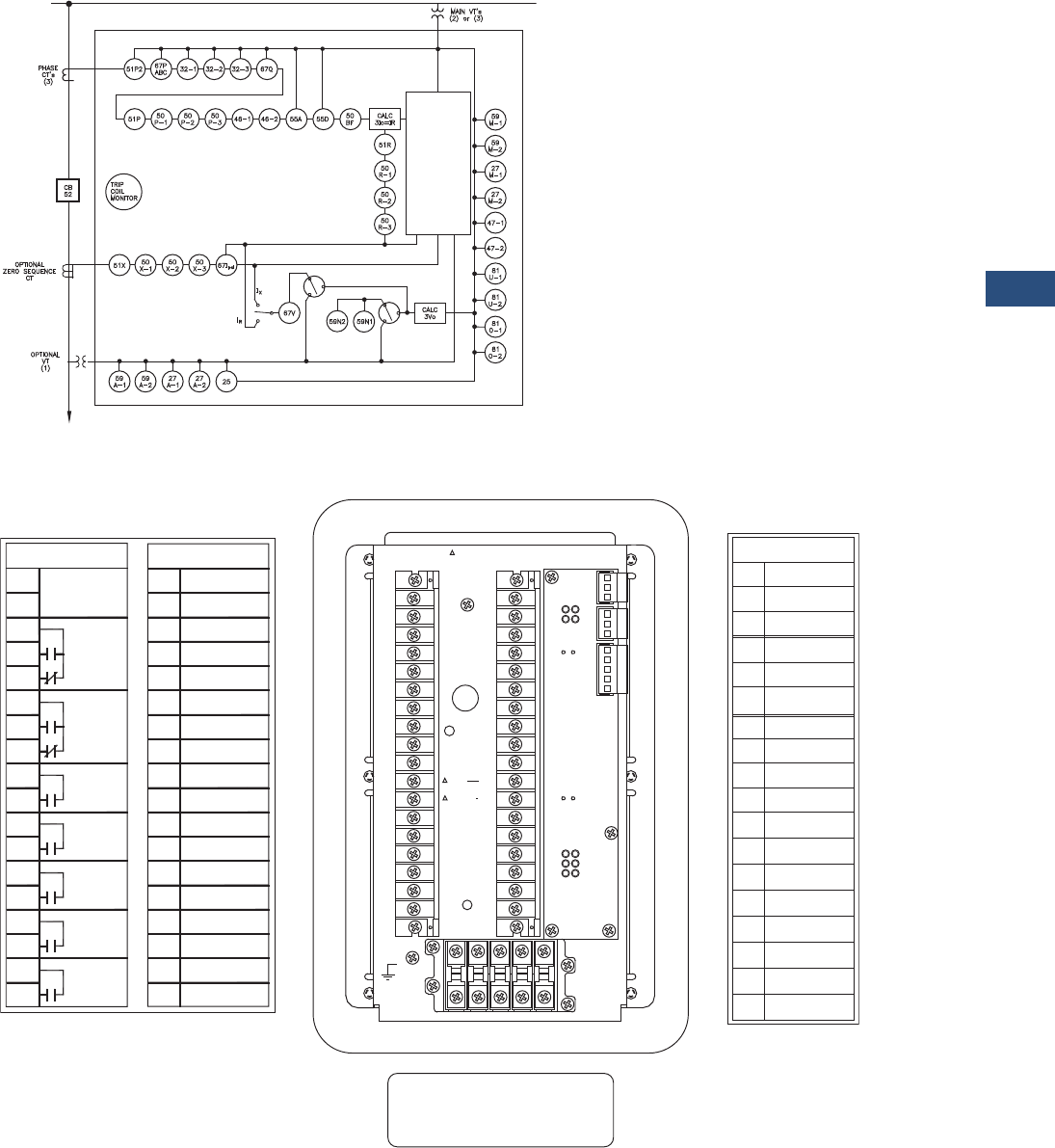
Volume 3—Power Distribution and Control Assemblies CA08100004E—November 2013 www.eaton.com V3-T9-177
9
9
9
9
9
9
9
9
9
9
9
9
9
9
9
9
9
9
9
9
9
9
9
9
9
9
9
9
9
9
9.4
Metering Devices, Protective Relays, Software and Connectivity
Protective Relays
Wiring Diagrams
FP-5000 One-Line Drawing
FP-5000 Rear View and Terminal Designations
Metering
FP-5000
Load
V, I, F, PF,
W, VARS, VA
Energy
Demand
Min./Max.
% THD
Phasors
Data Logger
Waveform
SER
Fault Records
TB1 TB2
101 Power Supply
Input (+)
102
103
104
105
106
107
108
109
110
111
112
113
114
115
116
117
118
201
202
203
204
205
206
207
208
209
210
211
212
213
214
215
216
217
218 Vg Main
Vx2 Aux
Vx1 Aux
VC(+) Main
VB(+) Main
VA(+) Main
Not Used
Not Used
C In 1
C In 2
C In 3
C In 4
C In Source 1
C In Source 2
C In 5
C In 6
C In 7
C In 8
Trip 1 N.O.
Trip 1 Com.
Trip 2 N.O.
Trip 2 Com.
RLY 3 N.O.
RLY 3 Com.
RLY 4 N.O.
RLY 4 Com.
RLY 5 N.O.
RLY 5 Com.
Alarm Com.
Alarm N.O.
Alarm N.C.
Power Supply
Input (–)
RLY Healthy
Com.
RLY Healthy
N.O.
RLY Healthy
N.C.
A1 B1 C1 X1 N.C. 1
A2 B2 C2 X2 N.C. 2
TB4
118
117
116
115
114
113
112
111
110
109
108
107
106
105
104
103
102
101
218
217
216
215
214
213
212
211
210
209
208
207
206
205
204
203
202
201
Red
White
Factory Connection Only
TB2TB1 TB3 TB3
J1-1
J1-2
J1-3
J2-1
J2-2
J2-3
J3-1
J3-2
J3-3
J3-4
J3-5 Zone Com.
J5-1 RS485(+)
J5-2 RS485(-)
J5-3 RS485com
J5-4 RS485shield
J4-1
J4-2
J4-3
PowerNet
PowerNet
PowerNet Shield
Accessory Bus
Accessory Bus
Zone In
Accessory Bus
Shield
Zone Out
Zone Com.
Zone Shield
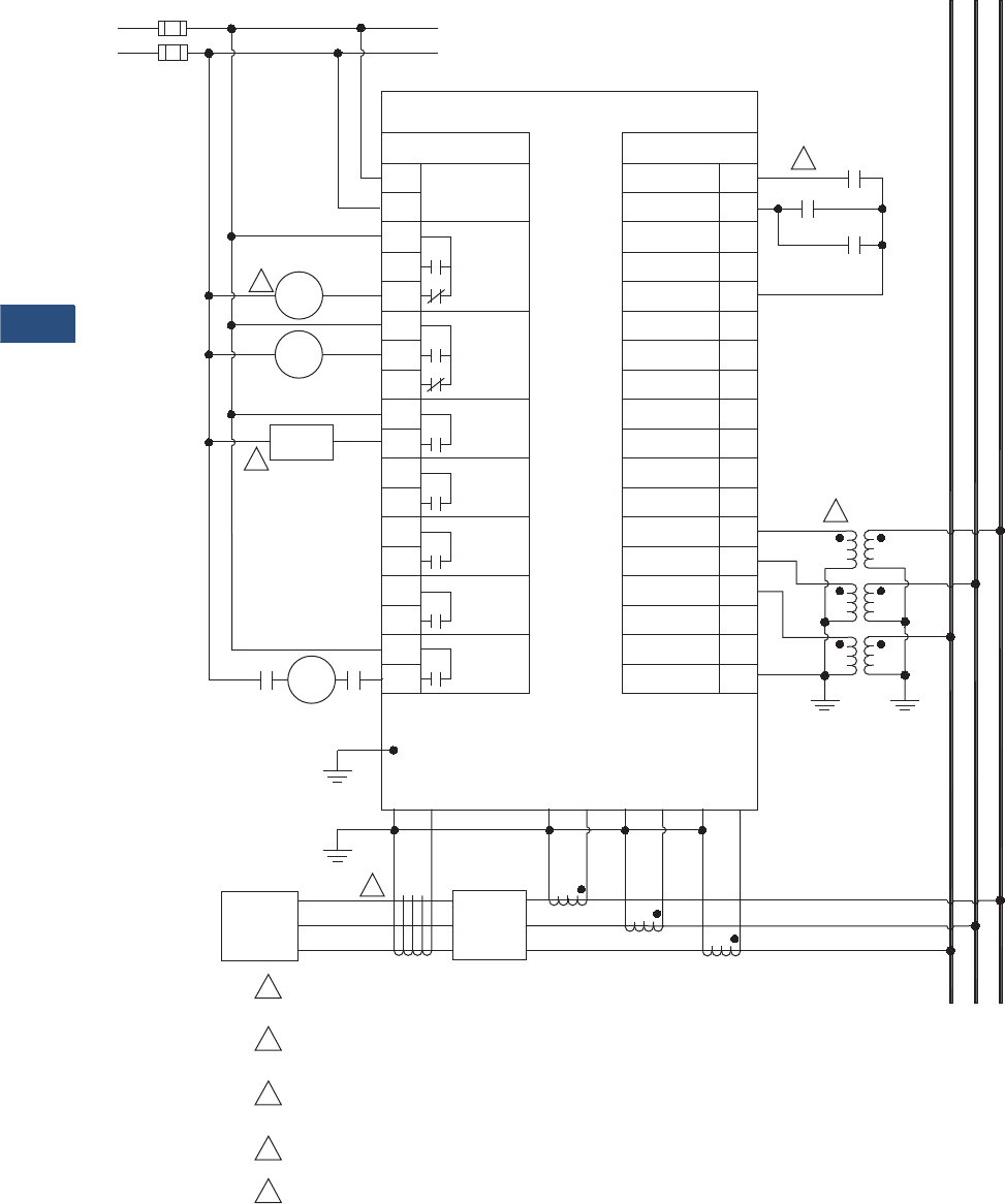
V3-T9-178 Volume 3—Power Distribution and Control Assemblies CA08100004E—November 2013 www.eaton.com
9
9
9
9
9
9
9
9
9
9
9
9
9
9
9
9
9
9
9
9
9
9
9
9
9
9
9
9
9
9
9.4
Metering Devices, Protective Relays, Software and Connectivity
Protective Relays
FP-5000 Typical Connection Drawing Using Wye PTs
ac/dc
Power Supply
(+)
(–)
48 – 125 Vac/dc or
100 – 240 Vac/dc
2
3
Breaker
Close
52A 52A
4
Ground
X2 X1
Load 52
A2 A1 B2 B1 C2 C1
5
C B A
C B A
152A
52B
52B TOC
FP-5000
TB1 TB2
101 Power Supply
Input (+)
102
103
104
105
106
107
108
109
110
111
112
113
114
115
116
117
118
201
202
203
204
205
206
207
208
209
210
211
212
213
214
215
216
217
218Vg Main
VX2 Aux
VX1 Aux
VC(+) Main
VB(+) Main
VA(+) Main
Not Used
Not Used
C In 1
C In 2
C In 3
C In 4
C In Source 1
C In Source 2
C In 5
C In 6
C In 7
C In 8
Trip 1 N.O.
Trip 1 Com.
Trip 2 N.O.
Trip 2 Com.
RLY 3 N.O.
RLY 3 Com.
RLY 4 N.O.
RLY 4 Com.
RLY 5 N.O.
RLY 5 Com.
Alarm Com.
Alarm N.O.
Alarm N.C.
Power Supply
Input (–)
RLY Healthy
Com.
RLY Healthy
N.O.
RLY Healthy
N.C.
1For maximum breaker diagnostics use both 52A and 52B contacts.
Some diagnostics are not available if only one of the two is used.
A relay failure alarm should provide immediate attention as circuit
is no longer protected. Relay failure output is normally energized.
FP-5000 can initiate a breaker close via the front panel interface
and/or remote activation through communication or discrete input.
Residual connection may be used in place of zero sequence CT.
Delta or open delta PT connection may be used in place of wye-ground connection.
2
3
4
5
Relay
Failure
Alarm
Breaker
Alarm
52
TC
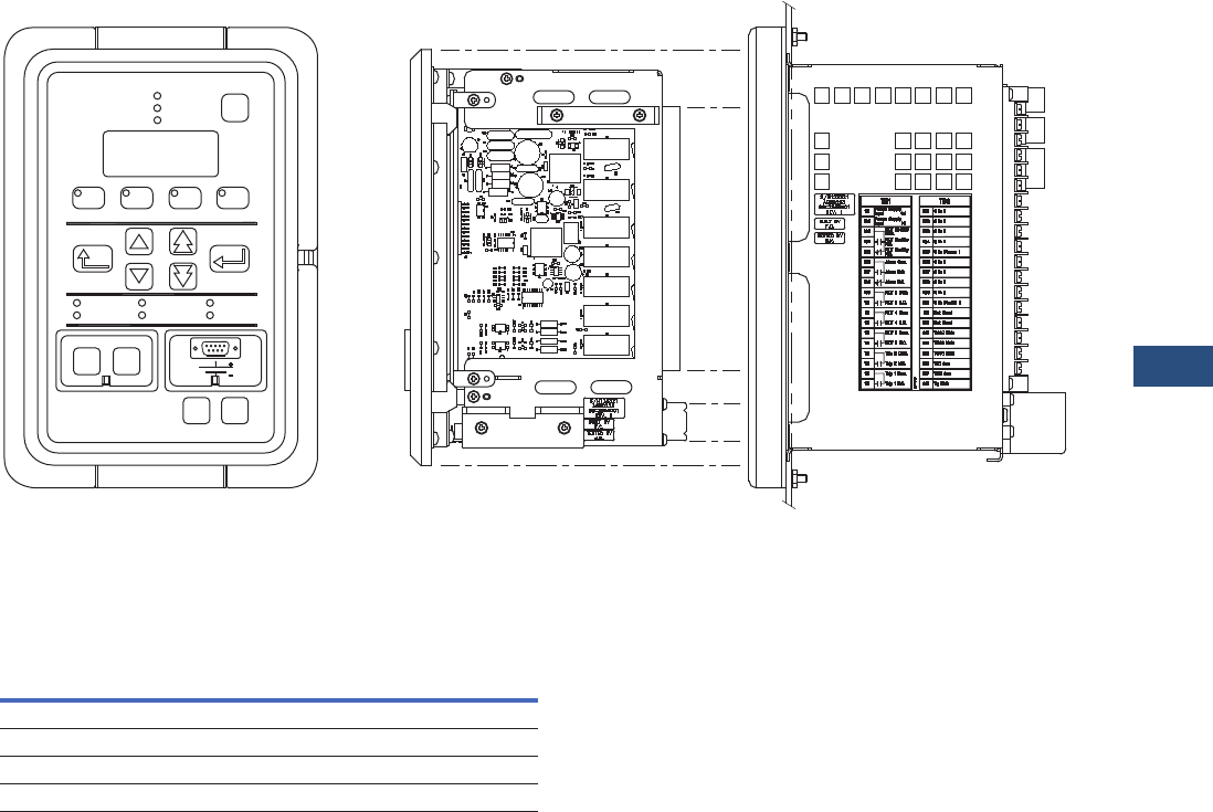
Volume 3—Power Distribution and Control Assemblies CA08100004E—November 2013 www.eaton.com V3-T9-179
9
9
9
9
9
9
9
9
9
9
9
9
9
9
9
9
9
9
9
9
9
9
9
9
9
9
9
9
9
9
9.4
Metering Devices, Protective Relays, Software and Connectivity
Protective Relays
FP-5000 Front View and Drawout Case Side View
Dimensions
Approximate Dimensions in Inches (mm)
FP-5000 Feeder Protection Relay
Height Width Depth
Shipping Weight
Lbs (kg)
In Front of Panel
11.34 (288.0) 7.72 (196.1) 0.80 (20.3) 12.5 (5.7)
Behind Panel
6.70 (170.2) 5.30 (134.6) 6.90 (175.3) 12.5 (5.7)
Feeder Protection
FP-5000
Operational
Breaker Closed
Breaker Open
Reset
Monitor View Setting Log Status/Control
Enter
Previous
Phase Trip Ground Trip Other Trip
Alarm Pickup Auxiliary
Set Test
Close Open
Breaker
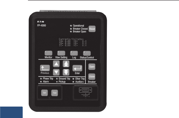
V3-T9-180 Volume 3—Power Distribution and Control Assemblies CA08100004E—November 2013 www.eaton.com
9
9
9
9
9
9
9
9
9
9
9
9
9
9
9
9
9
9
9
9
9
9
9
9
9
9
9
9
9
9
9.4
Metering Devices, Protective Relays, Software and Connectivity
Protective Relays
Feeder Protection FP-4000
Contents
Description Page
Product Selection Guide . . . . . . . . . . . . . . . . . . . . V3-T9-158
FP-6000 Feeder Protection . . . . . . . . . . . . . . . . . . V3-T9-162
FP-5000 Feeder Protection . . . . . . . . . . . . . . . . . . V3-T9-172
FP-4000 Feeder Protection
Features, Benefits and Functions . . . . . . . . . . . V3-T9-181
Standards and Certifications . . . . . . . . . . . . . . . V3-T9-183
Catalog Number Selection . . . . . . . . . . . . . . . . V3-T9-183
Technical Data and Specifications . . . . . . . . . . . V3-T9-184
Dimensions. . . . . . . . . . . . . . . . . . . . . . . . . . . . V3-T9-187
MP-3000 Motor Protection . . . . . . . . . . . . . . . . . . V3-T9-188
MP-4000 Motor Protection . . . . . . . . . . . . . . . . . . V3-T9-198
MD-3000 Motor/Generator Differential Relay . . . . V3-T9-204
Digitrip 3000 . . . . . . . . . . . . . . . . . . . . . . . . . . . . . V3-T9-207
VR-300 Multifunctional Voltage Relay . . . . . . . . . . V3-T9-217
DP-300 Current Differential Protection Relay . . . . . V3-T9-221
EDR-3000 Feeder Protection . . . . . . . . . . . . . . . . . V3-T9-226
ETR-4000 Transformer Protection Relay . . . . . . . . V3-T9-237
Ground Fault Relay. . . . . . . . . . . . . . . . . . . . . . . . . V3-T9-250
Universal RTD Module . . . . . . . . . . . . . . . . . . . . . . V3-T9-254
IQ 125 Volt DC Power Supply. . . . . . . . . . . . . . . . . V3-T9-258
FP-4000 Feeder Protection
Product Description
●Microprocessor-based
protection with monitoring
and control for medium
voltage main and feeder
applications
●Current, voltage, frequency
and power protection for
electric power distribution
systems
●Complete metering of
voltage, currents, power,
energy, minimum/
maximum and demand
functions
●Programmable logic control
functions for main-tie-main
transfer schemes
●Trip logs, event logs and
waveform capture for
better fault analysis and
system restoration
●Data logger to provide
energy usage profiles for
better planning, utilization
and energy usage
●Compact, drawout case
design
●Meets ANSI, CE and CSA
standards
●Multiple settings groups
●ANSI, IEC and thermal
protection curves for
greater flexibility
Application Description
Eaton’s FP-4000 Feeder
Protection relay provides
complete three-phase and
ground overcurrent and
voltage protection plus
metering in a single, compact
drawout case. It may be used
as primary protection on
feeders, mains and tie circuit
breaker applications, and
as backup protection for
transformers, high voltage
lines and differential
protection. The relay is
most commonly used on
medium voltage switchgear
applications.
The FP-4000 takes full
advantage of its micro-
processor technology
providing the user new
freedoms and a wealth of
ata-gathering features. The
relay performs self-checking
f all major hardware and
firmware protection elements
to ensure their operation in the
event of a system or
component electrical failure
or fault. Protection functions
are well suited for main and
distribution feeder circuit
applications. Programmable
logic control functions make
the FP-4000 relay ideally suited
for main-tie-main and main
1/main 2 transfer schemes.
The Zone-Interlocking feature
can be utilized for bus
protection instead of an
expensive and complicated
bus differential (87B)
scheme. The FP-4000 works
directly with Eaton’s Digitrip
3000 and Digitrip MV relays.
New breaker failure logic
provides faster remote
backup clearing times for
stuck breaker operation.
The multiple settings groups
can be utilized for arc
flash mitigation when an
alternative setting group,
set to have instantaneous
elements only is activated
using a selector switch and
the programmable I/O in
the FP-4000.
The FP-4000 provides trip
and close circuit monitoring
and alarming features. It
continually monitors the
complete trip and close
circuits for continuity and
readiness to trip. Open and
close pushbuttons are
conveniently located on the
front of the relay for local
breaker operation.
Loss-of-vacuum monitoring
is activated when the breaker
is open. Residual current is
monitored and alarmed if
detected.
When an electrical fault
or disturbance occurs, the
FP-4000 begins to store the
following in non-volatile
memory:
●Voltage and current
sampled data
●Calculated values
●Status of internal
protection functions, logic,
contact inputs and outputs
Retrieval and viewing of the
data is easy, aiding in the
quick analysis and restoration
of your electric power
system.

Volume 3—Power Distribution and Control Assemblies CA08100004E—November 2013 www.eaton.com V3-T9-181
9
9
9
9
9
9
9
9
9
9
9
9
9
9
9
9
9
9
9
9
9
9
9
9
9
9
9
9
9
9
9.4
Metering Devices, Protective Relays, Software and Connectivity
Protective Relays
Features, Benefits and Functions
When the FP-4000 isn’t
responding to disturbances
in the power system, it’s
providing valuable metering
information at the relay and
remotely. It provides energy
usage and demand reading,
and can alarm when usage
reaches a set value. Power
factor measurements can be
used for cap bank switching
to control kVAR demand.
Onboard data trending can
provide load profiles for up
to 40 days.
●Complete protection,
metering and control in a
single compact case to
reduce panel space, wiring
and costs
●Flexible current, voltage
and frequency protection
and programmability to
cover a broad range of
applications while
simplifying relay ordering
and reducing inventory
●Integral test function
reduces maintenance time
and expense
●Relay self-diagnostics and
reporting improves uptime
and troubleshooting
●Breaker trip circuit
monitoring improves the
reliability of the breaker
operation
●Programmable logic control
features that can replace
and eliminate external
auxiliary relays, timers
and wiring
●Zone selective interlocking
improves coordination and
tripping times and saves
money compared to a
traditional bus differential
scheme
●Trip and event recording
in non-volatile memory
provides detailed
information for analysis
and system restoration
●256 cycles of waveform
capture aids in post fault
analysis
●Front RS-232 port and
PowerPort software
provides local computer
access and a user-friendly,
WindowsT-based interface
for relay settings, and
configuration and data
retrieval
●Breaker open/close control
from relay faceplate or
remotely via
communications
●Remote communications
to Eaton PowerNet
monitoring system or PC
●Free PowerPort utility
software for local PC
interface to the FP-4000 for
relay settings, monitoring
and control
The protection functions are
listed below and shown on
Page V3-T9-185.
Phase Overcurrent
●Two-stage instantaneous
with timers (50P-1 and
50P-2)
●Inverse time overcurrent
(51P-1)
●10 standard curves
●Instantaneous or time
delay reset
●Two independent
directional overcurrent
elements, one measured
(IX) and one calculated (IR)
●Two-stage
instantaneous with
timers (50X-1 and 50X-2)
(50R-1 and 50R-2)
●Inverse time overcurrent
(51X and 51R)
●10 standard curves
●Instantaneous or time
delay reset
●Breaker failure (50BF)
●Phase unbalance negative
sequence overcurrent
(46-1, 46-2)
●Phase voltage unbalance
and sequence protection
(47-1, 47-2)
●Main three-phase under/
overvoltage (27M-1,
27M-2, 59M-1, 59M-2)
●Auxiliary single-phase
under/overvoltage (27A-1,
27A-2, 59A-1, 59A-2)
●Under/overfrequency
(81U-1, 81U-2, 81O-1,
81O-2)
●Power factor (55)
●Zone interlocking for bus
protection (87B). The
FP-4000 feeder relay
includes a zone selective
interlocking feature that
can be used with other
Eaton devices like the
Digitrip 3000 overcurrent
relay
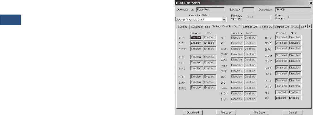
V3-T9-182 Volume 3—Power Distribution and Control Assemblies CA08100004E—November 2013 www.eaton.com
9
9
9
9
9
9
9
9
9
9
9
9
9
9
9
9
9
9
9
9
9
9
9
9
9
9
9
9
9
9
9.4
Metering Devices, Protective Relays, Software and Connectivity
Protective Relays
The FP-4000 provides the
following metering functions:
●
Amperes (rms, phasor and
sequence)
●Amperes demand and peak
demand
●Volts (rms, phasor and
sequence)
●VA and VA demand
●Watts and kW demand
and peak demand
●Forward/reverse/net kWh
●VARs and kVAR demand
and peak demand
●Lead/lag/net kVARh
●Power factor
●Frequency
●Voltage and current
●%THD and magnitude THD
●Minimum/maximum
recording with date/time
stamp
●Trending (load profile
over time)
The FP-4000 provides the
following monitoring and
data recording functions that
enhance the security of
the protection system and
provides useful
information
for scheduling maintenance:
●Trip circuit monitoring
●Close circuit monitoring
●Loss-of-vacuum monitoring
●Breaker wear (accumulated
interrupted current)
●Waveform capture
(256 cycles total, up to
16 events)
●Fault data logs (up to
16 events)
●Sequence of events report
(up to 100 events)
●Clock
The FP-4000 provides
standard control functions
plus user-configurable
custom control capabilities.
This logic can be used for
applications such as main-
tie-main transfer schemes.
●Remote open/close
●Programmable I/O
●Programmable logic gates
and timers
●Multiple setting groups
(up to four)
●Bus transfer logic
The FP-4000 supports the
following communication
options:
●Local HMI
●Password protected
●Addressable
●Local communication port
●Remote communication
port:
●FSK
●RS-232
●RS-485
●Protocols:
●INCOM
●Modbus
●Configuration software
Communication Software
Eaton provides two types
of communication software.
The first is PowerPort. It runs
on a PC or laptop for easy
access to a single relay to
change set points or
configuration and to view
metered values and stored
data. PowerPort is free and
can be downloaded from
www.eaton.com; search for
‘PowerPort,’ then click the
download search result.
The second package is
PowerNet. PowerNet is a
power management software
package that is designed for
continuous, remote monitoring
of many devices. It provides
all the functionality of
PowerPort plus additional
functions such as billing,
trending and graphics.
Contact your local Eaton
representative for more
information on PowerNet
software.
PowerPort and PowerNet Protection Overview Screen
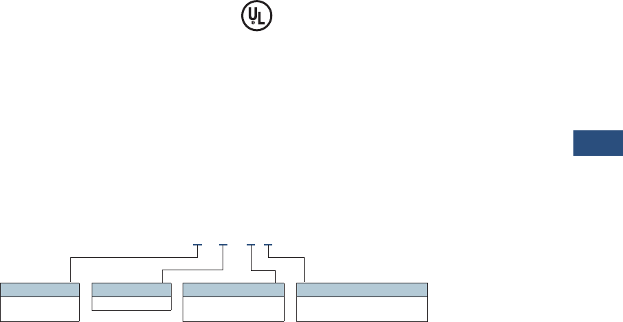
Volume 3—Power Distribution and Control Assemblies CA08100004E—November 2013 www.eaton.com V3-T9-183
9
9
9
9
9
9
9
9
9
9
9
9
9
9
9
9
9
9
9
9
9
9
9
9
9
9
9
9
9
9
9.4
Metering Devices, Protective Relays, Software and Connectivity
Protective Relays
Standards and Certifications
Compliance
●UL Recognized,
File # E154862
●UL 1053 (1994) recognized
●ANSI C37.90 (1989)
●EN 55011 (1991)
●EN 61000-6-2 (1999)
Emission Tests
●EN 55011 (1991)—Group 1
Class A (CISPR-11,
Class A)
●FCC 47 CFR Chapter 1—
Part 15 Subpart b Class A
Immunity Tests
●ANSI C37.90.1 (1989)—
Surge Withstand Capability
●ANSI C37.90.2 (1995)—EMI
Immunity to 35V/m.
●EN 61000-4-2 (1995)—ESD
Rating of 8 kV
●EN 61000-4-3 (1997)—
Radiated EM Field at 10V/m
●EN 61000-4-4 (1995)—Fast
Transient Burst at 2 kV
●EN 61000-4-5 (1995)—
Surge Immunity Test
●EN 61000-4-6 (1996)—
Conducted RF at 10V/m
●EN 61000-4-11 (1994)—
Voltage Dips and Variations
●EN 61000-4-8—Power
Frequency Magnetic Field
Immunity
Catalog Number Selection
FP-4000 Feeder Protection
FP4 2 01 - 0 1
Current Range
2 = 5 Amperes
3 = 1 Ampere
Communications Protocol
0 = INCOM
1 = Modbus RTU
Control Voltage
0 = 48–125 Vac/Vdc
1 = 100–240 Vac/Vdc
Packaging
1 = Fixed case

V3-T9-184 Volume 3—Power Distribution and Control Assemblies CA08100004E—November 2013 www.eaton.com
9
9
9
9
9
9
9
9
9
9
9
9
9
9
9
9
9
9
9
9
9
9
9
9
9
9
9
9
9
9
9.4
Metering Devices, Protective Relays, Software and Connectivity
Protective Relays
Technical Data and Specifications
Control Power
●Control voltage:
●48–125 Vac/dc
●100–240 Vac/dc
●Operating voltage:
●55–264 Vac
●38–300 Vdc
●Interruption ride-through
time: 20 cycle interruption
of nominal ac supply
●
Power consumption: 20 VA
maximum
Current Inputs
●Nominal (In): 1A or 5A
●CT rating:
●2 x In continuous
●80 x In for 1 second
●CT burdens:
●< 0.25 VA at 5A
(nominal)
●< 0.05 VA at 1A
(nominal)
Voltage Transformer Inputs
●Nominal: 120 Vac
●Operating range:
69–150 Vac
●Burden:
●<0.015 at 120 Vac
●1 megaohm
Metering Accuracy
●Phase current:
●±0.5% or ±0.025A from
0.02–20 per unit fully
offset current waveform
●Ground current:
●±0.5% of full scale (In)
from 0.02– 2.0 per unit
fully offset current
waveform
●Phase voltage: ±0.5% or
±0.2V from 0–160 Vac
●Frequency measurement
accuracy: ±0.02 Hz
●Phase angle: ±1ºC
●Power metering accuracy:
±1.5%
●
Metering accuracy
temperature range: 32ºF to
122ºF (0ºC to 50ºC)
●Temperature range: ±5%
for operation below 32ºF
(0ºC) and above 122ºF
(50ºC)
●Relay outputs:
●2 Form C, NO and NC
●5 Form A, NO Only
●Input signal frequency
necessary for accurate
operation:
●60 Hz nominal, 57–63 Hz
(±5%)
●50 Hz nominal, 47–53 Hz
(±5%)
●Clock accuracy:
●Free running ±1 minute/
month at 77ºF (25ºC)
●Clock automatically
updated by PowerNet
host when present
Protective Functions
Phase and Ground
Overcurrent Protection
●Inverse characteristics:
Mod, Very, Extremely,
IECA, IECB, IECC, It, I2t,
I4t, Flat
●TOC (51) pickup range: 0.1–
4.0 per unit in 0.01 steps
●Time multipliers: 0.05–10.0
in 0.01 steps
●IOC (50) pickup range: 0.1–
20.0 per unit in 0.01 steps
●Pickup accuracy: ±1%
(at 0.1–2 per unit)
●Time delay: 0–9999 cycles
in 1 cycle steps
●Time accuracy: ±3% or
±30 ms
Voltage Unbalance (47)
●Threshold (minimum
voltage) 1–100 volts in
1 volt steps
●% V2/V1: 4–40% in 1%
steps
●Time delay: 0–9999 cycles
in 1 cycle steps
Current Unbalance
●Threshold (minimum
current) 0.1–20.0 per unit
in 0.01 steps
●% I2/I1: 4–40% in 1%
steps
●Time delay: 0–9999 cycles
in 1 cycle steps
Under/Overvoltage Protection
●Pickup range: 10–150 volts
in 1 volt steps
●Time delay: 0–9999 cycles
in 1 cycle steps
Under/Overfrequency Protection
●Pickup range: 45–65 Hz in
0.01 Hz steps
●Time delay: 0–9999 cycles
in 1 cycle steps
Breaker Failure Protection
●Pickup range: 0.1–5.0 per
unit in 0.01 steps
●Time delay: 0–9999 cycles
in 1 cycle steps
Power Factor
●Trigger/reset threshold: 0.5
lag to 0.5 lead in 0.01 steps
●Time delay: 0–1000
seconds in 1 second steps
Discrete Inputs
●Number of contact
inputs: 8
●Rating: 48 Vdc wetting
voltage provided with
internal ground only
Output Contacts
●Number of output
contacts: Five Form A
and two Form C
Rating of Output Contacts
●Momentary:
●Make 30A AC/DC for
0.25
seconds
●Break 0.25A at 250 Vdc
(resistive)
●Break 5A at 120/240 Vac
●Continuous:
●5A at 120/240 Vac
●5A at 30 Vdc
– Logic and Control
Functions
●Six programmable logic
gates for AND, OR, NAND,
NOR operation
●Two latching (flip/flop)
gates
●Six timer gates provide
on/off delays
INCOM Communications
●Baud rate: 9600 fixed
●Maximum distance:
10,000 feet (3048 m)
●Protocol: INCOM
RS-485 Communications,
Rear Panel:
●Baud rate: 19.2K, 9.6K
●Protocol: Modbus RTU
RS-232 Communications,
Front Panel
●Baud rate: 38.4K, 19.2K,
9.6K
●Connector standard 9-pin
subminiature, three-wire
●Protocol: INCOM
Environmental Ratings
●Operating temperature:
–40ºF to +140ºF (–40ºC to
+60ºC) Product tested
to +185ºF (+85ºC)
●Storage temperature:
–40ºF to +185ºF (–40ºC to
+85ºC)
●Humidity: 5–95% relative
humidity (noncondensing)
●Altitude: 0–6350 feet
(0–1935m) above Mean
Sea Level
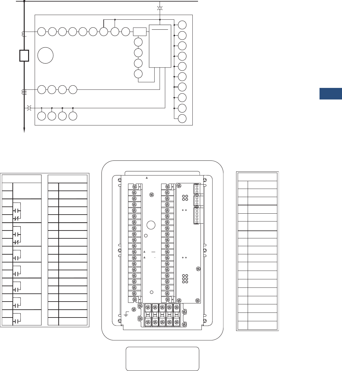
Volume 3—Power Distribution and Control Assemblies CA08100004E—November 2013 www.eaton.com V3-T9-185
9
9
9
9
9
9
9
9
9
9
9
9
9
9
9
9
9
9
9
9
9
9
9
9
9
9
9
9
9
9
9.4
Metering Devices, Protective Relays, Software and Connectivity
Protective Relays
Wiring Diagrams
FP-4000 One-Line Drawing
FP-4000 Rear View and Terminal Designations
CB
Phase
CTs (3)
Optional
Zero
Sequence
CT
Optional
VT (1)
Load
59
A–1
59
A–2 27
A–1 27
A–2
50
X–1 50
X–2
50
X–3
51X
FP-5000
Trip
Coil
Monitor
50
P–1
50
P–2 50
P–3
51P 50
BF
46–1 46–2 55A 55D
Main VTs
(2) or (3)
CALC
31o = IR
51R
50
R–1
50
R–2
50
R–3
59
M–1
59
M–2
27
M–1
27
M–2
47–1
47–2
81
U–1
81
U–2
81
O–1
81
O–2
METERING
V, I, F, PF,
W, VARS, VA
Energy
Demand
Min./Max.
%THD
Phasors
Data Logger
Waveform
SER
Fault Records
TB1 TB2
101 Power Supply
Input (+)
102
103
104
105
106
107
108
109
110
111
112
113
114
115
116
117
118
201
202
203
204
205
206
207
208
209
210
211
212
213
214
215
216
217
218 Vg Main
Vx2 Aux
Vx1 Aux
VC(+) Main
VB(+) Main
VA(+) Main
Not Used
Not Used
C In 1
C In 2
C In 3
C In 4
C In Source 1
C In Source 2
C In 5
C In 6
C In 7
C In 8
Trip 1 N.O.
Trip 1 Com.
Trip 2 N.O.
Trip 2 Com.
RLY 3 N.O.
RLY 3 Com.
RLY 4 N.O.
RLY 4 Com.
RLY 5 N.O.
RLY 5 Com.
Alarm Com.
Alarm N.O.
Alarm N.C.
Power Supply
Input (–)
RLY Healthy
Com.
RLY Healthy
N.O.
RLY Healthy
N.C.
A1 B1 C1 X1 N.C. 1
A2 B2 C2 X2 N.C. 2
TB4
118
117
116
115
114
113
112
111
110
109
108
107
106
105
104
103
102
101
218
217
216
215
214
213
212
211
210
209
208
207
206
205
204
203
202
201
Red
White
Factory Connection Only
TB2TB1 TB3 TB3
J1-1
J1-2
J1-3
J2-1
J2-2
J2-3
J3-1
J3-2
J3-3
J3-4
J3-5 Zone Com.
J5-1 RS485(+)
J5-2 RS485(-)
J5-3 RS485com
J5-4 RS485shield
J4-1
J4-2
J4-3
PowerNet
PowerNet
PowerNet Shield
Accessory Bus
Accessory Bus
Zone In
Accessory Bus
Shield
Zone Out
Zone Com.
Zone Shield
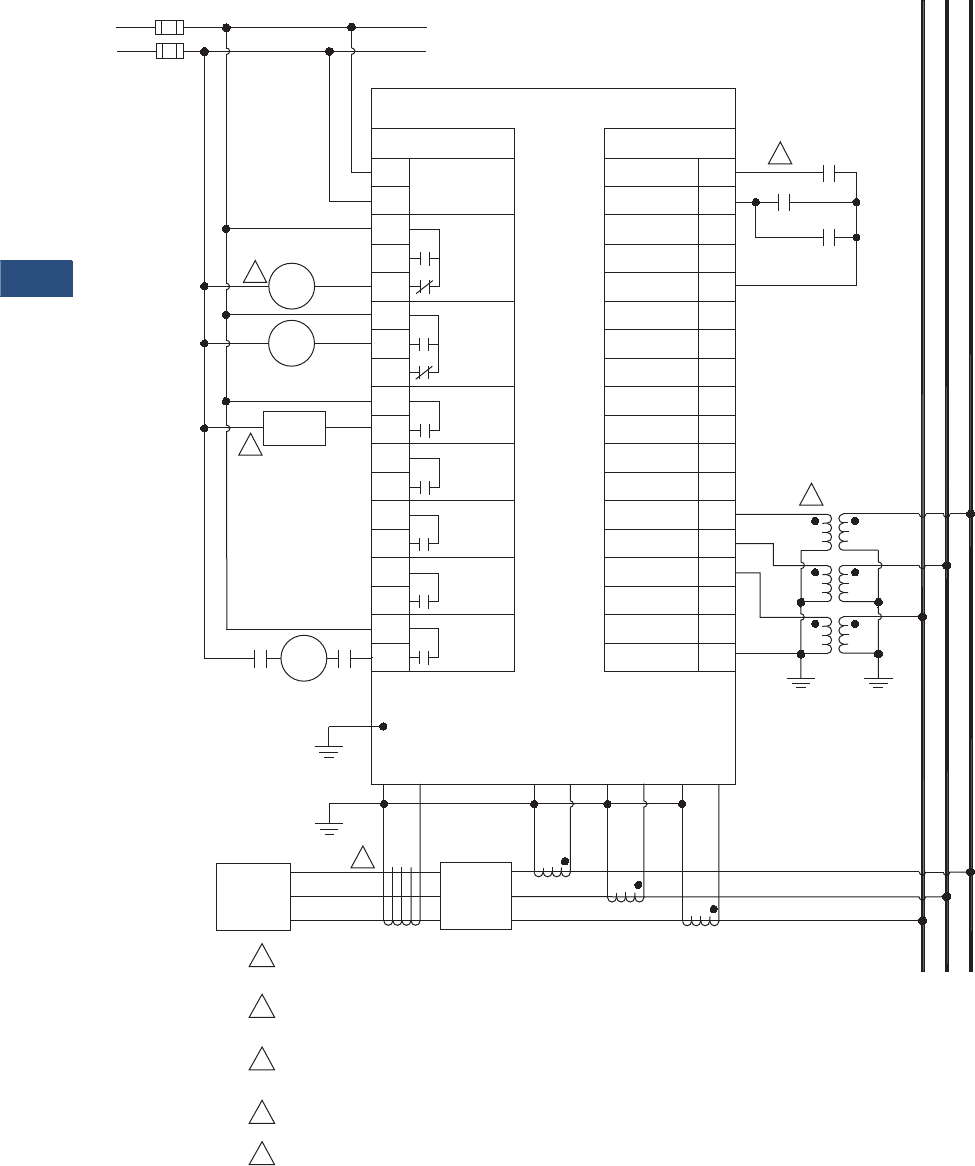
V3-T9-186 Volume 3—Power Distribution and Control Assemblies CA08100004E—November 2013 www.eaton.com
9
9
9
9
9
9
9
9
9
9
9
9
9
9
9
9
9
9
9
9
9
9
9
9
9
9
9
9
9
9
9.4
Metering Devices, Protective Relays, Software and Connectivity
Protective Relays
FP-4000 Typical Connection Drawing Using Wye PTs
ac/dc
Power Supply
(+)
(–)
48 – 125 Vac/dc or
100 – 240 Vac/dc
2
3
Breaker
Close
52A 52A
4
Ground
X2 X1
Load 52
A2 A1 B2 B1 C2 C1
5
C B A
C B A
152A
52B
52B TOC
FP-4000
TB1 TB2
101 Power Supply
Input (+)
102
103
104
105
106
107
108
109
110
111
112
113
114
115
116
117
118
201
202
203
204
205
206
207
208
209
210
211
212
213
214
215
216
217
218Vg Main
VX2 Aux
VX1 Aux
VC(+) Main
VB(+) Main
VA(+) Main
Not Used
Not Used
C In 1
C In 2
C In 3
C In 4
C In Source 1
C In Source 2
C In 5
C In 6
C In 7
C In 8
Trip 1 N.O.
Trip 1 Com.
Trip 2 N.O.
Trip 2 Com.
RLY 3 N.O.
RLY 3 Com.
RLY 4 N.O.
RLY 4 Com.
RLY 5 N.O.
RLY 5 Com.
Alarm Com.
Alarm N.O.
Alarm N.C.
Power Supply
Input (–)
RLY Healthy
Com.
RLY Healthy
N.O.
RLY Healthy
N.C.
1For maximum breaker diagnostics use both 52A and 52B contacts.
Some diagnostics are not available if only one of the two is used.
A relay failure alarm should provide immediate attention as circuit
is no longer protected. Relay failure output is normally energized.
FP-4000 can initiate a breaker close via the front panel interface
and/or remote activation through communication or discrete input.
Residual connection may be used in place of zero sequence CT.
Delta or open delta PT connection may be used in place of wye-ground connection.
2
3
4
5
Relay
Failure
Alarm
Breaker
Alarm
52
TC

Volume 3—Power Distribution and Control Assemblies CA08100004E—November 2013 www.eaton.com V3-T9-187
9
9
9
9
9
9
9
9
9
9
9
9
9
9
9
9
9
9
9
9
9
9
9
9
9
9
9
9
9
9
9.4
Metering Devices, Protective Relays, Software and Connectivity
Protective Relays
Dimensions
Approximate Dimensions in Inches (mm)
FP-4000 Feeder Protection Relay
Height Width Depth
Shipping Weight
Lbs (kg)
In Front of Panel
10.15 (257.9) 7.62 (193.5) 0.62 (15.7) 9.0 (4.1)
Behind Panel
10.15 (257.9) 7.62 (193.5) 7.48 (190.0) 9.0 (4.1)
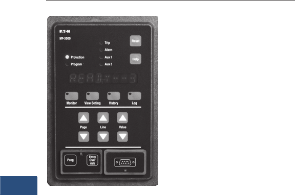
V3-T9-188 Volume 3—Power Distribution and Control Assemblies CA08100004E—November 2013 www.eaton.com
9
9
9
9
9
9
9
9
9
9
9
9
9
9
9
9
9
9
9
9
9
9
9
9
9
9
9
9
9
9
9.4
Metering Devices, Protective Relays, Software and Connectivity
Protective Relays
MP-3000
Contents
Description Page
Product Selection Guide . . . . . . . . . . . . . . . . . . . . V3-T9-158
FP-6000 Feeder Protection . . . . . . . . . . . . . . . . . . V3-T9-162
FP-5000 Feeder Protection . . . . . . . . . . . . . . . . . . V3-T9-172
FP-4000 Feeder Protection . . . . . . . . . . . . . . . . . . V3-T9-180
MP-3000 Motor Protection
Features, Benefits and Functions . . . . . . . . . . . V3-T9-189
Standards and Certifications . . . . . . . . . . . . . . . V3-T9-189
Product Selection . . . . . . . . . . . . . . . . . . . . . . . V3-T9-190
Options and Accessories . . . . . . . . . . . . . . . . . V3-T9-190
Technical Data and Specifications . . . . . . . . . . . V3-T9-191
Dimensions. . . . . . . . . . . . . . . . . . . . . . . . . . . . V3-T9-195
MP-4000 Motor Protection . . . . . . . . . . . . . . . . . . V3-T9-198
MD-3000 Motor/Generator Differential Relay . . . . V3-T9-204
Digitrip 3000 . . . . . . . . . . . . . . . . . . . . . . . . . . . . . V3-T9-207
VR-300 Multifunctional Voltage Relay . . . . . . . . . . V3-T9-217
DP-300 Current Differential Protection Relay . . . . . V3-T9-221
EDR-3000 Feeder Protection . . . . . . . . . . . . . . . . . V3-T9-226
ETR-4000 Transformer Protection Relay . . . . . . . . V3-T9-237
Ground Fault Relay. . . . . . . . . . . . . . . . . . . . . . . . . V3-T9-250
Universal RTD Module . . . . . . . . . . . . . . . . . . . . . . V3-T9-254
IQ 125 Volt DC Power Supply. . . . . . . . . . . . . . . . . V3-T9-258
MP-3000 Motor Protection
Product Description
●Microprocessor-based,
multi-function motor
protection
●Current only device—
no need to add PTs
●Intel-I-Trip™ overload
protection based on
motor data
●Event recording and
operational logging
●Motor Start Profile™
●Optional Quick Release
Drawout Case
●Used on AMPGARD®
and medium voltage
assemblies
●“Help” menu provides
user operational assistance
Application Description
Eaton’s MP-3000 motor
protection relay is a
multifunctional
microprocessor-based
protective relay for the
protection of three-phase AC
motors. The MP-3000 motor
relay may be applied to any
size motor at any voltage
level. It is most commonly
used on large, medium
voltage three-phase induction
motors. It has also been
widely used on important
low voltage (480 volt)
motor applications and
synchronous motors.
The MP-3000 motor relay is
a current only device that
monitors three-phase and
ground currents. It provides
motor overload, stall, short
circuit, phase unbalance,
single phasing and ground
fault motor protection.
It can also be used to provide
protection for a load jam or
loss of load condition. Please
refer to Page V3-T9-192.
The MP-3000 motor relay
provides start control logic
to protect the motor against
excessive starts or starting
the motor before it has had
sufficient time to cool down.
The MP-3000 motor relay
may be applied to either
across the line starters or
reduced voltage starters. On
reduced voltage starters, the
MP-3000 relay can control the
switch from reduced voltage
to full voltage based on time
and/or motor transition. The
MP-3000 can protect the
starter against failure to
transition to full voltage
through contact feedback and
an incomplete sequence
function.
The MP-3000 motor relay is
generally used on a motor
starter or a breaker used for
a motor load. The MP-3000
motor relay provides the
intelligence to protect and
control the motor against
abnormal operating
conditions. It monitors the
currents from either a 5A
or 1A secondary of a CT
circuit. Ground current may
be obtained from either a
ground CT or from the
residual connection of the
phase CTs. It provides a
Form C contact output for
controlling the starter contacts
or breaker operation.

Volume 3—Power Distribution and Control Assemblies CA08100004E—November 2013 www.eaton.com V3-T9-189
9
9
9
9
9
9
9
9
9
9
9
9
9
9
9
9
9
9
9
9
9
9
9
9
9
9
9
9
9
9
9.4
Metering Devices, Protective Relays, Software and Connectivity
Protective Relays
Features, Benefits and Functions
●Complete motor protection
and control in a single
compact case reduces
panel space requirements
and wiring costs
●Microprocessor design
with self diagnostics
eliminates calibration
and reduces installation,
commissioning and
maintenance
●Programmable stop
2–20% of PCT
●Intel-I-Trip overload
protection develops
customized curve from
manufacturer’s supplied
motor data
●Intel-I-Trip overload
protection provides
adaptive trip characteristics
based on motor
temperature when motor
RTDs are connected
through an optional
URTD module
●Meets UL 1053 ground
fault protection standards
that eliminates the need
for a separate ground relay
saving cost, space, wiring
and time
●Voltage dip/loss ride
through capability reduces
unnecessary trips caused
by poor power quality
●Motor currents,
temperatures and
conditions are monitored
and displayed either locally
or remotely
●Event log provides motor
operating records for the
most recent 20 Trip or
Alarm events with date
and time stamping. This
information can improve
troubleshooting and
reduce downtime
●Log book records the most
recent 100 events such as
motor START/STOP and
set point changes to
provide a log of motor
operation with date and
time stamping
●RTD diagnostics reduces
unnecessary tripping
caused by faulty RTD, RTD
wiring or communications
●Arm/Disarm feature
improves security for
critical motor applications
●Motor Start profile verifies
protection and motor
starting coordination. This
feature can be used to
develop protection settings
on old motors where data
is not available
●Optional communication
module and Eaton’s
software simplifies setting,
configuration, monitoring,
commissioning and data
retrieval either locally or
remotely
●Optional Quick Release
Drawout Case construction
simplifies relay removal
and replacement
The protection functions are
listed below.
●I2t overload protection
(49/51)
●Locked rotor (49S/51)
●Ultimate trip current (51)
●Negative sequence phase
unbalance (46)
●Instantaneous
overcurrent (50)
●Ground fault
protection (50G)
●RTD trip and alarm with
URTD module (49/38)
●Underload trip (37)
●Starts per time (66)
●Jam or stall (51R)
●Auto or manual reset (86)
●Fail-safe or non-fail-safe
trip modes
The metering functions are:
●Motor currents:
●Average current (Iave)
●Individual phase and
ground current in
primary amperes
●Percent of full load
●Percent of phase
unbalance
●RTD temperatures:
●Individual winding
●Motor bearing
●Load
●Auxiliary temperatures
●Motor conditions:
●Percent of I2t thermal
bucket
●Time before start
●Remaining starts
allowed
●Oldest start time
Standards and Certifications
The MP-3000 motor
protection was designed to
meet the industry standards
for protective relays. It is
recognized under UL 1053
Ground Fault Protection
Standard.
●UL recognized
(File No. E154862)
●UL 1053 recognized
●UL 508 recognized
●ANSI C37.90, C37.90.1
●cUL
●CSA

V3-T9-190 Volume 3—Power Distribution and Control Assemblies CA08100004E—November 2013 www.eaton.com
9
9
9
9
9
9
9
9
9
9
9
9
9
9
9
9
9
9
9
9
9
9
9
9
9
9
9
9
9
9
9.4
Metering Devices, Protective Relays, Software and Connectivity
Protective Relays
Product Selection
MP-3000
Options and Accessories
Additional Related Products
by Eaton’s Cutler-Hammer®
Series
The MP-3000 is available in
either a fixed mount or Quick
Release Drawout Case. Both
mountings use the same
panel cutout. Page V3-T9-195
shows cutout dimensions.
Page V3-T9-192 shows a
typical fixed mountwiring
diagram for a medium voltage
motor starter application.
Page V3-T9-193 shows the
fixed mount terminal
designation. Page V3-T9-195
shows the drawout case
panel mounting, and shows
the drawout case terminal
designation.
The Universal RTD module
(URTD) is required when the
motor is equipped with RTDs
that you wish to monitor and
use for protection. The URTD
can be mounted near the
motor to reduce RTD wiring
and costs. Page V3-T9-194
shows MP-3000 and URTD
inter-connection wiring.
Please refer to the URTD
information described
elsewhere in
this catalog.
The MP-3000 motor
protection is designed to
operate from 120 Vac or
240 Vac auxiliary control
power. The MP-3000 motor
relay can be used with DC
control power with the
addition of the IQDCPS.
The IQDCPS is an inverter
from DC to AC.
Description
Catalog
Number
MP-3000 Drawout, 5A with RS-232 MP3011
MP-3000 Drawout, INCOM, 5A with RS-232 MP3012
MP-3000 Drawout, Modbus, 5A with RS-232 MP3013
MP-3000 Drawout, DeviceNet, 5A with RS-232 MP3014
MP-3000 Drawout, 1A with RS-232 MP3111
MP-3000 Drawout, INCOM, 1A with RS-232 MP3112
MP-3000 Drawout, Modbus, 1A with RS-232 MP3113
MP-3000 Drawout, DeviceNet, 1A with RS-232 MP3114
MP-3000 Fixed Case, 5A with RS-232 MP3010
MP-3000 Fixed Case, INCOM, 5A with RS-232 MP3010-INCOM
MP-3000 Fixed Case, Modbus, 5A with RS-232 MP3010MODBUS
MP-3000 Fixed Case, DeviceNet, 5A with RS-232 MP3010DEVICEN
MP-3000 Fixed Case, 1A with RS-232 MP3110
MP-3000 Fixed Case, INCOM, 1A with RS-232 MP3110-INCOM
MP-3000 Fixed Case, Modbus, 1A with RS-232 MP3110MODBUS
MP-3000 Fixed Case, DeviceNet, 1A with RS-232 MP3110DEVICEN
MP-3000 Fixed Case, INCOM, 5A with RS-232, URTD MP3010VPI
MP-3000 Fixed Case, Modbus, 5A with RS-232, URTD MP3010VPM
MP-3000 Fixed Case, DeviceNet, 5A with RS-232, URTD MP3010VPD
MP-3000 Fixed Case, INCOM, 1A with RS-232, URTD MP3110VPI
MP-3000 Fixed Case, Modbus, 1A with RS-232, URTD MP3110VPM
MP-3000 Fixed Case, DeviceNet, 1A with RS-232, URTD MP3110VPD
MP-3000

Volume 3—Power Distribution and Control Assemblies CA08100004E—November 2013 www.eaton.com V3-T9-191
9
9
9
9
9
9
9
9
9
9
9
9
9
9
9
9
9
9
9
9
9
9
9
9
9
9
9
9
9
9
9.4
Metering Devices, Protective Relays, Software and Connectivity
Protective Relays
Technical Data and Specifications
Control Power
●Nominal rating:
●120 Vac or 240 Vac
●+10%, –25%
●Operating range:
●120 Vac: 90 132 Vac
●240 Vac:180 264 Vac
●Frequency: 50 or 60 Hz
●Power use:
●20 VA maximum
●URTD: 6 VA maximum
●IPONI: 1 VA maximum
●Ride-through time:
30 cycles from nominal Vac
Current Inputs
●Nominal (In): 1A or 5A
●CT rating:
●2 x In continuous
●50 x In for 1 second
●Burdens:
●< 0.25 VA at 5A
●< 0.05 VA at 1A
Metering Accuracy
●Phase current: ±1% of In
(5–100%)
●
Ground current: ±1.5% of I
n
(0–55%)
Discrete Inputs
●Number of inputs: two
programmable
●Ratings:
●1.2 VA at 120 Vac
●Maximum off = 36 Vac
●Minimum on = 86 Vac
Output Contacts
●Number of outputs: four
Form C, programmable
●Momentary:
●Make 30A AC/DC for
0.25 seconds
●Break 0.25A at 250 Vdc
(resistive)
●Break 5A at 120 240 Vac
●Continuous:
●5A at 120/240 Vac
●5A at 30 Vdc
Analog Output
●Rating: ± 4–20 mA
programmable
●Maximum load: 1K ohm
●Accuracy: 1%
Motor Overload Protection (I2t)
●Full load amperes:
10–3000A
●
Locked rotor current:
300–1200% FLA
●Locked rotor time:
1–120 seconds
●Ultimate trip current:
85–150% FLA
●Phase CT ratio:
10–4000 (In
)
●Ground CT ratio:
10–4000 (In
)
●Timing accuracy: ±
2.5% or
±30 mS
for I > 1.1x U.T.C
Trip Setting Range
●Ground fault (GF): Off,
2–55% CT ratio
●GF start time delay:
2–60 cycles
●GF run time delay:
0–60 cycles
●Timer accuracy: ± 20 mS
●Instantaneous O.C.: Off,
300–1600% FLA
●IOC start time delay:
2–60 cycles
●Timer accuracy: ±20 mS
●JAM trip: Off,
100–1200% FLA
●Underload trip: Off,
1–90% FLA
●Phase unbalance trip: Off,
4–40% Ineg/Ipos
●Start delay timers:
●0–120 seconds
(underload and phase
unbalance)
●0–1200 seconds (jam)
●Run delay timers: 0–240
seconds
●Timer accuracy: ±0.5%
+100 mS
Alarm Setting Range
●Ground fault: Off, 2–55%
CT ratio
●Overload I2t: Off,
60–99% I2t
●JAM: Off, 100–1200% FLA
●Underload: Off,
1–90% FLA
●Phase unbalance: Off,
4–40% Ineg/Ipos
●Run delay timers:
0–240 seconds
Start Control Functions
●Starts per time: 1–10 starts
●Time for starts per time:
Off, 1–240 minutes
●Time between starts: Off,
1–240 minutes
●Number of cold starts:
1–5 starts
●Motor transition current:
10–300% FLA
●Time for transition:
0–1200 seconds
●Inc. sequence timer: Off,
1–240 seconds
●Long acceleration timer:
Off, 1–1200 seconds
●Anti-Backspin timer: Off,
1–3600 minutes
RTD Inputs (Requires
URTD module)
●Sensor types:
●10 ohm copper
●100 ohm nickel
●120 ohm nickel
●100 ohm platinum
URTD Module Communications
●Interface:
●Electrical (three-wire)
●Fiber optic (preferred)
●Fiber optic cable: Type
HBFR-ERS or EUS
Clock
●Accuracy: ±1 minute/
month at 77ºF (25°C)
IPONI Communications
●Type: two-wire, FSK
●Baud rate: 1200 or
9600 baud
●Protocol: INCOM
●Functions:
●Read/write set points
●Read metered values
●Read trip/alarms
●Read events/history
●View starting profile
MPONI Communications
●Type: 5-wire, 485
●Baud rate: 1200 or
9600 baud
●Protocol: Modbus RTU
●Functions:
●Read/write set points
●Read metered values
●Read trip/alarms
●Read events/history
●View starting profile
DPONI Communications
●Type: J-wire
●Baud rate: 500k, 250k,
125k
●Protocol: DeviceNet
●Functions:
●Read metered values
●Read trip/alarms
Logging
●Log book: 100 events
●Log event: 20 trips and
alarms
●Log start: last four starts
●Start profile: last four starts
(communication only)
●History records: motor,
trips, alarms and total
records
Environmental Conditions
●Operating temperature:
–4ºF to 140ºF (–20ºC to
+60ºC)
●Storage temperature:
–49ºF to +185ºF
(–45°C to +85°C)
●Humidity: 0–95%
noncondensing
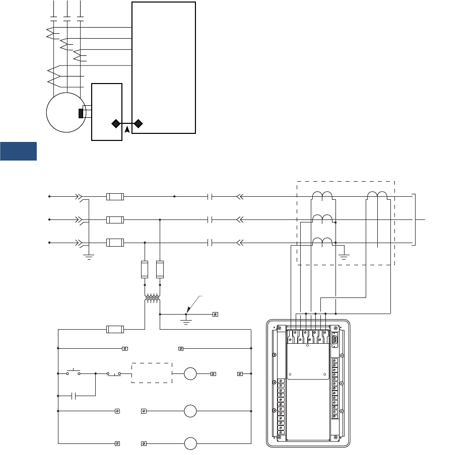
V3-T9-192 Volume 3—Power Distribution and Control Assemblies CA08100004E—November 2013 www.eaton.com
9
9
9
9
9
9
9
9
9
9
9
9
9
9
9
9
9
9
9
9
9
9
9
9
9
9
9
9
9
9
9.4
Metering Devices, Protective Relays, Software and Connectivity
Protective Relays
Wiring Diagrams
MP-3000 Motor Relay Protection Functions
MP-3000 Fixed Mount Typical
Motor
MP-3000
Protection Functions
49/51 Overload I2T
49S/51 Locked Rotor
51R Jam/Stall
37 Loss of Load/
Underload
46 Phase Loss/
Unbalance
50 Phase Inst. OC
50G Ground Inst. OC
66 Starts per time
period
URT
11 RTDs
H
1
A
H
2
A
H
1
B
H
2
B
H
1
C
H
2
C
G
1
G
2
MP-3000
Back View
with Jumper
Connection
CPT
Primary
Fuses
Secondary
Fuses 5
Ground
Ground
Non-Current
Carrying Ground
M
M
M
Main
Fuse
L1
L2
L3
L1
L2
L3
A
B
C
Gnd.
T1
T2
T3
X1 X2
CTs
GFCT
To Motor or
Load Device
Under Control
ac Supply
to MP-3000
47
11 12
START STOP
M
Alarm
18 19
Alarm Contacts
Auxiliary Trip Contacts
15 16
Auxiliary
Trip
Trip Contacts
Additional
Control M
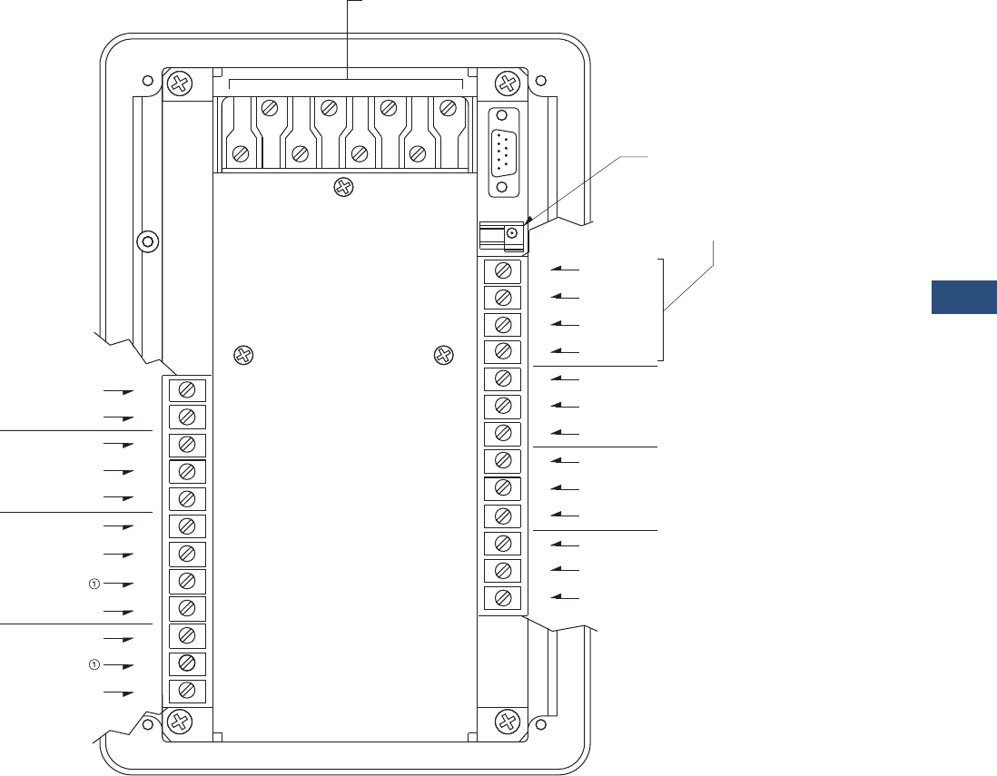
Volume 3—Power Distribution and Control Assemblies CA08100004E—November 2013 www.eaton.com V3-T9-193
9
9
9
9
9
9
9
9
9
9
9
9
9
9
9
9
9
9
9
9
9
9
9
9
9
9
9
9
9
9
9.4
Metering Devices, Protective Relays, Software and Connectivity
Protective Relays
MP-3000 Terminal Identification
Note
1Caution: Do not connect terminals 6 and 9 together.
+4/20 mA Output
-4/20 mA Output
Aux. 2 N/C
Aux. 2 N/O
Aux. 2 Com.
120 V or 240 V
Earth Ground
iscrete Source
Neutral
Discrete In 1
Discrete Com.
Discrete In 2
Trip Com.
Trip N/C
Trip N/O
Aux.
1 N/C
Aux.
1 N/O
Aux.
1 Com.
Alarm N/C
Strobe
Alarm Com.
Alarm N/O
Data
Common
Shield
URTD Optical Fiber
Communications
(Preferred Method)
or
URTD Wired
Communication
CT Connections
MP-3000
1
2
3
4
5
6
7
8
9
10
25
24
23
22
21
20
19
17
18
16
11
12
13
15
14
H
1
A
H
1
B
H
2
A
H
1
C
H
2
B
H
2
C
G
2
G
1
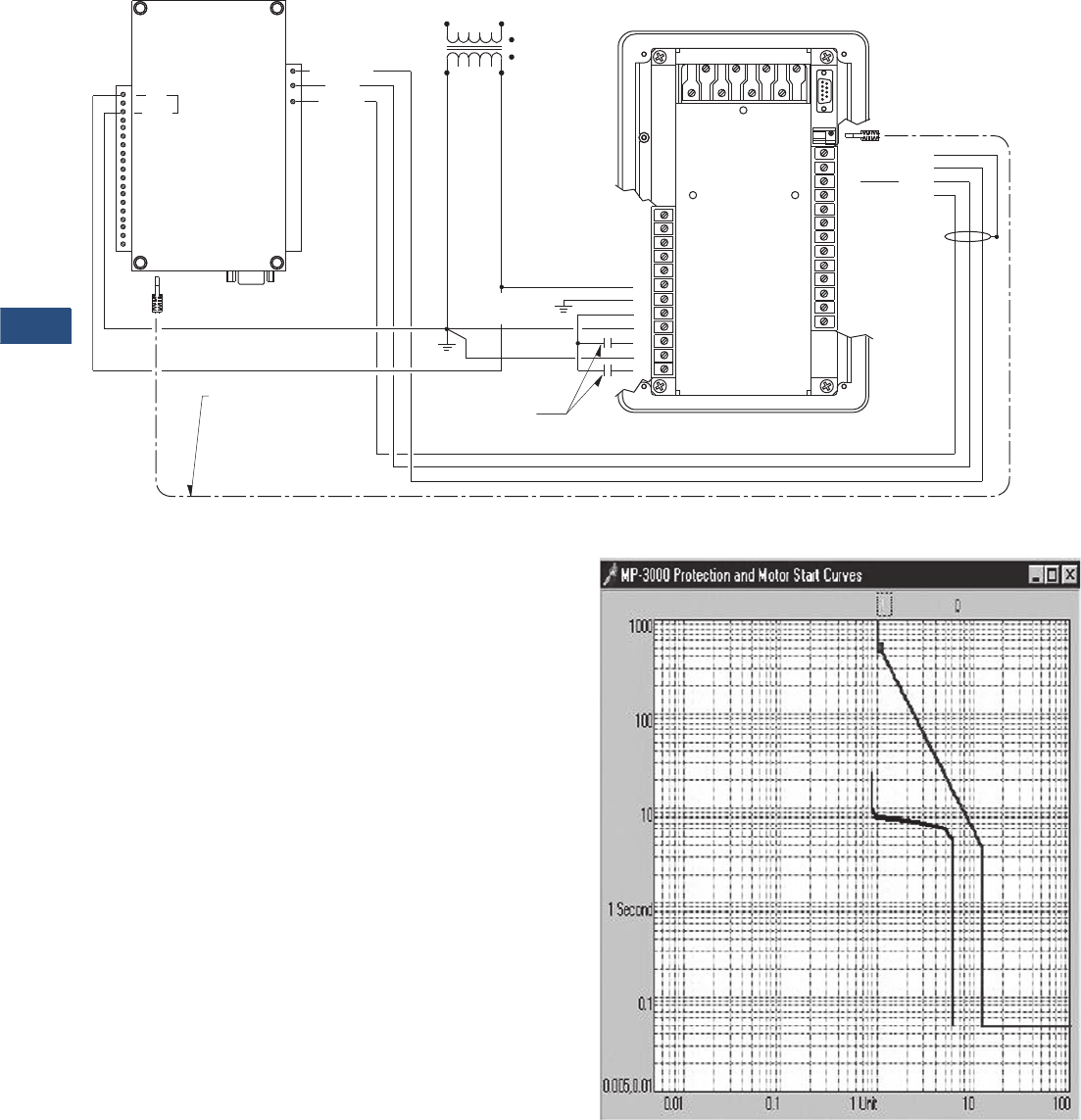
V3-T9-194 Volume 3—Power Distribution and Control Assemblies CA08100004E—November 2013 www.eaton.com
9
9
9
9
9
9
9
9
9
9
9
9
9
9
9
9
9
9
9
9
9
9
9
9
9
9
9
9
9
9
9.4
Metering Devices, Protective Relays, Software and Connectivity
Protective Relays
MP-3000 Control and URTD Wiring
Trip Curve Chart
The MP-3000 motor relay
records information on the
most recent four starts. It
records currents, percent of
I2t used, percent unbalance,
RTD temperatures and time
to transition and run. In
addition, a motor start profile
can be downloaded and
displayed using Eaton’s
PowerPort or PowerNet
Software. The starting profile
shows the motor starting
current plotted against the
relay protection curve. This
provides a quick view of the
coordination between the
protection and actual motor
start current.
When communications
are desired, an optional
communication module or
PONI (Product Operated
Network Interface) is
required. The MP-3000 is
compatible with an INCOM
(IPONI), Modbus RTU
(MPONI) or Ethernet (EPONI).
Future communication
modules are planned to
interface with other systems
using other protocols. Please
consult factory for availability
of other communication
options. Page V3-T9-197
shows typical mounting of
MP-3000 with optional PONI
and with URTD module and
PONI.
When the MP-3000 is
supplied in the optional
drawout case, then the
INCOM
(IPONI) is the only
communication option
available. The communication
option must be selected at
the time of order.
AC
ACN 120 Vac J3
Control Power
Transformer
Non-current
Carrying Gnd.
Common
Data
Strobe 120 Vac
Universal
RTD Module
MP-3000
Customer Remote
Input Contacts
or Pushbuttons
Optical Fiber for URTD
Communications
to MP-3000
(Preferred Method)
25
24
2
3
4
5
6
7
8
1
9
10
Shield
Common
Data
Strobe
23
22
21
20
19
17
18
16
11
12
13
15
14
H
1
A
H
1
B
H
2
A
H
1
C
H
2
B
H
2
CG
2
G
1
Motor Starting Profile Time/Current Chart
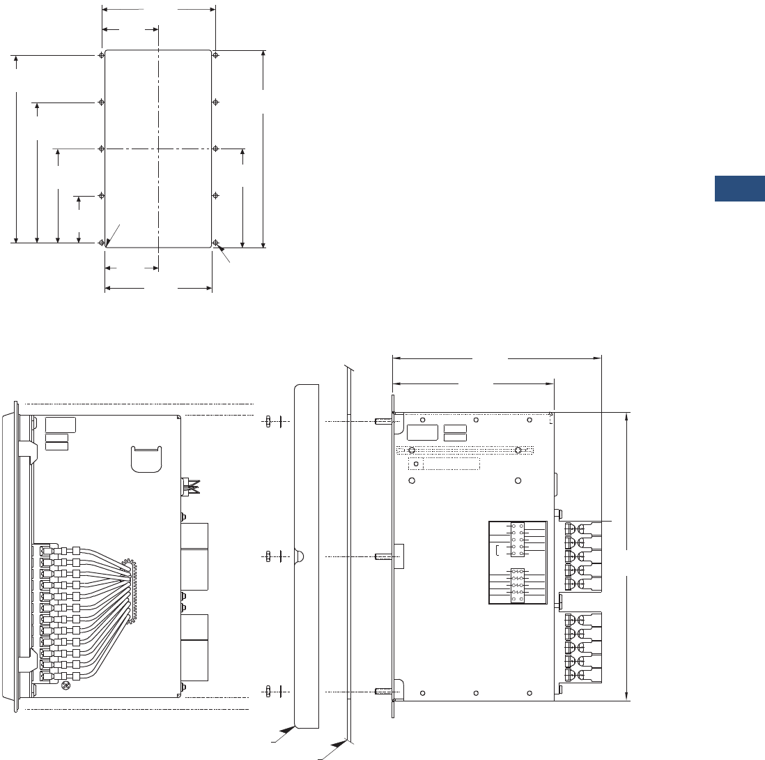
Volume 3—Power Distribution and Control Assemblies CA08100004E—November 2013 www.eaton.com V3-T9-195
9
9
9
9
9
9
9
9
9
9
9
9
9
9
9
9
9
9
9
9
9
9
9
9
9
9
9
9
9
9
9.4
Metering Devices, Protective Relays, Software and Connectivity
Protective Relays
Dimensions
Approximate Dimensions in Inches (mm)
Panel Cutout Diagram
MP-3000 Drawout Panel Mounting
5.38
(136.7)
9.38
(238.3)
4.69
(119.1)
2.53
(64.3) 5.06
(128.5)
2.23
(56.7)
4.45
(113.0)
6.68
(169.7)
8.90
(226.1)
.06
(1.5) RAD
4 Places
2.69
(68.3)
.218
(5.5) DIA 10 Places
66D2031G01
REV. 1
A980810
S/N123321 BUILT BY
G.K.
TESTED BY
F.C.
66C2020H01
Unused
G1
Unused
H1C
29
27
25
H1A
H1B
23
21
26
28
30
22
24
G2
H2C
H2A
H2B
Discrete In 1
Discrete In 2
Discrete Source
Discrete Com
Unused
Unused
120V
240V
Neut
Auto
Select
VAC
19
or
17
+4/20 Output
-4/20 Output
15
13
11
18
20
12
14
16
11
13
49
17
60
14
19
16
20
18
A980000
66D2029G01
REV. 1
S/N000000
G.K.
F.C.
TESTED BY
BUILT BY
45
47
6.89
(175.0)
5.33
(135.4)
9.51
(241.6)
Inner ChassisOuter Chassis Outer Flange
Mounting Panel
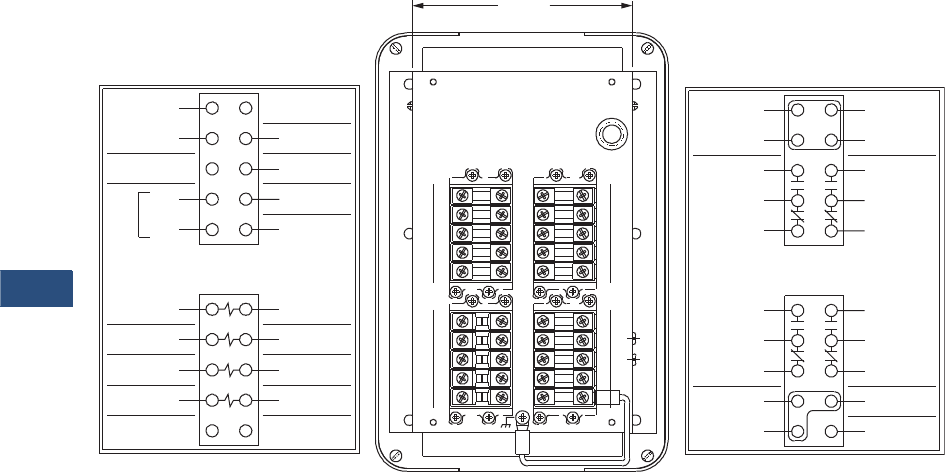
V3-T9-196 Volume 3—Power Distribution and Control Assemblies CA08100004E—November 2013 www.eaton.com
9
9
9
9
9
9
9
9
9
9
9
9
9
9
9
9
9
9
9
9
9
9
9
9
9
9
9
9
9
9
9.4
Metering Devices, Protective Relays, Software and Connectivity
Protective Relays
Approximate Dimensions in Inches (mm)
Rear View of MP-3000 Drawout Outer Case
2221
3029
26
2827
25
2423
18
2019
17
14
1615
13
1211
5251
59 60
57
55
58
56
53 54
49
47
50
48
45
43
46
44
41 42
URTD Common
Aux 2
41
43
45
47
Alarm
49
51
53
55
Aux 1
42
44
46
48
50
54
52
56
Tri p
57
59 60
58
Shield
66C2020H02
Earth Gnd
Discrete In 1
13
11
Discrete In 2
12
14
H1A
19
15
17
21
Unused
G1
H1B
H1C
66C2020H01
27
23
25
29
20
16
18
22
H2A
G2
26
24
28
H2B
H2C
30
Unused
Discrete Source URTD Shield
URTD DataURTD Strobe
Discrete Com
-4/20 Output
+4/20 Output Unused
Unused
PONI In
Neut
120Vor
240V
VAC
Auto
Select
5.23
(132.8)
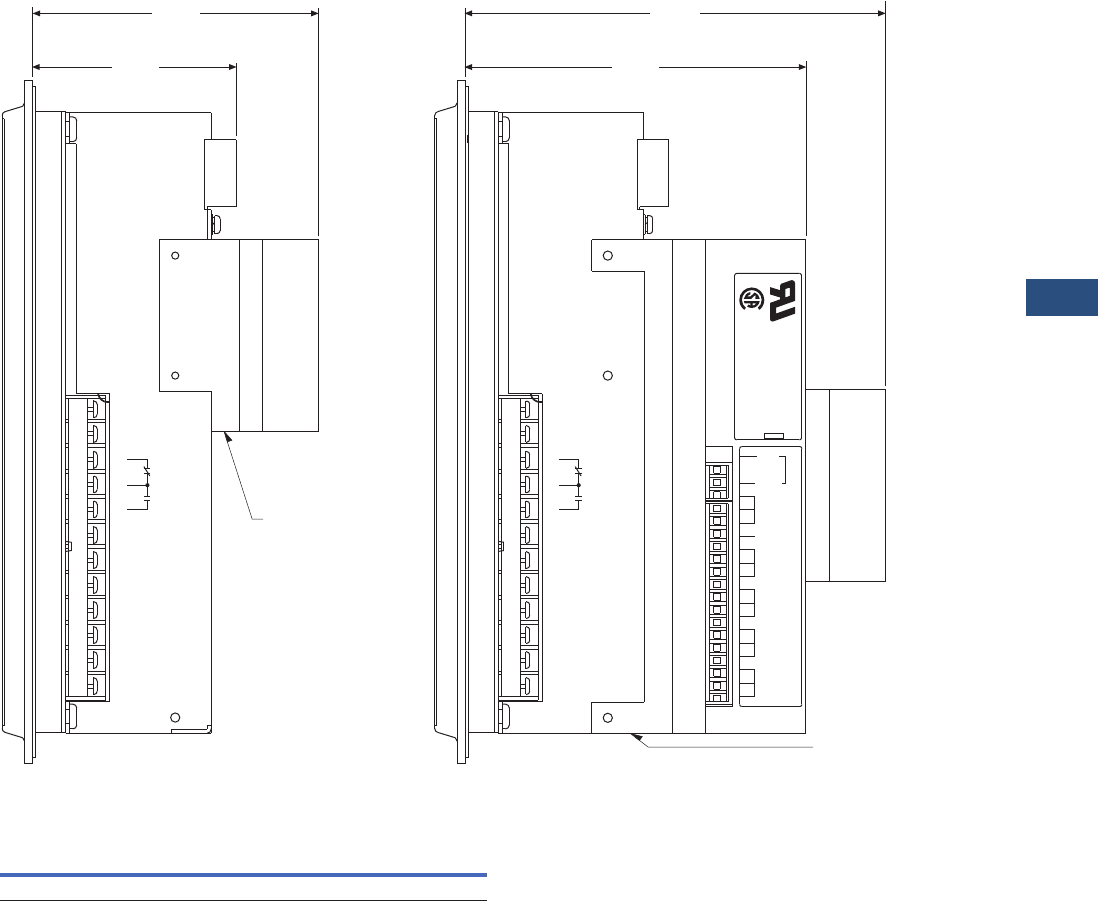
Volume 3—Power Distribution and Control Assemblies CA08100004E—November 2013 www.eaton.com V3-T9-197
9
9
9
9
9
9
9
9
9
9
9
9
9
9
9
9
9
9
9
9
9
9
9
9
9
9
9
9
9
9
9.4
Metering Devices, Protective Relays, Software and Connectivity
Protective Relays
Approximate Dimensions in Inches (mm)
MP-3000 PONI and URTD Mounting
FP-3000 Feeder Protection Relay
Height Width Depth
Shipping Weight
Lbs (kg)
10.25 (260.4) 6.72 (170.7) 3.70 (94.0) 7.0 (3.2)
ACN
PONI
Mounting
Bracket
MB1
AUX1
120
Vac
ac
MB2
LB1
LB2
GND
J3
27
28
29
30
31
32
33
34
35
20
21
22
23
24
25
26
UNIVERSAL RTD MODULE
STYLE NUMBER 2D78559
1A49102H19
6.26
(159.0)
5.07
(128.8)
®
®
RTD Module
Mounting
Bracket
124
-4/20
OUTPUT
25
+4/20
OUTPUT
AUX 2
7
465
32
DISCRETE
SOURCE
NEUT
EARTH
GROUND
120 V or
240 V
VAC AUTO SELECT
DISCRETE
COMMON
DISCRETE
IN 1
DISCRETE
IN 2
1098
4.25
(108.0)
with PONI
3.01
(76.5)
without PONI
124
-4/20
OUTPUT
25
+4/20
OUTPUT
AUX 2
7
465
32
DISCRETE
SOURCE
NEUT
EARTH
GROUND
120 V or
240 V
VAC AUTO SELECT
DISCRETE
COMMON
DISCRETE
IN 1
DISCRETE
IN 2
1098
with PONI and RTD Module
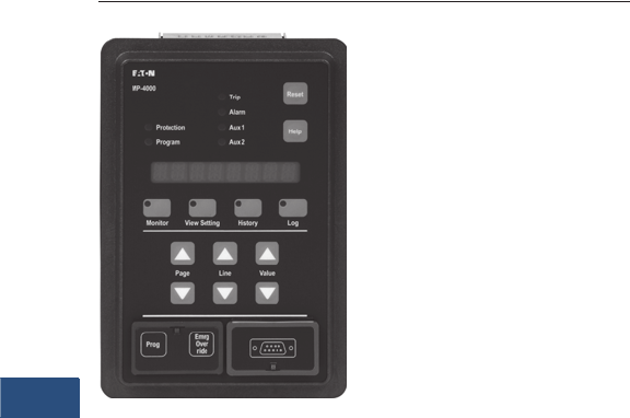
V3-T9-198 Volume 3—Power Distribution and Control Assemblies CA08100004E—November 2013 www.eaton.com
9
9
9
9
9
9
9
9
9
9
9
9
9
9
9
9
9
9
9
9
9
9
9
9
9
9
9
9
9
9
9.4
Metering Devices, Protective Relays, Software and Connectivity
Protective Relays
MP-4000
Contents
Description Page
Product Selection Guide . . . . . . . . . . . . . . . . . . . . V3-T9-158
FP-6000 Feeder Protection . . . . . . . . . . . . . . . . . . V3-T9-162
FP-5000 Feeder Protection . . . . . . . . . . . . . . . . . . V3-T9-172
FP-4000 Feeder Protection . . . . . . . . . . . . . . . . . . V3-T9-180
MP-3000 Motor Protection . . . . . . . . . . . . . . . . . . V3-T9-188
MP-4000 Motor Protection
Features, Benefits and Functions . . . . . . . . . . . V3-T9-199
Standards and Certifications . . . . . . . . . . . . . . . V3-T9-199
Product Selection . . . . . . . . . . . . . . . . . . . . . . . V3-T9-201
Options and Accessories . . . . . . . . . . . . . . . . . V3-T9-201
Technical Data and Specifications . . . . . . . . . . . V3-T9-202
Dimensions. . . . . . . . . . . . . . . . . . . . . . . . . . . . V3-T9-203
MD-3000 Motor/Generator Differential Relay . . . . V3-T9-204
Digitrip 3000 . . . . . . . . . . . . . . . . . . . . . . . . . . . . . V3-T9-207
VR-300 Multifunctional Voltage Relay . . . . . . . . . . V3-T9-217
DP-300 Current Differential Protection Relay . . . . . V3-T9-221
EDR-3000 Feeder Protection . . . . . . . . . . . . . . . . . V3-T9-226
ETR-4000 Transformer Protection Relay . . . . . . . . V3-T9-237
Ground Fault Relay. . . . . . . . . . . . . . . . . . . . . . . . . V3-T9-250
Universal RTD Module . . . . . . . . . . . . . . . . . . . . . . V3-T9-254
IQ 125 Volt DC Power Supply. . . . . . . . . . . . . . . . . V3-T9-258
MP-4000 Motor Protection
Product Description
●Microprocessor-based,
multi-function motor
protection
●Intel-I-Trip overload
protection based on
motor data
●Event recording and
operational logging
●Motor Start Profile
●Optional Quick Release
Drawout Case
●Used on AMPGARD
and medium voltage
assemblies
●“Help” menu provides
user operational assistance
Application Description
Eaton’s MP-4000 motor
protection relay is a
multifunctional
microprocessor-based
protective relay for the
protection of three-phase ac
motors. The MP-4000 motor
relay may be applied to any
size motor at any voltage level.
It is most commonly used on
large, medium voltage three-
phase induction motors. It has
also been widely used on
important low voltage (480
volt) motor applications and
synchronous motors.
The MP-4000 motor relay
monitors three-phase and
ground currents, and three-
phase voltages. It provides
motor overload, stall, short
circuit, phase unbalance, single
phasing over/undervoltage,
underpower, power factor and
ground fault motor protection.
It can also be used to provide
protection for a load jam or loss
of load condition.
The MP-4000 motor relay
provides start control logic
to protect the motor against
excessive starts or starting
the motor before it has had
sufficient time to cool down.
The MP-4000 motor relay may
be applied to either across the
line starters or reduced voltage
starters. On reduced voltage
starters, the MP-4000 relay can
control the switch from
reduced voltage to full voltage
based on time and/or motor
transition. The MP-4000 can
protect the starter against
failure to transition to full
voltage through contact
feedback and an incomplete
sequence function.
The MP-4000 motor relay is
generally used on a motor
starter or a breaker used for
a motor load. The MP-4000
motor relay provides the
intelligence to protect and
control the motor against
abnormal operating conditions.
It monitors the currents from
either a 5A or 1A secondary of
a CT circuit. Ground current
may be obtained from either a
ground CT or from the residual
connection of the phase CTs.
It provides a form C contact
output for controlling the
starter contacts or breaker
operation.

Volume 3—Power Distribution and Control Assemblies CA08100004E—November 2013 www.eaton.com V3-T9-199
9
9
9
9
9
9
9
9
9
9
9
9
9
9
9
9
9
9
9
9
9
9
9
9
9
9
9
9
9
9
9.4
Metering Devices, Protective Relays, Software and Connectivity
Protective Relays
Features, Benefits and Functions
●Complete motor protection
and control in a single
compact case reduces
panel space requirements
and wiring costs
●Microprocessor design
with self diagnostics
eliminates calibration
and reduces installation,
commissioning and
maintenance
●Programmable stop
2–20% of PCT
●Intel-I-Trip overload
protection develops
customized curve from
manufacturer’s supplied
motor data
●Intel-I-Trip overload
protection provides
adaptive trip characteristics
based on motor
temperature when motor
RTDs are connected
through an optional
URTD module
●Meets UL 1053 ground
fault protection standards
that eliminates the need
for a separate ground relay
saving cost, space, wiring
and time
●Voltage dip/loss ride
through capability reduces
unnecessary trips caused
by poor power quality
●Motor currents,
temperatures and
conditions are monitored
and displayed either locally
or remotely
●Event log provides motor
operating records for the
most recent 20 Trip or
Alarm events with date
and time stamping. This
information can improve
troubleshooting and
reduce downtime
●Log book records the most
recent 100 events such as
motor START/STOP and
set point changes to
provide a log of motor
operation with date and
time stamping
●RTD diagnostics reduces
unnecessary tripping
caused by faulty RTD, RTD
wiring or communications
●Arm/Disarm feature
improves security for
critical motor applications
●Motor Start profile verifies
protection and motor
starting coordination. This
feature can be used to
develop protection settings
on old motors where data
is not available
●Optional communication
module and Eaton’s
software simplifies setting,
configuration, monitoring,
commissioning and data
retrieval either locally or
remotely
●Optional Quick Release
Drawout Case construction
simplifies relay removal
and replacement
The protection functions are
listed below:
●I2t overload
protection (49/51)
●Locked rotor (49S/51)
●Ultimate trip current (51)
●Negative sequence phase
unbalance (46)
●Instantaneous
overcurrent (50)
●Ground fault
protection (50G)
●Undervoltage (27)
●Overvoltage (59)
●Under power (32)
●Negative sequence voltage
unbalance (47)
●Power factor (55)
●RTD trip and alarm with
URTD module (49/38)
●Underload trip (37)
●Starts per time (66)
●Jam or stall (51R)
●Auto or manual reset (86)
●Fail-safe or non-fail-safe
trip modes
The metering functions are:
●Metering:
●Average current
●Amperes: magnitude
and angle in primary
values
●Amperes: positive,
negative and zero
sequence
●Average voltage (V ave)
●Voltage: magnitude and
angle
●Voltage: positive,
negative and zero
sequence
●% of full load
●% current unbalance
●% voltage unbalance
●Power, vars and VA
●Power factor
●Frequency
●Energy metering with
time and date stamps
●RTD temperatures:
●Individual winding
●Motor bearing
●Load
●Auxiliary temperatures
●Motor conditions:
●Percent of I2t thermal
bucket
●Time before start
●Remaining starts
allowed
●Oldest start time
Standards and Certifications
The MP-4000 motor
protection was designed to
meet the industry standards
for protective relays. It is
recognized under UL 1053
Ground Fault Protection
Standard.
●UL recognized (File No.
E154862)
●UL 1053 recognized
●UL 508 recognized
●ANSI C37.90, C37.90.1
●cUL
●CSA

V3-T9-200 Volume 3—Power Distribution and Control Assemblies CA08100004E—November 2013 www.eaton.com
9
9
9
9
9
9
9
9
9
9
9
9
9
9
9
9
9
9
9
9
9
9
9
9
9
9
9
9
9
9
9.4
Metering Devices, Protective Relays, Software and Connectivity
Protective Relays
Reference Information
Cross-Reference
Westinghouse®/Cutler-Hammer
Eaton’s Cutler-Hammer MP-
3000 motor relay supersedes
the Cutler-Hammer (formerly
Westinghouse) IQ 1000 II
motor relay and can replace
the earlier IQ 1000 motor
relay version sold under the
Westinghouse name. The
MP-3000 motor relay fits in
the same cut out and
provides the protection
functions of these older
models. The MP-3000
relay provides numerous
enhancements and new
features over the superseded
models. The most notable
enhancements are UL 1053
ground fault protection
certified, voltage loss ride
through capability, data
logging, communications
features and the addition of
a clock for date and time
stamping of events.
GE Multilin™
GE Multilin has several
product offerings for motor
protection. The 269 PLUS is
the equivalent model to the
MP-3000 with optional URTD
module. Eaton offers MP-
3000 value packs that include
an MP-3000, PONI, URTD
module and fiber optic cable
at competitive prices.
GE Multilin has both lower
and higher end products.
The MP-3000 can be used in
place of their 239 motor relay.
The MP-3000 offers more
capabilities than the 239 for
a slightly higher price.
GE Multilin 369 and 469
are upgraded end products.
The MP-3000 relay offers
equivalent overload and
current protection functions.
It also provides equivalent
start control functions. Both
the 369 and 469 offer voltage
protection and metering
functions. An Eaton meter
and/or other manufacturers’
protective relays may be
needed to satisfy the
customer’s motor protection
requirements. The 469 adds
differential protection. This
function must be supplied
by others in addition to the
MP-3000 motor relay.
Cross-Reference
Note
1If RTD monitoring required.
New Eaton’s Series Old Cutler-Hammer (Westinghouse) GE Multilin
MP-3000 (URTD module) 1IQ 1000 II, IQ 1000 269, 269+, 239, base 369
MP-4000 (URTD module) 1— 369 with voltage option
MP-4000 + MP-3000 — 469

Volume 3—Power Distribution and Control Assemblies CA08100004E—November 2013 www.eaton.com V3-T9-201
9
9
9
9
9
9
9
9
9
9
9
9
9
9
9
9
9
9
9
9
9
9
9
9
9
9
9
9
9
9
9.4
Metering Devices, Protective Relays, Software and Connectivity
Protective Relays
Product Selection
MP-4000 Ordering Information
Options and Accessories
Additional Related Products
by Eaton’s Cutler-Hammer Series
The MP-4000 is available in
either a fixed mount or Quick
Release Drawout Case. Both
mountings use the same
panel cutout.
The Universal RTD module
(URTD) is required when the
motor is equipped with RTDs
that you wish to monitor and
use for protection. The URTD
can be mounted near the
motor to reduce RTD wiring
and costs.
The MP-4000 motor protection
is design-ed to operate from
120 Vac or 240 Vac auxiliary
control power. The MP-4000
motor relay can be used with
dc control power with the
addition of the IQDCPS. The
IQDCPS is an inverter from
DC to AC.
Description Catalog Number
MP-4000 drawout, 5A with RS-232 MP4011
MP-4000 drawout, INCOM, 5A with RS-232 MP4012
MP-4000 drawout, Modbus, 5A with RS-232 MP4013
MP-4000 drawout, DeviceNet, 5A with RS-232 MP4014
MP-4000 drawout, 1A with RS-232 MP4111
MP-4000 drawout, INCOM, 1A with RS-232 MP4112
MP-4000 drawout, Modbus, 1A with RS-232 MP4113
MP-4000 drawout, DeviceNet, 1A with RS-232 MP4114
MP-4000 fixed case, 5A with RS-232 MP4010
MP-4000 fixed case, INCOM, 5A with RS-232 MP4010INCOM
MP-4000 fixed case, Modbus, 5A with RS-232 MP4010MODBUS
MP-4000 fixed case, DeviceNet, 5A with RS-232 MP4010DEVICEN
MP-4000 fixed case, 1A with RS-232 MP4110
MP-4000 fixed case, INCOM, 1A with RS-232 MP4110INCOM
MP-4000 fixed case, Modbus, 1A with RS-232 MP4110MODBUS
MP-4000 fixed case, DeviceNet, 1A with RS-232 MP4110DEVICEN
MP-4000 fixed case, INCOM, 5A with RS-232, URTD MP4010VPI
MP-4000 fixed case, Modbus, 5A with RS-232, URTD MP4010VPM
MP-4000 fixed case, DeviceNet, 5A with RS-232, URTD MP4010VPD
MP-4000 fixed case, INCOM, 1A with RS-232, URTD MP4110VPI
MP-4000 fixed case, Modbus, 1A with RS-232, URTD MP4110VPM
MP-4000 fixed case, DeviceNet, 1A with RS-232, URTD MP4110VPD
MP-4000

V3-T9-202 Volume 3—Power Distribution and Control Assemblies CA08100004E—November 2013 www.eaton.com
9
9
9
9
9
9
9
9
9
9
9
9
9
9
9
9
9
9
9
9
9
9
9
9
9
9
9
9
9
9
9.4
Metering Devices, Protective Relays, Software and Connectivity
Protective Relays
Technical Data and Specifications
Control Power
●Nominal rating:
●120 Vac or 240 Vac
●+10%, –25%
●Operating range:
●120 Vac: 90 132 Vac
●240 Vac:180 264 Vac
●Frequency: 50 or 60 Hz
●Power use:
●20 VA maximum
●URTD: 6 VA maximum
●IPONI: 1 VA maximum
●Ride-through time:
30 cycles from nominal Vac
Current Inputs
●Nominal (In): 1A or 5A
●CT rating:
●2 x In continuous
●50 x In for 1 second
●Burdens:
●< 0.25 VA at 5A
●< 0.05 VA at 1A
Voltage Inputs
●Nominal: 120 Vac
●Operating range: 69 to
150 Vac
●Burden: 2 VA
Metering Accuracy
●Phase current: ±1% of In
(5–100%)
●
Ground current: ±1.5% of I
n
(0–55%)
Discrete Inputs
●Number of inputs: two
programmable
●Ratings:
●1.2 VA at 120 Vac
●Maximum off = 36 Vac
●Minimum on = 86 Vac
Output Contacts
●Number of outputs: four
Form C, programmable.
●Momentary:
●Make 30A AC/DC for
0.25 seconds
●Break 0.25A at 250 Vdc
(Resistive)
●Break 5A at 120 240 Vac
●Continuous:
●5A at 120/240 Vac
●5A at 30 Vdc
Analog Output
●Rating: ± 4–20 mA
programmable
●Maximum load: 1K ohm
●Accuracy: 1%
Motor Overload Protection (I2t)
●Full load amperes:
10–3000
●
Locked rotor current:
300–1200% FLA
●Locked rotor time:
1–120 seconds
●Ultimate trip current:
85–150% FLA
●Phase CT ratio:
10–4000 (In
)
●Ground CT ratio:
10–4000 (In
)
●Timing accuracy: ±
2.5% or
±30 mS
for I > 1.1x U.T.C.
Trip Setting Range
●Ground fault (GF): Off,
2–55% CT ratio
●GF start time delay:
2–60 cycles
●GF run time delay:
0–60 cycles
●Timer accuracy: ± 20 mS
●Instantaneous O.C.: Off,
300–1600% FLA
●IOC start time delay:
2–60 cycles
●Timer accuracy: ±20 mS
●JAM trip: Off, 100–
1200% FLA
●Underload trip: Off,
1–90% FLA
●Current unbalance trip:
Off, 4–40% Ineg/Ipos
●Start delay timers:
●0–120 seconds
(underload and phase
unbalance)
●0–1200 seconds (jam)
●Run delay timers:
0–240 seconds
●Timer accuracy: ±0.5%
+100 mS
●Voltage unbalance: Off,
1 to 100V
●% V2/V1: 4% + 40%
●Voltage unbalance time
delay: 0 to 1200 sec.
●Under/overvoltage time
delay: Off, 10 to 150V
●Under/overvoltage time
delay: 0 to 1200 sec
●Under/overfrequency:
Off, 15 to 60 Hz
●Under/overfrequency time
delay: 0 to 60 sec
●Power protection: Off,
0.06 to .90 + FLA VT
●Power time delay: 0 to
1200 sec
●Power factor: Off, 0.05 lag
to 0.99 lead
●Power factor time delay:
0 to 60 sec
Alarm Setting Range
●Ground fault: Off,
2–55% CT ratio
●Overload I2t: Off,
60–99% I2t
●JAM: Off, 100–1200% FLA
●Underload: Off,
1–90% FLA
●Phase unbalance: Off,
4–40% Ineg/Ipos
●Run delay timers:
0–240 seconds
Start Control Functions
●Starts per time: 1–10 starts
●Time for starts per time:
Off, 1–240 minutes
●Time between starts:
Off, 1–240 minutes
●Number of cold starts:
1–5 starts
●Motor transition current:
10–300% FLA
●Time for transition:
0–1200 seconds
●Inc. sequence timer:
Off, 1–240 seconds
●Long acceleration timer:
Off, 1–1200 seconds
●Anti-Backspin timer:
Off, 1–3600 minutes
RTD Inputs (Requires
URTD module)
●Sensor types:
●10 ohm copper
●100 ohm nickel
●120 ohm nickel
●100 ohm platinum
URTD Module Communications
●Interface:
●Electrical (three-wire)
●Fiber optic (preferred)
●Fiber optic cable: Type
HBFR-ERS or EUS
Clock
●Accuracy: ±1 minute/
month at 77ºF (25°C)
PONI Communications
●Type: two-wire, FSK
●Baud rate: 1200 or
9600 baud
●Protocol: INCOM
●Functions:
●Read/write set points
●Read metered values
●Read trip/alarms
●Read events/history
●View starting profile
MPONI Communications
●Type: five-wire, 485
●Baud rate: 1200 or
9600 baud
●Protocol: Modbus RTU
●Functions:
●Read metered values
●Read trip/alarms
DPONI Communications
●Type: J-wire
●Baud rate: 500k,
250k, 125k
●Protocol: DeviceNet
●Functions:
●Read metered values
●Read trip/alarms
Logging
●Log book: 100 events
●Log event: 20 trips
and alarms
●Log start: last four starts
●Start profile: last four starts
(communication only)
●History records: motor,
trips, alarms and total
records
Environmental Conditions
●Operating temperature:
–4ºF to +140ºF (
–20°C to +60°C)
●Storage temperature:
–49ºF to +185ºF
(–45°C to +85°C)
●Humidity: 0–95%
noncondensing

Volume 3—Power Distribution and Control Assemblies CA08100004E—November 2013 www.eaton.com V3-T9-203
9
9
9
9
9
9
9
9
9
9
9
9
9
9
9
9
9
9
9
9
9
9
9
9
9
9
9
9
9
9
9.4
Metering Devices, Protective Relays, Software and Connectivity
Protective Relays
Dimensions
Approximate Dimensions in Inches (mm)
MP-4000 Feeder Protection Relay
Height Width Depth
Shipping Weight
Lbs (kg)
10.25 (260.4) 6.72 (170.7) 3.70 (94.0) 7.0 (3.2)
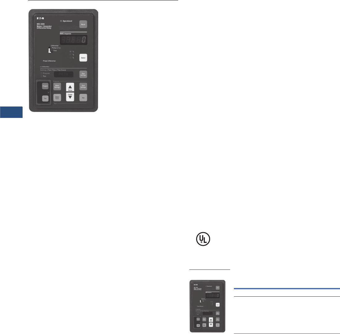
V3-T9-204 Volume 3—Power Distribution and Control Assemblies CA08100004E—November 2013 www.eaton.com
9
9
9
9
9
9
9
9
9
9
9
9
9
9
9
9
9
9
9
9
9
9
9
9
9
9
9
9
9
9
9.4
Metering Devices, Protective Relays, Software and Connectivity
Protective Relays
MD-3000
Contents
Description Page
Product Selection Guide . . . . . . . . . . . . . . . . . . . . V3-T9-158
FP-6000 Feeder Protection . . . . . . . . . . . . . . . . . . V3-T9-162
FP-5000 Feeder Protection . . . . . . . . . . . . . . . . . . V3-T9-172
FP-4000 Feeder Protection . . . . . . . . . . . . . . . . . . V3-T9-180
MP-3000 Motor Protection . . . . . . . . . . . . . . . . . . V3-T9-188
MP-4000 Motor Protection . . . . . . . . . . . . . . . . . . V3-T9-198
MD-3000 Motor/Generator Differential Relay
Technical Data and Specifications . . . . . . . . . . . V3-T9-205
Dimensions. . . . . . . . . . . . . . . . . . . . . . . . . . . . V3-T9-206
Digitrip 3000 . . . . . . . . . . . . . . . . . . . . . . . . . . . . . V3-T9-207
VR-300 Multifunctional Voltage Relay . . . . . . . . . . V3-T9-217
DP-300 Current Differential Protection Relay . . . . . V3-T9-221
EDR-3000 Feeder Protection . . . . . . . . . . . . . . . . . V3-T9-226
ETR-4000 Transformer Protection Relay . . . . . . . . V3-T9-237
Ground Fault Relay. . . . . . . . . . . . . . . . . . . . . . . . . V3-T9-250
Universal RTD Module . . . . . . . . . . . . . . . . . . . . . . V3-T9-254
IQ 125 Volt DC Power Supply. . . . . . . . . . . . . . . . . V3-T9-258
MD-3000 Motor/Generator Differential Relay
Product Description
Eaton's MD-3000 Protective
Relay is a microprocessor-
based sensitive three-phase
instantaneous OC-trip relay
designed for both ANSI
and IEC applications. The
MD-3000 is suitable for
use as a motor/generator
differential relay.
The MD-3000 Relay operates
from the 5 ampere secondary
output of standard current
transformers. Current
transformer ratio information
is quickly programmed into
the unit via settings. The
MD-3000 features a user-
friendly operator panel to
monitor, program and test the
relay. Operating parameters
and troubleshooting
information are displayed in
the two display windows.
Application Description
The MD-3000 microprocessor-
based relay provides reliable
instantaneous trip protection
for all voltage levels. It is
most commonly used as
motor differential protection
relay.
Features, Benefits
and Functions
●ANSI or IEC applications
●Phase differential currents
●Monitoring and reporting of
magnitude and phase of
current causing trip
●Relay failure alarm contact
●Trip alarm contact
●User-friendly front panel
●Non-volatile memory
●View settings any time
●Set CT ratios
●Integral test mode (phase
and ground)
●Program and test mode
security access cover with
meter seal provision
●Continuous internal
circuitry self-testing
●Programmable lockout/self
reset after trip
System Protection
●Instantaneous sensitive
phase overcurrent trip
●Configurable trip outputs
Information and Data Delivery
●Displays current
transformer ratio
●Data/information
transmission
Standards and Certifications
●ANSI C37.90 (1989),
C37.90.1 (1989),
C37.90.2 (1995)
●IEC 255
●UL 1053
Product Selection
Catalog Numbers
Description
Catalog
Number
Fixed Case MD3000
Drawout Case MD3001
MD-3000
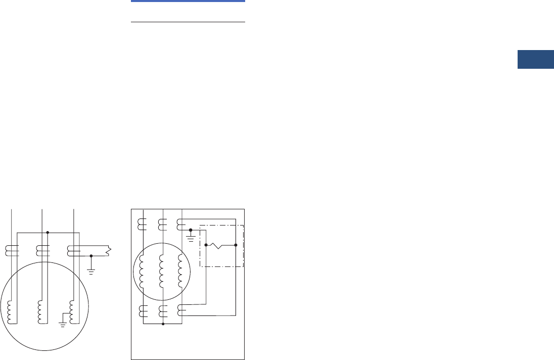
Volume 3—Power Distribution and Control Assemblies CA08100004E—November 2013 www.eaton.com V3-T9-205
9
9
9
9
9
9
9
9
9
9
9
9
9
9
9
9
9
9
9
9
9
9
9
9
9
9
9
9
9
9
9.4
Metering Devices, Protective Relays, Software and Connectivity
Protective Relays
Technical Data and Specifications
Product Specifications
Current Inputs
●CTs: 5A secondary
●CT burden:
●<0.004 ohm at rated
current (5A)
●<0.1 VA at rated
current (5A)
●In: 5A (Secondary) or
CT (Primary)
●Saturation: 30 x In
●CT thermal ratings:
●10A continuous
●500A for 1 second
CT (Primary) Settings Available
●Phase:
5/10/25/50/75/100/150/200/
250/300/400/500/600/630/
800/1000/1200/1250/1500/
1600/2000/2400 2500/
3000/3200/4000/5000
Input Voltage
●Nominal:
●48–250 Vdc
●120–240 Vac 50/60 Hz
●Operating range:
●28–280 Vdc
●90–254 Vac 50/60 Hz
Power Consumption
Output Trip Contacts
●Momentary:
●Make 30A AC/DC for
0.25 seconds
●Break 0.25A at 250 Vdc
●Break 5A at 120/240 Vac
●Continuous:
●5A at 120/240 Vac
●5A at 30 Vdc
●Meets ANSI C37.90,
Paragraph 6.7
Environmental Conditions
●Operating temperature:
–22ºF to +131ºF
(–30ºC to +55°C)
●Operating humidity:
0–95% relative humidity
(noncondensing)
●Storage temperature:
–40ºF to +158ºF
(–40°C to +70°C)
Auxiliary Alarm Contacts
●
5A continuous at 120/
240 Vac, 30 Vdc
●5A break at 120/240 Vac,
30 Vdc
Tests
●Dielectric strength,
current inputs:
●3000 Vac for 1 minute
●Phase-to-phase
●Seismic test: Meets
requirements for UBC® and
California Building Code
Zone 4. ZPA = 3.5
Communications
●
Eaton’s PowerNet
compatible
●Built-in INCOM
●Data rate is 1200 or
9600 baud
Drawout Case
●Refer to Page V3-T9-215
for drawout case
dimensions
Terminal Block
●Make/break rating:
●10A at 240 Vac nominal
●0.25A at 280 Vdc
maximum
●Terminal wire gauge:
No. 14 to No. 10 AWG
●Screw torque
requirements:
18-inch-pounds
Wiring Diagrams
Self-Balancing Differential
Protection
Conventional Phase
Differential Protection
24 48 125 250 120 240
Vdc
10W
Vdc
10W
Vdc
10W
Vdc
10W
Vac
10 VA
Vac
18 VA
87
X
87
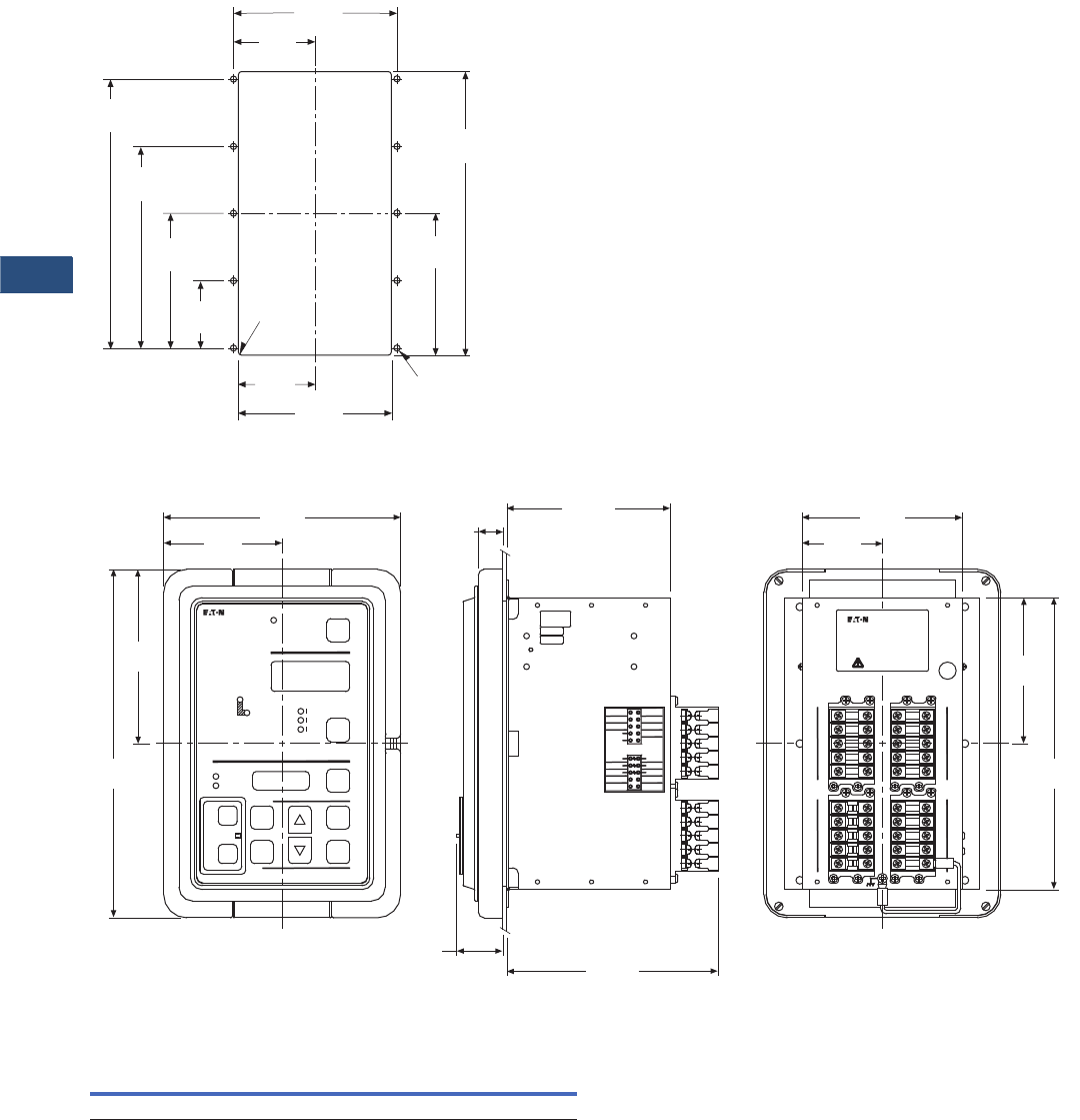
V3-T9-206 Volume 3—Power Distribution and Control Assemblies CA08100004E—November 2013 www.eaton.com
9
9
9
9
9
9
9
9
9
9
9
9
9
9
9
9
9
9
9
9
9
9
9
9
9
9
9
9
9
9
9.4
Metering Devices, Protective Relays, Software and Connectivity
Protective Relays
Dimensions
Approximate Dimensions in Inches (mm)
Drilling Pattern
MD-3000
MD-3000 Feeder Protection Relay (Fixed Case)
Height Width Depth
Shipping Weight
Lbs (kg)
10.25 (260.4) 6.72 (170.7) 3.70 (94.0) 7.0 (3.2)
5.38
(136.7)
9.38
(238.3)
4.69
(119.1)
2.53
(64.3) 5.06
(128.5)
2.23
(56.7)
4.45
(113.0)
6.68
(169.7)
8.90
(226.1)
.06
(1.5) RAD
4 Places
2.69
(68.3)
.218
(5.5) DIA 10 Places
MD 3000
Motor/Generator
Differential
7.72
(196.1)
3.86
(98.0)
5.67
(144.0)
11.34
(288.0)
1.51
(38.4)
Test
Test
Select
Tests
Lower
Raise
Select
Settings
Save
Settings
Test
Program
Program
Test
Settings/Test Time/Trip Cause
I =5A (Secondary)
n
Time
Differential
Pickup In
Operational
RMS Amperes
Reset
0.80
(20.3)
5.33
(135.4)
S/N000000
W000000
66D0000G0 0
REV. 0
Built by FEC
Tested by GLK
6.89
(175.0)
Unused
Unused
Unused
Unused
Unused
Unused
Unused
11
13
15
17
19
12
14
16
18
20
Power Supply
Input
(+)
(-)
A2
B2
C2
A1
B1
C1
Unused
Unused Unused
Unused
Current Input
21
23
27
29
22
24
26
28
30
25
Select
View
Settings
Program
A DIF
B DIF
C DIF
MD 3001 Motor Differential
Drawout Case
Power Supply Input:
Term. 17/19
AC 120-240 Vac, 50/60 Hz
DC 48-250 Vdc
Caution - Refer to
Instruction Leaet
5.23
(132.8)
2.61
(66.3)
11
13
15
17
19
12
14
16
18
20
41
43
45
47
49
42
44
46
48
50
21
23
25
27
29
22
24
26
28
30
51
53
55
57
52
54
56
58
4.75
(120.7)
9.51
(241.6)
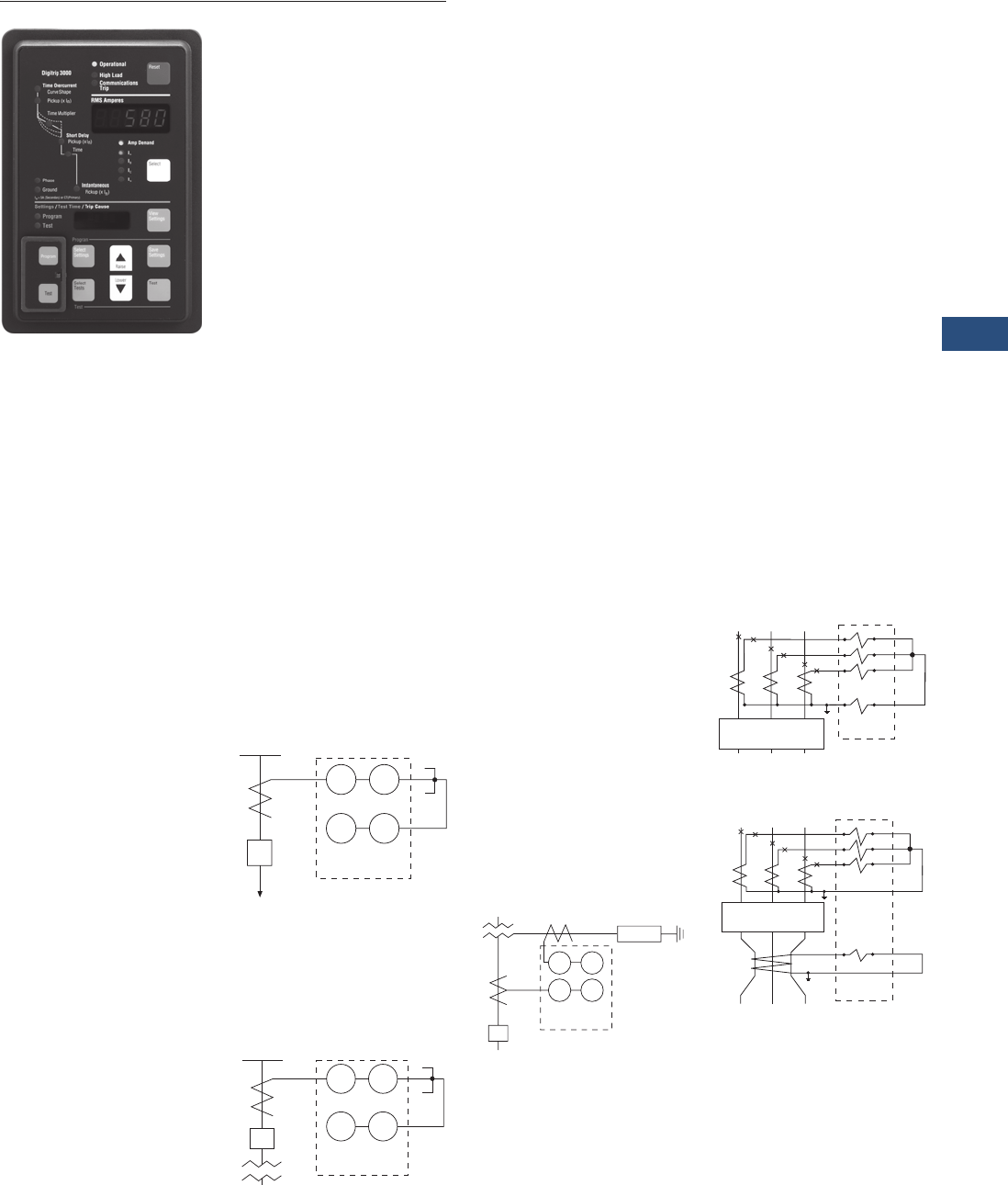
Volume 3—Power Distribution and Control Assemblies CA08100004E—November 2013 www.eaton.com V3-T9-207
9
9
9
9
9
9
9
9
9
9
9
9
9
9
9
9
9
9
9
9
9
9
9
9
9
9
9
9
9
9
9.4
Metering Devices, Protective Relays, Software and Connectivity
Protective Relays
DT-3000
Contents
Description Page
Product Selection Guide. . . . . . . . . . . . . . . . . . . . . V3-T9-158
FP-6000 Feeder Protection. . . . . . . . . . . . . . . . . . . V3-T9-162
FP-5000 Feeder Protection. . . . . . . . . . . . . . . . . . . V3-T9-172
FP-4000 Feeder Protection. . . . . . . . . . . . . . . . . . . V3-T9-180
MP-3000 Motor Protection. . . . . . . . . . . . . . . . . . . V3-T9-188
MP-4000 Motor Protection. . . . . . . . . . . . . . . . . . . V3-T9-198
MD-3000 Motor/Generator Differential Relay. . . . . V3-T9-204
Digitrip 3000
Features, Benefits and Functions . . . . . . . . . . . V3-T9-209
Standards and Certifications . . . . . . . . . . . . . . . V3-T9-209
Product Selection . . . . . . . . . . . . . . . . . . . . . . . V3-T9-210
Options and Accessories. . . . . . . . . . . . . . . . . . V3-T9-210
Technical Data and Specifications . . . . . . . . . . . V3-T9-211
Dimensions . . . . . . . . . . . . . . . . . . . . . . . . . . . . V3-T9-214
VR-300 Multifunctional Voltage Relay . . . . . . . . . . V3-T9-217
DP-300 Current Differential Protection Relay . . . . . V3-T9-221
EDR-3000 Feeder Protection . . . . . . . . . . . . . . . . . V3-T9-226
ETR-4000 Transformer Protection Relay. . . . . . . . . V3-T9-237
Ground Fault Relay . . . . . . . . . . . . . . . . . . . . . . . . . V3-T9-250
Universal RTD Module . . . . . . . . . . . . . . . . . . . . . . V3-T9-254
IQ 125 Volt DC Power Supply . . . . . . . . . . . . . . . . . V3-T9-258
Digitrip 3000
Product Description
●Microprocessor-based,
three-phase and ground
overcurrent relay
●Independent phase and
ground measuring circuits
and operation
●Inverse time (51), short
delay (50, 2) and
instantaneous (50)
protection
●Eleven time overcurrent
characters including ANSI,
IEC and thermal protection
curves
●Phase and ground
ampmeter and peak
demand functions
●INCOM communication
port
●Fixed mount or optional
quick release drawout
case design
●Dual-source power supply
option for AC control
power applications
Application Description
Eaton’s Digitrip 3000
microprocessor-based relay
provides reliable three-phase
and ground overcurrent
protection for all voltage
levels. It can be used for
any application where
instantaneous and/or time
overcurrent protection
is required. It is most
commonly used as primary
feeder circuit protection,
see figure below.
Primary Feeder
Circuit Protection
The Digitrip 3000 may be
applied as the transformer
primary protection or as
backup to the differential
protection, see figure below.
Transformer Overcurrent
Protection
The Digitrip 3000 may be
connected to the secondary
side of a delta-wye grounded
transformer with the ground
element connected to a
separate CT in the neutral
connection of the
transformer. With this
connection, a lower CT ratio
and a pickup setting can
be used to provide more
sensitive ground fault
protection especially for
resistance grounded
systems, see figure below.
Transformer Secondary
Protection with Neutral
CT Connection
The Digitrip 3000 ground
overcurrent element can be
connected in the residual
circuit of the phase CTs as
shown in the top figure or
to a separate ground CT as
shown in last figure.
Residual Ground
Connection
Separate Zero Sequence
Ground CT Connection
50 51
50G 51G
CB
52 Digitrip
3000
Load
50 51
50G 51G
CB
Digitrip
3000
5
0
G
5
1
G
5
0
5
1
Di
g
itrip
3
000
R
esist
or
C
B
a
b
c
GND
Digitrip
3000
CB-52
A1 A2
B1 B2
C1 C2
G1 G2
50N/51N
CB-52
a
b
c
GND
Digitrip
3000
A1 A2
B1 B2
C1 C2
G1 G2
50/51
50G/51G
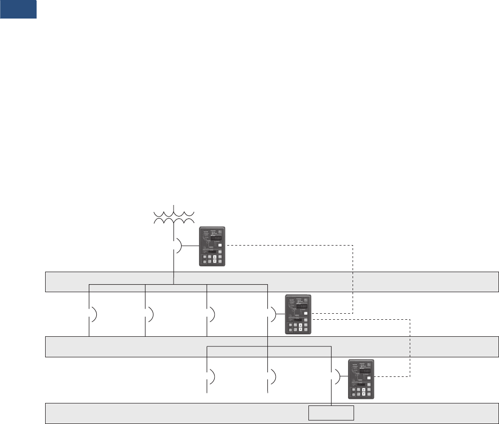
V3-T9-208 Volume 3—Power Distribution and Control Assemblies CA08100004E—November 2013 www.eaton.com
9
9
9
9
9
9
9
9
9
9
9
9
9
9
9
9
9
9
9
9
9
9
9
9
9
9
9
9
9
9
9.4
Metering Devices, Protective Relays, Software and Connectivity
Protective Relays
Zone Selective Interlocking (Phase and Ground)
Note: For the phase time
overcurrent element, the current
sensed by the Digitrip 3000 must
exceed 300% (3 x In) for the zone
selective interlocking to initiate an
immediate trip signal.
Zone Selective interlocking
is a protection function to
minimize equipment damage
resulting from a phase or a
ground fault in an area where
long-time and/or short-time
delay is in use.
When the “Ground Zone
Interlocking” feature is
utilized, an immediate trip
is initiated when the fault
is in the breaker’s zone of
protection, regardless of its
preset time delay. When the
“Phase Zone Interlocking”
feature is utilized, the time
overcurrent and short delay
phase elements work as
follows. The short delay
phase element will initiate an
immediate trip when the fault
is in the breaker’s zone of
protection, regardless of its
preset time delay. For the
time overcurrent phase
element, the current sensed
by the Digitrip 3000 must
exceed 300% (3 x In) for the
zone selective interlocking
to initiate an immediate trip
signal when the fault is in the
breaker’s zone of protection.
Upstream Digitrip 3000
protected breakers are
restrained from tripping
immediately by an
interlocking signal from the
downstream Digitrip 3000
relay. This interlocking signal
requires only a pair of wires
from the downstream breaker
to the upstream breaker.
The Upstream Digitrip 3000
provides time delayed
standard coordinated
tripping when the fault is
located outside the zone
of protection.
In the sample zone
interlocking system shown
below, circuit breakers A, B
and C are equipped with
Digitrip 3000 overcurrent
relays.
Fault Location Zone 3
Note: For the phase time
overcurrent element, the current
sensed by the Digitrip 3000 must
exceed 300% (3 x In) for the zone
selective interlocking to initiate an
immediate trip signal.
If a fault occurs at a point in
Zone 3, the Digitrip 3000 of
Downstream Breaker C
senses the fault and sends
a restraining signal to the
upstream Digitrip 3000 of
Feeder Breaker B.
Having received this signal,
the Digitrip 3000 of Feeder
Breaker B begins timing for
normal final delay tripping. As
a result, only Downstream
Breaker C is tripped.
Fault Location Zone 2
Note: For the phase time
overcurrent element, the current
sensed by the Digitrip 3000 must
exceed 300% (3 x In) for the zone
selective interlocking to initiate an
immediate trip signal.
If a fault occurs at a point in
Zone 2, the Digitrip 3000 of
Feeder Breaker B senses the
fault and sends a restraining
signal to the upstream
Digitrip 3000 of Main
Breaker A.
The Digitrip 3000 of the
Downstream Breaker C does
not see this fault since it is
situated on the downstream
side of the fault. As a result,
the Digitrip 3000 of
Downstream Breaker C does
not send a restraining signal
to the Digitrip 3000 of Feeder
Breaker B.
Since there is no restraining
signal from the Digitrip 3000
of Downstream Breaker C,
the Digitrip 3000 of Feeder
Breaker B identifies that
the fault is in Zone 2 and
immediately trips Feeder
Breaker B, regardless of its
time setting.
Fault Location Zone 1
Note: For the phase time
overcurrent element, the current
sensed by the Digitrip 3000 must
exceed 300% (3 x In) for the zone
selective interlocking to initiate an
immediate trip signal.
If a fault occurs in Zone 1, no
restraining signal is received
by the Digitrip of Main
Breaker A. As a result, Main
Breaker A is immediately
tripped by its Digitrip
overcurrent relay, regardless
of its time setting.
Sample Zone Selective Interlocking System
Main
Breaker
“A”
Feeder
Breaker
“B”
Downstream
Breaker
“C”
Interlocking
Wire
LOAD
Zone 1
Zone 2
Zone 3

Volume 3—Power Distribution and Control Assemblies CA08100004E—November 2013 www.eaton.com V3-T9-209
9
9
9
9
9
9
9
9
9
9
9
9
9
9
9
9
9
9
9
9
9
9
9
9
9
9
9
9
9
9
9.4
Metering Devices, Protective Relays, Software and Connectivity
Protective Relays
Features, Benefits and Functions
●Complete current
protection and metering
in a single compact case
reduces panel space, wiring
and cost
●Selectable trip
characteristics simplify
ordering and reduces
inventory
●Optional drawout case
provides easy and quick
removal and replacement
of the relay
●Optional dual-source
power supply provides
reliable protection when
applied with ac control
power, eliminating the
need for batteries or UPS
●Integral ampmeter and
display replaces separate
meter and switch, saving
panel space, wiring and
money
●Zone selective interlocking
improves coordination and
tripping times and can save
money by using in place of
traditional bus differential
●Integral test function and
microprocessor design can
reduce maintenance time
and expense
Standards and Certifications
●UL recognized
●UL 1053 recognized
●ANSI C37.90
●ANSI C37.90.1 (1989)
●ANSI C37.90.2 (1995)
Note: Fixed case versions meet
35V/m. Drawout case versions
meet 28V/m.
●IEC 255
●CE (DT3030/3031
version only)
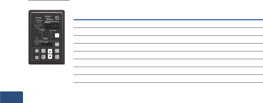
V3-T9-210 Volume 3—Power Distribution and Control Assemblies CA08100004E—November 2013 www.eaton.com
9
9
9
9
9
9
9
9
9
9
9
9
9
9
9
9
9
9
9
9
9
9
9
9
9
9
9
9
9
9
9.4
Metering Devices, Protective Relays, Software and Connectivity
Protective Relays
Product Selection
DT-3000
Options and Accessories
Additional Products by Eaton’s Cutler-Hammer Series
Dual-Source Power
Supply Option
The Digitrip 3000 with Dual-
Source Power Supply (DSPS)
is available in two versions,
DT-3010 and DT-3020. They
include an integral power
supply module that:
●Powers the relay from
nominal 120 Vac, 50/60 Hz
(DT-3010 model) or 240
Vac, 50/60 Hz (DT-3020
model) auxiliary power,
which is normally
connected and available.
●Operates solely from the
main current transformers
(CTs) during a fault if
the normally connected
auxiliary ac voltage is
not available, like an
electromechanical relay
or an electronic “self-
powered” relay.
Functional Description
The integral Dual-Source
Power Supply (DSPS)
contains one AC voltage
transformer and three AC
current transformers. The AC
voltage transformer is used to
supply nominal ac control
power to the unit. The current
transformers are used to
power the unit from the line
current. Normally, the unit
will operate from the AC
auxiliary voltage.
Because this voltage is
usually obtained from the
system containing the circuit
that the relay is protecting, a
fault on the protected line
could cause the AC voltage
to drop below an acceptable
operating level. Below
approximately 70 volts for
DT-3010 or 140 volts for
DT-3020, the DSPS switches
over to current powering.
All three current transformer
secondaries are connected in
series to supply this power.
The DSPS will supply enough
power to operate the Digitrip
3000 overcurrent relay in the
tripped state with currents
greater than 1.8 per unit rated
secondary current, or 9A, in a
single-phase. The DSPS will
operate with three-phase
currents in a tripped state
with currents greater than
1.2 per unit or 6A rated
secondary current.
Note: There will be no effect
to the DT-3000 relay trip time
accuracy when the Dual-Source
Power Supply switches from
normal ac voltage to fault-
current power.
Burden Data
In normal operating
conditions, the burden is
<0.08 ohms with three-phase
1A CT current, or 0.2 per unit,
and drops to less than 0.04
ohms at high current levels.
Present CT burden data in
ohms and volt-
amperes, see
Page V3-T9-212
.
In these cases, the burden
shown is the total CT terminal
value, which is the DSPS plus
the relay measuring circuits,
for the indicated operating
condition.
The trip curve on Page V3-
T9-212, right, shows burden
impedance magnitude in
ohms. The two lower curves
are the values with AC power
applied; the upper two are
with CT powering only. For
each of these pairs, one
curve shows the burden
for a single-phase current
(representing a single-phase-
to-ground fault) and the other
for three balanced phases
with normally arrayed
120-degree phase angle
increments. There is no
phase sequence sensitivity.
Page V3-T9-212, trip curve,
upper left, shows the burden
in volt-amperes for the same
four cases.
Digitrip 3000 Optional
Drawout Case
The Digitrip 3000 overcurrent
protective relay is available
in a new drawout case for
quick release, removal and
replacement of the unit
without disruption of the
wiring. The CT circuits are
self-shortening to prevent
damaging voltages from
existing across-the-current
transformer windings. All
voltage inputs, discrete
inputs and contact inputs
are disconnected while
maintaining security against
false tripping.
The terminal blocks feature
a two-stage disconnect
operation. Removal of the
DT-3000 Inner Chassis will
disconnect the trip circuits
and short the CT secondaries
before the unit control power
is disconnected. Upon
insertion of the Inner
Chassis, the control power
connections are made before
the trip circuits are activated.
This feature provides
added security against
false tripping.
Description
Catalog
Number
DT-3000 protective relay DT3000
DT-3000 protective relay Chicago version DT3100
DT-3030 protective relay (24–48 Vdc CE Mark version) DT3030
DT-3000 drawout case protective relay DT3001
DT-3000 Chicago version drawout case protective relay DT3101
DT-3030 drawout case protective relay (24–48 Vdc CE Mark version) DT3031
DT-3000 protective relay with 120 Vac dual-source power supply DT3010
DT-3000 protective relay with 240 Vac dual-source power supply DT3020
DT-3000

Volume 3—Power Distribution and Control Assemblies CA08100004E—November 2013 www.eaton.com V3-T9-211
9
9
9
9
9
9
9
9
9
9
9
9
9
9
9
9
9
9
9
9
9
9
9
9
9
9
9
9
9
9
9.4
Metering Devices, Protective Relays, Software and Connectivity
Protective Relays
Technical Data and Specifications
Current Inputs
●CTs: 5A secondary
●CT Burden:
●<0.004 ohm at rated
current (5A)
●<0.1 VA at rated
current (5A)
●In: 5A (Secondary) or
CT (Primary)
●Saturation: 30 x In
●CT thermal ratings:
●10A continuous
●500A for 1 second
CT (Primary) Settings Available
●Phase and ground:
5/10/25/50/75/100/150/200/
250/300/400/500/600/630/
800/1000/1200/1250/1500/
1600/2000/2400 2500/
3000/3200/4000/5000
Input Voltage DT-300X
●Nominal:
●48–250 Vdc
●120–240 Vac 50/60 Hz
●Operating range:
●28–280 Vdc
●90–254 Vac 50/60 Hz
Power Consumption
Input Voltage Digitrip 3030/
3031
Output Trip Contacts
(Trip OC/Comm., Trip Inst.
and Comm. Close)
●Momentary:
●Make 30A AC/DC for
0.25 seconds
●Break 0.25A at 250 Vdc
●Break 5A at 120/240 Vac
●Continuous:
●5A at 120/240 Vac
●5A at 30 Vdc
●Meets ANSI C37.90,
Paragraph 6.7
Environmental Conditions
●Operating temperature:
–22ºF to +131ºF
(–30ºC to +55°C)
●Operating humidity:
0–95% relative humidity
(noncondensing)
●Storage temperature:
–40ºF to +185ºF
(–40°C to +70°C)
Auxiliary Alarm Contacts
●
5A continuous at
120/240 Vac, 30 Vdc
●5A break at 120/240 Vac,
30 Vdc
Tests
●Dielectric strength,
current inputs:
●3000 Vac for 1 minute
●Phase-to-phase
●Seismic test: Meets
requirements for UBC® and
California Building Code
Zone 4. ZPA = 3.5
Phase and Ground
Time-Current Curves
●Thermal:
●It (Moderately Inverse)
●I2t (Very Inverse)
●I4t (Extremely lnverse)
●FLAT (Definite Time)
●ANSI (Per ANSI C37.112,
1996):
●Moderately Inverse
●Ver y Inverse
●Extremely Inverse
●IEC (Per IEC 255-3, 1989):
●IEC-A (Moderately
Inverse)
●IEC-B (Very Inverse)
●IEC-C (Extremely
Inverse)
●IEC-D (Definite Time)
Overcurrent Functions
and Pickup Ranges
Note: Consult factory for
sensitive ground fault.
●Long Delay or Inverse
Time Overcurrent:
●Phase: (0.2–2.2) x In
(29 settings)
●Ground: (0.1–2.0) x In,
None (26 settings)
●Short Delay:
●Phase: (1–11) x In,
None (25 settings)
●Ground: (0.1–11) x In,
None (45 settings)
●Instantaneous:
●Phase: (1–25) x In,
None (30 settings)
●Ground: (0.5–11) x In,
None (33 settings)
Time Delay Settings
●Inverse Time Overcurrent
Time Multiplier:
●Thermal: 0.2–40
(47 settings)
●FLAT: 0.2–2 (21 settings)
●ANSI (all): 0.1–5.0
(50 settings)
●IEC (all): 0.05–1.00
(20 settings)
●Short Delay Time: 0.05–
1.5 seconds (22 settings)
Current Monitoring
Note: Consult factory for
sensitive ground fault.
●True rms sensing: three-
phase and ground
●Display accuracy:
●±1% of Full Scale [ln]
from 0.04 x ln to 1 x In
●±2% of Full Scale [ln]
from 1 x ln to 2 x In
●Ampere demand: Average
demand over 5 minute
sampling window
●High load (with selectable
output): 85% of Inverse
Time Overcurrent setting
Timing Accuracy
●Inverse Time Overcurrent:
±10% at >1.5 x Pickup
●Short Delay Time: ±50 mS
Communications
●
Eaton’s PowerNet
Compatible
●Built-in INCOM
●Data rate is 1200 or
9600 baud
Drawout Case
●Refer to Page V3-T9-215
for Drawout Case
Dimensions
Terminal Block
●Make/Break rating:
●10A at 240 Vac nominal
●0.25A at 280 Vdc
maximum
●Terminal wire gauge:
No. 14 to No. 10 AWG
●Screw torque
requirements: 18-inch-
pounds
Reference Information
Cross-Reference
There are several products
that are equivalent to the
Digitrip 3000. The
following
lists the competitor’s name and
equivalent product to the
Digitrip 3000. In general, the
Digitrip 3000 can be used in
place of the competitive
product.
●ABB® MMCO, 51
●Basler Electric® BEI-51
●GE Multilin MDP, 735, 737
●Siemens® 7SJ 511, 7SJ 60
24 48 125 250 120 240
Vdc
10W
Vdc
10W
Vdc
10W
Vdc
10W
Vac
10 VA
Vac
18 VA
Description DT-3010 DT-3020
Nominal 120 Vac 240 Vac
Operating
Range
70–132 Vac 140–264 Vac
Power
Consumption
15 VA 15 VA
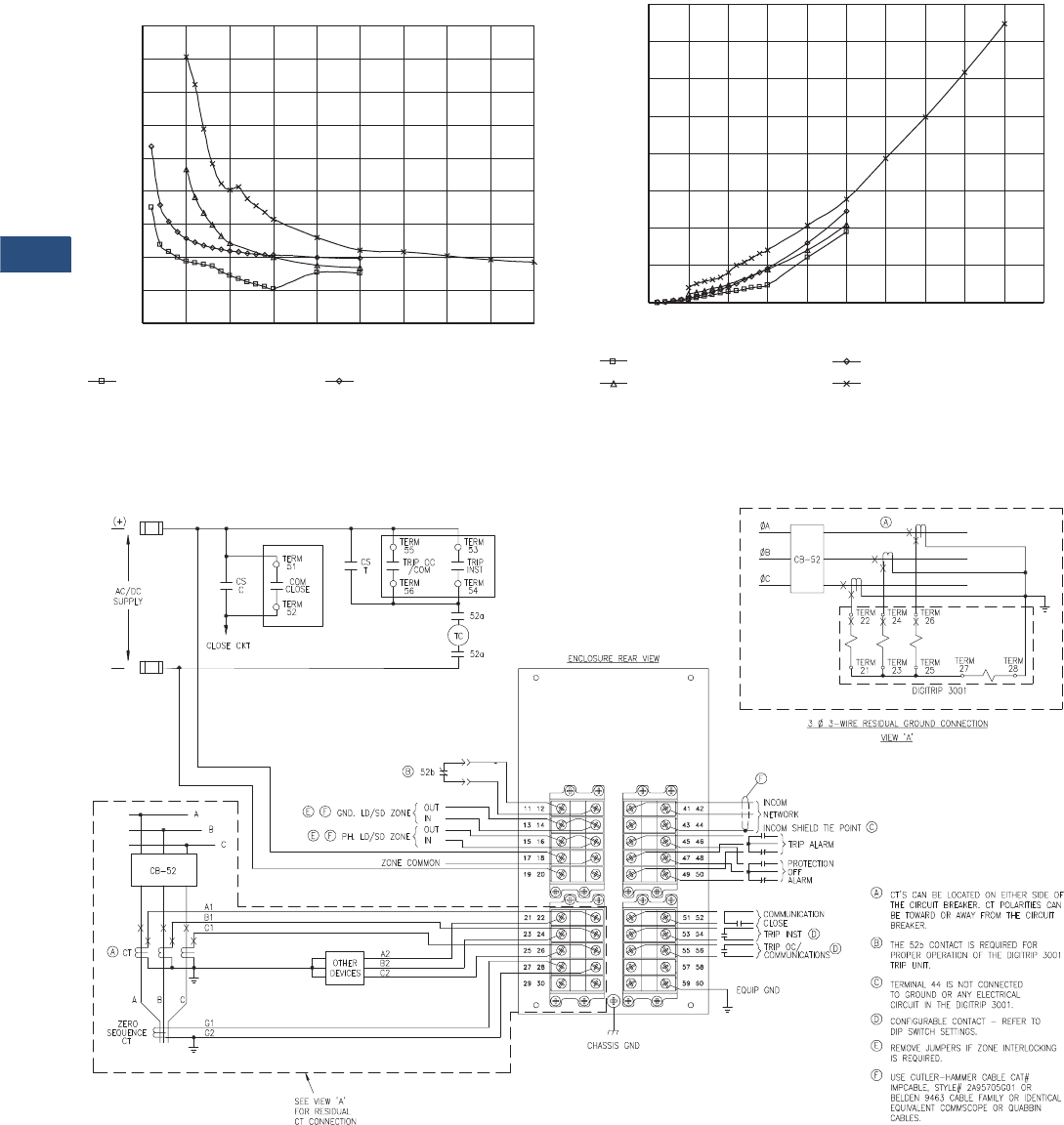
V3-T9-212 Volume 3—Power Distribution and Control Assemblies CA08100004E—November 2013 www.eaton.com
9
9
9
9
9
9
9
9
9
9
9
9
9
9
9
9
9
9
9
9
9
9
9
9
9
9
9
9
9
9
9.4
Metering Devices, Protective Relays, Software and Connectivity
Protective Relays
Trip Curve Charts
Digitrip 3000 With Dual-Source Power Supply
Burden Curves
Digitrip 3000 With Dual-Source Power Supply CT Power
Volt-Ampere Curves
Wiring Diagrams
Digitrip 3001
Typical wiring diagram for the fixed mount version.
CT Burden — Z, Ohms
0
0.02
0.04
0.06
0.08
0.1
0.12
0.14
0.16
0.18
0 5 10 15 20 25 30 35 40 45
CT Current — Amperes
Total Burden, With Vac, 3-Phase I Total Burden, With Vac, 1-Phase I
CT Power in Volt-Amperes
CT Current — Amperes
CT Power in VA, With Vac, 3-Phase I
CT Power in VA, No Vac, 3-Phase I
0
10
20
30
40
50
60
70
80
0 5 10 15 20 25 30 35 40 45 50
CT Power in VA, With Vac, 1-Phase I
CT Power in VA, No Vac, 1-Phase I
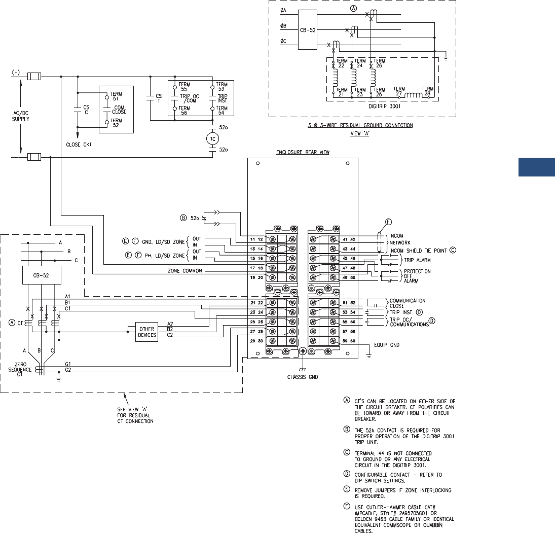
Volume 3—Power Distribution and Control Assemblies CA08100004E—November 2013 www.eaton.com V3-T9-213
9
9
9
9
9
9
9
9
9
9
9
9
9
9
9
9
9
9
9
9
9
9
9
9
9
9
9
9
9
9
9.4
Metering Devices, Protective Relays, Software and Connectivity
Protective Relays
Digitrip 3000 Typical Wiring System
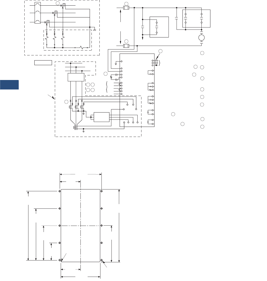
V3-T9-214 Volume 3—Power Distribution and Control Assemblies CA08100004E—November 2013 www.eaton.com
9
9
9
9
9
9
9
9
9
9
9
9
9
9
9
9
9
9
9
9
9
9
9
9
9
9
9
9
9
9
9.4
Metering Devices, Protective Relays, Software and Connectivity
Protective Relays
Digitrip 3000 Typical Wiring Diagram
Dimensions
Approximate Dimensions in Inches (mm)
Drilling Pattern
Note
Panel cutout dimensions for all versions of the Digitrip 3000 relay.
C1
C2
B1
B2
A1
A2 G1 G2
ØC
ØB
ØA A
Digitrip 3000
3-Phase 3-Wire Residual Ground Connection
View ”A“
52
A
B
C
See View ”A“
For Residual
CT Connection
A
CT
ABC
Zero
Sequence
CT
Other
Devices
G2 C2 B2 A2
G1
C1 B1 A1
Ground
Zone
Phase
Zone
Zone Common
E G Out
In
Out
In
11
12
13
14
15
5
6
9
10
4
52b
B
TB1
H
H
AC/DC
Supply
Close CKT
CS
C
TB2
4
TB2
5
Comm.
Close
CS
T
TB2
14
TB2
15
Trip OC
/Comm.
TB2
12
TB2
13
Trip
Inst.
52a
52a
TC
TB2
1
2
3
4
5
6
7
8
9
10
11
F
INCOM
Network
INCOM Shield Tie Point C
Communication
Close or High Load Alarm D
Trip Alarm
Protection
OFF
Alarm
Trip Inst.
or Ground D
Trip OC or Phase/
Communications D
12
13
14
15
A = CTs can be located on either
side of the circuit breaker.
CT polarities can be toward or
away from the circuit breaker.
B = The 52b contact is required for
proper operation of the Digitrip
3000 Protective Relay.
C = TB2 terminal 3 is not connected
to ground or any electrical
circuit in the Digitrip 3000.
D = Congurable contact, refer to DIP
switch settings.
E = Remove jumpers if Zone Interlocking
is required.
F = Use Eaton Cable CAT # IMPCABLE,
Style # 2A95705G01; Belden 9463 cable
family; or equivalent Commscope or
Quabbin cables.
G = Wire spec: 600 V 90ºC,
UL 1039 rated wire.
H = For the DT3030 to be ”CE Compliant,“
the power supply input fuse must be
rated at a maximum of 0.25 amperes.
E G
5.38
(136.7)
9.38
(238.3)
4.69
(119.1)
2.53
(64.3) 5.06
(128.5)
2.23
(56.7)
4.45
(113.0)
6.68
(169.7)
8.90
(226.1)
.06
(1.5) RAD
4 Places
2.69
(68.3)
.218
(5.5) DIA 10 Places
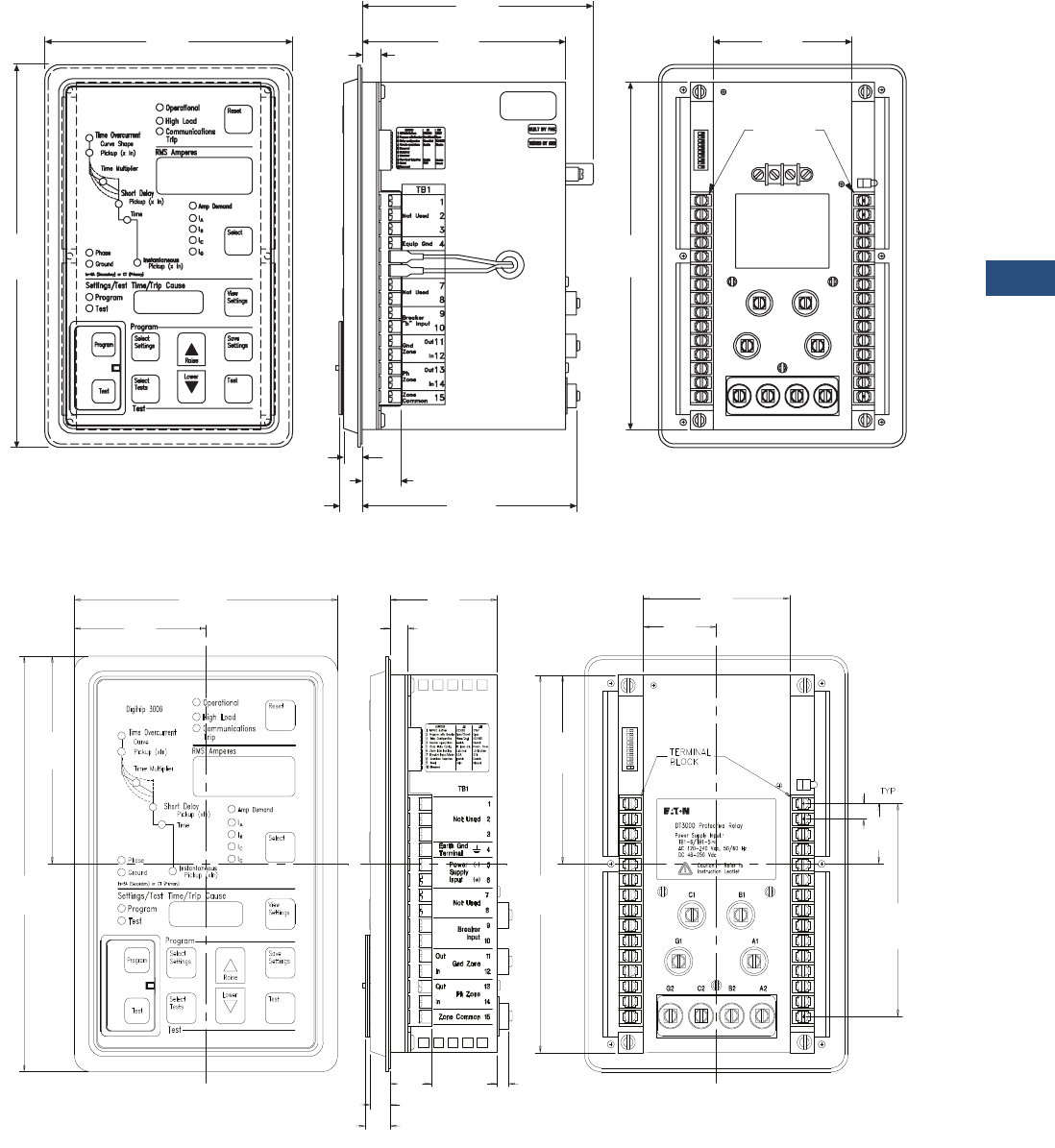
Volume 3—Power Distribution and Control Assemblies CA08100004E—November 2013 www.eaton.com V3-T9-215
9
9
9
9
9
9
9
9
9
9
9
9
9
9
9
9
9
9
9
9
9
9
9
9
9
9
9
9
9
9
9.4
Metering Devices, Protective Relays, Software and Connectivity
Protective Relays
Approximate Dimensions in Inches (mm)
Digitrip 3010/3020
Digitrip 3000
Digitrip 3000
6.72
(170.7)
10.25
260.3)
5.45
(138.4)
6.03
(153.2)
.51
(13.0)
.62
(15.7)
.50
(12.7) 1.05
(26.7) 5.74
(145.8)
3.74
(95.0)
9.31
(236.5)
AC Input
100-120 Vac, 50/60Hz
Digitrip 8010 Protective Relay
with Dual-Source Power Supply
Terminal
Block
S/N000217
P971210
4D13125G01
6.72
(170.7)
2.67
(67.8)
0.39
(9.9)
0.50
(12.7)
0.29
(7.4)
0.62
(15.7)
1.05
(26.7)
1.87
(47.5)
3.74
(95.0)
0.37
(9.4)
3.36
(85.3)
5.12
(130.0)
4.65
(118.1)
5.25
(133.4)
1.48
(37.6)
10.25
(260.4)
9.31
(236.5)
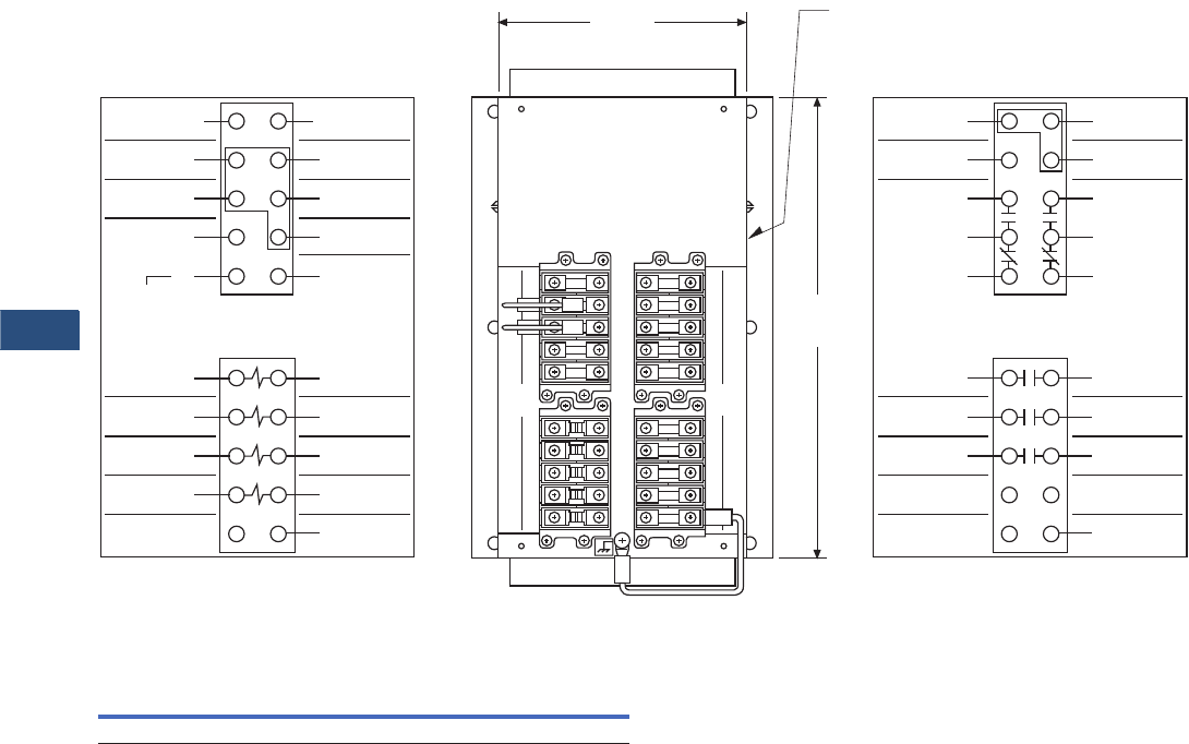
V3-T9-216 Volume 3—Power Distribution and Control Assemblies CA08100004E—November 2013 www.eaton.com
9
9
9
9
9
9
9
9
9
9
9
9
9
9
9
9
9
9
9
9
9
9
9
9
9
9
9
9
9
9
9.4
Metering Devices, Protective Relays, Software and Connectivity
Protective Relays
Approximate Dimensions in Inches (mm)
Rear View of Digitrip 3001 Drawout Outer Case Terminal Layout
Digitrip-3000 Feeder Protection Relay (Fixed Case)
Height Width Depth
Shipping Weight
Lbs (kg)
10.25 (260.4) 6.72 (170.7) 2.96 (75.2) 0.0 (0.0)
Hole for Viewing INCOM
Communications Activity LED.
9.51
(241.6)
11
Breaker “b” Input
13
Gnd Zone Out
15
Ph Zone Out
17
ac/dc Input
(+)
(–)
19
120 – 240 Vac
50/60 HZ
48 – 250 Vdc
21
A2
23
B2
Current Input
25
C2
27
G1
29
Unused
66C2025H01
22
24
26
28
30
A1
B1
C1
G2
Unused
12
14
16
18
20
Breaker “b” Input
Gnd Zone In
Ph Zone In
Zone Common
Unused 12
18
20
11
17
19
42
48
50
41
47
49
4443
4645
56
58
55
57
5251
5453
22
28
30
21
27
29
2423
2625
51
Communication
Close
53
55
57
59
Unused
66C2025H02
52
54
56
58
60
Unused
Trip Inst
or Ground
Trip OC or
Phase /Comm
Communication
Close
Equip Gnd
Unused
Trip Inst
or Ground
Trip OC or
Phase /Comm
41
INCOM
Network
43
45
47
49
42
44
46
48
50
Unused
Trip
Alarn
Protection
Off
Alarm
Shield Tie Point
INCOM
Network
5.23
(132.8)
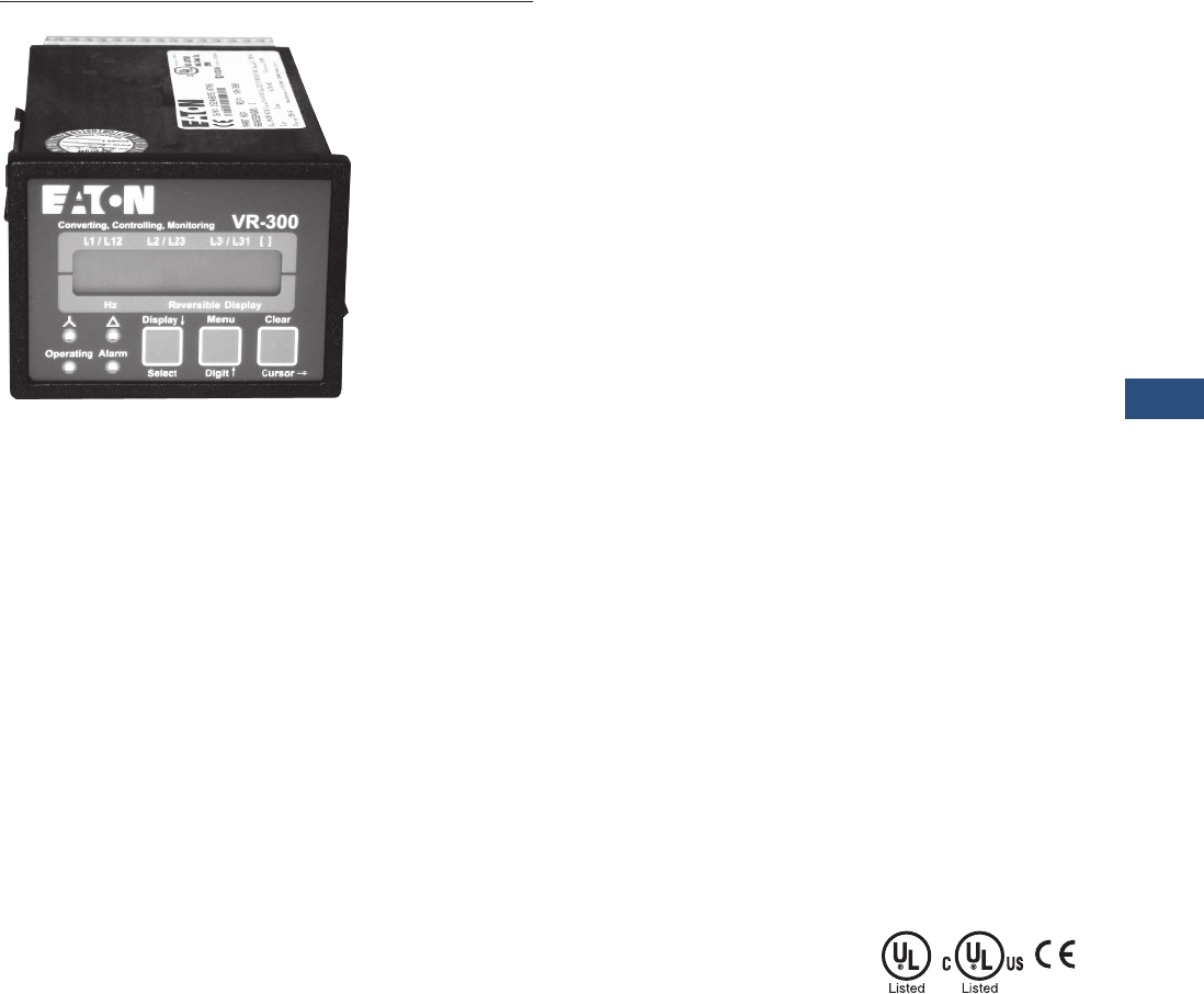
Volume 3—Power Distribution and Control Assemblies CA08100004E—November 2013 www.eaton.com V3-T9-217
9
9
9
9
9
9
9
9
9
9
9
9
9
9
9
9
9
9
9
9
9
9
9
9
9
9
9
9
9
9
9.4
Metering Devices, Protective Relays, Software and Connectivity
Protective Relays
VR-300
Contents
Description Page
Product Selection Guide. . . . . . . . . . . . . . . . . . . . . V3-T9-158
FP-6000 Feeder Protection. . . . . . . . . . . . . . . . . . . V3-T9-162
FP-5000 Feeder Protection. . . . . . . . . . . . . . . . . . . V3-T9-172
FP-4000 Feeder Protection. . . . . . . . . . . . . . . . . . . V3-T9-180
MP-3000 Motor Protection. . . . . . . . . . . . . . . . . . . V3-T9-188
MP-4000 Motor Protection. . . . . . . . . . . . . . . . . . . V3-T9-198
MD-3000 Motor/Generator Differential Relay. . . . . V3-T9-204
Digitrip 3000. . . . . . . . . . . . . . . . . . . . . . . . . . . . . . V3-T9-207
VR-300 Multifunctional Voltage Relay
Technical Data and Specifications . . . . . . . . . . . V3-T9-218
Dimensions . . . . . . . . . . . . . . . . . . . . . . . . . . . . V3-T9-220
DP-300 Current Differential Protection Relay . . . . . V3-T9-221
EDR-3000 Feeder Protection . . . . . . . . . . . . . . . . . V3-T9-226
ETR-4000 Transformer Protection Relay. . . . . . . . . V3-T9-237
Ground Fault Relay . . . . . . . . . . . . . . . . . . . . . . . . . V3-T9-250
Universal RTD Module . . . . . . . . . . . . . . . . . . . . . . V3-T9-254
IQ 125 Volt DC Power Supply . . . . . . . . . . . . . . . . . V3-T9-258
VR-300 Multifunctional Voltage Relay
Product Description
The VR-300 is an industrial
grade protective relay that
offers multiple protective
features in a single package,
ideal for standalone protection
or for the
implementation of
transfer schemes.
Using a digital processor to
measure true rms values
enables a high degree of
measuring accuracy
regardless of harmonics,
transients or disturbing
pulses.
The compact size and
multiple functions of the
VR-300 help to simplify
switchgear design. The digital
display offers a user-friendly
interface to set up the unit as
well as monitor the operation
and display any alarms.
Features, Benefits and
Functions
●Over-/undervoltage
monitoring (59/27)
●Over-/underfrequency
monitoring (81O/U)
●Voltage asymmetry
monitoring (47)
●Sync-check (25) fixed
to relay 3
●Zero voltage monitoring:
dead bus start functionality
(close CB to dead bus)
●Two configurable relays
●Discrete input for blocking
of protective functions or
remote acknowledgment
Standards and Certifications
●EMC-Test (CE): Tested
according to applicable
EN guidelines
●Listings: CE Marking;
UL listing for ordinary
locations, UL/cUL listed,
ordinary locations,
File No.: E231544
●Additional approvals: IEEE
C37.90.1 and C37.90.2
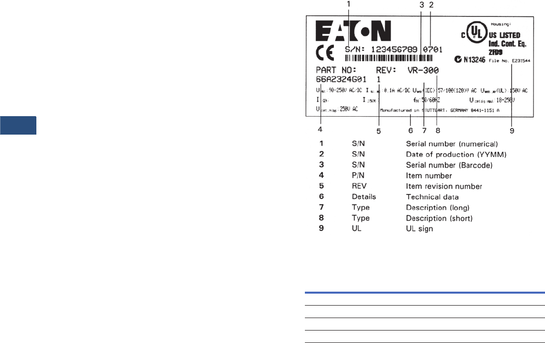
V3-T9-218 Volume 3—Power Distribution and Control Assemblies CA08100004E—November 2013 www.eaton.com
9
9
9
9
9
9
9
9
9
9
9
9
9
9
9
9
9
9
9
9
9
9
9
9
9
9
9
9
9
9
9.4
Metering Devices, Protective Relays, Software and Connectivity
Protective Relays
Technical Data and Specifications
Measuring Voltage
●Standard (Vrated) delta:
66/115 Vac
●Maximum value Vph-ph
max., (UL/cUL):
Max. 150 Vac
●Rated voltage Vph-ground:
50 Vac/2.5 kV
●Rated surge voltage: 2.5 kV
●Measuring frequency:
40.0 to 80.0 Hz
●Accuracy: Class 1
●Linear measuring range:
1. 3 x V rated.
●Input resistance:
0.21 M ohms
●Maximum power
consumption per path:
< 0.15W
Ambient Variables
●Wide range power supply:
90 to 250 Vac/Vdc
●Intrinsic consumption:
Max. 12 VA
●Ambient temperature:
●Storage: –22ºF to 176ºF
(–30ºC to 80°C)
●Operational: –4ºF to
158°F (–20ºC to 70°C)
●Ambient humidity: 95%,
noncondensing
●Maximum altitude:
6562 ft (2000m)
●Degree of pollution: 2
Discrete Inputs—Isolated
●Input range (VCont, Discrete
Input): Rated voltage
18 to 250 Vac/Vdc
●Input resistance:
Approximately 68 K ohms
Relay Outputs—Potential Free
●Contact material: AgCdO
●General purpose (GP)
(VCont, Relay Output):
●AC: 2.00 Aac at 250 Vac
●DC: 2.00 Adc at 24 Vdc,
0.22 Adc at 125 Vdc,
0.10 Adc at 250 Vdc
●Pilot duty (PD) (VCont, Relay
Output):
●AC: B300
●DC: 1.00 Adc at 24 Vdc,
0.22 Adc at 125 Vdc,
0.10 Adc at 250 Vdc
Housing
●Type: APRANORM
DIN 43 700
●Wiring: Screw-type,
terminals 2.5 mm2
(0.0039 in.2)
●Recommended tightening
torque: 0.5 Nm (0.369 ft/
lbs). Use 140/167°F (60/
75°C) Copper Wire Only.
Use Class 1 Wire Only
(or Equivalent)
Protection
●Protection system: IP42
from front with correct
mounting
●IP54 from front
with gasket
●(Gasket: P/N 8923-1036)
IP20 from back
●Front foil: Insulating
surface
Typical Nameplate
Typical VR-300 Nameplate
Reference Information
Reference Conditions
The data apply to the following
reference conditions:
●Input voltage = Sinusoidal
rated voltage
●Frequency = Rated
frequency ±2%
●Power supply = Rated
voltage ±2%
●Power factor cos f = 1
●Ambient temperature =
73ºF (23°C) ±2K
●Warm-up period =
20 minutes
Note
1Accuracy depending on the configured
transformer ratio.
Measuring Value Display Range Accuracy
Frequency
fL1, fL2, fL3 40.0 to.80.0 Hz 0.05 Hz
Vol t age
VL1, VL2, VL3, VL12, VL23, VL31 0 to 520, 0 to 65 kV 1% 1
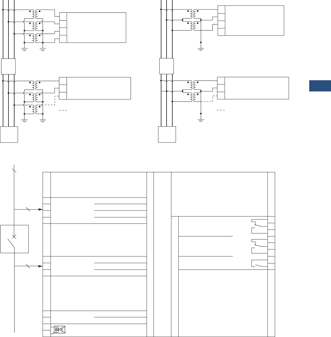
Volume 3—Power Distribution and Control Assemblies CA08100004E—November 2013 www.eaton.com V3-T9-219
9
9
9
9
9
9
9
9
9
9
9
9
9
9
9
9
9
9
9
9
9
9
9
9
9
9
9
9
9
9
9.4
Metering Devices, Protective Relays, Software and Connectivity
Protective Relays
Wiring Diagrams
Three-Line Wye Three-Line Delta
VR-300
A
VT
BC
L1
L2
L3
N
1
Measuring
Voltage
234
52
VT L1
L2
L3
707172
a) Not Measured
a)
Load
Synchronizing
Voltage
Not Required
A
VT
BC
L1
L2
L3
N
1
Measuring
Voltage
234
52
VT L1
L2
L3
707172
a)
Load
Synchronizing
Voltage
a) Not Measured
Not Required
The synchronizing voltage must be connected
3-phase if the measuring voltage is connected
3-phase (N not connected). If the measuring
voltage is connected 4-phase (L1, L2, L3, N),
the synchronizing voltage may be connected
2-phase (L1-L2). L3 is connected only for
compensation and is not measured.
0 Vdc
Blocking of protective functions
or remote acknowledgement.
Relay 1
(Ready for Operation)
Relay 2
Subject to Technical Modications.
2/3
Synchronizing System (Fixed)
CB
5678
VR-300 (Multi-Function Voltage Relay)
90 to 250 Vac/dc
Synchronizing Voltage L1
Synchronizing Voltage L2
Synchronizing Voltage L3
70 71 72
Measuring Voltage L1
Measuring Voltage L2
Measuring Voltage L3
(Measuring Voltage N)
1234
910111213141516
Relay 3
(Fixed to synch-check
zero voltage congurable)
Measuring Voltage
3-Wire or
4-Wire System
Supervised System
(Variable) 3/4
3/4
Measuring Voltage: 100 Vac
The socket for the PC parameterization
is situated on the side of the unit. This is
where the DPC must be plugged in.
Not Measured.
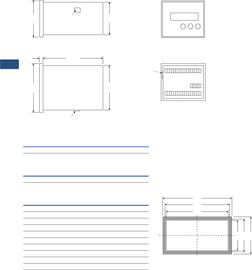
V3-T9-220 Volume 3—Power Distribution and Control Assemblies CA08100004E—November 2013 www.eaton.com
9
9
9
9
9
9
9
9
9
9
9
9
9
9
9
9
9
9
9
9
9
9
9
9
9
9
9
9
9
9
9.4
Metering Devices, Protective Relays, Software and Connectivity
Protective Relays
Dimensions
Approximate Dimensions in Inches (mm)
VR-300
Front Panel Cutout
VR-300 Dimensions
VR-300 Panel Cutout
The maximum permissible corner radius for cutout is
0.08 inches (2.0 mm).
Width Height
3.62 [+0.03] (92.0 [+0.8]) 2.68 [+0.03] (68.0 [+0.7])
Width Height Depth
Shipping Weight
Lbs (kg)
3.78 (96.0) 2.84 (72.1) 5.20 (132.1) 2.14 (0.97)
2.84
(72.1) Conguration Port 2.60
(66.0)
3.78
(96.0)
3.45
(87.6)
Conguration Port
Side View
Bottom View
.32
(8.1)
52.00
(1320.8)
115
70 75
32 17
Conguration Port
Front View
Back View with
Connecting Terminals
Measure Description
Dimensions
in Inches (mm)
Tolerance
in Inches (mm)
Height
H Total 2.83 (71.9) —
h Panel cutout 2.68 (68.1) 0.03 (+0.7)
h’ Housing dimension 2.60 (66.0) —
Width
B Total 3.78 (96.0) —
b Panel cutout 3.62 (91.9) 0.03 (+0.8)
b’ Housing dimension 3.54 (89.9) —
Depth (Including Terminals)
Total 6.30 (160.0) —
b‘
b
B
h‘ h H

Volume 3—Power Distribution and Control Assemblies CA08100004E—November 2013 www.eaton.com V3-T9-221
9
9
9
9
9
9
9
9
9
9
9
9
9
9
9
9
9
9
9
9
9
9
9
9
9
9
9
9
9
9
9.4
Metering Devices, Protective Relays, Software and Connectivity
Protective Relays
DP-300
Contents
Description Page
Product Selection Guide. . . . . . . . . . . . . . . . . . . . . V3-T9-158
FP-6000 Feeder Protection. . . . . . . . . . . . . . . . . . . V3-T9-162
FP-5000 Feeder Protection. . . . . . . . . . . . . . . . . . . V3-T9-172
FP-4000 Feeder Protection. . . . . . . . . . . . . . . . . . . V3-T9-180
MP-3000 Motor Protection. . . . . . . . . . . . . . . . . . . V3-T9-188
MP-4000 Motor Protection. . . . . . . . . . . . . . . . . . . V3-T9-198
MD-3000 Motor/Generator Differential Relay. . . . . V3-T9-204
Digitrip 3000. . . . . . . . . . . . . . . . . . . . . . . . . . . . . . V3-T9-207
VR-300 Multifunctional Voltage Relay . . . . . . . . . . V3-T9-217
DP-300 Current Differential Protection Relay
Standards and Certifications . . . . . . . . . . . . . . . V3-T9-222
Technical Data and Specifications . . . . . . . . . . . V3-T9-222
Dimensions . . . . . . . . . . . . . . . . . . . . . . . . . . . . V3-T9-224
EDR-3000 Feeder Protection . . . . . . . . . . . . . . . . . V3-T9-226
ETR-4000 Transformer Protection Relay. . . . . . . . . V3-T9-237
Ground Fault Relay . . . . . . . . . . . . . . . . . . . . . . . . . V3-T9-250
Universal RTD Module . . . . . . . . . . . . . . . . . . . . . . V3-T9-254
IQ 125 Volt DC Power Supply . . . . . . . . . . . . . . . . . V3-T9-258
DP-300 Current Differential Protection Relay
Product Description
The current flowing in the
individual conductors is
measured by means of
current transformers
installed on both sides of
the protection zone. These
transformers form the limits
of the protection zone. By
means of freely configurable
relays, the unit will indicate
if any of the adjusted fault
current limits have been
exceeded. The unit counts
with a slope characteristic
to prevent operation due
to CT ratio mismatches,
CT ratio errors, CT saturation
and errors because of tap
changes.
For transformer applications,
the unit has 2nd and 5th
harmonic restraints to
prevent misoperation in case
of inrush currents caused
for energization or over
excitation of the transformer.
When used in transformer
applications, the DP-300
allows you to change the
phase shift of the
transformer, without having
to worry about changing the
connection of the external
CTs, via selecting the vector
group in the display. The
different nominal currents of
the high and low voltage side
of the transformer, as well as
the transformer ratio, may be
configured. Every measuring
point may be set separately.
These features permit the
DP-300 to be universal in its
applications.
The DP-300 permits design
simplification of the
switchgear cabinet, facilitates
the commissioning, ensures
the operation of the system,
is user friendly and increases
the availability of the system.
Application Description
The DP-300 offers a three-
phase current differential
protection for generators,
motors and two winding
transformers, see Page V3-
T9-223.
Features, Benefits
and Functions
●True rms 6 x current
measurement, three-phase
system on both sides of
the protected zone
●Secondary current
transformer output
available as: /1A or /5A
●Configurable trip set
points for:
●Differential current (Id)
●Restrain current (Is)
●Configurable delays
●Four alarm relays
●Three discrete inputs (for
blocking, acknowledgment
and configuration)
●Two-line LC display
●Configurable transformer
ratio
●Configurable vector group
●Transformer inrush
detection/suppression
●Individual configuration of
the nominal current for the
high- and low-voltage side
of the transformer
●Configurable transformer
ratio separated for currents
of high- and low-voltage
side of the transformer
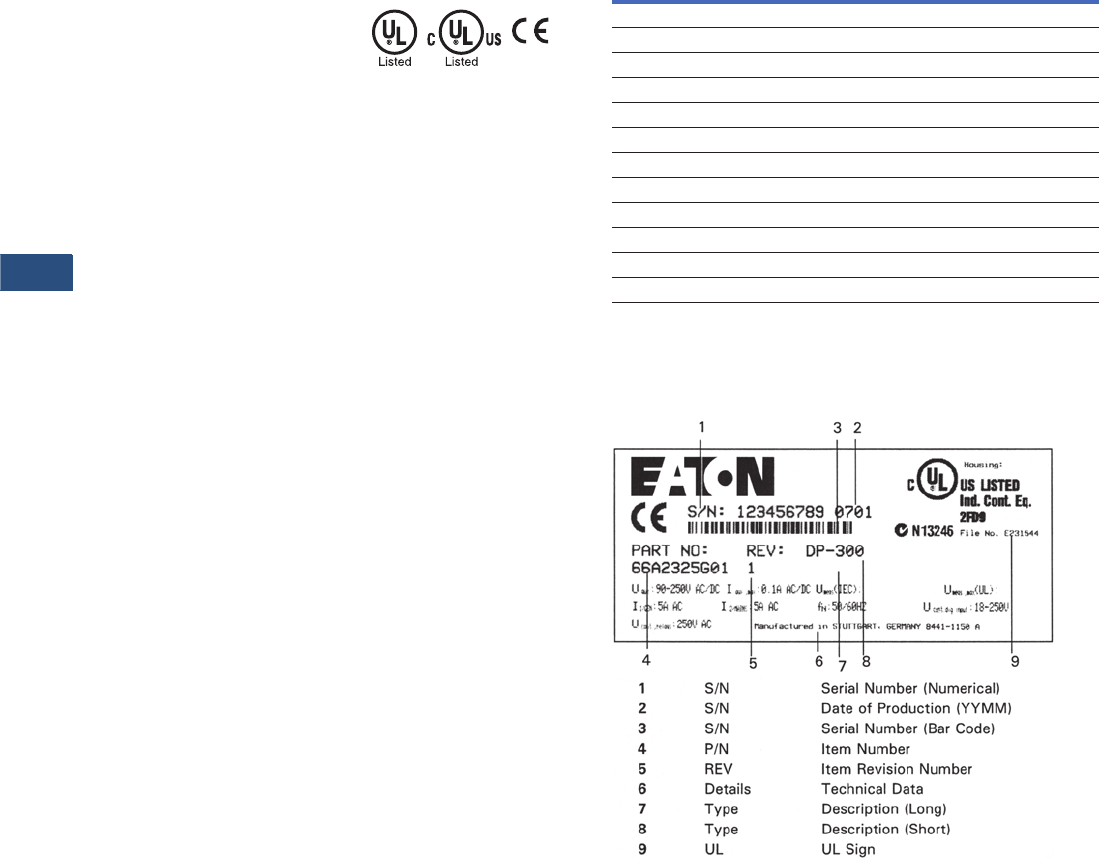
V3-T9-222 Volume 3—Power Distribution and Control Assemblies CA08100004E—November 2013 www.eaton.com
9
9
9
9
9
9
9
9
9
9
9
9
9
9
9
9
9
9
9
9
9
9
9
9
9
9
9
9
9
9
9.4
Metering Devices, Protective Relays, Software and Connectivity
Protective Relays
Standards and Certifications
●Listings: CE marking;
UL listing for ordinary
locations, UL/cUL listed,
ordinary locations,
File No.: E231544
●Additional Approvals: IEEE
C37.90.1 and C37.90.2
●EMC-Test (CE): Tested
according to applicable
EN guidelines
Technical Data and Specifications
Measurements, Currents—
Isolated
●Measured currents
(Nominal value IN): /5A
●Measuring frequency:
40.0 to 70.0 Hz
●Accuracy: Class 1
●Linear measuring range:
5.0 x IN
●Maximum power
consumption per path:
< 0.15 VA
●Rated short time current
(1s): 30.0 x IN
Ambient Conditions
●Voltage supply: 90 to
250 Vac/Vdc
●Intrinsic consumption:
Max. 10 VA
●Ambient temperature
storage: –22ºF to 176°F
(–30ºC to 80°C)
●Operational: –4ºF to 158°F
(20ºC to 70°C).
●Ambient humidity:
95%, noncondensing
●Maximum altitude:
6562 ft (2000m)
●Degree of pollution: 2
Digital Inputs—Isolated
●Input range
(VCont, Digital Input):
●Nominal voltage
●18 to 250 Vac/Vdc
●Input resistance:
Approximately 68 K ohms
Relay Outputs—Isolated
●Contact material: AgCdO
●Resistive load (GP)
(VCont, Relay Output):
●AC: 2.00 Aac @ 250 Vac
●DC: 2.00 Adc @24 Vdc,
0.36 Adc @ 125 Vdc,
0.18 Adc @ 250 Vdc
●Inductive load (PD)
(VCont, Relay Output):
●AC: B300
●DC: 1.00 Adc @ 24 Vdc,
0.22 Adc @ 125 Vdc,
0.10 Adc @ 250 Vdc
Protective Functions
●Operating Time:
Minimum 100m
●Differential current:
Minimum 10%
Housing
●Type: APRANORM
DIN 43 700
●Terminals: Screw-type,
terminals depending on
connector, 0.00388 in.2
(2.5 mm2) or 0.00620 in.2
(4.0 mm2)
●Recommended
tightening torque:
●4.43 in./lbs / [0.00620
in.2] 5.3 in./lbs)
●[2.5 mm2] 0.5 Nm /
[4.0 mm2] 0.6 Nm
([0.00388 in.2]
●Use 140ºF/167°F (60ºC/
75°C) copper wire only
●Use Class 1 wire only
(or equivalent)
Housing Protection
●Protection system:
●IP42 from front with
correct mounting
●IP54 from front
with gasket
●Gasket: P/N 8923-1038)
●IP20 from back
●Front foil: Insulating surface
Transformer Vector Groups
Transformer Vector Groups
Typical Nameplate
Typical DP-300 Nameplate
Vector Group Description
Yd5 HV: l-Circuit Arrangement, LV: n-Circuit Arrangement, 5 x 30° = 150°
Yy0 HV: l-Circuit Arrangement, LV: l-Circuit Arrangement, 0°
Dy5 HV: n-Circuit Arrangement, LV: l-Circuit Arrangement, 5 x 30° = 150°
Dd0 HV: n-Circuit Arrangement, LV: n-Circuit Arrangement, 0°
Yz5 HV: l-Circuit Arrangement, LV: Z-Circuit Arrangement, 5 x 30° = 150°
Dz0 HV: n-Circuit Arrangement, LV: Z-Circuit Arrangement, 0°
Yd11 HV: l-Circuit Arrangement, LV: n-Circuit Arrangement, 11 x 30° = 330°
Yy6 HV: l-Circuit Arrangement, LV: l-Circuit Arrangement, 6 x 30° = 180°
Dy11 HV: n-Circuit Arrangement, LV: l-Circuit Arrangement, 11 x 30° = 330°
Dd6 HV: n-Circuit Arrangement, LV: n-Circuit Arrangement, 6 x 30° = 180°
Yz11 HV: l-Circuit Arrangement, LV: Z-Circuit Arrangement, 11 x 30° = 330°
Dz6 HV: n-Circuit Arrangement, LV: Z-Circuit Arrangement, 6 x 30° = 180°
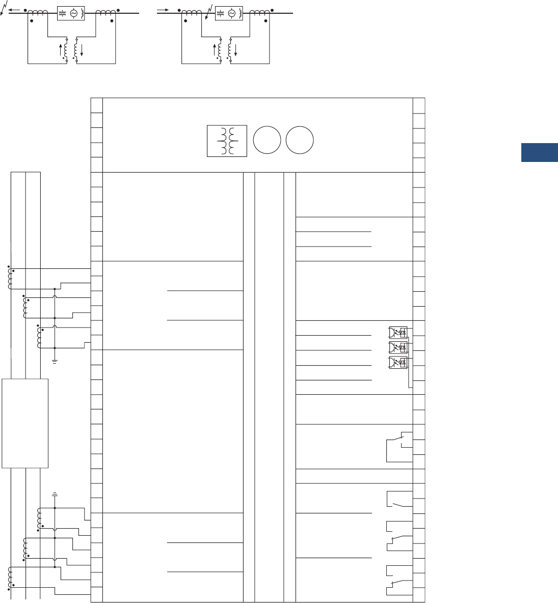
Volume 3—Power Distribution and Control Assemblies CA08100004E—November 2013 www.eaton.com V3-T9-223
9
9
9
9
9
9
9
9
9
9
9
9
9
9
9
9
9
9
9
9
9
9
9
9
9
9
9
9
9
9
9.4
Metering Devices, Protective Relays, Software and Connectivity
Protective Relays
Wiring Diagrams
Protected Area Principle—Fault “A” Outside = No Alarm, Fault “B” Inside = Alarm
DP-300
A) B)
Schematic Circuit Diagrams (Single-Phase Version):
A) Fault Outside the Protection Area
B) Fault Inside the Protection Area
Ia
or or
Ib
IL
Ia
or or
Ib
IL
DP-300
Block Differential Protection
Possible Protected Objects:
MG
N
PE
L (90 to 250 Vac/dc)
Current IL1 Transducer Set 2
Current IL2 Transducer Set 2
Current IL3 Transducer Set 2
Current IL3 Transducer Set 1
Current IL2 Transducer Set 1
Current IL1 Transducer Set 1 Relay 1
Relay 2
Relay 3
Ready for Operation
N/C
Relay 4
Common
N/C
Conguration Off
Acknowledgement
Blocking
Subject to Technical Modications.
L1
L2
L3
Transducer Set 1 (High Voltage Side)
Protected Object
Transducer Set 2 (Low Voltage Side)
The Transducer Ratio is
Adjustable in the Display.
The Transducer Ratio is
Adjustable in the Display.
25 26 27 28 29 30 35 36 33 34 31 32
DP-300 — Current Differential Protection Relay
1 2 3 4 5 6 7 8 9 10 11 12 15 16 17 18 19 83 81 79
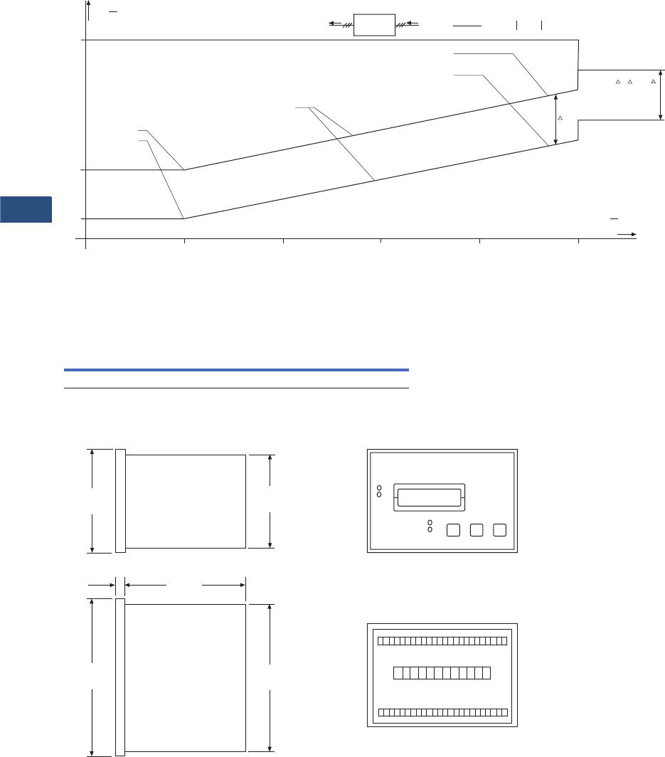
V3-T9-224 Volume 3—Power Distribution and Control Assemblies CA08100004E—November 2013 www.eaton.com
9
9
9
9
9
9
9
9
9
9
9
9
9
9
9
9
9
9
9
9
9
9
9
9
9
9
9
9
9
9
9.4
Metering Devices, Protective Relays, Software and Connectivity
Protective Relays
Tripping Characteristics
DP-300
Dimensions
Approximate Dimensions in Inches (mm)
DP-300
DP-300
Id
IN
Y= [%]
Monitoring step 2, xed limit (100%)
Characteristic gradient (xed) = 10%
X12, Y2 and Y1: adjustable
P (X12/Y2)
P (X12/Y1)
Monitoring step 2
(X12 = 100% / Y2 = 35%
Monitoring step 1
(X12 = 100% / Y1 = 10%
Monitoring step 2
xed limit (85%)
Monitoring
step 1 xed limit
(85%-Y2+Y1)
Protected
object IS =
IaIbIaIb
+
2Id =Ia - Ib
1
1
=22
X =IS
IN
[%]
500400
300
200100
10
35
100
Width Height Depth
Shipping Weight
Lbs (kg)
5.67 (144.0) 3.78 (96.0) 5.20 (132.1) 2.2 (0.99)
Side View
3.78
(96.0)
3.54
(89.9)
Bottom View
5.67
(144.0)
5.35
(135.9)
0.32
(8.0)
5.20
(132.1)
Front View
Back View with
Connecting Terminals
80 83
36 25
124
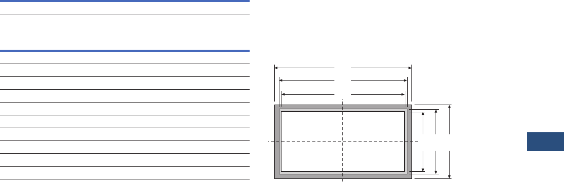
Volume 3—Power Distribution and Control Assemblies CA08100004E—November 2013 www.eaton.com V3-T9-225
9
9
9
9
9
9
9
9
9
9
9
9
9
9
9
9
9
9
9
9
9
9
9
9
9
9
9
9
9
9
9.4
Metering Devices, Protective Relays, Software and Connectivity
Protective Relays
Approximate Dimensions in Inches (mm)
Front panel cutout
DP-300 Panel Cutout
The maximum permissible corner radius for cutout is
0.08 inches (2.0 mm).
Width Height
5.43 [+0.039] (138.0 [+1.0]) 3.63 [=0.031] (92.0 [+0.8])
Measure Description Dimensions Tolerance
Height
H Total 3.78 (96.0) —
h Panel cutout 3.62 (91.9) 0.03 (+0.8)
h’ Housing dimension 3.54 (89.9) —
Width
B Total 5.67 (144.0) —
b Panel cutout 5.43 (137.9) 0.04 (+1.0)
b’ Housing dimension 5.35 (135.9) —
Depth (Including Terminals)
Total 6.30 (160.0) —
b‘
b
B
h‘ h H
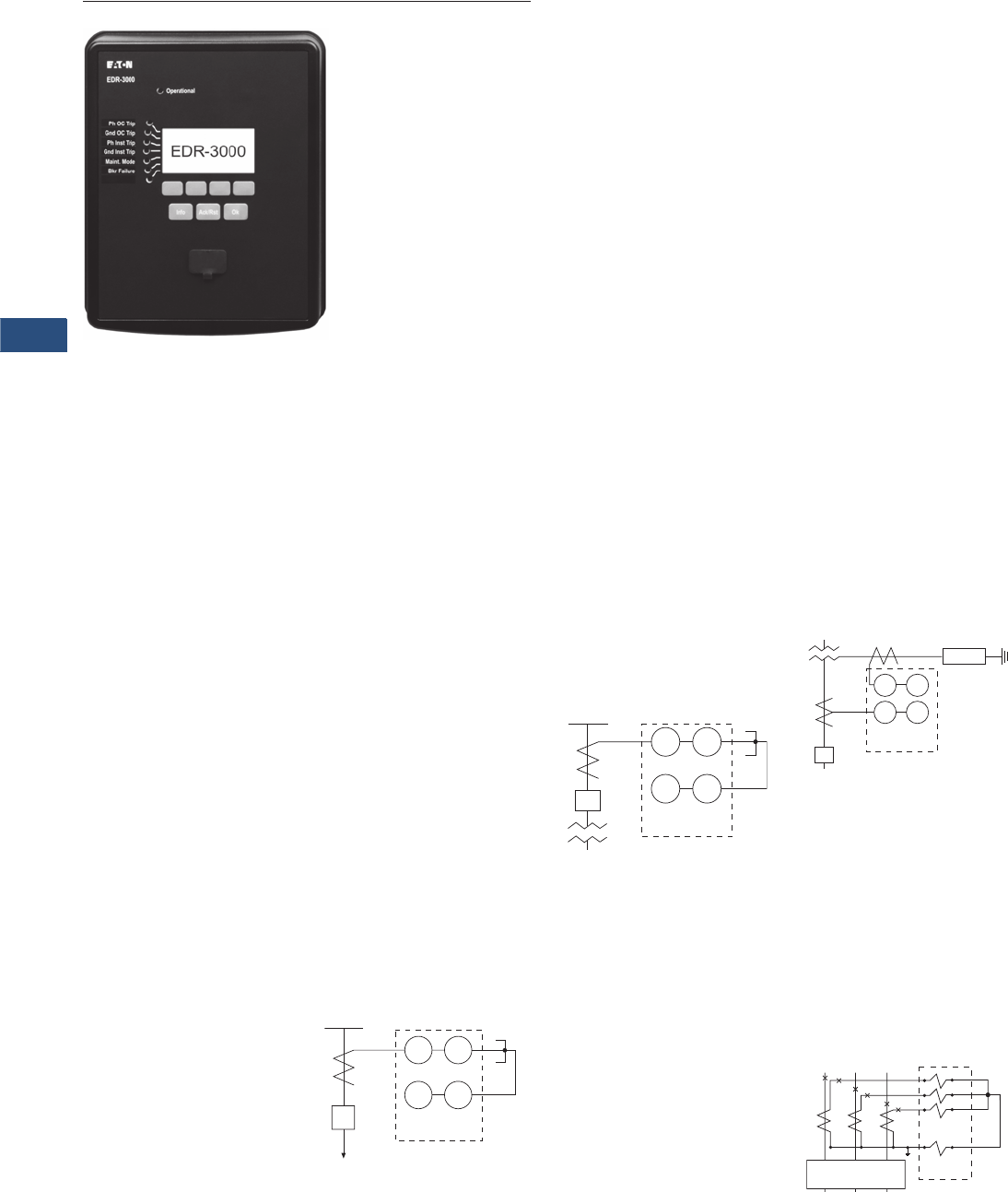
V3-T9-226 Volume 3—Power Distribution and Control Assemblies CA08100004E—November 2013 www.eaton.com
9
9
9
9
9
9
9
9
9
9
9
9
9
9
9
9
9
9
9
9
9
9
9
9
9
9
9
9
9
9
9.4
Metering Devices, Protective Relays, Software and Connectivity
Protective Relays
EDR-3000
Contents
Description Page
Product Selection Guide . . . . . . . . . . . . . . . . . . . . V3-T9-158
FP-6000 Feeder Protection . . . . . . . . . . . . . . . . . . V3-T9-162
FP-5000 Feeder Protection . . . . . . . . . . . . . . . . . . V3-T9-172
FP-4000 Feeder Protection . . . . . . . . . . . . . . . . . . V3-T9-180
MP-3000 Motor Protection . . . . . . . . . . . . . . . . . . V3-T9-188
MP-4000 Motor Protection . . . . . . . . . . . . . . . . . . V3-T9-198
MD-3000 Motor/Generator Differential Relay . . . . V3-T9-204
Digitrip 3000 . . . . . . . . . . . . . . . . . . . . . . . . . . . . . V3-T9-207
VR-300 Multifunctional Voltage Relay . . . . . . . . . . V3-T9-217
DP-300 Current Differential Protection Relay . . . . . V3-T9-221
EDR-3000 Feeder Protection
Features, Benefits and Functions . . . . . . . . . . . V3-T9-228
Standards and Certifications . . . . . . . . . . . . . . . V3-T9-228
Catalog Number Selection . . . . . . . . . . . . . . . . V3-T9-229
Technical Data and Specifications . . . . . . . . . . . V3-T9-230
Dimensions. . . . . . . . . . . . . . . . . . . . . . . . . . . . V3-T9-235
ETR-4000 Transformer Protection Relay . . . . . . . . V3-T9-237
Ground Fault Relay. . . . . . . . . . . . . . . . . . . . . . . . . V3-T9-250
Universal RTD Module . . . . . . . . . . . . . . . . . . . . . . V3-T9-254
IQ 125 Volt DC Power Supply. . . . . . . . . . . . . . . . . V3-T9-258
EDR-3000 Feeder Protection
Product Description
The EDR-3000 Protective
Relay is a multifunction,
microprocessor-based
overcurrent relay designed
for both ANSI and IEC
applications. It is a panel-
mounted, self-contained unit
that operates from either AC
or DC control power. The
EDR-3000 design provides
true rms and fundamental
sensing of each phase and
ground current. Only one unit
is required for each three-
phase circuit.
Current monitoring and
operator selectable protective
functions are integral to each
relay. The EDR-3000 relay
operates from the 5A or 1A
secondary output of standard
current transformers. Current
transformer ratio information
is quickly programmed into
the unit via settings. This
enables the relay to display
metered current in primary
amperes, secondary amperes
or per unit values. The EDR-
3000 features a user-friendly
operations panel to monitor
and program the relay.
Operating parameters and
troubleshooting information
are displayed in the 128 x 64
LCD. In addition, all data and
information can be
communicated to a host
computer equipped
with PowerPort-E™.
A “Communication Trip” and
“Communication Close”
control command can also be
initiated by a host computer
with an authorized access
code for remote breaker
operation.
Application Description
The EDR-3000
microprocessor-based relay
provides reliable three-phase
and ground overcurrent
protection for all voltage
levels. It can be used for
any application where
instantaneous and/or time
overcurrent protection is
required. It is most commonly
used as primary feeder circuit
protection, shown below.
Primary Feeder Circuit
Protection
The EDR-3000 may be
applied as the transformer
primary protection or as
backup to the differential
protection, see below.
Transformer Overcurrent
Protection
The EDR-3000 may be
connected to the secondary
side of a delta-wye grounded
transformer with the ground
element connected to a
separate CT in the neutral
connection of the
transformer. With this
connection, a lower CT
ratio and a pickup setting
can be used to provide
more sensitive ground fault
protection especially for
resistance grounded
systems, shown below.
Transformer Secondary
Protection with Neutral CT
Connection
The EDR-3000 relay has
special provisions for
connection in a Zone
Interlocking scheme that can
be used for bus protection
or to improve protection
coordination in a tight or close
system. Zone Interlocking
is described in following
sections. In addition the
EDR-3000 has multiple
setting groups that can be
used to reduce arc flash
hazard with instantaneous
elements.
Residual Ground Connection
50 51
50G 51G
CB
52 EDR-3000
Load
50 51
50G 51G
CB
EDR-3000
50G 51G
50 51
EDR-3000
Resistor
CB
a
b
c
GND
EDR-3000
CB-52
23
56
89
12 11
50N/51N
50/51
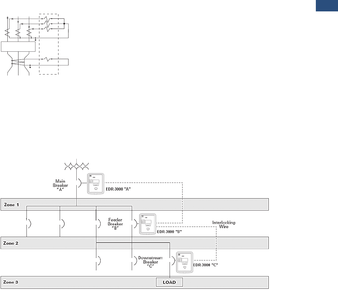
Volume 3—Power Distribution and Control Assemblies CA08100004E—November 2013 www.eaton.com V3-T9-227
9
9
9
9
9
9
9
9
9
9
9
9
9
9
9
9
9
9
9
9
9
9
9
9
9
9
9
9
9
9
9.4
Metering Devices, Protective Relays, Software and Connectivity
Protective Relays
Overcurrent Protection
The EDR-3000 provides
complete three-phase and
ground protection with
separate elements and
settings. The relay can be
used with CTs from 1 to
50,000A of primary current
and 1 or 5A of secondary
current. The CT ratio can be
set independently for phase
and ground, allowing the
ground element to be
connected in either the
residual or the separate
ground CT configuration,
shown on below.
Separate Zero Sequence
Ground CT Connection
Zone Selective Interlocking
(Phase and Ground)
Note: Refer to the Ordering
Information and (Catalog Ordering
Information) for optional features,
see Page V3-T9-229.
Zone Selective interlocking
is a protection function to
minimize equipment damage
resulting from a phase or a
ground fault in an area where
long time and/or short time
delay is in use.
When the “Ground Zone
Interlocking” feature is
utilized, an immediate trip is
initiated when the fault is in
the breaker’s zone of
protection, regardless of its
preset time delay. When the
“Phase Zone Interlocking”
feature is utilized, the time
overcurrent elements work
as follows. The instantaneous
phase element will initiate an
immediate trip when the fault
is in the breaker's zone of
protection, regardless of its
preset time delay. For the
time overcurrent phase
element, the current sensed
by the EDR-3000 must
exceed 1.5 times the pickup
setting for the zone selective
interlocking to initiate an
immediate trip signal when
the fault is in the breaker’s
zone of protection.
Upstream EDR-3000
protected breakers are
restrained from tripping
immediately by an
interlocking signal from the
downstream EDR-3000 relay.
This interlocking signal
requires only a pair of
wires from the downstream
breaker to the upstream
breaker. It provides standard
coordinated tripping when
the fault is located outside
the zone of protection.
In the sample zone
interlocking system shown
below, circuit breakers A,
B and C are equipped with
EDR-3000 overcurrent relays.
Fault Location Zone 3
Note: For the time overcurrent
phase element, the current
sensed by the EDR-3000 must
exceed 1.5 times the pickup
setting for the zone selective
interlocking to initiate an
immediate trip signal when
the fault is in the breaker's zone
of protection.
If a fault occurs at a point
in Zone 3, the EDR-3000
of downstream breaker C
senses the fault and sends
a restraining signal to the
upstream EDR-3000 of
feeder breaker B. Having
received this signal, the
EDR-3000 of feeder breaker
B withholds its trip command.
As a result, only downstream
breaker C is tripped.
Fault Location Zone 2
Note: For the time overcurrent
phase element, the current
sensed by the EDR-3000 must
exceed 1.5 times the pickup
setting for the zone selective
interlocking to initiate an
immediate trip signal when the
fault is in the breaker’s zone
of protection.
If a fault occurs at a point in
Zone 2, the EDR-3000 of
feeder breaker B senses the
fault and sends a restraining
signal to the upstream EDR-
3000 of main breaker A. The
EDR-3000 of the downstream
breaker C does not see this
fault since it is situated on the
downstream side of the fault.
As a result, the EDR-3000 of
downstream breaker C does
not send a restraining signal
to the EDR-3000 of feeder
breaker B. Since it did not
receive a restraining signal
from the EDR-3000 of
downstream breaker C, the
EDR-3000 of feeder breaker
B identifies that the fault is in
Zone 2 and immediately trips
feeder breaker B, regardless
of its time setting.
Fault Location Zone 1
Note: For the time overcurrent
phase element, the current
sensed by the EDR-3000 must
exceed 1.5 times the pickup
setting for the zone selective
interlocking to initiate an
immediate trip signal when the
fault is in the breaker's zone of
protection.
If a fault occurs in Zone 1,
no restraining signal is
received by the Digitrip
of main breaker A. As a
result, main breaker A is
immediately tripped by its
EDR-3000 overcurrent relay,
regardless of its time setting.
Sample Zone Selective Interlocking System
CB-52
a
b
c
GND
EDR-3000
23
56
89
11 12
50/51
50G/51G

V3-T9-228 Volume 3—Power Distribution and Control Assemblies CA08100004E—November 2013 www.eaton.com
9
9
9
9
9
9
9
9
9
9
9
9
9
9
9
9
9
9
9
9
9
9
9
9
9
9
9
9
9
9
9.4
Metering Devices, Protective Relays, Software and Connectivity
Protective Relays
Features, Benefits and Functions
Applications
●Provides reliable three-
phase and ground
overcurrent protection
for all voltage levels
●Primary feeder circuit
protection
●Primary transformer
protection
●Backup to differential
protection
●May be used where
instantaneous and/or time
overcurrent protection is
required
●Ground element capable
of residual, zero sequence
or external source
connections
Protection Functions
●Breaker failure (50BF)
●Phase overcurrent
protection per time-current
curve (51-1, 51-2, 51-3)
●Calculated ground fault
protection per time-current
curve (51R-1, 51R-2)
●Independent measured
ground or neutral fault
protection per time-current
curve (51X-1, 51X-2)
●Phase instantaneous
overcurrent (50-1, 50-2,
50-3)
●Calculated ground or
neutral instantaneous
overcurrent (50R-1, 50R-2)
●Independent measured
ground or neutral
instantaneous overcurrent
(50X-1, 50X-2)
●Curve shapes: ANSI,
IEC, or thermal curves
(11 thermal curves)
●Instantaneous or time
delay reset
●True rms or fundamental
sensing of each phase
and ground current
●Zone selective interlocking
(phase and ground) or
reverse blocking for
bus protection
Note: Refer to the Ordering
Information and Page V3-T9-229
(Catalog Ordering Information)
for optional features.
Metered Values
●rms and fundamental
phase currents
●rms and fundamental
ground currents
●Maximum, minimum
and average rms and
fundamental phase
currents
●Maximum, minimum
and average rms and
fundamental ground
currents
Monitored and Data
Recording Values
●Trip circuit monitoring
Note: Refer to the Ordering
Information and Page V3-T9-229
(Catalog Ordering Information)
for optional features.
●Breaker wear (accumulated
interrupted current)
●Fault data logs (up to
20 events)
●Sequence of event
recorders (up to
300 events)
●Waveform capture
(3600 cycles total)
●CT supervision
Control Functions
●Remote open/close
●Programmable I/O
●Programmable LEDs
●Multiple setting groups
(up to four)
Communication
●Local HMI
●Front RS-232 port
●Rear RS-485 port
●IRIG-B11
●Protocols
●Modbus RTU
Standards and Certifications
●Generic standard:
●EN 61000-6-2
●EN 61000-6-3
●Product standard:
●EC 60255-6
●EN 50178
●UL 508 (Industrial Control
Equipment)
●CSA C22.2 No. 14-95
(Industrial Control
Equipment)
●ANSI C37.90
●UL, CSA, CE
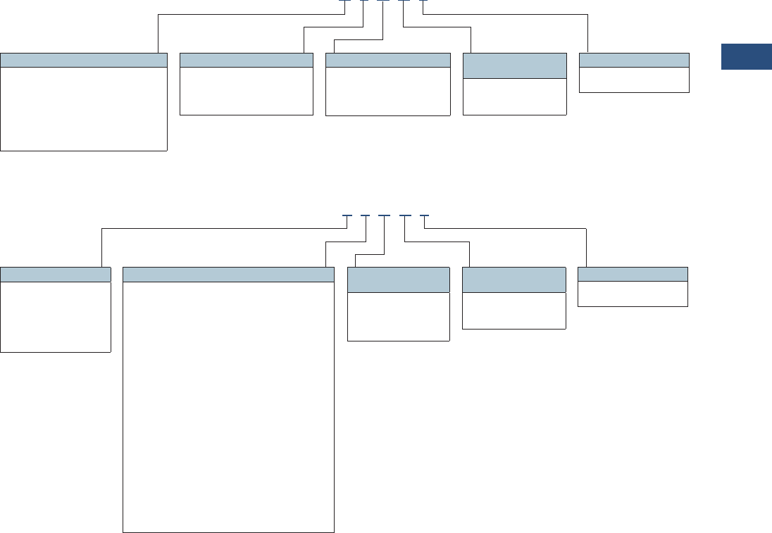
Volume 3—Power Distribution and Control Assemblies CA08100004E—November 2013 www.eaton.com V3-T9-229
9
9
9
9
9
9
9
9
9
9
9
9
9
9
9
9
9
9
9
9
9
9
9
9
9
9
9
9
9
9
9.4
Metering Devices, Protective Relays, Software and Connectivity
Protective Relays
Catalog Number Selection
The catalog number
identification chart defines
the electrical characteristics
and operation features
included in the EDR-3000. For
example, if the catalog number
were EDR3000-A0BA1,
the device would have
the following:
EDR-3000
(A)–Four digital inputs,
four output relays
(0)–Phase current 5A/1A,
Ground Current 5A/1A,
Power supply: 19–300 Vdc,
40–250 Vac
(B)–Modbus-RTU (RS-485)
(A)–Without conformal
coating
(1)–Projection panel mount
Relay Removable Terminals
Relay Fixed Terminals 2
Notes
1Consult factory for the availability of eight digital inputs, six outputs, trip coil monitor, zone interlocking, IRIG-B and Modbus-TCP.
2Consult factory for the availability of fixed terminals.
Hardware Option 1
A = 4 digital inputs, 4 outputs,
removable terminals
B = 8 digital inputs, 6 outputs, removable
terminals, trip coil monitor 1
C = 4 digital inputs, 4 outputs, removable
terminals, zone interlocking 1
and IRIG-B 1
Communication Options
B = Modbus-RTU
(RS-485)
C = Modbus-TCP 1
(RJ-45)
Conformal Coating
Options
A = None
B = Conformal coated
circuit boards
Mounting Options
0 = Standard mount
1 = Projection panel mount
Hardware Option 2
0 = Phase current 5A/1A, ground
current 5A/1A, power supply
range: 19–300 Vdc,
40–250 Vac
EDR3000 A 0 B A 1
Hardware Option 1 2
E = 4 digital inputs,
4 outputs, fixed terminals
F = 4 digital inputs,
4 outputs, fixed terminals,
zone interlocking
and IRIG-B
Hardware Option 2 2
0 = Phase current 1A, ground current 1A, power supply
range: 19–72 Vdc
1 = Phase current 5A, ground current 5A, power supply
range: 19–72 Vdc
2 = Phase current 1A, sensitive ground
current 0.1A, power supply range:
19–72 Vdc
3 = Phase current 5A, sensitive ground
current 0.5 A, power supply range:
19–72 Vdc
4 = Phase current 1A, ground current 1A, power supply
range: 85–300 Vdc,
85–250 Vac
5 = Phase current 5 A, ground current 5A, power supply
range: 85–300 Vdc,
85–250 Vac
6 = Phase current 1A, sensitive ground
current 0.1 A, power supply range:
85–300 Vdc, 85–250 Vac
7 = Phase current 5A, sensitive ground
current 0.5A, power supply range:
85–300 Vdc, 85–250 Vac
Communication
Options
B = Modbus-RTU
(RS-485)
C = Modbus-TCP 2
(RJ-45)
Conformal Coating
Options
A = None
B = Conformal coated
circuit boards
Mounting Options
0 = Standard mount
1 = Projection panel mount
EDR3000 E 0 B A 1

V3-T9-230 Volume 3—Power Distribution and Control Assemblies CA08100004E—November 2013 www.eaton.com
9
9
9
9
9
9
9
9
9
9
9
9
9
9
9
9
9
9
9
9
9
9
9
9
9
9
9
9
9
9
9.4
Metering Devices, Protective Relays, Software and Connectivity
Protective Relays
Technical Data and Specifications
Climatic Environmental
Conditions
●Storage temperature:
–13°F to 158°F (–25°C up
to +70°C)
●Operating temperature:
–4°F to 140°F (–20°C up
to +60°C)
●Permissible humidity at
ann. average: <75% rel.
(on 56d up to 95% rel.)
●Permissible Installation
altitude:
●<2000m (6561.67 ft)
above sea level
●If 4000m (13,123.35 ft)
altitude apply, a changed
classification of the
operating and test
voltages may be
necessary
Degree of Protection EN 60529
●HMI front panel with
seal: IP54
●Rear side terminals: IP30
Routine Test
●Insulation test according to
IEC 60255-5: All tests to be
carried out against ground
and other input and output
circuits
●Aux. voltage supply, digital
inputs, current measuring
inputs, signal relay outputs:
2.5 kV (eff)/50 Hz
●Voltage measuring inputs:
3.0 kV (eff)/50 Hz
●All wire-bound
communication interfaces:
1. 5 k V D C
Housing
●Material, housing:
aluminum extruded section
●Material, front panel:
aluminum/foil front
●Mounting position:
horizontal (±45° around the
X-axis must be permitted)
Plug-in Connector with
Integrated Short-Circuiter
(Conventional Current Inputs)
●Nominal current:
1A and 5A
●Continuous loading
capacity: 4 x In/
continuously
●Overcurrent withstand:
30 x In/10s
●100 x In/1s
●250 x In/10 ms
(1 half-wave)
●Screws: M4, captive type
according to VDEW
●Connection cross-sections:
●2 x 2.5 mm2 (2 x AWG
14) with wire end ferrule
●1 x or 2 x 4.0 mm2
(2 x AWG 12) with
ring cable sleeve or
cable sleeve
●1 x or 2 x 6 mm2
(2 x AWG 10) with
ring cable sleeve or
cable sleeve
Voltage Supply
●Aux. voltage: 19–300 Vdc/
40–250 Vac
●Buffer time in case of
supply failure: >= 50 ms
at minimal aux. voltage
communication is
permitted to be interrupted
●Max. permissible making
current:
●18A peak value for
<0.25 ms
●12A peak value for
<1 ms
●The voltage supply must
be protected by a fuse of:
●2.5A time-lag miniature
fuse 5 x 20 mm (approx.
1/5 in. x 0.8 in.) according
to IEC 60127
●3.5A time-lag miniature
fuse 6. 3 x 32 mm
(approx. 1/4 in. x
1 1/4 in.) according
to UL 248-14
Power Consumption
●Power supply range: Power
consumption in idle mode
●Max. power consumption
●19–300 Vdc: 6W 8.5W
●40–250 Vac
●For frequencies of
40–70 Hz: 6W 8.5W
Real-Time Clock
●Running reserve of the
real-time clock: 1 year min
Display
●Display type: LCD with
LED background
illumination
●Resolution graphics
display: 128 x 64 pixel
●LED-type: two colored,
red/green
●Number of LEDs, housing
B1: 8
Digital Inputs
●Max. input voltage:
300 Vdc/270 Vac
●Input current: <4 mA
●Reaction time: <20 ms
●Fallback time: <30 ms (safe
state of the digital inputs)
●Four switching thresholds:
Un = 24 Vdc, 48 Vdc,
60 Vdc, 110 Vac/dc,
230 Vac/Vdc Un = 24 Vdc
●Switching threshold
1 ON
– Switching threshold 1
OFF
– Min. 19.2 Vdc
– Max. 9.6 Vdc
– Un = 48 V/60 Vdc
●Switching threshold
2 ON
– Switching threshold 2
OFF
– Min. 42.6 Vdc
– Max. 21.3 Vdc
– Un = 110/120 Vac/dc
●Switching threshold
3 ON
– Switching threshold 3
OFF
– Min. 88.0 Vdc/
88.0 Vac
– Max. 44.0 Vdc/
44.0 Vac
– Un = 230/240 Vac/Vdc
●Switching threshold
4 ON
– Switching threshold 4
OFF
–Min. 184 Vdc/
184 Vac
– Max. 92 Vdc/92 Vac
●Terminals: screw-type
terminal

Volume 3—Power Distribution and Control Assemblies CA08100004E—November 2013 www.eaton.com V3-T9-231
9
9
9
9
9
9
9
9
9
9
9
9
9
9
9
9
9
9
9
9
9
9
9
9
9
9
9
9
9
9
9.4
Metering Devices, Protective Relays, Software and Connectivity
Protective Relays
Current and Ground
Current Measurement.
●Nominal currents: 1A/5A
●Max. measuring range:
●up to 40 x In (phase
currents)
●up to 25 x In (ground
current standard)
●up to 2.5 x In (ground
current sensitive)
●Continuous loading
capacity: 4 x In/
continuously
●Overcurrent proof:
●30 x In/10s
●100 x In/1s
●250 x In/10 ms
(1 half-wave)
●Power consumption:
Phase current inputs
●at In = 1A S = 0.15 mVA
●at In = 5A S = 0.15 mVA
●Ground current input
●at In = 1A S = 0.35 mVA
●at In = 5A S = 0.35 mVA
●Frequency range: 50 Hz/
60 Hz ±10%
●Terminals: Screw-type
terminals with integrated
short-circuiters (contacts)
Binary Output Relays
●Continuous current:
5A AC/DC
●Switch-on current:
25A AC/DC for 4s
●Max. breaking current:
5A AC up to 125 Vac
●5A DC up to 50V (resistive)
●0.2A DC at 300V
●Max. switching voltage:
250 Vac/300 Vdc
●Switching capacity:
2000 VA
●Contact type:
1 changeover contact
●Terminals: Screw-type
terminals
Front Interface RS-232
●Baud rates: 115,200 baud
●Handshake: RTS and CT
●Connection: 9-pole
D-Sub plug
RS-485
●Master/Slave: Slave
●Connection: 6 screw-
clamping terminals RM
3.5 mm (138 MIL)
(terminating resistors
internal)
Tolerances of the
Real-Time Clock
●Resolution: 1 ms
●Tolerance: <1 minute/
month (+20°C)
Measuring Accuracy
●Max. measuring range: up
to 40 x In (phase currents)
up to 25 x In (ground
current standard)
●Frequency range: 50 Hz/
60 Hz ± 10%
●Accuracy: Class 0.5
●Amplitude error if I < In:
±0.5% of the rated value
●Amplitude error if I > In:
±0.5% of the measured
value
●Amplitude error if I > 2 In:
±1.0% of the measured
value
●Resolution: 0.01A
●Harmonics up to 20% 3rd
harmonic ±2% up to 20%
5th harmonic ±2%
●Frequency influence
< ±2%/Hz in the range of
±5 Hz of the parameterized
nominal frequency
●Temperature influence
<±1% within the range
of 0°C up to +60°C

V3-T9-232 Volume 3—Power Distribution and Control Assemblies CA08100004E—November 2013 www.eaton.com
9
9
9
9
9
9
9
9
9
9
9
9
9
9
9
9
9
9
9
9
9
9
9
9
9
9
9
9
9
9
9.4
Metering Devices, Protective Relays, Software and Connectivity
Protective Relays
Protection Stages Tolerances
Overcurrent Protection Stages 50P(X), 51P(X)
Note
The tripping delay relates to the time between pickup and trip. The tolerance of the operating time relates to the time between the measured value has exceeded the threshold until
the protection stage is alarmed.
Description Range Step Tolerance
Pickup If the pick-up value is exceeded, the module/stage is started. 0.01–40.00 x In0.01 xIn±1.5% of the setting value resp. 1% In
Resetting ratio 97% or 0.5% x In——
t Tripping delay 0.00–300.00 x s 0.01 x s DEFT ±% resp. ±10 ms
Operating time Starting from l higher than 1.1 x l> — — <+35 ms
Disengaging time — — <+45 ms
t-multiplier Time multiplier/tripping characteristic factor 0.05–2.00 0.01 ±5%
IEC NINV 0.05–2.00 0.01 ±5%
IEC VINV 0.05–2.00 0.01 ±5%
IEC EINV 0.05–2.00 0.01 ±5%
IEC LINV 0.05–2.00 0.01 ±5%
ANSI MINV 0.05–2.00 0.01 ±5%
ANSI VINV 0.05–2.00 0.01 ±5%
ANSI EINV 0.05–2.00 0.01 ±5%
Flat 0.05–2.00 0.01 ±5%
It 0.05–2.00 0.01 ±5%
I2t 0.05–2.00 0.01 ±5%
I4t 0.05–2.00 0.01 ±5%
Reset mode Only available if IEC characteristics 0.00–60.00 0.01 x s ±1% resp. ±10 ms
IEC NINV 0.00–60.00 0.01 x s ±1% resp. ±10 ms
IEC VINV 0.00–60.00 0.01 x s ±1% resp. ±10 ms
IEC EINV 0.00–60.00 0.01 x s ±1% resp. ±10 ms
IEC LINV 0.00–60.00 0.01 x s ±1% resp. ±10 ms
Reset curves if ANSI characteristics — — 5%
ANSI MINV — — 5%
ANSI VINV — — 5%
ANSI EINV — — 5%
Flat — — 5%
It — — 5%
ANSI MINV — — 5%
I2t——5%
I4t——5%

Volume 3—Power Distribution and Control Assemblies CA08100004E—November 2013 www.eaton.com V3-T9-233
9
9
9
9
9
9
9
9
9
9
9
9
9
9
9
9
9
9
9
9
9
9
9
9
9
9
9
9
9
9
9.4
Metering Devices, Protective Relays, Software and Connectivity
Protective Relays
Ground Current Stages 50G(X), 50N(X), 51G(X), 51N(X)
Circuit Breaker Failure Protection 50BF
Note
The tripping delay relates to the time between pickup and trip. The tolerance of the operating time relates to the time between the measured value has exceeded the threshold until
the protection stage is alarmed.
Description Range Step Tolerance
Pickup If the pick-up value is exceeded, the module/stage is started. 0.01–40.00 x In0.01 x In ±1.5% of the setting value resp. 1% In
Resetting ratio 97% or 0.5% x In——
t Tripping delay 0.00–300.00 x s 0.01 x s DEFT ±% resp. ±10 ms
Operating time Starting from lG higher than 1.1 x l> — — <+35 ms
Disengaging time — — <+45 ms
t-multiplier Tripping characteristic factor 0.05–2.00 0.0 ±5%
IEC NINV 0.05–2.00 0.0 ±5%
IEC VINV 0.05–2.00 0.0 ±5%
IEC EINV 0.05–2.00 0.0 ±5%
IEC LINV 0.05–2.00 0.0 ±5%
ANSI MINV 0.05–2.00 0.0 ±5%
ANSI EINV 0.05–2.00 0.0 ±5%
Flat 0.05–2.00 0.0 ±5%
It 0.05–2.00 0.0 ±5%
I2t 0.05–2.00 0.0 ±5%
I4t 0.05–2.00 0.0 ±5%
Reset mode Only available if IEC characteristics 0.00–60.00 0.01 x s ±1% resp. ±10 ms
IEC NINV 0.00–60.00 0.01 x s ±1% resp. ±10 ms
IEC VINV 0.00–60.00 0.01 x s ±1% resp. ±10 ms
IEC EINV 0.00–60.00 0.01 x s ±1% resp. ±10 ms
IEC LINV 0.00–60.00 0.01 x s ±1% resp. ±10 ms
Reset curves if ANSI characteristics — — 5%
ANSI MINV — — 5%
ANSI VINV — — 5%
ANSI EINV — — 5%
Flat — — 5%
It — — 5%
I2t——5%
I4t——5%
Description Range Step Tolerance
I-CBF> If the pick-up value is exceeded, the module/stage will be started. 0.0–0.1 x 1 0.01 x In±1.5% of the setting value resp. 1% In
Resetting ratio 0.5% x In——
t-CBF If the delay time is expired, an CBF alarm is given out. — — <+40 ms
Operating time Starting from I higher than 1.3 x I-CBF> — — <+40 ms
Disengaging time — — <+40 ms
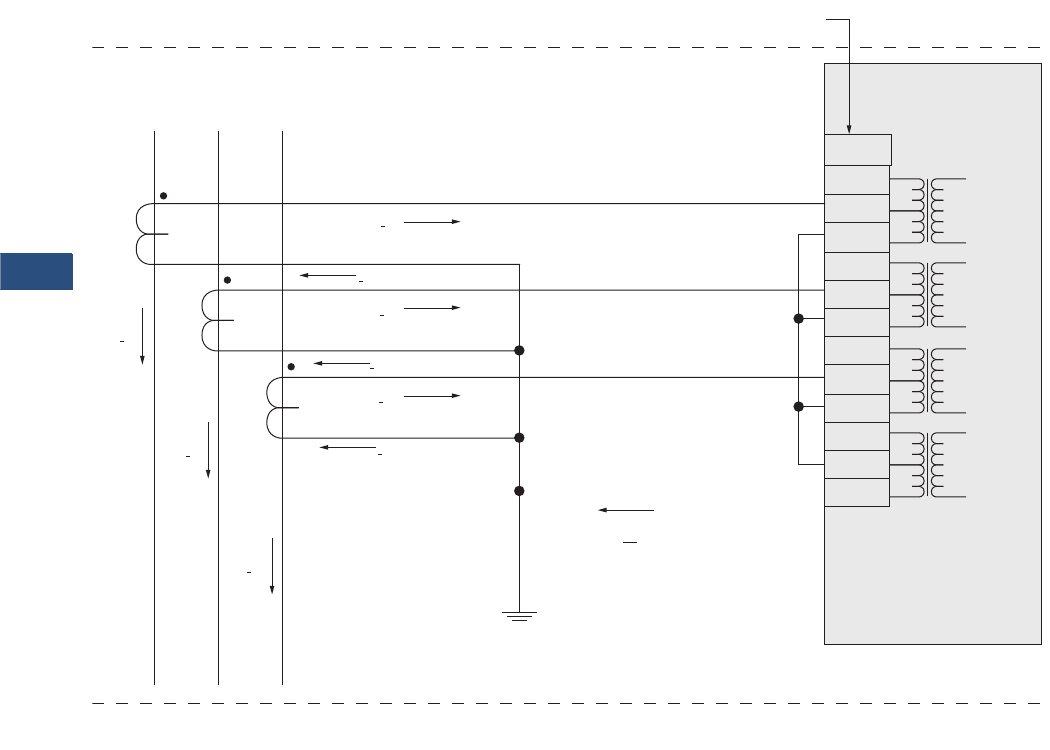
V3-T9-234 Volume 3—Power Distribution and Control Assemblies CA08100004E—November 2013 www.eaton.com
9
9
9
9
9
9
9
9
9
9
9
9
9
9
9
9
9
9
9
9
9
9
9
9
9
9
9
9
9
9
9.4
Metering Devices, Protective Relays, Software and Connectivity
Protective Relays
Wiring Diagrams
EDR-3000
Connection Example Clockwise Rotating Field
EDR3000 => Terminal Markings X3.
Three-Phase Current Measurement; Inom Secondary = 5A
Ground Current Measuring via Residual Connection; IGnom Secondary = 5A
ABC
IA
IA’
IB’
IB’
IA
IB
IC
IC’
IC’
IX’
X3.
1
2
3
4
5
6
7
8
9
10
11
12
1A
5A
N
1A
5A
N
1A
5A
N
1A
5A
N
1A
1B
1C
1X
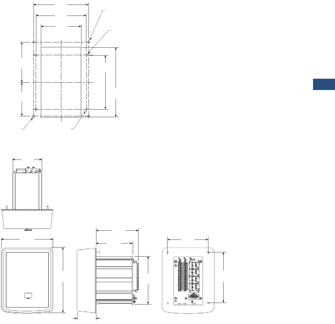
Volume 3—Power Distribution and Control Assemblies CA08100004E—November 2013 www.eaton.com V3-T9-235
9
9
9
9
9
9
9
9
9
9
9
9
9
9
9
9
9
9
9
9
9
9
9
9
9
9
9
9
9
9
9.4
Metering Devices, Protective Relays, Software and Connectivity
Protective Relays
Dimensions
Approximate Dimensions in Inches (mm)
Drilling Pattern
Projection Mounting
3.94
(100.0)
C
L
4.94
(125.5)
5.38
(136.7)
C
L
Cutout
“B” Holes for
Projection
Panel Mount
“A” Holes for
Standard
Panel Mount
B
A
B
A
B
A
B
A
3.62
(91.8)
3.05
(77.6)
6.30
(160.0)
4.88
(124.0)
4x ø0.19
(ø4.8)
4x ø0.19
(ø4.8)
3.82
(97.0)
6.82
(173.2)
5.38
(136.7)
2.50
(63.5)
4.80
(121.9)
5.56
(141.1)
6.67
(169.4)
8.62
(218.9)
6.14
(156.0)
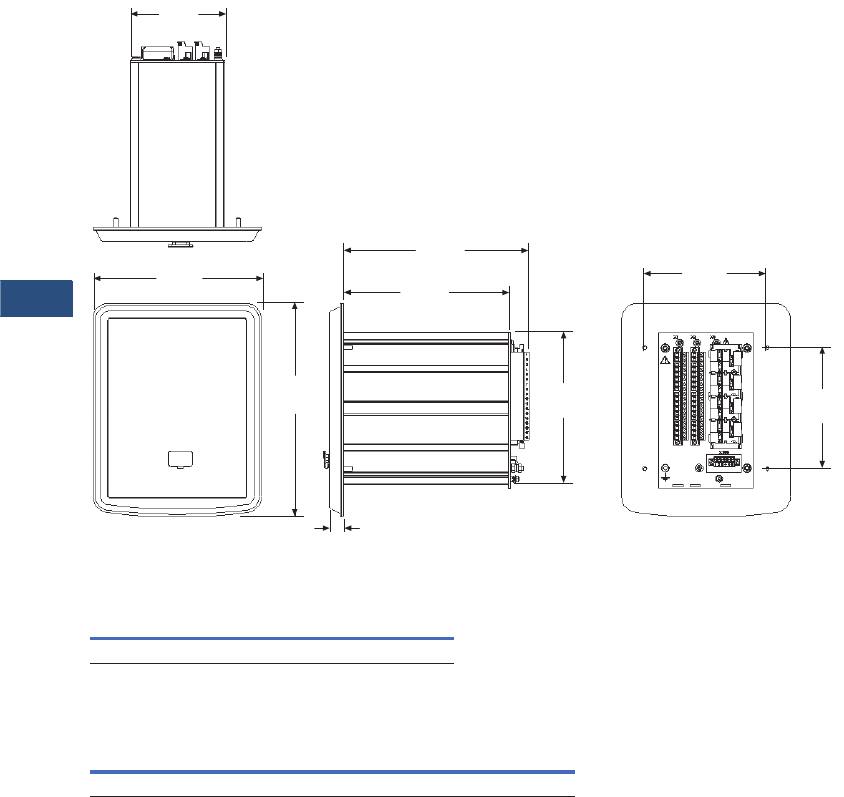
V3-T9-236 Volume 3—Power Distribution and Control Assemblies CA08100004E—November 2013 www.eaton.com
9
9
9
9
9
9
9
9
9
9
9
9
9
9
9
9
9
9
9
9
9
9
9
9
9
9
9
9
9
9
9.4
Metering Devices, Protective Relays, Software and Connectivity
Protective Relays
Approximate Dimensions in Inches (mm)
Standard Mounting
EDR-3000
EDR-3000 Housing B1
Notes
1Depth behind panel with projection mounted enclosure.
2Includes terminals.
Width Height Depth
6.82 (173.2) 8.62 (218.9) 7.49 (190.2) 1
Width Height Depth
Shipping Weight
Lbs (kg)
5.57 (141.5) 7.21 (183.0) 8.19 (208.0) 25.3 (2.4)
3.82
(97.0)
6.82
(173.2)
4.94
(125.5)
0.56
(14.2)
6.74
(171.2)
7.49
(190.4)
4.88
(124.0)
8.62
(218.9)
6.14
(156.0)

Volume 3—Power Distribution and Control Assemblies CA08100004E—November 2013 www.eaton.com V3-T9-237
9
9
9
9
9
9
9
9
9
9
9
9
9
9
9
9
9
9
9
9
9
9
9
9
9
9
9
9
9
9
9.4
Metering Devices, Protective Relays, Software and Connectivity
Protective Relays
ETR-4000
Contents
Description Page
Product Selection Guide. . . . . . . . . . . . . . . . . . . . . V3-T9-158
FP-6000 Feeder Protection. . . . . . . . . . . . . . . . . . . V3-T9-162
FP-5000 Feeder Protection. . . . . . . . . . . . . . . . . . . V3-T9-172
FP-4000 Feeder Protection. . . . . . . . . . . . . . . . . . . V3-T9-180
MP-3000 Motor Protection. . . . . . . . . . . . . . . . . . . V3-T9-188
MP-4000 Motor Protection. . . . . . . . . . . . . . . . . . . V3-T9-198
MD-3000 Motor/Generator Differential Relay. . . . . V3-T9-204
Digitrip 3000. . . . . . . . . . . . . . . . . . . . . . . . . . . . . . V3-T9-207
VR-300 Multifunctional Voltage Relay . . . . . . . . . . V3-T9-217
DP-300 Current Differential Protection Relay . . . . . V3-T9-221
EDR-3000 Feeder Protection . . . . . . . . . . . . . . . . . V3-T9-226
ETR-4000 Transformer Protection Relay
Features, Benefits and Functions . . . . . . . . . . . V3-T9-238
Catalog Number Selection . . . . . . . . . . . . . . . . V3-T9-241
Technical Data and Specifications . . . . . . . . . . . V3-T9-241
Dimensions . . . . . . . . . . . . . . . . . . . . . . . . . . . . V3-T9-248
Ground Fault Relay . . . . . . . . . . . . . . . . . . . . . . . . . V3-T9-250
Universal RTD Module . . . . . . . . . . . . . . . . . . . . . . V3-T9-254
IQ 125 Volt DC Power Supply . . . . . . . . . . . . . . . . . V3-T9-258
ETR-4000 Transformer Protection Relay
Product Description
Eaton’s ETR-4000
transformer protection
relay is a multi-functional,
microprocessor-based relay
for two winding transformers
of all voltage levels. The
ETR-4000 provides phase and
ground percentage restrained
differential protection using
a variable dual slope
characteristic with phase,
negative, residual and neutral
overcurrent elements for
backup protection. It can also
be used to provide restrained
differential protection to large
motors and generators.
The ETR-4000 has eight
current inputs rated for either
5 amperes or 1 ampere to
monitor both sides of the
transformers. The CTs can
be connected in wye in both
sides of the transformer;
the relay automatically
compensates for the
connection of the transformer
and CT mismatch errors.
The maintenance mode
password protected soft key,
can be used for arc flash
mitigation to change to an
alternate settings group,
set to have instantaneous
elements only.
An integral keypad and
display is provided for direct
user programming and
retrieval of data without
the need of a computer.
14 programmable LEDs
provide quick indication of
relay status.
A front port is provided for
direct computer connection.
An RS-485 communication
port on the back is standard
for local area networking
using Modbus-RTU. An
optional Ethernet port and
protocols are available.
Flash memory is used for the
programming and all settings
are stored in nonvolatile
memory. The relay allows for
four preprogrammed setting
groups which can be
activated through software,
the display or a contact input.
The ETR-4000 transformer
protection relay has mass
memory for data storage and
a real-time clock with 1 ms
time resolution. The relay will
log 300 sequence of event
records, 20 detailed trip logs,
minimum/maximum values,
load profiles, breaker wear
information and oscillography
data.
The ETR-4000 has eight
programmable binary inputs,
4 normally opened and
4 Form C heavy duty outputs
and one Form C signal alarm
relay. It can be powered from
19 Vdc to 300 Vdc or 40 Vac
to 250 Vac auxiliary power.
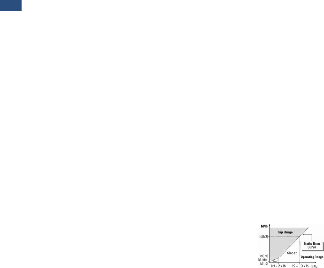
V3-T9-238 Volume 3—Power Distribution and Control Assemblies CA08100004E—November 2013 www.eaton.com
9
9
9
9
9
9
9
9
9
9
9
9
9
9
9
9
9
9
9
9
9
9
9
9
9
9
9
9
9
9
9.4
Metering Devices, Protective Relays, Software and Connectivity
Protective Relays
Features, Benefits and Functions
●Flexible phase and ground
differential protection for
two winding transformers,
large motors and
generators
●Complete protection and
control in a single compact
case to reduce panel
space, wiring and costs
●Integral test function
reduces maintenance
time and expense
●Zone selective interlocking
improves coordination and
tripping time, and saves
money compared to a
traditional bus differential
scheme
●Reduce troubleshooting
time and maintenance
costs. Trip and event
recording in non-volatile
memory provides detailed
information for analysis
and system restoration.
6000 cycles of waveform
capture aids in post fault
analysis (viewable using
PowerPort-E software)
●Minimum replacement
time. Removable terminal
blocks ideal for industrial
environments
●Front RS-232 port and
PowerPort-E software
provides local computer
access and user-friendly
Windows-based interface
for relay settings,
configuration and
data retrieval
●Breaker open/close from
relay faceplate or remotely
via communications
●Fast an easy
troubleshooting, improved
maintenance procedures
and increased device
security. Provides detailed
traceability for system
configuration changes
●Relays self-diagnostics and
reporting improves uptime
and troubleshooting
●Breaker trip circuit
monitoring improves the
reliability of the breaker
operation
Features
Protection Features
●Dual-slope percentage
restrained current
differential with
magnetizing inrush and
overexcitation blocking
(87R)
●Unrestrained current
differential (87H)
●Restricted ground fault/
Ground Differential (87GD)
●Phase overcurrent
(elements can be assigned
to either side of the
transformer):
●Four instantaneous
elements with timers
(50P[1], 50P[2], 50P[3]
and 50P[4])
●Four inverse time
overcurrent elements
(51P[1], 51P[2], 51P[3]
and 51P[4])
●11 standard curves
●Inrush Blocking
●Instantaneous or time
delay reset
●Negative sequence phase
overcurrent (elements can
be assigned to either side
of the transformer):
●Two inverse time
overcurrent elements
(51Q[1] and 51Q[2])
●11 standard curves
●Instantaneous or time
delay reset
●Ground overcurrent
(elements can be assigned
to either side of the
transformer):
●Two instantaneous
measured elements
with timers (50X[1]
and 50X[2])
●Two instantaneous
calculated elements
with timers (50R[1]
and 50R[2])
●Two inverse time
overcurrent measured
elements (51X[1]
and 51X[2])
●Two inverse time
overcurrent calculated
elements (51R[1]
and 51R[2])
●11 standard curves
●Instantaneous or time
delay reset
●Two breaker failure
elements (50BF[1]
and 50BF[2])
●Phase transformer
overload protection (49)
●Switch onto fault
protection
●Cold load pickup
●Zone interlocking for bus
protection (87B)
Metering Features
●Amperes: positive,
negative and zero
sequence
●Ampere demand
●Current phase angles
●% THD I
●Magnitude THD I
●Minimum/maximum
recording
●Trending
●RTD Temperatures with
remote URTD
Monitoring Features
●Trip coil monitor for both
primary and secondary
breakers
●Breaker wear primary and
secondary (accumulated
interrupted current)
●Oscillography
(6000 cycles total)
●Fault data logs
(up to 20 events)
●Sequence of events report
(up to 300 events)
●Clock (1 ms time stamping)
Control Functions
●Breaker open/close both
breakers
●Remote open/close
●Programmable I/O
●Programmable LEDs
●Multiple setting groups
●Cold load pickup
●CT supervision
Communication Features
●Local HMI
●Password protected
●Addressable
●IRIG-B
●Local communication port
●Remote communication
port:
●RS-232
●RS-485
●Protocols:
●Modbus-RTU
●Modbus-TCP (Optional)
●Configuration software
Protection and
Control Functions
Eaton’s ETR-4000
transformer protection
relay has been designed for
maximum user flexibility and
simplicity. The ETR-4000 is
suitable for application on
small, medium and large two
winding power transformers.
Multiple current inputs are
used to provide primary
protection, control and
back-up protection of
transformers, including
current differential, restricted
ground differential and
overcurrent protection.
Dual-Slope Percent Differential
Protection
The primary protective
element for transformer
protection is the percent
differential element, which
compares the current
entering the primary and
leaving the secondary of the
transformer. The ETR-4000
has built in compensation
for the turns-ratio and the
phase shift of the
transformer, so it's not
necessary to compensate for
the transformer connection
by the connection of the CTs.
The current differential
element looks at the vector
difference between the
current entering and leaving
the zone of protection. If the
difference exceeds a pre-
determined amount, the
element will operate.
The operating characteristic
of the percent differential
element is a dual-slope
characteristic to
accommodate for CT
saturation and CT errors.
Dual-Slope Operating Characteristic
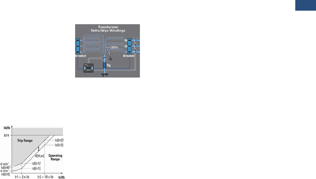
Volume 3—Power Distribution and Control Assemblies CA08100004E—November 2013 www.eaton.com V3-T9-239
9
9
9
9
9
9
9
9
9
9
9
9
9
9
9
9
9
9
9
9
9
9
9
9
9
9
9
9
9
9
9.4
Metering Devices, Protective Relays, Software and Connectivity
Protective Relays
Harmonic Restraints
There are certain conditions
like energizing one side of the
transformer with the other
side de-energized (inrush
currents) or the paralleling
of two transformers
(sympathetic currents) that
can create false differential
currents. These differential
currents if not recognized can
cause a false trip; in the case
of inrush conditions or
sympathetic currents the
differential current is
characterized by a heavy
content of 2nd and 4th
harmonic currents. The
percentage differential
element is desensitize either
permanently (stationary
conditions) or temporarily
(transient conditions),
whenever the 2nd or 4th
harmonic exceed the value
programmed into the relay.
Another condition that can
create a false differential
current is a sudden change of
voltage or frequency, that can
put the transformer in an
overexcitation state. In this
case there is high content of
5th harmonic currents. The
percentage differential
element is also desensitized
when the 5th harmonic
content exceeds a predefined
value.
Dynamic Rise of the Operating
Characteristic
Unrestrained Differential
An unrestrained differential
element is provided for fast
tripping on heavy internal
faults to limit catastrophic
damage to the transformer
and minimize risks to the
remainder of the power
system.
Restricted Ground Fault
Ground differential protection
is applied to transformers
having impedance grounded
wye windings. It is intended
to provide sensitive ground
fault detection for low
magnitude fault currents,
which would not be detected
by the main percent
differential element.
Restricted Ground Fault
Overcurrent Elements
The ETR-4000 can be used
to provide backup for
transformer and adjacent
power system equipment.
Instantaneous overcurrent
elements can be used for fast
clearing of severe internal or
external (through) faults.
Time overcurrent protection
elements per winding allow
coordinating with the
adjacent protection zones and
acting as a backup protection.
There are 11 user-selectable
inverse-time overcurrent
curve characteristics. The
user can select from the
ANSI, IEC or thermal curve
families and can select
instantaneous or time delay
reset characteristics.
Negative Sequence Overcurrent
Since this element does
not respond to balanced
load or three-phase faults,
the negative-sequence
overcurrent element may
provide the desired
overcurrent protection. This
is particularly applicable to
delta-wye grounded
transformers where only
58% of the secondary p.u.
phase-to-ground fault current
appears in any one primary
phase conductor. Backup
protection can be particularly
difficult when the wye is
impedance grounded. A
negative-sequence element
can be used in the primary
supply to the transformer and
set as sensitively as required
to protect for secondary
phase-to-ground or phase-to-
phase faults. This element
should be set to coordinate
with the low-side phase and
ground relays for phase-to-
ground and phase-to-phase
faults. The negative
sequence element must
also be set higher than the
negative-sequence current
due to unbalanced loads.
Breaker Failure
The ETR-4000 transformer
protection relay includes two
breaker failure (50BF, 62BF)
elements that can be initiated
from either an internal or
external trip signal. These are
independent elements that
can be used to operate a
lockout relay or trip an
upstream breaker. The timer
must be longer than the
breaker operating time and
the protective function
reset times.
Maintenance Mode
The Maintenance Mode can
improve safety by providing a
simple and reliable method to
reduce fault clearing time and
lower incident energy levels
at energized panels. The
Maintenance Mode allows
the user to switch to more
sensitive settings via a
password protected soft
key, communications or
via a digital input while
maintenance work is being
performed at an energized
panel or device. The more
sensitive settings provide
greater security for
maintenance personnel and
helps reduce the possibility
of injury.
Monitoring and Metering
Sequence of Events Records
The ETR-4000 protection
relay records a maximum
of 300 events associated with
the relay. An event is
classified as a change of state
as detected by the relay.
These include relay pickups,
dropouts, trips, contact
closure, alarms, setting
changes and self-diagnostic
failures. Each event is date
and time stamped to a 1 ms
resolution. The events are
stored in a FIFO in
chronological order.
Trip Log
The ETR-4000 protection
relay will store a maximum of
20 trip records in a FIFO trip
log. Each trip record will be
date and time stamped to a
1 ms resolution. The trip
log record will include
information on the type of
fault, protection elements
that operated, fault location
and currents at the time of
the fault.
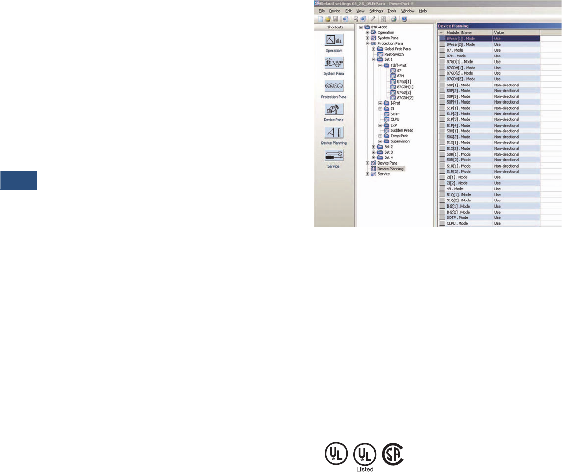
V3-T9-240 Volume 3—Power Distribution and Control Assemblies CA08100004E—November 2013 www.eaton.com
9
9
9
9
9
9
9
9
9
9
9
9
9
9
9
9
9
9
9
9
9
9
9
9
9
9
9
9
9
9
9.4
Metering Devices, Protective Relays, Software and Connectivity
Protective Relays
Waveform Capture
The ETR-4000 transformer
protection relay provides
oscillography-recording
capabilities. The relay will
record all measured signals
along with the binary signals
of pickup, trip, logic and
contact closures. The ETR-
4000 relay can record up to
6000 cycles of data. The
number of records is
proportional to the size of
each record; the maximum
size per record is 600 cycles.
The waveform capture is
initiated by up to 8 different
triggers; it can also be
generated manually through
the display or via
communications.
Integral User Interface
The front panel user interface
has a 128 x 64 pixel LCD
display with background
illumination for wide angle
viewing in all light conditions.
14 programmable LEDs
provide quick and easy visual
display of power on, mode
of operation, alarm and trip
indication. Soft keys are
provided for operation mode
selection, scrolling through
data and settings. In addition,
the relay settings and test
functions are password
protected.
Programmable I/O
The ETR-4000 transformer
protection relay provides
heavy-duty, trip-rated, 4
normally open and 4 Form C
contacts. Two isolated inputs
can be used for monitoring
the trip circuits. One Form C
contact is dedicated to the
relay failure alarm function
and is operated in a normally
energized (fail-safe) mode.
There are eight user-
configurable discrete inputs
that accept a wet contact
and can operate through a
wide range of power. Each
input and output is user-
programmable for maximum
application flexibility.
Communication Software
Eaton provides two types of
communication software. The
first is PowerPort-E. It runs
on a PC or laptop for easy
access to a single relay
to change set points or
configuration and to view
metered values and stored
data. PowerPort-E is free
and can be downloaded from
the Eaton Web site at the
following URL:
http://www.eaton.com/pr
The second package is
Power Xpert Software.
Power Xpert Software is a
power management software
package that is designed
for continuous, remote
monitoring of many devices.
It provides additional
functions such as billing,
trending and graphics.
Contact your local Eaton
representative for more
information on Power
Xpert Software.
PowerPort-E- ETR-4000 Device Planning
Standards and Certifications
Design Standards
●Generic Standard:
●EN 61000-6-2
●EN 61000-6-3
●Product Standard:
●IEC 60255-6
●EN 50178
●UL 508 (Industrial
Control Equipment)
●CSA C22.2 No. 14-95
(Industrial Control
Equipment)
●ANSI C37.90
●UL listed file: E217753

Volume 3—Power Distribution and Control Assemblies CA08100004E—November 2013 www.eaton.com V3-T9-241
9
9
9
9
9
9
9
9
9
9
9
9
9
9
9
9
9
9
9
9
9
9
9
9
9
9
9
9
9
9
9.4
Metering Devices, Protective Relays, Software and Connectivity
Protective Relays
Catalog Number Selection
The catalog number
identification chart defines
the electrical characteristics
and operation features
included in the ETR-4000.
For example, if the catalog
number were ETR-3000A0BA1,
the device would have the
following:
ETR-4000
(A)–8 Digital Inputs,
9 Output Relays
(0)–5A/1A phase and ground
CTs, Power Supply Range:
19-300 Vdc, 40–250 Vac
(B)–Modbus-RTU (RS-485)
(A)–Without Conformal
Coating
(1)–Projection Panel Mount
ETR-4000 Eaton Transformer Protection Relay
Technical Data and Specifications
Climatic Environmental
Conditions
●Storage temperature:
–22°F to 158°F (–30°C
to +70°C)
●Operating temperature:
–40°F to 140°F (–40°C 2
to +60°C)
●Permissible humidity at
ann. average: <75% rel.
(on 56d up to 95% rel.)
●Permissible installation
altitude:
●6,561.67 ft (<2,000m)
above sea level
●If 13,123.35 ft (4,000m)
altitude applies, a
changed classification
of the operating and test
voltages may be
necessary
Degree of Protection EN 60529
●HMI front panel with
seal: IP54
●Rear side terminals: IP30
Routine Test
●Insulation test according to
IEC 60255-5: All tests to be
carried out against ground
and other input and output
circuits
●Aux. voltage supply, digital
inputs: 2.5 kV (eff.)/50 Hz
●Current measuring inputs,
signal relay outputs: 2.5 kV
(eff.)/50 Hz
●Voltage measuring inputs:
3.0 kV (eff.)/50 Hz
●All wire-bound
communication interfaces:
1. 5 k V D C
Housing
●Material, housing:
Aluminum extruded
section
●Material, front panel:
Aluminum/foil front
●Mounting position:
Horizontal (±45° around
the X-axis must be
permitted)
Plug-in Connector with
Integrated Short-Circuiter
(Conventional Current Inputs)
●Nominal current: 1A and
5A
●Continuous loading
capacity: 4 x In/
continuously
●Overcurrent withstand:
●30 x In/10s
●100 x In/1s
●250 x In/10 ms
(1 half-wave)
●Screws: M4, captive type
acc. to VDEW
●Connection cross sections:
●2 x AWG 14 (1 x or 2 x
2.5 mm2) with wire
end ferrule
●2 x AWG 12 (1 x or 2 x
4.0 mm2) with ring cable
sleeve or cable sleeve
●2 x AWG 10 (1 x or 2 x
6 mm2) with ring cable
sleeve or cable sleeve
Control Power Supply
●Aux. voltage: 24–270 Vdc/
48–230 Vac (–20/+10%)
●Buffer time in case of
supply failure: >= 50 ms
at minimal aux. voltage
interrupted communication
is permitted
●Maximum permissible
making current:
●18A peak value for
<0.25 ms
●12A peak value for
<1 ms
●The voltage supply must
be protected by a fuse of:
●2.5A time-lag miniature
fuse approx. 0.2 x 0.8 in.
(5 x 20 mm) according to
IEC 60127
●3.5A time-lag miniature
fuse approx. 0.25 x
1.25 in. (6.3 x 32 mm)
according to UL 248-14
Notes
1Consult factory for the availability of
4 Inputs/5 Outputs, 8 Inputs/5 Outputs
and sensitive ground.
2Display will stop working at –20°C.
Hardware Option 1
A = 8 DI, 9 outputs, removable terminals,
2 zone interlocking, URTD interface, IRIG-B,
small display
B = 4 DI, 5 outputs, removable terminals,
IRIG-B, small display 1
C = 8 DI, 5 outputs, removable terminals,
1 zone interlocking, IRIG-B, small display 1
ETR4000 A 0 B A 1
Communication Options
B= Modbus-RTU (RS-485)
1= Modbus-RTU (RS-485) +
Modbus-TCP (RJ-45)
Conformal Coating
Options
A = None
B = Conformal coated
circuit boards
Mounting Options
0 = Standard mount
1 = Projection panel mount
Hardware Option 2
0 = Phase current 5A/1A, ground
current 5A/1A, power supply
range: 19–300 Vdc,
40–250 Vac
1 = Phase current 5A/1A sensitive
ground current, 0.5A/0.1A,
power supply range:
19–300 Vdc, 40–250 Vac

V3-T9-242 Volume 3—Power Distribution and Control Assemblies CA08100004E—November 2013 www.eaton.com
9
9
9
9
9
9
9
9
9
9
9
9
9
9
9
9
9
9
9
9
9
9
9
9
9
9
9
9
9
9
9.4
Metering Devices, Protective Relays, Software and Connectivity
Protective Relays
Power Consumption
●Power supply range:
19–300 Vdc
●Power consumption
in idle mode—7W
●Maximum power
consumption—13W
●Power supply range:
40–250 Vac (for
frequencies of 40–70 Hz)
●Power consumption
in idle mode—7W
●Maximum power
consumption—13W
Real-Time Clock
●Running reserve of
the real-time clock:
1 year minimum
Display
●Display type: LCD with
LED background
illumination
●Resolution graphics
display: 128 x 64 pixel
●LED type: Two colored—
red/green
●Number of LEDs, housing
B2: 15
Digital Inputs
●Maximum input voltage:
300 Vdc/270 Vac
●Input current: <4 mA
●Reaction time: <20 ms
●Fallback time: <30 ms
(Safe state of the
digital inputs)
●4 switching thresholds:
Un = 24 Vdc, 48 Vdc,
60 Vdc, 110 Vac/Vdc,
230 Vac/Vdc
●Un = 24 Vdc
●Switching threshold
1 ON: Min. 19.2 Vdc
●Switching threshold
1 OFF: Max. 9.6 Vdc
●Un = 48–60 Vdc
●Switching threshold
2 ON: Min. 42.6 Vdc
●Switching threshold
2 OFF: Max. 21.3 Vdc
●Un = 110/120 Vac/Vdc
●Switching threshold
3 ON: Min. 88.0 Vdc/
88.0 Vac
●Switching threshold
3 OFF: Max. 44.0 Vdc/
44.0 Vac
●Un = 230/240 Vac/Vdc
●Switching threshold
4 ON: Min. 184 Vdc/
184 Vac
●Switching threshold
4 OFF: Max. 92 Vdc/
92 Vac
●Terminals: Screw-type
terminal
Current and Ground
Current Measurement
●Nominal currents: 1A/5A
●Max. measuring range:
●Up to 40 x In (phase
currents)
●Up to 25 x In (ground
current standard)
●Up to 2.5 x In (ground
current sensitive)
●Continuous loading
capacity: 4 x In/
continuously
●Overcurrent proof:
●30 x In/10 s
●100 x In/1 s
●250 x In/10 ms
(1 half-wave)
●Power consumption:
●Phase current inputs
–At I
n = 1A
S = 0.15 MVA
–At I
n = 5A
S = 0.15 MVA
●Ground current input
–At I
n = 1A
S = 0.35 MVA
–At I
n = 5A
S = 0.35 MVA
●Frequency range: 50 Hz/
60 Hz ±10%
●Terminals: Screw-type
terminals with integrated
short-circuiters (contacts)
Relay Outputs
●Continuous current:
5A AC/DC
●Maximum make current:
●25A AC/25A DC up to
30V for 4s
●30A/230 Vac according
to ANSI IEEE Std.
C37.90-2005
●30A/250 Vdc according
to ANSI IEEE Std.
C37.90-2005
●Maximum breaking
current:
●5A AC up to 125 Vac
●5A DC up to 30V
(resistive)
●0.3A DC at 300V
●Maximum switching
voltage: 250 Vac/250 Vdc
●Switching capacity:
1250 VA
●Contact type: changeover
contact or normally
open contact
●Terminals: Screw-type
terminals
Supervision Contact (SC)
●Continuous current: 5A at
120/240 Vac or 30 Vdc
●Maximum switch-on
current: 15A at 120/240
Vac or 30 Vdc (max. 4s)
●Maximum breaking
current:
●5A at 120/240 Vac
or 30 Vdc
●0.4A at 125 Vdc
●Contact type:
1 changeover contact
●Terminals: Screw-type
terminals
Time Synchronization IRIG
●Nominal input voltage: 5V
●Connection: Screw-type
terminals (twisted pair)
Front Interface RS-232
●Baud rates: 115,200 baud
●Handshake: RTS and CTS
●Connection: 9-pole
D-Sub plug
RS-485
●Master/slave: Slave
●Connection: 6 screw-
clamping terminals RM 138
MIL (3.5 mm) (terminating
resistors internal)
Zone Interlocking
●Nominal input level: 5V
●Nominal output level: 5V
●Connection: Screw-type
terminals (twisted pair)
Standards
High Voltage Tests (IEC 60255-6)
●High frequency
interference test:
●IEC 60255-22-1 Class 3
– Within one circuit—
1 kV/2s
– Circuit to ground—
2.5 kV/2s
– Circuit to circuit—
2.5 kV/2s
●Insulation voltage test:
●IEC 60255-5, EN 50178
– All circuits to other
circuits and exposed
conductive parts:
2.5 kV (eff.)/50 Hz,
1 min.
– Except interfaces:
1.5 kV DC, 1 min.
– Voltage measuring
input: 3 kV (eff.)/
50 Hz, 1 min.
●Impulse voltage test:
●IEC 60255-5: 5 kV/0.5J,
1.2/50 μs

Volume 3—Power Distribution and Control Assemblies CA08100004E—November 2013 www.eaton.com V3-T9-243
9
9
9
9
9
9
9
9
9
9
9
9
9
9
9
9
9
9
9
9
9
9
9
9
9
9
9
9
9
9
9.4
Metering Devices, Protective Relays, Software and Connectivity
Protective Relays
EMC Immunity Tests
●Fast transient disturbance
immunity test (burst):
●IEC 60255-22-4: Power
supply, mains inputs—
±4 kV, 2.5 kHz
●IEC 61000-4-4 Class 4:
Other in- and outputs—
±2 kV, 5 kHz (coupling
network)
●ANSI C37.90.1: ± 4 kV,
2.5 kHz (coupling clamp)
●Surge Immunity Test:
●IEC 61000-4-5 Class 4
– Within one circuit—
2 kV
– Circuit to ground—
4 kV
●Electrical discharge
immunity test:
●IEC 60255-22-2: Air
discharge—8 kV
●IEC 61000-4-2 Class 3:
Contact discharge—6 kV
●Radiated radio frequency
electromagnetic field
immunity test
●IEC 61000-4-3: 26 MHz –
80 MHz—10 V/m
●Class X: 80 MHz–
1 GHz—35 V/m
●ANSI C37.90.2: 1 GHz– 3
GHz—10 V/m
●Immunity to conducted
disturbances induced by
radio frequency fields:
●IEC 61000-4-6 Class 3:
10 V
●Power frequency magnetic
field immunity test:
●IEC 61000-4-8:
Continues—30 A/m
●Class 4: 3 sec—300 A/m
EMC Emission Tests
●Radio interference
suppression test:
●IEC/CISPR11—
Limit value class B
●Radio interference
radiation test:
●IEC/CISPR11—
Limit value class B
Environmental Tests
Classification
●IEC 60068-1: Climatic—
0/055/56
●IEC 60721-3-1:
●Classification of ambient
conditions (storage)—
1K5/1B1/1C1L/1S1/1M2
but min. –13°F (–25°C)
●IEC 60721-3-2:
Classification of ambient
conditions (transportation)
—2K3/2B1/2C1/2S1/2M2
●IEC 60721-3-3:
Classification of ambient
conditions (Stationary use
at weather protected
locations)—3K6/3B1/3C1/
3S1/3M2 but min. 32°F
(0°C) and 3K8H for 2h
Test ad: Cold
●IEC 60068-2-1:
●Temperature—
–4°F (–20°C)
●Test duration—16h
Test Bd: Dry heat
●IEC 60068-2-2:
●Temperature—
131°F (55°C)
●Relative humidity—
<50%
●Test duration—72h
Test cab: Damp heat
(steady state)
●IEC 60068-2-78:
●Temperature—
104°F (40°C)
●Relative humidity—93%
●Test duration—56d
Test Db: Damp heat (cyclic)
●IEC 60068-2-30:
●Temperature—
131°F (55°C)
●Relative humidity—95%
●Cycles (12 + 12-hour)—2
Mechanical Tests
Test Fc: Vibration response test
●IEC 60068-2-6,
IEC 60255-21-1, Class 1:
●Displacement: (10 Hz–
59 Hz)—0.0014 in.
(0.035 mm)
●Acceleration: (59 Hz–
150 Hz)—0.5 gn
●Number of cycles in
each axis: 1
Test Fc: Vibration endurance test
●IEC 60068-2-6,
IEC 60255-21-1, Class:
●Acceleration: (10 Hz–
150 Hz)—1.0 gn
●Number of cycles in
each axis: 20
Test Ea: Shock test
●IEC 60068-2-27,
IEC 60255-21-2, Class 1
●Shock response test:
5 gn, 11 ms, 3 impulses
in each direction
●Shock resistance test:
15 gn, 11 ms, 3 impulses
in each direction
Test Eb: Shock endurance test
●IEC 60068-2-29,
IEC 60255-21-2, Class 1
●Shock endurance test:
10 gn, 16 ms, 10 00
impulses in each
direction
Test Fe: Earthquake test
●IEC 60068-3-3, KTA 3503,
IEC 60255-21-3, Class 2
●Single axis earthquake
vibration test:
– 3–7 Hz: Horizontal
0.394 in. (10 mm),
1 cycle each axis
– 7–35 Hz Horizontal:
2 gn, 1 cycle each axis
Tolerances
Tolerances of the Real -
Time Clock
●Resolution: 1 ms
●Tol e ran c e:
●<1 minute/month
(68°F [+20°C])
●<±1 ms if synchronized
via IRIG-B
Tolerances of the Measured
Value Acquisition
Phase and ground current
measuring
●Maximum measuring
range:
●Up to 40 x In (phase
currents)
●Up to 25 x In (ground
current standard)
●Up to 2.5 x In (earth
current sensitive)
Note: The precision does not
depend on the nominal value but
is referenced to 100 mA (with In
=1 A) respectively.
500 mA (with In = 5 A)
●Frequency range: 50 Hz /
60 Hz ± 10%
●Accuracy: Class 0.5
●Amplitude Error if I < 1 In:
±0.5% of the rated value
●Amplitude Error if I > In:
±0.5% of the measured
value
●Amplitude Error if I > 2 In:
±1.0% of the measured
value
●Resolution: 0.01A
●Harmonics: Up to 20%
3rd harmonic ±1%
●Up to 20% 5th harmonic
±1%
●Frequency influence:
< ±2% / Hz in the range of
±5 Hz of the parametrized
nominal frequency
●Temperature influence:
< ±1% within the range
of +32°F to +140°F
(0°C to +60°C)

V3-T9-244 Volume 3—Power Distribution and Control Assemblies CA08100004E—November 2013 www.eaton.com
9
9
9
9
9
9
9
9
9
9
9
9
9
9
9
9
9
9
9
9
9
9
9
9
9
9
9
9
9
9
9.4
Metering Devices, Protective Relays, Software and Connectivity
Protective Relays
Protection Elements Tolerances
Notice: The tripping delay relates to the time between alarm
and trip. The tolerance of the operating time relates to the time
between when the measured value has exceeded the threshold
until the protection element is picked up.
Description Tolerance
Differential Protection Stages: 87[x]
Id > 0.1 Id[x] ±3% of the setting value resp. 1% In
Operating time Id > 0.3 x In< 35 ms
Id > 0.5 x In< 25 ms
Id > 1.5 x In< 20 ms
Ground Differential Protection Stages: 87GD[x]
Id > 0.1 Id[x] ±3% of the setting value resp. 1% In
Operating time Ide > 0.3 x In< 35 ms
Ide > 0.5 x In< 25 ms
Ide > 1.5 x In< 20 ms
Overcurrent Protection Elements: 50P[x], 51P[x]
Pickup ±1.5% of the setting value resp. 1% In
Resetting ratio 97% or 0.5% x In
tDEFT
±1% resp. ±10 ms
Operating time Starting from I higher
than 1.1 x I> <+35 ms
Disengaging time <+45 ms
t-Multiplier ±5%
IEC NINV
IEC VINV
IEC EINV
IEC LINV
ANSI MINV
ANSI VINV
ANSI EINV
Flat
It
I2t
I4t
Reset Mode ±1% resp. ±10 ms
IEC NINV
IEC VINV
IEC EINV
IEC LINV
5%
ANSI MINV
ANSI VINV
ANSI EINV
Flat
It
I2t
I4t
Description Tolerance
Ground Current Elements: 50G[x], 50N[x], 51G[x], 51N[x]
Pickup ±1.5% of the setting value resp. 1% In
Resetting ratio 97% or 0.5% x In
t DEFT
±1% resp.
±10 ms
Operating time Starting from IE
Higher than 1.1 x IE> <+35 ms
Disengaging time <+45 ms
t-Multiplier ±5%
IEC NINV
IEC VINV
IEC EINV
IEC LINV
ANSI MINV
ANSI VINV
ANSI EINV
Flat
It
I2t
I4t
Reset mode IEC characteristics
IEC NINV
IEC VINV
IEC EINV
IEC LINV
5%
Reset curves if ANSI characteristics
ANSI MINV
ANSI VINV
ANSI EINV
Flat
It
I2t
I4t
Thermal Replica: ThR
Ib ±2% of the setting value
Resp. 1% In
K
Pickup ThR ±1.5 % of the setting value
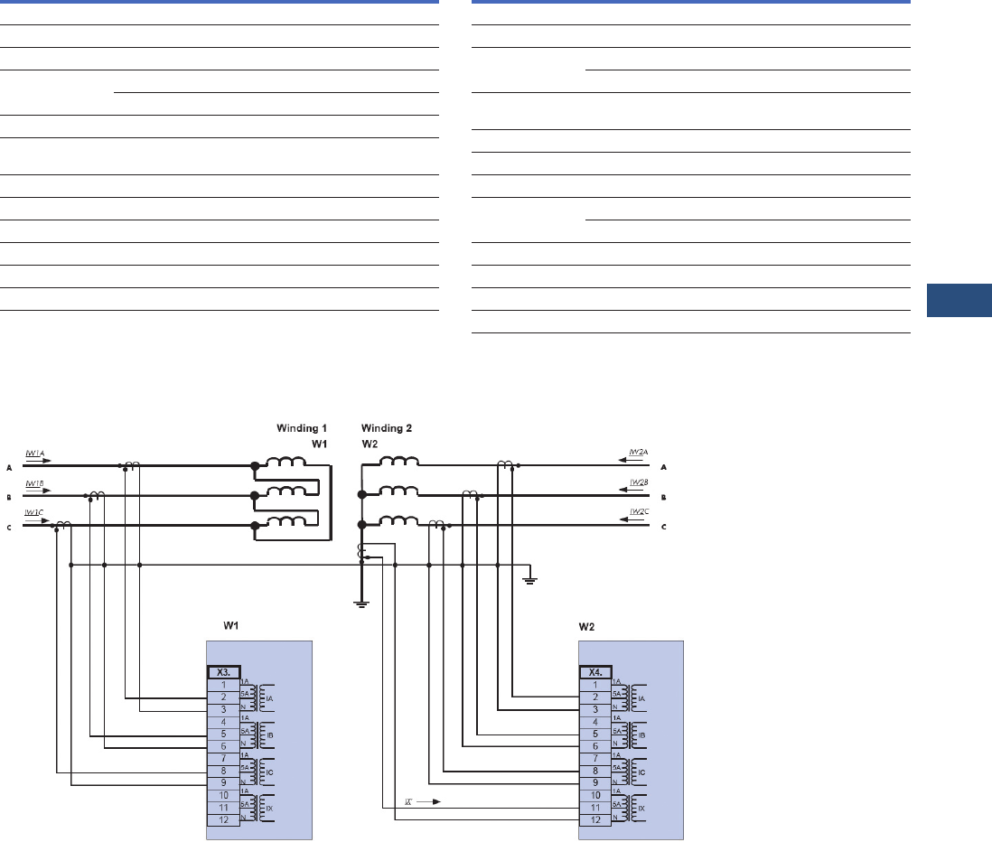
Volume 3—Power Distribution and Control Assemblies CA08100004E—November 2013 www.eaton.com V3-T9-245
9
9
9
9
9
9
9
9
9
9
9
9
9
9
9
9
9
9
9
9
9
9
9
9
9
9
9
9
9
9
9.4
Metering Devices, Protective Relays, Software and Connectivity
Protective Relays
Wiring Diagrams
Typical AC Connections Delta-Wye Transformer with Wye CTs and Neutral CT
Note
1Inrush supervision is possible, if the fundamental
Harmonic > 0.1xIn and 2nd Harmonic > 0.01xIn.
Description Tolerance
Unbalanced Load: 51Q[x]
I2> ±2% of the setting value resp.1% In
Resetting ratio 97% or 0.5% x In
tDEFT
±1% resp.
Tripping delay time (DEFT) ±10 ms
Operating time Starting from I2
higher than 1.3 x I2> <+60 ms
Release time <+40 ms
k±5% INV
T-cool ±5% INV
Inrush Supervision IH2 1
IH2/In±1% In
Resetting ratio 1% x In or 5% x IH2
Description Tolerance
Breaker Failure Protection 50BF
I-BF> ±1.5% of the setting value resp.1% In
Resetting ratio t-BF ±1% resp.
±10 ms
Operating time Starting from I Higher
than 1.3 x I-BF>
<+40 ms
Disengaging time <+40 ms
Trip Circuit Monitoring TCM
t-TCM ±1% resp
±10 ms.
Current Transformer Supervision CTS
Delta ±2% of the setting value resp. 1.5% In
Resetting ratio 94%
t ±1% resp. ± 10 ms
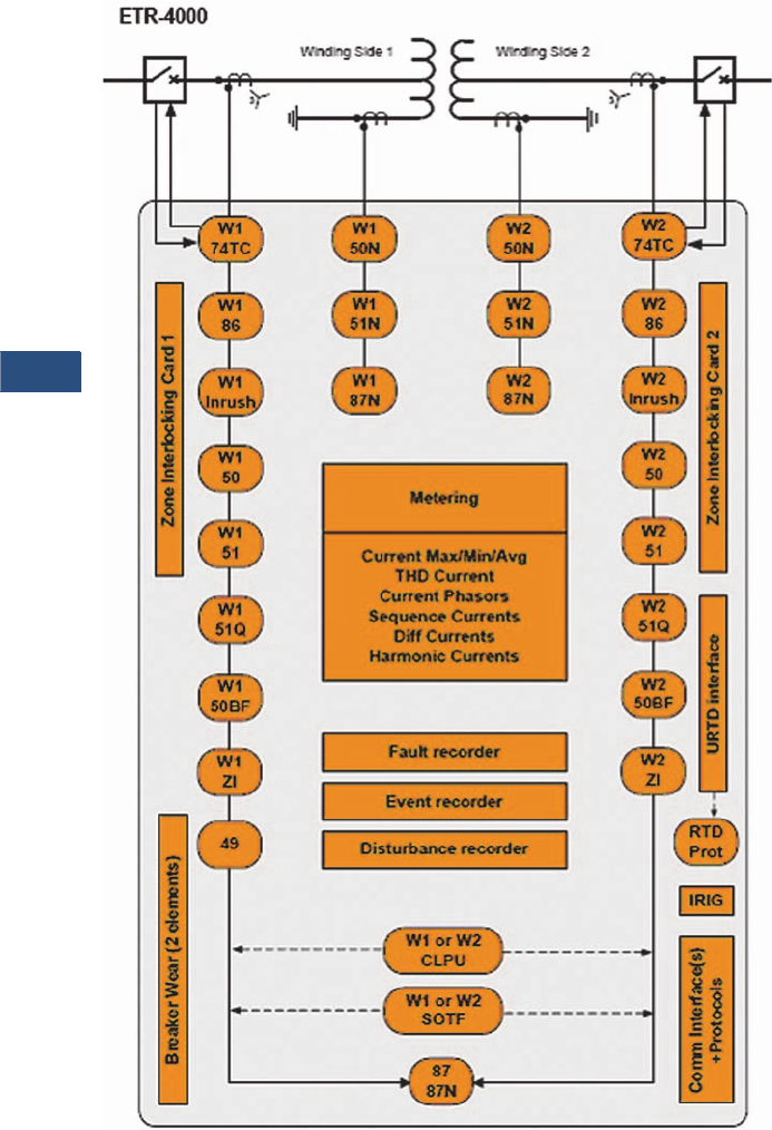
V3-T9-246 Volume 3—Power Distribution and Control Assemblies CA08100004E—November 2013 www.eaton.com
9
9
9
9
9
9
9
9
9
9
9
9
9
9
9
9
9
9
9
9
9
9
9
9
9
9
9
9
9
9
9.4
Metering Devices, Protective Relays, Software and Connectivity
Protective Relays
Typical One-Line Diagram
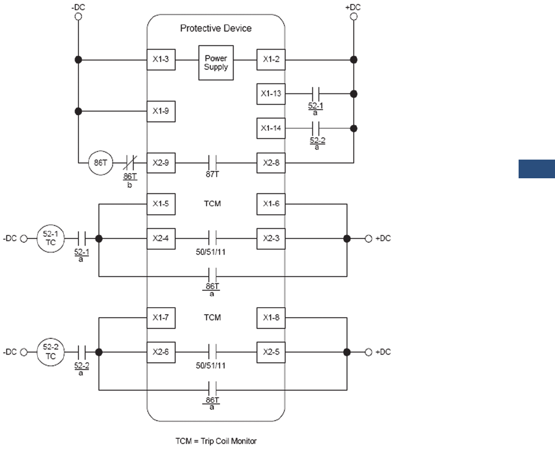
Volume 3—Power Distribution and Control Assemblies CA08100004E—November 2013 www.eaton.com V3-T9-247
9
9
9
9
9
9
9
9
9
9
9
9
9
9
9
9
9
9
9
9
9
9
9
9
9
9
9
9
9
9
9.4
Metering Devices, Protective Relays, Software and Connectivity
Protective Relays
Ty p i c a l C o n t r o l D i a g r a m
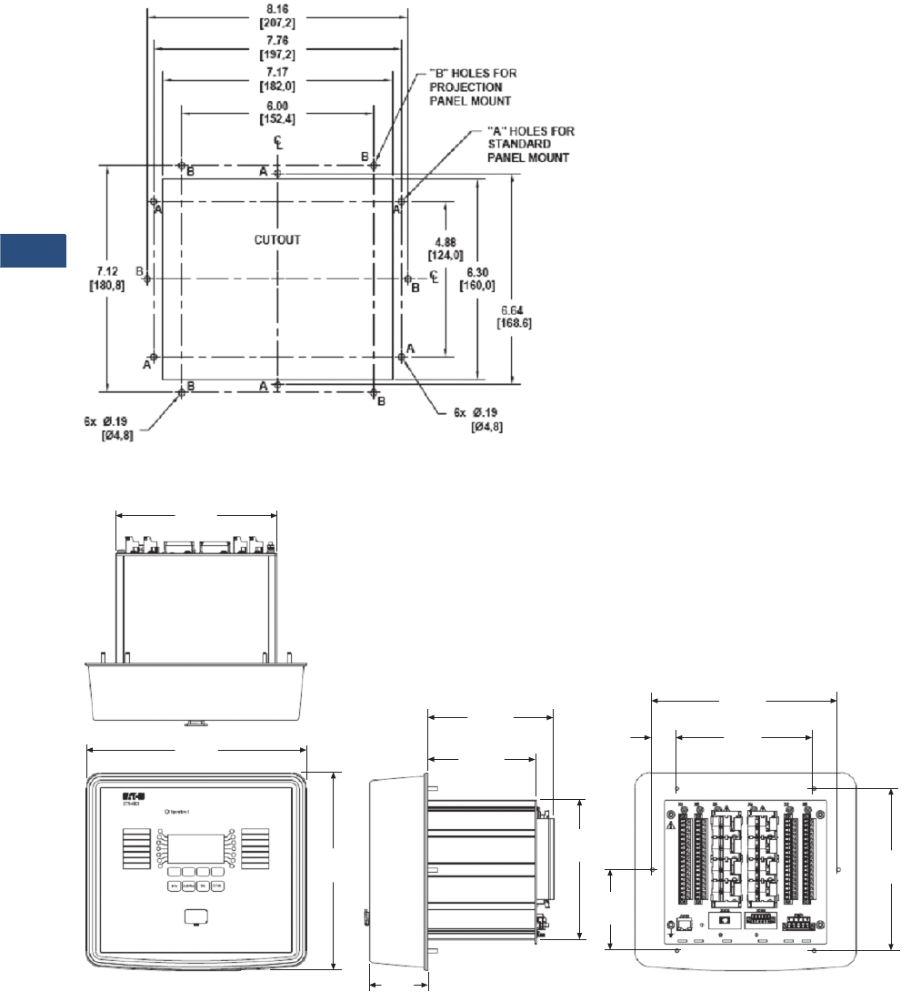
V3-T9-248 Volume 3—Power Distribution and Control Assemblies CA08100004E—November 2013 www.eaton.com
9
9
9
9
9
9
9
9
9
9
9
9
9
9
9
9
9
9
9
9
9
9
9
9
9
9
9
9
9
9
9.4
Metering Devices, Protective Relays, Software and Connectivity
Protective Relays
Dimensions
Approximate Dimensions in Inches (mm)
Drilling Plan
Projection Mount Front and Side Views
7.07
(179.5)
6.00
(152.4)
2.50
(63.5)
4.80
(122.0)
5.56
(141.1)
7. 1 2
(180.8)
8.70
(221.0)
6.14
(156.0)
9.72
(246.9)
8.16
(207.3)
3.56
(90.4)
1.08
(27.4)
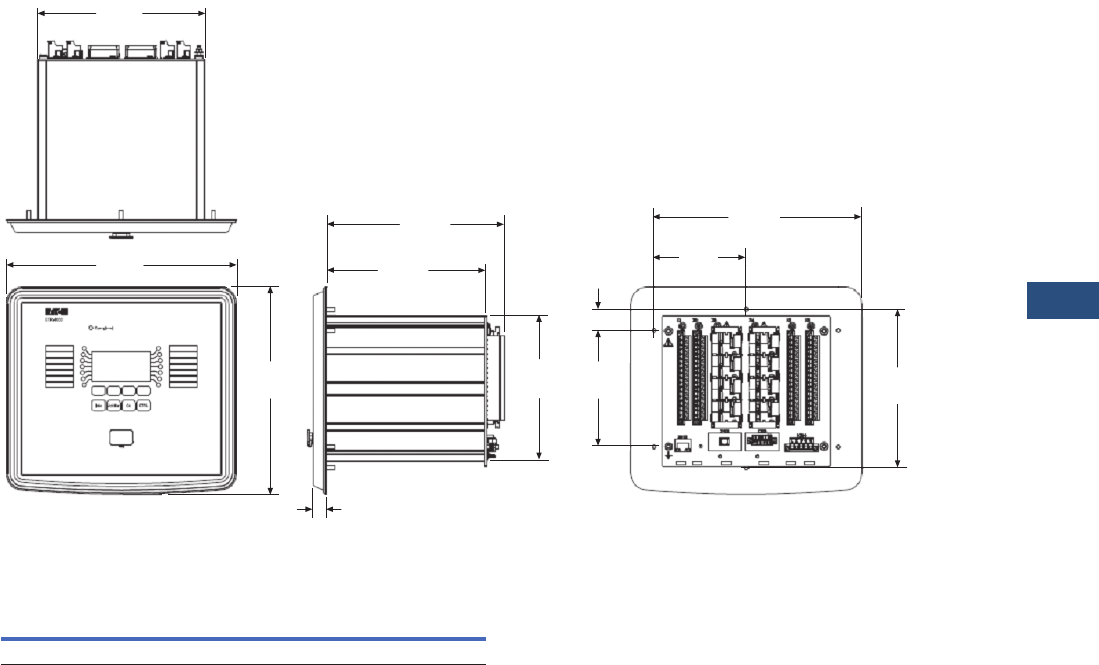
Volume 3—Power Distribution and Control Assemblies CA08100004E—November 2013 www.eaton.com V3-T9-249
9
9
9
9
9
9
9
9
9
9
9
9
9
9
9
9
9
9
9
9
9
9
9
9
9
9
9
9
9
9
9.4
Metering Devices, Protective Relays, Software and Connectivity
Protective Relays
Approximate Dimensions in Inches (mm)
Standard Mount Front and Side Views
ETR-4000 Housing B2
Note
1Includes terminals.
Width Height Depth 1
Shipping Weight
Lbs (kg)
6.81 (173.0) 8.37 (212.7) 8.19 (208.0) 9.3 (4.2)
7.07
(179.5)
3.88
(98.6)
0.56
(14.2)
6.74
(171.2)
7.49
(190.3)
4.94
(125.5)
8.70
(221.0)
6.14
(156.0)
9.72
(246.9)
7.75
(197.0)
4.88
(124.0)
0.88
(22.3)
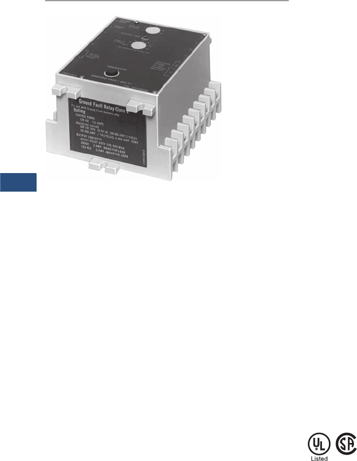
V3-T9-250 Volume 3—Power Distribution and Control Assemblies CA08100004E—November 2013 www.eaton.com
9
9
9
9
9
9
9
9
9
9
9
9
9
9
9
9
9
9
9
9
9
9
9
9
9
9
9
9
9
9
9.4
Metering Devices, Protective Relays, Software and Connectivity
Protective Relays
Ground Fault Relay
Contents
Description Page
Product Selection Guide . . . . . . . . . . . . . . . . . . . . V3-T9-158
FP-6000 Feeder Protection . . . . . . . . . . . . . . . . . . V3-T9-162
FP-5000 Feeder Protection . . . . . . . . . . . . . . . . . . V3-T9-172
FP-4000 Feeder Protection . . . . . . . . . . . . . . . . . . V3-T9-180
MP-3000 Motor Protection . . . . . . . . . . . . . . . . . . V3-T9-188
MP-4000 Motor Protection . . . . . . . . . . . . . . . . . . V3-T9-198
MD-3000 Motor/Generator Differential Relay . . . . V3-T9-204
Digitrip 3000 . . . . . . . . . . . . . . . . . . . . . . . . . . . . . V3-T9-207
VR-300 Multifunctional Voltage Relay . . . . . . . . . . V3-T9-217
DP-300 Current Differential Protection Relay . . . . . V3-T9-221
EDR-3000 Feeder Protection . . . . . . . . . . . . . . . . . V3-T9-226
ETR-4000 Transformer Protection Relay . . . . . . . . V3-T9-237
Ground Fault Relay
Options and Accessories . . . . . . . . . . . . . . . . . V3-T9-252
Technical Data and Specifications . . . . . . . . . . . V3-T9-253
Universal RTD Module . . . . . . . . . . . . . . . . . . . . . . V3-T9-254
IQ 125 Volt DC Power Supply. . . . . . . . . . . . . . . . . V3-T9-258
Ground Fault Relay
Product Description
A Type GFR ground fault
protection system, when
properly installed on a
grounded electrical system,
will sense phase-to-ground
fault currents. When the level
of fault current is in excess
of the pre-selected current
pickup and time delay
settings, the GFR relay will
initiate a trip action of a
disconnect device, which will
open the faulted circuit and
clear the fault.
The GFR devices are UL
Class 1 devices designed to
protect electrical equipment
against extensive damage
from arcing ground faults.
A basic Type GFR ground
fault protection system
consists of a ground fault
relay, a ground fault current
sensor and a disconnect
device equipped with a shunt
trip device. This disconnect
device can be a molded case
circuit breaker, a power
circuit breaker, a bolted
pressure switch or other
fusible disconnect device,
suitable for application with
UL Class 1 Ground Fault
Sensing and Relaying
equipment.
Standards and Certifications
Eaton’s GFR ground fault
relays, current sensors, test
panels and accessory devices
are UL listed by Underwriters
Laboratories in accordance
with their standard for
Ground Fault Sensing and
Relaying Equipment, UL 1053,
under File No. E48381.
Note: Relays are also listed with
CSA under File No. 43357.
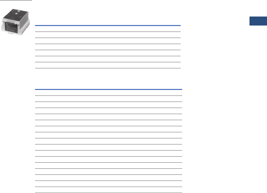
Volume 3—Power Distribution and Control Assemblies CA08100004E—November 2013 www.eaton.com V3-T9-251
9
9
9
9
9
9
9
9
9
9
9
9
9
9
9
9
9
9
9
9
9
9
9
9
9
9
9
9
9
9
9.4
Metering Devices, Protective Relays, Software and Connectivity
Protective Relays
Product Selection
Each installation requires:
●One relay unit (select trip
ampere as required)
●One current sensor (select
configuration required)
●One circuit breaker or
disconnect device with
shunt trip, or a shunt trip
attachment for mounting
in existing breaker
●Test panel (optional)
GFR Relay
Current Sensor
Note
1 Suitable for either surface or semi-flush mounting.
Ground Fault Pickup Amperes
1–12 5–60 100–1200
GFR Relay
Types
Catalog
Number 1
Catalog
Number 1
Catalog
Number 1
For 120 Volt 50/60 Hz Control
Electrical reset with zone interlocking GFR12EI GFR60EI GFR1200EI
Electrical reset without zone interlocking GFR12E GFR60E GFR1200E
Mechanical reset with zone interlocking GFR12MI GFR60MI GFR1200MI
Mechanical reset without zone interlocking GFR12M GFR60M GFR1200M
For 120 Vdc Control
Mechanical reset without zone interlocking — — GFR1200MD
Description—Window Size in Inches (mm)
Catalog
Number
Used with Relays Rated 1–12 Amperes
5.50 (139.7) inside diameter 1283C45G01
Used with Relays Rated 5–60 Amperes
2.50 (63.5) inside diameter 179C768G01
5.50 (139.7) inside diameter 1256C13G01
7.81 x 11.00 (198.4 x 279.4) rectangular 11257C88G04
3.31 x 24.94 (84.1 x 760.5) rectangular 11257C92G03
Used with Relays Rated 100–1200 Amperes
2.50 (63.5) inside diameter 179C768G02
5.50 (139.7) inside diameter 1256C13G02
8.25 (209.6) inside diameter 179C767G02
7.81 x 11.00 (198.4 x 279.4) rectangular 11257C88G03
9.94 x 16.94 (252.5 x 430.3) rectangular 11257C90G02
9.94 x 23.94 (252.5 x 608.1) rectangular 11257C91G02
15.94 x 19.94 (404.9 x 506.4) rectangular 11257C89G02
3.31 x 24.94 (84.1 x 633.5) rectangular 11257C92G04
6.75 x 29.64 (171.5 x 752.9) rectangular 11255C39G03
GFR Relay

V3-T9-252 Volume 3—Power Distribution and Control Assemblies CA08100004E—November 2013 www.eaton.com
9
9
9
9
9
9
9
9
9
9
9
9
9
9
9
9
9
9
9
9
9
9
9
9
9
9
9
9
9
9
9.4
Metering Devices, Protective Relays, Software and Connectivity
Protective Relays
Options and Accessories
Test Panel (120 Vac)
Used to test the ground fault
system, to give an indication
the relay has tripped the
breaker, and to reset the relay
after tripping. These functions
may be separately mounted
pilot devices.
Note: When a mechanically reset
relay is used with a test panel,
both the relay and test panel
must be reset following either a
simulated ground fault test or
actual ground fault. Not UL listed.
Ground Fault Warning Indicator
This is an accessory item for
use with GFR relays with
interlocking circuitry. At
approximately 30–50% of
the relay pickup setting, the
indicator switches separate
120 Vac control power to a
lamp or relay (not included) to
give an indication of a ground
fault. The indicator is rated
110/120 Vac 50/60 Hz for a
maximum indicator load of
0.5 amperes.
Indicating Ammeter
The optional indicating
ammeter connects to the
sensor terminals through
a momentary contact
pushbutton, and will indicate
(in amperes) any ground fault
current flowing through the
sensor. Kit includes the
ammeter and pushbutton.
Not UL listed.
Shunt Trip Attachments
Use 120 Vac shunt trips.
Face Plate
Recommended when
these relays are semi-flush
mounted, to close the door
cutout opening.
Options
Additional optional equipment
can be added to the protection
system to meet the
requirements of the specifying
engineer, including:
●Ground fault test panel
●Ground fault warning
indicator relay
●Ground fault indicating
ammeter
GFR relays are available with
zone selective interlocking
circuitry to interlock several
relays within the same system.
This allows the relay,
which detects a ground
fault, to instantly clear
the fault by tripping the
disconnect device. The relay
simultaneously sends a signal
to relay units “upstream” from
the fault to time delay or
to block their operation
completely. Current sensors
in various designs provide a
range of “window” sizes to
accommodate standard bus
and cable arrangements.
Shunt trip attachments may be
ordered for field mounting in
Eaton’s molded case circuit
breakers, or may be ordered
factory installed in the breaker.
Optional Test Panel
Ground Fault Warning Indicator
Ammeter Kit
Face Plate
Note
1One end removable for installation.
Instruction Leaflet 15321 available as a PDF at www.eaton.com (Go to Advanced Search and enter 15321).
Control Test
Catalog
Number
120 volt 50/60 Hz 120 volt 50/60 Hz GFRTP
Description
Catalog
Number
Manual reset 1234C67G01
Self-resetting 1234C67G02
GFR System
Used with
Kit Catalog
Number
1–12 amperes 752B820G01
5–60 amperes 752B820G02
100–1200 amperes 752B820G03
Description
Catalog
Number
Face plate 752B410G01

Volume 3—Power Distribution and Control Assemblies CA08100004E—November 2013 www.eaton.com V3-T9-253
9
9
9
9
9
9
9
9
9
9
9
9
9
9
9
9
9
9
9
9
9
9
9
9
9
9
9
9
9
9
9.4
Metering Devices, Protective Relays, Software and Connectivity
Protective Relays
Technical Data
and Specifications
GFR Relay
●Ground fault detection
ranges:
●1–12 amperes
●5–60 amperes
●100–1200 amperes
●Output contacts:
●240 Vac, 50/60 Hz:
3 amperes
●120 Vac, 50/60 Hz:
6 amperes
●28 Vdc: 3 amperes
●125 Vdc: 0.5 amperes
●Control power
requirements:
●
120V, 50/60 Hz:
0.125 amperes, or
125 Vdc (optional)
Current Sensor
●600 volt, 50/60 Hz
maximum system voltage
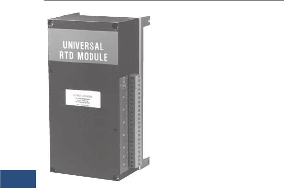
V3-T9-254 Volume 3—Power Distribution and Control Assemblies CA08100004E—November 2013 www.eaton.com
9
9
9
9
9
9
9
9
9
9
9
9
9
9
9
9
9
9
9
9
9
9
9
9
9
9
9
9
9
9
9.4
Metering Devices, Protective Relays, Software and Connectivity
Protective Relays
Universal RTD Module
Contents
Description Page
Product Selection Guide . . . . . . . . . . . . . . . . . . . . V3-T9-158
FP-6000 Feeder Protection . . . . . . . . . . . . . . . . . . V3-T9-162
FP-5000 Feeder Protection . . . . . . . . . . . . . . . . . . V3-T9-172
FP-4000 Feeder Protection . . . . . . . . . . . . . . . . . . V3-T9-180
MP-3000 Motor Protection . . . . . . . . . . . . . . . . . . V3-T9-188
MP-4000 Motor Protection . . . . . . . . . . . . . . . . . . V3-T9-198
MD-3000 Motor/Generator Differential Relay . . . . V3-T9-204
Digitrip 3000 . . . . . . . . . . . . . . . . . . . . . . . . . . . . . V3-T9-207
VR-300 Multifunctional Voltage Relay . . . . . . . . . . V3-T9-217
DP-300 Current Differential Protection Relay . . . . . V3-T9-221
EDR-3000 Feeder Protection . . . . . . . . . . . . . . . . . V3-T9-226
ETR-4000 Transformer Protection Relay . . . . . . . . V3-T9-237
Ground Fault Relay. . . . . . . . . . . . . . . . . . . . . . . . . V3-T9-250
Universal RTD Module
Product Selection . . . . . . . . . . . . . . . . . . . . . . . V3-T9-255
Options and Accessories . . . . . . . . . . . . . . . . . V3-T9-255
Technical Data and Specifications . . . . . . . . . . . V3-T9-255
Dimensions. . . . . . . . . . . . . . . . . . . . . . . . . . . . V3-T9-257
IQ 125 Volt DC Power Supply. . . . . . . . . . . . . . . . . V3-T9-258
Universal RTD Module
Product Description
●Electronic Resistance
Temperature Detector
(RTD) provides motor
temperature interface
for the MP-3000 Motor
Protection Relay
●Monitors up to 11 RTDs
consisting of six motor
windings, two motor
bearings, two load
bearings and one auxiliary
●Works with 10 ohm copper,
100 ohm
platinum, 100 ohm
nickel and 120 ohm
nickel
type RTDs
●Include fiber optic and
electrical communication
interfaces to the MP-3000
Motor Protection Relay
Application Description
Eaton’s URTD Module is
most commonly used to
provide motor temperature
information to the MP-3000
Motor Protection Relay. The
MP-3000 Motor Protection
uses this information for
monitoring, tripping and
alarming. The MP-3000 Intel-
I-Trip overload algorithm will
adjust its trip characteristics
based on the actual motor
temperature reported by the
URTD Module. This improves
the protection by using an
actual temperature value
instead of the assumed
NEMA Standard Ambient
Temperature.
The URTD Module may be
mounted close to the motor
or at the protective relay.
Both electrical and fiber optic
interface ports are provided
to communicate temperature
information to the MP-3000
relay. The electrical interface
can transmit information
using a three-conductor
shielded cable with a
maximum cable distance of
500 feet (152m). The fiber
optic link has a maximum
distance of 400 feet (122m).
The URTD Module may be
used with the IQ-1000 and
IQ-1000 II motor relays. It
may also be applied as a
standalone temperature
monitoring device
communicating, for example,
transformer temperature
information back to a remote
computer or PLC. An optional
PONI (Product Operated
Network Interface) is required
for standalone applications.
Features, Benefits
and Functions
●Universal design works
with any RTD type,
simplifying installation and
operation and reducing
inventory
●Standalone design permits
mounting the module close
to the motor, reducing RTD
wiring costs
●RTD diagnostics detects
faulty RTDs and wiring,
reducing unnecessary
tripping and alarming

Volume 3—Power Distribution and Control Assemblies CA08100004E—November 2013 www.eaton.com V3-T9-255
9
9
9
9
9
9
9
9
9
9
9
9
9
9
9
9
9
9
9
9
9
9
9
9
9
9
9
9
9
9
9.4
Metering Devices, Protective Relays, Software and Connectivity
Protective Relays
Product Selection
Universal RTD Module
Description
Catalog
Number
Universal RTD Module URTD
Universal RTD Module
Options and Accessories
Additional Related Products
from Eaton’s Cutler-Hammer
Series
The URTD Module must be
operated with an MP-3000
Motor Protection Relay,
computer or programmable
controller. Please refer to the
MP-3000 Motor Protection,
PONI and PowerNet sections
for additional related product
information.
Eaton provides fiber optic
cables for connecting to the
MP-3000 or IQ-1000 II Motor
Protection Relays.
Technical Data
and Specifications
●Input power requirements:
120 Vac (±15%)
●Frequency: 50/60 Hz
●Power consumption: 6 VA
●Operating temperature:
32°–158°F (0°–70°C)
●Storage temperature:
–4°–185°F(–20°–85°C)
●
Humidity: 0–95% R.H.
noncondensing
●Enclosure: Type 1
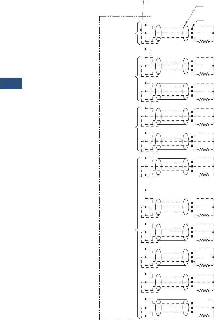
V3-T9-256 Volume 3—Power Distribution and Control Assemblies CA08100004E—November 2013 www.eaton.com
9
9
9
9
9
9
9
9
9
9
9
9
9
9
9
9
9
9
9
9
9
9
9
9
9
9
9
9
9
9
9.4
Metering Devices, Protective Relays, Software and Connectivity
Protective Relays
Wiring Diagram
RTD Wiring (Three-Lead Type)
Note
Showing a typical three-lead type RTD wiring connection.
Universal
RTD Module
Do not connect cable’s shield and drain wire
at this end. Use tape to insulate.
Connect cable’s shield
and drain wire here.
Note: Wiring between motor RTDs
and RTD Module must be
three-wire shielded cable.
Unused channels should
be shorted.
1. Each shielded cable’s conductors must be connected on Universal RTD Module as shown.
2. Use of three-lead RTDs is recommended.
3. RTDs must not be grounded at the motor, and no common connections between RTDs should be made at the
Universal RTD Module or the motor.
4.
Terminal 16 or 32 should be connected to a suitable earth ground.
Motor
Bearings
Motor
Windings
Auxiliary
Load
Bearings
Motor terminals
35
27
29
28
31
30
34
33
32
22
17
19
18
21
20
34
23
26
25
8
9
11
10
12
14
13
15
16
1
2
3
5
4
6
7
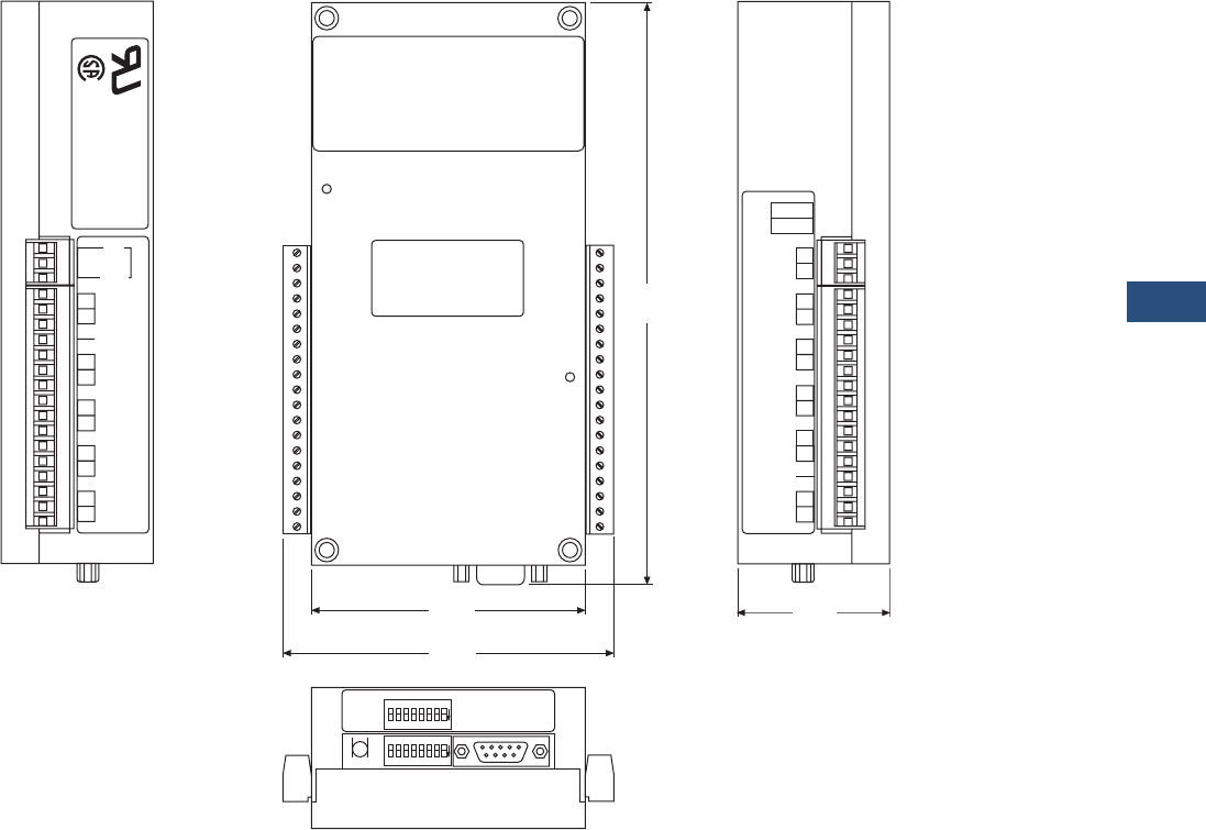
Volume 3—Power Distribution and Control Assemblies CA08100004E—November 2013 www.eaton.com V3-T9-257
9
9
9
9
9
9
9
9
9
9
9
9
9
9
9
9
9
9
9
9
9
9
9
9
9
9
9
9
9
9
9.4
Metering Devices, Protective Relays, Software and Connectivity
Protective Relays
Dimensions
Approximate Dimensions in Inches (mm)
Universal URTD Module
Note
Showing the URTD Module dimensions and terminal designations.
Power Management Products
Customer Satisfaction
1-800-542-7883
1-800-809-2772
(+1)412-490-6800
www.cutlerhammer.eaton.com/pmpc/
UNIVERSAL
RTD MODULE
UNIVERSAL RTD MODULE
STYLE NUMBER 2D78559
AUX1
29
30
31
32
33
34
35 ACN
120 ac
Vac
LB2
GND
J3
1A49102H19
25
26
27
28
LB1
MB1
20
21
22
23
24 MB2
1
MW1
J2 DATA
COM
STROBE
2
3
5
6
7
8
9
10
MW2
MW3
11
12
13
14
15
MW4
MW5
16
17
GND
18
19
MW6
234567
0N
81
SW1
INCOM Port
Fiber
Optic
Link
18765432
0N
®
®
2.00
(50.8)
3.60
(91.4)
7.67
(194.8)
4.32
(109.7)
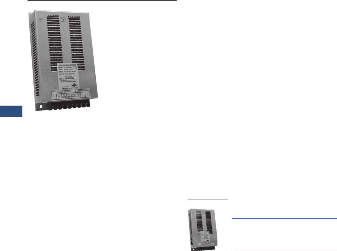
V3-T9-258 Volume 3—Power Distribution and Control Assemblies CA08100004E—November 2013 www.eaton.com
9
9
9
9
9
9
9
9
9
9
9
9
9
9
9
9
9
9
9
9
9
9
9
9
9
9
9
9
9
9
9.4
Metering Devices, Protective Relays, Software and Connectivity
Protective Relays
IQ DC Power Supply
Contents
Description Page
Product Selection Guide . . . . . . . . . . . . . . . . . . . . V3-T9-158
FP-6000 Feeder Protection . . . . . . . . . . . . . . . . . . V3-T9-162
FP-5000 Feeder Protection . . . . . . . . . . . . . . . . . . V3-T9-172
FP-4000 Feeder Protection . . . . . . . . . . . . . . . . . . V3-T9-180
MP-3000 Motor Protection . . . . . . . . . . . . . . . . . . V3-T9-188
MP-4000 Motor Protection . . . . . . . . . . . . . . . . . . V3-T9-198
MD-3000 Motor/Generator Differential Relay . . . . V3-T9-204
Digitrip 3000 . . . . . . . . . . . . . . . . . . . . . . . . . . . . . V3-T9-207
VR-300 Multifunctional Voltage Relay . . . . . . . . . . V3-T9-217
DP-300 Current Differential Protection Relay . . . . . V3-T9-221
EDR-3000 Feeder Protection . . . . . . . . . . . . . . . . . V3-T9-226
ETR-4000 Transformer Protection Relay . . . . . . . . V3-T9-237
Ground Fault Relay. . . . . . . . . . . . . . . . . . . . . . . . . V3-T9-250
Universal RTD Module . . . . . . . . . . . . . . . . . . . . . . V3-T9-254
IQ 125 Volt DC Power Supply
IQ 125 Volt DC Power Supply
Product Description
Eaton’s IQ DC Power Supply
is a DC to AC inverter module
intended for use where DC
power is available, but some
AC is required. The unit will
operate Eaton’s MP-3000, or
other AC powered IQ devices
requiring no more than 75 VA
of power at any power factor.
The IQ DC power supply is
available in two styles, one to
be used with the MP-3000
and one for all other products.
Features, Benefits
and Functions
●Single, two-wire input—
no need to set switches
or adjust jumpers
●Four connections—two for
DC in, two for AC out
●AC output is isolated from
the incoming power
●Built-in protection features
protect against short
circuits while providing
ample power to start loads
●Sinusoidal wave
Product Selection
IQ DC Power Supply
Technical Data and
Specifications
●Input voltage ranges from
105 Vdc to 140 Vdc
●Rated power output—
75 VA at any power factor
●Operating temperature—
–4ºF to 140ºF
(–20°C to 60°C)
Description
Catalog
Number
IQ DC power supply module IQDCPS
IQ DC Power Supply
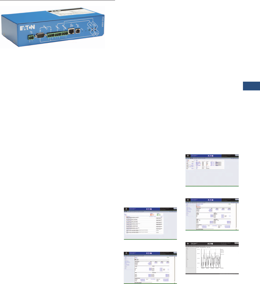
Volume 3—Power Distribution and Control Assemblies CA08100004E—November 2013 www.eaton.com V3-T9-259
9
9
9
9
9
9
9
9
9
9
9
9
9
9
9
9
9
9
9
9
9
9
9
9
9
9
9
9
9
9
9.5
Metering Devices, Protective Relays, Software and Connectivity
Connectivity Options
Power Xpert Gateways
Contents
Description Page
Power Xpert Gateways
Product Selection Guide . . . . . . . . . . . . . . . . . . V3-T9-260
Features. . . . . . . . . . . . . . . . . . . . . . . . . . . . . . . V3-T9-266
Standards and Certifications . . . . . . . . . . . . . . . V3-T9-267
Product Selection . . . . . . . . . . . . . . . . . . . . . . . V3-T9-267
Technical Data and Specifications . . . . . . . . . . . V3-T9-268
Dimensions . . . . . . . . . . . . . . . . . . . . . . . . . . . . V3-T9-271
Power Xpert Ethernet Switches . . . . . . . . . . . . . . . V3-T9-272
Power Xpert Gateway
Series 1000 Card—Power Distribution Unit . . . . . . V3-T9-276
Power Xpert Gateway
Series 2000 Card—Uninterruptible Power Supplies V3-T9-279
mMINT . . . . . . . . . . . . . . . . . . . . . . . . . . . . . . . . . . V3-T9-282
MINTII RS-232 Converter. . . . . . . . . . . . . . . . . . . . V3-T9-284
IPONI . . . . . . . . . . . . . . . . . . . . . . . . . . . . . . . . . . . V3-T9-285
DPONI . . . . . . . . . . . . . . . . . . . . . . . . . . . . . . . . . . V3-T9-286
MPONI . . . . . . . . . . . . . . . . . . . . . . . . . . . . . . . . . . V3-T9-287
I/O Devices Digital Input Module (DIM) . . . . . . . . . V3-T9-288
Addressable Relay II. . . . . . . . . . . . . . . . . . . . . . . . V3-T9-290
Breaker Interface Module II (BIM II) . . . . . . . . . . . V3-T9-293
Sub-Network Master Local Display (SMLD) . . . . . . V3-T9-297
IMPCABLE . . . . . . . . . . . . . . . . . . . . . . . . . . . . . . . V3-T9-299
Power Xpert Gateways
Product Description
The Power Xpert Gateway
400/600 is typically installed
in an electrical assembly—
a motor control center, low/
medium voltage switchgear
or switchboard to consolidate
data available from
components such as trip units,
meters, motor controllers and
protective relays.
Power Xpert Gateways
provide a cost-effective
method to easily Web-enable
Eaton and third-party products.
The Gateway consists of an
embedded Web server that
allows the user to connect
to Eaton products such as
breakers, meters and relays
found in MCCs, LV and MV
Switchgear and switchboards
—to name a few—that
communicate via Eaton
protocols INCOM and
QCPort, in addition to
third-party products that
communicate via Modbus
RTU. The Gateway provides
the central connection point
for the power metering/
monitoring/protective
devices, allowing their
parameters to be
monitored via the Web.
Power Xpert Gateways
provide data communications
to Eaton’s Power Xpert
Software to facilitate
centralizing and gathering data
for long-term data archival,
analysis and trending features.
The PXG is compatible with
and facilitates integration
with many third-party building
and factory automation
systems via Modbus TCP
and Web Services.
The PXG600 allows you
to enable pre-selected
parameters to be trended
for each supported device.
Selecting the trend symbol
will generate a real-time graph
for that parameter and can be
viewed for the past 24 hours,
seven days, 30 days or all
past history.
The PXG600 also offers direct
e-mail notifications to up to
10 users. Select from event
notifications, data logs, event
logs and heartbeat e-mails.
Information is presented in
organized, user-friendly Web
pages and includes, but is not
limited to, the following:
●Device status
●Comm status
●Voltage
●Current
●Power
●Power factor
●Energy
●Power quality
●Tem p erature
●I/O states
Power Xpert Gateway
Screenshots
Home Page
Main Page
Bus Page
Device Page
Trending Page (PXG600 Only)
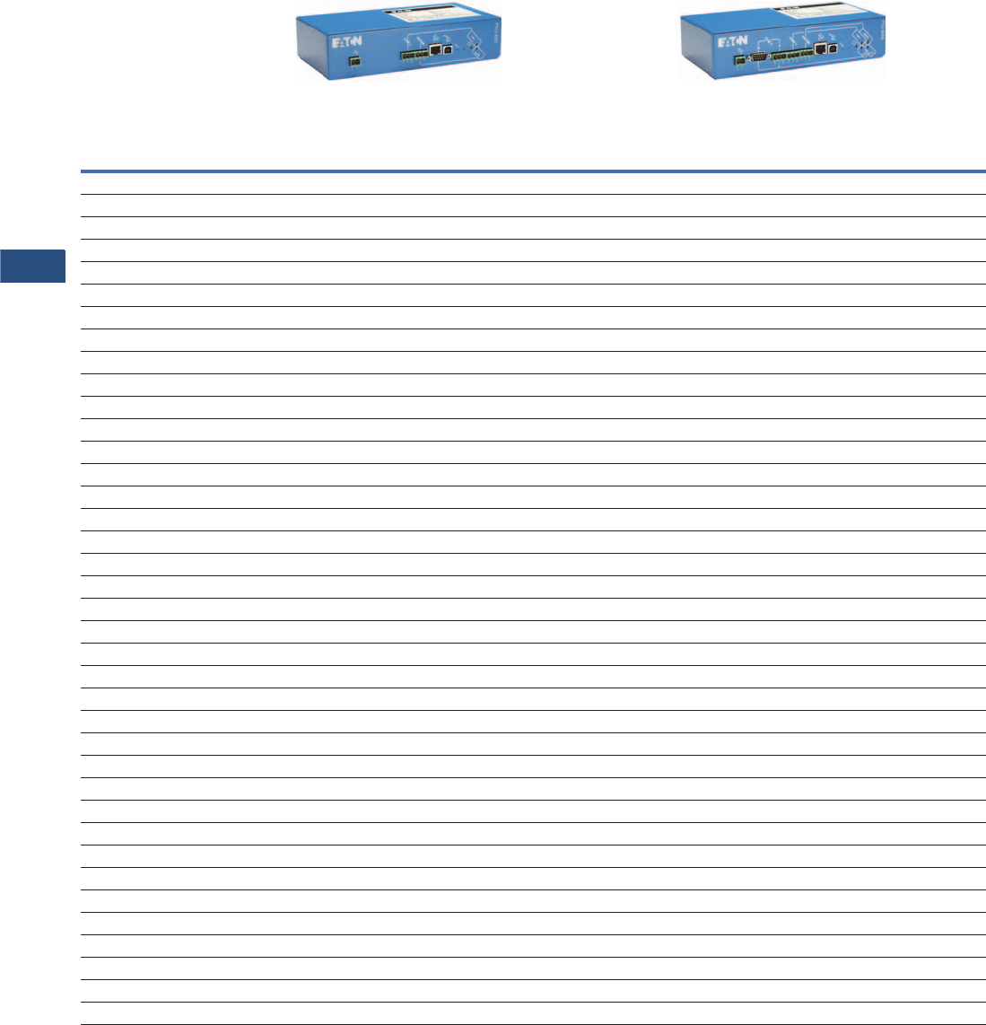
V3-T9-260 Volume 3—Power Distribution and Control Assemblies CA08100004E—November 2013 www.eaton.com
9
9
9
9
9
9
9
9
9
9
9
9
9
9
9
9
9
9
9
9
9
9
9
9
9
9
9
9
9
9
9.5
Metering Devices, Protective Relays, Software and Connectivity
Connectivity Options
Product Selection Guide
Data Acquisition and Integration Table for Supported Devices
Notes
1Required IPONI for connection to the Power Xpert Gateway.
2Required a WPONI for connection to the Power Xpert Gateway.
Information subject to change without notice. Visit www.eaton.com for latest up-to-date details on connectivity.
Supported Devices
Device
Type Device Name
PXG 400 and PXG 600 PXG 600 Only
HTTP
(Web
Browser)
Web
Services
(Power Xpert
Software)
Modbus
TCP
(BMS &
SCADA)
Pass-
Through
INCOM
(PowerNet)
Pass-
Through
QCPort
(CHStudio)
SNMP
(NMS)
SMTP
(E-mail
Client)
File Export
(Data File
Format)
File Export
(Waveform
File Export)
INCOM
Drive Accutrol 400 ■■■■ ■■■
Drive AF97 ■■■■ ■■■
I/O Universal RTD ■■■■ ■■■
I/O DIM ■■■■ ■■■
I/O DIM KYZ ■■■■ ■■■
Meter IQ DP-4000 1■■■■ ■■■
Meter IQ Energy Sentinel ■■■■ ■■■
Meter IQ 220/IQ 320 ■■■■ ■■■
Meter IQ 230/IQ 330 ■■■■ ■■■
Meter IQ Analyzer (6000/6200) 1■■■■ ■■■■
Meter IQ Analyzer (6400/6600) 1■■■■ ■■■■
Meter IQ Data 1■■■■ ■■■
Meter IQ Data Plus 1■■■■ ■■■
Meter IQ Data Plus II 1■■■■ ■■■
Meter Power Manager ■■■■ ■■■
Meter IQ Power Sentinel ■■■■ ■■■
Meter Point IQ MES II ■■■■ ■■■
Protective Digitrip 3000 ■■■■ ■■■
Protective Digitrip 3200 ■■■■ ■■■
Protective FP-5000 ■■■■ ■■■■
Protective FP-4000 ■■■■ ■■■■
Protective FP-6000 ■■■■ ■■■■
Protective MP-3000 1■■■■ ■■■
Protective MP-4000 1■■■■ ■■■
Protective Digitrip 520MC ■■■■ ■■■
Protective NRX520 ■■■■ ■■■
Protective IQ 500 ■■■■ ■■■
Protective MPCV Relay ■■■■ ■■■
Protective Digitrip 1150/DT1150V ■■■■ ■■■■
Protective Digitrip 810 ■■■■ ■■■
Protective Digitrip 910 ■■■■ ■■■
Protective Digitrip MV ■■■■ ■■■
Protective Digitrip OPTIM 1050 ■■■■ ■■■■
Protective Digitrip OPTIM 550 ■■■■ ■■■
Protective Digitrip OPTIM 750 ■■■■ ■■■
Starter Advantage 2■■■■ ■■■
Starter Advantage ACM 2■■■■ ■■■
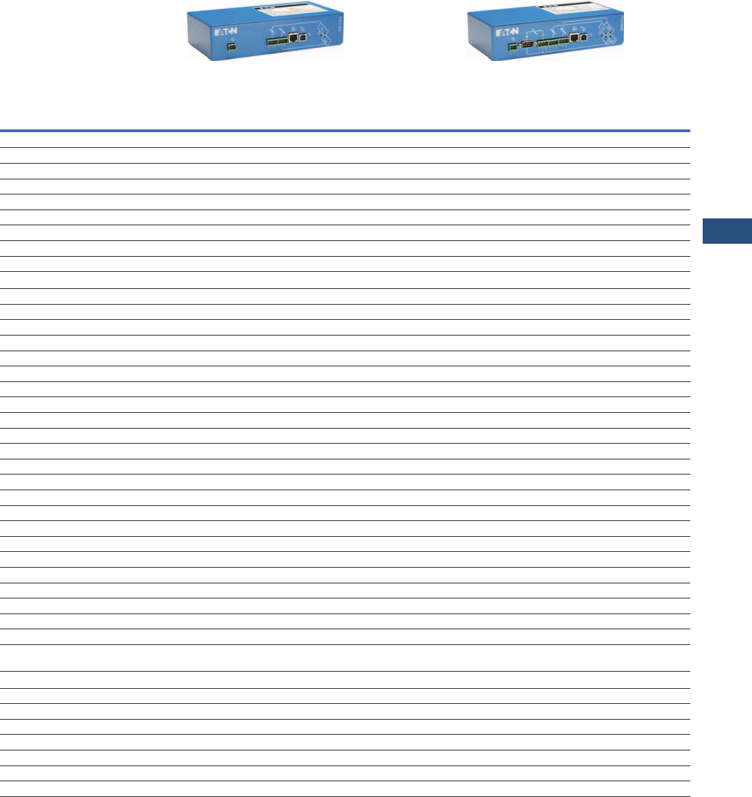
Volume 3—Power Distribution and Control Assemblies CA08100004E—November 2013 www.eaton.com V3-T9-261
9
9
9
9
9
9
9
9
9
9
9
9
9
9
9
9
9
9
9
9
9
9
9
9
9
9
9
9
9
9
9.5
Metering Devices, Protective Relays, Software and Connectivity
Connectivity Options
Data Acquisition and Integration Table for Supported Devices, continued
Notes
1Required IPONI for connection to the Power Xpert Gateway.
2Required a WPONI for connection to the Power Xpert Gateway.
3Requires a QSNAP for connection to the Power Xpert Gateway.
Information subject to change without notice. Visit www.eaton.com for latest up-to-date details on connectivity.
Supported Devices
Device Type Device Name
PXG 400 and PXG 600 PXG 600 Only
HTTP
(Web
Browser)
Web
Services
(Power Xpert
Software)
Modbus
TCP
(BMS &
SCADA)
Pass-
Through
INCOM
(PowerNet)
Pass-
Through
QCPort
(CHStudio)
SNMP
(NMS)
SMTP
(E-mail
Client)
File Export
(Data File
Format)
File Export
(Waveform
File Export)
INCOM, continued
Sub-network Master AEM II 1■■■■ ■■
Sub-network Master BIM II 1■■■■ ■■
Sub-network Master CMU 2■■■■ ■■
Sub-network Master IQ CED II 1■■■■ ■■
Sub-network Master IQ MES II ■■■■ ■■■
Transfer Switch ATC-400 1■■■■ ■■■
Transfer Switch ATC-600 1■■■■ ■■■
Transfer Switch ATC-800 1■■■■ ■■■
Modbus
Drive MVX9000 ■■■ ■■■
Drive SVX9000 ■■■ ■■■
Insulation Monitor InsulGard ■■■ ■■■
Meter IQ 130 ■■■ ■■■
Meter IQ 140 ■■■ ■■■
Meter IQ 150 ■■■ ■■■
Meter IQ 230M/IQ 330M ■■■ ■■■
Meter IQ 250 ■■■ ■■■
Meter IQ 260 ■■■ ■■■
Meter Nexus 1262 ■■■ ■■■
Meter SQD CM3000 Series ■■■ ■■■
Meter SQD CM4000 Series ■■■ ■■■
Meter SQD PM710 ■■■ ■■■
Meter SQD PM850 ■■■ ■■■
Meter PML 7350 ■■■ ■■■
Meter PML 7550 ■■■ ■■■
Meter PML 7650 ■■■ ■■■
Protective GE 369 Motor Relay ■■■ ■■■
Protective GE 469 Motor Relay ■■■ ■■■
Protective FP-4000/FP-5000 ■■■ ■■■
Protective FP-6000 ■■■ ■■■
Overload Relay C441 ■■■ ■■■
Temp Monitor Qualitrol 118 ■■■ ■■■
Transformer Differential
Relay
ABB TPU 2000
■■■ ■■■
QCPort
I/O D77A-AI16 ■■■ ■■■■
I/O D77A-AI8 ■■■ ■■■■
I/O D77A-DI16 ■■■ ■■■■
I/O D77A-DI8 ■■■ ■■■■
Starter IT. S811 (MV811) ■■■ ■■■■
Starter IT. Starter 3■■■ ■■■■
Starter IT. Starter QSNAP 3■■■ ■■■■

V3-T9-262 Volume 3—Power Distribution and Control Assemblies CA08100004E—November 2013 www.eaton.com
9
9
9
9
9
9
9
9
9
9
9
9
9
9
9
9
9
9
9
9
9
9
9
9
9
9
9
9
9
9
9.5
Metering Devices, Protective Relays, Software and Connectivity
Connectivity Options
The table below represents many of the parameters displayed on the Web page for a given device, however it is not
exhaustive. For the complete list of parameters display, per device, refer to the Device Data Map file at HYPERLINK
http://www.eaton.com/powerxpert www.eaton.com/powerxpert.
Web UI Device Parameters Displayed via Power Xpert Gateway
Units
IQ Meters
IQ
MES II
IQ Data
Plus II
IQ Data
Plus
IQ
Data
IQ
Analyzer
6000/
6200
IQ
Analyzer
6400/
6600
IQ
DP-
4000
IQ
220/
320
IQ
230/
330
IQ
230/
330M
IQ
130
IQ
140
IQ
150
IQ
250
IQ
260
IQ
Power
Sentinel
IQ
Energy
Sentinel
Power
Manager
Vol tage
Average V
■■
Voltage (Line-Line) V
■ ■ ■■ ■ ■ ■ ■ ■ ■■■■■■
Voltage (Line-Neutral) V
■ ■ ■ ■■ ■ ■ ■ ■ ■ ■■■■■■ ■
Current
Average A
■■
Phase A
■ ■ ■■ ■ ■ ■ ■ ■ ■■■■■■
Ground A
■■ ■
Neutral A
■■ ■ ■■
Peak A
■ ■ ■ ■ ■ ■ ■■■■■
Demand A
■ ■ ■ ■ ■ ■■■■■
Power
Apparent VA ■ ■ ■ ■ ■ ■ ■■ ■■
Reactive VAR ■ ■ ■ ■ ■ ■ ■ ■ ■■■■■
Real W ■ ■ ■ ■ ■ ■ ■ ■ ■ ■■■■■ ■ ■
Power Factor
Apparent PF ■ ■ ■ ■ ■ ■ ■ ■ ■■■■■
Displacement PF ■■■■■■ ■
Energy
Real Wh ■ ■ ■ ■ ■ ■ ■ ■ ■■■■ ■ ■
Forward Wh ■ ■■■■■■ ■■■■
Reverse Wh ■■■■■■ ■■■■
Apparent Vah ■■■■■■ ■■■
Reactive VARh ■■■■■■ ■■■
Leading VARh ■■■■■■ ■■■■
Lagging VARh ■■■■■■ ■■■■
Power Quality
THD % ■
Current THD % ■
Voltage THD % ■
Frequency Hz ■ ■ ■ ■ ■ ■ ■ ■ ■■■■■
Waveform Capture N/A ■■■
Temperature
Ambient C
Auxiliary C
Load Bearing C
Motor Bearing C
Winding C
Phase (L, C, R) C
Terminal Block C
Input Status
Number of Inputs ■■
Status/cause of trip
Thermal memory
Pole temperature
Winding temperature
Fan status
Alarm/trip relay

Volume 3—Power Distribution and Control Assemblies CA08100004E—November 2013 www.eaton.com V3-T9-263
9
9
9
9
9
9
9
9
9
9
9
9
9
9
9
9
9
9
9
9
9
9
9
9
9
9
9
9
9
9
9.5
Metering Devices, Protective Relays, Software and Connectivity
Connectivity Options
The table below represents many of the parameters displayed on the Web page for a given device, however it is not
exhaustive. For the complete list of parameters display, per device, refer to the Device Data Map file at HYPERLINK
http://www.eaton.com/powerxpert www.eaton.com/powerxpert.
Web UI Device Parameters Displayed via Power Xpert Gateway, continued
Units
Circuit Breaker
Trip Units
Protective
Relays
Digitrip
1150
Digitrip
520MC NRX520
Digitrip
RMS
910
Digitrip
RMS
810
Digitrip
OPTIM
1050
Digitrip
OPTIM
550
Digitrip
OPTIM
750
Digitrip
MV
Digitrip
3000
IQ
500
MPVCV
Relay
FP-
4000
FP-
5000
FP-
6000
MP-
3000
MP-
4000
Vol t age
Average V
■■■ ■
Voltage (Line-Line) V
■■ ■■■ ■
Voltage (Line-Neutral) V
■ ■■■ ■
Current
Average A
■■■■■
Phase A
■■■■■■■■■■■■■■■■■
Ground A
■■■■■■■■■■■ ■■■
Neutral A
■■■■■■■■■■ ■
Peak A
■ ■■■■■ ■■■
Demand A
■ ■■■ ■■
Power
Apparent VA ■■■■ ■
Reactive VAR ■■ ■■■ ■
Real W ■ ■■■ ■■■■ ■
Power Factor
Apparent PF ■■■■ ■
Displacement PF ■■■ ■
Energy
Real Wh ■■■ ■■■ ■
Forward Wh ■ ■■■ ■■■
Reverse Wh ■ ■■■ ■■■
Apparent Vah ■■■■ ■
Reactive VARh ■■■
Leading VARh ■■■
Lagging VARh ■■■
Power Quality
THD % ■
Current THD % ■■■
Voltage THD % ■■■
Frequency Hz ■■■
Waveform Capture N/A ■ ■ ■■■
Temperature
Ambient C
Auxiliary C ■■
Load Bearing C ■■
Motor Bearing C ■■
Winding C ■■
Phase (L, C, R) C
Terminal Block C
Input Status
Number of inputs ■■■
222
Status/cause of trip ■■■■■■■■■■■■■■■■■
Thermal memory
Pole temperature
Winding temperature
Fan status
Alarm/trip relay ■

V3-T9-264 Volume 3—Power Distribution and Control Assemblies CA08100004E—November 2013 www.eaton.com
9
9
9
9
9
9
9
9
9
9
9
9
9
9
9
9
9
9
9
9
9
9
9
9
9
9
9
9
9
9
9.5
Metering Devices, Protective Relays, Software and Connectivity
Connectivity Options
Web UI Device Parameters Displayed via Power Xpert Gateway, continued
Note
Information subject to change without notice. Visit www.eaton.com for latest up-to-date details on connectivity.
Units
Insulation
Monitor
Motor Starters
& VFDs
Transfer
Switches
InsulGard
Accutrol
400 AF97
Advantage
Starters IT. S811
IT. Starters/
QSNAP
SVX & MVX
Drives ATC-400 ATC-600 ATC-800
Vol t age
Average V
■■ ■
Voltage (Line-Line) V
■ ■■■
Voltage (Line-Neutral) V
Current
Average A
■■ ■■■
Phase A
■■■
Ground A
Neutral A
Peak A
Demand A
Power
Apparent VA ■
Reactive VAR
Real W
Power Factor
Apparent PF
Displacement PF
Energy
Real Wh
Forward Wh
Reverse Wh
Apparent Vah
Reactive VARh
Leading VARh
Lagging VARh
Power Quality
THD %
Current THD %
Voltage THD %
Frequency Hz ■■ ■■■■
Waveform Capture N/A
Temperature
Ambient C ■ ■
Auxiliary C
Load Bearing C
Motor Bearing C
Winding C
Phase (L, C, R) C
Terminal Block C
Input Status
Number of inputs ■■■
Status/cause of trip ■■■
Thermal memory ■■■
Pole temperature ■■■
Winding temperature
Fan status
Alarm/trip relay

Volume 3—Power Distribution and Control Assemblies CA08100004E—November 2013 www.eaton.com V3-T9-265
9
9
9
9
9
9
9
9
9
9
9
9
9
9
9
9
9
9
9
9
9
9
9
9
9
9
9
9
9
9
9.5
Metering Devices, Protective Relays, Software and Connectivity
Connectivity Options
Web UI Device Parameters Displayed via Power Xpert Gateway, continued
Note
Information subject to change without notice. Visit www.eaton.com for latest up-to-date details on connectivity.
Units
I/O Third-Party Devices
DIM
KYZ
EDR-
3000
Digital
Input
Module
D77A-
AI16
D77A-
AI8
D77A-
DI16
D77A-
DI8
Uni-
versal
RTD
C441
Overload
Relay
SQD
CM 3000
Series
SQD
CM 4000
Series
SQD
PM
710
SQD
PM
850
PML
7350
PML
7550
PML
7650
GE 369
Motor
Relay
GE 469
Motor
Relay
ABB
TPU
2000
Qualitrol
118
Nexus
1262/1272
Vol t age
Average V
■■■ ■■■■ ■
Voltage (Line-Line) V
■ ■■■■■■■ ■
Voltage
(Line-Neutral) V
■■■■■■■ ■ ■
Current
Average A
■ ■ ■ ■ ■■■■ ■ ■
Phase A
■ ■■■■■■■■■■■ ■
Ground A
■■■ ■■
Neutral A
■■■ ■
Peak A
■■■■■
Demand A
■■ ■
Power
Apparent VA ■■■■■■■ ■ ■
Reactive VAR ■■■■■■■ ■ ■
Real W ■■■■■■■ ■ ■
Power Factor
Apparent PF ■■■■■■■ ■ ■
Displacement PF ■■■
Energy
Real Wh ■ ■■■■■ ■ ■
Forward Wh ■■ ■■■■ ■
Reverse Wh ■■ ■■■■ ■
Apparent Vah ■■■■■■■
Reactive VARh ■■■■■
Leading VARh ■■ ■■■■ ■
Lagging VARh ■■ ■■■■ ■
Power Quality
THD % ■
Current THD % ■
Voltage THD % ■
Frequency Hz ■ ■■■■■■■ ■
Waveform Capture N/A
Temperature
Ambient C
Auxiliary C ■
Load Bearing C ■■■
Motor Bearing C ■■■
Winding C ■■■
Phase (L, C, R) C ■
Terminal Block C ■
Input Status
Number of inputs 4 8 16 8 16 8 8
Status/cause of
trip
■■■
Thermal memory ■
Pole temperature
Winding
temperature
■■
Fan status ■■
Alarm/trip relay ■■■
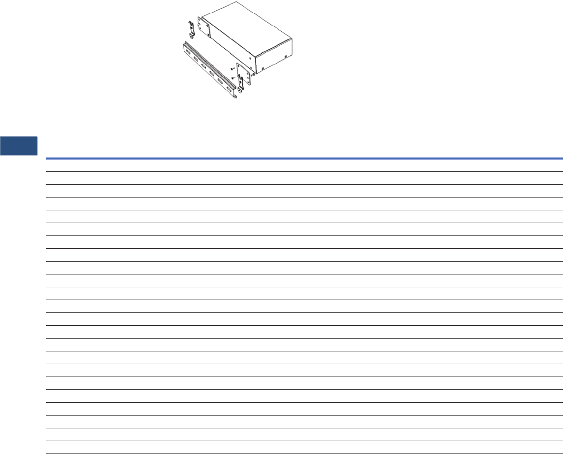
V3-T9-266 Volume 3—Power Distribution and Control Assemblies CA08100004E—November 2013 www.eaton.com
9
9
9
9
9
9
9
9
9
9
9
9
9
9
9
9
9
9
9
9
9
9
9
9
9
9
9
9
9
9
9.5
Metering Devices, Protective Relays, Software and Connectivity
Connectivity Options
Features
The Eaton Power Xpert Gateway
400/600 Includes:
●The Power Xpert
Gateway Module
●Mounting provisions
and required hardware
for panel and DIN rail
mounting
●CD-ROM: contains the
User Manual, Modbus
Register Maps, USB Driver
and other associated files
Power Xpert Gateway 400 with DIN Rail
Mounting (Brackets Included)
Features of the Power Xpert Gateway 400 vs. 600
Features PXG 400 PXG 600
Total number of supported devices 64 96
Maximum number of INCOM devices supported 64 64
Protocols supported on downstream devices: INCOM, QCPort and Modbus RTU Yes Yes
Number of downstream communication ports 23
Number of downstream protocols supported simultaneously 2 3
USB port for configuration Yes Yes
Modbus TCP/IP protocols supported Yes Yes
SNMP client access Yes Yes
INCOM slave action commands supported Yes Yes
INCOM date and time settings supported Yes Yes
Modbus writes supported Yes Yes
Device summary screen per communication port Yes Yes
Device waveform access and storage—COMTRADE file format No Yes
Set user-defined events No Yes
Trend graphs displayed No Yes
Data logs—csv file format, downloadable to Excel No Yes
Interval logs—csv file format, downloadable to Excel No Yes
Event notification via the Web interface Yes Yes
Event logs—csv file format, downloadable to Excel No Yes
E-mail notification on events and threshold alarms No Yes
Secure ethernet communications—SSL encryption Yes Yes
Secure communication ports via access control/trusted host list Yes Yes
Save and restore configuration file Yes Yes
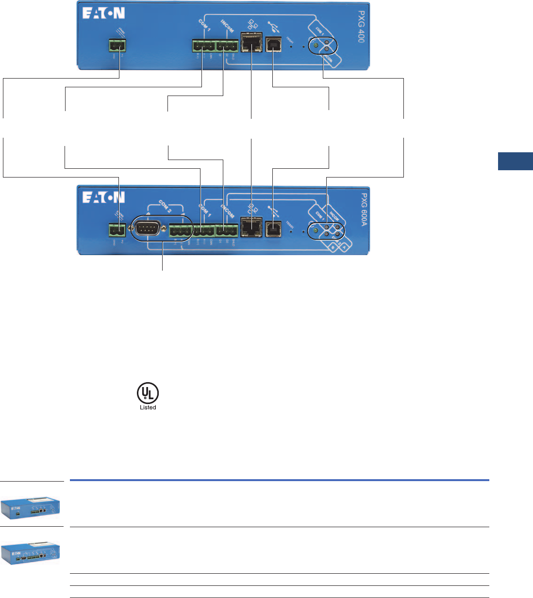
Volume 3—Power Distribution and Control Assemblies CA08100004E—November 2013 www.eaton.com V3-T9-267
9
9
9
9
9
9
9
9
9
9
9
9
9
9
9
9
9
9
9
9
9
9
9
9
9
9
9
9
9
9
9.5
Metering Devices, Protective Relays, Software and Connectivity
Connectivity Options
Power Xpert Gateway 400/600
Standards and Certifications
●UL 508, Standard
for Programmable
Controller Equipment
●FCC, Class A, Part 15,
Subpart B, Sections
15.107b & 15.109b
●EN55022: 1994 Class A,
Information Technology
Equipment
●EN 61000-6-2:2001
Electromagnetic
Compatibility (EMC)
Party 6-2: Immunity for
Industrial Environments
Product Selection
PXG Part Numbers
24 Vdc
Input Power
COM 1 Port:
RS-485 Connection for
up to Either (32) QCPort
or Modbus RTU Devices
INCOM Port:
RS-485 Connection
for up to 64 INCOM
Devices
RJ-45 Connection
to the LAN
USB Connection
for Local
Configuration
Capability
Power and Traffic
Indicator Lights
COM 2 Port: Either RS-485 or
RS-232 Connection for up to
Either (32) QCPort or Modbus
RTU Devices
Description
Style
Number
Catalog
Number
Power Xpert Gateway 400 66D2145G01 PXG400
Power Xpert Gateway 600 66D2146G01 PXG600
Power supply—24 Vdc ELC-PS02 ELC-PS02
Low profile mounting bracket kit 66B2146G01 PXGACC01
PXG400
PXG600

V3-T9-268 Volume 3—Power Distribution and Control Assemblies CA08100004E—November 2013 www.eaton.com
9
9
9
9
9
9
9
9
9
9
9
9
9
9
9
9
9
9
9
9
9
9
9
9
9
9
9
9
9
9
9.5
Metering Devices, Protective Relays, Software and Connectivity
Connectivity Options
Technical Data and Specifications
Memory
●Flash: 128 MB
●RAM: 64 MB
Communication Ports
●Network port: one
10/100Base-T
RJ-45 connector
●Configuration port:
one USB port
●Serial ports PXG 400
●One dedicated RS-485
port for connection to
INCOM devices
●One RS-485 port for
connection to either
QCPort or Modbus RTU
devices
●Serial ports PXG 600
●One dedicated RS-485
port for connection to
INCOM devices
●One RS-485 port for
connection to either
QCPort or Modbus RTU
devices
●One RS-485 or RS-232
(software selectable)
port for connection
to either QCPort or
Modbus RTU devices
Network Protocols Supported
●Modbus TCP/IP: Supports
data access from Modbus
TCP clients
●Web server: Supports
data access from Web
browsers (HTTP and
HTTPS)
●DHCP: Supports automatic
IP address assignments,
if enabled
●SNMP: Supports common
network management
tools
●NTP: Supports time
synchronization via a
network time server for
PXG synchronization
●SMTP: Supports mail
server for e-mail
notification
Serial Protocols Supported
●INCOM
●QCPort
●Modbus RTU
Supported Devices
Refer to www.eaton.com/
powerxpert for most current
list. Call for information on
additional devices.
Web Browsers Recommended
●IE 6.0 or higher
●Mozilla Firefox 2.0 or
higher
Number of Devices Supported
●PXG 400
●64 total with INCOM
port + COM 1 port not
to exceed 64. Port
limitations are as
follows:
– INCOM port: Up to 64
INCOM devices
– COM 1 port: Up to 32
QCPort or Modbus
RTU devices
●PXG 600
●96 total with INCOM
port + COM 1 port +
COM 2 port not to
exceed 96. Port
limitations are
as follows:
– INCOM port: Up to 64
INCOM devices
– COM 1 port: Up to 32
QCPort or Modbus
RTU devices
– COM 2 port: Up to 32
QCPort or Modbus
RTU devices
Power Input
●Input voltage, nominal:
24 Vdc; 0.8 A
●Input voltage range:
± 20% nominal
Power Consumption
●8 watts maximum
Operating Temperature
●32 to 140°F (0 to 60°C)
Ambient Storage Temperature
●–40 to 185°F (–40 to 85°C)
Relative Humidity
●5 to 95% noncondensing
at 50°C
Note: Features and specifications
listed in this document are
subject to change without notice
and represent the maximum
capabilities of the product with all
options installed. Although every
attempt has been made to ensure
the accuracy of information
contained within, Eaton makes no
representation about the
completeness, correctness or
accuracy and assumes no
responsibility for any errors or
omissions. Features and
functionality may vary depending
on selected options.

Volume 3—Power Distribution and Control Assemblies CA08100004E—November 2013 www.eaton.com V3-T9-269
9
9
9
9
9
9
9
9
9
9
9
9
9
9
9
9
9
9
9
9
9
9
9
9
9
9
9
9
9
9
9.5
Metering Devices, Protective Relays, Software and Connectivity
Connectivity Options
General Wiring Guidelines—RS-485 Network
When communicating over
RS-485 networks to Eaton
products, the following
General Wiring Guidelines
should be used.
Rule 1: Cable Selection—
Twisted Shielded Pair (TSP)
Note: Cables specifically
designed for RS-485 applications
are highly recommended.
The RS-485 bus is a length of
Twisted Shielded Pair (TSP)
that includes a third
conductor (used for the
common wire), a braided
shield accompanied by a drain
wire, and nominal impedance
of 120 ohms.
●Belden Wire and Cable
Company Part Number
3106A or equivalent
Rule 2: Cable Intermixing
Any cable in the Belden
3106A family can be
intermixed with each other
in the Modbus network.
Rule 3: System Topology,
Size and Capacity
●Strict daisy chain must be
adhered to. A strict daisy
chain configuration is one
where the transmission
line connects from one
RS-485 receiver to the
next. The transmission line
appears as one continuous
line to the RS-485 driver
●Maximum 32 devices
●Line termination:
Maximum cable lengths of
4000 feet (1219m); longer
bus lengths will slow the
data rate
Rule 4: Cable Splicing
The prime goal is to create a
secure electrical connection
while minimizing exposure to
electrical transients. Ferrules
are used to dress cable ends.
Most devices have built-in
terminal blocks that can be
used for splicing. Additionally,
terminal blocks should be
utilized when splicing
elsewhere in the gear or
facility to ensure a secure
electrical connection.
Rule 5: Cable Shielding
The cable shielding and outer
jacket should not be stripped
back beyond 1-1/2 inches.
Three-pole terminal blocks
are used to ensure a
continuous metallic shield
ground path. To ensure a
secure electrical connection
when daisy chaining devices
that have built-in two-pole
terminal blocks, mechanically
crimp sleeves onto the two
shield path drain wires.
Rule 6: Cable Grounding
Ground the communication
network at only one point in
the network, preferably by
terminating the drain wire
to ground at the EOL node
(same location as the EOLR).
A solid earth ground is
accomplished by connecting
the shield ground path’s drain
wire to a #14 AWG or larger
multi-stranded wire that has
an impedance path of 1 ohm
or less to a known earth
ground.
Note: The building electrical
ground may not be effective since
it may travel through many
connections and considerable
distances before reaching earth
ground. In such cases, a new
ground path will be required since
the effectiveness of this shield
earth ground connection will
affect the integrity of data
transferred over the cable.
Rule 7: Cable Termination
End of Line Resistors (EOLR)
are necessary to maintain
signal strength and minimize
reflections. EOLR must
match the impedance of the
TSP. Two EOLR are needed
and should be located at both
ends of the RS-485 bus. If
there is only one device
connected to the Modbus
master, it is considered the
last device in the network and
should be terminated with a
120 ohm 1/4 watt terminating
resistor.
Rule 8: Device Addressing
●Each device must have a
unique slave address
●No two devices on the
same RS-485 network can
have the same slave
address
Ethernet Cable Specifications
For complete specifications,
refer to the IEEE 802.3
Ethernet specification.
RS-485 Wiring Guide—Three Terminal Devices
Notes
1Transceiver (XCVR) Common Connected to:
I = Isolated
NI = Non Isolated
E = Earth Ground
2Center terminal on InsulGard (marked with Ground symbol) is for shield splicing only and is electrically floating.
Device Name
A
(– Wire)
B
(+ Wire)
Common
Wire
XCVR
Common 1
Data
Bias
IQ 230M 12 (MOD2) 11 (MOD1) 10 (INCOM 3) I 26V None
IQ 250 (–)
Older Models are Marked
B (–)
(+)
Older Models are Marked
A (–) or A(+)
SH I None
IQ 260 (–)
Older Models are Marked
B (–)
(+)
Older Models are Marked
A (–) or A (+)
SH I None
IQ 330M 12 (MOD2) 11 (MOD1) 10 (INCOM 3) I 26V None
NETLINK 1 (DATA–) 2 (DATA+) 5 (GND) E None
InsulGard 2B A None Floating None
Bushing Gard 2
(InsulGard G3 2)
B A None Floating None
Power Xpert Meter
4000/6000/8000
Data A
750B-S
Data B
750B-S
Shield
(COM)
I 300V 750 Ohm
Switch Sel
Power Xpert Gateway
400//600
A(–) B(+) COM I —

V3-T9-270 Volume 3—Power Distribution and Control Assemblies CA08100004E—November 2013 www.eaton.com
9
9
9
9
9
9
9
9
9
9
9
9
9
9
9
9
9
9
9
9
9
9
9
9
9
9
9
9
9
9
9.5
Metering Devices, Protective Relays, Software and Connectivity
Connectivity Options
INCOM Network
INCOM was specifically
designed with the intention of
delivering a comprehensive
and powerful energy
management solution for
use in electrical distribution
environments while ensuring
affordability, flexibility,
simplicity and noise immunity.
An INCOM network installed
per the following rules will
allow the user to fully realize
all of the above advantages.
(Refer to Eaton document
TD17513 for specific system
layout recommendations
and details.)
Rule 1: Cable Selection—
Twisted Shielded Pair
Approved cable types:
●Any of the cables in the
Belden 9463 family
●Quabbin 6205
●CommScope 9022
●Manhattan Electric M4154
●IMPCABLE—a 600V rated
cable custom designed for
INCOM—
Style # 2A95705G01
Rule 2: Cable Intermixing
Due to impedance
differences between
IMPCABLE and the Belden
9463 family, the main cable
run(s) should be entirely
for the 9463 family OR
IMPCABLE: do not alternate
between these types. The
cable used for taps can be
different from the main run.
Rule 3: System Topology,
Size and Capacity
Supports daisy chain, star
and multi-level network
segment topologies.
Note: Star Segment Topology is
not recommended for new
designs.
See Page V3-T9-271. Surge
protection is required for
FSK networks that leave a
building at the egress/ingress
of the building.
●Supports distances up to
10,000 ft (3048m) per
segment when designed
within the specifications of
this guideline
●Supports up to 1000
devices on a single
network segment
●Supports sub-network
master devices and
associated sub-networks
●Supports 1200 or
9600 baud rate
●Attenuation:
●Total system capacity:
25 dB
●Attenuation per device:
0.01 dB
●Attenuation for approved
wire types, see tables
below
Cable Attenuation
Attenuation at Star
●Definitions:
●Daisy chain: point-to-
point wiring between
devices or clusters of
devices
●Star: single point with a
number of long lines
emanating from it
●Long line: >200-foot
(61m) wire run
●Simple tap: <200-foot
(61m) connection to
cluster of devices
Rule 4: Cable Splicing
The goal is to create a secure
electrical connection while
minimizing exposure to
electrical transients. Ferrules
are used to dress cable ends
in order to avoid problems
associated with frayed and
loose wires. Besides
facilitating cable installation,
subsequent data line
troubleshooting and
downtime are minimized.
Most INCOM devices have
built-in three-pole terminal
blocks for data lines and
shield. For older INCOM
devices that have only two
terminals, shield continuity
must be ensured by other
means. Additional terminal
strips should be utilized when
splicing elsewhere in the
electrical enclosure or facility
to ensure secure electrical
connections. All devices, End
of Line Termination Resistors
and Taps should be wired in
parallel across the cable.
Rule 5: Cable Shielding
The cable shielding and outer
jacket should not be stripped
back beyond 1.5 inches (38
mm). Terminal blocks are
used at tap points to ensure a
continuous metallic shield
ground path. To ensure a
secure electrical connection
when daisy-chaining INCOM
devices that have built-in
two-pole terminal blocks, use
crimp sleeves to join the two
shield drain wires. The cable
shield ground path for a main
network and sub-network
must not be joined. Each
should have a separate
connection to earth ground
reference.
Rule 6: Cable Grounding
The shield should be
continuous across a network
segment and connected to
the building’s electrical
system grounding electrode
conductor. The 2005 NEC
provides the following
guidance on grounding
communication cables:
1. When a communication
cable enters a building, a
primary protector is required
and must be grounded as
described in Section 800 IV.
Specifically, Paragraphs
800.93 and 800.100 define
grounding requirements for
the primary protector.
2. Grounding systems are
generally covered by Section
250 III. The grounding
electrode conductor is
specifically covered by
Paragraphs 250.62, 250.64,
250.66, 250.68 and 250.70.
3. Bonding requirements
between communication
systems and the power
distribution system is
specified by Paragraph
250.94.
A solid earth ground is
accomplished by connecting
the shield ground path’s drain
wire to a #14 AWG or larger
multi-stranded wire that has
an impedance path of 1 ohm
or less to the building’s
grounding electrode
conductor.
Rule 7: Cable Termination
Each network segment
requires a minimum of two
End of Line Termination
Resistors (EOLTRs). The
EOLTRs maintain signal
strength and minimize
reflections. The EOLTRs
should be 1/2 watt 100 ohm
non-inductive resistors, such
as carbon composition or
metal film. Wire-wound
resistors are not acceptable.
Taps on network segments
should not be terminated.
Some INCOM devices have
the EOLTR permanently
installed and must be located
at the end of a main run.
Other INCOM devices have
an EOLTR that can be
switched to optionally
terminate the network
segment at the device. Care
must be exercised when
installing devices containing
termination resistors
that the switches are set
appropriately. A minimum of
two, up to a maximum of five
EOLTRs must be installed on
each network segment as
dictated by network topology.
Rule 8: Device Address
In order to avoid the
possibility of devices in a
Main Network having the
same addresses as those
in Subnetworks, set Main
Network device addresses
at 100 or higher excluding
addresses 901 to 908.
Cable
Type
Attenuation/
1000 Feet (305m)
IMPCABLE 1.6 dB
Belden 9463 family 2.0 dB
Number of
Long Lines Attenuation
33.5 dB
46 dB
5 8 dB
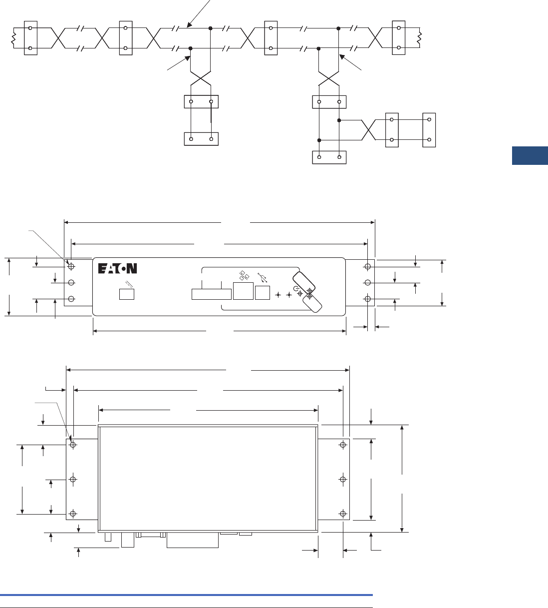
Volume 3—Power Distribution and Control Assemblies CA08100004E—November 2013 www.eaton.com V3-T9-271
9
9
9
9
9
9
9
9
9
9
9
9
9
9
9
9
9
9
9
9
9
9
9
9
9
9
9
9
9
9
9.5
Metering Devices, Protective Relays, Software and Connectivity
Connectivity Options
Daisy Chain Segment Topology
Dimensions
Approximate Dimensions in Inches (mm)
Power Xpert Gateway 400/600 with Standard Panel Mounting (Brackets Included)
Power Xpert Gateway 400/600 with Low Profile Mounting (Optional Bracket Kit Available)
Power Xpert Gateway 400/600
Tap
Device 10
Device 9
Device 8
Device 5
Device 4
Device 3
Device 2
Device 1
Main Run
Tap
EOLTR
EOLTR
Device 7
Device 6
INCOM
Master
Note: Device 1 may be a PC with
internal CONI Card, a SubNetwork Master
(BIM, LDISP), an INCOM MINT (RS-232
MINTII, Ethernet MINT, Modbus RS-485
MINT), an INCOM Gateway (NetLink,
Power Xpert Gateway).
Width Height Depth Shipping Weight Lbs (kg)
8.90 (226.1) 2.10 (53.3) 4.50 (114.3) 1.50 (0.6)
8.75
(222.3)
COM 1
INCOM
reset
COM 1
INCOM
24 VDC
GND
+V
SHLD
D2
D1
CMN
A (-)
B (+)
PXG 400
1.99
(50.5)
0.56
(14.2)
1.12
(28.4)
0.18
(4.6) (6)
10.25
(260.4)
10.75
(273.1)
0.56
(14.2)
0.24
(6.1)
1.60
(40.6)
0.25
(6.4)
ø0.19
(4.83) 8.75
(222.3)
10.80
(274.3)
11.30
(287.0)
3.23
(82.0)
0.51
(12.9)
4.30
(109.2)
0.56
(14.2)
1.03
(26.2)
Top
(6)
2.75
(69.9)
0.25
(6.35)
0.80
(20.3)
1.38
(35.1)
0.75
(19.1)
0.60
(15.2)
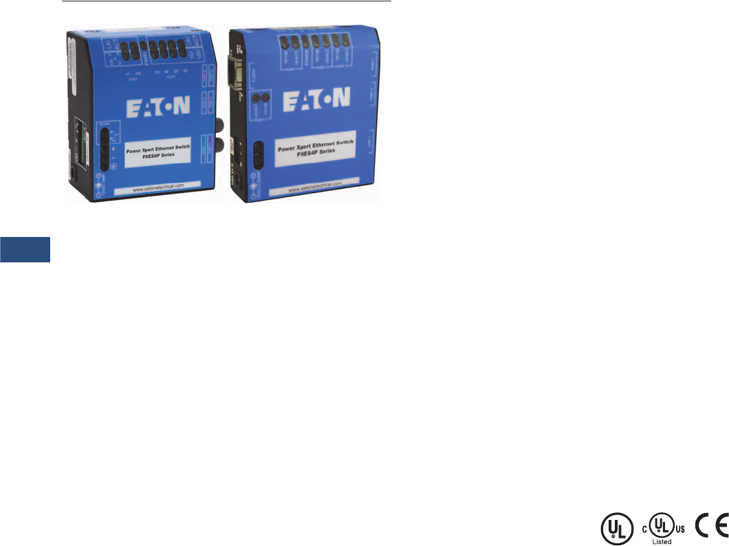
V3-T9-272 Volume 3—Power Distribution and Control Assemblies CA08100004E—November 2013 www.eaton.com
9
9
9
9
9
9
9
9
9
9
9
9
9
9
9
9
9
9
9
9
9
9
9
9
9
9
9
9
9
9
9.5
Metering Devices, Protective Relays, Software and Connectivity
Connectivity Options
Convenient Network Expansion
Power Xpert Ethernet Switches
Contents
Description Page
Power Xpert Gateways. . . . . . . . . . . . . . . . . . . . . . V3-T9-259
Power Xpert Ethernet Switches
Product Selection . . . . . . . . . . . . . . . . . . . . . . . V3-T9-273
Accessories. . . . . . . . . . . . . . . . . . . . . . . . . . . . V3-T9-273
Technical Data and Specifications . . . . . . . . . . . V3-T9-273
Dimensions. . . . . . . . . . . . . . . . . . . . . . . . . . . . V3-T9-275
Power Xpert Gateway
Series 1000 Card—Power Distribution Unit . . . . . . V3-T9-276
Power Xpert Gateway
Series 2000 Card—Uninterruptible Power Supplies V3-T9-279
mMINT. . . . . . . . . . . . . . . . . . . . . . . . . . . . . . . . . . V3-T9-282
MINTII RS-232 Converter . . . . . . . . . . . . . . . . . . . V3-T9-284
IPONI . . . . . . . . . . . . . . . . . . . . . . . . . . . . . . . . . . . V3-T9-285
DPONI . . . . . . . . . . . . . . . . . . . . . . . . . . . . . . . . . . V3-T9-286
MPONI . . . . . . . . . . . . . . . . . . . . . . . . . . . . . . . . . . V3-T9-287
I/O Devices Digital Input Module (DIM) . . . . . . . . . V3-T9-288
Addressable Relay II . . . . . . . . . . . . . . . . . . . . . . . V3-T9-290
Breaker Interface Module II (BIM II) . . . . . . . . . . . V3-T9-293
Sub-Network Master Local Display (SMLD). . . . . . V3-T9-297
IMPCABLE . . . . . . . . . . . . . . . . . . . . . . . . . . . . . . . V3-T9-299
Power Xpert Ethernet Switches
Product Description
Eaton’s Power Xpert
Ethernet Switches are ideal
for extending Ethernet
networks via CAT5 wiring
or fiber in harsh, industrial
environments. Built with
high-grade components and
constructed using special
thermal techniques, PXE
Switches can withstand the
unpredictable conditions of
such environments.
Features
●Simultaneous, full-duplex,
high-speed communication
on all ports—no network
performance bottlenecks
●Hardened for factory
floor—ideal for both
industrial or data center
applications
●Unmanaged, plug-and-play
implementation—no
software or additional
hardware required for
configuration
●Seamlessly integrates into
Eaton’s Power Xpert
Architecture—quality
and reliability of Eaton
guaranteed
●Mounting options include
standalone panel-
mounting, DIN rail
mounting, or 19-inch
standard rack mounting
PXES 6-Port Switch—10/100 Mb
with Optional 100 Mb Fiber
This compact switch provides
six Ethernet ports, with
flexible configurations. The
base models have one of
three options:
●Two 100 Mb fiber and
four 10/100 copper ports
●One fiber and five
copper ports
●Six copper ports
PXES 4-Port Switch—10/100 Mb
For smaller applications
requiring fewer connection
points and no fiber, the 4-port
Power Xpert Ethernet Switch
is a versatile option. It
provides edge access
Ethernet ports in a convenient
and compact package.
Standards and Certifications
●UL Listed (UL 60950)
●cUL
●CE
●Emissions meet FCC Part
15, Class A

Volume 3—Power Distribution and Control Assemblies CA08100004E—November 2013 www.eaton.com V3-T9-273
9
9
9
9
9
9
9
9
9
9
9
9
9
9
9
9
9
9
9
9
9
9
9
9
9
9
9
9
9
9
9.5
Metering Devices, Protective Relays, Software and Connectivity
Connectivity Options
Product Selection
Power Xpert Ethernet Switches
Accessories
Power Xpert Ethernet Switches
Technical Data and Specifications
Operating Environment
Network Standards
Power Consumption
Packaging
Mounting
Description
Catalog
Number
4-port Ethernet switch—copper only PXES4P24V
6-port Ethernet switch—copper only PXES6P24V
6-port Ethernet switch—5 copper/1 fiber (ST connector) PXES6P24V1ST
6-port Ethernet switch—4 copper/2 fiber (ST connector) PXES6P24V2ST
Ethernet Switch
Description
Catalog
Number
Power supply (preferred)—100–240 Vac input
DIN rail mount with screw—24 Vdc output terminals
ELC-PS02
Power supply (alternate)—120 Vac input
Wall plug-in type with 6 ft cord—12 Vdc output
PXESPS12V
DIN rail mounting bracket PXESDINRL
19-inch rack mount tray PXESTRAY
Ethernet Switch
Description Specifications
Ambient temperature ratings –25°C to 60°C long-term per independent agency tests (UL), or –40°C to 85°C short-term per IEC type tests
Storage temperature –40° to 185°F (–40°C to 85°C)
Cold start to –20°C
Ambient relative humidity 5%–95% (noncondensing)
Altitude –200 to 50,000 ft (–60 to 15,000m)
MTBF > 15 years
Description
Ethernet IEEE 802.3, IEEE 802.3u; IEEE 802.1p, 100Base-TX, 10Base-T, 100Base-FX
Description
7.0 watts typical—9 watts maximum
Description Specifications
Enclosure Robust sheet metal (steel)
Cooling method Case used as a heat sink
Description Specifications
Metal panel mounting clips Included
DIN rail mounting Optional
19-inch rack mount Optional

V3-T9-274 Volume 3—Power Distribution and Control Assemblies CA08100004E—November 2013 www.eaton.com
9
9
9
9
9
9
9
9
9
9
9
9
9
9
9
9
9
9
9
9
9
9
9
9
9
9
9
9
9
9
9.5
Metering Devices, Protective Relays, Software and Connectivity
Connectivity Options
Copper Ethernet Cable
Wiring Guidelines
The following information can
be used as a guide when
designing an Ethernet system
using Copper Ethernet Cable.
●Cables should not be
routed near equipment that
generates strong electric
or magnetic fields such as
motors, drive controllers,
arc welders and conduit
●Ethernet cable insulation
has a voltage rating of
300 Vac. Use of barriers,
cable trays or high voltage
sheathing with STP
Ethernet cable may be
required in installations
with cables carrying
voltages greater than
300 Vac. This may
also be necessary in
order to comply with
UL requirements. In
installations where the
cable cannot be physically
separated from the power
cables (where a physical
barrier is not practical) fiber
optic cable should be used
●When crossing power
conductors with Ethernet
cable, cross at right angles
●Shielded Twisted Pair (STP)
Ethernet cable should be
specified for use in high
noise environments.
Shielded shrouded
connectors must be used
and the shield must be
connected at both ends of
the wire. The mating plug
must have a shielded
shroud that is terminated
to ground at both ends.
Where there is a possibility
of a difference in ground
potential (common mode)
voltages between the
two terminated ends,
fiber optic cable is
recommended
●When using conduit or a
metal cable tray, each
section of the conduit or
tray must be bonded to
each adjacent section and
the conduit or tray needs
to be bonded to earth
ground. Do not allow the
shields to touch the
conduit or metal tray at
any point
●Only shielded (STP)
Ethernet cables should be
placed into metal conduit.
Some UTP cables may not
function properly when
installed in conduit, as the
metal conduit can affect the
electrical properties of an
unshielded cable. Consult
the cable manufacturer
when installing UTP cables
in conduit
●As a general rule for noise
protection, Ethernet Cable
should maintain a minimum
distance of 3 inches (8 cm)
from electric power
conductors for up to
100 volts and 1 inch (3 cm)
for each additional 100 volts
up to 400 volts. STP cable is
recommended
●For Ethernet cable run
within conduit, but near
conductors with potentially
noisy power conductors
carrying currents of greater
than 20A or voltages
greater than 400V, maintain
the following distances.
STP cable is required.
●Conductors of less than
20A = 3 inches
●Conductors of 20A or
more and up to 100 kVA
= 6 inches
●Conductors greater than
100 kVA = 12 inches
●For Ethernet cable run near
conductors with potentially
noisy power conductors
carrying currents of greater
than 20A or voltages
greater than 400V, maintain
the following distances.
STP cable is recommended
●Conductors of less than
20A = 6 inches
●Conductors of 20A
or more and up to
100 kVA = 12 inches
●Conductors greater than
100 kVA = 24 inches
●Route Ethernet cable at
least 5 feet (1.5m) from
sources of rf/microwave
radiation. STP cable is
required
●Do not cascade more than
four Ethernet repeaters
(router, switch or hub)
within a network segment
●Environmentally sealed
connectors should be
specified for cables used
in outdoor installations
●Avoid pinching the cable
when using cable ties
●Total distance between an
Ethernet Transmitter and
Receiver at the end points
of the network should not
exceed 328 feet (100m)
●Total distance from a patch
panel to a wall jack (using
solid cable) shall not
exceed 295 feet (90m).
Splices are not permitted
●Patch cords used as cross-
connect jumpers in a patch
panel should not exceed
20 feet (6m)
●Patch cords from a wall
jack to the work area PC
(or device) shall not exceed
16 feet (5m)
●Ethernet cable used in
harsh environments
must be selected to
withstand the following
conditions: vibration,
air born contaminants,
chemicals, temperature,
electromagnetic
interference, combustible
atmospheres and local
regulatory standards such
as UL and NEMA
●Ethernet connectors used
in harsh environments
must be robust enough
to withstand vibration,
multiple connection cycles,
temperature changes,
and provide a proper
seal to protect against
moisture, dust/dirt and
chemical attack
●Different cable media
support different
bandwidth capabilities.
When installing cable in a
network, care should be
taken to install the cable
that will fill current network
loading requirements and
future expansion needs. In
general, fiber optic cable
can support the greatest
bandwidth (upward of
25,000 gigabits) and UTP
has the lowest. CAT5e
cabling is designed to
operate a bit rates up to
1000 Mb and CAT6 cable
up to 2000 Mb
●Operating your cable at
maximum speed reduces
the distance between
network segments. Check
with your cable supplier for
specifications regarding
segment distance vs.
speed
●Cable with 5% impedance
mismatch or return
loss of 27 to 32 dB is
recommended. Ethernet
cable impedance can vary
by as much as 15%
(85 to 115 ohms). Average
Ethernet cable with 15%
impedance variation
can have up to 10 dB
additional return loss.
This discontinuity is
referred to as return loss,
since it causes some of the
signal to be reflected back
down the cable instead of
propagating forward. It
is measured in decibels or
ratio of transmitted versus
reflected signal

Volume 3—Power Distribution and Control Assemblies CA08100004E—November 2013 www.eaton.com V3-T9-275
9
9
9
9
9
9
9
9
9
9
9
9
9
9
9
9
9
9
9
9
9
9
9
9
9
9
9
9
9
9
9.5
Metering Devices, Protective Relays, Software and Connectivity
Connectivity Options
Fiber Optic Technology
The use of fiber optics in
telecommunications and wide
area networking has been
common for many years, but
more recently fiber optics
have become increasingly
prevalent in industrial data
communications systems
as well. High data rate
capabilities, noise rejection
and electrical isolation are
just a few of the important
characteristics that make
fiber optic technology ideal
for use in industrial and
commercial systems.
Although often used for point-
to-point connections, fiber
optic links are being used to
extend the distance
limitations of RS-232, RS-422/
485 and Ethernet systems
while ensuring high data rates
and minimizing electrical
interference.
Conventional electrical data
signals are converted into
a modulated light beam,
introduced into the fiber and
transported via a very small
diameter glass or plastic
fiber to a receiver that
converts the light back into
electrical signals.
Optical fibers allow data
signals to propagate through
them by ensuring that the
light signal enters the fiber
at an angle greater than the
critical angle of the interface
between two types of glass.
Optical fiber is actually made
up of three parts. The center
core is composed of very
pure glass. Core dimensions
are usually in the range
of 50 to 125 um for multi-
mode cables and 8-9 um for
single-mode cables. The
surrounding glass, called
cladding, is a slightly less
pure glass. The diameter of
the core and cladding
together is in the range of
125 to 440 um.
Surrounding the cladding is a
protective layer of flexible
silicone called the sheath.
Fiber Optic Cable
Wiring Guidelines
The following information
can be used as a guide
when designing an Ethernet
system using Fiber Optic
Ethernet Cable:
●Select a fiber cable that is
suited for the application,
e.g., outdoor, aerial, duct,
intra-building, risers,
general building and
plenum applications
●Fiber optic cable is useful in
applications where the
environment is combustible,
electrically noisy, the cable
must be bundles with high
voltage wires or where
common mode voltages
may exist between the
earth ground points of the
terminating connectors
●Fiber optic cable is
available in various
operating temperature
ranges. Care should be
taken to match the
temperature rating of the
fiber to the environment it
will be exposed to. The
temperature specification
for fiber may be narrower
than copper cable. Consult
the cable manufacturer for
temperature specifications
of your cable type
●Sealed fiber connectors are
available for use in harsh
environments to prevent
contamination from
entering the connector and
fiber. The type of seal
required will be application
dependant and can vary
from dust- and moisture-
proof to water-tight
●Mixing fiber cable types is
not permitted. The same
core dimensions and mode
must be used within
cable segments
●Care should be taken when
purchasing connectors to
include strain relief, which
reduces mechanical strain
(vibration) within the cable,
as well as the connector.
Strain relief also provides
support to the cable
to ensure proper bend
radius at the connector
●Single-Mode Fiber is
used for long distance
transmission of up to
120 km. Distance may vary
depending on speed and
type of converter used
●Multi-Mode Graded-Index
Fiber Cable is used for
communication over
shorter distances of up
to 2 km
●Fiber cable is composed of
glass and is not well suited
for applications requiring
tight bend radiuses. Cable
radius dimensions vary per
manufacturer. If the
manufacturer does not
provide a bend radius, a
typical rule of thumb is a
radius not less than 15x the
cable diameter
●Fiber cable to connector
terminations can be
performed in the field
using special equipment.
This method is not
recommended
●Tier One testing is
recommended when
diagnosing system
irregularities and should
be performed in all new
installations
●Tier Two testing is
recommended to certify
that a system complies
with standards set forth
by the owner/installer
Dimensions
Packaging
Description Specifications
Dimensions of PXES4P series
Weight of PXES4P series
3.5 in H x 3.0 in W x 1.0 in D (8.9 cm x 7.6 cm x 2.5 cm)
8.6 oz. (243g)
Dimensions of PXES6P series
Weight of PXES6P series
3.6 in H x 3.0 in W x 1.7 in D (9.2 cm x 7.6 cm x 4.3 cm)
13 oz. (370g)
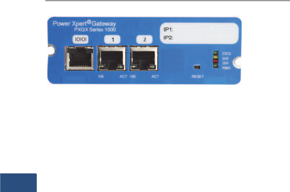
V3-T9-276 Volume 3—Power Distribution and Control Assemblies CA08100004E—November 2013 www.eaton.com
9
9
9
9
9
9
9
9
9
9
9
9
9
9
9
9
9
9
9
9
9
9
9
9
9
9
9
9
9
9
9.5
Metering Devices, Protective Relays, Software and Connectivity
Connectivity Options
Power Xpert Gateway Series 1000 Card
Contents
Description Page
Power Xpert Gateways. . . . . . . . . . . . . . . . . . . . . . V3-T9-259
Power Xpert Ethernet Switches . . . . . . . . . . . . . . . V3-T9-272
Power Xpert Gateway
Series 1000 Card—Power Distribution Unit
Features . . . . . . . . . . . . . . . . . . . . . . . . . . . . . . V3-T9-277
Product Selection . . . . . . . . . . . . . . . . . . . . . . . V3-T9-278
Technical Data and Specifications . . . . . . . . . . . V3-T9-278
Dimensions. . . . . . . . . . . . . . . . . . . . . . . . . . . . V3-T9-278
Power Xpert Gateway
Series 2000 Card—Uninterruptible Power Supplies V3-T9-279
mMINT. . . . . . . . . . . . . . . . . . . . . . . . . . . . . . . . . . V3-T9-282
MINTII RS-232 Converter . . . . . . . . . . . . . . . . . . . V3-T9-284
IPONI . . . . . . . . . . . . . . . . . . . . . . . . . . . . . . . . . . . V3-T9-285
DPONI . . . . . . . . . . . . . . . . . . . . . . . . . . . . . . . . . . V3-T9-286
MPONI . . . . . . . . . . . . . . . . . . . . . . . . . . . . . . . . . . V3-T9-287
I/O Devices Digital Input Module (DIM) . . . . . . . . . V3-T9-288
Addressable Relay II . . . . . . . . . . . . . . . . . . . . . . . V3-T9-290
Breaker Interface Module II (BIM II) . . . . . . . . . . . V3-T9-293
Sub-Network Master Local Display (SMLD). . . . . . V3-T9-297
IMPCABLE . . . . . . . . . . . . . . . . . . . . . . . . . . . . . . . V3-T9-299
Power Xpert Gateway
Series 1000 Card—Power Distribution Unit
Product Description
The Power Xpert Gateway
Series 1000 Card (PXGX
1000) provides Web-enabled,
real-time monitoring of
Powerware Power
Distribution Units (PDUs),
Rack Power Modules (RPM)
and Powerware Remote
Power Panels (RPPs) through
standard on-board Web
pages, Power Xpert Software
or third-party software.
An integral part of the Power
Xpert Architecture, which
provides end-to-end
PowerChain solutions, the
PXGX 1000 provides a central
point to connect distribution
products to an Ethernet
network.
Information is presented
in organized, user-friendly
Web pages and include
the following:
●PDU system identification
●Graphic panel layouts
●Voltage
●Current
●Frequency
●Energy
●Power
●THD (current and voltage)
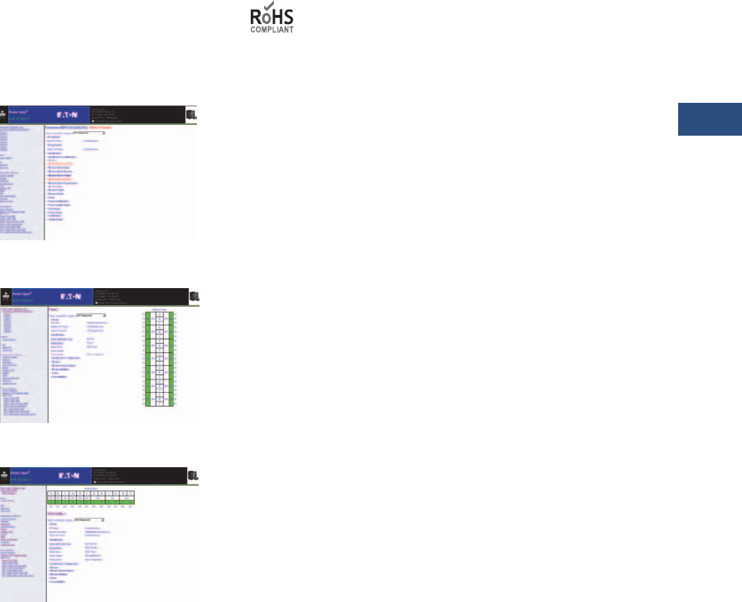
Volume 3—Power Distribution and Control Assemblies CA08100004E—November 2013 www.eaton.com V3-T9-277
9
9
9
9
9
9
9
9
9
9
9
9
9
9
9
9
9
9
9
9
9
9
9
9
9
9
9
9
9
9
9.5
Metering Devices, Protective Relays, Software and Connectivity
Connectivity Options
Features
●Web-enabled monitoring of
power quality data down to
the branch circuit level—
Data can be viewed
from any location with a
Web browser
●Configure and edit the
EMS remotely via the
Web interface—supports
remote configuration,
including naming, alarm
and warning set points and
percentages
●Data, interval and event
logging with time stamp—
accurate logging for power
quality analysis
●Modbus TCP/IP and SNMP
Support—open
communication protocol
facilitates integration with
standard building
management systems and
network management
systems
●Customized e-mail
messaging for events
notification, including data
and event logs and periodic
“heartbeat” e-mails—
direct alarm and event
notification to the
appropriate person(s)
in the organization
●Easy integration into
existing Ethernet
infrastructure—minimize
installation cost
●Securely access and view
information—password
authentication is required
at two levels. The card also
supports secure Web-
based communication
via SSL
●Generate Modbus Register
Maps on the fly—all of the
data specific to the system
is immediately available
and can be generated with
one click of the mouse
●Save and Restore
settings—configuring a
large PDU with EMS can
take time. Once the effort
is complete, the
configuration can be saved
for later use. It also allows
the user to duplicate panel
identical configurations in
minimal time
●Supports the
Environmental Monitoring
Probe—temperature,
humidity and contact
status can be viewed
though the Web page
PDU or RPP System Summary Page
PDU or RPP Panel Page
RPM Panel Page
Standards and Certifications
●FCC Part 15, Class A
●CISPR 22, Class A
●ROHS Compliant
●Telecom conducted via
EU Standard
●EN 55022:1988+A1:
2000+A2:2003, Class A/
EN55022:1988+A1:200
0+A2:2003

V3-T9-278 Volume 3—Power Distribution and Control Assemblies CA08100004E—November 2013 www.eaton.com
9
9
9
9
9
9
9
9
9
9
9
9
9
9
9
9
9
9
9
9
9
9
9
9
9
9
9
9
9
9
9.5
Metering Devices, Protective Relays, Software and Connectivity
Connectivity Options
Product Selection
Ordering Information
Technical Data and Specifications
The Power Xpert Gateway
Series 1000 Card Kit Includes
●Power Xpert Gateway
Series 1000 Card
●Ethernet cable
●Local configuration cable
●Quick start guide
Devices Supported
●Powerware Power
Distribution Units with
X-Slot® compatibility
●Power ware Remote Power
Panels with X-Slot
compatibility
●Power ware Rack Power
Modules with X-Slot
compatibility
Communication Ports
●Ethernet ports: Two
independent RJ-45 ports:
supports 10/100Base-T
for redundant network
configurations
●Serial ports: One RJ-45
console part: supports
local configuration and
optional connection to an
Environmental Monitoring
Probe (EMP)
Communication
Protocols Supported
●Web server: supports
data access from Web
browsers (HTTP and
HTTPS)
●Modbus TCP/IP: supports
data access from Modbus
TCP clients
●SNMP: supports common
network management
tools
●SMTP: supports e-mail
notification
●NTP: supports time
synchronization via an
NTP server for card and
PDU synchronization
●DHCP: supports automatic
IP address assignments,
if enabled
Supported MIBs
●Eaton PDU MIB
●Eaton EMP MIB
●Eaton alarms and traps
MIB
●RFC 4133 Entity MIB
●RFC 4268 Entity State MIB
●RFC 4268 Entity State MIB
Part II
●RFC 1213 MIB II
Web Browsers Supported
●IE
●Mozilla Firefox
Environmental
Specifications
●Ambient operating: 0 to
+40°C (32 to 104°F)
●Relative humidity: 10 to
80%, noncondensing
●Altitude: 10,000 ft
●Enclosure rating: indoor
use only
Mounting Configuration
●X-Slot form factor fits
directly into PDU/RPP/
RPM chassis
Power Supply
●Nominal input voltage:
12 Vdc, unregulated
(provided by PDU/RPP)
●Input voltage range:
8–25 Vdc, unregulated
Power Consumption
2.0 watts
Note: Features and specifications
listed in this document are
subject to change without notice
and represent the maximum
capabilities of the software and
products with all options
installed. This is not a complete
feature list. Features and
functionality may vary depending
on selected options.
Dimensions
Approximate Dimensions in Inches (mm)
Physical Characteristics
Description
Style
Number
Catalog
Number
Power Xpert Gateway Series 1000 Card for use with Eaton
PDUs, RPPs, RPMs, PDRs and EMS-UGK
103005741-5591 PXGX1000
Power Xpert Gateway
Series 1000 Card
Height Width Depth
Weight
Lbs (kg)
1.50 (39.0) 4.70 (120.0) 4.50 (114.0) 0.44 (0.2)

Volume 3—Power Distribution and Control Assemblies CA08100004E—November 2013 www.eaton.com V3-T9-279
9
9
9
9
9
9
9
9
9
9
9
9
9
9
9
9
9
9
9
9
9
9
9
9
9
9
9
9
9
9
9.5
Metering Devices, Protective Relays, Software and Connectivity
Connectivity Options
Power Xpert Gateway Series 2000 Card
Contents
Description Page
Power Xpert Gateways . . . . . . . . . . . . . . . . . . . . . . V3-T9-259
Power Xpert Ethernet Switches . . . . . . . . . . . . . . . V3-T9-272
Power Xpert Gateway
Series 1000 Card—Power Distribution Unit . . . . . . V3-T9-276
Power Xpert Gateway
Series 2000 Card—Uninterruptible Power Supplies
Features. . . . . . . . . . . . . . . . . . . . . . . . . . . . . . . V3-T9-280
Standards and Certifications . . . . . . . . . . . . . . . V3-T9-280
Product Selection . . . . . . . . . . . . . . . . . . . . . . . V3-T9-281
Technical Data and Specifications . . . . . . . . . . . V3-T9-281
Dimensions . . . . . . . . . . . . . . . . . . . . . . . . . . . . V3-T9-281
mMINT . . . . . . . . . . . . . . . . . . . . . . . . . . . . . . . . . . V3-T9-282
MINTII RS-232 Converter. . . . . . . . . . . . . . . . . . . . V3-T9-284
IPONI . . . . . . . . . . . . . . . . . . . . . . . . . . . . . . . . . . . V3-T9-285
DPONI . . . . . . . . . . . . . . . . . . . . . . . . . . . . . . . . . . V3-T9-286
MPONI . . . . . . . . . . . . . . . . . . . . . . . . . . . . . . . . . . V3-T9-287
I/O Devices Digital Input Module (DIM) . . . . . . . . . V3-T9-288
Addressable Relay II. . . . . . . . . . . . . . . . . . . . . . . . V3-T9-290
Breaker Interface Module II (BIM II) . . . . . . . . . . . V3-T9-293
Sub-Network Master Local Display (SMLD) . . . . . . V3-T9-297
IMPCABLE . . . . . . . . . . . . . . . . . . . . . . . . . . . . . . . V3-T9-299
Power Xpert Gateway
Series 2000 Card—Uninterruptible Power Supplies
Product Description
The Power Xpert Gateway
Series 2000 Card (PXGX
2000) provides Web-enabled,
real-time monitoring of
Powerware Uninterruptible
Power Supplies (UPS)
through standard on-board
Web pages, Power Xpert
Software or third-party
software.
An integral part of the Power
Xpert Architecture, which
provides end-to-end
PowerChain solutions, the
PXGX 2000 provides a central
point to connect distribution
products to an Ethernet
network.
Information is presented
in organized, user-friendly
Web pages and include
the following:
●UPS system identification
●Voltage
●Current
●Frequency
●Energy
●Output Power
●Power—full load %
●Battery information
●History and
maintenance
●Run time remaining
●Voltage
●% battery left
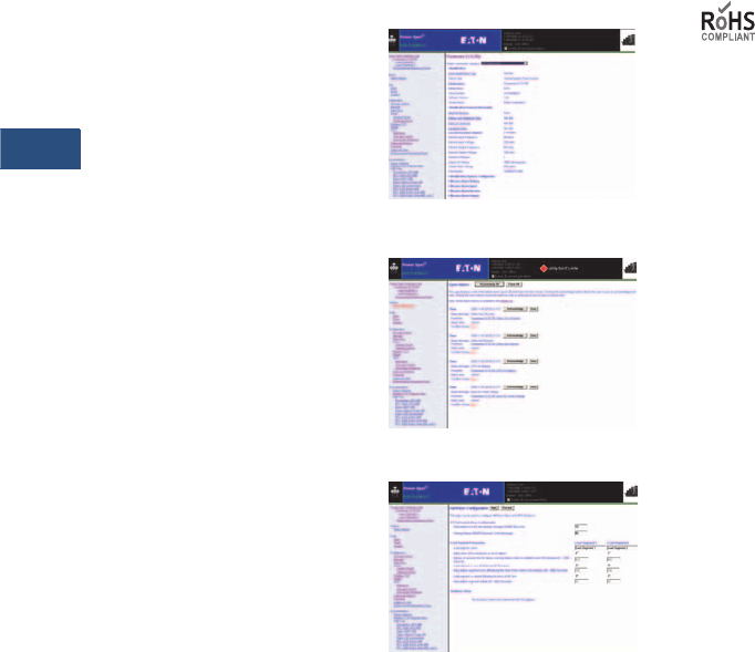
V3-T9-280 Volume 3—Power Distribution and Control Assemblies CA08100004E—November 2013 www.eaton.com
9
9
9
9
9
9
9
9
9
9
9
9
9
9
9
9
9
9
9
9
9
9
9
9
9
9
9
9
9
9
9.5
Metering Devices, Protective Relays, Software and Connectivity
Connectivity Options
Features
●Web-enabled monitoring of
power quality data—data
can be viewed from any
location with a Web
browser
●Data, event and system
logging with time stamp—
accurate logging for power
quality analysis
●Modbus TCP/IP and SNMP
Support—open
communication protocol
facilitates integration
with standard building
management systems and
network management
systems
●Intelligent e-mail
communications—two
options for alarm and
event e-mail notification,
individual e-mails for each
alarm or event, or
collective notification,
providing the same
information with a
drastically reduced number
of e-mails
●Easy integration into
existing Ethernet
infrastructure—minimize
installation cost
●Securely access and view
information—password
authentication is required
at two levels. The card also
supports secure Web-
based communication
via SSL
●Generate Modbus Register
Maps on the fly—all of the
data specific to the UPS is
immediately available and
can be generated with one
click of the mouse
●Save and Restore
settings—once the
configuration effort is
complete, it can be saved
for later use
●Supports the
Environmental Monitoring
Probe—temperature,
humidity and contact
status can be viewed
through the Web page
●Two independent,
redundant Ethernet
ports—designed to
support high reliability
systems
UPS Summary Page
Alarm Summary Page
NetWatch Support Page
Standards and Certifications
●FCC Part 15, Class A
●CISPR 22, Class A
●ROHS Compliant
●Telecom conducted via
EU Standard
●EN 55022:1988+A1:
2000+A2:2003, Class A/
EN55022:1988+A1:200
0+A2:2003

Volume 3—Power Distribution and Control Assemblies CA08100004E—November 2013 www.eaton.com V3-T9-281
9
9
9
9
9
9
9
9
9
9
9
9
9
9
9
9
9
9
9
9
9
9
9
9
9
9
9
9
9
9
9.5
Metering Devices, Protective Relays, Software and Connectivity
Connectivity Options
Product Selection
Ordering Information
Technical Data and Specifications
The Power Xpert Gateway
Series 2000 Card Kit Includes
●Power Xpert Gateway
Series 2000 Card
●Ethernet cable
●Local configuration cable
●Quick start guide
Devices Supported
●Powerware uninterruptible
power supplies with X-Slot
compatibility; these include
the Powerware 5115 RM,
5125, 9125, 9140, 9155,
9315, 9355, 9330, 9390,
9395, BladeUPST
Communication Ports
●Ethernet ports: two
independent RJ-45 ports:
supports 10/100Base-T for
redundant network
configurations
●Serial ports: one RJ-45
console port supports
local configuration and
optional connection to an
Environmental Monitoring
Probe (EMP)
Communication
Protocols Supported
●Web server: supports
data access from Web
browsers (HTTP and
HTTPS)
●Modbus TCP/IP: supports
data access from Modbus
TCP clients
●SNMP: supports common
network management
tools
●SMTP: supports e-mail
notification
●NTP: supports time
synchronization via an
NTP server for card and
UPS synchronization
●DHCP: supports automatic
IP address assignments,
if enabled
Supported MIBs
●Eaton Power MIB
●RFC 1628 UPS MIB
●Eaton EMP MIB
●Eaton alarms and
traps MIB
●RFC 4133 Entity MIB
●RFC 4268 Entity State
MIB; RFC 4268 Entity
State MIB Part 2
●RFC 1213 MIB II
Web Browsers Supported
●IE
●Mozilla Firefox
Environmental
Specifications
●Ambient operating:
0 to +40°C (32 to 104°F)
●Relative humidity:
10 to 80%, noncondensing
●Altitude: 10,000 ft
●Enclosure rating: indoor
use only
Mounting Configuration
●X-Slot form factor fits
directly into UPS chassis
Power Supply
●Nominal input voltage:
12 Vdc, unregulated
(provided by UPS)
●Input voltage range:
8–25 Vdc, unregulated
Power Consumption
●2.0 watts
Dimensions
Approximate Dimensions in Inches (mm)
Physical Characteristics
Description
Style
Number
Catalog
Number
Power Xpert Gateway Series 2000 Card for use with
Powerware UPSs
103005868-5591 PXGX 2000
Power Xpert Gateway
Series 2000 Card
Height Width Depth
Weight
Lbs (kg)
1.50 (39.0) 4.70 (120.0) 4.50 (114.0) 0.44 (0.2)
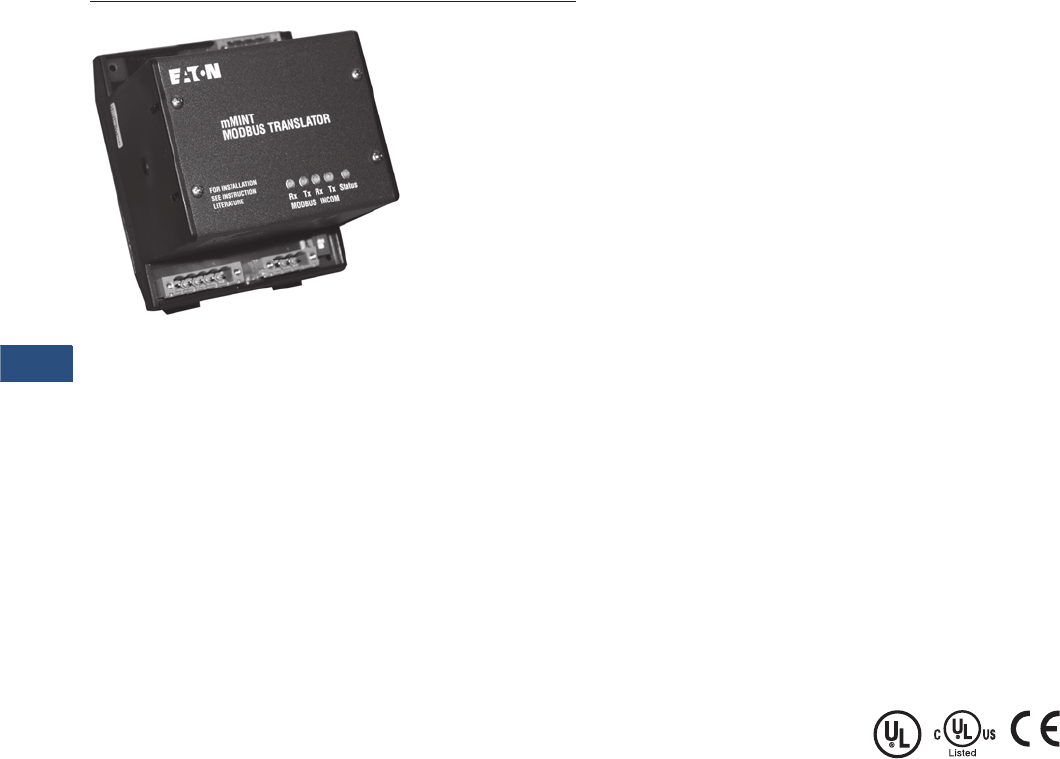
V3-T9-282 Volume 3—Power Distribution and Control Assemblies CA08100004E—November 2013 www.eaton.com
9
9
9
9
9
9
9
9
9
9
9
9
9
9
9
9
9
9
9
9
9
9
9
9
9
9
9
9
9
9
9.5
Metering Devices, Protective Relays, Software and Connectivity
Connectivity Options
mMINT Module
Contents
Description Page
Power Xpert Gateways. . . . . . . . . . . . . . . . . . . . . . V3-T9-259
Power Xpert Ethernet Switches . . . . . . . . . . . . . . . V3-T9-272
Power Xpert Gateway
Series 1000 Card—Power Distribution Unit . . . . . . V3-T9-276
Power Xpert Gateway
Series 2000 Card—Uninterruptible Power Supplies V3-T9-279
mMINT
Technical Data and Specifications . . . . . . . . . . . V3-T9-283
MINTII RS-232 Converter . . . . . . . . . . . . . . . . . . . V3-T9-284
IPONI . . . . . . . . . . . . . . . . . . . . . . . . . . . . . . . . . . . V3-T9-285
DPONI . . . . . . . . . . . . . . . . . . . . . . . . . . . . . . . . . . V3-T9-286
MPONI . . . . . . . . . . . . . . . . . . . . . . . . . . . . . . . . . . V3-T9-287
I/O Devices Digital Input Module (DIM) . . . . . . . . . V3-T9-288
Addressable Relay II . . . . . . . . . . . . . . . . . . . . . . . V3-T9-290
Breaker Interface Module II (BIM II) . . . . . . . . . . . V3-T9-293
Sub-Network Master Local Display (SMLD). . . . . . V3-T9-297
IMPCABLE . . . . . . . . . . . . . . . . . . . . . . . . . . . . . . . V3-T9-299
mMINT
Product Description
The mMINT (Modbus Master
INCOM Network Translator)
Module is an Eaton accessory
product that provides
communication between
a Modbus RTU network
and an INCOM (INdustrial
COMmunications) network
(see Page V3-T9-283). This
module is transparent to the
Modbus network. It
communicates to a master on
the Modbus network using
the Modbus RTU (Remote
Terminal Unit) protocol. It
communicates to slave
devices on the INCOM
network using the IMPACC
(Integrated Monitoring,
Protection, And Control
Communication) protocol.
Features
The mMINT module is a
slave device on the Modbus
network and as such requires
a master that will exchange
register objects with the
mMINT module.
●Handles generic pass-
through commands
(Modbus/INCOM/Modbus)
●Capable of passing
Modbus register objects
from Eaton’s existing
products and newer PnP
(Plug-n-Play) products to a
Modbus RTU master
●Data in IEEE Floating Point
format and fixed point
●Modbus RTU
communications data
transfer rates of 1200,
9600 or 19,200 baud with
one start bit, eight data
bits, no parity, and either
one or two stop bits
●Up to 32 products
connected to INCOM
network port (246 unique
addresses maximum)
●Flashing Status LED to
indicate an active module
●LED indicators for INCOM
transmit and receive
communications
exchanges
●LED indicators for Modbus
RS-485 transmit and
receive communications
exchanges
●Input power for the module
from either 120 Vac or 24
to 125 Vdc
●DIN rail mount package
●0ºC to 60ºC ambient
operation
Standards and Certifications
●UL
●CSA
●CE mark
Product Selection
The catalog number of this
product is mMINT.
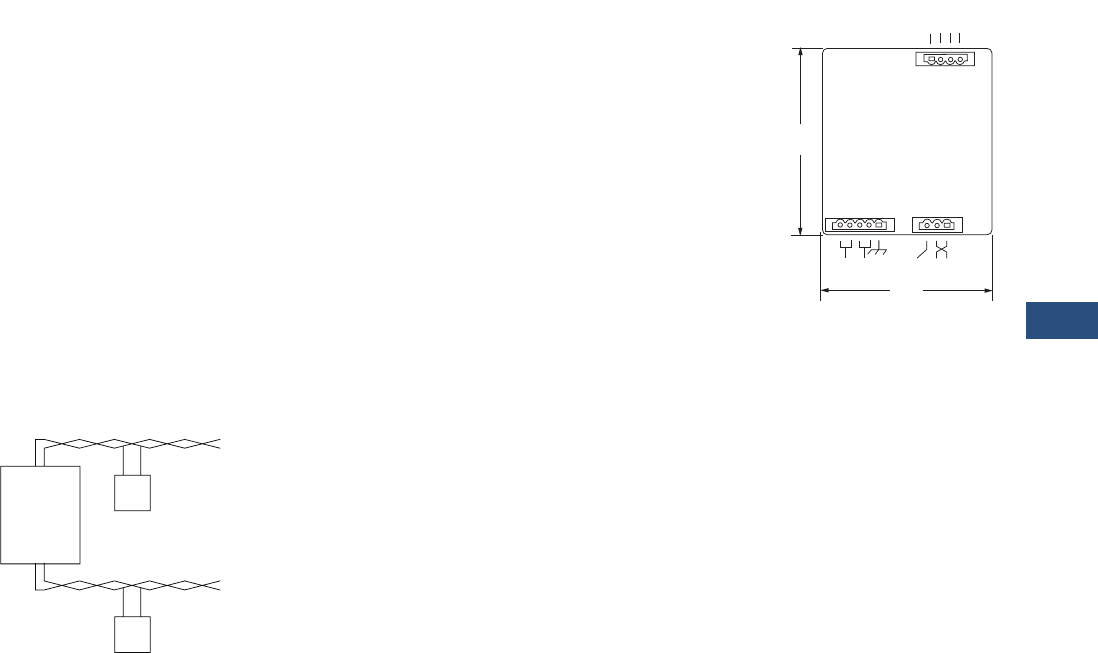
Volume 3—Power Distribution and Control Assemblies CA08100004E—November 2013 www.eaton.com V3-T9-283
9
9
9
9
9
9
9
9
9
9
9
9
9
9
9
9
9
9
9
9
9
9
9
9
9
9
9
9
9
9
9.5
Metering Devices, Protective Relays, Software and Connectivity
Connectivity Options
Technical Data and Specifications
Module Mounting
When mounting the
mMINT, verify that an
11 mm H x 28 mm W
DIN rail is used and that it is
within an enclosed space.
Simplified Wiring Rules
INCOM Network
The following simplified rules
apply to a given system
consisting of a single daisy-
chained main cable link
between master and slave
devices (see below). For
more complex considerations
including star configurations,
please refer to the IMPACC
wiring specification
T.D. 17513.
mMINT in a Communications Network
●Recommended INCOM
cable styles are Belden
9463 or C-H style
2A957805G01
●The maximum system
capacity is 10,000 feet of
communications cable and
32 slave devices on the
INCOM network under
the mMINT
●Non-terminated taps, up to
200 feet in length, off the
main link are permitted,
but add to the total
cable length
●Make sure that there is
twisted-pair wire that is
recommended for IMPACC
network use. Use shielded
twisted-pair wire to
connect each slave to the
INCOM network, daisy-
chain style. The polarity
of the twisted pair is
not important
Modbus RS-485 Network
The following simplified rules
apply to a given system
consisting of a cable link
between master and slave
devices (see below). For
more complex configurations,
please refer to standard
Modbus RTU wiring
specification rules for
the RS-485 network.
●The recommended
Modbus cable has twisted-
pair wires (24 AWG
stranded 7x32 conductors
with PVC insulation) having
an aluminum/mylar foil
shield with drain wire
●The maximum system
capacity is 4000 feet of
communications cable and
247 devices on the
Modbus RTU network
●Make sure that there is
twisted-pair wire that is
recommended for Modbus
RTU network use. Use
shielded twisted-pair wire
to connect each slave to
the Modbus RTU network,
daisy-chain style. The
polarity of the twisted pair
is critically important
mMINT Module Dimensions
Burden
●24 Vac/dc 3 VA
Communications Speed
■INCOM: 1200, 9600 baud
●N2 Bus: 9600 baud
Note: Contact Eaton for
availability and support for the
N2 Gateway.
Modbus RTU Serial Network
(Slave)
Modbus
mMINT
(Master)
Modbus
Master
INCOM Network
INCOM
Slaves
J1 J2
J3
4.25
(108.0)
RS-485
Modbus
3.54
(89.9)
24 – 125 Vdc
120 Vac
Shield INCOM
A B COM SHD
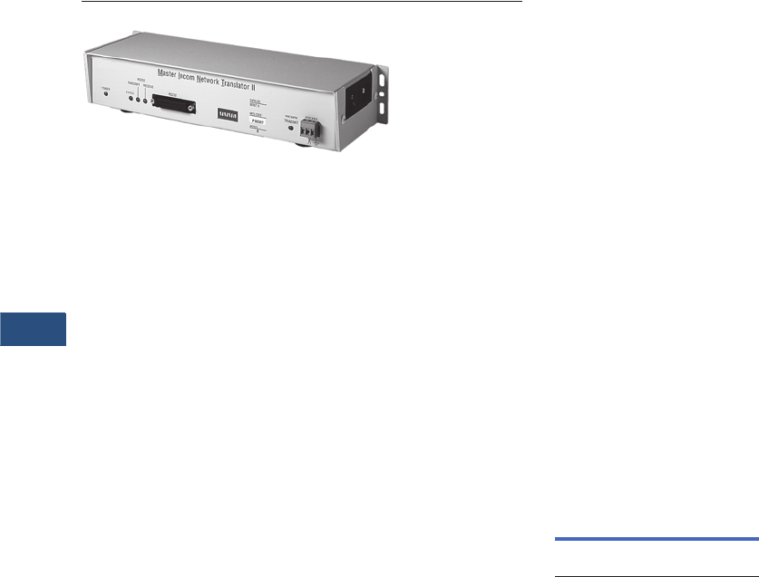
V3-T9-284 Volume 3—Power Distribution and Control Assemblies CA08100004E—November 2013 www.eaton.com
9
9
9
9
9
9
9
9
9
9
9
9
9
9
9
9
9
9
9
9
9
9
9
9
9
9
9
9
9
9
9.5
Metering Devices, Protective Relays, Software and Connectivity
Connectivity Options
MINTII RS-232 Converter
Contents
Description Page
Power Xpert Gateways. . . . . . . . . . . . . . . . . . . . . . V3-T9-259
Power Xpert Ethernet Switches . . . . . . . . . . . . . . . V3-T9-272
Power Xpert Gateway
Series 1000 Card—Power Distribution Unit . . . . . . V3-T9-276
Power Xpert Gateway
Series 2000 Card—Uninterruptible Power Supplies V3-T9-279
mMINT. . . . . . . . . . . . . . . . . . . . . . . . . . . . . . . . . . V3-T9-282
MINTII RS-232 Converter
IPONI . . . . . . . . . . . . . . . . . . . . . . . . . . . . . . . . . . . V3-T9-285
DPONI . . . . . . . . . . . . . . . . . . . . . . . . . . . . . . . . . . V3-T9-286
MPONI . . . . . . . . . . . . . . . . . . . . . . . . . . . . . . . . . . V3-T9-287
I/O Devices Digital Input Module (DIM) . . . . . . . . . V3-T9-288
Addressable Relay II . . . . . . . . . . . . . . . . . . . . . . . V3-T9-290
Breaker Interface Module II (BIM II) . . . . . . . . . . . V3-T9-293
Sub-Network Master Local Display (SMLD). . . . . . V3-T9-297
IMPCABLE . . . . . . . . . . . . . . . . . . . . . . . . . . . . . . . V3-T9-299
MINTII RS-232 Converter
Product Description
Converts a network of Power
Management Software
devices to ASCII RS-232
format for access through
a serial port of a personal
computer, laptop, or
Programmable Logic
Controller.
Displayed Parameters
●Eaton’s MINTII provides
access to all parameters
monitored over the Power
Management Software
network
●Supports INCOM networks
up to 8500 feet (2590m) in
distance and device counts
up to 1000
Application Description
The Master INCOM Network
Translator
II
(MINTII) converts
the twisted shielded pair
network of INCOM devices to
an RS-232 signal. This signal
can be accessed by PLCs,
computer serial ports,
building management system
serial interface cards. The
MINTII is also often applied
as an interface to standard
line drivers and converters to
allow communication through
dedicated telephone lines,
dial-up modems, fiber-optic
line drivers, radio frequency
or wireless modems.
Product Selection
MINTII RS-232 Converter
Technical Data and
Specifications
Temperature
●0°C to 60°C
Humidity
●0% to 95%
Power
●120V
Speed
●1200, 2400 and 9600 baud
(INCOM), 19.2K baud
(RS-232)
Communications
●INCOM, RS-232
Dimensions
●Suitable for panel
mounting or desktop use
●120 Vac power cord
included for plug-in to
standard duplex receptacle
●Height: 2.25 inches
(57.2 mm)
●Width: 11.5 inches
(292.1 mm)
●Depth: 4.25 inches
(108.0 mm)
Description
Catalog
Number
Master INCOM Network
Translator II
MINTII
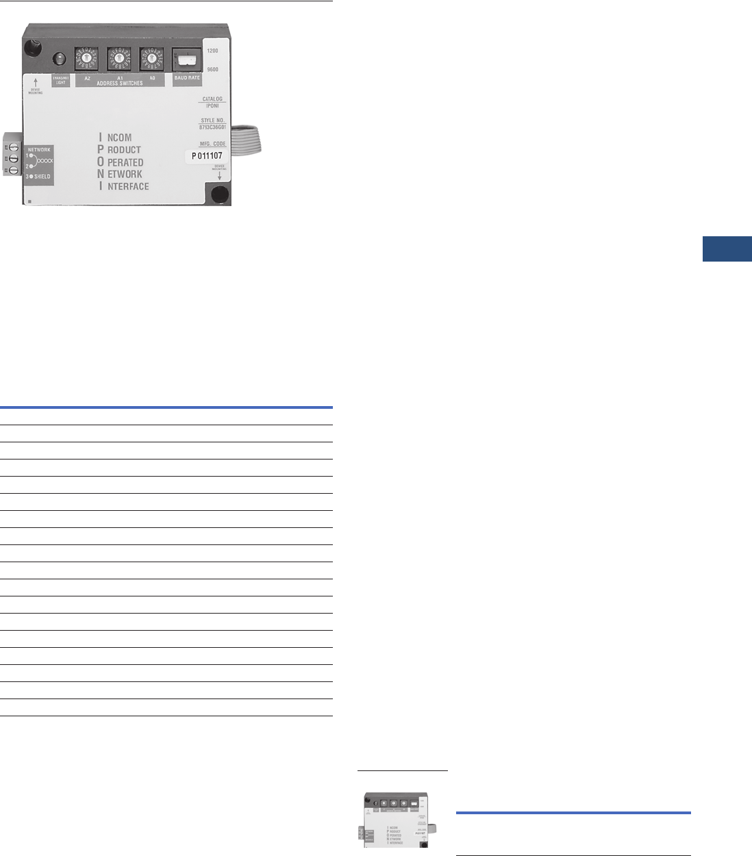
Volume 3—Power Distribution and Control Assemblies CA08100004E—November 2013 www.eaton.com V3-T9-285
9
9
9
9
9
9
9
9
9
9
9
9
9
9
9
9
9
9
9
9
9
9
9
9
9
9
9
9
9
9
9.5
Metering Devices, Protective Relays, Software and Connectivity
Connectivity Options
IPONI Communication Module
Contents
Description Page
Power Xpert Gateways . . . . . . . . . . . . . . . . . . . . . . V3-T9-259
Power Xpert Ethernet Switches . . . . . . . . . . . . . . . V3-T9-272
Power Xpert Gateway
Series 1000 Card—Power Distribution Unit . . . . . . V3-T9-276
Power Xpert Gateway
Series 2000 Card—Uninterruptible Power Supplies V3-T9-279
mMINT . . . . . . . . . . . . . . . . . . . . . . . . . . . . . . . . . . V3-T9-282
MINTII RS-232 Converter. . . . . . . . . . . . . . . . . . . . V3-T9-284
IPONI
DPONI . . . . . . . . . . . . . . . . . . . . . . . . . . . . . . . . . . V3-T9-286
MPONI . . . . . . . . . . . . . . . . . . . . . . . . . . . . . . . . . . V3-T9-287
I/O Devices Digital Input Module (DIM) . . . . . . . . . V3-T9-288
Addressable Relay II. . . . . . . . . . . . . . . . . . . . . . . . V3-T9-290
Breaker Interface Module II (BIM II) . . . . . . . . . . . V3-T9-293
Sub-Network Master Local Display (SMLD) . . . . . . V3-T9-297
IMPCABLE . . . . . . . . . . . . . . . . . . . . . . . . . . . . . . . V3-T9-299
IPONI
Product Selection Guide
IPONI Selection Chart
Description IPONI
INCOM
on Product MPONI
IQ Analyzer Š1.06 — ■
IQ DP-4000 ■—■
IQ 200 — ■—
IQ Multipoint Energy Submeter II —■—
Energy Sentinel — ■—
Power Sentinel — ■—
IQ Generator ■——
IQ Data ■——
IQ Data Plus II —— —
IQ 500 — — —
IQ Transfer ■——
AEMII ■——
BIM II ■——
CMU ■——
CED ■——
MP-3000 ■—■
Digitrip 3000 — ■—
FP-5000 — ■—
Product Description
The INCOM Product
Operated Network Interface
card, or IPONI card, adds
communication capability to
various Eaton products. Each
IPONI has three 16-digit
address switches to uniquely
identify each device on the
network. IPONIs are
designed to be daisy-chained
throughout a unit substation
or equipment room to a
master device such as a
mMINT, MINTII or Power
Xpert Gateway. From the
master computer, information
is distributed through the
facility’s TCP/IP Ethernet
network. A twisted shielded
pair network connecting
IPONIs may extend up to
10,000 feet (3048m) before
terminating a master device.
The IPONI comes with
mounting hardware and
attaches to the back of its
associated device.
Technical Data and
Specifications
Temperature
●–20°C to 70°C
Humidity
●5%–95% noncondensing
Power
●20–30 Vdc maximum,
50 mA nominal,
100 mA maximum
Speed
●1200 and 9600 baud
Communications
●Three-position removable
terminal block for twisted
shielded pair INCOM
Product Selection
PONI Communication Modules
Description
Catalog
Number
INCOM PONI IPONI
IPONI Card
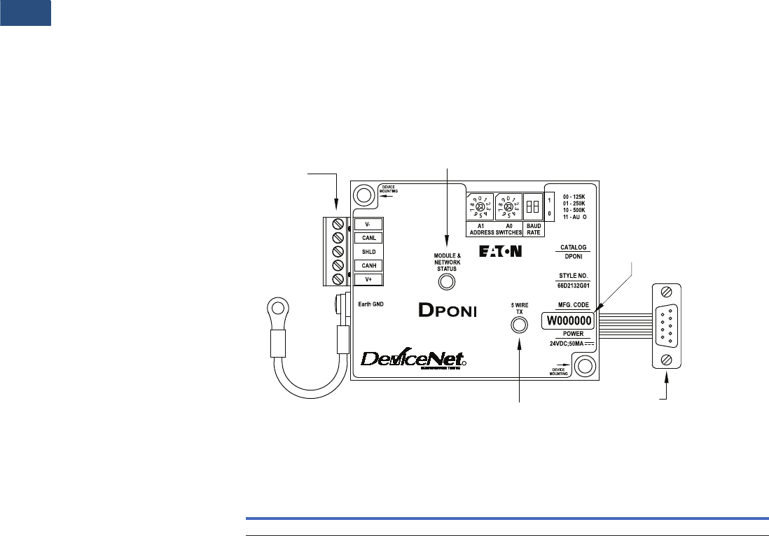
V3-T9-286 Volume 3—Power Distribution and Control Assemblies CA08100004E—November 2013 www.eaton.com
9
9
9
9
9
9
9
9
9
9
9
9
9
9
9
9
9
9
9
9
9
9
9
9
9
9
9
9
9
9
9.5
Metering Devices, Protective Relays, Software and Connectivity
Connectivity Options
Contents
Description Page
Power Xpert Gateways. . . . . . . . . . . . . . . . . . . . . . V3-T9-259
Power Xpert Ethernet Switches . . . . . . . . . . . . . . . V3-T9-272
Power Xpert Gateway
Series 1000 Card—Power Distribution Unit . . . . . . V3-T9-276
Power Xpert Gateway
Series 2000 Card—Uninterruptible Power Supplies V3-T9-279
mMINT. . . . . . . . . . . . . . . . . . . . . . . . . . . . . . . . . . V3-T9-282
MINTII RS-232 Converter . . . . . . . . . . . . . . . . . . . V3-T9-284
IPONI . . . . . . . . . . . . . . . . . . . . . . . . . . . . . . . . . . . V3-T9-285
DPONI
MPONI . . . . . . . . . . . . . . . . . . . . . . . . . . . . . . . . . . V3-T9-287
I/O Devices Digital Input Module (DIM) . . . . . . . . . V3-T9-288
Addressable Relay II . . . . . . . . . . . . . . . . . . . . . . . V3-T9-290
Breaker Interface Module II (BIM II) . . . . . . . . . . . V3-T9-293
Sub-Network Master Local Display (SMLD). . . . . . V3-T9-297
IMPCABLE . . . . . . . . . . . . . . . . . . . . . . . . . . . . . . . V3-T9-299
DPONI
Product Description
The DeviceNet Product
Operated Network
Interface (DPONI) enables
communication between a
DeviceNet network master
station and a host device in a
Master/Slave format over a
DeviceNet network. The
DPONI is compatible with the
MP-3000 and the MP-4000.
The DPONI is powered both
by the host product to which
it is attached and by the
DeviceNet network. The
DPONI uses opto-couplers
to isolate the two power
systems.
The DPONI communicates
at 125, 250 or 500 Kbps
selected via a front panel
DIP switch. All products on
the DeviceNet network
must be set at the same
communication rate.
The DPONI has a bi-color
network/module status
LED that functions in
accordance with the
DeviceNet specification.
An additional monocolor
LED flashes while the DPONI
is receiving a message from
the host device.
Features
Eaton’s DPONI
Product Selection
DPONI
Technical Data and Specifications
Temperature
●–20ºC to 70ºC
Humidity
●5%–90% noncondensing
Power
●11–27 Vdc, 40 mA maximum
Speed
●125, 250 or 500 Kbps
Communications
●Standard five-wire
CAN connection
DEVICE
MOUNTING
T
R
DeviceNet
Network
Connection
(5 point plug)
Earth
GND
DeviceNet
Status
Data
Code
INCOM
Status
IQ Host
Device
Connection
Description
Catalog
Number
The DeviceNet Product Operated Network Interface DPONI
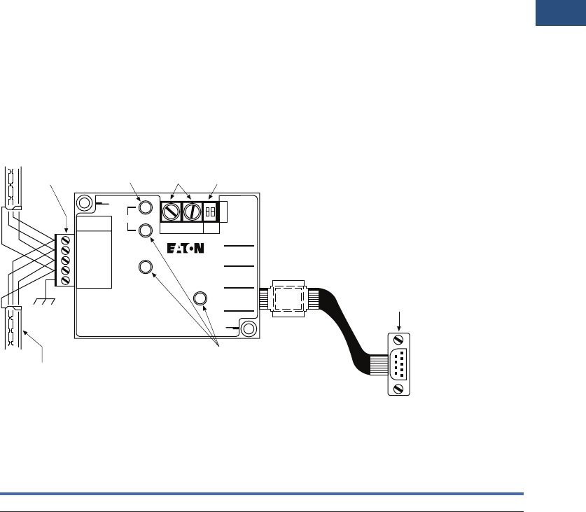
Volume 3—Power Distribution and Control Assemblies CA08100004E—November 2013 www.eaton.com V3-T9-287
9
9
9
9
9
9
9
9
9
9
9
9
9
9
9
9
9
9
9
9
9
9
9
9
9
9
9
9
9
9
9.5
Metering Devices, Protective Relays, Software and Connectivity
Connectivity Options
Contents
Description Page
Power Xpert Gateways . . . . . . . . . . . . . . . . . . . . . . V3-T9-259
Power Xpert Ethernet Switches . . . . . . . . . . . . . . . V3-T9-272
Power Xpert Gateway
Series 1000 Card—Power Distribution Unit . . . . . . V3-T9-276
Power Xpert Gateway
Series 2000 Card—Uninterruptible Power Supplies V3-T9-279
mMINT . . . . . . . . . . . . . . . . . . . . . . . . . . . . . . . . . . V3-T9-282
MINTII RS-232 Converter. . . . . . . . . . . . . . . . . . . . V3-T9-284
IPONI . . . . . . . . . . . . . . . . . . . . . . . . . . . . . . . . . . . V3-T9-285
DPONI . . . . . . . . . . . . . . . . . . . . . . . . . . . . . . . . . . V3-T9-286
MPONI
I/O Devices Digital Input Module (DIM) . . . . . . . . . V3-T9-288
Addressable Relay II. . . . . . . . . . . . . . . . . . . . . . . . V3-T9-290
Breaker Interface Module II (BIM II) . . . . . . . . . . . V3-T9-293
Sub-Network Master Local Display (SMLD) . . . . . . V3-T9-297
IMPCABLE . . . . . . . . . . . . . . . . . . . . . . . . . . . . . . . V3-T9-299
MPONI
Product Description
The MPONI Product Operated
Network Interface card, or
MPONI card, enables Modbus
communication capability to
various Eaton products. Each
MPONI contains two rotary
address switches to uniquely
identify each device on the
network and a baud rate DIP
switch. A 5-pin connector is
provided for wiring to the
RS-485 network. Various
baud rates are available for
networking flexibility, and
onboard LEDs indicate
operation, error and
communication status.
The MPONI is applied where
a device network exists
connected by a dedicated
shielded twisted pair
conductor. Modbus RS-485
allows a single device or
multiple units in a daisy-chain
configuration to communicate
with another local or remote
device and may extend up to
4000 feet (1219m) without a
repeater. The MPONI comes
with mounting hardware and
attaches to the back of its
associated device.
Note: Please see IL for detailed
register support information for
each supported product. Not all
device functionality is supported
with the RS-485 PONI over the
Modbus Protocol.
Features
MPONI
Product Selection
MPONI
Network Connection
(Green Phoenix
Connection)
Recommended
18 gauge twisted pair IMPCABLE or
20 gauge Belden 9463 class
Address
Selector
Switches
Function
Selector
Switch
IQ Host
Device
Connection
LED
STATUS
RX
TX
RS-485
NETWORK
1 = A
2 = G
3 = COMMON
4 = SHIELD
5 = CHASSIS
RS-485
P roduct
O perated
N etwork
I nterface
LED
Description
Catalog
Number
Modbus Product Operated Network Interface Card MPONI

V3-T9-288 Volume 3—Power Distribution and Control Assemblies CA08100004E—November 2013 www.eaton.com
9
9
9
9
9
9
9
9
9
9
9
9
9
9
9
9
9
9
9
9
9
9
9
9
9
9
9
9
9
9
9.5
Metering Devices, Protective Relays, Software and Connectivity
Connectivity Options
Digital Input Module (DIM)
Contents
Description Page
Power Xpert Gateways. . . . . . . . . . . . . . . . . . . . . . V3-T9-259
Power Xpert Ethernet Switches . . . . . . . . . . . . . . . V3-T9-272
Power Xpert Gateway
Series 1000 Card—Power Distribution Unit . . . . . . V3-T9-276
Power Xpert Gateway
Series 2000 Card—Uninterruptible Power Supplies V3-T9-279
mMINT. . . . . . . . . . . . . . . . . . . . . . . . . . . . . . . . . . V3-T9-282
MINTII RS-232 Converter . . . . . . . . . . . . . . . . . . . V3-T9-284
IPONI . . . . . . . . . . . . . . . . . . . . . . . . . . . . . . . . . . . V3-T9-285
DPONI . . . . . . . . . . . . . . . . . . . . . . . . . . . . . . . . . . V3-T9-286
MPONI . . . . . . . . . . . . . . . . . . . . . . . . . . . . . . . . . . V3-T9-287
I/O Devices Digital Input Module (DIM)
Product Selection . . . . . . . . . . . . . . . . . . . . . . . V3-T9-289
Technical Data and Specifications . . . . . . . . . . . V3-T9-289
Dimensions. . . . . . . . . . . . . . . . . . . . . . . . . . . . V3-T9-289
Addressable Relay II . . . . . . . . . . . . . . . . . . . . . . . V3-T9-290
Breaker Interface Module II (BIM II) . . . . . . . . . . . V3-T9-293
Sub-Network Master Local Display (SMLD). . . . . . V3-T9-297
IMPCABLE . . . . . . . . . . . . . . . . . . . . . . . . . . . . . . . V3-T9-299
I/O Devices Digital Input Module (DIM)
Product Description
Eaton’s Digital Input Module
is a device that interfaces
with up to four standard utility
(electric, gas, water) meters
or monitors eight digital
inputs. It translates KYZ
pulses from meters into a
register count that is
maintained and compiled
within the DIM module in
non-volatile memory. The
pulse count can be accessed
from the DIM module
remotely using Eaton Power
Management Software,
including the Energy Billing
application.
The DIM can also be used to
monitor eight digital inputs
from switch closures.
Features, Benefits and
Functions
●Reads four separate KYZ
equipped utility meters
●Pulse counts stored in non-
volatile memory
●Each channel
independently monitors
KYZ counts, pulse counts,
or digital indications
●Monitors a maximum of
eight individual digital
inputs
●Input channels are isolated
●Isolated 24 Vdc power
is provided on the I/O
connector
●LED indicators on the input
channels indicate when the
unit is counting
●10 LED status indicators,
100 ohm termination DIP
switch, address selector
switches
●DIN rail mounting
Standards and Certifications
●UL 873
●CE mark (48 Vdc operation)
●FCC Part 15, Class A
●IEC 1000-4-x
●CISPR 22, Class A
●IEC 1000-4-2; 1995, Electro
Static Discharge
●IEC 1000-4-3; 1995,
Radiated RF Immunity
●IEC 1000-4-6; 1996,
Conducted RF Immunity
●FCC Part 15 Class A
(10 meters) Radiated
Emissions
●CISPR 22, Class A
(30 meters); 1991,
Radiated Emissions
●CISPR 22, Class A; 1991,
Conducted Emissions
(PowerPort)
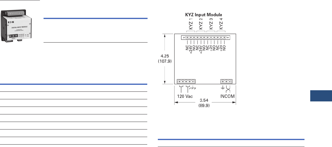
Volume 3—Power Distribution and Control Assemblies CA08100004E—November 2013 www.eaton.com V3-T9-289
9
9
9
9
9
9
9
9
9
9
9
9
9
9
9
9
9
9
9
9
9
9
9
9
9
9
9
9
9
9
9.5
Metering Devices, Protective Relays, Software and Connectivity
Connectivity Options
Product Selection
Ordering Information
Technical Data and Specifications
Specifications
Frequency Range
●50/60 Hz
Power
●85 to 138 Vac (120 Vac
nominal) 50/60 Hz; 100 mA
●48–128 Vdc (48 Vdc
nominal); 100 mA
●Brownout operation at
50% and 80% of nominal
AC and DC ratings
●Power input is provided
from a limited source,
isolated from the mains
by double isolation
●Power for all inputs is
supplied from an internal,
isolated 24 Vdc power
source
Mounting Information
The DIM module is designed
to be DIN rail mountable.
DIN rail must be 1/3 inches
H x 1-3/8 inches W (8.5 mm
H x 34.9 mm W).
Communications
The DIM is a fully compatible
Power Management Software
communicating device
with built-in INCOM
communications. The DIM
comes complete with a
3-pin connector to receive
the shielded twisted pair
conductor.
All wiring must be complete
as per Instruction Leaflet
TD17513, Wiring
Specification Base Rules.
Description
Catalog
Number
Digital Input Module DIM
DIM
Description Rating
Operating temperature –20ºC to 60ºC
Storage temperature –20ºC to 70ºC
Operating Humidity 5 to 90% maximum noncondensing
Altitude 10,000 ft. (3048m)
Environment Indoor use only
Transient overvoltage Category 2
Pollution 1º
Equipment Class 1
Dimensions
Approximate Dimensions in Inches (mm)
KYZ Input Module
KYZ Input Module
Note
1Does include DIN rail.
Width Height Depth
3.54 (89.9) 4.25 (107.9) 3.50 (88.9) 1
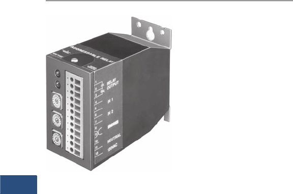
V3-T9-290 Volume 3—Power Distribution and Control Assemblies CA08100004E—November 2013 www.eaton.com
9
9
9
9
9
9
9
9
9
9
9
9
9
9
9
9
9
9
9
9
9
9
9
9
9
9
9
9
9
9
9.5
Metering Devices, Protective Relays, Software and Connectivity
Connectivity Options
Addressable Relay II
Contents
Description Page
Power Xpert Gateways. . . . . . . . . . . . . . . . . . . . . . V3-T9-259
Power Xpert Ethernet Switches . . . . . . . . . . . . . . . V3-T9-272
Power Xpert Gateway
Series 1000 Card—Power Distribution Unit . . . . . . V3-T9-276
Power Xpert Gateway
Series 2000 Card—Uninterruptible Power Supplies V3-T9-279
mMINT. . . . . . . . . . . . . . . . . . . . . . . . . . . . . . . . . . V3-T9-282
MINTII RS-232 Converter . . . . . . . . . . . . . . . . . . . V3-T9-284
IPONI . . . . . . . . . . . . . . . . . . . . . . . . . . . . . . . . . . . V3-T9-285
DPONI . . . . . . . . . . . . . . . . . . . . . . . . . . . . . . . . . . V3-T9-286
MPONI . . . . . . . . . . . . . . . . . . . . . . . . . . . . . . . . . . V3-T9-287
I/O Devices Digital Input Module (DIM) . . . . . . . . . V3-T9-288
Addressable Relay II
Product Selection . . . . . . . . . . . . . . . . . . . . . . . V3-T9-291
Technical Data and Specifications . . . . . . . . . . . V3-T9-291
Dimensions. . . . . . . . . . . . . . . . . . . . . . . . . . . . V3-T9-292
Breaker Interface Module II (BIM II) . . . . . . . . . . . V3-T9-293
Sub-Network Master Local Display (SMLD). . . . . . V3-T9-297
IMPCABLE . . . . . . . . . . . . . . . . . . . . . . . . . . . . . . . V3-T9-299
Addressable Relay II
Product Description
The Addressable Relay II is
designed for use where
information or control of non-
communicating devices is
required remotely. The relays
communicate at 9600/1200
baud on the INCOM network.
Devices are assigned a three-
digit address to uniquely
identify them on the daisy-
chained twisted shielded pair
network.
The Addressable Relay II is a
Form C relay on terminals 1, 2
and 3, with output contact
ratings as shown in the
Contact Ratings table. The
Addressable Relay II may be
powered by 48–120 Vac or
48–125 Vdc through
terminals 11 and 12 of the
terminal block. DC polarity is
not significant.
Application Description
●Enables remote control of
non-communication
capable devices on Eaton’s
PowerNet system
●Monitors two digital status
inputs on the PowerNet
system
Features, Benefits and
Functions
Each Addressable Relay II
includes two status indicating
circuits (IN1 and IN2) that can
be used to transmit the
contact status of devices
external to the Addressable
Relay II. Each input is isolated
with its own return. A typical
installation using these report-
back inputs to the Eaton
PowerNet system is shown in
the wiring example. Terminals
4 and 5 connect to the status
input 1 circuit (IN1) and
terminals 6 and 7 connect to
the status input 2 circuit (IN2).
These status indicating
circuits operate with input
voltages of 48–120 Vac or
48–125 Vdc circuits.
The Addressable Relay II
includes a feature called
the “communications
watchdog.” The
communications watchdog
monitors communications
between the Addressable
Relay II and the computer
control station. If
communications are lost, the
communications watchdog
will reset the relay to the de-
energized (OFF) state. The
Addressable Relay II must be
updated every 10 seconds
when the communications
watchdog is enabled or else
communications are
assumed to be lost. The
communications watchdog
is enabled when DIP switch 3
is set to the ON position.
When the communications
watchdog is not enabled, the
relay will remain in the state
set by the last command
issued. See V3-T9-296 for
DIP switch configuration.
Monitored Parameters
●Output relay energized/
de-energized
●Input 1 status
●Input 2 status
●Breaker status open/closed
●
Protective relay status
normal/tripped
Communications
●Built-in INCOM
communications for
monitoring in Eaton’s
PowerNet system
The Addressable Relay II also
includes a feature called
“relay pulse.” The relay pulse
feature sets the Addressable
Relay II to a pulse mode
where the relay is energized
(ON) for 10 seconds and then
is de-energized (OFF). The
relay pulse is enabled when
DIP switch 2 is set to the ON
position and disabled when
DIP switch 2 is set to the OFF
position. If this feature is not
enabled, the relay will remain
in the state set by the last
command.
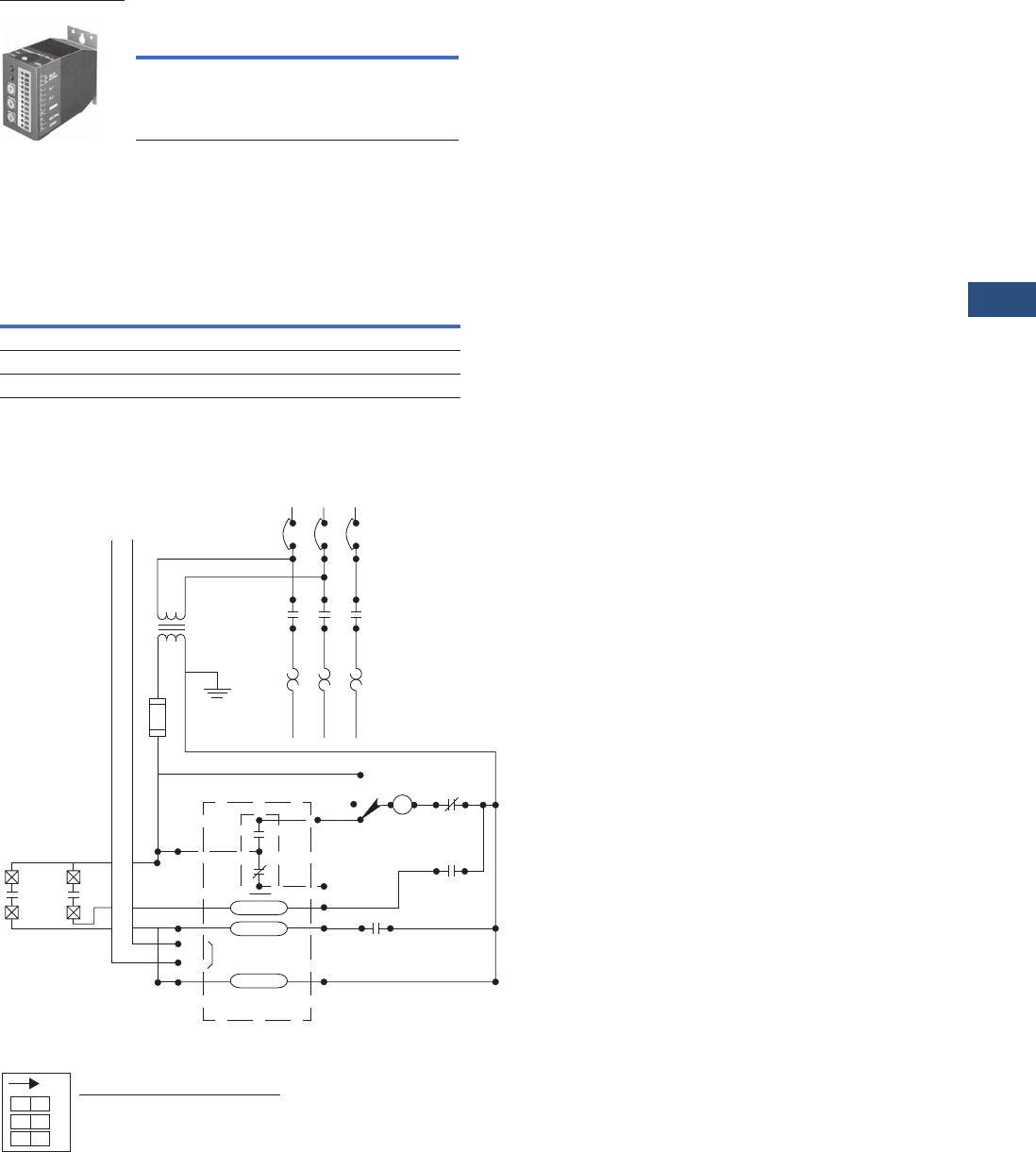
Volume 3—Power Distribution and Control Assemblies CA08100004E—November 2013 www.eaton.com V3-T9-291
9
9
9
9
9
9
9
9
9
9
9
9
9
9
9
9
9
9
9
9
9
9
9
9
9
9
9
9
9
9
9.5
Metering Devices, Protective Relays, Software and Connectivity
Connectivity Options
Product Selection
Addressable Relay
Technical Data and Specifications
●Power: 48–120 Vac; 48–125 Vdc
●Operating temperature range: 32°–158°F (0°–70°C)
Contact Ratings
Wiring Diagram
DIP Switch Functions
Description
Catalog
Number
Addressable Relay II ARII
Addressable Relay II
Contact
Ratings Make Break
120–240 Vac 4960 VA 828 VA
24–120 Vac 43A 7.2A
30 Vdc 10A 10A
INCOM
Network
Cpt
Power Bus
L1
M1
2
1
3
5
7
12
MA
OL
OL
Auto
Hand
Off
INCOM
Communications
Addressable Relay
6
8
9
11
OL OL OL
T1 T2 T3
M2 M3
L2 L3
FL
M
Communication and
Controlled Output Relay
Power
Input 2
Input 1
M
AUX OL
OFF ON
Baud Rate 9600 1200
Relay Pulse Disabled Enabled
Communications Watchdog
Disabled Enabled
O1 23
N
DOO
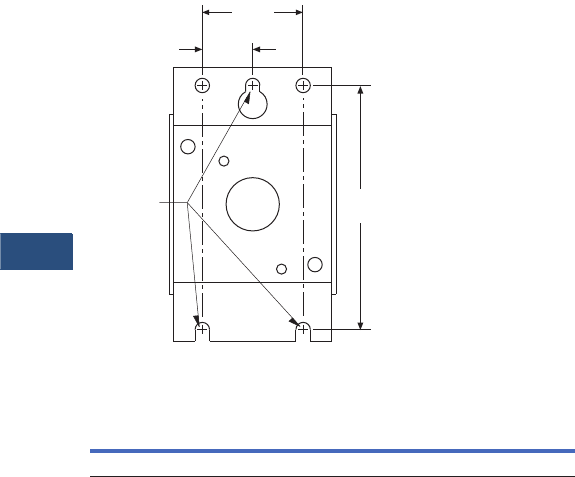
V3-T9-292 Volume 3—Power Distribution and Control Assemblies CA08100004E—November 2013 www.eaton.com
9
9
9
9
9
9
9
9
9
9
9
9
9
9
9
9
9
9
9
9
9
9
9
9
9
9
9
9
9
9
9.5
Metering Devices, Protective Relays, Software and Connectivity
Connectivity Options
Dimensions
Approximate Dimensions in Inches (mm)
Mounting
Addressable Relay
Width Height Depth
1.75 (44.5) 3.00 (76.2) 4.00 (101.6)
Insert (3)
#8 Screws
for
Mounting
Back View
2.82
(71.6)
.50
(12.7)
1.00
(25.4)

Volume 3—Power Distribution and Control Assemblies CA08100004E—November 2013 www.eaton.com V3-T9-293
9
9
9
9
9
9
9
9
9
9
9
9
9
9
9
9
9
9
9
9
9
9
9
9
9
9
9
9
9
9
9.5
Metering Devices, Protective Relays, Software and Connectivity
Connectivity Options
Breaker Interface Module II (BIM II)
Contents
Description Page
Power Xpert Gateways . . . . . . . . . . . . . . . . . . . . . . V3-T9-259
Power Xpert Ethernet Switches . . . . . . . . . . . . . . . V3-T9-272
Power Xpert Gateway
Series 1000 Card—Power Distribution Unit . . . . . . V3-T9-276
Power Xpert Gateway
Series 2000 Card—Uninterruptible Power Supplies V3-T9-279
mMINT . . . . . . . . . . . . . . . . . . . . . . . . . . . . . . . . . . V3-T9-282
MINTII RS-232 Converter. . . . . . . . . . . . . . . . . . . . V3-T9-284
IPONI . . . . . . . . . . . . . . . . . . . . . . . . . . . . . . . . . . . V3-T9-285
DPONI . . . . . . . . . . . . . . . . . . . . . . . . . . . . . . . . . . V3-T9-286
MPONI . . . . . . . . . . . . . . . . . . . . . . . . . . . . . . . . . . V3-T9-287
I/O Devices Digital Input Module (DIM) . . . . . . . . . V3-T9-288
Addressable Relay II. . . . . . . . . . . . . . . . . . . . . . . . V3-T9-290
Breaker Interface Module II (BIM II)
Features, Benefits and Functions . . . . . . . . . . . V3-T9-294
Product Selection . . . . . . . . . . . . . . . . . . . . . . . V3-T9-295
Technical Data and Specifications . . . . . . . . . . . V3-T9-295
Sub-Network Master Local Display (SMLD) . . . . . . V3-T9-297
IMPCABLE . . . . . . . . . . . . . . . . . . . . . . . . . . . . . . . V3-T9-299
Breaker Interface Module II (BIM II)
Product Description
Eaton’s Breaker Interface
Module is a panel-mounted
device that displays the
following parameters.
●Phase current
●Energy
●Present demand watts
●Peak demand watts
●Average demand current
●Cause and magnitude
of trip
●Trip history
●% Total Harmonic
Distortion (THD) for
each phase
●% Harmonic Content for
each phase (1st–27th
harmonic)
●Custom circuit description
Note: The Breaker Interface
Module displays only a portion of
the information it receives from
the Digitrip RMS 910, 1150 and
Power Sentinels. The balance of
the information (such as
Waveform Analysis and Power
Factor) can be passed through the
unit to a master computer, where
it can be viewed.
Application Description
●810, 910, 750, 1050, 550,
1150, 520MC, IQ Energy
Sentinels and Power
Sentinels
●Event logging
●Alarming
●High load indication
●Peak exceeded alarm
●Grouping of meters
An operator can use the
Breaker Interface Module to:
●Complete Initial System
Setup:
●Select system
frequency (50/60 Hz)
●Set password
●Configure OPTIM
Protective Settings.
●Select protection
options
●Select alarm levels
●Display Information:
●Metered values
●Trip event information
●Breaker information
●Time-current set points
●Te s t OP T I M Tr i p U n it
Performance:
●Phase and ground
●Trip/no trip
●Expanded Energy
Monitoring:
●Set addresses for group
energy monitoring
●Group energy readings
●Local and Remote
Indication:
●Remote indication/
alarming
●Breaker status LED
indication
●Expanded
Communications:
●Communicate with:
– OPTIM Trip Units
– Digitrip RMS 810, 910
a n d 115 0 Tr i p Un i t s
– IQ Energy Sentinels
and Universal IQ
Energy Sentinels
– A total of 50 devices

V3-T9-294 Volume 3—Power Distribution and Control Assemblies CA08100004E—November 2013 www.eaton.com
9
9
9
9
9
9
9
9
9
9
9
9
9
9
9
9
9
9
9
9
9
9
9
9
9
9
9
9
9
9
9.5
Metering Devices, Protective Relays, Software and Connectivity
Connectivity Options
Features, Benefits and Functions
●Monitors and displays
parameters from any
combination of Digitrip
RMS 810, 910, 1150 and
Digitrip OPTIM Trip Units,
F-/J-/K-Frame Energy
Sentinels, and Universal
Energy Sentinels,
supporting as many as
50 of these devices up to
10,000 feet (3048 m) away
●Communicates the
information from these
protective and energy
monitoring devices over
Eaton INCOM network
to a computer or PLC
●Continuously monitors
breakers recording and
time-stamping trip events
along with approximate
fault currents. Events are
logged into non-volatile
RAM
Physical Characteristics
●Graphical, glass plasma
display
●Up to seven lines of
information
●Membrane faceplate
NEMA 3R and 12 rated
Communications
Depending upon the type of
communication protocol used
by the main network, an
appropriate PONI module can
be easily field-mounted to the
back of the Breaker Interface
Module, enabling the unit to
pass the information from its
subnetwork to a remote
master control unit up to
10,000 feet (3048 m) away.
No reprogramming of the
unit is required when the
PONI is added.
The Breaker Interface Module
can be mounted directly on
the assembly or at a remote
location and can be used to
access and configure and
display information from
OPTIM Trip Units.
Password Protection
A user-defined password is
included for added security
when changing settings or
performing breaker tests.
Non-Volatile Memory
The programmed functions,
addresses and circuit
descriptions are stored in
non-volatile memory.
External Power
A 24 Vdc supply is required
for the BIM II. (No external
power supply is required for
the PONI Card.) A 120 or
240 Vac supply is required
for the BIMPS.
Rear Access Area
All wiring connections to the
Breaker Interface Module
are made at the chassis’ rear
and include:
●Relay connection for
“alarm” condition, “high
load” condition, “peak
exceed” for device or
group, and watthour pulse
●Initiator
●24 Vdc input—BIM II
●120 or 240 Vac input—
BIMPS
●DIP switches for selecting
an operating mode
●Three-contact connector
with subnetwork
●Connector for PONI
card for remote
communications Local
Display Units

Volume 3—Power Distribution and Control Assemblies CA08100004E—November 2013 www.eaton.com V3-T9-295
9
9
9
9
9
9
9
9
9
9
9
9
9
9
9
9
9
9
9
9
9
9
9
9
9
9
9
9
9
9
9.5
Metering Devices, Protective Relays, Software and Connectivity
Connectivity Options
Product Selection
Breaker Interface Module
Technical Data and Specifications
Power Requirement
●15 VA maximum
Input Voltage
●24 Vdc ±5%—BIM II
●120 or 240 Vac ±10%—
BIMPS
Operating Temperature
●0°C to 70°C
(32°C to 158°F)
Humidity
●5% to 95% R.H.
(noncondensing)
Alarm Contact Ratings
●10A at 277 Vac (resistive)
●10A at 30 Vdc (resistive)
●1/3 hp at 125, 250 Vac
Description
Catalog
Number
Breaker Interface Module BIMII
BIMPSII
Breaker Interface
Module II (BIM II)
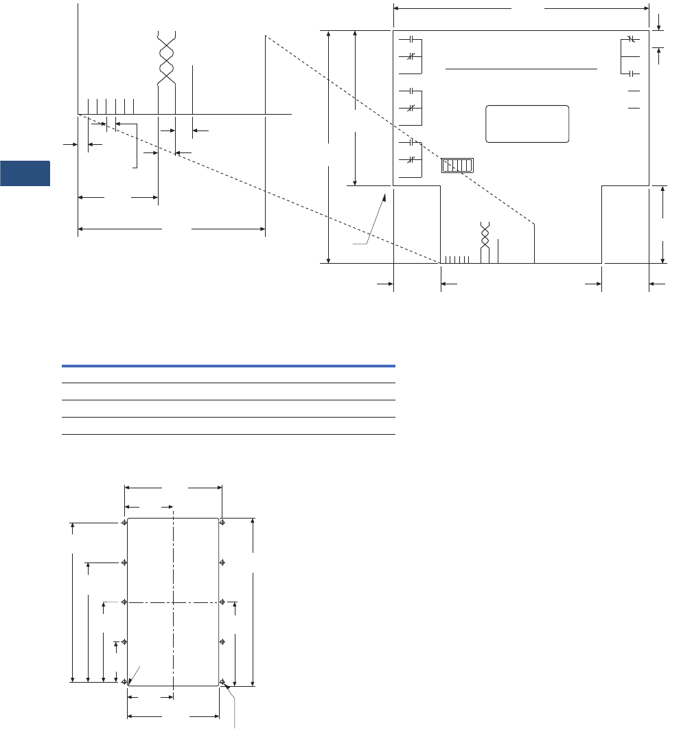
V3-T9-296 Volume 3—Power Distribution and Control Assemblies CA08100004E—November 2013 www.eaton.com
9
9
9
9
9
9
9
9
9
9
9
9
9
9
9
9
9
9
9
9
9
9
9
9
9
9
9
9
9
9
9.5
Metering Devices, Protective Relays, Software and Connectivity
Connectivity Options
Dimensions
Approximate Dimensions in Inches (mm)
Connections and DIP Switch Rear Label Diagram
Breaker Interface Module
Drilling Pattern
Height Width Depth
Without Communications Card
6.72 (170.7) 10.25 (260.4) 2.60 (66.0)
With Communications Card
6.72 (170.7) 10.25 (260.4) 3.85 (97.8)
Typical
5 Places
.10
(2.5)
.11
(2.8)
PONI Power
Learn/Run
Unused
Shield
PONI
Interface
Sub
Network
Unused
Unused
Unused
Expanded View
.87
(22.1)
.19
(4.8)
.19
(4.8)
2.04
(51.8)
Customer Satisfaction
We have established a toll-free
line for problems
Call 1-800-809-2772
9
8
7
6
5
4
3
2
1
Alarm High Load
Peak
Exceeded
Sub
Network
PONI
Interface
Common
24-30 Vac
Ground
Unused
10
11
12
13
14
15
16
17
18
WH Pulse
Initiator
Sync.
Pulse
Impulse
Unused
Run
Unused
Unused
PONI On
Learn
Off Unused
Sub
Network PONI
Interface
Shield
Unused
Learn/Run
Unused
Unused
PONI Power
Unused
H02
CATALOG # BIMPS
STYLE # 7801C61G02
.38
(9.7)
Typical
5.56
(141.2)
1.69
(42.9)
1.03
(26.2)
3.38
(85.9)
5.06
(128.6)
General Layout and Dimensions
1.03
(26.2)
.06
(1.5) RAD
4 Places
2.23
(56.7)
4.45
(113.0)
6.68
(169.7)
8.90
(226.1)
2.53
(64.3)
5.06
(128.5)
2.69
(68.3)
5.38
(136.7)
.218 (5.5) DIA 10 Places
9.38
(238.3)
4.69
(119.1)
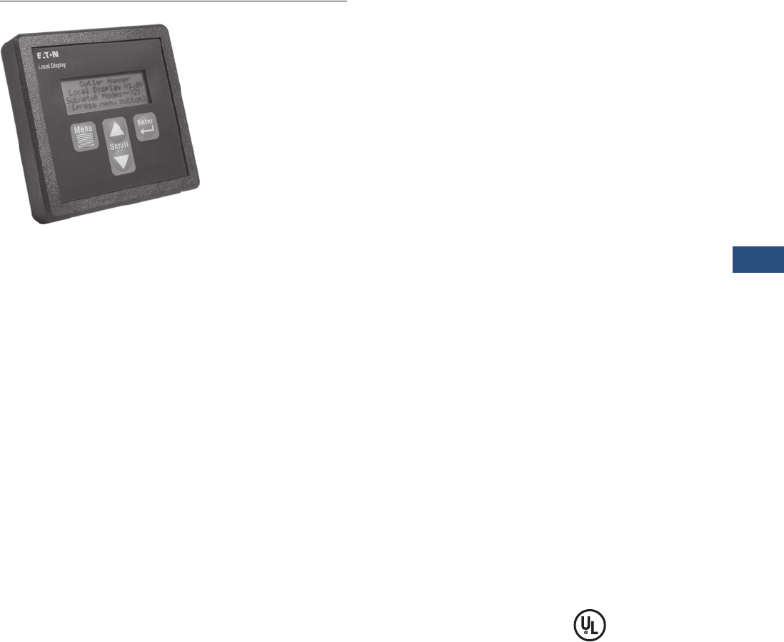
Volume 3—Power Distribution and Control Assemblies CA08100004E—November 2013 www.eaton.com V3-T9-297
9
9
9
9
9
9
9
9
9
9
9
9
9
9
9
9
9
9
9
9
9
9
9
9
9
9
9
9
9
9
9.5
Metering Devices, Protective Relays, Software and Connectivity
Connectivity Options
Sub-Network Master Local Display)
Contents
Description Page
Power Xpert Gateways . . . . . . . . . . . . . . . . . . . . . . V3-T9-259
Power Xpert Ethernet Switches . . . . . . . . . . . . . . . V3-T9-272
Power Xpert Gateway
Series 1000 Card—Power Distribution Unit . . . . . . V3-T9-276
Power Xpert Gateway
Series 2000 Card—Uninterruptible Power Supplies V3-T9-279
mMINT . . . . . . . . . . . . . . . . . . . . . . . . . . . . . . . . . . V3-T9-282
MINTII RS-232 Converter. . . . . . . . . . . . . . . . . . . . V3-T9-284
IPONI . . . . . . . . . . . . . . . . . . . . . . . . . . . . . . . . . . . V3-T9-285
DPONI . . . . . . . . . . . . . . . . . . . . . . . . . . . . . . . . . . V3-T9-286
MPONI . . . . . . . . . . . . . . . . . . . . . . . . . . . . . . . . . . V3-T9-287
I/O Devices Digital Input Module (DIM) . . . . . . . . . V3-T9-288
Addressable Relay II. . . . . . . . . . . . . . . . . . . . . . . . V3-T9-290
Breaker Interface Module II (BIM II) . . . . . . . . . . . V3-T9-293
Sub-Network Master Local Display (SMLD)
Product Selection . . . . . . . . . . . . . . . . . . . . . . . V3-T9-298
Technical Data and Specifications . . . . . . . . . . . V3-T9-298
Dimensions . . . . . . . . . . . . . . . . . . . . . . . . . . . . V3-T9-298
IMPCABLE . . . . . . . . . . . . . . . . . . . . . . . . . . . . . . . V3-T9-299
Sub-Network Master Local Display (SMLD)
Product Description
Eaton’s Sub-Network Master
Local Display (SMLD) is an
electronic submetering
device that provides users
the ability to view information
from sub-network connected
devices locally at switchgear,
switchboards, panelboards,
motor control centers and
control panels, nearby or
thousands of feet away. The
SMLD has a built-in LCD
display with navigations
for configuring, as well as
monitoring. Auto-learn
capabilities complete the
configuration requirements,
enabling customization by
use of user-defined
descriptions, as well as
adding and deleting meters.
The SMLD can be operated
standalone or in parallel with
the new FetchIT™ software
application or the Power Xpert
complete energy monitoring
system solution software.
Application Description
●Acquire and display data
(no control) from up to
100 devices that can
communicate on Eaton’s
INCOM network, used in
the PowerNet monitoring
system
Features, Benefits
and Functions
●Auto-learn connected
devices
●Configuration stored in
non-volatile memory
●Host communications
arbitration algorithm
enables seamless
integration into existing
communication networks
●Functions standalone or
networked
●Following devices are
supported:
●IQ 200
●IQ Multipoint Energy
Submeter II
●
IQ Energy Sentinel
(F, J, K Frames)
●Universal Internal
Energy Sentinel
●Universal External
Energy Sentinel
●IQ Power Sentinel
●Digitrip OPTIM 1050L
Physical Characteristics
●Keypad functions:
●Menu
●Scroll up
●Scroll down
●Enter
●Backlit LCD, 4-line x 20
character
Standards and Certifications
●Safety Standards—
UL 61010B-1
●EMC Susceptibility
Standards—IEC 1000-4-3,
1995 Radiated RF
Immunity
●EMC Emissions
Standards—FCC Part 15,
Class B Radiated
Emissions
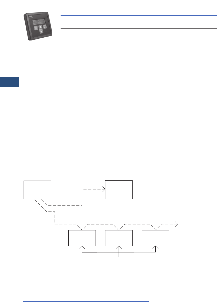
V3-T9-298 Volume 3—Power Distribution and Control Assemblies CA08100004E—November 2013 www.eaton.com
9
9
9
9
9
9
9
9
9
9
9
9
9
9
9
9
9
9
9
9
9
9
9
9
9
9
9
9
9
9
9.5
Metering Devices, Protective Relays, Software and Connectivity
Connectivity Options
Product Selection
Ordering Information
Technical Data and Specifications
Frequency Range
●50/60 Hz
Power
●Power consumption:
200 mA (maximum) at
24 Vac, 24 Vdc
●Power connector rating:
24 Vac or 24 Vdc at
1 ampere
●Power source: 120 Vac or
24 Vdc, UL Class 2 or CSA
Class III SELV transformer
in accordance with C22.2
No. 1010-1. The volt age
range is 18 to 24 Vac or
Vdc, 200 mA (maximum)
Ratings
●Operating temperature:
0°C to 60°C
●Storage temperature:
–20°C to 70°C
●Operating humidity: 5 to
90% maximum non-
condensing
●Altitude: 10,000 feet
(3048m)
●Environment: indoor
use only
Mounting Information
●4.37 H x 4.37 W x 1.50 D
inches (111.0 H x 111.0 W x
38.1 D mm)
●Door mount or panel
mount
Communications
●INCOM Frequency Shift
Key (FSK) network
compatible 9600 baud
●Non-intrusive arbitration
algorithm
●Passive monitoring
automatically enabled by
arbitration algorithm while
host PC is communicating
●Master on INCOM network
upon data request from
front panel if host PC is not
communicating
●Addresses for sub-network
devices
can be 001–044 hex
(1–255 decimals)
Typical Use Diagram of SMLD
Dimensions
Approximate Dimensions in Inches (mm)
Meter Base Unit
Note
DIN (92 mm x 92 mm) access cutout.
Description
Catalog
Number
Local Display (120 Vac) LDISP120
Local Display (24 Vac or Vdc) LDISP24
Sub-Network Master
Local Display
Digitrip
OPTIM 1050C
IQ
ES or
PS
IQ 200
Computer
with Power
Management
Software
SMLD
Multiple Units as Required
Width Height Depth
4.37 (111.0) 4.37 (111.0) 1.50 (38.1)
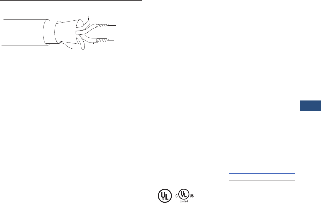
Volume 3—Power Distribution and Control Assemblies CA08100004E—November 2013 www.eaton.com V3-T9-299
9
9
9
9
9
9
9
9
9
9
9
9
9
9
9
9
9
9
9
9
9
9
9
9
9
9
9
9
9
9
9.5
Metering Devices, Protective Relays, Software and Connectivity
Connectivity Options
IMPCABLE
Conductors
Tinned
Copper
Braid
PVC
Outer Jacket
Polyethylene Filler
Drain Wire
Aluminum
Shield
Polyethylene Insulator
Contents
Description Page
Power Xpert Gateways . . . . . . . . . . . . . . . . . . . . . . V3-T9-259
Power Xpert Ethernet Switches . . . . . . . . . . . . . . . V3-T9-272
Power Xpert Gateway
Series 1000 Card—Power Distribution Unit . . . . . . V3-T9-276
Power Xpert Gateway
Series 2000 Card—Uninterruptible Power Supplies V3-T9-279
mMINT . . . . . . . . . . . . . . . . . . . . . . . . . . . . . . . . . . V3-T9-282
MINTII RS-232 Converter. . . . . . . . . . . . . . . . . . . . V3-T9-284
IPONI . . . . . . . . . . . . . . . . . . . . . . . . . . . . . . . . . . . V3-T9-285
DPONI . . . . . . . . . . . . . . . . . . . . . . . . . . . . . . . . . . V3-T9-286
MPONI
I/O Devices Digital Input Module (DIM) . . . . . . . . . V3-T9-288
Addressable Relay II. . . . . . . . . . . . . . . . . . . . . . . . V3-T9-290
Breaker Interface Module II (BIM II) . . . . . . . . . . . V3-T9-293
Sub-Network Master Local Display (SMLD) . . . . . . V3-T9-297
IMPCABLE
IMPCABLE
Product Description
The IMPCABLE is an 18 AWG
cable with a 100 ohm
impedance at 100 kHz tuned
to work optimally with the
FSK signal from Eaton’s
devices. The cable has been
designed with characteristics
that allow up to 1000 devices
or distances up to 10,000 feet
(3048m) from the master.
Please refer to Eaton’s wiring
specification for instructions
on cable runs and calculating
maximum distances and
devices on a given network.
Application Description
Eaton’s IMPCABLE was
designed to be run in
switchgear where codes
require a 600 volt insulation
rating. Typical “blue hose”
cables are rated at 300 volts.
Features
Physical Characteristics
●Twisted shielded pair with
drain wire
●600 volt at 80°C
●18 AWG, 20 AWG drain
UL AWM 20253
Standards and Certifications
●UL AWM 20253
●NECT CM
●CSA
●PCC-FT1
●P-MSHA
Product Selection
IMPCABLE
Technical Data and
Specifications
●INCOM signal: attenuation
1.6 db/1000 feet (305m)
●Long communication runs
●600 volt required ratings
Description
Catalog
Number
IMPCABLE IMPCABLE

Volume 3—Power Distribution and Control Assemblies CA08100004E—February 2012 www.eaton.com V3-T10-1
10
10
10
10
10
10
10
10
10
10
10
10
10
10
10
10
10
10
10
10
10
10
10
10
10
10
10
10
10
10
Power System Studies, Field Services
and Conversions
Full Service Providers
10.1 Overview of Services
Overview . . . . . . . . . . . . . . . . . . . . . . . . . . . . . . . . . . . . . . . . . . . . . . . V3-T10-2
Asset Optimization, Knowledge Management and
Product Life Extension . . . . . . . . . . . . . . . . . . . . . . . . . . . . . . . . . . . . V3-T10-5
Power Systems Automation Group . . . . . . . . . . . . . . . . . . . . . . . . . . . V3-T10-8
Instant Response Center Services . . . . . . . . . . . . . . . . . . . . . . . . . . . . V3-T10-10
Customized High Resistance Grounding Units. . . . . . . . . . . . . . . . . . . V3-T10-11
10.2 Power System Studies
Arc Flash, Short-Circuit and Coordination Studies . . . . . . . . . . . . . . . . V3-T10-12
Load Flow/Power Factor Correction Study . . . . . . . . . . . . . . . . . . . . . . V3-T10-15
Harmonic Analysis Study . . . . . . . . . . . . . . . . . . . . . . . . . . . . . . . . . . . V3-T10-17
Advanced Analysis and Design Services . . . . . . . . . . . . . . . . . . . . . . . V3-T10-19
10.3 Field Engineering Services
Selection Guide . . . . . . . . . . . . . . . . . . . . . . . . . . . . . . . . . . . . . . . . . . V3-T10-23
10.4 Predictive Diagnostic
Partial Discharge Testing. . . . . . . . . . . . . . . . . . . . . . . . . . . . . . . . . . . . V3-T10-29
Medium and High Voltage Predictive Diagnostics Online Monitoring
and Partial Discharge Analysis . . . . . . . . . . . . . . . . . . . . . . . . . . . . . . V3-T10-32
10.5 Retrofit Services
Medium Voltage Vacuum Replacement Circuit Breakers . . . . . . . . . . . V3-T10-34
AR Series Low Voltage Replacement Breakers . . . . . . . . . . . . . . . . . . V3-T10-39
Low Voltage Power Circuit Breaker Reconditioning . . . . . . . . . . . . . . . V3-T10-41
Arcflash Reduction Maintenance System™ Conversions. . . . . . . . . . . V3-T10-45
Digitrip Microprocessor Trip Unit Retrofit Kits . . . . . . . . . . . . . . . . . . . V3-T10-46
Low Voltage Breaker Drawout Vacuum Starter Replacement . . . . . . . V3-T10-50
MCC Replacement Units . . . . . . . . . . . . . . . . . . . . . . . . . . . . . . . . . . . V3-T10-52
10.6 Performance-Based Maintenance Services
General Description . . . . . . . . . . . . . . . . . . . . . . . . . . . . . . . . . . . . . . . V3-T10-55

V3-T10-2 Volume 3—Power Distribution and Control Assemblies CA08100004E—June 2013 www.eaton.com
10
10
10
10
10
10
10
10
10
10
10
10
10
10
10
10
10
10
10
10
10
10
10
10
10
10
10
10
10
10
10.1
Power System Studies, Field Services and Conversions
Overview of Services
Experienced Professional Engineers
Contents
Description Page
Overview of Services
Overview
Asset Optimization, Knowledge Management
and Product Life Extension . . . . . . . . . . . . . . V3-T10-5
Power Systems Automation Group . . . . . . . . . V3-T10-8
Instant Response Center Services . . . . . . . . . V3-T10-10
Customized High Resistance Grounding Units V3-T10-11
Overview
Eaton’s Electrical Services &
Systems (EESS) provides
intelligent PowerChain™
solutions for existing,
evolving, unexpected service
needs. The solutions can
improve electrical system
reliability, reduce downtime,
extend the useful life of
the power distribution
system, and minimize
electrical operating and
maintenance costs.
General Description
This organization supports
consultants and end-users on
new construction, integrated
engineering solutions and
facility expansion projects.
EESS can package a
complete power distribution
system with Eaton
manufactured products,
supplemented by other
OEM components to best
satisfy the end-user
requirements. EESS can
provide optimization of
owner’s electrical power
assets with guarantees
and savings.
Also provided is a full
complement of services to
maintain and modernize
electrical power distribution,
and process control systems.
End-users include industrials,
commercial facilities,
utilities, municipalities,
institutions, government
and military locations.
Service capabilities include:
●Turnkey project
management
●System integration
●Training
●Startup and commissioning
●Predictive and preventive
maintenance
●Electrical system
modernization
●Circuit breaker
specialized services
Division-wide capabilities
support regional service
centers located throughout
the U.S. and Canada. Service
centers are equipped with the
most technologically
advanced test and diagnostic
equipment. The Power
Systems Engineering Group
uses industry standard
software with advanced
system modeling and
analysis capabilities.
In addition to the local service
centers, aftermarket centers
of excellence can furnish the
full complement of circuit
breaker specialized services.
Division-wide safety and
quality programs ensure
customer satisfaction,
while maintaining safety
as a first priority.
Experienced professional
engineers, graduate
engineers, field engineers
and technicians are trained
on both Eaton products and
competitive electrical power
distribution products. This
cross-OEM experience allows
for the application
of new products and services
to all manufacturer’s
electrical equipment.
Turnkey Project Management
Project Team
The following is a detailed
listing of engineering
service offerings.
●Substation design,
management and
construction
●Electrical, mechanical and
instrumentation services
●Power system studies:
●Short-circuit
●Coordination
●Arc flash
●Load flow, etc.
●Power quality and
harmonic studies
●Renewable energy design
and interconnection
analysis
●Failure/root-cause analysis
●CAD services
●Equipment relocation
●Turnkey transformer and
capacitor replacements

Volume 3—Power Distribution and Control Assemblies CA08100004E—June 2013 www.eaton.com V3-T10-3
10
10
10
10
10
10
10
10
10
10
10
10
10
10
10
10
10
10
10
10
10
10
10
10
10
10
10
10
10
10
10.1
Power System Studies, Field Services and Conversions
Overview of Services
System Integration and Training
Computer Diagnostics
●Plant monitoring,
protection and control:
●Digitrip™/Advantage™
●PowerNet™/
Power Xpert®
●DeviceNet/PLC interface
●Energy management/
load shedding
●Distributed generation
●Generator/emergency
power systems
●PLC/PC control and open
automation systems
●Drive and MCC systems
training (scheduled and
on-site):
●Distribution systems
analysis
●Power quality and
grounding
●Electrical equipment
maintenance
●PLCs and drive systems
●Customized training
programs
Predictive Diagnostics
Field Data Collection
Eaton’s predictive diagnostics
leads the industry in
predictive diagnostic tools
and services. With the
growing demand for reduced
outages and increased
uptime, online monitoring of
electrical insulation systems
is becoming an integral part
of efficient plant maintenance
in the utility, industrial and
commercial markets. Eaton
predictive diagnostics
provides online monitoring
services of insulation
systems via the effective
measurement and analysis of
partial discharges. This allows
for detection of traditional
corona damage, or surface
tracking, prior to equipment
failure. This advanced
technology is applied to
medium voltage systems
such as: generators, motors,
switchgear, transformers and
cable systems.
Services are implemented
through the network of EESS
field locations.
●Medium voltage generator
and medium voltage motor
partial discharge (PD)
detection using existing
RTDs with temporary or
permanent sensors
●Medium voltage
switchgear PD detection
using temporary or
permanent sensors.
Permanent sensors
differentiate cable-related
PD to switchgear PD
●Transformers (34.5 kV
primary and above) PD
detection using permanent
sensors connected to
bushing capacitive taps
●Transformer (34.5 kV
primary and above)
bushing monitoring, with
permanent sensors, of any
change in power factor and
bushing capacitance
Startup, Commissioning
and Maintenance
Field Startup
●Installation support
and supervision
●Acceptance testing
●Commissioning and
energizing
●Startup, training and
warranty support
●Exclusive Eaton products
2-year warranty
●Ground fault certifications
●Ground grid testing
●Cable testing and fault
identification
●Relay testing and
calibration
●PM program design and
implementation
●Thermograph surveys
●Predictive, preventive
maintenance and
troubleshooting
●Transformers and
tap changers
●High voltage systems
●Substations medium
and low voltage
●Relay systems
●Automatic transfer
schemes
●Battery systems
●Low/medium
voltage breakers
●Motors
●SF6, OCB, WLI
components
●Network protectors
●Motor control centers
and molded case
breakers
●Drive systems
●PLC/control and open
automation systems
●Nuclear Class 1E safety-
related field service
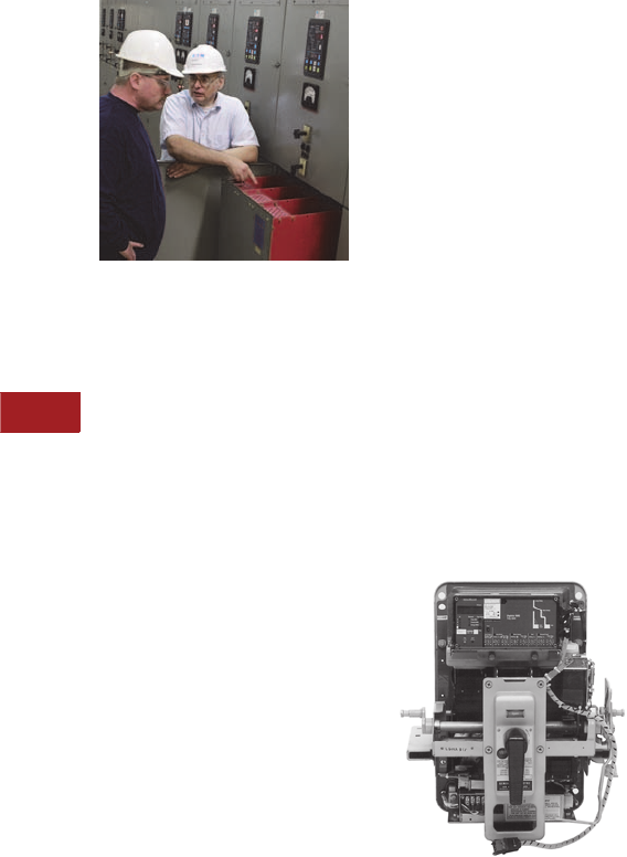
V3-T10-4 Volume 3—Power Distribution and Control Assemblies CA08100004E—June 2013 www.eaton.com
10
10
10
10
10
10
10
10
10
10
10
10
10
10
10
10
10
10
10
10
10
10
10
10
10
10
10
10
10
10
10.1
Power System Studies, Field Services and Conversions
Overview of Services
Electrical System Modernization
Equipment Inspection
●Switchgear bus
MVA upgrading
●Bus insulation systems
●Medium voltage
vacuum breaker roll-in
replacements
●Low voltage breaker
replacement
●Low and medium voltage
motor starting upgrades
●Low voltage breaker
(all OEMs) trip system
upgrades—Digitrip
●Low and medium voltage
cell retrofits
●Molded case breaker
upgrades
●Motor control center
buckets upgrades
●Protection, metering,
and communications:
●Low voltage breakers:
Digitrip/PowerNet
●Overload protection
●Metering systems:
IQ family
●PowerNet
implementation
●Harmonic
measurements
●Distribution and substation
automation systems
●Power factor control and
correction (filtered)
●Ground fault detection
systems
●Surge/lightning
protection systems
●Automatic transfer
scheme upgrades
●Network protector service/
relaying systems
●High resistance grounding
and detection
●Generator voltage
regulation
●Generator static
excitation systems
●Cogeneration switchgear
interface relaying
●Reduced voltage/
soft starters
●Drive/PLC system
upgrades
●Synchronous field
application upgrades
Trip Unit Upgrade
Circuit Breaker
Specialized Services
●Low and medium voltage
replacement breakers
●Low voltage retrofits (all
OEMs: Digitrip RMS kits)
●Medium voltage vacuum
roll-in breakers (all OEMs)
●Low and medium
voltage recondition and
remanufacture
●MCC recondition
and remanufacture
●Network protector service
●Navy shipboard breakers
●Nuclear Class 1E safety-
related circuit breakers
Manufacturer’s Brand
Equipment Serviced
●Cutler-Hammer®
●Westinghouse®
●Square D®
●General Electric®
●ITE®/BBC/ABB®
●Allis Chalmers/Siemens®
●Federal Pacific®
●Challenger®
●Obsolete equipment
References
Electrical System
Modernization uses advanced
Eaton products.

Volume 3—Power Distribution and Control Assemblies CA08100004E—June 2013 www.eaton.com V3-T10-5
10
10
10
10
10
10
10
10
10
10
10
10
10
10
10
10
10
10
10
10
10
10
10
10
10
10
10
10
10
10
10.1
Power System Studies, Field Services and Conversions
Overview of Services
Eaton’s Electrical Services & Systems (EESS)
Contents
Description Page
Overview . . . . . . . . . . . . . . . . . . . . . . . . . . . . . . . . V3-T10-2
Asset Optimization, Knowledge Management and
Product Life Extension
Elements of a Performance-Based
Maintenance Program . . . . . . . . . . . . . . . . . . V3-T10-6
Asset Optimization Services . . . . . . . . . . . . . . . V3-T10-6
Knowledge Management . . . . . . . . . . . . . . . . . V3-T10-7
Power Systems Engineering Solutions . . . . . . . V3-T10-7
Power Systems Automation Group . . . . . . . . . . . . V3-T10-8
Instant Response Center Services . . . . . . . . . . . . V3-T10-10
Customized High Resistance Grounding Units . . . V3-T10-11
Asset Optimization, Knowledge Management and Product Life Extension
General Description
A company’s facilities exist
for a single purpose: to
support the mission and
objectives of the company’s
business. It is essential that
the power distribution
equipment and energy assets
that sustain production and
services are working as
efficiently and effectively
as possible.
The core business of Eaton’s
Electrical Services & Systems
(EESS) centers on power
distribution and energy
management.
1. We offer Powerchain
Management solutions
and we take care of your
systems so you can take
care of your business.
2. One area of the
PowerChain™ is
maintenance solutions.
Eaton knows that a
successful maintenance
program has the following
characteristics:
●Enables you to schedule
maintenance based on
actual device operation
history
●Eliminates unnecessary
maintenance work and
related production outages
●Reduction of spare parts
requirements due to
increased accuracy of
equipment history
●Reduction of overall
maintenance costs
Performance-Based
Maintenance (PBM) Program
Eaton offers centrally
coordinated management of
all procurement, installation,
startup and systems required
to implement powerful
solutions. Whether you have
a single site or multiple sites,
Eaton has the solutions that
fit various project needs.
The PBM Program offers a
definitive result and at a
guaranteed price. We
integrate four proven
maintenance programs to
positively impact your key
business drivers and give you
high returns on investment.
1. Planned Maintenance
Module: addressing
operational performance,
as-left conditions,
environmental
considerations, and
testing and calibration
results.
2. Predictive Diagnostic
Module: focusing on
visual observations,
environmental and
thermal conditions,
and predictive indicator
results.
3. Reliability-Centered
Maintenance Module:
concentrating on the
potential for injuries,
environmental hazards
and product losses or
process interruptions.
4. Periodic Observations
Module: centering on
equipment loading, and
visual and environmental
observations.
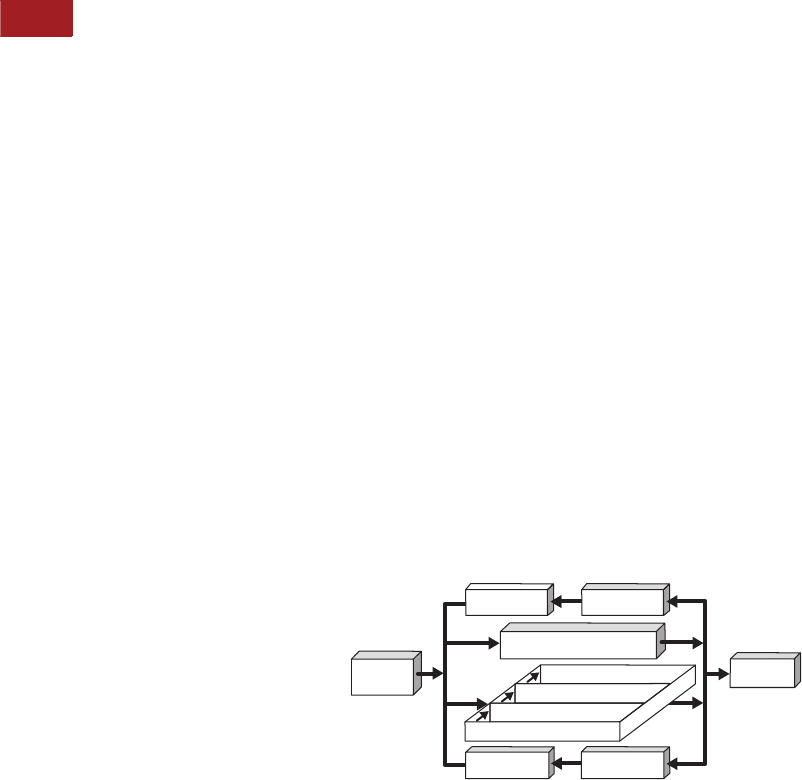
V3-T10-6 Volume 3—Power Distribution and Control Assemblies CA08100004E—June 2013 www.eaton.com
10
10
10
10
10
10
10
10
10
10
10
10
10
10
10
10
10
10
10
10
10
10
10
10
10
10
10
10
10
10
10.1
Power System Studies, Field Services and Conversions
Overview of Services
Getting a Performance-
Based Maintenance
Program Started
Getting started with a
PBM Program is easy. Highly
qualified EESS engineers
visit your facility and perform
a comprehensive site audit
and needs assessment.
While implementing
electrical system testing
and maintenance, EESS
engineers review both
the “condition” and the
“criticality” of each
component with plant
personnel.
The condition is determined
via traditional preventive
maintenance procedures
(industry-standard, time-
based) combined with
predictive diagnostic
technologies. The criticality
rating of each component
is established though
application of a reliability-
centered maintenance
approach, taking into
account its potential impact
on critical processes, safety
and the environment.
Then, EESS recommends a
maintenance interval (short-,
mid- or long-term) for each
component, as well as work
scopes and periodic
observation frequency.
Cost savings are realized
when the long-term
maintenance interval is
lengthened or by the
scope of maintenance
work during scheduled
outages is reduced. Uptime
and reliability improve when
preventive maintenance is
performed more frequently
on components with the
short-term designation.
Additional reliability
improvements can result
from redirecting some of
the savings to performing
additional predictive
diagnostics and equipment
modernization.
EESS delivers a periodic
scorecard to plant
personnel, summarizing
the recommendations,
performance and results
of the program.
Elements of a Performance-
Based Maintenance Program
●Site audit and maintenance
needs assessment
●Condition-based
maintenance
●Reliability centered
maintenance (RCM)
●Predictive diagnostics
●Efficient algorithms to
integrate equipment
condition results,
RCM input, predictive
diagnostics and periodic
observations
●Recommendations
for immediate action,
automation, remote
monitoring, life extension,
spare parts or upgrading
●Periodic observations while
energized and operating
●Maintenance implemented
based on equipment
condition and criticality
●Root-cause failure analysis
●Periodic scorecard and
customized reporting
of results
●Continuous improvement
●Optional ensured
performance improvements
and ensured savings—
typically, 15% savings over
two performance cycles
Asset Optimization Services
The Electrical Distribution
System (EDS) not only
represents a significant
capital investment, it is
essential to maintaining
production and critical
processes. In order to ensure
the maximum possible return
on this investment and
ensure that power to critical
processes is maintained,
EESS offers a suite of asset
optimization services. This
is not just a maintenance
program—we combine years
of EDS experience, as well as
power system engineering
and power quality expertise,
with the latest in predictive
diagnostic and remote
monitoring, and knowledge
management technology,
to deliver a comprehensive
program designed to optimize
EDS assets. This means
lower operating and
maintenance costs and
improved system reliability
and uptime. By outsourcing
responsibility for the electrical
distribution system assets
to EESS, owners can focus
on their core business while
we deliver maximum return
on your investment via
increased uptime and
decreased operation and
maintenance costs. Energy
management services and
performance contracts are
also available by which we
will guarantee specific
measurable results related
to energy savings, system
uptime, equipment
reliability, and operation and
maintenance cost reductions.
With a reputation as the
best-in-class power solution
strategists, it is obvious why
more and more industry
leaders are turning to Eaton
for uncompromising safe
and reliable electrical power
distribution systems, in the
PowerChain.
By providing the right
technology and intellectual
resources through
outsourcing the ownership,
operation and maintenance
of the plant electrical
distribution system, value
can be realized in three areas:
1. Capital funds previously
spent on non-core assets
are made available to
invest in core processes
and/or increase
shareholder value.
2. Operation and
maintenance costs
(salary/benefits; risk
and insurance related
to NFPA and OSHA;
training; engineering and
purchasing/procurement;
test equipment; tools;
safety equipment; and
parts inventory) are
significantly reduced or
eliminated completely.
3. Performance guarantees
and service level
agreements related
to uptime, energy,
and operating and
maintenance costs
are realized.
PBM Program Flowchart
Continuous
Improvement
Site Audit
& Needs
Assessment
Periodic
Scorecard
Ensured
Savings
Periodic Observations while
Energized & Operating
Traditional-Planned Maintenance
Continuous
Improvement
Root-Cause
Failure Analysis
Integrated Maintenance
Predictive Diagnostics
Condition-Based Maintenance
Reliability-Centered Maintenance

Volume 3—Power Distribution and Control Assemblies CA08100004E—June 2013 www.eaton.com V3-T10-7
10
10
10
10
10
10
10
10
10
10
10
10
10
10
10
10
10
10
10
10
10
10
10
10
10
10
10
10
10
10
10.1
Power System Studies, Field Services and Conversions
Overview of Services
Knowledge Management
Eaton has the expertise for
electrical distribution systems
with a variety of technologies
and expert analytical services
through our Instant Response
CenterSM. We aggregate data
gathered from your system
and use the information to
predict equipment failure and
identify energy cost reduction
opportunities.
Our practices can help you:
●Increase uptime:
●Avoid outages by
predicting equipment
failure or system
problems
●Decrease duration
of outages (remote
troubleshooting 24/7)
●Reduce operating and
maintenance costs:
●Service equipment
based on real-time
information rather than
traditional time-based
maintenance
●Better maintenance
with less man-hours
●Reduce energy costs:
●Optimize utility rate
structure
●Automated demand
management
●Energy usage
accountability
Power Systems
Engineering Solutions
Not only do we have one
of the largest teams of
power systems engineers
strategically located
throughout the world, but
many of these professionals
have influenced industry
standards and are sought
after because of their
expertise. With an emphasis
on precision and accuracy,
Eaton’s highly trained
engineers provide the most
focused and systematic
approach available to
enhance your system’s
performance. Your system
can save you money and
increase productivity while
meeting the growing and
changing demands of
your business.
Through surveys, studies,
predictive maintenance
solutions, energy
management, monitoring
and evaluation Eaton will
help you:
●Maintain IEEE
recommended power
quality levels, including
proper operating voltages
●Reduce costly system
disturbances
●Minimize harmonic
disturbances created
by nonlinear loads
●Provide arc flash levels
and personal protective
equipment to develop
customer safety programs
●With virtually all types of
software packages
We offer more than 15
standard and specialized
power system studies to
precisely target and help
correct your specific power
issues, utilizing a variety of
measurement instruments
and specialized software
packages.
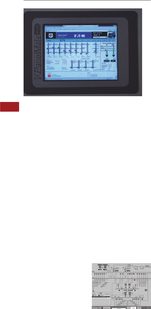
V3-T10-8 Volume 3—Power Distribution and Control Assemblies CA08100004E—June 2013 www.eaton.com
10
10
10
10
10
10
10
10
10
10
10
10
10
10
10
10
10
10
10
10
10
10
10
10
10
10
10
10
10
10
10.1
Power System Studies, Field Services and Conversions
Overview of Services
PSA Group
Contents
Description Page
Overview . . . . . . . . . . . . . . . . . . . . . . . . . . . . . . . . V3-T10-2
Asset Optimization, Knowledge Management and
Product Life Extension . . . . . . . . . . . . . . . . . . . . V3-T10-5
Power Systems Automation Group
General Capabilities . . . . . . . . . . . . . . . . . . . . . V3-T10-9
Instant Response Center Services . . . . . . . . . . . . V3-T10-10
Customized High Resistance Grounding Units . . . V3-T10-11
Power Systems Automation Group
General Description
The Power Systems
Automation (PSA) group
is a full-service systems
integrator. Eaton ensures
your hardware, software and
communication networks
perform as a seamless
system. PSA provides a
unique alternative to
conventional manufacturer-
integrator-contractor
teams by:
●Offering project
management and single-
point responsibility direct
from a major manufacturer
of power management and
control systems
●Providing unsurpassed
expertise in power
management and power
system control applications
across a broad range of
industries and end users
●Focusing on applying
new products effectively
and appropriately, and
integrating seamlessly with
all major manufacturers’
equipment, new or existing
●Bringing a wide range of
Eaton resources into a
project to address
geographic and technical
challenges, and managing
subcontractors and
manufacturers to handle
products and services
not provided directly by
Eaton’s Electrical Services
& Systems
PSA provides turnkey
systems integration projects
including system design,
programming, panel building,
installation, project
management, startup,
customer training and
complete documentation—
integrating Eaton’s and all
major OEM’s hardware,
software and systems.
The following is a summary
of services.
Example of a Fully Automated
Generator Paralleling and Emergency
Power Transfer Scheme for a
Mission-Critical Application
Power Systems Automation
●Power monitoring,
management and control
systems
●Eaton’s Power Xpert,
Foreseer and PowerNet
Systems including Power
Xpert Reporting
●Energy cost allocation
●Lighting management
systems (Eaton Pow-R-
Command™)
●Load management
systems
●Load shed and load
transfer schemes
●Generator paralleling
systems
●Backup and emergency
generation systems
●Demand management
systems
●Generator and ATS system
monitoring control and
remote testing
●Utility rate plan
optimization
●Health care emergency
power supply systems
monitoring
●Web-based monitoring
services

Volume 3—Power Distribution and Control Assemblies CA08100004E—June 2013 www.eaton.com V3-T10-9
10
10
10
10
10
10
10
10
10
10
10
10
10
10
10
10
10
10
10
10
10
10
10
10
10
10
10
10
10
10
10.1
Power System Studies, Field Services and Conversions
Overview of Services
General Capabilities
●Power Xpert
●Foreseer
●System design—functional
specification
●System network
architecture
●CAD drawings
●PC control and open
automation
●DeviceNet™ applications
●Open protocol systems
●PLC design and
programming:
●Eaton
●Allen-Bradley®
●Modicon®
●GE Fanuc®
●Siemens
●Human machine interface/
graphical user interface
design and configuration:
●Eaton PanelMate® and
PanelMate PC
●ICONICS GENESIS®
and WebHMI®
●Wonderware®
●Intellution
●PanelView™ and
RSView™
●Citect
●CIMPLICITY
●Full service custom
panel shop:
●UL® listing for industrial
control panels
●Motor starter panels
●PLC enclosures and
operator consoles
●Design and testing
●Turnkey capabilities
●Project management—
contractors, systems
integrators, other
OEMs, etc.
●Installation
●Startup and
commissioning
●Instruction manuals
●Customized training
●Complete
documentation
●Service contracts
and maintenance
agreements
●Single-point
responsibility
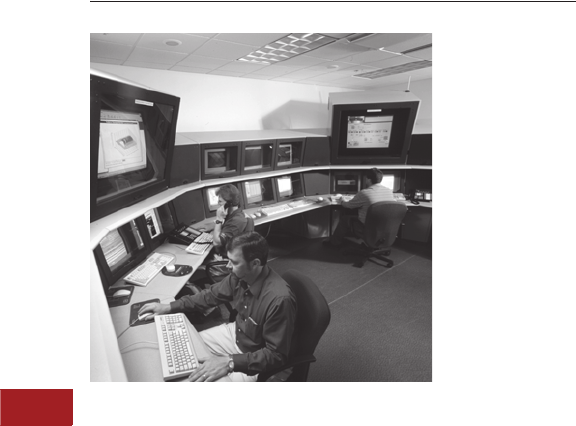
V3-T10-10 Volume 3—Power Distribution and Control Assemblies CA08100004E—June 2013 www.eaton.com
10
10
10
10
10
10
10
10
10
10
10
10
10
10
10
10
10
10
10
10
10
10
10
10
10
10
10
10
10
10
10.1
Power System Studies, Field Services and Conversions
Overview of Services
Eaton’s Instant Response Center
Contents
Description Page
Overview . . . . . . . . . . . . . . . . . . . . . . . . . . . . . . . . V3-T10-2
Asset Optimization, Knowledge Management and
Product Life Extension . . . . . . . . . . . . . . . . . . . . V3-T10-5
Power Systems Automation Group . . . . . . . . . . . . V3-T10-8
Instant Response Center Services
Customized High Resistance Grounding Units . . . V3-T10-11
Instant Response Center Services
General Description
Eaton’s Instant Response
CenterSM (IRC) is staffed by
power systems engineering
and power quality experts,
monitoring your electrical
distribution system in real-
time. The IRC continuously
monitors power distribution
equipment for changes in
performance or other
conditions that could signal
an impending power failure.
When changes exceed
predetermined thresholds,
the IRC issues alerts to
service personnel via Internet
e-mail or wireless page.
Eaton power systems
experts can then remotely
and securely access real-time
data from the subscriber’s
system, often correcting a
problem before electrical
service is impacted,
delivering to customers
a quantifiable return on
investment based on
maximum uptime, extended
equipment lifetime, and
reduced energy costs.
System outages can be
prevented or mitigated,
equipment life extended,
and operating, maintenance
and energy costs reduced
by monitoring key system
wellness parameters such as:
●Current, voltage
and energy
●Power quality and
harmonic content
●Partial discharge
●Vibration
●Temperature
●Environmental (such as
presence of water)
●Power factor
(transformer bushings)
●Key events (oscilligraphy)
●Energy monitoring
●Inverter monitoring
●Environmental condition
monitoring
The Instant Response Center
is the vanguard of Eaton’s
Knowledge Management
Services. Knowledge
management is a broad term
that describes the application
of a variety of related
technologies and expert
analytical services that
transform data into
information, and information
into knowledge. Data is
collected by remotely
monitoring customers’
electrical distribution and
related systems via the
Internet, and trending key
parameters related to energy
and utilities, power quality,
predictive diagnostics,
environment and key events.
This data is converted to
information through expert
analysis by power systems
engineering, power quality
and energy management
experts. This information
is then transformed into
knowledge using data
mining techniques and the
application of predictive
algorithms to extract trends
and patterns that will predict
equipment failure and identify
energy cost reduction
opportunities.
Using the latest
communications
technologies, such as
wireless videography, it is
also possible to extend this
high-end expertise to field
technicians or customer
personnel to guide them
through sophisticated
problem diagnosis,
troubleshooting or repairs.
Benefits of IRC:
●Experts are readily
available
●Eliminates the cost of
bringing experts on site
●Event analysis
●No employee turnover

Volume 3—Power Distribution and Control Assemblies CA08100004E—June 2013 www.eaton.com V3-T10-11
10
10
10
10
10
10
10
10
10
10
10
10
10
10
10
10
10
10
10
10
10
10
10
10
10
10
10
10
10
10
10.1
Power System Studies, Field Services and Conversions
Overview of Services
Oil Field HRG-3
Contents
Description Page
Overview . . . . . . . . . . . . . . . . . . . . . . . . . . . . . . . . V3-T10-2
Asset Optimization, Knowledge Management and
Product Life Extension . . . . . . . . . . . . . . . . . . . . V3-T10-5
Power Systems Automation Group . . . . . . . . . . . . V3-T10-8
Instant Response Center Services . . . . . . . . . . . . V3-T10-10
Customized High Resistance Grounding Units
Customized High Resistance Grounding Units
Eaton’s Electrical Services &
Systems builds custom
medium voltage High
Resistance Grounding Units
(HRGUs). They eliminate
the possibility of excessive
transient overvoltages due
to arcing ground faults on
ungrounded systems. There
are three categories:
●General industry—these
HRGUs typically are
freestanding and come
with a pulsing contactor
design to aid in finding
the ground fault
●Medium voltage
generators—new IEEE
research has proven high
risk for low resistance
grounded generators with
internal ground faults.
These systems require low
resistance grounding for
the system, but when an
internal generator ground
fault occurs, massive
damage can result. Eaton’s
Electrical Services &
Systems has developed
a hybrid high resistance
grounding unit (HHRG) that
allows the system to be
low resistance grounded
for external ground faults
but quickly reverts to high
resistance grounded only
for internal ground faults
●Oil field wells—electrical
submersible pumps used
in oil well applications
traditionally have been
designed to operate
ungrounded with the
expected history of
insulation type failures
due to arcing ground faults
on ungrounded systems.
These HRGU versions are
custom designed to match
the unique voltages, size
and locations (land or
platforms) for the oil field
industry and supply the
proven service continuity
and safety high resistance
grounding provides
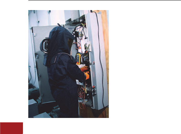
V3-T10-12 Volume 3—Power Distribution and Control Assemblies CA08100004E—June 2013 www.eaton.com
10
10
10
10
10
10
10
10
10
10
10
10
10
10
10
10
10
10
10
10
10
10
10
10
10
10
10
10
10
10
10.2
Power System Studies, Field Services and Conversions
Power System Studies
Arc Flash, Short-Circuit and Coordination Studies
Contents
Description Page
Arc Flash, Short-Circuit and Coordination Studies
Arc Flash Analysis Details. . . . . . . . . . . . . . . . . V3-T10-14
Protective Device Coordination Study. . . . . . . . V3-T10-13
Load Flow/Power Factor Correction Study. . . . . . . V3-T10-15
Harmonic Analysis Study . . . . . . . . . . . . . . . . . . . . V3-T10-17
Advanced Analysis and Design Services . . . . . . . . V3-T10-19
Arc Flash, Short-Circuit and Coordination Studies
General Description
Eaton’s Electrical Services &
Systems (EESS) can perform
short-circuit and coordination
studies per the following
standards, and others.
●Institute of Electrical and
Electronics Engineers, Inc.
(IEEE):
●IEEE 141,
Recommended Practice
for Electric Power
Distribution for
Industrial Plants
●IEEE 242,
Recommended Practice
for Protection and
Coordination of
Industrial and
Commercial
Power Systems
●IEEE 399,
Recommended Practice
for Industrial and
Commercial Power
System Analysis
●IEEE 241,
Recommended
Practice for Electric
Power Systems in
Commercial Buildings
●IEEE 1015,
Recommended Practice
for Applying Low Voltage
Circuit Breakers Used in
Industrial and
Commercial Power
Systems
●IEEE 1584, Methods
for calculating flash
protection boundary
distance and incident
energy values.
Determine hazard
risk category. Select
protective clothing
and PPE (Personal
Protective Equipment)
●American National
Standards Institute (ANSI):
●ANSI C57.12.00:
Standard General
Requirements for Liquid-
Immersed Distribution,
Power, and Regulating
Tr a n s fo r m e r s
●ANSI C37.13: Standard
for Low Voltage AC
Power Circuit Breakers
Used in Enclosures
●ANSI C37.010: Standard
Application Guide for
AC High Voltage Circuit
Breakers Rated on
a Symmetrical
Current Basis
●ANSI C37.41: Standard
Design Tests for
High Voltage Fuses,
Distribution Enclosed
Single-Pole Air Switches,
Fuse Disconnecting
Switches and
Accessories
●The National Fire Protection
Association 70E, National
Electrical Code®, latest
edition. Use methods to
calculate flash protection
boundary distance and
incident energy values
Eaton Quality Assurance
The short-circuit and
coordination studies will
be conducted under the
supervision and approval
of a registered professional
electrical engineer skilled in
performing and interpreting
the power system studies.
The registered professional
electrical engineer will be a
full-time employee of EESS.
The field engineering service
division can administer the
power system studies,
including acceptance and
startup testing. Equipment
and component titles used in
the studies shall be identical
to the equipment and
component titles shown on
the customer’s one-line
drawings. The power system
studies will be performed
with the aid of a digital
computer program and will be
in accordance with the latest
applicable IEEE and ANSI
standards.
Following the completion
of all studies, acceptance
testing and startup by EESS,
a 2-year warranty will be
provided on all components
manufactured by Eaton.
Sequencing and Scheduling
The short-circuit and
protective device
coordination studies will
be submitted to the design
engineer prior to receiving
final approval of the
distribution equipment
shop drawings and/or prior
to release of equipment
drawings for manufacturing.
If formal completion of the
studies may cause delay in
equipment manufacturing,
approval from the engineer
may be requested for
preliminary submittal of
sufficient study data to
ensure that the selection
of device ratings and
characteristics will be
satisfactory.

Volume 3—Power Distribution and Control Assemblies CA08100004E—June 2013 www.eaton.com V3-T10-13
10
10
10
10
10
10
10
10
10
10
10
10
10
10
10
10
10
10
10
10
10
10
10
10
10
10
10
10
10
10
10.2
Power System Studies, Field Services and Conversions
Power System Studies
Data Collection
The owner’s contractor,
under the direction of the
equipment manufacturer,
shall furnish all data as
required by the power
system studies. The engineer
performing the short-circuit
and coordination studies will
furnish the equipment
manufacturer and contractor
with a listing of required data
after award of the contract.
The contractor should
expedite collection
of the data to ensure
completion of the studies as
required for final approval of
the distribution equipment
shop drawings and/or prior to
the release of the equipment
for manufacturing. Provisions
shall be included by the
contractor to obtain the
services of the equipment
manufacturer to support
the proper data collection.
Fault contribution of
existing motors is included
in the study, with motors
<100 horsepower typically
grouped together. The
contractor shall obtain
required existing equipment
data, if necessary, to satisfy
the study requirements.
Short-Circuit and Protective
Device Evaluation Study Details
Typical conductor
impedances based on IEEE
Std. 141-1993 are utilized.
Transformer design
impedances are used
when test impedances
are not available.
The following is included
as part of the study:
●Calculation methods
and assumptions
●Selected base per
unit quantities
●One-line diagram of the
system being evaluated
●Source impedance data,
including electric utility
system and motor fault
contribution characteristics
●Tabulations of calculated
quantities
●Results, conclusions
and recommendations
A calculation of short-circuit
momentary and interrupting
duties for a three-phase
bolted fault is made for the
following locations:
●Electric utility’s supply
termination point
●Incoming switchgear
●Unit substation primary
and secondary terminals
●Low voltage switchgear
●Motor control centers
●Standby generators and
automatic transfer
switches
●Branch circuit panelboards
●Other significant locations
throughout the system
For grounded systems, a
bolted line-to-ground fault
current study for areas as
defined for the three-phase
bolted fault short-circuit study
will be provided.
Protective Device Evaluation
The protective device
evaluation portion of the
study will:
●Evaluate equipment and
protective devices short-
circuit ratings and compare
to calculated available
fault current
●Determine the adequacy of
switchgear, motor control
centers, and panelboard
bus bars to withstand
short-circuit stresses
●Determine the adequacy
of transformer windings
to withstand short-circuit
stresses
●Determine the adequacy
of cable and busway sizes
to withstand short-circuit
heating
●Notify owner in writing, of
existing circuit protective
devices improperly rated
for the calculated available
fault current
Protective Device
Coordination Study
●Proposed protective device
coordination time-current
curves will be displayed
on log-log
●Included on each curve
sheet will be a complete
title and one-line diagram
with legend identifying the
specific portion of the
system covered
●The device characteristic
curves will be terminated
at a point reflecting
maximum symmetrical or
asymmetrical fault current
to which device is exposed
●Identification of the device
associated with each curve
by manufacturer type and
function, and generated
using a commercially
available software program
The following characteristics
will be plotted on the curves,
where applicable:
●Electric utility’s
protective device
●Medium voltage
equipment relays
●Medium and low
voltage fuses, including
manufacturer’s minimum
melt, total clearing,
tolerance and damage
bands
●Low voltage equipment
circuit breaker trip devices,
including manufacturer’s
tolerance bands
●Transformer full-load
current, magnetizing
inrush current and ANSI
transformer withstand
parameters
●Conductor damage curves
●Ground fault protective
devices, as applicable
●Pertinent motor starting
characteristics and motor
damage points
●Pertinent generator
short-circuit decrement
curve and generator
damage point
●Other system load
protective devices for the
largest branch circuit and
the largest feeder circuit
breaker in each motor
control center
Where possible, adequate
time margins will be provided
between device characteristics
such that selective operation
is provided, while providing
proper protection.

V3-T10-14 Volume 3—Power Distribution and Control Assemblies CA08100004E—June 2013 www.eaton.com
10
10
10
10
10
10
10
10
10
10
10
10
10
10
10
10
10
10
10
10
10
10
10
10
10
10
10
10
10
10
10.2
Power System Studies, Field Services and Conversions
Power System Studies
Arc Flash Analysis Details
Background
NFPA 70E Standard,
Article 110.7 (F), states that
an electrical safety program
shall identify a hazard/risk
evaluation procedure to be
used before work is started
on or near live parts. Article
130.7 (A) states that
employees working in areas
where electrical hazards are
present shall be provided
with, and shall use, protective
equipment that is designed
and constructed for the
specific part of the body to
be protected and for the work
to be performed.
Procedure
In accordance with NFPA 70E
and IEEE 1584, commercially
available software packages
provide the calculation of
incident energy and flash
protection boundary. The
equations used in these
calculations are based on
actual test values. These
tests measured the calories
per square centimeter
(cal/cm2) radiating from
a simulated arcing fault.
The measurements were
performed at a theorized
working distance of
18.00 inches (457.2 mm).
The intent of the NFPA 70E
and IEEE 1584 guidelines
is to establish standard
calculations to determine an
Approach Boundary and an
associated PPE Hazard Level
that will limit the injury to the
onset of a second-degree
burn to the face and the torso
of the worker. An incident
energy of 1.2 cal/cm2
represents the onset of a
second-degree burn. The
various PPE Hazard Levels
are described in the NFPA
70E standard on a scale of
0 to 4. An incident energy
greater than 40 cal/cm2 will
be described in this study as
“Dangerous” and no Hazard
Level can be applied. Thus,
no PPE is approved to protect
the worker from a potential
arc flash hazard and the
equipment enclosure should
not be opened unless the
equipment is de-energized,
tagged-out and locked-out.
The arc flash analysis
considers each medium and
low voltage system location
within the scope of the work.
IEEE Std. 1584™-2002 states
that equipment below 240V
need not be considered
unless it involves at least one
125 kVA or larger low-
impedance transformer in
its immediate power supply.
Therefore, no detailed
calculations will be performed
for 120/208V locations
supplied by a transformer
smaller than 125 kVA,
however, labels will be
provided for these locations
and will be labeled as hazard
risk category zero. For the
detailed calculations, the
software determines the
available fault currents for
each location and the clearing
time of the device protecting
the same location. From
these determinations, the
potential incident energy is
calculated for each location.
Arc flash computations
shall include both line and
load side of main breaker
calculations, where necessary.
Tabulations
The following tabulations
will be provided as part of
the study:
Input Data
●Short-circuit reactance
of rotating machines
●Cable and conduit
materials
●Bus ducts
●Tr a n s fo r m e r s
●Reactors
●Aerial lines
●Circuit resistance and
reactance values
Short-Circuit Data
●Source fault impedance
and generator
contributions
●X to R ratios
●Asymmetry factors
●Motor contributions
●Short-circuit kVA
●Symmetrical and
asymmetrical fault currents
Recommended Protective
Device Settings
●Phase and ground relays:
●Current transformer ratio
●Current setting
●Time setting
●Instantaneous setting
●Specialty non-
overcurrent
device settings
●Recommendations
on improved relaying
systems, if applicable
●Circuit breakers:
●Adjustable pickups and
time delays (long time,
short time, ground)
●Adjustable time-current
characteristic
●Adjustable
instantaneous pickup
Arc Flash Results
●Arcing fault magnitude
●Device clearing time
●Duration of arc
●Arc flash boundary
●Working distance
●Incident energy
●Recommendations for new
equipment and/or system
changes to reduce the
calculated arc flash energy
level below 40 cal/cm2
where possible
Submittals
The results of the short-
circuit, coordination and
arc flash study will be
summarized in a final report.
The report will include the
following sections:
●One-line diagram
●Descriptions, purpose,
basis and scope of
the study
●Tabulations of circuit
breaker, fuse and other
protective device ratings
versus calculated short-
circuit duties
●Protective device time
versus current coordination
curves, tabulations of relay
and circuit breaker trip unit
settings, fuse selection
●Fault current calculations
including a definition of
terms and guide for
interpretation of the
computer printout
●Arc flash analysis
calculations including a
definition of terms and
guide for interpretation
of calculated values
●Recommendations for
system improvements,
where needed
●Executive summary
In addition to the report, EESS
can provide field services
(at additional cost) to:
●Adjust relay and protective
device settings according
to the recommended
settings table provided
by the coordination
study. Field adjustments
to be completed by the
engineering service
division of the equipment
manufacturer under the
startup and acceptance
testing contract portion
●Make minor modifications
to equipment as required to
accomplish conformance
with the short-circuit and
protective device
coordination studies
●Notify owner in writing
of any required major
equipment modifications
●Provide arc flash solution
engineering and
recommendations to lower
the incident energy at
specific locations where
the hazard is unacceptable

Volume 3—Power Distribution and Control Assemblies CA08100004E—June 2013 www.eaton.com V3-T10-15
10
10
10
10
10
10
10
10
10
10
10
10
10
10
10
10
10
10
10
10
10
10
10
10
10
10
10
10
10
10
10.2
Power System Studies, Field Services and Conversions
Power System Studies
Contents
Description Page
Arc Flash, Short-Circuit and Coordination Studies . V3-T10-12
Load Flow/Power Factor Correction Study
Harmonic Analysis Study . . . . . . . . . . . . . . . . . . . . V3-T10-17
Advanced Analysis and Design Services . . . . . . . . V3-T10-19
Load Flow/Power Factor Correction Study
General Description
Background
The primary function of
the electrical power
distribution system is to
provide real and reactive
powers demanded by the
various loads connected to
the system. Simultaneously,
the frequency and various
bus voltages must be kept
within specified tolerances,
even though the load
demands may undergo large
and unpredictable changes.
The Load Flow Study is an
analysis of the system
capability to supply the
connected load under steady-
state conditions. Optimal
management of the power
system can be achieved
through the use of this
analytical tool. Necessary in
the planning or expansion of
electrical power systems, a
load flow study demonstrates
the distribution of power and
voltage levels throughout the
system for selected operating
scenarios. These scenarios
may include normal and
emergency operating modes,
present and future circuit
arrangements, and alternative
designs and equipment
components.
Study results include real
(kW) and reactive (kVAR)
power flow through
transformers and cables,
voltage levels at system
buses, power factor and
system losses. These values
allow the power system
engineer to identify
overloaded transformers
and cables, provide
recommendations for proper
transformer tap settings, and
determine the need for
power factor correction
capacitors.
The Load Flow Study is a
prerequisite to developing
optimum generating strategies
and systems controls.
Study Procedure
Investigate the system
loading conditions for the
normal and contingent
operating conditions. All
system loads (kW and kVAR
components) and power
sources are included in
the analysis.
The study is processed using
state-of-the-art software,
which utilizes an iterative
technique to calculate real
and reactive power flows,
and bus voltage levels
throughout the system.
The data base for the load
flow analysis is established
from existing design or
nameplate load data or by
monitoring the existing
feeders with a digital power
monitor. Each feeder is
monitored for a minimum
of two hours, during typical
operating periods. The
following system data is
utilized as input to the load
flow program:
●Current and voltage
●kW, kVAR and kVA
●Power factor
The study for the electrical
system is based on both
present and future loading
considerations and switching
configurations. A maximum
of three load flow study
cases are performed to
analyze power flow, voltage
regulation, power factor,
transformer tap settings and
other load considerations.
An evaluation of the existing
utility billing contract will
determine whether power
factor correction should be
incorporated in the power
system. If power factor
correction is needed, the
appropriate hardware is
recommended and located to
maintain desired power factor
at the metering point. The
study also indicates any
switching of power factor
correction equipment that
may be necessary to maintain
proper voltage levels.
If the study results indicate
that power factor correction
equipment is necessary,
the approximate payback
period will be calculated
for equipment purchase
and installation.

V3-T10-16 Volume 3—Power Distribution and Control Assemblies CA08100004E—June 2013 www.eaton.com
10
10
10
10
10
10
10
10
10
10
10
10
10
10
10
10
10
10
10
10
10
10
10
10
10
10
10
10
10
10
10.2
Power System Studies, Field Services and Conversions
Power System Studies
Results
The Load Flow Study includes
the following for each circuit
condition analyzed:
●Bus voltages, line
currents, power factor
and transformer loading
in actual quantities and in
percent of the device
base values
●Recommended
transformer tap settings
●Recommended generator
dispatch schedules
●Complete set of capacitor
recommendations,
including calculated
payback period based
upon energy savings,
if additional shunt
compensation is
required for power
factor improvement or
voltage support
●Recommended equipment
upgrades or circuit
reconfigurations to
optimize the power
flow from the source
to the loads
Data Requirements
In addition to the data
required for the short-circuit
study, the following data is
required to complete the load
flow study:
●Design, nameplate or
measured load data
●Ratings and connections
of all power factor
correction capacitors
●Reactor impedance
and ratings
●Power flow measurements
(when available) at
utilization transformers

Volume 3—Power Distribution and Control Assemblies CA08100004E—June 2013 www.eaton.com V3-T10-17
10
10
10
10
10
10
10
10
10
10
10
10
10
10
10
10
10
10
10
10
10
10
10
10
10
10
10
10
10
10
10.2
Power System Studies, Field Services and Conversions
Power System Studies
Harmonic Analysis Study
Contents
Description Page
Arc Flash, Short-Circuit and Coordination Studies . V3-T10-12
Load Flow/Power Factor Correction Study . . . . . . . V3-T10-15
Harmonic Analysis Study
Advanced Analysis and Design Services . . . . . . . . V3-T10-19
Harmonic Analysis Study
General Description
Background
The operation of nonlinear
loads and in particular variable
frequency drives (VFDs) in a
power distribution system
creates harmonic currents
that flow throughout the
power system. When
considering VFDs, the
frequencies and magnitudes
of the harmonic currents are
functions of the number
of drive rectifier pulses,
as well as the AC system
impedances. Harmonic
voltages result from the
harmonic current flowing
back into the harmonic
impedances of the
distribution system. The
order of the harmonic
currents generated is np ± 1,
where n is any integer and p
is the number of drive pulses.
Therefore, for 6-pulse drive,
the order of harmonics is 5th,
7th, 11th, 13th, 17th, 19th,
etc. For 12-pulse drive, the
order of harmonics is 11th,
13th, 23rd, 25th, 35th,
37th, etc.
Harmonic studies can provide
calculation of the current
and voltage harmonics
throughout the electrical
distribution system when
the generated harmonic
current magnitudes and the
system 60 Hz impedances
are known.
Significant harmonic current
and voltage magnitudes can
have adverse effects on
system components and
overall system operation.
Harmonic currents cause
increased power losses in
transformers, motors and
cables. The higher power
losses increase equipment-
operating temperatures,
increasing the possibility of
overload, increasing thermal
stress on insulation, and
reducing overall system
efficiency.
Power factor correction
capacitor banks are
particularly vulnerable to the
detrimental effects of power
system harmonics. Most
capacitors are designed to
operate at a maximum of
110% of rated voltage and
135% of rated kVAR. Large
magnitudes of voltage and
current harmonics can
exceed these design limits,
and cause severe capacitor
bank damage. Since
capacitive reactance is
inversely proportional to
frequency, capacitor banks
act as sinks for current
harmonics in the system. This
often causes capacitor fuses
to open or capacitor damage
when fuses are not present
or improperly sized.
A serious condition, with
potential for substantial
damage, occurs as a result of
harmonic parallel resonance.
As frequency increases,
capacitive reactance
decreases and inductive
reactance increases.
Harmonic resonance occurs
at the frequency when the
inductive reactance of the
source-side circuit equals the
capacitive reactance of the
power factor correction
capacitor. Looking back into
the circuit from the harmonic
source, the capacitor is in
parallel with the substation
transformer. The circuit total
impedance (including the
capacitor) is very high at the
resonance frequency. If the
VFDs generate harmonic
current at the resonance
frequency, large harmonic
voltages will be developed at
the capacitor and transformer
bus, and serious equipment
damage can occur.
IEEE Std. 519-1992
establishes recommended
limits for harmonic voltages
and currents in power
systems.

V3-T10-18 Volume 3—Power Distribution and Control Assemblies CA08100004E—June 2013 www.eaton.com
10
10
10
10
10
10
10
10
10
10
10
10
10
10
10
10
10
10
10
10
10
10
10
10
10
10
10
10
10
10
10.2
Power System Studies, Field Services and Conversions
Power System Studies
Study Procedure
Harmonic analysis of the
electrical distribution system
for the circuit conditions
listed below.
●Existing system
configuration
●System with new VFDs or
other nonlinear harmonic
creating loads in operation
The power system is
modeled for the fundamental
frequency and appropriate
harmonic frequencies.
System impedances are
calculated for the
fundamental frequency as
well as for each appropriate
harmonic frequency.
The following is calculated for
each study:
●System harmonic voltages
in rms and % THD
●System harmonic currents
in rms and % THD
●An IEEE 519 analysis at the
point of common coupling
with incoming utility
●Capacitor bank evaluations
on the basis of voltage,
current and kVA
●The payback period of the
total cost (filter equipment,
installation and/or
relocation) for the three
most feasible filter options
In addition, the drive’s
harmonic generation based
upon the drive’s loading and
characteristics is calculated. If
specified, field measurement
of the VFD current harmonic
generation during the process
operation can be made. Each
harmonic component is then
successively injected into the
simulated system, and the
resulting harmonic currents
and voltages are computed
throughout the system.
If the calculated magnitudes
of harmonic voltages and/or
currents are excessive, the
optimal corrective solution will
be determined to reduce the
harmonic quantities to within
acceptable limits.
When a harmonic filter is
recommended, a complete
equipment specification will
be provided. A final study
case is conducted to verify
that the harmonic filtering
equipment will reduce
harmonic levels to within
acceptable standards.
Results
At the conclusion of the
Harmonic Analysis, the
following will be submitted
for each circuit condition
analyzed:
●Description, purpose, basis
and scope of the harmonic
study and a single-line
diagram of the portion of
the power system that is
included within the scope
of the study
●Tables listing the individual
harmonic voltages and
currents and total harmonic
distortions (THDs) for all
major buses within the
electrical distribution
system. Waveforms for all
of the calculated harmonic
voltages and currents will
be displayed
●Plots of frequency versus
impedance (harmonic
resonance scans) for all
shunt capacitor locations
●Complete
recommendations for
harmonic filters, shunt
capacitors and series
reactors, required for
harmonic suppression
●All computer output and
an interpretation guide
Data Requirements
In addition to the data
required for a load flow
analysis, the following data
is also required:
●Complete text report of
each measurement
location sorted by voltage
and current, and listing
the individual harmonic
component and the total
harmonic distortion (THD)
●Waveforms of each
measurement sample
●Detailed harmonic
spectrums of the harmonic
generating loads

Volume 3—Power Distribution and Control Assemblies CA08100004E—June 2013 www.eaton.com V3-T10-19
10
10
10
10
10
10
10
10
10
10
10
10
10
10
10
10
10
10
10
10
10
10
10
10
10
10
10
10
10
10
10.2
Power System Studies, Field Services and Conversions
Power System Studies
Contents
Description Page
Arc Flash, Short-Circuit and Coordination Studies . V3-T10-12
Load Flow/Power Factor Correction Study . . . . . . . V3-T10-15
Harmonic Analysis Study . . . . . . . . . . . . . . . . . . . . V3-T10-17
Advanced Analysis and Design Services
Transient Stability . . . . . . . . . . . . . . . . . . . . . . . V3-T10-19
Switching Transient Analysis . . . . . . . . . . . . . . . V3-T10-20
Transient Motor Starting Analysis . . . . . . . . . . . V3-T10-21
Ground Grid Analysis. . . . . . . . . . . . . . . . . . . . . V3-T10-21
Electrical Design Services . . . . . . . . . . . . . . . . . V3-T10-22
Advanced Analysis and Design Services
Transient Stability
Background
Power system stability is a
condition where the various
synchronous machines of a
system remain in synchronism,
or in step, with one another.
Instability is the condition
when one or more of the
machines fall out of step.
With a sudden increment
in load, there is a definite
upper limit to the load that a
machine will carry without
pulling out of step. This is
defined as the transient
stability limit of the system
for the given condition.
The transient stability limit
may have different values
for the same system,
depending upon the nature
and magnitude of the
disturbance. Disturbance
types include a sudden
increase in load, by the
disconnection of a parallel line
or disconnection of the utility
source. The most severe
disturbance subjected to the
electrical distribution system
is a short circuit.
All transient stability
studies should include
computer simulations that
determine the effects of
short circuits upon the
system transient stability.
Study Procedure
The Transient Stability
Study provides an analysis
of the transient response
of the system and rotating
machines following system
disturbances, and the behavior
of the system in relation to
the power company tie.
Data from the study can be
used to determine the effect
of generator and/or motor
performance, system voltage
and frequency, all as a
function of time. Generator
and motor performance are
affected by:
●Abrupt changes in load
and including the starting
and accelerating effect of
large motors
●Short Circuits, from which
effect the critical operating
time for protective relays
can be determined
●Partial loss of generation or
loss of power company tie,
and the corrective effect of
a load shedding scheme
Study engineers will analyze
system disturbance scenarios
using state-of-the-art
software. Protective device
fault clearing times will be
included in the computer
simulations and the
generator, motor, and tie-line
protection and coordination
will be evaluated from a
system stability perspective.
Load-shedding schemes will
be evaluated or developed,
based upon the operating
requirements of the
customer facility.
Results
At the conclusion of the
Transient Stability Analysis,
Eaton will submit the
following:
●Machine variables,
including turbine input
and generator output
power, accelerating power,
frequency deviation, rotor
angle, field voltage and
current, terminal voltage
magnitude and angle,
and generator current
and angle. These are
summarized for each
machine in time
increments over the
nominal transient time
interval of one or two
seconds. For the load
shedding study analysis,
the time interval would be
extended to five seconds
or longer
●Plotted swing curves of
power angle over the
transient time period for
each machine
●The magnitude and angle
of voltage and frequency
deviation for any bus in
the system
●Summary of line currents,
power flows and apparent
impedance on any line
●If required, details of the
load shedding scheme,
including the sequence
of load separation, critical
clearing time and type
of relay

V3-T10-20 Volume 3—Power Distribution and Control Assemblies CA08100004E—June 2013 www.eaton.com
10
10
10
10
10
10
10
10
10
10
10
10
10
10
10
10
10
10
10
10
10
10
10
10
10
10
10
10
10
10
10.2
Power System Studies, Field Services and Conversions
Power System Studies
Switching Transient Analysis
Background
A transient is initiated
whenever there is a sudden
change of circuit conditions.
This most often occurs when
a switching operation occurs,
such as capacitor switching,
transformer energizing and
fault current interruption.
Some of the most severe
and damaging transients are
produced by lightning strikes.
Voltage transients will result
when loads on an electrical
distribution system are
switched. Industrial and
commercial power systems
comprise capacitive and
inductive components. The
transient disturbance occurs
because the currents and
voltages do not reach their
final value instantaneously.
The severity of a voltage
transient is a function of the
relative power level of the
load being switched, and
the available fault current
magnitude in the supply
circuit where the switching
takes place. Some circuit
components such as motors
and transformers are
adversely affected by the
speed (frequency) of the
voltage transient as well
as its magnitude. Voltage
transient magnitudes
should not exceed twice
the system voltage when
they occur from normal
switching operations.
Properly rated equipment
BIL provides adequate
transient or surge protection
for these instances.
Complex voltage transients
result from abnormal
switching operations and
current chopping, prestrikes
and restrikes cause these
disturbances. Voltage
magnitudes may approach
ten times the system voltage
and must be controlled by
surge arresters, surge
capacitors and/or resistors.
These surges can damage
the most rugged system
components.
Study Procedure
Eaton engineers will discuss
with customer personnel all
aspects of the disturbance
that is being investigated. The
circuit configuration
and system loading prior
to the disturbance and any
subsequent equipment
damage incurred will
be examined.
Engineers will develop a
computer model of the
electrical circuit with EMTP,
Electromagnetic Transients
Program. All circuit
components, including surge
capacitors, equipment
capacitance, bushing
capacitance, CT and PT
capacitance, and transformer
saturation characteristics will
be modeled in detail.
The suspect switching
operations, including all
reasonable perturbations such
as current chopping, circuit
breaker restrike and prestrike,
will be simulated with the
computer. Voltage and
current transient magnitudes
will be calculated, and the
waveforms will be displayed
for all of the transients caused
by the switching operation.
If excessive transient
voltages or currents are
observed, the study engineer
will propose corrective
measures, which may
include surge protection,
damping resistors or modified
switching procedures. These
measures will be analyzed
with additional simulations
to ensure that excessive
switching transients are
avoided or reduced to
acceptable levels.
Finally, an insulation
coordination study, which
compares surge arrester
ratings with equipment BIL,
will be completed to confirm
the recommended surge
protection system for the
circuit being investigated.
Results
At the conclusion of the
Switching Transient Analysis,
Eaton will submit the
following:
●Detailed description of the
sequence of events that
preceded the switching
transient that disrupted the
electrical system operation
and caused equipment
damage
●Magnitudes and
waveforms of transient
voltages and currents
calculated by the
computer simulations
●Recommendations for
surge protection, such
as surge arresters, surge
capacitors, RC suppression,
damping resistors or
TVSSs, for all affected
equipment
●Results of the insulation
coordination study to
evaluate the degree of
protection afforded by
the recommended surge
protection system
●Appendix, including one-
line diagrams, computer
program output sheets
and all other pertinent
supporting documentation

Volume 3—Power Distribution and Control Assemblies CA08100004E—June 2013 www.eaton.com V3-T10-21
10
10
10
10
10
10
10
10
10
10
10
10
10
10
10
10
10
10
10
10
10
10
10
10
10
10
10
10
10
10
10.2
Power System Studies, Field Services and Conversions
Power System Studies
Transient Motor Starting Analysis
Background
A motor starting study is
conducted to evaluate the
motor’s impact on the power
system and the power
system’s impact on the
motor. Motor starting studies
are usually performed for
new motor installations
to ensure system reliability,
provide data for motor
protection, and to identify any
system modifications that
may be necessary to avoid
starting problems.
Starting a large motor on a
distribution grid with limited
capacity may cause severe
voltage reduction and not
produce enough motor
torque to accelerate the
motor. One of the most
noticeable effects is light
flicker during motor starting.
Voltage dips may cause
problems with voltage
sensitive electronic
equipment to such as
computers and
microprocessors.
The study will recommend
solutions to any problem
discovered. One possible
solution may be to install a
reduced voltage starter to
decrease the motor inrush
current and minimize the
voltage drop. A system
balance must be maintained
to minimize impact on the
system and allow sufficient
motor torque to perform
its function.
Eaton will investigate various
methods for minimizing
system disturbances when
starting of motors. These
methods include:
●Reduced voltage starting
methods such as: auto-
transformer, reactor,
wye-delta, primary
resistor, part winding
and solid state
●System modifications,
including paralleling
circuits, addition of shunt
capacitors, adjusting
transformer taps and
relocating loads
Study Procedure
A Motor Starting Study will
determine the system effects
of starting and accelerating
the motor and associated
load from time zero to full
speed. The study will
calculate the terminal
voltages of the motor and
other buses when the motor
and load is started.
Eaton will develop the circuit
model on the digital computer.
The procedure requires
a Load Flow analysis to
be completed initially to
determine system conditions
prior to motor starting.
Computer simulations of
various motor starting
methods, motor starting
sequences and circuit
configurations will follow.
From these results, Eaton
will recommend the best
means of starting motors
at that circuit location.
Results
At the conclusion of the
Motor Starting Study, Eaton
will submit the following for
each method analyzed:
●Tables listing voltages at
the motor terminals and at
other significant locations
within the electrical
distribution system
●Plots of motor speed,
motor current, motor
torque, load torque,
accelerating torque,
accelerating time, power
factor, and voltages at
the motor terminals and
other significant locations
in the system
●Recommendations of
various options to correct
any problems found in
starting and accelerating
the motor and load
Ground Grid Analysis
Background
A Ground Grid Analysis
ensures that the ground grid
design provides adequate
safety for personnel during
ground fault conditions.
When fault current flows
through the earth from the
ground grid of the plant
substation, the potential of
the plant substation ground is
elevated. Voltage potentials
along the ground surface
may be severe enough to
endanger a person walking on
the surface, and dangerous
potential differences may
exist between grounded
apparatus, structures,
fences and nearby earth.
Study Procedure
Eaton engineers will evaluate
your switchyard or substation
ground grid to ensure that the
performance of the grid
adheres to IEEE Standard 80,
“Guide for Safety in AC
Substation Grounding.”
This will involve utilizing a
computer software program
that models the ground grid
under fault conditions. All
voltages at the surface are
calculated, allowing
evaluation of Step and Touch
potentials, to ensure the
safety of plant personnel.
The Ground Potential Rise
is also calculated to evaluate
the potential of damage to
interconnected equipment.
The following services are
available and are an integral
part of doing a complete
evaluation:
●Inspection and evaluation
of existing grid conductors
and connectors and
continuity
●Soil resistive
measurements and
interpretation
●Measurement of ground
grid impedance
●Safety assessments—step
and touch voltage criteria
●Substation ground grid
layout design, ground grid
equipment specifications,
bills-of-materials,
requirements to meet
IEEE Std. 80
●Recommendations for
improving existing grids
Results
At the conclusion of the
Ground Grid Analysis, Eaton
will submit the following:
●Executive summary,
including findings and
recommendations
●Study procedures
●Calculation results,
including GPR and Step
and Touch Potentials
●Data summary, including
computer report output
●Appendix, including one-
line diagrams, computer
program output sheets,
and all other pertinent
supporting documentation

V3-T10-22 Volume 3—Power Distribution and Control Assemblies CA08100004E—June 2013 www.eaton.com
10
10
10
10
10
10
10
10
10
10
10
10
10
10
10
10
10
10
10
10
10
10
10
10
10
10
10
10
10
10
10.2
Power System Studies, Field Services and Conversions
Power System Studies
Electrical Design Services
Eaton’s electrical design
services can extend from
the point of utility connect
to the equipment. Design
services are integrated with
analysis services, resulting
in a complete engineered
solution. The level of design
detail can be customized
from minimal design
consultation and advice
to a complete design
package with specifications
and drawings.
Typical design services
include:
●Distribution System
Design—Design and
specification of the
electrical distribution
system from the point
of utility interconnection
to the downstream
utilization equipment
●Substation Design—
Complete substation
design service is available,
including ground grid
analysis and design,
substation layout,
equipment specification,
protection and control
●Protection and Control—
Design of advanced
electrical protection
and control, including
transmission line
protection, system
automation and
advanced metering
●Renewable energy
design, including the
AC and DC distribution
systems, collector
substation and utility
interconnection design
Typical construction drawings
and documentation for design
projects include:
●Demolition plans for the
existing equipment and
building (if applicable)
●New proposed switchgear
arrangement plans and
elevation views
●Specifications for all
new AC and DC
distribution equipment
●All necessary engineering
calculations (load flow,
short-circuit, etc.)
●Single line diagrams for
the AC and DC distribution
and auxiliary equipment
●Arrangement plans and
details for new structures,
bus systems, auxiliary and
DC equipment
●Conduit raceway drawings
and schedules
●Control panel and terminal
board panel design
drawings
●Lighting and grounding
modifications for the
new installation
●Building modification
for garage doors,
air ventilation, etc.

Volume 3—Power Distribution and Control Assemblies CA08100004E—June 2013 www.eaton.com V3-T10-23
10
10
10
10
10
10
10
10
10
10
10
10
10
10
10
10
10
10
10
10
10
10
10
10
10
10
10
10
10
10
10.3
Power System Studies, Field Services and Conversions
Field Engineering Services
Field Engineering Services
Contents
Description
Field Engineering Services
Selection Guide
The following tables present the relationship between Eaton’s Electrical Sector capabilities and the user’s needs:
Consulting and Turnkey Project Management
Engineering Services
Capabilities
New Construction
and Facility Growth
Improved Reliability
and Reduced Downtime
Life Extension
and Cost Reductions
New substation design,
management and construction
Support consultant or end-user by offering one-stop
shopping and an exclusive 2-year warranty on all
Eaton products supplied.
— Design and construction costs are reduced by a
single-source contract. In addition, end-user internal
engineering resources can be applied to core-business
process improvements, rather than the electrical
distribution system.
Electrical, mechanical and
instrumentation services
Through networking the experiences of our
many service locations, we can add mechanical
and instrumentation services to our
construction capabilities.
—
Power system studies
Short circuit
Device evaluation
Coordination
Load flow
Power factor
Harmonics
Power quality
Grounding
Reliability
Switching transient
Others
New construction requires the proper set of
power system studies. We can review your current
and future power needs: reliability, loading profiles,
emergency power requirements, etc., and determine
the necessary studies.
A short-circuit study is required for protection of
personnel and equipment. In addition, coordination
studies reduce downtime by limiting the power loss to
only the faulted feeder. Power quality studies are
necessary due to the many new nonlinear loads and
their potential effect on critical equipment.
Extending the life of an electrical distribution system
should include an updated single-line diagram and the
proper complement of Power System Studies to
address your current and future needs.
Failure/root-cause analysis — Electrical outages can result in extensive downtime
and loss production. Critical systems should be
investigated to determine the cause of such outages,
and corrective actions planned and implemented.
An investigation of critical outages can result in long-
range cost reductions by preventing the repeat of such
occurrences, and allowing system improvements
while funding is available.
Equipment relocation Changing production needs can be satisfied by
the relocation of power distribution components,
either by use of internal or sister-plant equipment.
— Costs can be reduced for new production projects
by the allocation of existing equipment, thereby
eliminating the need for new purchases.

V3-T10-24 Volume 3—Power Distribution and Control Assemblies CA08100004E—June 2013 www.eaton.com
10
10
10
10
10
10
10
10
10
10
10
10
10
10
10
10
10
10
10
10
10
10
10
10
10
10
10
10
10
10
10.3
Power System Studies, Field Services and Conversions
Field Engineering Services
System Integration
Training
Engineering Services
Capabilities
New Construction
and Facility Growth
Improved Reliability
and Reduced Downtime
Life Extension
and Cost Reductions
Plant monitoring, protection
and control
Digitrip
PowerNet
Advantage starters
DeviceNet
PLC interface
Plant-wide electrical power distribution system
monitoring and control can be cost-effectively
implemented during new construction. New
Eaton electrical products allow for communications
through all levels of the power distribution network.
Eaton’s PowerNet system allows for plant-wide
monitoring and control from a single workstation
or from any number of workstations connected to a
plant LAN, company, intranet or Internet.
Real-time monitoring, and remote control of circuit
breakers can greatly improve reliability by providing
immediate indication of a problem, allowing for a
quick resolution; and if necessary, remote control
of power distribution equipment.
Plant electrical distribution systems are being
subjected to higher loads, and greater harmonics.
Plant-wide monitoring can help identify these areas
of rapid deterioration, and implement corrective
actions to extend the life of the electrical system.
Taking such action will also prevent costly outages
and the resultant downtime. In addition, with the
advent of utility deregulation, having accurate power
usage values will allow for improved negotiating on
power purchases.
PLC/PC control and open
automation systems
New process and discrete control systems
currently employ PLCs for control and monitoring.
Eaton PC control and open automation products
can be applied for many of these systems with full
integration into plant-wide control and information
management systems. Integration to other OEM’s
equipment is also available.
The real-time, self-diagnostic information
available with a PC control/open automation
system significantly reduces system downtime
by allowing the operator to proactively respond to
system problems before a shutdown occurs.
PC control/open automation systems provide the
greatest level of flexibility when implementing a
control system. The open automation concept allows
the user to select the “best in class” components
without being tied to a single OEM. PC control systems
can provide a wealth of information that
can be easily integrated into manufacturing and
enterprise systems allowing the user to optimize
process efficiency.
Drive systems motor control Eaton drive systems, as well as modernized
motor control, provide critical hardware for
new efficient process system construction.
Modern drive systems and motor control will
greatly improve system reliability by the application
of new technology, and allowing for plant-wide
communications and control.
The electrical portion of the process-line can have
extended life, and develop a lower cost of production.
This can be combined with the life extension of the
mechanical components.
Energy management
load shedding
Eaton maintains application expertise and a full
line of products to support energy management
systems. Our energy management experts can
design and implement an energy management
program including financial analysis and justification.
— With the advent of utility deregulation, in-house
power generation and load shedding capabilities
can aid your negotiations for reduced electric rates.
In-house generation voltage regulation and excitation
systems can also add to system life.
Generator/emergency
power systems
New power reliability needs may require modern
emergency power systems.
Reliability can be improved for critical processes
with improved standby power systems.
Engineering Services
Capabilities
New Construction
and Facility Growth
Improved Reliability
and Reduced Downtime
Life Extension
and Cost Reductions
New product training
Electrical power equipment
Drive systems
PLC systems
Training is offered on all new products supplied
by Eaton’s Electrical Sector. The construction
phase is a beneficial time to incorporate training,
from equipment and a funding standpoint.
——
Distribution systems
analysis training
— Plant engineers require an understanding of the
dynamics of electrical power distribution systems.
This training addresses topics to improve existing
electrical systems, as well as plan for future
expansions.
Life extension of the power distribution system
requires a proper analysis by the plant electrical
engineer. Appropriate investigations can be completed
and recommendations planned for implementation.
Power quality and
grounding training
— Power quality and grounding issues are affecting
new sensitive process equipment. This training
can provide short- and long-term solutions, as well
as recommending methods to accurately measure
power quality.
—
Electrical equipment
maintenance training
— Completing proper and timely maintenance on
electrical equipment will improve reliability and
reduce downtime. This training shall identify simple,
yet effective, maintenance tasks, which can be
completed by plant personnel.
Proper equipment maintenance will result in system
life extension, indirectly by reducing failures. In
addition, training in-house personnel to complete
several maintenance duties can reduce costs.
Customized training
Scheduled
On-site
In conjunction with new construction, training can
also be integrated to include existing electrical
components, regardless of manufacturer. This allows
for effective one-time training, on-site if desired, and
incorporated into the construction project. A site review
would be conducted to identify the training needs, and
associated equipment.
A plant-wide custom training program can
address specific reliability needs, as well as
goals for reduced downtime.
Cost reductions can be achieved by providing
maintenance training to operation personnel, thereby
possibly combining operating and maintenance duties.
This training will also provide operators with a
better understanding of the needs of electrical
equipment, thereby resulting in life extension
through reduced fatigue.

Volume 3—Power Distribution and Control Assemblies CA08100004E—June 2013 www.eaton.com V3-T10-25
10
10
10
10
10
10
10
10
10
10
10
10
10
10
10
10
10
10
10
10
10
10
10
10
10
10
10
10
10
10
10.3
Power System Studies, Field Services and Conversions
Field Engineering Services
Startup and Commissioning
Predictive and Preventive Maintenance
Engineering Services
Capabilities
New Construction
and Facility Growth
Improved Reliability
and Reduced Downtime
Life Extension
and Cost Reductions
Installation support
and supervision
Electrical construction of sophisticated power
distribution equipment requires support and/or
supervision by factory trained personnel.
Proper installation techniques have been proven
to reduce short-term operation problems and the
resultant downtime.
Proper installation will result in an extended life,
through the proper application of stress and
tensions on various electrical components.
Acceptance testing
Electrical power
equipment:
Switchgear
Outdoor units
Circuit breakers
PowerNet, etc.
Starters
Motor control
Transformers
Tap changers
Network protection
Drive systems
PLC systems
Nuclear safety related 1E
Startup testing should be completed by an
independent division of a major electrical
equipment manufacturer. Eaton provides an exclusive
2-year warranty on all Cutler-Hammer brand products
supplied, when EESS completes engineering studies,
startup and acceptance testing.
Proper acceptance testing provides baseline
data for future maintenance. This allows the
development of predictive maintenance programs,
thereby anticipating outages, and identifying
correction actions. EESS offers comprehensive
ongoing predictive and preventive maintenance
programs.
Proper acceptance testing will identify any areas
requiring corrective action, thereby resulting in a
system with the longest life expectancy.
Startup, training and
warranty support
Trained individuals should complete equipment
startup. Voltage levels, phasing and proper
grounding requires attention to ensure a safe
startup. Specific equipment testing and adjustments
are also necessary to ensure all electrical safety
interlocks are operational and ready for long-term
service. Training can be provided immediately
following, or during the startup process. Warranty
issues can be quickly identified and corrected by
factory trained personnel.
Long-term reliability is ensured by the proper
startup, training and warranty support, all of
which are provided by EESS.
Allowing the training cycle to commence
immediately following, or during, the startup
of the equipment can reduce training costs.
Travel and setup costs are minimized, and
plant personnel witness the operation of all
associated electrical equipment, as part of the
training session.
Exclusive 2-year warranty Eaton has identified that warranty-related costs may be associated with improper startup and acceptance
testing by groups that are not factory trained. This results in construction delays, as well as possible
long-term reliability issues. Eaton offers an exclusive 2-year warranty on Cutler-Hammer
brand products, when all engineering studies, startup and acceptance testing is completed by EESS.
Startup costs are reduced by allowing EESS to
complete all functions since the required OEM
presence for equipment installation support can
be incorporated into the acceptance testing.
Engineering Services
Capabilities
New Construction
and Facility Growth
Improved Reliability
and Reduced Downtime
Life Extension
and Cost Reductions
PM program design and
implementation
Electrical power equipment:
Switchgear
Outdoor units
Circuit breakers
PowerNet, etc.
Starters
Motor control
Transformers
Tap changers
Network protection
Medium voltage generators
Medium voltage motors
Drive systems
PLC systems
Nuclear safety related
1E equipment
Following construction, EESS can develop a
long-term predictive/preventive maintenance
program. This allows for recording of the necessary
baseline data required for effective predictive
maintenance programs.
Partial discharge sensors installed in new medium
voltage switchgear provide years of predictive
diagnostics.
Predictive maintenance involves identifying
measurable parameters, which when trended,
provide an indication of the reliability and the life
expectancy of the subject equipment.
Preventive maintenance includes specific
maintenance tasks that extend the useful life
of the subject equipment.
A comprehensive program can be developed,
whereby plant personnel complete portions,
supplemented by EESS personnel. Plant personnel
would perform observations, minor maintenance
and data recording. Tasks would be developed to
complement plant personnel’s existing daily duties.
Periodic reports would be issued addressing
all trends. Immediate corrective actions would
be identified, as well as long-term predictive
maintenance requirements.
Reliability is improved and downtime reduced
by the proper and regular implementation
of predictive and preventive maintenance programs.
A properly designed program will take advantage
of in-house personnel, thereby providing a cost-
effective plan. Program implementation and
required corrective actions will result in the
longest life expectancy possible.
EESS can provide a complete short- and long-
range PM program to satisfy your life extension
and cost reduction needs.
Partial discharge detection identifies insulation
deterioration prior to permanent damage and
ultimate failure. Efficient outage correction
actions can be implemented.

V3-T10-26 Volume 3—Power Distribution and Control Assemblies CA08100004E—June 2013 www.eaton.com
10
10
10
10
10
10
10
10
10
10
10
10
10
10
10
10
10
10
10
10
10
10
10
10
10
10
10
10
10
10
10.3
Power System Studies, Field Services and Conversions
Field Engineering Services
Electrical System Modernization
Engineering Services
Capabilities
New Construction
and Facility Growth
Improved Reliability
and Reduced Downtime
Life Extension
and Cost Reductions
Switchgear bus
MVA upgrading
Existing switchgear and bus duct can be
retrofitted with partial discharge sensors,
therefore allowing for online predictive
diagnostics.
With possibly greater utility fault currents, new in-house cogeneration and additional motor loads
available, existing bus MVA ratings may be exceeded. Engineering inspection, testing and analysis are
employed by experienced engineers to determine corrective measures to improve bus MVA ratings. Life
extension is achieved for the entire switchgear lineup when combined with breaker MVA upgrading by
vacuum replacements.
Bus insulation systems Existing switchgear and bus duct can be
retrofitted with partial discharge sensors,
therefore allowing for online predictive
diagnostics.
Replacement fluidized insulated bus systems are supplied to improve the reliability and extend the
life expectancy of the switchgear bus system. During the preliminary inspection, the sources of
bus contamination, or environmental factors, are reviewed and long-term system corrections are
also implemented.
Medium voltage vacuum
retrofit and low voltage
Digitrip RMS retrofits
— As presented in Circuit Breaker Specialized Services, medium voltage vacuum replacements improve the
reliability and life expectancy of medium voltage breakers; as well as low voltage Digitrip RMS retrofits do the
same for low voltage breakers.
Low and medium voltage
motor starting upgrades
— Eaton’s Cutler-Hammer aftermarket products
include AMPGARD® retrofit kits with air to
vacuum replacements. In addition, for low voltage
motor control and DS switchgear, replacement
units are manufactured as direct replacements for
Westinghouse and other OEM’s MCC buckets.
Reliability is improved by the replacement of the
operating coils and associated contact assemblies.
Life extension is achieved for medium and low voltage
motor control centers by replacing the worn
components with new production units. In addition,
improved motor protection and communications can be
incorporated into the upgrade package.
Low and medium voltage
cell retrofit
— To assist in improving reliability of individual
feeder cubicles, Eaton can supply a complete
circuit breaker and supporting cell for installation
into existing switchgear. The result is a new
production unit, custom installed into an existing
older vintage switchgear lineup. A site inspection
is required to determine the best breaker/cell
combination to satisfy the system requirement.
Costs are reduced in comparison to modernizing
the entire switchgear lineup. Life extension is
achieved for a single cubicle feeder only.
Molded case circuit
breaker upgrades
— Older style molded case breakers can be replaced
with new Eaton standard or the high interrupting
Series C® class of molded case breakers.
Long-term reliability is improved.
Life extension is achieved for the entire lineup by
application of new production units into the existing
switchboard lineup.
Plant monitoring, protection
and control
Digitrip
PowerNet
Advantage starters
DeviceNet
PLC interface
— Real-time monitoring and remote control of
circuit breakers can greatly improve reliability
by providing immediate indication of a problem,
allowing for a quick resolution; and if necessary,
remote control of power distribution equipment.
Plant electrical system life extension can be achieved
by improving the monitoring, protection and control
of the individual components in a planned and unified
manner. Plant electrical distribution systems are being
subjected to higher loads and greater harmonics.
Plantwide monitoring can help identify these areas of
rapid deterioration, and implement corrective actions
to extend the life of the electrical system. In addition,
with the advent of utility deregulation, having accurate
power usage values will allow for improved
negotiating on power purchases.
Power factor control
and correction
— — Utility rates, as well as internal electrical system
losses, are related to power factor. Cost reductions
are achieved through proper power factor control
and correction. For systems with harmonics, filtered
power factor capacitor banks should be designed
and installed.
Ground fault detection
systems
— Improved system reliability and personnel safety
are achieved by a properly applied ground fault
detection system. Systems can be applied at MV,
or low voltage levels by the use of Eaton products.
Costly outages, and faults related to repeated arcing
grounds, can be eliminated, as well as providing an
improved environment for personnel safety.
High resistance grounding
and detection
— High resistance grounding systems can be
installed on ungrounded systems. These systems
will limit the ground fault current, thereby reducing
ground fault damage. The advantages of an
ungrounded system are maintained with the
added feature of ground detection and correction
while maintaining system operation.
Costs are reduced by limiting the damaging
effects of ground fault current and reducing the
troubleshooting time to locate grounds. Ground
fault pulsing allows for locating the ground,
with portable hand-held sensing devices, during
online operation.
Surge/lightning
protection systems
— Outages can be prevented, related to surges
or lightning by the proper application of
protective devices.
Costly equipment damage can be eliminated.
Automatic transfer
scheme upgrades
— Older automatic transfer schemes employ
old relay systems. The relay coils may be at
the end of their useful life, and operation can
not be assured for the next required automatic
transfer. Unfortunately, most defective transfer
schemes are not detected until a failed operation
has occurred.
Cost reductions related to downtime are eliminated,
by a review and upgrade of older transfer schemes,
before the first failed automatic transfer operation
occurs.

Volume 3—Power Distribution and Control Assemblies CA08100004E—June 2013 www.eaton.com V3-T10-27
10
10
10
10
10
10
10
10
10
10
10
10
10
10
10
10
10
10
10
10
10
10
10
10
10
10
10
10
10
10
10.3
Power System Studies, Field Services and Conversions
Field Engineering Services
Electrical System Modernization, continued
Engineering Services
Capabilities
New Construction
and Facility Growth
Improved Reliability
and Reduced Downtime
Life Extension
and Cost Reductions
Network protector
service/relaying systems
— Network protector relaying systems require
service and testing to ensure continued proper
operation. Older relaying systems can be upgraded,
and complete network protector service is
available to improve reliability.
Life extension is achieved by proper servicing,
and/or upgrading of network protector components.
Complete network protector reconditioning is also
available from Eaton.
Generator voltage regulation
and static excitation systems
— Many older in-house cogeneration units have
antiquated voltage regulation and excitation
systems. These older systems can not function
with the precision of modern replacements, and
often require extensive maintenance. Eaton offers
a complete range of products to apply to these
older systems, thereby improving overall system
reliability and reducing downtime.
With the advent of utility deregulation, in-house
cogeneration has become a critical source of
supplemental electrical power, for peak-shaving
and negotiating competitive power usage rates.
With the associated maintenance of the mechanical
and rotating components, the life expectancy can be
extended with the inclusion of a modern electrical
control system.
Reduced voltage and
soft starters
— Application of current production starters will
improve reliability due to the new components
installed.
Starter retrofits can be easily justified based on
energy cost savings, and reduced wear-and-tear
on the process line during starting.
Synchronous motor
field application
— Many older synchronous motors employ field
application panels that are obsolete, with parts
support no longer available. Applying a new Eaton
field application package will improve reliability
and reduce future downtime.
Life extension can be achieved for the synchronous
motor field application system by applying new
Eaton products.
Drive systems PLC
process systems
— Retrofitting older drive and relay-logic process
systems with new drives and PLCs provides for
greater reliability and reduced downtime. Older
devices are eliminated, thereby eliminating
nuisance control problems.
Process cost reductions will be realized by drive
system PLC improvements due to greater control
of production parameters. Eaton sensors, in
conjunction with drive and PLCs, can provide a
complete modernized production system.
All OEMs upgraded
Westinghouse/GE/ITE
BBC/ABB/Square D
Allis Chalmers/Siemens/
Federal Pacific/Roller Smith
— Field personnel are experienced in Eaton equipment, as well as other manufacturer’s equipment.
This cross-OEM experience allows the application of singular new products to satisfy many OEM
upgrading needs and provide uniformity across the various OEM’s equipment.

V3-T10-28 Volume 3—Power Distribution and Control Assemblies CA08100004E—June 2013 www.eaton.com
10
10
10
10
10
10
10
10
10
10
10
10
10
10
10
10
10
10
10
10
10
10
10
10
10
10
10
10
10
10
10.3
Power System Studies, Field Services and Conversions
Field Engineering Services
Circuit Breaker Specialized Services
Engineering Services
Capabilities
New Construction
and Facility Growth
Improved Reliability
and Reduced Downtime
Life Extension
and Cost Reductions
Low and medium voltage
replacement circuit breakers
Spare cubicles, part of new construction with
a planned expansion, can be equipped with low
voltage and medium voltage replacement breakers.
Eaton circuit breakers and other OEM circuit
breakers can be supplied.
Downtime can be substantially reduced by
allowing our Aftermarket Centers of Excellence
to provide spare replacement breakers.
Aging circuit breakers can be replaced with direct
roll-in replacements, thereby extending the life of
the entire switchgear assembly.
AR-Series low voltage
replacement breakers
Westinghouse
Allis-Chalmers
Federal Pacific
and others
— Eaton’s AR-Series low voltage replacement
breakers provide a solution tailored to meet
safety and reliability concerns while eliminating
the need for new switchgear. AR-Series breakers
are 100% new and are designed to be electrical
and mechanical equivalents of the vintage
breakers they replace. They are not “retrofits”
and do not reuse any parts from the original breaker.
The same safety, reliability and maintainability of
new switchgear are obtained for a fraction of the
total installed cost.
Life extension is achieved by upgrading existing
breakers to the most current breaker technology. The
AR-Series solution will result in a number of reduced
costs associated with maintaining or replacing vintage
equipment. These cost reductions include: reduced
maintenance time, decreased outages due to readily
available parts, elimination of field engineering costs,
reduced spare parts investment increase safety.
Low voltage retrofits
Digitrip RMS kits
Westinghouse
Cutler-Hammer
GE
ITE/BBC/ABB
Allis-Chalmers
Siemens
Federal Pacific
Square D
Roller Smith
— Eaton Digitrip RMS kits have been widely used
to modernized low voltage circuit breakers. They
offer advanced RMS sensing, digital display of
current, improved protection, fault indication,
self-testing and communications to Eaton’s
PowerNet system. Retrofits greatly improve
reliability by applying the latest technology to
existing circuit breakers.
Life extension is achieved by upgrading the critical trip
system on low voltage circuit breakers. In addition,
future testing costs are reduced, and in-house testing
can be applied by the purchase of a portable test set.
Medium voltage vacuum roll-in
circuit breakers
Eaton new production
breaker element
Full ANSI design testing
Increased MVA
ratings available
Field installation and startup
— Older air circuit breaker contacts, arc chutes,
mechanisms, secondary disconnects, etc.,
are replaced with current production vacuum
breakers, incorporating all of the above into a
single, fully ANSI tested device. Long-term
reliability is improved.
Life extension of medium voltage switchgear
assemblies can be accomplished by the replacement
of existing air circuit breakers with new vacuum
breakers. Eaton’s Electrical Sector manufactures
widely used vacuum breaker elements for this
purpose.
Low and medium voltage
recondition
Aftermarket centers of
excellence (ACE)
— All components are refurbished, or replaced,
depending on the extent of service contracted.
Spares are available for interchanging units during
scheduled outages, resulting in long-term reliability
gains without costly unexpected outages.
The low and medium voltage breaker life is
substantially extended. In addition, the service can
include the application of modernized rms sensing trip
systems. Specialized Navy, or Nuclear Safety Related
1E units are also serviced.
MCC motor starter buckets — Replacements provide all new components and
added reliability.
Spares are available to provide extended life,
during schedule outages.
MCC replacement buckets
for other manufacturers
Add buckets or increase starter sizes in
existing equipment.
Replacement units are newly manufactured
including stabs and all breaker and control
components. They utilize state-of-the-art
technology increasingly reliability and uptime.
Many designs of vintage MCC are no longer
supported. Eaton’s replacement units offer a cost-
effective means to extend the life or modernize
existing equipment without the need to replace the
original MCC.

Volume 3—Power Distribution and Control Assemblies CA08100004E—June 2013 www.eaton.com V3-T10-29
10
10
10
10
10
10
10
10
10
10
10
10
10
10
10
10
10
10
10
10
10
10
10
10
10
10
10
10
10
10
10.4
Power System Studies, Field Services and Conversions
Predictive Diagnostic
Partial Discharge Testing
Contents
Description Page
Predictive Diagnostic
Partial Discharge Testing . . . . . . . . . . . . . . . . . . V3-T10-29
Medium and High Voltage Predictive
Diagnostics Online Monitoring and
Partial Discharge Analysis . . . . . . . . . . . . . . . . V3-T10-32
Partial Discharge Testing
General Description
Application
Eaton’s Electrical Services &
Systems has developed
state-of-the-art technology
to allow for the long-term
predictive diagnostics of
medium voltage equipment.
New or existing medium
voltage switchgear lineups
are equipped with partial
discharge (PD) sensors to
measure PD within the
cubicles. The sensing
technology provides
measurement of all
discharges through
noninvasive sensing of
the electrical power signal.
Measurements are performed
online, while switchgear
equipment is energized under
normal operational conditions,
using measurement
equipment specifically
designed for this purpose.
Functionality
PD sensors detect partial
discharges, which are the
initial indicators of corona
or surface tracking. Corona
and surface tracking are
the primary root-causes of
insulation deterioration in
medium voltage electrical
equipment. The sensitivity
of PD sensors and
measurement technology
is sufficient to detect
early stages of defect
development by measuring
PD of low levels (less than
50 pico-coulombs). PD
occurring within the cubicles
as well as PD emanated
by external sources (cable
terminations, cables,
bus ducts, connected
transformers, motors, etc.)
within a limited distance is
identified. Sensors allow for
periodic partial discharge
sensing from the front of
each switchgear cubicle
without the need to open
cubicle doors, using
measurement equipment
specifically for this purpose.
Eaton provides a PD sensor
for each cubicle within the
switchgear lineup. Sensing
for PD at the ends of the
switchgear lineups only is
not acceptable due to the
signal attenuation of PD. The
sensing must occur in each
individual cubicle to ensure
maximum sensitivity and
predictive value of the
measurements.
Calibration and Baseline
Measurements
New switchgear can be
monitored at the factory
prior to shipment, and a
baseline signature of PD is
provided with the switchgear.
Field startup service includes
obtaining a post-installation
signature of the PD. In-service
medium voltage switchgear,
which is retrofitted with PD
sensors, will have an initial
baseline measurement
obtained, whereas our
database of switchgear PD
measurements does allow
us to provide immediate
results concerning the
insulation condition.
PD Analysis Instrumentation
(for use during periodic
PD measurements)
Eaton measurement and
analysis instrumentation is
capable of periodically
detecting partial discharges
related to medium voltage
switchgear, medium voltage
motors and generators,
medium voltage cables,
transformers and other
medium voltage electrical
equipment. It completes
concurrent sampling of a
minimum of four channels,
able to effectively suppress
electrical noise, eliminate
cross-coupling of measured
PD signals, maintain a
detection sensitivity of 50 pC
or better, and disseminate
the type of discharge
measured. Immediate
report documentation is
incorporated within the
instrumentation software,
with analysis and
recommendations included
in the final report.

V3-T10-30 Volume 3—Power Distribution and Control Assemblies CA08100004E—June 2013 www.eaton.com
10
10
10
10
10
10
10
10
10
10
10
10
10
10
10
10
10
10
10
10
10
10
10
10
10
10
10
10
10
10
10.4
Power System Studies, Field Services and Conversions
Predictive Diagnostic
Transformer
Predictive Diagnostics
(Bushing Power Factor, Partial
Discharge and Vibro-Acoustics)
Transformers, with a primary
voltage at or above 68 kV,
and containing capacitive
taps on the primary bushing,
should be equipped with
a continuous monitoring
system to allow for pre- and
post-shipment measurement
of bushing power factor and
internal PD. In addition,
vibro-acoustics testing can
be completed both prior to
shipment and after final
installation. Vibro-acoustics
testing will indicate any initial
internal winding or core
looseness prior to shipment,
and confirm that no additional
internal stress has occurred
during shipment and
installation. This additional
field-testing provides for
immediate indication of any
problem related to the
manufacturer, transportation,
installation and startup. Vibro-
acoustics also provides
indication of internal
looseness related to over-
drying out of insulation during
oil processing, and
can provide diagnostic
information in preparation
for a transformer internal
inspection. In addition, these
systems provide a method
to complete future predictive
diagnostics, online, without
any equipment outage,
therefore providing
extended life and increased
equipment uptime.
Transformer Bushing Monitoring System
Eaton’s system monitors
the changes in the bushing
insulation, for the set of
three bushings in a group,
based on changes in bushing
capacitance or bushing
power factor.
The system detects changes
of the power frequency
current through the bushing
insulation. If the transformer
has 6 or 9 bushings (two or
three windings), additional
systems can be installed
as required. The measured
current through the bushing
insulation can not be less
than 2 mA. The system
also provides provisions
for the connection of
instrumentation for periodical
PD measurements using
portable equipment without
requiring a transformer
outage, or any modifications
to the sensing circuit.
Sensors
The power factor (PF)
sensors are connected to the
bushing capacitance taps. All
sensors are designed for
outdoor installation within the
ambient temperature minus
50°C to plus 50°C. Insulation
level (withstand 1 minute
AC voltage) between primary
and secondary circuits is:
bushing sensor 1.5 kV plus
overvoltage protection;
neutral sensor 15 kV;
tank, core or cable shield
grounding 2.5 kV; and
5 sheath 1.5 kV. The sensor
system also includes
overvoltage protection to
suppress all overvoltages,
arising during transformer
operation, below this level.
Temperature sensor, if used
with a digital device, is of a
standard RTD type. Sensors
also provide provisions for
periodic PD measurements
online, using separate
instrumentation designed
for this purpose.
Instrumentation
Eaton’s predictive analysis
instrumentation is capable
of precise continuous
measurement of the
capacitive current through
the bushing insulation while
the transformer is energized.
The minimum detectable
change in current is 0.1%
of the initial current. The
temperature deviation of
the signal is the same order.
The display is available from
the bushing monitoring
instrumentation for one
complex PF signal per
bushing group, which will
include the display of the
current PF value. The
following output signals
can also be provided as
required: Two alarm signals
(dry contacts) for a local
alarm system, and
additionally 4–20 mA DC
output for an analog re-
transmitting or serial interface
for digital re-transmitting.
Instrumentation is completely
isolated from high voltages
and feature immunity to
high voltage transients.
Full field calibration
procedures are supplied
with the instrument’s
operation manual. All
necessary connections for
the selected options are
supplied with startup and
baseline calibration.
Software (Digital Option)
Eaton’s monitoring software
is compatible with Microsoft®
Windows® 95 or high O/S
based systems with the
following features: display
of the PF value for the group
of three bushings (up to three
groups), storage and trending
of the PF value for all
monitored groups (up to
three), trending PF readings
versus temperature, alarm
threshold setting, alarming
upon PF reaching the preset
thresholds, printing and
plotting of the historical data.
Calibration, Manuals and
Baseline Measurements
Eaton provides full field
calibration and startup. A
separate independent PF
test is performed of each
bushing as part of the startup
and calibration process.
Transformer bushings are
calibrated and baseline
measurements obtained.
Part of the field startup
service includes obtaining a
post-installation baseline
measurements to ensure
no detects have resulted
during bushing installation
and/or transformer
transportation, installation
and startup. A report with
any recommendations is
also provided. A complete
manual is supplied for
both the instrumentation
and the software describing
the operation of the
instrumentation, calibration
and troubleshooting.
Remote Monitoring
Eaton can monitor any asset
using partial discharge
equipment by several secure
methods including cellular,
Ethernet or dial-in. Eaton has a
secure APN that enables the
most secure connections
available and can provide
monthly reporting, alarms
and product support.

Volume 3—Power Distribution and Control Assemblies CA08100004E—June 2013 www.eaton.com V3-T10-31
10
10
10
10
10
10
10
10
10
10
10
10
10
10
10
10
10
10
10
10
10
10
10
10
10
10
10
10
10
10
10.4
Power System Studies, Field Services and Conversions
Predictive Diagnostic
Online Transformer Partial Discharge Monitoring
Eaton also installs PD
sensors to allow for online
PD measurements within
a transformer. PD
measurement can be
periodically obtained while
the transformer is online and
in normal operation, using
separate instrumentation
designed for this purpose.
The measurement system
can assess the insulation
condition based on PD
measurement of the
bushings and the transformer
windings insulation. The
system is also capable of
detecting sparking in the
core, sparking associated
with connections, and
sparking associated with the
static electrical discharges.
Sensors and Instrumentation
Sensors are noninvasive and
have no connection to the
energized components.
Sensors are designed for
outdoor installation within the
ambient installation within
the ambient temperature
–50ºC to +50ºC. Sensors are
connected, as required based
on the field conditions, to the
following locations: bushing
capacitor taps, transformer
neutral connection, tank
grounding, core grounding,
electrostatic shield
grounding, surge arresters,
isophase bus enclosure
bonds and grounds. The
sensor frequency range
of operation is 500 kHz to
50 MHz. Insulation level
(withstand 1 minute AC
voltage) between primary
and secondary circuits is:
bushing sensor 1.5 kV plus
overvoltage protection;
neutral sensor 15 kV; tank,
core or cable shield grounding
2.5 kV; and isophase sheath
1.5 kV. The sensor system
also includes overvoltage
protection to suppress all
overvoltages, arising during
transformer operation, below
this level.
Part of the field startup
service includes obtaining
post-installation baseline
measurements to ensure no
defects have resulted during
bushing installation and/or
transformer transportation,
installation and startup.
A report with any
recommendations is
also provided.
Measurement Parameters
Eaton’s instrumentation
measures the following:
apparent PD magnitude of
each impulse, number of
impulses per cycle, phase
position of each discharge
impulse, impulse repetition
rate, impulse discharge power,
and peak discharge magnitude
of the impulses. The following
quantities are plotted and
displayed in a report format:
apparent discharge magnitude
of each impulse, number of
impulses per cycle, phase
position of each discharge
impulse, impulse repletion
rate, impulse discharge power,
peak discharge magnitude of
the impulses, impulse count
and PD magnitude vs. phase
position representation and
impulse PD power. The above
information is provided to
support the findings and
recommendations, which are
contained in a field report.
Vibro-Acoustic Analysis
of Transformers
Eaton can perform vibro-
acoustics testing prior to
shipment and after final
installation. Vibro-acoustics
testing indicates any initial
internal winding or core
looseness prior to shipment,
and confirms that no
additional internal stress
has occurred during shipment
and installation.
Periodic Partial Discharge
Analysis Software
Eaton’s expert monitoring
system applies analysis
software, during periodic
measurements, with the
following features: display
of PD data, statistical
processing of the PD data,
data storage and editing,
and instrumentation control.
All data from the test is
automatically saved to a hard
disk in a database format.
The stored data format is
compatible with Microsoft
Windows applications Word®,
Excel®, Access® and others.
All standard “Microsoft
Windows” control functions
such as printing, and cut and
paste operations are available
within the software. Upon
initiation, the software
performs self-diagnostic
procedures to ensure all
components are operating
correctly.
Calibration, Manuals and
Baseline Measurements
Part of the field startup
service includes obtaining
post-installation baseline
measurements to ensure no
defects have resulted during
bushing installation and/or
transformer transportation,
installation and startup. A report
with recommendations is also
provided.
Measurements
Vibro-acoustics is based on
collecting steady-state vibro-
acoustic data from the outside
of the transformer tank under
two load conditions and
subsequent automated
analysis of the energy
distribution among different
frequencies in this vibration
data. The first measurement
at no-load will be obtained prior
to shipment. A subsequent,
post-installation, no-load, vibro-
acoustic measurement is also
completed on-site to verify
no internal stresses resulted
during shipment or installation.
After the unit is loaded to
approximately 50%, or greater,
a second set of measurements
shall be obtained. Two
subsequent measurements,
at 6 and 12 months, following
continuous online operation,
are recommended. Further
follow-up measurements will
be on an as-determined basis.
Measurements are made at
12 locations on the transformer
tank, 6 on the HV side of the
transformer tank and 6 on the
LV side (the HV side indicates
the side with HV bushings, and
the LV side indicates the side
with the LV bushings).
Traditional Transformer Startup
and Acceptance Testing
The above transformer
predictive diagnostic
systems and field startup
testing is completed by
Eaton in addition to traditional
transformer factory and
field acceptance testing in
accordance with ANSI, IEEE,
and other applicable testing
standards. For example, a
separate independent power
factor test is required of each
bushing as part of the startup
and calibration process.
These additional tests provide
for immediate indication
of any problem related to
manufacturer, transportation,
installation and startup. In
addition, Eaton’s predictive
diagnostics provides a
method to complete future
predictive diagnostics, online,
without any equipment
outage, therefore providing
extended life and increased
equipment uptime.
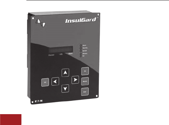
V3-T10-32 Volume 3—Power Distribution and Control Assemblies CA08100004E—June 2013 www.eaton.com
10
10
10
10
10
10
10
10
10
10
10
10
10
10
10
10
10
10
10
10
10
10
10
10
10
10
10
10
10
10
10.4
Power System Studies, Field Services and Conversions
Predictive Diagnostic
InsulGard Predictive Relay
Contents
Description Page
Partial Discharge Testing . . . . . . . . . . . . . . . . . . . . V3-T10-29
Medium and High Voltage Predictive Diagnostics
Online Monitoring and Partial Discharge Analysis
Features, Benefits and Functions . . . . . . . . . . . V3-T10-33
Medium and High Voltage Predictive Diagnostics Online Monitoring and Partial Discharge Analysis
General Description
Eaton’s predictive diagnostics
offers predictive diagnostic
equipment and systems for
medium and high voltage
equipment. Much of Eaton’s
technology is based on the
measurement and analysis
of partial discharges (PD).
PD is a well-known and an
industry-accepted indicator of
insulation deterioration that
leads to equipment failure.
Studies have shown that
approximately 80 percent of
all equipment failures occur
on a random basis and are not
age related. The statistic
indicates that whatever we
are doing today in terms of
preventive maintenance is
not overly effective and that
there are opportunities for
major improvements.
Certainly, a well-designed,
time-based preventive
maintenance program will
have a profound positive
effect on failure rates, but
they are generally invasive
in nature. This invasiveness
has a tendency to increase
failure rates due to the
introduction of new defects,
resulting in infant-mortality
failure patterns.
With industry moving toward
fewer and shorter outages,
companies are looking for
alternative and predictive
technologies to protect
their investment, lower
maintenance costs and
increase system reliability.
Use of the technologies
provided by Eaton will do
just that.
Application Description
InsulGard Predictive Relay for
Continuous Monitoring and
Analysis of PD
Applications of the InsulGard
system are available for
equipment that are rated
for 4000V to 38,000V
and include:
●Motors/generators (RTDs
are also used as sensors)
●Switchgear systems
●Bus ducts
●Power center transformers
●Gas insulated substations
●Splices and terminations
of cables

Volume 3—Power Distribution and Control Assemblies CA08100004E—June 2013 www.eaton.com V3-T10-33
10
10
10
10
10
10
10
10
10
10
10
10
10
10
10
10
10
10
10
10
10
10
10
10
10
10
10
10
10
10
10.4
Power System Studies, Field Services and Conversions
Predictive Diagnostic
Features, Benefits and Functions
InsulGard—Transformer
Monitoring System
Data gathered from Doble
conferences and other
scientific papers indicate
that bushing failures are
responsible for up to
35 percent of all large
power transformer failures.
This data also states that
52 percent of bushing failures
are violent in nature, which
presents safety concerns, as
well as concerns related to
environmental damage.
Among Eaton’s capabilities
is the ability to continuously
monitor the changes in the
C1 capacitance, as well as
any changes in the dielectric
losses of the bushing (bushing
power factor). It’s like having
a continuous online Doble
test of the bushings under
true electrical stress and
temperature. We also have
the ability to test the bushings
and the power transformer
windings for PD on a periodic
basis, while the equipment
is in operation.
Eaton’s comprehensive
transformer monitoring
system incorporates
permanent PD sensors to
timely detect a wide range
of electrical problems (PDs,
surface tracking, arcing,
sparking) in bushings,
winding insulation, core,
laminations, tap changer
connections, ground
connections, pressboard
barriers, etc. Ideal system
for critical transformers or
to keep your troublesome
unit out of trouble!
Implementation of Eaton’s
predictive diagnostics
provides an analysis of
your critical equipment to
reduce the risk of failure and
increase uptime.
Benefits of Using the
InsulGard System
●Saves money
●No labor is required to
conduct test
●More efficient deployment
of personnel. Labor can be
reallocated to fix problems
(instead of look for them)
and take care of other
important matters
●Tests are performed online
●No loss of asset
productivity
●More accurate data as
tests are conducted under
actual operating conditions
●No infant-mortality patterns
that are commonly
introduced
via invasive testing
procedures
●Tests are continuous
●Finding a problem is not
left to chance (like interval
testing). You will know
when a problem started
and how rapidly it is
progressing
●No surprises and no
forced outages. Increased
safety—you will always be
aware of conditions/
problems
●Allows trending of other
variables that affect PD
activity such as load,
temperature and humidity
●Unnecessary maintenance
is reduced because you are
constantly testing and have
more accurate data on
which to base decisions
●You have achieved
predictive/conditioned-
based maintenance
versus interval/chance
maintenance
●You can prioritize which
equipment receives
service first—a true
maintenance planning tool
Benefits of Remote Monitoring
●Relieves the burden
of data analysis
●Experts are readily
available
●Safe, secure and reliable
data collection
●Cost-effective—eliminates
cost of expert traveling
to site
●Automatic, easy to
understand reports
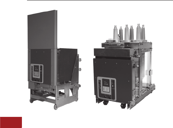
V3-T10-34 Volume 3—Power Distribution and Control Assemblies CA08100004E—June 2013 www.eaton.com
10
10
10
10
10
10
10
10
10
10
10
10
10
10
10
10
10
10
10
10
10
10
10
10
10
10
10
10
10
10
10.5
Power System Studies, Field Services and Conversions
Retrofit Services
VR-Series Breakers
Contents
Description Page
Retrofit Services
Medium Voltage Vacuum Replacement Circuit Breakers
AR Series Low Voltage Replacement Breakers . . V3-T10-39
Low Voltage Power Circuit Breaker
Reconditioning. . . . . . . . . . . . . . . . . . . . . . . . . V3-T10-41
Arcflash Reduction Maintenance System™
Conversions . . . . . . . . . . . . . . . . . . . . . . . . . . V3-T10-45
Digitrip Microprocessor Trip Unit Retrofit Kits . . . V3-T10-46
Low Voltage Breaker Drawout Vacuum
Starter Replacement . . . . . . . . . . . . . . . . . . . . V3-T10-50
MCC Replacement Units . . . . . . . . . . . . . . . . . . V3-T10-52
Medium Voltage Vacuum Replacement Circuit Breakers
Product Description
History and Technology
Most medium voltage air
magnetic power circuit
breakers have been in service
for 25 years and some for as
long as 60 years. They were
reliable and for many years
maintainable. Increased
short-circuit capabilities in
utility and industrial power
systems have created “over-
duty” situations with many
of these breakers. Parts
availability has also increased
the cost of maintaining the
breakers in peak condition.
In the mid 1970s, circuit
breaker manufacturers
began introducing vacuum
technology for medium
voltage power circuit
breakers. It was desirable
and feasible to incorporate
the advantages of vacuum
technology into replacement
breakers that would directly
interchange with the existing
medium voltage air magnetic
power circuit breakers to
extend the useful life of their
existing switchgear. Most
users wanted a replacement
that was functionally
interchangeable, both
electrically and mechanically,
with their existing medium
voltage air magnetic power
circuit breakers.
The market responded by
offering “retrofits” that
utilized the existing breaker
trucks (frames) and vacuum
circuit breaker modules.
These alternatives provided
extended life for electrical
equipment, reduced
maintenance, and allowed
increased capabilities for
many distribution systems.
IEEE/ANSI established
a standard for retrofits
(IEEE/ANSI C37.59) in 1991
that put consistency in the
retrofit process. However,
retrofits were costly, caused
inconvenience for users,
required months to complete,
and the lack of configuration
control made it difficult to
standardize designs.
Eaton now offers new VR
circuit breakers that can be
supplied in place of the old
retrofit technology. Unlike
retrofits, VR power circuit
breakers are new from the
ground up and offer improved
performance, maintainability
and convenience over
retrofits. They can be
supplied in large quantities to
facilitate complete substation
upgrades in a single outage.
System upgrades to handle
higher short-circuit levels
are available.
Application Description
Eaton’s vacuum replacement
(VR) circuit breakers are fully
engineered and tested to
provide the user with a means
of modernizing electrical
power distribution systems,
and in most cases, extending
the life of the equipment while
improving performance and
system reliability.
Medium voltage Type VR
circuit breakers are available
for 5 kV through 15 kV
distribution systems.

Volume 3—Power Distribution and Control Assemblies CA08100004E—June 2013 www.eaton.com V3-T10-35
10
10
10
10
10
10
10
10
10
10
10
10
10
10
10
10
10
10
10
10
10
10
10
10
10
10
10
10
10
10
10.5
Power System Studies, Field Services and Conversions
Retrofit Services
Features, Benefits and Functions
Eaton is a world leader in
circuit breaker technology.
The same reliable vacuum
technology is used
in our VR circuit breakers.
Eaton’s vacuum interrupter is
used in many manufacturers’
switchgear breakers
worldwide. Many of the
components and sub-
assemblies in Eaton medium
voltage VacClad-W metal-clad
switchgear are the same as
those used to manufacture
the VR product line. This helps
reduce spare parts inventories
and the amount of required
maintenance training.
Eaton vacuum technology
reduces maintenance since
the contacts are sealed
from contaminants in the
environment, no adjustments
or cleaning of the main
contacts are required, and
the main contacts require
no special gauges or devices
to measure wear or contact
pressure. Annual lubrication
and testing can be performed
in a fraction of the time
required for air magnetic
circuit breakers.
Eaton’s non-sliding current
transfer system eliminates
the need to check and tighten
connections between the
vacuum interrupter stem
and the main conductors
or the circuit breaker. The
connection is permanent and
provides high conductivity
without creating hotspots and
Holm effect as found in half-
clamp connections.
SURE CLOSE MOC operators
are available to provide
dependable MOC operation
that is decoupled from the
main closing function of
the VR circuit breaker
mechanism. This prevents
the VR circuit breaker from
stalling or failing to latch
during the closing operation.
SURE CLOSE mechanisms
also have adjustable stop
positions to control over-
travel of MOC switch
operators.
Service Life
Most medium voltage air
magnetic circuit breakers
have been in service for
25 to 60 years. As long
as the bus structures,
insulation systems and
general mechanical condition
of the switchgear cells/
structures are maintained in
good condition, equipment
life can easily be prolonged
with the addition of VR
circuit breakers.
Availability
VR breakers are available in
a wide range of ratings and
models to replace medium
voltage, air magnetic circuit
breakers originally
manufactured by:
●Westinghouse
●General Electric
●Allis-Chalmers/Siemens
●Federal Pacific Electric
●ITE/ABB
●McGraw-Edison
Required Information
In order to obtain the correct
VR circuit breaker, the
following information should
be provided to Eaton:
●Original switchgear
manufacturer
●Original breaker
manufacturer
●Breaker type or
catalog number
●Maximum voltage rating
continuous current rating
and maximum short-circuit
or MVA rating
●Control voltages
●List of options and/or
modifications
●Copy of schematic and
wiring diagram
●Year of manufacture of
original breaker and
switchgear
●MOC requirement
For site-specific
specifications, contact your
local General Field Sales
Force office, or your local
Engineering Services center.
Detailed Requirements
General
This section covers the
design, testing and
manufacturing requirements
for new vacuum replacement
(VR) circuit breakers for use
in medium voltage metal-clad
switchgear. The VR circuit
breakers will be functional
replacements (both
mechanically and electrically)
for the air magnetic circuit
breakers they replace. The
VR circuit breakers will be
interchangeable (within
the limits of the original
switchgear) between
different types of cells
(structures) of the same
voltage, MVA and ampere
class without cell (structure)
modifications.
Note: Retrofits, as defined by
IEEE/ANSI C37.59-1996 6.1.4.2
are not covered and will not be
considered as an alternative or
substitute for new VR circuit
breakers.
Scope of Work
Eaton’s Electrical Sector
will provide all project
management, factory and
field engineering, short-circuit
and coordination studies (if
required and at an additional
charge), supervision, labor,
material, tools, rental, test
equipment and transportation
as defined for a complete VR
circuit breaker replacement of
the required existing medium
voltage switchgear circuit
breakers. The VR circuit
breakers will be designed for
maximum voltages of either
4.76 kV, 8.25 kV or 15 kV
as required.
MVA Ratings
The available MVA rating of
the VR circuit breakers are
as follows:
All Eaton switchgear
structures designated for
VR circuit breakers with
increased MVA levels will
have the existing bus bracing
analyzed. EESS will determine
if bus bracing is capable of
withstanding the maximum
(peak) momentary ratings
per ANSI C37.09 and
ANSI C37.20.2 capabilities
of the new VR circuit
breakers. EESS will provide
documentation to verify
that the switchgear bus is
sufficiently braced to handle
the new ratings or supply the
cost as a separate item to
increase the bus bracing of
all designated switchgear
structures in the lineup to
comply with the increased
MVA ratings. Following the
study and/or the bracing
modifications, Eaton’s
service engineer will affix
a nameplate to each
switchgear structure stating
the new MVA rating, the
manufacturer’s name and
the date of verification
or upgrade.
VR Ratings
Notes
1MVA is obsolete switchgear terminology
and is used for reference only in this
document.
226-inch (660.4 mm) wide cells only.
Volts
kV
Original
MVA 1
New
MVA
4.76 100–250 2250
4.77 100–250 2350
8.25 150–500 500
15 150–500 500
150–500 750
150–500 1000
750 1000
150–1000 1500

V3-T10-36 Volume 3—Power Distribution and Control Assemblies CA08100004E—June 2013 www.eaton.com
10
10
10
10
10
10
10
10
10
10
10
10
10
10
10
10
10
10
10
10
10
10
10
10
10
10
10
10
10
10
10.5
Power System Studies, Field Services and Conversions
Retrofit Services
Cubicle Modifications
The VR circuit breakers
are designed to be
interchangeable with
existing breakers of the
same continuous current
and MVA ratings without
required modifications to
the existing cubicles in most
cases. Any required cell
modifications are designed
to be reversible. Existing cell
coding systems are retained
where possible.
VR circuit breakers with
upgraded/increased MVA
or continuous current ratings
do require modifications to
the cubicle coding system
to prevent the insertion of
breakers that do not have the
same ratings as the upgraded
VR circuit breakers.
Applicable Standards
All VR breakers will be
designed, manufactured and
tested in accordance with the
applicable sections of:
●IEEE C37.59-2007
(cell interface and
testing criteria)
●IEEE C37.04
●IEEE C37.06
●IEEE C37.09
●IEEE C37.20.2
●IEEE C37.100
●IEEE C37.100.1
●IEEE STD 4-1995
Materials
All materials used in the
manufacturing of the new
VR circuit breakers will be
new and unused. No parts
or materials from the original
air-magnetic circuit breakers
will be reconditioned and
reused in the manufacture of
the new VR circuit breakers.
All components used in the
manufacturing of the new
VR circuit breakers including,
mechanism, vacuum
interrupters and frame
components will all be
manufactured by Eaton
to ensure single-source
reliability and responsibility.
Manufacturer’s Qualifications
Eaton is currently engaged in
the design and manufacturing
of medium voltage vacuum
circuit breakers and
switchgear structures. Eaton
has a minimum of 50 years
experience in switchgear
manufacturing, is a member
of the National Electrical
Manufacturers Association
(NEMA), and has representation
on IEEE C37 Switchgear
Working and Balloting
Groups, and owns and
operates an engineering
services organization.
Eaton’s Electrical Services
& Systems (EESS)
●Experienced, factory-
trained field engineers and
technicians familiar with
the installation and startup
of medium voltage VR
circuit breakers
●A minimum of 30 field
service locations staffed
with engineers that are
available on a 24-hour basis
for emergency service
●Capabilities of on-site cell
alignment, breaker levering
system repairs and control
system modifications
●Capabilities to perform
computer-generated short-
circuit, coordination and
load flow studies for final
breaker trip settings. All
studies will be conducted
under the supervision and
approval of a registered
professional electrical
engineer skilled in
interpreting studies and
test results regarding
medium voltage VR circuit
breakers. The Registered
Professional Electrical
Engineer is a full-time
employee of EESS
Vacuum Circuit Breaker
Module Features
The VR circuit breakers will
utilize vacuum circuit breaker
modules manufactured by
Eaton. Acceptable conversion
modules are the VCP-18WR,
VCP-20WR, VCP-29WR and
the VCP-29WRSE.
Common Pole Shaft
The circuit breaker
mechanism will open and
close all three phases and
any auxiliary devices via a
common operating shaft
to ensure consistent and
simultaneous operation of
the main contacts. The
shaft will be supported at
the ends and along its
length with bearings. The
main drive shaft will be
connected to the individual
vacuum interrupters via
insulated drive links.
Insulated Drive Links
The mechanism drive shaft
will be connected to each
moving contact via an
insulated drive link made of
glass-reinforced polyester for
element types VCP-18WR,
VCP-20WR and VCP-29WR
and cycloaliphatic epoxy for
the VCP-29WRSE. The
insulated link material is non-
hydroscopic and meets the
flame-retardant requirements
as set forth in IEEE C37.20.2.
The drive links are easily
removable with single clevis
pins at each end and spring
retaining clips.
Shock Absorber System
The mechanism will contain
a shock absorber system to
dampen the opening force
of the circuit breaker. The
shock absorber has sufficient
resilience to prevent contact
bounce that could cause a
restrike of the main contacts
during the opening of the
circuit breaker or during
a spring discharge. The
VCP-20WR, VCP-29WR
and VCP-29WRSE vacuum
conversion element’s
mechanism consists of a
series of parallel steel plates
with spring separators that
spread the plates during
breaker opening. The shock
absorber has a design life of
10,000 breaker opening and
closing cycles without the
need for repair, replacement
or adjustment. The VCP-
18WR has a sealed
replaceable shock absorber
and is capable of being
adjusted if replaced or during
initial mechanism assembly.
Manual Trip and Close
The mechanism has front
accessible manual close and
trip operators that are directly
connected to the breaker
operating mechanism and
are an integral part of the
electrical close and trip coils.
Operations Counter
Each VR circuit breaker
mechanism has a five digit
non-resetting mechanical
operations counter connected
to the operating shaft.
Spring Charged Indicator
Each operating mechanism
will be equipped with a
visible indicator to show the
state of the stored energy
mechanism. The indicator will
show when the spring is fully
charged or discharged.
Auxiliary Contacts
The breaker will have a
low inertia, rotary operated
auxiliary switch connected
to the main pole shaft
assembly. Connections
will be made via insulated
ring-tongue terminals.
Vacuum Bottle Assembly
The vacuum bottle assembly
will be constructed from
virgin materials and
manufactured by Eaton. The
contacts will be principally
composed of powdered
metal, chromium-copper
contact material. The
powdered metal is fused
under high pressure to form
a consistent contact material.
The contacts are machined to
form spiral petal contacts to
assist in the swirling of the
arc during interruption.
The edges of the ceramic
components will be
“metallized” and fired
prior to assembly. The
components are inspected
and assembled in a Class
1000 clean room prior to
sealing the components. The
components are inserted into
a vacuum heat chamber and
sealed under vacuum. No
“pinch tubes” are used.

Volume 3—Power Distribution and Control Assemblies CA08100004E—June 2013 www.eaton.com V3-T10-37
10
10
10
10
10
10
10
10
10
10
10
10
10
10
10
10
10
10
10
10
10
10
10
10
10
10
10
10
10
10
10.5
Power System Studies, Field Services and Conversions
Retrofit Services
A stainless steel corrugated
bellow achieves isolation
of the ambient air and the
vacuum. The moving
contact stem of the vacuum
interrupter has a machined
groove to prevent rotation
of the contact within the
vacuum chamber.
The vacuum interrupter has a
visual method of identifying
contact wear without the use
of gauges or other devices.
In addition, a separate visual
“T-cutout” is used to verify
that the mechanism is
applying adequate spring
pressure to the contacts
when the breaker is in the
closed position.
The contacts are self-
aligning and do not require
adjustments for the life of the
vacuum interrupter assembly.
The contacts also have
a spring system to apply
proper contact pressure.
The operation of the contacts
cause a wiping action to clean
the contact surfaces.
Insulated Pole Assemblies
Pole assemblies are insulated
from ground with non-
hydroscopic insulating
materials manufactured from
glass-reinforced polyester.
Current Transfer System
The current transfer from the
conductor stem to the primary
bushing assemblies is via a
non-sliding current transfer
system consisting of a fused
stem assembly and a V-Flex™
silver-plated copper leaf
conductor or folded leaf
copper shunts. The stems
have the adjoining conductors
mechanically fused with the
stem material. This junction
forms a solid current transfer.
Trip-Free Operation
The new VR circuit breaker
operation mechanism is a
“true Trip-Free” design.
When the trip function is
mechanically engaged and
held, and the close function
is initiated either electrically
or mechanically, the contacts
do not close. The contacts
are restricted to 10% of the
total travel.
Mechanical Status Indicator
Each new VR circuit breaker
has a mechanical status
indicator with the word
“CLOSED” on a red
background when the
breakers are closed and the
word “OPEN” on a green
background when the
breakers are open.
Breaker Truck/Frame Assembly
Frame Materials and Plating
The frame is constructed
from steel, utilizing a
combination of bolting and
welding to assemble the
frames. All frames are
zinc-plated with a yellow
dichromate finish (commonly
referred to as yellow-zinc
dichromate).
Wheels and Casters
for Transport
VR circuit breakers are
supplied with a transport
system that is a functional
replacement of the
transport system of the
original design. The transport
system conforms to the
requirements of the original
design.
Hardware
All hardware is a minimum
grade five, zinc-plated with a
yellow dichromate finish or
black oxide.
Bushing and Interface
Conductor Material
Primary and power frequency
interface conductors are
constructed of 100% IACS
electrical grade conductive
copper. Conductors are
either silver- or tin-plated to
a thickness of 0.0001–0.0002
for non-sliding surfaces and
0.001–0.002 for sliding
surfaces. The power
frequency conductors are
sized to carry the full load
ampacity of the circuit
breaker without exceeding
the temperature rise
established in IEEE C37.09.
Insulation Systems
All bushings utilize either
glass-reinforced polyester
or molded cycloaliphatic epoxy
insulation systems or engineer
approved equal. Fluidized
epoxy coatings are used to
insulate interface conductors
when necessary.
Phase barriers are
manufactured from GPO-3
glass-reinforced polyester or
equivalent and designed to
isolate individual phase
conductors. Openings are
minimized to reduce the
possibility of ionized gas
propagation between phases.
Corona Shields
All 8.25 kV and 15 kV class
breakers have internal corona
shields when bushings are
mounted on metallic back
planes. The corona shields
are permanently grounded.
Bushings mounted on
nonmetallic back planes
do not have internal
corona shields.
Primary Connections
Primary connections
(finger clusters) are new
and designed to carry the
full nameplate rating of the
replacement breaker without
exceeding the allowable
temperature rise as stated
in ANSI C37.04.5.4.2-1979.
In addition, the primary
connections are capable
of withstanding the full
momentary/close and latch
rating as well as the K*I
current rating for two
seconds without melting,
arcing or pitting the
contact surface.
Ground Contacts
A metal-plated, self-coupling,
separable grounding contact
shall be supplied.
Control Circuit Wiring
Control wiring is SIS
cross-linked polyethylene,
#14 AWG minimum except
for short runs such as coil and
motor leads. Insulated ring
tongue terminals are used.
Solder or “fast-on” type
connections are not used.
Upfront, easy access
terminal blocks are provided
for maintenance and
troubleshooting.
Stored Energy Discharge
The replacement breaker
incorporates a manual and
an automatic system to
completely discharge all
stored energy before the
circuit breaker is fully
withdrawn from the
switchgear housing.
The system will never
intentionally discharge the
stored energy while in the
connected position.
Passive Interlocks
The mechanism will have
a passive interlock to block
the insertion or removal of a
closed breaker. The system
also prevents the insertion
of the levering tool at any
time the breaker is in the
closed position.
Active Interlocks
Each breaker has an active
interlock system. The system
is operated by the insertion or
removal of the VR circuit
breaker. In the event the
passive interlock is defeated,
active interlock system will
trip and open a connected,
closed breaker if an attempt
is made to remove it from
the connected position.
The system also holds the
breaker in the “trip-free”
position at all times between
the test and fully connected
positions.

V3-T10-38 Volume 3—Power Distribution and Control Assemblies CA08100004E—June 2013 www.eaton.com
10
10
10
10
10
10
10
10
10
10
10
10
10
10
10
10
10
10
10
10
10
10
10
10
10
10
10
10
10
10
10.5
Power System Studies, Field Services and Conversions
Retrofit Services
Locking Means
Locking means is provided
to lock the circuit breaker
while in the fully connected
or disconnected positions.
The lock prevents the
insertion or removal of the
breaker. The lock will not
prevent the breaker from
being operated while in the
fully connected position.
Secondary Contact Block
Control wiring connections
between stationary structure
and the removable breaker
are provided with automatic,
self-coupling contacts. The
secondary blocks will be mold
cycloaliphatic epoxy
insulation. The pins are
drilled and tapped to accept
standard 8-32 screws for
ease of maintenance
and wiring changes. The
secondary contact block is
made of cycloaliphatic epoxy.
MOC Operator
All breakers will be furnished
with MOC operators unless
specified. The MOC operator
will have sufficient power to
operate the largest MOC
switch or combination of
switches in the switchgear
lineup without affecting the
breaker’s ability to completely
close and latch. The MOC
driver is completely
“decoupled” from the main
breaker operating shaft and
shall be powered by separate
operating springs. The
system is SURE CLOSE as
manufactured by Eaton’s
Electrical Sector.
Cell Coding System
Eaton will supply or interface
with the cell coding system
to prevent the accidental
insertion of a breaker into
a cell of a different voltage,
current, interrupting capacity
or physical arrangement
than the type intended for
the switchgear cell receiving
the breaker.
Design and Certification
(Type) Testing
Each new VR circuit breaker
supplied will have type tests
performed on its base design
to certify it to IEEE/ANSI
standards. All Certification
(Type) shall be performed in
a switchgear cell/structure
when required or an
equivalent structure where
permitted by ANSI C37.09.
Written test reports, data logs
and digital reproductions of
the pulse used to perform the
BIL test will be on hand for
review by the buyer.
BIL—60 kV for 4.76 kV
applications, 95 kV for
8.25 and 15 kV applications
as a minimum> crest with
1.2 μsec x 50 μsec x 50%
wave shape per IEEE C37.09.
The tests will be conducted
per IEEE STD 4-1995. This
test shall be performed in a
breaker cell or cell equivalent
with controlled humidity
levels. Corrections for
barometric pressure and
ambient temperature will
be applied to the test
parameters. The breaker
must pass a total of 54 shots.
Mechanical operations
tests of each breaker
design are performed in
a switchgear cell designed
to accommodate MOC
switches. The maximum
number of auxiliary MOC
devices or their equivalent
force will be applied during
the test to ensure that the
vacuum breaker has
sufficient power to operate
the auxiliary devices,
successfully closes and
latches during each
operation, and that no
fatigue or failure occurs.
Consideration is given to
designing a system that
will not damage the MOC
switch in the switchgear
cell structure.
Momentary tests per IEEE
C37.20.2 will be performed
of the completed vacuum
replacement breaker including
the vacuum breaker element,
bushings, primary disconnects
(finger clusters), all bus in the
breaker unit, and all insulators
and braces per IEEE C37.09.
This test is to prove the
mechanical strength and
integrity of the conductor
and frame assembly of the
complete new vacuum
replacement breaker.
This test is performed in a
switchgear cell designed
to accommodate the circuit
breaker being tested. Anti-
rotation devices may be added
to the cell if required
to prevent rotation. If anti-
rotation devices are used in
the test breaker, then they
will be installed in all the
switchgear cells intended
to accommodate the
new breakers.
Short time current tests for
three seconds at K*I current
will be performed to confirm
the breakers I2t capability.
The test will be performed in
a switchgear cell.
Continuous rated current
testing per ANSI C37.04-1979
without exceeding 65°C
hotspot rise with a maximum
ambient not to exceed 40°C.
This test is performed in a
breaker cell or a cell structure
of the same equivalent
volume, dimensions and
ventilation as the original
switchgear structure.
Low Frequency Withstand—
19 kV rms for 4.76 kV
applications, 36 kV rms
for 8.25 kV and 15 kV
applications—per
IEEE C37.09.
Interlock functional test per
IEEE C37.20.2.
All production tests as stated
in IEEE C37.09. Timing values
per pole will be provided for
the vacuum element in msec.
Execution
Eaton’s factory trained
and certified field service
engineer(s) can perform the
commissioning of each
breaker at the customer’s
site. The field engineer will
be familiar with the VR circuit
breaker to the point that he/
she can offer initial training to
the owner’s on-site operators
and maintenance personnel
while performing the
commissioning.
Technical Data
and Specifications
Ratings
●Maximum voltages:
4.76 kV, 8.25 kV and 15 kV
●Interrupting ratings:
4.76 kV: 250 MVA (29 kA)
4.77 kV: 350 MVA (41 kA)
8.25 kV: 500 MVA (33 kA)
15 kV: 500 MVA (18 kA)
750 MVA (28 kA)
1000 MVA (37 kA)
1500 MVA (63 kA)
●Continuous current:
1200A, 2000A, 3000A
(5–15 kV)
4000A forced cooled
(5–15 kV)

Volume 3—Power Distribution and Control Assemblies CA08100004E—June 2013 www.eaton.com V3-T10-39
10
10
10
10
10
10
10
10
10
10
10
10
10
10
10
10
10
10
10
10
10
10
10
10
10
10
10
10
10
10
10.5
Power System Studies, Field Services and Conversions
Retrofit Services
FP-25 Original Magnetic FP25-AR Air
Circuit Breaker Replacement Breaker
AR Series Low Voltage Replacement Breakers
Contents
Description Page
Medium Voltage Vacuum Replacement
Circuit Breakers . . . . . . . . . . . . . . . . . . . . . . . . . . V3-T10-34
AR Series Low Voltage Replacement Breakers
Features. . . . . . . . . . . . . . . . . . . . . . . . . . . . . . . V3-T10-40
Standards and Certifications . . . . . . . . . . . . . . . V3-T10-40
Low Voltage Power Circuit Breaker
Reconditioning . . . . . . . . . . . . . . . . . . . . . . . . . . . V3-T10-41
Arcflash Reduction Maintenance System™
Conversions . . . . . . . . . . . . . . . . . . . . . . . . . . . . . V3-T10-45
Digitrip Microprocessor Trip Unit Retrofit Kits . . . . V3-T10-46
Low Voltage Breaker Drawout Vacuum
Starter Replacement . . . . . . . . . . . . . . . . . . . . . . V3-T10-50
MCC Replacement Units . . . . . . . . . . . . . . . . . . . . V3-T10-52
AR Series Low Voltage Replacement Breakers
Product Description
Application
Maximum life extension. All
AR-Series breakers are brand
new from the ground up. They
are designed to be electrical
and mechanical equivalents
of the breakers they replace.
Cell modifications, if required,
are kept to a minimum. They
are not “Retrofits” and no
parts are reused from the
original breakers. This reduces
out-of-service time, yielding
consistent product designs,
while reducing initial
installation costs. AR-Series
breakers correctly interface
with compartment cell
switches, and safety
interlocks are maintained
or improved.
Solve Parts Availability
Problems for Old Breakers
Replacement parts for
old breakers are becoming
harder and harder to find
as technology continually
advances. Parts availability
issues are basically
eliminated with AR-Series
breakers. Mechanism parts
and control components are
current production items and
are in stock. Additionally,
AR-Series breakers use
common components
across the product line.
This can save in future spare
parts investment.
Reduce Maintenance Cost
and Downtime with Reliable
Magnum™ DS Breaker
Technology
Maintenance procedures
commonly associated with
vintage air magnetic circuit
breakers take 8–12 hours
on average per breaker.
Eaton’s Magnum DS breaker
technology reduces normal
maintenance to 2–6 hours per
breaker. The arc chutes,
contacts, mechanism and
control components can be
easily inspected and minor
maintenance (such as
lubricating the mechanism)
can be easily accomplished.
Arc chutes can easily be
removed with two bolts and
visually inspected or replaced.
By removing the arc chutes,
viewing the main contacts
along with their contact wear
indicator results in a quick and
simple decision to replace if
necessary. Spare parts
inventory is considerably
reduced because AR-Series
breakers use common parts
throughout the entire product
line, including new Magnum
DS Switchgear assemblies.
For more information
on Magnum DS breaker
elements, see
Volume 3, Tab 4.
Increase Interruption Rating
Dynamic changes resulting
from larger transformers,
bus ties, parallel generation,
and new sources of incoming
power can drastically
increase the level of available
short-circuit current in low
voltage power distribution
systems. The bus system’s
momentary capability can
be increased and the entire
switchgear structure can
be re-certified to the new
higher levels by Eaton’s
factory qualified service
engineers. Many of the
AR-Series breakers are
available to increase
interrupting capabilities
while still maintaining the
original circuit breaker
dimensions. This provides
a savings versus the cost
of replacing the switchgear.
Cell-to-breaker coding
systems are maintained or
corrected to comply with
IEEE/ANSI standards.
Increase Continuous
Current Rating
Changes to industrial and
commercial facilities, such
as increased manufacturing
operations, will typically
increase the demand for
electrical power within the
facility. Often, an increase
in electrical demand can
cause the load on a circuit to
exceed the circuit breaker’s
continuous current rating.
Eaton’s factory qualified
service engineers can inspect
existing low voltage metal-
enclosed switchgear,
including the existing breaker
cubicles, line and load power
stabs, load cables, and
bus system to verify the
application for a circuit
breaker ampacity upgrade.
Many of the AR-Series
breakers are available
with increased continuous
current ratings.

V3-T10-40 Volume 3—Power Distribution and Control Assemblies CA08100004E—June 2013 www.eaton.com
10
10
10
10
10
10
10
10
10
10
10
10
10
10
10
10
10
10
10
10
10
10
10
10
10
10
10
10
10
10
10.5
Power System Studies, Field Services and Conversions
Retrofit Services
Features
●AR replacement breakers
are 100% rated, UL listed
(check factory), and built
and tested in an ISO 9001
and 14001 certified facility
●Safety: the cell door can
remain closed with the
breaker in connect, test
or disconnect position.
Simultaneously, the trip
unit, open-close controls,
and breaker nameplate
data are all readily visible
●Designed for easy access,
inspection and minimal
maintenance. The stored
energy mechanism, control
devices, accessories and
secondary contacts are
easily accessible by
removing the front cover.
The contact wear indicator
eliminates the need for
elaborate testing to
determine if the contact
assembly needs replacing.
The arc chutes can also
be easily removed and
inspected
●Installation savings and
robust interface reduce
installation and
commissioning time with
our unique design concept.
No modifications required
to the original line/load
power stabs or secondary
disconnect contacts.
Modifications to the
original cubicle are often
eliminated with an easy-to-
install cubicle adapter
(cassette). The cassette
includes new extension
rails and levering-in
adapters, resulting in a
more robust breaker-to-
cubicle interface. We also
provide a new door to
match the replacement
breaker
Availability
Designs available for:
●Westinghouse
●General Electric
●Allis-Chalmers
●Federal Pacific
●ITE/ABB
Standards and Certifications
All AR-Series low voltage
power air circuit breakers are
designed and tested to meet
or exceed IEEE/ANSI C37.59-
2002 standards. This ensures
compatibility with existing
installations and IEEE/ANSI
application guidelines.
IEEE/ANSI certification and
certified factory production
test reports are available.

Volume 3—Power Distribution and Control Assemblies CA08100004E—June 2013 www.eaton.com V3-T10-41
10
10
10
10
10
10
10
10
10
10
10
10
10
10
10
10
10
10
10
10
10
10
10
10
10
10
10
10
10
10
10.5
Power System Studies, Field Services and Conversions
Retrofit Services
Low Voltage Power Circuit Breaker Reconditioning
Contents
Description Page
Medium Voltage Vacuum Replacement Circuit
Breakers. . . . . . . . . . . . . . . . . . . . . . . . . . . . . . . . V3-T10-34
AR Series Low Voltage Replacement Breakers . . . V3-T10-39
Low Voltage Power Circuit Breaker
Reconditioning
Standards and Certifications . . . . . . . . . . . . . . V3-T10-44
Arcflash Reduction Maintenance System™
Conversions . . . . . . . . . . . . . . . . . . . . . . . . . . . . . V3-T10-45
Digitrip Microprocessor Trip Unit Retrofit Kits . . . . V3-T10-46
Low Voltage Breaker Drawout Vacuum
Starter Replacement . . . . . . . . . . . . . . . . . . . . . . V3-T10-50
MCC Replacement Units . . . . . . . . . . . . . . . . . . . . V3-T10-52
Low Voltage Power Circuit Breaker Reconditioning
General Description
Low voltage power circuit
breakers are designed to
be serviceable devices over
a long service life. These
breakers and the associated
switchgear have been
available in the industry for
over 50 years, and a large
installed base of equipment
by many manufacturers
exists throughout the
United States and Canada.
The low voltage switchgear is
essentially static. It consists
of structures, buswork,
control wiring and metering
components. If periodically
cleaned, it will last almost
indefinitely.
The low voltage power
breakers are the essential
elements of the switchgear.
They are required to properly
conduct the normal load
current for the vast majority
of time, and still provide the
means of interrupting an
overload or fault current
whenever it may occur.
These breakers contain
insulation systems (600 Vac
normal three-phase voltage or
less), conductors (from 225 to
over 5000A continuous),
a mechanism to open and
close the breaker, a trip
system to provide protection
of the circuit and the circuit
breaker, and an interruption
system (arc chutes and
contact structures) that can
handle fault currents as high
as 100,000A.
While some breakers are
fixed mounted (bolted into the
switchgear), the vast majority
are drawout for ease of
inspection and maintenance
of the breaker, as well as to
provide maximum isolation
of the load. These drawout
breakers include primary
disconnects (for the three-
phase conductors), secondary
disconnects (for breaker
control wiring), a levering-in
mechanism (to assist in the
insertion and withdrawal of
the breaker) and an interlock
system (to ensure that a
closed breaker cannot be
inserted or withdrawn from
the connected position).
Additional common options
to low voltage power circuit
breakers include electric
operation of the mechanism,
shunt trip and close coils for
remote operation of the
breaker, undervoltage trip
systems, and additional
auxiliary switches for
annunciation and control
schemes.
Factors that affect the life
of these circuit breaker
subsystems include time,
ambient temperature,
humidity, cleanliness of the
environment (contamination
and corrosive elements),
number of normal load
operations, number of fault
current interruptions, load
current magnitude, and
maintenance cycle.
While periodic maintenance,
cleaning, lubrication and
testing of the circuit breaker
can and will prolong its life,
at some point, the circuit
breaker must either be
completely reconditioned
or replaced. Failure or mis-
operation of any of the
breaker’s subsystems will
render it to be ineffective
for its intended purpose and
dangerous for personnel or
downstream equipment.
Class 1 reconditioning of the
low voltage power circuit
breaker is a cost-effective
method to restore all of the
breaker’s subsystems to full
functionality and prolong the
life of the breaker for many
additional years.
Manufacturers
Class 1 reconditioning is
available for all major
manufacturers’ low voltage
power circuit breakers that
have been produced over the
last 50 years. These breakers
are rated at 600 Vac, 225 to
5000A continuous, 15,000 to
100,000A interrupting. The
manufacturers include, but
are not limited to:
●Westinghouse
●Cutler-Hammer
●General Electric
●ITE
●ABB
●Allis-Chalmers
●Siemens
●Square D
●Federal Pacific
●Federal Pioneer

V3-T10-42 Volume 3—Power Distribution and Control Assemblies CA08100004E—June 2013 www.eaton.com
10
10
10
10
10
10
10
10
10
10
10
10
10
10
10
10
10
10
10
10
10
10
10
10
10
10
10
10
10
10
10.5
Power System Studies, Field Services and Conversions
Retrofit Services
Advantages
Eaton’s Electrical Sector
is the world leader in low
voltage power circuit
breaker and trip systems
technology. EESS is uniquely
positioned to provide Class 1
reconditioning of low voltage
power circuit breakers.
All Class 1 reconditioning is
done at facilities dedicated
to the purpose. These are
known as Aftermarket
Centers of Excellence (ACEs).
These facilities utilize state-
of-the-art equipment in
cleaning, plating, assembly
and testing of the breakers.
Each facility utilizes identical
standards and procedures in
the reconditioning process.
The reconditioned breakers
are tested to the same
standards as new production
breakers. The breaker test
results are stored in a North
American database (Pow-R
Test), facilitating predictive
maintenance and trending.
All manufacturers’ breaker
information is stored in our
Pow-R Master Database
and available to every ACE
performing the work. Breaker
trip systems are upgraded to
the latest Digitrip technology,
the same trip system used
in new production DS and
SPB breakers. Original
OEM replacement parts are
exclusively used to replace
broken, out of specification
or missing components.
Quality Control and
National Standards
All reconditioning will be
conducted under the
direction of a quality control
and reconditioning standard,
pursuant to ISO® 9001
certification. A quality
certificate will document the
progress of each breaker
through the reconditioning
process. Eaton has multiple
locations (minimum of five)
strategically located
throughout North America
that share best practices of
reconditioning and work to a
consistent national standard.
They utilize the same task-
specific equipment for
cleaning and testing at all
locations to ensure the quality
of the product.
Receiving and Data Collection
Upon receipt at the
reconditioning center, the
following process will be
performed on each breaker.
●Assign a unique job and
breaker identification
number
●Record all nameplate data,
customer identification,
existing trip settings, and
all numbers unique to each
breaker by direct entry into
a national computer
database archive for future
use and retrieval
●If electrically operated,
record all accessories
included on the circuit
breaker, as well as the
close, trip and charge volts.
The latest copy of the
customer’s control
schematic will be obtained
prior to disassembly and/or
test. Eaton will have the
capability of retrieving
control schematics for the
breakers it manufactured
●The circuit breaker will be
inspected for physical
damage. Parts that need to
be replaced will be
recorded. A quotation will
be issued to the customer
for replacement of the
defective part(s)
Preliminary Testing
and Inspection
The breaker will be manually
and/or electrically operated.
The following tests will be
performed.
●All breakers:
●Each primary pole
insulator will be tested
for dielectric integrity
by applying 1000 Vdc
between each
conductor and ground
and between line
and load
●With the breaker closed,
the contact resistance
using a 10 ampere
conductor will be
measured
●Measure the trip bar
force using a force
gauge
●Measure the trip button/
actuator device force
using a force gauge
●Verify continuity of
current limiting fuses (if
equipped) and measure
the resistance using a 10
ampere conductor;
check blown fuse
indicators’ integrity
●Verify overcurrent trip
device operation via
primary injection (not
required if a trip unit
retrofit is to be installed)
●Additional tests for
Electrically Operated
Breakers:
●Charge the breaker;
close and trip electrically
●Verify undervoltage,
pickup and dropout (if
equipped)
●Check auxiliary switch
operation and condition
Centralized Database
The results of all the above
tests and measurements shall
be entered into the Eaton
centralized database.
Breaker Disassembly, Cleaning
and Preparation
●The circuit breaker will be
completely disassembled
to its component parts. All
parts will be inspected for
wear and physical damage
●All heavily carbonized
components will be
cleaned and degreased in a
Vaque® Wet Blast System
to produce a smooth finish
without degrading the
component’s surface
●All current carrying parts,
main/arcing contacts,
ground contacts and
primary disconnects will
be cleaned, burnished
and polished in a TOREX®
vibratory system loaded
with a medium specifically
designed to clean silver
plating. Dry blasting or
other abrasive cleaning
systems that can remove
silver plating or distort the
contacts’ surfaces will not
be used
●All pole piece moldings and
insulating components will
be cleaned in a Giant™
ceramic polisher that
cleans and polishes the
components surface
without scratching

Volume 3—Power Distribution and Control Assemblies CA08100004E—June 2013 www.eaton.com V3-T10-43
10
10
10
10
10
10
10
10
10
10
10
10
10
10
10
10
10
10
10
10
10
10
10
10
10
10
10
10
10
10
10.5
Power System Studies, Field Services and Conversions
Retrofit Services
●After cleaning, each
component shall be dried
to obtain 1000 megohms
when megger tested at
1000 Vdc. They will be
sealed with a dielectric
grade sealant
●All heavily soiled and/or
greasy items including
mechanisms will be initially
cleaned in a non-abrasive
agitator filled with a
biodegradable cleaning
solution capable of
degreasing, de-scaling
and de-burring without
degrading the components
surface and without the
introduction or embedding
of grit or other abrasive
materials
●All frames will be stripped
to bare metal in
preparation for plating
●After cleaning, all ferrous
metal frames, mechanism
parts and linkages will be
yellow zinc dichromate
plated to provide superior
rust resistance to exposed
and hidden surfaces.
Painting of covers, handles
and indicators will be done
●A detailed inspection will
be performed of all
mechanism components
and linkages to detect
stress fractures and
excessive wear that can
cause premature failure.
Magnification will be used
on small components if
necessary
●Arc chutes will be hand-
wiped and cleaned with a
clean dry cloth. They will
be megger tested at 1000
Vdc. If the megger value is
less than 1000 megohms,
the arc chute assembly will
be dried and retested. If the
retest value is greater than
1000 megohms, then arc
chute surface will be sealed
with the manufacturer’s
recommended dielectric
grade clear sealant. If the
retest value is still less
than 1000 megohms,
then the arc chute will
be replaced
●Charging motor (if so
equipped) will be removed.
The drive shaft bushings
will be inspected and
replaced if worn. The
motor will be cleaned and
reconditioned. All ratchet
pawls and springs will be
inspected and replaced or
repaired if necessary.
●Gearbox (if equipped) will
be removed, disassembled
and fully inspected. Any
defective or leaking
components will be
repaired and cleaned
Circuit Breaker Reassembly
and Adjustment will Include:
●The circuit breaker frame
will be reassembled using
new yellow zinc dichromate
plated hardware
●A database of instruction
books that list the original
manufacturer’s information
on recommended
lubricants. When the
recommended lubricants
are no longer available or
have been changed, the
reconditioner’s new
breaker design group may
analyze and recommend
newer, high technology
lubricants as a substitute
●The operating mechanism
will be reassembled,
lubricated and reinstalled
on the circuit breaker
frame
●Reassemble and install the
main and arcing contact
components, and lubricate
as recommended by the
original manufacturer’s
information
●Reassemble, lubricate,
install and align the racking
mechanism and the
electrical and/or
mechanical charging
mechanism (if applicable)
●Install all electrical
components and secure
wiring harness (if
applicable)
●Align the contacts for
proper surface wipe and
mating. Perform a contact
wipe test. Verify that the
percent contact wipe and
the wipe width are per the
original manufacturer’s
information
●Adjust the main contacts
for proper gap, pressure
and contact resistance,
and adjust arcing contacts
for proper gap per the
original manufacturer’s
information
●Install new Eaton Digitrip
microprocessor trip system
where specified
●When a new trip device is
added to the breaker or
when changes are made to
the original mechanism or
arc interruption system, an
additional nameplate shall
be installed in accordance
with IEEE/ANSI C37.59-
1996 Section 8.3 and shall
include the unique serial/
identification number

V3-T10-44 Volume 3—Power Distribution and Control Assemblies CA08100004E—June 2013 www.eaton.com
10
10
10
10
10
10
10
10
10
10
10
10
10
10
10
10
10
10
10
10
10
10
10
10
10
10
10
10
10
10
10.5
Power System Studies, Field Services and Conversions
Retrofit Services
Standards and Certifications
The retrofitted breaker will
be designed, manufactured,
applied, installed and
certification tested in
accordance with the latest
applicable sections of:
●IEEE/ANSI C37.13
●IEEE/ANSI C37.16
●IEEE/ANSI C37.17
●IEEE/ANSI C37.50
●IEEE/ANSI C37.59-1996
●IEEE/ANSI C37.100
●UL 1066 (For originally UL
listed and labeled designs)
Test Procedures
General Production Testing
Each reconditioned low
voltage power circuit breaker
will be tested to the applicable
sections of IEEE/ANSI C37.50
Section 6 and UL 1066 if the
breaker was originally UL
labeled. The testing will
include, but not be limited to:
●Measuring and recording
trip bar force
●Setting of the
microprocessor trip
●Performing control and
secondary wiring and
device check tests
●Performing dielectric
withstand tests
●Performing no-load
operations tests
●Verifying interlock and
cell interface
●Test position dielectric
withstand (original UL
labeled breakers only)
Trip Bar Force Measurement
Measure and record the circuit
breaker’s trip bar force.
Microprocessor Trip
Device Setting
Direct-acting trip devices
will be tested/calibrated to
determine their conformance
to published trip characteristic
curves. Each breaker will be
primary injection tested using
a sinusoidal-wave-shape,
single-phase 60 Hz current
at a convenient voltage. The
primary injection test device
will be computer controlled to
ensure accuracy in the applied
currents. The primary injection
test device will be capable of
direct output of the test
results to a printer or storage
device. The applicable tests
will be performed.
●Long-time-delay-element
pickup
●Short-time-delay-element
pickup
●Instantaneous-element
pickup
●Time delay of long-time-
delay-element
●Time delay of short-time-
delay-element
●Ground-element pickup
●Time delay of the ground
element
Control, Secondary Wiring
and Devices Check Test
Perform control, secondary
wiring and devices checks
per IEEE/ANSI C37.50.6.3
to verify that all connections
are correct per the wiring
diagram. Those circuits for
which operation or testing is
not feasible will be checked
for continuity.
Dielectric Withstand Tests
Perform dielectric withstand
tests per IEEE/ANSI
C37.50.6.4. The applied test
voltages will be essentially
sinusoidal (within 20% of the
rated frequency of the circuit
breaker being tested) and
will have a minimum crest
value equal to 1.414 times
the specified test voltage
potentials. The potential
will be increased gradually
from zero so as to reach the
required test value in 5 to
10 seconds, and will be held
at that value for 1 minute,
except for the momentary
control voltages (listed in
number 4 below). The
following test values
are applied to Class 1
reconditioned low voltage
power circuit breakers.
1. 2200 Vac for the primary
circuit of a completely
assembled circuit breaker.
2. 1500 Vac for secondary
control wiring and control
devices, including
current sensors and
magnetic latch, except
(3), (4) and (5).
3. 1000 Vac for new or
reconditioned motors.
4. 500 Vac momentary
for control devices and
circuitry operating at
80 Vac rms (110 Vdc)
or less that are not
connected directly to the
primary circuit or external,
secondary control circuits.
5. Twice rated voltage
plus 1000 Vac for
undervoltage trip devices
operating at a voltage
above 250 Vac.
No-Load Operation Test
Perform no-load operation
test per IEEE/ANSI
C37.50.6.5.1 (for electrically
operated breakers).
●Five closing and five
opening operations at
minimum control voltage
●Five closing, five opening
and five trip-free operations
at maximum control voltage
●Two operations to check
antipumping, which will be
performed in the following
manner:
●Apply uninterrupted
control power to the
closing circuit of the
open circuit breaker
as the closing signal
●Trip the circuit breaker;
the circuit to remain
open until closing
circuit power has
been interrupted and
then restored
●Check all other devices,
both electrical and
mechanical, for proper
operation
Perform no-load operation
tests per IEEE/ANSI
C37.50.6.5.2 (for manually
operated breakers):
●Five closing and five
opening operations
●When shunt trip is used, a
minimum of five openings
using the shunt trip at the
minimum control voltage
specified for the coil
●Five trip-free operations
●Check all other devices
for proper mechanical
operation
Interlock and Cell Interface
Verify the functional
operation of all circuit breaker
interlocks and cell interfaces
in a cell structure, preferably
a cell in the reconditioner’s
facility.
Test Position Dielectric
Withstand (UL Listed
Breakers Only)
Original UL listed breakers
will have their dielectric
withstand verified by placing
the breaker in the test
position, closing the breaker,
and applying 2200 Vac across
the cell’s primary conductors
for 1 minute. No dielectric
breakdown shall occur.
Open-Fuse Trip Device
(If Included)
Test the trip device
mechanically or by application
of proper voltage to the device
to establish positive tripping of
the fused circuit breaker.
Undervoltage Test
The undervoltage device
will be tested for pickup and
dropout voltages.
Breaker Data History
All breaker information,
unique identification number,
and Eaton test results
shall be recorded on the
reconditioner test form
and in the Eaton centralized
database to track
each breaker
for predictive maintenance.
A
copy of the test form, with
the test results and a quality
certificate, shall be delivered
with each circuit breaker.
Warranty
Each Class 1 reconditioned
low voltage power circuit
breaker will include Eaton’s
2-year warranty.

Volume 3—Power Distribution and Control Assemblies CA08100004E—June 2013 www.eaton.com V3-T10-45
10
10
10
10
10
10
10
10
10
10
10
10
10
10
10
10
10
10
10
10
10
10
10
10
10
10
10
10
10
10
10.5
Power System Studies, Field Services and Conversions
Retrofit Services
ARMS Conversions
Contents
Description Page
Medium Voltage Vacuum Replacement Circuit
Breakers. . . . . . . . . . . . . . . . . . . . . . . . . . . . . . . . V3-T10-34
AR Series Low Voltage Replacement Breakers . . . V3-T10-39
Low Voltage Power Circuit Breaker
Reconditioning . . . . . . . . . . . . . . . . . . . . . . . . . . . V3-T10-41
Arcflash Reduction Maintenance System™
Conversions
Digitrip Microprocessor Trip Unit Retrofit Kits . . . . V3-T10-46
Low Voltage Breaker Drawout Vacuum
Starter Replacement . . . . . . . . . . . . . . . . . . . . . . V3-T10-50
MCC Replacement Units . . . . . . . . . . . . . . . . . . . . V3-T10-52
Arcflash Reduction Maintenance System™ Conversions
Product Description
A circuit breaker equipped
with an Arcflash Reduction
Maintenance System retrofit
can improve safety by
providing the worker with a
simple and reliable method to
reduce fault clearing time. A
lockable switch that can be
incorporated into a Lock Out
Tag Out (LOTO) procedure
controls the Arcflash
R
eduction Maintenance
System
. Workers
can easily
create and control fast
tripping time at the work
location by using this new
solution. Work locations
downstream of a circuit
breaker with this retrofit
can have a significantly
lower incident energy level.
The Arcflash Reduction
Maintenance System can
be applied to any retrofitted
low voltage power breaker
by modifying an existing
Digitrip trip unit or retrofitting
a breaker with a Digitrip
retrofit kit.
Features, Benefits
and Functions
●Increases worker safety
by limiting exposure to
arc flash energy
●Extremely easy to use
●Enabled with the circuit
breaker door closed by a
door-mounted lockable
switch (no special
PPE required)
●Used only for the time
required to perform the
work and is not enabled
continuously
●Preserves overcurrent
coordination under
normal conditions
●Reduces the arc flash
hazard level for the time
to perform the work task
●
Improves worker comfort
and mobility
via reduction
in incident energy levels
that may permit reduced
levels of PPE
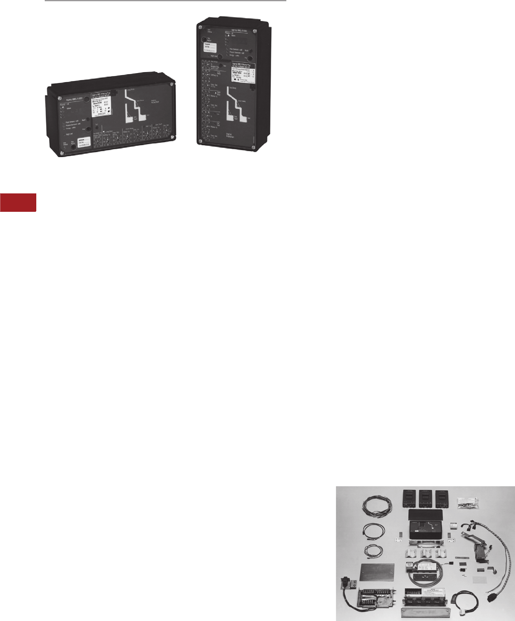
V3-T10-46 Volume 3—Power Distribution and Control Assemblies CA08100004E—June 2013 www.eaton.com
10
10
10
10
10
10
10
10
10
10
10
10
10
10
10
10
10
10
10
10
10
10
10
10
10
10
10
10
10
10
10.5
Power System Studies, Field Services and Conversions
Retrofit Services
Retrofit Kits
Contents
Description Page
Medium Voltage Vacuum Replacement Circuit
Breakers . . . . . . . . . . . . . . . . . . . . . . . . . . . . . . . V3-T10-34
AR Series Low Voltage Replacement Breakers . . . V3-T10-39
Low Voltage Power Circuit Breaker
Reconditioning. . . . . . . . . . . . . . . . . . . . . . . . . . . V3-T10-41
Arcflash Reduction Maintenance System™
Conversions. . . . . . . . . . . . . . . . . . . . . . . . . . . . . V3-T10-45
Digitrip Microprocessor Trip Unit Retrofit Kits
Features . . . . . . . . . . . . . . . . . . . . . . . . . . . . . . V3-T10-47
Reference Information . . . . . . . . . . . . . . . . . . . V3-T10-49
Product Selection . . . . . . . . . . . . . . . . . . . . . . . V3-T10-49
Low Voltage Breaker Drawout Vacuum
Starter Replacement . . . . . . . . . . . . . . . . . . . . . . V3-T10-50
MCC Replacement Units . . . . . . . . . . . . . . . . . . . . V3-T10-52
Digitrip Microprocessor Trip Unit Retrofit Kits
Product Description
Application
Eaton’s Digitrip RMS retrofit
kits are fully engineered, field
installable retrofit kits that
enable the user to completely
replace an existing tripping
system. They are applicable
to (600 Vac) low voltage
power breakers and are
designed for application
on both Eaton power
breakers and non-Eaton
power breakers.
Digitrip RMS retrofit kits
provide true rms sensing, the
most accurate and current
state-of-the-art technology for
measuring amperage loads.
True rms sensing removes the
possibility of false tripping due
to harmonic distortion of the
power waveform and enables
greater accuracy in selective
coordination of the power
distribution system. The
microprocessor-based Digitrip
trip unit also allows
communications for remote
monitoring to a host computer
or local AEM via the
PowerNet communication
system.
Ratings
Digitrip RMS retrofit kits are
available for a wide variety of
both Eaton and non-Eaton
low voltage power breaker
frames. Ratings range from
100 to 4000A. Digitrip retrofit
kits provide the user with
adaptive flexibility due to
multi-tapped current sensors
and interchangeable rating
plugs and programmable
pickup and time delay
settings.
History and Technology
In the past, there have been
three types of automatic
control for low voltage power
breakers. Electromechanical
(EM) trip units, solid-state
peak sensing trip units, and
state-of-the-art true rms
sensing trip units.
EM trip units were initially used
in the early 1950s and phased
out by all manufacturers in the
mid-1970s. EM trip units were
composed of a solenoid,
springs, a diaphragm, seals and
air venting apertures. Three
trip units were required per
breaker. Due to age or harsh
environments, these devices
would fail or lose calibration.
They required a great deal of
preventive maintenance.
Peak sensing trip units
were an improvement and
provided improved reliability
and accuracy. Only one
trip unit was required per
breaker; however, peak
sensing trip units were not
able to handle harmonic
conditions. They caused
nuisance tripping and
unnecessary downtime.
True rms trip units enable
the measuring of current
rather than the sensing
of current. Since they are
microprocessor-based digital
devices, they are capable of
taking discrete samples of
the current waveform in
each phase. By applying a
mathematical algorithm,
the current is accurately
mapped out and measured.
This method of measurement
provides the ability to adapt
to a changing harmonic
content while providing
repeatable and reliable
protection.
Kit Components

Volume 3—Power Distribution and Control Assemblies CA08100004E—June 2013 www.eaton.com V3-T10-47
10
10
10
10
10
10
10
10
10
10
10
10
10
10
10
10
10
10
10
10
10
10
10
10
10
10
10
10
10
10
10.5
Power System Studies, Field Services and Conversions
Retrofit Services
Features
Digitrip retrofit kits come
in several different model
types. Among these types,
they provide a variety of
accommodating features
(see Kit Type table on
Page V3-T10-48).
Tru e r m s measurement
and protection. Extremely
accurate and able to
accommodate harmonic
content and disturbances.
Ground fault protection
may be added to an existing
power breaker. Ground
fault protection is offered
in a three-wire and a four-
wire version.
Zone interlocking is available
on the short time and ground
fault modes of protection.
This enables enhanced
selectivity for high fault and
ground fault coordination
between the main and feeder
breakers.
Local monitoring via a
display. A red LED display
enables the user to step
through and read currents
and energy readings for
each phase and ground.
Communications via
the PowerNet system.
This allows all pertinent
information, regarding static
and dynamic operation of
the breaker, to be remotely
monitored either by a host
computer or local display
monitor. This facilitates
energy management and
power management.
Remember: “If you can't
measure it, you can't
manage it.”
Retrofit Breaker
Trip Functions
All Digitrip RMS retrofit kit
types are available with the
necessary combinations of
long, short, instantaneous
and ground fault (LSIG)
modes of protection as
depicted and deemed
necessary by industry
standards.
The combinations of modes
of protection are:
●LI
●LS
●LSI
●LIG
●LSG
●LSIG
The Packaged Kit
Each Digitrip RMS retrofit
kit includes a Digitrip trip unit,
an auxiliary CT module, a
Direct Trip Actuator (DTA),
quantity (three or four)
current sensors, a rating
plug, interconnecting wiring
harnesses, mounting
brackets, copper connectors
(when required), hardware
and installation instructions.
Digitrip RMS retrofit kits are
complete tripping systems
specifically engineered for
each breaker type and frame
rating. All kits are designed
for field installation.
Application and
Service Condition
In order to ensure that
Digitrip RMS retrofit kits
are successfully applied,
installation must only be
done by a qualified individual.
Appropriate testing must
be performed to qualify the
retrofitted breaker prior to
placing the breaker in service.
Digitrip RMS retrofit kits
will provide protection in
accordance with their
published time-current
characteristic curves and in
accordance with the original
breaker manufacturers
specifications on breakers
that have been properly
maintained and operate in
accordance with the original
manufacturer’s operating
instructions.
Service Life
The physical structure, the
bus assemblies and control
wiring of switchgear are
normally in good condition.
The replacement of the trip
system coupled along with
either refurbishment or
reconditioning of the breaker
will prolong the life of the
switchgear and provide
modern state-of-the-art
protection.
Availability
Digitrip retrofit kits are
currently available for select
breaker frames for the
following manufacturers:
●Eaton
●Westinghouse
●General Electric
●ITE
●Allis-Chalmers
●Federal Pacific
●Roller Smith
●Siemens-Allis
Additional Offerings
●Retrofit kits using
OPTIM™ 750 and 1050 trip
units are available for use
on DS breakers

V3-T10-48 Volume 3—Power Distribution and Control Assemblies CA08100004E—June 2013 www.eaton.com
10
10
10
10
10
10
10
10
10
10
10
10
10
10
10
10
10
10
10
10
10
10
10
10
10
10
10
10
10
10
10.5
Power System Studies, Field Services and Conversions
Retrofit Services
Kit Type
Digitrip Kit Features
RMS
510
RMS
510 Zone
RMS
610
RMS
810
RMS
910
Cause of trip LED indicators ■■■■■
Integral self test ■■■■■
Trip reset button ■■■■■
Thermal memory hardware driven —————
Thermal memory software driven selectable (on/off) ■■■■■
Discriminator circuit on LS and LSG protection modes —————
Discriminator circuit on LS and LSG protection modes selectable (on/off) ■■■■■
Zone protective interlocking for short-time and ground fault modes of protection —■■■■
Auxiliary contact for long time, short-circuit and ground fault functions —■■■■
Local display of phase currents ——■■■
Local display of ground currents ——■■■
Local display of cause of trip ——■■■
Local display of energy (MWh) ———■■
Local display of peak demand (MW) ———■■
Local display of present demand (MW) ———■■
Communication with PowerNet communicated data includes:
All display values
Trip unit status
High load alarm
Cause of trip
Rating plug status
Breaker status
Reason for breaker status
———■■
Trip settings ———■■
Power factor ———■■
Control via the PowerNet system (open/close) ———■■
Voltage phase-to-phase, displayed on trip unit and communicated via PowerNet communication ————■
Total current harmonic distortion (THD); phase A, B, C. Displayed on trip unit and communicated via
PowerNet communication ————■
Total current harmonic distortion per harmonic from the 2nd through the 27th harmonic displayed on trip
unit and communicated via PowerNet communication ————■
System power factor. Displayed on trip unit and communicated via PowerNet communication ————■
Waveform analysis data to PowerNet computer ————■

Volume 3—Power Distribution and Control Assemblies CA08100004E—June 2013 www.eaton.com V3-T10-49
10
10
10
10
10
10
10
10
10
10
10
10
10
10
10
10
10
10
10
10
10
10
10
10
10
10
10
10
10
10
10.5
Power System Studies, Field Services and Conversions
Retrofit Services
Reference Information
Sales Brochure for
Digitrip RMS Retrofit
Kits: B.22D.01.S.E
Instructions for the
Application of Digitrip RMS
Retrofit Kits on Power Circuit
Breakers: AD 33-855- 4
Digitrip RMS 510
Trip Unit: IL 29-885-B
Digitrip RMS 610
Trip Unit: IL 29-886-A
Digitrip RMS 810
Trip Unit: IL 29-888-A
Digitrip RMS 910
Trip Unit: IL 29-889-A
Time Current Curves
for DS and DSL Circuit
Breakers: AD 32-870
Retrofit Kit Product Guide
call 1-800-937-5487:
Doc. #9375487
Illustrates catalog number
system for each engineered
kit: YES Catalog Tab 17
Product Selection
Customer Required Information
In order to obtain the proper
kit, the following information
should be provided to Eaton:
●Breaker nameplate
information:
●Manufacturer
●Breaker type
●Ampere frame size
●Manually or electrically
operated
●Drawout or fixed mounting
●Fused or non-fused
●Digitrip trip unit type
required: 510, 610, 810, 910
●Protective functions
required: LI, LSI, LS, LIG,
LSG, LSIG
●Continuous current rating
required (trip rating of
breaker)
●Three-wire or four-wire
system (determines
number of sensors
required)
To properly select options,
the following questions need
to be answered:
●Will customer supply
120 Vac control power or
is breaker-mounted CPT
needed? Applies only to
Digitrip 610, 810 and 910
●Are zone interlocks
required?
●Does the application
require relay outputs from
the Digitrip 610, 810 or 910
for remote indication?
●Does the breaker have an
existing Amptector or
Digitrip trip unit installed?
If so, what is it?
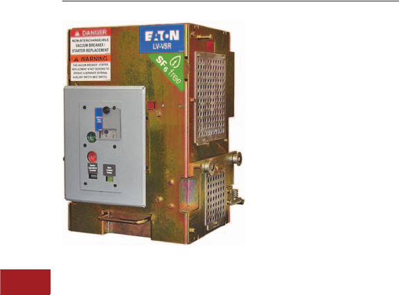
V3-T10-50 Volume 3—Power Distribution and Control Assemblies CA08100004E—June 2013 www.eaton.com
10
10
10
10
10
10
10
10
10
10
10
10
10
10
10
10
10
10
10
10
10
10
10
10
10
10
10
10
10
10
10.5
Power System Studies, Field Services and Conversions
Retrofit Services
DB-25 LV-VSR
Contents
Description Page
Medium Voltage Vacuum Replacement Circuit
Breakers . . . . . . . . . . . . . . . . . . . . . . . . . . . . . . . V3-T10-34
AR Series Low Voltage Replacement Breakers . . . V3-T10-39
Low Voltage Power Circuit Breaker
Reconditioning. . . . . . . . . . . . . . . . . . . . . . . . . . . V3-T10-41
Arcflash Reduction Maintenance System™
Conversions. . . . . . . . . . . . . . . . . . . . . . . . . . . . . V3-T10-45
Digitrip Microprocessor Trip Unit Retrofit Kits . . . . V3-T10-46
Low Voltage Breaker Drawout Vacuum Starter
Replacement
Technical Data and Specifications . . . . . . . . . . V3-T10-51
MCC Replacement Units . . . . . . . . . . . . . . . . . . . . V3-T10-52
Low Voltage Breaker Drawout Vacuum Starter Replacement
General Description
Eaton’s low voltage VSR
is a self-contained vacuum
starter replacement for a low
voltage drawout air circuit
breaker used for motor
starting applications.
In some cases, LV air circuit
breakers are used for motor
starting applications. Air
circuit breakers are not
designed to withstand the
frequent switching service
and mechanical stresses
associated with repetitive
motor starting duty. This is
due to the breaker mechanism
that must be designed to
close and latch against a
fault. In order to meet these
requirements, the mechanism
must close at high speeds
with a great deal of force.
Frequent closing operations
stress and deteriorate the
breaker mechanisms.
Eaton’s LV-VSR is a self-
contained replacement
vacuum starter for an LV
drawout air circuit breaker.
The LV-VSR is interchangeable
with the drawout breaker
element and requires no
cell modifications.
Features
Advantages
The use of an LV-VSR
vacuum starter can prolong
device life and significantly
reduce maintenance repair
and downtime.
A low voltage air circuit
breaker has an effective life
of 4000 operations while an
LV-VSR vacuum starter has
an effective life of 1,000,000
operations. For example, a
motor starting application that
required two starts per hour
on continuous duty would
require a major rebuild of
the LV breaker within three
months. The expected life of
an LV-VSR vacuum starter
would be over 50 years.
The LV-VSR vacuum starter
uses state-of-the-art Eaton
vacuum interrupters. The
interrupters employ the
latest vacuum technology
with long life, resistance to
environmental contaminants,
and positive contact wear
indicators.
The integral, solid-state, trip
units used on the air circuit
breakers are designed
primarily for cable and
transformer protection.
Motors require more precisely
set overcurrent devices that
prevent motor damage as well
as avoiding nuisance tripping.
A solid-state relay, Eaton
Type C440, provides
overload protection and
phase unbalance protection.
This relay was exclusively
designed for motor protection.
Motor Starter
The LV-VSR consists of
an Eaton V201 vacuum
contactor, Class J current
limiting fuses, multi-function
motor protective relay,
three current transformers
and an integral control
power transformer.
Vacuum Contactor
Eaton’s V201 vacuum
contactor is designed for
starting and controlling
three-phase, 50/60 Hz AC
motors. Current interruption
is contained within the
vacuum bottles and no arc
byproducts are vented to
the outside environment.
Contact condition is given
by wear indicators.
Series Current Limiting Fuses
Class J current limiting fuses
provide short-circuit
protection and allow a
combination rating of
100 kA at 480 or 600V.
C440 Electronic Overload Relay
Eaton’s C440 multi-function
electronic, motor protection
relay provides the following
features:
●Overload protection,
Class 10A, 10, 20 or 30
●Phase unbalance
protection, selectable
(ON/OFF)
●Ground fault selectable
(ON/OFF)
●Remote reset
●Alarm relay output contact
●LED status indication
●Communication modules
●Modbus RTU RS-485
●DeviceNet with IO
●PROFIBUS with IO

Volume 3—Power Distribution and Control Assemblies CA08100004E—June 2013 www.eaton.com V3-T10-51
10
10
10
10
10
10
10
10
10
10
10
10
10
10
10
10
10
10
10
10
10
10
10
10
10
10
10
10
10
10
10.5
Power System Studies, Field Services and Conversions
Retrofit Services
VSR Designs
●Westinghouse DS
●GE
●ITE
●and others
Contact EESS at 877-276-9379
for more details.
Life
Exceptional electrical and
mechanical life is offered
by the V201 contactor—
up to 1,000,000 electrical
operations and 2,500,000
mechanical operations, even
under harsh conditions.
Drawout Capability
The LV-VSR is mounted on a
drawout frame and maintains
the safety interlocking
system of the LV switchgear.
Ease of Installation
The LV-VSR may be inserted
into a standard breaker
compartment without
modification to the
compartment. The primary
and secondary contact
structures and drawout
mechanism are identical.
The LV-VSR control scheme
will interface with standard
switchgear wiring with no cell
modifications and remote
control schemes, if existing,
are maintained.
Safety Features
The LV-VSR vacuum starter
retains all the safety features
of the LV switchgear including:
●Racking the LV-VSR
vacuum starter is
prevented while the
contactor is in the closed
position. Closing the
LV-VSR vacuum starter is
prevented while racking
●Breaker position indication
is provided (connected,
test, disconnect, remove)
●The LV-VSR vacuum starter
is padlockable (optional) in
either the connect, test or
disconnect positions
●Positive ground connection
is maintained
●Closed door tripping
●Closed-door control, if
existing, can be maintained
LV-VSR Control Features
LV-VSR vacuum starter offers
the following standard control
features. Other devices can
be supplied on request.
●Start-stop pushbuttons
and run pilot light
●Eaton C440 electronic
overload relay
●2A/2B auxiliary contact
●1A/1B trip contact
(overload or short circuit)
●Provision for remote
control operation
●Integral control power
transformer
●Custom designed wiring
schemes
Ease of Maintenance
The LV-VSR control
components are front
mounted for easy access.
The LV-VSR uses the
same line and load finger
clusters, secondary contact
assemblies and drawout
mechanism as the original
circuit breaker. Renewal
parts are readily available.
Technical Data and
Specifications
Ratings
The LV-VSR vacuum starter is
rated as follows:
●Maximum continuous
current—425A
●Maximum voltage
rating—600V
●Short-circuit rating at
240–600V 200 kA
●Maximum motor hp at
480V 235 hp
●Maximum motor hp at
240V 117 hp
●Maximum motor hp at
600V 294 hp
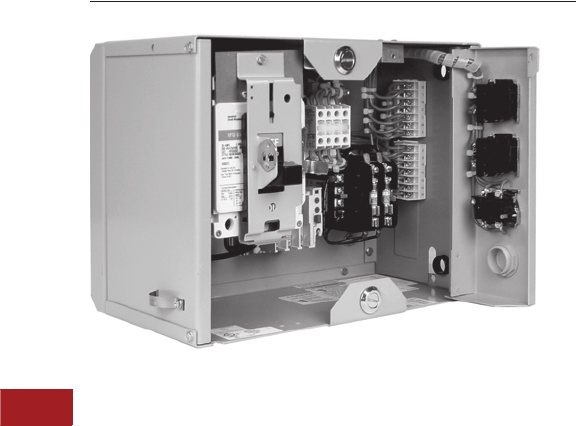
V3-T10-52 Volume 3—Power Distribution and Control Assemblies CA08100004E—June 2013 www.eaton.com
10
10
10
10
10
10
10
10
10
10
10
10
10
10
10
10
10
10
10
10
10
10
10
10
10
10
10
10
10
10
10.5
Power System Studies, Field Services and Conversions
Retrofit Services
ITE 5600 Series Motor Control Center Replacement Unit
Contents
Description Page
Medium Voltage Vacuum Replacement Circuit
Breakers . . . . . . . . . . . . . . . . . . . . . . . . . . . . . . . V3-T10-34
AR Series Low Voltage Replacement Breakers . . . V3-T10-39
Low Voltage Power Circuit Breaker
Reconditioning. . . . . . . . . . . . . . . . . . . . . . . . . . . V3-T10-41
Arcflash Reduction Maintenance System™
Conversions. . . . . . . . . . . . . . . . . . . . . . . . . . . . . V3-T10-45
Digitrip Microprocessor Trip Unit Retrofit Kits . . . . V3-T10-46
Low Voltage Breaker Drawout Vacuum
Starter Replacement . . . . . . . . . . . . . . . . . . . . . . V3-T10-50
MCC Replacement Units
Standards and Certifications . . . . . . . . . . . . . . . V3-T10-54
Product Selection . . . . . . . . . . . . . . . . . . . . . . . V3-T10-54
MCC Replacement Units
General Description
Eaton’s motor control center
(MCC) replacement units
are newly manufactured,
UL labeled units designed for
easy installation into existing
MCCs. We manufacture units
to fit into Westinghouse,
Cutler-Hammer and other
manufacturers such as GE,
Square D and ITE.
Replacement units allow
new starters and feeders
to be added to existing
motor control centers to
replace defective units or
to upgrade units.
Advantages
Motor starters are used in
applications where continuous
operation and frequent
opening and closing are
required. These conditions
lead to eventual mechanical
failure of contactors despite
best maintenance efforts.
Replacement MCC units are
the most time-efficient and
cost-effective way to restore
the original assembly to
operational condition.
Complete replacement
of the MCC involves costly
demolition, removal and
re-installation. Downtime
is extensive. The MCC
assembly often is in good
condition since there is very
little deterioration of the
enclosure, the bus or the
control wiring with normal
maintenance and proper
installation.
Replacement units are
newly manufactured and
have no used or fatigued
parts. Because they can be
manufactured to existing
wiring diagrams, the
installation time is minimal.
Only the power connections
and those wiring terminations
external to the MCC are
required to be disconnected
and reconnected. The
replacement unit
interchanges with the
existing unit without field
modifications. Downtime is
significantly reduced.
Features
Brand New Replacement Unit—
Not a Retrofit
All motor control units,
removable or fixed mounted,
are assembled with Eaton
components of proven
safety, quality and reliability.
All components are wired in
accordance with NEMA and
UL 845 standards.
Eaton has specifically
designed bus stabs to form
a standardization plug-in cell
that meets the highest safety
standards. These units fit into
the existing space of the
customer’s original MCC.
Solve Parts Availability
Problems for Old
Unsupported Products
We can also provide
additional inventory reduction
for the customer by using
components, such as
starters, which are currently
being used in other Eaton
MCCs. Unit starter types
include many options
including: Freedom, A200
and Soft Start. Additional
modifications include solid-
state overloads,
communication possibilities
and several cover control
options.
HMCP, HFD, HJD, HKD
breakers and 10250T series
pilot devices will provide
the customer with standard
features and current product
to adequately maintain their
MCCs for many years
to come.
For additional information,
contact 1-800-OLD-UNIT
or your local Eaton
Service Center.
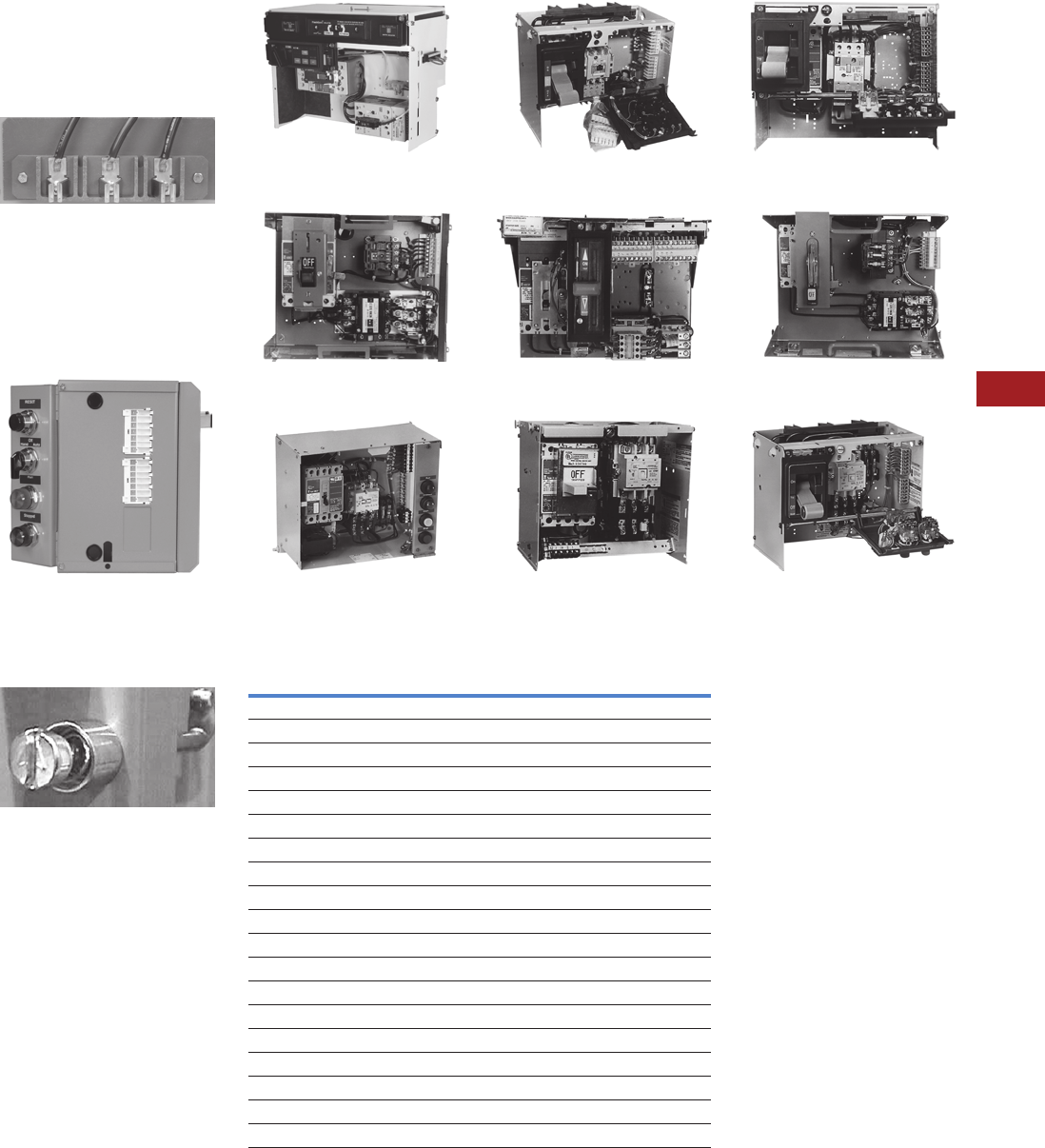
Volume 3—Power Distribution and Control Assemblies CA08100004E—June 2013 www.eaton.com V3-T10-53
10
10
10
10
10
10
10
10
10
10
10
10
10
10
10
10
10
10
10
10
10
10
10
10
10
10
10
10
10
10
10.5
Power System Studies, Field Services and Conversions
Retrofit Services
New Stab Design
●Tin-plated clip surface
●Spring clip for extra
pressure
●Sufficient insulating surface
Eaton Designed Stabs
Unit Features
●Holes for top and bottom
incoming line
●Self-aligning stab to bus
●Door device panel
●Knockout for terminal blocks
Side Item Stab
Door Features
●Door latch—1/4 turn
●Door hinge opens farther
Door Latch Closed
Unit Features
●Easy lock-out handle
mechanism
●Easy lock-in bucket tabs
●HMCP/HFD breakers
65k rated
●Additional ground clip
●10250T series cover
controls
Eaton FlashGard®
(2008 to Present)
F-10 Unitrol Replacement Starter Unit
(1972 to 1989)
11-300 Replacement Starter Unit
(1935 to 1965)
F2100 Replacement Starter Unit
(1995 to Present)
Freedom Unitrol Replacement Starter
Unit (1988 to 1994)
Type W Replacement Starter Unit
(1965 to 1975)
Advantage Replacement Starter Unit
(1992 to Present)
9800 Unitrol Replacement Starter Unit
(1956 to 1974)
5-Star/Series 2100 Replacement
Starter Unit (1975 to 1995)
UL 845 Eaton MCC Aftermarket Units
Note
1FlashGard replacement units available.
Name Brand MCC Vintage Type
Westinghouse 11-300 1935 to 1965
Cutler-Hammer 9800 Unitrol 1956 to 1974
ITE 5600 Series 1957 to 1976
Gould 5600 Series 1957 to 1976
Telemecanique 5600 Series 1957 to 1976
Westinghouse Type W 1965 to 1975
Cutler-Hammer F10 Unitrol 1972 to 1989
Westinghouse 5 Star 1975 to 1986
Cutler-Hammer Freedom Unitrol 1989 to 1994
Westinghouse 2100 Series 11986 to 1995
Westinghouse Advantage™ 11991 to present
Cutler-Hammer Freedom 2100
11995 to present
Cutler-Hammer IT. MCC 2002 to present
GE 7700/8000 1975 to present
Allen-Bradley Centerline 1971 to present
Square D Model 6 1992 to present
Siemens/Furnas 89 Series 89 1979 to 2001
Eaton IT. FlashGard 2006 to present
Eaton Freedom FlashGard 2007 to present

V3-T10-54 Volume 3—Power Distribution and Control Assemblies CA08100004E—June 2013 www.eaton.com
10
10
10
10
10
10
10
10
10
10
10
10
10
10
10
10
10
10
10
10
10
10
10
10
10
10
10
10
10
10
10.5
Power System Studies, Field Services and Conversions
Retrofit Services
Standards and Certifications
Designed and Tested to
NEMA/UL Standards
Eaton MCC replacement
units have passed all UL
required short-circuit and
heat tests. This high standard
of testing is important to
provide confidence to our
customers that UL 845 units
mean something for the
upkeep of their equipment.
Product Selection
Availability
Replacement units are
available for all MCCs
manufactured by Eaton,
Cutler-Hammer or
Westinghouse. Units are
available as follows:
Eaton:
●F2100: 1995 to present
●Freedom Unitro:
1988 to 1994
●F-10 Unitrol: 1972 to 1989
●9800 Unitrol: 1956 to 1974
Westinghouse:
●Advantage: 1992 to present
●Series 2100: 1987 to 1995
●5 Star: 1975 to 1987
●Type W: 1965 to 1975
●11-300: 1935 to 1965
All replacement units utilize
Eaton HMCP motor circuit
protectors allowing the units
to be UL 508 combination
rated 65 kA. The units can
be supplied with either
Freedom, Advantage,
A200 or Citation starters.
Communication Capability
Eaton’s MCC communication
solutions include DeviceNet,
EtherNet/IP, Modbus RTU,
Modbus TCP, PROFIBUS,
and Web interface using
Eaton’s Power Xpert®
Architecture.
Information Required
In order to obtain the
proper replacement unit,
the following information
should be provided to Eaton:
●MCC manufacturer
●MCC type
●Required starter hp rating
●Type of starter (i.e., FVNR,
FVR, 2S2W, etc.)
●Desired protective features
●Desired control devices
●Desired control scheme

Volume 3—Power Distribution and Control Assemblies CA08100004E—June 2013 www.eaton.com V3-T10-55
10
10
10
10
10
10
10
10
10
10
10
10
10
10
10
10
10
10
10
10
10
10
10
10
10
10
10
10
10
10
10.6
Power System Studies, Field Services and Conversions
Performance-Based Maintenance Services
Contents
Description
Performance-Based Maintenance Services
Performance-Based Maintenance Services
General Description
Approximately 80 percent of
all equipment failures occur on
a random basis and are not
age-related. Certainly, a well-
designed, time-based
preventive maintenance
program can reduce failure
rates, but what about these
80 percent of equipment
failures that occur on no
timetable? You could increase
the rate of preventive
maintenance activities, but
that is no panacea. These
maintenance activities tend to
be invasive, introducing new
defects that can actually
increase failure rates.
Under pressure to deliver
ever higher levels of
availability, facilities
managers are looking for a
better way. An optimal
maintenance program would:
●Enable you to schedule
maintenance based on
actual device operation
history, rather than
arbitrary calendar dates
●Eliminate unnecessary
maintenance work and
related production outages
●Reduce spare parts
requirements due to
increased accuracy of
equipment history
●Reduce overall
maintenance costs
You can achieve these results
by having Eaton apply
predictive analytic
technologies to the
maintenance program. The
result is a strategy that Eaton
calls “Performance-Based
Maintenance.” Services are
scheduled and performed
based on actual device
operating history, not on
arbitrary calendar dates. This
knowledge-based approach
reduces maintenance time,
cost and spare parts
requirements.
Performance-Based Maintenance (PBM) Program
Eaton offers Performance-
Based Maintenance (PBM)
solutions that fit various
project needs, for single sites
or multiple sites, and a full
range of equipment types.
This maintenance strategy
actually integrates four
proven maintenance
programs to deliver
quantifiable results at a
guaranteed price:
●The Planned
Maintenance Module
addresses operational
performance, as-left
conditions, environmental
considerations, and testing
and calibration results
●The Predictive Diagnostic
Module focuses on visual
observations,
environmental and thermal
conditions, and predictive
indicator results
●The Reliability-Centered
Maintenance Module
concentrates on the
potential for injuries,
environmental hazards and
product losses or process
interruptions
●The Periodic
Observations Module
centers on equipment
loading, and visual and
environmental
observations
It is easy to get started
on Performance-Based
Maintenance program.
EESS engineers visit your
facility and perform a
comprehensive site audit
and needs assessment.
While implementing
electrical system testing
and maintenance, EESS
engineers review both the
“condition” and “criticality”
of each component with plant
personnel. The condition is
determined via traditional
preventive maintenance
procedures (industry-
standard, time-based)
combined with predictive
diagnostic technologies. The
criticality rating of each
component is established
through application of a
reliability-centered
maintenance approach, taking
into account its potential
impact on critical processes,
safety and the environment.
Then, EESS engineers
recommend a maintenance
interval (short-, mid- or long-
term) for each component, as
well as work scopes and
periodic observation
frequency.

V3-T10-56 Volume 3—Power Distribution and Control Assemblies CA08100004E—June 2013 www.eaton.com
10
10
10
10
10
10
10
10
10
10
10
10
10
10
10
10
10
10
10
10
10
10
10
10
10
10
10
10
10
10
10.6
Power System Studies, Field Services and Conversions
Performance-Based Maintenance Services
You save money when this
analysis reveals an
opportunity to lengthen
maintenance interviews or
reduce the scope of
maintenance work performed
during scheduled outages.
You improve uptime and
reliability when this analysis
reveals components on
which preventive
maintenance should be
performed more frequently.
You can increase reliability
even more by redirecting
some of your cost savings
into additional predictive
diagnostics and equipment
modernization. EESS delivers
a periodic scorecard to plant
personnel, summarizing
the recommendations,
performance and results
of the program.
Elements of a Performance-
Based Maintenance Program
●Site audit and maintenance
needs assessment
●Condition-based
maintenance
●Reliability-centered
maintenance (RCM)
●Predictive diagnostics
●Efficient algorithms to
integrate equipment
condition results, RCM
input, predictive
diagnostics and periodic
observations
●Recommendations for
immediate action,
automation, remote
monitoring, life extension,
spare parts or upgrading
●Periodic observations while
energized and operating
●Maintenance implemented
based on equipment
condition and criticality
●Root-cause failure analysis
●Periodic scorecard and
customized reporting
of results
●Continuous improvement
●Optional ensured
performance
improvements and
ensured savings—typically,
15 percent savings over
two performance cycles
Our knowledge management
practices—when applied to
optimize the maintenance
program—reduce the
potential for outages by
predicting equipment failure
or system problems,
decrease the duration of
outages by providing 24/7
remote troubleshooting, and
reduce operating and
maintenance costs by basing
service on real-time
equipment information rather
than arbitrary timelines. The
bottom-line is more effective
maintenance service at
lower cost.

Volume 3—Power Distribution and Control Assemblies CA08100002E—December 2011 www.eaton.com V3-A1-1
Appendix 1—Eaton Terms & Conditions
Effective Date: November 1, 2008
Eaton Terms & Conditions
Contents
Description Page
Terms and Conditions of Sale. . . . . . . . . . . . . . . . . V3-A1-1
Terms of Payment . . . . . . . . . . . . . . . . . . . . . . . . . V3-A1-2
Freight . . . . . . . . . . . . . . . . . . . . . . . . . . . . . . . . . . V3-A1-3
Warranty . . . . . . . . . . . . . . . . . . . . . . . . . . . . . . . . . V3-A1-3
Selling Policy (Supersedes Selling Policy 25-000, dated February 20, 2006)
Terms and Conditions of Sale
The Terms and Conditions of
Sale set forth herein, and any
supplements which may be
attached hereto, constitute
the full and final expression
of the contract for the sale
of products or services
(hereinafter referred to as
Product(s) or Services by
Eaton Corporation
(hereinafter referred to as
Seller) to the Buyer, and
supersedes all prior
quotations, purchase orders,
correspondence or
communications whether
written or oral between the
Seller and the Buyer.
Notwithstanding any contrary
language in the Buyer’s
purchase order,
correspondence or other
form of acknowledgment,
Buyer shall be bound by
these Terms and Conditions
of Sale when it sends a
purchase order or otherwise
indicates acceptance of this
contract, or when it accepts
delivery from Seller of the
Products or Services.
THE CONTRACT FOR SALE
OF THE PRODUCTS OR
SERVICES IS EXPRESSLY
LIMITED TO THE TERMS
AND CONDITIONS OF SALE
STATED HEREIN. ANY
ADDITIONAL OR DIFFERENT
TERMS PROPOSED BY
BUYER ARE REJECTED
UNLESS EXPRESSLY
AGREED TO IN WRITING BY
SELLER. No contract shall
exist except as herein
provided.
Complete Agreement
No amendment or
modification hereto nor any
statement, representation or
warranty not contained herein
shall be binding on the Seller
unless made in writing by an
authorized representative of
the Seller. Prior dealings,
usage of the trade or a course
of performance shall not be
relevant to determine the
meaning of this contract even
though the accepting or
acquiescing party had
knowledge of the nature
of the performance and
opportunity for objection.
Quotations
Written quotations are valid
for 30 days from its date
unless otherwise stated in
the quotation or terminated
sooner by notice.
Verbal quotations, unless
accepted, expire the same
day they are made.
A complete signed order
must be received by Seller
within 20 calendar days of
notification of award,
otherwise the price and
shipment will be subject to
re-negotiation.
Termination and Cancellation
Any order may be terminated
by the Buyer only by written
notice and upon payment
of reasonable termination
charges, including all costs
plus profit.
Seller shall have the right to
cancel any order at any time
by written notice if Buyer
breaches any of the terms
hereof, becomes the subject
of any proceeding under state
or federal law for the relief
of debtors, or otherwise
becomes insolvent or
bankrupt, generally does not
pay its debts as they become
due or makes an assignment
for the benefit of creditors.
V3-A1-2 Volume 3—Power Distribution and Control Assemblies CA08100002E—December 2011 www.eaton.com
Appendix 1—Eaton Terms & Conditions
Effective Date: November 1, 2008
Prices
All prices are subject to
change without notice. In the
event of a price change, the
effective date of the change
will be the date of the new
price or discount sheet, letter
or telegram. All quotations
made or orders accepted
after the effective date will be
on the new basis. For existing
orders, the price of the
unshipped portion of an order
will be the price in effect at
time of shipment.
Price Policy—Products and
Services
When prices are quoted as
firm for quoted shipment, they
are firm provided the following
conditions are met:
1. The order is released
with complete
engineering details.
2. Shipment of Products are
made, and Services
purchased are provided
within the quoted
lead time.
3. When drawings for
approval are required
for any Products, the
drawings applicable to
those Products must be
returned within 30*
calendar days from the
date of the original
mailing of the drawings
by Seller. The return
drawings must be
released for manufacture
and shipment and must
be marked “APPROVED”
or “APPROVED AS
NOTED.” Drawing
re-submittals which are
required for any other
reason than to correct
Seller errors will not
extend the 30-day period.
* 60 days for orders
through contractors
to allow time for their
review and approval
before and after
transmitting them
to their customers.
If the Buyer initiates or in
any way causes delays
in shipment, provision of
Services or return of approval
drawings beyond the periods
stated above, the price of the
Products or Services will be
increased 1% per month
or fraction thereof up to a
maximum of 18 months from
the date of the Buyer’s order.
For delays resulting in
shipment or provision of
Services beyond 18 months
from the date of the Buyer’s
order, the price must be
renegotiated.
Price Policy—BLS
Refer to Price Policy 25-050.
Minimum Billing
Orders less than $1,000 will
be assessed a shipping and
handling charge of 5% of the
price of the order, with a
minimum charge of $25.00
unless noted differently on
Product discount sheets.
Taxes
The price does not include
any taxes. Buyer shall be
responsible for the payment
of all taxes applicable to, or
arising from the transaction,
the Products, its sale, value,
or use, or any Services
performed in connection
therewith regardless of
the person or entity
actually taxed.
Terms of Payment
Products
Acceptance of all orders is
subject to the Buyer meeting
Seller’s credit requirements.
Terms of payment are subject
to change for failure to meet
such requirements. Seller
reserves the right at any time
to demand full or partial
payment before proceeding
with a contract of sale as a
result of changes in the
financial condition of the
Buyer. Terms of Payment are
either Net 30 days from the
date of invoice of each
shipment or carry a cash
discount based on Product
type. Specific payment terms
for Products are outlined in
the applicable Product
discount schedules.
Services
Terms of payment are net
within 30 days from date of
invoice for orders amounting
to less than $50,000.00.
Terms of payment for orders
exceeding $50,000.00 shall
be made according to the
following:
1. Twenty percent (20%) of
order value with the
purchase order payable
30 days from date of
invoice.
2. Eighty percent (80%) of
order value in equal
monthly payments over
the performance period
payable 30 days from
date of invoice.
Except for work performed (i)
under a firm fixed price basis
or (ii) pursuant to terms of a
previously priced existing
contract between Seller and
Buyer, invoices for work
performed by Seller shall
have added and noted on
each invoice a charge of 3%
(over and above the price of
the work) which is related
to Seller compliance with
present and proposed
environmental, health, and
safety regulations associated
with prescribed requirements
covering hazardous materials
management and employee
training, communications,
personal protective
equipment, documentation
and record keeping
associated therewith.
Adequate Assurances
If, in the judgment of Seller,
the financial condition of the
Buyer, at any time during the
period of the contract, does
not justify the terms of
payment specified, Seller
may require full or partial
payment in advance.
Delayed Payment
If payments are not made in
accordance with these terms,
a service charge will, without
prejudice to the right of Seller
to immediate payment, be
added in an amount equal to
the lower of 1.5% per month
or fraction thereof or the
highest legal rate on the
unpaid balance.
Volume 3—Power Distribution and Control Assemblies CA08100002E—December 2011 www.eaton.com V3-A1-3
Appendix 1—Eaton Terms & Conditions
Effective Date: November 1, 2008
Freight
Freight policy will be listed on
the Product discount sheets,
or at option of Seller one of
the following freight terms
will be quoted.
F.O.B.—P/S—Frt./Ppd. and
Invoiced
Products are sold F.O.B. point
of shipment freight prepaid
and invoiced to the Buyer.
F.O.B.—P/S—Frt./Ppd.
and Allowed
Products sold are delivered
F.O.B. point of shipment,
freight prepaid and included
in the price.
F.O.B. Destination—Frt./Ppd.
and Allowed
At Buyer’s option, Seller will
deliver the Products F.O.B.
destination freight prepaid
and 2% will be added to the
net price.
The term “freight prepaid”
means that freight charges
will be prepaid to the
accessible common carrier
delivery point nearest the
destination for shipments
within the United States and
Puerto Rico unless noted
differently on the Product
discount sheets. For any
other destination contact
Seller’s representative.
Shipment and Routing
Seller shall select the point of
origin of shipment, the
method of transportation, the
type of carrier equipment and
the routing of the shipment.
If the Buyer specifies a
special method of
transportation, type of carrier
equipment, routing, or
delivery requirement, Buyer
shall pay all special freight
and handling charges.
When freight is included in
the price, no allowance will
be made in lieu of
transportation if the Buyer
accepts shipment at factory,
warehouse, or freight station
or otherwise supplies its own
transportation.
Risk of Loss
Risk of loss or damage to the
Products shall pass to Buyer
at the F.O.B. point.
Concealed Damage
Except in the event of F.O.B.
destination shipments, Seller
will not participate in any
settlement of claims for
concealed damage.
When shipment has been
made on an F.O.B. destination
basis, the Buyer must unpack
immediately and, if damage is
discovered must:
1. Not move the Products
from the point of
examination.
2. Retain shipping container
and packing material.
3. Notify the carrier in
writing of any apparent
damage.
4. Notify Seller
representative within
72 hours of delivery.
5. Send Seller a copy of
the carrier’s inspection
report.
Witness Tests/Customer
Inspection
Standard factory tests may be
witnessed by the Buyer
at Seller’s factory for an
additional charge calculated
at the rate of $2,500 per day
(not to exceed eight (8) hours)
per Product type. Buyer may
final inspect Products at the
Seller’s factory for $500 per
day per Product type.
Witness tests will add one (1)
week to the scheduled
shipping date. Seller will
notify Buyer fourteen (14)
calendar days prior to
scheduled witness testing
or inspection. In the event
Buyer is unable to attend, the
Parties shall mutually agree
on a rescheduled date.
However, Seller reserves
the right to deem the witness
tests waived with the right to
ship and invoice Products.
Held Orders
For any order held, delayed
or rescheduled at the request
of the Buyer, Seller may, at
its sole option (1) require
payment to be based on any
reasonable basis, including
but not limited to the contract
price, and any additional
expenses, or cost resulting
from such a delay; (2) store
Products at the sole cost and
risk of loss of the Buyer; and/
or (3) charge to the Buyer
those prices under the
applicable price policy.
Payment for such price,
expenses and costs, in any
such event, shall be due by
Buyer within thirty (30) days
from date of Seller’s invoice.
Any order so held delayed or
rescheduled beyond six (6)
months will be treated as a
Buyer termination.
Drawing Approval
Seller will design the
Products in line with, in
Seller’s judgment, good
commercial practice. If at
drawing approval Buyer
makes changes outside of
the design as covered in their
specifications, Seller will then
be paid reasonable charges
and allowed a commensurate
delay in shipping date based
on the changes made.
Drawing Re-Submittal
When Seller agrees to do so
in its quotation, Seller shall
provide Buyer with the first
set of factory customer
approval drawing(s) at Seller’s
expense. The customer
approval drawing(s) will be
delivered at the quoted
delivery date. If Buyer
requests drawing changes
or additions after the initial
factory customer approval
drawing(s) have been
submitted by Seller, the
Seller, at its option, may
assess Buyer drawing
charges. Factory customer
approval drawing changes
required due to
misinterpretation by Seller
will be at Seller’s expense.
Approval drawings generated
by Bid Manager are excluded
from this provision.
Warranty
Warranty for Products
Seller warrants that the
Products manufactured by
it will conform to Seller’s
applicable specifications and
be free from failure due to
defects in workmanship and
material for one (1) year from
the date of installation of
the Product or eighteen (18)
months from the date of
shipment of the Product,
whichever occurs first.
In the event any Product fails
to comply with the foregoing
warranty Seller will, at its
option, either (a) repair or
replace the defective
Product, or defective part or
component thereof, F.O.B.
Seller’s facility freight
prepaid, or (b) credit Buyer
for the purchase price of the
Product. All warranty claims
shall be made in writing.
Seller requires all non-
conforming Products be
returned at Seller’s expense
for evaluation unless
specifically stated otherwise
in writing by Seller.
This warranty does not
cover failure or damage
due to storage, installation,
operation or maintenance not
in conformance with Seller’s
recommendations and
industry standard practice
or due to accident, misuse,
abuse or negligence. This
warranty does not cover
reimbursement for labor,
gaining access, removal,
installation, temporary power
or any other expenses, which
may be incurred in connection
with repair or replacement.
This warranty does not
apply to equipment not
manufactured by Seller.
Seller limits itself to
extending the same warranty
it receives from the supplier.
V3-A1-4 Volume 3—Power Distribution and Control Assemblies CA08100002E—December 2011 www.eaton.com
Appendix 1—Eaton Terms & Conditions
Effective Date: November 1, 2008
Extended Warranty for Products
If requested by the Buyer and
specifically accepted in
writing by Seller, the
foregoing standard warranty
for Products will be extended
from the date of shipment for
the period and price indicated
below:
●24 months—2% of
Contract Price
●30 months—3% of
Contract Price
●36 months—4% of
Contract Price
Special Warranty (In and Out)
for Products
If requested by the Buyer
and specifically accepted in
writing by Seller, Seller will,
during the warranty period
for Products, at an additional
cost of 2% of the contract
price, be responsible for the
direct cost of:
1. Removing the Product
from the installed
location.
2. Transportation to the
repair facility and return
to the site.
3. Reinstallation on site.
The total liability of Seller for
this Special Warranty for
Products is limited to 50%
of the contract price of the
particular Product being
repaired and excludes
expenses for removing
adjacent apparatus, walls,
piping, structures, temporary
service, etc.
Warranty for Services
Seller warrants that the
Services performed by it
hereunder will be performed
in accordance with generally
accepted professional
standards.
The Services, which do not
so conform, shall be
corrected by Seller upon
notification in writing by the
Buyer within one (1) year
after completion of the
Services.
Unless otherwise agreed to in
writing by Seller, Seller
assumes no responsibility
with respect to the suitability
of the Buyer’s, or its
customer’s, equipment or
with respect to any latent
defects in equipment not
supplied by Seller. This
warranty does not cover
damage to Buyer’s, or its
customer’s, equipment,
components or parts
resulting in whole or in part
from improper maintenance
or operation or from their
deteriorated condition. Buyer
will, at its cost, provide Seller
with unobstructed access
to the defective Services,
as well as adequate free
working space in the
immediate vicinity of the
defective Services and such
facilities and systems,
including, without limitation,
docks, cranes and utility
disconnects and connects,
as may be necessary in order
that Seller may perform its
warranty obligations. The
conducting of any tests shall
be mutually agreed upon and
Seller shall be notified of, and
may be present at, all tests
that may be made.
Warranty for Power Systems
Studies
Seller warrants that any
power systems studies
performed by it will conform
to generally accepted
professional standards. Any
portion of the study, which
does not so conform, shall
be corrected by Seller upon
notification in writing by the
Buyer within six (6) months
after completion of the study.
All warranty work shall be
performed in a single shift
straight time basis Monday
through Friday. In the event
that the study requires
correction of warranty items
on an overtime schedule,
the premium portion of such
overtime shall be for the
Buyer’s account.
Limitation on Warranties for
Products, Services and Power
Systems Studies
THE FOREGOING
WARRANTIES ARE
EXCLUSIVE EXCEPT FOR
WARRANTY OF TITLE.
SELLER DISCLAIMS ALL
OTHER WARRANTIES
INCLUDING ANY IMPLIED
WARRANTIES OF
MERCHANTABILITY
AND FITNESS FOR A
PARTICULAR PURPOSE.
CORRECTION OF NON-
CONFORMITIES IN THE
MANNER AND FOR THE
PERIOD OF TIME PROVIDED
ABOVE SHALL CONSTITUTE
SELLER’S SOLE LIABILITY
AND BUYER’S EXCLUSIVE
REMEDY FOR FAILURE OF
SELLER TO MEET ITS
WARRANTY OBLIGATIONS,
WHETHER CLAIMS OF
THE BUYER ARE BASED
IN CONTRACT, IN TORT
(INCLUDING NEGLIGENCE
OR STRICT LIABILITY), OR
OTHERWISE.
Asbestos
Federal Law requires that
building or facility owners
identify the presence,
location and quantity of
asbestos containing material
(hereinafter “ACM”) at work
sites. Seller is not licensed to
abate ACM. Accordingly, for
any contract which includes
the provision of Services,
prior to (i) commencement of
work at any site under a
specific Purchase Order, (ii) a
change in the work scope of
any Purchase Order, the
Buyer will certify that the
work area associated with the
Seller’s scope of work
includes the handling of Class
II ACM, including but not
limited to generator wedges
and high temperature gaskets
which include asbestos
materials. The Buyer shall, at
its expense, conduct
abatement should the
removal, handling,
modification or reinstallation,
or some or all of them, of said
Class II ACM be likely to
generate airborne asbestos
fibers; and should such
abatement affect the cost
of or time of performance
of the work then Seller shall
be entitled to an equitable
adjustment in the schedule,
price and other pertinent
affected provisions of
the contract.
Compliance with Nuclear
Regulation
Seller’s Products are sold as
commercial grade Products
not intended for application in
facilities or activities licensed
by the United States Nuclear
Regulatory Commission for
atomic purposes. Further
certification will be required
for use of the Products in any
safety-related application in
any nuclear facility licensed
by the U.S. Nuclear
Regulatory Commission.
Volume 3—Power Distribution and Control Assemblies CA08100002E—December 2011 www.eaton.com V3-A1-5
Appendix 1—Eaton Terms & Conditions
Effective Date: November 1, 2008
Returning Products
Authorization and shipping
instructions for the return
of any Products must be
obtained from Seller before
returning the Products.
When return is occasioned
due to Seller error, full credit
including all transportation
charges will be allowed.
Product Notices
Buyer shall provide the user
(including its employees) of
the Products with all Seller
supplied Product notices,
warnings, instructions,
recommendations, and
similar materials.
Force Majeure
Seller shall not be liable for
failure to perform or delay
in performance due to fire,
flood, strike or other labor
difficulty, act of God, act of
any governmental authority or
of the Buyer, riot, embargo,
fuel or energy shortage, car
shortage, wrecks or delays in
transportation, or due to any
other cause beyond Seller’s
reasonable control. In the
event of delay in performance
due to any such cause, the
date of delivery or time for
completion will be extended
by a period of time reasonably
necessary
to overcome the
effect of such delay.
Liquidated Damages
Contracts which include
liquidated damage clauses for
failure to meet shipping or job
completion promises are not
acceptable or binding on
Seller, unless such clauses
are specifically accepted in
writing by an authorized
representative of the Seller at
its headquarters office.
Patent Infringement
Seller will defend or, at its
option, settle any suit or
proceeding brought against
Buyer, or Buyer’s customers,
to the extent it is based upon
a claim that any Product or
part thereof, manufactured by
Seller or its subsidiaries and
furnished hereunder,
infringes any United States
patent, other than a claim of
infringement based upon use
of a Product or part thereof in
a process, provided Seller is
notified in reasonable time
and given authority,
information and assistance
(at Seller’s expense) for the
defense of same. Seller shall
pay all legal and court costs
and expenses and court-
assessed damages awarded
therein against Buyer
resulting from or incident to
such suit or proceeding. In
addition to the foregoing, if at
any time Seller determines
there is a substantial question
of infringement of any United
States patent, and the use of
such Product is or may be
enjoined, Seller may, at its
option and expense: either (a)
procure for Buyer the right to
continue using and selling the
Product; (b) replace the
Product with non-infringing
apparatus; (c) modify the
Product so it becomes non-
infringing; or (d) as a last
resort, remove the Product
and refund the purchase
price, equitably adjusted for
use and obsolescence. In no
case does Seller agree to pay
any recovery based upon its
Buyer’s savings or profit
through use of Seller’s
Products whether the use be
special or ordinary. The
foregoing states the entire
liability of Seller for patent
infringement.
The preceding paragraph
does not apply to any claim of
infringement based upon: (a)
any modification made to a
Product other than by Seller;
(b) any design and/or
specifications of Buyer to
which a Product was
manufactured; or (c) the use
or combination of Product
with other products where
the Product does not itself
infringe. As to the above-
identified claim situations
where the preceding
paragraph does not apply,
Buyer shall defend and hold
Seller harmless in the same
manner and to the extent as
Seller’s obligations described
in the preceding paragraph.
Buyer shall be responsible for
obtaining (at Buyer’s
expense) all license rights
required for Seller to be able
to use software products in
the possession of Buyer
where such use is required in
order to perform any Service
for Buyer.
With respect to a Product or
part thereof not manufactured
by Seller or its subsidiaries,
Seller will attempt to obtain
for Buyer, from the supplier(s),
the patent indemnification
protection normally provided
by the supplier(s) to
customers.
Limitation of Liability
THE REMEDIES OF THE
BUYER SET FORTH IN THIS
CONTRACT ARE EXCLUSIVE
AND ARE ITS SOLE
REMEDIES FOR ANY
FAILURE OF SELLER
TO COMPLY WITH ITS
OBLIGATIONS HEREUNDER.
NOTWITHSTANDING
ANY PROVISION IN THIS
CONTRACT TO THE
CONTRARY, IN NO EVENT
SHALL SELLER BE LIABLE
IN CONTRACT, IN TORT
(INCLUDING NEGLIGENCE
OR STRICT LIABILITY) OR
OTHERWISE FOR DAMAGE
TO PROPERTY OR
EQUIPMENT OTHER THAN
PRODUCTS SOLD
HEREUNDER, LOSS OF
PROFITS OR REVENUE,
LOSS OF USE OF
PRODUCTS, COST OF
CAPITAL, CLAIMS OF
CUSTOMERS OF THE
BUYER OR ANY SPECIAL,
INDIRECT, INCIDENTAL OR
CONSEQUENTIAL
DAMAGES WHATSOEVER,
REGARDLESS OF WHETHER
SUCH POTENTIAL
DAMAGES ARE
FORESEEABLE OR IF
SELLER HAS BEEN ADVISED
OF THE POSSIBILITY OF
SUCH DAMAGES.
THE TOTAL CUMULATIVE
LIABILITY OF SELLER
ARISING FROM OR
RELATED TO THIS
CONTRACT WHETHER
THE CLAIMS ARE BASED
IN CONTRACT, IN TORT
(INCLUDING NEGLIGENCE
OR STRICT LIABILITY) OR
OTHERWISE, SHALL NOT
EXCEED THE PRICE OF THE
PRODUCT OR SERVICES
ON WHICH SUCH LIABILITY
IS BASED.
Volume 3—Power Distribution and Control Assemblies CA08100004E—June 2014 www.eaton.com V3-A2-1
Appendix 2—Catalog Parent Number Index
A
ARII . . . . . . . . . . . V3-T9-291
B
BIM . . . . . . . . . . . V3-T9-295
BLR . . . . . . . . . . . V3-T5-5
D
DIM . . . . . . . . . . . V3-T9-289
DPONI . . . . . . . . . V3-T9-286
DP4 . . . . . . . . . . . V3-T9-89
DT3 . . . . . . . . . . . V3-T9-210
E
ELC-P . . . . . . . . . V3-T9-267, V3-T9-273
F
FP6 . . . . . . . . . . . V3-T9-165
FTA . . . . . . . . . . . V3-T2-70
FTE . . . . . . . . . . . V3-T2-70
G
GFR . . . . . . . . . . . V3-T9-251, V3-T9-252
H
HMURF . . . . . . . . V3-T2-51
HURF. . . . . . . . . . V3-T2-50
I
IMPC . . . . . . . . . . V3-T9-299
IPONI. . . . . . . . . . V3-T9-83, V3-T9-89, V3-T9-285
IQA . . . . . . . . . . . V3-T9-83, V3-T9-89, V3-T9-132
IQD . . . . . . . . . . . V3-T9-89
IQDC . . . . . . . . . . V3-T9-258
IQES . . . . . . . . . . V3-T9-116
IQF . . . . . . . . . . . V3-T9-83, V3-T9-89, V3-T9-134
IQM . . . . . . . . . . . V3-T9-83, V3-T9-89
IQ2 . . . . . . . . . . . V3-T9-95
IQ25 . . . . . . . . . . V3-T9-55, V3-T9-62, V3-T9-67
IQ3 . . . . . . . . . . . V3-T9-77
J
JMR. . . . . . . . . . . V3-T2-42
L
LDIS . . . . . . . . . . V3-T9-298
M
MD3 . . . . . . . . . . V3-T9-204
MINTII . . . . . . . . . V3-T9-284
MP. . . . . . . . . . . . V3-T9-83, V3-T9-89
MPONI . . . . . . . . V3-T9-83, V3-T9-89, V3-T9-287
MP3. . . . . . . . . . . V3-T9-190
MP4. . . . . . . . . . . V3-T9-201
M00. . . . . . . . . . . V3-T9-124
M03. . . . . . . . . . . V3-T9-125
M04. . . . . . . . . . . V3-T9-125
M05 . . . . . . . . . . V3-T9-124
M06 . . . . . . . . . . V3-T9-125
M08 . . . . . . . . . . V3-T9-125
P
PCRMA . . . . . . . V3-T2-39
PCSR231 . . . . . . V3-T2-60
PHRMA . . . . . . . V3-T2-39
PMURF . . . . . . . V3-T2-46–V3-T2-49
PX . . . . . . . . . . . V3-T9-19
PXD . . . . . . . . . . V3-T9-43
PXE . . . . . . . . . . V3-T9-273
PXGA . . . . . . . . . V3-T9-267
PXGX 2. . . . . . . . V3-T9-281
PXGX1 . . . . . . . . V3-T9-278
PXG4 . . . . . . . . . V3-T9-267
PXG6 . . . . . . . . . V3-T9-267
PXM . . . . . . . . . . V3-T9-43
PXM2 . . . . . . . . . V3-T9-55, V3-T9-62
PX-P . . . . . . . . . . V3-T9-43
PXR . . . . . . . . . . V3-T9-19
PXS . . . . . . . . . . V3-T9-19
Q
Q250 . . . . . . . . . V3-T9-135
S
SP1 . . . . . . . . . . V3-T2-22, V3-T5-5
SP2 . . . . . . . . . . V3-T2-24
SRT . . . . . . . . . . V3-T2-34, V3-T2-35
S02. . . . . . . . . . . V3-T9-123
S05. . . . . . . . . . . V3-T9-123
S06. . . . . . . . . . . V3-T9-123
S08. . . . . . . . . . . V3-T9-123
S09. . . . . . . . . . . V3-T9-123
S21. . . . . . . . . . . V3-T5-5
S61. . . . . . . . . . . V3-T5-5
U
URTD . . . . . . . . . V3-T9-255
Numerics
100M . . . . . . . . . V3-T2-56
100T. . . . . . . . . . V3-T2-60
1000T. . . . . . . . . V3-T2-60, V3-T2-61
1100T. . . . . . . . . V3-T2-60, V3-T2-61
1200T. . . . . . . . . V3-T2-60, V3-T2-61
1234. . . . . . . . . . V3-T9-252
125M . . . . . . . . . V3-T2-56
125T. . . . . . . . . . V3-T2-60
1255. . . . . . . . . . V3-T9-251
1256. . . . . . . . . . V3-T9-251
1257. . . . . . . . . . V3-T9-251
1283. . . . . . . . . . V3-T9-251
150M . . . . . . . . . V3-T2-56
150T. . . . . . . . . . V3-T2-60, V3-T2-61
175M . . . . . . . . . V3-T2-56
179C . . . . . . . . . V3-T9-251
V3-A2-2 Volume 3—Power Distribution and Control Assemblies CA08100004E—June 2014 www.eaton.com
Appendix 2—Catalog Parent Number Index
200M. . . . . . . . . . V3-T2-56
200T . . . . . . . . . . V3-T2-60, V3-T2-61, V3-T2-65
225M. . . . . . . . . . V3-T2-56
25M. . . . . . . . . . . V3-T2-56
250M. . . . . . . . . . V3-T2-56
250T . . . . . . . . . . V3-T2-60, V3-T2-61, V3-T2-65
300M. . . . . . . . . . V3-T2-56
300T . . . . . . . . . . V3-T2-60, V3-T2-61, V3-T2-65
350T . . . . . . . . . . V3-T2-60, V3-T2-61, V3-T2-65
400T . . . . . . . . . . V3-T2-60, V3-T2-61, V3-T2-65
450T . . . . . . . . . . V3-T2-60, V3-T2-61, V3-T2-65
50M. . . . . . . . . . . V3-T2-56
500T. . . . . . . . . . V3-T2-60, V3-T2-61, V3-T2-65
550T. . . . . . . . . . V3-T2-60, V3-T2-61, V3-T2-65
600T. . . . . . . . . . V3-T2-60, V3-T2-61, V3-T2-65
660T. . . . . . . . . . V3-T2-60, V3-T2-61
700T. . . . . . . . . . V3-T2-60, V3-T2-61
720T. . . . . . . . . . V3-T2-60, V3-T2-61
75M . . . . . . . . . . V3-T2-56
75T. . . . . . . . . . . V3-T2-60
752B . . . . . . . . . V3-T9-252
800T. . . . . . . . . . V3-T2-60, V3-T2-61
840T. . . . . . . . . . V3-T2-60, V3-T2-61
900T. . . . . . . . . . V3-T2-60, V3-T2-61
Volume 3—Power Distribution and Control Assemblies CA08100004E—June 2014 www.eaton.com V3-A3-1
Appendix 3—Alphabetical Product Index
A
Accessories. . . . . . . . . . . . . . . . . . . . . . . . . . . . . . . . . . . . . . V3-T3-7
Automatic Insulation Tester (Motorguard) . . . . . . . . . . V3-T3-7
Connectivity Options, Power Xpert Ethernet Switches
DIN Rail Mounting Bracket. . . . . . . . . . . . . . . . . . . V3-T9-273
Power Supply . . . . . . . . . . . . . . . . . . . . . . . . . . . . . V3-T9-273
Rack Mount Tray, 19-inch. . . . . . . . . . . . . . . . . . . . V3-T9-273
Control and Distribution Equipment Packaging. . . . . . . V3-T3-7
FlashGard Locking Accessory . . . . . . . . . . . . . . . . . . . . V3-T3-7
FlashGard Remote Racking Accessory . . . . . . . . . . . . . V3-T3-7
Metal-Clad Vacuum Switchgear
Ground and Test Device. . . . . . . . . . . . . . . . . . . . . . . V3-T7-6
Optional . . . . . . . . . . . . . . . . . . . . . . . . . . . . . . . . . . . V3-T7-6
Standard . . . . . . . . . . . . . . . . . . . . . . . . . . . . . . . . . . . V3-T7-6
Supplemental Devices . . . . . . . . . . . . . . . . . . . . . . . . V3-T7-6
Metering Devices, IQ 130/140/150 Series
Panel Mounting Adapter. . . . . . . . . . . . . . . . . . . . . . V3-T9-67
Metering Devices, IQ 250/260 Meter
Panel Mounting Adapter. . . . . . . . . . . . . . . . . . . . . . V3-T9-62
PXM 2000 Gateway Upgrade Kit . . . . . . . . . . . . . . . V3-T9-62
Metering Devices, IQ Analyzer 6400/6600 Series
IQ Auxiliary Power Supply . . . . . . . . . . . . . . . . . . . . V3-T9-83
Metering Devices, IQ DP-4000 Series
I/O Module . . . . . . . . . . . . . . . . . . . . . . . . . . . . . . . . V3-T9-89
Metering Devices, Power Xpert Meter 2000 Series
Panel Mounting Bracket . . . . . . . . . . . . . . . . . . . . . . V3-T9-55
PXM 2000 Gateway Upgrade Kit . . . . . . . . . . . . . . . V3-T9-55
Metering Devices, Power Xpert Meter 4000/6000/8000
Communication Expansion Card . . . . . . . . . . . . . . . V3-T9-43
Digital I/O Card . . . . . . . . . . . . . . . . . . . . . . . . . . . . . V3-T9-43
Graphic Display Module . . . . . . . . . . . . . . . . . . . . . . V3-T9-43
Panel Mounting Bracket . . . . . . . . . . . . . . . . . . . . . . V3-T9-43
Power Xpert Meter 4000 to 6000 License
Upgrade Key . . . . . . . . . . . . . . . . . . . . . . . . . . . . . V3-T9-43
Protective Relays, Digitrip 3000
Drawout Case. . . . . . . . . . . . . . . . . . . . . . . . . . . . . V3-T9-210
Dual-Source Power Supply. . . . . . . . . . . . . . . . . . . V3-T9-210
Protective Relays, Ground Fault Relay
Ammeter Kit . . . . . . . . . . . . . . . . . . . . . . . . . . . . . . V3-T9-252
Face Place . . . . . . . . . . . . . . . . . . . . . . . . . . . . . . . V3-T9-252
Ground Fault Warning Indicator . . . . . . . . . . . . . . . V3-T9-252
Shunt Trip . . . . . . . . . . . . . . . . . . . . . . . . . . . . . . . . V3-T9-252
Test Panel (120 Vac). . . . . . . . . . . . . . . . . . . . . . . . V3-T9-252
Protective Relays, MP-3000 Motor Protection . . . . . V3-T9-190
Protective Relays, MP-4000 Motor Protection . . . . . V3-T9-201
Protective Relays, Universal RTD Module . . . . . . . . V3-T9-255
Voltage Presence Indicator (VoltageVision). . . . . . . . . . V3-T3-7
Active-Harmonic Filter-Harmonic Correction Unit—
NEMA 1 Enclosure
Power Factor Correction Capacitors . . . . . . . . . . . . . . V3-T2-71
Addressable Relay II
Connectivity Options, Software and Connectivity. . . V3-T9-290
Advanced Analysis and Design Services
Power System Studies . . . . . . . . . . . . . . . . . . . . . . . V3-T10-19
Advantage
Aftermarket Products . . . . . . . . . . . . . . . . . . . . . . . . . . V3-T3-3
AEGIS Powerline Filters
Surge Protective Devices . . . . . . . . . . . . . . . . . . . . . . V3-T2-25
Aftermarket Products
11-300 . . . . . . . . . . . . . . . . . . . . . . . . . . . . . . . . . . . . . . V3-T3-3
9800 Unitrol . . . . . . . . . . . . . . . . . . . . . . . . . . . . . . . . . . V3-T3-3
Advantage . . . . . . . . . . . . . . . . . . . . . . . . . . . . . . . . . . . V3-T3-3
F10 Unitrol . . . . . . . . . . . . . . . . . . . . . . . . . . . . . . . . . . . V3-T3-3
Freedom . . . . . . . . . . . . . . . . . . . . . . . . . . . . . . . . . . . . V3-T3-3
Freedom Unitrol. . . . . . . . . . . . . . . . . . . . . . . . . . . . . . . V3-T3-3
IT. . . . . . . . . . . . . . . . . . . . . . . . . . . . . . . . . . . . . . . . . . . V3-T3-3
Series 2100/5 Star . . . . . . . . . . . . . . . . . . . . . . . . . . . . . V3-T3-3
Type W . . . . . . . . . . . . . . . . . . . . . . . . . . . . . . . . . . . . . V3-T3-3
XT and XT FlashGard . . . . . . . . . . . . . . . . . . . . . . . . . . V3-T3-3
Ammeter Kit
Protective Relays, Ground Fault Relay
Accessories. . . . . . . . . . . . . . . . . . . . . . . . . . . . . . . V3-T9-252
AMPGARD Motor Control
Medium Voltage Motor Control Assemblies . . V3-T5-2–V3-T5-6
AR Series Low Voltage Replacement Breakers
Retrofit Services . . . . . . . . . . . . . . . . . . . . . . . . . . . . V3-T10-39
Arc Flash, Short-Circuit and Coordination Studies
Power System Studies . . . . . . . . . . . . . . . . . . . . . . . V3-T10-12
Arcflash Reduction Maintenance System Conversions
Retrofit Services . . . . . . . . . . . . . . . . . . . . . . . . . . . . V3-T10-45
Arc-Resistant AMPGARD
AMPGARD Motor Control
Medium Voltage Motor Control Assemblies. . . . . . . . V3-T5-3
Asset Optimization, Knowledge Management and
Product Life Extension
Power System Studies, Field Services and
Conversions . . . . . . . . . . . . . . . . . . . . . . . . . . . . . . . V3-T10-5
Automatic Insulation Tester (Motorguard) . . . . . . . . . . . . . . . V3-T3-7
AUTOVAR 300
Power Factor Correction Capacitors . . . . . . . . . . . . . . V3-T2-55
AUTOVAR 600
Power Factor Correction Capacitors . . . . . . . . . . . . . . V3-T2-58
AUTOVAR Filter
Power Factor Correction Capacitors . . . . . . . . . . . . . . V3-T2-63
B
Bid Manager . . . . . . . . . . . . . . . . . . . . . . . . . . . . . . . . . . . . . V3-T3-2
Breaker Interface Module II (BIM II)
Connectivity Options, Software and Connectivity . . . V3-T9-293
Busway Products. . . . . . . . . . . . . . . . . . . . . . . . . . . V3-T1-1–V3-T1-7
Medium Voltage . . . . . . . . . . . . . . . . . . . . . . . V3-T1-2–V3-T1-7
Medium Voltage Busway—Nonsegregated
Phase Bus . . . . . . . . . . . . . . . . . . . . . . . . . . . V3-T1-2–V3-T1-7
C
C-HRG Free-Standing NEMA 1 Unit
High Resistance Grounding System . . . . . . . . . . . . . . V3-T7-18
Circuit Breaker Specialized Services
Field Engineering Services . . . . . . . . . . . . . . . . . . . . V3-T10-28
Clamp-On Current Transformers
Metering Devices . . . . . . . . . . . . . . . . . . . . . . . . . . . V3-T9-131
CM52
Network Protectors . . . . . . . . . . . . . . . . . . . . . . . . . . . . V3-T8-2
V3-A3-2 Volume 3—Power Distribution and Control Assemblies CA08100004E—June 2014 www.eaton.com
Appendix 3—Alphabetical Product Index
Commercial and Light Industrial Surge Protection
PF Capacitors and Harmonic Filters . . . . . . . . . . . . . . . V3-T2-2
Communication Expansion Card
Metering Devices, Power Xpert Meter 4000/6000/8000
Accessories . . . . . . . . . . . . . . . . . . . . . . . . . . . . . . . V3-T9-43
Connectivity Options. . . . . . . . . . . . . . . . . . . . V3-T9-259–V3-T9-299
Connectivity Options, Software and Connectivity
Addressable Relay II . . . . . . . . . . . . . . . . . . . . . . . . . V3-T9-290
Breaker Interface Module II (BIM II). . . . . . . . . . . . . V3-T9-293
DPONI . . . . . . . . . . . . . . . . . . . . . . . . . . . . . . . . . . . . V3-T9-286
I/O Devices Digital Input Module (DIM) . . . . . . . . . . V3-T9-288
IMPCABLE . . . . . . . . . . . . . . . . . . . . . . . . . . . . . . . . V3-T9-299
IPONI. . . . . . . . . . . . . . . . . . . . . . . . . . . . . . . . . . . . . V3-T9-285
MINTII RS-232 Converter . . . . . . . . . . . . . . . . . . . . . V3-T9-284
mMINT . . . . . . . . . . . . . . . . . . . . . . . . . . . . . . . . . . . V3-T9-282
MPONI . . . . . . . . . . . . . . . . . . . . . . . . . . . . . . . . . . . V3-T9-287
Power Xpert Ethernet Switches . . . . . . . . . . . . . . . . V3-T9-272
Power Xpert Gateway Series 1000 Card—
Power Distribution Unit . . . . . . . . . . . . . . . . . . . . . V3-T9-276
Power Xpert Gateway Series 2000 Card—
Uninterruptible Power Supplies . . . . . . . . . . . . . . . V3-T9-279
Power Xpert Gateways . . . . . . . . . . . . . . . . . . . . . . . V3-T9-259
Sub-Network Master Local Display (SMLD) . . . . . . . V3-T9-297
Consulting and Turnkey Project Management
Field Engineering Services . . . . . . . . . . . . . . . . . . . . V3-T10-23
Control and Distribution Equipment Packaging . . . . . . . . . . . V3-T3-7
Critical Load Protection
PF Capacitors and Harmonic Filters . . . . . . . . . . . . . . . V3-T2-2
Current Transformers (CTs)
Metering Devices . . . . . . . . . . . . . . . . . . . . . . . . . . . V3-T9-122
Customer Manufacturing and Solutions Centers . . . . . . . . . V3-T3-2
Customized High Resistance Grounding Units
Power System Studies, Field Services and
Conversions . . . . . . . . . . . . . . . . . . . . . . . . . . . . . . V3-T10-11
CVL Surge Protective Device
Surge Protective Devices . . . . . . . . . . . . . . . . . . . . . . V3-T2-16
CVX050/100
Surge Protective Devices . . . . . . . . . . . . . . . . . . . . . . V3-T2-18
D
Digital I/O Card
Metering Devices, Power Xpert Meter 4000/6000/8000
Accessories . . . . . . . . . . . . . . . . . . . . . . . . . . . . . . . V3-T9-43
Digitrip 3000
Protective Relays . . . . . . . . . . . . . . . . . . . . . . . . . . . V3-T9-207
Digitrip Microprocessor Trip Unit Retrofit Kits
Retrofit Services . . . . . . . . . . . . . . . . . . . . . . . . . . . . V3-T10-46
DIN Rail Mounting Bracket
Connectivity Options, Power Xpert Ethernet Switches
Accessories . . . . . . . . . . . . . . . . . . . . . . . . . . . . . . V3-T9-273
DP-300 Current Differential Protection Relay
Protective Relays . . . . . . . . . . . . . . . . . . . . . . . . . . . V3-T9-221
DPONI
Connectivity Options, Software and Connectivity. . . V3-T9-286
Drawout Air Circuit Breaker Design
Network Protectors. . . . . . . . . . . . . . . . . . . . . V3-T8-2, V3-T8-3
Drawout Case
Protective Relays, Digitrip 3000
Accessories. . . . . . . . . . . . . . . . . . . . . . . . . . . . . . . V3-T9-210
Dual-Source Power Supply
Protective Relays, Digitrip 3000
Accessories. . . . . . . . . . . . . . . . . . . . . . . . . . . . . . . V3-T9-210
E
Eaton Terms & Conditions. . . . . . . . . . . . . . . . . . . . . . . . . . . V3-T1-1
Freight . . . . . . . . . . . . . . . . . . . . . . . . . . . . . . . . . . . . . . V3-T1-3
Limitation of Liability . . . . . . . . . . . . . . . . . . . . . . . . . . . V3-T1-5
Terms and Conditions of Sale . . . . . . . . . . . . . . . . . . . . V3-T1-1
Terms of Payment . . . . . . . . . . . . . . . . . . . . . . . . . . . . . V3-T1-2
Warranty . . . . . . . . . . . . . . . . . . . . . . . . . . . . . . . . . . . . V3-T1-3
EDR-3000 Feeder Protection
Protective Relays . . . . . . . . . . . . . . . . . . . . . . . . . . . . V3-T9-226
Electrical System Modernization
Field Engineering Services. . . . . . . . . . . . . . . . . . . . . V3-T10-26
Electronic Self-Enclosed Meters
IQ 150S/250S. . . . . . . . . . . . . . . . . . . . . . . . . . . . . . . . V3-T9-71
Electronic Voltage Regulator
Power Conditioning . . . . . . . . . . . . . . . . . . . . . . . . . . . V3-T2-36
Enclosed Meters
Metering Devices . . . . . . . . . . . . . . . . . . . . . . . . . . . V3-T9-136
ETR-4000 Transformer Protection Relay
Protective Relays . . . . . . . . . . . . . . . . . . . . . . . . . . . . V3-T9-237
F
F10 Unitrol
Aftermarket Products . . . . . . . . . . . . . . . . . . . . . . . . . . V3-T3-3
Face Plate
Protective Relays, Ground Fault Relay
Accessories. . . . . . . . . . . . . . . . . . . . . . . . . . . . . . . V3-T9-252
Field Engineering Services. . . . . . . . . . . . . . . . V3-T10-23–V3-T10-28
Circuit Breaker Specialized Services . . . . . . . . . . . . . V3-T10-28
Consulting and Turnkey Project Management. . . . . . V3-T10-23
Electrical System Modernization . . . . . . . . . . . . . . . . V3-T10-26
Predictive and Preventive Maintenance . . . . . . . . . . V3-T10-25
Startup and Commissioning. . . . . . . . . . . . . . . . . . . . V3-T10-25
System Integration . . . . . . . . . . . . . . . . . . . . . . . . . . V3-T10-24
Training . . . . . . . . . . . . . . . . . . . . . . . . . . . . . . . . . . . V3-T10-24
FlashGard Locking Accessory . . . . . . . . . . . . . . . . . . . . . . . . V3-T3-7
FlashGard Remote Racking Accessory . . . . . . . . . . . . . . . . . V3-T3-7
FP-4000 Feeder Protection
Protective Relays . . . . . . . . . . . . . . . . . . . . . . . . . . . . V3-T9-180
FP-5000 Feeder Protection
Protective Relays . . . . . . . . . . . . . . . . . . . . . . . . . . . . V3-T9-172
FP-6000 Feeder Protection
Protective Relays . . . . . . . . . . . . . . . . . . . . . . . . . . . . V3-T9-162
Freedom
Aftermarket Products . . . . . . . . . . . . . . . . . . . . . . . . . . V3-T3-3
Freedom Unitrol
Aftermarket Products . . . . . . . . . . . . . . . . . . . . . . . . . . V3-T3-3
Freedom, Freedom Arc-Resistant and Freedom FlashGard
Motor Control Centers. . . . . . . . . . . . . . . . . . . . . . . . . . V3-T3-8
Volume 3—Power Distribution and Control Assemblies CA08100004E—June 2014 www.eaton.com V3-A3-3
Appendix 3—Alphabetical Product Index
G
Graphic Display Module
Metering Devices, Power Xpert Meter 4000/6000/8000
Accessories . . . . . . . . . . . . . . . . . . . . . . . . . . . . . . . V3-T9-43
Ground and Test Device
Metal-Clad Vacuum Switchgear
Accessories . . . . . . . . . . . . . . . . . . . . . . . . . . . . . . . . V3-T7-6
Ground Fault Relay
Protective Relays . . . . . . . . . . . . . . . . . . . . . . . . . . . V3-T9-250
Ground Fault Warning Indicator
Protective Relays, Ground Fault Relay
Accessories . . . . . . . . . . . . . . . . . . . . . . . . . . . . . . V3-T9-252
H
Harmonic Analysis Study
Power System Studies . . . . . . . . . . . . . . . . . . . . . . . V3-T10-17
High Resistance Grounding System
C-HRG Free-Standing NEMA 1 Unit . . . . . . . . . . . . . . V3-T7-18
Medium Voltage Switchgear. . . . . . . . . . . . V3-T7-18–V3-T7-26
I
I/O Devices Digital Input Module (DIM)
Connectivity Options, Software and Connectivity. . . V3-T9-288
I/O Module
Metering Devices, IQ DP-4000 Series
Accessories . . . . . . . . . . . . . . . . . . . . . . . . . . . . . . . V3-T9-89
IMPCABLE
Connectivity Options, Software and Connectivity. . . V3-T9-299
Industrial and Commercial Surge Protection
PF Capacitors and Harmonic Filters . . . . . . . . . . . . . . . V3-T2-2
Instant Response Center Services
Power System Studies, Field Services and
Conversions . . . . . . . . . . . . . . . . . . . . . . . . . . . . . . V3-T10-10
IPONI
Connectivity Options, Software and Connectivity. . . V3-T9-285
IQ 125 Volt DC Power Supply
Protective Relays . . . . . . . . . . . . . . . . . . . . . . . . . . . V3-T9-258
IQ 130/140/150 Series Electronic Power Meters
Metering Devices . . . . . . . . . . . . . . . . . . . . . . . . . . . . V3-T9-66
IQ 210/220/230 Meters
Metering Devices . . . . . . . . . . . . . . . . . . . . . . . . . . . . V3-T9-93
IQ 250/260 Series Electronic Power Meters
Metering Devices . . . . . . . . . . . . . . . . . . . . . . . . . . . . V3-T9-60
IQ 35M
Metering Devices . . . . . . . . . . . . . . . . . . . . . . . . . . . . V3-T9-76
IQ Analyzer 6400/6600 Series
Metering Devices . . . . . . . . . . . . . . . . . . . . . . . . . . . . V3-T9-79
IQ Auxiliary Power Supply
Metering Devices, IQ Analyzer
Accessories . . . . . . . . . . . . . . . . . . . . . . . . . . . . . . . V3-T9-83
IQ DP-4000 Series
Metering Devices . . . . . . . . . . . . . . . . . . . . . . . . . . . . V3-T9-87
IQ Energy Sentinel
Metering Devices . . . . . . . . . . . . . . . . . . . . . . . . . . . V3-T9-112
IQ Flange
Metering Devices . . . . . . . . . . . . . . . . . . . . . . . . . . . V3-T9-134
IT.
Aftermarket Products . . . . . . . . . . . . . . . . . . . . . . . . . . V3-T3-3
L
Load Flow/Power Factor Correction Study
Power System Studies . . . . . . . . . . . . . . . . . . . . . . . V3-T10-15
Low Voltage Breaker Drawout Vacuum Starter Replacement
Retrofit Services . . . . . . . . . . . . . . . . . . . . . . . . . . . . V3-T10-50
Low Voltage Power Circuit Breaker Reconditioning
Retrofit Services . . . . . . . . . . . . . . . . . . . . . . . . . . . . V3-T10-41
Low Voltage Switchgear . . . . . . . . . . . . . . . . . . . . . V3-T4-1–V3-T4-8
Magnum DS Metal-Enclosed. . . . . . . . . . . . . . V3-T4-2–V3-T4-6
Primary Unit Substations . . . . . . . . . . . . . . . . . V3-T4-7, V3-T4-8
Secondary Unit Substations . . . . . . . . . . . . . . V3-T4-7, V3-T4-8
M
Magnum DS Metal-Enclosed
Low Voltage Switchgear . . . . . . . . . . . . . . . . . V3-T4-2–V3-T4-6
Main Breaker AMPGARD
AMPGARD Motor Control
Medium Voltage Motor Control Assemblies. . . . . . . . V3-T5-3
MCC Operation . . . . . . . . . . . . . . . . . . . . . . . . . . . . . . . . . . . V3-T3-2
MCC Replacement Units
Retrofit Services . . . . . . . . . . . . . . . . . . . . . . . . . . . . V3-T10-52
MD-3000 Motor/Generator Differential Relay
Protective Relays. . . . . . . . . . . . . . . . . . . . . . . . . . . . V3-T9-204
Medium and High Voltage Predictive Diagnostics
Online Monitoring and Partial Discharge Analysis
Predictive Diagnostic . . . . . . . . . . . . . . . . . . . . . . . . . V3-T10-32
Medium Voltage Busway. . . . . . . . . . . . . . . . . . . . . V3-T1-1–V3-T1-7
Nonsegregated Phase Bus . . . . . . . . . . . . . . . . . . . . . . V3-T1-2
Medium Voltage Busway—Nonsegregated Phase Bus
Busway Products. . . . . . . . . . . . . . . . . . . . . . . V3-T1-2–V3-T1-7
Medium Voltage Metal-Enclosed Switches. . . . . . V3-T6-1–V3-T6-11
Medium Voltage Switch and Breaker—MSB . V3-T6-4, V3-T6-5
Medium Voltage Switch—MVS . . . . . . . . . . . . V3-T6-2, V3-T6-3
Metal-Enclosed Breaker—MEB . . . . . . . . . . . . V3-T6-6, V3-T6-7
OEM Medium Voltage Switch Components—
MVS-C. . . . . . . . . . . . . . . . . . . . . . . . . . . . V3-T6-10, V3-T6-11
Unitized Power Centers—UPC . . . . . . . . . . . . V3-T6-8, V3-T6-9
Medium Voltage Motor Control Assemblies . . . . . . V3-T5-1–V3-T5-6
AMPGARD Motor Control . . . . . . . . . . . . . . . . V3-T5-2–V3-T5-6
Arc-Resistant AMPGARD . . . . . . . . . . . . . . . . . . . . . . V3-T5-3
Main Breaker AMPGARD . . . . . . . . . . . . . . . . . . . . . . V3-T5-3
Reduced Voltage Solid-State Starters . . . . . . . . . . . . . V3-T5-3
SC 9000 Adjustable Frequency Drive . . . . . . . . . . . . . V3-T5-2
Medium Voltage Switch and Breaker—MSB
Medium Voltage Metal-Enclosed Switches. . . V3-T6-4, V3-T6-5
Medium Voltage Switchgear . . . . . . . . . . . . . . . . . V3-T7-1–V3-T7-26
High Resistance Grounding System . . . . . . V3-T7-18–V3-T7-26
4200V Delta Systems . . . . . . . . . . . . . . . . . . . . . . . . V3-T7-18
4200V Wye Systems . . . . . . . . . . . . . . . . . . . . . . . . V3-T7-18
Metal-Clad Vacuum Switchgear . . . . . . . . . . V3-T7-4–V3-T7-17
26-Inch Wide, 5 kV, 250 MVA, 1200A Switchgear . . . V3-T7-7
V3-A3-4 Volume 3—Power Distribution and Control Assemblies CA08100004E—June 2014 www.eaton.com
Appendix 3—Alphabetical Product Index
38 kV Metal-Clad Switchgear . . . . . . . . . . . . . . . . . . . V3-T7-8
Accessories . . . . . . . . . . . . . . . . . . . . . . . . . . . . . . . . V3-T7-6
Medium Voltage Switch—MVS
Medium Voltage Metal-Enclosed Switches . . V3-T6-2, V3-T6-3
Medium Voltage Vacuum Replacement Circuit Breakers
Retrofit Services . . . . . . . . . . . . . . . . . . . . . . . . . . . . V3-T10-34
Metal-Clad Vacuum Switchgear
Medium Voltage Switchgear
26-Inch Wide, 5 kV, 250 MVA, 1200A Switchgear . . . V3-T7-7
38 kV Metal-Clad Switchgear . . . . . . . . . . . . . . . . . . . V3-T7-8
Metal-Clad Vacuum Switchgear, VCP-W
Accessories
Ground and Test Device . . . . . . . . . . . . . . . . . . . . . . . V3-T7-6
Medium Voltage Switchgear. . . . . . . . . . . . . V3-T7-4–V3-T7-17
Metal-Enclosed Breaker—MEB
Medium Voltage Metal-Enclosed Switches . . V3-T6-6, V3-T6-7
Metering Devices . . . . . . . . . . . . . . . . . . . . . . . . V3-T9-21–V3-T9-78
Clamp-On Current Transformers. . . . . . . . . . . . . . . . V3-T9-131
Current Transformers (CTs). . . . . . . . . . . . . . . . . . . . V3-T9-122
Enclosed Meters . . . . . . . . . . . . . . . . . . . . . . . . . . . . V3-T9-136
IQ 130/140/150 Series Electronic Power Meters . . . . V3-T9-66
IQ 150S/250S . . . . . . . . . . . . . . . . . . . . . . . . . . . . . . . V3-T9-71
IQ 210/220/230 Meters. . . . . . . . . . . . . . . . . . . . . . . . V3-T9-93
IQ 250/260 Series Electronic Power Meters. . . . . . . . V3-T9-60
IQ 35M . . . . . . . . . . . . . . . . . . . . . . . . . . . . . . . . . . . . V3-T9-76
IQ Analyzer 6400/6600 Series. . . . . . . . . . . . . . . . . . . V3-T9-79
IQ DP-4000 Series. . . . . . . . . . . . . . . . . . . . . . . . . . . . V3-T9-87
IQ Energy Sentinel . . . . . . . . . . . . . . . . . . . . . . . . . . V3-T9-112
IQ Flange. . . . . . . . . . . . . . . . . . . . . . . . . . . . . . . . . . V3-T9-134
Panel Mounting Adapter Kit for IQ 100/200 Series
and PXM 2000 Meters . . . . . . . . . . . . . . . . . . . . . . V3-T9-135
Power Xpert 4000/6000/8000 Series . . . . . . . . . . . . . V3-T9-30
Power Xpert Meter 2000 Series . . . . . . . . . . . . . . . . . V3-T9-49
Power Xpert Multi-Point Meter . . . . . . . . . . . . . . . . . V3-T9-100
Product Selection Guide . . . . . . . . . . . . . . . . . . . . . . . V3-T9-22
Metering Devices, Protective Relays, Software and
Connectivity . . . . . . . . . . . . . . . . . . . . . . . . . . . V3-T9-1–V3-T9-299
Connectivity Options. . . . . . . . . . . . . . . . . . . . . . . . . V3-T9-259
Metering Devices . . . . . . . . . . . . . . . . . . . . . . . . . . . . V3-T9-21
Monitoring Software and Reporting . . . . . . . . . . . . . . V3-T9-14
Power Xpert Architecture . . . . . . . . . . . . . . . . . . . . . . . V3-T9-2
Protective Relays . . . . . . . . . . . . . . . . . . . . . . . . . . . V3-T9-158
MINTII RS-232 Converter
Connectivity Options, Software and Connectivity. . . V3-T9-284
mMINT
Connectivity Options, Software and Connectivity. . . V3-T9-282
Monitoring Software and Reporting . . . . . . . . . . V3-T9-14–V3-T9-20
Power Xpert Software. . . . . . . . . . . . . . . . . . . . . . . . . V3-T9-14
Motor Control Centers . . . . . . . . . . . . . . . . . . . . . V3-T3-1–V3-T3-39
Aftermarket Products . . . . . . . . . . . . . . . . . . . . . . . . . . V3-T3-3
Freedom, Freedom Arc-Resistant and
Freedom FlashGard . . . . . . . . . . . . . . . . . . . . . . . . . . V3-T3-8
MP-3000 Motor Protection
Protective Relays . . . . . . . . . . . . . . . . . . . . . . . . . . . V3-T9-188
MP-4000 Motor Protection
Protective Relays . . . . . . . . . . . . . . . . . . . . . . . . . . . V3-T9-198
MPCV
Network Relay . . . . . . . . . . . . . . . . . . . . . . . . . . . . . . . . V3-T8-4
MPONI
Connectivity Options, Software and Connectivity . . . V3-T9-287
N
NEMA . . . . . . . . . . . . . . . . . . . . . . . . . . . . . . . . . . . . . . . . . V3-T7-18
Network Protector Aftermarket
Rebuild and Parts Program . . . . . . . . . . . . . . . . . . . . . . V3-T8-5
Network Protectors . . . . . . . . . . . . . . . . . . . . . . . . . V3-T8-1–V3-T8-5
CM52 . . . . . . . . . . . . . . . . . . . . . . . . . . . . . . . . . . . . . . . V3-T8-2
Drawout Air Circuit Breaker Design. . . . . . . . . V3-T8-2, V3-T8-3
Network Protector Aftermarket . . . . . . . . . . . . . . . . . . . V3-T8-5
Network Relay . . . . . . . . . . . . . . . . . . . . . . . . . . . . . . . . V3-T8-4
Network Relay
MPCV. . . . . . . . . . . . . . . . . . . . . . . . . . . . . . . . . . . . . . . V3-T8-4
Network Protectors . . . . . . . . . . . . . . . . . . . . . . . . . . . . V3-T8-4
Nonsegregated Phase Bus
Medium Voltage Busway. . . . . . . . . . . . . . . . . . . . . . . . V3-T1-2
O
OEM Medium Voltage Switch Components—MVS-C
Medium Voltage Metal-Enclosed
Switches . . . . . . . . . . . . . . . . . . . . . . . . . . V3-T6-10, V3-T6-11
P
Panel Mounting Adapter
Metering Devices, IQ 130/140/150 Series
Accessories. . . . . . . . . . . . . . . . . . . . . . . . . . . . . . . . V3-T9-67
Metering Devices, IQ 250/260 Meter
Accessories. . . . . . . . . . . . . . . . . . . . . . . . . . . . . . . . V3-T9-62
Panel Mounting Adapter Kit for IQ 100/200 Series and
PXM 2000 Meters
Metering Devices . . . . . . . . . . . . . . . . . . . . . . . . . . . V3-T9-135
Panel Mounting Bracket
Metering Devices, Power Xpert Meter 2000 Series
Accessories. . . . . . . . . . . . . . . . . . . . . . . . . . . . . . . . V3-T9-55
Metering Devices, Power Xpert Meter 4000/6000/8000
Accessories. . . . . . . . . . . . . . . . . . . . . . . . . . . . . . . . V3-T9-43
Partial Discharge Testing
Predictive Diagnostic . . . . . . . . . . . . . . . . . . . . . . . . . V3-T10-29
PF Capacitors and Harmonic Filters
Commercial and Light Industrial Surge Protection . . . . V3-T2-2
Critical Load Protection . . . . . . . . . . . . . . . . . . . . . . . . . V3-T2-2
Industrial and Commercial Surge Protection . . . . . . . . . V3-T2-2
Power Conditioning . . . . . . . . . . . . . . . . . . . . . . . . . . . . V3-T2-3
PM3 Monitoring and Metering Module . . . . . . . . . . . . . . . V3-T9-121
Power Conditioning
Electronic Voltage Regulator . . . . . . . . . . . . . . . . . . . . V3-T2-36
PF Capacitors and Harmonic Filters. . . . . . . . . . . . . . . . V3-T2-3
Sag Ride-Through . . . . . . . . . . . . . . . . . . . . . . . . . . . . V3-T2-30
SPD, Power Conditioning, PF Capacitors and
Harmonic Filters . . . . . . . . . . . . . . . . . . . . . V3-T2-2–V3-T2-37
Power Factor Correction Capacitors
Active-Harmonic Filter-Harmonic Correction Unit—
NEMA 1 Enclosure . . . . . . . . . . . . . . . . . . . . . . . . . . V3-T2-71
Volume 3—Power Distribution and Control Assemblies CA08100004E—June 2014 www.eaton.com V3-A3-5
Appendix 3—Alphabetical Product Index
AUTOVAR 300 . . . . . . . . . . . . . . . . . . . . . . . . . . . . . . V3-T2-55
AUTOVAR 600 . . . . . . . . . . . . . . . . . . . . . . . . . . . . . . V3-T2-58
AUTOVAR Filter . . . . . . . . . . . . . . . . . . . . . . . . . . . . . V3-T2-63
SPD, Power Conditioning, PF Capacitors and
Harmonic Filters . . . . . . . . . . . . . . . . . . . . V3-T2-38–V3-T2-77
Transient-Free Static Switching Power Factor
Correction Units . . . . . . . . . . . . . . . . . . . . . . . . . . . . V3-T2-67
UNIPAK . . . . . . . . . . . . . . . . . . . . . . . . . . . . . . . . . . . . V3-T2-44
UNIPUMP . . . . . . . . . . . . . . . . . . . . . . . . . . . . . . . . . . V3-T2-41
Power Supply
Connectivity Options, Power Xpert Ethernet Switches
Accessories . . . . . . . . . . . . . . . . . . . . . . . . . . . . . . V3-T9-273
Power System Studies . . . . . . . . . . . . . . . . . . V3-T10-19–V3-T10-22
Advanced Analysis and Design Services . . . . . . . . . V3-T10-19
Arc Flash, Short-Circuit and Coordination Studies. . . V3-T10-12
Harmonic Analysis Study . . . . . . . . . . . . . . . . . . . . . V3-T10-17
Load Flow/Power Factor Correction Study . . . . . . . . V3-T10-15
Power System Studies, Field Services and
Conversions . . . . . . . . . . . . . . . . . . . . . . . . . . V3-T10-1–V3-T10-54
Asset Optimization, Knowledge Management and
Product Life Extension . . . . . . . . . . . . . . . . . . . . . . . V3-T10-5
Customized High Resistance Grounding Units . . . . . V3-T10-11
Instant Response Center Services . . . . . . . . . . . . . . V3-T10-10
Overview of Services . . . . . . . . . . . . . . . . . . . . . . . . V3-T10-10
Power Systems Automation Group . . . . . . . . . . . . . . V3-T10-8
Power Systems Automation Group
Power System Studies, Field Services and
Conversions . . . . . . . . . . . . . . . . . . . . . . . . . . . . . . . V3-T10-8
Power Xpert 4000/6000/8000 Series
Metering Devices . . . . . . . . . . . . . . . . . . . . . . . . . . . . V3-T9-30
Power Xpert Architecture . . . . . . . . . . . . . . . . . . . V3-T9-2–V3-T9-13
Power Xpert Ethernet Switches
Connectivity Options, Software and Connectivity. . . V3-T9-272
Power Xpert Gateway Series 1000 Card—Power Distribution Unit
Connectivity Options, Software and Connectivity. . . V3-T9-276
Power Xpert Gateway Series 2000 Card—Uninterruptible
Power Supplies
Connectivity Options, Software and Connectivity. . . V3-T9-279
Power Xpert Gateways
Connectivity Options, Software and Connectivity. . . V3-T9-259
Power Xpert Meter 2000 Series
Metering Devices . . . . . . . . . . . . . . . . . . . . . . . . . . . . V3-T9-49
Power Xpert Meter 4000 to 6000 License Upgrade Key
Metering Devices, Power Xpert Meter 4000/6000/8000
Accessories . . . . . . . . . . . . . . . . . . . . . . . . . . . . . . . V3-T9-43
Power Xpert Multi-Point Meter
Metering Devices . . . . . . . . . . . . . . . . . . . . . . . . . . . V3-T9-100
Power Xpert Software
Monitoring Software and Reporting . . . . . . . . . . . . . . V3-T9-14
Predictive and Preventive Maintenance
Field Engineering Services . . . . . . . . . . . . . . . . . . . . V3-T10-25
Predictive Diagnostic. . . . . . . . . . . . . . . . . . . . V3-T10-32–V3-T10-33
Medium and High Voltage Predictive Diagnostics
Online Monitoring and Partial Discharge Analysis . V3-T10-32
Partial Discharge Testing . . . . . . . . . . . . . . . . . . . . . V3-T10-29
Primary Unit Substations
Low Voltage Switchgear . . . . . . . . . . . . . . . . . V3-T4-7, V3-T4-8
Protective Relays . . . . . . . . . . . . . . . . . . . . . . . V3-T9-158–V3-T9-258
Digitrip 3000 . . . . . . . . . . . . . . . . . . . . . . . . . . . . . . . V3-T9-207
DP-300 Current Differential Protection Relay . . . . . . V3-T9-221
EDR-3000 Feeder Protection. . . . . . . . . . . . . . . . . . . V3-T9-226
ETR-4000 Transformer Protection Relay . . . . . . . . . . V3-T9-237
FP-4000 Feeder Protection . . . . . . . . . . . . . . . . . . . . V3-T9-180
FP-5000 Feeder Protection . . . . . . . . . . . . . . . . . . . . V3-T9-172
FP-6000 Feeder Protection . . . . . . . . . . . . . . . . . . . . V3-T9-162
Ground Fault Relay . . . . . . . . . . . . . . . . . . . . . . . . . . V3-T9-250
IQ 125 Volt DC Power Supply . . . . . . . . . . . . . . . . . . V3-T9-258
MD-3000 Motor/Generator Differential Relay . . . . . . V3-T9-204
MP-3000 Motor Protection . . . . . . . . . . . . . . . . . . . . V3-T9-188
MP-4000 Motor Protection . . . . . . . . . . . . . . . . . . . . V3-T9-198
Product Selection Guide . . . . . . . . . . . . . . . . . . . . . . V3-T9-158
Universal RTD Module. . . . . . . . . . . . . . . . . . . . . . . . V3-T9-254
VR-300 Multifunctional Voltage Relay . . . . . . . . . . . . V3-T9-217
PXM 2000 Gateway Upgrade Kit
Metering Devices, IQ 250/260 Meter
Accessories. . . . . . . . . . . . . . . . . . . . . . . . . . . . . . . . V3-T9-62
Metering Devices, Power Xpert Meter 2000 Series
Accessories. . . . . . . . . . . . . . . . . . . . . . . . . . . . . . . . V3-T9-55
R
Rack Mount Tray, 19-inch
Connectivity Options, Power Xpert Ethernet Switches
Accessories. . . . . . . . . . . . . . . . . . . . . . . . . . . . . . . V3-T9-273
Rebuild and Parts Program
Network Protector Aftermarket . . . . . . . . . . . . . . . . . . . V3-T8-5
Reduced Voltage Solid-State Starters
AMPGARD Motor Control
Medium Voltage Motor Control Assemblies. . . . . . . . V3-T5-3
Renewal Parts . . . . . . . . . . . . . . . . . . . . . . . . . . . . . . . . . . . . V3-T3-3
Retrofit Services . . . . . . . . . . . . . . . . . . . . . . . V3-T10-34–V3-T10-54
AR Series Low Voltage Replacement Breakers . . . . V3-T10-39
Arcflash Reduction Maintenance System
Conversions . . . . . . . . . . . . . . . . . . . . . . . . . . . . . . V3-T10-45
Digitrip Microprocessor Trip Unit Retrofit Kits. . . . . . V3-T10-46
Low Voltage Breaker Drawout Vacuum
Starter Replacement . . . . . . . . . . . . . . . . . . . . . . . . V3-T10-50
Low Voltage Power Circuit Breaker Reconditioning . V3-T10-41
MCC Replacement Units. . . . . . . . . . . . . . . . . . . . . . V3-T10-52
Medium Voltage Vacuum Replacement
Circuit Breakers. . . . . . . . . . . . . . . . . . . . . . . . . . . . V3-T10-34
S
Sag Ride-Through
Power Conditioning . . . . . . . . . . . . . . . . . . . . . . . . . . . V3-T2-30
SC 9000 Adjustable Frequency Drive
AMPGARD Motor Control
Medium Voltage Motor Control Assemblies. . . . . . . . V3-T5-2
Secondary Unit Substations
Low Voltage Switchgear . . . . . . . . . . . . . . . . . V3-T4-7, V3-T4-8
Seismic Qualification . . . . . . . . . . . . . . . . . . . . . . . . . . . . . . . V3-T3-2
Self-Enclosed Electronic Meters
IQ 150S/250S . . . . . . . . . . . . . . . . . . . . . . . . . . . . . . . V3-T9-71
V3-A3-6 Volume 3—Power Distribution and Control Assemblies CA08100004E—June 2014 www.eaton.com
Appendix 3—Alphabetical Product Index
Series 2100/5 Star
Aftermarket Products . . . . . . . . . . . . . . . . . . . . . . . . . . V3-T3-3
Shunt Trip
Protective Relays, Ground Fault Relay
Accessories . . . . . . . . . . . . . . . . . . . . . . . . . . . . . . V3-T9-252
SP1 Surge Protective Device
Surge Protective Devices . . . . . . . . . . . . . . . . . . . . . . V3-T2-21
SP2 Surge Protective Device
Surge Protective Devices . . . . . . . . . . . . . . . . . . . . . . V3-T2-23
SPD Series Integrated Units
Surge Protective Devices . . . . . . . . . . . . . . . . . . . . . . . V3-T2-7
SPD Series Sidemount Units
Surge Protective Devices . . . . . . . . . . . . . . . . . . . . . . V3-T2-11
SPD, Power Conditioning, PF Capacitors and
Harmonic Filters . . . . . . . . . . . . . . . . . . . . . . . . . V3-T2-1–V3-T2-77
Power Conditioning. . . . . . . . . . . . . . . . . . . . V3-T2-2–V3-T2-37
Power Factor Correction Capacitors . . . . . . V3-T2-38–V3-T2-77
Surge Protective Devices . . . . . . . . . . . . . . . V3-T2-5–V3-T2-22
Startup and Commissioning
Field Engineering Services . . . . . . . . . . . . . . . . . . . . V3-T10-25
Sub-Network Master Local Display (SMLD)
Connectivity Options, Software and Connectivity. . . V3-T9-297
Supplemental Devices
Metal-Clad Vacuum Switchgear
Accessories . . . . . . . . . . . . . . . . . . . . . . . . . . . . . . . . V3-T7-6
Surge Protective Devices
AEGIS Powerline Filters . . . . . . . . . . . . . . . . . . . . . . . V3-T2-25
CVL Surge Protective Device . . . . . . . . . . . . . . . . . . . V3-T2-16
CVX050/100 . . . . . . . . . . . . . . . . . . . . . . . . . . . . . . . . V3-T2-18
SP1 Surge Protective Device . . . . . . . . . . . . . . . . . . . V3-T2-21
SP2 Surge Protective Device . . . . . . . . . . . . . . . . . . . V3-T2-23
SPD Series Integrated Units . . . . . . . . . . . . . . . . . . . . . V3-T2-7
SPD Series Sidemount Units . . . . . . . . . . . . . . . . . . . V3-T2-11
SPD, Power Conditioning, PF Capacitors and
Harmonic Filters . . . . . . . . . . . . . . . . . . . . . V3-T2-5–V3-T2-22
System Integration
Field Engineering Services . . . . . . . . . . . . . . . . . . . . V3-T10-24
T
Test Panel (120 Vac)
Protective Relays, Ground Fault Relay
Accessories . . . . . . . . . . . . . . . . . . . . . . . . . . . . . . V3-T9-252
Training
Field Engineering Services . . . . . . . . . . . . . . . . . . . . V3-T10-24
Transient-Free Static Switching Power Factor Correction Units
Power Factor Correction Capacitors . . . . . . . . . . . . . . V3-T2-67
Type W
Aftermarket Products . . . . . . . . . . . . . . . . . . . . . . . . . . V3-T3-3
U
UNIPAK
Power Factor Correction Capacitors . . . . . . V3-T2-44–V3-T2-54
UNIPUMP
Power Factor Correction Capacitors . . . . . . V3-T2-41–V3-T2-43
Unitized Power Centers—UPC
Medium Voltage Metal-Enclosed Switches. . . V3-T6-8, V3-T6-9
Universal RTD Module
Protective Relays . . . . . . . . . . . . . . . . . . . . . . . . . . . . V3-T9-254
V
VCP-W, Metal-Clad Vacuum Switchgear
Medium Voltage Switchgear . . . . . . . . . . . . . V3-T7-4–V3-T7-17
Voltage. . . . . . . . . . . . . . . . . . . . . . . . . . . . . . . . . . . . . . . . . . V3-T1-1
Voltage Presence Indicator (VoltageVision) . . . . . . . . . . . . . . V3-T3-7
VR-300 Multifunctional Voltage Relay
Protective Relays . . . . . . . . . . . . . . . . . . . . . . . . . . . . V3-T9-217
X
XT
XT and XT FlashGard
Aftermarket Products . . . . . . . . . . . . . . . . . . . . . . . . . V3-T3-3
Numerics
11-300
Aftermarket Products . . . . . . . . . . . . . . . . . . . . . . . . . . V3-T3-3
26-Inch Wide, 5 kV, 250 MVA, 1200A Switchgear
Metal-Clad Vacuum Switchgear
Medium Voltage Switchgear. . . . . . . . . . . . . . . . . . . . V3-T7-7
38 kV Metal-Clad Switchgear
Metal-Clad Vacuum Switchgear
Medium Voltage Switchgear. . . . . . . . . . . . . . . . . . . . V3-T7-8
4200V Delta Systems
High Resistance Grounding System
Medium Voltage Switchgear. . . . . . . . . . . . . . . . . . . V3-T7-18
4200V Wye Systems
High Resistance Grounding System
Medium Voltage Switchgear. . . . . . . . . . . . . . . . . . . V3-T7-18
9800 Unitrol
Aftermarket Products . . . . . . . . . . . . . . . . . . . . . . . . . . V3-T3-3
