Schneider Electric Zelio Timing Relay Catalog 88814
2016-10-06
: Pdf 88814-Catalog 88814-Catalog B5 unilog
Open the PDF directly: View PDF ![]() .
.
Page Count: 40
Zelio®
Timing relays
Catalog
2010
Courtesy of Steven Engineering, Inc.-230 Ryan Way, South San Francisco, CA 94080-6370-Main Office: (650) 588-9200-Outside Local Area: (800) 258-9200-www.stevenengineering.com
Courtesy of Steven Engineering, Inc.-230 Ryan Way, South San Francisco, CA 94080-6370-Main Office: (650) 588-9200-Outside Local Area: (800) 258-9200-www.stevenengineering.com

3
Contents Zelio® Timing Relays
b Selection guide .........................................................................................page 4
b Introduction ..............................................................................................page 6
b Denitions ...................................................................................... page 6 and 7
b Selection ....................................................................................... page 8 and 9
b Functions....................................................................................... page 10 to 15
b Catalog numbers ........................................................................... page 16 to 25
b Dimensions and wiring .................................................................. page 26 to 36
For user guides and instruction sheets, visit www.schneider-electric.us.
Telemecanique® and Zelio® are registered trademarks of Schneider Electric.
Other trademarks used herein are the property of their respective owners.
Courtesy of Steven Engineering, Inc.-230 Ryan Way, South San Francisco, CA 94080-6370-Main Office: (650) 588-9200-Outside Local Area: (800) 258-9200-www.stevenengineering.com
4
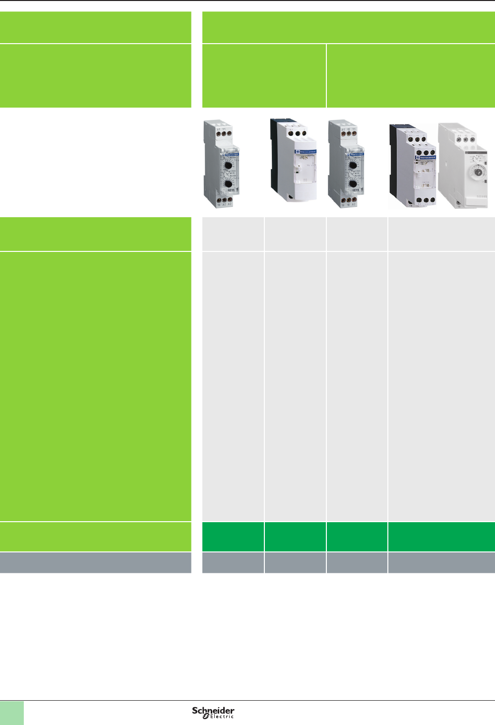
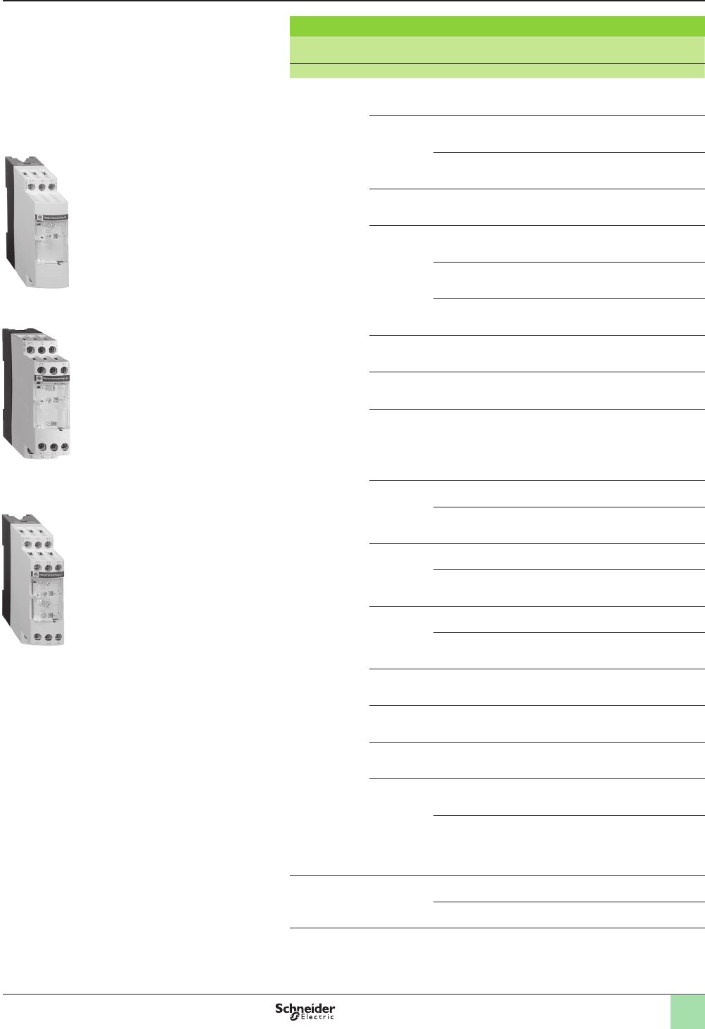
Applications Zelio timing relays enable simple automation cycles to be set up using wired logic.
They can also be used to complement the functions of PLCs.
Zelio timing relays enable simple automation cycles to be set up using wired logic.
They can also be used to complement the functions of PLCs.
Output Solid state
Timing relays with solid state output
reduce the amount of wiring
required (wired in series). The
durability of these timing relays is
independent of the number of
operating cycles.
Relay
Relay outputs provide isolation between the
supply circuit and the output.
It is possible to have several output circuits.
Relay
Relay outputs provide isolation between the supply circuit and the output.
It is possible to have several output circuits.
Type Modular Industrial Modular Industrial Optimum Plug-in Panel mounted
Universal Miniature Analog
Time ranges v 7 ranges:
1 s,
10 s,
1 min,
10 min,
1 h,
10 h,
100 h
v 1 or 2 ranges
depending on
model:
10 s,
30 s,
300 s,
60 min
Depending on
model:
v 6 ranges
1 s,
10 s,
1 min,
10 min,
1 h,
10 h
v 7 ranges:
1 s,
10 s,
1 min,
10 min,
1 h,
10 h,
100 h
Depending on model:
v 4 ranges:
0.6 s,
2.5 s,
20 s,
160 s
v 7 ranges:
1 s,
10 s,
1 min,
10 min,
1 h,
10 h,
100 h
v 7 ranges:
1 s,
3 s,
10 s,
30 s,
100 s,
300 s,
10 min
v 10 ranges:
1 s,
3 s,
10 s,
30 s,
100 s,
300 s,
30 min,
300 min,
30 h,
300 h
v 1 range depending on model:
0.5 s,
3 s,
10 s,
30 s,
300 s,
30 min
v 7 ranges:
1 s,
10 s,
1 min,
10 min,
1 h,
10 h,
100 h
v 7 ranges:
0.1–1 s,
1–10 s,
0.1–1 min,
1–10 min,
0.1–1 h,
1–10 h,
10–100 h
14 ranges:
1.2 s,
3 s,
12 s,
30 s,
120 s,
300 s,
12 min,
30 min,
120 min,
300 min,
12 h,
30 h,
120 h,
300 h
Relay type RE11Lppp RE9 RE11Rppp RE88865ppp
RE7
RE8 RE88867ppp REXLpTMpp RE48Appp
See pages 16, 26 17, 28 16, 26 18 ,19, 32, 28 20, 28 21 , 22, 34 23, 33 24, 35
Zelio® Timing Relays
Selection guide
Courtesy of Steven Engineering, Inc.-230 Ryan Way, South San Francisco, CA 94080-6370-Main Office: (650) 588-9200-Outside Local Area: (800) 258-9200-www.stevenengineering.com
5
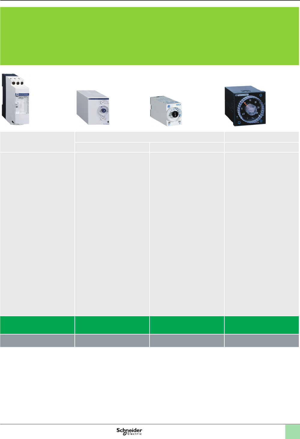
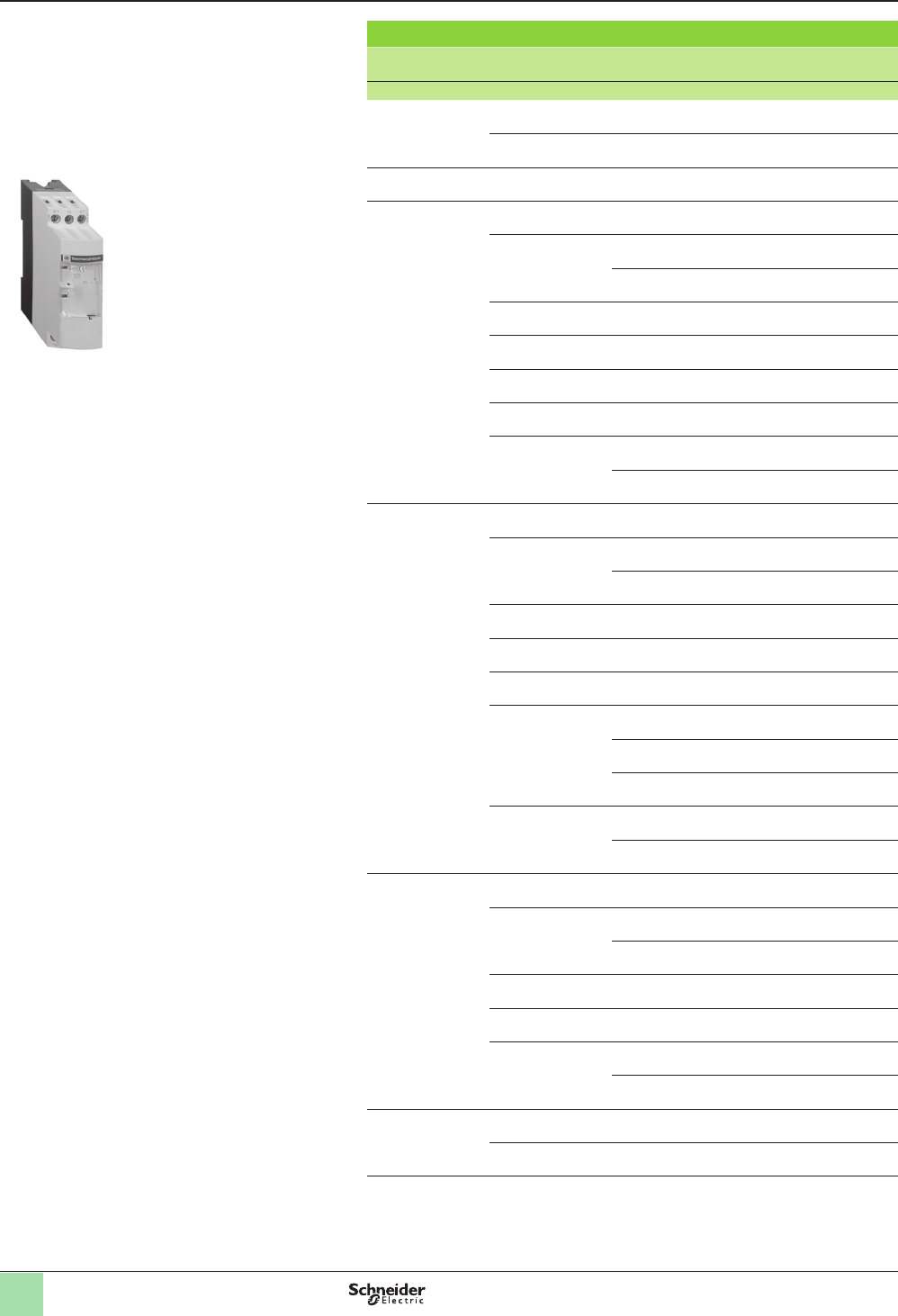
Applications Zelio timing relays enable simple automation cycles to be set up using wired logic.
They can also be used to complement the functions of PLCs.
Zelio timing relays enable simple automation cycles to be set up using wired logic.
They can also be used to complement the functions of PLCs.
Output Solid state
Timing relays with solid state output
reduce the amount of wiring
required (wired in series). The
durability of these timing relays is
independent of the number of
operating cycles.
Relay
Relay outputs provide isolation between the
supply circuit and the output.
It is possible to have several output circuits.
Relay
Relay outputs provide isolation between the supply circuit and the output.
It is possible to have several output circuits.
Type Modular Industrial Modular Industrial Optimum Plug-in Panel mounted
Universal Miniature Analog
Time ranges v 7 ranges:
1 s,
10 s,
1 min,
10 min,
1 h,
10 h,
100 h
v 1 or 2 ranges
depending on
model:
10 s,
30 s,
300 s,
60 min
Depending on
model:
v 6 ranges
1 s,
10 s,
1 min,
10 min,
1 h,
10 h
v 7 ranges:
1 s,
10 s,
1 min,
10 min,
1 h,
10 h,
100 h
Depending on model:
v 4 ranges:
0.6 s,
2.5 s,
20 s,
160 s
v 7 ranges:
1 s,
10 s,
1 min,
10 min,
1 h,
10 h,
100 h
v 7 ranges:
1 s,
3 s,
10 s,
30 s,
100 s,
300 s,
10 min
v 10 ranges:
1 s,
3 s,
10 s,
30 s,
100 s,
300 s,
30 min,
300 min,
30 h,
300 h
v 1 range depending on model:
0.5 s,
3 s,
10 s,
30 s,
300 s,
30 min
v 7 ranges:
1 s,
10 s,
1 min,
10 min,
1 h,
10 h,
100 h
v 7 ranges:
0.1–1 s,
1–10 s,
0.1–1 min,
1–10 min,
0.1–1 h,
1–10 h,
10–100 h
14 ranges:
1.2 s,
3 s,
12 s,
30 s,
120 s,
300 s,
12 min,
30 min,
120 min,
300 min,
12 h,
30 h,
120 h,
300 h
Relay type RE11Lppp RE9 RE11Rppp RE88865ppp
RE7
RE8 RE88867ppp REXLpTMpp RE48Appp
See pages 16, 26 17, 28 16, 26 18 ,19, 32, 28 20, 28 21 , 22, 34 23, 33 24, 35
Courtesy of Steven Engineering, Inc.-230 Ryan Way, South San Francisco, CA 94080-6370-Main Office: (650) 588-9200-Outside Local Area: (800) 258-9200-www.stevenengineering.com
6
Introduction
Introduction
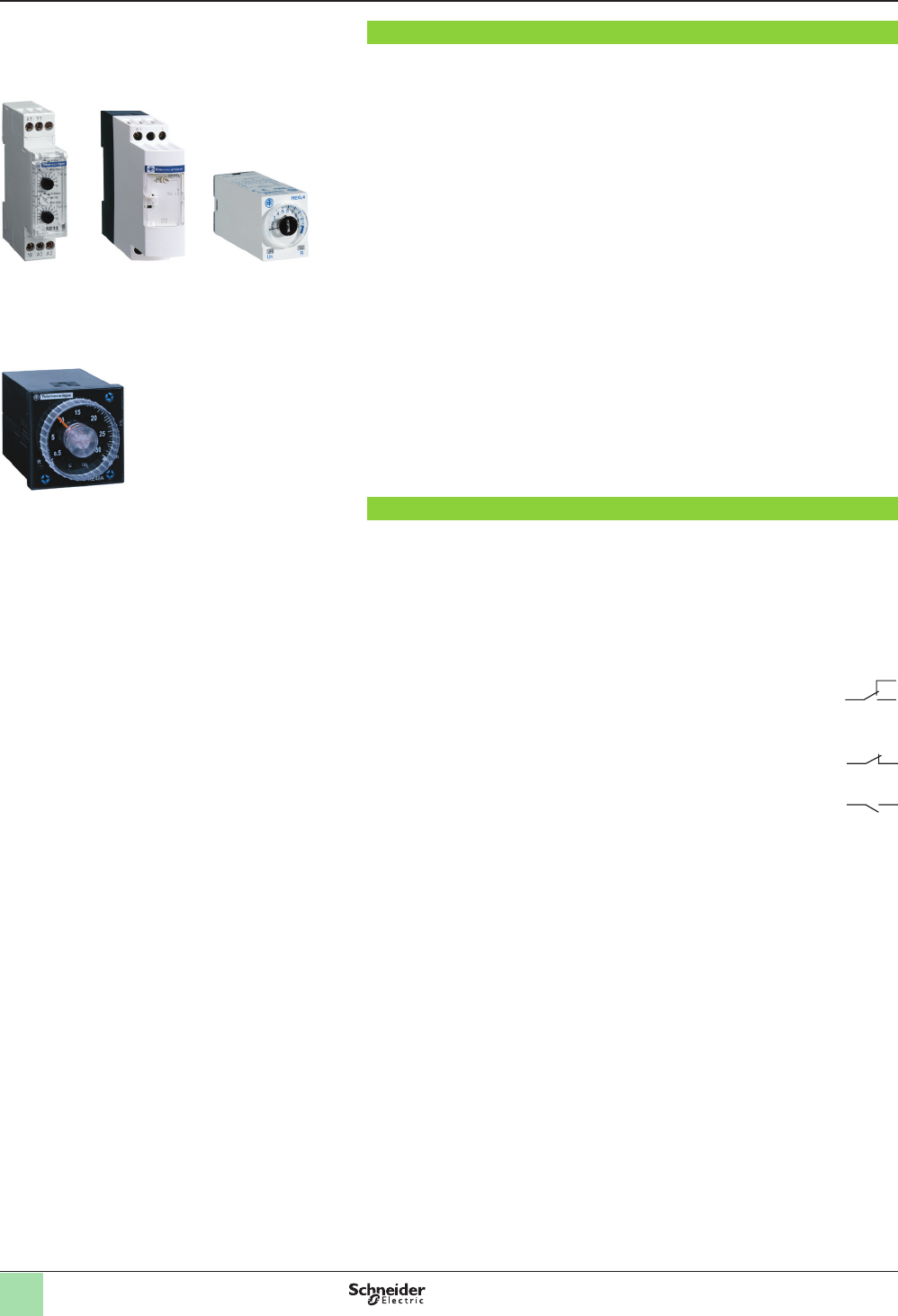
A timing relay is a component which is designed to time events in industrial
automation systems by closing or opening contacts before, during, or after a set
timing period.
There are two main families of timing relays:
bDIN rail mounted relays (RE7, RE8, RE9, RE11, REXL…) designed for mounting
on DIN rails in an enclosure,
bPanel-mounted relays type RE48A designed for mounting on the front of a panel
to give users easy access to the settings.
These relays have one, two, or four outputs. Sometimes the second output can be
timed or instantaneous.
If the power is switched off during the timing period, the relay reverts to its initial
position.
Application examples:
bopening automatic doors,
balarm,
blighting in toilets,
bcar park barriers
Denitions
bRelay output:
This is the most common type of output. When the relay is energized, the moving
armature is attracted by the coil and so actuates the contacts, which change state.
When the relay is de-energized, both the armature and the contacts revert to their
initial position.
This type of output allows isolation between the supply and the output.
There are three types of outputs:
vC/O: changeover contact. When the relay is de-energized, the circuit
between the common point C and N/C is closed. When the relay is
operating (coil energized), the circuit between the common point C and
N/O is closed.
C
N/C
N/O
vN/C: a contact that is closed without being actuated is called a
Normally Closed (N/C) contact.
N/C
vN/O: a contact that closes when actuated is called a Normally Open
(N/O) contact.
N/O
bSolid state output:
These outputs are entirely electronic and involve no moving parts; service life is
therefore increased.
bBreaking capacity:
The current value that a contact is capable of breaking in specied conditions.
bMechanical durability:
The number of mechanical operating cycles of the contact or contacts.
bMinimum switching capacity (or minimum breaking capacity):
The minimum required current which can ow through the contacts of a relay.
bG (Gate) Input:
Gate input allows timing in progress to be interrupted without resetting it.
DIN rail mounted relays
Panel mounted relays
Zelio® Timing Relays
REXLRE11 RE7, RE8, RE9
RE48A
Courtesy of Steven Engineering, Inc.-230 Ryan Way, South San Francisco, CA 94080-6370-Main Office: (650) 588-9200-Outside Local Area: (800) 258-9200-www.stevenengineering.com
7
Denitions (continued)
Denitions (continued)
Functions
Timing functions are identied by letters.
Main timing
functions
Complementary
functions (1)
Denitions
A (2) Delay on energization
Ac Timing after closing and opening of control contact
Ad Timing on closing of control contact
Ah Flashing single cycle by operation of control contact
Ak Asymmetrical On-delay and Off-delay with external
control
At Delay on energization with memory
Aw Off-delay on energization or on opening of control
contact
B (2) Timing on impulse, one shot
Bw Pulse output (width adjustable)
C (2) Timing after opening of control contact
D (2) Symmetrical ashing, start with output in rest position
Di (2) Symmetrical ashing, start with output in operating
position
H (2) Timing on energization
He Pulse-on de-energization
Ht Timing on energization with memory
KDelay on de-energization (without auxiliary supply)
L (2) Asymmetrical ashing, start with output in rest position
Li (2) Asymmetrical ashing, start with output in operating
position
Lt Asymmetrical ashing with partial stop of timing
NSafeguard
ODelayed safeguard
PDelayed xed-length pulse
Pt Impulse counter (On-delay)
Qc Star-delta timing
Qe Star-delta timing
Qg Star-delta timing
Qt Star-delta timing
TBistable relay
Tt Timed impulse relay
WOn-delay after opening of control contact
(1) Complementary functions enhance the main timing functions.
Example: Ac: timing after closing and opening of control contact.
(2) The most commonly used timing functions.
Zelio® Timing Relays
Courtesy of Steven Engineering, Inc.-230 Ryan Way, South San Francisco, CA 94080-6370-Main Office: (650) 588-9200-Outside Local Area: (800) 258-9200-www.stevenengineering.com
8
Selection
Selection table
Selection criteria
bFunctions (On-delay or Off-delay, counter, ashing)
bSupply voltage (example: a/c 12–240 V).
bTiming range for a timing relay (example: 0.05 s–100 h)
bType of output (contact or solid state) and required Number of contacts.
bBreaking capacity or Rated current of contacts, expressed in amperes.
This is the maximum current which may ow through the contacts.
Functions Timing
range
Supply
voltage
Type of
output
Rated
current
Relay
A0.1 s–100 h c 12 V 2 C/O contacts 5 A REXL2TMJD
4 C/O contacts 3 A REXL4TMJD
0.1 s–100 h c24 V 2 C/O contacts 5 A REXL2TMBD
4 C/O contacts 3 A REXL4TMBD
0.1 s–100 h a 24 V 2 C/O contacts 5 A REXL2TMB7
4 C/O contacts 3 A REXL4TMB7
0.1 s–100 h a 120 V 2 C/O contacts 5 A REXL2TMF7
4 C/O contacts 3 A REXL4TMF7
0.1 s–100 h a 230 V 2 C/O contacts 5 A REXL2TMP7
4 C/O contacts 3 A REXL4TMP7
0.1–10 s a/c24–240 V 1 solid state output 0.7 A RE9TA11MW
0.3–30 s 0.7 A RE9TA31MW
3–300 s 0.7 A RE9TA21MW
40 s–60 min 0.7 A RE9TA51MW
1 s–100 h 0.7 A RE11LAMW
0.02 s–300 h 2 timed C/O contacts 5 A RE48ATM12MW
0.05 s–300 h a/c 24 V, a 110–240 V 1 C/O contact 8 A RE7TL11BU
0.1–3 s 8 A RE8TA61BUTQ
0.1–10 s 8 A RE8TA11BUTQ
0.3–30 s 8 A RE8TA31BUTQ
3 s–300 s 8 A RE8TA21BUTQ
20–30 min 8 A RE8TA41BUTQ
0.05 s–300 h a/c 24 V, a 110–240 V,
a/c 42–48 V
2 C/O contacts 8 A RE7TP13BU
A, Ac, At, B, Bw, C, D, Di, H, Ht 1 s–100 h a 24–240 V 1 solid state output 0.7 A RE11LMBM
1 s–100 h a/c 12 V 1 C/O contact 8 A RE11RMJU
1 s–100 h a/c 12–240 V 1 C/O contact 8 A RE11RMMW
8 A RE11RMMWS
1 s–100 h c 24 V, a 24–240 V 1 C/O contact 8 A RE11RMMU
A, At 1 s–100 h c 24 V, a 24–240 V 1 C/O contact 8 A RE11RAMU
A, At, Aw 0.05 s–300 h a 110–240 V, a/c 24 V,
a/c 42–48 V
1 C/O contact 8 A RE7TM11BU
A, At, B, C, D, Di, H, Ht 1 s–10 h c24 V, a 24–240 V 1 C/O contact 5 A RE11RMEMU
A, B, C, Di 0.02 s–300 h a/c 24–240 V 2 C/O contacts 5 A RE48AML12MW
A, C, D, Di, H, Qg, Qt, W 0.05 s–300 h a 110–240 V, a/c 24 V,
a/c 42–48 V
2 C/O contacts 8 A RE7MY13BU
0.05 s–300 h a/c 24–240 V 2 C/O contacts 8 A RE7MY13MW
A, C, D, Di, H, W 0.05 s–300 h a 110–240 V, a/c 24 V,
a/c 42–48 V
1 C/O contact 8 A RE7ML11BU
A, D, Di, H 0.1–10 s and 3–300 s a/c 24–240 V
a 24–240 V
1 solid state output 0.7 A RE9MS21MW
A1, A2, H1, H2 0.02 s–300 h a/c 24–240 V 2 C/O contacts 5 A RE48AMH13MW
Ac 0.05 s–300 h a 110–240 V, a/c 24 V,
a/c 42–48 V
1 C/O contact 8 A RE7MA11BU
2 C/O contacts 8 A RE7MA13BU
Ad, Ah, N, O, P, Pt, T, Tt, W 1 s–100 h c 24 V, a 24–240 V 1 C/O contact 8 A RE11RMXMU
Ak 0.05 s–300 h a 110–240 V, a/c 24 V,
a/c 42–48 V
1 C/O contact 8 A RE7MV11BU
Zelio® Timing Relays
Courtesy of Steven Engineering, Inc.-230 Ryan Way, South San Francisco, CA 94080-6370-Main Office: (650) 588-9200-Outside Local Area: (800) 258-9200-www.stevenengineering.com
9
Selection (continued)
Selection table (continued)
Functions Timing
range
Supply
voltage
Type of
output
Rated
current
Relay
B1 s–100 h c 24 V, a 24–240 V 1 C/O contact 8 A RE11RB MU
C 0.1–10 s a/c 24 V 1 C/O contact 8 A RE8RA11BTQ
0.3–30 s 8 A RE8RA31BTQ
3–300 s 8 A RE8RA21BTQ
1 s–100 h c 24 V, a 24–240 V 1 C/O contact 8 A RE11RCMU
0.1–10 s a 110–240 V 1 C/O contact 8 A RE8RA11FUTQ
0.3–30 s 8 A RE8RA31FUTQ
3–300 s 8 A RE8RA21FUTQ
20 s–30 min 8 A RE8RA41FUTQ
0.05 s–300 h a/c 24 V, a 110–240 V,
a/c 42–48 V
1 C/O contact 8 A RE7RA11BU
8 A RE7RM11BU
2 C/O contacts 8 A RE7RL13BU
0.1–10 s a 24–240 V 1 solid state output 0.7 A RE9RA11MW7
0.3–30 s 0.7 A RE9RA31MW7
3–300 s 0.7 A RE9RA21MW7
40 s–60 min 0.7 A RE9RA51MW7
1 s–100 h 0.7 A RE11LCBM
D0.05 s–300 h a/c 24 V, a 110–240 V 1 C/O contact 8 A RE7CL11BU
0.1–10 s 8 A RE8CL11BUTQ
0.05 s–300 h a/c 24 V, a 110–240 V,
a/c 42–48 V
2 C/O contacts 8 A RE7CP13BU
H0.05 s–300 h a/c 24 V, a 110–240 V 1 C/O contact 8 A RE7PE11BU
0.1–10 s 8 A RE8PE11BUTQ
0.3–30 s 8 A RE8PE31BUTQ
3–300 s 8 A RE8PE21BUTQ
0.05 s–300 h a/c 24 V, a 110–240 V,
a/c 42–48 V
2 C/O contacts 8 A RE7PP13BU
1 s–100 h a 24–240 V 1 solid state output 0. 7 A RE11LHBM
H, Ht 1 s–100 h c 24 V, a 24–240 V 1 C/O contact 8 A RE11RHMU
He 0.05–0.5 s a/c 24 V, a 110–240 V 1 C/O contact 8 A RE8PT01BUTQ
K0.05 s–10 min a/c 24–240 V 1 C/O contact 5 A RE7RB11MW
0.05–0.5 s a/c 24 V, a 110–240 V 1 C/O contact 8 A RE8RB51BUTQ
0.1–10 s 8 A RE8RB11BUTQ
0.3–30 s 8 A RE8RB31BUTQ
0.05 s–10 min a/c 24–240 V 2 C/O contacts 5 A RE7RB13MW
L, Li 1 s–100 h c24 V, a 24–240 V 1 C/O contact 8 A RE11RLMU
1 s–100 h a 24–240 V 1 solid state output 0.7 A RE11LLBM
1 s–100 h a/c 12 V 1 C/O contact 8 A RE11RLJU
0.02 s–300 h a/c 24–240 V 2 timed C/O contacts 5 A RE48ACV12MW
L, Li, Lt 0.05 s–300 h a 110–240 V, a/c 24 V,
a/c 42–48 V
1 C/O contact 8 A RE7CV11BU
Qc 0.1–10 s a/c 24 V, a 110–240 V 1 C/O contact 8 A RE8YG11BUTQ
0.3–30 s 8 A RE8YG31BUTQ
3–300 s 8 A RE8YG21BUTQ
Qe 0.3–30 s a/c 24 V 1 N/O + 1 N/C 8 A RE8YA32BTQ
0.3–30 s a 110–240 V 1 N/O + 1 N/C 8 A RE8YA32FUTQ
0.3–30 s a 380–415 V 1 N/O + 1 N/C 8 A RE8YA32QTQ
Qg 0.05 s–300 h a/c 24 V, a 110–240 V,
a/c 42–48 V
1 N/O + 1 N/C 8 A RE7YR12BU
Qt 0.05 s–300 h a/c 24 V, a 110–240 V,
a/c 42–48 V
2 C/O contacts 8 A RE7YA12BU
W0.1–10 s a/c 24 V 1 C/O contact 8 A RE8PD11BTQ
0.3–30 s 8 A RE8PD31BTQ
3–300 s 8 A RE8PD21BTQ
0.1–10 s a 110–240 V 1 C/O contact 8 A RE8PD11FUTQ
0.3–30 s 8 A RE8PD31FUTQ
3–300 s 8 A RE8PD21FUTQ
0.05 s–300 h a/c 24 V, a 110–240 V,
a/c 42–48 V
2 C/O contacts 8 A RE7PD13BU
W, Ht 0.05 s–300 h a/c 24 V, a 110–240 V,
a/c 42–48 V
1 C/O contact 8 A RE7PM11BU
Zelio® Timing Relays
Courtesy of Steven Engineering, Inc.-230 Ryan Way, South San Francisco, CA 94080-6370-Main Office: (650) 588-9200-Outside Local Area: (800) 258-9200-www.stevenengineering.com
10
Functions
Functions
U: Supply
R: Relay or solid state output
R1/R2: 2 timed outputs
R2 inst.: The second output can be congured to be
instantaneous.
T: Timing period
C: Control contact
G: Gate
Ta: Adjustable On-delay
Tr: Adjustable Off-delay
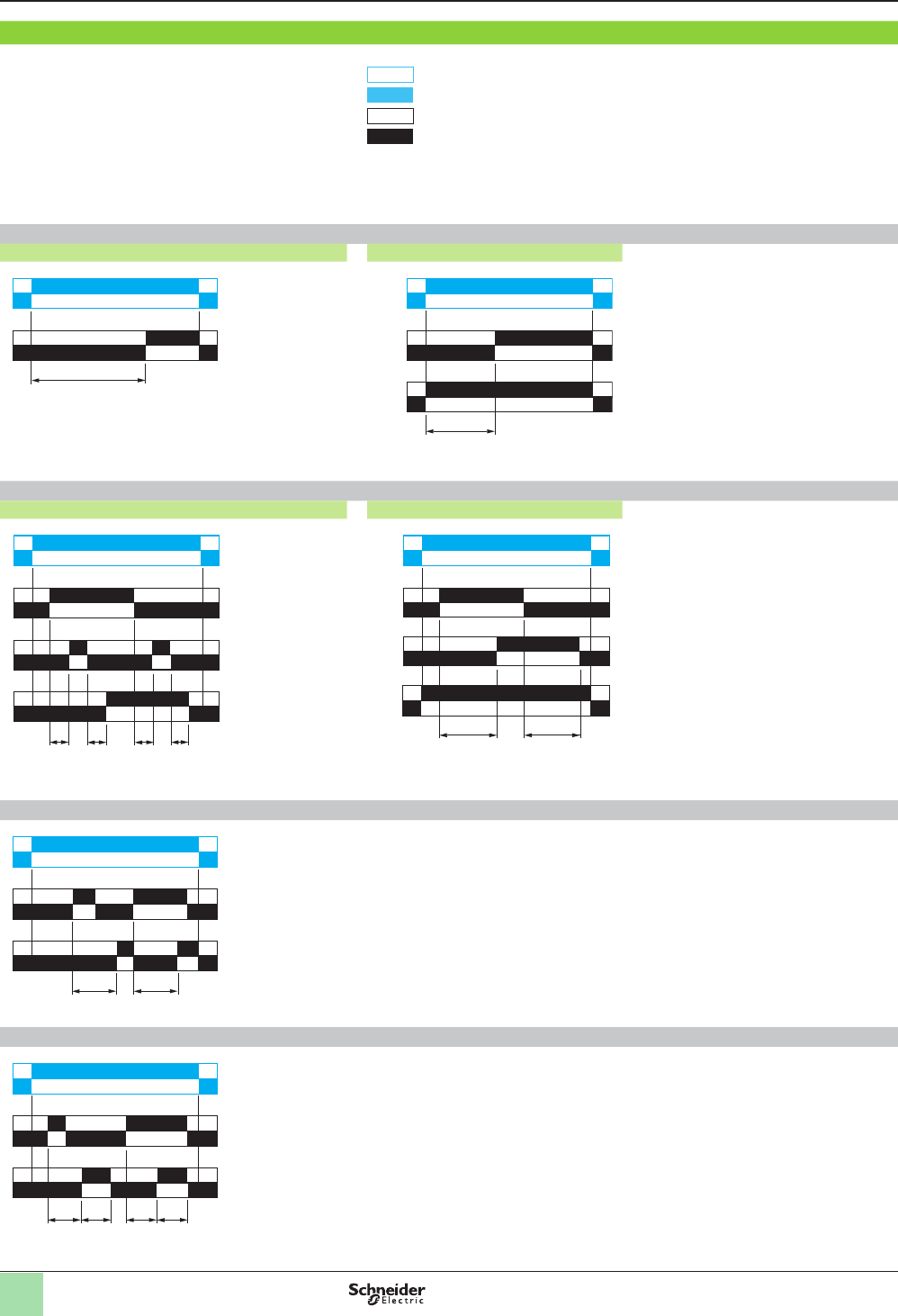
Function diagram :
Relay de-energized
Relay energized
Output open
Output closed
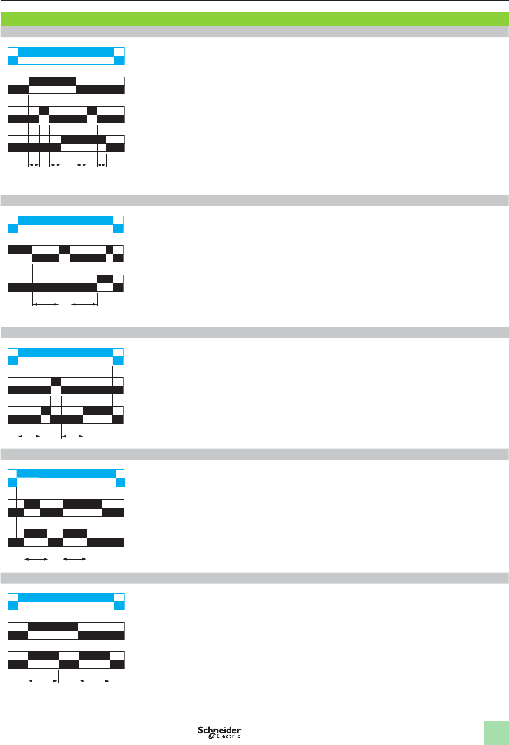
Function A: Delay on energization
1 output 2 outputs
The timing period T begins on
energization.
After timing, the outputs R close.
The second output can be either timed
or instantaneous.
2 timed outputs (R1/R2) or 1 timed output
(R1) and 1 instantaneous output (R2 inst.).
Function Ac: Timing after closing and opening of control contact
1 output 2 outputs
After power-up, closing of the control
contact C causes the timing period T to
start (timing can be interrupted by
operating the Gate control contact G).
At the end of this timing period, the relay
closes.
When control contact C re-opens, the
timing period T starts.
At the end of this timing period T, the
outputs R revert to their initial position
(timing can be interrupted by operating
the Gate control contact G).
The second output can be either timed
or instantaneous.
T = t1 + t2 + …
T = t’1 + t’2 + …
2 timed outputs (R1/R2) or 1 timed output
(R1) and 1 instantaneous output (R2 inst.).
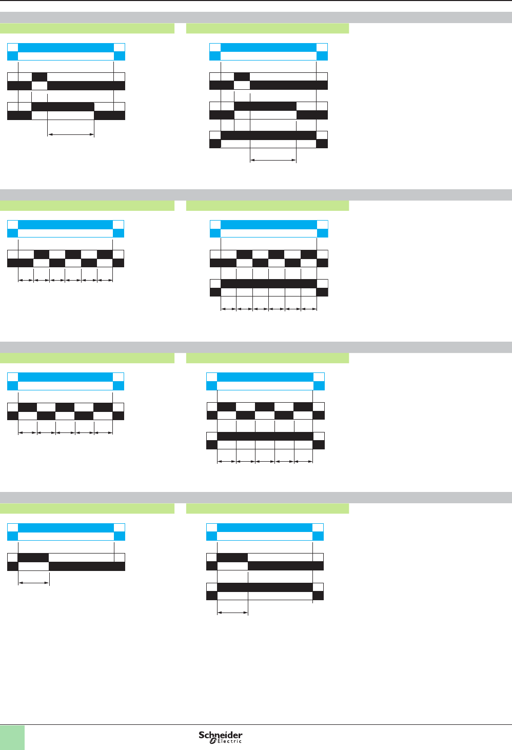
Function Ad: Timing on closing of control contact
After power-up, pulsing or maintaining control contact C starts the timing period T.
At the end of this timing period T, the output R closes.
The output R will be reset the next time control contact C is pulsed or maintained.
Function Ah: Flashing single cycle by operation of control contact
After power-up, pulsing or maintaining control contact C starts the timing period T.
A single cycle then starts with 2 timing periods T of equal duration (start with output
in rest position).
Output R changes state at the end of the rst timing period T and reverts to its initial
position at the end of the second timing period T.
Control contact C must be reset in order to re-start the single ashing cycle.
U
R
T
U
R1/R2
T
R2 inst.
U
C
t1
G
R
t'1t2 t'2
U
C
R1/R2
T T
R2 inst.
U
R
C
T T
U
R
C
TT T T
Zelio® Timing Relays
Courtesy of Steven Engineering, Inc.-230 Ryan Way, South San Francisco, CA 94080-6370-Main Office: (650) 588-9200-Outside Local Area: (800) 258-9200-www.stevenengineering.com
11
Functions (continued)
Functions (continued)
Function Ak: Asymmetrical On-delay and Off-delay with external control
After power-up and closing of the control contact C, timing starts for a period Ta
(timing can be interrupted by operating the Gate control contact G).
At the end of this timing period Ta, the output R closes.
Opening of control contact C causes a second timing period Tr to start (timing can be
interrupted by operating the Gate control contact G).
At the end of this timing period Tr, the output R reverts to its initial state.
Ta = t1 + t2 + …
Tr = t’1 + t’2 + …
Function At: Delay on energization with memory
After power-up, the rst opening of control contact C starts the timing. Timing can be
interrupted each time control contact C closes. When the cumulative total of time
periods elapsed reaches the pre-set value T, the output relay closes.
T = t1 + t2 + …
Function Aw: Off-delay on energization or on opening of control contact
The timing period T starts on energization.
At the end of the timing period T, the output R closes.
Closing control contact C opens output R.
Opening control contact C restarts the timing period T.
At the end of the timing period T, the output R closes.
Function B: Timing on impulse, one shot
After power-up, pulsing or maintaining control contact C starts the timing period T.
The output R closes for the duration of the timing period T, then reverts to its initial
state.
Function Bw: Pulse output (width adjustable)
On closing and opening of control contact C, the output R closes for the duration of
the timing period T.
U
C
t1
G
R
t'1t2 t'2
U
R
C
t1 t2
U
R
C
T T
U
R
C
TT
U
R
C
T T
Zelio® Timing Relays
Courtesy of Steven Engineering, Inc.-230 Ryan Way, South San Francisco, CA 94080-6370-Main Office: (650) 588-9200-Outside Local Area: (800) 258-9200-www.stevenengineering.com
12
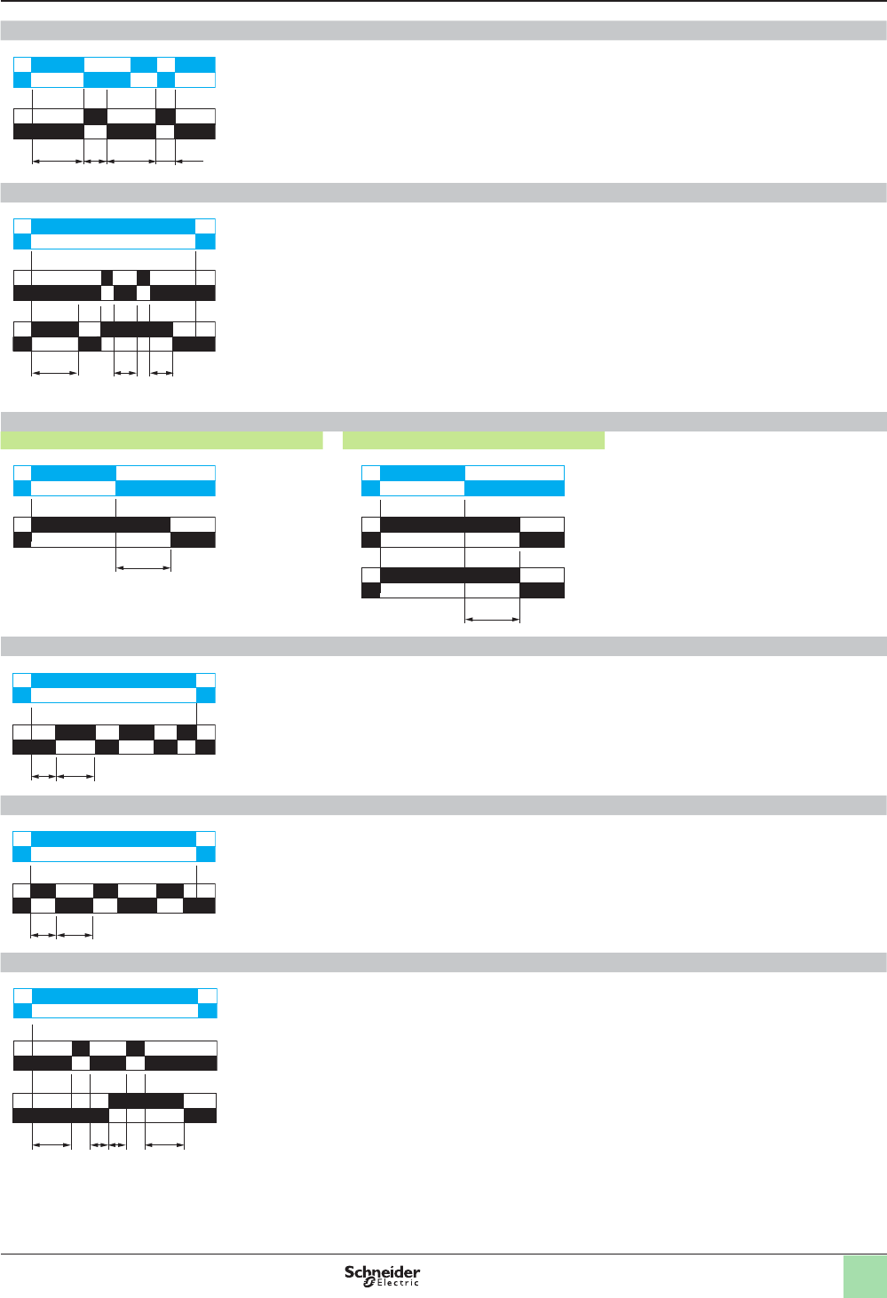
Function C: Timing after opening of control contact
1 output 2 outputs
After power-up and closing of the control
contact C, the outputs R close.
When control contact C re-opens, timing
period T starts.
At the end of the timing period, the outputs
R revert to their initial state.
The second output can be either timed or
instantaneous.
2 timed outputs (R1/R2) or 1 timed output (R1)
and 1 instantaneous output (R2 inst.).
Function D: Symmetrical ashing, start with output in rest position
1 output 2 outputs
Repetitive cycle with two timing periods T
of equal duration, with the outputs R
changing their state at the end of each
timing period T.
The second output can be either timed or
instantaneous.
2 timed outputs (R1/R2) or 1 timed output (R1)
and 1 instantaneous output (R2 inst.).
Function Di: Symmetrical ashing, start with output in operating position
1 output 2 outputs
Repetitive cycle with two timing periods T
of equal duration, with the outputs R
changing their state at the end of each
timing period T.
The second output can be either timed or
instantaneous.
2 timed outputs (R1/R2) or 1 timed output (R1)
and 1 instantaneous output (R2 inst.).
Function H: Timing on energization
1 output 2 outputs
On energization of the relay, timing period
T starts and the outputs R close.
At the end of the timing period T, outputs
R revert to their initial state.
The second output can be either timed or
instantaneous.
2 timed outputs (R1/R2) or 1 timed output (R1)
and 1 instantaneous output (R2 inst.).
U
C
R
T
U
R1/R2
C
T
R2 inst.
T T T T T T
U
R
U
R1/R2
T T T T T T
R2 inst.
T T T T T
U
R
U
R1/R2
T T T T T
R2 inst.
U
R
T
U
R1/R2
T
R2 inst.
Zelio® Timing Relays
Functions (continued)
Courtesy of Steven Engineering, Inc.-230 Ryan Way, South San Francisco, CA 94080-6370-Main Office: (650) 588-9200-Outside Local Area: (800) 258-9200-www.stevenengineering.com
13
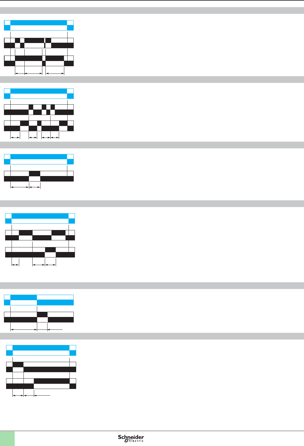
Function He: Pulse on de-energization
On de-energization, the output R closes for the duration of a timing period T.
Function Ht: Timing on energization with memory
On energization, the output R closes for the duration of a timing period T, then
reverts to its initial state.
Pulsing or maintaining control contact C will again close the output R.
Timing T is only active when control contact C is released and so the output R will
not revert to its initial state until after a time t1 + t2 + … .
The relay memorizes the total, cumulative opening time of control contact C and,
when the set time T is reached, output R reverts to its initial state.
T = t1 + t2 + …
Function K: Delay on de-energization (without auxiliary supply)
1 output 2 outputs
On energization, the outputs R close.
On de-energization, timing period T starts
and, at the end of this period, the outputs
R revert to their initial state.
Function L: Asymmetrical ashing, start with output in rest position
Repetitive cycle with two, independently adjustable timing periods Ta and Tr.
Each timing period corresponds to a different state of the output R.
Function Li: Asymmetrical ashing, start with output in operating position
Repetitive cycle with two, independently adjustable timing periods Ta and Tr.
Each timing period corresponds to a different state of the output R.
Function Lt: Asymmetrical ashing with partial stop of timing
Repetitive cycle with two, independently adjustable timing periods Ta and Tr.
Each timing period corresponds to a different state of the output R.
Gate control contact G can be operated to partially stop timing periods Ta and Tr.
Tr = t1 + t2 + …
Ta = t’1 + t’2 + …
U
R
> 80 ms 80 ms
T < T
U
R
C
t1 t2T
U
R
T
U
R1
R2
T
Tr Ta
U
R
Ta Tr
U
R
R
G
t1 t'2t2 t'1
U
Zelio® Timing Relays
Functions (continued)
Courtesy of Steven Engineering, Inc.-230 Ryan Way, South San Francisco, CA 94080-6370-Main Office: (650) 588-9200-Outside Local Area: (800) 258-9200-www.stevenengineering.com
14
Functions (continued) Zelio® Timing Relays
Function N: Safeguard
After power-up and an initial control pulse C, the output R closes.
If the interval between two control pulses C is greater than the set timing period T,
timing elapses normally and the output R opens at the end of the timing period. If the
interval is not greater than the set timing period, the output R remains closed until
this condition is met.
Function O: Delayed safeguard
An initial timing period T begins on energization. At the end of this timing period, the
output R closes.
As soon as there is a control pulse C, the output R reverts to its initial state and
remains in that state until the interval between two control pulses is less than the
value of the set timing period T. Otherwise, the output R closes at the end of the
timing period T.
Function P: Delayed xed-length pulse
The timing period T starts on energization.
At the end of this period, the output R closes for a xed time P.
Function Pt: Impulse counter (On-delay)
On energization, timing period T starts (it can be interrupted by operating the Gate
control contact G).
At the end of this period, the output R closes for a xed time P.
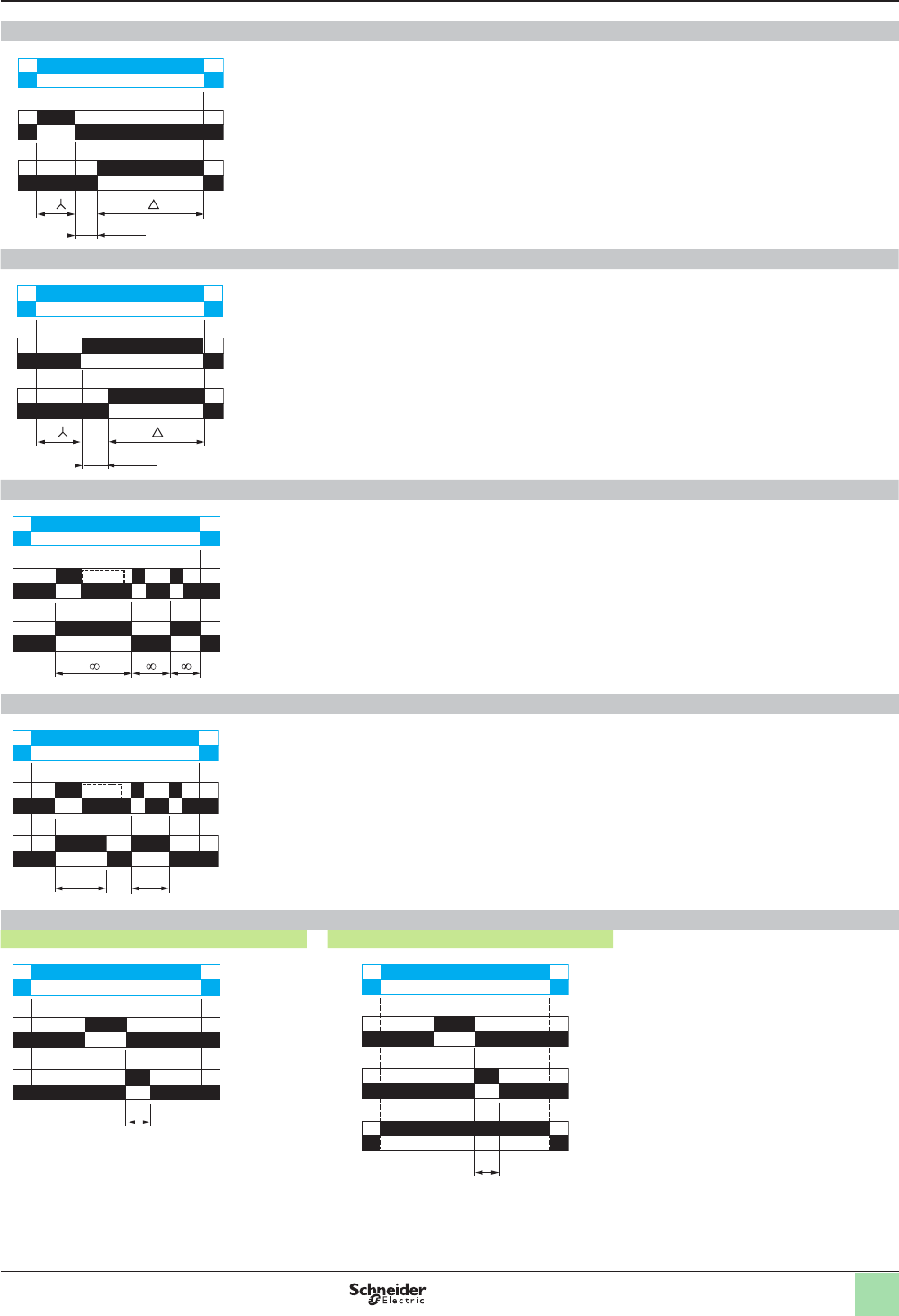
Function Qc: Star-delta timing
Timing for star delta starter with contact for switching to star connection.
Function Qe: Star-delta timing
On energization, the star contact closes instantly and timing starts.
At the end of the timing period, the star contact opens.
After an 80 ms pause, the delta contact closes and remains in this position.
T
U
C
R
T
T T T
U
C
R
t<T
U
R
TP
P = 500 ms
t1 t2 P
U
G
R
T = t1 + t2 + …
P = 500 ms
T 50 ms
U
R
T80 ms
U
R1
R2
Courtesy of Steven Engineering, Inc.-230 Ryan Way, South San Francisco, CA 94080-6370-Main Office: (650) 588-9200-Outside Local Area: (800) 258-9200-www.stevenengineering.com
15
Functions (continued) Zelio® Timing Relays
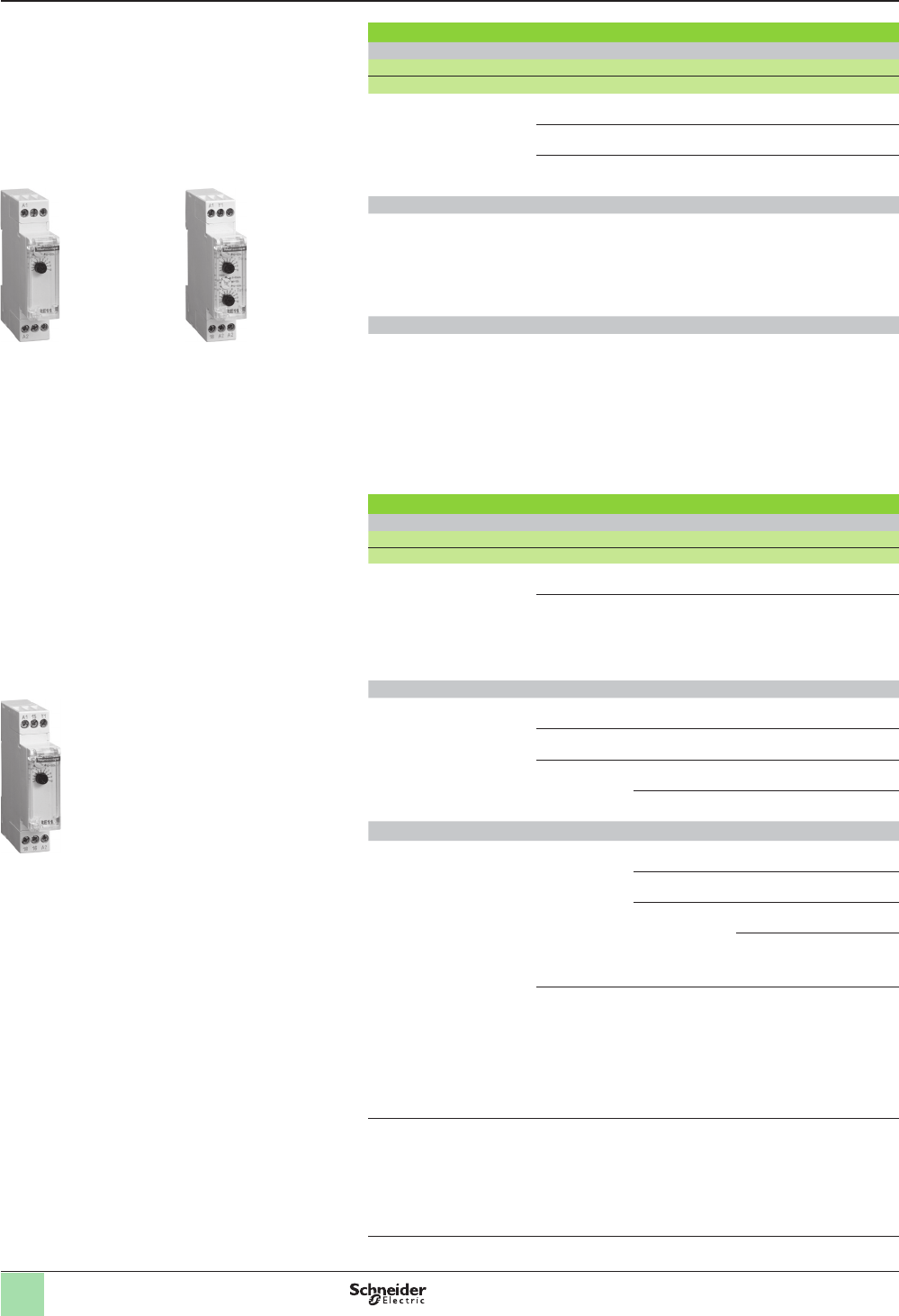
Function Qg: Star-delta timing
Timing for star delta starter with contact for switching to star connection.
Function Qt: Star-delta timing
Timing for star-delta starter with double On-delay period.
Function T: Bistable relay
After power-up, pulsing or maintaining of control contact C turns on the output R.
A second pulse on the control contact C turns off the output R.
Function Tt: Timed impulse relay
After power-up, pulsing or maintaining control contact C turns on output R and starts
the timing.
The output turns off at the end of the timing period T or following a second pulse on
the control contact C.
Function W: On-delay after opening of control contact
1 output 2 outputs
After power-up and opening of the control
contact, the outputs R close for a timing
period T.
At the end of this timing period, the
outputs revert to their initial state.
The second output can be either timed or
instantaneous.
2 timed outputs (R1/R2) or 1 timed output (R1)
and 1 instantaneous output (R2 inst.).
T T
50 ms
U
R1
R2
U
R1
R2
T T
50 ms
U
C
R
U
C
R
T t<T
T
U
C
R
U
C
R1/R2
T
R2 inst.
Courtesy of Steven Engineering, Inc.-230 Ryan Way, South San Francisco, CA 94080-6370-Main Office: (650) 588-9200-Outside Local Area: (800) 258-9200-www.stevenengineering.com
16
Catalog numbers Zelio® Timing Relays
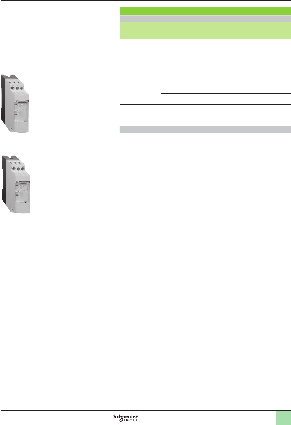
Modular relays with solid state or relay output,
width 17.5 mm (0.7 in.)
Modular relays with solid state output 0.7 A
Single function
Timing ranges Functions Voltages Catalog number Weight
V kg (lb)
1 s,
10 s,
1 min,
10 min,
1 h,
10 h,
100 h
Az24–240 RE11LAMW 0.060
(0.13)
Ha 24–240 RE11LHBM 0.060
(0.13)
Ca 24–240 RE11LCBM 0.060
(0.13)
Dual function
1 s,
10 s,
1 min,
10 min,
1 h,
10 h,
100 h
L,
Li
a 24–240 RE11LLBM 0.060
(0.13)
Multifunction
1 s,
10 s,
1 min,
10 min,
1 h,
10 h,
100 h
A,
At,
B,
C,
H,
Ht,
D,
Di,
Ac,
Bw
a 24–240 RE11LMBM 0.060
(0.13)
Modular relays with relay output, 1 C/O contact
Single function
Timing ranges Functions Voltages Catalog number Weight
V kg (lb)
1 s,
10 s,
1 min,
10 min,
1 h,
10 h,
100 h
Bz24–240 RE11RBMU 0.060
(0.13)
Cz24–240 RE11RCMU 0.060
(0.13)
Dual function
1 s,
10 s,
1 min,
10 min,
1 h,
10 h,
100 h
A,
At
z 24–240 RE11RAMU 0.060
(0.13)
H,
Ht
z24–240 RE11RHMU 0.060
(0.13)
L,
Li
z24–240 RE11RLMU 0.060
(0.13)
z 12 RE11RLJU 0.060
(0.13)
Multifunction
1 s,
10 s,
1 min,
10 min,
1 h,
10 h,
100 h
A,
At,
B,
C,
H,
Ht,
D,
Di,
Ac,
Bw
z 12 RE11RMJU 0.060
(0.13)
z24–240 RE11RMMU 0.060
(0.13)
z 12–240 RE11RMMW 0.060
(0.13)
RE11RMMWS 0.060
(0.13)
Ad,
Ah,
N,
O,
P,
Pt,
T,
Tt,
W
z 24–240 RE11RMXMU 0.060
(0.13)
1 s,
10 s,
1 min
10 min,
1 h,
10 h
A,
At,
B,
C,
H,
Ht,
D,
Di
z 24–240 RE11RMEMU 0.060
(0.13)
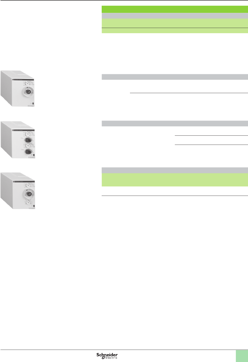
RE11LAMW RE11LLBM
RE11RpMp
Solid state output
vMultifunction, dual function, or single function
vMulti-range (7 selectable ranges)
vMultivoltage
vSolid state output: 0.7 A
vScrew terminals
Relay output, 1 C/O contact
vDual function or single function
vMulti-range (7 selectable ranges)
vMultivoltage
v1 relay output: 8 A
vScrew terminals
vState indication by 1 LED
vOption of supplying a load in parallel
v3-wire sensor control option
NOTE: Detailed function descriptions begin on page 10.
Dimensions and wiring diagrams begin on page 26.
Courtesy of Steven Engineering, Inc.-230 Ryan Way, South San Francisco, CA 94080-6370-Main Office: (650) 588-9200-Outside Local Area: (800) 258-9200-www.stevenengineering.com
17
Catalog numbers
Single function
Timing
ranges
Functions Voltages Catalog number Weight
V kg (lb)
0.1–10 s A z 24–240 V RE9TA11MW 0.110
(0.24)
Cz 24–240 V RE9RA11MW7 0.110
(0.24)
0.3–30 s Az 24–240 V RE9TA31MW 0.110
(0.24)
Cz 24–240 V RE9RA31MW7 0.110
(0.24)
3–300 s A z 24–240 V RE9TA21MW 0.110
(0.24)
Cz 24–240 V RE9RA21MW7 0.110
(0.24)
40 s–60 min Az 24–240 V RE9TA51MW 0.110
(0.24)
Cz 24–240 V RE9RA51MW7 0.110
(0.24)
Multifunction
0.1–10 s,
0.3–30 s
Az 24–240 V RE9MS21MW 0.110
(0.24)
H,
D,
Di
a 24–240 V
Zelio® Timing Relays
Industrial single or multifunction relays,
solid state output, width 22.5 mm (0.9 in.)
Catalog numbers (continued)
RE9pAp1MW
RE9MS21MW
Solid state output
vMultifunction or single function
vMultivoltage
vScrew terminals
vTransparent, hinged, and sealable ap on front panel
NOTE: Detailed function descriptions begin on page 10.
Dimensions and wiring diagrams begin on page 26.
Courtesy of Steven Engineering, Inc.-230 Ryan Way, South San Francisco, CA 94080-6370-Main Office: (650) 588-9200-Outside Local Area: (800) 258-9200-www.stevenengineering.com
18
Catalog numbers
Single function
Timing
ranges
Functions No. of relay
outputs
Voltages Catalog number Weight
V kg (lb)
1 s,
10 s,
1 min,
10 min,
1 h,
10 h,
100 h
B1z24–240 RE88865125
(1)
0.090
(0.20)
C1z24–240 RE88865135
(1)
0.090
(0.20)
0.6 s,
2.5 s,
20 s,
160 s
K2z24–240 RE88865265
(1)
0.090
(0.20)
Selectable
interswitching
time
Functions No. of relay
outputs
Voltages Catalog number Weight
kg (lb)
20 ms,
40 ms,
60 ms,
80 ms,
100 ms,
120 ms,
140 ms
Q1z24–240 RE88865175
(1)
0.090
(0.20)
a230 / 380 RE88865176
(1)
0.090
(0.20)
Dual function
Timing
ranges
Functions No. of relay
outputs
Voltages Catalog number Weight
kg (lb)
1 s,
10 s,
1 min,
10 min,
1 h,
10 h,
100 h
A,
At
2z24–240 RE88865215
(1)
0.090
(0.20)
1z24–240 RE88865115
(1)
0.090
(0.20)
H,
Ht
1z24–240 RE88865145
(1)
0.090
(0.20)
L,
Li
1z24–240 RE88865155
(1)
0.090
(0.20)
Multifunction
1 s,
10 s,
1 min,
10 min,
1 h,
10 h,
100 h
A,
At,
B,
C,
H,
Ht,
Di,
D,
Ac,
Bw
1z24–240 RE88865105
(1)
0.090
(0.20)
1z12 RE88865100
(1)
0.090
(0.20)
1z12–240 RE88865103
(1)
0.090
(0.20)
RE88865503
(2)
0.090
(0.20)
2, of which 1 is
convertible to
instantaneous
z24–240 RE88865305
(1)
0.090
(0.20)
z12 RE88865300
(1)
0.090
(0.20)
z12–240 RE88865303
(1)
0.090
(0.20)
Ad,
Ah,
N,
O
P,
Pt,
Tl,
Tt,
W
1z24–240 RE88865185
(1)
0.090
(0.20)
2z24–240 RE88865385
(1)
0.090
(0.20)
(1) Connection by screw terminals.
(2) Connection by spring terminals.
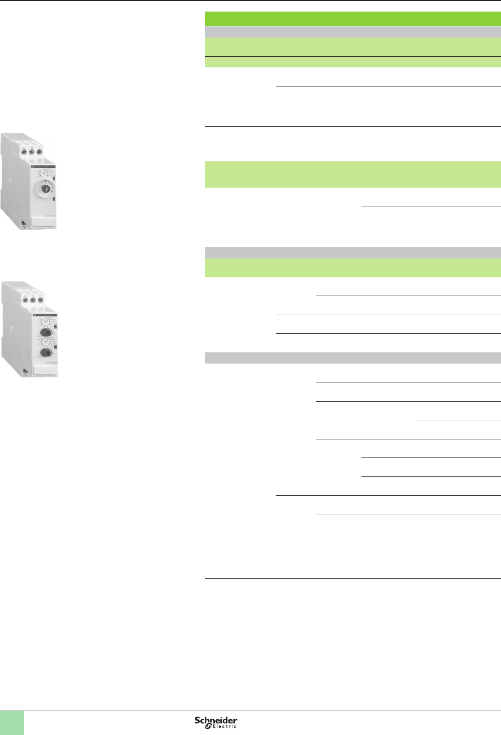
RE88865125
Zelio® Timing Relays
Industrial single, dual, or multifunction relays,
relay output, width 22.5 mm (0.9 in.)
Catalog numbers (continued)
Output 1 C/O and 2 C/O contacts
vMultifunction, dual function, or single function
vMultiple timing ranges (7 switchable ranges)
vMultivoltage
v1 and 2 relay outputs: 8 A - 250 V (10 A UL)
vScrew or spring terminals
vState indication by 1 LED
vOption of supplying a load in parallel
v3-wire sensor control option
RE88865155
NOTE: Detailed function descriptions begin on page 10.
Dimensions and wiring diagrams begin on page 26.
Courtesy of Steven Engineering, Inc.-230 Ryan Way, South San Francisco, CA 94080-6370-Main Office: (650) 588-9200-Outside Local Area: (800) 258-9200-www.stevenengineering.com
19
Catalog numbers
Timing
ranges
Functions No. of relay
outputs
Voltages Catalog number Weight
V kg (lb)
0.05 s–300 h
(10 ranges)
A,
Aw,
At
1z 24,
a 110–240,
z 42–48
RE7TM11BU 0.150
(0.33)
Ac 1z 24,
a 110–240,
z 42–48
RE7MA11BU 0.150
(0.33)
2z 24,
a 110–240,
z 42–48
RE7MA13BU
(symmetrical)
0.150
(0.33)
Ak 1z 24,
a 110–240,
z 42–48
RE7MV11BU 0.150
(0.33)
C1z 24,
a 110–240,
z 42–48
RE7RA11BU 0.150
(0.33)
1z 24,
a 110–240,
z 42–48
RE7RM11BU
(low level contact)
0.150
(0.33)
2z 24,
a 110–240,
z 42–48
RE7RL13BU
(low level contact)
0.150
(0.33)
Ht,
W
1z 24,
a 110–240,
z 42–48
RE7PM11BU 0.150
(0.33)
L,
Li,
Lt
1z 24,
a 110–240,
z 42–48
RE7CV11BU 0.150
(0.33)
A,
C,
H,
W,
D,
Di
1z 24,
a 110–240,
z 42–48
RE7ML11BU 0.150
(0.33)
A1z 24,
a 110…240
RE7TL11BU 0.150
(0.33)
2z 24,
a 110–240,
z 42–48
RE7TP13BU 0.150
(0.33)
H1z 24,
a 110–240
RE7PE11BU 0.150
(0.33)
2z 24,
a 110–240,
z 42–48
RE7PP13BU 0.150
(0.33)
D1z 24,
a 110–240
RE7CL11BU 0.150
(0.33)
2z 24,
a 110–240,
z 42–48
RE7CP13BU 0.150
(0.33)
W2z 24,
a 110–240,
z 42–48
RE7PD13BU 0.150
(0.33)
Qt 2z 24,
a 110–240,
z 42–48
RE7YA12BU 0.150
(0.33)
Qg 2z 24,
a 110–240,
z 42–48
RE7YR12BU 0.150
(0.33)
A,
C,
H,
W,
D,
Di,
Qg,
Qt
2z 24,
a 110–240,
z 42–48
RE7MY13BU 0.150
(0.33)
2z 24–240 RE7MY13MW 0.150
(0.33)
0.05 s–10 min
(7 ranges)
K1 z 24–240 RE7RB11MW 0.150
(0.33)
2 z 24–240 RE7RB13MW 0.150
(0.33)
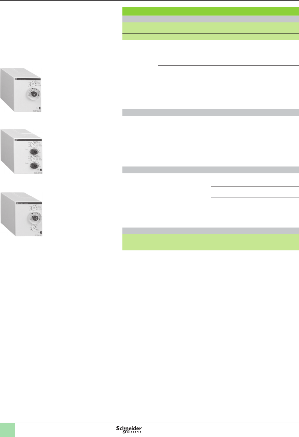
RE7TM11BU
RE7MA11BU
RE7CV11BU
Zelio® Timing Relays
Industrial single, dual, or multifunction relays,
relay output, width 22.5 mm (0.9 in.)
Catalog numbers (continued)
Output 1 C/O and 2 C/O contacts
vMultifunction, dual function, or single function
vMultiple timing ranges
vMultivoltage
vTransparent, hinged, and sealable ap on front panel
NOTE: Detailed function descriptions begin on page 10.
Dimensions and wiring diagrams begin on page 26.
Courtesy of Steven Engineering, Inc.-230 Ryan Way, South San Francisco, CA 94080-6370-Main Office: (650) 588-9200-Outside Local Area: (800) 258-9200-www.stevenengineering.com
20
Catalog numbers
Timing
ranges
Functions Voltages Catalog number Weight
V(1) kg (lb)
0.05–0.5 s Kz24,
a 110–240
RE8RB51BUTQ 0.110
(0.24)
He z24,
a 110–240
RE8PT01BUTQ 0.110
(0.24)
0.1–3 s Az24,
a 110–240
RE8TA61BUTQ 0.110
(0.24)
0.1–10 s Az24,
a 110–240
RE8TA11BUTQ 0.110
(0.24)
Cz 24 RE8RA11BTQ 0.110
(0.24)
a 110–240 RE8RA11FUTQ 0.110
(0.24)
Dz24,
a 110–240
RE8CL11BUTQ 0.110
(0.24)
Kz24,
a 110–240
RE8RB11BUTQ 0.110
(0.24)
Hz24,
a 110–240
RE8PE11BUTQ 0.110
(0.24)
Qc z24,
a 110–240
RE8YG11BUTQ 0.110
(0.24)
Wz 24 RE8PD11BTQ 0.110
(0.24)
a 110–240 RE8PD11FUTQ 0.110
(0.24)
0.3–30 s Az24,
a 110–240
RE8TA31BUTQ 0.110
(0.24)
Cz 24 RE8RA31BTQ 0.110
(0.24)
a 110–240 RE8RA31FUTQ 0.110
(0.24)
Hz24,
a 110–240
RE8PE31BUTQ 0.110
(0.24)
Kz24,
a 110–240
RE8RB31BUTQ 0.110
(0.24)
Qc z24,
a 110–240
RE8YG31BUTQ 0.110
(0.24)
Qe z 24 RE8YA32BTQ 0.110
(0.24)
a 110–240 RE8YA32FUTQ 0.110
(0.24)
a 380–415 RE8YA32QTQ 0.110
(0.24)
Wz 24 RE8PD31BTQ 0.110
(0.24)
a 110–240 RE8PD31FUTQ 0.110
(0.24)
3–300 s Az24,
a 110–240
RE8TA21BUTQ 0.110
(0.24)
Cz 24 RE8RA21BTQ 0.110
(0.24)
a 110–240 RE8RA21FUTQ 0.110
(0.24)
Hz24,
a 110–240
RE8PE21BUTQ 0.110
(0.24)
Qc z24,
a 110–240
RE8YG21BUTQ 0.110
(0.24)
Wz 24 RE8PD21BTQ 0.110
(0.24)
a 110–240 RE8PD21FUTQ 0.110
(0.24)
20 s–30 min Az24,
a 110–240
RE8TA41BUTQ 0.110
(0.24)
C a 110–240 RE8RA41FUTQ 0.110
(0.24)
(1) These products are sold in packs of 10
Zelio® Timing Relays
Industrial single function relays, optimum,
relay output, width 22.5 mm (0.9 in.)
Catalog numbers (continued)
vSingle function
vSingle timing range
vOutput 1 C/O contact
vTransparent, hinged, and sealable ap on front panel
RE8TApppppp
NOTE: Detailed function descriptions begin on page 10.
Dimensions and wiring diagrams begin on page 26.
Courtesy of Steven Engineering, Inc.-230 Ryan Way, South San Francisco, CA 94080-6370-Main Office: (650) 588-9200-Outside Local Area: (800) 258-9200-www.stevenengineering.com
21
RE88867305
RE88867415
Catalog numbers
Single function
Timing
ranges
Functions No. of relay
outputs
Voltages Catalog number Weight
V kg (lb)
1 s,
10 s,
1 min,
10 min,
1 h,
10 h,
100 h
C2z24–240 RE88867435 0.080
(0.18)
Dual function
1 s,
10 s,
1 min,
10 min,
1 h,
10 h,
100 h
A,
At
2z24–240 RE88867415 0.080
(0.18)
Li,
L
2z24–240 RE88867455 0.080
(0.18)
Multifunction
1 s,
10 s,
1 min,
10 min,
1 h,
10 h,
100 h
A,
At,
B,
C,
H,
Ht,
Di,
D,
Ac,
Bw
2,
of which 1 is
instantaneous
z24–240 RE88867305 0.080
(0.18)
z12 RE88867300 0.080
(0.18)
z12–240 RE88867303 0.080
(0.18)
Sockets (1) for 11-pin relays
Contact
terminal
arrangement
For use with relays Connection Catalog number Weight
kg (lb)
Mixed (2) RE88867ppp Connector RXZE2M114 0.054
(0.12)
(1) These products are sold in packs of 10
(2) The inputs are mixed with the relay's supply. The outputs are located on the opposite side of the
socket.
RE88867300
Zelio® Timing Relays
Universal plug-in relays, 11-pin,
relay output, width 35 mm (1.4 in.)
Catalog numbers (continued)
Output 2 C/O contacts
vMultifunction, dual function, or single function
vMultiple timing ranges (7 switchable ranges)
vMultivoltage
v2 relay output: 8 A - 250 V (10 A UL)
vPlug-in
vState indication by 1 LED
vOption of supplying a load in parallel
v3-wire sensor control option
NOTE: Detailed function descriptions begin on page 10.
Dimensions and wiring diagrams begin on page 26.
Courtesy of Steven Engineering, Inc.-230 Ryan Way, South San Francisco, CA 94080-6370-Main Office: (650) 588-9200-Outside Local Area: (800) 258-9200-www.stevenengineering.com
22
Catalog numbers
Single function
Timing
ranges
Functions No. of relay
outputs
Voltages Catalog number Weight
V kg (lb)
1 s,
10 s ,
1 min,
10 min,
1 h,
10 h,
100 h
A
2z24–240 RE88867215 0.080
(0.18)
C1z24–240 RE88867135 0.080
(0.18)
Dual function
1 s,
10 s,
1 min,
10 min,
1 h,
10 h,
100 h
Li,
L
1z24–240 RE88867155 0.080
(0.18)
Multifunction
1 s,
10 s,
1 min,
10 min,
1 h,
10 h,
100 h
A,
At,
B,
C,
H,
Ht,
Di,
D,
Ac,
Bw
1z24–240 RE88867105 0.080
(0.18)
z12 RE88867100 0.080
(0.18)
z12–240 RE88867103 0.080
(0.18)
Sockets (1) for 8-pin relays
Contact
terminal
arrangement
For use with relays Catalog number Weight
kg (lb)
Mixed (2) RE888671pp,
RE888672pp RUZC2M 0.054
(0.12)
(1) These products are sold in packs of 10.
(2) The inputs are mixed with the relay’s supply. The outputs are located on the opposite side of the
socket.
RE88867215
561179
RE88867155
561177
RE88867105
Zelio® Timing Relays
Universal plug-in relays, 8-pin,
relay output, width 35 mm (1.4 in.)
Catalog numbers (continued)
Output 1 C/O or 2 C/O contacts
vMultifunction, dual function, or single function
vMultiple timing ranges (7 switchable ranges)
vMultivoltage
v1 or 2 relay outputs: 8 A - 250 V (10 A UL)
vPlug-in
vState indication by 1 LED
vOption of supplying a load in parallel
v3-wire sensor control option
NOTE: Detailed function descriptions begin on page 10.
Dimensions and wiring diagrams begin on page 26.
Courtesy of Steven Engineering, Inc.-230 Ryan Way, South San Francisco, CA 94080-6370-Main Office: (650) 588-9200-Outside Local Area: (800) 258-9200-www.stevenengineering.com
23
Catalog numbers
Single function
Timing
ranges
Functions No. of relay
outputs
Voltages Catalog number Weight
V kg (lb)
0.1–1 s,
1–10 s,
0.1–1 min,
1–10 min,
0.1–1 h,
1–10 h,
10–100 h
(7 switchable
ranges)
A2c 12 REXL2TMJD 0.050
(0.11)
c24 REXL2TMBD 0.050
(0.11)
a 24 (50/60 Hz) REXL2TMB7 0.050
(0.11)
a 120 (50/60 Hz) REXL2TMF7 0.050
(0.11)
a 230 (50/60 Hz) REXL2TMP7 0.050
(0.11)
4c 12 REXL4TMJD 0.050
(0.11)
c24
(1)
REXL4TMBD 0.050
(0.11)
a 24 (50/60 Hz)
(1)
REXL4TMB7 0.050
(0.11)
a 120 (50/60 Hz) REXL4TMF7 0.050
(0.11)
a 230 (50/60 Hz) REXL4TMP7 0.050
(0.11)
Sockets (2) for relays
Contact
terminal
arrangement
For use with relays Connection Catalog number Weight
kg (lb)
Mixed (3) REXL2TMpp,
REXL4TMpp Screw clamp RXZE2M114
(5)
0.048
(0.11)
REXL2TMpp,
REXL4TMpp Connector RXZE2M114M
(6)
0.056
(0.12)
Separate (4) REXL2TMpp Connector RXZES108M 0.070
(0.15)
REXL4TMpp Connector RXZE2S114M 0.058
(0.13)
(1) For c 48 V supply, additional resistor 560 W 2 W / c 24 V.
For a 48 V, additional resistor 390 W 4 W / a 24 V.
(2) These products are sold in packs of 10.
(3) The inputs are mixed with the relay’s supply. The outputs are located on the opposite side of the
socket.
(4) The inputs and outputs are separated from the relay supply.
(5) Thermal current Ith: 10 A.
(6) Thermal current Ith: 12 A.
Zelio® Timing Relays
Miniature plug-in relays, relay output
Catalog numbers (continued)
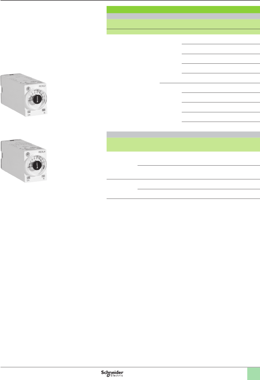
REXL4TMpp
REXL2TMpp
Output, 2 C/O and 4 C/O contacts
vMiniature and plug-in (21 x 27 mm)
vSingle function: function A = delay on energization
vRated current a 5 A
v7 timing ranges (0.1 s to 100 h)
vMultivoltage
vExcellent immunity to interference
vPower on and relay energized indication by 2 LEDs
NOTE: Detailed function descriptions begin on page 10.
Dimensions and wiring diagrams begin on page 26.
Courtesy of Steven Engineering, Inc.-230 Ryan Way, South San Francisco, CA 94080-6370-Main Office: (650) 588-9200-Outside Local Area: (800) 258-9200-www.stevenengineering.com
24
Catalog numbers
8-pin relay
Timing ranges Function No. of relay
outputs
Voltages Catalog number Weight
V kg (lb)
1.2 s,
3 s,
12 s,
30 s,
120 s,
300 s,
12 min,
30 min,
120 min,
300 min,
12 h,
30 h,
120 h,
300 h
A
1z24–240 RE48ATM12MW 0.140
(0.31)
A1,
A2,
H1,
H2
2,
of which 1 is
instantaneous
z 24–240 RE48AMH13MW 0.140
(0.31)
11-pin relay
1.2 s,
3 s,
12 s,
30 s,
120 s,
300 s,
12 min,
30 min,
120 min,
300 min,
12 h,
30 h,
120 h,
300 h
L,
Li
2z24–240 RE48ACV12MW 0.140
(0.31)
A,
B,
C,
Di
2z24–240 RE48AML12MW 0.140
(0.31)
Catalog numbers (continued) Zelio® Timing Relays
Analog, electronic relays,
relay output, 48 x 48
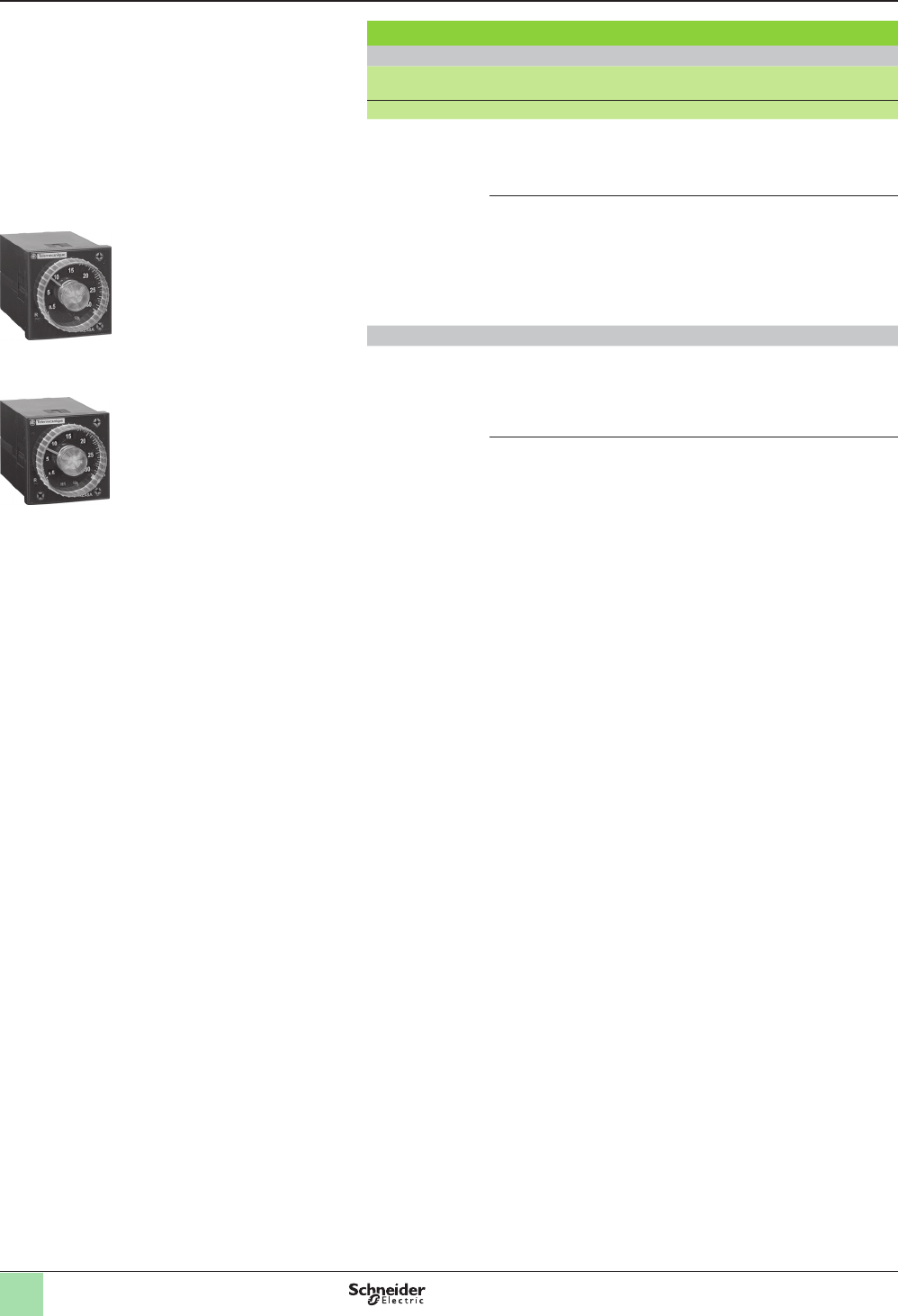
RE48ATM12MW
RE48AMH13MW
Output 2 C/O contacts
vTime unit selector knob
vMultifunction, single function, or dual function
vMultirange
vMultivoltage
v2 relay outputs, 5 A
vPanel-mounted or plug-in
vLED indication
NOTE: Detailed function descriptions begin on page 10.
Dimensions and wiring diagrams begin on page 26.
Courtesy of Steven Engineering, Inc.-230 Ryan Way, South San Francisco, CA 94080-6370-Main Office: (650) 588-9200-Outside Local Area: (800) 258-9200-www.stevenengineering.com
25
Sockets
Description Number
of pins
For use
with relays
Sold in
packs
of
Catalog number Weight
kg (lb)
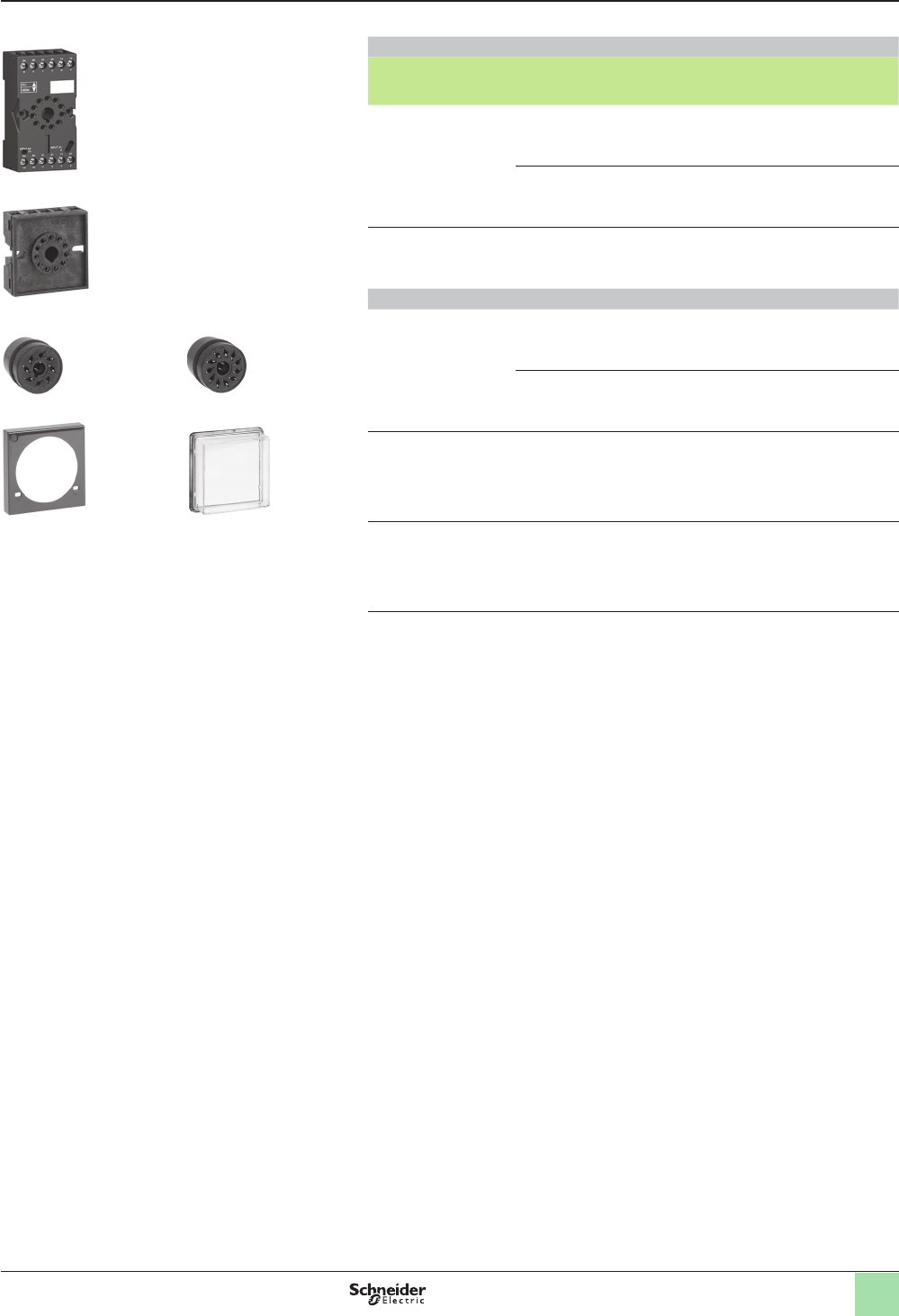
IP20 sockets with
connection by
connector and mixed
contact terminals (1)
8 RE48ATM12MW,
RE48AMH13MW
10 RUZC2M 0.054
(0.12)
11 RE48ACV12MW,
RE48AML12MW
10 RUZC3M 0.054
(0.12)
IP20 socket with screw
terminal connections
on rear face
11 RE48ACV12MW,
RE48AML12MW
1RE48ASOC11AR –
Connectors and protective cover
IP20 solder connectors 8 RE48ATM12MW,
RE48AMH13MW
1RE48A SOC8SOLD –
11 RE48ACV12MW,
RE48AML12MW
1RE48A SOC11SOLD –
Setting protection
cover
– RE48ATM12MW,
RE48ACV12MW,
RE48AML12MW,
RE48AMH13MW
1RE48ASETCOV –
Protective cover
IP64
– RE48ATM12MW,
RE48ACV12MW,
RE48AML12MW,
RE48AMH13MW
1RE48AIPCOV –
(1) The inputs are mixed with the relay’s supply. The outputs are located on the opposite side of the
socket.
RUZC3M
RE48ASOC11AR
RE48ASOC8SOLD RE48ASOC11SOLD
RE48ASETCOV RE48AIPCOV
Catalog numbers (continued) Zelio® Timing Relays
Analog, electronic relays,
relay output, 48 x 48
NOTE: Detailed function descriptions begin on page 10.
Dimensions and wiring diagrams begin on page 26.
Courtesy of Steven Engineering, Inc.-230 Ryan Way, South San Francisco, CA 94080-6370-Main Office: (650) 588-9200-Outside Local Area: (800) 258-9200-www.stevenengineering.com
26
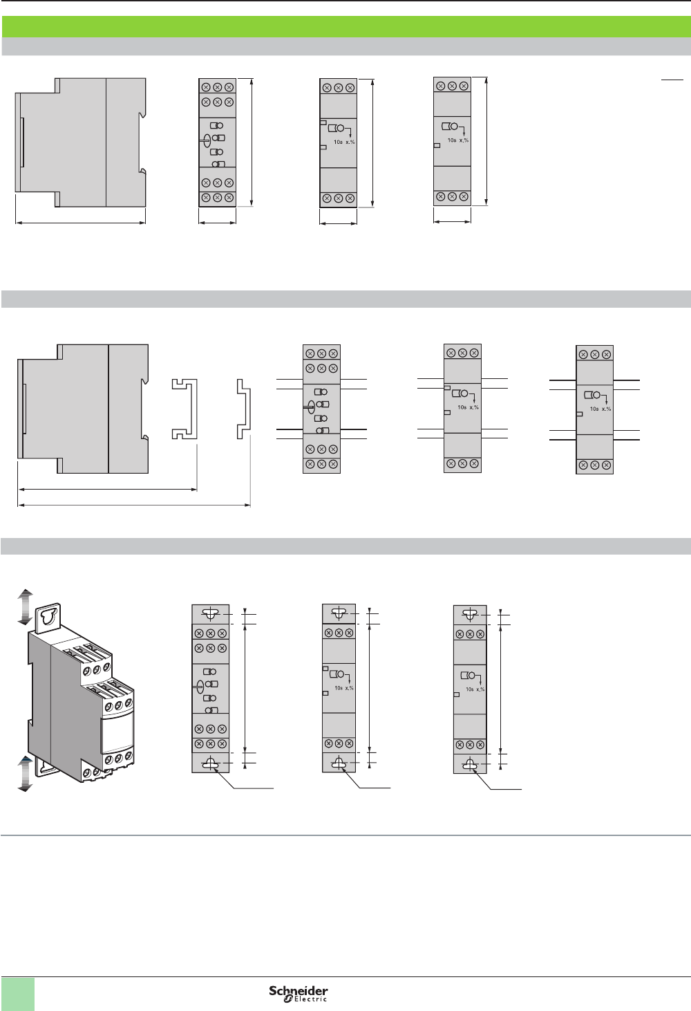
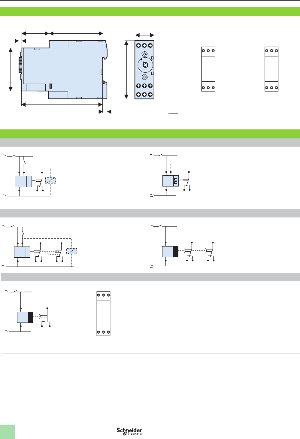
Dimensions and wiring
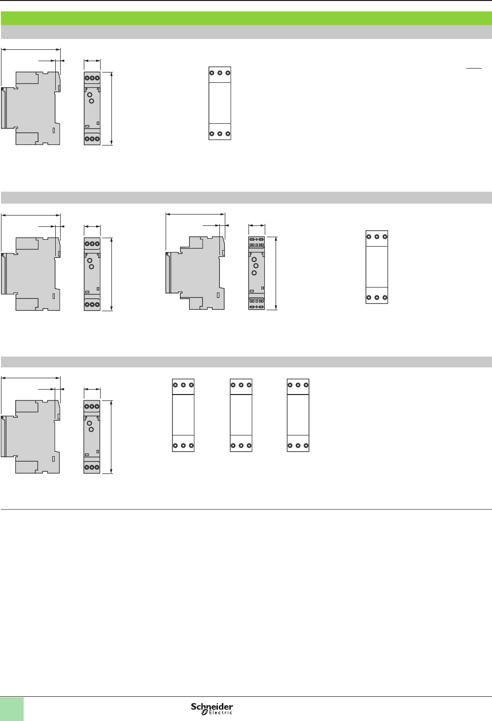
Dimensions and terminal locations for RE11 models
RE11RAMU, RE11RHMU, RE11RLMU
0.21
(5.5)
2.83
(72) 0.70
(17.9)
3.19
(81)
RE11RMMU, RE11RMMW, RE11RMJU RE11RMMWS
0.21
(5.5)
2.83
(72) 0.70
(17.9)
31.9
(81)
0.21
(5.5)
2.83
(72) 0.70
(17.9)
31.9
(81)
RE11LAMW, RE11LHBM, RE11LCBM, RE11LLBM, RE11LMBM
0.21
(5.5)
2.83
(72) 0.70
(17.9)
3.19
(81)
A1 A1
Y2
L A2 A2
A1
Y1
18 A2 A2
A2/L
RE11LAMW
RE11LHBM
RE11LCBM RE11LLBM
RE11LMBM
Zelio® Timing Relays
Modular relays with solid state or relay output,
width 17.5 mm (0.7 in.)
Dual dimensions = in.
mm
A1 15 Y1
18 16 A2
A1 15 Y1
18 16 A2
Courtesy of Steven Engineering, Inc.-230 Ryan Way, South San Francisco, CA 94080-6370-Main Office: (650) 588-9200-Outside Local Area: (800) 258-9200-www.stevenengineering.com
27
Dimensions and wiring
(continued)
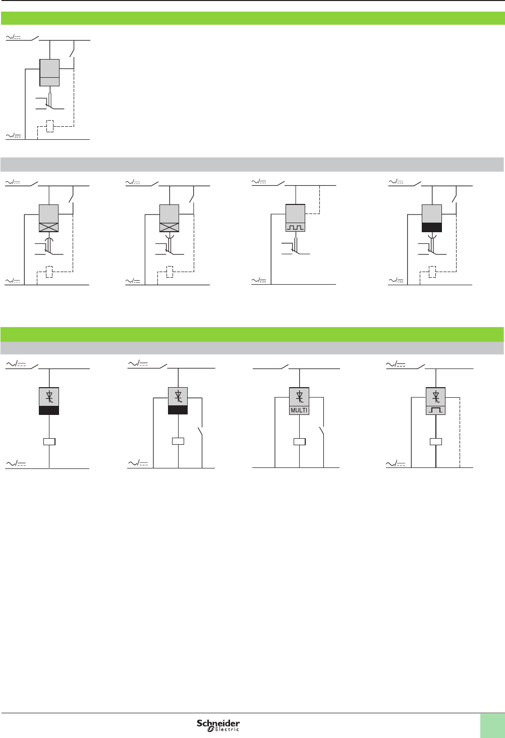
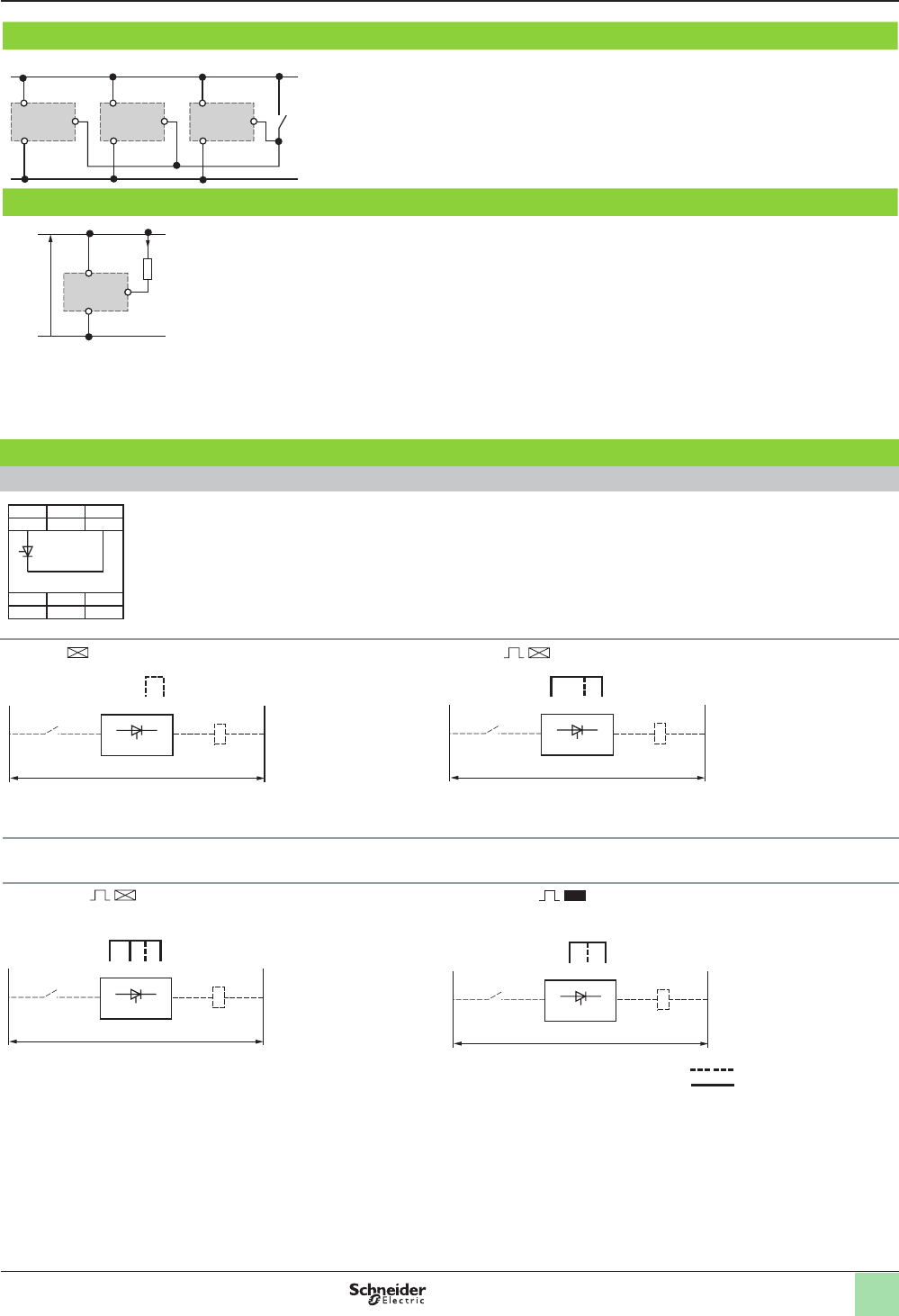
Wiring connection diagrams for RE11 models
A2 Y1
A1
U
+
–
16
15
R
18
Y1
(1)
Contact Y1:
Control for functions B, C, Ac, Bw, Ad, Ah, N, O, W, Tl, Tt
Partial stop for functions At, Ht, and Pt
Function D if Di selected
Not used for functions A, H, and P
Functions A and At Functions H and Ht Functions L and Li Functions B and C
A2 Y1
A1
U
+
–
16
15
R
18
A2 Y1
A1
U
+
–
16
15
R
18
A2 Y1
A1
U
+
–
16
15
R
18
(1)
A2 Y1
A1
U
+
–
16
15
R
18
(1) Jumper A1-Y1 for function L only
Single function relay Multi-function relay Flasher
Functions A and H Function C Functions L and Li
R
A2/L A1
U
±
±
R
L A1
U
±
±
A2 Y1
Y1
R
A2 Y1
18 A1
U
Y1
(1)
a/c
a/c
(1)
R
A2 Y1
18 A1
U
Contact Y1:
- Control for functions B, C, Ac, Bw
- Partial stop for functions At, Ht
- Function D if Di selected
- Not used for functions A and H
Zelio® Timing Relays
Modular relays with solid state or relay output,
width 17.5 mm (0.7 in.)
Courtesy of Steven Engineering, Inc.-230 Ryan Way, South San Francisco, CA 94080-6370-Main Office: (650) 588-9200-Outside Local Area: (800) 258-9200-www.stevenengineering.com
28
Dimensions and terminal locations for RE7, RE8, and RE9 models
RE7 RE8 RE9
0.89
22.5
3.15
80
3.07
78
0.89
22.5
3.15
80
3.07
78
0.89
22.5
3.15
80
3.07
78
Rail mounting
RE7 RE8 RE9
3.52
89.5 3.23
82
3.52
89.5 3.23
82
3.52
89.5 3.23
82
Direct panel mounting
RE7 RE8 RE9
Ø 0.16
4
0.24
6
0.24
6
3.07
78
Ø 0.16
4
0.24
6
3.07
78
0.24
6
Ø 0.16
4
0.24
6
3.07
78
0.24
6
Zelio® Timing Relays
Industrial single or multifunction relays, relay or
solid-state output, width 22.5 mm (0.9 in.)
Dual dimensions = in.
mm
Dimensions and wiring
(continued)
Courtesy of Steven Engineering, Inc.-230 Ryan Way, South San Francisco, CA 94080-6370-Main Office: (650) 588-9200-Outside Local Area: (800) 258-9200-www.stevenengineering.com
29
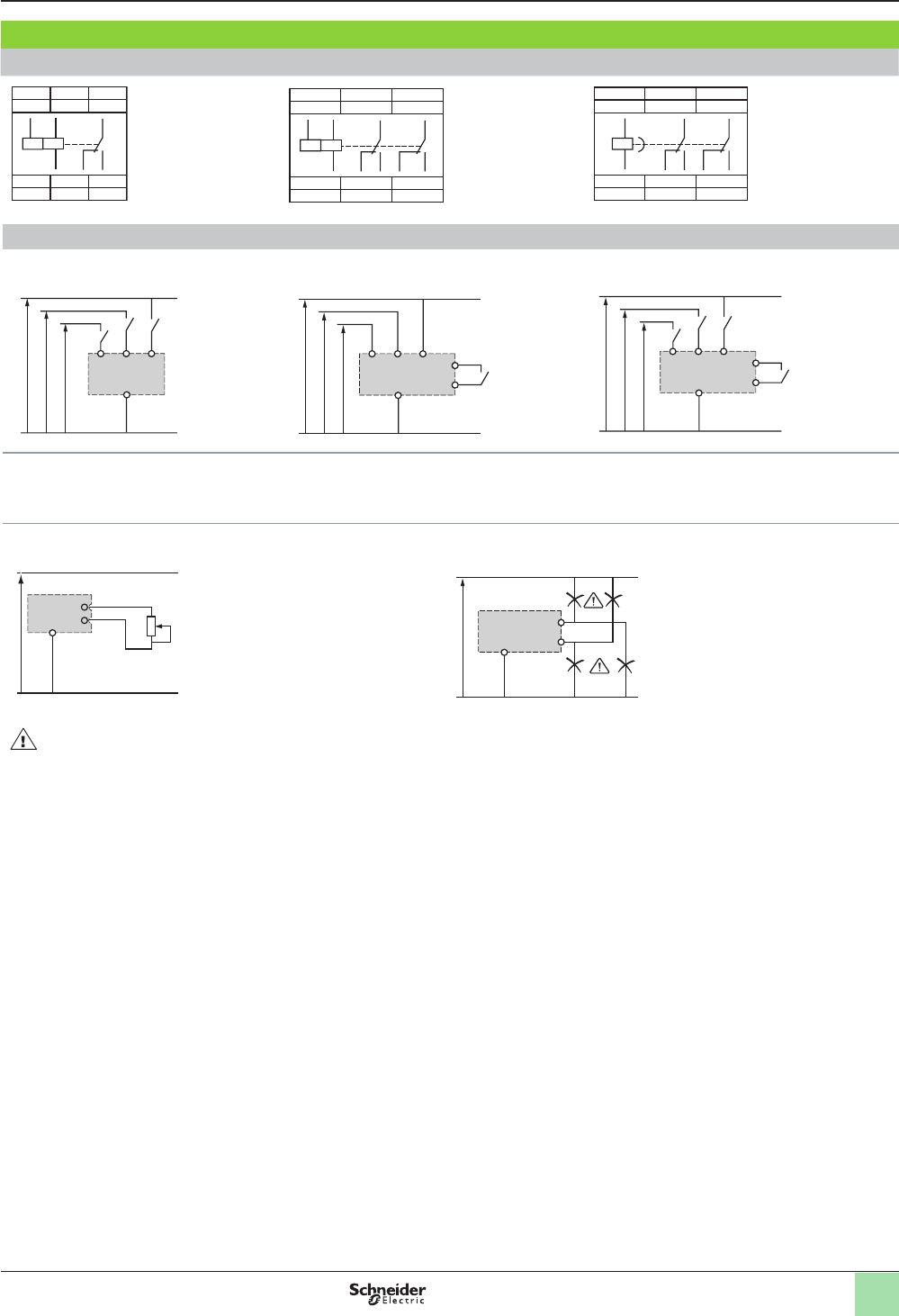
Dimensions and wiring
(continued)
Wiring connection diagrams for RE7 models: Industrial multi-function timers
RE7ML11BU RE7MY13BU RE7MY13MW
A1 15 B1
Z1 B2
Y1X1 Z2
18 16 A2
18 15
B1
A1A2
16
A1 15 B1
25 (21)Z1 Y1
26 (22)28 (24) Z2
18 16 A2
18 15
B1
A1A2
16
28
(24)
25
(21)
26
(22)
A1 15 Y1
25 (21)Z1 X1
26 (22)28 (24) Z2
18 16 A2
18 15
A1A2
16
28 25
26
(24) (21)
(22)
Recommended wiring diagrams
Start on energization
RE7ML11BU, RE7MY13BU, or RE7MY13MW
(3)
(2)
(1)
B1 A1B2
A2
Start by external control
RE7ML11BU, RE7MY13BU, or RE7MY13MW
B1 A1B2
A2
Y1
Z2
(3)
(2)
(1)
External control of partial stop
RE7ML11BU or RE7MY13MW
B1 A1B2
A2
X1
Z2
(3)
(2)
(1)
(1) 110-240 Vac: RE7ML11BU or RE7MY13BU; 24-240 Vdc or Vac: RE7MY13MW
(2) 42-48 Vac or Vdc: RE7ML11BU
(3) 24 Vac or Vdc: RE7ML11BU or RE7MY13BU
Potentiometer wiring
RE7ML11BU, RE7MY13BU, or RE7MY13MW
Wiring precautions
X1 or Y1 or Z1
Z2
A2
No electrical insulation between supply terminals A1, A2, B1, B2 and control inputs X1, Y1, Z1, Z2.
Zelio® Timing Relays
Industrial single or multifunction relays, relay or
solid-state output, width 22.5 mm (0.9 in.)
Z1
Z2
A2
Courtesy of Steven Engineering, Inc.-230 Ryan Way, South San Francisco, CA 94080-6370-Main Office: (650) 588-9200-Outside Local Area: (800) 258-9200-www.stevenengineering.com
30
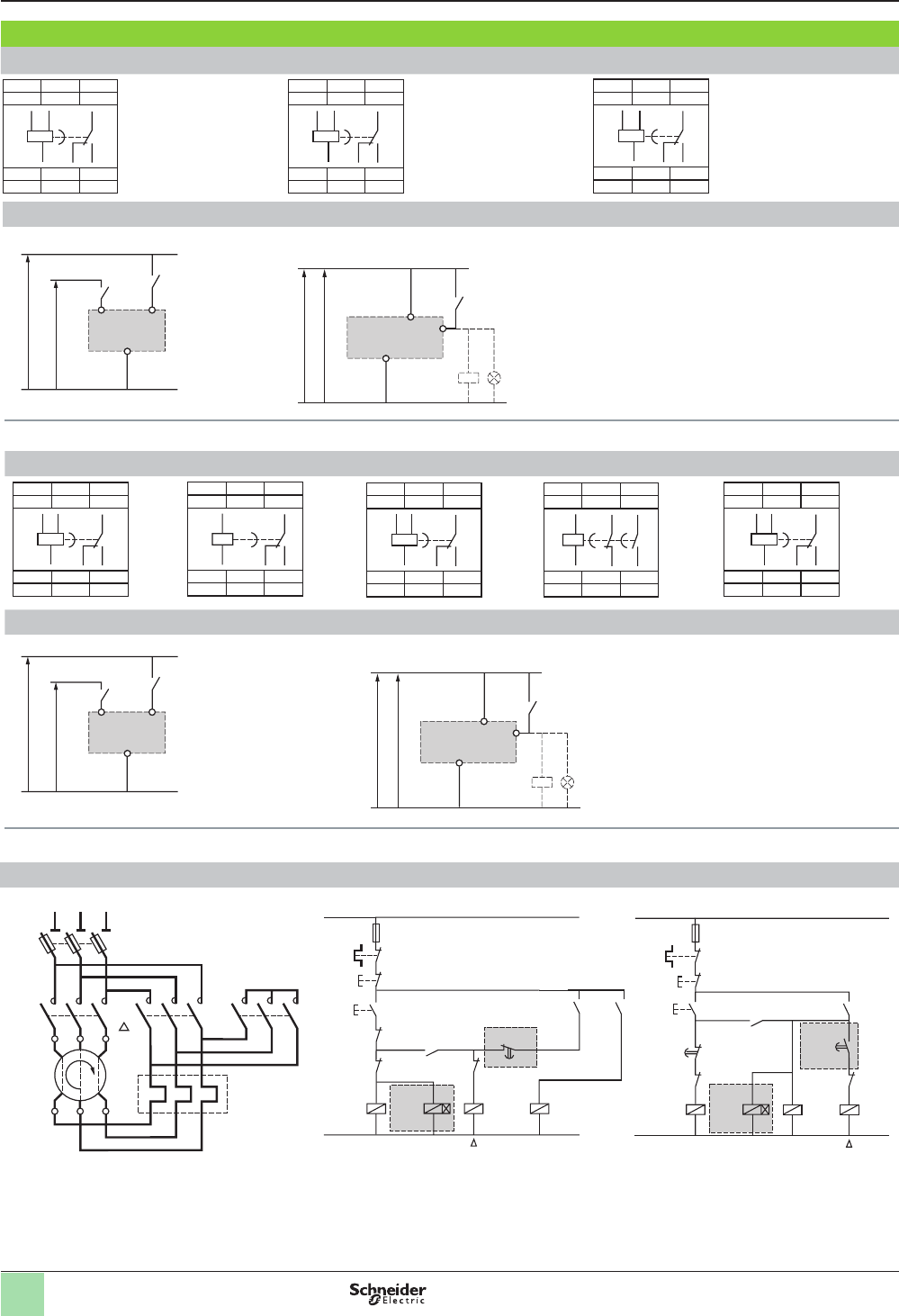
Dimensions and wiring
(continued)
Wiring connection diagrams for RE8 models: Industrial single-function relay output timers
RE8TA, CL RE8RA RE8RB
A1 15 B1
18 16 A2
18 15
B1
A2
A1
16
A1 15 B1
18 16 A2
18 15
B1
A2
A1
16
A1 15 B1
18 16 A2
18 15
B1
A2
A1
16
Recommended wiring diagrams
RE8TA, RB, CL
(2)
(1)
B1 A2
A1
RE8RA
A1
A2
Y1
(4)
(3)
+
–
(1) 110-240 Vac (2) 24 Vdc or Vac (3) 24 Vdc (4) 24 Vac or 110-240 Vac
RE8TPE RE8PD RE8PT RE8YA RE8YG
A1 15 B1
18 16 A2
18 15
16
B1
A2
A1
A1 15 Y1
18 16 A2
18 15
A2A1
16
A1 15 B1
18 16 A2
18 15
16
B1
A2
A1
A1 15 25
28 16 A2
16 15
A2A1
28 25
A1 15 B1
18 16 A2
18 15
B1
A2
A1
16
Recommended wiring diagrams - interval timers
RE8PE
(2)
(1)
B1 A2
A1
RE8PD
A1
A2
Y1
(4)
(3)
+
–
(1) 110-240 Vac (2) 24 Vdc or Vac (3) 24 Vdc (4) 24 Vac or 110-240 Vac
Recommended wiring diagrams - timers for star-delta starters
RE8YG, RE8YA
– KM2 – KM3 – KM1
U1
V1
W1
U2
V2
W2
– Q1
L1
L2
L3
– Rth
Y
RE8YG
– KM3 – KM2
– K1T
(1)
– KM1
Y
A1A2
A1A2
A1A2
A1A2
– KM3
– KM2
– KM1
– S2
– KM1
– K1T
(1)
16 15
– KM1
– KM2
– S1
– FU1
– Rth
L
(1) K1T: RE8YG
●
1
●●
TQ
RE8YA
– KM2 – KM3
– K1T
(1)
– KM1
Y
A1A2
A1A2
A1A2
A1A2
– KM3
– KM2
– KM1
– S2
– KM1
– K1T
– K1T
1516
2528
– S1
– FU1
– Rth
L
(1) K1T: RE8YA32
●●
TQ
NOTE: Correct operation of the star-delta starter associated with the RE8YG is only possible if the wiring diagram is strictly followed.
Zelio® Timing Relays
Industrial single or multifunction relays, relay or
solid-state output, width 22.5 mm (0.9 in.)
Courtesy of Steven Engineering, Inc.-230 Ryan Way, South San Francisco, CA 94080-6370-Main Office: (650) 588-9200-Outside Local Area: (800) 258-9200-www.stevenengineering.com
31
Control of several RE8 single-function relay output timers with a single external control contact
RE8RA, PD
Y1
A2
Y1
A2
Y1
A2
A1A1 A1
C
The external control contact C may be an electronic control device, for
example, a 2-wire sensor. In this case, A1 - A2 = 24 Vdc and the control device
can only control up to a maximum of 4 timers.
Connection of Telemecanique 2-wire VDC sensor
Y1
–
+
A1
A2
Leakage current
(open state) if < 1 mA
Wiring connection diagrams for RE9 models
RE9MS
A1 L
X1 X3
X2
X4
On-delay
A2
L
A1
A1
K
X3 X4
RE9-MS
Supply Vac or Vdc
Interval
A2
LA1
A1
K
X1 X3 X4
RE9-MS
Supply Vac
Jumper to be made between terminals X1 and X4
Selection of timing range: X3-X4 not jumpered: range 3-300 s (factory conguration)
X3-X4 jumpered: range 0.1-10 s
Repeat cycle
Start on energization of the load
A2L A1
A1
K
X2 X3X1 X4
RE9-MS
Supply Vac
Repeat cycle
Start on de-energization of the load
A2L A1
A1
K
X2 X3 X4
RE9-MS
Supply Vac
Jumper to be made between terminals X2 and X4 on one side and
X1 and X2 on the other side.
Jumper to be made between terminals X2 and X4.
NOTE: For supply voltages greater than 30 V, the rated voltage of the load is equal to the supply voltage. For a supply voltage of 24 V, the
voltage drop in the RE9 timer must be taken into account (about 3 V); select a coil with a nominal voltage of 21 V for the load.
Zelio® Timing Relays
Industrial or optimum, single or multifunction
relays, relay or solid-state output,
width 22.5 mm (0.9 in.)
Dimensions and wiring
(continued)
May need to be jumpered.
Must be jumpered
Courtesy of Steven Engineering, Inc.-230 Ryan Way, South San Francisco, CA 94080-6370-Main Office: (650) 588-9200-Outside Local Area: (800) 258-9200-www.stevenengineering.com
32
Dimensions and terminal locations for RE88865 models
Wiring connection diagrams for RE88865 models
All functions except L and Li Functions L and Li
U
A1
R
15
A2
1816
Y1
+
U
A1
R
15
(1)
A2
1816
Y1
+
(1) Jumper A1-Y1 for function L only
All functions except K Function K
U
A1
R1 R2
15
A2
1816
25/21
28/2426/22
Y1
+
U
A1
A2
R1 R2
15
1816
25
2826
+
Function Q
U
A1
R
15
A2
18
28
+
A1 15
28 18 A2
Zelio® Timing Relays
Industrial single, dual, or multifunction relays,
relay output, width 22.5 mm (0.9 in.)
Dimensions and wiring
(continued)
A1 15 Y1
18 16 A2
1.26
(32)
0.14
(3.5)
3.74
(95)
0.20
(5)
2.24
(57)3
3.07
(78)
2.48
(63) 0.89
(22.5)
A1 15 Y1
18 16 A2
Dual dimensions = in.
mm
A1 15
28 18 A2
Function Q
Courtesy of Steven Engineering, Inc.-230 Ryan Way, South San Francisco, CA 94080-6370-Main Office: (650) 588-9200-Outside Local Area: (800) 258-9200-www.stevenengineering.com
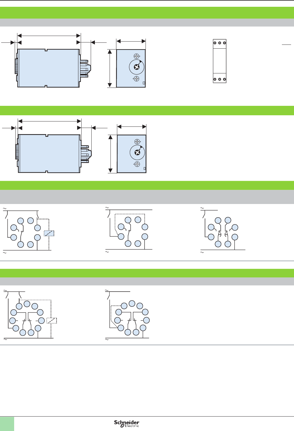
33
Dimensions and terminal locations for REXL models
Approximate dimensions
REXL4TMpp
1.06
27
0.83
21
1.06
27
0.83
21
REXL2TMpp
R Un
0.83
21
2.58
65.5
0.14
3.5
1.06
27
2.34
59.5
0.02
0.55
0.11
2.8
0.01
0.3
0.05
1.2
Terminal locations
REXL4TMpp
1
5
9
13
(-)
2
6
10
3
7
11
4
8
12
14
(+)
REXL2TMpp
1
5
9
13
(-)
4
8
12
14
(+)
Wiring connection diagrams for REXL models
Timer with 4 C/O contacts Timer with 2 C/O contacts
- 13
9
5 1
+ 14
6
10
2
11
7 3
12
8 4 - 13
9
5 1
+ 14
8
12
4
Zelio® Timing Relays
Miniature plug-in relays, relay output
Dual dimensions = in.
mm
Dimensions and wiring
(continued)
Courtesy of Steven Engineering, Inc.-230 Ryan Way, South San Francisco, CA 94080-6370-Main Office: (650) 588-9200-Outside Local Area: (800) 258-9200-www.stevenengineering.com
34
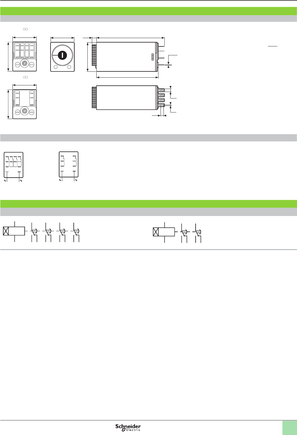
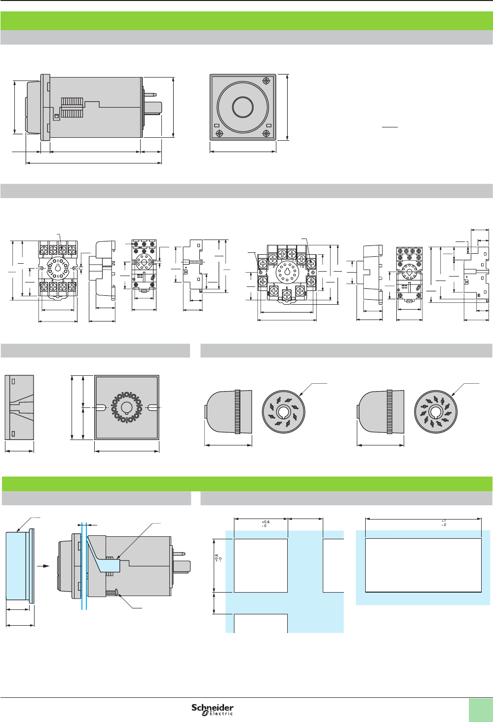
Dimensions and terminal locations for RE88867 plug-in timers (8-pin, relay output)
Approximate dimensions
1.77
(45)
0.02
(3.5)
0.49
(12.5)
2.93
(74.5) 1.38
(35)
A1 15 Y1
18 16 A2
Dimensions and terminal locations for RE88867 plug-in timers (11-pin, relay output)
1.77
(45)
0.02
(3.5)
0.49
(12.5)
2.93
(74.5) 1.38
(35)
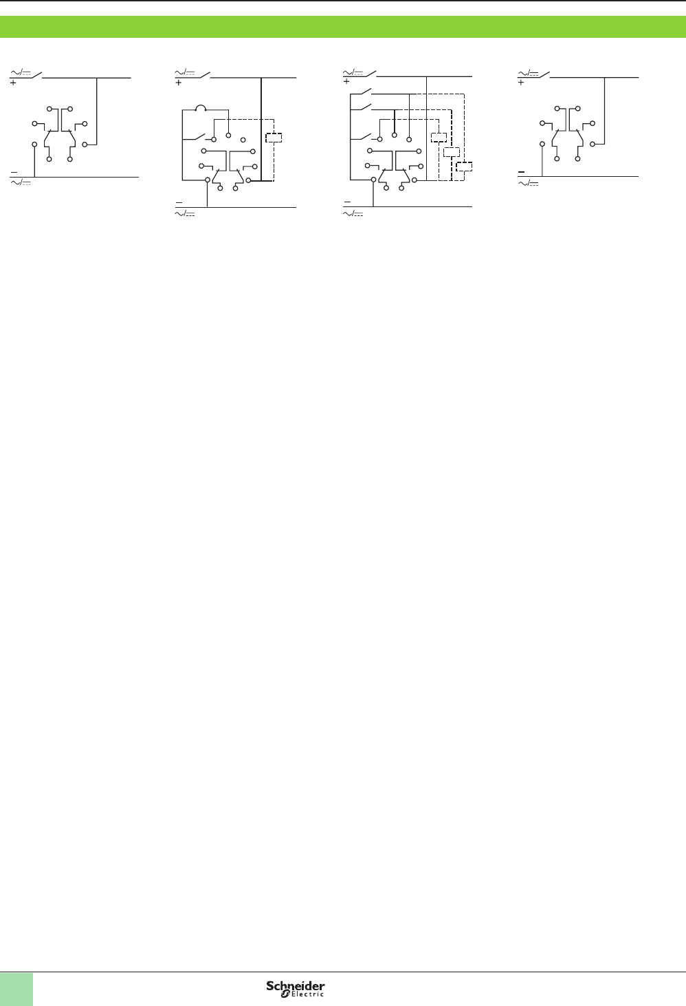
Wiring connection diagrams for RE88867 plug-in timers (8-pin, relay output)
Timing relays with 1 relay output
All functions except L and Li Functions L and Li Timing relays with 2 relay outputs
Function A
U
4
R
+
–
5
6
7
8
1
2
3
YU(1)
4
R
+
–
5
6
7
8
1
2
3
U
4
R1 R2
+
–
5
6
7
8
1
2
3
(1) Jumper between pins 2 and 6 for function L only
Wiring connection diagrams for RE88867 plug-in timers (11-pin, relay output)
All functions except L and Li Functions L and Li
U
4
R1
Y1
R2
+
–
567
8
9
10
11
1
2
3
U
(1)
4
R1 R2
+
–
567
8
9
10
11
1
2
3
(1) Jumper between pins 2 and 5 for function L only
Zelio® Timing Relays
Universal plug-in relays, 8-pin or 11-pin,
relay output, width 35 mm (1.4 in.)
Dimensions and wiring
(continued)
Dual dimensions = in.
mm
Courtesy of Steven Engineering, Inc.-230 Ryan Way, South San Francisco, CA 94080-6370-Main Office: (650) 588-9200-Outside Local Area: (800) 258-9200-www.stevenengineering.com
35
Dimensions and wiring
(continued)
Dimensions for RE48 models
Approximate dimensions
RE48App1pMW
1.89
(48)
1.75
(44.4)
Ø 1.54
(39)
0.27
(6.8)
2.54
(64.5)
0.61
(15.5)
1.89
(48)
3.81
(96.8)
8-pin socket 11-pin socket
8501NR51 8501NR52 8501NR61 8501NR62
0.77
20
0.97
25
Terminal screws M3 .5 x .6
2.14
54
2.03
51
1.30
33
1.60
41
0.17
4
1.01
26
1.09
28
1.42
36
3.06
78
2.86
73
0.88
22
0.71
18
1.11
28
0.14
4
1.57
40
2.04
52
Terminal screws M3.5 x 7
1.07
(27)
0.77
20
0.97
25
Terminal screws 6-32 x 5/16"
dia.
0.17
4
2.06
52 2.33
59
0.96
24
1.30
33
2.16
55
2.04
52 3.22
82
3.02
77
1.88
48
0.76
19
0.38
10
0.71
18
1.44
37
0.62
16
1.03
26
1.32
34
1.50
38
1.79
46
11-pin socket 8-pin connector 11-pin connector
RE48ASOC11AR RE48ASOC8SOLD RE48ASOC11SOLD
==
1.18
(46)
1.18
(46)
0.79
(20)
Ø 1.18
(30)
1.34
(34)
Ø 1.18
(30)
1.34
(34)
Mounting
Cover positioning and mounting Panel cut-out
e(2)
(3)
0.67
(17)
0.79
(20)
(1) 1.77
(45)
1.18
(30)
1.77
(45)
0.59
(15)
A = (48n - 2.5 )
A = 1.89n - 0.10)
e: panel thickness
(1) IP64 protective cover: RE48AIPCOV
(2) Panel mounting frame
(3) Locating screw
n: number of devices mounted side-by-side
Zelio® Timing Relays
Analog, electronic relays,
relay output, 48 x 48
Dual dimensions = in.
mm
Courtesy of Steven Engineering, Inc.-230 Ryan Way, South San Francisco, CA 94080-6370-Main Office: (650) 588-9200-Outside Local Area: (800) 258-9200-www.stevenengineering.com
36
Wiring connection diagrams for RE48 panel-mount timers
RE48ATM12MW
1
U
R
2
3
4 5
8
7
6
RE48ACV12MW
67
58
4
9
3
111
10
2
U
R
Gate
RE48AML12MW
67
58
4
9
3
111
10
2
U
R
Gate
Reset
Start
RE48AMH13MW
1
U
R1 R2
2
3
4 5
8
7
6
Zelio® Timing Relays
Analog, electronic relays,
relay output, 48 x 48
Dimensions and wiring
(continued)
Courtesy of Steven Engineering, Inc.-230 Ryan Way, South San Francisco, CA 94080-6370-Main Office: (650) 588-9200-Outside Local Area: (800) 258-9200-www.stevenengineering.com
Courtesy of Steven Engineering, Inc.-230 Ryan Way, South San Francisco, CA 94080-6370-Main Office: (650) 588-9200-Outside Local Area: (800) 258-9200-www.stevenengineering.com
Courtesy of Steven Engineering, Inc.-230 Ryan Way, South San Francisco, CA 94080-6370-Main Office: (650) 588-9200-Outside Local Area: (800) 258-9200-www.stevenengineering.com
Courtesy of Steven Engineering, Inc.-230 Ryan Way, South San Francisco, CA 94080-6370-Main Office: (650) 588-9200-Outside Local Area: (800) 258-9200-www.stevenengineering.com
Schneider Electric USA, Inc.
8001 Knightdale Blvd.
Knightdale, NC 27545
USA
1-888-SquareD
1-888-778-2733
www.schneider-electric.us
© 2010 Schneider Electric All Rights Reserved. May 2010
The information and dimensions in this catalog are provided for the convenience of customers.
While this information is believed to be accurate, Schneider Electric reserves the right to make
updates and changes without prior notication and assumes no liability for any errors or omissions.
Design: Schneider Electric
Photos: Schneider Electric
9050CT0001R03/10
Courtesy of Steven Engineering, Inc.-230 Ryan Way, South San Francisco, CA 94080-6370-Main Office: (650) 588-9200-Outside Local Area: (800) 258-9200-www.stevenengineering.com
